JP4479121B2 - 半導体装置の製造方法 - Google Patents
半導体装置の製造方法 Download PDFInfo
- Publication number
- JP4479121B2 JP4479121B2 JP2001127516A JP2001127516A JP4479121B2 JP 4479121 B2 JP4479121 B2 JP 4479121B2 JP 2001127516 A JP2001127516 A JP 2001127516A JP 2001127516 A JP2001127516 A JP 2001127516A JP 4479121 B2 JP4479121 B2 JP 4479121B2
- Authority
- JP
- Japan
- Prior art keywords
- pair
- semiconductor device
- heat sink
- resin
- heat
- Prior art date
- Legal status (The legal status is an assumption and is not a legal conclusion. Google has not performed a legal analysis and makes no representation as to the accuracy of the status listed.)
- Expired - Lifetime
Links
Images


Classifications
-
- H—ELECTRICITY
- H10—SEMICONDUCTOR DEVICES; ELECTRIC SOLID-STATE DEVICES NOT OTHERWISE PROVIDED FOR
- H10W—GENERIC PACKAGES, INTERCONNECTIONS, CONNECTORS OR OTHER CONSTRUCTIONAL DETAILS OF DEVICES COVERED BY CLASS H10
- H10W72/00—Interconnections or connectors in packages
- H10W72/30—Die-attach connectors
-
- H—ELECTRICITY
- H10—SEMICONDUCTOR DEVICES; ELECTRIC SOLID-STATE DEVICES NOT OTHERWISE PROVIDED FOR
- H10W—GENERIC PACKAGES, INTERCONNECTIONS, CONNECTORS OR OTHER CONSTRUCTIONAL DETAILS OF DEVICES COVERED BY CLASS H10
- H10W40/00—Arrangements for thermal protection or thermal control
- H10W40/70—Fillings or auxiliary members in containers or in encapsulations for thermal protection or control
- H10W40/77—Auxiliary members characterised by their shape
- H10W40/778—Auxiliary members characterised by their shape in encapsulations
-
- H—ELECTRICITY
- H10—SEMICONDUCTOR DEVICES; ELECTRIC SOLID-STATE DEVICES NOT OTHERWISE PROVIDED FOR
- H10W—GENERIC PACKAGES, INTERCONNECTIONS, CONNECTORS OR OTHER CONSTRUCTIONAL DETAILS OF DEVICES COVERED BY CLASS H10
- H10W74/00—Encapsulations, e.g. protective coatings
- H10W74/01—Manufacture or treatment
- H10W74/016—Manufacture or treatment using moulds
-
- H—ELECTRICITY
- H10—SEMICONDUCTOR DEVICES; ELECTRIC SOLID-STATE DEVICES NOT OTHERWISE PROVIDED FOR
- H10W—GENERIC PACKAGES, INTERCONNECTIONS, CONNECTORS OR OTHER CONSTRUCTIONAL DETAILS OF DEVICES COVERED BY CLASS H10
- H10W74/00—Encapsulations, e.g. protective coatings
- H10W74/10—Encapsulations, e.g. protective coatings characterised by their shape or disposition
- H10W74/111—Encapsulations, e.g. protective coatings characterised by their shape or disposition the semiconductor body being completely enclosed
- H10W74/121—Encapsulations, e.g. protective coatings characterised by their shape or disposition the semiconductor body being completely enclosed by multiple encapsulations, e.g. by a thin protective coating and a thick encapsulation
-
- H—ELECTRICITY
- H10—SEMICONDUCTOR DEVICES; ELECTRIC SOLID-STATE DEVICES NOT OTHERWISE PROVIDED FOR
- H10W—GENERIC PACKAGES, INTERCONNECTIONS, CONNECTORS OR OTHER CONSTRUCTIONAL DETAILS OF DEVICES COVERED BY CLASS H10
- H10W72/00—Interconnections or connectors in packages
- H10W72/01—Manufacture or treatment
- H10W72/015—Manufacture or treatment of bond wires
- H10W72/01515—Forming coatings
-
- H—ELECTRICITY
- H10—SEMICONDUCTOR DEVICES; ELECTRIC SOLID-STATE DEVICES NOT OTHERWISE PROVIDED FOR
- H10W—GENERIC PACKAGES, INTERCONNECTIONS, CONNECTORS OR OTHER CONSTRUCTIONAL DETAILS OF DEVICES COVERED BY CLASS H10
- H10W72/00—Interconnections or connectors in packages
- H10W72/071—Connecting or disconnecting
- H10W72/073—Connecting or disconnecting of die-attach connectors
- H10W72/07331—Connecting techniques
-
- H—ELECTRICITY
- H10—SEMICONDUCTOR DEVICES; ELECTRIC SOLID-STATE DEVICES NOT OTHERWISE PROVIDED FOR
- H10W—GENERIC PACKAGES, INTERCONNECTIONS, CONNECTORS OR OTHER CONSTRUCTIONAL DETAILS OF DEVICES COVERED BY CLASS H10
- H10W72/00—Interconnections or connectors in packages
- H10W72/071—Connecting or disconnecting
- H10W72/075—Connecting or disconnecting of bond wires
-
- H—ELECTRICITY
- H10—SEMICONDUCTOR DEVICES; ELECTRIC SOLID-STATE DEVICES NOT OTHERWISE PROVIDED FOR
- H10W—GENERIC PACKAGES, INTERCONNECTIONS, CONNECTORS OR OTHER CONSTRUCTIONAL DETAILS OF DEVICES COVERED BY CLASS H10
- H10W72/00—Interconnections or connectors in packages
- H10W72/30—Die-attach connectors
- H10W72/381—Auxiliary members
-
- H—ELECTRICITY
- H10—SEMICONDUCTOR DEVICES; ELECTRIC SOLID-STATE DEVICES NOT OTHERWISE PROVIDED FOR
- H10W—GENERIC PACKAGES, INTERCONNECTIONS, CONNECTORS OR OTHER CONSTRUCTIONAL DETAILS OF DEVICES COVERED BY CLASS H10
- H10W72/00—Interconnections or connectors in packages
- H10W72/50—Bond wires
- H10W72/551—Materials of bond wires
- H10W72/552—Materials of bond wires comprising metals or metalloids, e.g. silver
- H10W72/5522—Materials of bond wires comprising metals or metalloids, e.g. silver comprising gold [Au]
-
- H—ELECTRICITY
- H10—SEMICONDUCTOR DEVICES; ELECTRIC SOLID-STATE DEVICES NOT OTHERWISE PROVIDED FOR
- H10W—GENERIC PACKAGES, INTERCONNECTIONS, CONNECTORS OR OTHER CONSTRUCTIONAL DETAILS OF DEVICES COVERED BY CLASS H10
- H10W72/00—Interconnections or connectors in packages
- H10W72/50—Bond wires
- H10W72/551—Materials of bond wires
- H10W72/552—Materials of bond wires comprising metals or metalloids, e.g. silver
- H10W72/5524—Materials of bond wires comprising metals or metalloids, e.g. silver comprising aluminium [Al]
-
- H—ELECTRICITY
- H10—SEMICONDUCTOR DEVICES; ELECTRIC SOLID-STATE DEVICES NOT OTHERWISE PROVIDED FOR
- H10W—GENERIC PACKAGES, INTERCONNECTIONS, CONNECTORS OR OTHER CONSTRUCTIONAL DETAILS OF DEVICES COVERED BY CLASS H10
- H10W72/00—Interconnections or connectors in packages
- H10W72/851—Dispositions of multiple connectors or interconnections
- H10W72/853—On the same surface
- H10W72/865—Die-attach connectors and bond wires
-
- H—ELECTRICITY
- H10—SEMICONDUCTOR DEVICES; ELECTRIC SOLID-STATE DEVICES NOT OTHERWISE PROVIDED FOR
- H10W—GENERIC PACKAGES, INTERCONNECTIONS, CONNECTORS OR OTHER CONSTRUCTIONAL DETAILS OF DEVICES COVERED BY CLASS H10
- H10W72/00—Interconnections or connectors in packages
- H10W72/851—Dispositions of multiple connectors or interconnections
- H10W72/874—On different surfaces
- H10W72/884—Die-attach connectors and bond wires
-
- H—ELECTRICITY
- H10—SEMICONDUCTOR DEVICES; ELECTRIC SOLID-STATE DEVICES NOT OTHERWISE PROVIDED FOR
- H10W—GENERIC PACKAGES, INTERCONNECTIONS, CONNECTORS OR OTHER CONSTRUCTIONAL DETAILS OF DEVICES COVERED BY CLASS H10
- H10W74/00—Encapsulations, e.g. protective coatings
-
- H—ELECTRICITY
- H10—SEMICONDUCTOR DEVICES; ELECTRIC SOLID-STATE DEVICES NOT OTHERWISE PROVIDED FOR
- H10W—GENERIC PACKAGES, INTERCONNECTIONS, CONNECTORS OR OTHER CONSTRUCTIONAL DETAILS OF DEVICES COVERED BY CLASS H10
- H10W90/00—Package configurations
- H10W90/701—Package configurations characterised by the relative positions of pads or connectors relative to package parts
- H10W90/731—Package configurations characterised by the relative positions of pads or connectors relative to package parts of die-attach connectors
- H10W90/736—Package configurations characterised by the relative positions of pads or connectors relative to package parts of die-attach connectors between a chip and a stacked lead frame, conducting package substrate or heat sink
-
- H—ELECTRICITY
- H10—SEMICONDUCTOR DEVICES; ELECTRIC SOLID-STATE DEVICES NOT OTHERWISE PROVIDED FOR
- H10W—GENERIC PACKAGES, INTERCONNECTIONS, CONNECTORS OR OTHER CONSTRUCTIONAL DETAILS OF DEVICES COVERED BY CLASS H10
- H10W90/00—Package configurations
- H10W90/701—Package configurations characterised by the relative positions of pads or connectors relative to package parts
- H10W90/751—Package configurations characterised by the relative positions of pads or connectors relative to package parts of bond wires
- H10W90/756—Package configurations characterised by the relative positions of pads or connectors relative to package parts of bond wires between a chip and a stacked lead frame, conducting package substrate or heat sink
Landscapes
- Cooling Or The Like Of Semiconductors Or Solid State Devices (AREA)
- Encapsulation Of And Coatings For Semiconductor Or Solid State Devices (AREA)
- Structures Or Materials For Encapsulating Or Coating Semiconductor Devices Or Solid State Devices (AREA)
- Injection Moulding Of Plastics Or The Like (AREA)
Description
【発明の属する技術分野】
本発明は、発熱素子と、この発熱素子の両面に接合された一対の放熱板とを備えて成る半導体装置の製造方法に関する。
【0002】
【従来の技術】
例えば高耐圧・大電流用のパワーICの半導体チップ(発熱素子)は、使用時の発熱が大きいため、チップからの放熱性を向上させるための構成が必要になる。この構成の一例として、チップの両面に一対の放熱板を例えば半田層を介して接合する構成が、従来より、考えられており、この構成によれば、チップの両面から放熱できるので、放熱性が向上する。
【0003】
上記した構成の半導体装置の一例を、図4に示す。この図4に示すように、半導体装置1は、一対のヒートシンク(放熱板)2、3の間に半導体チップ4とヒートシンクブロック5を挟んで構成されている。ヒートシンク2と半導体チップ4の間、半導体チップ4とヒートシンクブロック5の間、ヒートシンクブロック5とヒートシンク3の間は、それぞれ半田6により接合されている。そして、このような構成の半導体装置1は、樹脂7でモールドされている。
【0004】
【発明が解決しようとする課題】
上記構成の半導体装置1においては、ヒートシンク2、3からの放熱性を良くするために、半導体装置1を樹脂7でモールドする際に、ヒートシンク2、3の各外面を露出させることが好ましい。このため、樹脂モールド時には、図4に示すような構成の成形型8を使用することが考えられている。この成形型8は、下型8aと、上型8bと、可動型8cとから構成されている。可動型8cは、半導体装置1を適度な加圧力で押圧するための型であり、この可動型8cの加圧力により、樹脂モールド時に、樹脂7がヒートシンク2、3の各外面に回り込むことを防止している。
【0005】
しかし、上記構成の場合、可動型8cの加圧力を適度な力に調整することがかなり困難であり、半導体チップ4を割ってしまうことがかなりあるという問題点があった。また、可動型8cを必要とするため、成形型8の構成が複雑になり、成形型8の製造コストひいては半導体装置11の製造コストが高くなるという欠点があった。
【0006】
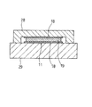
更に、半導体装置1の完成後の検査やスクリーニングにおいては、ヒートシンク2、3の露出した各外面を絶縁する必要があり、何らかの絶縁用の構成が必要であった。また、上記半導体装置1をインバータ装置等へ組み込む場合も、ヒートシンク2、3の露出した各外面を絶縁するための構成が必要であった。例えば、図5に示すように、半導体装置1を冷却板9、9で挟む場合には、冷却板9、9と半導体装置1のヒートシンク2、3との間に、絶縁材製の放熱シート10、10を挟む必要があった。
【0007】
一方、ヒートシンク2、3と樹脂7との密着力を向上させるために、コーティング樹脂(例えばポリアミド樹脂)をヒートシンク2、3の表面に塗布することが考えられている。しかし、上記半導体装置1の場合、ヒートシンク2、3間の隙間は約1〜2mm程度しかないので、コーティング樹脂を塗布することが困難であった。特に、均一に塗布されたか否かを確認することが困難であった。
【0008】
そこで、本発明の目的は、樹脂モールド時に使用する成形型の構成を簡単化することができ、発熱素子の損傷を防止することができ、絶縁用の構成を不要にすることができ、また、コーティング樹脂を容易に塗布することができる半導体装置の製造方法を提供することにある。
【0009】
【課題を解決するための手段】
請求項1の発明によれば、一対の放熱板の間に前記発熱素子を挟む工程と、前記一対の放熱板の各外面にシリコンゴム製の絶縁シートを取り付ける工程と、成形型に前記一対の放熱板及び前記発熱素子を収容して樹脂モールドする工程とを備えるように構成したので、成形型として単純な構成の上下型を使用しても、樹脂が放熱板の各外面に回り込むことを防止できる。このため、樹脂モールド時に使用する成形型の構成を簡単化することができる。そして、成形型の押圧力を絶縁シートで緩和できるから、発熱素子が損傷することを防止できる。また、放熱板の各外面に絶縁シートを貼り付けたので、検査時等に絶縁用の構成を不要にすることができる。
【0013】
請求項2発明によれば、一対の放熱板の間に発熱素子を挟む工程を実行した後、一対の放熱板及び発熱素子にコーティング樹脂を塗布する工程を備えたので、放熱板及び発熱素子と樹脂との密着力を強くすることができる。
【0014】
請求項3の発明によれば、一対の放熱板の各外面に絶縁シートを取り付ける工程において、塗布されたコーティング樹脂によって絶縁シートを接着する方法を使用したので、絶縁シートを貼り付けるための専用の接着剤を塗布する必要がない。
【0015】
請求項4の発明によれば、コーティング樹脂を塗布する工程において、コーティング樹脂の液中に一対の放熱板及び発熱素子をディッピングする方法を使用したので、放熱板及び発熱素子にコーティング樹脂を容易に塗布することができる。
【0016】
また、請求項5の発明のように、コーティング樹脂を塗布する工程において、コーティング樹脂を一対の放熱板及び発熱素子に滴下または噴霧する方法を使用しても良い。更に、請求項6の発明のように、コーティング樹脂として例えばポリアミド樹脂を用いることが好ましい。
【0017】
【発明の実施の形態】
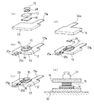
以下、本発明の一実施例について、図1ないし図3を参照しながら説明する。まず、図1に示すように、本実施例の半導体装置11は、半導体チップ(発熱素子)12と、下側ヒートシンク(放熱板)13と、上側ヒートシンク(放熱板)14と、ヒートシンクブロック15とを備えて構成されている。
【0018】
この構成の場合、半導体チップ12の下面と下側ヒートシンク13の上面との間は、接合部材である例えば半田16によって接合されている。そして、半導体チップ12の上面とヒートシンクブロック15の下面との間も、半田16によって接合されている。更に、ヒートシンクブロック15の上面と上側ヒートシンク14の下面との間も、半田16によって接合されている。これにより、上記構成においては、半導体チップ12の両面からヒートシンク13、14(即ち、一対の放熱板)を介して放熱される構成となっている。
【0019】
尚、上記半導体チップ12は、例えばIGBTやサイリスタ等のパワー半導体素子から構成されている。半導体チップ12の形状は、本実施例の場合、図2 (a)に示すように、例えば矩形状の薄板状である。また、下側ヒートシンク13、上側ヒートシンク14及びヒートシンクブロック15は、例えばCuやAl等の熱伝導性及び電気伝導性の良い金属で構成されている。この構成の場合、下側ヒートシンク13及び上側ヒートシンク14は、半導体チップ12の各主電極(例えばコレクタ電極やエミッタ電極等)に半田16を介して電気的にも接続されている。
【0020】
そして、下側ヒートシンク13は、図2(a)に示すように、全体として例えばほぼ長方形状の板材であり、端子部13aが後方へ向けて延びるように突設されている。また、ヒートシンクブロック15は、図2(a)に示すように、半導体チップ12よりも1回り小さい程度の大きさの矩形状の板材である。更に、上側ヒートシンク14は、図2(d)に示すように、全体として例えばほぼ長方形状の板材で構成されており、端子部14aが後方へ向けて延びるように突設されている。尚、下側ヒートシンク13の端子部13aと、上側ヒートシンク14の端子部14aは、互いの位置がずれるように、即ち、対向しないように構成されている。
【0021】
また、上記構成の場合、下側ヒートシンク13の上面と上側ヒートシンク14の下面との間の距離は、例えば1〜2mm程度になるように構成されている。図1及び図2においては、上記距離をかなり拡大して示している。
【0022】
そして、図1に示すように、コーティング樹脂である例えばポリアミド樹脂17が、一対のヒートシンク13、14の表面、並びに、チップ12及びヒートシンクブロック15の周囲部分に、やや太い実線で示すように塗布されている。本実施例の場合、上記ポリアミド樹脂17は、例えばディッピングにより塗布されている。
【0023】
更に、図1に示すように、下側ヒートシンク13の下面(外面)、並びに、上側ヒートシンク14の上面(外面)には、圧縮変形可能な材質であって高熱伝導性を有する絶縁シート18、18が例えば接着剤を介して貼り付けられている。これら絶縁シート18は、例えばシリコンゴム製のシートで構成されている。尚、上記接着剤としては、熱伝導性の良いものを使用することが好ましい。
【0024】
更にまた、図1に示すように、一対のヒートシンク13、14の隙間、並びに、チップ12及びヒートシンクブロック15の周囲部分には、樹脂(例えばエポキシ樹脂)19が充填封止されている。この場合、ヒートシンク13、14等を樹脂19でモールドするに当たっては、図1に示すような構成の成形型20を使用している。この成形型20は、単純な構成の上下型であり、下型21と、上型22とから構成されている。
【0025】
上記実施例の場合、成形型20のキャビティ23内にヒートシンク13、14等の構成を収容したときに、ヒートシンク13、14の各外面の絶縁シート18、18が、その厚さ方向に約10〜40%程度圧縮変形する(即ち、押し潰される)ように構成されている。これにより、成形型20のキャビティ23内に樹脂19を注入したときに、該樹脂19がヒートシンク13、14の外面である絶縁シート18の外面に回り込むことを防止している。また、成形型20、即ち、下型21及び上型22の押圧力を上記絶縁シート19で緩和している。これにより、上記押圧力によってチップ12が損傷することを防止できる。
【0026】
ここで、下側ヒートシンク13の下面と上側ヒートシンク14の上面との距離(即ち、半導体装置11の厚み寸法)は、後述する製造方法により、設定距離となるように構成されるものであるが、実際には、各構成部品の寸法のばらつきや、ヒートシンク13、14の平面度や傾き等のばらつき等により、ある程度の誤差が出る。今、上記誤差が例えば0.1mmであるとし、絶縁シート18がその厚さ方向に例えば15%程度圧縮変形するものとすると、絶縁シート18の厚さ寸法は、次の式で計算される値以上あれば良い。
【0027】
0.1/0.15/2=0.33
即ち、絶縁シート18の厚さ寸法は、0.33mm以上あれば良い。これは、一例であり、実際の寸法の誤差やばらつきに適合するように、絶縁シート18の厚さを調整すれば良い。
【0028】
尚、前記ポリアミド樹脂17は、樹脂19とヒートシンク13、14との密着力、樹脂19とチップ12との密着力、並びに、樹脂19とヒートシンクブロック15との密着力を強くするためのコーティング層(樹脂)である。
【0029】
次に、上記した構成の半導体装置11の製造方法(即ち、製造工程)について、図2を参照して説明する。まず、図2(a)及び(b)に示すように、下側ヒートシンク13の上面に、半導体チップ12とヒートシンクブロック15を半田付けする工程を実行する。この場合、下側ヒートシンク13の上面に半田箔24を介してチップ12を積層すると共に、このチップ12の上に半田箔24を介してヒートシンクブロック15を積層する。この後、加熱装置(リフロー装置)によって上記半田箔24、24を溶融させてから、硬化させる。
【0030】
続いて、図2(c)に示すように、チップ12の制御電極(例えばゲートパッド等)とリードフレーム25a、25bとをワイヤーボンディングする工程を実行する。これにより、例えばAlやAu等製のワイヤー26によってチップ12の制御電極とリードフレーム25a、25bとが接続される。
【0031】
次いで、図2(d)及び(e)に示すように、ヒートシンクブロック15の上に上側ヒートシンク14を半田付けする工程を実行する。この場合、図2(d)に示すように、ヒートシンクブロック15の上に半田箔24を介して上側ヒートシンク14を載せる。そして、加熱装置によって上記半田箔24を溶融させてから、硬化させる。
【0032】
このとき、図2(e)に示すように、上側ヒートシンク14の上に例えば重り27を載置することにより、上側ヒートシンク14を下方へ向けて加圧するように構成されている。これと共に、上側ヒートシンク14と下側ヒートシンク13との間に、スペーサ治具(図示しない)を取り付けることにより、上側ヒートシンク14と下側ヒートシンク13との間の距離を設定距離に保持するように構成している。
【0033】
この場合、半田箔24が溶融する前の状態では、上側ヒートシンク14と下側ヒートシンク13との距離は、スペーサ治具の設定距離よりも大きくなるように構成されている。そして、半田箔24が溶融すると、重り27の加圧力により、溶融した半田層の部分が薄くなり、上側ヒートシンク14と下側ヒートシンク13との距離がスペーサ治具の設定距離と等しくなる。このとき、半田層は、適度な薄さまで薄くなるように構成されている。そして、溶融した半田層が硬化すれば、チップ12とヒートシンク13、14とヒートシンクブロック15の接合及び電気的接続が完了する。
【0034】
次いで、ポリアミド樹脂17を、一対のヒートシンク13、14の表面、並びに、チップ12及びヒートシンクブロック15の周囲部分等に塗布する工程を実行する。この場合、ポリアミド樹脂の液中に一対のヒートシンク13、14(及びチップ12等)をディッピングする方法を使用している。これにより、ポリアミド樹脂17をもれなく均一に塗布することができる。この構成の場合、ポリアミド樹脂17は、ワイヤー26及びリードフレーム25a、25bの表面にも塗布されるようになっている。
【0035】
この後、図1に示すように、下側ヒートシンク13の下面(外面)、並びに、上側ヒートシンク14の上面(外面)に、絶縁シート18、18を貼り付ける工程を実行する。この場合、上記塗布したポリアミド樹脂17が乾燥する前に、絶縁シート18、18を貼り付ければ、ポリアミド樹脂17を接着剤として利用することができる。これにより、絶縁シート18接着用の接着剤を別途塗布する作業を省略することができる。尚、ポリアミド樹脂17を十分乾燥させた後、絶縁シート18を接着剤(例えば熱伝導性の良い接着剤)により貼り付けるように構成しても良い。
【0036】
続いて、上述したように絶縁シート18を取り付けた後の構成を、図1に示すように、成形型20、即ち、上型21及び下型22のキャビティ23の内部に収容し、樹脂19を注入(充填)する工程を実行する。これにより、図1に示すように、一対のヒートシンク13、14の隙間、並びに、チップ12及びヒートシンクブロック15の周囲部分等に、樹脂19が充填される。そして、樹脂19が硬化した後、成形型20内から半導体装置11を取り出せば、半導体装置11が完成する。
【0037】
このような構成の本実施例によれば、一対のヒートシンク13、14の各外面に圧縮変形可能な材質の絶縁シート18を貼り付けた状態で樹脂モールドするように構成したので、成形型20として単純な構成の上下型を使用しても、樹脂19がヒートシンク13、14の各外面に回り込むことを確実に防止できる。これによって、樹脂モールド時に使用する成形型20の構成を簡単化することができる。
【0038】
そして、上記実施例では、成形型20の下型21及び上型22の押圧力を上記絶縁シート18で緩和することができるから、半導体チップ12が割れたり損傷したりすることをほぼ確実に防止できる。また、上記実施例では、ヒートシンク13、14の各外面に絶縁シート18を貼り付けたので、検査時等に絶縁用の構成を不要にすることができる。
【0039】
特に、上記実施例においては、絶縁シート18として、高熱伝導性(良好な放熱性)を有するシリコンゴム製のシートを用いたので、半導体チップ12で発生する熱をすみやかに放熱させることができる。この場合、上記半導体装置11を例えばインバータ装置等へ組み込む場合には、半導体装置11を2枚の冷却板で挟むような構成(図5参照)が必要となる。このような構成の場合、ヒートシンク13、14の各外面に絶縁シート18が予め貼り付けられているので、2枚の冷却板で半導体装置11を直接挟むことができ、従来、別途必要であった絶縁材製の放熱シート10、10(図5参照)を不要にすることができる。
【0040】
尚、図3に示すような形状の冷却部材(冷却板)28、29で、本実施例の半導体装置11を挟むこともある。この構成の場合も、冷却板28、29で半導体装置11を直接挟むことができ、従来、別途必要であった絶縁材製の放熱シートを不要にすることができる。
【0041】
また、上記実施例においては、一対のヒートシンク13、14及びチップ12等にポリアミド樹脂17を塗布するように構成したので、ヒートシンク13、14及びチップ12等と樹脂19との密着力を強くすることができる。更に、上記実施例では、一対のヒートシンク13、14の各外面に絶縁シート18を貼り付けるに際して、ヒートシンク13、14の表面にコーティングされたポリアミド樹脂17によって絶縁シート18を貼り付けるように構成したので、絶縁シート18を貼り付けるための専用の接着剤を塗布する必要がなくなる。
【0042】
更にまた、上記実施例では、ポリアミド樹脂17を塗布する工程において、ポリアミド樹脂17の液中にヒートシンク13、14及びチップ12をディッピングする方法を使用したので、ヒートシンク13、14及びチップ12にポリアミド樹脂17を容易に塗布することができる。
【0043】
尚、ポリアミド樹脂17を塗布する工程において、ポリアミド樹脂17をヒートシンク13、14及びチップ12に対して滴下または噴霧する方法を使用して塗布しても良い。この場合、ヒートシンク13、14間に、ポリアミド樹脂17塗布用のディスペンサのノズルを挿入して(差し込んで)、該ノズルの先端からポリアミド樹脂17を滴下(または噴霧)することにより、ポリアミド樹脂17の塗布を実行することが好ましい。
【0044】
また、上記実施例においては、ヒートシンク13、14とチップ12とヒートシンクブロック15とを接合する接合部材として半田箔24を用いたが、これに代えて、半田ペーストや、導電性接着剤を用いるように構成しても良い。
【図面の簡単な説明】
【図1】本発明の一実施例を示す半導体装置及び成形型の縦断面図
【図2】半導体装置の製造工程を示す図
【図3】冷却部材で半導体装置を挟んだ構成の縦断面図
【図4】従来構成を示す図1相当図
【図5】2枚の冷却板で半導体装置を挟んだ構成の分解縦断面図
【符号の説明】
11は半導体装置、12は半導体チップ(発熱素子)、13は下側ヒートシンク(放熱板)、14は上側ヒートシンク(放熱板)、15はヒートシンクブロック、16は半田、17はポリアミド樹脂、18は絶縁シート、19は樹脂、20は成形型、21は下型、22は上型、24は半田箔を示す。
Claims (6)
- 発熱素子と、この発熱素子の両面から放熱するための一対の放熱板とを備え、装置の全体を樹脂モールドし、前記一対の放熱板の各外面を露出させるように構成した半導体装置の製造方法において、
前記一対の放熱板の間に前記発熱素子を挟む工程と、
前記一対の放熱板の各外面にシリコンゴム製の絶縁シートを取り付ける工程と、
成形型に前記一対の放熱板及び前記発熱素子を収容して樹脂モールドする工程とを備えたことを特徴とする半導体装置の製造方法。 - 前記一対の放熱板の間に前記発熱素子を挟む工程を実行した後、前記一対の放熱板及び前記発熱素子にコーティング樹脂を塗布する工程を備えたことを特徴とする請求項1記載の半導体装置の製造方法。
- 前記一対の放熱板の各外面に前記絶縁シートを取り付ける工程においては、塗布されたコーティング樹脂によって接着する方法を使用することを特徴とする請求項2記載の半導体装置の製造方法。
- 前記コーティング樹脂を塗布する工程においては、コーティング樹脂の液中に前記一対の放熱板及び前記発熱素子をディッピングする方法を使用することを特徴とする請求項2記載の半導体装置の製造方法。
- 前記コーティング樹脂を塗布する工程においては、コーティング樹脂を前記一対の放熱板及び前記発熱素子に滴下または噴霧する方法を使用することを特徴とする請求項2記載の半導体装置の製造方法。
- 前記コーティング樹脂は、ポリアミド樹脂であることを特徴とする請求項2ないし5のいずれかに記載の半導体装置の製造方法。
Priority Applications (4)
| Application Number | Priority Date | Filing Date | Title |
|---|---|---|---|
| JP2001127516A JP4479121B2 (ja) | 2001-04-25 | 2001-04-25 | 半導体装置の製造方法 |
| US10/127,613 US6963133B2 (en) | 2001-04-25 | 2002-04-23 | Semiconductor device and method for manufacturing semiconductor device |
| EP02009461A EP1253637B1 (en) | 2001-04-25 | 2002-04-25 | Semiconductor device including heat sinks and manufacturing method therefor |
| US10/787,164 US6946730B2 (en) | 2001-04-25 | 2004-02-27 | Semiconductor device having heat conducting plate |
Applications Claiming Priority (1)
| Application Number | Priority Date | Filing Date | Title |
|---|---|---|---|
| JP2001127516A JP4479121B2 (ja) | 2001-04-25 | 2001-04-25 | 半導体装置の製造方法 |
Publications (2)
| Publication Number | Publication Date |
|---|---|
| JP2002324816A JP2002324816A (ja) | 2002-11-08 |
| JP4479121B2 true JP4479121B2 (ja) | 2010-06-09 |
Family
ID=18976372
Family Applications (1)
| Application Number | Title | Priority Date | Filing Date |
|---|---|---|---|
| JP2001127516A Expired - Lifetime JP4479121B2 (ja) | 2001-04-25 | 2001-04-25 | 半導体装置の製造方法 |
Country Status (3)
| Country | Link |
|---|---|
| US (2) | US6963133B2 (ja) |
| EP (1) | EP1253637B1 (ja) |
| JP (1) | JP4479121B2 (ja) |
Cited By (1)
| Publication number | Priority date | Publication date | Assignee | Title |
|---|---|---|---|---|
| US9466549B2 (en) | 2015-02-24 | 2016-10-11 | Toyota Jidosha Kabushiki Kaisha | Semiconductor module |
Families Citing this family (59)
| Publication number | Priority date | Publication date | Assignee | Title |
|---|---|---|---|---|
| US6693350B2 (en) | 1999-11-24 | 2004-02-17 | Denso Corporation | Semiconductor device having radiation structure and method for manufacturing semiconductor device having radiation structure |
| US6703707B1 (en) * | 1999-11-24 | 2004-03-09 | Denso Corporation | Semiconductor device having radiation structure |
| WO2002103792A2 (en) * | 2001-06-19 | 2002-12-27 | Koninklijke Philips Electronics N.V. | Method of manufacturing a semiconductor device and semiconductor device |
| JP3580293B2 (ja) * | 2002-03-26 | 2004-10-20 | 株式会社デンソー | 半導体装置の製造方法 |
| US7145254B2 (en) * | 2001-07-26 | 2006-12-05 | Denso Corporation | Transfer-molded power device and method for manufacturing transfer-molded power device |
| EP1389802A1 (de) * | 2002-08-16 | 2004-02-18 | ABB Schweiz AG | Schutzschicht für Leistungshalbleitermodul-Kontaktplättchen |
| US7549047B2 (en) * | 2002-11-21 | 2009-06-16 | Xerox Corporation | Method and system for securely sharing files |
| JP3870896B2 (ja) * | 2002-12-11 | 2007-01-24 | 株式会社デンソー | 半導体装置の製造方法およびそれにより製造される半導体装置 |
| JP4120876B2 (ja) * | 2003-05-26 | 2008-07-16 | 株式会社デンソー | 半導体装置 |
| US7193326B2 (en) * | 2003-06-23 | 2007-03-20 | Denso Corporation | Mold type semiconductor device |
| WO2005024941A1 (ja) * | 2003-09-04 | 2005-03-17 | Matsushita Electric Industrial Co., Ltd. | 半導体装置 |
| JP2005117009A (ja) * | 2003-09-17 | 2005-04-28 | Denso Corp | 半導体装置およびその製造方法 |
| JP2005158917A (ja) * | 2003-11-25 | 2005-06-16 | Sharp Corp | 電子ヒートポンプ装置、レーザ部品、光ピックアップおよび電子機器 |
| JP2005217072A (ja) * | 2004-01-28 | 2005-08-11 | Renesas Technology Corp | 半導体装置 |
| DE102004018475A1 (de) * | 2004-04-16 | 2005-11-10 | eupec Europäische Gesellschaft für Leistungshalbleiter mbH | Leistungshalbleiteranordnung |
| US7696532B2 (en) | 2004-12-16 | 2010-04-13 | Abb Research Ltd | Power semiconductor module |
| EP1672692B1 (de) * | 2004-12-16 | 2015-01-07 | ABB Research Ltd | Leistungshalbleiter-Modul |
| US7229855B2 (en) * | 2005-02-23 | 2007-06-12 | Delphi Technologies, Inc. | Process for assembling a double-sided circuit component |
| US7342294B2 (en) * | 2005-07-01 | 2008-03-11 | International Business Machines Corporation | SOI bipolar transistors with reduced self heating |
| US20070076377A1 (en) * | 2005-10-03 | 2007-04-05 | Matteo Gravina | Bi-Polar Thermal Managment |
| JP4899481B2 (ja) * | 2006-01-10 | 2012-03-21 | サンケン電気株式会社 | 外部に露出する放熱体を上部に有する樹脂封止型半導体装置の製法 |
| JP4564937B2 (ja) * | 2006-04-27 | 2010-10-20 | 日立オートモティブシステムズ株式会社 | 電気回路装置及び電気回路モジュール並びに電力変換装置 |
| US7619302B2 (en) * | 2006-05-23 | 2009-11-17 | International Rectifier Corporation | Highly efficient both-side-cooled discrete power package, especially basic element for innovative power modules |
| JP4861749B2 (ja) * | 2006-05-31 | 2012-01-25 | トヨタ自動車株式会社 | モールド装置およびモールド品の製造方法 |
| US20080042302A1 (en) * | 2006-08-16 | 2008-02-21 | Crispell Robert B | Plastic overmolded packages with molded lid attachments |
| US7557434B2 (en) | 2006-08-29 | 2009-07-07 | Denso Corporation | Power electronic package having two substrates with multiple electronic components |
| DE102006040820B4 (de) * | 2006-08-31 | 2009-07-02 | Denso Corporation, Kariya | Elektrische Leistungspackung mit zwei Substraten mit mehreren elektronischen Komponenten |
| WO2008035464A1 (en) | 2006-09-22 | 2008-03-27 | Ntn Corporation | Rotation detector, wheel bearing equipped therewith and process for manufacturing the same |
| US7737548B2 (en) * | 2007-08-29 | 2010-06-15 | Fairchild Semiconductor Corporation | Semiconductor die package including heat sinks |
| JP4506848B2 (ja) * | 2008-02-08 | 2010-07-21 | 株式会社デンソー | 半導体モジュール |
| WO2009125779A1 (ja) * | 2008-04-09 | 2009-10-15 | 富士電機デバイステクノロジー株式会社 | 半導体装置及び半導体装置の製造方法 |
| JP5045631B2 (ja) * | 2008-09-30 | 2012-10-10 | 株式会社デンソー | 半導体装置 |
| US7960800B2 (en) * | 2008-12-12 | 2011-06-14 | Fairchild Semiconductor Corporation | Semiconductor dice with backside trenches filled with elastic material for improved attachment, packages using the same, and methods of making the same |
| JP2010238868A (ja) * | 2009-03-31 | 2010-10-21 | Honda Motor Co Ltd | 半導体装置の製造装置及び製造方法 |
| JP2010239033A (ja) * | 2009-03-31 | 2010-10-21 | Honda Motor Co Ltd | 半導体装置及びその製造方法 |
| WO2010110445A1 (ja) * | 2009-03-26 | 2010-09-30 | 本田技研工業株式会社 | 半導体装置、半導体装置の製造装置及び製造方法 |
| JP5404124B2 (ja) * | 2009-03-26 | 2014-01-29 | 本田技研工業株式会社 | 半導体装置 |
| JP5262983B2 (ja) * | 2009-05-19 | 2013-08-14 | 株式会社デンソー | モールドパッケージおよびその製造方法 |
| JP5126278B2 (ja) * | 2010-02-04 | 2013-01-23 | 株式会社デンソー | 半導体装置およびその製造方法 |
| US7999371B1 (en) * | 2010-02-09 | 2011-08-16 | Amkor Technology, Inc. | Heat spreader package and method |
| JP5486990B2 (ja) * | 2010-04-01 | 2014-05-07 | 日立オートモティブシステムズ株式会社 | パワーモジュール及びそれを用いた電力変換装置 |
| US8804340B2 (en) * | 2011-06-08 | 2014-08-12 | International Rectifier Corporation | Power semiconductor package with double-sided cooling |
| ITMI20111214A1 (it) | 2011-06-30 | 2012-12-31 | St Microelectronics Srl | Dispositivo di potenza a spessore ridotto |
| ITMI20112300A1 (it) * | 2011-12-19 | 2013-06-20 | St Microelectronics Srl | Realizzazione di dispositivi elettronici di tipo dsc tramite inserto distanziatore |
| KR101614669B1 (ko) * | 2012-08-27 | 2016-04-21 | 미쓰비시덴키 가부시키가이샤 | 전력용 반도체 장치 |
| JP5472498B2 (ja) * | 2013-02-19 | 2014-04-16 | 三菱電機株式会社 | パワーモジュールの製造方法 |
| JP5854011B2 (ja) * | 2013-09-06 | 2016-02-09 | トヨタ自動車株式会社 | 半導体装置、及び半導体装置の製造方法 |
| JP6407756B2 (ja) * | 2014-03-31 | 2018-10-17 | 株式会社東芝 | 半導体モジュールの製造方法 |
| DE102015100234A1 (de) * | 2015-01-09 | 2016-07-14 | Kunststoff-Institut Für Die Mittelständische Wirtschaft Nrw Gmbh (Kimw Nrw Gmbh) | Verfahren zum Anformen eines Kunststoffkörpers an einem Metallteil sowie Kunststoffurformwerkzeug zum Durchführen des Verfahrens |
| DE102015200868A1 (de) * | 2015-01-20 | 2016-07-21 | Zf Friedrichshafen Ag | Steuerelektronik |
| JP6521754B2 (ja) * | 2015-06-11 | 2019-05-29 | 三菱電機株式会社 | 半導体装置 |
| JP6416706B2 (ja) * | 2015-06-25 | 2018-10-31 | アサヒ・エンジニアリング株式会社 | 電子素子の樹脂封止方法 |
| CN107799428B (zh) * | 2017-09-13 | 2020-08-25 | 全球能源互联网研究院有限公司 | 一种功率芯片封装方法和结构 |
| CN107731696B (zh) * | 2017-09-13 | 2020-08-25 | 全球能源互联网研究院有限公司 | 一种功率芯片封装方法和结构 |
| CN107749399B (zh) * | 2017-09-13 | 2020-08-25 | 全球能源互联网研究院有限公司 | 一种功率芯片封装方法和结构 |
| CN108183090B (zh) * | 2017-11-29 | 2020-05-01 | 全球能源互联网研究院有限公司 | 一种芯片独立成型的压接式igbt模块及其制备方法 |
| JP6973109B2 (ja) * | 2018-01-23 | 2021-11-24 | 株式会社デンソー | 半導体装置の製造方法 |
| EP3872851B1 (en) | 2020-02-27 | 2025-04-30 | Infineon Technologies Austria AG | Protection cap for package with thermal interface material |
| JP7444007B2 (ja) * | 2020-09-24 | 2024-03-06 | 株式会社オートネットワーク技術研究所 | 基板ユニット |
Family Cites Families (70)
| Publication number | Priority date | Publication date | Assignee | Title |
|---|---|---|---|---|
| US3818584A (en) * | 1967-09-06 | 1974-06-25 | Tokyo Shibaura Electric Co | Method for manufacturing a semiconductor apparatus |
| US3648121A (en) * | 1967-09-06 | 1972-03-07 | Tokyo Shibaura Electric Co | A laminated semiconductor structure |
| DE2556749A1 (de) | 1975-12-17 | 1977-06-23 | Bbc Brown Boveri & Cie | Leistungshalbleiterbauelement in scheibenzellenbauweise |
| JPS5440569A (en) | 1977-09-06 | 1979-03-30 | Mitsubishi Electric Corp | Semiconductor device and its manufacture |
| JPS5495183A (en) | 1978-01-13 | 1979-07-27 | Mitsubishi Electric Corp | Pressure contact-type semiconductor device |
| US4546374A (en) | 1981-03-23 | 1985-10-08 | Motorola Inc. | Semiconductor device including plateless package |
| JPS5834951A (ja) | 1981-08-26 | 1983-03-01 | Nec Home Electronics Ltd | ダブルヒ−トシンク形半導体装置の製造方法 |
| JPS5931042A (ja) | 1982-08-12 | 1984-02-18 | Mitsubishi Electric Corp | 高周波高出力半導体装置 |
| US4538170A (en) | 1983-01-03 | 1985-08-27 | General Electric Company | Power chip package |
| US4685987A (en) * | 1983-09-02 | 1987-08-11 | The Bergquist Company | Method of preparing interfacings of heat sinks with electrical devices |
| US4646129A (en) | 1983-09-06 | 1987-02-24 | General Electric Company | Hermetic power chip packages |
| GB2146174B (en) | 1983-09-06 | 1987-04-23 | Gen Electric | Hermetic power chip packages |
| US4558345A (en) | 1983-10-27 | 1985-12-10 | Rca Corporation | Multiple connection bond pad for an integrated circuit device and method of making same |
| JPS6095947A (ja) | 1983-10-31 | 1985-05-29 | Tanaka Denshi Kogyo Kk | 半導体素子のボンデイング用Al線 |
| JPS60137042A (ja) | 1983-12-26 | 1985-07-20 | Matsushita Electronics Corp | 樹脂封止形半導体装置 |
| JPS60235430A (ja) | 1984-05-09 | 1985-11-22 | Hitachi Ltd | 半導体装置 |
| US4687987A (en) * | 1984-09-28 | 1987-08-18 | The United States Of America As Represented By The United States Department Of Energy | Beam current sensor |
| JPS61166051A (ja) | 1985-01-17 | 1986-07-26 | Matsushita Electronics Corp | 樹脂封止型半導体装置 |
| JPS61251043A (ja) | 1985-04-30 | 1986-11-08 | Hitachi Ltd | 圧接型半導体装置 |
| JPS61265849A (ja) | 1985-05-20 | 1986-11-25 | Sharp Corp | 電力半導体装置 |
| JP3258200B2 (ja) | 1995-05-31 | 2002-02-18 | 株式会社東芝 | 圧接型半導体装置 |
| JPS622558A (ja) * | 1985-06-27 | 1987-01-08 | Toshiba Corp | 半導体整流装置 |
| JPS6292349A (ja) | 1985-10-17 | 1987-04-27 | Mitsubishi Electric Corp | 半導体素子冷却装置 |
| JPS62141751A (ja) | 1985-12-16 | 1987-06-25 | Fuji Electric Co Ltd | 平形半導体素子スタツク |
| JPH077810B2 (ja) | 1986-06-06 | 1995-01-30 | 株式会社日立製作所 | 半導体装置 |
| JPS6396946A (ja) | 1986-10-13 | 1988-04-27 | Mitsubishi Electric Corp | 半導体装置 |
| JPS63102326A (ja) | 1986-10-20 | 1988-05-07 | Hitachi Cable Ltd | クラツド材 |
| JPS63283040A (ja) | 1987-05-15 | 1988-11-18 | Toshiba Corp | 半導体装置 |
| JP2579315B2 (ja) | 1987-06-17 | 1997-02-05 | 新光電気工業株式会社 | セラミツクパツケ−ジ |
| JPH01228138A (ja) | 1988-03-09 | 1989-09-12 | Fuji Electric Co Ltd | 二端子半導体素子の外装構造 |
| US5260604A (en) | 1988-09-27 | 1993-11-09 | Mitsubishi Denki Kabushiki Kaisha | Semiconductor device with improved immunity to contact and conductor defects |
| JPH02117157A (ja) | 1988-10-26 | 1990-05-01 | Mitsubishi Electric Corp | 半導体装置 |
| US5229646A (en) | 1989-01-13 | 1993-07-20 | Mitsubishi Denki Kabushiki Kaisha | Semiconductor device with a copper wires ball bonded to aluminum electrodes |
| JPH0320067A (ja) | 1989-04-29 | 1991-01-29 | Tokin Corp | セラミック放熱フィン付半導体装置 |
| US5175612A (en) * | 1989-12-19 | 1992-12-29 | Lsi Logic Corporation | Heat sink for semiconductor device assembly |
| JPH0412555A (ja) | 1990-05-02 | 1992-01-17 | Matsushita Electron Corp | 半導体装置 |
| JPH0427145A (ja) | 1990-05-22 | 1992-01-30 | Seiko Epson Corp | 半導体装置 |
| JPH04103150A (ja) | 1990-08-23 | 1992-04-06 | Mitsubishi Materials Corp | Ic実装構造 |
| JP2905609B2 (ja) | 1991-02-05 | 1999-06-14 | 三菱電機株式会社 | 樹脂封止型半導体装置 |
| JPH05109919A (ja) | 1991-10-12 | 1993-04-30 | Nippondenso Co Ltd | 混成集積回路 |
| US5248853A (en) | 1991-11-14 | 1993-09-28 | Nippondenso Co., Ltd. | Semiconductor element-mounting printed board |
| JPH05267491A (ja) * | 1992-03-18 | 1993-10-15 | Hitachi Ltd | 圧接型半導体装置及びこれを使用した電力変換装置 |
| JPH05283562A (ja) | 1992-03-31 | 1993-10-29 | Toshiba Corp | 樹脂封止型半導体装置 |
| JP3129020B2 (ja) | 1992-04-09 | 2001-01-29 | 富士電機株式会社 | 半導体装置 |
| JP3371504B2 (ja) | 1993-01-25 | 2003-01-27 | 株式会社デンソー | 合金電極にワイヤボンディングされた半導体装置及び合金電極の製造方法 |
| JP2504913B2 (ja) | 1993-06-08 | 1996-06-05 | 日本電気株式会社 | ヒ―トシンク搭載型半導体装置及びその製造方法並びに半導体装置用ヒ―トシンク |
| JPH0738013A (ja) | 1993-07-22 | 1995-02-07 | Origin Electric Co Ltd | 複合ベース部材及び電力用半導体装置 |
| JPH0745765A (ja) | 1993-07-27 | 1995-02-14 | Fuji Electric Co Ltd | 樹脂封止型半導体装置の樹脂封止法 |
| US5641997A (en) | 1993-09-14 | 1997-06-24 | Kabushiki Kaisha Toshiba | Plastic-encapsulated semiconductor device |
| JPH07273276A (ja) | 1994-03-28 | 1995-10-20 | Nissan Motor Co Ltd | パワー素子とスナバ素子の接続構造及びその実装構造 |
| JPH0845874A (ja) | 1994-07-30 | 1996-02-16 | Mitsumi Electric Co Ltd | 半導体装置 |
| JPH08191145A (ja) | 1995-01-12 | 1996-07-23 | Fuji Electric Co Ltd | 絶縁ゲート型半導体素子およびその製造方法 |
| US5886400A (en) * | 1995-08-31 | 1999-03-23 | Motorola, Inc. | Semiconductor device having an insulating layer and method for making |
| JPH09148492A (ja) | 1995-11-17 | 1997-06-06 | Murata Mfg Co Ltd | 電子部品パッケージ装置 |
| JP3070473B2 (ja) | 1996-02-28 | 2000-07-31 | 日本電気株式会社 | 半導体装置の実装方法及び構造 |
| JP3510039B2 (ja) | 1996-03-15 | 2004-03-22 | 株式会社デンソー | 半導体装置およびその製造方法 |
| JPH11186469A (ja) | 1997-12-22 | 1999-07-09 | Seiko Epson Corp | 半導体装置 |
| JP4091159B2 (ja) | 1998-03-10 | 2008-05-28 | 株式会社日本自動車部品総合研究所 | 圧接型半導体装置 |
| JP3922809B2 (ja) | 1998-07-09 | 2007-05-30 | 株式会社東芝 | 半導体装置 |
| JP2000091485A (ja) | 1998-07-14 | 2000-03-31 | Denso Corp | 半導体装置 |
| US6072240A (en) * | 1998-10-16 | 2000-06-06 | Denso Corporation | Semiconductor chip package |
| JP2000174180A (ja) | 1998-12-02 | 2000-06-23 | Shibafu Engineering Kk | 半導体装置 |
| EP1198005A4 (en) * | 1999-03-26 | 2004-11-24 | Hitachi Ltd | SEMICONDUCTOR MODULE AND ITS ASSEMBLY |
| US6784541B2 (en) | 2000-01-27 | 2004-08-31 | Hitachi, Ltd. | Semiconductor module and mounting method for same |
| JP2000294699A (ja) * | 1999-04-08 | 2000-10-20 | Mitsubishi Electric Corp | 半導体装置の絶縁性放熱板およびその製造方法 |
| JP2001118961A (ja) | 1999-10-15 | 2001-04-27 | Mitsubishi Electric Corp | 樹脂封止型電力用半導体装置及びその製造方法 |
| US6693350B2 (en) * | 1999-11-24 | 2004-02-17 | Denso Corporation | Semiconductor device having radiation structure and method for manufacturing semiconductor device having radiation structure |
| US6703707B1 (en) * | 1999-11-24 | 2004-03-09 | Denso Corporation | Semiconductor device having radiation structure |
| EP1148547B8 (en) * | 2000-04-19 | 2016-01-06 | Denso Corporation | Coolant cooled type semiconductor device |
| JP3923258B2 (ja) | 2001-01-17 | 2007-05-30 | 松下電器産業株式会社 | 電力制御系電子回路装置及びその製造方法 |
-
2001
- 2001-04-25 JP JP2001127516A patent/JP4479121B2/ja not_active Expired - Lifetime
-
2002
- 2002-04-23 US US10/127,613 patent/US6963133B2/en not_active Expired - Lifetime
- 2002-04-25 EP EP02009461A patent/EP1253637B1/en not_active Expired - Lifetime
-
2004
- 2004-02-27 US US10/787,164 patent/US6946730B2/en not_active Expired - Lifetime
Cited By (1)
| Publication number | Priority date | Publication date | Assignee | Title |
|---|---|---|---|---|
| US9466549B2 (en) | 2015-02-24 | 2016-10-11 | Toyota Jidosha Kabushiki Kaisha | Semiconductor module |
Also Published As
| Publication number | Publication date |
|---|---|
| EP1253637A2 (en) | 2002-10-30 |
| EP1253637B1 (en) | 2012-12-26 |
| JP2002324816A (ja) | 2002-11-08 |
| US20020158333A1 (en) | 2002-10-31 |
| US6963133B2 (en) | 2005-11-08 |
| EP1253637A3 (en) | 2004-03-03 |
| US6946730B2 (en) | 2005-09-20 |
| US20050073043A1 (en) | 2005-04-07 |
Similar Documents
| Publication | Publication Date | Title |
|---|---|---|
| JP4479121B2 (ja) | 半導体装置の製造方法 | |
| US8183094B2 (en) | Method of manufacturing a semiconductor device having a semiconductor chip and resin sealing portion | |
| JP3807354B2 (ja) | 半導体装置 | |
| WO2020050325A1 (ja) | パワー半導体装置およびその製造方法、ならびに電力変換装置 | |
| KR20040080394A (ko) | 반도체장치 및 그 제조방법 | |
| JP7691208B2 (ja) | パワーモジュール及びその製造方法、コンバータ、並びに電子機器 | |
| JP2004303900A (ja) | 半導体装置 | |
| JP6266168B2 (ja) | 半導体装置 | |
| JP2003124437A (ja) | 半導体装置 | |
| JP2014072305A (ja) | 半導体モジュールの製造方法、接合装置、半導体モジュール | |
| EP3428962B1 (en) | Semiconductor device and method for manufacturing semiconductor device | |
| CN106952882B (zh) | 半导体装置及半导体装置的制造方法 | |
| CN111095537B (zh) | 半导体装置及具备该半导体装置的功率转换装置 | |
| JP2002329804A (ja) | 半導体装置 | |
| JP4631205B2 (ja) | 半導体装置及びその製造方法 | |
| JP3601529B2 (ja) | 半導体装置 | |
| JP2001051011A (ja) | 高耐圧半導体チップの評価方法、高耐圧電子機器基板およびその製造方法、および高耐圧半導体装置 | |
| JP3619708B2 (ja) | パワー半導体モジュール | |
| JP3770164B2 (ja) | 半導体装置およびその製造方法 | |
| JP2002319654A (ja) | 半導体装置 | |
| JP2001332664A (ja) | 半導体装置およびその製造方法 | |
| CN114709185A (zh) | 功率模块及其内部电气连接方法 | |
| JP4254487B2 (ja) | 半導体装置 | |
| CN110970375B (zh) | 一种封装结构及其制备方法 | |
| JP2014060344A (ja) | 半導体モジュールの製造方法、半導体モジュール |
Legal Events
| Date | Code | Title | Description |
|---|---|---|---|
| A621 | Written request for application examination |
Free format text: JAPANESE INTERMEDIATE CODE: A621 Effective date: 20070606 |
|
| A977 | Report on retrieval |
Free format text: JAPANESE INTERMEDIATE CODE: A971007 Effective date: 20071001 |
|
| A131 | Notification of reasons for refusal |
Free format text: JAPANESE INTERMEDIATE CODE: A131 Effective date: 20091222 |
|
| A521 | Request for written amendment filed |
Free format text: JAPANESE INTERMEDIATE CODE: A523 Effective date: 20100202 |
|
| TRDD | Decision of grant or rejection written | ||
| A01 | Written decision to grant a patent or to grant a registration (utility model) |
Free format text: JAPANESE INTERMEDIATE CODE: A01 Effective date: 20100223 |
|
| A01 | Written decision to grant a patent or to grant a registration (utility model) |
Free format text: JAPANESE INTERMEDIATE CODE: A01 |
|
| A61 | First payment of annual fees (during grant procedure) |
Free format text: JAPANESE INTERMEDIATE CODE: A61 Effective date: 20100308 |
|
| FPAY | Renewal fee payment (event date is renewal date of database) |
Free format text: PAYMENT UNTIL: 20130326 Year of fee payment: 3 |
|
| FPAY | Renewal fee payment (event date is renewal date of database) |
Free format text: PAYMENT UNTIL: 20140326 Year of fee payment: 4 |
|
| R250 | Receipt of annual fees |
Free format text: JAPANESE INTERMEDIATE CODE: R250 |
|
| R250 | Receipt of annual fees |
Free format text: JAPANESE INTERMEDIATE CODE: R250 |
|
| R250 | Receipt of annual fees |
Free format text: JAPANESE INTERMEDIATE CODE: R250 |
|
| R250 | Receipt of annual fees |
Free format text: JAPANESE INTERMEDIATE CODE: R250 |
|
| R250 | Receipt of annual fees |
Free format text: JAPANESE INTERMEDIATE CODE: R250 |
|
| R250 | Receipt of annual fees |
Free format text: JAPANESE INTERMEDIATE CODE: R250 |