EP3738632B1 - Inhalator - Google Patents
Inhalator Download PDFInfo
- Publication number
- EP3738632B1 EP3738632B1 EP20171293.2A EP20171293A EP3738632B1 EP 3738632 B1 EP3738632 B1 EP 3738632B1 EP 20171293 A EP20171293 A EP 20171293A EP 3738632 B1 EP3738632 B1 EP 3738632B1
- Authority
- EP
- European Patent Office
- Prior art keywords
- inhaler
- tobacco
- chamber
- nicotine
- inhaler component
- Prior art date
- Legal status (The legal status is an assumption and is not a legal conclusion. Google has not performed a legal analysis and makes no representation as to the accuracy of the status listed.)
- Active
Links
- SNICXCGAKADSCV-JTQLQIEISA-N (-)-Nicotine Chemical compound CN1CCC[C@H]1C1=CC=CN=C1 SNICXCGAKADSCV-JTQLQIEISA-N 0.000 claims description 127
- 229960002715 nicotine Drugs 0.000 claims description 123
- SNICXCGAKADSCV-UHFFFAOYSA-N nicotine Natural products CN1CCCC1C1=CC=CN=C1 SNICXCGAKADSCV-UHFFFAOYSA-N 0.000 claims description 123
- LFQSCWFLJHTTHZ-UHFFFAOYSA-N Ethanol Chemical compound CCO LFQSCWFLJHTTHZ-UHFFFAOYSA-N 0.000 claims description 96
- 239000000443 aerosol Substances 0.000 claims description 94
- 238000009833 condensation Methods 0.000 claims description 75
- 230000005494 condensation Effects 0.000 claims description 75
- 239000000203 mixture Substances 0.000 claims description 72
- XLYOFNOQVPJJNP-UHFFFAOYSA-N water Substances O XLYOFNOQVPJJNP-UHFFFAOYSA-N 0.000 claims description 37
- 239000002131 composite material Substances 0.000 claims description 32
- 239000006200 vaporizer Substances 0.000 claims description 20
- 239000000126 substance Substances 0.000 claims description 16
- 239000000835 fiber Substances 0.000 claims description 15
- 230000015572 biosynthetic process Effects 0.000 claims description 14
- 238000003860 storage Methods 0.000 claims description 13
- 230000008016 vaporization Effects 0.000 claims description 12
- 238000009834 vaporization Methods 0.000 claims description 11
- 239000006260 foam Substances 0.000 claims description 8
- 239000013590 bulk material Substances 0.000 claims description 6
- 239000000919 ceramic Substances 0.000 claims description 4
- 230000007246 mechanism Effects 0.000 claims description 4
- 239000011230 binding agent Substances 0.000 claims description 3
- 239000006262 metallic foam Substances 0.000 claims description 3
- 229920002301 cellulose acetate Polymers 0.000 claims description 2
- 238000004146 energy storage Methods 0.000 claims description 2
- 239000000945 filler Substances 0.000 claims description 2
- 241000208125 Nicotiana Species 0.000 description 119
- 235000002637 Nicotiana tabacum Nutrition 0.000 description 119
- 239000000243 solution Substances 0.000 description 82
- 238000011049 filling Methods 0.000 description 68
- 239000000463 material Substances 0.000 description 66
- 239000007788 liquid Substances 0.000 description 61
- 230000000694 effects Effects 0.000 description 38
- 238000010438 heat treatment Methods 0.000 description 32
- 229910052751 metal Inorganic materials 0.000 description 29
- 239000002184 metal Substances 0.000 description 29
- 239000011148 porous material Substances 0.000 description 25
- 235000019504 cigarettes Nutrition 0.000 description 23
- 239000000110 cooling liquid Substances 0.000 description 22
- 238000001704 evaporation Methods 0.000 description 22
- 239000000796 flavoring agent Substances 0.000 description 20
- 239000012528 membrane Substances 0.000 description 20
- 230000008020 evaporation Effects 0.000 description 19
- 239000002245 particle Substances 0.000 description 18
- 239000007789 gas Substances 0.000 description 17
- PEDCQBHIVMGVHV-UHFFFAOYSA-N Glycerine Chemical compound OCC(O)CO PEDCQBHIVMGVHV-UHFFFAOYSA-N 0.000 description 16
- 239000000853 adhesive Substances 0.000 description 16
- 230000001070 adhesive effect Effects 0.000 description 16
- 238000000034 method Methods 0.000 description 16
- 235000019634 flavors Nutrition 0.000 description 14
- 239000011888 foil Substances 0.000 description 14
- 239000011344 liquid material Substances 0.000 description 13
- 210000000214 mouth Anatomy 0.000 description 13
- 239000000779 smoke Substances 0.000 description 13
- 239000000284 extract Substances 0.000 description 12
- 239000002904 solvent Substances 0.000 description 12
- 239000010935 stainless steel Substances 0.000 description 12
- 229910001220 stainless steel Inorganic materials 0.000 description 12
- 230000035508 accumulation Effects 0.000 description 11
- 238000009825 accumulation Methods 0.000 description 11
- BVKZGUZCCUSVTD-UHFFFAOYSA-N carbonic acid Chemical compound OC(O)=O BVKZGUZCCUSVTD-UHFFFAOYSA-N 0.000 description 10
- 230000006870 function Effects 0.000 description 10
- 239000003921 oil Substances 0.000 description 10
- 239000004033 plastic Substances 0.000 description 10
- 229920003023 plastic Polymers 0.000 description 10
- 230000008569 process Effects 0.000 description 10
- 125000003118 aryl group Chemical group 0.000 description 9
- 238000001816 cooling Methods 0.000 description 9
- 230000008878 coupling Effects 0.000 description 9
- 238000010168 coupling process Methods 0.000 description 9
- 238000005859 coupling reaction Methods 0.000 description 9
- 238000013461 design Methods 0.000 description 9
- 238000005245 sintering Methods 0.000 description 9
- 230000002349 favourable effect Effects 0.000 description 8
- 230000002209 hydrophobic effect Effects 0.000 description 8
- JVTAAEKCZFNVCJ-UHFFFAOYSA-N lactic acid Chemical group CC(O)C(O)=O JVTAAEKCZFNVCJ-UHFFFAOYSA-N 0.000 description 8
- 238000003466 welding Methods 0.000 description 8
- NOOLISFMXDJSKH-KXUCPTDWSA-N (-)-Menthol Chemical compound CC(C)[C@@H]1CC[C@@H](C)C[C@H]1O NOOLISFMXDJSKH-KXUCPTDWSA-N 0.000 description 7
- 229910045601 alloy Inorganic materials 0.000 description 7
- 239000000956 alloy Substances 0.000 description 7
- 235000013355 food flavoring agent Nutrition 0.000 description 7
- 239000004615 ingredient Substances 0.000 description 7
- NOOLISFMXDJSKH-UHFFFAOYSA-N DL-menthol Natural products CC(C)C1CCC(C)CC1O NOOLISFMXDJSKH-UHFFFAOYSA-N 0.000 description 6
- DNIAPMSPPWPWGF-UHFFFAOYSA-N Propylene glycol Chemical compound CC(O)CO DNIAPMSPPWPWGF-UHFFFAOYSA-N 0.000 description 6
- 239000000654 additive Substances 0.000 description 6
- 238000009835 boiling Methods 0.000 description 6
- 210000004072 lung Anatomy 0.000 description 6
- 238000004519 manufacturing process Methods 0.000 description 6
- 229940041616 menthol Drugs 0.000 description 6
- 230000002829 reductive effect Effects 0.000 description 6
- QTBSBXVTEAMEQO-UHFFFAOYSA-N acetic acid Substances CC(O)=O QTBSBXVTEAMEQO-UHFFFAOYSA-N 0.000 description 5
- WPYMKLBDIGXBTP-UHFFFAOYSA-N benzoic acid Chemical compound OC(=O)C1=CC=CC=C1 WPYMKLBDIGXBTP-UHFFFAOYSA-N 0.000 description 5
- 150000001735 carboxylic acids Chemical class 0.000 description 5
- 238000011161 development Methods 0.000 description 5
- 238000005516 engineering process Methods 0.000 description 5
- 238000000605 extraction Methods 0.000 description 5
- 229920000642 polymer Polymers 0.000 description 5
- 230000001681 protective effect Effects 0.000 description 5
- 230000009467 reduction Effects 0.000 description 5
- 239000000523 sample Substances 0.000 description 5
- 238000000926 separation method Methods 0.000 description 5
- 238000009423 ventilation Methods 0.000 description 5
- IJGRMHOSHXDMSA-UHFFFAOYSA-N Atomic nitrogen Chemical compound N#N IJGRMHOSHXDMSA-UHFFFAOYSA-N 0.000 description 4
- OKTJSMMVPCPJKN-UHFFFAOYSA-N Carbon Chemical compound [C] OKTJSMMVPCPJKN-UHFFFAOYSA-N 0.000 description 4
- 230000009471 action Effects 0.000 description 4
- 238000000889 atomisation Methods 0.000 description 4
- 238000011217 control strategy Methods 0.000 description 4
- 239000002826 coolant Substances 0.000 description 4
- 238000009792 diffusion process Methods 0.000 description 4
- 239000008187 granular material Substances 0.000 description 4
- 230000006872 improvement Effects 0.000 description 4
- 230000008595 infiltration Effects 0.000 description 4
- 238000001764 infiltration Methods 0.000 description 4
- 239000004310 lactic acid Substances 0.000 description 4
- 235000014655 lactic acid Nutrition 0.000 description 4
- 238000002156 mixing Methods 0.000 description 4
- 238000004806 packaging method and process Methods 0.000 description 4
- 238000005192 partition Methods 0.000 description 4
- 239000012071 phase Substances 0.000 description 4
- 239000004810 polytetrafluoroethylene Substances 0.000 description 4
- 229920001343 polytetrafluoroethylene Polymers 0.000 description 4
- 238000011144 upstream manufacturing Methods 0.000 description 4
- JOOXCMJARBKPKM-UHFFFAOYSA-N 4-oxopentanoic acid Chemical compound CC(=O)CCC(O)=O JOOXCMJARBKPKM-UHFFFAOYSA-N 0.000 description 3
- 239000004925 Acrylic resin Substances 0.000 description 3
- 229920000178 Acrylic resin Polymers 0.000 description 3
- WHXSMMKQMYFTQS-UHFFFAOYSA-N Lithium Chemical compound [Li] WHXSMMKQMYFTQS-UHFFFAOYSA-N 0.000 description 3
- 239000002250 absorbent Substances 0.000 description 3
- 230000002745 absorbent Effects 0.000 description 3
- 239000004480 active ingredient Substances 0.000 description 3
- 230000002411 adverse Effects 0.000 description 3
- YPZUZOLGGMJZJO-LQKXBSAESA-N ambroxan Chemical compound CC([C@@H]1CC2)(C)CCC[C@]1(C)[C@@H]1[C@]2(C)OCC1 YPZUZOLGGMJZJO-LQKXBSAESA-N 0.000 description 3
- 230000004888 barrier function Effects 0.000 description 3
- 239000011324 bead Substances 0.000 description 3
- 239000004020 conductor Substances 0.000 description 3
- 239000002274 desiccant Substances 0.000 description 3
- XBDQKXXYIPTUBI-UHFFFAOYSA-N dimethylselenoniopropionate Natural products CCC(O)=O XBDQKXXYIPTUBI-UHFFFAOYSA-N 0.000 description 3
- 229940079593 drug Drugs 0.000 description 3
- 239000003814 drug Substances 0.000 description 3
- 238000005530 etching Methods 0.000 description 3
- 239000006261 foam material Substances 0.000 description 3
- 230000005484 gravity Effects 0.000 description 3
- 238000009533 lab test Methods 0.000 description 3
- 229910052744 lithium Inorganic materials 0.000 description 3
- 229910001416 lithium ion Inorganic materials 0.000 description 3
- BDAGIHXWWSANSR-UHFFFAOYSA-N methanoic acid Natural products OC=O BDAGIHXWWSANSR-UHFFFAOYSA-N 0.000 description 3
- 238000012856 packing Methods 0.000 description 3
- 239000012466 permeate Substances 0.000 description 3
- WLJVXDMOQOGPHL-UHFFFAOYSA-N phenylacetic acid Chemical compound OC(=O)CC1=CC=CC=C1 WLJVXDMOQOGPHL-UHFFFAOYSA-N 0.000 description 3
- 239000013049 sediment Substances 0.000 description 3
- 230000000391 smoking effect Effects 0.000 description 3
- KDYFGRWQOYBRFD-UHFFFAOYSA-N succinic acid Chemical compound OC(=O)CCC(O)=O KDYFGRWQOYBRFD-UHFFFAOYSA-N 0.000 description 3
- 238000012360 testing method Methods 0.000 description 3
- 238000005979 thermal decomposition reaction Methods 0.000 description 3
- XKRFYHLGVUSROY-UHFFFAOYSA-N Argon Chemical compound [Ar] XKRFYHLGVUSROY-UHFFFAOYSA-N 0.000 description 2
- 239000005711 Benzoic acid Substances 0.000 description 2
- 239000004593 Epoxy Substances 0.000 description 2
- PXHVJJICTQNCMI-UHFFFAOYSA-N Nickel Chemical compound [Ni] PXHVJJICTQNCMI-UHFFFAOYSA-N 0.000 description 2
- KDLHZDBZIXYQEI-UHFFFAOYSA-N Palladium Chemical compound [Pd] KDLHZDBZIXYQEI-UHFFFAOYSA-N 0.000 description 2
- 239000004698 Polyethylene Substances 0.000 description 2
- 150000001298 alcohols Chemical class 0.000 description 2
- 239000003125 aqueous solvent Substances 0.000 description 2
- 239000012298 atmosphere Substances 0.000 description 2
- 230000008901 benefit Effects 0.000 description 2
- 235000010233 benzoic acid Nutrition 0.000 description 2
- 239000003795 chemical substances by application Substances 0.000 description 2
- VNNRSPGTAMTISX-UHFFFAOYSA-N chromium nickel Chemical compound [Cr].[Ni] VNNRSPGTAMTISX-UHFFFAOYSA-N 0.000 description 2
- 150000001875 compounds Chemical class 0.000 description 2
- 238000005520 cutting process Methods 0.000 description 2
- 238000001514 detection method Methods 0.000 description 2
- 238000001035 drying Methods 0.000 description 2
- 238000001914 filtration Methods 0.000 description 2
- 239000010419 fine particle Substances 0.000 description 2
- 230000009931 harmful effect Effects 0.000 description 2
- 238000007373 indentation Methods 0.000 description 2
- 238000002347 injection Methods 0.000 description 2
- 239000007924 injection Substances 0.000 description 2
- 229910000953 kanthal Inorganic materials 0.000 description 2
- 230000000873 masking effect Effects 0.000 description 2
- 238000005259 measurement Methods 0.000 description 2
- 239000008155 medical solution Substances 0.000 description 2
- 150000002739 metals Chemical class 0.000 description 2
- 229910001120 nichrome Inorganic materials 0.000 description 2
- 229910052757 nitrogen Inorganic materials 0.000 description 2
- 230000000704 physical effect Effects 0.000 description 2
- 229920000728 polyester Polymers 0.000 description 2
- 229920000098 polyolefin Polymers 0.000 description 2
- 239000000843 powder Substances 0.000 description 2
- 239000003755 preservative agent Substances 0.000 description 2
- 239000000047 product Substances 0.000 description 2
- 238000004080 punching Methods 0.000 description 2
- 230000001105 regulatory effect Effects 0.000 description 2
- 235000019613 sensory perceptions of taste Nutrition 0.000 description 2
- 229910052709 silver Inorganic materials 0.000 description 2
- 239000004332 silver Substances 0.000 description 2
- 239000007787 solid Substances 0.000 description 2
- 230000003381 solubilizing effect Effects 0.000 description 2
- 238000001179 sorption measurement Methods 0.000 description 2
- 230000035923 taste sensation Effects 0.000 description 2
- 210000005182 tip of the tongue Anatomy 0.000 description 2
- 238000005406 washing Methods 0.000 description 2
- 230000003313 weakening effect Effects 0.000 description 2
- 210000002268 wool Anatomy 0.000 description 2
- OSWFIVFLDKOXQC-UHFFFAOYSA-N 4-(3-methoxyphenyl)aniline Chemical compound COC1=CC=CC(C=2C=CC(N)=CC=2)=C1 OSWFIVFLDKOXQC-UHFFFAOYSA-N 0.000 description 1
- 241000894006 Bacteria Species 0.000 description 1
- UFHFLCQGNIYNRP-UHFFFAOYSA-N Hydrogen Chemical compound [H][H] UFHFLCQGNIYNRP-UHFFFAOYSA-N 0.000 description 1
- 206010061217 Infestation Diseases 0.000 description 1
- HBBGRARXTFLTSG-UHFFFAOYSA-N Lithium ion Chemical compound [Li+] HBBGRARXTFLTSG-UHFFFAOYSA-N 0.000 description 1
- 239000002202 Polyethylene glycol Substances 0.000 description 1
- 239000004743 Polypropylene Substances 0.000 description 1
- BQCADISMDOOEFD-UHFFFAOYSA-N Silver Chemical compound [Ag] BQCADISMDOOEFD-UHFFFAOYSA-N 0.000 description 1
- 238000010521 absorption reaction Methods 0.000 description 1
- 230000001133 acceleration Effects 0.000 description 1
- 230000004913 activation Effects 0.000 description 1
- 230000000996 additive effect Effects 0.000 description 1
- 238000005273 aeration Methods 0.000 description 1
- 239000007864 aqueous solution Substances 0.000 description 1
- 229910052786 argon Inorganic materials 0.000 description 1
- 238000005899 aromatization reaction Methods 0.000 description 1
- QVGXLLKOCUKJST-UHFFFAOYSA-N atomic oxygen Chemical compound [O] QVGXLLKOCUKJST-UHFFFAOYSA-N 0.000 description 1
- 244000052616 bacterial pathogen Species 0.000 description 1
- 230000000903 blocking effect Effects 0.000 description 1
- 238000004364 calculation method Methods 0.000 description 1
- 229910052799 carbon Inorganic materials 0.000 description 1
- 230000015556 catabolic process Effects 0.000 description 1
- 210000003169 central nervous system Anatomy 0.000 description 1
- 230000008859 change Effects 0.000 description 1
- 238000006243 chemical reaction Methods 0.000 description 1
- 239000007795 chemical reaction product Substances 0.000 description 1
- 238000004891 communication Methods 0.000 description 1
- 238000005056 compaction Methods 0.000 description 1
- 239000012809 cooling fluid Substances 0.000 description 1
- 238000012937 correction Methods 0.000 description 1
- 230000007797 corrosion Effects 0.000 description 1
- 238000005260 corrosion Methods 0.000 description 1
- 230000007547 defect Effects 0.000 description 1
- 230000001419 dependent effect Effects 0.000 description 1
- 238000009795 derivation Methods 0.000 description 1
- 238000010586 diagram Methods 0.000 description 1
- 238000010790 dilution Methods 0.000 description 1
- 239000012895 dilution Substances 0.000 description 1
- 238000009826 distribution Methods 0.000 description 1
- 238000005553 drilling Methods 0.000 description 1
- BEFDCLMNVWHSGT-UHFFFAOYSA-N ethenylcyclopentane Chemical compound C=CC1CCCC1 BEFDCLMNVWHSGT-UHFFFAOYSA-N 0.000 description 1
- 239000002657 fibrous material Substances 0.000 description 1
- 238000005429 filling process Methods 0.000 description 1
- 230000004907 flux Effects 0.000 description 1
- 235000019253 formic acid Nutrition 0.000 description 1
- 239000003205 fragrance Substances 0.000 description 1
- 230000002070 germicidal effect Effects 0.000 description 1
- PCHJSUWPFVWCPO-UHFFFAOYSA-N gold Chemical compound [Au] PCHJSUWPFVWCPO-UHFFFAOYSA-N 0.000 description 1
- 229910052737 gold Inorganic materials 0.000 description 1
- 239000010931 gold Substances 0.000 description 1
- 210000003128 head Anatomy 0.000 description 1
- 230000036541 health Effects 0.000 description 1
- 238000000265 homogenisation Methods 0.000 description 1
- 230000001771 impaired effect Effects 0.000 description 1
- 238000001727 in vivo Methods 0.000 description 1
- 230000006698 induction Effects 0.000 description 1
- 230000003993 interaction Effects 0.000 description 1
- 230000007794 irritation Effects 0.000 description 1
- 238000002955 isolation Methods 0.000 description 1
- 229940040102 levulinic acid Drugs 0.000 description 1
- 238000011068 loading method Methods 0.000 description 1
- 238000007726 management method Methods 0.000 description 1
- 230000013011 mating Effects 0.000 description 1
- 229940126601 medicinal product Drugs 0.000 description 1
- 239000002905 metal composite material Substances 0.000 description 1
- 230000000813 microbial effect Effects 0.000 description 1
- 150000007522 mineralic acids Chemical class 0.000 description 1
- 238000010137 moulding (plastic) Methods 0.000 description 1
- 238000002663 nebulization Methods 0.000 description 1
- 229910052759 nickel Inorganic materials 0.000 description 1
- 150000004005 nitrosamines Chemical class 0.000 description 1
- 238000005457 optimization Methods 0.000 description 1
- 210000000056 organ Anatomy 0.000 description 1
- 150000007524 organic acids Chemical class 0.000 description 1
- 238000013021 overheating Methods 0.000 description 1
- 230000003647 oxidation Effects 0.000 description 1
- 238000007254 oxidation reaction Methods 0.000 description 1
- 239000001301 oxygen Substances 0.000 description 1
- 229910052760 oxygen Inorganic materials 0.000 description 1
- 229910052763 palladium Inorganic materials 0.000 description 1
- 230000036961 partial effect Effects 0.000 description 1
- 235000011837 pasties Nutrition 0.000 description 1
- 230000000149 penetrating effect Effects 0.000 description 1
- 230000000144 pharmacologic effect Effects 0.000 description 1
- 229960003424 phenylacetic acid Drugs 0.000 description 1
- 239000003279 phenylacetic acid Substances 0.000 description 1
- 238000005554 pickling Methods 0.000 description 1
- 238000009832 plasma treatment Methods 0.000 description 1
- 229920001223 polyethylene glycol Polymers 0.000 description 1
- -1 polytetrafluoroethylene Polymers 0.000 description 1
- 238000003825 pressing Methods 0.000 description 1
- 230000002265 prevention Effects 0.000 description 1
- 238000012545 processing Methods 0.000 description 1
- 235000019260 propionic acid Nutrition 0.000 description 1
- 230000001007 puffing effect Effects 0.000 description 1
- IUVKMZGDUIUOCP-BTNSXGMBSA-N quinbolone Chemical compound O([C@H]1CC[C@H]2[C@H]3[C@@H]([C@]4(C=CC(=O)C=C4CC3)C)CC[C@@]21C)C1=CCCC1 IUVKMZGDUIUOCP-BTNSXGMBSA-N 0.000 description 1
- KVZLHPXEUGJPAH-QNDGGIRCSA-N rac-lactic acid Chemical compound C[C@@H](O)C(O)=O.C[C@H](O)C(O)=O KVZLHPXEUGJPAH-QNDGGIRCSA-N 0.000 description 1
- 238000004064 recycling Methods 0.000 description 1
- 230000000630 rising effect Effects 0.000 description 1
- 238000005096 rolling process Methods 0.000 description 1
- 235000015067 sauces Nutrition 0.000 description 1
- 238000007789 sealing Methods 0.000 description 1
- 230000001953 sensory effect Effects 0.000 description 1
- 230000014860 sensory perception of taste Effects 0.000 description 1
- 238000005476 soldering Methods 0.000 description 1
- 239000004334 sorbic acid Substances 0.000 description 1
- 235000010199 sorbic acid Nutrition 0.000 description 1
- 229940075582 sorbic acid Drugs 0.000 description 1
- 239000001384 succinic acid Substances 0.000 description 1
- 230000008093 supporting effect Effects 0.000 description 1
- 239000000725 suspension Substances 0.000 description 1
- 229920002994 synthetic fiber Polymers 0.000 description 1
- 239000012209 synthetic fiber Substances 0.000 description 1
- 235000019505 tobacco product Nutrition 0.000 description 1
- 231100000331 toxic Toxicity 0.000 description 1
- 230000002588 toxic effect Effects 0.000 description 1
- 238000012549 training Methods 0.000 description 1
- 239000012808 vapor phase Substances 0.000 description 1
- 238000009736 wetting Methods 0.000 description 1
- 230000003245 working effect Effects 0.000 description 1
Images


Classifications
-
- A—HUMAN NECESSITIES
- A61—MEDICAL OR VETERINARY SCIENCE; HYGIENE
- A61M—DEVICES FOR INTRODUCING MEDIA INTO, OR ONTO, THE BODY; DEVICES FOR TRANSDUCING BODY MEDIA OR FOR TAKING MEDIA FROM THE BODY; DEVICES FOR PRODUCING OR ENDING SLEEP OR STUPOR
- A61M11/00—Sprayers or atomisers specially adapted for therapeutic purposes
- A61M11/04—Sprayers or atomisers specially adapted for therapeutic purposes operated by the vapour pressure of the liquid to be sprayed or atomised
- A61M11/041—Sprayers or atomisers specially adapted for therapeutic purposes operated by the vapour pressure of the liquid to be sprayed or atomised using heaters
- A61M11/042—Sprayers or atomisers specially adapted for therapeutic purposes operated by the vapour pressure of the liquid to be sprayed or atomised using heaters electrical
-
- A—HUMAN NECESSITIES
- A24—TOBACCO; CIGARS; CIGARETTES; SIMULATED SMOKING DEVICES; SMOKERS' REQUISITES
- A24F—SMOKERS' REQUISITES; MATCH BOXES; SIMULATED SMOKING DEVICES
- A24F40/00—Electrically operated smoking devices; Component parts thereof; Manufacture thereof; Maintenance or testing thereof; Charging means specially adapted therefor
- A24F40/40—Constructional details, e.g. connection of cartridges and battery parts
- A24F40/44—Wicks
-
- A—HUMAN NECESSITIES
- A24—TOBACCO; CIGARS; CIGARETTES; SIMULATED SMOKING DEVICES; SMOKERS' REQUISITES
- A24F—SMOKERS' REQUISITES; MATCH BOXES; SIMULATED SMOKING DEVICES
- A24F40/00—Electrically operated smoking devices; Component parts thereof; Manufacture thereof; Maintenance or testing thereof; Charging means specially adapted therefor
- A24F40/40—Constructional details, e.g. connection of cartridges and battery parts
- A24F40/46—Shape or structure of electric heating means
-
- A—HUMAN NECESSITIES
- A24—TOBACCO; CIGARS; CIGARETTES; SIMULATED SMOKING DEVICES; SMOKERS' REQUISITES
- A24F—SMOKERS' REQUISITES; MATCH BOXES; SIMULATED SMOKING DEVICES
- A24F40/00—Electrically operated smoking devices; Component parts thereof; Manufacture thereof; Maintenance or testing thereof; Charging means specially adapted therefor
- A24F40/40—Constructional details, e.g. connection of cartridges and battery parts
- A24F40/48—Fluid transfer means, e.g. pumps
- A24F40/485—Valves; Apertures
-
- A—HUMAN NECESSITIES
- A61—MEDICAL OR VETERINARY SCIENCE; HYGIENE
- A61K—PREPARATIONS FOR MEDICAL, DENTAL OR TOILETRY PURPOSES
- A61K31/00—Medicinal preparations containing organic active ingredients
- A61K31/33—Heterocyclic compounds
- A61K31/395—Heterocyclic compounds having nitrogen as a ring hetero atom, e.g. guanethidine or rifamycins
- A61K31/435—Heterocyclic compounds having nitrogen as a ring hetero atom, e.g. guanethidine or rifamycins having six-membered rings with one nitrogen as the only ring hetero atom
- A61K31/465—Nicotine; Derivatives thereof
-
- A—HUMAN NECESSITIES
- A61—MEDICAL OR VETERINARY SCIENCE; HYGIENE
- A61M—DEVICES FOR INTRODUCING MEDIA INTO, OR ONTO, THE BODY; DEVICES FOR TRANSDUCING BODY MEDIA OR FOR TAKING MEDIA FROM THE BODY; DEVICES FOR PRODUCING OR ENDING SLEEP OR STUPOR
- A61M11/00—Sprayers or atomisers specially adapted for therapeutic purposes
- A61M11/04—Sprayers or atomisers specially adapted for therapeutic purposes operated by the vapour pressure of the liquid to be sprayed or atomised
- A61M11/041—Sprayers or atomisers specially adapted for therapeutic purposes operated by the vapour pressure of the liquid to be sprayed or atomised using heaters
-
- A—HUMAN NECESSITIES
- A61—MEDICAL OR VETERINARY SCIENCE; HYGIENE
- A61M—DEVICES FOR INTRODUCING MEDIA INTO, OR ONTO, THE BODY; DEVICES FOR TRANSDUCING BODY MEDIA OR FOR TAKING MEDIA FROM THE BODY; DEVICES FOR PRODUCING OR ENDING SLEEP OR STUPOR
- A61M15/00—Inhalators
- A61M15/0001—Details of inhalators; Constructional features thereof
- A61M15/0021—Mouthpieces therefor
-
- A—HUMAN NECESSITIES
- A61—MEDICAL OR VETERINARY SCIENCE; HYGIENE
- A61M—DEVICES FOR INTRODUCING MEDIA INTO, OR ONTO, THE BODY; DEVICES FOR TRANSDUCING BODY MEDIA OR FOR TAKING MEDIA FROM THE BODY; DEVICES FOR PRODUCING OR ENDING SLEEP OR STUPOR
- A61M15/00—Inhalators
- A61M15/0086—Inhalation chambers
-
- A—HUMAN NECESSITIES
- A61—MEDICAL OR VETERINARY SCIENCE; HYGIENE
- A61M—DEVICES FOR INTRODUCING MEDIA INTO, OR ONTO, THE BODY; DEVICES FOR TRANSDUCING BODY MEDIA OR FOR TAKING MEDIA FROM THE BODY; DEVICES FOR PRODUCING OR ENDING SLEEP OR STUPOR
- A61M15/00—Inhalators
- A61M15/06—Inhaling appliances shaped like cigars, cigarettes or pipes
-
- A—HUMAN NECESSITIES
- A24—TOBACCO; CIGARS; CIGARETTES; SIMULATED SMOKING DEVICES; SMOKERS' REQUISITES
- A24F—SMOKERS' REQUISITES; MATCH BOXES; SIMULATED SMOKING DEVICES
- A24F40/00—Electrically operated smoking devices; Component parts thereof; Manufacture thereof; Maintenance or testing thereof; Charging means specially adapted therefor
- A24F40/10—Devices using liquid inhalable precursors
-
- A—HUMAN NECESSITIES
- A61—MEDICAL OR VETERINARY SCIENCE; HYGIENE
- A61M—DEVICES FOR INTRODUCING MEDIA INTO, OR ONTO, THE BODY; DEVICES FOR TRANSDUCING BODY MEDIA OR FOR TAKING MEDIA FROM THE BODY; DEVICES FOR PRODUCING OR ENDING SLEEP OR STUPOR
- A61M16/00—Devices for influencing the respiratory system of patients by gas treatment, e.g. mouth-to-mouth respiration; Tracheal tubes
- A61M16/0003—Accessories therefor, e.g. sensors, vibrators, negative pressure
- A61M2016/0015—Accessories therefor, e.g. sensors, vibrators, negative pressure inhalation detectors
- A61M2016/0018—Accessories therefor, e.g. sensors, vibrators, negative pressure inhalation detectors electrical
- A61M2016/0021—Accessories therefor, e.g. sensors, vibrators, negative pressure inhalation detectors electrical with a proportional output signal, e.g. from a thermistor
-
- A—HUMAN NECESSITIES
- A61—MEDICAL OR VETERINARY SCIENCE; HYGIENE
- A61M—DEVICES FOR INTRODUCING MEDIA INTO, OR ONTO, THE BODY; DEVICES FOR TRANSDUCING BODY MEDIA OR FOR TAKING MEDIA FROM THE BODY; DEVICES FOR PRODUCING OR ENDING SLEEP OR STUPOR
- A61M2205/00—General characteristics of the apparatus
- A61M2205/11—General characteristics of the apparatus with means for preventing cross-contamination when used for multiple patients
-
- A—HUMAN NECESSITIES
- A61—MEDICAL OR VETERINARY SCIENCE; HYGIENE
- A61M—DEVICES FOR INTRODUCING MEDIA INTO, OR ONTO, THE BODY; DEVICES FOR TRANSDUCING BODY MEDIA OR FOR TAKING MEDIA FROM THE BODY; DEVICES FOR PRODUCING OR ENDING SLEEP OR STUPOR
- A61M2205/00—General characteristics of the apparatus
- A61M2205/36—General characteristics of the apparatus related to heating or cooling
- A61M2205/3606—General characteristics of the apparatus related to heating or cooling cooled
-
- A—HUMAN NECESSITIES
- A61—MEDICAL OR VETERINARY SCIENCE; HYGIENE
- A61M—DEVICES FOR INTRODUCING MEDIA INTO, OR ONTO, THE BODY; DEVICES FOR TRANSDUCING BODY MEDIA OR FOR TAKING MEDIA FROM THE BODY; DEVICES FOR PRODUCING OR ENDING SLEEP OR STUPOR
- A61M2205/00—General characteristics of the apparatus
- A61M2205/36—General characteristics of the apparatus related to heating or cooling
- A61M2205/3653—General characteristics of the apparatus related to heating or cooling by Joule effect, i.e. electric resistance
-
- A—HUMAN NECESSITIES
- A61—MEDICAL OR VETERINARY SCIENCE; HYGIENE
- A61M—DEVICES FOR INTRODUCING MEDIA INTO, OR ONTO, THE BODY; DEVICES FOR TRANSDUCING BODY MEDIA OR FOR TAKING MEDIA FROM THE BODY; DEVICES FOR PRODUCING OR ENDING SLEEP OR STUPOR
- A61M2205/00—General characteristics of the apparatus
- A61M2205/75—General characteristics of the apparatus with filters
- A61M2205/7536—General characteristics of the apparatus with filters allowing gas passage, but preventing liquid passage, e.g. liquophobic, hydrophobic, water-repellent membranes
-
- A—HUMAN NECESSITIES
- A61—MEDICAL OR VETERINARY SCIENCE; HYGIENE
- A61M—DEVICES FOR INTRODUCING MEDIA INTO, OR ONTO, THE BODY; DEVICES FOR TRANSDUCING BODY MEDIA OR FOR TAKING MEDIA FROM THE BODY; DEVICES FOR PRODUCING OR ENDING SLEEP OR STUPOR
- A61M2205/00—General characteristics of the apparatus
- A61M2205/82—Internal energy supply devices
- A61M2205/8206—Internal energy supply devices battery-operated
-
- A—HUMAN NECESSITIES
- A61—MEDICAL OR VETERINARY SCIENCE; HYGIENE
- A61M—DEVICES FOR INTRODUCING MEDIA INTO, OR ONTO, THE BODY; DEVICES FOR TRANSDUCING BODY MEDIA OR FOR TAKING MEDIA FROM THE BODY; DEVICES FOR PRODUCING OR ENDING SLEEP OR STUPOR
- A61M2205/00—General characteristics of the apparatus
- A61M2205/82—Internal energy supply devices
- A61M2205/8237—Charging means
Definitions
- inhaler refers to medical as well as non-medical inhalers.
- the term also refers to smoking articles and cigarette substitute articles, such as those contained in European patent class A24F47/00B, insofar as these are intended to provide the user with a vapor/air mixture and/or condensation aerosol.
- the invention relates to “draw inhalers” or to inhaler components of such draw inhalers which permit intermittent, draw-synchronous operation.
- One such mode of operation is when the nicotine solution is vaporized only during one puff while essentially no vaporization occurs at intervals between puffs.
- Draw inhalers are inhalers in which the vapor-air mixture formed and/or condensation aerosol is fed to the user in two steps, like a cigarette, namely first as a draw into the oral cavity (first step) and - after stopping the inhaler - in form of a subsequent one Lung inhalation (second step).
- the puff volume is individually varying about 20-80mL.
- a "nicotine solution highly diluted with ethanol and/or water” is any nicotine-containing solution whose combined mass fraction of ethanol and/or water is at least 50%.
- a high proportion of ethanol and/or aqueous solvent in the nicotine solution has a number of advantageous effects.
- WO 03/101454 (Mark Warchol et al. ) describes such highly diluted nicotine solutions, specifically buffered or pH-regulated nicotine solutions.
- the solvents used are primarily ethanol and/or water, the mass fraction of which in the nicotine solution is at least 50%, preferably at least 90% and particularly preferably around 99%.
- WO 03/101454 also describes the additional addition of propylene glycol, glycerol and/or polyethylene glycol to the highly diluted nicotine solution.
- these substances In addition to a fundamentally solubilizing effect, these substances also have an aerosol-forming effect. With regard to nicotine, these substances also have a masking effect by reducing the organoleptic potential of nicotine irritation through dilution. Finally are in WO 03/101454 various organic and inorganic acids to regulate the pH of the nicotine solution.
- nebulizers based on ultrasonic, compressed air or electrohydrodynamic atomization principles as a means of aerosol formation
- highly diluted nicotine solutions can also be converted into an inhalable aerosol, with restrictions, according to the vaporization and condensation principle described above, as our own extensive series of tests have shown.
- One such limitation is that the nicotine solution only vaporizes without residue contains ingredients, especially if the vaporizer is to be used repeatedly.
- a first advantageous effect of the high proportion of ethanol and/or water can already be seen here, which namely significantly improves the evaporability of the nicotine solution due to their low boiling point.
- ingredients which do not evaporate without leaving a residue can also be transferred to the condensation aerosol, largely without leaving a residue, that is to say viewed in isolation.
- An example is lactic acid, which can be used as a pH-regulating agent in the nicotine solution: evaporated as a single substance, lactic acid always leaves evaporation residues on the evaporation surface. If the lactic acid is evaporated in a solution highly diluted with ethanol and/or water, practically no evaporation residues remain. The improvement in vaporability goes hand in hand with a reduction in the thermal breakdown of less stable ingredients in the highly diluted nicotine solution. The nicotine itself also benefits from this (boiling point: 246°C), which evaporates as a single substance and shows a certain tendency towards thermal decomposition.
- Nicotine solutions highly diluted with ethanol and/or water are proposed, lead to a number of problems when used in inhaler components of draw inhalers, as described above: the high solvent ballast leads to the fact that, measured against the actually supplied amount or dose of nicotine, comparatively large amounts of ethanol or vapor / And water are released in the chamber, which because of their high vapor pressure and the small amounts of air throughput (about 20-80mL) result in considerable amounts of condensate residues.
- the condensate residues are mainly deposited on the chamber inner wall and on other structural components in the chamber and downstream of the chamber.
- the amount of condensate residues formed depends secondarily on other factors, in particular on the specific flow conditions in the chamber and the mixing dynamics between the steam and the air.
- the separated condensate residues can combine to form free-moving accumulations of condensate, which can disrupt the function of the inhaler component.
- the accumulations of condensate can also reach the user's oral cavity via the mouthpiece opening and disturb the user's sense of taste there.
- such accumulations of condensate always contain certain amounts of nicotine condensate, which, if it gets into the oral cavity in batches together with a larger accumulation of condensate, can also have harmful and toxic effects.
- US 6,155,268 (Manabu Takeuchi ) describes an aroma-generating device consisting of ( 8 ) a liquid container 32 for holding a liquid flavoring agent 34, a capillary 371 formed by two plates 361, 362, which communicates with the liquid flavoring agent 34 and can be heated in an end section by means of two plate-shaped heating elements 421, 422.
- the liquid flavoring agent 34 flows through the capillary forces acting in the capillary 371 to the heating element 421, 422, where it evaporates and flows as a stream of vapor into a chamber 121, which is at least partially formed by a mouthpiece 161.
- the aroma-generating device can be assigned to the so-called capillary tube aerosol generators.
- a filter 102 can also optionally be provided in the mouthpiece.
- the plates 361, 362 and plate-shaped heating elements 421, 422 are outside of a cylindrical Body 103 surrounded, an annular gap 104 is formed (see also 9 ).
- the annular gap 104 and the capillary 371 are aligned in such a way that they point towards the outlet opening of the mouthpiece 161 .
- the air sucked in during an inhalation or a puff enters the device from the outside through the opening 18 and enters the annular gap 104.
- the vapor emerging from the capillary 371 is encased by the air emerging from the annular gap 104 and reaches the outlet opening of the mouthpiece 161 guided.
- the liquid flavoring agent 34 contains at least one flavoring agent.
- aerosol-forming substances can also be contained, namely alcohols, sugar, water and a mixture of at least two of these substances. Examples of alcohols that can be used are glycerol, propylene glycol and mixtures thereof.
- the liquid flavoring agent 34 may also contain tobacco components such as tobacco extracts and tobacco smoke condensate. The use of nicotine as an ingredient is not explicitly mentioned, but tobacco extracts and especially tobacco smoke condensate usually contain nicotine.
- US 5,666,977 (Charles D. Higgins et al. ) describes an electrical smoking article 10 for the production and administration of tobacco flavors and/or tobacco aerosols consisting of ( Figures 1-3 ) a reusable part 20 and a replaceable filter insert 21, which is inserted into the reusable part 20 and through which the user relates the tobacco flavors or the aerosol formed.
- the reusable part 20 includes a feed system 32, 33 for supplying liquid tobacco flavor to a heating element 23, a power source 22 for energizing the heating element 23 with electrical current, a control circuit 24 for various control tasks and finally a cartridge 28 for receiving the liquid tobacco flavors.
- the replaceable filter insert 21 has the task of producing a flow resistance that is comfortable for the user.
- the replaceable filter insert 21 also contains a wall part 21A which largely encloses the heating element 23 and the feed system 32,33. To this extent, this wall part 21A forms a barrier to permanent structural components of the reusable part 20, as a result of which the risk of condensate deposits on these structural components is reduced.
- the liquid tobacco flavor can be noisy U.S. 5,666,977 consist of any liquid material as long as tobacco flavors are released when heated.
- the tobacco flavor may or may not include tobacco extracts. It is also desirable that the liquid tobacco flavor contains an aerosol forming material contains.
- tobacco extracts usually contain nicotine. What is certain is that the holding capacity of the inner surface of the wall part 21A for condensate is limited. If the liquid tobacco flavor consisted of a nicotine solution highly diluted by means of ethanol and/or water, problems similar to those already discussed above would arise U.S. 6,155,268 were presented.
- the device consists of a probe 182 which is advanced to the lungs of a patient 180, at the end of which is placed a mass control unit 26E for the distribution of the aerosol formed.
- 9 shows the structure of the mass control unit 26E: approximately in the center of the probe 182 runs the light guide 188, which is supplied by a laser 52E ( 7 ) is fed.
- the light guide 188 is surrounded coaxially by the medication hose 190, which forms an opening 197 at its end.
- the opening 197 is preferably about 100 microns in diameter.
- the focusing lens 199 At the end of the light guide 188 and immediately in front of the opening 197 is the focusing lens 199, which is acted upon by the light emerging from the light guide 188 and focuses the light beam in such a way that the medical solution is nebulized without endangering the surrounding tissue.
- the aerosol particles 185 generated in this way leave the probe 182 via the opening 194.
- the opening 194 is formed by curved or cup-shaped boundary walls 183 and is in a vertically elevated position. This arrangement ensures that larger droplets formed in the course of atomization are separated at the boundary walls 183 and only relatively fine particles of a uniform size can pass through the opening 194.
- the boundary walls 183 or the inner wall of the probe 182 are lined with an absorbent material 192 .
- the absorbent material 192 is used to absorb unatomized residues of the medical solution and is made of paper or a plastic sponge, for example.
- additional gas for example air, can be fed into the aerosol formation zone via a capillary line 201 .
- Another inhaler component for forming a vapor-air mixture containing nicotine is made of EP0295122A2 famous.
- the object of the invention is to eliminate the disadvantages identified above.
- the invention is based in particular on the object of designing an inhaler component of the type described above in such a way that the high proportion of ethanol and/or water in the nicotine solution to be evaporated and subsequently in the vapor-air mixture or condensation aerosol formed does not affect the function of the inhaler component nor has an adverse effect on the user or his environment.
- it should be prevented that freely moving condensate accumulations are deposited inside the inhaler component over the entire service life of the inhaler component, which accumulations could get into the oral cavity of the user or interfere with the function of the inhaler component. Condensate residues should also not be able to get into the environment in any other way.
- the vapor-air mixture or condensation aerosol formed should be able to be consumed by the user without disadvantageous organoleptic side effects.
- an inhaler component of the type described above a cigarette substitute that is as valuable as possible should be created, both with regard to the pharmacological and pharmacokinetic effects and with regard to the organoleptic effects of the vapor-air mixture or condensation aerosol produced.
- the inhaler component should be ergonomic be handled and designed as compact and space-saving as possible, so that it can be used as a pocket inhaler.
- the inhaler component can have a two-stage solvent separation device, consisting firstly of a condensate drainage and storage device communicating with the chamber and secondly of a cooler through which the vapor-air mixture formed and/or condensation aerosol can flow.
- the two-stage solvent separation device has the effect that the considerable ethanol and/or water vapor ballast contained in the vapor-air mixture formed or condensation aerosol is largely condensed out and separated without the function of the inhaler component being disturbed.
- the condensate drainage and storage device which represents the first stage of the solvent separation device, serves to receive, drain and store the condensate residues occurring in large quantities in the chamber.
- the condensate residues are a result of the high vapor concentration in the chamber, especially in the vicinity of the evaporation surface or vapor outlet surface. Their formation is essentially determined by diffusion in the direction of cooler boundary walls and takes place in a flash.
- the condensate drainage and storage device prevents free-moving accumulations of condensate from forming in the chamber. Such accumulations of condensate could namely also contaminate the downstream cooler and impair its function.
- the condensate drainage and storage device can consist, for example, of one or more drainage channels which communicate with the chamber and drain the condensate residues formed in the chamber to a separate collection container. The derivation can be effected by gravity and/or capillary, for example by means of a wick.
- the collection container can optionally contain a sponge (see explanation of terms below), which binds the condensate in a capillary manner.
- a separate collection container can also be dispensed with, namely if the wick itself assumes the function of storing the condensate.
- the cooler which represents the second stage of the solvent separation device
- the vapor-air mixture or condensation aerosol is cooled. It Surprisingly, it was found that the problems described at the outset relating to the disadvantageous organoleptic effects associated with the high ethanol ballast and/or water ballast can be largely mitigated by the cooling.
- An attempt to explain the mechanisms of action involved could now also be undertaken: the vaporization of a nicotine solution highly diluted with ethanol and/or water requires a comparatively large amount of energy compared to the amount or dose of nicotine actually administered. This applies in particular to high proportions of water, because of the comparatively high specific heat capacity and enthalpy of vaporization of the water.
- the high rate of condensation apparently continues after the vapour-air mixture or condensation aerosol has passed into the user's oral cavity, where it seems to provoke the disadvantageous organoleptic effects.
- the cooling causes a reduction in the saturation limit of the vapor contained in the vapor-air mixture or condensation aerosol and, associated with this, extensive condensing of the same.
- the condensate can be separated from the vapour-air mixture or condensation aerosol in the cooler, or be deposited on the particles of the condensation aerosol and in this way enrich the particle phase.
- Evaporation surface or vapor exit surface the surface on which the vaporization of the nicotine solution takes place, or the surface or opening from which the vapor formed flows out.
- the free end of the capillary tube corresponds to the vapor outlet surface.
- the condensate drainage and storage device consists of a sponge arranged in the chamber.
- This arrangement makes it possible to control the condensate residues occurring in the chamber in a structurally simple and effective manner.
- the sponge absorbs the condensate residues on its outer surface and drains it inwards via its open capillary structure.
- the condensate residues are collected, drained and stored where they occur, namely in the chamber. Neither the air flowing into the chamber nor the vapor-air mixture or condensation aerosol formed flows through the pores of the sponge.
- the pores are also not used to store the nicotine solution to be vaporized or to convey it to the vaporizer.
- the pores of the sponge serve the sole purpose of capillary binding of condensate residues.
- the drainage and storage of the condensate using a sponge also works without the supporting effect of gravity and is therefore independent of the position.
- the term "sponge" includes any open-cell porous body, provided that it has an adsorbing/absorbing effect on at least ethanol and/or water.
- the sponge fills out most of the chamber. In this way, a large absorption capacity for the liquid condensate residues can be realized with a compact design. It is also favorable if the sponge consists of a dimensionally stable material which largely retains its shape even after complete infiltration with the condensate residues. The dimensional stability ensures that the flow conditions in the chamber and thus the conditions for the formation of the vapour-air mixture or condensation aerosol remain constant. In order to determine whether a specific material is dimensionally stable, it is sufficient to soak it in a solution of ethanol and water and check the dimensional stability after three days.
- the sponge can be made from a solid foam-like material such as metal foam or ceramic foam, from a porous sintered molded body a porous filling or bulk material without a tendency to swell, for example a desiccant granulate bulk, or a porous fiber composite, for example formed from natural or man-made fibers that are thermally bonded to one another or with the aid of a binder. It is also essential that the material is largely chemically inert to the condensate residues.
- the sponge is largely enclosed by the housing and is inseparably connected to the housing. This is intended to ensure that the sponge cannot come into direct contact with the environment and that it can only be removed from the housing by using force and destroying the housing and thus the inhaler component.
- This protective measure proves to be advantageous, since the condensate bound in the sponge always contains nicotine residues, which pose a threat to the environment.
- the inhaler component forms a single-use item that must be disposed of in an environmentally friendly manner once it has reached its intended service life. Individual components of the inhaler component, including the sponge, can optionally be reused in the course of recycling.
- the cooler is designed as a liquid cooler.
- the vapor-air mixture or condensation aerosol formed in the form of gas bubbles permeates the cooling liquid of the liquid cooler.
- the driving force is the buoyancy of the gas bubbles in the coolant.
- the liquid cooler can, for example, be designed in principle similar to a water pipe or gas washing bottle.
- the vapor-air mixture or condensation aerosol is advantageously introduced into the liquid via one or more nozzle openings or a frit. Since the draw volume of the inhaler component according to the invention is significantly smaller than the volume of air passed through a water pipe (20-80mL versus 0.5-1.0L), a comparatively small amount of cooling liquid is sufficient to bring about adequate cooling.
- the coolant preferably consists of water and/or ethanol.
- ethanol is characterized by a germicidal and solubilizing effect.
- preservatives such as carboxylic acids, e.g. sorbic acid or benzoic acid, be included.
- carboxylic acids e.g. sorbic acid or benzoic acid
- the cooling liquid can also be acidified to such an extent that it is able to absorb and bind free, unprotonated nicotine from the vapor/air mixture or condensation aerosol.
- the free, unprotonated nicotine has disadvantageous organoleptic properties and has a negative effect on the inhalability of the vapor-air mixture or condensation aerosol presented.
- the inhaler component optionally includes a mouthpiece opening formed by a mouthpiece, which communicates with the chamber and through which a user is presented with the nicotine-containing vapor-air mixture and/or condensation aerosol, and it is provided that the liquid cooler can be connected to the chamber on the one hand and to the mouthpiece opening on the other hand communicates via a liquid barrier in the form of an open-pore porous body or a semi-permeable membrane with hydrophobic material properties.
- the open-pored pore body or the semi-permeable membrane is permeable to the vapor-air mixture or condensation aerosol; however, its hydrophobic material properties prevent cooling fluid from entering the chamber or exiting through the mouthpiece opening, regardless of the spatial location of the inhaler component.
- the inhaler component includes a nozzle body for introducing the vapor-air mixture or condensation aerosol formed in the chamber into the cooling liquid of the liquid cooler, and the nozzle body is formed by the open-pored pore body or by the semipermeable membrane .
- the open-pore porous body or the semipermeable membrane fulfills two tasks simultaneously, namely firstly the atomization of the vapour-air mixture or condensation aerosol in the cooling liquid, and secondly the prevention of the cooling liquid flowing out into the chamber.
- the inhaler component includes a mouthpiece through which a user inhales the nicotine-containing vapour-air mixture and/or condensation aerosol, and a flat housing that holds the cooling liquid of the liquid cooler, and it is provided that the mouthpiece attaches to an end face of the flat housing and protrudes in a curved manner from the end face without protruding beyond one of the boundary planes of the flat housing.
- This arrangement of the mouthpiece allows the user to maintain the flatpack in an approximately vertical position during a puff, assuming an upright or slightly tilted head position on the part of the user.
- the vertical position ensures that the cooling liquid has an approximately constant liquid level on all sides, and the gas bubbles permeate the cooling liquid relatively evenly over the entire cross section. Since the mouthpiece is arranged within the boundary planes of the flat housing, the flat housing always lies flat and is therefore stable after the inhaler component has been placed on a flat surface, for example a table surface.
- the cooler can also be formed by a regenerator material.
- the regenerator material is able to quickly absorb a lot of heat with a large surface or heat exchange area without significant flow losses.
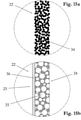
- Typical regenerator materials are: metal wool, metal chips, metal mesh, knitted wire mesh, metal fiber fleece, open-cell metal foams, bulk metal or ceramic granules.
- the regenerator material causes an intimate mixing of the steam-air mixture or condensation aerosol flowing through, whereby its properties are homogenized, for example concentration peaks are reduced.
- the cooler can be formed by a porous body through which a flow can flow and which is largely permeable to the particles of the condensation aerosol formed.
- the aerosol particles formed have a mass median aerodynamic diameter (MMAD) of less than 2 ⁇ m.
- the particles should flow through the porous body with as little loss as possible. Filtration of the particles is undesirable. Particles deposited in the porous body would gradually clog its pores, which would result in a sudden increase in the pressure drop in the porous body. Also included deposited particles always also nicotine. Nicotine already deposited in the pore body would reduce the efficiency of nicotine delivery.
- the porous body typically consists of a wide-pored material, for example an open-cell foam material, a coarse-pored, porous filling material or a fleece-like fiber material. However, in order to ensure a sufficiently large heat exchange surface for cooling and condensation, the volume of the porous body must be dimensioned sufficiently large. Like the regenerator material, the porous body also has a homogenizing effect on the vapor-air mixture or condensation aerosol flowing through it. The material used must also be as chemically inert as possible with respect to the vapor-air mixture or condensation
- the cooler contains tobacco and/or flavorings.
- the tobacco or the flavorings enrich the vapor-air mixture or condensation aerosol flowing through with fragrances and flavorings, making it more pleasant for the user to consume.
- Dried fermented tobacco, reconstituted tobacco, expanded tobacco or mixtures thereof are particularly suitable as tobacco.
- the tobacco can be in the form of cut tobacco or ground tobacco, for example. Tobacco extract, tobacco aroma oils, menthol, coffee extract, tobacco smoke condensate or a volatile aromatic fraction of a tobacco smoke condensate are suitable as flavoring substances.
- the cooler is formed by a tobacco filling.
- the tobacco filling is able to combine all the previously mentioned effects of the cooler: cooling and condensation, homogenization and aromatization of the vapor-air mixture or condensation aerosol flowing through.
- other favorable effects were also found: for example, the inhalability of the nicotine-containing vapor-air mixture and condensation aerosol could be improved, which can be attributed in part to the effects described above.
- additional mechanisms of action are involved - in particular diffusion and adsorption processes relating to the free, unprotonated nicotine, which are discussed in detail were still to be explored.
- the filling density of the tobacco filling is limited by the fact that on the one hand the filling must be as permeable as possible for the aerosol particles flowing through, and on the other hand the induced flow resistance should not be greater than that of cigarettes.
- the tobacco filling can be formed from cut tobacco, fine-cut tobacco, stuffing tobacco, from a cigar-like tobacco wrapper or from comparable or similar shapes of tobacco. Dried fermented tobacco, reconstituted tobacco, expanded tobacco or mixtures thereof are particularly suitable as tobacco.
- the tobacco can be additionally flavored, flavored, flavored and/or perfumed by adding aromatic additives such as tobacco extract, tobacco aroma oils, menthol, coffee extract, tobacco smoke condensate or a volatile aromatic fraction of a tobacco smoke condensate.
- a tobacco filling as a cooler can also make switching from tobacco products to the inhaler component according to the invention more attractive and/or easier.
- the volume of the tobacco filling is greater than 3 cm 3 .
- the cooler may contain a desiccant and/or an activated carbon.
- the desiccant and the activated charcoal bring about an even further reduction in the ethanol and/or water content in the gas phase surrounding them through their adsorption capacity and microporosity, both during the flow through the cooler and during times when the inhaler component is not being used.
- the cooler is formed by a filling or bulk material, and the filling or bulk material is present as a prefabricated pack.
- a prefabricated pack makes assembling the inhaler components much easier.
- the pack need only be inserted into the housing of the inhaler component. A complex filling process can be avoided in this way.
- the pack can, for example, consist of a strand, in particular an endless strand, consisting of the porous filling or bulk material and a Filling or bulk material surrounding casing can be obtained.
- the casing can be made of paper or plastic, for example.
- the two ends can optionally be closed using a perforated cover that is permeable to the vapor/air mixture or condensation aerosol.
- Packs produced in this way also have a comparatively homogeneous and constantly reproducible filling density.
- the cooler has a multi-stage design. Due to the multi-stage cooler design, the properties of the vapor-air mixture or condensation aerosol can be influenced in an even more targeted manner, and in this way the quality of the same can be further improved. Different cooler types and materials or just different physical properties can be assigned to the individual cooler stages.
- the cooler is connected to the housing in a detachable manner. This arrangement makes it possible to replace the cooler independently of the other parts of the inhaler component. If the quality of the vapor-air mixture or condensation aerosol produced deteriorates, or if the cooler is already heavily laden with solvent condensate, only the cooler needs to be replaced, while the other parts of the inhaler component can continue to be used until their intended service life has been reached. In this way, the use of the inhaler component according to the invention can be made particularly economical.
- the inhaler component includes a mouthpiece through which a user is presented with the nicotine-containing vapor-air mixture and/or condensation aerosol, and it is provided that the cooler forms a structural unit with the mouthpiece, and the structural unit with is detachably connected to the housing.
- the cooler can also be replaced in this embodiment variant. Due to the fact that the cooler forms a structural unit with the mouthpiece, the manipulation of the replacement is particularly easy, in that the user grasps the structural unit at the mouthpiece and decouples it from the housing. A favorable side effect is that the user is actually forced to Regularly replacing the mouthpiece with a new one if he wants to maintain the effects of the cooler.
- the regular, for example daily replacement of the mouthpiece is undoubtedly advantageous from a hygienic point of view.
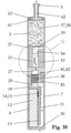
- the inhaler shown as an example basically consists of two parts, namely an inhaler part 1 and an inhaler component 2.
- the inhaler component 2 consists of a housing 3 and includes, among other things, a liquid container 4 and a tobacco pipe-like mouthpiece 5.
- the liquid container 4 contains nicotine in the form of a highly diluted ethanolic and/or aqueous solution, which is vaporized in the inhaler component 2 and converted into an inhalable vapor-air mixture or condensation aerosol.
- the vapor/air mixture or condensation aerosol formed is presented to the user via the mouthpiece 5 .
- the mass fraction of ethanol and/or water in the nicotine solution is at least 50%.
- Table 1 shows an example of the composition of a typical nicotine solution.
- SF8010, SF8011 or SF208118 or according to patent publication no. DE19654945A1 , DE19630619A1 , DE3218760A1 , DE3148335A1 (Adam Müller et al. ) manufactured tobacco flavor oils;
- a prerequisite for the use of such tobacco aroma oils in the nicotine solution is that they are as free as possible of tobacco-specific nitrosamines (TSNA).
- TSNA tobacco-specific nitrosamines
- the nicotine solution presented as an example represents the provisional end point of our own extensive development work and in vivo test series
- the proportion of solvent ie the proportion of ethanol and water, is 85.3% by mass in the specific example.
- the glycerol it contains supports aerosol formation thanks to its extremely low vapor pressure ( ⁇ 0.1 Pa at 20°C) and also has a masking effect on nicotine, which dampens its organoleptic effects. To put it bluntly, glycerol replaces the tar in cigarette smoke.
- the mix of carboxylic acids serves to regulate the pH value of the nicotine solution and is adjusted in such a way that the pH value of the vapour-air mixture or condensation aerosol produced is roughly comparable to the values of cigarette smoke.
- the nicotine-containing aerosol particles generated by condensation usually have a mass median aerodynamic diameter (MMAD) of less than 2 ⁇ m and thus also reach the alveoli, where the nicotine passes into the bloodstream in a flash.
- MMAD mass median aerodynamic diameter
- the concentrated concentration of nicotine reaches its target organ - namely the central nervous system - just 7-10 seconds after inhalation.
- the inhaler part 1 contains at least one energy store and an electrical circuit, the energy store being protected by a battery cover 6 and the circuit being protected by a circuit cover 7 .
- the inhaler part 1 and the inhaler component 2 are designed to be detachable from one another in the specific exemplary embodiment.
- the solvable Coupling consists of a snap connection formed by two snap hooks 8 and two detents 9 cooperating with these.
- This arrangement makes the inhaler part 1 reusable, which makes sense in principle, considering that, firstly, the inhaler part 1 does not come into contact with the nicotine solution , i.e. is not contaminated with the nicotine solution, and secondly contains components which are more durable than the components of the inhaler component 2. After the nicotine solution in the liquid container 4 has been used up, the inhaler component 2 is properly disposed of by the user as a whole and replaced with a new inhaler component 2 replaced.
- the inhaler component 2 represents a replaceable disposable item. Proper disposal is indicated because nicotine-containing condensate residues always form and deposit inside the housing 3 of the inhaler component 2 in the course of the formation of the vapour-air mixture and/or condensation aerosol. Residues of the nicotine solution always remain in the liquid container 4 as well.
- the inhaler part 1 and the inhaler component 2 it would of course also be conceivable for the inhaler part 1 and the inhaler component 2 to be designed in one piece, that is to say inseparable from one another.
- this embodiment is likely to be less economical because in this case all parts and components of the inhaler, ie the inhaler as a whole, form a disposable item for single use.
- the subject invention also includes this embodiment, in which case the entire inhaler is to be regarded as an inhaler component.
- the Figures 3 to 5 show different views of the reusable inhaler part 1 with and without a lid.
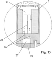
- the reusable inhaler part 1 is composed essentially of the following three housing parts: the battery cover 6, the circuit cover 7 and a carrier housing 10 arranged between them.
- the three housing parts are preferably made of plastic for reasons of weight.
- the support housing 10 accommodates the electrical circuit 11 and the energy store 12 and includes a partition wall 13 which separates the circuit 11 and the energy store 12 from one another.
- the electrical circuit 11 is designed as a printed circuit board populated on one side, which is fastened to the partition wall 13, for example, by means of an adhesive bond.
- the energy store 12 preferably consists of a rechargeable battery, for example a lithium-ion accumulator or a lithium-polymer accumulator, preferably in flat design.
- a rechargeable battery for example a lithium-ion accumulator or a lithium-polymer accumulator, preferably in flat design.
- These battery types currently provide the highest energy densities and currents and have been used in a variety of ways for a long time, with widespread use in mobile phones being the first to be mentioned.
- the power is supplied from the battery 12 to the circuit board 11 via two flat contacts 14, which are soldered to the back of the circuit board 11 - see also 10 .
- the flat contacts 14 protrude through two somewhat larger windows 15 in the partition wall 13 .
- the battery 12 includes two mating contacts (not shown) which are pressed against the tabs 14, thereby making releasable electrical contact.
- the compressive force required for this purpose is preferably generated by a leaf spring (not shown) arranged between the battery 12 and the battery cover 6 .
- the battery cover 6 is detachably connected to the carrier housing 10 - in the exemplary embodiment by means of a screw connection (see 1 ).
- the battery cover 6 could alternatively also be designed as a lockable sliding cover.
- the circuit cover 7 is preferably inseparably connected to the carrier housing 10, for example by means of an adhesive or welded connection. In this way, an unauthorized manipulation of the circuit 11 is to be counteracted. In the normally rare case of a circuit defect, the entire inhaler part 1, with the exception of the battery 12, must be replaced. Other components and properties of the reusable inhaler part 1 will be described in more detail later.
- the replaceable inhaler component 2 is essentially formed by the housing 3 and includes, among other things, the liquid container 4 and the tobacco pipe-like mouthpiece 5.
- the liquid container 4 and the mouthpiece 5 are inseparable from the housing 3 connected.
- the liquid container 4 and/or the mouthpiece 5 it is of course also conceivable for the liquid container 4 and/or the mouthpiece 5 to be designed in one piece with the housing 3 .
- the housing 3, the liquid container 4 and the mouthpiece 5 are preferably made of plastic for weight reasons, with the choice of material for the liquid container 4 plastics according to US 5,167,242 (James E Turner et al. ) and US 6,790,496 (Gustaf Levander et al. ) can be used.
- the liquid container 4 is filled with the nicotine solution 16 via a filling hole 17, preferably under a protective gas atmosphere such as argon or nitrogen.
- a flap-like, openable closure 18 On one end of the liquid container 4 there is a flap-like, openable closure 18 which is opened by the user before using the inhaler component 2 by pressing it.
- the openable shutter 18 will be described later in detail.
- the liquid container 4 is never completely filled with the nicotine solution 16. Due to the incompressibility of the nicotine solution 16, complete filling would result in the flap-like, openable closure 18, which always has a certain elasticity, no longer being able to be pressed in and opened.
- the filling hole 17 is hermetically sealed with a sealing cap 19 .
- the closure cover 19 can, for example, be glued or welded on, in which case the effect of heat on the nicotine solution 16 should be avoided as far as possible.
- the filling hole 17 can be designed as a capillary bore, and the filling with the nicotine solution 16 can take place via an injection needle.
- the closure cap 19 could be omitted and the capillary bore itself melted shut.
- Other components and properties of the replaceable inhaler component 2 will be described in detail later.
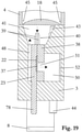
- the 8 shows the inhaler 1 with lifted circuit cover 7.
- the 8 the snap connection, consisting of the two snap hooks 8 and the corresponding locking lugs 9, in the coupled, locked state.
- the snap hooks 8 are designed as extensions of the housing 3, while the latching lugs 9 are formed by contact elements 20.
- the contact elements 20 are attached to the carrier housing 10 of the reusable inhaler part 1 by an adhesive connection and fulfill other functions which will be described in detail later.
- the housing 3 of the replaceable inhaler component 2 forms a chamber 21 on the inside 11 best shows from a vaporizer 22 bridge-like and thus interspersed without contact.
- the evaporator 22 is in the form of a film or strip and consists of an electrical resistance heating element and a wick, which together form a flat composite.
- the capillary structure of the wick is suitable for absorbing the liquid nicotine solution 16.
- the heating element and the wick can be designed and connected to one another in a wide variety of ways. Exemplary training forms will be described later.
- the flat evaporator 22 rests with two end sections on two electrically conductive, plate-shaped contacts 23, on the surface of which it is also electrically contacted at the same time.
- the electrical contacting of the evaporator 22 on the plate-shaped contacts 23 can be effected by a welded connection.
- the welded connection can be produced by spot welding, resistance welding, ultrasonic welding, laser welding, bonding or other suitable welding processes. It is advantageous here if the plate-shaped contacts 23 consist of the same or a similar material as the heating element, which results in favorable conditions for a welded connection as the contacting method. It is important to ensure that the wick or its capillary structure is not impaired by the welding if possible. If necessary, the welding should only be carried out selectively.
- the electrical contacting of the flat evaporator 22 takes place by means of an adhesive connection using an electrically conductive adhesive, for example using an epoxy-based adhesive containing silver.
- an electrically conductive adhesive for example using an epoxy-based adhesive containing silver.
- Such adhesives can be obtained, for example, from Epoxy Technology, www.epotek.com.
- the plate-shaped contacts 23 can in principle be made of any electrical contact material, as long as the material is compatible with the adhesive used; It is particularly favorable if the plate-shaped contacts 23 are formed by printed circuit boards, which are distinguished by the advantage of a particularly low weight.
- the area between the two plate-shaped contacts 23 defines a heated section of the evaporator 22 which is arranged in the chamber 21 without contact.
- the non-contact arrangement means that the heat conduction losses in the thickness direction of the flat evaporator 22 are equal to zero. As a result, this section can heat up to the point where the nicotine solution 16 stored in the wick boils reached and evaporated.
- the capillary structure of the wick is largely exposed in said section, at least on one side of the flat evaporator 22 . This side is preferably the side 24 of the flat evaporator 22 facing away from the plate-shaped contacts 23, as will be explained later in the course of the description of exemplary embodiments of the evaporator flow out of the exposed capillary structure of the wick.
- the capillary structure of the wick in said section is also largely exposed on the side 25 of the flat evaporator 22 opposite the side 24, so that the evaporation surface and consequently also the maximum achievable evaporation capacity is doubled compared to the first case.
- the maximum achievable evaporation rate is defined by the first occurrence of a boiling crisis in the wick.
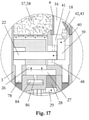
- the housing 3 also defines an air inlet port 26 for the supply of air from the environment into the chamber 21.
- the supplied air mixes in the chamber 21 with the vapor emanating from the exposed capillary structure of the wick, in the course of which the vapour-air Mixture or condensation aerosol forms.
- the air inlet opening 26 is designed as a slit-shaped channel.
- the slit-shaped channel is aligned parallel to the flat evaporator 22 .
- the slit-shaped channel is arranged somewhat laterally offset to the flat evaporator 22, namely on that side of the flat evaporator on which the capillary structure of the wick is largely exposed.
- This arrangement ensures that the air flowing through the slit-shaped channel 26 into the chamber 21 flows completely over the exposed capillary structure of the wick, and homogeneous mixing conditions can be established.
- the flow velocity of the inflowing air can be changed, and in this way the dynamics of aerosol formation and the properties of the aerosol generated can be influenced within certain limits be taken.
- a reduction in the flow velocity causes the aerosol particles to increase in size on average.
- the geometric position of the Slot-shaped channel 26 in relation to the flat evaporator 22 has an influence on the formation of aerosols.
- the 13 shows an alternative arrangement of the air inlet opening 26: accordingly, the air inlet opening 26 is formed by two slit-shaped channels 26, which are arranged on opposite sides of the flat evaporator 22.
- the air flowing into the chamber 21 thus flows around the flat evaporator 22 on both sides.
- This arrangement is particularly suitable for the embodiment variant of the flat evaporator 22 in which the capillary structure of the wick is exposed on both sides, since in this case steam flows off from both sides 24 and 25 of the flat evaporator 22 .
- the air inlet opening 26 designed as a slit-shaped duct draws the air from a plenum chamber 27, which serves to distribute the air evenly over the slit-shaped duct 26, so that essentially the same flow conditions prevail in the slit-shaped duct on all sides.
- a flow restrictor 28 Upstream of the plenum chamber 27 is a flow restrictor 28.
- the purpose of the flow restrictor 28 is to create a flow resistance similar to that of a cigarette so that the user feels a similar drag during a puff as when puffing on a cigarette.
- the flow resistance should be in the range of 12-16 mbar at a flow rate of 1.05 L/min and have a characteristic that is as linear as possible.
- the flow restrictor 28 can be formed, for example, from an open-pored sintered body made of metal or plastic, through the pores of which the air flows.
- porous plastic moldings from Porex, www.porex.com have proven successful in prototypes.
- the plenum chamber 27 is part of the replaceable inhaler component 2 and the flow restrictor 28 is part of the reusable inhaler part 1.
- the 10 shows the further course of the air flow upstream of the flow throttle 28.
- the flow is indicated by arrows.
- the flow restrictor 28 draws the air from a transverse channel 29 which in turn opens into the space between the circuit board 11 and the circuit cover 7 .
- the actual supply of air from the environment takes place via a feed opening 30 formed by the circuit cover 7.
- the feed opening 30 is arranged on the end face of the inhaler opposite the mouthpiece 5. This position provides the best protection against the ingress of rainwater.
- the 14a, 14b and 15a, 15b , 15c show exemplary configurations of the flat evaporator 22 based on cross-sectional representations, with "cross-section” being understood to mean a section normal to the longitudinal direction of the flat composite (cf. 9 ). Specifically, they show Figures 14a and 14b Embodiments with capillary structure exposed only on one side, while the Figures 15a and 15b Show embodiments in which the capillary structure of the wick is exposed on both sides of the flat evaporator.
- the evaporator 22 consists of a composite of four layers: namely a metal foil 31 and three metal wire meshes 32 sintered onto it.
- the metal consists of stainless steel (e.g.
- AISI 304 or AISI 316 or of a heating conductor alloy - in particular from the group of NiCr alloys or CrFeAl alloys ("Kanthal").
- Kanthal NiCr alloys or CrFeAl alloys
- the metal foil 31 can be obtained in a stainless steel design, for example from Record Metall-Folien GmbH, www.recordmetall.de.
- the wire mesh can be obtained, for example, from the companies Haver & Boecker, www.haverboecker.com or Spörl KG, www.spoerl.de.
- the four layers are connected to each other by sintering.
- the sintering is preferably carried out in a vacuum or under a protective hydrogen gas.
- a vacuum or under a protective hydrogen gas Such sintering is part of the prior art and is routinely carried out, for example, by GKN Sinter Metals Filters GmbH, www.gkn-filters.com, and by Spörl KG, www.spoerl.de.
- the sintering is advantageously carried out in the form of a multiple panel; This means that not individual flat composites are sintered, but larger flat panels, for example in the 200x200mm format.
- the individual evaporators are cut by laser or Punching obtained from the multiple use and then optionally etched in a pickling bath.
- Table 2 shows an example of the specifications of flat composites or evaporators 22 used in prototypes.
- Metal foil thickness 10 ⁇ m Metal Foil Material: AISI 304 1.
- wire mesh layer 36 ⁇ 90 ⁇ m Wire diameter ⁇ mesh size 2.
- wire mesh layer 30 ⁇ 71 ⁇ m Wire diameter ⁇ mesh size 3.
- wire mesh layer 20 ⁇ 53 ⁇ m Wire diameter ⁇ mesh size
- Wire Cloth Material AISI 316L Composite Span: 14mm Compound width: 2-5mm Composite Thickness: 140-160 ⁇ m Etch rate: until 50% with bath stain Avesta 302 *) Porosity: 65-80% depending on the etch rate *) Manufacturer: Avesta Finishing Chemicals, www.avestafinishing.com
- the composite span corresponds to that distance in the chamber 21 which the evaporator 22 bridges without contact; In the specific embodiment, this distance corresponds to the distance between the two plate-shaped contacts 23.
- the bond span and the bond width have an opposite influence on the resulting heating element resistance.
- the etch rate defines the total mass loss achieved by the etch.
- the first layer of wire mesh rests directly on the metal foil 31 .
- the third wire mesh layer forms the cover layer and at the same time the exposed capillary structure of the flat evaporator 22.
- the flat evaporator 22 is preferably mounted with the metal foil 31 on the plate-shaped contacts 23.
- the electrical contacting of the metal foil 31 is preferably carried out via a flat adhesive connection between the metal foil 31 and the electrically conductive, plate-shaped contacts 23.
- the contact could also be made a welded connection to be made.
- a flat evaporator 22 contacted in such a way with the specifications according to Table 2, with a compound width of 2 mm and an etching rate of 35% has a heating element resistance of approximately 310 mOhm.
- the heating element resistance can be increased significantly, specifically when using DIN material number 2.4872 (NiCr20AISi) compared to AISI 304/ AISI 316 by a factor of 1.8 and when using DIN material Number 1.4765 (CrAl255) by a factor of 2.0.
- a flat evaporator with a composite width of 5mm in the design DIN material number 2.4872 but otherwise the same specifications as mentioned above would have a heating element resistance of around 225 mOhm. If the energy supply is based on a lithium-polymer cell with a nominal or no-load voltage of 3.7V and a useful voltage under load of approx. 3.1V, the current flowing through the flat evaporator is calculated on the basis of Ohm's law, to 10A (for 310mOhm) or 13.8A (for 225mOhm). These amperages can easily be obtained from today's lithium polymer cells.
- the rated electrical power is calculated, which is also the maximum heat output that can be achieved at 31W (for 310mOhm) or 42.7W (for 225mOhm). As will be described later, these powers can be arbitrarily reduced by the electrical circuit 11.
- the pore volume of the flat evaporator in the section of the composite span is calculated at around 7.5 ⁇ L. This volume is filled by the nicotine solution 16 to be vaporized and corresponds to the maximum amount of liquid material that can be vaporized per puff (intermittent inhaler operation). If, for example, the nicotine concentration of 1.8% by mass or 1.5% by volume given in Table 1 is taken as a basis, this theoretically results in a maximum released nicotine dose of 110 ⁇ g or added up per vaporization or puff 10 inhalations a total dose of 1.1mg.
- the maximum achievable dose will be slightly below the calculated values for various reasons.
- both the metal foil 31 and the metal wire mesh 32 sintered onto the foil contribute to the electrical heating resistance.
- the electrical heating resistance can be interpreted as a parallel connection of these individual resistances.
- the capillary effect of the wick is also based on the interaction of the wire mesh 32 with the metal foil 31, with even a single wire mesh layer in combination with the metal foil 31 being able to produce a capillary effect.
- FIG 14b shows a second exemplary embodiment of a flat evaporator 22 with a capillary structure that is only exposed on one side.
- This embodiment differs from that shown in FIG 14a only in that instead of the two outer wire mesh layers, a fiber composite in the form of a fleece 33 is provided, which is sintered onto the first wire mesh layer 32.
- Such fleeces 33 can be made in stainless steel, for example, by the company GKN Sinter Metals Filters GmbH, www.gkn-filters.com according to customer specifications.
- the fleece 33 preferably has a thickness of 100-300 ⁇ m and a porosity >70%.
- the fleece 33 forming the exposed capillary structure of the wick has a significantly larger surface area in comparison to the wire mesh 32; the larger surface has a favorable effect on the evaporation process.
- the flat composite 22 can optionally be etched again after sintering.
- Figure 15a shows an embodiment of a flat evaporator 22 with a capillary structure that is exposed on both sides.
- the evaporator consists of an open-pored sintered structure formed from a homogeneous granular, fibrous or flaky sintered composite 34.
- JP 2004/332069 (Tsujimoto Tetsushi et al., Mitsubishi Materials Corporation ) describes, for example, a method for Production of thin, porous sintered metal composites in the preferred thickness range of 50-300 ⁇ m, which is characterized by the fact that removable fillers, in this specific case acrylic resin beads, are added to the metal powder to be processed.
- the acrylic resin beads are placeholders, which sublime in a vacuum at around 500°C in the course of a heat treatment before the actual sintering, leaving cavities which remain during and after the sintering.
- flat composites consisting of stainless steel of specification AISI 316L with porosities of typically 70-90% were produced.
- the method is suitable for producing an evaporator 22 for use in an inhaler component 2 according to the invention. It should only be noted that the average pore diameter in the homogeneous sintered composite is >10 ⁇ m if possible, in order to ensure sufficiently rapid infiltration of the wick with the nicotine solution 16 .
- the grain size of the metal powder to be processed and the acrylic resin beads must be matched to this condition.
- the one in the process JP 2004/332069 The preferred thickness range of 50-300 ⁇ m mentioned coincides with the thickness range particularly preferred for the flat evaporator 22 .
- the sintered composite 34 can optionally be etched again after sintering.
- the attachment and contacting of the flat sintered composite 34 on the plate-shaped contacts 23 is preferably carried out by a welded connection.
- An adhesive connection is only possible if the adhesive used has a sufficiently pasty or viscous consistency. Otherwise there would be a risk of the adhesive entering the pore structure of the composite and impairing the capillary action of the wick.
- FIG. 1 shows another embodiment of an evaporator 22 with a capillary structure that is exposed on both sides.
- the flat evaporator consists of an open-pored foam 35 formed from an electrical resistance material.
- a foam material can be obtained in a stainless steel version (eg AISI 316L) from Mitsubishi Materials Corporation, www.mmc.co.jp. This is based on a standard foam material with a thickness of 0.5 mm, a pore diameter in the range of 50-150 ⁇ m and a porosity of around 90%, which material can be compacted in any thickness by rolling down to around 100 ⁇ m. The compacted material can then optionally be sintered.
- the flat evaporator 22 can consist of a single foam layer or of several foam layers sintered together.
- the foam 35 can optionally be sintered onto a thin carrier layer 36, for example onto a wire mesh made of stainless steel.
- heat conductor alloys in particular from the group of NiCr alloys and CrFeAl alloys ("Kanthal"), can of course also be processed according to the method.
- the supply of the vaporizer 22 with the nicotine solution 16 will be described in more detail below. how 12a and 16 show, one end of the vaporizer 22 protrudes into a capillary gap 37.
- the capillary gap 37 feeds the wick of the vaporizer with the liquid nicotine solution 16;
- the cross section of the capillary gap 37 is larger than the cross section of the evaporator 22. This has the effect that the nicotine solution 16 flows mainly through the clear cross section of the capillary gap 37 to the evaporation zone, as a result of which the wick can be infiltrated more quickly. and the waiting time between two puffs or inhalations can be shortened.
- the effect works at least up to the opening of the capillary gap 37 into the chamber 21.
- the capillary gap 37 is basically formed by one of the two plate-shaped contacts 23 and an upper part 38 placed flat on this, by corresponding recesses forming the capillary gap 37 being machined into the upper part 38 and into the plate-shaped contact 23 . It should be noted that even a single recess, whether it is arranged in the upper part 38 or in the plate-shaped contact 23, would be sufficient to form a capillary gap 37.
- the recess in the plate-shaped contact 23 can also be used as a positioning aid during the assembly of the evaporator 22 .
- the upper part 38 is preferably connected to the plate-shaped contact 23 by a Adhesive bonded and consists of a material that can be easily wetted with the nicotine solution 16, preferably made of light metal or a wettable plastic; the wettability and also the bondability of plastics can be significantly improved by surface activation, for example by plasma treatment with oxygen as the process gas.
- the capillary gap 37 is formed by two thin plates 39 arranged parallel and spaced apart (see Fig 16 ), One plate being connected to the upper part 38 and the other plate to the plate-shaped contact 23, preferably by an adhesive connection.
- the plates 39 can be stamped from a stainless steel strip, for example. how 17-19 best show, the plates 39 forming the capillary gap 37 project into a reservoir 41 via an extension 40 .
- the reservoir 41 connects directly to the liquid container 4 and is separated from it only by the flap-like closure 18 that can be opened.
- the openable closure 18 is opened with the aid of a pin 42 .
- the pin 42 is mounted in the housing 3 in an axially displaceable manner and is preferably made of stainless steel. A first end 43 of pin 42 is directed toward openable closure 18 .
- a second end 44 protrudes from the outer surface of the housing 3 in the manner of an extension when the closure 18 is still closed.
- the second end 44 of the pin 42 is in a plunger-like operative connection with one of the two contact elements 20 of the inhaler part 1, in that the contact element 20 presses against the second end 44 of the pin 42 during the course of the coupling of the inhaler component 2 to the inhaler part 1, and the pin 42 is thereby displaced into the housing 3.
- the compressive force exerted by the contact element 20 is transmitted from the pin 42 to the openable closure 18.
- the openable closure 18 has a material weakening 45 on its circumference, which is dimensioned such that when pressure is applied by the pin 42 it tears open like a predetermined breaking point over a wide circumferential area, but forms a hinge 46 on one side. In this way, the openable shutter 18 is caused to open like a flap.
- the pin 42 has near the first end 43 a cross-sectional widening 47 which, like a stop, prevents the pin from sliding out of the housing 3 or being able to be removed.
- the supply of the vaporizer 22 with the nicotine solution 16 will be explained in summary below, the 17 and 19 the flow conditions are illustrated by arrows: in the course of coupling the inhaler component 2 to the reusable inhaler part 1, the flap-like closure 18 is opened via the pin 42 and the reservoir 41 is then flooded with the liquid material 16 under the influence of gravity. In 18 the liquid levels before and after flooding are shown.
- the capillary gap 37 sucks in the nicotine solution 16 via the extension 40 and feeds it to the vaporizer 22, as a result of which the wick is finally completely infiltrated with the liquid material 16.
- the extension 40 formed by the plates 39 is intended to prevent gas bubbles from settling in the mouth area of the capillary gap 37, which could impede the capillary coupling.
- a ventilation channel 48 is worked into the plate-shaped contact 23, which connects the reservoir 41 to the chamber 21 and causes pressure equalization. In this way, each portion of liquid material 16 which enters the capillary gap 37 is immediately replaced by an equal volume portion of air.
- a buffer memory 49 is integrated into the upper part 38 - see 11 and 16 .
- the buffer memory 49 consists of slots 50 which are arranged parallel to one another and which are incorporated into the upper part 38 .
- the slits 50 communicate on the one hand via openings 51 with the capillary gap 37 and on the other hand via an aeration gap 52 with the chamber 21.
- the capillarity of the slits 50 causes the liquid material 16 to flow out of the reservoir 41 via the capillary gap 37 and via the openings 51 into the Slots 50 flows, where it is temporarily stored and can be withdrawn from the wick of the vaporizer 22 as required, regardless of the position of the inhaler component 2.
- Figures 9-12 12 also show a condensate drainage and storage device according to the invention arranged in the chamber 21 and consisting of two absorbent sponges 53.
- the basic effects of the condensate drainage and storage device have already been explained in more detail earlier.
- the two sponges 53 are plate-shaped and spaced apart and arranged parallel to one another, with the flat evaporator 22 being covered by the two sponges 53 on both sides.
- a flow channel 54 is formed between the two sponges 53, in which the formation of the steam-air mixture or condensation aerosol takes place.
- the main part of the condensate residues is deposited on the wall sections 55 of the sponges 53 forming the flow channel 54 and immediately sucked up by the open pore structure of the sponges.
- the sponges 53 are attached to two opposite walls of the chamber 21 by means of an adhesive bond, fill the majority of the chamber 21 and are preferably made of a highly porous, dimensionally stable and fine-pored material. If coarse-pored material is used, there is a risk that the capillary forces of the sponge material will no longer suffice to retain the liquid condensate in the event of abrupt movements or accelerations of the inhaler component 2, and parts of the condensate will be thrown out of the sponges 53. Fiber composites, formed from natural or man-made fibers that are thermally bonded to one another or with the aid of a binder, have proven to be particularly suitable as sponge material.
- Filtrona Richmond Inc. www.filtronaporoustechnologies.com, specializes in the production of such fiber composites, using triacetin-bonded cellulose acetate fibers as well as thermally bonded polyolefin and polyester fibers.
- the inhaler component 2 should only be given to the consumer against a reasonable deposit. In this way it is ensured that the majority of the sponges 53 contaminated with nicotine residues are disposed of in an environmentally friendly manner.
- the sponges 53 are arranged somewhat spaced apart from the upper part 38 and from the plate-shaped contact 23 connected to the upper part 38, so that a gap 56 is formed.
- the gap 56 ensures that the ventilation channel 48 and the ventilation gap 52 can communicate with the chamber 21 unhindered.
- the sponges 53 are to be dimensioned in such a way that their pore volume is able to absorb the amount of condensate residue formed over the useful life of the inhaler component 2 .
- the amount of condensate depends primarily on the ethanol and water content in the nicotine solution 16 and on the air throughput through the air inlet opening 26 and through the flow channel 54 . The less air that is pushed through, the less vapor the air can absorb up to saturation.
- the chamber 21 is downstream downstream of a cooler in the form of a tobacco filling 57 whose pores are formed by the vapor-air mixture or condensation aerosol.
- the main effects of the cooler have already been explained in detail earlier.
- the tobacco filling 57 is located in a filling space 58 which is delimited by a perforated wall 59 on the flow inlet side, by the mouthpiece 5 on the flow outlet side, and by the housing 3 and a wall of the liquid container 4 on the jacket side.
- the perforated wall 59 supports the filling material 57 and at the same time stiffens the housing 3 .
- the hole wall 59 is arranged somewhat spaced from the sponges 53 - see 12 .
- a first wire mesh 60 is arranged between the tobacco filling 57 and the perforated wall 59 so that the filling material cannot escape from the holes in the perforated wall 59 .
- the tobacco filling 57 is delimited by a second wire mesh 61, which prevents the filling material from getting into the mouthpiece channel 62 or even into the user's oral cavity.
- the mouthpiece 5 forms a collection chamber 63, which causes the tobacco filling 57 to flow through evenly even in the end section.
- the second wire mesh 61 is advantageously attached directly to the mouthpiece 5, eg melted onto it.
- the first wire mesh 60 is placed on the perforated wall 59 .
- a predefined amount of tobacco or filling material 57 is then introduced into the filling chamber 58, with filling also being able to take place in several stages, and the filling material 57 being intermediately compressed after each partial filling. In this way, a relatively homogeneous filling density can be achieved.
- the mouthpiece 5 is mounted and the filling space 58 is closed.
- Fine-cut tobacco is characterized by a particularly small cutting width of usually 0.3mm.
- the small cutting width causes an extraordinarily large surface of the tobacco filling 57.
- These conditions favor both the heat exchange and the exchange of substances between the tobacco and the vapor-air mixture or condensation aerosol that permeates it.
- fine-cut tobacco light American Blend fine-cut tobacco and dark fine-cut tobacco, mostly with a spicy character. Both fine cuts are suitable for producing a tobacco filling 57 according to the invention.
- the tobacco can also be flavored, spiced, flavored and/or perfumed, with all the recipes and processes used by the tobacco industry being able to be adopted here.
- menthol and tobacco aroma oils obtained by means of supercritical CO2 extraction (see Table 1) and coffee extract were successfully tested as aromatic additives.
- Tobacco smoke condensate or a volatile aromatic fraction thereof is also useful as a flavor additive.
- it should be offered for sale in airtight packaging and the packaging should only be opened immediately before the inhaler component 2 is used. Even after the inhaler component 2 has been coupled to the inhaler part 1, there is still the possibility of suppressing the escape of aroma substances by closing the mouthpiece opening, for example by means of a cap or a plug (not shown).
- the packing density of the tobacco filling 57 determines the flow resistance which the filling material 57 opposes to the vapor/air mixture or condensation aerosol; the packing density is to be matched to the flow resistance of the flow restrictor 28 in such a way that the resulting flow resistance is as far as possible within the aforementioned preferred range of 12-16 mbar at an air throughput of 1.05 l/min.
- a filter effect of the tobacco filling 57 is undesirable; the aerosol particles generated in the chamber 21 should be able to penetrate the tobacco filling 57 with as few losses as possible.
- the alternative embodiment variant without a flow throttle 28 also has an effect on the sensor-based detection of the start of the train, which effects will be explained in more detail later.
- any porous material can be used as an alternative filling material 57, provided it is largely permeable to the aerosol particles and largely chemically inert under the given conditions of use.
- a filter material that would cause the aerosol particles to be separated is ruled out from the outset as a porous material.
- the pore material must therefore have sufficiently large or wide pores in order to qualify as filling material 57 for cooling the vapor-air mixture or condensation aerosol.
- regenerator materials are suitable, such as fillings made of metal wool or metal chips, or beds made of metallic or ceramic granules, with the granules themselves advantageously having a porous structure.
- Fillings made of natural or man-made fibers can also be considered, provided they have sufficiently large pores and are largely chemically inert.
- tobacco is suitable for flavoring the alternative filling material 57, for example added in dispersed form as a sauce. If the use of tobacco as an additive for flavoring is also prohibited, alternative recipes and processes must be used, which, however, can hardly ever reproduce the natural tobacco flavor in all its complexity.
- the cooler is designed as a liquid cooler 64 .
- the liquid cooler 64 consists of a container 65 formed by the housing 3, which is arranged downstream of the chamber 21.
- the container 65 contains a cooling liquid 66 through which the vapor-air mixture formed or condensation aerosol flows in the form of gas bubbles 67 .
- the cooling liquid 66 essentially consists of water and/or ethanol. Preservatives can optionally be added to the cooling liquid 66 .
- the container 65 is not completely filled with coolant. Rather, a buffer space 68 is provided, which allows the cooling liquid 66 to expand unhindered while the vapor-air mixture or condensation aerosol flows through. The following condition applies to the volume Vp of the buffer space 68: Vp>Vbl (Vbl ... total volume of all gas bubbles during the flow).
- the container 65 is formed by the housing 3 on the casing side.
- the container 65 communicates at the front with the chamber 21 on the one hand and with the mouthpiece 5 on the other hand via a liquid barrier in the form of two semipermeable membranes 69 and 70.
- Such membranes can be obtained, for example, from Porex Technologies, www.porex.com, in the form of porous, sintered Plastic membranes are obtained.
- Porex Technologies manufactures such membranes from naturally hydrophobic and extra hydrophobic plastics such as PTFE, PE and PP in thicknesses from 0.5mm and with pore diameters of 10-150 ⁇ m.
- the membranes made of PTFE are sold under the name Mupor ® .
- the pore diameter should be in the range of 50-150 ⁇ m; even smaller pore diameters led to impermissibly high flow and draft resistances.
- the membrane 69 on the chamber side simultaneously serves to introduce and atomize the vapor-air mixture or condensation aerosol into or in the cooling liquid 66.
- the membrane 69 on the chamber side acts in this respect like a nozzle base or similar to a frit in a washing bottle.
- the chamber-side membrane 69 is arranged somewhat spaced from the sponges 53 . As a result, the membrane 69 is acted upon almost uniformly over its entire cross-section by the vapor-air mixture or condensation aerosol flowing in from the flow channel 54 .
- the mouthpiece 5 again forms a collection chamber 63, which also causes the membrane 70 to be emptied of the meanwhile cooled vapor/air mixture or condensation aerosol over its entire cross section is applied and enforced.
- the blocking effect of the membrane 70 can be used over a large area, and at the same time the flow resistance can be kept at a low level.
- the cooling liquid 66 has an approximately constant liquid level in relation to the membrane 69 on all sides. This is the only way to ensure that the gas bubbles 67 penetrate the cooling liquid 66 relatively evenly over the entire cross section, and that the potential of liquid cooling is fully exploited.
- the special arrangement and curved shape of the mouthpiece 5 is intended to assist the user in holding the container 65 in the correct position.
- the indentation 71 formed by the curvature of the mouthpiece 5 serves to accommodate the user's lower lip. It is also structurally remarkable that the mouthpiece 5, despite its considerable curvature, does not protrude beyond any of the delimiting planes Y of the housing 3 designed as a flat housing. The effect of this arrangement has been explained earlier.
- tobacco and/or flavorings can optionally be added to the cooling liquid 66.
- tobacco and/or the flavorings can also be dispersed in the cooling liquid 66 or present as sediment, or just float on the surface of the cooling liquid.
- the gas bubbles 67 penetrating the cooling liquid 66 produce a considerable flow turbulence, which not only promotes the heat exchange but also the mass exchange.
- the addition of ground tobacco, such as that used in snuff has proven its worth.
- the tobacco particles are present in the cooling liquid 66 as a suspension, with a large part of the particles being deposited on the membrane 69 as sediment. During a train, the sediment is whirled up by the rising gas bubbles 67 and circulated as in a fluidized bed.
- menthol and tobacco aroma oils obtained by means of supercritical CO2 extraction see Table 1 and coffee extract were successfully tested as aromatic additives in prototypes.
- it should be offered for sale in airtight packaging, and the packaging first opened immediately before using the inhaler component. Even after the inhaler component 2 has been coupled to the inhaler part 1, there is still the possibility of suppressing the escape of aroma substances by closing the mouthpiece opening, for example by means of a cap or a plug (not shown).
- the cooler has a two-stage structure and consists of a pre-cooler 72 and a tobacco filling 57 arranged downstream of this.
- the pre-cooler 72 forms the first cooler stage and has the task of pre-cooling the vapour-air mixture or condensation aerosol as effectively and largely as possible before it fills the tobacco 57 reached.
- the pre-cooler 72 shields the tobacco filling 57 from the chamber 21, so that the tobacco filling 57 is not affected by the condensation processes in the chamber 21. These conditions result in the tobacco filling 57 becoming less loaded with solvent condensate. Excessive condensate loading of the tobacco filling 57 can adversely affect the flavoring effect of the same.
- the pre-cooler 72 can consist of a synthetic fiber fleece, for example.
- the company Freudenberg Vliesstoffe KG, www.freudenberg-filter.com offers such a material in the form of mats/plates under the name Viledon ® filter mats.
- the material can be made to customer specifications. In particular, the material properties can be adjusted in such a way that the end product is largely permeable to the fine particles of the condensation aerosol produced.
- the mats/plates are made of polyolefin fibers (PE, PP) or polyester fibers and can be further processed by punching.
- the tobacco filling 57 is in the form of a prefabricated pack and consists of a paper-wrapped tobacco rod 73 which is advantageously obtained from an endless rod.
- the tobacco rod 73 and the pre-cooler 72 are pushed into a hollow cylinder 74 .
- the hollow cylinder 74 is part of the mouthpiece 5.
- the tobacco filling 57 is delimited by a wire mesh 75, which prevents the filling material from getting into the mouthpiece channel 62 or even into the user's oral cavity.
- the pre-cooler 72 and the tobacco rod 73 together with the mouthpiece 5 form a structural unit 76 which can be inserted into the housing 3 of the inhaler component 2 via the housing opening 77 . This arrangement allows the user to operate the mouthpiece cooler unit 76 independently of the rest Replace parts of the inhaler component 2.
- the tobacco rod 73 can optionally also be flavored. If they are in liquid form, the aromatic additives can be introduced into the tobacco rod 73 via one or more injection needles. Viscous and solid flavorings can be diluted or dissolved in a suitable solvent beforehand for this purpose. Typical aromatic additives are tobacco aroma oils obtained by means of supercritical CO2 extraction (see Table 1), coffee extract, tobacco smoke condensate or a volatile aromatic fraction of a tobacco smoke condensate, to name just a few examples.
- the tobacco rod 73 can also be mentholized like cigarettes, with analogous methods being able to be used.
- the mouthpiece cooler unit 76 is to be sealed airtight immediately after flavoring, for example by being sealed in a protective film. Welding preferably takes place under a protective gas atmosphere, e.g. under nitrogen; in this way, oxidation and microbial infestation by bacteria and mold can be prevented.
- the plate-shaped contacts 23 of the replaceable inhaler component 2 protrude from the outer surface of the housing 3 in the form of two plug-in contacts 78 .
- the plug-in contacts 78 form electrical contacts with corresponding spring contacts 79 in the course of the coupling of the inhaler component 2 to the inhaler part 1, via which electrical energy for evaporating the nicotine solution 16 is supplied to the electrical resistance heating element.
- the spring contacts 79 are part of the contact elements 20 and are preferably connected to them by a welded connection - see also Figures 4-5 .
- the contact elements 20 consist of a metallic contact material and can, for example, from the company Ami Doduco GmbH, www.amidoduco.com.
- the insufficient electrical conductivity of this material requires that the plate-shaped contacts 23 be at least partially of the plug contacts 78, for example, to be galvanically coated with a conductive layer made of gold, silver, palladium and/or nickel, as a result of which the electrical contact resistance is significantly reduced.
- the contact elements 20 obtain the electrical energy via two wires 80 which connect the contact elements 20 to the board 11 - see Figures 4-5 .
- the wires 80 are preferably attached on both sides by soldering.
- the contact elements 20 fulfill three different tasks: first, as just described above, they transmit the electrical energy from the circuit board 11 to the plate-shaped contacts 23. Second, they form lateral latching lugs 9, which are connected to the snap hooks 8 of the housing 3 cooperate, whereby the snap connection between the inhaler component 2 and the inhaler part 1 is realized. And thirdly, one of the two contact elements 20 forms a stop for the pin 42, as a result of which the ram-like operative connection to the opening of the liquid container 4 is established.
- a positioning device For coupling the inhaler component 2 to the inhaler part 1 in a precise position, a positioning device is provided, which consists of a centering projection 81 arranged on the carrier housing 10 and a centering recess 82 corresponding thereto and arranged on the housing 3 - see 3 , 6 , 10 and 12 .
- the centering projection 81 has two vent holes 83 which vent the centering recess 82 in the course of the coupling.
- the pressure sensor 84 forms an essential part of the inhaler according to the invention—see FIG 8 and 17 .
- the pressure sensor 84 has the function of detecting the start of a puff, whereupon the electrical circuit 11 activates the supply of electrical energy to the heating element of the vaporizer 22 and vaporization of the nicotine solution 16 stored in the wick begins.
- the pressure sensor 84 is glued into the carrier housing 10 and its electrical connections or pins 85 are soldered directly onto the circuit board 11 .
- the pressure sensor 84 communicates with the plenum chamber 27 via a bore 86 and measures or monitors the pressure in the plenum chamber 27 - see 17 .
- a suitable pressure sensor 84 is, for example, the type CPCL04GC from the manufacturer Honeywell Inc., www.honeywell.com, with a measuring range of +/-10 mbar.
- the sensor mentioned consists essentially of a zero-point calibrated and temperature-compensated measuring bridge and can be connected as follows on circuit board 11: the negative sensor output is connected to ground via a high-impedance resistor with a defined resistance value - e.g. 2.2 MOhm, whereby the Output or measurement signal of the pressure sensor 84 is slightly distorted, or to put it another way, the offset of the measuring bridge is calibrated to a defined value.
- a switching threshold is specified by the distortion or by the offset, which corresponds to a specific pressure threshold value.
- the measurement signal processed in this way is applied to the input of a precision operational amplifier 87 connected as a comparator - for example of the type LTC1049CS8 from the manufacturer Linear Technology Inc., www.linear.com.
- This wiring results in an output signal that shows the start of the train in digital form extremely quickly and precisely.
- the pressure sensor 84 is of course only suitable as a sensor for detecting the start of traction if a flow throttle 28 is arranged upstream of the plenum chamber 27 . In this case, in relation to the environment, a negative pressure occurs in the plenum chamber 27 in the course of a train, which is typically in the range of 0-50 mbar.
- the pressure curve is approximately bell-shaped.
- the beginning of the train can be detected in a simple manner by specifying a pressure threshold value, as described above, which is constantly compared with the actually measured pressure.
- the start of traction can be defined as the first time the pressure threshold is exceeded.
- a value in the range of 0.2-5 mbar is expediently selected for the pressure threshold value. The smaller the selected pressure threshold value, the faster the train detection responds.
- a lower limit is set by the specifications of the particular pressure sensor and operational amplifier used.
- the measuring bridge contains a second thermistor of the same type for temperature compensation and is calibrated to a defined offset threshold value using precision resistors.
- the output signal of the measuring bridge is then fed back to the input of an operational amplifier connected as a comparator.
- both thermistors are at the same temperature level - typically in the range of 80-200°C, depending on the dissipated power.
- air flows through the transverse channel 29. The air cools the thermistor, which increases its resistance.
- the change in resistance is processed by the measuring bridge.
- the comparator flips over and emits a digital signal indicating the start of the train.
- the further processing of the signal output by the pressure or flow sensor and its wiring preferably takes place in an integrated circuit 88--see FIG 8 .
- the integrated circuit 88 can also be a microprocessor.
- the integrated circuit 88 processes a large part of all electrical signals from the inhaler and carries out the control operations which are essential for the operation of the inhaler.
- a central control operation is the supply of electrical energy to the heating element of the evaporator 22 .
- the electrical energy is supplied by the energy store 12 .
- lithium polymer and lithium ion cells are particularly suitable as energy stores 12 due to their high energy and power density. In the case of metallic heating elements, a single lithium polymer or lithium ion cell with an open circuit or nominal voltage of around 3.7V is sufficient.
- the energy and power supply to the heating element of the evaporator 22 can be regulated in a simple manner by chopping the battery voltage over the duration of the energy supply with a variable degree of control and applying the resulting useful voltage to the heating element.
- the resulting useful voltage is a square-wave signal with a variable duty cycle.
- the amplitude of The square-wave signal corresponds to the battery voltage, disregarding minor voltage losses.
- the actual chopping preferably takes place by means of a power MOSFET 89, for example of the type IRF6635 from the manufacturer International Rectifier, www.irf.com, which is suitable for switching very high currents with a minimal drain-source on-resistance.
- the integrated circuit 88 controls the gate of the power MOSFET 89.
- a very simple control strategy which has also proven itself in prototypes according to the invention, consists of dividing the duration of the energy supply into two periods - a heating-up period and a subsequent one evaporation period.
- the duration of the energy supply is based on the duration of a puff.
- An average puff duration of about 2.1sec (+/-0.4sec) can be assumed. The same value applies roughly to cigarettes. If one considers that even after the energy supply has been switched off, post-evaporation takes place to a certain extent because of the heat still stored in the evaporator 22, it seems appropriate to choose the duration of the energy supply somewhat shorter, eg a value in the range 1.5-1.8 seconds .
- the heating-up period During the first of the two periods mentioned above - the heating-up period - the vaporizer 22 together with the nicotine solution 16 stored in the wick are heated by the heating element.
- the vaporization of the nicotine solution 16 does not begin until the temperature of the vaporizer 22 has reached approximately the boiling range of the low-boiling fractions of the nicotine solution 16 .
- the heating-up period should therefore be as short as possible. In this respect, it makes sense to pass on the battery voltage to the heating element uninterrupted or with a modulation level or duty cycle of 100% during this period.
- the duration of the heating-up period depends above all on the specifications of the evaporator 22 and on the quantity and composition of the nicotine solution 16 and should be ⁇ 0.5 seconds if possible.
- the evaporation period--the degree of control is significantly reduced, and the actual evaporation of the nicotine solution 16 takes place.
- the energy supplied is used in this second period primarily to evaporate the nicotine solution 16 and secondarily to cover energy losses.
- the degree of control By appropriately selecting the degree of control, the vaporization performance and thus also the amount of nicotine solution 16 vaporized per puff or inhalation can be controlled within certain limits to be controlled.
- An upper limit is set by the occurrence of a boiling crisis and by local drying out and overheating of the wick.
- thermal decomposition of the liquid material 16 can be counteracted by reducing or throttling the degree of modulation.
- control strategy just described can be expanded and refined as desired: for example, it can make sense to also take into account the state of battery 12 in the control strategy, since the battery voltage drops significantly as the battery discharges and ages, especially under load. This effect can be countered by increasing the modulation level. In order to be able to carry out this correction during the warm-up period as well, it is advisable not to control the battery voltage of a new, charged battery at 100%, as previously suggested, but only at 80%, for example, so that there is still enough leeway for an adjustment.
- the control of the power supply to the heating element of the evaporator 22 also requires various auxiliary operations: for example, it must be provided that the power supply cannot be activated again immediately after the end of an evaporation cycle. Rather, a waiting time must be observed, which allows the nicotine solution 16 enough time to completely infiltrate the wick again.
- the minimum required waiting time depends on the particular specifications of the evaporator 22 as well as the viscosity of the liquid material 16 . It could be shown in prototypes and calculations confirm that with an appropriate design a complete infiltration of the wick can be achieved in less than 10 seconds. A mandatory waiting time of this magnitude should be tolerated by most users, especially considering that in the case of the cigarette, the interval between two puffs averages 25 seconds.
- the integrated circuit 88 preferably performs other control operations. Examples include: communication with the user (user interface), dosage recording, identification of the used Inhaler component 2, identification of the user, cell and charge management of the battery 12.
- control operations include: communication with the user (user interface), dosage recording, identification of the used Inhaler component 2, identification of the user, cell and charge management of the battery 12.
- the implementation of all control operations in a circuit diagram can be performed by any expert in this field using known methods, and will therefore not be discussed further in this context .
- the user makes a new inhaler component 2 ready for use by coupling it to the reusable inhaler part 1 via the snap connection 8, 9.
- the liquid container 4 is opened synchronously with the coupling to the inhaler part 1 by means of the pin 42 in cooperation with the contact element 20 (see FIG 18 ), whereupon the end of the capillary gap 37 designed as an extension 40 is wetted with the nicotine solution 16 .
- the capillary gap 37 exerts a capillary force on the nicotine solution 16 wetting it, which causes the capillary gap 37 to be rapidly flooded.
- the nicotine solution 16 reaches the vaporizer 22 (see 11 ).
- the evaporator 22 consists of a wick and an electrical heating element, which together form a flat composite.
- the capillary forces in the wick cause it to be quickly infiltrated by the nicotine solution 16 as well.
- the buffer store 49 consisting of slit-shaped capillaries 50 is also flooded with the nicotine solution 16 .
- the buffer store 49 enables the inhaler to be operated in any position.
- the time between the opening of the liquid container 4 and the complete infiltration of the wick corresponds to an obligatory waiting time for the user and is in any case less than 10 seconds if the design is appropriate.
- the inhaler is now ready for use.
- the user uses the mouthpiece 5 to take a puff similar to that of a cigarette.
- the pressure sensor 84 ( 8 and figure 18 ) detects the beginning of the puff and causes the integrated circuit 88 to supply the heating element of the evaporator 22 with electrical energy according to a predetermined control strategy. This results in the vaporizer 22 being heated up in a flash, and the nicotine solution 16 in the wick vaporizes. The vapor formed leaves the evaporator 22 via the wick surface which is exposed in large areas of the evaporator and mixes in the chamber 21 with the air flowing into the chamber 21 through the air inlet opening 26 . Mixing with the air, the vapor cools and forms a condensation aerosol ( Figures 9-10 ).
- the liquid container 4 contains, for example, 5mL of effectively usable liquid material 16 ( 21 ), and the liquid material 16 contains nicotine in a concentration of typically 1.5 vol. 750 puffs correspond to about 75 cigarettes. If only 50 ⁇ g of nicotine is vaporized per puff, the range increases to 1500 puffs or inhalations, which corresponds to about 7 1/2 packs of cigarettes.
- the evaporator 22 is always designed as a flat composite in the exemplary embodiments, consisting of an electrical heating element and a wick, the invention is of course not limited to this embodiment. Rather, the evaporator can have any desired embodiment, as long as it has an evaporation surface or vapor outlet surface arranged in the chamber 21 , from which the generated vapor passes into the chamber 21 .
- the evaporator could also be designed as a capillary tube evaporator according to FIG US 6,155,268 (Manabu Takeuchi ) or US 5,743,251 (Tony M. Howell et al. ) be formed, in which case the capillary tube opening would form the steam outlet surface.
- the vaporizer can also be supplied with the nicotine solution in any way and is not limited to the supply via a capillary gap 37 shown in the exemplary embodiments.
- the vaporizer could be heated with induction heat, radiant heat, or microwaves.
- Non-electric heat sources can also be used to vaporize the nicotine solution.
- the direct use of chemical reaction heat is mentioned as an example.
Description
- Die Erfindung betrifft eine Inhalatorkomponente für die Bildung eines nikotinhaltigen Dampf-Luft-Gemisches oder/und Kondensationsaerosols durch Verdampfung einer mittels Ethanol oder/und Wasser hochverdünnten Nikotinlösung, umfassend:
- ein Gehäuse;
- eine im Gehäuse angeordnete Kammer;
- eine Lufteinlaßöffnung für die Zufuhr von Luft aus der Umgebung in die Kammer;
- einen Verdampfer zur Verdampfung einer Portion der hochverdünnten Nikotinlösung mit einer in der Kammer angeordneten Verdampfungsfläche bzw. Dampfaustrittsfläche, aus welcher der erzeugte Dampf in die Kammer übertritt und sich in der Kammer mit der durch die Lufteinlaßöffnung zugeführten Luft mischt, wodurch sich schließlich das nikotinhaltige Dampf-Luft-Gemisch oder/und Kondensationsaerosol, wobei die Inhalatorkomponente eine Kondensat-Drainage- und Speichereinrichtung umfasst, wobei die Kondensat-Drainage- und Speichereinrichtung einen Schwamm umfasst.
- In der gegenständlichen Patentanmeldung bezieht sich der Begriff "Inhalator" auf medizinische wie nicht-medizinische Inhalationsapparate. Der Begriff bezieht sich außerdem auf Rauchartikel und Zigarettenersatz-Artikel, wie sie beispielsweise in der Europäische Patentklasse A24F47/00B enthalten sind, soweit diese dazu bestimmt sind, dem Benutzer ein Dampf-Luft-Gemisch oder/und Kondensationsaerosol darzureichen.
- Die Erfindung bezieht sich auf "Zug-Inhalatoren" bzw. auf Inhalatorkomponenten solcher Zug-Inhalatoren, welche einen intermittierenden, zugsynchronen Betrieb erlauben. Eine solche Betriebsart liegt vor, wenn die Nikotinlösung nur während eines Zuges verdampft wird, während in Intervallen zwischen zwei Zügen im Wesentlichen keine Verdampfung erfolgt. Zug-Inhalatoren sind Inhalationsapparate, bei welchen das gebildete Dampf-Luft-Gemisch oder/und Kondensationsaerosol dem Benutzer wie bei einer Zigarette in zwei Schritten zugeführt wird, nämlich zuerst als Zug in die Mundhöhle (erster Schritt) und - nach Absetzen des Inhalators - in Form einer daran anschließenden Lungeninhalation (zweiter Schritt). Das Zugvolumen beträgt dabei individuell variierend etwa 20-80mL. Im Gegensatz dazu erfolgt bei "klassischen Inhalatoren" die Zufuhr des gebildete Dampf-Luft-Gemisches oder/und Kondensationsaerosols in einem einzigen Schritt als direkte Lungeninhalation. Klassische Inhalatoren weisen im Vergleich zu Zug-Inhalatoren einen deutlich höheren Luftdurchsatz durch den Inhalator auf: ca. 100-750mL/s gegenüber 10-40mL/s. Der vergleichsweise geringe Luftdurchsatz führt bei Zug-Inhalatoren im Zusammenwirken mit einem hohen ethanolischen oder/und wässrigen Lösungsmittelanteil in der Nikotinlösung zu einer Reihe von Problemen, welche später noch im Detail erörtert werden.
- Als eine "mittels Ethanol oder/und Wasser hochverdünnte Nikotinlösung" gelte im Rahmen der gegenständlichen Patentanmeldung jede nikotinhaltige Lösung, deren Massenanteil an Ethanol oder/und Wasser zusammen mindestens 50% beträgt. Ein hoher ethanolischer oder/und wässriger Lösungsmittelanteil in der Nikotinlösung hat eine Reihe von vorteilhaften Effekten.
WO 03/101454 (Mark Warchol et al. WO 03/101454 WO 03/101454 - Obwohl die
WO 03/101454 - Weitere vorteilhafte Wirkungen des hohen Anteils an Ethanol oder/und Wasser in der Nikotinlösung sind: Verbesserung der Dosierbarkeit des eigentlichen Wirkstoffes Nikotin, allgemeine Verbesserung der Löslichkeit für weitere Inhaltsstoffe in der Nikotinlösung, Verbesserung verschiedener physikalischer Eigenschaften, wie beispielsweise eine Verringerung der Viskosität der Nikotinlösung. Letzterer Effekt kommt vor allem zum Tragen, wenn der Transport der Nikotinlösung zum Verdampfer oder Zerstäuber mittels eines Dochts erfolgt. Wasser vermindert zudem die Hygroskopizität des gebildeten Aerosols und beugt so einem Austrocknen der Mundhöhle und des Rachens vor. Ethanol und Wasser wirken zusammen ferner keimtötend und vebessern dadurch die Hygiene der Aerosolerzeugung und -verabreichung.
- Mittels Ethanol oder/und Wasser hochverdünnte Nikotinlösungen, wie sie beispielhaft in
WO 03/101454 -
US 6,155,268 (Manabu Takeuchi ) beschreibt ein Aroma-erzeugendes Gerät, bestehend aus (Fig. 8 ) einem Flüssigkeitsbehälter 32 zur Aufnahme eines flüssigen Aromamittels 34, eine durch zwei Platten 361, 362 gebildete Kapillare 371, welche mit dem flüssigen Aromamittel 34 kommuniziert und in einem Endabschitt mittels zweier plattenförmiger Heizelemente 421, 422 aufgeheizt werden kann. Das flüssige Aromamittel 34 strömt durch die in der Kapillare 371 wirkenden Kapillarkräfte zum Heizelement 421, 422, wo es verdampft und als Dampfstrom in eine Kammer 121 strömt, welche zumindest teilweise durch ein Mundstück 161 gebildet wird. Das Aroma-erzeugende Gerät ist insoweit vom Aufbau her den sogenannten Kapillarrohr-Aerosol-Generatoren zuzuordnen. Im Mundstück kann ferner optional ein Filter 102 vorgesehen sein. Die Platten 361, 362 und plattenförmigen Heizelemente 421, 422 sind außen von einem zylindrischen Körper 103 umgeben, wobei ein Ringspalt 104 gebildet wird (siehe auchFig. 9 ). Der Ringspalt 104 und die Kapillare 371 sind so ausgerichtet, daß sie zur Austrittsöffnung des Mundstücks 161 weisen. Die während einer Inhalation oder eines Zuges angesaugte Luft tritt von außen durch die Öffnung 18 in das Gerät ein und gelangt in den Ringspalt 104. Der aus der Kapillare 371 austretende Dampf wird durch die aus dem Ringspalt 104 austretende Luft ummantelt und zur Austrittsöffnung des Mundstücks 161 geführt. Auf diese Weise soll vermieden werden, daß sich Teile des gebildeten Dampfes als Kondensat auf den Innenflächen der Kammer 121 ablagern. Sollte es doch zu Ablagerungen kommen, so setzen sich diese vornehmlich auf der inneren Oberfläche des auswechselbaren Mundstücks 161 ab, da dieses nämlich einen Großteil der Kammer 121 auskleidet und sich fast bis zur Mündung der Kapillare 371 erstreckt. - Das flüssige Aromamittel 34 beinhaltet zumindest einen Aromastoff. Zusätzlich können noch aerosolbildende Substanzen enthalten sein, und zwar Alkohole, Zucker, Wasser sowie eine Mischung aus zumindest zwei dieser Substanzen. Als Alkohole können beispielsweise Glycerin, Propylenglykol sowie Mischungen derselben Verwendung finden. Im Fall, daß das Aroma-erzeugende Gerät als simulierender Rauchartikel (Zigarettenersatz) verwendet werden soll, kann das flüssige Aromamittel 34 auch Tabakkomponenten wie Tabakextrakte und Tabakrauchkondensat enthalten. Die Verwendung von Nikotin als Inhaltsstoff wird explizit nicht erwähnt, allerdings enthalten Tabakextrakte und insbesondere Tabakrauchkondensat in der Regel Nikotin.
- Grundsätzlich muß angemerkt werden, daß der Prozess der Bildung von Kondensatablagerungen in erster Linie durch molekulare Diffusionsvorgänge in der Dampfphase bestimmt wird und insofern von makroskopischen Strömungsbedingungen nur begrenzt beeinflußt werden kann. Bestünde das flüssige Aromamittel 34 aus einer mittels Ethanol oder/und Wasser hochverdünnten Nikotinlösung, und setzt man voraus, daß das Aroma-erzeugende Gerät nach dem Prinzip eines Zug-Inhalators arbeitet und zugsynchron betrieben wird, so wäre trotz der ergriffenen strömungstechnischen Optimierungsmaßnahmen mit erheblichen Diffusionsströmen in Richtung der Innenfläche der Kammer 121 bzw. des Mundstücks 161 und damit verbundenen mit erheblichen Kondensatabscheidungen zu rechnen. Die Aufnahmekapazität der Innenflächen der Kammer 121 und des Mundstücks 161 für Kondensatrückstände wäre jedenfalls schnell erschöpft. Würde das Mundstück 161 nicht in kurzen Abständen gewechselt werden, bildeten sich bald frei bewegliche Kondensatansammlungen, welche die Funktion des Aroma-erzeugenden Gerätes stören könnten. Aber auch schon allein die Möglichkeit an sich, das Kondensat vom Benutzer selbst aus dem Gerät entfernen zu lassen, birgt ein Risiko für die Umwelt, weil davon auszugehen ist, daß das Kondensat auch Nikotinreste enthält. Die Kondensatansammlungen im Inneren der Kammer 121 könnten aber auch über die Mundstücköffnung in die Mundhöhle des Benutzers gelangen, verbunden mit den bereits erwähnten Nachteilen und Gefahren. Im Fall, daß im Mundstück 161 der Filter 102 appliziert ist, könnten die Kondensatansammlungen den Filter 102 blockieren, wodurch der Strömungswiderstand sprunghaft ansteigen würde. Der Filter 102, welcher als Option vorgesehen ist, dient offenbar nur dazu, einen für den Benutzer komfortablen Strömungswiderstand einzustellen.
-
US 5,666,977 (Charles D. Higgins et al. ) beschreibt einen elektrischen Rauchartikel 10 für die Erzeugung und Verabreichung von Tabakaromen oder/und Tabakaerosolen bestehend aus (Fig. 1-3 ) einem wiederverwendbaren Teil 20 und einem auswechselbaren Filtereinsatz 21, welcher in den wiederverwendbaren Teil 20 eingeschoben ist und über welchen der Benutzer die Tabakaromen oder das gebildete Aerosol bezieht. Der wiederverwendbare Teil 20 beinhaltet ein Beschickungssystem 32, 33 für die Zufuhr von flüssigem Tabakaroma zu einem Heizelement 23, eine Energiequelle 22 für die Anspeisung des Heizelements 23 mit elektrischem Strom, einen Steuerkreis 24 für diverse Steueraufgaben und schließlich eine Patrone 28 für die Aufnahme des flüssigen Tabakaromas. Der auswechselbare Filtereinsatz 21 hat neben dem Zweck der Filterung die Aufgabe, einen für den Benutzer komfortablen Strömungswiderstand herzustellen. Der auswechselbare Filtereinsatz 21 enthält außerdem einen Wandteil 21A, welcher das Heizelement 23 und das Beschickungssystem 32, 33 weitgehend umschließt. Dieser Wandteil 21A bildet insofern eine Barriere zu permanenten Strukturkomponenten des wiederverwendbaren Teils 20, wodurch die Gefahr von Kondensatablagerungen auf diesen Strukturkomponenten reduziert wird. - Das flüssige Tabakaroma kann laut
US 5,666,977 aus jedem beliebigen flüssigen Material bestehen, solange bei Erhitzung desselben Tabakaromen freigesetzt werden. Das Tabakaroma kann Tabakauszüge beinhalten oder auch nicht. Ferner ist es wünschenswert, daß das flüssige Tabakaroma ein aerosolbildendes Material beinhaltet. Die Verwendung von Nikotin als Inhaltsstoff wird explizit nicht erwähnt, allerdings enthalten Tabakauszüge in der Regel Nikotin. Fest steht, daß die Aufnahmekapazität der Innenfläche des Wandteils 21A für Kondensat limitiert ist. Bestünde das flüssige Tabakaroma aus einer mittels Ethanol oder/und Wasser hochverdünnten Nikotinlösung, würden sich ähnliche Probleme ergeben, wie sie bereits zuvor bei der Erörterung derUS 6,155,268 dargestellt wurden. -
US 5,390,864 undUS 5,553,791 (Dennis R. Alexander ) beschreiben eine Vorrichtung für die Zerstäubung und Verabreichung von medizinischen Lösungen mittels Laser. NachFig. 7-9 besteht die Vorrichtung aus einer Sonde 182 die bis zur Lunge eines Patienten 180 vorgeschoben wird, an deren Ende eine Massen-Steuereinheit 26E für die Verteilung des gebildeten Aerosols angeordnet ist.Fig. 9 zeigt den Aufbau der Massen-Steuereinheit 26E: etwa im Zentrum der Sonde 182 verläuft der Lichtleiter 188, welcher von einem Laser 52E (Fig. 7 ) gespeist wird. Der Lichtleiter 188 wird koaxial vom Medikationsschlauch 190 umgeben, welcher an seinem Ende eine Öffnung 197 bildet. Die Öffnung 197 hat vorzugsweise einen Durchmesser von etwa 100µm. Am Ende des Lichtleiters 188 und unmittelbar vor der Öffnung 197 befindet sich die Fokusierlinse 199, welche vom aus dem Lichtleiter 188 austretenden Licht beaufschlagt wird, und den Lichtstrahl derart fokusiert, daß die medizinische Lösung zerstäubt wird, ohne das umgebende Gewebe dabei zu gefährden. Die auf diese Weise erzeugten Aerosolpartikel 185 verlassen die Sonde 182 über die Öffnung 194. Die Öffnung 194 wird durch gekrümmte bzw. becherförmige Begrenzungswände 183 gebildet und befindet sich in einer vertikal erhöhten Position. Durch diese Anordnung wird erreicht, daß im Zuge der Zerstäubung gebildete größere Tropfen an den Begrenzungswänden 183 abgeschieden werden, und nur relativ feine Partikel einheitlicher Größe die Öffnung 194 passieren können. Die Begrenzungswände 183 bzw. die Innenwand der Sonde 182 ist mit einem absorbierenden Material 192 ausgekleidet. Das absorbierende Material 192 dient zur Aufnahme von unzerstäubten Rückständen der medizinischen Lösung und besteht beispielsweise aus Papier oder aus einem Kunststoffschwamm. Zur Unterstützung der Zerstäubung kann über eine Kapillarleitung 201 zusätzlich Gas, beispielsweise Luft in die Aerosolbildungszone eingespeist werden. - Die Anordnung nach
US 5,390,864 undUS 5,553,791 betrifft keinen Inhalator im üblichen Sinne. Vielmehr wird das Medikament über eine Sonde direkt in der Lunge appliziert. Durch die zuvor beschriebenen konstruktiven Maßnahmen soll vermieden werden, daß unzerstäubte Teile des verabreichten Medikaments in die Lunge des Patienten gelangen. Die der gegenständlichen Anmeldung zugrundeliegende Problematik im Zusammenhang mit dem hohen Ethanol-oder/und Wasserbalast und den damit verbundenen nachteiligen organoleptischen Wirkungen, kann bei der Lungenapplikation nach denFig. 7-9 gar nicht erst in Erscheinung treten. DieUS 5,390,864 undUS 5,553,791 geben auch keinerlei Lehre in diese Richtung. - Eine weitere Inhalatorkomponente zur Bildung eines nikotinhaltigen Dampf-Luft Gemisches ist aus
EP0295122A2 bekannt. - Die Erfindung wird in dem unabhängigen Anspruch 1 definiert. Bevorzugte Ausführungsformen bilden den Gegenstand der abhängigen Ansprüche.
- Der Erfindung liegt die Aufgabe zugrunde, die zuvor aufgezeigten Nachteile zu beheben. Der Erfindung liegt insbesondere die Aufgabe zugrunde, eine Inhalatorkomponente der eingangs geschilderten Art so auszugestalten, daß der hohe Ethanol- oder/und Wasseranteil in der zu verdampfenden Nikotinlösung und in der Folge im gebildeten Dampf-Luft-Gemisch bzw. Kondensationsaerosol sich weder auf die Funktion der Inhalatorkomponente noch auf den Benutzer oder dessen Umwelt nachteilig auswirkt. Konkret soll verhindert werden, daß sich im Inneren der Inhalatorkomponente über die gesamte Nutzungsdauer der Inhalatorkomponente hinweg frei bewegliche Kondensatansammlungen ablagern, welche in die Mundhöhle des Benutzers gelangen oder die Funktion der Inhalatorkomponente stören könnten. Kondensatrückstände sollen auch nicht auf anderem Wege in die Umwelt gelangen können. Ferner soll das gebildete Dampf-Luft-Gemisch bzw. Kondensationsaerosol vom Benutzer ohne nachteilige organoleptische Nebenwirkungen zu konsumieren sein. Insbesondere bedeutet dies, daß der Genuß des gebildeten nikotinhaltigen Dampf-Luft-Gemisches bzw. Kondensationsaerosols auf der Zungenspitze, auf den Lippen und in der Mundhöhle des Benutzers keine unangenehmen oder störenden Geschmacksempfindungen provozieren darf und gut inhalierbar sein soll, wobei vorausgesetzt wird, daß die verabreichte Nikotindosis mit jener von Zigaretten vergleichbar ist, also bis zu 0,2mg pro Zug betragen kann. Anders formuliert soll ausgehend von einer Inhalatorkomponente der eingangs geschilderten Art ein möglichst vollwertiger Zigarettenersatz geschaffen werden, und zwar sowohl hinsichtlich der pharmakologischen und pharmakokinetischen Wirkungen als auch hinsichtlich der organoleptischen Wirkungen des erzeugten Dampf-Luft-Gemisches bzw. Kondensationsaerosols. Die Inhalatorkomponente soll schließlich ergonomisch zu handhaben sein und möglichst kompakt und raumsparend ausgestaltet werden, so daß eine Verwendung als Tascheninhalator möglich ist.
- Die Inhalatorkomponente kann eine zweistufige Lösungsmittel-Abscheidevorrichtung aufweisen, bestehend erstens aus einer mit der Kammer kommunizierenden Kondensat-Drainage- und Speichereinrichtung und zweitens aus einem vom gebildeten Dampf-Luft-Gemisch oder/und Kondensationsaerosol durchströmbaren Kühler. Die zweistufige Lösungsmittel-Abscheidevorrichtung hat den Effekt, daß der im gebildeten Dampf-Luft-Gemisch bzw. Kondensationsaerosol enthaltene erhebliche Ethanol- oder/und Wasserdampfbalast sehr weitgehend auskondensiert und abgeschieden wird, ohne daß hierbei die Funktion der Inhalatorkomponente gestört würde. Die Kondensat-Drainage- und Speichereinrichtung, welche die erste Stufe der Lösungsmittel-Abscheidevorrichtung darstellt, dient dazu, die in der Kammer in großer Menge anfallenden Kondensatrückstände aufzunehmen, abzuleiten und zu speichern. Die Kondensatrückstände sind eine Folge der hohen Dampfkonzentration in der Kammer, insbesondere in der Nähe der Verdampfungsfläche bzw. Dampfaustrittsfläche. Ihre Bildung wird im Wesentlichen durch eine Diffusion in Richtung kühlerer Begrenzungswände bestimmt und erfolgt blitzartig. Die Kondensat-Drainage- und Speichereinrichtung verhindert, daß sich in der Kammer freibewegliche Kondensatansammlungen bilden. Solche Kondensatansammlungen könnten nämlich auch den nachgeordneten Kühler kontaminieren und dessen Funktion beeinträchtigen. Die Kondensat-Drainage- und Speichereinrichtung kann beispielsweise aus einem oder mehreren Drainage-Kanälen bestehen, welche mit der Kammer kommunizieren und die in der Kammer gebildeten Kondensatrückstände zu einem separaten Sammelbehälter ableiten. Die Ableitung kann durch die Schwerkraft oder/und kapillar, beispielsweise mittels eines Dochts erfolgen. Der Sammelbehälter kann optional einen Schwamm (siehe nachstehende Begriffserläuterung) beinhalten, wodurch das Kondensat kapillar gebunden wird. Im Fall, daß die Ableitung des Kondensats mittels eines Dochts erfolgt, kann auf einen separaten Sammelbehälter auch verzichtet werden, nämlich wenn der Docht selbst die Funktion der Kondensatspeicherung übernimmt.
- Im Kühler, welcher die zweite Stufe der Lösungsmittel-Abscheidevorrichtung darstellt, wird das Dampf-Luft-Gemisch bzw. Kondensationsaerosol gekühlt. Es zeigte sich überraschend, daß durch die Kühlung die eingangs beschriebene Problematik betreffend die mit dem hohen Ethanol- oder/und Wasserbalast zusammenhängenden nachteiligen organoleptischen Wirkungen weitgehend entschärft werden kann. Damit konnte nun auch ein Erklärungsversuch für die involvierten Wirkmechanismen unternommen werden: die Verdampfung einer mittels Ethanol oder/und Wasser hochverdünnten Nikotinlösung macht, gemessen an der eigentlich verabreichten Nikotinmenge bzw. -dosis, einen vergleichsweise großen Energiebetrag erforderlich. Dies gilt im besonderen Maße für hohe Wasseranteile, wegen der vergleichsweise hohen spezifischen Wärmekapazität und Verdampfungsenthalpie des Wassers. Ein wesentlicher Teil der im Zuge der Verdampfung zugeführten Wärme findet sich als thermische oder innere Energie im gebildeten Kondensationsaerosol wieder und manifestiert sich in einer vergleichsweise hohen Temperatur desselben. Mit zunehmender Temperatur steigt aber auch der Sättigungsdampfdruck des enthaltenen Ethanols oder/und Wassers sowie gegebenenfalls weiterer Inhaltsstoffe, insbesondere aerosolbildender Substanzen, deutlich an, was dazu führt, daß deren Konzentration in der Gasphase relativ hoch ist. Es wird ferner angenommen, daß die Flüchtigkeit von in der Partikelphase enthaltenen weiteren Substanzen, wie zum Beispiel aerosolbildenden Substanzen, durch den großen Ethanol- oder/und Wasseranteil deutlich erhöht wird. Diese Bedingungen bewirken relativ hohe Kondensationsflüsse in Richtung kühlerer Begrenzungswände und sonstiger beaufschlagter Strukturelemente. Die hohe Kondensationsrate setzt sich offenbar auch nach Übertreten des Dampf-Luft-Gemisches bzw. Kondensationsaerosols in die Mundhöhle des Benutzers fort, und scheint dort die nachteiligen organoleptischen Wirkungen zu provozieren. Die Kühlung bewirkt eine Herabsetzung der Sättigungsgrenze des im Dampf-Luft-Gemisch bzw. Kondensationsaerosol enthaltenen Dampfes und damit verbunden ein weitgehendes Auskondensieren desselben. Das Kondensat kann aus dem Dampf-Luft-Gemisch bzw. Kondensationsaerosol im Kühler abgeschieden werden, oder sich auf den Partikeln des Kondensationsaerosols niederschlagen und auf diese Weise die Partikelphase anreichern.
- Begriffserläuterungen :
"Kammer": soll auch Kanäle mit einschließen; somit fällt auch ein rohrförmiger Kanal unter den Begriff "Kammer"; ein offenes Rohrende könnte in diesem Fall beispielsweise die Lufteinlaßöffnung bilden. - "Verdampfungsfläche bzw. Dampfaustrittsfläche": jene Fläche, auf welcher die Verdampfung der Nikotinlösung stattfindet, bzw. jene Fläche oder Öffnung, aus welcher der gebildete Dampf ausströmt. Im Fall von Kapillarrohr-Aerosol-Generatoren entspricht das freie Kapillarrohrende der Dampfaustrittsfläche.
- Erfindungsgemäß besteht die Kondensat-Drainage- und Speichereinrichtung aus einem in der Kammer angeordneten Schwamm. Durch diese Anordnung gelingt es, die in der Kammer anfallenden Kondensatrückstände auf konstruktiv einfache und effektive Weise zu beherrschen. Der Schwamm nimmt die Kondensatrückstände an seiner äußeren Oberfläche auf und leitet sie über seine offene Kapillarstruktur nach innen hin ab. Die Kondensatrückstände werden am Ort ihres Entstehens, nämlich in der Kammer, aufgenommen, abgeleitet und gespeichert. Die Poren des Schwamms werden weder von der in die Kammer einströmenden Luft noch vom gebildeten Dampf-Luft-Gemisch bzw. Kondensationsaerosol durchströmt. Die Poren dienen auch nicht dazu, die zu verdampfende Nikotinlösung zu speichern oder zum Verdampfer zu fördern. Die Poren des Schwamms dienen ausschließlich dem Zweck, Kondensatrückstände kapillar zu binden. Zusätzliche DrainageKanäle, Dochte oder separate Sammelbehälter erübrigen sich. Die Drainage und Speicherung des Kondensats mittels eines Schwamms funktioniert auch ohne die unterstützende Wirkung der Schwerkraft und ist damit lageunabhängig. Unter den Begriff "Schwamm" falle jeder offenzellige Porenkörper, sofern dieser zumindest auf Ethanol oder/und Wasser adsorbierend/ saugfähig wirkt.
- In einer vorteilhaften Weiterbildung der Erfindung füllt der Schwamm den überwiegenden Teil der Kammer aus. Auf diese Weise kann bei kompakter Bauweise eine große Aufnahmekapazität für die flüssigen Kondensatrückstände realisiert werden. Günstig ist ferner, wenn der Schwamm aus einem formbeständigen Material besteht, welches auch nach vollständiger Infiltration mit den Kondensatrückständen seine Form weitgehend beibehält. Die Formbeständigkeit gewährleistet, daß die Strömungsverhältnisse in der Kammer, und damit die Bedingungen für die Bildung des Dampf-Luft-Gemisches bzw. Kondensationsaerosols konstant bleiben. Um festzustellen, ob ein konkretes Material formbeständig ist, reicht es aus, dieses mit einer Ethanol-Wasser-Lösung zu tränken, und nach drei Tagen Verweildauer die Formbeständigkeit zu überprüfen. Der Schwamm kann aus einem festen schaumartigen Material wie Metallschaum oder Keramikschaum, aus einem porösen Sinterformkörper, aus einem porösen Füll- oder Schüttmaterial ohne Blähneigung, beispielsweise aus einer Trocknungsmittel-Granulat-Schüttung, oder aus einem porösen Faserverbund, beispielsweise gebildet aus thermisch oder mit Hilfe eines Bindemittels miteinander verbundenen Natur- oder Chemiefasern, bestehen. Wesentlich ist außerdem, daß das Material gegenüber den Kondensatrückständen weitestgehend chemisch inert ist.
- Es wird ferner als erfindungsgemäß angesehen, daß der Schwamm vom Gehäuse weitgehend umschlossen wird und mit dem Gehäuse untrennbar verbunden ist. Damit soll erreicht werden, daß der Schwamm nicht direkt mit der Umwelt in Kontakt kommen kann, und eine Entfernung desselben aus dem Gehäuse nur durch Gewalteinwirkung und Zerstörung des Gehäuses und damit der Inhalatorkomponente möglich ist. Diese Schutzmaßnahme erweist sich als vorteilhaft, da das im Schwamm gebundene Kondensat stets auch Nikotinrückstände enthält, welche eine Gefahr für die Umwelt darstellen. Die Inhalatorkomponente bildet zusammen mit dem Schwamm einen Einwegartikel, welcher nach Erreichen der vorgesehenen Lebensdauer umweltgerecht zu entsorgen ist. Einzelbestandteile der Inhalatorkomponente einschließlich des Schwamms können gegebenenfalls im Zuge eines Recyclings wiederverwendet werden.
- Beispielsweise ist der Kühler als Flüssigkeitskühler ausgebildet. Die Kühlflüssigkeit des Flüssigkeitskühlers wird vom gebildeten Dampf-Luft-Gemisch bzw. Kondensationsaerosol in Form von Gasblasen durchsetzt. Die treibende Kraft ist die Auftriebskraft der Gasblasen in der Kühlflüssigkeit. Der Flüssigkeitskühler kann beispielsweise vom Prinzip her ähnlich einer Wasserpfeife oder Gaswaschflasche ausgebildet sein. Die Einleitung des Dampf-Luft-Gemisches bzw. Kondensationsaerosols in die Flüssigkeit erfolgt vorteilhafterweise über eine oder mehrere Düsenöffnungen oder eine Fritte. Da das Zugvolumen der erfindungsgemäßen Inhalatorkomponente wesentlich kleiner ist als das durch eine Wasserpfeife durchgesetzte Luftvolumen (20-80mL versus 0,5-1,0L), reicht schon eine vergleichsweise kleine Kühlflüssigkeitsmenge aus, um eine ausreichende Kühlung zu bewirken. Die Kühlflüssigkeit besteht vorzugsweise aus Wasser oder/und Ethanol. Ethanol zeichnet sich unter anderem durch eine keimtötende und lösungsvermittelnde Wirkung aus. Zusätzlich können in der Kühlflüssigkeit Konservierungsmittel wie Carbonsäuren, z.B. Sorbinsäure oder Benzoesäure, enthalten sein. Durch die Zugabe von Carbonsäuren kann die Kühlflüssigkeit ferner soweit angesäuert werden, daß sie in der Lage ist, aus dem Dampf-Luft-Gemisch bzw. Kondensationsaerosol freies, unprotonisiertes Nikotin aufzunehmen und zu binden. Das freie, unprotonisierte Nikotin hat nachteilige organoleptische Eigenschaften und wirkt sich negativ auf die Inhalierbarkeit des dargebotenen Dampf-Luft-Gemisches bzw. Kondensationsaerosols aus.
- Die Inhalatorkomponente umfaßt optionall eine von einem Mundstück gebildete Mundstücköffnung, welche mit der Kammer kommuniziert, und durch welche ein Benutzer das nikotinhaltige Dampf-Luft-Gemisch oder/und Kondensationsaerosol dargeboten erhält, und es ist vorgesehen, daß der Flüssigkeitskühler mit der Kammer einerseits und mit der Mundstücköffnung andererseits jeweils über eine Flüssigkeitssperre in Form eines offenporigen Porenkörpers oder einer semipermeablen Membran mit hydrophoben Materialeigenschaften kommuniziert. Der offenporige Porenkörper bzw. die semipermeable Membran ist für das Dampf-Luft-Gemisch bzw. Kondensationsaerosol durchlässig; seine hydrophoben Materialeigenschaften verhindern jedoch, daß Kühlflüssigkeit in die Kammer gelangt oder über die Mundstücköffnung austritt, und zwar unabhängig von der räumlichen Lage der Inhalatorkomponente. Als hydrophobes Material eignet sich grundsätzlich jedes von Natur aus hydrophobe Material sowie durch geeignete Verfahren hydrophobisiertes Material. Als typisches Beispiel für ein naturhydrophobes Material sei PTFE (Polytetrafluorethylen) genannt. In einer vorteilhaften Ausgestaltung umfaßt die Inhalatorkomponente einen Düsenkörper zur Einleitung des in der Kammer gebildeten Dampf-Luft-Gemisches bzw. Kondensationsaerosols in die Kühlflüssigkeit des Flüssigkeitskühlers, und es ist vorgesehen, daß der Düsenkörper durch den offenporigen Porenkörper bzw. durch die semipermeable Membran gebildet wird. Der offenporige Porenkörper bzw. die semipermeable Membran erfüllt in diesem Fall also zwei Aufgaben gleichzeitig, nämlich erstens die Verdüsung des Dampf-Luft-Gemisches bzw. Kondensationsaerosols in der Kühlflüssigkeit, und zweitens die Verhinderung eines Ausfließens der Kühlflüssigkeit in die Kammer.
- In einer Weiterbildung umfaßt die Inhalatorkomponente ein Mundstück, über welches ein Benutzer das nikotinhaltige Dampf-Luft-Gemisch oder/und Kondensationsaerosol dargeboten erhält, sowie ein die Kühlflüssigkeit des Flüssigkeitskühlers aufnehmendes Flachgehäuse, und es ist vorgesehen, daß das Mundstück an einer Stirnfläche des Flachgehäuses ansetzt und aus der Stirnfläche gekrümmt vorspringt, ohne über eine der Begrenzungsebenen des Flachgehäuses hinauszuragen. Diese Anordnung des Mundstücks ermöglicht es dem Benutzer, das Flachgehäuse während eines Zuges in annähernd vertikaler Lage zu halten, wenn man eine aufrechte oder leicht geneigte Kopfhaltung des Benutzers voraussetzt. Die vertikale Lage gewährleistet, daß die Kühlflüssigkeit allseits einen annähernd konstanten Flüssigkeitspegel aufweist, und die Gasblasen die Kühlflüssigkeit über den gesamten Querschnitt relativ gleichmäßig durchsetzen. Dadurch, daß das Mundstück innerhalb der Begrenzungsebenen des Flachgehäuses angeordnet ist, liegt das Flachgehäuse nach dem Ablegen der Inhalatorkomponente auf einer ebenen Fläche, zum Beispiel Tischfläche, stets flächig und damit stabil auf.
- Alternativ zu dem zuvor beschriebenen Flüssigkeitskühler kann der Kühler auch durch ein Regeneratormaterial gebildet werden. Das Regeneratormaterial ist in der Lage, bei einer großen Oberfläche bzw. Wärmeaustauschfläche ohne wesentliche Strömungsverluste schnell und viel Wärme aufzunehmen. Typische Regeneratormaterialien sind: Metallwolle, Metallspäne, Metallgewebe, Drahtgestricke, Metallfaservliese, offenzellige Metallschäume, Schüttungen aus metallischem oder keramischem Granulat. Selbstverständlich ist die Erfindung nicht auf diese beispielhafte Auswahl beschränkt. Neben dem Kühleffekt bewirkt das Regeneratormaterial eine innige Durchmischung des durchströmenden Dampf-Luft-Gemisches bzw. Kondensationsaerosols, wodurch dessen Eigenschaften homogenisiert werden, zum Beispiel Konzentrationsspitzen abgebaut werden.
- Der Kühler kann durch einen durchströmbaren und für die Partikel des gebildeten Kondensationsaerosols weitgehend durchlässigen Porenkörper gebildet werden.
- Die gebildeten Aerosolpartikel haben einen massemedianen aerodynamischen Durchmesser (MMAD) kleiner als 2µm. Die Partikel sollen den Porenkörper möglichst ohne Verluste durchströmen. Eine Filtration der Partikel ist unerwünscht. Im Porenkörper abgeschiedene Partikel würden dessen Poren nach und nach verstopfen, was einen sprunghaften Anstieg des Druckverlustes im Porenkörper zur Folge hätte. Ferner enthalten die abgeschiedenen Partikel stets auch Nikotin. Bereits im Porenkörper abgeschiedenes Nikotin würde den Wirkungsgrad der Nikotinverabreichung schmälern. Der Porenkörper besteht typischerweise aus einem weitporigen Material, beispielsweise aus einem offenzelligen Schaummaterial, aus einem grobporigen, porösen Füllmaterial oder aus einem vliesartigen Fasermaterial. Um dennoch eine für die Kühlung und Kondensation ausreichend große Wärmeaustauschfläche zu gewährleisten, ist das Volumen des Porenkörpers ausreichend groß zu bemessen. Wie das Regeneratormaterial wirkt auch der Porenkörper auf das ihn durchströmende Dampf-Luft-Gemisch bzw. Kondensationsaerosol homogenisierend. Das verwendete Material muß außerdem gegenüber dem durchströmenden Dampf-Luft-Gemisch bzw. Kondensationsaerosol weitestgehend chemisch inert sein.
- In einer bevorzugten Ausgestaltung beinhaltet der Kühler Tabak oder/und Aromastoffe. Der Tabak bzw. die Aromastoffe reichern das durchströmende Dampf-Luft-Gemisch bzw. Kondensationsaerosol mit Riech- und Geschmacksstoffen an, wodurch es vom Benutzer angenehmer zu konsumieren ist. Als Tabak eignen sich insbesondere getrockneter fermentierter Tabak, rekonstituierter Tabak, expandierter Tabak oder Mischungen derselben. Der Tabak kann beispielsweise als Schnitttabak oder gemahlener Tabak vorliegen. Als Aromastoffe eignen sich beispielhaft Tabakextrakt, Tabakaromaöle, Menthol, Kaffeeextrakt, Tabakrauch-Kondensat oder eine flüchtige aromatische Fraktion eines Tabakrauch-Kondensats.
- In einer besonders bevorzugten Ausgestaltung wird der Kühler durch eine Tabakfüllung gebildet. Die Tabakfüllung vermag es, alle bisher genannten Wirkungen des Kühlers zu vereinen: Kühlung und Kondensation, Homogenisierung und Aromatisierung des durchströmenden Dampf-Luft-Gemisches bzw. Kondensationsaerosols. Bei labormäßigen Versuchen mit Prototypen wurden darüberhinaus noch weitere günstige Effekte festgestellt: beispielsweise konnte die Inhalierbarkeit des nikotinhaltigen Dampf-Luft-Gemisches und Kondensationsaerosols verbessert werden, was zum Teil gewiß auf die oben beschriebenen Effekte zurückzuführen ist. Es besteht jedoch die Hypothese, daß zusätzliche Wirkmechanismen beteiligt sind - insbesondere Diffusions- und Adsorptionsprozesse das freie, unprotonisierte Nikotin betreffend, welche im Detail noch zu erforschen wären. Die Fülldichte der Tabakfüllung ist nach oben hin dadurch beschränkt, daß die Füllung einerseits für die durchströmenden Aerosolpartikel möglichst durchlässig sein muß, und andererseits der induzierte Strömungswiderstand nicht größer sein sollte als jener von Zigaretten. Die Tabakfüllung kann aus Schnitttabak, Feinschnitt-Tabak, Stopftabak, aus einem zigarrenartigen Tabakwickel oder aus vergleichbaren oder ähnlichen Tabakformen gebildet werden. Als Tabak eignen sich insbesondere getrockneter fermentierter Tabak, rekonstituierter Tabak, expandierter Tabak oder Mischungen derselben. Der Tabak kann zusätzlich gesoßt, gewürzt, aromatisiert oder/und parfümiert werden, indem ihm aromatische Zusätze wie beispielsweise Tabakextrakt, Tabakaromaöle, Menthol, Kaffeeextrakt, Tabakrauch-Kondensat oder eine flüchtige aromatische Fraktion eines Tabakrauch-Kondensats zugesetzt werden. Die Verwendung einer Tabakfüllung als Kühler kann außerdem den Umstieg von Tabakwaren auf die erfindungsgemäße Inhalatorkomponente attraktiver machen oder/und erleichtern. In einer bevorzugten Weiterbildung der Erfindung ist vorgesehen, daß das Volumen der Tabakfüllung größer als 3cm3 ist. In eigenen labormäßigen Versuchen hat sich gezeigt, daß die oben genannten Wirkungen der Tabakfüllung erst ab dem zuvor spezifizierten Mindestvolumen in einem für den Benutzer zufriedenstellenden Maß zum Tragen kommen.
- Des Weiteren ist es möglich, daß der Kühler ein Trocknungsmittel oder/und eine Aktivkohle enthält. Das Trocknungsmittel und die Aktivkohle bewirken durch ihre Adsorptionsfähigkeit und Mikroporosität eine noch weitergehende Absenkung des Ethanol- oder/und Wassergehaltes in der sie umgebenden Gasphase, und zwar sowohl während der Durchströmung des Kühlers als auch während Zeiten des Nichtgebrauches der Inhalatorkomponente.
- In einer günstigen Ausgestaltungsvariante wird der Kühler durch ein Füll- oder Schüttmaterial gebildet, und das Füll- oder Schüttmaterial liegt als vorfabrizierte Packung vor. Die Verwendung einer vorfabrizierten Packung erleichtert das Assembling der Inhalatorkomponente erheblich. Die Packung braucht lediglich in das Gehäuse der Inhalatorkomponente eingesetzt zu werden. Ein aufwendiger Befüllungsprozess kann auf diese Weise vermieden werden. Die Packung kann beispielsweise aus einem Strang, insbesondere aus einem Endlosstrang, bestehend aus dem porösen Füll- oder Schüttmaterial und eine das Füll- oder Schüttmaterial umgebende Ummantelung gewonnen werden. Die Ummantelung kann beispielsweise aus Papier oder Kunststoff bestehen. Um ein Herausfallen des Füll- bzw. Schüttmaterials an den offenen Stirnseiten der Packung zu vermeiden, können die beiden Stirnseiten optional mittels einer perforierten und für das Dampf-Luft-Gemisch bzw. Kondensationsaerosol durchlässigen Abdeckung verschlossen werden. Auf solche Weise hergestellte Packungen weisen außerdem eine vergleichsweise homogene und konstant reproduzierbare Fülldichte auf.
- In einer Weiterbildung ist der Kühler mehrstufig aufgebaut. Durch den mehrstufigen Kühleraufbau kann auf die Eigenschaften des Dampf-Luft-Gemisches bzw. Kondensationsaerosols noch gezielter Einfluß genommen werden, und auf diese Weise die Qualität desselben weiter verbessert werden. Den einzelnen Kühlerstufen können verschiedene Kühlerarten und -materialien oder auch nur unterschiedliche physikalische Eigenschaften zugeordnet sein.
- In einer optionalen Ausgestaltung ist vorgesehen, daß der Kühler mit dem Gehäuse trennbar verbunden ist. Diese Anordnung ermöglicht es, den Kühler unabhängig von den übrigen Bestandteilen der Inhalatorkomponente auszuwechseln. Läßt die Qualität des erzeugten Dampf-Luft-Gemisches bzw. Kondensationsaerosols nach, oder ist der Kühler bereits stark mit Lösungsmittelkondensat beladen, braucht nur der Kühler ausgetauscht zu werden, während die übrigen Bestandteile der Inhalatorkomponente bis zum Erreichen ihrer vorgesehenen Lebensdauergrenze weiterverwendet werden können. Auf diese Weise kann der Gebrauch der erfindungsgemäßen Inhalatorkomponente besonders wirtschaftlich gestaltet werden.
- In einer anderen optionalen Ausgestaltung umfaßt die Inhalatorkomponente ein Mundstück, über welches ein Benutzer das nikotinhaltige Dampf-Luft-Gemisch oder/und Kondensationsaerosol dargeboten erhält, und es ist vorgesehen, daß der Kühler mit dem Mundstück eine bauliche Einheit bildet, und die bauliche Einheit mit dem Gehäuse trennbar verbunden ist. Auch in dieser Ausgestaltungsvariante kann der Kühler ausgetauscht werden. Dadurch, daß der Kühler mit dem Mundstück eine bauliche Einheit bildet, gestaltet sich die Manipulation des Austausches besonders einfach, indem der Benutzer die bauliche Einheit am Mundstück ergreift und vom Gehäuse entkoppelt. Als günstiger Nebeneffekt ist zu werten, daß der Benutzer faktisch dazu gezwungen wird, das Mundstück regelmäßig durch ein neues Mundstück zu ersetzen, wenn er die Wirkungen des Kühlers aufrechterhalten möchte. Der regelmäßige, zum Beispiel tägliche Austausch des Mundstückes ist aus hygienischer Sicht zweifelsohne vorteilhaft.
- Zweckmäßige und vorteilhafte Ausführungsbeispiele der Erfindung sind in den Zeichnungen dargestellt und werden in der nachfolgenden Beschreibung näher erläutert.
- Es zeigen:
-
Fig.1 einen erfindungsgemäßen Zug-Inhalator in verschiedenen Ansichten; -
Fig. 2 einen Inhalator nachFig. 1 mit einem wiederverwendbaren Inhalatorteil und einer auswechselbaren Inhalatorkomponente im entkoppelten Zustand; -
Fig. 3 das wiederverwendbare Inhalatorteil in verschiedenen Ansichten; -
Fig. 4 undFig. 5 das wiederverwendbare Inhalatorteil ohne Batteriedeckel und ohne Schaltkreisdeckel in verschiedenen Ansichten; -
Fig. 6 die auswechselbare Inhalatorkomponente in verschiedenen Ansichten; -
Fig. 7 die auswechselbare Inhalatorkomponente mit getrennt dargestelltem Flüssigkeitsbehälter und Mundstück; -
Fig. 8 den Inhalator nachFig. 1 ohne Schaltkreisdeckel; -
Fig. 9 einen Längsschnitt durch den Inhalator nachFig. 8 in Höhe des flächigen Verdampfers, wobei die Schnittführung abseits des Verdampfers zweckmäßig angepaßt wurde; -
Fig. 10 eine Schnittansicht des Inhalators längs der Linie A-A inFig. 9 mit Schaltkreisdeckel; -
Fig. 11 einen Querschnitt des Inhalators nachFig. 1 in Höhe des flächigen Verdampfers; -
Fig. 12 das Detail a ausFig. 10 in einer vergrößerten Darstellung; -
Fig. 12a das Detail b ausFig. 12 in einer vergrößerten Darstellung; -
Fig. 13 eine alternative Ausführungsvarianten betreffend das Detail a; -
Fig. 14a, Fig. 14b sowieFig. 15a, Fig. 15b Querschnitte des flächigen Verdampfers in verschiedenen Ausführungsformen in vergrößerter Darstellung; -
Fig. 16 das Detail c ausFig. 11 in einer vergrößerten Darstellung; -
Fig. 17 das Detail d ausFig. 9 in einer vergrößerten Darstellung; -
Fig. 18 eine Schnittansicht des Inhalators längs der Linie B-B inFig. 9 mit Schaltkreisdeckel; -
Fig. 19 eine Schnittansicht der auswechselbaren Inhalatorkomponente längs der Linie C-C inFig. 7 undFig. 11 mit angedeutetem Flüssigkeitsbehälter; -
Fig. 20 eine auswechselbare Inhalatorkomponente in einer alternativen Ausführungsform in verschiedenen Schnittansichten; -
Fig. 21 eine auswechselbare Inhalatorkomponente in einer weiteren alternativen Ausführungsform in einer Schnittansicht. -
Fig. 1 zeigt einen erfindungsgemäßen Zug-Inhalator, dessen Form und Größe derart gestaltet sind, daß der Inhalator vom Benutzer einfach und bequem gehandhabt werden kann. Volumenmäßig ist der Inhalator nur etwa halb so groß wie eine Zigarettenschachtel. Der beispielhaft dargestellte Inhalator besteht grundsätzlich aus zwei Teilen, nämlich aus einem Inhalatorteil 1 und einer Inhalatorkomponente 2. Die Inhalatorkomponente 2 besteht aus einem Gehäuse 3 und umfaßt unter anderem einen Flüssigkeitsbehälter 4 und ein tabakpfeifenartiges Mundstück 5. Der Flüssigkeitsbehälter 4 beinhaltet Nikotin in Form einer hochverdünnten ethanolischen oder/und wässrigen Lösung, welche in der Inhalatorkomponente 2 verdampft und in ein inhalierbares Dampf-Luft-Gemisch bzw. Kondensationsaerosol übergeführt wird. Das gebildete Dampf-Luft-Gemisch bzw. Kondensationsaerosol wird dem Benutzer über das Mundstück 5 dargeboten. Der Massenanteil an Ethanol oder/und Wasser in der Nikotinlösung beträgt zusammen mindestens 50%. Um die eingangs beschriebenen vorteilhaften Wirkungen des hohen Lösungsmittelanteils möglichst weitgehend nutzbar zu machen, wird es in vielen Fällen zweckmäßig sein, den Lösungsmittelanteil deutlich über 50% zu steigern. Tabelle 1 zeigt exemplarisch die Zusammensetzung einer typischen Nikotinlösung.Tabelle 1: Stoff CAS-Nummer Massen-% Ethanol 64-17-5 68,80 Wasser 7732-18-5 16,50 Glycerol 56-81-5 9,10 Nikotin 54-11-5 1,80 Milchsäure 50-21-5 0,23 Bernsteinsäure 110-15-6 0,28 Lävulinsäure 123-76-2 0,46 Benzoesäure 65-85-0 0,08 Phenylessigsäure 103-82-2 0,08 Essigsäure 64-19-7 1,67 Ameisensäure 64-18-6 0,53 Propionsäure 79-09-4 0,27 Solanon 1937-54-8 0,05 Tabakaromaöle *) 0,15 Ambroxid 6790-58-5 optional Menthol 2216-51-5 optional Summe: 100,00 *) mittels überkritischer CO2-Extraktion gewonnene Tabakaromaöle; z.B. Tabakextrakte der Firma Pro-Chem Specialty Limited, Hong Kong, www.pro-chem-specialty.com, z.B. Produkt-Nr. SF8010, SF8011 oder SF208118; oder gemäß Patent-Publikations-Nr. DE19654945A1 ,DE19630619A1 ,DE3218760A1 ,DE3148335A1 (Adam Müller et al. ) hergestellte Tabakaromaöle; Voraussetzung für die Verwendung solcher Tabakaromaöle in der Nikotinlösung ist, daß diese möglichst frei von tabakspezifischen Nitrosaminen (TSNA) sind. - Die exemplarisch dargestellte Nikotinlösung stellt den vorläufigen Endpunkt von eigenen umfangreichen Entwicklungsarbeiten und in vivo- Testreihen dar. Der Lösungsmittelanteil, das heißt der Anteil an Ethanol und Wasser beträgt im konkreten Beispiel 85,3 Massen-%. Das enthaltene Glycerol unterstützt durch seinen äußerst niedrigen Dampfdruck (< 0,1 Pa bei 20°C) die Aerosolbildung und hat außerdem auf Nikotin eine maskierende Wirkung, wodurch dessen organoleptischen Effekte gedämpft werden. Salopp formuliert tritt das Glycerol an die Stelle des Teers im Zigarettenrauch. Der Mix an Carbonsäuren dient zur Regulierung des pH-Wertes der Nikotinlösung und ist so abgestimmt, daß der pH-Wert des erzeugten Dampf-Luft-Gemisches bzw. Kondensationsaerosols mit den Werten von Zigarettenrauch etwa vergleichbar ist. Der pH-Wert hat einen wesentlichen Einfluß auf die Pharmakokinetik der Nikotinverabreichung. Die relativ komplexe Zusammensetzung der Carbonsäuren bewirkt außerdem ein mehrdimensionales Geschmacksempfinden, welches jenem von Zigarettenrauch ähnelt. Angemerkt sei, daß sämtliche in Tabelle 1 angeführten Carbonsäuren auch in Zigarettenrauch enthalten sind. Die exemplarisch angeführte Nikotinlösung enthält schließlich noch Solanon und mittels überkritischer CO2-Extraktion gewonnene Tabakaromaöle. Die Zugabe dieser Stoffe verleiht dem gebildeten Dampf-Luft-Gemisch bzw. Kondensationsaerosol eine typische Tabaknote. Optional können der Nikotinlösung noch weitere Aromastoffe wie Ambroxid oder Menthol zugegeben werden. Selbstverständlich ist die Erfindung nicht auf die in Tabelle 1 beispielhaft angeführte Nikotinlösung beschränkt; die Tabelle 1 soll lediglich dazu beitragen, das Verständnis der Erfindung zu vertiefen, und einen Fachmann dabei unterstützen, die Erfindung auszuführen.
- Die durch Kondensation erzeugten nikotinhaltigen Aerosolpartikel weisen in der Regel einen massemedianen aerodynamischen Durchmesser (MMAD) kleiner als 2µm auf und erreichen dadurch auch die Alveolen, wo das Nikotin blitzartig in den Blutkreislauf übergeht. Schon etwa 7-10 Sekunden nach der Inhalation erreicht das Nikotin in gebündelter Konzentration sein Zielorgan - nämlich das zentrale Nervensystem.
- Das Inhalatorteil 1 beinhaltet, wie nachfolgend noch im Detail erläutert wird, zumindest einen Energiespeicher und einen elektrischen Schaltkreis, wobei der Energiepeicher durch einen Batteriedeckel 6 und der Schaltkreis durch einen Schaltkreisdeckel 7 geschützt sind.
- Wie die
Fig. 2 zeigt, sind das Inhalatorteil 1 und die Inhalatorkomponente 2 im konkreten Ausführungsbeispiel voneinander lösbar ausgeführt. Die lösbare Kopplung besteht aus einer Schnappverbindung, gebildet aus zwei Schnapphaken 8 und zwei mit diesen zusammenwirkenden Rastnasen 9. Diese Anordnung macht das Inhalatorteil 1 wiederverwendbar, was grundsätzlich sinnvoll ist, wenn man in Betracht zieht, daß erstens das Inhalatorteil 1 mit der Nikotinlösung nicht in Berührung kommt, also nicht mit der Nikotinlösung kontaminiert wird, und zweitens Komponenten beinhaltet, welche langlebiger sind als die Bestandteile der Inhalatorkomponente 2. Die Inhalatorkomponente 2 wird, nachdem die Nikotinlösung im Flüssigkeitsbehälter 4 aufgebraucht ist, vom Benutzer als Ganzes sachgerecht entsorgt, und durch eine neue Inhalatorkomponente 2 ersetzt. Die Inhalatorkomponente 2 stellt insofern einen auswechselbaren Einwegartikel dar. Eine sachgerechte Entsorgung ist angezeigt, weil sich im Inneren des Gehäuses 3 der Inhalatorkomponente 2 im Zuge der Bildung des Dampf-Luft-Gemisches oder/und Kondensationsaerosols stets nikotinhältige Kondensatrückstände bilden und ablagern. Auch im Flüssigkeitsbehälter 4 bleiben stets Reste der Nikotinlösung zurück. Grundsätzlich wäre es natürlich auch denkbar, das Inhalatorteil 1 und die Inhalatorkomponente 2 einteilig, also voneinander untrennbar auszuführen. Diese Ausführungsform dürfte jedoch unwirtschaftlicher sein, weil in diesem Fall alle Teile und Komponenten des Inhalators, also der Inhalator als Ganzes einen Einwegartikel zur einmaligen Benutzung bildet. Selbstverständlich schließt die gegenständliche Erfindung auch diese Ausführungsform mit ein, wobei in diesem Fall der ganze Inhalator als Inhalatorkomponente aufzufassen ist. - Die
Fig. 3 bis 5 zeigen verschiedene Ansichten des wiederverwendbaren Inhalatorteils 1 mit und ohne Deckel. Das wiederverwendbare Inhalatorteil 1 setzt sich im Wesentlichen aus folgenden drei Gehäuseteilen zusammen: dem Batteriedeckel 6, dem Schaltkreisdeckel 7 und einem dazwischen angeordneten Trägergehäuse 10. Die drei Gehäuseteile sind aus Gewichtsgründen vorzugsweise aus Kunststoff gefertigt. Das Trägergehäuse 10 beherbergt den elektrischen Schaltkreis 11 und den Energiespeicher 12 und umfaßt eine Trennwand 13, welche den Schaltkreis 11 und den Energiespeicher 12 voneinander trennt. Der elektrische Schaltkreis 11 ist im Ausführungsbeispiel als einseitig bestückte Leiterplatte ausgebildet, welche auf der Trennwand 13 beispielsweise durch eine Klebeverbindung befestigt ist. Der Energiespeicher 12 besteht vorzugsweise aus einer wiederaufladbaren Batterie, beispielsweise aus einem Lithium-Ionen-Akkumulator oder einem Lithium-Polymer-Akkumulator, vorzugsweise in Flachbauweise. Diese Akku-Typen stellen gegenwärtig die höchsten Energiedichten und -ströme zur Verfügung und werden seit längerem vielfältig eingesetzt, wobei an erster Stelle die breite Verwendung in Mobiltelefonen zu nennen ist. Die Stromzufuhr von der Batterie 12 zur Platine 11 erfolgt über zwei Flachkontakte 14, welche auf der Rückseite der Platine 11 aufgelötet sind - siehe auchFig. 10 . Die Flachkontakte 14 ragen durch zwei etwas größere Fenster 15 in der Trennwand 13 hindurch. Die Batterie 12 umfaßt zwei korrespondierende Kontake (nicht dargestellt), welche gegen die Flachkontakte 14 gedrückt werden, wodurch ein lösbarer elektrischer Kontakt hergestellt wird. Die für diesen Zweck erforderliche Druckkraft wird vorzugsweise durch eine zwischen der Batterie 12 und dem Batteriedeckel 6 angeordnete Blattfeder (nicht dargestellt) erzeugt. Der Batteriedeckel 6 ist mit dem Trägergehäuse 10 lösbar verbunden - im Ausführungsbeispiel mittels einer Schraubverbindung (sieheFig. 1 ). Selbstverständlich könnte der Batteriedeckel 6 alternativ auch als ein verrastbarer Schiebedeckel ausgebildet sein. Der Schaltkreisdeckel 7 ist mit dem Trägergehäuse 10 vorzugsweise untrennbar verbunden, zum Beispiel mittels einer Klebe- oder Schweißverbindung. Auf diese Weise soll einer unbefugten Manipulation des Schaltkreises 11 entgegengewirkt werden. Im normalerweise seltenen Fall eines Schaltkreisdefektes ist das ganze Inhalatorteil 1 mit Ausnahme der Batterie 12 zu ersetzen. Weitere Bestandteile und Eigenschaften des wiederverwendbaren Inhalatorteils 1 werden später noch näher beschrieben. - Die
Fig. 6 und7 zeigen verschiedene Ansichten der auswechselbaren Inhalatorkomponente 2. Wie schon erwähnt wurde, wird die auswechselbare Inhalatorkomponente 2 im Wesentlichen vom Gehäuse 3 ausgebildet, und beinhaltet unter anderem den Flüssigkeitsbehälter 4 und das tabakpfeifenartige Mundstück 5. Der Flüssigkeitsbehälter 4 und das Mundstück 5 sind untrennbar mit dem Gehäuse 3 verbunden. Herstellungstechnisch ist es günstig, den Flüssigkeitsbehälter 4 und das Mundstück 5 als separate Teile zu fertigen, und erst in einem Folgeschritt mit dem Gehäuse 3 beispielsweise durch eine Klebe- oder Schweißverbindung zu verbinden - sieheFig. 7 . Grundsätzlich ist es natürlich auch denkbar, den Flüssigkeitsbehälter 4 oder/und das Mundstück 5 mit dem Gehäuse 3 einteilig auszubilden. Das Gehäuse 3, der Flüssigkeitsbehälter 4 und das Mundstück 5 sind aus Gewichtsgründen vorzugsweise aus Kunststoff gefertigt, wobei bei der Materialauswahl für den Flüssigkeitsbehälters 4 Kunststoffe gemäßUS 5,167,242 (James E. Turner et al. ) undUS 6,790,496 (Gustaf Levander et al. ) Verwendung finden können. - Die Befüllung des Flüssigkeitsbehälters 4 mit der Nikotinlösung 16 erfolgt über ein Füllloch 17 vorzugsweise unter Schutzgasatmosphäre wie Argon oder Stickstoff. An einer Stirnseite des Flüssigkeitsbehälters 4 befindet sich ein klappenartiger, öffenbarer Verschluß 18, welcher vom Benutzer vor der Verwendung der Inhalatorkomponente 2 durch Eindrücken geöffnet wird. Der öffenbare Verschluß 18 wird später noch im Detail beschrieben. Der Flüssigkeitsbehälter 4 wird niemals vollständig mit der Nikotinlösung 16 gefüllt. Eine vollständige Befüllung würde wegen der Inkompressibilität der Nikotinlösung 16 dazu führen, daß sich der klappenartige, öffenbare Verschluß 18, welcher stets eine gewisse Elastizität aufweist, nicht mehr eindrücken und öffnen ließe. Nach der Befüllung wird das Füllloch 17 mit einem Verschlußdeckel 19 luftdicht verschlossen. Der Verschlußdeckel 19 kann beispielsweise aufgeklebt oder aufgeschweißt werden, wobei eine Hitzeeinwirkung auf die Nikotinlösung 16 möglichst vermieden werden sollte. Alternativ kann das Füllloch 17 als Kapillarbohrung ausgebildet sein, und die Befüllung mit der Nikotinlösung 16 über eine Injektionsnadel erfolgen. In diesem Fall könnte der Verschlußdeckel 19 entfallen, und die Kapillarbohrung selbst zugeschmolzen werden. Weitere Bestandteile und Eigenschaften der auswechselbaren Inhalatorkomponente 2 werden später noch im Detail beschrieben.
-
Fig. 8 zeigt den Inhalator nachFig. 1 mit abgehobenem Schaltkreisdeckel 7. Unter anderem zeigt dieFig. 8 die Schnappverbindung, bestehend aus den zwei Schnapphaken 8 und den korrespondierenden Rastnasen 9, im gekoppelten, eingerasteten Zustand. Dabei sind die Schnapphaken 8 als Fortsätze des Gehäuses 3 ausgebildet, während die Rastnasen 9 von Kontaktelementen 20 gebildet werden. Die Kontaktelemente 20 sind am Trägergehäuse 10 des wiederverwendbaren Inhalatorteils 1 durch eine Klebeverbindung befestigt und erfüllen noch weitere Funktionen, welche später noch im Detail beschrieben werden. - Die
Fig. 9 bis 13 geben nähere Aufschlüsse über das Innenleben des Inhalators und über dessen grundsätzliche Funktionsweise. Demnach bildet das Gehäuse 3 der auswechselbaren Inhalatorkomponente 2 im Inneren eine Kammer 21. Die Kammer 21 wird, wieFig. 11 am besten zeigt, von einem Verdampfer 22 brückenartig und damit berührungsfrei durchsetzt. Der Verdampfer 22 hat im Ausführungsbeispiel eine folien- bzw. streifenförmige Gestalt und besteht aus einem elektrischen Widerstandsheizelement und einem Docht, welche zusammen einen flächigen Verbund bilden. Die Kapillarstruktur des Dochts ist dazu geeignet, die flüssige Nikotinlösung 16 aufzusaugen. Das Heizelement und der Docht können auf verschiedenste Weise ausgebildet und miteinander verbunden sein. Beispielhafte Ausbildungsformen werden später noch beschrieben. Der flächige Verdampfer 22 lagert mit zwei Endabschnitten auf zwei elektrisch leitenden, plattenförmigen Kontakten 23, auf deren Oberfläche er auch gleichzeitig elektrisch kontaktiert ist. Die elektrische Kontaktierung des Verdampfers 22 auf den plattenförmigen Kontakten 23 kann durch eine Schweißverbindung erfolgen. Die Schweißverbindung kann durch Punktschweißen, Widerstandsschweißen, Ultraschallschweißen, Laserschweißen, Bonden oder sonstige geeignete Schweißverfahren hergestellt werden. Hierbei ist es vorteilhaft, wenn die plattenförmigen Kontakte 23 aus demselben oder aus einem ähnlichen Material bestehen wie das Heizelement, woraus sich günstige Voraussetzungen für eine Schweißverbindung als Kontaktierungsverfahren ergeben. Es ist darauf zu achten, daß der Docht bzw. dessen Kapillarstruktur durch die Schweißung nach Möglichkeit nicht beeinträchtigt wird. Bei Bedarf ist die Schweißung nur punktuell auszuführen. Alternativ erfolgt die elektrische Kontaktierung des flächigen Verdampfers 22 durch eine Klebeverbindung mittels eines elektrisch leitenden Klebstoffes, z.B. mittels eines silberhaltigen Klebers auf Epoxidbasis. Solche Klebstoffe können beispielsweise von der Firma Epoxy Technology, www.epotek.com bezogen werden. In diesem Fall können die plattenförmigen Kontakte 23 im Prinzip aus jedem beliebigen elektrischen Kontaktwerkstoff hergestellt werden, solange der Werkstoff mit dem verwendeten Klebstoff kompatibel ist; besonders günstig ist es, wenn die plattenförmigen Kontakte 23 durch Leiterplatten gebildet werden, welche sich durch den Vorteil eines besonders geringen Gewichts auszeichnen. - Der Bereich zwischen den beiden plattenförmigen Kontakten 23 definiert im Ausführungsbeispiel einen beheizten Abschnitt des Verdampfers 22, welcher berührungsfrei in der Kammer 21 angeordnet ist. Die berührungsfreie Anordnung führt dazu, daß die Wärmeleitungsverluste in Dickenrichtung des flächigen Verdampfers 22 gleich null sind. Dadurch kann sich dieser Abschnitt so weit aufheizen, daß die im Docht gespeicherte Nikotinlösung 16 Siedetemperatur erreicht und verdampft. Die Kapillarstruktur des Dochts liegt im besagten Abschnitt zumindest auf einer Seite des flächigen Verdampfers 22 weitgehend frei. Diese Seite ist, wie später noch im Zuge der Beschreibung beispielhafter Ausbildungsformen des Verdampfers verständlich gemacht wird, vorzugsweise die den plattenförmigen Kontakten 23 abgewandte Seite 24 des flächigen Verdampfers 22. Der im Zuge der Verdamfung der Nikotinlösung gebildete Dampf kann also weitflächig und ohne wesentliche Behinderung aus der freiliegenden Kapillarstruktur des Dochts ausströmen. In einer zweiten Ausgestaltung des Verdampfers 22, welche ebenfalls später noch anhand von Beispielen beschrieben wird, liegt die Kapillarstruktur des Dochts im besagten Abschnitt zusätzlich auf der der Seite 24 gegenüberliegenden Seite 25 des flächigen Verdampfers 22 weitgehend frei, so daß sich die Verdampfungsfläche und folglich auch die maximal erzielbare Verdampfungsleistung gegenüber dem zuerst genannten Fall verdoppelt. Die maximal erzielbare Verdampfungsleistung sei durch das erstmalige Auftreten einer Siedekrise im Docht definiert.
- Das Gehäuse 3 bildet ferner eine Lufteinlaßöffnung 26 für die Zufuhr von Luft aus der Umgebung in die Kammer 21. Die zugeführte Luft mischt sich in der Kammer 21 mit dem aus der freiliegenden Kapillarstruktur des Dochts ausströmenden Dampf, im Zuge dessen sich das Dampf-Luft-Gemisch bzw. Kondensationsaerosol ausbildet. Die Lufteinlaßöffnung 26 ist als schlitzförmiger Kanal ausgebildet. Der schlitzförmige Kanal ist parallel zum flächigen Verdampfer 22 ausgerichtet. Im Ausführungsbeispiel nach
Fig. 10 bzw.Fig. 12 ist der schlitzförmige Kanal etwas seitlich versetzt zum flächigen Verdampfer 22, nämlich auf jener Seite des flächigen Verdampfers angeordnet, auf welcher die Kapillarstruktur des Dochts weitgehend freiliegt. Durch diese Anordnung wird erreicht, daß die, durch den schlitzförmigen Kanal 26 in die Kammer 21 einströmende Luft die freiliegende Kapillarstruktur des Dochts komplett überströmt, und sich homogene Mischungsbedingungen einstellen können. Durch Variation der Schlitzhöhe des schlitzförmigen Kanals 26 kann, wenn man ein konstantes Zugprofil (Zugvolumen, Zugdauer) voraussetzt, die Strömungsgeschwindigkeit der einströmenden Luft verändert werden, und auf diese Weise auf die Dynamik der Aerosolbildung und auf die Eigenschaften des erzeugten Aerosols in gewissen Grenzen Einfluß genommen werden. Eine Verringerung der Strömungsgeschwindigkeit läßt die Aerosolteilchen im Mittel an Größe zunehmen. Auch die geometrische Lage des schlitzförmigen Kanals 26 in Bezug auf den flächigen Verdampfer 22 hat einen Einfluß auf die Aerosolbildung. - Die
Fig. 13 zeigt eine alternative Anordungen der Lufteinlaßöffnung 26: demnach wird die Lufteinlaßöffnung 26 durch zwei schlitzförmige Kanäle 26 gebildet, welche auf gegenüberliegenden Seiten des flächigen Verdampfers 22 angeordnet sind. Der flächige Verdampfer 22 wird also auf beiden Seiten von der in die Kammer 21 einströmenden Luft umströmt. Diese Anordnung eignet sich sich vor allem für die Ausführungsvariante des flächigen Verdampfers 22, bei welcher die Kapillarstruktur des Dochts beidseitig freiliegt, da in diesem Fall von beiden Seiten 24 und 25 des flächigen Verdampfers 22 Dampf abströmt. Sie ist jedoch ebenso für die Ausführungsvariante des flächigen Verdampfers 22 mit nur einseitig freiliegender Kapillarstruktur geeignet, insofern als der zweite Luftstromanteil, welcher den Verdampfer dann quasi passiv umströmt, den ersten, die Aerosolbildung bewirkenden Luftstromanteil abschwächt, wodurch wiederum Einfluß auf die Eigenschaften des gebildeten Aerosols genommen werden kann. - Die als schlitzförmiger Kanal ausgebildete Lufteinlaßöffnung 26 bezieht die Luft aus einer Plenumkammer 27, welche dazu dient, die Luft gleichmäßig auf den schlitzförmigen Kanal 26 zu verteilen, sodaß im schlitzförmigen Kanal im Wesentlichen allseits gleiche Strömungsbedingungen herrschen. Stromaufwärts der Plenumkammer 27 befindet sich eine Strömungsdrossel 28. Die Strömungsdrossel 28 hat den Zweck, einen Strömungswiderstand zu erzeugen, welcher dem einer Zigarette ähnlich ist, so daß der Benutzer während eines Zuges einen ähnlichen Zugwiderstand verspürt wie bei einem Zug an einer Zigarette. Konkret sollte der Strömungswiderstand bei einem Durchfluß von 1,05 L/min im Bereich 12-16mbar liegen und eine möglichst lineare Charakteristik aufweisen. Die Strömungsdrossel 28 kann beispielsweise aus einem offenporigen Sinterkörper aus Metall oder Kunststoff gebildet sein, dessen Poren von der Luft durchströmt werden. In Prototypen haben sich beispielsweise poröse Kunststoffformkörper der Firma Porex, www.porex.com bewährt. Im Ausführungsbeispiel ist die Plenumkammer 27 Teil der auswechselbaren Inhalatorkomponente 2 und die Strömungsdrossel 28 Teil des wiederverwendbaren Inhalatorteils 1. Grundsätzlich wäre es auch möglich, die Plenumkammer 27 und die Strömungsdrossel 28 in der auswechselbaren Inhalatorkomponente 2 anzuordnen, oder alternativ beide im wiederverwendbaren Inhalatorteil 1 anzuordnen.
- Die
Fig. 10 zeigt den weiteren Verlauf der Luftströmung stromaufwärts der Strömungsdrossel 28. Die Strömung ist durch Pfeile angedeutet. Demnach bezieht die Strömungsdrossel 28 die Luft aus einem Querkanal 29, welcher seinerseits in den Raum zwischen der Platine 11 und dem Schaltkreisdeckel 7 mündet. Die eigentliche Zufuhr der Luft aus der Umgebung erfolgt über eine vom Schaltkreisdeckel 7 gebildete Speiseöffnung 30. Die Speiseöffnung 30 ist auf der dem Mundstück 5 gegenüberliegenden Stirnseite des Inhalators angeordnet. Diese Lage schützt am ehesten vor dem Eintritt von Regenwasser. - Die
Fig. 14a, 14b und15a, 15b , 15c zeigen beispielhafte Ausbildungsformen des flächigen Verdampfers 22 anhand von Querschnittsdarstellungen, wobei unter "Querschnitt" ein Schnitt normal zur Längsrichtung des flächigen Verbundes verstanden wird (vgl.Fig. 9 ). Konkret zeigen dieFig. 14a und 14b Ausführungsformen mit nur einseitig freiliegender Kapillarstruktur, während dieFig. 15a und 15b Ausführungsformen zeigen, bei welchen die Kapillarstruktur des Dochts auf beiden Seiten des flächigen Verdampfers freiliegt. Nach der Ausführungsform gemäßFig. 14a besteht der Verdampfer 22 aus einem Verbund von vier Lagen: nämlich aus einer Metallfolie 31 und drei darauf aufgesinterten Metalldrahtgeweben 32. Das Metall besteht aus Edelstahl (z.B. AISI 304 oder AISI 316), oder aus einer Heizleiterlegierung - insbesondere aus der Gruppe der NiCr-Legierungen oder CrFeAI-Legierungen ("Kanthal"). Bei Verwendung von Edelstahl wird kohlenstoffreduzierten Chargen (z.B. AISI 304L oder AISI 316L) der Vorzug gegeben, weil diese weniger anfällig für interkristalline Korrosion sind. Die Metallfolie 31 kann in Edelstahlausführung beispielsweise von der Firma Record Metall-Folien GmbH, www.recordmetall.de bezogen werden. Die Drahtgewebe können beispielsweise von den Firmen Haver & Boecker, www.haverboecker.com oder Spörl KG, www.spoerl.de bezogen werden. Die vier Lagen sind durch eine Sinterung miteinander verbunden. Die Sinterung wird vorzugsweise im Vakuum oder unter Wasserstoff-Schutzgas durchgeführt. Solche Sinterungen zählen zum Stand der Technik und werden beispielsweise von der Firma GKN Sinter Metals Filters GmbH, www.gkn-filters.com sowie von der Firma Spörl KG, www.spoerl.de routinemäßig durchgeführt. Die Sinterung erfolgt vorteilhafterweise in Form eines Vielfachnutzens; das heißt, daß nicht einzelne flächige Verbunde gesintert werden, sondern größere flächige Nutzen beispielsweise im Format 200x200mm. Die einzelnen Verdampfer werden nach der Sinterung durch Laserschneiden oder Stanzen aus dem Vielfachnutzen gewonnen und anschließend optional in einem Beizbad geätzt. Tabelle 2 zeigt beispielhaft die Spezifikationen von in Prototypen eingesetzten flächigen Verbunden bzw. Verdampfern 22.Tabelle 2: Metallfolien-Dicke: 10µm Metallfolien-Material: AISI 304 1. Drahtgewebelage: 36×90µm Drahtdurchmesser × Maschenweite 2. Drahtgewebelage: 30×71µm Drahtdurchmesser × Maschenweite 3. Drahtgewebelage: 20×53µm Drahtdurchmesser × Maschenweite Drahtgewebe-Material: AISI 316L Verbund-Spannweite: 14mm Verbund-Breite: 2-5mm Verbund-Dicke: 140-160µm Ätzrate: bis 50% mit Badbeize Avesta 302 *) Porosität: 65-80% abhängig von der Ätzrate *) Hersteller: Avesta Finishing Chemicals, www.avestafinishing.com - Die Verbund-Spannweite entspricht jener Strecke in der Kammer 21, welche der Verdampfer 22 berührungsfrei überbrückt; im konkreten Ausführungsbeispiel entspricht diese Strecke dem Abstand zwischen den beiden plattenförmigen Kontakten 23. Die Verbund-Spannweite und die Verbund-Breite haben einen entgegengesetzten Einfluß auf den resultierenden Heizelement-Widerstand. Die Ätzrate definiert den insgesamt durch die Ätzung erzielten Massenverlust. Die erste Drahtgewebelage liegt direkt auf der Metallfolie 31 auf. Die dritte Drahtgewebelage bildet die Decklage und gleichzeitig die freiliegende Kapillarstruktur des flächigen Verdampfers 22. Der flächige Verdampfer 22 lagert vorzugsweise mit der Metallfolie 31 auf den plattenförmigen Kontakten 23. Die elektrische Kontaktierung der Metallfolie 31 erfolgt vorzugsweise über eine flächige Klebeverbindung zwischen der Metallfolie 31 und den elektrisch leitenden, plattenförmigen Kontakten 23. Grundsätzlich könnte die Kontaktierung auch durch eine Schweißverbindung hergestellt werden. Ein auf solche Weise kontaktierter flächiger Verdampfer 22 mit den Spezifikationen gemäß Tabelle 2, mit einer Verbund-Breite von 2mm und einer Ätzrate von 35% weist einen Heizelement-Widerstand von etwa 310mOhm auf. Bei Verwendung von Heizleiterlegierungen anstatt Edelstahl kann der Heizelement-Widerstand deutlich gesteigert werden, konkret bei Verwendung von DIN-Werkstoff-Nummer 2.4872 (NiCr20AISi) im Vergleich zu AISI 304/ AISI 316 um den Faktor 1,8 und bei Verwendung von DIN-Werkstoff-Nummer 1.4765 (CrAl255) gar um den Faktor 2,0. Folgedessen hätte ein flächiger Verdampfer mit einer Verbund-Breite von 5mm in Ausführung DIN-Werkstoff-Nummer 2.4872 aber ansonsten gleichen Spezifikationen, wie zuvor angeführt, einen Heizelement-Widerstand von etwa 225 mOhm. Erfolgt die Energiezufuhr auf Basis einer Lithium-Polymer-Zelle mit einer Nenn- oder Leerlaufspannung von 3,7V und einer Nutzspannung unter Last von ca. 3,1V, errechnet sich auf Basis des Ohmschen Gesetzes der Strom, welcher durch den flächigen Verdampfer fließt, zu 10A (für 310mOhm) bzw. 13,8A (für 225mOhm). Diese Stromstärken können aus heutigen Lithium-Polymer-Zellen problemlos bezogen werden. In einem weiteren Schritt errechnet sich die elektrische Nennleistung, das ist gleichzeitig die maximal realisierbare Heizleistung zu 31W (für 310mOhm) bzw. 42,7W (für 225mOhm). Wie später noch beschrieben wird, können diese Leistungen durch den elektrischen Schaltkreis 11 beliebig reduziert werden.
- Auf Basis der zuvor angeführten Spezifikationen eines beispielhaften flächigen Verdampfers mit einer Verbund-Breite von 5mm und einer Ätzrate von 35% errechnet sich das Porenvolumen des flächigen Verdampfers im Abschnitt der Verbund-Spannweite (Verdampfungsabschitt) zu etwa 7,5µL. Dieses Volumen wird von der zu verdampfenden Nikotinlösung 16 ausgefüllt und entspricht jener Menge an flüssigem Material, welche pro Zug (intermittierender Inhalatorbetrieb) maximal verdampft werden kann. Legt man beispielhaft die in Tabelle 1 angeführte Nikotinkonzentration in Höhe von 1,8 Massen-% bzw. 1,5 Vol.-% zugrunde, so resultiert daraus theoretisch pro Verdampfung bzw. Zug eine maximal freigesetzte Nikotin-Dosis von 110µg bzw. aufgerechnet auf 10 Inhalationen eine Gesamtdosis von 1,1mg. Real wird die maximal erzielbare Dosis aus verschiedenen Gründen etwas unter den berechneten Werten liegen. Wesentlich ist jedoch die Tatsache, daß mit dem Inhalator die Nikotin-Dosen von heutigen Zigaretten (0,1-1,0mg) problemlos verabreicht werden können. Wesentlich ist ferner, daß sich die Wirkstoff-Dosis beliebig reduzieren läßt, sei es durch eine Verringerung der Wirkstoffkonzentration im flüssigen Material, sei es durch die Wahl einer kleineren Verbund-Breite, oder sei es durch eine Drosselung der zugeführten Heizleistung mittels des elektrischen Schaltkreises 11. Die letztere Maßnahme wirkt außerdem einer thermischen Zersetzung des flüssigen Materials 16 entgegen, da der Verbund 22 nicht so hoch aufgeheizt wird.
- Es sei angemerkt, daß sowohl die Metallfolie 31 als auch die auf die Folie aufgesinterten Metalldrahtgewebe 32 einen Beitrag zum elektrischen Heizwiderstand leisten. Der elektrische Heizwiderstand kann insofern als Parallelschaltung von diesen Einzelwiderständen interpretiert werden. Ebenso ist auch die Kapillarwirkung des Dochts im Zusammenwirken der Drahtgewebe 32 mit der Metallfolie 31 begründet, wobei auch schon eine einzelne Drahtgewebelage in Kombination mit der Metallfolie 31 einen Kapillareffekt erzeugen kann.
-
Fig. 14b zeigt eine zweite exemplarische Ausführungsform eines flächigen Verdampfers 22 mit nur einseitig freiliegender Kapillarstruktur. Diese Ausführungsform unterscheidet sich von jener nachFig. 14a nur dadurch, daß anstatt der äußeren zwei Drahtgewebelagen ein Faserverbund in Form eines Vlieses 33 vorgesehen ist, welches auf die erste Drahtgewebelage 32 aufgesintert ist. Solche Vliese 33 können in Edelstahlausführung beispielsweise von der Firma GKN Sinter Metals Filters GmbH, www.gkn-filters.com nach Kundenspezifikation angefertigt werden. Das Vlies 33 hat vorzugsweise eine Dicke von 100-300µm und eine Porosität >70%. Das die freiliegende Kapillarstruktur des Dochts bildende Vlies 33 weist im Vergleich zu den Drahtgeweben 32 eine deutlich größere Oberfläche auf; die größere Oberfläche wirkt sich günstig auf den Verdampfungsprozess aus. Der flächige Verbund 22 kann nach der Sinterung optional wieder geätzt werden. -
Fig. 15a zeigt eine Ausführungsform eines flächigen Verdampfers 22 mit beidseitig freiliegender Kapillarstruktur. Der Verdampfer besteht demnach aus einer offenporigen Sinterstruktur gebildet aus einem homogenen körnigen, faserigen oder flockigen Sinterverbund 34. Die Herstellung von dünnen porösen Sinterverbunden ist seit langem bekannt.JP 2004/332069 (Tsujimoto Tetsushi et al., Mitsubishi Materials Corporation JP 2004/332069 -
Fig. 15b zeigt schließlich eine weitere Ausführungsform eines Verdampfers 22 mit beidseitig freiliegender Kapillarstruktur. Demnach besteht der flächige Verdampfer aus einem offenporigen Schaum 35 gebildet aus einem elektrischen Widerstandsmaterial. Ein solches Schaummaterial kann in Edelstahlausführung (z.B. AISI 316L) von der Firma Mitsubishi Materials Corporation, www.mmc.co.jp bezogen werden. Hierbei wird von einem standardmäßigen Schaummaterial mit einer Dicke von 0,5mm, einem Porendurchmesser im Bereich 50-150µm und einer Porosität von zirka 90% ausgegangen, welches Material durch Walzen in der Dicke beliebig bis auf etwa 100µm verdichtet werden kann. Das verdichtete Material kann anschließend optional noch gesintert werden. Durch die Verdichtung sinkt natürlich auch die Porosität, welche aber bei Bedarf im Zuge einer abschließenden Ätzbehandlung wieder gesteigert werden kann. Der flächige Verdampfer 22 kann aus einer einzigen Schaumlage oder aus mehreren, miteinander versinterten Schaumlagen bestehen. Zur Steigerung der Stabilität und Festigkeit des flächigen Verbundes 22 kann der Schaum 35 optional auf eine dünne Trägerlage 36, beispielsweise auf ein Drahtgewebe aus Edelstahl aufgesintert werden. Bezüglich der Befestigung und Kontaktierung des Schaums 35 auf den plattenförmigen Kontakten 23 gilt Gleiches, wie schon in Zusammenhang mit der Ausführungsform gemäßFig. 15a ausgeführt wurde. - Angemerkt werden soll, daß bei den Ausführungsformen nach
Fig. 15a und 15b anstatt Edelstahl selbstverständlich auch Heizleiterlegierungen, insbesondere aus der Gruppe der NiCr-Legierungen und CrFeAI-Legierungen ("Kanthal") verfahrensgemäß verarbeitet werden können. - Im Folgenden soll die Versorgung des Verdampfers 22 mit der Nikotinlösung 16 näher beschrieben werden. Wie
Fig. 12a undFig. 16 zeigen, ragt der Verdampfer 22 mit einem Ende in einen Kapillarspalt 37. Der Kapillarspalt 37 speist den Docht des Verdampfers mit der flüssigen Nikotinlösung 16; wie den Figuren entnommen werden kann, ist der Querschnitt des Kapillarspalts 37 größer als der Querschnitt des Verdampfers 22. Dies hat den Effekt, daß die Nikotinlösung 16 hauptsächlich durch den lichten Querschnitt des Kapillarspalts 37 zur Verdampfungszone strömt, wodurch der Docht schneller infiltriert werden kann, und die Wartezeit zwischen zwei Zügen bzw. Inhalationen verkürzt werden kann. Der Effekt wirkt zumindest bis zur Mündung des Kapillarspalts 37 in die Kammer 21. Ab diesem Punkt ist allein der Docht des Verdampfers 22 für den Flüssigkeitstransport verantwortlich. Der Kapillarspalt 37 wird im Grunde durch einen der beiden plattenförmigen Kontakte 23 und ein auf diesen flächig aufgesetztes Oberteil 38 gebildet, indem in das Oberteil 38 und in den plattenförmigen Kontakt 23 entprechende, den Kapillarspalt 37 bildende Ausnehmungen eingearbeitet sind. Es sei angemerkt, daß auch schon eine einzelne Ausnehmung, sei sie im Oberteil 38 oder im plattenförmigen Kontakt 23 angeordnet, ausreichen würde, um einen Kapillarspalt 37 auszubilden. Die Ausnehmung im plattenförmigen Kontakt 23 kann gleichzeitig als Positionierhilfe im Zuge der Montage des Verdampfers 22 genutzt werden. Das Oberteil 38 ist mit dem plattenförmigen Kontakt 23 vorzugweise durch eine Klebeverbindung gefügt und besteht aus einem mit der Nikotinlösung 16 gut benetzbaren Werkstoff, vorzugsweise aus Leichtmetall oder aus einem benetzbaren Kunststoff; die Benetzbarkeit und im Übrigen auch die Verklebbarkeit von Kunststoffen kann durch eine Oberflächenaktivierung, beispielsweise durch eine Plasma-Behandlung mit Sauerstoff als Prozessgas erheblich verbessert werden. - Weiter stromaufwärts wird der Kapillarspalt 37 durch zwei zueinander parallel und beabstandet angeordnete dünne Platten 39 gebildet (siehe
Fig. 16 ), wobei eine Platte mit dem Oberteil 38 und die andere Platte mit dem plattenförmigen Kontakt 23 vorzugsweise durch eine Klebeverbindung verbunden sind. Die Platten 39 können beispielsweise aus einem Edelstahlband gestanzt werden. WieFig. 17-19 am besten zeigen, ragen die den Kapillarspalt 37 bildenden Platten 39 über einen Fortsatz 40 in ein Reservoir 41 hinein. Das Reservoir 41 schließt direkt an den Flüssigkeitsbehälter 4 an und ist von diesem nur durch den klappenartigen, öffenbaren Verschluß 18 getrennt. Der öffenbare Verschluß 18 wird mit Hilfe eines Stiftes 42 geöffnet. Der Stift 42 ist im Gehäuse 3 axial verschiebbar gelagert und besteht vorzugsweise aus Edelstahl. Ein erstes Ende 43 des Stiftes 42 ist gegen den öffenbaren Verschluß 18 gerichtet. Ein zweites Ende 44 ragt bei noch geschlossenem Verschluß 18 aus der äußeren Oberfläche des Gehäuses 3 fortsatzartig heraus. Das zweite Ende 44 des Stiftes 42 steht mit einem der beiden Kontaktelemente 20 des Inhalatorteils 1 in einer stößelartigen Wirkverbindung, indem das Kontaktelement 20 im Zuge der Kopplung der Inhalatorkomponente 2 mit dem Inhalatorteil 1 gegen das zweite Ende 44 des Stiftes 42 drückt, und der Stift 42 dadurch in das Gehäuse 3 verschoben wird. Die vom Kontaktelement 20 ausgeübte Druckkraft wird vom Stift 42 auf den öffenbaren Verschluß 18 übertragen. Der öffenbare Verschluß 18 weist auf seinem Umfang eine Materialschwächung 45 auf, welche so dimensioniert ist, daß sie bei Druckbeaufschlagung durch den Stift 42 gleich einer Sollbruchstelle über einen weiten Umfangsbereich aufreißt, jedoch auf einer Seite ein Scharnier 46 ausbildet. Auf diese Weise wird bewirkt, daß sich der öffenbare Verschluß 18 wie eine Klappe öffnet. Der Stift 42 weist nahe dem ersten Ende 43 eine Querschnittserweiterung 47 auf, welche in der Art eines Anschlages verhindert, daß der Stift aus dem Gehäuse 3 herausgleiten oder entnommen werden kann. - Die Versorgung des Verdampfers 22 mit der Nikotinlösung 16 soll im Folgenden zusammenfassend erläutert werden, wobei die
Fig. 17 undFig. 19 die Strömungsverhältnisse durch Pfeile veranschaulichen: im Zuge der Kopplung der Inhalatorkomponente 2 mit dem wiederverwendbaren Inhalatorteil 1 wird der klappenartige Verschluß 18 über den Stift 42 geöffnet, und in der Folge das Reservoir 41 vom flüssigen Material 16 unter Schwerkrafteinfluß geflutet. InFig. 18 sind die Flüssigkeitsstände vor und nach dem Fluten eingezeichnet. Der Kapillarspalt 37 saugt die Nikotinlösung 16 über den Fortsatz 40 an und führt es dem Verdampfer 22 zu, wodurch schließlich der Docht vollständig mit dem flüssigen Material 16 infiltriert wird. Der durch die Platten 39 gebildete Fortsatz 40 soll vermeiden, daß sich im Mündungsbereich des Kapillarspalts 37 Gasblasen ansiedeln, welche die kapillare Kopplung behindern könnten. Desweiteren ist in den plattenförmigen Kontakt 23 ein Belüftungskanal 48 eingearbeitet, welcher das Reservoir 41 mit der Kammer 21 verbindet und einen Druckausgleich bewirkt. Auf diese Weise wird jede Portion flüssigen Materials 16, welche in den Kapillarspalt 37 gelangt, unmittelbar durch eine volumengleiche Portion Luft ersetzt. Schließlich ist in das Oberteil 38 ein Pufferspeicher 49 integriert - sieheFig. 11 undFig. 16 . Der Pufferspeicher 49 besteht im gegenständlichen Ausführungsbeispiel aus parallel zueinander angeordneten Schlitzen 50, welche in das Oberteil 38 eingearbeitet sind. Die Schlitze 50 kommunizieren einerseits über Öffnungen 51 mit dem Kapillarspalt 37 und andererseits über einen Belüftungsspalt 52 mit der Kammer 21. Die Kapillarität der Schlitze 50 bewirkt, daß das flüssige Material 16 aus dem Reservoir 41 über den Kapillarspalt 37 und über die Öffnungen 51 in die Schlitze 50 strömt, wo es zwischengespeichert wird und vom Docht des Verdampfers 22 nach Bedarf wieder abgezogen werden kann, und zwar unabhängig von der Lage der Inhalatorkomponente 2. -
Fig. 9-12 zeigen ferner eine in der Kammer 21 angeordnete erfindungsgemäße Kondensat-Drainage-und Speichereinrichtung bestehend aus zwei saugfähigen Schwämmen 53. Die grundsätzlichen Wirkungen der Kondensat-Drainage- und Speichereinrichtung wurden bereits früher näher erläutert. Die beiden Schwämme 53 sind plattenförmig ausgebildet und beabstandet und parallel zueinander angeordnet, wobei der flächige Verdampfer 22 von den beiden Schwämmen 53 beidseitig überdeckt wird. Zwischen den beiden Schwämmen 53 bildet sich ein Strömungskanal 54 aus, in welchem die Bildung des Dampf-Luft-Gemisches bzw. Kondensationsaerosols stattfindet. Der Hauptanteil der Kondensatrückstände wird an den, den Strömungskanal 54 bildenden Wandabschnitten 55 der Schwämme 53 abgeschieden und sofort von der offenen Porenstruktur der Schwämme aufgesaugt. Die Schwämme 53 sind an zwei gegenüberliegenden Wänden der Kammer 21 mittels einer Klebeverbindung befestigt, füllen den überwiegenden Teil der Kammer 21 aus und bestehen vorzugsweise aus einem hochporösen, formbeständigen und möglichst feinporigen Material. Bei Verwendung von grobporigem Material besteht nämlich die Gefahr, daß bei abrupten Bewegungen bzw. Beschleunigungen der Inhalatorkomponente 2 die Kapillarkräfte des Schwammmaterials nicht mehr ausreichen, um das flüssige Kondensat zurückzuhalten, und Teile des Kondensats aus den Schwämmen 53 herausgeschleudert werden. Als Schwammmaterial besonders geeignet erweisen sich Faserverbunde, gebildet aus thermisch oder mit Hilfe eines Bindemittels miteinander verbundenen Natur- oder Chemiefasern. Die Firma Filtrona Richmond Inc., www.filtronaporoustechnologies.com, ist auf die Herstellung solcher Faserverbunde spezialisiert, wobei sowohl mittels Triacetin gebundene Celluloseacetat-Fasern als auch thermisch gebundene Polyolefin- und Polyesterfasern verarbeitet weden. Die Inhalatorkomponente 2 sollte grundsätzlich nur gegen ein angemessenes Pfand an den Verbraucher abgegeben werden. Auf diese Weise wird sichergestellt, daß der Großteil der mit Nikotinrückständen kontaminierten Schwämme 53 umweltgerecht entsorgt wird. - Die Schwämme 53 sind zum Oberteil 38 und zu dem mit dem Oberteil 38 verbundenen plattenförmigen Kontakt 23 etwas beabstandet angeordnet, sodaß sich ein Spalt 56 bildet. Der Spalt 56 gewährleistet, daß der Belüftungskanal 48 sowie der Belüftungsspalt 52 ungehindert mit der Kammer 21 kommunizieren können. Die Schwämme 53 sind so zu dimensionieren, daß deren Porenvolumen die über die Nutzungsdauer der Inhalatorkomponente 2 gebildete Menge an Kondensatrückständen aufzunehmen vermag. Die Kondensatmenge hängt in erster Linie vom Ethanol- und Wasseranteil in der Nikotinlösung 16 sowie vom Luftdurchsatz durch die Lufteinlaßöffnung 26 bzw. durch den Strömungskanal 54 ab. Je weniger Luft durchgesetzt wird, umso weniger Dampf kann die Luft bis zur Sättigung aufnehmen.
- Wie
Fig. 9-10 undFig. 12 zeigen, ist der Kammer 21 stromabwärts ein Kühler in Form einer Tabakfüllung 57 nachgeordnet, deren Poren vom gebildeten Dampf-Luft-Gemisch bzw. Kondensationsaerosol durchströmt werden. Die wesentlichen Wirkungen des Kühlers wurden bereits früher eingehend erläutert. Die Tabakfüllung 57 befindet sich in einem Füllraum 58, welcher strömungseingangsseitig durch eine Lochwand 59, strömungsausgangsseitig durch das Mundstück 5, und mantelseitig durch das Gehäuse 3 und durch eine Wand des Flüssigkeitsbehälters 4 begrenzt ist. Die Lochwand 59 stützt das Füllmaterial 57 und steift gleichzeitig das Gehäuse 3 aus. Die Lochwand 59 ist etwas beabstandet zu den Schwämmen 53 angeordnet - sieheFig. 12 . Dadurch wird erreicht, daß sich das aus dem Strömungskanal 54 austretende Dampf-Luft-Gemisch bzw. Kondensationsaerosol noch vor der Lochwand 59 gleichmäßig über den ganzen Querschnitt der Tabakfüllung 57 verteilen kann, und die Tabakfüllung 57 gleichmäßig durchströmt wird. Damit das Füllmaterial nicht aus den Löchern der Lochwand 59 austreten kann, ist zwischen der Tabakfüllung 57 und der Lochwand 59 ein erstes Drahtgewebe 60 angeordnet. Mundstückseitig wird die Tabakfüllung 57 durch ein zweites Drahtgewebe 61 begrenzt, welches verhindert, daß das Füllmaterial in den Mundstückkanal 62 oder gar in die Mundhöhle des Benutzers gelangen kann. Zwischen dem zweiten Drahtgewebe 61 und dem Mundstückkanal 62 bildet das Mundstück 5 eine Sammelkammer 63 aus, welche bewirkt, daß die Tabakfüllung 57 auch im Endabschnitt gleichmäßig durchströmt wird. Das zweite Drahtgewebe 61 ist vorteilhafterweise direkt am Mundstück 5 befestigt, z.B. auf dieses aufgeschmolzen. Im Zuge der Montage wird zuerst das erste Drahtgewebe 60 auf die Lochwand 59 aufgelegt. Danach wird eine vordefinierte Menge des Tabaks bzw. Füllmaterials 57 in den Füllraum 58 eingebracht, wobei das Befüllen auch mehrstufig erfolgen kann, und das Füllmaterial 57 nach jeder Teilbefüllung zwischenverdichtet wird. Auf diese Weise kann eine relativ homogene Fülldichte erzielt werden. Schließlich wird das Mundstück 5 montiert, und der Füllraum 58 verschlossen. In Prototypen wurden auf Basis von Feinschnitt-Tabak und einem Füllvolumen von etwa 7cm3 hinsichtlich der Qualität des auf diese Weise erzeugten Dampf-Luft-Gemisches bzw. Kondensationsaerosols, namentlich hinsichtlich der organoleptischen Eigenschaften desselben, ausgezeichnete Ergebnisse erzielt. Feinschnitt-Tabak zeichnet sich durch eine besonders kleine Schnittbreite von üblicherweise 0,3mm aus. Die kleine Schnittbreite bewirkt eine außerordentlich große Oberfläche der Tabakfüllung 57. Diese Bedingungen begünstigen sowohl den Wärmeaustauch als auch den Stoffaustausch zwischen dem Tabak und dem ihn durchsetzenden Dampf-Luft-Gemisch bzw. Kondensationsaerosol. Man unterscheidet bei Feinschnitt-Tabak zwei grundsätzlich verschiedene Typen bzw. Geschmacksrichtungen: helle American Blend Feinschnitte und dunkle Feinschnitte von meist würzigem Charakter. Beide Feinschnitte eignen sich zur Herstellung einer erfindungsgemäßen Tabakfüllung 57. Der Tabak kann zusätzlich gesoßt, gewürzt, aromatisiert oder/und parfümiert werden, wobei hier sämtliche von der Tabakindustrie verwendeten Rezepturen und angewendeten Verfahren übernommen werden können. In Prototypen wurden beispielsweise Menthol sowie mittels überkritischer CO2-Extraktion gewonnene Tabakaromaöle (vgl. Tabelle 1) und Kaffeeextrakt erfolgreich als aromatische Zusätze getestet. Tabakrauch-Kondensat oder eine flüchtige aromatische Fraktion desselben eignet sich ebenfalls als Aromazusatz. Um ein Entweichen von Aromastoffen aus der Inhalatorkomponente 2 zu verhindern, sollte diese in einer luftdichten Verpackung feilgeboten werden, und die Verpackung erst unmittelbar vor dem Gebrauch der Inhalatorkomponente 2 geöffnet werden. Auch noch nach der Kopplung der Inhalatorkomponente 2 mit dem Inhalatorteil 1 besteht die Möglichkeit, durch Verschließen der Mundstücköffnung beispielsweise mittels einer Kappe oder eines Stöpsels (nicht dargestellt) ein Entweichen von Aromastoffen zu unterdrücken. - Die Packungsdichte der Tabakfüllung 57 bestimmt den Strömungswiderstand, welchen das Füllmaterial 57 dem Dampf-Luft-Gemisch bzw. Kondensationsaerosol entgegensetzt; die Packungsdichte ist mit dem Strömungswiderstand der Strömungsdrossel 28 so abzustimmen, daß der resultierende Strömungswiderstand möglichst innerhalb des bereits genannten, bevorzugten Bereiches von 12-16mbar bei einem Luftdurchsatz von 1,05L/min liegt. Grundsätzlich ist es auch möglich, auf die Strömungsdrossel 28 ganz zu verzichten, und den gewünschten Strömungswiderstand allein durch die Tabakfüllung 57 zu erzeugen, indem deren Packungsdichte entsprechend erhöht wird. Generell sollte jedoch in diesem Zusammenhang beachtet werden, daß eine Filterwirkung der Tabakfüllung 57 unerwünscht ist; die in der Kammer 21 erzeugten Aerosolpartikel sollten die Tabakfüllung 57 möglichst ohne Verluste durchsetzen können. Die alternative Ausführungsvariante ohne Strömungsdrossel 28 hat außerdem Auswirkungen auf die sensortechnische Erfassung des Zugbeginns, welche Auswirkungen später noch näher erläutert werden.
- Anstatt Tabak könnten alternativ auch andere Füllmaterialien zur Kühlung des Dampf-Luft-Gemisches bzw. Kondensationsaerosols Verwendung finden, vor allem, wenn die Verwendung von Tabak als Arzneimittel aus scheinheiligen gesundheitspolitischen Gründen abgelehnt wird. Der Anmelder ist allerdings davon überzeugt, daß der Umstieg von der Zigarette auf die erfindungsgemäße Inhalatorkomponente durch die Verwendung von Tabak als Füllmaterial 57 wesentlich erleichtert wird. Es erscheint aus diesem Grund auch zweckdienlich, das Vorhandensein des Tabaks in der Inhalatorkomponente 2 durch geeignete Mittel hervorzuheben. Tabakfreie, "rein künstliche" Zigaretten-Ersatzprodukte würden beim Durchschnittsverbraucher, insbesondere bei ehemaligen Zigarettenrauchern, aller Wahrscheinlichkeit nach nicht dieselbe Akzeptanz finden. Der Tabak wird in der Inhalatorkomponente 2 weder verbrannt, noch wird er nennenswert erwärmt, so daß von ihm keine gesundheitsschädlichen Wirkungen ausgehen. Als alternatives Füllmaterial 57 bietet sich grundsätzlich jedes Porenmaterial an, sofern dieses für die Aerosolpartikel weitgehend durchlässig und unter den gegebenen Einsatzbedingungen weitestgehend chemisch inert ist. Ein Filtermaterial, welches eine Abscheidung der Aerosolpartikel bewirken würde, scheidet von vornherein als Porenmaterial aus. Das Porenmaterial muß also hinreichend grob- bzw. weitporig sein, um sich als Füllmaterial 57 zur Kühlung des Dampf-Luft-Gemisches bzw. Kondensationsaerosols zu qualifizieren. Als alternatives Füllmaterial 57 eignen sich beispielsweise Regeneratormaterialien, wie Füllungen aus Metallwolle oder Metallspänen, oder Schüttungen aus metallischem oder keramischem Granulat, wobei vorteilhafterweise das Granulat selbst eine poröse Struktur aufweisen sollte. Füllungen aus Natur- oder Chemiefasern kommen ebenfalls in Betracht, sofern diese hinreichend weitporig und weitestgehend chemisch inert sind. Zur Aromatisierung des alternativen Füllmaterials 57 eignet sich zuallererst Tabak, zum Beispiel in disperser Form als Soße zugesetzt. Verbietet sich auch die Verwendung von Tabak als Zusatz zur Aromatisierung, muß auf alternative Rezepturen und Verfahren ausgewichen werden, welche allerdings kaum das natürliche Tabakaroma in seiner ganzen Komplexität je nachbilden werden können.
-
Fig. 20 zeigt eine alternative Ausführungsform des Kühlers. Demnach ist der Kühler als Flüssigkeitskühler 64 ausgebildet. Der Flüssigkeitskühler 64 besteht aus einem vom Gehäuse 3 ausgebildeten Behälter 65, welcher der Kammer 21 stromabwärts nachgeordnet ist. Der Behälter 65 beinhaltet eine Kühlflüssigkeit 66, welche vom gebildeten Dampf-Luft-Gemisch bzw. Kondensationsaerosol in Form von Gasblasen 67 durchströmt wird. Die Kühlflüssigkeit 66 besteht im Wesentlichen aus Wasser oder/und Ethanol. Der Kühlflüssigkeit 66 können optional Konservierungsmittel zugesetzt sein. Der Behälter 65 ist nicht vollständig mit Kühlflüssigkeit gefüllt. Vielmehr ist ein Pufferraum 68 vorgesehen, welcher es der Kühlflüssigkeit 66 gestattet, sich während der Durchströmug des Dampf-Luft-Gemisches bzw. Kondensationsaerosols ungehindert auszudehnen. Für das Volumen Vp des Pufferraums 68 gilt die Bedingung: Vp>Vbl (Vbl ... Gesamtvolumen aller Gasblasen während der Durchströmung). - Der Behälter 65 wird mantelseitig durch das Gehäuse 3 gebildet. Stirnseitig kommuniziert der Behälter 65 mit der Kammer 21 einerseits und mit dem Mundstück 5 andererseits über eine Flüssigkeitssperre in Form zweier semipermeabler Membranen 69 und 70. Solche Membranen können beispielsweise von der Firma Porex Technologies, www.porex.com, in Form von porösen, gesinterten Kunststoff-Membranen bezogen werden. Porex Technologies fertigt solche Membranen unter anderem aus naturhydrophoben sowie extrahydrophobisierten Kunststoffen wie PTFE, PE und PP in Dicken ab 0,5mm und mit Porendurchmessern von 10-150µm. Die aus PTFE gefertigten Membranen werden unter der Bezeichnung Mupor® vertrieben. Der Porendurchmesser sollte im Bereich 50-150µm gewählt werden; noch kleinere Porendurchmesser führten zu unzulässig hohen Strömungs- bzw. Zugwiderständen. Die kammerseitige Membran 69 dient gleichzeitig zur Einleitung und Verdüsung des Dampf-Luft-Gemisches bzw. Kondensationsaerosols in die bzw. in der Kühlflüssigkeit 66. Die kammerseitige Membran 69 wirkt insofern wie ein Düsenboden oder ähnlich einer Fritte in einer Waschflasche. Die kammerseitige Membran 69 ist etwas beabstandet zu den Schwämmen 53 angeordnet. Dadurch wird erreicht, daß die Membran 69 vom aus dem Strömungskanal 54 zuströmenden Dampf-Luft-Gemisch bzw. Kondensationsaerosol über ihren gesamten Querschnitt annähernd gleichmäßig beaufschlagt wird. Zwischen der mundstückseitigen Membran 70 und dem Mundstückkanal 62 bildet das Mundstück 5 wieder eine Sammelkammer 63 aus, welche bewirkt, daß auch die Membran 70 vom mittlerweile gekühlten Dampf-Luft-Gemisch bzw. Kondensationsaerosol über ihren gesamten Querschnitt beaufschlagt und durchsetzt wird. Auf diese Weise kann der Sperreffekt der Membran 70 großflächig genutzt werden, und gleichzeitig der Strömungswiderstand auf einem niedrigen Niveau gehalten werden.
- Für den funktionsgerechten Betrieb des Flüssigkeitskühlers ist es wesentlich, daß der Benutzer den Behälter 65 annähernd senkrecht hält, sodaß die Kühlflüssigkeit 66 in Bezug auf die Membran 69 allseits einen annähernd konstanten Flüssigkeitspegel aufweist. Nur so kann gewährleistet werden, daß die Gasblasen 67 die Kühlflüssigkeit 66 über den gesamten Querschnitt relativ gleichmäßig durchsetzen, und das Potenzial der Flüssigkeitskühlung voll ausgeschöpft wird. Die spezielle Anordung und gekrümmte Form des Mundstückes 5 soll den Benutzer unterstützen, den Behälter 65 in der korrekten Lage zu halten. Die durch die Krümmung des Mundstückes 5 gebildete Einbuchtung 71 dient zur Aufnahme der Unterlippe des Benutzers. Konstruktiv bemerkenswert ist ferner, daß das Mundstück 5 trotz seiner beachtlichen Krümmung über keine der Begrenzungsebenen Y des als Flachgehäuse ausgebildeten Gehäuses 3 hinausragt. Der Effekt dieser Anordnung wurde bereits früher erläutert.
- Zur Aromatisierung des Flüssigkeitskühlers 64 können der Kühlflüssigkeit 66 optional Tabak oder/und Aromastoffe zugesetzt werden. Hierbei ist es nicht zwingend erforderlich, daß der Tabak oder/und die Aromastoffe in der Kühlflüssigkeit 66 löslich sind. Der Tabak oder/und die Aromastoffe können auch in der Kühlflüssigkeit 66 dispergiert oder als Sediment vorliegen, oder auch nur auf der Kühlflüssigkeitsoberfläche aufschwimmen. Die die Kühlflüssigkeit 66 durchsetzenden Gasblasen 67 erzeugen eine erhebliche Strömungsturbulenz, welche nicht nur den Wärmeaustausch sondern auch den Stoffaustausch begünstigt. In Prototypen hat sich die Zugabe von gemahlenem Tabak, wie er beispielsweise in Schnupftabak Verwendung findet, bewährt. Die Tabakpartikel liegen in der Kühlflüssigkeit 66 als Suspension vor, wobei sich ein Großteil der Partikel auf der Membran 69 als Sediment absetzt. Während eines Zuges wird das Sediment durch die aufsteigenden Gasblasen 67 aufgewirbelt und wie in einem Wirbelbett umgewälzt. In Prototypen wurden außerdem Menthol sowie mittels überkritischer CO2-Extraktion gewonnene Tabakaromaöle (vgl. Tabelle 1) und Kaffeeextrakt erfolgreich als aromatische Zusätze getestet. Um ein Entweichen von Aromastoffen aus der Inhalatorkomponente 2 zu verhindern, sollte diese in einer luftdichten Verpackung feilgeboten werden, und die Verpackung erst unmittelbar vor dem Gebrauch der Inhalatorkomponente geöffnet werden. Auch noch nach der Kopplung der Inhalatorkomponente 2 mit dem Inhalatorteil 1 besteht die Möglichkeit, durch Verschließen der Mundstücköffnung beispielsweise mittels einer Kappe oder eines Stöpsels (nicht dargestellt) ein Entweichen von Aromastoffen zu unterdrücken.
-
Fig. 21 zeigt eine weitere alternative Ausführungsform des Kühlers. Danach ist der Kühler zweistufig aufgebaut und besteht aus einem Vorkühler 72 und einer diesem nachgeordneten Tabakfüllung 57. Der Vorkühler 72 bildet die erste Kühlerstufe und hat die Aufgabe, das Dampf-Luft-Gemisch bzw. Kondensationsaerosol möglichst effektiv und weitgehend vorzukühlen, bevor dieses die Tabakfüllung 57 erreicht. Ferner schirmt der Vorkühler 72 die Tabakfüllung 57 von der Kammer 21 ab, so daß die Tabakfüllung 57 von den Kondensationsvorgängen in der Kammer 21 nicht tangiert wird. Diese Bedingungen führen dazu, daß die Tabakfüllung 57 weniger mit Lösungsmittelkondensat beladen wird. Eine allzu große Kondensatbeladung der Tabakfüllung 57 kann die aromatisierende Wirkung derselben nachteilig beeinflussen. Der Vorkühler 72 kann beispielsweise aus einem Synthetikfaservlies bestehen. Die Firma Freudenberg Vliesstoffe KG, www.freudenberg-filter.com, bietet ein solches Material in Form von Matten/ Platten unter der Bezeichnung Viledon®-Filtermatten an. Das Material kann nach Kundenspezifikation angefertigt werden. Insbesondere können die Materialeigenschaften so abgestimmt werden, daß das Endprodukt für die feinen Partikel des erzeugten Kondensationsaerosols weitestgehend durchlässig ist. Die Matten/ Platten werden aus Polyolefinfasern (PE, PP) oder Polyesterfasern gefertigt und können durch Stanzen weiterverarbeitet werden. Die Tabakfüllung 57 liegt als vorfabrizierte Packung vor und besteht aus einem papierumwickelten Tabakstrang 73, welcher vorteilhafterweise aus einem Endlosstrang gewonnen wird. Der Tabakstrang 73 sowie der Vorkühler 72 sind in einen Hohlzylinder 74 eingeschoben. Der Hohlzylinder 74 ist Teil des Mundstückes 5. Mundstückseitig wird die Tabakfüllung 57 durch ein Drahtgewebe 75 begrenzt, welches verhindert, daß das Füllmaterial in den Mundstückkanal 62 oder gar in die Mundhöhle des Benutzers gelangen kann. Der Vorkühler 72 und der Tabakstrang 73 bilden mit dem Mundstück 5 eine bauliche Einheit 76, welche über die Gehäuseöffnung 77 in das Gehäuse 3 der Inhalatorkomponente 2 einsetzbar ist. Diese Anordnung erlaubt es dem Benutzer, die Mundstück-Kühler-Einheit 76 unabhängig von den übrigen Bestandteilen der Inhalatorkomponente 2 auszuwechseln. Dies ermöglicht es, die Inhalatorkomponente 2 mit einem vergleichsweise großen Flüssigkeitsbehälter 4 mit einem entsprechend großen Vorrat an Nikotinlösung 16 auszustatten, welcher Vorrat bei durchschnittlicher Konsumation bis zu einer Woche und darüber hinaus reichen kann, während die Mundstück-Kühler-Einheit 76 nicht zuletzt auch aus hygienischen Gründen vorzugsweise täglich ersetzt wird. - Der Tabakstrang 73 kann optional zusätzlich aromatisiert werden. Die aromatischen Zusätze können, sofern sie in flüssiger Form vorliegen, über eine oder mehrere Injektionsnadeln in den Tabakstrang 73 eingebracht werden. Zähflüssige und feste Aromastoffe können zu diesem Zweck zuvor in einem geeigneten Lösungsmittel verdünnt bzw. gelöst werden. Typische aromatische Zusätze sind mittels überkritischer CO2-Extraktion gewonnene Tabakaromaöle (vgl. Tabelle 1), Kaffeeextrakt, Tabakrauch-Kondensat oder eine flüchtige aromatische Fraktion eines Tabakrauch-Kondensats, um nur einige Beispiele zu nennen. Der Tabakstrang 73 kann ferner wie Zigaretten mentholisiert werden, wobei analoge Verfahren zur Anwendung kommen können. Die Mundstück-Kühler-Einheit 76 ist nach der Aromatisierung sofort luftdicht zu verschließen, indem sie beispielsweise in eine Schutzfolie eingeschweißt wird. Das Einschweißen erfolgt vorzugsweise unter Schutzgasatmosphäre, z.B. unter Stickstoff; auf diese Weise kann einer Oxidation sowie einem mikrobiellen Befall durch Bakterien und Schimmelpilze vorgebeugt werden.
- Im Folgenden sollen noch weitere, allgemeine Bestandteile des Inhalators näher beschrieben werden, soweit diese für das Verständnis und die Ausführbarkeit der Erfindung relevant erscheinen: wie
Fig. 6 ,Fig. 9 undFig. 18 zeigen, ragen die plattenförmigen Kontakte 23 der auswechselbaren Inhalatorkomponente 2 aus der äußeren Oberfläche des Gehäuses 3 in Form zweier Steckkontakte 78 heraus. Die Steckkontakte 78 bilden mit korrespondierenden Federkontakten 79 im Zuge der Kopplung der Inhalatorkomponente 2 mit dem Inhalatorteil 1 elektrische Kontakte aus, über welche dem elektrischen Widerstandsheizelement die elektrische Energie zur Verdampfung der Nikotinlösung 16 zugeführt wird. Die Federkontakte 79 sind Teil der Kontaktelemente 20 und vorzugsweise durch eine Schweißverbindung mit diesen verbunden - siehe auchFig. 4-5 . Die Kontaktelemente 20 bestehen aus einem metallischen Kontaktwerkstoff und können beispielsweise von der Firma Ami Doduco GmbH, www.amidoduco.com gefertigt werden. Für den Fall, daß für die plattenförmigen Kontakte 23 aus den bereits genannten Gründen dasselbe oder ein ähnliches Material verwendet wird wie für das Heizelement des Verdampfers, z.B. Edelstahl, ist es aufgrund der unzureichenden elektrischen Leitfähigkeit dieses Materials erforderlich, die plattenförmigen Kontakte 23 zumindest im Bereich der Steckkontakte 78 beispielsweise galvanisch mit einer Leitschicht aus Gold, Silber, Palladium oder/und Nickel zu überziehen, wodurch der elektrische Kontaktwiderstand wesentlich herabgesetzt wird. Die Kontaktelemente 20 beziehen die elektrische Energie über zwei Drähte 80, welche die Kontaktelemente 20 mit der Platine 11 verbinden - sieheFig. 4-5 . Die Drähte 80 sind vorzugsweise beidseitig durch eine Lötung befestigt. Zusammenfassend sei nochmals darauf hingewiesen, daß die Kontaktelemente 20 drei verschiedene Aufgaben erfüllen: erstens übertragen sie, wie zuvor gerade beschrieben, die elektrische Energie von der Platine 11 auf die plattenförmigen Kontakte 23. Zweitens bilden sie seitliche Rastnasen 9 aus, welche mit den Schnapphaken 8 des Gehäuses 3 zusammenwirken, wodurch die Schnappverbindung zwischen der Inhalatorkomponente 2 und dem Inhalatorteil 1 verwirklicht wird. Und drittens bildet eines der beiden Kontaktelemente 20 einen Anschlag für den Stift 42 aus, wodurch die stößelartige Wirkverbindung zur Öffnung des Flüssigkeitsbehälters 4 hergestellt wird. - Zur lagegenauen Kopplung der Inhalatorkomponente 2 mit dem Inhalatorteil 1 ist eine Positioniereinrichtung vorgesehen, welche aus einem am Trägergehäuse 10 angeordneten Zentriervorsprung 81, und einer mit diesem korrespondierenden und am Gehäuse 3 angeordneten Zentrierausnehmung 82 besteht - siehe
Fig. 3 ,Fig. 6 ,Fig. 10 undFig. 12 . Der Zentriervorsprung 81 weist zwei Entlüftungslöcher 83 auf, welche die Zentrierausnehmung 82 im Zuge der Kopplung entlüften. - Einen wesentlichen Bestandteil des erfindungsgemäßen Inhalators bildet der Drucksensor 84 - siehe
Fig. 8 undFig. 17 . Der Drucksensor 84 hat die Aufgabe, den Beginn eines Zuges zu detektieren, woraufhin der elektrische Schaltkreis 11 die Zufuhr der elektrischen Energie zum Heizelement des Verdampfers 22 aktiviert, und die Verdampfung der im Docht gespeicherten Nikotinlösung 16 einsetzt. Der Drucksensor 84 ist in das Trägergehäuse 10 eingeklebt, und seine elektrischen Anschlüsse oder Pins 85 sind direkt auf der Platine 11 verlötet. Der Drucksensor 84 kommuniziert über eine Bohrung 86 mit der Plenumkammer 27 und mißt bzw. überwacht den Druck in der Plenumkammer 27 - sieheFig. 17 . Als Drucksensor 84 eignet sich beispielsweise der Typ CPCL04GC des Herstellers Honeywell Inc., www.honeywell.com mit einem Meßbereich von +/-10mbar. Der genannte Sensor besteht im Wesentlichen aus einer Nullpunkt-kalibrierten und Temperatur-kompensierten Meßbrücke und kann auf der Platine 11 folgendermaßen beschaltet werden: der negative Sensorausgang wird über einen hochohmigen Widerstand mit einem definierten Widerstandswert - z.B. 2,2MOhm - auf Masse gelegt, wodurch das Ausgangs- oder Meßsignal des Drucksensors 84 geringfügig verzerrt wird, oder anders formuliert, der Offset der Meßbrücke auf einen definierten Wert kalibriert wird. Durch die Verzerrung bzw. durch den Offset wird eine Schaltschwelle vorgegeben, welche einem bestimmten Druck-Schwellwert entspricht. Das auf diese Weise aufbereitete Meßsignal wird auf den Eingang eines als Komparator geschalteten Präzisions-Operationsverstärkers 87 - z.B. des Typs LTC1049CS8 des Herstellers Linear Technology Inc., www.linear.com gelegt. Aus dieser Beschaltung resultiert ein Ausgangssignal, welches den Zugbeginn in digitaler Form überaus schnell und exakt abbildet. Der Drucksensor 84 eignet sich als Sensor zur Erfassung des Zugbeginns freilich nur, wenn stromaufwärts von der Plenumkammer 27 eine Strömungsdrossel 28 angeordnet ist. In diesem Fall tritt in der Plenumkammer 27 im Verlauf eines Zuges bezogen auf die Umgebung ein Unterdruck auf, welcher typischerweise im Bereich 0-50mbar liegt. Der Druckverlauf hat näherungsweise eine Glockenform. Der Zugbeginn kann auf einfache Weise detektiert werden, indem ein Druck-Schwellwert, wie zuvor beschrieben, vorgegeben wird, welcher ständig mit dem tatsächlich gemessenen Druck verglichen wird. Der Zugbeginn kann als das erstmalige Überschreiten des Druck-Schwellwertes definiert werden. Für den Druck-Schwellwert wird zweckmäßigerweise ein Wert im Bereich 0,2-5mbar gewählt. Je kleiner der Druck-Schwellwert gewählt wird, umso schneller spricht die Zugerkennung an. Eine untere Grenze wird durch die Spezifikationen des jeweiligen verwendeten Drucksensors und Operationsverstärkers gezogen. - Ist im Inhalator keine Strömungsdrossel 28 vorgesehen, und wird der gewünschte Strömungswiderstand bzw. Zugwiderstand allein durch den durchströmten Kühler erzeugt, so herrscht in der Plenumkammer 27 praktisch Umgebungsdruck. In diesem Fall ist es zweckmäßiger, den Zugbeginn mittels eines im Querkanal 29 angeordneten Strömungssensors (nicht dargestellt) zu detektieren, dessen Anschlüsse oder Pins vorteilhafterweise wieder direkt auf der Platine 11 verlötet sein können. Als Strömungssensor eignet sich vorzugsweise ein Thermistor, beispielsweise des Typs GR015 des Herstellers Betatherm Corporation, www.betatherm.com. Der Thermistor ist auf der Platine 11 zu einer Meßbrücke (nicht dargestellt) verschaltet. Die Meßbrücke beinhaltet zur Temperaturkompensation einen typgleichen zweiten Thermistor und wird mittels Präzisionswiderständen auf einen definierten Offset-Schwellwert kalibriert. Das Ausgangssignal der Meßbrücke wird sodann wieder auf den Eingang eines als Komparator geschalteten Operationsverstärkers gelegt. Im Gleichgewichtszustand befinden sich beide Thermistoren auf gleichem Temperaturniveau - typischerweise im Bereich 80-200°C, abhängig von der dissipierten Leistung. Sobald nun ein Benutzer am Mundstück 5 zieht, strömt Luft durch den Querkanal 29. Die Luft kühlt den Thermistor ab, wodurch dessen Widerstand steigt. Die Widerstandsänderung wird von der Meßbrücke verarbeitet. In dem Moment, wo das Ausgangssignal der Meßbrücke den Nullpunkt durchschreitet, kippt der Komparator und gibt ein den Zugbeginn kennzeichnendes digitales Signal aus.
- Die Weiterverarbeitung des vom Druck- bzw. Strömungssensor und dessen Beschaltung ausgegebenen Signals erfolgt vorzugsweise in einem integrierten Schaltkreis 88 - siehe
Fig. 8 . Der integrierte Schaltkreis 88 kann auch ein Mikroprozessor sein. Der integrierte Schaltkreis 88 verarbeitet einen Großteil aller elektrischen Signale des Inhalators und führt die für den Betrieb des Inhalators wesentlichen Steuer-Operationen aus. Eine zentrale Steuer-Operation stellt die Zufuhr der elektrischen Energie zum Heizelement des Verdampfers 22 dar. Die elektrische Energie wird vom Energiespeicher 12 geliefert. Basierend auf dem heutigen Stand der Technik bieten sich Lithium-Polymer- und Lithium-Ionen-Zellen aufgrund ihrer hohen Energie- und Leistungsdichte in besonderer Weise als Energiespeicher 12 an. Im Fall von metallischen Heizelementen findet man bereits mit einer einzelnen Lithium-Polymer- oder Lithium-Ionen-Zelle mit einer Leerlauf-oder Nennspannung von etwa 3,7V das Auslangen. Die Regelung der Energie- und Leistungszufuhr zum Heizelement des Verdampfers 22 kann in einfacher Weise dadurch erfolgen, daß die Batteriespannung über die Dauer der Energiezufuhr mit variablem Aussteuerungsgrad zerhackt wird, und die daraus resultierende Nutzspannung am Heizelement angelegt wird. Die resultierende Nutzspannung ist ein Rechteck-Signal mit variablem Tastverhältnis (Duty Cycle). Die Amplitude des Rechteck-Signals entspricht, wenn man von geringen Spannungsverlusten einmal absieht, der Batteriespannung. Die eigentliche Zerhackung erfolgt vorzugsweise mittels eines Leistungs-MOSFETs 89, z.B. des Typs IRF6635 des Herstellers International Rectifier, www.irf.com, welcher dazu geeignet ist, sehr hohe Ströme bei minimalem Drain-Source-Durchlasswiderstand zu schalten. Der integrierte Schaltkreis 88 steuert dabei das Gate des Leistungs-MOSFETs 89. Eine sehr einfache Regelungsstrategie, welche sich im Übrigen auch in erfindungsgemäßen Prototypen bewährt hat, besteht darin, die Dauer der Energiezufuhr in zwei Perioden zu unterteilen - in eine Aufheizperiode und eine daran anschließende Verdampfungsperiode. Im intermittierenden, zugsynchronen Betrieb des Inhalators orientiert sich die Dauer der Energiezufuhr an der Dauer eines Zuges. Es kann von einer durchschnittlichen Zugdauer von etwa 2,1sec (+/-0,4sec) ausgegangen werden. Derselbe Wert gilt in etwa auch für Zigaretten. Berücksichtigt man, daß auch nach Abschalten der Energiezufuhr wegen der im Verdampfer 22 noch gespeicherten Wärme zu einem gewissen Grad eine Nachverdampfung stattfindet, erscheint es zweckmäßig, die Dauer der Energiezufuhr etwas kürzer zu wählen, z.B. einen Wert im Bereich 1,5-1,8sec. Während der ersten der zuvor genannten zwei Perioden - der Aufheizperiode - wird der Verdampfer 22 samt der im Docht gespeicherten Nikotinlösung 16 durch das Heizelement aufgeheizt. Die Verdampfung der Nikotinlösung 16 setzt erst ein, wenn die Temperatur des Verdampfers 22 etwa den Siedebereich der niedrig siedenden Fraktionen der Nikotinlösung 16 erreicht hat. Die Aufheizperiode sollte daher möglichst kurz sein. Insofern liegt es nahe, die Batteriespannung in dieser Periode unzerhackt bzw. mit einem Aussteuerungsgrad oder Duty Cycle von 100% an das Heizelement weiterzugeben. Die Dauer der Aufheizperiode hängt vor allem von den Spezifikationen des Verdampfers 22 und von der Menge und Zusammensetzung der Nikotinlösung 16 ab und sollte möglichst <0,5sec sein. In der anschließenden zweiten Periode - der Verdampfungsperiode - wird der Aussteuerungsgrad wesentlich zurückgenommen, und es erfolgt die eigentliche Verdampfung der Nikotinlösung 16. Die zugeführte Energie wird in dieser zweiten Periode primär zur Verdampfung der Nikotinlösung 16 und sekundär zur Deckung von Energieverlusten verwendet. Durch entsprechende Wahl des Aussteuerungsgrades kann die Verdampfungsleistung und damit auch die pro Zug oder Inhalation verdampfte Menge der Nikotinlösung 16 in gewissen Grenzen gesteuert werden. Eine obere Grenze ist durch das Auftreten einer Siedekrise sowie durch ein lokales Austrocknen und Überhitzen des Dochts gesetzt. Durch eine Zurücknahme bzw. Drosselung des Aussteuerungsgrades kann hingegen einer thermischen Zersetzung des flüssigen Materials 16 entgegengewirkt werden. - Die soeben beschriebene Regelungsstrategie kann beliebig erweitert und verfeinert werden: zum Beispiel kann es sinnvoll sein, auch den Zustand der Batterie 12 in der Regelungsstrategie zu berücksichtigen, da die Batteriespannung mit zunehmender Entladung und zunehmendem Alter der Batterie vor allem unter Last deutlich sinkt. Diesem Effekt kann mit einer Erhöhung des Aussteuerungsgrades begegnet werden. Um diese Korrektur auch in der Aufheizperiode vornehmen zu können, ist es zweckmäßig, die Batteriespannung einer neuen, geladenen Batterie nicht wie früher vorgeschlagen zu 100%, sondern z.B. nur zu 80% auszusteuern, sodaß noch genügend Spielraum für eine Anpassung bleibt.
- Die Steuerung der Energiezufuhr zum Heizelement des Verdampfers 22 erfordert außerdem verschiedene Hilfs-Operationen: beispielsweise muß vorgesehen werden, daß die Energiezufuhr nach dem Ende eines Verdampfungszyklus nicht gleich nochmals aktiviert werden kann. Vielmehr ist eine Wartezeit einzuhalten, welche der Nikotinlösung 16 genügend Zeit läßt, den Docht von neuem vollständig zu infiltrieren. Die mindestens erforderliche Wartezeit hängt von den jeweiligen Spezifikationen des Verdampfers 22 sowie von der Zähigkeit des flüssigen Materials 16 ab. In Prototypen konnte gezeigt werden, und Berechnungen bestätigen, daß bei entsprechender Auslegung eine vollständige Infiltration des Dochts in weniger als 10sec erzielt werden kann. Eine verbindliche Wartezeit in dieser Größenordnung sollte von den meisten Benutzern toleriert werden, vor allem wenn man berücksichtigt, daß im Fall der Zigarette das Intervall zwischen zwei Zügen durchschnittlich 25sec beträgt. Eine solche Wartezeit ist gleichfalls nach dem Ankoppeln einer neuen Inhalatorkomponente 2 an das Inhalatorteil 1 einzuhalten. Eine andere Hilfs-Operation besteht darin, daß die Energiezufuhr zum Heizelement des Verdampfers 22 sofort abgebrochen wird, wenn der Benutzer den Zug vorzeitig abbricht. Auf diese Weise wird verhindert, daß in der Kammer 21 unnötig Dampf gebildet wird.
- Der integrierte Schaltkreis 88 führt vorzugsweise noch weitere Steuer-Operationen aus. Als Beispiele seien genannt: Kommunikation mit dem Benutzer (Benutzer-Schnittstelle), Dosage Recording, Identifizierung der verwendeten Inhalatorkomponente 2, Identifizierung des Benutzers, Zell- und Lademanagement der Batterie 12. Die Umsetzung aller Steuer-Operationen in einen Schaltplan kann von jedem auf diesem Gebiet versierten Fachmann unter Anwendung bekannter Methoden geleistet werden, und soll daher in diesem Rahmen auch nicht weiter erörtert werden.
- Abschließend sei nochmals die Funktions- und Betriebsweise des Inhalators zusammenfassend dargestellt: der Benutzer macht eine neue Inhalatorkomponente 2 einsatzbereit, indem er sie über die Schnappverbindung 8, 9 mit dem wiederverwendbaren Inhalatorteil 1 koppelt. Das Öffnen des Flüssigkeitsbehälters 4 erfolgt synchron zur Kopplung mit dem Inhalatorteil 1 mittels des Stiftes 42 im Zusammenwirken mit dem Kontaktelement 20 (siehe
Fig. 18 ), woraufhin das als Fortsatz 40 ausgebildete Ende des Kapillarspalts 37 mit der Nikotinlösung 16 benetzt wird. Der Kapillarspalt 37 übt auf die ihn benetzende Nikotinlösung 16 eine Kapillarkraft aus, welche bewirkt, daß der Kapillarspalt 37 rasch geflutet wird. Die Nikotinlösung 16 erreicht den Verdampfer 22 (sieheFig. 11 ). Der Verdampfer 22 besteht aus einem Docht und einem elektrischen Heizelement, welche zusammen einen flächigen Verbund bilden. Die Kapillarkräfte im Docht bewirken, daß dieser ebenfalls rasch von der Nikotinlösung 16 infiltriert wird. Gleichzeitig wird auch der aus schlitzförmigen Kapillaren 50 bestehende Pufferspeicher 49 von der Nikotinlösung 16 geflutet. Der Pufferspeicher 49 ermöglicht einen lageunabhängigen Betrieb des Inhalators. Die Dauer zwischen dem Öffnen des Flüssigkeitsbehälters 4 bis zur vollständigen Infiltration des Dochts entspricht einer verbindlichen Wartezeit für den Benutzer und beträgt bei entsprechender Auslegung jedenfalls weniger als 10sec. Der Inhalator ist nun betriebsbereit. Der Benutzer führt über das Mundstück 5 einen Zug ähnlich wie bei einer Zigarette aus. Der Drucksensor 84 (Fig. 8 undFig 18 ) detektiert den Beginn des Zuges und veranlaßt den integrierten Schaltkreis 88 das Heizelement des Verdampfers 22 nach einer vorgegebenen Regelungsstrategie mit elektrischer Energie zu versorgen. Dies führt dazu, daß der Verdampfer 22 blitzartig aufgeheizt wird, und die Nikotinlösung 16 im Docht verdampft. Der gebildete Dampf verläßt den Verdampfer 22 über die in weiten Bereichen des Verdampfers freiliegende Dochtoberfläche und mischt sich in der Kammer 21 mit der durch die Lufteinlaßöffnung 26 in die Kammer 21 einströmenden Luft. Durch die Mischung mit der Luft kühlt der Dampf ab und bildet ein Kondensationsaerosol (Fig. 9-10 ). Überschüssiges Kondensat, welches nicht zur Bildung des Kondensationsaerosols oder Dampf-Luft-Gemisches beiträgt, wird erfindungsgemäß von in der Kammer 21 angeordneten Schwämmen 53 aufgesaugt und gebunden. Das gebildete Dampf-Luft-Gemisch bzw. Kondensationsaerosol strömt schließlich noch durch einen von einer Tabakfüllung 57 ausgebildeten Kühler (Fig. 9-10 ) oder durch einen Flüssigkeitskühler 64 (Fig. 20 ), bevor es über den Mundstückkanal 62 in die Mundhöhle des Benutzers gelangt. Nach einer Wartezeit von wenigen Sekunden hat die Nikotinlösung 16 den Docht des Verdampfers 22 von neuem vollständig infiltriert, und der Inhalator ist bereit für eine weitere Inhalation. Enthält der Flüssigkeitsbehälter 4 beispielsweise 5mL effektiv nutzbares flüssiges Material 16 (Fig. 21 ), und beinhaltet das flüssige Material 16 Nikotin in einer Konzentration von typischerweise 1,5 Vol.-%, dann können mit einer solchen Inhalatorkomponente bis zu 750 Züge bzw. Inhalationen ausgeführt werden, wenn pro Inhalation 100µg Nikotin verdampft werden. 750 Züge entsprechen etwa 75 Zigaretten. Werden pro Zug nur 50µg Nikotin verdampft, dann steigert sich die Reichweite auf 1500 Züge bzw. Inhalationen, welcher Wert etwa 7 1/2 Packungen Zigaretten entspricht. - Obwohl der Verdampfer 22 in den Ausführungsbeispielen stets als flächiger Verbund, bestehend aus einem elektrischen Heizelement und einem Docht, ausgebildet ist, ist die Erfindung selbstverständlich nicht auf diese Ausführungsform beschränkt. Der Verdampfer kann vielmehr jede beliebige Ausführungsform aufweisen, solange er eine in der Kammer 21 angeordnete Verdampfungsfläche bzw. Dampfaustrittsfläche aufweist, aus welcher der erzeugte Dampf in die Kammer 21 übertritt. So könnte der Verdampfer beispielsweise auch als Kapillarrohr-Verdampfer gemäß
US 6,155,268 (Manabu Takeuchi ) oderUS 5,743,251 (Tony M. Howell et al. ) ausgebildet sein, wobei in diesem Fall die Kapillarrohröffnung die Dampfaustrittsfläche bilden würde. Auch die Versorgung des Verdampfers mit der Nikotinlösung kann beliebig erfolgen und ist nicht auf die in den Ausführungsbeispielen dargestellte Anspeisung über einen Kapillarspalt 37 beschränkt. Schließlich könnte der Verdampfer anstatt mit Ohmscher Wärme auch mit Induktionswärme, Strahlungswärme oder Mikrowellen aufgeheizt werden. Auch nicht-elektrische Wärmequellen können für die Verdampfung der Nikotinlösung genutzt werden. Die unmittelbare Nutzung von chemischer Reaktionswärme sei als Beispiel genannt. - Abschließend sei noch erwähnt, daß durch die zusätzliche Beimischung von Kohlensäure (CO2) in die angesaugte Luft oder in das gebildete Dampf-Luft-Gemisch bzw. Kondensationsaerosol, beispielsweise durch Einspeisung in die Kammer 21, subjektiv keine nennenswerte Verbesserung der organoleptischen Eigenschaften des verabreichten Dampf-Luft-Gemisches bzw. Kondensationsaerosols erzielt werden konnte. Es wurden diesbezüglich umfangreiche labormäßige Versuche mit erfindungsgemäßen Prototypen und variierenden Kohlensäureanteilen durchgeführt. G. Rudolph, B.A.T. Cigarettenfabriken GmbH, hat erstmals eine solche Beimischung von CO2 bei nikotinhaltigen Zigarettenersatzprodukten vorgeschlagen - vgl. "The Influence of CO2 on the Sensory Characteristics of the Favor-System" (1987), http://legacy.library.ucsf.edu/tid/sla51f00.
-
- 1
- Inhalatorteil
- 2
- Inhalatorkomponente
- 3
- Gehäuse
- 4
- Flüssigkeitsbehälter
- 5
- Mundstück
- 6
- Batteriedeckel
- 7
- Schaltkreisdeckel
- 8
- Schnapphaken
- 9
- Rastnase
- 10
- Trägergehäuse
- 11
- elektrischer Schaltkreis, Platine
- 12
- Energiespeicher; Batterie
- 13
- Trennwand
- 14
- Flachkontakt
- 15
- Fenster
- 16
- flüssiges Material; Nikotinlösung
- 17
- Füllloch
- 18
- öffenbarer Verschluß
- 19
- Verschlußdeckel
- 20
- Kontaktelement
- 21
- Kammer
- 22
- Verdampfer; flächiger Verbund
- 23
- plattenförmiger Kontakt
- 24
- erste Seite des flächigen Verbundes bzw. Verdampfers
- 25
- zweite Seite des flächigen Verbundes bzw. Verdampfers
- 26
- Lufteinlaßöffnung; schlitzförmiger Kanal
- 27
- Plenumkammer
- 28
- Strömungsdrossel
- 29
- Querkanal
- 30
- Speiseöffnung
- 31
- Folie; Metallfolie
- 32
- Gewebe; Metalldrahtgewebe
- 33
- offenporige Faserstruktur; Vlies
- 34
- offenporige Sinterstruktur; körniger, faseriger oder flockiger Sinterverbund
- 35
- offenporiger Schaum
- 36
- Trägerlage
- 37
- Kapillarspalt
- 38
- Oberteil
- 39
- Platte
- 40
- Fortsatz
- 41
- Reservoir
- 42
- Stift
- 43
- erstes Ende
- 44
- zweites Ende
- 45
- Materialschwächung
- 46
- Scharnier
- 47
- Querschnittserweiterung
- 48
- Belüftungskanal
- 49
- Pufferspeicher
- 50
- Kapillare; Schlitz
- 51
- Öffnung
- 52
- Belüftungsspalt
- 53
- Schwamm
- 54
- Strömungskanal
- 55
- Wandabschnitt
- 56
- Spalt
- 57
- Tabakfüllung; Füll- oder Schüttmaterial
- 58
- Füllraum
- 59
- Lochwand
- 60
- erstes Drahtgewebe
- 61
- zweites Drahtgewebe
- 62
- Mundstückkanal
- 63
- Sammelkammer
- 64
- Flüssigkeitskühler
- 65
- Behälter
- 66
- Kühlflüssigkeit
- 67
- Gasblasen
- 68
- Pufferraum
- 69
- semipermeable Membran; Düsenboden
- 70
- semipermeable Membran
- 71
- Einbuchtung
- 72
- Vorkühler
- 73
- vorfabrizierte Packung; Tabakstrang
- 74
- Hohlzylinder
- 75
- Drahtgewebe
- 76
- Mundstück-Kühler-Einheit
- 77
- Gehäuseöffnung
- 78
- Steckkontakt
- 79
- Federkontakt
- 80
- Draht
- 81
- Zentriervorsprung
- 82
- Zentrierausnehmung
- 83
- Entlüftungsloch
- 84
- Drucksensor
- 85
- elektrischer Anschluß; Pin
- 86
- Bohrung
- 87
- Operationsverstärker; Komparator
- 88
- integrierter Schaltkreis; Mikroprozessor
- 89
- Leistungs-MOSFET
- 90
- Ladestecker
Claims (7)
- Inhalatorkomponente für die Bildung eines nikotinhaltigen Dampf-Luftgemisches oder/und Kondensationsaerosols durch Verdampfung einer mittels Ethanol oder/und Wasser hochverdünnten Nikotinlösung, umfassend:ein Gehäuse (3);eine im Gehäuse (3) angeordnete Kammer (21);eine Lufteinlassöffnung (26) für die Zufuhr von Luft aus der Umgebung in die Kammer (21);einen Verdampfer (22) zur Verdampfung einer Portion der hochverdünnten Nikotinlösung (16) mit einer in der Kammer (21) angeordneten Verdampfungsfläche beziehungsweise Dampfaustrittsfläche, aus welcher der erzeugte Dampf in die Kammer (21) übertritt und sich in der Kammer (21) mit der durch die Lufteinlassöffnung (26) zugeführten Luft mischt, wodurch sich schließlich das nikotinhaltige Dampf-Luftgemisch oder/und Kondensationsaerosol bildet,dadurch gekennzeichnet, dass die Inhalatorkomponente (2) eine Kondensat-Drainage- und Speichereinrichtung umfasst, wobei die Kondensat-Drainage- und Speichereinrichtung einen Schwamm (53) umfasst.
- Inhalatorkomponente (2) nach Anspruch 1, wobei der Schwamm (53) gebildet ist aus einem Metallschaum oder einem Keramikschaum, aus einem porösen Sinterformkörper, aus einem porösen Füll- oder Schüttmaterial ohne Blähneigung oder aus einem porösen Faserverbund gebildet aus thermisch oder mithilfe eines Bindemittels miteinander verbundenen Natur- oder Chemiefasern.
- Inhalatorkomponente (2) gemäß einem der vorhergehenden Ansprüche, wobei der Schwamm (53) weitgehend vom Gehäuse (3) umschlossen wird und mit dem Gehäuse (3) untrennbar verbunden ist.
- Inhalatorkomponente (2) nach einem der vorhergehenden Ansprüche, wobei die Inhalatorkomponente (2) zwei plattenförmige Schwämme umfasst.
- Inhalatorkomponente (2) nach Anspruch 4, wobei die Schwämme (53) parallel zueinander angeordnet sind.
- Inhalatorkomponente (2) nach einem der vorhergehenden Ansprüche, wobei der Schwamm Celluloseacetat umfasst.
- Inhalator (1) umfassend wenigstens einen Energiespeichermechanismus (12), einen elektrischen Schaltkreis (11) und eine Inhalatorkomponente (2) nach einem der Ansprüche 1 bis 6.
Priority Applications (2)
| Application Number | Priority Date | Filing Date | Title |
|---|---|---|---|
| PL20171293T PL3738632T3 (pl) | 2008-10-23 | 2009-10-21 | Inhalator |
| EP22155057.7A EP4026440A1 (de) | 2008-10-23 | 2009-10-21 | Inhalator |
Applications Claiming Priority (5)
| Application Number | Priority Date | Filing Date | Title |
|---|---|---|---|
| AT0166008A AT507187B1 (de) | 2008-10-23 | 2008-10-23 | Inhalator |
| AT0059709A AT507188B1 (de) | 2008-10-23 | 2009-04-17 | Inhalator |
| PCT/AT2009/000413 WO2010045670A1 (de) | 2008-10-23 | 2009-10-21 | Inhalator |
| EP17189951.1A EP3284500B1 (de) | 2008-10-23 | 2009-10-21 | Inhalator |
| EP09756650.9A EP2358223B1 (de) | 2008-10-23 | 2009-10-21 | Inhalator |
Related Parent Applications (2)
| Application Number | Title | Priority Date | Filing Date |
|---|---|---|---|
| EP17189951.1A Division EP3284500B1 (de) | 2008-10-23 | 2009-10-21 | Inhalator |
| EP09756650.9A Division EP2358223B1 (de) | 2008-10-23 | 2009-10-21 | Inhalator |
Related Child Applications (1)
| Application Number | Title | Priority Date | Filing Date |
|---|---|---|---|
| EP22155057.7A Division EP4026440A1 (de) | 2008-10-23 | 2009-10-21 | Inhalator |
Publications (2)
| Publication Number | Publication Date |
|---|---|
| EP3738632A1 EP3738632A1 (de) | 2020-11-18 |
| EP3738632B1 true EP3738632B1 (de) | 2022-02-16 |
Family
ID=41809014
Family Applications (8)
| Application Number | Title | Priority Date | Filing Date |
|---|---|---|---|
| EP09756651.7A Active EP2358418B2 (de) | 2008-10-23 | 2009-10-21 | Inhalatorkomponente und inhalator |
| EP09756650.9A Active EP2358223B1 (de) | 2008-10-23 | 2009-10-21 | Inhalator |
| EP22155057.7A Pending EP4026440A1 (de) | 2008-10-23 | 2009-10-21 | Inhalator |
| EP16166656.5A Active EP3117860B1 (de) | 2008-10-23 | 2009-10-21 | Inhalator |
| EP20171293.2A Active EP3738632B1 (de) | 2008-10-23 | 2009-10-21 | Inhalator |
| EP22204218.6A Pending EP4162823A1 (de) | 2008-10-23 | 2009-10-21 | Inhalator |
| EP17189951.1A Active EP3284500B1 (de) | 2008-10-23 | 2009-10-21 | Inhalator |
| EP18205608.5A Active EP3527086B1 (de) | 2008-10-23 | 2009-10-21 | Inhalator |
Family Applications Before (4)
| Application Number | Title | Priority Date | Filing Date |
|---|---|---|---|
| EP09756651.7A Active EP2358418B2 (de) | 2008-10-23 | 2009-10-21 | Inhalatorkomponente und inhalator |
| EP09756650.9A Active EP2358223B1 (de) | 2008-10-23 | 2009-10-21 | Inhalator |
| EP22155057.7A Pending EP4026440A1 (de) | 2008-10-23 | 2009-10-21 | Inhalator |
| EP16166656.5A Active EP3117860B1 (de) | 2008-10-23 | 2009-10-21 | Inhalator |
Family Applications After (3)
| Application Number | Title | Priority Date | Filing Date |
|---|---|---|---|
| EP22204218.6A Pending EP4162823A1 (de) | 2008-10-23 | 2009-10-21 | Inhalator |
| EP17189951.1A Active EP3284500B1 (de) | 2008-10-23 | 2009-10-21 | Inhalator |
| EP18205608.5A Active EP3527086B1 (de) | 2008-10-23 | 2009-10-21 | Inhalator |
Country Status (11)
| Country | Link |
|---|---|
| US (8) | US8833364B2 (de) |
| EP (8) | EP2358418B2 (de) |
| JP (6) | JP5612585B2 (de) |
| CN (4) | CN102264420B (de) |
| AT (2) | AT507187B1 (de) |
| ES (6) | ES2720054T3 (de) |
| HK (1) | HK1231420A1 (de) |
| HU (4) | HUE043017T2 (de) |
| PL (6) | PL3738632T3 (de) |
| RU (1) | RU2527351C2 (de) |
| WO (2) | WO2010045671A1 (de) |
Cited By (1)
| Publication number | Priority date | Publication date | Assignee | Title |
|---|---|---|---|---|
| US11744964B2 (en) | 2016-04-27 | 2023-09-05 | Nicoventures Trading Limited | Electronic aerosol provision system and vaporizer therefor |
Families Citing this family (723)
| Publication number | Priority date | Publication date | Assignee | Title |
|---|---|---|---|---|
| US9675109B2 (en) | 2005-07-19 | 2017-06-13 | J. T. International Sa | Method and system for vaporization of a substance |
| US11647783B2 (en) | 2005-07-19 | 2023-05-16 | Juul Labs, Inc. | Devices for vaporization of a substance |
| US10244793B2 (en) | 2005-07-19 | 2019-04-02 | Juul Labs, Inc. | Devices for vaporization of a substance |
| US7726320B2 (en) | 2006-10-18 | 2010-06-01 | R. J. Reynolds Tobacco Company | Tobacco-containing smoking article |
| US8991402B2 (en) | 2007-12-18 | 2015-03-31 | Pax Labs, Inc. | Aerosol devices and methods for inhaling a substance and uses thereof |
| EP2113178A1 (de) | 2008-04-30 | 2009-11-04 | Philip Morris Products S.A. | Elektrisch beheiztes Rauchsystem mit einem Element zur Flüssigkeitsspeicherung |
| AT507187B1 (de) | 2008-10-23 | 2010-03-15 | Helmut Dr Buchberger | Inhalator |
| WO2011033396A2 (en) | 2009-09-18 | 2011-03-24 | Minilogic Device Corporation Ltd. | Electronic smoke |
| US10420374B2 (en) | 2009-09-18 | 2019-09-24 | Altria Client Services Llc | Electronic smoke apparatus |
| WO2011045672A1 (en) | 2009-10-13 | 2011-04-21 | Philip Morris Products S.A. | Air freshening device |
| EP2319334A1 (de) | 2009-10-27 | 2011-05-11 | Philip Morris Products S.A. | Rauchsystem mit einem Flüssigkeitsspeicherteil |
| AT509046B1 (de) | 2010-03-10 | 2011-06-15 | Helmut Dr Buchberger | Flächiger verdampfer |
| AT508244B1 (de) | 2010-03-10 | 2010-12-15 | Helmut Dr Buchberger | Inhalatorkomponente |
| CN104839892B (zh) | 2010-04-30 | 2020-01-21 | 富特姆 4 有限公司 | 电子吸烟设备 |
| AU2013237685B2 (en) * | 2010-04-30 | 2017-02-02 | Fontem Holdings 4 B.V. | Electronic smoking device |
| US11344683B2 (en) * | 2010-05-15 | 2022-05-31 | Rai Strategic Holdings, Inc. | Vaporizer related systems, methods, and apparatus |
| US9259035B2 (en) | 2010-05-15 | 2016-02-16 | R. J. Reynolds Tobacco Company | Solderless personal vaporizing inhaler |
| US10136672B2 (en) | 2010-05-15 | 2018-11-27 | Rai Strategic Holdings, Inc. | Solderless directly written heating elements |
| US9095175B2 (en) * | 2010-05-15 | 2015-08-04 | R. J. Reynolds Tobacco Company | Data logging personal vaporizing inhaler |
| US9999250B2 (en) | 2010-05-15 | 2018-06-19 | Rai Strategic Holdings, Inc. | Vaporizer related systems, methods, and apparatus |
| US9743691B2 (en) * | 2010-05-15 | 2017-08-29 | Rai Strategic Holdings, Inc. | Vaporizer configuration, control, and reporting |
| US10159278B2 (en) | 2010-05-15 | 2018-12-25 | Rai Strategic Holdings, Inc. | Assembly directed airflow |
| US8757147B2 (en) | 2010-05-15 | 2014-06-24 | Minusa Holdings Llc | Personal vaporizing inhaler with internal light source |
| US9861772B2 (en) | 2010-05-15 | 2018-01-09 | Rai Strategic Holdings, Inc. | Personal vaporizing inhaler cartridge |
| CN201830900U (zh) * | 2010-06-09 | 2011-05-18 | 李永海 | 电子香烟的烟液雾化装置 |
| HUE051560T2 (hu) * | 2010-06-18 | 2021-03-01 | Boehringer Ingelheim Int | Inhalátor |
| US11247003B2 (en) | 2010-08-23 | 2022-02-15 | Darren Rubin | Systems and methods of aerosol delivery with airflow regulation |
| PL2982255T3 (pl) | 2010-08-24 | 2019-11-29 | Jt Int Sa | Urządzenie do wdychania z kontrolowanym użyciem substancji |
| CN102160906B (zh) * | 2010-11-01 | 2012-08-08 | 常州市富艾发进出口有限公司 | 口吸式便携雾化器 |
| EP2460424A1 (de) | 2010-12-03 | 2012-06-06 | Philip Morris Products S.A. | Aerosolerzeugungssystem mit Leckagenschutz |
| WO2012079975A1 (en) * | 2010-12-14 | 2012-06-21 | Unilever Plc | Liquid dispensing device with refill unit |
| EP2468117A1 (de) | 2010-12-24 | 2012-06-27 | Philip Morris Products S.A. | Aerosolerzeugungssystem mit Mitteln zur Bestimmung der Erschöpfung eines Flüssigsubstrats |
| EP2468118A1 (de) * | 2010-12-24 | 2012-06-27 | Philip Morris Products S.A. | Aerosolerzeugungssystem mit Mitteln zur Deaktivierung von Verbrauchsmaterial |
| AT510405B1 (de) * | 2011-02-11 | 2012-04-15 | Helmut Dr Buchberger | Inhalatorkomponente |
| AT510837B1 (de) | 2011-07-27 | 2012-07-15 | Helmut Dr Buchberger | Inhalatorkomponente |
| AU2012214085B2 (en) * | 2011-02-11 | 2015-07-09 | Nicoventures Trading Limited | Inhaler component |
| US8528569B1 (en) | 2011-06-28 | 2013-09-10 | Kyle D. Newton | Electronic cigarette with liquid reservoir |
| US9078473B2 (en) | 2011-08-09 | 2015-07-14 | R.J. Reynolds Tobacco Company | Smoking articles and use thereof for yielding inhalation materials |
| ES2621888T3 (es) | 2011-08-16 | 2017-07-05 | Pax Labs, Inc. | Dispositivo de vaporización electrónica a baja temperatura |
| WO2013034456A1 (en) | 2011-09-06 | 2013-03-14 | British American Tobacco (Investments) Limited | Heating smokable material |
| PL3354144T3 (pl) | 2011-09-06 | 2021-06-14 | Nicoventures Trading Limited | Ogrzewanie materiału do palenia |
| GB201207054D0 (en) | 2011-09-06 | 2012-06-06 | British American Tobacco Co | Heating smokeable material |
| UA110646C2 (uk) | 2011-09-06 | 2016-01-25 | Брітіш Амерікан Тобакко (Інвестментс) Лімітед | Пристрій для нагрівання курильного матеріалу |
| EP2753200B1 (de) | 2011-09-06 | 2017-12-27 | British American Tobacco (Investments) Limited | Erwärmung von rauchbarem material |
| AT511344B1 (de) * | 2011-10-21 | 2012-11-15 | Helmut Dr Buchberger | Inhalatorkomponente |
| TWM432471U (en) * | 2011-11-18 | 2012-07-01 | Microbase Technology Corp | Atomizing device with negative pressure structure |
| CN202385728U (zh) * | 2011-11-25 | 2012-08-22 | 周学武 | 内置雾化器电子香烟 |
| UA112883C2 (uk) | 2011-12-08 | 2016-11-10 | Філіп Морріс Продактс С.А. | Пристрій для утворення аерозолю з капілярним примежовим шаром |
| US9498588B2 (en) * | 2011-12-14 | 2016-11-22 | Atmos Nation, LLC | Portable pen sized electric herb vaporizer with ceramic heating chamber |
| WO2013110211A1 (zh) * | 2012-01-25 | 2013-08-01 | Maas Bernard Karel | 一种电子仿真烟及其雾化器 |
| US9854839B2 (en) | 2012-01-31 | 2018-01-02 | Altria Client Services Llc | Electronic vaping device and method |
| DE102012002044A1 (de) * | 2012-02-02 | 2013-08-08 | Marco Pfeffer | Edelstahldocht als Glasfaserersatz in E-Zigaretten (elektronischen Zigaretten) |
| US9532597B2 (en) * | 2012-02-22 | 2017-01-03 | Altria Client Services Llc | Electronic smoking article |
| US20130255702A1 (en) | 2012-03-28 | 2013-10-03 | R.J. Reynolds Tobacco Company | Smoking article incorporating a conductive substrate |
| GB201207039D0 (en) | 2012-04-23 | 2012-06-06 | British American Tobacco Co | Heating smokeable material |
| GB2502053B (en) * | 2012-05-14 | 2014-09-24 | Nicoventures Holdings Ltd | Electronic smoking device |
| GB2502055A (en) | 2012-05-14 | 2013-11-20 | Nicoventures Holdings Ltd | Modular electronic smoking device |
| WO2013185358A1 (zh) * | 2012-06-16 | 2013-12-19 | Liu Qiuming | 电子烟盒及其电子烟装置 |
| US10004259B2 (en) | 2012-06-28 | 2018-06-26 | Rai Strategic Holdings, Inc. | Reservoir and heater system for controllable delivery of multiple aerosolizable materials in an electronic smoking article |
| GB2504075A (en) | 2012-07-16 | 2014-01-22 | Nicoventures Holdings Ltd | Electronic smoking device |
| GB2504076A (en) | 2012-07-16 | 2014-01-22 | Nicoventures Holdings Ltd | Electronic smoking device |
| GB2504074A (en) | 2012-07-16 | 2014-01-22 | Nicoventures Holdings Ltd | Electronic cigarette |
| US20140060552A1 (en) * | 2012-08-28 | 2014-03-06 | Ploom, Inc. | Methods and devices for delivery and monitoring of tobacco, nicotine, or other substances |
| US10517530B2 (en) | 2012-08-28 | 2019-12-31 | Juul Labs, Inc. | Methods and devices for delivering and monitoring of tobacco, nicotine, or other substances |
| US8881737B2 (en) | 2012-09-04 | 2014-11-11 | R.J. Reynolds Tobacco Company | Electronic smoking article comprising one or more microheaters |
| US8910639B2 (en) | 2012-09-05 | 2014-12-16 | R. J. Reynolds Tobacco Company | Single-use connector and cartridge for a smoking article and related method |
| US20150189916A1 (en) * | 2012-09-29 | 2015-07-09 | Ahmad Thaer | Electronic smoking device |
| EP2903672B1 (de) | 2012-10-04 | 2018-01-10 | Boehringer Ingelheim International GmbH | System, verfahren und verwendungzum trainieren eines inhalationsvorgangs |
| US10117460B2 (en) | 2012-10-08 | 2018-11-06 | Rai Strategic Holdings, Inc. | Electronic smoking article and associated method |
| US9854841B2 (en) * | 2012-10-08 | 2018-01-02 | Rai Strategic Holdings, Inc. | Electronic smoking article and associated method |
| GB2507104A (en) | 2012-10-19 | 2014-04-23 | Nicoventures Holdings Ltd | Electronic inhalation device |
| GB2507102B (en) * | 2012-10-19 | 2015-12-30 | Nicoventures Holdings Ltd | Electronic inhalation device |
| GB2507103A (en) * | 2012-10-19 | 2014-04-23 | Nicoventures Holdings Ltd | Electronic inhalation device |
| US20140123989A1 (en) * | 2012-11-05 | 2014-05-08 | The Safe Cig, Llc | Device and method for vaporizing a fluid |
| WO2014089757A1 (zh) * | 2012-12-11 | 2014-06-19 | Liu Qiuming | 电子烟及其电子烟装置 |
| US20140174459A1 (en) * | 2012-12-21 | 2014-06-26 | Vapor Innovations, LLC | Smart Electronic Cigarette |
| CN104968225A (zh) * | 2013-01-24 | 2015-10-07 | 洛艾克有限公司 | 用于非易燃吸烟制品的气雾剂的功能化的方法、组分和装置 |
| US8910640B2 (en) | 2013-01-30 | 2014-12-16 | R.J. Reynolds Tobacco Company | Wick suitable for use in an electronic smoking article |
| CA2902502A1 (en) * | 2013-02-22 | 2014-08-28 | Altria Client Services Llc. | Electronic smoking article |
| US9993023B2 (en) | 2013-02-22 | 2018-06-12 | Altria Client Services Llc | Electronic smoking article |
| CA2901391A1 (en) * | 2013-02-22 | 2014-08-28 | Altria Client Services Inc. | Electronic smoking article |
| GB2511305A (en) * | 2013-02-27 | 2014-09-03 | British American Tobacco Co | A smoking device and a component for a smoking device |
| US10031183B2 (en) | 2013-03-07 | 2018-07-24 | Rai Strategic Holdings, Inc. | Spent cartridge detection method and system for an electronic smoking article |
| US9277770B2 (en) | 2013-03-14 | 2016-03-08 | R. J. Reynolds Tobacco Company | Atomizer for an aerosol delivery device formed from a continuously extending wire and related input, cartridge, and method |
| US9918495B2 (en) | 2014-02-28 | 2018-03-20 | Rai Strategic Holdings, Inc. | Atomizer for an aerosol delivery device and related input, aerosol production assembly, cartridge, and method |
| US9609893B2 (en) † | 2013-03-15 | 2017-04-04 | Rai Strategic Holdings, Inc. | Cartridge and control body of an aerosol delivery device including anti-rotation mechanism and related method |
| US9491974B2 (en) | 2013-03-15 | 2016-11-15 | Rai Strategic Holdings, Inc. | Heating elements formed from a sheet of a material and inputs and methods for the production of atomizers |
| US10279934B2 (en) | 2013-03-15 | 2019-05-07 | Juul Labs, Inc. | Fillable vaporizer cartridge and method of filling |
| US9220302B2 (en) | 2013-03-15 | 2015-12-29 | R.J. Reynolds Tobacco Company | Cartridge for an aerosol delivery device and method for assembling a cartridge for a smoking article |
| US9423152B2 (en) | 2013-03-15 | 2016-08-23 | R. J. Reynolds Tobacco Company | Heating control arrangement for an electronic smoking article and associated system and method |
| MX2015013515A (es) * | 2013-03-22 | 2016-10-26 | Altria Client Services Llc | Articulo electronico para fumar. |
| GB2513639A (en) | 2013-05-02 | 2014-11-05 | Nicoventures Holdings Ltd | Electronic cigarette |
| GB2513637A (en) * | 2013-05-02 | 2014-11-05 | Nicoventures Holdings Ltd | Electronic cigarette |
| GB2513638A (en) | 2013-05-02 | 2014-11-05 | Nicoventures Holdings Ltd | Electronic cigarette |
| WO2014182736A1 (en) * | 2013-05-06 | 2014-11-13 | Ploom, Inc. | Nicotine salt formulations for aerosol devices and methods thereof |
| ITMO20130127A1 (it) * | 2013-05-14 | 2014-11-15 | Biodue S P A | Metodo per somministrare integratori alimentari o curativi e simili. |
| GB2514893B (en) | 2013-06-04 | 2017-12-06 | Nicoventures Holdings Ltd | Container |
| RU2674711C2 (ru) | 2013-06-04 | 2018-12-12 | Никовентчерс Холдингс Лимитед | Футляр |
| WO2014201432A1 (en) | 2013-06-14 | 2014-12-18 | Ploom, Inc. | Multiple heating elements with separate vaporizable materials in an electric vaporization device |
| RU2655908C2 (ru) | 2013-06-19 | 2018-05-29 | ФОНТЕМ ХОЛДИНГС 4 Би.Ви. | Устройство и способ измерения массового расхода воздуха |
| US20140376895A1 (en) * | 2013-06-19 | 2014-12-25 | Sihui Han | Dual-tube electronic cigarette atomizer |
| UA117370C2 (uk) * | 2013-07-03 | 2018-07-25 | Філіп Морріс Продактс С.А. | Система, що генерує аерозоль, багаторазового застосування |
| CN103315404A (zh) * | 2013-07-17 | 2013-09-25 | 中国烟草总公司郑州烟草研究院 | 基于微波加热的非燃烧型烟草抽吸装置 |
| US11229239B2 (en) | 2013-07-19 | 2022-01-25 | Rai Strategic Holdings, Inc. | Electronic smoking article with haptic feedback |
| CN110367592B (zh) | 2013-07-19 | 2022-12-02 | 奥驰亚客户服务有限责任公司 | 电子吸烟器具的液体气溶胶制剂 |
| US10251422B2 (en) | 2013-07-22 | 2019-04-09 | Altria Client Services Llc | Electronic smoking article |
| US9918496B2 (en) * | 2013-07-24 | 2018-03-20 | Altria Client Services Llc | Electronic smoking article |
| US9848645B2 (en) | 2013-07-24 | 2017-12-26 | Sis Resources Ltd. | Cartomizer structure for automated assembly |
| MY193506A (en) * | 2013-07-25 | 2022-10-17 | Altria Client Services Llc | Electronic smoking article |
| ES2744489T3 (es) | 2013-08-06 | 2020-02-25 | Fontem Holdings 1 Bv | Dispositivo para fumar electrónico y procedimiento de fabricación del mismo |
| CN103549664A (zh) * | 2013-08-07 | 2014-02-05 | 林光榕 | 一种电子烟中的发热丝组件及焊接方法 |
| FI125544B (en) † | 2013-08-14 | 2015-11-30 | Pixan Oy | Apparatus and method for controlling an electric vaporizer |
| CN203398241U (zh) * | 2013-08-16 | 2014-01-15 | 刘秋明 | 电池组件及由该电池组件制成的电子烟 |
| US10172387B2 (en) | 2013-08-28 | 2019-01-08 | Rai Strategic Holdings, Inc. | Carbon conductive substrate for electronic smoking article |
| PL3038686T3 (pl) * | 2013-08-29 | 2019-09-30 | Fontem Holdings 4 B.V. | Elektroniczne urządzenie dla palaczy, skonfigurowane do automatycznego montażu |
| CN203986093U (zh) * | 2013-09-13 | 2014-12-10 | 惠州市吉瑞科技有限公司 | 一种电子烟的电池组件、雾化组件以及电子烟 |
| CN103960782B (zh) * | 2013-09-29 | 2016-09-21 | 深圳麦克韦尔股份有限公司 | 电子烟 |
| CN103948172B (zh) * | 2013-09-29 | 2017-08-01 | 深圳麦克韦尔股份有限公司 | 电子烟 |
| EP3039973B1 (de) * | 2013-09-30 | 2019-09-18 | Japan Tobacco Inc. | Verbrennungsfreier aromaaspirator |
| GB2519101A (en) * | 2013-10-09 | 2015-04-15 | Nicoventures Holdings Ltd | Electronic vapour provision system |
| US9820509B2 (en) | 2013-10-10 | 2017-11-21 | Kyle D. Newton | Electronic cigarette with encoded cartridge |
| KR102444219B1 (ko) | 2013-10-29 | 2022-09-15 | 니코벤처스 트레이딩 리미티드 | 끽연 가능한 재료를 가열하기 위한 장치 |
| US10292424B2 (en) | 2013-10-31 | 2019-05-21 | Rai Strategic Holdings, Inc. | Aerosol delivery device including a pressure-based aerosol delivery mechanism |
| US10039321B2 (en) | 2013-11-12 | 2018-08-07 | Vmr Products Llc | Vaporizer |
| US10980273B2 (en) | 2013-11-12 | 2021-04-20 | VMR Products, LLC | Vaporizer, charger and methods of use |
| US20160278436A1 (en) * | 2013-11-12 | 2016-09-29 | VMR Products, LLC | Vaporizer |
| PL3071273T3 (pl) | 2013-11-21 | 2021-06-28 | Fontem Holdings 4 B.V. | Urządzenie, sposób i system do rejestrowania danych dotyczących palenia |
| US9839237B2 (en) | 2013-11-22 | 2017-12-12 | Rai Strategic Holdings, Inc. | Reservoir housing for an electronic smoking article |
| JP6877141B2 (ja) * | 2013-12-05 | 2021-05-26 | ジュール・ラブズ・インコーポレイテッドJuul Labs, Inc. | エアロゾル装置のためのニコチン液体製剤及びその方法 |
| CN103977489B (zh) * | 2013-12-18 | 2016-09-07 | 捷锐企业(上海)有限公司 | 一种管路用雾化器 |
| AT16039U3 (de) * | 2013-12-23 | 2019-02-15 | Juul Labs Uk Holdco Ltd | Systeme für eine verdampfungsvorrichtung |
| US9549573B2 (en) | 2013-12-23 | 2017-01-24 | Pax Labs, Inc. | Vaporization device systems and methods |
| USD825102S1 (en) | 2016-07-28 | 2018-08-07 | Juul Labs, Inc. | Vaporizer device with cartridge |
| US10159282B2 (en) | 2013-12-23 | 2018-12-25 | Juul Labs, Inc. | Cartridge for use with a vaporizer device |
| US20160366947A1 (en) | 2013-12-23 | 2016-12-22 | James Monsees | Vaporizer apparatus |
| US10076139B2 (en) | 2013-12-23 | 2018-09-18 | Juul Labs, Inc. | Vaporizer apparatus |
| US10058129B2 (en) | 2013-12-23 | 2018-08-28 | Juul Labs, Inc. | Vaporization device systems and methods |
| DE202014011297U1 (de) | 2013-12-23 | 2019-02-13 | Juul Labs Uk Holdco Limited | Systeme für eine Verdampfungsvorrichtung |
| USD842536S1 (en) | 2016-07-28 | 2019-03-05 | Juul Labs, Inc. | Vaporizer cartridge |
| CN103720049B (zh) * | 2013-12-31 | 2016-05-04 | 广东中烟工业有限责任公司 | 一种盒状烟料加热装置 |
| US20150196057A1 (en) * | 2014-01-14 | 2015-07-16 | Shenzhen Jieshibo Technology Co., Ltd. | Electronic atomization device |
| US9974334B2 (en) | 2014-01-17 | 2018-05-22 | Rai Strategic Holdings, Inc. | Electronic smoking article with improved storage of aerosol precursor compositions |
| GB201401524D0 (en) * | 2014-01-29 | 2014-03-12 | Batmark Ltd | Aerosol-forming member |
| GB201401519D0 (en) * | 2014-01-29 | 2014-03-12 | Batmark Ltd | Aerosol-forming member |
| EP3100623B1 (de) * | 2014-01-29 | 2018-12-26 | Japan Tobacco, Inc. | Verbrennungsfreier aromainhalator |
| GB201401520D0 (en) * | 2014-01-29 | 2014-03-12 | Batmark Ltd | Aerosol-forming member |
| US10575558B2 (en) | 2014-02-03 | 2020-03-03 | Rai Strategic Holdings, Inc. | Aerosol delivery device comprising multiple outer bodies and related assembly method |
| US10238764B2 (en) | 2014-08-19 | 2019-03-26 | Vapium Inc. | Aromatherapy vaporization device |
| US11065402B2 (en) * | 2014-02-04 | 2021-07-20 | Gseh Holistic, Inc. | Aromatherapy vaporization device |
| US9451791B2 (en) | 2014-02-05 | 2016-09-27 | Rai Strategic Holdings, Inc. | Aerosol delivery device with an illuminated outer surface and related method |
| TWI828016B (zh) | 2014-02-06 | 2024-01-01 | 美商尤爾實驗室有限公司 | 用於產生可吸入蒸汽之電子裝置及包括該電子裝置之系統及套件 |
| US10709173B2 (en) | 2014-02-06 | 2020-07-14 | Juul Labs, Inc. | Vaporizer apparatus |
| US20150224268A1 (en) | 2014-02-07 | 2015-08-13 | R.J. Reynolds Tobacco Company | Charging Accessory Device for an Aerosol Delivery Device and Related System, Method, Apparatus, and Computer Program Product for Providing Interactive Services for Aerosol Delivery Devices |
| CA2936265A1 (en) | 2014-02-10 | 2015-08-13 | Philip Morris Products S.A. | Cartridge with a heater assembly for an aerosol-generating system |
| JP6438967B2 (ja) * | 2014-02-10 | 2018-12-19 | フィリップ・モーリス・プロダクツ・ソシエテ・アノニム | 流体透過性ヒーター組立品を持つエアロゾル発生システム |
| MY178036A (en) * | 2014-02-10 | 2020-09-29 | Philip Morris Products Sa | An aerosol-generating system having a fluid permeable heater assembly and a cartridge for an aerosol-generating system having a fluid permeable heater assembly |
| KR20230047494A (ko) | 2014-02-10 | 2023-04-07 | 필립모리스 프로덕츠 에스.에이. | 에어로졸 발생 시스템용 유체 투과성 히터 조립체 및 에어로졸 발생 시스템용 유체 투과성 히터를 조립하기 위한 방법 |
| ES2887365T3 (es) * | 2014-02-10 | 2021-12-22 | Philip Morris Products Sa | Cartucho para un sistema generador de aerosol |
| US9833019B2 (en) | 2014-02-13 | 2017-12-05 | Rai Strategic Holdings, Inc. | Method for assembling a cartridge for a smoking article |
| EP2910268A1 (de) | 2014-02-25 | 2015-08-26 | PARI Pharma GmbH | Inhalator und Inhalatorsatz |
| US10136674B2 (en) | 2014-02-28 | 2018-11-27 | Beyond Twenty Ltd. | Electronic vaporiser system |
| US10588176B2 (en) | 2014-02-28 | 2020-03-10 | Ayr Ltd. | Electronic vaporiser system |
| GB201413019D0 (en) | 2014-02-28 | 2014-09-03 | Beyond Twenty Ltd | Beyond 1B |
| US10081531B2 (en) | 2014-02-28 | 2018-09-25 | Beyond Twenty Ltd. | Electronic vaporiser system |
| US9839238B2 (en) | 2014-02-28 | 2017-12-12 | Rai Strategic Holdings, Inc. | Control body for an electronic smoking article |
| US10091839B2 (en) | 2014-02-28 | 2018-10-02 | Beyond Twenty Ltd. | Electronic vaporiser system |
| US11085550B2 (en) | 2014-02-28 | 2021-08-10 | Ayr Ltd. | Electronic vaporiser system |
| US10201181B2 (en) | 2014-02-28 | 2019-02-12 | Beyond Twenty Ltd. | Electronic vaporiser system |
| US20150257447A1 (en) * | 2014-03-11 | 2015-09-17 | Voodoo Science Llc | Electronic Cigarette Assembly |
| US9597466B2 (en) | 2014-03-12 | 2017-03-21 | R. J. Reynolds Tobacco Company | Aerosol delivery system and related method, apparatus, and computer program product for providing control information to an aerosol delivery device via a cartridge |
| US11696604B2 (en) | 2014-03-13 | 2023-07-11 | Rai Strategic Holdings, Inc. | Aerosol delivery device and related method and computer program product for controlling an aerosol delivery device based on input characteristics |
| MY178889A (en) | 2014-03-19 | 2020-10-21 | Philip Morris Products Sa | Monolithic plane with electrical contacts and methods for manufacturing the same |
| US10052449B2 (en) | 2014-03-21 | 2018-08-21 | Fisher & Paykel Healthcare Limited | Heating arrangements for humidification systems |
| GB201407056D0 (en) * | 2014-04-22 | 2014-06-04 | Essentra Filter Products Dev Co Pte Ltd | Smoking article |
| USD775762S1 (en) * | 2014-03-31 | 2017-01-03 | Smiss Technology Co., Ltd | Electronic smoke device |
| USD753336S1 (en) * | 2014-03-31 | 2016-04-05 | Smiss Technology Co., Ltd | Electronic smoke device |
| US9642397B2 (en) | 2014-03-31 | 2017-05-09 | Westfield Limited (Ltd.) | Personal vaporizer with liquid supply by suction |
| CN203986095U (zh) * | 2014-04-03 | 2014-12-10 | 惠州市吉瑞科技有限公司 | 一种雾化器以及电子烟 |
| US9877510B2 (en) | 2014-04-04 | 2018-01-30 | Rai Strategic Holdings, Inc. | Sensor for an aerosol delivery device |
| EP3129087B1 (de) | 2014-04-07 | 2020-02-26 | Boehringer Ingelheim International GmbH | Verfahren, elektronische vorrichtung, inhalationsübungssystem zum üben und/oder steuern eines inhalationsverfahrens eines patienten |
| EA033261B1 (ru) | 2014-04-07 | 2019-09-30 | Бёрингер Ингельхайм Интернациональ Гмбх | Ингаляционный тренажер и система для тренировки процесса ингаляции |
| DE102014207154A1 (de) * | 2014-04-14 | 2015-10-15 | Hauni Maschinenbau Ag | Rauchprodukt mit einer elektrischen Energiequelle und mindestens einer elektrischen Funktionseinheit |
| CN103948177A (zh) * | 2014-04-16 | 2014-07-30 | 深圳市合元科技有限公司 | 具有指纹识别功能的电子吸烟装置及使用方法 |
| US10932493B2 (en) * | 2014-04-23 | 2021-03-02 | Fontem Holdings 1 B.V. | Electronic cigarette with coil-less atomizer |
| GB201407426D0 (en) | 2014-04-28 | 2014-06-11 | Batmark Ltd | Aerosol forming component |
| GB201407642D0 (en) | 2014-04-30 | 2014-06-11 | British American Tobacco Co | Aerosol-cooling element and arrangements for apparatus for heating a smokable material |
| MY189739A (en) | 2014-05-02 | 2022-02-28 | Japan Tobacco Inc | Non-burning-type flavor inhaler |
| US9924741B2 (en) | 2014-05-05 | 2018-03-27 | Rai Strategic Holdings, Inc. | Method of preparing an aerosol delivery device |
| CA2985988C (en) | 2014-05-12 | 2021-05-25 | Loto Labs, Inc. | Improved vaporizer device |
| US11478021B2 (en) | 2014-05-16 | 2022-10-25 | Juul Labs, Inc. | Systems and methods for aerosolizing a vaporizable material |
| US20150335070A1 (en) | 2014-05-20 | 2015-11-26 | R.J. Reynolds Tobacco Company | Electrically-powered aerosol delivery system |
| TWI661782B (zh) | 2014-05-21 | 2019-06-11 | 瑞士商菲利浦莫里斯製品股份有限公司 | 電熱式氣溶膠產生系統、電熱式氣溶膠產生裝置及產生氣溶膠之方法 |
| TWI669072B (zh) | 2014-05-21 | 2019-08-21 | 瑞士商菲利浦莫里斯製品股份有限公司 | 電熱式霧劑產生系統及用於此系統中之匣筒 |
| TWI660685B (zh) | 2014-05-21 | 2019-06-01 | 瑞士商菲利浦莫里斯製品股份有限公司 | 電熱式氣溶膠產生系統及用於此系統中之匣筒 |
| TWI666992B (zh) | 2014-05-21 | 2019-08-01 | 瑞士商菲利浦莫里斯製品股份有限公司 | 氣溶膠產生系統及用在氣溶膠產生系統中之料匣 |
| US9955726B2 (en) | 2014-05-23 | 2018-05-01 | Rai Strategic Holdings, Inc. | Sealed cartridge for an aerosol delivery device and related assembly method |
| US20150342259A1 (en) * | 2014-05-30 | 2015-12-03 | Carolina Vapordom, LLC | E-liquid vaporizing apparatus |
| GB201410171D0 (en) | 2014-06-09 | 2014-07-23 | Nicoventures Holdings Ltd | Electronic vapour provision system |
| GB201410562D0 (en) | 2014-06-13 | 2014-07-30 | Nicoventures Holdings Ltd | Aerosol provision system |
| PL2959784T3 (pl) * | 2014-06-27 | 2019-10-31 | Fontem Holdings 1 Bv | Elektroniczne urządzenie do palenia i system kapsułowy |
| GB201411483D0 (en) * | 2014-06-27 | 2014-08-13 | Batmark Ltd | Vaporizer Assembly |
| PL3160552T3 (pl) * | 2014-06-30 | 2020-03-31 | Syqe Medical Ltd. | Wkład z dawką leku dla urządzenia inhalacyjnego |
| US10888119B2 (en) | 2014-07-10 | 2021-01-12 | Rai Strategic Holdings, Inc. | System and related methods, apparatuses, and computer program products for controlling operation of a device based on a read request |
| RU2683656C2 (ru) | 2014-07-11 | 2019-04-01 | Филип Моррис Продактс С.А. | Образующая аэрозоль система, содержащая съемный нагреватель |
| US10058123B2 (en) | 2014-07-11 | 2018-08-28 | R. J. Reynolds Tobacco Company | Heater for an aerosol delivery device and methods of formation thereof |
| PT3166426T (pt) | 2014-07-11 | 2018-12-24 | Philip Morris Products Sa | Sistema gerador de aerossol compreendendo a deteção de cartuchos |
| GB2528673B (en) | 2014-07-25 | 2020-07-01 | Nicoventures Holdings Ltd | Aerosol provision system |
| GB2528711B (en) | 2014-07-29 | 2019-02-20 | Nicoventures Holdings Ltd | E-cigarette and re-charging pack |
| GB2528712B (en) | 2014-07-29 | 2019-03-27 | Nicoventures Holdings Ltd | E-cigarette and re-charging pack |
| GB201413835D0 (en) | 2014-08-05 | 2014-09-17 | Nicoventures Holdings Ltd | Electronic vapour provision system |
| GB2529201A (en) | 2014-08-13 | 2016-02-17 | Batmark Ltd | Device and method |
| CN104126877A (zh) * | 2014-08-14 | 2014-11-05 | 刘团芳 | 一种雾化器装置 |
| US9609895B2 (en) | 2014-08-21 | 2017-04-04 | Rai Strategic Holdings, Inc. | System and related methods, apparatuses, and computer program products for testing components of an aerosol delivery device |
| US10765144B2 (en) | 2014-08-21 | 2020-09-08 | Rai Strategic Holdings, Inc. | Aerosol delivery device including a moveable cartridge and related assembly method |
| US9913493B2 (en) | 2014-08-21 | 2018-03-13 | Rai Strategic Holdings, Inc. | Aerosol delivery device including a moveable cartridge and related assembly method |
| GB2529629B (en) | 2014-08-26 | 2021-05-12 | Nicoventures Trading Ltd | Electronic aerosol provision system |
| EP4088594B1 (de) | 2014-09-17 | 2023-09-06 | Fontem Ventures B.V. | Vorrichtung zum speichern und verdampfen flüssiger medien |
| GB2534336A (en) * | 2014-09-26 | 2016-07-27 | Kind Consumer Ltd | A method of assembling and testing a simulated cigarette |
| UA31653S (uk) | 2014-09-29 | 2016-03-10 | Алтріа Клаент Се | Курильне приладдя |
| CN106998809A (zh) * | 2014-10-02 | 2017-08-01 | 迪吉雷特有限公司 | 一次性烟弹型电子香烟、制造方法及使用方法 |
| EA201790835A1 (ru) * | 2014-10-15 | 2017-08-31 | Олтриа Клайент Сервисиз Ллк | Электронное устройство для вейпинга и его компоненты |
| GB201418817D0 (en) | 2014-10-22 | 2014-12-03 | British American Tobacco Co | Apparatus and method for generating an inhalable medium, and a cartridge for use therewith |
| GB2535427A (en) | 2014-11-07 | 2016-08-24 | Nicoventures Holdings Ltd | Solution |
| AU2014411337A1 (en) | 2014-11-10 | 2017-06-29 | Japan Tobacco Inc. | Cartridge and non-burning type flavor inhaler |
| US11051554B2 (en) | 2014-11-12 | 2021-07-06 | Rai Strategic Holdings, Inc. | MEMS-based sensor for an aerosol delivery device |
| WO2016075028A1 (en) * | 2014-11-14 | 2016-05-19 | Jt International Sa | Container for an aerosol generating device |
| CN106686993A (zh) * | 2014-11-14 | 2017-05-17 | 惠州市吉瑞科技有限公司深圳分公司 | 一种电子烟以及电子烟雾化控制方法 |
| CN204317492U (zh) | 2014-11-14 | 2015-05-13 | 深圳市合元科技有限公司 | 适用于液体基质的雾化装置及电子烟 |
| WO2016090037A1 (en) * | 2014-12-02 | 2016-06-09 | Goldstein Gabriel Marc | Vaporizing reservoir |
| KR102627987B1 (ko) | 2014-12-05 | 2024-01-22 | 쥴 랩스, 인크. | 교정된 투여량 제어 |
| US10500600B2 (en) | 2014-12-09 | 2019-12-10 | Rai Strategic Holdings, Inc. | Gesture recognition user interface for an aerosol delivery device |
| GB2533135B (en) | 2014-12-11 | 2020-11-11 | Nicoventures Holdings Ltd | Aerosol provision systems |
| EP3232839B1 (de) * | 2014-12-15 | 2019-02-27 | Philip Morris Products S.a.s. | Dauermodus-heizungsanordnung für aerosolerzeugungssystem |
| TWI674071B (zh) | 2014-12-15 | 2019-10-11 | 瑞士商菲利浦莫里斯製品股份有限公司 | 氣溶膠產生系統及用於在電熱式氣溶膠產生系統內導引氣流的方法 |
| CN111713747B (zh) | 2014-12-15 | 2023-09-26 | 菲利普莫里斯生产公司 | 气溶胶生成系统和用于在气溶胶生成系统中使用的筒 |
| AR103016A1 (es) | 2014-12-15 | 2017-04-12 | Philip Morris Products Sa | Sistemas generadores de aerosol y métodos para dirigir un flujo de aire hacia dentro de un sistema generador de aerosol calentado eléctricamente |
| KR101696363B1 (ko) * | 2014-12-16 | 2017-01-13 | 신종수 | 전자 담배 |
| EA034092B1 (ru) * | 2014-12-18 | 2019-12-26 | ДжейТи ИНТЕРНЭШНЛ СА | Контейнер для устройства, генерирующего аэрозоль |
| US11291082B2 (en) * | 2014-12-26 | 2022-03-29 | Tuanfang Liu | Electronic cigarette |
| GB201423312D0 (en) | 2014-12-29 | 2015-02-11 | British American Tobacco Co | Heating device for apparatus for heating smokable material and method of manufacture |
| GB201423318D0 (en) | 2014-12-29 | 2015-02-11 | British American Tobacco Co | Cartridge for use with apparatus for heating smokable material |
| GB201423317D0 (en) | 2014-12-29 | 2015-02-11 | British American Tobacco Co | Apparatus for heating smokable material |
| GB201423316D0 (en) * | 2014-12-29 | 2015-02-11 | British American Tobacco Co | Cartridge for use with apparatus for heating smokable material |
| USD775413S1 (en) * | 2015-01-14 | 2016-12-27 | Huizhou Kimree Technology Co., Ltd | Atomizer for electronic cigarette |
| US10321711B2 (en) | 2015-01-29 | 2019-06-18 | Rai Strategic Holdings, Inc. | Proximity detection for an aerosol delivery device |
| PL229757B1 (pl) * | 2015-02-06 | 2018-08-31 | Esmoking Inst Spolka Z Ograniczona Odpowiedzialnoscia | Elektroniczne urządzenie do wytwarzania aerozolu, moduł parownika oraz sposób wytwarzania aerozolu |
| CN104770888B (zh) * | 2015-02-15 | 2017-11-10 | 卓尔悦欧洲控股有限公司 | 一种电子烟 |
| GB201503411D0 (en) | 2015-02-27 | 2015-04-15 | British American Tobacco Co | Apparatus and method for generating an inhalable medium, and a cartridge for use therewith |
| CN107529830B (zh) * | 2015-02-27 | 2021-06-29 | 尼科创业贸易有限公司 | 用于生成可吸入介质的料筒、部件、以及方法 |
| US10027016B2 (en) | 2015-03-04 | 2018-07-17 | Rai Strategic Holdings Inc. | Antenna for an aerosol delivery device |
| US10010111B2 (en) | 2015-03-04 | 2018-07-03 | Altria Client Services Llc | E-vaping device |
| US9980516B2 (en) | 2015-03-09 | 2018-05-29 | Rai Strategic Holdings, Inc. | Aerosol delivery device including a wave guide and related method |
| US10172388B2 (en) | 2015-03-10 | 2019-01-08 | Rai Strategic Holdings, Inc. | Aerosol delivery device with microfluidic delivery component |
| US10765821B2 (en) | 2015-03-19 | 2020-09-08 | Altria Client Services Llc | Vaporizer for vaporizing a constituent of a plant material |
| US10179215B2 (en) | 2015-03-19 | 2019-01-15 | Altria Client Services Llc | Vaporizer for vaporizing a constituent of a plant material |
| GB201505593D0 (en) | 2015-03-31 | 2015-05-13 | British American Tobacco Co | Article for use with apparatus for heating smokable material |
| GB201505595D0 (en) | 2015-03-31 | 2015-05-13 | British American Tobacco Co | Cartridge for use with apparatus for heating smokeable material |
| EP3275321B1 (de) * | 2015-04-02 | 2023-05-03 | Japan Tobacco Inc. | Geschmacksinhalator |
| US10278382B2 (en) | 2015-04-23 | 2019-05-07 | Wyndscent, Llc | Device for creating and distributing vaporized scent |
| US10779572B2 (en) | 2015-04-30 | 2020-09-22 | Philip Morris Products S.A. | Cartridge for an aerosol-generating system |
| CA2984037C (en) | 2015-04-30 | 2024-03-19 | Philip Morris Products S.A. | Fault diagnosis apparatus for electrically operated smoking devices |
| WO2016178377A1 (ja) * | 2015-05-01 | 2016-11-10 | 日本たばこ産業株式会社 | 非燃焼型香味吸引器、香喫味源ユニット及び霧化ユニット |
| US10136679B1 (en) * | 2015-05-04 | 2018-11-27 | Skapa Holdings, LLC | Electronic cigarette |
| US10588350B2 (en) | 2015-05-04 | 2020-03-17 | Fontem Holdings 1 B.V. | Liquid guiding structure, coil-less heating element and power management unit for electronic cigarettes |
| CN111990695A (zh) | 2015-05-06 | 2020-11-27 | 奥驰亚客户服务有限责任公司 | 非燃烧吸烟装置及其元件 |
| USD782108S1 (en) | 2015-05-15 | 2017-03-21 | Altria Client Services Llc | Mouthpiece for electronic vaping device |
| CA165365S (en) | 2015-05-15 | 2016-11-22 | Altria Client Services Llc | Mouthpiece for electronic vaping device |
| USD767820S1 (en) | 2015-05-15 | 2016-09-27 | Altria Client Services Llc | Mouthpiece for electronic vaping device |
| US11000069B2 (en) | 2015-05-15 | 2021-05-11 | Rai Strategic Holdings, Inc. | Aerosol delivery device and methods of formation thereof |
| US10238145B2 (en) | 2015-05-19 | 2019-03-26 | Rai Strategic Holdings, Inc. | Assembly substation for assembling a cartridge for a smoking article |
| EP3574780A1 (de) | 2015-05-29 | 2019-12-04 | Japan Tobacco Inc. | Geschmacksinhalator vom verbrennungsfreien typ und aerosolausgabeverfahren |
| US11589427B2 (en) * | 2015-06-01 | 2023-02-21 | Altria Client Services Llc | E-vapor device including a compound heater structure |
| US20160353800A1 (en) * | 2015-06-08 | 2016-12-08 | Fernando Di Carlo | Dual-source vaporizer |
| CN106307614A (zh) * | 2015-06-17 | 2017-01-11 | 深圳市新宜康科技有限公司 | 电子烟雾化温度控制方法、控制电路及可控温电子烟雾化芯 |
| US10314338B2 (en) | 2015-06-25 | 2019-06-11 | Altria Client Services Llc | Electronic vaping device |
| USD767822S1 (en) | 2015-06-25 | 2016-09-27 | Altria Client Services Llc | Cartomizer for an electronic vaping device |
| CA166053S (en) | 2015-06-25 | 2016-11-22 | Altria Client Services Llc | Electronic vaping device |
| GB201511349D0 (en) | 2015-06-29 | 2015-08-12 | Nicoventures Holdings Ltd | Electronic aerosol provision systems |
| GB201511359D0 (en) | 2015-06-29 | 2015-08-12 | Nicoventures Holdings Ltd | Electronic vapour provision system |
| GB201511358D0 (en) | 2015-06-29 | 2015-08-12 | Nicoventures Holdings Ltd | Electronic aerosol provision systems |
| GB2540135B (en) | 2015-07-01 | 2021-03-03 | Nicoventures Holdings Ltd | Electronic aerosol provision system |
| US10251425B2 (en) | 2015-07-06 | 2019-04-09 | Njoy, Llc | Vaporizing device with power component |
| CN107920594B (zh) | 2015-07-14 | 2019-11-26 | 戴纳威普有限责任公司 | 放热汽化器 |
| US10039323B2 (en) * | 2015-07-16 | 2018-08-07 | Njoy, Llc | Vaporizer tank with atomizer |
| US10966460B2 (en) | 2015-07-17 | 2021-04-06 | Rai Strategic Holdings, Inc. | Load-based detection of an aerosol delivery device in an assembled arrangement |
| US11504489B2 (en) | 2015-07-17 | 2022-11-22 | Rai Strategic Holdings, Inc. | Contained liquid system for refilling aerosol delivery devices |
| KR20180044898A (ko) * | 2015-07-20 | 2018-05-03 | 메디컬 디벨롭먼츠 인터네셔널 리미티드 | 흡입가능한 액체를 위한 흡입기 장치 |
| US10015987B2 (en) | 2015-07-24 | 2018-07-10 | Rai Strategic Holdings Inc. | Trigger-based wireless broadcasting for aerosol delivery devices |
| US11033054B2 (en) | 2015-07-24 | 2021-06-15 | Rai Strategic Holdings, Inc. | Radio-frequency identification (RFID) authentication system for aerosol delivery devices |
| US20180199628A1 (en) * | 2015-07-24 | 2018-07-19 | Fontem Holdings 1 B.V. | Liquid containers for electronic smoking device |
| US10206429B2 (en) | 2015-07-24 | 2019-02-19 | Rai Strategic Holdings, Inc. | Aerosol delivery device with radiant heating |
| US11134544B2 (en) | 2015-07-24 | 2021-09-28 | Rai Strategic Holdings, Inc. | Aerosol delivery device with radiant heating |
| US10721965B2 (en) | 2015-07-29 | 2020-07-28 | Altria Client Services Llc | E-vapor device including heater structure with recessed shell layer |
| US10869502B2 (en) * | 2015-07-31 | 2020-12-22 | 14Th Round Inc. | Disposable assembly for vaporizing e-liquid and a method of using the same |
| PL3127441T3 (pl) | 2015-08-06 | 2019-06-28 | Fontem Holdings 1 B.V. | Elektroniczne urządzenie do palenia ze szklaną rurką kapilarną |
| WO2017025311A1 (en) | 2015-08-07 | 2017-02-16 | Philip Morris Products S.A. | An aerosol-generating system with enhanced airflow management |
| JP7034902B2 (ja) | 2015-08-07 | 2022-03-14 | フィリップ・モーリス・プロダクツ・ソシエテ・アノニム | 気流管理が強化されたエアロゾル発生システム |
| US10229803B2 (en) * | 2015-08-09 | 2019-03-12 | Microsemi Corporation | High voltage relay systems and methods |
| DE102015113124A1 (de) | 2015-08-10 | 2017-02-16 | Schott Ag | Offenporige Sintergläser zur Verwendung in elektronischen Zigaretten |
| EP3337341B1 (de) | 2015-08-20 | 2020-01-15 | Fontem Holdings 1 B.V. | Elektronische rauchvorrichtung mit kapillarpuffer |
| US11924930B2 (en) | 2015-08-31 | 2024-03-05 | Nicoventures Trading Limited | Article for use with apparatus for heating smokable material |
| US20170055584A1 (en) | 2015-08-31 | 2017-03-02 | British American Tobacco (Investments) Limited | Article for use with apparatus for heating smokable material |
| EP4233948A1 (de) * | 2015-09-01 | 2023-08-30 | Ayr Ltd | Elektronisches verdampfersystem |
| GB2542007B (en) * | 2015-09-01 | 2020-04-22 | Ayr Ltd | Electronic vaporiser system |
| GB2542006A (en) * | 2015-09-01 | 2017-03-08 | Beyond Twenty Ltd | Electronic vaporiser system |
| CN205143486U (zh) * | 2015-09-02 | 2016-04-13 | 深圳市合元科技有限公司 | 雾化头、雾化器及电子烟 |
| GB201516674D0 (en) | 2015-09-21 | 2015-11-04 | Nicoventures Holdings Ltd | Topology |
| GB201516673D0 (en) | 2015-09-21 | 2015-11-04 | Nicoventures Holdings Ltd | Topology |
| GB201517087D0 (en) * | 2015-09-28 | 2015-11-11 | Nicoventures Holdings Ltd | Vaping policy alert system and method |
| GB2542838B (en) * | 2015-10-01 | 2022-01-12 | Nicoventures Trading Ltd | Aerosol provision system |
| GB201517471D0 (en) | 2015-10-02 | 2015-11-18 | British American Tobacco Co | Apparatus for generating an inhalable medium |
| US10058125B2 (en) | 2015-10-13 | 2018-08-28 | Rai Strategic Holdings, Inc. | Method for assembling an aerosol delivery device |
| US20170112194A1 (en) | 2015-10-21 | 2017-04-27 | Rai Strategic Holdings, Inc. | Rechargeable lithium-ion capacitor for an aerosol delivery device |
| US10918134B2 (en) | 2015-10-21 | 2021-02-16 | Rai Strategic Holdings, Inc. | Power supply for an aerosol delivery device |
| US10582726B2 (en) | 2015-10-21 | 2020-03-10 | Rai Strategic Holdings, Inc. | Induction charging for an aerosol delivery device |
| CN105394816B (zh) * | 2015-10-22 | 2018-12-21 | 深圳麦克韦尔股份有限公司 | 电子烟及其雾化组件和雾化元件 |
| US20170117654A1 (en) * | 2015-10-27 | 2017-04-27 | Dennis Cruz | Electronic cigarette connector |
| US10201187B2 (en) | 2015-11-02 | 2019-02-12 | Rai Strategic Holdings, Inc. | User interface for an aerosol delivery device |
| EP3370551B1 (de) * | 2015-11-02 | 2020-12-30 | Philip Morris Products S.a.s. | Aerosol-erzeugungssystem mit einem schwingungsfähigen element |
| US10820630B2 (en) | 2015-11-06 | 2020-11-03 | Rai Strategic Holdings, Inc. | Aerosol delivery device including a wirelessly-heated atomizer and related method |
| USD847419S1 (en) | 2015-11-13 | 2019-04-30 | Altria Client Services, Llc | Electronic vaping device |
| USD797990S1 (en) | 2015-11-13 | 2017-09-19 | Altria Client Services Llc | Electronic vaporizer |
| GB201520056D0 (en) * | 2015-11-13 | 2015-12-30 | British American Tobacco Co | Tobacco blend |
| USD790122S1 (en) | 2015-11-13 | 2017-06-20 | Altria Client Services Llc | Electronic vaping device |
| KR20180084104A (ko) | 2015-11-20 | 2018-07-24 | 포사이트 비젼4, 인크. | 연장 방출 약물 전달 장치를 위한 다공성 구조물 |
| CA3005788C (en) * | 2015-11-24 | 2022-11-08 | Stephen Benson Sears | Electrically-powered aerosol delivery system |
| CN108348710B (zh) * | 2015-11-30 | 2021-03-30 | 菲利普莫里斯生产公司 | 不可燃吸烟装置和其元件 |
| US10412995B2 (en) * | 2015-12-01 | 2019-09-17 | Altria Client Services Llc | E-vapor device including puncture device and sealed packet of pre-vapor formulation |
| WO2017093862A1 (en) * | 2015-12-02 | 2017-06-08 | Koninklijke Philips N.V. | Method of co2 measurement during non-invasive ventilation |
| US9955733B2 (en) | 2015-12-07 | 2018-05-01 | Rai Strategic Holdings, Inc. | Camera for an aerosol delivery device |
| US10440992B2 (en) | 2015-12-07 | 2019-10-15 | Rai Strategic Holdings, Inc. | Motion sensing for an aerosol delivery device |
| US9844233B2 (en) * | 2015-12-15 | 2017-12-19 | Smiss Technology Co., Ltd. | Airflow preheating device |
| US11291252B2 (en) | 2015-12-18 | 2022-04-05 | Rai Strategic Holdings, Inc. | Proximity sensing for an aerosol delivery device |
| SG11201805302UA (en) * | 2015-12-23 | 2018-07-30 | Fisher & Paykel Healthcare Ltd | Heating arrangements for humidification systems |
| CN105433443A (zh) * | 2015-12-25 | 2016-03-30 | 深圳市合元科技有限公司 | 雾化器和电子吸烟装置 |
| US10092036B2 (en) | 2015-12-28 | 2018-10-09 | Rai Strategic Holdings, Inc. | Aerosol delivery device including a housing and a coupler |
| US10051891B2 (en) | 2016-01-05 | 2018-08-21 | Rai Strategic Holdings, Inc. | Capacitive sensing input device for an aerosol delivery device |
| US10194694B2 (en) | 2016-01-05 | 2019-02-05 | Rai Strategic Holdings, Inc. | Aerosol delivery device with improved fluid transport |
| CA3010983A1 (en) * | 2016-01-11 | 2017-07-20 | Arizona Board Of Regents On Behalf Of Arizona State University | Ereptiospiration device for medicinal waxes, solids, biopolymers, or highly viscous oils, and cannabinoids |
| US10258086B2 (en) | 2016-01-12 | 2019-04-16 | Rai Strategic Holdings, Inc. | Hall effect current sensor for an aerosol delivery device |
| US10104912B2 (en) | 2016-01-20 | 2018-10-23 | Rai Strategic Holdings, Inc. | Control for an induction-based aerosol delivery device |
| US10015989B2 (en) | 2016-01-27 | 2018-07-10 | Rai Strategic Holdings, Inc. | One-way valve for refilling an aerosol delivery device |
| WO2017155635A1 (en) * | 2016-02-01 | 2017-09-14 | Brandon Nedelman | Plurality of product concepts |
| USD858868S1 (en) | 2016-02-08 | 2019-09-03 | Juul Labs, Inc. | Vaporizer cartridge |
| CA173518S (en) | 2016-02-08 | 2017-09-01 | Nicoventures Holdings Ltd | Cartridge for an electronic cigarette |
| USD861975S1 (en) | 2016-02-08 | 2019-10-01 | Juul Labs, Inc. | Vaporizer device with cartridges |
| EA039727B1 (ru) | 2016-02-11 | 2022-03-04 | Джуул Лэбз, Инк. | Надежно прикрепляющиеся картриджи для испарительных устройств |
| WO2017139595A1 (en) | 2016-02-11 | 2017-08-17 | Pax Labs, Inc. | Fillable vaporizer cartridge and method of filling |
| US11412781B2 (en) | 2016-02-12 | 2022-08-16 | Rai Strategic Holdings, Inc. | Adapters for refilling an aerosol delivery device |
| BR112018067606A2 (pt) | 2016-02-25 | 2019-01-08 | Juul Labs Inc | métodos e sistemas de controle de dispositivo de vaporização |
| US10433580B2 (en) | 2016-03-03 | 2019-10-08 | Altria Client Services Llc | Methods to add menthol, botanic materials, and/or non-botanic materials to a cartridge, and/or an electronic vaping device including the cartridge |
| US20170251722A1 (en) * | 2016-03-03 | 2017-09-07 | Altria Client Services Llc | Flavor assembly for electronic vaping device |
| US10455863B2 (en) | 2016-03-03 | 2019-10-29 | Altria Client Services Llc | Cartridge for electronic vaping device |
| US10368580B2 (en) | 2016-03-08 | 2019-08-06 | Altria Client Services Llc | Combined cartridge for electronic vaping device |
| US9936733B2 (en) | 2016-03-09 | 2018-04-10 | Rai Strategic Holdings, Inc. | Accessory configured to charge an aerosol delivery device and related method |
| US10258087B2 (en) | 2016-03-10 | 2019-04-16 | Altria Client Services Llc | E-vaping cartridge and device |
| US10405582B2 (en) | 2016-03-10 | 2019-09-10 | Pax Labs, Inc. | Vaporization device with lip sensing |
| US10357060B2 (en) | 2016-03-11 | 2019-07-23 | Altria Client Services Llc | E-vaping device cartridge holder |
| US10368581B2 (en) * | 2016-03-11 | 2019-08-06 | Altria Client Services Llc | Multiple dispersion generator e-vaping device |
| GB201605100D0 (en) | 2016-03-24 | 2016-05-11 | Nicoventures Holdings Ltd | Vapour provision system |
| GB201605105D0 (en) | 2016-03-24 | 2016-05-11 | Nicoventures Holdings Ltd | Vapour provision apparatus |
| GB201605101D0 (en) * | 2016-03-24 | 2016-05-11 | Nicoventures Holdings Ltd | Electronic vapour provision system |
| GB201605102D0 (en) * | 2016-03-24 | 2016-05-11 | Nicoventures Holdings Ltd | Mechanical connector for electronic vapour provision system |
| US11207478B2 (en) | 2016-03-25 | 2021-12-28 | Rai Strategic Holdings, Inc. | Aerosol production assembly including surface with micro-pattern |
| US10334880B2 (en) | 2016-03-25 | 2019-07-02 | Rai Strategic Holdings, Inc. | Aerosol delivery device including connector comprising extension and receptacle |
| US10717313B2 (en) * | 2016-03-28 | 2020-07-21 | Nucoat, Inc. | Heated writing device for use with thermochromatic ink |
| US10945462B2 (en) | 2016-04-12 | 2021-03-16 | Rai Strategic Holdings, Inc. | Detachable power source for an aerosol delivery device |
| US10333339B2 (en) | 2016-04-12 | 2019-06-25 | Rai Strategic Holdings, Inc. | Charger for an aerosol delivery device |
| RU2738701C2 (ru) | 2016-04-20 | 2020-12-15 | Филип Моррис Продактс С.А. | Гибридный элемент, генерирующий аэрозоль, и способ изготовления гибридного элемента, генерирующего аэрозоль |
| US10028534B2 (en) | 2016-04-20 | 2018-07-24 | Rai Strategic Holdings, Inc. | Aerosol delivery device, and associated apparatus and method of formation thereof |
| WO2017182975A1 (en) * | 2016-04-22 | 2017-10-26 | Resolve Digital Health Inc. | An inhalation device, system and method |
| EP3445189A4 (de) * | 2016-04-22 | 2020-03-11 | Resolve Digital Health Inc. | Inhalationsvorrichtung, -system und -verfahren |
| US20170303587A1 (en) * | 2016-04-22 | 2017-10-26 | Intrepid Brands Llc | Oven assembly with a shaft element |
| US10405579B2 (en) | 2016-04-29 | 2019-09-10 | Rai Strategic Holdings, Inc. | Methods for assembling a cartridge for an aerosol delivery device, and associated systems and apparatuses |
| CN105768238B (zh) * | 2016-05-16 | 2019-05-24 | 湖南中烟工业有限责任公司 | 一种超声波雾化器及电子烟 |
| US10342262B2 (en) | 2016-05-31 | 2019-07-09 | Altria Client Services Llc | Cartridge for an aerosol-generating system |
| EP3463531B1 (de) * | 2016-05-31 | 2021-03-03 | Philip Morris Products S.a.s. | Kartusche für ein aerosolerzeugungssystem |
| CN105852222B (zh) * | 2016-06-08 | 2019-06-14 | 卓尔悦欧洲控股有限公司 | 一种电子烟 |
| GB201610220D0 (en) | 2016-06-13 | 2016-07-27 | Nicoventures Holdings Ltd | Aerosol delivery device |
| US10111468B2 (en) * | 2016-06-13 | 2018-10-30 | Db Innovation Inc. | Vaporization device |
| USD849996S1 (en) | 2016-06-16 | 2019-05-28 | Pax Labs, Inc. | Vaporizer cartridge |
| CN113397221A (zh) * | 2016-06-20 | 2021-09-17 | 菲利普莫里斯生产公司 | 用于气溶胶生成系统的蒸发器组件 |
| US10959458B2 (en) | 2016-06-20 | 2021-03-30 | Rai Strategic Holdings, Inc. | Aerosol delivery device including an electrical generator assembly |
| KR20230062656A (ko) * | 2016-06-20 | 2023-05-09 | 필립모리스 프로덕츠 에스.에이. | 에어로졸 발생 시스템용 증발기 조립체 |
| USD848057S1 (en) | 2016-06-23 | 2019-05-07 | Pax Labs, Inc. | Lid for a vaporizer |
| USD836541S1 (en) | 2016-06-23 | 2018-12-25 | Pax Labs, Inc. | Charging device |
| USD851830S1 (en) | 2016-06-23 | 2019-06-18 | Pax Labs, Inc. | Combined vaporizer tamp and pick tool |
| US10292426B2 (en) * | 2016-06-24 | 2019-05-21 | Altria Client Services, Llc | E-vaping device cartridge with superabsorbent polymer |
| KR102248618B1 (ko) * | 2016-06-27 | 2021-05-04 | 니뽄 다바코 산교 가부시키가이샤 | 에어로졸 흡인기용 카트리지 및 그것을 구비하는 에어로졸 흡인기, 및 에어로졸 흡인기용 발열 시트 |
| EP3469926A4 (de) * | 2016-06-27 | 2020-02-19 | Japan Tobacco, Inc. | Patrone für geschmacksinhalator und geschmacksinhalator mit der geschmacksinhalatorpatrone |
| US10085485B2 (en) | 2016-07-06 | 2018-10-02 | Rai Strategic Holdings, Inc. | Aerosol delivery device with a reservoir housing and a vaporizer assembly |
| US10212964B2 (en) * | 2016-07-07 | 2019-02-26 | Altria Client Services | Additive assembly for electronic vaping device |
| US10463078B2 (en) | 2016-07-08 | 2019-11-05 | Rai Strategic Holdings, Inc. | Aerosol delivery device with condensing and non-condensing vaporization |
| US10231485B2 (en) | 2016-07-08 | 2019-03-19 | Rai Strategic Holdings, Inc. | Radio frequency to direct current converter for an aerosol delivery device |
| US10405581B2 (en) | 2016-07-08 | 2019-09-10 | Rai Strategic Holdings, Inc. | Gas sensing for an aerosol delivery device |
| US10617151B2 (en) | 2016-07-21 | 2020-04-14 | Rai Strategic Holdings, Inc. | Aerosol delivery device with a liquid transport element comprising a porous monolith and related method |
| US10602775B2 (en) | 2016-07-21 | 2020-03-31 | Rai Strategic Holdings, Inc. | Aerosol delivery device with a unitary reservoir and liquid transport element comprising a porous monolith and related method |
| US11524823B2 (en) | 2016-07-22 | 2022-12-13 | Nicoventures Trading Limited | Case for a vapor provision device |
| US20180020724A1 (en) | 2016-07-25 | 2018-01-25 | Fontem Holdings 1 B.V. | Data Connection for an Electronic Smoking Device |
| US10485267B2 (en) | 2016-07-25 | 2019-11-26 | Altria Client Services Llc | Fluid permeable heater assembly with cap |
| US9974338B2 (en) | 2016-07-25 | 2018-05-22 | Fontem Holdings 1 B.V. | Electronic cigarette with illuminated tip |
| US10383367B2 (en) | 2016-07-25 | 2019-08-20 | Fontem Holdings 1 B.V. | Electronic cigarette power supply portion |
| GB201612945D0 (en) | 2016-07-26 | 2016-09-07 | British American Tobacco Investments Ltd | Method of generating aerosol |
| US11019847B2 (en) | 2016-07-28 | 2021-06-01 | Rai Strategic Holdings, Inc. | Aerosol delivery devices including a selector and related methods |
| US10306927B2 (en) | 2016-07-28 | 2019-06-04 | Altria Client Services Llc | Venturi effect-driven formulation delivery in e-vaping devices |
| US10729177B2 (en) | 2016-07-31 | 2020-08-04 | Altria Client Services Llc | Electronic vaping device, battery section, and charger |
| CA3033086A1 (en) * | 2016-08-05 | 2018-02-08 | Juul Labs, Inc. | Anemometric-assisted control of a vaporizer |
| US10765146B2 (en) | 2016-08-08 | 2020-09-08 | Rai Strategic Holdings, Inc. | Boost converter for an aerosol delivery device |
| BR112019002298A2 (pt) | 2016-08-09 | 2019-06-18 | British American Tobacco Investments Ltd | receptáculo, cartucho, aparelho e método para gerar um meio inalável |
| CN107752129B (zh) * | 2016-08-19 | 2024-04-23 | 湖南中烟工业有限责任公司 | 一种超声雾化片及其制作方法、超声雾化器、电子烟 |
| GB2553136B (en) * | 2016-08-25 | 2020-09-16 | Nerudia Ltd | Device and system |
| GB2598492B (en) * | 2016-08-25 | 2022-07-06 | Nicoventures Trading Ltd | Electronic vapour provision device with absorbent element |
| GB2556024B (en) | 2016-08-25 | 2021-12-08 | Nicoventures Trading Ltd | Electronic vapour provision device with absorbent element |
| US11937647B2 (en) | 2016-09-09 | 2024-03-26 | Rai Strategic Holdings, Inc. | Fluidic control for an aerosol delivery device |
| GB201615601D0 (en) | 2016-09-14 | 2016-10-26 | British American Tobacco Investments Ltd | Receptacle section |
| GB201615602D0 (en) | 2016-09-14 | 2016-10-26 | British American Tobacco Investments Ltd | Receptacle Section |
| WO2018053689A1 (zh) * | 2016-09-20 | 2018-03-29 | 惠州市吉瑞科技有限公司深圳分公司 | 一种电子烟以及识别方法 |
| GB201616036D0 (en) * | 2016-09-21 | 2016-11-02 | Nicoventures Holdings Ltd | Device with liquid flow restriction |
| GB201616135D0 (de) * | 2016-09-22 | 2016-11-09 | Nicoventures Holdings Limited | |
| US11660403B2 (en) | 2016-09-22 | 2023-05-30 | Juul Labs, Inc. | Leak-resistant vaporizer device |
| US10080387B2 (en) | 2016-09-23 | 2018-09-25 | Rai Strategic Holdings, Inc. | Aerosol delivery device with replaceable wick and heater assembly |
| US10842193B2 (en) | 2016-10-04 | 2020-11-24 | Altria Client Services Llc | Non-combustible smoking device and elements thereof |
| USD805248S1 (en) * | 2016-10-11 | 2017-12-12 | Smiss Technology Co., Ltd | Electronic cigarette atomizer |
| US10477896B2 (en) | 2016-10-12 | 2019-11-19 | Rai Strategic Holdings, Inc. | Photodetector for measuring aerosol precursor composition in an aerosol delivery device |
| US10986873B2 (en) | 2016-10-12 | 2021-04-27 | Changzhou Patent Electronic Technology Co., LTD | Electronic cigarette |
| GB201618481D0 (en) | 2016-11-02 | 2016-12-14 | British American Tobacco Investments Ltd | Aerosol provision article |
| RU2020123996A (ru) * | 2016-11-04 | 2020-08-03 | Бритиш Америкэн Тобэкко (Инвестментс) Лимитед | Композиция, применимая для имитации табачного аромата |
| CN106343615B (zh) * | 2016-11-09 | 2023-06-09 | 云南中烟工业有限责任公司 | 一种光子加热的低温烟具 |
| US10492530B2 (en) | 2016-11-15 | 2019-12-03 | Rai Strategic Holdings, Inc. | Two-wire authentication system for an aerosol delivery device |
| US10524508B2 (en) | 2016-11-15 | 2020-01-07 | Rai Strategic Holdings, Inc. | Induction-based aerosol delivery device |
| CN106404619B (zh) * | 2016-11-15 | 2023-12-22 | 重庆科技学院 | 一种烧结混合料原始粒度测定系统 |
| US9864947B1 (en) | 2016-11-15 | 2018-01-09 | Rai Strategic Holdings, Inc. | Near field communication for a tobacco-based article or package therefor |
| US11103012B2 (en) | 2016-11-17 | 2021-08-31 | Rai Strategic Holdings, Inc. | Satellite navigation for an aerosol delivery device |
| US10524509B2 (en) | 2016-11-18 | 2020-01-07 | Rai Strategic Holdings, Inc. | Pressure sensing for an aerosol delivery device |
| US10172392B2 (en) | 2016-11-18 | 2019-01-08 | Rai Strategic Holdings, Inc. | Humidity sensing for an aerosol delivery device |
| US10653183B2 (en) | 2016-11-18 | 2020-05-19 | Rai Strategic Holdings, Inc. | Power source for an aerosol delivery device |
| US10206431B2 (en) | 2016-11-18 | 2019-02-19 | Rai Strategic Holdings, Inc. | Charger for an aerosol delivery device |
| US10537137B2 (en) * | 2016-11-22 | 2020-01-21 | Rai Strategic Holdings, Inc. | Rechargeable lithium-ion battery for an aerosol delivery device |
| CN106490686A (zh) * | 2016-11-23 | 2017-03-15 | 深圳市合元科技有限公司 | 烟雾生成器、电子烟及可拆卸安装的雾化装置 |
| CN206403199U (zh) * | 2016-11-24 | 2017-08-15 | 深圳市合元科技有限公司 | 雾化器和分体式电子烟 |
| US9993027B1 (en) * | 2016-12-06 | 2018-06-12 | Funai Electric Co., Ltd. | Heater element for a vaporization device |
| US11013266B2 (en) | 2016-12-09 | 2021-05-25 | Rai Strategic Holdings, Inc. | Aerosol delivery device sensory system including an infrared sensor and related method |
| CA3046954C (en) | 2016-12-12 | 2024-01-02 | Vmr Products Llc | Refillable cartridge for vaporizer |
| WO2018111879A1 (en) * | 2016-12-12 | 2018-06-21 | Vmr Products Llc | Vaporizer |
| CN111869935B (zh) * | 2016-12-16 | 2023-09-05 | 韩国烟草人参公社 | 气溶胶生成装置 |
| CN206250251U (zh) * | 2016-12-16 | 2017-06-13 | 常州市派腾电子技术服务有限公司 | 一种电池组件及其电子烟 |
| US11045615B2 (en) | 2016-12-19 | 2021-06-29 | Altria Client Services Llc | Vapor-generating systems |
| KR102593862B1 (ko) | 2016-12-27 | 2023-10-24 | 쥴 랩스, 인크. | 전자 기화기용 열 윅 |
| US10433585B2 (en) | 2016-12-28 | 2019-10-08 | Altria Client Services Llc | Non-combustible smoking systems, devices and elements thereof |
| GB201700136D0 (en) | 2017-01-05 | 2017-02-22 | British American Tobacco Investments Ltd | Aerosol generating device and article |
| GB201700620D0 (en) | 2017-01-13 | 2017-03-01 | British American Tobacco Investments Ltd | Aerosol generating device and article |
| CN108294360A (zh) * | 2017-01-13 | 2018-07-20 | 田悦丰 | 一种改进吸烟者体验的烟斗 |
| CN206603240U (zh) * | 2017-01-19 | 2017-11-03 | 深圳市合元科技有限公司 | 一种雾化器 |
| US10517326B2 (en) | 2017-01-27 | 2019-12-31 | Rai Strategic Holdings, Inc. | Secondary battery for an aerosol delivery device |
| JP6826798B2 (ja) * | 2017-02-09 | 2021-02-10 | ナチュラン・インターナショナル有限会社 | 吸引具 |
| IL268332B2 (en) | 2017-02-24 | 2023-03-01 | Philip Morris Products Sa | A designed fixture for a spray forming component in a spray forming system |
| US10827783B2 (en) | 2017-02-27 | 2020-11-10 | Rai Strategic Holdings, Inc. | Digital compass for an aerosol delivery device |
| GB201703284D0 (en) | 2017-03-01 | 2017-04-12 | Nicoventures Holdings Ltd | Vapour provision device with liquid capture |
| US11771138B2 (en) | 2017-04-11 | 2023-10-03 | Kt&G Corporation | Aerosol generating device and method for providing smoking restriction function in aerosol generating device |
| US11622582B2 (en) | 2017-04-11 | 2023-04-11 | Kt&G Corporation | Aerosol generating device and method for providing adaptive feedback through puff recognition |
| WO2018188231A1 (zh) * | 2017-04-14 | 2018-10-18 | 常州市派腾电子技术服务有限公司 | 加热装置、雾化器及电子烟 |
| AT519470B1 (de) * | 2017-04-20 | 2018-07-15 | Von Erl Gmbh | Mundstück für einen Inhalator |
| CN110785239A (zh) * | 2017-04-21 | 2020-02-11 | J·瓦格纳有限责任公司 | 用于液体的静电雾化器和用于操作静电雾化器的方法 |
| US10314340B2 (en) | 2017-04-21 | 2019-06-11 | Rai Strategic Holdings, Inc. | Refillable aerosol delivery device and related method |
| GB201707050D0 (en) | 2017-05-03 | 2017-06-14 | British American Tobacco Investments Ltd | Data communication |
| GB201707194D0 (en) | 2017-05-05 | 2017-06-21 | Nicoventures Holdings Ltd | Electronic aerosol provision system |
| JP6813697B2 (ja) | 2017-05-11 | 2021-01-13 | ケーティー・アンド・ジー・コーポレーション | 蒸気化器、及びそれを具備するエアロゾル生成装置 |
| KR20180124739A (ko) * | 2017-05-11 | 2018-11-21 | 주식회사 케이티앤지 | 궐련의 종류별로 에어로졸 생성장치에 포함된 히터의 온도를 제어하는 방법 및 궐련의 종류별로 히터의 온도를 제어하는 에어로졸 생성장치 |
| US11297876B2 (en) | 2017-05-17 | 2022-04-12 | Rai Strategic Holdings, Inc. | Aerosol delivery device |
| US10517330B2 (en) | 2017-05-23 | 2019-12-31 | RAI Stategic Holdings, Inc. | Heart rate monitor for an aerosol delivery device |
| US11589621B2 (en) | 2017-05-23 | 2023-02-28 | Rai Strategic Holdings, Inc. | Heart rate monitor for an aerosol delivery device |
| WO2018217926A1 (en) | 2017-05-24 | 2018-11-29 | Vmr Products Llc | Flavor disk |
| DE102017111435B4 (de) | 2017-05-24 | 2018-12-06 | Hauni Maschinenbau Gmbh | Verdampfereinheit für einen Inhalator und Verfahren zum Steuern einer Verdampfereinheit |
| KR102035313B1 (ko) | 2017-05-26 | 2019-10-22 | 주식회사 케이티앤지 | 히터 조립체 및 이를 구비한 에어로졸 생성 장치 |
| CN110740650A (zh) * | 2017-06-02 | 2020-01-31 | 富特姆1有限公司 | 电子烟吸芯 |
| GB201709201D0 (en) | 2017-06-09 | 2017-07-26 | Nicoventures Holdings Ltd | Electronic aerosol provision system |
| CN107252138B (zh) * | 2017-06-16 | 2020-05-12 | 深圳麦克韦尔科技有限公司 | 加热式吸入器及其加热组件 |
| WO2018227593A1 (zh) * | 2017-06-16 | 2018-12-20 | 深圳麦克韦尔股份有限公司 | 加热式吸入器及其加热组件 |
| CN107280072A (zh) | 2017-06-19 | 2017-10-24 | 深圳市合元科技有限公司 | 电子烟及其控制方法 |
| US10842197B2 (en) | 2017-07-12 | 2020-11-24 | Rai Strategic Holdings, Inc. | Detachable container for aerosol delivery having pierceable membrane |
| US11337456B2 (en) | 2017-07-17 | 2022-05-24 | Rai Strategic Holdings, Inc. | Video analytics camera system for an aerosol delivery device |
| US10349674B2 (en) | 2017-07-17 | 2019-07-16 | Rai Strategic Holdings, Inc. | No-heat, no-burn smoking article |
| EP3437496A1 (de) * | 2017-08-02 | 2019-02-06 | BSMW Limited | System zum schnellen ersetzen einer hygienische spule |
| US10701977B2 (en) * | 2017-08-09 | 2020-07-07 | Vuber Technologies, Inc. | Permeable element based vaporization process and device |
| JP6940218B2 (ja) | 2017-08-09 | 2021-09-22 | ケーティー・アンド・ジー・コーポレーション | 電子タバコ制御方法及び装置 |
| KR20190049391A (ko) | 2017-10-30 | 2019-05-09 | 주식회사 케이티앤지 | 히터를 구비한 에어로졸 생성 장치 |
| WO2019031877A2 (ko) | 2017-08-09 | 2019-02-14 | 주식회사 케이티앤지 | 에어로졸 생성 장치 및 에어로졸 생성 장치 제어 방법 |
| US11707090B2 (en) * | 2017-08-09 | 2023-07-25 | Vuber Technologies, Llc | Permeable element based vaporization process and device |
| CN107350617B (zh) * | 2017-08-14 | 2023-10-20 | 上海华瑞气雾剂有限公司 | 一种用于吸入器的钢丝网焊接工艺及其装置 |
| KR102344996B1 (ko) * | 2017-08-18 | 2021-12-30 | 삼성전자주식회사 | 전구체 공급 유닛, 기판 처리 장치 및 그를 이용한 반도체 소자의 제조방법 |
| US11647785B2 (en) | 2017-09-06 | 2023-05-16 | Kt&G Corporation | Aerosol generation device having structure for preventing liquid leakage |
| WO2019049029A1 (en) * | 2017-09-07 | 2019-03-14 | Philip Morris Products S.A. | AEROSOL GENERATING DEVICES FOR USE WITH DIFFERENT SUBSTRATES AND USER INTERFACES AND ASSOCIATED METHODS |
| US10786633B2 (en) * | 2017-09-08 | 2020-09-29 | Hcmed Innovations Co., Ltd. | Nebulizer and nozzle assembly thereof |
| CN107692317B (zh) * | 2017-09-11 | 2019-07-16 | 云南中烟工业有限责任公司 | 一种能自动点燃或加热卷烟的装置 |
| USD887632S1 (en) | 2017-09-14 | 2020-06-16 | Pax Labs, Inc. | Vaporizer cartridge |
| KR102140799B1 (ko) * | 2017-09-18 | 2020-08-03 | 주식회사 케이티앤지 | 사용자에게 향상된 흡연 경험을 제공하는 흡연물품용 보조장치 |
| US11039645B2 (en) | 2017-09-19 | 2021-06-22 | Rai Strategic Holdings, Inc. | Differential pressure sensor for an aerosol delivery device |
| US10505383B2 (en) | 2017-09-19 | 2019-12-10 | Rai Strategic Holdings, Inc. | Intelligent charger for an aerosol delivery device |
| DE102017121664A1 (de) | 2017-09-19 | 2019-03-21 | Hauni Maschinenbau Gmbh | Komponententeil und Basisteil für einen Inhalator, sowie Verfahren zur Fertigung derselben |
| US10157265B1 (en) * | 2017-09-21 | 2018-12-18 | Rai Strategic Holdings, Inc. | Clinical study product dispensing device |
| GB2604314A (en) * | 2017-09-22 | 2022-09-07 | Nerudia Ltd | Device, system and method |
| US10506830B2 (en) * | 2017-09-22 | 2019-12-17 | Altria Client Services Llc | Air flow design for an e-vaping cartridge, method of making the e-vaping cartridge, and e-vaping device including the cartridge |
| EP3687323B1 (de) * | 2017-09-27 | 2021-12-01 | Philip Morris Products S.A. | Stützelement für aerosolerzeugungsartikel |
| DE102017123000B4 (de) | 2017-10-04 | 2021-05-12 | Schott Ag | Sinterkörper mit leitfähiger Beschichtung, Verfahren zur Herstellung eines Sinterkörpers mit leitfähiger Beschichtung und dessen Verwendung |
| CN107495482B (zh) * | 2017-10-09 | 2019-12-24 | 深圳市你我网络科技有限公司 | 一种电子烟 |
| US10772356B2 (en) | 2017-10-11 | 2020-09-15 | Altria Client Services Llc | Electronic vaping device including transfer pad with oriented fibers |
| USD870375S1 (en) | 2017-10-11 | 2019-12-17 | Altria Client Services Llc | Battery for an electronic vaping device |
| GB201716732D0 (en) | 2017-10-12 | 2017-11-29 | British American Tobacco Investments Ltd | Vapour provision systems |
| GB201716730D0 (en) | 2017-10-12 | 2017-11-29 | British American Tobacco Investments Ltd | Aerosol provision systems |
| US10660370B2 (en) | 2017-10-12 | 2020-05-26 | Rai Strategic Holdings, Inc. | Aerosol delivery device including a control body, an atomizer body, and a cartridge and related methods |
| DE102017123869B4 (de) * | 2017-10-13 | 2019-05-23 | Hauni Maschinenbau Gmbh | Flüssigkeitsspeicher für einen Inhalator, insbesondere für ein elektronisches Zigarettenprodukt |
| DE102017123870B4 (de) * | 2017-10-13 | 2019-05-09 | Hauni Maschinenbau Gmbh | Verdampfereinheit für einen Inhalator, insbesondere für ein elektronisches Zigarettenprodukt |
| DE102017123868B4 (de) * | 2017-10-13 | 2019-05-09 | Hauni Maschinenbau Gmbh | Verdampfereinheit für einen Inhalator, insbesondere für ein elektronisches Zigarettenprodukt |
| CA3020746C (en) | 2017-10-13 | 2023-10-17 | Wyndscent, Llc | Electronic vapor dispenser for hunting |
| CN111246760B (zh) * | 2017-10-24 | 2023-06-20 | 日本烟草产业株式会社 | 气溶胶生成装置 |
| GB201717476D0 (en) * | 2017-10-24 | 2017-12-06 | British American Tobacco Investments Ltd | Aerosol provision system and removable member |
| KR102012851B1 (ko) * | 2017-10-30 | 2019-08-21 | 주식회사 케이티앤지 | 에어로졸 생성 장치 및 제어 방법 |
| US20200329772A1 (en) * | 2017-10-30 | 2020-10-22 | Kt&G Corporation | Aerosol generating device |
| JP6978580B2 (ja) | 2017-10-30 | 2021-12-08 | ケイティー アンド ジー コーポレイション | エアロゾル生成装置及びエアロゾル生成装置用ヒータ |
| EP4008204A1 (de) | 2017-10-30 | 2022-06-08 | KT&G Corporation | Aerosolerzeugungsvorrichtung und verfahren zur steuerung davon |
| US11369145B2 (en) | 2017-10-30 | 2022-06-28 | Kt&G Corporation | Aerosol generating device including detachable vaporizer |
| KR102057215B1 (ko) * | 2017-10-30 | 2019-12-18 | 주식회사 케이티앤지 | 에어로졸 생성 장치 및 생성 방법 |
| KR102138245B1 (ko) | 2017-10-30 | 2020-07-28 | 주식회사 케이티앤지 | 에어로졸 생성 장치 |
| EP3704964A4 (de) * | 2017-10-30 | 2021-09-15 | KT&G Corporation | Aerosolerzeugungsvorrichtung |
| KR102180421B1 (ko) * | 2017-10-30 | 2020-11-18 | 주식회사 케이티앤지 | 에어로졸 생성 장치 |
| KR102138246B1 (ko) | 2017-10-30 | 2020-07-28 | 주식회사 케이티앤지 | 증기화기 및 이를 구비하는 에어로졸 생성 장치 |
| KR102141648B1 (ko) * | 2017-10-30 | 2020-08-05 | 주식회사 케이티앤지 | 에어로졸 생성 장치 및 그 제어 방법 |
| KR102057216B1 (ko) | 2017-10-30 | 2019-12-18 | 주식회사 케이티앤지 | 에어로졸 생성 장치 및 에어로졸 생성 장치용 히터 조립체 |
| US10517332B2 (en) | 2017-10-31 | 2019-12-31 | Rai Strategic Holdings, Inc. | Induction heated aerosol delivery device |
| GB201718462D0 (en) | 2017-11-08 | 2017-12-20 | British American Tobacco Investments Ltd | Vapour provision systems |
| JP6925437B2 (ja) | 2017-11-13 | 2021-08-25 | 日本たばこ産業株式会社 | 非燃焼型香味吸引器用の回路基板、及び非燃焼型香味吸引器 |
| IL263217B (en) | 2017-11-24 | 2022-06-01 | Juul Labs Inc | Emission sensing and power circuit for vaporizers |
| US10537139B2 (en) * | 2017-11-26 | 2020-01-21 | Romo LLC | Disposable electronic nicotine delivery device |
| GB201720338D0 (en) | 2017-12-06 | 2018-01-17 | British American Tobacco Investments Ltd | Component for an aerosol-generating apparatus |
| US10806181B2 (en) | 2017-12-08 | 2020-10-20 | Rai Strategic Holdings, Inc. | Quasi-resonant flyback converter for an induction-based aerosol delivery device |
| GB201721821D0 (en) | 2017-12-22 | 2018-02-07 | Nicoventures Holdings Ltd | Electronic aerosol provision system |
| GB201722278D0 (en) | 2017-12-29 | 2018-02-14 | British American Tobacco Investments Ltd | Device identification and method |
| US10555558B2 (en) | 2017-12-29 | 2020-02-11 | Rai Strategic Holdings, Inc. | Aerosol delivery device providing flavor control |
| US10687557B2 (en) | 2017-12-29 | 2020-06-23 | Altria Client Services Llc | Electronic vaping device with outlet-end illumination |
| CN108272136B (zh) * | 2018-01-13 | 2024-01-12 | 深圳市新宜康科技股份有限公司 | 自调式智能雾化芯及其制作方法 |
| BR112020012677A2 (pt) | 2018-01-30 | 2020-11-24 | Philip Morris Products S.A. | dispositivo gerador de aerossol com vazamento reduzido |
| US11019850B2 (en) | 2018-02-26 | 2021-06-01 | Rai Strategic Holdings, Inc. | Heat conducting substrate for electrically heated aerosol delivery device |
| GB201803648D0 (en) | 2018-03-07 | 2018-04-25 | Nicoventures Trading Ltd | Electronic aerosol provision system |
| KR102167020B1 (ko) * | 2018-04-10 | 2020-10-16 | 주식회사 케이티앤지 | 에어로졸 발생원 지지 조립체 및 이를 구비한 에어로졸 생성 장치 |
| WO2019224310A1 (en) | 2018-05-25 | 2019-11-28 | Jt International Sa | Vapour generating device with sensors to measure strain generated by a vapour generating material |
| CA3100749A1 (en) * | 2018-05-29 | 2019-12-05 | Juul Labs, Inc. | Vaporizer device with cartridge |
| KR102074934B1 (ko) | 2018-06-04 | 2020-02-07 | 주식회사 케이티앤지 | 에어로졸 생성 장치 |
| KR102096065B1 (ko) | 2018-06-05 | 2020-04-01 | 주식회사 케이티앤지 | 에어로졸 생성 장치 |
| KR102227135B1 (ko) * | 2018-06-05 | 2021-03-15 | 주식회사 이엠텍 | 전기가열식 에어로졸 발생기용 카토마이저 |
| KR102135804B1 (ko) * | 2018-06-05 | 2020-07-20 | 주식회사 이엠텍 | 전기가열식 에어로졸 발생기용 카토마이저 |
| US11399566B2 (en) | 2018-06-05 | 2022-08-02 | Kt&G Corporation | Aerosol generating device |
| KR102135791B1 (ko) * | 2018-06-05 | 2020-07-20 | 주식회사 이엠텍 | 전기가열식 에어로졸 발생기 |
| EP3809893A1 (de) | 2018-06-07 | 2021-04-28 | Juul Labs, Inc. | Kartuschen für verdampfervorrichtungen |
| CN108557495A (zh) * | 2018-06-11 | 2018-09-21 | 东莞市泰利锐航机械科技有限公司 | 一种pcb板上板机及其上板工艺 |
| KR102055749B1 (ko) * | 2018-06-15 | 2019-12-13 | 주식회사 이엠텍 | 전기가열식 에어로졸 발생기용 드립팁 |
| KR102059415B1 (ko) * | 2018-06-20 | 2019-12-27 | 주식회사 이엠텍 | 미세 입자 발생 장치용 액상 카트리지 어셈블리 |
| WO2019244324A1 (ja) | 2018-06-22 | 2019-12-26 | 日本たばこ産業株式会社 | エアロゾル生成装置並びにこれを動作させる方法及びプログラム |
| US20210251296A1 (en) * | 2018-06-26 | 2021-08-19 | Omega Life Science Ltd. | Aerosol generation devices |
| US10888125B2 (en) | 2018-06-27 | 2021-01-12 | Juul Labs, Inc. | Vaporizer device with subassemblies |
| CN108851240B (zh) | 2018-07-04 | 2021-05-11 | 江门摩尔科技有限公司 | 加热式吸入器及其控制方法 |
| DE102018127926A1 (de) | 2018-07-09 | 2020-01-09 | Hauni Maschinenbau Gmbh | Verdampferkopf für einen Inhalator, insbesondere für ein elektronisches Zigarettenprodukt |
| KR102116118B1 (ko) | 2018-07-18 | 2020-05-27 | 주식회사 케이티앤지 | 에어로졸 생성장치의 히터의 온도를 구간별로 제어하는 방법 및 그 방법을 구현하기 위한 에어로졸 생성장치 |
| KR102146055B1 (ko) * | 2018-07-19 | 2020-08-19 | 주식회사 케이티앤지 | 에어로졸 생성장치의 히터의 오버슛을 방지하는 방법 및 그 방법을 구현하기 위한 에어로졸 생성장치 |
| PT3826705T (pt) | 2018-07-23 | 2022-11-03 | Juul Labs Inc | Gestão do fluxo de ar num dispositivo vaporizador |
| US20210212364A1 (en) * | 2018-07-26 | 2021-07-15 | Philip Morris Products S.A. | Article for forming an aerosol |
| BR112021001164A2 (pt) * | 2018-08-21 | 2021-04-27 | Philip Morris Products S.A. | produto consumível para um dispositivo gerador de aerossol e métodos de enchimento e fabricação de um produto consumível para um dispositivo gerador de aerossol |
| US11103013B2 (en) | 2018-09-07 | 2021-08-31 | Fontem Holdings 1 B.V. | Pivotable charging case for electronic smoking device |
| US11413409B2 (en) | 2018-09-12 | 2022-08-16 | Juul Labs, Inc. | Vaporizer including positive temperature coefficient of resistivity (PTCR) heating element |
| JP7241863B2 (ja) * | 2018-09-27 | 2023-03-17 | フィリップ・モーリス・プロダクツ・ソシエテ・アノニム | 織物繊維を有するエアロゾル発生装置のためのマウスピース |
| TWI826545B (zh) | 2018-10-08 | 2023-12-21 | 美商尤爾實驗室有限公司 | 用於對蒸發器裝置充電之可攜式充電轉接系統及方法 |
| US10939702B2 (en) | 2018-10-12 | 2021-03-09 | Rai Strategic Holdings, Inc. | Connectors for forming electrical and mechanical connections between interchangeable units in an aerosol delivery system |
| US10791767B2 (en) | 2018-10-12 | 2020-10-06 | Rai Strategic Holdings, Inc. | Connectors for forming electrical and mechanical connections between interchangeable units in an aerosol delivery system |
| US11502466B2 (en) | 2018-10-12 | 2022-11-15 | Rai Strategic Holdings, Inc. | Aerosol delivery device with improved connectivity, airflow, and aerosol paths |
| US20200113243A1 (en) * | 2018-10-12 | 2020-04-16 | Rai Strategic Holdings, Inc. | Heater and liquid transport for an aerosol delivery system |
| US11291249B2 (en) | 2018-10-12 | 2022-04-05 | Rai Strategic Holdings, Inc. | Aerosol delivery device with visible indicator |
| US11678700B2 (en) | 2018-10-12 | 2023-06-20 | Rai Strategic Holdings, Inc. | Aerosol delivery device with visible indicator |
| FR3087093A1 (fr) | 2018-10-15 | 2020-04-17 | Juul Labs, Inc. | Element chauffant |
| GB2580214B (en) * | 2018-10-17 | 2021-06-16 | Juul Labs Inc | Cartridge for a vaporizer device |
| US20200128874A1 (en) * | 2018-10-17 | 2020-04-30 | Juul Labs, Inc. | Cartridge for a vaporizer device |
| EP3665768A1 (de) | 2018-10-19 | 2020-06-17 | Juul Labs, Inc. | Verdampferleistungssystem |
| GB201817554D0 (en) * | 2018-10-29 | 2018-12-12 | Nerudia Ltd | Smoking substitute consumable |
| KR102124911B1 (ko) * | 2018-10-29 | 2020-06-19 | 주식회사 이엠텍 | 단자 구조를 개선한 액상 카트리지 어셈블리 |
| KR102195129B1 (ko) * | 2018-10-29 | 2020-12-24 | 주식회사 이엠텍 | 미세 입자 발생 장치 |
| WO2020097080A1 (en) | 2018-11-05 | 2020-05-14 | Juul Labs, Inc. | Cartridges for vaporizer devices |
| CN113226080A (zh) | 2018-11-05 | 2021-08-06 | 尤尔实验室有限公司 | 用于蒸发器装置的料筒 |
| JP2022506533A (ja) | 2018-11-05 | 2022-01-17 | ジュール・ラブズ・インコーポレイテッド | 気化器デバイス用のカートリッジ |
| WO2020097567A1 (en) | 2018-11-08 | 2020-05-14 | Juul Labs, Inc. | Vaporizer device with more than one heating element |
| US11553734B2 (en) | 2018-11-08 | 2023-01-17 | Juul Labs, Inc. | Cartridges for vaporizer devices |
| KR102203851B1 (ko) * | 2018-11-12 | 2021-01-15 | 주식회사 케이티앤지 | 에어로졸 생성 장치 및 이를 제어하는 방법 |
| KR102203852B1 (ko) | 2018-11-16 | 2021-01-15 | 주식회사 케이티앤지 | 에어로졸 생성 장치 및 시스템 |
| KR102317838B1 (ko) * | 2018-11-16 | 2021-10-26 | 주식회사 케이티앤지 | 에어로졸 생성장치의 히터의 전력을 제어하는 방법 및 그 에어로졸 생성장치 |
| US11592793B2 (en) | 2018-11-19 | 2023-02-28 | Rai Strategic Holdings, Inc. | Power control for an aerosol delivery device |
| KR102199795B1 (ko) * | 2018-11-19 | 2021-01-07 | 주식회사 케이티앤지 | 일정주파수 이하의 신호로 에어로졸 생성장치의 히터의 전력을 제어하는 방법 및 그 에어로졸 생성장치 |
| US11614720B2 (en) | 2018-11-19 | 2023-03-28 | Rai Strategic Holdings, Inc. | Temperature control in an aerosol delivery device |
| US11372153B2 (en) | 2018-11-19 | 2022-06-28 | Rai Strategic Holdings, Inc. | Cartridge orientation for selection of a control function in a vaporization system |
| US11156766B2 (en) | 2018-11-19 | 2021-10-26 | Rai Strategic Holdings, Inc. | Aerosol delivery device |
| US10813843B2 (en) * | 2019-01-07 | 2020-10-27 | Lester Fowler | Personalized medication dispenser |
| KR102211820B1 (ko) * | 2019-01-15 | 2021-02-03 | (주)아이피아이테크 | 열전달 효율이 우수한 궐련형 전자담배용 히터 및 그 제조 방법 |
| KR102219853B1 (ko) * | 2019-01-16 | 2021-02-24 | 주식회사 케이티앤지 | 복수의 지자기센서로 에어로졸 생성장치를 제어하는 방법 및 그 에어로졸 생성장치 |
| US11154086B2 (en) | 2019-01-21 | 2021-10-26 | Altria Client Services Llc | Capsules, heat-not-burn (HNB) aerosol-generating devices, and methods of generating an aerosol |
| GB201901201D0 (en) * | 2019-01-29 | 2019-03-20 | British American Tobacco Investments Ltd | Equipment and methods for there automated assembly of inhalation devices and components thereof |
| CN109619698B (zh) * | 2019-01-29 | 2022-02-15 | 常州市派腾电子技术服务有限公司 | 电池装置及电子烟 |
| CN111493361B (zh) * | 2019-01-29 | 2023-04-07 | 常州市派腾电子技术服务有限公司 | 电压输出电路、电子设备以及电子烟 |
| US10531693B1 (en) | 2019-02-14 | 2020-01-14 | Glas, Inc. | Vaporization device having remotely controllable operational modes |
| USD870369S1 (en) | 2019-02-14 | 2019-12-17 | Glas, Inc. | Vaporization device |
| USD870373S1 (en) | 2019-02-14 | 2019-12-17 | Glas, Inc. | Cartridge for use with a vaporization device |
| USD870374S1 (en) | 2019-02-14 | 2019-12-17 | Glas, Inc. | Mouthpiece of a cartridge for use with a vaporization device |
| USD870370S1 (en) | 2019-02-14 | 2019-12-17 | Glas, Inc. | Vaporization device |
| US11253001B2 (en) * | 2019-02-28 | 2022-02-22 | Juul Labs, Inc. | Vaporizer device with vaporizer cartridge |
| GB201903250D0 (en) * | 2019-03-11 | 2019-04-24 | Nicoventures Trading Ltd | Aerosol provision device |
| US20220191979A1 (en) * | 2019-03-11 | 2022-06-16 | Nicoventures Trading Limited | Aerosol provision device |
| EP3711511A1 (de) * | 2019-03-22 | 2020-09-23 | Nerudia Limited | Rauchersatzsystem |
| WO2020194286A1 (en) * | 2019-03-24 | 2020-10-01 | Omega Life Science Ltd. | Aerosol generation devices |
| CN109875127A (zh) * | 2019-03-26 | 2019-06-14 | 索图电子(惠州)有限公司 | 一种颗粒型低温不燃烧烟具 |
| US11666089B2 (en) * | 2019-04-04 | 2023-06-06 | Altria Client Services Llc | Heat-not-burn device and flavor carrier |
| KR102216140B1 (ko) | 2019-04-30 | 2021-02-16 | 주식회사 케이티앤지 | 에어로졸 생성 장치 및 그의 동작 방법 |
| CN110132339B (zh) * | 2019-05-06 | 2021-04-13 | 深圳雷炎科技有限公司 | 一种电子烟气流感应器的检测装置 |
| US11181199B2 (en) * | 2019-06-04 | 2021-11-23 | 14Th Round Inc. | Assembly for preventing leakage in a vaporization device |
| DE102019116729A1 (de) * | 2019-06-20 | 2020-12-24 | Hauni Maschinenbau Gmbh | Verfahren zur Herstellung eines Dochtorgans für eine Verdampferkartusche als Bestandteil eines Inhalators |
| DE102019116727A1 (de) * | 2019-06-20 | 2020-12-24 | Hauni Maschinenbau Gmbh | Verdampferkartusche sowie Inhalator mit einer solchen Verdampferkartusche |
| EP3753595A1 (de) * | 2019-06-21 | 2020-12-23 | Nerudia Limited | Aerosolabgabevorrichtung |
| WO2020259961A1 (en) * | 2019-06-25 | 2020-12-30 | Philip Morris Products S.A. | An aerosol-generating system and a cartridge for an aerosol-generating system having improved heating assembly |
| US10690553B1 (en) * | 2019-06-28 | 2020-06-23 | All Zack Everything Llc | Vaporizable substance application tool having an integrated ideal temperature indicator |
| CN113811208A (zh) * | 2019-07-05 | 2021-12-17 | 尹利民 | 电连接器、供电电源、雾化器及电子烟 |
| CN112274737B (zh) * | 2019-07-12 | 2023-05-05 | 深圳市卓力能技术有限公司 | 一种医用鼻吸设备 |
| JP6683866B1 (ja) * | 2019-07-17 | 2020-04-22 | 日本たばこ産業株式会社 | エアロゾル吸引器用の電源ユニット、エアロゾル吸引器の電源診断方法、及びエアロゾル吸引器の電源診断プログラム |
| EP3999152B1 (de) * | 2019-07-19 | 2024-01-24 | Juul Labs, Inc. | Konzentrat-adapter für eine verdampfervorrichtung |
| CN110547503B (zh) * | 2019-08-27 | 2022-04-29 | 宁波帅特龙集团有限公司 | 一种车用烟灰盒 |
| EP3794979A1 (de) * | 2019-09-20 | 2021-03-24 | Nerudia Limited | Rauchersatzvorrichtung |
| EP3794989A1 (de) * | 2019-09-20 | 2021-03-24 | Nerudia Limited | Rauchersatzvorrichtung |
| CN110638101A (zh) * | 2019-09-30 | 2020-01-03 | 深圳麦克韦尔科技有限公司 | 一种雾化器及电子雾化装置 |
| US10842189B1 (en) | 2019-10-09 | 2020-11-24 | Cegnum LLC | Electronic smoking device including terminals arranged to provide for selective energizing of heating elements |
| US10721973B1 (en) | 2019-10-09 | 2020-07-28 | Cegnum LLC | Electronic smoking device with an indicator assembly for providing visual output based on operation of plural atomizers |
| CN211558820U (zh) * | 2019-10-31 | 2020-09-25 | 刘敏娟 | 雾化器组件及包括该雾化器组件的雾化器设备 |
| USD943161S1 (en) | 2019-11-14 | 2022-02-08 | Juul Labs, Inc. | Vaporizer device |
| USD943158S1 (en) | 2019-11-14 | 2022-02-08 | Juul Labs, Inc. | Vaporizer cartridge |
| USD943159S1 (en) | 2019-11-14 | 2022-02-08 | Juul Labs, Inc. | Component for a vaporizer cartridge |
| USD943160S1 (en) | 2019-11-14 | 2022-02-08 | Juul Labs, Inc. | Vaporizer device |
| WO2021097133A1 (en) | 2019-11-15 | 2021-05-20 | Pax Labs, Inc. | Machine for laser etching and tag writing a vaporizer cartridge |
| US11576432B2 (en) * | 2019-11-26 | 2023-02-14 | Altria Client Services Llc | Nicotine pod assemblies and nicotine e-vaping devices |
| US11596172B2 (en) | 2019-11-26 | 2023-03-07 | Altria Client Services Llc | Non-nicotine pod assemblies and non-nicotine e-vaping devices |
| US11490656B2 (en) | 2019-11-26 | 2022-11-08 | Altria Client Services Llc | Nicotine pod assemblies and nicotine e-vaping devices |
| US11528939B2 (en) | 2019-11-26 | 2022-12-20 | Altria Client Services Llc | Non-nicotine pod assemblies and non-nicotine e-vaping devices |
| US11528937B2 (en) | 2019-11-26 | 2022-12-20 | Altria Client Services Llc | Nicotine pod assemblies and nicotine e-vaping devices |
| US11528938B2 (en) | 2019-11-26 | 2022-12-20 | Altria Client Services Llc | Non-nicotine pod assemblies and non-nicotine e-vaping devices |
| US11484062B2 (en) | 2019-11-26 | 2022-11-01 | Altria Client Services Llc | Nicotine pod assemblies and nicotine e-vaping devices |
| US11564416B2 (en) | 2019-11-26 | 2023-01-31 | Altria Client Services Llc | Non-nicotine pod assemblies and non-nicotine e-vaping devices |
| EP3831221B1 (de) * | 2019-12-02 | 2023-07-26 | JT International S.A. | Aerosolerzeugungsvorrichtung mit porösem konvektionserwärmer |
| CN114828671A (zh) * | 2019-12-19 | 2022-07-29 | 日本烟草国际股份有限公司 | 气溶胶产生装置 |
| KR102095226B1 (ko) * | 2019-12-26 | 2020-04-01 | 한국항공촬영 주식회사 | 촬영된 지형지물 영상 이미지의 정밀도를 향상시켜 처리하는 영상처리시스템 |
| US11751606B2 (en) | 2020-02-10 | 2023-09-12 | Altria Client Services Llc | Heating engine control algorithm for non-nicotine e-vapor device |
| US11793237B2 (en) | 2020-02-10 | 2023-10-24 | Altria Client Services Llc | Heating engine control algorithm for nicotine e-vapor device |
| US11278688B2 (en) * | 2020-03-12 | 2022-03-22 | Max Azevedo | Inhaling device for heavy metal salts and a method of use thereof for medical treatment |
| GB202004707D0 (en) | 2020-03-31 | 2020-05-13 | Nicoventures Holdings Ltd | Delivery system |
| GB202004701D0 (en) | 2020-03-31 | 2020-05-13 | Nicoventures Holdings Ltd | Delivery system |
| GB202004702D0 (en) | 2020-03-31 | 2020-05-13 | Nicoventures Trading Ltd | Delivery system |
| GB202004730D0 (en) | 2020-03-31 | 2020-05-13 | Nicoventures Trading Ltd | Delivery system |
| GB202004705D0 (en) | 2020-03-31 | 2020-05-13 | Nicoventures Trading Ltd | Delivery system |
| GB202004704D0 (en) | 2020-03-31 | 2020-05-13 | Nicoventures Trading Ltd | Delivery system |
| GB202004731D0 (en) | 2020-03-31 | 2020-05-13 | Nicoventures Trading Ltd | Delivery system |
| JP6785391B1 (ja) * | 2020-04-02 | 2020-11-18 | 日本たばこ産業株式会社 | エアロゾル吸引器及びエアロゾル吸引器の電源ユニット |
| EP4136992A4 (de) * | 2020-04-26 | 2024-01-10 | Shenzhen Smoore Technology Ltd | Heizanordnung, zerstäuber und elektronische zerstäubungsvorrichtung |
| US11535435B2 (en) * | 2020-05-15 | 2022-12-27 | Catherine Netter | Locking beverage container |
| KR102525021B1 (ko) | 2020-06-12 | 2023-04-21 | 주식회사 케이티앤지 | 증기화기 및 이를 포함하는 에어로졸 발생 장치 |
| KR102472655B1 (ko) | 2020-06-12 | 2022-11-30 | 주식회사 케이티앤지 | 증기화기 및 이를 포함하는 에어로졸 발생 장치 |
| KR102167030B1 (ko) * | 2020-08-21 | 2020-10-16 | 주식회사 케이티앤지 | 에어로졸 발생원 지지 조립체 및 이를 구비한 에어로졸 생성 장치 |
| EP4203732A1 (de) * | 2020-08-28 | 2023-07-05 | JT International S.A. | Aerosolisierungsmodul für ein aerosolerzeugungssystem mit optimierter konfiguration |
| EP3989755A4 (de) * | 2020-09-07 | 2022-08-10 | KT&G Corporation | Aerosolerzeugungsvorrichtung |
| US11653703B2 (en) * | 2020-10-01 | 2023-05-23 | Made It LLC | Vaporizer system |
| US11856986B2 (en) | 2020-10-19 | 2024-01-02 | Rai Strategic Holdings, Inc. | Customizable panel for aerosol delivery device |
| JP1715888S (ja) | 2020-10-30 | 2022-05-25 | 喫煙用エアロゾル発生器 | |
| USD990765S1 (en) | 2020-10-30 | 2023-06-27 | Nicoventures Trading Limited | Aerosol generator |
| JP1714440S (ja) | 2020-10-30 | 2022-05-10 | 喫煙用エアロゾル発生器 | |
| JP1714442S (ja) | 2020-10-30 | 2022-05-10 | 喫煙用エアロゾル発生器 | |
| JP1714441S (ja) | 2020-10-30 | 2022-05-10 | 喫煙用エアロゾル発生器 | |
| JP1714443S (ja) | 2020-10-30 | 2022-05-10 | 喫煙用エアロゾル発生器 | |
| DE102020130559A1 (de) | 2020-11-19 | 2022-05-19 | Schott Ag | Elektrisch leitfähiger poröser Sinterkörper |
| DE102020130560A1 (de) | 2020-11-19 | 2022-05-19 | Schott Ag | Elektrisch leitfähiger, poröser Sinterkörper mit zumindest zwei elektrisch leitfähigen Materialien und Verfahren zu dessen Herstellung |
| KR102523579B1 (ko) * | 2020-12-04 | 2023-04-20 | 주식회사 케이티앤지 | 에어로졸 생성 장치 |
| US11832651B2 (en) * | 2020-12-16 | 2023-12-05 | Flume Sarl | Hookah bowl thermal vaporizer |
| WO2022140292A1 (en) * | 2020-12-21 | 2022-06-30 | Breatheasy Co. | Aerosol generating device and method |
| CN112675389A (zh) * | 2020-12-29 | 2021-04-20 | 褚艳红 | 一种医用儿科药液雾化装置及其使用方法 |
| JP2024507557A (ja) * | 2021-02-24 | 2024-02-20 | アール・エイ・アイ・ストラテジック・ホールディングス・インコーポレイテッド | エアロゾル前駆体製剤 |
| WO2022200855A1 (en) * | 2021-03-23 | 2022-09-29 | Cme Fz Llc | Devices, systems, and methods for monitoring fluid intake, healthcare gamification, and health prediction |
| WO2022208080A1 (en) | 2021-03-31 | 2022-10-06 | Nicoventures Trading Limited | Electrical electrode pin and non-combustible areosol provision system comprising said electrode pin |
| EP4312623A1 (de) | 2021-03-31 | 2024-02-07 | Nicoventures Trading Limited | Lieferungssystem |
| KR20230151541A (ko) | 2021-03-31 | 2023-11-01 | 니코벤처스 트레이딩 리미티드 | 전달 시스템 |
| WO2022208079A1 (en) | 2021-03-31 | 2022-10-06 | Nicoventures Trading Limited | Delivery system |
| DE102021108387A1 (de) | 2021-04-01 | 2022-10-06 | Schott Ag | Elektrisch leitend beschichteter poröser Sinterkörper mit homogener Schichtdicke |
| KR102545831B1 (ko) * | 2021-04-28 | 2023-06-20 | 주식회사 케이티앤지 | 에어로졸 생성장치 |
| USD989384S1 (en) | 2021-04-30 | 2023-06-13 | Nicoventures Trading Limited | Aerosol generator |
| JP7201861B2 (ja) * | 2021-05-10 | 2023-01-10 | 日本たばこ産業株式会社 | エアロゾル生成装置 |
| WO2022239387A1 (ja) * | 2021-05-10 | 2022-11-17 | 日本たばこ産業株式会社 | エアロゾル生成装置の電源ユニット |
| JP7201862B2 (ja) * | 2021-05-10 | 2023-01-10 | 日本たばこ産業株式会社 | エアロゾル生成装置 |
| JP7467770B2 (ja) | 2021-05-10 | 2024-04-15 | 日本たばこ産業株式会社 | エアロゾル生成装置の電源ユニット |
| GB202110543D0 (en) | 2021-07-22 | 2021-09-08 | Nicoventures Trading Ltd | Delivery system |
| GB202110546D0 (en) | 2021-07-22 | 2021-09-08 | Nicoventures Trading Ltd | Delivery system |
| GB202110541D0 (en) | 2021-07-22 | 2021-09-08 | Nicoventures Trading Ltd | Delivery system |
| CN113424993A (zh) * | 2021-08-18 | 2021-09-24 | 深圳中创雾联科技有限公司 | 一种可智能识别的多功能电子烟 |
| CN113876042A (zh) * | 2021-09-26 | 2022-01-04 | 深圳市克莱鹏科技有限公司 | 一种烟弹及电子烟 |
| WO2023056610A1 (zh) * | 2021-10-08 | 2023-04-13 | 深圳麦克韦尔科技有限公司 | 雾化器及电子雾化装置 |
| WO2023068636A1 (en) * | 2021-10-20 | 2023-04-27 | Kt&G Corporation | Device for generating aerosol |
| WO2023068679A1 (en) * | 2021-10-20 | 2023-04-27 | Kt&G Corporation | Aerosol-generating device |
| DE102021127532B4 (de) | 2021-10-22 | 2023-11-09 | Körber Technologies Gmbh | Verdampfervorrichtung, Verdampfer-Tank-Einheit, Inhalator und Verfahren zur Herstellung einer Verdampfervorrichtung |
| WO2023101323A1 (en) * | 2021-12-01 | 2023-06-08 | Kt&G Corporation | Aerosol generating device |
| WO2023105771A1 (ja) * | 2021-12-10 | 2023-06-15 | 日本たばこ産業株式会社 | エアロゾル生成装置の電源ユニット |
| WO2023118796A1 (en) | 2021-12-22 | 2023-06-29 | Nicoventures Trading Limited | Aerosol provision system |
| WO2023118795A1 (en) | 2021-12-22 | 2023-06-29 | Nicoventures Trading Limited | Delivery system |
| WO2023118864A1 (en) * | 2021-12-22 | 2023-06-29 | Nicoventures Trading Limited | Cartomiser |
| WO2023118790A1 (en) | 2021-12-22 | 2023-06-29 | Nicoventures Trading Limited | Delivery system |
| WO2023118797A1 (en) | 2021-12-22 | 2023-06-29 | Nicoventures Trading Limited | Provision system |
| WO2023118792A1 (en) | 2021-12-22 | 2023-06-29 | Nicoventures Trading Limited | Aerosol delivery system |
| WO2023118791A1 (en) | 2021-12-22 | 2023-06-29 | Nicoventures Trading Limited | Heating elements for an aerosol delivery system |
| WO2023118798A1 (en) | 2021-12-22 | 2023-06-29 | Nicoventures Trading Limited | Aerosol delivery system |
| WO2023118793A1 (en) | 2021-12-22 | 2023-06-29 | Nicoventures Trading Limited | Aerosol generating system |
| WO2023118794A1 (en) | 2021-12-22 | 2023-06-29 | Nicoventures Trading Limited | Aerosol generating system |
| WO2023118789A1 (en) | 2021-12-22 | 2023-06-29 | Nicoventures Trading Limited | Provision system |
| WO2023201543A1 (zh) * | 2022-04-19 | 2023-10-26 | 深圳市华诚达精密工业有限公司 | 电子雾化器及其雾化装置 |
| WO2023205385A1 (en) | 2022-04-22 | 2023-10-26 | Qnovia, Inc. | Electronic devices for aerosolizing and inhaling liquid |
| DE102022110722A1 (de) * | 2022-05-02 | 2023-11-02 | Innovative Sensor Technology Ist Ag | Vorrichtung zum Transferieren von einem Wirkstoff in eine Gasphase |
| GB202208019D0 (en) * | 2022-05-31 | 2022-07-13 | Nicoventures Trading Ltd | Delivery device |
| CN115039920A (zh) * | 2022-07-04 | 2022-09-13 | 深圳市吉迩科技有限公司 | 一种金属毡雾化器及金属毡雾化装置 |
| CN117770510A (zh) * | 2022-09-21 | 2024-03-29 | 上海琨纬科技有限公司 | 电子雾化器及雾化器防自启动装置 |
Citations (23)
| Publication number | Priority date | Publication date | Assignee | Title |
|---|---|---|---|---|
| GB190903566A (en) | 1909-02-13 | 1909-06-24 | Adolf Speck | Tobacco Pipe. |
| GB438750A (en) | 1933-10-15 | 1935-11-22 | Louis Georges Gautron | Improvements in smoking devices having means for preventing nicotine contained in the tobacco smoke from being absorbed by the smoker |
| US3221752A (en) | 1962-07-02 | 1965-12-07 | Allen D Strahm | Smoking pipe trap and filter chamber |
| US3402724A (en) | 1965-10-21 | 1968-09-24 | Lester L. Blount | Apparatus for withdrawal from tobacco habit |
| US3804100A (en) | 1971-11-22 | 1974-04-16 | L Fariello | Smoking pipe |
| US4031906A (en) | 1974-11-29 | 1977-06-28 | Lawrence Robert Knapp | Water pipe |
| US4677992A (en) | 1986-02-10 | 1987-07-07 | Bliznak Bedrich V | Smoking apparatus having convoluted filtering/heat-reduction passageway |
| EP0295122A2 (de) | 1987-06-11 | 1988-12-14 | Imperial Tobacco Limited | Rauchvorrichtung |
| EP0358002A2 (de) | 1988-09-08 | 1990-03-14 | R.J. Reynolds Tobacco Company | Rauchartikel mit Verwendung von elektrischer Energie |
| US4947875A (en) | 1988-09-08 | 1990-08-14 | R. J. Reynolds Tobacco Company | Flavor delivery articles utilizing electrical energy |
| US5247947A (en) | 1990-02-27 | 1993-09-28 | R. J. Reynolds Tobacco Company | Cigarette |
| US5540241A (en) | 1993-07-22 | 1996-07-30 | Kim; Yong-Sik | Cigarette holder with filter |
| US5666977A (en) | 1993-06-10 | 1997-09-16 | Philip Morris Incorporated | Electrical smoking article using liquid tobacco flavor medium delivery system |
| WO1997048293A1 (fr) | 1996-06-17 | 1997-12-24 | Japan Tobacco Inc. | Parfumeur d'ambiance |
| DE29719509U1 (de) | 1997-11-04 | 1998-01-29 | Dehn Walter | Tabakrauchfilter |
| EP0893071A1 (de) | 1997-07-23 | 1999-01-27 | Japan Tobacco Inc. | Aromaerzeugende Vorrichtung |
| WO2001002040A1 (en) | 1999-06-30 | 2001-01-11 | Maico Polzella | Cigarette-shaped device for inhaling the vapours from liquid substances |
| US20040081624A1 (en) | 2002-09-06 | 2004-04-29 | Chrysalis Technologies Incorporated | Liquid aerosol formulations and aerosol generating devices and methods for generating aerosols |
| EP1736065A1 (de) | 2004-04-14 | 2006-12-27 | Lik Hon | Elektronische aerosolzigarette |
| US20080149118A1 (en) | 2005-02-02 | 2008-06-26 | Oglesby & Butler Research & Development | Device for Vaporising Vaporisable Matter |
| US20080241255A1 (en) | 2007-03-30 | 2008-10-02 | Duke University | Device and method for delivery of a medicament |
| US20090095311A1 (en) | 2006-05-16 | 2009-04-16 | Li Han | Aerosol Electronic Cigarette |
| WO2010045670A1 (de) | 2008-10-23 | 2010-04-29 | Helmut Buchberger | Inhalator |
Family Cites Families (249)
| Publication number | Priority date | Publication date | Assignee | Title |
|---|---|---|---|---|
| FR960469A (de) | 1950-04-20 | |||
| US2057353A (en) | 1936-10-13 | Vaporizing unit fob therapeutic | ||
| GB191125575A (en) | 1911-11-16 | 1912-03-28 | Elwin Kendal Hill | Improvements in Inhalers, Respirators and the like. |
| GB191125763A (en) | 1911-11-18 | 1912-08-08 | Neville Ivens Spriggs | Improvements in or relating to Apparatus for Repairing Indiarubber Goods. |
| GB191325575A (en) | 1913-11-08 | 1914-06-18 | Arthur William Rammage | Trough Flooring or Decking for Bridges, Piers, Subways, Culverts, Buildings, and the like. |
| US2809634A (en) | 1956-08-07 | 1957-10-15 | Murai Hirotada | Inhaling and sniffing pipe |
| US3111396A (en) | 1960-12-14 | 1963-11-19 | Gen Electric | Method of making a porous material |
| US3431393A (en) * | 1965-09-07 | 1969-03-04 | Dainippon Jochugiku Kk | Apparatus for vaporizing chemicals and perfumes by heating |
| US3433632A (en) | 1967-06-30 | 1969-03-18 | Union Carbide Corp | Process for producing porous metal bodies |
| US3521643A (en) | 1968-02-26 | 1970-07-28 | Ernest Toth | Cigarette-simulating inhaler |
| US3604428A (en) | 1969-06-09 | 1971-09-14 | A K Moukaddem | Cigarette filter |
| DE1950439A1 (de) | 1969-10-07 | 1971-04-15 | Bbc Brown Boveri & Cie | Verfahren zur Herstellung einer Kapillarstruktur fuer Waermerohre |
| AU6393173A (en) | 1972-10-23 | 1975-06-26 | Broken Hill Pty Co Ltd | Steel compacting and sintering ferrous metal flake powders to produce extruded wire particularly iron and stainless |
| US3964902A (en) * | 1974-02-27 | 1976-06-22 | The United States Of America As Represented By The United States National Aeronautics And Space Administration | Method of forming a wick for a heat pipe |
| US4009713A (en) * | 1976-04-23 | 1977-03-01 | Rama Corporation | Nebulizer |
| US4094119A (en) | 1977-03-18 | 1978-06-13 | The Risdon Manufacturing Company | Method of making a product for dispensing a volatile substance |
| US4193513A (en) | 1977-04-19 | 1980-03-18 | Bull Glen C Jr | Non-aerosol type dispenser |
| US4161283A (en) | 1977-06-03 | 1979-07-17 | Sy Hyman | Article for the dispensing of volatiles |
| US4145001A (en) | 1977-09-15 | 1979-03-20 | American Can Company | Packaging for controlled release of volatile substances |
| JPS5752456A (en) | 1980-09-11 | 1982-03-27 | Matsushita Electric Ind Co Ltd | Evaporating unit for liquid |
| DE3148335C2 (de) | 1981-12-07 | 1984-03-29 | Adam Dr. 8630 Coburg Müller | Verfahren zur Gewinnung von Aromastoffen aus Tabak und deren Verwendung |
| DE3218760A1 (de) | 1982-05-18 | 1983-12-01 | Adam Dr. 8630 Coburg Müller | Klares tabak-aromaoel, sowie verfahren zu seiner gewinnung aus einem tabakextrakt und dessen verwendung |
| JPS59106340A (ja) | 1982-12-13 | 1984-06-20 | Nissan Motor Co Ltd | フロアコンソ−ル |
| US4503851A (en) | 1983-08-05 | 1985-03-12 | Klaus Braunroth | Disposable face mask with odor masking attachment |
| JPS6196765A (ja) | 1984-10-17 | 1986-05-15 | Toshiba Corp | 金属パタ−ン形成方法 |
| JPS6196763A (ja) | 1984-10-17 | 1986-05-15 | Fuji Electric Co Ltd | 半導体素子の制御回路 |
| US4588976A (en) | 1984-11-19 | 1986-05-13 | Microelettrica Scientifica S.P.S. | Resistors obtained from sheet material |
| US4676237A (en) * | 1985-01-29 | 1987-06-30 | Boutade Worldwide Investments Nv | Inhaler device |
| US4735217A (en) | 1986-08-21 | 1988-04-05 | The Procter & Gamble Company | Dosing device to provide vaporized medicament to the lungs as a fine aerosol |
| US4858630A (en) * | 1986-12-08 | 1989-08-22 | R. J. Reynolds Tobacco Company | Smoking article with improved aerosol forming substrate |
| US4830028A (en) | 1987-02-10 | 1989-05-16 | R. J. Reynolds Tobacco Company | Salts provided from nicotine and organic acid as cigarette additives |
| US5052413A (en) | 1987-02-27 | 1991-10-01 | R. J. Reynolds Tobacco Company | Method for making a smoking article and components for use therein |
| GB2202422B (en) | 1987-03-23 | 1991-09-25 | Imp Tobacco Co Ltd | Smoking material and process for making same |
| US5497792A (en) | 1987-11-19 | 1996-03-12 | Philip Morris Incorporated | Process and apparatus for the semicontinuous extraction of nicotine from tobacco |
| GB8803519D0 (en) * | 1988-02-16 | 1988-03-16 | Emi Plc Thorn | Electrical connectors |
| US4966171A (en) * | 1988-07-22 | 1990-10-30 | Philip Morris Incorporated | Smoking article |
| US4922901A (en) | 1988-09-08 | 1990-05-08 | R. J. Reynolds Tobacco Company | Drug delivery articles utilizing electrical energy |
| EP0358114A3 (de) * | 1988-09-08 | 1990-11-14 | R.J. Reynolds Tobacco Company | Elektrisches Gerät zur Verabreichung von Aerosol |
| US4885129A (en) * | 1988-10-24 | 1989-12-05 | The United States Of America As Represented By The Secretary Of The Air Force | Method of manufacturing heat pipe wicks |
| US4951659A (en) | 1988-11-04 | 1990-08-28 | Automatic Liquid Packaging, Inc. | Nebulizer with cooperating disengageable on-line heater |
| US4917301A (en) | 1988-11-15 | 1990-04-17 | International Flavors & Fragrances, Inc. | Container with microporous membrane for dispensing vapor from volatile liquid |
| IT1231085B (it) | 1989-09-29 | 1991-11-12 | Zobele Ind Chim | Apparecchio per tenere lontano dalle persone insetti volatili, in particolare zanzare e procedimento di fabbricazione. |
| US5060671A (en) | 1989-12-01 | 1991-10-29 | Philip Morris Incorporated | Flavor generating article |
| US5234008A (en) * | 1990-02-23 | 1993-08-10 | R. J. Reynolds Tobacco Company | Tobacco processing |
| US5099861A (en) * | 1990-02-27 | 1992-03-31 | R. J. Reynolds Tobacco Company | Aerosol delivery article |
| KR910021225A (ko) | 1990-02-27 | 1991-12-20 | 지.로보트 디 마르코 | 궐련 |
| US5027837A (en) | 1990-02-27 | 1991-07-02 | R. J. Reynolds Tobacco Company | Cigarette |
| US5390864A (en) | 1990-03-13 | 1995-02-21 | The Board Of Regents Of The University Of Nebraska | Apparatus for forming fine particles |
| US5167242A (en) | 1990-06-08 | 1992-12-01 | Kabi Pharmacia Aktiebolaq | Nicotine-impermeable container and method of fabricating the same |
| US5179966A (en) | 1990-11-19 | 1993-01-19 | Philip Morris Incorporated | Flavor generating article |
| US5095921A (en) | 1990-11-19 | 1992-03-17 | Philip Morris Incorporated | Flavor generating article |
| US5121881A (en) | 1991-01-04 | 1992-06-16 | Reckitt & Colman Inc. | Air-freshening liquid container |
| US5665262A (en) | 1991-03-11 | 1997-09-09 | Philip Morris Incorporated | Tubular heater for use in an electrical smoking article |
| US5505214A (en) | 1991-03-11 | 1996-04-09 | Philip Morris Incorporated | Electrical smoking article and method for making same |
| US5479948A (en) * | 1993-08-10 | 1996-01-02 | Philip Morris Incorporated | Electrical smoking article having continuous tobacco flavor web and flavor cassette therefor |
| CN2092880U (zh) * | 1991-05-22 | 1992-01-15 | 巫启源 | 多功能吸烟器 |
| JPH05309136A (ja) | 1992-05-08 | 1993-11-22 | Nippon Carbureter Co Ltd | 呼吸ガス用加湿器 |
| US5322075A (en) | 1992-09-10 | 1994-06-21 | Philip Morris Incorporated | Heater for an electric flavor-generating article |
| ES2171455T3 (es) * | 1993-06-29 | 2002-09-16 | Ponwell Entpr Ltd | Dispensador. |
| US5388574A (en) | 1993-07-29 | 1995-02-14 | Ingebrethsen; Bradley J. | Aerosol delivery article |
| DE4422710C1 (de) * | 1994-06-29 | 1995-09-14 | Boehringer Ingelheim Kg | Inhalationsgerät mit einem Elektronikmodul zur Funktionsüberwachung |
| AR002035A1 (es) | 1995-04-20 | 1998-01-07 | Philip Morris Prod | Un cigarrillo, un cigarrillo y encendedor adaptados para cooperar entre si, un metodo para mejorar la entrega de aerosol de un cigarrillo, un material continuo de tabaco, un cigarrillo operativo, un metodo para manufacturar un material continuo, el material asi obtenido, un calentador, un metodo para formar un calentador y un sistema electrico para fumar |
| CN2220168Y (zh) * | 1995-05-11 | 1996-02-21 | 王敬树 | 一种过滤烟斗 |
| JPH08299862A (ja) | 1995-05-11 | 1996-11-19 | Matsushita Seiko Co Ltd | 蒸気発生装置 |
| US5636787A (en) | 1995-05-26 | 1997-06-10 | Gowhari; Jacob F. | Eyeglasses-attached aromatic dispensing device |
| US5649554A (en) | 1995-10-16 | 1997-07-22 | Philip Morris Incorporated | Electrical lighter with a rotatable tobacco supply |
| US5743251A (en) | 1996-05-15 | 1998-04-28 | Philip Morris Incorporated | Aerosol and a method and apparatus for generating an aerosol |
| DE19654945C2 (de) | 1996-07-29 | 1998-05-20 | Mueller Extract Co Gmbh | Im wesentlichen nikotinfreies Tabakaromaöl sowie Verfahren zu dessen Herstellung |
| DE19630619C2 (de) | 1996-07-29 | 1998-07-09 | Mueller Extract Co Gmbh | Im wesentlichen nikotinfreies Tabakaromaöl sowie Verfahren zu dessen Herstellung |
| FR2752291B1 (fr) * | 1996-08-12 | 1998-09-25 | Centre Nat Etd Spatiales | Evaporateur capillaire pour boucle diphasique de transfert d'energie entre une source chaude et une source froide |
| US6040560A (en) | 1996-10-22 | 2000-03-21 | Philip Morris Incorporated | Power controller and method of operating an electrical smoking system |
| SE510741E (sv) * | 1997-04-07 | 2008-03-28 | Gibeck Ab Louis | Anordning och förfarande för tillförsel av behandlingsgas till människa eller djur genom förgasning av behandlingsvätska |
| JP2984657B2 (ja) * | 1997-07-23 | 1999-11-29 | 日本たばこ産業株式会社 | 香味発生装置 |
| JP2002512308A (ja) | 1998-04-17 | 2002-04-23 | ゲーカーエヌ・ジンター・メタルス・ゲゼルシャフト・ミト・ベシュレンクテル・ハフツング | 開放多孔性の薄い金属層を作製する方法 |
| US6095505A (en) | 1998-07-15 | 2000-08-01 | Pegasus Research Corporation | Patient-end humidifier |
| US6234169B1 (en) | 1998-08-14 | 2001-05-22 | Arthur Slutsky | Inhaler |
| US6234167B1 (en) | 1998-10-14 | 2001-05-22 | Chrysalis Technologies, Incorporated | Aerosol generator and methods of making and using an aerosol generator |
| JP2002532393A (ja) | 1998-12-16 | 2002-10-02 | ユニヴァーシティー オブ サウス フロリダ | エキソ−r−メカミラミン製剤および治療におけるその使用 |
| SE9900215D0 (sv) | 1999-01-26 | 1999-01-26 | Pharmacia & Upjohn Ab | New use |
| US6196218B1 (en) | 1999-02-24 | 2001-03-06 | Ponwell Enterprises Ltd | Piezo inhaler |
| EP1055428B1 (de) | 1999-05-25 | 2004-11-17 | USE Techno Corporation | Flüssige Zubereitung zum Verdampfen gegen Erhöhung des Blutzuckerspiegels und Verdampfer für dieselbe |
| GB2356145B (en) * | 1999-11-10 | 2004-07-28 | Mas Mfg Ltd | Dressing |
| DE10001035A1 (de) | 2000-01-13 | 2001-07-26 | Bayer Ag | Wirkstoffchip mit integriertem Heizelement |
| BR0109685B1 (pt) | 2000-03-23 | 2013-07-23 | sistema de fumo elÉtrico e mÉtodo para fabricaÇço de cigarro para sistema de fumo elÉtrico | |
| JP2001299916A (ja) | 2000-04-18 | 2001-10-30 | Kao Corp | マスク型吸入器 |
| DE60108002T2 (de) | 2000-06-21 | 2005-12-29 | Fisher & Paykel Healthcare Ltd., East Tamaki | Rohrleitung mit beheiztem Docht |
| IT1318093B1 (it) | 2000-06-30 | 2003-07-23 | Chemitronic S R L | Apparato ad acqua per il trattamento di prodotti industriali di scarto |
| DE50115743D1 (de) * | 2000-09-29 | 2011-01-27 | Tormaxx Gmbh | Gas- oder hitzemelder, gaserzeuger oder hitzeerzeuger, rauchgaserzeuger sowie verfahren zum prüfen eines gasmelders oder eines hitzemelders und verfahren zum prüfen eines rauchgasmelders |
| US6501052B2 (en) | 2000-12-22 | 2002-12-31 | Chrysalis Technologies Incorporated | Aerosol generator having multiple heating zones and methods of use thereof |
| US6701921B2 (en) * | 2000-12-22 | 2004-03-09 | Chrysalis Technologies Incorporated | Aerosol generator having heater in multilayered composite and method of use thereof |
| US6799572B2 (en) * | 2000-12-22 | 2004-10-05 | Chrysalis Technologies Incorporated | Disposable aerosol generator system and methods for administering the aerosol |
| US6681998B2 (en) * | 2000-12-22 | 2004-01-27 | Chrysalis Technologies Incorporated | Aerosol generator having inductive heater and method of use thereof |
| US7674429B2 (en) * | 2001-01-22 | 2010-03-09 | Johnsondiversey, Inc. | Electrostatic disinfectant delivery |
| US7024723B2 (en) | 2001-06-15 | 2006-04-11 | Headwaters R&D, Inc. | Duster cleaning member for a vacuum cleaner |
| US20030005620A1 (en) * | 2001-07-06 | 2003-01-09 | Ananth Gopal P. | Wick based liquid emanation system |
| EP2495004B1 (de) * | 2001-07-31 | 2014-04-16 | Philip Morris Products S.a.s. | Verfahren und Vorrichtung zum Erzeugen eines verflüchtigten Materials |
| US6640050B2 (en) | 2001-09-21 | 2003-10-28 | Chrysalis Technologies Incorporated | Fluid vaporizing device having controlled temperature profile heater/capillary tube |
| GB0126150D0 (en) | 2001-10-31 | 2002-01-02 | Gw Pharma Ltd | A device method and resistive element for vaporising a substance |
| US6681769B2 (en) | 2001-12-06 | 2004-01-27 | Crysalis Technologies Incorporated | Aerosol generator having a multiple path heater arrangement and method of use thereof |
| US20030106551A1 (en) * | 2001-12-06 | 2003-06-12 | Sprinkel F. Murphy | Resistive heater formed inside a fluid passage of a fluid vaporizing device |
| US6804458B2 (en) * | 2001-12-06 | 2004-10-12 | Chrysalis Technologies Incorporated | Aerosol generator having heater arranged to vaporize fluid in fluid passage between bonded layers of laminate |
| US20030168057A1 (en) * | 2001-12-14 | 2003-09-11 | Inhale Therapeutic Systems, Inc. | Electronically controllable aerosol delivery |
| US6701922B2 (en) * | 2001-12-20 | 2004-03-09 | Chrysalis Technologies Incorporated | Mouthpiece entrainment airflow control for aerosol generators |
| ATE400192T1 (de) | 2001-12-28 | 2008-07-15 | Japan Tobacco Inc | Rauchvorrichtung |
| JP4761709B2 (ja) * | 2002-01-15 | 2011-08-31 | エアロジェン,インコーポレイテッド | エアロゾル発生器を作動するための方法およびシステム |
| US6871792B2 (en) | 2002-03-22 | 2005-03-29 | Chrysalis Technologies Incorporated | Apparatus and method for preparing and delivering fuel |
| US6829044B2 (en) * | 2002-04-24 | 2004-12-07 | Msp Corporation | Compact, high-efficiency condensation nucleus counter |
| US6830046B2 (en) | 2002-04-29 | 2004-12-14 | Hewlett-Packard Development Company, L.P. | Metered dose inhaler |
| US6854461B2 (en) * | 2002-05-10 | 2005-02-15 | Philip Morris Usa Inc. | Aerosol generator for drug formulation and methods of generating aerosol |
| RU2311859C2 (ru) | 2002-05-13 | 2007-12-10 | Тинк! Глобал Б.В. | Ингалятор |
| SE0201669D0 (sv) | 2002-06-03 | 2002-06-03 | Pharmacia Ab | New formulation and use thereof |
| US7767698B2 (en) | 2002-06-03 | 2010-08-03 | Mcneil Ab | Formulation and use thereof |
| GB0215145D0 (en) | 2002-07-01 | 2002-08-07 | Reckitt Benckiser Uk Ltd | Electrical heated vapour dispensing apparatus |
| US7267120B2 (en) * | 2002-08-19 | 2007-09-11 | Allegiance Corporation | Small volume nebulizer |
| WO2004021810A1 (ja) | 2002-09-04 | 2004-03-18 | Japan Tobacco Inc. | 喫煙用フィルター |
| AU2003270321B2 (en) | 2002-09-06 | 2008-04-03 | Philip Morris Products S.A. | Aerosol generating devices and methods for generating aerosols having controlled particle sizes |
| ES2400706T3 (es) | 2002-09-06 | 2013-04-11 | Philip Morris Usa Inc. | Dispositivo de generación de aerosol y método de uso del mismo |
| JP4261851B2 (ja) * | 2002-09-11 | 2009-04-30 | キヤノン株式会社 | 吸入装置および該吸入装置の制御方法 |
| US7719054B2 (en) | 2006-05-31 | 2010-05-18 | Advanced Analogic Technologies, Inc. | High-voltage lateral DMOS device |
| CN100381082C (zh) * | 2003-03-14 | 2008-04-16 | 韩力 | 一种非可燃性电子雾化香烟 |
| DE20310436U1 (de) | 2003-03-26 | 2003-12-11 | Ionto-Comed Gmbh | Gerät zur Kräuterbedampfung |
| US7101341B2 (en) | 2003-04-15 | 2006-09-05 | Ross Tsukashima | Respiratory monitoring, diagnostic and therapeutic system |
| CN100381083C (zh) * | 2003-04-29 | 2008-04-16 | 韩力 | 一种非可燃性电子喷雾香烟 |
| US7100618B2 (en) | 2003-05-05 | 2006-09-05 | Armando Dominguez | Sensory smoking simulator |
| US7683029B2 (en) * | 2003-05-07 | 2010-03-23 | Philip Morris Usa Inc. | Liquid aerosol formulations containing insulin and aerosol generating devices and methods for generating aerosolized insulin |
| JP4300871B2 (ja) | 2003-05-09 | 2009-07-22 | 三菱マテリアル株式会社 | シート状多孔質金属体の製造方法 |
| US7318659B2 (en) * | 2004-03-03 | 2008-01-15 | S. C. Johnson & Son, Inc. | Combination white light and colored LED light device with active ingredient emission |
| JP2005034021A (ja) * | 2003-07-17 | 2005-02-10 | Seiko Epson Corp | 電子タバコ |
| KR20050037919A (ko) | 2003-10-20 | 2005-04-25 | (주)지엔씨 | 액체 증기 흡입 기구 |
| DE10356925B4 (de) | 2003-12-05 | 2006-05-11 | Lts Lohmann Therapie-Systeme Ag | Inhalator für basische pharmazeutische Wirkstoffe sowie Verfahren für dessen Herstellung |
| US20050194013A1 (en) | 2004-03-02 | 2005-09-08 | Wright Milton F. | Hydrated lime tobacco smoke filter |
| US6997243B2 (en) * | 2004-04-23 | 2006-02-14 | Hul-Chun Hsu | Wick structure of heat pipe |
| EP1745247B1 (de) | 2004-04-23 | 2015-11-11 | Philip Morris Products S.a.s. | Aerosolgeneratoren und verfahren zur herstellung von aerosolen |
| US7540286B2 (en) | 2004-06-03 | 2009-06-02 | Alexza Pharmaceuticals, Inc. | Multiple dose condensation aerosol devices and methods of forming condensation aerosols |
| EP1750788B1 (de) * | 2004-06-03 | 2014-01-08 | Alexza Pharmaceuticals, Inc. | Multidosis-kondensationsaerosolvorrichtungen und verfahren zur herstellung von kondensationsaerosolen |
| CA2578724A1 (en) * | 2004-09-08 | 2006-03-16 | The Dial Corporation | Methods and apparatus for a low-cost vapor-dispersing device |
| CN2754386Y (zh) * | 2004-11-09 | 2006-02-01 | 周毅 | 新型液体吸收过滤香烟滤嘴 |
| US20060137681A1 (en) | 2004-12-28 | 2006-06-29 | Ric Investments, Llc. | Actuator for a metered dose inhaler |
| US8322350B2 (en) * | 2004-12-30 | 2012-12-04 | Philip Morris Usa Inc. | Aerosol generator |
| JP4861033B2 (ja) * | 2005-03-30 | 2012-01-25 | キヤノン株式会社 | 薬剤吐出装置 |
| CH698603B1 (de) | 2005-04-29 | 2009-09-15 | Burger Soehne Man Ag | Inhalator. |
| US7363828B2 (en) | 2005-08-25 | 2008-04-29 | Msp Corporation | Aerosol measurement by dilution and particle counting |
| US7186958B1 (en) | 2005-09-01 | 2007-03-06 | Zhao Wei, Llc | Inhaler |
| US20070074722A1 (en) * | 2005-09-21 | 2007-04-05 | Kurve Technology, Inc. | Medicament delivery control, monitoring, and reporting system and method |
| WO2007035940A2 (en) * | 2005-09-23 | 2007-03-29 | Alza Corporation | Transdermal norelgestromin delivery system |
| US20070102013A1 (en) * | 2005-09-30 | 2007-05-10 | Philip Morris Usa Inc. | Electrical smoking system |
| JP4789567B2 (ja) * | 2005-10-04 | 2011-10-12 | キヤノン株式会社 | 液体吐出装置 |
| DE102005054344B3 (de) * | 2005-11-15 | 2007-06-28 | Dräger Medical AG & Co. KG | Flüssigkeitsverdampfer |
| US7494344B2 (en) | 2005-12-29 | 2009-02-24 | Molex Incorporated | Heating element connector assembly with press-fit terminals |
| DE102006004484A1 (de) * | 2006-01-29 | 2007-08-09 | Karsten Schmidt | Technische Lösung zum Betreiben von rauchfreien Zigaretten |
| PT2032266E (pt) * | 2006-06-09 | 2013-03-25 | Philip Morris Prod | Gerador capilar de aerossóis aquecido indirectamente |
| WO2008012625A2 (en) | 2006-07-20 | 2008-01-31 | Cnr Consiglio Nazionale Delle Ricerche | Apparatus for controlled and automatic medical gas dispensing |
| CA2659083C (en) * | 2006-08-01 | 2012-09-04 | Manabu Yamada | Aerosol aspirator and aerosol sucking method |
| JP2008035742A (ja) | 2006-08-03 | 2008-02-21 | British American Tobacco Pacific Corporation | 揮発装置 |
| DE202006013439U1 (de) | 2006-09-01 | 2006-10-26 | W + S Wagner + Söhne Mess- und Informationstechnik GmbH & Co.KG | Vorrichtung zur Abgabe eines nikotinhaltigen Aerosols |
| US7518123B2 (en) | 2006-09-25 | 2009-04-14 | Philip Morris Usa Inc. | Heat capacitor for capillary aerosol generator |
| EP2068982A1 (de) | 2006-09-27 | 2009-06-17 | NicoNovum AB | Gerichtete verwendung |
| DE102007026979A1 (de) * | 2006-10-06 | 2008-04-10 | Friedrich Siller | Inhalationsvorrichtung |
| US7726320B2 (en) | 2006-10-18 | 2010-06-01 | R. J. Reynolds Tobacco Company | Tobacco-containing smoking article |
| CN200966824Y (zh) | 2006-11-10 | 2007-10-31 | 韩力 | 吸入雾化装置 |
| US9061300B2 (en) * | 2006-12-29 | 2015-06-23 | Philip Morris Usa Inc. | Bent capillary tube aerosol generator |
| WO2008112661A2 (en) | 2007-03-09 | 2008-09-18 | Alexza Pharmaceuticals, Inc. | Heating unit for use in a drug delivery device |
| EP1972215A1 (de) * | 2007-03-20 | 2008-09-24 | Wedegree GmbH | Rauchfreies Zigarettenersatzprodukt |
| EP1989946A1 (de) | 2007-05-11 | 2008-11-12 | Rauchless Inc. | Rauchartikel, Ladevorrichtung und Verwendungsverfahren |
| US8459259B2 (en) | 2007-07-31 | 2013-06-11 | Resmed Limited | Heating element, humidifier for respiratory apparatus including heating element, and respiratory apparatus |
| DE102007047415B3 (de) | 2007-10-04 | 2009-04-02 | Dräger Medical AG & Co. KG | Flüssigkeitsverdampfer |
| JP5196672B2 (ja) | 2007-11-29 | 2013-05-15 | 日本たばこ産業株式会社 | エアロゾル吸引システム |
| EP2110033A1 (de) | 2008-03-25 | 2009-10-21 | Philip Morris Products S.A. | Verfahren zum Steuern der Bildung von Rauchbestandteilen in einem elektrischen Aerosolerzeugungssystem |
| RU2360583C1 (ru) | 2008-04-28 | 2009-07-10 | Владимир Николаевич Урцев | Трубка для бездымного курения |
| EP2113178A1 (de) | 2008-04-30 | 2009-11-04 | Philip Morris Products S.A. | Elektrisch beheiztes Rauchsystem mit einem Element zur Flüssigkeitsspeicherung |
| US20090293892A1 (en) | 2008-05-30 | 2009-12-03 | Vapor For Life | Portable vaporizer for plant material |
| CN201238609Y (zh) | 2008-07-21 | 2009-05-20 | 北京格林世界科技发展有限公司 | 电子烟用电子雾化器 |
| US20100065653A1 (en) * | 2008-08-01 | 2010-03-18 | Wingo James P | Wicks for dispensers of vaporizable materials |
| CN102196866B (zh) | 2008-10-24 | 2014-08-06 | 松下电器产业株式会社 | 弹性表面波雾化装置 |
| CN201379072Y (zh) | 2009-02-11 | 2010-01-13 | 韩力 | 一种改进的雾化电子烟 |
| CN102395398B (zh) | 2009-02-23 | 2016-03-16 | 日本烟草产业株式会社 | 非加热型烟草香味吸取器 |
| EP2399638B1 (de) | 2009-02-23 | 2014-01-22 | Japan Tobacco, Inc. | Dampfinhalator ohne erwärmung |
| CN101518361B (zh) | 2009-03-24 | 2010-10-06 | 北京格林世界科技发展有限公司 | 高仿真电子烟 |
| CN201375023Y (zh) | 2009-04-15 | 2010-01-06 | 中国科学院理化技术研究所 | 一种采用电容供电的加热雾化电子烟 |
| CN101878958B (zh) | 2009-07-14 | 2012-07-18 | 方晓林 | 电子烟的雾化器 |
| CN101606758B (zh) | 2009-07-14 | 2011-04-13 | 方晓林 | 电子烟 |
| RU89927U1 (ru) | 2009-07-22 | 2009-12-27 | Владимир Николаевич Урцев | Трубка для бездымного курения |
| CN101648041A (zh) | 2009-09-02 | 2010-02-17 | 王成 | 一种医疗微孔雾化吸药器 |
| EP2319334A1 (de) | 2009-10-27 | 2011-05-11 | Philip Morris Products S.A. | Rauchsystem mit einem Flüssigkeitsspeicherteil |
| EP2327318A1 (de) | 2009-11-27 | 2011-06-01 | Philip Morris Products S.A. | Elektrisch erhitztes Rauchsystem mit interner oder externer Heizvorrichtung |
| EP2340729A1 (de) | 2009-12-30 | 2011-07-06 | Philip Morris Products S.A. | Verbessertes Heizgerät für ein elektrisch beheiztes Aerosolerzeugungssystem |
| AT508244B1 (de) | 2010-03-10 | 2010-12-15 | Helmut Dr Buchberger | Inhalatorkomponente |
| AT509046B1 (de) | 2010-03-10 | 2011-06-15 | Helmut Dr Buchberger | Flächiger verdampfer |
| RU94815U1 (ru) | 2010-03-18 | 2010-06-10 | Евгений Иванович Евсюков | Электронная сигарета |
| US8550068B2 (en) | 2010-05-15 | 2013-10-08 | Nathan Andrew Terry | Atomizer-vaporizer for a personal vaporizing inhaler |
| CN201830900U (zh) | 2010-06-09 | 2011-05-18 | 李永海 | 电子香烟的烟液雾化装置 |
| NZ607358A (en) | 2010-08-23 | 2015-04-24 | Takeda Gmbh | Humidified particles comprising a therapeutically active substance |
| AT510504B1 (de) | 2010-09-30 | 2014-03-15 | Schriebl Franz | Verfahren und vorrichtung zum entfernen von an gefässen oder behältern anhaftenden teilen |
| US9301547B2 (en) | 2010-11-19 | 2016-04-05 | Huizhou Kimree Technology Co., Ltd. Shenzhen Branch | Electronic cigarette, electronic cigarette smoke capsule and atomization device thereof |
| CN201860753U (zh) | 2010-12-09 | 2011-06-15 | 深圳市施美乐科技有限公司 | 一种电子香烟一次性雾化装置 |
| RU103281U1 (ru) | 2010-12-27 | 2011-04-10 | Общество с ограниченной ответственностью "ПромКапитал" | Электронная сигарета |
| AT510837B1 (de) | 2011-07-27 | 2012-07-15 | Helmut Dr Buchberger | Inhalatorkomponente |
| AU2012214085B2 (en) | 2011-02-11 | 2015-07-09 | Nicoventures Trading Limited | Inhaler component |
| AT510405B1 (de) | 2011-02-11 | 2012-04-15 | Helmut Dr Buchberger | Inhalatorkomponente |
| JP5598991B2 (ja) | 2011-06-03 | 2014-10-01 | 日本たばこ産業株式会社 | 香味発生装置 |
| CN202172846U (zh) | 2011-06-17 | 2012-03-28 | 北京正美华信生物科技有限公司 | 一种带吸气自动感应的电子烟 |
| WO2013034453A1 (en) | 2011-09-06 | 2013-03-14 | British American Tobacco (Investments) Limited | Heating smokeable material |
| WO2013034456A1 (en) | 2011-09-06 | 2013-03-14 | British American Tobacco (Investments) Limited | Heating smokable material |
| UA110646C2 (uk) | 2011-09-06 | 2016-01-25 | Брітіш Амерікан Тобакко (Інвестментс) Лімітед | Пристрій для нагрівання курильного матеріалу |
| PL3354144T3 (pl) | 2011-09-06 | 2021-06-14 | Nicoventures Trading Limited | Ogrzewanie materiału do palenia |
| GB201207054D0 (en) | 2011-09-06 | 2012-06-06 | British American Tobacco Co | Heating smokeable material |
| US20140216485A1 (en) | 2011-09-06 | 2014-08-07 | British American Tobacco (Investments) Limited | Insulating |
| US20130087160A1 (en) | 2011-10-06 | 2013-04-11 | Alexandru Gherghe | Electronic pipe personal vaporizer with concealed removable atomizer/ cartomizer |
| RU115629U1 (ru) | 2011-10-10 | 2012-05-10 | Сергей Павлович Кузьмин | Электронная сигарета |
| AT511344B1 (de) | 2011-10-21 | 2012-11-15 | Helmut Dr Buchberger | Inhalatorkomponente |
| US9572378B2 (en) | 2011-11-28 | 2017-02-21 | Roka Sports, Inc. | Swimwear design and construction |
| AU2012360817B2 (en) | 2011-12-30 | 2017-09-07 | Philip Morris Products S.A. | Aerosol generating device with improved temperature distribution |
| US9854839B2 (en) | 2012-01-31 | 2018-01-02 | Altria Client Services Llc | Electronic vaping device and method |
| WO2013126777A2 (en) | 2012-02-22 | 2013-08-29 | Altria Client Services Inc. | Electronic smoking article and improved heater element |
| WO2013149484A1 (zh) | 2012-04-01 | 2013-10-10 | Liu Qiuming | 雾化装置及其电子烟 |
| EP3466282B1 (de) | 2012-04-12 | 2021-06-30 | JT International SA | Aerosolbildende vorrichtungen |
| US20130284192A1 (en) | 2012-04-25 | 2013-10-31 | Eyal Peleg | Electronic cigarette with communication enhancements |
| US9427023B2 (en) | 2012-06-20 | 2016-08-30 | Huizhou Kimree Technology Co., Ltd., Shenzhen Branch | Electronic cigarette and electronic cigarette device |
| US10004259B2 (en) | 2012-06-28 | 2018-06-26 | Rai Strategic Holdings, Inc. | Reservoir and heater system for controllable delivery of multiple aerosolizable materials in an electronic smoking article |
| CN202722498U (zh) | 2012-06-29 | 2013-02-13 | 陈超 | 电子烟雾化器 |
| GB2504076A (en) | 2012-07-16 | 2014-01-22 | Nicoventures Holdings Ltd | Electronic smoking device |
| GB2504075A (en) | 2012-07-16 | 2014-01-22 | Nicoventures Holdings Ltd | Electronic smoking device |
| GB2504074A (en) | 2012-07-16 | 2014-01-22 | Nicoventures Holdings Ltd | Electronic cigarette |
| RU122000U1 (ru) | 2012-07-18 | 2012-11-20 | Общество с ограниченной ответственностью "САМАРИН" | Электронная сигарета с изменяемым вкусом |
| KR20150012253A (ko) | 2012-07-23 | 2015-02-03 | 킴르 하이테크 인코퍼레이티드 | 전자담배 |
| CN202750708U (zh) | 2012-08-17 | 2013-02-27 | 深圳市愉康科技有限公司 | 电子烟的改良结构 |
| RU124120U1 (ru) | 2012-09-03 | 2013-01-20 | Андрей Олегович Козулин | Неперезаряжаемая (одноразовая) электронная сигарета |
| US8881737B2 (en) | 2012-09-04 | 2014-11-11 | R.J. Reynolds Tobacco Company | Electronic smoking article comprising one or more microheaters |
| US8910639B2 (en) | 2012-09-05 | 2014-12-16 | R. J. Reynolds Tobacco Company | Single-use connector and cartridge for a smoking article and related method |
| EP2907397B1 (de) | 2012-10-18 | 2017-09-06 | Japan Tobacco, Inc. | Verbrennungsfreier aromainhalator |
| US8910640B2 (en) | 2013-01-30 | 2014-12-16 | R.J. Reynolds Tobacco Company | Wick suitable for use in an electronic smoking article |
| CN203072896U (zh) | 2013-01-31 | 2013-07-24 | 深圳市合元科技有限公司 | 电子烟用雾化器及电子烟 |
| DE202013100606U1 (de) | 2013-02-11 | 2013-02-27 | Ewwk Ug | Elektronische Zigarette oder Pfeife |
| US9993023B2 (en) | 2013-02-22 | 2018-06-12 | Altria Client Services Llc | Electronic smoking article |
| CA2901391A1 (en) | 2013-02-22 | 2014-08-28 | Altria Client Services Inc. | Electronic smoking article |
| CA2902502A1 (en) | 2013-02-22 | 2014-08-28 | Altria Client Services Llc. | Electronic smoking article |
| US9277770B2 (en) | 2013-03-14 | 2016-03-08 | R. J. Reynolds Tobacco Company | Atomizer for an aerosol delivery device formed from a continuously extending wire and related input, cartridge, and method |
| US20140261488A1 (en) | 2013-03-15 | 2014-09-18 | Altria Client Services Inc. | Electronic smoking article |
| RU2653467C2 (ru) | 2013-03-15 | 2018-05-08 | Филип Моррис Продактс С.А. | Генерирующая аэрозоль система с дифференциальным нагревом |
| US9877508B2 (en) | 2013-03-15 | 2018-01-30 | Altria Client Services Llc | Electronic cigarette |
| RU132318U1 (ru) | 2013-04-29 | 2013-09-20 | Андрей Олегович Козулин | Вэйпор (электронный ингалятор) |
| GB2513639A (en) | 2013-05-02 | 2014-11-05 | Nicoventures Holdings Ltd | Electronic cigarette |
| GB2513637A (en) | 2013-05-02 | 2014-11-05 | Nicoventures Holdings Ltd | Electronic cigarette |
| GB2513638A (en) | 2013-05-02 | 2014-11-05 | Nicoventures Holdings Ltd | Electronic cigarette |
| GB201401520D0 (en) | 2014-01-29 | 2014-03-12 | Batmark Ltd | Aerosol-forming member |
| CN203986095U (zh) | 2014-04-03 | 2014-12-10 | 惠州市吉瑞科技有限公司 | 一种雾化器以及电子烟 |
| GB201407426D0 (en) | 2014-04-28 | 2014-06-11 | Batmark Ltd | Aerosol forming component |
| RU2674714C2 (ru) | 2014-04-30 | 2018-12-12 | Филип Моррис Продактс С.А. | Контейнер, имеющий нагреватель, для образующего аэрозоль устройства, и образующее аэрозоль устройство |
| US10201198B2 (en) | 2014-12-23 | 2019-02-12 | Profit Royal Pharmaceutical Limited | Protective masks with coating comprising different electrospun fibers interweaved with each other, formulations forming the same, and method of producing thereof |
-
2008
- 2008-10-23 AT AT0166008A patent/AT507187B1/de active
-
2009
- 2009-04-17 AT AT0059709A patent/AT507188B1/de active
- 2009-10-21 EP EP09756651.7A patent/EP2358418B2/de active Active
- 2009-10-21 JP JP2011532464A patent/JP5612585B2/ja active Active
- 2009-10-21 ES ES16166656T patent/ES2720054T3/es active Active
- 2009-10-21 EP EP09756650.9A patent/EP2358223B1/de active Active
- 2009-10-21 CN CN200980152394.XA patent/CN102264420B/zh active Active
- 2009-10-21 EP EP22155057.7A patent/EP4026440A1/de active Pending
- 2009-10-21 PL PL20171293T patent/PL3738632T3/pl unknown
- 2009-10-21 EP EP16166656.5A patent/EP3117860B1/de active Active
- 2009-10-21 HU HUE16166656A patent/HUE043017T2/hu unknown
- 2009-10-21 ES ES17189951T patent/ES2805877T3/es active Active
- 2009-10-21 US US13/125,343 patent/US8833364B2/en active Active
- 2009-10-21 CN CN201610255788.XA patent/CN105963833A/zh active Pending
- 2009-10-21 ES ES20171293T patent/ES2911514T3/es active Active
- 2009-10-21 WO PCT/AT2009/000414 patent/WO2010045671A1/de active Application Filing
- 2009-10-21 EP EP20171293.2A patent/EP3738632B1/de active Active
- 2009-10-21 PL PL16166656T patent/PL3117860T3/pl unknown
- 2009-10-21 PL PL18205608.5T patent/PL3527086T3/pl unknown
- 2009-10-21 EP EP22204218.6A patent/EP4162823A1/de active Pending
- 2009-10-21 EP EP17189951.1A patent/EP3284500B1/de active Active
- 2009-10-21 CN CN201610256674.7A patent/CN105919162B/zh active Active
- 2009-10-21 HU HUE20171293A patent/HUE058124T2/hu unknown
- 2009-10-21 WO PCT/AT2009/000413 patent/WO2010045670A1/de active Application Filing
- 2009-10-21 HU HUE09756651A patent/HUE028517T2/en unknown
- 2009-10-21 PL PL17189951T patent/PL3284500T3/pl unknown
- 2009-10-21 HU HUE17189951A patent/HUE050043T2/hu unknown
- 2009-10-21 RU RU2011120430/14A patent/RU2527351C2/ru active
- 2009-10-21 EP EP18205608.5A patent/EP3527086B1/de active Active
- 2009-10-21 ES ES09756651.7T patent/ES2588985T3/es active Active
- 2009-10-21 PL PL09756650T patent/PL2358223T3/pl unknown
- 2009-10-21 ES ES18205608T patent/ES2936139T3/es active Active
- 2009-10-21 PL PL09756651.7T patent/PL2358418T3/pl unknown
- 2009-10-21 ES ES09756650.9T patent/ES2649363T3/es active Active
- 2009-10-21 CN CN2009801523954A patent/CN102264249A/zh active Pending
-
2014
- 2014-06-05 US US14/296,803 patent/US10543323B2/en active Active
- 2014-06-17 US US14/306,831 patent/US20140299125A1/en not_active Abandoned
- 2014-09-04 JP JP2014179732A patent/JP5969559B2/ja active Active
-
2016
- 2016-07-07 JP JP2016134648A patent/JP6359053B2/ja active Active
-
2017
- 2017-03-27 US US15/470,089 patent/US20170197046A1/en active Pending
- 2017-03-27 US US15/470,078 patent/US20170197043A1/en active Granted
- 2017-03-27 US US15/470,095 patent/US20170197044A1/en active Pending
- 2017-05-16 HK HK17104904.8A patent/HK1231420A1/zh unknown
-
2018
- 2018-05-01 JP JP2018088088A patent/JP6736605B2/ja active Active
-
2020
- 2020-07-15 JP JP2020121265A patent/JP7446936B2/ja active Active
- 2020-09-17 US US16/948,413 patent/US20210077752A1/en active Pending
-
2021
- 2021-01-29 US US17/248,596 patent/US20210146067A1/en active Pending
-
2023
- 2023-12-07 JP JP2023206560A patent/JP2024028880A/ja active Pending
Patent Citations (24)
| Publication number | Priority date | Publication date | Assignee | Title |
|---|---|---|---|---|
| GB190903566A (en) | 1909-02-13 | 1909-06-24 | Adolf Speck | Tobacco Pipe. |
| GB438750A (en) | 1933-10-15 | 1935-11-22 | Louis Georges Gautron | Improvements in smoking devices having means for preventing nicotine contained in the tobacco smoke from being absorbed by the smoker |
| US3221752A (en) | 1962-07-02 | 1965-12-07 | Allen D Strahm | Smoking pipe trap and filter chamber |
| US3402724A (en) | 1965-10-21 | 1968-09-24 | Lester L. Blount | Apparatus for withdrawal from tobacco habit |
| US3804100A (en) | 1971-11-22 | 1974-04-16 | L Fariello | Smoking pipe |
| US4031906A (en) | 1974-11-29 | 1977-06-28 | Lawrence Robert Knapp | Water pipe |
| US4677992A (en) | 1986-02-10 | 1987-07-07 | Bliznak Bedrich V | Smoking apparatus having convoluted filtering/heat-reduction passageway |
| EP0295122A2 (de) | 1987-06-11 | 1988-12-14 | Imperial Tobacco Limited | Rauchvorrichtung |
| EP0358002A2 (de) | 1988-09-08 | 1990-03-14 | R.J. Reynolds Tobacco Company | Rauchartikel mit Verwendung von elektrischer Energie |
| US4947875A (en) | 1988-09-08 | 1990-08-14 | R. J. Reynolds Tobacco Company | Flavor delivery articles utilizing electrical energy |
| US5247947A (en) | 1990-02-27 | 1993-09-28 | R. J. Reynolds Tobacco Company | Cigarette |
| US5666977A (en) | 1993-06-10 | 1997-09-16 | Philip Morris Incorporated | Electrical smoking article using liquid tobacco flavor medium delivery system |
| US5540241A (en) | 1993-07-22 | 1996-07-30 | Kim; Yong-Sik | Cigarette holder with filter |
| WO1997048293A1 (fr) | 1996-06-17 | 1997-12-24 | Japan Tobacco Inc. | Parfumeur d'ambiance |
| EP0845220A1 (de) | 1996-06-17 | 1998-06-03 | Japan Tobacco Inc. | Geruch produzierender artikel |
| EP0893071A1 (de) | 1997-07-23 | 1999-01-27 | Japan Tobacco Inc. | Aromaerzeugende Vorrichtung |
| DE29719509U1 (de) | 1997-11-04 | 1998-01-29 | Dehn Walter | Tabakrauchfilter |
| WO2001002040A1 (en) | 1999-06-30 | 2001-01-11 | Maico Polzella | Cigarette-shaped device for inhaling the vapours from liquid substances |
| US20040081624A1 (en) | 2002-09-06 | 2004-04-29 | Chrysalis Technologies Incorporated | Liquid aerosol formulations and aerosol generating devices and methods for generating aerosols |
| EP1736065A1 (de) | 2004-04-14 | 2006-12-27 | Lik Hon | Elektronische aerosolzigarette |
| US20080149118A1 (en) | 2005-02-02 | 2008-06-26 | Oglesby & Butler Research & Development | Device for Vaporising Vaporisable Matter |
| US20090095311A1 (en) | 2006-05-16 | 2009-04-16 | Li Han | Aerosol Electronic Cigarette |
| US20080241255A1 (en) | 2007-03-30 | 2008-10-02 | Duke University | Device and method for delivery of a medicament |
| WO2010045670A1 (de) | 2008-10-23 | 2010-04-29 | Helmut Buchberger | Inhalator |
Non-Patent Citations (1)
| Title |
|---|
| ANONYMOUS: "Electronic cigarette", WIKIPEDIA, 16 April 2009 (2009-04-16), pages 1 - 7, XP093002305 |
Cited By (1)
| Publication number | Priority date | Publication date | Assignee | Title |
|---|---|---|---|---|
| US11744964B2 (en) | 2016-04-27 | 2023-09-05 | Nicoventures Trading Limited | Electronic aerosol provision system and vaporizer therefor |
Also Published As
Similar Documents
| Publication | Publication Date | Title |
|---|---|---|
| EP3738632B1 (de) | Inhalator | |
| AT508244B1 (de) | Inhalatorkomponente | |
| EP2456329B1 (de) | Rauchfreies zigarettenersatzprodukt | |
| AT511344B1 (de) | Inhalatorkomponente | |
| DE102011011676B4 (de) | Rauchfreie Zigarette, Zigarre oder Pfeife | |
| DE2939965A1 (de) | Nichtverbrennbare zigarette | |
| EP2277398A1 (de) | Rauchfreies Zigarettenersatzprodukt | |
| JP2022529599A (ja) | 消耗品 | |
| DE102019111218A1 (de) | Raucherinstrumentersatzprodukt, Hauptstromrauchersatz, Liquid und Verfahren |
Legal Events
| Date | Code | Title | Description |
|---|---|---|---|
| PUAI | Public reference made under article 153(3) epc to a published international application that has entered the european phase |
Free format text: ORIGINAL CODE: 0009012 |
|
| STAA | Information on the status of an ep patent application or granted ep patent |
Free format text: STATUS: THE APPLICATION HAS BEEN PUBLISHED |
|
| AC | Divisional application: reference to earlier application |
Ref document number: 3284500 Country of ref document: EP Kind code of ref document: P Ref document number: 2358223 Country of ref document: EP Kind code of ref document: P |
|
| AK | Designated contracting states |
Kind code of ref document: A1 Designated state(s): AT BE BG CH CY CZ DE DK EE ES FI FR GB GR HR HU IE IS IT LI LT LU LV MC MK MT NL NO PL PT RO SE SI SK SM TR |
|
| RAP1 | Party data changed (applicant data changed or rights of an application transferred) |
Owner name: NICOVENTURES TRADING LIMITED |
|
| STAA | Information on the status of an ep patent application or granted ep patent |
Free format text: STATUS: REQUEST FOR EXAMINATION WAS MADE |
|
| 17P | Request for examination filed |
Effective date: 20210518 |
|
| RBV | Designated contracting states (corrected) |
Designated state(s): AT BE BG CH CY CZ DE DK EE ES FI FR GB GR HR HU IE IS IT LI LT LU LV MC MK MT NL NO PL PT RO SE SI SK SM TR |
|
| GRAP | Despatch of communication of intention to grant a patent |
Free format text: ORIGINAL CODE: EPIDOSNIGR1 |
|
| STAA | Information on the status of an ep patent application or granted ep patent |
Free format text: STATUS: GRANT OF PATENT IS INTENDED |
|
| RIC1 | Information provided on ipc code assigned before grant |
Ipc: A61M 15/06 20060101AFI20210826BHEP |
|
| INTG | Intention to grant announced |
Effective date: 20210915 |
|
| GRAS | Grant fee paid |
Free format text: ORIGINAL CODE: EPIDOSNIGR3 |
|
| GRAA | (expected) grant |
Free format text: ORIGINAL CODE: 0009210 |
|
| STAA | Information on the status of an ep patent application or granted ep patent |
Free format text: STATUS: THE PATENT HAS BEEN GRANTED |
|
| AC | Divisional application: reference to earlier application |
Ref document number: 2358223 Country of ref document: EP Kind code of ref document: P Ref document number: 3284500 Country of ref document: EP Kind code of ref document: P |
|
| AK | Designated contracting states |
Kind code of ref document: B1 Designated state(s): AT BE BG CH CY CZ DE DK EE ES FI FR GB GR HR HU IE IS IT LI LT LU LV MC MK MT NL NO PL PT RO SE SI SK SM TR |
|
| REG | Reference to a national code |
Ref country code: GB Ref legal event code: FG4D Free format text: NOT ENGLISH |
|
| REG | Reference to a national code |
Ref country code: CH Ref legal event code: EP |
|
| REG | Reference to a national code |
Ref country code: DE Ref legal event code: R096 Ref document number: 502009016417 Country of ref document: DE |
|
| REG | Reference to a national code |
Ref country code: AT Ref legal event code: REF Ref document number: 1468507 Country of ref document: AT Kind code of ref document: T Effective date: 20220315 |
|
| REG | Reference to a national code |
Ref country code: IE Ref legal event code: FG4D Free format text: LANGUAGE OF EP DOCUMENT: GERMAN |
|
| REG | Reference to a national code |
Ref country code: RO Ref legal event code: EPE |
|
| REG | Reference to a national code |
Ref country code: NL Ref legal event code: FP |
|
| REG | Reference to a national code |
Ref country code: ES Ref legal event code: FG2A Ref document number: 2911514 Country of ref document: ES Kind code of ref document: T3 Effective date: 20220519 |
|
| REG | Reference to a national code |
Ref country code: LT Ref legal event code: MG9D Ref country code: GR Ref legal event code: EP Ref document number: 20220400808 Country of ref document: GR Effective date: 20220509 |
|
| REG | Reference to a national code |
Ref country code: HU Ref legal event code: AG4A Ref document number: E058124 Country of ref document: HU |
|
| PG25 | Lapsed in a contracting state [announced via postgrant information from national office to epo] |
Ref country code: SE Free format text: LAPSE BECAUSE OF FAILURE TO SUBMIT A TRANSLATION OF THE DESCRIPTION OR TO PAY THE FEE WITHIN THE PRESCRIBED TIME-LIMIT Effective date: 20220216 Ref country code: PT Free format text: LAPSE BECAUSE OF FAILURE TO SUBMIT A TRANSLATION OF THE DESCRIPTION OR TO PAY THE FEE WITHIN THE PRESCRIBED TIME-LIMIT Effective date: 20220616 Ref country code: NO Free format text: LAPSE BECAUSE OF FAILURE TO SUBMIT A TRANSLATION OF THE DESCRIPTION OR TO PAY THE FEE WITHIN THE PRESCRIBED TIME-LIMIT Effective date: 20220516 Ref country code: LT Free format text: LAPSE BECAUSE OF FAILURE TO SUBMIT A TRANSLATION OF THE DESCRIPTION OR TO PAY THE FEE WITHIN THE PRESCRIBED TIME-LIMIT Effective date: 20220216 Ref country code: HR Free format text: LAPSE BECAUSE OF FAILURE TO SUBMIT A TRANSLATION OF THE DESCRIPTION OR TO PAY THE FEE WITHIN THE PRESCRIBED TIME-LIMIT Effective date: 20220216 Ref country code: BG Free format text: LAPSE BECAUSE OF FAILURE TO SUBMIT A TRANSLATION OF THE DESCRIPTION OR TO PAY THE FEE WITHIN THE PRESCRIBED TIME-LIMIT Effective date: 20220516 |
|
| PG25 | Lapsed in a contracting state [announced via postgrant information from national office to epo] |
Ref country code: LV Free format text: LAPSE BECAUSE OF FAILURE TO SUBMIT A TRANSLATION OF THE DESCRIPTION OR TO PAY THE FEE WITHIN THE PRESCRIBED TIME-LIMIT Effective date: 20220216 Ref country code: FI Free format text: LAPSE BECAUSE OF FAILURE TO SUBMIT A TRANSLATION OF THE DESCRIPTION OR TO PAY THE FEE WITHIN THE PRESCRIBED TIME-LIMIT Effective date: 20220216 |
|
| PG25 | Lapsed in a contracting state [announced via postgrant information from national office to epo] |
Ref country code: IS Free format text: LAPSE BECAUSE OF FAILURE TO SUBMIT A TRANSLATION OF THE DESCRIPTION OR TO PAY THE FEE WITHIN THE PRESCRIBED TIME-LIMIT Effective date: 20220617 |
|
| PG25 | Lapsed in a contracting state [announced via postgrant information from national office to epo] |
Ref country code: SM Free format text: LAPSE BECAUSE OF FAILURE TO SUBMIT A TRANSLATION OF THE DESCRIPTION OR TO PAY THE FEE WITHIN THE PRESCRIBED TIME-LIMIT Effective date: 20220216 Ref country code: SK Free format text: LAPSE BECAUSE OF FAILURE TO SUBMIT A TRANSLATION OF THE DESCRIPTION OR TO PAY THE FEE WITHIN THE PRESCRIBED TIME-LIMIT Effective date: 20220216 Ref country code: EE Free format text: LAPSE BECAUSE OF FAILURE TO SUBMIT A TRANSLATION OF THE DESCRIPTION OR TO PAY THE FEE WITHIN THE PRESCRIBED TIME-LIMIT Effective date: 20220216 Ref country code: DK Free format text: LAPSE BECAUSE OF FAILURE TO SUBMIT A TRANSLATION OF THE DESCRIPTION OR TO PAY THE FEE WITHIN THE PRESCRIBED TIME-LIMIT Effective date: 20220216 |
|
| REG | Reference to a national code |
Ref country code: DE Ref legal event code: R026 Ref document number: 502009016417 Country of ref document: DE |
|
| PLBI | Opposition filed |
Free format text: ORIGINAL CODE: 0009260 |
|
| PLAX | Notice of opposition and request to file observation + time limit sent |
Free format text: ORIGINAL CODE: EPIDOSNOBS2 |
|
| PLAB | Opposition data, opponent's data or that of the opponent's representative modified |
Free format text: ORIGINAL CODE: 0009299OPPO |
|
| PLAB | Opposition data, opponent's data or that of the opponent's representative modified |
Free format text: ORIGINAL CODE: 0009299OPPO |
|
| 26 | Opposition filed |
Opponent name: PHILIP MORRIS PRODUCTS S.A. Effective date: 20221114 Opponent name: IMPERIAL TOBACCO VENTURES LIMITED Effective date: 20221110 |
|
| R26 | Opposition filed (corrected) |
Opponent name: IMPERIAL TOBACCO LIMITED Effective date: 20221110 |
|
| R26 | Opposition filed (corrected) |
Opponent name: IMPERIAL TOBACCO LIMITED Effective date: 20221110 |
|
| PG25 | Lapsed in a contracting state [announced via postgrant information from national office to epo] |
Ref country code: SI Free format text: LAPSE BECAUSE OF FAILURE TO SUBMIT A TRANSLATION OF THE DESCRIPTION OR TO PAY THE FEE WITHIN THE PRESCRIBED TIME-LIMIT Effective date: 20220216 |
|
| PGFP | Annual fee paid to national office [announced via postgrant information from national office to epo] |
Ref country code: BE Payment date: 20221019 Year of fee payment: 14 Ref country code: PL Payment date: 20221014 Year of fee payment: 14 |
|
| PLBB | Reply of patent proprietor to notice(s) of opposition received |
Free format text: ORIGINAL CODE: EPIDOSNOBS3 |
|
| PG25 | Lapsed in a contracting state [announced via postgrant information from national office to epo] |
Ref country code: MC Free format text: LAPSE BECAUSE OF FAILURE TO SUBMIT A TRANSLATION OF THE DESCRIPTION OR TO PAY THE FEE WITHIN THE PRESCRIBED TIME-LIMIT Effective date: 20220216 |
|
| P01 | Opt-out of the competence of the unified patent court (upc) registered |
Effective date: 20230504 |
|
| PG25 | Lapsed in a contracting state [announced via postgrant information from national office to epo] |
Ref country code: LU Free format text: LAPSE BECAUSE OF NON-PAYMENT OF DUE FEES Effective date: 20221021 |
|
| P02 | Opt-out of the competence of the unified patent court (upc) changed |
Effective date: 20230526 |
|
| PG25 | Lapsed in a contracting state [announced via postgrant information from national office to epo] |
Ref country code: IE Free format text: LAPSE BECAUSE OF NON-PAYMENT OF DUE FEES Effective date: 20221021 |
|
| PGFP | Annual fee paid to national office [announced via postgrant information from national office to epo] |
Ref country code: NL Payment date: 20231019 Year of fee payment: 15 |
|
| PGFP | Annual fee paid to national office [announced via postgrant information from national office to epo] |
Ref country code: GR Payment date: 20231020 Year of fee payment: 15 Ref country code: GB Payment date: 20231020 Year of fee payment: 15 |
|
| PGFP | Annual fee paid to national office [announced via postgrant information from national office to epo] |
Ref country code: ES Payment date: 20231227 Year of fee payment: 15 |
|
| PGFP | Annual fee paid to national office [announced via postgrant information from national office to epo] |
Ref country code: TR Payment date: 20231018 Year of fee payment: 15 Ref country code: FR Payment date: 20231026 Year of fee payment: 15 Ref country code: DE Payment date: 20231020 Year of fee payment: 15 Ref country code: CZ Payment date: 20231013 Year of fee payment: 15 Ref country code: CH Payment date: 20231102 Year of fee payment: 15 Ref country code: AT Payment date: 20231020 Year of fee payment: 15 Ref country code: RO Payment date: 20231018 Year of fee payment: 15 Ref country code: IT Payment date: 20231023 Year of fee payment: 15 Ref country code: HU Payment date: 20231024 Year of fee payment: 15 |
|
| PGFP | Annual fee paid to national office [announced via postgrant information from national office to epo] |
Ref country code: PL Payment date: 20231013 Year of fee payment: 15 Ref country code: BE Payment date: 20231019 Year of fee payment: 15 |