EP3540134B1 - Four-jets toilet - Google Patents
Four-jets toilet Download PDFInfo
- Publication number
- EP3540134B1 EP3540134B1 EP19171660.4A EP19171660A EP3540134B1 EP 3540134 B1 EP3540134 B1 EP 3540134B1 EP 19171660 A EP19171660 A EP 19171660A EP 3540134 B1 EP3540134 B1 EP 3540134B1
- Authority
- EP
- European Patent Office
- Prior art keywords
- bowl
- toilet
- shroud
- hole
- water
- Prior art date
- Legal status (The legal status is an assumption and is not a legal conclusion. Google has not performed a legal analysis and makes no representation as to the accuracy of the status listed.)
- Active
Links
- XLYOFNOQVPJJNP-UHFFFAOYSA-N water Substances O XLYOFNOQVPJJNP-UHFFFAOYSA-N 0.000 claims description 86
- 239000002699 waste material Substances 0.000 claims description 38
- 230000005484 gravity Effects 0.000 claims description 14
- 238000004891 communication Methods 0.000 claims description 7
- 239000012530 fluid Substances 0.000 claims description 7
- 230000013011 mating Effects 0.000 claims description 5
- 239000008400 supply water Substances 0.000 claims description 3
- 238000005406 washing Methods 0.000 claims description 2
- 230000001419 dependent effect Effects 0.000 claims 2
- 238000013461 design Methods 0.000 description 38
- 238000011010 flushing procedure Methods 0.000 description 11
- 238000004519 manufacturing process Methods 0.000 description 10
- 238000012360 testing method Methods 0.000 description 9
- 230000008901 benefit Effects 0.000 description 7
- 238000011109 contamination Methods 0.000 description 6
- 238000012986 modification Methods 0.000 description 6
- 230000004048 modification Effects 0.000 description 6
- 230000009471 action Effects 0.000 description 4
- 238000000034 method Methods 0.000 description 4
- 238000012827 research and development Methods 0.000 description 4
- 238000005304 joining Methods 0.000 description 3
- 239000000463 material Substances 0.000 description 3
- 238000005192 partition Methods 0.000 description 3
- 230000007704 transition Effects 0.000 description 3
- 238000010276 construction Methods 0.000 description 2
- 239000007789 gas Substances 0.000 description 2
- 230000008569 process Effects 0.000 description 2
- 238000012552 review Methods 0.000 description 2
- 239000002910 solid waste Substances 0.000 description 2
- 238000010200 validation analysis Methods 0.000 description 2
- 241000894006 Bacteria Species 0.000 description 1
- 238000009825 accumulation Methods 0.000 description 1
- 239000000853 adhesive Substances 0.000 description 1
- 230000001070 adhesive effect Effects 0.000 description 1
- 230000004075 alteration Effects 0.000 description 1
- 230000000903 blocking effect Effects 0.000 description 1
- 238000005266 casting Methods 0.000 description 1
- 239000003086 colorant Substances 0.000 description 1
- 230000001010 compromised effect Effects 0.000 description 1
- 230000008030 elimination Effects 0.000 description 1
- 238000003379 elimination reaction Methods 0.000 description 1
- 229910052573 porcelain Inorganic materials 0.000 description 1
- 230000001105 regulatory effect Effects 0.000 description 1
- 239000007921 spray Substances 0.000 description 1
- 229910001220 stainless steel Inorganic materials 0.000 description 1
- 239000010935 stainless steel Substances 0.000 description 1
- 238000006467 substitution reaction Methods 0.000 description 1
- 238000012546 transfer Methods 0.000 description 1
Images


Classifications
-
- E—FIXED CONSTRUCTIONS
- E03—WATER SUPPLY; SEWERAGE
- E03D—WATER-CLOSETS OR URINALS WITH FLUSHING DEVICES; FLUSHING VALVES THEREFOR
- E03D11/00—Other component parts of water-closets, e.g. noise-reducing means in the flushing system, flushing pipes mounted in the bowl, seals for the bowl outlet, devices preventing overflow of the bowl contents; devices forming a water seal in the bowl after flushing, devices eliminating obstructions in the bowl outlet or preventing backflow of water and excrements from the waterpipe
- E03D11/02—Water-closet bowls ; Bowls with a double odour seal optionally with provisions for a good siphonic action; siphons as part of the bowl
- E03D11/08—Bowls with means producing a flushing water swirl
-
- E—FIXED CONSTRUCTIONS
- E03—WATER SUPPLY; SEWERAGE
- E03D—WATER-CLOSETS OR URINALS WITH FLUSHING DEVICES; FLUSHING VALVES THEREFOR
- E03D11/00—Other component parts of water-closets, e.g. noise-reducing means in the flushing system, flushing pipes mounted in the bowl, seals for the bowl outlet, devices preventing overflow of the bowl contents; devices forming a water seal in the bowl after flushing, devices eliminating obstructions in the bowl outlet or preventing backflow of water and excrements from the waterpipe
- E03D11/02—Water-closet bowls ; Bowls with a double odour seal optionally with provisions for a good siphonic action; siphons as part of the bowl
-
- E—FIXED CONSTRUCTIONS
- E03—WATER SUPPLY; SEWERAGE
- E03D—WATER-CLOSETS OR URINALS WITH FLUSHING DEVICES; FLUSHING VALVES THEREFOR
- E03D11/00—Other component parts of water-closets, e.g. noise-reducing means in the flushing system, flushing pipes mounted in the bowl, seals for the bowl outlet, devices preventing overflow of the bowl contents; devices forming a water seal in the bowl after flushing, devices eliminating obstructions in the bowl outlet or preventing backflow of water and excrements from the waterpipe
- E03D11/13—Parts or details of bowls; Special adaptations of pipe joints or couplings for use with bowls, e.g. provisions in bowl construction preventing backflow of waste-water from the bowl in the flushing pipe or cistern, provisions for a secondary flushing, for noise-reducing
- E03D11/135—Supports for bowls
-
- E—FIXED CONSTRUCTIONS
- E03—WATER SUPPLY; SEWERAGE
- E03D—WATER-CLOSETS OR URINALS WITH FLUSHING DEVICES; FLUSHING VALVES THEREFOR
- E03D11/00—Other component parts of water-closets, e.g. noise-reducing means in the flushing system, flushing pipes mounted in the bowl, seals for the bowl outlet, devices preventing overflow of the bowl contents; devices forming a water seal in the bowl after flushing, devices eliminating obstructions in the bowl outlet or preventing backflow of water and excrements from the waterpipe
- E03D11/13—Parts or details of bowls; Special adaptations of pipe joints or couplings for use with bowls, e.g. provisions in bowl construction preventing backflow of waste-water from the bowl in the flushing pipe or cistern, provisions for a secondary flushing, for noise-reducing
- E03D11/14—Means for connecting the bowl to the wall, e.g. to a wall outlet
- E03D11/143—Mounting frames for toilets and urinals
-
- E—FIXED CONSTRUCTIONS
- E03—WATER SUPPLY; SEWERAGE
- E03D—WATER-CLOSETS OR URINALS WITH FLUSHING DEVICES; FLUSHING VALVES THEREFOR
- E03D11/00—Other component parts of water-closets, e.g. noise-reducing means in the flushing system, flushing pipes mounted in the bowl, seals for the bowl outlet, devices preventing overflow of the bowl contents; devices forming a water seal in the bowl after flushing, devices eliminating obstructions in the bowl outlet or preventing backflow of water and excrements from the waterpipe
- E03D11/18—Siphons
-
- E—FIXED CONSTRUCTIONS
- E03—WATER SUPPLY; SEWERAGE
- E03D—WATER-CLOSETS OR URINALS WITH FLUSHING DEVICES; FLUSHING VALVES THEREFOR
- E03D2201/00—Details and methods of use for water closets and urinals not otherwise provided for
- E03D2201/30—Water injection in siphon for enhancing flushing
-
- E—FIXED CONSTRUCTIONS
- E03—WATER SUPPLY; SEWERAGE
- E03D—WATER-CLOSETS OR URINALS WITH FLUSHING DEVICES; FLUSHING VALVES THEREFOR
- E03D2201/00—Details and methods of use for water closets and urinals not otherwise provided for
- E03D2201/40—Devices for distribution of flush water inside the bowl
Definitions
- This application relates generally to the field of toilets (e.g., water closets, flush toilets, etc.). More specifically, this application relates to an improved dual-jet rimless toilet having two jets that are positioned proximate a water spot to more efficiently and effectively utilize the flush water.
- the toilet may have a two-piece construction, as will be described herein.
- GB471058 discloses a toilet comprising a plurality of orifices arranged to direct flows of water across the surface of the toilet bowl.
- the toilet comprises an elongate rear aperture disposed near to the rim of the bowl, the rear aperture being connected to two further apertures disposed laterally from the rear aperture.
- WO03/014483 discloses a toilet comprising an arrangement of nozzles disposed around an upper portion of a bowl. The nozzles convey a flow of water down surfaces of the bowl.
- EP2318601 discloses a lavatory pan comprising a plurality of outlets, the lavatory pan being suitable for use in secure institutions.
- toilet manufacturers have tried to design toilets which have a more efficient flush cycle (i.e., the toilets use less water per flush cycle). As toilets use less and less water for a flush cycle, the effectiveness of the toilet to clean and evacuate a bowl of waste may be undesirably compromised.
- Conventional toilets typically include a bowl which is configured to receive waste. Water is usually introduced to the bowl in order to wash the bowl and facilitate in transferring the waste therein to a drain, such as a municipal sewer drain.
- An upper rim may be positioned above the bowl (e.g., overhanging the bowl), and the rim may include several holes (e.g., apertures, spray holes, jets, etc.) through which flush water may flow in order to wash the bowl and transfer any waste to a drain.
- a conventional rim design is a box-type rim, which may have a closed, hollow cross-section through which water may flow.
- a box rim may be integrally formed with a toilet bowl, or formed as a separate part and attached to a top portion of the toilet bowl. Apertures may be provided along a bottom surface of the bowl rim.
- Another example of a conventional rim design is an open-type rim, which may have a cross-section shaped like an inverted "U.” When compared to the box-type rim, the open rim does not include a bottom wall for at least part of its length.
- Open-type rims may be integrally formed with a toilet bowl, or cast as a separate piece and attached to the toilet bowl.
- An example of an open rim is disclosed, e.g., in U.S. Patent Application Publication 2013/0019391 .
- Toilets rims such as the box-type rim and the open-type rim, typically overhang at least a portion of the toilet bowl (i.e., usually near an upper, outward portion of the toilet bowl). Consequently, water flowing from such a toilet rim typically enters a top portion of the toilet bowl, and has to cover most of the toilet bowl surface before reaching a water spot.
- Toilet bowl surfaces while typically smooth, provide at least some resistance to water flow, which removes hydraulic energy from the flush water. Water flowing through such rim holes also loses hydraulic energy simply because such rim holes are typically positioned far away from the water spot, and water flowing through the rim holes changes direction and also becomes somewhat dispersed as it flows to the water spot.
- toilet designs which incorporate these types of rims may undesirably result in the flush water having a lower amount of hydraulic energy with which to use in a flush cycle.
- a portion of the toilet bowl which is directly underneath an overhanging rim may be concealed from view above. Accordingly, portions of a toilet bowl which are concealed from a user's view might be inadvertently neglected when the user cleans the toilet. As a result, waste and contamination (e.g., bacteria) may undesirably collect underneath and within an overhanging toilet rim. Also, waste and contamination may collect within the rim itself.
- waste and contamination e.g., bacteria
- a toilet which is designed such that the hydraulic energy of the flush water is not reduced by flowing over a toilet bowl surface. It would also be advantageous to produce a toilet that more efficiently and effectively removes waste from a toilet bowl while using less flush water than may be conventionally used. It would be further advantageous to provide a toilet which does not collect waste underneath or within a toilet rim. Further, it would be advantageous to provide a rimless toilet that can achieve a strong flushing action in order to remove larger quantities of waste without using additional water for a flush cycle. Further, it would be advantageous to provide a toilet which is inexpensive to manufacture. Still further, it would be advantageous to provide a standard toilet which can be mounted in a variety of enclosures.
- a design that utilizes one or more jets positioned just above a water line of a toilet may more efficiently and effectively remove waste from a toilet bowl, thus potentially reducing the amount of flush water necessary for effective flushing.
- a design that utilizes one or more jets positioned just above a water line of a toilet may be able to flush a higher quantity of bulk waste without using a higher volume of flush water.
- Such toilets may also optionally include a gravity sump design that is configured to provide gravity assistance to a flush so as to further enhance the flush effectiveness for a toilet.
- the height of a jet above a water spot may advantageously be tailored to affect the efficiency of a flushing cycle. For example, as the height of a jet above a water spot of a toilet is reduced, the efficiency of a flushing cycle may be improved.
- a toilet assembly includes a bowl having an opening, an outlet hole, and at least one jet hole configured to evacuate waste from the bowl into a drain.
- two jets are placed just above the waterline of the toilet and are configured to introduce flush water in a manner that is intended to more efficiently and effectively remove waste from the toilet.
- One advantageous feature of such a configuration is that the need for a rim that disperses water may be reduced or eliminated altogether.
- the location of the jets may advantageously allow for the production of a toilet with a rimless design while retaining the effectiveness of the toilet at removing waste.
- the toilet includes a gravity sump design in which the toilet includes a sump having a mouth cut-out and a lowermost point, and wherein the lowermost point is located rearward of an imaginary vertical line drawn at the point of the mouth cut-out such that gravity may assist in removing solid waste from the toilet through the outlet.
- a toilet assembly includes a bowl having an upper surface, an opening, and an outlet.
- the toilet assembly also includes a shroud having an upper surface and a cavity.
- the bowl is configured to be received within the cavity and supported on the shroud, and the bowl and the shroud are cooperatively configured such that the upper surfaces of the bowl and the shroud are essentially flush when the bowl is supported on the shroud.
- a toilet assembly includes a bowl having an upper surface, an opening, and an outlet.
- the toilet assembly also includes a shroud having an upper surface and a cavity.
- the bowl is configured to be received within the cavity and supported on the shroud, and the opening of the bowl does not overhang a portion of the bowl.
- a dual-jet rimless toilet design includes two jets, shown as a front hole 14 and a rear hole 16, which are positioned in relatively close proximity to a water spot (indicated in FIG. 2 by the line "A") of a toilet bowl 18 so as to more efficiently utilize the energy associated with the flush water to eliminate waste from the bowl 18.
- both a front jet and a rear jet are positioned relatively near to the water spot.
- One advantageous consequence of such an arrangement is that the hydraulic energy of the water used to initiate a flush cycle may be preserved to a greater extent that would be the case in a more conventional rimmed toilet design (i.e., such that less energy is lost or reduced by flowing over a toilet bowl surface).
- the positions and orientations of both the rear hole 16 and the front hole 14 are cooperatively configured as a "dual-jet" design.
- the dual-jet design of the holes 14, 16 focuses the kinetic energy of the flush water during a flush cycle to more efficiently and effectively be designed to use less water to evacuate the bowl 18 of waste or evacuate higher quantity of waste at the same flush volume (i.e., the flush cycle may evacuate a greater quantity of waste without using a greater amount of water).
- the position or height of a weir 20 within a sump 26 may determine the location of a water spot in the bowl 18. For example, when water is supplied to the bowl 18 during a flushing cycle, the flush water is used to carry waste from the bowl 18, through the sump 26, over the weir 20, and into a drain (not shown, but, e.g., a municipal sewer drain). After waste is transferred into a drain, excess water from the flushing cycle remains within the trapway and the bowl 18 at a height of the water spot, thereby defining the height of a water spot and blocking sewer gases from escaping into the bowl 18.
- a vertical distance i.e., a height
- a vertical distance between the holes 14, 16 and the water line (indicated in FIG. 2 as the line "A," which is determined or created by the weir 20)
- a vertical distance is less than one-quarter of a vertical distance between the water line and an opening 22 of the bowl 18 (i.e., corresponding to an overall depth of the bowl 18).
- the sump 26 is shown as a wash-down type trapway (i.e., a trapway in which a sufficient amount of water is used to carry waste over a weir 20 and provide a water seal to block sewer gases from escaping into the bowl).
- a wash-down type trapway i.e., a trapway in which a sufficient amount of water is used to carry waste over a weir 20 and provide a water seal to block sewer gases from escaping into the bowl.
- the sump 26 is shown as being a wash-down type trapway, it should be understood that the bowl member 10 may be provided instead with a siphonic trapway (i.e., a trapway configured to generate a siphon during a flush cycle in order to pull waste therethrough), according to another exemplary embodiment, and that the trapways disclosed herein are not limiting.
- the holes 14, 16 are configured to direct (i.e., project, spout, etc.) flush water toward a central portion of an outlet hole 24 of a sump 26 (i.e., a trap, trapway, etc.), such that the flush water does not lose velocity by colliding and flowing over a portion of the bowl 18. Thereby, the force of the flush water used to evacuate the bowl 18 may be maximized.
- the toilet includes a gravity sump design that is configured to more effectively and efficiently remove solid waste from the bowl by utilizing gravity to assist in the removal process.
- the bowl 18 includes a sump 26 having a mouth cut-out portion 26a (i.e., shown in FIG. 2 as a downwardly protruding member positioned such that it extends into the sump of the toilet), a front portion 26b of the sump 26, and a rear portion 26c of the sump 26.
- the front portion 26b of the sump has a downwardly sloping profile and the rear portion 26c has an upwardly sloping profile.
- the lowermost point of the sump 26 i.e., the point where the downwardly sloping front portion of the sump transitions to the upwardly sloping rear portion of the sump
- the lowermost point of the sump 26 is located behind or rearward of the mouth cut-out 26a, such that the mouth cut-out 26a does not extend downward at the same location of the lowermost point of the sump 26.
- an imaginary vertical line e.g., the line "C” shown in FIG. 2
- another imaginary vertical line e.g., the line "B" shown in FIG.
- the combination of the position of the jets 14, 16 just above the waterline and the gravity sump configuration may allow one to produce a toilet that more effectively and efficiently removes waste from a bowl, which may allow for other design modifications.
- One such modification is the elimination of a water-dispersing rim at the upper part of the toilet. While the present application is described in the context of a particular rimless toilet design as shown and described in the figures, it should be understood that the jets and gravity sump configurations may be used in other toilet designs as well, and that the embodiment shown and described herein should not be interpreted as limiting.
- an inlet channel 38 is shown as extending horizontally from a rear side of the bowl member 10 to the bowl 18. As shown, the rear hole 16 and multiple channels 34 may be fluidly coupled to the inlet channel 38. Further, the front hole 14 and a pair of side holes 29 may be fluidly coupled to the inlet channel 38. Referring briefly to FIG. 8 , according to an exemplary embodiment, an inlet channel 38 is defined by an inlet hole 40, which is provided on a rear end of the bowl member 10.
- the inlet hole 40 may be configured to couple to a flush valve (not shown, but, e.g., a flush valve which is coupled to a water supply, such as a water tank, an in-wall cistern, or a pressurized water supply, in order to supply water to the bowl 18).
- a flush valve not shown, but, e.g., a flush valve which is coupled to a water supply, such as a water tank, an in-wall cistern, or a pressurized water supply, in order to supply water to the bowl 18).
- the front hole 14 is centrally disposed between a left and right side of the bowl 18, within a front side of the bowl 18.
- the front hole 14 may be in fluid communication with the inlet channel 38 and a plurality of water channels 34.
- the front hole 14 is configured such that water flowing therethrough is projected (e.g., directed, dispersed, sprayed, etc.) in a downward direction toward the outlet hole 24 and the sump 26.
- the shape, position, and orientation of the front hole 14 may be configured to facilitate a flushing action, thereby transferring waste from the bowl 18 to a drain (not shown) and the sump 26.
- the front hole 14 may be round, oblong, oval, or have any other suitable shape, and the shapes of the front hole 14 disclosed herein are not limiting.
- the rear hole 16 and the front hole 14 may be cooperatively configured to facilitate a flushing action of water and waste through the outlet hole 24 and the sump 26.
- the rear hole 16 is centrally disposed between a left and right side of the bowl 18, within a rear side of the bowl 18.
- the rear hole 16 may be in fluid communication with the inlet channel 38 (not shown in FIG. 3 , but see, e.g., the cross-sectional view in FIG. 2 ).
- the rear hole 16 is slot-shaped (i.e., shaped like a slot), such that a horizontal dimension of the rear hole 16 is larger than a vertical dimension.
- the rear hole may have any suitable shape (e.g., round, oblong, oval, etc.) to optimize (i.e., increase the velocity) the flow of water therethrough.
- the rear hole 16 is configured such that water flowing therethrough is projected (e.g., directed, dispersed, sprayed, etc.) in a downward direction toward the outlet hole 24 and the sump 26. Further, the position and orientation of the rear hole 16 may be configured to facilitate a flushing action, thereby transferring waste from the bowl 18 to a drain (not shown) and the sump 26.
- a toilet may include greater or fewer jet holes, according to other exemplary embodiments.
- the position of the jet holes may be in any suitable position, according to other exemplary embodiments.
- the jet holes may be arranged, for example, on a front, rear, left, or right side of the bowl 18, according to other exemplary embodiments.
- multiple jet holes may be positioned relative to a water spot at different heights, or the same height.
- the front hole 14 and the rear hole 16 may have any suitable shape.
- the shape of the holes 14, 16 may be substantially round (i.e., circular), oval-shaped, or slot-shaped. Further, it should be understood that the exemplary embodiments disclosed herein are not limiting.
- the holes 14, 16 at the rear and front of the toilet bowl 18 may obviate the need for a rim that carries water to various holes/jets. Therefore, the holes 14, 16 may potentially allow one to produce a rimless bowl design that is easier and less costly to manufacture, since the rim is no longer required to direct water.
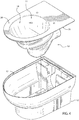
- a rimless toilet assembly 8 is disclosed.
- the toilet may be produced as having a rimless design (i.e., the rim may no longer be required to distribute or direct water to a toilet bowl).
- the term "rimless” is intended to mean a toilet which does not include an upper rim (i.e., a rim which is either integrally formed with a toilet bowl or fixedly coupled to a toilet bowl) which overhangs an opening of a toilet bowl, or which extends inwardly into a toilet bowl proximate the opening.
- a bowl 18 of a bowl member 10 may be substantially outwardly concave from an opening 22 of the bowl 18 down to an outlet hole 24 (not shown in FIG. 1 , but see, e.g., FIG. 2 ).
- the bowl 18 may include one or more points of inflection where an outwardly concave surface transitions to an outwardly convex surface, or an outwardly convex surface transitions to an outwardly concave surface.
- a rim does not overhang the opening 22.
- the toilet may include a rim, and the other features described herein (e.g., the location of the jet holes just above the waterline of the bowl, the gravity sump design) may be used either with or without a rimless design, and either with or without the two-piece assembly that will be discussed below according to one particular exemplary embodiment. It should be noted that any of the features discussed herein may be used with toilets having other configurations, and that all such modifications are intended to be encompassed by the present disclosure.
- the rimless toilet assembly may be provided as a two-piece assembly, in which a bowl member constitutes the first piece of the toilet assembly and is configured to be received within, and supported by, an outer shroud, which is the second piece of the toilet assembly.
- the rimless toilet assembly 8 includes an inner bowl member 10 and an outer shroud 12 (e.g., a casing, shell, enclosure, etc.).
- the toilet assembly 8 is configured to be a wall-hung toilet (i.e., a rear side of the toilet assembly 8 is configured to be mounted to a wall, as will be explained below).
- a toilet assembly may be configured to be a floor-mounted toilet.
- the bowl member 10 is configured to be received within, and supported by, the shroud 12.
- the shroud 12 is configured to enclose or envelop the bowl member 10.
- the shroud 12 and the bowl member 10 may be formed from vitreous china, porcelain, stainless steel, or any other suitable material, and it should be understood that the materials disclosed herein are not limiting.
- the bowl member 10 and the shroud 12 are provided with contact surfaces (e.g., mating surfaces) which are cooperatively configured so that when the bowl member 10 is supported by the shroud 12, a top surface of the bowl member 10 is essentially flush with a top surface of the shroud 12.
- contact surfaces e.g., mating surfaces
- an outer periphery of the bowl member 10 may be configured to pair (i.e., correspond to, match, etc.) with an outer periphery of the shroud 12, such that when the outer periphery of the bowl member 10 rests upon the outer periphery of the shroud 12, a top surface of the bowl member 10 is essentially flush with a top surface of the shroud 12 and form an integral assembly.
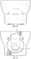
- the bowl member 10 may include a top wall 28 that extends outwardly from the opening 22 of the bowl 18.
- a periphery of the top wall 28 includes a bowl contact surface 30 (e.g., a mating surface) provided at an angle relative to the top wall 28, such that the bowl contact surface 30 is angled inwards downwardly toward a bottom of the bowl 18.
- the bowl contact surface 30 is configured to rest upon a corresponding shroud contact surface 32 (e.g., a mating surface) of the outer shroud 12.
- the shroud contact surface 32 may be angled inwards downwardly relative to the outer shroud, such that the contact surfaces 30, 32 are cooperatively configured to be coupled together.
- a bowl contact surface is perpendicular to a top wall of the bowl member, and a shroud contact surface is a ledge (e.g., a shelf, flange, rabbet, wall, etc.) formed within an outer shroud.
- a ledge e.g., a shelf, flange, rabbet, wall, etc.
- the bowl member 10 and the shroud 12 may be coupled together in various ways in order to form the toilet assembly 8.
- mechanical fasteners or an adhesive may be used to couple the bowl member 10 to the shroud 12.
- the bowl member 10 may be coupled to the shroud 12 in any suitable way, and the methods disclosed herein are not limiting.
- the bowl member 10 is shown and will be described in more detail below.
- the rimless bowl member 10 may be cast as a single part. Because the bowl 18 does not include a rim overhanging an upper portion of the bowl 18, the casting process of the bowl member 10 may be simplified. For example, the number of molds and/or dies used to cast the bowl member 10 may be reduced.
- the contact surface 30 of the bowl member 10 is clearly shown.
- a duality of water channels 34 are shown surrounding the bowl 18 (i.e., on a left and right side of the bowl 18).
- the water channels 34 extend downwardly from a rear portion of the bowl member 10 (see also, e.g., FIGS 8 and 10-11 ) to a front portion of the bowl member 10.
- only a single water channel 34 may be provided on the bowl member 10, the single water channel extending along either a left or right side of the bowl member 10.
- a plurality of mounting holes 36 are provided within the top wall 28, behind the bowl 18.
- the mounting holes 36 may be used to couple a toilet attachment (not shown, but e.g., a toilet seat, toilet lid, bidet attachment, etc.) to the bowl member 10.
- the various toilet attachments that may be used with the bowl member 10 may pivot between closed and open positions. Such toilet attachments may rest upon the top wall 28 when the toilet attachments are in a closed position.
- the sump 26 is provided on a bottom end of the bowl member 10.
- a rear side of the sump 26 includes an outlet hole 42, which is provided below the inlet hole 40, and an outlet hole 24 (not shown in FIG. 8 , but see, e.g., FIG. 2 ), which is provided within the bowl 18.
- a vertical wall 44 is provided on either side of the inlet hole 40.
- the walls 44 may be used to position the bowl member 10 within the outer shroud 12.
- the walls 44 may also be used to support the inlet channel.
- the bowl 18 may be defined by two halves, an upper half 46 and a lower half 48.
- the upper half 46 is provided above a front hole 14 (not shown in FIGS. 10-11 , but see, e.g., the cross-sectional view in FIG. 2 ) which is defined by the channels 34, and the lower half 48 is provided below the front hole 14.
- the outer shroud 12 is shown and will be described in more detail below.
- the outer shroud 12 may be configured to have any other suitable shape.
- a particular bowl member 10 i.e., a standard bowl member
- a variety of outer shrouds each outer shroud having a different shape or style, according to the particular toilet styles that may be in demand at any given time. Accordingly, a design for a new toilet assembly may only require designing a new outer shroud, which may be designed to couple to the standard bowl member 10.
- a two-part toilet assembly 8 when compared to unitary toilets which are integrally formed and designed having particular interior characteristics relating to the bowl, as well as exterior characteristics, the costs to design and produce a two-part toilet assembly 8 may be comparatively less.
- such a two-part toilet assembly may lead to overall cost savings because the bowl member could be used across multiple product lines which would lead to cost savings on bowl molds, engineering costs, etc.
- the two-piece toilet assembly 8 may provide several manufacturing benefits over unitary toilets, only some of which are described in detail herein.
- various toilets each having a unique design, may comprise a standard bowl member 10, and a unique (i.e., different, individual, customized, etc.) outer shroud 12.
- the bowl member 10 may be a standard part, which is configured to be used (i.e., such that the bowl member is common, shared, etc.) among a variety of outer shrouds, a company may realize an initial tooling cost required to manufacture the bowl member 10.
- the tooling costs required for a new toilet design may be limited to the tooling costs for a particular outer shroud.
- the tooling required to manufacture an outer shroud may be significantly less complicated and less expensive to produce than the tooling used to produce a unitary toilet which is integrally formed and designed having particular interior and exterior characteristics. Accordingly, a two-piece toilet assembly 8 may save a company significant tooling costs related to manufacturing a new toilet design.
- the research and development (R&D) costs to design a new two-piece toilet assembly 8 may be comparatively less than those associated with designing a new unitary toilet.
- testing and validation is required to ensure that a new toilet design functions properly (e.g., that a flush cycle adequately cleans and evacuates a toilet bowl, etc.) and that a new toilet design is compliant with various governmental regulations (e.g., those relating to the consumption of water per flush).
- the costs of testing and validating a new toilet design may include, for example, costs to develop prototypes and costs of labor and equipment required to conduct tests.
- Durability tests may be required in which a new toilet design undergoes thousands of flush cycles in order to validate the toilet over its useful life.
- Thermal tests may be required to ensure a new toilet design can withstand a range of hot and cold temperatures.
- the costs to develop, test, and validate a new toilet design may be substantial, and a new unitary toilet design will typically bear at least some of these costs.
- the R&D costs related to testing and validating the operation of a new two-piece toilet assembly may be limited to the initial R&D costs associated with testing and validating the standard bowl member 10.
- a new toilet may be designed by simply developing a new outer shroud which is configured to receive and support the bowl member 10, which is already pre-tested and pre-validated.
- the costs required to design a two-part toilet assembly may be comparatively less than the costs required to design a unitary toilet.
- the outer shroud 12 includes a rear wall 50 and a partition 52.
- the rear wall 50 is configured to mount (e.g., couple, attach, connect, etc.) to a wall, as will be explained below in greater detail.
- the rear wall 50 and the partition 52 define a mounting cavity 54 provided therebetween.
- the mounting cavity 54 may receive the walls 44 of the bowl member 10 when the bowl member is received by the shroud 12.
- the partition 52 separates a central cavity 56 of the shroud 12 from the mounting cavity 54 and the rear wall 50.
- a rear side of the outer shroud 12 includes a plurality of mounting holes 58.
- a plurality of fasteners (not shown, but e.g., bolts, studs, etc.) may be used to couple the shroud 12 to a wall.
- a rear cavity 60 is also disposed within the rear wall 50. The rear cavity 60 is configured to receive the sump 26 when the bowl member 10 is received within the shroud 12.
- a ledge 62 is provided within the central cavity of the shroud 12.
- the ledge 62 and the bowl 18 may be cooperatively configured such that the lower half 48 of the bowl 18 is supported by (i.e., rests upon) the ledge 62 when the bowl member 10 is received within the shroud 12.
- the ledge 62 extends inwardly from a bottom of the shroud 12.
- the ledge 62 is provided on a front and left/right sides of the shroud 12, while the rear side of the shroud 12 is left open so as to accommodate the sump 26 of the bowl member 10 (not shown in FIG. 15 , but see, e.g., FIGS. 2 and 4 ).
- the bowl member 10 is supported proximate outlet hole 24 by the ledge 62.
- an access hole 64 is disposed within a left and right side of the shroud 12.
- a rear side of the access holes 64 is defined by the rear cavity 60.
- the access holes 64 may be used to provide access to fasteners (not shown, but e.g., nuts threaded onto bolts or studs) within the rear cavity 60, which are used to secure the toilet assembly 8 to a wall.
- the access holes 64 are not covered; however, a cover may be used to conceal the fasteners within the rear cavity 60, or to provide the shroud 12 with a more aesthetic appearance.
- a plurality of holes are provided along a rear portion of the bowl 18.
- a side hole 29 e.g., an aperture, jet, outlet, etc.
- the side holes 29 may be in fluid communication with the inlet channel 38 (not shown in FIG. 3 , but see, e.g., the cross-sectional view in FIG. 2 ) via separate channels (not shown).
- the side holes 29 are configured such that the holes do not project into the area defined by a curvature of the bowl 18.
- the curvature of the bowl 18 around the side holes 29 is continuous.
- the holes 29 are configured so that an undercut is not provided thereunder, thereby preventing the accumulation (e.g., collection, build-up, etc.) of contamination below the holes 29. Also, in the event that any contamination does build up anywhere on the bowl 18, a user is able to visually see the contamination in order to clean the toilet assembly 8.
- the side holes 29 are oriented such that water flowing therethrough is projected (e.g., directed, dispersed, etc.) forwardly and laterally across the surface of the bowl 18, thereby washing the bowl 18 and carrying waste toward an outlet hole 24.
- the side holes 29 and the channels connecting the holes 14,16 to the inlet channel 25 are configured so that a sufficient amount of water is introduced thereto during a flushing cycle in order to completely wash the bowl 18.
- the size of the side holes 29 and the channels between the side holes 29 and the inlet channel 38 may be large enough to allow a sufficient (i.e., adequate) amount of water from the flushing cycle to flow therethrough in order for the bowl 18 to be completely washed.
- a bowl member 10 may include a greater or fewer number of side holes, which may be disposed in different positions within a toilet bowl, according to other exemplary embodiments, and that the embodiments disclosed herein are not limiting.
- a toilet comprises a bowl having an opening, an outlet, and two jet holes positioned above a water line defined by a weir of a trapway, wherein the two jet holes are configured to evacuate waste from the bowl into a drain.
- the two jet holes are positioned at a height above the water line that is less than one-quarter of a distance between the opening of the bowl and the water line. It may be that the two jet holes are configured to direct flush water toward a central portion of an outlet hole of a sump of the toilet without flowing over a portion of the bowl.
- a first of the two jet holes is positioned toward a front of the bowl and a second of the two jet holes is positioned toward a rear of the bowl. It may be that an inlet channel used to supply water to the bowl is in fluid communication with the second jet hole and with a pair of channels that extend around a left and right side of the bowl; and wherein the pair of channels and the first jet hole are in fluid communication.
- the toilet includes a sump having a mouth cut-out, and a lowest point of the sump is located rearward of the mouth cut-out, whereby the sump is configured to allow gravity to assist the flow of waste to the outlet. It may be that the toilet does not include a rim that overhangs the bowl for distributing flush water to the toilet. It may be that the bowl comprises an upper surface and the toilet further comprises a shroud having an upper surface and an upper cavity, wherein the bowl is configured to be received within the upper cavity and supported by the shroud, and wherein the bowl and the shroud are cooperatively configured such that the upper surfaces of the bowl and the shroud are essentially flush when the bowl is supported on the shroud.
- a toilet comprises a bowl having an upper surface, an opening, and an outlet; and a shroud having an upper surface and an upper cavity; wherein the bowl is configured to be received within the upper cavity and supported on the shroud; wherein the bowl and the shroud are cooperatively configured such that the upper surfaces of the bowl and the shroud are essentially flush when the bowl is supported on the shroud.
- the bowl further includes a jet hole positioned above a water spot defined by a weir of a trapway, the jet hole being configured to evacuate waste from the bowl into a drain.
- cooperatively configured mating surfaces are provided on an upwardly-facing surface of the shroud and a downwardly-facing of the bowl.
- a rear wall of the shroud is configured to be mounted to a wall.
- the shroud is further configured to support a trapway of the bowl.
- the shroud includes a rear cavity, and when the bowl is received within the upper cavity of the shroud, a trapway and an inlet channel of the bowl are accessible through the rear cavity.
- a toilet comprises a bowl having an upper wall, an opening, and an outlet; and a shroud having an upper surface and a cavity; wherein the bowl is configured to be received within the cavity and supported on the shroud; wherein the opening of the bowl does not overhang a portion of the bowl.
- the upper wall of the bowl extends outwardly from the opening to an outer edge, and wherein the outer edge of the upper wall is configured to be supported on the upper surface of the shroud. It may be that the upper wall of the bowl and the upper surface of the shroud are essentially flush when the bowl is supported on the shroud. It may be that the bowl further comprises two jet holes positioned less than 51mm (two inches) above a water spot defined by a weir of a trapway, the two jet holes being configured to evacuate waste from the bowl into a drain.
- a first of the two jet holes is positioned toward a front of the bowl and a second of the two jet holes is positioned toward a rear of the bowl; and wherein preferably the rear jet hole is slot-shaped.
- the toilet includes a sump having a mouth cut-out, and the lowest point of the sump is located rearward of the mouth cut-out, whereby the sump is configured to allow gravity to assist the flow of waste to the outlet.
- a toilet is provided as defined by claim 1.
- Optional features are the subject of claims 2 to 15.
- Coupled means the joining of two members directly or indirectly to one another. Such joining may be stationary (e.g., permanent) or moveable (e.g., removable or releasable). Such joining may be achieved with the two members or the two members and any additional intermediate members being integrally formed as a single unitary body with one another or with the two members or the two members and any additional intermediate members being attached to one another.
Landscapes
- Health & Medical Sciences (AREA)
- Life Sciences & Earth Sciences (AREA)
- Engineering & Computer Science (AREA)
- Hydrology & Water Resources (AREA)
- Public Health (AREA)
- Water Supply & Treatment (AREA)
- Sanitary Device For Flush Toilet (AREA)
Applications Claiming Priority (2)
| Application Number | Priority Date | Filing Date | Title |
|---|---|---|---|
| US201461954907P | 2014-03-18 | 2014-03-18 | |
| EP15159722.6A EP2921598A3 (en) | 2014-03-18 | 2015-03-18 | Dual-jet toilet |
Related Parent Applications (1)
| Application Number | Title | Priority Date | Filing Date |
|---|---|---|---|
| EP15159722.6A Division EP2921598A3 (en) | 2014-03-18 | 2015-03-18 | Dual-jet toilet |
Publications (2)
| Publication Number | Publication Date |
|---|---|
| EP3540134A1 EP3540134A1 (en) | 2019-09-18 |
| EP3540134B1 true EP3540134B1 (en) | 2020-07-29 |
Family
ID=52686231
Family Applications (2)
| Application Number | Title | Priority Date | Filing Date |
|---|---|---|---|
| EP19171660.4A Active EP3540134B1 (en) | 2014-03-18 | 2015-03-18 | Four-jets toilet |
| EP15159722.6A Withdrawn EP2921598A3 (en) | 2014-03-18 | 2015-03-18 | Dual-jet toilet |
Family Applications After (1)
| Application Number | Title | Priority Date | Filing Date |
|---|---|---|---|
| EP15159722.6A Withdrawn EP2921598A3 (en) | 2014-03-18 | 2015-03-18 | Dual-jet toilet |
Country Status (3)
| Country | Link |
|---|---|
| US (1) | US9719239B2 (zh) |
| EP (2) | EP3540134B1 (zh) |
| CN (1) | CN105040791B (zh) |
Families Citing this family (14)
| Publication number | Priority date | Publication date | Assignee | Title |
|---|---|---|---|---|
| JP6284236B2 (ja) * | 2014-08-18 | 2018-02-28 | 株式会社Lixil | 水洗式便器 |
| US9845593B2 (en) * | 2015-11-03 | 2017-12-19 | David R. Hall | Modular toilet system and components |
| JP6691659B2 (ja) * | 2015-11-12 | 2020-05-13 | Toto株式会社 | 水洗大便器 |
| JP6691662B2 (ja) * | 2016-01-18 | 2020-05-13 | Toto株式会社 | 水洗式大便器 |
| JP7219532B2 (ja) * | 2016-03-09 | 2023-02-08 | Toto株式会社 | 水洗大便器 |
| USD796652S1 (en) * | 2016-03-11 | 2017-09-05 | Sloan Valve Company | Wall hung water closet |
| CN108396840B (zh) * | 2018-02-28 | 2020-07-28 | 厦门优胜卫厨科技有限公司 | 一种冲水坐便器 |
| JP6647685B2 (ja) * | 2018-03-27 | 2020-02-14 | Toto株式会社 | 水洗大便器 |
| CN112543830B (zh) * | 2018-08-07 | 2022-05-24 | 科勒公司 | 具有非玻化冲水引擎的马桶 |
| CN216379829U (zh) | 2018-08-31 | 2022-04-26 | As 美国股份有限公司 | 马桶组件 |
| US11047123B2 (en) | 2018-11-16 | 2021-06-29 | Kohler Co. | Gravity-fed toilet with quiet siphonic flush |
| DE102019002225A1 (de) * | 2019-03-28 | 2020-10-01 | Grohe Ag | Schüssel für eine Toilette und Verfahren zur Herstellung einer solchen Schüssel |
| EP4105401A1 (de) * | 2021-06-16 | 2022-12-21 | Georg Kantor | Spülrandloser sanitärgegenstand und verfahren zum spülen eines solchen |
| DE202023100979U1 (de) | 2022-07-25 | 2023-03-28 | Hatria S.R.L. | Sanitärbecken ohne Spülrand |
Family Cites Families (161)
| Publication number | Priority date | Publication date | Assignee | Title |
|---|---|---|---|---|
| US1308301A (en) | 1919-07-01 | Masttkrosuke sakogawa | ||
| US172572A (en) | 1876-01-25 | Improvement in water-closet pans | ||
| US273668A (en) | 1883-03-06 | Pateigk connolly | ||
| US243329A (en) | 1881-06-21 | Eighaed h | ||
| US266309A (en) | 1882-10-24 | Watee closet | ||
| US303027A (en) * | 1884-08-05 | Bidet | ||
| US233470A (en) | 1880-10-19 | Dominic bukke | ||
| DE25991C (de) | O. syrbius in Hannover | Neuerung an der ERARD'schen Flügelmechanik | ||
| US310370A (en) | 1885-01-06 | Edwaed j | ||
| US206049A (en) | 1878-07-16 | Improvement in valves for water-closets | ||
| US166209A (en) | 1875-08-03 | Improvement in pans for water-closets | ||
| DE214437C (zh) | ||||
| US345667A (en) | 1886-07-20 | buskiek | ||
| US1107094A (en) | 1914-08-11 | William R Mitchell | Water-closet. | |
| US476011A (en) | 1892-05-31 | Water-closet | ||
| DE596604C (de) | 1934-05-08 | Inventia Patent Verwert Ges | Stoerschutz fuer Elektromotoren mit verdeckt angeordneten Buersten | |
| US97105A (en) | 1869-11-23 | george r | ||
| DE9725C (de) | K. FRANDSEN in Triest | Neuerungen an Wasserclosetts | ||
| US340287A (en) | 1886-04-20 | John cliffoed | ||
| US220688A (en) | 1879-10-14 | Improvement in water-closet hoppers | ||
| US305141A (en) | 1884-09-16 | Leopold beandeis | ||
| US172571A (en) | 1876-01-25 | Improvement in water-closet pans | ||
| DE596504C (de) * | 1934-05-03 | Josef Pohlen | Flachspuelklosett | |
| DE9884C (de) | H. P. KREINER in Berlin SW" Grofsbeerenstr. 73 | Neuerung am Wasserkloset | ||
| US26243A (en) | 1859-11-29 | Water-closet basin | ||
| US188897A (en) | 1877-03-27 | Improvement in water-closet basins | ||
| US796848A (en) | 1904-07-14 | 1905-08-08 | Jacob F Leanhart | Water-closet. |
| US1183893A (en) | 1915-05-26 | 1916-05-23 | Ira A Mann | Plumbing-fixture. |
| US1529819A (en) | 1924-02-20 | 1925-03-17 | Oscar B Van Fleet | Toilet siphon bowl |
| US1928717A (en) | 1932-09-26 | 1933-10-03 | Cesare C Campus | Siphon jet flushing nozzle, water closet, flushing valve, and bidet combination |
| GB471058A (en) | 1936-02-20 | 1937-08-20 | Alan Henry Adams | Improvements relating to closet pans, slop sinks and other receptacles which are discharged by flushing |
| GB519531A (en) | 1937-09-11 | 1940-03-29 | William Charles Groeniger | Improvements in or relating to water closets and like apparatus |
| US2154240A (en) | 1937-09-11 | 1939-04-11 | Pierce John B Foundation | Combined seat and flush rim |
| US2153536A (en) | 1937-09-25 | 1939-04-11 | Pierce John B Foundation | Combined hinge and flow valve |
| GB519533A (en) | 1937-09-25 | 1940-03-29 | William Charles Groeniger | Improvements in or relating to water closets |
| GB524423A (en) | 1938-02-15 | 1940-08-06 | William Charles Groeniger | Improvements in or relating to water closets and like apparatus |
| US2164320A (en) | 1938-04-08 | 1939-07-04 | Pierce John B Foundation | Combination seat and flush rim |
| GB528110A (en) | 1939-03-14 | 1940-10-23 | Edward Johns & Company Ltd | Improvements in water closet basins |
| GB531085A (en) | 1939-06-22 | 1940-12-30 | William Charles Groeniger | Improvements in or relating to water closets |
| FR856962A (fr) | 1939-06-27 | 1940-08-19 | Perfectionnements apportés aux dispositifs pour la décharge ou l'évacuation d'eaux souillées | |
| GB935949A (en) | 1960-06-01 | 1963-09-04 | Leeds Fireclay Company Ltd | Improvements in or relating to water-closets |
| GB983855A (en) | 1961-06-06 | 1965-02-17 | Shanks & Company Ltd | Improvements in or relating to water-closet pans |
| US3046569A (en) | 1961-07-25 | 1962-07-31 | Youngstown Sheet And Tube Co | Rimless mounting for sheet steel enameled sinks, lavatories and the like |
| GB1036427A (en) | 1962-05-18 | 1966-07-20 | Armitage Excelsior Ltd | Improvements in or relating to water closet pans |
| US3334358A (en) | 1964-09-17 | 1967-08-08 | Peters & Russel Inc | Jet operated toilet |
| US3538518A (en) | 1968-12-09 | 1970-11-10 | Koehler Dayton | Flushing manifold for portable toilets |
| DE2150451C3 (de) | 1971-10-09 | 1974-08-15 | Duravit-Hornberg, Sanitaer-Keramisches Werk Gmbh Vorm. Steingutfabrik Schwarzwald Gmbh, 7746 Hornberg | Vorrichtung zum Befestigen eines Klosettbeckens am Fußboden |
| US3798681A (en) * | 1972-01-10 | 1974-03-26 | O Johansen | Device in water closets |
| FR2188003B1 (zh) | 1972-06-07 | 1976-11-12 | Roehm Gmbh | |
| US3860973A (en) | 1973-04-04 | 1975-01-21 | Itt | Toilet construction |
| US4075718A (en) | 1975-04-03 | 1978-02-28 | Hargraves William J | Nozzle flush system |
| US4145776A (en) | 1977-01-24 | 1979-03-27 | Trayco, Inc. | Unitary bowl, waterway and trap for a toilet, and the method of making same |
| US4158243A (en) | 1977-07-29 | 1979-06-19 | Mccann William E | Easy clean lavatory |
| GB2012835B (en) | 1977-11-25 | 1982-03-03 | Sissons Ltd W & G | Sanitary appliances |
| US4155129A (en) | 1978-03-23 | 1979-05-22 | Russell Harold J | Pan type bottom discharge toilet |
| US4246666A (en) | 1978-11-17 | 1981-01-27 | Stansbury Jr Benjamin H | Flush toilet |
| GB2045311B (en) | 1979-04-03 | 1983-04-20 | Armitage Shanks Ltd | Water closet pan |
| GB2057030A (en) | 1979-05-31 | 1981-03-25 | Wedgwood & Sons Ltd J | Water closet and bidet bowls |
| US4217668A (en) | 1979-09-20 | 1980-08-19 | Thetford Corporation | Portable toilet |
| US4404696A (en) | 1981-08-10 | 1983-09-20 | International Water Saving Systems, Inc. | Fluid velocity assist |
| WO1984001973A1 (en) | 1982-11-09 | 1984-05-24 | Matsushita Electric Ind Co Ltd | Sanitary washing apparatus |
| US4475887A (en) | 1983-05-19 | 1984-10-09 | Norton Company | Lavatory setter |
| DE3512305A1 (de) | 1985-04-04 | 1986-10-09 | Georg Rost & Söhne Armaturenfabrik GmbH & Co KG, 4952 Porta Westfalica | Wc-spuelanlage |
| GB2203178B (en) | 1987-04-06 | 1990-11-28 | Ifoe Sanitaer Ab | Flush water distributor for a wc pan |
| US4930167A (en) | 1988-09-26 | 1990-06-05 | Household Manufacturing, Inc. | Toilet with vortex flushing action |
| US5073994A (en) | 1990-09-12 | 1991-12-24 | Thetford Corporation | Low water toilet with pulsed flush |
| DE4127835C2 (de) | 1991-06-07 | 1993-11-11 | Frietjof Scheffler | Kleintiertoilette |
| ITFI910142A1 (it) | 1991-06-17 | 1992-12-17 | Bruno Giani | Dispositivo per il lavaggio di tazze per gabinetto e tazza per gabinetto incorporante detto dispositivo |
| US5271105A (en) | 1992-04-02 | 1993-12-21 | Tyler Steven J | Vacuum flush toilet assembly |
| JP2952645B2 (ja) | 1994-10-19 | 1999-09-27 | 株式会社イナックス | 洗浄水分配器を用いた便器 |
| US5651148A (en) | 1995-06-07 | 1997-07-29 | American Standard | Toilet with vortex flushing action |
| US5715544A (en) | 1995-11-22 | 1998-02-10 | Thetford Corporation | Toilet with improved flush nozzle |
| PT808395E (pt) * | 1995-12-07 | 2002-09-30 | Amila Ag | Instalacao sanitaria com o vaso articulado rotativamente |
| CN1282806C (zh) | 1996-10-15 | 2006-11-01 | 东陶机器株式会社 | 水洗便器 |
| CA2209796A1 (en) | 1997-08-11 | 1999-02-11 | Shu-Ki Yeung | Tilting-bowl toilet |
| AU1329999A (en) | 1997-12-05 | 1999-06-28 | Keramik Holding Ag Laufen | Water closet |
| US5875499A (en) | 1998-01-23 | 1999-03-02 | Thetford Corporation | Recreational vehicle toilet with flush nozzle deflector shield |
| JP3649001B2 (ja) | 1998-09-02 | 2005-05-18 | 東陶機器株式会社 | ボウル洗浄機能付便座を有する便器 |
| AT408108B (de) | 1999-08-19 | 2001-09-25 | Riepl Josef | Toilettenmuschel |
| AU3542101A (en) | 2000-01-18 | 2001-07-31 | Roediger Vakuum- Und Haustechnik Gmbh | Sanitary system |
| JP2001271407A (ja) | 2000-01-19 | 2001-10-05 | Toto Ltd | 水洗便器 |
| US6415457B2 (en) | 2000-02-08 | 2002-07-09 | Geberit Technik Ag | Flushing device for toilet system |
| CN1295405C (zh) | 2000-03-29 | 2007-01-17 | 东陶机器株式会社 | 水洗座便器 |
| JP2001279789A (ja) | 2000-03-30 | 2001-10-10 | Toto Ltd | 水洗便器とその製造方法 |
| JP2001279791A (ja) | 2000-03-31 | 2001-10-10 | Toto Ltd | 水洗便器 |
| ATE401466T1 (de) | 2000-04-10 | 2008-08-15 | Inax Corp | Wc nach westlichem standard |
| US6397405B1 (en) | 2000-04-11 | 2002-06-04 | Thetford Corporation | Flush toilet for RV's and boats |
| JP2001323541A (ja) | 2000-05-12 | 2001-11-22 | Inax Corp | 洋風水洗式便器 |
| JP2002106048A (ja) | 2000-09-29 | 2002-04-10 | Toto Ltd | 水洗便器および便器のリム部素地を製造する方法 |
| JP4721026B2 (ja) | 2001-03-28 | 2011-07-13 | Toto株式会社 | 大便器装置 |
| AUPR695801A0 (en) | 2001-08-10 | 2001-09-06 | Caroma Industries Limited | An ultra-low volume gravity flushing toilet |
| KR20040015668A (ko) | 2001-08-13 | 2004-02-19 | 도토기키 가부시키가이샤 | 대변기와 그 제조방법 |
| JP4141153B2 (ja) | 2002-03-07 | 2008-08-27 | Toto株式会社 | 大便器装置 |
| EP1507935B1 (de) | 2002-05-30 | 2006-07-05 | Geberit Technik Ag | Spülvorrichtung einer toilettenanlage mit spülarm zum ausspülen einer toilettenschüssel |
| JP3817734B2 (ja) | 2002-09-03 | 2006-09-06 | 東陶機器株式会社 | 水洗便器 |
| JP4048921B2 (ja) | 2002-11-06 | 2008-02-20 | Toto株式会社 | 水洗便器 |
| JP4196646B2 (ja) | 2002-11-06 | 2008-12-17 | Toto株式会社 | 水洗便器 |
| ITFI20030069A1 (it) | 2003-03-17 | 2004-09-18 | Marcello Picchi | Un sistema di lavaggio per un vaso sciacquone |
| GB0310878D0 (en) | 2003-05-12 | 2003-06-18 | Buchanan Thomas J | Hygiene luxury system |
| DE10326149A1 (de) | 2003-06-06 | 2004-12-23 | Sigismund Laskowski | Eine umweltfreundliche, schnell und gründliche zu reinigende Schüssel eines Wasserklosetts (WC-Schüssel) oder eine Klosettschüssel |
| JP3876919B2 (ja) | 2003-06-23 | 2007-02-07 | 東陶機器株式会社 | 大便器ユニット |
| JP4305109B2 (ja) | 2003-09-26 | 2009-07-29 | Toto株式会社 | 水洗便器 |
| JP2004011413A (ja) | 2003-10-07 | 2004-01-15 | Toto Ltd | 水洗便器 |
| JP3578169B2 (ja) | 2003-10-07 | 2004-10-20 | 東陶機器株式会社 | 水洗便器 |
| JP2005113642A (ja) | 2003-10-10 | 2005-04-28 | Toto Ltd | 水洗便器 |
| US7263758B2 (en) * | 2003-12-02 | 2007-09-04 | American Standard Intl. Inc. | System and method for casting toilet bowls |
| JP4403813B2 (ja) | 2004-01-29 | 2010-01-27 | Toto株式会社 | 水洗便器 |
| TW200530467A (en) | 2004-03-08 | 2005-09-16 | Toto Ltd | Flush toilet bowl |
| JP2005307622A (ja) | 2004-04-23 | 2005-11-04 | Matsushita Electric Works Ltd | 水洗便器とその製造方法 |
| EP1605109A1 (de) | 2004-06-08 | 2005-12-14 | Geberit Technik Ag | Klosettschüssel für ein WC |
| FI116952B (fi) | 2005-01-25 | 2006-04-13 | Evac Int Oy | Alipaineviemärijärjestelmä |
| TW200636133A (en) | 2005-02-10 | 2006-10-16 | Toto Ltd | Flushing type toilet |
| JP2006230980A (ja) | 2005-02-22 | 2006-09-07 | Kazuhiro Kawamoto | 鏡付きトイレブラシ |
| US20060260033A1 (en) | 2005-03-03 | 2006-11-23 | Oep, Inc. | Toilet |
| GB2433074B (en) | 2005-12-09 | 2011-02-16 | Itt Mfg Enterprises Inc | Marine toilet |
| US7263727B1 (en) | 2006-02-24 | 2007-09-04 | Viacheslav V. Zhurin | Hygienic high detergency toilet |
| JP2007308912A (ja) | 2006-05-17 | 2007-11-29 | Matsushita Electric Works Ltd | 水洗便器 |
| JP2007315011A (ja) | 2006-05-25 | 2007-12-06 | Matsushita Electric Works Ltd | 水洗便器 |
| JP5559451B2 (ja) | 2006-10-13 | 2014-07-23 | パナソニック株式会社 | 便器装置 |
| US8336128B2 (en) | 2006-11-28 | 2012-12-25 | Toilet Technologies Company, Llc | Water-conserving toilet using timer-controlled valve |
| JP4508186B2 (ja) | 2006-11-30 | 2010-07-21 | パナソニック電工株式会社 | 水洗便器 |
| JP2008274679A (ja) | 2007-05-01 | 2008-11-13 | Toto Ltd | サイホンゼット便器 |
| US8151379B2 (en) | 2007-05-07 | 2012-04-10 | Kohler Co. | Toilet with reduced water usage |
| US20080276362A1 (en) | 2007-05-10 | 2008-11-13 | O'malley Conor | Mechanically sealable rapid opening stagger-flush residential toilet |
| ITBO20070503A1 (it) * | 2007-07-20 | 2009-01-21 | Sacmi | Prodotto sanitario in materiale ceramico. |
| GB2453319B (en) | 2007-09-05 | 2011-09-21 | Trane Bvba | Rimless toilet |
| JP5247091B2 (ja) | 2007-09-12 | 2013-07-24 | 小林製薬株式会社 | 薬剤供給具 |
| JP5141174B2 (ja) | 2007-10-15 | 2013-02-13 | Toto株式会社 | 水洗便器 |
| JP5104388B2 (ja) | 2008-02-22 | 2012-12-19 | パナソニック株式会社 | 便器 |
| JP5446113B2 (ja) | 2008-04-01 | 2014-03-19 | 株式会社Lixil | トイレ装置 |
| JP5257838B2 (ja) | 2008-07-29 | 2013-08-07 | Toto株式会社 | 水洗大便器 |
| GB0814000D0 (en) * | 2008-07-31 | 2008-09-10 | Wallgate Ltd | Lavatory pan |
| GB2466763A (en) | 2008-09-09 | 2010-07-07 | Steven Thorne Design Ltd | A toilet unit with flushing, washing and drying functions |
| US8528123B2 (en) | 2008-11-25 | 2013-09-10 | Dometic Corporation | Exterior rim wash bowl |
| CN102300601A (zh) | 2009-01-30 | 2011-12-28 | 久光制药株式会社 | 微针装置 |
| JP5467494B2 (ja) | 2009-02-04 | 2014-04-09 | Toto株式会社 | 水洗大便器 |
| JP5510881B2 (ja) | 2009-03-31 | 2014-06-04 | Toto株式会社 | 水洗大便器 |
| JP2010265693A (ja) | 2009-05-15 | 2010-11-25 | Panasonic Electric Works Co Ltd | 便器 |
| GB0911983D0 (en) | 2009-07-10 | 2009-08-19 | Castle Kate E | Portable toilet apparatus |
| JP2011208362A (ja) | 2010-03-29 | 2011-10-20 | Toto Ltd | 水洗大便器 |
| CN201704771U (zh) | 2010-04-30 | 2011-01-12 | 陈福环 | 无水箱节水型抽水马桶 |
| JP2012172403A (ja) | 2011-02-22 | 2012-09-10 | Toto Ltd | 水洗大便器 |
| KR101204787B1 (ko) | 2011-03-25 | 2012-11-26 | 대림비앤코주식회사 | 일체 성형 양변기 및 이의 제조방법 |
| JP5740788B2 (ja) | 2011-03-30 | 2015-07-01 | Toto株式会社 | 水洗大便器 |
| JP5804242B2 (ja) | 2011-03-30 | 2015-11-04 | Toto株式会社 | 水洗大便器 |
| ITBO20110201A1 (it) | 2011-04-15 | 2012-10-16 | Ativa | Vaso sanitario in materiale ceramico. |
| ITBO20110202A1 (it) | 2011-04-15 | 2012-10-16 | Ativa | Vaso sanitario in materiale ceramico. |
| JP5802959B2 (ja) | 2011-04-27 | 2015-11-04 | ジャニス工業株式会社 | 水洗便器 |
| CN202090410U (zh) | 2011-06-10 | 2011-12-28 | 谢潮藩 | 一种挂式座便器 |
| JP5093627B1 (ja) | 2011-07-14 | 2012-12-12 | Toto株式会社 | 水洗大便器 |
| JP5930508B2 (ja) | 2011-08-24 | 2016-06-08 | Toto株式会社 | 水洗大便器 |
| JP5935970B2 (ja) | 2011-08-24 | 2016-06-15 | Toto株式会社 | 水洗大便器 |
| EP2562314B1 (en) | 2011-08-24 | 2022-05-11 | Toto Ltd. | Flush toilet |
| JP6246453B2 (ja) | 2011-08-24 | 2017-12-13 | Toto株式会社 | 水洗大便器 |
| JP5930509B2 (ja) | 2011-08-24 | 2016-06-08 | Toto株式会社 | 水洗大便器 |
| JP5935971B2 (ja) | 2011-08-24 | 2016-06-15 | Toto株式会社 | 水洗大便器 |
| PL2602391T3 (pl) | 2011-12-05 | 2015-08-31 | Geberit Int Ag | Muszla klozetowa |
| PT2604761E (pt) | 2011-12-14 | 2015-05-13 | Geberit Int Ag | Vaso sanitário |
| CN202755424U (zh) | 2012-08-03 | 2013-02-27 | 科勒(中国)投资有限公司 | 马桶导水圈及马桶 |
| JP6006037B2 (ja) * | 2012-08-17 | 2016-10-12 | 株式会社Lixil | 水洗式便器 |
| JP5818230B2 (ja) | 2012-12-13 | 2015-11-18 | Toto株式会社 | 水洗大便器 |
-
2015
- 2015-03-16 US US14/659,035 patent/US9719239B2/en active Active
- 2015-03-17 CN CN201510117163.2A patent/CN105040791B/zh active Active
- 2015-03-18 EP EP19171660.4A patent/EP3540134B1/en active Active
- 2015-03-18 EP EP15159722.6A patent/EP2921598A3/en not_active Withdrawn
Non-Patent Citations (1)
| Title |
|---|
| None * |
Also Published As
| Publication number | Publication date |
|---|---|
| EP3540134A1 (en) | 2019-09-18 |
| US20150267388A1 (en) | 2015-09-24 |
| EP2921598A2 (en) | 2015-09-23 |
| CN105040791B (zh) | 2017-03-29 |
| EP2921598A3 (en) | 2015-12-30 |
| US9719239B2 (en) | 2017-08-01 |
| CN105040791A (zh) | 2015-11-11 |
Similar Documents
| Publication | Publication Date | Title |
|---|---|---|
| EP3540134B1 (en) | Four-jets toilet | |
| US10233627B2 (en) | Rimless toilet | |
| US11180910B2 (en) | Toilet with non-vitreous flush engine | |
| JP2011012508A (ja) | 便器本体 | |
| US20130067652A1 (en) | Water-conserving toilet | |
| EP3215682B1 (en) | Low noise wc | |
| US20150176264A1 (en) | Toilet pan and toilet | |
| JP2018105048A (ja) | 水洗大便器 | |
| CA2944072C (en) | Wall-hung toilet with improved load-bearing capacity | |
| JPH07224455A (ja) | 間接排出型衛生装置 | |
| CN205421480U (zh) | 一种座便器及其模具 | |
| CN107201775B (zh) | 一种座便器及其模具和制造方法 | |
| US20230036047A1 (en) | Toilet with canned sump | |
| CN217399843U (zh) | 一种低噪音的蹲便器 | |
| JP6666578B2 (ja) | 排水弁装置、この排水弁装置を備えた洗浄水タンク装置、及び、この洗浄水タンク装置を備えた水洗大便器 | |
| WO2016027644A1 (ja) | 水洗式便器、便器及び水洗式大便器 | |
| JP7218767B2 (ja) | 水洗大便器 | |
| JP5224772B2 (ja) | 排水トラップ及び排水トラップへの排水方法 | |
| JPH08270050A (ja) | 便 器 | |
| JP6607342B2 (ja) | 小便器 | |
| AU2022204495A1 (en) | Ceramic flush water distributor for rimless toilet unit | |
| JP2016041882A (ja) | 水洗式便器 | |
| JP2004116279A (ja) | 壁掛式便器 | |
| KR200403934Y1 (ko) | 기능성 와변기 | |
| CN110700371A (zh) | 一种新型低噪声冲落式座便器 |
Legal Events
| Date | Code | Title | Description |
|---|---|---|---|
| PUAI | Public reference made under article 153(3) epc to a published international application that has entered the european phase |
Free format text: ORIGINAL CODE: 0009012 |
|
| STAA | Information on the status of an ep patent application or granted ep patent |
Free format text: STATUS: THE APPLICATION HAS BEEN PUBLISHED |
|
| AC | Divisional application: reference to earlier application |
Ref document number: 2921598 Country of ref document: EP Kind code of ref document: P |
|
| AK | Designated contracting states |
Kind code of ref document: A1 Designated state(s): AL AT BE BG CH CY CZ DE DK EE ES FI FR GB GR HR HU IE IS IT LI LT LU LV MC MK MT NL NO PL PT RO RS SE SI SK SM TR |
|
| STAA | Information on the status of an ep patent application or granted ep patent |
Free format text: STATUS: REQUEST FOR EXAMINATION WAS MADE |
|
| GRAP | Despatch of communication of intention to grant a patent |
Free format text: ORIGINAL CODE: EPIDOSNIGR1 |
|
| STAA | Information on the status of an ep patent application or granted ep patent |
Free format text: STATUS: GRANT OF PATENT IS INTENDED |
|
| 17P | Request for examination filed |
Effective date: 20200228 |
|
| RBV | Designated contracting states (corrected) |
Designated state(s): AL AT BE BG CH CY CZ DE DK EE ES FI FR GB GR HR HU IE IS IT LI LT LU LV MC MK MT NL NO PL PT RO RS SE SI SK SM TR |
|
| RIN1 | Information on inventor provided before grant (corrected) |
Inventor name: SRIVASTAVA, VIVEK KUMAR Inventor name: KUMAR, SHYAM NANDAN Inventor name: BHARDWAJ, ARUN |
|
| INTG | Intention to grant announced |
Effective date: 20200408 |
|
| GRAS | Grant fee paid |
Free format text: ORIGINAL CODE: EPIDOSNIGR3 |
|
| GRAA | (expected) grant |
Free format text: ORIGINAL CODE: 0009210 |
|
| STAA | Information on the status of an ep patent application or granted ep patent |
Free format text: STATUS: THE PATENT HAS BEEN GRANTED |
|
| AC | Divisional application: reference to earlier application |
Ref document number: 2921598 Country of ref document: EP Kind code of ref document: P |
|
| AK | Designated contracting states |
Kind code of ref document: B1 Designated state(s): AL AT BE BG CH CY CZ DE DK EE ES FI FR GB GR HR HU IE IS IT LI LT LU LV MC MK MT NL NO PL PT RO RS SE SI SK SM TR |
|
| REG | Reference to a national code |
Ref country code: CH Ref legal event code: EP |
|
| REG | Reference to a national code |
Ref country code: AT Ref legal event code: REF Ref document number: 1295951 Country of ref document: AT Kind code of ref document: T Effective date: 20200815 |
|
| REG | Reference to a national code |
Ref country code: IE Ref legal event code: FG4D |
|
| REG | Reference to a national code |
Ref country code: DE Ref legal event code: R096 Ref document number: 602015056767 Country of ref document: DE |
|
| REG | Reference to a national code |
Ref country code: LT Ref legal event code: MG4D |
|
| REG | Reference to a national code |
Ref country code: NL Ref legal event code: MP Effective date: 20200729 |
|
| REG | Reference to a national code |
Ref country code: AT Ref legal event code: MK05 Ref document number: 1295951 Country of ref document: AT Kind code of ref document: T Effective date: 20200729 |
|
| PG25 | Lapsed in a contracting state [announced via postgrant information from national office to epo] |
Ref country code: FI Free format text: LAPSE BECAUSE OF FAILURE TO SUBMIT A TRANSLATION OF THE DESCRIPTION OR TO PAY THE FEE WITHIN THE PRESCRIBED TIME-LIMIT Effective date: 20200729 Ref country code: GR Free format text: LAPSE BECAUSE OF FAILURE TO SUBMIT A TRANSLATION OF THE DESCRIPTION OR TO PAY THE FEE WITHIN THE PRESCRIBED TIME-LIMIT Effective date: 20201030 Ref country code: LT Free format text: LAPSE BECAUSE OF FAILURE TO SUBMIT A TRANSLATION OF THE DESCRIPTION OR TO PAY THE FEE WITHIN THE PRESCRIBED TIME-LIMIT Effective date: 20200729 Ref country code: AT Free format text: LAPSE BECAUSE OF FAILURE TO SUBMIT A TRANSLATION OF THE DESCRIPTION OR TO PAY THE FEE WITHIN THE PRESCRIBED TIME-LIMIT Effective date: 20200729 Ref country code: ES Free format text: LAPSE BECAUSE OF FAILURE TO SUBMIT A TRANSLATION OF THE DESCRIPTION OR TO PAY THE FEE WITHIN THE PRESCRIBED TIME-LIMIT Effective date: 20200729 Ref country code: NO Free format text: LAPSE BECAUSE OF FAILURE TO SUBMIT A TRANSLATION OF THE DESCRIPTION OR TO PAY THE FEE WITHIN THE PRESCRIBED TIME-LIMIT Effective date: 20201029 Ref country code: SE Free format text: LAPSE BECAUSE OF FAILURE TO SUBMIT A TRANSLATION OF THE DESCRIPTION OR TO PAY THE FEE WITHIN THE PRESCRIBED TIME-LIMIT Effective date: 20200729 Ref country code: BG Free format text: LAPSE BECAUSE OF FAILURE TO SUBMIT A TRANSLATION OF THE DESCRIPTION OR TO PAY THE FEE WITHIN THE PRESCRIBED TIME-LIMIT Effective date: 20201029 Ref country code: PT Free format text: LAPSE BECAUSE OF FAILURE TO SUBMIT A TRANSLATION OF THE DESCRIPTION OR TO PAY THE FEE WITHIN THE PRESCRIBED TIME-LIMIT Effective date: 20201130 Ref country code: HR Free format text: LAPSE BECAUSE OF FAILURE TO SUBMIT A TRANSLATION OF THE DESCRIPTION OR TO PAY THE FEE WITHIN THE PRESCRIBED TIME-LIMIT Effective date: 20200729 |
|
| PG25 | Lapsed in a contracting state [announced via postgrant information from national office to epo] |
Ref country code: PL Free format text: LAPSE BECAUSE OF FAILURE TO SUBMIT A TRANSLATION OF THE DESCRIPTION OR TO PAY THE FEE WITHIN THE PRESCRIBED TIME-LIMIT Effective date: 20200729 Ref country code: RS Free format text: LAPSE BECAUSE OF FAILURE TO SUBMIT A TRANSLATION OF THE DESCRIPTION OR TO PAY THE FEE WITHIN THE PRESCRIBED TIME-LIMIT Effective date: 20200729 Ref country code: LV Free format text: LAPSE BECAUSE OF FAILURE TO SUBMIT A TRANSLATION OF THE DESCRIPTION OR TO PAY THE FEE WITHIN THE PRESCRIBED TIME-LIMIT Effective date: 20200729 Ref country code: IS Free format text: LAPSE BECAUSE OF FAILURE TO SUBMIT A TRANSLATION OF THE DESCRIPTION OR TO PAY THE FEE WITHIN THE PRESCRIBED TIME-LIMIT Effective date: 20201129 |
|
| PG25 | Lapsed in a contracting state [announced via postgrant information from national office to epo] |
Ref country code: NL Free format text: LAPSE BECAUSE OF FAILURE TO SUBMIT A TRANSLATION OF THE DESCRIPTION OR TO PAY THE FEE WITHIN THE PRESCRIBED TIME-LIMIT Effective date: 20200729 |
|
| PG25 | Lapsed in a contracting state [announced via postgrant information from national office to epo] |
Ref country code: IT Free format text: LAPSE BECAUSE OF FAILURE TO SUBMIT A TRANSLATION OF THE DESCRIPTION OR TO PAY THE FEE WITHIN THE PRESCRIBED TIME-LIMIT Effective date: 20200729 Ref country code: SM Free format text: LAPSE BECAUSE OF FAILURE TO SUBMIT A TRANSLATION OF THE DESCRIPTION OR TO PAY THE FEE WITHIN THE PRESCRIBED TIME-LIMIT Effective date: 20200729 Ref country code: RO Free format text: LAPSE BECAUSE OF FAILURE TO SUBMIT A TRANSLATION OF THE DESCRIPTION OR TO PAY THE FEE WITHIN THE PRESCRIBED TIME-LIMIT Effective date: 20200729 Ref country code: CZ Free format text: LAPSE BECAUSE OF FAILURE TO SUBMIT A TRANSLATION OF THE DESCRIPTION OR TO PAY THE FEE WITHIN THE PRESCRIBED TIME-LIMIT Effective date: 20200729 Ref country code: DK Free format text: LAPSE BECAUSE OF FAILURE TO SUBMIT A TRANSLATION OF THE DESCRIPTION OR TO PAY THE FEE WITHIN THE PRESCRIBED TIME-LIMIT Effective date: 20200729 Ref country code: EE Free format text: LAPSE BECAUSE OF FAILURE TO SUBMIT A TRANSLATION OF THE DESCRIPTION OR TO PAY THE FEE WITHIN THE PRESCRIBED TIME-LIMIT Effective date: 20200729 |
|
| REG | Reference to a national code |
Ref country code: DE Ref legal event code: R097 Ref document number: 602015056767 Country of ref document: DE |
|
| PG25 | Lapsed in a contracting state [announced via postgrant information from national office to epo] |
Ref country code: AL Free format text: LAPSE BECAUSE OF FAILURE TO SUBMIT A TRANSLATION OF THE DESCRIPTION OR TO PAY THE FEE WITHIN THE PRESCRIBED TIME-LIMIT Effective date: 20200729 |
|
| PLBE | No opposition filed within time limit |
Free format text: ORIGINAL CODE: 0009261 |
|
| STAA | Information on the status of an ep patent application or granted ep patent |
Free format text: STATUS: NO OPPOSITION FILED WITHIN TIME LIMIT |
|
| PG25 | Lapsed in a contracting state [announced via postgrant information from national office to epo] |
Ref country code: SK Free format text: LAPSE BECAUSE OF FAILURE TO SUBMIT A TRANSLATION OF THE DESCRIPTION OR TO PAY THE FEE WITHIN THE PRESCRIBED TIME-LIMIT Effective date: 20200729 |
|
| 26N | No opposition filed |
Effective date: 20210430 |
|
| PG25 | Lapsed in a contracting state [announced via postgrant information from national office to epo] |
Ref country code: SI Free format text: LAPSE BECAUSE OF FAILURE TO SUBMIT A TRANSLATION OF THE DESCRIPTION OR TO PAY THE FEE WITHIN THE PRESCRIBED TIME-LIMIT Effective date: 20200729 |
|
| PG25 | Lapsed in a contracting state [announced via postgrant information from national office to epo] |
Ref country code: MC Free format text: LAPSE BECAUSE OF FAILURE TO SUBMIT A TRANSLATION OF THE DESCRIPTION OR TO PAY THE FEE WITHIN THE PRESCRIBED TIME-LIMIT Effective date: 20200729 |
|
| REG | Reference to a national code |
Ref country code: CH Ref legal event code: PL |
|
| REG | Reference to a national code |
Ref country code: BE Ref legal event code: MM Effective date: 20210331 |
|
| PG25 | Lapsed in a contracting state [announced via postgrant information from national office to epo] |
Ref country code: LU Free format text: LAPSE BECAUSE OF NON-PAYMENT OF DUE FEES Effective date: 20210318 Ref country code: LI Free format text: LAPSE BECAUSE OF NON-PAYMENT OF DUE FEES Effective date: 20210331 Ref country code: IE Free format text: LAPSE BECAUSE OF NON-PAYMENT OF DUE FEES Effective date: 20210318 Ref country code: CH Free format text: LAPSE BECAUSE OF NON-PAYMENT OF DUE FEES Effective date: 20210331 |
|
| PG25 | Lapsed in a contracting state [announced via postgrant information from national office to epo] |
Ref country code: BE Free format text: LAPSE BECAUSE OF NON-PAYMENT OF DUE FEES Effective date: 20210331 |
|
| PGFP | Annual fee paid to national office [announced via postgrant information from national office to epo] |
Ref country code: FR Payment date: 20230316 Year of fee payment: 9 |
|
| PG25 | Lapsed in a contracting state [announced via postgrant information from national office to epo] |
Ref country code: CY Free format text: LAPSE BECAUSE OF FAILURE TO SUBMIT A TRANSLATION OF THE DESCRIPTION OR TO PAY THE FEE WITHIN THE PRESCRIBED TIME-LIMIT Effective date: 20200729 |
|
| PG25 | Lapsed in a contracting state [announced via postgrant information from national office to epo] |
Ref country code: HU Free format text: LAPSE BECAUSE OF FAILURE TO SUBMIT A TRANSLATION OF THE DESCRIPTION OR TO PAY THE FEE WITHIN THE PRESCRIBED TIME-LIMIT; INVALID AB INITIO Effective date: 20150318 |
|
| P01 | Opt-out of the competence of the unified patent court (upc) registered |
Effective date: 20230712 |
|
| PG25 | Lapsed in a contracting state [announced via postgrant information from national office to epo] |
Ref country code: MK Free format text: LAPSE BECAUSE OF FAILURE TO SUBMIT A TRANSLATION OF THE DESCRIPTION OR TO PAY THE FEE WITHIN THE PRESCRIBED TIME-LIMIT Effective date: 20200729 |
|
| PGFP | Annual fee paid to national office [announced via postgrant information from national office to epo] |
Ref country code: DE Payment date: 20240318 Year of fee payment: 10 Ref country code: GB Payment date: 20240221 Year of fee payment: 10 |