EP3283336B1 - Système d'évacuation de coussin de sécurité gonflable actif - Google Patents
Système d'évacuation de coussin de sécurité gonflable actif Download PDFInfo
- Publication number
- EP3283336B1 EP3283336B1 EP16780522.5A EP16780522A EP3283336B1 EP 3283336 B1 EP3283336 B1 EP 3283336B1 EP 16780522 A EP16780522 A EP 16780522A EP 3283336 B1 EP3283336 B1 EP 3283336B1
- Authority
- EP
- European Patent Office
- Prior art keywords
- airbag
- inflator
- hose
- vent
- seam
- Prior art date
- Legal status (The legal status is an assumption and is not a legal conclusion. Google has not performed a legal analysis and makes no representation as to the accuracy of the status listed.)
- Active
Links
- 238000000034 method Methods 0.000 claims description 12
- 230000000977 initiatory effect Effects 0.000 claims description 11
- 239000000463 material Substances 0.000 claims description 11
- 230000004044 response Effects 0.000 claims description 6
- 238000001514 detection method Methods 0.000 claims description 4
- 238000013022 venting Methods 0.000 claims description 4
- 230000008878 coupling Effects 0.000 claims 2
- 238000010168 coupling process Methods 0.000 claims 2
- 238000005859 coupling reaction Methods 0.000 claims 2
- 238000007789 sealing Methods 0.000 claims 2
- 238000005516 engineering process Methods 0.000 description 33
- 239000007789 gas Substances 0.000 description 32
- 230000007246 mechanism Effects 0.000 description 11
- 230000000712 assembly Effects 0.000 description 8
- 238000000429 assembly Methods 0.000 description 8
- 230000001133 acceleration Effects 0.000 description 6
- 239000004744 fabric Substances 0.000 description 4
- 230000036961 partial effect Effects 0.000 description 4
- 238000004891 communication Methods 0.000 description 3
- 238000006073 displacement reaction Methods 0.000 description 3
- 238000007667 floating Methods 0.000 description 3
- XKRFYHLGVUSROY-UHFFFAOYSA-N Argon Chemical compound [Ar] XKRFYHLGVUSROY-UHFFFAOYSA-N 0.000 description 2
- IJGRMHOSHXDMSA-UHFFFAOYSA-N Atomic nitrogen Chemical compound N#N IJGRMHOSHXDMSA-UHFFFAOYSA-N 0.000 description 2
- 239000004677 Nylon Substances 0.000 description 2
- 230000006835 compression Effects 0.000 description 2
- 238000007906 compression Methods 0.000 description 2
- 239000012530 fluid Substances 0.000 description 2
- 229920001778 nylon Polymers 0.000 description 2
- 238000009958 sewing Methods 0.000 description 2
- 229920000271 Kevlar® Polymers 0.000 description 1
- 208000027418 Wounds and injury Diseases 0.000 description 1
- 239000003570 air Substances 0.000 description 1
- 229910052786 argon Inorganic materials 0.000 description 1
- 230000008901 benefit Effects 0.000 description 1
- 239000003990 capacitor Substances 0.000 description 1
- 238000010276 construction Methods 0.000 description 1
- 238000002788 crimping Methods 0.000 description 1
- 230000006378 damage Effects 0.000 description 1
- 238000010304 firing Methods 0.000 description 1
- 239000001307 helium Substances 0.000 description 1
- 229910052734 helium Inorganic materials 0.000 description 1
- SWQJXJOGLNCZEY-UHFFFAOYSA-N helium atom Chemical compound [He] SWQJXJOGLNCZEY-UHFFFAOYSA-N 0.000 description 1
- 230000000266 injurious effect Effects 0.000 description 1
- 208000014674 injury Diseases 0.000 description 1
- 238000009434 installation Methods 0.000 description 1
- 230000002452 interceptive effect Effects 0.000 description 1
- 239000004761 kevlar Substances 0.000 description 1
- 238000012986 modification Methods 0.000 description 1
- 230000004048 modification Effects 0.000 description 1
- 229910052757 nitrogen Inorganic materials 0.000 description 1
- 238000005192 partition Methods 0.000 description 1
- 229920002635 polyurethane Polymers 0.000 description 1
- 239000004814 polyurethane Substances 0.000 description 1
- 230000002028 premature Effects 0.000 description 1
- 239000003380 propellant Substances 0.000 description 1
- 230000002829 reductive effect Effects 0.000 description 1
- 230000000452 restraining effect Effects 0.000 description 1
- 230000007704 transition Effects 0.000 description 1
- 238000011144 upstream manufacturing Methods 0.000 description 1
Images


Classifications
-
- B—PERFORMING OPERATIONS; TRANSPORTING
- B60—VEHICLES IN GENERAL
- B60R—VEHICLES, VEHICLE FITTINGS, OR VEHICLE PARTS, NOT OTHERWISE PROVIDED FOR
- B60R21/00—Arrangements or fittings on vehicles for protecting or preventing injuries to occupants or pedestrians in case of accidents or other traffic risks
- B60R21/02—Occupant safety arrangements or fittings, e.g. crash pads
- B60R21/16—Inflatable occupant restraints or confinements designed to inflate upon impact or impending impact, e.g. air bags
- B60R21/26—Inflatable occupant restraints or confinements designed to inflate upon impact or impending impact, e.g. air bags characterised by the inflation fluid source or means to control inflation fluid flow
- B60R21/263—Inflatable occupant restraints or confinements designed to inflate upon impact or impending impact, e.g. air bags characterised by the inflation fluid source or means to control inflation fluid flow using a variable source, e.g. plural stage or controlled output
-
- B—PERFORMING OPERATIONS; TRANSPORTING
- B60—VEHICLES IN GENERAL
- B60R—VEHICLES, VEHICLE FITTINGS, OR VEHICLE PARTS, NOT OTHERWISE PROVIDED FOR
- B60R21/00—Arrangements or fittings on vehicles for protecting or preventing injuries to occupants or pedestrians in case of accidents or other traffic risks
- B60R21/02—Occupant safety arrangements or fittings, e.g. crash pads
- B60R21/16—Inflatable occupant restraints or confinements designed to inflate upon impact or impending impact, e.g. air bags
- B60R21/18—Inflatable occupant restraints or confinements designed to inflate upon impact or impending impact, e.g. air bags the inflatable member formed as a belt or harness or combined with a belt or harness arrangement
-
- B—PERFORMING OPERATIONS; TRANSPORTING
- B60—VEHICLES IN GENERAL
- B60R—VEHICLES, VEHICLE FITTINGS, OR VEHICLE PARTS, NOT OTHERWISE PROVIDED FOR
- B60R21/00—Arrangements or fittings on vehicles for protecting or preventing injuries to occupants or pedestrians in case of accidents or other traffic risks
- B60R21/02—Occupant safety arrangements or fittings, e.g. crash pads
- B60R21/16—Inflatable occupant restraints or confinements designed to inflate upon impact or impending impact, e.g. air bags
- B60R21/23—Inflatable members
- B60R21/231—Inflatable members characterised by their shape, construction or spatial configuration
- B60R21/233—Inflatable members characterised by their shape, construction or spatial configuration comprising a plurality of individual compartments; comprising two or more bag-like members, one within the other
-
- B—PERFORMING OPERATIONS; TRANSPORTING
- B60—VEHICLES IN GENERAL
- B60R—VEHICLES, VEHICLE FITTINGS, OR VEHICLE PARTS, NOT OTHERWISE PROVIDED FOR
- B60R21/00—Arrangements or fittings on vehicles for protecting or preventing injuries to occupants or pedestrians in case of accidents or other traffic risks
- B60R21/02—Occupant safety arrangements or fittings, e.g. crash pads
- B60R21/16—Inflatable occupant restraints or confinements designed to inflate upon impact or impending impact, e.g. air bags
- B60R21/23—Inflatable members
- B60R21/231—Inflatable members characterised by their shape, construction or spatial configuration
- B60R21/2334—Expansion control features
- B60R21/2342—Tear seams
-
- B—PERFORMING OPERATIONS; TRANSPORTING
- B60—VEHICLES IN GENERAL
- B60R—VEHICLES, VEHICLE FITTINGS, OR VEHICLE PARTS, NOT OTHERWISE PROVIDED FOR
- B60R21/00—Arrangements or fittings on vehicles for protecting or preventing injuries to occupants or pedestrians in case of accidents or other traffic risks
- B60R21/02—Occupant safety arrangements or fittings, e.g. crash pads
- B60R21/16—Inflatable occupant restraints or confinements designed to inflate upon impact or impending impact, e.g. air bags
- B60R21/23—Inflatable members
- B60R21/239—Inflatable members characterised by their venting means
-
- B—PERFORMING OPERATIONS; TRANSPORTING
- B64—AIRCRAFT; AVIATION; COSMONAUTICS
- B64D—EQUIPMENT FOR FITTING IN OR TO AIRCRAFT; FLIGHT SUITS; PARACHUTES; ARRANGEMENT OR MOUNTING OF POWER PLANTS OR PROPULSION TRANSMISSIONS IN AIRCRAFT
- B64D25/00—Emergency apparatus or devices, not otherwise provided for
-
- B—PERFORMING OPERATIONS; TRANSPORTING
- B60—VEHICLES IN GENERAL
- B60R—VEHICLES, VEHICLE FITTINGS, OR VEHICLE PARTS, NOT OTHERWISE PROVIDED FOR
- B60R21/00—Arrangements or fittings on vehicles for protecting or preventing injuries to occupants or pedestrians in case of accidents or other traffic risks
- B60R21/01—Electrical circuits for triggering passive safety arrangements, e.g. airbags, safety belt tighteners, in case of vehicle accidents or impending vehicle accidents
- B60R2021/01204—Actuation parameters of safety arrangents
- B60R2021/01211—Expansion of air bags
- B60R2021/01231—Expansion of air bags control of expansion timing or sequence
-
- B—PERFORMING OPERATIONS; TRANSPORTING
- B60—VEHICLES IN GENERAL
- B60R—VEHICLES, VEHICLE FITTINGS, OR VEHICLE PARTS, NOT OTHERWISE PROVIDED FOR
- B60R21/00—Arrangements or fittings on vehicles for protecting or preventing injuries to occupants or pedestrians in case of accidents or other traffic risks
- B60R21/02—Occupant safety arrangements or fittings, e.g. crash pads
- B60R21/16—Inflatable occupant restraints or confinements designed to inflate upon impact or impending impact, e.g. air bags
- B60R21/23—Inflatable members
- B60R21/231—Inflatable members characterised by their shape, construction or spatial configuration
- B60R21/233—Inflatable members characterised by their shape, construction or spatial configuration comprising a plurality of individual compartments; comprising two or more bag-like members, one within the other
- B60R2021/23324—Inner walls crating separate compartments, e.g. communicating with vents
-
- B—PERFORMING OPERATIONS; TRANSPORTING
- B60—VEHICLES IN GENERAL
- B60R—VEHICLES, VEHICLE FITTINGS, OR VEHICLE PARTS, NOT OTHERWISE PROVIDED FOR
- B60R21/00—Arrangements or fittings on vehicles for protecting or preventing injuries to occupants or pedestrians in case of accidents or other traffic risks
- B60R21/02—Occupant safety arrangements or fittings, e.g. crash pads
- B60R21/16—Inflatable occupant restraints or confinements designed to inflate upon impact or impending impact, e.g. air bags
- B60R21/23—Inflatable members
- B60R21/239—Inflatable members characterised by their venting means
- B60R2021/2395—Inflatable members characterised by their venting means comprising means to control the venting
-
- B—PERFORMING OPERATIONS; TRANSPORTING
- B64—AIRCRAFT; AVIATION; COSMONAUTICS
- B64D—EQUIPMENT FOR FITTING IN OR TO AIRCRAFT; FLIGHT SUITS; PARACHUTES; ARRANGEMENT OR MOUNTING OF POWER PLANTS OR PROPULSION TRANSMISSIONS IN AIRCRAFT
- B64D2201/00—Airbags mounted in aircraft for any use
Definitions
- the present technology relates generally to airbag safety systems, and more specifically, to airbag venting systems for use with airbags on aircraft and other vehicles, and associated systems and methods.
- airbags typically deploy from the steering column, dashboard, side panel, and/or other fixed locations.
- airbags can deploy from seat belts (e.g., lap or shoulder belts), seats and/or other aircraft structures.
- a sensor detects a rapid deceleration event (e.g., a collision or crash) and transmits a corresponding signal to an initiation device (e.g., a pyrotechnic device) on an airbag inflator. This causes the inflator to release compressed gas into the airbag, thereby rapidly inflating and deploying the airbag.
- a rapid deceleration event e.g., a collision or crash
- an initiation device e.g., a pyrotechnic device
- a typical airbag is designed to deploy toward an occupant and slow the velocity of the occupant to a rate that is non-injurious or reduces injury.
- the airbag is positioned between the occupant and the surrounding structure in the direction of impact.
- the airbag is compressed against and/or into the surrounding structure and the internal pressure increases.
- the rate of occupant deceleration also increases, and can become excessively high.
- the rate of deceleration can be reduced by using vents in the airbag to release some of the internal pressure during occupant impact. Such vents cannot release all the internal pressure during impact, however, because doing so would greatly reduce occupant protection.
- compression of the airbag continues until the occupant's movement is momentarily arrested.
- the compressed airbag accelerates the occupant in an opposite direction (e.g., rearward toward the seat in which the occupant was seated). This is known as "airbag rebound.”
- airbag rebound Improved airbag systems are needed to enhance occupant protection by actively deflating airbags to reduce airbag rebound.
- US 2013/0119645 A1 discloses an airbag module comprising a gas bag, which is inflatable by means of a gas generator for the protection of a person, and a vent opening through which gas originating from the airbag module can escape, and a device for controlling the outlet cross-section of the vent opening.
- US 7,665,761 B1 discloses an airbag including a first inflatable chamber in fluid communication with a second inflatable chamber.
- an active airbag vent system has a vent that remains closed during initial deployment of the airbag, but is then actively opened momentarily afterward to allow gas to escape from the airbag.
- the vent can be opened in response to a mechanical or electrical signal based on the internal pressure of the airbag (e.g., the airbag reaching a predetermined pressure threshold), the position of the occupant (e.g., the position of the occupant relative to a seat, an airbag, and/or another structure), and/or an elapsed time interval (e.g., a predetermined time period) after initial deployment of the airbag.
- a mechanical or electrical signal based on the internal pressure of the airbag (e.g., the airbag reaching a predetermined pressure threshold), the position of the occupant (e.g., the position of the occupant relative to a seat, an airbag, and/or another structure), and/or an elapsed time interval (e.g., a predetermined time period) after initial deployment of the airbag.
- the use of an active vent allows the airbag to maintain pressure during an accident or other rapid deceleration event to protect the occupant up to the point of occupant rebound, at which time the airbag pressure rapidly
- an airbag system can include two inflators.
- the first inflator is operably connected to a main volume of the airbag to deploy and inflate the airbag.
- the second inflator is operably connected to a vent to rupture or release the vent after the airbag has at least partially deployed.
- the first and second inflators can be deployed by a single electronic module assembly and/or two separate electronic module assemblies configured to delay firing or initiation of the second inflator relative to the first inflator.
- the first inflator can be installed in the airbag and/or external to the airbag, and gas (e.g., air) can be routed into the airbag via a hose or other suitable delivery conduit extending from the first inflator to the airbag.
- the second inflator can be also installed in the airbag and/or external to the airbag.
- a hose extending from the second inflator can be in fluid communication with the active vent.
- the active vent can be sewn, glued, heat sealed, or otherwise closed.
- the vent can be configured to release, rupture, and/or tear apart when, for example, gas from the second inflator expands the hose or inflates an airbag chamber inside the airbag against the vent.
- FIG. 1A is a front view of an occupant restraint system 100 having an airbag system 110 configured in accordance with an embodiment of the present technology.
- the restraint system 100 secures an occupant 101 in a vehicle seat 102.
- the seat 102 can be positioned in various orientations and in a variety of vehicles, such as aircraft (e.g., private, commercial, and/or military airplanes, helicopters, etc.), ground vehicles (e.g., private, commercial, and/or military automobiles, trucks, buses, trains, etc.), watercraft, spacecraft, etc.
- the restraint system 100 can be used with passenger seats in a commercial airplane.
- the restraint system 100 can include one or more belts or webs extending around the occupant 101 and connected together with one or more buckles.
- webs can refer to a flexible strap or belt suitable for restraining an occupant during an accident event, such as a typical seat belt made from a woven material (e.g., nylon).
- the restraint system 100 includes lap belt 103 having a first web portion 104a joined to a second web portion 104b by a releasable buckle 126.
- the restraint system 100 can include additional webs, such as a shoulder belt that extends across the occupant's torso and/or a crotch belt that extends between the occupant's legs.
- the second web portion 104b carries an airbag 108 that is enclosed in a cover 106 prior to deployment.
- the airbag 108 is shown in Figure 1 in the inflated state after deployment.
- the airbag 108 can be rolled, folded, stuffed, or otherwise suitably stowed within the cover 106 such that the second web portion 104b has the general appearance of a conventional seat belt with padding.
- the airbag 108 can have other shapes and be mounted in other positions and/or to other structures than that shown in Figure 1A .
- the airbag 108 can be mounted to the first web portion 104a, a shoulder belt, to the back of a seat positioned directly in front of the seat 102, to a partition, galley wall, privacy wall, other monument, etc.
- the airbag system 110 includes one or more inflators 111 (identified individually as a first inflator 111a and a second inflator 111b).
- the inflators 111 can be operably coupled to one or more electronics assemblies 112 (e.g., an electronics module assembly ("EMA"); shown schematically) via corresponding electrical links 116 (e.g., a wire, electrical line, retractile cord, connector, wireless communication link, etc.; identified individually as a first electrical link 116a and a second electrical link 116b).
- electronics assemblies 112 e.g., an electronics module assembly ("EMA"); shown schematically
- electrical links 116 e.g., a wire, electrical line, retractile cord, connector, wireless communication link, etc.; identified individually as a first electrical link 116a and a second electrical link 116b.
- the electronics assembly 112 can include one or more crash sensors 118 (e.g., a an acceleration sensor, such as a magnetic field sensor, etc.) and associated devices and circuitry configured to detect a rapid deceleration event above a preset magnitude, and transmit one or more corresponding signals to the inflators 111 via the electrical links 116.
- the electronics assembly 112 is configured to transmit a first signal to the first inflator 111a to initiate deployment of the first airbag 108, and a second signal to the second inflator 111b to initiate deployment of a second airbag (not shown in Figure 1A ) at a different time.
- a first electronics assembly can be configured to transmit a first signal to the first inflator 111a to initiate deployment of the first airbag 108
- a second electronics assembly can be configured to transmit a second signal to the second inflator 111b to initiate deployment of a second airbag (not shown in Figure 1A ) shortly after the first signal is transmitted.
- Each of the inflators 111 can include a canister, cylinder, and/or other container filled with a substantially inert compressed gas (e.g., air, nitrogen, helium, argon, etc.).
- a substantially inert compressed gas e.g., air, nitrogen, helium, argon, etc.
- the gas can be released by a spike in internal pressure caused by a pyrotechnic, electric, or other initiation device (not shown) that is activated by an electrical signal from the electronics assembly 112 in response to a rapid deceleration event or similar dynamic event (e.g., an impact, collision, crash, acceleration, etc.).
- the inflators 111 can include a propellant-based gas generating device and/or other gas sources suitable for airbag inflation.
- Each of the inflators 111a, 111b is operably coupled to a first end portion of a respective hose 114 (identified individually as a first hose 114a and a second hose 114b).
- a second end portion of the first hose 114a can be operably connected to the airbag 108 so that gas can flow from the first inflator 111a to the airbag 108 during deployment.
- a second end portion of the second hose 114b can be operably connected to a second airbag (not shown in Figure 1A ) positioned within the first airbag 108.
- the second hose 114b enables gas to flow from the second inflator 111b to inflate the second airbag, and thereby open a vent in the first airbag 108 after initial deployment of the first airbag 108.
- the hoses 114 can be flexible fabric hoses made from the same material as the airbag 108 (e.g., nylon). In other embodiments, the hoses 114 can be made from other suitable materials known in the art, such as Kevlar, polyurethane, etc. that can, for example, provide a gas flow path from the inflators 111 to the respective airbags.
- the restraint system 100 can protect the occupant 101 during a crash, rapid deceleration event, or other type of dynamic event above a preset level of acceleration/deceleration.
- the electronics assembly 112 can transmit a first signal to the first inflator 111a via the first electrical link 116a, causing the compressed gas stored within the inflator 111a to rapidly inflate the first airbag 108 via the first hose 114a.
- the airbag 108 can deploy upwardly from the lap belt 103 in front of the occupant 101 to provide forward impact protection.
- the seat belt-deployable airbag 108 of Figure 1A positions the airbag 108 in front of the occupant 101, and may be of particular use when incorporated into aircraft and other vehicle seats with movable seat backs.
- the airbag 108 is carried on or otherwise supported by the second web portion 104b of the lap belt 103.
- the airbag 108 can be carried on and deployed from the first web portion 104a, or from other portions of the web or other structures (e.g., adjacent vehicle or seat structures).
- the airbag 108 can deploy from a shoulder web, a seat back or other monument, and/or provide impact protection from different angles (e.g., side impact protection).
- the electronics assembly 112 can include a microprocessor 113 that receives electrical power from a power source 115 (e.g., one or more batteries).
- the one or more crash sensors 118 e.g., an acceleration sensor, a magnetic field sensor, etc.
- the electronics assembly 112 can also include a latching relay 121 (e.g., an electrical relay) positioned between the sensor 118 and the microprocessor 113 and/or elsewhere within the electronics assembly 112.
- the latching relay 121 provides a path to ground to allow for inflation of the second inflator 111b.
- the latching relay 121 can maintain a completed circuit after a crash event has been detected by the sensor 118 and after the sensor 118 has returned to a normal state (i.e., in which the circuit is open) to allow the microprocessor 113 to send the second signal and initiate deployment of the second inflator 111b.
- a normal state i.e., in which the circuit is open
- one or more switches in the sensor 118 and the latching relay 121 can close and cause the microprocessor 113 to send a corresponding signal to a deployment circuit 117.
- the deployment circuit 117 Upon receiving the signal from the microprocessor 113, the deployment circuit 117 transmits a first signal to the first inflator 111a via the first electrical link 116a to initiate deployment of the first airbag 108 (e.g., discharge gas into the airbag 108 via the hose 114a).
- the deployment circuit 117 can be configured to transmit a second signal to the second inflator 111b via the second electrical link 116b after transmitting the first signal to the first inflator 111a to expand the second hose 114b or inflate a second airbag operably connected to the second hose 114b.
- the deployment circuit 117 and/or the microprocessor 113 can include one or more timers 119 (e.g., a resistor-capacitor circuit "RC circuit" or other timing circuit) and/or a programmable routine to instruct the deployment circuit 117 to transmit the second signal a short period of time after the first signal is sent or the rapid deceleration event is detected.
- timers 119 e.g., a resistor-capacitor circuit "RC circuit" or other timing circuit
- the microprocessor 113 or sensor 118 can send a signal to start the timer 119 or routine when a rapid deceleration event is detected or a signal is transmitted to initiate the first inflator 111a.
- the deployment circuit 117 can transmit the second signal to initiate the second inflator 111b after a time period of from about 100ms to 200ms, from about 100ms to 180ms, from about 100ms to 172ms, about 120ms, about 130ms, and/or a different time period after a predetermined event.
- the second signal can be sent, for example, a predetermined period of time after the first signal is sent, after detection of the rapid deceleration event, after initiation of the first inflator 111a, and/or after initial deployment of the airbag 108.
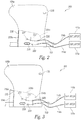
- FIG 2 is a front view of an airbag assembly 200 including a first airbag 108a configured in accordance with an embodiment of the present technology.
- the first airbag 108a is secured to the lap belt 103 via first stitching 228 (e.g., "racetrack” stitching) or other suitable fasteners.
- a second airbag 224a is sewn into the interior of the first airbag 108a.
- the first and second hoses 114a, 114b enter the first airbag 108a through a first opening 226 (e.g., a slit).
- the first hose 114a is attached to the inside of the first airbag 108a with second stitching 229 or other suitable fasteners.
- the second hose 114b enters the second airbag 224a through a second opening 227 (e.g., a slit) in the second airbag 224a, and is attached to the inside of the second airbag 224a with third stitching 231 or other suitable fasteners.
- the first and second hoses 114a, 114b provide gas from the inflators 111a and 111b to deploy the first airbag 108a and the second airbag 224a, respectively.
- the second airbag 224a can be sewn to the first airbag 108a with fourth stitching 233a, forming one or more common seams 230 (e.g., perimeter seams).
- the common seams 230 close and seal both the first airbag 108a and the second airbag 224a.
- the first inflator 111a inflates the first airbag 108a in response to a rapid deceleration event in a conventional manner.
- the second inflator 111b is initiated to inflate and over-pressurize the second airbag 224a.
- the second airbag 224a is inflated until one or more of the common seams 230 rupture (e.g., fail, tear apart, release, or open) to rapidly deflate the first airbag 108a and reduce occupant rebound from the first airbag 108a.
- the electronics assembly 112 can transmit a signal to the second inflator 111b to initiate the second inflator 111b after the first inflator 111a deploys the first airbag 108 (e.g., airbag 108a).
- the electronics assembly 112 can stagger the first and second inflator signals by a period of time from about 100ms to 200ms, 100ms to 180ms, 100ms to 172ms, about 120ms, or about 130ms, and/or any value therebetween.
- the electronics assembly 112 can transmit the second signal to the second inflator 111b to initiate second airbag inflation based on various other criteria, such as the internal pressure of the first airbag 108a (e.g., reaching a predetermined level).
- the airbag 108 can include one or more pressure sensors 235 (shown schematically) to sense and provide internal pressure information to the electronics assembly 112.
- the electronics assembly 112 can be configured to transmit the second signal to initiate second airbag inflation when the internal pressure reaches a predetermined level.
- other sensors e.g., accelerometers, displacement sensors, etc.
- the electronics assembly 112 can be configured to transmit the second signal to initiate second airbag inflation when, for example, the occupant reaches a predetermined level of acceleration or a position relative to the seat 102.
- the electronics assembly 112 can be configured to transmit the second signal to the second inflator 111b to initiate the second inflator 111b based on a preset or predetermined time period after initial deployment of the first airbag 108a.
- Figure 3 is a front view of an airbag assembly 300 including a first airbag 108b configured in accordance with another embodiment of the present technology.
- the embodiment of Figure 3 is substantially similar to the embodiment of Figure 2 , however, in this embodiment, a second airbag 224b is not sewn at a common seam 230 ( Figure 2 ) that seals both airbags. Instead, the second airbag 224b is sewn to the first airbag 108b with a seam 332 in such a way that the seam 332 only seals the first airbag 108b.
- the seam 332 is sewn through the first airbag 108b and the second airbag 224b with a fourth stitching 233b.
- the second airbag 224b includes an interior portion 334a disposed inside the first airbag 108b and an exterior portion 334b disposed outside the first airbag 108b.
- the exterior portion 334b extends from the first airbag 108b through the seam 332.
- the second airbag 224b is inflated momentarily after the first airbag 108b is inflated in a similar manner as described above with reference to Figure 2 .
- the second airbag 224b (e.g., the interior portion 334a) is inflated until the seam 332 ruptures (e.g., fails, tears apart, releases, or opens) to rapidly deflate the first airbag 108b and reduce occupant rebound from the first airbag 108b.
- the second airbag 224b remains inflated because the ruptured seam 332 does not release gas from the second airbag 224b.
- Such a configuration allows the second airbag 224b to be reusable because the airbag assembly of Figure 3 is designed to rupture the seam 332 upon inflation without tearing the second airbag 224b, instead of rupturing the seal of both airbags apart at a common seam 230 as in the embodiment of Figure 2 .
- Figure 4A is a front view of an airbag assembly 400 including an airbag 108c configured in accordance with another embodiment of the present technology
- Figure 4B is an enlarged view of a portion of the airbag 108c taken from Figure 4A .
- a second airbag within the airbag 108c is not required.
- a seam 436 sews airbag material panels together around a perimeter of the airbag 108c.
- the seam 436 includes a first seam portion 437a and a second seam portion 437b.
- the first seam portion 437a is sewn over the second hose 114b to secure the second hose 114b to the interior of the airbag 108c such that the second hose 114b is positioned or sandwiched between the airbag material panels.
- the first seam portion 437a can be sewn with a first stitching type 438 (e.g., a lock stitch).
- the first stitching type 438 is configured to have sufficient strength to sew the airbag material panels to the second hose 114b, yet weak enough to tear apart upon inflation of the second air hose 114b to release the first seam portion 437a. As described in further detail below, releasing the first seam portion 437a rapidly deflates the airbag 108c and reduces occupant rebound from the airbag 108c.
- the airbag material panels can be sewn together along the second seam portion 437b (e.g., the remaining portion of the seam 436 away from the second hose 114b) with a second stitching type 440 (e.g., a chain stitch).
- the second stitching type 440 is configured to be relatively "forgiving" to sew the airbag material panels together along curved portions of the second seam portion 437b.
- the first seam portion 437a extends past an end portion of the second hose 114b, forming a third seam portion 442 (e.g., a transition portion) that is sewn with the first stitching type 438.
- the third seam portion 442 is not sewn or attached directly to the second hose 114b and is positioned between the first seam portion 437a and second seam portion 437b.
- the third seam portion 442 extends from the end portion of the second hose 114b to a stopper 448 (as indicated by the "X" in Figure 4B ) on the seam 436.
- the stopper 448 at the end of the third portion 442 can provide a stop or end point to limit a tear or rupture of the first seam portion 437a.
- the second hose 114b can be sewn partially or substantially shut by a stitching 444 or other suitable fastener before one or more diffuser holes 446 in the second hose 114b.
- the partial closure of the second hose 114b limits the amount of gas escaping through the diffuser holes 446 so that the second hose 114b inflates more rapidly and, therefore, the more rapidly rupturing the first seam portion 437a.
- the second hose 114b is not completely sewn shut by the stitching 444, as this could cause undue pressure in the second hose 114b when inflated, causing the second hose 114b to fail.
- the stitching 444 allows a relatively small amount of gas to seep or leak through the stitching 444 out the diffuser holes 446. Due to the more rapid inflation of the second hose 114b caused by the partially closed stitching 44, the second inflator 111b that inflates the second hose 114b can be smaller relative to the first inflator 111a (i.e., hold less compressed gas within the second inflator 111b than is held in the first inflator 111a) because less gas is needed to inflate the second hose 114b and rupture the first seam portion 437a.
- the end portion of the second hose 114b can also be oriented or angled such that none or few of the diffuser holes 446 are directed inwardly toward the interior of the airbag 108c.
- the diffuser holes 446 can be directed toward the interior of the airbag 108c, while the remaining diffuser holes 446 are directed outwardly away from the interior of the airbag 108c. Orienting the second hose 114b in this manner reduces the amount of gas released back into the airbag 108c from the diffuser holes 446 when the first seam portion 437a is ruptured or released.
- the second hose 114b can also be attached to the airbag 108c via one or more secondary fasteners 449 (e.g., stitching, clips, or other suitable fasteners) to prevent the second hose 114b from ripping away or separating from the airbag 108c after the first seam portion 437a is released as described in more detail below.
- secondary fasteners 449 e.g., stitching, clips, or other suitable fasteners
- the second inflator 111b is initiated momentarily after deployment of the airbag 108c to inflate the second hose 114b.
- the second hose 114b inflates, it releases the first seam portion 437a (e.g., by rupturing or tearing apart the first stitching type 438) to rapidly deflate the airbag 108c.
- the release of the first seam portion 437b forms an opening (e.g., vent) in the airbag 108c that propagates to the ends of the first seam portion 437a. Accordingly, the length of the first seam portion 437a can affect the rate of deflation and/or amount of venting of the airbag 108c.
- the stopper 448 at the end of the third seam portion 442 can prevent further propagation of the opening or vent formed by the first seam portion 437a. For example, if the opening created by the first seam portion 437a continues to propagate past an end portion of the second hose 114b, further propagation is ceased at the stopper 448.
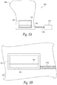
- Figures 5A is a front view of an airbag assembly 500 with an airbag 108d configured in accordance with another embodiment of the present technology
- Figure 5B is an enlarged view of a portion of the airbag 108d taken from Figure 5A
- the airbag assembly 500 incudes a first inflator and a first hose that inflate an airbag 108d upon detection of a crash event (e.g., as described above with respect to Figures 1A-4B .
- the airbag assembly 500 includes only one airbag 108d.
- a patch 552 is secured to the airbag 108d over a vent slit 554 (e.g., an opening) in the airbag 108d to prevent or reduce gas from escaping the airbag 108d through the vent slit 554 during inflation.
- the second hose 114b is sandwiched between a portion of the patch 552 (e.g., a perimeter portion of the patch 552) and the airbag 108d.
- the airbag 108d, the perimeter portion of the patch 552, and the second hose 114b can be stitched together along a seam 550 and/or otherwise attached to each other.
- the airbag assembly 500 illustrated in Figures 5A and 5B can include one or more of any of the features with respect to any of the other embodiments described herein, in whole or in part.
- an end portion of the second hose 114b can be sewn partially shut upstream of one or more diffuser holes to increase the rate of inflation of the second hose 114b and/or allow the use of a relatively smaller second inflator.
- FIG. 6A Operation of the airbag assembly 500 of Figures 5A and 5B is illustrated in the series of partially schematic side views of Figures 6A-6C , which show various stages of inflation of the second hose 114b.
- the patch 552 is sewn shut over the vent slit 554 to prevent or reduce gas from escaping the airbag 108d through the vent slit 554 during airbag inflation.
- the second hose 114b is inflated, as shown in Figure 6B , the pressure of the expanded second hose 114b ruptures (e.g., tears apart) at least a portion of the seam 550 that attaches the patch 552 to the airbag 108d.
- the patch 552 lifts away from the airbag 108d to allow gas to escape from the vent slit 554 and rapidly deflate airbag 108d (as indicated by arrow G in Figure 6C ).
- the gas can escape through the vent slit 554 at any time after a portion of the seam 550 has ruptured, including while the second hose 114b is expanding ( Figure 6B ) and after the second hose 114b has deflated ( Figure 6C ; e.g., after releasing the gas from the second inflator 11b ( Figure 5A )).
- FIG. 7A and 7B illustrate the airbag 108d of Figures 5A and 5B in stowed and deployed configurations, respectively, according to certain embodiments of the present technology.
- the broken lines in Figure 7A indicate the inflated airbag 108d in the deployed configuration.
- a deployed length of the second hose 114b can be stowed inside or outside the airbag 108d.
- a fabric tube 756 disposed partially outside the airbag 108d can house a portion of the second hose 114b, and a portion of the second hose 114b can be stored inside the airbag 108d in the stowed configuration with one or more induced bends 758 (e.g., folds or coils).
- the bends 758 in the portion of the second hose 114b stored inside the airbag 108d enable the second hose 114b to unfold as the airbag 108d deploys without applying unnecessary stress on the seam 550 and/or the second inflator 111b.
- the second hose 114b could inadvertently apply a tension force F during, for example, deployment of the airbag 108d.
- Insufficient slack in the second hose 114b may also apply undue force F during assembly and transportation of the airbag assembly 500.
- the force F can cause inadvertent tearing of the seam 550 and premature deflation of the airbag 108d.
- this may cause the second hose 114b to pull on and initiate the second inflator 111b, causing inadvertent inflation of the second hose 114b.
- Positioning the second hose 114b within the airbag 108d may also inhibit binding that could occur during deployment of the airbag 108d if the second hose 114b were folded outside of the airbag 108d or within the fabric tube 756.
- Figures 8A-8C are a series of top cross-sectional views illustrating a method of folding and storing the second hose 114b within the airbag 108d of Figures 5A and 5B .
- a pulling force in the direction of arrow G can be applied to an end portion of the second hose 114b to pull the second hose 114b into position inside the airbag 108d.
- one or more folds, bends and/or coils 858 can be induced in the second hose 114b and the airbag 108d by pushing a portion of the airbag 108d adjacent to the second hose 114b inwardly in the direction of arrow H.
- the airbag 108d and the second hose 114b can then be collapsed together with a downward force in the direction of arrow I as shown in Figure 8C .
- the airbag 108d is then ready to be further assembled, stowed in a cover, and/or secured to the lap belt 103 ( Figure 1A ), a shoulder web, a seat back, a divider wall, a surrounding monument, and/or other structure.
- one or more stitches 859 and/or other fasteners can be used to temporarily secure the second hose 114b to itself and maintain the at least one fold, coil and/or bend 858 in the second hose 114b when in the stowed or undeployed configuration.
- the stitches 859 can be configured to break as the airbag 108d is deployed. This can prevent the second hose 114b from sliding or being pulled out of the airbag 108d and into, for example, the fabric tube 756 prior to deployment of the airbag 108d (e.g., during transportation, assembly, and/or installation of the airbag 108d).
- FIG. 9A is an enlarged view of a portion of an airbag assembly 900a including an airbag 108e configured in accordance with another embodiment of the present technology.
- the airbag 108e can include a vent or seam 954 sewn together by stitching 960 (e.g., a single threaded chain stitch in which only one loop must fail to open the seam 954).
- the seam 954 is configured to be released without a second inflator, a second hose, and/or a second airbag.
- the airbag assembly 900a can include a release mechanism 961 (shown schematically) operably coupled an end portion 960a of the stitching 960 to release the seam 954 and, thereby, open the seam 954 to release gas from the airbag 108e.
- the release mechanism 961 may be a pull cord, a solenoid spool valve, a spring-loaded mechanism, an automatic retractor spool, and/or other suitable mechanical release device attached to an end portion 960a of the stitching 960
- a single inflator 111a (not shown; Figure 1A ) can be used to inflate the airbag 108e in a conventional manner, and then a pull force F can be applied to a free end portion 960a of the stitching 960 by the release mechanism 961 that extends outside the airbag 108e. This causes the stitching 960 to unravel and/or rupture and release the seam 954 to rapidly deflate the airbag 108e after initial deployment.
- the pull force F can be applied by a pull cord or other mechanical device attached to the end portion of the stitching 960.
- the release mechanism 961 can be operably coupled to the electronics assembly 112 ( Figure 1A ) such that the electronics assembly 112 can transmit a signal to, for example, an actuator or other device to activate the release mechanism 961.
- the signal from the electronics assembly 112 can activate an actuator to release a pull cord or a spring-loaded mechanism to apply force F and release the stitching 960 after inflating the airbag 108e.
- a second electronics assembly (not shown) can be configured to transmit a signal to an actuator to activate the pull cord or release a spring-loaded mechanism shortly after a first electronics assembly 112 ( Figure 1A ) transmits a signal to inflate the airbag 108e.
- the pull force F can be applied by an impact of an occupant against the deployed airbag 108e (e.g., as described in more detail below with respect to the embodiment of Figure 9B ).
- Figure 9B is a top cross-sectional view of an airbag assembly 900b including an airbag 108f that is at least substantially similar to the airbag 108e of Figure 9A .
- a portion 964 of the thread from the stitching 960 e.g., the portion that is not holding the seam 954 closed
- an opening 962 e.g., a cut-out, an eyelet, etc.
- the thread portion 964 is attached (e.g., fixed or secured by stitching 963, other fasteners, etc.) to a second side of the airbag 108f opposite the first side, so that the thread portion 964 extends between the first and second sides across an interior face of the airbag 108f facing or directed towards the occupant 101 ( Figure 1A )).
- the thread portion 964 is drawn inward in tension (e.g., as indicated by arrow F and the broken lines 965). This causes the stitching 960 to undo or unravel and release the seam 954, as described above.
- timing of the venting can be controlled by the amount of slack in the thread portion 964. For example, if the length of the thread portion 964 is increased, the slack is increased requiring an increased displacement D in the direction of arrow F to release the seam 954 relative to a shorter length thread portion 964. Accordingly, using longer thread portions 964 results in an increased time interval or period to release the seam 954 after the airbag 108f is deployed as compared to shorter thread portions 964.
- Figure 10A is an isometric view of an airbag assembly 1000 including an airbag 108g configured in accordance with another embodiment of the present technology.
- Figure 10B is an enlarged view of a patch 1052 sewn over a vent slit 1054 (e.g., opening) in the airbag 108g of Figure 10A .
- This embodiment includes certain features at least substantially similar to the features of the airbag assemblies 900a and 900b of Figures 9A and 9B .
- a first stitching type 1060 secures a portion 1053 of the patch 1052 (e.g., a side portion of the patch 1052) over the vent slit 1054 instead of directly sewing a vent seam together (e.g., as in the airbag embodiments of Figures 9A and 9B ).
- the first stitching type 1060 can be unraveled to release the portion 1053 of the patch 1052 and expose the vent slit 1054, thereby allowing gas to escape through the vent slit 1054 to rapidly deflate the airbag 108g.
- a second stitching type 1066 e.g., double needle chain stitches.
- the second stitching type 1066 keeps the patch 1052 at least partially secured to the airbag 108g after the first stitching type 1060 is unraveled.
- the thread that forms the first stitching type 1060 can include an extension portion 1065 that extends through an opening 1062 ( Figure 10A ; e.g., a cut-out or pass-through) on a first side or portion 1067a of the airbag 108g.
- the thread extension portion 1065 can extend across an interior portion of the airbag 108g and be attached (e.g., fixed or secured) to an attachment point 1066 on a second side or portion 1067a of the airbag 108g opposite the first portion 1067a.
- the occupant strikes and compresses a panel 1069 of the airbag 108g (as shown by arrow F in Figure 10A ).
- This compression of the airbag 108b displaces the thread extension portion 1065 and places the thread extension portion 1065 in tension.
- the tension on the thread extension portion 1065 pulls and unravels the first stitching type 1060 to release the patch 1052. This allows gas to escape out of the vent slit 1054 to rapidly deflate the airbag 108g.
- the airbag assembly 1000 includes a pull cord or other suitable mechanical release mechanism operably coupled to a free end portion of the first stitching type 1060 that extends outside of the airbag 108g.
- the release mechanism is activated to pull on the free end portion and unravel the first stitching type 1060 to release the patch 1052.
- the airbag 108g includes a cut-out or opening 1063 in the airbag 108g adjacent or proximate to the patch 1052.
- the thread extension portion 1065 that extends beyond the patch 1062 includes at least one loop or thread portion 1061 of the first stitching type 1060 that is not attached (e.g., sewn) to the airbag 108g.
- the thread portion 1061 can extend off of, out of, and/or away from the airbag 108g through the opening 1063, thereby allowing the thread extension 1065 to "float" within the airbag 108g (through the opening 1063) or extend outside the airbag 108g.
- the first stitching type 1060 would have to continue to be sewn from the patch 1052 to an edge or side panel or face of the airbag 108g. This could result in a perimeter seam that attaches the airbag material panels together being sewn through the first stitching type 1060 (if the first stitching type continued on the airbag 108g from the patch 1052 to an edge or side portion of the airbag 108g), and may prevent unraveling of the first stitching type 1060 to release the patch 1052. Accordingly, the floating thread portion 1061 removes the possibility of the perimeter stitching interfering with the active vent of the airbag 108g.
- the thread portion 1061 can be crimped. Crimping the thread portion 1061 can prevent the first stitching type 1060 from being inadvertently pulled and unraveled as the airbag 108g is assembled and/or during deployment.
- the crimped thread portion 1061 can be configured to withstand (e.g., sufficiently strong to not unravel or release in response to) forces applied during assembly or deployment of the airbag 108g, yet fragile enough to be released or unraveled in response to tension applied to the thread extension 1065 by an occupant striking the airbag 108g or a release mechanism (e.g., pull cord). Any of the features described with reference to the embodiment of Figure 10B can be applied or included in the airbag assemblies 900a and 900b described above with reference to Figures 9A and 9B .
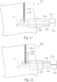
- Figures 11 and 12 are front views of airbag assemblies 1100 and 1200 including airbags 108h and 108i, respectively, configured in accordance with other embodiments of the present technology.
- the airbag assemblies 1100 and 1200 of Figures 11 and 12 include certain features substantially similar to the features of the airbag assemblies 900a and 900b of Figures 9A and 10B , respectively.
- a second inflator 1111b and a second hose 1114b are configured to directly release a stitched vent seam 1154 ( Figure 11 ) in the airbag 108h, or release a stitched patch 1252 ( Figure 12 ) covering a vent 1254 ( Figure 12 ) on the airbag 108i.
- stitching 1160 sews the vent seam 1154 or other opening closed on the airbag 108h.
- the stitching 1160 can be sewn to an end portion of the second hose 1114b (as indicated by arrow S), such that the stitching 1160 extends (e.g., starts or originates) from the second hose 1114b (or beyond the second hose 1114b).
- the stitching 1160 then continues from the second hose 1114b onto the airbag 108h to an end portion of the airbag 108h to sew the vent seam 1154 closed.
- the stitching 1160 attached to the second hose 1114b is configured to rupture upon inflation of the second hose 1114b to release the stitching 1160 and vent seam 1154.
- the stitching 1160 attached to the second hose 1114b is configured to rupture upon inflation of the second hose 1114b to release the stitching 1160 and vent seam 1154.
- internal pressure increases within the second hose 1114b that results in a force being applied on an end portion of the stitching 1160. This force ruptures the stitching 1160 to release the vent seam 1154.
- the stitching 1260 sews a patch 1252 over the vent 1254.
- the stitches 1260 can be sewn to the second hose 1114b and ruptured and released upon inflation of the second hose 1114b. This releases at least a portion of the patch 1252 from the airbag 108i, which allows gas to escape from the vent seam 1254 and rapidly deflate the airbag 108i to prevent or reduce occupant rebound.
- certain embodiments of the present technology may include a crimped end portion of the stitching 1160, 1260 and/or including an opening (not shown) through which the stitching 1160, 1260 can be threaded such that it is spaced apart or off from the airbag to prevent inadvertently releasing the stitching or sewing the stitching to the airbag with perimeter seams.
- the airbags assemblies 1100 and 1200 of Figures 11 and 12 do not include crimped end portions or additional opening to prevent or reduce the potential for inadvertently releasing the stitching during assembly, construction, and/or deployment of the airbag.
- an end portion (e.g., a loop or thread portion) of the stitching 1160 sewn to the second hose 1114b can be sewn to the second hose 1114b, and not secured directly to the airbag 108h.
- the stitching 1160 can first be sewn to the second hose 1114b, and then the second hose 1114b (with the stitching 1160) can then be inserted into the airbag 108h such that a portion of the stitching 1160 attached to the second hose 1114b is free or "floating" within the airbag 108h.
- the other end portion of the stitching 1160 can then continue to be sewn to close the vent seam 1154 or patch 1252 ( Figure 12 ) and to a portion (e.g., an edge or side portion of a panel or face) of the airbag 108h.
Landscapes
- Engineering & Computer Science (AREA)
- Mechanical Engineering (AREA)
- Physics & Mathematics (AREA)
- Fluid Mechanics (AREA)
- Business, Economics & Management (AREA)
- Emergency Management (AREA)
- Aviation & Aerospace Engineering (AREA)
- Air Bags (AREA)
Claims (15)
- Système d'évacuation de coussin de sécurité gonflable actif (110, 200, 300, 400, 500, 800a, 900b, 1000, 1100, 1200), comprenant:un coussin de sécurité gonflable (108, 108a, 108b, 108c, 108d, 108e, 108f, 108g, 108h, 108i, 224a, 224b) ayant une ouverture active;un premier dispositif de gonflage (111a, 1111a);un second dispositif de gonflage (111b, 1111b);un premier tuyau (114a, 11114a) raccordant de manière opérationnelle le premier dispositif de gonflage (111a, 1111a) au coussin de sécurité gonflable (108, 108a, 108b, 108c, 108d, 108e, 108f, 108f, 108g, 108h, 108h, 108i, 224a, 224b), le déclenchement du premier dispositif de gonflage (111 a, 1111 a) libérant un gaz dans le coussin de sécurité gonflable (108, 108a, 108b, 108c, 108d, 108e, 108f, 108f, 108g, 108h, 108i, 224a, 224b) du premier dispositif de gonflage (111a, 1111a) par le premier tuyau (114a, 11114a) pour gonfler le coussin de sécurité gonflable (108, 108a, 108b, 108c, 108d, 108f, 108g, 108h, 108i, 224a, 224b); etcaractérisé en ce queun second tuyau flexible (114b, 1114b) raccordant de manière opérationnelle le second dispositif de gonflage (111b, 1111b) à l'évent actif, l'évent actif restant fermé pendant le gonflage initial du coussin de sécurité gonflable (108, 108a, 108b, 108c, 108d, 108e, 108f, 108f, 108g, 108h, 108i, 224a, 224b) via le premier tuyau (114a, 11114a),et dans lequel l'initiation du second dispositif de gonflage (111b, 1111b) après le gonflage initial du coussin de sécurité gonflable (108, 108a, 108b, 108c, 108d, 108e, 108f, 108g, 108h, 108i, 224a, 224b) libère du gaz dans le second tuyau (114b, 1114b) pour ouvrir l'évent actif et réduire la pression dans le coussin de sécurité gonflable (108, 108a, 108b, 108c, 108d, 108e, 108f, 108g, 108h, 108i, 224a, 224b).
- Système d'évacuation de coussin de sécurité gonflable actif selon la revendication 1, comprenant en outre:un ensemble électronique (112) couplé de manière communicative aux premier et second dispositif de gonflages (111b, 1111b), dans lequel l'ensemble électronique (112) est configuré pour transmettre un premier signal au premier dispositif de gonflage (111a, 1111a) afin de déclencher le déploiement du coussin de sécurité gonflable (108, 108a, 108b, 108c, 108d, 108e, 108f, 108g, 108h, 108i, 224a, 224b),l'ensemble électronique est en outre configuré pour transmettre un second signal au second dispositif de gonflage (111b, 1111 b) afin de déclencher le second dispositif de gonflage (111b, 1111b), etle second signal est transmis après une période de temps prédéterminée après le premier signal, le déclenchement du premier dispositif de gonflage (111a, 1111a), un événement de décélération rapide ou le déploiement du coussin de sécurité gonflable (108, 108a, 108b, 108c, 108d, 108e, 108f, 108g, 108h, 108i, 224a, 224b).
- Système d'évacuation de coussin de sécurité gonflable actif selon la revendication 1, comprenant en outre:un ensemble électronique (112) couplé de manière communicative aux premier et second dispositif de gonflages (111b, 1111b), dans lequel l'ensemble électronique (112) est configuré pour transmettre un premier signal au premier dispositif de gonflage (111a, 1111a) afin de déclencher le déploiement du coussin de sécurité gonflable (108, 108a, 108b, 108c, 108d, 108e, 108f, 108g, 108h, 108i, 224a, 224b),l'ensemble électronique (112) est en outre configuré pour transmettre un second signal au second dispositif de gonflage (111b, 1111b) afin de déclencher le second dispositif de gonflage (111b, 1111b), etle second signal est transmis en réponse à une position d'un occupant de siège (D1) par rapport à au moins l'un des coussins de sécurité gonflables (108, 108a, 108b, 108c, 108d, 108e, 108f, 108g, 108h, 108h, 108i, 224a, 224b), un siège (102) ou un obstacle entourant l'occupant de siège (101).
- Système d'évacuation de coussin de sécurité gonflable actif selon la revendication 1, comprenant en outre:un ensemble électronique (112) couplé de manière communicative aux premier et second dispositif de gonflages (111b, 1111b), dans lequel l'ensemble électronique (112) est configuré pour transmettre un premier signal au premier dispositif de gonflage (111a, 1111a) afin de déclencher le déploiement du coussin de sécurité gonflable (108, 108a, 108b, 108c, 108d, 108e, 108f, 108g, 108h, 108i, 224a, 224b), etl'ensemble électronique (112) est en outre configuré pour transmettre un second signal au second dispositif de gonflage (111b, 1111b) afin de déclencher le second dispositif de gonflage (111b, 1111b); etun capteur de pression (235) configuré pour détecter la pression interne du coussin de sécurité gonflable (108, 108a, 108b, 108c, 108d, 108e, 108f, 108g, 108h, 108i, 224a, 224b), dans lequel l'ensemble module électronique (EMA) est configuré pour transmettre le second signal lorsque la pression interne atteint un niveau prédéterminé.
- Système d'évacuation de coussin gonflable actif selon la revendication 1, dans lequel le coussin de sécurité gonflable (108a) est un premier coussin de sécurité gonflable (108a),
et dans lequel le système d'évacuation de coussin de sécurité gonflable actif (200) comprend en outre:un second coussin de sécurité gonflable (224b) à l'intérieur du premier coussin de sécurité gonflable (108, 108a, 108b), dans lequel le second tuyau flexible (114b) relie le second dispositif de gonflage (1111b) au second coussin de sécurité gonflable (224b) pour délivrer le gaz du second dispositif de gonflage (1111b) au second coussin de sécurité gonflable (224b) lorsque le second dispositif de gonflage (111b, 1111b) est activé, et dans lequel le second dispositif de gonflage (111b, 1111b) est configuré pour surgonfler le second coussin de sécurité gonflable (224b) ; etune couture (230) scellant une partie du premier coussin de sécurité gonflable (108, 108a, 108b) et une partie du second (224b) pendant le gonflage initial du premier coussin de sécurité gonflable (108, 108a, 108b), dans lequel la couture (230) est configurée pour se rompre lors du gonflage du second coussin de sécurité gonflable (224b). - Système d'évacuation de coussin gonflable actif selon la revendication 1, dans lequel le coussin de sécurité gonflable (108a) est un premier coussin de sécurité gonflable (108a),
et dans lequel le système d'évacuation de coussin de sécurité gonflable actif (300) comprend en outre:un second coussin de sécurité gonflable au moins partiellement à l'intérieur du premier coussin de sécurité gonflable, dans lequel le second tuyau flexible (114b, 1114b) relie le second dispositif de gonflage (111b, 1111b) au second coussin de sécurité gonflable pour délivrer le gaz du second dispositif de gonflage (111b, 1111b) au second coussin lorsque le second dispositif de gonflage (1111b) est activé; etune couture (332) reliant le premier coussin de sécurité gonflable (108, 108a, 108b) au second coussin de sécurité gonflable (224b),dans laquelle la couture (332) scelle une partie du premier coussin de sécurité gonflable (108, 108a, 108b) fermé pendant le gonflage initial du premier coussin de sécurité gonflable (224b),la couture (332) est configurée pour se rompre lors du gonflage du second coussin de sécurité gonflable (224b), etle second coussin de sécurité gonflable (224b) est configuré pour rester scellé après rupture de la couture (332),dans laquelle, de préférence, le second coussin de sécurité gonflable (224b) comprend une partie intérieure disposée à l'intérieur du premier coussin de sécurité gonflable (108, 108a, 108b) et une partie extérieure disposée à l'extérieur du premier coussin de sécurité gonflable (108, 108a, 108b). - Système d'évacuation de coussin de sécurité gonflable actif selon la revendication 1, comprenant en outre:une première partie de couture (437a) fixant le second tuyau (114b) à une partie interne du coussin de sécurité gonflable (108c); etune seconde partie de couture (437b) fixant des panneaux du coussin de sécurité gonflable (108c) ensemble, dans lequel la seconde partie de couture (437b) est configurée pour sceller les panneaux du coussin de sécurité gonflable (108c) ensemble après le déclenchement des premier (111a) et second (111b) dispositifs de gonflage, etdans laquelle la première partie de couture (437a) comprend un premier type de suture (438) configuré pour sceller le coussin de sécurité gonflable (108c) pendant le gonflage du coussin de sécurité gonflable (108c) via le premier dispositif de gonflage (111a) etconfiguré pour se rompre lors du gonflage du second tuyau (114b), dans lequel la rupture de la première partie de couture (437a) libère du gaz à partir du coussin de sécurité gonflable (108c).
- Système d'évacuation de coussin de sécurité gonflable actif selon la revendication 1, comprenant en outre:une fente d'évacuation (554) dans le coussin de sécurité gonflable (108d);un patch (552) au-dessus de la fente d'évacuation (554), dans lequel le patch (552) est configurée pour sceller le coussin de sécurité gonflable (108d) pendant le gonflage initial du coussin de sécurité gonflable (108d) via le premier dispositif de gonflage (111a) ; et une couture (550) reliant le patch (552) au second tuyau (114b) et au matériau du coussin de sécurité gonflable (108d), le second tuyau (114b) étant disposé entre le patch (552) etle matériau du coussin de sécurité gonflable (108d), et dans lequel au moins une partie de la couture (550) est configurée pour se rompre lors du gonflage du second tuyau (114b) pour libérer du gaz à partir du coussin de sécurité gonflable (108d) via la fente d'évacuation (554).
- Système d'évacuation de coussin de sécurité gonflable actif selon la revendication 1, comprenant en outre:une couture d'évacuation (1154) dans le coussin de sécurité gonflable (108d); etune suture (1160) cousue sur la couture d'évacuation (1154) et sur une partie d'extrémité du second tuyau (1114b), dans lequel la suture (1160) se termine ou commence à la partie d'extrémité du second tuyau (1114b), et dans lequel la suture (1160) est configurée pour rompre lors du gonflage du second tuyau (1114b) et libérer du gaz à partir de la couture d'évacuation (1154).
- Système d'évacuation de coussin de sécurité gonflable actif selon la revendication 1, comprenant en outre:une fente d'évacuation (1254) dans le coussin de sécurité gonflable (108i);un patch (1252) au-dessus de la fente d'évacuation (1254); etune suture (1160, 1260) configurée pour fermer le patch (1252) au-dessus de la fente d'évacuation (1254) et ayant une extrémité à une partie d'extrémité du second tuyau (114b, 1114b), dans laquelle la suture (1160, 1260) est configurée pour se rompre lors du gonflage du second tuyau (1114b) afin de libérer une partie du patch (1252) et permettre au gaz de s'échapper de la couture d'évacuation (1154).
- Procédé d'évacuation d'un coussin de sécurité gonflable, le procédé comprenant les opérations suivantes:détecter un événement de collision avec un ensemble électronique (112) d'un système de coussin de sécurité gonflable (110, 200, 300, 400, 500, 900a, 900b, 1000, 1100, 1200);envoyer un premier signal à partir de l'ensemble électronique (112) pour déclencher un premier dispositif de gonflage (111a, 1111a), dans lequel le déclenchement du premier dispositif de gonflage (111a, 1111a) gonfle un coussin de sécurité gonflable (108, 108a, 108b, 108c, 108d, 108e, 108f, 108g, 108h, 108h, 108i, 224a, 224b); etenvoyer un second signal à partir de l'ensemble électronique (112) pour déclencher un second dispositif de gonflage (111b, 1111b), dans lequel le second signal est transmis après le premier signal, dans lequel le déclenchement du second dispositif de gonflage (111b, 1111b) gonfle un tuyau (114b, 1114b), et dans lequelle gonflage du tuyau (114b, 1114b) ouvre un évent pour réduire la pression dans le coussin de sécurité gonflable (108, 108a, 108b, 108c, 108d, 108e, 108f, 108g, 108h, 108i, 224a, 224b)caractérisé en ce que le second signal est transmis après détection d'une pression interne dans le coussin de sécurité gonflable au-dessus d'un niveau prédéterminé.
- Procédé selon la revendication 11, dans lequel le coussin de sécurité gonflable est un premier coussin de sécurité gonflable et le procédé comprend en outre les opérations suivantes:
gonfler, par l'intermédiaire du second dispositif de gonflage (111 b, 1111 b), un second coussin de sécurité gonflable (224b) dans le premier coussin de sécurité gonflable (108a), dans lequel le gonflage du second coussin de sécurité gonflable (224b) provoque une couture (220, 332, 436, 550, 954, 1154) qui ferme le premier sac gonflable devant se rompre. - Procédé selon la revendication 11, dans lequel une première partie de couture (437a) fixe le tuyau (114b) à une partie interne du coussin de sécurité gonflable (108c) et une seconde partie de couture (437b) scelle une partie restante du coussin de sécurité gonflable (108c) ensemble, et dans lequel le gonflage du tuyau (114b) rompt la première partie de couture (437a) pour former la fente d'évacuation et libérer du gaz à partir du coussin de sécurité gonflable (108c).
- Procédé selon la revendication 11, dans lequel l'évent comprend une fente d'évacuation (554) recouverte d'un patch (552), dans lequel le gonflage du tuyau (114b) rompt une couture (550) reliant le patch (552) au tuyau (114b) et au coussin de sécurité gonflable (108c).
- Procédé selon la revendication 11, dans lequel l'évent comprend une couture d'évacuation (1154) fermée par une suture (1160), dans lequel la suture (1160) est fixée à une partie d'extrémité du tuyau (1114b), et dans lequel le gonflage du tuyau (114b) rompt la suture (1160) pour libérer la suture (1160) de la couture d'évacuation (1154).
Applications Claiming Priority (2)
| Application Number | Priority Date | Filing Date | Title |
|---|---|---|---|
| US201562146268P | 2015-04-11 | 2015-04-11 | |
| PCT/US2016/026987 WO2016168124A1 (fr) | 2015-04-11 | 2016-04-11 | Système d'évacuation de coussin de sécurité gonflable actif |
Publications (3)
| Publication Number | Publication Date |
|---|---|
| EP3283336A1 EP3283336A1 (fr) | 2018-02-21 |
| EP3283336A4 EP3283336A4 (fr) | 2018-09-26 |
| EP3283336B1 true EP3283336B1 (fr) | 2019-11-20 |
Family
ID=57111699
Family Applications (1)
| Application Number | Title | Priority Date | Filing Date |
|---|---|---|---|
| EP16780522.5A Active EP3283336B1 (fr) | 2015-04-11 | 2016-04-11 | Système d'évacuation de coussin de sécurité gonflable actif |
Country Status (6)
| Country | Link |
|---|---|
| US (1) | US9925950B2 (fr) |
| EP (1) | EP3283336B1 (fr) |
| JP (1) | JP2018515381A (fr) |
| CN (1) | CN107428308A (fr) |
| SG (1) | SG11201708221UA (fr) |
| WO (1) | WO2016168124A1 (fr) |
Families Citing this family (7)
| Publication number | Priority date | Publication date | Assignee | Title |
|---|---|---|---|---|
| DE102014200252A1 (de) * | 2014-01-09 | 2014-04-10 | Takata AG | Gassackanordnung und Verfahren zur Herstellung einer Gassackanordnung |
| DE102017108404B4 (de) * | 2017-04-20 | 2020-06-18 | Webasto SE | Elektrische Heizeinrichtung |
| US11235731B2 (en) | 2017-10-05 | 2022-02-01 | Autoliv Development Ab | Airbag device |
| US10889257B2 (en) * | 2019-02-27 | 2021-01-12 | Ford Global Technologies, Llc | Vehicle seat assembly |
| US11180103B2 (en) | 2019-10-28 | 2021-11-23 | Autoliv Asp, Inc. | Frontal airbag systems |
| US11390232B2 (en) | 2019-10-31 | 2022-07-19 | ZF Passive Safety Systems US Inc. | Vehicle safety systems including inflatable seatbelt restraint |
| US11691586B2 (en) | 2021-05-06 | 2023-07-04 | ZF Passive Safety Systems US Inc. | Seatbelt airbag |
Family Cites Families (521)
| Publication number | Priority date | Publication date | Assignee | Title |
|---|---|---|---|---|
| US2502206A (en) | 1946-10-04 | 1950-03-28 | John O Creek | Pressure fluid coupling |
| US3430979A (en) | 1966-11-17 | 1969-03-04 | Chrysler Corp | Inflatable cushioning device |
| US3560027A (en) | 1967-02-20 | 1971-02-02 | Gra Tec Inc | Coupling assembly |
| US3603535A (en) | 1968-11-13 | 1971-09-07 | Maurice Depolo | Lifesaving support system |
| US3586347A (en) | 1969-06-05 | 1971-06-22 | Eaton Yale & Towne | Safety device |
| BE756451A (fr) | 1970-02-21 | 1971-03-01 | Rutzki Edith | Ceinture de securite |
| US3706463A (en) | 1970-02-24 | 1972-12-19 | Martin Lipkin | Inflatable safety balloon with inertial means of actuation |
| GB1362672A (en) | 1970-07-31 | 1974-08-07 | Nissan Motor | Vehicular safety device |
| JPS5030339B1 (fr) | 1970-09-14 | 1975-09-30 | ||
| US3730583A (en) | 1971-05-21 | 1973-05-01 | Ford Motor Co | Passenger compartment |
| US3756620A (en) | 1971-08-12 | 1973-09-04 | Allied Chem | Cushion with restraining bands |
| US3801156A (en) | 1971-11-15 | 1974-04-02 | H Granig | Safety-belt |
| US3766612A (en) | 1972-05-02 | 1973-10-23 | Tokai Rika Co Ltd | Seat belt buckle provided with a switch means |
| US3841654A (en) | 1972-09-21 | 1974-10-15 | Allied Chem | Vehicle safety system |
| US3820842A (en) | 1972-11-17 | 1974-06-28 | Allied Chem | Slip tongue with inflator band |
| DE2358070A1 (de) | 1972-11-27 | 1974-06-06 | Nissan Motor | Sicherheitsgurt |
| US3897081A (en) | 1972-11-29 | 1975-07-29 | Allied Chem | Vehicle safety system |
| US3970329A (en) | 1973-01-10 | 1976-07-20 | Allied Chemical Corporation | Inflatable band restraint stitching |
| US3866940A (en) | 1973-01-11 | 1975-02-18 | Allied Chem | Differentially inflatable restraining band for vehicles |
| US3865398A (en) | 1973-02-05 | 1975-02-11 | Toni Woll | Expandable crash-restraining means |
| JPS49110029A (fr) | 1973-02-21 | 1974-10-19 | ||
| US3888503A (en) | 1973-02-22 | 1975-06-10 | Allied Chem | Limiting of continuous extent of inflatable restraint |
| US3905615A (en) | 1974-06-27 | 1975-09-16 | Us Navy | Inflatable body and head restraint |
| US3948541A (en) | 1974-06-27 | 1976-04-06 | The United States Of America As Represented By The Secretary Of The Navy | Inflatable body and head restraint |
| US4107604A (en) | 1976-12-01 | 1978-08-15 | Compunetics, Incorporated | Hall effect displacement transducer using a bar magnet parallel to the plane of the Hall device |
| US4437628A (en) | 1979-06-29 | 1984-03-20 | The United States Of America As Represented By The Secretary Of The Navy | Position and restraint system for aircrewman |
| US4261535A (en) | 1979-10-05 | 1981-04-14 | The United States Of America As Represented By The Secretary Of The Air Force | Streamline afterbody for an ejection seat |
| US4536008A (en) | 1982-05-28 | 1985-08-20 | Brown Jr Milton F | Vehicle safety restraint device |
| GB2158243B (en) | 1984-05-05 | 1986-10-22 | Ferranti Plc | Accelerometer system |
| US4565535A (en) | 1984-07-18 | 1986-01-21 | Tomas Tassy | Life preserver device |
| JPS6258248U (fr) | 1985-09-30 | 1987-04-10 | ||
| US4657516A (en) | 1985-12-09 | 1987-04-14 | Tomas Tassy | Reinflatable life preserver device |
| US4987783A (en) | 1986-02-28 | 1991-01-29 | Antonio Nicholas F D | Sensor and transducer apparatus |
| JPH0736846Y2 (ja) | 1987-01-13 | 1995-08-23 | トヨタ自動車株式会社 | エアバッグドアの固定構造 |
| US4765569A (en) | 1987-04-06 | 1988-08-23 | Higgins Joseph M | Passenger safety device for high speed vehicles |
| SE460535B (sv) | 1987-04-14 | 1989-10-23 | Karlo Smit | Skyddsbaelte i fordon med automatiskt verkande straeck- och skyddsorgan |
| JPS63258239A (ja) | 1987-04-14 | 1988-10-25 | Mitsuharu Yamaguchi | 膨張機能を有する人体緊締保護方法 |
| JPS6483436A (en) | 1987-09-25 | 1989-03-29 | Mitsuharu Yamaguchi | Inflation type restraining device |
| JPH0726209Y2 (ja) | 1988-12-29 | 1995-06-14 | トヨタ自動車株式会社 | エアバッグカバー |
| US4971354A (en) | 1989-03-15 | 1990-11-20 | Kiil Kim | Compact vehicle air bag apparatus |
| JPH038045U (fr) | 1989-06-12 | 1991-01-25 | ||
| US5611564A (en) | 1993-08-18 | 1997-03-18 | Tip Engineering Group, Inc. | Method and treatment for forming an air bag deployment opening in leather covered trim |
| US5375875A (en) | 1993-10-05 | 1994-12-27 | Tip Engineering Group, Inc. | Two stage cutter arrangement for forming an air bag deployment opening |
| JPH03112747A (ja) | 1989-09-25 | 1991-05-14 | Takata Kk | エアバッグ装置のモジュールカバー |
| JPH03279055A (ja) | 1990-03-28 | 1991-12-10 | Mazda Motor Corp | 自動車のエアバッグ装置 |
| US5062662A (en) | 1990-05-16 | 1991-11-05 | Cameron Robert W | Vehicle seatbelt having an integral airbag |
| DE4019596A1 (de) | 1990-06-20 | 1992-01-09 | Diehl Gmbh & Co | Rueckhalteeinrichtung |
| US5026305A (en) | 1990-06-28 | 1991-06-25 | Amp Incorporated | Connector for reed switch or similar electrical component |
| JP2890757B2 (ja) | 1990-09-05 | 1999-05-17 | トヨタ自動車株式会社 | エアバッグドア開放機構 |
| US5485041A (en) | 1990-11-19 | 1996-01-16 | Meister; Jack B. | Impact sensor for vehicle safety restraint system |
| US5100169A (en) | 1990-11-27 | 1992-03-31 | Goor Associates, Inc. | Integral inflatable occupant restraint system |
| FR2671838B1 (fr) | 1991-01-22 | 1995-01-13 | Sicma Aero Seat | Dispositif d'absorption d'energie, structure formant pietement pour siege d'appareil de transport aerien comportant un tel dispositif, et siege comportant une telle structure. |
| US5194755A (en) | 1991-03-04 | 1993-03-16 | Ford Motor Company | Airbag triggering system |
| US5324071A (en) | 1991-03-22 | 1994-06-28 | Mazda Motor Corporation | Air bag system for an automotive vehicle |
| DE4116162A1 (de) | 1991-05-17 | 1992-11-19 | Keiper Recaro Gmbh Co | Sicherheitsgurt fuer fahrzeugsitze, insbesondere kraftfahrzeugsitze |
| US5162006A (en) | 1991-06-07 | 1992-11-10 | Yandle Ii Sylvester E | Portable safety apparatus |
| DE4218252A1 (de) | 1991-06-21 | 1992-12-24 | Volkswagen Ag | Sicherheitsvorrichtung mit einem airbag |
| US6905135B2 (en) | 1995-06-07 | 2005-06-14 | Automotive Technologies International, Inc. | Inflator system |
| US5772238A (en) | 1995-12-12 | 1998-06-30 | Automotive Technologies International Inc. | Efficient airbag module |
| US5161821A (en) | 1991-09-13 | 1992-11-10 | Davidson Textron Inc. | Side impact airbag system attached to seat belt |
| US5335939A (en) | 1991-11-13 | 1994-08-09 | Toyoda Gosei Co., Ltd. | Air bag device |
| JPH05208649A (ja) | 1992-01-31 | 1993-08-20 | Takata Kk | 助手席用エアバッグ装置におけるケースとドアとの連結構造 |
| DE4211209C2 (de) | 1992-04-03 | 1995-05-18 | Hans Otto Dipl Ing Grandi | Gurtairbag |
| US6648367B2 (en) | 1995-06-07 | 2003-11-18 | Automotive Technologies International Inc. | Integrated occupant protection system |
| DE4217172C2 (de) | 1992-05-23 | 1994-06-09 | Daimler Benz Ag | Rückhaltesystem für Insassen eines Kraftfahrzeuges |
| US5911434A (en) | 1992-07-13 | 1999-06-15 | Joalto Design Inc. | Side impact air bag deployable between a vehicle body and an occupant |
| DE4229379C2 (de) | 1992-09-03 | 1996-03-28 | Daimler Benz Ag | Abdeckung für das Gaskissen einer Aufprallschutzvorrichtung für Fahrzeuginsassen |
| DE4229564C1 (fr) | 1992-09-04 | 1993-08-26 | Mercedes-Benz Aktiengesellschaft, 7000 Stuttgart, De | |
| US5863065A (en) | 1992-09-04 | 1999-01-26 | Double Eagle Ltd, Inc. | Portable passenger air bag |
| JP2713059B2 (ja) | 1992-10-07 | 1998-02-16 | 三菱電機株式会社 | 電子部品または電子機器を収納する箱または蓋からなる筺体の製造方法。 |
| US5556056A (en) | 1992-11-09 | 1996-09-17 | Flight Safety Systems, Inc. | Adaptable aircraft airbag protection apparatus and method |
| US5301902A (en) | 1992-11-09 | 1994-04-12 | Kalberer Robert C | Aircraft airbag protection apparatus and method |
| US5288104A (en) | 1992-11-09 | 1994-02-22 | Johnny Chen | Buffering safe device in vehicles |
| US5246250A (en) | 1992-11-25 | 1993-09-21 | General Motors Corporation | Air bag valve assembly |
| US5280953A (en) | 1992-11-25 | 1994-01-25 | General Motors Corporation | Displacement responsive air bag vent |
| FR2703011B1 (fr) | 1993-03-24 | 1995-07-07 | Ecia Equip Composants Ind Auto | Procédé de fabrication d'une structure de support d'un garnissage d'un module à sac gonflable, notamment pour véhicule automobile et structure de support obtenue. |
| US5482230A (en) | 1993-06-25 | 1996-01-09 | B E Aerospace, Inc. | Vehicle bulkhead safety system |
| DE4329275A1 (de) | 1993-08-31 | 1995-03-09 | Walter Fritsche | Schutzvorrichtung gegen Seitenaufprall in Fahrzeugen u. Flugzeugen aller Art |
| US5411289A (en) | 1993-10-29 | 1995-05-02 | Morton International, Inc. | Air bag system for a motor vehicle |
| US5499840A (en) | 1994-03-31 | 1996-03-19 | Ikeda Bussan Co., Ltd. | Automotive seat with air-bag |
| US5492360A (en) | 1994-04-11 | 1996-02-20 | Davidson Textron Inc. | Tether tear strap and trim panel having same |
| US5472231A (en) | 1994-04-25 | 1995-12-05 | France; John J. | Retrofit airbag system for vehicles |
| DE4415469C1 (de) | 1994-05-03 | 1995-07-13 | Daimler Benz Ag | Rückhaltesystem für Fahrzeuge |
| US5921507A (en) | 1994-05-16 | 1999-07-13 | Flight Safety Systems, Inc. | Aircraft control yoke |
| US8041483B2 (en) | 1994-05-23 | 2011-10-18 | Automotive Technologies International, Inc. | Exterior airbag deployment techniques |
| US5447327A (en) | 1994-05-25 | 1995-09-05 | Morton International, Inc. | Arrangement for providing an air bag deployment opening |
| US5466002A (en) | 1994-06-30 | 1995-11-14 | Takata Corporation | Inflatable seat belt with leak detection device |
| US5466003A (en) | 1994-06-30 | 1995-11-14 | Takata Corporation | Inflatable seat belt having bag filter |
| US5465999A (en) | 1994-06-30 | 1995-11-14 | Takata Corporation | Inflatable seat belt having defined shape |
| US5456491A (en) | 1994-08-16 | 1995-10-10 | Chen; Fou-Min | Air bag received in a safety belt |
| US5597178A (en) | 1994-08-18 | 1997-01-28 | Hardin, Jr.; Paul W. | Seatbelt airbag |
| US5454595A (en) | 1994-09-08 | 1995-10-03 | Morton International, Inc. | Hidden volume cushion |
| US5802479A (en) | 1994-09-23 | 1998-09-01 | Advanced Safety Concepts, Inc. | Motor vehicle occupant sensing systems |
| US5496059A (en) | 1994-10-26 | 1996-03-05 | Tip Engineering Group, Inc. | Air bag installation using integrated energy device to form trim piece air bag deployment openings |
| US5470103A (en) | 1994-12-27 | 1995-11-28 | Davidson Textron Inc. | Motor vehicle head impact air bag system |
| US5492361A (en) | 1995-01-26 | 1996-02-20 | Kim; Ki I. | Side airbag apparatus |
| US5558300A (en) | 1995-02-02 | 1996-09-24 | Flight Safety Systems, Inc. | Adaptable aircraft airbag protection apparatus and method |
| DE19505334C2 (de) | 1995-02-17 | 2003-08-14 | Bosch Gmbh Robert | Elektronisches Gerät |
| US5727270A (en) | 1995-06-07 | 1998-03-17 | Airceltec Inc. | Valveless self sealing fluid or gas container |
| DE19527420B4 (de) | 1995-07-27 | 2004-04-01 | Robert Bosch Gmbh | Elektronisches Gerät |
| ATE176637T1 (de) | 1995-09-29 | 1999-02-15 | Salvatore Russo | Sicherheitsgurt, kombiniert mit luftsäcken |
| DE29517373U1 (de) | 1995-11-02 | 1996-03-07 | Trw Repa Gmbh | Gassack-Seitenaufprall-Schutzeinrichtung für Fahrzeuginsassen |
| DE19541779A1 (de) | 1995-11-09 | 1997-05-15 | Daimler Benz Ag | Schutzsystem für einen Fahrer eines Wettbewerbsfahrzeugs |
| US5609363A (en) | 1995-11-17 | 1997-03-11 | Chrysler Corporation | Passenger side air bag with tether |
| DE19546585A1 (de) | 1995-12-13 | 1997-06-19 | Trw Repa Gmbh | Gassack-Abdeckung für ein Fahrzeuginsassen-Rückhaltesystem sowie Verfahren zu deren Herstellung |
| US6142511A (en) | 1995-12-22 | 2000-11-07 | Universal Propulsion Company | Inflatable passenger restraint and inflator therefor |
| US5630616A (en) | 1996-02-14 | 1997-05-20 | Lear Seating Corporation | Seat frame integrated air bag inflator |
| US5695242A (en) | 1996-02-15 | 1997-12-09 | Breed Automotive Technology, Inc. | Seat cushion restraint system |
| US6364350B2 (en) | 1996-05-22 | 2002-04-02 | Unique Technologies, L.P. | Motor vehicle occupant safety device |
| WO1997046426A1 (fr) | 1996-06-03 | 1997-12-11 | Universal Propulsion Company, Inc. | Systeme d'airbag lateral |
| US6425601B1 (en) | 1996-06-03 | 2002-07-30 | Universal Propulsion Company, Inc. | Air bag module |
| US5871231A (en) | 1996-06-05 | 1999-02-16 | Simula Inc. | Low aggressivity variable-volume variable-inflation air bag system |
| US5871230A (en) | 1996-06-14 | 1999-02-16 | Universal Propulsion Company, Inc. | Lap mounted inflatable bag and method of use |
| US6293582B1 (en) | 1996-06-14 | 2001-09-25 | Universal Propulsion Company, Inc. | Control system for air bags in different vehicle locations |
| US5839753A (en) | 1997-03-31 | 1998-11-24 | Simula Inc. | Inflatable tubular torso restraint system |
| US5738368A (en) | 1996-08-29 | 1998-04-14 | General Motors Corporation | Restraint system for rear seat occupant |
| US5765869A (en) | 1996-09-06 | 1998-06-16 | Huber; John F. | Automatically tightened seatbelt |
| JP3430835B2 (ja) | 1996-09-26 | 2003-07-28 | 三菱自動車工業株式会社 | エアバック装置 |
| DE19639467C1 (de) | 1996-09-26 | 1998-01-08 | Pars Passive Rueckhaltesysteme | Einrichtung zur Verminderung der Verletzungsgefahr des Fuß- und Beinbereiches einer Person im Inneren eines Fahrzeugs |
| SE508095C2 (sv) | 1996-12-04 | 1998-08-24 | Volvo Ab | Anordning för skydd av åkande i ett fordon |
| JPH10209178A (ja) | 1997-01-27 | 1998-08-07 | Mitsubishi Electric Corp | 電界効果型トランジスタ,およびその製造方法 |
| US5851055A (en) | 1997-03-13 | 1998-12-22 | Universal Propulsion Company, Inc. | Inflatable passenger-size adjustable torso belt system including enclosure mount and method of passenger restraint |
| GB2323336B (en) | 1997-03-17 | 2000-12-06 | Autoliv Dev | Improvements in or relating to a vehicle safety seat |
| US6126194A (en) | 1997-03-31 | 2000-10-03 | Simula, Inc. | Inflatable tubular torso restraint system |
| US5752714A (en) | 1997-04-03 | 1998-05-19 | Morton International, Inc. | Side-impact airbag assembly |
| US6419263B1 (en) | 1998-05-11 | 2002-07-16 | The B. F. Goodrich Company | Seatbelt system having seamless inflatable member |
| US5924726A (en) | 1997-05-23 | 1999-07-20 | Tina Chen | Fasten-on supplemental restraint system |
| US6199900B1 (en) | 1997-06-09 | 2001-03-13 | Gary D. Zeigler | Vehicle safety collision headrest system |
| US5927748A (en) | 1997-06-26 | 1999-07-27 | O'driscoll; Peter | Multi-stage inflatable bag for vehicular safety systems |
| US5947513A (en) | 1997-07-03 | 1999-09-07 | Lehto; Mark R. | Passenger restraint system |
| US6168195B1 (en) | 1997-07-15 | 2001-01-02 | Honda Giken Kogyo Kabushiki Kaisha | Occupant protecting device |
| US5906391A (en) | 1997-08-05 | 1999-05-25 | Takata, Inc. | Dual chamber airbag with improved assembly features |
| DE19738842A1 (de) | 1997-09-05 | 1999-03-18 | Volkswagen Ag | Insassenschutzvorrichtung für ein Kraftfahrzeug |
| DE69838939T2 (de) | 1997-09-19 | 2008-04-30 | Nissan Motor Co., Ltd., Yokohama | Vorrichtung zum schützen der insassen eines fahrzeuges bei einem seitenaufprall |
| US5984350A (en) | 1997-09-22 | 1999-11-16 | Am-Safe, Inc. | Vehicle safety system |
| JP3712845B2 (ja) | 1997-09-30 | 2005-11-02 | 本田技研工業株式会社 | 乗員保護装置 |
| JP3598781B2 (ja) | 1997-12-03 | 2004-12-08 | タカタ株式会社 | エアベルト及びエアベルト装置 |
| US6109647A (en) | 1997-12-15 | 2000-08-29 | Honda Giken Kogyo Kabushiki Kaisha | Seat-occupant restraining apparatus |
| JP3741850B2 (ja) | 1997-12-25 | 2006-02-01 | 本田技研工業株式会社 | 乗員拘束装置 |
| DE19804365C2 (de) | 1998-02-04 | 2000-06-08 | Hs Tech & Design | Dreipunkt-Sicherheitsgurt |
| US6042139A (en) | 1998-02-19 | 2000-03-28 | Textron Automotive Company Inc. | Integral PSIR door for an instrument panel and method for making same |
| US6059311A (en) | 1998-02-21 | 2000-05-09 | Breed Automotive Technology, Inc. | Pillar-mounted side impact and rollover air bag |
| US5988438A (en) | 1998-03-16 | 1999-11-23 | Universal Propulsion Company, Inc. | Apparatus for rapid inflation of inflatable object and related method |
| US6254130B1 (en) | 1998-04-13 | 2001-07-03 | Georgia Tech Research Corporation | Method and apparatus for controlling air bag deployment |
| DE29807424U1 (de) | 1998-04-23 | 1998-08-27 | Trw Repa Gmbh | Knieschutzeinrichtung für Fahrzeuginsassen |
| JP3809743B2 (ja) | 1998-05-13 | 2006-08-16 | タカタ株式会社 | エアバッグ取付構造 |
| DE29808982U1 (de) | 1998-05-18 | 1998-09-17 | Trw Repa Gmbh | Kopfstütze mit Gassackmodul |
| JP3440823B2 (ja) | 1998-05-18 | 2003-08-25 | タカタ株式会社 | エアバッグ装置 |
| US5975565A (en) | 1998-05-27 | 1999-11-02 | Trw Inc. | Vehicle occupant protection apparatus |
| JPH11348721A (ja) | 1998-06-08 | 1999-12-21 | Takata Kk | エアベルト及びエアベルト装置 |
| DE69938022T2 (de) | 1998-06-09 | 2008-05-08 | Takata Corp. | Kettenwirkstoff für Bezug für aufblasbaren Sicherheitsgurt |
| US20020125701A1 (en) | 1998-06-18 | 2002-09-12 | Alex Devonport | Inflator for safety belt movable within inflator guide structure |
| EP1087878B1 (fr) | 1998-06-18 | 2004-08-25 | Universal Propulsion Company, Inc. | Systeme de ceinture dote d'une partie gonflable situee au sein d'une partie de ceinture exterieure et methode de retenue |
| JP3694727B2 (ja) * | 1998-07-27 | 2005-09-14 | 日産自動車株式会社 | 自動車用安全装置 |
| US6213497B1 (en) | 1998-08-07 | 2001-04-10 | Delphi Technologies, Inc. | Inflatable knee bolster |
| US6135489A (en) | 1998-10-07 | 2000-10-24 | Trw Vehicle Safety Systems Inc. | Tear seam for air bag module cover |
| DE19847854C2 (de) | 1998-10-16 | 2002-06-20 | Breed Automotive Tech | Zweikammerluftsack |
| JP3521769B2 (ja) | 1998-11-09 | 2004-04-19 | トヨタ自動車株式会社 | 頭部保護エアバッグ装置 |
| US6254121B1 (en) | 1998-12-14 | 2001-07-03 | Breed Automotive Technology, Inc. | Chambered driver side air bag and module attachment method |
| DE19860933A1 (de) | 1998-12-30 | 2000-07-13 | Petri Ag | Airbagmodul |
| US6325412B1 (en) | 1998-12-30 | 2001-12-04 | Yue Ming Pan | Fasten-on air bag device |
| DE19860932A1 (de) | 1998-12-30 | 2000-07-13 | Petri Ag | Airbagmodul |
| US6633159B1 (en) | 1999-03-29 | 2003-10-14 | Otis Elevator Company | Method and apparatus for magnetic detection of degradation of jacketed elevator rope |
| JP3595998B2 (ja) | 1999-04-07 | 2004-12-02 | マツダ株式会社 | 車両のサイドエアバッグ装置 |
| DE19916848B4 (de) | 1999-04-14 | 2014-10-30 | Volkswagen Ag | Sicherheitsvorrichtung mit wenigstens einem Fondairbag für ein Kraftfahrzeug |
| US6257626B1 (en) | 1999-04-27 | 2001-07-10 | Flow-Rite Controls, Ltd. | Connector for fluid handling system |
| US6378898B1 (en) | 1999-06-09 | 2002-04-30 | The B.F. Goodrich Company | Inflatable air bag for an inflatable restraint system |
| DE29912578U1 (de) | 1999-07-20 | 2000-04-20 | Holz Christian | Kopfstützen-Airbag |
| US6217059B1 (en) | 1999-08-16 | 2001-04-17 | Trw Inc. | Apparatus for helping to protect a vehicle occupant's legs |
| US6422512B1 (en) | 1999-08-31 | 2002-07-23 | Goodrich Corporation | Inflatable restraint systems for ejection seats |
| US6155598A (en) | 1999-09-01 | 2000-12-05 | Trw Vehicle Safety Systems Inc. | Side impact air bag |
| US6352282B2 (en) | 1999-11-01 | 2002-03-05 | Tokuzo Hirose | Seat belt mounted airbag apparatus |
| US6406058B1 (en) | 1999-11-18 | 2002-06-18 | Universal Propulsion Co., Inc. | Inflatable safety restraint system |
| JP2001247010A (ja) | 1999-12-28 | 2001-09-11 | Takata Corp | 乗員保護装置 |
| US6260877B1 (en) * | 1999-12-30 | 2001-07-17 | William J. Rasmussen, Sr. | Soft shell air bag |
| US6442807B1 (en) | 2000-03-13 | 2002-09-03 | Am-Safe, Inc. | Airbag buckle assembly |
| US6382666B1 (en) | 2000-03-13 | 2002-05-07 | Universal Propulsion Company, Inc. | Arrangement for providing deployment of inflatable member coaxially with safety belt portion and related method |
| US20020125700A1 (en) | 2000-03-13 | 2002-09-12 | Adkisson Rick Alexander | Method and apparatus for controlling the deployment of an air bag |
| US6439600B1 (en) | 2000-03-13 | 2002-08-27 | Am-Safe, Inc. | Self-centering airbag and method for manufacturing and tuning the same |
| WO2001068413A1 (fr) | 2000-03-14 | 2001-09-20 | Am-Safe Incorporated | Element pour coussin de securite gonflable |
| US6260572B1 (en) | 2000-03-28 | 2001-07-17 | Scott Wu | Valve-coupling device for an inflation device |
| DE10024293B4 (de) | 2000-05-17 | 2013-06-13 | TAKATA Aktiengesellschaft | Luftsackanordnung |
| US6962363B2 (en) | 2000-07-07 | 2005-11-08 | Milliken & Company | Multiple chamber airbags and methods |
| US6547273B2 (en) | 2000-10-05 | 2003-04-15 | Simula, Inc. | Inflatable seat restraint system using an inflation integrated inertia reel |
| GB2368050B (en) | 2000-10-19 | 2003-12-03 | Autoliv Dev | Improvements in or relating to a safety device |
| US20020089152A1 (en) | 2001-01-09 | 2002-07-11 | Khoudari Bassam Georges | Dual plane head protection air bag system |
| US6923483B2 (en) | 2001-01-11 | 2005-08-02 | Universal Propulsion Company, Inc. | Bumper airbag and system |
| EP1358092B1 (fr) | 2001-01-11 | 2012-03-07 | Goodrich Corporation | Airbag de pare-chocs a plusieurs compartiments |
| US6547900B2 (en) | 2001-01-24 | 2003-04-15 | Breed Automotive Technology, Inc. | Method of stabilizing the density of gas generant pellets containing nitroguanidine |
| US6749220B1 (en) | 2001-02-16 | 2004-06-15 | Key Safety Systems, Inc. | Air bag and method of construction |
| US6863301B2 (en) | 2001-02-23 | 2005-03-08 | Key Safety Systems, Inc. | Driver side air bag module with annular air bag and centrally disposed control module |
| US6994372B2 (en) | 2002-08-01 | 2006-02-07 | Key Safety Systems, Inc. | Air bag cover with articulated tear seam |
| US6851710B2 (en) | 2001-03-06 | 2005-02-08 | Autoliv Asp, Inc. | Apparatus and method for rapid airbag component installation |
| US6729643B1 (en) | 2001-03-08 | 2004-05-04 | David Clark Company, Inc. | Driver neck support and head restraint |
| US6669229B2 (en) | 2001-03-22 | 2003-12-30 | General Motors Corporation | Automotive vehicle air bag system |
| US6390502B1 (en) | 2001-03-26 | 2002-05-21 | Delphi Technologies, Inc. | Supplemental restraint assembly for an automotive vehicle |
| US20020140209A1 (en) | 2001-03-30 | 2002-10-03 | Waid Bryan T. | Air bag assembly including bias element |
| US7134691B2 (en) | 2001-05-23 | 2006-11-14 | Delphi Technologies, Inc. | Air bag cushion including break-away tethers |
| US6616177B2 (en) | 2001-06-11 | 2003-09-09 | General Motors Corporation | Dual depth airbag |
| US6688642B2 (en) | 2001-08-15 | 2004-02-10 | Milliken & Company | Concentrically disposed airbag system for seatbelts |
| US6823645B2 (en) | 2001-08-23 | 2004-11-30 | Key Safety Systems, Inc. | Radial tube air bag folding apparatus and method |
| DE20114375U1 (de) | 2001-08-31 | 2002-01-17 | Trw Automotive Safety Sys Gmbh | Gassackmodul |
| US6682141B2 (en) | 2001-09-14 | 2004-01-27 | The Boeing Company | Seat assembly having a seat repositioning device and an associated method |
| US6802530B2 (en) | 2001-09-26 | 2004-10-12 | Key Safety Systems, Inc. | Rollover air bag with damping mechanism |
| DE10148829A1 (de) | 2001-10-04 | 2003-04-24 | Breed Automotive Tech | Airbag-Modul und Gehäuse für ein Airbag-Modul |
| US7044500B2 (en) | 2001-10-30 | 2006-05-16 | Key Safety Systems, Inc. | Side impact or curtain air bag with position enhancing or locating mechanism |
| US6776434B2 (en) | 2001-11-06 | 2004-08-17 | Key Safety Systems, Inc. | Driver side airbag with a baffle |
| US6629703B2 (en) | 2001-12-14 | 2003-10-07 | Breed Automotive Technology, Inc. | Opening device for a cold gas inflator |
| DE10163447B4 (de) | 2001-12-21 | 2004-12-09 | Breed Automotive Technology, Inc., Lakeland | Verfahren und Vorrichtung zum Falten eines Gassacks eines Airbags-Moduls |
| US6659499B2 (en) * | 2002-01-09 | 2003-12-09 | Trw Vehicle Safety Systems Inc. | Air bag with vent |
| DE10204642B4 (de) | 2002-02-05 | 2010-08-12 | Key Safety Systems, Inc., Sterling Heights | Airbagmodul mit einer Grundplatte, Verfahren zum Strecken eines Gassacks eines Airbagmoduls und Vorrichtung zum Ausführen des Verfahrens |
| DE10204643C1 (de) | 2002-02-05 | 2003-10-16 | Breed Automotive Tech | Verfahren und Vorrichtung zum Falten eines Gassacks eines Airbagmoduls |
| US6840537B2 (en) | 2002-02-08 | 2005-01-11 | Key Safety Systems, Inc. | Airbag module attachment arrangement |
| US6705641B2 (en) | 2002-03-08 | 2004-03-16 | Autoliv Asp, Inc. | Inflatable seat belt system |
| US6808198B2 (en) | 2002-03-20 | 2004-10-26 | Autoliv Asp, Inc. | Pillar-mounted frontal airbag |
| US6719320B2 (en) | 2002-03-27 | 2004-04-13 | Collins & Aikman Automotive Company, Inc. | Controlled tether arrangement for an airbag |
| WO2003082635A2 (fr) | 2002-03-28 | 2003-10-09 | Collins & Aikman Automotive Company Inc. | Ensemble attache dynamique/commandee pour porte d'airbag |
| US7021653B2 (en) | 2002-04-06 | 2006-04-04 | Key Safety Systems, Inc. | Air bag module with partial external hood or tether |
| US6955377B2 (en) | 2002-04-06 | 2005-10-18 | Key Safety Systems, Inc. | Inflatable restraint module with external tether |
| US7017945B2 (en) * | 2002-05-17 | 2006-03-28 | Depottey Timothy | Active venting apparatus and method for airbag systems |
| EP1364839A3 (fr) | 2002-05-24 | 2004-02-25 | Breed Automotive Technology, Inc. | Coussin gonflable de type rideau amélioré |
| EP1507685B1 (fr) | 2002-05-30 | 2007-12-19 | Key Safety Systems, Inc. | Module de coussin gonflable a ouverture controlee sur l'atmosphere |
| DE10224726B4 (de) | 2002-06-04 | 2005-11-10 | Key Safety Systems, Inc., Sterling Heights | Airbag-Halteklammer |
| JP3972736B2 (ja) | 2002-06-04 | 2007-09-05 | タカタ株式会社 | 乗員保護装置 |
| JP3912195B2 (ja) | 2002-06-12 | 2007-05-09 | タカタ株式会社 | 乗員保護装置 |
| US6769714B2 (en) | 2002-06-13 | 2004-08-03 | Key Safety Systems, Inc. | Low onset dual stage hybrid inflator |
| US6874814B2 (en) | 2002-06-13 | 2005-04-05 | Key Safety Systems, Inc. | Multiple stage inflator |
| US6832778B2 (en) | 2002-07-19 | 2004-12-21 | Delphi Technologies, Inc. | Air bag restraint including selectively operable venting elements |
| US6773030B2 (en) | 2002-07-24 | 2004-08-10 | Trw Vehicle Safety Systems Inc. | Air bag with vent |
| US6886858B2 (en) | 2002-07-26 | 2005-05-03 | Key Safety Systems, Inc. | Air bag assembly with tethers in a woven cushion and method of construction |
| DE20212337U1 (de) * | 2002-08-09 | 2002-10-02 | Trw Automotive Safety Sys Gmbh | Gassack-Schutzeinrichtung |
| US20040051280A1 (en) | 2002-09-13 | 2004-03-18 | Trw Vehicle Safety Systems Inc. | Air bag door |
| JP4048894B2 (ja) * | 2002-09-27 | 2008-02-20 | マツダ株式会社 | 車両用エアバッグ装置 |
| US6882914B2 (en) | 2002-10-07 | 2005-04-19 | Key Safety Systems, Inc. | Vehicle occupant safety system |
| US6758489B2 (en) | 2002-10-11 | 2004-07-06 | Key Safety Systems, Inc. | Inflator used as damper for steering wheel |
| US6789818B2 (en) | 2002-10-31 | 2004-09-14 | Key Safety Systems, Inc. | Variable time venting algorithm |
| US6739264B1 (en) | 2002-11-04 | 2004-05-25 | Key Safety Systems, Inc. | Low cost ignition device for gas generators |
| US6796578B2 (en) | 2002-11-08 | 2004-09-28 | Key Safety Systems, Inc. | Airbag with bag mounted sensor |
| JP4135480B2 (ja) | 2002-11-21 | 2008-08-20 | タカタ株式会社 | 乗員保護装置 |
| US6846005B2 (en) | 2002-12-09 | 2005-01-25 | Key Safety Systems, Inc. | Air bag cushion and module |
| US6877771B2 (en) | 2002-12-13 | 2005-04-12 | Autoliv Asp, Inc. | Dual flow gas guide apparatus and method |
| JP2004210257A (ja) | 2002-12-18 | 2004-07-29 | Takata Corp | 頭部保護エアバッグ及び頭部保護エアバッグ装置 |
| US6871874B2 (en) | 2002-12-18 | 2005-03-29 | Key Safety Systems, Inc. | Airbag deployment velocity sensor |
| EP1433672B8 (fr) | 2002-12-26 | 2007-06-06 | Toyo Boseki Kabushiki Kaisha | Tuyau pour introduction et distribuition de gaz |
| DE10301462B3 (de) | 2003-01-16 | 2004-08-05 | Breed Automotive Technology, Inc., Lakeland | Kraftfahrzeug-Rückhaltevorrichtung |
| NL1022580C2 (nl) | 2003-02-04 | 2004-08-05 | Skohold B V | Module voor plaatsing in een passagierscabine van een transportmiddel, meer in het bijzonder een vliegtuig. |
| US6966576B1 (en) | 2003-02-05 | 2005-11-22 | Greenstein Vincent M | Airbag restraint system |
| US6793243B2 (en) | 2003-02-06 | 2004-09-21 | Key Safety Systems, Inc. | Airbag deployment rate sensor with spool brake |
| US7055856B2 (en) | 2003-02-06 | 2006-06-06 | Key Safety Systems, Inc. | Airbag module for selectively venting airbag inflation gas |
| US6840539B2 (en) | 2003-02-21 | 2005-01-11 | Key Safety Systems, Inc. | Airbag and a deployment sensor |
| US6951350B2 (en) | 2003-02-24 | 2005-10-04 | Universal Propulsion Company, Inc. | Seatbelt airbag |
| US6825654B2 (en) | 2003-03-07 | 2004-11-30 | Key Safety Systems, Inc. | Airbag deployment monitor and sensing electronics |
| US20050006884A1 (en) | 2003-03-10 | 2005-01-13 | Key Safety Systems, Inc. | Occupant safety protection system |
| DE10311062B4 (de) | 2003-03-13 | 2006-07-27 | Key Safety Systems, Inc., Sterling Heights | Gasmassensteuerung für Airbags |
| US20040178614A1 (en) | 2003-03-14 | 2004-09-16 | Countryman Kevin S. | Inflatable lap belt safety bag |
| US6789819B1 (en) | 2003-03-20 | 2004-09-14 | Key Safety Systems, Inc. | Sensor for monitoring airbag deployment |
| US7404572B2 (en) | 2003-03-24 | 2008-07-29 | Key Safety Systems, Inc | Curtain air bag |
| US7222877B2 (en) | 2003-03-31 | 2007-05-29 | Key Safety Systems, Inc. | Occupant-to-occupant air bag system |
| US6886856B2 (en) | 2003-04-01 | 2005-05-03 | Key Safety Systems, Inc. | Dual stage inflator |
| US6857657B2 (en) | 2003-04-07 | 2005-02-22 | Key Safety Systems, Inc. | Inflator having a support member capable of sliding to open the pressure vessel |
| DE10316221B3 (de) | 2003-04-09 | 2004-07-08 | Breed Automotive Technology, Inc., Lakeland | Spannband für Airbags |
| US7506891B2 (en) | 2003-04-17 | 2009-03-24 | Automotive Systems Laboratory Inc. | Belt and side impact inflator |
| US7007973B2 (en) | 2003-04-22 | 2006-03-07 | Key Safety Systems, Inc. | Tubular dual stage inflator |
| FR2854594B1 (fr) | 2003-05-09 | 2005-11-11 | Patrick Dirassuian | Carte deployable automatiquement |
| US6871872B2 (en) | 2003-05-09 | 2005-03-29 | Key Safety Systems, Inc. | Air bag module diffuser |
| US6951532B2 (en) | 2003-05-09 | 2005-10-04 | Key Safety Systems, Inc. | Method of folding an airbag containing sensor tapes integrated within the airbag |
| US6942244B2 (en) | 2003-06-25 | 2005-09-13 | Key Safety Systems, Inc. | Cover and housing structure for an airbag module |
| DE10328603B4 (de) | 2003-06-25 | 2006-04-20 | Key Safety Systems, Inc., Sterling Heights | Airbagabdichtung |
| US6746074B1 (en) | 2003-06-25 | 2004-06-08 | Key Safety Systems, Inc. | Pedestrian protecting device for a vehicle |
| US6851374B1 (en) | 2003-06-30 | 2005-02-08 | Key Safety Systems, Inc. | Dual stage inflator for low melting gas generants |
| EP1502824A1 (fr) | 2003-07-29 | 2005-02-02 | Key Safety Systems, Inc. | Dispositif de fixation de la sangle de retenue d'un sac de sécurité gonflable en forme de rideau |
| US6983956B2 (en) | 2003-08-14 | 2006-01-10 | Key Safety Systems, Inc. | Dual stage pyrotechnic inflator |
| US6908104B2 (en) | 2003-08-27 | 2005-06-21 | Key Safety Systems, Inc. | Pyrotechnic side impact inflator |
| US6932378B2 (en) | 2003-08-29 | 2005-08-23 | Key Safety Systems, Inc. | Passenger air bag module with cover coupling mechanism |
| US7048298B2 (en) | 2003-09-22 | 2006-05-23 | Key Safety Systems, Inc. | Upward deploying inflatable knee bolster with mechanical guides |
| US7063350B2 (en) | 2003-09-23 | 2006-06-20 | Autoliv Asp, Inc. | Dual chamber side airbag apparatus and method |
| US7029024B2 (en) | 2003-09-24 | 2006-04-18 | Key Safety Systems, Inc. | Air bag housing |
| US6957828B2 (en) | 2003-09-26 | 2005-10-25 | Amsafe, Inc. | Inflatable lap belt safety bag |
| DE10347205B4 (de) | 2003-10-10 | 2006-03-16 | Key Safety Systems, Inc.(n.d.Ges.d.Staates Delaware), Sterling Heights | Befestigung für einen Airbag |
| GB2410009A (en) | 2004-01-19 | 2005-07-20 | Autoliv Dev | An air-bag unit |
| US7198293B2 (en) | 2004-01-20 | 2007-04-03 | Key Safety Systems, Inc. | Side impact air bag with head protection region |
| DE602005008377D1 (de) * | 2004-02-05 | 2008-09-04 | Autoliv Dev | Insassenrückhaltevorrichtung und insassenrückhaltesystem |
| JP4674468B2 (ja) | 2004-02-10 | 2011-04-20 | タカタ株式会社 | 乗員保護装置 |
| DE102004007415B4 (de) | 2004-02-16 | 2006-02-09 | Key Safety Systems, Inc.(n.d.Ges.d.Staates Delaware), Sterling Heights | Befestigung für einen Gassack |
| DE102004007630B4 (de) | 2004-02-17 | 2006-03-09 | Key Safety Systems, Inc., Sterling Heights | Airbagmodul-Halterung |
| US20050184492A1 (en) | 2004-02-20 | 2005-08-25 | Shilliday David M. | Inflatable cushioning devices |
| US7044502B2 (en) | 2004-02-24 | 2006-05-16 | Key Safety Systems, Inc. | Dual stage pyrotechnic driver inflator |
| JP2005239055A (ja) | 2004-02-27 | 2005-09-08 | Takata Corp | 乗員保護装置 |
| JP4734933B2 (ja) | 2004-02-27 | 2011-07-27 | タカタ株式会社 | 車両乗員保護システムおよびインフレータ |
| US7255364B2 (en) | 2004-03-05 | 2007-08-14 | Key Safety Systems, Inc. | Driver air bag cover and attachment method |
| DE102004012836A1 (de) | 2004-03-16 | 2005-10-13 | Key Safety Systems, Inc., Sterling Heights | Gassackhülle mit Back Tack |
| JP4407336B2 (ja) | 2004-03-24 | 2010-02-03 | 豊田合成株式会社 | エアバッグ装置 |
| US20050212270A1 (en) | 2004-03-26 | 2005-09-29 | Key Safety Systems, Inc. | Unfolding assist mechanism for side curtain air bag |
| US7275763B2 (en) | 2004-03-26 | 2007-10-02 | General Motors Corporation | Air bag system and method |
| KR100796095B1 (ko) | 2004-03-30 | 2008-01-21 | 키 세이프티 시스템즈 인코포레이티드 | 측면 충돌 에어백 모듈 |
| DE102004017188B4 (de) | 2004-04-07 | 2006-08-24 | Key Safety Systems, Inc., Sterling Heights | Befestigungselement für Airbagmodul |
| US7614653B2 (en) | 2006-09-27 | 2009-11-10 | Autoliv Asp, Inc. | Pre-folded airbag cushion with optional venting for out-of-position conditions |
| EP1595754B1 (fr) | 2004-05-10 | 2008-06-04 | Key Safety Systems, Inc. | Assemblage d'un module de coussin gonflable sur un volant |
| US7107133B2 (en) | 2004-05-26 | 2006-09-12 | Key Safety Systems, Inc. | Simulated airbag squib interface |
| US7070203B2 (en) | 2004-05-26 | 2006-07-04 | Key Safety Systems, Inc. | Airbag deployment rate sensor with electrostatic dissipative guide slots |
| WO2006003749A1 (fr) | 2004-07-01 | 2006-01-12 | Autoliv Development Ab | Dispositif à coussin d’air pour immobiliser la taille et dispositif de coussin de siège utilisant celui-ci |
| US7131662B2 (en) | 2004-08-05 | 2006-11-07 | Key Safety Systems, Inc. | Airbag with tear seam sensor and deployment rate sensor |
| EP1625980B1 (fr) | 2004-08-09 | 2008-10-15 | Nissan Motor Co., Ltd. | Système de retenue pour les occupants d'un véhicule et procédé |
| US7318599B2 (en) | 2004-08-09 | 2008-01-15 | Indiana Mills & Manufacturing Inc. | Modular inflatable restraint apparatus |
| US7216892B2 (en) | 2004-08-20 | 2007-05-15 | Key Safety Systems, Inc. | Air bag door and attachment method |
| US7213836B2 (en) | 2004-08-25 | 2007-05-08 | Key Safety Systems, Inc. | Curtain air bag module |
| US7328915B2 (en) | 2004-10-06 | 2008-02-12 | Autoliv Asp, Inc. | Airbag cushion with tether deactivated venting for reduced out-of-position effects |
| US7121628B2 (en) | 2004-11-15 | 2006-10-17 | Chie-Fang Lo | Belt pressure reduction device |
| DE102004056010B4 (de) | 2004-11-19 | 2007-03-22 | Key Safety Systems, Inc., Sterling Heights | Luftsackbefestigung für Beifahrer Airbag |
| US7401805B2 (en) | 2004-12-06 | 2008-07-22 | Key Safety Systems, Inc | Curtain air bag module |
| JP4609056B2 (ja) | 2004-12-07 | 2011-01-12 | 日産自動車株式会社 | 乗員保護装置および乗員保護方法 |
| EP1669254B1 (fr) | 2004-12-13 | 2007-12-12 | Key Safety Systems, Inc. | Arrangement d'un module d'airbag stationnaire pour conducteur |
| US7261319B2 (en) | 2005-01-07 | 2007-08-28 | Autoliv Asp, Inc. | Airbag cushion with adaptive venting for reduced out-of-position effects |
| US7354064B2 (en) | 2005-02-01 | 2008-04-08 | Key Safety Systems, Inc. | Active tether air bag module |
| US7621560B2 (en) | 2005-02-07 | 2009-11-24 | Key Safety Systems, Inc | Horn switch |
| US7533897B1 (en) | 2005-02-16 | 2009-05-19 | Key Safety Systems, Inc. | Method and apparatus for securing an air bag |
| US7264268B2 (en) | 2005-02-18 | 2007-09-04 | Tk Holdings Inc. | Air bag |
| EP1848613B1 (fr) | 2005-02-18 | 2010-09-22 | Key Safety Systems, Inc. | Module d'airbag |
| JP4736687B2 (ja) | 2005-10-07 | 2011-07-27 | タカタ株式会社 | インフレータ取付構造及びラップアンカ |
| JP4622651B2 (ja) | 2005-02-25 | 2011-02-02 | タカタ株式会社 | エアバッグ装置 |
| US7380817B2 (en) | 2005-03-29 | 2008-06-03 | Key Safety Systems, Inc. | Assembly for retaining an airbag module to a steering wheel |
| EP1707469A1 (fr) | 2005-04-01 | 2006-10-04 | Key Safety Systems, Inc. | Volant de direction avec une partie fixé montée sur un moyeu |
| US7789418B2 (en) | 2005-05-10 | 2010-09-07 | Key Safety Systems, Inc. | Curtain air bag assembly |
| JP4775111B2 (ja) | 2005-05-25 | 2011-09-21 | タカタ株式会社 | 乗員保護装置 |
| DE102005025553A1 (de) | 2005-06-01 | 2006-12-07 | Autoliv Development Ab | Airbaganordnung |
| JP4622691B2 (ja) | 2005-06-14 | 2011-02-02 | タカタ株式会社 | エアバッグ、その製造方法、エアバッグ装置及び車両 |
| US7681917B2 (en) | 2005-06-24 | 2010-03-23 | Zodiac Automotive Us Inc. | Sealing and reinforcing strips principally for airbag assembly joints |
| US7322603B2 (en) | 2005-06-29 | 2008-01-29 | Takata Seat Belts, Inc. | Seat belt system including an airbag |
| US20070001437A1 (en) | 2005-07-01 | 2007-01-04 | Key Safety Systems, Inc. | Single stage inflator |
| JP2007022212A (ja) | 2005-07-13 | 2007-02-01 | Takata Corp | 乗員拘束ベルト及び乗員拘束装置 |
| US7367590B2 (en) | 2005-08-04 | 2008-05-06 | Key Safety Systems, Inc. | Seat belt assembly and method of installation |
| DE102005039418B4 (de) * | 2005-08-16 | 2012-06-06 | Takata-Petri Ag | Vorrichtung zur Steuerung des Austrittsquerschnitts mindestens einer Entlüftungsöffnung für ein Airbagmodul und Airbagmodul mit einer Vorrichtung zur Steuerung des Austrittsquerschnitts mindestens einer Entlüftungsöffnung |
| DE602006001275D1 (de) | 2005-08-24 | 2008-07-03 | Takata Corp | Gassack und Gassackeinrichtung |
| US8020889B2 (en) | 2005-09-21 | 2011-09-20 | Tk Holdings, Inc. | Passive airbag venting |
| US7320479B2 (en) | 2005-10-03 | 2008-01-22 | Key Safety Systems, Inc. | Hybrid inflator |
| US7325829B2 (en) | 2005-10-03 | 2008-02-05 | Key Safety Systems, Inc. | Airbag inflator |
| US7341276B2 (en) | 2005-10-03 | 2008-03-11 | Key Safety Systems, Inc. | Airbag module with external venting |
| JP4835312B2 (ja) | 2005-10-07 | 2011-12-14 | タカタ株式会社 | エアベルトとアンカとの接続体及びエアベルト装置 |
| FR2892070B1 (fr) | 2005-10-13 | 2009-05-01 | Comm Materiel Aeronautiquesicm | Siege d'avion a architecture de controle repartie |
| US20070085309A1 (en) | 2005-10-17 | 2007-04-19 | Key Safety Systems, Inc. | Dual stage hybrid inflator |
| US7625008B2 (en) | 2005-10-17 | 2009-12-01 | Key Safety Systems, Inc. | Air bag with groove or recess, open or partially covered |
| US7152880B1 (en) | 2005-10-17 | 2006-12-26 | Key Safety Systems, Inc. | Grooved air bag |
| JP2007118687A (ja) | 2005-10-26 | 2007-05-17 | Takata Corp | 乗員拘束装置 |
| JP2007118817A (ja) | 2005-10-28 | 2007-05-17 | Takata Corp | 乗員拘束装置 |
| JP4454028B2 (ja) | 2005-11-04 | 2010-04-21 | トヨタ自動車株式会社 | 車両用エアベルト装置 |
| JP4923529B2 (ja) | 2005-11-14 | 2012-04-25 | タカタ株式会社 | 乗員拘束装置 |
| EP1790538A3 (fr) | 2005-11-28 | 2008-09-03 | Toyoda Gosei Co., Ltd. | Dispositif d'airbag |
| DE602005016470D1 (de) * | 2005-12-01 | 2009-10-15 | Takata Petri Ag | Airbagsystem |
| DE602005010730D1 (de) | 2005-12-20 | 2008-12-11 | Key Safety Systems Inc | Gasgenerator mit Drosselklappe für variablen Gasstrom |
| EP1800972B1 (fr) | 2005-12-20 | 2008-10-29 | Key Safety Systems, Inc. | Dispositif de gonflage couvercle de fermeture amélioré |
| JP5286789B2 (ja) | 2006-02-03 | 2013-09-11 | タカタ株式会社 | エアバッグ及びエアバッグ装置 |
| JP2007210420A (ja) | 2006-02-08 | 2007-08-23 | Takata Corp | エアベルト及びエアベルト装置 |
| JP4174515B2 (ja) | 2006-02-09 | 2008-11-05 | トヨタ自動車株式会社 | 車両用エアベルト装置 |
| US20070200329A1 (en) | 2006-02-27 | 2007-08-30 | Key Safety Systems, Inc. | Woven air bag with integrally woven 3-D tethers |
| DE102006011105B4 (de) | 2006-03-08 | 2010-09-16 | Autoliv Development Ab | Sicherheitsanordnung in einem Fahrzeugsitz |
| ES2302603B1 (es) | 2006-03-13 | 2009-05-20 | Dalphi Metal España S.A. | Airbag con un dispositivo de ventilacion obturable adaptativamente. |
| US7452002B2 (en) | 2006-03-27 | 2008-11-18 | Key Safety Systems, Inc. | Inflatable knee bolster airbag with internal tether |
| JP2007276599A (ja) | 2006-04-05 | 2007-10-25 | Takata Corp | 車両シート、車両、エアバッグモジュール |
| US7740274B2 (en) | 2006-04-05 | 2010-06-22 | Zodiac Automotive Us Inc. | Airbag vent |
| US7631830B2 (en) | 2006-04-17 | 2009-12-15 | Key Safety Systems, Inc. | Retractor with rotary rack pretensioner |
| JP4904941B2 (ja) | 2006-06-23 | 2012-03-28 | 日産自動車株式会社 | 車両の乗員保護装置および乗員保護方法 |
| DE102006031542A1 (de) | 2006-07-07 | 2008-01-10 | Trw Automotive Gmbh | Gassack für ein Fahrzeuginsassen-Rückhaltesystem |
| US7658407B2 (en) | 2006-07-19 | 2010-02-09 | Key Safety Systems, Inc. | Air bag with active vent |
| JP2008179337A (ja) | 2006-08-04 | 2008-08-07 | Takata Corp | エアバッグ及びエアバッグ装置 |
| WO2008136336A1 (fr) | 2007-05-01 | 2008-11-13 | Takata Corporation | Coussin gonflable et dispositif de coussin gonflable |
| US20080054602A1 (en) | 2006-08-29 | 2008-03-06 | Key Safety Systems, Inc. | Passenger side twin airbag module assembly |
| US7445237B2 (en) | 2006-09-28 | 2008-11-04 | Chrysler Llc | Air bag vent |
| US7648167B2 (en) | 2006-10-06 | 2010-01-19 | Zodiac Automotive Us Inc. | Airbags formed with efficient use of materials and methods of forming such airbags |
| US7753402B2 (en) | 2006-10-09 | 2010-07-13 | Key Safety Systems, Inc. | Air bag assembly and clip therefor |
| ES2354926T3 (es) | 2006-10-11 | 2011-03-21 | Key Safety Systems, Inc. | Módulo de airbag lateral. |
| US20080106074A1 (en) | 2006-11-02 | 2008-05-08 | Key Safety Systems, Inc. | Air Bag Module and Fastener |
| US7261316B1 (en) | 2006-12-22 | 2007-08-28 | Key Safety Systems, Inc. | Side curtain airbag assembly |
| WO2008084605A1 (fr) | 2007-01-12 | 2008-07-17 | Autoliv Development Ab | Dispositif de coussin d'air |
| US7278656B1 (en) | 2007-01-30 | 2007-10-09 | Key Safety Systems, Inc. | Seat mounted side impact airbag module |
| JP5286673B2 (ja) | 2007-02-19 | 2013-09-11 | タカタ株式会社 | エアバッグ及びエアバッグ装置 |
| GB2448157A (en) | 2007-04-03 | 2008-10-08 | Amsafe Bridport Ltd | Spiral stitching of net webs |
| US7658409B2 (en) | 2007-05-21 | 2010-02-09 | Key Safety Systems, Inc | Driver side air bag |
| DE102007024002B4 (de) | 2007-05-22 | 2017-10-19 | TAKATA Aktiengesellschaft | Gassackanordnung für ein Fahrzeuginsassen-Rückhaltesystem und Fahrzeuginsassen-Rückhaltesystem |
| JP5194579B2 (ja) * | 2007-06-19 | 2013-05-08 | タカタ株式会社 | エアバッグ装置及び乗員拘束装置 |
| US8262130B2 (en) | 2007-07-30 | 2012-09-11 | Trw Vehicle Safety Systems Inc. | Air bag with improved tear stitch |
| US7954850B2 (en) | 2007-06-21 | 2011-06-07 | Trw Vehicle Safety Systems Inc. | Air bag with adaptive venting |
| US8419058B2 (en) | 2008-03-21 | 2013-04-16 | Trw Vehicle Safety Systems Inc. | Dual volume air bag |
| US20090020197A1 (en) | 2007-07-16 | 2009-01-22 | Key Safety Systems, Inc. | Gas generating compositions and airbag inflators |
| US7887090B2 (en) | 2007-07-17 | 2011-02-15 | Key Safety Systems, Inc. | Ignition delay module for an airbag inflator |
| US7658406B2 (en) | 2007-07-22 | 2010-02-09 | Key Safety Systems, Inc. | Venting device for an airbag inflator |
| JP2009040206A (ja) * | 2007-08-08 | 2009-02-26 | Takata Corp | エアバッグ及びエアバッグ装置 |
| JP5186832B2 (ja) | 2007-08-09 | 2013-04-24 | タカタ株式会社 | エアバッグ及びエアバッグ装置 |
| JP2010158914A (ja) | 2007-08-10 | 2010-07-22 | Autoliv Development Ab | エアバッグ装置 |
| US8007002B2 (en) | 2007-08-21 | 2011-08-30 | Key Safety Systems, Inc. | Air bag with fill hose and method of assembly |
| WO2009029203A1 (fr) | 2007-08-27 | 2009-03-05 | Key Safety Systems, Inc. | Module de coussin de sécurité gonflable pour genou |
| US7883106B2 (en) | 2007-09-11 | 2011-02-08 | Autoliv Asp, Inc. | Inflatable seat belt including a thorax airbag |
| JP5382585B2 (ja) | 2007-09-14 | 2014-01-08 | トヨタ自動車東日本株式会社 | エアバッグ |
| US20090111341A1 (en) | 2007-10-30 | 2009-04-30 | Charles Rodriguez | Floating air bag |
| JP5104234B2 (ja) | 2007-11-09 | 2012-12-19 | タカタ株式会社 | エアバッグ及びエアバッグ装置 |
| KR100941262B1 (ko) | 2007-12-13 | 2010-02-11 | 현대모비스 주식회사 | 에어백 쿠션 |
| US8272664B2 (en) | 2007-12-13 | 2012-09-25 | Autoliv Asp, Inc. | Airbag lateral flap |
| US8408494B2 (en) | 2007-12-18 | 2013-04-02 | Camilo Garcia Rojo | Airbag system for aircraft |
| US7883109B2 (en) * | 2007-12-20 | 2011-02-08 | Toyoda Gosei Co. Ltd. | Dynamic airbag venting |
| JP4596003B2 (ja) * | 2007-12-25 | 2010-12-08 | トヨタ自動車株式会社 | 乗員保護装置 |
| US7708312B2 (en) | 2008-01-14 | 2010-05-04 | Key Safety Systems, Inc. | Three-point safety belt system with integral air bag |
| JP4640419B2 (ja) | 2008-02-22 | 2011-03-02 | トヨタ自動車株式会社 | 車両用エアバッグ装置 |
| JP5286825B2 (ja) | 2008-02-25 | 2013-09-11 | タカタ株式会社 | エアバッグ及びエアバッグ装置 |
| US7980590B2 (en) | 2008-03-19 | 2011-07-19 | Amsafe, Inc. | Inflatable personal restraint systems having web-mounted inflators and associated methods of use and manufacture |
| JP5112129B2 (ja) * | 2008-03-24 | 2013-01-09 | 日本プラスト株式会社 | エアバッグ装置 |
| US7665761B1 (en) | 2008-03-27 | 2010-02-23 | Amsafe, Inc. | Inflatable personal restraint systems and associated methods of use and manufacture |
| JP4992790B2 (ja) | 2008-03-28 | 2012-08-08 | 豊田合成株式会社 | 乗員保護装置 |
| JP4996550B2 (ja) * | 2008-06-11 | 2012-08-08 | タカタ株式会社 | エアバッグ装置 |
| JP4992853B2 (ja) | 2008-08-06 | 2012-08-08 | タカタ株式会社 | エアバッグ装置 |
| US7887086B2 (en) | 2008-09-12 | 2011-02-15 | Key Safety Systems, Inc. | Curtain air bag module and mounting clip |
| DE102008049505B4 (de) | 2008-09-29 | 2018-07-19 | GM Global Technology Operations LLC (n. d. Ges. d. Staates Delaware) | Airbaganordnung für einen Fahrzeugsitz sowie Fahrzeugsitz mit der Airbaganordnung |
| JP5177220B2 (ja) | 2008-10-29 | 2013-04-03 | トヨタ自動車株式会社 | 車両用座席間エアバッグ装置 |
| US7904997B2 (en) | 2008-11-07 | 2011-03-15 | Amsafe, Inc. | Buckles for inflatable personal restraint systems and associated systems and methods |
| JP4666059B2 (ja) | 2008-11-12 | 2011-04-06 | トヨタ自動車株式会社 | 車両用エアバッグ装置 |
| US8007003B2 (en) | 2008-12-31 | 2011-08-30 | Key Safety Systems, Inc. | Air bag module with T-diffuser for inflator |
| DE102009018159A1 (de) | 2009-04-21 | 2010-11-04 | Autoliv Development Ab | Gassackmodul mit einem eine adaptive Ventilationsöffnung aufweisenden Gassack |
| JP2011051413A (ja) | 2009-08-31 | 2011-03-17 | Autoliv Development Ab | 助手席用エアバッグ |
| KR101078882B1 (ko) | 2009-12-09 | 2011-11-02 | 아우토리브 디벨롭먼트 아베 | 보조스트링 및 벤트부를 포함한 전면 에어백 |
| JP5338649B2 (ja) | 2009-12-16 | 2013-11-13 | タカタ株式会社 | 航空機用エアバッグ、エアバッグ装置及び航空機 |
| JP5584503B2 (ja) | 2010-03-26 | 2014-09-03 | テイ・エス テック株式会社 | 乗物用シート |
| WO2011141680A1 (fr) | 2010-05-12 | 2011-11-17 | Sicma Aero Seat | Tablette de siège à trajectoire contrôlée et optimisée et meuble de siège associé |
| JP5463199B2 (ja) | 2010-05-14 | 2014-04-09 | 芦森工業株式会社 | エアバッグ装置 |
| US20110285115A1 (en) | 2010-05-24 | 2011-11-24 | Gm Global Technology Operations, Inc. | Roof Rail Side Air Bag With Tensioning Tether |
| DE102010039895A1 (de) * | 2010-06-15 | 2011-12-15 | Takata-Petri Ag | Airbagmodul für ein Kraftfahrzeug |
| US8746736B2 (en) | 2010-07-02 | 2014-06-10 | Tk Holdings Inc. | Airbag module |
| US8641090B2 (en) | 2010-08-16 | 2014-02-04 | Tk Holdings Inc. | Occupant safety system |
| US8382154B2 (en) | 2010-09-22 | 2013-02-26 | Nihon Plast Co., Ltd. | Airbag device |
| JP5607480B2 (ja) | 2010-09-24 | 2014-10-15 | タカタ株式会社 | エアバッグ、エアバッグ装置及びエアバッグの蓋部材の縫合方法 |
| FR2965288B1 (fr) | 2010-09-28 | 2012-10-12 | Sicma Aero Seat | Palette a double verrouillage et triple detections |
| US8931847B2 (en) | 2010-10-18 | 2015-01-13 | Zodiac Seats France | Passenger seating assemblies and aspects thereof |
| US8684407B2 (en) | 2010-10-27 | 2014-04-01 | Trw Vehicle Safety Systems Inc. | Air bag with height adaptive tether |
| US8684404B2 (en) | 2010-10-27 | 2014-04-01 | Trw Vehicle Safety Systems Inc. | Air bag with variable venting |
| KR101806590B1 (ko) | 2010-10-28 | 2018-01-10 | 키 세이프티 시스템즈 인코포레이티드 | 단일 리트랙터 팽창가능한 벨트 시스템 |
| JP5629554B2 (ja) | 2010-11-04 | 2014-11-19 | タカタ株式会社 | エアバッグ及びエアバッグ装置 |
| KR20120051279A (ko) | 2010-11-12 | 2012-05-22 | 현대자동차주식회사 | 차량의 센터 에어백모듈 |
| US8500163B2 (en) | 2010-12-21 | 2013-08-06 | Key Safety Systems, Inc | Airbag vent assembly |
| EP2481647B1 (fr) | 2011-01-26 | 2013-10-02 | Autoliv Development AB | Agencement d'airbag pour piétons |
| US8657334B2 (en) | 2011-02-11 | 2014-02-25 | Key Safety Systems, Inc. | Airbag cushion |
| US9176202B2 (en) | 2011-04-05 | 2015-11-03 | Amsafe, Inc. | Electronic module assembly for inflatable personal restraint systems and associated methods |
| US8403361B2 (en) * | 2011-04-05 | 2013-03-26 | Amsafe, Inc. | Activation systems for inflatable personal restraint systems |
| US8469397B2 (en) | 2011-04-13 | 2013-06-25 | Amsafe, Inc. | Stitch patterns for restraint-mounted airbags and associated systems and methods |
| US8528932B2 (en) | 2011-07-06 | 2013-09-10 | Zodiac Seats France | Deviating airbag |
| US8556291B2 (en) | 2011-07-06 | 2013-10-15 | Zodiac Seats France | Airbag in privacy wall |
| EP2543553B1 (fr) | 2011-07-07 | 2015-03-04 | Zodiac Seats France | Absorbeur d'énergie pneumatique et mécanique |
| US20130015642A1 (en) | 2011-07-12 | 2013-01-17 | Zodiac Aerospace | Bonnet airbag |
| EP2546146A1 (fr) | 2011-07-12 | 2013-01-16 | Zodiac Aerospace | Dossier de siège active pour aéronefs |
| JP6092861B2 (ja) | 2011-07-12 | 2017-03-08 | ティーケー ホールディングス インク.Tk Holdings Inc. | エアバッグ |
| BR112014001033B1 (pt) | 2011-07-18 | 2021-06-22 | Key Safety Systems, Inc. | Sistema de limitação em uma aeronave para proteger pelo menos um ocupante da aeronave |
| US20130026803A1 (en) | 2011-07-27 | 2013-01-31 | Zodiac Aerospace | Airbag module on seat back |
| US8439398B2 (en) | 2011-07-29 | 2013-05-14 | Amsafe, Inc. | Inflator connectors for inflatable personal restraints and associated systems and methods |
| EP2572994B1 (fr) | 2011-09-26 | 2016-04-06 | Zodiac Seats France | Airbag dans un évidement de porte d'aéronef |
| US20130088056A1 (en) | 2011-10-11 | 2013-04-11 | Zodiac Aerospace | Tubular airbag |
| US20160001735A1 (en) | 2011-10-11 | 2016-01-07 | Zodiac Seats France | Tubular airbag |
| US20130106079A1 (en) | 2011-10-28 | 2013-05-02 | Patrick Jarboe | Airbag arrangement for bulkhead seats |
| US20130106080A1 (en) | 2011-10-28 | 2013-05-02 | Patrick Jarboe | Airbag arrangement for angled aircraft seats |
| US8740244B2 (en) | 2011-11-22 | 2014-06-03 | Zodiac Seats France | Airbag guide by seat belt |
| KR101356178B1 (ko) | 2011-11-28 | 2014-01-27 | 현대자동차주식회사 | 차량의 에어백 장치 |
| KR101355594B1 (ko) | 2011-12-07 | 2014-01-29 | 현대자동차주식회사 | 차량용 듀얼 챔버 사이드에어백 장치 |
| US8684403B2 (en) | 2011-12-12 | 2014-04-01 | Chrysler Group Llc | Active airbag venting system |
| US8996242B2 (en) | 2012-01-30 | 2015-03-31 | Zodiac Cabin Controls Gmbh | Airbag data exchange system |
| US8727377B2 (en) | 2012-02-23 | 2014-05-20 | GM Global Technology Operations LLC | Adaptive vent and method for airbag |
| US20130221644A1 (en) | 2012-02-23 | 2013-08-29 | Key Safety Systems, Inc. | Airbag with multi-state vent |
| US20150008706A1 (en) | 2012-03-19 | 2015-01-08 | Zodiac Seats France | Vehicle seat powered by fuel cell |
| US8523220B1 (en) | 2012-03-19 | 2013-09-03 | Amsafe, Inc. | Structure mounted airbag assemblies and associated systems and methods |
| US9511866B2 (en) | 2012-03-19 | 2016-12-06 | Amsafe, Inc. | Structure mounted airbag assemblies and associated systems and methods |
| KR101360434B1 (ko) | 2012-03-28 | 2014-02-11 | 기아자동차주식회사 | 사이드 에어백 |
| JP5883325B2 (ja) | 2012-03-28 | 2016-03-15 | タカタ株式会社 | エアバッグ、エアバッグ装置及びベントホール開閉制御方法 |
| US8919811B2 (en) | 2012-04-13 | 2014-12-30 | Key Safety Systems, Inc. | Knee airbag with clamshell housing |
| KR101371724B1 (ko) | 2012-05-15 | 2014-03-07 | 기아자동차(주) | 에어백 커버 및 에어백 모듈 |
| DE102012011035A1 (de) | 2012-06-05 | 2013-12-05 | Trw Automotive Gmbh | Adaptiver Kniegassack für eine Fahrzeuginsassen-Rückhaltevorrichtung |
| JP6209598B2 (ja) | 2012-06-07 | 2017-10-04 | ゾディアック シーツ フランス | 航空機エアバッグシステム |
| US8646808B2 (en) | 2012-06-18 | 2014-02-11 | Autoliv Asp, Inc. | Airbag with active vent |
| US20130341975A1 (en) | 2012-06-26 | 2013-12-26 | David W. Schneider | Airbag arrangement for seats arranged in tandem |
| US8622417B1 (en) | 2012-07-05 | 2014-01-07 | Autoliv Asp, Inc. | Airbag with low-volume structure |
| JP5958129B2 (ja) | 2012-07-12 | 2016-07-27 | 豊田合成株式会社 | シートクッションエアバッグ装置 |
| US8690188B2 (en) | 2012-08-08 | 2014-04-08 | Key Safety Systems, Inc. | Child seat with inflatable child restraint |
| DE102012016460B4 (de) * | 2012-08-18 | 2018-10-18 | Autoliv Development Ab | Gassackmodul mit einer adaptiven Beeinflussungseinrichtung |
| WO2014031934A1 (fr) | 2012-08-23 | 2014-02-27 | Zodiac Seats Us Llc | Système de gestion d'énergie de dossier |
| JP5941803B2 (ja) | 2012-09-21 | 2016-06-29 | タカタ株式会社 | エアバッグ及びエアバッグ装置 |
| JP5976479B2 (ja) | 2012-09-21 | 2016-08-23 | タカタ株式会社 | エアバッグ及びエアバッグ装置 |
| US9096193B2 (en) | 2012-11-05 | 2015-08-04 | Key Safety Systems, Inc. | Airbag with enhanced gas diffuser |
| DE102012023226A1 (de) * | 2012-11-28 | 2014-05-28 | Autoliv Development Ab | Gassackmodul mit einer adaptiven Ventilationseinrichtung |
| JP2014184951A (ja) | 2012-11-30 | 2014-10-02 | Nippon Plast Co Ltd | エアバッグ装置 |
| EP2931564B1 (fr) * | 2012-12-13 | 2017-08-23 | Takata AG | Ensemble formant un coussin de sécurité gonflable comprenant un dispositif servant à commander une section transversale de sortie d'une ouverture d'aération |
| US8882143B2 (en) | 2013-02-08 | 2014-11-11 | Autoliv Asp, Inc. | Airbag with slit vent |
| US9108590B2 (en) | 2013-04-03 | 2015-08-18 | Autoliv Asp, Inc. | Airbag with active vent |
| US8894095B1 (en) | 2013-05-31 | 2014-11-25 | B/E Aerospace, Inc. | Leg restraint device for side-facing seated vehicle occupants |
| US8955914B2 (en) | 2013-05-31 | 2015-02-17 | B/E Aerospace, Inc. | Leg restraint device for side-seated vehicle occupants |
| US8851511B1 (en) | 2013-06-03 | 2014-10-07 | Key Safety Systems, Inc. | Shaped airbag |
| JP5780265B2 (ja) | 2013-06-07 | 2015-09-16 | トヨタ自動車株式会社 | クッションエアバック装置を内蔵した車両用シート |
| WO2014205443A1 (fr) | 2013-06-21 | 2014-12-24 | Zodiac Seats Us Llc | Ceinture de sécurité à alignement automatique |
| KR101491276B1 (ko) | 2013-07-11 | 2015-02-06 | 현대자동차주식회사 | 에어백 장치 |
| DE102013108004B4 (de) | 2013-07-26 | 2017-08-10 | Autoliv Development Ab | Gassackmodul mit einem eine in gefaltetem Zustand durch ein Fangband verschlossene Ventöffnung aufweisenden Gassack und Verfahren zu dessen Herstellung |
| US9272685B2 (en) | 2013-12-06 | 2016-03-01 | Trw Vehicle Safety Systems Inc. | Air bag with adaptive vent |
| JP6102797B2 (ja) | 2014-02-27 | 2017-03-29 | 豊田合成株式会社 | 運転席用エアバッグ装置 |
| US9174603B2 (en) | 2014-03-28 | 2015-11-03 | Trw Vehicle Safety Systems Inc. | Air bag with tear stitched tether |
| US9327674B2 (en) | 2014-04-02 | 2016-05-03 | Trw Vehicle Safety Systems, Inc. | Passive air bag vent with guide |
| CN104973004B (zh) | 2014-04-02 | 2018-02-06 | 现代摩比斯株式会社 | 安全气囊装置 |
| KR102187872B1 (ko) | 2014-04-02 | 2020-12-07 | 현대모비스 주식회사 | 에어백 장치 |
| WO2015170841A1 (fr) | 2014-05-09 | 2015-11-12 | Autoliv Development Ab | Coussin de sécurité gonflable pour véhicule |
| US9616839B2 (en) | 2014-05-18 | 2017-04-11 | Toyota Motor Engineering & Manufacturing North America, Inc. | H-point referenced seat cushion airbag system |
| KR101620174B1 (ko) | 2014-07-11 | 2016-05-24 | 기아자동차주식회사 | 차량의 에어백 장치 |
| US9199602B1 (en) | 2014-07-23 | 2015-12-01 | Trw Vehicle Safety Systems Inc. | Passive air bag with slack creator |
| KR102181907B1 (ko) | 2014-07-30 | 2020-11-23 | 현대모비스 주식회사 | 차량용 에어백 장치 |
| KR102216133B1 (ko) | 2014-08-14 | 2021-02-16 | 현대모비스 주식회사 | 차량의 동승석 에어백 |
| KR101655526B1 (ko) | 2014-08-20 | 2016-09-07 | 현대자동차주식회사 | 차량의 에어백 장치 |
| US10569890B2 (en) | 2014-08-25 | 2020-02-25 | Amsafe, Inc. | Airbag assembly for leg flail protection and associated systems and methods |
| KR101720979B1 (ko) | 2014-08-27 | 2017-03-29 | 현대모비스 주식회사 | 차량의 동승석 에어백 |
| DE102014113277A1 (de) | 2014-09-15 | 2016-03-17 | Recaro Aircraft Seating Gmbh & Co. Kg | Flugzeugsitzvorrichtung |
| US9352839B2 (en) | 2014-10-02 | 2016-05-31 | Amsafe, Inc. | Active positioning airbag assembly and associated systems and methods |
| JP6584068B2 (ja) | 2014-12-12 | 2019-10-02 | Joyson Safety Systems Japan株式会社 | エアバッグ及びエアバッグ装置 |
| JP6319156B2 (ja) | 2015-03-31 | 2018-05-09 | 豊田合成株式会社 | 運転席用エアバッグ装置 |
| JP6413893B2 (ja) | 2015-03-31 | 2018-10-31 | 豊田合成株式会社 | 運転席用エアバッグ装置 |
| JP2016222203A (ja) | 2015-06-03 | 2016-12-28 | 株式会社東海理化電機製作所 | エアベルト装置 |
| WO2017017278A1 (fr) | 2015-07-29 | 2017-02-02 | Zodiac Seats France | Ceinture de securite, notamment pour siège d'avion |
| JP6237727B2 (ja) | 2015-07-30 | 2017-11-29 | トヨタ自動車株式会社 | 車両用乗員保護装置 |
| US9598042B2 (en) | 2015-08-12 | 2017-03-21 | Autoliv Asp, Inc. | Safety restraint system with inflatable pelvis restraint device |
| US9758124B2 (en) | 2015-09-16 | 2017-09-12 | Autoliv Asp, Inc. | Frontal airbag systems for oblique crash protection |
| US9676364B2 (en) | 2015-09-30 | 2017-06-13 | Autoliv Asp, Inc. | Airbag systems with passive venting control |
| US9731678B2 (en) | 2015-11-06 | 2017-08-15 | Hyundai Motor Company | Passenger air bag apparatus for vehicle |
| US10093270B2 (en) | 2016-01-13 | 2018-10-09 | Autoliv Asp, Inc. | Multi-flap vents for inflatable chambers |
| US20170225788A1 (en) * | 2016-02-08 | 2017-08-10 | Amsafe, Inc. | Multi-chamber airbags and associated methods of manufacture and use |
-
2016
- 2016-04-11 EP EP16780522.5A patent/EP3283336B1/fr active Active
- 2016-04-11 JP JP2017553140A patent/JP2018515381A/ja active Pending
- 2016-04-11 US US15/096,158 patent/US9925950B2/en active Active
- 2016-04-11 CN CN201680021299.6A patent/CN107428308A/zh active Pending
- 2016-04-11 SG SG11201708221UA patent/SG11201708221UA/en unknown
- 2016-04-11 WO PCT/US2016/026987 patent/WO2016168124A1/fr active Application Filing
Non-Patent Citations (1)
| Title |
|---|
| None * |
Also Published As
| Publication number | Publication date |
|---|---|
| EP3283336A1 (fr) | 2018-02-21 |
| US9925950B2 (en) | 2018-03-27 |
| US20160297396A1 (en) | 2016-10-13 |
| CN107428308A (zh) | 2017-12-01 |
| JP2018515381A (ja) | 2018-06-14 |
| EP3283336A4 (fr) | 2018-09-26 |
| SG11201708221UA (en) | 2017-11-29 |
| WO2016168124A1 (fr) | 2016-10-20 |
Similar Documents
| Publication | Publication Date | Title |
|---|---|---|
| EP3283336B1 (fr) | Système d'évacuation de coussin de sécurité gonflable actif | |
| US20180290615A1 (en) | Multi-chamber airbags and associated methods of manufacture and use | |
| KR101645556B1 (ko) | 능동 벤트를 구비한 에어백 | |
| US5454595A (en) | Hidden volume cushion | |
| US5813696A (en) | Air bag with tether | |
| US8419058B2 (en) | Dual volume air bag | |
| US7731230B2 (en) | Air bag with deployment flap | |
| JP5474275B2 (ja) | 受動エアバッグガス抜き | |
| US6378898B1 (en) | Inflatable air bag for an inflatable restraint system | |
| US5765867A (en) | Air bag with externally mounted tether | |
| US7506892B2 (en) | Cushion shaping sleeve and tether for airbags | |
| CN104071115B (zh) | 气囊展开限制器 | |
| US20200298984A1 (en) | Airbag systems for use on aircraft | |
| CN106394473B (zh) | 可充气帘限制器 | |
| US20200290545A1 (en) | Airbag systems for use on aircraft | |
| KR20000016636A (ko) | 무릎의 팽창성 백과 사용 방법 | |
| US20190315470A1 (en) | Adjustably positionable airbag assemblies and associated systems and methods | |
| CN111071194B (zh) | 具有展开控制翼片的安全气囊 | |
| JP2017065483A (ja) | サイドエアバッグ装置 | |
| CN116963941A (zh) | 带有充气装置附接件的气囊 |
Legal Events
| Date | Code | Title | Description |
|---|---|---|---|
| STAA | Information on the status of an ep patent application or granted ep patent |
Free format text: STATUS: THE INTERNATIONAL PUBLICATION HAS BEEN MADE |
|
| PUAI | Public reference made under article 153(3) epc to a published international application that has entered the european phase |
Free format text: ORIGINAL CODE: 0009012 |
|
| STAA | Information on the status of an ep patent application or granted ep patent |
Free format text: STATUS: REQUEST FOR EXAMINATION WAS MADE |
|
| 17P | Request for examination filed |
Effective date: 20171108 |
|
| AK | Designated contracting states |
Kind code of ref document: A1 Designated state(s): AL AT BE BG CH CY CZ DE DK EE ES FI FR GB GR HR HU IE IS IT LI LT LU LV MC MK MT NL NO PL PT RO RS SE SI SK SM TR |
|
| AX | Request for extension of the european patent |
Extension state: BA ME |
|
| DAV | Request for validation of the european patent (deleted) | ||
| DAX | Request for extension of the european patent (deleted) | ||
| A4 | Supplementary search report drawn up and despatched |
Effective date: 20180828 |
|
| RIC1 | Information provided on ipc code assigned before grant |
Ipc: B60R 21/239 20060101AFI20180822BHEP |
|
| GRAP | Despatch of communication of intention to grant a patent |
Free format text: ORIGINAL CODE: EPIDOSNIGR1 |
|
| STAA | Information on the status of an ep patent application or granted ep patent |
Free format text: STATUS: GRANT OF PATENT IS INTENDED |
|
| GRAJ | Information related to disapproval of communication of intention to grant by the applicant or resumption of examination proceedings by the epo deleted |
Free format text: ORIGINAL CODE: EPIDOSDIGR1 |
|
| STAA | Information on the status of an ep patent application or granted ep patent |
Free format text: STATUS: REQUEST FOR EXAMINATION WAS MADE |
|
| INTG | Intention to grant announced |
Effective date: 20190522 |
|
| GRAP | Despatch of communication of intention to grant a patent |
Free format text: ORIGINAL CODE: EPIDOSNIGR1 |
|
| STAA | Information on the status of an ep patent application or granted ep patent |
Free format text: STATUS: GRANT OF PATENT IS INTENDED |
|
| INTC | Intention to grant announced (deleted) | ||
| INTG | Intention to grant announced |
Effective date: 20190628 |
|
| GRAS | Grant fee paid |
Free format text: ORIGINAL CODE: EPIDOSNIGR3 |
|
| GRAA | (expected) grant |
Free format text: ORIGINAL CODE: 0009210 |
|
| STAA | Information on the status of an ep patent application or granted ep patent |
Free format text: STATUS: THE PATENT HAS BEEN GRANTED |
|
| AK | Designated contracting states |
Kind code of ref document: B1 Designated state(s): AL AT BE BG CH CY CZ DE DK EE ES FI FR GB GR HR HU IE IS IT LI LT LU LV MC MK MT NL NO PL PT RO RS SE SI SK SM TR |
|
| REG | Reference to a national code |
Ref country code: GB Ref legal event code: FG4D |
|
| REG | Reference to a national code |
Ref country code: CH Ref legal event code: EP |
|
| REG | Reference to a national code |
Ref country code: IE Ref legal event code: FG4D |
|
| REG | Reference to a national code |
Ref country code: DE Ref legal event code: R096 Ref document number: 602016024758 Country of ref document: DE |
|
| REG | Reference to a national code |
Ref country code: AT Ref legal event code: REF Ref document number: 1203835 Country of ref document: AT Kind code of ref document: T Effective date: 20191215 |
|
| REG | Reference to a national code |
Ref country code: NL Ref legal event code: MP Effective date: 20191120 |
|
| REG | Reference to a national code |
Ref country code: LT Ref legal event code: MG4D |
|
| PG25 | Lapsed in a contracting state [announced via postgrant information from national office to epo] |
Ref country code: NL Free format text: LAPSE BECAUSE OF FAILURE TO SUBMIT A TRANSLATION OF THE DESCRIPTION OR TO PAY THE FEE WITHIN THE PRESCRIBED TIME-LIMIT Effective date: 20191120 Ref country code: LT Free format text: LAPSE BECAUSE OF FAILURE TO SUBMIT A TRANSLATION OF THE DESCRIPTION OR TO PAY THE FEE WITHIN THE PRESCRIBED TIME-LIMIT Effective date: 20191120 Ref country code: GR Free format text: LAPSE BECAUSE OF FAILURE TO SUBMIT A TRANSLATION OF THE DESCRIPTION OR TO PAY THE FEE WITHIN THE PRESCRIBED TIME-LIMIT Effective date: 20200221 Ref country code: NO Free format text: LAPSE BECAUSE OF FAILURE TO SUBMIT A TRANSLATION OF THE DESCRIPTION OR TO PAY THE FEE WITHIN THE PRESCRIBED TIME-LIMIT Effective date: 20200220 Ref country code: LV Free format text: LAPSE BECAUSE OF FAILURE TO SUBMIT A TRANSLATION OF THE DESCRIPTION OR TO PAY THE FEE WITHIN THE PRESCRIBED TIME-LIMIT Effective date: 20191120 Ref country code: SE Free format text: LAPSE BECAUSE OF FAILURE TO SUBMIT A TRANSLATION OF THE DESCRIPTION OR TO PAY THE FEE WITHIN THE PRESCRIBED TIME-LIMIT Effective date: 20191120 Ref country code: BG Free format text: LAPSE BECAUSE OF FAILURE TO SUBMIT A TRANSLATION OF THE DESCRIPTION OR TO PAY THE FEE WITHIN THE PRESCRIBED TIME-LIMIT Effective date: 20200220 Ref country code: FI Free format text: LAPSE BECAUSE OF FAILURE TO SUBMIT A TRANSLATION OF THE DESCRIPTION OR TO PAY THE FEE WITHIN THE PRESCRIBED TIME-LIMIT Effective date: 20191120 |
|
| PG25 | Lapsed in a contracting state [announced via postgrant information from national office to epo] |
Ref country code: RS Free format text: LAPSE BECAUSE OF FAILURE TO SUBMIT A TRANSLATION OF THE DESCRIPTION OR TO PAY THE FEE WITHIN THE PRESCRIBED TIME-LIMIT Effective date: 20191120 Ref country code: IS Free format text: LAPSE BECAUSE OF FAILURE TO SUBMIT A TRANSLATION OF THE DESCRIPTION OR TO PAY THE FEE WITHIN THE PRESCRIBED TIME-LIMIT Effective date: 20200320 Ref country code: HR Free format text: LAPSE BECAUSE OF FAILURE TO SUBMIT A TRANSLATION OF THE DESCRIPTION OR TO PAY THE FEE WITHIN THE PRESCRIBED TIME-LIMIT Effective date: 20191120 |
|
| PG25 | Lapsed in a contracting state [announced via postgrant information from national office to epo] |
Ref country code: AL Free format text: LAPSE BECAUSE OF FAILURE TO SUBMIT A TRANSLATION OF THE DESCRIPTION OR TO PAY THE FEE WITHIN THE PRESCRIBED TIME-LIMIT Effective date: 20191120 |
|
| PGFP | Annual fee paid to national office [announced via postgrant information from national office to epo] |
Ref country code: FR Payment date: 20200312 Year of fee payment: 5 |
|
| PG25 | Lapsed in a contracting state [announced via postgrant information from national office to epo] |
Ref country code: EE Free format text: LAPSE BECAUSE OF FAILURE TO SUBMIT A TRANSLATION OF THE DESCRIPTION OR TO PAY THE FEE WITHIN THE PRESCRIBED TIME-LIMIT Effective date: 20191120 Ref country code: PT Free format text: LAPSE BECAUSE OF FAILURE TO SUBMIT A TRANSLATION OF THE DESCRIPTION OR TO PAY THE FEE WITHIN THE PRESCRIBED TIME-LIMIT Effective date: 20200412 Ref country code: DK Free format text: LAPSE BECAUSE OF FAILURE TO SUBMIT A TRANSLATION OF THE DESCRIPTION OR TO PAY THE FEE WITHIN THE PRESCRIBED TIME-LIMIT Effective date: 20191120 Ref country code: ES Free format text: LAPSE BECAUSE OF FAILURE TO SUBMIT A TRANSLATION OF THE DESCRIPTION OR TO PAY THE FEE WITHIN THE PRESCRIBED TIME-LIMIT Effective date: 20191120 Ref country code: RO Free format text: LAPSE BECAUSE OF FAILURE TO SUBMIT A TRANSLATION OF THE DESCRIPTION OR TO PAY THE FEE WITHIN THE PRESCRIBED TIME-LIMIT Effective date: 20191120 Ref country code: CZ Free format text: LAPSE BECAUSE OF FAILURE TO SUBMIT A TRANSLATION OF THE DESCRIPTION OR TO PAY THE FEE WITHIN THE PRESCRIBED TIME-LIMIT Effective date: 20191120 |
|
| PGFP | Annual fee paid to national office [announced via postgrant information from national office to epo] |
Ref country code: DE Payment date: 20200331 Year of fee payment: 5 |
|
| REG | Reference to a national code |
Ref country code: AT Ref legal event code: MK05 Ref document number: 1203835 Country of ref document: AT Kind code of ref document: T Effective date: 20191120 |
|
| REG | Reference to a national code |
Ref country code: DE Ref legal event code: R097 Ref document number: 602016024758 Country of ref document: DE |
|
| PG25 | Lapsed in a contracting state [announced via postgrant information from national office to epo] |
Ref country code: SM Free format text: LAPSE BECAUSE OF FAILURE TO SUBMIT A TRANSLATION OF THE DESCRIPTION OR TO PAY THE FEE WITHIN THE PRESCRIBED TIME-LIMIT Effective date: 20191120 Ref country code: SK Free format text: LAPSE BECAUSE OF FAILURE TO SUBMIT A TRANSLATION OF THE DESCRIPTION OR TO PAY THE FEE WITHIN THE PRESCRIBED TIME-LIMIT Effective date: 20191120 |
|
| PGFP | Annual fee paid to national office [announced via postgrant information from national office to epo] |
Ref country code: GB Payment date: 20200401 Year of fee payment: 5 |
|
| PLBE | No opposition filed within time limit |
Free format text: ORIGINAL CODE: 0009261 |
|
| STAA | Information on the status of an ep patent application or granted ep patent |
Free format text: STATUS: NO OPPOSITION FILED WITHIN TIME LIMIT |
|
| 26N | No opposition filed |
Effective date: 20200821 |
|
| PG25 | Lapsed in a contracting state [announced via postgrant information from national office to epo] |
Ref country code: SI Free format text: LAPSE BECAUSE OF FAILURE TO SUBMIT A TRANSLATION OF THE DESCRIPTION OR TO PAY THE FEE WITHIN THE PRESCRIBED TIME-LIMIT Effective date: 20191120 Ref country code: PL Free format text: LAPSE BECAUSE OF FAILURE TO SUBMIT A TRANSLATION OF THE DESCRIPTION OR TO PAY THE FEE WITHIN THE PRESCRIBED TIME-LIMIT Effective date: 20191120 Ref country code: AT Free format text: LAPSE BECAUSE OF FAILURE TO SUBMIT A TRANSLATION OF THE DESCRIPTION OR TO PAY THE FEE WITHIN THE PRESCRIBED TIME-LIMIT Effective date: 20191120 Ref country code: MC Free format text: LAPSE BECAUSE OF FAILURE TO SUBMIT A TRANSLATION OF THE DESCRIPTION OR TO PAY THE FEE WITHIN THE PRESCRIBED TIME-LIMIT Effective date: 20191120 |
|
| REG | Reference to a national code |
Ref country code: CH Ref legal event code: PL |
|
| PG25 | Lapsed in a contracting state [announced via postgrant information from national office to epo] |
Ref country code: LI Free format text: LAPSE BECAUSE OF NON-PAYMENT OF DUE FEES Effective date: 20200430 Ref country code: CH Free format text: LAPSE BECAUSE OF NON-PAYMENT OF DUE FEES Effective date: 20200430 Ref country code: LU Free format text: LAPSE BECAUSE OF NON-PAYMENT OF DUE FEES Effective date: 20200411 Ref country code: IT Free format text: LAPSE BECAUSE OF FAILURE TO SUBMIT A TRANSLATION OF THE DESCRIPTION OR TO PAY THE FEE WITHIN THE PRESCRIBED TIME-LIMIT Effective date: 20191120 |
|
| REG | Reference to a national code |
Ref country code: BE Ref legal event code: MM Effective date: 20200430 |
|
| PG25 | Lapsed in a contracting state [announced via postgrant information from national office to epo] |
Ref country code: BE Free format text: LAPSE BECAUSE OF NON-PAYMENT OF DUE FEES Effective date: 20200430 |
|
| PG25 | Lapsed in a contracting state [announced via postgrant information from national office to epo] |
Ref country code: IE Free format text: LAPSE BECAUSE OF NON-PAYMENT OF DUE FEES Effective date: 20200411 |
|
| REG | Reference to a national code |
Ref country code: DE Ref legal event code: R119 Ref document number: 602016024758 Country of ref document: DE |
|
| GBPC | Gb: european patent ceased through non-payment of renewal fee |
Effective date: 20210411 |
|
| PG25 | Lapsed in a contracting state [announced via postgrant information from national office to epo] |
Ref country code: DE Free format text: LAPSE BECAUSE OF NON-PAYMENT OF DUE FEES Effective date: 20211103 Ref country code: GB Free format text: LAPSE BECAUSE OF NON-PAYMENT OF DUE FEES Effective date: 20210411 Ref country code: FR Free format text: LAPSE BECAUSE OF NON-PAYMENT OF DUE FEES Effective date: 20210430 |
|
| PG25 | Lapsed in a contracting state [announced via postgrant information from national office to epo] |
Ref country code: TR Free format text: LAPSE BECAUSE OF FAILURE TO SUBMIT A TRANSLATION OF THE DESCRIPTION OR TO PAY THE FEE WITHIN THE PRESCRIBED TIME-LIMIT Effective date: 20191120 Ref country code: MT Free format text: LAPSE BECAUSE OF FAILURE TO SUBMIT A TRANSLATION OF THE DESCRIPTION OR TO PAY THE FEE WITHIN THE PRESCRIBED TIME-LIMIT Effective date: 20191120 Ref country code: CY Free format text: LAPSE BECAUSE OF FAILURE TO SUBMIT A TRANSLATION OF THE DESCRIPTION OR TO PAY THE FEE WITHIN THE PRESCRIBED TIME-LIMIT Effective date: 20191120 |
|
| PG25 | Lapsed in a contracting state [announced via postgrant information from national office to epo] |
Ref country code: MK Free format text: LAPSE BECAUSE OF FAILURE TO SUBMIT A TRANSLATION OF THE DESCRIPTION OR TO PAY THE FEE WITHIN THE PRESCRIBED TIME-LIMIT Effective date: 20191120 |