US6832778B2 - Air bag restraint including selectively operable venting elements - Google Patents
Air bag restraint including selectively operable venting elements Download PDFInfo
- Publication number
- US6832778B2 US6832778B2 US10/199,573 US19957302A US6832778B2 US 6832778 B2 US6832778 B2 US 6832778B2 US 19957302 A US19957302 A US 19957302A US 6832778 B2 US6832778 B2 US 6832778B2
- Authority
- US
- United States
- Prior art keywords
- air bag
- bag cushion
- cover element
- depth
- vent opening
- Prior art date
- Legal status (The legal status is an assumption and is not a legal conclusion. Google has not performed a legal analysis and makes no representation as to the accuracy of the status listed.)
- Expired - Lifetime
Links
Images


Classifications
-
- B—PERFORMING OPERATIONS; TRANSPORTING
- B60—VEHICLES IN GENERAL
- B60R—VEHICLES, VEHICLE FITTINGS, OR VEHICLE PARTS, NOT OTHERWISE PROVIDED FOR
- B60R21/00—Arrangements or fittings on vehicles for protecting or preventing injuries to occupants or pedestrians in case of accidents or other traffic risks
- B60R21/02—Occupant safety arrangements or fittings, e.g. crash pads
- B60R21/16—Inflatable occupant restraints or confinements designed to inflate upon impact or impending impact, e.g. air bags
- B60R21/23—Inflatable members
- B60R21/231—Inflatable members characterised by their shape, construction or spatial configuration
- B60R21/233—Inflatable members characterised by their shape, construction or spatial configuration comprising a plurality of individual compartments; comprising two or more bag-like members, one within the other
-
- B—PERFORMING OPERATIONS; TRANSPORTING
- B60—VEHICLES IN GENERAL
- B60R—VEHICLES, VEHICLE FITTINGS, OR VEHICLE PARTS, NOT OTHERWISE PROVIDED FOR
- B60R21/00—Arrangements or fittings on vehicles for protecting or preventing injuries to occupants or pedestrians in case of accidents or other traffic risks
- B60R21/02—Occupant safety arrangements or fittings, e.g. crash pads
- B60R21/16—Inflatable occupant restraints or confinements designed to inflate upon impact or impending impact, e.g. air bags
- B60R21/23—Inflatable members
- B60R21/231—Inflatable members characterised by their shape, construction or spatial configuration
- B60R21/2334—Expansion control features
- B60R21/2338—Tethers
-
- B—PERFORMING OPERATIONS; TRANSPORTING
- B60—VEHICLES IN GENERAL
- B60R—VEHICLES, VEHICLE FITTINGS, OR VEHICLE PARTS, NOT OTHERWISE PROVIDED FOR
- B60R21/00—Arrangements or fittings on vehicles for protecting or preventing injuries to occupants or pedestrians in case of accidents or other traffic risks
- B60R21/02—Occupant safety arrangements or fittings, e.g. crash pads
- B60R21/16—Inflatable occupant restraints or confinements designed to inflate upon impact or impending impact, e.g. air bags
- B60R21/23—Inflatable members
- B60R21/239—Inflatable members characterised by their venting means
-
- B—PERFORMING OPERATIONS; TRANSPORTING
- B60—VEHICLES IN GENERAL
- B60R—VEHICLES, VEHICLE FITTINGS, OR VEHICLE PARTS, NOT OTHERWISE PROVIDED FOR
- B60R21/00—Arrangements or fittings on vehicles for protecting or preventing injuries to occupants or pedestrians in case of accidents or other traffic risks
- B60R21/02—Occupant safety arrangements or fittings, e.g. crash pads
- B60R21/16—Inflatable occupant restraints or confinements designed to inflate upon impact or impending impact, e.g. air bags
- B60R21/26—Inflatable occupant restraints or confinements designed to inflate upon impact or impending impact, e.g. air bags characterised by the inflation fluid source or means to control inflation fluid flow
- B60R21/276—Inflatable occupant restraints or confinements designed to inflate upon impact or impending impact, e.g. air bags characterised by the inflation fluid source or means to control inflation fluid flow with means to vent the inflation fluid source, e.g. in case of overpressure
-
- B—PERFORMING OPERATIONS; TRANSPORTING
- B60—VEHICLES IN GENERAL
- B60R—VEHICLES, VEHICLE FITTINGS, OR VEHICLE PARTS, NOT OTHERWISE PROVIDED FOR
- B60R21/00—Arrangements or fittings on vehicles for protecting or preventing injuries to occupants or pedestrians in case of accidents or other traffic risks
- B60R21/02—Occupant safety arrangements or fittings, e.g. crash pads
- B60R21/16—Inflatable occupant restraints or confinements designed to inflate upon impact or impending impact, e.g. air bags
- B60R21/23—Inflatable members
- B60R21/231—Inflatable members characterised by their shape, construction or spatial configuration
- B60R21/2334—Expansion control features
- B60R21/2338—Tethers
- B60R2021/23382—Internal tether means
-
- B—PERFORMING OPERATIONS; TRANSPORTING
- B60—VEHICLES IN GENERAL
- B60R—VEHICLES, VEHICLE FITTINGS, OR VEHICLE PARTS, NOT OTHERWISE PROVIDED FOR
- B60R21/00—Arrangements or fittings on vehicles for protecting or preventing injuries to occupants or pedestrians in case of accidents or other traffic risks
- B60R21/02—Occupant safety arrangements or fittings, e.g. crash pads
- B60R21/16—Inflatable occupant restraints or confinements designed to inflate upon impact or impending impact, e.g. air bags
- B60R21/26—Inflatable occupant restraints or confinements designed to inflate upon impact or impending impact, e.g. air bags characterised by the inflation fluid source or means to control inflation fluid flow
- B60R2021/26094—Inflatable occupant restraints or confinements designed to inflate upon impact or impending impact, e.g. air bags characterised by the inflation fluid source or means to control inflation fluid flow characterised by fluid flow controlling valves
-
- B—PERFORMING OPERATIONS; TRANSPORTING
- B60—VEHICLES IN GENERAL
- B60R—VEHICLES, VEHICLE FITTINGS, OR VEHICLE PARTS, NOT OTHERWISE PROVIDED FOR
- B60R21/00—Arrangements or fittings on vehicles for protecting or preventing injuries to occupants or pedestrians in case of accidents or other traffic risks
- B60R21/02—Occupant safety arrangements or fittings, e.g. crash pads
- B60R21/16—Inflatable occupant restraints or confinements designed to inflate upon impact or impending impact, e.g. air bags
- B60R21/26—Inflatable occupant restraints or confinements designed to inflate upon impact or impending impact, e.g. air bags characterised by the inflation fluid source or means to control inflation fluid flow
- B60R21/276—Inflatable occupant restraints or confinements designed to inflate upon impact or impending impact, e.g. air bags characterised by the inflation fluid source or means to control inflation fluid flow with means to vent the inflation fluid source, e.g. in case of overpressure
- B60R2021/2765—Inflatable occupant restraints or confinements designed to inflate upon impact or impending impact, e.g. air bags characterised by the inflation fluid source or means to control inflation fluid flow with means to vent the inflation fluid source, e.g. in case of overpressure comprising means to control the venting
-
- B—PERFORMING OPERATIONS; TRANSPORTING
- B60—VEHICLES IN GENERAL
- B60R—VEHICLES, VEHICLE FITTINGS, OR VEHICLE PARTS, NOT OTHERWISE PROVIDED FOR
- B60R21/00—Arrangements or fittings on vehicles for protecting or preventing injuries to occupants or pedestrians in case of accidents or other traffic risks
- B60R21/02—Occupant safety arrangements or fittings, e.g. crash pads
- B60R21/16—Inflatable occupant restraints or confinements designed to inflate upon impact or impending impact, e.g. air bags
- B60R21/20—Arrangements for storing inflatable members in their non-use or deflated condition; Arrangement or mounting of air bag modules or components
- B60R21/217—Inflation fluid source retainers, e.g. reaction canisters; Connection of bags, covers, diffusers or inflation fluid sources therewith or together
- B60R21/2171—Inflation fluid source retainers, e.g. reaction canisters; Connection of bags, covers, diffusers or inflation fluid sources therewith or together specially adapted for elongated cylindrical or bottle-like inflators with a symmetry axis perpendicular to the main direction of bag deployment, e.g. extruded reaction canisters
-
- B—PERFORMING OPERATIONS; TRANSPORTING
- B60—VEHICLES IN GENERAL
- B60R—VEHICLES, VEHICLE FITTINGS, OR VEHICLE PARTS, NOT OTHERWISE PROVIDED FOR
- B60R21/00—Arrangements or fittings on vehicles for protecting or preventing injuries to occupants or pedestrians in case of accidents or other traffic risks
- B60R21/02—Occupant safety arrangements or fittings, e.g. crash pads
- B60R21/16—Inflatable occupant restraints or confinements designed to inflate upon impact or impending impact, e.g. air bags
- B60R21/23—Inflatable members
- B60R21/231—Inflatable members characterised by their shape, construction or spatial configuration
- B60R21/2334—Expansion control features
- B60R21/2342—Tear seams
Definitions
- This invention relates to an air bag assembly, and more particularly to an air bag assembly including an inflatable air bag cushion and one or more selectively actuated vents across the surface of the air bag cushion.
- the vents are selectively actuated in conjunction with control of the inflated profile of the air bag cushion such that venting is properly matched to the inflated profile characteristics of the air bag cushion.
- the venting characteristics of the air bag cushion and the profile of the air bag cushion may be controlled by the selective adjustment of tethering elements based upon the measured size and/or position of the vehicle occupant to be protected.
- an air bag assembly including an inflatable air bag cushion for protecting the occupant of a transportation vehicle.
- air bag assemblies are typically located within the hub of the steering wheel and in a recess in the vehicle instrument panel for protection of the vehicle occupants seated in opposing relation to such assemblies.
- Additional air bag assemblies may be located within the seats and/or door panels for protection of the occupants during a side-impact event.
- inflatable curtain-like structures for deployment from the structural pillars or roof line of the motor vehicle so as to promote restraint and protection of the vehicle occupant during a roll-over event.
- Air bag assemblies typically include an inflatable cushion in fluid communication with a gas emitting inflator.
- the inflator Upon sensing certain predetermined vehicle conditions, such as a certain level of vehicle deceleration, the inflator discharges a fixed amount of inflator gas thereby forcing the air bag into a deployed position.
- the inflator gas occupies the available volume within the air bag cushion thereby forcing the air bag cushion to expand outwardly to the extent permitted by its construction.
- the pressure within the air bag cushion upon deployment is proportional to the quantity of inflator gas expelled into the air bag and inversely proportional to the volume occupied by the inflator gas within the air bag.
- vents in the form of normally open fixed diameter apertures across the walls of the air bag.
- rate of venting is correspondingly increased.
- tethering elements in the form of straps or webs extending between surfaces of the air bag which may be released from a first restrained operative length to a second extended operative length upon the occurrence of vehicle conditions warranting an increased air bag profile. It has also been suggested to utilize air bag cushions which incorporate sewn or woven in seams within the air bag to control the expanded geometry of the inflated air bag wherein the seams separate upon the introduction of pressures exceeding a certain level thereby freeing the air bag cushion from the restraint imposed by the seams at lower pressures.
- the present invention provides advantages and alternatives over the prior art by providing an air bag assembly including one or more selectively activatable vents which may be either opened or closed in conjunction with adjustment of the cushion profile characteristics such that venting is selectively controlled in a predefined manner.
- an air bag assembly having an inflatable cushion selectively deployable to a controlled geometry with a controlled venting character desired in view of crash severity and/or the position of the occupant to be protected and/or the size of the occupant to be protected such that an air bag of desired volume and venting capacity matched to the impact and occupant conditions is available to protect a range of occupants during impact events of various severity.
- the air bag assembly provides a simple, cost effective and highly reproducible mechanism for controlling the venting character of the air bag cushion in conjunction with control of the profile and performance of deployed air bag cushions even when using a traditional single stage inflator.
- FIG. 1 is a cut-away view of a vehicle interior showing an air bag cushion in a stored undeployed state in opposing relation to a vehicle occupant;
- FIG. 2 is a cut-away view of an exemplary air bag module including an inflator and one exemplary embodiment of an actuation mechanism for controlling the extension of tethering elements and discharge of inflation gas within an air bag cushion;
- FIG. 3A illustrates an arrangement of profile restricting tethers of variable effective length and selectively activatable vents in an air bag cushion wherein the air bag cushion is restrained to a diminished profile with the vents in a closed gas blocking orientation;
- FIG. 3B is a view similar to FIG. 3A wherein the air bag cushion is in an expanded profile configuration with the vents in an open gas emitting orientation;
- FIG. 4A is a detailed view of a normally closed selectively activatable vent in a gas blocking orientation
- FIG. 4B is a view similar to FIG. 4A wherein the vent is in an open gas emitting orientation
- FIG. 5A is a detailed view of a normally open selectively activatable vent in an open gas emitting orientation
- FIG. 5B is a view similar to FIG. 5A wherein the vent is in a closed gas blocking orientation
- FIG. 6A illustrates an arrangement of profile restricting tethers of variable effective length and selectively activatable patch-like vents in an air bag cushion wherein the air bag cushion is restrained to a diminished profile with the vents in an open gas emitting orientation;
- FIG. 6B is a view similar to FIG. 6A wherein the air bag cushion is in an expanded profile configuration with the vents in a closed gas blocking orientation;
- FIG. 7 is an enlarged view of an exemplary patch-like vent as may be used in the air bag cushion illustrated in FIGS. 6A and 6B;
- FIG. 8A is an enlarged view of a patch-like vent in an open gas emitting orientation as illustrated in FIG. 6A;
- FIG. 8B is an enlarged view of a patch-like vent in a closed gas blocking orientation as illustrated in FIG. 6 B.
- FIG. 9A illustrates an arrangement of profile restricting tethers of variable effective length and selectively activatable patch-like vents in an air bag cushion wherein the air bag cushion is restrained to a diminished profile with the vents in an open tensioned gas emitting orientation;
- FIG. 9B is a view similar to FIG. 9A wherein the air bag cushion is in an expanded profile configuration with the vents in a sealed gas blocking orientation.
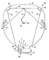
- a vehicle 10 may include a seating structure 12 which supports an occupant 14 in generally opposing relation to a dash panel 16 .
- An inflatable air bag cushion 20 may be housed within the dash panel 16 for outward deployment towards the occupant 14 in the event of a collision.
- air bag cushion 20 is illustrated for descriptive purposes in relation to a vehicle passenger, it is to be understood that the present invention is in no way intended to be limited to a passenger side configuration. On the contrary, it is contemplated that the present invention may have equal applicability to air bag deployment in opposing relation to the operator (not shown) of the vehicle from the steering column (not shown) as well as in relation to air bags deployed from other regions within the vehicle interior including, by way of example only, side-impact air bags and inflatable curtain structures.
- the vehicle interior may include a seat position sensor 22 to detect the position of the occupant 14 relative to the dash panel 16 .
- the vehicle 10 may include additional position sensors such as an optical scanner 24 or the like to measure both the volume and position of the occupant to be protected.
- the interior of the vehicle 10 may also be provided with a scale 26 disposed within the seating structure 12 so as to provide additional data regarding the load to which the inflatable air bag cushion 20 may be subjected.
- the seating structure 12 may also be provided with sensing elements to measure the degree to which the seating structure 12 is reclined.
- the vehicle 10 may also be provided with sensors to determine and communicate whether or not the occupant is utilizing the recommended seat belt structures 28 . The data so collected may be utilized to determine desirable expanded profile and venting characteristics for the air bag cushion 20 .
- the air bag cushion 20 has a first expanded profile and at least a second expanded profile which is characterized by less depth and volume than the first expanded profile.
- One or more tethering elements 30 in the form of straps or webs are preferably utilized to control the inflated profile of the air bag cushion 20 .
- the tethering elements 30 are disposed across the interior of the air bag cushion 20 and extend in a travel path between fixed points of connection 25 at the surface of the air bag cushion 20 .
- the tethering elements 30 may be further connected to the surface of the air bag cushion 20 at locations along the travel path by guide elements 29 such as at an impact face portion 92 .
- the operative length of the tethering elements 30 may be shortened by drawing a portion of the tethering elements 30 intermediate the fixed points of connection 25 towards an anchoring structure remote from the air bag cushion 20 .
- Such a shortening in the operative length of the tethering elements 30 causes the depth of the air bag cushion 20 to be restrained. As shown in FIG. 3B, the operative length of the tethering elements 30 is increased when the tethering elements 30 are released from the anchoring position.
- the release or retention of the tethering elements 30 is preferably carried out at the time of inflation of the air bag cushion 20 based upon the preferred profile character of the air bag cushion 20 in view of the measured impact severity and physical character and position of the occupant 14 . That is, if the physical character and orientation of the occupant 14 in combination with the nature of the impact are such that a deep profile is desired, then the tethering elements are released from their anchored position to assume an increased operative length at the time of inflation thereby permitting the inflatable air bag cushion 20 to assume an expanded profile of enhanced depth.
- the tethering elements 30 remain anchored in a restricted operative length during deployment of the inflatable air bag cushion 20 so as to restrain the final profile thereof.
- the tethering elements 30 may remain connected to at least two secure points of attachment 25 at locations across the surface of the air bag cushion. Such connection provides for the continued restraint of the air bag cushion 20 by the tethering elements even after the operative length is increased. That is, even with an enhanced operating length, the tethering elements continue to contour the profile of the air bag cushion 20 .
- FIG. 2 one possible mechanism for the controlled retention and release of the tethering elements 30 is shown in FIG. 2 .
- one or more tethering elements 30 are operatively connected to an anchoring strap 31 which in turn is passed through the opening at the interior of a ring element 32 so as to form a loop 33 which can slide along the length of the ring element 32 .
- the configuration of the loop 33 is thereafter maintained by attaching the surfaces of the looped anchoring strap 31 by stitching 34 along a length remote from the ring element 32 .
- a single tether 30 or multiple tethers may be operatively attached to the ring element either directly or through use of an anchoring strap 31 . That is, the anchoring strap 31 may be eliminated if desired.
- the material forming the tethering elements 30 and the anchoring strap 31 are preferably of pliable nature such as a woven or knitted textile of construction resistant to substantial elongation upon the application of tensile forces.
- a woven structure of nylon yarns may be preferred.
- a ring element 32 is utilized to hold the tethering elements 30 in place, it is preferably formed from a smooth surface material of high strength such as metal or the like. Such materials have the ability to withstand substantial loading without undergoing plastic deformation. As will be discussed further hereinafter, the ring element 32 may pass in sliding relation over a retaining stud 48 which extends through the opening in the ring element 32 such that the ring element 32 may be pulled away from the retaining stud 48 when tension is applied to the tethering elements 30 . In the event that the ring element 32 is not utilized, it is contemplated that this function may be carried out by the loop 33 which may likewise accept the retaining member therein.
- the illustrated embodiment utilizes a female member such as the ring element 32 or loop 33 disposed in sliding relation over a male retaining member, such a configuration for retaining the tethering elements in a shortened condition it is in no way critical to the present invention and any number of other releasable attachment mechanisms may likewise be utilized. Accordingly, by way of example only and not limitation, it is contemplated that the female ring element 32 may be substituted with a male element for disposition in sliding relation within a supporting female retaining member if desired.
- an actuation mechanism 36 including a support structure 38 is operatively connected to a gas emitting inflator 40 which is activated by an initiator 41 such as a pyrotechnic squib or other suitable device as will be well known to those of skill in the art.
- the gas emitting inflator 40 is stored within a housing 42 which may include one or more vent openings 43 for transmission of inflator gas outwardly from the module away from the air bag 20 . As illustrated, such vent openings 43 are normally in fluid communication with gas discharge ports 44 generally surrounding the diffuser portion 45 of the inflator 40 .
- the support structure 38 of the actuation mechanism 36 is illustrated as being connected to the gas emitting inflator 40 , it is likewise contemplated that any number of other arrangements may also be utilized. By way of example only, it is contemplated that the actuation mechanism 36 may be located remote from the inflator 40 and attached directly to the housing 42 .
- the ring element 32 or loop 33 on the anchor strap 31 is disposed in sliding relation over the retaining stud 48 which is secured in substantially stable relation to the housing 42 .
- the retaining stud 48 is disposed in butting or notched relation to a tether blocking element 49 such as a plate or notched post.
- a tether blocking element 49 such as a plate or notched post.
- the tethering elements 30 which are fixedly attached to the anchor strap 31 are likewise anchored against outward movement as best seen in FIG. 3 A. Accordingly, the expanded profile of the air bag 20 is limited due to the anchored relation between the anchor strap 31 (or tethering elements 30 ) and the stationary retaining stud 48 .
- the tether blocking element 49 is carried within a plunger element 50 which is held within the interior of the support structure 38 at the end of the inflator 40 .
- the support structure 38 has a substantially hollow tubular shape including interior walls 39 defining an axial opening into which the plunger element 50 and an initiator device 60 may be inserted during assembly.
- the support structure 38 includes a first support end 70 of a substantially flanged configuration that is secured directly to the head portion of the inflator 40 .
- the first support end 70 of the support structure 38 may be secured to the inflator 40 by any suitable method, such as welding.
- the support structure 38 also includes a spacing shoulder 74 which is sized larger than an end opening in the housing 42 such that the support structure 38 is limited from going through the end opening within the housing 42 and is properly positioned during assembly.
- the spacing shoulder 74 is preferably integrally formed with the support structure 38 such as by machining or molding but may also be provided as a separate piece attached to or slipped over the support structure 38 .
- the support structure 38 includes a first guide channel 76 which extends longitudinally along at least a portion of the distance between the spacing shoulder 74 and the first support end 70 of the support structure 38 such that the tether blocking element 49 passes through the first guide channel 76 and into the plunger element 50 as shown.
- the support structure 38 further includes a threaded end portion 78 which extends past the spacing shoulder 74 through the end opening of the housing 42 for mating with a cap nut 80 to secure the inflator 40 and the actuation mechanism 36 to the housing 42 .
- the plunger element 50 may be integrally formed from a plastic material and has a generally cylindrical shape.
- the plunger element 50 is seated within the interior walls 39 of the support structure 38 and has a diameter which is slightly smaller than the axial opening between the interior walls 39 such that the plunger element 50 is may slide relative to the interior walls 39 .
- the plunger element 50 includes a first radial opening which is sized for the receipt of the tether blocking element 49 .
- the plunger element 50 also includes a second radial plunger hole for the receipt of a moveable vent blocking device 85 .
- the plunger element 50 includes a shear feature 52 which is illustrated as a flange located at the end of the plunger element 50 .
- the shear feature 52 is preferably integrally formed with the plunger element 50 , but may also be a separate piece attached to the plunger element 50 .
- the shear feature 52 is sized larger than the axial opening within the support structure 38 such that the sheer feature 52 engages the support structure 38 during insertion to limit the insertion of the plunger element 50 into the support structure 38 .
- the plunger element 50 includes an axial plunger bore 54 in which the initiator device 60 such as a pyrotechnic squib, pneumatic actuator or the like is seated prior to activation.
- the initiator device 60 preferably is activated in response to a signal from a control device such as an on-board computer 27 based upon inputs from a deceleration sensor, the seat position sensor 22 , the optical scanner 24 and any other sensor as may be used to measure the nature of the occupant and the severity of the impact event taking place.
- the initiator device 60 produces a pressure wave that presses against a plunger reaction surface 57 .
- the application of such force causes the shear feature 52 to break off and permits the plunger element 50 to slide within the support structure 38 until engaging the head of the inflator 40 which acts as a stop surface.
- the vent blocking element 85 includes an upwardly projecting arm portion 86 which may be snap fittedly attached in the plunger element 50 .
- the vent blocking element 85 also includes a slide portion 87 extending at generally a right angle to the arm portion 86 .
- the retaining stud 48 , tether blocking element 49 , and vent blocking element 85 are arranged in a substantially “Z” shaped cross sectional profile.
- the vent blocking element 85 is moveable within a second guide channel 77 within the support structure 38 so as to close an inflator vent opening 43 upon activation of the initiator device 60 .
- the slide portion 87 is shown in a first position in solid lines in which the inflator vent opening 43 is open thereby lowering the amount of gas available for inflation of the air bag cushion 20 and is illustrated in phantom lines in a second position in which the slide portion 87 is blocking the inflator vent opening 43 within the housing 142 thereby directing a larger quantity of available inflator gas into the air bag cushion 20 .
- one such arrangement may utilize a slide portion 87 with one or more gas transmission openings normally aligned with the inflator vent opening 43 . Upon movement of the slide portion 87 the gas transmission openings would move out of alignment with the inflator vent opening 43 thereby blocking gas flow.
- the air bag cushion 20 is stored in a folded condition atop the inflator 40 .
- the tether blocking element 49 as well as the optional vent blocking element 85 are held in a first position by the shear feature 52 such that the retaining stud 48 and tether blocking element 49 hold the anchor strap 31 in place.
- the slide portion 87 of the vent blocking element 85 is misaligned with the inflator vent opening 43 such that the inflator vent opening 43 is open thereby permitting the egress of inflator gas outwardly from the housing 42 .
- a signal is sent to the inflator initiator 41 thereby activating the inflator 40 .
- a signal is also sent from the onboard computer 27 to the initiator device 60 advising the initiator device 60 as to whether the first position is to be maintained or whether the initiator device 60 is to be activated at a predetermined time during activation of the inflator 40 to move the tether blocking element 49 thereby permitting the anchor strap 31 to slide away from the retaining stud 48 .
- the initiator device 60 is activated when conditions indicate that a deeper profile and larger volume is required and will remain in a deactivated state when conditions indicate that an air bag of more shallow profile and lower volume is desirable.
- the initiator device 60 upon activation the initiator device 60 produces a pressure wave which presses against the reaction surface 57 of the plunger element 50 and quickly forces the plunger element 50 towards the head portion of the inflator 40 .
- This movement carries the tether blocking element 49 as well as any optional vent blocking element 85 within the plunger element 50 from the first position illustrated in FIG. 2 to a second position wherein the plunger element 50 is in contact with the head portion of the inflator 40 .
- Such movement rapidly opens a path of egress for the ring element 32 or loop 33 disposed over the retaining stud 48 thereby permitting the ring element 32 or loop 33 to slide out of engagement with the retaining stud 48 as tension is applied to the anchor strap 31 .
- This tension arises due to the outward expansion of the air bag cushion 20 as it is filled with inflator gas.
- such tension may include both a horizontal as well as a vertical force component arising from an angled relation between the anchor strap 31 and the retaining stud 48 so as to promote sliding disengagement from the retaining stud 48 .
- the vent blocking element 85 covers the vent opening 43 thereby increasing the quantity of inflation gas available to inflate the air bag cushion 20 .
- the effective length of the tethering elements 30 is increased from the arrangement in FIG. 3A thereby permitting the air bag 20 to assume a substantially extended profile and increased volume as illustrated in FIG. 3 B.
- the tethering elements 30 when the anchoring strap 31 is released the tethering elements 30 are permitted to move outwardly with the air bag cushion.
- the tethering elements 30 nonetheless remain secured at the surface of the air bag cushion at the fixed points of connection 25 such that even in the fully inflated state, the tethering elements 30 apply shaping tension to the surface of the air bag cushion 20 .
- the exemplary vent arrangement incorporates a folded cover element designated generally as 63 such as a strip of fabric, polymeric film or other pliable material disposed across a vent opening 64 such as an aperture extending between the interior and the exterior of the air bag cushion 20 . While the cover element is illustrated as being disposed at the interior of the air bag cushion 20 , it is likewise contemplated that it may be disposed at the exterior if desired.
- the cover element 63 is held in fixed relation to the air bag cushion 20 at an attachment location 65 disposed outboard of the vent opening 64 by stitching or other suitable attachment systems such as adhesive bonding welding and the like.
- a displaceable blocking portion 66 of the cover element 63 is disposed in covering relation over the vent opening 64 .
- the blocking portion 66 forms a covering over the vent opening 64 (shown in hidden lines) thereby at least partially blocking gas flow out of air bag cushion 20 through the vent opening 64 .
- the sealing relation of the blocking portion across the vent opening 64 is enhanced by the internal pressure within the air bag cushion 20 .
- a portion of the cover element 63 is collected in a pleat structure 67 disposed between the attachment location 65 and the vent opening 64 .
- the pleat structure 67 is normally held in folded relation by one or more break-away seams 68 , 68 ′. While only a single fold pleat structure is illustrated, it is likewise contemplated that other pleat structures including multiple fold pleat structures and the like may likewise be utilized.
- the break-away seams 68 , 68 ′ may be of any suitable construction including stitching, adhesive bonding, welding or the like. The strength of the break-away seams 68 , 68 ′ is selected such that they will rupture upon the application of a sufficient tensioning force pulling in the direction away from the attachment location in a manner as will be described further hereinafter.
- the pleat structure 67 includes a cut-out portion 69 .
- the cut-out portion 69 defines an opening within the cover element 63 .
- the break-away seams 68 , 68 ′ experience rupture. This rupture permits at least the partial collapse and spreading of pleat structure 67 . The resulting slack is taken up by pulling the available material in the cover element 63 away from the attachment location 65 .
- the cut-out portion 69 is thereby pulled over the vent opening 64 so as to give rise to substantial alignment between the cut-out portion 69 and the vent opening 64 while moving the blocking portion 66 away from the vent opening 64 .
- Inflation gas is thereby permitted to pass out of the air bag cushion 20 through the vent opening 64 .
- tension to the cover element 63 may be introduced through one or more tensioning straps 71 which extend away from the cover element 63 and which are operatively attached to the tethering elements 30 as shown or to a surface of the air bag cushion 20 at a remote location.
- the operative length of the tensioning straps is such that they are not placed into tension when the air bag cushion is inflated to a first diminished profile (FIG. 3 A). However, in those instances when the air bag cushion 20 is inflated to an enhanced profile (FIG.
- the tensioning straps 71 are placed into tension as the tethering elements move outwardly thereby transmitting such tension across the pleat structure 67 and causing rupture of the break-away seams 68 , 68 ′.
- the resulting slack within the cover element 63 is then taken up as inflation proceeds.
- Movement of the cover element 63 in the desired direction may be facilitated by the use of one or more travel guides 73 .
- the travel guides are half loop structures attached to the interior surface of the air bag cushion 20 and extending over the cover element 63 between opposing lateral sides such that the cover element 63 may slide through the travel guides in a predefined bounded path during extension.
- the tensioning straps 71 may extend from the cover element 63 to a location on the surface of the air bag cushion 20 such that the expansion of the air bag cushion 20 imparts the desired tensioning force to the tensioning straps 71 . It is also contemplated that the tensioning straps 71 may be eliminated entirely if desired. In such a construction, the cover element 63 may be attached at both ends to the air bag cushion 20 and natural extension during enhanced inflation is used to impart the desired tension.
- vent arrangement illustrated in FIGS. 4A and 4B is normally closed so as to reduce venting when the air bag cushion is deployed to a restricted profile (FIG. 3A) and to increase venting when the air bag cushion is deployed to a deep profile (FIG. 3 B).
- venting may be selectively decreased when the air bag cushion is deployed to a deep profile.
- FIGS. 5A and 5B An exemplary vent arrangement to achieve such characteristics is illustrated in FIGS. 5A and 5B wherein components corresponding to those previously illustrated and described are designated by like reference numerals increased by 100.
- an activatable vent arrangement 162 is illustrated which is normally open in a gas emitting orientation (FIG. 5 A).
- the cover element 163 includes a cut out portion 169 which is normally disposed over the vent opening 164 so as to allow for the venting passage of inflation gas through the vent opening 164 .
- the cover element 163 includes a pleat structure 167 of substantially uninterrupted construction located outboard of the vent opening 164 between the vent opening 164 and the attachment location 165 .
- any number of activatable vent arrangements other than the collapsible pleat structures illustrated in FIGS. 4A, 4 B, 5 A and 5 B may likewise be utilized to provide selective venting characteristics.
- one such activatable vent arrangement 262 incorporating a vent cover element 263 in the form of a patch structure such as a substantially flat piece of fabric, film or the like is illustrated in FIGS. 6A, 6 B, 7 , 8 A and 8 B.
- components corresponding to those previously illustrated and described are designated by like reference numerals increased by 200 .
- FIG. 6A, 6 B, 7 , 8 A and 8 B components corresponding to those previously illustrated and described are designated by like reference numerals increased by 200 .
- the vent cover element 263 is secured in place over the vent opening 264 by intermittent attachment seams 265 extending along perimeter segments of the cover element 263 .
- the attachment seams 265 may be of any suitable construction to effect secure attachment such as sewn seams, welded seams or the like. Due to the intermittent coverage of the attachment seams around the perimeter, openings 269 are formed in a defined pattern around the cover element 263 . These perimeter openings 269 thus define gas passageways through which inflation gas may be vented.
- the cover element 263 may be operatively secured to a tensioning strap 271 which extends away from the cover element 263 to the tethering elements 230 .
- the length of the tensioning strap 271 is such that when the air bag cushion is inflated to the diminished profile (FIG. 6A) the cover element 263 is in relaxed relation to the air bag cushion 220 and the vent opening 264 . This relaxed relationship allows pressurized inflation gas to vent through the openings 269 around the perimeter of the cover element 263 .
- FIGS. 6B and 8B when the air bag cushion 220 is inflated to an enhanced profile (FIG.
- the tensioning strap 271 is pulled tight thereby pulling the cover element 263 into a sealed relation across the vent opening 264 (FIG. 8 B). This action thereby eliminates the relaxed relation between the air bag cushion 220 and the cover element 263 so as to restrict the quantity of inflation gas which can be vented through the openings 269 .
- the patch-like cover element 263 has been illustrated as being located on the exterior of the air bag cushion 220 , it is likewise contemplated that such a cover element and associated perimeter seams may be located at the interior of the air bag cushion if desired.
- the cover element 263 when the cover element 263 is in a relaxed state across the surface of the cushion such as during the low profile expansion of the air bag cushion, the internal gas pressure will tend to press the cover element 263 against the surface of the air bag cushion 220 thereby closing down gas passage around the cover element.
- openings around the perimeter of the cover element will tend to open up thereby increasing venting capacity.
- a tension sensitive patch structure may be arranged within the air bag such that it is held in tension when the air bag is inflated to a low profile and is released when the air bag is inflated to a deeper profile.
- a tension sensitive patch structure may be arranged within the air bag such that it is held in tension when the air bag is inflated to a low profile and is released when the air bag is inflated to a deeper profile.
- FIGS. 9A and 9B one such activatable vent arrangement 262 ′ incorporating a vent cover element 263 ′ in the form of a patch structure such as a substantially flat piece of fabric, film or the like at the interior of the air bag cushion 220 ′ is illustrated in FIGS. 9A and 9B.
- components corresponding to those previously illustrated and described in relation to FIGS. 6A and 6B are designated by like reference numerals with a prime.
- the vent cover element 263 ′ may be of a configuration as illustrated in FIG.
- the cover elements 263 ′ may be operatively secured to tensioning straps 271 ′ which extend away from the cover elements 263 ′ to the releasable anchor line 231 ′.
- the length of the tensioning straps 271 ′ is such that when the air bag cushion is inflated to the diminished profile (FIG. 9A) the cover elements 263 ′ are in a tensioned condition pulled away from the vent openings 264 ′. In the illustrated arrangement with the cover elements at the interior of the cushion, this tension causes gas emission openings to open around the cover elements 263 ′ thereby increasing venting capacity.
- a reduced venting capacity is desired at the low profile deployment condition of FIG.
- this venting characteristic may be achieved by arranging the cover elements 263 ′ across the exterior of the air bag cushion. Such external placement will cause the cover elements to be pulled inwardly when the tensioning straps 271 ′ are under pressure in a manner similar to that shown in FIG. 8B thereby reducing venting.
- the tensioning straps 271 ′ may engage the anchor line 231 ′ at ring elements 281 ′ so as to permit an easy sliding relation. However, it is also contemplated that other attachment arrangements such as integral loop structures and the like may also be utilized. As best illustrated through reference to FIG. 9B, in the illustrated embodiment when the air bag cushion 220 ′ is inflated to an enhanced profile (FIG. 6B) by release of the anchor line 231 ′, the anchor line 231 slidingly disengages from the tensioning straps 271 ′. This release eliminates the tension through the tensioning straps 271 ′.
Abstract
Description
Claims (10)
Priority Applications (5)
| Application Number | Priority Date | Filing Date | Title |
|---|---|---|---|
| US10/199,573 US6832778B2 (en) | 2002-07-19 | 2002-07-19 | Air bag restraint including selectively operable venting elements |
| US10/373,373 US6932385B2 (en) | 2002-07-19 | 2003-02-24 | Air bag restraint including selectively operable venting elements |
| EP03765479.5A EP1534563B1 (en) | 2002-07-19 | 2003-07-01 | Air bag restraint including selectively operable venting elements |
| PCT/US2003/020691 WO2004009404A2 (en) | 2002-07-19 | 2003-07-01 | Air bag restraint including selectively operable venting elements |
| US11/014,612 US20050098990A1 (en) | 2002-07-19 | 2004-12-16 | Air bag restraint including selectively operable venting elements |
Applications Claiming Priority (1)
| Application Number | Priority Date | Filing Date | Title |
|---|---|---|---|
| US10/199,573 US6832778B2 (en) | 2002-07-19 | 2002-07-19 | Air bag restraint including selectively operable venting elements |
Related Child Applications (2)
| Application Number | Title | Priority Date | Filing Date |
|---|---|---|---|
| US10/373,373 Continuation-In-Part US6932385B2 (en) | 2002-07-19 | 2003-02-24 | Air bag restraint including selectively operable venting elements |
| US11/014,612 Continuation US20050098990A1 (en) | 2002-07-19 | 2004-12-16 | Air bag restraint including selectively operable venting elements |
Publications (2)
| Publication Number | Publication Date |
|---|---|
| US20040012179A1 US20040012179A1 (en) | 2004-01-22 |
| US6832778B2 true US6832778B2 (en) | 2004-12-21 |
Family
ID=30443333
Family Applications (3)
| Application Number | Title | Priority Date | Filing Date |
|---|---|---|---|
| US10/199,573 Expired - Lifetime US6832778B2 (en) | 2002-07-19 | 2002-07-19 | Air bag restraint including selectively operable venting elements |
| US10/373,373 Expired - Fee Related US6932385B2 (en) | 2002-07-19 | 2003-02-24 | Air bag restraint including selectively operable venting elements |
| US11/014,612 Abandoned US20050098990A1 (en) | 2002-07-19 | 2004-12-16 | Air bag restraint including selectively operable venting elements |
Family Applications After (2)
| Application Number | Title | Priority Date | Filing Date |
|---|---|---|---|
| US10/373,373 Expired - Fee Related US6932385B2 (en) | 2002-07-19 | 2003-02-24 | Air bag restraint including selectively operable venting elements |
| US11/014,612 Abandoned US20050098990A1 (en) | 2002-07-19 | 2004-12-16 | Air bag restraint including selectively operable venting elements |
Country Status (3)
| Country | Link |
|---|---|
| US (3) | US6832778B2 (en) |
| EP (1) | EP1534563B1 (en) |
| WO (1) | WO2004009404A2 (en) |
Cited By (109)
| Publication number | Priority date | Publication date | Assignee | Title |
|---|---|---|---|---|
| US20040051286A1 (en) * | 2002-09-16 | 2004-03-18 | Trw Vehicle Safety Systems Inc. | Air bag module vent with releasable latch |
| US20040130135A1 (en) * | 2002-11-06 | 2004-07-08 | Kalle Ekdahl | Airbag arrangement |
| US20050057029A1 (en) * | 2003-09-12 | 2005-03-17 | Thomas Scott David | Automotive vehicle air bag system |
| US20060151975A1 (en) * | 2003-07-02 | 2006-07-13 | Naoki Yamaji | Air-bag device |
| US20060186655A1 (en) * | 2005-02-18 | 2006-08-24 | Takata Restraint Systems, Inc. | Air bag |
| US20060249943A1 (en) * | 2005-05-06 | 2006-11-09 | Takata Restraint Systems, Inc. | Adaptive depth airbag |
| US20060282203A1 (en) * | 2005-06-14 | 2006-12-14 | Takata Corporation | Airbag, method of manufacturing the same, airbag apparatus and vehicle |
| US20060290117A1 (en) * | 2005-06-23 | 2006-12-28 | Trw Vehicle Safety Systems Inc. | Vehicle occupant protection apparatus having vent member that is controlled by a releasable tether |
| US20060290118A1 (en) * | 2005-06-24 | 2006-12-28 | Thomas Scott D | Air bag system and method |
| DE102005034250A1 (en) * | 2005-07-18 | 2007-02-01 | Takata-Petri (Ulm) Gmbh | Airbag for a vehicle occupant restraint system |
| US20070029762A1 (en) * | 2005-07-29 | 2007-02-08 | Daicel Chemical Industries, Ltd. | Gas generator for air bag |
| US20070040366A1 (en) * | 2005-08-16 | 2007-02-22 | Takata-Petri (Ulm) Gmbh | Airbag module |
| US20070080530A1 (en) * | 2005-10-06 | 2007-04-12 | Trw Automotive Gmbh | Gas bag module |
| DE102005049553A1 (en) * | 2005-10-17 | 2007-04-19 | Trw Airbag Systems Gmbh | Airbag module and method for restraining a vehicle occupant with such an airbag module |
| US20070108750A1 (en) * | 2005-09-21 | 2007-05-17 | Tk Holdings, Inc. | Passive airbag venting |
| US20070126219A1 (en) * | 2005-12-07 | 2007-06-07 | Williams Jeffrey D | Airbag cushion with diffuser and cinch tube to vent gas for out-of-position conditions |
| US20070126218A1 (en) * | 2005-12-07 | 2007-06-07 | Schnieder David W | Locking mechanism for a cinch tube or an airbag cushion |
| US20070187936A1 (en) * | 2006-02-13 | 2007-08-16 | Trw Automotive Safety Systems Gmbh | Impact protection device for a vehicle occupant |
| US20070187935A1 (en) * | 2006-02-16 | 2007-08-16 | Thomas Scott D | Air bag system |
| US20070205591A1 (en) * | 2006-03-03 | 2007-09-06 | Toyoda Gosei Co., Ltd. | Airbag apparatus for a front passenger's seat |
| US20070216146A1 (en) * | 2004-04-27 | 2007-09-20 | Williams Jeffrey D | Airbag cushions with optional venting for out-of-position conditions |
| US20070228710A1 (en) * | 2006-03-28 | 2007-10-04 | Toyoda Gosei Co., Ltd. | Airbag apparatus |
| WO2007115818A1 (en) | 2006-04-11 | 2007-10-18 | Autoliv Development Ab | Airbag unit |
| US20070252370A1 (en) * | 2006-04-26 | 2007-11-01 | Thomas Scott D | Air bag system |
| US20070267855A1 (en) * | 2006-05-19 | 2007-11-22 | Lewis Robert E | Active venting inflator device |
| US20070284864A1 (en) * | 2006-06-08 | 2007-12-13 | Trw Vehicle Safety Systems Inc. | Inflatable vehicle occupant protection device construction |
| US20080042416A1 (en) * | 2006-03-13 | 2008-02-21 | Dalphi Metal Espana, S.A. | Airbag with an adaptatively closable vent device |
| US20080054602A1 (en) * | 2006-08-29 | 2008-03-06 | Key Safety Systems, Inc. | Passenger side twin airbag module assembly |
| US20080073892A1 (en) * | 2006-09-27 | 2008-03-27 | Rose Larry D | Airbag cushion with a flap vent to optionally vent gas for out-of-position conditions |
| US20080079242A1 (en) * | 2006-09-29 | 2008-04-03 | Honda Motor Co., Ltd. | Airbag system for motorcycle |
| US20080174094A1 (en) * | 2006-09-06 | 2008-07-24 | Toyoda Gosei Co., Ltd. | Airbag apparatus |
| US20080179866A1 (en) * | 2006-09-20 | 2008-07-31 | Tk Holdings Inc. | Airbag Cushion |
| US20080203713A1 (en) * | 2005-09-21 | 2008-08-28 | Tk Holdings Inc. | Low risk deployment airbag cushion |
| US20080203707A1 (en) * | 2007-02-26 | 2008-08-28 | Trw Vehicle Safety Systems Inc. | Inflator with vent |
| US20080238062A1 (en) * | 2007-03-26 | 2008-10-02 | Brent Parks | Airbag with automatic vent closer |
| US20080243343A1 (en) * | 2007-03-30 | 2008-10-02 | Takata Corporation | Control Method for Occupant Restraint Apparatus and Occupant Restraint Apparatus |
| US20080315567A1 (en) * | 2007-06-21 | 2008-12-25 | Trw Vehicle Safety Systems Inc. | Air bag with adaptive venting |
| US20090033081A1 (en) * | 2007-07-30 | 2009-02-05 | Trw Vehicle Safety Systems Inc. | Air bag with improved tear stitch |
| US20090091109A1 (en) * | 2007-10-09 | 2009-04-09 | Dalphi Metal Espana, S.L. | Front airbag with an adaptive venting device |
| US20090121461A1 (en) * | 2007-11-09 | 2009-05-14 | Takata Corporation | Airbag and airbag apparatus |
| US7556290B2 (en) | 2006-09-27 | 2009-07-07 | Autoliv Asp, Inc. | Airbag cushion with a laced vent to optionally vent gas for out-of-position conditions |
| US20090212538A1 (en) * | 2008-02-25 | 2009-08-27 | Takata Corporation | Airbag and airbag apparatus |
| US20090218797A1 (en) * | 2005-06-24 | 2009-09-03 | Samsung Electrionics Co., Ltd | Airbag With a Closable Venting Device |
| US20090230663A1 (en) * | 2008-03-11 | 2009-09-17 | Autoliv Asp, Inc. | Dual depth airbag with active venting |
| US20090236839A1 (en) * | 2006-09-20 | 2009-09-24 | Tk Holdings Inc. | Airbag apparatus |
| US7597356B2 (en) | 2007-06-05 | 2009-10-06 | Autoliv Asp, Inc. | Airbag cushions with gas deflectors and optional venting for out-of-position conditions |
| US20090267326A1 (en) * | 2008-02-15 | 2009-10-29 | Toyota Jidosha Kabushiki Kaisha | Airbag device |
| US7614653B2 (en) | 2006-09-27 | 2009-11-10 | Autoliv Asp, Inc. | Pre-folded airbag cushion with optional venting for out-of-position conditions |
| US20100001498A1 (en) * | 2007-02-19 | 2010-01-07 | Kazuhiro Abe | Airbag and airbag device |
| US20100025975A1 (en) * | 2007-12-25 | 2010-02-04 | Toyota Jidosha Kabushiki Kaisha | Occupant protection device |
| US20100032931A1 (en) * | 2008-08-06 | 2010-02-11 | Takata Corporation | Airbag and airbag apparatus |
| US20100045008A1 (en) * | 2006-11-22 | 2010-02-25 | Takata-Petri Ag | Airbag for a motor vehicle |
| US20100090445A1 (en) * | 2008-10-14 | 2010-04-15 | Autoliv Asp, Inc. | Mounting bracket for tether release mechanism |
| US20100090450A1 (en) * | 2008-10-10 | 2010-04-15 | Webber James L | Apparatus and method for controlling an inflatable cushion |
| US20100102542A1 (en) * | 2007-01-12 | 2010-04-29 | Autoliv Developement Ab | Airbag device |
| US20100109303A1 (en) * | 2006-08-22 | 2010-05-06 | Takata Corporation | Airbag and airbag apparatus |
| US20100140908A1 (en) * | 2007-08-09 | 2010-06-10 | Takata Corporation | Airbag cushion and airbag apparatus |
| US7748738B2 (en) | 2006-09-27 | 2010-07-06 | Autoliv Asp, Inc. | Airbag cushion with adaptive diffuser for out-of-position conditions |
| US7770926B2 (en) | 2007-08-09 | 2010-08-10 | Autoliv Asp, Inc. | Airbag adaptive venting for out-of-position occupants |
| US20100201107A1 (en) * | 2007-06-18 | 2010-08-12 | Takata Corporation | Airbag, airbag device and airbag exhausting method |
| US20100253054A1 (en) * | 2009-04-01 | 2010-10-07 | Honda Motor Co., Ltd. | Air bag system for vehicle |
| US20110018246A1 (en) * | 2009-07-24 | 2011-01-27 | Tanja Kryzaniwskyj | Exterior airbag panel |
| US20110062692A1 (en) * | 2009-09-11 | 2011-03-17 | Fuji Jukogyo Kabushiki Kaisha | Side airbag apparatus |
| US7938445B2 (en) | 2009-03-03 | 2011-05-10 | Autoliv Asp, Inc. | Dual chamber airbag cushions with a safety vent in the front chamber |
| US7946613B2 (en) | 2009-03-03 | 2011-05-24 | Autoliv Asp, Inc. | Dual chamber airbag cushion |
| US20110140401A1 (en) * | 2007-06-21 | 2011-06-16 | Trw Vehicle Safety Systems Inc. | Tear stitching for inflatable vehicle occupant protection devices |
| US20110140400A1 (en) * | 2008-09-17 | 2011-06-16 | Honda Motor Co., Ltd. | Airbag and method of manufacturing same |
| US20120104734A1 (en) * | 2010-10-27 | 2012-05-03 | Trw Vehicle Safety Systems Inc. | Air bag with height adaptive tether |
| US8191925B2 (en) | 2008-04-14 | 2012-06-05 | Autoliv Asp, Inc. | Dynamic safety vent |
| US8226118B2 (en) | 2009-08-05 | 2012-07-24 | Autoliv Asp, Inc. | Safety venting with passively closeable vents |
| US8353525B2 (en) | 2011-03-23 | 2013-01-15 | Autoliv Asp, Inc. | Pyrotechnic tether release assembly with a break-away piston for inflatable airbags |
| US8408584B2 (en) | 2011-03-23 | 2013-04-02 | Autoliv Asp, Inc. | Pyrotechnic tether release assembly for inflatable airbags |
| US8408585B2 (en) | 2011-03-23 | 2013-04-02 | Autoliv Asp, Inc. | Pyrotechnic tether release assembly for inflatable airbags |
| US8500163B2 (en) | 2010-12-21 | 2013-08-06 | Key Safety Systems, Inc | Airbag vent assembly |
| US8646808B2 (en) | 2012-06-18 | 2014-02-11 | Autoliv Asp, Inc. | Airbag with active vent |
| US8651521B2 (en) | 2009-04-21 | 2014-02-18 | Autoliv Development Ab | Airbag module having an airbag with an adaptive ventilation opening |
| US8684404B2 (en) | 2010-10-27 | 2014-04-01 | Trw Vehicle Safety Systems Inc. | Air bag with variable venting |
| US8696022B2 (en) | 2010-10-27 | 2014-04-15 | Trw Vehicle Safety Systems Inc. | Air bag with variable venting |
| US20140232091A1 (en) * | 2011-10-12 | 2014-08-21 | Key Safety Systems, Inc. | Air Bag Assembly and Tether |
| US20140306433A1 (en) * | 2013-04-10 | 2014-10-16 | Tk Holdings Inc. | Two-Way Valve For Multi-Chambered Airbags |
| US8882143B2 (en) | 2013-02-08 | 2014-11-11 | Autoliv Asp, Inc. | Airbag with slit vent |
| US9022422B2 (en) * | 2012-10-04 | 2015-05-05 | Cis Tech, Llc | Spool airbag |
| US20150239424A1 (en) * | 2012-08-18 | 2015-08-27 | Autoliv Development Ab | Airbag Module With an Adaptive Influencing Device |
| US20150336534A1 (en) * | 2014-05-26 | 2015-11-26 | Hyundai Mobis Co., Ltd. | Airbag apparatus |
| US9199602B1 (en) * | 2014-07-23 | 2015-12-01 | Trw Vehicle Safety Systems Inc. | Passive air bag with slack creator |
| US20150375707A1 (en) * | 2014-06-26 | 2015-12-31 | Nihon Plast Co., Ltd. | Airbag |
| US9272685B2 (en) * | 2013-12-06 | 2016-03-01 | Trw Vehicle Safety Systems Inc. | Air bag with adaptive vent |
| US9352721B2 (en) * | 2014-04-02 | 2016-05-31 | Hyundai Mobis Co., Ltd. | Airbag apparatus |
| US9499118B2 (en) * | 2015-04-23 | 2016-11-22 | Ford Global Technologies, Llc | Airbag for oblique vehicle impacts |
| US20170028957A1 (en) * | 2015-07-29 | 2017-02-02 | Hyundai Mobis Co., Ltd. | Cushion for driver airbag apparatus |
| US9676364B2 (en) * | 2015-09-30 | 2017-06-13 | Autoliv Asp, Inc. | Airbag systems with passive venting control |
| US9731677B1 (en) | 2016-04-18 | 2017-08-15 | Ford Global Technologies, Llc | Passive restraint system |
| US9889937B2 (en) | 2012-03-19 | 2018-02-13 | Amsafe, Inc. | Structure mounted airbag assemblies and associated systems and methods |
| US9925950B2 (en) | 2015-04-11 | 2018-03-27 | Amsafe, Inc. | Active airbag vent system |
| US9944245B2 (en) | 2015-03-28 | 2018-04-17 | Amsafe, Inc. | Extending pass-through airbag occupant restraint systems, and associated systems and methods |
| US20180281742A1 (en) * | 2017-03-31 | 2018-10-04 | Toyoda Gosei Co., Ltd. | Airbag |
| US10093270B2 (en) | 2016-01-13 | 2018-10-09 | Autoliv Asp, Inc. | Multi-flap vents for inflatable chambers |
| US10173632B2 (en) | 2015-02-05 | 2019-01-08 | Joyson Safety Systems Germany Gmbh | Airbag unit |
| US20190077358A1 (en) * | 2017-09-14 | 2019-03-14 | Honda Motor Co., Ltd. | Airbag apparatus |
| US10427639B2 (en) | 2018-01-10 | 2019-10-01 | Autoliv Asp, Inc. | Airbag systems with passive venting control |
| US20200031304A1 (en) * | 2018-07-25 | 2020-01-30 | Ford Global Technologies, Llc | Airbag for retractable steering wheel |
| US10604259B2 (en) | 2016-01-20 | 2020-03-31 | Amsafe, Inc. | Occupant restraint systems having extending restraints, and associated systems and methods |
| US20200122666A1 (en) * | 2018-10-19 | 2020-04-23 | Toyota Motor Engineering & Manufacturing North America, Inc. | Venting of airbag for adjustment of cushioning surface position |
| US11130468B2 (en) * | 2017-04-16 | 2021-09-28 | Autoliv Development Ab | Airbag apparatus with an active vent mechanism |
| US11180107B2 (en) | 2019-12-05 | 2021-11-23 | Autoliv Asp, Inc. | Tether release for an automotive safety device |
| US20220097643A1 (en) * | 2019-01-30 | 2022-03-31 | Dalphi Metal Espana S.A. | Airbag module for a vehicle occupant restraint system, and method for operating a vehicle occupant restraint system comprising such an airbag module |
| US11292423B2 (en) | 2020-05-18 | 2022-04-05 | Autoliv Asp, Inc. | Vent flap for airbag assemblies |
| US11377063B2 (en) * | 2018-10-30 | 2022-07-05 | Dalphi Metal Espana S.A. | Airbag for vehicle occupant restraint system |
| US11912221B2 (en) | 2019-12-05 | 2024-02-27 | Autoliv Asp, Inc. | Actuator devices and assemblies for automotive safety devices |
Families Citing this family (109)
| Publication number | Priority date | Publication date | Assignee | Title |
|---|---|---|---|---|
| US7566074B2 (en) * | 2002-02-20 | 2009-07-28 | Delphi Technologies, Inc. | Apparatus and method for controlling an inflatable cushion |
| US7819425B2 (en) * | 2002-02-20 | 2010-10-26 | Autoliv Development Ab | Apparatus and method for controlling an inflatable cushion |
| US6991258B2 (en) * | 2002-02-20 | 2006-01-31 | Delphi Technologies, Inc. | Frontal air bag system |
| US7188862B2 (en) | 2004-03-17 | 2007-03-13 | Delphi Technologies, Inc | Apparatus and method for controlling an inflatable cushion |
| US7543848B2 (en) * | 2002-02-20 | 2009-06-09 | Delphi Technologies, Inc. | Apparatus and method for controlling an inflatable cushion |
| US7083191B2 (en) * | 2002-09-16 | 2006-08-01 | Trw Vehicle Safety Systems Inc. | Air bag module with vent controlled by tether |
| JP2004314811A (en) * | 2003-04-16 | 2004-11-11 | Takata Corp | Airbag device, and motorcycle with the airbag device |
| US8186713B2 (en) * | 2003-06-24 | 2012-05-29 | Trw Vehicle Safety Systems Inc. | Vented air bag |
| JP2005104323A (en) * | 2003-09-30 | 2005-04-21 | Toyoda Gosei Co Ltd | Air bag for steering wheel |
| EP1711381B1 (en) * | 2004-01-23 | 2012-04-11 | Takata - Petri Ag | Side protection device |
| JP2005239130A (en) * | 2004-02-24 | 2005-09-08 | Takata Corp | Curtain air bag with cascade inflator |
| DE102004009013B4 (en) † | 2004-02-25 | 2006-03-16 | Trw Automotive Gmbh | Side impact restraint device |
| DE202004003464U1 (en) * | 2004-03-05 | 2005-07-14 | Trw Automotive Safety Systems Gmbh | Steering wheel for a motor vehicle with a gas bag module |
| US7347450B2 (en) * | 2004-10-06 | 2008-03-25 | Autoliv Asp, Inc. | Airbag cushion with cinch tube for reduced out-of-position effects |
| DE602005010341D1 (en) * | 2004-08-09 | 2008-11-27 | Nissan Motor | Vehicle occupant restraint system and method |
| DE102004039079B4 (en) * | 2004-08-12 | 2009-06-10 | Autoliv Development Ab | Airbag unit for a motor vehicle |
| US7328915B2 (en) * | 2004-10-06 | 2008-02-12 | Autoliv Asp, Inc. | Airbag cushion with tether deactivated venting for reduced out-of-position effects |
| DE102004058439B3 (en) * | 2004-12-03 | 2006-07-13 | Trw Automotive Gmbh | Gas bag for a car passenger restraining system has cover made of a front impact-bearing part and a back part, control strap connecting them, slit-opening on bag containing pull-tab with one end fixed to strap and the other to bag |
| US7261319B2 (en) * | 2005-01-07 | 2007-08-28 | Autoliv Asp, Inc. | Airbag cushion with adaptive venting for reduced out-of-position effects |
| DE102005004183A1 (en) * | 2005-01-29 | 2006-05-04 | Daimlerchrysler Ag | Gas bag for air bag module, has catch strip extending when internal pressure prevailing inside the gas bag exceeds about longitudinal section in order to increase volume of gas bag |
| DE202005005466U1 (en) * | 2005-04-07 | 2005-07-14 | Trw Automotive Safety Systems Gmbh | Vehicle occupant restraint device |
| GB2425991A (en) * | 2005-05-11 | 2006-11-15 | Autoliv Dev | A front seat passenger air-bag |
| US10539941B2 (en) * | 2005-05-24 | 2020-01-21 | Deep Science, Llc | Energy dissipative cushioning elements |
| DE102005031544A1 (en) * | 2005-07-06 | 2007-01-11 | Autoliv Development Ab | Airbag unit |
| DE102005039419B4 (en) * | 2005-08-16 | 2011-01-13 | Takata-Petri Ag | Occupant restraint system |
| EP1757495B1 (en) * | 2005-08-24 | 2008-05-21 | Takata Corporation | Airbag and airbag apparatus |
| JP5045017B2 (en) * | 2005-08-24 | 2012-10-10 | タカタ株式会社 | Air bag and air bag device |
| DE502005003011D1 (en) * | 2005-09-29 | 2008-04-10 | Delphi Tech Inc | Air bag module with discharge opening |
| US7448646B2 (en) * | 2005-11-04 | 2008-11-11 | Ford Global Technologies, Llc | Airbag system for out-of-position occupant protection and adaptive venting |
| GB2432344A (en) * | 2005-11-04 | 2007-05-23 | Autoliv Dev | An airbag with a releasable tether |
| EP1790538A3 (en) * | 2005-11-28 | 2008-09-03 | Toyoda Gosei Co., Ltd. | Airbag apparatus |
| WO2007088961A1 (en) * | 2006-02-03 | 2007-08-09 | Takata Corporation | Air bag and air bag system |
| US7506892B2 (en) * | 2006-02-17 | 2009-03-24 | Tk Holdings Inc. | Cushion shaping sleeve and tether for airbags |
| US7393011B2 (en) * | 2006-02-24 | 2008-07-01 | Milliken & Company | Airbag with floating tethers |
| JP4803663B2 (en) * | 2006-05-29 | 2011-10-26 | 本田技研工業株式会社 | Airbag tether structure |
| DE102006027588A1 (en) * | 2006-06-14 | 2007-12-20 | Trw Automotive Gmbh | Front seat passenger sided-passenger protection device for motor vehicle, has catch belt with fastening section that is fastened at front wall of gas bag, where fastening section vertically extends in unfolded condition of gas bag |
| DE102006031542A1 (en) * | 2006-07-07 | 2008-01-10 | Trw Automotive Gmbh | Airbag for a vehicle occupant restraint system |
| KR100747909B1 (en) * | 2006-07-10 | 2007-08-08 | 현대자동차주식회사 | The air-bag housing structure of a passenger seat |
| US7658407B2 (en) * | 2006-07-19 | 2010-02-09 | Key Safety Systems, Inc. | Air bag with active vent |
| JP5007539B2 (en) | 2006-09-01 | 2012-08-22 | タカタ株式会社 | Air bag and air bag device |
| US7445237B2 (en) * | 2006-09-28 | 2008-11-04 | Chrysler Llc | Air bag vent |
| US20080136227A1 (en) * | 2006-12-11 | 2008-06-12 | 3M Innovative Properties Company | Vehicle seat sensor assembly |
| US7510212B2 (en) * | 2007-03-26 | 2009-03-31 | Autoliv Asp, Inc. | Airbag tether cutter and vent closer |
| JP2010523398A (en) * | 2007-04-03 | 2010-07-15 | デルファイ・テクノロジーズ・インコーポレーテッド | Apparatus and method for controlling an inflatable cushion |
| US7770921B2 (en) * | 2007-05-25 | 2010-08-10 | Autoliv Development Ab | Airbag for protection of a vehicle occupant |
| EP1990248B1 (en) * | 2007-05-09 | 2010-10-27 | Dalphi Metal España, S.A. | Side airbag with an adaptive venting device |
| US7527292B2 (en) * | 2007-05-10 | 2009-05-05 | Honda Motor Co., Ltd. | Tethered throat liner for side curtain air bag |
| DE102007024002B4 (en) * | 2007-05-22 | 2017-10-19 | TAKATA Aktiengesellschaft | A gas bag assembly for a vehicle occupant restraint system and vehicle occupant restraint system |
| US8632095B2 (en) * | 2007-06-21 | 2014-01-21 | Trw Vehicle Safety Systems Inc. | Air bag with adaptive tether |
| JP5186832B2 (en) | 2007-08-09 | 2013-04-24 | タカタ株式会社 | Air bag and air bag device |
| KR100941262B1 (en) * | 2007-12-13 | 2010-02-11 | 현대모비스 주식회사 | Air Bag Cushion |
| US7883109B2 (en) * | 2007-12-20 | 2011-02-08 | Toyoda Gosei Co. Ltd. | Dynamic airbag venting |
| US7793978B2 (en) * | 2008-01-29 | 2010-09-14 | Toyoda Gosei Co. Ltd. | Constrained airbag deployment using an external tether |
| US20090200777A1 (en) * | 2008-02-13 | 2009-08-13 | Webber James L | Apparatus and method for controlling an inflatable cushion |
| DE102008015731A1 (en) * | 2008-03-26 | 2009-10-08 | Schreiner Group Gmbh & Co. Kg | Airbag jacket element |
| US20090289444A1 (en) * | 2008-05-20 | 2009-11-26 | Ramesh Keshavaraj | Airbag, system and method for deploying an airbag |
| US20090302588A1 (en) * | 2008-06-05 | 2009-12-10 | Autoliv Asp, Inc. | Systems and methods for airbag tether release |
| JP4996550B2 (en) | 2008-06-11 | 2012-08-08 | タカタ株式会社 | Airbag device |
| DE102008028921B4 (en) * | 2008-06-18 | 2024-02-08 | Zf Airbag Germany Gmbh | Gas bag module for a vehicle security system |
| JP5125847B2 (en) * | 2008-07-23 | 2013-01-23 | タカタ株式会社 | Air bag and air bag device |
| JP5171707B2 (en) * | 2009-03-24 | 2013-03-27 | 日本プラスト株式会社 | Airbag device |
| USPP21525P3 (en) * | 2009-03-26 | 2010-11-23 | Gartenbau Und Spezialkulturen Westhoff Gbr | Variety of Calibrachoa plant named ‘Wescadobl’ |
| DE102009014687B4 (en) * | 2009-03-27 | 2012-06-21 | Autoliv Development Ab | Occupant protection device for a motor vehicle |
| KR101688955B1 (en) * | 2009-05-07 | 2016-12-22 | 아우토리브 디벨롭먼트 아베 | Side Air-bag unit for Vehicle |
| DE102009024142B4 (en) * | 2009-06-04 | 2016-05-12 | TAKATA Aktiengesellschaft | Airbag module for a motor vehicle |
| KR101078882B1 (en) * | 2009-12-09 | 2011-11-02 | 아우토리브 디벨롭먼트 아베 | Front Air Bag including Sst―rings & Vent parts |
| DE102010001502B4 (en) * | 2010-02-02 | 2014-03-20 | TAKATA Aktiengesellschaft | Airbag arrangement for a vehicle occupant restraint system |
| DE102010039895A1 (en) * | 2010-06-15 | 2011-12-15 | Takata-Petri Ag | Airbag module for a motor vehicle |
| DE102010026933B4 (en) * | 2010-07-12 | 2013-02-28 | Autoliv Development Ab | Side air bag |
| JP5613542B2 (en) * | 2010-11-30 | 2014-10-22 | 日本プラスト株式会社 | Airbag |
| JP5607480B2 (en) * | 2010-09-24 | 2014-10-15 | タカタ株式会社 | Airbag, airbag device, and method for suturing airbag lid member |
| US8678431B2 (en) * | 2010-10-27 | 2014-03-25 | Trw Vehicle Safety Systems | Air bag with tether and pulley arrangement |
| DE102011015309A1 (en) * | 2011-03-29 | 2012-10-04 | Autoliv Development Ab | Airbag unit with a holding device for a tension element |
| US8534704B2 (en) * | 2011-05-24 | 2013-09-17 | Trw Vehicle Safety Systems, Inc. | Active air bag vent |
| US8500164B2 (en) * | 2011-07-13 | 2013-08-06 | Tk Holdings Inc. | Airbag with passive-active venting |
| US8491007B2 (en) * | 2011-10-20 | 2013-07-23 | Ford Global Technologies | Variable lateral thickness airbag, system comprising same, and method of deploying same |
| KR101875919B1 (en) * | 2012-06-04 | 2018-07-09 | 현대모비스 주식회사 | Airbag apparatus |
| DE102012011036A1 (en) * | 2012-06-05 | 2013-12-05 | Trw Automotive Gmbh | Vehicle occupant restraint with adaptive knee airbag |
| DE102012011035A1 (en) * | 2012-06-05 | 2013-12-05 | Trw Automotive Gmbh | Adaptive knee airbag for a vehicle occupant restraint device |
| DE102012107802A1 (en) * | 2012-08-24 | 2014-10-30 | Autoliv Development Ab | Airbag module with an external three-dimensionally constructed vent device |
| JP5817684B2 (en) * | 2012-08-29 | 2015-11-18 | 豊田合成株式会社 | Airbag device |
| US9108590B2 (en) * | 2013-04-03 | 2015-08-18 | Autoliv Asp, Inc. | Airbag with active vent |
| DE102013207273A1 (en) * | 2013-04-22 | 2014-10-23 | Bayerische Motoren Werke Aktiengesellschaft | Gas outlet valve for an automotive airbag and motor vehicle airbag with such a gas outlet valve |
| DE102013008285A1 (en) * | 2013-05-15 | 2014-11-20 | Trw Airbag Systems Gmbh | Actuator assembly for a gas bag module in a vehicle safety system, airbag module, vehicle safety system and manufacturing method |
| DE102013108004B4 (en) * | 2013-07-26 | 2017-08-10 | Autoliv Development Ab | Airbag module with a gas bag having a vent opening closed in the folded state by a tether and method for the production thereof |
| CN106132785B (en) * | 2014-01-30 | 2019-09-17 | Trw汽车股份有限公司 | Air bag and method for running passenger restraint system |
| KR102293581B1 (en) * | 2014-04-02 | 2021-08-25 | 현대모비스 주식회사 | Air bag apparatus |
| US9327674B2 (en) * | 2014-04-02 | 2016-05-03 | Trw Vehicle Safety Systems, Inc. | Passive air bag vent with guide |
| DE102014104966B4 (en) * | 2014-04-08 | 2018-01-04 | Autoliv Development Ab | Airbag with adjustable ventilation area and airbag manufacturing process |
| US9150189B1 (en) * | 2014-05-22 | 2015-10-06 | Autoliv Asp, Inc. | Airbag systems with side venting |
| JP6445797B2 (en) | 2014-06-30 | 2018-12-26 | 日本プラスト株式会社 | Air bag and air bag device |
| KR102131451B1 (en) * | 2014-06-30 | 2020-07-08 | 현대모비스 주식회사 | Passenger Airbag Of Vehicle |
| US9333940B2 (en) | 2014-08-27 | 2016-05-10 | Autoliv Asp, Inc. | Frontal airbag systems and uses thereof |
| US9771047B2 (en) | 2015-10-01 | 2017-09-26 | Autoliv Asp, Inc. | Frontal airbag systems for oblique crash protection |
| US9776594B2 (en) * | 2015-12-04 | 2017-10-03 | Autoliv Asp, Inc. | Airbag tether release assemblies |
| US10336285B2 (en) | 2016-09-07 | 2019-07-02 | Joyson Safety Systems Acquisition Llc | Airbag module with active vent rotation countermeasure |
| JP6758162B2 (en) * | 2016-11-18 | 2020-09-23 | 日本プラスト株式会社 | Airbag device |
| KR102452472B1 (en) * | 2017-08-18 | 2022-10-12 | 현대자동차주식회사 | Occupant ankle protection apparatus for vehicle |
| US10814823B2 (en) * | 2017-08-29 | 2020-10-27 | Ford Global Technologies, Llc | Vehicle energy absorber |
| DE102018119527A1 (en) * | 2018-08-10 | 2020-02-13 | Trw Automotive Gmbh | Airbag control device and airbag device |
| US11345305B2 (en) | 2018-09-26 | 2022-05-31 | Trw Vehicle Safety Systems Inc. | Adaptive airbag for protecting occupants in a vehicle |
| JP7199896B2 (en) * | 2018-09-28 | 2023-01-06 | セーレン株式会社 | Airbag |
| DE202019100719U1 (en) | 2019-02-08 | 2020-05-11 | Dalphi Metal Espana, S.A. | Airbag for a vehicle occupant restraint system |
| US10953833B2 (en) * | 2019-04-09 | 2021-03-23 | Ford Global Technologies, Llc | Airbag with breakable band |
| DE102019129912A1 (en) * | 2019-11-01 | 2021-05-06 | Joyson Safety Systems Germany Gmbh | Airbag arrangement for a vehicle occupant restraint system and method for protecting a vehicle occupant |
| DE102020106468A1 (en) | 2020-03-10 | 2021-09-16 | Audi Aktiengesellschaft | Gas bag of a vehicle occupant restraint system |
| CN112326103B (en) * | 2020-10-23 | 2021-11-23 | 亳州联岐医疗科技有限公司 | Pneumoperitoneum machine gas consumption measuring device |
| DE102021113621A1 (en) | 2021-05-26 | 2022-12-01 | Autoliv Development Ab | Airbag with an adaptive ventilation device |
| KR20230068677A (en) * | 2021-11-11 | 2023-05-18 | 현대모비스 주식회사 | Air bag apparatus for vehicle |
Citations (38)
| Publication number | Priority date | Publication date | Assignee | Title |
|---|---|---|---|---|
| DE3618060A1 (en) * | 1986-05-28 | 1987-12-03 | Bayerische Motoren Werke Ag | Air bag for protecting the occupants of vehicles |
| US5016913A (en) * | 1989-07-14 | 1991-05-21 | Takata Kabushiki Kaisha | Air bag in air bag equipment |
| US5280953A (en) * | 1992-11-25 | 1994-01-25 | General Motors Corporation | Displacement responsive air bag vent |
| US5308113A (en) | 1992-10-09 | 1994-05-03 | Trw Vehicle Safety Systems Inc. | Airbag inflation-controlling member |
| US5395134A (en) | 1993-04-02 | 1995-03-07 | Morton International, Inc. | Passenger side air bag with controlled deployment |
| US5405166A (en) * | 1993-07-30 | 1995-04-11 | Alliedsignal Inc. | Air bag with inflation limiter |
| JPH0820305A (en) * | 1994-07-05 | 1996-01-23 | Toyo Tire & Rubber Co Ltd | Air bag for vehicle |
| US5489119A (en) | 1992-09-01 | 1996-02-06 | Morton International, Inc. | Tethers with tearseams for air bag cushion |
| DE19633883A1 (en) * | 1996-08-19 | 1998-02-26 | Petri Ag | Gas-bag for an airbag module |
| US5746447A (en) | 1997-01-21 | 1998-05-05 | Morton International, Inc. | Airbag module |
| US5762367A (en) | 1997-04-10 | 1998-06-09 | General Motors Corporation | Air bag module with inflation control device |
| US5887894A (en) | 1995-04-03 | 1999-03-30 | Autoliv Development Ab | Safety arrangement for a motor vehicle |
| US5931497A (en) * | 1996-05-31 | 1999-08-03 | Trw Occupant Restraint Systems Gmbh | Gas bag |
| US5945184A (en) | 1996-05-07 | 1999-08-31 | Toyoda Gosei Co., Ltd. | Air bag for air bag apparatus |
| JP2000016228A (en) * | 1998-07-03 | 2000-01-18 | Honda Motor Co Ltd | Airbag device |
| US6039346A (en) | 1997-01-17 | 2000-03-21 | General Motors Corporation | Air bag module with variable inflation |
| US6076854A (en) | 1998-12-16 | 2000-06-20 | General Motors Corporation | Air bag assembly with selectively variable volume |
| US6095557A (en) * | 1997-08-08 | 2000-08-01 | Toyoda Gosei Co., Ltd. | Air bag apparatus |
| US6123358A (en) | 1998-05-11 | 2000-09-26 | General Motors Corporation | Air bag module with variable inflation |
| US6231072B1 (en) | 1999-10-15 | 2001-05-15 | Delphi Technologies, Inc. | Headliner based supplemental restraint assembly |
| US6237949B1 (en) | 1998-06-25 | 2001-05-29 | Mitsubishi Jidosha Kogyo Kabushiki Kaisha | Air bag system for motor vehicle |
| JP2001171456A (en) * | 1999-12-20 | 2001-06-26 | Takata Corp | Air bag |
| US6276712B1 (en) | 1999-09-10 | 2001-08-21 | Delphi Technologies, Inc. | Side restraint assembly for an automotive vehicle |
| US6290257B1 (en) | 1998-07-27 | 2001-09-18 | Nihon Plast Co., Ltd. | Safety system for automobile |
| JP2002079905A (en) * | 2000-09-08 | 2002-03-19 | Calsonic Kansei Corp | Air bag device for vehicle |
| US20020036400A1 (en) | 2000-09-28 | 2002-03-28 | Winters Mark Thomas | Variable profile air bag restraint |
| US6390502B1 (en) | 2001-03-26 | 2002-05-21 | Delphi Technologies, Inc. | Supplemental restraint assembly for an automotive vehicle |
| US6390501B1 (en) | 1999-11-12 | 2002-05-21 | Delphi Technologies, Inc. | Variable profile air bag restraint |
| US6422597B1 (en) | 1999-11-12 | 2002-07-23 | Delphi Technologies, Inc. | Variable profile air bag restraint |
| US6422593B1 (en) | 1999-12-30 | 2002-07-23 | Delphi Technologies, Inc. | Supplemental restraint assembly for an automobile |
| US6425603B1 (en) | 1999-04-29 | 2002-07-30 | Trw Occupant Restraint Systems Gmbh & Co. Kg | Gas bag restraint system |
| US6428042B1 (en) * | 2001-01-08 | 2002-08-06 | Trw Vehicle Safety Systems Inc. | Dual volume air bag with vent |
| US6447006B1 (en) * | 2000-10-03 | 2002-09-10 | Autoliv Asp, Inc. | Inflatable curtain cushion vent |
| US6454300B1 (en) | 2001-02-27 | 2002-09-24 | Delphi Technologies, Inc. | Air bag tether release assembly |
| US6454296B1 (en) | 2000-11-22 | 2002-09-24 | Delphi Technologies, Inc. | Side air bag for roll-over restraint |
| US6502858B2 (en) * | 2000-04-25 | 2003-01-07 | Takata Corporation | Airbag device with tearable strap |
| US6508486B1 (en) | 2001-06-06 | 2003-01-21 | Delphi Technologies, Inc. | Door mounted side restraint |
| US20030020266A1 (en) * | 2001-07-12 | 2003-01-30 | Vendely Michael Joseph | Variable venting air bag assembly |
Family Cites Families (17)
| Publication number | Priority date | Publication date | Assignee | Title |
|---|---|---|---|---|
| JPH06127330A (en) * | 1992-10-16 | 1994-05-10 | Toyoda Gosei Co Ltd | Air bag for air bag device |
| US5310215A (en) * | 1993-01-13 | 1994-05-10 | Trw Vehicle Safety Systems Inc. | Apparatus for venting of an inflatable air bag |
| US6186542B1 (en) * | 1997-10-14 | 2001-02-13 | Autoliv Asp, Inc. | Compact knee bolster airbag assembly |
| EP1026049B1 (en) * | 1997-10-31 | 2004-09-22 | Asahi Kasei Kabushiki Kaisha | Air bag |
| US6213502B1 (en) | 1998-11-24 | 2001-04-10 | Delphi Technologies, Inc. | Air bag module with variable inflation |
| US6203061B1 (en) | 1999-10-07 | 2001-03-20 | Delphi Technologies, Inc. | Variable output air bag module with PAV heat sink |
| US6439603B2 (en) | 1999-10-13 | 2002-08-27 | Delphi Technologies, Inc. | Air bag module with variable inflation |
| US6371517B1 (en) | 1999-12-28 | 2002-04-16 | Delphi Technologies, Inc. | Adaptive inflation mechanism |
| JP2001301555A (en) * | 2000-04-18 | 2001-10-31 | Takata Corp | Air bag device |
| US6499765B2 (en) | 2000-10-31 | 2002-12-31 | Delphi Technologies, Inc. | Bias deployment inflatable air bag |
| JP2002144996A (en) | 2000-11-14 | 2002-05-22 | Nippon Plast Co Ltd | Air bag and its folding-up method |
| JP4631172B2 (en) * | 2001-01-22 | 2011-02-16 | タカタ株式会社 | Airbag device |
| US6746044B2 (en) * | 2001-12-27 | 2004-06-08 | Trw Inc. | Actuatable fastener for air bag module vent |
| US6991258B2 (en) * | 2002-02-20 | 2006-01-31 | Delphi Technologies, Inc. | Frontal air bag system |
| US6746045B2 (en) * | 2002-04-05 | 2004-06-08 | Ford Global Technologies, Llc | Air bag inflator gas venting system |
| US7083191B2 (en) * | 2002-09-16 | 2006-08-01 | Trw Vehicle Safety Systems Inc. | Air bag module with vent controlled by tether |
| US6932384B2 (en) * | 2002-11-15 | 2005-08-23 | Delphi Technologies, Inc. | Apparatus and method for controlling an inflatable cushion |
-
2002
- 2002-07-19 US US10/199,573 patent/US6832778B2/en not_active Expired - Lifetime
-
2003
- 2003-02-24 US US10/373,373 patent/US6932385B2/en not_active Expired - Fee Related
- 2003-07-01 EP EP03765479.5A patent/EP1534563B1/en not_active Expired - Lifetime
- 2003-07-01 WO PCT/US2003/020691 patent/WO2004009404A2/en not_active Application Discontinuation
-
2004
- 2004-12-16 US US11/014,612 patent/US20050098990A1/en not_active Abandoned
Patent Citations (40)
| Publication number | Priority date | Publication date | Assignee | Title |
|---|---|---|---|---|
| DE3618060A1 (en) * | 1986-05-28 | 1987-12-03 | Bayerische Motoren Werke Ag | Air bag for protecting the occupants of vehicles |
| US5016913A (en) * | 1989-07-14 | 1991-05-21 | Takata Kabushiki Kaisha | Air bag in air bag equipment |
| US5489119A (en) | 1992-09-01 | 1996-02-06 | Morton International, Inc. | Tethers with tearseams for air bag cushion |
| US5308113A (en) | 1992-10-09 | 1994-05-03 | Trw Vehicle Safety Systems Inc. | Airbag inflation-controlling member |
| US5280953A (en) * | 1992-11-25 | 1994-01-25 | General Motors Corporation | Displacement responsive air bag vent |
| US5395134A (en) | 1993-04-02 | 1995-03-07 | Morton International, Inc. | Passenger side air bag with controlled deployment |
| US5405166A (en) * | 1993-07-30 | 1995-04-11 | Alliedsignal Inc. | Air bag with inflation limiter |
| JPH0820305A (en) * | 1994-07-05 | 1996-01-23 | Toyo Tire & Rubber Co Ltd | Air bag for vehicle |
| US5887894A (en) | 1995-04-03 | 1999-03-30 | Autoliv Development Ab | Safety arrangement for a motor vehicle |
| US5945184A (en) | 1996-05-07 | 1999-08-31 | Toyoda Gosei Co., Ltd. | Air bag for air bag apparatus |
| US5931497A (en) * | 1996-05-31 | 1999-08-03 | Trw Occupant Restraint Systems Gmbh | Gas bag |
| DE19633883A1 (en) * | 1996-08-19 | 1998-02-26 | Petri Ag | Gas-bag for an airbag module |
| US6039346A (en) | 1997-01-17 | 2000-03-21 | General Motors Corporation | Air bag module with variable inflation |
| US5746447A (en) | 1997-01-21 | 1998-05-05 | Morton International, Inc. | Airbag module |
| US5762367A (en) | 1997-04-10 | 1998-06-09 | General Motors Corporation | Air bag module with inflation control device |
| US6095557A (en) * | 1997-08-08 | 2000-08-01 | Toyoda Gosei Co., Ltd. | Air bag apparatus |
| US6123358A (en) | 1998-05-11 | 2000-09-26 | General Motors Corporation | Air bag module with variable inflation |
| US6237949B1 (en) | 1998-06-25 | 2001-05-29 | Mitsubishi Jidosha Kogyo Kabushiki Kaisha | Air bag system for motor vehicle |
| JP2000016228A (en) * | 1998-07-03 | 2000-01-18 | Honda Motor Co Ltd | Airbag device |
| US6290257B1 (en) | 1998-07-27 | 2001-09-18 | Nihon Plast Co., Ltd. | Safety system for automobile |
| US6076854A (en) | 1998-12-16 | 2000-06-20 | General Motors Corporation | Air bag assembly with selectively variable volume |
| US6425603B1 (en) | 1999-04-29 | 2002-07-30 | Trw Occupant Restraint Systems Gmbh & Co. Kg | Gas bag restraint system |
| US6276712B1 (en) | 1999-09-10 | 2001-08-21 | Delphi Technologies, Inc. | Side restraint assembly for an automotive vehicle |
| US6231072B1 (en) | 1999-10-15 | 2001-05-15 | Delphi Technologies, Inc. | Headliner based supplemental restraint assembly |
| US6422597B1 (en) | 1999-11-12 | 2002-07-23 | Delphi Technologies, Inc. | Variable profile air bag restraint |
| US6592146B2 (en) | 1999-11-12 | 2003-07-15 | Delphi Technologies, Inc. | Variable profile air bag restraint |
| US6390501B1 (en) | 1999-11-12 | 2002-05-21 | Delphi Technologies, Inc. | Variable profile air bag restraint |
| US6561545B2 (en) | 1999-11-12 | 2003-05-13 | Delphi Technologies, Inc. | Variable profile air bag restraint |
| JP2001171456A (en) * | 1999-12-20 | 2001-06-26 | Takata Corp | Air bag |
| US6422593B1 (en) | 1999-12-30 | 2002-07-23 | Delphi Technologies, Inc. | Supplemental restraint assembly for an automobile |
| US6502858B2 (en) * | 2000-04-25 | 2003-01-07 | Takata Corporation | Airbag device with tearable strap |
| JP2002079905A (en) * | 2000-09-08 | 2002-03-19 | Calsonic Kansei Corp | Air bag device for vehicle |
| US20020036400A1 (en) | 2000-09-28 | 2002-03-28 | Winters Mark Thomas | Variable profile air bag restraint |
| US6447006B1 (en) * | 2000-10-03 | 2002-09-10 | Autoliv Asp, Inc. | Inflatable curtain cushion vent |
| US6454296B1 (en) | 2000-11-22 | 2002-09-24 | Delphi Technologies, Inc. | Side air bag for roll-over restraint |
| US6428042B1 (en) * | 2001-01-08 | 2002-08-06 | Trw Vehicle Safety Systems Inc. | Dual volume air bag with vent |
| US6454300B1 (en) | 2001-02-27 | 2002-09-24 | Delphi Technologies, Inc. | Air bag tether release assembly |
| US6390502B1 (en) | 2001-03-26 | 2002-05-21 | Delphi Technologies, Inc. | Supplemental restraint assembly for an automotive vehicle |
| US6508486B1 (en) | 2001-06-06 | 2003-01-21 | Delphi Technologies, Inc. | Door mounted side restraint |
| US20030020266A1 (en) * | 2001-07-12 | 2003-01-30 | Vendely Michael Joseph | Variable venting air bag assembly |
Cited By (186)
| Publication number | Priority date | Publication date | Assignee | Title |
|---|---|---|---|---|
| US20040051286A1 (en) * | 2002-09-16 | 2004-03-18 | Trw Vehicle Safety Systems Inc. | Air bag module vent with releasable latch |
| US7083192B2 (en) * | 2002-09-16 | 2006-08-01 | Trw Vehicle Safety Systems Inc. | Air bag module vent with releasable latch |
| US20040130135A1 (en) * | 2002-11-06 | 2004-07-08 | Kalle Ekdahl | Airbag arrangement |
| US7413218B2 (en) * | 2002-11-06 | 2008-08-19 | Autoliv Development Ab | Airbag arrangement |
| US20060151975A1 (en) * | 2003-07-02 | 2006-07-13 | Naoki Yamaji | Air-bag device |
| US7441802B2 (en) * | 2003-07-02 | 2008-10-28 | Ashimori Industry Co., Ltd. | Air-bag device |
| US20080246259A1 (en) * | 2003-07-02 | 2008-10-09 | Ashimori Industry Co., Ltd. | Airbag device |
| US7584993B2 (en) | 2003-07-02 | 2009-09-08 | Ashimori Industry Co., Ltd. | Airbag device |
| US20050057029A1 (en) * | 2003-09-12 | 2005-03-17 | Thomas Scott David | Automotive vehicle air bag system |
| US7192053B2 (en) * | 2003-09-12 | 2007-03-20 | General Motors Corporation | Automotive vehicle air bag system |
| US7597355B2 (en) | 2004-04-27 | 2009-10-06 | Autoliv Asp, Inc. | Airbag cushions with optional venting for out-of-position conditions |
| US20070216146A1 (en) * | 2004-04-27 | 2007-09-20 | Williams Jeffrey D | Airbag cushions with optional venting for out-of-position conditions |
| US20060186655A1 (en) * | 2005-02-18 | 2006-08-24 | Takata Restraint Systems, Inc. | Air bag |
| US7264268B2 (en) | 2005-02-18 | 2007-09-04 | Tk Holdings Inc. | Air bag |
| US7377548B2 (en) | 2005-05-06 | 2008-05-27 | Tk Holdings Inc. | Adaptive depth airbag |
| US20060249943A1 (en) * | 2005-05-06 | 2006-11-09 | Takata Restraint Systems, Inc. | Adaptive depth airbag |
| US7334815B2 (en) * | 2005-06-14 | 2008-02-26 | Takata Corporation | Airbag, method of manufacturing the same, airbag apparatus and vehicle |
| US20060282203A1 (en) * | 2005-06-14 | 2006-12-14 | Takata Corporation | Airbag, method of manufacturing the same, airbag apparatus and vehicle |
| US20060290117A1 (en) * | 2005-06-23 | 2006-12-28 | Trw Vehicle Safety Systems Inc. | Vehicle occupant protection apparatus having vent member that is controlled by a releasable tether |
| US7552942B2 (en) * | 2005-06-23 | 2009-06-30 | Trw Vehicle Safety Systems Inc. | Vehicle occupant protection apparatus having vent member that is controlled by a releasable tether |
| US20060290118A1 (en) * | 2005-06-24 | 2006-12-28 | Thomas Scott D | Air bag system and method |
| US20090218797A1 (en) * | 2005-06-24 | 2009-09-03 | Samsung Electrionics Co., Ltd | Airbag With a Closable Venting Device |
| DE102005034250A1 (en) * | 2005-07-18 | 2007-02-01 | Takata-Petri (Ulm) Gmbh | Airbag for a vehicle occupant restraint system |
| US20080179867A1 (en) * | 2005-07-18 | 2008-07-31 | Takata-Petri Ag | Airbag for a vehicle passenger restraint system |
| US20070029762A1 (en) * | 2005-07-29 | 2007-02-08 | Daicel Chemical Industries, Ltd. | Gas generator for air bag |
| US7556289B2 (en) * | 2005-07-29 | 2009-07-07 | Daicel Chemical Industries, Ltd. | Gas generator for air bag |
| US7681914B2 (en) | 2005-08-16 | 2010-03-23 | Takata Petri Ag | Airbag module |
| US20070040366A1 (en) * | 2005-08-16 | 2007-02-22 | Takata-Petri (Ulm) Gmbh | Airbag module |
| US20070108750A1 (en) * | 2005-09-21 | 2007-05-17 | Tk Holdings, Inc. | Passive airbag venting |
| US20080203713A1 (en) * | 2005-09-21 | 2008-08-28 | Tk Holdings Inc. | Low risk deployment airbag cushion |
| US8152199B2 (en) | 2005-09-21 | 2012-04-10 | Tk Holdings Inc. | Passive airbag venting |
| US20110079988A1 (en) * | 2005-09-21 | 2011-04-07 | Tk Holdings, Inc. | Passive airbag venting |
| US7931299B2 (en) * | 2005-09-21 | 2011-04-26 | Tk Holdings, Inc. | Low risk deployment airbag cushion |
| US8020889B2 (en) | 2005-09-21 | 2011-09-20 | Tk Holdings, Inc. | Passive airbag venting |
| US7789421B2 (en) * | 2005-10-06 | 2010-09-07 | Trw Automotive Gmbh | Gas bag module |
| US20070080530A1 (en) * | 2005-10-06 | 2007-04-12 | Trw Automotive Gmbh | Gas bag module |
| DE102005049553A1 (en) * | 2005-10-17 | 2007-04-19 | Trw Airbag Systems Gmbh | Airbag module and method for restraining a vehicle occupant with such an airbag module |
| US20070085311A1 (en) * | 2005-10-17 | 2007-04-19 | Trw Airbag Systems Gmbh | Airbag module and method of restraining a vehicle occupant with such an airbag module |
| US7246819B2 (en) | 2005-10-17 | 2007-07-24 | Trw Airbag Systems Gmbh | Airbag module and method of restraining a vehicle occupant with such an airbag module |
| DE102005049553B4 (en) * | 2005-10-17 | 2017-09-07 | Trw Airbag Systems Gmbh | Airbag module and method for restraining a vehicle occupant with such an airbag module |
| US7568729B2 (en) | 2005-12-07 | 2009-08-04 | Autoliv Asp, Inc. | Locking mechanism for a cinch tube of an airbag cushion |
| US20070126219A1 (en) * | 2005-12-07 | 2007-06-07 | Williams Jeffrey D | Airbag cushion with diffuser and cinch tube to vent gas for out-of-position conditions |
| US20070126218A1 (en) * | 2005-12-07 | 2007-06-07 | Schnieder David W | Locking mechanism for a cinch tube or an airbag cushion |
| US7614654B2 (en) | 2005-12-07 | 2009-11-10 | Autoliv Asp, Inc. | Airbag cushion with diffuser with cinch tube to vent gas for out-of-position conditions |
| US20070187936A1 (en) * | 2006-02-13 | 2007-08-16 | Trw Automotive Safety Systems Gmbh | Impact protection device for a vehicle occupant |
| US7591482B2 (en) * | 2006-02-16 | 2009-09-22 | Gm Global Technology Operations, Inc. | Air bag system |
| US20070187935A1 (en) * | 2006-02-16 | 2007-08-16 | Thomas Scott D | Air bag system |
| US20070205591A1 (en) * | 2006-03-03 | 2007-09-06 | Toyoda Gosei Co., Ltd. | Airbag apparatus for a front passenger's seat |
| US20080042416A1 (en) * | 2006-03-13 | 2008-02-21 | Dalphi Metal Espana, S.A. | Airbag with an adaptatively closable vent device |
| US20070228710A1 (en) * | 2006-03-28 | 2007-10-04 | Toyoda Gosei Co., Ltd. | Airbag apparatus |
| US7614656B2 (en) * | 2006-03-28 | 2009-11-10 | Toyoda Gosei Co., Ltd. | Airbag apparatus |
| WO2007115818A1 (en) | 2006-04-11 | 2007-10-18 | Autoliv Development Ab | Airbag unit |
| US7651130B2 (en) | 2006-04-11 | 2010-01-26 | Autoliv Development Ab | Airbag unit |
| US20090020989A1 (en) * | 2006-04-11 | 2009-01-22 | Autoliv Development Ab | Airbag Unit |
| DE102006017332B3 (en) * | 2006-04-11 | 2007-12-13 | Autoliv Development Ab | Airbag unit |
| US7681913B2 (en) * | 2006-04-26 | 2010-03-23 | Gm Global Technology Operations, Inc. | Air bag system |
| US20070252370A1 (en) * | 2006-04-26 | 2007-11-01 | Thomas Scott D | Air bag system |
| US7469926B2 (en) | 2006-05-19 | 2008-12-30 | Autoliv Asp, Inc. | Active venting inflator device |
| US20070267855A1 (en) * | 2006-05-19 | 2007-11-22 | Lewis Robert E | Active venting inflator device |
| US20070284864A1 (en) * | 2006-06-08 | 2007-12-13 | Trw Vehicle Safety Systems Inc. | Inflatable vehicle occupant protection device construction |
| US8353532B2 (en) * | 2006-08-22 | 2013-01-15 | Takata Corporation | Airbag and airbag apparatus |
| US20100109303A1 (en) * | 2006-08-22 | 2010-05-06 | Takata Corporation | Airbag and airbag apparatus |
| US20080054602A1 (en) * | 2006-08-29 | 2008-03-06 | Key Safety Systems, Inc. | Passenger side twin airbag module assembly |
| US7530596B2 (en) * | 2006-09-06 | 2009-05-12 | Toyoda Gosei Co., Ltd. | Airbag apparatus |
| US20080174094A1 (en) * | 2006-09-06 | 2008-07-24 | Toyoda Gosei Co., Ltd. | Airbag apparatus |
| US7988194B2 (en) | 2006-09-20 | 2011-08-02 | Tk Holdings Inc. | Airbag apparatus |
| US7878537B2 (en) | 2006-09-20 | 2011-02-01 | Tk Holdings Inc. | Airbag cushion |
| US20080179866A1 (en) * | 2006-09-20 | 2008-07-31 | Tk Holdings Inc. | Airbag Cushion |
| US20090236839A1 (en) * | 2006-09-20 | 2009-09-24 | Tk Holdings Inc. | Airbag apparatus |
| US7722080B2 (en) | 2006-09-27 | 2010-05-25 | Autoliv Asp, Inc. | Airbag cushion with a flap vent to optionally vent gas for out-of-position conditions |
| US20080073892A1 (en) * | 2006-09-27 | 2008-03-27 | Rose Larry D | Airbag cushion with a flap vent to optionally vent gas for out-of-position conditions |
| US7614653B2 (en) | 2006-09-27 | 2009-11-10 | Autoliv Asp, Inc. | Pre-folded airbag cushion with optional venting for out-of-position conditions |
| US7556290B2 (en) | 2006-09-27 | 2009-07-07 | Autoliv Asp, Inc. | Airbag cushion with a laced vent to optionally vent gas for out-of-position conditions |
| US7748738B2 (en) | 2006-09-27 | 2010-07-06 | Autoliv Asp, Inc. | Airbag cushion with adaptive diffuser for out-of-position conditions |
| US20080079242A1 (en) * | 2006-09-29 | 2008-04-03 | Honda Motor Co., Ltd. | Airbag system for motorcycle |
| US7823921B2 (en) * | 2006-09-29 | 2010-11-02 | Honda Motor Co., Ltd. | Airbag system for motorcycle |
| US20100045008A1 (en) * | 2006-11-22 | 2010-02-25 | Takata-Petri Ag | Airbag for a motor vehicle |
| US8267426B2 (en) | 2006-11-22 | 2012-09-18 | Takata AG | Airbag for a motor vehicle |
| US8087692B2 (en) * | 2006-11-22 | 2012-01-03 | Takata-Petri Ag | Airbag for a motor vehicle |
| US20100102542A1 (en) * | 2007-01-12 | 2010-04-29 | Autoliv Developement Ab | Airbag device |
| US20100001498A1 (en) * | 2007-02-19 | 2010-01-07 | Kazuhiro Abe | Airbag and airbag device |
| US7931297B2 (en) * | 2007-02-19 | 2011-04-26 | Takata Corporation | Airbag and airbag device |
| US20080203707A1 (en) * | 2007-02-26 | 2008-08-28 | Trw Vehicle Safety Systems Inc. | Inflator with vent |
| US7735860B2 (en) * | 2007-02-26 | 2010-06-15 | Trw Vehicle Safety Systems Inc. | Inflator with vent |
| US7690683B2 (en) * | 2007-03-26 | 2010-04-06 | Autoliv Asp, Inc. | Airbag with automatic vent closer |
| US20080238062A1 (en) * | 2007-03-26 | 2008-10-02 | Brent Parks | Airbag with automatic vent closer |
| US20080243343A1 (en) * | 2007-03-30 | 2008-10-02 | Takata Corporation | Control Method for Occupant Restraint Apparatus and Occupant Restraint Apparatus |
| US7925403B2 (en) | 2007-03-30 | 2011-04-12 | Takata Corporation | Control method for occupant restraint apparatus and occupant restraint apparatus |
| US7597356B2 (en) | 2007-06-05 | 2009-10-06 | Autoliv Asp, Inc. | Airbag cushions with gas deflectors and optional venting for out-of-position conditions |
| US20100201107A1 (en) * | 2007-06-18 | 2010-08-12 | Takata Corporation | Airbag, airbag device and airbag exhausting method |
| US8322748B2 (en) | 2007-06-18 | 2012-12-04 | Takata Corporation | Airbag, airbag device and airbag exhausting method |
| US7954850B2 (en) | 2007-06-21 | 2011-06-07 | Trw Vehicle Safety Systems Inc. | Air bag with adaptive venting |
| US20080315567A1 (en) * | 2007-06-21 | 2008-12-25 | Trw Vehicle Safety Systems Inc. | Air bag with adaptive venting |
| US20110140401A1 (en) * | 2007-06-21 | 2011-06-16 | Trw Vehicle Safety Systems Inc. | Tear stitching for inflatable vehicle occupant protection devices |
| US8544883B2 (en) | 2007-06-21 | 2013-10-01 | Trw Vehicle Safety Systems Inc. | Tear stitching for inflatable vehicle occupant protection devices |
| US8764058B2 (en) | 2007-07-30 | 2014-07-01 | Trw Vehicle Safety Systems Inc. | Air bag with improved tear stitch |
| US20090033081A1 (en) * | 2007-07-30 | 2009-02-05 | Trw Vehicle Safety Systems Inc. | Air bag with improved tear stitch |
| US8262130B2 (en) | 2007-07-30 | 2012-09-11 | Trw Vehicle Safety Systems Inc. | Air bag with improved tear stitch |
| US8128124B2 (en) * | 2007-08-09 | 2012-03-06 | Takata Corporation | Airbag cushion and airbag apparatus |
| US7770926B2 (en) | 2007-08-09 | 2010-08-10 | Autoliv Asp, Inc. | Airbag adaptive venting for out-of-position occupants |
| US20100140908A1 (en) * | 2007-08-09 | 2010-06-10 | Takata Corporation | Airbag cushion and airbag apparatus |
| US20090091109A1 (en) * | 2007-10-09 | 2009-04-09 | Dalphi Metal Espana, S.L. | Front airbag with an adaptive venting device |
| US20090121461A1 (en) * | 2007-11-09 | 2009-05-14 | Takata Corporation | Airbag and airbag apparatus |
| US7878538B2 (en) * | 2007-11-09 | 2011-02-01 | Takata Corporation | Airbag and airbag apparatus |
| US20110148085A1 (en) * | 2007-12-25 | 2011-06-23 | Toyota Jidosha Kabushiki Kaisha | Occupant protection device |
| US20100025975A1 (en) * | 2007-12-25 | 2010-02-04 | Toyota Jidosha Kabushiki Kaisha | Occupant protection device |
| US8262129B2 (en) * | 2007-12-25 | 2012-09-11 | Toyota Jidosha Kabushiki Kaisha | Occupant protection device |
| US8286999B2 (en) | 2007-12-25 | 2012-10-16 | Toyota Jidosha Kabushiki Kaisha | Occupant protection device |
| US7841623B2 (en) * | 2008-02-15 | 2010-11-30 | Toyota Jidosha Kabushiki Kaisha | Airbag device |
| US20090267326A1 (en) * | 2008-02-15 | 2009-10-29 | Toyota Jidosha Kabushiki Kaisha | Airbag device |
| US7857347B2 (en) | 2008-02-25 | 2010-12-28 | Takata Corporation | Airbag and airbag apparatus |
| US20090212538A1 (en) * | 2008-02-25 | 2009-08-27 | Takata Corporation | Airbag and airbag apparatus |
| US20090230663A1 (en) * | 2008-03-11 | 2009-09-17 | Autoliv Asp, Inc. | Dual depth airbag with active venting |
| US7784828B2 (en) | 2008-03-11 | 2010-08-31 | Autoliv Asp, Inc. | Dual depth airbag with active venting |
| US8191925B2 (en) | 2008-04-14 | 2012-06-05 | Autoliv Asp, Inc. | Dynamic safety vent |
| US20100032931A1 (en) * | 2008-08-06 | 2010-02-11 | Takata Corporation | Airbag and airbag apparatus |
| US8070183B2 (en) * | 2008-08-06 | 2011-12-06 | Takata Corporation | Airbag and airbag apparatus |
| US8419055B2 (en) * | 2008-09-17 | 2013-04-16 | Honda Motor Co., Ltd. | Airbag and method of manufacturing same |
| US20110140400A1 (en) * | 2008-09-17 | 2011-06-16 | Honda Motor Co., Ltd. | Airbag and method of manufacturing same |
| US20100090450A1 (en) * | 2008-10-10 | 2010-04-15 | Webber James L | Apparatus and method for controlling an inflatable cushion |
| US8020890B2 (en) * | 2008-10-10 | 2011-09-20 | Autoliv Development Ab | Apparatus and method for controlling an inflatable cushion |
| US7938444B2 (en) | 2008-10-14 | 2011-05-10 | Autoliv Asp, Inc. | Mounting bracket for tether release mechanism |
| US20100090445A1 (en) * | 2008-10-14 | 2010-04-15 | Autoliv Asp, Inc. | Mounting bracket for tether release mechanism |
| US7938445B2 (en) | 2009-03-03 | 2011-05-10 | Autoliv Asp, Inc. | Dual chamber airbag cushions with a safety vent in the front chamber |
| US7946613B2 (en) | 2009-03-03 | 2011-05-24 | Autoliv Asp, Inc. | Dual chamber airbag cushion |
| US20100253054A1 (en) * | 2009-04-01 | 2010-10-07 | Honda Motor Co., Ltd. | Air bag system for vehicle |
| US8267425B2 (en) * | 2009-04-01 | 2012-09-18 | Honda Motor Co., Ltd. | Air bag system for vehicle |
| US8651521B2 (en) | 2009-04-21 | 2014-02-18 | Autoliv Development Ab | Airbag module having an airbag with an adaptive ventilation opening |
| US20110018246A1 (en) * | 2009-07-24 | 2011-01-27 | Tanja Kryzaniwskyj | Exterior airbag panel |
| US8007004B2 (en) * | 2009-07-24 | 2011-08-30 | Toyoda Gosei Co. Ltd. | Exterior airbag panel |
| US8226118B2 (en) | 2009-08-05 | 2012-07-24 | Autoliv Asp, Inc. | Safety venting with passively closeable vents |
| US20110062692A1 (en) * | 2009-09-11 | 2011-03-17 | Fuji Jukogyo Kabushiki Kaisha | Side airbag apparatus |
| US8123248B2 (en) * | 2009-09-11 | 2012-02-28 | Fuji Jukogyo Kabushiki Kaisha | Side airbag apparatus |
| US8684407B2 (en) * | 2010-10-27 | 2014-04-01 | Trw Vehicle Safety Systems Inc. | Air bag with height adaptive tether |
| US20120104734A1 (en) * | 2010-10-27 | 2012-05-03 | Trw Vehicle Safety Systems Inc. | Air bag with height adaptive tether |
| US8696022B2 (en) | 2010-10-27 | 2014-04-15 | Trw Vehicle Safety Systems Inc. | Air bag with variable venting |
| US8684404B2 (en) | 2010-10-27 | 2014-04-01 | Trw Vehicle Safety Systems Inc. | Air bag with variable venting |
| US8500163B2 (en) | 2010-12-21 | 2013-08-06 | Key Safety Systems, Inc | Airbag vent assembly |
| US8408585B2 (en) | 2011-03-23 | 2013-04-02 | Autoliv Asp, Inc. | Pyrotechnic tether release assembly for inflatable airbags |
| US8353525B2 (en) | 2011-03-23 | 2013-01-15 | Autoliv Asp, Inc. | Pyrotechnic tether release assembly with a break-away piston for inflatable airbags |
| US8408584B2 (en) | 2011-03-23 | 2013-04-02 | Autoliv Asp, Inc. | Pyrotechnic tether release assembly for inflatable airbags |
| US9290150B2 (en) * | 2011-10-12 | 2016-03-22 | Key Safety Systems, Inc. | Air bag assembly and tether |
| US20140232091A1 (en) * | 2011-10-12 | 2014-08-21 | Key Safety Systems, Inc. | Air Bag Assembly and Tether |
| US9889937B2 (en) | 2012-03-19 | 2018-02-13 | Amsafe, Inc. | Structure mounted airbag assemblies and associated systems and methods |
| US8646808B2 (en) | 2012-06-18 | 2014-02-11 | Autoliv Asp, Inc. | Airbag with active vent |
| US20150239424A1 (en) * | 2012-08-18 | 2015-08-27 | Autoliv Development Ab | Airbag Module With an Adaptive Influencing Device |
| US9376086B2 (en) * | 2012-08-18 | 2016-06-28 | Autoliv Development Ab | Airbag module with an adaptive influencing device |
| US9022422B2 (en) * | 2012-10-04 | 2015-05-05 | Cis Tech, Llc | Spool airbag |
| US9150188B2 (en) | 2013-02-08 | 2015-10-06 | Autoliv Asp, Inc. | Airbag with slit vent |
| US8882143B2 (en) | 2013-02-08 | 2014-11-11 | Autoliv Asp, Inc. | Airbag with slit vent |
| US20140306433A1 (en) * | 2013-04-10 | 2014-10-16 | Tk Holdings Inc. | Two-Way Valve For Multi-Chambered Airbags |
| US9266493B2 (en) * | 2013-04-10 | 2016-02-23 | Tk Holdings Inc. | Two-way valve for multi-chambered airbags |
| US9272685B2 (en) * | 2013-12-06 | 2016-03-01 | Trw Vehicle Safety Systems Inc. | Air bag with adaptive vent |
| US9352721B2 (en) * | 2014-04-02 | 2016-05-31 | Hyundai Mobis Co., Ltd. | Airbag apparatus |
| US20150336534A1 (en) * | 2014-05-26 | 2015-11-26 | Hyundai Mobis Co., Ltd. | Airbag apparatus |
| US9415743B2 (en) * | 2014-05-26 | 2016-08-16 | Hyundai Mobis Co., Ltd. | Airbag apparatus |
| US20150375707A1 (en) * | 2014-06-26 | 2015-12-31 | Nihon Plast Co., Ltd. | Airbag |
| US9873402B2 (en) * | 2014-06-26 | 2018-01-23 | Nihon Plast Co., Ltd. | Airbag |
| US9199602B1 (en) * | 2014-07-23 | 2015-12-01 | Trw Vehicle Safety Systems Inc. | Passive air bag with slack creator |
| US10173632B2 (en) | 2015-02-05 | 2019-01-08 | Joyson Safety Systems Germany Gmbh | Airbag unit |
| US9944245B2 (en) | 2015-03-28 | 2018-04-17 | Amsafe, Inc. | Extending pass-through airbag occupant restraint systems, and associated systems and methods |
| US9925950B2 (en) | 2015-04-11 | 2018-03-27 | Amsafe, Inc. | Active airbag vent system |
| US9499118B2 (en) * | 2015-04-23 | 2016-11-22 | Ford Global Technologies, Llc | Airbag for oblique vehicle impacts |
| US20170028957A1 (en) * | 2015-07-29 | 2017-02-02 | Hyundai Mobis Co., Ltd. | Cushion for driver airbag apparatus |
| US9902360B2 (en) * | 2015-07-29 | 2018-02-27 | Hyundai Mobis Co., Ltd. | Cushion for driver airbag apparatus |
| US9676364B2 (en) * | 2015-09-30 | 2017-06-13 | Autoliv Asp, Inc. | Airbag systems with passive venting control |
| US10093270B2 (en) | 2016-01-13 | 2018-10-09 | Autoliv Asp, Inc. | Multi-flap vents for inflatable chambers |
| US10604259B2 (en) | 2016-01-20 | 2020-03-31 | Amsafe, Inc. | Occupant restraint systems having extending restraints, and associated systems and methods |
| US9731677B1 (en) | 2016-04-18 | 2017-08-15 | Ford Global Technologies, Llc | Passive restraint system |
| US20180281742A1 (en) * | 2017-03-31 | 2018-10-04 | Toyoda Gosei Co., Ltd. | Airbag |
| US10647287B2 (en) * | 2017-03-31 | 2020-05-12 | Toyoda Gosei Co., Ltd. | Airbag |
| US11130468B2 (en) * | 2017-04-16 | 2021-09-28 | Autoliv Development Ab | Airbag apparatus with an active vent mechanism |
| US20190077358A1 (en) * | 2017-09-14 | 2019-03-14 | Honda Motor Co., Ltd. | Airbag apparatus |
| US10787147B2 (en) * | 2017-09-14 | 2020-09-29 | Honda Motor Co., Ltd. | Airbag apparatus |
| CN109501710A (en) * | 2017-09-14 | 2019-03-22 | 本田技研工业株式会社 | Airbag apparatus |
| US10427639B2 (en) | 2018-01-10 | 2019-10-01 | Autoliv Asp, Inc. | Airbag systems with passive venting control |
| US10723301B2 (en) * | 2018-07-25 | 2020-07-28 | Ford Global Technologies, Llc | Airbag for retractable steering wheel |
| US20200031304A1 (en) * | 2018-07-25 | 2020-01-30 | Ford Global Technologies, Llc | Airbag for retractable steering wheel |
| US20200122666A1 (en) * | 2018-10-19 | 2020-04-23 | Toyota Motor Engineering & Manufacturing North America, Inc. | Venting of airbag for adjustment of cushioning surface position |
| US11254273B2 (en) * | 2018-10-19 | 2022-02-22 | Toyota Motor Engineering & Manufacturing North America, Inc. | Venting of airbag for adjustment of cushioning surface position |
| US11377063B2 (en) * | 2018-10-30 | 2022-07-05 | Dalphi Metal Espana S.A. | Airbag for vehicle occupant restraint system |
| US20220097643A1 (en) * | 2019-01-30 | 2022-03-31 | Dalphi Metal Espana S.A. | Airbag module for a vehicle occupant restraint system, and method for operating a vehicle occupant restraint system comprising such an airbag module |
| US11738708B2 (en) * | 2019-01-30 | 2023-08-29 | Dalphi Metal Espana S.A. | Airbag module for a vehicle occupant restraint system, and method for operating a vehicle occupant restraint system comprising such an airbag module |
| US11180107B2 (en) | 2019-12-05 | 2021-11-23 | Autoliv Asp, Inc. | Tether release for an automotive safety device |
| US11912221B2 (en) | 2019-12-05 | 2024-02-27 | Autoliv Asp, Inc. | Actuator devices and assemblies for automotive safety devices |
| US11292423B2 (en) | 2020-05-18 | 2022-04-05 | Autoliv Asp, Inc. | Vent flap for airbag assemblies |
Also Published As
| Publication number | Publication date |
|---|---|
| US6932385B2 (en) | 2005-08-23 |
| EP1534563B1 (en) | 2020-05-27 |
| WO2004009404A3 (en) | 2004-04-08 |
| US20050098990A1 (en) | 2005-05-12 |
| US20040012179A1 (en) | 2004-01-22 |
| EP1534563A2 (en) | 2005-06-01 |
| EP1534563A4 (en) | 2015-09-09 |
| US20040012180A1 (en) | 2004-01-22 |
| WO2004009404A2 (en) | 2004-01-29 |
Similar Documents
| Publication | Publication Date | Title |
|---|---|---|
| US6832778B2 (en) | Air bag restraint including selectively operable venting elements | |
| US6736426B2 (en) | Variable profile air bag restraint | |
| US6422597B1 (en) | Variable profile air bag restraint | |
| US6390501B1 (en) | Variable profile air bag restraint | |
| US6648371B2 (en) | Variable venting air bag assembly | |
| US6918614B2 (en) | Inflation assembly for variable profile air bag | |
| EP1230108B1 (en) | Variable profile air bag restraint | |
| US6454300B1 (en) | Air bag tether release assembly | |
| US7134691B2 (en) | Air bag cushion including break-away tethers | |
| US6749217B2 (en) | Air bag assembly providing adjustable cushion depth | |
| US5813696A (en) | Air bag with tether | |
| US7021657B2 (en) | Air bag including variable tethers | |
| US5913536A (en) | Air bag module | |
| US20100102542A1 (en) | Airbag device | |
| US5704638A (en) | Integrated side impact inflator and module with seat belt pretensioning capability | |
| US7618059B2 (en) | Tether venting system for airbag module | |
| EP1504970B1 (en) | Variable profile air bag restraint | |
| EP1390239A1 (en) | Air bag tether release assembly |
Legal Events
| Date | Code | Title | Description |
|---|---|---|---|
| AS | Assignment |
Owner name: DELPHI TECHNOLOGIES, INC., MICHIGAN Free format text: ASSIGNMENT OF ASSIGNORS INTEREST;ASSIGNORS:PINSENSCHAUM, RYAN TODD;DUNKLE, STEPHANIE L.;WINTERS, MARK THOMAS;AND OTHERS;REEL/FRAME:013127/0668;SIGNING DATES FROM 20020709 TO 20020711 |
|
| STCF | Information on status: patent grant |
Free format text: PATENTED CASE |
|
| AS | Assignment |
Owner name: JPMORGAN CHASE BANK, N.A., TEXAS Free format text: SECURITY AGREEMENT;ASSIGNOR:DELPHI TECHNOLOGIES, INC.;REEL/FRAME:016237/0402 Effective date: 20050614 |
|
| AS | Assignment |
Owner name: DELPHI TECHNOLOGIES, INC., MICHIGAN Free format text: RELEASE OF SECURITY AGREEMENT;ASSIGNOR:JPMORGAN CHASE BANK, N.A.;REEL/FRAME:020808/0583 Effective date: 20080225 |
|
| FPAY | Fee payment |
Year of fee payment: 4 |
|
| FPAY | Fee payment |
Year of fee payment: 8 |
|
| FPAY | Fee payment |
Year of fee payment: 12 |