EP1990248B1 - Side airbag with an adaptive venting device - Google Patents
Side airbag with an adaptive venting device Download PDFInfo
- Publication number
- EP1990248B1 EP1990248B1 EP07381037A EP07381037A EP1990248B1 EP 1990248 B1 EP1990248 B1 EP 1990248B1 EP 07381037 A EP07381037 A EP 07381037A EP 07381037 A EP07381037 A EP 07381037A EP 1990248 B1 EP1990248 B1 EP 1990248B1
- Authority
- EP
- European Patent Office
- Prior art keywords
- flexible material
- part made
- inflatable cushion
- side airbag
- venting
- Prior art date
- Legal status (The legal status is an assumption and is not a legal conclusion. Google has not performed a legal analysis and makes no representation as to the accuracy of the status listed.)
- Active
Links
Images

Classifications
-
- B—PERFORMING OPERATIONS; TRANSPORTING
- B60—VEHICLES IN GENERAL
- B60R—VEHICLES, VEHICLE FITTINGS, OR VEHICLE PARTS, NOT OTHERWISE PROVIDED FOR
- B60R21/00—Arrangements or fittings on vehicles for protecting or preventing injuries to occupants or pedestrians in case of accidents or other traffic risks
- B60R21/02—Occupant safety arrangements or fittings, e.g. crash pads
- B60R21/16—Inflatable occupant restraints or confinements designed to inflate upon impact or impending impact, e.g. air bags
- B60R21/23—Inflatable members
- B60R21/239—Inflatable members characterised by their venting means
-
- B—PERFORMING OPERATIONS; TRANSPORTING
- B60—VEHICLES IN GENERAL
- B60R—VEHICLES, VEHICLE FITTINGS, OR VEHICLE PARTS, NOT OTHERWISE PROVIDED FOR
- B60R21/00—Arrangements or fittings on vehicles for protecting or preventing injuries to occupants or pedestrians in case of accidents or other traffic risks
- B60R21/02—Occupant safety arrangements or fittings, e.g. crash pads
- B60R21/16—Inflatable occupant restraints or confinements designed to inflate upon impact or impending impact, e.g. air bags
- B60R21/23—Inflatable members
- B60R21/231—Inflatable members characterised by their shape, construction or spatial configuration
- B60R21/2334—Expansion control features
- B60R21/2338—Tethers
- B60R2021/23382—Internal tether means
Definitions
- the present invention relates to a venting device of a side airbag used in automobiles to dampen impacts experienced by drivers and passengers in the event of impacts or collisions, and more particularly to a venting device that can be adapted to impacts or collisions of different severities.
- a side airbag basically consists of a folded cushion that is quickly inflated by means of a gas produced by a generator when certain sensor devices detect a collision of the vehicle.
- the cushion is thus deployed between the vehicle's occupant and, usually, a door of the vehicle and protecting him/her during the collision.
- the internal pressure produced by the generator when the cushion is filled with gas may be high enough to cause the cushion to be so hard that the occupant bounces off it.
- they have been provided with a venting opening serving to reduce internal pressure of the cushion and, accordingly, the possibility of causing damage when they are activated.
- venting devices that allow increasing the gas outlet flow according to the specific characteristics of each collision and the type of passenger involved have also become necessary, and to that effect several venting device solutions providing surface adjustable venting openings facilitating the increase of the venting area as the internal pressure in the cushion increases are also known.
- Patent applications EP 1,640,221 and WO 2007/003418 describe passive venting control mechanisms using elements which close the venting opening when certain conditions arise.
- the present invention proposes a side airbag with an adaptive venting device with functionalities different from those of the mentioned art.
- An objective of the present invention is to provide a side airbag with a venting that can be adjusted to different conditions of severity of the impact or collision. It aims to take into consideration the different, configurations of the impact and the evolutions provided therein (increase of the impact velocity, barrier change,%) contemplated by the administrative regulations and/or regulations demanded by the consumers.
- Another objective of the present invention is to provide a side airbag without gas losses - or with little gas losses- in the initial deployment phase.
- Another objective of the present invention is to provide a side airbag which allows controlling the stress applied on the occupant's side, i.e. the chest, abdomen or pelvis as required. Controlling the stress allows preventing injuries to the occupant.
- a side airbag comprising an inflatable cushion including at least one venting opening and being configured to be deployed between a vehicle occupant and the vehicle body, and incorporating a venting regulation device formed by a part made of a flexible material joined to the inflatable cushion such that it can completely or partially close or free said venting opening, and a tension belt joined by one part to said part made of flexible material and by another part to the inflatable cushion, the geometric configurations of said tension belt and said part made of flexible material being determined such that the degree of closing/freeing the venting opening varies according to the width of the inflatable cushion during the different phases of its deployment during the collision, being closed in the initial and end phases and freed in the intermediate phase when the inflatable cushion reaches its maximum width when it enters into contact with the vehicle occupant.
- the object of the present invention is a side airbag which does not allow venting in its initial, and end deployment phases and which regulates venting during the intermediate deployment phase in a manner adapted to the nature of the impact.
- a side airbag with these functional features meets the objectives mentioned above.
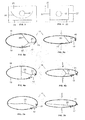
- the side airbag according to the present invention includes an inflatable cushion 11 with a venting opening 17 and a venting regulation device formed by a part made of a flexible material 21 and a tension belt 23 the features of which will be explained below according to Figures 1a, 1b and 1c in which the inflatable cushion 11 can be seen schematically in three moments of the initial phase, the intermediate phase and the end phase of its deployment.
- the part made of a flexible material 21 is joined by its perimeter, completely or partially to the inflatable cushion 11 by means of suitable joining means 33 such as seams for example, without being tensed, but rather leaving a clearance between it and the cushion.
- suitable joining means 33 such as seams for example, without being tensed, but rather leaving a clearance between it and the cushion.
- the venting opening 17 is located inside the perimeter of the part made of a flexible material 21.
- the tension belt 23 which is usually in band shape, is joined by one part to the part made of a flexible material 21 by means of suitable joining means such as seams 35, and by another part to the inflatable cushion 11 by means of suitable means such as seams 37, 39, at two points thereof in the case shown in Figures 1a, 1b and 1c .
- the geometric configuration of said part made of a flexible material 21 and said tension belt 23 are provided so that the deployment of the inflatable cushion during a collision occurs in the three phases described below.
- the venting opening 17 is completely closed by the part made of a flexible material 21, preventing gas losses through the venting opening 17.
- venting regulation device may require the use of means in addition to the joining means 33 of the part made of a flexible material 21 to the inflatable cushion 11.
- An additional suitable mean shown in Figure 3 consists of an additional seam 25 of the part made of a flexible material 21 to the inflatable cushion which can be broken when the tension belt 23 applies certain tension on the part made of a flexible material 21.
- Another additional suitable mean particularly when the part made of a flexible material 21 is joined to the inflatable cushion 11 along its entire perimeter preventing any gas leak consists of, according to Figure 4 , pro-cuts 27 defining breaking lines when the tension belt 23 applies a certain tension on the part made of a flexible material 21.
- the tension belt 23 pulls on the part made of a flexible material 21 making it depart from the opening and, as the case may be, breaking the breakable seam 25 or opening the breaking lines defined by the pre-cuts 27. Since the tension belt. 23 and the part made of a flexible material 21 are tensed, the venting opening 17 does not close,
- FIGS 2b and 2a The improvement of the adaptiveness of the side airbag according to the invention is illustrated in Figures 2b and 2a , respectively showing stress (S) /movement (M) graphs of a side airbag with and without a venting regulation device according to the present invention, where S is the stress applied by the airbag cushion on the occupant and M the occupant's position in relation to the vehicle door.
- Figure 2a shows three sections in the graph as a result of the evolution of the pressure in the cushion: in the first section between movement m3, when the airbag cushion enters into contact with the occupant, and movement m2, stress S constantly increases, in a second section between movement m2 and movement m1, stress S is constant, and in the end section between movement m2 and movement d0 in which the occupant would come into contact with the vehicle door, the stress constantly decreases.
- Figure 2b includes together with the graphic of the side airbag according to the present invention, the graphic of Figure 2a using dotted lines and areas with lines between them to facilitate the comparison, the following differences can be observed in relation to Figure 2a :
- the inflatable cushion 11 is formed by two panels 13, 15, the part made of a flexible material 21 is joined to the inside surface of the panel 13 of the cushion 11 by means of joining means 41, 45 and the tension belt 23 is joined to the other panel 15.
- Figure 5a shows the cushion 11 in its state of maximum width with the opening 17 open since the tension belt 23 is tensed and Figure 5b does so in a state of less width after receiving the occupant's strike, in which the orifice 17 is closed by the part made of a flexible material 21 when the tension belt 23 loses tension.
- Figures 6a and 6b show another embodiment of the invention in which the tension belt 23 has three arms and the part made of a flexible material 21 has a relatively small dimension.
- Figures 7a and 7b show another embodiment of the invention in which the part made of a flexible material 21. is joined to the outside surface of the inflatable cushion 11.
- Figure 7a shows the cushion 11 in its state of maximum width with the opening 17 open and with the belt 23 without tension since the part made of a flexible material 21 is located on the outside of the cushion 11, and
- Figure 7b shows the cushion 11 with a reduced width after receiving the load of the occupant and with the belt 23 tensed to close the opening 17.
Abstract
Description
- The present invention relates to a venting device of a side airbag used in automobiles to dampen impacts experienced by drivers and passengers in the event of impacts or collisions, and more particularly to a venting device that can be adapted to impacts or collisions of different severities.
- A side airbag basically consists of a folded cushion that is quickly inflated by means of a gas produced by a generator when certain sensor devices detect a collision of the vehicle. The cushion is thus deployed between the vehicle's occupant and, usually, a door of the vehicle and protecting him/her during the collision.
- In normal cushion deployment operation, the internal pressure produced by the generator when the cushion is filled with gas may be high enough to cause the cushion to be so hard that the occupant bounces off it. To prevent this drawback, they have been provided with a venting opening serving to reduce internal pressure of the cushion and, accordingly, the possibility of causing damage when they are activated.
- The use of several means of blocking this venting opening to achieve a better control of the internal pressure in the cushion than that provided by only the variation of the size of the opening is in turn known. In this sense, the use of patches for achieving that the gas does not exit the discharge opening immediately but rather when the patch breaks as a given pressure inside the cushion has been reached, must be pointed out. The art has proposed different types of patches with different means for controlling the breaking thereof, more or less according to a certain resistance to the gas pressure inside the cushion. The presence of the gas pressure required for the cushion to carry out its protective function is thus made compatible with the assurance that the gas pressure will not reach an excessive value, with the risk for the people for whom the cushion is deployed.
- Additionally, venting devices that allow increasing the gas outlet flow according to the specific characteristics of each collision and the type of passenger involved have also become necessary, and to that effect several venting device solutions providing surface adjustable venting openings facilitating the increase of the venting area as the internal pressure in the cushion increases are also known.
- A newly arisen need involves the need for airbags that allow reducing the venting area, even completely eliminating it, in certain impact conditions, which requires closing mechanisms that must function in the sense opposite to the art known up until now. The traditional previously mentioned patches had to completely seal the outlet opening until the internal gas pressure inside the cushion did not reach a given level and then they broke, no longer functioning; now the opposite is required: devices that allow closing the venting opening in certain situations. Some proposals to that effect are known, such as the following.
- Spanish patent
ES 2,182,629 US patent 6, 139, 048 ,US patent application 2004/0090054 , patent applicationWO 2006/024472 ,US patent application 2006/0151979 EP 1 044 855FR 2 757 465 DE 10 2005 019 778 describe devices using moving elements to close the venting opening using the stresses produced in the cushion due to the pressure difference together with the difference of how the occupant strikes the airbag. - Patent applications
EP 1,640,221 andWO 2007/003418 describe passive venting control mechanisms using elements which close the venting opening when certain conditions arise. - The present invention proposes a side airbag with an adaptive venting device with functionalities different from those of the mentioned art.
- An objective of the present invention is to provide a side airbag with a venting that can be adjusted to different conditions of severity of the impact or collision. It aims to take into consideration the different, configurations of the impact and the evolutions provided therein (increase of the impact velocity, barrier change,...) contemplated by the administrative regulations and/or regulations demanded by the consumers.
- Another objective of the present invention is to provide a side airbag without gas losses - or with little gas losses- in the initial deployment phase.
- Another objective of the present invention is to provide a side airbag which allows controlling the stress applied on the occupant's side, i.e. the chest, abdomen or pelvis as required. Controlling the stress allows preventing injuries to the occupant.
- These and other objectives are achieved by means of a side airbag comprising an inflatable cushion including at least one venting opening and being configured to be deployed between a vehicle occupant and the vehicle body, and incorporating a venting regulation device formed by a part made of a flexible material joined to the inflatable cushion such that it can completely or partially close or free said venting opening, and a tension belt joined by one part to said part made of flexible material and by another part to the inflatable cushion, the geometric configurations of said tension belt and said part made of flexible material being determined such that the degree of closing/freeing the venting opening varies according to the width of the inflatable cushion during the different phases of its deployment during the collision, being closed in the initial and end phases and freed in the intermediate phase when the inflatable cushion reaches its maximum width when it enters into contact with the vehicle occupant.
- Some relevant advantages of said venting regulation device include the following:
- It can be easily integrated in the inflatable cushion.
- It is passive and therefore requires no electrical signal to be activated.
- - It is low-cost.
- - Its operation regulating parameters can be easily changed.
- Other features and advantages of the present invention will become evident from the following detailed description of several illustrative and by no means limiting embodiments of its object in relation to the attached drawings.
-
-
Figures 1a, 1b and 1c schematically show the operation of a side airbag with a venting regulation device according to the present invention formed by a part made of a flexible material and a tension belt. -
Figures 2a and 2b schematically show the effect of the venting regulation device according to the present invention in a stress-movement diagram. -
Figures 3 and 4 schematically show two embodiments of the device allowing the part made of a flexible material to completely close the venting opening in the initial cushion deployment, phase. -
Figures 5a and 5b schematically show a first embodiment of the present invention. -
Figures 6a and 6b schematically show a second embodiment of the present invention. -
Figures 7a and 7b schematically show a third embodiment of the present invention. - The object of the present invention is a side airbag which does not allow venting in its initial, and end deployment phases and which regulates venting during the intermediate deployment phase in a manner adapted to the nature of the impact. A side airbag with these functional features meets the objectives mentioned above.
- The side airbag according to the present invention includes an
inflatable cushion 11 with aventing opening 17 and a venting regulation device formed by a part made of aflexible material 21 and atension belt 23 the features of which will be explained below according toFigures 1a, 1b and 1c in which theinflatable cushion 11 can be seen schematically in three moments of the initial phase, the intermediate phase and the end phase of its deployment. - The part made of a
flexible material 21 is joined by its perimeter, completely or partially to theinflatable cushion 11 by means ofsuitable joining means 33 such as seams for example, without being tensed, but rather leaving a clearance between it and the cushion. Theventing opening 17 is located inside the perimeter of the part made of aflexible material 21. - The
tension belt 23, which is usually in band shape, is joined by one part to the part made of aflexible material 21 by means of suitable joining means such asseams 35, and by another part to theinflatable cushion 11 by means of suitable means such asseams Figures 1a, 1b and 1c . - According to the invention, the geometric configuration of said part made of a
flexible material 21 and saidtension belt 23 are provided so that the deployment of the inflatable cushion during a collision occurs in the three phases described below. - In the initial deployment phase shown in
Figure 1 , theventing opening 17 is completely closed by the part made of aflexible material 21, preventing gas losses through theventing opening 17. - The suitable operation of the venting regulation device may require the use of means in addition to the
joining means 33 of the part made of aflexible material 21 to theinflatable cushion 11. - An additional suitable mean shown in
Figure 3 consists of anadditional seam 25 of the part made of aflexible material 21 to the inflatable cushion which can be broken when thetension belt 23 applies certain tension on the part made of aflexible material 21. - Another additional suitable mean particularly when the part made of a
flexible material 21 is joined to theinflatable cushion 11 along its entire perimeter preventing any gas leak consists of, according toFigure 4 ,pro-cuts 27 defining breaking lines when thetension belt 23 applies a certain tension on the part made of aflexible material 21. - In the intermediate deployment phase of the
inflatable cushion 11 shown inFigure 1b , and as a result of the progressive entrance of gas increasing the width of the cushion, thetension belt 23 pulls on the part made of aflexible material 21 making it depart from the opening and, as the case may be, breaking thebreakable seam 25 or opening the breaking lines defined by the pre-cuts 27. Since the tension belt. 23 and the part made of aflexible material 21 are tensed, theventing opening 17 does not close, - In the end phase shown in
Figure 1c , when theinflatable cushion 11 is struck, when it enters into contact with the occupant its width reduces, determining that thetension belt 23 and the part made of aflexible material 21 lose tension, causing the part made of aflexible material 21 to gradually move towards theventing opening 17 until completely closing it. - The improvement of the adaptiveness of the side airbag according to the invention is illustrated in
Figures 2b and 2a , respectively showing stress (S) /movement (M) graphs of a side airbag with and without a venting regulation device according to the present invention, where S is the stress applied by the airbag cushion on the occupant and M the occupant's position in relation to the vehicle door. -
Figure 2a shows three sections in the graph as a result of the evolution of the pressure in the cushion: in the first section between movement m3, when the airbag cushion enters into contact with the occupant, and movement m2, stress S constantly increases, in a second section between movement m2 and movement m1, stress S is constant, and in the end section between movement m2 and movement d0 in which the occupant would come into contact with the vehicle door, the stress constantly decreases. -
Figure 2b includes together with the graphic of the side airbag according to the present invention, the graphic ofFigure 2a using dotted lines and areas with lines between them to facilitate the comparison, the following differences can be observed in relation toFigure 2a : - The first section, between movement m3' and movement m2' is shorter since the pressure increases quickly since the venting opening is closed.
- The start of the second section in movement m2' moves ahead, the opening of the venting opening beginning, which allows controlling the stress applied on the side of the occupant, i.e. the chest, abdomen or pelvis, as needed, preventing injuries to the occupant.
- In the third section the venting opening is closed, thereby keeping gas in the airbag cushion preventing contact between the occupant, and the vehicle door. Its start is therefore delayed to movement m1' and its end is moved ahead to movement m0'.
- In the embodiment shown in
Figures 5a and 5b , theinflatable cushion 11 is formed by twopanels flexible material 21 is joined to the inside surface of thepanel 13 of thecushion 11 by means ofjoining means tension belt 23 is joined to theother panel 15.Figure 5a shows thecushion 11 in its state of maximum width with theopening 17 open since thetension belt 23 is tensed andFigure 5b does so in a state of less width after receiving the occupant's strike, in which theorifice 17 is closed by the part made of aflexible material 21 when thetension belt 23 loses tension. -
Figures 6a and 6b show another embodiment of the invention in which thetension belt 23 has three arms and the part made of aflexible material 21 has a relatively small dimension. - Finally,
Figures 7a and 7b show another embodiment of the invention in which the part made of aflexible material 21. is joined to the outside surface of theinflatable cushion 11. In this case,Figure 7a shows thecushion 11 in its state of maximum width with theopening 17 open and with thebelt 23 without tension since the part made of aflexible material 21 is located on the outside of thecushion 11, andFigure 7b shows thecushion 11 with a reduced width after receiving the load of the occupant and with thebelt 23 tensed to close theopening 17. - Although several embodiments of the invention have been described and shown, modifications comprised within the scope thereof can be introduced, the scope not being limited to said embodiment but to the content of the following claims.
Claims (8)
- A side airbag for an automotive vehicle comprising an inflatable cushion (11) that can be inflated with the gas produced by a generator when a collision occurs, including at least one venting opening (117) and being configured to be deployed between a vehicle occupant and the vehicle body, characterized in that it also comprises a venting regulation device formed by a part made of a flexible material (21) joined to the inflatable cushion (11) such that it can completely or partially close or free said venting opining (17), preventing or allowing the outlet of gas, and a tension belt (23) joined by one part to said part made of a flexible material (21) and by another part to the inflatable cushion (11), the geometric configurations of said tension belt (23) and said part made of a flexible material (21) being determined such that the degree of closing/freeing of the venting opening (17) varies according to the width of the inflatable cushion (11) during its different deployment phases during the collision, being closed in the initial and end phases and freed in the intermediate phase in which the inflatable cushion (11) reaches its maximum width when entering into contact with the vehicle occupant.
- A side airbag for an automotive vehicle according to claim 1, characterized in that the part made of a flexible material (21) is joined to the inside surface of the inflatable cushion (11).
- A side airbag for an automotive vehicle according to claim 2, characterized in that the part made of a flexible material (21) is initially joined to the inflatable cushion (11) such that it completely closes the venting opening (17), and in that it includes means (25, 27) allowing the formation therein of a breaking line when tension is applied thereof by means of the tension belt (23).
- A side airbag for an automotive vehicle according to claim 3, characterised in that said means consist of a breakable seam (25) in the part made of it flexible material (21).
- A side airbag for an automotive vehicle according to claim 3, characterized in that said means consist of pre-cuts (27) in the part made of a flexible material (21).
- A side airbag for an automotive vehicle according to any of claims 1-5, characterized in that the inflatable cushion (11) is formed by two panels (13, 15) and the tension belt (23) is joined to the part made of a flexible material (21) and to the two panels (13, 15) of the inflatable cushion (11).
- A side airbag for an automotive vehicle according to claim 6, characterized in that the part made of a flexible material (21) is joined only to one of the panels (13) of the inflatable cushion (11).
- A side airbag for an automotive vehicle according to claim 1, characterized in that the part made of a flexible material (21) is jointed to the outside surface of the inflatable cushion (11).
Priority Applications (5)
| Application Number | Priority Date | Filing Date | Title |
|---|---|---|---|
| ES07381037T ES2351860T3 (en) | 2007-05-09 | 2007-05-09 | SIDE AIRBAG WITH AN ADAPTIVE VENTILATION DEVICE. |
| AT07381037T ATE485976T1 (en) | 2007-05-09 | 2007-05-09 | SIDE AIRBAG WITH ADAPTIVE VENTILATION DEVICE |
| EP07381037A EP1990248B1 (en) | 2007-05-09 | 2007-05-09 | Side airbag with an adaptive venting device |
| DE602007010105T DE602007010105D1 (en) | 2007-05-09 | 2007-05-09 | Side airbag with adaptive ventilation device |
| US12/151,737 US7810839B2 (en) | 2007-05-09 | 2008-05-08 | Side airbag with an adaptive venting device |
Applications Claiming Priority (1)
| Application Number | Priority Date | Filing Date | Title |
|---|---|---|---|
| EP07381037A EP1990248B1 (en) | 2007-05-09 | 2007-05-09 | Side airbag with an adaptive venting device |
Publications (2)
| Publication Number | Publication Date |
|---|---|
| EP1990248A1 EP1990248A1 (en) | 2008-11-12 |
| EP1990248B1 true EP1990248B1 (en) | 2010-10-27 |
Family
ID=38523494
Family Applications (1)
| Application Number | Title | Priority Date | Filing Date |
|---|---|---|---|
| EP07381037A Active EP1990248B1 (en) | 2007-05-09 | 2007-05-09 | Side airbag with an adaptive venting device |
Country Status (5)
| Country | Link |
|---|---|
| US (1) | US7810839B2 (en) |
| EP (1) | EP1990248B1 (en) |
| AT (1) | ATE485976T1 (en) |
| DE (1) | DE602007010105D1 (en) |
| ES (1) | ES2351860T3 (en) |
Families Citing this family (6)
| Publication number | Priority date | Publication date | Assignee | Title |
|---|---|---|---|---|
| US8262130B2 (en) | 2007-07-30 | 2012-09-11 | Trw Vehicle Safety Systems Inc. | Air bag with improved tear stitch |
| US8047564B2 (en) * | 2009-09-02 | 2011-11-01 | Tk Holdings Inc. | Airbag |
| KR101078882B1 (en) * | 2009-12-09 | 2011-11-02 | 아우토리브 디벨롭먼트 아베 | Front Air Bag including Sst―rings & Vent parts |
| DE102010026933B4 (en) * | 2010-07-12 | 2013-02-28 | Autoliv Development Ab | Side air bag |
| FR2993223A1 (en) * | 2012-07-12 | 2014-01-17 | Peugeot Citroen Automobiles Sa | Airbag safety device for car, has airbag including control unit to control access to opening according to airbag depression, where access is restricted when depression is large to vary stiffness of airbag depending on depression |
| JP6225877B2 (en) * | 2014-10-22 | 2017-11-08 | トヨタ自動車株式会社 | Side airbag device for vehicle |
Family Cites Families (13)
| Publication number | Priority date | Publication date | Assignee | Title |
|---|---|---|---|---|
| FR2757465B1 (en) * | 1996-12-20 | 1999-03-05 | Aerazur | INFLATABLE SAFETY BAG WITH CONTROLLED OPENING VALVE |
| DE29720461U1 (en) | 1997-11-19 | 1998-02-26 | Trw Automotive Safety Sys Gmbh | Airbag with adjustable outlet cross-section |
| JP3463598B2 (en) * | 1999-04-13 | 2003-11-05 | トヨタ自動車株式会社 | Airbag device |
| ES2182629B1 (en) | 2000-03-13 | 2004-08-16 | Dalphi Metal España, S.A. | LOW PRESSURE MEMBRANE OBSTRUCTION DEVICE APPLICABLE FOR AIRBAGS. |
| US6832778B2 (en) * | 2002-07-19 | 2004-12-21 | Delphi Technologies, Inc. | Air bag restraint including selectively operable venting elements |
| DE10236859A1 (en) | 2002-08-07 | 2004-02-19 | Takata Corp. | Gas bag for airbag module has control belt connected to gas bag cover near outflow orifice to invert part of cover on reaching predetermined unfolded state into gas bag to close orifice |
| JP4360525B2 (en) | 2003-07-02 | 2009-11-11 | 芦森工業株式会社 | Airbag device |
| EP1786655B1 (en) | 2004-09-01 | 2010-04-14 | Autoliv Development Ab | Airbag and a motor vehicle |
| US7261319B2 (en) | 2005-01-07 | 2007-08-28 | Autoliv Asp, Inc. | Airbag cushion with adaptive venting for reduced out-of-position effects |
| DE102005019748A1 (en) * | 2005-04-28 | 2006-11-02 | Autoliv Development Ab | Front gas bag e.g. driver-gas bag, for arrangement in steering wheel, has inner layer and outer cover with respective openings, where gas flows into main chamber and then into auxiliary chamber via opening of layer, during operation of bag |
| DE102005031544A1 (en) | 2005-07-06 | 2007-01-11 | Autoliv Development Ab | Airbag unit |
| ES2302603B1 (en) * | 2006-03-13 | 2009-05-20 | Dalphi Metal España S.A. | AIRBAG WITH AN ADAPTABLE OBTAINABLE VENTILATION DEVICE. |
| US7770926B2 (en) * | 2007-08-09 | 2010-08-10 | Autoliv Asp, Inc. | Airbag adaptive venting for out-of-position occupants |
-
2007
- 2007-05-09 EP EP07381037A patent/EP1990248B1/en active Active
- 2007-05-09 ES ES07381037T patent/ES2351860T3/en active Active
- 2007-05-09 DE DE602007010105T patent/DE602007010105D1/en active Active
- 2007-05-09 AT AT07381037T patent/ATE485976T1/en not_active IP Right Cessation
-
2008
- 2008-05-08 US US12/151,737 patent/US7810839B2/en active Active
Also Published As
| Publication number | Publication date |
|---|---|
| US7810839B2 (en) | 2010-10-12 |
| EP1990248A1 (en) | 2008-11-12 |
| ATE485976T1 (en) | 2010-11-15 |
| DE602007010105D1 (en) | 2010-12-09 |
| US20090091106A1 (en) | 2009-04-09 |
| ES2351860T3 (en) | 2011-02-11 |
Similar Documents
| Publication | Publication Date | Title |
|---|---|---|
| EP1834848B1 (en) | Airbag with an adaptatively closable vent device | |
| US7810840B2 (en) | Airbag with a venting regulation device | |
| US8491004B2 (en) | Airbag module | |
| US7938438B2 (en) | Three-chamber adaptive side airbag | |
| US7793978B2 (en) | Constrained airbag deployment using an external tether | |
| EP1990248B1 (en) | Side airbag with an adaptive venting device | |
| US20070023223A1 (en) | Vehicle with collision object protection device | |
| US20100133798A1 (en) | Vehicular airbag device | |
| US8590927B2 (en) | Airbag module | |
| JP2007518622A (en) | Side protector | |
| JP2007518622A5 (en) | ||
| EP2019002B1 (en) | Adaptive airbag with a tension retension band that shapes bag areas into a v | |
| JP2515230B2 (en) | Collision protection device with air bag | |
| WO2017123442A1 (en) | Multi-flap vents for inflatable chambers | |
| EP1896298B1 (en) | Airbag with a closable venting device | |
| EP2048041B1 (en) | Front airbag with an adaptive venting device | |
| US9352720B2 (en) | Airbag for vehicle | |
| US9022423B2 (en) | Airbag device | |
| US20040108693A1 (en) | Device for unrestricted side airbag or curtain deployment | |
| EP2008882B1 (en) | Adaptive airbag with multi-venting | |
| WO2007016972A1 (en) | Airbag with externally closable venting openings | |
| KR101251754B1 (en) | Cover structure of air-bag | |
| KR20230047851A (en) | Air bag device | |
| JP2023156103A (en) | Vehicle side part structure | |
| WO2017182543A1 (en) | Driver airbag and steering wheel unit |
Legal Events
| Date | Code | Title | Description |
|---|---|---|---|
| PUAI | Public reference made under article 153(3) epc to a published international application that has entered the european phase |
Free format text: ORIGINAL CODE: 0009012 |
|
| AK | Designated contracting states |
Kind code of ref document: A1 Designated state(s): AT BE BG CH CY CZ DE DK EE ES FI FR GB GR HU IE IS IT LI LT LU LV MC MT NL PL PT RO SE SI SK TR |
|
| AX | Request for extension of the european patent |
Extension state: AL BA HR MK RS |
|
| 17P | Request for examination filed |
Effective date: 20090506 |
|
| AKX | Designation fees paid |
Designated state(s): AT BE BG CH CY CZ DE DK EE ES FI FR GB GR HU IE IS IT LI LT LU LV MC MT NL PL PT RO SE SI SK TR |
|
| GRAP | Despatch of communication of intention to grant a patent |
Free format text: ORIGINAL CODE: EPIDOSNIGR1 |
|
| GRAS | Grant fee paid |
Free format text: ORIGINAL CODE: EPIDOSNIGR3 |
|
| GRAA | (expected) grant |
Free format text: ORIGINAL CODE: 0009210 |
|
| AK | Designated contracting states |
Kind code of ref document: B1 Designated state(s): AT BE BG CH CY CZ DE DK EE ES FI FR GB GR HU IE IS IT LI LT LU LV MC MT NL PL PT RO SE SI SK TR |
|
| REG | Reference to a national code |
Ref country code: GB Ref legal event code: FG4D |
|
| REG | Reference to a national code |
Ref country code: CH Ref legal event code: EP |
|
| REG | Reference to a national code |
Ref country code: IE Ref legal event code: FG4D |
|
| REF | Corresponds to: |
Ref document number: 602007010105 Country of ref document: DE Date of ref document: 20101209 Kind code of ref document: P |
|
| REG | Reference to a national code |
Ref country code: ES Ref legal event code: FG2A Effective date: 20110201 |
|
| REG | Reference to a national code |
Ref country code: NL Ref legal event code: VDEP Effective date: 20101027 |
|
| LTIE | Lt: invalidation of european patent or patent extension |
Effective date: 20101027 |
|
| PG25 | Lapsed in a contracting state [announced via postgrant information from national office to epo] |
Ref country code: LT Free format text: LAPSE BECAUSE OF FAILURE TO SUBMIT A TRANSLATION OF THE DESCRIPTION OR TO PAY THE FEE WITHIN THE PRESCRIBED TIME-LIMIT Effective date: 20101027 |
|
| PG25 | Lapsed in a contracting state [announced via postgrant information from national office to epo] |
Ref country code: SE Free format text: LAPSE BECAUSE OF FAILURE TO SUBMIT A TRANSLATION OF THE DESCRIPTION OR TO PAY THE FEE WITHIN THE PRESCRIBED TIME-LIMIT Effective date: 20101027 Ref country code: IS Free format text: LAPSE BECAUSE OF FAILURE TO SUBMIT A TRANSLATION OF THE DESCRIPTION OR TO PAY THE FEE WITHIN THE PRESCRIBED TIME-LIMIT Effective date: 20110227 Ref country code: PT Free format text: LAPSE BECAUSE OF FAILURE TO SUBMIT A TRANSLATION OF THE DESCRIPTION OR TO PAY THE FEE WITHIN THE PRESCRIBED TIME-LIMIT Effective date: 20110228 Ref country code: BG Free format text: LAPSE BECAUSE OF FAILURE TO SUBMIT A TRANSLATION OF THE DESCRIPTION OR TO PAY THE FEE WITHIN THE PRESCRIBED TIME-LIMIT Effective date: 20110127 Ref country code: FI Free format text: LAPSE BECAUSE OF FAILURE TO SUBMIT A TRANSLATION OF THE DESCRIPTION OR TO PAY THE FEE WITHIN THE PRESCRIBED TIME-LIMIT Effective date: 20101027 Ref country code: LV Free format text: LAPSE BECAUSE OF FAILURE TO SUBMIT A TRANSLATION OF THE DESCRIPTION OR TO PAY THE FEE WITHIN THE PRESCRIBED TIME-LIMIT Effective date: 20101027 Ref country code: NL Free format text: LAPSE BECAUSE OF FAILURE TO SUBMIT A TRANSLATION OF THE DESCRIPTION OR TO PAY THE FEE WITHIN THE PRESCRIBED TIME-LIMIT Effective date: 20101027 Ref country code: AT Free format text: LAPSE BECAUSE OF FAILURE TO SUBMIT A TRANSLATION OF THE DESCRIPTION OR TO PAY THE FEE WITHIN THE PRESCRIBED TIME-LIMIT Effective date: 20101027 Ref country code: SI Free format text: LAPSE BECAUSE OF FAILURE TO SUBMIT A TRANSLATION OF THE DESCRIPTION OR TO PAY THE FEE WITHIN THE PRESCRIBED TIME-LIMIT Effective date: 20101027 |
|
| PG25 | Lapsed in a contracting state [announced via postgrant information from national office to epo] |
Ref country code: GR Free format text: LAPSE BECAUSE OF FAILURE TO SUBMIT A TRANSLATION OF THE DESCRIPTION OR TO PAY THE FEE WITHIN THE PRESCRIBED TIME-LIMIT Effective date: 20110128 Ref country code: BE Free format text: LAPSE BECAUSE OF FAILURE TO SUBMIT A TRANSLATION OF THE DESCRIPTION OR TO PAY THE FEE WITHIN THE PRESCRIBED TIME-LIMIT Effective date: 20101027 |
|
| PG25 | Lapsed in a contracting state [announced via postgrant information from national office to epo] |
Ref country code: EE Free format text: LAPSE BECAUSE OF FAILURE TO SUBMIT A TRANSLATION OF THE DESCRIPTION OR TO PAY THE FEE WITHIN THE PRESCRIBED TIME-LIMIT Effective date: 20101027 Ref country code: CZ Free format text: LAPSE BECAUSE OF FAILURE TO SUBMIT A TRANSLATION OF THE DESCRIPTION OR TO PAY THE FEE WITHIN THE PRESCRIBED TIME-LIMIT Effective date: 20101027 |
|
| PG25 | Lapsed in a contracting state [announced via postgrant information from national office to epo] |
Ref country code: SK Free format text: LAPSE BECAUSE OF FAILURE TO SUBMIT A TRANSLATION OF THE DESCRIPTION OR TO PAY THE FEE WITHIN THE PRESCRIBED TIME-LIMIT Effective date: 20101027 Ref country code: RO Free format text: LAPSE BECAUSE OF FAILURE TO SUBMIT A TRANSLATION OF THE DESCRIPTION OR TO PAY THE FEE WITHIN THE PRESCRIBED TIME-LIMIT Effective date: 20101027 Ref country code: DK Free format text: LAPSE BECAUSE OF FAILURE TO SUBMIT A TRANSLATION OF THE DESCRIPTION OR TO PAY THE FEE WITHIN THE PRESCRIBED TIME-LIMIT Effective date: 20101027 Ref country code: PL Free format text: LAPSE BECAUSE OF FAILURE TO SUBMIT A TRANSLATION OF THE DESCRIPTION OR TO PAY THE FEE WITHIN THE PRESCRIBED TIME-LIMIT Effective date: 20101027 |
|
| PLBE | No opposition filed within time limit |
Free format text: ORIGINAL CODE: 0009261 |
|
| STAA | Information on the status of an ep patent application or granted ep patent |
Free format text: STATUS: NO OPPOSITION FILED WITHIN TIME LIMIT |
|
| 26N | No opposition filed |
Effective date: 20110728 |
|
| REG | Reference to a national code |
Ref country code: DE Ref legal event code: R097 Ref document number: 602007010105 Country of ref document: DE Effective date: 20110728 |
|
| PG25 | Lapsed in a contracting state [announced via postgrant information from national office to epo] |
Ref country code: IT Free format text: LAPSE BECAUSE OF FAILURE TO SUBMIT A TRANSLATION OF THE DESCRIPTION OR TO PAY THE FEE WITHIN THE PRESCRIBED TIME-LIMIT Effective date: 20101027 Ref country code: MT Free format text: LAPSE BECAUSE OF FAILURE TO SUBMIT A TRANSLATION OF THE DESCRIPTION OR TO PAY THE FEE WITHIN THE PRESCRIBED TIME-LIMIT Effective date: 20101027 Ref country code: MC Free format text: LAPSE BECAUSE OF NON-PAYMENT OF DUE FEES Effective date: 20110531 |
|
| REG | Reference to a national code |
Ref country code: CH Ref legal event code: PL |
|
| GBPC | Gb: european patent ceased through non-payment of renewal fee |
Effective date: 20110509 |
|
| PG25 | Lapsed in a contracting state [announced via postgrant information from national office to epo] |
Ref country code: LI Free format text: LAPSE BECAUSE OF NON-PAYMENT OF DUE FEES Effective date: 20110531 Ref country code: CH Free format text: LAPSE BECAUSE OF NON-PAYMENT OF DUE FEES Effective date: 20110531 |
|
| REG | Reference to a national code |
Ref country code: IE Ref legal event code: MM4A |
|
| PG25 | Lapsed in a contracting state [announced via postgrant information from national office to epo] |
Ref country code: IE Free format text: LAPSE BECAUSE OF NON-PAYMENT OF DUE FEES Effective date: 20110509 |
|
| PG25 | Lapsed in a contracting state [announced via postgrant information from national office to epo] |
Ref country code: GB Free format text: LAPSE BECAUSE OF NON-PAYMENT OF DUE FEES Effective date: 20110509 |
|
| PG25 | Lapsed in a contracting state [announced via postgrant information from national office to epo] |
Ref country code: LU Free format text: LAPSE BECAUSE OF NON-PAYMENT OF DUE FEES Effective date: 20110509 Ref country code: CY Free format text: LAPSE BECAUSE OF FAILURE TO SUBMIT A TRANSLATION OF THE DESCRIPTION OR TO PAY THE FEE WITHIN THE PRESCRIBED TIME-LIMIT Effective date: 20101027 |
|
| PG25 | Lapsed in a contracting state [announced via postgrant information from national office to epo] |
Ref country code: TR Free format text: LAPSE BECAUSE OF FAILURE TO SUBMIT A TRANSLATION OF THE DESCRIPTION OR TO PAY THE FEE WITHIN THE PRESCRIBED TIME-LIMIT Effective date: 20101027 |
|
| PG25 | Lapsed in a contracting state [announced via postgrant information from national office to epo] |
Ref country code: HU Free format text: LAPSE BECAUSE OF FAILURE TO SUBMIT A TRANSLATION OF THE DESCRIPTION OR TO PAY THE FEE WITHIN THE PRESCRIBED TIME-LIMIT Effective date: 20101027 |
|
| REG | Reference to a national code |
Ref country code: FR Ref legal event code: PLFP Year of fee payment: 10 |
|
| REG | Reference to a national code |
Ref country code: FR Ref legal event code: PLFP Year of fee payment: 11 |
|
| REG | Reference to a national code |
Ref country code: FR Ref legal event code: PLFP Year of fee payment: 12 |
|
| PGFP | Annual fee paid to national office [announced via postgrant information from national office to epo] |
Ref country code: FR Payment date: 20230309 Year of fee payment: 17 |
|
| P01 | Opt-out of the competence of the unified patent court (upc) registered |
Effective date: 20230528 |
|
| PGFP | Annual fee paid to national office [announced via postgrant information from national office to epo] |
Ref country code: ES Payment date: 20230605 Year of fee payment: 17 Ref country code: DE Payment date: 20230531 Year of fee payment: 17 |