US7347450B2 - Airbag cushion with cinch tube for reduced out-of-position effects - Google Patents
Airbag cushion with cinch tube for reduced out-of-position effects Download PDFInfo
- Publication number
- US7347450B2 US7347450B2 US10/959,256 US95925604A US7347450B2 US 7347450 B2 US7347450 B2 US 7347450B2 US 95925604 A US95925604 A US 95925604A US 7347450 B2 US7347450 B2 US 7347450B2
- Authority
- US
- United States
- Prior art keywords
- cinch
- airbag cushion
- tube
- cord
- aperture
- Prior art date
- Legal status (The legal status is an assumption and is not a legal conclusion. Google has not performed a legal analysis and makes no representation as to the accuracy of the status listed.)
- Active, expires
Links
Images


Classifications
-
- B—PERFORMING OPERATIONS; TRANSPORTING
- B60—VEHICLES IN GENERAL
- B60R—VEHICLES, VEHICLE FITTINGS, OR VEHICLE PARTS, NOT OTHERWISE PROVIDED FOR
- B60R21/00—Arrangements or fittings on vehicles for protecting or preventing injuries to occupants or pedestrians in case of accidents or other traffic risks
- B60R21/02—Occupant safety arrangements or fittings, e.g. crash pads
- B60R21/16—Inflatable occupant restraints or confinements designed to inflate upon impact or impending impact, e.g. air bags
- B60R21/23—Inflatable members
- B60R21/231—Inflatable members characterised by their shape, construction or spatial configuration
- B60R21/2334—Expansion control features
- B60R21/2338—Tethers
-
- B—PERFORMING OPERATIONS; TRANSPORTING
- B60—VEHICLES IN GENERAL
- B60R—VEHICLES, VEHICLE FITTINGS, OR VEHICLE PARTS, NOT OTHERWISE PROVIDED FOR
- B60R21/00—Arrangements or fittings on vehicles for protecting or preventing injuries to occupants or pedestrians in case of accidents or other traffic risks
- B60R21/02—Occupant safety arrangements or fittings, e.g. crash pads
- B60R21/16—Inflatable occupant restraints or confinements designed to inflate upon impact or impending impact, e.g. air bags
- B60R21/23—Inflatable members
- B60R21/239—Inflatable members characterised by their venting means
-
- B—PERFORMING OPERATIONS; TRANSPORTING
- B60—VEHICLES IN GENERAL
- B60R—VEHICLES, VEHICLE FITTINGS, OR VEHICLE PARTS, NOT OTHERWISE PROVIDED FOR
- B60R21/00—Arrangements or fittings on vehicles for protecting or preventing injuries to occupants or pedestrians in case of accidents or other traffic risks
- B60R21/02—Occupant safety arrangements or fittings, e.g. crash pads
- B60R21/16—Inflatable occupant restraints or confinements designed to inflate upon impact or impending impact, e.g. air bags
- B60R21/26—Inflatable occupant restraints or confinements designed to inflate upon impact or impending impact, e.g. air bags characterised by the inflation fluid source or means to control inflation fluid flow
-
- B—PERFORMING OPERATIONS; TRANSPORTING
- B60—VEHICLES IN GENERAL
- B60R—VEHICLES, VEHICLE FITTINGS, OR VEHICLE PARTS, NOT OTHERWISE PROVIDED FOR
- B60R21/00—Arrangements or fittings on vehicles for protecting or preventing injuries to occupants or pedestrians in case of accidents or other traffic risks
- B60R21/02—Occupant safety arrangements or fittings, e.g. crash pads
- B60R21/16—Inflatable occupant restraints or confinements designed to inflate upon impact or impending impact, e.g. air bags
- B60R21/23—Inflatable members
- B60R21/231—Inflatable members characterised by their shape, construction or spatial configuration
- B60R21/2334—Expansion control features
- B60R21/2338—Tethers
- B60R2021/23382—Internal tether means
-
- B—PERFORMING OPERATIONS; TRANSPORTING
- B60—VEHICLES IN GENERAL
- B60R—VEHICLES, VEHICLE FITTINGS, OR VEHICLE PARTS, NOT OTHERWISE PROVIDED FOR
- B60R21/00—Arrangements or fittings on vehicles for protecting or preventing injuries to occupants or pedestrians in case of accidents or other traffic risks
- B60R21/02—Occupant safety arrangements or fittings, e.g. crash pads
- B60R21/16—Inflatable occupant restraints or confinements designed to inflate upon impact or impending impact, e.g. air bags
- B60R21/23—Inflatable members
- B60R21/231—Inflatable members characterised by their shape, construction or spatial configuration
- B60R21/2334—Expansion control features
- B60R21/2338—Tethers
- B60R2021/23386—External tether means
-
- B—PERFORMING OPERATIONS; TRANSPORTING
- B60—VEHICLES IN GENERAL
- B60R—VEHICLES, VEHICLE FITTINGS, OR VEHICLE PARTS, NOT OTHERWISE PROVIDED FOR
- B60R21/00—Arrangements or fittings on vehicles for protecting or preventing injuries to occupants or pedestrians in case of accidents or other traffic risks
- B60R21/02—Occupant safety arrangements or fittings, e.g. crash pads
- B60R21/16—Inflatable occupant restraints or confinements designed to inflate upon impact or impending impact, e.g. air bags
- B60R21/26—Inflatable occupant restraints or confinements designed to inflate upon impact or impending impact, e.g. air bags characterised by the inflation fluid source or means to control inflation fluid flow
- B60R21/276—Inflatable occupant restraints or confinements designed to inflate upon impact or impending impact, e.g. air bags characterised by the inflation fluid source or means to control inflation fluid flow with means to vent the inflation fluid source, e.g. in case of overpressure
- B60R2021/2765—Inflatable occupant restraints or confinements designed to inflate upon impact or impending impact, e.g. air bags characterised by the inflation fluid source or means to control inflation fluid flow with means to vent the inflation fluid source, e.g. in case of overpressure comprising means to control the venting
Definitions
- the present invention relates generally to the field of automotive protective systems. More specifically, the present invention relates to inflatable airbags for automobiles.
- FIG. 1A is a cross-sectional view of an embodiment of a deploying airbag cushion.
- FIG. 1B is a cross-sectional view of the deploying airbag cushion of FIG. 1A .
- FIG. 1C is a cross-sectional view of an embodiment of a deploying airbag cushion of FIGS. 1A and 1B .
- FIG. 2A is a perspective view of an embodiment of a cinch tube.
- FIG. 2B is a perspective view of the cinch tube of FIG. 2A .
- FIG. 3 is a perspective view of an alternative embodiment of a cinch tube.
- FIG. 4 is a perspective view of another alternative embodiment of a cinch tube.
- FIG. 5A is a cross-sectional view illustrating initial deployment of an airbag cushion.
- FIG. 5B is a cross-sectional view illustrating a deploying airbag cushion.
- FIG. 5C is a cross-sectional view of a deployed airbag cushion.
- FIG. 5D is a cross-sectional view illustrating initial deployment of an airbag cushion.
- FIG. 5E is a cross-sectional view illustrating a deploying airbag cushion.
- FIG. 5F is a cross-sectional view of a deployed airbag cushion.
- FIG. 6 is a diagram illustrating an airbag cushion venting graph in relation to an airbag cushion's deployment.
- FIG. 7 is a cross-sectional view of an alternative embodiment of a deployed airbag cushion.
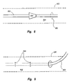
- FIG. 8 is a side view of one embodiment of a cinch cord disposed within a cinch tube.
- FIG. 9 is a side view of another embodiment of a cinch tube with a cinch cord partially disposed therein.
- an airbag cushion and venting mechanism Described below are embodiments of an airbag cushion and venting mechanism. As those of skill in the art will appreciate, the principles of the invention may be applied to and used with a variety of airbag deployment systems including frontal driver and passenger airbags, knee airbags, overhead airbags, curtain airbags, and the like. Thus, the present invention is applicable to airbag cushions of various shapes and sizes.
- Airbag cushions are frequently located in an instrument panel and directly in front of an occupant. During a collision, the airbag cushion inflates and deploys through a cosmetic cover. The airbag cushion deploys towards the occupant and provides a restraint. A dangerous situation occurs where an occupant is positioned to closely to the airbag which causes the occupant to contact the airbag as it is deploying. Ideally, the occupant should be in position to contact the airbag only after full deployment. It would be advantageous to provide an airbag with a softer deployment when an occupant is out-of-position. Embodiments described below provide an airbag cushion that responds to an occupant's position and vents accordingly to avoid excessive deploying impact.
- Embodiments disclosed herein include a cinch cord that is connected at one end to a cinch tube and at an opposing end to an interior surface of the cushion. If an occupant is in close proximity to the deploying airbag and restricts normal inflation, the cinch tube remains open and allows gas to rapidly escape. If the occupant is in a normal position and inflation is unrestricted, the tension pulls on the cinch tube to quickly close the cinch tube. Closure retains gas for normal occupant restraint.
- the cinch tube may be used as a variable feature in out-of-position conditions and in normal restraint conditions. In this manner, the airbag cushion is sensitive to obstructive expansion of the cushion.
- FIGS. 1A through 1C depicts a cross-sectional view of an airbag cushion 100 deploying from a housing 10 .
- the airbag cushion 100 includes a cinch tube 102 that may include a nylon woven fabric-type or other suitable material known in the art.
- the cinch tube 102 may be embodied with a generally cylindrical shape and having opposing open ends to enable gas venting.
- the cinch tube 102 may have any suitable shape such as rectangular, triangular, or polygon shapes.
- the cinch tube 102 may be embodied with a height that is sufficient to achieve desired closure.
- the cinch tube 102 is coupled to a surface 104 of the airbag cushion 100 and circumvents an aperture 106 in the surface 104 .
- the surface 104 may form part of an airbag cushion throat 108 or may be proximate to the throat 108 .
- the cinch tube 102 may extend into the airbag cushion interior 110 or may extend from the airbag cushion 100 .
- a single cinch tube 102 is disclosed but the airbag cushion 100 may include multiple cinch tubes to provide required venting capability.
- the airbag cushion 100 includes a cinch cord 112 that couples or engages the cinch tube 102 and couples to a surface 114 of the airbag cushion 100 .
- the cinch cord 112 may include a nylon material or other suitable material known in the art.
- the surface 114 may be an interior surface of the airbag cushion as depicted.
- the surface 114 may be the surface opposing the face surface 116 of the airbag cushion that contacts the occupant.
- the surface 114 may be disposed proximate to a surface opposing the face surface 116 .
- the surface 114 may be an exterior surface such as the face surface 116 .
- the cinch cord 112 may extend through the interior 110 of the airbag cushion 100 or may be positioned exterior to the airbag cushion 100 .
- the location of the surface 114 depends on module deployment angle, vehicle interior geometry, and cushion fold type.
- the initially deploying airbag cushion 100 has a slack cinch cord 112 and the cinch tube 102 remains open.
- the cinch cord 112 is pulled taut and the cinch tube 102 begins to close.
- the cinch cord 112 is completely taut and the cinch tube 102 is closed.
- FIGS. 2A and 2B perspective views of one embodiment of a cinch tube 102 in both the open and closed positions are shown.
- the cinch cord 112 circumvents a majority of the perimeter 200 of the cinch tube 102 in order to properly tighten and restrict the cinch tube 102 .
- the cinch cord 112 has a length that includes an initial free length and a circumference of the cinch tube 102 .
- the cinch cord 112 may be disposed within a sleeve 202 that is formed within the cinch tube 102 . Access to the sleeve 120 is through a sleeve aperture 204 formed in the cinch tube 102 .
- the cinch cord 112 enters the sleeve aperture 204 , feeds through the sleeve 202 , and is coupled at an end 206 within the sleeve 120 to the cinch tube 102 .
- Coupling may be achieved by stitches, bonds, or adhesives.
- a cinch tube 300 wherein a cinch cord 302 loops around the majority of the cinch tube perimeter 304 .
- the cinch tube 300 includes first and second sleeve apertures 306 , 308 that are in communication with a sleeve 310 formed within the cinch tube 300 .
- the cinch cord 302 enters the first sleeve aperture 306 , extends along the sleeve 310 , and exits out the second sleeve aperture 308 .
- a cinch tube 400 is shown wherein the cinch tube 400 includes a plurality of cinch loops 402 .
- the cinch loops 402 may be disposed on a periphery 404 as shown or on an inner or outer surface 406 , 408 of the cinch tube 400 .
- a cinch cord 410 is fed through the cinch loops 402 and is thereby able to restrict the cinch tube 400 as needed.
- FIGS. 5A-C illustrate three stages of a deploying airbag cushion 500 without obstruction in the deploying path.
- the depicted airbag cushion 500 includes two cinch tubes 502 symmetrically disposed on the cushion 500 and two vents 504 symmetrically disposed on the cushion 500 .
- the vents 504 provide consistent venting of the airbag cushion 500 and are not restricted by an occupant's position.
- the vents 504 may be optional in certain cushion embodiments based on venting requirements.
- the locations for the cinch tubes 502 and vents 504 may vary as does the number of tubes 502 and vents 504 .
- An occupant 12 is in a normal seating position which will allow the airbag cushion 500 to fully expand before impacting the occupant. In this manner, the occupant 12 benefits from the full restraint capability of the airbag cushion 500 .
- FIG. 5A the initial breakout of the airbag cushion 500 occurs.
- the cinch tubes 502 are open and, in the depicted embodiment, extend from the airbag cushion 500 .
- FIG. 5B cinch cords 506 corresponding to each cinch tube 502 are pulled taut and the cinch tubes 502 are restricted.
- the cinch tubes 502 may also be pulled within the interior 508 of the airbag cushion 500 .
- FIG. 5C the cinch tubes 502 are completely closed, the gas vents through the vents 504 , and normal restraint is provided to the occupant 12 .
- FIGS. 5D-F illustrate three stages of a deploying airbag cushion 500 with obstruction in the deploying path.
- An occupant 12 is out-of-position and obstructs the deploying airbag cushion 500 and prevents the airbag cushion 500 from fully inflating.
- the airbag cushion 500 begins initial deployment as in FIG. 5A .
- the airbag cushion 500 impacts the occupant 12 and the cinch cords 506 remain slack.
- the cinch tubes 502 remain open and venting rapidly occurs from tubes 502 and vents 504 .
- the cushion inflation is restricted but the occupant 12 receives less than the full deployment loading of the cushion 500 .
- the cushion 500 is partially inflated and provides limited restraint. Venting continues through the tubes 502 and vents 504 .
- FIG. 6 a graph illustrating cinch tube venting as a function of airbag cushion displacement is shown.
- an airbag cushion 600 is shown in various stages of deployment.
- the airbag cushion 600 includes two symmetrically disposed cinch tubes 602 .
- the airbag cushion 600 is unfolding and the cinch tubes 602 provide little or no venting.
- the airbag cushion 600 expands into an out-of-position zone 604 where, if obstructed, the cinch tubes 602 will remain completely or nearly open and full venting occurs. In this zone an occupant does not receive the full restraint capability but does benefit from limited restraint.
- the airbag cushion 600 expands into a gray zone 606 where partial closure of the cinch tubes 602 begins and venting is limited.
- the cinch tubes 602 may be pulled into the airbag cushion 600 depending on the cushion design. If further unobstructed, the airbag cushion 600 fully expands to the restraint zone 608 . At this zone, the cinch tubes 602 completely close and an occupant benefits from the full restraint capability of the airbag cushion 600 .
- the airbag cushion 700 includes two symmetrical cinch tubes 702 that may be embodied as described above.
- the cinch tubes 702 have been pulled completely into the airbag cushion interior 704 .
- a single cinch cord 706 is used.
- the cinch cord 706 is coupled to or engages each cinch tube 702 in a manner similar to that previously described.
- the cinch cord 706 passes through a cord loop 708 that is coupled to an interior surface 710 .
- the cord loop 708 may be formed of a fabric material similar or identical to that of the airbag cushion 700 .
- the cinch cord 706 may freely pass through the loop 708 and may therefore be referred to as a “floating” cinch cord.
- the cinch cord 706 may be disposed on the airbag cushion exterior and passes through a cord loop 708 coupled to an exterior surface of the airbag cushion 700 .
- airbag cushion deployment pulls the cinch cord 706 taut and closes both cinch tubes 702 .
- FIG. 8 an alternative embodiment of a cinch cord 800 disposed within a cinch tube 802 is shown.
- the cinch tube 802 includes a sleeve 804 that extends around a periphery of the cinch tube 802 and houses a portion of the cinch cord 800 .
- the cinch cord 800 exits from the sleeve 804 through a sleeve aperture 806 .
- the cinch cord 800 includes a stopper 808 that, prior to airbag cushion deployment, is disposed within the sleeve 804 .
- the stopper 808 is sized and configured to permit deploying movement, i.e.
- the stopper 808 prevents a cinch tube 802 from reopening after deployment and closure of the cinch tube 802 . This may occur during deflation of an airbag cushion as the cinch cord becomes slack. Venting is thereby directed to other vents.
- FIG. 9 an alternative embodiment of a cinch tube 900 is shown with a cinch cord 902 partially disposed within.
- the cinch tube 900 includes a sleeve 904 that contains a portion of the cinch cord 902 .
- the cinch tube 900 further includes tack stitching 906 that is inserted through the sleeve 904 and the cinch cord 902 to retain the cinch cord 902 and prevent inadvertent closing of the cinch tube 900 during shipping and handling.
- the tack stitching 906 is designed to be easily broken and provides no interference to airbag cushion deployment.
- Embodiments disclosed herein illustrate novel techniques for venting an airbag cushion to retain an open vent when an occupant obstructs the path of a deploying cushion and closed when an occupant does not obstruct a deploying cushion.
- Airbag cushions provide improved safety by deploying with less pressure when an occupant is obstructing deployment.
- the airbag cushions deploy with more pressure when an occupant is not obstructing deployment and when high pressure is required to provide the necessary restraint.
- the airbag cushions described herein have application to both driver and passenger positions.
- the airbag cushions may be configured in a variety of sizes based on design constraints.
- Venting means refers to cinch tubes 102 , 300 , 400 , 502 , 602 , 702 , 802 , and 900 .
- Restricting means refers to cinch cords 112 , 302 , 410 , 506 , 706 , 800 , and 902 ,
Abstract
Description
Claims (20)
Priority Applications (14)
| Application Number | Priority Date | Filing Date | Title |
|---|---|---|---|
| US10/959,256 US7347450B2 (en) | 2004-10-06 | 2004-10-06 | Airbag cushion with cinch tube for reduced out-of-position effects |
| KR1020077007439A KR101223793B1 (en) | 2004-10-06 | 2005-08-01 | Airbag cushion with cinch tube for reduced out of position effects |
| RU2007117017/11A RU2391231C2 (en) | 2004-10-06 | 2005-08-01 | Airbag with tightening branch pipe to reduce displacement effects |
| EP05777506A EP1824710B1 (en) | 2004-10-06 | 2005-08-01 | Airbag cushion with cinch tube for reduced out-of-position effects |
| JP2007535671A JP4871286B2 (en) | 2004-10-06 | 2005-08-01 | Airbag cushion with grip tube that reduces the effects of non-regular positions |
| MX2007003956A MX2007003956A (en) | 2004-10-06 | 2005-08-01 | Airbag cushion with cinch tube for reduced out-of-position effects. |
| BRPI0515856-7A BRPI0515856A (en) | 2004-10-06 | 2005-08-01 | cinch tube airbag cushion to reduce unwinding effects |
| AU2005294731A AU2005294731B2 (en) | 2004-10-06 | 2005-08-01 | Airbag cushion with cinch tube for reduced out-of-position effects |
| AT05777506T ATE434547T1 (en) | 2004-10-06 | 2005-08-01 | AIRBAG AIR CUSHION WITH CINCH TUBE FOR REDUCED OUT-OF-POSITION EFFECTS |
| PCT/US2005/027255 WO2006041552A2 (en) | 2004-10-06 | 2005-08-01 | Airbag cushion with cinch tube for reduced out-of-position effects |
| CA2575577A CA2575577C (en) | 2004-10-06 | 2005-08-01 | Airbag cushion with cinch tube for reduced out-of-position effects |
| DE602005015137T DE602005015137D1 (en) | 2004-10-06 | 2005-08-01 | AIRBAG AIR CUSHION WITH CINCH TUBE FOR REDUCED OUT OF POSITION EFFECTS |
| CN200580027547XA CN101084141B (en) | 2004-10-06 | 2005-08-01 | Airbag cushions with optional venting for out-of-position conditions |
| US11/589,316 US7597355B2 (en) | 2004-04-27 | 2006-10-27 | Airbag cushions with optional venting for out-of-position conditions |
Applications Claiming Priority (1)
| Application Number | Priority Date | Filing Date | Title |
|---|---|---|---|
| US10/959,256 US7347450B2 (en) | 2004-10-06 | 2004-10-06 | Airbag cushion with cinch tube for reduced out-of-position effects |
Related Parent Applications (1)
| Application Number | Title | Priority Date | Filing Date |
|---|---|---|---|
| US10/959,386 Continuation-In-Part US7012390B1 (en) | 2004-04-27 | 2004-10-06 | Method and apparatus for controlling a variable speed fan in an image forming device |
Related Child Applications (2)
| Application Number | Title | Priority Date | Filing Date |
|---|---|---|---|
| US11/296,031 Continuation-In-Part US7614654B2 (en) | 2004-04-27 | 2005-12-07 | Airbag cushion with diffuser with cinch tube to vent gas for out-of-position conditions |
| US11/589,316 Continuation-In-Part US7597355B2 (en) | 2004-04-27 | 2006-10-27 | Airbag cushions with optional venting for out-of-position conditions |
Publications (2)
| Publication Number | Publication Date |
|---|---|
| US20060071461A1 US20060071461A1 (en) | 2006-04-06 |
| US7347450B2 true US7347450B2 (en) | 2008-03-25 |
Family
ID=36124807
Family Applications (1)
| Application Number | Title | Priority Date | Filing Date |
|---|---|---|---|
| US10/959,256 Active 2025-09-15 US7347450B2 (en) | 2004-04-27 | 2004-10-06 | Airbag cushion with cinch tube for reduced out-of-position effects |
Country Status (13)
| Country | Link |
|---|---|
| US (1) | US7347450B2 (en) |
| EP (1) | EP1824710B1 (en) |
| JP (1) | JP4871286B2 (en) |
| KR (1) | KR101223793B1 (en) |
| CN (1) | CN101084141B (en) |
| AT (1) | ATE434547T1 (en) |
| AU (1) | AU2005294731B2 (en) |
| BR (1) | BRPI0515856A (en) |
| CA (1) | CA2575577C (en) |
| DE (1) | DE602005015137D1 (en) |
| MX (1) | MX2007003956A (en) |
| RU (1) | RU2391231C2 (en) |
| WO (1) | WO2006041552A2 (en) |
Cited By (65)
| Publication number | Priority date | Publication date | Assignee | Title |
|---|---|---|---|---|
| US20070126219A1 (en) * | 2005-12-07 | 2007-06-07 | Williams Jeffrey D | Airbag cushion with diffuser and cinch tube to vent gas for out-of-position conditions |
| US20070126218A1 (en) * | 2005-12-07 | 2007-06-07 | Schnieder David W | Locking mechanism for a cinch tube or an airbag cushion |
| US20070273133A1 (en) * | 2004-09-01 | 2007-11-29 | Ralf Zauritz | Airbag And A Motor Vehicle |
| US20080023950A1 (en) * | 2006-07-27 | 2008-01-31 | Trw Vehicle Safety Systems Inc. | Air bag vent with tether |
| US20080073891A1 (en) * | 2006-09-27 | 2008-03-27 | Rose Larry D | Pre-folded airbag cushion with optional venting for out-of-position conditions |
| US20080073890A1 (en) * | 2006-09-27 | 2008-03-27 | Williams Jeffrey D | Airbag cushion with a laced vent to optionally gas for out-of-position conditions |
| US20080106075A1 (en) * | 2006-10-13 | 2008-05-08 | Tk Holdings Inc. | Airbag module |
| US20080252053A1 (en) * | 2007-04-12 | 2008-10-16 | Autoliv Asp, Inc. | Airbag cushion with vent tube |
| US20080252052A1 (en) * | 2007-04-12 | 2008-10-16 | Autoliv Asp, Inc. | Airbag vent tube |
| US20080303256A1 (en) * | 2007-06-05 | 2008-12-11 | Autoliv Asp, Inc. | Airbag cushions with gas deflectors and optional venting for out-of-position conditions |
| US20090102173A1 (en) * | 2005-04-27 | 2009-04-23 | Autoliv Asp, Inc. | Airbag cushion folding methods |
| US20090212538A1 (en) * | 2008-02-25 | 2009-08-27 | Takata Corporation | Airbag and airbag apparatus |
| US20090218795A1 (en) * | 2008-02-22 | 2009-09-03 | Toyota Jidosha Kabushiki Kaisha | Airbag device |
| US7597355B2 (en) | 2004-04-27 | 2009-10-06 | Autoliv Asp, Inc. | Airbag cushions with optional venting for out-of-position conditions |
| US20090256338A1 (en) * | 2008-04-14 | 2009-10-15 | Autoliv Asp, Inc. | Dynamic safety vent |
| US20090256340A1 (en) * | 2008-04-10 | 2009-10-15 | Autoliv Asp, Inc. | Airbag assembly and method of packing |
| US20090289444A1 (en) * | 2008-05-20 | 2009-11-26 | Ramesh Keshavaraj | Airbag, system and method for deploying an airbag |
| US20100019476A1 (en) * | 2008-07-23 | 2010-01-28 | Takata Corporation | Airbag and airbag apparatus |
| US20100032931A1 (en) * | 2008-08-06 | 2010-02-11 | Takata Corporation | Airbag and airbag apparatus |
| US20100052297A1 (en) * | 2008-09-01 | 2010-03-04 | Toyota Jidosha Kabushiki Kaisha | Front passenger seat air bag apparatus |
| US20100102542A1 (en) * | 2007-01-12 | 2010-04-29 | Autoliv Developement Ab | Airbag device |
| US7722080B2 (en) | 2006-09-27 | 2010-05-25 | Autoliv Asp, Inc. | Airbag cushion with a flap vent to optionally vent gas for out-of-position conditions |
| JP2010116010A (en) * | 2008-11-12 | 2010-05-27 | Toyota Motor Corp | Vehicular airbag device |
| US20100147987A1 (en) * | 2008-12-15 | 2010-06-17 | Wang Charlotte T | Combination of Hose Reel and Carrier |
| US7748738B2 (en) | 2006-09-27 | 2010-07-06 | Autoliv Asp, Inc. | Airbag cushion with adaptive diffuser for out-of-position conditions |
| US20100194084A1 (en) * | 2007-08-02 | 2010-08-05 | Autoliv Development Ab | Side airbag having hose as ventilation opening |
| US7770922B2 (en) | 2008-09-04 | 2010-08-10 | Autoliv Asp, Inc. | Cushion and housing vents for inflatable cushion airbags |
| US7770926B2 (en) | 2007-08-09 | 2010-08-10 | Autoliv Asp, Inc. | Airbag adaptive venting for out-of-position occupants |
| US20100225094A1 (en) * | 2009-03-03 | 2010-09-09 | Autoliv Asp, Inc. | Dual chamber airbag cushion |
| DE102009014687A1 (en) | 2009-03-27 | 2010-10-07 | Autoliv Development Ab | Occupant protection device for motor vehicle, is provided with air bag module mounted on motor vehicle, where gas generator is arranged in airbag module of airbag |
| US7845682B2 (en) | 2005-04-27 | 2010-12-07 | Autoliv Asp, Inc. | Airbag cushion folding methods |
| US20110031725A1 (en) * | 2009-08-05 | 2011-02-10 | Autoliv Asp, Inc. | Safety venting with passively closeable vents |
| US20110101663A1 (en) * | 2009-10-29 | 2011-05-05 | Autoliv Asp, Inc. | Inflatable airbag assembly with an airbag housing vent panel |
| US7938445B2 (en) | 2009-03-03 | 2011-05-10 | Autoliv Asp, Inc. | Dual chamber airbag cushions with a safety vent in the front chamber |
| US20120104734A1 (en) * | 2010-10-27 | 2012-05-03 | Trw Vehicle Safety Systems Inc. | Air bag with height adaptive tether |
| US8191926B2 (en) | 2010-07-26 | 2012-06-05 | Autoliv Asp, Inc. | Inflatable airbag assembly with an airbag housing vent panel |
| US8407968B2 (en) | 2009-10-16 | 2013-04-02 | Autoliv Asp, Inc. | Method of packaging an inflatable airbag cushion including a wrapper and deployment flap |
| US8540276B2 (en) | 2011-11-07 | 2013-09-24 | Autoliv Asp, Inc. | Inflatable knee airbag assemblies with cushion fold pattern |
| US8646808B2 (en) | 2012-06-18 | 2014-02-11 | Autoliv Asp, Inc. | Airbag with active vent |
| US8651521B2 (en) | 2009-04-21 | 2014-02-18 | Autoliv Development Ab | Airbag module having an airbag with an adaptive ventilation opening |
| WO2014029482A1 (en) * | 2012-08-24 | 2014-02-27 | Autoliv Development Ab | Airbag module with a three-dimensionally structured vent arrangement |
| US8684404B2 (en) | 2010-10-27 | 2014-04-01 | Trw Vehicle Safety Systems Inc. | Air bag with variable venting |
| US8696022B2 (en) | 2010-10-27 | 2014-04-15 | Trw Vehicle Safety Systems Inc. | Air bag with variable venting |
| US8777260B2 (en) | 2011-03-29 | 2014-07-15 | Autoliv Development Ab | Airbag unit comprising a holding device for a tension element |
| US20140265275A1 (en) * | 2013-03-15 | 2014-09-18 | Autoliv Asp, Inc. | Delayed vent in airbag curtain |
| US8882143B2 (en) | 2013-02-08 | 2014-11-11 | Autoliv Asp, Inc. | Airbag with slit vent |
| US20150042082A1 (en) * | 2012-03-28 | 2015-02-12 | Takata Corporation | Airbag, airbag unit, and vent hole open/close control method |
| US20150084318A1 (en) * | 2012-02-16 | 2015-03-26 | Ashimori Industry Co., Ltd. | Airbag device |
| US9199602B1 (en) | 2014-07-23 | 2015-12-01 | Trw Vehicle Safety Systems Inc. | Passive air bag with slack creator |
| US9248799B2 (en) | 2014-06-03 | 2016-02-02 | Autoliv Asp, Inc. | Dual cushion airbag with independent inflation |
| US9272684B1 (en) | 2014-10-10 | 2016-03-01 | Autoliv Asp, Inc. | Multi-chamber airbag with pinch valve |
| US9376086B2 (en) | 2012-08-18 | 2016-06-28 | Autoliv Development Ab | Airbag module with an adaptive influencing device |
| US9376084B2 (en) | 2013-12-07 | 2016-06-28 | Autoliv Asp, Inc. | Multi-chamber airbags |
| US9434346B2 (en) | 2012-11-28 | 2016-09-06 | Autoliv Development Ab | Airbag module with an adaptive ventilation device |
| US9533652B1 (en) | 2015-07-14 | 2017-01-03 | Autoliv Asp, Inc. | One-directional valve for multi-chamber airbags |
| US9580039B2 (en) | 2014-04-22 | 2017-02-28 | Autoliv Asp, Inc. | Multi-chamber airbag with unidirectional vent |
| US9827941B2 (en) | 2014-01-14 | 2017-11-28 | Autoliv Development Ab | Airbag module with a control device |
| US10093270B2 (en) | 2016-01-13 | 2018-10-09 | Autoliv Asp, Inc. | Multi-flap vents for inflatable chambers |
| US10293777B2 (en) | 2016-08-26 | 2019-05-21 | Autoliv Asp, Inc. | Multi-cushion airbag assemblies for reducing rotational velocity of an occupant's head |
| US10981533B2 (en) * | 2016-05-20 | 2021-04-20 | Autoliv Development Ab | Side airbag device |
| US11192517B2 (en) | 2019-11-18 | 2021-12-07 | Ford Global Technologies, Llc | Curtain airbag including external cinching loop |
| US11254273B2 (en) * | 2018-10-19 | 2022-02-22 | Toyota Motor Engineering & Manufacturing North America, Inc. | Venting of airbag for adjustment of cushioning surface position |
| US11292423B2 (en) | 2020-05-18 | 2022-04-05 | Autoliv Asp, Inc. | Vent flap for airbag assemblies |
| US11590923B2 (en) * | 2020-07-17 | 2023-02-28 | Hyundai Mobis Co., Ltd. | Roof mounted airbag |
| US11639148B2 (en) | 2020-07-17 | 2023-05-02 | Hyundai Mobis Co., Ltd. | Roof mounted airbag |
Families Citing this family (55)
| Publication number | Priority date | Publication date | Assignee | Title |
|---|---|---|---|---|
| US7261319B2 (en) * | 2005-01-07 | 2007-08-28 | Autoliv Asp, Inc. | Airbag cushion with adaptive venting for reduced out-of-position effects |
| DE602006001275D1 (en) * | 2005-08-24 | 2008-07-03 | Takata Corp | Airbag and airbag device |
| JP5286789B2 (en) | 2006-02-03 | 2013-09-11 | タカタ株式会社 | Air bag and air bag device |
| DE102006017332B3 (en) * | 2006-04-11 | 2007-12-13 | Autoliv Development Ab | Airbag unit |
| JP2008018859A (en) * | 2006-07-13 | 2008-01-31 | Toyoda Gosei Co Ltd | Side air bag device |
| JP5007539B2 (en) | 2006-09-01 | 2012-08-22 | タカタ株式会社 | Air bag and air bag device |
| WO2008039109A1 (en) * | 2006-09-25 | 2008-04-03 | Autoliv Development Ab | An air-bag |
| EP2263921B1 (en) * | 2006-10-26 | 2011-10-12 | Ashimori Industry Co., Ltd. | Airbag device |
| JP5286673B2 (en) | 2007-02-19 | 2013-09-11 | タカタ株式会社 | Air bag and air bag device |
| JP5053658B2 (en) * | 2007-02-23 | 2012-10-17 | 日本プラスト株式会社 | Airbag device |
| JP5140072B2 (en) | 2007-05-01 | 2013-02-06 | タカタ株式会社 | Air bag and air bag device |
| JP5166779B2 (en) | 2007-06-18 | 2013-03-21 | タカタ株式会社 | Air bag, air bag device, and air bag exhaust method |
| JP2009040206A (en) * | 2007-08-08 | 2009-02-26 | Takata Corp | Airbag and airbag device |
| JP5186832B2 (en) | 2007-08-09 | 2013-04-24 | タカタ株式会社 | Air bag and air bag device |
| JP5104234B2 (en) | 2007-11-09 | 2012-12-19 | タカタ株式会社 | Air bag and air bag device |
| JP5001869B2 (en) * | 2008-01-30 | 2012-08-15 | 日本プラスト株式会社 | Airbag device |
| US7784828B2 (en) * | 2008-03-11 | 2010-08-31 | Autoliv Asp, Inc. | Dual depth airbag with active venting |
| DE102008028389B4 (en) | 2008-06-13 | 2017-06-08 | Autoliv Development Ab | Front airbag and valve device |
| JP2010012917A (en) * | 2008-07-03 | 2010-01-21 | Autoliv Development Ab | Airbag device with open-and-close function |
| JP4623170B2 (en) * | 2008-09-02 | 2011-02-02 | トヨタ自動車株式会社 | Knee airbag device for vehicle |
| US7938444B2 (en) * | 2008-10-14 | 2011-05-10 | Autoliv Asp, Inc. | Mounting bracket for tether release mechanism |
| DE102008052566B4 (en) | 2008-10-21 | 2010-07-22 | Autoliv Development Ab | Airbag for a vehicle occupant safety system |
| JP2010143528A (en) * | 2008-12-22 | 2010-07-01 | Nippon Plast Co Ltd | Airbag device |
| KR101547328B1 (en) | 2009-09-25 | 2015-08-25 | 삼성전자주식회사 | Ferroelectric memory devices and operating method of the same |
| JP5652784B2 (en) * | 2011-01-14 | 2015-01-14 | タカタ株式会社 | Air bag and air bag device |
| US8408584B2 (en) | 2011-03-23 | 2013-04-02 | Autoliv Asp, Inc. | Pyrotechnic tether release assembly for inflatable airbags |
| US8408585B2 (en) | 2011-03-23 | 2013-04-02 | Autoliv Asp, Inc. | Pyrotechnic tether release assembly for inflatable airbags |
| US8353525B2 (en) | 2011-03-23 | 2013-01-15 | Autoliv Asp, Inc. | Pyrotechnic tether release assembly with a break-away piston for inflatable airbags |
| KR20120126646A (en) * | 2011-05-12 | 2012-11-21 | 현대모비스 주식회사 | An airbag apparatus |
| US8500165B2 (en) * | 2011-09-23 | 2013-08-06 | Hyundai Mobis Co., Ltd | Passenger airbag apparatus |
| KR101262977B1 (en) | 2011-09-29 | 2013-05-08 | 현대자동차주식회사 | Airbag and airbag system with multi chamber |
| DE102012003344B4 (en) | 2012-02-21 | 2020-12-10 | Autoliv Development Ab | Airbag unit with an airbag cover and a detachable tension element |
| DE102013000142B4 (en) | 2013-01-05 | 2020-08-06 | Autoliv Development Ab | Airbag unit with influencing device |
| DE102013002363B4 (en) | 2013-02-09 | 2017-03-23 | Autoliv Development Ab | Airbag unit and holding part for use in such a gas bag unit |
| US9566935B2 (en) | 2013-03-15 | 2017-02-14 | Autoliv Asp, Inc. | Double fold and roll cushions for IC |
| US8636301B1 (en) | 2013-03-15 | 2014-01-28 | Autoliv Asp, Inc. | Top tether for curtain airbag |
| US9266494B2 (en) | 2013-03-15 | 2016-02-23 | Autoliv Asp, Inc. | Fold over design for small overlap |
| US8894094B2 (en) | 2013-03-15 | 2014-11-25 | Autoliv Asp, Inc. | Curtain airbag for small overlap |
| JP2014201284A (en) * | 2013-04-09 | 2014-10-27 | オートリブ ディベロップメント エービー | Air bag device |
| DE102013013177B4 (en) | 2013-08-07 | 2020-02-20 | Autoliv Development Ab | Airbag unit with a control device |
| DE102013019939B4 (en) | 2013-11-28 | 2019-02-21 | Autoliv Development Ab | Front airbag unit with two chambers |
| DE102014001781B4 (en) | 2014-02-12 | 2020-08-27 | Autoliv Development Ab | Gas bag module with a control device |
| JP6350798B2 (en) * | 2014-03-13 | 2018-07-04 | 三菱自動車工業株式会社 | Side airbag device for vehicle |
| KR102293581B1 (en) * | 2014-04-02 | 2021-08-25 | 현대모비스 주식회사 | Air bag apparatus |
| KR20160035344A (en) * | 2014-09-23 | 2016-03-31 | 현대모비스 주식회사 | Airbag of Vehicle |
| KR101718693B1 (en) * | 2015-04-13 | 2017-03-22 | 아우토리브 디벨롭먼트 아베 | Airbag for vehicle |
| CN105253090A (en) * | 2015-10-22 | 2016-01-20 | 成都易默生汽车技术有限公司 | Safety belt |
| DE102015119307A1 (en) * | 2015-11-10 | 2017-05-11 | Deutsche Telekom Ag | Device and method for preventing injuries due to airbags |
| KR101755989B1 (en) * | 2016-03-04 | 2017-07-10 | 현대자동차주식회사 | Front airbag for vehicle |
| KR102434047B1 (en) * | 2017-10-11 | 2022-08-19 | 현대모비스 주식회사 | Airbag apparatus |
| JP7124806B2 (en) * | 2019-07-30 | 2022-08-24 | 豊田合成株式会社 | air bag device |
| KR20210056683A (en) * | 2019-11-11 | 2021-05-20 | 현대모비스 주식회사 | Air bag device |
| US11180107B2 (en) | 2019-12-05 | 2021-11-23 | Autoliv Asp, Inc. | Tether release for an automotive safety device |
| US11912221B2 (en) | 2019-12-05 | 2024-02-27 | Autoliv Asp, Inc. | Actuator devices and assemblies for automotive safety devices |
| US20230219516A1 (en) * | 2020-04-24 | 2023-07-13 | Autoliv Development Ab | Vehicular airbag device |
Citations (15)
| Publication number | Priority date | Publication date | Assignee | Title |
|---|---|---|---|---|
| JPH0585295A (en) * | 1991-03-27 | 1993-04-06 | Nissan Shatai Co Ltd | Air bag |
| US5280953A (en) | 1992-11-25 | 1994-01-25 | General Motors Corporation | Displacement responsive air bag vent |
| US5405166A (en) * | 1993-07-30 | 1995-04-11 | Alliedsignal Inc. | Air bag with inflation limiter |
| US6095557A (en) | 1997-08-08 | 2000-08-01 | Toyoda Gosei Co., Ltd. | Air bag apparatus |
| US6126196A (en) * | 1995-06-27 | 2000-10-03 | Bsrs Restraint Systems Gmbh | Airbag module |
| US6139048A (en) | 1997-11-19 | 2000-10-31 | Trw Automoive Safety Systems Gmbh | Impact protection device for vehicle occupants with an inflatable gas bag |
| US20030020266A1 (en) * | 2001-07-12 | 2003-01-30 | Vendely Michael Joseph | Variable venting air bag assembly |
| US20030020268A1 (en) * | 2001-07-25 | 2003-01-30 | Daimler Chrysler Ag. | Safety device for a motor vehicle |
| US20030209895A1 (en) * | 2002-05-10 | 2003-11-13 | Takata Corporation | Airbag and airbag apparatus |
| US20040012179A1 (en) * | 2002-07-19 | 2004-01-22 | Pinsenschaum Ryan Todd | Air bag restraint including selectively operable venting elements |
| US20040056459A1 (en) * | 2002-09-19 | 2004-03-25 | Kassman Mark E. | Method and apparatus for air bag venting |
| US20040090054A1 (en) * | 2002-08-07 | 2004-05-13 | Takata Corporation | Gas bag for an airbag module |
| US20040130135A1 (en) * | 2002-11-06 | 2004-07-08 | Kalle Ekdahl | Airbag arrangement |
| US20040188990A1 (en) * | 2002-04-05 | 2004-09-30 | Ford Global Technologies, Llc | Air bag inflator gas venting system |
| US20060071462A1 (en) * | 2004-10-06 | 2006-04-06 | Smith Bradley W | Airbag cushion with tether deactivated venting for reduced out-of-position effects |
Family Cites Families (1)
| Publication number | Priority date | Publication date | Assignee | Title |
|---|---|---|---|---|
| JP3932867B2 (en) * | 2001-11-07 | 2007-06-20 | 豊田合成株式会社 | Airbag device for passenger seat |
-
2004
- 2004-10-06 US US10/959,256 patent/US7347450B2/en active Active
-
2005
- 2005-08-01 EP EP05777506A patent/EP1824710B1/en active Active
- 2005-08-01 MX MX2007003956A patent/MX2007003956A/en active IP Right Grant
- 2005-08-01 AT AT05777506T patent/ATE434547T1/en not_active IP Right Cessation
- 2005-08-01 KR KR1020077007439A patent/KR101223793B1/en active IP Right Review Request
- 2005-08-01 WO PCT/US2005/027255 patent/WO2006041552A2/en active Application Filing
- 2005-08-01 DE DE602005015137T patent/DE602005015137D1/en active Active
- 2005-08-01 CA CA2575577A patent/CA2575577C/en active Active
- 2005-08-01 RU RU2007117017/11A patent/RU2391231C2/en not_active IP Right Cessation
- 2005-08-01 AU AU2005294731A patent/AU2005294731B2/en active Active
- 2005-08-01 BR BRPI0515856-7A patent/BRPI0515856A/en not_active Application Discontinuation
- 2005-08-01 CN CN200580027547XA patent/CN101084141B/en active Active
- 2005-08-01 JP JP2007535671A patent/JP4871286B2/en active Active
Patent Citations (15)
| Publication number | Priority date | Publication date | Assignee | Title |
|---|---|---|---|---|
| JPH0585295A (en) * | 1991-03-27 | 1993-04-06 | Nissan Shatai Co Ltd | Air bag |
| US5280953A (en) | 1992-11-25 | 1994-01-25 | General Motors Corporation | Displacement responsive air bag vent |
| US5405166A (en) * | 1993-07-30 | 1995-04-11 | Alliedsignal Inc. | Air bag with inflation limiter |
| US6126196A (en) * | 1995-06-27 | 2000-10-03 | Bsrs Restraint Systems Gmbh | Airbag module |
| US6095557A (en) | 1997-08-08 | 2000-08-01 | Toyoda Gosei Co., Ltd. | Air bag apparatus |
| US6139048A (en) | 1997-11-19 | 2000-10-31 | Trw Automoive Safety Systems Gmbh | Impact protection device for vehicle occupants with an inflatable gas bag |
| US20030020266A1 (en) * | 2001-07-12 | 2003-01-30 | Vendely Michael Joseph | Variable venting air bag assembly |
| US20030020268A1 (en) * | 2001-07-25 | 2003-01-30 | Daimler Chrysler Ag. | Safety device for a motor vehicle |
| US20040188990A1 (en) * | 2002-04-05 | 2004-09-30 | Ford Global Technologies, Llc | Air bag inflator gas venting system |
| US20030209895A1 (en) * | 2002-05-10 | 2003-11-13 | Takata Corporation | Airbag and airbag apparatus |
| US20040012179A1 (en) * | 2002-07-19 | 2004-01-22 | Pinsenschaum Ryan Todd | Air bag restraint including selectively operable venting elements |
| US20040090054A1 (en) * | 2002-08-07 | 2004-05-13 | Takata Corporation | Gas bag for an airbag module |
| US20040056459A1 (en) * | 2002-09-19 | 2004-03-25 | Kassman Mark E. | Method and apparatus for air bag venting |
| US20040130135A1 (en) * | 2002-11-06 | 2004-07-08 | Kalle Ekdahl | Airbag arrangement |
| US20060071462A1 (en) * | 2004-10-06 | 2006-04-06 | Smith Bradley W | Airbag cushion with tether deactivated venting for reduced out-of-position effects |
Non-Patent Citations (1)
| Title |
|---|
| Search Report and Written Opinion concerning the Corresponding International Application No. PCT/US05/27255. |
Cited By (97)
| Publication number | Priority date | Publication date | Assignee | Title |
|---|---|---|---|---|
| US7597355B2 (en) | 2004-04-27 | 2009-10-06 | Autoliv Asp, Inc. | Airbag cushions with optional venting for out-of-position conditions |
| US20070273133A1 (en) * | 2004-09-01 | 2007-11-29 | Ralf Zauritz | Airbag And A Motor Vehicle |
| US7850200B2 (en) * | 2004-09-01 | 2010-12-14 | Autoliv Development Ab | Airbag and a motor vehicle |
| US20090102173A1 (en) * | 2005-04-27 | 2009-04-23 | Autoliv Asp, Inc. | Airbag cushion folding methods |
| US7845682B2 (en) | 2005-04-27 | 2010-12-07 | Autoliv Asp, Inc. | Airbag cushion folding methods |
| US7942442B2 (en) | 2005-04-27 | 2011-05-17 | Autoliv Asp, Inc. | Airbag cushion folding methods |
| US7614654B2 (en) | 2005-12-07 | 2009-11-10 | Autoliv Asp, Inc. | Airbag cushion with diffuser with cinch tube to vent gas for out-of-position conditions |
| US20070126218A1 (en) * | 2005-12-07 | 2007-06-07 | Schnieder David W | Locking mechanism for a cinch tube or an airbag cushion |
| US20070126219A1 (en) * | 2005-12-07 | 2007-06-07 | Williams Jeffrey D | Airbag cushion with diffuser and cinch tube to vent gas for out-of-position conditions |
| US7568729B2 (en) * | 2005-12-07 | 2009-08-04 | Autoliv Asp, Inc. | Locking mechanism for a cinch tube of an airbag cushion |
| US20080023950A1 (en) * | 2006-07-27 | 2008-01-31 | Trw Vehicle Safety Systems Inc. | Air bag vent with tether |
| US7607689B2 (en) * | 2006-07-27 | 2009-10-27 | Trw Vehicle Safety Systems, Inc. | Air bag vent with tether |
| US7722080B2 (en) | 2006-09-27 | 2010-05-25 | Autoliv Asp, Inc. | Airbag cushion with a flap vent to optionally vent gas for out-of-position conditions |
| US7556290B2 (en) * | 2006-09-27 | 2009-07-07 | Autoliv Asp, Inc. | Airbag cushion with a laced vent to optionally vent gas for out-of-position conditions |
| US20080073890A1 (en) * | 2006-09-27 | 2008-03-27 | Williams Jeffrey D | Airbag cushion with a laced vent to optionally gas for out-of-position conditions |
| US20080073891A1 (en) * | 2006-09-27 | 2008-03-27 | Rose Larry D | Pre-folded airbag cushion with optional venting for out-of-position conditions |
| US7748738B2 (en) | 2006-09-27 | 2010-07-06 | Autoliv Asp, Inc. | Airbag cushion with adaptive diffuser for out-of-position conditions |
| US7614653B2 (en) * | 2006-09-27 | 2009-11-10 | Autoliv Asp, Inc. | Pre-folded airbag cushion with optional venting for out-of-position conditions |
| US20080106075A1 (en) * | 2006-10-13 | 2008-05-08 | Tk Holdings Inc. | Airbag module |
| US7669882B2 (en) * | 2006-10-13 | 2010-03-02 | Tk Holdings, Inc. | Airbag module |
| US20100102542A1 (en) * | 2007-01-12 | 2010-04-29 | Autoliv Developement Ab | Airbag device |
| US20080252052A1 (en) * | 2007-04-12 | 2008-10-16 | Autoliv Asp, Inc. | Airbag vent tube |
| US20080252053A1 (en) * | 2007-04-12 | 2008-10-16 | Autoliv Asp, Inc. | Airbag cushion with vent tube |
| US7731231B2 (en) * | 2007-04-12 | 2010-06-08 | Autoliv Asp, Inc. | Airbag vent tube |
| US7731233B2 (en) * | 2007-04-12 | 2010-06-08 | Autoliv Asp, Inc. | Airbag cushion with vent tube |
| US7597356B2 (en) | 2007-06-05 | 2009-10-06 | Autoliv Asp, Inc. | Airbag cushions with gas deflectors and optional venting for out-of-position conditions |
| US20080303256A1 (en) * | 2007-06-05 | 2008-12-11 | Autoliv Asp, Inc. | Airbag cushions with gas deflectors and optional venting for out-of-position conditions |
| US20100194084A1 (en) * | 2007-08-02 | 2010-08-05 | Autoliv Development Ab | Side airbag having hose as ventilation opening |
| US7988188B2 (en) | 2007-08-02 | 2011-08-02 | Autoliv Development Ab | Side airbag having hose as ventilation opening |
| US7770926B2 (en) | 2007-08-09 | 2010-08-10 | Autoliv Asp, Inc. | Airbag adaptive venting for out-of-position occupants |
| US20090218795A1 (en) * | 2008-02-22 | 2009-09-03 | Toyota Jidosha Kabushiki Kaisha | Airbag device |
| US7628422B2 (en) * | 2008-02-22 | 2009-12-08 | Toyota Jidosha Kabushiki Kaisha | Airbag device |
| US20090212538A1 (en) * | 2008-02-25 | 2009-08-27 | Takata Corporation | Airbag and airbag apparatus |
| US7857347B2 (en) | 2008-02-25 | 2010-12-28 | Takata Corporation | Airbag and airbag apparatus |
| US7926844B2 (en) | 2008-04-10 | 2011-04-19 | Autoliv Asp, Inc. | Airbag assembly and method of packing |
| US20090256340A1 (en) * | 2008-04-10 | 2009-10-15 | Autoliv Asp, Inc. | Airbag assembly and method of packing |
| US8191925B2 (en) | 2008-04-14 | 2012-06-05 | Autoliv Asp, Inc. | Dynamic safety vent |
| US20090256338A1 (en) * | 2008-04-14 | 2009-10-15 | Autoliv Asp, Inc. | Dynamic safety vent |
| US20090289444A1 (en) * | 2008-05-20 | 2009-11-26 | Ramesh Keshavaraj | Airbag, system and method for deploying an airbag |
| US7883110B2 (en) * | 2008-07-23 | 2011-02-08 | Takata Corporation | Airbag and airbag apparatus |
| US20100019476A1 (en) * | 2008-07-23 | 2010-01-28 | Takata Corporation | Airbag and airbag apparatus |
| US8070183B2 (en) * | 2008-08-06 | 2011-12-06 | Takata Corporation | Airbag and airbag apparatus |
| US20100032931A1 (en) * | 2008-08-06 | 2010-02-11 | Takata Corporation | Airbag and airbag apparatus |
| US7959184B2 (en) | 2008-09-01 | 2011-06-14 | Toyota Jidosha Kabushiki Kaisha | Front passenger seat air bag apparatus |
| US20100052297A1 (en) * | 2008-09-01 | 2010-03-04 | Toyota Jidosha Kabushiki Kaisha | Front passenger seat air bag apparatus |
| US7770922B2 (en) | 2008-09-04 | 2010-08-10 | Autoliv Asp, Inc. | Cushion and housing vents for inflatable cushion airbags |
| JP2010116010A (en) * | 2008-11-12 | 2010-05-27 | Toyota Motor Corp | Vehicular airbag device |
| US8020891B2 (en) | 2008-11-12 | 2011-09-20 | Toyota Jidosha Kabushiki Kaisha | Vehicular airbag device |
| JP4666059B2 (en) * | 2008-11-12 | 2011-04-06 | トヨタ自動車株式会社 | Airbag device for vehicle |
| US20100147987A1 (en) * | 2008-12-15 | 2010-06-17 | Wang Charlotte T | Combination of Hose Reel and Carrier |
| US7938445B2 (en) | 2009-03-03 | 2011-05-10 | Autoliv Asp, Inc. | Dual chamber airbag cushions with a safety vent in the front chamber |
| US7946613B2 (en) | 2009-03-03 | 2011-05-24 | Autoliv Asp, Inc. | Dual chamber airbag cushion |
| US20100225094A1 (en) * | 2009-03-03 | 2010-09-09 | Autoliv Asp, Inc. | Dual chamber airbag cushion |
| DE102009014687A1 (en) | 2009-03-27 | 2010-10-07 | Autoliv Development Ab | Occupant protection device for motor vehicle, is provided with air bag module mounted on motor vehicle, where gas generator is arranged in airbag module of airbag |
| US8651521B2 (en) | 2009-04-21 | 2014-02-18 | Autoliv Development Ab | Airbag module having an airbag with an adaptive ventilation opening |
| US20110031725A1 (en) * | 2009-08-05 | 2011-02-10 | Autoliv Asp, Inc. | Safety venting with passively closeable vents |
| US8226118B2 (en) | 2009-08-05 | 2012-07-24 | Autoliv Asp, Inc. | Safety venting with passively closeable vents |
| US8407968B2 (en) | 2009-10-16 | 2013-04-02 | Autoliv Asp, Inc. | Method of packaging an inflatable airbag cushion including a wrapper and deployment flap |
| US20110101663A1 (en) * | 2009-10-29 | 2011-05-05 | Autoliv Asp, Inc. | Inflatable airbag assembly with an airbag housing vent panel |
| US8186714B2 (en) | 2009-10-29 | 2012-05-29 | Autoliv Asp, Inc. | Inflatable airbag assembly with an airbag housing vent panel |
| US8191926B2 (en) | 2010-07-26 | 2012-06-05 | Autoliv Asp, Inc. | Inflatable airbag assembly with an airbag housing vent panel |
| US8684407B2 (en) * | 2010-10-27 | 2014-04-01 | Trw Vehicle Safety Systems Inc. | Air bag with height adaptive tether |
| US20120104734A1 (en) * | 2010-10-27 | 2012-05-03 | Trw Vehicle Safety Systems Inc. | Air bag with height adaptive tether |
| US8684404B2 (en) | 2010-10-27 | 2014-04-01 | Trw Vehicle Safety Systems Inc. | Air bag with variable venting |
| US8696022B2 (en) | 2010-10-27 | 2014-04-15 | Trw Vehicle Safety Systems Inc. | Air bag with variable venting |
| US8777260B2 (en) | 2011-03-29 | 2014-07-15 | Autoliv Development Ab | Airbag unit comprising a holding device for a tension element |
| US8540276B2 (en) | 2011-11-07 | 2013-09-24 | Autoliv Asp, Inc. | Inflatable knee airbag assemblies with cushion fold pattern |
| US9187058B2 (en) * | 2012-02-16 | 2015-11-17 | Ashimori Industry Co., Ltd. | Airbag device |
| US20150084318A1 (en) * | 2012-02-16 | 2015-03-26 | Ashimori Industry Co., Ltd. | Airbag device |
| US9333939B2 (en) * | 2012-03-28 | 2016-05-10 | Takata Corporation | Airbag, airbag unit, and vent hole open/close control method |
| US20150042082A1 (en) * | 2012-03-28 | 2015-02-12 | Takata Corporation | Airbag, airbag unit, and vent hole open/close control method |
| US8646808B2 (en) | 2012-06-18 | 2014-02-11 | Autoliv Asp, Inc. | Airbag with active vent |
| US9376086B2 (en) | 2012-08-18 | 2016-06-28 | Autoliv Development Ab | Airbag module with an adaptive influencing device |
| WO2014029482A1 (en) * | 2012-08-24 | 2014-02-27 | Autoliv Development Ab | Airbag module with a three-dimensionally structured vent arrangement |
| US9555763B2 (en) * | 2012-08-24 | 2017-01-31 | Autoliv Development Ab | Airbag module with a three-dimensionally structured vent arrangement |
| US20150239420A1 (en) * | 2012-08-24 | 2015-08-27 | Autoliv Development Ab | Airbag Module With a Three-Dimensionally Structured Vent Arrangement |
| US9434346B2 (en) | 2012-11-28 | 2016-09-06 | Autoliv Development Ab | Airbag module with an adaptive ventilation device |
| US9150188B2 (en) | 2013-02-08 | 2015-10-06 | Autoliv Asp, Inc. | Airbag with slit vent |
| US8882143B2 (en) | 2013-02-08 | 2014-11-11 | Autoliv Asp, Inc. | Airbag with slit vent |
| US9205800B2 (en) | 2013-03-15 | 2015-12-08 | Autoliv Asp, Inc. | Delayed venting in a curtain airbag |
| US8851508B1 (en) * | 2013-03-15 | 2014-10-07 | Autoliv Asp, Inc. | Delayed vent in airbag curtain |
| US20140265275A1 (en) * | 2013-03-15 | 2014-09-18 | Autoliv Asp, Inc. | Delayed vent in airbag curtain |
| US9376084B2 (en) | 2013-12-07 | 2016-06-28 | Autoliv Asp, Inc. | Multi-chamber airbags |
| US9827941B2 (en) | 2014-01-14 | 2017-11-28 | Autoliv Development Ab | Airbag module with a control device |
| US9580039B2 (en) | 2014-04-22 | 2017-02-28 | Autoliv Asp, Inc. | Multi-chamber airbag with unidirectional vent |
| US9248799B2 (en) | 2014-06-03 | 2016-02-02 | Autoliv Asp, Inc. | Dual cushion airbag with independent inflation |
| US9199602B1 (en) | 2014-07-23 | 2015-12-01 | Trw Vehicle Safety Systems Inc. | Passive air bag with slack creator |
| US9272684B1 (en) | 2014-10-10 | 2016-03-01 | Autoliv Asp, Inc. | Multi-chamber airbag with pinch valve |
| US9533652B1 (en) | 2015-07-14 | 2017-01-03 | Autoliv Asp, Inc. | One-directional valve for multi-chamber airbags |
| US10093270B2 (en) | 2016-01-13 | 2018-10-09 | Autoliv Asp, Inc. | Multi-flap vents for inflatable chambers |
| US10981533B2 (en) * | 2016-05-20 | 2021-04-20 | Autoliv Development Ab | Side airbag device |
| US10293777B2 (en) | 2016-08-26 | 2019-05-21 | Autoliv Asp, Inc. | Multi-cushion airbag assemblies for reducing rotational velocity of an occupant's head |
| US11254273B2 (en) * | 2018-10-19 | 2022-02-22 | Toyota Motor Engineering & Manufacturing North America, Inc. | Venting of airbag for adjustment of cushioning surface position |
| US11192517B2 (en) | 2019-11-18 | 2021-12-07 | Ford Global Technologies, Llc | Curtain airbag including external cinching loop |
| US11292423B2 (en) | 2020-05-18 | 2022-04-05 | Autoliv Asp, Inc. | Vent flap for airbag assemblies |
| US11590923B2 (en) * | 2020-07-17 | 2023-02-28 | Hyundai Mobis Co., Ltd. | Roof mounted airbag |
| US11639148B2 (en) | 2020-07-17 | 2023-05-02 | Hyundai Mobis Co., Ltd. | Roof mounted airbag |
Also Published As
| Publication number | Publication date |
|---|---|
| WO2006041552A3 (en) | 2007-04-12 |
| ATE434547T1 (en) | 2009-07-15 |
| JP4871286B2 (en) | 2012-02-08 |
| BRPI0515856A (en) | 2008-08-12 |
| KR20070058573A (en) | 2007-06-08 |
| AU2005294731B2 (en) | 2012-04-19 |
| DE602005015137D1 (en) | 2009-08-06 |
| EP1824710A2 (en) | 2007-08-29 |
| CA2575577C (en) | 2013-06-18 |
| EP1824710B1 (en) | 2009-06-24 |
| CA2575577A1 (en) | 2006-04-20 |
| EP1824710A4 (en) | 2007-12-05 |
| RU2007117017A (en) | 2008-11-20 |
| US20060071461A1 (en) | 2006-04-06 |
| CN101084141B (en) | 2013-04-24 |
| KR101223793B1 (en) | 2013-01-17 |
| CN101084141A (en) | 2007-12-05 |
| AU2005294731A1 (en) | 2006-04-20 |
| MX2007003956A (en) | 2008-03-13 |
| WO2006041552A2 (en) | 2006-04-20 |
| RU2391231C2 (en) | 2010-06-10 |
| JP2008515716A (en) | 2008-05-15 |
Similar Documents
| Publication | Publication Date | Title |
|---|---|---|
| US7347450B2 (en) | Airbag cushion with cinch tube for reduced out-of-position effects | |
| US7568729B2 (en) | Locking mechanism for a cinch tube of an airbag cushion | |
| US7614654B2 (en) | Airbag cushion with diffuser with cinch tube to vent gas for out-of-position conditions | |
| US7614653B2 (en) | Pre-folded airbag cushion with optional venting for out-of-position conditions | |
| US7748738B2 (en) | Airbag cushion with adaptive diffuser for out-of-position conditions | |
| US7597355B2 (en) | Airbag cushions with optional venting for out-of-position conditions | |
| US7328915B2 (en) | Airbag cushion with tether deactivated venting for reduced out-of-position effects | |
| US7722080B2 (en) | Airbag cushion with a flap vent to optionally vent gas for out-of-position conditions | |
| US7938445B2 (en) | Dual chamber airbag cushions with a safety vent in the front chamber | |
| US7556290B2 (en) | Airbag cushion with a laced vent to optionally vent gas for out-of-position conditions | |
| US8020889B2 (en) | Passive airbag venting | |
| US7946613B2 (en) | Dual chamber airbag cushion | |
| US20060151979A1 (en) | Airbag cushion with adaptive venting for reduced out-of-position effects | |
| US20070102911A1 (en) | Airbag system for out-of-position occupant protection and adaptive venting | |
| US9150189B1 (en) | Airbag systems with side venting | |
| JP2008515716A5 (en) | ||
| US7731231B2 (en) | Airbag vent tube |
Legal Events
| Date | Code | Title | Description |
|---|---|---|---|
| AS | Assignment |
Owner name: AUTOLIV ASP, INC., UTAH Free format text: ASSIGNMENT OF ASSIGNORS INTEREST;ASSIGNORS:WILLIAMS, JEFFREY D.;ROSE, LARRY D.;SMITH, BRADLEY W.;AND OTHERS;REEL/FRAME:015875/0013 Effective date: 20041006 |
|
| AS | Assignment |
Owner name: AUTOLIV ASP, INC., UTAH Free format text: ASSIGNMENT OF ASSIGNORS INTEREST;ASSIGNORS:WILLIAMS, JEFFREY D.;ROSE, LARRY D.;SMITH, BRADLEY W.;AND OTHERS;REEL/FRAME:016229/0079 Effective date: 20041006 |
|
| STCF | Information on status: patent grant |
Free format text: PATENTED CASE |
|
| FPAY | Fee payment |
Year of fee payment: 4 |
|
| IPR | Aia trial proceeding filed before the patent and appeal board: inter partes review |
Free format text: TRIAL NO: IPR2014-01005 Opponent name: HYUNDAI MOBIS CO., LTD. Effective date: 20140624 |
|
| FPAY | Fee payment |
Year of fee payment: 8 |
|
| IPRC | Trial and appeal board: inter partes review certificate |
Kind code of ref document: K1 Free format text: INTER PARTES REVIEW CERTIFICATE; TRIAL NO. IPR2014-01005, JUN. 24, 2014INTER PARTES REVIEW CERTIFICATE FOR PATENT 7,347,450, ISSUED MAR. 25, 2008, APPL. NO. 10/959,256, OCT. 6, 2004INTER PARTES REVIEW CERTIFICATE ISSUED FEB. 9, 2018 Effective date: 20180209 |
|
| MAFP | Maintenance fee payment |
Free format text: PAYMENT OF MAINTENANCE FEE, 12TH YEAR, LARGE ENTITY (ORIGINAL EVENT CODE: M1553); ENTITY STATUS OF PATENT OWNER: LARGE ENTITY Year of fee payment: 12 |