US8070183B2 - Airbag and airbag apparatus - Google Patents
Airbag and airbag apparatus Download PDFInfo
- Publication number
- US8070183B2 US8070183B2 US12/458,823 US45882309A US8070183B2 US 8070183 B2 US8070183 B2 US 8070183B2 US 45882309 A US45882309 A US 45882309A US 8070183 B2 US8070183 B2 US 8070183B2
- Authority
- US
- United States
- Prior art keywords
- airbag
- occupant
- vent
- head
- inflated
- Prior art date
- Legal status (The legal status is an assumption and is not a legal conclusion. Google has not performed a legal analysis and makes no representation as to the accuracy of the status listed.)
- Expired - Fee Related, expires
Links
Images


Classifications
-
- B—PERFORMING OPERATIONS; TRANSPORTING
- B60—VEHICLES IN GENERAL
- B60R—VEHICLES, VEHICLE FITTINGS, OR VEHICLE PARTS, NOT OTHERWISE PROVIDED FOR
- B60R21/00—Arrangements or fittings on vehicles for protecting or preventing injuries to occupants or pedestrians in case of accidents or other traffic risks
- B60R21/02—Occupant safety arrangements or fittings, e.g. crash pads
- B60R21/16—Inflatable occupant restraints or confinements designed to inflate upon impact or impending impact, e.g. air bags
- B60R21/23—Inflatable members
- B60R21/239—Inflatable members characterised by their venting means
-
- B—PERFORMING OPERATIONS; TRANSPORTING
- B60—VEHICLES IN GENERAL
- B60R—VEHICLES, VEHICLE FITTINGS, OR VEHICLE PARTS, NOT OTHERWISE PROVIDED FOR
- B60R21/00—Arrangements or fittings on vehicles for protecting or preventing injuries to occupants or pedestrians in case of accidents or other traffic risks
- B60R21/02—Occupant safety arrangements or fittings, e.g. crash pads
- B60R21/16—Inflatable occupant restraints or confinements designed to inflate upon impact or impending impact, e.g. air bags
- B60R21/23—Inflatable members
- B60R21/231—Inflatable members characterised by their shape, construction or spatial configuration
- B60R21/2334—Expansion control features
- B60R21/2338—Tethers
- B60R2021/23382—Internal tether means
-
- B—PERFORMING OPERATIONS; TRANSPORTING
- B60—VEHICLES IN GENERAL
- B60R—VEHICLES, VEHICLE FITTINGS, OR VEHICLE PARTS, NOT OTHERWISE PROVIDED FOR
- B60R21/00—Arrangements or fittings on vehicles for protecting or preventing injuries to occupants or pedestrians in case of accidents or other traffic risks
- B60R21/02—Occupant safety arrangements or fittings, e.g. crash pads
- B60R21/16—Inflatable occupant restraints or confinements designed to inflate upon impact or impending impact, e.g. air bags
- B60R21/23—Inflatable members
- B60R21/239—Inflatable members characterised by their venting means
- B60R2021/2395—Inflatable members characterised by their venting means comprising means to control the venting
Definitions
- the present invention relates to an airbag including an opening and closing vent and a discharging gas control member configured to restrain gas from discharging from the opening and closing vent. More specifically, the present invention relates to an airbag configured in such a manner that the opening and closing vent is closed until an occupant comes into contact with a surface facing the occupant of the inflated airbag, and that the vent is opened when the occupant comes into contact with the surface of the inflated airbag and the surface of the airbag is pressed in a direction opposite to an inflating direction of the airbag. The present invention also relates to an airbag apparatus having the airbag.
- the term AF05 type occupant dummy is an occupant dummy for a vehicle collision experiment which corresponds a 5 percentile small size adult woman specified in United State regulations
- the term AM50 type occupant dummy is an occupant dummy for a vehicle collision experiment which corresponds a 50 percentile adult man which has a larger size than the 5 percentile small size adult woman.
- Patent Document 1 a configuration in which the vent is opened and closed according to the position of the occupant when the airbag is inflated is shown.
- a vent is provided on a side surface of an airbag, and a vent flap is attached so as to cover the vent from the inside of the airbag.
- This vent flap is joined at one end thereof to a portion in the vicinity of the vent by stitching or the like and is not joined to the airbag at the other end.
- a strap is provided at the other end side of the vent flap. The distal end side of the strap is connected to a surface facing the occupant of the airbag when inflated. A middle portion of the strap is inserted into a loop provided on an inner surface of the airbag.
- the airbag In a state in which the occupant is positioned at a normal seated position, that is, so-called an in-position, the airbag is inflated to an inflation-completed shape before the occupant comes into contact with a front surface facing the occupant. At this time, the entire part of the vent flap is pulled by the strap and is pulled inwardly of the airbag, and the vent flap is pushed against the vent by a gas pressure in the airbag, thereby closing the vent. Accordingly, discharging of the gas from the vent is restrained.
- the vent is preferably opened to allow the gas to be discharged from the airbag after the airbag has received the occupant.
- the vent is preferably opened in an early stage after the occupant has come into contact with the airbag.
- the occupant fastened with a seat belt and seated on a seat is constrained at a lumbar part from moving forward by a lap belt upon collision of the vehicle, so that an upper half body rotates downward relative to the lumbar part. Therefore, the head portion of the occupant comes into contact with the surface facing the occupant of the airbag in an earlier stage than other portions.
- An airbag is an airbag including an opening and closing vent and a discharging gas control member configured to restrain gas from discharging from the opening and closing vent.
- the discharging gas control member closes the opening and closing vent or slightly opens the opening and closing vent when an occupant does not come into contact with a surface facing the occupant (front surface) of the airbag during inflation of the airbag.
- the discharging gas control member further opens the opening and closing vent or widely opens the opening and closing vent when the occupant comes into contact with the front surface of the inflated airbag whereby the front surface is moved backward in the direction opposite from the occupant to allow the gas to be discharged from the opening and closing vent out of the airbag.
- the discharging gas control member is configured to open the opening and closing vent or widely open when a portion of the front surface of the airbag facing the head portion of the occupant is moved backward in the direction opposite from the occupant.
- the airbag according to a second aspect is, in the first aspect, that the occupant is an AF05 type dummy.
- the airbag according to a third aspect is, in the first or second aspect, that at least portion of the front surface of the airbag facing the head portion of the occupant corresponds to a recessed portion which is recessed toward a direction opposite to the occupant with respect to the periphery thereof in a state when the inflation is completed.
- the airbag according to a fourth aspect is, in any one of the first to third aspects, that the discharging gas control member closes or slightly opens the opening and closing vent when a tensile force is applied inwardly of the airbag and opens or widely opens the opening and closing vent when the tensile force is reduced.
- the airbag further includes a connecting member configured to connect the discharging gas control member and the head-facing portion.
- the connecting portion is tensed between the head-facing portion and the discharging gas control member when the occupant does not come into contact with the head-facing portion in a state when the airbag is inflated. Therefore, the tensile force is applied to the discharging gas control member to close or slightly open the opening and closing vent.
- the connecting member is loosened when the occupant comes into contact with the head-facing portion of the inflated airbag, whereby the head-facing portion is moved backward, thereby reducing the tensile force, and opening or widely opening the opening and closing vent.
- the airbag according to a fifth aspect is, in the fourth aspect, that the connecting member extends in substantially parallel to the direction in which the head-facing portion is pressed by the head portion of the occupant upon contacting when viewing the airbag from the left and right of the occupant in a state in which the airbag is inflated.
- the airbag according to a sixth aspect is, in the fifth aspect, that the connecting member extends substantially horizontally or in the direction to be lowered as it goes away from the head-facing portion in the state in which the airbag is inflated.
- the airbag according to a seventh aspect is, in the sixth aspect, that the angle of the direction of extension of the connecting member with respect to the horizontal direction is from 0 to 50° in the state in which the airbag is inflated.
- the airbag according to an eighth aspect is, in any one of the fourth to seventh aspects, that the connecting member is connected to the head-facing portion in a range from 0 to 80 mm from a center of the head-facing portion in the lateral direction to the left and right when inflated.
- the airbag according to a ninth aspect is, in any one of the fourth to eighth aspects, that the discharging gas control member is a vent flap which covers the opening and closing vent, the connecting member is tensed between the head-facing portion and the vent flap when the airbag is inflated, whereby the movement of the vent flap outwardly of the airbag is prohibited, and the connecting member is loosened when the vent flap is overlapped with the opening and closing vent to close the opening and closing vent or slightly open the opening and closing vent and the occupant comes into contact with the head-facing portion of the inflated airbag, whereby the head-facing portion is moved backward, so that the vent flap is moved away from the opening and closing vent by a gas pressure in the airbag and the opening and closing vent is opened or widely opened.
- the discharging gas control member is a vent flap which covers the opening and closing vent
- the connecting member is tensed between the head-facing portion and the vent flap when the airbag is inflated, whereby the movement of the vent flap outwardly of the airbag is prohibited,
- An airbag apparatus includes an airbag according to any one of the first to ninth aspects, and an inflator for inflating the airbag.
- the discharging gas control member is configured to open the opening and closing vent or widely open the same when the head-facing portion of the front surface of the inflated airbag facing the head portion of the occupant is moved backward in the direction opposite from the occupant. Therefore, when the occupant seated on the seat with the seat belt fastened falls into the inflated airbag and the head portion comes into contact with the front surface of the airbag, the opening and closing vent is opened or widely opened in an early stage.
- the large size occupant has a larger kinetic energy upon collision of the vehicle. Therefore, in a case where the inflated airbag receives the large size occupant, the internal pressure of the airbag is preferably maintained at a high level for a relatively long time in comparison with a case of receiving the small size occupant.
- the airbag is configured in such a manner that the opening and closing vent is opened or widely opened when the head-facing portion facing the head portion of the AF05 type dummy moves backward in a state of being inflated, when the small size occupant seated on the seat with the seat belt fastened falls into the inflated airbag, the opening and closing vent is opened or widely opened when the head portion of the occupant comes into contact with the head-facing portion in an early stage.
- the opening and closing vent is not opened or is not widely opened immediately when the head portion of the occupant comes into contact with the front surface of the airbag. Accordingly, when the inflated airbag received the large size occupant, the internal pressure in the airbag is maintained at a high level for a relatively long time, so that the large size occupant is stably received.
- the connecting member when the occupant does not come into contact with the head-facing portion of the airbag when the airbag is inflated, the connecting member is tensed between the head-facing portion and the discharging gas control member, whereby a tensile force is applied on the discharging gas control member, so that the opening and closing vent is closed or slightly opened. Then, when the occupant comes into contact with the head-facing portion of the inflated airbag whereby the head-facing portion is moved backward, the connecting member is loosened, whereby the tensile force applied to the discharging gas control member is reduced, so that the opening and closing vent is opened or widely opened.
- the connecting member in the state in which the airbag is inflated, extends in the direction substantially parallel to the direction in which the head-facing portion is pressed by the head portion when the head portion of the occupant comes into contact with the head-facing portion of the airbag when viewing the airbag from the left and right of the occupant in a state in which the airbag is inflated.
- the connecting member preferably extends in the substantially horizontal direction or extends downward as it goes away from the head-facing portion when inflated.
- the angle of the extending direction of the connecting member with respect to the horizontal direction is 0 to 50°.
- the connecting member preferably is connected to the head-facing portion in a range from 0 to 80 mm from the center of the head-facing portion in the lateral direction to the left and right in the head-facing portion in a state when the airbag is inflated. Accordingly, the opening and closing vent is opened quickly when the head portion of the occupant comes into contact with the head-facing portion of the inflated airbag.
- the discharging gas control member is a vent flap covering the opening and closing vent, the configuration is simple.
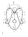
- FIG. 1 is a perspective view of an airbag according to an embodiment of the present invention in an inflated state.
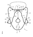
- FIG. 2 is a side view of the airbag in the inflated state in FIG. 1 .
- FIG. 3 is a cross-sectional view taken along the line 3 - 3 in FIG. 2 .
- FIG. 4 is a cross-sectional view of a portion similar to FIG. 3 in a state in which an opening and closing vent is opened.
- FIG. 5 is a side view showing a state in which a large size occupant faces the inflated airbag.
- FIG. 6 is a side view showing a movement of a small size occupant who is not restrained by the seat belt until the occupant contacts the inflated airbag.
- FIG. 7 is a cross-sectional view of a portion similar to FIG. 3 in a state immediately after the large size occupant who is not restrained by the seat belt contacts the inflated airbag.
- FIG. 8 is a cross-sectional view of a portion similar to FIG. 3 in a state in which the opening and closing vent is opened after the large size occupant who is not restrained by the seat belt contacts the inflated airbag.
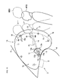
- FIG. 9 is a side view showing arrangements of tethers in the embodiment and a comparative example.
- FIG. 10 is a side view of the airbag and the airbag apparatus according to an embodiment in a case wherein the occupant is restrained by the seat belt.
- FIG. 11 is a side view of the airbag and the airbag apparatus in FIG. 10 in a case wherein the occupant is not restrained by the seat belt.
- FIG. 12 is a side view of the airbag and the airbag apparatus according to an embodiment.
- FIG. 13 is a cross-sectional view taken along line 13 - 13 in FIG. 12 .
- FIG. 1 is a perspective view of an airbag according to an embodiment of the present invention in an inflated state
- FIG. 2 is a side view of the airbag in the inflated state
- FIG. 3 is a cross-sectional view taken along line 3 - 3 in FIG. 2
- FIG. 4 is a cross-sectional view of a portion similar to FIG. 3 in a state in which an opening and closing vent is opened
- FIG. 5 is a side view showing a state in which a large size occupant faces the inflated airbag
- FIG. 6 is a side view showing a movement of a small size occupant who is not restrained by the seat belt until he or she comes into contact with the inflated airbag
- FIG. 7 is a cross-sectional view of a portion similar to FIG.
- FIG. 8 is a cross-sectional view of a portion similar to FIG. 3 in a state in which the opening and closing vent is opened after the large size occupant who is not restrained by the seat belt comes into contact with the inflated airbag; and
- FIG. 9 is a side view showing an arrangements of tethers as connecting members in the embodiment and a comparative example.
- FIGS. 1 to 4 show a state in which the small size occupant faces the inflated airbag.
- the small size occupant means an AF05 (5 percentile adult woman) type occupant dummy
- the large size occupant means an AM50 (50 percentile adult man) type occupant dummy
- front and rear directions and left and right directions correspond to front and rear directions and left and right directions relative to the occupant seated in a seat.
- an airbag 1 is a passenger airbag of a vehicle.
- a passenger airbag apparatus S includes the airbag 1 , a case 2 , and an inflator (not shown).
- the airbag 1 is stored in the case 2 in a folded state and is inflated by the inflator.
- the case 2 is a container opened at an upper surface thereof and the upper surface thereof is covered with a lid (not shown).
- the passenger airbag apparatus S is installed on an upper surface portion of an instrument panel 4 of a motor vehicle.
- a windshield 5 exists above the instrument panel 4 .
- the lid may constitute part of the instrument panel 4 , and may be a plate separate from the instrument panel 4 .
- the airbag 1 is inflated upward so as to fill a space between the instrument panel 4 and the windshield 5 from an upper surface of the instrument panel 4 by the gas supplied by the inflator, and is inflated toward the rear side of a vehicle body so as to fill a space in front of a passenger seat as shown in FIG. 2 .
- a surface of the inflated airbag 1 on the rear side of the vehicle body corresponds to a front surface 1 F which faces the occupant on the passenger seat.
- the airbag 1 includes a gas receiving chamber 1 a positioned at a front most side in the fore-and-aft direction of the vehicle body, a left chamber 1 b inflating on the front left side of the occupant, and a right chamber 1 c inflated on the front right side of the occupant which respectively continues from the gas receiving chamber 1 a .
- the gas receiving chamber la is provided with a gas receiving inlet 1 d on a bottom surface thereof for receiving gas from the inflator.
- the left chamber 1 b and the right chamber 1 c respectively expand toward the occupant, and a recessed portion 10 recessed in the direction opposite from the occupant is formed therebetween as shown in FIG. 3 .
- Reference numeral 1 t designates a distal portion in the direction of expansion of the left chamber 1 b and the right chamber 1 c .
- a bridging member such as a tie panel does not exist between the distal portions 1 t , 1 t of the left chamber 1 b and the right chamber 1 c of the inflated airbag 1 , and the recessed portion 10 therebetween is opened toward the occupant.
- the recessed portion 10 extends continuously from an upper portion to a lower portion of the airbag 1 .
- a deepest portion 11 of the recessed portion 10 is curved in such a manner that a mid-section in the vertical direction protrudes toward the occupant.
- the deepest portion 11 of the recessed portion 10 is positioned near an intermediate portion C (see FIG. 3 ) in the lateral direction of the airbag 1 in a state in which the airbag 1 is inflated.
- the distal portions 1 t of the left chamber 1 b and the right chamber 1 c are respectively positioned at a substantially same distance from the intermediate portion C.
- the head portion of the occupant seated on a passenger seat (not shown) at a normal seated position faces the recessed portion 10 .
- a depth D ( FIG. 3 ) in the horizontal direction from the distal portions 1 t of the left chamber 1 b and the right chamber 1 c to the deepest portion 11 of the recessed portion 10 in the state in which the inflation of the airbag 1 is completed is preferably from 20 to 150 mm, more specifically, from 30 to 70 mm.
- a width W 1 ( FIG. 3 ) between the distal portions 1 t , 1 t of the left chamber 1 b and the right chamber 1 c in the state in which the inflation of the airbag 1 is completed is preferably from 100 to 350 mm, more specifically, from 200 to 300 mm.
- a panel configuration of the airbag 1 having such an inflation-completed shape will be described later in detail.
- the airbag 1 includes opening and closing vents 12 , vent flaps 13 as discharging gas control members which restrict discharging of the gas from the opening and closing vents 12 , and tethers 14 as connecting members extending through the interior of the airbag 1 for connecting the front surface 1 F and the vent flaps 13 of the airbag 1 .
- one of the opening and closing vents 12 is provided on each of the left and right side surfaces of the airbag 1 when inflated.
- the opening and closing vents 12 have a circular opening shape, the opening shape of the opening and closing vents 12 is not limited thereto.
- vent flaps 13 cover the respective opening and closing vents 12 respectively from the outside of the airbag 1 .
- the vent flap 13 in this embodiment is formed of a base cloth having a substantially fan shape having one side 13 a curved into an arcuate shape and a corner portion 13 b facing the side 13 a as a center of curvature of the side 13 a as shown in FIG. 2 .
- the lengths of a pair of oblique lines (not designated by reference numerals) extending from both ends of the side 13 a toward the corner portion 13 b are shorter than the distances between a mid-section of the side 13 a in the extending direction and the corner portion 13 b.
- the vent flap 13 is overlapped on the opening and closing vent 12 in a position in which the side 13 a is positioned on the front surface 1 F side of the airbag 1 with respect to the opening and closing vent 12 and the corner portion 13 b is positioned on the opposite side from the front surface 1 F with the intermediary of the opening and closing vent 12 and is stitched to a side surface of the airbag 1 by a seam 13 c along the side 13 a in the state in which the airbag 1 is inflated.
- the seam 13 c also extends so as to curve into an arcuate shape with the corner portion 13 b side as a center of curvature.
- One end of the tether 14 is connected to the corner portion 13 b of the vent flap 13 .
- the vent flap 13 and the tether 14 are provided separately from each other, and the one end of the tether 14 is stitched to the corner portion 13 b of the vent flap 13 .
- Reference numeral 14 a designates a seam of the stitch.
- the one end of the tether 14 is stitched to a surface of the vent flap 13 near the corner portion 13 b on the side of the airbag 1 .
- the vent flap 13 and the tether 14 may be integrally formed of a common base cloth.
- tether insertion ports 15 are provided respectively in the vicinity of the opening and closing vents 12 on the left and right side surfaces of the airbag 1 for communicating the interior and the exterior of the airbag 1 .
- the tether insertion ports 15 are arranged on the side opposite from the front surface 1 F of the airbag 1 with the intermediary of the opening and closing vents 12 in the state in which the airbag 1 is inflated.
- the tether insertion ports 15 have a circular opening shape, the opening shape of the tether insertion ports 15 is not limited thereto.
- tether connecting portions 16 are referred to as tether connecting portions 16 . A behavior of the occupant upon the collision of the vehicle will be described later in detail.
- the tether connecting portion 16 is arranged at a position of the recessed portion 10 with which the head portion, more preferably, the chin portion of a small size occupant seated on the passenger seat with the seat belt fastened comes into contact when he or she falls into the airbag 1 upon collision of the vehicle in the state in which the airbag 1 is inflated.
- the tether connecting portions 16 are preferably arranged in a range W 2 from 0 to 80 mm, more specifically, from 10 to 50 mm to the left and right from the deepest portion 11 of the recessed portion 10 , that is, from the center portion of the recessed portion 10 in the lateral direction in the state in which the airbag 1 is inflated.
- the left tether 14 which continues from the vent flap 13 on the left side surface of the airbag 1 and the right tether 14 which continues from the vent flap 13 on the right side surface thereof are connected to positions slightly apart from each other in the left and right direction from the deepest portion 11 of the recessed portion 10 respectively, they may be connected to the deepest portion 11 .
- the tethers 14 may be connected to each other by being connected to the recessed portion 10 at a distance in the lateral direction as shown in the drawing, and may also be connected to the same position.
- the tethers 14 may be connected to the recessed portion 10 at positions shifted in the vertical direction.
- the panel configuration of the airbag 1 is as follows.
- the airbag 1 includes left and right outside panels 21 and left and right inside panels 22 .
- the respective panels 21 , 22 are formed of woven cloths coated with a synthetic resin.
- the outside panels 21 constitute outwardly faced left and right surfaces of the airbag 1 and portions extending from an upper surface to a bottom surface of the gas receiving chamber 1 a . Portions of the outside panels 21 which constitute the outwardly faced left and right surfaces of the airbag 1 are provided with the opening and closing vents 12 and the tether insertion ports 15 , and a portion which constitutes the bottom surface of the gas receiving chamber 1 a is provided with the gas receiving chamber 1 d and a mounting portion (not shown) for mounting the airbag into the case 2 .
- the inside panels 22 constitute surfaces extending to the recessed portion 10 of the airbag 1 .
- the outside panels 21 and the inside panels 22 are stitched to each other by stitched seams 23 .
- vent flaps 13 are stitched to the outer surfaces of the respective outside panels 21 .
- the other ends of the tethers 14 are stitched to inner side surfaces of the respective inside panels 22 .
- the airbag 1 when folding the airbag 1 , the airbag 1 is folded in advance in a state in which the respective tethers 14 are pulled inwardly of the airbag 1 so that the respective vent flaps 13 are overlapped with the respective opening and closing vents 12 and the respective tethers 14 extend without slackness between the respective corner portions 13 b of the vent flap 13 and the respective tether insertion ports 15 .
- the respective opening and closing vents 12 assume a state of being closed by the vent flaps 13 from the start of inflation of the airbag 1 when the airbag is inflated.
- a method of folding the airbag 1 is arbitrary, and the method of folding the airbag 1 is not limited thereto.
- the inflator Upon collision of the vehicle on which the passenger airbag apparatus S is mounted, the inflator is activated to inject gas, and the airbag 1 starts to be inflated by the gas from the inflator.
- the airbag 1 opens the lids, and is inflated and deployed from the upper surface of the instrument panel 4 toward the occupant on the passenger seat.
- the opening and closing vents 12 of the airbag 1 is closed by the vent flaps 13 from the beginning of the inflation, and hence the gas is not discharged from the opening and closing vents 12 . Accordingly, the airbag 1 is inflated quickly.
- the tethers 14 are pulled inwardly of the airbag 1 , and the corner portions 13 b of the vent flaps 13 are pulled in the direction away from the sides 13 a via the tether 14 . Accordingly, the vent flaps 13 are tensed along the side surfaces of the airbag 1 , so that the vent flaps 13 are not moved away from the opening and closing vents 12 even when the internal pressure of the airbag 1 is increased.
- the opening and closing vents 12 are kept in a closed state by the vent flaps 13 until the occupant on the passenger seat comes into contact with the front surface 1 F of the inflated airbag 1 , so that the interior of the airbag 1 is maintained at a high internal pressure.
- a left chest of the occupant is received by the inflated left chamber 1 b
- a right chest of the occupant is received by the inflated right chamber 1 c
- the head portion is received by being entered into the recessed portion 10 therebetween.
- the opening and closing vents 12 are preferably opened in a relatively early stage to allow the gas to be discharged from the airbag 1 .
- the timing to open the opening and closing vents 12 is preferably delayed in comparison to the case where the occupant has the small size, thereby maintaining the internal pressure in the airbag 1 at a high level for a relatively long time.
- the tethers 14 are connected to a position of the recessed portion 10 where the small size occupant seated on the passenger seat with the seat belt fastened, that is, the AF05 type occupant dummy comes into contact with when he or she falls into the airbag 1 upon collision of the vehicle in the state in which the airbag 1 is inflated.
- the occupant is seated on the passenger seat with the seat belts (not shown) fastened, the occupant is constrained at the lumbar part from moving forward by the lap belt (not shown) upon collision of the vehicle as indicated by a double-dashed chain line in FIG. 2 , the upper half body of the occupant rotatingly moves toward the front relative to the lumbar part as an axis.
- the head portion of the occupant comes into contact with the inflated airbag 1 in a relatively early stage in comparison with other parts. Therefore, when the small size occupant seated on the passenger seat with the seat belt fastened falls into the inflated airbag 1 , the head portion of the occupant comes into contact with the tether connecting portions 16 of the recessed portion 10 in an early stage to move the same backward, and hence the opening and closing vents 12 are opened in an early stage.
- the tether connecting portions 16 are arranged at a position of the recessed portion 10 where the head portion of the small size occupant seated on the passenger seat with the seat belt fastened comes into contact with when he or she falls into the airbag 1 upon collision of the vehicle in a state in which the airbag 1 is inflated, and are positioned in the range W 2 of 30 mm to the left and right from the center portion of the recessed portion 10 in the lateral direction, so that the tether connecting portions 16 are moved backward quickly and the opening and closing vents 12 are opened when the head portion of the small size occupant comes into contact with the recessed portion 10 .
- the tether connecting portions 16 of the recessed portion 10 faces a portion near the lower chest portion rather than the head portion of this occupant, so that the head portion of this occupant comes into contact with the recessed portion 10 above the tether connecting portions 16 . Therefore, even when the head portion of the occupant presses the recessed portion 10 , the timing when the tether connecting portions 16 starts to move backward is delayed in comparison with the case where it is pressed directly by the head portion of the small size occupant, and the amount of backward movement is also small.
- the opening and closing vents 12 are opened later than the case where the of the airbag 1 receives the small size occupant, and the amount of release is also small, so that the internal pressure in the airbag 1 is maintained at a high level for a relatively long time and hence the occupant is stably received.
- the timing of release of the opening and closing vents 12 is preferably delayed to maintain the internal pressure in the airbag 1 at a high level over a relatively long time.
- the tether connecting portions 16 are not pressed immediately after the occupant comes into contact with the front surface 1 F, and the opening and closing vents 12 are opened after the portion of the occupant near the chest portion comes into contact with the front surface 1 F, so that the internal pressure of the airbag 1 is maintained at a high level for a relatively long time and the occupant is stably received.
- the connecting position of the tether 14 to the recessed portion 10 in a state in which the airbag 1 was inflated was changed as follows, and head portion injury values when the inflated airbag 1 received the occupant were measured.
- the tethers 14 were connected to positions of the recessed portion 10 where the chin portion of the AF05 type occupant dummy seated on the passenger seat with the seat belt fastened contacted when it fell into the airbag 1 in the state in which the airbag 1 was inflated.
- the tethers 14 were connected to positions of the recessed portion 10 lower than that in Embodiment 1 by 80 mm in the state in which the airbag 1 was inflated.
- the tethers 14 were connected to positions of the recessed portion 10 lower than that in Embodiment 1 by 160 mm in the state in which the airbag 1 was inflated.
- the tethers 14 were connected to the positions near the center portion (deepest portion 11 ) of the recessed portion 10 in the lateral direction in the state in which the airbag 1 was inflated.
- Embodiment 1 About Embodiment 1, Comparative Examples 1 and 2, a vehicle collision experiment was conducted in the following cases 1 to 4, and head injury values were measured.
- Case 1 The AF05 type dummy was used as the occupant, and the vehicle was caused to collide in the state in which the seat belt was fastened.
- Case 2 The AF05 type dummy was used as the occupant, and the vehicle was caused to collide in the state in which the seat belt was not fastened.
- Case 3 The AM50 type dummy was used as the occupant, and the vehicle was caused to collide in the state in which the seat belt was fastened.
- Case 4 The AM50 type dummy was used as the occupant, and the vehicle was caused to collide in the state in which the seat belt was not fastened.
- FIGS. 10 and 11 are side views of the airbag and the airbag apparatus according to another embodiment.
- FIG. 10 shows a behavior of the occupant when the seat belt is fastened
- FIG. 11 shows a behavior when the occupant is not restrained by the seat belt.
- the tethers 14 extend obliquely so as to be lower as they go away from the front surface 1 F (recessed portion 10 ) in the state in which the airbag 1 A is inflated.
- an angle ⁇ T of the direction of extension of the tether 14 with respect to the horizontal direction when the airbag is inflated is substantially parallel to an angle ⁇ F of a direction of movement M F of the head portion of the AF05 type dummy restrained by the seat belt with respect to the horizontal direction when it falls into the inflated airbag 1 A and the head portion thereof comes into contact with the recessed portion 10 .
- the angle ⁇ T of the direction of extension of the tether 14 with respect to the horizontal direction when the airbag is inflated is preferably from 0 to 50°, more specifically, from 15 to 45°.
- FIGS. 1 to 8 Other configurations of the airbag 1 A are the same as those of the airbag 1 shown in FIGS. 1 to 8 , and same reference numerals as in FIGS. 1 to 8 designate the same parts in FIGS. 10 , 11 .
- the airbag 1 A configured in this manner, in the state in which the airbag 1 A is inflated, when the tether connecting portions 16 of the recessed portion 10 are moved backward in parallel to the direction of extension of the tethers 14 , the amounts of slackness of the tethers 14 become maximum in comparison with the case in which the tether connecting portions 16 are moved backward in the direction closer to the horizontal direction than that and closer to the vertical direction than that.
- the head portion of the occupant comes into contact with the tether connecting portions 16 in an early stage, and the head portion of the occupant causes the tether connecting portions 16 to move backward in substantially parallel to the direction of extension of the tethers 14 , so that the opening and closing vents 12 are opened quickly and widely as shown in FIG. 10 .
- an angle ⁇ M of a direction of movement M M of the head portion at the time when the AM50 type dummy restrained by the seat belt falls into the inflated airbag 1 A and the head portion thereof comes into contact with the recessed portion 10 with respect the horizontal direction is generally smaller than the angle ⁇ T of the tether 14 described above.
- the head portion thereof comes into contact with the recessed portion 10 at a portion above the tether connecting portions 16 , and the contact portion is moved backward at the angle ⁇ M which is smaller than the angle ⁇ T of the tethers 14 , so that the opening and closing vents 12 are opened later and the openings of the opening and closing vents 12 are small in comparison with the case in which the inflated airbag 1 A receives the AF05 type dummy restrained by the seat belt. Accordingly, the internal pressure in the airbag 1 A is maintained at a high level for a relatively long time, and the occupant is stably received.
- the opening and closing vents 12 are opened later and the openings of the opening and closing vents 12 are small in comparison with the case where the AF05 type dummy restrained by the seat belt are received. Accordingly, the internal pressure in the airbag 1 A is maintained at a high level for a relatively long time, and the occupant is stably received.
- the center portion of the front surface 1 F in the lateral direction is adapted to assume the recessed portion 10 recessed inwardly of the airbag when the airbag is inflated by stitching the inside panels 22 , 22 which continue to the recessed portion 10 so as to be recessed inwardly of the airbag.
- a method of causing a head-facing portion of the front surface to be recessed when the airbag is inflated is not limited thereto.
- FIGS. 12 and 13 Another configuration of the airbag in which the recessed portion is formed on the front surface when inflated will be shown in FIGS. 12 and 13 .
- FIG. 12 is a side view of the airbag and the airbag apparatus according to another embodiment
- FIG. 13 is a cross-sectional view taken along the line 13 - 13 in FIG. 12 .
- a suspender tape 30 which connects the front surface 1 F and a counter-front surface 1 R on the opposite side is provided inside the airbag 1 B.
- An end portion of the suspender tape 30 on the side of the front surface 1 F is joined to the front surface 1 F near the center in the lateral direction at a level opposing the head portion of the AF05 type dummy when the airbag is inflated stitching or the like. Accordingly, in a state in which the airbag 1 B is inflated, an area of the front surface 1 F which faces the head portion of the AF05 type dummy corresponds to a recessed portion 10 ′ which is recessed inwardly of the airbag, and hence both left and right sides thereof protrude toward the occupant with respect to the recessed portion 10 ′.
- Reference numeral 32 designates seams whereby both ends of the suspender tape 30 are stitched to the front surface 1 F and the counter-front surface 1 R respectively.
- the suspender tape 30 is formed of band-shaped base cloths. Each of the band-shaped base cloths is separated for the front surface 1 F side or the counter-front surface 1 R side from a mid-section in the longitudinal direction thereof. These base cloths are connected so that the suspender tape 30 has a predetermined length.
- Reference numeral 33 designates a seam which connects these base cloths.
- the opening and closing vents are provided on the left and right side surfaces of the airbag, two or more of the opening and closing vents may be provided for each of the side surfaces. Also, the opening and closing vent may be formed on any one of side surfaces of the airbag.
- vent flaps which cover the opening and closing vents from the outside of the airbag are provided as the discharging gas control members for restraining the discharging of the gas from the opening and closing vents.
- the configuration of the discharging gas control member is not limited thereto.
- the gas discharging restraining member may be a vent flap which covers the opening and closing vent from the inside of the airbag.
- the gas discharging restraining member may be arranged at a peripheral edge portion of the opening and closing vent, so as to enclose the opening and closing vent by being pulled inwardly of the airbag to close or slightly open the opening and closing vent.
- the discharging gas control member may be configured to have a cylindrical duct connected to the opening and closing vent, so that the duct is pulled inwardly of the airbag to close or slightly open, and the duct is pushed outwardly of the airbag by the gas pressure in the airbag to open or widely open the opening and closing vent via the duct.
- the restraining member may have other configuration as a matter of course.
- a constantly opened vent which constantly communicates the interior and the exterior of the airbag may be provided.
- the vent flap is configured to close the entire part of the opening and closing vent.
- it may be configured to bring the opening and closing vent from the large opening to the small opening.
- it may be configured in such a manner that the opening and closing vent is partly protruded from the vent flap and the protruded portion allows the gas to be discharged therefrom even when the vent flap is overlapped with the opening and closing vent.
- a configuration in which a hole of a smaller diameter than the opening and closing vent is provided at a position of the vent flap overlapped with the opening and closing vent, and the gas is allowed to be discharged via this hole even when the opening and closing vent is closed is also applicable.
- the respective vents are substantially circular openings.
- the shapes of the respective vents are not limited thereto, and may be shapes other than the circular shape, for example, a slit-shape.
- the respective embodiments described above are examples of applications of the present invention to the airbag or the airbag apparatus for the passenger seat in the vehicle.
- the present invention may be applied to various airbags and the airbag apparatuses other than those described above such as the airbags and the airbag apparatuses for a driver's seat or rear seats, for example.
Landscapes
- Engineering & Computer Science (AREA)
- Mechanical Engineering (AREA)
- Air Bags (AREA)
Abstract
Description
| TABLE 1 | ||||
| Comparative | | |||
| Embodiment | ||||
| 1 | Example 1 | Example 2 | ||
| |
very good | very good | | ||
| case | |||||
| 2 | very good | very good | very | ||
| case | |||||
| 3 | very good | good | good | ||
| case 4 | very good | very good | very god | ||
Claims (18)
Applications Claiming Priority (2)
| Application Number | Priority Date | Filing Date | Title |
|---|---|---|---|
| JP2008203245A JP4992853B2 (en) | 2008-08-06 | 2008-08-06 | Airbag device |
| JP2008-203245 | 2008-08-06 |
Publications (2)
| Publication Number | Publication Date |
|---|---|
| US20100032931A1 US20100032931A1 (en) | 2010-02-11 |
| US8070183B2 true US8070183B2 (en) | 2011-12-06 |
Family
ID=41268475
Family Applications (1)
| Application Number | Title | Priority Date | Filing Date |
|---|---|---|---|
| US12/458,823 Expired - Fee Related US8070183B2 (en) | 2008-08-06 | 2009-07-23 | Airbag and airbag apparatus |
Country Status (3)
| Country | Link |
|---|---|
| US (1) | US8070183B2 (en) |
| EP (1) | EP2156995B1 (en) |
| JP (1) | JP4992853B2 (en) |
Cited By (48)
| Publication number | Priority date | Publication date | Assignee | Title |
|---|---|---|---|---|
| US20110031725A1 (en) * | 2009-08-05 | 2011-02-10 | Autoliv Asp, Inc. | Safety venting with passively closeable vents |
| US20110101652A1 (en) * | 2007-08-09 | 2011-05-05 | Takata Corporation | Airbag and airbag apparatus |
| US20110140400A1 (en) * | 2008-09-17 | 2011-06-16 | Honda Motor Co., Ltd. | Airbag and method of manufacturing same |
| US20120049492A1 (en) * | 2010-08-30 | 2012-03-01 | Hyundai Motor Company | Airbag Apparatus for Vehicle |
| US20120104734A1 (en) * | 2010-10-27 | 2012-05-03 | Trw Vehicle Safety Systems Inc. | Air bag with height adaptive tether |
| US20120235393A1 (en) * | 2010-10-27 | 2012-09-20 | Trw Vehicle Safety Systems Inc. | Air bag with variable venting |
| US20130026744A1 (en) * | 2010-10-27 | 2013-01-31 | Trw Vehicle Safety Systems Inc. | Air bag with variable venting |
| US8407968B2 (en) | 2009-10-16 | 2013-04-02 | Autoliv Asp, Inc. | Method of packaging an inflatable airbag cushion including a wrapper and deployment flap |
| US8439399B2 (en) * | 2010-07-30 | 2013-05-14 | Ford Global Technologies | Airbag with tethered slit |
| US8505970B2 (en) * | 2011-09-08 | 2013-08-13 | Hyundai Motor Company | Airbag cushion for vehicles |
| US8540276B2 (en) | 2011-11-07 | 2013-09-24 | Autoliv Asp, Inc. | Inflatable knee airbag assemblies with cushion fold pattern |
| US8646808B2 (en) | 2012-06-18 | 2014-02-11 | Autoliv Asp, Inc. | Airbag with active vent |
| US8657334B2 (en) * | 2011-02-11 | 2014-02-25 | Key Safety Systems, Inc. | Airbag cushion |
| US8807596B1 (en) * | 2013-01-31 | 2014-08-19 | Ford Global Technologies, Llc | Airbag and vehicle passenger restraint system |
| US20140300094A1 (en) * | 2013-04-03 | 2014-10-09 | Autoliv Asp, Inc. | Airbag with active vent |
| US8870223B2 (en) * | 2012-12-26 | 2014-10-28 | Hyundai Motor Company | Airbag apparatus for vehicle |
| US8882143B2 (en) | 2013-02-08 | 2014-11-11 | Autoliv Asp, Inc. | Airbag with slit vent |
| US20150035264A1 (en) * | 2013-08-01 | 2015-02-05 | Tk Holdings Inc. | Single Stage Dual Chambered Passenger Airbag |
| US20150084318A1 (en) * | 2012-02-16 | 2015-03-26 | Ashimori Industry Co., Ltd. | Airbag device |
| US20150239421A1 (en) * | 2012-09-21 | 2015-08-27 | Takata Corporation | Airbag and airbag device |
| US20150266447A1 (en) * | 2012-09-21 | 2015-09-24 | Takata Corporation | Airbag and airbag device |
| US9150189B1 (en) | 2014-05-22 | 2015-10-06 | Autoliv Asp, Inc. | Airbag systems with side venting |
| US9199602B1 (en) * | 2014-07-23 | 2015-12-01 | Trw Vehicle Safety Systems Inc. | Passive air bag with slack creator |
| US20160031408A1 (en) * | 2014-07-30 | 2016-02-04 | Hyundai Mobis Co., Ltd. | Airbag system for vehicle |
| US9376081B2 (en) * | 2014-08-20 | 2016-06-28 | Hyundai Motor Company | Airbag device for vehicle |
| KR20160122000A (en) | 2015-04-13 | 2016-10-21 | 아우토리브 디벨롭먼트 아베 | Airbag for vehicle |
| KR20160122001A (en) | 2015-04-13 | 2016-10-21 | 아우토리브 디벨롭먼트 아베 | Airbag for vehicle |
| KR20160123734A (en) | 2015-04-17 | 2016-10-26 | 아우토리브 디벨롭먼트 아베 | Airbag having active vent |
| US9561775B2 (en) * | 2012-02-23 | 2017-02-07 | Key Safety Systems, Inc. | Airbag with multi-state vent |
| KR20170013695A (en) | 2015-07-28 | 2017-02-07 | 아우토리브 디벨롭먼트 아베 | Airbag with varibable vetning |
| US9889937B2 (en) | 2012-03-19 | 2018-02-13 | Amsafe, Inc. | Structure mounted airbag assemblies and associated systems and methods |
| US9925950B2 (en) | 2015-04-11 | 2018-03-27 | Amsafe, Inc. | Active airbag vent system |
| US9944245B2 (en) | 2015-03-28 | 2018-04-17 | Amsafe, Inc. | Extending pass-through airbag occupant restraint systems, and associated systems and methods |
| US20180134244A1 (en) * | 2016-11-11 | 2018-05-17 | Hyundai Motor Company | Front airbag for vehicle |
| US10093270B2 (en) | 2016-01-13 | 2018-10-09 | Autoliv Asp, Inc. | Multi-flap vents for inflatable chambers |
| US20180334129A1 (en) * | 2017-05-19 | 2018-11-22 | Hyundai Motor Company | Airbag apparatus for vehicle |
| CN110182164A (en) * | 2018-02-20 | 2019-08-30 | 日本富拉司特株式会社 | Air bag device |
| US10604259B2 (en) | 2016-01-20 | 2020-03-31 | Amsafe, Inc. | Occupant restraint systems having extending restraints, and associated systems and methods |
| US10814826B2 (en) | 2016-06-07 | 2020-10-27 | Autoliv Development Ab | Airbag device |
| US10940821B2 (en) * | 2018-11-16 | 2021-03-09 | Toyoda Gosei Co., Ltd. | Airbag device |
| US11130468B2 (en) * | 2017-04-16 | 2021-09-28 | Autoliv Development Ab | Airbag apparatus with an active vent mechanism |
| US11167717B2 (en) * | 2017-04-28 | 2021-11-09 | Autoliv Development Ab | Airbag apparatus with protrusion parts |
| US11292423B2 (en) | 2020-05-18 | 2022-04-05 | Autoliv Asp, Inc. | Vent flap for airbag assemblies |
| US11628797B2 (en) * | 2020-06-23 | 2023-04-18 | Nihon Plast Co., Ltd. | Airbag |
| US20230219516A1 (en) * | 2020-04-24 | 2023-07-13 | Autoliv Development Ab | Vehicular airbag device |
| US20240166157A1 (en) * | 2022-11-18 | 2024-05-23 | Toyoda Gosei Co., Ltd. | Airbag device |
| US12036941B1 (en) * | 2023-04-19 | 2024-07-16 | GM Global Technology Operations LLC | Airbag with extended horizontal cushion preventing head and knee contact |
| US20240326734A1 (en) * | 2023-04-03 | 2024-10-03 | Toyoda Gosei Co., Ltd. | Variable vent mechanism, airbag device, and flap mechanism |
Families Citing this family (29)
| Publication number | Priority date | Publication date | Assignee | Title |
|---|---|---|---|---|
| US20100102542A1 (en) * | 2007-01-12 | 2010-04-29 | Autoliv Developement Ab | Airbag device |
| US7938445B2 (en) * | 2009-03-03 | 2011-05-10 | Autoliv Asp, Inc. | Dual chamber airbag cushions with a safety vent in the front chamber |
| US7946613B2 (en) * | 2009-03-03 | 2011-05-24 | Autoliv Asp, Inc. | Dual chamber airbag cushion |
| US8047564B2 (en) * | 2009-09-02 | 2011-11-01 | Tk Holdings Inc. | Airbag |
| WO2011099158A1 (en) * | 2010-02-15 | 2011-08-18 | トヨタ自動車株式会社 | Airbag device |
| JP5607480B2 (en) * | 2010-09-24 | 2014-10-15 | タカタ株式会社 | Airbag, airbag device, and method for suturing airbag lid member |
| JP5572597B2 (en) * | 2011-06-30 | 2014-08-13 | 富士重工業株式会社 | Crew protection device |
| KR101356178B1 (en) * | 2011-11-28 | 2014-01-27 | 현대자동차주식회사 | Airbab apparatus for vehicle |
| DE112014004507T5 (en) * | 2013-09-30 | 2016-07-28 | Tk Holdings Inc. | Dual-chamber passenger airbag |
| KR102187872B1 (en) * | 2014-04-02 | 2020-12-07 | 현대모비스 주식회사 | Air bag apparatus |
| WO2015170841A1 (en) * | 2014-05-09 | 2015-11-12 | Autoliv Development Ab | Airbag for vehicle |
| JP6383176B2 (en) | 2014-05-12 | 2018-08-29 | Joyson Safety Systems Japan株式会社 | Air bag and air bag device |
| US9016721B1 (en) * | 2014-05-13 | 2015-04-28 | Autoliv Asp, Inc. | Airbag assemblies with adaptive venting |
| JP6445797B2 (en) | 2014-06-30 | 2018-12-26 | 日本プラスト株式会社 | Air bag and air bag device |
| KR101620174B1 (en) * | 2014-07-11 | 2016-05-24 | 기아자동차주식회사 | Airbag device for vehicle |
| US9283920B1 (en) * | 2014-11-07 | 2016-03-15 | Trw Vehicle Safety Systems Inc. | Air bag with uninflated pocket |
| KR102508056B1 (en) * | 2015-08-13 | 2023-03-09 | 현대모비스 주식회사 | Airbag apparatus |
| KR102407265B1 (en) * | 2015-09-04 | 2022-06-10 | 현대모비스 주식회사 | Airbag apparatus |
| US9731678B2 (en) * | 2015-11-06 | 2017-08-15 | Hyundai Motor Company | Passenger air bag apparatus for vehicle |
| KR101737793B1 (en) * | 2015-12-11 | 2017-05-19 | 현대모비스 주식회사 | Passenger air bag apparatus and manufacturing method thereof |
| JP6706503B2 (en) * | 2016-01-26 | 2020-06-10 | 豊田合成株式会社 | Airbag for passenger seat |
| US10427638B2 (en) * | 2016-06-08 | 2019-10-01 | Autoliv Asp, Inc. | Frontal airbag assemblies for reducing rotational velocity of a head of an occupant |
| US10293775B2 (en) | 2016-10-21 | 2019-05-21 | Autoliv Asp, Inc. | Frontal airbag assemblies for reducing rotational velocity of a head of an occupant |
| US10814823B2 (en) * | 2017-08-29 | 2020-10-27 | Ford Global Technologies, Llc | Vehicle energy absorber |
| JP7040288B2 (en) * | 2018-05-25 | 2022-03-23 | Joyson Safety Systems Japan株式会社 | Airbag |
| DE202018106208U1 (en) | 2018-10-30 | 2020-02-03 | Dalphi Metal Espana, S.A. | Airbag for a vehicle occupant restraint system |
| DE102019102098A1 (en) * | 2019-01-29 | 2020-07-30 | Dalphi Metal Espana, S.A. | GAS BAG, GAS BAG MODULE, VEHICLE PASSENGER SECURITY SYSTEM AND METHOD FOR INFLATING A GAS BAG |
| US11027688B2 (en) | 2019-08-27 | 2021-06-08 | Autoliv Asp, Inc. | Systems and methods to support an inflatable airbag cushion |
| KR102771429B1 (en) * | 2019-11-11 | 2025-02-24 | 현대모비스 주식회사 | Air bag device |
Citations (38)
| Publication number | Priority date | Publication date | Assignee | Title |
|---|---|---|---|---|
| JPH06127330A (en) | 1992-10-16 | 1994-05-10 | Toyoda Gosei Co Ltd | Airbag device airbag |
| FR2757465A1 (en) | 1996-12-20 | 1998-06-26 | Aerazur | Airbag for vehicle passenger protection, with faster inflation |
| JP2000142307A (en) | 1998-11-04 | 2000-05-23 | Kansei Corp | Air bag device for vehicle |
| US6676158B2 (en) * | 2000-11-14 | 2004-01-13 | Nihon Plast Co., Ltd. | Airbag and folding method thereof |
| US6832778B2 (en) * | 2002-07-19 | 2004-12-21 | Delphi Technologies, Inc. | Air bag restraint including selectively operable venting elements |
| US20050236822A1 (en) * | 2004-04-27 | 2005-10-27 | Rose Larry D | Cushion venting design for out of position occupant protection |
| US20050248137A1 (en) | 2002-09-16 | 2005-11-10 | Trw Vehicle Safety Systems Inc. | Air bag module with vent controlled by tether |
| WO2006009404A1 (en) | 2004-07-23 | 2006-01-26 | Ki Bang Lee | Systems with water-activated battery |
| US20060028009A1 (en) * | 2002-05-22 | 2006-02-09 | Takata Corporation | Airbag device |
| US20060071462A1 (en) * | 2004-10-06 | 2006-04-06 | Smith Bradley W | Airbag cushion with tether deactivated venting for reduced out-of-position effects |
| WO2006041552A2 (en) | 2004-10-06 | 2006-04-20 | Autoliv Asp, Inc. | Airbag cushion with cinch tube for reduced out-of-position effects |
| US20060131859A1 (en) * | 2004-12-16 | 2006-06-22 | Takata Corporation | Airbag and aribag system |
| US20060151979A1 (en) | 2005-01-07 | 2006-07-13 | Depottey Timothy A | Airbag cushion with adaptive venting for reduced out-of-position effects |
| US20070045997A1 (en) * | 2005-08-24 | 2007-03-01 | Takata Corporation | Airbag and airbag apparatus |
| JP2007099104A (en) | 2005-10-05 | 2007-04-19 | Ashimori Ind Co Ltd | Air bag device |
| US20070145729A1 (en) * | 2005-11-28 | 2007-06-28 | Toyoda Gosei Co., Ltd. | Airbag apparatus |
| JP2007216943A (en) * | 2005-08-24 | 2007-08-30 | Takata Corp | Airbag and airbag apparatus |
| US20080023950A1 (en) | 2006-07-27 | 2008-01-31 | Trw Vehicle Safety Systems Inc. | Air bag vent with tether |
| WO2008015877A1 (en) | 2006-08-04 | 2008-02-07 | Takata Corporation | Air bag and air bag device |
| JP2008056175A (en) * | 2006-09-01 | 2008-03-13 | Takata Corp | Airbag and airbag device |
| US7364192B2 (en) | 2002-09-16 | 2008-04-29 | Trw Vehicle Safety Systems Inc. | Air bag module with locking member for locking the position of a vent member |
| WO2008084605A1 (en) * | 2007-01-12 | 2008-07-17 | Autoliv Development Ab | Airbag device |
| US7458607B2 (en) * | 2005-02-25 | 2008-12-02 | Takata Corporation | Airbag and airbag apparatus |
| US20080303256A1 (en) * | 2007-06-05 | 2008-12-11 | Autoliv Asp, Inc. | Airbag cushions with gas deflectors and optional venting for out-of-position conditions |
| US20080315567A1 (en) * | 2007-06-21 | 2008-12-25 | Trw Vehicle Safety Systems Inc. | Air bag with adaptive venting |
| WO2009016871A1 (en) | 2007-07-31 | 2009-02-05 | Takata Corporation | Airbag and airbag device |
| US20090033081A1 (en) * | 2007-07-30 | 2009-02-05 | Trw Vehicle Safety Systems Inc. | Air bag with improved tear stitch |
| US20090121461A1 (en) * | 2007-11-09 | 2009-05-14 | Takata Corporation | Airbag and airbag apparatus |
| US20090224522A1 (en) * | 2006-05-11 | 2009-09-10 | Trw Vehicle Safety Systems Inc. | Bi-lobular air bag |
| US7614654B2 (en) * | 2005-12-07 | 2009-11-10 | Autoliv Asp, Inc. | Airbag cushion with diffuser with cinch tube to vent gas for out-of-position conditions |
| US7614656B2 (en) * | 2006-03-28 | 2009-11-10 | Toyoda Gosei Co., Ltd. | Airbag apparatus |
| US20090289444A1 (en) * | 2008-05-20 | 2009-11-26 | Ramesh Keshavaraj | Airbag, system and method for deploying an airbag |
| US20100001498A1 (en) * | 2007-02-19 | 2010-01-07 | Kazuhiro Abe | Airbag and airbag device |
| US20100007124A1 (en) * | 2008-07-14 | 2010-01-14 | Trw Vehicle Safety Systems Inc. | Bi-lobular air bag |
| US7651130B2 (en) * | 2006-04-11 | 2010-01-26 | Autoliv Development Ab | Airbag unit |
| US20100019476A1 (en) * | 2008-07-23 | 2010-01-28 | Takata Corporation | Airbag and airbag apparatus |
| US7695012B2 (en) * | 2008-04-03 | 2010-04-13 | Autoliv Asp, Inc. | Airbag systems with a split pocket |
| US20110031725A1 (en) * | 2009-08-05 | 2011-02-10 | Autoliv Asp, Inc. | Safety venting with passively closeable vents |
Family Cites Families (3)
| Publication number | Priority date | Publication date | Assignee | Title |
|---|---|---|---|---|
| US7083191B2 (en) * | 2002-09-16 | 2006-08-01 | Trw Vehicle Safety Systems Inc. | Air bag module with vent controlled by tether |
| CN101378936B (en) * | 2006-02-03 | 2010-12-22 | 高田株式会社 | Airbag and airbag device |
| JP4793124B2 (en) * | 2006-06-21 | 2011-10-12 | 豊田合成株式会社 | Passenger airbag |
-
2008
- 2008-08-06 JP JP2008203245A patent/JP4992853B2/en not_active Expired - Fee Related
-
2009
- 2009-07-01 EP EP09164331.2A patent/EP2156995B1/en not_active Not-in-force
- 2009-07-23 US US12/458,823 patent/US8070183B2/en not_active Expired - Fee Related
Patent Citations (46)
| Publication number | Priority date | Publication date | Assignee | Title |
|---|---|---|---|---|
| JPH06127330A (en) | 1992-10-16 | 1994-05-10 | Toyoda Gosei Co Ltd | Airbag device airbag |
| FR2757465A1 (en) | 1996-12-20 | 1998-06-26 | Aerazur | Airbag for vehicle passenger protection, with faster inflation |
| JP2000142307A (en) | 1998-11-04 | 2000-05-23 | Kansei Corp | Air bag device for vehicle |
| US6676158B2 (en) * | 2000-11-14 | 2004-01-13 | Nihon Plast Co., Ltd. | Airbag and folding method thereof |
| US20060028009A1 (en) * | 2002-05-22 | 2006-02-09 | Takata Corporation | Airbag device |
| US6832778B2 (en) * | 2002-07-19 | 2004-12-21 | Delphi Technologies, Inc. | Air bag restraint including selectively operable venting elements |
| US20050098990A1 (en) * | 2002-07-19 | 2005-05-12 | Delphi Technologies, Inc. | Air bag restraint including selectively operable venting elements |
| US7364192B2 (en) | 2002-09-16 | 2008-04-29 | Trw Vehicle Safety Systems Inc. | Air bag module with locking member for locking the position of a vent member |
| US20050248137A1 (en) | 2002-09-16 | 2005-11-10 | Trw Vehicle Safety Systems Inc. | Air bag module with vent controlled by tether |
| US7237802B2 (en) * | 2004-04-27 | 2007-07-03 | Autoliv Asp, Inc. | Cushion venting design for out of position occupant protection |
| US20050236822A1 (en) * | 2004-04-27 | 2005-10-27 | Rose Larry D | Cushion venting design for out of position occupant protection |
| WO2006009404A1 (en) | 2004-07-23 | 2006-01-26 | Ki Bang Lee | Systems with water-activated battery |
| WO2006041552A2 (en) | 2004-10-06 | 2006-04-20 | Autoliv Asp, Inc. | Airbag cushion with cinch tube for reduced out-of-position effects |
| WO2006041547A2 (en) | 2004-10-06 | 2006-04-20 | Autoliv Asp, Inc. | Airbag cushion with tether deactivated venting for reduced out-of-position effects |
| US20060071462A1 (en) * | 2004-10-06 | 2006-04-06 | Smith Bradley W | Airbag cushion with tether deactivated venting for reduced out-of-position effects |
| US7347450B2 (en) * | 2004-10-06 | 2008-03-25 | Autoliv Asp, Inc. | Airbag cushion with cinch tube for reduced out-of-position effects |
| US20060131859A1 (en) * | 2004-12-16 | 2006-06-22 | Takata Corporation | Airbag and aribag system |
| US20060151979A1 (en) | 2005-01-07 | 2006-07-13 | Depottey Timothy A | Airbag cushion with adaptive venting for reduced out-of-position effects |
| US7458607B2 (en) * | 2005-02-25 | 2008-12-02 | Takata Corporation | Airbag and airbag apparatus |
| JP2007216943A (en) * | 2005-08-24 | 2007-08-30 | Takata Corp | Airbag and airbag apparatus |
| US20070045997A1 (en) * | 2005-08-24 | 2007-03-01 | Takata Corporation | Airbag and airbag apparatus |
| US7607690B2 (en) * | 2005-08-24 | 2009-10-27 | Takata Corporation | Airbag and airbag apparatus |
| JP2007099104A (en) | 2005-10-05 | 2007-04-19 | Ashimori Ind Co Ltd | Air bag device |
| US20070145729A1 (en) * | 2005-11-28 | 2007-06-28 | Toyoda Gosei Co., Ltd. | Airbag apparatus |
| US7614654B2 (en) * | 2005-12-07 | 2009-11-10 | Autoliv Asp, Inc. | Airbag cushion with diffuser with cinch tube to vent gas for out-of-position conditions |
| US7614656B2 (en) * | 2006-03-28 | 2009-11-10 | Toyoda Gosei Co., Ltd. | Airbag apparatus |
| US7651130B2 (en) * | 2006-04-11 | 2010-01-26 | Autoliv Development Ab | Airbag unit |
| US20090224522A1 (en) * | 2006-05-11 | 2009-09-10 | Trw Vehicle Safety Systems Inc. | Bi-lobular air bag |
| US20080023950A1 (en) | 2006-07-27 | 2008-01-31 | Trw Vehicle Safety Systems Inc. | Air bag vent with tether |
| WO2008015877A1 (en) | 2006-08-04 | 2008-02-07 | Takata Corporation | Air bag and air bag device |
| US7726685B2 (en) * | 2006-08-04 | 2010-06-01 | Takata Corporation | Airbag and airbag apparatus |
| JP2008056175A (en) * | 2006-09-01 | 2008-03-13 | Takata Corp | Airbag and airbag device |
| US20090206587A1 (en) * | 2006-09-01 | 2009-08-20 | Kazuhiro Abe | Airbag and Airbag Device |
| US20100102542A1 (en) * | 2007-01-12 | 2010-04-29 | Autoliv Developement Ab | Airbag device |
| WO2008084605A1 (en) * | 2007-01-12 | 2008-07-17 | Autoliv Development Ab | Airbag device |
| US20100001498A1 (en) * | 2007-02-19 | 2010-01-07 | Kazuhiro Abe | Airbag and airbag device |
| US20080303256A1 (en) * | 2007-06-05 | 2008-12-11 | Autoliv Asp, Inc. | Airbag cushions with gas deflectors and optional venting for out-of-position conditions |
| US20080315567A1 (en) * | 2007-06-21 | 2008-12-25 | Trw Vehicle Safety Systems Inc. | Air bag with adaptive venting |
| US20090033081A1 (en) * | 2007-07-30 | 2009-02-05 | Trw Vehicle Safety Systems Inc. | Air bag with improved tear stitch |
| WO2009016871A1 (en) | 2007-07-31 | 2009-02-05 | Takata Corporation | Airbag and airbag device |
| US20090121461A1 (en) * | 2007-11-09 | 2009-05-14 | Takata Corporation | Airbag and airbag apparatus |
| US7695012B2 (en) * | 2008-04-03 | 2010-04-13 | Autoliv Asp, Inc. | Airbag systems with a split pocket |
| US20090289444A1 (en) * | 2008-05-20 | 2009-11-26 | Ramesh Keshavaraj | Airbag, system and method for deploying an airbag |
| US20100007124A1 (en) * | 2008-07-14 | 2010-01-14 | Trw Vehicle Safety Systems Inc. | Bi-lobular air bag |
| US20100019476A1 (en) * | 2008-07-23 | 2010-01-28 | Takata Corporation | Airbag and airbag apparatus |
| US20110031725A1 (en) * | 2009-08-05 | 2011-02-10 | Autoliv Asp, Inc. | Safety venting with passively closeable vents |
Cited By (66)
| Publication number | Priority date | Publication date | Assignee | Title |
|---|---|---|---|---|
| US20110101652A1 (en) * | 2007-08-09 | 2011-05-05 | Takata Corporation | Airbag and airbag apparatus |
| US8419054B2 (en) * | 2007-08-09 | 2013-04-16 | Takata Corporation | Airbag and airbag apparatus |
| US8419055B2 (en) * | 2008-09-17 | 2013-04-16 | Honda Motor Co., Ltd. | Airbag and method of manufacturing same |
| US20110140400A1 (en) * | 2008-09-17 | 2011-06-16 | Honda Motor Co., Ltd. | Airbag and method of manufacturing same |
| US8226118B2 (en) * | 2009-08-05 | 2012-07-24 | Autoliv Asp, Inc. | Safety venting with passively closeable vents |
| US20110031725A1 (en) * | 2009-08-05 | 2011-02-10 | Autoliv Asp, Inc. | Safety venting with passively closeable vents |
| US8407968B2 (en) | 2009-10-16 | 2013-04-02 | Autoliv Asp, Inc. | Method of packaging an inflatable airbag cushion including a wrapper and deployment flap |
| US8757661B2 (en) | 2010-07-30 | 2014-06-24 | Ford Global Technologies | Airbag with tethered slit |
| US8844969B2 (en) | 2010-07-30 | 2014-09-30 | Ford Global Technologies | Airbag with tethered slit |
| US8439399B2 (en) * | 2010-07-30 | 2013-05-14 | Ford Global Technologies | Airbag with tethered slit |
| US8393637B2 (en) * | 2010-08-30 | 2013-03-12 | Hyndai Motor Company | Airbag apparatus for vehicle |
| US20120049492A1 (en) * | 2010-08-30 | 2012-03-01 | Hyundai Motor Company | Airbag Apparatus for Vehicle |
| US8684404B2 (en) * | 2010-10-27 | 2014-04-01 | Trw Vehicle Safety Systems Inc. | Air bag with variable venting |
| US20130026744A1 (en) * | 2010-10-27 | 2013-01-31 | Trw Vehicle Safety Systems Inc. | Air bag with variable venting |
| US20120235393A1 (en) * | 2010-10-27 | 2012-09-20 | Trw Vehicle Safety Systems Inc. | Air bag with variable venting |
| US20120104734A1 (en) * | 2010-10-27 | 2012-05-03 | Trw Vehicle Safety Systems Inc. | Air bag with height adaptive tether |
| US8696022B2 (en) * | 2010-10-27 | 2014-04-15 | Trw Vehicle Safety Systems Inc. | Air bag with variable venting |
| US8684407B2 (en) * | 2010-10-27 | 2014-04-01 | Trw Vehicle Safety Systems Inc. | Air bag with height adaptive tether |
| US8657334B2 (en) * | 2011-02-11 | 2014-02-25 | Key Safety Systems, Inc. | Airbag cushion |
| US8505970B2 (en) * | 2011-09-08 | 2013-08-13 | Hyundai Motor Company | Airbag cushion for vehicles |
| US8540276B2 (en) | 2011-11-07 | 2013-09-24 | Autoliv Asp, Inc. | Inflatable knee airbag assemblies with cushion fold pattern |
| US9187058B2 (en) * | 2012-02-16 | 2015-11-17 | Ashimori Industry Co., Ltd. | Airbag device |
| US20150084318A1 (en) * | 2012-02-16 | 2015-03-26 | Ashimori Industry Co., Ltd. | Airbag device |
| US9561775B2 (en) * | 2012-02-23 | 2017-02-07 | Key Safety Systems, Inc. | Airbag with multi-state vent |
| US9889937B2 (en) | 2012-03-19 | 2018-02-13 | Amsafe, Inc. | Structure mounted airbag assemblies and associated systems and methods |
| US8646808B2 (en) | 2012-06-18 | 2014-02-11 | Autoliv Asp, Inc. | Airbag with active vent |
| US9434345B2 (en) * | 2012-09-21 | 2016-09-06 | Takata Corporation | Airbag and airbag device |
| US9340177B2 (en) * | 2012-09-21 | 2016-05-17 | Takata Corporation | Airbag and airbag device |
| US20150239421A1 (en) * | 2012-09-21 | 2015-08-27 | Takata Corporation | Airbag and airbag device |
| US20150266447A1 (en) * | 2012-09-21 | 2015-09-24 | Takata Corporation | Airbag and airbag device |
| US8870223B2 (en) * | 2012-12-26 | 2014-10-28 | Hyundai Motor Company | Airbag apparatus for vehicle |
| US8807596B1 (en) * | 2013-01-31 | 2014-08-19 | Ford Global Technologies, Llc | Airbag and vehicle passenger restraint system |
| US9150188B2 (en) | 2013-02-08 | 2015-10-06 | Autoliv Asp, Inc. | Airbag with slit vent |
| US8882143B2 (en) | 2013-02-08 | 2014-11-11 | Autoliv Asp, Inc. | Airbag with slit vent |
| US9108590B2 (en) * | 2013-04-03 | 2015-08-18 | Autoliv Asp, Inc. | Airbag with active vent |
| US20140300094A1 (en) * | 2013-04-03 | 2014-10-09 | Autoliv Asp, Inc. | Airbag with active vent |
| US9545894B2 (en) * | 2013-08-01 | 2017-01-17 | Tk Holdings Inc. | Single stage dual chambered passenger airbag |
| US20150035264A1 (en) * | 2013-08-01 | 2015-02-05 | Tk Holdings Inc. | Single Stage Dual Chambered Passenger Airbag |
| US9150189B1 (en) | 2014-05-22 | 2015-10-06 | Autoliv Asp, Inc. | Airbag systems with side venting |
| US9199602B1 (en) * | 2014-07-23 | 2015-12-01 | Trw Vehicle Safety Systems Inc. | Passive air bag with slack creator |
| US20160031408A1 (en) * | 2014-07-30 | 2016-02-04 | Hyundai Mobis Co., Ltd. | Airbag system for vehicle |
| US9573556B2 (en) * | 2014-07-30 | 2017-02-21 | Hyundai Mobis Co., Ltd. | Airbag system for vehicle |
| US9376081B2 (en) * | 2014-08-20 | 2016-06-28 | Hyundai Motor Company | Airbag device for vehicle |
| US9944245B2 (en) | 2015-03-28 | 2018-04-17 | Amsafe, Inc. | Extending pass-through airbag occupant restraint systems, and associated systems and methods |
| US9925950B2 (en) | 2015-04-11 | 2018-03-27 | Amsafe, Inc. | Active airbag vent system |
| KR20160122001A (en) | 2015-04-13 | 2016-10-21 | 아우토리브 디벨롭먼트 아베 | Airbag for vehicle |
| KR20160122000A (en) | 2015-04-13 | 2016-10-21 | 아우토리브 디벨롭먼트 아베 | Airbag for vehicle |
| KR20160123734A (en) | 2015-04-17 | 2016-10-26 | 아우토리브 디벨롭먼트 아베 | Airbag having active vent |
| KR20170013695A (en) | 2015-07-28 | 2017-02-07 | 아우토리브 디벨롭먼트 아베 | Airbag with varibable vetning |
| US10093270B2 (en) | 2016-01-13 | 2018-10-09 | Autoliv Asp, Inc. | Multi-flap vents for inflatable chambers |
| US10604259B2 (en) | 2016-01-20 | 2020-03-31 | Amsafe, Inc. | Occupant restraint systems having extending restraints, and associated systems and methods |
| US10814826B2 (en) | 2016-06-07 | 2020-10-27 | Autoliv Development Ab | Airbag device |
| US20180134244A1 (en) * | 2016-11-11 | 2018-05-17 | Hyundai Motor Company | Front airbag for vehicle |
| US11130468B2 (en) * | 2017-04-16 | 2021-09-28 | Autoliv Development Ab | Airbag apparatus with an active vent mechanism |
| US11167717B2 (en) * | 2017-04-28 | 2021-11-09 | Autoliv Development Ab | Airbag apparatus with protrusion parts |
| US20180334129A1 (en) * | 2017-05-19 | 2018-11-22 | Hyundai Motor Company | Airbag apparatus for vehicle |
| US10501046B2 (en) * | 2017-05-19 | 2019-12-10 | Hyundai Motor Company | Airbag apparatus for vehicle |
| CN110182164A (en) * | 2018-02-20 | 2019-08-30 | 日本富拉司特株式会社 | Air bag device |
| US10940821B2 (en) * | 2018-11-16 | 2021-03-09 | Toyoda Gosei Co., Ltd. | Airbag device |
| US20230219516A1 (en) * | 2020-04-24 | 2023-07-13 | Autoliv Development Ab | Vehicular airbag device |
| US12145524B2 (en) * | 2020-04-24 | 2024-11-19 | Autoliv Development Ab | Vehicular airbag device |
| US11292423B2 (en) | 2020-05-18 | 2022-04-05 | Autoliv Asp, Inc. | Vent flap for airbag assemblies |
| US11628797B2 (en) * | 2020-06-23 | 2023-04-18 | Nihon Plast Co., Ltd. | Airbag |
| US20240166157A1 (en) * | 2022-11-18 | 2024-05-23 | Toyoda Gosei Co., Ltd. | Airbag device |
| US20240326734A1 (en) * | 2023-04-03 | 2024-10-03 | Toyoda Gosei Co., Ltd. | Variable vent mechanism, airbag device, and flap mechanism |
| US12036941B1 (en) * | 2023-04-19 | 2024-07-16 | GM Global Technology Operations LLC | Airbag with extended horizontal cushion preventing head and knee contact |
Also Published As
| Publication number | Publication date |
|---|---|
| EP2156995B1 (en) | 2013-09-18 |
| EP2156995A1 (en) | 2010-02-24 |
| JP2010036770A (en) | 2010-02-18 |
| JP4992853B2 (en) | 2012-08-08 |
| US20100032931A1 (en) | 2010-02-11 |
Similar Documents
| Publication | Publication Date | Title |
|---|---|---|
| US8070183B2 (en) | Airbag and airbag apparatus | |
| US8511710B2 (en) | Airbag device | |
| US5927750A (en) | Side impact air bag system | |
| CN107531206B (en) | occupant protection device | |
| JP2010036770A5 (en) | ||
| JP5376836B2 (en) | Airbag device for passenger seat | |
| EP0800961B1 (en) | Side impact air bag system | |
| US7878538B2 (en) | Airbag and airbag apparatus | |
| EP3272593B1 (en) | Vehicular occupant restraining device | |
| US7954846B2 (en) | Interior structure of vehicle | |
| JP6574554B2 (en) | Airbag | |
| KR100967685B1 (en) | Airbag device | |
| CN109693635B (en) | Airbag device | |
| JP6939179B2 (en) | Airbags and occupant restraint devices | |
| CN109760618B (en) | Rear seat side airbag device | |
| US10543805B2 (en) | Side airbag device | |
| US12187217B2 (en) | Airbag device and passenger protection device | |
| US7516979B2 (en) | Occupant restraint apparatus | |
| US11787358B2 (en) | Occupant protection device | |
| CN117177885A (en) | Side airbag device | |
| US10940821B2 (en) | Airbag device | |
| US11932190B2 (en) | Airbag apparatus for vehicle | |
| KR20190057898A (en) | Side airbag deployment structure of vehicle seat | |
| WO2020059362A1 (en) | Airbag | |
| US11780402B2 (en) | Airbag apparatus for vehicle |
Legal Events
| Date | Code | Title | Description |
|---|---|---|---|
| AS | Assignment |
Owner name: TAKATA CORPORATION,JAPAN Free format text: ASSIGNMENT OF ASSIGNORS INTEREST;ASSIGNORS:KUMAGAI, MASAYOSHI;MIYATA, YASUHITO;ABE, KAZUHIRO;AND OTHERS;SIGNING DATES FROM 20090704 TO 20090721;REEL/FRAME:023031/0012 Owner name: TAKATA CORPORATION, JAPAN Free format text: ASSIGNMENT OF ASSIGNORS INTEREST;ASSIGNORS:KUMAGAI, MASAYOSHI;MIYATA, YASUHITO;ABE, KAZUHIRO;AND OTHERS;SIGNING DATES FROM 20090704 TO 20090721;REEL/FRAME:023031/0012 |
|
| STCF | Information on status: patent grant |
Free format text: PATENTED CASE |
|
| FPAY | Fee payment |
Year of fee payment: 4 |
|
| FEPP | Fee payment procedure |
Free format text: PAYOR NUMBER ASSIGNED (ORIGINAL EVENT CODE: ASPN); ENTITY STATUS OF PATENT OWNER: LARGE ENTITY |
|
| AS | Assignment |
Owner name: JOYSON SAFETY SYSTEMS JAPAN K.K., JAPAN Free format text: ASSIGNMENT OF ASSIGNORS INTEREST;ASSIGNOR:TAKATA CORPORATION;REEL/FRAME:045938/0931 Effective date: 20180410 |
|
| AS | Assignment |
Owner name: DEUTSCHE BANK TRUST COMPANY AMERICAS, NEW YORK Free format text: SECURITY INTEREST;ASSIGNOR:JOYSON SAFETY SYSTEMS JAPAN K. K.;REEL/FRAME:046286/0789 Effective date: 20180525 |
|
| FEPP | Fee payment procedure |
Free format text: MAINTENANCE FEE REMINDER MAILED (ORIGINAL EVENT CODE: REM.); ENTITY STATUS OF PATENT OWNER: LARGE ENTITY |
|
| LAPS | Lapse for failure to pay maintenance fees |
Free format text: PATENT EXPIRED FOR FAILURE TO PAY MAINTENANCE FEES (ORIGINAL EVENT CODE: EXP.); ENTITY STATUS OF PATENT OWNER: LARGE ENTITY |
|
| STCH | Information on status: patent discontinuation |
Free format text: PATENT EXPIRED DUE TO NONPAYMENT OF MAINTENANCE FEES UNDER 37 CFR 1.362 |
|
| FP | Lapsed due to failure to pay maintenance fee |
Effective date: 20191206 |
|
| AS | Assignment |
Owner name: JOYSON SAFETY SYSTEMS JAPAN K.K., JAPAN Free format text: RELEASE BY SECURED PARTY;ASSIGNOR:DEUTSCHE BANK TRUST COMPANY AMERICAS, AS SECURITY AGENT FOR THE SECURED PARTIES;REEL/FRAME:057775/0655 Effective date: 20211004 |