JP2010523398A - Apparatus and method for controlling an inflatable cushion - Google Patents
Apparatus and method for controlling an inflatable cushion Download PDFInfo
- Publication number
- JP2010523398A JP2010523398A JP2010502290A JP2010502290A JP2010523398A JP 2010523398 A JP2010523398 A JP 2010523398A JP 2010502290 A JP2010502290 A JP 2010502290A JP 2010502290 A JP2010502290 A JP 2010502290A JP 2010523398 A JP2010523398 A JP 2010523398A
- Authority
- JP
- Japan
- Prior art keywords
- inflatable cushion
- releasable
- retaining device
- releasable retaining
- secured
- Prior art date
- Legal status (The legal status is an assumption and is not a legal conclusion. Google has not performed a legal analysis and makes no representation as to the accuracy of the status listed.)
- Pending
Links
- 238000000034 method Methods 0.000 title claims description 14
- 239000000463 material Substances 0.000 claims description 18
- 239000012530 fluid Substances 0.000 claims description 4
- 239000004033 plastic Substances 0.000 claims description 3
- 230000000452 restraining effect Effects 0.000 claims description 3
- 230000013011 mating Effects 0.000 claims 1
- 230000000717 retained effect Effects 0.000 claims 1
- 230000014759 maintenance of location Effects 0.000 abstract description 9
- 230000004913 activation Effects 0.000 description 7
- 238000010586 diagram Methods 0.000 description 6
- 230000006870 function Effects 0.000 description 3
- 230000003213 activating effect Effects 0.000 description 2
- 230000008859 change Effects 0.000 description 2
- 230000000295 complement effect Effects 0.000 description 2
- 238000001514 detection method Methods 0.000 description 2
- 230000003287 optical effect Effects 0.000 description 2
- 230000002093 peripheral effect Effects 0.000 description 2
- 230000008569 process Effects 0.000 description 2
- 230000004044 response Effects 0.000 description 2
- 239000004677 Nylon Substances 0.000 description 1
- 229910000831 Steel Inorganic materials 0.000 description 1
- 238000004364 calculation method Methods 0.000 description 1
- 238000001914 filtration Methods 0.000 description 1
- 239000007769 metal material Substances 0.000 description 1
- 229920001778 nylon Polymers 0.000 description 1
- 230000002028 premature Effects 0.000 description 1
- 230000002250 progressing effect Effects 0.000 description 1
- 238000005070 sampling Methods 0.000 description 1
- 238000009958 sewing Methods 0.000 description 1
- 239000010959 steel Substances 0.000 description 1
Images


Classifications
-
- B—PERFORMING OPERATIONS; TRANSPORTING
- B60—VEHICLES IN GENERAL
- B60R—VEHICLES, VEHICLE FITTINGS, OR VEHICLE PARTS, NOT OTHERWISE PROVIDED FOR
- B60R21/00—Arrangements or fittings on vehicles for protecting or preventing injuries to occupants or pedestrians in case of accidents or other traffic risks
- B60R21/02—Occupant safety arrangements or fittings, e.g. crash pads
- B60R21/16—Inflatable occupant restraints or confinements designed to inflate upon impact or impending impact, e.g. air bags
- B60R21/23—Inflatable members
- B60R21/231—Inflatable members characterised by their shape, construction or spatial configuration
- B60R21/233—Inflatable members characterised by their shape, construction or spatial configuration comprising a plurality of individual compartments; comprising two or more bag-like members, one within the other
-
- B—PERFORMING OPERATIONS; TRANSPORTING
- B60—VEHICLES IN GENERAL
- B60R—VEHICLES, VEHICLE FITTINGS, OR VEHICLE PARTS, NOT OTHERWISE PROVIDED FOR
- B60R21/00—Arrangements or fittings on vehicles for protecting or preventing injuries to occupants or pedestrians in case of accidents or other traffic risks
- B60R21/02—Occupant safety arrangements or fittings, e.g. crash pads
- B60R21/16—Inflatable occupant restraints or confinements designed to inflate upon impact or impending impact, e.g. air bags
- B60R21/23—Inflatable members
- B60R21/231—Inflatable members characterised by their shape, construction or spatial configuration
- B60R21/2334—Expansion control features
- B60R21/2338—Tethers
-
- B—PERFORMING OPERATIONS; TRANSPORTING
- B60—VEHICLES IN GENERAL
- B60R—VEHICLES, VEHICLE FITTINGS, OR VEHICLE PARTS, NOT OTHERWISE PROVIDED FOR
- B60R21/00—Arrangements or fittings on vehicles for protecting or preventing injuries to occupants or pedestrians in case of accidents or other traffic risks
- B60R21/01—Electrical circuits for triggering passive safety arrangements, e.g. airbags, safety belt tighteners, in case of vehicle accidents or impending vehicle accidents
- B60R21/015—Electrical circuits for triggering passive safety arrangements, e.g. airbags, safety belt tighteners, in case of vehicle accidents or impending vehicle accidents including means for detecting the presence or position of passengers, passenger seats or child seats, and the related safety parameters therefor, e.g. speed or timing of airbag inflation in relation to occupant position or seat belt use
- B60R21/01512—Passenger detection systems
- B60R21/0153—Passenger detection systems using field detection presence sensors
- B60R21/01534—Passenger detection systems using field detection presence sensors using electromagneticwaves, e.g. infrared
-
- B—PERFORMING OPERATIONS; TRANSPORTING
- B60—VEHICLES IN GENERAL
- B60R—VEHICLES, VEHICLE FITTINGS, OR VEHICLE PARTS, NOT OTHERWISE PROVIDED FOR
- B60R21/00—Arrangements or fittings on vehicles for protecting or preventing injuries to occupants or pedestrians in case of accidents or other traffic risks
- B60R21/01—Electrical circuits for triggering passive safety arrangements, e.g. airbags, safety belt tighteners, in case of vehicle accidents or impending vehicle accidents
- B60R21/015—Electrical circuits for triggering passive safety arrangements, e.g. airbags, safety belt tighteners, in case of vehicle accidents or impending vehicle accidents including means for detecting the presence or position of passengers, passenger seats or child seats, and the related safety parameters therefor, e.g. speed or timing of airbag inflation in relation to occupant position or seat belt use
- B60R21/01512—Passenger detection systems
- B60R21/0153—Passenger detection systems using field detection presence sensors
- B60R21/01538—Passenger detection systems using field detection presence sensors for image processing, e.g. cameras or sensor arrays
-
- B—PERFORMING OPERATIONS; TRANSPORTING
- B60—VEHICLES IN GENERAL
- B60R—VEHICLES, VEHICLE FITTINGS, OR VEHICLE PARTS, NOT OTHERWISE PROVIDED FOR
- B60R21/00—Arrangements or fittings on vehicles for protecting or preventing injuries to occupants or pedestrians in case of accidents or other traffic risks
- B60R21/02—Occupant safety arrangements or fittings, e.g. crash pads
- B60R21/16—Inflatable occupant restraints or confinements designed to inflate upon impact or impending impact, e.g. air bags
- B60R21/23—Inflatable members
- B60R21/231—Inflatable members characterised by their shape, construction or spatial configuration
- B60R21/2334—Expansion control features
-
- B—PERFORMING OPERATIONS; TRANSPORTING
- B60—VEHICLES IN GENERAL
- B60R—VEHICLES, VEHICLE FITTINGS, OR VEHICLE PARTS, NOT OTHERWISE PROVIDED FOR
- B60R21/00—Arrangements or fittings on vehicles for protecting or preventing injuries to occupants or pedestrians in case of accidents or other traffic risks
- B60R21/01—Electrical circuits for triggering passive safety arrangements, e.g. airbags, safety belt tighteners, in case of vehicle accidents or impending vehicle accidents
- B60R2021/01204—Actuation parameters of safety arrangents
- B60R2021/01211—Expansion of air bags
- B60R2021/01238—Expansion of air bags control of expansion shape
-
- B—PERFORMING OPERATIONS; TRANSPORTING
- B60—VEHICLES IN GENERAL
- B60R—VEHICLES, VEHICLE FITTINGS, OR VEHICLE PARTS, NOT OTHERWISE PROVIDED FOR
- B60R21/00—Arrangements or fittings on vehicles for protecting or preventing injuries to occupants or pedestrians in case of accidents or other traffic risks
- B60R21/02—Occupant safety arrangements or fittings, e.g. crash pads
- B60R21/16—Inflatable occupant restraints or confinements designed to inflate upon impact or impending impact, e.g. air bags
- B60R21/23—Inflatable members
- B60R21/231—Inflatable members characterised by their shape, construction or spatial configuration
- B60R21/2334—Expansion control features
- B60R21/2338—Tethers
- B60R2021/23382—Internal tether means
- B60R2021/23384—Internal tether means having ends which are movable or detachable during deployment
-
- B—PERFORMING OPERATIONS; TRANSPORTING
- B60—VEHICLES IN GENERAL
- B60R—VEHICLES, VEHICLE FITTINGS, OR VEHICLE PARTS, NOT OTHERWISE PROVIDED FOR
- B60R21/00—Arrangements or fittings on vehicles for protecting or preventing injuries to occupants or pedestrians in case of accidents or other traffic risks
- B60R21/02—Occupant safety arrangements or fittings, e.g. crash pads
- B60R21/16—Inflatable occupant restraints or confinements designed to inflate upon impact or impending impact, e.g. air bags
- B60R21/23—Inflatable members
- B60R21/231—Inflatable members characterised by their shape, construction or spatial configuration
- B60R21/2334—Expansion control features
- B60R21/2338—Tethers
- B60R2021/23386—External tether means
- B60R2021/23388—External tether means having ends which are movable or detachable during deployment
Landscapes
- Engineering & Computer Science (AREA)
- Mechanical Engineering (AREA)
- Computer Vision & Pattern Recognition (AREA)
- Physics & Mathematics (AREA)
- Electromagnetism (AREA)
- Air Bags (AREA)
Abstract
エアバッグモジュールの膨張可能なクッションの展開特性を修正するための制御装置において、制御装置は、解除可能な保持装置であって、解除可能な保持装置の第1の端部は、膨張可能なクッションの内面の第1の位置に解放可能に固定されていて、解除可能な保持装置が、膨張可能なクッションの第1の位置に固定されている時には、解除可能な保持装置は、膨張可能なクッションの第1の方向への展開を制限するように構成されている、解除可能な保持装置と、解除可能な保持装置を第1の位置から解放するための感知装置であって、感知装置は、膨張可能なクッションの内面の、第1の位置から離れている第2の位置に固定的に固定され、解除可能な保持装置に解放可能に固定されていて、感知装置は、膨張可能なクッションの第2の位置が膨張の間に所定の距離だけ移動すると、解除可能な保持装置を第1の位置から解放するように構成されている、感知装置と、を備えている。
【選択図】図2In a control device for correcting the deployment characteristics of an inflatable cushion of an airbag module, the control device is a releasable holding device, and the first end of the releasable holding device is an inflatable cushion When the releasable retaining device is releasably secured to the first position on the inner surface of the inflatable cushion, the releasable retaining device is inflatable cushion. A releasable retaining device configured to limit deployment in a first direction and a sensing device for releasing the releasable retaining device from the first position, the sensing device comprising: A sensing device is fixedly secured to a second position of the inner surface of the inflatable cushion away from the first position and releasably secured to a releasable retaining device. Second Position is provided when moving a predetermined distance during inflation, and is configured to release the releasable retention device from the first position, a sensing device.
[Selection] Figure 2
Description
本発明は、概括的には、車両用のエアバッグ又は膨張可能なクッションに関する。より厳密には、本発明は、エアバッグモジュールの膨張可能なクッションの展開を制御するためのシステム及び方法に関する。 The present invention generally relates to vehicle airbags or inflatable cushions. More specifically, the present invention relates to a system and method for controlling deployment of an inflatable cushion of an airbag module.
エアバッグモジュールは、現代の自動車では一般的になっている。エアバッグモジュールは、通常、ハウジングの中に、膨張可能なクッションとインフレータとを備えている。モジュールは、例えば、ステアリングホイール、ダッシュボード、シート、車両のドア、Aピラー、及び他の位置の様な車両の中の所望の位置に取り付けられる。膨張可能なクッションは、ハウジングの中に折り畳まれた状態で、インフレータと流体連通させて格納されている。起動事象又は事件に応えて、センサーは、インフレータを起動するための信号を提供する。インフレータは、クッションを膨張させるために、クッションへ膨張ガスを供給し、クッションをハウジングから車両の中へと展開させる。 Airbag modules are common in modern cars. Airbag modules typically include an inflatable cushion and inflator in the housing. Modules are mounted at desired locations in the vehicle, such as, for example, steering wheels, dashboards, seats, vehicle doors, A-pillars, and other locations. The inflatable cushion is stored in fluid communication with the inflator in a folded state within the housing. In response to the activation event or event, the sensor provides a signal to activate the inflator. The inflator supplies inflation gas to the cushion to inflate the cushion and deploy the cushion from the housing into the vehicle.
膨張可能なクッションの膨張レベルを、特定の状態に繋ぐために、様々な方法が採用されてきた。この様なわけで、展開している膨張可能なクッションへの近接の状態に応じて膨張可能なクッションの展開を制御するための膨張可能なクッション及び/又は装置、又はシステムを提供することが望まれている。 Various methods have been employed to link the inflation level of an inflatable cushion to a particular condition. As such, it would be desirable to provide an inflatable cushion and / or device or system for controlling the deployment of an inflatable cushion in response to proximity to the inflatable cushion being deployed. It is rare.
ここに開示しているのは、エアバッグモジュールの膨張可能なクッションの展開特性を操作するための装置及び方法である。
1つの例示的な実施形態では、エアバッグモジュールの膨張可能なクッションの展開特性を修正する制御装置が提供されており、同制御装置は、解除可能な保持装置であって、解除可能な保持装置の第1の端部は、膨張可能なクッションの内面の第1の位置に解放可能に固定されていて、解除可能な保持装置が、膨張可能なクッションの第1の位置に固定されている時には、解除可能な保持装置は、膨張可能なクッションの第1の方向への展開を制限するように構成されている、解除可能な保持装置と、解除可能な保持装置を第1の位置から解放するための感知装置であって、感知装置は、膨張可能なクッションの内面の、第1の位置から離れている第2の位置に固定的に固定され、解除可能な保持装置に解放可能に固定されていて、感知装置は、膨張可能なクッションの第2の位置が膨張の間に所定の距離だけ移動すると、解除可能な保持装置を第1の位置から解放するように構成されている、感知装置と、を備えている。
Disclosed herein is an apparatus and method for manipulating the deployment characteristics of an inflatable cushion of an airbag module.
In one exemplary embodiment, a control device is provided that modifies the deployment characteristics of an inflatable cushion of an airbag module, the control device being a releasable retaining device, the releasable retaining device. The first end is releasably secured to a first position on the inner surface of the inflatable cushion, and the releasable retaining device is secured to the first position of the inflatable cushion The releasable retaining device is configured to limit deployment of the inflatable cushion in the first direction and releases the releasable retaining device and the releasable retaining device from the first position. And a releasable retaining device releasably secured to a releasable retaining device, wherein the sensing device is fixedly secured to a second position on the inner surface of the inflatable cushion away from the first position. And sensing equipment A sensing device configured to release the releasable retaining device from the first position when the second position of the inflatable cushion moves a predetermined distance during inflation. Yes.
別の例示的な実施形態では、エアバッグモジュールが提供されており、同エアバッグモジュールは、ハウジングと、ハウジングから展開するように構成されている膨張可能なクッションと、膨張可能なクッションを膨張させるためのインフレータであって、膨張可能なクッションと流体連通しているインフレータと、解除可能な保持装置であって、解除可能な保持装置の第1の端部は、膨張可能なクッションの内面の第1の位置に解放可能に固定されていて、解除可能な保持装置は、解除可能な保持装置が膨張可能なクッションの第1の位置に固定されている時には、解除可能な保持装置は、膨張可能なクッションの第1の方向への展開を制限するように構成されている、解除可能な保持装置と、解除可能な保持装置を第1の位置から解放するための感知装置であって、感知装置は、膨張可能なクッションの内面の、第1の位置から離れている第2の位置に固定的に固定され、解除可能な保持装置に解放可能に固定されていて、感知装置は、膨張可能なクッションの第2の位置が膨張の間に所定の距離だけ移動すると、解除可能な保持装置を第1の位置から解放するように構成されている、感知装置と、を備えている。 In another exemplary embodiment, an airbag module is provided, the airbag module inflating a housing, an inflatable cushion configured to deploy from the housing, and an inflatable cushion. An inflator in fluid communication with the inflatable cushion, and a releasable holding device, wherein the first end of the releasable holding device is the first of the inner surface of the inflatable cushion. The releasable retaining device is releasably secured in position 1 and the releasable retaining device is inflatable when the releasable retaining device is secured in the first position of the inflatable cushion. A releasable retaining device configured to limit deployment of the flexible cushion in the first direction and a releasable retaining device from the first position And a releasable retaining device releasably secured to a releasable retaining device, wherein the sensing device is fixedly secured to a second position on the inner surface of the inflatable cushion away from the first position. The sensing device is configured to release the releasable retaining device from the first position when the second position of the inflatable cushion moves a predetermined distance during inflation. And.
別の例示的な実施形態では、膨張可能なクッションの第1の方向への展開を制限するための方法が提供されており、同方法は、解除可能な保持装置を、膨張可能なクッションの内面の第1の位置に固定する段階であって、解除可能な保持装置は、解除可能な保持装置が膨張可能なクッションの第1の位置に固定されている時には、膨張可能なクッションの第1の方向への展開を制限するように構成されており、解除可能な保持装置は、感知装置の係合部材によって第1の位置に固定されている、解除可能な保持装置を固定する段階と、膨張可能なクッションの内面の、第1の位置から離れた第2の位置に固定的に固定されている感知装置の一部分が、膨張の間に所定の距離だけ移動し、係合部材が、解除可能な保持装置から取り外されると、解除可能な保持装置を第1の位置から解放する段階と、を備えている。 In another exemplary embodiment, a method is provided for restricting deployment of an inflatable cushion in a first direction, the method including a releasable retaining device on an inner surface of the inflatable cushion. The releasable retaining device is secured to the first position of the inflatable cushion when the releasable retaining device is secured to the first position of the inflatable cushion. Securing the releasable retainer, wherein the releasable retainer is configured to limit deployment in a direction and the releasable retainer is secured in a first position by an engagement member of the sensing device; A portion of the sensing device, fixedly secured to a second position on the inner surface of the possible cushion, away from the first position, moves a predetermined distance during inflation and the engagement member is releasable Once removed from the holding device It comprises the steps of releasing the dividing capable holding device from the first position.
本出願の上記及びその他の特徴は、以下の詳細な説明、図面、及び、特許請求の範囲から、当業者には理解頂けるであろう。 These and other features of the present application will be apparent to those skilled in the art from the following detailed description, drawings, and claims.
ここに開示しているのは、膨張可能なクッションの展開特性を制御するように作動する制御装置の使用を通して、エアバッグモジュールの膨張可能なクッションの展開又は膨張を選択的に制御するための方法と装置である。例示的な実施形態によれば、別の又は第2の方向で妨害されていない展開が検知されなければ、制御装置は、膨張可能なクッションの第1の方向の展開を制約する。 Disclosed herein is a method for selectively controlling the deployment or inflation of an inflatable cushion of an airbag module through the use of a controller that operates to control the deployment characteristics of the inflatable cushion. And equipment. According to an exemplary embodiment, the controller constrains the deployment of the inflatable cushion in the first direction unless unhindered deployment in another or second direction is detected.
本発明の或る例示的な実施形態によれば、制御装置は、解除可能な保持装置であって、解除可能な保持装置が膨張可能なクッションに固定されている時には、膨張可能なクッションの第1の方向の展開を制限するように構成されている、解除可能な保持装置と、膨張可能なクッションが膨張の間に第2の方向に所定の距離だけ移動すると、解除可能な保持装置を膨張可能なクッションから解放するための感知装置と、を備えている。 According to an exemplary embodiment of the present invention, the control device is a releasable holding device, wherein the releasable holding device is fixed to the inflatable cushion when the inflatable cushion first. A releasable retainer configured to limit deployment in one direction and the releasable retainer when the inflatable cushion moves a predetermined distance in the second direction during inflation A sensing device for releasing the possible cushion.
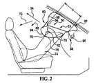
次に図を参照してゆくが、具体的に図1は、車両10の内部の一部分を示している。車両10の室内には、座席構造12と、座席構造12に対して選択された空間的な関係に配置されているエアバッグモジュール14とが含まれている。エアバッグモジュール14は、ハウジング16と、インフレータ18と、膨張可能なエアバッグ又はクッション20とを備えている。モジュール14は、クッション20が座席構造12に向かって展開するように、車両10内に配置されている。
Next, referring to the drawings, FIG. 1 specifically shows a part of the inside of the
センサー又は感知及び診断モジュール22は、起動事象を検知するようになっており、その際、閾値事象が発生すると、起動信号24が発せられ、インフレータ18によって受信されることによって、インフレータが膨張可能なクッションを膨張させることになる。閾値事象の検知は、既知の技術によって車両の周囲に設置された1つ又はそれ以上のセンサーによって確定される。而して、起動信号24は、エアバッグモジュール14の起動を制御する。例示的な実施形態の感知及び診断モジュール22は、マイクロプロセッサ、マイクロコントローラー、又は、エアバッグモジュールの作動を制御する制御アルゴリズムを実行するためのコンピュータ読み取り可能データ又はプログラムのコマンドを実行することができる他の同等な処理装置を備えている。規定された機能及び所望の処理、並びにそのための計算を遂行(例えば、フーリエ解析アルゴリズム及びここで規定した制御処理などの実行)するために、コントローラーは、これらに限定するわけではないが、1つ又は複数のプロセッサ、1つ又は複数のコンピュータ、メモリ、記憶装置、1つ又は複数のレジスタ、タイミング、1つ又は複数のインタラプト、通信インターフェイス、及び入/出力信号インターフェイス、並びに、上記の少なくとも1つを備えているそれらの組み合わせ、を含んでいてもよい。例えば、コントローラーは、その様な信号を通信インターフェイスから正確にサンプリングし、変換し、又は取得することができるようにするため、入力信号フィルタリングを含んでいてもよい。上で説明したように、本発明の例示的な実施形態は、コンピュータが実施するプロセスと、これらのプロセスを実行するための装置とを通して実施することができる。
The sensor or sensing and
膨張可能なクッションは、ハウジング16の中に折り畳まれた又は展開していない状態で格納されている。クッションは、膨張ガスを発生させてクッションを膨張させることになるインフレータ18と流体連通するように配置されている。感知及び診断モジュール22によって起動事象が検知されると、インフレータ18は、信号24を介して起動され、膨張ガスを発生させる。膨張ガスは、クッション20を膨張させ、ハウジング16から車両の内部へと拡張させる。モジュール14は、ほんの一例として、車両のダッシュボードに含まれているように示されているものと理解頂きたい。無論、モジュール14は、例えば、これらに限定するわけではないが、ステアリングホイール、座席、Aピラー、ルーフ、及び他の場所、並びに図1に示している他の角度的又は位置的な関係で、車両の他の領域で展開させるために取り付けることもできると考えられる。更に、車両内部、インスツルメントパネル、エアバッグモジュールの特定な構成、及びそれらとの関係は、一例として提供されており、無論、これらの構成は、図1に示している特定の構成から変わってもよいものと理解頂きたい。
The inflatable cushion is stored in the
加えて、本開示は、更に、様々な型式の膨張可能なクッション及びインフレータと共に使用することも想定している。例えば、クッションは、様々な展開構成及び様々な型式のインフレータ(例えば、二段階式インフレータ)を実現するため特定の方式で構築され、及び/又は、折り畳まれている。 In addition, the present disclosure further contemplates use with various types of inflatable cushions and inflators. For example, the cushions are constructed and / or folded in a particular manner to achieve different deployment configurations and different types of inflators (eg, two-stage inflators).
更に、本発明の代替的な例示的実施形態によれば、感知及び診断モジュールは、座席構造の1つ又はそれ以上の状態を検知できるようにすることもできる。例えば、感知及び診断モジュール22は、下記の、座席構造12の上の荷重又は荷重量(例えば、乗員重量)、座席構造の位置、座席構造の一部分の、別の部分に対する角度、座席構造のエアバッグモジュール14からの距離、及び、車両の周囲に配置された複数のセンサーからの入力を受信することでエアバッグが展開することに関連するその他のデータ、の内の1つ又はそれ以上を検知できるようにすることができる。
Further in accordance with an alternative exemplary embodiment of the present invention, the sensing and diagnostic module may be capable of detecting one or more conditions of the seat structure. For example, the sensing and
例えば、感知及び診断モジュールは、例えば、これらに限定するわけではないが、座席位置センサー26、光学式スキャナー28、荷重センサー30、座席リクライニングセンサー32、座席ベルト使用検知センサー(図示せず)、及びベルト張力センサー34の様な、1つ又はそれ以上のセンサーからの入力を受信することができる。センサーは、入力信号を1つ又はそれ以上の座席状態を示すモジュール22に提供するために設置されている。乗員のサイズ(例えば、センサーによって判定される重量)と組み合わされた1つ又はそれ以上の座席状態は、膨張可能なクッションに望ましい展開スキームを判定するために、感知及び診断モジュール内に設置されたマイクロプロセッサに常駐する制御アルゴリズムに入力される。例えば、データ入力は、マイクロプロセッサ又は他の読み取り可能なフォーマットのメモリに記憶された検索表と比較すると、アルゴリズムが、エアバッグの完全な展開又は部分的な展開の何れが望ましいかを判定することができる。(例えば、クッション展開特性を変更するように設計されているシステムを起動させるか又は起動させないことによって、エアバッグモジュールを特注仕様にする)。
For example, the sensing and diagnostic module may include, for example, but not limited to, a
様々なセンサーを連続的にサンプリングすると、起動事象(展開)が発生する前に、感知及び診断モジュールに様々な入力を提供することができる。なお、本開示のエアバッグ膨張システムは、上に述べたセンサーのどの様な組み合せとでも共に使用できると考えられており、上に論議した特定の型式のセンサーによって制限されるように意図されてはいない。 Sequential sampling of various sensors can provide various inputs to the sensing and diagnostic module before an activation event (deployment) occurs. It should be noted that the airbag inflation system of the present disclosure is believed to be usable with any combination of the sensors described above and is intended to be limited by the specific types of sensors discussed above. No.
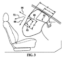
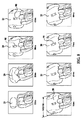
本発明の或る例示的な実施形態によれば、次に、図2から図8で示すように、第1の方向への膨張式クッションの展開は、エアバッグモジュールの膨張可能なクッションの展開特性を変更するために、制御装置50によって制御される。或る例示的な実施形態では、制御装置は、エアバッグモジュールの膨張可能なクッションの中に設置されている。本発明の或る例示的な実施形態によれば、制御装置は、膨張可能なクッションが矢印54で概略的に示されている第1の方向に展開することを制限するように構成されている、解除可能な保持装置52を備えている。
According to certain exemplary embodiments of the present invention, the deployment of the inflatable cushion in the first direction is then followed by the deployment of the inflatable cushion of the airbag module, as shown in FIGS. In order to change the characteristic, it is controlled by the
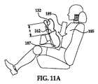
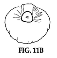
本発明の或る例示的な実施形態によれば、解除可能な保持装置は、膨張可能なクッションの運動学によって、エアバッグモジュールから遠くに、車両の乗員に向けて展開するための膨張可能なクッションの第1の部分となる膨張可能なクッションの第1の部分又は先導縁部の進行を妨げ又は拘束する。その結果、膨張可能なクッションのこの部分の進行を妨げることによって、クッションの他の部分又は第2の部分は、エアバッグモジュールから遠くの他の方向に素早く、又はより迅速に展開することになる。例えば、少なくとも、助手席側エアバッグモジュールの膨張可能なクッションを示している図1から図3では、下縁部は前縁部より先に外向きに展開し、その後、下縁部が妨害されなければ、前縁部は完全に展開することができる。更に、少なくとも、運転者席側エアバッグモジュールの膨張可能なクッションを示している図9Aから図11Bでは、上縁部は、進行を妨げられており、前縁部は、上縁部より先に外向きに展開し、その後、前縁部が妨害されなければ、上縁部は完全に展開することができる。加えて、運転者席側の膨張可能なクッションの上縁部が拘束される場合も、下縁部が最初に移動して出るので、下縁部が、乗員の下部(例えば、上側脚部と胴部)とステアリングホイールの間に位置することになる。 According to an exemplary embodiment of the present invention, the releasable retaining device is inflatable for deployment toward the vehicle occupant, away from the airbag module, by kinematics of the inflatable cushion. The first part of the inflatable cushion or leading edge that becomes the first part of the cushion is impeded or constrained. As a result, by preventing the progression of this part of the inflatable cushion, the other part or the second part of the cushion will be deployed quickly or more quickly in other directions far from the airbag module. . For example, at least in FIGS. 1-3, which shows an inflatable cushion for a passenger side air bag module, the lower edge deploys outward prior to the front edge, after which the lower edge is obstructed. If not, the leading edge can be fully deployed. Further, at least in FIGS. 9A to 11B showing the inflatable cushion of the driver side airbag module, the upper edge is impeded from progressing and the front edge is ahead of the upper edge. If deployed outward and then the leading edge is not obstructed, the upper edge can be fully deployed. In addition, even when the upper edge of the inflatable cushion on the driver's seat side is restrained, the lower edge is moved out first, so that the lower edge is the lower part of the occupant (for example, the upper leg part). The body part) and the steering wheel.
即ち、クッションの運動学のために、拘束されていない膨張可能なクッションは、モジュールから遠くに展開し、少なくとも1つ又は第1の部分が、膨張可能なクッションの他の部分又は第2の部分より前に対象物又は個人に接することになる先導縁部を提供する。従って、他の部分は、先導縁部に対応する第1の部分がモジュールから遠くに展開した後、外向きに、エアバッグモジュールから遠くに展開することになる。更に、膨張可能なクッションに対する乗員の位置次第で、先導縁部は、膨張可能なクッションの「他の部分」が通常接触する部分に比べ、より望ましくない乗員の領域に接触するかもしれない。 That is, because of the kinematics of the cushion, the unconstrained inflatable cushion deploys away from the module and at least one or the first part is the other part or the second part of the inflatable cushion. Provide a leading edge that will contact the object or individual earlier. Therefore, the other part will be deployed outwardly and away from the airbag module after the first part corresponding to the leading edge is deployed farther from the module. Further, depending on the position of the occupant with respect to the inflatable cushion, the leading edge may contact a less desirable occupant area than the part where the “other part” of the inflatable cushion normally contacts.
対照的に、本発明の或る例示的な実施形態によれば、制御装置は、膨張可能なクッションの第1の部分の進行を妨げることで、第2の部分又は他の部分を最初に展開させており、その際、他の部分は、他の部分又は第2の部分を感知装置として使用して、乗員が膨張可能なクッションに近接しているか否かを判定するために使用されている。更に、これらの他の部分は、それらの他の部分を、膨張可能なクッションとの接触により寛容な、乗員の領域に接触させることになる方向に展開することになる。 In contrast, according to certain exemplary embodiments of the present invention, the controller may first deploy the second or other portion by preventing the advancement of the first portion of the inflatable cushion. And the other part is used to determine whether the occupant is in close proximity to the inflatable cushion using the other part or the second part as a sensing device. . In addition, these other parts will unfold in a direction that will cause them to come into contact with the occupant area, which is more forgiving by contact with the inflatable cushion.
本発明の或る例示的な実施形態によれば、解除可能な保持装置は、膨張可能なクッションの内面58の第1の位置60に解放可能に固定された第1端部56を有しており、この第1の位置は、膨張可能なクッションの運動学によってエアバッグモジュールから遠くに車両の乗員に向かって展開する、膨張可能なクッションの第1の部分となる、膨張可能なクッションの先導縁部を提供している、膨張可能なクッションの第1の部分に対応している。
In accordance with certain exemplary embodiments of the present invention, the releasable retention device has a
本発明の或る例示的な実施形態によれば、解除可能な保持装置は、繋ぎ紐又は膨張可能なクッションに加えられる膨張力に耐えるのに適した他の材料を備えている。或る例示的な実施形態では、解除可能な保持装置又は繋ぎ紐は、膨張可能なクッションの第1の位置60の、第1の方向54への展開に対応する、又は、固定点から第1の位置及び、1つの例示的な実施形態ではエアバッグモジュールハウジングである、別の固定点までの展開有効長「x」又は伸長時長「x」を有している。即ち、有効長「x」は、例えば、膨張可能なクッションの第1の方向への展開に対応し、図2で示すように、解除可能な保持装置52の一部分は、インスツルメントパネル又はエアバッグモジュールハウジングの部分の周りに曲がっている。
According to certain exemplary embodiments of the present invention, the releasable retaining device comprises a tether or other material suitable to withstand the expansion force applied to the inflatable cushion. In certain exemplary embodiments, the releasable retaining device or tether corresponds to deployment of the
図3に示すように、解除可能な保持装置の有効長xは、膨張可能なクッションが妨害する物の無い展開の際に第1の方向54に展開する距離に対応する、距離「xl」より短くなっている。従って、本発明の或る例示的な実施形態によれば、解除可能な保持装置は、膨張可能なクッションの少なくとも1つの他の部分が、妨害されていない様式で展開していない場合には、膨張式クッションが、第1の方向に完全に展開することを防止する。更に、膨張可能なクッションの第1の部分を第1の方向に拘束することで、第2の部分又は他の部分を、膨張可能なクッションの展開時に最初に又は先に展開させ、その後、膨張可能なクッションの第1の部分が拘束されていなかった場合は、それらの部分が展開される。更に、より早い段階で展開している他方の部分は、他方の部分又は第2の部分を感知部材として使用することによって、乗員が膨張可能なクッションに近接しているか否かを判定するために使用される。即ち、解除可能な保持装置は、膨張可能なクッションが展開され、解除可能な保持装置が第1の位置に固定されている時には、膨張可能なクッションが距離xlに達するのを防止する。
As shown in FIG. 3, the effective length x of the releasable retaining device is from a distance “xl”, which corresponds to the distance deployed in the
或る例示的な実施形態によれば、解除可能な保持装置を解放するために、制御装置は、更に、感知装置62を備えている。感知装置は、膨張可能なクッションの第2の部分が、第2の方向68に妨害されること無く展開するか否かを検知するように構成されている。この第2の方向は、感知装置を解除可能な保持装置に解放可能に固定する点から、感知装置を、或る例示的な実施形態では、第2の部分64の先導縁部に近接している膨張可能なクッションの内面である、第2の部分に固定するもう1つの点に向けて、として説明することもできる、第2の部分64の第2の方向68への展開に対応している。
According to an exemplary embodiment, the control device further comprises a
上記のように、解除可能な保持装置による第1の部分の拘束は、第2の部分を、拘束されていない膨張可能なクッションよりも速く展開させる。その後、第2の部分は、膨張可能なクッションが妨害されているか否かを判定するために使用される。 As described above, restraining the first portion by the releasable retaining device causes the second portion to deploy faster than an unconstrained inflatable cushion. The second part is then used to determine whether the inflatable cushion is obstructed.
本発明の或る例示的な実施形態では、膨張可能なクッションの第2の部分は、膨張可能なクッションの下側前縁部70であり、第2の方向は、概ね、第1の方向から、下向き又は前向きで下向きの方向72であり、本発明の或る例示的な実施形態によれば、より望ましい接触位置に対応している。
In an exemplary embodiment of the invention, the second portion of the inflatable cushion is the lower
或る例示的な実施形態によれば、感知装置は、更に、膨張可能なクッションの第2の部分が妨害されること無く第2の方向に展開する時に、膨張可能なクッションが第2の方向に展開する距離に対応する長さ「y1」より短い有効長、又は伸張時長「y」を有する繋ぎ紐を備えている。この様な次第で、本発明の或る実施形態によれば、膨張可能なクッションの第2の部分が第2の方向に、少なくとも「y」より大きい距離だけ展開すると、感知装置は、教示されることになり、而して、解除可能な保持装置を第1の位置に解放可能に固定しているピン又は他の等価な装置を引き抜き、解除可能な保持装置を膨張可能なクッションの第1の位置から、更には固定されたピンを有する感知装置の端部から解放し、それによって、膨張可能なクッションが第1の方向に「xl」の距離だけ展開することができるようにする。 According to certain exemplary embodiments, the sensing device may further cause the inflatable cushion to move in the second direction when the second portion of the inflatable cushion deploys in the second direction without obstruction. A tether having an effective length shorter than the length “y1” corresponding to the distance to be expanded, or a length “y” at the time of extension is provided. As such, according to an embodiment of the present invention, the sensing device is taught when the second portion of the inflatable cushion is deployed in the second direction by a distance greater than at least “y”. Thus, the pin or other equivalent device that releasably secures the releasable retaining device in the first position is withdrawn, and the releasable retaining device is the first of the inflatable cushion. And from the end of the sensing device with a fixed pin, so that the inflatable cushion can be deployed a distance of “xl” in the first direction.
本発明の或る例示的な実施形態によれば、解除可能な保持装置は、膨張可能なクッションの第2の部分が展開中に妨害されると、膨張可能なクッションが第1の方向に完全に展開するのを防止するが、これは、或る非限定的な例示的実施形態では、後ろ向きのチャイルドシート74が、展開している膨張可能なクッションの前に配置されている場合である(図2参照)。図示のように、後ろ向きのチャイルドシートは、膨張可能なクッションの第2の方向への展開を妨害することになり、その結果、解除可能な保持装置は、膨張可能なクッションに固定されたままとなり、而して、膨張可能なクッションの第1の方向への展開を制限することになる。即ち、膨張可能なクッションが第2の方向への展開を妨害されると、感知装置は、展開長に完全には達しなくなり、而して、感知装置は、解除可能な保持装置をクッションに固定しているピンを引き抜かないので、解除可能な保持装置は、膨張可能なクッションに固定されたままとなる。
According to an exemplary embodiment of the present invention, the releasable retaining device is such that the inflatable cushion is fully in the first direction when the second portion of the inflatable cushion is obstructed during deployment. In a non-limiting exemplary embodiment, where a rear-facing
この様な次第で、本発明の或る例示的な実施形態は、膨張可能なクッションの中に配置されている制御装置に着眼しており、制御装置は、膨張可能なクッションの少なくとも第2の方向の展開を制限するように構成されている解除可能な保持装置であって、膨張可能なクッションの内面の第1の位置に解放可能に固定されている、解除可能な保持装置と、膨張可能なクッションの第2の位置が、膨張中に所定の距離だけ移動すると、解除可能な保持装置を第1の位置から解放するための感知装置と、を備えている。感知装置は、膨張可能なクッションの内面の第2の位置に固定的に固定されており、更に、感知装置は、第2の位置が所定の距離だけ移動すると、解除可能な保持装置を第1の位置から解放するように構成されている。 As such, certain exemplary embodiments of the present invention are directed to a control device disposed within an inflatable cushion, the control device comprising at least a second of the inflatable cushion. A releasable retainer configured to limit directional deployment, wherein the releasable retainer is releasably secured to a first position on an inner surface of the inflatable cushion, and inflatable And a sensing device for releasing the releasable retaining device from the first position when the second position of the cushion is moved a predetermined distance during inflation. The sensing device is fixedly secured to a second position on the inner surface of the inflatable cushion, and further the sensing device has a releasable retaining device that is releasable when the second position is moved a predetermined distance. It is configured to release from the position.
或る例示する実施形態によれば、感知装置は、膨張可能なクッションの第2の位置76に固定されており、膨張可能なクッションの第2の位置が、第2の方向に所定の距離だけ展開すると、解除可能な保持装置を膨張可能なクッションの第1の位置から解放するための解除部材78を備えている。
According to an exemplary embodiment, the sensing device is secured to the
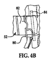
1つの非限定的な例示的実施形態によれば、図4Aから6Bに示すように、解除部材は、端部82が保持部材84を通過した後で、解除可能な保持装置の端部82をそれ自身に解放可能に固定するための、感知装置の一方の端部に固定されているピン又は保持装置80を備えており、保持部材は、膨張可能なクッションの内面に固定され、端部をその中に通して、解除可能な保持装置を膨張可能なクッションの内面に固定できるようにする開口部86を提供している。ピン又は保持装置80の非限定的な例には、コッターピン構造が含まれ、同構造では、コッターピンの一部分が、解除可能な保持装置の端部82に通され、それを、それが保持部材の周囲を通過した後で、解除可能な保持装置の別の部分に固定するようになっている。例示的な実施形態によれば、ピン又は保持装置80は、曝されることになる引張力に十分に耐え、更に、解除可能な保持装置の材料に対して低い又は望ましい摩擦係数を提供するプラスチック材料又は金属材料(例えば、鋼)で形成されている。
According to one non-limiting exemplary embodiment, as shown in FIGS. 4A to 6B, the release member may be configured to release the
1つの非限定的な例示的実施形態では、保持部材84は、膨張可能なクッションの前方部分又は第1の部分又は先導縁部の表面区域の周りに解除可能な保持装置52の拘束力を配分するように構成されている固定部材88に、両端が固定されたピン又はロッド(図4C)である。1つの非限定的な例示的実施形態では、固定部材は、少なくとも2つの端部が膨張可能なクッションの内面に固定された一片の材料であり、保持部材は、保持荷重を膨張可能なクッションの面の周りに分散させるために、2つの固定された端部の間で、材料の表面に固定されている。更に、開口部86は、保持部材と材料の表面の間に位置することになる。
In one non-limiting exemplary embodiment, the
更に、本発明の或る例示的な実施形態によれば、解除可能な保持装置の第1の部分に対する固定は、解除可能な保持装置を解放するのに、感知装置が最小限の量の力しか必要としないように構成されている。これは、少なくとも1つの非限定的な実施形態では、解除可能な保持装置を保持部材84の周りに輪にして、解除可能な保持装置の少なくとも2つの部分が、膨張可能なクッションの第1の部分の進行を妨げ又は拘束する張力を受けるようにすることで、実現し易くなっている。この様な次第で、保持装置80を解除可能な保持装置から取り外すために必要な力の量は、保持部材84の周囲に巻かれている解除可能な保持装置の2つの脚部又は部分の間に分割され、而して、解除可能な保持装置の2つの部分を保持部材に固定している保持装置80に掛かる張力を減らしている。
Further, in accordance with certain exemplary embodiments of the present invention, the securing of the releasable retaining device to the first portion causes the sensing device to have a minimal amount of force to release the releasable retaining device. However, it is configured to require only. This is because, in at least one non-limiting embodiment, the releasable retaining device is looped around the retaining
更に、解除可能な保持装置を解放する(例えば、ピンを引き出す)のに感知装置が最小限の量の力しか必要としないようにすることによって、対象物又は乗員に接触する部分又は第2の部分は、更に、拘束されている第1の部分又は先導縁部と比較して、接触力が低くなる。感知装置を解除可能な保持装置に固定しているピンが容易に取り外せるので、膨張可能なクッションの円滑な展開が促進されるようになる。この場合も、これは、クッションの運動学によって、最初にインスツルメントパネルから外側に向かってクッションの他の部分より大きな力を伴って展開する可能性が高いクッションの部分である、クッションの先導縁部の進行を妨げ又は拘束することによって実現し易くなっている。 Further, by allowing the sensing device to require a minimal amount of force to release the releasable retaining device (e.g., pulling out the pin), the portion contacting the object or occupant or the second The portion further has a lower contact force compared to the constrained first portion or leading edge. Since the pin fixing the sensing device to the releasable holding device can be easily removed, smooth deployment of the inflatable cushion is facilitated. Again, this is the leading part of the cushion, which is the part of the cushion that the kinematics of the cushion are likely to deploy from the instrument panel outward with greater force than the rest of the cushion. This is facilitated by preventing or constraining the advance of the edge.
この様な次第で、膨張可能なクッションの第2の部分が妨害されない場合には、感知装置は、解除可能な保持装置をクッションの前方部分から解放し(例えば、解除可能な保持装置の端部を自身に保持又は固定しているピンを引き抜く)、クッションの先導縁部は、完全に外に出るか、又は一杯に展開することができるようになる。そうではなく、感知装置が完全には伸張しない場合は、ピンは引き抜かれず、解除可能な保持装置は、膨張可能なクッションの先導縁部に固定されたままとなる。 As such, if the second portion of the inflatable cushion is not obstructed, the sensing device releases the releasable retaining device from the front portion of the cushion (eg, the end of the releasable retaining device). Pulling out the pin holding or securing it to the cushion), the leading edge of the cushion will either be completely out or fully unfolded. Otherwise, if the sensing device does not fully extend, the pin is not withdrawn and the releasable retaining device remains secured to the leading edge of the inflatable cushion.
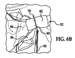
図6Aと6Bには、解除可能な保持装置を膨張可能なクッションに解放可能に固定するための別の代替的な方法が、図解されている。ここでは、固定部及び保持部材は、それぞれ、2つの位置で膨張可能なクッションの内面に固定された単一片の材料90に置き換えられている。前の実施形態での様に、解除可能な保持装置の端部は、材料90の周囲に固定され、感知部材に固定された解除部材78は、端部82を解除可能な保持装置に、端部が材料90によって画定された開口部を通過した後に、固定しており、前と同じように、膨張可能なクッションの膨張力に耐えるために、解除可能な保持装置の2つの部分を提供している。
FIGS. 6A and 6B illustrate another alternative method for releasably securing a releasable retention device to an inflatable cushion. Here, the fixing part and the holding member are each replaced by a single piece of
次に、再び図1から図6Bを参照すると、感知装置は、一端が解除部材78又はピン80に固定され、他端が膨張可能なクッションの第2の部分64に近接した内面の部分に固定された、繋ぎ紐92を備えている。この様な次第で、第2の部分が、感知装置又は繋ぎ紐92の長さより長い距離だけ妨害されること無く移動すると、繋ぎ紐は、教示され、ピンを解除可能な保持装置の端部82から引き抜き、而して、膨張可能なクッションの第1の部分は、端部82が、膨張可能なクッションに固定された保持部材84から翻り又は分離されるので、矢印44の方向に拡張又は展開することができるようになる。
Referring now again to FIGS. 1-6B, the sensing device has one end secured to the
更に、1つの非限定的な例示的実施形態では、膨張可能なクッションが展開され、解除可能な保持装置が膨張可能なクッションから解放されない時には、解除可能な保持装置の固定された端部を膨張力に耐えることのできる構造に固定するために、固定点94が、解除可能な保持装置の固定端部96を、膨張可能なクッションに、膨張可能なクッションの外面100に固定されたアンカー98に近接して固定すること(例えば、縫い付けるか、又は他の等価な固定手段)によって、提供される。或る例示的な実施形態によれば、アンカー98は、エアバッグモジュールハウジング又はインスツルメントパネルの構造部材の何れか又は両方の相補的開口部の中に受け入れられるように構成されている。
Further, in one non-limiting exemplary embodiment, the fixed end of the releasable retaining device is inflated when the inflatable cushion is deployed and the releasable retaining device is not released from the inflatable cushion. To secure the structure to withstand force, a securing point 94 attaches the releasable retaining device
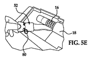
更に別の代替案では、図5Aから5Eに示すように、膨張可能なクッションが展開され、解除可能な保持装置が膨張可能なクッションから解放されない時には、解除可能な保持装置の固定された端部を膨張力に耐えることのできる構造に固定するために、固定点94が、解除可能な保持装置の端部分を膨張可能なクッションの開口部に通すことによって、提供され、その際、端部分は、そこに固定されたアンカー98を有しており、アンカー98は、エアバッグモジュールハウジング又はインスツルメントパネルの構造部材の何れか又は両方の相補的開口部102の中に受け入れられるように構成されている。
In yet another alternative, as shown in FIGS. 5A to 5E, when the inflatable cushion is deployed and the releasable retaining device is not released from the inflatable cushion, the fixed end of the releasable retaining device Is secured by passing the end portion of the releasable retaining device through the opening of the inflatable cushion, wherein the end portion is An
更に別の代替案では、アンカー98は、インフレータの一部分とインフレータを所定の位置に保持しているブラケット104の間に配置されている(図5D)。図5Aから5Eに示すように、解除可能な保持装置は、その固定された固定端部を、膨張可能なクッションの膨張開口部に通し、その後、解除可能な保持装置の一部分が、インフレータとエアバッグモジュールハウジングの間に配置される。更に、アンカーは、膨張可能なクッションが展開している間に、インフレータとエアバッグモジュールハウジングの間を通ることができないように構成されている。その上、図5Dに示すように、インフレータは、アンカーが中を通過するのを防ぐ機能もある取り付けプレート104によって所定の位置に保持されている。図5Eは、明瞭にするために膨張可能なクッションを取り除いた状態の、エアバッグモジュールハウジングに固定された解除可能な保持装置を示している。
In yet another alternative, the
無論、上に述べた実施形態は、解除可能な保持装置を膨張可能なクッションにしっかりと固定するための方法の例であり、本発明の例示的な実施形態は、ここに図解された特定の構成に限定されるよう意図されてはいない。 Of course, the above-described embodiment is an example of a method for securely securing a releasable retention device to an inflatable cushion, and the exemplary embodiment of the present invention is a specific example illustrated herein. It is not intended to be limited to configuration.
次に、図7には、膨張可能なクッションが、妨害する物の無い状態で展開している連続的な図が示されており、一方図8は、膨張可能なクッションが、妨害する物の在る状態で展開している連続的な図を示している。図8に明瞭に示されているように、膨張可能なクッションは、膨張可能なクッションの第2の部分が阻止又は妨害され、感知装置が最大の作動長さまで展開されていないので、解除可能な保持装置によって第1の方向に拘束されている。更に、図8に示すように、拘束された膨張可能なクッションは、明らかに、図7に示した膨張可能なクッションの展開された幅より大きな幅を有している。 Next, FIG. 7 shows a continuous view in which the inflatable cushion is deployed without obstructing objects, while FIG. It shows a continuous diagram unfolding in a certain state. As clearly shown in FIG. 8, the inflatable cushion is releasable because the second portion of the inflatable cushion is blocked or obstructed and the sensing device is not deployed to its maximum working length. It is restrained in the first direction by the holding device. Further, as shown in FIG. 8, the constrained inflatable cushion clearly has a width that is greater than the deployed width of the inflatable cushion shown in FIG.
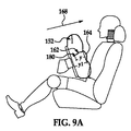
図9から図16には、本発明の代替的な例示的実施形態が示されている。ここでは、同様の又は類似の機能を遂行している部品には、100番台の数字が付けられている。これらの図面には、運転者側エアバッグモジュールと共に使用するように構成された膨張可能なクッション108が示されている。先の実施形態と同様に、第1の方向に膨張可能なクッションは、膨張可能なクッションの中に設置されている制御装置150によって制御されている。
9-16 illustrate alternative exemplary embodiments of the present invention. Here, parts having similar or similar functions are numbered in the 100s. These drawings show an inflatable cushion 108 configured for use with a driver side airbag module. Similar to the previous embodiment, the cushion that is inflatable in the first direction is controlled by a
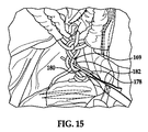
ここで、制御装置は、膨張可能なクッションが矢印154で概略的に示されている第1の方向に展開するのを制限するように構成されている、解除可能な保持装置152を備えている。例示的な実施形態によれば、解除可能な保持装置は、一方の端部157が膨張可能なクッションの膨張開口部159に近接して固定されている第1の部分155と、第1の位置160で膨張可能なクッションの内面に解放可能に固定されている第2の部分161とを有している。1つの非限定的な例示的実施形態では、第2の部分は、開口部163を画定するため少なくとも2つの部分で固定されている複数の部材165によって画定された複数の開口部163を通過させた、ナイロン製の織材料又は他の等価な材料のループを備えている。例示的な実施形態によれば、第2の部分は、それぞれの開口部163を通過しており(図13参照)、その際、第2の部分の幾つかの部分167は、第2の部分161と第1の部分155の間に1つの固定点169を提供するために一緒に引っ張られている。図13に示すように、第2の部分161の端部分と中間部分は、固定点を提供するために集められ、部材165も、一緒に集められている。本発明の或る例示的な実施形態によれば、部材165は、膨張可能なクッションの周辺縁部に位置しており、前方クッション部分173が、後方クッション部分175に固定されている区域に対応しており、膨張可能なクッションの周辺縁部を画定し、而して、第1の部分が第2の部分に固定されている時には、膨張可能なクッションの第1の方向の展開を制限又は拘束する。無論、部材165は、膨張可能なクッションの他の部分に配置されていてもよい。
Here, the control device includes a
図14に示すように、第1の部分は、部材の開口部を通過した後、第2の部分によって画定されたループを通過している。その後、第1の部分の端部分182は、第2の部分のループを通過した後で、第1の部分に固定される。
As shown in FIG. 14, the first portion passes through the opening defined by the member and then passes through the loop defined by the second portion. The
本発明の或る例示的な実施形態によれば、解除可能な保持装置の第1の部分と第2の部分は、膨張可能なクッションに加えられる膨張力に耐えるのに適した繋ぎ紐又は他の材料を備えている。 According to certain exemplary embodiments of the present invention, the first and second portions of the releasable retaining device are tethers or other suitable for withstanding the inflating force applied to the inflatable cushion. It is equipped with the material.
次に、図9から11Bに示すように、例示的な実施形態によれば、解除可能な保持装置又は繋ぎ紐の第1の部分と第2の部分を組み合わせた長さは、有効長「x」、又は、膨張可能なクッションの第1の位置160の第1の方向154への展開に対応する、伸張時長「x」を有している。即ち、有効長「x」は、膨張可能なクッションの第1の方向への展開に対応している。
Next, as shown in FIGS. 9-11B, according to an exemplary embodiment, the combined length of the first and second portions of the releasable retaining device or tether is the effective length “x Or an extended length “x” corresponding to the deployment of the
図示のように、解除可能な保持装置の有効長xは、距離「x1」より短く、この距離は、妨害する物の無い展開の際に、膨張可能なクッションが第1の方向に展開する距離に対応している。この様な次第で、本発明の或る例示的な実施形態によれば、解除可能な保持装置は、膨張可能なクッションの少なくとも1つの他の部分が妨害されていない様式で展開しているのでなければ、膨張可能なクッションが第1の方向に完全に展開することを妨げる。即ち、解除可能な保持装置は、膨張可能なクッションが展開され、解除可能な保持装置が第1の位置に固定されている時には、膨張可能なクッションが距離xlに達するのを妨げる。 As shown, the effective length x of the releasable holding device is shorter than the distance “x1”, which is the distance that the inflatable cushion is deployed in the first direction when deployed without obstruction. It corresponds to. As such, according to certain exemplary embodiments of the present invention, the releasable retaining device is deployed in a manner that does not obstruct at least one other portion of the inflatable cushion. If not, it prevents the inflatable cushion from fully deploying in the first direction. That is, the releasable retaining device prevents the inflatable cushion from reaching the distance xl when the inflatable cushion is deployed and the releasable retaining device is secured in the first position.
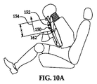
或る例示的な実施形態によれば、解除可能な保持装置を解放するために、制御装置は、感知装置162を更に備えている。感知装置は、膨張可能なクッションの164の第2の部分が、膨張可能なクッションの第2の部分164の第2の方向168への展開に、又は、解除可能な保持装置に対する解除可能な固定点から、1つの例示的な実施形態では第2の部分164に近接する膨張可能なクッションの内面である、もう1つの固定点までに対応する第2の方向に妨害されること無く展開しているか否かを検知するように構成されている。本発明の或る例示的な実施形態によれば、膨張可能なクッションの第2の部分は、膨張可能なクッションの前方又は中央面部分170であり、第2の方向は、第1の方向から概ね前方である。
According to an exemplary embodiment, the control device further comprises a
本発明の或る例示的な実施形態によれば、感知装置は、膨張可能なクッションの第2の部分が第2の方向に妨害されること無く展開する時に、膨張可能なクッションが第2の方向に展開する距離に対応する長さ「y1」より短い有効長又は伸張時長「y」を有している。この様な次第で、本発明の或る例示的な実施形態によれば、膨張可能なクッションの第2の部分が、少なくとも、第2の方向に「y」より長い距離だけ展開すると、感知装置は、解除可能な保持装置を膨張可能なクッションの第1の位置から解放して、膨張可能なクッションが第1の方向に距離「x1」だけ展開することができるようにする。 According to certain exemplary embodiments of the present invention, the sensing device is configured such that when the second portion of the inflatable cushion deploys unhindered in the second direction, the inflatable cushion is second. The effective length or the extended length “y” is shorter than the length “y1” corresponding to the distance developed in the direction. As such, in accordance with certain exemplary embodiments of the present invention, the sensing device when the second portion of the inflatable cushion is deployed at least a distance greater than “y” in the second direction. Releases the releasable retaining device from the first position of the inflatable cushion so that the inflatable cushion can be deployed in the first direction by a distance “x1”.
これも図11Aに示されているが、膨張可能なクッションが第1の方向に拘束されていない時でも、膨張可能なクッションが第2の方向に拘束されるか、又は膨張可能なクッションが早期に第2の方向に拘束されると、下縁部187は、矢印189の方向に展開し、膨張可能なクッションの一部分が、乗員とステアリングホイールの間に位置することになる。助手席側エアバッグモジュールの膨張可能なクッションの拘束された展開の際にも、同じことが当てはまる。即ち、膨張可能なクッションが1つの方向に拘束されると、膨張可能なクッションは、膨張可能なクッションによって拘束されていない別の方向に展開することになる。
This is also shown in FIG. 11A, but even when the inflatable cushion is not constrained in the first direction, the inflatable cushion is constrained in the second direction or the inflatable cushion is premature. When restrained in the second direction, the
本発明の或る例示的な実施形態によれば、解除可能な保持装置は、膨張可能なクッションの第2の部分が展開の際に妨害されると、膨張可能なクッションが第1の方向に完全に展開するのを防ぐが、これは、1つの非限定的な例示的実施形態では、乗員185が、展開する膨張可能なクッションの正面の所定の距離に位置している場合である(少なくとも図9Aと図10A参照)。図示のように、乗員は、膨張可能なクッションの第2の方向への展開を妨害し、従って、解除可能な保持装置は、膨張可能なクッションに固定されたままとなり、而して、膨張可能なクッションの第1の方向への展開が制限されることになる。即ち、膨張可能なクッションを第2の方向に妨害すると、感知装置は、展開長に完全には達しなくなり、而して、解除可能な保持装置は、膨張可能なクッションに固定されたままとなる。
According to an exemplary embodiment of the present invention, the releasable retaining device is configured such that when the second portion of the inflatable cushion is obstructed during deployment, the inflatable cushion is in the first direction. Prevent full deployment, in one non-limiting exemplary embodiment, where the
或る例示的な実施形態によれば、感知装置は、膨張可能なクッションの第2の位置176に固定され、膨張可能なクッションの第2の位置が第2の方向に所定の距離だけ展開すると、解除可能な保持装置を膨張可能なクッションの第1の位置から解放するための解除部材178を備えている。
According to an exemplary embodiment, the sensing device is secured to the
1つの非限定的な例示的実施形態によれば、図15及び図16に示すように、解除部材は、解除可能な保持装置の第1の部分の端部182を、解除可能な保持装置の第2の部分に、端部が膨張可能なクッションの内面に解放可能に固定されている複数の第2の部分のループを通過した後で、固定するためのピン又は保持装置180を備えている。1つの非限定的な例示的実施形態では、各固定部材165は、保持荷重を膨張可能なクッションの所望の部分の周囲に分散させるために、少なくとも2つの部分で膨張可能なクッションの内面に固定された一片の材料である。
According to one non-limiting exemplary embodiment, as shown in FIGS. 15 and 16, the release member may connect the
この様な次第で、膨張可能なクッションの第2の部分が妨害されなければ、感知装置は、解除可能な保持装置を、クッションの前方部分から解放し(例えば、解除可能な保持装置の端部を自身に保持又は固定しているピンを引き抜き)、クッションの先導縁部が完全に出てゆき又は展開できるようにする。そうではなく、感知装置が、完全には伸張しない場合には、ピンは、引き抜かれず、解除可能な保持装置は、膨張可能なクッションの先導縁部に固定されたままとなる。 As such, if the second portion of the inflatable cushion is not obstructed, the sensing device releases the releasable retaining device from the front portion of the cushion (eg, the end of the releasable retaining device). Pull out the pin holding or securing it) so that the leading edge of the cushion can be fully extended or deployed. Otherwise, if the sensing device does not fully extend, the pin is not withdrawn and the releasable retaining device remains secured to the leading edge of the inflatable cushion.
無論、上に述べた実施形態は、解除可能な保持装置を膨張可能なクッションに解放可能に固定するための方法の例であり、本発明の例示的な実施形態は、ここに図解した特定の構造に制限されるよう意図されてはいない。 Of course, the embodiment described above is an example of a method for releasably securing a releasable retention device to an inflatable cushion, and the exemplary embodiment of the present invention is not limited to the particular embodiment illustrated herein. It is not intended to be limited to structure.
10 車両
12 座席構造
14 エアバッグモジュール
16 ハウジング
18 インフレータ
20 クッション
22 感知及び診断モジュール
24 起動信号
26 座席位置センサー
28 光学式スキャナー
30 荷重センサー
32 座席リクライニングセンサー
34 ベルト張力センサー
50 制御装置
52 保持装置
54 矢印、第1の方向
56 第1端部
58 内面
60 第1の位置
62 感知装置
64 第2の部分
68 第2の方向
70 下側前縁部
72 下向き方向
74 チャイルドシート
76 第2の位置
78 解除部材
80 保持装置
82 保持装置の端部
84 保持部材
86 開口部
88 固定部材
90 材料
92 繋ぎ紐
94 固定点
96 固定端部
98 アンカー
100 外面
104 ブラケット
108 クッション
150 制御装置
152 保持装置
154 矢印
155 第1の部分
157 端部
159 膨張開口部
160 第1の位置
161 第2の部分
163 開口部
165 部材
167 部分
169 固定点
173 前方のクッション部分
175 後方のクッション部分
176 第2の位置
178 解除部材
182 第1の部分の端部分
187 下縁部
189 矢印
DESCRIPTION OF
Claims (20)
解除可能な保持装置であって、前記解除可能な保持装置の第1の端部は、前記膨張可能なクッションの内面の第1の位置に解放可能に固定されていて、前記解除可能な保持装置が、前記膨張可能なクッションの第1の位置に固定されている時には、前記解除可能な保持装置は、前記膨張可能なクッションの第1の方向への展開を制限するように構成されている、解除可能な保持装置と、
前記解除可能な保持装置を前記第1の位置から解放するための感知装置であって、前記感知装置は、前記膨張可能なクッションの前記内面の前記第1の位置から離れている第2の位置に固定的に固定され、前記解除可能な保持装置に解放可能に固定されていて、前記感知装置は、前記膨張可能なクッションの前記第2の位置が膨張の間に所定の距離だけ移動すると、前記解除可能な保持装置を前記第1の位置から解放するように構成されている、感知装置と、を備えている制御装置。 In a control device for correcting the deployment characteristics of an inflatable cushion of an airbag module,
A releasable retaining device, wherein a first end of the releasable retaining device is releasably secured to a first position on an inner surface of the inflatable cushion, the releasable retaining device However, when secured to the first position of the inflatable cushion, the releasable retaining device is configured to limit deployment of the inflatable cushion in a first direction; A releasable holding device;
A sensing device for releasing the releasable retaining device from the first position, wherein the sensing device is a second position away from the first position of the inner surface of the inflatable cushion. The releasable retaining device is releasably secured to the sensing device when the second position of the inflatable cushion moves a predetermined distance during inflation; A control device comprising: a sensing device configured to release the releasable holding device from the first position.
ハウジングと、
前記ハウジングから展開するように構成されている膨張可能なクッションと、
前記膨張可能なクッションを膨張させるためのインフレータであって、前記膨張可能なクッションと流体連通しているインフレータと、
解除可能な保持装置であって、前記解除可能な保持装置の第1の端部は、前記膨張可能なクッションの内面の第1の位置に解放可能に固定されていて、前記解除可能な保持装置は、前記解除可能な保持装置が前記膨張可能なクッションの前記第1の位置に固定されている時には、前記解除可能な保持装置は、前記膨張可能なクッションの前記第1の方向への展開を制限するように構成されている、解除可能な保持装置と、
前記解除可能な保持装置を前記第1の位置から解放するための感知装置であって、前記感知装置は、前記可膨張クッションの内面の、前記第1の位置から離れている第2の位置に固定的に固定され、前記解除可能な保持装置に解放可能に固定されていて、前記感知装置は、前記膨張可能なクッションの前記第2の位置が膨張の間に所定の距離だけ移動すると、前記解除可能な保持装置を前記第1の位置から解放するように構成されている、感知装置と、を備えているエアバッグモジュール。 In the airbag module,
A housing;
An inflatable cushion configured to deploy from the housing;
An inflator for inflating the inflatable cushion, wherein the inflator is in fluid communication with the inflatable cushion;
A releasable retaining device, wherein a first end of the releasable retaining device is releasably secured to a first position on an inner surface of the inflatable cushion, the releasable retaining device When the releasable retaining device is fixed in the first position of the inflatable cushion, the releasable retaining device causes the inflatable cushion to expand in the first direction. A releasable retaining device configured to restrict;
A sensing device for releasing the releasable retaining device from the first position, wherein the sensing device is in a second position away from the first position on the inner surface of the inflatable cushion. Fixedly secured and releasably secured to the releasable retaining device, wherein the sensing device is configured to move the second position of the inflatable cushion a predetermined distance during inflation; An air bag module comprising: a sensing device configured to release a releasable retaining device from the first position.
解除可能な保持装置を、前記膨張可能なクッションの内面の第1の位置に固定する段階であって、前記解除可能な保持装置は、前記解除可能な保持装置が前記膨張可能なクッションの前記第1の位置に固定されている時には、前記膨張可能なクッションの第1の方向への展開を制限するように構成されており、前記解除可能な保持装置は、感知装置の係合部材によって前記第1の位置に固定されている、解除可能な保持装置を固定する段階と、
前記膨張可能なクッションの前記内面の、前記第1の位置から離れた第2の位置に固定的に固定されている前記感知装置の一部分が、膨張の間に所定の距離だけ移動し、前記係合部材が、前記解除可能な保持装置から取り外されると、前記解除可能な保持装置を前記第1の位置から解放する段階と、を備える方法。 In a method for limiting deployment of an inflatable cushion in a first direction,
Securing a releasable retaining device to a first position on an inner surface of the inflatable cushion, wherein the releasable retaining device is configured such that the releasable retaining device is the first of the inflatable cushion; And is configured to limit deployment of the inflatable cushion in a first direction when secured to the position of 1, wherein the releasable retaining device is configured by the engagement member of the sensing device. Fixing a releasable holding device fixed in position 1;
A portion of the sensing device fixedly secured to a second position of the inner surface of the inflatable cushion that is remote from the first position moves a predetermined distance during inflation, and Releasing a releasable retaining device from the first position when a mating member is removed from the releasable retaining device.
Applications Claiming Priority (2)
| Application Number | Priority Date | Filing Date | Title |
|---|---|---|---|
| US90993307P | 2007-04-03 | 2007-04-03 | |
| PCT/US2008/059260 WO2008124497A1 (en) | 2007-04-03 | 2008-04-03 | Apparatus and method for controlling an inflatable cushion |
Publications (1)
| Publication Number | Publication Date |
|---|---|
| JP2010523398A true JP2010523398A (en) | 2010-07-15 |
Family
ID=39826294
Family Applications (1)
| Application Number | Title | Priority Date | Filing Date |
|---|---|---|---|
| JP2010502290A Pending JP2010523398A (en) | 2007-04-03 | 2008-04-03 | Apparatus and method for controlling an inflatable cushion |
Country Status (6)
| Country | Link |
|---|---|
| US (1) | US7922199B2 (en) |
| EP (1) | EP2144789A4 (en) |
| JP (1) | JP2010523398A (en) |
| KR (1) | KR101047069B1 (en) |
| CN (1) | CN101668665B (en) |
| WO (1) | WO2008124497A1 (en) |
Cited By (1)
| Publication number | Priority date | Publication date | Assignee | Title |
|---|---|---|---|---|
| US9707923B2 (en) | 2015-03-26 | 2017-07-18 | Toyoda Gosei Co., Ltd. | Airbag device for a front passenger seat |
Families Citing this family (10)
| Publication number | Priority date | Publication date | Assignee | Title |
|---|---|---|---|---|
| US8419058B2 (en) * | 2008-03-21 | 2013-04-16 | Trw Vehicle Safety Systems Inc. | Dual volume air bag |
| US8020890B2 (en) * | 2008-10-10 | 2011-09-20 | Autoliv Development Ab | Apparatus and method for controlling an inflatable cushion |
| US11498486B2 (en) | 2009-10-07 | 2022-11-15 | Magna Mirrors Of America, Inc. | Vehicular exterior rearview mirror assembly |
| US10261648B2 (en) | 2009-10-07 | 2019-04-16 | Magna Mirrors Of America, Inc. | Exterior rearview mirror assembly |
| KR101251836B1 (en) * | 2011-09-02 | 2013-04-09 | 현대자동차주식회사 | Driver condition detecting device with IR sensor |
| US9174578B2 (en) | 2013-04-22 | 2015-11-03 | Magna Mirrors Of America, Inc. | Interior rearview mirror assembly |
| US9676364B2 (en) * | 2015-09-30 | 2017-06-13 | Autoliv Asp, Inc. | Airbag systems with passive venting control |
| US10427639B2 (en) | 2018-01-10 | 2019-10-01 | Autoliv Asp, Inc. | Airbag systems with passive venting control |
| US11345305B2 (en) * | 2018-09-26 | 2022-05-31 | Trw Vehicle Safety Systems Inc. | Adaptive airbag for protecting occupants in a vehicle |
| FR3093483B1 (en) * | 2019-03-05 | 2022-04-01 | Seva Tech | Communication interface for an external inflatable pedestrian safety structure fitted to a vehicle, inflatable structure-vehicle communication protocol and associated safety module |
Citations (2)
| Publication number | Priority date | Publication date | Assignee | Title |
|---|---|---|---|---|
| US20050127653A1 (en) * | 2003-12-11 | 2005-06-16 | Williams Jeffrey D. | Expansion-controlled joints in airbags for out-of-position occupants and cushion positioning |
| JP2005313675A (en) * | 2004-04-27 | 2005-11-10 | Autoliv Development Ab | Air bag device |
Family Cites Families (56)
| Publication number | Priority date | Publication date | Assignee | Title |
|---|---|---|---|---|
| DE3618060A1 (en) | 1986-05-28 | 1987-12-03 | Bayerische Motoren Werke Ag | Air bag for protecting the occupants of vehicles |
| US5022675A (en) * | 1989-11-30 | 1991-06-11 | Allied-Signal Inc. | Air bag and folding technique |
| JP2812076B2 (en) | 1992-06-11 | 1998-10-15 | 池田物産株式会社 | Airbag device |
| MX9304559A (en) | 1992-09-01 | 1994-03-31 | Morton Int Inc | STRINGS WITH SCRAPABLE SEAMS FOR INFLATABLE BAG CUSHION. |
| US5246250A (en) | 1992-11-25 | 1993-09-21 | General Motors Corporation | Air bag valve assembly |
| US5280953A (en) | 1992-11-25 | 1994-01-25 | General Motors Corporation | Displacement responsive air bag vent |
| US5405166A (en) | 1993-07-30 | 1995-04-11 | Alliedsignal Inc. | Air bag with inflation limiter |
| US5588675A (en) | 1993-12-20 | 1996-12-31 | General Motors Corporation | Air bag module with gas augmentation |
| US5540166A (en) * | 1994-03-16 | 1996-07-30 | Diversified Systems, Inc. | Edge steer finishing device and method |
| GB2299550B (en) | 1995-04-03 | 1998-06-24 | Autoliv Dev | Improvements in or relating to a safety arrangement |
| JPH09142241A (en) | 1995-11-24 | 1997-06-03 | Honda Motor Co Ltd | Airbag device for passenger protection |
| DE59707717D1 (en) | 1996-08-22 | 2002-08-22 | Volkswagen Ag | Occupant protection device for a vehicle |
| SE510534C2 (en) | 1996-12-17 | 1999-05-31 | Aga Ab | Method of filling an empty, flexible container and a container device |
| US6039346A (en) | 1997-01-17 | 2000-03-21 | General Motors Corporation | Air bag module with variable inflation |
| US5746447A (en) | 1997-01-21 | 1998-05-05 | Morton International, Inc. | Airbag module |
| US5762367A (en) | 1997-04-10 | 1998-06-09 | General Motors Corporation | Air bag module with inflation control device |
| JPH11105664A (en) | 1997-08-08 | 1999-04-20 | Toyoda Gosei Co Ltd | Air bag device |
| DE19813832C2 (en) | 1998-03-20 | 2003-10-23 | Takata Petri Ag | Airbag for an airbag module |
| DE19816075A1 (en) | 1998-04-09 | 1999-10-14 | Volkswagen Ag | Safety device for a motor vehicle with a multi-chamber airbag |
| US6116644A (en) | 1998-04-24 | 2000-09-12 | Delphi Technologies, Inc. | Frontal air bag system |
| US6123358A (en) | 1998-05-11 | 2000-09-26 | General Motors Corporation | Air bag module with variable inflation |
| GB2338214B (en) | 1998-06-09 | 2002-02-13 | Autoliv Dev | Improvements in or relating to an air-bag arrangement |
| US6170871B1 (en) | 1998-06-24 | 2001-01-09 | Breed Automotive Technology, Inc. | Inflatable trim panel assembly for safety restraint systems |
| US6176511B1 (en) | 1998-10-07 | 2001-01-23 | Trw Inc. | Air bag module |
| US6213502B1 (en) | 1998-11-24 | 2001-04-10 | Delphi Technologies, Inc. | Air bag module with variable inflation |
| JP2000233704A (en) | 1999-02-12 | 2000-08-29 | Takata Corp | Air bag device |
| DE19912369A1 (en) | 1999-03-19 | 2000-10-05 | Bsrs Restraint Syst Gmbh | Airbag module controlled by dynamics |
| JP3463598B2 (en) | 1999-04-13 | 2003-11-05 | トヨタ自動車株式会社 | Airbag device |
| DE29907618U1 (en) | 1999-04-29 | 1999-09-16 | Trw Repa Gmbh | Airbag restraint system |
| US6168191B1 (en) | 1999-06-11 | 2001-01-02 | Delphi Technologies, Inc. | Inflatable air bag for an automotive vehicle |
| US6203061B1 (en) | 1999-10-07 | 2001-03-20 | Delphi Technologies, Inc. | Variable output air bag module with PAV heat sink |
| US6439603B2 (en) | 1999-10-13 | 2002-08-27 | Delphi Technologies, Inc. | Air bag module with variable inflation |
| US6422597B1 (en) | 1999-11-12 | 2002-07-23 | Delphi Technologies, Inc. | Variable profile air bag restraint |
| US6390501B1 (en) | 1999-11-12 | 2002-05-21 | Delphi Technologies, Inc. | Variable profile air bag restraint |
| US6315323B1 (en) | 1999-12-21 | 2001-11-13 | Trw Vehicle Safety Systems Inc. | Apparatus for positioning an inflated air bag |
| US6371517B1 (en) | 1999-12-28 | 2002-04-16 | Delphi Technologies, Inc. | Adaptive inflation mechanism |
| DE20004076U1 (en) | 2000-01-21 | 2000-06-21 | TRW Automotive Safety Systems GmbH & Co. KG, 63743 Aschaffenburg | Airbag module |
| US6511094B2 (en) | 2000-03-27 | 2003-01-28 | General Motors Corporation | Automotive vehicle air bag system |
| JP4560881B2 (en) | 2000-04-21 | 2010-10-13 | タカタ株式会社 | Airbag device |
| DE20018091U1 (en) | 2000-10-23 | 2001-03-08 | Trw Repa Gmbh | Vehicle occupant protection system |
| US6499765B2 (en) | 2000-10-31 | 2002-12-31 | Delphi Technologies, Inc. | Bias deployment inflatable air bag |
| US6454300B1 (en) | 2001-02-27 | 2002-09-24 | Delphi Technologies, Inc. | Air bag tether release assembly |
| US6431583B1 (en) | 2001-02-28 | 2002-08-13 | Autoliv Asp, Inc. | Inflatable knee bolster with external tethering |
| US6616184B2 (en) | 2001-04-25 | 2003-09-09 | Trw Vehicle Safety Systems Inc. | Vehicle occupant protection apparatus with inflation volume and shape control |
| US6991258B2 (en) | 2002-02-20 | 2006-01-31 | Delphi Technologies, Inc. | Frontal air bag system |
| JP2003260996A (en) * | 2002-03-07 | 2003-09-16 | Takata Corp | Air bag device |
| US6832778B2 (en) | 2002-07-19 | 2004-12-21 | Delphi Technologies, Inc. | Air bag restraint including selectively operable venting elements |
| KR20040023323A (en) * | 2002-09-11 | 2004-03-18 | 현대모비스 주식회사 | Air bag cushion with plural tether |
| US7083191B2 (en) | 2002-09-16 | 2006-08-01 | Trw Vehicle Safety Systems Inc. | Air bag module with vent controlled by tether |
| US6959945B2 (en) | 2002-09-16 | 2005-11-01 | Trw Vehicle Safety Systems Inc. | Air bag module with vent controlled by tether |
| US6932384B2 (en) | 2002-11-15 | 2005-08-23 | Delphi Technologies, Inc. | Apparatus and method for controlling an inflatable cushion |
| US7192053B2 (en) | 2003-09-12 | 2007-03-20 | General Motors Corporation | Automotive vehicle air bag system |
| JP2005096495A (en) | 2003-09-22 | 2005-04-14 | Honda Motor Co Ltd | Airbag device |
| GB2432344A (en) * | 2005-11-04 | 2007-05-23 | Autoliv Dev | An airbag with a releasable tether |
| US7506892B2 (en) * | 2006-02-17 | 2009-03-24 | Tk Holdings Inc. | Cushion shaping sleeve and tether for airbags |
| US7621561B2 (en) * | 2006-03-07 | 2009-11-24 | Gm Global Technology Operations, Inc. | Simplified restraining tether system for use with a vehicle air bag system |
-
2008
- 2008-04-03 EP EP08745017A patent/EP2144789A4/en not_active Withdrawn
- 2008-04-03 JP JP2010502290A patent/JP2010523398A/en active Pending
- 2008-04-03 KR KR1020097020400A patent/KR101047069B1/en not_active Expired - Fee Related
- 2008-04-03 US US12/062,139 patent/US7922199B2/en not_active Expired - Fee Related
- 2008-04-03 WO PCT/US2008/059260 patent/WO2008124497A1/en not_active Ceased
- 2008-04-03 CN CN2008800114664A patent/CN101668665B/en not_active Expired - Fee Related
Patent Citations (2)
| Publication number | Priority date | Publication date | Assignee | Title |
|---|---|---|---|---|
| US20050127653A1 (en) * | 2003-12-11 | 2005-06-16 | Williams Jeffrey D. | Expansion-controlled joints in airbags for out-of-position occupants and cushion positioning |
| JP2005313675A (en) * | 2004-04-27 | 2005-11-10 | Autoliv Development Ab | Air bag device |
Cited By (1)
| Publication number | Priority date | Publication date | Assignee | Title |
|---|---|---|---|---|
| US9707923B2 (en) | 2015-03-26 | 2017-07-18 | Toyoda Gosei Co., Ltd. | Airbag device for a front passenger seat |
Also Published As
| Publication number | Publication date |
|---|---|
| CN101668665A (en) | 2010-03-10 |
| CN101668665B (en) | 2012-11-28 |
| WO2008124497A1 (en) | 2008-10-16 |
| US7922199B2 (en) | 2011-04-12 |
| KR20090125152A (en) | 2009-12-03 |
| EP2144789A4 (en) | 2011-05-25 |
| EP2144789A1 (en) | 2010-01-20 |
| KR101047069B1 (en) | 2011-07-07 |
| US20080246261A1 (en) | 2008-10-09 |
Similar Documents
| Publication | Publication Date | Title |
|---|---|---|
| JP2010523398A (en) | Apparatus and method for controlling an inflatable cushion | |
| JP4923559B2 (en) | Crew restraint system | |
| US8020890B2 (en) | Apparatus and method for controlling an inflatable cushion | |
| US20040094941A1 (en) | Apparatus and method for controlling an inflatable cushion | |
| US11447089B2 (en) | Airbag assembly with reaction surface | |
| KR100558180B1 (en) | Airbag module having variable tether system | |
| US7261320B2 (en) | Airbag cushion with dual mode deployment for pre-impact and impact conditions | |
| JP4923879B2 (en) | Airbag device | |
| JP2008290606A (en) | Curtain side airbag device | |
| JP2006206043A (en) | Vehicle restraint system | |
| US7819425B2 (en) | Apparatus and method for controlling an inflatable cushion | |
| JP2016190542A (en) | Air bag and pedestrian air bag device | |
| JP2008279977A (en) | Rear seat occupant restraint device, airbag deployment method, and vehicle having rear seat occupant restraint device | |
| JP2007161205A (en) | Occupant restraining device | |
| JP2007161203A (en) | Occupant restraining device | |
| CN101652274B (en) | Apparatus and method for controlling an inflatable cushion | |
| JP2001114065A (en) | Vehicle occupant protection system | |
| JP2007161206A (en) | Occupant restraining device | |
| JP2010195328A (en) | Strap accommodating structure for curtain airbag | |
| JP2008230485A (en) | Curtain airbag device |
Legal Events
| Date | Code | Title | Description |
|---|---|---|---|
| A621 | Written request for application examination |
Free format text: JAPANESE INTERMEDIATE CODE: A621 Effective date: 20100601 |
|
| A977 | Report on retrieval |
Free format text: JAPANESE INTERMEDIATE CODE: A971007 Effective date: 20120126 |
|
| A131 | Notification of reasons for refusal |
Free format text: JAPANESE INTERMEDIATE CODE: A131 Effective date: 20120130 |
|
| A601 | Written request for extension of time |
Free format text: JAPANESE INTERMEDIATE CODE: A601 Effective date: 20120426 |
|
| A602 | Written permission of extension of time |
Free format text: JAPANESE INTERMEDIATE CODE: A602 Effective date: 20120508 |
|
| A02 | Decision of refusal |
Free format text: JAPANESE INTERMEDIATE CODE: A02 Effective date: 20121003 |