US7735860B2 - Inflator with vent - Google Patents
Inflator with vent Download PDFInfo
- Publication number
- US7735860B2 US7735860B2 US11/710,198 US71019807A US7735860B2 US 7735860 B2 US7735860 B2 US 7735860B2 US 71019807 A US71019807 A US 71019807A US 7735860 B2 US7735860 B2 US 7735860B2
- Authority
- US
- United States
- Prior art keywords
- vent
- chamber
- inflation fluid
- inflator
- openings
- Prior art date
- Legal status (The legal status is an assumption and is not a legal conclusion. Google has not performed a legal analysis and makes no representation as to the accuracy of the status listed.)
- Expired - Fee Related, expires
Links
Images


Classifications
-
- B—PERFORMING OPERATIONS; TRANSPORTING
- B60—VEHICLES IN GENERAL
- B60R—VEHICLES, VEHICLE FITTINGS, OR VEHICLE PARTS, NOT OTHERWISE PROVIDED FOR
- B60R21/00—Arrangements or fittings on vehicles for protecting or preventing injuries to occupants or pedestrians in case of accidents or other traffic risks
- B60R21/02—Occupant safety arrangements or fittings, e.g. crash pads
- B60R21/16—Inflatable occupant restraints or confinements designed to inflate upon impact or impending impact, e.g. air bags
- B60R21/26—Inflatable occupant restraints or confinements designed to inflate upon impact or impending impact, e.g. air bags characterised by the inflation fluid source or means to control inflation fluid flow
- B60R21/276—Inflatable occupant restraints or confinements designed to inflate upon impact or impending impact, e.g. air bags characterised by the inflation fluid source or means to control inflation fluid flow with means to vent the inflation fluid source, e.g. in case of overpressure
-
- B—PERFORMING OPERATIONS; TRANSPORTING
- B60—VEHICLES IN GENERAL
- B60R—VEHICLES, VEHICLE FITTINGS, OR VEHICLE PARTS, NOT OTHERWISE PROVIDED FOR
- B60R21/00—Arrangements or fittings on vehicles for protecting or preventing injuries to occupants or pedestrians in case of accidents or other traffic risks
- B60R21/02—Occupant safety arrangements or fittings, e.g. crash pads
- B60R21/16—Inflatable occupant restraints or confinements designed to inflate upon impact or impending impact, e.g. air bags
- B60R21/23—Inflatable members
- B60R21/231—Inflatable members characterised by their shape, construction or spatial configuration
- B60R21/2334—Expansion control features
- B60R21/2338—Tethers
- B60R2021/23382—Internal tether means
Definitions
- the present invention relates to an apparatus for helping to protect an occupant of a vehicle and, more specifically, to an apparatus including an inflatable vehicle occupant protection device, such as an air bag module, that has a vent for directing inflation fluid away from the protection device.
- an inflatable vehicle occupant protection device such as an air bag module
- An inflatable vehicle occupant protection device for helping to protect an occupant of a vehicle.
- An inflatable vehicle occupant protection device may, for example, include a frontal air bag inflatable between vehicle structure, such as an instrument panel or steering wheel, and a vehicle occupant.
- Sensed vehicle conditions may include, for example, a sensed seat position, a sensed seat weight, and a sensed seat belt buckle latch condition.
- Sensed occupant conditions may include, for example, a sensed occupant position.
- the present invention relates to an apparatus that includes an inflatable vehicle occupant protection device and an inflator for providing inflation fluid for inflating the protection device.
- the inflator includes an inflation fluid control structure.
- the control structure includes discharge openings for directing inflation fluid into an inflatable volume of the protection device and vent openings for venting inflation fluid outside the inflatable volume.
- the control structure also includes a vent member actuatable from an open condition permitting inflation flow through the vent openings to a closed condition blocking inflation fluid flow through the vent openings.
- the present invention also relates to an inflator for providing inflation fluid to an inflatable vehicle occupant protection device.
- the inflator includes a housing that defines an inflation fluid chamber and a gas distribution portion.
- the gas distribution portion is adapted to receive inflation fluid from the inflation fluid chamber and includes discharge openings and vent openings.
- a vent member supported in the gas distribution portion is actuatable from an open condition permitting inflation flow through the vent openings to a closed condition blocking inflation fluid flow through the vent openings.
- the present invention also relates to an apparatus for helping to protect an occupant of a vehicle.
- the apparatus includes an inflatable vehicle occupant protection device inflatable to help protect the vehicle occupant and an inflator for providing inflation fluid for inflating the protection device.
- the apparatus also includes a housing for supporting the protection device and inflator in the vehicle.
- the inflator includes discharge openings positioned within the housing for directing inflation fluid into an inflatable volume of the protection device to inflate the protection device.
- the inflator also includes a portion that extends outside the housing and comprises vent openings for venting inflation fluid outside the inflatable volume of the protection device.
- the present invention further relates to an apparatus for helping to protect an occupant of a vehicle.
- the apparatus includes an inflatable vehicle occupant protection device and an inflator for providing inflation fluid for inflating the protection device.
- the apparatus also includes a tether having a first end portion connected to the protection device and an opposite second end portion connected to the inflator. The tether is configured to actuate a vent for directing inflation fluid away from the protection device.
- FIG. 1 is a schematic representation of an apparatus for helping to protect an occupant of a vehicle according to a first embodiment of the present invention, illustrating the apparatus in a deflated and stored condition;
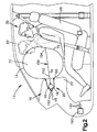
- FIG. 2 is a schematic representation of the apparatus of FIG. 1 illustrating the apparatus in a first inflated and deployed condition
- FIG. 3 is a schematic representation of the apparatus of FIG. 1 illustrating the apparatus in a second inflated and deployed condition
- FIG. 4 is a schematic sectional view taken generally along line 4 - 4 in FIG. 2 ;
- FIG. 5 is a schematic sectional view taken generally along line 5 - 5 in FIG. 3 ;
- FIG. 6 is a schematic sectional view of a portion of the apparatus according to a second embodiment of the present invention, illustrating the apparatus in a condition corresponding to FIG. 2 ;
- FIG. 7 is a schematic sectional view of the portion of the apparatus of FIG. 6 , illustrating the apparatus in a condition corresponding to FIG. 3 .
- an apparatus 10 helps protect an occupant 30 of a vehicle 12 .
- the apparatus comprises a frontal air bag module 20 that includes an air bag 14 , an inflator 16 for providing inflation fluid for inflating the air bag, and a housing 18 , such as a reaction canister, for helping to support the air bag and inflator in the vehicle 12 .
- the air bag module 20 illustrated in FIGS. 1-3 is a frontal passenger air bag module mounted in an instrument panel 22 on a passenger side 24 of the vehicle 12 .
- the air bag module 20 could, however, have an alternative configuration.
- the air bag module 20 could be a frontal driver air bag module mounted on a vehicle steering wheel (not shown) on a driver side of the vehicle 12 .
- FIG. 1 illustrates the air bag 14 in a stored condition in which the air bag is deflated and packaged in the housing 18 .
- the air bag 14 is inflatable from the stored condition of FIG. 1 to an inflated and deployed condition ( FIGS. 2 and 3 ) for helping to protect the occupant 30 seated in a vehicle seat 26 .
- the occupant 30 In the inflated and deployed condition of FIG. 2 , the occupant 30 is illustrated in solid lines positioned in a normally seated position at the time an event triggering actuation of the apparatus 10 occurs. This allows the air bag 14 to reach the fully inflated and deployed condition of FIG. 2 . In response to the event, the occupant 30 may move from the normally seated position into engagement with the fully inflated air bag 14 , as indicated generally at 30 ′ in FIG. 2 .
- the occupant 30 is illustrated as being positioned away from the normally seated position at the time an event triggering actuation of the apparatus 10 occurs. This may be the case, for example, where the occupant 30 is leaned forward (as shown in FIG. 3 ) or where the occupant is seated in a full forward and upright position of the vehicle seat 26 when the event occurs.
- the air bag module 20 may have any desired construction or configuration.
- An example of the construction of the air bag module 20 is illustrated schematically in greater detail in FIGS. 4 and 5 .
- the inflator 16 has a generally cylindrical configuration and is supported in the reaction canister 18 with a longitudinal axis 50 of the inflator extending transverse, e.g., generally perpendicular, to a deployment direction (indicated generally by the arrow A) of the air bag 14 .
- the inflator 16 has opposite first and second end portions 52 and 54 that project through respective openings in opposite side walls 56 of the reaction canister 18 .
- the air bag 14 has a mouth portion 60 secured to the reaction canister 18 by means 62 , such as a retainer ring.
- the mouth portion 60 defines an inflation fluid opening 64 through which the air bag 14 may receive inflation fluid from the inflator 16 via an outlet opening 66 of the reaction canister 18 .
- the air bag 14 has an outer panel portion 70 (see FIGS. 2 and 3 ) that is presented toward the vehicle occupant 30 and that the occupant may engage when the air bag is in the inflated and deployed condition.
- the air bag 14 may be constructed of any suitable material, such as nylon (e.g., woven nylon 6-6 yarns).
- the air bag 14 may have a one-piece woven construction or may include one or more pieces of material that are interconnected by suitable means, such as stitching, ultrasonic welding, heat bonding, adhesives, etc.
- the air bag 14 may be uncoated, coated with a material such as a gas impermeable urethane, or laminated with a material such as a gas impermeable film.
- the air bag 14 thus has a gas-tight or substantially gas-tight construction.
- alternative materials such as polyester yarn, and alternative coatings, such as silicone, may also be used to construct the air bag 14 .
- the inflator 16 may be of any type or configuration suited to provide inflation fluid to the air bag 14 .
- the inflator 16 may be a pyrotechnic inflator that uses the combustion of gas-generating material to generate inflation fluid.
- the inflator 16 may contain a stored quantity of pressurized inflation fluid (not shown) in the form of a gas for inflating the air bag 14 .
- the inflator 16 may contain a combination of pressurized inflation fluid and ignitable material for heating the inflation fluid.
- the inflator 16 may be of any suitable type or construction for providing inflation fluid to inflate the air bag 14 .
- the inflator 16 may also have any construction suited to provide inflation fluid to the air bag 14 .
- the inflator 16 includes a housing 80 that helps define an inflation fluid chamber 82 for storing inflation fluid or inflation fluid generating materials.
- the second end portion 54 of the inflator 16 comprises an end cap 84 secured to the housing by known means (not shown) such as a weld (e.g., a capacitor discharge (CD) or friction weld).
- the end cap 84 projects through the side wall 56 of the reaction canister 18 and thus may help secure the inflator to the reaction canister.
- the housing 80 and end cap 84 have generally cylindrical configurations and are aligned with each other along the axis 50 .
- the inflator 16 includes an inflation fluid control structure 100 for selectively venting inflation fluid from the air bag 14 .
- venting it is meant that the inflation fluid control structure 100 may direct or divert inflation fluid outside the inflatable volume 72 of the air bag 14 .
- the inflation fluid control structure 100 occupies the first end portion 52 of the inflator 16 and is aligned with the housing 80 and end cap 84 along the axis 50 .
- the control structure 100 is secured to the housing by known means (not shown) such as a weld (e.g., a CD or friction weld).
- the control structure 100 extends through the side wall 56 and thus may help support the inflator in the reaction canister 18 .
- the control structure 100 includes a cylindrical side wall 102 , a first end wall 104 , and an opposite second end wall 106 that together help define a chamber 108 .
- the first end wall 104 also helps define a terminal end of the inflator 16 .
- the second end wall 106 helps define the chamber 82 .
- the control structure 100 includes two axially spaced vent walls 110 that divide the chamber 108 into a discharge chamber 112 and a vent chamber 114 .
- the side wall 102 includes discharge openings 116 that establish fluid communication between the discharge chamber 112 and the exterior of the inflator 16 .
- the discharge openings 116 are configured to direct inflation fluid into the inflatable volume 72 of the air bag 14 .
- the side wall 102 also includes vent openings 118 that establish fluid communication between the vent chamber 114 and the exterior of the inflator 16 .
- the vent openings 118 are configured to direct inflation fluid outside the inflatable volume 72 of the air bag 14 .
- the vent openings 118 are positioned outside the reaction canister 18 and thus establish fluid communication between the vent chamber 114 and the exterior of the air bag module 20 .
- the second end wall 106 includes a central opening 120 that provides fluid communication between the inflation fluid chamber 82 and the discharge chamber 112 .
- a rupturable closure member 122 such as a burst disk, blocks this fluid communication and isolates the inflation fluid chamber 82 from the discharge chamber 112 prior to actuation of the inflator 16 .
- the vent walls 110 include axially aligned openings 130 that provide fluid communication between the discharge chamber 112 and the vent chamber 114 .
- An actuatable vent member 132 is disposed in a space 134 defined between the vent walls 110 .
- the vent member 132 has a central opening 136 positioned in the space 134 and an actuator tab 138 that projects through the sidewall 102 of the inflation fluid control structure 100 .
- the vent member 132 is movable in the space 134 between a closed condition shown in FIG. 4 and an open condition shown in FIG. 5 .
- the opening 136 of the vent member 132 is offset axially from the openings 130 in the vent walls 110 .
- the vent member 132 thus blocks fluid communication between the discharge chamber 112 and the vent chamber 114 when in the closed condition.
- the opening 136 of the vent member 132 is aligned axially with the openings 130 in the vent walls 110 .
- the opening 136 thus establishes fluid communication between the discharge chamber 112 and the vent chamber 114 when the vent member 132 is in the open condition.
- the apparatus 10 includes a tether 150 for actuating the vent member 132 .
- the tether 150 has a first end portion 152 looped through an opening 156 in the actuator tab 138 of the vent member 132 and secured to itself (e.g., via stitching or a knot) to thereby connect the tether 150 to the vent member.
- the tether 150 has a second end portion 154 secured to the air bag 14 by means (not shown) such as stitching or ultrasonic welding. In the embodiment illustrated in FIGS. 2 and 3 , the second end portion 154 is secured to the outer panel 70 of the air bag 14 .
- the tether 150 could, however, be connected to the air bag 14 at alternative locations.
- the tether 150 may be constructed of any material suited to perform the functions described herein.
- the tether 150 may comprise a narrow, elongated strip of fabric material, such as a woven nylon webbing.
- the tether 150 may have a width of approximately three-eighths of an inch, a thickness of approximately two millimeters, and a length dependent upon the configuration of the air bag 14 .
- the apparatus 10 includes a sensor 160 for sensing the occurrence of an event for which actuation of the apparatus is desired.
- the event may, for example, include a vehicle collision, a vehicle rollover, or both.
- the sensor 160 Upon sensing the occurrence of such an event, the sensor 160 provides a signal to the inflator via lead wires 162 .
- the inflator 16 is actuated in response to the signal and provides inflation fluid to the air bag 14 .
- the air bag 14 deploys in the deployment direction indicated generally by the arrow labeled “A” in FIGS. 4 and 5 from the stored condition ( FIG. 1 ) to the inflated and deployed condition ( FIGS. 2 and 3 ).
- the air bag 14 when inflated, helps absorb impacts with the air bag and helps distribute the impact energy over a large area of the air bag.
- the vent member 132 of the inflation fluid control structure 100 is actuatable in response to the position of the vehicle occupant 30 when the air bag 14 is inflated and deployed. More particularly, the vent member 132 is actuatable in response to whether the occupant 30 is in the normally seated position (see FIG. 2 ) or positioned away from the normally seated position (see FIG. 3 ).
- the vent member 132 Prior to deployment of the air bag 14 , i.e., in the stored condition of the air bag, the vent member 132 is maintained in the open position of FIG. 5 .
- the closure member 122 Upon actuation of the inflator 16 , the closure member 122 is ruptured and inflation fluid is directed into the discharge chamber 112 of the control structure 100 via the opening 120 , as indicated generally by the arrow labeled “B” in FIGS. 4 and 5 .
- Inflation fluid enters the discharge chamber 112 and is directed through the discharge openings 116 into the inflatable volume 72 of the air bag 14 , which inflates and deploys.
- vent member 132 Since the vent member 132 is maintained in the open condition prior to actuation, a portion of the inflation fluid initially is also directed into the vent chamber 114 via the aligned openings 130 and 136 in the vent walls 110 and vent member 132 , respectively. This is indicated generally by the arrow labeled “D” in FIG. 5 . This portion of the inflation fluid is vented through the vent openings 118 outside the inflatable volume 72 of the air bag 14 , as indicated generally by the arrows labeled “E” in FIG. 5 . Thus, during initial deployment of the air bag 14 , the vent member 132 is in the open condition and the inflation fluid control structure 100 vents inflation fluid from the air bag module 20 .
- the air bag 14 and tether 150 are configured to selectively actuate the vent member 132 depending on the position of the occupant 30 .
- the outer panel 70 moves away from the reaction canister 80 and inflator 16 a distance sufficient to tension the tether 150 .
- the tether 150 when tensioned, pulls on the vent member 132 and moves the vent member from the open condition of FIG. 5 to the closed condition of FIG. 4 . This blocks inflation fluid flow into the vent chamber 114 and through the vent openings 118 .
- the inflation fluid control structure 100 blocks inflation fluid from venting from the air bag module 20 .
- the occupant 30 when the occupant 30 is positioned away from the normally seated position and the air bag 14 deploys, the occupant may block movement of the outer panel 70 away from the reaction canister 80 and inflator 16 . In this instance, the outer panel is impeded from moving a distance sufficient to tension the tether 150 . Because the tether 150 remains slacked, the vent member 132 is not pulled, remains in the open condition of FIG. 5 , and continues to vent inflation fluid through the vent openings 118 . Thus, when the occupant 30 is positioned away from the normally seated position, the inflation fluid control structure 100 vents inflation fluid from the air bag module 20 .
- FIGS. 6 and 7 A second embodiment of the present invention is illustrated schematically in FIGS. 6 and 7 .
- the second embodiment of the invention is similar to the first embodiment of the invention illustrated in FIGS. 4 and 5 . Accordingly, numerals that are the same as to those of FIGS. 4 and 5 will be utilized in FIGS. 6 and 7 to identify similar components, the suffix letter “a” being associated with the numerals of FIGS. 6 and 7 to avoid confusion.
- FIGS. 6 and 7 illustrate a portion of an air bag module 20 a in accordance with the second embodiment of the present invention.
- the apparatus 10 a comprises an inflator 16 a having an inflation fluid control structure 100 a with a configuration different from that of the first embodiment.
- the inflation fluid control structure 100 a includes a housing 200 that has a main portion and an end portion.
- the housing has a generally cylindrical configuration with the end portion having a diameter reduced from that of the main portion.
- the main portion is secured to the inflator housing 80 a and thus helps define the inflation fluid chamber 82 a.
- the control structure 100 a includes a central bore 210 that extends along the axis 50 a from a terminal end surface 212 of the housing 200 through the main portion and into the end portion.
- One or more discharge openings 220 are located in the main portion and extend radially from the central bore 210 to an outer surface 222 of the main portion.
- One or more vent openings 224 are located in the end portion and extend radially from the central bore 210 to an outer surface 226 of the end portion.
- the control structure 100 a also includes a vent member housing 230 formed in the main portion of the housing 200 .
- the vent member housing 230 includes a vent assist chamber 232 , a vent assist port 234 , and a vent member sleeve 236 .
- the vent assist chamber 232 is radially offset from the central bore 210 .
- the vent assist port 234 extends diagonally from the central bore 210 to the vent assist chamber 232 and provides fluid communication between the central bore and the vent assist chamber.
- the vent member sleeve 236 extends radially into the main portion from the outer surface 222 , through the central bore 210 , and into the vent assist chamber 232 .
- the vent member sleeve 236 intersects the vent assist chamber 232 at a location spaced radially inward from the location at which the vent assist port 234 intersects the vent assist chamber.
- the control structure 100 a further includes a vent member 250 supported in the vent member housing 230 .
- the vent member 250 includes an assist portion 252 and a stem portion 254 .
- the assist portion 252 is disposed in the vent assist chamber 232 .
- the assist portion 252 has a configuration that conforms or closely matches that of the vent assist chamber 232 so that the assist portion 252 may function in the manner of a piston in the vent assist chamber 232 .
- the stem portion 254 extends through the vent member sleeve 236 and has an actuator tab 256 that extends outside the vent member housing 230 .
- An opening 260 extends through the stem portion 254 .
- the vent member 250 is movable in the vent member housing 230 between a closed condition shown in FIG. 6 and an open condition shown in FIG. 7 .
- the opening 260 of the vent member 250 is offset radially from the central bore 210 of the housing 200 .
- the vent member 250 thus blocks fluid communication between the chamber 80 a and the vent openings 224 when in the closed condition.
- the opening 260 of the vent member 250 is aligned with the central bore 210 .
- the opening 260 thus establishes fluid communication between the chamber 80 a and the vent openings 224 when the vent member 250 is in the open condition.
- the apparatus 10 a includes a tether 150 a for actuating the vent member 250 .
- the tether 150 a has a first end portion 152 a looped through an opening 258 in the actuator tab 256 of the vent member 250 and secured to itself (e.g., via stitching or a knot), thereby to connect the tether 150 a to the vent member.
- the tether 150 a is connected to the air bag and actuates the vent member 250 of the inflation fluid control structure 100 a in response to whether the occupant is in the normally seated position in a manner similar or identical to that described above in regard to the first embodiment (see FIGS. 1 and 2 ).
- the vent member 250 is maintained in the open condition ( FIG. 7 ) prior to actuation of the inflator 16 a .
- the vent member 250 is in the open condition and vents inflation fluid from the air bag module 20 a.
- the tether 150 a is tensioned and pulls the vent member 250 to the closed condition of FIG. 6 , thus blocking inflation fluid flow through the vent openings 224 .
- the vent assist structure 270 helps maintain the vent member 250 in the closed condition, as described above.
- the inflation fluid control structure 100 a blocks inflation fluid from venting from the air bag module 20 a.
- the tether 150 a is not tensioned and the vent member 250 remains in the open condition of FIG. 7 .
- the inflation fluid control structure 100 a vents inflation fluid from the air bag module 20 a.
- vent member 250 , the vent assist chamber 232 and the vent assist port 234 help define a vent assist mechanism 270 of the inflation fluid control structure 100 a .
- the vent member 250 when in the open condition ( FIG. 7 ), blocks inflation fluid flow through the vent assist port 234 .
- the vent assist port 234 eventually becomes unblocked by the vent member 250 . When this occurs, inflation fluid is directed through the vent assist port 234 into the vent assist chamber 232 .
- Inflation fluid pressurizes the vent assist chamber 232 and acts on the assist portion 252 of the vent member 250 .
- the assist portion 252 acts as a piston and urges the vent member 250 toward the closed condition. While the vent member is in the closed condition, inflation fluid directed through the vent assist port 234 helps maintain pressurization of the vent assist chamber 232 , which helps maintain the vent member 250 in the closed condition.
Landscapes
- Engineering & Computer Science (AREA)
- Mechanical Engineering (AREA)
- Physics & Mathematics (AREA)
- Fluid Mechanics (AREA)
- Air Bags (AREA)
Abstract
Description
Claims (19)
Priority Applications (2)
| Application Number | Priority Date | Filing Date | Title |
|---|---|---|---|
| US11/710,198 US7735860B2 (en) | 2007-02-26 | 2007-02-26 | Inflator with vent |
| DE102008003497.5A DE102008003497B4 (en) | 2007-02-26 | 2008-01-08 | Inflator with drain |
Applications Claiming Priority (1)
| Application Number | Priority Date | Filing Date | Title |
|---|---|---|---|
| US11/710,198 US7735860B2 (en) | 2007-02-26 | 2007-02-26 | Inflator with vent |
Publications (2)
| Publication Number | Publication Date |
|---|---|
| US20080203707A1 US20080203707A1 (en) | 2008-08-28 |
| US7735860B2 true US7735860B2 (en) | 2010-06-15 |
Family
ID=39670259
Family Applications (1)
| Application Number | Title | Priority Date | Filing Date |
|---|---|---|---|
| US11/710,198 Expired - Fee Related US7735860B2 (en) | 2007-02-26 | 2007-02-26 | Inflator with vent |
Country Status (2)
| Country | Link |
|---|---|
| US (1) | US7735860B2 (en) |
| DE (1) | DE102008003497B4 (en) |
Cited By (2)
| Publication number | Priority date | Publication date | Assignee | Title |
|---|---|---|---|---|
| US20100187797A1 (en) * | 2009-01-23 | 2010-07-29 | Trw Automotive Gmbh | Actuator subassembly |
| US8602453B1 (en) * | 2010-06-03 | 2013-12-10 | Tk Holdings, Inc. | Releasable tether retention system |
Families Citing this family (2)
| Publication number | Priority date | Publication date | Assignee | Title |
|---|---|---|---|---|
| KR100999735B1 (en) * | 2007-06-26 | 2010-12-08 | 현대자동차주식회사 | Pressure control apparatus of a air bag |
| DE102009055975A1 (en) | 2009-11-27 | 2011-06-01 | Voith Patent Gmbh | Cooling system, in particular of a motor vehicle |
Citations (21)
| Publication number | Priority date | Publication date | Assignee | Title |
|---|---|---|---|---|
| US5762367A (en) | 1997-04-10 | 1998-06-09 | General Motors Corporation | Air bag module with inflation control device |
| WO1999064273A1 (en) | 1998-06-09 | 1999-12-16 | Autoliv Development Ab | An air-bag arrangement |
| US6409213B2 (en) | 1999-12-28 | 2002-06-25 | Delphi Technologies, Inc. | Adaptive inflation mechanism |
| US6422597B1 (en) | 1999-11-12 | 2002-07-23 | Delphi Technologies, Inc. | Variable profile air bag restraint |
| US6431596B1 (en) * | 1998-05-11 | 2002-08-13 | Delphi Technologies, Inc. | Air bag module with variable inflation |
| US6454300B1 (en) * | 2001-02-27 | 2002-09-24 | Delphi Technologies, Inc. | Air bag tether release assembly |
| US6513835B2 (en) | 2001-03-26 | 2003-02-04 | General Motors Corporation | Automotive vehicle air bag system |
| DE10139626A1 (en) | 2001-08-14 | 2003-03-13 | Takata Petri Ag | An air bag assembly |
| EP1338480A2 (en) | 2002-02-20 | 2003-08-27 | Delphi Technologies, Inc. | Frontal air bag system |
| US6616184B2 (en) | 2001-04-25 | 2003-09-09 | Trw Vehicle Safety Systems Inc. | Vehicle occupant protection apparatus with inflation volume and shape control |
| US20040012180A1 (en) * | 2002-07-19 | 2004-01-22 | Hawthorn Laura Adelle | Air bag restraint including selectively operable venting elements |
| US6736426B2 (en) | 2000-09-28 | 2004-05-18 | Delphi Technologies, Inc. | Variable profile air bag restraint |
| US6746045B2 (en) | 2002-04-05 | 2004-06-08 | Ford Global Technologies, Llc | Air bag inflator gas venting system |
| US6893041B2 (en) | 2001-10-12 | 2005-05-17 | Trw Automotive U.S. Llc | Air bag module with vent cover |
| US20050104347A1 (en) * | 2002-02-20 | 2005-05-19 | Delphi Technologies, Inc. | Apparatus and method for controlling an inflatable cushion |
| DE102005022298A1 (en) | 2004-06-28 | 2006-05-11 | Trw Vehicle Safety Systems Inc., Washington | Vehicle occupant protection apparatus, has vent unit that is moved back to closed position due to tension in tether, where tension results from inflation of protection device away from support unit by more than preset distance |
| DE202006002496U1 (en) | 2005-10-06 | 2006-06-29 | Trw Automotive Gmbh | Gas bag module for motor vehicle, has gas bag with catch belt that is guided along gas bag wall of gas bag, and venting hole provided inside or outside of module housing in wall of gas bag |
| US20070085311A1 (en) * | 2005-10-17 | 2007-04-19 | Trw Airbag Systems Gmbh | Airbag module and method of restraining a vehicle occupant with such an airbag module |
| US7341276B2 (en) * | 2005-10-03 | 2008-03-11 | Key Safety Systems, Inc. | Airbag module with external venting |
| US7377546B2 (en) * | 2002-09-16 | 2008-05-27 | Trw Vehicle Safety Systems, Inc. | Air bag module with vent controlled by tether |
| US7469926B2 (en) * | 2006-05-19 | 2008-12-30 | Autoliv Asp, Inc. | Active venting inflator device |
Family Cites Families (4)
| Publication number | Priority date | Publication date | Assignee | Title |
|---|---|---|---|---|
| US5664802A (en) | 1996-02-15 | 1997-09-09 | Morton International, Inc. | Adjustable performance hybrid inflator |
| DE19912369A1 (en) | 1999-03-19 | 2000-10-05 | Bsrs Restraint Syst Gmbh | Airbag module controlled by dynamics |
| DE29907607U1 (en) | 1999-04-29 | 1999-09-30 | TRW Occupant Restraint Systems GmbH & Co. KG, 73553 Alfdorf | Protection device with gas bag for motor vehicle occupants |
| US6550807B1 (en) | 2000-11-21 | 2003-04-22 | Trw Vehicle Safety Systems Inc. | Air bag module with electronically modulated vent |
-
2007
- 2007-02-26 US US11/710,198 patent/US7735860B2/en not_active Expired - Fee Related
-
2008
- 2008-01-08 DE DE102008003497.5A patent/DE102008003497B4/en not_active Expired - Fee Related
Patent Citations (24)
| Publication number | Priority date | Publication date | Assignee | Title |
|---|---|---|---|---|
| US5762367A (en) | 1997-04-10 | 1998-06-09 | General Motors Corporation | Air bag module with inflation control device |
| US6431596B1 (en) * | 1998-05-11 | 2002-08-13 | Delphi Technologies, Inc. | Air bag module with variable inflation |
| WO1999064273A1 (en) | 1998-06-09 | 1999-12-16 | Autoliv Development Ab | An air-bag arrangement |
| US6422597B1 (en) | 1999-11-12 | 2002-07-23 | Delphi Technologies, Inc. | Variable profile air bag restraint |
| US6409213B2 (en) | 1999-12-28 | 2002-06-25 | Delphi Technologies, Inc. | Adaptive inflation mechanism |
| US6736426B2 (en) | 2000-09-28 | 2004-05-18 | Delphi Technologies, Inc. | Variable profile air bag restraint |
| US6454300B1 (en) * | 2001-02-27 | 2002-09-24 | Delphi Technologies, Inc. | Air bag tether release assembly |
| US6513835B2 (en) | 2001-03-26 | 2003-02-04 | General Motors Corporation | Automotive vehicle air bag system |
| US6616184B2 (en) | 2001-04-25 | 2003-09-09 | Trw Vehicle Safety Systems Inc. | Vehicle occupant protection apparatus with inflation volume and shape control |
| US7055857B2 (en) * | 2001-08-14 | 2006-06-06 | Takata-Petri Ag | Airbag arrangement |
| DE10139626A1 (en) | 2001-08-14 | 2003-03-13 | Takata Petri Ag | An air bag assembly |
| US6893041B2 (en) | 2001-10-12 | 2005-05-17 | Trw Automotive U.S. Llc | Air bag module with vent cover |
| EP1338480A2 (en) | 2002-02-20 | 2003-08-27 | Delphi Technologies, Inc. | Frontal air bag system |
| US20050104347A1 (en) * | 2002-02-20 | 2005-05-19 | Delphi Technologies, Inc. | Apparatus and method for controlling an inflatable cushion |
| US6746045B2 (en) | 2002-04-05 | 2004-06-08 | Ford Global Technologies, Llc | Air bag inflator gas venting system |
| US6832778B2 (en) * | 2002-07-19 | 2004-12-21 | Delphi Technologies, Inc. | Air bag restraint including selectively operable venting elements |
| US20040012180A1 (en) * | 2002-07-19 | 2004-01-22 | Hawthorn Laura Adelle | Air bag restraint including selectively operable venting elements |
| US7377546B2 (en) * | 2002-09-16 | 2008-05-27 | Trw Vehicle Safety Systems, Inc. | Air bag module with vent controlled by tether |
| DE102005022298A1 (en) | 2004-06-28 | 2006-05-11 | Trw Vehicle Safety Systems Inc., Washington | Vehicle occupant protection apparatus, has vent unit that is moved back to closed position due to tension in tether, where tension results from inflation of protection device away from support unit by more than preset distance |
| US7341276B2 (en) * | 2005-10-03 | 2008-03-11 | Key Safety Systems, Inc. | Airbag module with external venting |
| DE202006002496U1 (en) | 2005-10-06 | 2006-06-29 | Trw Automotive Gmbh | Gas bag module for motor vehicle, has gas bag with catch belt that is guided along gas bag wall of gas bag, and venting hole provided inside or outside of module housing in wall of gas bag |
| US20070085311A1 (en) * | 2005-10-17 | 2007-04-19 | Trw Airbag Systems Gmbh | Airbag module and method of restraining a vehicle occupant with such an airbag module |
| US7246819B2 (en) * | 2005-10-17 | 2007-07-24 | Trw Airbag Systems Gmbh | Airbag module and method of restraining a vehicle occupant with such an airbag module |
| US7469926B2 (en) * | 2006-05-19 | 2008-12-30 | Autoliv Asp, Inc. | Active venting inflator device |
Cited By (4)
| Publication number | Priority date | Publication date | Assignee | Title |
|---|---|---|---|---|
| US20100187797A1 (en) * | 2009-01-23 | 2010-07-29 | Trw Automotive Gmbh | Actuator subassembly |
| US8517419B2 (en) * | 2009-01-23 | 2013-08-27 | Trw Airbag Systems Gmbh | Actuator subassembly |
| US8602453B1 (en) * | 2010-06-03 | 2013-12-10 | Tk Holdings, Inc. | Releasable tether retention system |
| US9221417B1 (en) * | 2010-06-03 | 2015-12-29 | Tk Holdings Inc. | Releasable tether retention system |
Also Published As
| Publication number | Publication date |
|---|---|
| DE102008003497B4 (en) | 2021-08-26 |
| US20080203707A1 (en) | 2008-08-28 |
| DE102008003497A1 (en) | 2008-09-04 |
Similar Documents
| Publication | Publication Date | Title |
|---|---|---|
| US7093854B2 (en) | Air bag with active tear stitch tethers | |
| EP1398226B1 (en) | Inflation assembly for variable profile air bag | |
| US7607689B2 (en) | Air bag vent with tether | |
| US7469926B2 (en) | Active venting inflator device | |
| US6095551A (en) | Non-inflatable curtain with inflatable device | |
| US5813696A (en) | Air bag with tether | |
| US7837226B2 (en) | Airbag apparatus | |
| US6082765A (en) | Air bag module with fluid venting | |
| US9272685B2 (en) | Air bag with adaptive vent | |
| US6224088B1 (en) | Inflatable occupant protection device extending adjacent a windshield | |
| US20080082236A1 (en) | Airbag apparatus | |
| JP2008149965A (en) | Air bag device | |
| US7618061B2 (en) | Air bag module with releasable tether | |
| US8235417B2 (en) | Apparatus and method for releasing an inflation gas from an inflator | |
| WO2006007125A2 (en) | Inflator with internally mounted initiator | |
| US7735860B2 (en) | Inflator with vent | |
| US7900959B2 (en) | Airbag apparatus | |
| US7618056B2 (en) | Inflatable curtain with integral shield | |
| US6176512B1 (en) | Apparatus for directing the flow of inflation fluid into an air bag | |
| US8226116B2 (en) | Vehicle airbag system | |
| US20080238060A1 (en) | Airbag Device | |
| JP2005178659A (en) | Air bag device | |
| US7658405B2 (en) | Apparatus and method for providing extended inflator output | |
| US7594676B2 (en) | Extended output inflator device | |
| US20080136148A1 (en) | Inflatable curtain with integral shield |
Legal Events
| Date | Code | Title | Description |
|---|---|---|---|
| AS | Assignment |
Owner name: TRW AIRBAG SYSTEMS GMBH, GERMANY Free format text: ASSIGNMENT OF ASSIGNORS INTEREST;ASSIGNORS:ENGLBRECHT, KARL;LAST, DR. DETLEF;REEL/FRAME:019038/0912 Effective date: 20070222 Owner name: TRW AIRBAG SYSTEMS GMBH,GERMANY Free format text: ASSIGNMENT OF ASSIGNORS INTEREST;ASSIGNORS:ENGLBRECHT, KARL;LAST, DR. DETLEF;REEL/FRAME:019038/0912 Effective date: 20070222 |
|
| AS | Assignment |
Owner name: TRW VEHICLE SAFETY SYSTEMS INC., MICHIGAN Free format text: ASSIGNMENT OF ASSIGNORS INTEREST;ASSIGNOR:FISCHER, KURT F.;REEL/FRAME:019038/0910 Effective date: 20070219 Owner name: TRW VEHICLE SAFETY SYSTEMS INC.,MICHIGAN Free format text: ASSIGNMENT OF ASSIGNORS INTEREST;ASSIGNOR:FISCHER, KURT F.;REEL/FRAME:019038/0910 Effective date: 20070219 |
|
| FEPP | Fee payment procedure |
Free format text: PAYOR NUMBER ASSIGNED (ORIGINAL EVENT CODE: ASPN); ENTITY STATUS OF PATENT OWNER: LARGE ENTITY |
|
| STCF | Information on status: patent grant |
Free format text: PATENTED CASE |
|
| AS | Assignment |
Owner name: JPMORGAN CHASE BANK, N.A., AS COLLATERAL AGENT, NE Free format text: SECURITY AGREEMENT;ASSIGNORS:TRW VEHICLE SAFETY SYSTEMS INC.;TRW AUTOMOTIVE U.S. LLC;KELSEY-HAYES COMPANY;REEL/FRAME:029529/0534 Effective date: 20120928 |
|
| AS | Assignment |
Owner name: TRW AUTOMOTIVE U.S. LLC, MICHIGAN Free format text: RELEASE OF SECURITY INTEREST;ASSIGNOR:JPMORGAN CHASE BANK, N.A.;REEL/FRAME:031645/0697 Effective date: 20131028 Owner name: TRW VEHICLE SAFETY SYSTEMS INC., MICHIGAN Free format text: RELEASE OF SECURITY INTEREST;ASSIGNOR:JPMORGAN CHASE BANK, N.A.;REEL/FRAME:031645/0697 Effective date: 20131028 Owner name: KELSEY-HAYES COMPANY, MICHIGAN Free format text: RELEASE OF SECURITY INTEREST;ASSIGNOR:JPMORGAN CHASE BANK, N.A.;REEL/FRAME:031645/0697 Effective date: 20131028 Owner name: TRW INTELLECTUAL PROPERTY CORP., MICHIGAN Free format text: RELEASE OF SECURITY INTEREST;ASSIGNOR:JPMORGAN CHASE BANK, N.A.;REEL/FRAME:031645/0697 Effective date: 20131028 |
|
| FPAY | Fee payment |
Year of fee payment: 4 |
|
| MAFP | Maintenance fee payment |
Free format text: PAYMENT OF MAINTENANCE FEE, 8TH YEAR, LARGE ENTITY (ORIGINAL EVENT CODE: M1552) Year of fee payment: 8 |
|
| FEPP | Fee payment procedure |
Free format text: MAINTENANCE FEE REMINDER MAILED (ORIGINAL EVENT CODE: REM.); ENTITY STATUS OF PATENT OWNER: LARGE ENTITY |
|
| LAPS | Lapse for failure to pay maintenance fees |
Free format text: PATENT EXPIRED FOR FAILURE TO PAY MAINTENANCE FEES (ORIGINAL EVENT CODE: EXP.); ENTITY STATUS OF PATENT OWNER: LARGE ENTITY |
|
| STCH | Information on status: patent discontinuation |
Free format text: PATENT EXPIRED DUE TO NONPAYMENT OF MAINTENANCE FEES UNDER 37 CFR 1.362 |
|
| FP | Lapsed due to failure to pay maintenance fee |
Effective date: 20220615 |