EP2746568A2 - Montagestruktur eines Kraftstoffeinspritzventils und Kraftstoffeinspritzsystem - Google Patents
Montagestruktur eines Kraftstoffeinspritzventils und Kraftstoffeinspritzsystem Download PDFInfo
- Publication number
- EP2746568A2 EP2746568A2 EP14161026.1A EP14161026A EP2746568A2 EP 2746568 A2 EP2746568 A2 EP 2746568A2 EP 14161026 A EP14161026 A EP 14161026A EP 2746568 A2 EP2746568 A2 EP 2746568A2
- Authority
- EP
- European Patent Office
- Prior art keywords
- fuel
- fuel injection
- intake
- valve
- injection
- Prior art date
- Legal status (The legal status is an assumption and is not a legal conclusion. Google has not performed a legal analysis and makes no representation as to the accuracy of the status listed.)
- Granted
Links
Images


Classifications
-
- F—MECHANICAL ENGINEERING; LIGHTING; HEATING; WEAPONS; BLASTING
- F02—COMBUSTION ENGINES; HOT-GAS OR COMBUSTION-PRODUCT ENGINE PLANTS
- F02M—SUPPLYING COMBUSTION ENGINES IN GENERAL WITH COMBUSTIBLE MIXTURES OR CONSTITUENTS THEREOF
- F02M35/00—Combustion-air cleaners, air intakes, intake silencers, or induction systems specially adapted for, or arranged on, internal-combustion engines
- F02M35/10—Air intakes; Induction systems
- F02M35/1015—Air intakes; Induction systems characterised by the engine type
- F02M35/10177—Engines having multiple fuel injectors or carburettors per cylinder
-
- F—MECHANICAL ENGINEERING; LIGHTING; HEATING; WEAPONS; BLASTING
- F02—COMBUSTION ENGINES; HOT-GAS OR COMBUSTION-PRODUCT ENGINE PLANTS
- F02D—CONTROLLING COMBUSTION ENGINES
- F02D41/00—Electrical control of supply of combustible mixture or its constituents
- F02D41/30—Controlling fuel injection
- F02D41/3094—Controlling fuel injection the fuel injection being effected by at least two different injectors, e.g. one in the intake manifold and one in the cylinder
-
- F—MECHANICAL ENGINEERING; LIGHTING; HEATING; WEAPONS; BLASTING
- F02—COMBUSTION ENGINES; HOT-GAS OR COMBUSTION-PRODUCT ENGINE PLANTS
- F02M—SUPPLYING COMBUSTION ENGINES IN GENERAL WITH COMBUSTIBLE MIXTURES OR CONSTITUENTS THEREOF
- F02M35/00—Combustion-air cleaners, air intakes, intake silencers, or induction systems specially adapted for, or arranged on, internal-combustion engines
- F02M35/10—Air intakes; Induction systems
- F02M35/10209—Fluid connections to the air intake system; their arrangement of pipes, valves or the like
- F02M35/10216—Fuel injectors; Fuel pipes or rails; Fuel pumps or pressure regulators
-
- F—MECHANICAL ENGINEERING; LIGHTING; HEATING; WEAPONS; BLASTING
- F02—COMBUSTION ENGINES; HOT-GAS OR COMBUSTION-PRODUCT ENGINE PLANTS
- F02M—SUPPLYING COMBUSTION ENGINES IN GENERAL WITH COMBUSTIBLE MIXTURES OR CONSTITUENTS THEREOF
- F02M35/00—Combustion-air cleaners, air intakes, intake silencers, or induction systems specially adapted for, or arranged on, internal-combustion engines
- F02M35/10—Air intakes; Induction systems
- F02M35/104—Intake manifolds
- F02M35/108—Intake manifolds with primary and secondary intake passages
- F02M35/1085—Intake manifolds with primary and secondary intake passages the combustion chamber having multiple intake valves
-
- F—MECHANICAL ENGINEERING; LIGHTING; HEATING; WEAPONS; BLASTING
- F02—COMBUSTION ENGINES; HOT-GAS OR COMBUSTION-PRODUCT ENGINE PLANTS
- F02M—SUPPLYING COMBUSTION ENGINES IN GENERAL WITH COMBUSTIBLE MIXTURES OR CONSTITUENTS THEREOF
- F02M61/00—Fuel-injectors not provided for in groups F02M39/00 - F02M57/00 or F02M67/00
- F02M61/16—Details not provided for in, or of interest apart from, the apparatus of groups F02M61/02 - F02M61/14
- F02M61/18—Injection nozzles, e.g. having valve seats; Details of valve member seated ends, not otherwise provided for
- F02M61/1853—Orifice plates
-
- F—MECHANICAL ENGINEERING; LIGHTING; HEATING; WEAPONS; BLASTING
- F02—COMBUSTION ENGINES; HOT-GAS OR COMBUSTION-PRODUCT ENGINE PLANTS
- F02M—SUPPLYING COMBUSTION ENGINES IN GENERAL WITH COMBUSTIBLE MIXTURES OR CONSTITUENTS THEREOF
- F02M69/00—Low-pressure fuel-injection apparatus ; Apparatus with both continuous and intermittent injection; Apparatus injecting different types of fuel
- F02M69/04—Injectors peculiar thereto
- F02M69/042—Positioning of injectors with respect to engine, e.g. in the air intake conduit
- F02M69/044—Positioning of injectors with respect to engine, e.g. in the air intake conduit for injecting into the intake conduit downstream of an air throttle valve
-
- F—MECHANICAL ENGINEERING; LIGHTING; HEATING; WEAPONS; BLASTING
- F02—COMBUSTION ENGINES; HOT-GAS OR COMBUSTION-PRODUCT ENGINE PLANTS
- F02M—SUPPLYING COMBUSTION ENGINES IN GENERAL WITH COMBUSTIBLE MIXTURES OR CONSTITUENTS THEREOF
- F02M61/00—Fuel-injectors not provided for in groups F02M39/00 - F02M57/00 or F02M67/00
- F02M61/04—Fuel-injectors not provided for in groups F02M39/00 - F02M57/00 or F02M67/00 having valves, e.g. having a plurality of valves in series
- F02M61/06—Fuel-injectors not provided for in groups F02M39/00 - F02M57/00 or F02M67/00 having valves, e.g. having a plurality of valves in series the valves being furnished at seated ends with pintle or plug shaped extensions
-
- F—MECHANICAL ENGINEERING; LIGHTING; HEATING; WEAPONS; BLASTING
- F02—COMBUSTION ENGINES; HOT-GAS OR COMBUSTION-PRODUCT ENGINE PLANTS
- F02M—SUPPLYING COMBUSTION ENGINES IN GENERAL WITH COMBUSTIBLE MIXTURES OR CONSTITUENTS THEREOF
- F02M61/00—Fuel-injectors not provided for in groups F02M39/00 - F02M57/00 or F02M67/00
- F02M61/16—Details not provided for in, or of interest apart from, the apparatus of groups F02M61/02 - F02M61/14
- F02M61/18—Injection nozzles, e.g. having valve seats; Details of valve member seated ends, not otherwise provided for
- F02M61/1806—Injection nozzles, e.g. having valve seats; Details of valve member seated ends, not otherwise provided for characterised by the arrangement of discharge orifices, e.g. orientation or size
Definitions
- the fuel injection valve may be conceivably installed in each intake port.
- the intake air distributed to an intake port further flows into the combustion chamber by way of a branch port. Accordingly, the flow quantity of the intake air flowing through the branch port is reduced.
- the amount of fuel injected from the fuel injection valve needs to be reduced corresponding to the low flow quantity of intake air in order to facilitate the atomization of fuel.
- a reduction in the amount of fuel injected from each fuel injection valve installed in the intake port does not suffice the flow quantity of fuel required to increase the output of the engine.
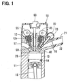
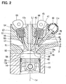
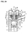
- FIGS. 1 and 2 show an internal combustion engine (an engine), in which a mount structure of a fuel injection valve and a fuel injection system according to the first embodiment of the present invention are implemented.
- the engine 10 may be, for example, a gasoline engine that uses gasoline as fuel.
- the fuel may alternately be, for example, alcohol.
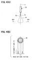
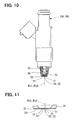
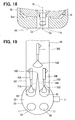
- the fuel injection valve 70 forms the fuel mist 91, which is elliptical in the cross section that is perpendicular to the center axis Ic, i.e., in the cross section along line VC-VC shown in FIG. 5(C) .
- the fuel injection valve 70 forms the fuel mist 91, which is shaped like a hollow elliptic cone.
- the shape of the fuel mist 91 can be easily changed by adjusting the location of the injection holes 71 of the fuel injection valve 70.
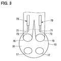
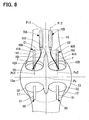
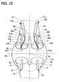
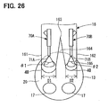
- the intake port 16 is branched into the two branch ports 161, 162 at the branching portion 163, which is located between the surge tank 25 and the combustion chamber 20. In this way, the intake air, which is drawn from the surge tank 25 into the intake port 16, is distributed to the two branch ports 161, 162 at the branching portion 163.
- the two branch ports 161, 162 have generally the same inner diameter.
- a wall portion 164 is provided between the branch port 161 and the branch port 162 to partition therebetween.
- the small quantity of fuel is injected from the fuel injection valves 70A, 70B, which are placed in the branch ports 161, 162, respectively.
- the diameter of the respective injection holes is made small, so that the atomization of the fuel is promoted. Therefore, even when the flow quantity of the intake air is small, or the temperature of the engine coolant is low, the intake air, which flows in the branch ports 161, 162, is sufficiently mixed with the fuel. Thereby, the fuel is sufficiently combusted in the combustion chamber 20. Thus, the deterioration in the fuel consumption does not occur, and it is possible to reduce the amount of HC contained in the exhaust gas.
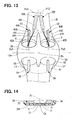
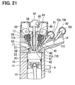
- the intake valve 40 extends through the cylinder head 12.
- the intake valve 40 has a shaft portion 41 and a valve portion 42.
- the shaft portion 41 is slidably supported by the cylinder head 12 through a gasket 43.
- One axial end portion of the shaft portion 41 is connected to the valve portion 42, and the other axial end portion of the shaft portion 41 is connected to an intake cam 45 through a tappet 44.
- the valve portion 42 opens and closes the end portion of the intake port 16.
- a spring (resilient member) 46 is placed between the cylinder head 12 and the tappet 44.
- the spring 46 urges the tappet 44 in a direction away from the cylinder head 12.
- the tappet 44 moves integrally with the intake valve 40. Therefore, the spring 46 urges the intake valve 40 in a closing direction thereof for closing the intake port 16 with the intake valve 40.
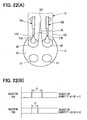
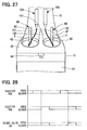
- the engine system of the sixteenth embodiment is that the injection timing of fuel is controlled in the engine system of the fourteenth embodiment.
Landscapes
- Engineering & Computer Science (AREA)
- Chemical & Material Sciences (AREA)
- Combustion & Propulsion (AREA)
- Mechanical Engineering (AREA)
- General Engineering & Computer Science (AREA)
- Fuel-Injection Apparatus (AREA)
- Electrical Control Of Air Or Fuel Supplied To Internal-Combustion Engine (AREA)
Applications Claiming Priority (6)
| Application Number | Priority Date | Filing Date | Title |
|---|---|---|---|
| JP2006089711 | 2006-03-29 | ||
| JP2006089704A JP4804188B2 (ja) | 2006-03-29 | 2006-03-29 | インジェクタの取付構造および燃料噴射装置 |
| JP2006089715A JP2007262996A (ja) | 2006-03-29 | 2006-03-29 | 内燃機関用燃料噴射装置 |
| JP2006136467A JP2007309121A (ja) | 2006-05-16 | 2006-05-16 | インジェクタの取付構造および内燃機関用燃料噴射装置 |
| JP2007070191A JP4615535B2 (ja) | 2006-03-29 | 2007-03-19 | 燃料噴射制御装置 |
| EP07739753.7A EP2000663A4 (de) | 2006-03-29 | 2007-03-27 | Installationsstruktur für ein kraftstoffeinspritzventil und kraftstoffeinspritzsystem |
Related Parent Applications (1)
| Application Number | Title | Priority Date | Filing Date |
|---|---|---|---|
| EP07739753.7A Division EP2000663A4 (de) | 2006-03-29 | 2007-03-27 | Installationsstruktur für ein kraftstoffeinspritzventil und kraftstoffeinspritzsystem |
Publications (3)
| Publication Number | Publication Date |
|---|---|
| EP2746568A2 true EP2746568A2 (de) | 2014-06-25 |
| EP2746568A3 EP2746568A3 (de) | 2014-10-29 |
| EP2746568B1 EP2746568B1 (de) | 2016-07-27 |
Family
ID=38609299
Family Applications (2)
| Application Number | Title | Priority Date | Filing Date |
|---|---|---|---|
| EP07739753.7A Withdrawn EP2000663A4 (de) | 2006-03-29 | 2007-03-27 | Installationsstruktur für ein kraftstoffeinspritzventil und kraftstoffeinspritzsystem |
| EP14161026.1A Not-in-force EP2746568B1 (de) | 2006-03-29 | 2007-03-27 | Montagestruktur eines Kraftstoffeinspritzventils und Kraftstoffeinspritzsystem |
Family Applications Before (1)
| Application Number | Title | Priority Date | Filing Date |
|---|---|---|---|
| EP07739753.7A Withdrawn EP2000663A4 (de) | 2006-03-29 | 2007-03-27 | Installationsstruktur für ein kraftstoffeinspritzventil und kraftstoffeinspritzsystem |
Country Status (4)
| Country | Link |
|---|---|
| US (3) | US20090241905A1 (de) |
| EP (2) | EP2000663A4 (de) |
| CN (1) | CN102207052B (de) |
| WO (1) | WO2007119520A1 (de) |
Families Citing this family (32)
| Publication number | Priority date | Publication date | Assignee | Title |
|---|---|---|---|---|
| EP2000663A4 (de) * | 2006-03-29 | 2014-01-01 | Denso Corp | Installationsstruktur für ein kraftstoffeinspritzventil und kraftstoffeinspritzsystem |
| JP2009074440A (ja) * | 2007-09-20 | 2009-04-09 | Hitachi Ltd | 内燃機関の燃料噴射制御装置 |
| JP4766074B2 (ja) | 2008-05-30 | 2011-09-07 | 株式会社デンソー | 内燃機関の燃料噴射制御装置 |
| DE102008044244A1 (de) * | 2008-12-01 | 2010-06-02 | Robert Bosch Gmbh | Brennkraftmaschine |
| DE112009005130B4 (de) * | 2009-08-07 | 2018-10-04 | Toyota Jidosha Kabushiki Kaisha | Brennkraftmaschine mit funkenzündung |
| CN101798979B (zh) * | 2010-02-24 | 2011-12-14 | 力帆实业(集团)股份有限公司 | 进气歧管及燃油喷嘴安装系统 |
| DE102010029935B4 (de) * | 2010-06-10 | 2023-01-26 | Robert Bosch Gmbh | Verfahren und Vorrichtung zum Zuführen von Kraftstoff in einem Verbrennungsmotor |
| DE102010037003B4 (de) * | 2010-08-16 | 2025-08-21 | Ford Global Technologies, Llc. | Verfahren zum Betreiben einer Brennkraftmaschine mit Gas als Kraftstoff und Brennkraftmaschine zur Durchführung eines derartigen Verfahrens |
| JP5161278B2 (ja) * | 2010-09-22 | 2013-03-13 | 日立オートモティブシステムズ株式会社 | 内燃機関の燃料噴射制御装置 |
| JP2012067681A (ja) * | 2010-09-24 | 2012-04-05 | Toyota Motor Corp | 内燃機関 |
| DE102010064182A1 (de) * | 2010-12-27 | 2012-06-28 | Robert Bosch Gmbh | Einspritzvorrichtung, Brennkraftmaschine und Verfahren zum Betrieb einer Einspritzvorrichtung |
| DE102010064163A1 (de) * | 2010-12-27 | 2012-06-28 | Robert Bosch Gmbh | Einspritzsystem, Brennkraftmaschine und Verfahren zum Betrieb einer Brennkraftmaschine |
| DE102010064166A1 (de) | 2010-12-27 | 2012-06-28 | Robert Bosch Gmbh | Einspritzvorrichtung, Brennkraftmaschine und Verfahren zum Betrieb einer Einspritzvorrichtung |
| DE102011007327B4 (de) * | 2011-04-13 | 2024-01-18 | Robert Bosch Gmbh | Einspritzvorrichtung und Brennkraftmaschine |
| JP2013024196A (ja) * | 2011-07-25 | 2013-02-04 | Toyota Motor Corp | 内燃機関の制御装置 |
| JP5541535B2 (ja) * | 2011-09-13 | 2014-07-09 | 日立オートモティブシステムズ株式会社 | 内燃機関の燃料噴射制御装置 |
| DE102012001650B4 (de) * | 2012-01-27 | 2019-06-19 | Audi Ag | Verfahren zum Betreiben einer Brennkraftmaschine sowie Brennkraftmaschine |
| KR101393896B1 (ko) * | 2012-11-05 | 2014-05-12 | 현대자동차주식회사 | 엔진의 듀얼 인젝터 제어방법 및 장치 |
| KR101417390B1 (ko) * | 2012-11-05 | 2014-07-08 | 현대자동차주식회사 | 듀얼 인젝터 엔진의 연료량 분배 방법 및 장치 |
| JP6146648B2 (ja) * | 2013-01-10 | 2017-06-14 | スズキ株式会社 | エンジンのシリンダヘッド |
| US9163570B2 (en) * | 2013-08-16 | 2015-10-20 | GM Global Technology Operations LLC | Method and system for determining diesel engine airflow in an engine using a late intake valve closure strategy |
| DE102013222498A1 (de) * | 2013-11-06 | 2015-05-07 | Continental Automotive Gmbh | Vorrichtung zur Kraftstoffversorgung für eine Brennkraftmaschine |
| US10119496B2 (en) * | 2014-04-15 | 2018-11-06 | Cummins Inc. | Cryogenic fuel injection and combustion |
| US9677467B2 (en) | 2014-05-13 | 2017-06-13 | Suzuki Motor Corporation | Vertical engine |
| JP6460453B2 (ja) * | 2014-10-24 | 2019-01-30 | 三菱自動車工業株式会社 | 内燃機関 |
| DE102015200455B4 (de) * | 2015-01-14 | 2018-01-25 | Ford Global Technologies, Llc | Motor, Kraftfahrzeug, Einspritzverfahren |
| KR101795168B1 (ko) * | 2015-11-23 | 2017-11-10 | 현대자동차주식회사 | 차량의 엔진 구조 |
| JP6670718B2 (ja) * | 2016-09-28 | 2020-03-25 | 日立オートモティブシステムズ株式会社 | 制御装置 |
| US10968854B2 (en) * | 2018-03-27 | 2021-04-06 | Toyota Jidosha Kabushiki Kaisha | Controller and control method for internal combustion engine |
| JP7239869B2 (ja) * | 2018-10-17 | 2023-03-15 | トヨタ自動車株式会社 | 内燃機関の制御装置 |
| DE112022001691T5 (de) * | 2021-06-04 | 2024-01-25 | Cummins Inc. | Kraftstoffsystem |
| US20260063065A1 (en) * | 2024-08-28 | 2026-03-05 | Caterpillar Inc. | Gaseous fuel engine strategy biasing port fuel admission along flow streamlines |
Citations (5)
| Publication number | Priority date | Publication date | Assignee | Title |
|---|---|---|---|---|
| JP2000234579A (ja) | 1999-02-16 | 2000-08-29 | Denso Corp | 燃料噴射弁 |
| JP2003262175A (ja) | 2002-03-07 | 2003-09-19 | Nissan Motor Co Ltd | 内燃機関 |
| JP2003262174A (ja) | 2002-03-07 | 2003-09-19 | Nissan Motor Co Ltd | 内燃機関 |
| JP2004225598A (ja) | 2003-01-22 | 2004-08-12 | Hitachi Ltd | 燃料噴射弁 |
| JP2004232463A (ja) | 2003-01-28 | 2004-08-19 | Hitachi Ltd | 燃料噴射装置 |
Family Cites Families (115)
| Publication number | Priority date | Publication date | Assignee | Title |
|---|---|---|---|---|
| AU465612B2 (en) * | 1973-02-27 | 1975-10-02 | Nippon Soken, Inc | An internal combustion engine |
| US3995609A (en) * | 1975-04-21 | 1976-12-07 | General Motors Corporation | Internal combustion engine fuel control arrangement |
| AU511290B2 (en) * | 1977-12-19 | 1980-08-07 | Nissan Motor Company Limited | Dual induction system fori. C. engine |
| US4200067A (en) * | 1978-05-01 | 1980-04-29 | General Motors Corporation | Hydraulic valve actuator and fuel injection system |
| JPS5564115A (en) * | 1978-11-09 | 1980-05-14 | Honda Motor Co Ltd | Internal combustion engine |
| US4612904A (en) * | 1983-02-15 | 1986-09-23 | Mazda Motor Corporation | Fuel injection system for internal combustion engines |
| US4548175A (en) * | 1983-12-05 | 1985-10-22 | Toyota Jidosha Kabushiki Kaisha | Internal combustion engine with two intake valves |
| JPH0631174Y2 (ja) * | 1985-02-21 | 1994-08-22 | トヨタ自動車株式会社 | 火花点火機関の燃料噴射装置 |
| JPH0413415Y2 (de) * | 1985-04-10 | 1992-03-27 | ||
| JPS6248927A (ja) * | 1985-08-27 | 1987-03-03 | Toyota Motor Corp | 内燃機関の吸気ポ−ト装置 |
| US4726343A (en) * | 1986-03-20 | 1988-02-23 | Volkswagen Ag | Suction pipe arrangement for multi-cylinder internal combustion engines with fuel injection nozzles |
| US4779594A (en) * | 1986-04-25 | 1988-10-25 | Mazda Motor Corporation | Intake system for an internal combustion engine |
| JPS637260A (ja) | 1986-06-25 | 1988-01-13 | Nippon Kokan Kk <Nkk> | 天井クレ−ンの巻上げドラム用研削装置 |
| JPH06102981B2 (ja) * | 1986-07-02 | 1994-12-14 | トヨタ自動車株式会社 | 2サイクル内燃機関 |
| JPH0733770B2 (ja) * | 1987-07-09 | 1995-04-12 | トヨタ自動車株式会社 | 2サイクル内燃機関の燃焼室構造 |
| JPH01173467A (ja) | 1987-12-28 | 1989-07-10 | Sony Corp | ディスクファイル装置 |
| NL8801334A (nl) * | 1988-05-24 | 1989-12-18 | Texas Instruments Holland | Verbrandingsmotor van het inspuittype, en plaat bestemd om te worden aangebracht tussen de inlaatpoorten van een cilinderblok van een dergelijke motor en een inspuitstuk. |
| JP2848491B2 (ja) * | 1988-11-16 | 1999-01-20 | 株式会社日立製作所 | 燃料噴射制御装置 |
| JP2580823B2 (ja) * | 1989-03-31 | 1997-02-12 | 三菱自動車工業株式会社 | 成層燃焼型内燃エンジン |
| DE69014960T2 (de) * | 1989-04-07 | 1995-05-04 | Honda Motor Co Ltd | Einlassvorrichtung für Brennkraftmaschine. |
| JP2790668B2 (ja) | 1989-08-10 | 1998-08-27 | 株式会社日立製作所 | データ転送制御方式 |
| AT402535B (de) * | 1990-02-23 | 1997-06-25 | Avl Verbrennungskraft Messtech | Brennkraftmaschine mit zumindest zwei einlassventilen je motorzylinder |
| JPH0413415A (ja) | 1990-05-08 | 1992-01-17 | Ishikawajima Harima Heavy Ind Co Ltd | サイドガイド装置 |
| DE69107242T2 (de) * | 1990-06-01 | 1995-06-14 | Mazda Motor | Ansauganlage für einen Motor. |
| US5218943A (en) * | 1991-01-07 | 1993-06-15 | Toyota Jidosha Kabushiki Kaisha | Fuel injection apparatus for internal combustion engine |
| JP2887797B2 (ja) * | 1991-02-15 | 1999-04-26 | ヤマハ発動機株式会社 | 4サイクルエンジンの吸気装置 |
| US5449120A (en) * | 1991-06-11 | 1995-09-12 | Nippondenso Co., Ltd. | Fuel feed apparatus of internal combustion engine |
| US5259348A (en) * | 1991-06-20 | 1993-11-09 | Toyota Jidosha Kabushiki Kaisha | Direct injection type engine |
| JPH0526286A (ja) | 1991-07-22 | 1993-02-02 | Tokico Ltd | 減衰力調整式緩衝器 |
| JP2588803B2 (ja) * | 1991-08-29 | 1997-03-12 | 本田技研工業株式会社 | 内燃機関 |
| JP3071255B2 (ja) | 1991-09-12 | 2000-07-31 | マツダ株式会社 | エンジンの吸気装置 |
| JP2531322B2 (ja) * | 1991-09-13 | 1996-09-04 | トヨタ自動車株式会社 | 内燃機関 |
| EP0542264B1 (de) * | 1991-11-13 | 1996-01-31 | Suzuki Kabushiki Kaisha | Viertaktbrennkraftmaschine |
| JP3003339B2 (ja) * | 1991-12-06 | 2000-01-24 | トヨタ自動車株式会社 | 燃料噴射式内燃機関の吸気装置 |
| JPH05223040A (ja) * | 1992-02-07 | 1993-08-31 | Mazda Motor Corp | エンジンの吸気装置 |
| JP2809558B2 (ja) | 1992-06-30 | 1998-10-08 | 三菱電機株式会社 | 内燃機関の燃料供給装置 |
| US5284117A (en) * | 1992-04-27 | 1994-02-08 | Mitsubishi Denki Kabushiki Kaisha | Fuel supply apparatus for an internal combustion engine |
| JP3321831B2 (ja) | 1992-07-16 | 2002-09-09 | 日産自動車株式会社 | 排気ガス浄化用触媒 |
| JP3631770B2 (ja) * | 1993-01-22 | 2005-03-23 | 本田技研工業株式会社 | 内燃機関の吸気装置 |
| JPH06249109A (ja) * | 1993-02-26 | 1994-09-06 | Mazda Motor Corp | エンジンの燃料噴射装置 |
| JPH06288330A (ja) * | 1993-03-31 | 1994-10-11 | Mazda Motor Corp | エンジンの燃焼制御装置 |
| JP2869916B2 (ja) * | 1993-11-01 | 1999-03-10 | 本田技研工業株式会社 | 内燃機関の燃料制御装置 |
| JP3107489B2 (ja) * | 1993-11-08 | 2000-11-06 | 株式会社日立製作所 | 内燃機関の混合気形成装置 |
| JPH07259701A (ja) * | 1994-03-25 | 1995-10-09 | Keihin Seiki Mfg Co Ltd | 電磁式燃料噴射弁 |
| DE69412453T2 (de) * | 1994-03-25 | 1998-12-24 | Kabushiki Kaisha Keihinseiki Seisakusho, Tokio/Tokyo | Elektromagnetisches Kraftstoffeinspritzventil |
| EP0676533B1 (de) * | 1994-04-09 | 1997-09-24 | Adam Opel Ag | Einlasskanalsystem für eine Brennkraftmaschine |
| FR2720113B1 (fr) * | 1994-05-20 | 1996-06-21 | Inst Francais Du Petrole | Procédé et dispositif de préparation d'un mélange carbure dans un moteur quatre temps à allumage commande. |
| JP3690824B2 (ja) * | 1994-06-03 | 2005-08-31 | スズキ株式会社 | 内燃機関の燃料噴射装置 |
| US5553580A (en) * | 1995-01-13 | 1996-09-10 | Ganoung; David P. | Stratified charge engines and method for their operation |
| JPH08218986A (ja) * | 1995-02-08 | 1996-08-27 | Nippon Soken Inc | 燃料噴射装置 |
| JP3783285B2 (ja) * | 1995-07-03 | 2006-06-07 | マツダ株式会社 | エンジンの制御装置 |
| DE19535744A1 (de) * | 1995-09-26 | 1997-03-27 | Bosch Gmbh Robert | Brennstoffeinspritzanordnung für eine Brennkraftmaschine und Verfahren zur Brennstoffeinspritzung |
| KR100321329B1 (ko) * | 1995-10-02 | 2002-03-08 | 가나이 쓰도무 | 내연기관의제어장치 |
| US20010045194A1 (en) * | 1998-04-02 | 2001-11-29 | Takuya Shiraishi | Internal combustion engine control system |
| US5577481A (en) * | 1995-12-26 | 1996-11-26 | General Motors Corporation | Fuel injector |
| JP3750768B2 (ja) * | 1996-10-25 | 2006-03-01 | 株式会社デンソー | 流体噴射ノズル |
| JPH10259774A (ja) * | 1997-03-19 | 1998-09-29 | Keihin Corp | 隣接する複数の燃料噴射弁の取付構造 |
| DE19712591A1 (de) * | 1997-03-26 | 1998-10-01 | Bosch Gmbh Robert | Brennstoffeinspritzventil und Verfahren zur Herstellung sowie Verwendung eines Brennstoffeinspritzventils |
| JPH1172067A (ja) * | 1997-06-24 | 1999-03-16 | Toyota Motor Corp | 内燃機関の燃料噴射弁 |
| JP3164023B2 (ja) * | 1997-06-25 | 2001-05-08 | トヨタ自動車株式会社 | 内燃機関の燃料噴射弁 |
| JPH1073061A (ja) * | 1997-09-16 | 1998-03-17 | Hitachi Ltd | 電磁燃料噴射弁 |
| JPH11107890A (ja) | 1997-10-07 | 1999-04-20 | Nippon Soken Inc | 内燃機関用の燃料噴射装置 |
| US6032652A (en) * | 1997-11-27 | 2000-03-07 | Denso Corporation | Fuel injection system having variable fuel atomization control |
| JP2001159322A (ja) | 1999-12-02 | 2001-06-12 | Nissan Motor Co Ltd | エンジンの吸気装置 |
| JP2001193553A (ja) * | 2000-01-11 | 2001-07-17 | Hidaka Eng:Kk | エンジンの吸気装置 |
| US6386161B2 (en) * | 2000-01-13 | 2002-05-14 | Delphi Technologies, Inc. | Cam link variable valve mechanism |
| US6588399B2 (en) * | 2000-02-22 | 2003-07-08 | Hitachi, Ltd. | Fuel injection method of internal combustion engine and fuel injection apparatus of internal combustion engine |
| US6253737B1 (en) * | 2000-03-30 | 2001-07-03 | Bombardier Motor | Direct fuel injection using a fuel pump driven by a linear electric motor |
| WO2001077502A1 (en) * | 2000-04-10 | 2001-10-18 | Honda Giken Kogyo Kabushiki Kaisha | Valve gear of internal combustion engine |
| JP2002122038A (ja) * | 2000-08-10 | 2002-04-26 | Honda Motor Co Ltd | 内燃機関の燃料噴射制御装置 |
| DE60114344T2 (de) * | 2000-10-26 | 2006-07-27 | Hitachi, Ltd. | Kraftstoffeinspritzventil und Kraftstoffeinspritzsystem |
| US6681741B2 (en) * | 2000-12-04 | 2004-01-27 | Denso Corporation | Control apparatus for internal combustion engine |
| US7240661B2 (en) * | 2000-12-28 | 2007-07-10 | Hitachi, Ltd. | Fuel injection device for internal combustion engine |
| US20020129794A1 (en) * | 2001-03-19 | 2002-09-19 | Jun Xin | Curved fuel injector nozzle orifice |
| US6708907B2 (en) * | 2001-06-18 | 2004-03-23 | Siemens Automotive Corporation | Fuel injector producing non-symmetrical conical fuel distribution |
| JP2003013741A (ja) | 2001-06-28 | 2003-01-15 | Nippon Soken Inc | 内燃機関の混合気供給システム |
| JP3969247B2 (ja) * | 2001-11-06 | 2007-09-05 | 株式会社デンソー | 燃料噴射弁 |
| US6609499B2 (en) * | 2001-11-08 | 2003-08-26 | Ford Global Technologies, Llc | Gaseous-fuel injection system and method |
| JP2003250141A (ja) * | 2002-02-22 | 2003-09-05 | Ricoh Co Ltd | 映像配信サーバ |
| JP3852363B2 (ja) * | 2002-04-19 | 2006-11-29 | 日産自動車株式会社 | エンジンの制御装置 |
| JP4045844B2 (ja) * | 2002-04-19 | 2008-02-13 | 日産自動車株式会社 | エンジンの制御装置 |
| JP4276620B2 (ja) * | 2002-05-17 | 2009-06-10 | ヤマハ発動機株式会社 | エンジンの動弁装置 |
| JP4022882B2 (ja) * | 2002-06-20 | 2007-12-19 | 株式会社デンソー | 燃料噴射装置 |
| JP4108386B2 (ja) * | 2002-06-28 | 2008-06-25 | 株式会社日立製作所 | エンジンの燃料噴射装置 |
| AU2003246142A1 (en) | 2002-07-01 | 2004-01-19 | Honda Giken Kogyo Kabushiki Kaisha | Internal combustion engine-driven working machine |
| JP4167656B2 (ja) * | 2003-01-04 | 2008-10-15 | フォード グローバル テクノロジーズ、リミテッド ライアビリティ カンパニー | 水素燃料形内燃機関の制御方法、水素燃料形ハイブリッド・パワートレイン及び水素燃料形ハイブリッド車両の運転方法 |
| DE102004005526B4 (de) * | 2003-02-05 | 2022-03-31 | Denso Corporation | Kraftstoffeinspritzvorrichtung einer Brennkraftmaschine mit innerer Verbrennung |
| JP4201617B2 (ja) * | 2003-02-24 | 2008-12-24 | 本田技研工業株式会社 | 内燃機関 |
| JP4054711B2 (ja) * | 2003-04-21 | 2008-03-05 | 株式会社日立製作所 | 可変動弁式内燃機関 |
| JP4154317B2 (ja) * | 2003-04-25 | 2008-09-24 | トヨタ自動車株式会社 | 燃料噴射弁 |
| JP4258275B2 (ja) | 2003-05-27 | 2009-04-30 | トヨタ自動車株式会社 | 内燃機関の制御装置 |
| US6990968B2 (en) * | 2003-07-24 | 2006-01-31 | Nissan Motor Co., Ltd. | Engine fuel injection amount control device |
| JP2005098231A (ja) * | 2003-09-25 | 2005-04-14 | Denso Corp | 燃料噴射弁 |
| JP2005180285A (ja) * | 2003-12-18 | 2005-07-07 | Fuji Heavy Ind Ltd | 過給機付エンジンの制御装置 |
| JP4334368B2 (ja) * | 2004-02-09 | 2009-09-30 | 本田技研工業株式会社 | 燃料噴射制御装置 |
| JP2005307904A (ja) * | 2004-04-23 | 2005-11-04 | Denso Corp | 燃料噴射装置 |
| GB2415744B (en) * | 2004-05-13 | 2008-10-29 | Anthony Edgar Blackburn | Engine cycles |
| JP4764014B2 (ja) | 2004-08-27 | 2011-08-31 | 株式会社ブリヂストン | ゴム組成物及びそれを用いた架橋ゴム |
| JP2006125333A (ja) | 2004-10-29 | 2006-05-18 | Toyota Motor Corp | 内燃機関 |
| JP4462079B2 (ja) * | 2004-11-11 | 2010-05-12 | トヨタ自動車株式会社 | 内燃機関の制御装置 |
| FR2879666B1 (fr) * | 2004-12-21 | 2010-01-15 | Inst Francais Du Petrole | Procede de commande d'un moteur a combustion interne suralimente a allumage commande, notamment de type essence |
| DE202005002921U1 (de) | 2005-02-23 | 2005-04-21 | Magcode Ag | Verbindungssystem, insbesondere elektrisches Verbindungssystem |
| WO2006089711A1 (de) | 2005-02-24 | 2006-08-31 | Ludwig Hiss | Flaschenverschluss |
| JP4475221B2 (ja) * | 2005-03-11 | 2010-06-09 | トヨタ自動車株式会社 | エンジン |
| JP2006258021A (ja) * | 2005-03-18 | 2006-09-28 | Toyota Motor Corp | 内燃機関の制御装置 |
| DE102005018926B4 (de) | 2005-04-22 | 2007-08-16 | Plasma Treat Gmbh | Verfahren und Plasmadüse zum Erzeugen eines mittels hochfrequenter Hochspannung erzeugten atmosphärischen Plasmastrahls umfassend eine Vorrichtung jeweils zur Charakterisierung einer Oberfläche eines Werkstückes |
| US20070150819A1 (en) | 2005-12-09 | 2007-06-28 | Mks Instruments, Inc. | Graphical User Interface |
| JP2007187112A (ja) * | 2006-01-13 | 2007-07-26 | Honda Motor Co Ltd | 予混合圧縮着火内燃機関 |
| US7581528B2 (en) * | 2006-03-17 | 2009-09-01 | Ford Global Technologies, Llc | Control strategy for engine employng multiple injection types |
| JP4804188B2 (ja) | 2006-03-29 | 2011-11-02 | 株式会社デンソー | インジェクタの取付構造および燃料噴射装置 |
| EP2000663A4 (de) * | 2006-03-29 | 2014-01-01 | Denso Corp | Installationsstruktur für ein kraftstoffeinspritzventil und kraftstoffeinspritzsystem |
| JP4305962B2 (ja) * | 2007-01-12 | 2009-07-29 | 株式会社デンソー | 噴孔部材およびそれを用いた燃料噴射弁 |
| JP4519162B2 (ja) * | 2007-09-28 | 2010-08-04 | 株式会社デンソー | 内燃機関 |
| US8297257B2 (en) * | 2008-03-26 | 2012-10-30 | Denso Corporation | Fuel supply pipe device and fuel injection device having the same |
| JP4650511B2 (ja) * | 2008-03-27 | 2011-03-16 | 株式会社デンソー | 燃料供給システム |
-
2007
- 2007-03-27 EP EP07739753.7A patent/EP2000663A4/de not_active Withdrawn
- 2007-03-27 CN CN201110123593.7A patent/CN102207052B/zh not_active Expired - Fee Related
- 2007-03-27 US US12/064,968 patent/US20090241905A1/en not_active Abandoned
- 2007-03-27 WO PCT/JP2007/056315 patent/WO2007119520A1/ja not_active Ceased
- 2007-03-27 EP EP14161026.1A patent/EP2746568B1/de not_active Not-in-force
-
2010
- 2010-04-26 US US12/662,603 patent/US8281766B2/en active Active
-
2012
- 2012-09-05 US US13/603,485 patent/US20130000605A1/en not_active Abandoned
Patent Citations (8)
| Publication number | Priority date | Publication date | Assignee | Title |
|---|---|---|---|---|
| JP2000234579A (ja) | 1999-02-16 | 2000-08-29 | Denso Corp | 燃料噴射弁 |
| US6308684B1 (en) | 1999-02-16 | 2001-10-30 | Denso Corporation | Fuel injection valve having a plurality of injection holes |
| JP2003262175A (ja) | 2002-03-07 | 2003-09-19 | Nissan Motor Co Ltd | 内燃機関 |
| JP2003262174A (ja) | 2002-03-07 | 2003-09-19 | Nissan Motor Co Ltd | 内燃機関 |
| JP2004225598A (ja) | 2003-01-22 | 2004-08-12 | Hitachi Ltd | 燃料噴射弁 |
| DE102004003361A1 (de) | 2003-01-22 | 2004-08-12 | Hitachi, Ltd. | Kraftstoffeinspritzventil |
| US20040164187A1 (en) | 2003-01-22 | 2004-08-26 | Hitachi, Ltd. | Fuel injection valve |
| JP2004232463A (ja) | 2003-01-28 | 2004-08-19 | Hitachi Ltd | 燃料噴射装置 |
Also Published As
| Publication number | Publication date |
|---|---|
| CN102207052B (zh) | 2013-02-06 |
| EP2000663A4 (de) | 2014-01-01 |
| EP2746568A3 (de) | 2014-10-29 |
| WO2007119520A1 (ja) | 2007-10-25 |
| US8281766B2 (en) | 2012-10-09 |
| US20100250100A1 (en) | 2010-09-30 |
| EP2746568B1 (de) | 2016-07-27 |
| EP2000663A2 (de) | 2008-12-10 |
| EP2000663A9 (de) | 2009-03-25 |
| US20130000605A1 (en) | 2013-01-03 |
| US20090241905A1 (en) | 2009-10-01 |
| CN102207052A (zh) | 2011-10-05 |
Similar Documents
| Publication | Publication Date | Title |
|---|---|---|
| EP2746568B1 (de) | Montagestruktur eines Kraftstoffeinspritzventils und Kraftstoffeinspritzsystem | |
| JP4615535B2 (ja) | 燃料噴射制御装置 | |
| CN101360912B (zh) | 燃料喷射阀的安装构造及燃料喷射系统 | |
| US4196701A (en) | Internal combustion engine intake system having auxiliary passage bypassing main throttle to produce swirl in intake port | |
| EP0375789B1 (de) | Zweitaktverbrennungsmotor | |
| EP1770256B1 (de) | Direkteinspritzungsottobrennkraftmaschine und Vefahren zum Betrieb | |
| JP2010281332A (ja) | 燃料噴射制御装置 | |
| CN100494669C (zh) | 发动机 | |
| US20210040925A1 (en) | Fuel system, fuel injector nozzle assembly, and engine head assembly structured for ducted fuel injection | |
| EP1607601B1 (de) | Brennkraftmaschine mit primären und sekundären Einlasskanälen | |
| WO2023110127A1 (en) | A nozzle cap, a fuel gas injection and a hydrogen internal combustion engine | |
| US20120227706A1 (en) | Internal combustion engine | |
| JP2006226163A (ja) | 内燃機関の制御装置 | |
| JP2004245204A (ja) | 内燃機関の燃料噴射装置 | |
| US20190128217A1 (en) | Mounting structure of water injection device of internal combustion engine | |
| CN110778433A (zh) | 具有扭绕喷嘴孔的多孔燃料喷射器 | |
| JP2534630B2 (ja) | エンジンの吸気装置 | |
| JP2010053737A (ja) | 内燃機関の制御装置及び内燃機関の冷却装置 | |
| JPH06213081A (ja) | エンジンのegr装置 | |
| KR960007390Y1 (ko) | 자동차용 흡기 스월조절장치 | |
| EP0953761A2 (de) | Brennkraftmaschine mit Hilfseinlasskanal | |
| KR100405786B1 (ko) | 가변 텀블형 연료-공기 분사 장치 | |
| JPH07293259A (ja) | 燃料噴射式エンジン | |
| JP2006188995A (ja) | 吸気装置 | |
| KR20030090835A (ko) | 자동차 엔진의 연료분사구조 |
Legal Events
| Date | Code | Title | Description |
|---|---|---|---|
| PUAI | Public reference made under article 153(3) epc to a published international application that has entered the european phase |
Free format text: ORIGINAL CODE: 0009012 |
|
| 17P | Request for examination filed |
Effective date: 20140402 |
|
| AC | Divisional application: reference to earlier application |
Ref document number: 2000663 Country of ref document: EP Kind code of ref document: P |
|
| AK | Designated contracting states |
Kind code of ref document: A2 Designated state(s): DE FR IT |
|
| PUAL | Search report despatched |
Free format text: ORIGINAL CODE: 0009013 |
|
| AK | Designated contracting states |
Kind code of ref document: A3 Designated state(s): DE FR IT |
|
| RIC1 | Information provided on ipc code assigned before grant |
Ipc: F02M 61/18 20060101ALN20140926BHEP Ipc: F02M 35/10 20060101ALI20140926BHEP Ipc: F02M 35/108 20060101ALN20140926BHEP Ipc: F02M 69/00 20060101AFI20140926BHEP Ipc: F02D 41/30 20060101ALI20140926BHEP Ipc: F02D 41/32 20060101ALI20140926BHEP Ipc: F02M 61/06 20060101ALN20140926BHEP Ipc: F02M 69/04 20060101ALI20140926BHEP |
|
| REG | Reference to a national code |
Ref country code: DE Ref legal event code: R079 Ref document number: 602007047240 Country of ref document: DE Free format text: PREVIOUS MAIN CLASS: F02M0069040000 Ipc: F02M0069000000 |
|
| GRAP | Despatch of communication of intention to grant a patent |
Free format text: ORIGINAL CODE: EPIDOSNIGR1 |
|
| RIC1 | Information provided on ipc code assigned before grant |
Ipc: F02M 35/108 20060101ALN20160226BHEP Ipc: F02M 61/06 20060101ALN20160226BHEP Ipc: F02D 41/30 20060101ALI20160226BHEP Ipc: F02D 41/32 20060101ALI20160226BHEP Ipc: F02M 69/04 20060101ALI20160226BHEP Ipc: F02M 69/00 20060101AFI20160226BHEP Ipc: F02M 35/10 20060101ALI20160226BHEP Ipc: F02M 61/18 20060101ALN20160226BHEP |
|
| INTG | Intention to grant announced |
Effective date: 20160324 |
|
| RIC1 | Information provided on ipc code assigned before grant |
Ipc: F02M 69/00 20060101AFI20160314BHEP Ipc: F02M 35/10 20060101ALI20160314BHEP Ipc: F02M 61/18 20060101ALN20160314BHEP Ipc: F02M 35/108 20060101ALN20160314BHEP Ipc: F02M 69/04 20060101ALI20160314BHEP Ipc: F02M 61/06 20060101ALN20160314BHEP Ipc: F02D 41/30 20060101ALI20160314BHEP Ipc: F02D 41/32 20060101ALI20160314BHEP |
|
| GRAS | Grant fee paid |
Free format text: ORIGINAL CODE: EPIDOSNIGR3 |
|
| GRAA | (expected) grant |
Free format text: ORIGINAL CODE: 0009210 |
|
| AC | Divisional application: reference to earlier application |
Ref document number: 2000663 Country of ref document: EP Kind code of ref document: P |
|
| AK | Designated contracting states |
Kind code of ref document: B1 Designated state(s): DE FR IT |
|
| REG | Reference to a national code |
Ref country code: DE Ref legal event code: R096 Ref document number: 602007047240 Country of ref document: DE |
|
| REG | Reference to a national code |
Ref country code: DE Ref legal event code: R097 Ref document number: 602007047240 Country of ref document: DE |
|
| REG | Reference to a national code |
Ref country code: DE Ref legal event code: R084 Ref document number: 602007047240 Country of ref document: DE |
|
| PLBE | No opposition filed within time limit |
Free format text: ORIGINAL CODE: 0009261 |
|
| STAA | Information on the status of an ep patent application or granted ep patent |
Free format text: STATUS: NO OPPOSITION FILED WITHIN TIME LIMIT |
|
| 26N | No opposition filed |
Effective date: 20170502 |
|
| REG | Reference to a national code |
Ref country code: FR Ref legal event code: ST Effective date: 20171130 |
|
| PG25 | Lapsed in a contracting state [announced via postgrant information from national office to epo] |
Ref country code: FR Free format text: LAPSE BECAUSE OF NON-PAYMENT OF DUE FEES Effective date: 20170331 |
|
| PG25 | Lapsed in a contracting state [announced via postgrant information from national office to epo] |
Ref country code: IT Free format text: LAPSE BECAUSE OF NON-PAYMENT OF DUE FEES Effective date: 20170327 |
|
| PGFP | Annual fee paid to national office [announced via postgrant information from national office to epo] |
Ref country code: DE Payment date: 20240320 Year of fee payment: 18 |
|
| REG | Reference to a national code |
Ref country code: DE Ref legal event code: R119 Ref document number: 602007047240 Country of ref document: DE |
|
| PG25 | Lapsed in a contracting state [announced via postgrant information from national office to epo] |
Ref country code: DE Free format text: LAPSE BECAUSE OF NON-PAYMENT OF DUE FEES Effective date: 20251001 |