WO2016052507A1 - Dispositif de commande de conduite automatique - Google Patents
Dispositif de commande de conduite automatique Download PDFInfo
- Publication number
- WO2016052507A1 WO2016052507A1 PCT/JP2015/077519 JP2015077519W WO2016052507A1 WO 2016052507 A1 WO2016052507 A1 WO 2016052507A1 JP 2015077519 W JP2015077519 W JP 2015077519W WO 2016052507 A1 WO2016052507 A1 WO 2016052507A1
- Authority
- WO
- WIPO (PCT)
- Prior art keywords
- vehicle
- mode
- automatic
- driver
- information
- Prior art date
Links
- 238000000034 method Methods 0.000 description 186
- 230000008569 process Effects 0.000 description 164
- 230000006870 function Effects 0.000 description 111
- 238000004891 communication Methods 0.000 description 86
- 238000012790 confirmation Methods 0.000 description 66
- 238000012545 processing Methods 0.000 description 24
- 238000001514 detection method Methods 0.000 description 22
- 238000012423 maintenance Methods 0.000 description 19
- 230000008859 change Effects 0.000 description 16
- 230000000994 depressogenic effect Effects 0.000 description 14
- 238000010276 construction Methods 0.000 description 13
- 230000007704 transition Effects 0.000 description 9
- 230000033228 biological regulation Effects 0.000 description 7
- 230000005855 radiation Effects 0.000 description 7
- 230000002159 abnormal effect Effects 0.000 description 6
- 230000005856 abnormality Effects 0.000 description 5
- 230000004044 response Effects 0.000 description 5
- 230000006399 behavior Effects 0.000 description 4
- 230000001276 controlling effect Effects 0.000 description 4
- 238000005516 engineering process Methods 0.000 description 4
- 230000001629 suppression Effects 0.000 description 4
- 230000001133 acceleration Effects 0.000 description 3
- 230000005540 biological transmission Effects 0.000 description 3
- 238000010586 diagram Methods 0.000 description 3
- 230000014509 gene expression Effects 0.000 description 3
- 230000009191 jumping Effects 0.000 description 3
- 241000700605 Viruses Species 0.000 description 2
- 230000004913 activation Effects 0.000 description 2
- 238000013459 approach Methods 0.000 description 2
- 238000003384 imaging method Methods 0.000 description 2
- 230000000737 periodic effect Effects 0.000 description 2
- 238000003825 pressing Methods 0.000 description 2
- 210000004243 sweat Anatomy 0.000 description 2
- 230000035900 sweating Effects 0.000 description 2
- 125000002066 L-histidyl group Chemical group [H]N1C([H])=NC(C([H])([H])[C@](C(=O)[*])([H])N([H])[H])=C1[H] 0.000 description 1
- 206010039203 Road traffic accident Diseases 0.000 description 1
- 230000009471 action Effects 0.000 description 1
- 230000000694 effects Effects 0.000 description 1
- 230000008921 facial expression Effects 0.000 description 1
- 230000002349 favourable effect Effects 0.000 description 1
- 230000005484 gravity Effects 0.000 description 1
- 238000009434 installation Methods 0.000 description 1
- 230000006996 mental state Effects 0.000 description 1
- 230000001105 regulatory effect Effects 0.000 description 1
- 230000005236 sound signal Effects 0.000 description 1
- 239000007921 spray Substances 0.000 description 1
Images


Classifications
-
- B—PERFORMING OPERATIONS; TRANSPORTING
- B60—VEHICLES IN GENERAL
- B60W—CONJOINT CONTROL OF VEHICLE SUB-UNITS OF DIFFERENT TYPE OR DIFFERENT FUNCTION; CONTROL SYSTEMS SPECIALLY ADAPTED FOR HYBRID VEHICLES; ROAD VEHICLE DRIVE CONTROL SYSTEMS FOR PURPOSES NOT RELATED TO THE CONTROL OF A PARTICULAR SUB-UNIT
- B60W30/00—Purposes of road vehicle drive control systems not related to the control of a particular sub-unit, e.g. of systems using conjoint control of vehicle sub-units
- B60W30/10—Path keeping
-
- B—PERFORMING OPERATIONS; TRANSPORTING
- B60—VEHICLES IN GENERAL
- B60W—CONJOINT CONTROL OF VEHICLE SUB-UNITS OF DIFFERENT TYPE OR DIFFERENT FUNCTION; CONTROL SYSTEMS SPECIALLY ADAPTED FOR HYBRID VEHICLES; ROAD VEHICLE DRIVE CONTROL SYSTEMS FOR PURPOSES NOT RELATED TO THE CONTROL OF A PARTICULAR SUB-UNIT
- B60W30/00—Purposes of road vehicle drive control systems not related to the control of a particular sub-unit, e.g. of systems using conjoint control of vehicle sub-units
- B60W30/14—Adaptive cruise control
-
- B—PERFORMING OPERATIONS; TRANSPORTING
- B60—VEHICLES IN GENERAL
- B60W—CONJOINT CONTROL OF VEHICLE SUB-UNITS OF DIFFERENT TYPE OR DIFFERENT FUNCTION; CONTROL SYSTEMS SPECIALLY ADAPTED FOR HYBRID VEHICLES; ROAD VEHICLE DRIVE CONTROL SYSTEMS FOR PURPOSES NOT RELATED TO THE CONTROL OF A PARTICULAR SUB-UNIT
- B60W30/00—Purposes of road vehicle drive control systems not related to the control of a particular sub-unit, e.g. of systems using conjoint control of vehicle sub-units
- B60W30/18—Propelling the vehicle
- B60W30/182—Selecting between different operative modes, e.g. comfort and performance modes
-
- G—PHYSICS
- G08—SIGNALLING
- G08G—TRAFFIC CONTROL SYSTEMS
- G08G1/00—Traffic control systems for road vehicles
- G08G1/09—Arrangements for giving variable traffic instructions
-
- G—PHYSICS
- G08—SIGNALLING
- G08G—TRAFFIC CONTROL SYSTEMS
- G08G1/00—Traffic control systems for road vehicles
- G08G1/16—Anti-collision systems
Definitions
- the present disclosure allows some or all of various driving operations of the driver necessary for driving the vehicle, such as various judgments and operations by the driver, to be automatically performed without requiring the driver's operation or the like.
- the present invention relates to an automatic operation control device capable of operating.
- Patent Document 1 discloses an autonomous driving vehicle capable of autonomous driving according to a preset travel plan.
- One of the ultimate goals of automated driving technology is to set the destination so that the occupant can reach the destination without any involvement in driving.
- the current situation is that the level of reliability is not high enough to achieve this.
- One aspect of the present disclosure is an automatic operation control device mounted on a vehicle, and includes an ambient information acquisition unit, an operation mode setting unit, and an automatic control unit.
- the surrounding information acquisition unit acquires the surrounding information of the vehicle.
- Ambient information is information indicating the state of the surroundings of the vehicle, and is information necessary for automatically executing at least one of the above-described plural types of driving operations without requiring a driver's operation.
- the driving mode setting unit sets the driving mode of the vehicle to either the advanced automation mode or the basic mode.
- the advanced automation mode is an operation mode in which some or all of a plurality of types of driving operations necessary for traveling of the vehicle are automatically executed based on surrounding information.
- the basic mode is an operation mode in which the type of driving operation to be automatically executed is less than or zero in the advanced automation mode.
- the automatic control unit executes an operation that is set to be automatically executed in the operation mode.
- the operation mode setting unit switches the operation mode to the basic mode when the preset basic mode switching condition is satisfied when the operation mode is set to the highly automated mode.
- the automatic operation control apparatus configured as described above has an advanced automation mode and a basic mode as operation modes, and switches to the basic mode when the basic mode switching condition is satisfied during the advanced automation mode.
- the basic mode switching condition is a specific condition where it is necessary or desirable to switch the operation mode from the highly automated mode to the basic mode.
- the number and contents of the basic mode switching conditions may be determined as appropriate.
- the mode may be switched to the basic mode when at least one of the plurality of basic mode switching conditions is satisfied, or all the set basic modes are set.
- the mode may be switched to the basic mode when two or more specific numbers or all of the mode switching conditions are satisfied.
- the operation mode setting unit may switch the operation mode to the advanced automation mode when a preset advanced automation switching condition is satisfied.
- the advanced automation switching condition is a specific condition where it is necessary or desirable to switch the operation mode from the basic mode to the advanced automation mode.
- the number and content of advanced automation switching conditions may be determined as appropriate. Further, when a plurality of advanced automation switching conditions are set, switching to the advanced automation mode may be performed when at least one of the plurality of advanced automation switching conditions is satisfied, or all of the set advanced automation switching conditions may be set. It is also possible to switch to the advanced automation mode when two or more specific numbers or all of the advanced automation switching conditions are satisfied.
- the automatic operation control apparatus configured as described above, it is possible to switch between the advanced automation mode and the basic mode at an appropriate timing by appropriately setting the advanced automation switching condition.
- the operation mode setting unit may maintain the basic mode even if the advanced automation switching condition is satisfied or when the basic mode switching condition continues.
- the basic mode switching condition is satisfied is presumed that it is preferable to increase the specific gravity of the driving operation by the driver's own operation by reducing the types of driving operation to be automated. Therefore, if both the advanced automation switching condition and the basic mode switching condition are satisfied, the basic mode is prioritized so as not to switch to the advanced automation mode. Vehicle control can be realized.
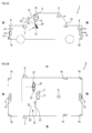
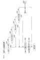
- FIG. 1A is a side view of the vehicle of the embodiment
- FIG. 1B is a top view of the vehicle of the embodiment.
- It is a block diagram which shows the electric constitution of the vehicle of embodiment.
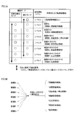
- FIG. 3A is an explanatory diagram showing the automatic operation level in each operation mode
- FIG. 3B is an explanatory diagram showing that the control content at each automatic operation level may be arbitrarily set.
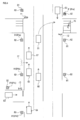
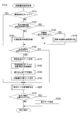
- It is explanatory drawing for demonstrating the outline
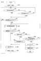
- operation control process in the main process of FIG. 7 is a flowchart of an initial automatic switching confirmation process in the automatic operation control process of FIG. 6.
- SYMBOLS 1,61-66 ... Vehicle, 2 ... 1st front camera, 3 ... Indoor camera, 4 ... 1st rear camera, 5 ... 2nd front camera, 6 ... 2nd rear camera, 7 ... Left side camera, 8 ... Right side Direction camera, 11 ... forward radar device, 12 ... rear radar device, 13 ... left side radar device, 14 ... right side radar device, 16 ... automatic driving operation lamp, 20 ... handle, 21 ... biological sensor, 22 ... solar radiation sensor, DESCRIPTION OF SYMBOLS 23 ... Rainfall sensor, 24 ... Vehicle speed sensor, 25 ... Seat sensor, 26 ... Belt sensor, 27 ... Travel drive control part, 28 ... Brake control part, 29 ...
- FIG. 1A shows a side view of the vehicle 1 of the present embodiment
- FIG. 1B shows a top view of the vehicle 1.
- FIG. 1A and FIG. 1B briefly illustrate the arrangement states of various cameras, radars, sensors, etc. in the vehicle 1 mainly for the purpose of clearly showing the arrangement states.
- the vehicle 1 has at least a first front camera 2, an indoor camera 3, a first rear camera 4, and a second front camera 5 as cameras for photographing the inside and outside of the vehicle 1.
- Each of the cameras 2 to 8 is a camera capable of shooting color images and moving images.
- Each of the cameras 2 to 8 may be a monocular camera, or may be a stereo camera that can acquire information in the depth direction by providing a plurality of lenses.
- the first front camera 2 is provided so as to face forward on the front end side of the ceiling in the passenger compartment.
- the first front camera 2 can capture the front of the vehicle 1 in a wide range.
- the indoor camera 3 is provided so as to face the rear (vehicle interior) on the front end side of the ceiling in the vehicle interior.
- the indoor camera 3 can photograph at least the upper body of the driver (driver) in the vehicle interior.
- the first rear camera 4 is provided to face rearward on the rear end side of the ceiling in the vehicle interior.
- the first rear camera 4 can shoot the rear of the vehicle 1 in a wide range.
- the second front camera 5 is provided at the front end of the vehicle 1 so as to face the front. With this second front camera 5, the front of the vehicle 1 can be photographed in a wide range.
- the second rear camera 6 is provided at the rear end portion of the vehicle 1 so as to face the rear. With this second rear camera 6, the rear of the vehicle 1 can be photographed in a wide range.
- the left side camera 7 is provided on the left side surface of the vehicle 1 so as to face the left side.
- the left side camera 7 can shoot the left side of the vehicle 1 in a wide range.
- the right side camera 8 is provided to face the right side on the right side surface of the vehicle 1.
- the right side camera 8 can shoot the right side of the vehicle 1 in a wide range.
- the vehicle 1 includes a front radar device 11, a rear radar device 12, a left side radar device 13, and a right side radar device 14.
- Each of the radar apparatuses 11 to 14 is a millimeter wave radar in this embodiment.
- a millimeter wave radar is based on the relationship between a transmitted wave and each received wave and the relationship between each received wave by transmitting a millimeter wave radio wave and receiving the reflected wave by a plurality of receiving antennas.
- the radar is capable of detecting target information related to targets around the vehicle 1.
- the target information that can be detected by each of the radar devices 11 to 14 includes the presence / absence of the target in the detection direction, the distance to the target, the direction of the target with reference to the vehicle 1, and the moving speed of the target (with respect to the vehicle 1). Relative speed).
- the front radar device 11 is provided at the front end of the vehicle 1 and transmits and receives millimeter waves of a predetermined frequency to the front of the vehicle 1.
- the front radar apparatus 11 can acquire target information related to a target ahead of the vehicle 1.
- the rear radar device 12 is provided at the rear end of the vehicle 1 and transmits and receives millimeter waves of a predetermined frequency to the rear of the vehicle 1.
- the rear radar device 12 can acquire target information regarding a target behind the vehicle 1.
- the left side radar device 13 is provided on the left side surface of the vehicle 1 and transmits / receives millimeter waves of a predetermined frequency to / from the left side of the vehicle 1.
- the left side radar device 13 can acquire target information related to the left side target of the vehicle 1.
- the right side radar device 14 is provided on the right side surface of the vehicle 1 and transmits and receives millimeter waves of a predetermined frequency to the right side of the vehicle 1.
- the right side radar device 14 can acquire target information regarding the right side target of the vehicle 1.
- the vehicle 1 includes a living body sensor 21, a solar radiation sensor 22, and a rainfall sensor 23 as shown in FIGS. 1A and 1B.
- a plurality (two in this embodiment) of biosensors 21 are provided on the handle 20 that is operated by the driver for steering.
- the biometric sensor 21 can detect whether or not the driver is touching the handle 20 and can detect various types of biometric information such as the driver's pulse and sweating while the driver is touching the handle 20.
- the solar radiation sensor 22 is installed in the lower part of the front window 10 in front of the vehicle interior.
- the solar radiation sensor 22 can detect the amount of solar radiation with respect to the vehicle 1 and consequently the brightness around the vehicle 1.
- the rain sensor 23 is installed on the upper part of the front window 10 on the vehicle interior side. This rainfall sensor 23 can detect the presence or absence of rainfall and the amount of rainfall.
- the vehicle 1 includes four automatic driving operation lamps 16 as shown in FIGS. 1A and 1B.
- the vehicle 1 of the present embodiment can switch the operation mode to either the advanced automation mode or the basic mode, and each automatic operation operation lamp is set while the operation mode is set to the advanced automation mode. 16 lights up with a predetermined lighting pattern. The lighting state of each automatic driving operation lamp 16 is visible from the outside of the vehicle 1. Therefore, when the driving mode is set to the advanced automation mode, it is possible to appeal that the vehicle 1 or the pedestrian traveling around the vehicle 1 is traveling in the advanced automation mode.
- Various lighting patterns of the automatic operation operation lamps 16 are conceivable.
- the automatic driving operation lamps 16 may be constantly lit during the high-level automation mode, or may be alternately switched on and off at a constant cycle.
- the vehicle 1 includes an automatic driving control unit 30.
- the automatic operation control unit 30 mainly has a mode switching function and an automatic operation function.
- the mode switching function is a function for setting the operation mode of the vehicle 1 to either the highly automated mode or the basic mode.
- the automatic operation function is a function for executing automatic operation in accordance with the automatic operation level of the set operation mode (see FIG. 3A, details will be described later).
- the automatic driving control unit 30 appropriately switches the driving mode of the vehicle 1 according to various factors such as the traveling state of the vehicle 1, the surrounding state of the vehicle 1, and the state of the driver of the vehicle 1.
- the types of automatic driving of vehicles include partial automatic driving and fully automatic driving.
- Partially automatic driving is an automatic driving in which a part of various driving operations of a driver necessary for driving a vehicle is automated.
- automation means that it can be performed without requiring a driver's operation.
- the fully automatic driving is an automatic driving in which traveling to the destination is completely automated without requiring a driver's operation or the like to the set destination.
- a parameter indicating the type and number of driving operations that are automated in automatic driving is hereinafter referred to as an automatic driving level.
- Fully automatic operation has a higher level of automatic operation than partially automatic operation.
- the vehicle 1 of the present embodiment is configured to be capable of fully automatic driving as well as partially automatic driving by the automatic driving control unit 30.
- the driver can arbitrarily change the setting of the automatic driving level, that is, which operation among various driving operations necessary for traveling is automated and which operation is performed by the driver.
- the main automatic control functions for realizing fully automatic driving are automatic start / stop control, lane keeping control, inter-vehicle distance control, lane change control, right / left turn control, and collision suppression control.
- the automatic operation control unit 30 can execute these seven types of automatic control functions, and a fully automatic operation can be realized by executing these seven types of automatic control functions.
- partial automatic operation is realized by executing any six or less of the above seven types of automatic control functions.
- the specific contents of the seven types of automatic control functions will be described in detail later.
- the automatic operation level becomes higher as the number of functions to be executed among the seven types of automatic control functions increases.
- the level of automatic driving when none of the seven types of automatic control functions is executed is level 0.
- the automatic operation level when n types of the seven types of automatic control functions are executed is level n. Therefore, in the level 0 operation mode, it is necessary for the driver to determine and operate the control operation corresponding to the seven types of automatic control functions.
- the operation modes of level 1 to level 6 are operation modes in which partial automatic operation is performed.
- Level 7 operation mode is an operation mode in which fully automatic operation is performed.
- the advanced automation mode is an operation mode in which automatic operation is performed at an automatic operation level of level 1 or higher.
- the basic mode is an operation mode in which the automatic operation level is relatively lower than the advanced automation mode.
- the advanced automation mode is level n
- the basic mode can be set to any of level n ⁇ 1 to level 0.
- Level 0 is a level at which the driver does not perform all of the seven types of automatic control functions, and the driver needs to perform most of the various driving operations required for traveling.
- the automatic operation control unit 30 includes a calculation unit 30a and a memory 30b.
- the memory 30b includes at least one of ROM, RAM, and other various storage media (for example, EEPROM, flash memory).
- the calculation unit 30a implements various functions including the above-described mode switching function and automatic driving function by executing various programs stored in the memory 30b.
- the arithmetic unit 30a includes at least a CPU.
- the various programs stored in the memory 30b include programs (so-called security software) that can detect unauthorized operations from outside, computer viruses, unauthorized software and data (hereinafter collectively referred to as “illegal factors”). )It is included.
- the computing unit 30a monitors the presence or absence of fraud factors at any time by making this security software resident during activation. And when a fraud factor occurs, various fraud countermeasure processing is executed.
- the fraud handling process includes a process for forcibly setting the automatic driving level to level 0 and not operating the automatic control function at all.
- various specific contents of the fraud countermeasure processing are conceivable. For example, a warning by voice or the like may be output to the driver, or the vehicle 1 may be forcibly decelerated or stopped. Further, the connection between the automatic driving control unit 30 and the communication units 31 to 35 may be physically blocked so that the automatic driving control unit 30 cannot be accessed from the outside via wireless communication.
- the automatic driving control unit 30 is connected to the cameras 2 to 8, the radar devices 11 to 14, the sensors 21 to 23, and the four automatic driving operation lamps 16 shown in FIGS. 1A and 1B.
- the calculation unit 30a of the automatic operation control unit 30 individually controls the operation of each of the cameras 2 to 8, obtains the photographing result (image data) from each of the cameras 2 to 8, and stores it in the memory 30b. Image data acquisition and storage are repeated at predetermined time intervals.
- the calculation unit 30a can recognize various situations inside and outside the vehicle based on the image data of each camera 2-8. For example, from the image data of the indoor camera 3, it is possible to recognize the driver's line of sight, eye state, gesture, and the like. Further, from the image data of the first front camera 2, it is possible to detect a state in which sunlight is incident on the vehicle and the driver feels dazzling (so-called backlight). Further, from the image data of the first front camera 2 and the second front camera 5, the vehicle ahead, the oncoming vehicle, the vehicle in the adjacent lane running diagonally forward, the lane line, the pedestrian crossing, the pedestrian, the bicycle, etc. It is possible to recognize pop-outs, the entry of other vehicles to the intersection at the intersection, the contents of signs, traffic lights, signboards, and other objects around the vehicle.
- the arithmetic unit 30a of the automatic operation control unit 30 individually controls the radar apparatuses 11 to 14, acquires target detection results from the radar apparatuses 11 to 14, and stores them in the memory 30b. Acquisition and storage of detection results from each of the radar apparatuses 11 to 14 is repeated at predetermined time intervals.
- the calculation unit 30a calculates and acquires the presence / absence of the target, the distance to the target, the direction of the target, the relative speed of the target viewed from the vehicle 1, and the like based on the detection results of the radar devices 11 to 14. be able to.
- the calculation unit 30 a of the automatic operation control unit 30 determines whether or not the driver is touching the handle 20 based on the detection signal from the biosensor 21. Further, while the driver is touching the handle 20 (specifically, while being in contact with the biosensor 21), biometric information such as the driver's pulse and sweating state is acquired based on the detection signal from the biosensor 21. The calculation unit 30a can estimate the physical condition and mental state of the driver based on the acquired biological information.
- the calculation unit 30a of the automatic operation control unit 30 determines the brightness of the driving environment based on the detection signal from the solar radiation sensor 22, and uses the brightness of the night or a similar situation (hereinafter simply referred to as “night”). Judgment can be made. Further, the calculation unit 30 a of the automatic operation control unit 30 can determine the presence or absence of rainfall and the amount of rainfall based on the detection signal from the rain sensor 23.
- the vehicle 1 includes a seating sensor 25 and a belt sensor 26 as components connected to the automatic driving control unit 30 as shown in FIG.
- the seating sensor 25 is a sensor for detecting whether an occupant is sitting on the seat of the vehicle 1. Although only one seating sensor 25 is shown in FIG. 2 for simplification of illustration, actually, it is provided for each seat individually. Specifically, when the number of passengers is N, the seating sensor 25 is provided for each of N seats.
- the belt sensor 26 is a sensor for detecting whether or not the occupant is wearing a seat belt when the occupant is sitting on the seat of the vehicle 1. Although only one belt sensor 26 is illustrated in FIG. 2 for the sake of simplicity, in reality, it is provided for each seat belt of each seat. Specifically, in the case of a vehicle 1 having N passengers, a seat belt is provided for each of N seats, and a belt sensor 26 is provided for each of the seat belts.
- the vehicle 1 includes components, such as a GPS communication unit 31, an inter-vehicle communication unit 32, an inter-vehicle communication unit 33, an inter-vehicle communication unit 34, LTE, as components connected to the automatic driving control unit 30.
- a communication unit 35 and a TV / radio reception unit 36 are provided.
- the GPS communication unit 31 receives radio waves from a plurality of GPS (Global Positioning System) satellites, and outputs information (GPS information) included in the received radio waves to the automatic operation control unit 30.
- the calculation unit 30 a of the automatic driving control unit 30 can calculate the current position of the vehicle 1 based on the information received by the GPS communication unit 31.
- the automatic driving control unit 30 has a route guidance function that is one of various element functions for realizing the automatic driving function.
- the route guidance function calculates an appropriate route from the current position to the destination based on the current position of the vehicle 1 calculated based on the GPS information and the destination set by the driver. It is a function which carries out guidance control of the vehicle 1 so that it may drive
- the content of the guidance control of the vehicle 1 in the route guidance function varies depending on the automatic driving level. For example, the guidance control in the case where the automatic driving level is set to the level 7 of fully automatic driving corresponds to a plurality of types of automatic control functions (seven types as described above in the present embodiment) for realizing fully automatic driving.
- the guidance control is set to partially automatic driving among a plurality of types of automatic control functions. It is to provide route information for the necessary automatic control function and to guide the driving route (for example, voice guidance) to the driver as necessary.
- Map data and other various data necessary for the route guidance function are stored in the memory 30b.
- the arithmetic unit 30a implements a route guidance function (specifically, the above guidance control) by executing a route guidance function program stored in the memory 30b while referring to these various data.
- the computing unit 30a can also recognize the road conditions around the vehicle 1 based on the route guidance function. Specifically, for example, the shape of the route from the current position to the destination and the vehicle width can be recognized.
- the inter-vehicle communication unit 32 is a communication module for transmitting and receiving various data wirelessly with vehicles other than the own vehicle.
- the calculation unit 30a of the automatic driving control unit 30 can acquire information (for example, traveling direction, traveling speed, position, etc.) of other surrounding vehicles via the inter-vehicle communication unit 32. On the contrary, the information of the own vehicle 1 can also be transmitted to another vehicle.
- the road-to-vehicle communication unit 33 is a communication module for receiving various information wirelessly transmitted from a road communication device 81 (see FIG. 4) provided on the road (on the ground side). Various information received by the road-to-vehicle communication unit 33 is input to the automatic driving control unit 30.
- the roadside communication device 81 is connected to a server (not shown), receives various information from the server, and wirelessly transmits the information within a predetermined area.
- Various kinds of road traffic information such as various infrastructure information (such as traffic signal information and road regulation information) and presence information of other vehicles and pedestrians are collected in the server.
- the server transmits, for each road communicator 81, individual road information related to the road communicator 81 based on the aggregated road traffic information.
- the individual road information is various kinds of road traffic information related to the traveling direction of the vehicle traveling in the communication area of the roadside communication device 81.
- Each road communicator 81 wirelessly transmits the individual road information transmitted from the server within a predetermined communication area.
- the calculation unit 30a of the automatic driving control unit 30 can acquire various road traffic information related to the traveling road in the traveling direction via the road-to-vehicle communication unit 33.
- Information that can be acquired by the calculation unit 30a via the road-to-vehicle communication unit 33 includes dangerous sections (for example, sections where curves are continuous, sections where the road width is narrow, etc.), sections where construction is being performed, and accident sites Section information related to various sections such as a certain section close to.
- the calculation unit 30a can recognize the relative relationship between the section and the vehicle 1 such as whether or not the vehicle 1 is traveling in the section indicated by the section information by linking the acquired section information and the route guidance function. .
- a camera 82 is mounted on each on-road communication device 81 illustrated in FIG.
- Each camera 82 photographs the road side and transmits the photographed data to the server via the network.
- the server can acquire road traffic information around the camera from the shooting data transmitted from each camera 82.
- the inter-vehicle communication unit 34 is a communication module for performing wireless communication with a communication terminal (for example, a mobile phone or a smartphone) possessed by a pedestrian on the ground side.
- a communication terminal for example, a mobile phone or a smartphone
- the communication terminal possessed by the pedestrian is configured to be able to wirelessly transmit terminal position information indicating the position of the communication terminal (that is, the position of the pedestrian)
- the terminal position information transmitted from the communication terminal Can be received by the inter-vehicle communication unit 34.
- the terminal position information received by the inter-pedestrian communication unit 34 is input to the automatic driving control unit 30.
- the automatic driving control unit 30 may inform the pedestrian of the position information of the vehicle 1 by wirelessly transmitting various information such as the position information of the vehicle 1 from the inter-vehicle communication unit 34 to the communication terminal of the pedestrian. it can.
- the calculation unit 30 a of the automatic driving control unit 30 can know the position and movement of the pedestrian based on the terminal position information received via the inter-vehicle communication unit 34.
- the presence / absence and movement of pedestrians can also be detected by the cameras and radar devices described above, but in addition, the presence / absence of pedestrians and pop-up of pedestrians are also obtained from information obtained via the inter-pedestrian communication unit Can be detected.
- the LTE communication unit 35 is a communication module for realizing wireless communication based on LTE, which is a well-known mobile phone communication standard.
- the TV / radio receiver 36 is a receiving module for receiving radio waves of television broadcasting or radio broadcasting.
- the calculation unit 30a acquires various information necessary for automatic driving of the vehicle 1 or updates existing information (for example, update of map data) via the LTE communication unit 35 (that is, by LTE wireless communication). be able to. In addition, it is not essential to perform acquisition and update of such various information by LTE wireless communication, and may be performed using other wireless communication.
- the vehicle 1 includes components such as a display 37, a HUD (abbreviation of head-up display) 38, a microphone 39, a speaker 40, and a blinker as components connected to the automatic driving control unit 30.
- An operation unit 41, an automatic operation activation lamp 16, an automatic operation start switch 42, an automatic operation stop switch 43, an emergency stop switch 44, and a level setting operation unit 45 are provided.
- the switch is also referred to as “SW”.
- the display 37 is a display device for displaying various information including map information in the route guidance function.
- the display 37 has a touch panel function, and various input operations can be performed by touching the display 37 according to the display content of the display 37 (specifically, touching the touch panel).
- the HUD 38 is a display device that can project various types of information near the front window 10.
- the microphone 39 acquires the voice of the driver and other occupants and inputs the voice signal to the automatic driving control unit 30.
- the speaker 40 outputs sound based on various sound signals output from the automatic operation control unit 30.
- the winker operation unit 41 has an operation lever operated by a driver to blink a winker (not shown), and outputs a winker operation signal indicating an operation state of the operation lever to the automatic operation control unit 30.
- the automatic operation start SW 42 is a switch for setting the vehicle 1 to an advanced automation mode.
- the driver of the vehicle 1 needs to press the automatic driving start SW 42 in order to set the vehicle 1 to the highly automated mode and execute the automatic driving.
- the automatic operation stop SW 43 is a switch for forcibly switching the automatic operation level of the vehicle 1 to level 0 regardless of the set operation mode.
- the emergency stop SW 44 is a switch for forcibly stopping the vehicle 1.
- the level setting operation unit 45 is a user interface for accepting an operation of setting an automatic driving level (details will be described later) by the driver.
- the driver When the driver recognizes that an unauthorized factor such as a computer virus or an unauthorized operation has occurred, the driver forcibly cancels the automatic operation by pressing the automatic operation stop SW 43, and the vehicle 1 is operated by the driver's own operation. It can be run.
- the automatic driving start SW 42, the automatic driving stop SW 43, and the emergency stop SW 44 are provided, for example, in the vicinity of the driver's seat in the passenger compartment at a position where the driver sitting in the driver's seat can operate during driving.
- the installation locations of these SWs 42, 43, and 44 may be determined as appropriate, or the same SW may be provided at a plurality of locations.
- the emergency stop SW 44 may be provided in the vicinity of a seat other than the driver's seat (for example, a passenger seat). By doing so, for example, when an abnormality occurs in the driving driver and it becomes difficult for the driver to operate normally, the passenger sitting in the passenger seat operates the emergency stop SW 44.
- the vehicle 1 can be urgently stopped.
- the vehicle 1 is provided with an accelerator pedal 27a and a brake pedal 28a.
- the accelerator pedal 27a is depressed by the driver when the driver wants the vehicle 1 to travel.
- the brake pedal 28a is depressed by the driver when the driver wants to decelerate or stop the traveling vehicle 1.
- the vehicle 1 includes, as components connected to the automatic driving control unit 30, a vehicle speed sensor 24, a travel drive control unit 27, a brake control unit 28, a pedal sensor 28b, a steering, And a control unit 29.
- the pedal sensor 28b is a sensor for detecting whether or not the driver's foot is placed on the brake pedal 28a, and is provided on the surface of the brake pedal 28a that is touched by the driver's foot.
- the signal output from the pedal sensor 28b differs depending on whether or not the driver's foot is placed on the brake pedal 28a.
- the automatic driving control unit 30 is configured to be able to determine whether or not the driver's foot is placed on the brake pedal 28a based on a signal output from the pedal sensor 28b.
- the traveling drive control unit 27 includes an accelerator sensor (not shown) for detecting the depression amount of the accelerator pedal 27a.
- the travel drive control unit 27 is based on various information such as the depression amount of an accelerator pedal 27a detected by an accelerator sensor, an operation position of a shift lever (not shown), a vehicle speed, an engine speed, and the like, an engine and a transmission (not shown). Is controlled to control the traveling of the vehicle 1.
- the operation mode is set to the advanced automation mode (specifically, when any of the above seven types of automatic control functions is executed)
- the automatic operation control unit 30 sets the automatic control function to be executed. Control information necessary for the realization is output to the travel drive control unit 27.
- the travel drive control unit 27 controls the engine and the transmission according to the control information from the automatic operation control unit 30 even if the accelerator pedal 27a is not depressed.
- the vehicle 1 of the present embodiment includes an engine as a driving source for traveling
- the automatic driving control device of the present disclosure can also be applied to a vehicle including a driving source for traveling other than the engine.
- the travel drive control unit 27 shown in FIG. 2 has a function of controlling the travel drive source of the vehicle.
- the brake control unit 28 includes a brake sensor (not shown) for detecting the depression amount of the brake pedal 28a.
- the brake control unit 28 controls a brake device (not shown) based on the depression amount of the brake pedal 28a detected by the brake sensor.
- the brake control unit 28 does not depress the brake pedal 28a.
- the brake device is controlled in accordance with the control information from the automatic operation control unit 30.
- the steering control unit 29 mainly has two functions. One is a so-called electric power steering function.
- the electric power steering function is a function that assists the operation of the handle 20 by the driver with a motor.
- the other is an automatic steering function that automatically steers a steered wheel (for example, a front wheel) of the vehicle 1 without requiring a driver's operation.
- Steering wheels are steered basically by the driver operating the steering wheel 20, but when the driving mode is set to the highly automated mode (more specifically, at least of the above seven types of automatic control functions, When any one of automatic start / stop control and inter-vehicle distance control is executed), the steering control unit 29 responds to the control information from the automatic operation control unit 30 even when the driver does not operate the handle 20. Then, the steering of the steered wheels is automatically controlled by controlling the motor.
- the automatic driving control unit 30 can acquire and detect various information necessary for realizing the above-described automatic driving function.
- Information that can be used to realize the automatic driving function includes information such as the position and speed of the vehicle (vehicle information).
- vehicle information vehicle information
- the own vehicle position can be obtained by calculation based on GPS information.
- the own vehicle speed can be obtained by calculation based on a vehicle speed signal from the vehicle speed sensor 24, a steering angle signal from a steering angle sensor (not shown), a yaw rate signal from a yaw rate sensor (not shown), and the like.
- the own vehicle speed can also be calculated from the rate of change of the own vehicle position.
- information that can be used to realize the automatic driving function includes information on surrounding moving objects. Specifically, it is information related to the position, distance, and speed relative to the host vehicle, such as a forward vehicle, a rear vehicle, a side vehicle, an oncoming vehicle, a vehicle that crosses an intersection at an entry destination, a pedestrian, and a bicycle.
- Information on these surrounding moving objects can be acquired based on the shooting data of the cameras 2 to 8, the detection results of the radar devices 11 to 14, and the like.
- Various techniques for recognizing surrounding objects based on imaging data and the detection result of the radar apparatus have been proposed and put into practical use, and will not be described here.
- Information related to surrounding moving objects can also be acquired by inter-vehicle communication, road-to-vehicle communication, and inter-vehicle communication.
- inter-vehicle communication by performing inter-vehicle communication with surrounding vehicles, it is possible to recognize not only the surrounding vehicles that can be seen from the own vehicle, but also the positions and movements of surrounding vehicles that are in a blind spot and cannot be seen directly from the own vehicle.
- road-to-vehicle communication as described above, it is possible to acquire presence information of surrounding vehicles and pedestrians.
- the position and movement of the pedestrian can be known based on the terminal position information received via the inter-vehicle communication unit 34.
- inter-vehicle communication road-to-vehicle communication
- inter-vehicle communication for example, to acquire oncoming vehicle information during normal driving (especially in a curve) or right turn to suppress a frontal collision with an oncoming vehicle
- information on the left and rear motorcycles is acquired, information on the vehicle on the side (rear side) is obtained when the lane is changed, and information on the front vehicle is used to prevent rear-end collisions.
- information on other vehicles that are traveling on the intersection to prevent encounter collisions at intersections, or to acquire information on pedestrians to prevent collisions with pedestrians, etc. Can do.
- information that can be used to realize the automatic driving function includes information on various road displays drawn directly on the road, such as lane line (including parking line), pedestrian crossing, and temporary stop line.
- Information on the road display includes the position and content of the road display.
- Information on the road display can be acquired based on the photographing data of the cameras 2 to 8.
- Various techniques for recognizing road displays from photographic data have been proposed and put to practical use, and the description thereof is omitted here.
- Information on road displays in the direction of travel can also be obtained by road-to-vehicle communication.
- vehicle 1 of this embodiment is not provided, it is also possible to acquire the information regarding various road displays using a laser radar.
- Information that can be used to realize the automatic driving function includes information on traffic lights, railroad crossings, signs (including signboards), intersections, junctions / divergence points, sidewalks, obstacles, dangerous parts, and other ground structures (hereinafter “ And "infrastructure related information”).
- Infrastructure-related information includes the presence and location of the various objects described above, color information for traffic lights, operating status for railroad crossings, display content for signs and signs, etc. .
- Infrastructure-related information can also be recognized and acquired based on the shooting data of each camera 2 to 8, and can also be acquired by road-to-vehicle communication.
- Various infrastructure information can also be acquired from the route guidance function described above based on GPS information and map data.
- information that can be used to realize the automatic driving function includes regulatory information.
- regulatory information For example, when travel regulation due to construction, accidents, natural disasters, or the like is performed in the traveling direction, the regulation information can be acquired by road-to-vehicle communication.
- the various types of information that can be used to realize the automatic driving function such as the information related to the surrounding moving object, the infrastructure related information, the information related to the road display, and the regulation information, correspond to an example of the surrounding information of the present disclosure.
- the automatic operation control unit 30 acquires the above-described various information and automatically controls the travel drive control unit 27, the brake control unit 28, the steering control unit 29, and other necessary in-vehicle devices based on the information. Driving can be realized. Specifically, the seven types of automatic control functions described above can be executed. As described above, the seven types of automatic control functions in this embodiment are automatic start / stop control, lane keeping control, inter-vehicle distance control, lane change control, right / left turn control, collision suppression control, and parking control.
- the automatic start / stop control is a control in which the vehicle 1 is automatically stopped when the condition to be stopped is satisfied during traveling, and the vehicle 1 is automatically started when the condition to be stopped is canceled after the stop. is there.
- This control is performed using information on surrounding moving objects obtained from the cameras 2 to 8 and the radar sensors 11 to 14, infrastructure-related information and regulation information obtained by road-to-vehicle communication, in addition to the vehicle information.
- this automatic start / stop control for example, if the traffic light is blue at an intersection, the vehicle will run as it is and if it is red or yellow, it will stop. Control is performed such as stopping when it is recognized, or stopping once when the circuit breaker is not descended and then starting again. In addition, when an obstacle or the like is recognized ahead, it is automatically stopped.
- default values are set in advance for various control parameters required to execute the automatic start / stop control, such as deceleration for automatic stop and acceleration for automatic start. And stored in the memory 30b. However, these control parameters may be arbitrarily changed from the default values.
- the lane keeping control is a control configured to automatically steer the steered wheels so that the vehicle travels along the lane without departing from the lane marking.
- This control is performed in cooperation with the route guidance function by using information on the road displays (particularly vehicle division lines) obtained from the cameras 2 to 8 and the radar sensors 11 to 14 in addition to the vehicle information.
- the inter-vehicle distance control is a control method in which when other vehicles are traveling in front of the host vehicle, speed control is performed so as to follow the other vehicles while keeping the distance between the other vehicles at a constant distance.
- the inter-vehicle distance control includes so-called cruise control. Specifically, when there is no other vehicle within a certain range in front of the host vehicle (for example, within 100 m ahead), in other words, when the vehicle to be followed does not exist in front of the host vehicle, the vehicle is driven at the set speed. .
- the inter-vehicle distance control is performed mainly using information on the surrounding moving object (particularly the forward vehicle) obtained from the cameras 2 to 8 and the radar sensors 11 to 14 in addition to the own vehicle information.
- the vehicle speed which is one of the control parameters used when no other vehicle exists within a certain range in front of the host vehicle, is set to the legal speed of the traveling road in principle.
- the vehicle speed in this case may be set arbitrarily. At that time, it may be arbitrarily set within a range not exceeding the legal speed.
- Lane change control detects other vehicles in the adjacent lane of the change destination when lane change (steering for lane change) is necessary, and other vehicles according to the presence, position, speed, etc. of other vehicles.
- This control is a control for automatically changing the lane while controlling the driving force, the braking force and the steering so as not to collide with the vehicle.
- This control is obtained not only by the own vehicle information but also by information on surrounding moving objects (particularly other vehicles in adjacent lanes) obtained from the cameras 2 to 8 and radar sensors 11 to 14, information on vehicle lane markings, and inter-vehicle communication. This is performed using information on other vehicles (traveling vehicles in adjacent lanes).
- Right / left turn control is a control that automatically makes a right or left turn without colliding with an oncoming vehicle, a vehicle traveling on an intersection, other vehicles around the vehicle, or a pedestrian when a right or left turn is required. It is.
- this control includes information on surrounding moving objects obtained from the cameras 2 to 8 and the radar sensors 11 to 14, information on other vehicles obtained by inter-vehicle communication, and pedestrians obtained by inter-vehicle communication. It is performed using information such as.
- Collision suppression control is control for automatically steering or braking / stopping a vehicle so that it does not collide with an obstacle when there is an obstacle on the road in the vehicle traveling direction. This is performed by using information on surrounding moving objects obtained from the cameras 2 to 8 and the radar sensors 11 to 14, infrastructure-related information and regulation information obtained by road-to-vehicle communication.
- parking control calculates a travel locus to the target parking position and drives the vehicle along the travel locus. This is a control to automatically park by controlling the force, braking force and steering.
- the driver or the like can be arbitrarily set as to which of the above seven types of control functions is to be executed, that is, the automatic driving level.
- the automatic operation level can be arbitrarily set in both the advanced automation mode and the basic mode.
- level 7 cannot be set, and any of level 0 to level 6 can be set.
- level 0 cannot be set, and any of level 1 to level 7 can be set.
- the level of the basic mode can be set within a range of levels lower than the level of the advanced automation mode. In other words, the level of the advanced automation mode can be set within a range of levels higher than the level of the basic mode.
- control A for example, lane keeping control
- control B for example, inter-vehicle distance control
- control C for example, automatic start / stop control
- control D for example, collision suppression control
- control E for example, lane change control
- control F for example, right / left turn control
- control G for example, parking control
- the level setting for each operation mode can be performed by operating the level setting operation unit 45 provided near the driver's seat for each operation mode.
- the automatic driving level in the basic mode is set to level 0 by default
- the automatic driving level in the advanced automation mode is set to level 7 by default.
- the automatic operation level currently set can be arbitrarily set and changed for each operation mode. For example, when the basic mode is set to level 0, the advanced automation mode can be arbitrarily changed between levels 1-7. Also, for example, when the basic mode is set to level 1, the advanced automation mode can be arbitrarily changed between levels 2-7. Further, for example, when the advanced automation mode is set to level 4, the basic mode can be arbitrarily changed between level 0 and level 3.
- the automatic control function to be executed at which level is not limited to the content illustrated in FIG. 3A.
- the seven types of automatic control functions described above are merely examples, and the number of automatic control functions and the specific contents of each automatic control function may be determined as appropriate.
- control A to control G are as follows, assuming that the number of automatic control functions executed each time the level is increased as shown in FIG. 3A. May be arbitrarily set by the driver or the like.
- the operation mode is normally set to the basic mode.
- the automatic operation start SW 42 when it is pressed, the operation mode becomes the advanced automation mode under a certain condition.
- a destination when it is set to execute lane change control, right / left turn control, and parking control, a destination (a target parking position in the case of parking control) may be set.
- a route guidance function may be started and a destination may be input via a touch panel. Automatic driving when the destination is set is basically performed along the route to the calculated destination while checking the position of the host vehicle in cooperation with the route guidance function. .
- the automatic operation level is set to an operation mode of level 1 or higher and the destination is not set
- how to specifically execute the automatic control function applied in the current operation mode May be determined as appropriate. For example, when the operation mode is set so that the right / left turn control function is executed, if the destination is not set, the right / left turn control function should be executed so that the vehicle travels along the road in principle. Also good. Then, for example, when it is necessary to select a traveling direction, such as when a bifurcating branch point is reached, for example, the right / left turn control function may be executed so as to proceed in a predetermined direction. Further, when the destination is not set, the right / left turn control function may be disabled.
- the parking control function may also be disabled when a destination (specifically, a place to park) is not set.
- Each of the vehicles 61 to 67 shown in FIG. 4 has the same configuration as the vehicle 1 shown in FIGS. 1A, 1B, and 2.
- a vehicle traveling in the communication area of the road communicator 81 can receive individual road information from the road communicator 81.
- At least four vehicles 61, 65, 66, and 67 among the vehicles in FIG. 4 can receive individual road information from at least two roadside communication devices 81a and 81b in the vicinity thereof. Specifically, information on the traffic light 71 ahead, information on the oncoming vehicle 62, information on the pedestrian 76, and the like can be acquired.
- At least the vehicle 63 can receive individual road information from at least the roadside communication device 81c in the vicinity thereof. Specifically, it is possible to acquire information such as the presence of the stop sign 73 (that is, that the vehicle should be stopped) and that another vehicle 64 is approaching from the right side.
- At least the vehicle 64 can receive individual road information from at least the roadside communication device 81d in the vicinity thereof. Specifically, information such as that another vehicle 63 is approaching from the left side can be acquired.
- At least the vehicle 62 can receive individual road information from at least the roadside communication device 81e in the vicinity thereof. Specifically, information on the traffic light 72 ahead, information that there is an oncoming vehicle 61 that is about to turn right, that there is a pedestrian crossing in the left turn direction, and that there is a pedestrian 76 on the pedestrian crossing. You can get it.
- Each vehicle 61-66 can obtain various information from its own cameras 2-8 and each radar device 11-14, and can also obtain various information by inter-vehicle communication and inter-vehicle communication. Can do.
- the vehicle 65 can detect the front vehicle 67 or the right side vehicle 66 by a camera or a radar device, and can thereby travel while keeping the distance between the front vehicle 67 and the lane change appropriately. If necessary, the lane can be changed at an appropriate timing while considering the positional relationship with the vehicle 66 on the right side.
- the vehicle 65 can also detect the pedestrian 77 jumping out by a camera or a radar device. When the vehicle 65 detects the pedestrian 77 jumping out, the vehicle 65 can perform appropriate deceleration control so as not to collide with the pedestrian 77 in consideration of the distance from the vehicle 65 behind.
- each of the vehicles 61 to 66 travels appropriately to the destination by automatic driving while using various information such as various information obtained from the own vehicle and various information obtained from the roadside. Can be made.
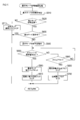
- the calculation unit 30a reads and executes the main process program of FIG. 5 from the memory 30b.
- the arithmetic unit 30a sets the operation mode to the basic mode and executes an automatic control function based on the automatic operation level set as the basic mode in S10. For example, when level 1 is set as the basic mode, the automatic control function of control A (see FIG. 3A) is executed. The execution of the automatic control function is performed based on the acquired various information while acquiring various information including the surrounding information as necessary. Note that when level 0 is set as the basic mode, all automatic control functions are not executed. The automatic control function set as the execution target in the basic mode is automatically executed, but other functions are basically left to the operation of the driver.
- S15 it is determined whether or not the destination has been set. If the destination has not been set yet (S15: NO), it is determined in S20 whether or not a destination setting input has been performed. If the destination setting input has not been performed (S20: NO), the process returns to S15. That is, the basic mode is continued until the destination is set.
- the automatic operation control process is a process of determining whether or not the operation mode can be switched from the basic mode to the advanced automation mode, and switching to the advanced automation mode if the operation mode can be switched.
- the automatic operation control process includes a process of switching to the basic mode when it is determined whether to switch to the basic mode again after switching to the advanced automation mode. Details of the automatic operation control process of S30 are as shown in FIG.
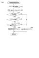
- the initial automatic switching confirmation processing is one of automatic switching confirmation processing for determining whether or not the operation mode of the vehicle 1 can be switched from the basic mode to the advanced automation mode, and the start switch of the vehicle 1 is turned on. This is an automatic switching confirmation process that is executed first after.
- the process proceeds to S130 to execute the initial automatic switching confirmation process. If the initial automatic switching confirmation processing has already been executed after the start of the main processing (S120: YES), it is determined in S140 whether or not traveling has been performed after startup. If the vehicle has traveled even a little after startup regardless of the operation mode (S140: YES), the process proceeds to S150 to execute a normal time automatic switching confirmation process. If the vehicle has not traveled at all after startup (S140: NO), the process proceeds to S160.
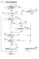
- the normal automatic switching confirmation process is one of the automatic switching confirmation processes for determining whether or not the operation mode of the vehicle 1 can be switched from the basic mode to the advanced automation mode, and the initial automatic switching confirmation process has already been executed. This is an automatic switching confirmation process that is executed in the case of being completed.
- the operation state of the driver is confirmed in S310.
- the driver can normally operate the vehicle 1 when switching to the advanced automation mode immediately after startup. This is to enable smooth return to the basic mode when it is necessary to return to the basic mode after starting traveling in the highly automated mode.
- it also has the meaning which suppresses that the person who is immature in driving operation (for example, a child) and the person who should not operate the vehicle 1 run the vehicle 1 by automatic driving without permission.
- a first determination method for determining whether or not the handle 20 is being gripped and the brake pedal 28a is being depressed may be used.
- a second determination method may be used in which the driver travels the vehicle 1 for a certain time (for example, several tens of seconds) and determines whether or not the driving operation during the travel is normal. Specifically, for example, whether the accelerator operation is smooth or the operation of the handle 20 is smooth (whether the operation along the shape of the travel route has been performed), or the lane detected by various in-vehicle cameras and radar devices fluctuates. It may be determined whether or not the driving operation is normal based on whether the vehicle has traveled without error, whether the vehicle has been driven according to signals and signs detected by various on-vehicle cameras and radar devices, and the like.
- the method for determining whether or not the driver is seated in the driver's seat may be used alone or in combination with other determination methods.
- S320 it is determined whether or not switching to the advanced automation mode is possible based on the confirmation result in S310. For example, when the first determination method is used in S310, if it is determined that the handle 20 is being gripped and the brake pedal 28a is being depressed, it may be determined that switching to the advanced automation mode is possible. Good. At that time, it is also determined whether or not the driver is seated in the driver's seat based on the detection signal from the seating sensor 25, and when the driver is seated in the driver's seat, switching to the advanced automation mode is performed. You may make it judge that it is possible.
- the second determination method when it is determined that the driving operation during traveling is normal, it may be determined that switching to the high-level automation mode is possible. At that time, it is also determined whether or not the driver is seated in the driver's seat based on the detection signal from the seating sensor 25, and when the driver is seated in the driver's seat, switching to the advanced automation mode is performed. It may be determined that is possible. Note that the fact that the operation state confirmed in S310 is determined to be switchable to the advanced automation mode in S320 is an example of a basic mode switching condition.
- S330 it is determined whether or not switching to the advanced automation mode is possible based on the determination result in S320. If it is determined in S320 that switching to the advanced automation mode is possible (S330: YES), the process proceeds to S335.
- S335 it is determined whether or not the occupant is wearing a seat belt. This determination is made based on each detection signal from the seating sensor 25 and the belt sensor 26. Specifically, the determination in S335 may be, for example, a determination on whether all occupants are wearing seat belts, or, for example, at least a specific seat (for example, a driver's seat). And a determination as to whether an occupant in the specific seat is wearing a seat belt. If it is determined in S335 that all the determination subject occupants are wearing seat belts (S335: YES), the process proceeds to S340.
- the advanced automation switching flag is set in S350. After the process of S350, the process proceeds to S160 (FIG. 6). If it is determined in S330 that switching to the advanced automation mode is not possible, the process proceeds to S360. In S335, when there is an occupant not wearing a seat belt among the occupants to be determined (S335: NO), the process proceeds to S360. If it is determined in S340 that the basic mode maintenance flag is not cleared (that is, set) (S340: NO), the process proceeds to S360. In S360, the advanced automation switching flag is cleared. After the process of S360, the process proceeds to S160 (FIG. 6).
- the process proceeds to the normal-time automatic switching confirmation process of FIG. 8, it is determined in S410 whether or not the normal-time transition condition to the advanced automation mode is satisfied.
- the normal-time transition condition may be set so that the advanced automation mode can be switched in a stable state.
- normal state transition condition for example, the fact that the driver is seated in the driver's seat may be used alone or in combination with other conditions (for example, as a logical sum or logical product with other conditions).
- This normal transition condition is an example of the advanced automation switching condition.
- S410 If the normal condition for shifting to the advanced automation mode is satisfied (S410: YES), it is determined in S480 whether the basic mode maintenance flag is cleared. If the basic mode maintenance flag is not cleared (S480: NO), the advanced automation switching flag is cleared in S470, and the process proceeds to S160 (FIG. 6). If the basic mode maintenance flag is cleared (S480: YES), the advanced automation switching flag is set in S490, and the process proceeds to S160 (FIG. 6).
- the basic mode is basically prioritized and maintained. However, if the driver is seated in the driver's seat, the driver's state is confirmed by the processing after S420, and there is some abnormality in the driver's state (the driver may not be able to drive normally) If this occurs, the advanced automation switching flag is set to switch to the advanced automation mode.
- S410 determines whether or not the driver is seated in the driver's seat. If the driver is not seated in the driver's seat (S415: NO), the normal automatic switching confirmation process in FIG. 8 is terminated, and the process proceeds to S160 (FIG. 6). In this case, the operation mode is maintained in the basic mode. On the other hand, when the driver is seated in the driver's seat (S415: YES), the process proceeds to S420.
- S420 it is determined whether or not the driver's line of sight is facing forward. This determination may be made based on image data taken by the indoor camera 3. As a case where the driver's line of sight is not facing forward, for example, it is assumed that the driver is watching TV, operating a mobile phone or a smartphone, or driving aside.
- the process proceeds to S450. If the driver's line of sight is facing forward (S420: YES), the process proceeds to S450. If the driver's line of sight is not facing forward (S420: NO), it is determined in S430 whether the vehicle is stopped. If the vehicle 1 is stopped (S430: YES), the process proceeds to S450. If the vehicle 1 is traveling (S430: NO), it is determined in S440 whether or not the state where the driver's line of sight is not facing forward has continued for a specified time. When the state where the driver's line of sight is not facing forward has not continued for the specified time (S440: NO), the process proceeds to S450. When the driver's line of sight does not face forward for a specified time (S440: YES), the process proceeds to S490, and the advanced automation switching flag is set.
- S450 it is determined whether or not the driver's eyes are normal. Specifically, if it is not in a dozing state or a state close thereto, it is determined as normal, and if it is in a dozing state or a state close thereto, it is determined as abnormal. This determination may be made based on image data taken by the indoor camera 3.
- S460 it is determined whether or not the driver's physical condition is normal. Specifically, the determination is made based on the biological information obtained from the biological sensor 21. For example, if the pulse is within the normal range and is not in an abnormal sweat state, it is determined that the physical condition is normal. Conversely, if the pulse exceeds the normal range or is in an abnormal sweat state, it is determined that the physical condition is abnormal.
- the process proceeds to S470 and the advanced automation switching flag is cleared. If the driver's physical condition is abnormal (S460: NO), the process proceeds to S490, and the advanced automation switching flag is set. After the process of S470 and the process of S490, the process proceeds to S160 (FIG. 6). Note that the driver's state is a state in which an affirmative determination is made in S440, a state in which a negative determination is made in S450, and a state in which a negative determination is made in S460, are all examples of advanced automation switching conditions. It is.
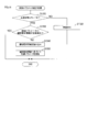
- S160 it is determined whether or not the advanced automation switching flag is set.
- the advanced automation switching flag is not set (cleared) (S160: NO)
- the process proceeds to S200.
- the altitude automation switching flag is set (S160: YES)
- the operation mode is set to the advanced automation mode, and an automatic control function based on the automatic operation level set as the advanced automation mode is executed. For example, when level 6 is set as the advanced automation mode, six types of automatic control functions A to F (see FIG. 3A) are executed. For example, when level 7 is set as the advanced automation mode, fully automatic operation is realized by executing all seven types of automatic control functions A to G. The execution of the automatic control function is performed based on the acquired various information while acquiring various information including the surrounding information as necessary.
- a notification is made that automatic driving in the advanced automation mode has started.
- the driver is notified by voice or the like that the mode has been switched to the advanced automation mode.
- This notification may be performed only when the mode is switched to the advanced automation mode, or may be performed as appropriate after switching (for example, repeatedly at regular time intervals).
- the notification method is not limited to voice.
- an interruption running disapproval notification is made to recognize that it is not desired to interrupt the front of the vehicle 1 around the vehicle 1.
- the specific method for notifying the interrupting travel may be determined as appropriate. For example, a lamp for notifying that the vehicle cannot travel on an interruption may be provided and turned on. Further, for example, an image indicating that it is not desired to be interrupted on the side surface or window of the vehicle 1 may be displayed so as to be visible from outside the vehicle. Further, for example, a specific sound may be generated from the horn. The specific sound is, for example, a sound different from a normal sound that is generated when the driver himself presses a button for horn sounding.
- information that the user does not want to interrupt is notified outside the vehicle by using wireless communication such as road-to-vehicle communication, vehicle-to-vehicle communication, and vehicle-to-vehicle communication together with information on the vehicle (for example, position information and number information). May be.
- the four automatic driving operation lamps 16 are turned on. Thereby, when the vehicle 1 is viewed from the outside, it can be recognized that the vehicle 1 is traveling in the altitude automation mode.
- a method for informing the outside that the vehicle is traveling in the highly automated mode a method other than lighting the four automatic driving operation lamps 16 may be adopted. For example, an image indicating that the vehicle 1 is traveling in the highly automated mode may be displayed on the side surface or window of the vehicle 1 so as to be visible from outside the vehicle.
- the fact that it is set to the advanced automation mode means that it is outside the vehicle using wireless communication such as road-to-vehicle communication, vehicle-to-vehicle communication, and vehicle-to-vehicle communication together with information on the vehicle (for example, position information and number information). You may make it alert
- wireless communication such as road-to-vehicle communication, vehicle-to-vehicle communication, and vehicle-to-vehicle communication together with information on the vehicle (for example, position information and number information). You may make it alert
- a basic mode switching confirmation process is executed. Details of the basic mode switching confirmation processing in S200 are as shown in FIG.
- the basic mode switching confirmation processing in FIG. 10 determines whether or not a condition for switching from the advanced automation mode to the basic mode is satisfied, and switches to the basic mode when the condition is satisfied (for details, refer to the advanced automation switching flag). Clearing).
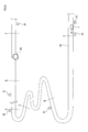
- FIG. 9 shows a road 90 having a curve.
- road construction is being performed in a part of the section, and a sign 91 indicating the start of the construction section is installed in the vicinity of the point A. Further, a sign 92 indicating the end of the construction section is installed in the vicinity of the point D.
- the vehicle 1 is about to enter the point A.
- the vehicle 1 can recognize the contents of the signboards 91 and 92 from the photographing results of the front cameras 2 and 5, and can detect that the vehicle has entered the construction section or has left the construction section. Also, by acquiring the position information of the construction section from the road communicator 81, the vehicle 1 is approaching the construction section start point, the vehicle 1 has entered the construction section, and the vehicle 1 has left the construction section. Can be detected.
- This construction section (may be included up to a section a predetermined distance before the construction section start point) corresponds to a specific travel area described later.
- the section from point B to point C is a travel caution section with a narrow road width and a lot of curves, and is a section where safe driving should be attempted by reducing the vehicle speed.
- the vehicle 1 acquires the position information of the travel attention section from the road communicator 81, so that the vehicle 1 approaches the travel attention section start point, the vehicle 1 enters the travel attention section, or the vehicle 1 It is possible to detect that the vehicle has left the driving attention section.
- the travel attention section from point B to point C (which may include a section before a predetermined distance from the start of the travel attention section) also corresponds to a specific travel area described later.
- an almost halfway point between point E and point F is an accident scene 95 where a traffic accident has occurred.
- the accident section from the point E to the point F centered on the accident scene 95 is also a section that should be traveled with caution while reducing the vehicle speed.
- the vehicle 1 acquires the position information of the accident section from the road communicator 81, so that the vehicle 1 approaches the accident section start point, the vehicle 1 enters the accident section, or the vehicle 1 enters the accident section. It is possible to detect that the user has left.
- the accident section from point E to point F (which may include a section a predetermined distance before the start of the accident section) also corresponds to a specific travel area described later.
- the high-level automation mode is switched to the basic mode.
- the basic mode switching confirmation process in S200 (FIG. 6) for realizing this will be described with reference to FIG.
- the calculation unit 30a determines whether or not the winker operation in the right turn direction is performed by the winker operation unit 41. If a winker operation in the right turn direction is performed (S510: YES), the basic mode maintenance flag is set in S550 to clear the advanced automation switching flag in S560 to switch to the basic mode, and the process proceeds to S210 (FIG. 6). move on. Note that the turn signal operation in the right turn direction is an example of the basic mode switching condition.
- S520 if the vehicle is not traveling in the specific traveling area (S520: NO), it is determined in S530 whether or not a pedestrian has been detected. This determination may be made based on the imaging results of the front cameras 2 and 5, the detection signal of the front radar device 11, the reception information of road-to-vehicle communication, and the reception information of inter-vehicle communication. If a jump of a pedestrian is detected (S530: YES), the basic mode maintenance flag is set in S550 to clear the altitude automation switching flag in S560 to switch to the basic mode, and the process proceeds to S210 (FIG. 6). Note that the detection of a pedestrian jump is an example of a basic mode switching condition.
- an image (such as a dummy pedestrian) is used to give a voice warning or to highlight that the pedestrian has jumped off the road using the HUD 38 to alert the driver. Image) may be displayed.
- S530 If no pedestrian jumping is detected at S530 (S530: NO), it is determined at S540 whether the outside of the vehicle is in a specific environment.
- the specific environment to be switched to the basic mode may be set as appropriate. In the present embodiment, at least during bad weather with a lot of rainfall, at night when the field of view is dark, and when the driver feels dazzled by backlight, the specific environment is set as the specific environment.
- the basic mode maintenance flag is set at S550 to switch to the basic mode, the advanced automation switching flag is cleared at S560, and S210 (FIG. 6).
- the basic mode maintenance flag is cleared in S570, and the process proceeds to S210 (FIG. 6). Note that the fact that the outside of the vehicle is in a specific environment is an example of a basic mode switching condition.
- S210 it is determined whether or not the advanced automation switching flag is cleared. If the advanced automation switching flag is cleared (S210: YES), the operation mode is switched to the basic mode in S220, and the process proceeds to S35 (FIG. 5).
- the specific processing content of S220 is basically the same as S10, and the operation mode is set to the basic mode, and the automatic control function based on the automatic operation level set as the basic mode is executed.
- the four automatic driving operation lamps 16 are turned off. Thereby, when the vehicle 1 is viewed from the outside, it can be recognized that the vehicle 1 is traveling in the basic mode.
- the traveling speed of the vehicle 1 may be appropriately reduced.
- the driver may be notified of the switching to the basic mode by various methods such as voice, vibration of the steering wheel, display on the in-vehicle instrument panel, and the like.
- S210 If the advanced automation switching flag is not cleared in S210 (S210: NO), the process proceeds to S35 (FIG. 5) while maintaining the advanced automation mode.
- S35 it is determined whether or not the automatic operation stop SW43 is turned on.
- S40 When the automatic operation stop SW 43 is turned on (S35: YES), all the flags (including a forced stop flag described later) are cleared in S40, the operation mode is set to the basic mode in S45, and the process returns to S15. .
- S45 as in S10, the operation mode is set to the basic mode, and the automatic control function based on the automatic operation level set as the basic mode is executed.
- the automatic operation stop SW 43 is not turned on (S35: NO)
- step S70 a forced stop process is executed to forcibly stop the vehicle 1 and the main process ends. Thereafter, in order to execute the main processing again next, at least the start switch needs to be turned on again (for example, the ignition switch is turned off and then turned on again).
- the forced stop process of S70 is a process of forcibly stopping the vehicle 1 automatically. You may decide suitably about how to stop specifically.
- the vehicle may be immediately decelerated and stopped on a traveling road. Further, for example, instead of stopping on the road, the vehicle 1 may be automatically driven to a place where the vehicle 1 can be stopped outside the road (for example, a parking lot near the vehicle).
- the driving mode has the high-level automation mode and the basic mode, and the high-level automation mode should be shifted to the basic mode (or even if the mode is shifted). (Good) If the condition is met, switch to basic mode. Therefore, switching from the advanced automation mode to the basic mode can be performed at an appropriate timing. On the other hand, during the basic mode, when a condition that should be (or may be shifted to) the advanced automation mode is satisfied, the operation is switched to the advanced automation mode. Therefore, switching from the basic mode to the advanced automation mode can be performed at an appropriate timing.
- the operation mode is the basic mode
- the advanced automation mode specifically, even if the advanced automation switching flag is set
- the state to maintain the basic mode continues. If it is (specifically, the basic mode maintenance flag is set), the basic mode is maintained. Therefore, in a situation where the basic mode should be maintained, it is possible to realize appropriate vehicle control in which the driving operation of the driver is respected.
- calculation unit 30a, S10 and S45 in FIG. 5, and S170 and S220 in FIG. 6 correspond to an example of a surrounding information acquisition unit, an example of an operation mode setting unit, and an example of an automatic control unit.
- the process in which an affirmative determination is made in S410 and the process proceeds to S480, and a negative determination is made in S480 and the process proceeds to S470 corresponds to an example of an operation mode setting unit.
- the basic mode switching confirmation process shown in FIG. 11 may be adopted.
- the basic mode switching necessity determination is performed. This determination is a determination as to whether or not it is necessary to switch to the basic mode, and may be determined according to various criteria. For example, when the vehicle 1 is traveling in a specific travel area or outside the vehicle is in a specific environment, it may be determined that it is necessary to switch to the basic mode. Further, for example, when an occupant wearing a seat belt removes the seat belt, it may be determined that it is necessary to switch to the basic mode. Further, for example, when another vehicle around the own vehicle exhibits a specific behavior with respect to the own vehicle, it may be determined that it is necessary to switch to the basic mode.
- This determination can be made based on, for example, images taken by the cameras 2 to 8, detection results by the radar devices 11 to 14, and the like.
- the specific behavior may be determined as appropriate.
- a specific behavior may be that another vehicle has approached the host vehicle.
- a method for determining whether or not the width has been adjusted may be appropriately determined. For example, when the distance in the left-right direction (direction perpendicular to the front-rear direction) with the host vehicle is within a specified distance, it may be determined that the width has been increased. Further, for example, when the rate of change of the distance in the left-right direction with the host vehicle is equal to or less than the negative specified rate of change, it may be determined that the width has been increased.
- a specific behavior may be that a vehicle traveling in the rear has suddenly approached the host vehicle.
- a method for determining whether or not the vehicle has approached rapidly may be determined as appropriate. For example, the determination may be made based on the distance to the rear vehicle and the rate of change of the distance, in the same manner as the above-described determination method of width adjustment.
- S620 it is determined whether switching to the basic mode is necessary based on the determination result in S610. If switching to the basic mode is not required (S620: NO), the basic mode maintenance flag is cleared in S710, and the process proceeds to S210 (FIG. 6). If switching to the basic mode is necessary (S620: YES), it is determined in S630 whether the basic mode has already been set. If the basic mode has already been set (S630: YES), the process proceeds to S210 (FIG. 6). If it is not the basic mode yet (that is, in the advanced automation mode) (S630: NO), in S640, the voice, vibration in a specific pattern of the steering wheel, or a specific display on the instrument panel in the vehicle is displayed to the driver. The advance notice of switching to the basic mode is reported using various methods such as
- a prescribed operation it is determined whether or not a prescribed operation has been performed by the driver in response to the notification in S640.
- various operations may be adopted so that the driver can confirm that the driver can handle the driving in the basic mode.
- the prescribed movement may be determined by the driver holding the handle 20 and looking forward.
- the specific operation may be determined by causing the driver to generate a specific sound, causing the driver to perform a specific gesture, or causing the driver to operate a specific operation member (for example, a specific switch) in the vehicle. .
- the prescribed operation by the triver is performed (S650: YES)
- the basic mode maintenance flag is set in S660
- the advanced automation switching flag is cleared in S670, and the process proceeds to S210 (FIG. 6).
- the prescribed operation by the triber is not performed (S650: NO)
- S680 whether or not the driver has timed out without the prescribed operation from the start of notification in S640, that is, the state without the prescribed operation of the driver has continued for a certain period of time. Determine whether or not.
- the basic mode switching confirmation processing shown in FIG. 12 may be adopted.
- the basic mode switching confirmation process shown in FIG. 12 first, in S1010, it is determined whether or not the inter-vehicle distance control is being executed among a plurality of types of automatic control functions. In the above embodiment, as illustrated in FIG. 3A, the inter-vehicle distance control is executed when the automatic driving level is level 2 or higher.
- S1020 it is determined whether there is an interruption of another vehicle ahead of the host vehicle. This determination can be made based on, for example, images taken by the cameras 2 to 8, detection results by the radar devices 11 to 14, and the like. A specific method of this determination may be determined as appropriate. For example, it may be determined that there is an interruption when another vehicle enters in front of the host vehicle in the lane in which the host vehicle is traveling. At that time, it may be determined that there is an interruption when the state of entry has continued for a predetermined time or more as well as just entering.
- the process proceeds to S1040. If it is determined that there is no interruption of another vehicle ahead of the vehicle (S1020: NO), the process proceeds to S1040. If it is determined that there is an interruption of another vehicle ahead of the host vehicle (S1020: YES), a warning process is performed in S1030, and the process proceeds to S1040.
- the warning process of S1030 is for urging attention to other vehicles that have interrupted in front of the host vehicle (for example, the presence of the host vehicle behind the other vehicle, the desire not to be interrupted, etc.) It is processing of.
- the specific contents of the warning process may be determined as appropriate. For example, the same processing as the interruption travel impossible notification in S185 of FIG. 6 may be performed.
- S1040 based on the detection signal from the pedal sensor 28b, it is determined whether or not the driver's foot is placed on the brake pedal 28a.
- the process proceeds to S1060. If the driver's feet are not placed on the brake pedal 28a (S1040: NO), a warning process is performed in S1050, and the process proceeds to S1060.
- the warning process in S1050 is a process for prompting the driver to place his / her foot on the brake pedal 28a.
- the specific content of this alerting process may be determined as appropriate. For example, it may be urged by voice, may be urged by vibrating a specific place in the vehicle (for example, the seat, the handle 20, etc.), or may be urged by displaying caution information on the display 37 or HUD 38. Also good. Note that if the foot is not placed on the brake pedal 28a even after the alerting process, a specific process may be executed.
- the specific process in this case may be, for example, a process for forcibly stopping the vehicle 1 or a process for switching the operation mode to the basic mode.
- S1060 it is determined whether or not the brake pedal 28a is depressed.
- the brake pedal 28a is not depressed (S1060: NO)
- the process proceeds to S1080.
- S1060: YES When the brake pedal 28a is depressed (S1060: YES), a brake handling process is performed in S1070, and the process proceeds to S1080.
- the specific content of the brake handling process of S1070 may be determined as appropriate.
- the inter-vehicle distance which is one of the control parameters used in the inter-vehicle distance control
- the inter-vehicle distance may be changed to a value larger than the current value so that the inter-vehicle distance with the preceding vehicle becomes longer.
- the so-called cruise control is being performed when there is no other vehicle within a certain range in front of the host vehicle
- one of the control parameters used in the inter-vehicle distance control is to reduce the speed of the host vehicle.
- the vehicle speed may be changed to a value lower than the current value.
- S1080 it is determined whether or not the accelerator pedal 27a is depressed. When the accelerator pedal 27a is not depressed (S1080: NO), the process proceeds to S1100. When the accelerator pedal 27a is depressed (S1080: YES), the accelerator handling process is performed in S1090, and the process proceeds to S1100.
- the specific contents of the accelerator handling process of S1090 may be determined as appropriate.
- the inter-vehicle distance which is one of the control parameters used in the inter-vehicle distance control
- the inter-vehicle distance control may be changed to a value smaller than the current value so that the inter-vehicle distance with the preceding vehicle becomes shorter.
- the so-called cruise control is being performed when there is no other vehicle within a certain range in front of the host vehicle
- one of the control parameters used in the inter-vehicle distance control is to increase the speed of the host vehicle.
- the vehicle speed may be changed to a value higher than the current value.
- S1100 it is determined whether or not the sudden brake is automatically activated by an automatic control function including inter-vehicle distance control. You may decide suitably what determines it as a sudden brake. For example, when the deceleration of the vehicle 1 exceeds a predetermined threshold value, it may be determined that the sudden braking has been activated.
- S1100 when the sudden brake is not operating (S1100: NO), the process proceeds to S1140. In S1140, the basic mode maintenance flag is cleared. If it is determined in S1100 that the sudden braking has been activated (S1100: YES), the process proceeds to S1110.
- S1110 it is determined whether or not the operation mode needs to be switched from the advanced automation mode to the basic mode.
- This determination method may be determined as appropriate. For example, it may be determined that it is necessary to switch to the basic mode based on the fact that the sudden brake operation itself is to be switched to the basic mode. Further, for example, every time it is determined that the sudden braking is activated in S1100, the determined number of times is accumulated and stored, and when the accumulated value reaches a predetermined upper limit number, it is necessary to switch to the basic mode. You may make it judge that there exists.
- S1110 If it is determined in S1110 that there is no need to switch to the basic mode (S1110: NO), the process proceeds to S1140. If it is determined in S1110 that it is necessary to switch to the basic mode (S1110: YES), in order to switch to the basic mode, the basic mode maintenance flag is set in S1120, and the advanced automation switching flag is cleared in S1130.
- sudden braking has been activated means that, for example, some abnormality (for example, an accident or an obstacle) has occurred in front of the vehicle and the driver himself / herself performed the driving operation while paying attention to the surroundings. May be in a favorable situation. Further, for example, there is a possibility that an abnormality has occurred in the automatic control function. Therefore, when the sudden brake is automatically activated (S1100: YES), the operation mode is switched to the basic mode by executing the processing of S1120 and S1130 on the condition that an affirmative determination is made in S1110. .
- S1100 YES
- S810 it is determined whether or not it is a confirmation timing (for example, a periodic timing of several minutes interval or a predetermined non-periodic timing). If it is not the confirmation timing (S810: NO), the basic mode preparation confirmation process is terminated. If it is the confirmation timing (S810: YES), in S820, a confirmation operation is requested to the driver by voice or the like.
- the confirmation operation required here can be determined as appropriate. For example, it may be the same as the specified operation in S650 of FIG.
- S830 it is determined whether or not a confirmation operation by the driver has been performed.
- S830: YES it is determined that the driver can immediately return to the basic mode, and the basic mode preparation confirmation process is terminated. If the confirmation operation by the driver is not performed (S830: NO), a warning alert is added to the driver by voice or the like in S840, and the request for the confirmation operation is continued.
- S850 as in S830, it is determined whether or not a confirmation operation by the driver has been performed. If the confirmation operation by the driver is performed (S850: YES), it is determined that the driver can immediately return to the basic mode, and the basic mode preparation confirmation process is terminated. If the confirmation operation by the driver is not performed (S850: NO), in order to forcibly stop the vehicle 1, the advanced automation switching flag is cleared in S860, the forced stop flag is set in S870, and this basic mode preparation confirmation The process ends. If the forced stop flag is set in S870, the process may immediately proceed to S70 (FIG. 5) to execute the forced stop process.
- the conditions for switching from the advanced automation mode to the basic mode may be determined as appropriate. Whether or not to make a transition immediately after confirming whether or not the driver should be able to drive normally when conditions for transitioning to the basic mode are met , May be determined as appropriate.
- the switching condition from the basic mode to the advanced automation mode may be determined as appropriate. For example, when an incoming call or email is received from a mobile phone or smartphone held by the driver, the incoming ring tone is detected, and the advanced automation switching flag is automatically set to enter the advanced automation mode. You may do it.
- the vehicle 1 of the said embodiment is equipped with the LTE communication function, and the automatic driving
- a part of the switching condition from the advanced automation mode to the basic mode exemplified in the above embodiment may be used as the switching condition from the basic mode to the advanced automation mode.
- a part of the switching condition from the basic mode to the advanced automation mode exemplified in the above embodiment may be used as the switching condition from the advanced automation mode to the basic mode.
- the switching condition may be set in consideration of the driver's skill, the driver's preference for the driving mode (for example, which one should prioritize the advanced automation mode or the basic mode), and other various circumstances.
- the state to operate in the basic mode (the basic mode maintenance flag is set).
- the basic mode continues for a period of time during which the operation is continued.
- the state that should operate in the basic mode (the basic mode maintenance flag is set) May be forcibly switched to the highly automated mode.
- the state should be changed to the basic mode (may be changed) while the state to operate in the advanced automation mode continues.
- the advanced automation mode may be continued.
- the automatic driving start SW 42 in order to set the vehicle 1 to the advanced automation mode and execute the automatic driving, it is necessary to press the automatic driving start SW 42. However, pressing the automatic driving start SW 42 is not essential. .
- the automatic operation start SW 42 may be omitted, and the automatic operation mode may be automatically switched to the advanced automation mode when a condition to be switched to (or may be switched to) the advanced automation mode is satisfied.
- the automatic operation level is forcibly set to level 0 regardless of the automatic operation level set as the basic mode. It may be. In this case, the level 0 may be maintained until a predetermined operation by the driver is performed, and the automatic operation level set as the basic mode may be switched when the predetermined operation by the driver is performed.
- the fully automatic operation may be executed by forcibly setting the automatic operation level to level 7.
- the number of passengers in the vehicle can be detected at any time based on the detection signal from the seating sensor 25. Therefore, during traveling in the altitude automation mode, the number of occupants may be monitored, and if a change occurs in the occupants, a predetermined process may be performed. As the predetermined processing, for example, the fact that the number of passengers has changed may be notified to other passengers by voice output, image display, or the like. Further, for example, as the predetermined process, the operation mode may be switched to the basic mode. Further, for example, the vehicle 1 may be forcibly stopped as a predetermined process.
- the vehicle occupant may ask the vehicle occupant whether or not to continue driving in the advanced automation mode, and if there is a response to continue, the advanced automation mode should be continued and should not be continued. If there is a response, it may be switched to the basic mode or forcibly stopped.
- the specific method for asking the vehicle occupant whether to continue traveling in the highly automated mode may be determined as appropriate. For example, you may ask by voice. Further, for example, the inquiry may be made by displaying a message on the display 37, the HUD 38, or the like. Moreover, you may decide suitably about the response method of the passenger
- the driver's driving operation may be learned and the learning result may be reflected in the automatic control function.
- the control parameter setting process shown in FIG. 14 is repeatedly executed at a predetermined cycle, so that various control parameters used in the automatic control function can be determined according to the driving operation content of the driver. You may make it update suitably.
- the control parameter setting process in FIG. 14 will be described.
- the calculation unit 30a of the automatic operation control unit 30 starts the control parameter setting process of FIG. 14, in S1310, the calculation unit 30a determines whether or not the operation mode is set to the advanced automation mode.
- the advanced automation mode is not set, that is, when the basic mode is set (S1310: NO), the learning process is performed in S1320.
- the learning process of S1320 is a process of detecting a driver's habit and preference from the content of the driver's own driving operation and storing information indicating the detected habit and preference (hereinafter referred to as “driving preference information”) in the memory 30b. is there.
- the driver's accelerator operation when starting the stopped vehicle 1 it is determined whether the accelerator pedal 27a tends to be depressed slowly or relatively quickly, and the determination result is determined based on the driving result.
- store as one of preference information. Whether or not the accelerator is depressed slowly may be determined based on, for example, whether or not the rate of change in the amount of depression of the accelerator pedal 27a is equal to or greater than a predetermined threshold.
- the distance from the position of the vehicle 1 to the corner at the time of the operation is detected, and the distance is stored as one of the driving preference information. Good.
- the type of driving preference information detected and stored in the learning process may be one or plural. Further, the specific contents may be determined as appropriate.
- the above examples of the two driving preference information are merely examples.
- S1310 when the operation mode is set to the advanced automation mode (S1310: YES), the process proceeds to S1330.
- S1330 it is determined whether driving preference information is reflected in the control parameter. More specifically, it is determined whether or not the processing of S1340 to S1350 has already been executed after the operation mode is switched from the basic mode to the current advanced automation mode.
- the driving preference information stored in the memory 30b is read by the learning process in S1320.
- the control parameters of the automatic control function set as the execution target in the advanced automation mode are calculated. Then, the currently used control parameter is updated to the calculated control parameter.
- one of the control parameters in the automatic start / stop control is As acceleration, a value lower than the default value is calculated and updated to the calculated value.
- a higher value than the default value is calculated as the acceleration at the time of starting, and updated to the calculated value.
- the distance from the position at which the winker is operated as the driving preference information is stored, the distance from the position at which the winker is operated to the corner, which is one of the control parameters in the right / left turn control, A distance that is the same as or close to the stored distance is calculated and updated to the calculated value.
- the driver may be able to select whether or not to execute the control parameter setting process of FIG.
- a preset default value may be used as the control parameter.
- the driver preference information that is already stored may be arbitrarily deleted.
- each control parameter may be reset to a default value.
- the driver's facial expressions, gestures, remarks, etc. are detected, and based on the detection results, the driver's automatic control function for the automatic control function currently being executed is detected. You may make it judge satisfaction. For example, if the driver's face image captured by the camera is image-recognized and the driver has an unpleasant expression, it may be determined that the driver is dissatisfied with the current automatic control function. . On the other hand, when the driver has no expression or a happy expression, it may be determined that he is not dissatisfied with the contents of the current automatic control function.
- the driver's remarks are recognized by voice recognition processing and a remark indicating dissatisfaction with the current automatic control function content, it is determined that the driver is dissatisfied with the current automatic control function content. May be.
- the user does not make a statement indicating dissatisfaction with the current contents of the automatic control function, it may be determined that the user is not dissatisfied with the contents of the current automatic control function.
- the operation mode may be switched to the basic mode.
- the functions of one component in the above embodiment may be distributed as a plurality of components, or the functions of a plurality of components may be integrated into one component.
- at least a part of the configuration of the above embodiment may be replaced with a known configuration having the same function.
- at least a part of the configuration of the above embodiment may be added to or replaced with the configuration of the other embodiment.
- all the aspects included in the technical idea specified from the wording described in the claims are embodiments of the present disclosure.
- the automatic operation control device of the present disclosure configured as in the following (A) may be further configured as in the following (B) to ().
- An operation mode setting unit configured to set one of a basic mode whose type is less than or zero than the advanced automation mode; Based on the operation mode set by the operation mode setting unit, an automatic control unit configured to execute the operation operation that is set to automatically execute in the operation mode; With The operation mode setting unit is configured to switch the operation mode to the basic mode when a preset basic mode switching condition is satisfied when the operation mode is set to the advanced automation mode.
- An automatic driving control device In order to notify the driver of the vehicle that the driving mode is switched to the basic mode when a preset basic mode switching condition is satisfied when the driving mode is set to the advanced automation mode.
- An automatic driving control device comprising a switching notification unit configured to perform the specific notification.
- the driver of the vehicle can recognize that when the driving mode is switched from the advanced automation mode to the basic mode. Therefore, the driver can drive the vehicle by appropriately operating the vehicle even after switching to the basic mode.
- a regulation configured to determine whether or not the driver of the vehicle is performing a prescribed action when a preset basic mode switching condition is satisfied when the driving mode is set to the advanced automation mode. It has an operation judgment unit, When the driving mode is set to the advanced automation mode and the preset basic mode switching condition is satisfied, the driving mode setting unit performs the specified operation by the driver by the specified operation determination unit. Configured to switch the operation mode to the basic mode when it is determined that Automatic operation control device.
- a confirmation operation request unit configured to repeatedly request a specific confirmation operation to the driver of the vehicle at a specific timing while the operation mode is set to the advanced automation mode;
- a confirmation operation determination unit configured to determine whether or not the confirmation operation has been performed by the driver every time the confirmation operation request is made by the confirmation operation request unit;
- a stopping unit configured to stop the vehicle when the checking operation determination unit does not determine that the checking operation has been performed;
- An automatic operation control device comprising: (E) In any one of the above (A) to (D), An automatic driving control device comprising an out-of-vehicle notification unit configured to notify the outside of the vehicle when the driving mode is set to the advanced automation mode.
Landscapes
- Engineering & Computer Science (AREA)
- Automation & Control Theory (AREA)
- Transportation (AREA)
- Mechanical Engineering (AREA)
- Control Of Driving Devices And Active Controlling Of Vehicle (AREA)
- Traffic Control Systems (AREA)
- Auxiliary Drives, Propulsion Controls, And Safety Devices (AREA)
Abstract
Un aspect de la présente invention porte sur un dispositif de commande de conduite automatique disposé dans un véhicule, lequel dispositif comporte : une unité d'acquisition d'information périphérique ; une unité d'établissement de mode de conduite ; et une unité de commande automatique. Dans des cas dans lesquels le mode de conduite du véhicule est établi à un mode d'automatisation élevée, si des conditions de commutation de mode de base pré-rétablies sont remplies, l'unité d'établissement de mode de conduite commute le mode de conduite du véhicule dans un mode de base.
Priority Applications (1)
| Application Number | Priority Date | Filing Date | Title |
|---|---|---|---|
| JP2016552064A JP6432948B2 (ja) | 2014-09-30 | 2015-09-29 | 自動運転制御装置 |
Applications Claiming Priority (2)
| Application Number | Priority Date | Filing Date | Title |
|---|---|---|---|
| JP2014-201407 | 2014-09-30 | ||
| JP2014201407 | 2014-09-30 |
Publications (1)
| Publication Number | Publication Date |
|---|---|
| WO2016052507A1 true WO2016052507A1 (fr) | 2016-04-07 |
Family
ID=55630534
Family Applications (1)
| Application Number | Title | Priority Date | Filing Date |
|---|---|---|---|
| PCT/JP2015/077519 WO2016052507A1 (fr) | 2014-09-30 | 2015-09-29 | Dispositif de commande de conduite automatique |
Country Status (2)
| Country | Link |
|---|---|
| JP (28) | JP6432948B2 (fr) |
| WO (1) | WO2016052507A1 (fr) |
Cited By (40)
| Publication number | Priority date | Publication date | Assignee | Title |
|---|---|---|---|---|
| WO2017179151A1 (fr) * | 2016-04-13 | 2017-10-19 | 本田技研工業株式会社 | Système de commande de véhicule, procédé de commande de véhicule, et programme de commande de véhicule |
| WO2017179209A1 (fr) * | 2016-04-15 | 2017-10-19 | 本田技研工業株式会社 | Système, procédé et programme de commande de véhicule |
| JP2017197066A (ja) * | 2016-04-28 | 2017-11-02 | 本田技研工業株式会社 | 車両制御システム、交通制御システム、車両制御方法、および車両制御プログラム |
| JP2017197053A (ja) * | 2016-04-28 | 2017-11-02 | トヨタ自動車株式会社 | 自動運転制御装置 |
| JP2017199205A (ja) * | 2016-04-27 | 2017-11-02 | トヨタ自動車株式会社 | 車両の制御装置 |
| KR101794310B1 (ko) | 2017-08-28 | 2017-11-07 | 공간정보기술 주식회사 | 스테레오 카메라를 이용한 교차로 이동 객체 충돌 방지시스템 |
| JP2017208002A (ja) * | 2016-05-20 | 2017-11-24 | トヨタ自動車株式会社 | 車両 |
| JP2018052445A (ja) * | 2016-09-30 | 2018-04-05 | 株式会社Subaru | 車両の衝突入力低減装置 |
| CN108032860A (zh) * | 2016-11-03 | 2018-05-15 | 福特全球技术公司 | 使用自主驾驶的紧急状况撤离 |
| WO2018087862A1 (fr) * | 2016-11-10 | 2018-05-17 | 本田技研工業株式会社 | Système, procédé et programme de commande de véhicule |
| JP2018075873A (ja) * | 2016-11-07 | 2018-05-17 | 本田技研工業株式会社 | 車両制御システム、車両制御方法、および車両制御プログラム |
| WO2018092298A1 (fr) * | 2016-11-21 | 2018-05-24 | 本田技研工業株式会社 | Dispositif et procédé de commande de véhicule |
| JP2018118609A (ja) * | 2017-01-25 | 2018-08-02 | トヨタ自動車株式会社 | 自動運転システム |
| KR20180092781A (ko) * | 2017-02-10 | 2018-08-20 | 주식회사 더로카 | 맞춤형 ui 제공 자율 주행 차량의 주행 정보를 표시하는 방법, 이를 위한 차량용 단말 및 관리자 단말 |
| JP2018151902A (ja) * | 2017-03-14 | 2018-09-27 | オムロン株式会社 | 集中度判定装置、集中度判定方法及び集中度判定のためのプログラム |
| JP2018154245A (ja) * | 2017-03-17 | 2018-10-04 | 本田技研工業株式会社 | 運転支援装置、運転支援方法及びプログラム |
| CN108885826A (zh) * | 2016-04-15 | 2018-11-23 | 本田技研工业株式会社 | 车辆控制系统、车辆控制方法及车辆控制程序 |
| JP2018188063A (ja) * | 2017-05-10 | 2018-11-29 | 本田技研工業株式会社 | 運転支援装置および運転支援方法 |
| JPWO2017191762A1 (ja) * | 2016-05-06 | 2019-03-07 | ソニー株式会社 | 情報処理装置および方法、並びにプログラム |
| US20190113914A1 (en) * | 2016-04-08 | 2019-04-18 | Honda Motor Co., Ltd. | Vehicle control system, vehicle control method, and vehicle control program |
| WO2019073844A1 (fr) * | 2017-10-12 | 2019-04-18 | 京セラ株式会社 | Véhicule, procédé de détermination et programme de détermination |
| JP2019073280A (ja) * | 2018-11-16 | 2019-05-16 | 本田技研工業株式会社 | 運転支援装置、運転支援方法及びプログラム |
| JP2019107956A (ja) * | 2017-12-18 | 2019-07-04 | ジヤトコ株式会社 | 自動運転車両 |
| WO2019142276A1 (fr) * | 2018-01-17 | 2019-07-25 | 三菱電機株式会社 | Dispositif, procédé et programme de commande de conduite |
| WO2020003788A1 (fr) * | 2018-06-25 | 2020-01-02 | パナソニックIpマネジメント株式会社 | Dispositif d'assistance à la conduite |
| CN110869260A (zh) * | 2017-07-04 | 2020-03-06 | 株式会社电装 | 控制装置 |
| JP2020067743A (ja) * | 2018-10-23 | 2020-04-30 | 株式会社京三製作所 | 道路交通制御システム |
| CN111688687A (zh) * | 2019-03-14 | 2020-09-22 | 丰田自动车株式会社 | 车辆行驶控制装置 |
| JP2021000974A (ja) * | 2019-06-24 | 2021-01-07 | 本田技研工業株式会社 | 駐車支援システム |
| JPWO2019150525A1 (ja) * | 2018-02-01 | 2021-02-25 | 本田技研工業株式会社 | 車両制御装置、車両、および車両制御方法 |
| WO2021200340A1 (fr) * | 2020-04-01 | 2021-10-07 | 株式会社デンソー | Dispositif de commande de présentation et programme de commande de présentation |
| CN113492828A (zh) * | 2020-03-20 | 2021-10-12 | 罗伯特·博世有限公司 | 车辆控制方法及设备 |
| JP2021166038A (ja) * | 2020-04-01 | 2021-10-14 | 株式会社デンソー | 提示制御装置及び提示制御プログラム |
| CN114194207A (zh) * | 2020-09-17 | 2022-03-18 | 华为技术有限公司 | 一种自动驾驶方法、ads及自动驾驶车辆 |
| JP2022052572A (ja) * | 2020-09-23 | 2022-04-04 | 株式会社日本総合研究所 | プログラム、情報処理方法および情報処理装置 |
| CN114655237A (zh) * | 2016-12-22 | 2022-06-24 | 株式会社电装 | 驾驶转换控制装置以及驾驶转换控制方法 |
| US11482020B2 (en) | 2018-03-27 | 2022-10-25 | Nec Corporation | Looking away determination device, looking away determination system, looking away determination method, and storage medium |
| JP2023139893A (ja) * | 2022-03-22 | 2023-10-04 | 本田技研工業株式会社 | 制御装置、制御方法、及び制御プログラム |
| US11893806B2 (en) | 2018-03-27 | 2024-02-06 | Nec Corporation | Looking away determination device, looking away determination system, looking away determination method, and storage medium |
| JP7576915B2 (ja) | 2020-01-20 | 2024-11-01 | 本田技研工業株式会社 | 制御システム、制御方法、車両、およびプログラム |
Families Citing this family (9)
| Publication number | Priority date | Publication date | Assignee | Title |
|---|---|---|---|---|
| CN110914129B (zh) * | 2017-10-03 | 2021-06-15 | 谷歌有限责任公司 | 使用基于传感器的验证的车辆功能控制 |
| JP7182113B2 (ja) * | 2018-10-09 | 2022-12-02 | パナソニックIpマネジメント株式会社 | 車両および停止スイッチ装置 |
| US10824148B2 (en) | 2018-12-14 | 2020-11-03 | Waymo Llc | Operating an autonomous vehicle according to road user reaction modeling with occlusions |
| CN112055327B (zh) * | 2019-06-05 | 2022-09-16 | 华为技术有限公司 | 自动驾驶信息指示方法、自动驾驶信息获取方法、自动驾驶信息发送方法及装置 |
| WO2021181855A1 (fr) | 2020-03-12 | 2021-09-16 | 株式会社ワコム | Capteur de détection de position et procédé de fabrication de capteur de détection de position |
| JP7008785B1 (ja) * | 2020-12-28 | 2022-01-25 | 昂志 坂本 | 衝突防止システム |
| WO2022185736A1 (fr) * | 2021-03-04 | 2022-09-09 | 株式会社Jvcケンウッド | Dispositif de commande de fonction de détection, procédé de commande de fonction de détection et programme |
| US20240217534A1 (en) * | 2021-05-28 | 2024-07-04 | Nissan Motor Co., Kanagawa-ku | Driving Assistance Method and Driving Assistance Device |
| JP7433354B2 (ja) * | 2022-03-23 | 2024-02-19 | 本田技研工業株式会社 | 制御装置、制御方法、およびプログラム |
Citations (2)
| Publication number | Priority date | Publication date | Assignee | Title |
|---|---|---|---|---|
| JPH1191397A (ja) * | 1997-09-22 | 1999-04-06 | Toyota Motor Corp | 自動走行車両制御装置 |
| JP2012051441A (ja) * | 2010-08-31 | 2012-03-15 | Toyota Motor Corp | 自動運転車両制御装置 |
Family Cites Families (98)
| Publication number | Priority date | Publication date | Assignee | Title |
|---|---|---|---|---|
| JPH0285634U (fr) * | 1988-12-22 | 1990-07-05 | ||
| JPH02120259U (fr) * | 1989-03-15 | 1990-09-27 | ||
| JPH07108849A (ja) * | 1993-10-13 | 1995-04-25 | Hitachi Ltd | 車の自動走行制御装置 |
| JP3708180B2 (ja) * | 1995-09-14 | 2005-10-19 | 富士重工業株式会社 | 自動ブレーキ制御装置 |
| JPH10962A (ja) * | 1996-06-13 | 1998-01-06 | Toyota Motor Corp | 追従走行制御装置 |
| JP3800719B2 (ja) * | 1997-05-06 | 2006-07-26 | 日本精工株式会社 | 電動式リニアアクチュエータ |
| JPH10309960A (ja) * | 1997-05-12 | 1998-11-24 | Toyota Motor Corp | 自動走行車両制御装置 |
| JPH11321380A (ja) * | 1998-05-15 | 1999-11-24 | Fujitsu Ten Ltd | 車両群形成制御装置および方法 |
| JP3668829B2 (ja) * | 1998-06-03 | 2005-07-06 | トヨタ自動車株式会社 | ナビゲーション装置及び記録媒体 |
| JP2000113384A (ja) * | 1998-09-30 | 2000-04-21 | Honda Motor Co Ltd | 共用車両 |
| JP3094100B1 (ja) | 1999-03-26 | 2000-10-03 | 建設省土木研究所長 | 自動運転制御装置 |
| JP3833845B2 (ja) * | 1999-04-21 | 2006-10-18 | 株式会社東芝 | 自動走行支援システム |
| JP3675235B2 (ja) * | 1999-06-30 | 2005-07-27 | 日産自動車株式会社 | 車両用走行制御装置 |
| JP2001187175A (ja) * | 1999-12-28 | 2001-07-10 | Sanyo Electric Co Ltd | ゴルフカート |
| JP3758443B2 (ja) * | 2000-01-19 | 2006-03-22 | 日産自動車株式会社 | 走行状態提示装置 |
| JP2001249719A (ja) * | 2000-03-07 | 2001-09-14 | Atex Co Ltd | 作業車の走行制御装置 |
| JP4742451B2 (ja) * | 2000-07-11 | 2011-08-10 | トヨタ自動車株式会社 | 走行制御装置 |
| JP2002144912A (ja) * | 2000-11-13 | 2002-05-22 | Daihatsu Motor Co Ltd | 車間距離制御装置及び制御方法 |
| JP2002145020A (ja) | 2000-11-15 | 2002-05-22 | Teruya:Kk | 自動車盗難防止システム |
| JP3603018B2 (ja) | 2000-12-12 | 2004-12-15 | 独立行政法人科学技術振興機構 | 電気自動車の制御装置 |
| JP2002236993A (ja) * | 2001-02-09 | 2002-08-23 | Kddi Research & Development Laboratories Inc | 走行制御システム |
| JP2002251690A (ja) * | 2001-02-23 | 2002-09-06 | Toshiba Corp | 自動誘導制御システム |
| JP2002264826A (ja) * | 2001-03-09 | 2002-09-18 | Toyota Motor Corp | 移動体の自動運転装置 |
| JP4066609B2 (ja) * | 2001-03-19 | 2008-03-26 | 日産自動車株式会社 | 車両用走行制御装置の状態表示装置 |
| JP2003040132A (ja) * | 2001-07-27 | 2003-02-13 | Mitsubishi Motors Corp | 走行レーン逸脱防止装置 |
| JP2003067896A (ja) * | 2001-08-28 | 2003-03-07 | Hitachi Ltd | 車両制御装置 |
| JP2003123186A (ja) * | 2001-10-16 | 2003-04-25 | Toshiba Corp | 路車間通信を利用した配光制御システム |
| DE10218017A1 (de) * | 2002-04-23 | 2003-11-06 | Bosch Gmbh Robert | Verfahren zur Geschwindigkeits- und Abstandsregelung bei Kraftfahrzeugen |
| KR20040091788A (ko) * | 2003-04-22 | 2004-11-02 | 현대자동차주식회사 | 고속도로 자율주행 시스템 및 그의 제어방법 |
| JP4476575B2 (ja) | 2003-06-06 | 2010-06-09 | 富士通テン株式会社 | 車両状況判定装置 |
| US7561966B2 (en) * | 2003-12-17 | 2009-07-14 | Denso Corporation | Vehicle information display system |
| JP4305318B2 (ja) * | 2003-12-17 | 2009-07-29 | 株式会社デンソー | 車両情報表示システム |
| JP4203857B2 (ja) | 2004-03-01 | 2009-01-07 | 株式会社デンソー | 安全運転支援システム |
| JP4033153B2 (ja) | 2004-03-12 | 2008-01-16 | 株式会社日立製作所 | 車両走行制御装置 |
| JP2005271721A (ja) * | 2004-03-24 | 2005-10-06 | Denso Corp | 車両制御装置及びプログラム |
| JP2006064164A (ja) * | 2004-08-30 | 2006-03-09 | Calsonic Kansei Corp | 自動変速機のセレクトアシスト装置 |
| JP2005289357A (ja) | 2005-03-07 | 2005-10-20 | Equos Research Co Ltd | 車両用安全運転支援装置 |
| JP2006282073A (ja) * | 2005-04-01 | 2006-10-19 | Fujitsu Ten Ltd | 車両制御装置,車両制御システム及び車両制御方法 |
| US7209050B2 (en) * | 2005-05-02 | 2007-04-24 | Corcoran Iii James John | Automatic vehicle collision avoidance and warning system |
| JP2006347508A (ja) | 2005-06-20 | 2006-12-28 | Mazda Motor Corp | 車両の走行補助装置 |
| US7686119B2 (en) * | 2006-06-13 | 2010-03-30 | Greene Robert A | Apparatus for reinforcing seatbelt usage in automobiles |
| JP4835291B2 (ja) * | 2006-07-12 | 2011-12-14 | トヨタ自動車株式会社 | 車両用走行制御装置 |
| DE102006036458A1 (de) * | 2006-08-04 | 2008-02-07 | GM Global Technology Operations, Inc., Detroit | Sicherheitseinrichtung für ein Fahrzeug und Verfahren zum Betrieb eines Kraftfahrzeuges mit einer solchen Sicherheitseinrichtung |
| JP2007098567A (ja) * | 2006-09-25 | 2007-04-19 | Hitachi Ltd | 自律制御型ロボットおよびその制御装置 |
| JP2008084004A (ja) * | 2006-09-27 | 2008-04-10 | Mazda Motor Corp | 車両用運転支援システム |
| DE102006056094A1 (de) * | 2006-11-28 | 2008-05-29 | Robert Bosch Gmbh | Fahrerassistenzsystem mit Anwesenheitsüberwachung |
| JP2008162553A (ja) * | 2007-01-04 | 2008-07-17 | Toyota Motor Corp | 車両用制御装置 |
| JP4941059B2 (ja) | 2007-04-02 | 2012-05-30 | 株式会社豊田中央研究所 | 運転支援装置 |
| JP2008261703A (ja) | 2007-04-11 | 2008-10-30 | Toyota Motor Corp | 車載機器機能説明装置 |
| JP4985103B2 (ja) * | 2007-05-28 | 2012-07-25 | トヨタ自動車株式会社 | 車両の自動運転装置 |
| JP4996979B2 (ja) | 2007-05-29 | 2012-08-08 | 日立オートモティブシステムズ株式会社 | ナビ協調走行制御システム、および、ナビ協調走行制御方法 |
| US20090140887A1 (en) * | 2007-11-29 | 2009-06-04 | Breed David S | Mapping Techniques Using Probe Vehicles |
| JP2009133779A (ja) * | 2007-11-30 | 2009-06-18 | Toyota Motor Corp | 運転支援装置 |
| JP4989448B2 (ja) * | 2007-12-25 | 2012-08-01 | トヨタ自動車株式会社 | 近傍車両監視装置 |
| JP2009184464A (ja) | 2008-02-05 | 2009-08-20 | Daihatsu Motor Co Ltd | 追従走行制御装置 |
| JP5019467B2 (ja) | 2008-02-25 | 2012-09-05 | 矢崎総業株式会社 | コネクタ支持構造 |
| JP2009274594A (ja) * | 2008-05-15 | 2009-11-26 | Hitachi Ltd | 車線変更支援装置 |
| JP4737239B2 (ja) * | 2008-06-20 | 2011-07-27 | トヨタ自動車株式会社 | 運転支援装置 |
| JP4737238B2 (ja) * | 2008-06-20 | 2011-07-27 | トヨタ自動車株式会社 | 運転支援装置 |
| JP2010067234A (ja) * | 2008-09-12 | 2010-03-25 | Fujitsu Ten Ltd | 運転支援装置および運転支援プログラム |
| JP5115458B2 (ja) | 2008-11-26 | 2013-01-09 | トヨタ自動車株式会社 | 運転支援装置 |
| JP2010173601A (ja) * | 2009-02-02 | 2010-08-12 | Toyota Motor Corp | 運転支援装置 |
| JP2010215081A (ja) | 2009-03-16 | 2010-09-30 | Toyota Motor Corp | 運転支援装置 |
| JP4973687B2 (ja) * | 2009-05-13 | 2012-07-11 | トヨタ自動車株式会社 | 走行支援装置 |
| JP2011020666A (ja) * | 2009-06-19 | 2011-02-03 | Honda Motor Co Ltd | 車両制御システム |
| CN102076538B (zh) * | 2009-06-19 | 2014-03-12 | 丰田自动车株式会社 | 车辆行驶控制装置 |
| JP4970504B2 (ja) * | 2009-07-29 | 2012-07-11 | 日立オートモティブシステムズ株式会社 | 駐車支援装置 |
| JP2011118603A (ja) * | 2009-12-02 | 2011-06-16 | Clarion Co Ltd | 車両制御装置 |
| JP5500963B2 (ja) * | 2009-12-11 | 2014-05-21 | Udトラックス株式会社 | 衝突被害軽減装置 |
| JP5454179B2 (ja) | 2010-02-02 | 2014-03-26 | トヨタ自動車株式会社 | 運転支援装置 |
| CN102939230B (zh) * | 2010-06-16 | 2015-05-20 | 丰田自动车株式会社 | 驾驶辅助装置 |
| JP5838547B2 (ja) | 2010-12-02 | 2016-01-06 | トヨタ自動車株式会社 | 運転支援装置 |
| JP2012126193A (ja) * | 2010-12-14 | 2012-07-05 | Denso Corp | 駐車場の自動駐車システム |
| JP5804725B2 (ja) * | 2011-02-24 | 2015-11-04 | ダイハツ工業株式会社 | アイドルストップ車の制御装置 |
| JP5494560B2 (ja) * | 2011-04-21 | 2014-05-14 | 三菱自動車工業株式会社 | 先行車両発進報知装置 |
| WO2012147166A1 (fr) * | 2011-04-26 | 2012-11-01 | トヨタ自動車株式会社 | Dispositif d'assistance à la conduite |
| JP2013084147A (ja) * | 2011-10-11 | 2013-05-09 | National Institute Of Advanced Industrial & Technology | 前方情報と走行情報の後方車両への伝達方法およびその伝達装置 |
| JP2013116698A (ja) * | 2011-12-05 | 2013-06-13 | Denso Corp | 制御システム |
| JP2013123993A (ja) * | 2011-12-14 | 2013-06-24 | Toyota Motor Corp | 先行車両発進報知装置 |
| KR101703144B1 (ko) | 2012-02-09 | 2017-02-06 | 한국전자통신연구원 | 차량의 자율주행 장치 및 그 방법 |
| JP2013196040A (ja) * | 2012-03-15 | 2013-09-30 | Toshiba Corp | 車両および通信ユニット |
| JP5906895B2 (ja) | 2012-03-29 | 2016-04-20 | トヨタ自動車株式会社 | 追従制御装置 |
| US8700251B1 (en) * | 2012-04-13 | 2014-04-15 | Google Inc. | System and method for automatically detecting key behaviors by vehicles |
| JP6000658B2 (ja) * | 2012-06-01 | 2016-10-05 | 日野自動車株式会社 | 障害物回避支援装置及び障害物回避支援方法 |
| CN104508719B (zh) * | 2012-07-17 | 2018-02-23 | 日产自动车株式会社 | 驾驶辅助系统以及驾驶辅助方法 |
| CN202806543U (zh) * | 2012-09-04 | 2013-03-20 | 蒋雲霄 | 车速指示灯控制器 |
| JP2014067165A (ja) * | 2012-09-25 | 2014-04-17 | Mitsubishi Motors Corp | 運転支援装置 |
| JP5825239B2 (ja) * | 2012-10-09 | 2015-12-02 | トヨタ自動車株式会社 | 車両制御装置 |
| JP2014091380A (ja) * | 2012-11-01 | 2014-05-19 | Toyota Motor Corp | 運転走行支援装置 |
| JP2014102673A (ja) * | 2012-11-20 | 2014-06-05 | Nissan Motor Co Ltd | 車載機及びセキュリティシステム |
| JP2014106854A (ja) * | 2012-11-29 | 2014-06-09 | Toyota Infotechnology Center Co Ltd | 自動運転車両制御装置および方法 |
| US8825258B2 (en) | 2012-11-30 | 2014-09-02 | Google Inc. | Engaging and disengaging for autonomous driving |
| JP6152653B2 (ja) * | 2013-02-14 | 2017-06-28 | 三菱自動車工業株式会社 | 緊急車両通行支援システム |
| JP2014181020A (ja) * | 2013-03-21 | 2014-09-29 | Denso Corp | 走行制御装置 |
| US8874301B1 (en) * | 2013-07-09 | 2014-10-28 | Ford Global Technologies, Llc | Autonomous vehicle with driver presence and physiological monitoring |
| SE540270C2 (sv) * | 2014-04-01 | 2018-05-22 | Scania Cv Ab | Förfarande och system för att riskbedöma körfältsbyte vid framförande av ett ledande fordon på en vägbana med åtminstonetvå angränsande körfält |
| JP2015230573A (ja) * | 2014-06-05 | 2015-12-21 | アルパイン株式会社 | 車両運転支援装置、方法およびプログラム |
| JP6652091B2 (ja) * | 2017-03-10 | 2020-02-19 | オムロン株式会社 | 運転制御動作支援装置、運転制御動作支援方法及び運転制御動作支援プログラム |
-
2015
- 2015-09-29 WO PCT/JP2015/077519 patent/WO2016052507A1/fr active Application Filing
- 2015-09-29 JP JP2016552064A patent/JP6432948B2/ja active Active
-
2018
- 2018-10-29 JP JP2018203030A patent/JP6593730B2/ja active Active
- 2018-10-29 JP JP2018203031A patent/JP2019050005A/ja active Pending
-
2019
- 2019-06-20 JP JP2019114307A patent/JP6807496B2/ja active Active
- 2019-06-20 JP JP2019114303A patent/JP2019189220A/ja active Pending
- 2019-06-20 JP JP2019114305A patent/JP6893611B2/ja active Active
- 2019-06-20 JP JP2019114306A patent/JP6893602B2/ja active Active
- 2019-06-20 JP JP2019114304A patent/JP6951612B2/ja active Active
- 2019-09-19 JP JP2019169945A patent/JP6976592B2/ja active Active
- 2019-11-06 JP JP2019201651A patent/JP6857418B2/ja active Active
- 2019-11-06 JP JP2019201645A patent/JP6851645B2/ja active Active
-
2020
- 2020-01-20 JP JP2020006735A patent/JP6948728B2/ja active Active
- 2020-01-27 JP JP2020010760A patent/JP6998073B2/ja active Active
- 2020-02-05 JP JP2020018016A patent/JP6940188B2/ja active Active
- 2020-06-25 JP JP2020109888A patent/JP7093909B2/ja active Active
-
2021
- 2021-03-09 JP JP2021037384A patent/JP7082265B2/ja active Active
- 2021-03-15 JP JP2021041580A patent/JP7049011B2/ja active Active
- 2021-05-13 JP JP2021081757A patent/JP7203448B2/ja active Active
- 2021-09-02 JP JP2021142996A patent/JP7345894B2/ja active Active
- 2021-10-18 JP JP2021170296A patent/JP7253840B2/ja active Active
-
2022
- 2022-01-14 JP JP2022004466A patent/JP2022058625A/ja active Pending
- 2022-01-14 JP JP2022004459A patent/JP2022058624A/ja active Pending
- 2022-01-18 JP JP2022005635A patent/JP7270307B2/ja active Active
-
2023
- 2023-01-20 JP JP2023007403A patent/JP2023052552A/ja active Pending
- 2023-07-19 JP JP2023117491A patent/JP7470275B2/ja active Active
- 2023-07-19 JP JP2023117492A patent/JP2023156310A/ja active Pending
- 2023-08-22 JP JP2023134596A patent/JP7565110B2/ja active Active
-
2024
- 2024-02-29 JP JP2024029777A patent/JP7575827B2/ja active Active
Patent Citations (2)
| Publication number | Priority date | Publication date | Assignee | Title |
|---|---|---|---|---|
| JPH1191397A (ja) * | 1997-09-22 | 1999-04-06 | Toyota Motor Corp | 自動走行車両制御装置 |
| JP2012051441A (ja) * | 2010-08-31 | 2012-03-15 | Toyota Motor Corp | 自動運転車両制御装置 |
Cited By (77)
| Publication number | Priority date | Publication date | Assignee | Title |
|---|---|---|---|---|
| US10691123B2 (en) | 2016-04-08 | 2020-06-23 | Honda Motor Co., Ltd. | Vehicle control system, vehicle control method, and vehicle control program |
| US20190113914A1 (en) * | 2016-04-08 | 2019-04-18 | Honda Motor Co., Ltd. | Vehicle control system, vehicle control method, and vehicle control program |
| CN109074730B (zh) * | 2016-04-13 | 2022-03-11 | 本田技研工业株式会社 | 车辆控制系统、车辆控制方法及存储介质 |
| US10676101B2 (en) | 2016-04-13 | 2020-06-09 | Honda Motor Co., Ltd. | Vehicle control system, vehicle control method, and vehicle control program |
| US20190106120A1 (en) * | 2016-04-13 | 2019-04-11 | Honda Motor Co., Ltd. | Vehicle control system, vehicle control method, and vehicle control program |
| CN109074730A (zh) * | 2016-04-13 | 2018-12-21 | 本田技研工业株式会社 | 车辆控制系统、车辆控制方法及车辆控制程序 |
| JPWO2017179151A1 (ja) * | 2016-04-13 | 2018-10-25 | 本田技研工業株式会社 | 車両制御システム、車両制御方法、および車両制御プログラム |
| WO2017179151A1 (fr) * | 2016-04-13 | 2017-10-19 | 本田技研工業株式会社 | Système de commande de véhicule, procédé de commande de véhicule, et programme de commande de véhicule |
| CN108885826A (zh) * | 2016-04-15 | 2018-11-23 | 本田技研工业株式会社 | 车辆控制系统、车辆控制方法及车辆控制程序 |
| WO2017179209A1 (fr) * | 2016-04-15 | 2017-10-19 | 本田技研工業株式会社 | Système, procédé et programme de commande de véhicule |
| US11169537B2 (en) | 2016-04-15 | 2021-11-09 | Honda Motor Co., Ltd. | Providing driving support in response to changes in driving environment |
| CN108885826B (zh) * | 2016-04-15 | 2021-10-15 | 本田技研工业株式会社 | 车辆控制系统、车辆控制方法及存储介质 |
| CN108885828B (zh) * | 2016-04-15 | 2021-08-17 | 本田技研工业株式会社 | 车辆控制系统、车辆控制方法及存储介质 |
| US10967877B2 (en) | 2016-04-15 | 2021-04-06 | Honda Motor Co., Ltd. | Vehicle control system, vehicle control method, and vehicle control program |
| JPWO2017179209A1 (ja) * | 2016-04-15 | 2018-10-18 | 本田技研工業株式会社 | 車両制御システム、車両制御方法、および車両制御プログラム |
| CN108885828A (zh) * | 2016-04-15 | 2018-11-23 | 本田技研工业株式会社 | 车辆控制系统、车辆控制方法及车辆控制程序 |
| JP2017199205A (ja) * | 2016-04-27 | 2017-11-02 | トヨタ自動車株式会社 | 車両の制御装置 |
| JP2017197066A (ja) * | 2016-04-28 | 2017-11-02 | 本田技研工業株式会社 | 車両制御システム、交通制御システム、車両制御方法、および車両制御プログラム |
| JP2017197053A (ja) * | 2016-04-28 | 2017-11-02 | トヨタ自動車株式会社 | 自動運転制御装置 |
| US10336341B2 (en) | 2016-04-28 | 2019-07-02 | Honda Motor Co., Ltd. | Vehicle control system, traffic control system, vehicle control method, and vehicle control program |
| US11900468B2 (en) | 2016-05-06 | 2024-02-13 | Sony Corporation | Information processing apparatus and method |
| JPWO2017191762A1 (ja) * | 2016-05-06 | 2019-03-07 | ソニー株式会社 | 情報処理装置および方法、並びにプログラム |
| JP2017208002A (ja) * | 2016-05-20 | 2017-11-24 | トヨタ自動車株式会社 | 車両 |
| JP2018052445A (ja) * | 2016-09-30 | 2018-04-05 | 株式会社Subaru | 車両の衝突入力低減装置 |
| CN108032860A (zh) * | 2016-11-03 | 2018-05-15 | 福特全球技术公司 | 使用自主驾驶的紧急状况撤离 |
| US10960879B2 (en) | 2016-11-07 | 2021-03-30 | Honda Motor Co., Ltd. | Vehicle control system, vehicle control method, and vehicle control program |
| JP2018075873A (ja) * | 2016-11-07 | 2018-05-17 | 本田技研工業株式会社 | 車両制御システム、車両制御方法、および車両制御プログラム |
| US11235782B2 (en) | 2016-11-10 | 2022-02-01 | Honda Motor Co., Ltd. | Vehicle control system, vehicle control method, and vehicle control program |
| CN109890679A (zh) * | 2016-11-10 | 2019-06-14 | 本田技研工业株式会社 | 车辆控制系统、车辆控制方法及车辆控制程序 |
| CN109890679B (zh) * | 2016-11-10 | 2022-02-15 | 本田技研工业株式会社 | 车辆控制系统、车辆控制方法及存储介质 |
| WO2018087862A1 (fr) * | 2016-11-10 | 2018-05-17 | 本田技研工業株式会社 | Système, procédé et programme de commande de véhicule |
| JPWO2018087862A1 (ja) * | 2016-11-10 | 2019-07-04 | 本田技研工業株式会社 | 車両制御システム、車両制御方法、および車両制御プログラム |
| WO2018092298A1 (fr) * | 2016-11-21 | 2018-05-24 | 本田技研工業株式会社 | Dispositif et procédé de commande de véhicule |
| CN109982908A (zh) * | 2016-11-21 | 2019-07-05 | 本田技研工业株式会社 | 车辆控制装置和车辆控制方法 |
| CN109982908B (zh) * | 2016-11-21 | 2022-03-29 | 本田技研工业株式会社 | 车辆控制装置和车辆控制方法 |
| JPWO2018092298A1 (ja) * | 2016-11-21 | 2019-10-10 | 本田技研工業株式会社 | 車両制御装置及び車両制御方法 |
| US11130488B2 (en) | 2016-11-21 | 2021-09-28 | Honda Motor Co., Ltd. | Vehicle control device and vehicle control method |
| CN114655237A (zh) * | 2016-12-22 | 2022-06-24 | 株式会社电装 | 驾驶转换控制装置以及驾驶转换控制方法 |
| US10759425B2 (en) | 2017-01-25 | 2020-09-01 | Toyota Jidosha Kabushiki Kaisha | Autonomous driving system |
| JP2018118609A (ja) * | 2017-01-25 | 2018-08-02 | トヨタ自動車株式会社 | 自動運転システム |
| KR20180092781A (ko) * | 2017-02-10 | 2018-08-20 | 주식회사 더로카 | 맞춤형 ui 제공 자율 주행 차량의 주행 정보를 표시하는 방법, 이를 위한 차량용 단말 및 관리자 단말 |
| KR101995892B1 (ko) * | 2017-02-10 | 2019-07-04 | 주식회사 더로카 | 맞춤형 ui 제공 자율 주행 차량의 주행 정보를 표시하는 방법, 이를 위한 차량용 단말 및 관리자 단말 |
| JP2018151902A (ja) * | 2017-03-14 | 2018-09-27 | オムロン株式会社 | 集中度判定装置、集中度判定方法及び集中度判定のためのプログラム |
| JP2018154245A (ja) * | 2017-03-17 | 2018-10-04 | 本田技研工業株式会社 | 運転支援装置、運転支援方法及びプログラム |
| JP2018188063A (ja) * | 2017-05-10 | 2018-11-29 | 本田技研工業株式会社 | 運転支援装置および運転支援方法 |
| CN110869260A (zh) * | 2017-07-04 | 2020-03-06 | 株式会社电装 | 控制装置 |
| KR101794310B1 (ko) | 2017-08-28 | 2017-11-07 | 공간정보기술 주식회사 | 스테레오 카메라를 이용한 교차로 이동 객체 충돌 방지시스템 |
| WO2019073844A1 (fr) * | 2017-10-12 | 2019-04-18 | 京セラ株式会社 | Véhicule, procédé de détermination et programme de détermination |
| JP2019073069A (ja) * | 2017-10-12 | 2019-05-16 | 京セラ株式会社 | 車両、判定方法及び判定プログラム |
| JP2019107956A (ja) * | 2017-12-18 | 2019-07-04 | ジヤトコ株式会社 | 自動運転車両 |
| WO2019142276A1 (fr) * | 2018-01-17 | 2019-07-25 | 三菱電機株式会社 | Dispositif, procédé et programme de commande de conduite |
| US11639183B2 (en) | 2018-01-17 | 2023-05-02 | Mitsubishi Electric Corporation | Driving control device, driving control method, and computer readable medium |
| JPWO2019142276A1 (ja) * | 2018-01-17 | 2020-10-22 | 三菱電機株式会社 | 運転制御装置、運転制御方法及び運転制御プログラム |
| US11318963B2 (en) | 2018-02-01 | 2022-05-03 | Honda Motor Co., Ltd. | Vehicle control apparatus, vehicle, and vehicle control method |
| JPWO2019150525A1 (ja) * | 2018-02-01 | 2021-02-25 | 本田技研工業株式会社 | 車両制御装置、車両、および車両制御方法 |
| US11893806B2 (en) | 2018-03-27 | 2024-02-06 | Nec Corporation | Looking away determination device, looking away determination system, looking away determination method, and storage medium |
| US11482020B2 (en) | 2018-03-27 | 2022-10-25 | Nec Corporation | Looking away determination device, looking away determination system, looking away determination method, and storage medium |
| WO2020003788A1 (fr) * | 2018-06-25 | 2020-01-02 | パナソニックIpマネジメント株式会社 | Dispositif d'assistance à la conduite |
| JP7054667B2 (ja) | 2018-10-23 | 2022-04-14 | 株式会社京三製作所 | 道路交通制御システム |
| JP2020067743A (ja) * | 2018-10-23 | 2020-04-30 | 株式会社京三製作所 | 道路交通制御システム |
| JP2019073280A (ja) * | 2018-11-16 | 2019-05-16 | 本田技研工業株式会社 | 運転支援装置、運転支援方法及びプログラム |
| CN111688687B (zh) * | 2019-03-14 | 2023-07-04 | 丰田自动车株式会社 | 车辆行驶控制装置 |
| CN111688687A (zh) * | 2019-03-14 | 2020-09-22 | 丰田自动车株式会社 | 车辆行驶控制装置 |
| JP6990687B2 (ja) | 2019-06-24 | 2022-01-12 | 本田技研工業株式会社 | 駐車支援システム |
| JP2021000974A (ja) * | 2019-06-24 | 2021-01-07 | 本田技研工業株式会社 | 駐車支援システム |
| JP7576915B2 (ja) | 2020-01-20 | 2024-11-01 | 本田技研工業株式会社 | 制御システム、制御方法、車両、およびプログラム |
| CN113492828A (zh) * | 2020-03-20 | 2021-10-12 | 罗伯特·博世有限公司 | 车辆控制方法及设备 |
| WO2021200340A1 (fr) * | 2020-04-01 | 2021-10-07 | 株式会社デンソー | Dispositif de commande de présentation et programme de commande de présentation |
| CN115443495A (zh) * | 2020-04-01 | 2022-12-06 | 株式会社电装 | 提示控制装置以及提示控制程序 |
| JP2021166038A (ja) * | 2020-04-01 | 2021-10-14 | 株式会社デンソー | 提示制御装置及び提示制御プログラム |
| JP7338653B2 (ja) | 2020-04-01 | 2023-09-05 | 株式会社デンソー | 提示制御装置及び提示制御プログラム |
| CN114194207B (zh) * | 2020-09-17 | 2024-03-15 | 华为技术有限公司 | 一种自动驾驶方法、ads及自动驾驶车辆 |
| CN114194207A (zh) * | 2020-09-17 | 2022-03-18 | 华为技术有限公司 | 一种自动驾驶方法、ads及自动驾驶车辆 |
| JP2022052572A (ja) * | 2020-09-23 | 2022-04-04 | 株式会社日本総合研究所 | プログラム、情報処理方法および情報処理装置 |
| JP7471184B2 (ja) | 2020-09-23 | 2024-04-19 | 株式会社日本総合研究所 | プログラム、情報処理方法および情報処理装置 |
| JP2023139893A (ja) * | 2022-03-22 | 2023-10-04 | 本田技研工業株式会社 | 制御装置、制御方法、及び制御プログラム |
| JP7528142B2 (ja) | 2022-03-22 | 2024-08-05 | 本田技研工業株式会社 | 制御装置、制御方法、及び制御プログラム |
Also Published As
Similar Documents
| Publication | Publication Date | Title |
|---|---|---|
| JP6593730B2 (ja) | 自動運転制御装置 | |
| JP2024160254A (ja) | 車両 |
Legal Events
| Date | Code | Title | Description |
|---|---|---|---|
| 121 | Ep: the epo has been informed by wipo that ep was designated in this application |
Ref document number: 15845608 Country of ref document: EP Kind code of ref document: A1 |
|
| ENP | Entry into the national phase |
Ref document number: 2016552064 Country of ref document: JP Kind code of ref document: A |
|
| NENP | Non-entry into the national phase |
Ref country code: DE |
|
| 122 | Ep: pct application non-entry in european phase |
Ref document number: 15845608 Country of ref document: EP Kind code of ref document: A1 |