WO2011125156A1 - ダイオード領域とigbt領域を有する半導体基板を備える半導体装置 - Google Patents
ダイオード領域とigbt領域を有する半導体基板を備える半導体装置 Download PDFInfo
- Publication number
- WO2011125156A1 WO2011125156A1 PCT/JP2010/056094 JP2010056094W WO2011125156A1 WO 2011125156 A1 WO2011125156 A1 WO 2011125156A1 JP 2010056094 W JP2010056094 W JP 2010056094W WO 2011125156 A1 WO2011125156 A1 WO 2011125156A1
- Authority
- WO
- WIPO (PCT)
- Prior art keywords
- region
- mask
- diode
- igbt
- semiconductor device
- Prior art date
Links
- 239000004065 semiconductor Substances 0.000 title claims abstract description 211
- 239000000758 substrate Substances 0.000 title claims abstract description 41
- 239000012535 impurity Substances 0.000 claims abstract description 59
- 238000005468 ion implantation Methods 0.000 claims description 92
- 238000000034 method Methods 0.000 claims description 92
- 230000015572 biosynthetic process Effects 0.000 claims description 79
- 238000004519 manufacturing process Methods 0.000 claims description 67
- 150000002500 ions Chemical class 0.000 claims description 43
- 239000013078 crystal Substances 0.000 claims description 31
- 230000007547 defect Effects 0.000 claims description 31
- 238000005224 laser annealing Methods 0.000 claims description 20
- 239000002245 particle Substances 0.000 claims description 20
- 238000002955 isolation Methods 0.000 claims description 19
- 230000001154 acute effect Effects 0.000 claims description 15
- 238000000137 annealing Methods 0.000 claims description 14
- 210000000746 body region Anatomy 0.000 claims description 12
- 230000001678 irradiating effect Effects 0.000 claims description 6
- 239000012790 adhesive layer Substances 0.000 claims description 2
- 238000011084 recovery Methods 0.000 abstract description 23
- 239000010410 layer Substances 0.000 description 267
- 238000000926 separation method Methods 0.000 description 16
- 239000000969 carrier Substances 0.000 description 15
- 238000010586 diagram Methods 0.000 description 13
- 230000000694 effects Effects 0.000 description 8
- 230000003071 parasitic effect Effects 0.000 description 6
- 230000004048 modification Effects 0.000 description 4
- 238000012986 modification Methods 0.000 description 4
- 238000005516 engineering process Methods 0.000 description 3
- 230000005684 electric field Effects 0.000 description 2
- 239000000463 material Substances 0.000 description 2
- 230000006798 recombination Effects 0.000 description 2
- 238000005215 recombination Methods 0.000 description 2
- 230000001105 regulatory effect Effects 0.000 description 2
- XUIMIQQOPSSXEZ-UHFFFAOYSA-N Silicon Chemical compound [Si] XUIMIQQOPSSXEZ-UHFFFAOYSA-N 0.000 description 1
- 239000011358 absorbing material Substances 0.000 description 1
- 238000009825 accumulation Methods 0.000 description 1
- 230000003213 activating effect Effects 0.000 description 1
- 229910052782 aluminium Inorganic materials 0.000 description 1
- XAGFODPZIPBFFR-UHFFFAOYSA-N aluminium Chemical compound [Al] XAGFODPZIPBFFR-UHFFFAOYSA-N 0.000 description 1
- 230000015556 catabolic process Effects 0.000 description 1
- 230000007423 decrease Effects 0.000 description 1
- 230000006866 deterioration Effects 0.000 description 1
- 238000010894 electron beam technology Methods 0.000 description 1
- 238000002513 implantation Methods 0.000 description 1
- 229910052751 metal Inorganic materials 0.000 description 1
- 239000002184 metal Substances 0.000 description 1
- 229910052710 silicon Inorganic materials 0.000 description 1
- 239000010703 silicon Substances 0.000 description 1
- 239000007787 solid Substances 0.000 description 1
Images


Classifications
-
- H01L27/04—
-
- H—ELECTRICITY
- H01—ELECTRIC ELEMENTS
- H01L—SEMICONDUCTOR DEVICES NOT COVERED BY CLASS H10
- H01L21/00—Processes or apparatus adapted for the manufacture or treatment of semiconductor or solid state devices or of parts thereof
- H01L21/70—Manufacture or treatment of devices consisting of a plurality of solid state components formed in or on a common substrate or of parts thereof; Manufacture of integrated circuit devices or of parts thereof
- H01L21/71—Manufacture of specific parts of devices defined in group H01L21/70
- H01L21/76—Making of isolation regions between components
- H01L21/761—PN junctions
-
- H—ELECTRICITY
- H01—ELECTRIC ELEMENTS
- H01L—SEMICONDUCTOR DEVICES NOT COVERED BY CLASS H10
- H01L21/00—Processes or apparatus adapted for the manufacture or treatment of semiconductor or solid state devices or of parts thereof
- H01L21/02—Manufacture or treatment of semiconductor devices or of parts thereof
- H01L21/04—Manufacture or treatment of semiconductor devices or of parts thereof the devices having potential barriers, e.g. a PN junction, depletion layer or carrier concentration layer
- H01L21/18—Manufacture or treatment of semiconductor devices or of parts thereof the devices having potential barriers, e.g. a PN junction, depletion layer or carrier concentration layer the devices having semiconductor bodies comprising elements of Group IV of the Periodic Table or AIIIBV compounds with or without impurities, e.g. doping materials
- H01L21/26—Bombardment with radiation
- H01L21/263—Bombardment with radiation with high-energy radiation
- H01L21/265—Bombardment with radiation with high-energy radiation producing ion implantation
-
- H—ELECTRICITY
- H01—ELECTRIC ELEMENTS
- H01L—SEMICONDUCTOR DEVICES NOT COVERED BY CLASS H10
- H01L21/00—Processes or apparatus adapted for the manufacture or treatment of semiconductor or solid state devices or of parts thereof
- H01L21/70—Manufacture or treatment of devices consisting of a plurality of solid state components formed in or on a common substrate or of parts thereof; Manufacture of integrated circuit devices or of parts thereof
- H01L21/71—Manufacture of specific parts of devices defined in group H01L21/70
- H01L21/76—Making of isolation regions between components
-
- H01L27/0761—
-
- H01L29/0834—
-
- H01L29/32—
-
- H01L29/7397—
-
- H01L29/861—
Definitions
- the technology described in this specification relates to a semiconductor device in which a diode region and an IGBT region are formed on the same semiconductor substrate.
- Patent Document 1 discloses a semiconductor device in which a diode region and an IGBT region are formed on the same semiconductor substrate.
- the back side of the semiconductor substrate is an n-type cathode layer in the diode region, and a p-type collector layer in the IGBT region.
- the cathode layer and the collector layer are in contact with each other, and the boundary exists within the boundary region between the diode region and the IGBT region.
- carriers may move between the IGBT region and the diode region.
- carriers move from the IGBT region to the diode region.
- the carrier density in the drift region of the IGBT region decreases, the resistance of the drift region increases, and the on-voltage during the IGBT operation increases.
- a reverse recovery current flows in the diode region.
- carriers move from the IGBT region to the diode region.
- the reverse recovery current of the diode is increased, and element breakdown is likely to occur.
- the present specification is a semiconductor device in which a diode region and an IGBT region are formed on the same semiconductor substrate, and suppresses carrier movement between the IGBT region and the diode region, and suppresses an increase in on-voltage during IGBT operation.
- a semiconductor device capable of improving the recovery characteristics of the diode is also provided.
- the present specification provides a semiconductor device in which a diode region and an IGBT region are formed on the same semiconductor substrate.
- the diode region includes a first conductivity type anode region exposed on the surface of the semiconductor substrate, a second conductivity type diode drift region formed on the back side of the anode region, and a diode drift region.
- the IGBT region is formed with a second conductivity type emitter region exposed on the surface of the semiconductor substrate, a side region and a back surface side of the emitter region, and a first conductivity type body region in contact with the emitter electrode.
- the second conductivity type IGBT drift region formed on the back surface side of the body region, the first conductivity type collector region formed on the back surface side of the IGBT drift region, the emitter region and the IGBT drift region are separated. And a gate electrode facing the body region in the range through the insulating film.
- a low concentration region is provided between the cathode region and the collector region on the back side of the semiconductor substrate.
- the low-concentration region is a first conductivity type, which is a first low-concentration region whose impurity concentration of the first conductivity type is lower than that of the collector region, and a second conductivity type, which is of the second conductivity type than the cathode region. At least one of the second low concentration region having a low impurity concentration is provided.
- a low concentration region having a higher electrical resistance than the cathode region and the collector region is formed between the cathode region and the collector region. Since carriers hardly flow into the low-concentration region with high resistance, the carrier density is low in the region above the low-concentration region of the semiconductor substrate. For this reason, the carrier density between the diode region and the IGBT region can be reduced. As a result, carrier movement between the IGBT region and the diode region can be suppressed, an increase in the on-voltage during the IGBT operation can be suppressed, and the recovery characteristics of the diode can be improved.
- the cathode region, the collector region, and the low concentration region can be exposed on the back surface of the semiconductor substrate, and an electrode in contact with the back surface of the semiconductor substrate can be provided.
- the contact resistance between the low concentration region and the electrode is preferably higher than both the contact resistance between the cathode region and the electrode and the contact resistance between the collector region and the electrode.
- the carrier density between the diode region and the IGBT region can be further reduced.
- the boundary between the cathode region and the low concentration region is preferably located closer to the diode region than below the body region of the IGBT region when the semiconductor device is viewed in plan.
- a lifetime control region may be formed in the diode drift region.
- the carrier lifetime in the lifetime control region is shorter than the carrier lifetime in the diode drift region outside the lifetime control region.
- the end of the lifetime control region on the IGBT region side is preferably located above the low concentration region when the semiconductor device is viewed in plan.
- An isolation region of the first conductivity type can be formed between the diode region and the IGBT region in a range from the surface of the semiconductor substrate to a depth deeper than the lower end of the anode region and the lower end of the body region.
- the end of the lifetime control region on the IGBT region side may be located below the isolation region when the semiconductor device is viewed in plan.
- the first method for manufacturing a semiconductor device includes a mask process, an ion implantation process, and an annealing process.
- a mask is disposed on the back surface side of the diode forming region or the back surface side of the IGBT forming region of the semiconductor wafer.
- impurity ions are implanted from the back side of the mask to the back side of the semiconductor wafer to form an ion implantation region.
- first ions are implanted into the back surface of the semiconductor wafer in a first direction that forms an acute angle with the back surface of the semiconductor wafer from the region where the mask is formed in the mask process toward the region where the mask is not formed.
- the annealing step an ion implantation region is annealed.
- a mask is disposed in either the diode formation region or the IGBT formation region.
- a second ion implantation step is performed in which ions are implanted into the back surface of the semiconductor wafer in a second direction intersecting with the one direction, the first direction ion implantation and the first Only one of the two directions of ion implantation is shielded and a portion that does not reach is formed.
- This portion is a low ion implantation region and is formed in the vicinity of the boundary between the diode formation region and the IGBT formation region.
- a region with a low impurity concentration can be formed between the diode region and the IGBT region.
- the second manufacturing method of the semiconductor device includes a mask process in which a mask is disposed on the back surface side of the diode region or the IGBT region of the semiconductor wafer, and impurity ions are implanted from the back surface side of the mask to the back surface of the semiconductor wafer.
- the ions are activated by irradiating the ion implantation region with a laser. Since the ion implantation region in the vicinity of the boundary with the region where the mask is disposed does not have a sufficiently high temperature, the ions are not sufficiently activated and become a region having a low impurity concentration. Since either one of the diode formation region and the IGBT formation region is provided with a mask in the mask process, a region with a low impurity concentration can be formed between the diode formation region and the IGBT formation region.
- the mask in the mask process, the mask may be fixed to the semiconductor wafer via an adhesive layer in contact with the back surface of the semiconductor wafer.
- the third manufacturing method of the above semiconductor device includes a mask process in which a mask is disposed on the back surface side of the diode formation region or the IGBT formation region of the semiconductor wafer, and ion implantation from the back surface side of the mask to the back surface of the semiconductor wafer. And performing a laser annealing process on the boundary between the first collector region and the cathode region on the back surface of the semiconductor wafer, and an ion implantation process for forming the first conductivity type collector region and the second conductivity type cathode region adjacent to each other. And a laser annealing step.
- the impurity concentration of the first conductivity type is lower than that of the collector region in the vicinity of the boundary between the collector region of the first conductivity type and the cathode region of the second conductivity type, and the second conductivity type is lower than that of the cathode region.
- a region having a low impurity concentration can be formed.
- the above first to third manufacturing methods may further include a crystal defect forming step.
- a mask in the mask process, a mask is disposed on the back surface side of the IGBT formation region of the semiconductor wafer, and in the crystal defect formation process, charged particles are irradiated from the back surface side of the mask to the back surface of the semiconductor wafer. It is preferable to form crystal defects in the diode formation region.
- the mask arranged in the mask process can be used as a mask for shielding impurity ions in the ion implantation process, and can be used as a mask for shielding charged particles in the crystal defect forming process.
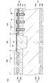
- FIG. 6 is a diagram for explaining the method for manufacturing the semiconductor device according to the first embodiment.
- FIG. 6 is a diagram for explaining the method for manufacturing the semiconductor device according to the first embodiment.
- FIG. 6 is a diagram for explaining the method for manufacturing the semiconductor device according to the first embodiment.
- FIG. 6 is a diagram for explaining the method for manufacturing the semiconductor device according to the first embodiment.
- FIG. 6 is a diagram for explaining the method for manufacturing the semiconductor device according to the first embodiment.
- FIG. 6 is a diagram for explaining the method for manufacturing the semiconductor device according to the first embodiment.
- FIG. 6 is a diagram for explaining the method for manufacturing the semiconductor device according to the first embodiment.
- FIG. It is a figure explaining the manufacturing method of the semiconductor device which concerns on a modification.
- FIG. 6 is a diagram illustrating a method for manufacturing a semiconductor device according to Example 2.
- FIG. 6 is a diagram illustrating a method for manufacturing a semiconductor device according to Example 2.
- FIG. 6 is a diagram illustrating a method for manufacturing a semiconductor device according to Example 2.
- FIG. 6 is a diagram illustrating a method for manufacturing a semiconductor device according to Example 3.
- FIG. 6 is a diagram illustrating a method for manufacturing a semiconductor device according to Example 3.
- FIG. 6 is a diagram illustrating a method for manufacturing a semiconductor device according to Example 3.
- FIG. It is sectional drawing of the semiconductor device which concerns on other embodiment. It is sectional drawing of the semiconductor device which concerns on other embodiment.
- the semiconductor device 10 includes a semiconductor substrate 12, a metal layer formed on the front surface and the back surface of the semiconductor substrate 12, an insulating film, and the like.
- a diode region 20, an IGBT region 40, and a boundary region 80 are formed in the semiconductor substrate 12.
- a boundary region 80 is formed between the diode region 20 and the IGBT region 40.
- An anode electrode 22 is formed on the surface of the semiconductor substrate 12 in the diode region 20.
- An emitter electrode 42 is formed on the surface of the semiconductor substrate 12 in the IGBT region 40.
- a common electrode 60 is formed on the back surface of the semiconductor substrate 12.
- an anode layer 26 In the diode region 20, an anode layer 26, a diode drift layer 28, and a cathode layer 30 are formed.
- the anode layer 26 is p-type.
- the anode layer 26 includes an anode contact region 26a and a low concentration anode layer 26b.
- the anode contact region 26 a is formed in an island shape in a range exposed on the surface of the semiconductor substrate 12.
- the anode contact region 26a has a high impurity concentration.
- the anode contact region 26 a is ohmically connected to the anode electrode 22.
- the low concentration anode layer 26b is formed on the lower side and the side of the anode contact region 26a and covers the anode contact region 26a.
- the impurity concentration of the low concentration anode layer 26b is lower than that of the anode contact region 26a.
- the diode drift layer 28 is formed below the anode layer 26.
- the diode drift layer 28 is n-type.
- the diode drift layer 28 includes an upper drift layer 28a and a lower drift layer 28b.
- the upper drift layer 28a has a lower impurity concentration than the lower drift layer 28b.
- the cathode layer 30 is formed below the diode drift layer 28.
- the cathode layer 30 is formed in a range exposed on the back surface of the semiconductor substrate 12.
- the cathode layer 30 is n-type and has a high impurity concentration.
- the cathode layer 30 is ohmically connected to the common electrode 60.
- the anode layer 26, the diode drift layer 28, and the cathode layer 30 form a diode.
- an emitter region 44 In the IGBT region 40, an emitter region 44, a body layer 48, an IGBT drift layer 50, a collector layer 52, a gate electrode 54, and the like are formed.
- a plurality of trenches are formed on the surface of the semiconductor substrate 12 in the IGBT region 40.
- a gate insulating film 56 is formed on the inner surface of each trench.
- a gate electrode 54 is formed inside each trench. The surface of the gate electrode 54 is covered with an insulating film 58. The gate electrode 54 is insulated from the emitter electrode 42.
- the emitter region 44 is formed in an island shape in a range exposed on the surface of the semiconductor substrate 12.
- the emitter region 44 is formed in a range in contact with the gate insulating film 56.
- the emitter region 44 is n-type and has a high impurity concentration.
- the emitter region 44 is ohmically connected to the emitter electrode 42.
- the body layer 48 is p-type.
- the body layer 48 includes a body contact region 48a and a low concentration body layer 48b.
- the body contact region 48 a is formed in an island shape in a range exposed on the surface of the semiconductor substrate 12.
- the body contact region 48 a is formed between the two emitter regions 44.
- the body contact region 48a has a high impurity concentration.
- the body contact region 48 a is ohmically connected to the emitter electrode 42.
- the low concentration body layer 48b is formed under the emitter region 44 and the body contact region 48a.
- the low concentration body layer 48 b is formed in a shallower range than the lower end of the gate electrode 54.
- the impurity concentration of the low-concentration body layer 48b is lower than that of the body contact region 48a.
- the emitter region 44 is separated from the IGBT drift layer 50 by the low-concentration body layer 48b.
- the gate electrode 54 is opposed to the low-concentration body layer 48 b in a range separating the emitter region 44 and the IGBT drift layer 50 through the gate insulating film 56.
- the IGBT drift layer 50 is formed below the body layer 48.
- the IGBT drift layer 50 is n-type.
- the IGBT drift layer 50 includes a drift layer 50a and a buffer layer 50b.
- the drift layer 50 a is formed below the body layer 48.
- the drift layer 50a has a low impurity concentration.
- the drift layer 50a has substantially the same impurity concentration as the upper drift layer 28a of the diode region 20, and is a layer continuous with the upper drift layer 28a.
- the buffer layer 50b is formed below the drift layer 50a.
- the buffer layer 50b has a higher impurity concentration than the drift layer 50a.
- the buffer layer 50b has substantially the same impurity concentration as the lower drift layer 28b of the diode region 20, and is a layer continuous with the lower drift layer 28b.
- the collector layer 52 is formed below the IGBT drift layer 50.
- the collector layer 52 is formed in a range exposed on the back surface of the semiconductor substrate 12.
- the collector layer 52 is p-type and has a high impurity concentration.
- the collector layer 52 is ohmically connected to the common electrode 60.
- An IGBT is formed by the emitter region 44, the body layer 48, the IGBT drift layer 50, the collector layer 52, and the gate electrode 54.
- a boundary region 80 is formed between the diode region 20 and the IGBT region 40.
- the boundary region is an inactive region where no element structure is formed, and the surface of the boundary region 80 is not in contact with the electrode.
- An insulating film 82 is formed on the surface of the boundary region 80.
- a separation region 70 is formed in the boundary region 80.
- the isolation region 70 is formed in a range from the surface of the semiconductor substrate 12 to a depth deeper than the lower end of the anode layer 26 and the lower end of the body layer 48. More specifically, the isolation region 70 is formed in a range from the surface of the semiconductor substrate 12 to a depth deeper than the lower end of the gate electrode 54.
- the isolation region 70 is in contact with the anode layer 26 and the body layer 48.
- the isolation region 70 is p-type.
- the impurity concentration of the isolation region 70 is higher than that of the low concentration anode layer 26b and the low concentration body layer 48b.
- the bottom surface of the separation region 70 is flat.
- the isolation region 70 prevents the electric field from concentrating between the anode layer 26 and the body layer 48. In particular, since the isolation region 70 is formed to a position deeper than the lower end of the gate electrode 54, the electric field is suppressed from concentrating on the gate electrode 54 near the isolation region 70.
- the upper drift layer 28a and the drift layer 50a are continuous.
- the lower drift layer 28b and the buffer layer 50b are continuous below the continuous upper drift layer 28a and the drift layer 50a.
- the lower drift layer 28b and the buffer layer 50b are continuous.
- the low concentration layer 100 is formed between the cathode layer 30 and the collector layer 52.
- the low concentration layer 100 is n-type and has a lower impurity concentration than the cathode layer 30.
- the electrical resistance of the low concentration layer 100 is higher than both the electrical resistance of the cathode layer 30 and the electrical resistance of the collector layer 52.
- the low concentration layer 100 is formed in a range exposed on the back surface of the semiconductor substrate 12 and is ohmically connected to the common electrode 60. Since the impurity concentration is low, the contact resistance between the low concentration layer 100 and the common electrode 60 is higher than the contact resistance between the cathode layer 30 and the common electrode 60 and the contact resistance between the collector layer 52 and the common electrode.
- the cathode layer 30 in the diode region 20 extends to the lower side of the separation region 70, and is adjacent to the low concentration layer 100 on the lower side of the separation region 70.
- the low concentration layer 100 extends to the boundary between the IGBT region 40 and the boundary region 80, and is adjacent to the collector layer 52 of the IGBT region 40. That is, the boundary 72 between the cathode layer 30 and the low concentration layer 100 is located closer to the diode region 20 than below the body region 48 of the IGBT region 40 when the semiconductor device 10 is viewed in plan. More specifically, the boundary 72 is located below the bottom surface (flat portion) of the separation region 70.
- the boundary 74 between the collector layer 52 and the low concentration layer 100 is located below the inclined portion of the isolation region 70 and at the same time below the body region 48 of the IGBT region 40.
- a carrier lifetime control region 39 is formed in the upper drift layer 28 a of the diode drift layer 28.
- the carrier lifetime control region 39 there are crystal defects formed by implanting charged particles into the semiconductor substrate 12.
- the crystal defect density in the carrier lifetime control region 39 is extremely higher than the surrounding upper drift layer 28a.
- the carrier lifetime control region 39 has a depth near the anode layer 26 and is deeper than the lower end of the separation region 70.
- the carrier lifetime control region 39 extends from the diode region 20 into the boundary region 80 and does not enter the IGBT region 40.
- the reference number 39a indicates the end of the carrier lifetime control area 39 on the IGBT area 40 side.
- An end 39 a of the carrier lifetime control region 39 is located inside the boundary region 80 and below the separation region 70. More specifically, the end portion 39 a is located below the bottom surface (flat portion) of the separation region 70. Further, the end portion 39 a is located above the low concentration layer 100.
- the structure of the boundary region 80 shown in FIG. 1 extends between the diode region 20 and the IGBT region 40. That is, between the diode region 20 and the IGBT region 40, the low concentration layer 100, the boundary 72, the boundary 74, and the end portion 39 a of the carrier lifetime control region 39 extend along the separation region 70.
- holes flow from the common electrode 60 to the emitter electrode 42 through the collector layer 52, the IGBT drift layer 50, the low-concentration body layer 48b, and the body contact region 48a. That is, a current flows from the common electrode 60 to the emitter electrode 42. Electrons and holes flow into the IGBT drift layer 50, and the resistance is reduced by conductivity modulation. This reduces the on-voltage during the IGBT operation.
- the low concentration layer 100 is formed under the isolation region 70.
- the low concentration layer 100 has a higher electrical resistance than the cathode layer 30 and the collector layer 52 and has a high contact resistance with the common electrode 60, and therefore, carriers between the semiconductor substrate 12 and the common electrode 60 through the low concentration layer 100. Is difficult to move. As a result, the carrier density is low in the semiconductor substrate 12 on the upper side of the low concentration layer 100. For this reason, it is suppressed that the holes supplied to the IGBT drift layer 50 move to the boundary region 80 side and flow into the low concentration layer 100.
- the low concentration layer 100 exists between the collector layer 52 and the cathode layer 30 and the distance from the IGBT drift layer 50 to the cathode layer 30 is long, the low concentration layer 100 is supplied to the IGBT drift layer 50. The movement of the holes toward the cathode layer 30 is suppressed. Thus, since a hole is suppressed from moving from the IGBT area
- a portion of the body layer 48 of the IGBT region 40 close to the diode region 20, and a portion of the IGBT drift layer 50 and the cathode layer 30 of the diode region 20 close to the IGBT region 40 serve as parasitic diodes. May work.
- carriers holes in the semiconductor device 10
- Carriers accumulate in the drift layer.
- the forward voltage of the diode region 40 increases.
- the parasitic diode described above is easy to operate when the diode is on.
- the number of carriers moving from the IGBT drift layer 50 side to the boundary region 80 side increases, and the carrier concentration of the drift layer in the boundary region 80 is reduced despite the formation of the carrier lifetime control region 39. The effect of reducing cannot be obtained sufficiently.
- the low concentration layer 100 is formed under the separation region 70 of the boundary region 80.
- the low concentration layer 100 has a higher electrical resistance than the cathode layer 30 and the collector layer 52 and has a higher contact resistance with the common electrode 60, and thus the parasitic diode is less likely to operate. That is, carriers are unlikely to accumulate in the drift layer in the boundary region 80.
- the diode performs a reverse recovery operation. That is, holes that existed in the diode drift layer 28 when the forward voltage is applied are discharged to the anode electrode 22, and electrons that existed in the diode drift layer 28 when the forward voltage is applied are discharged to the common electrode 60.
- Carriers may accumulate in the IGBT drift layer 50 in the boundary region 80. As the number of carriers accumulated in the IGBT drift layer 50 in the boundary region 80 increases, the reverse recovery current increases and the recovery characteristics of the diode deteriorate.
- the low concentration layer 100 is formed under the isolation region 70, the accumulation of carriers in the IGBT drift layer 50 in the boundary region 80 is suppressed when the diode is on.
- an increase in reverse recovery current is suppressed. That is, the deterioration of the recovery characteristics of the diode is suppressed.
- a carrier lifetime control region 39 is formed in the diode drift layer 28 .
- the crystal defects in the carrier lifetime control region 39 function as carrier recombination centers. Therefore, during the reverse recovery operation, many of the carriers in the diode drift layer 28 disappear by recombination in the carrier lifetime control region 39. Therefore, in the semiconductor device 10, the reverse recovery current generated during the reverse recovery operation is suppressed.
- the carrier lifetime control region 39 extends to the lower side of the separation region 70. Accordingly, carriers existing in the diode drift region 28 below the isolation region 70 are recombined in the carrier lifetime control region 39. This prevents a high current from being generated in the vicinity of the separation region 70 during the reverse recovery operation.
- the low concentration layer 100 is provided between the collector layer 52 and the cathode layer 30.
- an effect of suppressing an increase in on-voltage during the IGBT operation can be obtained.
- the diode when the diode is operated, it is constituted by a parasitic diode (a portion close to the diode region 20 in the body layer 48 of the IGBT region 40, an IGBT drift layer 50, and a portion close to the IGBT region 40 in the cathode layer 30 of the diode region 20). The effect of improving the recovery characteristics at the time of reverse diode recovery can be obtained.
- the parasitic diode is difficult to operate, so that the carrier lifetime control region has a sufficient effect of attenuating carriers. This is effective for improving the recovery characteristics of the diode.
- the end 39 a of the carrier lifetime control region 39 is located under the separation region 70. Even if the position of the end 39a (position in the width direction of the separation region 70 (left and right direction in FIG. 1)) is shifted under the separation region 70 due to a manufacturing error, the area of the carrier lifetime control region 39 in the diode region 20 Will not change. Further, as described above, the current flowing through the diode drift layer 28 under the isolation region 70 is small. Therefore, even if the characteristics of the diode drift layer 28 under the isolation region 70 change due to the position of the end 39a being shifted, the influence on the reverse recovery characteristics of the diode is small. For this reason, in the semiconductor device 10, the reverse recovery characteristic of the diode is unlikely to fluctuate even if the position of the end 39a is shifted. That is, the reverse recovery characteristics of the diode are unlikely to vary when the semiconductor device 10 is mass-produced.
- Method for manufacturing semiconductor device Next, a method for manufacturing the semiconductor device 10 will be described. After a plurality of element structures of the semiconductor device 10 according to FIG. 1 are formed on a semiconductor wafer, the semiconductor device 10 is manufactured by separating each semiconductor device by dicing or the like. Hereinafter, first to third manufacturing methods for forming the element structure of the semiconductor device 10 on a semiconductor wafer will be described.
- the first manufacturing method of the semiconductor device 10 includes a mask process, a crystal defect forming process, an ion implantation process, and an annealing process.
- a mask is disposed on the back side of the diode formation region (region where the diode region of the semiconductor device is formed) of the semiconductor wafer or on the back side of the IGBT formation region (region where the IGBT region of the semiconductor device is formed).
- the mask material may be any material that can shield charged particles and impurity ions, and silicon (Si) or the like can be preferably used.
- charged particles ions, neutrons, electron beams, etc.
- irradiation with charged particles may be performed through an energy absorbing material made of aluminum or the like.
- impurity ions having a conductivity type opposite to the side on which the mask is disposed are implanted a plurality of times into the back surface of the semiconductor wafer to form an ion implantation region.
- impurity ions having a conductivity type opposite to the side on which the mask is disposed are implanted a plurality of times into the back surface of the semiconductor wafer to form an ion implantation region.
- p-type impurity ions are implanted.
- n-type impurity ions are implanted.
- the multiple ion implantation steps include a first ion implantation step in which ions are implanted in a first direction that forms an acute angle with the back surface of the semiconductor wafer from the region where the mask is formed toward the region where the mask is not formed, A second ion implantation step of performing ion implantation in a second direction intersecting with the one direction.
- the first direction is a direction that forms an acute angle with the back surface of the semiconductor wafer from the IGBT forming region side toward the diode forming region side.
- the first direction is a direction that forms an acute angle with the back surface of the semiconductor wafer from the diode formation region side toward the IGBT formation region side.
- Either the first ion implantation step or the second ion implantation step may be performed first, whereby a low ion implantation region can be formed between the diode formation region and the IGBT formation region.
- annealing step annealing treatment is performed on the ion implantation region and the low ion implantation region.
- the mask disposed in the mask process can be used as a mask for shielding impurity ions of the first conductivity type in the ion implantation process, and can be used as a mask for shielding charged particles in the crystal defect forming process.
- the first manufacturing method will be described more specifically as Example 1 with reference to FIGS. 2 to 8 illustrating the method for manufacturing a semiconductor device according to the embodiment.
- FIG. 2 is a view showing a cross section of a part of a semiconductor wafer according to the first manufacturing method of the semiconductor device 10.
- a wafer 610 shown in FIG. 2 shows a state before the carrier lifetime control region 39, the cathode layer 30, the low concentration layer 100, and the common electrode 60 of the semiconductor device 10 are formed. Is already formed.
- a p-type collector layer 652 is formed on the back side of the wafer 610.
- a region that becomes the diode region 20 of the semiconductor device 10 of FIG. 1 is a diode formation region 620
- a region that becomes the IGBT region 40 is an IGBT formation region 640
- a region that becomes the boundary region 80 is a boundary.
- a formation region 680 is shown. Components similar to those of the semiconductor device 10 of FIG. 1 are denoted by the same reference numerals.
- the carrier lifetime control region 39, the cathode layer 30, and the low concentration layer 100 of the semiconductor device 10 are formed.
- a mask 701 is disposed on the back side of the IGBT formation region of the wafer 610.
- the mask 701 is used as a mask for shielding impurity ions of the first conductivity type in the ion implantation process, and is used as a mask for shielding charged particles in the crystal defect formation process.
- ribs 661 are provided on the periphery of the wafer 610, and the element structure shown in FIG. 2 is formed in the element formation region inside the ribs 661.
- FIG. 4 is a view showing the wafer 610 with the mask 701 installed in the same cross section as FIG. As shown in FIG. 4, a mask 701 is opened in a part of the diode formation region 620 and the boundary region 680 that form the carrier lifetime control region 39. The position of the end portion 701 a of the mask 701 is adjusted according to the position of the end portion 39 a of the carrier lifetime control region 39.
- a crystal defect forming step is performed.
- charged particles are irradiated from the back surface side of the mask 701 from the direction perpendicular to the back surface of the wafer 610 to form crystal defects in the diode forming region 620 of the wafer 610.
- the charged particles are irradiated with the irradiation energy adjusted so as to stop at the upper drift layer 28 a of the diode drift layer 28.
- a region having a high crystal defect density is formed in the upper drift layer 28 a and becomes a carrier lifetime control region 39.
- the position of the end portion 39a of the carrier lifetime control region 39 substantially coincides with the end portion 701a of the mask 701 on the diode forming region 620 side.
- n-type impurity ions are implanted twice into the back surface of the wafer 610, and an ion implantation region in which n-type ions are implanted into a part of the collector layer 652 on the back surface of the wafer 610 is formed.
- the direction of these two ion implantations is from the IGBT formation region 640 side (region side where the mask is formed in the mask process) to the diode formation region 620 side (region where the mask is not formed in the mask process).
- a direction forming an acute angle with the back surface of the semiconductor wafer hereinafter referred to as a first direction, which is a direction indicated by a dashed arrow 662 in FIG. 6.
- a second direction which is a direction indicated by a solid arrow 664 in FIG. 6).
- the second direction intersects the first direction.
- n-type ions are implanted into the portion 600 of the collector layer 652 when n-type ion implantation is performed in the second direction.
- n-type ions are not implanted into the portion 600.
- the portion 630 of the collector layer 652 on the side closer to the diode formation region 620 than the portion 600 N-type ions are implanted.
- a first direction that forms an acute angle with the back surface of the semiconductor wafer from the IGBT formation region 640 side to the diode formation region 620 side and a second direction that intersects the first direction (more specifically, from the diode formation region 620 side).
- the n-type ion concentration implanted into the portion 600 is lower than the n-type ion concentration implanted into the portion 630.
- the portion 600 is a low ion implantation region, and is formed between the diode formation region 620 and the IGBT formation region 640 along the end portion 701a of the mask 701 on the diode formation region 620 side.
- the end of the portion 600 on the diode formation region 620 side is defined as a boundary 672, and the end of the IGBT formation region 640 side is defined as a boundary 674.
- FIG. 7 is a view schematically showing a part of the wafer 610 and the mask 701 shown in FIG. 6, and includes an end 701a of the mask 701 and a collector layer 652 (including the portion 600 and the portion 630) located in the vicinity thereof. ).
- the positions of points A, B, and C in FIG. 7 coincide with the end portion 701 a of the mask 701.
- a line segment AB is the distance between the back surface of the wafer 610 and the surface of the mask 701 on the wafer 610 side, and is denoted by d1.
- a line segment BC is the thickness of the mask 701 and is d2.
- the line segment CD schematically shows the path of the charged particle in the ion implantation in the first direction regulated by the end 701a, and the point D is at the same position as the boundary 672. Assuming that the angle formed by the line segment CD and the back surface of the wafer 610 is ⁇ 1 (0 ⁇ 1 ⁇ 90 °), the angle formed by the charged particle path in the first direction ion implantation and the back surface of the wafer 610 is ⁇ 1.
- the line segment BE schematically shows the path of the charged particle in the ion implantation in the second direction regulated by the end 701a, and the point E is at the same position as the boundary 674. If the angle formed by the line segment BE and the back surface of the wafer 610 is ⁇ 2 (0 ⁇ 2 ⁇ 90 °), the angle formed by the path of the charged particles in the ion implantation in the second direction and the back surface of the wafer 610 is ⁇ 2.
- the length of the line segment AD is (d1 + d2) / tan ⁇ 1, and indicates the distance in the planar direction of the wafer 610 from the end 701a to the boundary 672.
- the length of the line segment AE is d1 / tan ⁇ 2, and indicates the distance in the planar direction of the wafer 610 from the end 701a to the boundary 674. Therefore, the distance DE between the boundary 672 and the boundary 672 can be expressed by the following equation (1). (D1 + d2) / tan ⁇ 1 + d1 / tan ⁇ 2 (1)
- Example 1 the value of ⁇ 2 is adjusted using the above equation (1) so that the low concentration layer 100 does not penetrate to the lower side of the body layer 48 in the IGBT region 40.
- the mask 701 is removed, and then an annealing process for the wafer 610 is performed.
- the annealing process is performed on the portion 600 and the portion 630 which are ion implantation regions.
- the portion 630 becomes the n-type cathode layer 30, and the portion 600 becomes the low-concentration layer 100 in which the n-type impurity concentration is lower than that of the cathode layer 30.
- the back surface of the wafer 610 can include three layers of the collector layer 52, the low concentration layer 100, and the cathode layer 30.
- the semiconductor device 10 according to the embodiment can be formed by forming the common electrode 60 shown in FIG. 1 on the back surface of the wafer 610 shown in FIG. 8 and dicing the semiconductor electrode into individual semiconductor devices.
- a mask is arranged on the back side of either the diode formation region or the IGBT formation region of the semiconductor wafer.
- ion implantation is performed in a direction (first direction) that forms an acute angle with the back surface of the semiconductor wafer from the IGBT formation region side to the diode formation region side, and from the diode formation region side to the IGBT formation region side.
- ion implantation is performed in a direction (second direction) that forms an acute angle with the back surface of the semiconductor wafer.
- a low ion implantation region is formed between the diode formation region and the IGBT formation region, in which one of the first direction ion implantation and the second direction ion implantation is shielded and does not reach.
- a region with a low impurity concentration can be formed between the diode region and the IGBT region by performing an annealing process after forming the low ion implantation region.
- a mask for shielding impurity ions of the first conductivity type in the ion implantation step can be used as a mask for shielding charged particles in the crystal defect forming step. Since one mask can be used in combination in the ion implantation process and the crystal defect formation process, the manufacturing process is simplified.
- the position of the edge of the mask to be arranged in the mask process is matched with the position of the edge of the carrier lifetime control region, and then the mask is used in the ion implantation process.
- the boundary between the low concentration layer and the cathode layer is located closer to the diode region than the end of the carrier lifetime control region, Can be located closer to the IGBT region than the end of the carrier lifetime control region. That is, the end of the carrier lifetime control region can be positioned above the low concentration layer. Since the position of the end of the carrier lifetime control region and the position of the low-concentration layer can be appropriately aligned using one mask, the manufacturing process is simplified.
- the positions of the edge portions of the carrier lifetime control region and the positions of the low-concentration layers may be shifted due to the shift of the positions of the plurality of masks. Therefore, it is not necessary to align the positions of the plurality of masks.
- the second direction is a direction from the diode formation region side where the mask is not formed in the mask process to the IGBT formation region side where the mask is formed in the mask process, but is not limited thereto.
- the second direction is a direction intersecting the first direction (a direction not parallel to the first direction), and thereby, ion implantation in the first direction and the second direction between the diode formation region and the IGBT formation region. It is only necessary to form a portion (a portion that becomes a low ion implantation region) where only one of the first and second ion implantations is shielded and does not reach. For example, as shown in FIG.
- the second direction intersects the first direction.
- the direction may be perpendicular to the back surface of the semiconductor wafer.
- the boundary 674a between the low concentration layer 102a and the IGBT formation region 640 is the diode formation of the mask 701. It coincides with the end portion 701a on the region 620 side. Also, as shown in FIG.
- the second direction is the IGBT formation region side. From the back surface of the semiconductor wafer toward the diode forming region side and an acute angle ⁇ 21, and ⁇ 21> ⁇ 11. Also in this case, the second direction intersects the first direction, and a low ion implantation region can be formed on the back surface of the semiconductor wafer.
- the boundary 674b between the low concentration layer 102b and the IGBT formation region 640 is closer to the diode formation region 640 side than the end portion 701a of the mask 701 on the diode formation region 620 side.
- a mask 701 can be attached to the back surface of the wafer 610 using a resist 703 or the like.
- the boundary 674c between the low concentration layer 102c and the IGBT formation region 640 is on the diode formation region 620 side of the mask 701. It coincides with the end 701a.
- the second manufacturing method of the semiconductor device 10 includes a mask step of arranging a mask on the back surface side of the diode forming region or the IGBT forming region of the semiconductor wafer, and charged particles on the back surface of the semiconductor wafer from the back surface side of the mask.
- a laser annealing step of performing a laser annealing process on the ion implantation region in a state where the mask is arranged.
- Example 2 the second manufacturing method will be specifically described as Example 2 with reference to FIGS. 12 to 14 illustrating the method for manufacturing the semiconductor device 10 according to the embodiment.
- FIG. 12 shows the wafer 710 after completion of the crystal defect forming step with respect to the wafer 610 shown in FIG.
- a carrier lifetime control region 39 is formed in the upper drift layer 28 a of the diode drift layer 28 of the wafer 710.
- a mask 701 is disposed on the back side of the wafer 710 as in FIG.
- the same components as those in FIGS. 1 and 2 are denoted by the same reference numerals.
- n-type impurity ions are implanted into the back surface of the wafer 710, and n-type ions are implanted into a part of the collector layer 652 on the back surface of the wafer 710 as shown in FIG.
- An ion implantation region 730 is formed.
- a laser annealing process is performed in a state where the mask 701 is disposed.
- the ion implantation region is annealed by laser annealing.
- ions are sufficiently activated in a portion that is in a high energy state, while the vicinity of the boundary with the region where the mask is disposed is sufficient for activating the ions. Can't get enough energy.
- FIG. 14 when a laser is irradiated in the vicinity of the end portion 701a of the mask 701, the portion 120 enters a high energy state, and ions are sufficiently activated, while the portion 120 is closer to the IGBT formation region 640.
- the portion 123 is in a state of insufficient energy, and ions are not sufficiently activated.
- the portion 123 becomes insufficiently activated by ions and becomes a low concentration layer 103 with a low impurity concentration.
- the cathode layer 30 can be formed on the entire back surface of the diode forming region 620.
- the low concentration layer 103 can be formed between the cathode layer 30 and the collector layer 52 along the end portion 701 a of the mask 701.
- the common electrode 60 shown in FIG. 1 is formed on the back surface of the wafer 710 shown in FIG. 14, and the semiconductor device 10 according to the embodiment can be formed by dicing and dividing into individual semiconductor devices.
- a mask for shielding impurity ions of the first conductivity type in the ion implantation step is used in the crystal defect forming step as in the case of using the first manufacturing method. It can be used as a mask for shielding charged particles. Since the position of the end of the carrier lifetime control region and the position of the low-concentration layer can be appropriately aligned using one mask, the manufacturing process is simplified. Further, since one mask is used, it is not necessary to align the positions of the plurality of masks.
- the third manufacturing method of the semiconductor device 10 includes a mask step of arranging a mask on the back surface side of the diode formation region or the IGBT formation region of the semiconductor wafer, and charging from the back surface side of the mask to the back surface of the semiconductor wafer.
- Example 3 the third manufacturing method will be specifically described as Example 3 with reference to FIGS. 15 to 17 illustrating the method for manufacturing the semiconductor device according to the embodiment.
- Example 3 after the wafer 710 shown in FIG. 13 is manufactured by the same manufacturing process as that of Example 2 according to the second manufacturing method, the mask 701 is removed and an annealing process is performed. Thereby, the wafer 810 shown in FIG. 15 can be manufactured.
- the same reference numerals are assigned to the same components as those in FIGS.
- an n-type cathode layer 830 and a p-type collector layer 852 are formed adjacent to each other on the back surface side of the wafer 810.
- the boundary 121 is a boundary between the cathode layer 830 and the collector layer 852.
- Laser annealing is performed on the boundary 121 on the back surface side of the wafer 810 shown in FIG.
- the cathode layer 830 and the collector layer 852 in the vicinity of the boundary 121 are locally heated.
- the n-type impurity in the cathode layer 830 and the p-type impurity in the collector layer 852 cancel each other, and a low-concentration layer 104 having a low impurity concentration is formed as shown in FIG.
- the n-type impurity concentration of the cathode layer 830 may be set higher than the p-type impurity concentration of the collector layer 852.
- FIG. 17 is a view of the wafer 810 viewed from the back side.
- the low concentration layer 104 can be selectively formed in a part between the cathode layer 830 and the collector layer 852.
- Laser annealing is performed on the entire boundary 121 to form the low concentration layer 104 between the cathode layer 830 and the collector layer 852, and then the common electrode 60 shown in FIG.
- the semiconductor device 10 according to the embodiment can be formed by dividing the semiconductor device into individual semiconductor devices.
- a mask for shielding impurity ions of the first conductivity type in the ion implantation step is used as in the case of using the first and second manufacturing methods.
- it can be used as a mask for shielding charged particles. Since the position of the end of the carrier lifetime control region and the position of the low-concentration layer can be appropriately aligned using one mask, the manufacturing process is simplified. Further, since one mask is used, it is not necessary to align the positions of the plurality of masks.
- a semiconductor device in which a low concentration layer is selectively formed in a part between the cathode layer and the collector layer can be manufactured.
- any of the ion implantation process and the crystal defect formation process may be performed first.
- the semiconductor device 10 can be manufactured by methods other than the first, second, and third manufacturing methods described above.
- a first n-type ion implantation is performed on the back surface of the wafer 610 shown in FIG. 3 using a first mask patterned in accordance with the cathode layer 30, and patterned in accordance with the low concentration layer 100.
- the second n-type ion implantation is performed at a lower impurity concentration than the first n-type ion implantation using the second mask, and the p-type is used using the third mask patterned in accordance with the collector layer 52. Can be used, followed by annealing.
- the semiconductor device in which the low concentration layer is n-type has been described as an example, but the low concentration layer may be p-type.
- a p-type low concentration layer may be formed instead of the n-type low concentration layer 100.
- the impurity concentration of the p-type low concentration layer is lower than the p-type impurity concentration of the collector layer 30.
- both the n-type low concentration layer 111 and the p-type low concentration layer 112 can be provided.
- the positions of the n-type low concentration layer 111 and the p-type low concentration layer 112 may be interchanged.
- the same components as those in FIG. 1 are denoted by the same reference numerals.
- the p-type low concentration layer has higher electrical resistance than the cathode layer and the collector layer. For this reason, in the semiconductor device 10 shown in FIG. 1, even if a p-type low concentration layer is formed instead of the n-type low concentration layer 100, the n-type low concentration layer described above is formed. The same effect as when 100 is formed can be obtained. That is, even when the p-type low-concentration layer is formed, it is possible to obtain an effect of suppressing an increase in on-voltage during the IGBT operation and an effect of improving the recovery characteristics of the diode.
- the contact resistance between the p-type low concentration layer and the common electrode is higher than the contact resistance between the cathode layer and the common electrode and the contact resistance between the collector layer and the common electrode, the contact resistance is more effective.
- the n-type low-concentration layer it is possible to suppress an increase in the on-voltage during the IGBT operation and improve the recovery characteristics of the diode.
- the first to third manufacturing methods described above are applied. Is possible.
- the semiconductor device in which the carrier lifetime control region 39 is provided in the diode region 20 has been described as an example.
- the semiconductor device 10b does not have the carrier lifetime control region. May be.
- the effect obtained by providing the low concentration layer in the semiconductor device described above can be obtained even in a semiconductor device not provided with the carrier lifetime control region.
- the same components as those in FIG. 1 are denoted by the same reference numerals.
- a semiconductor device that does not include a carrier lifetime control region can be manufactured by not performing the crystal defect forming step in the first to third manufacturing methods of the semiconductor device 10 described above.
- the first conductivity type is p-type and the second conductivity type is n-type.
- the first conductivity type may be n-type and the second conductivity type may be p-type.
Landscapes
- Engineering & Computer Science (AREA)
- Physics & Mathematics (AREA)
- Condensed Matter Physics & Semiconductors (AREA)
- General Physics & Mathematics (AREA)
- Manufacturing & Machinery (AREA)
- Computer Hardware Design (AREA)
- Microelectronics & Electronic Packaging (AREA)
- Power Engineering (AREA)
- High Energy & Nuclear Physics (AREA)
- Health & Medical Sciences (AREA)
- Toxicology (AREA)
- Metal-Oxide And Bipolar Metal-Oxide Semiconductor Integrated Circuits (AREA)
Priority Applications (6)
| Application Number | Priority Date | Filing Date | Title |
|---|---|---|---|
| KR1020127020205A KR101218459B1 (ko) | 2010-04-02 | 2010-04-02 | 다이오드 영역과 igbt 영역을 갖는 반도체 기판을 구비하는 반도체 장치 |
| DE112010005443.6T DE112010005443B4 (de) | 2010-04-02 | 2010-04-02 | Halbleitervorrichtung mit einem Halbleitersubstrat mit einem Diodenbereich und einem IGBT-Bereich sowie Verfahren zu dessen Herstellung |
| PCT/JP2010/056094 WO2011125156A1 (ja) | 2010-04-02 | 2010-04-02 | ダイオード領域とigbt領域を有する半導体基板を備える半導体装置 |
| JP2011535749A JP5083468B2 (ja) | 2010-04-02 | 2010-04-02 | ダイオード領域とigbt領域を有する半導体基板を備える半導体装置 |
| CN201080065840.6A CN102822968B (zh) | 2010-04-02 | 2010-04-02 | 具备具有二极管区和绝缘栅双极性晶体管区的半导体基板的半导体装置 |
| US13/609,868 US8686467B2 (en) | 2010-04-02 | 2012-09-11 | Semiconductor device comprising semiconductor substrate and having diode region and IGBT region |
Applications Claiming Priority (1)
| Application Number | Priority Date | Filing Date | Title |
|---|---|---|---|
| PCT/JP2010/056094 WO2011125156A1 (ja) | 2010-04-02 | 2010-04-02 | ダイオード領域とigbt領域を有する半導体基板を備える半導体装置 |
Related Child Applications (1)
| Application Number | Title | Priority Date | Filing Date |
|---|---|---|---|
| US13/609,868 Continuation US8686467B2 (en) | 2010-04-02 | 2012-09-11 | Semiconductor device comprising semiconductor substrate and having diode region and IGBT region |
Publications (1)
| Publication Number | Publication Date |
|---|---|
| WO2011125156A1 true WO2011125156A1 (ja) | 2011-10-13 |
Family
ID=44762143
Family Applications (1)
| Application Number | Title | Priority Date | Filing Date |
|---|---|---|---|
| PCT/JP2010/056094 WO2011125156A1 (ja) | 2010-04-02 | 2010-04-02 | ダイオード領域とigbt領域を有する半導体基板を備える半導体装置 |
Country Status (6)
| Country | Link |
|---|---|
| US (1) | US8686467B2 (zh) |
| JP (1) | JP5083468B2 (zh) |
| KR (1) | KR101218459B1 (zh) |
| CN (1) | CN102822968B (zh) |
| DE (1) | DE112010005443B4 (zh) |
| WO (1) | WO2011125156A1 (zh) |
Cited By (10)
| Publication number | Priority date | Publication date | Assignee | Title |
|---|---|---|---|---|
| CN103918078A (zh) * | 2011-11-09 | 2014-07-09 | 丰田自动车株式会社 | 半导体装置及其制造方法 |
| JP2015008235A (ja) * | 2013-06-25 | 2015-01-15 | 富士電機株式会社 | 半導体装置の製造方法 |
| JP2015118989A (ja) * | 2013-12-17 | 2015-06-25 | トヨタ自動車株式会社 | 半導体装置 |
| WO2016204227A1 (ja) * | 2015-06-17 | 2016-12-22 | 富士電機株式会社 | 半導体装置および半導体装置の製造方法 |
| JP2017045949A (ja) * | 2015-08-28 | 2017-03-02 | 株式会社デンソー | 半導体装置 |
| WO2017047276A1 (ja) * | 2015-09-16 | 2017-03-23 | 富士電機株式会社 | 半導体装置および半導体装置の製造方法 |
| JP2017147435A (ja) * | 2016-02-16 | 2017-08-24 | 富士電機株式会社 | 半導体装置 |
| JP2020077674A (ja) * | 2018-11-05 | 2020-05-21 | 富士電機株式会社 | 半導体装置および製造方法 |
| WO2020129186A1 (ja) * | 2018-12-19 | 2020-06-25 | 三菱電機株式会社 | 半導体装置 |
| US10985158B2 (en) | 2018-03-16 | 2021-04-20 | Fuji Electric Co., Ltd. | Semiconductor device with transistor portion having low injection region on the bottom of a substrate |
Families Citing this family (31)
| Publication number | Priority date | Publication date | Assignee | Title |
|---|---|---|---|---|
| JP5937413B2 (ja) * | 2011-06-15 | 2016-06-22 | 株式会社デンソー | 半導体装置 |
| DE112012005981T5 (de) * | 2012-03-05 | 2015-04-09 | Mitsubishi Electric Corporation | Halbleitervorrichtung |
| JP6078961B2 (ja) * | 2012-03-19 | 2017-02-15 | 富士電機株式会社 | 半導体装置の製造方法 |
| JP5787853B2 (ja) * | 2012-09-12 | 2015-09-30 | 株式会社東芝 | 電力用半導体装置 |
| CN104253154A (zh) * | 2013-06-28 | 2014-12-31 | 无锡华润上华半导体有限公司 | 一种具有内置二极管的igbt及其制造方法 |
| JP6119593B2 (ja) * | 2013-12-17 | 2017-04-26 | トヨタ自動車株式会社 | 半導体装置 |
| JP2015176927A (ja) * | 2014-03-13 | 2015-10-05 | 株式会社東芝 | 半導体装置および絶縁ゲート型バイポーラトランジスタ |
| US9419148B2 (en) | 2014-03-28 | 2016-08-16 | Stmicroelectronics S.R.L. | Diode with insulated anode regions |
| CN104979160A (zh) * | 2014-04-04 | 2015-10-14 | 中国科学院微电子研究所 | 半导体器件的制作方法及ti-igbt的制作方法 |
| JP6222702B2 (ja) * | 2014-09-11 | 2017-11-01 | 株式会社東芝 | 半導体装置 |
| JP6197773B2 (ja) * | 2014-09-29 | 2017-09-20 | トヨタ自動車株式会社 | 半導体装置 |
| JP6641983B2 (ja) | 2015-01-16 | 2020-02-05 | 株式会社デンソー | 半導体装置 |
| JP2016174041A (ja) | 2015-03-16 | 2016-09-29 | 株式会社東芝 | 半導体装置 |
| JP6334465B2 (ja) * | 2015-06-17 | 2018-05-30 | 富士電機株式会社 | 半導体装置 |
| JP6588774B2 (ja) * | 2015-09-02 | 2019-10-09 | 株式会社東芝 | 半導体装置 |
| JP6445952B2 (ja) | 2015-10-19 | 2018-12-26 | 株式会社東芝 | 半導体装置 |
| CN106711232A (zh) * | 2015-11-16 | 2017-05-24 | 上海联星电子有限公司 | 一种快恢复二极管及其制作方法 |
| WO2018016208A1 (ja) * | 2016-07-19 | 2018-01-25 | 三菱電機株式会社 | 半導体装置及びその製造方法 |
| JP6801324B2 (ja) * | 2016-09-15 | 2020-12-16 | 富士電機株式会社 | 半導体装置 |
| DE102016117723A1 (de) * | 2016-09-20 | 2018-03-22 | Infineon Technologies Ag | Diodenstruktur eines Leistungshalbleiterbauelements |
| JP6674395B2 (ja) | 2017-02-03 | 2020-04-01 | 株式会社東芝 | 半導体装置 |
| JP6790908B2 (ja) * | 2017-02-23 | 2020-11-25 | 株式会社デンソー | 半導体装置 |
| JP6804379B2 (ja) | 2017-04-24 | 2020-12-23 | 三菱電機株式会社 | 半導体装置 |
| CN110785852B (zh) * | 2017-12-06 | 2023-10-24 | 富士电机株式会社 | 半导体装置 |
| JP6958732B2 (ja) * | 2018-05-10 | 2021-11-02 | 富士電機株式会社 | 半導体装置の製造方法 |
| JP7010184B2 (ja) * | 2018-09-13 | 2022-01-26 | 株式会社デンソー | 半導体装置 |
| JP7099404B2 (ja) * | 2019-05-27 | 2022-07-12 | 株式会社デンソー | 負荷駆動装置 |
| DE102019125007B4 (de) * | 2019-09-17 | 2022-06-30 | Infineon Technologies Ag | RC-IGBT mit einem IGBT-Bereich und einem Diodenbereich und Verfahren zur Herstellung eines RC-IGBT |
| US20220084825A1 (en) * | 2020-09-14 | 2022-03-17 | Mitsubishi Electric Corporation | Semiconductor device and method of manufacturing semiconductor device |
| JP7410900B2 (ja) | 2021-03-17 | 2024-01-10 | 株式会社東芝 | 半導体装置 |
| CN113224131B (zh) * | 2021-04-27 | 2024-02-06 | 上海华虹宏力半导体制造有限公司 | 半导体器件及其制造方法 |
Citations (10)
| Publication number | Priority date | Publication date | Assignee | Title |
|---|---|---|---|---|
| JPH03105977A (ja) * | 1989-09-20 | 1991-05-02 | Hitachi Ltd | 半導体装置 |
| JPH06260499A (ja) * | 1993-03-02 | 1994-09-16 | Casio Comput Co Ltd | 薄膜トランジスタおよびその製造方法 |
| JPH08316480A (ja) * | 1995-03-15 | 1996-11-29 | Toshiba Corp | 高耐圧半導体素子 |
| JPH09326495A (ja) * | 1996-04-03 | 1997-12-16 | Sharp Corp | 薄膜トランジスタ及びその製造方法 |
| JP2000200906A (ja) * | 1999-01-07 | 2000-07-18 | Mitsubishi Electric Corp | 電力用半導体装置およびその製造方法 |
| WO2004109808A1 (ja) * | 2003-06-05 | 2004-12-16 | Mitsubishi Denki Kabushiki Kaisha | 半導体装置およびその製造方法 |
| JP2005142288A (ja) * | 2003-11-05 | 2005-06-02 | Honda Motor Co Ltd | 半導体装置とその製造方法 |
| JP2006093520A (ja) * | 2004-09-27 | 2006-04-06 | Nikon Corp | イオン注入方法、並びに、これを用いた電界効果トランジスタの製造方法及び固体撮像素子の製造方法 |
| JP2008103590A (ja) * | 2006-10-20 | 2008-05-01 | Mitsubishi Electric Corp | 半導体装置およびその製造方法 |
| JP2008192737A (ja) * | 2007-02-02 | 2008-08-21 | Denso Corp | 半導体装置 |
Family Cites Families (6)
| Publication number | Priority date | Publication date | Assignee | Title |
|---|---|---|---|---|
| US5969400A (en) | 1995-03-15 | 1999-10-19 | Kabushiki Kaisha Toshiba | High withstand voltage semiconductor device |
| US6180966B1 (en) * | 1997-03-25 | 2001-01-30 | Hitachi, Ltd. | Trench gate type semiconductor device with current sensing cell |
| JP5332175B2 (ja) | 2007-10-24 | 2013-11-06 | 富士電機株式会社 | 制御回路を備える半導体装置 |
| JP4893609B2 (ja) * | 2007-12-07 | 2012-03-07 | トヨタ自動車株式会社 | 半導体装置とその半導体装置を備えている給電装置の駆動方法 |
| WO2011027474A1 (ja) | 2009-09-07 | 2011-03-10 | トヨタ自動車株式会社 | ダイオード領域とigbt領域を有する半導体基板を備える半導体装置 |
| JP5282823B2 (ja) * | 2009-09-14 | 2013-09-04 | トヨタ自動車株式会社 | ダイオード領域とigbt領域を有する半導体基板を備える半導体装置 |
-
2010
- 2010-04-02 JP JP2011535749A patent/JP5083468B2/ja not_active Expired - Fee Related
- 2010-04-02 WO PCT/JP2010/056094 patent/WO2011125156A1/ja active Application Filing
- 2010-04-02 CN CN201080065840.6A patent/CN102822968B/zh active Active
- 2010-04-02 KR KR1020127020205A patent/KR101218459B1/ko active IP Right Grant
- 2010-04-02 DE DE112010005443.6T patent/DE112010005443B4/de active Active
-
2012
- 2012-09-11 US US13/609,868 patent/US8686467B2/en active Active
Patent Citations (10)
| Publication number | Priority date | Publication date | Assignee | Title |
|---|---|---|---|---|
| JPH03105977A (ja) * | 1989-09-20 | 1991-05-02 | Hitachi Ltd | 半導体装置 |
| JPH06260499A (ja) * | 1993-03-02 | 1994-09-16 | Casio Comput Co Ltd | 薄膜トランジスタおよびその製造方法 |
| JPH08316480A (ja) * | 1995-03-15 | 1996-11-29 | Toshiba Corp | 高耐圧半導体素子 |
| JPH09326495A (ja) * | 1996-04-03 | 1997-12-16 | Sharp Corp | 薄膜トランジスタ及びその製造方法 |
| JP2000200906A (ja) * | 1999-01-07 | 2000-07-18 | Mitsubishi Electric Corp | 電力用半導体装置およびその製造方法 |
| WO2004109808A1 (ja) * | 2003-06-05 | 2004-12-16 | Mitsubishi Denki Kabushiki Kaisha | 半導体装置およびその製造方法 |
| JP2005142288A (ja) * | 2003-11-05 | 2005-06-02 | Honda Motor Co Ltd | 半導体装置とその製造方法 |
| JP2006093520A (ja) * | 2004-09-27 | 2006-04-06 | Nikon Corp | イオン注入方法、並びに、これを用いた電界効果トランジスタの製造方法及び固体撮像素子の製造方法 |
| JP2008103590A (ja) * | 2006-10-20 | 2008-05-01 | Mitsubishi Electric Corp | 半導体装置およびその製造方法 |
| JP2008192737A (ja) * | 2007-02-02 | 2008-08-21 | Denso Corp | 半導体装置 |
Cited By (26)
| Publication number | Priority date | Publication date | Assignee | Title |
|---|---|---|---|---|
| US9887190B2 (en) | 2011-11-09 | 2018-02-06 | Toyota Jidosha Kabushiki Kaisha | Semiconductor device and method for manufacturing the same |
| JPWO2013069113A1 (ja) * | 2011-11-09 | 2015-04-02 | トヨタ自動車株式会社 | 半導体装置およびその製造方法 |
| US9397206B2 (en) | 2011-11-09 | 2016-07-19 | Toyota Jidosha Kabushiki Kaisha | Semiconductor device and method for manufacturing the same |
| CN103918078B (zh) * | 2011-11-09 | 2016-09-14 | 丰田自动车株式会社 | 半导体装置及其制造方法 |
| CN103918078A (zh) * | 2011-11-09 | 2014-07-09 | 丰田自动车株式会社 | 半导体装置及其制造方法 |
| JP2015008235A (ja) * | 2013-06-25 | 2015-01-15 | 富士電機株式会社 | 半導体装置の製造方法 |
| JP2015118989A (ja) * | 2013-12-17 | 2015-06-25 | トヨタ自動車株式会社 | 半導体装置 |
| US10756182B2 (en) | 2015-06-17 | 2020-08-25 | Fuji Electric Co., Ltd. | Semiconductor device and method of manufacturing semiconductor device |
| JPWO2016204227A1 (ja) * | 2015-06-17 | 2017-09-28 | 富士電機株式会社 | 半導体装置および半導体装置の製造方法 |
| US10304928B2 (en) | 2015-06-17 | 2019-05-28 | Fuji Electric Co., Ltd. | Semiconductor device and method of manufacturing semiconductor device |
| US11335772B2 (en) | 2015-06-17 | 2022-05-17 | Fuji Electric Co., Ltd. | Semiconductor device and method of manufacturing semiconductor device |
| WO2016204227A1 (ja) * | 2015-06-17 | 2016-12-22 | 富士電機株式会社 | 半導体装置および半導体装置の製造方法 |
| JP2017045949A (ja) * | 2015-08-28 | 2017-03-02 | 株式会社デンソー | 半導体装置 |
| WO2017038389A1 (ja) * | 2015-08-28 | 2017-03-09 | 株式会社デンソー | 半導体装置 |
| US10950446B2 (en) | 2015-09-16 | 2021-03-16 | Fuji Electric Co., Ltd. | Manufacturing method of semiconductor device |
| WO2017047276A1 (ja) * | 2015-09-16 | 2017-03-23 | 富士電機株式会社 | 半導体装置および半導体装置の製造方法 |
| JPWO2017047276A1 (ja) * | 2015-09-16 | 2017-12-28 | 富士電機株式会社 | 半導体装置および半導体装置の製造方法 |
| US10468254B2 (en) | 2015-09-16 | 2019-11-05 | Fuji Electric Co., Ltd. | Semiconductor device and manufacturing method of semiconductor device |
| JP2017147435A (ja) * | 2016-02-16 | 2017-08-24 | 富士電機株式会社 | 半導体装置 |
| US10985158B2 (en) | 2018-03-16 | 2021-04-20 | Fuji Electric Co., Ltd. | Semiconductor device with transistor portion having low injection region on the bottom of a substrate |
| JP2020077674A (ja) * | 2018-11-05 | 2020-05-21 | 富士電機株式会社 | 半導体装置および製造方法 |
| JP7268330B2 (ja) | 2018-11-05 | 2023-05-08 | 富士電機株式会社 | 半導体装置および製造方法 |
| WO2020129186A1 (ja) * | 2018-12-19 | 2020-06-25 | 三菱電機株式会社 | 半導体装置 |
| JPWO2020129186A1 (ja) * | 2018-12-19 | 2021-10-28 | 三菱電機株式会社 | 半導体装置 |
| US11374091B2 (en) | 2018-12-19 | 2022-06-28 | Mitsubishi Electric Corporation | Semiconductor device |
| JP7131632B2 (ja) | 2018-12-19 | 2022-09-06 | 三菱電機株式会社 | 半導体装置 |
Also Published As
| Publication number | Publication date |
|---|---|
| JPWO2011125156A1 (ja) | 2013-07-08 |
| US20130001639A1 (en) | 2013-01-03 |
| CN102822968B (zh) | 2016-08-03 |
| KR20120115529A (ko) | 2012-10-18 |
| DE112010005443T5 (de) | 2013-01-24 |
| US8686467B2 (en) | 2014-04-01 |
| JP5083468B2 (ja) | 2012-11-28 |
| DE112010005443B4 (de) | 2019-03-14 |
| KR101218459B1 (ko) | 2013-01-22 |
| CN102822968A (zh) | 2012-12-12 |
Similar Documents
| Publication | Publication Date | Title |
|---|---|---|
| JP5083468B2 (ja) | ダイオード領域とigbt領域を有する半導体基板を備える半導体装置 | |
| US10629678B2 (en) | Semiconductor device and method of manufacturing semiconductor device | |
| JP6406361B2 (ja) | 半導体装置及びその製造方法 | |
| JP5321669B2 (ja) | 半導体装置 | |
| JP6078961B2 (ja) | 半導体装置の製造方法 | |
| US8748236B2 (en) | Method for manufacturing semiconductor device | |
| JP5499692B2 (ja) | 半導体装置及びその製造方法 | |
| JP5693962B2 (ja) | 逆導電絶縁ゲート・バイポーラ・トランジスタを製造するための方法 | |
| EP2654084B1 (en) | Method of manufacturing a semiconductor device | |
| JP5811861B2 (ja) | 半導体装置の製造方法 | |
| WO2011030454A1 (ja) | ダイオード領域とigbt領域を有する半導体基板を備える半導体装置 | |
| JP5742962B2 (ja) | 半導体装置およびその製造方法 | |
| WO2016204098A1 (ja) | 半導体装置 | |
| JP6611532B2 (ja) | 半導体装置および半導体装置の製造方法 | |
| JP6037495B2 (ja) | 半導体装置およびその製造方法 | |
| JP2010147239A (ja) | 半導体装置及びその製造方法 | |
| JP2011129619A (ja) | 半導体装置の製造方法 | |
| JP2020031155A (ja) | 半導体装置 | |
| WO2014087499A1 (ja) | 半導体装置 | |
| WO2020075248A1 (ja) | 半導体装置及びその製造方法 | |
| JP6665713B2 (ja) | 半導体装置 | |
| JP5751106B2 (ja) | 半導体装置の製造方法 | |
| JP5686033B2 (ja) | 半導体装置の製造方法 | |
| JP5887848B2 (ja) | 半導体装置の製造方法 | |
| JP6569512B2 (ja) | 半導体装置の製造方法 |
Legal Events
| Date | Code | Title | Description |
|---|---|---|---|
| WWE | Wipo information: entry into national phase |
Ref document number: 201080065840.6 Country of ref document: CN |
|
| WWE | Wipo information: entry into national phase |
Ref document number: 2011535749 Country of ref document: JP |
|
| 121 | Ep: the epo has been informed by wipo that ep was designated in this application |
Ref document number: 10849400 Country of ref document: EP Kind code of ref document: A1 |
|
| ENP | Entry into the national phase |
Ref document number: 20127020205 Country of ref document: KR Kind code of ref document: A |
|
| WWE | Wipo information: entry into national phase |
Ref document number: 112010005443 Country of ref document: DE Ref document number: 1120100054436 Country of ref document: DE |
|
| 122 | Ep: pct application non-entry in european phase |
Ref document number: 10849400 Country of ref document: EP Kind code of ref document: A1 |