WO2001079585A1 - Dlc-schichtsystem sowie verfahren zur herstellung eines derartigen schichtsystems - Google Patents
Dlc-schichtsystem sowie verfahren zur herstellung eines derartigen schichtsystems Download PDFInfo
- Publication number
- WO2001079585A1 WO2001079585A1 PCT/EP2000/013299 EP0013299W WO0179585A1 WO 2001079585 A1 WO2001079585 A1 WO 2001079585A1 EP 0013299 W EP0013299 W EP 0013299W WO 0179585 A1 WO0179585 A1 WO 0179585A1
- Authority
- WO
- WIPO (PCT)
- Prior art keywords
- layer
- dlc
- carbon
- sliding
- substrate
- Prior art date
Links
Classifications
-
- H—ELECTRICITY
- H01—ELECTRIC ELEMENTS
- H01J—ELECTRIC DISCHARGE TUBES OR DISCHARGE LAMPS
- H01J37/00—Discharge tubes with provision for introducing objects or material to be exposed to the discharge, e.g. for the purpose of examination or processing thereof
- H01J37/32—Gas-filled discharge tubes
- H01J37/32009—Arrangements for generation of plasma specially adapted for examination or treatment of objects, e.g. plasma sources
- H01J37/32055—Arc discharge
-
- C—CHEMISTRY; METALLURGY
- C23—COATING METALLIC MATERIAL; COATING MATERIAL WITH METALLIC MATERIAL; CHEMICAL SURFACE TREATMENT; DIFFUSION TREATMENT OF METALLIC MATERIAL; COATING BY VACUUM EVAPORATION, BY SPUTTERING, BY ION IMPLANTATION OR BY CHEMICAL VAPOUR DEPOSITION, IN GENERAL; INHIBITING CORROSION OF METALLIC MATERIAL OR INCRUSTATION IN GENERAL
- C23C—COATING METALLIC MATERIAL; COATING MATERIAL WITH METALLIC MATERIAL; SURFACE TREATMENT OF METALLIC MATERIAL BY DIFFUSION INTO THE SURFACE, BY CHEMICAL CONVERSION OR SUBSTITUTION; COATING BY VACUUM EVAPORATION, BY SPUTTERING, BY ION IMPLANTATION OR BY CHEMICAL VAPOUR DEPOSITION, IN GENERAL
- C23C14/00—Coating by vacuum evaporation, by sputtering or by ion implantation of the coating forming material
- C23C14/22—Coating by vacuum evaporation, by sputtering or by ion implantation of the coating forming material characterised by the process of coating
- C23C14/34—Sputtering
- C23C14/35—Sputtering by application of a magnetic field, e.g. magnetron sputtering
-
- C—CHEMISTRY; METALLURGY
- C23—COATING METALLIC MATERIAL; COATING MATERIAL WITH METALLIC MATERIAL; CHEMICAL SURFACE TREATMENT; DIFFUSION TREATMENT OF METALLIC MATERIAL; COATING BY VACUUM EVAPORATION, BY SPUTTERING, BY ION IMPLANTATION OR BY CHEMICAL VAPOUR DEPOSITION, IN GENERAL; INHIBITING CORROSION OF METALLIC MATERIAL OR INCRUSTATION IN GENERAL
- C23C—COATING METALLIC MATERIAL; COATING MATERIAL WITH METALLIC MATERIAL; SURFACE TREATMENT OF METALLIC MATERIAL BY DIFFUSION INTO THE SURFACE, BY CHEMICAL CONVERSION OR SUBSTITUTION; COATING BY VACUUM EVAPORATION, BY SPUTTERING, BY ION IMPLANTATION OR BY CHEMICAL VAPOUR DEPOSITION, IN GENERAL
- C23C16/00—Chemical coating by decomposition of gaseous compounds, without leaving reaction products of surface material in the coating, i.e. chemical vapour deposition [CVD] processes
- C23C16/02—Pretreatment of the material to be coated
- C23C16/0272—Deposition of sub-layers, e.g. to promote the adhesion of the main coating
- C23C16/029—Graded interfaces
-
- C—CHEMISTRY; METALLURGY
- C23—COATING METALLIC MATERIAL; COATING MATERIAL WITH METALLIC MATERIAL; CHEMICAL SURFACE TREATMENT; DIFFUSION TREATMENT OF METALLIC MATERIAL; COATING BY VACUUM EVAPORATION, BY SPUTTERING, BY ION IMPLANTATION OR BY CHEMICAL VAPOUR DEPOSITION, IN GENERAL; INHIBITING CORROSION OF METALLIC MATERIAL OR INCRUSTATION IN GENERAL
- C23C—COATING METALLIC MATERIAL; COATING MATERIAL WITH METALLIC MATERIAL; SURFACE TREATMENT OF METALLIC MATERIAL BY DIFFUSION INTO THE SURFACE, BY CHEMICAL CONVERSION OR SUBSTITUTION; COATING BY VACUUM EVAPORATION, BY SPUTTERING, BY ION IMPLANTATION OR BY CHEMICAL VAPOUR DEPOSITION, IN GENERAL
- C23C16/00—Chemical coating by decomposition of gaseous compounds, without leaving reaction products of surface material in the coating, i.e. chemical vapour deposition [CVD] processes
- C23C16/22—Chemical coating by decomposition of gaseous compounds, without leaving reaction products of surface material in the coating, i.e. chemical vapour deposition [CVD] processes characterised by the deposition of inorganic material, other than metallic material
- C23C16/26—Deposition of carbon only
-
- C—CHEMISTRY; METALLURGY
- C23—COATING METALLIC MATERIAL; COATING MATERIAL WITH METALLIC MATERIAL; CHEMICAL SURFACE TREATMENT; DIFFUSION TREATMENT OF METALLIC MATERIAL; COATING BY VACUUM EVAPORATION, BY SPUTTERING, BY ION IMPLANTATION OR BY CHEMICAL VAPOUR DEPOSITION, IN GENERAL; INHIBITING CORROSION OF METALLIC MATERIAL OR INCRUSTATION IN GENERAL
- C23C—COATING METALLIC MATERIAL; COATING MATERIAL WITH METALLIC MATERIAL; SURFACE TREATMENT OF METALLIC MATERIAL BY DIFFUSION INTO THE SURFACE, BY CHEMICAL CONVERSION OR SUBSTITUTION; COATING BY VACUUM EVAPORATION, BY SPUTTERING, BY ION IMPLANTATION OR BY CHEMICAL VAPOUR DEPOSITION, IN GENERAL
- C23C28/00—Coating for obtaining at least two superposed coatings either by methods not provided for in a single one of groups C23C2/00 - C23C26/00 or by combinations of methods provided for in subclasses C23C and C25C or C25D
- C23C28/04—Coating for obtaining at least two superposed coatings either by methods not provided for in a single one of groups C23C2/00 - C23C26/00 or by combinations of methods provided for in subclasses C23C and C25C or C25D only coatings of inorganic non-metallic material
- C23C28/044—Coating for obtaining at least two superposed coatings either by methods not provided for in a single one of groups C23C2/00 - C23C26/00 or by combinations of methods provided for in subclasses C23C and C25C or C25D only coatings of inorganic non-metallic material coatings specially adapted for cutting tools or wear applications
-
- C—CHEMISTRY; METALLURGY
- C23—COATING METALLIC MATERIAL; COATING MATERIAL WITH METALLIC MATERIAL; CHEMICAL SURFACE TREATMENT; DIFFUSION TREATMENT OF METALLIC MATERIAL; COATING BY VACUUM EVAPORATION, BY SPUTTERING, BY ION IMPLANTATION OR BY CHEMICAL VAPOUR DEPOSITION, IN GENERAL; INHIBITING CORROSION OF METALLIC MATERIAL OR INCRUSTATION IN GENERAL
- C23C—COATING METALLIC MATERIAL; COATING MATERIAL WITH METALLIC MATERIAL; SURFACE TREATMENT OF METALLIC MATERIAL BY DIFFUSION INTO THE SURFACE, BY CHEMICAL CONVERSION OR SUBSTITUTION; COATING BY VACUUM EVAPORATION, BY SPUTTERING, BY ION IMPLANTATION OR BY CHEMICAL VAPOUR DEPOSITION, IN GENERAL
- C23C28/00—Coating for obtaining at least two superposed coatings either by methods not provided for in a single one of groups C23C2/00 - C23C26/00 or by combinations of methods provided for in subclasses C23C and C25C or C25D
- C23C28/04—Coating for obtaining at least two superposed coatings either by methods not provided for in a single one of groups C23C2/00 - C23C26/00 or by combinations of methods provided for in subclasses C23C and C25C or C25D only coatings of inorganic non-metallic material
- C23C28/046—Coating for obtaining at least two superposed coatings either by methods not provided for in a single one of groups C23C2/00 - C23C26/00 or by combinations of methods provided for in subclasses C23C and C25C or C25D only coatings of inorganic non-metallic material with at least one amorphous inorganic material layer, e.g. DLC, a-C:H, a-C:Me, the layer being doped or not
-
- C—CHEMISTRY; METALLURGY
- C23—COATING METALLIC MATERIAL; COATING MATERIAL WITH METALLIC MATERIAL; CHEMICAL SURFACE TREATMENT; DIFFUSION TREATMENT OF METALLIC MATERIAL; COATING BY VACUUM EVAPORATION, BY SPUTTERING, BY ION IMPLANTATION OR BY CHEMICAL VAPOUR DEPOSITION, IN GENERAL; INHIBITING CORROSION OF METALLIC MATERIAL OR INCRUSTATION IN GENERAL
- C23C—COATING METALLIC MATERIAL; COATING MATERIAL WITH METALLIC MATERIAL; SURFACE TREATMENT OF METALLIC MATERIAL BY DIFFUSION INTO THE SURFACE, BY CHEMICAL CONVERSION OR SUBSTITUTION; COATING BY VACUUM EVAPORATION, BY SPUTTERING, BY ION IMPLANTATION OR BY CHEMICAL VAPOUR DEPOSITION, IN GENERAL
- C23C28/00—Coating for obtaining at least two superposed coatings either by methods not provided for in a single one of groups C23C2/00 - C23C26/00 or by combinations of methods provided for in subclasses C23C and C25C or C25D
- C23C28/04—Coating for obtaining at least two superposed coatings either by methods not provided for in a single one of groups C23C2/00 - C23C26/00 or by combinations of methods provided for in subclasses C23C and C25C or C25D only coatings of inorganic non-metallic material
- C23C28/048—Coating for obtaining at least two superposed coatings either by methods not provided for in a single one of groups C23C2/00 - C23C26/00 or by combinations of methods provided for in subclasses C23C and C25C or C25D only coatings of inorganic non-metallic material with layers graded in composition or physical properties
-
- C—CHEMISTRY; METALLURGY
- C23—COATING METALLIC MATERIAL; COATING MATERIAL WITH METALLIC MATERIAL; CHEMICAL SURFACE TREATMENT; DIFFUSION TREATMENT OF METALLIC MATERIAL; COATING BY VACUUM EVAPORATION, BY SPUTTERING, BY ION IMPLANTATION OR BY CHEMICAL VAPOUR DEPOSITION, IN GENERAL; INHIBITING CORROSION OF METALLIC MATERIAL OR INCRUSTATION IN GENERAL
- C23C—COATING METALLIC MATERIAL; COATING MATERIAL WITH METALLIC MATERIAL; SURFACE TREATMENT OF METALLIC MATERIAL BY DIFFUSION INTO THE SURFACE, BY CHEMICAL CONVERSION OR SUBSTITUTION; COATING BY VACUUM EVAPORATION, BY SPUTTERING, BY ION IMPLANTATION OR BY CHEMICAL VAPOUR DEPOSITION, IN GENERAL
- C23C28/00—Coating for obtaining at least two superposed coatings either by methods not provided for in a single one of groups C23C2/00 - C23C26/00 or by combinations of methods provided for in subclasses C23C and C25C or C25D
- C23C28/40—Coatings including alternating layers following a pattern, a periodic or defined repetition
- C23C28/42—Coatings including alternating layers following a pattern, a periodic or defined repetition characterized by the composition of the alternating layers
-
- B—PERFORMING OPERATIONS; TRANSPORTING
- B82—NANOTECHNOLOGY
- B82Y—SPECIFIC USES OR APPLICATIONS OF NANOSTRUCTURES; MEASUREMENT OR ANALYSIS OF NANOSTRUCTURES; MANUFACTURE OR TREATMENT OF NANOSTRUCTURES
- B82Y30/00—Nanotechnology for materials or surface science, e.g. nanocomposites
-
- F—MECHANICAL ENGINEERING; LIGHTING; HEATING; WEAPONS; BLASTING
- F16—ENGINEERING ELEMENTS AND UNITS; GENERAL MEASURES FOR PRODUCING AND MAINTAINING EFFECTIVE FUNCTIONING OF MACHINES OR INSTALLATIONS; THERMAL INSULATION IN GENERAL
- F16C—SHAFTS; FLEXIBLE SHAFTS; ELEMENTS OR CRANKSHAFT MECHANISMS; ROTARY BODIES OTHER THAN GEARING ELEMENTS; BEARINGS
- F16C33/00—Parts of bearings; Special methods for making bearings or parts thereof
- F16C33/02—Parts of sliding-contact bearings
- F16C33/04—Brasses; Bushes; Linings
- F16C33/043—Sliding surface consisting mainly of ceramics, cermets or hard carbon, e.g. diamond like carbon [DLC]
-
- Y—GENERAL TAGGING OF NEW TECHNOLOGICAL DEVELOPMENTS; GENERAL TAGGING OF CROSS-SECTIONAL TECHNOLOGIES SPANNING OVER SEVERAL SECTIONS OF THE IPC; TECHNICAL SUBJECTS COVERED BY FORMER USPC CROSS-REFERENCE ART COLLECTIONS [XRACs] AND DIGESTS
- Y10—TECHNICAL SUBJECTS COVERED BY FORMER USPC
- Y10T—TECHNICAL SUBJECTS COVERED BY FORMER US CLASSIFICATION
- Y10T428/00—Stock material or miscellaneous articles
- Y10T428/24—Structurally defined web or sheet [e.g., overall dimension, etc.]
- Y10T428/24942—Structurally defined web or sheet [e.g., overall dimension, etc.] including components having same physical characteristic in differing degree
- Y10T428/2495—Thickness [relative or absolute]
- Y10T428/24967—Absolute thicknesses specified
- Y10T428/24975—No layer or component greater than 5 mils thick
-
- Y—GENERAL TAGGING OF NEW TECHNOLOGICAL DEVELOPMENTS; GENERAL TAGGING OF CROSS-SECTIONAL TECHNOLOGIES SPANNING OVER SEVERAL SECTIONS OF THE IPC; TECHNICAL SUBJECTS COVERED BY FORMER USPC CROSS-REFERENCE ART COLLECTIONS [XRACs] AND DIGESTS
- Y10—TECHNICAL SUBJECTS COVERED BY FORMER USPC
- Y10T—TECHNICAL SUBJECTS COVERED BY FORMER US CLASSIFICATION
- Y10T428/00—Stock material or miscellaneous articles
- Y10T428/25—Web or sheet containing structurally defined element or component and including a second component containing structurally defined particles
- Y10T428/252—Glass or ceramic [i.e., fired or glazed clay, cement, etc.] [porcelain, quartz, etc.]
-
- Y—GENERAL TAGGING OF NEW TECHNOLOGICAL DEVELOPMENTS; GENERAL TAGGING OF CROSS-SECTIONAL TECHNOLOGIES SPANNING OVER SEVERAL SECTIONS OF THE IPC; TECHNICAL SUBJECTS COVERED BY FORMER USPC CROSS-REFERENCE ART COLLECTIONS [XRACs] AND DIGESTS
- Y10—TECHNICAL SUBJECTS COVERED BY FORMER USPC
- Y10T—TECHNICAL SUBJECTS COVERED BY FORMER US CLASSIFICATION
- Y10T428/00—Stock material or miscellaneous articles
- Y10T428/26—Web or sheet containing structurally defined element or component, the element or component having a specified physical dimension
- Y10T428/263—Coating layer not in excess of 5 mils thick or equivalent
- Y10T428/264—Up to 3 mils
- Y10T428/265—1 mil or less
-
- Y—GENERAL TAGGING OF NEW TECHNOLOGICAL DEVELOPMENTS; GENERAL TAGGING OF CROSS-SECTIONAL TECHNOLOGIES SPANNING OVER SEVERAL SECTIONS OF THE IPC; TECHNICAL SUBJECTS COVERED BY FORMER USPC CROSS-REFERENCE ART COLLECTIONS [XRACs] AND DIGESTS
- Y10—TECHNICAL SUBJECTS COVERED BY FORMER USPC
- Y10T—TECHNICAL SUBJECTS COVERED BY FORMER US CLASSIFICATION
- Y10T428/00—Stock material or miscellaneous articles
- Y10T428/30—Self-sustaining carbon mass or layer with impregnant or other layer
Definitions
- the present invention relates to a layer system according to claim 1, a method according to claim 21 and a device according to claim 40.
- Preferred embodiments of the invention are disclosed in subclaims 2 to 20, 22 to 39 and 41 and in the description, examples and drawings.
- DLC layers diamond-like carbon layers
- HF high-frequency
- Typical wear protection applications include applications in mechanical engineering, such as protection against sliding wear, pitting, cold welding, etc., in particular on components with surfaces that move against one another, such as gears, pump and bucket tappets, piston rings, injector needles, complete bearing sets or their individual components, etc. called, and on the other hand applications in the field of material processing to protect the tools used for machining or forming as well as in injection molds.
- the substrate voltage US drops sharply with increasing substrate surface AS, accompanied by a sharp increase in power loss. Therefore, depending on the performance of the generators used, only a certain maximum area can be coated. Otherwise, insufficient power can either be introduced into the system or the potential difference (substrate voltage) cannot be set sufficiently high in order to achieve the ion plating effect necessary for tightly adhering layers.
- EP 87 836 discloses a DLC layer system with a 0.1-49.1% share of metallic components, which is deposited, for example, by means of cathodic sputtering.
- DE 43 43 354 AI describes a process for producing a multilayer Ti-containing layer system with a hard material layer made of titanium nitrides, titanium carbides and titanium borides and a friction-reducing C-containing surface layer, the Ti and N content being progressively reduced in the direction of the surface ,
- EP-A-651 069 describes a friction-reducing wear protection system consisting of 2 - 5000 alternating DLC and SiDLC layers.
- a process for the deposition of a-DLC layers with an Si intermediate layer and the subsequent a-SiC: H transition zone to improve the adhesion is described in EP-A-600 533.
- Various processes for producing such layers are also described in EP-A-885 983 and EP-A-856 592.
- EP-A-885 983 for example, the plasma is generated by a DC-heated filament and the substrates are subjected to negative direct voltage or MF between 20 and 10,000 kHz (MF frequency in the following means the frequency range between 1 and 10,000 kHz) ,
- US Pat. No. 4,728,529 describes a method for the deposition of DLC using an HF plasma, in which the layer formation takes place in a pressure range between 103 and 1 mbar from an oxygen-free hydrocarbon plasma, to which noble gas or hydrogen is admixed if necessary.
- the process described in DE-C-195 13 614 uses a bipolar substrate voltage with a shorter positive pulse duration in a pressure range between 50-1000 Pa. Layers in the range from 10 nm to 10 ⁇ m and a hardness between 15 - 40 GPa are deposited.
- a CVD ner driving with substrate voltage generated independently of the coating plasma is described in DE-A-198 26 259, preferably bipolar, but also other periodically changed substrate voltages are applied.
- this requires a rela- tivly complex, because in two versions to be provided, electrical supply unit for performing the method.
- US 5,707,748 discloses a layer combination of metal-containing hard material layers (TiN, TiAlVN, WC) and a less hard metal carbide layer with an increasing content of carbon bound graphitically, ie in sp 2 hybridization. Due to the good sliding properties of metal / - or metal carbide / carbon layers (MeC / C), these are preferably used in tribological systems where, in addition to protecting the coated part, the aim is to reduce the frictional forces and / or protect the counter body.
- metal-containing hard material layers TiN, TiAlVN, WC
- MoC / C metal carbide / carbon layers
- MeC / C layers with a high C content have proven to be particularly effective, in which the soft top layer on the one hand achieves a running-in effect and, on the other hand, a lubricating effect for the entire tribosystem by transferring C particles.
- Similar layer combinations with an adhesion-enhancing metallic intermediate layer between the hard material layer and the graphitic carbon-containing metal or MeC layer are described in WO 99-55929.
- the object of the present invention is therefore in particular to provide a DLC or diamond layer with excellent adhesive strength and high wear resistance, which has improved sliding properties and, if desired, run-in properties compared to conventional DLC or diamond layers.
- a DLC sliding layer system can be of advantage for wear protection, corrosion protection and to improve the sliding properties, especially if up to s properties that are difficult to achieve in a layer system are now desired at the same time.
- Another object of the invention is to provide a method and a device for producing a DLC sliding layer system according to the invention.
- a DLC layer system according to the invention is achieved by producing a layer with the following layer structure.
- An adhesive layer composed of the elements Cr or Ti is preferably used, which has proven to be particularly suitable for this purpose.
- transition layer which is preferably designed as a gradient layer, in the course of which the metal content decreases perpendicularly to the substrate surface - and the C content increases.
- the transition layer essentially comprises carbon and at least one element from the group of elements which form the adhesive layer.
- hydrogen may also be present.
- both the transition layer and the adhesive layer contain unavoidable impurities, such as those caused by atoms from the surrounding atmosphere built into the layer, for example the noble gases used in the production, such as argon or xenon.
- the carbon can grow in the direction of the cover layer by increasing, if necessary, different carbidic phases, by increasing the free carbon, or by mixing such phases with the metallic phase of the transition layer.
- the thickness of the gradient or transition layer can, as is known to the person skilled in the art, be adjusted by setting suitable process ramps.
- the increase in the C content or decrease in the metallic phase can take place continuously or in stages.
- a sequence of metal-rich and C-rich individual layers can be provided at least in part of the transition layer for further reduction of layer stresses.
- the material properties (for example modulus of elasticity, structure, etc.) of the adhesive and the abhesive DLC layer are essentially continuously matched to one another by the mentioned configurations of the gradient layer and thus the risk of crack formation along an otherwise occurring metal or Si / DLC layer. Counteracted interface.
- the end of the layer package is formed by a layer consisting essentially of carbon and preferably hydrogen, with a greater layer thickness than the adhesive and transition layer.
- a layer consisting essentially of carbon and preferably hydrogen, with a greater layer thickness than the adhesive and transition layer.
- noble gases such as argon or xenon can also occur here. It is essential here, however, that additional metallic elements or silicon are completely dispensed with.
- the hardness of the entire DLC coating system is set to a value greater than 15 GPa, preferably greater than / equal to 20 GPa, and an adhesive strength better than or equal to HF 3, preferably better than or equal to HF 2, in particular equal to HF 1 according to VDI 3824 sheet 4, is achieved.
- the hardness is measured using the Knoop hardness measurement with o, l N load, i.e. HK0.1 correspond.
- the present DLC layer is characterized by the low coefficient of friction typical of DLC, preferably ⁇ ⁇ 0.3 in the pen / disk test.
- the layer thicknesses are in total> 1 ⁇ m, preferably> 2 ⁇ m, the adhesive layer and the transition layer preferably having layer thicknesses from 0.05 ⁇ m to 1.5 ⁇ m, in particular from 0.1 ⁇ m to 0.8 ⁇ m, while the cover layer preferably has a thickness of Has 0.5 ⁇ m to 20 ⁇ m, in particular 1 ⁇ m to 10 ⁇ m.
- the H content in the cover layer is preferably 5 to 30 atom%, in particular 10-20 atom%.
- deposited DLC layer systems according to the invention show fracture surfaces which, in contrast to conventional DLC layers, do not have a glassy-amorphous but a fine-grained structure, the grain size preferably being ⁇ 300 nm, in particular ⁇ 100 nm.
- the coating shows a multiple service life compared to other DLC layers, such as metal carbon, in particular WC / C layers.
- DLC layers such as metal carbon, in particular WC / C layers.
- DLC layer system with the above properties lie in the first successful combination of large layer thicknesses with excellent adhesive strength, which still have sufficient conductivity to enable a relatively simple process control in industrial production.
- the layer shows a significantly improved adhesion due to its structure and the process steps according to the invention.
- Conventional layer systems require a doping in the functional layer (DLC) to reduce the layer tension, which also reduces the hardness.
- SEM fracture patterns of the layer according to the invention show a fine-grained straight fracture surface.
- Layers with the property profile described above are particularly suitable for applications in mechanical engineering, such as for coating heavily loaded pump or cup tappets and valve drives, cams or camshafts as used for automotive internal combustion engines and transmissions, but also for protection of heavily loaded gears, plungers, pump spindles, etc. Components that require a particularly hard and smooth surface with good sliding properties.
- these layers can be used advantageously for forming (pressing, punching, deep drawing, ...) and injection molding tools due to their high hardness and very smooth surface, but also, with certain restrictions when processing ferrous materials, for cutting tools , especially if a low coefficient of friction combined with high hardness is required for the application.
- the growth rate of the DLC layer is around 1-3 ⁇ m / h, the layer tension for the whole system is 1-4 GPa and thus in the usual range of hard DLC layers.
- the sliding properties achieved with DLC layer systems deposited according to the invention are more favorable than those of other nitridic and / or carbide hard material layers, for example, but do not achieve the extraordinarily small friction coefficients that can be achieved with metal / carbon layers, nor are they suitable as run-in layers.
- the sliding or running-in properties of the DLC layer or the DLC layer system are to be improved further, it is recommended to apply a final softer sliding layer containing a relatively large proportion of graphitic carbon.
- the latter can also be advantageously applied to non-inventive DLC layers and layer systems as well as to diamond layers, in particular to nano-crystal diamond layers.
- a DLC sliding layer system according to the invention is described below, which advantageously, but by no means in a limiting manner, consists of a DLC layer system as described above with a sliding layer placed thereon. Surprisingly, it has been shown that it is possible with very differently structured sliding layers in addition to improving the sliding and possibly running-in properties, to maintain the excellent adhesive strength of the DLC layer system for the DLC sliding layer system despite the increased layer thickness.
- An advantageous embodiment of the friction-reducing layer which is particularly suitable, in particular for use on the inventive DLC layer system described above, consists in a DLC structure without a metallic additional element, but instead with an increasing proportion of sp 2 bonds, preferably in a graphitic layer structure, with which the The hardness of the top layer is reduced, and the sliding and running-in properties are improved.
- Another advantageous embodiment of the sliding layer can be carried out by forming a second, inverse gradient layer in which the metal content increases towards the surface, but the C content decreases.
- the metal content is increased until the coefficient of friction reaches a desired low value.
- one or more metals from the TV, NI subgroup, and Si are preferably used. Cr, W, Ta, ⁇ b and / or Si are particularly preferred.
- the metal content of the layers should be between 0.1 and 50 atom%, preferably between 1 and 20 atom%.
- a further preferred embodiment of the friction-reducing layer can be produced by applying a metallic or carbidic, in particular a Cr or WC intermediate layer to the layer consisting essentially exclusively of carbon and hydrogen, with a gradient top layer similarly formed as the first gradient layer with decreasing metal and increasing C content follows.
- the same or the same metallic elements as in the first gradient layer are advantageously, but not necessarily, used to keep the complexity of the coating device as low as possible.
- the metal content of the layers should be between 0.1 and 50 atom%, preferably between 1 and 20 atom%.
- the hardness of the DLC layer is preferably set to a value greater than 15 GPa, preferably greater than / equal to 20 GPa, and the hardness of the softer sliding layer above it is adjusted as required.
- the integral hydrogen content of the layer system according to the invention is preferably set to a content between 5-30 atom%, in particular between 10-20 atom%.
- the layer roughness can be set to an Ra value of less than 0.04, preferably less than 0.01, or an RzDiN value of less than 0.8, preferably less than 0.5.
- DLC sliding layer systems lie in the combination of the great hardness of the DLC layer, paired with sliding properties which are improved by up to an order of magnitude compared to the already good running behavior of the DLC layer.
- DLC layers also succeed in imparting run-in behavior through initial layer removal and graphitic counter-body lubrication, which can also significantly reduce the wear on an uncoated counter-body.
- a lower Rz or Ra number i.e. a lower roughness of the coated surfaces than with conventionally used hard material layers, in particular applied with the Are method.
- the running-in of the tribosystem can often be disturbed, if not prevented and prevented, in particular by hard roughness peaks, which can result in the partial or total destruction of the surface of a counterbody, in particular if the latter is not itself caused by one Hard layer is protected. This is particularly the case in tribosystems with a high proportion of sliding, such as rocker and slide levers on bucket tappets, different toothing, etc. significant.
- These layers can also be used in the tool area due to their high hardness and very smooth surface, especially for forming (pressing, stamping, deep-drawing, ...) and injection molding tools, but also with certain restrictions when machining iron materials for cutting tools. especially if a particularly low coefficient of friction, possibly combined with a defined run-in effect, is required for the application.
- a polishing effect was observed on the chip discharge surface after only one use (one borehole), which is advantageous, for example, for deep-hole drilling.
- expensive polishing of the chip discharge surfaces can be dispensed with.
- DLC sliding layer systems according to the invention can be deposited smoother than conventional hard material / sliding layer combinations (e.g. TiAlN / / WC / C) deposited, for example, with arc evaporators and can be integrated more easily in a continuous process than, for example, also known Ti-DLC // MoSx layer combinations.
- conventional hard material / sliding layer combinations e.g. TiAlN / / WC / C
- the method according to the invention for producing the DLC layer system is further distinguished by the following features.
- the parts to be coated are cleaned in a manner known for PVD processes and mounted on a holder device.
- holder devices with - depending on the particle geometry - 1, 2 or 3 essentially parallel axes of rotation can be used, whereby a greater loading density can be achieved.
- the holding device with the parts to be coated is brought into the process chamber of a coating system and after pumping down to a starting pressure of less than 10-4 mbar, preferably 10-5 mbar, the process sequence is started.
- the first part of the process is carried out, for example, as a heating process in order to remove the volatile substances still adhering to the surface of the parts.
- an inert gas plasma is preferably ignited by means of a high-current / low-voltage discharge between one or more filaments placed in a ionization chamber adjacent to the process chamber and placed at negative potential and the holding devices with the parts placed at positive potential. This causes intensive electron bombardment and thus heating of the parts.
- the use of an Ar / H2 mixture has proven to be particularly advantageous, since the reducing effect of the hydrogen simultaneously achieves a cleaning effect on the part surfaces.
- the high-current / low-voltage arc discharge can be carried out with a static or advantageously locally variable magnetic field.
- a hollow cathode or another known ion or electron source can also be used.
- an etching process can additionally or alternatively be started as a cleaning process, for example by igniting a low-voltage arc between the ionization chamber and an auxiliary anode, and the ions using a negative bias voltage of 50-300 V are pulled onto the parts.
- the ions bombard the surface there and remove residual impurities. This ensures a clean surface.
- noble gases e.g. Argon also contain hydrogen.
- the etching process can also be carried out by applying a pulsed substrate bias voltage without or with the support of a low-voltage arc as just described, preferably using a medium-frequency bias in the range from 1 to 10,000 kHz, in particular between 20 and 250 kHz.
- a preferably metallic adhesive layer in particular composed of Cr or Ti, is coated with a known PVD or plasma CVD method, such as, for example, by means of vaporization, various ion-plating methods, but preferably by cathodic sputtering evaporated at least one target.
- PVD or plasma CVD method such as, for example, by means of vaporization, various ion-plating methods, but preferably by cathodic sputtering evaporated at least one target.
- a negative substrate bias voltage is applied to the substrate to assist vapor deposition.
- the ion bombardment and the resulting layer compaction during the sputtering process can additionally be driven low-voltage arc and / or a magnetic field applied to stabilize or intensify the plasma, and or by applying a DC bias voltage to the substrate or by applying a medium-frequency bias between the substrate and the process chamber in the range from 1 to 10,000, in particular between 20 to 250 kHz get supported.
- the thickness of the adhesive layer is adjusted in a known manner by a choice of the sputtering or evaporation time and power corresponding to the respective system geometry.
- the transition layer is applied in such a way that, in addition to the plasma-assisted vapor deposition of the adhesive layer components, carbon is simultaneously separated from the gas phase.
- This is preferably done via a plasma CVD process, in which a carbon-containing gas, preferably a hydrocarbon gas, in particular acetylene, is used as the reaction gas.
- a particularly “pulsed”, medium-frequency substrate bias voltage is applied to the substrate and a magnetic field is superimposed.
- the proportion of carbon deposition is increased step by step or continuously as the thickness of the transition layer is increased until finally essentially only carbon deposition takes place.
- the diamond-like carbon layer is then produced as a cover layer by plasma CVD deposition of carbon from the gas phase, a carbon-containing gas, preferably a carbon water gas, in particular acetylene, being used as the reaction gas.
- a substrate bias voltage is maintained on the substrate and the superimposed magnetic field is maintained.
- the reaction gas for the deposition of carbon to form the transition layer and the cover layer made of diamond-like carbon may additionally contain hydrogen and noble gas, preferably argon or xenon, in addition to the carbon-containing gas.
- the set pressure in the process chamber is between 10-4 to 10-2 mbar.
- the substrate bias voltage applied to the substrate during the vapor deposition of the adhesive layer, application of the transition layer and deposition of the cover layer can, in particular when forming the transition layer and the cover layer, an alternating voltage (AC), a direct voltage (DC) or modulated direct voltage superimposed with AC or pulse be, such as in particular a unipolar (negative) or bipolar substrate bias voltage, which is pulsed in a medium frequency range from 1 to 10000 kHz, preferably 20 to 250 kHz.
- the pulse shape can be symmetrical, for example sinusoidal, sawtooth, or rectangular, or asymmetrical, so that long negative and short positive pulse times or large negative and small positive amplitudes are applied.
- a longitudinal magnetic field with a uniform field line course is preferably set during the entire coating process, the magnetic field being changeable laterally and / or spatially, continuously or stepwise.
- a medium-frequency generator is first connected to the mounting device when applying the transition layer, which generator generates its impulse (regulation via control of the power input is also possible, but not preferred) in the form of a sine, or another bipolar or unipolar signal curve.
- the frequency range used is between 1 and approx. 10,000 kHz, preferably between 20 and 250 kHz, the amplitude voltage between 100 and 3,000 V, preferably between 500 and 2,500 V.
- the change in the substrate voltage is preferably carried out by switching over a and medium frequency voltage designed generator.
- a medium frequency voltage is also applied to the substrates for carrying out the etching and adhesive coating process.
- the positive pulse can be applied either shorter or with a lower voltage than the negative pulse, since the electrons follow the field more quickly and due to their low mass when they strike especially lead to additional heating of the parts, which can lead to damage due to overheating, especially with temperature-sensitive base materials.
- a hydrocarbon gas preferably acetylene
- the power of the at least one metallic or Si target is preferably reduced step by step or continuously.
- the target is preferably shut down to a minimum output, which can easily be determined by a person skilled in the art, depending on the hydrocarbon flow achieved, at which stable operation is still possible without any signs of poisoning by the reactive gas.
- the at least one target is then shielded, and preferably switched off, against the process chamber, preferably with one or more movably arranged screens.
- This measure largely prevents the target from being covered with a DLC layer, which means that there is no need for free sputtering between individual DLC coating batches.
- a significant contribution to stabilizing the DLC coating process according to the invention is achieved by forming a longitudinal magnetic field. Unless already used in the previous process step to apply the adhesive layer, this will take place essentially at the same time as the substrate voltage is switched to the medium frequency generator.
- the magnetic field is designed in such a way that the course of the field lines is as uniform as possible in the process chamber.
- current is preferably introduced through two electromagnetic coils essentially delimiting the process chamber on opposite sides in such a way that a co-directional, mutually reinforcing magnetic field is produced on both coils. In the case of smaller chamber dimensions, a sufficient effect can also be achieved with just one coil, if necessary. This results in an approximately uniform distribution of the medium-frequency plasma over larger chamber volumes.
- the growth rate also depends on the load and the holder. In particular, this affects whether the parts to be coated are rotated 1, 2 or 3 times, on magnetic holders, or clamped or plugged in.
- the total mass and plasma continuity of the brackets is also important, for example with lightweight brackets, e.g. by using spoke plates instead of plates made of solid material, higher growth rates and an overall better layer quality.
- additional local magnetic fields - so-called near fields - can be provided in addition to the longitudinal magnetic field (femfield) that penetrates the entire process chamber.
- a magnetron magnet system of the at least one target further preferably permanent magnet systems are attached to the walls delimiting the plasma chamber, which have a similar or the same magnetic effect as the at least one magnetron magnet system.
- Either the same structure can be used for all magnetron and other magnet systems, or the polarities can be reversed. This makes it possible to design the individual near fields of the magnet or magnetron magnet systems as a magnetic enclosure surrounding the process chamber in order to prevent the free electrons from being absorbed on the walls of the process chamber.
- the bias voltage is set either stepwise or continuously to a value above 2000 V, preferably between 2000 and 2500 V. As the voltage increases, the proportion of carbon atoms growing in the graphitic sp 2 bond increases. In this way, in a particularly simple manner, the pure DLC layer deposited beforehand can be given improved sliding properties.
- the process can initially be carried out while maintaining the same parameters as in the previous DLC layer by switching on one or more metallic or metal carbide.
- it has proven to be advantageous either to first reduce the hydrocarbon content in the gas flow, to increase the noble gas content or to carry out both measures together in order to avoid poisoning of the targets and thus unstable process states.
- starting the targets behind initially closed diaphragms can be advantageous in order to avoid possible dropplets on the substrates.
- the output of the at least one target is then gradually or preferably continuously increased to a value at which the layer has certain desired layer properties (coefficient of friction, ).
- the other parameters are preferably left unchanged, however an additional adjustment is possible at any time if desired.
- the process is then preferably completed while keeping the setting constant until a desired layer thickness of the inverse gradient layer is reached.
- a further advantageous possibility for the formation of an inverse gradient layer is obtained if, in addition to or instead of the hydrocarbon gas mentioned, gases containing silicon or silicon and oxygen or nitrogen, such as mono- and disilanes, siloxanes, hexamethyldisiloxane, hexamethyldisilazane, dimethyl diethoxysilane, tetramethysilane etc. are let in to influence the properties of the layer, especially its hardness and coefficient of friction. It is thus also possible to produce a gradient layer with, for example, silicon, oxygen and / or nitrogen content increasing towards the surface, without additionally switching on one or more sputter targets.
- gases containing silicon or silicon and oxygen or nitrogen such as mono- and disilanes, siloxanes, hexamethyldisiloxane, hexamethyldisilazane, dimethyl diethoxysilane, tetramethysilane etc.
- a sliding layer can be applied as a gradient cover layer, either directly on a DLC layer or after applying a metallic or carbide intermediate layer.
- the at least one source used for this is switched on, similarly as already described above, but after a greater reduction to 0% in the carbon content of the process gas.
- Carbide or metallic targets can be used to produce the friction-reducing cover layer, the carbide targets offering the advantage of allowing an overall higher C content with very high resilience of the layers.
- the content of graphitic carbon is in turn adjusted by admitting a C-containing reactive gas, the gas flow advantageously being increased by means of a ramp function after switching on the targets used for producing the MeC / C layer, or with a time delay, and at the end of the coating for is held constant for a certain time.
- a particularly advantageous embodiment of the layer is obtained if a thin (0.01-0.9 ⁇ m) carbide layer, such as a WC layer, is first deposited on the DLC layer.
- carbide layers in particular are particularly suitable as adhesion promoters on a DLC layer that has already been deposited.
- the layer structure is completed by a WC / C layer with an increasing C content and a thickness of approx. 0.1-5 ⁇ m.
- the layer thickness of the MeC / C layer is advantageously chosen to be less than that of the pure DLC layer.
- a further preferred embodiment of an inventive DLC sliding layer system results when the final sliding layer is applied to a diamond layer which has been deposited, for example, by means of a high-current, low-voltage arc discharge or the hot filament technique.
- the magnetic field generating devices are preferably formed by at least one Helmholtz coil, preferably a pair of Helmholtz coils.
- the magnetic field that can be generated or the magnetic flux density can be controlled both locally and in time by the current strength in the coils.
- a further possibility for generating a longitudinal magnetic field arises if two magnetrons are arranged on opposite sides of the recipient, and at least one electromagnetic coil is additionally assigned to each of them.
- the respectively assigned coil is advantageously attached in such a way that it essentially limits the entire lateral circumference of the magnetron arrangement.
- the polarities of the opposite magnetron magnet systems are aligned in opposite directions, i.e. the north pole of one system faces a south pole of the other system and vice versa.
- the respectively assigned coils are connected to a current source in such a way that the fields of the magnetic coils complement one another in a Helmholtz arrangement to form a closed magnetic field and the polarity of the outer poles of the magnetron magnet systems and of the magnetic coils is in the same direction.
- Such devices can advantageously be used both to amplify the magnetron plasma and to increase the ionization during the plasma CVD process.
- the device comprises a device for generating a substrate bias voltage which can change the applied substrate bias voltage continuously or step by step and, accordingly, can also be operated bipolar or unipolar.
- the device is suitable for generating a substrate bias voltage pulsed in the medium frequency range.
- the evaporation devices used in the device include sputtering targets, in particular magnetron sputtering targets, arc sources, thermal evaporators and the like. It is advantageous here that the evaporator device can be separated from the rest of the process chamber, for example by pivoting screens.
- the device advantageously has a substrate heater in the form of inductive heating, radiant heating or the like in order to be able to clean the substrates in one heating step before coating.
- a substrate heater in the form of inductive heating, radiant heating or the like in order to be able to clean the substrates in one heating step before coating.
- the ignition of a plasma is preferably used.
- a low-voltage arc generating device in the device, which comprises an ion source with a filament, preferably a refractory filament, in particular made of tungsten, tantalum or the like in an ionization chamber, as well as an anode and a DC voltage supply.
- the ion source is connected to the negative pole of the DC voltage supply.
- the positive pole of the DC voltage supply can optionally be connected to the anode or the substrate holders, so that a low-voltage arc can be ignited between the ion source and the anode or the ion source and substrates.
- the ion source like the evaporator device, can also be separated from the actual process chamber, e.g. through a pinhole, e.g. made of tungsten, tantalum or a similar refractory metal.
- the substrate holders are movable and can preferably rotate about at least one or more axes.
- the medium-frequency substrate voltage supply and a Helmholtz coil arrangement which can also be implemented using coils attached to the side and comprising two opposing targets, it is possible for the first time on an industrial scale to use a stable medium-frequency plasma to carry out a DLC process even at low pressures , In contrast to DLC layers produced with other systems, the layers produced with them have greatly improved properties.
- DLC sliding layer systems with adjustable sliding and running-in behavior can also be separated.
- Q Further advantages, characteristics and features of DLC sliding layer systems are contained in the feature sets attached to the description.
- Figure 1 shows an inventive device in the cross member
- Figure 2 shows the inventive device of Figure 1 in plan view
- FIG. 6 SEM fracture recording of a DLC layer according to the invention
- FIG. 1 shows a schematic cross section through the process chamber 1 of a coating system according to the invention.
- the parts 2 to be coated are mounted on one or more holding devices 3, which comprise means for producing an at least simple 4, if necessary also double 5 rotation of the parts.
- the holding devices 3 are positioned on a carousel 7 which can additionally be rotated about the system axis 6.
- the different process gases in particular Ar and acetylene, can be fed into the process chamber via gas inlets 8 by means of suitable control devices, not shown here.
- a pump station 9 suitable for high vacuum is flanged to the chamber.
- An ion source 10 is preferably arranged in the region of the system axis, which is connected to the negative output of a DC voltage supply 11.
- the positive pole of the DC voltage supply 11 can be connected via a switch 12 to the carousel 7 or to the holding device 3 and the parts 2 electrically connected to it (heating process) or to the auxiliary anode 13 (etching process, or if necessary also during the Coating processes).
- the evaporator source 14 which is not shown here, it can be attached centrally as an anodically connected crucible in the bottom of the process chamber 1.
- the material to be evaporated is converted into the gas phase by means of heating through the low-voltage arc 15 in order to produce the transition or gradient layer.
- an additional electrical voltage supply 16 is provided, with the aid of which a periodically variable medium frequency voltage in the range between 1-10,000, preferably between 20 and 250 kHz can be applied to the substrates.
- the electromagnetic coils 17 for generating a longitudinal magnetic field penetrating the plasma space are arranged on opposite boundary walls of the process chamber 1 and are fed in the same direction by at least one, preferably two, separate DC voltage sources, not shown here.
- magnet systems 20 for forming a plurality of magnetic near fields 21 can be attached to the side walls 19 of the plasma chamber 1.
- magnet systems alternately with NSN or SNS arranged polarity and a magnetic tunnel-shaped, schleifenfb 'WAVY confine the plasma causes in the process chamber.
- the magnet systems 20 for the near field generation are preferably designed as magnetron magnet systems.
- the individual systems of the coating system are advantageously related to one another by a process control.
- This makes it possible, in addition to the basic functions of a valve coating system (pump position control, safety control loops, etc.), the various plasma-generating systems such as magnetrons with the magnetron supply not described here, ionization chamber 1 and auxiliary anode 13 or carousel 7 and DC voltage supply 11, and carousel 7 and medium frequency generator 16, as well as the corresponding adjustment of the gas flows, and the control of the possibly different coil currents can be flexibly adapted to one another and optimized for different processes.
- Zo Zo
- Figure 3 shows the relationship between substrate current and coil current when using Helmholtz coils to build up a magnetic field. It can be seen that the substrate current and thus the plasma intensity are directly proportional to the coil current and thus to the magnetic field build-up. This clearly shows the positive effect of a superimposed magnetic field.
- FIG. 4 shows an example of the course of individual parameters during the application of a gradient layer: If the parameters are otherwise the same as the adhesive layer, the substrate bias is switched from direct current to medium frequency with a preferred amplitude voltage between 500 and 2500 V and a frequency between 20 and 250 kHz , After approx. 2 minutes an acetylene ramp is started at 50 sccm and the drive is increased to 350 sccm over approx. 30 minutes. Approximately 5 minutes after switching on the medium frequency generator, the power of the Cr targets used is reduced to 7 kW, after another 10 minutes to 5 kW, and is kept constant there for 2 minutes. Subsequently, diaphragms are moved in front of the targets and these are switched off, with which the deposition of the “pure” DLC layer essentially composed of carbon, in small amounts of hydrogen and even smaller amounts of argon atoms begins.
- the substrate bias is switched from direct current to medium frequency with a preferred amplitude voltage between 500 and 2500 V and a frequency between 20 and 250
- the process can be completed with the vaporization sources switched off, but otherwise with the same parameters as in the previous gradient layer. It has proven to be advantageous, however, either to increase the proportion of hydrocarbon in the gas flow, to decrease the proportion of noble gas, or to carry out both measures together, in the course of the deposition of the pure DLC layer.
- the formation of a longitudinal magnetic field, as described above, is of particular importance for maintaining a stable plasma.
- FIG. 6 shows a scanning electron micrograph of a fracture surface of a DLC layer system according to the invention. It can be clearly seen that there is a fine-grained structure in the area of the cover layer made of diamond-like carbon, so that the DLC layer has a polycrystalline character.
- FIG. 7 shows an example of the overall course of individual process parameters during the application of an inventive DLC layer system. 5.
- FIG. 8 shows an example of the overall course of individual process parameters during the application of an inventive DLC sliding layer system with a graphitized sliding layer.
- the pulsed substrate bias is set to a value between 1500 and 2500 V by means of a voltage ramp and then a running-in layer is deposited under constant conditions.
- FIG. 9 shows an example of the overall course of individual process parameters during the application of an inventive DLC sliding layer system with an inverse gradient layer.
- the power is sputtered free at least one target behind closed apertures for 10 minutes, at 5 kW, behind the apertures, then the apertures are opened and inside increased from approx. 20 minutes to 7 kW.
- the acetyl lamp is started, for example, at 350 sccm and driven to 50 sccm over about 30 minutes. The process is then preferably completed, while keeping the settings constant, until a desired layer thickness of the run-in layer is reached.
- FIG. 10 shows an example of the course of individual process parameters during the application of a gradient layer as a sliding layer. This can be done similar to the transition layer, but also without a metallic adhesive layer.
- a run-in layer with constant parameters is also provided here as a layer closure.
- FIG. 11 shows an example of the overall course of individual process parameters during the application of an inventive DLC sliding layer system with an H 2 -rich sliding layer.
- a methane ramp is started and, for example, the drive is from 0 to 100 sccm over about 30 minutes.
- an acetylene ramp is started, for example, at 350 sccm and reduced to 120 sccm over approximately 30 minutes.
- the running-in layer is run as a layer end with constant parameters.
- the process chamber is pumped down to a pressure of approximately 10-5 mbar and the process sequence is started.
- a heating process is carried out in order to bring the substrates to be coated to a higher temperature and to remove volatile substances on the surface.
- an Ar-hydrogen plasma is ignited using the low-voltage arc between the ionization chamber and an auxiliary anode.
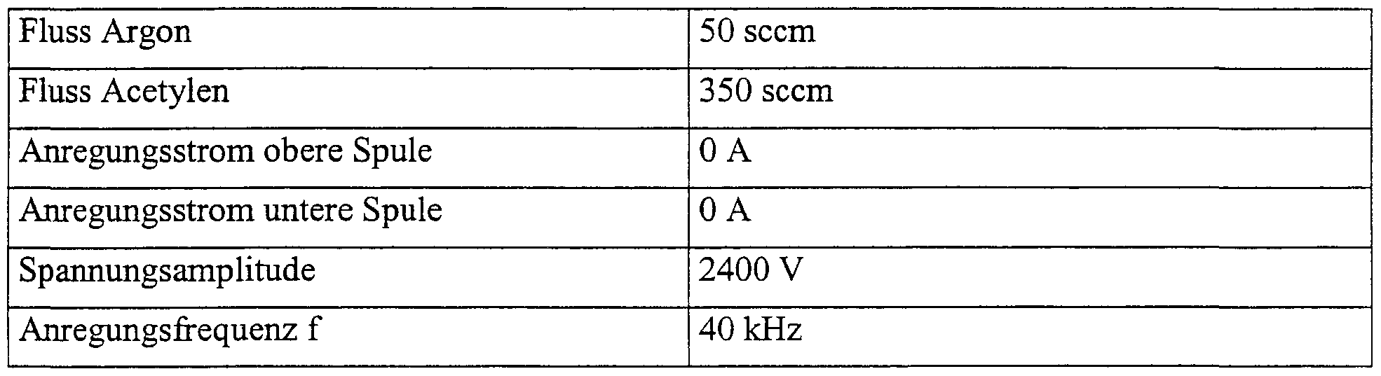
- Table 1 shows the process parameters of the heating process:
- the Helmholtz coils are used to activate the plasma and are controlled cyclically.
- the current of the upper coil is varied between 20 and 10 A with a period of 1.5 min, the current of the lower coil alternates between 5 and 20 A in the same cycle.
- an etching process is started by pulling the ions from the low-voltage arc onto the substrates using a negative bias voltage of 150V.
- the orientation of the low-voltage arc and the intensity of the plasma are supported by the pair of Helmholtz coils mounted in a horizontal orientation.
- the following table shows the parameters of the etching process.
- the application of the Cr adhesive layer is started by activating the Cr magnetron sputtering targets.
- the Ar gas flow is set to 115 sccm.
- the Cr sputtering targets are driven with an output of 8 kW and the substrates are now rotated past the targets for a period of 6 minutes.
- the resulting pressure range is between 10-3 mbar and 10-4 mbar.
- the sputtering process is supported by connecting the low-voltage arc and applying a negative DC bias voltage of 75 V to the substrate.
- the low-voltage arc is switched off and the deposition for the rest of the Cr sputtering time is only carried out with the help of the plasma active in front of the Cr target.
- a plasma is ignited by switching on a sinus generator.
- the sine plasma generator is set to an amplitude voltage of 2400 V at a frequency of 40 kHz.
- the generator ignites a plasma discharge between the substrate holders and the housing wall.
- the Helmholtz coils attached to the recipient are both activated with a constant current flow of 3 A in the lower coil and 10 A in the upper coil. With an acetylene flow of 230 sccm, the Cr targets are deactivated.
- the deposition rate that now arises in the coating process will be in the range between 0.5 and 4 ⁇ m / h, which also depends on the area to be coated in the process chamber.
- the sine generator and the gas flow are switched off and the substrates are removed from the process chamber.
- Process example 2 provides for an implementation similar to example 1.
- the plasma is generated by a pulse generator.
- the excitation frequency is 50 kHz with an amplitude voltage of 700V.
- the table shows the parameters of the 2nd example.
- Process example 3 provides an implementation similar to example 1.
- the plasma is excited by a unipolar pulse voltage, the parameters of the experiment are shown in the following table.
- the coating produced has the properties described in the following table.
- a plasma is produced which, compared to example 1, is stable only at higher pressures than in example 1, is inhomogeneously distributed over the process chamber and is very strongly influenced by geometric effects. Therefore, there is an inhomogeneous in the process chamber and because of the lower deposition rate compared to example 1 at the set process pressure.
- plasma formation was not possible without the use of a second plasma source such as a target or by switching on the filament. Only by using the Helmholtz coils was it possible to stabilize the plasma in the process chamber and achieve a homogeneous separation over the height of the process chamber. Without the use of the coils, a plasma ignited in the area of the ionization chamber, where high temperatures are generated locally and destruction must be feared.
- Table 5 shows various process examples, each with a graphitized sliding layer:
- Table 6 shows various options for the formation of a sliding layer, e.g. a grading layer (No. 8), an inverse gradient layer (No. 9), or a hydrogen-rich C layer (No. 10):
- the acetylene ramp can also be started with a line delay of 5-10 min after switching on the Cr targets. Such a procedure is particularly advantageous if DLC and sliding layers are applied in different process chambers or coating systems.
- a DC voltage source can also be used to apply the suabstrate bias.
- the graphite content can be increased by simultaneous or likewise delayed co-sputtering of carbide targets, for example WC and / or graphite targets. If you want to use the particularly favorable sliding properties of W or Ta or Nb / C layers, it is advantageous to switch off or down-regulate the Cr targets after the formation of an adhesive or gradient layer and to regulate the process only with the appropriate metal or To finish metal carbide targets.
- Layer system for wear protection, corrosion protection and to improve the sliding properties and the like with an adhesive layer for arrangement on a substrate, a transition layer for arrangement on the adhesive layer and a cover layer made of diamond-like carbon, characterized in that the adhesive layer at least one element from the group which includes the elements of the 4th,
- the transition layer comprises carbon and at least one element from the group comprising the elements of 4th, 5th and
- the cover layer comprises essentially diamond-like carbon, the layer system having a hardness of at least 15 GPa, preferably at least 20 Gpa, and an adhesive strength of at least 3 HF.
- transition layer is a continuous or step-wise changing individual or multilayered gradient layer in the composition, with an increasing carbon content from the substrate and a decreasing proportion of at least one element from the group comprising the elements the 4th, 5th and 6th subgroup as well as silicon.
- transition layer and / or cover layer additionally comprises hydrogen and unavoidable impurities
- the unavoidable impurities include noble gases, in particular argon and xenon.
- Layer system according to feature set 4 characterized in that the cover layer contains only carbon or carbon and hydrogen.
- Layer system according to feature set 4 characterized in that the cover layer has a hydrogen content of 5 to 30 atom%, preferably 10 to 20 atom%.
- Layer system according to one of the preceding sets of features, characterized in that the at least one element from the group comprising the elements of the 4th, 5th and 6th subgroup is titanium and / or chromium.
- Layer system according to one of the preceding sets of features, characterized in that the adhesive layer and the transition layer each have a thickness of 0.05 ⁇ m to 1.5 ⁇ m, preferably from 0.1 ⁇ m to 0.8 ⁇ m.
- the cover layer has a thickness of 0.5 ⁇ m to 20 ⁇ m, preferably of 1 ⁇ m to 10 ⁇ m.
- a method for producing a layer system, in particular according to one of the feature sets 1 to 10, on a substrate characterized in that the method comprises: a) introducing the substrate into a vacuum chamber and pumping it down to a vacuum with a pressure of less than 10 ⁇ 4 mbar, preferably 10 ⁇ 5 mbar is reached.
- etching step is carried out by ion etching, a low-voltage arc being ignited with an inert gas, preferably argon, and / or hydrogen as the process gas, and a continuous negative substrate bias voltage being applied to the substrate.
- etching step is carried out by ion etching with a noble gas, preferably argon, and / or hydrogen as the process gas, an AC or AC superimposed bias voltage, such as in particular a pulsed, preferably medium-frequency substrate bias voltage being applied.
- a noble gas preferably argon
- AC or AC superimposed bias voltage such as in particular a pulsed, preferably medium-frequency substrate bias voltage being applied.
- a carbon-containing gas preferably a hydrocarbon gas, in particular acetylene
- reaction gas for separating carbon comprises hydrogen and / or noble gas, preferably argon or / and xenon, in addition to the carbon-containing gas.
- Device for coating one or more substrates in particular for carrying out the coating method according to one of the feature sets 10 to 29, with a vacuum chamber (1) with a pump system (9) for generating a vacuum in the vacuum chamber (1), substrate holders (3) for receiving the substrates to be coated, at least one gas supply unit (8) for metering in process gas, at least one evaporator device (14) for providing coating material for vapor deposition, an arc generating device (10, 143) for igniting a DC low-voltage arc, a device (16) for generating a substrate bias voltage and with at least one or more magnetic field generating devices (17) for forming a magnetic far field.
- Device according to feature set 31 characterized in that the Helmholtz coil can be controlled with respect to the magnetic flux density that can be generated.
- Device according to one of the feature sets 30 to 32 characterized in that the device for generating a substrate bias voltage is designed such that the substrate bias voltage can be changed continuously or stepwise with respect to the sign and / or the size of the applied substrate bias voltage and / or bipolar or unipolar can preferably be operated at a frequency in a medium frequency range.
- the evaporator device (14) comprises sputtering targets, in particular magnetron sputtering targets, arc sources, thermal evaporators and the like.
- Device according to one of the feature sets 30 to 34 characterized in that the evaporator device (14) can be separated from the rest of the process chamber (1).
- Device according to one of the feature sets 30 to 35, characterized in that the device further comprises a substrate heater in the form of an inductive heater, radiant heater or the like.
- the arc generating device (10, 13) comprises an ion source (10) and an anode (13) and a DC voltage supply (11), the ion source (10) having the negative Pole of the DC voltage supply (11) is connected.
- Device according to feature set 37 characterized in that the positive pole of the direct voltage supply (11) can be connected either to the anode (13) or to the substrate holders (3).
- the ion source (10) is a filamanet, preferably a refractory filament, in particular ⁇ 1 comprises, in particular, tungsten, tantalum or the like, which is arranged in an ionization chamber, which can be separated from the process chamber (1) by a screen, preferably a refractory screen, in particular made of tungsten, tantalum or the like.
- Device Device according to one of the feature sets 30 to 39, characterized in that the substrate holders (3) are movable, and preferably rotatable about at least one or more axes.
- Device according to one of the feature sets 30 to 40, characterized in that permanent magnets (20) are additionally provided for generating a magnetic near field.
- Device according to 41 characterized in that the additional permanent magnets (20) are designed annularly around the vacuum chamber (1), preferably with an alternating pole orientation, and in particular are designed as a magnetron electron trap.
Abstract
Description


Claims
Priority Applications (10)
| Application Number | Priority Date | Filing Date | Title |
|---|---|---|---|
| US10/257,678 US7160616B2 (en) | 2000-04-12 | 2000-12-27 | DLC layer system and method for producing said layer system |
| KR1020027013744A KR100762346B1 (ko) | 2000-04-12 | 2000-12-27 | 디엘씨층 시스템 및 이러한 층 시스템을 제작하기 위한 방법 |
| BR0017216-2A BR0017216A (pt) | 2000-04-12 | 2000-12-27 | Sistema de camada de dlc com caracterìsticas de deslizamento melhoradas e processo para a produção desses sistemas de camada |
| JP2001576965A JP4849759B2 (ja) | 2000-04-12 | 2000-12-27 | 滑り特性が向上したdlc層システム、およびそのような層システムを生成するためのプロセス |
| EP00993868A EP1272683B1 (de) | 2000-04-12 | 2000-12-27 | Dlc-schichtsystem sowie verfahren zur herstellung eines derartigen schichtsystems |
| EP03014612.0A EP1362931B2 (de) | 2000-04-12 | 2000-12-27 | Verfahren und Vorrichtung zur Herstellung eines DLC-Schichtsystems |
| DE50011775T DE50011775D1 (de) | 2000-04-12 | 2000-12-27 | Dlc-schichtsystem sowie verfahren zur herstellung eines derartigen schichtsystems |
| AU28440/01A AU2844001A (en) | 2000-04-12 | 2000-12-27 | Dlc layer system and method for producing said layer system |
| AT00993868T ATE311483T1 (de) | 2000-04-12 | 2000-12-27 | Dlc-schichtsystem sowie verfahren zur herstellung eines derartigen schichtsystems |
| HK03102687A HK1050553A1 (en) | 2000-04-12 | 2003-04-14 | Dlc layer system and method for producing said layer system |
Applications Claiming Priority (2)
| Application Number | Priority Date | Filing Date | Title |
|---|---|---|---|
| DE10018143.0 | 2000-04-12 | ||
| DE10018143A DE10018143C5 (de) | 2000-04-12 | 2000-04-12 | DLC-Schichtsystem sowie Verfahren und Vorrichtung zur Herstellung eines derartigen Schichtsystems |
Publications (1)
| Publication Number | Publication Date |
|---|---|
| WO2001079585A1 true WO2001079585A1 (de) | 2001-10-25 |
Family
ID=7638477
Family Applications (1)
| Application Number | Title | Priority Date | Filing Date |
|---|---|---|---|
| PCT/EP2000/013299 WO2001079585A1 (de) | 2000-04-12 | 2000-12-27 | Dlc-schichtsystem sowie verfahren zur herstellung eines derartigen schichtsystems |
Country Status (12)
| Country | Link |
|---|---|
| US (5) | US6740393B1 (de) |
| EP (2) | EP1362931B2 (de) |
| JP (1) | JP4849759B2 (de) |
| KR (1) | KR100762346B1 (de) |
| AT (2) | ATE311483T1 (de) |
| AU (1) | AU2844001A (de) |
| BR (1) | BR0017216A (de) |
| DE (3) | DE10018143C5 (de) |
| ES (2) | ES2252092T3 (de) |
| HK (1) | HK1050553A1 (de) |
| PT (1) | PT1362931E (de) |
| WO (1) | WO2001079585A1 (de) |
Cited By (20)
| Publication number | Priority date | Publication date | Assignee | Title |
|---|---|---|---|---|
| WO2003091474A1 (de) * | 2002-04-25 | 2003-11-06 | Unaxis Balzers Ag | Strukturiertes schichtsystem |
| WO2005029538A2 (en) * | 2003-09-22 | 2005-03-31 | Seok Kyun Song | A plasma generating apparatus and an alignment process for liquid crystal displays using the apparatus |
| WO2006116889A1 (de) * | 2005-05-04 | 2006-11-09 | Oerlikon Trading Ag, Trübbach | Plasmaverstärker für plasmabehandlungsanlage |
| US7270719B2 (en) | 2003-01-13 | 2007-09-18 | Sandvik Intellectual Property Ab | Method for manufacturing surface hardened stainless steel with improved wear resistance and low static friction properties |
| WO2007110322A1 (en) * | 2006-03-28 | 2007-10-04 | Nv Bekaert Sa | Sputtering apparatus |
| WO2008037515A1 (de) * | 2006-08-11 | 2008-04-03 | Polysius Ag | Walzen- oder rollenmühle |
| WO2008047044A2 (fr) * | 2006-10-20 | 2008-04-24 | H.E.F. | Piece en contact glissant, en regime lubrifie, revetue d'une couche mince |
| WO2008011642A3 (de) * | 2006-07-26 | 2008-06-19 | Bosch Gmbh Robert | Verfahren zum aufbringen eines beschichtungsmaterials sowie beschichtung für eine metallische oberfläche |
| WO2009106201A1 (de) * | 2008-02-29 | 2009-09-03 | Ks Kolbenschmidt Gmbh | Beschichtung von bauteilen einer brennkraftmaschine zur verminderung von reibung, verschleiss und adhäsionsneigung |
| DE102010062114A1 (de) * | 2010-11-29 | 2012-05-31 | Federal-Mogul Burscheid Gmbh | Gleitelement, insbesondere Kolbenring, mit einer Beschichtung |
| US8192597B2 (en) | 2006-03-28 | 2012-06-05 | Nv Bekaert Sa | Coating apparatus |
| EP2257654B1 (de) * | 2008-04-02 | 2012-08-01 | Federal-Mogul Burscheid GmbH | Kolbenring |
| WO2012106791A1 (pt) * | 2011-02-10 | 2012-08-16 | Mahle Metal Leve S/A | Componente de motor |
| WO2012116818A1 (en) * | 2011-03-02 | 2012-09-07 | Oerlikon Trading Ag, Trübbach | Sliding component coated with metal-comprising carbon layer for improving wear and friction behavior by tribological applications under lubricated conditions |
| WO2012156647A1 (fr) | 2011-05-19 | 2012-11-22 | H.E.F. | Piece avec revetement dlc et procede d'application du revetement dlc |
| KR101357097B1 (ko) | 2004-02-24 | 2014-02-03 | 어플라이드 머티어리얼스, 인코포레이티드 | 다이아몬드-형 재료의 코팅을 갖는 열 교환 페데스탈 |
| EP2821525A1 (de) * | 2013-07-01 | 2015-01-07 | General Electric Company | Mehrschichtige Beschichtungen mit diamantähnlichem Kohlenstoff |
| WO2015193584A1 (fr) * | 2014-06-18 | 2015-12-23 | H.E.F. | Procédé de revêtement en carbone dlc du nez des cames d'un arbre à came, arbre à cames ainsi obtenu et installation pour la mise en oeuvre de ce procédé |
| WO2018041560A1 (de) * | 2016-08-30 | 2018-03-08 | Federal-Mogul Valvetrain Gmbh | Verschleissarmes ventilkegelstück |
| EP3284980B1 (de) | 2015-04-16 | 2020-08-05 | Eagle Industry Co., Ltd. | Schiebeteil |
Families Citing this family (167)
| Publication number | Priority date | Publication date | Assignee | Title |
|---|---|---|---|---|
| JP3555844B2 (ja) | 1999-04-09 | 2004-08-18 | 三宅 正二郎 | 摺動部材およびその製造方法 |
| US7250196B1 (en) * | 1999-10-26 | 2007-07-31 | Basic Resources, Inc. | System and method for plasma plating |
| DE10018143C5 (de) * | 2000-04-12 | 2012-09-06 | Oerlikon Trading Ag, Trübbach | DLC-Schichtsystem sowie Verfahren und Vorrichtung zur Herstellung eines derartigen Schichtsystems |
| JP2003231203A (ja) * | 2001-08-21 | 2003-08-19 | Toshiba Corp | 炭素膜被覆部材 |
| JP4304598B2 (ja) * | 2001-09-27 | 2009-07-29 | 株式会社豊田中央研究所 | 高摩擦摺動部材 |
| DE10149588B4 (de) * | 2001-10-08 | 2017-09-07 | Oerlikon Trading Ag, Trübbach | Verfahren zur Diamantbeschichtung von Substraten |
| JP2003206820A (ja) * | 2002-01-17 | 2003-07-25 | Keihin Corp | 電磁式燃料噴射弁 |
| DE10203730B4 (de) * | 2002-01-30 | 2010-09-16 | Fraunhofer-Gesellschaft zur Förderung der angewandten Forschung e.V. | Verfahren zur Abscheidung von metallfreien Kohlenstoffschichten |
| GB0205959D0 (en) * | 2002-03-14 | 2002-04-24 | Teer Coatings Ltd | Apparatus and method for applying diamond-like carbon coatings |
| US20030180450A1 (en) * | 2002-03-22 | 2003-09-25 | Kidd Jerry D. | System and method for preventing breaker failure |
| DE10223844B4 (de) * | 2002-05-28 | 2013-04-04 | Danfoss A/S | Wasserhydraulische Maschine |
| JP2004138128A (ja) * | 2002-10-16 | 2004-05-13 | Nissan Motor Co Ltd | 自動車エンジン用摺動部材 |
| DE10305159B4 (de) * | 2002-11-02 | 2006-12-07 | Rowapack Gmbh Verpackungsdesign Und Stanztechnik | Stanzverfahren |
| US6969198B2 (en) | 2002-11-06 | 2005-11-29 | Nissan Motor Co., Ltd. | Low-friction sliding mechanism |
| DE10256063A1 (de) * | 2002-11-30 | 2004-06-17 | Mahle Gmbh | Verfahren zum Beschichten von Kolbenringen für Verbrennungsmotoren |
| US7866342B2 (en) * | 2002-12-18 | 2011-01-11 | Vapor Technologies, Inc. | Valve component for faucet |
| US8220489B2 (en) | 2002-12-18 | 2012-07-17 | Vapor Technologies Inc. | Faucet with wear-resistant valve component |
| US8555921B2 (en) | 2002-12-18 | 2013-10-15 | Vapor Technologies Inc. | Faucet component with coating |
| US7866343B2 (en) | 2002-12-18 | 2011-01-11 | Masco Corporation Of Indiana | Faucet |
| DE10259174B4 (de) * | 2002-12-18 | 2006-10-12 | Robert Bosch Gmbh | Verwendung eines tribologisch beanspruchten Bauelements |
| US20060226003A1 (en) * | 2003-01-22 | 2006-10-12 | John Mize | Apparatus and methods for ionized deposition of a film or thin layer |
| WO2004076710A1 (ja) * | 2003-02-26 | 2004-09-10 | Sumitomo Electric Industries, Ltd. | 非晶質炭素膜、その製造方法および非晶質炭素膜被覆部材 |
| US20040258547A1 (en) * | 2003-04-02 | 2004-12-23 | Kurt Burger | Pump piston and/or elements sealing the pump piston, in particular a sealing ring of elastomeric material, and a device and method for coating an object of elastomeric material |
| RU2240376C1 (ru) * | 2003-05-22 | 2004-11-20 | Ооо "Альбатэк" | Способ формирования сверхтвердого аморфного углеродного покрытия в вакууме |
| EP1651796B1 (de) * | 2003-07-25 | 2007-01-03 | NV Bekaert SA | Substrat mit zwischenüberzug und hartem kohlenstoffüberzug |
| JP4863152B2 (ja) | 2003-07-31 | 2012-01-25 | 日産自動車株式会社 | 歯車 |
| WO2005014761A2 (ja) | 2003-08-06 | 2005-02-17 | Nissan Motor Co., Ltd. | 低摩擦摺動機構、低摩擦剤組成物及び摩擦低減方法 |
| JP4973971B2 (ja) | 2003-08-08 | 2012-07-11 | 日産自動車株式会社 | 摺動部材 |
| US7771821B2 (en) | 2003-08-21 | 2010-08-10 | Nissan Motor Co., Ltd. | Low-friction sliding member and low-friction sliding mechanism using same |
| EP1508611B1 (de) | 2003-08-22 | 2019-04-17 | Nissan Motor Co., Ltd. | Getriebe enthaltend eine getriebeölzusammensetzung |
| US20050126497A1 (en) * | 2003-09-30 | 2005-06-16 | Kidd Jerry D. | Platform assembly and method |
| US20050193852A1 (en) * | 2004-03-05 | 2005-09-08 | Cooper Clark V. | Transmission system with increased power density |
| JP4572688B2 (ja) * | 2004-04-27 | 2010-11-04 | 株式会社豊田中央研究所 | 低摩擦摺動部材 |
| EP1769100A1 (de) * | 2004-04-29 | 2007-04-04 | OC Oerlikon Balzers AG | Dlc hartstoffbeschichtungen auf kupferhaltigen lagerwerkstoffen |
| JP4543373B2 (ja) * | 2004-06-03 | 2010-09-15 | 三菱マテリアル株式会社 | 非鉄材料の高速切削加工ですぐれた耐摩耗性を発揮する表面被覆超硬合金製切削工具の製造方法 |
| CN101001976B (zh) * | 2004-07-09 | 2010-12-29 | 奥尔利康贸易股份公司(特吕巴赫) | 具有金属-类金刚石碳硬质材料涂层的含铜导电材料 |
| JP2006116633A (ja) * | 2004-10-20 | 2006-05-11 | Osg Corp | 硬質被膜被覆工具、コーティング被膜、および被膜のコーティング方法 |
| JP2006138404A (ja) * | 2004-11-12 | 2006-06-01 | Kobe Steel Ltd | 水系環境下での耐摩耗性に優れた摺動部材 |
| CH697552B1 (de) * | 2004-11-12 | 2008-11-28 | Oerlikon Trading Ag | Vakuumbehandlungsanlage. |
| EP1698713A1 (de) * | 2005-03-01 | 2006-09-06 | Ceco Ltd | Kratzfester Werkstoff und Verfahren zu seiner Herstellung |
| US9659758B2 (en) * | 2005-03-22 | 2017-05-23 | Honeywell International Inc. | Coils utilized in vapor deposition applications and methods of production |
| US9997338B2 (en) * | 2005-03-24 | 2018-06-12 | Oerlikon Surface Solutions Ag, Pfäffikon | Method for operating a pulsed arc source |
| EP1883717A1 (de) * | 2005-05-26 | 2008-02-06 | NV Bekaert SA | Kolbenring mit hartem mehrschichtigem überzug |
| US20060278520A1 (en) * | 2005-06-13 | 2006-12-14 | Lee Eal H | Use of DC magnetron sputtering systems |
| CN1899992A (zh) * | 2005-07-19 | 2007-01-24 | 鸿富锦精密工业(深圳)有限公司 | 模仁及其制备方法 |
| PT1915472T (pt) * | 2005-08-18 | 2018-12-06 | Oerlikon Surface Solutions Ag Pfaeffikon | Substrato revestido com uma estrutura em camadas compreendendo uma camada de carbono tetraédrico e uma camada exterior mais macia |
| DE502006005651D1 (de) * | 2005-09-10 | 2010-01-28 | Ixetic Hueckeswagen Gmbh | Verschleißfeste Beschichtung und Verfahren zur Herstellung derselben |
| CN100482379C (zh) * | 2005-10-27 | 2009-04-29 | 鸿富锦精密工业(深圳)有限公司 | 一种压铸模仁及其制备方法 |
| DE102005054132B4 (de) * | 2005-11-14 | 2020-03-26 | Robert Bosch Gmbh | Ventil zum Steuern eines Fluids mit Tribosystem |
| US8119240B2 (en) * | 2005-12-02 | 2012-02-21 | United Technologies Corporation | Metal-free diamond-like-carbon coatings |
| WO2007070026A1 (en) * | 2005-12-13 | 2007-06-21 | United Technologies Corporation | Process for deposition of amorphous carbon |
| JP2007162099A (ja) * | 2005-12-15 | 2007-06-28 | Toyota Motor Corp | 硬質炭素膜及びその製造方法並びに摺動部材 |
| KR100656955B1 (ko) * | 2005-12-30 | 2006-12-14 | 삼성전자주식회사 | 이온 임플랜터의 이온 발생 장치 |
| JP4735309B2 (ja) * | 2006-02-10 | 2011-07-27 | トヨタ自動車株式会社 | 耐キャビテーションエロージョン用部材及びその製造方法 |
| US9526814B2 (en) * | 2006-02-16 | 2016-12-27 | Boston Scientific Scimed, Inc. | Medical balloons and methods of making the same |
| JP5030439B2 (ja) * | 2006-02-28 | 2012-09-19 | 株式会社リケン | 摺動部材 |
| JP2007246996A (ja) * | 2006-03-16 | 2007-09-27 | Tdk Corp | 保護膜及び該保護膜付き内燃機関用部品 |
| JP4704950B2 (ja) * | 2006-04-27 | 2011-06-22 | 株式会社神戸製鋼所 | 非晶質炭素系硬質多層膜及びこの膜を表面に備えた硬質表面部材 |
| US8273222B2 (en) * | 2006-05-16 | 2012-09-25 | Southwest Research Institute | Apparatus and method for RF plasma enhanced magnetron sputter deposition |
| WO2007136777A2 (en) * | 2006-05-17 | 2007-11-29 | G & H Technologies Llc | Wear resistant coating |
| EP1884978B1 (de) * | 2006-08-03 | 2011-10-19 | Creepservice S.à.r.l. | Verfahren zur Beschichtung von Substraten mit diamantähnlichen Kohlenstoffschichten |
| DE102006049974A1 (de) * | 2006-10-24 | 2008-04-30 | Oerlikon Leybold Vacuum Gmbh | Turbomaschine |
| DE102006058078A1 (de) * | 2006-12-07 | 2008-06-19 | Systec System- Und Anlagentechnik Gmbh & Co. Kg | Vakuumbeschichtungsanlage zur homogenen PVD-Beschichtung |
| JP2008163430A (ja) * | 2006-12-28 | 2008-07-17 | Jtekt Corp | 高耐食性部材およびその製造方法 |
| DE102007047629A1 (de) * | 2007-04-13 | 2008-10-16 | Stein, Ralf | Verfahren zum Aufbringen einer hochfesten Beschichtung auf Werkstücke und/oder Werkstoffe |
| DE102007019994A1 (de) * | 2007-04-27 | 2008-10-30 | Fraunhofer-Gesellschaft zur Förderung der angewandten Forschung e.V. | Transparente Barrierefolie und Verfahren zum Herstellen derselben |
| CA2686445C (en) * | 2007-05-25 | 2015-01-27 | Oerlikon Trading Ag, Truebbach | Vacuum treatment installation and vacuum treatment method |
| KR100897323B1 (ko) * | 2007-05-30 | 2009-05-14 | 한국생산기술연구원 | 플라즈마 화학기상증착과 물리기상증착을 복합한 박막 코팅방법 |
| JP2008310849A (ja) * | 2007-06-12 | 2008-12-25 | Fuji Electric Device Technology Co Ltd | 保護膜形成法及び保護膜を備えた磁気記録媒体 |
| US20090029067A1 (en) * | 2007-06-28 | 2009-01-29 | Sciamanna Steven F | Method for producing amorphous carbon coatings on external surfaces using diamondoid precursors |
| US8105660B2 (en) * | 2007-06-28 | 2012-01-31 | Andrew W Tudhope | Method for producing diamond-like carbon coatings using PECVD and diamondoid precursors on internal surfaces of a hollow component |
| US8277617B2 (en) * | 2007-08-14 | 2012-10-02 | Southwest Research Institute | Conformal magnetron sputter deposition |
| JP2009127059A (ja) * | 2007-11-20 | 2009-06-11 | Tokyo Denki Univ | ダイヤモンドライクカーボン膜の形成方法 |
| US20090194414A1 (en) * | 2008-01-31 | 2009-08-06 | Nolander Ira G | Modified sputtering target and deposition components, methods of production and uses thereof |
| TW200942633A (en) * | 2008-04-14 | 2009-10-16 | Yu-Hsueh Lin | Method for plating film on surface of drill and structure of film-plated drill |
| JP2011521106A (ja) * | 2008-05-13 | 2011-07-21 | サブ−ワン・テクノロジー・インコーポレーテッド | 太陽熱およびその他の応用例におけるパイプの内面および外面のコーティング方法 |
| DE102008028542B4 (de) * | 2008-06-16 | 2012-07-12 | Fraunhofer-Gesellschaft zur Förderung der angewandten Forschung e.V. | Verfahren und Vorrichtung zum Abscheiden einer Schicht auf einem Substrat mittels einer plasmagestützten chemischen Reaktion |
| JP5244495B2 (ja) * | 2008-08-06 | 2013-07-24 | 三菱重工業株式会社 | 回転機械用の部品 |
| TWI399451B (zh) * | 2008-09-05 | 2013-06-21 | Yu Hsueh Lin | 傳動機構之表面鍍膜方法 |
| DE102008042896A1 (de) * | 2008-10-16 | 2010-04-22 | Federal-Mogul Burscheid Gmbh | Verfahren zur Beschichtung eines Gleitelements und Gleitelement, insbesondere Kolbenring oder Zylinderlaufbuchse eines Verbrennungsmotors |
| US8332314B2 (en) | 2008-11-05 | 2012-12-11 | Kent Griffin | Text authorization for mobile payments |
| US7939367B1 (en) * | 2008-12-18 | 2011-05-10 | Crystallume Corporation | Method for growing an adherent diamond layer atop an interlayer bonded to a compound semiconductor substrate |
| JP4755262B2 (ja) * | 2009-01-28 | 2011-08-24 | 株式会社神戸製鋼所 | ダイヤモンドライクカーボン膜の製造方法 |
| JP5222764B2 (ja) * | 2009-03-24 | 2013-06-26 | 株式会社神戸製鋼所 | 積層皮膜および積層皮膜被覆部材 |
| JP5741891B2 (ja) * | 2009-06-19 | 2015-07-01 | 株式会社ジェイテクト | Dlc膜形成方法 |
| RU2553803C2 (ru) * | 2009-08-07 | 2015-06-20 | Эрликон Трейдинг Аг, Трюббах | Трибология в сочетании с коррозионной стойкостью: новое семейство pvd- и pacvd-покрытий |
| DE102009028504C5 (de) * | 2009-08-13 | 2014-10-30 | Federal-Mogul Burscheid Gmbh | Kolbenring mit einer Beschichtung |
| JP5816187B2 (ja) * | 2009-11-20 | 2015-11-18 | エリコン・サーフェス・ソリューションズ・アクチェンゲゼルシャフト,トリュープバッハ | 真空処理チャンバおよびコーティング設備 |
| US8715789B2 (en) | 2009-12-18 | 2014-05-06 | Sub-One Technology, Inc. | Chemical vapor deposition for an interior of a hollow article with high aspect ratio |
| US9132609B2 (en) * | 2010-03-03 | 2015-09-15 | Taiyo Chemical Industry Co., Ltd. | Method for fixation onto layer comprising amorphous carbon film, and laminate |
| US8747631B2 (en) * | 2010-03-15 | 2014-06-10 | Southwest Research Institute | Apparatus and method utilizing a double glow discharge plasma for sputter cleaning |
| US9169551B2 (en) * | 2010-04-15 | 2015-10-27 | DePuy Synthes Products, Inc. | Coating for a CoCrMo substrate |
| KR101779776B1 (ko) * | 2010-04-15 | 2017-09-19 | 신세스 게엠바하 | 코발트크롬몰리브덴 기재를 위한 코팅 |
| EP2385259A1 (de) * | 2010-05-06 | 2011-11-09 | Protec Surface Technologies S.r.L. | Flüssigkeitsbetätigter Betriebszylinder für einen Materialtransportträger |
| JP5649333B2 (ja) * | 2010-06-01 | 2015-01-07 | 株式会社神戸製鋼所 | イオンボンバードメント装置及びこの装置を用いた基材表面のクリーニング方法 |
| MX361608B (es) * | 2010-06-22 | 2018-12-07 | Oerlikon Surface Solutions Ag Pfaeffikon | Fuente de desposicion por arco que tiene un campo electrico definido. |
| US9034466B2 (en) * | 2010-07-09 | 2015-05-19 | Daido Metal Company Ltd. | Sliding member |
| US9051967B2 (en) * | 2010-07-09 | 2015-06-09 | Daido Metal Company Ltd. | Sliding member |
| JP5665409B2 (ja) * | 2010-08-06 | 2015-02-04 | 株式会社ジェイテクト | 被膜の成膜方法 |
| DE102011009347B4 (de) | 2010-11-29 | 2016-05-12 | Fraunhofer-Gesellschaft zur Förderung der angewandten Forschung e.V. | Verfahren zur Herstellung eines kohlenstoffhaltigen Schichtsystems sowie Vorrichtung zur Durchführung des Verfahrens |
| DE102010052971A1 (de) * | 2010-11-30 | 2012-05-31 | Amg Coating Technologies Gmbh | Werkstück mit Si-DLC Beschichtung und Verfahren zur Herstellung von Beschichtungen |
| CN102108484B (zh) * | 2011-01-18 | 2012-07-04 | 厦门建霖工业有限公司 | 一种双层抗菌镀层的制备方法 |
| CN102108485B (zh) * | 2011-01-28 | 2012-03-28 | 厦门建霖工业有限公司 | 塑胶表面抗菌镀层的制备方法 |
| US9366219B2 (en) * | 2011-02-11 | 2016-06-14 | Sphenic Technologies Inc | System, circuit, and method for controlling combustion |
| US9217195B2 (en) * | 2011-04-20 | 2015-12-22 | Ntn Corporation | Amorphous carbon film and method for forming same |
| US9909365B2 (en) | 2011-04-29 | 2018-03-06 | Baker Hughes Incorporated | Downhole tools having mechanical joints with enhanced surfaces |
| DE102011077556A1 (de) | 2011-06-15 | 2012-12-20 | Schaeffler Technologies AG & Co. KG | Gleitlager |
| US9340854B2 (en) * | 2011-07-13 | 2016-05-17 | Baker Hughes Incorporated | Downhole motor with diamond-like carbon coating on stator and/or rotor and method of making said downhole motor |
| JP2011225999A (ja) * | 2011-07-21 | 2011-11-10 | Yamaguchi Prefectural Industrial Technology Institute | プラズマ処理装置及び成膜方法 |
| WO2013042765A1 (ja) * | 2011-09-22 | 2013-03-28 | Ntn株式会社 | 硬質膜、硬質膜形成体、および転がり軸受 |
| DE102011116576A1 (de) * | 2011-10-21 | 2013-04-25 | Oerlikon Trading Ag, Trübbach | Bohrer mit Beschichtung |
| JP5689051B2 (ja) * | 2011-11-25 | 2015-03-25 | 株式会社神戸製鋼所 | イオンボンバードメント装置 |
| AT511605B1 (de) * | 2011-12-12 | 2013-01-15 | High Tech Coatings Gmbh | Kohlenstoffbasierende beschichtung |
| KR101382997B1 (ko) * | 2012-02-08 | 2014-04-08 | 현대자동차주식회사 | 코팅층 표면 처리 방법 |
| EP2628817B1 (de) | 2012-02-15 | 2016-11-02 | IHI Hauzer Techno Coating B.V. | Beschichteter Artikel aus Martensitstahl und Verfahren zur Herstellung eines beschichteten Artikels aus Stahl |
| EP2628822B1 (de) | 2012-02-15 | 2015-05-20 | IHI Hauzer Techno Coating B.V. | Stromisolierende Lagerkomponenten und Lager |
| DE102012007763A1 (de) | 2012-04-20 | 2013-10-24 | Ulrich Schmidt | Modularer Rahmen für Steckdosen und Schalter |
| EP2664690B1 (de) | 2012-05-15 | 2015-09-16 | ZhongAo HuiCheng Technology Co. Ltd. | Magnetron-Sputter-Beschichtungsvorrichtung und Herstellungsverfahren für Nano-Mehrschichtfolie |
| RU2494172C1 (ru) * | 2012-08-07 | 2013-09-27 | Федеральное государственное бюджетное образовательное учреждение высшего профессионального образования "Казанский национальный исследовательский технологический университет" (ФГБОУ ВПО "КНИТУ") | Способ получения износостойкого покрытия |
| DE102012214284B4 (de) | 2012-08-10 | 2014-03-13 | Federal-Mogul Burscheid Gmbh | Gleitelement, insbesondere Kolbenring, mit einer widerstandsfähigen Beschichtung |
| US9793098B2 (en) | 2012-09-14 | 2017-10-17 | Vapor Technologies, Inc. | Low pressure arc plasma immersion coating vapor deposition and ion treatment |
| US9412569B2 (en) | 2012-09-14 | 2016-08-09 | Vapor Technologies, Inc. | Remote arc discharge plasma assisted processes |
| US10056237B2 (en) | 2012-09-14 | 2018-08-21 | Vapor Technologies, Inc. | Low pressure arc plasma immersion coating vapor deposition and ion treatment |
| KR101439131B1 (ko) * | 2012-09-21 | 2014-09-11 | 현대자동차주식회사 | 흡배기 밸브용 코팅재 및 이의 제조방법 |
| TWI565353B (zh) * | 2012-10-19 | 2017-01-01 | 逢甲大學 | 可撓性電熱發熱體及其製作方法 |
| JP5564099B2 (ja) * | 2012-12-28 | 2014-07-30 | 株式会社リケン | シリンダとピストンリングの組合せ |
| JP6076112B2 (ja) * | 2013-02-07 | 2017-02-08 | 株式会社神戸製鋼所 | イオンボンバードメント装置及びこの装置を用いた基材の表面のクリーニング方法 |
| DE102013002911A1 (de) | 2013-02-21 | 2014-08-21 | Oerlikon Trading Ag, Trübbach | Dekorative, tiefschwarze Beschichtung |
| US9534291B2 (en) * | 2013-02-21 | 2017-01-03 | Oerlikon Surface Solutions Ag, Pfäffikon | DLC coating with run-in layer |
| DE102013007146A1 (de) * | 2013-04-25 | 2014-10-30 | Oerlikon Trading Ag, Trübbach | DLC Beschichtung mit Einlaufschicht |
| US9308090B2 (en) | 2013-03-11 | 2016-04-12 | DePuy Synthes Products, Inc. | Coating for a titanium alloy substrate |
| US20160281216A1 (en) * | 2013-03-19 | 2016-09-29 | Taiyo Yuden Chemical Technology Co., Ltd. | Structure having stain-proofing amorphous carbon film and method of forming stain-proofing amorphous carbon film |
| WO2014147805A1 (ja) * | 2013-03-22 | 2014-09-25 | 日鍛バルブ株式会社 | Dlc被覆膜及び被覆バルブリフタ |
| MY173635A (en) * | 2013-03-29 | 2020-02-12 | Hitachi Metals Ltd | Coated tool and method for producing same |
| JP2014237890A (ja) * | 2013-05-10 | 2014-12-18 | 国立大学法人電気通信大学 | ダイヤモンドライクカーボン膜の成膜装置および形成方法 |
| DE102013213454B3 (de) * | 2013-07-09 | 2015-01-15 | Friedrich-Alexander-Universität Erlangen - Nürnberg | Werkzeug zum Einsatz beim Aluminiumguss |
| EP3022327A2 (de) * | 2013-07-19 | 2016-05-25 | Oerlikon Surface Solutions AG, Trübbach | Beschichtungen für formwerkzeuge |
| JP6533374B2 (ja) * | 2013-11-06 | 2019-06-19 | Dowaサーモテック株式会社 | Dlc皮膜の成膜方法 |
| DE102013225608A1 (de) * | 2013-12-11 | 2015-06-11 | Apo Gmbh Massenkleinteilbeschichtung | Vorrichtung und Verfahren zur Oberflächenbehandlung von Kleinteilen mittels Plasma |
| US10233537B2 (en) * | 2014-04-23 | 2019-03-19 | Zhongao Huicheng Technology Co., Ltd. | Artificial joint cup, magnetic control sputtering coating film device and preparation method thereof |
| JP6044602B2 (ja) | 2014-07-11 | 2016-12-14 | トヨタ自動車株式会社 | 成膜装置 |
| JP6308298B2 (ja) * | 2014-08-01 | 2018-04-11 | 日立金属株式会社 | 被覆工具の製造方法 |
| US10612123B2 (en) * | 2015-02-04 | 2020-04-07 | The University Of Akron | Duplex surface treatment for titanium alloys |
| JP6612864B2 (ja) * | 2015-05-28 | 2019-11-27 | 京セラ株式会社 | 切削工具 |
| JP6014941B2 (ja) * | 2015-07-31 | 2016-10-26 | 地方独立行政法人山口県産業技術センター | プラズマ処理装置及び成膜方法 |
| US10787737B2 (en) * | 2015-11-12 | 2020-09-29 | National Oilwell DHT, L.P. | Downhole drill bit with coated cutting element |
| CN105734527B (zh) * | 2016-03-08 | 2019-01-18 | 仪征亚新科双环活塞环有限公司 | 一种用于活塞环表面的类金刚石镀层、活塞环及制备工艺 |
| KR101828508B1 (ko) * | 2016-07-13 | 2018-03-29 | 제이와이테크놀로지(주) | Dlc 박막 제조 장치 |
| JP6380483B2 (ja) | 2016-08-10 | 2018-08-29 | トヨタ自動車株式会社 | 成膜装置 |
| US10377508B2 (en) | 2016-11-29 | 2019-08-13 | The Boeing Company | Enhanced tooling for interference-fit fasteners |
| WO2019059054A1 (ja) * | 2017-09-25 | 2019-03-28 | 住友電気工業株式会社 | 硬質炭素系被膜の製造方法、及び被膜付き部材 |
| US11183373B2 (en) | 2017-10-11 | 2021-11-23 | Honeywell International Inc. | Multi-patterned sputter traps and methods of making |
| KR102055046B1 (ko) * | 2017-12-29 | 2019-12-12 | 트인로드 주식회사 | Dlc 및 다이아몬드 박막이 이중 코팅된 펀칭공구 및 그 제조방법 |
| CN108374154B (zh) * | 2018-02-26 | 2023-06-13 | 温州职业技术学院 | 带有复合磁场的类金刚石涂层制备装置及其应用 |
| US10702862B2 (en) * | 2018-04-13 | 2020-07-07 | U.S. Department Of Energy | Superlubricious carbon films derived from natural gas |
| FR3082526B1 (fr) * | 2018-06-18 | 2020-09-18 | Hydromecanique & Frottement | Piece revetue par un revetement de carbone amorphe hydrogene sur une sous-couche comportant du chrome, du carbone et du silicium |
| FR3082527B1 (fr) * | 2018-06-18 | 2020-09-18 | Hydromecanique & Frottement | Piece revetue par un revetement de carbone amorphe non-hydrogene sur une sous-couche comportant du chrome, du carbone et du silicium |
| DE102018125464B4 (de) * | 2018-10-15 | 2022-09-29 | PiKa GbR (Vertretungsberechtigter Gesellschafter: Markus Pittroff, 91278 Pottenstein) | Sägekette zur Holz- und Kunststoffbearbeitung und Verfahren zur Herstellung eines Sägegliedes |
| EP3650583A1 (de) | 2018-11-08 | 2020-05-13 | Nanofilm Technologies International Pte Ltd | Ta-c-basiertebeschichtungen mit verbesserter härte |
| CN110066982A (zh) * | 2019-04-17 | 2019-07-30 | 厦门阿匹斯智能制造系统有限公司 | 一种pvd镀膜产线磁控溅射的磁场分布方法 |
| CN111676452A (zh) * | 2020-06-29 | 2020-09-18 | 哈尔滨奥瑞德光电技术有限公司 | 一种高效镀超硬膜的方法 |
| US11664214B2 (en) | 2020-06-29 | 2023-05-30 | Applied Materials, Inc. | Methods for producing high-density, nitrogen-doped carbon films for hardmasks and other patterning applications |
| US11664226B2 (en) | 2020-06-29 | 2023-05-30 | Applied Materials, Inc. | Methods for producing high-density carbon films for hardmasks and other patterning applications |
| CN111748789B (zh) * | 2020-07-10 | 2022-06-24 | 哈尔滨工业大学 | 一种石墨阴极弧增强辉光放电沉积纯dlc的装置及其方法 |
| EP3964356A1 (de) * | 2020-09-03 | 2022-03-09 | Boegli-Gravures SA | Verfahren und vorrichtung zur herstellung einer prägevorrichtung unter verwendung einer ätzmaske |
| US20240117493A1 (en) * | 2021-02-09 | 2024-04-11 | Oerlikon Surface Solutions Ag, Pfäffikon | Arc-beam position monitoring and position control in picvd coating systems |
| RU2763357C1 (ru) * | 2021-04-13 | 2021-12-28 | Александр Васильевич Вахрушев | Способ получения высококачественных пленок методом механической вибрации подложки |
Citations (10)
| Publication number | Priority date | Publication date | Assignee | Title |
|---|---|---|---|---|
| EP0229936A1 (de) * | 1985-12-17 | 1987-07-29 | Technische Universität Chemnitz | Hartstoffschichten für mechanisch und korrosiv beanspruchte Teile |
| JPS62188776A (ja) * | 1986-01-14 | 1987-08-18 | Sumitomo Electric Ind Ltd | 対向タ−ゲツト式スパツタ装置 |
| EP0579983A1 (de) * | 1992-07-02 | 1994-01-26 | Sumitomo Electric Industries, Limited | Verunreinigungen enthaltender harter Kohlenstoffilm |
| US5709784A (en) * | 1996-03-11 | 1998-01-20 | Balzers Aktiengesellschaft | Process and apparatus for workpiece coating |
| US5750210A (en) * | 1989-04-28 | 1998-05-12 | Case Western Reserve University | Hydrogenated carbon composition |
| US5768046A (en) * | 1994-07-26 | 1998-06-16 | Korea Institute Of Science And Technology | VCR head drum coated with diamond-like hard carbon films and the method and apparatus for manufacturing the same |
| JPH10259482A (ja) * | 1997-03-19 | 1998-09-29 | Sanyo Electric Co Ltd | 硬質炭素被膜の形成方法 |
| JPH10259481A (ja) * | 1997-03-19 | 1998-09-29 | Sanyo Electric Co Ltd | 非晶質炭素系被膜の形成方法 |
| JPH11100294A (ja) * | 1997-09-25 | 1999-04-13 | Sanyo Electric Co Ltd | 硬質炭素薄膜及びその製造方法 |
| US6066399A (en) * | 1997-03-19 | 2000-05-23 | Sanyo Electric Co., Ltd. | Hard carbon thin film and method of forming the same |
Family Cites Families (172)
| Publication number | Priority date | Publication date | Assignee | Title |
|---|---|---|---|---|
| US50681A (en) * | 1865-10-31 | Improvement in photographic lenses | ||
| US91154A (en) * | 1869-06-08 | Improvement in attaching- handles to picks | ||
| US50689A (en) * | 1865-10-31 | Improvement in gaging and ullaging casks | ||
| US3287630A (en) * | 1964-03-02 | 1966-11-22 | Varian Associates | Apparatus for improving the uniformity of magnetic fields |
| US3458426A (en) * | 1966-05-25 | 1969-07-29 | Fabri Tek Inc | Symmetrical sputtering apparatus with plasma confinement |
| DD133688A1 (de) † | 1977-08-04 | 1979-01-17 | Klaus Bewilogua | Verfahren zur herstellung diamanthaltiger schichten hoher haftfestigkeit |
| US4276570A (en) * | 1979-05-08 | 1981-06-30 | Nancy Burson | Method and apparatus for producing an image of a person's face at a different age |
| DE3260505D1 (en) * | 1981-01-23 | 1984-09-13 | Takeda Chemical Industries Ltd | Alicyclic compounds, their production and use |
| DE3246361A1 (de) * | 1982-02-27 | 1983-09-08 | Philips Patentverwaltung Gmbh, 2000 Hamburg | Kohlenstoff enthaltende gleitschicht |
| US4486286A (en) * | 1982-09-28 | 1984-12-04 | Nerken Research Corp. | Method of depositing a carbon film on a substrate and products obtained thereby |
| US4602280A (en) * | 1983-12-05 | 1986-07-22 | Maloomian Laurence G | Weight and/or measurement reduction preview system |
| US4698256A (en) * | 1984-04-02 | 1987-10-06 | American Cyanamid Company | Articles coated with adherent diamondlike carbon films |
| US4877677A (en) * | 1985-02-19 | 1989-10-31 | Matsushita Electric Industrial Co., Ltd. | Wear-protected device |
| FR2583250B1 (fr) * | 1985-06-07 | 1989-06-30 | France Etat | Procede et dispositif d'excitation d'un plasma par micro-ondes a la resonance cyclotronique electronique |
| CH664768A5 (de) * | 1985-06-20 | 1988-03-31 | Balzers Hochvakuum | Verfahren zur beschichtung von substraten in einer vakuumkammer. |
| FR2596775B1 (fr) | 1986-04-07 | 1992-11-13 | Univ Limoges | Revetement dur multicouches elabore par depot ionique de nitrure de titane, carbonitrure de titane et i-carbone |
| JPS63195266A (ja) * | 1987-02-10 | 1988-08-12 | Semiconductor Energy Lab Co Ltd | 炭素膜がコーティングされた時計 |
| KR900008505B1 (ko) * | 1987-02-24 | 1990-11-24 | 세미콘덕터 에너지 라보라터리 캄파니 리미티드 | 탄소 석출을 위한 마이크로파 강화 cvd 방법 |
| DE3706340A1 (de) * | 1987-02-27 | 1988-09-08 | Winter & Sohn Ernst | Verfahren zum auftragen einer verschleissschutzschicht und danach hergestelltes erzeugnis |
| DE3708716C2 (de) * | 1987-03-18 | 1993-11-04 | Hans Prof Dr Rer Nat Oechsner | Hochfrequenz-ionenquelle |
| EP0286306B1 (de) * | 1987-04-03 | 1993-10-06 | Fujitsu Limited | Verfahren und Vorrichtung zur Gasphasenabscheidung von Diamant |
| US4926791A (en) * | 1987-04-27 | 1990-05-22 | Semiconductor Energy Laboratory Co., Ltd. | Microwave plasma apparatus employing helmholtz coils and ioffe bars |
| US5113493A (en) * | 1987-05-11 | 1992-05-12 | Liberty Life Insurance Co. | Full speed animation system for low-speed computers and method |
| JPS63286334A (ja) * | 1987-05-19 | 1988-11-24 | Idemitsu Petrochem Co Ltd | 積層体およびその製造法 |
| KR920002864B1 (ko) * | 1987-07-20 | 1992-04-06 | 가부시기가이샤 히다찌세이사꾸쇼 | 플라즈마 처리방법 및 그 장치 |
| ES2022946T5 (es) † | 1987-08-26 | 1996-04-16 | Balzers Hochvakuum | Procedimiento para la aportacion de capas sobre sustratos. |
| NL8800345A (nl) * | 1988-02-12 | 1989-09-01 | Philips Nv | Knipeenheid voor een scheerapparaat en scheerapparaat voorzien van deze knipeenheid. |
| JP2610469B2 (ja) * | 1988-02-26 | 1997-05-14 | 株式会社 半導体エネルギー研究所 | 炭素または炭素を主成分とする被膜を形成する方法 |
| US5411797A (en) * | 1988-04-18 | 1995-05-02 | Board Of Regents, The University Of Texas System | Nanophase diamond films |
| EP0403552B1 (de) † | 1988-08-25 | 1994-12-14 | Hauzer Industries Bv | Physikalische dampfniederschlag-doppelbeschichtungsvorrichtung und verfahren |
| US4952273A (en) * | 1988-09-21 | 1990-08-28 | Microscience, Inc. | Plasma generation in electron cyclotron resonance |
| US4918031A (en) * | 1988-12-28 | 1990-04-17 | American Telephone And Telegraph Company,At&T Bell Laboratories | Processes depending on plasma generation using a helical resonator |
| US4919974A (en) * | 1989-01-12 | 1990-04-24 | Ford Motor Company | Making diamond composite coated cutting tools |
| US4992153A (en) | 1989-04-26 | 1991-02-12 | Balzers Aktiengesellschaft | Sputter-CVD process for at least partially coating a workpiece |
| CZ278295B6 (en) † | 1989-08-14 | 1993-11-17 | Fyzikalni Ustav Avcr | Process of sputtering layers and apparatus for making the same |
| EP0413853B1 (de) † | 1989-08-21 | 1996-01-31 | Balzers Aktiengesellschaft | Beschichtetes Werkstück mit einer Mischkristallbeschichtung, Verfahren zu dessen Herstellung, sowie Vorrichtung zur Durchführung des Verfahrens |
| GB9006073D0 (en) † | 1990-03-17 | 1990-05-16 | D G Teer Coating Services Limi | Magnetron sputter ion plating |
| EP0469204B1 (de) * | 1990-08-03 | 1997-01-15 | Fujitsu Limited | Verfahren zur Abscheidung aus der Gasphase eines Diamantfilmes |
| DE4029270C1 (de) * | 1990-09-14 | 1992-04-09 | Balzers Ag, Balzers, Li | |
| KR930011413B1 (ko) * | 1990-09-25 | 1993-12-06 | 가부시키가이샤 한도오따이 에네루기 겐큐쇼 | 펄스형 전자파를 사용한 플라즈마 cvd 법 |
| DE4035131C2 (de) * | 1990-11-05 | 1995-09-21 | Balzers Hochvakuum | Verfahren und Vorrichtung zum gleichmäßigen Erwärmen von Heizgut, insbes. von zu beschichtenden Substraten, in einer Vakuumkammer |
| DE4126852A1 (de) * | 1991-08-14 | 1993-02-18 | Krupp Widia Gmbh | Werkzeug mit verschleissfester diamantschneide, verfahren zu dessen herstellung sowie dessen verwendung |
| US6692359B1 (en) * | 1991-02-15 | 2004-02-17 | America Online, Inc. | Method of interfacing on a computer network by visual representations of users, method of interacting and computer network |
| JPH07109034B2 (ja) * | 1991-04-08 | 1995-11-22 | ワイケイケイ株式会社 | 硬質多層膜形成体およびその製造方法 |
| US5147687A (en) * | 1991-05-22 | 1992-09-15 | Diamonex, Inc. | Hot filament CVD of thick, adherent and coherent polycrystalline diamond films |
| DE69232403T2 (de) * | 1991-08-06 | 2002-08-22 | Canon Kk | Dreidimensionales Modellverarbeitungsverfahren und -gerät |
| US5541003A (en) * | 1991-10-31 | 1996-07-30 | Tdk Corporation | Articles having diamond-like protective thin film |
| EP0542628B1 (de) * | 1991-11-12 | 2001-10-10 | Fujitsu Limited | Vorrichtung zur Sprachsynthese |
| US5989511A (en) * | 1991-11-25 | 1999-11-23 | The University Of Chicago | Smooth diamond films as low friction, long wear surfaces |
| US5555426A (en) * | 1992-01-08 | 1996-09-10 | International Business Machines Corporation | Method and apparatus for disseminating messages to unspecified users in a data processing system |
| US5416899A (en) * | 1992-01-13 | 1995-05-16 | Massachusetts Institute Of Technology | Memory based method and apparatus for computer graphics |
| US5680481A (en) * | 1992-05-26 | 1997-10-21 | Ricoh Corporation | Facial feature extraction method and apparatus for a neural network acoustic and visual speech recognition system |
| US5537662A (en) * | 1992-05-29 | 1996-07-16 | Casio Computer Co., Ltd. | Electronic montage composing apparatus |
| US5439492A (en) * | 1992-06-11 | 1995-08-08 | General Electric Company | Fine grain diamond workpieces |
| US5306408A (en) * | 1992-06-29 | 1994-04-26 | Ism Technologies, Inc. | Method and apparatus for direct ARC plasma deposition of ceramic coatings |
| JPH06111287A (ja) * | 1992-09-30 | 1994-04-22 | Matsushita Electric Ind Co Ltd | 磁気記録媒体 |
| US5420801A (en) * | 1992-11-13 | 1995-05-30 | International Business Machines Corporation | System and method for synchronization of multimedia streams |
| EP0598598B1 (de) * | 1992-11-18 | 2000-02-02 | Canon Information Systems, Inc. | Prozessor zur Umwandlung von Daten in Sprache und Ablaufsteuerung hierzu |
| US5640590A (en) * | 1992-11-18 | 1997-06-17 | Canon Information Systems, Inc. | Method and apparatus for scripting a text-to-speech-based multimedia presentation |
| US5637373A (en) * | 1992-11-19 | 1997-06-10 | Semiconductor Energy Laboratory Co., Ltd. | Magnetic recording medium |
| US5387178A (en) * | 1992-11-23 | 1995-02-07 | Moses; Gary L. | Multi-stimuli chair |
| BE1006711A3 (nl) * | 1992-12-02 | 1994-11-22 | Vito | Werkwijze voor het aanbrengen van een diamantachtige koolstoflaag op staal, ijzer of legeringen daarvan. |
| US5638502A (en) * | 1992-12-25 | 1997-06-10 | Casio Computer Co., Ltd. | Device for creating a new object image relating to plural object images |
| US5249554A (en) * | 1993-01-08 | 1993-10-05 | Ford Motor Company | Powertrain component with adherent film having a graded composition |
| US5237967A (en) * | 1993-01-08 | 1993-08-24 | Ford Motor Company | Powertrain component with amorphous hydrogenated carbon film |
| US5431963A (en) * | 1993-02-01 | 1995-07-11 | General Electric Company | Method for adhering diamondlike carbon to a substrate |
| US5645900A (en) * | 1993-04-22 | 1997-07-08 | The United States Of America As Represented By The Administrator Of The National Aeronautics And Space Administration | Diamond composite films for protective coatings on metals and method of formation |
| SE9301596L (sv) * | 1993-05-10 | 1994-05-24 | Televerket | Anordning för att öka talförståelsen vid översätttning av tal från ett första språk till ett andra språk |
| US5860064A (en) * | 1993-05-13 | 1999-01-12 | Apple Computer, Inc. | Method and apparatus for automatic generation of vocal emotion in a synthetic text-to-speech system |
| US5387288A (en) * | 1993-05-14 | 1995-02-07 | Modular Process Technology Corp. | Apparatus for depositing diamond and refractory materials comprising rotating antenna |
| US5626963A (en) * | 1993-07-07 | 1997-05-06 | Sanyo Electric Co., Ltd. | Hard-carbon-film-coated substrate and apparatus for forming the same |
| DE4421144C2 (de) * | 1993-07-21 | 2003-02-13 | Unaxis Balzers Ag | Beschichtetes Werkzeug mit erhöhter Standzeit |
| AU7381594A (en) † | 1993-07-29 | 1995-02-28 | Institute Of Physics Academy Of Sciences Of The Czech Republic | Method and device for magnetron sputtering |
| BE1008229A3 (nl) * | 1993-10-29 | 1996-02-20 | Vito | Werkwijze voor het aanbrengen van een tegen slijtage beschermende laag op een substraat. |
| US5347306A (en) * | 1993-12-17 | 1994-09-13 | Mitsubishi Electric Research Laboratories, Inc. | Animated electronic meeting place |
| DE4343354C2 (de) * | 1993-12-18 | 2002-11-14 | Bosch Gmbh Robert | Verfahren zur Herstellung einer Hartstoffschicht |
| JPH07175710A (ja) * | 1993-12-20 | 1995-07-14 | Canon Inc | データ管理方法及び装置 |
| US5657426A (en) * | 1994-06-10 | 1997-08-12 | Digital Equipment Corporation | Method and apparatus for producing audio-visual synthetic speech |
| US5779925A (en) * | 1994-10-14 | 1998-07-14 | Fujitsu Limited | Plasma processing with less damage |
| WO1996028270A1 (fr) * | 1995-03-09 | 1996-09-19 | Citizen Watch Co., Ltd. | Douille de guidage et procede de formation d'un film de carbone dur sur la surface circonferentielle interne de ladite douille |
| DE19513614C1 (de) * | 1995-04-10 | 1996-10-02 | Fraunhofer Ges Forschung | Verfahren zur Abscheidung von Kohlenstoffschichten, Kohlenstoffschichten auf Substraten und deren Verwendung |
| US5688557A (en) * | 1995-06-07 | 1997-11-18 | Lemelson; Jerome H. | Method of depositing synthetic diamond coatings with intermediates bonding layers |
| US5647834A (en) * | 1995-06-30 | 1997-07-15 | Ron; Samuel | Speech-based biofeedback method and system |
| US5745360A (en) * | 1995-08-14 | 1998-04-28 | International Business Machines Corp. | Dynamic hypertext link converter system and process |
| US5712000A (en) † | 1995-10-12 | 1998-01-27 | Hughes Aircraft Company | Large-scale, low pressure plasma-ion deposition of diamondlike carbon films |
| US5818461A (en) * | 1995-12-01 | 1998-10-06 | Lucas Digital, Ltd. | Method and apparatus for creating lifelike digital representations of computer animated objects |
| SE519244C2 (sv) * | 1995-12-06 | 2003-02-04 | Telia Ab | Anordning och metod vid talsyntes |
| US5880731A (en) * | 1995-12-14 | 1999-03-09 | Microsoft Corporation | Use of avatars with automatic gesturing and bounded interaction in on-line chat session |
| FR2743089B1 (fr) * | 1995-12-28 | 1998-04-17 | Commissariat Energie Atomique | Procede de depot d'un revetement par couplage des techniques de depot physique en phase vapeur et de depot chimique en phase vapeur assiste par plasma, revetement ainsi obtenu et substrat recouvert de ce revetement |
| US5781186A (en) * | 1996-02-02 | 1998-07-14 | Lucent Technologies Inc. | Arrangement for specifying presentation of multimedia message components |
| US6069622A (en) * | 1996-03-08 | 2000-05-30 | Microsoft Corporation | Method and system for generating comic panels |
| JPH09266096A (ja) * | 1996-03-28 | 1997-10-07 | Hitachi Ltd | プラズマ処理装置及びこれを用いたプラズマ処理方法 |
| US5923337A (en) * | 1996-04-23 | 1999-07-13 | Image Link Co., Ltd. | Systems and methods for communicating through computer animated images |
| JP2947170B2 (ja) * | 1996-05-29 | 1999-09-13 | 日本電気株式会社 | 線対称図形整形装置 |
| US6233544B1 (en) * | 1996-06-14 | 2001-05-15 | At&T Corp | Method and apparatus for language translation |
| US6075905A (en) * | 1996-07-17 | 2000-06-13 | Sarnoff Corporation | Method and apparatus for mosaic image construction |
| JPH1082390A (ja) * | 1996-07-18 | 1998-03-31 | Sanyo Electric Co Ltd | 摺動部材、圧縮機及び回転圧縮機 |
| DE19635736C2 (de) † | 1996-09-03 | 2002-03-07 | Saxonia Umformtechnik Gmbh | Diamantähnliche Beschichtung |
| EP1067210A3 (de) * | 1996-09-06 | 2002-11-13 | Sanyo Electric Co., Ltd. | Verfahren zur Abscheidung eines harten Kohlenstoff-Filmes auf einem Substrat und Klinge für einen elektrischen Rasierer |
| US5732232A (en) * | 1996-09-17 | 1998-03-24 | International Business Machines Corp. | Method and apparatus for directing the expression of emotion for a graphical user interface |
| US5857099A (en) * | 1996-09-27 | 1999-01-05 | Allvoice Computing Plc | Speech-to-text dictation system with audio message capability |
| US6064383A (en) * | 1996-10-04 | 2000-05-16 | Microsoft Corporation | Method and system for selecting an emotional appearance and prosody for a graphical character |
| US6343141B1 (en) * | 1996-10-08 | 2002-01-29 | Lucent Technologies Inc. | Skin area detection for video image systems |
| JPH10137861A (ja) † | 1996-11-05 | 1998-05-26 | Sky Alum Co Ltd | 絞りしごき加工法 |
| US5963217A (en) * | 1996-11-18 | 1999-10-05 | 7Thstreet.Com, Inc. | Network conference system using limited bandwidth to generate locally animated displays |
| US6122606A (en) * | 1996-12-10 | 2000-09-19 | Johnson; William J. | System and method for enhancing human communications |
| CA2278709A1 (en) * | 1997-01-27 | 1998-08-13 | Benjamin Slotznick | System for delivering and displaying primary and secondary information |
| US5942317A (en) * | 1997-01-31 | 1999-08-24 | International Business Machines Corporation | Hydrogenated carbon thin films |
| CA2277977C (en) * | 1997-02-04 | 2006-10-31 | N.V. Bekaert S.A. | A coating comprising layers of diamond like carbon and diamond like nanocomposite compositions |
| US6078700A (en) * | 1997-03-13 | 2000-06-20 | Sarachik; Karen B. | Method and apparatus for location and inspecting a two-dimensional image including co-linear features |
| US5933151A (en) * | 1997-03-26 | 1999-08-03 | Lucent Technologies Inc. | Simulated natural movement of a computer-generated synthesized talking head |
| JP3848723B2 (ja) * | 1997-03-31 | 2006-11-22 | 株式会社日立製作所 | 半導体装置の実装構造体及びその検査方法 |
| US6175857B1 (en) * | 1997-04-30 | 2001-01-16 | Sony Corporation | Method and apparatus for processing attached e-mail data and storage medium for processing program for attached data |
| US6014689A (en) * | 1997-06-03 | 2000-01-11 | Smith Micro Software Inc. | E-mail system with a video e-mail player |
| DE19825983C2 (de) * | 1997-06-11 | 2002-12-12 | Fraunhofer Ges Forschung | Verfahren zum Aufbringen von Diamant- und karbidische Phasen enthaltenden Komposit-Gradienten-Schichten |
| US6372303B1 (en) * | 1997-06-16 | 2002-04-16 | Robert Bosch Gmbh | Method and device for vacuum-coating a substrate |
| US6215505B1 (en) * | 1997-06-20 | 2001-04-10 | Nippon Telegraph And Telephone Corporation | Scheme for interactive video manipulation and display of moving object on background image |
| US6018774A (en) * | 1997-07-03 | 2000-01-25 | Yobaby Productions, Llc | Method and system for creating messages including image information |
| JP3224760B2 (ja) * | 1997-07-10 | 2001-11-05 | インターナショナル・ビジネス・マシーンズ・コーポレーション | 音声メールシステム、音声合成装置およびこれらの方法 |
| JPH1149506A (ja) * | 1997-07-31 | 1999-02-23 | Kyocera Corp | 装飾部材 |
| US6075857A (en) * | 1997-09-11 | 2000-06-13 | Ooltewah Manufacturing, Inc. | Motor cycle helmet headset |
| DE19740793C2 (de) * | 1997-09-17 | 2003-03-20 | Bosch Gmbh Robert | Verfahren zur Beschichtung von Oberflächen mittels einer Anlage mit Sputterelektroden und Verwendung des Verfahrens |
| JPH1192935A (ja) * | 1997-09-19 | 1999-04-06 | Daido Steel Co Ltd | 耐摩耗性硬質炭素被膜 |
| EP1034507A2 (de) * | 1997-12-01 | 2000-09-13 | Arsev H. Eraslan | Dreidimensionales gesichtserkennungssystem |
| US6726993B2 (en) † | 1997-12-02 | 2004-04-27 | Teer Coatings Limited | Carbon coatings, method and apparatus for applying them, and articles bearing such coatings |
| US6417853B1 (en) * | 1998-02-05 | 2002-07-09 | Pinnacle Systems, Inc. | Region based moving image editing system and method |
| US6466213B2 (en) * | 1998-02-13 | 2002-10-15 | Xerox Corporation | Method and apparatus for creating personal autonomous avatars |
| US6433784B1 (en) * | 1998-02-26 | 2002-08-13 | Learn2 Corporation | System and method for automatic animation generation |
| US6195631B1 (en) * | 1998-04-15 | 2001-02-27 | At&T Corporation | Method and apparatus for automatic construction of hierarchical transduction models for language translation |
| CA2273188A1 (en) * | 1999-05-28 | 2000-11-28 | Interquest Inc. | Method and apparatus for encoding/decoding image data |
| BE1011927A3 (nl) † | 1998-05-20 | 2000-03-07 | Vito | Plasmamethode voor de afzetting van deklagen. |
| US6173250B1 (en) * | 1998-06-03 | 2001-01-09 | At&T Corporation | Apparatus and method for speech-text-transmit communication over data networks |
| US6405225B1 (en) * | 1998-06-17 | 2002-06-11 | Microsoft Corporation | Integrating email functionality into a word processor by incorporating an email GUI within the word processor |
| JP2000008155A (ja) * | 1998-06-25 | 2000-01-11 | Sumitomo Electric Ind Ltd | 硬質炭素膜被覆部材 |
| US6366949B1 (en) * | 1998-07-30 | 2002-04-02 | Maila Nordic Ab | Method and arrangement relating to communication in a network |
| US6230111B1 (en) * | 1998-08-06 | 2001-05-08 | Yamaha Hatsudoki Kabushiki Kaisha | Control system for controlling object using pseudo-emotions and pseudo-personality generated in the object |
| US6782431B1 (en) * | 1998-09-30 | 2004-08-24 | International Business Machines Corporation | System and method for dynamic selection of database application code execution on the internet with heterogenous clients |
| IT1315446B1 (it) * | 1998-10-02 | 2003-02-11 | Cselt Centro Studi Lab Telecom | Procedimento per la creazione di modelli facciali tridimensionali apartire da immagini di volti. |
| US6163794A (en) * | 1998-10-23 | 2000-12-19 | General Magic | Network system extensible by users |
| US6219638B1 (en) * | 1998-11-03 | 2001-04-17 | International Business Machines Corporation | Telephone messaging and editing system |
| JP2000209425A (ja) * | 1998-11-09 | 2000-07-28 | Canon Inc | 画像処理装置及び方法並びに記憶媒体 |
| KR100311234B1 (ko) * | 1999-01-18 | 2001-11-02 | 학교법인 인하학원 | 고품위 유도결합 플라즈마 리액터 |
| US6385586B1 (en) * | 1999-01-28 | 2002-05-07 | International Business Machines Corporation | Speech recognition text-based language conversion and text-to-speech in a client-server configuration to enable language translation devices |
| US6449634B1 (en) * | 1999-01-29 | 2002-09-10 | Digital Impact, Inc. | Method and system for remotely sensing the file formats processed by an E-mail client |
| JP3711411B2 (ja) * | 1999-04-19 | 2005-11-02 | 沖電気工業株式会社 | 音声合成装置 |
| US6553341B1 (en) * | 1999-04-27 | 2003-04-22 | International Business Machines Corporation | Method and apparatus for announcing receipt of an electronic message |
| US6393107B1 (en) * | 1999-05-25 | 2002-05-21 | Lucent Technologies Inc. | Method and apparatus for creating and sending structured voicemail messages |
| US7149690B2 (en) * | 1999-09-09 | 2006-12-12 | Lucent Technologies Inc. | Method and apparatus for interactive language instruction |
| US6522333B1 (en) * | 1999-10-08 | 2003-02-18 | Electronic Arts Inc. | Remote communication through visual representations |
| US6384829B1 (en) * | 1999-11-24 | 2002-05-07 | Fuji Xerox Co., Ltd. | Streamlined architecture for embodied conversational characters with reduced message traffic |
| US6680934B1 (en) * | 1999-12-02 | 2004-01-20 | Nortel Networks Limited | System, device and method for expediting control flow in a communication system |
| DE19960092A1 (de) † | 1999-12-14 | 2001-07-12 | Bosch Gmbh Robert | Beschichtungsverfahren |
| US6377925B1 (en) * | 1999-12-16 | 2002-04-23 | Interactive Solutions, Inc. | Electronic translator for assisting communications |
| US6766299B1 (en) * | 1999-12-20 | 2004-07-20 | Thrillionaire Productions, Inc. | Speech-controlled animation system |
| CA2400037A1 (en) * | 2000-02-14 | 2001-08-23 | Adriana Guzman | System and method for graphical programming |
| US6593539B1 (en) * | 2000-02-25 | 2003-07-15 | George Miley | Apparatus and methods for controlling charged particles |
| US6539354B1 (en) * | 2000-03-24 | 2003-03-25 | Fluent Speech Technologies, Inc. | Methods and devices for producing and using synthetic visual speech based on natural coarticulation |
| DE10018143C5 (de) * | 2000-04-12 | 2012-09-06 | Oerlikon Trading Ag, Trübbach | DLC-Schichtsystem sowie Verfahren und Vorrichtung zur Herstellung eines derartigen Schichtsystems |
| AU2001255787A1 (en) * | 2000-05-01 | 2001-11-12 | Lifef/X Networks, Inc. | Virtual representatives for use as communications tools |
| US6784901B1 (en) * | 2000-05-09 | 2004-08-31 | There | Method, system and computer program product for the delivery of a chat message in a 3D multi-user environment |
| US6545682B1 (en) * | 2000-05-24 | 2003-04-08 | There, Inc. | Method and apparatus for creating and customizing avatars using genetic paradigm |
| US6453294B1 (en) * | 2000-05-31 | 2002-09-17 | International Business Machines Corporation | Dynamic destination-determined multimedia avatars for interactive on-line communications |
| TW517210B (en) * | 2000-08-31 | 2003-01-11 | Bextech Inc | A method for generating speaking expression variation without distortion in 2D picture using polygon computation |
| US6976082B1 (en) * | 2000-11-03 | 2005-12-13 | At&T Corp. | System and method for receiving multi-media messages |
| US6990452B1 (en) * | 2000-11-03 | 2006-01-24 | At&T Corp. | Method for sending multi-media messages using emoticons |
| US7091976B1 (en) * | 2000-11-03 | 2006-08-15 | At&T Corp. | System and method of customizing animated entities for use in a multi-media communication application |
| US7203648B1 (en) * | 2000-11-03 | 2007-04-10 | At&T Corp. | Method for sending multi-media messages with customized audio |
| US7035803B1 (en) * | 2000-11-03 | 2006-04-25 | At&T Corp. | Method for sending multi-media messages using customizable background images |
| US7085259B2 (en) * | 2001-07-31 | 2006-08-01 | Comverse, Inc. | Animated audio messaging |
| US20030046348A1 (en) * | 2001-08-29 | 2003-03-06 | Pinto Albert Gregory | System and method of converting video to bitmap animation for use in electronic mail |
| US20030046160A1 (en) * | 2001-09-06 | 2003-03-06 | Paz-Pujalt Gustavo R. | Animated electronic message and method of producing |
| US6919892B1 (en) * | 2002-08-14 | 2005-07-19 | Avaworks, Incorporated | Photo realistic talking head creation system and method |
-
2000
- 2000-04-12 DE DE10018143A patent/DE10018143C5/de not_active Expired - Lifetime
- 2000-04-18 US US09/551,883 patent/US6740393B1/en not_active Expired - Lifetime
- 2000-12-27 AU AU28440/01A patent/AU2844001A/en not_active Abandoned
- 2000-12-27 EP EP03014612.0A patent/EP1362931B2/de not_active Expired - Lifetime
- 2000-12-27 AT AT00993868T patent/ATE311483T1/de active
- 2000-12-27 ES ES00993868T patent/ES2252092T3/es not_active Expired - Lifetime
- 2000-12-27 BR BR0017216-2A patent/BR0017216A/pt not_active IP Right Cessation
- 2000-12-27 EP EP00993868A patent/EP1272683B1/de not_active Expired - Lifetime
- 2000-12-27 US US10/257,678 patent/US7160616B2/en not_active Expired - Lifetime
- 2000-12-27 DE DE50010785T patent/DE50010785D1/de not_active Expired - Lifetime
- 2000-12-27 PT PT03014612T patent/PT1362931E/pt unknown
- 2000-12-27 ES ES03014612T patent/ES2244870T3/es not_active Expired - Lifetime
- 2000-12-27 JP JP2001576965A patent/JP4849759B2/ja not_active Expired - Lifetime
- 2000-12-27 WO PCT/EP2000/013299 patent/WO2001079585A1/de active IP Right Grant
- 2000-12-27 KR KR1020027013744A patent/KR100762346B1/ko active IP Right Grant
- 2000-12-27 AT AT03014612T patent/ATE299956T1/de active
- 2000-12-27 DE DE50011775T patent/DE50011775D1/de not_active Expired - Lifetime
-
2003
- 2003-04-14 HK HK03102687A patent/HK1050553A1/xx not_active IP Right Cessation
-
2004
- 2004-02-05 US US10/771,331 patent/US20040219294A1/en not_active Abandoned
-
2008
- 2008-01-11 US US12/013,003 patent/US7601405B2/en not_active Expired - Fee Related
-
2009
- 2009-08-19 US US12/543,869 patent/US20100018464A1/en not_active Abandoned
Patent Citations (10)
| Publication number | Priority date | Publication date | Assignee | Title |
|---|---|---|---|---|
| EP0229936A1 (de) * | 1985-12-17 | 1987-07-29 | Technische Universität Chemnitz | Hartstoffschichten für mechanisch und korrosiv beanspruchte Teile |
| JPS62188776A (ja) * | 1986-01-14 | 1987-08-18 | Sumitomo Electric Ind Ltd | 対向タ−ゲツト式スパツタ装置 |
| US5750210A (en) * | 1989-04-28 | 1998-05-12 | Case Western Reserve University | Hydrogenated carbon composition |
| EP0579983A1 (de) * | 1992-07-02 | 1994-01-26 | Sumitomo Electric Industries, Limited | Verunreinigungen enthaltender harter Kohlenstoffilm |
| US5768046A (en) * | 1994-07-26 | 1998-06-16 | Korea Institute Of Science And Technology | VCR head drum coated with diamond-like hard carbon films and the method and apparatus for manufacturing the same |
| US5709784A (en) * | 1996-03-11 | 1998-01-20 | Balzers Aktiengesellschaft | Process and apparatus for workpiece coating |
| JPH10259482A (ja) * | 1997-03-19 | 1998-09-29 | Sanyo Electric Co Ltd | 硬質炭素被膜の形成方法 |
| JPH10259481A (ja) * | 1997-03-19 | 1998-09-29 | Sanyo Electric Co Ltd | 非晶質炭素系被膜の形成方法 |
| US6066399A (en) * | 1997-03-19 | 2000-05-23 | Sanyo Electric Co., Ltd. | Hard carbon thin film and method of forming the same |
| JPH11100294A (ja) * | 1997-09-25 | 1999-04-13 | Sanyo Electric Co Ltd | 硬質炭素薄膜及びその製造方法 |
Non-Patent Citations (2)
| Title |
|---|
| PATENT ABSTRACTS OF JAPAN vol. 012, no. 040 (C - 474) 5 February 1988 (1988-02-05) * |
| PATENT ABSTRACTS OF JAPAN vol. 1998, no. 14 31 December 1998 (1998-12-31) * |
Cited By (36)
| Publication number | Priority date | Publication date | Assignee | Title |
|---|---|---|---|---|
| WO2003091474A1 (de) * | 2002-04-25 | 2003-11-06 | Unaxis Balzers Ag | Strukturiertes schichtsystem |
| US7270719B2 (en) | 2003-01-13 | 2007-09-18 | Sandvik Intellectual Property Ab | Method for manufacturing surface hardened stainless steel with improved wear resistance and low static friction properties |
| WO2005029538A2 (en) * | 2003-09-22 | 2005-03-31 | Seok Kyun Song | A plasma generating apparatus and an alignment process for liquid crystal displays using the apparatus |
| WO2005029538A3 (en) * | 2003-09-22 | 2005-06-09 | Seok Kyun Song | A plasma generating apparatus and an alignment process for liquid crystal displays using the apparatus |
| KR101357097B1 (ko) | 2004-02-24 | 2014-02-03 | 어플라이드 머티어리얼스, 인코포레이티드 | 다이아몬드-형 재료의 코팅을 갖는 열 교환 페데스탈 |
| US10053778B2 (en) | 2004-02-24 | 2018-08-21 | Applied Materials, Inc. | Cooling pedestal with coating of diamond-like carbon |
| US7798097B2 (en) | 2005-05-04 | 2010-09-21 | Oerlikon Trading Ag, Trubbach | Plasma booster for plasma treatment installation |
| WO2006116889A1 (de) * | 2005-05-04 | 2006-11-09 | Oerlikon Trading Ag, Trübbach | Plasmaverstärker für plasmabehandlungsanlage |
| WO2007110322A1 (en) * | 2006-03-28 | 2007-10-04 | Nv Bekaert Sa | Sputtering apparatus |
| US8192597B2 (en) | 2006-03-28 | 2012-06-05 | Nv Bekaert Sa | Coating apparatus |
| US9082595B2 (en) | 2006-03-28 | 2015-07-14 | Sulzer Metaplas Gmbh | Sputtering apparatus |
| WO2008011642A3 (de) * | 2006-07-26 | 2008-06-19 | Bosch Gmbh Robert | Verfahren zum aufbringen eines beschichtungsmaterials sowie beschichtung für eine metallische oberfläche |
| US8178213B2 (en) | 2006-07-26 | 2012-05-15 | Robert Bosch Gmbh | Method for applying a coating material and coating for a metallic surface |
| WO2008037515A1 (de) * | 2006-08-11 | 2008-04-03 | Polysius Ag | Walzen- oder rollenmühle |
| WO2008047044A2 (fr) * | 2006-10-20 | 2008-04-24 | H.E.F. | Piece en contact glissant, en regime lubrifie, revetue d'une couche mince |
| WO2008047044A3 (fr) * | 2006-10-20 | 2008-06-19 | Hydromecanique & Frottement | Piece en contact glissant, en regime lubrifie, revetue d'une couche mince |
| US8722197B2 (en) | 2006-10-20 | 2014-05-13 | H.E.F. | Sliding mating part in lubricated regime, coated by a thin film |
| FR2907470A1 (fr) * | 2006-10-20 | 2008-04-25 | Hef Soc Par Actions Simplifiee | Piece en contact glissant, en regime lubrifie, revetue d'une couche mince. |
| WO2009106201A1 (de) * | 2008-02-29 | 2009-09-03 | Ks Kolbenschmidt Gmbh | Beschichtung von bauteilen einer brennkraftmaschine zur verminderung von reibung, verschleiss und adhäsionsneigung |
| EP2257654B1 (de) * | 2008-04-02 | 2012-08-01 | Federal-Mogul Burscheid GmbH | Kolbenring |
| US8641046B2 (en) | 2008-04-02 | 2014-02-04 | Federal-Mogul Burscheid Gmbh | Piston ring |
| DE102010062114A1 (de) * | 2010-11-29 | 2012-05-31 | Federal-Mogul Burscheid Gmbh | Gleitelement, insbesondere Kolbenring, mit einer Beschichtung |
| DE102010062114B4 (de) * | 2010-11-29 | 2014-12-11 | Federal-Mogul Burscheid Gmbh | Gleitelement, insbesondere Kolbenring, mit einer Beschichtung |
| WO2012106791A1 (pt) * | 2011-02-10 | 2012-08-16 | Mahle Metal Leve S/A | Componente de motor |
| WO2012116818A1 (en) * | 2011-03-02 | 2012-09-07 | Oerlikon Trading Ag, Trübbach | Sliding component coated with metal-comprising carbon layer for improving wear and friction behavior by tribological applications under lubricated conditions |
| US9528180B2 (en) | 2011-03-02 | 2016-12-27 | Oerlikon Surface Solutions Ag, Pfaffikon | Sliding component coated with metal-comprising carbon layer for improving wear and friction behavior by tribological applications under lubricated conditions |
| US9103016B2 (en) | 2011-05-19 | 2015-08-11 | H.E.F. | Part having a DLC coating and method for applying the DLC coating |
| WO2012156647A1 (fr) | 2011-05-19 | 2012-11-22 | H.E.F. | Piece avec revetement dlc et procede d'application du revetement dlc |
| EP2821525A1 (de) * | 2013-07-01 | 2015-01-07 | General Electric Company | Mehrschichtige Beschichtungen mit diamantähnlichem Kohlenstoff |
| WO2015193584A1 (fr) * | 2014-06-18 | 2015-12-23 | H.E.F. | Procédé de revêtement en carbone dlc du nez des cames d'un arbre à came, arbre à cames ainsi obtenu et installation pour la mise en oeuvre de ce procédé |
| FR3022561A1 (fr) * | 2014-06-18 | 2015-12-25 | Hydromecanique & Frottement | Procede de revetement en carbone dlc du nez des cames d'un arbre a came, arbre a cames ainsi obtenu et installation pour la mise en oeuvre de ce procede |
| KR20170020471A (ko) * | 2014-06-18 | 2017-02-22 | 에이치.이.에프. | Dlc로 캠샤프트의 캠의 노즈를 코팅하기 위한 방법, 이 방법으로 얻어진 캠샤프트 및 이 방법을 구현하기 위한 설비 |
| US10683777B2 (en) | 2014-06-18 | 2020-06-16 | H.E.F. | Method for coating the nose of the cams of a camshaft with DLC, camshaft obtained in this way and facility for implementing said method |
| KR102365491B1 (ko) | 2014-06-18 | 2022-02-18 | 이드러메까니끄 에 프러뜨망 | Dlc로 캠샤프트의 캠의 노즈를 코팅하기 위한 방법, 이 방법으로 얻어진 캠샤프트 및 이 방법을 구현하기 위한 설비 |
| EP3284980B1 (de) | 2015-04-16 | 2020-08-05 | Eagle Industry Co., Ltd. | Schiebeteil |
| WO2018041560A1 (de) * | 2016-08-30 | 2018-03-08 | Federal-Mogul Valvetrain Gmbh | Verschleissarmes ventilkegelstück |
Also Published As
| Publication number | Publication date |
|---|---|
| EP1362931A1 (de) | 2003-11-19 |
| EP1362931B9 (de) | 2005-10-05 |
| DE10018143B4 (de) | 2006-05-04 |
| JP2004501793A (ja) | 2004-01-22 |
| PT1362931E (pt) | 2005-09-30 |
| DE50011775D1 (de) | 2006-01-05 |
| JP4849759B2 (ja) | 2012-01-11 |
| EP1362931B1 (de) | 2005-07-20 |
| DE10018143A1 (de) | 2001-10-25 |
| ES2244870T3 (es) | 2005-12-16 |
| BR0017216A (pt) | 2003-06-10 |
| US20080311310A1 (en) | 2008-12-18 |
| EP1362931B2 (de) | 2019-08-21 |
| ATE299956T1 (de) | 2005-08-15 |
| US20100018464A1 (en) | 2010-01-28 |
| US20040219294A1 (en) | 2004-11-04 |
| DE10018143C5 (de) | 2012-09-06 |
| US6740393B1 (en) | 2004-05-25 |
| US20040038033A1 (en) | 2004-02-26 |
| KR100762346B1 (ko) | 2007-10-02 |
| EP1272683A1 (de) | 2003-01-08 |
| US7601405B2 (en) | 2009-10-13 |
| DE50010785D1 (de) | 2005-08-25 |
| ES2252092T3 (es) | 2006-05-16 |
| HK1050553A1 (en) | 2003-06-27 |
| KR20030063109A (ko) | 2003-07-28 |
| AU2844001A (en) | 2001-10-30 |
| US7160616B2 (en) | 2007-01-09 |
| EP1272683B1 (de) | 2005-11-30 |
| ATE311483T1 (de) | 2005-12-15 |
Similar Documents
| Publication | Publication Date | Title |
|---|---|---|
| EP1362931B2 (de) | Verfahren und Vorrichtung zur Herstellung eines DLC-Schichtsystems | |
| EP0990061B1 (de) | Verfahren und einrichtung zum vakuumbeschichten eines substrates | |
| EP1863947B1 (de) | Hartstoffschicht | |
| EP2148939B1 (de) | Vakuumbehandlungsanlage und vakuumbehandlungsverfahren | |
| EP1423551B1 (de) | Verfahren zur erzeugung einer nanostrukturierten beschichtung | |
| DE4408250C2 (de) | Oberflächenschichtsystem für Substrate | |
| EP2236641B1 (de) | Verfahren zur Vorbehandlung von Substraten fuer PVD Verfahren | |
| EP2447978A2 (de) | Arcquelle | |
| EP2165003A1 (de) | Pdv-verfahren und pvd-vorrichtung zur erzeugung von reibungsarmen, verschleissbeständigen funktionsschichten und damit hergestellte beschichtungen | |
| EP2912207B1 (de) | Bauteil mit einer beschichtung und verfahren zu seiner herstellung | |
| EP3423609A1 (de) | Wasserstofffreie kohlenstoffbeschichtung mit zirkonium haftschicht | |
| EP0748395A1 (de) | Verfahren zur herstellung von schichten aus kubischem bornitrid | |
| WO2003031675A2 (de) | Verfahren zur diamantbeschichtung von substraten | |
| EP2286643A1 (de) | Vorrichtung und verfahren zum hochleistungs-puls-gasfluss-sputtern | |
| AT504909B1 (de) | Hartmetallkörper mit einer beschichtung aus kubischem bornitrid | |
| WO2012072215A1 (de) | Verfahren zur herstellung eines kohlenstoffhaltigen schichtsystems sowie vorrichtung zur durchführung des verfahrens | |
| DD275264A1 (de) | Cvd-verfahren zur abscheidung von siliciumnitridschichten unterschiedlicher modifikationen |
Legal Events
| Date | Code | Title | Description |
|---|---|---|---|
| AK | Designated states |
Kind code of ref document: A1 Designated state(s): AE AG AL AM AT AU AZ BA BB BG BR BY BZ CA CH CN CR CU CZ DE DK DM DZ EE ES FI GB GD GE GH GM HR HU ID IL IN IS JP KE KG KP KR KZ LC LK LR LS LT LU LV MA MD MG MK MN MW MX MZ NO NZ PL PT RO RU SD SE SG SI SK SL TJ TM TR TT TZ UA UG US UZ VN YU ZA ZW |
|
| AL | Designated countries for regional patents |
Kind code of ref document: A1 Designated state(s): GH GM KE LS MW MZ SD SL SZ TZ UG ZW AM AZ BY KG KZ MD RU TJ TM AT BE CH CY DE DK ES FI FR GB GR IE IT LU MC NL PT SE TR BF BJ CF CG CI CM GA GN GW ML MR NE SN TD TG |
|
| DFPE | Request for preliminary examination filed prior to expiration of 19th month from priority date (pct application filed before 20040101) | ||
| 121 | Ep: the epo has been informed by wipo that ep was designated in this application | ||
| REG | Reference to national code |
Ref country code: DE Ref legal event code: 8642 |
|
| WWE | Wipo information: entry into national phase |
Ref document number: 2000993868 Country of ref document: EP |
|
| ENP | Entry into the national phase |
Ref country code: JP Ref document number: 2001 576965 Kind code of ref document: A Format of ref document f/p: F |
|
| WWE | Wipo information: entry into national phase |
Ref document number: 1020027013744 Country of ref document: KR |
|
| WWP | Wipo information: published in national office |
Ref document number: 2000993868 Country of ref document: EP |
|
| WWP | Wipo information: published in national office |
Ref document number: 1020027013744 Country of ref document: KR |
|
| WWE | Wipo information: entry into national phase |
Ref document number: 10257678 Country of ref document: US |
|
| WWG | Wipo information: grant in national office |
Ref document number: 2000993868 Country of ref document: EP |