EP2628822B1 - Stromisolierende Lagerkomponenten und Lager - Google Patents
Stromisolierende Lagerkomponenten und Lager Download PDFInfo
- Publication number
- EP2628822B1 EP2628822B1 EP20120000975 EP12000975A EP2628822B1 EP 2628822 B1 EP2628822 B1 EP 2628822B1 EP 20120000975 EP20120000975 EP 20120000975 EP 12000975 A EP12000975 A EP 12000975A EP 2628822 B1 EP2628822 B1 EP 2628822B1
- Authority
- EP
- European Patent Office
- Prior art keywords
- layer
- ald
- bearing
- vapor deposition
- component
- Prior art date
- Legal status (The legal status is an assumption and is not a legal conclusion. Google has not performed a legal analysis and makes no representation as to the accuracy of the status listed.)
- Active
Links
- 238000000034 method Methods 0.000 claims description 100
- 238000000231 atomic layer deposition Methods 0.000 claims description 93
- 230000008569 process Effects 0.000 claims description 91
- 238000000576 coating method Methods 0.000 claims description 87
- 239000011248 coating agent Substances 0.000 claims description 48
- 238000005240 physical vapour deposition Methods 0.000 claims description 47
- 238000000151 deposition Methods 0.000 claims description 44
- 238000005229 chemical vapour deposition Methods 0.000 claims description 39
- 239000000463 material Substances 0.000 claims description 35
- 238000000623 plasma-assisted chemical vapour deposition Methods 0.000 claims description 31
- 238000005096 rolling process Methods 0.000 claims description 30
- PNEYBMLMFCGWSK-UHFFFAOYSA-N aluminium oxide Inorganic materials [O-2].[O-2].[O-2].[Al+3].[Al+3] PNEYBMLMFCGWSK-UHFFFAOYSA-N 0.000 claims description 28
- 230000008021 deposition Effects 0.000 claims description 26
- 229910052593 corundum Inorganic materials 0.000 claims description 25
- 229910001845 yogo sapphire Inorganic materials 0.000 claims description 25
- 238000009413 insulation Methods 0.000 claims description 21
- 229910000831 Steel Inorganic materials 0.000 claims description 15
- 239000010959 steel Substances 0.000 claims description 15
- 238000001755 magnetron sputter deposition Methods 0.000 claims description 13
- GWEVSGVZZGPLCZ-UHFFFAOYSA-N Titan oxide Chemical compound O=[Ti]=O GWEVSGVZZGPLCZ-UHFFFAOYSA-N 0.000 claims description 10
- 229910020781 SixOy Inorganic materials 0.000 claims description 7
- 230000009977 dual effect Effects 0.000 claims description 6
- CJNBYAVZURUTKZ-UHFFFAOYSA-N hafnium(IV) oxide Inorganic materials O=[Hf]=O CJNBYAVZURUTKZ-UHFFFAOYSA-N 0.000 claims description 5
- 239000000203 mixture Substances 0.000 claims description 5
- 229910000734 martensite Inorganic materials 0.000 claims description 4
- 239000010410 layer Substances 0.000 description 225
- XKRFYHLGVUSROY-UHFFFAOYSA-N Argon Chemical compound [Ar] XKRFYHLGVUSROY-UHFFFAOYSA-N 0.000 description 42
- 239000011651 chromium Substances 0.000 description 28
- 239000007789 gas Substances 0.000 description 25
- 239000000758 substrate Substances 0.000 description 25
- 229910052799 carbon Inorganic materials 0.000 description 23
- 150000002500 ions Chemical class 0.000 description 23
- OKTJSMMVPCPJKN-UHFFFAOYSA-N Carbon Chemical compound [C] OKTJSMMVPCPJKN-UHFFFAOYSA-N 0.000 description 22
- 229910052786 argon Inorganic materials 0.000 description 21
- 238000000168 high power impulse magnetron sputter deposition Methods 0.000 description 21
- 229910052757 nitrogen Inorganic materials 0.000 description 17
- 229910052804 chromium Inorganic materials 0.000 description 16
- 238000004544 sputter deposition Methods 0.000 description 15
- 238000005530 etching Methods 0.000 description 14
- 229910052717 sulfur Inorganic materials 0.000 description 14
- 239000010936 titanium Substances 0.000 description 13
- 229910052719 titanium Inorganic materials 0.000 description 13
- JLTRXTDYQLMHGR-UHFFFAOYSA-N trimethylaluminium Chemical compound C[Al](C)C JLTRXTDYQLMHGR-UHFFFAOYSA-N 0.000 description 12
- UFHFLCQGNIYNRP-UHFFFAOYSA-N Hydrogen Chemical compound [H][H] UFHFLCQGNIYNRP-UHFFFAOYSA-N 0.000 description 10
- 239000001257 hydrogen Substances 0.000 description 10
- 229910052739 hydrogen Inorganic materials 0.000 description 10
- 229910052710 silicon Inorganic materials 0.000 description 10
- 239000012790 adhesive layer Substances 0.000 description 9
- XLYOFNOQVPJJNP-UHFFFAOYSA-N water Substances O XLYOFNOQVPJJNP-UHFFFAOYSA-N 0.000 description 9
- 239000012298 atmosphere Substances 0.000 description 8
- QVGXLLKOCUKJST-UHFFFAOYSA-N atomic oxygen Chemical compound [O] QVGXLLKOCUKJST-UHFFFAOYSA-N 0.000 description 8
- 239000001301 oxygen Substances 0.000 description 8
- 229910052760 oxygen Inorganic materials 0.000 description 8
- 238000006243 chemical reaction Methods 0.000 description 7
- 238000010438 heat treatment Methods 0.000 description 7
- VNWKTOKETHGBQD-UHFFFAOYSA-N methane Chemical compound C VNWKTOKETHGBQD-UHFFFAOYSA-N 0.000 description 7
- 239000003990 capacitor Substances 0.000 description 6
- 239000000919 ceramic Substances 0.000 description 6
- 238000005137 deposition process Methods 0.000 description 6
- 239000002019 doping agent Substances 0.000 description 6
- 229910052751 metal Inorganic materials 0.000 description 6
- 239000002184 metal Substances 0.000 description 6
- 125000002496 methyl group Chemical group [H]C([H])([H])* 0.000 description 6
- 238000001771 vacuum deposition Methods 0.000 description 6
- HSFWRNGVRCDJHI-UHFFFAOYSA-N alpha-acetylene Natural products C#C HSFWRNGVRCDJHI-UHFFFAOYSA-N 0.000 description 5
- 229910052782 aluminium Inorganic materials 0.000 description 5
- 239000011324 bead Substances 0.000 description 5
- UFGZSIPAQKLCGR-UHFFFAOYSA-N chromium carbide Chemical compound [Cr]#C[Cr]C#[Cr] UFGZSIPAQKLCGR-UHFFFAOYSA-N 0.000 description 5
- 238000013461 design Methods 0.000 description 5
- 125000002534 ethynyl group Chemical group [H]C#C* 0.000 description 5
- 238000005086 pumping Methods 0.000 description 5
- 229910003470 tongbaite Inorganic materials 0.000 description 5
- IJGRMHOSHXDMSA-UHFFFAOYSA-N Atomic nitrogen Chemical compound N#N IJGRMHOSHXDMSA-UHFFFAOYSA-N 0.000 description 4
- XEEYBQQBJWHFJM-UHFFFAOYSA-N Iron Chemical compound [Fe] XEEYBQQBJWHFJM-UHFFFAOYSA-N 0.000 description 4
- VYPSYNLAJGMNEJ-UHFFFAOYSA-N Silicium dioxide Chemical compound O=[Si]=O VYPSYNLAJGMNEJ-UHFFFAOYSA-N 0.000 description 4
- XAGFODPZIPBFFR-UHFFFAOYSA-N aluminium Chemical compound [Al] XAGFODPZIPBFFR-UHFFFAOYSA-N 0.000 description 4
- 125000004429 atom Chemical group 0.000 description 4
- 239000003518 caustics Substances 0.000 description 4
- 238000005524 ceramic coating Methods 0.000 description 4
- 238000004140 cleaning Methods 0.000 description 4
- 239000011261 inert gas Substances 0.000 description 4
- 230000001050 lubricating effect Effects 0.000 description 4
- 238000004519 manufacturing process Methods 0.000 description 4
- 239000011148 porous material Substances 0.000 description 4
- 239000002243 precursor Substances 0.000 description 4
- 238000003466 welding Methods 0.000 description 4
- 239000004215 Carbon black (E152) Substances 0.000 description 3
- 239000004411 aluminium Substances 0.000 description 3
- -1 argon ions Chemical class 0.000 description 3
- 230000008901 benefit Effects 0.000 description 3
- 230000015572 biosynthetic process Effects 0.000 description 3
- 238000011109 contamination Methods 0.000 description 3
- 230000007797 corrosion Effects 0.000 description 3
- 238000005260 corrosion Methods 0.000 description 3
- 230000007547 defect Effects 0.000 description 3
- 229910003460 diamond Inorganic materials 0.000 description 3
- 239000010432 diamond Substances 0.000 description 3
- 238000010292 electrical insulation Methods 0.000 description 3
- 238000005516 engineering process Methods 0.000 description 3
- 230000004907 flux Effects 0.000 description 3
- 229910002804 graphite Inorganic materials 0.000 description 3
- 239000010439 graphite Substances 0.000 description 3
- 229930195733 hydrocarbon Natural products 0.000 description 3
- 150000002430 hydrocarbons Chemical class 0.000 description 3
- 238000002844 melting Methods 0.000 description 3
- 230000008018 melting Effects 0.000 description 3
- 229910052756 noble gas Inorganic materials 0.000 description 3
- 239000011224 oxide ceramic Substances 0.000 description 3
- 229910052574 oxide ceramic Inorganic materials 0.000 description 3
- 239000000243 solution Substances 0.000 description 3
- VYZAMTAEIAYCRO-UHFFFAOYSA-N Chromium Chemical compound [Cr] VYZAMTAEIAYCRO-UHFFFAOYSA-N 0.000 description 2
- BLRPTPMANUNPDV-UHFFFAOYSA-N Silane Chemical compound [SiH4] BLRPTPMANUNPDV-UHFFFAOYSA-N 0.000 description 2
- 230000009286 beneficial effect Effects 0.000 description 2
- 229910052681 coesite Inorganic materials 0.000 description 2
- 239000002131 composite material Substances 0.000 description 2
- 229910052906 cristobalite Inorganic materials 0.000 description 2
- 230000007423 decrease Effects 0.000 description 2
- 230000001419 dependent effect Effects 0.000 description 2
- 230000005284 excitation Effects 0.000 description 2
- 125000004435 hydrogen atom Chemical group [H]* 0.000 description 2
- 229910052742 iron Inorganic materials 0.000 description 2
- 239000000314 lubricant Substances 0.000 description 2
- 238000005461 lubrication Methods 0.000 description 2
- 239000002245 particle Substances 0.000 description 2
- 238000007750 plasma spraying Methods 0.000 description 2
- 238000010926 purge Methods 0.000 description 2
- 238000005546 reactive sputtering Methods 0.000 description 2
- 230000008439 repair process Effects 0.000 description 2
- 238000007789 sealing Methods 0.000 description 2
- 229910000077 silane Inorganic materials 0.000 description 2
- 239000000377 silicon dioxide Substances 0.000 description 2
- 229910052682 stishovite Inorganic materials 0.000 description 2
- 230000007704 transition Effects 0.000 description 2
- 229910052905 tridymite Inorganic materials 0.000 description 2
- 229910052721 tungsten Inorganic materials 0.000 description 2
- 241000510097 Megalonaias nervosa Species 0.000 description 1
- 206010063493 Premature ageing Diseases 0.000 description 1
- 208000032038 Premature aging Diseases 0.000 description 1
- 229910018540 Si C Inorganic materials 0.000 description 1
- 229910006992 Si1-xCx Inorganic materials 0.000 description 1
- 229910004158 TaO Inorganic materials 0.000 description 1
- ATJFFYVFTNAWJD-UHFFFAOYSA-N Tin Chemical group [Sn] ATJFFYVFTNAWJD-UHFFFAOYSA-N 0.000 description 1
- 239000003082 abrasive agent Substances 0.000 description 1
- 239000000654 additive Substances 0.000 description 1
- 239000000853 adhesive Substances 0.000 description 1
- 230000001070 adhesive effect Effects 0.000 description 1
- 229910003481 amorphous carbon Inorganic materials 0.000 description 1
- 239000012300 argon atmosphere Substances 0.000 description 1
- 239000002199 base oil Substances 0.000 description 1
- 125000004432 carbon atom Chemical group C* 0.000 description 1
- JJWKPURADFRFRB-UHFFFAOYSA-N carbonyl sulfide Chemical compound O=C=S JJWKPURADFRFRB-UHFFFAOYSA-N 0.000 description 1
- 239000010406 cathode material Substances 0.000 description 1
- 239000003153 chemical reaction reagent Substances 0.000 description 1
- 230000002301 combined effect Effects 0.000 description 1
- 150000001875 compounds Chemical class 0.000 description 1
- 230000001010 compromised effect Effects 0.000 description 1
- 229910052802 copper Inorganic materials 0.000 description 1
- RKTYLMNFRDHKIL-UHFFFAOYSA-N copper;5,10,15,20-tetraphenylporphyrin-22,24-diide Chemical compound [Cu+2].C1=CC(C(=C2C=CC([N-]2)=C(C=2C=CC=CC=2)C=2C=CC(N=2)=C(C=2C=CC=CC=2)C2=CC=C3[N-]2)C=2C=CC=CC=2)=NC1=C3C1=CC=CC=C1 RKTYLMNFRDHKIL-UHFFFAOYSA-N 0.000 description 1
- 230000003247 decreasing effect Effects 0.000 description 1
- 238000011161 development Methods 0.000 description 1
- 230000018109 developmental process Effects 0.000 description 1
- 239000002283 diesel fuel Substances 0.000 description 1
- 238000009792 diffusion process Methods 0.000 description 1
- 238000007599 discharging Methods 0.000 description 1
- 238000006073 displacement reaction Methods 0.000 description 1
- 238000009826 distribution Methods 0.000 description 1
- 230000000694 effects Effects 0.000 description 1
- 239000012777 electrically insulating material Substances 0.000 description 1
- 238000010894 electron beam technology Methods 0.000 description 1
- 230000007613 environmental effect Effects 0.000 description 1
- 239000004519 grease Substances 0.000 description 1
- UQEAIHBTYFGYIE-UHFFFAOYSA-N hexamethyldisiloxane Chemical compound C[Si](C)(C)O[Si](C)(C)C UQEAIHBTYFGYIE-UHFFFAOYSA-N 0.000 description 1
- 125000002887 hydroxy group Chemical group [H]O* 0.000 description 1
- 238000002329 infrared spectrum Methods 0.000 description 1
- 238000002347 injection Methods 0.000 description 1
- 239000007924 injection Substances 0.000 description 1
- 238000009434 installation Methods 0.000 description 1
- 239000012212 insulator Substances 0.000 description 1
- 238000010849 ion bombardment Methods 0.000 description 1
- 238000002955 isolation Methods 0.000 description 1
- 239000007788 liquid Substances 0.000 description 1
- 239000010687 lubricating oil Substances 0.000 description 1
- 238000012423 maintenance Methods 0.000 description 1
- 229910044991 metal oxide Inorganic materials 0.000 description 1
- 150000004706 metal oxides Chemical group 0.000 description 1
- 150000002739 metals Chemical class 0.000 description 1
- 229910052750 molybdenum Inorganic materials 0.000 description 1
- 229910052759 nickel Inorganic materials 0.000 description 1
- 150000004767 nitrides Chemical class 0.000 description 1
- 239000003921 oil Substances 0.000 description 1
- 230000037361 pathway Effects 0.000 description 1
- 239000000843 powder Substances 0.000 description 1
- 238000004886 process control Methods 0.000 description 1
- 230000005855 radiation Effects 0.000 description 1
- 230000004044 response Effects 0.000 description 1
- 239000000565 sealant Substances 0.000 description 1
- 229910010271 silicon carbide Inorganic materials 0.000 description 1
- 235000012239 silicon dioxide Nutrition 0.000 description 1
- 238000004901 spalling Methods 0.000 description 1
- 239000002344 surface layer Substances 0.000 description 1
- 230000003746 surface roughness Effects 0.000 description 1
- 230000001360 synchronised effect Effects 0.000 description 1
- 229910052715 tantalum Inorganic materials 0.000 description 1
- PBCFLUZVCVVTBY-UHFFFAOYSA-N tantalum pentoxide Inorganic materials O=[Ta](=O)O[Ta](=O)=O PBCFLUZVCVVTBY-UHFFFAOYSA-N 0.000 description 1
- 239000013077 target material Substances 0.000 description 1
- CZDYPVPMEAXLPK-UHFFFAOYSA-N tetramethylsilane Chemical compound C[Si](C)(C)C CZDYPVPMEAXLPK-UHFFFAOYSA-N 0.000 description 1
- 239000002470 thermal conductor Substances 0.000 description 1
- 238000012546 transfer Methods 0.000 description 1
- 230000001960 triggered effect Effects 0.000 description 1
- MTPVUVINMAGMJL-UHFFFAOYSA-N trimethyl(1,1,2,2,2-pentafluoroethyl)silane Chemical compound C[Si](C)(C)C(F)(F)C(F)(F)F MTPVUVINMAGMJL-UHFFFAOYSA-N 0.000 description 1
- UONOETXJSWQNOL-UHFFFAOYSA-N tungsten carbide Chemical compound [W+]#[C-] UONOETXJSWQNOL-UHFFFAOYSA-N 0.000 description 1
- 230000008016 vaporization Effects 0.000 description 1
Images


Classifications
-
- F—MECHANICAL ENGINEERING; LIGHTING; HEATING; WEAPONS; BLASTING
- F16—ENGINEERING ELEMENTS AND UNITS; GENERAL MEASURES FOR PRODUCING AND MAINTAINING EFFECTIVE FUNCTIONING OF MACHINES OR INSTALLATIONS; THERMAL INSULATION IN GENERAL
- F16C—SHAFTS; FLEXIBLE SHAFTS; ELEMENTS OR CRANKSHAFT MECHANISMS; ROTARY BODIES OTHER THAN GEARING ELEMENTS; BEARINGS
- F16C33/00—Parts of bearings; Special methods for making bearings or parts thereof
- F16C33/02—Parts of sliding-contact bearings
- F16C33/04—Brasses; Bushes; Linings
- F16C33/06—Sliding surface mainly made of metal
- F16C33/12—Structural composition; Use of special materials or surface treatments, e.g. for rust-proofing
-
- C—CHEMISTRY; METALLURGY
- C23—COATING METALLIC MATERIAL; COATING MATERIAL WITH METALLIC MATERIAL; CHEMICAL SURFACE TREATMENT; DIFFUSION TREATMENT OF METALLIC MATERIAL; COATING BY VACUUM EVAPORATION, BY SPUTTERING, BY ION IMPLANTATION OR BY CHEMICAL VAPOUR DEPOSITION, IN GENERAL; INHIBITING CORROSION OF METALLIC MATERIAL OR INCRUSTATION IN GENERAL
- C23C—COATING METALLIC MATERIAL; COATING MATERIAL WITH METALLIC MATERIAL; SURFACE TREATMENT OF METALLIC MATERIAL BY DIFFUSION INTO THE SURFACE, BY CHEMICAL CONVERSION OR SUBSTITUTION; COATING BY VACUUM EVAPORATION, BY SPUTTERING, BY ION IMPLANTATION OR BY CHEMICAL VAPOUR DEPOSITION, IN GENERAL
- C23C16/00—Chemical coating by decomposition of gaseous compounds, without leaving reaction products of surface material in the coating, i.e. chemical vapour deposition [CVD] processes
- C23C16/44—Chemical coating by decomposition of gaseous compounds, without leaving reaction products of surface material in the coating, i.e. chemical vapour deposition [CVD] processes characterised by the method of coating
- C23C16/455—Chemical coating by decomposition of gaseous compounds, without leaving reaction products of surface material in the coating, i.e. chemical vapour deposition [CVD] processes characterised by the method of coating characterised by the method used for introducing gases into reaction chamber or for modifying gas flows in reaction chamber
- C23C16/45523—Pulsed gas flow or change of composition over time
- C23C16/45525—Atomic layer deposition [ALD]
- C23C16/45544—Atomic layer deposition [ALD] characterized by the apparatus
- C23C16/45546—Atomic layer deposition [ALD] characterized by the apparatus specially adapted for a substrate stack in the ALD reactor
-
- C—CHEMISTRY; METALLURGY
- C23—COATING METALLIC MATERIAL; COATING MATERIAL WITH METALLIC MATERIAL; CHEMICAL SURFACE TREATMENT; DIFFUSION TREATMENT OF METALLIC MATERIAL; COATING BY VACUUM EVAPORATION, BY SPUTTERING, BY ION IMPLANTATION OR BY CHEMICAL VAPOUR DEPOSITION, IN GENERAL; INHIBITING CORROSION OF METALLIC MATERIAL OR INCRUSTATION IN GENERAL
- C23C—COATING METALLIC MATERIAL; COATING MATERIAL WITH METALLIC MATERIAL; SURFACE TREATMENT OF METALLIC MATERIAL BY DIFFUSION INTO THE SURFACE, BY CHEMICAL CONVERSION OR SUBSTITUTION; COATING BY VACUUM EVAPORATION, BY SPUTTERING, BY ION IMPLANTATION OR BY CHEMICAL VAPOUR DEPOSITION, IN GENERAL
- C23C16/00—Chemical coating by decomposition of gaseous compounds, without leaving reaction products of surface material in the coating, i.e. chemical vapour deposition [CVD] processes
- C23C16/44—Chemical coating by decomposition of gaseous compounds, without leaving reaction products of surface material in the coating, i.e. chemical vapour deposition [CVD] processes characterised by the method of coating
- C23C16/455—Chemical coating by decomposition of gaseous compounds, without leaving reaction products of surface material in the coating, i.e. chemical vapour deposition [CVD] processes characterised by the method of coating characterised by the method used for introducing gases into reaction chamber or for modifying gas flows in reaction chamber
- C23C16/45523—Pulsed gas flow or change of composition over time
- C23C16/45525—Atomic layer deposition [ALD]
- C23C16/45555—Atomic layer deposition [ALD] applied in non-semiconductor technology
-
- C—CHEMISTRY; METALLURGY
- C23—COATING METALLIC MATERIAL; COATING MATERIAL WITH METALLIC MATERIAL; CHEMICAL SURFACE TREATMENT; DIFFUSION TREATMENT OF METALLIC MATERIAL; COATING BY VACUUM EVAPORATION, BY SPUTTERING, BY ION IMPLANTATION OR BY CHEMICAL VAPOUR DEPOSITION, IN GENERAL; INHIBITING CORROSION OF METALLIC MATERIAL OR INCRUSTATION IN GENERAL
- C23C—COATING METALLIC MATERIAL; COATING MATERIAL WITH METALLIC MATERIAL; SURFACE TREATMENT OF METALLIC MATERIAL BY DIFFUSION INTO THE SURFACE, BY CHEMICAL CONVERSION OR SUBSTITUTION; COATING BY VACUUM EVAPORATION, BY SPUTTERING, BY ION IMPLANTATION OR BY CHEMICAL VAPOUR DEPOSITION, IN GENERAL
- C23C16/00—Chemical coating by decomposition of gaseous compounds, without leaving reaction products of surface material in the coating, i.e. chemical vapour deposition [CVD] processes
- C23C16/44—Chemical coating by decomposition of gaseous compounds, without leaving reaction products of surface material in the coating, i.e. chemical vapour deposition [CVD] processes characterised by the method of coating
- C23C16/50—Chemical coating by decomposition of gaseous compounds, without leaving reaction products of surface material in the coating, i.e. chemical vapour deposition [CVD] processes characterised by the method of coating using electric discharges
-
- F—MECHANICAL ENGINEERING; LIGHTING; HEATING; WEAPONS; BLASTING
- F16—ENGINEERING ELEMENTS AND UNITS; GENERAL MEASURES FOR PRODUCING AND MAINTAINING EFFECTIVE FUNCTIONING OF MACHINES OR INSTALLATIONS; THERMAL INSULATION IN GENERAL
- F16C—SHAFTS; FLEXIBLE SHAFTS; ELEMENTS OR CRANKSHAFT MECHANISMS; ROTARY BODIES OTHER THAN GEARING ELEMENTS; BEARINGS
- F16C33/00—Parts of bearings; Special methods for making bearings or parts thereof
- F16C33/30—Parts of ball or roller bearings
- F16C33/38—Ball cages
-
- F—MECHANICAL ENGINEERING; LIGHTING; HEATING; WEAPONS; BLASTING
- F16—ENGINEERING ELEMENTS AND UNITS; GENERAL MEASURES FOR PRODUCING AND MAINTAINING EFFECTIVE FUNCTIONING OF MACHINES OR INSTALLATIONS; THERMAL INSULATION IN GENERAL
- F16C—SHAFTS; FLEXIBLE SHAFTS; ELEMENTS OR CRANKSHAFT MECHANISMS; ROTARY BODIES OTHER THAN GEARING ELEMENTS; BEARINGS
- F16C33/00—Parts of bearings; Special methods for making bearings or parts thereof
- F16C33/30—Parts of ball or roller bearings
- F16C33/46—Cages for rollers or needles
-
- F—MECHANICAL ENGINEERING; LIGHTING; HEATING; WEAPONS; BLASTING
- F16—ENGINEERING ELEMENTS AND UNITS; GENERAL MEASURES FOR PRODUCING AND MAINTAINING EFFECTIVE FUNCTIONING OF MACHINES OR INSTALLATIONS; THERMAL INSULATION IN GENERAL
- F16C—SHAFTS; FLEXIBLE SHAFTS; ELEMENTS OR CRANKSHAFT MECHANISMS; ROTARY BODIES OTHER THAN GEARING ELEMENTS; BEARINGS
- F16C33/00—Parts of bearings; Special methods for making bearings or parts thereof
- F16C33/30—Parts of ball or roller bearings
- F16C33/58—Raceways; Race rings
- F16C33/62—Selection of substances
-
- F—MECHANICAL ENGINEERING; LIGHTING; HEATING; WEAPONS; BLASTING
- F16—ENGINEERING ELEMENTS AND UNITS; GENERAL MEASURES FOR PRODUCING AND MAINTAINING EFFECTIVE FUNCTIONING OF MACHINES OR INSTALLATIONS; THERMAL INSULATION IN GENERAL
- F16C—SHAFTS; FLEXIBLE SHAFTS; ELEMENTS OR CRANKSHAFT MECHANISMS; ROTARY BODIES OTHER THAN GEARING ELEMENTS; BEARINGS
- F16C33/00—Parts of bearings; Special methods for making bearings or parts thereof
- F16C33/30—Parts of ball or roller bearings
- F16C33/58—Raceways; Race rings
- F16C33/64—Special methods of manufacture
-
- F—MECHANICAL ENGINEERING; LIGHTING; HEATING; WEAPONS; BLASTING
- F16—ENGINEERING ELEMENTS AND UNITS; GENERAL MEASURES FOR PRODUCING AND MAINTAINING EFFECTIVE FUNCTIONING OF MACHINES OR INSTALLATIONS; THERMAL INSULATION IN GENERAL
- F16C—SHAFTS; FLEXIBLE SHAFTS; ELEMENTS OR CRANKSHAFT MECHANISMS; ROTARY BODIES OTHER THAN GEARING ELEMENTS; BEARINGS
- F16C41/00—Other accessories, e.g. devices integrated in the bearing not relating to the bearing function as such
- F16C41/008—Identification means, e.g. markings, RFID-tags; Data transfer means
-
- H—ELECTRICITY
- H02—GENERATION; CONVERSION OR DISTRIBUTION OF ELECTRIC POWER
- H02K—DYNAMO-ELECTRIC MACHINES
- H02K5/00—Casings; Enclosures; Supports
- H02K5/04—Casings or enclosures characterised by the shape, form or construction thereof
- H02K5/16—Means for supporting bearings, e.g. insulating supports or means for fitting bearings in the bearing-shields
-
- F—MECHANICAL ENGINEERING; LIGHTING; HEATING; WEAPONS; BLASTING
- F16—ENGINEERING ELEMENTS AND UNITS; GENERAL MEASURES FOR PRODUCING AND MAINTAINING EFFECTIVE FUNCTIONING OF MACHINES OR INSTALLATIONS; THERMAL INSULATION IN GENERAL
- F16C—SHAFTS; FLEXIBLE SHAFTS; ELEMENTS OR CRANKSHAFT MECHANISMS; ROTARY BODIES OTHER THAN GEARING ELEMENTS; BEARINGS
- F16C2202/00—Solid materials defined by their properties
- F16C2202/30—Electric properties; Magnetic properties
-
- F—MECHANICAL ENGINEERING; LIGHTING; HEATING; WEAPONS; BLASTING
- F16—ENGINEERING ELEMENTS AND UNITS; GENERAL MEASURES FOR PRODUCING AND MAINTAINING EFFECTIVE FUNCTIONING OF MACHINES OR INSTALLATIONS; THERMAL INSULATION IN GENERAL
- F16C—SHAFTS; FLEXIBLE SHAFTS; ELEMENTS OR CRANKSHAFT MECHANISMS; ROTARY BODIES OTHER THAN GEARING ELEMENTS; BEARINGS
- F16C2206/00—Materials with ceramics, cermets, hard carbon or similar non-metallic hard materials as main constituents
- F16C2206/02—Carbon based material
- F16C2206/04—Diamond like carbon [DLC]
-
- F—MECHANICAL ENGINEERING; LIGHTING; HEATING; WEAPONS; BLASTING
- F16—ENGINEERING ELEMENTS AND UNITS; GENERAL MEASURES FOR PRODUCING AND MAINTAINING EFFECTIVE FUNCTIONING OF MACHINES OR INSTALLATIONS; THERMAL INSULATION IN GENERAL
- F16C—SHAFTS; FLEXIBLE SHAFTS; ELEMENTS OR CRANKSHAFT MECHANISMS; ROTARY BODIES OTHER THAN GEARING ELEMENTS; BEARINGS
- F16C2206/00—Materials with ceramics, cermets, hard carbon or similar non-metallic hard materials as main constituents
- F16C2206/40—Ceramics, e.g. carbides, nitrides, oxides, borides of a metal
- F16C2206/42—Ceramics, e.g. carbides, nitrides, oxides, borides of a metal based on ceramic oxides
- F16C2206/44—Ceramics, e.g. carbides, nitrides, oxides, borides of a metal based on ceramic oxides based on aluminium oxide (Al2O3)
-
- F—MECHANICAL ENGINEERING; LIGHTING; HEATING; WEAPONS; BLASTING
- F16—ENGINEERING ELEMENTS AND UNITS; GENERAL MEASURES FOR PRODUCING AND MAINTAINING EFFECTIVE FUNCTIONING OF MACHINES OR INSTALLATIONS; THERMAL INSULATION IN GENERAL
- F16C—SHAFTS; FLEXIBLE SHAFTS; ELEMENTS OR CRANKSHAFT MECHANISMS; ROTARY BODIES OTHER THAN GEARING ELEMENTS; BEARINGS
- F16C2223/00—Surface treatments; Hardening; Coating
- F16C2223/30—Coating surfaces
- F16C2223/60—Coating surfaces by vapour deposition, e.g. PVD, CVD
-
- F—MECHANICAL ENGINEERING; LIGHTING; HEATING; WEAPONS; BLASTING
- F16—ENGINEERING ELEMENTS AND UNITS; GENERAL MEASURES FOR PRODUCING AND MAINTAINING EFFECTIVE FUNCTIONING OF MACHINES OR INSTALLATIONS; THERMAL INSULATION IN GENERAL
- F16C—SHAFTS; FLEXIBLE SHAFTS; ELEMENTS OR CRANKSHAFT MECHANISMS; ROTARY BODIES OTHER THAN GEARING ELEMENTS; BEARINGS
- F16C2240/00—Specified values or numerical ranges of parameters; Relations between them
- F16C2240/40—Linear dimensions, e.g. length, radius, thickness, gap
- F16C2240/60—Thickness, e.g. thickness of coatings
- F16C2240/64—Thickness, e.g. thickness of coatings in the nanometer range
-
- F—MECHANICAL ENGINEERING; LIGHTING; HEATING; WEAPONS; BLASTING
- F16—ENGINEERING ELEMENTS AND UNITS; GENERAL MEASURES FOR PRODUCING AND MAINTAINING EFFECTIVE FUNCTIONING OF MACHINES OR INSTALLATIONS; THERMAL INSULATION IN GENERAL
- F16C—SHAFTS; FLEXIBLE SHAFTS; ELEMENTS OR CRANKSHAFT MECHANISMS; ROTARY BODIES OTHER THAN GEARING ELEMENTS; BEARINGS
- F16C2380/00—Electrical apparatus
- F16C2380/26—Dynamo-electric machines or combinations therewith, e.g. electro-motors and generators
-
- F—MECHANICAL ENGINEERING; LIGHTING; HEATING; WEAPONS; BLASTING
- F16—ENGINEERING ELEMENTS AND UNITS; GENERAL MEASURES FOR PRODUCING AND MAINTAINING EFFECTIVE FUNCTIONING OF MACHINES OR INSTALLATIONS; THERMAL INSULATION IN GENERAL
- F16C—SHAFTS; FLEXIBLE SHAFTS; ELEMENTS OR CRANKSHAFT MECHANISMS; ROTARY BODIES OTHER THAN GEARING ELEMENTS; BEARINGS
- F16C33/00—Parts of bearings; Special methods for making bearings or parts thereof
- F16C33/02—Parts of sliding-contact bearings
- F16C33/04—Brasses; Bushes; Linings
- F16C33/043—Sliding surface consisting mainly of ceramics, cermets or hard carbon, e.g. diamond like carbon [DLC]
-
- F—MECHANICAL ENGINEERING; LIGHTING; HEATING; WEAPONS; BLASTING
- F16—ENGINEERING ELEMENTS AND UNITS; GENERAL MEASURES FOR PRODUCING AND MAINTAINING EFFECTIVE FUNCTIONING OF MACHINES OR INSTALLATIONS; THERMAL INSULATION IN GENERAL
- F16C—SHAFTS; FLEXIBLE SHAFTS; ELEMENTS OR CRANKSHAFT MECHANISMS; ROTARY BODIES OTHER THAN GEARING ELEMENTS; BEARINGS
- F16C33/00—Parts of bearings; Special methods for making bearings or parts thereof
- F16C33/30—Parts of ball or roller bearings
- F16C33/32—Balls
-
- F—MECHANICAL ENGINEERING; LIGHTING; HEATING; WEAPONS; BLASTING
- F16—ENGINEERING ELEMENTS AND UNITS; GENERAL MEASURES FOR PRODUCING AND MAINTAINING EFFECTIVE FUNCTIONING OF MACHINES OR INSTALLATIONS; THERMAL INSULATION IN GENERAL
- F16C—SHAFTS; FLEXIBLE SHAFTS; ELEMENTS OR CRANKSHAFT MECHANISMS; ROTARY BODIES OTHER THAN GEARING ELEMENTS; BEARINGS
- F16C33/00—Parts of bearings; Special methods for making bearings or parts thereof
- F16C33/30—Parts of ball or roller bearings
- F16C33/34—Rollers; Needles
-
- F—MECHANICAL ENGINEERING; LIGHTING; HEATING; WEAPONS; BLASTING
- F16—ENGINEERING ELEMENTS AND UNITS; GENERAL MEASURES FOR PRODUCING AND MAINTAINING EFFECTIVE FUNCTIONING OF MACHINES OR INSTALLATIONS; THERMAL INSULATION IN GENERAL
- F16C—SHAFTS; FLEXIBLE SHAFTS; ELEMENTS OR CRANKSHAFT MECHANISMS; ROTARY BODIES OTHER THAN GEARING ELEMENTS; BEARINGS
- F16C33/00—Parts of bearings; Special methods for making bearings or parts thereof
- F16C33/30—Parts of ball or roller bearings
- F16C33/38—Ball cages
- F16C33/44—Selection of substances
- F16C33/445—Coatings
-
- F—MECHANICAL ENGINEERING; LIGHTING; HEATING; WEAPONS; BLASTING
- F16—ENGINEERING ELEMENTS AND UNITS; GENERAL MEASURES FOR PRODUCING AND MAINTAINING EFFECTIVE FUNCTIONING OF MACHINES OR INSTALLATIONS; THERMAL INSULATION IN GENERAL
- F16C—SHAFTS; FLEXIBLE SHAFTS; ELEMENTS OR CRANKSHAFT MECHANISMS; ROTARY BODIES OTHER THAN GEARING ELEMENTS; BEARINGS
- F16C33/00—Parts of bearings; Special methods for making bearings or parts thereof
- F16C33/30—Parts of ball or roller bearings
- F16C33/46—Cages for rollers or needles
- F16C33/56—Selection of substances
- F16C33/565—Coatings
Definitions
- the present invention relates to current insulated bearing components and bearings.
- Rolling element bearings are used in many industrial applications, such as in diverse machines, in wheel sets and traction motors of rail vehicles, in DC and electric motors used in drive trains and in generators, such as those driven by wind power.
- Such rolling bearings can be exposed to electrical current. In a worst case scenario this can damage raceways and rolling elements, which in turn causes the motor or generator to fail prematurely and without warning. On top of the extra expenses incurred for repairs, this also means additional costs caused by machine downtime and the resulting production losses.
- the type of electrical insulation which is to be used depends on the time response of the relevant voltages.
- the ohmic resistance of the bearing is the determining property for current insulation.
- the capacitive reactance of the bearing is an important parameter to consider when selecting the current insulation property of the bearing. Basically speaking, a current insulated bearing acts like a resistor and a capacitor connected in parallel. To ensure a good insulation, the resistance should be as high as possible and the capacitance should be as low as possible.
- the resulting changes to the surface of the bearing are invariably the same, at least up to frequencies in the megahertz range.
- the electrical current forms uniformly dull grey marks at the raceways on the rolling elements. These marks are not very specific and can also be caused by other factors (for example by a film of lubricating oils containing abrasives).
- the damage found in bearings as a result of current flow is examined under a scanning electron microscope, then it can be shown that the damage is characterized by densely packed craters caused by local melting and welding beads with micron sized diameters covering the raceways. Such damage can be definitively accepted as proof that electrical current has passed through the bearing.
- the craters and welding beads are the result of electrical discharges between the microscopic peaks that are always found in raceways and on rolling element surfaces.
- a spark penetrates a fully developed lubricating film at a bottleneck, it causes the adjacent surface to momentarily melt.
- the mixed friction range metal-to-metal contact
- the effective surfaces are temporarily fused together, then immediately broken apart again, by the rotation of the bearing.
- a reliable criterion for assessing the level of danger posed by electrical current is referred to in the art as the "calculated current density", that is to say the effective amperage divided by the total area of contact between the rolling elements and the bearing's inner ring and outer ring.
- the current density is dependent on the type of bearing and on the operating conditions. According to current experience there is normally no risk of fluting when current densities are less than approximately 0.1 A eff /mm 2 . Densities that are above 1 A eff /mm 2 are, however, likely to cause this type of damage.
- the electrical current also negatively affects the lubricant.
- the base oil and additives in the oil tend to oxidize and cracks develop. This is clearly evident under the infrared spectrum.
- the lubricating properties are compromised by premature aging as well as by increased concentration of iron particles which can cause the bearing to overheat.
- the typical concept is to use plasma spraying to apply oxide ceramic coatings.
- a special sealant helps the sprayed ceramic coating to retain its insulating properties even in a damp environment.
- the resulting oxide ceramic coating is very hard, wear resistant, and a good thermal conductor.
- the outer race is coated at the outer side and sometimes the inner race is coated at the inner side.
- the bearings are usually made in such a way that the thickness of the coating is taken into account so that the ceramic coated bearings are interchangeable with standard bearings, for example in accordance with DIN 616 (ISO15).
- Bearings can be deep groove ball bearings and are available in both open and sealed versions (with lip seals on one or both sides). This enables the user to also benefit from the advantages offered by lubrication for life.
- the plasma spraying process involves the generation of an arc between two electrodes to ionize a noble gas that is issued from the plasma torch.
- the resulting plasma jet is used to carry the injected aluminium oxide powder which is melted by the heat and sprayed at high speed onto the outer or inner ring.
- the oxide layer adheres extremely well to the base material and is then seated and ground to size.
- Current coatings are available that guarantee a dielectric strength of at least 1000 VDC or of at least 500 VDC.
- the insulating layer only permits extremely low levels of current flow through the bearing. It offers resistance to DC currents and AC currents.
- the sprayed ceramic layer typically has a DC resistance of 1 to 10 GOhm depending on the bearing size. As the temperature increases the DC resistance decreases exponentially, typically by approximately 40 to 50 % per 10 °K. However, even at operating temperatures of 60 °C or even 80 °C, the insulting layer still has a resistance of several MOhm. According to Ohm's law (i.e. I equals V divided by R) this means that voltages up to 1000 V only produce currents that are significantly below 1 milliampere which are not critical for bearings.
- the insulating unit acts like a capacitor which can accumulate charges. When exposed to an AC voltage, this causes an alternating current to flow through the contact area between the rolling element and the raceways.
- a bearing with an oxide ceramic coating typically has a capacitance of 2 to 20 nf depending on the bearing size. Thus, at a frequency of 50 Hz, it has a capacitive reactance of 0.15 to 1.5 MOhm which is significantly lower than its DC resistance. At higher frequencies this value decreases even further. Nevertheless, in most cases, it will be significantly higher than the resistance of a non-insulated bearing which, at voltages higher than 1 V is very low (1 Ohm and less).
- the coating thicknesses that are used vary from somewhat less than 100 ⁇ m to average values of 200 ⁇ m or even above 200 ⁇ m.
- hybrid bearings which typically have rings made from rolling bearing steel but ceramic rolling elements.
- the rolling elements are essentially wear-free and provide the requisite current insulation.
- Such bearings have a greater resistance to the passage of current than ceramic coated bearings. Even at high temperatures the DC resistance is in the GOhm range.
- the bearings typically have a capacitance of about 40pf which is lower than for ceramic coated bearings by a factor of 100.
- Such rolling bearings have lower friction at higher speed which means reduced operating temperatures. They also have better dry running properties.
- Such hybrid bearings typically also have a longer grease life than traditional lubricated for life bearings.
- the principal object underlying the present invention is to provide a bearing component having a high hardness and high current insulation properties, the insulation property being understood to mean a voltage insulation property better than 500 VDC and preferably better than 1000 VDC, for an effective current of less than 0.1A eff /mm 2 with these values being achieved for significantly thinner coatings than the previously known coatings.
- An additional object of the invention is to provide a coating which can be used not only on bearing races, but also on cages for the rolling elements and on the rolling elements themselves.
- a bearing component for a linear bearing of a rolling element bearing and a sliding bearing, for example a component selected from the group comprising a bearing race, a rolling element such as a tapered roller, a barrel roller, a needle roller, a bearing ball and a rolling element cage, the bearing component having at least one layer having a high hardness and a high current insulation property applied by a PVD (physical vapor deposition) process, by a CVD (chemical vapor deposition) process, or by a PECVD (plasma enhanced chemical vapor deposition) process (but excluding an ALD process or a plasma enhanced ALD process) at at least one surface region of said article, said at least one layer comprising a non-conductive oxide layer selected from the group comprising an Al 2 O 3 layer, a TaO layer (more generally a Ta x O y layer), an SiO2 layer (more generally a Si x O y layer), a mixed
- German standard VDI 2840 (“Carbon films: Basic knowledge, film types and properties”) provides a well-defined overview of the plurality of carbon films, which are all indicated as diamond or diamond-like coatings.
- the important coatings for tribological applications are the hydrogen-free tetragonal "ta-C” coatings and further coatings of this kind with incorporated hydrogen referred to as ta-C:H coatings.
- amorphous carbon coatings with or without incorporated hydrogen which are respectively referred to as a-C coatings and a-C:H coatings.
- a-C:H:Me coatings which include metal carbide material such as tungsten carbide, a-C:H coatings can be deposited in known manner by CVD and especially by plasma enhanced CVD processes and by PVD processes. PVD processes are also used to deposit and a-C;H:Me coatings. These processes are well known per se as shown by the paper referred to above and they will not be described further here.
- the ta-C coatings have been made using an arc process.
- the coatings are quite rough because the arc process leads to the generation of macroparticles.
- the surface has rough points due to the macroparticles.
- Hydrogen free ta-C coatings are of particular interest for the present invention because of their good electrical insulating properties.
- the workpieces 12 are mounted on holding devices on a support device in the form of a table 20 which rotates in the direction of the arrow 22 by means of an electric motor 24.
- the electric motor drives a shaft 26 which is connected to the table 20.
- the shaft 26 passes through a lead-through 28 at the base of the chamber 14 in a sealed and isolated manner which is well known per se.
- This substrate bias power supply 32 is shown here with the letters BPS, an abbreviation for bias power supply.
- the BPS is preferably equipped with HIPIMS-biasing capability, as described in the EP application 07724122.2 published as WO2007/115819 , in particular with regard to the embodiment of Figs. 1 to 3 of that document.
- the trees 29 of the holding devices for the workpieces 12 can also be rotated about their own longitudinal axes (two-fold rotation) and if desired the workpieces can be rotated about their own axes (three-fold rotation) if the holding devices are appropriately designed.
- the metallic housing of the vacuum chamber 14 is connected to ground.
- the positive terminal(s) of the high impulse cathode power supply(ies) 18 is/are likewise connected to the housing 14 and thus to ground 36 as well as the positive terminal of the bias power supply 32.
- a further electric voltage supply 17 is provided for use when the apparatus is operated in a plasma enhanced chemical vapor deposition mode (PECVD) and will be explained later in more detail. It can be connected to the rotary table 20 instead of the bias power supply 32 by way of the switch 19.
- the electric voltage supply 17 is adapted to apply a periodically variable medium frequency voltage in the range of between of up to 9,000 volts, typically 500 to 2,500 volts, and at a frequency in the range between 20 and 250 kHz to the workpieces 12 mounted on the table 20.
- connection stub 40 is provided at the top of the vacuum chamber 14 (but could be located at other locations as well) and can be connected via a valve 42 and a further duct 44 to a vacuum system for the purpose of evacuating the treatment chamber 14.
- this connection stub 40 is much larger than is shown, it forms the connection to a pumping stand which is suitable for generating a high vacuum in the chamber and is flanged onto the duct 44 or directly onto the chamber 14.
- the vacuum system or pumping stand is not shown but well known in this field.
- a line 50 which serves for the supply of an inert gas, especially argon to the vacuum chamber 14, is likewise connected to the top of the vacuum chamber 14 via a valve 48 and a further connection stub 46.
- additional gas supply systems 43, 45, 47 can be used.
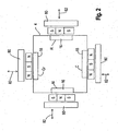
- Vacuum coating apparatuses of the generally described kind are known in the prior art and frequently equipped with two or more cathodes 16.
- a vacuum coating apparatus is available from the company Hauzer Techno Coating BV in which the chamber has a generally square shape in cross-section with one cathode at each of the four sides. This design has one side designed as a door permitting access to the chamber 14.
- the chamber is approximately octagonal in cross-section with two doors which each form three sides of the chamber. Each door can carry up to three magnetrons and associated cathodes 16.
- a typical vacuum coating apparatus includes a plurality of further devices which are not shown in the schematic drawings of this application.
- Such further devices comprise items such as dark space shields, heaters for the pre-heating of the substrates and sometimes electron beam sources or plasma sources in diverse designs.
- An ion source for use in the plasma enhanced chemical vapor deposition mode is shown in Fig. 1 by the reference numeral 21 and is positioned generally on the central longitudinal axis of the vacuum chamber. It can be a resistance heating filament connected to its own power supply or any other known design of ion source.
- the ion source 21 is connected to the negative output of a direct voltage supply (not shown). The positive pole of the direct voltage supply can be applied by way of a switch to the table 20 and thus to the holding devices and the workpieces 12 during the PECVD coating process.
- the vacuum chamber of Fig. 1 is also equipped with two coils 23 and 25 at the top and at the bottom of the chamber respectively. These can be connected to a DC power supply or to respective DC power supplies, they operate as Helmholz coils and enhance the magnetic field along the axis of the chamber.
- the current flows through each of the coils 23 and 25 in the same sense. It is known that the plasma intensity and the current flowing at the workpieces 12 are proportional to the current flowing in the coils 23 and 25 and thus to the magnetic field generated thereby.
- the individual items of the coating apparatus are preferably all connected to a computer based process control.
- This makes it possible to coordinate all the basic functions of a vacuum coating apparatus (vacuum pumping system, vacuum level (pressure in the vacuum chamber), power supplies, switches, process gas supplies and gas flow control, currents in the coils 23 and 25, positions of any variably positioned magnets, safety controls etc.). It also makes it possible to allow the specific values of all relevant variable parameters to be flexibly matched at any point in time to the coating or process requirements and to produce coatings to specific repeatable recipes.
- air is first extracted from the vacuum chamber 14 by the vacuum pumping system via the duct 44, the valve 42 and the stub 40 and argon is supplied via the line 50, the valve 48 and the connection stub 46.
- the chamber and the workpieces are preheated during pump-down to drive out any volatile gases or compounds which adhere to the workpieces or chamber walls.
- the inert gas (argon), which is supplied to the chamber, is always ionized to an initial extent, for example by cosmic radiation and splits up into ions and electrons.
- Ar ions can be generated by a plasma source.
- the generated ions are attracted to the workpieces 12 by the negative substrate bias voltage and etch the workpieces 12.
- the coating mode can be switched on.
- the cathodes will be activated during deposition. Ar ions collide with the target and knock atoms out of the target. Electrons are ejected from the target due to sputtering and are accelerated by the dark space voltage gradient. With their energy they can collide with Ar atoms, where secondary electrons will be emitted and help to maintain the discharge.
- Each of the cathodes is provided with a magnet system (not shown in Fig. 1 ) which is well known per se and which normally generates a magnetic tunnel in the form of a closed loop which extends over the surface of the associated cathode.
- This tunnel formed as a closed loop forces the electrons to move around the loop and collide with argon atoms causing further ionization in the gas atmosphere of the vacuum chamber 14. This in turn causes further ionization in the chamber from the material of the associated cathode and the generation of further argon ions.
- these ions can be attracted to the substrates by the applied negative bias voltage of for example 10 V to 1200 V and strike the surface of the workpieces with appropriate energy to control the coating properties.
- the power supply to the cathode or cathodes causes a flux of ions of the material of the cathode to move into the space occupied by the workpieces 12 and to coat them with the material of the respective cathode.
- the structure of the coating is influenced by the applied negative bias voltage that influences the movement of ions towards the workpieces.
- a special form of a pulsed discharge is the HIPIMS discharge.
- the power which is supplied to each cathode during a power impulse can be much higher than the power of a DC sputtering mode because there are substantial intervals between each pulse.
- the average power remains the same as for DC puttering.
- the limiting constraint on the power is the amount of heat that can be dissipated at the cathode before this overheats.
- each power pulse can have a duration of say 10 ⁇ s and a pulse repetition time is used of say 2000 ⁇ s, (corresponding to a pulse repetition frequency of 500 Hz, i.e. a spacing between impulses of1990 ⁇ s).
- the pulse repetition frequency might be 50 Hz and the pulse duration 100 ⁇ s, i.e. a spacing between impulses of 20 ms - 100 ⁇ s.
- an impulse duration can be selected between 10 ⁇ s and 4 ms and a pulse repetition time between 200 ⁇ s and 1 s.
- the average power can be kept to a moderate level equivalent to that of a DC sputtering process. It has been found that by the application of high power impulses at the cathode these operate in a different mode in which a very high degree of ionization of the ions arises which are ejected from the cathodes: This degree of ionization, which is material dependent, can lie in the range between 40 % and 90 %.
- WO 2007/ 115819 describes a solution as shown in Fig. 1 of this application in connection with the bias power supply BPS (32) in which an additional voltage source 60 is provided.
- the additional voltage source 60 is best realized by a capacitor.
- the capacitor 60 is charged by a customary bias power supply to the desired output voltage.
- the capacitor 62 which is charged by the bias power supply to the desired voltage in the periods between the power impulses, is able to keep the desired bias at the substrates constant within narrow limits and to supply the required current which only causes a small degree of discharging of the capacitor. In this way, the bias voltage remains at least substantially constant.
- the discharge can take place in such a way that a bias voltage of -50 V drops during the power pulses to -40 V.
- one of the cathodes 16 is a Cr, Ti or Si target for supplying a bond layer material. Possibly, other materials could also be used for a bond layer.
- the workpieces When depositing a DLC layer in the form of a ta-C layer the workpieces were positioned on a table 20 and were made by a PVD arc process from a carbon cathode in manner known per se.
- the chamber 10 had a working height of the space in which the workpieces are located of 850 mm.
- the apparatus initially used a standard ARC adhesion layer such as is used when depositing ta-C by carbon arc. It will not be described in detail because it is not the preferred solution and the arc process is in any case well known.
- Fig. 2 shows a view of the vacuum chamber of Fig. 1 in a cross-section perpendicular to the vertical axis with additional detail but without the workpieces.
- the chamber also has four cathodes, one of Cr as a bond layer material, one of graphite as a source of carbon and two of aluminium for forming an Al2O3 layer by dual magnetron sputtering in a reactive oxygen atmosphere.
- the two cathodes 16 labelled also A1 are of aluminium and have magnet arrangements with center poles of polarity "north" (N) and outside poles of polarity "south” (S) to generate the well-known magnetic tunnel of a magnetron.
- the cathodes have the shape of elongate rectangles when viewed face on and are shown here in a cross-section perpendicular to their long axis. Instead of having SNS polarity as shown, they could have NSN polarity as shown for the magnet arrangements for the cathodes of Cr and C at the top and bottom of Fig. 2 .
- the cathodes 16 of Cr and C would then have magnet arrangements with SNS polarity.
- the magnet arrangements can be moved in the direction of the respective double arrows 82 towards and away from the respective cathodes 16. This is an important control parameter for the operation of the HIPIMS cathodes.
- the magnetrons to have alternating polarities going around the vacuum chamber 14. This means, with an even number of cathodes, that the magnetic poles always alternate, i.e. N, S, N, S, N, S, N, S, N, S, N, S, N, S, N, S, N, S, N, S, S, S, S, S, S, S, S, S, when going around the chamber. This leads to an enhanced magnetic confinement of the plasma. A similar magnetic confinement can also be achieved if all cathodes have the same polarities, say NSN. Then it is necessary to operate with auxiliary S poles between the adjacent magnetrons to obtain a similar N, S, N, S, N arrangement around the chamber. It will be appreciated that the described arrangements only work with an even number of magnetrons.
- FIG. 2 also shows is four rectangular coils 80 positioned outside of the chamber 14 like the magnets with the SNS poles or NSN poles.
- the coils form electromagnets and have the same polarity as the outer magnets for the respective cathodes 16.
- These electromagnetic coils 80 enable the magnetic flux in front of the cathodes 16 and inside the chamber 14, to be varied.
- the vacuum coating system can be operated as follows:
- HIPIMS etching with a Cr, Ti or Si target operated in a HIPIMS magnetron etching mode with a relatively high substrate bias of - 500 to -2000 V. This is well known in the art and described in EP-B-1260603 of Sheffield Hallam University.
- the typical time averaged equivalent DC etching power applied to the Cr, Ti or Si cathode is in the range of 1 to 25 kW.
- a bond layer of Cr, Ti or Si is deposited on the metal surface. This is done for about 10 to 20 minutes from a target of Cr, Ti or Si operated in a sputter discharge mode or in a HIPIMS coating mode.
- the maximum average power which can be dissipated by and thus effectively applied to a cathode is the power which does not lead to an undesirable temperature increase of the cathode or unwanted melting thereof.
- a maximum power of approximately 15 W/cm2 might be applied to a particular cathode in the case of indirectly cooled targets, corresponding to the allowable thermal load of the target.
- a pulsed power supply which might typically apply power in 10 to 4000 ⁇ s wide pulses at a pulse repetition frequency of less than 1 Hz - 5 kHz.
- the maximum pulse power that can be supplied during a HIPIMS pulse is thus 180 kW.
- An appropriate negative substrate bias of about 0 to 200V should be provided during the deposition of the bond layer.
- the pressure in the chamber may be between 10 -4 and 10 -3 mbar.
- the deposition of the bond layer can also be done with filtered arc cathodes. Also the use of unfiltered arc cathodes is a possibility, but this is less advantageous because it will lead to additional roughness of the coating because of droplet generation.
- a Cr-C, Ti-C or Si-C transition layer is deposited for about 1 to 5 minutes with simultaneous operation of a Cr, Ti or Si target and a graphite target in a HIPIMS mode or with carbon-arc cathodes with about -50 to -2000 V substrate bias.
- the pressure in the chamber can again be in the range between 10 -4 and 10 -3 mbar.
- the apparatus of the invention typically comprises a plurality of magnetrons and associated cathodes, at least one of which comprises a bond layer material (Cr, Ti or Si).
- the at least one cathode for the bond layer material can also be an arc cathode (filtered, or unfiltered).
- the apparatus further comprises a power supply for the sputtering of bond layer material for the deposition of the bond layer material on the substrate or substrates prior to deposition of the DLC layer.
- a typical example of a bond layer material is as already stated Cr, Ti or Si.
- the pulse repetition frequency is preferably in the range from 1 Hz to 2 kHz, especially in the range from 1 Hz to 1.5 kHz and in particular of about 10 to 30 Hz.
- dopants can be added to the coating.
- dopants can be metals from sputter targets operated with arc sputtering or magnetron sputtering or from HIPIMS cathodes (Si, Cr, Ti, W, WC).
- the dopants can also be supplied from precursors in gas phase (such as hydrocarbon gases, nitrogen, oxygen, Si containing precursors like silane, HMDSO, TMS).
- the invention also comprises the use of dopants to the ta-C coating) so long as the dopants do not undesirably reduce the insulating properties so that the calculated current density exceeds the permissible value.
- etching takes place once a steady temperature has been reached.
- the etching is for example carried out using a HIPIMS etching process as covered by European patent EP-B-1260603 although other etching processes can also be used.
- argon gas is supplied to the vacuum chamber for example at 75sccm and ionized by operation of one or more of the magnetrons incorporated therein, for example the magnetron with the target 16 of Cr can be used.
- the workpiece can be provided with an adhesive layer, also termed a bond layer, to facilitate the adhesion of the DLC coating.
- an adhesive layer also termed a bond layer
- Such a bond layer is not always necessary.
- the DLC layer, or some types of DLC layer could be deposited directly on the cleaned and etched workpieces without the use of a bond layer.
- an adhesive layer is provided on the workpiece then it can be selected from the group of elements of the IV, V and VI Subgroup as well as Si.
- an adhesive layer of the elements Cr or Ti is used which have been found to be particularly suitable for this purpose.
- the adhesive layer can be deposited by arc sputtering or filtered arc sputtering, but is preferably deposited using magnetron sputtering from the Cr target 16 in Fig 2 .
- argon is supplied to the vacuum chamber.
- the argon flow is higher than during pre-heating and etching and may, for example, be set at 120 sccm.
- the pressure in the vacuum chamber is typically around 10 -3 mbar but can be up to an order of magnitude lower or can be somewhat higher than 10 -3 mbar.
- a negative bias of around 50 V is applied to the substrate carrier and the deposition of the bonding layer takes only a few minutes with about 10 kW of power applied to the cathode (average power if the magnetron cathode is operated in the HIPIMS mode).
- the idea of the gradient layer is to progressively reduce the proportion of Cr in the gradient layer while increasing the proportion of carbon in it thus forming chromium carbide and allowing the carbon content to increase until only a DLC coating is being applied.
- EP-B-1272683 Another possibility is to use the technique described in EP-B-1272683 for the deposition of an adhesive layer, of a graded layer and subsequently a DLC layer.
- the substrate bias is switched over from direct current to medium frequency by using the switch 19 to connect the electric voltage supply 17, which is a bipolar generator, to the table 20 instead of the constant bias supply 32.
- the electric voltage supply is operated with a preferred amplitude voltage of between 500 and 2,500 V, for example 700 V, and a frequency between 20 and 250 kHz, for example 50 kHz.
- the pressure in the vacuum chamber is typically around 10 -3 mbar, but can be up to an order of magnitude lower or can be somewhat higher than 10 -3 mbar.
- acetylene ramp is started at 50 sccm and is raised over a time period of approximately 30 minutes to 350 sccm.
- the power of the used Cr target is reduced to 7 kW; after another 10 minutes, it is reduced to 5 kW and is held constant there for another 2 minutes.
- acetylene or another carbon containing gas can be supplied to the vacuum chamber in increasing amounts during the deposition of the adhesive or bonding layer after about one third of that layer has been deposited so that the composition of the adhesive layer or bonding layer progressively changes from chromium to chromium carbide.
- the process can be completed with switched-off vaporizing sources, but otherwise with the same parameters as in the case of the preceding gradient layer.
- the medium frequency supply is adjusted to remain constant and the argon flow remains the same, the acetylene ramp started during the gradient layer is increased for approximately 10 minutes uniformly to a flow between approximately 200 and 400 sccm. Subsequently, for a time period of 5 minutes, the argon flow is continuously reduced to a flow between approximately 0 and 100 sccm, for example to 50 sccm. During the next 55 minutes, the process is completed while the settings remain the same.
- the pressure in the vacuum chamber is typically around 10 -3 mbar but can be up to an order of magnitude lower or can be somewhat higher than 10 -3 mbar.
- the upper coil is operated with an excitation current of about 10 A and the lower coil with an excitation current about one third of that of the top coil.
- the deposition of the DLC layer thus takes place by a plasma assisted CVD (chemical vapor deposition) process.
- the plasma assistance comes from the plasma generated by the ion source 21 in combination with the vacuum in the chamber and the magnetic field generated in the chamber by the upper and lower coils 23 and 25 respectively as well as the contributions to the magnetic field of the other magnets that are present or in operation such as the magnets associated with the magnetrons (which are operative to generate magnetic fields even if magnetron sputtering is not taking place).
- the depositing rate will typically be about 1 to 2 microns per hour.
- the DLC coating has a hardness of about 25 GPa and a coefficient of friction of about 0.2. It has a hydrogen content of about 13 % and a resistance of around 500 kOhm.
- the adhesion of the DLC coating which can be measured according to DVI 3824, Sheet 4 is very good and can be classified as HF1 according to the DVI 3824 document.
- EP-A-600533 describes a method of depositing a DLC coating on an iron substrate with a graded transition layer of a-Si 1-x C x :H by PACVD using silane gas enriched with hydrogen for the Si source and methane enriched with hydrogen for the carbon source.
- a thin layer of Si of 15 nm thickness is first deposited followed by the graded layer of 25 nm thickness, with the proportion of Si decreasing and the proportion of C increasing, and is capped by a relatively thick DLC layer to a total layer thickness of 2.3 microns.
- DE-A-19826259 describes multilayer structures of metal carbide layers (titanium carbide or chromium carbide) alternating with a-C:H (DLC) layers.
- the PVD coating process is complete and the workpieces can be transferred to another vacuum chamber such as Fig. 5 for the deposition of the ALD coating.
- a workpiece or article 12 having an-O-H terminated surface is created. This can be done in a vacuum chamber, described later with reference to Fig. 5 , by admitting water to the chamber under CVD (chemical vapor deposition) conditions, especially under PECVD (plasma enhanced chemical vapor deposition) conditions, i.e. in the presence of a plasma, as is well known from the field of wafer bonding.
- CVD chemical vapor deposition
- PECVD plasma enhanced chemical vapor deposition
- the substrate Prior to this step the substrate can be subjected to extensive cleaning and etching, for example under PVD (physical vapor deposition) conditions, e.g. by subjecting the surface to argon ion bombardment as discussed below with reference to Fig. 5 .
- the 2-OH radicals bond to the aluminium to result in the situation shown in Fig. 3C .
- These reactions typically take place in the temperature range from 100 °C to 400 °C.
- the CH4 which is formed is sucked away out of the vacuum chamber by the vacuum pump together with the excess water vapor. Again the reaction is chemically stopped once all CH 3 groups have been substituted by -OH groups.
- the present invention is not restricted to the deposition of Al 2 O 3 layers but can in principle be used with all layer materials capable of being grown by ALD including: Al 2 O 3 , TaO, SiO 2 , TiO 2 , Ta 2 O 5 , HfO 2 , a mixed layer comprising two or more of the foregoing oxides, or a multilayer structure comprising alternating layers of two or more of the foregoing oxides.
- the deposition of these materials by ALD can be done using the reagents described in the IC Knowledge publication "2004 IC Technology".
- One particular application for the ALD process is in the manufacture of integrated circuits and the process is described in this connection in some detail in the IC Knowledge publication "2004 IC Technology”. The details described there can be of assistance in realizing the present teaching and the disclosure of that reference in this respect is included herein by reference.
- the process can be conveniently considered as if each cycle of the process is used to deposit one or more layers each essentially one atom thick if the coating used is a coating of an element such as Cu, Mo, Ni, Ta, Ti or W in the above list. If the coating is molecular, e.g. an Al 2 O 3 coating, then the name is strictly speaking incorrect but internationally understood. Moreover, as stressed by Puurunen, the actual growth per cycle of the ALD process can be less than one, since not all sites on the substrate or on the preceding ALD layer are necessarily reactive sites for a variety of reasons.
- the ALD process described above is one example of how the process can take place and is in no way to be understood as a limiting example.
- the trimethyl aluminium can also bond "simultaneously" on two OH groups on the surface and then have only one methyl group sticking out. Both will occur. Which one will occur preferentially has to do (among others) with the degree of steric hindrance, which more or less means what has the best geometrical fit.
- Another variant of the ALD process using trimethyl aluminium and water is described in the document " Plasma Assisted Atomic Deposition of TiN films, June 23rd 2004 " authored by Stephan Heil of the Technical University of Eindhoven. The details described there can be of assistance in realizing the present teaching and the disclosure of that reference in this respect is included herein by reference.
- Al 2 O 3 by ALD using oxygen (O 2 ) as a precursor.
- O 2 oxygen
- Al 2 O 3 by ALD is for example described in the PhD thesis of Dr. Stephan Heil dated June 29th 2008 and entitled "Atomic layer deposition of Metal Oxide and Nitrides". The details described there can be of assistance in realizing the present teaching and the disclosure of that reference in this respect is included herein by reference.
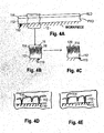
- the PVD or CVD layer 112 is an electrically insulating layer as described above with reference to Figs. 1 and 2 and generally has a high hardness and high wear resistance, optionally with a low coefficient of friction.
- the layer 110 is a DLC layer applied directly onto the surface of a martensitic steel workpiece, i.e. without a bond layer or a graded layer between the DLC layer and the workpiece, although such layers can be provided if desired or if necessary to obtain good adhesion of the DLC layer and/or to prevent spalling.
- the ALD layers 114 are Al 2 O 3 layers.
- the DLC layer 112 typically has a columnar structure and/or a porous structure which would otherwise allow corrosive substances such as liquids or gases to reach the substrate and cause corrosion there.
- Such a columnar structure and/or porous structure would, in the absence of the electrically insulating ALD layer 114 be a poor coating from the point of view of electrical isolation despite the fact that the coating itself is a good insulator.
- the point is that the columnar or porous structure means small areas of the article surface are effectively exposed and, particularly with thin coatings, can readily lead to local conducting pathways which must be avoided. This is achieved by the conformal sealing layer in the form of the ALD layer (layer system) 114.
- the coating would normally be applied to the outer surfaces of the outer bearing race and/or to the radially inner surfaces of the inner bearing race, but generally not to the raceway surfaces themselves which are in contact with the rolling elements.
- a PECVD (plasma enhanced chemical vapor deposition) process (but excluding an ALD process or a plasma enhanced ALD process) has a high hardness and a high resistance to wear such as a DLC layer because then the raceways of the inner an/or outer races could also be coated. This applies even if the ALD layer applied to the aforementioned layer wears away from the surface of the aforementioned layer, since the ALD layer is only very thin.
- Coatings applied to the outer surfaces of the outer bearing race and/or to the radially inner surfaces of the inner bearing race do not necessarily have to be extremely hard or wear resistant because they are not intended to move within the housing or on the associated shaft. Nevertheless, hard and wear resistant coatings are preferred at such locations because the inner and outer races may shuffle within the housing or on the shaft. Since the coatings of the present invention tend to be extremely hard or wear resistant and are also extremely thin they can also be formed on the raceway surfaces if they are sufficiently hard and wear resistant. Theoretically at least the coating could also be provided on the rolling elements if desired.
- This embodiment recognizes and exploits an important advantage of the ALD process, that the atomic layer growth can take place in deep and narrow gaps, i.e. here on the side walls of the interstitial passages and on the side walls of open pores and of any other defects such as cracks. This means that even if only a few layers are grown by ALD these are sufficient to seal the PVD layer. If enough ALD layers are grown they can seal the open pores and interstitial passages as shown in Fig. 4B and achieve excellent electrical insulation.
- the ALD layer 114 comprises a plurality of monolayers having a thickness in the range from 1 nm to 50 nm. Thin layers of 1 nm or a few nm in thickness can be deposited relatively quickly because the number of repetitions (cycles) of the ALD process necessary to build up the layer 114 is restricted.
- the conformal ALD layer 114 which is itself usually extremely hard, wears significantly in use then it wears down until the surface of the PVD or CVD layer is exposed, as shown in Figs. 4C and 4E and thereafter wear is insignificant for a long period of time as a result of the hard DLC layer.
- the substrate 10 is protected by the PVD or CVD layer 112 which remains sealed electrically by the ALD layer material which lines or fully fills the "openings" in the PVD or CVD layer 112.
- Figs 4A to 4E is thus also beneficial when the ALD layer has worn down to the free surface of the PVD or CVD layer because, although the corrosive substances can reach the free surface of the PVD or CVD or PECVD layer they still cannot reach the surface of the article itself.
- the PVD layer 112 of Figs 4D and 4E still has a porous structure or a columnar structure with interstitial passages into which corrosive substances can penetrate. They cannot however reach the substrate because of the ALD layer (layer system) 114 which extends down to the actual surface of the article in such passages.
- the PVD or CVD layer 112 can also comprise a layer system (not shown but comprising a plurality of different PVD and/or CVD layers or an alternating layer system or a superlattice structure) or a graded layer. Such layer structures are well known per se.
- the PVD or CVD layer 112 can - without restriction and without including a possible bond layer - comprise one of a DLC layer, a metal-DLC layer, or a layer of the same composition as the ALD layer.
- the PVD layer can for example also be an Al 2 O 3 layer.
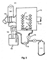
- the treatment chamber 130 shown in Fig. 5 has a central at least substantially rectangular form when viewed from any of its sides.
- a chamber door not shown in Fig. 5 is pivotally connected to the front side of the chamber about vertical pivot axles, i.e. axles which lie parallel to the plane of the drawing.
- the rear side of the chamber could be connected by a load lock to a correspondingly designed opening at one side of the chamber 14 of Fig 1 which is normally closed by a door located within the opening, that door of the chamber 14 may carry a magnetron and associated cathode.
- a load lock is not necessary, the treated articles from the chamber of Figs. 1 and 2 can simply be transported in the normal ambient atmosphere to the chamber of Fig. 5 .
- one chamber for applying a DLC coating such as a chamber in accordance with Figs. 1 and 2 , could supply coated workpieces to a plurality of apparatuses for applying an ALD coating, such as apparatuses in accordance with Fig. 5 .
- the arrangement can be such that the workpiece table 20 of Fig. 1 together with the workpieces 12 can be to be transferred after deposition of the PVD coating 112 into the ALD chamber. If a load lock system is used this can be done without loss of vacuum and without contamination of the workpiece surface.
- the table 20 can rotate in the chamber 130 if desired but this is not essential.
- the transfer system is not shown but can be designed as in customary load lock systems.
- the apparatus could also be designed as a cluster system with a plurality of satellite ALD chambers such as 130 arranged around one chamber for depositing DLC coatings, such as is shown in Figs. 1 and 2 .
- the reference numeral 132 refers to a duct for the connection duct for a performance vacuum pump (not shown) such as a diffusion pump, a cryo pump or simply a mechanical pump which serves in known manner to generate the necessary vacuum in the treatment chamber. That vacuum may be of the order of 100 millitorr although it is certainly not necessary to go so low as there is a thermal space in the chamber of high temperature.
- the pressure can generally lie in a range from 1 to 1000 millitorr.
- a plasma generator 164 Disposed opposite the vacuum connection duct 162 is a plasma generator 164 for generating a plasma from O 2 gas supplied to the chamber 130 via a valve system (not shown but including a flow regulator and an on/off valve) through port 166.
- the reference numeral 168 identifies an rf plasma generator basically comprising a coil 170 fed with a rf energy from source 172.
- the plant of Fig. 5 can be operated as follows:
- the apparatus is then changed over to the oxygen admission cycle and a plasma is generated in the chamber by the rf-generator and the oxygen supplied thereto. Thereafter a predetermined quantity of Al(CH 3 ) 3 is added to the chamber for formation of the first Al 2 O 3 layer by ALD. Thereafter the process is repeated until the desired number of ALD layers have been generated by the plasma enhanced ALD process.
- the final layer has been deposited by the ALD process, i.e. once the ALD layer (layer system) 114 has been completed the articles can now be removed from the chamber by opening the chamber doors.
- ALD layer or layer system 114 is relatively thin and can be deposited relatively quickly in a time frame comparable to that required for depositing the layer 112 by PVD or CVD a cluster arrangement may not be the ideal layout.
- the complete apparatus could for example be realized as a long tubular plant with successive stations for PVD deposition processes and/or CVD deposition processes and ALD deposition processes through which individual articles move.
- the entire tubular plant can be evacuated by the use of load locks for admitting articles to the plant and removing them from the plant without loss of vacuum.
- Local gas supplies to the individual stations and local vacuum pumps can also be provided to maintain desired atmospheres in the individual stations through which the articles sequentially move, for example on a conveyor belt.
- Such an arrangement can help minimize wastage of the gases required and enhance useful process time relative to non-profitable vacuum generation periods.
- a surface region 110 of an article in the form of a bearing race of 100Cr6 steel which is provided with a layer 112 of hydrogen free ta-C layer of 4 microns thickness.
- the layer 112 has a structure similar to that illustrated in Fig. 4D .
- the coating is similar to the coating of Example 2 but includes an additional layer 112" of Al 2 O 3 of 200 nm-2 ⁇ m thickness deposited by PVD in the apparatus of Fig. 1 .
- the apparatus of Figs. 1 and 2 is modified so that it can carry out dual magnetron sputtering from two opposed magnetron cathodes of A1 additionally provided in the vacuum chamber 14 for reactive sputtering. using oxygen in the chamber atmosphere.
- the reactive sputtering of Al 2 O 3 is described in detail in the European patent application published as EP-A-2076916 .
- the apparatus can also be designed to make use of the combined use of HIPIMS and dual magnetron sputtering as described in the European patent application 11007077.8 .
- the layer structure is a two layer structure as shown in Fig. 6A but the layer 112 is an a-C:H layer of 1-4 microns thickness deposited by a CVD process (but not an ALD process).
- the ALD layer 114 of Al 2 O 3 again has a thickness of 10 nm.
- Example 2 This example is the same as Example 2 but the ALD layer 114 has a greater thickness of 26-50 nm.
- Example 3 This example is similar to Example 1 but here the layer 112 is a layer of Al 2 O 3 4 microns thick deposited by PVD (dual magnetron sputtering in a reactive oxygen atmosphere) as in Example 3.
- the layer 112 is a layer of Al 2 O 3 4 microns thick deposited by PVD (dual magnetron sputtering in a reactive oxygen atmosphere) as in Example 3.
- the layer structure resembles that of Example 6 ( Fig. 6E ) but with a bond layer 112' of Cr or Ti deposited by PVD. It should be noted that it is unimportant whether the bond layer is electrically conducting or insulating since even if it is electrically conductive this situation is no worse than the component itself being electrically conductive.
- the layers have the same thicknesses as in other examples unless something different is specifically stated.
- the layer 112 is generally 1-4 microns thick.
- the layer 112 if present, is generally 50 nm - 2.5 ⁇ m thick and the ALD layer 114 is generally 10-50 nm thick.
- the thickness of the layers are 10nm for the layer 112', 4 microns for the layer 112, 10nm for the layer 112" and 10nm for the layer 114 unless otherwise stated.
- the electrical insulation and corrosion resistance of all examples was found to be good.
Claims (10)
- Lagerkomponente aus Stahl (12), wie etwa eine Komponente eines Linearlagers, eines Wälzelementlagers oder eines Gleitlagers, z.B. eine Komponente, die aus der Gruppe gewählt ist, die einen Lagerring, ein Wälzelement, wie etwa eine Kegelrolle, eine Tonnenrolle, eine Nadelrolle, eine Lagerkugel und einen Wälzelementkäfig, umfasst, wobei die Lagerkomponente zumindest eine Schicht (112; 112, 112'; 112, 112'; 112") aufweist, die eine hohe Härte und eine Hochstromisolationseigenschaft aufweist und durch einen PVD-Prozess (physical vapor deposition process), durch einen CVD-Prozess (chemical vapor deposition process) oder durch einen PECVD-Prozess (plasma enhanced chemical vapor deposition process), aber unter Ausschluss eines ALD-Prozesses oder eines plasmaverstärkten ALD-Prozesses auf zumindest einem Oberflächenbereich (110) der Komponente (12) aufgebracht ist, wobei die zumindest eine Schicht (112; 112, 112'; 112, 112'; 112") eine nichtleitfähige Oxidschicht umfasst, die aus der Gruppe von Materialien gewählt ist, die eine Al2O3-Schicht, eine TaxOy-Schicht, eine SixOy-Schicht, eine gemischte Schicht mit zwei oder mehreren der vorstehenden Oxide, eine Mehrschichtstruktur mit abwechselnden Schichten aus zwei oder mehreren der vorstehenden Oxide und/oder einer DLC-Schicht, wie etwa einer ta-C-Schicht, umfasst, wobei es zumindest eine ALD-Schicht (114) gibt, die zumindest eine Schicht aus einem Material umfasst, das durch einen ALD-Prozess (atomic layer deposition process) auf der zumindest einen Schicht abgeschieden ist, die eine hohe Härte und eine Hochstromisolationseigenschaft aufweist, wobei die ALD-Schicht selbst eine Hochstromisolationseigenschaft aufweist und ein Material oder eine Schichtstruktur umfasst, die aus der Gruppe von Materialien gewählt ist, die eine Al2O3-Schicht, eine TaxOy-Schicht, eine SixOy-Schicht, eine TiO2-Schicht oder eine HfO2-Schicht, eine gemischte Schicht mit zwei oder mehreren der vorstehenden Oxide und eine Mehrschichtstruktur mit abwechselnden Schichten aus zwei oder mehreren der vorstehenden Oxide umfasst.
- Lagerkomponente nach Anspruch 1, wobei die Zusammensetzung der zumindest einen Schicht, die durch einen PVD-Prozess (physical vapor deposition process), durch einen CVD-Prozess (chemical vapor deposition process) oder durch einen PECVD-Prozess (plasma enhanced chemical vapor deposition process), aber unter Ausschluss eines ALD-Prozesses oder eines plasmaverstärkten ALD-Prozesses aufgebracht ist, zumindest im Wesentlichen gleich ist wie die Zusammensetzung der Schicht, die durch den ALD-Prozess abgeschieden ist.
- Lagerkomponente nach Anspruch 1 oder Anspruch 2, wobei die zumindest eine Schicht, die durch einen PVD-Prozess (physical vapor deposition process), durch einen CVD-Prozess (chemical vapor deposition process) oder durch einen PECVD-Prozess (plasma enhanced chemical vapor deposition process), aber unter Ausschluss eines ALD-Prozesses oder eines plasmaverstärkten ALD-Prozesses aufgebracht ist, eine Dicke im Bereich von 0,5 Mikron bis 4 Mikron aufweist und die ALD-Schicht eine Dicke im Bereich von 1 nm bis 1000 nm, insbesondere 10 bis 50 nm, aufweist.
- Lagerkomponente nach einem der vorhergehenden Ansprüche, wobei der Stahl, aus dem der Gegenstand hergestellt ist, eine martensitische Stahlqualität ist.
- Lagerkomponente nach Anspruch 4, wobei die martensitische Stahlqualität zumindest eine von einem Lagerstahl und einem Kaltarbeitsstahl ist.
- Lagerkomponente nach einem der vorhergehenden Ansprüche 4 und 5, wobei die martensitische Stahlqualität eine von 100Cr6, 100CrMn6, 16MnCr5, C80 oder X30CrMoN 15 1 oder ein Stahl gemäß Din: 1.4108 oder SAE: AMS5898 ist.
- Lagerkomponente nach einem der vorhergehenden Ansprüche, wobei die zumindest eine Schicht, die eine hohe Härte und eine Hochstromisolationseigenschaft aufweist und durch einen PVD-Prozess (physical vapor deposition process), durch einen CVD-Prozess (chemical vapor deposition process) oder durch einen PECVD-Prozess (plasma enhanced chemical vapor deposition process), aber unter Ausschluss eines ALD-Prozesses oder eines plasmaverstärkten ALD-Prozesses aufgebracht ist, mit einer zusätzlichen PVD-Schicht versehen ist, die durch einen Lichtbogen (gefilterter Lichtbogen, rechteckige Quellen, runde Quellen, Laserlichtbogen, zylindrische Quellen), durch Magnetron-Sputtern, durch reaktives Magnetron-Sputtern oder mittels Dual-Magnetron-Sputtern (rechteckige Quellen, runde Quellen, zylindrische Quellen), ein jedes der vorstehenden optional mit Plasmaverstärkung, vor der Abscheidung der ALD-Schicht abgeschieden ist.
- Lager mit einer Lagerkomponente nach einem der vorhergehenden Ansprüche.
- Maschine mit einer Lagerkomponente nach einem der vorhergehenden Ansprüche 1 bis 7 oder einem Lager nach Anspruch 8.
- Verfahren zum Beschichten einer Lagerkomponente aus Stahl (12), wie etwa eine Komponente eines Linearlagers, eines Wälzelementlagers und eines Gleitlagers, z.B. einer Komponente, die aus der Gruppe gewählt ist, die einen Lagerring, ein Wälzelement, wie etwa eine Kegelrolle, eine Tonnenrolle, eine Nadelrolle, eine Lagerkugel und einen Wälzelementkäfig, umfasst, wobei zumindest eine Schicht (112; 112, 112'; 112, 112'; 112") auf zumindest einem Oberflächenbereich (110) der Komponente (12) abgeschieden wird, wobei die Schicht eine hohe Härte und eine Hochstromisolationseigenschaft aufweist und durch einen PVD-Prozess (physical vapor deposition process), durch einen CVD-Prozess (chemical vapor deposition process) oder durch einen PECVD-Prozess (plasma enhanced chemical vapor deposition process), aber unter Ausschluss eines ALD-Prozesses oder eines plasmaverstärkten ALD-Prozesses aufgebracht wird, wobei die zumindest eine Schicht (112; 112, 112'; 112, 112'; 112") eine nichtleitende Oxidschicht umfasst, die aus der Gruppe von Materialien gewählt ist, die eine Al2O3-Schicht, eine TaxOy-Schicht, eine SixOy-Schicht, eine gemischte Schicht mit zwei oder mehreren der vorstehenden Oxide, eine Mehrschichtstruktur mit abwechselnden Schichten aus zwei oder mehreren der vorstehenden Oxide und/oder einer DLC-Schicht, wie etwa einer ta-C-Schicht, umfasst, wobei zumindest eine ALD-Schicht (114) auf der zumindest einen Schicht die eine hohe Härte und eine Hochstromisolationseigenschaft aufweist abgeschieden wird, wobei die ALD-Schicht zumindest eine Schicht aus einem Material umfasst, die durch einen ALD-Prozess (atomic layer deposition process) abgeschieden wird, wobei die ALD-Schicht selbst eine Hochstromisolationseigenschaft aufweist und ein Material oder eine Schichtstruktur umfasst, die aus der Gruppe von Materialien gewählt ist, die eine Al2O3-Schicht, eine TaxOy-Schicht, eine SixOy-Schicht, eine TiO2-Schicht oder eine HfO2-Schicht, eine gemischte Schicht mit zwei oder mehreren der vorstehenden Oxide und eine Mehrschichtstruktur mit abwechselnden Schichten aus zwei oder mehreren der vorstehenden Oxide umfasst.
Priority Applications (9)
| Application Number | Priority Date | Filing Date | Title |
|---|---|---|---|
| ES12000975.8T ES2543579T3 (es) | 2012-02-15 | 2012-02-15 | Componentes de cojinete y cojinetes aislados frente a corriente |
| PL12000975T PL2628822T3 (pl) | 2012-02-15 | 2012-02-15 | Elementy łożysk i łożyska izolowane elektrycznie |
| EP20120000975 EP2628822B1 (de) | 2012-02-15 | 2012-02-15 | Stromisolierende Lagerkomponenten und Lager |
| US13/728,895 US9115755B2 (en) | 2012-02-15 | 2012-12-27 | Current insulated bearing components and bearings |
| SG2012096566A SG193070A1 (en) | 2012-02-15 | 2012-12-28 | Current insulated bearing components and bearings |
| JP2012287625A JP6190590B2 (ja) | 2012-02-15 | 2012-12-28 | ベアリングコンポーネント、ベアリング、機械、およびベアリングコンポーネントの被覆方法 |
| CN201210593021.XA CN103256306B (zh) | 2012-02-15 | 2012-12-31 | 电流绝缘的轴承部件及轴承 |
| KR1020130000409A KR101948013B1 (ko) | 2012-02-15 | 2013-01-02 | 전류 절연 베어링 부품 및 베어링 |
| TW102100001A TWI577814B (zh) | 2012-02-15 | 2013-01-02 | 電流絕緣軸承組件及軸承及塗覆軸承組件的方法 |
Applications Claiming Priority (1)
| Application Number | Priority Date | Filing Date | Title |
|---|---|---|---|
| EP20120000975 EP2628822B1 (de) | 2012-02-15 | 2012-02-15 | Stromisolierende Lagerkomponenten und Lager |
Publications (2)
| Publication Number | Publication Date |
|---|---|
| EP2628822A1 EP2628822A1 (de) | 2013-08-21 |
| EP2628822B1 true EP2628822B1 (de) | 2015-05-20 |
Family
ID=45655019
Family Applications (1)
| Application Number | Title | Priority Date | Filing Date |
|---|---|---|---|
| EP20120000975 Active EP2628822B1 (de) | 2012-02-15 | 2012-02-15 | Stromisolierende Lagerkomponenten und Lager |
Country Status (9)
| Country | Link |
|---|---|
| US (1) | US9115755B2 (de) |
| EP (1) | EP2628822B1 (de) |
| JP (1) | JP6190590B2 (de) |
| KR (1) | KR101948013B1 (de) |
| CN (1) | CN103256306B (de) |
| ES (1) | ES2543579T3 (de) |
| PL (1) | PL2628822T3 (de) |
| SG (1) | SG193070A1 (de) |
| TW (1) | TWI577814B (de) |
Families Citing this family (19)
| Publication number | Priority date | Publication date | Assignee | Title |
|---|---|---|---|---|
| CN111593324A (zh) * | 2015-02-13 | 2020-08-28 | 恩特格里斯公司 | 多孔基质过滤器及其制作方法 |
| CN105132888B (zh) * | 2015-09-11 | 2019-02-19 | 兰州空间技术物理研究所 | 一种高温抗氧化涂层的复合沉积方法 |
| JP6672812B2 (ja) * | 2016-01-14 | 2020-03-25 | 三菱電機株式会社 | 半導体装置及びその製造方法 |
| US10190640B2 (en) | 2016-03-23 | 2019-01-29 | Schaeffler Technologies AG & Co. KG | Bearing with integrated shunt |
| US10794427B2 (en) | 2016-04-05 | 2020-10-06 | Schaeffler Technologies AG & Co. KG | Bearing ring with insulating coating |
| US10858727B2 (en) | 2016-08-19 | 2020-12-08 | Applied Materials, Inc. | High density, low stress amorphous carbon film, and process and equipment for its deposition |
| WO2018056584A1 (ko) | 2016-09-21 | 2018-03-29 | 삼성전자 주식회사 | 피부 상태 측정 방법 및 이를 위한 전자 장치 |
| JP6729437B2 (ja) * | 2017-02-08 | 2020-07-22 | 株式会社デンソー | 金属構造体およびその製造方法 |
| JP7134639B2 (ja) | 2017-03-24 | 2022-09-12 | アクティエボラゲット・エスコーエッフ | 電気絶縁層を含む転がり軸受 |
| US10539178B2 (en) | 2017-05-18 | 2020-01-21 | Schaeffler Technologies AG & Co. KG | Vapor deposition bearing coating |
| KR102019057B1 (ko) | 2018-01-31 | 2019-09-06 | 셰플러코리아(유) | 구름 베어링 전식 시험 장치 |
| WO2019160836A1 (en) * | 2018-02-13 | 2019-08-22 | Schaeffler Technologies AG & Co. KG | Coated bearing components |
| WO2019209401A1 (en) * | 2018-04-27 | 2019-10-31 | Applied Materials, Inc. | Protection of components from corrosion |
| US11560808B2 (en) * | 2018-09-19 | 2023-01-24 | Raytheon Technologies Corporation | Seal assembly for gas turbine engine |
| CN109576679B (zh) * | 2018-12-24 | 2022-03-22 | 上海治臻新能源股份有限公司 | 一种燃料电池双极板碳涂层连续沉积系统及其应用 |
| CN114008757A (zh) * | 2019-05-07 | 2022-02-01 | 欧瑞康表面处理解决方案股份公司普费菲孔 | 用于保持待处理工件的移动式工件承载装置 |
| CN111876754A (zh) * | 2020-08-04 | 2020-11-03 | 中国科学院兰州化学物理研究所 | 通过纳米金属镀膜钢球与含氢碳薄膜配副实现宏观超滑的方法 |
| CN113564552A (zh) * | 2021-07-29 | 2021-10-29 | 中国科学院兰州化学物理研究所 | 一种电磁分离式镀膜装置及方法 |
| CN114150282B (zh) * | 2021-11-22 | 2022-08-09 | 苏州大学 | 一种纳米刀具涂层及其制备方法 |
Family Cites Families (37)
| Publication number | Priority date | Publication date | Assignee | Title |
|---|---|---|---|---|
| DE3421739A1 (de) | 1984-06-12 | 1985-12-12 | Battelle-Institut E.V., 6000 Frankfurt | Verfahren zur herstellung von diamantartigen kohlenstoffschichten |
| US5067826A (en) * | 1987-03-31 | 1991-11-26 | Lemelson Jerome H | Ball and roller bearings and bearing components |
| BE1006711A3 (nl) | 1992-12-02 | 1994-11-22 | Vito | Werkwijze voor het aanbrengen van een diamantachtige koolstoflaag op staal, ijzer of legeringen daarvan. |
| BE1008229A3 (nl) | 1993-10-29 | 1996-02-20 | Vito | Werkwijze voor het aanbrengen van een tegen slijtage beschermende laag op een substraat. |
| DE19513614C1 (de) | 1995-04-10 | 1996-10-02 | Fraunhofer Ges Forschung | Verfahren zur Abscheidung von Kohlenstoffschichten, Kohlenstoffschichten auf Substraten und deren Verwendung |
| US5593234A (en) * | 1995-05-16 | 1997-01-14 | Ntn Corporation | Bearing assembly with polycrystalline superlattice coating |
| EP0791760A3 (de) * | 1996-02-20 | 1997-09-10 | Ebara Corporation | Wassergeschmiertes Lager oder Dichtung |
| DE19631988A1 (de) * | 1996-08-08 | 1998-02-12 | Dieter Westerhoff | Kugel- bzw. wälzgelagerter Großelektromotor |
| US6372303B1 (en) | 1997-06-16 | 2002-04-16 | Robert Bosch Gmbh | Method and device for vacuum-coating a substrate |
| NL1009170C2 (nl) * | 1998-05-14 | 1999-11-16 | Skf Eng & Res Centre Bv | Bekleed wentellager. |
| US6357923B1 (en) * | 1999-02-19 | 2002-03-19 | Nsk Ltd. | Rolling bearing and bearing device |
| DE10018143C5 (de) | 2000-04-12 | 2012-09-06 | Oerlikon Trading Ag, Trübbach | DLC-Schichtsystem sowie Verfahren und Vorrichtung zur Herstellung eines derartigen Schichtsystems |
| US6482733B2 (en) | 2000-05-15 | 2002-11-19 | Asm Microchemistry Oy | Protective layers prior to alternating layer deposition |
| US6497772B1 (en) | 2000-09-27 | 2002-12-24 | Molecular Metallurgy, Inc. | Surface treatment for improved hardness and corrosion resistance |
| JP2002276679A (ja) * | 2001-03-15 | 2002-09-25 | Daido Metal Co Ltd | すべり軸受装置 |
| ITMO20010080A1 (it) | 2001-05-03 | 2002-11-03 | Franco Berselli | Realizzazione di piastrelle contenenti decoro costituito da elementi organici ed inorganici cristallizzati |
| DE10124749A1 (de) | 2001-05-21 | 2002-11-28 | Wolf-Dieter Muenz | Kombiniertes Beschichtungs Verfahren magnetfeldunterstützte Hochleistungs-Impuls-Kathodenzerstäubung und Unbalanziertes Magnetron |
| KR100466309B1 (ko) | 2002-05-21 | 2005-01-13 | 삼성전자주식회사 | 반도체 장치의 금속층 형성 방법 및 장치 |
| US7049226B2 (en) | 2001-09-26 | 2006-05-23 | Applied Materials, Inc. | Integration of ALD tantalum nitride for copper metallization |
| US6936906B2 (en) | 2001-09-26 | 2005-08-30 | Applied Materials, Inc. | Integration of barrier layer and seed layer |
| US6921702B2 (en) | 2002-07-30 | 2005-07-26 | Micron Technology Inc. | Atomic layer deposited nanolaminates of HfO2/ZrO2 films as gate dielectrics |
| US6904935B2 (en) * | 2002-12-18 | 2005-06-14 | Masco Corporation Of Indiana | Valve component with multiple surface layers |
| JP2005032346A (ja) * | 2003-07-14 | 2005-02-03 | Tdk Corp | 磁気ヘッドスライダ、ヘッドジンバルアセンブリおよびハードディスク装置 |
| JP2005133876A (ja) * | 2003-10-31 | 2005-05-26 | Ntn Corp | 電食防止型転がり軸受 |
| US7285312B2 (en) * | 2004-01-16 | 2007-10-23 | Honeywell International, Inc. | Atomic layer deposition for turbine components |
| KR100636325B1 (ko) | 2004-12-14 | 2006-10-18 | 삼성전자주식회사 | 프린터의 미싱 노즐 보상 방법 및 이를 이용하는 프린터 |
| JP2006226500A (ja) * | 2005-02-21 | 2006-08-31 | Nsk Ltd | 転がり軸受 |
| SE529051C2 (sv) * | 2005-09-27 | 2007-04-17 | Seco Tools Ab | Skärverktygsskär belagt med aluminiumoxid |
| US20070116888A1 (en) | 2005-11-18 | 2007-05-24 | Tokyo Electron Limited | Method and system for performing different deposition processes within a single chamber |
| US20070116872A1 (en) | 2005-11-18 | 2007-05-24 | Tokyo Electron Limited | Apparatus for thermal and plasma enhanced vapor deposition and method of operating |
| GB2437080B (en) | 2006-04-11 | 2011-10-12 | Hauzer Techno Coating Bv | A vacuum treatment apparatus, a bias power supply and a method of operating a vacuum treatment apparatus |
| GB2445218B (en) | 2006-09-21 | 2011-05-25 | Smith International | Atomic layer deposition nanocoating on cutting tool powder materials |
| US20100140083A1 (en) | 2006-10-26 | 2010-06-10 | Hauzer Techno Coating Bv | Dual Magnetron Sputtering Power Supply And Magnetron Sputtering Apparatus |
| DE102007035342A1 (de) | 2007-07-27 | 2009-01-29 | Schaeffler Kg | Verfahren zum Herstellen einer Gleitschicht auf einer Gleitlagerkomponente sowie Gleitlagerkomponente |
| GB2455993B (en) * | 2007-12-28 | 2012-09-05 | Hauzer Techno Coating Bv | A corrosion resistant coated article |
| DE102008045381A1 (de) | 2008-09-02 | 2010-03-04 | Schaeffler Kg | Verschleiß- und korrosionshemmender Schichtverbund |
| FI20095630A0 (fi) | 2009-06-05 | 2009-06-05 | Beneq Oy | Suojapinnoitus, menetelmä alustan suojaamiseksi ja menetelmän käyttö |
-
2012
- 2012-02-15 EP EP20120000975 patent/EP2628822B1/de active Active
- 2012-02-15 PL PL12000975T patent/PL2628822T3/pl unknown
- 2012-02-15 ES ES12000975.8T patent/ES2543579T3/es active Active
- 2012-12-27 US US13/728,895 patent/US9115755B2/en active Active
- 2012-12-28 SG SG2012096566A patent/SG193070A1/en unknown
- 2012-12-28 JP JP2012287625A patent/JP6190590B2/ja active Active
- 2012-12-31 CN CN201210593021.XA patent/CN103256306B/zh active Active
-
2013
- 2013-01-02 KR KR1020130000409A patent/KR101948013B1/ko active IP Right Grant
- 2013-01-02 TW TW102100001A patent/TWI577814B/zh active
Also Published As
| Publication number | Publication date |
|---|---|
| CN103256306A (zh) | 2013-08-21 |
| US9115755B2 (en) | 2015-08-25 |
| US20130209006A1 (en) | 2013-08-15 |
| SG193070A1 (en) | 2013-09-30 |
| ES2543579T3 (es) | 2015-08-20 |
| PL2628822T3 (pl) | 2016-04-29 |
| JP6190590B2 (ja) | 2017-08-30 |
| CN103256306B (zh) | 2017-03-08 |
| TWI577814B (zh) | 2017-04-11 |
| TW201402842A (zh) | 2014-01-16 |
| EP2628822A1 (de) | 2013-08-21 |
| JP2013167353A (ja) | 2013-08-29 |
| KR20130094226A (ko) | 2013-08-23 |
| KR101948013B1 (ko) | 2019-02-14 |
Similar Documents
| Publication | Publication Date | Title |
|---|---|---|
| EP2628822B1 (de) | Stromisolierende Lagerkomponenten und Lager | |
| EP2628817B1 (de) | Beschichteter Artikel aus Martensitstahl und Verfahren zur Herstellung eines beschichteten Artikels aus Stahl | |
| CN109267007B (zh) | 用于在工件上沉积无氢四面体非晶碳层的装置和方法 | |
| EP2963145B1 (de) | Beschichtung und verfahren zu ihrer abscheidung zum betrieb unter grenzflächenschmierungs-bedingungen und bei erhöhter temperatur | |
| US7160616B2 (en) | DLC layer system and method for producing said layer system | |
| US20070071993A1 (en) | Carbon film-coated article and method of producing the same | |
| JP2009133008A (ja) | 多層構造体 | |
| JP2001214269A (ja) | 硬質炭素積層膜とその形成方法 | |
| WO2014103318A1 (ja) | プラズマcvd法による保護膜の形成方法 |
Legal Events
| Date | Code | Title | Description |
|---|---|---|---|
| PUAI | Public reference made under article 153(3) epc to a published international application that has entered the european phase |
Free format text: ORIGINAL CODE: 0009012 |
|
| AK | Designated contracting states |
Kind code of ref document: A1 Designated state(s): AL AT BE BG CH CY CZ DE DK EE ES FI FR GB GR HR HU IE IS IT LI LT LU LV MC MK MT NL NO PL PT RO RS SE SI SK SM TR |
|
| AX | Request for extension of the european patent |
Extension state: BA ME |
|
| RAP1 | Party data changed (applicant data changed or rights of an application transferred) |
Owner name: PICOSUN OY Owner name: SCHAEFFLER AG Owner name: IHI HAUZER TECHNO COATING B.V. |
|
| RAP1 | Party data changed (applicant data changed or rights of an application transferred) |
Owner name: PICOSUN OY Owner name: IHI HAUZER TECHNO COATING B.V. |
|
| 17P | Request for examination filed |
Effective date: 20140221 |
|
| RBV | Designated contracting states (corrected) |
Designated state(s): AL AT BE BG CH CY CZ DE DK EE ES FI FR GB GR HR HU IE IS IT LI LT LU LV MC MK MT NL NO PL PT RO RS SE SI SK SM TR |
|
| GRAP | Despatch of communication of intention to grant a patent |
Free format text: ORIGINAL CODE: EPIDOSNIGR1 |
|
| INTG | Intention to grant announced |
Effective date: 20140721 |
|
| GRAS | Grant fee paid |
Free format text: ORIGINAL CODE: EPIDOSNIGR3 |
|
| GRAP | Despatch of communication of intention to grant a patent |
Free format text: ORIGINAL CODE: EPIDOSNIGR1 |
|
| INTG | Intention to grant announced |
Effective date: 20150113 |
|
| GRAA | (expected) grant |
Free format text: ORIGINAL CODE: 0009210 |
|
| AK | Designated contracting states |
Kind code of ref document: B1 Designated state(s): AL AT BE BG CH CY CZ DE DK EE ES FI FR GB GR HR HU IE IS IT LI LT LU LV MC MK MT NL NO PL PT RO RS SE SI SK SM TR |
|
| REG | Reference to a national code |
Ref country code: GB Ref legal event code: FG4D |
|
| REG | Reference to a national code |
Ref country code: CH Ref legal event code: EP |
|
| REG | Reference to a national code |
Ref country code: AT Ref legal event code: REF Ref document number: 727804 Country of ref document: AT Kind code of ref document: T Effective date: 20150615 |
|
| REG | Reference to a national code |
Ref country code: IE Ref legal event code: FG4D |
|
| REG | Reference to a national code |
Ref country code: DE Ref legal event code: R096 Ref document number: 602012007347 Country of ref document: DE |
|
| REG | Reference to a national code |
Ref country code: ES Ref legal event code: FG2A Ref document number: 2543579 Country of ref document: ES Kind code of ref document: T3 Effective date: 20150820 |
|
| REG | Reference to a national code |
Ref country code: NL Ref legal event code: T3 |
|
| REG | Reference to a national code |
Ref country code: SE Ref legal event code: TRGR |
|
| REG | Reference to a national code |
Ref country code: LT Ref legal event code: MG4D |
|
| PG25 | Lapsed in a contracting state [announced via postgrant information from national office to epo] |
Ref country code: PT Free format text: LAPSE BECAUSE OF FAILURE TO SUBMIT A TRANSLATION OF THE DESCRIPTION OR TO PAY THE FEE WITHIN THE PRESCRIBED TIME-LIMIT Effective date: 20150921 Ref country code: HR Free format text: LAPSE BECAUSE OF FAILURE TO SUBMIT A TRANSLATION OF THE DESCRIPTION OR TO PAY THE FEE WITHIN THE PRESCRIBED TIME-LIMIT Effective date: 20150520 Ref country code: NO Free format text: LAPSE BECAUSE OF FAILURE TO SUBMIT A TRANSLATION OF THE DESCRIPTION OR TO PAY THE FEE WITHIN THE PRESCRIBED TIME-LIMIT Effective date: 20150820 Ref country code: LT Free format text: LAPSE BECAUSE OF FAILURE TO SUBMIT A TRANSLATION OF THE DESCRIPTION OR TO PAY THE FEE WITHIN THE PRESCRIBED TIME-LIMIT Effective date: 20150520 |
|
| PG25 | Lapsed in a contracting state [announced via postgrant information from national office to epo] |
Ref country code: GR Free format text: LAPSE BECAUSE OF FAILURE TO SUBMIT A TRANSLATION OF THE DESCRIPTION OR TO PAY THE FEE WITHIN THE PRESCRIBED TIME-LIMIT Effective date: 20150821 Ref country code: RS Free format text: LAPSE BECAUSE OF FAILURE TO SUBMIT A TRANSLATION OF THE DESCRIPTION OR TO PAY THE FEE WITHIN THE PRESCRIBED TIME-LIMIT Effective date: 20150520 Ref country code: IS Free format text: LAPSE BECAUSE OF FAILURE TO SUBMIT A TRANSLATION OF THE DESCRIPTION OR TO PAY THE FEE WITHIN THE PRESCRIBED TIME-LIMIT Effective date: 20150920 Ref country code: LV Free format text: LAPSE BECAUSE OF FAILURE TO SUBMIT A TRANSLATION OF THE DESCRIPTION OR TO PAY THE FEE WITHIN THE PRESCRIBED TIME-LIMIT Effective date: 20150520 Ref country code: BG Free format text: LAPSE BECAUSE OF FAILURE TO SUBMIT A TRANSLATION OF THE DESCRIPTION OR TO PAY THE FEE WITHIN THE PRESCRIBED TIME-LIMIT Effective date: 20150820 |
|
| REG | Reference to a national code |
Ref country code: CH Ref legal event code: NV Representative=s name: DR. GRAF AND PARTNER AG INTELLECTUAL PROPERTY, CH |
|
| PG25 | Lapsed in a contracting state [announced via postgrant information from national office to epo] |
Ref country code: DK Free format text: LAPSE BECAUSE OF FAILURE TO SUBMIT A TRANSLATION OF THE DESCRIPTION OR TO PAY THE FEE WITHIN THE PRESCRIBED TIME-LIMIT Effective date: 20150520 Ref country code: EE Free format text: LAPSE BECAUSE OF FAILURE TO SUBMIT A TRANSLATION OF THE DESCRIPTION OR TO PAY THE FEE WITHIN THE PRESCRIBED TIME-LIMIT Effective date: 20150520 |
|
| REG | Reference to a national code |
Ref country code: ES Ref legal event code: PC2A Owner name: PICOSUM OY Effective date: 20160201 |
|
| REG | Reference to a national code |
Ref country code: AT Ref legal event code: UEP Ref document number: 727804 Country of ref document: AT Kind code of ref document: T Effective date: 20150520 |
|
| REG | Reference to a national code |
Ref country code: FR Ref legal event code: PLFP Year of fee payment: 5 |
|
| REG | Reference to a national code |
Ref country code: DE Ref legal event code: R097 Ref document number: 602012007347 Country of ref document: DE |
|
| PG25 | Lapsed in a contracting state [announced via postgrant information from national office to epo] |
Ref country code: SK Free format text: LAPSE BECAUSE OF FAILURE TO SUBMIT A TRANSLATION OF THE DESCRIPTION OR TO PAY THE FEE WITHIN THE PRESCRIBED TIME-LIMIT Effective date: 20150520 Ref country code: CZ Free format text: LAPSE BECAUSE OF FAILURE TO SUBMIT A TRANSLATION OF THE DESCRIPTION OR TO PAY THE FEE WITHIN THE PRESCRIBED TIME-LIMIT Effective date: 20150520 Ref country code: RO Free format text: LAPSE BECAUSE OF NON-PAYMENT OF DUE FEES Effective date: 20150520 |
|
| PLBE | No opposition filed within time limit |
Free format text: ORIGINAL CODE: 0009261 |
|
| STAA | Information on the status of an ep patent application or granted ep patent |
Free format text: STATUS: NO OPPOSITION FILED WITHIN TIME LIMIT |
|
| 26N | No opposition filed |
Effective date: 20160223 |
|
| PG25 | Lapsed in a contracting state [announced via postgrant information from national office to epo] |
Ref country code: SI Free format text: LAPSE BECAUSE OF FAILURE TO SUBMIT A TRANSLATION OF THE DESCRIPTION OR TO PAY THE FEE WITHIN THE PRESCRIBED TIME-LIMIT Effective date: 20150520 |
|
| PG25 | Lapsed in a contracting state [announced via postgrant information from national office to epo] |
Ref country code: MC Free format text: LAPSE BECAUSE OF FAILURE TO SUBMIT A TRANSLATION OF THE DESCRIPTION OR TO PAY THE FEE WITHIN THE PRESCRIBED TIME-LIMIT Effective date: 20150520 Ref country code: LU Free format text: LAPSE BECAUSE OF FAILURE TO SUBMIT A TRANSLATION OF THE DESCRIPTION OR TO PAY THE FEE WITHIN THE PRESCRIBED TIME-LIMIT Effective date: 20160215 |
|
| REG | Reference to a national code |
Ref country code: IE Ref legal event code: MM4A |
|
| PG25 | Lapsed in a contracting state [announced via postgrant information from national office to epo] |
Ref country code: IE Free format text: LAPSE BECAUSE OF NON-PAYMENT OF DUE FEES Effective date: 20160215 |
|
| REG | Reference to a national code |
Ref country code: FR Ref legal event code: PLFP Year of fee payment: 6 |
|
| PG25 | Lapsed in a contracting state [announced via postgrant information from national office to epo] |
Ref country code: MT Free format text: LAPSE BECAUSE OF FAILURE TO SUBMIT A TRANSLATION OF THE DESCRIPTION OR TO PAY THE FEE WITHIN THE PRESCRIBED TIME-LIMIT Effective date: 20150520 |
|
| REG | Reference to a national code |
Ref country code: FR Ref legal event code: PLFP Year of fee payment: 7 |
|
| PG25 | Lapsed in a contracting state [announced via postgrant information from national office to epo] |
Ref country code: CY Free format text: LAPSE BECAUSE OF FAILURE TO SUBMIT A TRANSLATION OF THE DESCRIPTION OR TO PAY THE FEE WITHIN THE PRESCRIBED TIME-LIMIT Effective date: 20150520 Ref country code: SM Free format text: LAPSE BECAUSE OF FAILURE TO SUBMIT A TRANSLATION OF THE DESCRIPTION OR TO PAY THE FEE WITHIN THE PRESCRIBED TIME-LIMIT Effective date: 20150520 Ref country code: HU Free format text: LAPSE BECAUSE OF FAILURE TO SUBMIT A TRANSLATION OF THE DESCRIPTION OR TO PAY THE FEE WITHIN THE PRESCRIBED TIME-LIMIT; INVALID AB INITIO Effective date: 20120215 |
|
| PG25 | Lapsed in a contracting state [announced via postgrant information from national office to epo] |
Ref country code: MK Free format text: LAPSE BECAUSE OF FAILURE TO SUBMIT A TRANSLATION OF THE DESCRIPTION OR TO PAY THE FEE WITHIN THE PRESCRIBED TIME-LIMIT Effective date: 20150520 Ref country code: TR Free format text: LAPSE BECAUSE OF FAILURE TO SUBMIT A TRANSLATION OF THE DESCRIPTION OR TO PAY THE FEE WITHIN THE PRESCRIBED TIME-LIMIT Effective date: 20150520 Ref country code: MT Free format text: LAPSE BECAUSE OF FAILURE TO SUBMIT A TRANSLATION OF THE DESCRIPTION OR TO PAY THE FEE WITHIN THE PRESCRIBED TIME-LIMIT Effective date: 20160229 |
|
| PG25 | Lapsed in a contracting state [announced via postgrant information from national office to epo] |
Ref country code: AL Free format text: LAPSE BECAUSE OF FAILURE TO SUBMIT A TRANSLATION OF THE DESCRIPTION OR TO PAY THE FEE WITHIN THE PRESCRIBED TIME-LIMIT Effective date: 20150520 |
|
| REG | Reference to a national code |
Ref country code: FI Ref legal event code: PCE Owner name: PICOSUN OY |
|
| REG | Reference to a national code |
Ref country code: NL Ref legal event code: PD Owner name: PICOSUN OY; FI Free format text: DETAILS ASSIGNMENT: CHANGE OF OWNER(S), ASSIGNMENT; FORMER OWNER NAME: PICOSUN OY Effective date: 20221028 Ref country code: GB Ref legal event code: 732E Free format text: REGISTERED BETWEEN 20221013 AND 20221019 |
|
| REG | Reference to a national code |
Ref country code: AT Ref legal event code: PC Ref document number: 727804 Country of ref document: AT Kind code of ref document: T Owner name: PICOSUN OY, FI Effective date: 20221220 |
|
| PGFP | Annual fee paid to national office [announced via postgrant information from national office to epo] |
Ref country code: NL Payment date: 20230216 Year of fee payment: 12 |
|
| PGFP | Annual fee paid to national office [announced via postgrant information from national office to epo] |
Ref country code: FR Payment date: 20230221 Year of fee payment: 12 Ref country code: FI Payment date: 20230224 Year of fee payment: 12 Ref country code: CH Payment date: 20230307 Year of fee payment: 12 Ref country code: AT Payment date: 20230217 Year of fee payment: 12 |
|
| PGFP | Annual fee paid to national office [announced via postgrant information from national office to epo] |
Ref country code: SE Payment date: 20230216 Year of fee payment: 12 Ref country code: PL Payment date: 20230124 Year of fee payment: 12 Ref country code: IT Payment date: 20230217 Year of fee payment: 12 Ref country code: GB Payment date: 20230220 Year of fee payment: 12 Ref country code: BE Payment date: 20230216 Year of fee payment: 12 |
|
| PGFP | Annual fee paid to national office [announced via postgrant information from national office to epo] |
Ref country code: ES Payment date: 20230426 Year of fee payment: 12 Ref country code: DE Payment date: 20230427 Year of fee payment: 12 |
|
| PGFP | Annual fee paid to national office [announced via postgrant information from national office to epo] |
Ref country code: NL Payment date: 20240219 Year of fee payment: 13 Ref country code: ES Payment date: 20240325 Year of fee payment: 13 |