EP2972404B1 - Analyseurs diagnostiques automatiques comprenant des systèmes de rail accessibles par l'arrière et procédés associés - Google Patents
Analyseurs diagnostiques automatiques comprenant des systèmes de rail accessibles par l'arrière et procédés associés Download PDFInfo
- Publication number
- EP2972404B1 EP2972404B1 EP14717953.5A EP14717953A EP2972404B1 EP 2972404 B1 EP2972404 B1 EP 2972404B1 EP 14717953 A EP14717953 A EP 14717953A EP 2972404 B1 EP2972404 B1 EP 2972404B1
- Authority
- EP
- European Patent Office
- Prior art keywords
- carrier
- analyzer
- shuttle
- track
- examples
- Prior art date
- Legal status (The legal status is an assumption and is not a legal conclusion. Google has not performed a legal analysis and makes no representation as to the accuracy of the status listed.)
- Active
Links
- 238000000034 method Methods 0.000 title claims description 48
- 230000007246 mechanism Effects 0.000 claims description 108
- 239000007788 liquid Substances 0.000 claims description 52
- 238000002405 diagnostic procedure Methods 0.000 claims description 26
- 238000012546 transfer Methods 0.000 claims description 12
- 239000000969 carrier Substances 0.000 description 74
- 239000000523 sample Substances 0.000 description 55
- 230000032258 transport Effects 0.000 description 49
- 238000012360 testing method Methods 0.000 description 42
- 239000003153 chemical reaction reagent Substances 0.000 description 34
- 230000008569 process Effects 0.000 description 23
- 238000012545 processing Methods 0.000 description 23
- 238000003860 storage Methods 0.000 description 21
- 238000004458 analytical method Methods 0.000 description 13
- 238000003556 assay Methods 0.000 description 8
- 238000003018 immunoassay Methods 0.000 description 8
- 239000012530 fluid Substances 0.000 description 7
- 238000004891 communication Methods 0.000 description 6
- 210000002966 serum Anatomy 0.000 description 6
- 210000004369 blood Anatomy 0.000 description 5
- 239000008280 blood Substances 0.000 description 5
- 210000002381 plasma Anatomy 0.000 description 5
- 238000010586 diagram Methods 0.000 description 4
- 238000005070 sampling Methods 0.000 description 4
- 210000000601 blood cell Anatomy 0.000 description 2
- 230000003139 buffering effect Effects 0.000 description 2
- 210000004027 cell Anatomy 0.000 description 2
- 238000005119 centrifugation Methods 0.000 description 2
- -1 for example Substances 0.000 description 2
- 238000011534 incubation Methods 0.000 description 2
- 230000002452 interceptive effect Effects 0.000 description 2
- 238000004519 manufacturing process Methods 0.000 description 2
- 239000011859 microparticle Substances 0.000 description 2
- 108090000765 processed proteins & peptides Proteins 0.000 description 2
- 230000001902 propagating effect Effects 0.000 description 2
- 238000005057 refrigeration Methods 0.000 description 2
- 238000011144 upstream manufacturing Methods 0.000 description 2
- 108091032973 (ribonucleotides)n+m Proteins 0.000 description 1
- 206010053567 Coagulopathies Diseases 0.000 description 1
- 108020004414 DNA Proteins 0.000 description 1
- 108090000790 Enzymes Proteins 0.000 description 1
- 102000004190 Enzymes Human genes 0.000 description 1
- 102000018697 Membrane Proteins Human genes 0.000 description 1
- 108010052285 Membrane Proteins Proteins 0.000 description 1
- 108020005196 Mitochondrial DNA Proteins 0.000 description 1
- 102000029797 Prion Human genes 0.000 description 1
- 108091000054 Prion Proteins 0.000 description 1
- 108020004566 Transfer RNA Proteins 0.000 description 1
- 239000013566 allergen Substances 0.000 description 1
- 239000012491 analyte Substances 0.000 description 1
- 239000000427 antigen Substances 0.000 description 1
- 108091007433 antigens Proteins 0.000 description 1
- 102000036639 antigens Human genes 0.000 description 1
- 238000013096 assay test Methods 0.000 description 1
- 239000012472 biological sample Substances 0.000 description 1
- 210000001772 blood platelet Anatomy 0.000 description 1
- 210000001124 body fluid Anatomy 0.000 description 1
- 239000010839 body fluid Substances 0.000 description 1
- 230000001413 cellular effect Effects 0.000 description 1
- 230000035602 clotting Effects 0.000 description 1
- 230000000295 complement effect Effects 0.000 description 1
- 230000007423 decrease Effects 0.000 description 1
- 230000003247 decreasing effect Effects 0.000 description 1
- 230000001934 delay Effects 0.000 description 1
- 238000000151 deposition Methods 0.000 description 1
- 238000013461 design Methods 0.000 description 1
- 239000012634 fragment Substances 0.000 description 1
- 230000006870 function Effects 0.000 description 1
- 239000011521 glass Substances 0.000 description 1
- 230000036541 health Effects 0.000 description 1
- 239000004973 liquid crystal related substance Substances 0.000 description 1
- 210000004880 lymph fluid Anatomy 0.000 description 1
- 108020004999 messenger RNA Proteins 0.000 description 1
- 108091064355 mitochondrial RNA Proteins 0.000 description 1
- 239000000203 mixture Substances 0.000 description 1
- 229920001184 polypeptide Polymers 0.000 description 1
- 238000007781 pre-processing Methods 0.000 description 1
- 102000004196 processed proteins & peptides Human genes 0.000 description 1
- 102000004169 proteins and genes Human genes 0.000 description 1
- 108090000623 proteins and genes Proteins 0.000 description 1
- 239000011541 reaction mixture Substances 0.000 description 1
- 230000004044 response Effects 0.000 description 1
- 230000000284 resting effect Effects 0.000 description 1
- 239000007787 solid Substances 0.000 description 1
- 230000001360 synchronised effect Effects 0.000 description 1
- 210000001519 tissue Anatomy 0.000 description 1
- 230000007704 transition Effects 0.000 description 1
- 210000002700 urine Anatomy 0.000 description 1
- 238000005353 urine analysis Methods 0.000 description 1
Images


Classifications
-
- G—PHYSICS
- G01—MEASURING; TESTING
- G01N—INVESTIGATING OR ANALYSING MATERIALS BY DETERMINING THEIR CHEMICAL OR PHYSICAL PROPERTIES
- G01N35/00—Automatic analysis not limited to methods or materials provided for in any single one of groups G01N1/00 - G01N33/00; Handling materials therefor
- G01N35/02—Automatic analysis not limited to methods or materials provided for in any single one of groups G01N1/00 - G01N33/00; Handling materials therefor using a plurality of sample containers moved by a conveyor system past one or more treatment or analysis stations
- G01N35/04—Details of the conveyor system
-
- G—PHYSICS
- G01—MEASURING; TESTING
- G01N—INVESTIGATING OR ANALYSING MATERIALS BY DETERMINING THEIR CHEMICAL OR PHYSICAL PROPERTIES
- G01N35/00—Automatic analysis not limited to methods or materials provided for in any single one of groups G01N1/00 - G01N33/00; Handling materials therefor
- G01N35/00584—Control arrangements for automatic analysers
- G01N35/0092—Scheduling
-
- G—PHYSICS
- G01—MEASURING; TESTING
- G01N—INVESTIGATING OR ANALYSING MATERIALS BY DETERMINING THEIR CHEMICAL OR PHYSICAL PROPERTIES
- G01N35/00—Automatic analysis not limited to methods or materials provided for in any single one of groups G01N1/00 - G01N33/00; Handling materials therefor
- G01N35/02—Automatic analysis not limited to methods or materials provided for in any single one of groups G01N1/00 - G01N33/00; Handling materials therefor using a plurality of sample containers moved by a conveyor system past one or more treatment or analysis stations
-
- G—PHYSICS
- G01—MEASURING; TESTING
- G01N—INVESTIGATING OR ANALYSING MATERIALS BY DETERMINING THEIR CHEMICAL OR PHYSICAL PROPERTIES
- G01N33/00—Investigating or analysing materials by specific methods not covered by groups G01N1/00 - G01N31/00
- G01N33/48—Biological material, e.g. blood, urine; Haemocytometers
- G01N33/50—Chemical analysis of biological material, e.g. blood, urine; Testing involving biospecific ligand binding methods; Immunological testing
- G01N33/53—Immunoassay; Biospecific binding assay; Materials therefor
- G01N33/5302—Apparatus specially adapted for immunological test procedures
-
- G—PHYSICS
- G01—MEASURING; TESTING
- G01N—INVESTIGATING OR ANALYSING MATERIALS BY DETERMINING THEIR CHEMICAL OR PHYSICAL PROPERTIES
- G01N35/00—Automatic analysis not limited to methods or materials provided for in any single one of groups G01N1/00 - G01N33/00; Handling materials therefor
- G01N35/00584—Control arrangements for automatic analysers
- G01N35/00722—Communications; Identification
- G01N35/00732—Identification of carriers, materials or components in automatic analysers
-
- G—PHYSICS
- G01—MEASURING; TESTING
- G01N—INVESTIGATING OR ANALYSING MATERIALS BY DETERMINING THEIR CHEMICAL OR PHYSICAL PROPERTIES
- G01N35/00—Automatic analysis not limited to methods or materials provided for in any single one of groups G01N1/00 - G01N33/00; Handling materials therefor
- G01N35/0099—Automatic analysis not limited to methods or materials provided for in any single one of groups G01N1/00 - G01N33/00; Handling materials therefor comprising robots or similar manipulators
-
- G—PHYSICS
- G01—MEASURING; TESTING
- G01N—INVESTIGATING OR ANALYSING MATERIALS BY DETERMINING THEIR CHEMICAL OR PHYSICAL PROPERTIES
- G01N35/00—Automatic analysis not limited to methods or materials provided for in any single one of groups G01N1/00 - G01N33/00; Handling materials therefor
- G01N35/02—Automatic analysis not limited to methods or materials provided for in any single one of groups G01N1/00 - G01N33/00; Handling materials therefor using a plurality of sample containers moved by a conveyor system past one or more treatment or analysis stations
- G01N35/025—Automatic analysis not limited to methods or materials provided for in any single one of groups G01N1/00 - G01N33/00; Handling materials therefor using a plurality of sample containers moved by a conveyor system past one or more treatment or analysis stations having a carousel or turntable for reaction cells or cuvettes
-
- G—PHYSICS
- G01—MEASURING; TESTING
- G01N—INVESTIGATING OR ANALYSING MATERIALS BY DETERMINING THEIR CHEMICAL OR PHYSICAL PROPERTIES
- G01N35/00—Automatic analysis not limited to methods or materials provided for in any single one of groups G01N1/00 - G01N33/00; Handling materials therefor
- G01N35/02—Automatic analysis not limited to methods or materials provided for in any single one of groups G01N1/00 - G01N33/00; Handling materials therefor using a plurality of sample containers moved by a conveyor system past one or more treatment or analysis stations
- G01N35/026—Automatic analysis not limited to methods or materials provided for in any single one of groups G01N1/00 - G01N33/00; Handling materials therefor using a plurality of sample containers moved by a conveyor system past one or more treatment or analysis stations having blocks or racks of reaction cells or cuvettes
-
- G—PHYSICS
- G01—MEASURING; TESTING
- G01N—INVESTIGATING OR ANALYSING MATERIALS BY DETERMINING THEIR CHEMICAL OR PHYSICAL PROPERTIES
- G01N35/00—Automatic analysis not limited to methods or materials provided for in any single one of groups G01N1/00 - G01N33/00; Handling materials therefor
- G01N35/10—Devices for transferring samples or any liquids to, in, or from, the analysis apparatus, e.g. suction devices, injection devices
- G01N35/1009—Characterised by arrangements for controlling the aspiration or dispense of liquids
- G01N35/1011—Control of the position or alignment of the transfer device
-
- G—PHYSICS
- G01—MEASURING; TESTING
- G01N—INVESTIGATING OR ANALYSING MATERIALS BY DETERMINING THEIR CHEMICAL OR PHYSICAL PROPERTIES
- G01N35/00—Automatic analysis not limited to methods or materials provided for in any single one of groups G01N1/00 - G01N33/00; Handling materials therefor
- G01N35/10—Devices for transferring samples or any liquids to, in, or from, the analysis apparatus, e.g. suction devices, injection devices
- G01N35/1065—Multiple transfer devices
- G01N35/1072—Multiple transfer devices with provision for selective pipetting of individual channels
-
- G—PHYSICS
- G01—MEASURING; TESTING
- G01N—INVESTIGATING OR ANALYSING MATERIALS BY DETERMINING THEIR CHEMICAL OR PHYSICAL PROPERTIES
- G01N35/00—Automatic analysis not limited to methods or materials provided for in any single one of groups G01N1/00 - G01N33/00; Handling materials therefor
- G01N35/00584—Control arrangements for automatic analysers
- G01N35/00722—Communications; Identification
- G01N35/00732—Identification of carriers, materials or components in automatic analysers
- G01N2035/00742—Type of codes
- G01N2035/00752—Type of codes bar codes
-
- G—PHYSICS
- G01—MEASURING; TESTING
- G01N—INVESTIGATING OR ANALYSING MATERIALS BY DETERMINING THEIR CHEMICAL OR PHYSICAL PROPERTIES
- G01N35/00—Automatic analysis not limited to methods or materials provided for in any single one of groups G01N1/00 - G01N33/00; Handling materials therefor
- G01N35/00584—Control arrangements for automatic analysers
- G01N35/00722—Communications; Identification
- G01N35/00732—Identification of carriers, materials or components in automatic analysers
- G01N2035/00742—Type of codes
- G01N2035/00762—Type of codes magnetic code
-
- G—PHYSICS
- G01—MEASURING; TESTING
- G01N—INVESTIGATING OR ANALYSING MATERIALS BY DETERMINING THEIR CHEMICAL OR PHYSICAL PROPERTIES
- G01N35/00—Automatic analysis not limited to methods or materials provided for in any single one of groups G01N1/00 - G01N33/00; Handling materials therefor
- G01N35/02—Automatic analysis not limited to methods or materials provided for in any single one of groups G01N1/00 - G01N33/00; Handling materials therefor using a plurality of sample containers moved by a conveyor system past one or more treatment or analysis stations
- G01N35/04—Details of the conveyor system
- G01N2035/0401—Sample carriers, cuvettes or reaction vessels
- G01N2035/0406—Individual bottles or tubes
-
- G—PHYSICS
- G01—MEASURING; TESTING
- G01N—INVESTIGATING OR ANALYSING MATERIALS BY DETERMINING THEIR CHEMICAL OR PHYSICAL PROPERTIES
- G01N35/00—Automatic analysis not limited to methods or materials provided for in any single one of groups G01N1/00 - G01N33/00; Handling materials therefor
- G01N35/02—Automatic analysis not limited to methods or materials provided for in any single one of groups G01N1/00 - G01N33/00; Handling materials therefor using a plurality of sample containers moved by a conveyor system past one or more treatment or analysis stations
- G01N35/04—Details of the conveyor system
- G01N2035/0439—Rotary sample carriers, i.e. carousels
- G01N2035/0446—Combinations of the above
-
- Y—GENERAL TAGGING OF NEW TECHNOLOGICAL DEVELOPMENTS; GENERAL TAGGING OF CROSS-SECTIONAL TECHNOLOGIES SPANNING OVER SEVERAL SECTIONS OF THE IPC; TECHNICAL SUBJECTS COVERED BY FORMER USPC CROSS-REFERENCE ART COLLECTIONS [XRACs] AND DIGESTS
- Y10—TECHNICAL SUBJECTS COVERED BY FORMER USPC
- Y10T—TECHNICAL SUBJECTS COVERED BY FORMER US CLASSIFICATION
- Y10T436/00—Chemistry: analytical and immunological testing
- Y10T436/11—Automated chemical analysis
- Y10T436/113332—Automated chemical analysis with conveyance of sample along a test line in a container or rack
Definitions
- the present disclosure relates generally to automated diagnostic analyzers and, more particularly, to automated diagnostic analyzers having rear accessible track systems and related methods.
- Known automated diagnostic analyzers employ multiple carousels and multiple pipetting mechanisms to automatically aspirate liquid from and dispense liquid to different areas in the analyzer to perform diagnostic analysis procedures.
- the carousels may include a carousel for reaction vessels and a carousel for reagents.
- these known analyzers are capable of conducting multiple assays on multiple test samples as the carousels rotate.
- These analyzers typically include a pipetting mechanism that aspirates a sample from a sample container and dispenses the sample into one or more reaction vessels on one of the carousels.
- a robotic device is utilized to individually transport a single sample container at a time to a region near the sample pipetting mechanism for aspiration.
- US 5 876 670 discloses a multi-item analyzer that includes a first analyzing module for performing analysis items having a larger request in number arranged in the upstream side of a transporting line, and a second analyzing module for performing analysis items having a smaller request in number arranged in the downstream side.
- a sample sampling position for the analyzing module in the upstream side is provided on the transporting line, and a sample sampling position for the analyzing module in the downstream side is provided on a rack receiving area.
- US 6 019 945 discloses a sample analysis system that includes blood scrum analysis units, blood plasma analysis units and urine analysis units which are arranged along a main conveyor line. The width size of each analysis unit on the side along the main conveyor line is the same.
- Each analysis unit can be removed integral with a sampling line and its rack transfer device from, the main conveyor line. Removed analysis units can be replaced by each other without changing the entry and exit positions for the sample rack.
- the conveyor line has the same number of line frame segments as the number of the analysis units.
- Diagnostics laboratories employ diagnostic instruments such as those for testing and analyzing specimens or samples including, for example, clinical chemistry analyzers, immunoassay analyzers and hematology analyzers. Specimens and biological samples are analyzed to, for example, check for the presence or absence of an item of interest including, for example, a specific region of DNA, mitochondrial DNA, a specific region of RNA, messenger RNA, transfer RNA, mitochondrial RNA, a fragment, a complement, a peptide, a polypeptide, an enzyme, a prion, a protein, an antibody, an antigen, an allergen, a part of a biological entity such as a cell or a viron, a surface protein, and/or functional equivalent(s) of the above.
- diagnostic instruments such as those for testing and analyzing specimens or samples including, for example, clinical chemistry analyzers, immunoassay analyzers and hematology analyzers.
- Specimens and biological samples are analyzed to, for example, check
- Specimens such as a patient's body fluids (e.g., serum, whole blood, urine, swabs, plasma, cerebra-spinal fluid, lymph fluids, tissue solids) can be analyzed using a number of different tests to provide information about the patient's health.
- body fluids e.g., serum, whole blood, urine, swabs, plasma, cerebra-spinal fluid, lymph fluids, tissue solids
- analysis of a test sample involves the reaction of test samples with one or more reagents with respect to one or more analytes.
- the reaction mixtures are analyzed by an apparatus for one or more characteristics such as, for example, the presence and/or concentration of a certain analyte in the test sample.
- Use of automated diagnostic analyzers improves the efficiency of the laboratory procedures as the technician (e.g., an operator) has fewer tasks to perform and, thus, the potential for operator or technician error is reduced.
- automated diagnostic analyzers also provide results much more rapidly and with increased accuracy and repeatability.
- Automated diagnostic analyzers use multiple pipettes to move liquids between storage containers (e.g., receptacles such as open topped tubes) and containers in which the specimens are to be processed (e.g., reaction vessels).
- a specimen may be contained in a tube that is loaded in a rack on an analyzer, and a head carrying a pipette moves the pipette into the tube where a vacuum is applied to extract a selected amount of the specimen from the tube into the pipette.
- the head retracts the pipette from the tube and moves the pipette to another tube or reaction vessel located at a processing station, depositing the extracted amount of the specimen from the pipette into the reaction vessel.
- a reagent is similarly acquired from a reagent supply.
- a track or positioner e.g., a robotic device
- a track or positioner is disposed at the front of an analyzer to move a sample tube or a sample carrier to a position near a pipette such that the pipette can aspirate from the sample tube.
- a loading bay or rack is disposed on the front side of the analyzer to receive and hold multiple carriers, which may contain, for example, samples and/or reagents to be used in the diagnostic testing.
- the positioner retrieves the carrier from the loading bay and transfers the carrier to a location near an operating range of the sample pipette, which is also adjacent the front of the analyzer. After aspiration, the positioner transports the sample carrier back to the loading bay and reloads the sample carrier in a respective slot. The positioner may then retrieve a second carrier and likewise transfers the second carrier to the location near the sample pipette.
- the pipetting mechanisms of these known analyzers are only able to aspirate samples from sample tubes that are positioned in a specific location by the positioner.
- the positioner can only retrieve and hold one carrier at a time and, thus, there are increased time delays between aspirations from different carriers.
- some samples may have a higher priority for testing, some samples and/or reagents may need to be refrigerated and/or other samples and/or reagents may involve additional processing steps (e.g., centrifugation, incubation) prior to analysis.
- Some known laboratories use a laboratory automated system having a track to transport priority samples and other liquids (e.g., reagents, calibration fluids, control fluids, wash fluids, etc.) to the analyzers.
- the track is located along a side of the analyzer and transports the priority samples to a location within the operating range of the sample pipetting mechanism.
- This arrangement increases the footprint of the analyzer particularly in configurations in which multiple analyzers (e.g., modules) are arranged next to each other.
- the track system being disposed on the sides of the analyzers prevents the alignment (e.g., a side-by-side layout) of multiple modules, and in some examples, it may be desired to add multiple modules (e.g., analyzers) to increase throughput of a laboratory or facility utilizing the analyzers.
- the track system is disposed along the front of the analyzers outside of the front loading bay.
- additional robotic mechanisms and/or spurs are needed to move the carriers from the track system to the loading bay, and then from the loading bay into the analyzer.
- the track system blocks access to the front loading bay and, thus, an operator or technician is not able to manually load samples and/or reagents for diagnostic testing.
- the example analyzers disclosed herein have a sample pipette (e.g., a pipetting mechanism) disposed near a rear side of the analyzer and one or more shuttle carriers to transport sample carriers from a front side of the analyzer to the rear side of the analyzer near the sample pipette.
- the sample pipette is positioned to aspirate sample liquid from sample tubes in the carriers and to dispense the sample liquid into one or more reaction vessels in the analyzer.
- the analyzer includes two carrier shuttles that operate independently of each other, which decreases time between aspirations and, thus, increases throughput of the analyzer.
- a laboratory automated system (LAS) track can be disposed (e.g., mounted) at or along the rear side of analyzer without interfering with the layout of the laboratory.
- multiple modules or analyzers may be aligned side-by-side, and the LAS track may traverse along the rear side of the modules for delivering additional samples (e.g., priority samples) and sample carriers to the individual analyzers.
- the example analyzers may perform diagnostic testing according to traditional protocols or schedules that utilize the front loading bay and may also receive priority samples and other liquids (e.g., calibration/control liquids) from the LAS without interrupting normal operations of the analyzer.
- the modularity of the example analyzers allows more or less analyzers (e.g., one, two, three, four or more) to be utilized depending on the demand (e.g., increased demand for immunoassay testing and/or clinical chemistry testing) of the laboratory or facility.
- the analyzers may be any combination of immunoassay or clinical chemistry analyzers. For example, there may be a laboratory system with three immunoassay analyzers coupled as modules with a clinical chemistry analyzer. In other examples, there may be two of each and/or other combinations are possible.
- An example apparatus disclosed herein includes an analyzer to perform a diagnostic test, the analyzer having a first side and a second side opposite the first side.
- the example apparatus includes a loading bay disposed on the first side of the analyzer to receive a first carrier and a pipetting mechanism coupled to the analyzer adjacent the second side.
- the example apparatus also includes a first carrier shuttle to transport the first carrier from a first location adjacent the loading bay to a second location adjacent the pipetting mechanism.
- the example apparatus includes a track disposed adjacent the second side of the analyzer to transfer a second carrier to a third location adjacent the pipetting mechanism.
- the apparatus also includes a second carrier shuttle, wherein the loading bay is to receive a third carrier and the second carrier shuttle is to transport the third carrier from the first location adjacent the loading bay to the second location adjacent the pipetting mechanism.
- the first carrier shuttle and the second carrier shuttle are independently movable.
- the apparatus also includes a positioner to transport the first carrier from a slot in the loading bay to the first carrier shuttle. In some such examples, the positioner is to transport the third carrier from a slot in the loading bay to the second carrier shuttle.
- the first carrier shuttle comprises a lead screw. In some examples, the first carrier shuttle comprises a conveyor belt.
- the first carrier shuttle is to move in a direction substantially perpendicular to the track.
- the track comprises a spur to transport the first carrier to or from the third location.
- the apparatus also includes a motor to operate the first carrier shuttle, the motor being disposed at one of the first location or the second location.
- the apparatus also includes a sensor to detect movement in the first carrier shuttle, the sensor disposed at the other of the first location or the second location, opposite the motor.
- the analyzer comprises a rotatable plate having a plurality of reaction vessels
- the pipetting mechanism is to dispense liquid into one or more of the reaction vessels.
- the pipetting mechanism is to follow a first protocol of liquid transfer between at least one of the second location or the third location and the reaction vessels.
- the first protocol to be suspended, the first carrier shuttle or a second carrier shuttle is to transport a third carrier from the loading bay to the second location, and the pipetting mechanism is to transfer liquid between the third carrier and at least one of the reaction vessels.
- the track is coupled to a refrigerated storage area.
- the pipetting mechanism is to at least one of dispense or aspirate a sample from the second location and the third location.
- Another example apparatus disclosed herein includes a first carousel, a second carousel, a first track on a first side of the first carousel, a second track on a second side of the first carousel parallel to the first track, a third track on a third side of the first carousel and a pipette to access the first carousel, the first track and the third track.
- the pipette is to pivot about a single axis to access each of the first carousel, the first track and the third track.
- the third track is perpendicular to the first track.
- the third track comprises a first shuttle to transport a carrier from a first position near the second track to a second position near the pipette.
- the third track comprises a first shuttle and a second shuttle.
- the first shuttle and second shuttle are independently movable.
- the first carousel is to carry a reaction vessel and the second carousel is to carry a reagent container.
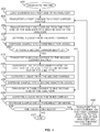
- An example method includes transporting a first carrier from a first side of an analyzer having a loading bay to a second side of the analyzer opposite the first side, aspirating a first liquid from the first carrier using a pipetting mechanism disposed adjacent the second side of the analyzer, and dispensing the first liquid, via the pipetting mechanism, into a first reaction vessel on the analyzer.
- the example method includes transporting a second carrier along a track to a position adjacent the pipetting mechanism, the track disposed along the second side of the analyzer, aspirating a second liquid from the second carrier using the pipetting mechanism, and dispensing the second liquid, via the pipetting mechanism, into a second reaction vessel on the analyzer.
- the first carrier is transported to the second side of the analyzer via a first carrier shuttle.
- the method includes transporting a third carrier from the first side of the analyzer to the second side of the analyzer.
- the method includes aspirating a third liquid from the third carrier using the pipetting mechanism and dispensing the third liquid, via the pipetting mechanism, into a third reaction vessel on the analyzer.
- the third carrier is transported to the second side of the analyzer via a second carrier shuttle.
- the first carrier shuttle and the second carrier shuttle operate independently of each other.
- one or more of the first carrier shuttle or the second carrier shuttle is a track comprising a lead screw.
- one or more of the first carrier shuttle or the second carrier shuttle is a track comprising a conveyor belt.
- one or more of the first carrier, the second carrier or the third carrier comprises at least one test sample tube.
- the example system includes multiple analyzers.
- the example system includes a first analyzer to perform a first diagnostic test and a second analyzer to perform a second diagnostic test.
- the example first analyzer includes a first proximal side, a first distal side opposite the first proximal side, a first pipetting mechanism adjacent the first distal side and a first loading bay disposed on the first proximal side to receive a first carrier.
- the example analyzer also includes a first carrier shuttle to transport the first carrier from a first location adjacent the first proximal side to a second location adjacent the first pipetting mechanism.
- the example second analyzer includes a second proximal side, a second distal side opposite the second proximal side, a second pipetting mechanism adjacent the second distal side and a second loading bay disposed on the second proximal side to receive a second carrier.
- the example second analyzer includes a second carrier shuttle to transport the second carrier from a third location adjacent the second proximal side of the second analyzer to a fourth location adjacent the second pipetting mechanism.
- the example system includes a track disposed along the first distal side and the second distal side. The example track includes a first sidetrack to transfer a third carrier to a fifth location adjacent the first pipetting mechanism.
- the example track includes a second sidetrack to transfer the third carrier to a sixth location adjacent the second pipetting mechanism.
- first carrier shuttle and the second carrier shuttle are substantially parallel. In some examples, the first carrier shuttle is substantially perpendicular to the track.
- the first diagnostic test is an immunoassay and the second diagnostic test is a clinical chemistry assay. Also, in some examples, the first diagnostic test is an immunoassay and the second diagnostic test is an immunoassay. In addition, in some examples, the first diagnostic test is a clinical chemistry assay and the second diagnostic test is a clinical chemistry assay.
- the example system also includes a positioner disposed along the first proximal side and the second proximal side of the second analyzer.
- the positioner is to transfer the second carrier from the second loading bay to the first carrier shuttle on the first analyzer.
- example system also may include a third analyzer disposed next to one of the first analyzer or the second analyzer.
- the example third analyzer includes a third proximal side, a third distal side opposite the third proximal side, a third pipetting mechanism adjacent the third distal side and a third loading bay disposed on the third proximal side to receive a fourth carrier.
- the example third analyzer includes a third carrier shuttle to transport the fourth carrier from a sixth location adjacent the third proximal side of the third analyzer to a seventh location adjacent the third pipetting mechanism.
- the example track of the example system also is disposed along the third distal side of the third analyzer.
- FIGS. 1A and 1B an example automated diagnostic analyzer 100 is shown in FIGS. 1A and 1B as having a first carousel 102 and a second carousel 104.
- the analyzer 100 may be used, for example, to perform immunoassays, clinical chemistry tests, or any other diagnostics tests.
- the first carousel 102 and the second carousel 104 are rotatably coupled to a base station 106 independent of each other.
- the base station 106 houses different subassemblies and other components used for testing (e.g., performing diagnostic analyses) such as, for example, wash liquid, bulk reagents, a vacuum source, a pressure source, a refrigeration system, temperature sensors, a processor, motors, etc.
- the second carousel 104 is vertically distanced (e.g., spaced) above the first carousel 102 and at least a portion of the second carousel 104 is disposed above and over the first carousel 102.
- the first carousel 102 and the second carousel 104 are disposed next to each other (e.g., coplanar) or may be arranged to be concentric with each other.
- the first carousel 102 is a reagent carousel and the second carousel 104 is a reaction vessel carousel.
- the first and second carousels 102, 104 may hold reagents, samples, reaction vessels or any combination thereof.
- the first carousel 102 includes a plurality of reagent containers (including, for example, liquids having microparticles) arranged annularly around the carousel.
- the first carousel 102 has an inner annular array of reagent containers and outer annular array of reagent containers, concentric with the inner annular array of containers.
- the second carousel 104 is a plate having a plurality of reaction vessels 108a-n disposed around an outer circumference of the plate.
- the reaction vessels 108a-n are reusable cuvettes (e.g., washable glass cuvettes). After a test has been completed in a reaction vessel, the vessel is cleaned (e.g., sterilized) and the vessel may be used for another test.
- the reaction vessels 108a-n are disposable cuvettes (e.g., plastic cuvettes) that are discarded after one or more tests. In operation, the second carousel 104 rotates as one or more assay tests are carried out in the reaction vessels 108a-n.
- a plurality of different modules or instruments may be disposed around the second carousel 104 to, for example, dispense reagents, mix the contents of the reaction vessels, incubate the contents of the reaction vessels, analyze the contents, wash the reaction vessels, etc.
- the example automated diagnostic analyzers disclosed herein also include one or more pipetting mechanisms (e.g., probe arms, automated pipettes, pipettes, etc.) to aspirate and dispense liquids within the reaction vessels 108a-n on the second carousel 104.
- the analyzer 100 includes a pipetting mechanism 110 (e.g., a sample pipette) that is coupled (e.g., mounted) to the base station 106.
- the pipetting mechanism 110 has multiple degrees of freedom.
- the pipetting mechanism 110 has a path of travel 112 (e.g., an arc path, a horizontal arc path, a radius of travel, an operating range), such that the pipetting mechanism 110 can aspirate (e.g., draw liquid) from or dispense liquid to containers located along the path of travel 112.
- the pipetting mechanism 110 is positioned to have access to one of the reaction vessels 108a-n on the second carousel 104 at point A.
- the pipetting mechanism 110 has an axis of rotation and rotates a probe arm with a pipette disposed at the distal end of the probe arm.
- the pipetting mechanism 110 is also movable in the Z direction (e.g., the vertical direction).
- the pipetting mechanism 110 is disposed outside of the first carousel 102 and outside of the second carousel 104, for example, coupled to the base 106 in a position at a distance from the center of the first carousel 102 and the center of the second carousel 104 that is greater than either a first diameter of the first carousel 102 or a second diameter of the second carousel 104.
- the pipetting mechanism 110 is disposed above and over the first carousel 102 and/or adjacent the second carousel 104.
- the pipetting mechanism 110 may be mounted to a platform that is disposed between the first carousel 102 and the second carousel 104.
- the pipetting mechanism 110 may be disposed over the first carousel 102 and over the second carousel 104.
- the example analyzer 100 has a first side 114 (e.g., a front side) and a second side 116 (e.g., a back side, a rear side) opposite the first side 114.
- the pipetting mechanism 110 is disposed near (e.g., adjacent, along, next to, closer to, bordering) the second side 116 of the analyzer 100.
- the analyzer 100 also includes a random sample handler (RSH) 118 (e.g., a loading bay) on the first side 114 of the analyzer 100 for accepting and retaining carriers having samples and/or reagents that are to be used for diagnostic testing.
- RSH random sample handler
- the RSH 118 includes a loading rack 120 having a plurality of slots 122a-n for receiving containers, carriers and/or trays of carriers.
- a plurality of carriers 124a-n have been inserted into the slots 122a-n in the loading rack 120.
- the carriers 124a-n may hold one or more containers (e.g., a tube, a vessel, an open top container, a vial, a cup, etc.).
- the containers may include samples, reagents, calibrations, control liquids, etc., used by the analyzer 100 for assay diagnostic testing.
- an operator e.g., a laboratory technician loads the carriers 124a-n individually or in trays into the loading rack 120 of the RSH 118.
- an automated track system transports the carriers 124a-n to the RSH 118 and loads the carriers 124a-n into respective ones of the slots 122a-n, for example, via a robotic mechanism.
- each of the carriers 124a-n is holding six containers.
- the carriers 124a-n can be configured to hold more or fewer containers depending on the analyzer, the RSH design parameters and/or the carrier layout.
- the carriers 124a-n are held in the slots 122a-n until selected for testing or retesting.
- the RSH 118 includes a positioner 126, which may be a robotic device, to transport the carriers 124a-n and containers coupled thereto to and from the loading rack 120.
- the positioner 126 is movable along a positioner track 128 disposed along the length of the loading rack 120 and the first side 114 of the analyzer 100.
- the positioner 126 has an arm 130 to engage the carriers 124a-n loaded in the RSH 118.
- the positioner 126 and the arm 130 operate to remove the carriers 124a-n from their respective slots 122a-n and transport the carriers 124a-n to different locations along the positioner track 128.
- the example analyzer 100 also includes a first carrier shuttle 134 (e.g., a transporter) and a second carrier shuttle 136 that are disposed near (e.g., along, adjacent, next to, bordering) a third side 138 (e.g., the left side of FIGS. 1A and 1B ) of the analyzer 100, opposite a fourth side 140 (e.g., the right side of FIGS. 1A and 1B ) of the analyzer 100.
- the first side 114, the second side 116, the third side 138 and the fourth side 140 define the outer boundaries of the analyzer 100.
- the analyzer 100 has a rectangular cross-section or footprint. However, in other examples, the analyzer 100 has a square cross-section, a circular cross-section, or any other shaped cross-section or footprint.
- the positioner 126 transports the carriers 124a-n to and from the first carrier shuttle 134 and/or the second carrier shuttle 136.
- the positioner 126 engages the first carrier 124a in the loading rack 120 of RSH 118.
- the positioner 126 transports the first carrier 124a to, in this example, the first shuttle 134, as shown in FIG. 1B , where the positioner 126 releases or otherwise transfers the first carrier 124a onto the first carrier shuttle 134.
- the positioner 126 is controlled by a programmable computer for moving the carriers 124a-n as needed and/or desired (e.g., according to scheduling protocols or timetables) for testing.
- the RSH 118 provides random access to the carriers 124a-n on the loading rack 120.
- the analyzer 100 includes software that allows users to flexibly configure rules or criteria for testing samples.
- the software may be programmed into and/or operated from an example processor 316 ( FIG. 3 ), which is disclosed in more detail below.
- the positioner 126 includes a label reader such as, for example, a barcode reader, a radio frequency identification (RFID) reader and/or other type of reader, to read carrier and container information.
- the label reader reads the labels attached to the carriers, the sample tubes and/or reagent tubes as the positioner 126 passes the carriers by the reader.
- RFID radio frequency identification
- An example RSH and an example positioner are disclosed in U.S. Patent Application Serial No. 12/106,755, titled “ASSAY TESTING DIAGNOSTIC ANALYZER,” filed on April 21, 2008 , which is incorporated herein by reference in its entirety.
- the first and second carrier shuttles 134, 136 operate to move carriers (e.g., the carriers 124a-n) and/or containers between a first position near the first side 114 of the analyzer 100 (e.g., adjacent the rack 120 or the RSH 118) and a second position near the second side 116 of the analyzer 100 (e.g., near the pipetting mechanism 110).
- the first and second carrier shuttles 134, 136 operate to transport carriers 124a-n to a position within the path of travel 112 of the pipetting mechanism 110, such that liquid (e.g., a sample, a specimen) within the containers on the carriers 124a-n can be aspirated from the containers via the pipetting mechanism 110.
- the pipetting mechanism 110 may then dispense the liquid at point A into one or more of the reaction vessels 108a-n on the second carousel 104 for testing.
- the first carrier shuttle 134 includes a first track 142 and the second carrier shuttle 136 includes a second track 144.
- the first track 142 and the second track 144 are conveyor belts that move to transport carriers placed on the respective tracks 142, 144 from one position to another position along the first and second tracks 142, 144.
- the first and second tracks 142, 144 include other track devices such as, for example, a belt, a chain, a carriage, a lead screw, an air cylinder, and/or a linear motor or combinations thereof.
- the first carrier shuttle 134 and the second carrier shuttle 136 comprise different types of tracks.
- the first carrier shuttle 134 includes a first motor 146 (e.g., an electric motor, a servo motor, a stepper motor, etc.) to drive the first track 142 and the second carrier shuttle 136 includes a second motor 148 to drive the second track 144.
- the first and second tracks 142, 144 are operated independently of each other. In other examples, the operations of the first and second tracks 142, 144 are coordinated.
- the first and second motors 146, 148 may be used to rotate one or more pulleys or gears, which, in turn, move the tracks 142, 144.
- the first and second motors 146, 148 are rotatable in either direction to move the first and second tracks 142, 144, respectively, in either direction.
- the first and second motors 146, 148 are located closer to the second side 116 of the analyzer 100.
- the first and second carrier shuttles 134, 136 also include respective sensors 150, 152 such as, for example, a linear encoder and/or a transducer.
- the first and second sensors 150, 152 are located adjacent the first and second tracks 142, 144 to sense a position/movement of the respective tracks 142, 144.
- the first and second sensors 150, 152 provide feedback to the first and second motors 146, 148 to indicate whether the first and second tracks 142, 144 are actually moving when the first and second motors 146, 148 are operating.
- the first and second sensors 150, 152 are positioned on the first and second carrier shuttles 134, 136 opposite the first and second motors 146, 148 as a safety feature to ensure that the tracks 142, 144 are moving when the motors 146, 148 are operating.
- the first and/or second tracks 142, 144 may become dislodged, misaligned or otherwise inoperative and, thus, will not properly transport the carriers.
- the first and second motors 146, 148 may continue to operate (e.g., spin, rotate, etc.) according to a programmed testing protocol.
- the sensors 150, 152 were located adjacent the first and second motors 146, 148, the continued operation of the motors 146, 148 could interfere with the readings of the sensors 146, 148, and cause the sensors 150, 152 to erroneously indicate that the tracks 142, 144 were operating normally.
- the sensors 150, 152 can ensure the tracks 134, 136 are actually moving in accordance with the programming of the first and second motors 146, 148.
- the motors 146, 148 are disposed at, near or closer to the second side 116 of the analyzer 100, and the sensors 150, 152 are at, near or closer to the first side 114 of the analyzer 100. In other examples, this configuration may be switched, such that the motors 146, 148 are disposed at, near or closer to the first side 114 of the analyzer 100, and the sensors 150, 152 are disposed at, near or closer to the second side 116 of the analyzer 100.
- a first carrier 124a can be retrieved from the RSH 118 by the positioner 126 ( FIG. 1A ) and deposited on the first track 142 of the first carrier shuttle 134 ( FIG. 1B ).
- the arm 130 of the positioner 126 includes a hook to engage a tab on the end of the carrier.
- the arm 130 has a gripping mechanism to grip the sides of the carrier.
- the arm 130 is used to grab the first carrier 124a from its respective slot 122a-n in the loading rack 120 ( FIG. 1A ) and then lifts to extract the first carrier 124a from of its respective slot 122a-n.
- the positioner 126 retrieves the first carrier 124a
- the positioner 126 moves (e.g., slides, translates) along the positioner track 128 towards the third side 138 of the analyzer 100 and, thus, towards the first and second carrier shuttles 134, 136.
- the arm 130 of the positioner 126 then rotates to align the first carrier on the first track 142 of the first carrier shuttle 134, as shown in the position in FIG. IB.
- the arm 130 is capable of rotating at least about 180°.
- the first motor 146 operates to move the first carrier 124a, via the first track 142, from a first position near the first side 114 of the analyzer 100 to a second position near the second side 116 of the analyzer 100 and, thus, within the path of travel 112 of the pipetting mechanism 110.
- the pipetting mechanism 110 may aspirate from a container on the first track 142 along the first path of travel 112 at point B.
- the first motor 146 operates to position the first carrier 124a so that the first path of travel 112 intersects the appropriate container on the first carrier. After aspirating from a container, the pipetting mechanism 110 moves along its first path of travel 112 to dispense the liquid into one or more of the reaction vessels 108a-n on the second carousel 104 at point A.
- the positioner 126 can retrieve a second carrier 124b-n from the RSH 118 and load the second carrier 124b-n onto the second track 144 of the second carrier shuttle 136.
- the second motor 148 operates to move the second carrier 124b-n on the second track 144 from the first position near the first side 114 of the analyzer 100 to the second side 116 of the analyzer 100 near the pipetting mechanism 110.
- the second motor 148 operates to position the second carrier 124b-n along the first path of travel 112 of the pipetting mechanism 110 (e.g., the position shown in FIGS. 1A and 1B ).
- the pipetting mechanism 100 may aspirate from a container on the carrier 124b- n on the second track 144 at point C.
- the first carrier shuttle 134 may simultaneously and independently transport the first carrier 124a to/from the first position adjacent the first side 114 of the analyzer 100 and/or the second position adjacent the second side 116.
- the positioner 126 When a carrier, e.g., the first carrier 124a, returns to the first position adjacent the first side 114 of the analyzer 100, the positioner 126 unloads the first carrier 124a and places the first carrier 124a within one of the slots 122a-n in the loading rack 120. The positioner 126 is then able to retrieve the first carrier 124a or another carrier 124b- n from the loading rack 120 and deposit that carrier 124a-n on the first track 144 of the first carrier shuttle 134.
- a carrier e.g., the first carrier 124a
- one of the carrier shuttles 134, 136 can operate to hold a carrier near the second position for aspiration while another carrier can be loaded onto the other carrier shuttle 134, 136 for subsequent transportation to the second side 116 of the analyzer 100.
- the time between aspirations is reduced, which increases throughput of the example analyzer 100.
- first and second carrier shuttles 134, 136 are aligned substantially parallel to one another and are disposed along the third side 138 of the analyzer 100. However, in other examples, the first and second carrier shuttles 136, 136 may be positioned other locations and/or not parallel to one another. In the example shown, the first and second carrier shuttles 134, 136 are disposed over a portion of the first carousel 102. In other examples, the first and/or second carrier shuttles 134, 136 are disposed outside of the first carousel 102 (i.e., next to the first carousel 102).
- test orders are programmed by an operator or downloaded via a lab information system or any network.
- a test order may require a plurality of assays.
- a programmable computer determines the order (e.g., scheduling, protocols) of the different sample tests based on factors including, for example, number of tests to be conducted, types of reagents to be used, number of reagents to be used, an incubation period, scheduled priority and other factors.
- the positioner 126, the first track 142, the second track 144, the first motor 146, the second motor 148 and other components are controlled in response to commands from the programmable computer.
- a laboratory automated system (LAS) 154 has a main track 156 and a first subtrack or spur 158, which is disposed along the second side 116 of the analyzer 100.
- the LAS 154 may include multiple instruments and equipment for processing and preprocessing certain samples, reagents, calibrations, controls, etc.
- the LAS 154 includes and/or is coupled to a refrigerated storage area, a centrifuge, an aliquoter and/or any other processing station(s).
- the LAS includes a system of tracks and robotic positioners to move carriers from one instrument to another.
- the LAS 154 transports carriers (e.g., sample carriers) or containers to a position near the analyzer 100 and, more specifically, to a position within the first path of travel 112 of the pipetting mechanism 110.
- carriers e.g., sample carriers
- a carrier 124c is depicted on the first subtrack or spur 158.
- the carrier 124c is transported along the main track 156 of the LAS 154 and when the carrier 124c arrives at the first spur 158, the carrier 124c may continue down the main track 156 or may be diverted to the first spur 158 to be sent to the position adjacent the pipetting mechanism 110.
- the path of travel 112 of the pipetting mechanism 110 extends beyond the second side 116 of the analyzer 110.
- the pipetting mechanism 110 may aspirate a liquid (e.g., a sample) from a container on the carrier at the first spur 158 at point D.
- a liquid e.g., a sample
- the main track 156 and the spur 158 of the LAS 154 are substantially parallel to the second side 116 of the analyzer 100 and are substantially perpendicular to the first and second carrier shuttles 134, 136.
- the pipetting mechanism 110 is located near the second side 116 of the analyzer 100 and has access (e.g., can aspirate from and/or can dispense to) to the reaction vessels 108a-n on the second carousel 104 at point A, a carrier on the first track 142 of the first carrier shuttle 134 at point B, a carrier the second track 144 of the second carrier shuttle 136 at point C and/or a carrier on the spur 158 of the LAS 154 at point D.
- access e.g., can aspirate from and/or can dispense to
- the pipetting mechanism 110 has access to carriers loaded in the RSH 118 at the first side 114 (e.g., the front side) of the analyzer 110 (via one or more of the carrier shuttles 134, 136) and carriers transported along the track 156 of the LAS 154 on the second side 116 (e.g., the back side) of the analyzer 100. Continuous access to carriers at different locations around the pipetting mechanism 110 points allows the pipetting mechanism 110 to aspirate from multiple sample containers more efficiently and with less idle or down time and, as a result, increases the throughput of the example analyzer 100.
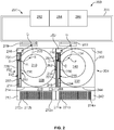
- FIG. 2 illustrates an example laboratory system 200 having a first diagnostic analyzer 202 (e.g., a first module), a second diagnostic analyzer 204 (e.g., a second module) and a laboratory automation system (LAS) 206.
- the first analyzer 202 includes a first carousel 208 and a second carousel 210.
- the second carousel 210 is reaction carousel having a plurality of reaction vessels for conducting diagnostic tests on one or more samples in the plurality of reaction vessels.
- the first analyzer 202 also includes a first random sample handler (RSH) 212 (e.g., a first loading bay) disposed along a first side 214 (e.g., a front side) of the first analyzer 202, opposite a second side 216 (e.g., a rear side) of the first analyzer 202.
- RSH random sample handler
- a first pipetting mechanism 218 is disposed on the first analyzer 202 adjacent the second side 216 of the first analyzer 202 and has a first path of travel 220 (e.g., horizontal arc path, range of access).
- the first analyzer 202 further includes a first carrier shuttle 222 and a second carrier shuttle 224 located along a third side 226 (e.g., the left side) of the first analyzer 202, opposite a fourth side 228 (e.g., the right side) of the first analyzer 202.
- each of the first and second carrier shuttles 222, 224 has a respective track 230, 232 (e.g., lead screw) and a respective carriage 234, 236 (e.g., shuttles).
- the first and second tracks 230, 232 operate to move the respective carriages 234, 236 from a first position near the first side 214 of the first analyzer 202 to a second position near the second side 216 of the first analyzer 202 and within the first path of travel 220 of the first pipetting mechanism 218.
- the first and second carriages 234, 236 are platforms for holding a carrier. As the first and second tracks 230, 232 operate (e.g., rotate), the first and second carriages 234, 236 move along the longitudinal axes of the respective track 230, 232.
- the second analyzer 204 includes similar components as the first analyzer 202 such as, for example, a third carousel 238 (e.g., a reagent carousel), a fourth carousel 240 (e.g., a reaction carousel), a second RSH 242, a first side 244 (e.g., a front side) opposite a second side 246 (e.g., a rear side), a third side 248 (e.g., a left side) opposite a fourth side 250 (e.g., a right side), a second pipetting mechanism 252 with a second path of travel 254, a third carrier shuttle 256, a fourth carrier shuttle 258, a third track 260 (e.g., a third lead screw), a fourth track 262 (e.g., a fourth lead screw), a third carriage 264 and a fourth carriage 266.
- a third carousel 238 e.g., a reagent carousel
- the third and fourth carrier shuttles 256, 258 of the second analyzer 204 operate to transport carriers from a first position adjacent the first side 244 of the second analyzer 204 to a second position adjacent the second side 246 of the second analyzer 204 and within the second path of travel 254 of the second analyzer 204.
- a positioner 268 is movable along a positioner path 270 between the first and second RSH 212, 242 and along the first sides 214, 244 of the first and second analyzers 202, 204.
- only one positioner 268 is utilized to transport carriers among the first RSH 212, the second RSH 242, the first track 230, the second track 232, the third track 260 and/or the fourth track 262.
- the positioner 268 is substantially similar to the positioner 126 disclosed above in connection with FIGS. 1A and IB.
- the positioner 268 may retrieve carriers loaded within the first and second RSH 212, 242 and may transport the carriers via the first, second, third or fourth carrier shuttles 222, 224, 256, 258.
- a first plurality of carriers 272a- n are loaded in the first RSH 212
- a second plurality of carriers 274a-n are loaded in the second RSH 242.
- the positioner 268 is to retrieve one of the first or second plurality of carriers 272a-n, 274a-n and is to place (e.g., position, deposit, transport) the carrier on one of the first, second, third or fourth carrier shuttles 222, 224, 256, 258.
- the carriers 272a-n, 274a-n may then be transported via one of the carriages 234, 236, 264, 266 and tracks 230, 232, 260, 262 to a position near the second side 216, 246 of one of the analyzers 202, 204.
- the first pipetting mechanism 218 of the first analyzer 202 may aspirate from a container in a first carrier on the first carriage 234 at point A and may aspirate from another container in a second carrier on the second carriage 236 at point B, which are both along the first path of travel 220.
- the second pipetting mechanism 252 may aspirate from a container in a third carrier on the third carriage 264 at point C and may aspirate from another container in a fourth carrier on the fourth carriage 266 at point D, both of which are along the second path of travel 254 of the second pipetting mechanism 252.
- the first pipetting mechanism 218 may access one or more reaction vessels on the second carousel 210 at point E
- the second pipetting mechanism 252 may access one or more reaction vessels on the fourth carousel 240 at point F.
- the LAS 206 includes a main track 276 that is disposed along the second sides 216, 246 of the first and second analyzers 202, 204.
- the main track 276 has a first subtrack or spur 278 and a second subtrack or spur 280.
- the first spur 278 displaces a carrier on the main track 276 to a position near the second side 216 of the first analyzer 202 and within the first path of travel 220 of the first pipetting mechanism 218.
- the second spur 280 displaces a carrier on the main track 276 to a position near the second side 246 of the second analyzer 204 and within the second path of travel 254 of the second pipetting mechanism 252.
- the first pipetting mechanism may aspirate from a container on a carrier on the first spur 278 at point G
- the second pipetting mechanism 252 may aspirate from another container on another carrier on the second spur 280 at point H.
- the track 276 of the LAS 206 may be configured to traverse along or near the analyzers to supply the analyzers with access to additional carriers.
- the LAS 206 transports carriers having additional liquids such as, for example, priority samples for testing, calibration and control liquids, additional reagents (including, for example, liquids with microparticles), etc.
- the LAS 206 is tied to additional equipment such as, for example, a refrigerated storage area 282, a centrifuge 284 and/or an aliquoter 286.
- a body liquid may be analyzed, such as, for example, serum or plasma.
- Serum is the yellow, watery part of blood that is left after blood has been allowed to clot and all blood cells have been removed such as, for example, via centrifugation, which packs the denser blood cells and platelets to the bottom of a centrifuge tube and leaves the liquid serum fraction resting above the packed cells.
- Plasma is similar to serum but is obtained by centrifuging blood without clotting.
- the LAS 206 of example system 200 enables sample liquids such as, for example, serum or plasma to be processed in the centrifuge 284 and then transported to one or more of the first and second analyzers 202, 204 for diagnostic testing.
- the LAS 206 allows priority samples to be loaded onto carriers and sent along the track 276 to a position within the first and/or second paths of travel 220, 254 of the respective pipetting mechanisms 218, 252.
- the pipetting mechanisms 218, 252 near the second sides 216, 246 of the analyzers 202, 204, and by providing the carrier shuttles 222, 224, 256, 258 to transport carrier to and from the first and second sides 214, 244, 216, 246 of the analyzers 202, 204, the analyzers 202, 204 may receive samples in a traditional operating manner through the first sides 214, 244 and/or may receive samples from the LAS 206 at the second sides 216, 246.
- the analyzers 202, 204 can be arranged in a side-by-side configuration without interfering with operations of the respective analyzers 202, 204 and, thus, laboratory floor space is decreased.
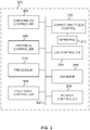
- FIG. 3 is a block diagram of an example processing system 300 for use with any of the analyzers 100, 202, 204 and/or the LAS 154, 206 disclosed herein.
- Example analyzers disclosed herein are used to, for example, perform diagnostic testing on multiple test samples using one or more reagents and/or other diagnostic test procedures.
- the example processing system 300 includes a carousel controller 302 to control the operations (e.g., rotational sequences, locksteps, indexing, etc.) of one or more carousels on an analyzer.
- an analyzer includes one or more carousels having a plurality of containers or vessels.
- the analyzer includes a first carousel having a plurality of reagent containers that contain reagents for diagnostic testing and a second carousel having a plurality of vessels (e.g., reaction vessels) that are used for testing the samples.
- the analyzer 100 disclosed above includes the first carousel 102 (e.g., a reagent carousel), and the second carousel 104 (e.g., a reaction carousel).
- the second carousel 104 includes a plurality of reaction vessels 108a-n and rotates the reaction vessels 108a-n in a continuous or discrete manner while a plurality of diagnostic functions are performed on the reaction vessels 108-n.
- the carousel controller 302 may be used, for example, to control the rotational sequence (e.g., lockstep timing) of the first and second carousels 102, 104.
- the example processing system 300 includes a pipette controller 304.
- an analyzer utilizes one or more pipettes (e.g., automated pipetting mechanisms, probe arms, etc.) to aspirate a fluid from one location and dispense the fluid into another location.
- an analyzer has multiple pipettes such as, for example, a first pipette for dispensing a sample into a reaction vessel, a second pipette for dispensing a first reagent into a reaction vessel, a third pipette for dispensing a second reagent into a reaction vessel, etc.
- the pipette controller 306 operates to control the pipettes such as, for example, the movement of the pipettes, the vacuum applied to the pipettes for aspirating, the pressure applied to the pipettes for dispensing, etc.
- the analyzer 100 includes the pipetting mechanism 110, which moves a pipette along the path of travel 112 to aspirate and dispense fluid such as, for example, sample.
- the example pipetting mechanism 110 dispenses sample into the reaction vessels 108a-n on the second carousel 104 at point A.
- the pipette controller 304 is used to control the pipetting mechanism 110.
- the example processing system 300 includes a reader controller 306.
- a reader e.g., an analyzer
- the reader may analyze the contents of the respective reaction vessels.
- a reaction vessel is held stationary in front of the reader for a predetermined time and a reading is taken.
- one or more reaction vessels may be passed continuously in front of the reader, and the reader takes a plurality of individual readings corresponding to each reaction vessel.
- the reader controller 306 operates to control when the readings are taken.
- the reader controller 306 may also be used to control other readers.
- a reader positioned near the RSH 118 may be operated to read an RFID tag, a bar code, a QR code or other machine readable code to gather information about the identity of or other data related to the contents of a carrier 124a-n and/or a container coupled to the carrier 124a-n.
- the example processing system 300 also includes a positioner controller 308 and a shuttle controller 310.
- an analyzer includes a loading bay for receiving containers, carriers having containers and/or trays of carriers.
- the containers may include reagents, samples, controls, calibrations, etc.
- the loading bay is disposed on a first side or front side of the analyzer.
- a positioner e.g., a robotic mechanism retrieves the carriers from the loading bay and transports the carriers to different areas of the analyzer for testing and retesting.
- the positioner controller 308 controls the movement of the positioner to engage and move carriers in the analyzer.
- the positioner 126 translates along the track 128 on the first side 114 of the analyzer 100.
- the positioner 126 also has the arm 130 that rotates to engage carriers in the RSH 118.
- the positioner controller 308 may be used, for example, to control the movement of the positioner 126 and the arm 130 along the track 128.
- an analyzer includes one or more shuttle carriers to transport carriers from one side of the analyzer to the other side of the analyzer.
- the pipette is disposed along a second side or rear side of the analyzer and the carrier shuttle(s) transports the carriers from the front of the analyzer adjacent the loading bay to a position near the back side of the analyzer and within the range of the pipette.
- the carrier shuttles are operated by motors (e.g., electric motors, servo motors, stepper motors, etc.).
- the shuttle carriers utilize a track system such as, for example, a conveyor belt or a lead screw, to transport the carriers.
- the carrier shuttle controller 310 operates to control the movement of the one or more carrier shuttles to transport carriers along the carrier shuttle(s).
- the carrier shuttle controller 310 may be used, for example, to control the motors 146, 148 of the respective carrier shuttles 134, 136.
- the example processing system 300 includes sensors 312 communicatively coupled to the shuttle carrier controller 310.
- one or more sensors e.g., transducers, encoders, etc.
- the sensors 312 are disposed at an opposite end of the carrier shuttles than the motors.
- the sensors 150, 152 are disposed along the tracks 142, 146 of the respective carrier shuttles 134, 136 to determine whether the tracks 142, 146 of the respective shuttle carriers 134, 136 are operating effectively and that the tracks 142, 146 are not dislodged, misaligned or otherwise inoperable.
- the example processing system 300 includes a laboratory automation system (LAS) controller 314.
- a laboratory automation system includes a system of tracks and instruments to transport carriers around a laboratory. Some samples, reagents, and other liquids used in diagnostic testing, require additional processing steps and/or refrigeration.
- the LAS may connect to various instruments and, when time for processing, the LAS may transport the liquid (e.g., a priority sample), via a carrier, to the back side of the analyzer for aspirating by the pipette.
- the main track of the LAS includes a subtrack or spur to transport a carrier to the rear side of the analyzer, such that the carrier is not held stationary on the main track.
- the LAS controller 314 controls operation of the LAS including, for example, the main track, the spurs, and/or any equipment or instruments attached thereto.
- the example LAS 154 disclosed above includes the main track 156 and the spur 158 to transport a carrier (e.g., 124c) to a location adjacent the rear side of the analyzer 100, such that the pipetting mechanism 110 may aspirate from the contents of the carrier.
- a carrier e.g., 124c
- the example processing system 300 also includes a processor 316 and a database 318.
- the processor interfaces with the controllers and sensors 302-314 of the processing system 300 to control the various operations of each of the components.
- the processor 316 is programmable to operate in accordance with desired testing protocol(s).
- the database 318 may be used to store, for example, information regarding tests that have occurred, are to occur, and/or are occurring, testing protocol(s), information regarding the individual samples and/or reagents data gathered from the reader(s), position(s) of the carrier(s), postioner(s), carrier shuttle(s), pipetting mechanism(s), LAS, and/or carousel(s), and/or other information.
- the processing system components 302-318 are communicatively coupled to other components of the example system 300 via communication links 320.
- the communication links 320 may be any type of wired connection (e.g., a databus, a USB connection, etc.) or a wireless communication mechanism (e.g., radio frequency, infrared, etc.) using any past, present or future communication protocol (e.g., Bluetooth, USB 2.0, USB 3.0, etc.).
- the components of the example system 300 may be integrated in one device or distributed over two or more devices.
- FIG. 3 While an example manner of implementing the analyzers 100, 202, 204 and/or the LAS 154, 206 of FIGS. 1A-2 is illustrated in FIG. 3 , one or more of the elements, processes and/or devices illustrated in FIG. 3 may be combined, divided, re-arranged, omitted, eliminated and/or implemented in any other way. Further, the example carousel controller 302, the example pipette controller 304, the example reader controller 306, the example positioner controller 308, the example carrier shuttle controller 310, the example sensor(s) 312, the example LAS controller 314, the example processor 316, the example database 318 and/or, more generally, the example processing system 300 of FIG.
- any of the example carousel controller 302, the example pipette controller 304, the example reader controller 306, the example positioner controller 308, the example carrier shuttle controller 310, the example sensor(s) 312, the example LAS controller 314, the example processor 316, the example database 318 and/or, more generally, the example processing system 300 could be implemented by one or more analog or digital circuit(s), logic circuits, programmable processor(s), application specific integrated circuit(s) (ASIC(s)), programmable logic device(s) (PLD(s)) and/or field programmable logic device(s) (FPLD(s)).
- ASIC application specific integrated circuit
- PLD programmable logic device
- FPLD field programmable logic device
- At least one of the example carousel controller 302, the example pipette controller 304, the example reader controller 306, the example positioner controller 308, the example carrier shuttle controller 310, the example sensor(s) 312, the example LAS controller 314, the example processor 316 and/or the example database 318 is/are hereby expressly defined to include a tangible computer readable storage device or storage disk such as a memory, a digital versatile disk (DVD), a compact disk (CD), a Blu-ray disk, etc. storing the software and/or firmware.
- the example processing system 300 of FIG. 3 may include one or more elements, processes and/or devices in addition to, or instead of, those illustrated in FIG. 3 , and/or may include more than one of any or all of the illustrated elements, processes and devices.
- FIG. 4 A flowchart representative of an example method 400, at least some of which are machine readable, for implementing the example analyzers 100, 202, 204, the example LAS 154, 206 and/or the example processing system 300 is shown in FIG. 4 .
- the method 400 may be implemented using machine readable instructions that comprise a program for execution by a processor such as the processor 512 shown in the example processor platform 500 discussed below in connection with FIG. 5 .
- the program may be embodied in software stored on a tangible computer readable storage medium such as a CD-ROM, a floppy disk, a hard drive, a digital versatile disk (DVD), a Blu-ray disk, or a memory associated with the processor 512, but the entire program and/or parts thereof could alternatively be executed by a device other than the processor 512 and/or embodied in firmware or dedicated hardware.
- a tangible computer readable storage medium such as a CD-ROM, a floppy disk, a hard drive, a digital versatile disk (DVD), a Blu-ray disk, or a memory associated with the processor 512, but the entire program and/or parts thereof could alternatively be executed by a device other than the processor 512 and/or embodied in firmware or dedicated hardware.
- a device such as a CD-ROM, a floppy disk, a hard drive, a digital versatile disk (DVD), a Blu-ray disk, or a memory associated with the processor 512
- DVD digital versatile disk
- coded instructions e.g., computer and/or machine readable instructions
- a tangible computer readable storage medium such as a hard disk drive, a flash memory, a read-only memory (ROM), a compact disk (CD), a digital versatile disk (DVD), a cache, a random-access memory (RAM) and/or any other storage device or storage disk in which information is stored for any duration (e.g., for extended time periods, permanently, for brief instances, for temporarily buffering, and/or for caching of the information).
- a tangible computer readable storage medium is expressly defined to include any type of computer readable storage device and/or storage disk and to exclude propagating signals.
- tangible computer readable storage medium and “tangible machine readable storage medium” are used interchangeably. Additionally or alternatively, the example processes of FIG. 4 may be implemented using coded instructions (e.g., computer and/or machine readable instructions) stored on a non-transitory computer and/or machine readable medium such as a hard disk drive, a flash memory, a read-only memory, a compact disk, a digital versatile disk, a cache, a random-access memory and/or any other storage device or storage disk in which information is stored for any duration (e.g., for extended time periods, permanently, for brief instances, for temporarily buffering, and/or for caching of the information).
- coded instructions e.g., computer and/or machine readable instructions
- a non-transitory computer and/or machine readable medium such as a hard disk drive, a flash memory, a read-only memory, a compact disk, a digital versatile disk, a cache, a random-access memory and/or any other storage device or storage disk in which information is
- non-transitory computer readable medium is expressly defined to include any type of computer readable device or disk and to exclude propagating signals.
- phrase “at least” is used as the transition term in a preamble of a claim, it is open-ended in the same manner as the term “comprising” is open ended.
- FIG. 4 is a flowchart representing the example diagnostic testing method 400 that may be implemented, for example, by the analyzers 100, 202, 204, the LAS 154, 206 and/or the processing system 300 detailed above.
- the example analyzers include a first carousel and a second carousel, the second carousel being a reaction carousel having a plurality of reaction vessels for conducting diagnostic tests. As the reaction carousel rotates, a plurality of automated modules each perform assay steps on the individual reaction vessels.
- the example analyzers have a first side (e.g., a front side) and a second side (e.g., a back side), opposite the first side.
- a pipetting mechanism is disposed near the second side of the analyzer to dispense sample into the reaction vessels on the reaction carousel as the reaction carousel rotates.
- a loading bay is disposed on the first side of the example analyzer to receive carriers or trays of carriers.
- the example method or process 400 includes loading carriers in the first side of the analyzer (block 402).
- each carrier includes multiple containers such as, for example, test tubes having test samples.
- the example process 400 also includes transporting a first carrier to a first carrier shuttle (block 404).
- the example analyzer 100 disclosed above includes a first carrier shuttle 134 and a second carrier shuttle 136 to transport carriers from the first side 114 of the analyzer 100 to the second side 116 of the analyzer 100.
- a positioner is located along the loading bay to retrieve carriers from respective slots and transfer the carriers to other locations in the analyzer including, for example, to a carrier shuttle.
- the example process 400 includes transporting the first carrier from the first side of the analyzer to the second side of the analyzer (block 406).
- the first carrier shuttle includes a conveyor belt and a motor to transport the first carrier.
- the first carrier shuttle comprises a lead screw and a carriage, such that the first carrier may be placed in the carriage and the first lead screw operates (e.g., rotates) to move the carriage (and the first carrier) from the first side of the analyzer to the second side of the analyzer.
- the first carrier shuttle has a sensor (e.g., an encoder, a transducer) to sense movement of the conveyor belt, as a safety feature.
- the example process 400 also includes aspirating a liquid from the first carrier (block 408).
- the example analyzer 100 disclosed above locates the pipetting mechanism 110 adjacent the second side 116 of the analyzer 100.
- the first carrier shuttle 134 is to transport the first carrier from a first location near the first side 114 of the analyzer 100 to a second location near the second side 116 of the analyzer and, more specifically, within an access range (e.g., the path of travel 112, a horizontal arc path, etc.) of the pipetting mechanism 110, to enable the pipetting mechanism 110 to aspirate from the first carrier.
- the liquid is dispensed into a first reaction vessel (block 410).
- the pipetting mechanism 110 has an axis of rotation and a probe arm with a pipette disposed on the distal end of the probe arm.
- the probe arm rotates to access liquids along a path of travel (e.g., a horizontal arc path) and dispenses the aspirated liquid into the first reaction vessel on the reaction carousel 104.
- the example process includes determining whether there is a second carrier shuttle (412).
- the analyzer employs only one carrier shuttle.
- a second carrier shuttle is utilized to reduce turnaround time and increase throughput.
- the second carrier shuttle is independently operated. Therefore, one or more of the operations of the second carrier shuttle and/or components related thereto (e.g., blocks 314, 316, 318, 320) may occur independently and/or simultaneously relative to the one or more of the operation of the first carrier shuttle and/or components related thereto (e.g., blocks 304, 306, 308, 310).
- the example process 400 includes transporting a second carrier to the second carrier shuttle (block 414).
- the positioner 126 of the analyzer 100 retrieves the second carrier 124b-n from a slot 122b-n in the loading bay 120 and transports the second carrier 124b- n to the second carrier shuttle 136.
- the example process 400 also includes transporting the second carrier from the first side of the analyzer to the second side of the analyzer (block 416).
- the second carrier shuttle includes a conveyor belt or a lead screw. The second carrier shuttle operates to transport the second carrier from the first location near the first side of the analyzer to the second location adjacent the second side of the analyzer and, more specifically, to a location within the path of travel of the pipetting mechanism.
- the example process 400 includes aspirating a liquid from the second carrier (block 418) and dispensing the liquid into a second reaction vessel on the reaction carousel (420).
- the example process 400 includes transporting a third carrier to the second side of the analyzer (block 422).
- the example analyzer 100 may include the laboratory automation system (LAS) 154.
- the LAS 154 has a track system 156 to transport carriers and/or containers of diagnostic testing liquid around a laboratory, and a portion of the track (e.g., 158) is disposed adjacent the second side of the analyzer.
- the transport of the third carrier is independent of the transport of the first and/or second carriers.
- one or more of the operations of the first and second carrier shuttle and/or components related thereto may occur independently and/or simultaneously relative to the one or more of the operation of the LAS 154 and/or components related thereto (e.g., blocks 322, 324, 326).
- the example process 400 also includes aspirating a liquid from the third carrier (block 424).
- the LAS 154 includes the spur 158 that directs the third carrier 124c from the main track 156 to a position within the path of travel 112 of the pipetting mechanism 110 to enable access for aspirating the liquid from the third carrier 124c.
- the example process 300 also includes dispensing the liquid into a third reaction vessel on the reaction carousel (block 426).
- the pipetting mechanism 110 may move in the path of travel 112 and dispense aspirated liquid into a reaction vessel on the second carousel 104.
- the example process includes determining whether additional tests are to be performed (block 428). If further testing is desired, then the example process includes transporting the first carrier, via the first shuttle carrier, from the second location to the first location adjacent the first side of the analyzer (block 430). In some examples, the positioner removes the first carrier from the first carrier shuttle and places the first carrier in an empty slot in the loading bay. The example process may then continue with loading or transporting another carrier (block 404) onto the first carrier shuttle (i.e., as the "first" carrier in the illustrated example process 400), and the example process 400 proceeds as disclosed above. If further testing is not desired and/or needed (bock 428), then the example process 400 ends (block 432).
- FIG. 5 is a block diagram of an example processor platform 500 capable of executing the instructions to be performed of FIG. 4 to implement one or more portions of the apparatus and/or systems of FIGS. 1A-3 .
- the processor platform 500 can be, for example, a server, a personal computer, a mobile device, a personal digital assistant (PDA), an Internet appliance, and/or or any other type of computing device.
- PDA personal digital assistant
- the processor platform 500 of the illustrated example includes a processor 512.
- the processor 512 of the illustrated example is hardware.
- the processor 512 can be implemented by one or more integrated circuits, logic circuits, microprocessors or controllers from any desired family or manufacturer.
- the processor 512 of the illustrated example includes a local memory 513 (e.g., a cache).
- the processor 512 of the illustrated example is in communication with a main memory including a volatile memory 514 and a non-volatile memory 516 via a bus 518.
- the volatile memory 514 may be implemented by Synchronous Dynamic Random Access Memory (SDRAM), Dynamic Random Access Memory (DRAM), RAMBUS Dynamic Random Access Memory (RDRAM) and/or any other type of random access memory device.
- the non-volatile memory 516 may be implemented by flash memory and/or any other desired type of memory device. Access to the main memory 514, 516 is controlled by a memory controller.
- the processor platform 500 of the illustrated example also includes an interface circuit 520.
- the interface circuit 520 may be implemented by any type of interface standard, such as an Ethernet interface, a universal serial bus (USB), and/or a PCI express interface.
- one or more input devices 522 are connected to the interface circuit 520.
- the input device(s) 522 permit(s) a user to enter data and commands into the processor 512.
- the input device(s) can be implemented by, for example, an audio sensor, a microphone, a camera (still or video), a keyboard, a button, a mouse, a touchscreen, a track-pad, a trackball, isopoint and/or a voice recognition system.
- One or more output devices 524 are also connected to the interface circuit 520 of the illustrated example.
- the output devices 524 can be implemented, for example, by display devices (e.g., a light emitting diode (LED), an organic light emitting diode (OLED), a liquid crystal display, a cathode ray tube display (CRT), a touchscreen, a tactile output device and/or a light emitting diode (LED).
- the interface circuit 520 of the illustrated example thus, typically includes a graphics driver card, a graphics driver chip or a graphics driver processor.
- the interface circuit 520 of the illustrated example also includes a communication device such as a transmitter, a receiver, a transceiver, a modem and/or network interface card to facilitate exchange of data with external machines (e.g., computing devices of any kind) via a network 526 (e.g., an Ethernet connection, a digital subscriber line (DSL), a telephone line, coaxial cable, a cellular telephone system, etc.).
- a communication device such as a transmitter, a receiver, a transceiver, a modem and/or network interface card to facilitate exchange of data with external machines (e.g., computing devices of any kind) via a network 526 (e.g., an Ethernet connection, a digital subscriber line (DSL), a telephone line, coaxial cable, a cellular telephone system, etc.).
- DSL digital subscriber line
- the processor platform 500 of the illustrated example also includes one or more mass storage devices 528 for storing software and/or data.
- mass storage devices 528 include floppy disk drives, hard drive disks, compact disk drives, Blu-ray disk drives, RAID systems, and digital versatile disk (DVD) drives.
- Coded instructions 532 to implement the method of FIG. 4 may be stored in the mass storage device 528, in the volatile memory 514, in the non-volatile memory 516, and/or on a removable tangible computer readable storage medium such as a CD or DVD.
Claims (15)
- Appareil comprenant :un analyseur (100) pour réaliser un test de diagnostic, l'analyseur (100) ayant un premier côté (114) et un second côté (116) opposé au premier côté (114) ;une baie de chargement (118) disposée sur le premier côté (114) de l'analyseur (100) afin de recevoir un premier support (124a) ;un mécanisme de pipetage (110) couplé à l'analyseur (100) adjacent au second côté (114) ;une première navette de support (134) pour transporter le premier support (124a) d'un premier emplacement adjacent à la baie de chargement (118) jusqu'à un deuxième emplacement adjacent au mécanisme de pipetage (110) ; etun rail (156) disposé de manière adjacente et parallèle au second côté de l'analyseur (100) pour transférer un deuxième support (124c) jusqu'à un troisième emplacement adjacent au mécanisme de pipetage (110).
- Appareil selon la revendication 1, comprenant en outre une seconde navette de support (136), dans lequel la baie de chargement (118) est prévue pour recevoir un troisième support (124b) et la seconde navette de support (136) est prévue pour transporter le troisième support (124b) depuis le premier emplacement adjacent à la baie de chargement (118) jusqu'au deuxième emplacement adjacent au mécanisme de pipetage (110).
- Appareil selon la revendication 2, dans lequel la première navette de support (134) et la seconde navette de support (136) sont indépendamment mobiles.
- Appareil selon la revendication 2, comprenant en outre un dispositif de positionnement (126) pour transporter le premier support (124a) d'une fente (122a-122n) dans la baie de chargement (118) jusqu'à la première navette de support (134).
- Appareil selon la revendication 1, dans lequel la première navette de support (134) est prévue pour se déplacer dans une direction sensiblement perpendiculaire au rail (156).
- Appareil selon la revendication 1, dans lequel le rail (156) comprend une voie de dérivation (158) pour transporter le deuxième support (124c) vers et depuis le troisième emplacement.
- Appareil selon la revendication 1, comprenant en outre :un moteur (146) pour actionner la première navette de support (134), dans lequel le moteur (146) est disposé au niveau de l'un parmi le premier emplacement ou le deuxième emplacement ; etun capteur (150) pour détecter le déplacement dans la première navette de support (134), dans lequel le capteur (150) est disposé au niveau de l'autre parmi le premier emplacement ou le deuxième emplacement, opposé au moteur (146).
- Appareil selon la revendication 1, dans lequel le mécanisme de pipetage (110) est prévu pour au moins une action parmi la distribution ou l'aspiration d'un échantillon du deuxième emplacement et du troisième emplacement.
- Procédé comprenant les étapes suivantes :transporter un premier support (124a) depuis un premier côté (114) d'un analyseur (100) ayant une baie de chargement (118) jusqu'à un second côté (116) de l'analyseur (100) opposé au premier côté (114) ;aspirer un premier liquide du premier support (124a) en utilisant un mécanisme de pipetage (110) disposé de manière adjacente au second côté (116) de l'analyseur (100) ;distribuer le premier liquide, via le mécanisme de pipetage (110), dans un premier flacon (108a-108n) sur l'analyseur (100) ;transporter un deuxième support (124c) le long d'un rail (156) jusqu'à une position adjacente au mécanisme de pipetage (110), le rail (156) étant disposé le long du second côté (116) de l'analyseur (100) ;aspirer un deuxième liquide du deuxième support (124c) en utilisant le mécanisme de pipetage (110) ; etdistribuer le deuxième liquide, via le mécanisme de pipetage (110), dans un deuxième flacon (108a-108n) sur l'analyseur (100).
- Procédé selon la revendication 9, dans lequel le premier support (124a) est transporté vers le second côté (116) de l'analyseur (100) via une première navette de support (134).
- Procédé selon la revendication 10, comprenant en outre l'étape pour transporter un troisième support (124b) du premier côté (114) de l'analyseur (100) jusqu'au second côté (116) de l'analyseur (100).
- Procédé selon la revendication 11, comprenant en outre les étapes suivantes :aspirer un troisième liquide du troisième support (124b) en utilisant le mécanisme de pipetage (110) ; etdistribuer le troisième liquide, via le mécanisme de pipetage (110), dans un troisième flacon (108a-108n) sur l'analyseur (100).
- Procédé selon la revendication 11, dans lequel le troisième support (124b) est transporté vers le second côté (116) de l'analyseur (100) via une seconde navette de support (136).
- Procédé selon la revendication 10, comprenant en outre l'étape pour transporter le premier support (124a) de la baie de chargement (118) jusqu'à la première navette de support (134).
- Procédé selon la revendication 14, dans lequel le premier support (124a) est transporté de la baie de chargement (118) jusqu'à la première navette de support (134) via le dispositif de positionnement (126).
Priority Applications (1)
| Application Number | Priority Date | Filing Date | Title |
|---|---|---|---|
| EP21204389.7A EP3964839B1 (fr) | 2013-03-15 | 2014-03-14 | Analyseurs diagnostiques automatiques comprenant des systèmes de rail accessibles par l'arrière et procédés associés |
Applications Claiming Priority (2)
| Application Number | Priority Date | Filing Date | Title |
|---|---|---|---|
| US201361794311P | 2013-03-15 | 2013-03-15 | |
| PCT/US2014/029118 WO2014144627A1 (fr) | 2013-03-15 | 2014-03-14 | Analyseurs diagnostiques automatiques comprenant des systèmes de rail accessibles par l'arrière et procédés associés |
Related Child Applications (1)
| Application Number | Title | Priority Date | Filing Date |
|---|---|---|---|
| EP21204389.7A Division EP3964839B1 (fr) | 2013-03-15 | 2014-03-14 | Analyseurs diagnostiques automatiques comprenant des systèmes de rail accessibles par l'arrière et procédés associés |
Publications (2)
| Publication Number | Publication Date |
|---|---|
| EP2972404A1 EP2972404A1 (fr) | 2016-01-20 |
| EP2972404B1 true EP2972404B1 (fr) | 2021-11-24 |
Family
ID=50489433
Family Applications (2)
| Application Number | Title | Priority Date | Filing Date |
|---|---|---|---|
| EP14717953.5A Active EP2972404B1 (fr) | 2013-03-15 | 2014-03-14 | Analyseurs diagnostiques automatiques comprenant des systèmes de rail accessibles par l'arrière et procédés associés |
| EP21204389.7A Active EP3964839B1 (fr) | 2013-03-15 | 2014-03-14 | Analyseurs diagnostiques automatiques comprenant des systèmes de rail accessibles par l'arrière et procédés associés |
Family Applications After (1)
| Application Number | Title | Priority Date | Filing Date |
|---|---|---|---|
| EP21204389.7A Active EP3964839B1 (fr) | 2013-03-15 | 2014-03-14 | Analyseurs diagnostiques automatiques comprenant des systèmes de rail accessibles par l'arrière et procédés associés |
Country Status (6)
| Country | Link |
|---|---|
| US (4) | US9335338B2 (fr) |
| EP (2) | EP2972404B1 (fr) |
| JP (5) | JP6169245B2 (fr) |
| CN (4) | CN107966576B (fr) |
| ES (1) | ES2901756T3 (fr) |
| WO (1) | WO2014144627A1 (fr) |
Families Citing this family (31)
| Publication number | Priority date | Publication date | Assignee | Title |
|---|---|---|---|---|
| ES2901756T3 (es) | 2013-03-15 | 2022-03-23 | Abbott Lab | Analizadores de diagnóstico automatizados que tienen sistemas de pista accesibles por la parte trasera y métodos relacionados |
| US9868555B2 (en) * | 2014-04-28 | 2018-01-16 | Robert F. LiVolsi | Systems and methods for filling inoculations |
| WO2016210420A1 (fr) | 2015-06-26 | 2016-12-29 | Abbott Laboratories | Dispositif d'échangeur de cuve de réaction pour un analyseur de diagnostic |
| WO2016210413A1 (fr) | 2015-06-26 | 2016-12-29 | Abbott Laboratories | Élément de déplacement de cuve de réaction pour déplacer des cuves de réaction d'une voie de traitement vers un dispositif rotatif dans un analyseur de diagnostic |
| US10351893B2 (en) | 2015-10-05 | 2019-07-16 | GeneWeave Biosciences, Inc. | Reagent cartridge for detection of cells |
| ES2846863T3 (es) | 2015-12-11 | 2021-07-29 | Babson Diagnostics Inc | Recipiente para muestras y método para separar suero o plasma de la sangre completa |
| CA3014617C (fr) | 2016-02-17 | 2023-08-22 | Becton, Dickinson And Company | Systeme de preparation d'echantillons automatise a des fins de tests diagnostiques |
| CN106093442A (zh) * | 2016-04-15 | 2016-11-09 | 四川迈克生物医疗电子有限公司 | 样本输送系统、样本输送方法以及样本检测系统 |
| AU2017254365B2 (en) | 2016-04-22 | 2022-07-21 | Becton, Dickinson And Company | Automated diagnostic analyzer and method for its operation |
| CN109073669B (zh) | 2016-04-22 | 2022-11-25 | 贝克顿·迪金森公司 | 自动化诊断分析仪和用于自动化诊断分析仪的操作的方法 |
| EP3488248A4 (fr) * | 2016-07-21 | 2019-09-11 | Siemens Healthcare Diagnostics Inc. | Système d'analyseur clinique automatisé et procédé |
| JP7101174B2 (ja) * | 2016-11-14 | 2022-07-14 | バブソン ダイアグノスティックス インコーポレイテッド | サンプル調製装置 |
| CN106771283B (zh) * | 2016-12-19 | 2018-08-10 | 宁波美康盛德生物科技有限公司 | 生化分析仪输送系统 |
| FR3061959B1 (fr) | 2017-01-19 | 2019-05-31 | Horiba Abx Sas | Systeme d'analyses biologiques |
| US11077444B2 (en) | 2017-05-23 | 2021-08-03 | Roche Molecular Systems, Inc. | Packaging for a molecular diagnostic cartridge |
| CN107356772A (zh) * | 2017-06-27 | 2017-11-17 | 珠海意动智能装备有限公司 | 清洗换液机构、芯片检测装置及其控制方法 |
| US10399048B2 (en) * | 2017-08-03 | 2019-09-03 | Agilent Technologies, Inc. | Sample processing apparatus with integrated heater, shaker and magnet |
| EP3872497A4 (fr) * | 2018-10-23 | 2022-07-13 | Sekisui Medical Co., Ltd. | Échantillonneur automatique, dispositif d'analyse automatique, procédé d'échantillonnage et procédé d'inspection automatique |
| JPWO2020085271A1 (ja) * | 2018-10-23 | 2021-09-24 | 積水メディカル株式会社 | オートサンプラ、自動分析装置、サンプリング方法、及び、自動検査方法 |
| EP3881080A1 (fr) * | 2018-11-16 | 2021-09-22 | Aixinno Limited | Module de traitement pour système biologique automatisée |
| JP7333818B2 (ja) * | 2018-11-16 | 2023-08-25 | アイキシンノ・リミテッド | マイクロプレート又はラボウェアを移送するためのインターフェースを備えた自動化生物学ラボラトリーシステム用のモジュール |
| US20220010254A1 (en) * | 2018-11-16 | 2022-01-13 | Aixinno Limited | A system for processing biology material, comprising a plurality of uniform design storage modules |
| CN111521772B (zh) * | 2019-02-02 | 2021-12-07 | 深圳迎凯生物科技有限公司 | 液体分配方法和免疫分析方法 |
| FR3100371B1 (fr) * | 2019-08-30 | 2021-12-17 | Dreampath Diagnostics | Equipement et procédé pour la gestion automatisée de pots d’échantillons biologiques |
| CN110806492B (zh) * | 2019-11-20 | 2023-03-14 | 青岛大学附属医院 | 一种基于医学检验科中的血液学技术的检验血脂装置 |
| USD914231S1 (en) | 2019-11-20 | 2021-03-23 | Agilent Technologies, Inc. | Sample processing apparatus |
| USD917063S1 (en) | 2019-11-20 | 2021-04-20 | Agilent Technologies, Inc. | Sample processing apparatus |
| DE102019134002A1 (de) | 2019-12-11 | 2021-06-17 | Aixinno Limited | Vorrichtung zur Behandlung biologischer Zellkulturen |
| EP3879274A1 (fr) * | 2020-03-13 | 2021-09-15 | Roche Diagnostics GmbH | Système de traitement d'échantillons pour le traitement d'échantillons liquides |
| US20230168264A1 (en) * | 2020-04-30 | 2023-06-01 | Diasys Technologies S.A.R.L. | Apparatus for the automated diagnostic analysis of liquid samples |
| EP4330423A1 (fr) | 2021-04-29 | 2024-03-06 | Abbott Laboratories | Test d'acides nucléiques à haut débit d'échantillons biologiques |
Family Cites Families (385)
| Publication number | Priority date | Publication date | Assignee | Title |
|---|---|---|---|---|
| GB1149383A (en) | 1965-05-07 | 1969-04-23 | Joyce Loebl And Co Ltd | Improvements in chemical sampling methods |
| US3449959A (en) | 1966-06-27 | 1969-06-17 | Bausch & Lomb | Sample container for automatic sampling apparatus |
| US3451433A (en) | 1967-05-24 | 1969-06-24 | Sonoco Products Co | Forming tube for glass fibers |
| JPS5719667A (en) | 1980-07-10 | 1982-02-01 | Asahi Glass Co Ltd | Pretreating device for analyzer |
| JPS5868670A (ja) | 1981-10-21 | 1983-04-23 | Hitachi Ltd | 自動分折装置 |
| US5482834A (en) | 1982-05-17 | 1996-01-09 | Hahnemann University | Evaluation of nucleic acids in a biological sample hybridization in a solution of chaotrophic salt solubilized cells |
| JPS59116047A (ja) | 1982-12-22 | 1984-07-04 | Olympus Optical Co Ltd | 自動分析機の制御方法 |
| JPS6195248A (ja) | 1984-10-17 | 1986-05-14 | Hitachi Ltd | 試料認識分注装置 |
| JPS6195248U (fr) | 1984-11-30 | 1986-06-19 | ||
| US4738825A (en) | 1985-02-27 | 1988-04-19 | Fisher Scientific Company | Cuvette handling |
| US5071625A (en) | 1985-02-27 | 1991-12-10 | Fisher Scientific Company | Cuvette handling |
| US5656493A (en) | 1985-03-28 | 1997-08-12 | The Perkin-Elmer Corporation | System for automated performance of the polymerase chain reaction |
| US4774055A (en) | 1985-06-26 | 1988-09-27 | Japan Tectron Instruments Corporation | Automatic analysis apparatus |
| JPH0690212B2 (ja) | 1986-02-21 | 1994-11-14 | 株式会社東芝 | 自動化学分析装置 |
| JPH0754326B2 (ja) | 1986-06-24 | 1995-06-07 | 株式会社東芝 | 自動化学分析装置 |
| JPS6385459A (ja) * | 1986-09-30 | 1988-04-15 | Shimadzu Corp | 自動分析装置 |
| US5698450A (en) | 1986-10-14 | 1997-12-16 | Ringrose; Anthony | Method for measuring antigens or antibodies in biological fluids |
| US5714380A (en) | 1986-10-23 | 1998-02-03 | Amoco Corporation | Closed vessel for isolating target molecules and for performing amplification |
| US5750338A (en) | 1986-10-23 | 1998-05-12 | Amoco Corporation | Target and background capture methods with amplification for affinity assays |
| JPH068558Y2 (ja) * | 1987-01-30 | 1994-03-02 | 株式会社島津製作所 | 自動分析装置 |
| US4849177A (en) | 1987-05-08 | 1989-07-18 | Abbott Laboratories | Reagent pack and carousel |
| US5051238A (en) | 1987-11-20 | 1991-09-24 | Hitachi, Ltd. | Automatic analyzing system |
| US5597733A (en) | 1988-07-25 | 1997-01-28 | Precision Systems, Inc. | Automatic multiple-sample multiple-reagent dispensing method in chemical analyzer |
| FR2634893B1 (fr) | 1988-07-28 | 1990-09-14 | Guigan Jean | Laboratoire miniature pour la realisation d'analyses biologiques par reaction chimique a partir d'un echantillon de sang |
| EP0353589B1 (fr) | 1988-08-02 | 1996-02-07 | Abbott Laboratories | Méthode et dispositif de production de données de calibrage pour analyse |
| US4848917A (en) | 1988-08-26 | 1989-07-18 | E. I. Du Pont De Nemours And Company | Automatic vortex mixer |
| US5536475A (en) | 1988-10-11 | 1996-07-16 | Baxter International Inc. | Apparatus for magnetic cell separation |
| JPH0526883Y2 (fr) | 1988-12-02 | 1993-07-08 | ||
| CA1329698C (fr) | 1989-06-12 | 1994-05-24 | Mark Joseph Devaney, Jr. | Regulateur de temperature |
| JP2539512B2 (ja) | 1989-07-17 | 1996-10-02 | 株式会社日立製作所 | 複数項目分析装置およびその分析装置を動作させる方法 |
| JPH0394828A (ja) | 1989-09-05 | 1991-04-19 | Mochida Pharmaceut Co Ltd | 反応容器着脱装置および固相と液相との反応装置 |
| FR2654836B1 (fr) | 1989-11-17 | 1994-01-28 | Biotrol Sa Laboratoires | Appareil d'execution automatique d'un immunodosage en plusieurs etapes successives d'au moins une substance biologique dans une pluralite d'echantillons biologiques, procede et reactif mettant en óoeuvre ledit appareil. |
| AU635008B2 (en) | 1989-12-13 | 1993-03-11 | Genelabs Diagnostics Pte Ltd | Analytical apparatus and method for automated blot assay |
| DE69031334T2 (de) | 1989-12-22 | 1998-01-29 | Alfa Biotech Spa | Vorrichtung zum selektiven Rühren von Reaktionskomponenten |
| GB9020352D0 (en) | 1990-09-18 | 1990-10-31 | Anagen Ltd | Assay or reaction apparatus |
| JPH0833402B2 (ja) * | 1990-01-26 | 1996-03-29 | 株式会社島津製作所 | 自動分析装置 |
| US5585068A (en) | 1990-02-20 | 1996-12-17 | Biochemical Diagnostics, Inc. | Apparatus for automatically separating a compound from a plurality of discrete liquid specimens |
| US6472217B1 (en) | 1990-03-02 | 2002-10-29 | Ventana Medical Systems, Inc. | Slide aqueous volume controlling apparatus |
| US5595707A (en) | 1990-03-02 | 1997-01-21 | Ventana Medical Systems, Inc. | Automated biological reaction apparatus |
| TW199858B (fr) | 1990-03-30 | 1993-02-11 | Fujirebio Kk | |
| WO1991016675A1 (fr) | 1990-04-06 | 1991-10-31 | Applied Biosystems, Inc. | Laboratoire de biologie moleculaire automatise |
| US5935522A (en) | 1990-06-04 | 1999-08-10 | University Of Utah Research Foundation | On-line DNA analysis system with rapid thermal cycling |
| US5455175A (en) | 1990-06-04 | 1995-10-03 | University Of Utah Research Foundation | Rapid thermal cycling device |
| US6787338B2 (en) | 1990-06-04 | 2004-09-07 | The University Of Utah | Method for rapid thermal cycling of biological samples |
| US7273749B1 (en) | 1990-06-04 | 2007-09-25 | University Of Utah Research Foundation | Container for carrying out and monitoring biological processes |
| US7081226B1 (en) | 1996-06-04 | 2006-07-25 | University Of Utah Research Foundation | System and method for fluorescence monitoring |
| JP3127488B2 (ja) | 1990-06-07 | 2001-01-22 | 萬有製薬株式会社 | エンドセリン拮抗性ペプチド誘導体 |
| JP2927082B2 (ja) | 1990-11-28 | 1999-07-28 | 株式会社日立製作所 | 液体サンプル用分析方法および分析装置 |
| US5525302A (en) | 1991-02-01 | 1996-06-11 | Astle; Thomas W. | Method and device for simultaneously transferring plural samples |
| US6436349B1 (en) | 1991-03-04 | 2002-08-20 | Bayer Corporation | Fluid handling apparatus for an automated analyzer |
| CA2384529C (fr) | 1991-03-04 | 2007-01-02 | Bayer Corporation | Analyseur automatise |
| US6498037B1 (en) | 1991-03-04 | 2002-12-24 | Bayer Corporation | Method of handling reagents in a random access protocol |
| JP2972367B2 (ja) | 1991-03-20 | 1999-11-08 | 株式会社日立製作所 | 細胞分析装置 |
| US5466574A (en) | 1991-03-25 | 1995-11-14 | Immunivest Corporation | Apparatus and methods for magnetic separation featuring external magnetic means |
| US5576215A (en) | 1991-06-03 | 1996-11-19 | Abbott Laboratories | Adaptive scheduling system and method for operating a biological sample analyzer with variable interval periods |
| DE4121089A1 (de) | 1991-06-26 | 1993-01-07 | Boehringer Mannheim Gmbh | Analysesystem zur automatischen analyse von koerperfluessigkeiten |
| JPH0526883A (ja) | 1991-07-19 | 1993-02-02 | Nittec Co Ltd | 自動分析装置 |
| FR2679660B1 (fr) | 1991-07-22 | 1993-11-12 | Pasteur Diagnostics | Procede et dispositif magnetique d'analyse immunologique sur phase solide. |
| US5266268A (en) | 1991-08-15 | 1993-11-30 | Iniziative Maritime 1991, S.R.L. | Centrifugal analyzer rotors |
| IL102486A (en) | 1991-10-04 | 1997-11-20 | Orgenics Ltd | Method and apparatus for detection of nucleic acid sequences with a nucleic acid probe |
| JP2601075B2 (ja) | 1991-10-21 | 1997-04-16 | 株式会社日立製作所 | 試験片を用いる分析方法および分析装置 |
| SE469198B (sv) | 1991-10-29 | 1993-05-24 | Perstorp Analytical Ab | Luminometeranordning |
| DE69306671T2 (de) | 1992-01-24 | 1997-07-03 | Dade Int Inc | Vorrichtung und verfahren zur bestimmung von gerinnung |
| US5376313A (en) | 1992-03-27 | 1994-12-27 | Abbott Laboratories | Injection molding a plastic assay cuvette having low birefringence |
| CA2092026A1 (fr) | 1992-04-06 | 1993-10-07 | Burkard Rosenberg | Poste de traitement pour dispositif d'analyse |
| DE59306558D1 (de) | 1992-04-06 | 1997-07-03 | Hoffmann La Roche | Analysenvorrichtung |
| CA2092025A1 (fr) | 1992-04-06 | 1993-10-07 | Bruno Koch | Porte-recipients pour dispositif d'analyse |
| JP3193443B2 (ja) | 1992-04-24 | 2001-07-30 | オリンパス光学工業株式会社 | 自動分析装置 |
| JP2682741B2 (ja) | 1992-04-28 | 1997-11-26 | 山之内製薬株式会社 | 新規置換3級アミノ化合物又はその塩 |
| US5401465A (en) | 1992-05-05 | 1995-03-28 | Chiron Corporation | Luminometer with reduced sample crosstalk |
| US5380487A (en) | 1992-05-05 | 1995-01-10 | Pasteur Sanofi Diagnostics | Device for automatic chemical analysis |
| US5244633A (en) | 1992-05-22 | 1993-09-14 | Eastman Kodak Company | Analyzer incubator with plural independently driven rings supporting cuvettes |
| US5360597A (en) | 1993-03-22 | 1994-11-01 | Eastman Kodak Company | Ribbed mechanism for mixing sample by vibration |
| JP3204737B2 (ja) * | 1992-06-17 | 2001-09-04 | 株式会社東芝 | 自動化学分析装置 |
| CA2096198A1 (fr) | 1992-06-26 | 1993-12-27 | Christopher J. Macko | Analyseur clinique automatise avec controle de la temperature |
| JP2844264B2 (ja) | 1992-07-01 | 1999-01-06 | ベーリング ダイアグノスティックス,インコーポレーテッド | 流体試料保持トレー移送アセンブリを備えた自動化分析器械 |
| JPH0627004A (ja) | 1992-07-10 | 1994-02-04 | Shimadzu Corp | 前処理装置 |
| US5250440A (en) | 1992-07-16 | 1993-10-05 | Schiapparelli Biosystems, Inc. | Cuvette delivery module and turntable for a chemical analyzer |
| US5314825A (en) | 1992-07-16 | 1994-05-24 | Schiapparelli Biosystems, Inc. | Chemical analyzer |
| GB9219825D0 (en) | 1992-09-18 | 1992-10-28 | Philips Electronics Uk Ltd | Power amplifier and a transmitter including the power amplifier |
| US5897783A (en) | 1992-09-24 | 1999-04-27 | Amersham International Plc | Magnetic separation method |
| JP2616360B2 (ja) | 1992-09-30 | 1997-06-04 | 株式会社島津製作所 | 血液凝固分析装置 |
| US5422271A (en) | 1992-11-20 | 1995-06-06 | Eastman Kodak Company | Nucleic acid material amplification and detection without washing |
| KR970011065B1 (ko) | 1992-12-21 | 1997-07-05 | 다이닛뽕 스크린 세이조오 가부시키가이샤 | 기판처리장치와 기판처리장치에 있어서 기판교환장치 및 기판교환방법 |
| ATE157460T1 (de) | 1992-12-23 | 1997-09-15 | Univ Nebraska | Verfahren zur automatischen pruefung von laborproben |
| US5538849A (en) | 1992-12-29 | 1996-07-23 | Toyo Boseki Kabushiki Kaisha | Apparatus for automated assay of DNA probe and method for assaying nucleic acid in sample |
| US5352612A (en) | 1993-02-09 | 1994-10-04 | Baxter Diagnostics Inc. | Method and apparatus for the stepwise movement of items |
| AU687363B2 (en) | 1993-03-19 | 1998-02-26 | Ciba Corning Diagnostics Corp. | Luminometer |
| US5601783A (en) | 1993-05-04 | 1997-02-11 | Pasteur Sanofi Diagnostics | Vessel transport device for automatic chemical analysis |
| US5681530A (en) | 1993-06-11 | 1997-10-28 | Ortho Diagnostic Systems Inc. | Transport system for fluid analysis instrument |
| US5578269A (en) | 1993-06-11 | 1996-11-26 | Ortho Diagnostic Systems Inc. | Automated blood analysis system with an integral centrifuge |
| US5518693A (en) | 1994-06-27 | 1996-05-21 | Johnson & Johnson Clinical Diagnostics, Inc. | Transfer mechanism for automatic loading and unloading of reagent modules |
| DE69429038T2 (de) | 1993-07-28 | 2002-03-21 | Pe Corp Ny Norwalk | Vorrichtung und Verfahren zur Nukleinsäurevervielfältigung |
| CA2130013C (fr) | 1993-09-10 | 1999-03-30 | Rolf Moser | Appareil servant a modifier automatiquement la temperature du contenu de differentes eprouvettes |
| DE59410037D1 (de) | 1993-09-17 | 2002-03-14 | Hoffmann La Roche | Analysengerät mit einer Vorrichtung zum Abtrennen magnetischer Mikropartikel |
| AU7662794A (en) | 1993-09-23 | 1995-04-10 | Zeneca Limited | Nucleic acid detection with energy transfer |
| US5525300A (en) | 1993-10-20 | 1996-06-11 | Stratagene | Thermal cycler including a temperature gradient block |
| ATE170001T1 (de) | 1993-10-21 | 1998-09-15 | Abbott Lab | Vorrichtung und verfahren zur überführung einer probe eines fluids |
| US6165778A (en) | 1993-11-02 | 2000-12-26 | Affymax Technologies N.V. | Reaction vessel agitation apparatus |
| FR2714302B1 (fr) | 1993-12-29 | 1996-03-15 | Hoechst France | Utilisation d'animals cycliques de l'acide glyoxylique pour le piégeage de l'hydrogène sulfuré. |
| JP3000755U (ja) * | 1994-02-04 | 1994-08-16 | 日本テクトロン株式会社 | 生化学自動分析装置 |
| US5882918A (en) | 1995-08-08 | 1999-03-16 | Genespan Corporation | Cell culture incubator |
| JP2996860B2 (ja) | 1994-03-18 | 2000-01-11 | 株式会社日立製作所 | 自動分析装置 |
| US5470744A (en) | 1994-04-14 | 1995-11-28 | Astle; Thomas W. | Bioassay incubator for use with robotic arms |
| US5419871A (en) | 1994-04-29 | 1995-05-30 | Muszak; Martin F. | Analyzer elevator assembly |
| JP3115501B2 (ja) | 1994-06-15 | 2000-12-11 | プレシジョン・システム・サイエンス株式会社 | 分注機を利用した磁性体の脱着制御方法及びこの方法によって処理される各種装置 |
| DE4420732A1 (de) | 1994-06-15 | 1995-12-21 | Boehringer Mannheim Gmbh | Vorrichtung zur Behandlung von Nukleinsäuren aus einer Probe |
| US5826129A (en) | 1994-06-30 | 1998-10-20 | Tokyo Electron Limited | Substrate processing system |
| DE69515565T2 (de) | 1994-07-15 | 2000-11-02 | Dade Chemistry Systems Inc | Analysevorrichtung |
| DE4429155A1 (de) | 1994-08-17 | 1996-02-22 | Hans Schiesl | Meßanordnung und Verfahren zur Durchführung luminometrischer Reihenanalysen sowie Mehrfachküvette zur Aufnahme von Flüssigkeitsproben hierfür |
| SE505060C2 (sv) | 1994-09-15 | 1997-06-16 | Lennart Silverstolpe | Anordning vid centrifug med roterbart armkors |
| JP3228645B2 (ja) | 1994-09-21 | 2001-11-12 | 株式会社日立製作所 | 免疫分析装置 |
| US5639425A (en) | 1994-09-21 | 1997-06-17 | Hitachi, Ltd. | Analyzing apparatus having pipetting device |
| JP3229498B2 (ja) | 1994-09-21 | 2001-11-19 | シスメックス株式会社 | 検体の自動分析方法および装置 |
| JP3251441B2 (ja) | 1994-09-30 | 2002-01-28 | シスメックス株式会社 | キュベットおよびキュベット搬送装置 |
| US5849247A (en) | 1994-11-07 | 1998-12-15 | Merck S.A. | Automatic apparatus for immunological assay |
| US5773268A (en) | 1994-11-09 | 1998-06-30 | Cedars-Sinai Medical Center | Chromosome 21 gene marker, compositions and methods using same |
| US5599501A (en) | 1994-11-10 | 1997-02-04 | Ciba Corning Diagnostics Corp. | Incubation chamber |
| DE4440294A1 (de) | 1994-11-11 | 1996-05-15 | Boehringer Mannheim Gmbh | System zur Inkubation von Probeflüssigkeiten |
| JP3229915B2 (ja) | 1995-01-19 | 2001-11-19 | 日本電子株式会社 | 生化学自動分析装置 |
| US5571481A (en) | 1995-02-17 | 1996-11-05 | Vicam, L.P. | Magnetic capture rack with slidable magnetic member |
| JP3962789B2 (ja) | 1995-02-21 | 2007-08-22 | ダブリュー. シディキー,イクバール | 磁性粒子を利用した混合/分離装置及びその方法 |
| US5670114A (en) | 1995-03-08 | 1997-09-23 | Hitachi, Ltd. | Apparatus of handling reagent for suppressing decrease in effect of reagent |
| JP3063564B2 (ja) | 1995-03-17 | 2000-07-12 | 株式会社日立製作所 | 自動分析装置 |
| US5895631A (en) | 1995-03-20 | 1999-04-20 | Precision System Science Co., Ltd. | Liquid processing method making use of pipette device and apparatus for same |
| US5578270A (en) | 1995-03-24 | 1996-11-26 | Becton Dickinson And Company | System for nucleic acid based diagnostic assay |
| DE19512368A1 (de) | 1995-04-01 | 1996-10-02 | Boehringer Mannheim Gmbh | System zur Freisetzung und Isolierung von Nukleinsäuren |
| US6919175B1 (en) | 1995-04-01 | 2005-07-19 | Roche Diagnostics Gmbh | System for releasing and isolating nucleic acids |
| US5589137A (en) | 1995-04-07 | 1996-12-31 | Lab-Interlink, Inc. | Specimen carrier |
| US5741461A (en) | 1995-05-19 | 1998-04-21 | Hitachi, Ltd. | Automatic analyzer having cuvette cleaning control device |
| US5686046A (en) | 1995-07-13 | 1997-11-11 | Chiron Diagnostics Corporation | Luminometer |
| US5720377A (en) | 1995-07-14 | 1998-02-24 | Chiron Diagnostics Corporation | Magnetic conveyor system |
| US5730938A (en) | 1995-08-09 | 1998-03-24 | Bio-Chem Laboratory Systems, Inc. | Chemistry analyzer |
| US5738827A (en) | 1995-08-23 | 1998-04-14 | Ljl Biosystems, Inc. | Apparatus for holding reagent and sample vessels |
| FR2738344B1 (fr) | 1995-09-04 | 1997-11-21 | Rech Investissements Sfri Soc | Luminometre notamment pour analyses medicales |
| JP3063584B2 (ja) | 1995-09-05 | 2000-07-12 | 株式会社日立製作所 | 自動分析装置 |
| DE19534632A1 (de) | 1995-09-19 | 1997-03-20 | Boehringer Mannheim Gmbh | System zur Temperaturwechselbehandlung von Probenflüssigkeiten |
| SE508707C2 (sv) | 1995-10-02 | 1998-10-26 | Volvo Ab | Anordning vid skivbromsar för motorfordon |
| JP3001087B2 (ja) | 1995-10-18 | 2000-01-17 | 株式会社日立製作所 | 自動分析装置および方法 |
| US5611994A (en) | 1995-11-22 | 1997-03-18 | Dynatech Laboratories, Inc. | Luminometer |
| JP3559879B2 (ja) | 1995-12-13 | 2004-09-02 | 東ソー株式会社 | 自動分析装置用の反応装置 |
| US5679309A (en) | 1995-12-14 | 1997-10-21 | Beckman Instruments, Inc. | Automated random access analyzer |
| US6277332B1 (en) | 1995-12-18 | 2001-08-21 | Solid Phase Sciences Corporation | Reaction plenum with magnetic separation and/or ultrasonic agitation |
| JPH09196925A (ja) | 1996-01-19 | 1997-07-31 | Hitachi Ltd | 自動分析装置 |
| US5792427A (en) | 1996-02-09 | 1998-08-11 | Forma Scientific, Inc. | Controlled atmosphere incubator |
| US5670375A (en) | 1996-02-21 | 1997-09-23 | Biomerieux Vitek, Inc. | Sample card transport method for biological sample testing machine |
| US5762873A (en) | 1996-02-21 | 1998-06-09 | Biomerieux Vitek, Inc. | Automatic sample testing machine |
| US6156565A (en) | 1996-02-21 | 2000-12-05 | Biomerieux, Inc. | Incubation station for test sample cards |
| US5682026A (en) | 1996-03-01 | 1997-10-28 | Waters Investments Limited | Multiple carousel carrier and carousel handling mechanism |
| US6733728B1 (en) | 1996-03-11 | 2004-05-11 | Hitachi, Ltd. | Analyzer system having sample rack transfer line |
| JP2988362B2 (ja) | 1996-03-11 | 1999-12-13 | 株式会社日立製作所 | 多検体分析システム |
| DE19610354C1 (de) | 1996-03-15 | 1997-11-20 | Innova Gmbh | Vorrichtung, Verfahren und Einrichtung zur Isolierung von Nukleinsäuren |
| EP0891546B1 (fr) | 1996-03-29 | 2006-01-04 | Byk Gulden Italia S.p.A. | Dispositif de diagnostic automatique |
| JP3031237B2 (ja) | 1996-04-10 | 2000-04-10 | 株式会社日立製作所 | 検体ラックの搬送方法及び検体ラックを搬送する自動分析装置 |
| WO1997041445A1 (fr) | 1996-04-26 | 1997-11-06 | Dade International Inc. | Procede et appareil pour pretraiter des echantillons dans un analyseur chimique automatique |
| EP0899572A4 (fr) | 1996-05-01 | 2005-02-02 | Sanko Junyaku Kk | Procede et dispositif d'analyse immunologique automatique |
| US6143578A (en) | 1996-05-10 | 2000-11-07 | Bayer Corporation | Method and apparatus for wash, resuspension, recollection and localization of magnetizable particles in assays using magnetic separation technology |
| US5748978A (en) | 1996-05-17 | 1998-05-05 | Advanced Micro Devices, Inc. | Byte queue divided into multiple subqueues for optimizing instruction selection logic |
| WO1997044671A1 (fr) | 1996-05-20 | 1997-11-27 | Precision System Science Co., Ltd. | Procede et appareil pour commander des particules magnetiques a l'aide d'une machine de pipettage |
| JP3031242B2 (ja) * | 1996-05-20 | 2000-04-10 | 株式会社日立製作所 | 多項目分析装置 |
| ES2243393T3 (es) | 1996-06-04 | 2005-12-01 | University Of Utah Research Foundation | Monitorizacion de la hibridacion durante la pcr. |
| JP3582240B2 (ja) | 1996-06-14 | 2004-10-27 | 東ソー株式会社 | 自動検体前処理装置および自動検体前処理方法 |
| US5885353A (en) | 1996-06-21 | 1999-03-23 | Micron Technology, Inc. | Thermal conditioning apparatus |
| US5773296A (en) | 1996-06-28 | 1998-06-30 | Dpc Cirrus, Inc. | Bead dispenser and bead dispenser system for immunoassay analysis |
| US5721141A (en) | 1996-06-28 | 1998-02-24 | Dpc Cirrus Inc. | Tube washing system |
| US5632399A (en) | 1996-06-28 | 1997-05-27 | Dpc Cirrus Inc. | Self-sealing reagent container and reagent container system |
| US5723092A (en) | 1996-06-28 | 1998-03-03 | Dpc Cirrus Inc. | Sample dilution system and dilution well insert therefor |
| US5885529A (en) | 1996-06-28 | 1999-03-23 | Dpc Cirrus, Inc. | Automated immunoassay analyzer |
| US5807523A (en) | 1996-07-03 | 1998-09-15 | Beckman Instruments, Inc. | Automatic chemistry analyzer |
| WO1998001760A2 (fr) | 1996-07-05 | 1998-01-15 | Beckman Coulter, Inc. | Systeme automatise de traitement d'echantillons |
| US7141213B1 (en) | 1996-07-05 | 2006-11-28 | Beckman Coulter, Inc. | Automated sample processing system |
| JP3419430B2 (ja) | 1996-08-21 | 2003-06-23 | 日本電子株式会社 | 生化学自動分析装置における試薬注入攪拌装置 |
| EP1167977A1 (fr) | 1996-09-19 | 2002-01-02 | Abbott Laboratories | Analyseur et méthode d'analyse |
| US5795784A (en) | 1996-09-19 | 1998-08-18 | Abbott Laboratories | Method of performing a process for determining an item of interest in a sample |
| US5856194A (en) | 1996-09-19 | 1999-01-05 | Abbott Laboratories | Method for determination of item of interest in a sample |
| JP3032159B2 (ja) | 1996-09-24 | 2000-04-10 | 株式会社日立製作所 | 分析システム |
| FR2754599B1 (fr) | 1996-10-15 | 1998-12-04 | Merck Clevenot Laboratoires | Appareil automatique de dosage immunologique |
| JPH10123136A (ja) * | 1996-10-24 | 1998-05-15 | Nippon Tectron Co Ltd | 自動免疫分析装置 |
| US5863506A (en) | 1996-11-12 | 1999-01-26 | Beckman Instruments, Inc. | Automatic chemistry analyzer with improved heated reaction cup assembly |
| US6110676A (en) | 1996-12-04 | 2000-08-29 | Boston Probes, Inc. | Methods for suppressing the binding of detectable probes to non-target sequences in hybridization assays |
| JP3336894B2 (ja) | 1997-01-29 | 2002-10-21 | 株式会社日立製作所 | 自動分析装置 |
| DE19704732A1 (de) | 1997-02-07 | 1998-08-13 | Stratec Elektronik Gmbh | Meßvorrichtung zur Durchführung von Lumineszenzmessungen an Flüssigproben |
| JP3693783B2 (ja) | 1997-03-21 | 2005-09-07 | 大日本スクリーン製造株式会社 | 基板処理装置 |
| JP3428426B2 (ja) * | 1997-03-26 | 2003-07-22 | 株式会社日立製作所 | 検体分析システム |
| DE69835181T2 (de) | 1997-04-09 | 2006-11-23 | Hitachi, Ltd. | System zur automatischen Probenanalyse und Verfahren zu dessen Betrieb |
| EP0871034B1 (fr) | 1997-04-10 | 2007-03-07 | Hitachi, Ltd. | Appareil d'analyses automatisé |
| WO1998050583A1 (fr) | 1997-05-02 | 1998-11-12 | Gen-Probe Incorporated | Hybridation en deux temps et capture d'un polynucleotide |
| DK1216754T3 (da) | 1997-05-02 | 2005-03-14 | Gen Probe Inc | Reaktionsbeholderapparat |
| US6558901B1 (en) | 1997-05-02 | 2003-05-06 | Biomerieux Vitek | Nucleic acid assays |
| US5786182A (en) | 1997-05-02 | 1998-07-28 | Biomerieux Vitek, Inc. | Dual chamber disposable reaction vessel for amplification reactions, reaction processing station therefor, and methods of use |
| ATE308037T1 (de) | 1997-05-23 | 2005-11-15 | Becton Dickinson Co | Automat für mikrobiologische tests und verfahren dafür |
| US6056923A (en) | 1997-06-25 | 2000-05-02 | Clmp, Inc. | Dual injector for chemiluminescence immunoanalyzing system |
| US6300138B1 (en) | 1997-08-01 | 2001-10-09 | Qualigen, Inc. | Methods for conducting tests |
| US6597450B1 (en) | 1997-09-15 | 2003-07-22 | Becton, Dickinson And Company | Automated Optical Reader for Nucleic Acid Assays |
| US6043880A (en) | 1997-09-15 | 2000-03-28 | Becton Dickinson And Company | Automated optical reader for nucleic acid assays |
| US6825921B1 (en) | 1999-11-10 | 2004-11-30 | Molecular Devices Corporation | Multi-mode light detection system |
| US5928952A (en) | 1997-11-05 | 1999-07-27 | Zymark Corporation | Scheduled system and method for processing chemical products |
| US6068393A (en) | 1997-11-05 | 2000-05-30 | Zymark Corporation | Robotic system for processing chemical products |
| US5955373A (en) | 1997-11-05 | 1999-09-21 | Zymark Corporation | Environmentally controlled system for processing chemical products |
| JP3062481B2 (ja) | 1997-11-19 | 2000-07-10 | グルポ グリフォルス,エス.エー. | 実験室試験を自動的に行う装置 |
| ID23862A (id) | 1998-02-20 | 2000-05-25 | Scil Diagnotics Gmbh | Sistem analisis |
| BR9904828A (pt) | 1998-02-20 | 2000-05-23 | Scil Animal Care Company Gmbh | Sistema para identificar e autenticar acessórios, substâncias/materiais operacionais e/ou auxiliares para itens de um equipamento e método para detectar e decodificar a informação proporcionada numa parte portadora de dados oticamente legìvel do sistema |
| DE69928084T2 (de) | 1998-02-27 | 2006-04-20 | Pall Corp. | Vorrichtungen zur probevorbereitung |
| JPH11258248A (ja) * | 1998-03-09 | 1999-09-24 | Hitachi Ltd | 検体搬送方法および装置 |
| US5948691A (en) | 1998-04-10 | 1999-09-07 | Abbott Laboratories | Carrier and method of use |
| US6337050B1 (en) | 1998-04-20 | 2002-01-08 | Hitachi, Ltd. | Sample rack handling system |
| DE69939347D1 (de) | 1998-05-01 | 2008-09-25 | Gen Probe Inc | Luminometer für eine automatische Analysevorrichtung |
| US8337753B2 (en) | 1998-05-01 | 2012-12-25 | Gen-Probe Incorporated | Temperature-controlled incubator having a receptacle mixing mechanism |
| US6780617B2 (en) | 2000-12-29 | 2004-08-24 | Chen & Chen, Llc | Sample processing device and method |
| JP3031335B2 (ja) * | 1998-07-07 | 2000-04-10 | 株式会社日立製作所 | 検体ラックの搬送方法及び自動分析装置 |
| CA2273729A1 (fr) | 1998-07-14 | 2000-01-14 | Bayer Corporation | Systeme de robotique pour le transport de receptacles et d'autres objets a l'interieur d'un appareil d'analyse automatise et outil pour l'entretien de ce systeme |
| EP1876451A3 (fr) | 1998-07-27 | 2012-02-29 | Hitachi, Ltd. | Procédé et système pour fournir des informations visuelles d'un emplacement à distance pour un conducteur de véhicule |
| US5988869A (en) | 1998-07-29 | 1999-11-23 | Pharmacopeia, Inc. | Agitator for orbital agitation |
| JP3930977B2 (ja) * | 1998-07-31 | 2007-06-13 | 株式会社日立製作所 | 検体処理システム |
| JP3727481B2 (ja) | 1999-02-04 | 2005-12-14 | 株式会社日立製作所 | 自動分析方法及び装置 |
| FI113703B (fi) | 1999-03-12 | 2004-05-31 | Innotrac Diagnostics Oy | Diagnostinen mittauslaite |
| EP1826572B1 (fr) | 1999-03-25 | 2016-03-23 | Tosoh Corporation | Analyseur avec verification de programmation |
| JP4451539B2 (ja) | 1999-05-11 | 2010-04-14 | シスメックス株式会社 | 自動分析装置および自動分析装置用容器供給装置 |
| CA2373537A1 (fr) | 1999-05-12 | 2000-11-16 | Aclara Biosciences, Inc. | Detection multiplex de fluorescence dans des dispositifs microfluidiques |
| ES2252925T3 (es) * | 1999-05-14 | 2006-05-16 | F. Hoffmann-La Roche Ag | Sistema de analizador automatico. |
| JP3598019B2 (ja) * | 1999-06-16 | 2004-12-08 | 株式会社日立製作所 | 自動分析装置 |
| EP1099950A1 (fr) | 1999-11-12 | 2001-05-16 | F. Hoffmann-La Roche Ag | Appareil d'analyse avec un support rotatif de présentoir d'échantillon |
| JP3446696B2 (ja) | 1999-12-10 | 2003-09-16 | 株式会社島津製作所 | 自動生化学分析装置 |
| JP4122768B2 (ja) | 2000-01-12 | 2008-07-23 | 株式会社日立製作所 | 自動分析装置及びラック搬送方法 |
| JP3641408B2 (ja) * | 2000-02-18 | 2005-04-20 | 株式会社日立製作所 | 自動分析装置および自動分析方法 |
| US7360984B1 (en) | 2000-03-15 | 2008-04-22 | Roche Diagnostics Corp. | Automatic analyzer and part feeding device used for the analyzer |
| JP2001305145A (ja) | 2000-04-20 | 2001-10-31 | Toshiba Medical System Co Ltd | 自動分析装置 |
| US6783934B1 (en) | 2000-05-01 | 2004-08-31 | Cepheid, Inc. | Methods for quantitative analysis of nucleic acid amplification reaction |
| US6386749B1 (en) | 2000-06-26 | 2002-05-14 | Affymetrix, Inc. | Systems and methods for heating and mixing fluids |
| JP4873823B2 (ja) | 2000-07-21 | 2012-02-08 | ベックマン コールター, インコーポレイテッド | 自動化学アナライザを統合するためのワークステーション |
| JP2002048802A (ja) | 2000-08-07 | 2002-02-15 | Hitachi Ltd | 自動分析システム |
| CA2423552A1 (fr) | 2000-10-13 | 2002-04-18 | Irm Llc | Systeme de traitement a haut rendement et procede d'utilisation |
| JP2002202316A (ja) | 2000-11-01 | 2002-07-19 | Jeol Ltd | 分析システムおよび分析方法 |
| GB0029617D0 (en) | 2000-12-05 | 2001-01-17 | Norchip As | Ligand detection method |
| US20020155590A1 (en) | 2001-04-24 | 2002-10-24 | Dade Behring Inc. | Canister for inventorying susceptability test devices in an automated microbiological analyzer |
| US7458483B2 (en) | 2001-04-24 | 2008-12-02 | Abbott Laboratories, Inc. | Assay testing diagnostic analyzer |
| US6588625B2 (en) * | 2001-04-24 | 2003-07-08 | Abbott Laboratories | Sample handling system |
| US20020164807A1 (en) | 2001-05-03 | 2002-11-07 | Hideki Itaya | Diagnostic instrument having overlapping carousels |
| US7217513B2 (en) | 2001-07-10 | 2007-05-15 | Massachusetts Institute Of Technology | Apparatus and method for isolating a nucleic acid from a sample |
| US7250303B2 (en) | 2001-07-20 | 2007-07-31 | Ortho-Clinical Diagnostics, Inc. | Chemistry system for a clinical analyzer |
| US7015042B2 (en) * | 2001-07-27 | 2006-03-21 | Dade Behring Inc. | Increasing throughput in an automatic clinical analyzer by partitioning assays according to type |
| US6632654B1 (en) | 2001-08-08 | 2003-10-14 | Dade Microscan Inc. | Canister for inventorying susceptability test devices in an automated microbiological analyzer |
| US6919058B2 (en) | 2001-08-28 | 2005-07-19 | Gyros Ab | Retaining microfluidic microcavity and other microfluidic structures |
| JP5193408B2 (ja) | 2001-09-13 | 2013-05-08 | ベックマン コールター, インコーポレイテッド | 自動分析装置 |
| JP4558995B2 (ja) | 2001-09-12 | 2010-10-06 | ベックマン コールター, インコーポレイテッド | 移送ユニットおよびその移送ユニットを備える自動分析装置 |
| JP3723110B2 (ja) * | 2001-09-27 | 2005-12-07 | アロカ株式会社 | 検体処理システム |
| US6752967B2 (en) | 2002-01-04 | 2004-06-22 | Dade Behring Inc. | Stackable aliquot vessel array |
| US6835947B2 (en) | 2002-01-31 | 2004-12-28 | Hewlett-Packard Development Company, L.P. | Emitter and method of making |
| US6723288B2 (en) * | 2002-04-29 | 2004-04-20 | Dade Behring Inc. | Method of providing assay processing in a multi-analyzer system |
| DE60316938T2 (de) | 2002-05-17 | 2008-07-17 | Gen-Probe Inc., San Diego | Probenträger mit lösbarer sperreinrichtung |
| CA2480188C (fr) | 2002-05-17 | 2008-07-08 | Gen-Probe Incorporated | Porte-echantillon equipe de moyens de blocage de tubes a echantillons et protection contre les egouttements a utiliser avec celui-ci |
| JP2004020457A (ja) * | 2002-06-19 | 2004-01-22 | Olympus Corp | 自動分析装置 |
| FR2842912B1 (fr) | 2002-07-25 | 2004-09-10 | Junior Instruments | Procede et dispositf pour le pretraitement par centrifugeage d'echantillons. |
| US6991764B2 (en) * | 2002-12-13 | 2006-01-31 | Dade Behring Inc. | Method for replacing used reaction cuvettes in an automatic analyzer depending upon next scheduled assay |
| JP2004271265A (ja) * | 2003-03-06 | 2004-09-30 | Hitachi High-Technologies Corp | 自動分析装置 |
| JP4193566B2 (ja) | 2003-05-06 | 2008-12-10 | 東ソー株式会社 | 自動分析装置 |
| JP3873039B2 (ja) | 2003-05-14 | 2007-01-24 | 株式会社日立ハイテクノロジーズ | 自動分析装置 |
| JP4130905B2 (ja) | 2003-06-23 | 2008-08-13 | 株式会社日立ハイテクノロジーズ | 自動分析装置 |
| JP4033060B2 (ja) | 2003-07-17 | 2008-01-16 | 株式会社日立ハイテクノロジーズ | 自動分析装置 |
| US7029922B2 (en) | 2003-07-18 | 2006-04-18 | Dade Behring Inc. | Method for resupplying reagents in an automatic clinical analyzer |
| US7138091B2 (en) | 2003-07-18 | 2006-11-21 | Dade Behring Inc. | Reaction cuvette having anti-wicking features for use in an automatic clinical analyzer |
| US7169356B2 (en) | 2003-07-18 | 2007-01-30 | Dade Behring Inc. | Random access reagent delivery system for use in an automatic clinical analyzer |
| US7402281B2 (en) | 2003-07-18 | 2008-07-22 | Siemens Healthcare Diagnostics Inc. | Magazine for inventorying reaction cuvettes in an automatic analyzer |
| US7381370B2 (en) | 2003-07-18 | 2008-06-03 | Dade Behring Inc. | Automated multi-detector analyzer |
| US7331474B2 (en) | 2004-03-05 | 2008-02-19 | Beckman Coulter, Inc. | Specimen-container rack for automated clinical instrument |
| US7028831B2 (en) | 2004-03-05 | 2006-04-18 | Beckman Coulter, Inc. | Magnetic specimen-transport system for automated clinical instrument |
| US7850914B2 (en) | 2004-03-05 | 2010-12-14 | Beckman Coulter, Inc. | Specimen-transport module for a multi-instrument clinical workcell |
| FR2867861B1 (fr) | 2004-03-16 | 2006-07-14 | Abx Sa | Dispositif pour l'approvisionnement d'analyseurs sur sang total |
| US20050220670A1 (en) | 2004-03-31 | 2005-10-06 | Thomas Palmieri | Multipath access system for use in an automated immunoassay analyzer |
| US7951329B2 (en) | 2004-03-31 | 2011-05-31 | Siemens Healthcare Diagnostics Inc. | Rotary luminometer |
| US7842504B2 (en) | 2004-04-02 | 2010-11-30 | Siemens Healthcare Diagnostics Inc. | Method for increasing throughput in an automatic clinical analyzer by duplicating reagent resources |
| US20050249634A1 (en) | 2004-05-10 | 2005-11-10 | Devlin William J Sr | Calibration solution system for use in an automatic clinical analyzer |
| CH701163B1 (de) | 2004-06-24 | 2010-12-15 | Tecan Trading Ag | System zum Manipulieren von Flüssigkeitsproben sowie Vorrichtung und Verfahren zum Anordnen von Pipetten- oder Dispenserspitzen in einem solchen System. |
| FR2873447B1 (fr) | 2004-07-23 | 2007-09-28 | Alain Michel Rousseau | Analyseur automatique pluridisciplinaire pour le diagnostic in vitro |
| ES2234440B1 (es) | 2004-11-18 | 2006-02-16 | Grifols, S.A. | Aparato para analisis clinico automatizado de muestras. |
| DE502004006789D1 (de) | 2004-11-25 | 2008-05-21 | Roche Diagnostics Gmbh | Vorrichtung zum Analysieren von Proben |
| US20060159587A1 (en) | 2005-01-19 | 2006-07-20 | Beckman Coulter, Inc. | Automated clinical analyzer with dual level storage and access |
| US7670553B2 (en) | 2005-03-24 | 2010-03-02 | Siemens Healthcare Diagnostics Inc. | Carousel system for automated chemical or biological analyzers employing linear racks |
| US7998751B2 (en) | 2005-04-26 | 2011-08-16 | Siemens Healthcare Diagnostics Inc. | Method and apparatus for aspirating and dispensing small liquid samples in an automated clinical analyzer |
| US7628954B2 (en) | 2005-05-04 | 2009-12-08 | Abbott Laboratories, Inc. | Reagent and sample handling device for automatic testing system |
| US20060286004A1 (en) | 2005-06-15 | 2006-12-21 | Jacobs Merrit N | Containers for reducing or eliminating foaming |
| CN105823877B (zh) | 2005-06-22 | 2022-02-25 | 约翰·霍普金斯大学 | 卵巢癌的生物标记:ctap3-相关蛋白质 |
| JP5116953B2 (ja) | 2005-06-23 | 2013-01-09 | 株式会社東芝 | 自動分析装置用アルカリ性洗剤、自動分析装置、および自動分析装置の洗浄方法 |
| JPWO2007004466A1 (ja) * | 2005-07-01 | 2009-01-29 | シスメックス株式会社 | 分析装置 |
| DE602005020298D1 (de) | 2005-09-21 | 2010-05-12 | Roche Diagnostics Gmbh | Halter für Kuvetten, Kuvettenmatrix und Analysevorrichtung mit diesen Komponenten |
| ATE409865T1 (de) | 2005-09-21 | 2008-10-15 | Hoffmann La Roche | Reagenzbehälteranordnung und analysator mit solchen anordnung |
| US20070092390A1 (en) | 2005-10-26 | 2007-04-26 | Copeland Corporation | Scroll compressor |
| US8153061B2 (en) | 2005-11-23 | 2012-04-10 | Siemens Healthcare Diagnostics Inc. | Storage and supply system for clinical solutions used in an automatic analyzer |
| EP1803499A1 (fr) | 2005-12-27 | 2007-07-04 | F.Hoffmann-La Roche Ag | Support pour tubes à essais |
| JP4654934B2 (ja) | 2006-02-17 | 2011-03-23 | 株式会社日立製作所 | 微量液滴の搬送方法 |
| WO2007114117A1 (fr) | 2006-04-06 | 2007-10-11 | A & T Corporation | Dispositif de distribution |
| JP2008002897A (ja) | 2006-06-21 | 2008-01-10 | Olympus Corp | 分注装置および自動分析装置 |
| WO2007148396A1 (fr) | 2006-06-22 | 2007-12-27 | Shinmaywa Industries, Ltd. | Source d'évaporation par arc et système d'évaporation sous vide |
| JP4980671B2 (ja) | 2006-08-18 | 2012-07-18 | シスメックス株式会社 | 血液試料分析装置 |
| JP4890998B2 (ja) | 2006-08-22 | 2012-03-07 | 株式会社日立ハイテクノロジーズ | 検体処理システム |
| US7641855B2 (en) | 2006-08-25 | 2010-01-05 | Siemens Healthcare Diagnostics Inc. | System for automatically storing and reprocessing patient samples in an automatic clinical analyzer |
| JP4801542B2 (ja) * | 2006-09-08 | 2011-10-26 | 株式会社日立ハイテクノロジーズ | 自動分析装置 |
| JP4210306B2 (ja) | 2007-01-15 | 2009-01-14 | 株式会社アイディエス | 試験管の自動開栓装置 |
| JP4871152B2 (ja) * | 2007-01-25 | 2012-02-08 | ベックマン コールター, インコーポレイテッド | 自動分析装置 |
| US7731414B2 (en) | 2007-02-08 | 2010-06-08 | Instrumentation Laboratory Company | Reagent cartridge mixing tube |
| JP2008224439A (ja) | 2007-03-13 | 2008-09-25 | Olympus Corp | 分析装置および異常特定方法 |
| CN103913585B (zh) | 2007-03-30 | 2016-08-31 | 希森美康株式会社 | 配液器、配液方法及吸液管 |
| US8357538B2 (en) | 2007-04-06 | 2013-01-22 | Qiagen Gaithersburg, Inc. | Automated assay and system |
| US8877507B2 (en) | 2007-04-06 | 2014-11-04 | Qiagen Gaithersburg, Inc. | Ensuring sample adequacy using turbidity light scattering techniques |
| US8355132B2 (en) | 2007-04-06 | 2013-01-15 | Qiagen Gaithersburg, Inc. | Sample adequacy measurement system having a plurality of sample tubes and using turbidity light scattering techniques |
| US7985375B2 (en) | 2007-04-06 | 2011-07-26 | Qiagen Gaithersburg, Inc. | Sample preparation system and method for processing clinical specimens |
| US8703492B2 (en) | 2007-04-06 | 2014-04-22 | Qiagen Gaithersburg, Inc. | Open platform hybrid manual-automated sample processing system |
| JP2008309661A (ja) | 2007-06-14 | 2008-12-25 | Olympus Corp | 分析装置 |
| US8556564B2 (en) | 2007-06-26 | 2013-10-15 | Siemens Healthcare Diagnostics Inc. | Mobile sample storage and retrieval unit for a laboratory automated sample handling worksystem |
| JP4945342B2 (ja) * | 2007-06-28 | 2012-06-06 | 株式会社日立ハイテクノロジーズ | 自動分析装置、および自動分析装置の分注方法 |
| ATE547710T1 (de) | 2007-07-10 | 2012-03-15 | Ventana Med Syst Inc | Vorrichtung und verfahren zur verarbeitung biologischer proben |
| JP2009031204A (ja) | 2007-07-30 | 2009-02-12 | Hitachi High-Technologies Corp | 自動分析装置、および自動分析装置の稼動方法 |
| JP4558017B2 (ja) * | 2007-07-31 | 2010-10-06 | 株式会社日立ハイテクノロジーズ | 自動分析装置および自動分析装置の使用方法 |
| JP2009074911A (ja) * | 2007-09-20 | 2009-04-09 | Sysmex Corp | ピペットチップ供給装置および検体分析装置 |
| JP5428276B2 (ja) | 2007-10-23 | 2014-02-26 | 株式会社島津製作所 | オートサンプラ及び試料注入方法 |
| US8066943B2 (en) | 2007-11-16 | 2011-11-29 | Siemens Healthcare Diagnostics Inc. | Clinical analyzer having a variable cycle time and throughput |
| EP2062643B1 (fr) | 2007-11-24 | 2012-01-18 | Roche Diagnostics GmbH | Système d'analyse et procédé d'analyse d'un échantillon de liquide corporel sur un analyte contenu dans celui-ci |
| JP5097522B2 (ja) | 2007-12-07 | 2012-12-12 | 株式会社日立ハイテクノロジーズ | 自動分析装置 |
| JP5205948B2 (ja) | 2007-12-14 | 2013-06-05 | セイコーエプソン株式会社 | 検査容器、検査装置、並びに検査方法 |
| JP5049769B2 (ja) * | 2007-12-25 | 2012-10-17 | 株式会社日立ハイテクノロジーズ | 自動分析装置および検体処理システム |
| US8304255B1 (en) | 2008-02-11 | 2012-11-06 | Access Medical Systems, Ltd. | Immunoassay cuvettes |
| JP4659054B2 (ja) | 2008-02-27 | 2011-03-30 | 株式会社日立ハイテクノロジーズ | 自動分析装置 |
| JP5386099B2 (ja) * | 2008-02-29 | 2014-01-15 | シスメックス株式会社 | 分析装置及び異常からの測定再開方法 |
| JP5280882B2 (ja) | 2008-06-30 | 2013-09-04 | シスメックス株式会社 | 分析装置 |
| EP3650865B1 (fr) | 2008-03-07 | 2021-11-24 | Sysmex Corporation | Dispositif de transport |
| JP5166996B2 (ja) | 2008-06-30 | 2013-03-21 | シスメックス株式会社 | 分析装置 |
| JP5289798B2 (ja) | 2008-03-07 | 2013-09-11 | シスメックス株式会社 | 分析装置および検体の搬送方法 |
| JP5192263B2 (ja) | 2008-03-07 | 2013-05-08 | シスメックス株式会社 | 分析装置および検体の搬送方法 |
| JP5198094B2 (ja) | 2008-03-07 | 2013-05-15 | シスメックス株式会社 | 分析装置 |
| DE102008017196B4 (de) | 2008-04-04 | 2010-10-07 | Dräger Safety AG & Co. KGaA | Verfahren zur Inbetriebnahme und zum Betrieb einer Messvorrichtung |
| EP2128627B1 (fr) | 2008-05-30 | 2013-01-09 | F. Hoffmann-La Roche AG | Analyseur pour effectuer une analyse de diagnostic médical |
| WO2009151058A1 (fr) | 2008-06-12 | 2009-12-17 | 株式会社 日立ハイテクノロジーズ | Analyseur utilisant des particules magnétiques |
| JP5530609B2 (ja) | 2008-09-05 | 2014-06-25 | 株式会社日立ハイテクノロジーズ | 前処理装置及びそれを備えた質量分析装置 |
| CN102124348B (zh) * | 2008-09-16 | 2013-11-13 | 株式会社日立高新技术 | 自动分析装置及检测体处理系统 |
| JP2010078335A (ja) | 2008-09-24 | 2010-04-08 | Olympus Corp | 自動分析装置および移送ユニット |
| JP5431755B2 (ja) | 2008-10-31 | 2014-03-05 | シスメックス株式会社 | 検体分析装置および検体分析方法 |
| US10974213B2 (en) | 2008-12-01 | 2021-04-13 | Siemens Healthcare Diagnostics Inc. | Rotary reagent tray assembly and method of mixing solid-phase reagents |
| JP5300447B2 (ja) * | 2008-12-04 | 2013-09-25 | ベックマン コールター, インコーポレイテッド | 自動分析装置および自動分析装置における検体分注方法 |
| JP2010151672A (ja) * | 2008-12-25 | 2010-07-08 | Beckman Coulter Inc | 自動分析装置 |
| DE112010000822B4 (de) * | 2009-01-27 | 2013-09-19 | Hitachi High-Technologies Corporation | Automatische Analysevorrichtung und automatisches Analyseverfahren |
| JP5331824B2 (ja) | 2009-01-30 | 2013-10-30 | 株式会社日立ハイテクノロジーズ | 自動分析装置、及び検体処理装置 |
| JP2010181197A (ja) * | 2009-02-03 | 2010-08-19 | Beckman Coulter Inc | 自動分析装置およびラック搬送方法 |
| US8366997B2 (en) | 2009-02-10 | 2013-02-05 | Shoto Technologies Llc | Modular laboratory automation system |
| JP5517467B2 (ja) | 2009-02-20 | 2014-06-11 | 株式会社日立ハイテクノロジーズ | 自動分析装置 |
| JP2010217047A (ja) * | 2009-03-17 | 2010-09-30 | Beckman Coulter Inc | 自動分析装置とその検体搬送方法 |
| JP2010217115A (ja) * | 2009-03-18 | 2010-09-30 | Beckman Coulter Inc | 反応カード、反応像安定化方法、および反応カードを用いた自動分析装置 |
| JP5286120B2 (ja) | 2009-03-18 | 2013-09-11 | 株式会社日立ハイテクノロジーズ | 自動分析装置 |
| JP2011027636A (ja) * | 2009-07-28 | 2011-02-10 | Beckman Coulter Inc | 分析システムおよび試薬容器供給方法 |
| EP3096147B1 (fr) | 2009-07-29 | 2023-12-20 | Hitachi High-Tech Corporation | Analyseur automatique |
| JP2011033426A (ja) * | 2009-07-31 | 2011-02-17 | Hitachi High-Technologies Corp | 自動分析装置および自動分析装置の制御方法 |
| US20130064737A1 (en) | 2010-01-13 | 2013-03-14 | Hitachi High-Technologies Corporation | Automatic analyzer |
| JP4919119B2 (ja) | 2010-01-19 | 2012-04-18 | 株式会社日立プラントテクノロジー | 試薬分注ノズルによる分取・分注方法および試薬分取・分注機構 |
| JP5320313B2 (ja) | 2010-01-22 | 2013-10-23 | 株式会社日立ハイテクノロジーズ | 自動分析装置 |
| CN102906573B (zh) | 2010-02-23 | 2015-02-18 | 瑞昂尼克公司 | 独立式生物检测装置、方法和应用 |
| JP5393535B2 (ja) * | 2010-02-26 | 2014-01-22 | シスメックス株式会社 | 検体処理装置 |
| US10675508B2 (en) | 2010-04-08 | 2020-06-09 | Cetatek Holdings Inc. | Coupleable fin apparatuses and boot toe bodies |
| CN102221625B (zh) | 2010-04-14 | 2014-09-10 | 深圳迈瑞生物医疗电子股份有限公司 | 一种全自动生化分析仪及其样本在线加载方法 |
| US20110312567A1 (en) | 2010-06-17 | 2011-12-22 | Geneasys Pty Ltd | Loc device for electrochemiluminescent detection of target nucleic acid sequences using hybridization chamber array and negative control chamber without probes |
| JP2012021926A (ja) | 2010-07-16 | 2012-02-02 | Hitachi High-Technologies Corp | 自動分析装置 |
| EP2647997B1 (fr) | 2010-11-29 | 2019-09-18 | Hitachi High-Technologies Corporation | Appareil automatique d'analyse |
| CN103384833B (zh) | 2010-11-29 | 2014-10-15 | 株式会社日立高新技术 | 自动分析装置 |
| JP5400021B2 (ja) | 2010-12-20 | 2014-01-29 | 日本電子株式会社 | 自動分析装置 |
| JP5706185B2 (ja) | 2011-02-22 | 2015-04-22 | 富士レビオ株式会社 | 測定装置及び測定方法 |
| EP2690445B1 (fr) | 2011-03-25 | 2023-05-03 | Shenzhen Mindray Bio-Medical Electronics Co., Ltd. | Appareil pour une analyse automatique et procédé d'analyse d'échantillons à l'aide de celui-ci |
| GB2489920A (en) | 2011-04-06 | 2012-10-17 | Peters Aremu | Apparatus and method for automatically preparing pre-analysis cytological specimens |
| WO2012158541A1 (fr) * | 2011-05-13 | 2012-11-22 | Beckman Coulter, Inc. | Système et procédé impliquant un élément de transport de produits de laboratoire |
| JP5739236B2 (ja) | 2011-05-31 | 2015-06-24 | 株式会社東芝 | 自動分析装置 |
| JP5808582B2 (ja) | 2011-06-03 | 2015-11-10 | 株式会社日立ハイテクノロジーズ | 自動分析装置 |
| JP5852334B2 (ja) | 2011-06-07 | 2016-02-03 | 株式会社日立ハイテクノロジーズ | 自動分析方法 |
| EP2546655B1 (fr) * | 2011-07-13 | 2019-12-04 | F. Hoffmann-La Roche AG | Instrument et procédé de traitement automatique d'échantillons liquides |
| JP5178891B2 (ja) | 2011-08-23 | 2013-04-10 | 株式会社日立ハイテクノロジーズ | 自動分析装置 |
| JP6097297B2 (ja) | 2011-09-09 | 2017-03-15 | ジェン−プローブ・インコーポレーテッド | 自動試料操作器具、システム、プロセス、及び方法 |
| JP5830331B2 (ja) | 2011-09-28 | 2015-12-09 | シスメックス株式会社 | 試料分析装置および試料分析装置の制御方法 |
| US20140273268A1 (en) | 2011-10-12 | 2014-09-18 | Eprep Pty Ltd. | Preparation of samples for analysis |
| PL396829A1 (pl) | 2011-10-31 | 2013-05-13 | Pz Cormay Spólka Akcyjna | Sposób przemieszczania próbki w analizatorze biochemicznym i analizator biochemiczny realizujacy ten sposób |
| PL396830A1 (pl) | 2011-10-31 | 2013-05-13 | Pz Cormay Spólka Akcyjna | Sposób walidacji próbek w analizatorze biochemicznym i analizator biochemiczny realizujacy ten sposób |
| WO2013070740A1 (fr) | 2011-11-07 | 2013-05-16 | Beckman Coulter, Inc. | Système d'aliquote et flux de travail |
| CN102520200B (zh) | 2011-12-14 | 2013-09-18 | 北京众驰伟业科技发展有限公司 | 旋转加样式全自动凝血测试仪 |
| JP6074365B2 (ja) | 2011-12-22 | 2017-02-01 | 株式会社日立ハイテクノロジーズ | 自動分析装置 |
| JP5898972B2 (ja) | 2012-01-23 | 2016-04-06 | 株式会社日立ハイテクノロジーズ | 自動分析装置 |
| US10101351B2 (en) | 2012-04-04 | 2018-10-16 | Siemens Healthcare Diagnostics Inc. | Method for processing priority samples that preserves a FIFO processing queue |
| CN103376330B (zh) | 2012-04-17 | 2016-05-18 | 深圳迈瑞生物医疗电子股份有限公司 | 自动分析装置及其试剂盘 |
| CN103596688B (zh) | 2012-05-30 | 2016-02-24 | 埃佩多夫股份公司 | 用于定位容器的装置和用于定位容器的装置的应用 |
| JP5550692B2 (ja) | 2012-09-03 | 2014-07-16 | 株式会社東芝 | 自動分析装置 |
| ES2901756T3 (es) | 2013-03-15 | 2022-03-23 | Abbott Lab | Analizadores de diagnóstico automatizados que tienen sistemas de pista accesibles por la parte trasera y métodos relacionados |
-
2014
- 2014-03-14 ES ES14717953T patent/ES2901756T3/es active Active
- 2014-03-14 CN CN201710832967.XA patent/CN107966576B/zh active Active
- 2014-03-14 CN CN201710834908.6A patent/CN107831324B/zh active Active
- 2014-03-14 EP EP14717953.5A patent/EP2972404B1/fr active Active
- 2014-03-14 CN CN201480028131.9A patent/CN105745546B/zh active Active
- 2014-03-14 JP JP2016502987A patent/JP6169245B2/ja active Active
- 2014-03-14 US US14/213,048 patent/US9335338B2/en active Active
- 2014-03-14 WO PCT/US2014/029118 patent/WO2014144627A1/fr active Application Filing
- 2014-03-14 CN CN202110831890.0A patent/CN114137240A/zh active Pending
- 2014-03-14 EP EP21204389.7A patent/EP3964839B1/fr active Active
-
2016
- 2016-04-14 US US15/099,000 patent/US10267818B2/en active Active
-
2017
- 2017-06-27 JP JP2017125387A patent/JP6345850B2/ja active Active
-
2018
- 2018-05-23 JP JP2018098432A patent/JP6785820B2/ja active Active
-
2019
- 2019-03-19 US US16/357,972 patent/US11125766B2/en active Active
-
2020
- 2020-08-06 JP JP2020134112A patent/JP7108663B2/ja active Active
-
2021
- 2021-09-20 US US17/479,575 patent/US20220011335A1/en active Pending
-
2022
- 2022-07-15 JP JP2022114264A patent/JP7408733B2/ja active Active
Non-Patent Citations (1)
| Title |
|---|
| None * |
Also Published As
| Publication number | Publication date |
|---|---|
| CN107966576A (zh) | 2018-04-27 |
| US10267818B2 (en) | 2019-04-23 |
| CN114137240A (zh) | 2022-03-04 |
| JP2016516998A (ja) | 2016-06-09 |
| US11125766B2 (en) | 2021-09-21 |
| EP2972404A1 (fr) | 2016-01-20 |
| ES2901756T3 (es) | 2022-03-23 |
| US9335338B2 (en) | 2016-05-10 |
| JP6169245B2 (ja) | 2017-07-26 |
| JP6785820B2 (ja) | 2020-11-18 |
| CN107831324B (zh) | 2021-11-19 |
| JP2020201270A (ja) | 2020-12-17 |
| CN105745546B (zh) | 2017-10-13 |
| JP2018151404A (ja) | 2018-09-27 |
| US20140273242A1 (en) | 2014-09-18 |
| CN105745546A (zh) | 2016-07-06 |
| WO2014144627A1 (fr) | 2014-09-18 |
| US20190212354A1 (en) | 2019-07-11 |
| JP7408733B2 (ja) | 2024-01-05 |
| JP6345850B2 (ja) | 2018-06-20 |
| CN107831324A (zh) | 2018-03-23 |
| US20220011335A1 (en) | 2022-01-13 |
| EP3964839A1 (fr) | 2022-03-09 |
| JP2022160472A (ja) | 2022-10-19 |
| EP3964839B1 (fr) | 2024-04-10 |
| US20160245836A1 (en) | 2016-08-25 |
| JP2017198695A (ja) | 2017-11-02 |
| JP7108663B2 (ja) | 2022-07-28 |
| CN107966576B (zh) | 2021-08-03 |
Similar Documents
| Publication | Publication Date | Title |
|---|---|---|
| US11125766B2 (en) | Automated diagnostic analyzers having rear accessible track systems and related methods | |
| JP7233403B2 (ja) | 前処理カルーセルを有する診断分析装置および関連方法 | |
| US11536739B2 (en) | Automated diagnostic analyzers having vertically arranged carousels and related methods |
Legal Events
| Date | Code | Title | Description |
|---|---|---|---|
| PUAI | Public reference made under article 153(3) epc to a published international application that has entered the european phase |
Free format text: ORIGINAL CODE: 0009012 |
|
| 17P | Request for examination filed |
Effective date: 20151006 |
|
| AK | Designated contracting states |
Kind code of ref document: A1 Designated state(s): AL AT BE BG CH CY CZ DE DK EE ES FI FR GB GR HR HU IE IS IT LI LT LU LV MC MK MT NL NO PL PT RO RS SE SI SK SM TR |
|
| AX | Request for extension of the european patent |
Extension state: BA ME |
|
| DAX | Request for extension of the european patent (deleted) | ||
| RAP1 | Party data changed (applicant data changed or rights of an application transferred) |
Owner name: CANON MEDICAL SYSTEMS CORPORATION Owner name: ABBOTT LABORATORIES |
|
| STAA | Information on the status of an ep patent application or granted ep patent |
Free format text: STATUS: EXAMINATION IS IN PROGRESS |
|
| 17Q | First examination report despatched |
Effective date: 20201001 |
|
| STAA | Information on the status of an ep patent application or granted ep patent |
Free format text: STATUS: EXAMINATION IS IN PROGRESS |
|
| GRAP | Despatch of communication of intention to grant a patent |
Free format text: ORIGINAL CODE: EPIDOSNIGR1 |
|
| STAA | Information on the status of an ep patent application or granted ep patent |
Free format text: STATUS: GRANT OF PATENT IS INTENDED |
|
| INTG | Intention to grant announced |
Effective date: 20210616 |
|
| GRAA | (expected) grant |
Free format text: ORIGINAL CODE: 0009210 |
|
| STAA | Information on the status of an ep patent application or granted ep patent |
Free format text: STATUS: THE PATENT HAS BEEN GRANTED |
|
| GRAS | Grant fee paid |
Free format text: ORIGINAL CODE: EPIDOSNIGR3 |
|
| AK | Designated contracting states |
Kind code of ref document: B1 Designated state(s): AL AT BE BG CH CY CZ DE DK EE ES FI FR GB GR HR HU IE IS IT LI LT LU LV MC MK MT NL NO PL PT RO RS SE SI SK SM TR |
|
| REG | Reference to a national code |
Ref country code: GB Ref legal event code: FG4D |
|
| REG | Reference to a national code |
Ref country code: AT Ref legal event code: REF Ref document number: 1450243 Country of ref document: AT Kind code of ref document: T Effective date: 20211215 |
|
| REG | Reference to a national code |
Ref country code: DE Ref legal event code: R096 Ref document number: 602014081393 Country of ref document: DE |
|
| REG | Reference to a national code |
Ref country code: IE Ref legal event code: FG4D |
|
| REG | Reference to a national code |
Ref country code: ES Ref legal event code: FG2A Ref document number: 2901756 Country of ref document: ES Kind code of ref document: T3 Effective date: 20220323 |
|
| REG | Reference to a national code |
Ref country code: LT Ref legal event code: MG9D |
|
| REG | Reference to a national code |
Ref country code: NL Ref legal event code: MP Effective date: 20211124 |
|
| REG | Reference to a national code |
Ref country code: AT Ref legal event code: MK05 Ref document number: 1450243 Country of ref document: AT Kind code of ref document: T Effective date: 20211124 |
|
| PG25 | Lapsed in a contracting state [announced via postgrant information from national office to epo] |
Ref country code: RS Free format text: LAPSE BECAUSE OF FAILURE TO SUBMIT A TRANSLATION OF THE DESCRIPTION OR TO PAY THE FEE WITHIN THE PRESCRIBED TIME-LIMIT Effective date: 20211124 Ref country code: LT Free format text: LAPSE BECAUSE OF FAILURE TO SUBMIT A TRANSLATION OF THE DESCRIPTION OR TO PAY THE FEE WITHIN THE PRESCRIBED TIME-LIMIT Effective date: 20211124 Ref country code: FI Free format text: LAPSE BECAUSE OF FAILURE TO SUBMIT A TRANSLATION OF THE DESCRIPTION OR TO PAY THE FEE WITHIN THE PRESCRIBED TIME-LIMIT Effective date: 20211124 Ref country code: BG Free format text: LAPSE BECAUSE OF FAILURE TO SUBMIT A TRANSLATION OF THE DESCRIPTION OR TO PAY THE FEE WITHIN THE PRESCRIBED TIME-LIMIT Effective date: 20220224 Ref country code: AT Free format text: LAPSE BECAUSE OF FAILURE TO SUBMIT A TRANSLATION OF THE DESCRIPTION OR TO PAY THE FEE WITHIN THE PRESCRIBED TIME-LIMIT Effective date: 20211124 |
|
| PG25 | Lapsed in a contracting state [announced via postgrant information from national office to epo] |
Ref country code: IS Free format text: LAPSE BECAUSE OF FAILURE TO SUBMIT A TRANSLATION OF THE DESCRIPTION OR TO PAY THE FEE WITHIN THE PRESCRIBED TIME-LIMIT Effective date: 20220324 Ref country code: SE Free format text: LAPSE BECAUSE OF FAILURE TO SUBMIT A TRANSLATION OF THE DESCRIPTION OR TO PAY THE FEE WITHIN THE PRESCRIBED TIME-LIMIT Effective date: 20211124 Ref country code: PT Free format text: LAPSE BECAUSE OF FAILURE TO SUBMIT A TRANSLATION OF THE DESCRIPTION OR TO PAY THE FEE WITHIN THE PRESCRIBED TIME-LIMIT Effective date: 20220324 Ref country code: PL Free format text: LAPSE BECAUSE OF FAILURE TO SUBMIT A TRANSLATION OF THE DESCRIPTION OR TO PAY THE FEE WITHIN THE PRESCRIBED TIME-LIMIT Effective date: 20211124 Ref country code: NO Free format text: LAPSE BECAUSE OF FAILURE TO SUBMIT A TRANSLATION OF THE DESCRIPTION OR TO PAY THE FEE WITHIN THE PRESCRIBED TIME-LIMIT Effective date: 20220224 Ref country code: NL Free format text: LAPSE BECAUSE OF FAILURE TO SUBMIT A TRANSLATION OF THE DESCRIPTION OR TO PAY THE FEE WITHIN THE PRESCRIBED TIME-LIMIT Effective date: 20211124 Ref country code: LV Free format text: LAPSE BECAUSE OF FAILURE TO SUBMIT A TRANSLATION OF THE DESCRIPTION OR TO PAY THE FEE WITHIN THE PRESCRIBED TIME-LIMIT Effective date: 20211124 Ref country code: HR Free format text: LAPSE BECAUSE OF FAILURE TO SUBMIT A TRANSLATION OF THE DESCRIPTION OR TO PAY THE FEE WITHIN THE PRESCRIBED TIME-LIMIT Effective date: 20211124 Ref country code: GR Free format text: LAPSE BECAUSE OF FAILURE TO SUBMIT A TRANSLATION OF THE DESCRIPTION OR TO PAY THE FEE WITHIN THE PRESCRIBED TIME-LIMIT Effective date: 20220225 |
|
| PG25 | Lapsed in a contracting state [announced via postgrant information from national office to epo] |
Ref country code: SM Free format text: LAPSE BECAUSE OF FAILURE TO SUBMIT A TRANSLATION OF THE DESCRIPTION OR TO PAY THE FEE WITHIN THE PRESCRIBED TIME-LIMIT Effective date: 20211124 Ref country code: SK Free format text: LAPSE BECAUSE OF FAILURE TO SUBMIT A TRANSLATION OF THE DESCRIPTION OR TO PAY THE FEE WITHIN THE PRESCRIBED TIME-LIMIT Effective date: 20211124 Ref country code: RO Free format text: LAPSE BECAUSE OF FAILURE TO SUBMIT A TRANSLATION OF THE DESCRIPTION OR TO PAY THE FEE WITHIN THE PRESCRIBED TIME-LIMIT Effective date: 20211124 Ref country code: EE Free format text: LAPSE BECAUSE OF FAILURE TO SUBMIT A TRANSLATION OF THE DESCRIPTION OR TO PAY THE FEE WITHIN THE PRESCRIBED TIME-LIMIT Effective date: 20211124 Ref country code: DK Free format text: LAPSE BECAUSE OF FAILURE TO SUBMIT A TRANSLATION OF THE DESCRIPTION OR TO PAY THE FEE WITHIN THE PRESCRIBED TIME-LIMIT Effective date: 20211124 Ref country code: CZ Free format text: LAPSE BECAUSE OF FAILURE TO SUBMIT A TRANSLATION OF THE DESCRIPTION OR TO PAY THE FEE WITHIN THE PRESCRIBED TIME-LIMIT Effective date: 20211124 |
|
| REG | Reference to a national code |
Ref country code: DE Ref legal event code: R097 Ref document number: 602014081393 Country of ref document: DE |
|
| PLBE | No opposition filed within time limit |
Free format text: ORIGINAL CODE: 0009261 |
|
| STAA | Information on the status of an ep patent application or granted ep patent |
Free format text: STATUS: NO OPPOSITION FILED WITHIN TIME LIMIT |
|
| PG25 | Lapsed in a contracting state [announced via postgrant information from national office to epo] |
Ref country code: MC Free format text: LAPSE BECAUSE OF FAILURE TO SUBMIT A TRANSLATION OF THE DESCRIPTION OR TO PAY THE FEE WITHIN THE PRESCRIBED TIME-LIMIT Effective date: 20211124 Ref country code: AL Free format text: LAPSE BECAUSE OF FAILURE TO SUBMIT A TRANSLATION OF THE DESCRIPTION OR TO PAY THE FEE WITHIN THE PRESCRIBED TIME-LIMIT Effective date: 20211124 |
|
| REG | Reference to a national code |
Ref country code: CH Ref legal event code: PL |
|
| 26N | No opposition filed |
Effective date: 20220825 |
|
| PG25 | Lapsed in a contracting state [announced via postgrant information from national office to epo] |
Ref country code: SI Free format text: LAPSE BECAUSE OF FAILURE TO SUBMIT A TRANSLATION OF THE DESCRIPTION OR TO PAY THE FEE WITHIN THE PRESCRIBED TIME-LIMIT Effective date: 20211124 |
|
| REG | Reference to a national code |
Ref country code: BE Ref legal event code: MM Effective date: 20220331 |
|
| PG25 | Lapsed in a contracting state [announced via postgrant information from national office to epo] |
Ref country code: LU Free format text: LAPSE BECAUSE OF NON-PAYMENT OF DUE FEES Effective date: 20220314 Ref country code: LI Free format text: LAPSE BECAUSE OF NON-PAYMENT OF DUE FEES Effective date: 20220331 Ref country code: IE Free format text: LAPSE BECAUSE OF NON-PAYMENT OF DUE FEES Effective date: 20220314 Ref country code: CH Free format text: LAPSE BECAUSE OF NON-PAYMENT OF DUE FEES Effective date: 20220331 |
|
| PG25 | Lapsed in a contracting state [announced via postgrant information from national office to epo] |
Ref country code: BE Free format text: LAPSE BECAUSE OF NON-PAYMENT OF DUE FEES Effective date: 20220331 |
|
| PGFP | Annual fee paid to national office [announced via postgrant information from national office to epo] |
Ref country code: FR Payment date: 20230209 Year of fee payment: 10 |
|
| PGFP | Annual fee paid to national office [announced via postgrant information from national office to epo] |
Ref country code: IT Payment date: 20230310 Year of fee payment: 10 Ref country code: GB Payment date: 20230208 Year of fee payment: 10 Ref country code: DE Payment date: 20230210 Year of fee payment: 10 |
|
| P01 | Opt-out of the competence of the unified patent court (upc) registered |
Effective date: 20230602 |
|
| PGFP | Annual fee paid to national office [announced via postgrant information from national office to epo] |
Ref country code: ES Payment date: 20230403 Year of fee payment: 10 |
|
| PG25 | Lapsed in a contracting state [announced via postgrant information from national office to epo] |
Ref country code: HU Free format text: LAPSE BECAUSE OF FAILURE TO SUBMIT A TRANSLATION OF THE DESCRIPTION OR TO PAY THE FEE WITHIN THE PRESCRIBED TIME-LIMIT; INVALID AB INITIO Effective date: 20140314 |