EP2128627B1 - Analyseur pour effectuer une analyse de diagnostic médical - Google Patents
Analyseur pour effectuer une analyse de diagnostic médical Download PDFInfo
- Publication number
- EP2128627B1 EP2128627B1 EP08009896A EP08009896A EP2128627B1 EP 2128627 B1 EP2128627 B1 EP 2128627B1 EP 08009896 A EP08009896 A EP 08009896A EP 08009896 A EP08009896 A EP 08009896A EP 2128627 B1 EP2128627 B1 EP 2128627B1
- Authority
- EP
- European Patent Office
- Prior art keywords
- cuvette
- conveyor
- holders
- workstation
- analyzer
- Prior art date
- Legal status (The legal status is an assumption and is not a legal conclusion. Google has not performed a legal analysis and makes no representation as to the accuracy of the status listed.)
- Active
Links
Images


Classifications
-
- G—PHYSICS
- G01—MEASURING; TESTING
- G01N—INVESTIGATING OR ANALYSING MATERIALS BY DETERMINING THEIR CHEMICAL OR PHYSICAL PROPERTIES
- G01N35/00—Automatic analysis not limited to methods or materials provided for in any single one of groups G01N1/00 - G01N33/00; Handling materials therefor
- G01N35/02—Automatic analysis not limited to methods or materials provided for in any single one of groups G01N1/00 - G01N33/00; Handling materials therefor using a plurality of sample containers moved by a conveyor system past one or more treatment or analysis stations
- G01N35/025—Automatic analysis not limited to methods or materials provided for in any single one of groups G01N1/00 - G01N33/00; Handling materials therefor using a plurality of sample containers moved by a conveyor system past one or more treatment or analysis stations having a carousel or turntable for reaction cells or cuvettes
-
- G—PHYSICS
- G01—MEASURING; TESTING
- G01N—INVESTIGATING OR ANALYSING MATERIALS BY DETERMINING THEIR CHEMICAL OR PHYSICAL PROPERTIES
- G01N35/00—Automatic analysis not limited to methods or materials provided for in any single one of groups G01N1/00 - G01N33/00; Handling materials therefor
- G01N35/02—Automatic analysis not limited to methods or materials provided for in any single one of groups G01N1/00 - G01N33/00; Handling materials therefor using a plurality of sample containers moved by a conveyor system past one or more treatment or analysis stations
- G01N35/04—Details of the conveyor system
- G01N2035/0439—Rotary sample carriers, i.e. carousels
- G01N2035/0444—Rotary sample carriers, i.e. carousels for cuvettes or reaction vessels
-
- G—PHYSICS
- G01—MEASURING; TESTING
- G01N—INVESTIGATING OR ANALYSING MATERIALS BY DETERMINING THEIR CHEMICAL OR PHYSICAL PROPERTIES
- G01N35/00—Automatic analysis not limited to methods or materials provided for in any single one of groups G01N1/00 - G01N33/00; Handling materials therefor
- G01N35/02—Automatic analysis not limited to methods or materials provided for in any single one of groups G01N1/00 - G01N33/00; Handling materials therefor using a plurality of sample containers moved by a conveyor system past one or more treatment or analysis stations
- G01N35/04—Details of the conveyor system
- G01N2035/0439—Rotary sample carriers, i.e. carousels
- G01N2035/0453—Multiple carousels working in parallel
- G01N2035/0455—Coaxial carousels
-
- Y—GENERAL TAGGING OF NEW TECHNOLOGICAL DEVELOPMENTS; GENERAL TAGGING OF CROSS-SECTIONAL TECHNOLOGIES SPANNING OVER SEVERAL SECTIONS OF THE IPC; TECHNICAL SUBJECTS COVERED BY FORMER USPC CROSS-REFERENCE ART COLLECTIONS [XRACs] AND DIGESTS
- Y10—TECHNICAL SUBJECTS COVERED BY FORMER USPC
- Y10T—TECHNICAL SUBJECTS COVERED BY FORMER US CLASSIFICATION
- Y10T436/00—Chemistry: analytical and immunological testing
- Y10T436/11—Automated chemical analysis
- Y10T436/113332—Automated chemical analysis with conveyance of sample along a test line in a container or rack
- Y10T436/114165—Automated chemical analysis with conveyance of sample along a test line in a container or rack with step of insertion or removal from test line
-
- Y—GENERAL TAGGING OF NEW TECHNOLOGICAL DEVELOPMENTS; GENERAL TAGGING OF CROSS-SECTIONAL TECHNOLOGIES SPANNING OVER SEVERAL SECTIONS OF THE IPC; TECHNICAL SUBJECTS COVERED BY FORMER USPC CROSS-REFERENCE ART COLLECTIONS [XRACs] AND DIGESTS
- Y10—TECHNICAL SUBJECTS COVERED BY FORMER USPC
- Y10T—TECHNICAL SUBJECTS COVERED BY FORMER US CLASSIFICATION
- Y10T436/00—Chemistry: analytical and immunological testing
- Y10T436/11—Automated chemical analysis
- Y10T436/113332—Automated chemical analysis with conveyance of sample along a test line in a container or rack
- Y10T436/114998—Automated chemical analysis with conveyance of sample along a test line in a container or rack with treatment or replacement of aspirator element [e.g., cleaning, etc.]
Definitions
- the invention concerns an analyzer according to the preamble of claim 1.
- U. S. Patent Specification No. 6,106,781 (Rosenberg ) describes a conveying system for analytical samples.
- This system comprises a disk-shaped cuvette conveyor which has an array of cuvette holders located at the periphery of the cuvette conveyor and uniformly spaced along a first circle, and drive means for rotating the cuvette conveyor about a rotation axis in order to position each of the cuvettes carried by the cuvette conveyor at an angular position.
- This conveyor comprises 99 cuvette holders. This number limits the number of samples that can be analyzed by the analyzer per unit of time.
- the analyzer is preferably used for clinical chemistry tests only, because for immunoassays the maximum number of samples that can be analyzed by the analyzer per unit of time would be even lower. Immunoassays require indeed different dilution steps and/or incubation times, compared to clinical chemistry assays.
- An object of the invention is to overcome the above mentioned limitation so that a higher number of samples can be analyzed by the analyzer per unit of time.
- an analyzer defined by claim 1 comprising at least two disc-shaped cuvette conveyors.
- Claims 2 to 13 define preferred embodiments of this analyzer.
- the cuvettes are containers for holding samples and/or mixing samples with reagents. According to a preferred embodiment cuvettes are adapted to allow optical detection of the liquid contained therein directly through the cuvette walls.
- the present invention makes it possible to achieve a higher number of samples analyzed per unit of time and/or to perform clinical chemistry tests as well as immunoassays using one and the same analyzer. Moreover, due to the fact that the at least two cuvette conveyors can operate synergistically, e.g. by exchanging cuvettes and/or delegating assay steps to the other while one is busy with other operations, or when failure in one occurs, time, costs and space can be saved if compared to e.g. two analyzers each carrying only one cuvette conveyor.
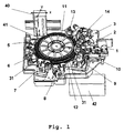
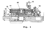
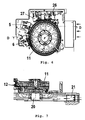
- Fig. 1 shows an analyzer for performing medical diagnostic analysis of biological samples comprising the following components: a first disk-shaped cuvette conveyor 12, and first drive means 24 (not shown in Fig. 1 , but shown in Fig. 14 ) for rotating the first cuvette conveyor 12 about a rotation axis 43 (represented in Fig. 4 ).
- Rotation axis 43 passes through the center of cuvette conveyor 12 and extends in vertical direction, e.g. in Z-direction in Fig. 1 .
- Cuvette conveyor 12 is arranged parallel to a horizontal plane, e.g. an X-Y-plane in Fig. 1 , and has a first array of cuvette holding positions, hereinafter called cuvette holders, spaced along a first circle the center of which lies on rotation axis 43.
- First drive means 24 rotate cuvette conveyor 12 about the vertical rotation axis 43 in order to position cuvettes 31 carried by the first cuvette conveyor at a first angular position.
- the analyzer shown by Fig. 1 further comprises:
- Cuvette conveyor 11 is also arranged parallel to a horizontal plane, e.g. an X-Y-plane in Fig. 1 , and has a second array of cuvette holders spaced along a second circle the center of which also lies on rotation axis 43.
- the cuvette holders of the first cuvette conveyor 12 and the cuvette holders of the at least second cuvette conveyor 11 are adapted for holding cuvettes 31 which preferably have the same shape and dimensions.
- the centers of the first circle and of the second circle lie on a vertical axis which is a common rotation axis 43 of the first cuvette conveyor 12 and the at least second cuvette conveyor 11.
- the first cuvette conveyor 12 and the at least second cuvette conveyor 11 are rotatable around their common rotation axis 43.
- the first cuvette conveyor 12 and the at least second cuvette conveyor 11 are spaced from each other in axial direction along the rotation axis 43 with an air gap between the first cuvette conveyor 12 and the at least second cuvette conveyor 11.
- the analyzer shown by Fig. 1 further comprises a workstation 1 (WSA), a fluorescence polarization photometer 2, a workstation 3 (WSE), a workstation 5 (WSB), a workstation 6 (WS2), a workstation 7 (WSC1), a workstation 8 (WSC2), absorption photometer 9, a first waste drop-off station 10, an automatic pipetting unit 40 and a control unit 42.
- WSA workstation 1
- WSE fluorescence polarization photometer 2
- WSE workstation 3
- WSE workstation 5
- WS2 workstation 6
- WSC1 workstation 7
- WSC2 workstation 8
- absorption photometer 9 a first waste drop-off station 10
- a control unit 42 a control unit 42.
- the analyzer shown by Fig. 1 preferably comprises a second waste drop-off station 13.
- Workstation 1 transports a cuvette and positions it in a cuvette holder of conveyor 12 and after termination of the processing of the cuvette removes it from conveyor 12 and brings it to a waste drop-off station 10 which delivers the cuvette to a waste container.
- Fluorescence polarization photometer 2 measures the content of a liquid, e.g. comprising a blood sample, contained in a cuvette.
- WSE Workstation 3
- a selected cuvette containing a liquid comprising a sample e.g. a blood sample
- conveyor 12 transports it to fluorescence polarization photometer 2, and brings the cuvette back to a cuvette holder of conveyor 12.
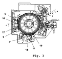
- Workstation 5 takes a selected cuvette containing a liquid from conveyor 12, brings it to a reagent pipetting position 16 where a first reagent is pipetted into the cuvette, agitates the cuvette for effective mixing of the liquids in the cuvette, and after this mixing step brings the cuvette back to a cuvette holder of conveyor 12.
- Workstation 6 takes a selected cuvette containing a liquid from conveyor 12, brings it to a reagent pipetting position 17 where a second reagent is pipetted into the cuvette, agitates the cuvette for effective mixing of the liquids in the cuvette, and after this mixing step brings the cuvette back to a cuvette holder of conveyor 12.
- Workstation 7 takes a selected cuvette containing a liquid from conveyor 12, brings it to a reagent pipetting position 18 where a liquid, e.g. sample, reagent or a dilution liquid is pipetted into the cuvette, agitates the cuvette for effective mixing of the liquids in the cuvette, and after this mixing step brings the cuvette back to a cuvette holder of conveyor 12.
- a liquid e.g. sample, reagent or a dilution liquid
- Workstation 8 takes a selected cuvette containing a liquid from conveyor 12, brings it to a reagent pipetting position 19 where a liquid, e.g. sample, reagent or a dilution liquid is pipetted into the cuvette, agitates the cuvette for effective mixing of the liquids in the cuvette, and after this mixing step brings the cuvette back to a cuvette holder of conveyor 12.
- a liquid e.g. sample, reagent or a dilution liquid
- Workstation 7 takes a selected cuvette containing a liquid from conveyor 11, brings it to a reagent pipetting position 18 where a liquid, e.g. sample, reagent or a dilution liquid is pipetted into the cuvette, agitates the cuvette for effective mixing of the liquids in the cuvette, and after this mixing step brings the cuvette back to a cuvette holder of conveyor 11.
- a liquid e.g. sample, reagent or a dilution liquid
- Absorption photometer 9 measures the content of a liquid, e.g. comprising a blood sample, contained in a cuvette.
- the cuvette holders of the first cuvette conveyor 12 and the cuvette holders of the at least second cuvette conveyor 11 are adapted for holding cuvettes 31 having an inner volume in a range going from 0.2 to 3 milliliter.
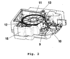
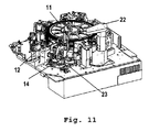
- a preferred embodiment of the analyzer shown by Fig. 1 further comprises a housing 15 the interior of which defines a chamber.
- This chamber has an upper opening which is closed by a removable cover (not shown) during operation of the analyzer. That opening allows access to the components contained therein.
- air temperature within the chamber is regulated and maintained at a determined value by means of a temperature regulation arrangement which includes a fan 20 and a heating element 21 shown by Fig. 7 .
- a temperature regulation arrangement which includes a fan 20 and a heating element 21 shown by Fig. 7 .
- the air flow generated by fan 20 is represented by arrows.
- the first cuvette conveyor 12 and the at least second cuvette conveyor 11 are located within the above mentioned chamber of housing 15 and are thereby kept at the same temperature.
- a preferred embodiment of the analyzer shown by Fig. 1 further comprises a first cuvette transport device 14 (WSF), which is located close to the periphery of the first cuvette conveyor 12, respectively the at least second cuvette conveyor 11, and which is adapted for transporting a cuvette 31 from one of the cuvette holders of the first cuvette conveyor 12 to one of the cuvette holders of the at least second cuvette conveyor 11 and/or vice versa.
- WSF first cuvette transport device 14
- Preferred embodiments of the analyzer shown by Fig. 1 further comprise a plurality of workstations arranged around and close to the periphery of the first cuvette conveyor 12 and the at least second cuvette conveyor 11.
- Those workstations comprise cuvette transport means for removing a cuvette 31 from one of the cuvette holders of the first cuvette conveyor or of the at least second cuvette conveyor 11, for transporting the cuvette to a processing position, and for transporting the cuvette from the processing position to another one of the cuvette holders of the first cuvette conveyor 12 or of the at least second cuvette conveyor 11, or for transferring said cuvette 31 to a cuvette ejection device, e.g. waste drop-off station 10 or 13.
- a cuvette ejection device e.g. waste drop-off station 10 or 13.
- the automatic pipetting unit of the analyzer shown by Fig. 1 comprises a pipetting head 40 which transports a pipetting needle 41 in three orthogonal directions X, Y and Z for performing pipetting operations, e.g. for pipetting a sample or a reagent aliquot into a selected cuvette 31 at a selected processing position at a selected point of time.
- the location of the processing position is associated with the position of one of the plurality of workstations.
- the control unit 42 of the analyzer shown by Fig. 1 controls the operation of the first drive means 24, of the at least second drive means 25, of the first cuvette transport device 14 (WSF), of the plurality of workstations, of the automatic pipetting unit, and of the photometers 2 and 9.
- the control unit 42 continuously receives and stores the current position of each cuvette, wherein the cuvettes 31 have a variable position.
- the control unit 42 controls the processing of each sample contained in one of the cuvettes 31 according to predetermined specific sequence of method steps for the treatment of that sample.
- the control unit 42 optimizes the execution of the sequences of method steps for processing the samples contained in all the cuvettes 31 and thereby maximizes the number of samples analyzed per unit of time.
- the at least second cuvette conveyor 11 has the same shape and dimensions as the first cuvette conveyor 12.
- each of the cuvette holders has a recess for receiving a tongue 37, 38 which is an integral portion of a cuvette 31. That recess extends in radial direction and the tongue 37, 38 is insertable in the recess in radial direction.
- first drive means 24 and the at least second drive means 25 are each adapted for rotating the first cuvette conveyor 12 respectively the at least second cuvette conveyor 11 in a first sense and/or in a second sense opposite to the first sense.
- the first cuvette transport device 14 is further adapted for removing a cuvette 31 from one of the cuvette holders of the at least second cuvette conveyor 11 and for transferring the cuvette 31 to a cuvette ejection device, e.g. waste drop-off station 13.
- the first cuvette transport device 14 is further adapted for transferring the cuvette 31 from one of the cuvette holders of the at least second cuvette conveyor 11 to a processing position, e.g. a pipetting position 44, and from the processing position back to the cuvette holder, or to a cuvette ejection position in waste drop-off station 13 which delivers the cuvette to a waste container.
- a processing position e.g. a pipetting position 44
- waste drop-off station 13 which delivers the cuvette to a waste container.
- the analyzer further comprises a second cuvette transport device 1 (WSA) for automatically loading empty cuvettes 31 onto the first cuvette conveyor 12, by inserting each cuvette 31 into a cuvette holder of the first cuvette conveyor 12.
- WSA second cuvette transport device 1
- the second cuvette transport device 1 is also adapted for removing a cuvette 31 from one of the cuvette holders of the first cuvette conveyor 12 and for transferring the cuvette 31 to a cuvette ejection device, e.g. waste drop-off station 10.
- the second cuvette transport device 1 is also adapted for removing a cuvette 31 from one of the cuvette holders of the at least second cuvette conveyor 12 and for transferring the cuvette 31 to a cuvette ejection device, e.g. waste drop-off station 10 or 13.
- the analyzer further comprises a third cuvette transport device 1 (WSA) for automatically loading empty cuvettes 31 onto the at least second cuvette conveyor 11, by inserting each cuvette 31 into a cuvette holder of the at least second cuvette conveyor 11.
- WSA third cuvette transport device 1
- a plurality of workstations are arranged around the second cuvette conveyor 12 and this plurality of workstations comprises a workstation, e.g. workstation 5 (WSB), 6 (WS2), 7 (WSC1) and/or 8 (WSC2), which are adapted for removing a cuvette 31 from a cuvette holder of the at least second cuvette conveyor 12, and for transporting the cuvette 31 to a processing position 16, 17, 18, 19 and from that processing position back to a cuvette holder of the at least second cuvette conveyor 12.
- processing positions are defined e.g. by pipetting openings 16, 17, 18, 19 of work stations 5, 6, 7, 8 respectively.
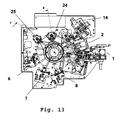
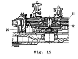
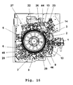
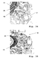
- FIG. 16 A second embodiment of an analyzer according to the invention is shown by Fig. 16 .
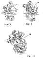
- This second embodiment comprises the above mentioned components of the analyzer described above as Example 1 and the plurality of workstations arranged around the cuvette conveyors comprises: a workstation 22 (WSK) shown also by Figures 19 20, 21 and 22 , workstation 26 (WSI 1), optionally a workstation 27 (WSI 2) which has the same structure and function as workstation 26 (WSI 1), workstation 28 (WSG) shown also by Fig. 17 , a workstation 29 (WSH), and a workstation 23 (WSL) shown also by Figures 23, 24 and 25 .
- a workstation 22 shown also by Figures 19 20, 21 and 22
- workstation 26 WI 1
- WSH workstation 29
- WSL workstation 23
- the reference numbers 44, 45 and 46 designate a pipetting position in workstation 14 (WSF), workstation 28 (WSG), and workstation 29 (WSH) respectively.
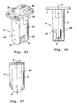
- Workstation 22 is adapted for taking out liquid from a cuvette 31 and/or adding liquid to a cuvette 31, wherein cuvette 31 is preferably held by workstation 26 (WSI 1).
- Workstation 26 is adapted for removing a cuvette 31 from a cuvette holder of the at least second cuvette conveyor 11, for mixing the liquid in the cuvette, and for inserting the cuvette 31 into one of the cuvette holders of the at least second cuvette conveyor 11.
- Workstation 28 is adapted for removing a cuvette 31 from a cuvette holder of the at least second cuvette conveyor 11, for transporting the cuvette 31 to a reagent pipetting position 45, for mixing the liquid in the cuvette 31, and for transporting the cuvette 31 from that pipetting position to one of the cuvette holders of the at least second cuvette conveyor 11.
- Workstation 29 is adapted for removing a cuvette 31 from a cuvette holder of the at least second cuvette conveyor 11, for transporting the cuvette 31 to a sample pipetting position 46, for mixing the liquid in the cuvette 31, and for transporting the cuvette 31 from that pipetting position back to one of the cuvette holders of the at least second cuvette conveyor 11.
- Workstation 23 is a washing station which serves for cleaning the pipetting needle 41 and which provides cleaning liquids for rinsing a measuring station.
- absorption photometer 9 photometrically measures the contents of a cuvette 31 held by one of the cuvette holders.
- the analyzer comprises a fourth cuvette transport device 3 (WSE) for removing a cuvette 31 containing a sample-reagent-mixture from a cuvette holder, for holding the cuvette 31 at a measurement position for the fluorescence polarization photometer 2, and for inserting the cuvette 31 into one of the cuvette holders or for transferring said cuvette 31 to a cuvette ejection device, e.g. waste drop-off station 10, after a measurement of the cuvette contents in the fluorescence polarization photometer 2.
- WSE cuvette transport device 3
- the analyzer further comprises a plurality of reaction cuvettes 31 of the type illustrated by Figures 25, 26 and 27 .
- Each cuvette 31 is insertable into one of the cuvette holders of the cuvette conveyors 11 and 12.
- Cuvette 31 has a tubular body 32 which has a longitudinal axis 39 and two opposite ends along said longitudinal axis.
- the tubular body 32 has an upper opening 36, a bottom wall 35, planar side walls 47, 48 opposing each other through which optical detection is carried out, and tongues 37, 38 which are adjacent to the upper opening 36 and which extend in opposite directions along a plane normal to the longitudinal axis 39.
- Each of the tongues 37, 38 is insertable in one of the cuvette holders of the cuvette conveyors 11 and 12.
- Planar side walls 47, 48 are preferably plane-parallel side walls which are parallel to each other.
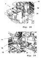
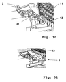
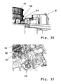
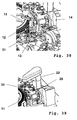
- Figures 28 to 44 illustrate the cooperation of the various workstations with the cuvette conveyors 11 and 12 and with the photometers 2 and 9.
Claims (13)
- Analyseur pour effectuer une analyse de diagnostic médical d'échantillons biologiques, ledit analyseur comprenant(a) un premier transporteur de cuvettes (12) en forme de disque ayant un premier ensemble de porte-cuvettes espacés sur un premier cercle, et(b) un premier moyen d'entraînement (24) pour mettre en rotation ledit premier transporteur de cuvettes (12) autour d'un axe de rotation (43) afin de positionner des cuvettes (31) transportées par le premier transporteur de cuvettes à une première position angulaire,
ledit analyseur étant caractérisé en ce qu'il comprend en outre(c) au moins un deuxième transporteur de cuvettes (11) en forme de disque ayant un deuxième ensemble de porte-cuvettes espacés sur un deuxième cercle,
lesdits porte-cuvettes dudit premier transporteur de cuvettes (12) et lesdits porte-cuvettes dudit au moins un deuxième transporteur de cuvettes (11) étant adaptés à porter des cuvettes (31) ayant la même forme et les mêmes dimensions,
les centres dudit premier cercle et dudit deuxième cercle reposant sur un axe vertical qui est un axe de rotation (43) commun dudit premier transporteur de cuvettes (12) et dudit au moins un deuxième transporteur de cuvettes (11),
ledit premier transporteur de cuvettes (12) et ledit au moins un deuxième transporteur de cuvettes (11) étant rotatifs autour dudit axe de rotation (43) commun,
ledit premier transporteur de cuvettes (12) et ledit au moins un deuxième transporteur de cuvettes (11) étant espacés l'un de l'autre dans un sens axial sur ledit axe de rotation (43) avec un espace d'air entre ledit premier transporteur de cuvettes (12) et ledit au moins un deuxième transporteur de cuvettes (11), et(d) au moins un deuxième moyen d'entraînement (25) pour mettre en rotation ledit au moins un deuxième transporteur de cuvettes (11) autour dudit axe de rotation (43) vertical afin de positionner des cuvettes (31) transportées par l'au moins un deuxième transporteur de cuvettes (11) à une deuxième position angulaire, le fonctionnement dudit au moins un deuxième moyen d'entraînement (25) étant indépendant du fonctionnement dudit premier moyen d'entraînement (24),e) un premier dispositif de transport de cuvettes (14, WSF) qui est situé à proximité de la périphérie dudit premier transporteur de cuvettes (12), respectivement dudit au moins un deuxième transporteur de cuvettes (11), et qui est adapté à transporter une cuvette (31) d'un des porte-cuvettes dudit premier transporteur de cuvettes (12) jusqu'à un des porte-cuvettes dudit au moins un deuxième transporteur de cuvettes (11) et/ou vice-versaf) un logement (15) qui définit une chambre à l'intérieur de laquelle la température de l'air est régulée et maintenue à une valeur déterminée, ledit premier transporteur de cuvettes (12) et ledit au moins un deuxième transporteur de cuvettes (11) étant situés à l'intérieur de ladite chambre,g) une pluralité de stations de travail agencées autour et à proximité de la périphérie dudit premier transporteur de cuvettes (12) et dudit au moins un deuxième transporteur de cuvettes (11), lesdites stations de travail comprenant un moyen de transport de cuvettes pour enlever une cuvette (31) d'un desdits porte-cuvettes dudit premier transporteur de cuvettes (12) ou dudit au moins un deuxième transporteur de cuvettes (11), pour transporter la cuvette jusqu'à une position de traitement, et de ladite position de traitement jusqu'à un desdits porte-cuvettes dudit premier transporteur de cuvettes (12) ou dudit au moins un deuxième transporteur de cuvettes (11). - Analyseur selon la revendication 1, dans lequel lesdits porte-cuvettes dudit premier transporteur de cuvettes (12) et lesdits porte-cuvettes dudit au moins un deuxième transporteur de cuvettes (11) sont adaptés à porter des cuvettes (31) ayant un volume intérieur dans une plage allant de 0,2 à 3 millilitre(s).
- Analyseur selon la revendication 1, dans lequel ledit premier dispositif de transport de cuvettes (14, WSF) est en outre adapté à enlever une cuvette (31) d'un des porte-cuvettes dudit au moins un deuxième transporteur de cuvettes (11) et à transférer ladite cuvette (31) jusqu'à un dispositif d'éjection de cuvette (13).
- Analyseur selon la revendication 1, dans lequel ledit premier dispositif de transport de cuvettes (14, WSF) est en outre adapté à transférer ladite cuvette (31) d'un des porte-cuvettes dudit au moins un deuxième transporteur de cuvettes (11) jusqu'à une position de traitement et de ladite position de traitement en retour jusqu'audit porte-cuvette, ou jusqu'à un dispositif d'éjection de cuvette (13).
- Analyseur selon la revendication 1, comprenant en outre
des moyens automatiques de pipetage (40, 41) pour pipeter une aliquote d'échantillon ou de réactif dans une cuvette (31) sélectionnée en une position de traitement sélectionnée à un point dans le temps sélectionné, l'emplacement de ladite position de traitement étant associé avec la position d'une de ladite pluralité de stations de travail. - Analyseur selon l'une quelconque des revendications précédentes comprenant en outre un moyen de commande pour commander le fonctionnement dudit premier moyen d'entraînement (24), dudit au moins un deuxième moyen d'entraînement (25), dudit dispositif de transport de cuvettes (14, WSF), de ladite pluralité de stations de travail et desdits moyens automatiques de pipetage (40, 41).
- Analyseur selon la revendication 1, dans lequel ledit au moins un deuxième transporteur de cuvettes (11) a la même forme et les mêmes dimensions que ledit premier transporteur de cuvettes (12).
- Analyseur selon la revendication 1, dans lequel chacun desdits porte-cuvettes a un renfoncement pour recevoir une languette (37, 38) qui fait partie intégrante d'une cuvette (31), ledit renfoncement s'étendant dans un sens radial et ladite languette (37, 38) étant insérable dans ledit renfoncement dans le sens radial.
- Analyseur selon la revendication 1, qui comprend en outre un deuxième dispositif de transport de cuvettes (1, WSA) pour charger automatiquement des cuvettes (31) vides sur ledit premier transporteur de cuvettes (12) et/ou dans ledit deuxième transporteur de cuvettes (11), en insérant chaque cuvette (31) dans un porte-cuvette dudit premier transporteur de cuvettes (12) et/ou dudit deuxième transporteur de cuvettes (11) respectivement, et/ou pour enlever une cuvette (31) d'un des porte-cuvettes dudit premier transporteur de cuvettes (12) et/ou dudit deuxième transporteur de cuvettes (11) et pour transférer ladite cuvette (31) jusqu'à un dispositif d'éjection de cuvette (10).
- Analyseur selon la revendication 1, qui comprend en outre un troisième dispositif de transport de cuvettes (1, WSA) pour charger automatiquement des cuvettes (31) vides sur ledit au moins un deuxième transporteur de cuvettes (11), en insérant chaque cuvette (31) dans un porte-cuvette dudit au moins un deuxième transporteur de cuvettes (11) et/ou pour enlever une cuvette (31) d'un des porte-cuvettes dudit au moins un deuxième transporteur de cuvettes (11) et pour transférer ladite cuvette (31) jusqu'à un dispositif d'éjection de cuvette (10).
- Analyseur selon la revendication 1, comprenant en outre- une station de travail (22, WSK) qui est adaptée à prélever un liquide d'une cuvette (31), par exemple une cuvette portée par une station de travail 26 (WSI 1) et/ou ajouter un liquide, par exemple une solution tampon, à cette cuvette (31),- une station de travail (28, WSG) qui est adaptée à enlever une cuvette (31) d'un porte-cuvette dudit au moins un deuxième transporteur de cuvettes (11), à transporter ladite cuvette (31) jusqu'à une position de pipetage de réactif, à mélanger le liquide dans ladite cuvette (31), et à transporter ladite cuvette (31) de cette position de pipetage jusqu'à un desdits porte-cuvettes, et- une station de travail (29, WSH) qui est adaptée à enlever une cuvette (31) d'un porte-cuvette dudit au moins un deuxième transporteur de cuvettes (11), à transporter ladite cuvette (31) jusqu'à une position de pipetage d'échantillon (46), à mélanger le liquide dans ladite cuvette (31), et à transporter ladite cuvette (31) de cette position de pipetage jusqu'à un desdits porte-cuvettes.
- Analyseur selon l'une quelconque des revendications précédentes, caractérisé en ce qu'il comprend en outre un photomètre d'absorption (9) et/ou un photomètre de polarisation de fluorescence pour une mesure photométrique du contenu d'une cuvette (31).
- Analyseur selon l'une quelconque des revendications précédentes, caractérisé en ce qu'il comprend en outre une pluralité de cuvettes (31) de réaction, chacune desquelles est insérable dans un desdits porte-cuvettes desdits transporteurs de cuvettes, chacune desdites cuvettes (31) ayant un corps tubulaire (32) ayant un axe longitudinal (39) et deux extrémités opposées sur ledit axe longitudinal, ledit corps tubulaire (32) ayant une ouverture supérieure (36), une paroi de fond (35), et des parois latérales planes (47, 48) opposées l'une à l'autre à travers lesquelles une détection optique est effectuée, ledit corps tubulaire ayant des languettes (37, 38) qui sont adjacentes à ladite ouverture supérieure (36) et qui s'étendent dans des directions opposées sur un plan normal audit axe longitudinal (39), chacune desdites languettes (37, 38) étant insérable dans un desdits porte-cuvettes.
Priority Applications (4)
| Application Number | Priority Date | Filing Date | Title |
|---|---|---|---|
| EP08009896A EP2128627B1 (fr) | 2008-05-30 | 2008-05-30 | Analyseur pour effectuer une analyse de diagnostic médical |
| JP2011510894A JP5264999B2 (ja) | 2008-05-30 | 2009-05-28 | 医学診断分析 |
| PCT/EP2009/003796 WO2009144020A1 (fr) | 2008-05-30 | 2009-05-28 | Analyseur permettant la mise en œuvre d'analyses pour diagnostic médical |
| US12/956,303 US8431079B2 (en) | 2008-05-30 | 2010-11-30 | Analyzer for performing medical diagnostic analysis |
Applications Claiming Priority (1)
| Application Number | Priority Date | Filing Date | Title |
|---|---|---|---|
| EP08009896A EP2128627B1 (fr) | 2008-05-30 | 2008-05-30 | Analyseur pour effectuer une analyse de diagnostic médical |
Publications (2)
| Publication Number | Publication Date |
|---|---|
| EP2128627A1 EP2128627A1 (fr) | 2009-12-02 |
| EP2128627B1 true EP2128627B1 (fr) | 2013-01-09 |
Family
ID=39929739
Family Applications (1)
| Application Number | Title | Priority Date | Filing Date |
|---|---|---|---|
| EP08009896A Active EP2128627B1 (fr) | 2008-05-30 | 2008-05-30 | Analyseur pour effectuer une analyse de diagnostic médical |
Country Status (4)
| Country | Link |
|---|---|
| US (1) | US8431079B2 (fr) |
| EP (1) | EP2128627B1 (fr) |
| JP (1) | JP5264999B2 (fr) |
| WO (1) | WO2009144020A1 (fr) |
Families Citing this family (15)
| Publication number | Priority date | Publication date | Assignee | Title |
|---|---|---|---|---|
| ES2859774T3 (es) * | 2005-04-01 | 2021-10-04 | Lsi Medience Corp | Aparato de análisis automático múltiple de muestras biológicas, procedimiento de autoanálisis y cubeta de reacción |
| JP2014532877A (ja) | 2011-11-01 | 2014-12-08 | サウジ アラビアン オイル カンパニー | 光学方式測定のためのマルチキュベット自動サンプラー |
| EP2746774A1 (fr) | 2012-12-19 | 2014-06-25 | F.Hoffmann-La Roche Ag | Système et procédé d'analyse d'échantillons liquides |
| EP2746775B1 (fr) * | 2012-12-19 | 2019-09-04 | F.Hoffmann-La Roche Ag | Dispositif et procédé de transfert de récipients de réaction |
| JP6165961B2 (ja) | 2013-03-15 | 2017-07-19 | アボット・ラボラトリーズAbbott Laboratories | 前処理カルーセルを有する診断分析装置および関連方法 |
| CN107831324B (zh) | 2013-03-15 | 2021-11-19 | 雅培制药有限公司 | 具有后面可进入轨道系统的自动化诊断分析仪及相关方法 |
| CN109358202B (zh) | 2013-03-15 | 2023-04-07 | 雅培制药有限公司 | 具有竖直布置的圆盘传送带的自动化诊断分析仪及相关方法 |
| DK2881740T3 (da) * | 2013-12-03 | 2019-05-13 | Immunodiagnostic Systems Ltd | Fremgangsmåde til kvantificering af en analyt og automatisk analyseanordning, der er konfigureret til at gennemføre fremgangsmåden |
| US10031085B2 (en) | 2014-07-24 | 2018-07-24 | Ortho-Clinical Diagnostics, Inc. | Point of care analytical processing system |
| WO2016210420A1 (fr) * | 2015-06-26 | 2016-12-29 | Abbott Laboratories | Dispositif d'échangeur de cuve de réaction pour un analyseur de diagnostic |
| CN108738348B (zh) | 2016-02-17 | 2023-09-01 | 贝克顿·迪金森公司 | 用于相同的诊断测试的自动化样品制备系统 |
| CN115754322A (zh) | 2016-04-22 | 2023-03-07 | 贝克顿·迪金森公司 | 自动诊断分析仪及其操作方法 |
| CN115754323A (zh) | 2016-04-22 | 2023-03-07 | 贝克顿·迪金森公司 | 自动化诊断分析仪和用于自动化诊断分析仪的操作的方法 |
| CN108956570A (zh) * | 2018-07-26 | 2018-12-07 | 上海凯创生物技术有限公司 | 干式荧光免疫分析仪 |
| CN115948224A (zh) * | 2020-02-27 | 2023-04-11 | 莫拉雷研究公司 | 生物样本自动提取系统和装置 |
Family Cites Families (16)
| Publication number | Priority date | Publication date | Assignee | Title |
|---|---|---|---|---|
| US4054416A (en) * | 1976-08-11 | 1977-10-18 | Secretary Of State For Social Services | Apparatus for use in investigating specimens |
| JPS55136957A (en) * | 1979-04-14 | 1980-10-25 | Olympus Optical Co Ltd | Automatic analyzer |
| JP2723922B2 (ja) * | 1988-09-07 | 1998-03-09 | 株式会社日立製作所 | 空気恒温槽を備えた自動分析装置 |
| US5233844A (en) * | 1991-08-15 | 1993-08-10 | Cryo-Cell International, Inc. | Storage apparatus, particularly with automatic insertion and retrieval |
| CA2092026A1 (fr) | 1992-04-06 | 1993-10-07 | Burkard Rosenberg | Poste de traitement pour dispositif d'analyse |
| US5244633A (en) * | 1992-05-22 | 1993-09-14 | Eastman Kodak Company | Analyzer incubator with plural independently driven rings supporting cuvettes |
| CA2096198A1 (fr) | 1992-06-26 | 1993-12-27 | Christopher J. Macko | Analyseur clinique automatise avec controle de la temperature |
| US5419871A (en) * | 1994-04-29 | 1995-05-30 | Muszak; Martin F. | Analyzer elevator assembly |
| DE69733927T2 (de) * | 1996-04-26 | 2006-05-24 | Dade Behring Inc., Deerfield | Verfahren und vorrichtung zur vorbehandlung von proben in einem chemischen analysator |
| ID23862A (id) * | 1998-02-20 | 2000-05-25 | Scil Diagnotics Gmbh | Sistem analisis |
| JP4451539B2 (ja) * | 1999-05-11 | 2010-04-14 | シスメックス株式会社 | 自動分析装置および自動分析装置用容器供給装置 |
| NZ506689A (en) * | 2000-09-01 | 2003-03-28 | Intellitech Automation Ltd | Automatic processing system for preparing samples prior to testing by an electronic analyser |
| US7402282B2 (en) * | 2001-07-20 | 2008-07-22 | Ortho-Clinical Diagnostics, Inc. | Auxiliary sample supply for a clinical analyzer |
| US20060159587A1 (en) * | 2005-01-19 | 2006-07-20 | Beckman Coulter, Inc. | Automated clinical analyzer with dual level storage and access |
| ES2859774T3 (es) * | 2005-04-01 | 2021-10-04 | Lsi Medience Corp | Aparato de análisis automático múltiple de muestras biológicas, procedimiento de autoanálisis y cubeta de reacción |
| US20090182802A1 (en) | 2008-01-10 | 2009-07-16 | Microsoft Corporation | Mobile device management scheduling |
-
2008
- 2008-05-30 EP EP08009896A patent/EP2128627B1/fr active Active
-
2009
- 2009-05-28 JP JP2011510894A patent/JP5264999B2/ja active Active
- 2009-05-28 WO PCT/EP2009/003796 patent/WO2009144020A1/fr active Application Filing
-
2010
- 2010-11-30 US US12/956,303 patent/US8431079B2/en active Active
Also Published As
| Publication number | Publication date |
|---|---|
| EP2128627A1 (fr) | 2009-12-02 |
| WO2009144020A1 (fr) | 2009-12-03 |
| JP2011522230A (ja) | 2011-07-28 |
| US8431079B2 (en) | 2013-04-30 |
| US20110293475A1 (en) | 2011-12-01 |
| JP5264999B2 (ja) | 2013-08-14 |
Similar Documents
| Publication | Publication Date | Title |
|---|---|---|
| EP2128627B1 (fr) | Analyseur pour effectuer une analyse de diagnostic médical | |
| JP4119845B2 (ja) | 積み重ね可能なアリクォット容器アレイ | |
| US9134332B2 (en) | Instrument and process for the automated processing of liquid samples | |
| US7015042B2 (en) | Increasing throughput in an automatic clinical analyzer by partitioning assays according to type | |
| US20080026472A1 (en) | Instrument For Efficient Treatment Of Analytical Devices | |
| JP7113941B2 (ja) | 体外診断分析方法およびシステム | |
| US8066943B2 (en) | Clinical analyzer having a variable cycle time and throughput | |
| JP2007524082A (ja) | 自動臨床アナライザに用いるランダム・アクセス試薬給送システム | |
| AU2004201313B2 (en) | Analyzer having a stationary multifunction probe | |
| EP1542020A2 (fr) | Analyseur avec support amovible pour récipients ou centrifuge | |
| EP2746774A1 (fr) | Système et procédé d'analyse d'échantillons liquides | |
| JP6120763B2 (ja) | 反応槽を搬送する装置およびプロセス | |
| JP2007524081A (ja) | モジュール式試薬給送手段を使用することによって自動臨床アナライザの性能を向上させる方法 | |
| EP1477810A1 (fr) | Appareil d'analyse comportant des rotors concentriques | |
| US20040191923A1 (en) | Test element holder with a probe guide for an analyzer | |
| EP0576291A2 (fr) | Analyseur clinique automatisé avec régulation de température | |
| US20030040117A1 (en) | Increasing throughput in an automatic clinical analyzer by partitioning assays according to type |
Legal Events
| Date | Code | Title | Description |
|---|---|---|---|
| PUAI | Public reference made under article 153(3) epc to a published international application that has entered the european phase |
Free format text: ORIGINAL CODE: 0009012 |
|
| AK | Designated contracting states |
Kind code of ref document: A1 Designated state(s): AT BE BG CH CY CZ DE DK EE ES FI FR GB GR HR HU IE IS IT LI LT LU LV MC MT NL NO PL PT RO SE SI SK TR |
|
| AX | Request for extension of the european patent |
Extension state: AL BA MK RS |
|
| 17P | Request for examination filed |
Effective date: 20100602 |
|
| 17Q | First examination report despatched |
Effective date: 20100629 |
|
| AKX | Designation fees paid |
Designated state(s): AT BE BG CH CY CZ DE DK EE ES FI FR GB GR HR HU IE IS IT LI LT LU LV MC MT NL NO PL PT RO SE SI SK TR |
|
| GRAP | Despatch of communication of intention to grant a patent |
Free format text: ORIGINAL CODE: EPIDOSNIGR1 |
|
| GRAS | Grant fee paid |
Free format text: ORIGINAL CODE: EPIDOSNIGR3 |
|
| GRAA | (expected) grant |
Free format text: ORIGINAL CODE: 0009210 |
|
| AK | Designated contracting states |
Kind code of ref document: B1 Designated state(s): AT BE BG CH CY CZ DE DK EE ES FI FR GB GR HR HU IE IS IT LI LT LU LV MC MT NL NO PL PT RO SE SI SK TR |
|
| REG | Reference to a national code |
Ref country code: GB Ref legal event code: FG4D |
|
| REG | Reference to a national code |
Ref country code: CH Ref legal event code: EP Ref country code: AT Ref legal event code: REF Ref document number: 593040 Country of ref document: AT Kind code of ref document: T Effective date: 20130115 |
|
| REG | Reference to a national code |
Ref country code: IE Ref legal event code: FG4D |
|
| REG | Reference to a national code |
Ref country code: DE Ref legal event code: R096 Ref document number: 602008021464 Country of ref document: DE Effective date: 20130307 |
|
| PG25 | Lapsed in a contracting state [announced via postgrant information from national office to epo] |
Ref country code: SI Free format text: LAPSE BECAUSE OF FAILURE TO SUBMIT A TRANSLATION OF THE DESCRIPTION OR TO PAY THE FEE WITHIN THE PRESCRIBED TIME-LIMIT Effective date: 20130109 |
|
| REG | Reference to a national code |
Ref country code: NL Ref legal event code: VDEP Effective date: 20130109 |
|
| REG | Reference to a national code |
Ref country code: AT Ref legal event code: MK05 Ref document number: 593040 Country of ref document: AT Kind code of ref document: T Effective date: 20130109 |
|
| REG | Reference to a national code |
Ref country code: LT Ref legal event code: MG4D |
|
| PG25 | Lapsed in a contracting state [announced via postgrant information from national office to epo] |
Ref country code: ES Free format text: LAPSE BECAUSE OF FAILURE TO SUBMIT A TRANSLATION OF THE DESCRIPTION OR TO PAY THE FEE WITHIN THE PRESCRIBED TIME-LIMIT Effective date: 20130420 Ref country code: NO Free format text: LAPSE BECAUSE OF FAILURE TO SUBMIT A TRANSLATION OF THE DESCRIPTION OR TO PAY THE FEE WITHIN THE PRESCRIBED TIME-LIMIT Effective date: 20130409 Ref country code: BE Free format text: LAPSE BECAUSE OF FAILURE TO SUBMIT A TRANSLATION OF THE DESCRIPTION OR TO PAY THE FEE WITHIN THE PRESCRIBED TIME-LIMIT Effective date: 20130109 Ref country code: AT Free format text: LAPSE BECAUSE OF FAILURE TO SUBMIT A TRANSLATION OF THE DESCRIPTION OR TO PAY THE FEE WITHIN THE PRESCRIBED TIME-LIMIT Effective date: 20130109 Ref country code: BG Free format text: LAPSE BECAUSE OF FAILURE TO SUBMIT A TRANSLATION OF THE DESCRIPTION OR TO PAY THE FEE WITHIN THE PRESCRIBED TIME-LIMIT Effective date: 20130409 Ref country code: LT Free format text: LAPSE BECAUSE OF FAILURE TO SUBMIT A TRANSLATION OF THE DESCRIPTION OR TO PAY THE FEE WITHIN THE PRESCRIBED TIME-LIMIT Effective date: 20130109 Ref country code: SE Free format text: LAPSE BECAUSE OF FAILURE TO SUBMIT A TRANSLATION OF THE DESCRIPTION OR TO PAY THE FEE WITHIN THE PRESCRIBED TIME-LIMIT Effective date: 20130109 Ref country code: IS Free format text: LAPSE BECAUSE OF FAILURE TO SUBMIT A TRANSLATION OF THE DESCRIPTION OR TO PAY THE FEE WITHIN THE PRESCRIBED TIME-LIMIT Effective date: 20130509 |
|
| PG25 | Lapsed in a contracting state [announced via postgrant information from national office to epo] |
Ref country code: FI Free format text: LAPSE BECAUSE OF FAILURE TO SUBMIT A TRANSLATION OF THE DESCRIPTION OR TO PAY THE FEE WITHIN THE PRESCRIBED TIME-LIMIT Effective date: 20130109 Ref country code: NL Free format text: LAPSE BECAUSE OF FAILURE TO SUBMIT A TRANSLATION OF THE DESCRIPTION OR TO PAY THE FEE WITHIN THE PRESCRIBED TIME-LIMIT Effective date: 20130109 Ref country code: PT Free format text: LAPSE BECAUSE OF FAILURE TO SUBMIT A TRANSLATION OF THE DESCRIPTION OR TO PAY THE FEE WITHIN THE PRESCRIBED TIME-LIMIT Effective date: 20130509 Ref country code: GR Free format text: LAPSE BECAUSE OF FAILURE TO SUBMIT A TRANSLATION OF THE DESCRIPTION OR TO PAY THE FEE WITHIN THE PRESCRIBED TIME-LIMIT Effective date: 20130410 Ref country code: PL Free format text: LAPSE BECAUSE OF FAILURE TO SUBMIT A TRANSLATION OF THE DESCRIPTION OR TO PAY THE FEE WITHIN THE PRESCRIBED TIME-LIMIT Effective date: 20130109 Ref country code: LV Free format text: LAPSE BECAUSE OF FAILURE TO SUBMIT A TRANSLATION OF THE DESCRIPTION OR TO PAY THE FEE WITHIN THE PRESCRIBED TIME-LIMIT Effective date: 20130109 |
|
| PG25 | Lapsed in a contracting state [announced via postgrant information from national office to epo] |
Ref country code: HR Free format text: LAPSE BECAUSE OF FAILURE TO SUBMIT A TRANSLATION OF THE DESCRIPTION OR TO PAY THE FEE WITHIN THE PRESCRIBED TIME-LIMIT Effective date: 20130109 |
|
| PG25 | Lapsed in a contracting state [announced via postgrant information from national office to epo] |
Ref country code: DK Free format text: LAPSE BECAUSE OF FAILURE TO SUBMIT A TRANSLATION OF THE DESCRIPTION OR TO PAY THE FEE WITHIN THE PRESCRIBED TIME-LIMIT Effective date: 20130109 Ref country code: RO Free format text: LAPSE BECAUSE OF FAILURE TO SUBMIT A TRANSLATION OF THE DESCRIPTION OR TO PAY THE FEE WITHIN THE PRESCRIBED TIME-LIMIT Effective date: 20130109 Ref country code: CZ Free format text: LAPSE BECAUSE OF FAILURE TO SUBMIT A TRANSLATION OF THE DESCRIPTION OR TO PAY THE FEE WITHIN THE PRESCRIBED TIME-LIMIT Effective date: 20130109 Ref country code: EE Free format text: LAPSE BECAUSE OF FAILURE TO SUBMIT A TRANSLATION OF THE DESCRIPTION OR TO PAY THE FEE WITHIN THE PRESCRIBED TIME-LIMIT Effective date: 20130109 Ref country code: SK Free format text: LAPSE BECAUSE OF FAILURE TO SUBMIT A TRANSLATION OF THE DESCRIPTION OR TO PAY THE FEE WITHIN THE PRESCRIBED TIME-LIMIT Effective date: 20130109 |
|
| PLBE | No opposition filed within time limit |
Free format text: ORIGINAL CODE: 0009261 |
|
| STAA | Information on the status of an ep patent application or granted ep patent |
Free format text: STATUS: NO OPPOSITION FILED WITHIN TIME LIMIT |
|
| PG25 | Lapsed in a contracting state [announced via postgrant information from national office to epo] |
Ref country code: CY Free format text: LAPSE BECAUSE OF FAILURE TO SUBMIT A TRANSLATION OF THE DESCRIPTION OR TO PAY THE FEE WITHIN THE PRESCRIBED TIME-LIMIT Effective date: 20130109 |
|
| 26N | No opposition filed |
Effective date: 20131010 |
|
| PG25 | Lapsed in a contracting state [announced via postgrant information from national office to epo] |
Ref country code: MC Free format text: LAPSE BECAUSE OF FAILURE TO SUBMIT A TRANSLATION OF THE DESCRIPTION OR TO PAY THE FEE WITHIN THE PRESCRIBED TIME-LIMIT Effective date: 20130109 Ref country code: IT Free format text: LAPSE BECAUSE OF FAILURE TO SUBMIT A TRANSLATION OF THE DESCRIPTION OR TO PAY THE FEE WITHIN THE PRESCRIBED TIME-LIMIT Effective date: 20130109 |
|
| REG | Reference to a national code |
Ref country code: DE Ref legal event code: R097 Ref document number: 602008021464 Country of ref document: DE Effective date: 20131010 |
|
| REG | Reference to a national code |
Ref country code: IE Ref legal event code: MM4A |
|
| PG25 | Lapsed in a contracting state [announced via postgrant information from national office to epo] |
Ref country code: IE Free format text: LAPSE BECAUSE OF NON-PAYMENT OF DUE FEES Effective date: 20130530 |
|
| PG25 | Lapsed in a contracting state [announced via postgrant information from national office to epo] |
Ref country code: MT Free format text: LAPSE BECAUSE OF FAILURE TO SUBMIT A TRANSLATION OF THE DESCRIPTION OR TO PAY THE FEE WITHIN THE PRESCRIBED TIME-LIMIT Effective date: 20130109 |
|
| PG25 | Lapsed in a contracting state [announced via postgrant information from national office to epo] |
Ref country code: TR Free format text: LAPSE BECAUSE OF FAILURE TO SUBMIT A TRANSLATION OF THE DESCRIPTION OR TO PAY THE FEE WITHIN THE PRESCRIBED TIME-LIMIT Effective date: 20130109 |
|
| PG25 | Lapsed in a contracting state [announced via postgrant information from national office to epo] |
Ref country code: HU Free format text: LAPSE BECAUSE OF FAILURE TO SUBMIT A TRANSLATION OF THE DESCRIPTION OR TO PAY THE FEE WITHIN THE PRESCRIBED TIME-LIMIT; INVALID AB INITIO Effective date: 20080530 Ref country code: LU Free format text: LAPSE BECAUSE OF NON-PAYMENT OF DUE FEES Effective date: 20130530 |
|
| REG | Reference to a national code |
Ref country code: FR Ref legal event code: PLFP Year of fee payment: 9 |
|
| REG | Reference to a national code |
Ref country code: FR Ref legal event code: PLFP Year of fee payment: 10 |
|
| REG | Reference to a national code |
Ref country code: FR Ref legal event code: PLFP Year of fee payment: 11 |
|
| PGFP | Annual fee paid to national office [announced via postgrant information from national office to epo] |
Ref country code: FR Payment date: 20190417 Year of fee payment: 12 |
|
| PGFP | Annual fee paid to national office [announced via postgrant information from national office to epo] |
Ref country code: CH Payment date: 20190425 Year of fee payment: 12 |
|
| PGFP | Annual fee paid to national office [announced via postgrant information from national office to epo] |
Ref country code: GB Payment date: 20190430 Year of fee payment: 12 |
|
| PG25 | Lapsed in a contracting state [announced via postgrant information from national office to epo] |
Ref country code: LI Free format text: LAPSE BECAUSE OF NON-PAYMENT OF DUE FEES Effective date: 20200531 Ref country code: CH Free format text: LAPSE BECAUSE OF NON-PAYMENT OF DUE FEES Effective date: 20200531 |
|
| GBPC | Gb: european patent ceased through non-payment of renewal fee |
Effective date: 20200530 |
|
| PG25 | Lapsed in a contracting state [announced via postgrant information from national office to epo] |
Ref country code: GB Free format text: LAPSE BECAUSE OF NON-PAYMENT OF DUE FEES Effective date: 20200530 Ref country code: FR Free format text: LAPSE BECAUSE OF NON-PAYMENT OF DUE FEES Effective date: 20200531 |
|
| PGFP | Annual fee paid to national office [announced via postgrant information from national office to epo] |
Ref country code: DE Payment date: 20230412 Year of fee payment: 16 |