EP2261745B1 - Appareil lithographique et méthode de fabrication d'un dispositif - Google Patents
Appareil lithographique et méthode de fabrication d'un dispositif Download PDFInfo
- Publication number
- EP2261745B1 EP2261745B1 EP10181629A EP10181629A EP2261745B1 EP 2261745 B1 EP2261745 B1 EP 2261745B1 EP 10181629 A EP10181629 A EP 10181629A EP 10181629 A EP10181629 A EP 10181629A EP 2261745 B1 EP2261745 B1 EP 2261745B1
- Authority
- EP
- European Patent Office
- Prior art keywords
- liquid
- substrate
- gas
- trench
- holder
- Prior art date
- Legal status (The legal status is an assumption and is not a legal conclusion. Google has not performed a legal analysis and makes no representation as to the accuracy of the status listed.)
- Not-in-force
Links
Images


Classifications
-
- H—ELECTRICITY
- H01—ELECTRIC ELEMENTS
- H01L—SEMICONDUCTOR DEVICES NOT COVERED BY CLASS H10
- H01L21/00—Processes or apparatus adapted for the manufacture or treatment of semiconductor or solid state devices or of parts thereof
- H01L21/02—Manufacture or treatment of semiconductor devices or of parts thereof
- H01L21/027—Making masks on semiconductor bodies for further photolithographic processing not provided for in group H01L21/18 or H01L21/34
- H01L21/0271—Making masks on semiconductor bodies for further photolithographic processing not provided for in group H01L21/18 or H01L21/34 comprising organic layers
- H01L21/0273—Making masks on semiconductor bodies for further photolithographic processing not provided for in group H01L21/18 or H01L21/34 comprising organic layers characterised by the treatment of photoresist layers
- H01L21/0274—Photolithographic processes
-
- G—PHYSICS
- G03—PHOTOGRAPHY; CINEMATOGRAPHY; ANALOGOUS TECHNIQUES USING WAVES OTHER THAN OPTICAL WAVES; ELECTROGRAPHY; HOLOGRAPHY
- G03F—PHOTOMECHANICAL PRODUCTION OF TEXTURED OR PATTERNED SURFACES, e.g. FOR PRINTING, FOR PROCESSING OF SEMICONDUCTOR DEVICES; MATERIALS THEREFOR; ORIGINALS THEREFOR; APPARATUS SPECIALLY ADAPTED THEREFOR
- G03F7/00—Photomechanical, e.g. photolithographic, production of textured or patterned surfaces, e.g. printing surfaces; Materials therefor, e.g. comprising photoresists; Apparatus specially adapted therefor
- G03F7/70—Microphotolithographic exposure; Apparatus therefor
- G03F7/708—Construction of apparatus, e.g. environment aspects, hygiene aspects or materials
- G03F7/70858—Environment aspects, e.g. pressure of beam-path gas, temperature
- G03F7/70883—Environment aspects, e.g. pressure of beam-path gas, temperature of optical system
-
- G—PHYSICS
- G03—PHOTOGRAPHY; CINEMATOGRAPHY; ANALOGOUS TECHNIQUES USING WAVES OTHER THAN OPTICAL WAVES; ELECTROGRAPHY; HOLOGRAPHY
- G03F—PHOTOMECHANICAL PRODUCTION OF TEXTURED OR PATTERNED SURFACES, e.g. FOR PRINTING, FOR PROCESSING OF SEMICONDUCTOR DEVICES; MATERIALS THEREFOR; ORIGINALS THEREFOR; APPARATUS SPECIALLY ADAPTED THEREFOR
- G03F7/00—Photomechanical, e.g. photolithographic, production of textured or patterned surfaces, e.g. printing surfaces; Materials therefor, e.g. comprising photoresists; Apparatus specially adapted therefor
- G03F7/20—Exposure; Apparatus therefor
- G03F7/2041—Exposure; Apparatus therefor in the presence of a fluid, e.g. immersion; using fluid cooling means
-
- G—PHYSICS
- G03—PHOTOGRAPHY; CINEMATOGRAPHY; ANALOGOUS TECHNIQUES USING WAVES OTHER THAN OPTICAL WAVES; ELECTROGRAPHY; HOLOGRAPHY
- G03F—PHOTOMECHANICAL PRODUCTION OF TEXTURED OR PATTERNED SURFACES, e.g. FOR PRINTING, FOR PROCESSING OF SEMICONDUCTOR DEVICES; MATERIALS THEREFOR; ORIGINALS THEREFOR; APPARATUS SPECIALLY ADAPTED THEREFOR
- G03F7/00—Photomechanical, e.g. photolithographic, production of textured or patterned surfaces, e.g. printing surfaces; Materials therefor, e.g. comprising photoresists; Apparatus specially adapted therefor
- G03F7/70—Microphotolithographic exposure; Apparatus therefor
- G03F7/70216—Mask projection systems
- G03F7/70341—Details of immersion lithography aspects, e.g. exposure media or control of immersion liquid supply
-
- G—PHYSICS
- G03—PHOTOGRAPHY; CINEMATOGRAPHY; ANALOGOUS TECHNIQUES USING WAVES OTHER THAN OPTICAL WAVES; ELECTROGRAPHY; HOLOGRAPHY
- G03F—PHOTOMECHANICAL PRODUCTION OF TEXTURED OR PATTERNED SURFACES, e.g. FOR PRINTING, FOR PROCESSING OF SEMICONDUCTOR DEVICES; MATERIALS THEREFOR; ORIGINALS THEREFOR; APPARATUS SPECIALLY ADAPTED THEREFOR
- G03F7/00—Photomechanical, e.g. photolithographic, production of textured or patterned surfaces, e.g. printing surfaces; Materials therefor, e.g. comprising photoresists; Apparatus specially adapted therefor
- G03F7/70—Microphotolithographic exposure; Apparatus therefor
- G03F7/708—Construction of apparatus, e.g. environment aspects, hygiene aspects or materials
- G03F7/70858—Environment aspects, e.g. pressure of beam-path gas, temperature
- G03F7/70866—Environment aspects, e.g. pressure of beam-path gas, temperature of mask or workpiece
-
- G—PHYSICS
- G03—PHOTOGRAPHY; CINEMATOGRAPHY; ANALOGOUS TECHNIQUES USING WAVES OTHER THAN OPTICAL WAVES; ELECTROGRAPHY; HOLOGRAPHY
- G03F—PHOTOMECHANICAL PRODUCTION OF TEXTURED OR PATTERNED SURFACES, e.g. FOR PRINTING, FOR PROCESSING OF SEMICONDUCTOR DEVICES; MATERIALS THEREFOR; ORIGINALS THEREFOR; APPARATUS SPECIALLY ADAPTED THEREFOR
- G03F7/00—Photomechanical, e.g. photolithographic, production of textured or patterned surfaces, e.g. printing surfaces; Materials therefor, e.g. comprising photoresists; Apparatus specially adapted therefor
- G03F7/70—Microphotolithographic exposure; Apparatus therefor
- G03F7/708—Construction of apparatus, e.g. environment aspects, hygiene aspects or materials
- G03F7/7095—Materials, e.g. materials for housing, stage or other support having particular properties, e.g. weight, strength, conductivity, thermal expansion coefficient
Definitions
- the present invention relates to a lithographic apparatus and a method for manufacturing a device.
- a lithographic apparatus is a machine that applies a desired pattern onto a substrate, usually onto a target portion of the substrate.
- a lithographic apparatus can be used, for example, in the manufacture of integrated circuits (ICs).
- a patterning device which is alternatively referred to as a mask or a reticle, may be used to generate a circuit pattern to be formed on an individual layer of the IC.
- This pattern can be transferred onto a target portion (e.g. comprising part of, one, or several dies) on a substrate (e.g. a silicon wafer). Transfer of the pattern is typically via imaging onto a layer of radiation-sensitive material (resist) provided on the substrate.
- resist radiation-sensitive material
- a single substrate will contain a network of adjacent target portions that are successively patterned.
- lithographic apparatus include so-called steppers, in which each target portion is irradiated by exposing an entire pattern onto the target portion at one time, and so-called scanners, in which each target portion is irradiated by scanning the pattern through a radiation beam in a given direction (the "scanning"-direction) while synchronously scanning the substrate parallel or anti-parallel to this direction. It is also possible to transfer the pattern from the patterning device to the substrate by imprinting the pattern onto the substrate.
- liquid supply system to provide liquid on only a localized area of the substrate and in between the final element of the projection system and the substrate (the substrate generally has a larger surface area than the final element of the projection system).
- the substrate generally has a larger surface area than the final element of the projection system.
- liquid is supplied by at least one inlet IN onto the substrate, preferably along the direction of movement of the substrate relative to the final element, and is removed by at least one outlet OUT after having passed under the projection system. That is, as the substrate is scanned beneath the element in a -X direction, liquid is supplied at the +X side of the element and taken up at the -X side.
- Figure 2 shows the arrangement schematically in which liquid is supplied via inlet IN and is taken up on the other side of the element by outlet OUT which is connected to a low pressure source.
- the liquid is supplied along the direction of movement of the substrate relative to the final element, though this does not need to be the case.
- Figure 3 shows the arrangement schematically in which liquid is supplied via inlet IN and is taken up on the other side of the element by outlet OUT which is connected to a low pressure source.
- removal of an immersion liquid typically involves a two-phase flow - the immersion liquid mixes with ambient gas (e.g., air) or gas from a gas seal used to confine the immersion liquid.
- ambient gas e.g., air
- gas from a gas seal used to confine the immersion liquid.
- Such a two-phase flow is not very stable, especially when large pressure differentials are used to create strong gas flows to confine the immersion liquid or to ensure that all liquid is collected, and the resulting vibration is undesirable.
- High pressure gas flows may also cause evaporative drying of liquid remaining on the substrate leading to thermal gradients.
- Gas flows spilling over into the path of interferometer beams may also affect the accuracy of substrate table position measurements because the interferometer is very sensitive to changes in the refractive index of the gas in the path of the interferometer beams, such as may be caused by changes in temperature, pressure and humidity.
- EP 1 429 188 A discusses an immersion lithographic apparatus in which an edge seal member is provided around the periphery of the substrate to prevent catastrophic loss of immersion liquid.
- WO2004/053953 and EP1641028 which is citable under Article 54(3) EPC, discloses an immersion lithographic apparatus in which a substrate table is provided which comprises a recess for accommodating a substrate holder.
- the recess has a trench, which, when a substrate is placed on the substrate holder, is positioned radially outward of the substrate edge.
- the trenches are suitable for collecting immersion liquid together with gas. The liquid and the gas are separated after having been extracted together from the trench.
- Figure 1 schematically depicts a lithographic apparatus according to one embodiment of the invention.
- the apparatus comprises:
- the illumination system may include various types of optical components, such as refractive, reflective, magnetic, electromagnetic, electrostatic or other types of optical components, or any combination thereof, for directing, shaping, or controlling radiation.
- optical components such as refractive, reflective, magnetic, electromagnetic, electrostatic or other types of optical components, or any combination thereof, for directing, shaping, or controlling radiation.
- the support structure supports, i.e. bears the weight of, the patterning device. It holds the patterning device in a manner that depends on the orientation of the patterning device, the design of the lithographic apparatus, and other conditions, such as for example whether or not the patterning device is held in a vacuum environment.
- the support structure can use mechanical, vacuum, electrostatic or other clamping techniques to hold the patterning device.
- the support structure may be a frame or a table, for example, which may be fixed or movable as required.
- the support structure may ensure that the patterning device is at a desired position, for example with respect to the projection system. Any use of the terms "reticle” or “mask” herein may be considered synonymous with the more general term "patterning device.”
- patterning device used herein should be broadly interpreted as referring to any device that can be used to impart a radiation beam with a pattern in its cross-section such as to create a pattern in a target portion of the substrate. It should be noted that the pattern imparted to the radiation beam may not exactly correspond to the desired pattern in the target portion of the substrate, for example if the pattern includes phase-shifting features or so called assist features. Generally, the pattern imparted to the radiation beam will correspond to a particular functional layer in a device being created in the target portion, such as an integrated circuit.
- the patterning device may be transmissive or reflective.
- Examples of patterning devices include masks, programmable mirror arrays, and programmable LCD panels.
- Masks are well known in lithography, and include mask types such as binary, alternating phase-shift, and attenuated phase-shift, as well as various hybrid mask types.
- An example of a programmable mirror array employs a matrix arrangement of small mirrors, each of which can be individually tilted so as to reflect an incoming radiation beam in different directions. The tilted mirrors impart a pattern in a radiation beam which is reflected by the mirror matrix.
- projection system used herein should be broadly interpreted as encompassing any type of projection system, including refractive, reflective, catadioptric, magnetic, electromagnetic and electrostatic optical systems, or any combination thereof, as appropriate for the exposure radiation being used, or for other factors such as the use of an immersion liquid or the use of a vacuum. Any use of the term “projection lens” herein may be considered as synonymous with the more general term “projection system”.
- the apparatus is of a transmissive type (e.g. employing a transmissive mask).
- the apparatus may be of a reflective type (e.g. employing a programmable mirror array of a type as referred to above, or employing a reflective mask).
- the lithographic apparatus may be of a type having two (dual stage) or more substrate tables (and/or two or more mask tables). In such "multiple stage” machines the additional tables may be used in parallel, or preparatory steps may be carried out on one or more tables while one or more other tables are being used for exposure.
- the illuminator IL receives a radiation beam from a radiation source SO.
- the source and the lithographic apparatus may be separate entities, for example when the source is an excimer laser. In such cases, the source is not considered to form part of the lithographic apparatus and the radiation beam is passed from the source SO to the illuminator IL with the aid of a beam delivery system BD comprising, for example, suitable directing mirrors and/or a beam expander. In other cases the source may be an integral part of the lithographic apparatus, for example when the source is a mercury lamp.
- the source SO and the illuminator IL, together with the beam delivery system BD if required, may be referred to as a radiation system.
- the illuminator IL may comprise an adjuster AD for adjusting the angular intensity distribution of the radiation beam.
- an adjuster AD for adjusting the angular intensity distribution of the radiation beam.
- the illuminator IL may comprise various other components, such as an integrator IN and a condenser CO.
- the illuminator may be used to condition the radiation beam, to have a desired uniformity and intensity distribution in its cross-section.
- the radiation beam PB is incident on the patterning device (e.g., mask MA), which is held on the support structure (e.g., mask table MT), and is patterned by the patterning device. Having traversed the mask MA, the radiation beam PB passes through the projection system PL, which focuses the beam onto a target portion C of the substrate W.
- An immersion hood IH which is described further below, supplies immersion liquid to a space between the final element of the projection system PL and the substrate W.
- the substrate table WT can be moved accurately, e.g. so as to position different target portions C in the path of the radiation beam PB.
- the first positioner PM and another position sensor (which is not explicitly depicted in Figure 1 ) can be used to accurately position the mask MA with respect to the path of the radiation beam PB, e.g. after mechanical retrieval from a mask library, or during a scan.
- movement of the mask table MT may be realized with the aid of a long-stroke module (coarse positioning) and a short-stroke module (fine positioning), which form part of the first positioner PM.
- movement of the substrate table WT may be realized using a long-stroke module and a short-stroke module, which form part of the second positioner PW.
- the mask table MT may be connected to a short-stroke actuator only, or may be fixed.
- Mask MA and substrate W may be aligned using mask alignment marks M1, M2 and substrate alignment marks P1, P2.
- the substrate alignment marks as illustrated occupy dedicated target portions, they may be located in spaces between target portions (these are known as scribe-lane alignment marks).
- the mask alignment marks may be located between the dies.
- the depicted apparatus could be used in at least one of the following modes:
- FIG. 4 A further immersion lithography solution with a localized liquid supply system is shown in Figure 4 .
- Liquid is supplied by two groove inlets IN on either side of the projection system PL and is removed by a plurality of discrete outlets OUT arranged radially outwardly of the inlets IN.
- the inlets IN and OUT can be arranged in a plate with a hole in its centre and through which the projection beam is projected.
- Liquid is supplied by one groove inlet IN on one side of the projection system PL and removed by a plurality of discrete outlets OUT on the other side of the projection system PL, causing a flow of a thin film of liquid between the projection system PL and the substrate W.
- the choice of which combination of inlet IN and outlets OUT to use can depend on the direction of movement of the substrate W (the other combination of inlet IN and outlets OUT being inactive).
- FIG. 5 Another immersion lithography solution with a localized liquid supply system solution which has been proposed is to provide the liquid supply system with a seal member which extends along at least a part of a boundary of the space between the final element of the projection system and the substrate table.
- the seal member is substantially stationary relative to the projection system in the XY plane though there may be some relative movement in the Z direction (in the direction of the optical axis).
- a seal is formed between the seal member and the surface of the substrate.
- reservoir 10 forms a contactless seal to the substrate around the image field of the projection system so that liquid is confined to fill a space between the substrate surface and the final element of the projection system.
- the reservoir is formed by a seal member 12 positioned below and surrounding the final element of the projection system PL. Liquid is brought into the space below the projection system and within the seal member 12.
- the seal member 12 extends a little above the final element of the projection system and the liquid level rises above the final element so that a buffer of liquid is provided.
- the seal member 12 has an inner periphery that at the upper end, in an embodiment, closely conforms to the shape of the projection system or the final element thereof and may, e.g., be round. At the bottom, the inner periphery closely conforms to the shape of the image field, e.g., rectangular though this need not be the case.
- the liquid is confined in the reservoir by a gas seal 16 between the bottom of the seal member 12 and the surface of the substrate W.
- the gas seal is formed by gas, e.g. air or synthetic air but, in an embodiment, N 2 or another inert gas, provided under pressure via inlet 15 to the gap between seal member 12 and substrate and extracted via first outlet 14.
- gas e.g. air or synthetic air but, in an embodiment, N 2 or another inert gas
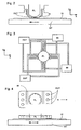
- FIGS 6 and 7 illustrate a liquid removal device 20.
- the liquid removal device 20 comprises a chamber which is maintained at a slight underpressure p c and is filled with the immersion liquid.
- the lower surface of the chamber is formed of a thin plate 21 having a large number of small holes, e.g. of diameter d hole in the range of 5 to 50 ⁇ m, and is maintained at a height h gap in the range of 50 to 300 ⁇ m above a surface from which liquid is to be removed, e.g. the surface of a substrate W.
- perforated plate 21 is at least slightly hydrophilic, i.e. having a contact angle of less than 90° to the immersion liquid, e.g. water.
- the underpressure p c is such that the menisci 22 formed in the holes in the perforated plate 21 prevent gas being drawn into the chamber of the liquid removal device.
- the plate 21 comes into contact with liquid on the surface W there is no meniscus to restrict flow and the liquid can flow freely into the chamber of the liquid removal device.
- Such a device can remove most of the liquid from the surface of a substrate W, though a thin film of liquid may remain, as shown in the drawings.
- the perforated plate 21 should be as thin as possible and the pressure differential between the pressure in the liquid p gap and the pressure in the chamber p c should be as high as possible, whilst the pressure differential between p c and the pressure in the gas in the gap p air must be low enough to prevent significant amounts of gas being drawn into the liquid removal device 20. It may not always be possible to prevent gas being drawn into the liquid removal device but the perforated plate will prevent large uneven flows that may cause vibration.
- Micro-sieves made by electroforming, photoetching and/or laser cutting can be used as the plate 21. Suitable sieves are made by Stork Veco B.V., of Eerbeek, the Netherlands. Other porous plates or solid blocks of porous material may also be used, provided the pore size is suitable to maintain a meniscus with the pressure differential that will be experienced in use.
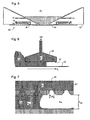
- Figure 8 shows a liquid removal device incorporated in a seal member 12 of and immersion hood IH.
- Figure 8 is a cross-sectional view of one side of the seal member 12, which forms a ring (as used herein, a ring may be circular, rectangular or any other shape) at least partially around the exposure field of the projection system PL (not shown in Figure 8 ).
- the liquid removal device 20 is formed by a ring-shaped chamber 31 near the innermost edge of the underside of the seal member 12.
- the lower surface of the chamber 31 is formed by a porous plate 30, as described above.
- Ring-shaped chamber 31 is connected to a suitable pump or pumps to remove liquid from the chamber and maintain the desired underpressure. In use, the chamber 31 is full of liquid but is shown empty here for clarity.
- the gas supply ring 33 has a narrow slit in its lower part and is supplied with gas, e.g. air, artificial air or flushing gas, at a pressure such that the gas escaping out of the slit forms a gas knife 34.
- gas e.g. air, artificial air or flushing gas
- the gas forming the gas knife is extracted by suitable vacuum pumps connected to the gas extraction ring 32 so that the resulting gas flow drives any residual liquid inwardly where it can be removed by the liquid removal device and/or the vacuum pumps, which should be able to tolerate vapour of the immersion liquid and/or small liquid droplets.
- the liquid removal device 20 since the majority of the liquid is removed by the liquid removal device 20, the small amount of liquid removed via the vacuum system does not cause unstable flows which may lead to vibration.
- gas extraction ring 32 While the chamber 31, gas extraction ring 32, gas supply ring 33 and other rings are described as rings herein, it is not necessary that they surround the exposure field or be complete.
- Such inlet(s) and outlet(s) may simply be circular, rectangular or other type of elements extending partially along one or more sides of the exposure field, such as for example, shown in Figures 2, 3 and 4 .
- Removal of most of the liquid without evaporation also means that temperature gradients may be reduced, avoiding thermal deformation of the substrate, which can lead to printing errors. Evaporation may also be further minimized by using humid gas in the gas knife, e.g. with a relative humidity of about 50 to 75%, in combination with a pressure drop of about 100 to 500mbar and a flow rate of about 20 to 200 l/min.
- humid gas in the gas knife e.g. with a relative humidity of about 50 to 75%, in combination with a pressure drop of about 100 to 500mbar and a flow rate of about 20 to 200 l/min.
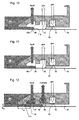
- the porous plate 30a can be set at a slight angle, so that it is higher at the outside.
- sharp corners 35 are used to limit the position of the meniscus 11a which is held by surface tension at the sharp corner.
- the sharp corner can be an obtuse angle, as shown in Figure 10 , or a right angle, as shown in Figure 11 .
- the shape of the gas extraction ring 32 can be adjusted as necessary.
- a seal member is shown in Figure 12 , which is a similar view to Figure 8 .
- a liquid bearing 36 is used to at least partially support the seal member 12, in place of separate actuators.
- the liquid, or hydro-dynamic, bearing 36 is formed by immersion liquid supplied under pressure to liquid supply chamber 37, in a known manner.
- the liquid is removed via two-phase extraction chamber 38, which is connected to suitable pumps (not shown) capable of handling the two-phase flow.
- a gas knife 34 confines the immersion liquid in the same manner as in previous embodiments.
- liquid bearing 36 enables the seal member 12 to be maintained at a height of about 50 to 200 ⁇ m above the substrate W or substrate table WT, easing control and flatness requirements as described above. At the same time, the two-phase extraction reduces the number of chambers that need to be formed in the seal member 12 and the number of hoses that need to be provided to it.
- a porous plate 30 is provided across the bottom of two-phase extraction chamber 38, to control the flow of gas and liquid into it. By suitable selection of the size, number and arrangement of the pores in this plate, the two-phase flow is made steady, avoiding uneven flow that may cause vibrations. As in the embodiments described above, a micro-sieve may be used as the plate 30.
- an inclination or a sharp edge may be provided in the porous plate 30 to control the position of the meniscus of the immersion liquid 11.
- the removal of any residual liquid can be effected by a high-humidity, large flow gas knife 34 and the pressure of the gas knife can also be used to control the meniscus position.
- the shape of the part of the seal member that is in the immersion liquid may be adjusted to provide a desired degree of damping of vertical movements of the seal member 12.
- the width L da , and hence area, of a part of the seal member which confines the liquid 11 into a narrow passage can be selected to provide the desired damping.
- the amount of damping will be determined by the area of the damping region, its height h da above the substrate W or substrate table WT, the density ⁇ of the immersion liquid and its viscosity ⁇ . Damping may reduce variations in the position of the seal member due to vibrations, e.g. caused by uneven fluid flows.
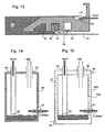
- a porous plate 41 may also be used to control the flow in an overflow drain 40, as shown in Figure 13 .
- the overflow drain of Figure 13 may be applied in any of the embodiments of the invention described herein.
- the overflow drain is provided in an upper surface of the seal member 12 at a relatively large radius from the centre of the seal member 12. In case the space between the final element of the projection system PL and the substrate W becomes overfull of immersion liquid, the excess liquid will flow onto the top of the seal member 12 and into the drain 40.
- the drain 40 is normally full of liquid and maintained at a slight underpressure.
- the porous plate 41 prevents gas being drawn into the overflow drain but allows liquid to be drained away when required.
- the porous plate may also be set at a slight angle to the horizontal.
- a porous separator can also be used in a manifold 50 that is provided in a liquid drain system that takes a two-phase flow from the immersion hood IH. As shown in Figure 14 , the two-phase flow 51 is discharged into a manifold chamber 51 in which the liquid and gas separate. The gas is removed from the top of the manifold by a gas outlet 52 which is kept at a pressure of about -0.1barg by a suitable vacuum pump and pressure controller.
- a liquid removal pipe 53 extends to near the bottom of the manifold and is closed by a porous plate 54. The liquid removal pipe 53 is kept at a pressure below the bubble point of the porous plate 54, e.g.
- FIG. 15 A variation of the manifold is shown in Figure 15 .
- the manifold is thermally isolated from its surroundings. The vacuum flow through the manifold will cause evaporation of the immersion liquid, leading to cooling. If the manifold is positioned close to or in thermal contact with a temperature sensitive part of the lithographic apparatus such as the reference or metrology frame, such cooling may have undesirable effects.
- the manifold is therefore formed as a double-walled tank, comprising inner tank 50a and outer tank 50b, with a flow of temperature controlled liquid, e.g. water, between the walls of the inner and outer tanks.
- the temperature-controlled liquid is supplied at inlet 55 and removed at outlet 56.
- a series of baffles 57 are arranged in the space between the walls of the two tanks to ensure there are no regions of stagnant liquid.
- no baffle contacts both inner and outer tanks The rate of flow of temperature controlled liquid is determined to ensure that the temperature deviation of the outer tank 50b is within the limits imposed by any nearby temperature-sensitive components.
- An air gap or additional thermal insulation is preferably also provided between the outer tank and any nearby temperature-sensitive components.
- a liquid supply system 60 that may be used in embodiments of the invention is shown in Figure 16 . It comprises, in series: a source 61 of immersion liquid, e.g. a fab supply of ultra pure liquid; a constant flow restrictor 62; a variable flow restrictor 63; and a pressure regulator 64 with an external tap, a variable restriction 65 and a constant restriction 66, positioned just before the immersion hood IH.
- the pilot line for the pressure regulator 64 is connected downstream of the variable restriction 65 and so the input to the constant restriction 66 is at a constant pressure, hence the flow into the immersion hood is at constant pressure and rate.
- FIG. 17 An alternative liquid supply system 60' is shown in Figure 17 . This is the same as the system 60 except as described below.
- a forward pressure regulator 67 and backward pressure regulator 68 are provided in place of the regulator 64, and fixed restriction 66.
- Two pressure meters 69a, 69b are also provided.
- the forward pressure regulator 67 maintains the pressure downstream of it at a predetermined level and the backward pressure regulator maintains the pressure upstream of it at a predetermined level, in both cases independently of flow rate.
- the variable flow restriction operates with constant upstream and downstream pressures, avoiding instability.
- the flow rate can be adjusted by adjustment of the pressure levels set by the pressure regulators 67, 68 and the variable flow restrictor 65, aided by the pressure sensors 69a, 69b which may also be used for monitoring purposes.
- a substrate is held on a substrate holder (often referred to as a pimple plate, burl plate or chuck), which comprises a flat plate of the same diameter as the substrate having a large number of small pimples or burls on its major surfaces.
- the substrate holder is placed in a recess in the substrate table (mirror block) and the substrate placed on top of the substrate holder.
- a vacuum is developed in the spaces between the substrate table and holder and between the holder and substrate so that the substrate and holder are clamped in place by atmospheric pressure above the substrate.
- the recess in the substrate table is necessarily slightly larger than the substrate holder and substrate to accommodate variations in substrate size and placement.
- the substrate holder is generally made of a material having a low thermal coefficient of expansivity, such as Zerodur or ULE. Some such materials are porous and in that case the surface pores are filled in to prevent contaminants becoming trapped there. However, it is proposed to leave the surface pores unfilled around the edge of the substrate holder and/or in a peripheral region. Then, when the substrate holder is used in an immersion lithography apparatus, the immersion liquid entering the groove will enter the pores of the substrate holder and not be blown out by the gas bearing or gas knife. If the substrate holder has an open-celled structure, the immersion liquid that has entered its pores can be removed by the vacuum system that clamps the substrate and holder to the table.
- a material having a low thermal coefficient of expansivity such as Zerodur or ULE.
- an extraction channel 70 connected to a volume from which only liquid is to be extracted via a narrow capillary 71 with hydrophilic walls 72 can be arranged so that liquid, e.g. water, is extracted by suitable underpressure -p, but when no liquid is present in the volume, a meniscus 73 prevents entry of gas, e.g. air.
- an extraction channel 80 connected to the volume via a capillary 81 with hydrophobic walls 82 extracts gas, e.g. air, but when liquid, e.g. water, is present meniscus 83 prevents further flow.
- underpressure -p The exact level of underpressure -p required for these arrangements will depend on the liquid and gas involved, the size of the capillary and the contact angle of the liquid to the walls of the capillary. However, for a capillary of 0.05mm width an underpressure of 20mbar is suitable to enable selective extraction of water or air.
- Extraction arrangements of this type can be used to remove selectively liquid or gas from any desired part of the lithographic apparatus.
- a particularly advantageous use in accordance with an embodiment of the invention is shown in Figures 20a to d , where liquid extraction channel 70 and gas extraction channel 80 are both connected to a trench in the substrate table WT around the edge of the substrate W.
- channel 70 extracts liquid so that there is a flow of liquid downwards. This draws any bubbles that might form in the trench, e.g. due to incomplete filling, downwards. This brings the bubbles to a position where the gas can be extracted via channel 80, but they will not enter the channel 70..
- the trench When the substrate edge is no longer under the projection lens the trench can quickly be emptied. In this way, escape of bubbles to interfere with imaging is prevented. By separating the liquid and gas flows, instabilities which may cause vibrations are avoided and the cooling effect of evaporation is minimized.
- lithographic apparatus in the manufacture of ICs
- the lithographic apparatus described herein may have other applications, such as the manufacture of integrated optical systems, guidance and detection patterns for magnetic domain memories, flat-panel displays, liquid-crystal displays (LCDs), thin-film magnetic heads, etc.
- LCDs liquid-crystal displays
- any use of the terms “wafer” or “die” herein may be considered as synonymous with the more general terms “substrate” or "target portion”, respectively.
- the substrate referred to herein may be processed, before or after exposure, in for example a track (a tool that typically applies a layer of resist to a substrate and develops the exposed resist), a metrology tool and/or an inspection tool. Where applicable, the disclosure herein may be applied to such and other substrate processing tools. Further, the substrate may be processed more than once, for example in order to create a multi-layer IC, so that the term substrate used herein may also refer to a substrate that already contains multiple processed layers.
- UV radiation e.g. having a wavelength of or about 365, 248, 193, 157 or 126 nm.
- lens may refer to any one or combination of various types of optical components, including refractive and reflective optical components.
- the invention may take the form of a computer program containing one or more sequences of machine-readable instructions describing a method as disclosed above, or a data storage medium (e.g. semiconductor memory, magnetic or optical disk) having such a computer program stored therein.
- a data storage medium e.g. semiconductor memory, magnetic or optical disk
- the present invention can be applied to any immersion lithography apparatus, in particular, but not exclusively, those types mentioned above.
- the immersion liquid used in the apparatus may have different compositions, according to the desired properties and the wavelength of exposure radiation used. For an exposure wavelength of 193nm, ultra pure water or water-based compositions may be used and for this reason the immersion liquid is sometimes referred to as water and water-related terms such as hydrophilic, hydrophobic, humidity, etc. may be used. However, it is to be understood that embodiments of the present invention may be used with other types of liquid in which case such water-related terms should be considered replaced by equivalent terms relating to the immersion liquid used.
Claims (15)
- Un appareil de projection lithographique arrangé pour projeter un motif à partir d'un dispositif servant à conformer selon un motif (MA) sur un substrat (W) à l'aide d'un système de projection (PL) et disposant d'un système d'alimentation en liquide (IH) arrangé pour amener un liquide dans un espace entre le système de projection et le substrat, l'appareil de projection lithographique comprenant :une table porte-substrat (WT) ;un porte-substrat pour supporter le substrat, le porte-substrat étant situé dans un renfoncement dans la table porte-substrat, le renfoncement étant plus grand que le porte-substrat et le substrat et comprenant une tranchée autour du bord du substrat, la tranchée étant destinée à recueillir du liquide d'immersion ; caractérisé par :un canal d'extraction de liquide (70) raccordé à la tranchée et arrangé pour extraire du liquide de la tranchée séparément du gaz.
- Appareil de la revendication 1, dans lequel le porte-substrat est réalisé en matériau présentant un faible coefficient de dilatation thermique.
- Appareil de la revendication 2, dans lequel le matériau est du Zérodur ou de l'ULE.
- Appareil de la revendication 2 ou de la revendication 3, dans lequel le matériau est poreux avec des pores de surface non remplis autour du bord du porte-substrat, dans une région périphérique du support de substrat ou les deux.
- Appareil de n'importe quelle revendication précédente, dans lequel le porte-substrat a une structure à alvéoles ouvertes de sorte que du liquide d'immersion qui pénètre dans ses pores soit retiré par un système à vide qui abloque le substrat et le porte-substrat sur la table.
- Appareil de n'importe lesquelles des revendications 1 à 5, dans lequel le substrat et le porte-substrat sont arrangés pour être abloqués dans le renfoncement par : un vide dans les espaces entre la table porte-substrat et le porte-substrat et entre le porte-substrat et le substrat ; et la pression atmosphérique au-dessus du substrat.
- Appareil de n'importe quelle revendication précédente, dans lequel le canal d'extraction de liquide (70) est arrangé pour extraire du liquide de sorte que, à l'utilisation, il y ait un écoulement de liquide vers le bas dans la tranchée lorsqu'un bord du substrat se trouve sous le système de projection et que la tranchée est remplie de liquide.
- Appareil de la revendication 7, dans lequel le canal d'extraction de liquide (70) est raccordé à un volume duquel seul du liquide est extrait via un étroit capillaire (71) à parois hydrophiles (72).
- Appareil de la revendication 8, dans lequel le canal d'extraction de liquide (70) est arrangé de sorte que du liquide puisse être extrait par une sous-pression, et dans lequel, en l'absence de liquide dans le volume, un ménisque (73) empêche du gaz de pénétrer dans le canal d'extraction de liquide (70).
- Appareil de n'importe lesquelles des revendications 7 à 9, comprenant en outre un canal d'extraction de gaz (80) raccordé à la tranchée.
- Appareil de la revendication 10, dans lequel le canal d'extraction de gaz (80) est raccordé à un volume par un capillaire (81) à parois hydrophobes (82) pour extraire du gaz et dans lequel, en présence de liquide dans le volume, un ménisque (83) empêche un écoulement de gaz plus avant dans le canal d'extraction de gaz (80).
- Appareil de n'importe quelle revendication précédente, dans lequel le porte-substrat comprend une plaque plate présentant un certain nombre de noeuds sur ses surfaces principales.
- Appareil de n'importe quelle revendication précédente, comprenant en outre un élément d'étanchéité (12) entre le système de projection et le substrat, la table porte-substrat ou les deux pour confiner du liquide dans l'espace, l'élément d'étanchéité comprenant : un élément poreux (30, 41) au travers duquel du liquide est extrait de l'espace.
- Appareil de la revendication 13, dans lequel l'élément poreux (41) est fourni sur une surface supérieure de l'élément d'étanchéité.
- Un procédé de fabrication de dispositif comprenant :projeter un faisceau de rayonnement à motif au travers d'un liquide sur un substrat (W) à l'aide d'un système de projection (PL) ; etretirer du liquide d'une tranchée autour du bord du substrat, lequel est maintenu sur un porte-substrat situé dans un renfoncement dans la table porte-substrat qui est plus grand que le porte-substrat, le renfoncement comprenant la tranchée, le liquide étant retiré de la tranchée par le biais d'un canal d'extraction de liquide (70) raccordé à la tranchée et arrangé pour extraire du liquide de la tranchée séparément du gaz.
Applications Claiming Priority (3)
| Application Number | Priority Date | Filing Date | Title |
|---|---|---|---|
| US10/921,348 US7701550B2 (en) | 2004-08-19 | 2004-08-19 | Lithographic apparatus and device manufacturing method |
| EP07000192.0A EP1783556B1 (fr) | 2004-08-19 | 2005-08-05 | Appareil lithographique et procédé de fabrication d'un dispositif semiconducteur |
| EP05254920A EP1628163B1 (fr) | 2004-08-19 | 2005-08-05 | Appareil lithographique et méthode de fabrication d'un dispositif |
Related Parent Applications (3)
| Application Number | Title | Priority Date | Filing Date |
|---|---|---|---|
| EP07000192.0A Division-Into EP1783556B1 (fr) | 2004-08-19 | 2005-08-05 | Appareil lithographique et procédé de fabrication d'un dispositif semiconducteur |
| EP05254920.1 Division | 2005-08-05 | ||
| EP07000192.0 Division | 2007-01-05 |
Publications (3)
| Publication Number | Publication Date |
|---|---|
| EP2261745A2 EP2261745A2 (fr) | 2010-12-15 |
| EP2261745A3 EP2261745A3 (fr) | 2011-01-05 |
| EP2261745B1 true EP2261745B1 (fr) | 2012-03-14 |
Family
ID=35432522
Family Applications (4)
| Application Number | Title | Priority Date | Filing Date |
|---|---|---|---|
| EP07000192.0A Expired - Fee Related EP1783556B1 (fr) | 2004-08-19 | 2005-08-05 | Appareil lithographique et procédé de fabrication d'un dispositif semiconducteur |
| EP10181627A Not-in-force EP2261744B1 (fr) | 2004-08-19 | 2005-08-05 | Appareil lithographique et méthode de fabrication d'un dispositif |
| EP05254920A Not-in-force EP1628163B1 (fr) | 2004-08-19 | 2005-08-05 | Appareil lithographique et méthode de fabrication d'un dispositif |
| EP10181629A Not-in-force EP2261745B1 (fr) | 2004-08-19 | 2005-08-05 | Appareil lithographique et méthode de fabrication d'un dispositif |
Family Applications Before (3)
| Application Number | Title | Priority Date | Filing Date |
|---|---|---|---|
| EP07000192.0A Expired - Fee Related EP1783556B1 (fr) | 2004-08-19 | 2005-08-05 | Appareil lithographique et procédé de fabrication d'un dispositif semiconducteur |
| EP10181627A Not-in-force EP2261744B1 (fr) | 2004-08-19 | 2005-08-05 | Appareil lithographique et méthode de fabrication d'un dispositif |
| EP05254920A Not-in-force EP1628163B1 (fr) | 2004-08-19 | 2005-08-05 | Appareil lithographique et méthode de fabrication d'un dispositif |
Country Status (8)
| Country | Link |
|---|---|
| US (13) | US7701550B2 (fr) |
| EP (4) | EP1783556B1 (fr) |
| JP (12) | JP4456044B2 (fr) |
| KR (3) | KR100806823B1 (fr) |
| CN (1) | CN100526987C (fr) |
| DE (1) | DE602005020720D1 (fr) |
| SG (3) | SG173341A1 (fr) |
| TW (1) | TWI308674B (fr) |
Families Citing this family (243)
| Publication number | Priority date | Publication date | Assignee | Title |
|---|---|---|---|---|
| US20040031167A1 (en) * | 2002-06-13 | 2004-02-19 | Stein Nathan D. | Single wafer method and apparatus for drying semiconductor substrates using an inert gas air-knife |
| TWI232357B (en) | 2002-11-12 | 2005-05-11 | Asml Netherlands Bv | Lithographic apparatus and device manufacturing method |
| KR101643112B1 (ko) * | 2003-02-26 | 2016-07-26 | 가부시키가이샤 니콘 | 노광 장치, 노광 방법 및 디바이스 제조 방법 |
| KR101178754B1 (ko) * | 2003-04-10 | 2012-09-07 | 가부시키가이샤 니콘 | 액침 리소그래피 장치용 진공 배출을 포함하는 환경 시스템 |
| KR20170064003A (ko) * | 2003-04-10 | 2017-06-08 | 가부시키가이샤 니콘 | 액침 리소그래피 장치용 운반 영역을 포함하는 환경 시스템 |
| TWI347741B (en) * | 2003-05-30 | 2011-08-21 | Asml Netherlands Bv | Lithographic apparatus and device manufacturing method |
| WO2005006418A1 (fr) | 2003-07-09 | 2005-01-20 | Nikon Corporation | Dispositif d'exposition et procede de fabrication |
| US7384149B2 (en) | 2003-07-21 | 2008-06-10 | Asml Netherlands B.V. | Lithographic projection apparatus, gas purging method and device manufacturing method and purge gas supply system |
| KR101590686B1 (ko) * | 2003-09-03 | 2016-02-01 | 가부시키가이샤 니콘 | 액침 리소그래피용 유체를 제공하기 위한 장치 및 방법 |
| KR101748504B1 (ko) * | 2004-01-05 | 2017-06-16 | 가부시키가이샤 니콘 | 노광 장치, 노광 방법 및 디바이스 제조 방법 |
| KR101579361B1 (ko) * | 2004-02-04 | 2015-12-21 | 가부시키가이샤 니콘 | 노광 장치, 노광 방법 및 디바이스 제조 방법 |
| KR101707294B1 (ko) * | 2004-03-25 | 2017-02-15 | 가부시키가이샤 니콘 | 노광 장치 및 디바이스 제조 방법 |
| US7898642B2 (en) | 2004-04-14 | 2011-03-01 | Asml Netherlands B.V. | Lithographic apparatus and device manufacturing method |
| JP4677986B2 (ja) * | 2004-04-19 | 2011-04-27 | 株式会社ニコン | ノズル部材、露光方法、露光装置及びデバイス製造方法 |
| EP1747499A2 (fr) | 2004-05-04 | 2007-01-31 | Nikon Corporation | Appareil et procede d'approvisionnement en fluide pour la lithographie par immersion |
| US20070103661A1 (en) * | 2004-06-04 | 2007-05-10 | Nikon Corporation | Exposure apparatus, exposure method, and method for producing device |
| KR101264936B1 (ko) * | 2004-06-04 | 2013-05-15 | 가부시키가이샤 니콘 | 노광 장치, 노광 방법 및 디바이스 제조 방법 |
| US8508713B2 (en) * | 2004-06-10 | 2013-08-13 | Nikon Corporation | Exposure apparatus, exposure method, and method for producing device |
| US20070139628A1 (en) * | 2004-06-10 | 2007-06-21 | Nikon Corporation | Exposure apparatus, exposure method, and method for producing device |
| US8373843B2 (en) | 2004-06-10 | 2013-02-12 | Nikon Corporation | Exposure apparatus, exposure method, and method for producing device |
| EP3067750B1 (fr) | 2004-06-10 | 2019-01-30 | Nikon Corporation | Appareil d'exposition, procédé d'exposition et procédé de production de dispositif |
| US20070222959A1 (en) * | 2004-06-10 | 2007-09-27 | Nikon Corporation | Exposure apparatus, exposure method, and method for producing device |
| US8482716B2 (en) | 2004-06-10 | 2013-07-09 | Nikon Corporation | Exposure apparatus, exposure method, and method for producing device |
| US8717533B2 (en) * | 2004-06-10 | 2014-05-06 | Nikon Corporation | Exposure apparatus, exposure method, and method for producing device |
| US7481867B2 (en) | 2004-06-16 | 2009-01-27 | Edwards Limited | Vacuum system for immersion photolithography |
| US7701550B2 (en) | 2004-08-19 | 2010-04-20 | Asml Netherlands B.V. | Lithographic apparatus and device manufacturing method |
| US7522261B2 (en) * | 2004-09-24 | 2009-04-21 | Asml Netherlands B.V. | Lithographic apparatus and device manufacturing method |
| US7379155B2 (en) | 2004-10-18 | 2008-05-27 | Asml Netherlands B.V. | Lithographic apparatus and device manufacturing method |
| US7362412B2 (en) * | 2004-11-18 | 2008-04-22 | International Business Machines Corporation | Method and apparatus for cleaning a semiconductor substrate in an immersion lithography system |
| US7119035B2 (en) * | 2004-11-22 | 2006-10-10 | Taiwan Semiconductor Manufacturing Company, Ltd. | Method using specific contact angle for immersion lithography |
| US7397533B2 (en) * | 2004-12-07 | 2008-07-08 | Asml Netherlands B.V. | Lithographic apparatus and device manufacturing method |
| DE602006012746D1 (de) * | 2005-01-14 | 2010-04-22 | Asml Netherlands Bv | Lithografische Vorrichtung und Herstellungsverfahren |
| EP3079164A1 (fr) | 2005-01-31 | 2016-10-12 | Nikon Corporation | Appareil d'exposition et procédé de production d'un dispositif |
| US8692973B2 (en) * | 2005-01-31 | 2014-04-08 | Nikon Corporation | Exposure apparatus and method for producing device |
| US8018573B2 (en) * | 2005-02-22 | 2011-09-13 | Asml Netherlands B.V. | Lithographic apparatus and device manufacturing method |
| JP4262252B2 (ja) * | 2005-03-02 | 2009-05-13 | キヤノン株式会社 | 露光装置 |
| TW200644079A (en) * | 2005-03-31 | 2006-12-16 | Nikon Corp | Exposure apparatus, exposure method, and device production method |
| US20070132976A1 (en) * | 2005-03-31 | 2007-06-14 | Nikon Corporation | Exposure apparatus, exposure method, and method for producing device |
| US7411654B2 (en) | 2005-04-05 | 2008-08-12 | Asml Netherlands B.V. | Lithographic apparatus and device manufacturing method |
| KR101555707B1 (ko) * | 2005-04-18 | 2015-09-25 | 가부시키가이샤 니콘 | 노광 장치 및 노광 방법, 그리고 디바이스 제조 방법 |
| US7433016B2 (en) * | 2005-05-03 | 2008-10-07 | Asml Netherlands B.V. | Lithographic apparatus and device manufacturing method |
| US7468779B2 (en) * | 2005-06-28 | 2008-12-23 | Asml Netherlands B.V. | Lithographic apparatus and device manufacturing method |
| US7474379B2 (en) | 2005-06-28 | 2009-01-06 | Asml Netherlands B.V. | Lithographic apparatus and device manufacturing method |
| US7751026B2 (en) * | 2005-08-25 | 2010-07-06 | Nikon Corporation | Apparatus and method for recovering fluid for immersion lithography |
| JP4125315B2 (ja) * | 2005-10-11 | 2008-07-30 | キヤノン株式会社 | 露光装置及びデバイス製造方法 |
| WO2007055373A1 (fr) * | 2005-11-14 | 2007-05-18 | Nikon Corporation | Élément de récupération de liquide, appareil d'exposition, procédé d'exposition et procédé de production de dispositif |
| US7864292B2 (en) | 2005-11-16 | 2011-01-04 | Asml Netherlands B.V. | Lithographic apparatus and device manufacturing method |
| US7804577B2 (en) | 2005-11-16 | 2010-09-28 | Asml Netherlands B.V. | Lithographic apparatus |
| US7446859B2 (en) * | 2006-01-27 | 2008-11-04 | International Business Machines Corporation | Apparatus and method for reducing contamination in immersion lithography |
| US8027019B2 (en) | 2006-03-28 | 2011-09-27 | Asml Netherlands B.V. | Lithographic apparatus and device manufacturing method |
| US7903232B2 (en) * | 2006-04-12 | 2011-03-08 | Asml Netherlands B.V. | Lithographic apparatus and device manufacturing method |
| US9477158B2 (en) | 2006-04-14 | 2016-10-25 | Asml Netherlands B.V. | Lithographic apparatus and device manufacturing method |
| US7701551B2 (en) | 2006-04-14 | 2010-04-20 | Asml Netherlands B.V. | Lithographic apparatus and device manufacturing method |
| JP5151977B2 (ja) * | 2006-05-10 | 2013-02-27 | 株式会社ニコン | 露光装置及びデバイス製造方法 |
| US8144305B2 (en) | 2006-05-18 | 2012-03-27 | Asml Netherlands B.V. | Lithographic apparatus and device manufacturing method |
| CN101410948B (zh) * | 2006-05-18 | 2011-10-26 | 株式会社尼康 | 曝光方法及装置、维护方法、以及组件制造方法 |
| EP2034514A4 (fr) * | 2006-05-22 | 2012-01-11 | Nikon Corp | Procédé et appareil d'exposition, procédé de maintenance, et procédé de fabrication du dispositif associé |
| US20070273856A1 (en) * | 2006-05-25 | 2007-11-29 | Nikon Corporation | Apparatus and methods for inhibiting immersion liquid from flowing below a substrate |
| US7532309B2 (en) * | 2006-06-06 | 2009-05-12 | Nikon Corporation | Immersion lithography system and method having an immersion fluid containment plate for submerging the substrate to be imaged in immersion fluid |
| KR100827507B1 (ko) * | 2006-06-22 | 2008-05-06 | 주식회사 하이닉스반도체 | 이머젼 리소그래피 장치 |
| US7656502B2 (en) * | 2006-06-22 | 2010-02-02 | Asml Netherlands B.V. | Lithographic apparatus and device manufacturing method |
| KR20090033170A (ko) * | 2006-06-30 | 2009-04-01 | 가부시키가이샤 니콘 | 메인터넌스 방법, 노광 방법 및 장치 및 디바이스 제조 방법 |
| US20080043211A1 (en) * | 2006-08-21 | 2008-02-21 | Nikon Corporation | Apparatus and methods for recovering fluid in immersion lithography |
| TWI653511B (zh) * | 2006-08-31 | 2019-03-11 | 日商尼康股份有限公司 | Exposure apparatus, exposure method, and component manufacturing method |
| US7826030B2 (en) * | 2006-09-07 | 2010-11-02 | Asml Netherlands B.V. | Lithographic apparatus and device manufacturing method |
| US8330936B2 (en) * | 2006-09-20 | 2012-12-11 | Asml Netherlands B.V. | Lithographic apparatus and device manufacturing method |
| US20080100812A1 (en) * | 2006-10-26 | 2008-05-01 | Nikon Corporation | Immersion lithography system and method having a wafer chuck made of a porous material |
| JP5029870B2 (ja) * | 2006-11-13 | 2012-09-19 | 株式会社ニコン | 露光方法及び装置、液浸部材、露光装置のメンテナンス方法、並びにデバイス製造方法 |
| US8045135B2 (en) | 2006-11-22 | 2011-10-25 | Asml Netherlands B.V. | Lithographic apparatus with a fluid combining unit and related device manufacturing method |
| US8634053B2 (en) | 2006-12-07 | 2014-01-21 | Asml Netherlands B.V. | Lithographic apparatus and device manufacturing method |
| US9632425B2 (en) * | 2006-12-07 | 2017-04-25 | Asml Holding N.V. | Lithographic apparatus, a dryer and a method of removing liquid from a surface |
| US8004651B2 (en) | 2007-01-23 | 2011-08-23 | Nikon Corporation | Liquid recovery system, immersion exposure apparatus, immersion exposing method, and device fabricating method |
| KR100843709B1 (ko) * | 2007-02-05 | 2008-07-04 | 삼성전자주식회사 | 액체 실링 유니트 및 이를 갖는 이멀젼 포토리소그래피장치 |
| US20080212050A1 (en) * | 2007-02-06 | 2008-09-04 | Nikon Corporation | Apparatus and methods for removing immersion liquid from substrates using temperature gradient |
| US20080198348A1 (en) * | 2007-02-20 | 2008-08-21 | Nikon Corporation | Apparatus and methods for minimizing force variation from immersion liquid in lithography systems |
| US8068209B2 (en) * | 2007-03-23 | 2011-11-29 | Nikon Corporation | Nozzle to help reduce the escape of immersion liquid from an immersion lithography tool |
| US8134685B2 (en) * | 2007-03-23 | 2012-03-13 | Nikon Corporation | Liquid recovery system, immersion exposure apparatus, immersion exposing method, and device fabricating method |
| US20080231823A1 (en) * | 2007-03-23 | 2008-09-25 | Nikon Corporation | Apparatus and methods for reducing the escape of immersion liquid from immersion lithography apparatus |
| KR101373013B1 (ko) | 2007-05-14 | 2014-03-14 | 삼성전자주식회사 | 방송 서비스로의 효율적인 액세스를 위한 방송 전송 장치및 방법 및 방송 서비스 수신 장치 및 방법 |
| US20090122282A1 (en) * | 2007-05-21 | 2009-05-14 | Nikon Corporation | Exposure apparatus, liquid immersion system, exposing method, and device fabricating method |
| US8514365B2 (en) * | 2007-06-01 | 2013-08-20 | Asml Netherlands B.V. | Lithographic apparatus and device manufacturing method |
| US8141566B2 (en) * | 2007-06-19 | 2012-03-27 | Lam Research Corporation | System, method and apparatus for maintaining separation of liquids in a controlled meniscus |
| US7576833B2 (en) * | 2007-06-28 | 2009-08-18 | Nikon Corporation | Gas curtain type immersion lithography tool using porous material for fluid removal |
| US7916269B2 (en) | 2007-07-24 | 2011-03-29 | Asml Netherlands B.V. | Lithographic apparatus and contamination removal or prevention method |
| US9019466B2 (en) * | 2007-07-24 | 2015-04-28 | Asml Netherlands B.V. | Lithographic apparatus, reflective member and a method of irradiating the underside of a liquid supply system |
| NL1035757A1 (nl) * | 2007-08-02 | 2009-02-03 | Asml Netherlands Bv | Lithographic apparatus and device manufacturing method. |
| JP4961299B2 (ja) * | 2007-08-08 | 2012-06-27 | キヤノン株式会社 | 露光装置およびデバイス製造方法 |
| US7924404B2 (en) * | 2007-08-16 | 2011-04-12 | Asml Netherlands B.V. | Lithographic apparatus and device manufacturing method |
| US8681308B2 (en) * | 2007-09-13 | 2014-03-25 | Asml Netherlands B.V. | Lithographic apparatus and device manufacturing method |
| NL1035908A1 (nl) | 2007-09-25 | 2009-03-26 | Asml Netherlands Bv | Lithographic apparatus and device manufacturing method. |
| SG151198A1 (en) * | 2007-09-27 | 2009-04-30 | Asml Netherlands Bv | Methods relating to immersion lithography and an immersion lithographic apparatus |
| NL1036009A1 (nl) * | 2007-10-05 | 2009-04-07 | Asml Netherlands Bv | An Immersion Lithography Apparatus. |
| NL1036069A1 (nl) * | 2007-10-30 | 2009-05-07 | Asml Netherlands Bv | An Immersion Lithography Apparatus. |
| JP5017232B2 (ja) | 2007-10-31 | 2012-09-05 | エーエスエムエル ネザーランズ ビー.ブイ. | クリーニング装置および液浸リソグラフィ装置 |
| NL1036187A1 (nl) | 2007-12-03 | 2009-06-04 | Asml Netherlands Bv | Lithographic apparatus and device manufacturing method. |
| NL1036211A1 (nl) * | 2007-12-03 | 2009-06-04 | Asml Netherlands Bv | Lithographic Apparatus and Device Manufacturing Method. |
| NL1036253A1 (nl) * | 2007-12-10 | 2009-06-11 | Asml Netherlands Bv | Lithographic apparatus and device manufacturing method. |
| NL1036273A1 (nl) * | 2007-12-18 | 2009-06-19 | Asml Netherlands Bv | Lithographic apparatus and method of cleaning a surface of an immersion lithographic apparatus. |
| NL1036306A1 (nl) | 2007-12-20 | 2009-06-23 | Asml Netherlands Bv | Lithographic apparatus and in-line cleaning apparatus. |
| US8339572B2 (en) | 2008-01-25 | 2012-12-25 | Asml Netherlands B.V. | Lithographic apparatus and device manufacturing method |
| JP5369443B2 (ja) | 2008-02-05 | 2013-12-18 | 株式会社ニコン | ステージ装置、露光装置、露光方法、及びデバイス製造方法 |
| JP4922322B2 (ja) | 2008-02-14 | 2012-04-25 | エーエスエムエル ネザーランズ ビー.ブイ. | コーティング |
| NL1036579A1 (nl) * | 2008-02-19 | 2009-08-20 | Asml Netherlands Bv | Lithographic apparatus and methods. |
| NL1036596A1 (nl) | 2008-02-21 | 2009-08-24 | Asml Holding Nv | Re-flow and buffer system for immersion lithography. |
| US8289497B2 (en) | 2008-03-18 | 2012-10-16 | Nikon Corporation | Apparatus and methods for recovering fluid in immersion lithography |
| NL1036631A1 (nl) * | 2008-03-24 | 2009-09-25 | Asml Netherlands Bv | Immersion Lithographic Apparatus and Device Manufacturing Method. |
| US8233139B2 (en) * | 2008-03-27 | 2012-07-31 | Nikon Corporation | Immersion system, exposure apparatus, exposing method, and device fabricating method |
| NL1036715A1 (nl) * | 2008-04-16 | 2009-10-19 | Asml Netherlands Bv | Lithographic apparatus. |
| NL1036709A1 (nl) * | 2008-04-24 | 2009-10-27 | Asml Netherlands Bv | Lithographic apparatus and a method of operating the apparatus. |
| NL1036766A1 (nl) * | 2008-04-25 | 2009-10-27 | Asml Netherlands Bv | Methods relating to immersion lithography and an immersion lithographic apparatus. |
| US8421993B2 (en) * | 2008-05-08 | 2013-04-16 | Asml Netherlands B.V. | Fluid handling structure, lithographic apparatus and device manufacturing method |
| EP2131241B1 (fr) | 2008-05-08 | 2019-07-31 | ASML Netherlands B.V. | Structure de manipulation de fluide, appareil lithographique et procédé de fabrication du dispositif |
| EP2249205B1 (fr) | 2008-05-08 | 2012-03-07 | ASML Netherlands BV | Appareil lithographique à immersion, dispositif de séchage, appareil de métrologie à immersion et procédé de fabrication d'un dispositif |
| NL1036835A1 (nl) * | 2008-05-08 | 2009-11-11 | Asml Netherlands Bv | Lithographic Apparatus and Method. |
| US9176393B2 (en) | 2008-05-28 | 2015-11-03 | Asml Netherlands B.V. | Lithographic apparatus and a method of operating the apparatus |
| NL1036924A1 (nl) * | 2008-06-02 | 2009-12-03 | Asml Netherlands Bv | Substrate table, lithographic apparatus and device manufacturing method. |
| EP2131242A1 (fr) * | 2008-06-02 | 2009-12-09 | ASML Netherlands B.V. | Table de substrat, appareil lithographique et procédé de fabrication d'un dispositif |
| NL2002964A1 (nl) * | 2008-06-16 | 2009-12-17 | Asml Netherlands Bv | Lithographic Apparatus, a Metrology Apparatus and a Method of Using the Apparatus. |
| EP2136250A1 (fr) * | 2008-06-18 | 2009-12-23 | ASML Netherlands B.V. | Appareil et procédé lithographique |
| NL2002983A1 (nl) * | 2008-06-26 | 2009-12-29 | Asml Netherlands Bv | A lithographic apparatus and a method of operating the lithographic apparatus. |
| JP4922359B2 (ja) * | 2008-07-25 | 2012-04-25 | エーエスエムエル ネザーランズ ビー.ブイ. | 流体ハンドリング構造、リソグラフィ装置及びデバイス製造方法 |
| TW201009895A (en) * | 2008-08-11 | 2010-03-01 | Nikon Corp | Exposure apparatus, maintaining method and device fabricating method |
| NL2003226A (en) * | 2008-08-19 | 2010-03-09 | Asml Netherlands Bv | Lithographic apparatus, drying device, metrology apparatus and device manufacturing method. |
| NL2003392A (en) | 2008-09-17 | 2010-03-18 | Asml Netherlands Bv | Lithographic apparatus and a method of operating the apparatus. |
| JP2010098172A (ja) * | 2008-10-17 | 2010-04-30 | Canon Inc | 液体回収装置、露光装置及びデバイス製造方法 |
| NL2003421A (en) * | 2008-10-21 | 2010-04-22 | Asml Netherlands Bv | Lithographic apparatus and a method of removing contamination. |
| US8477284B2 (en) * | 2008-10-22 | 2013-07-02 | Nikon Corporation | Apparatus and method to control vacuum at porous material using multiple porous materials |
| US8634055B2 (en) * | 2008-10-22 | 2014-01-21 | Nikon Corporation | Apparatus and method to control vacuum at porous material using multiple porous materials |
| NL2003333A (en) * | 2008-10-23 | 2010-04-26 | Asml Netherlands Bv | Fluid handling structure, lithographic apparatus and device manufacturing method. |
| NL2003575A (en) | 2008-10-29 | 2010-05-03 | Asml Netherlands Bv | Lithographic apparatus and device manufacturing method. |
| NL2003638A (en) | 2008-12-03 | 2010-06-07 | Asml Netherlands Bv | Lithographic apparatus and device manufacturing method. |
| US20100328637A1 (en) * | 2008-12-04 | 2010-12-30 | Nikon Corporation | Exposure apparatus, exposing method and device fabricating method |
| NL2003758A (en) * | 2008-12-04 | 2010-06-07 | Asml Netherlands Bv | A member with a cleaning surface and a method of removing contamination. |
| JP5199982B2 (ja) | 2008-12-08 | 2013-05-15 | エーエスエムエル ネザーランズ ビー.ブイ. | リソグラフィ装置 |
| EP2196857A3 (fr) * | 2008-12-09 | 2010-07-21 | ASML Netherlands BV | Appareil lithographique et procédé de fabrication de dispositif |
| JP5001343B2 (ja) * | 2008-12-11 | 2012-08-15 | エーエスエムエル ネザーランズ ビー.ブイ. | 流体抽出システム、液浸リソグラフィ装置、及び液浸リソグラフィ装置で使用される液浸液の圧力変動を低減する方法 |
| JP2010147471A (ja) * | 2008-12-18 | 2010-07-01 | Asml Netherlands Bv | リソグラフィ装置及び少なくとも2つのターゲット部分を照射する方法 |
| NL2003820A (en) * | 2008-12-22 | 2010-06-23 | Asml Netherlands Bv | Fluid handling structure, table, lithographic apparatus, immersion lithographic apparatus, and device manufacturing methods. |
| US8896806B2 (en) | 2008-12-29 | 2014-11-25 | Nikon Corporation | Exposure apparatus, exposure method, and device manufacturing method |
| NL2004162A (en) * | 2009-02-17 | 2010-08-18 | Asml Netherlands Bv | A fluid supply system, a lithographic apparatus, a method of varying fluid flow rate and a device manufacturing method. |
| EP2221669A3 (fr) | 2009-02-19 | 2011-02-09 | ASML Netherlands B.V. | Appareil lithographique, procédé de commande de l'appareil et procédé de fabrication d'un dispositif |
| NL2004305A (en) | 2009-03-13 | 2010-09-14 | Asml Netherlands Bv | Substrate table, immersion lithographic apparatus and device manufacturing method. |
| NL2004362A (en) * | 2009-04-10 | 2010-10-12 | Asml Netherlands Bv | A fluid handling device, an immersion lithographic apparatus and a device manufacturing method. |
| JP2010251745A (ja) * | 2009-04-10 | 2010-11-04 | Asml Netherlands Bv | 液浸リソグラフィ装置及びデバイス製造方法 |
| NL2004497A (en) * | 2009-05-01 | 2010-11-02 | Asml Netherlands Bv | Lithographic apparatus and a method of operating the apparatus. |
| NL2004523A (en) * | 2009-05-08 | 2010-11-09 | Asml Netherlands Bv | Immersion lithographic apparatus and device manufacturing method. |
| NL2004547A (en) * | 2009-05-14 | 2010-11-18 | Asml Netherlands Bv | An immersion lithographic apparatus and a device manufacturing method. |
| NL2004540A (en) * | 2009-05-14 | 2010-11-18 | Asml Netherlands Bv | Lithographic apparatus and a method of operating the apparatus. |
| EP2256553B1 (fr) * | 2009-05-26 | 2016-05-25 | ASML Netherlands B.V. | Structure de manipulation de fluide et appareil lithographique |
| EP2264529A3 (fr) | 2009-06-16 | 2011-02-09 | ASML Netherlands B.V. | Appareil lithographique, procédé de commande de l'appareil et procédé de fabrication d'un dispositif utilisant un appareil lithographique |
| EP2264528A1 (fr) | 2009-06-19 | 2010-12-22 | ASML Netherlands B.V. | Capteur et appareil lithographique |
| NL2004907A (en) | 2009-06-19 | 2010-12-20 | Asml Netherlands Bv | Lithographic apparatus and device manufacturing method. |
| NL2004808A (en) * | 2009-06-30 | 2011-01-12 | Asml Netherlands Bv | Fluid handling structure, lithographic apparatus and device manufacturing method. |
| NL2004820A (en) | 2009-06-30 | 2011-01-04 | Asml Netherlands Bv | Lithographic apparatus and a method of measuring flow rate in a two phase flow. |
| NL2004980A (en) * | 2009-07-13 | 2011-01-17 | Asml Netherlands Bv | Heat transfers assembly, lithographic apparatus and manufacturing method. |
| NL2005009A (en) * | 2009-07-27 | 2011-01-31 | Asml Netherlands Bv | Lithographic apparatus and device manufacturing method. |
| NL2005322A (en) | 2009-09-11 | 2011-03-14 | Asml Netherlands Bv | A shutter member, a lithographic apparatus and device manufacturing method. |
| NL2005126A (en) * | 2009-09-21 | 2011-03-22 | Asml Netherlands Bv | Lithographic apparatus, coverplate and device manufacturing method. |
| NL2005120A (en) * | 2009-09-21 | 2011-03-22 | Asml Netherlands Bv | Lithographic apparatus, coverplate and device manufacturing method. |
| NL2005089A (nl) * | 2009-09-23 | 2011-03-28 | Asml Netherlands Bv | Fluid handling structure, lithographic apparatus and device manufacturing method. |
| NL2005207A (en) * | 2009-09-28 | 2011-03-29 | Asml Netherlands Bv | Heat pipe, lithographic apparatus and device manufacturing method. |
| NL2005208A (en) * | 2009-09-28 | 2011-03-29 | Asml Netherlands Bv | Heat pipe, lithographic apparatus and device manufacturing method. |
| NL2005167A (en) * | 2009-10-02 | 2011-04-05 | Asml Netherlands Bv | Lithographic apparatus and a method of operating the apparatus. |
| NL2005478A (en) * | 2009-11-17 | 2011-05-18 | Asml Netherlands Bv | Lithographic apparatus, removable member and device manufacturing method. |
| NL2005479A (en) * | 2009-11-17 | 2011-05-18 | Asml Netherlands Bv | Lithographic apparatus, removable member and device manufacturing method. |
| NL2005610A (en) | 2009-12-02 | 2011-06-06 | Asml Netherlands Bv | Lithographic apparatus and surface cleaning method. |
| NL2005657A (en) * | 2009-12-03 | 2011-06-06 | Asml Netherlands Bv | A lithographic apparatus and a method of forming a lyophobic coating on a surface. |
| US20110134400A1 (en) * | 2009-12-04 | 2011-06-09 | Nikon Corporation | Exposure apparatus, liquid immersion member, and device manufacturing method |
| NL2005655A (en) * | 2009-12-09 | 2011-06-14 | Asml Netherlands Bv | A lithographic apparatus and a device manufacturing method. |
| NL2005717A (en) * | 2009-12-18 | 2011-06-21 | Asml Netherlands Bv | A lithographic apparatus and a device manufacturing method. |
| NL2005666A (en) * | 2009-12-18 | 2011-06-21 | Asml Netherlands Bv | A lithographic apparatus and a device manufacturing method. |
| NL2005874A (en) | 2010-01-22 | 2011-07-25 | Asml Netherlands Bv | A lithographic apparatus and a device manufacturing method. |
| NL2005951A (en) * | 2010-02-02 | 2011-08-03 | Asml Netherlands Bv | Lithographic apparatus and a device manufacturing method. |
| NL2006054A (en) | 2010-02-09 | 2011-08-10 | Asml Netherlands Bv | Fluid handling structure, lithographic apparatus and device manufacturing method. |
| NL2005974A (en) * | 2010-02-12 | 2011-08-15 | Asml Netherlands Bv | Lithographic apparatus and a device manufacturing method. |
| NL2006127A (en) * | 2010-02-17 | 2011-08-18 | Asml Netherlands Bv | A substrate table, a lithographic apparatus and a method for manufacturing a device using a lithographic apparatus. |
| NL2006076A (en) * | 2010-03-04 | 2011-09-06 | Asml Netherlands Bv | A lithographic apparatus and a method of manufacturing a device using a lithographic apparatus. |
| JP5981855B2 (ja) * | 2010-03-05 | 2016-08-31 | テラダイオード, インコーポレーテッド | 波長ビーム結合システムおよび方法 |
| US20110222031A1 (en) * | 2010-03-12 | 2011-09-15 | Nikon Corporation | Liquid immersion member, exposure apparatus, liquid recovering method, device fabricating method, program, and storage medium |
| JP5269128B2 (ja) * | 2010-03-12 | 2013-08-21 | エーエスエムエル ネザーランズ ビー.ブイ. | リソグラフィ装置および方法 |
| NL2006243A (en) * | 2010-03-19 | 2011-09-20 | Asml Netherlands Bv | A lithographic apparatus, an illumination system, a projection system and a method of manufacturing a device using a lithographic apparatus. |
| NL2006389A (en) | 2010-04-15 | 2011-10-18 | Asml Netherlands Bv | Fluid handling structure, lithographic apparatus and a device manufacturing method. |
| EP2381310B1 (fr) | 2010-04-22 | 2015-05-06 | ASML Netherlands BV | Structure de manipulation de fluide et appareil lithographique |
| NL2006272A (en) | 2010-05-04 | 2011-11-07 | Asml Netherlands Bv | A fluid handling structure, a lithographic apparatus and a device manufacturing method. |
| NL2006648A (en) | 2010-06-01 | 2011-12-06 | Asml Netherlands Bv | A fluid supply system, a lithographic apparatus, a method of varying fluid flow rate and a device manufacturing method. |
| NL2006818A (en) | 2010-07-02 | 2012-01-03 | Asml Netherlands Bv | A method of adjusting speed and/or routing of a table movement plan and a lithographic apparatus. |
| US20120013863A1 (en) * | 2010-07-14 | 2012-01-19 | Nikon Corporation | Liquid immersion member, immersion exposure apparatus, liquid recovering method, device fabricating method, program, and storage medium |
| US20120013864A1 (en) * | 2010-07-14 | 2012-01-19 | Nikon Corporation | Liquid immersion member, immersion exposure apparatus, liquid recovering method, device fabricating method, program, and storage medium |
| US8937703B2 (en) * | 2010-07-14 | 2015-01-20 | Nikon Corporation | Liquid immersion member, immersion exposure apparatus, liquid recovering method, device fabricating method, program, and storage medium |
| US20120012191A1 (en) * | 2010-07-16 | 2012-01-19 | Nikon Corporation | Liquid recovery apparatus, exposure apparatus, liquid recovering method, device fabricating method, program, and storage medium |
| EP2423749B1 (fr) | 2010-08-24 | 2013-09-11 | ASML Netherlands BV | Appareil lithographique et procédé de fabrication d'un dispositif |
| NL2007453A (en) | 2010-10-18 | 2012-04-19 | Asml Netherlands Bv | A fluid handling structure, a lithographic apparatus and a device manufacturing method. |
| NL2007477A (en) | 2010-10-22 | 2012-04-24 | Asml Netherlands Bv | Method of optimizing a lithographic process, device manufacturing method, lithographic apparatus, computer program product and simulation apparatus. |
| NL2007633A (en) | 2010-11-22 | 2012-05-23 | Asml Netherlands Bv | A positioning system, a lithographic apparatus and a method for positional control. |
| NL2007768A (en) | 2010-12-14 | 2012-06-18 | Asml Netherlands Bv | Substrate holder, lithographic apparatus, device manufacturing method, and method of manufacturing a substrate holder. |
| EP2490073B1 (fr) | 2011-02-18 | 2015-09-23 | ASML Netherlands BV | Porte-substrat, appareil lithographique et procédé de fabrication d'un porte-substrat |
| NL2008183A (en) * | 2011-02-25 | 2012-08-28 | Asml Netherlands Bv | A lithographic apparatus, a method of controlling the apparatus and a device manufacturing method. |
| NL2008199A (en) | 2011-02-28 | 2012-08-29 | Asml Netherlands Bv | A fluid handling structure, a lithographic apparatus and a device manufacturing method. |
| NL2008250A (en) * | 2011-03-08 | 2012-09-11 | Asml Netherlands Bv | Lithographic apparatus and device manufacturing method. |
| NL2008272A (en) * | 2011-03-09 | 2012-09-11 | Asml Netherlands Bv | Lithographic apparatus. |
| NL2008630A (en) | 2011-04-27 | 2012-10-30 | Asml Netherlands Bv | Substrate holder, lithographic apparatus, device manufacturing method, and method of manufacturing a substrate holder. |
| NL2008979A (en) | 2011-07-11 | 2013-01-14 | Asml Netherlands Bv | A fluid handling structure, a lithographic apparatus and a device manufacturing method. |
| NL2008980A (en) | 2011-07-11 | 2013-01-14 | Asml Netherlands Bv | A fluid handling structure, a lithographic apparatus and a device manufacturing method. |
| NL2009139A (en) | 2011-08-05 | 2013-02-06 | Asml Netherlands Bv | A fluid handling structure, a lithographic apparatus and a device manufacturing method. |
| JP5778093B2 (ja) | 2011-08-10 | 2015-09-16 | エーエスエムエル ネザーランズ ビー.ブイ. | 基板テーブルアセンブリ、液浸リソグラフィ装置及びデバイス製造方法 |
| NL2009189A (en) | 2011-08-17 | 2013-02-19 | Asml Netherlands Bv | Support table for a lithographic apparatus, lithographic apparatus and device manufacturing method. |
| SG188036A1 (en) | 2011-08-18 | 2013-03-28 | Asml Netherlands Bv | Lithographic apparatus, support table for a lithographic apparatus and device manufacturing method |
| US9256137B2 (en) * | 2011-08-25 | 2016-02-09 | Nikon Corporation | Exposure apparatus, liquid holding method, and device manufacturing method |
| US20130050666A1 (en) * | 2011-08-26 | 2013-02-28 | Nikon Corporation | Exposure apparatus, liquid holding method, and device manufacturing method |
| NL2009272A (en) | 2011-08-31 | 2013-03-04 | Asml Netherlands Bv | A fluid handling structure, a lithographic apparatus and a device manufacturing method. |
| NL2009271A (en) | 2011-09-15 | 2013-03-18 | Asml Netherlands Bv | A fluid handling structure, a lithographic apparatus and a device manufacturing method. |
| NL2009487A (en) | 2011-10-14 | 2013-04-16 | Asml Netherlands Bv | Substrate holder, lithographic apparatus, device manufacturing method, and method of manufacturing a substrate holder. |
| NL2009472A (en) | 2011-10-24 | 2013-04-25 | Asml Netherlands Bv | A fluid handling structure, a lithographic apparatus and a device manufacturing method. |
| NL2009692A (en) | 2011-12-07 | 2013-06-10 | Asml Netherlands Bv | A lithographic apparatus and a device manufacturing method. |
| NL2009899A (en) | 2011-12-20 | 2013-06-24 | Asml Netherlands Bv | A pump system, a carbon dioxide supply system, an extraction system, a lithographic apparatus and a device manufacturing method. |
| NL2009858A (en) | 2011-12-27 | 2013-07-01 | Asml Netherlands Bv | Substrate holder, lithographic apparatus, and device manufacturing method. |
| WO2013113569A1 (fr) | 2012-02-03 | 2013-08-08 | Asml Netherlands B.V. | Support de substrat et procédé de fabrication d'un support de substrat |
| CN102621818B (zh) * | 2012-04-10 | 2013-12-04 | 中国科学院光电技术研究所 | 一种用于光刻机的浸没控制装置 |
| EP2839342A1 (fr) | 2012-04-19 | 2015-02-25 | ASML Netherlands B.V. | Support de substrat, appareil lithographique et procédé de fabrication de dispositif |
| US9891541B2 (en) | 2012-05-17 | 2018-02-13 | Asml Netherlands B.V. | Thermal conditioning unit, lithographic apparatus and device manufacturing method |
| CN104321702B (zh) | 2012-05-22 | 2016-11-23 | Asml荷兰有限公司 | 传感器、光刻设备以及器件制造方法 |
| NL2010762A (en) * | 2012-05-29 | 2013-12-02 | Asml Netherlands Bv | An object holder, a lithographic apparatus and a device manufacturing method. |
| EP2856262B1 (fr) | 2012-05-29 | 2019-09-25 | ASML Netherlands B.V. | Procédé de fabrication de dispositif, appareil lithographique et appareil de support |
| CN102707580B (zh) * | 2012-05-30 | 2014-01-29 | 浙江大学 | 用于浸没式光刻机的气密封和气液分离回收装置 |
| NL2010934A (en) | 2012-06-11 | 2013-12-12 | Asml Netherlands Bv | Lithographic apparatus and device manufacturing method. |
| NL2011261A (en) | 2012-08-20 | 2014-02-24 | Asml Netherlands Bv | Method of preparing a pattern, method of forming a mask set, device manufacturing method and computer program. |
| US9377697B2 (en) | 2012-12-20 | 2016-06-28 | Asml Netherlands B.V. | Lithographic apparatus and table for use in such an apparatus |
| CN103176368B (zh) * | 2013-03-06 | 2014-12-10 | 浙江大学 | 用于浸没式光刻机的气密封和气液减振回收装置 |
| NL2010527A (en) | 2013-03-27 | 2014-09-30 | Asml Netherlands Bv | Object holder, lithographic apparatus, device manufacturing method, and method of manufacturing an object holder. |
| US10216095B2 (en) | 2013-08-30 | 2019-02-26 | Asml Netherlands B.V. | Immersion lithographic apparatus |
| EP3049869B1 (fr) | 2013-09-27 | 2017-11-08 | ASML Netherlands B.V. | Table de support pour appareil lithographique, appareil lithographique et procédé de fabrication d'un dispositif |
| WO2015106860A1 (fr) | 2014-01-20 | 2015-07-23 | Asml Netherlands B.V. | Dispositif de maintien de substrat et plateau de support de lithographie |
| JP6317825B2 (ja) | 2014-04-30 | 2018-04-25 | エーエスエムエル ネザーランズ ビー.ブイ. | リソグラフィ装置のためのサポートテーブル、リソグラフィ装置及びデバイス製造方法 |
| NL2015915A (en) | 2014-12-19 | 2016-09-20 | Asml Netherlands Bv | A Fluid Handling Structure, A Lithographic Apparatus and a Device Manufacturing Method. |
| KR20230048456A (ko) | 2016-01-13 | 2023-04-11 | 에이에스엠엘 네델란즈 비.브이. | 유체 핸들링 구조체 및 리소그래피 장치 |
| CN107561865B (zh) * | 2016-06-30 | 2019-10-25 | 上海微电子装备(集团)股份有限公司 | 一种流体抽排装置和一种浸没式光刻机 |
| CN110088686B (zh) * | 2016-12-14 | 2021-11-16 | Asml荷兰有限公司 | 光刻设备及器件制造方法 |
| WO2020177971A1 (fr) | 2019-03-01 | 2020-09-10 | Asml Netherlands B.V. | Support d'objet comprenant une pince électrostatique |
| CN109883995B (zh) * | 2019-03-05 | 2021-06-29 | 中国计量大学 | 基于哈特曼光线追迹的非均匀介质场的测量系统及其方法 |
| CN113138537B (zh) * | 2020-01-17 | 2023-10-13 | 浙江大学 | 一种用于浸没式光刻机的浸液供给回收装置 |
| CN113138538A (zh) * | 2020-01-17 | 2021-07-20 | 浙江启尔机电技术有限公司 | 一种用于浸没式光刻机的浸液供给回收装置 |
| CN113138540B (zh) * | 2020-01-17 | 2024-02-09 | 浙江启尔机电技术有限公司 | 一种具有气液分离回收功能的浸液供给回收装置 |
| EP4323841A1 (fr) * | 2021-04-15 | 2024-02-21 | ASML Netherlands B.V. | Système de manipulation de fluide, procédé et appareil lithographique |
Family Cites Families (268)
| Publication number | Priority date | Publication date | Assignee | Title |
|---|---|---|---|---|
| DE224448C (fr) | ||||
| DE206607C (fr) | ||||
| DE242880C (fr) | ||||
| DE221563C (fr) | ||||
| GB1242527A (en) * | 1967-10-20 | 1971-08-11 | Kodak Ltd | Optical instruments |
| US3573975A (en) * | 1968-07-10 | 1971-04-06 | Ibm | Photochemical fabrication process |
| JPS5919912Y2 (ja) | 1978-08-21 | 1984-06-08 | 清水建設株式会社 | 複合熱交換器 |
| DE2963537D1 (en) | 1979-07-27 | 1982-10-07 | Tabarelli Werner W | Optical lithographic method and apparatus for copying a pattern onto a semiconductor wafer |
| FR2474708B1 (fr) | 1980-01-24 | 1987-02-20 | Dme | Procede de microphotolithographie a haute resolution de traits |
| JPS5754317A (en) * | 1980-09-19 | 1982-03-31 | Hitachi Ltd | Method and device for forming pattern |
| US4509852A (en) * | 1980-10-06 | 1985-04-09 | Werner Tabarelli | Apparatus for the photolithographic manufacture of integrated circuit elements |
| US4346164A (en) * | 1980-10-06 | 1982-08-24 | Werner Tabarelli | Photolithographic method for the manufacture of integrated circuits |
| US4390273A (en) * | 1981-02-17 | 1983-06-28 | Censor Patent-Und Versuchsanstalt | Projection mask as well as a method and apparatus for the embedding thereof and projection printing system |
| JPS57153433A (en) | 1981-03-18 | 1982-09-22 | Hitachi Ltd | Manufacturing device for semiconductor |
| JPS57153433U (fr) | 1981-03-20 | 1982-09-27 | ||
| JPS58189018A (ja) * | 1982-04-28 | 1983-11-04 | Asahi Chem Ind Co Ltd | 膜を利用した有機溶媒の分離濃縮方法 |
| JPS58202448A (ja) | 1982-05-21 | 1983-11-25 | Hitachi Ltd | 露光装置 |
| JPS58189018U (ja) | 1982-06-07 | 1983-12-15 | 株式会社神戸製鋼所 | 圧延機出側における圧延油回収装置 |
| DD206607A1 (de) | 1982-06-16 | 1984-02-01 | Mikroelektronik Zt Forsch Tech | Verfahren und vorrichtung zur beseitigung von interferenzeffekten |
| JPS5919912A (ja) | 1982-07-26 | 1984-02-01 | Hitachi Ltd | 液浸距離保持装置 |
| DD242880A1 (de) | 1983-01-31 | 1987-02-11 | Kuch Karl Heinz | Einrichtung zur fotolithografischen strukturuebertragung |
| DD221563A1 (de) | 1983-09-14 | 1985-04-24 | Mikroelektronik Zt Forsch Tech | Immersionsobjektiv fuer die schrittweise projektionsabbildung einer maskenstruktur |
| DD224448A1 (de) | 1984-03-01 | 1985-07-03 | Zeiss Jena Veb Carl | Einrichtung zur fotolithografischen strukturuebertragung |
| JPS61113376A (ja) | 1984-11-07 | 1986-05-31 | Sony Corp | テレビジヨン信号の動き検出装置 |
| JPS6265326A (ja) | 1985-09-18 | 1987-03-24 | Hitachi Ltd | 露光装置 |
| JPS6265326U (fr) | 1985-10-16 | 1987-04-23 | ||
| JPS62121417A (ja) | 1985-11-22 | 1987-06-02 | Hitachi Ltd | 液浸対物レンズ装置 |
| WO1987004114A1 (fr) * | 1985-12-30 | 1987-07-16 | Ebara Corporation | Procede et dispositif de deshydratation |
| JPS62121417U (fr) | 1986-01-24 | 1987-08-01 | ||
| US4729932A (en) * | 1986-10-08 | 1988-03-08 | United Technologies Corporation | Fuel cell with integrated cooling water/static water removal means |
| JPS63157419A (ja) | 1986-12-22 | 1988-06-30 | Toshiba Corp | 微細パタ−ン転写装置 |
| JPS63157419U (fr) | 1987-03-31 | 1988-10-14 | ||
| US5040020A (en) * | 1988-03-31 | 1991-08-13 | Cornell Research Foundation, Inc. | Self-aligned, high resolution resonant dielectric lithography |
| JPH03209479A (ja) | 1989-09-06 | 1991-09-12 | Sanee Giken Kk | 露光方法 |
| US5195577A (en) | 1989-10-26 | 1993-03-23 | Mitsubishi Denki Kabushiki Kaisha | Cooling device for power semiconductor switching elements |
| US5207915A (en) * | 1990-02-23 | 1993-05-04 | Minnesota Mining And Manufacturing Company | Separation method using controlled pore composite polytetrafluoroethylene article |
| US5121256A (en) * | 1991-03-14 | 1992-06-09 | The Board Of Trustees Of The Leland Stanford Junior University | Lithography system employing a solid immersion lens |
| JPH04305917A (ja) | 1991-04-02 | 1992-10-28 | Nikon Corp | 密着型露光装置 |
| JPH04305915A (ja) | 1991-04-02 | 1992-10-28 | Nikon Corp | 密着型露光装置 |
| JPH0562877A (ja) | 1991-09-02 | 1993-03-12 | Yasuko Shinohara | 光によるlsi製造縮小投影露光装置の光学系 |
| JPH06124873A (ja) | 1992-10-09 | 1994-05-06 | Canon Inc | 液浸式投影露光装置 |
| JP2753930B2 (ja) * | 1992-11-27 | 1998-05-20 | キヤノン株式会社 | 液浸式投影露光装置 |
| JP2520833B2 (ja) | 1992-12-21 | 1996-07-31 | 東京エレクトロン株式会社 | 浸漬式の液処理装置 |
| JPH07220990A (ja) | 1994-01-28 | 1995-08-18 | Hitachi Ltd | パターン形成方法及びその露光装置 |
| JPH08316125A (ja) | 1995-05-19 | 1996-11-29 | Hitachi Ltd | 投影露光方法及び露光装置 |
| JPH08316124A (ja) * | 1995-05-19 | 1996-11-29 | Hitachi Ltd | 投影露光方法及び露光装置 |
| WO1998009278A1 (fr) * | 1996-08-26 | 1998-03-05 | Digital Papyrus Technologies | Procede et appareillage de couplage d'une lentille optique a un disque, a travers un milieu de couplage possedant un indice de refraction relativement eleve |
| US5825043A (en) | 1996-10-07 | 1998-10-20 | Nikon Precision Inc. | Focusing and tilting adjustment system for lithography aligner, manufacturing apparatus or inspection apparatus |
| CN1144263C (zh) | 1996-11-28 | 2004-03-31 | 株式会社尼康 | 曝光装置以及曝光方法 |
| JP3612920B2 (ja) | 1997-02-14 | 2005-01-26 | ソニー株式会社 | 光学記録媒体の原盤作製用露光装置 |
| JPH10228861A (ja) | 1997-02-17 | 1998-08-25 | Hitachi Ltd | シャドウマスク検査手段を具備した露光装置 |
| JP3626504B2 (ja) | 1997-03-10 | 2005-03-09 | アーエスエム リソグラフィ ベスローテン フェンノートシャップ | 2個の物品ホルダを有する位置決め装置 |
| JPH10255319A (ja) | 1997-03-12 | 1998-09-25 | Hitachi Maxell Ltd | 原盤露光装置及び方法 |
| US5788477A (en) * | 1997-03-26 | 1998-08-04 | Jones; Wendyle | Gas flare |
| JP3747566B2 (ja) | 1997-04-23 | 2006-02-22 | 株式会社ニコン | 液浸型露光装置 |
| JPH10340850A (ja) | 1997-06-05 | 1998-12-22 | Nikon Corp | 露光装置 |
| JP3817836B2 (ja) | 1997-06-10 | 2006-09-06 | 株式会社ニコン | 露光装置及びその製造方法並びに露光方法及びデバイス製造方法 |
| US5900354A (en) * | 1997-07-03 | 1999-05-04 | Batchelder; John Samuel | Method for optical inspection and lithography |
| JPH11176727A (ja) | 1997-12-11 | 1999-07-02 | Nikon Corp | 投影露光装置 |
| AU1505699A (en) | 1997-12-12 | 1999-07-05 | Nikon Corporation | Projection exposure method and projection aligner |
| WO1999049504A1 (fr) | 1998-03-26 | 1999-09-30 | Nikon Corporation | Procede et systeme d'exposition par projection |
| JP2000058436A (ja) | 1998-08-11 | 2000-02-25 | Nikon Corp | 投影露光装置及び露光方法 |
| TWI242111B (en) * | 1999-04-19 | 2005-10-21 | Asml Netherlands Bv | Gas bearings for use in vacuum chambers and their application in lithographic projection apparatus |
| KR20020019121A (ko) | 1999-07-23 | 2002-03-09 | 시마무라 테루오 | 노광 방법 및 장치 |
| JP4504479B2 (ja) | 1999-09-21 | 2010-07-14 | オリンパス株式会社 | 顕微鏡用液浸対物レンズ |
| US6995930B2 (en) | 1999-12-29 | 2006-02-07 | Carl Zeiss Smt Ag | Catadioptric projection objective with geometric beam splitting |
| US7187503B2 (en) | 1999-12-29 | 2007-03-06 | Carl Zeiss Smt Ag | Refractive projection objective for immersion lithography |
| JP2001272604A (ja) * | 2000-03-27 | 2001-10-05 | Olympus Optical Co Ltd | 液浸対物レンズおよびそれを用いた光学装置 |
| TW591653B (en) * | 2000-08-08 | 2004-06-11 | Koninkl Philips Electronics Nv | Method of manufacturing an optically scannable information carrier |
| JP2002260999A (ja) | 2000-12-08 | 2002-09-13 | Carl-Zeiss-Stiftung Trading As Carl Zeiss | 対物レンズの少なくとも1つの内部空間を気体洗浄するシステム |
| KR100866818B1 (ko) * | 2000-12-11 | 2008-11-04 | 가부시키가이샤 니콘 | 투영광학계 및 이 투영광학계를 구비한 노광장치 |
| US7099896B2 (en) * | 2001-04-06 | 2006-08-29 | Patientkeeper, Inc. | Synchronizing data between disparate schemas using composite version |
| US20020163629A1 (en) * | 2001-05-07 | 2002-11-07 | Michael Switkes | Methods and apparatus employing an index matching medium |
| US6600547B2 (en) * | 2001-09-24 | 2003-07-29 | Nikon Corporation | Sliding seal |
| KR20050044371A (ko) * | 2001-11-07 | 2005-05-12 | 어플라이드 머티어리얼스, 인코포레이티드 | 광학 스폿 그리드 어레이 프린터 |
| JP3572357B2 (ja) | 2001-12-17 | 2004-09-29 | 防衛庁技術研究本部長 | ハンガ装置 |
| US6686084B2 (en) * | 2002-01-04 | 2004-02-03 | Hybrid Power Generation Systems, Llc | Gas block mechanism for water removal in fuel cells |
| DE10210899A1 (de) | 2002-03-08 | 2003-09-18 | Zeiss Carl Smt Ag | Refraktives Projektionsobjektiv für Immersions-Lithographie |
| US7092069B2 (en) | 2002-03-08 | 2006-08-15 | Carl Zeiss Smt Ag | Projection exposure method and projection exposure system |
| DE10229818A1 (de) * | 2002-06-28 | 2004-01-15 | Carl Zeiss Smt Ag | Verfahren zur Fokusdetektion und Abbildungssystem mit Fokusdetektionssystem |
| FR2837098B1 (fr) | 2002-03-18 | 2004-05-28 | Vincience | Composition cosmetique ou pharmaceutique comprenant des peptides, procedes de traitement et utilisations |
| JP2005531672A (ja) | 2002-07-02 | 2005-10-20 | デグサ アクチエンゲゼルシャフト | 液状デュロプラスチック |
| EP1532489A2 (fr) | 2002-08-23 | 2005-05-25 | Nikon Corporation | Systeme optique de projection et procede associe pour la photolithographie, et appareil d'exposition et procede associe |
| US6954993B1 (en) | 2002-09-30 | 2005-10-18 | Lam Research Corporation | Concentric proximity processing head |
| US7093375B2 (en) | 2002-09-30 | 2006-08-22 | Lam Research Corporation | Apparatus and method for utilizing a meniscus in substrate processing |
| US7367345B1 (en) | 2002-09-30 | 2008-05-06 | Lam Research Corporation | Apparatus and method for providing a confined liquid for immersion lithography |
| US6988327B2 (en) | 2002-09-30 | 2006-01-24 | Lam Research Corporation | Methods and systems for processing a substrate using a dynamic liquid meniscus |
| US7383843B2 (en) | 2002-09-30 | 2008-06-10 | Lam Research Corporation | Method and apparatus for processing wafer surfaces using thin, high velocity fluid layer |
| US6988326B2 (en) | 2002-09-30 | 2006-01-24 | Lam Research Corporation | Phobic barrier meniscus separation and containment |
| US6788477B2 (en) * | 2002-10-22 | 2004-09-07 | Taiwan Semiconductor Manufacturing Co., Ltd. | Apparatus for method for immersion lithography |
| TWI232357B (en) * | 2002-11-12 | 2005-05-11 | Asml Netherlands Bv | Lithographic apparatus and device manufacturing method |
| DE60335595D1 (de) | 2002-11-12 | 2011-02-17 | Asml Netherlands Bv | Lithographischer Apparat mit Immersion und Verfahren zur Herstellung einer Vorrichtung |
| EP1420300B1 (fr) | 2002-11-12 | 2015-07-29 | ASML Netherlands B.V. | Appareil lithographique et méthode de fabrication d'un dispositif |
| US7110081B2 (en) | 2002-11-12 | 2006-09-19 | Asml Netherlands B.V. | Lithographic apparatus and device manufacturing method |
| KR100588124B1 (ko) | 2002-11-12 | 2006-06-09 | 에이에스엠엘 네델란즈 비.브이. | 리소그래피장치 및 디바이스제조방법 |
| SG121822A1 (en) | 2002-11-12 | 2006-05-26 | Asml Netherlands Bv | Lithographic apparatus and device manufacturing method |
| EP1429188B1 (fr) | 2002-11-12 | 2013-06-19 | ASML Netherlands B.V. | Appareil lithographique à projection |
| CN101424881B (zh) | 2002-11-12 | 2011-11-30 | Asml荷兰有限公司 | 光刻投射装置 |
| DE10253679A1 (de) | 2002-11-18 | 2004-06-03 | Infineon Technologies Ag | Optische Einrichtung zur Verwendung bei einem Lithographie-Verfahren, insbesondere zur Herstellung eines Halbleiter-Bauelements, sowie optisches Lithographieverfahren |
| SG131766A1 (en) | 2002-11-18 | 2007-05-28 | Asml Netherlands Bv | Lithographic apparatus and device manufacturing method |
| TWI255971B (en) | 2002-11-29 | 2006-06-01 | Asml Netherlands Bv | Lithographic apparatus and device manufacturing method |
| DE10258718A1 (de) * | 2002-12-09 | 2004-06-24 | Carl Zeiss Smt Ag | Projektionsobjektiv, insbesondere für die Mikrolithographie, sowie Verfahren zur Abstimmung eines Projektionsobjektives |
| JP4595320B2 (ja) | 2002-12-10 | 2010-12-08 | 株式会社ニコン | 露光装置、及びデバイス製造方法 |
| EP1429190B1 (fr) | 2002-12-10 | 2012-05-09 | Canon Kabushiki Kaisha | Appareil et méthode d'exposition |
| AU2003289199A1 (en) | 2002-12-10 | 2004-06-30 | Nikon Corporation | Exposure apparatus and method for manufacturing device |
| US7242455B2 (en) * | 2002-12-10 | 2007-07-10 | Nikon Corporation | Exposure apparatus and method for producing device |
| EP1571700A4 (fr) | 2002-12-10 | 2007-09-12 | Nikon Corp | Dispositif optique et appareil de projection d'ambiance utilisant un tel dispositif optique |
| KR20050085236A (ko) | 2002-12-10 | 2005-08-29 | 가부시키가이샤 니콘 | 노광 장치 및 디바이스 제조 방법 |
| AU2003302831A1 (en) | 2002-12-10 | 2004-06-30 | Nikon Corporation | Exposure method, exposure apparatus and method for manufacturing device |
| DE10257766A1 (de) | 2002-12-10 | 2004-07-15 | Carl Zeiss Smt Ag | Verfahren zur Einstellung einer gewünschten optischen Eigenschaft eines Projektionsobjektivs sowie mikrolithografische Projektionsbelichtungsanlage |
| CN100446179C (zh) | 2002-12-10 | 2008-12-24 | 株式会社尼康 | 曝光设备和器件制造法 |
| WO2004053957A1 (fr) | 2002-12-10 | 2004-06-24 | Nikon Corporation | Appareil de detection de position de surface, procede d'exposition et procede de fabrication d'un dispositif |
| JP4352874B2 (ja) | 2002-12-10 | 2009-10-28 | 株式会社ニコン | 露光装置及びデバイス製造方法 |
| KR101101737B1 (ko) | 2002-12-10 | 2012-01-05 | 가부시키가이샤 니콘 | 노광장치 및 노광방법, 디바이스 제조방법 |
| AU2003289236A1 (en) | 2002-12-10 | 2004-06-30 | Nikon Corporation | Exposure apparatus and method for manufacturing device |
| KR101157002B1 (ko) | 2002-12-10 | 2012-06-21 | 가부시키가이샤 니콘 | 노광 장치 및 디바이스 제조 방법 |
| JP4232449B2 (ja) | 2002-12-10 | 2009-03-04 | 株式会社ニコン | 露光方法、露光装置、及びデバイス製造方法 |
| WO2004055803A1 (fr) | 2002-12-13 | 2004-07-01 | Koninklijke Philips Electronics N.V. | Evacuation du liquide dans un procede et un dispositif permettant l'irradiation de points sur une couche |
| US7010958B2 (en) | 2002-12-19 | 2006-03-14 | Asml Holding N.V. | High-resolution gas gauge proximity sensor |
| EP1431710A3 (fr) * | 2002-12-19 | 2004-09-15 | ASML Holding N.V. | Capteur de proximité avec flux de liquide pour la lithographie à immersion |
| AU2003295177A1 (en) | 2002-12-19 | 2004-07-14 | Koninklijke Philips Electronics N.V. | Method and device for irradiating spots on a layer |
| CN100385535C (zh) | 2002-12-19 | 2008-04-30 | 皇家飞利浦电子股份有限公司 | 照射光敏层上斑点的方法和装置 |
| AU2003282325A1 (en) | 2002-12-20 | 2004-07-14 | Koninklijke Philips Electronics N.V. | Protocol-based volume visualization |
| US6781670B2 (en) | 2002-12-30 | 2004-08-24 | Intel Corporation | Immersion lithography |
| US7090964B2 (en) | 2003-02-21 | 2006-08-15 | Asml Holding N.V. | Lithographic printing with polarized light |
| KR101643112B1 (ko) | 2003-02-26 | 2016-07-26 | 가부시키가이샤 니콘 | 노광 장치, 노광 방법 및 디바이스 제조 방법 |
| US6943941B2 (en) | 2003-02-27 | 2005-09-13 | Asml Netherlands B.V. | Stationary and dynamic radial transverse electric polarizer for high numerical aperture systems |
| US7206059B2 (en) | 2003-02-27 | 2007-04-17 | Asml Netherlands B.V. | Stationary and dynamic radial transverse electric polarizer for high numerical aperture systems |
| US7029832B2 (en) | 2003-03-11 | 2006-04-18 | Samsung Electronics Co., Ltd. | Immersion lithography methods using carbon dioxide |
| US7105089B2 (en) * | 2003-03-13 | 2006-09-12 | 3M Innovative Properties Company | Liquid—liquid extraction system and method |
| US20050164522A1 (en) | 2003-03-24 | 2005-07-28 | Kunz Roderick R. | Optical fluids, and systems and methods of making and using the same |
| KR101176817B1 (ko) | 2003-04-07 | 2012-08-24 | 가부시키가이샤 니콘 | 노광장치 및 디바이스 제조방법 |
| KR20110104084A (ko) | 2003-04-09 | 2011-09-21 | 가부시키가이샤 니콘 | 액침 리소그래피 유체 제어 시스템 |
| JP4488005B2 (ja) | 2003-04-10 | 2010-06-23 | 株式会社ニコン | 液浸リソグラフィ装置用の液体を捕集するための流出通路 |
| JP4656057B2 (ja) | 2003-04-10 | 2011-03-23 | 株式会社ニコン | 液浸リソグラフィ装置用電気浸透素子 |
| KR101178754B1 (ko) | 2003-04-10 | 2012-09-07 | 가부시키가이샤 니콘 | 액침 리소그래피 장치용 진공 배출을 포함하는 환경 시스템 |
| KR20170064003A (ko) * | 2003-04-10 | 2017-06-08 | 가부시키가이샤 니콘 | 액침 리소그래피 장치용 운반 영역을 포함하는 환경 시스템 |
| KR101178756B1 (ko) | 2003-04-11 | 2012-08-31 | 가부시키가이샤 니콘 | 액침 리소그래피 머신에서 웨이퍼 교환동안 투영 렌즈 아래의 갭에서 액침액체를 유지하는 장치 및 방법 |
| CN106444292A (zh) | 2003-04-11 | 2017-02-22 | 株式会社尼康 | 沉浸式光刻装置、清洗方法、器件制造方法及液体沉浸式光刻装置 |
| WO2004092830A2 (fr) | 2003-04-11 | 2004-10-28 | Nikon Corporation | Systeme de projection et de recuperation de liquides pour lithographie par immersion |
| JP2006523958A (ja) | 2003-04-17 | 2006-10-19 | 株式会社ニコン | 液浸リソグラフィで使用するためのオートフォーカス素子の光学的構造 |
| SI1620423T1 (sl) | 2003-05-02 | 2008-06-30 | Dsm Ip Assets Bv | Postopek za pripravo (4-hidroksi-6-okso-tetrahidro-piran-2-il)-aceetonitrila in njihovih derivatov |
| JP4146755B2 (ja) | 2003-05-09 | 2008-09-10 | 松下電器産業株式会社 | パターン形成方法 |
| JP4025683B2 (ja) | 2003-05-09 | 2007-12-26 | 松下電器産業株式会社 | パターン形成方法及び露光装置 |
| TWI295414B (en) * | 2003-05-13 | 2008-04-01 | Asml Netherlands Bv | Lithographic apparatus and device manufacturing method |
| TWI282487B (en) | 2003-05-23 | 2007-06-11 | Canon Kk | Projection optical system, exposure apparatus, and device manufacturing method |
| TW201806001A (zh) * | 2003-05-23 | 2018-02-16 | 尼康股份有限公司 | 曝光裝置及元件製造方法 |
| US7274472B2 (en) * | 2003-05-28 | 2007-09-25 | Timbre Technologies, Inc. | Resolution enhanced optical metrology |
| US7013094B2 (en) | 2003-05-29 | 2006-03-14 | Xerox Corporation | Reload error compensation method |
| TWI347741B (en) | 2003-05-30 | 2011-08-21 | Asml Netherlands Bv | Lithographic apparatus and device manufacturing method |
| US7213963B2 (en) | 2003-06-09 | 2007-05-08 | Asml Netherlands B.V. | Lithographic apparatus and device manufacturing method |
| US7684008B2 (en) * | 2003-06-11 | 2010-03-23 | Asml Netherlands B.V. | Lithographic apparatus and device manufacturing method |
| JP4054285B2 (ja) | 2003-06-12 | 2008-02-27 | 松下電器産業株式会社 | パターン形成方法 |
| JP4084710B2 (ja) | 2003-06-12 | 2008-04-30 | 松下電器産業株式会社 | パターン形成方法 |
| KR101528089B1 (ko) * | 2003-06-13 | 2015-06-11 | 가부시키가이샤 니콘 | 노광 방법, 기판 스테이지, 노광 장치, 및 디바이스 제조 방법 |
| US6867844B2 (en) | 2003-06-19 | 2005-03-15 | Asml Holding N.V. | Immersion photolithography system and method using microchannel nozzles |
| JP4084712B2 (ja) | 2003-06-23 | 2008-04-30 | 松下電器産業株式会社 | パターン形成方法 |
| JP4029064B2 (ja) | 2003-06-23 | 2008-01-09 | 松下電器産業株式会社 | パターン形成方法 |
| JP2005019616A (ja) * | 2003-06-25 | 2005-01-20 | Canon Inc | 液浸式露光装置 |
| JP4343597B2 (ja) * | 2003-06-25 | 2009-10-14 | キヤノン株式会社 | 露光装置及びデバイス製造方法 |
| JP3862678B2 (ja) * | 2003-06-27 | 2006-12-27 | キヤノン株式会社 | 露光装置及びデバイス製造方法 |
| DE60308161T2 (de) | 2003-06-27 | 2007-08-09 | Asml Netherlands B.V. | Lithographischer Apparat und Verfahren zur Herstellung eines Artikels |
| EP1498778A1 (fr) * | 2003-06-27 | 2005-01-19 | ASML Netherlands B.V. | Appareil lithographique et méthode de fabrication d'un dispositif |
| US6809794B1 (en) | 2003-06-27 | 2004-10-26 | Asml Holding N.V. | Immersion photolithography system and method using inverted wafer-projection optics interface |
| EP1494074A1 (fr) | 2003-06-30 | 2005-01-05 | ASML Netherlands B.V. | Appareil lithographique et méthode de fabrication d'un dispositif |
| KR20060027832A (ko) | 2003-07-01 | 2006-03-28 | 가부시키가이샤 니콘 | 광학 엘리먼트로서 동위원소적으로 특정된 유체를 사용하는방법 |
| EP2843472B1 (fr) | 2003-07-08 | 2016-12-07 | Nikon Corporation | Table support de tranches pour lithographie en immersion |
| US7738074B2 (en) * | 2003-07-16 | 2010-06-15 | Asml Netherlands B.V. | Lithographic apparatus and device manufacturing method |
| US7384149B2 (en) | 2003-07-21 | 2008-06-10 | Asml Netherlands B.V. | Lithographic projection apparatus, gas purging method and device manufacturing method and purge gas supply system |
| EP1500982A1 (fr) | 2003-07-24 | 2005-01-26 | ASML Netherlands B.V. | Appareil lithographique et méthode de fabrication d'un dispositif |
| US7006209B2 (en) | 2003-07-25 | 2006-02-28 | Advanced Micro Devices, Inc. | Method and apparatus for monitoring and controlling imaging in immersion lithography systems |
| CN102323724B (zh) | 2003-07-28 | 2014-08-13 | 株式会社尼康 | 液浸曝光装置及其制造方法、曝光装置、器件制造方法 |
| US7326522B2 (en) * | 2004-02-11 | 2008-02-05 | Asml Netherlands B.V. | Device manufacturing method and a substrate |
| US7175968B2 (en) | 2003-07-28 | 2007-02-13 | Asml Netherlands B.V. | Lithographic apparatus, device manufacturing method and a substrate |
| EP1503244A1 (fr) | 2003-07-28 | 2005-02-02 | ASML Netherlands B.V. | Appareil de projection lithographique et méthode de fabrication d'un dispositif |
| US7579135B2 (en) | 2003-08-11 | 2009-08-25 | Taiwan Semiconductor Manufacturing Company, Ltd. | Lithography apparatus for manufacture of integrated circuits |
| US7061578B2 (en) | 2003-08-11 | 2006-06-13 | Advanced Micro Devices, Inc. | Method and apparatus for monitoring and controlling imaging in immersion lithography systems |
| US7700267B2 (en) | 2003-08-11 | 2010-04-20 | Taiwan Semiconductor Manufacturing Company, Ltd. | Immersion fluid for immersion lithography, and method of performing immersion lithography |
| US7085075B2 (en) | 2003-08-12 | 2006-08-01 | Carl Zeiss Smt Ag | Projection objectives including a plurality of mirrors with lenses ahead of mirror M3 |
| US6844206B1 (en) | 2003-08-21 | 2005-01-18 | Advanced Micro Devices, Llp | Refractive index system monitor and control for immersion lithography |
| US6954256B2 (en) * | 2003-08-29 | 2005-10-11 | Asml Netherlands B.V. | Gradient immersion lithography |
| US7070915B2 (en) * | 2003-08-29 | 2006-07-04 | Tokyo Electron Limited | Method and system for drying a substrate |
| US7014966B2 (en) | 2003-09-02 | 2006-03-21 | Advanced Micro Devices, Inc. | Method and apparatus for elimination of bubbles in immersion medium in immersion lithography systems |
| KR101590686B1 (ko) | 2003-09-03 | 2016-02-01 | 가부시키가이샤 니콘 | 액침 리소그래피용 유체를 제공하기 위한 장치 및 방법 |
| JP4378136B2 (ja) | 2003-09-04 | 2009-12-02 | キヤノン株式会社 | 露光装置及びデバイス製造方法 |
| JP3870182B2 (ja) * | 2003-09-09 | 2007-01-17 | キヤノン株式会社 | 露光装置及びデバイス製造方法 |
| WO2005029559A1 (fr) | 2003-09-19 | 2005-03-31 | Nikon Corporation | Appareil d'insolation et procede permettant de produire un dispositif |
| US6961186B2 (en) | 2003-09-26 | 2005-11-01 | Takumi Technology Corp. | Contact printing using a magnified mask image |
| US7369217B2 (en) | 2003-10-03 | 2008-05-06 | Micronic Laser Systems Ab | Method and device for immersion lithography |
| US7678527B2 (en) | 2003-10-16 | 2010-03-16 | Intel Corporation | Methods and compositions for providing photoresist with improved properties for contacting liquids |
| US7411653B2 (en) * | 2003-10-28 | 2008-08-12 | Asml Netherlands B.V. | Lithographic apparatus |
| JP2005159322A (ja) * | 2003-10-31 | 2005-06-16 | Nikon Corp | 定盤、ステージ装置及び露光装置並びに露光方法 |
| EP1685446A2 (fr) | 2003-11-05 | 2006-08-02 | DSM IP Assets B.V. | Procede et appareil de production de microcircuits |
| US7924397B2 (en) | 2003-11-06 | 2011-04-12 | Taiwan Semiconductor Manufacturing Company, Ltd. | Anti-corrosion layer on objective lens for liquid immersion lithography applications |
| EP1695148B1 (fr) | 2003-11-24 | 2015-10-28 | Carl Zeiss SMT GmbH | Objectif à immersion |
| US7545481B2 (en) | 2003-11-24 | 2009-06-09 | Asml Netherlands B.V. | Lithographic apparatus and device manufacturing method |
| US7125652B2 (en) | 2003-12-03 | 2006-10-24 | Advanced Micro Devices, Inc. | Immersion lithographic process using a conforming immersion medium |
| JP2005166197A (ja) | 2003-12-04 | 2005-06-23 | Fuji Photo Film Co Ltd | 磁気転写マスターの位置測定装置および位置決め装置 |
| JP2005175016A (ja) * | 2003-12-08 | 2005-06-30 | Canon Inc | 基板保持装置およびそれを用いた露光装置ならびにデバイス製造方法 |
| JP2005175034A (ja) * | 2003-12-09 | 2005-06-30 | Canon Inc | 露光装置 |
| US7385764B2 (en) | 2003-12-15 | 2008-06-10 | Carl Zeiss Smt Ag | Objectives as a microlithography projection objective with at least one liquid lens |
| JP5106858B2 (ja) | 2003-12-15 | 2012-12-26 | カール・ツァイス・エスエムティー・ゲーエムベーハー | 高開口数と平面状端面とを有する投影対物レンズ |
| ATE491221T1 (de) * | 2003-12-15 | 2010-12-15 | Nikon Corp | Bühnensystem, belichtungsvorrichtung und belichtungsverfahren |
| JP5102492B2 (ja) | 2003-12-19 | 2012-12-19 | カール・ツァイス・エスエムティー・ゲーエムベーハー | 結晶素子を有するマイクロリソグラフィー投影用対物レンズ |
| US7460206B2 (en) | 2003-12-19 | 2008-12-02 | Carl Zeiss Smt Ag | Projection objective for immersion lithography |
| US20050185269A1 (en) | 2003-12-19 | 2005-08-25 | Carl Zeiss Smt Ag | Catadioptric projection objective with geometric beam splitting |
| US7589818B2 (en) | 2003-12-23 | 2009-09-15 | Asml Netherlands B.V. | Lithographic apparatus, alignment apparatus, device manufacturing method, and a method of converting an apparatus |
| US7394521B2 (en) | 2003-12-23 | 2008-07-01 | Asml Netherlands B.V. | Lithographic apparatus and device manufacturing method |
| US7119884B2 (en) | 2003-12-24 | 2006-10-10 | Asml Netherlands B.V. | Lithographic apparatus and device manufacturing method |
| JP4954444B2 (ja) | 2003-12-26 | 2012-06-13 | 株式会社ニコン | 流路形成部材、露光装置及びデバイス製造方法 |
| JP2005191393A (ja) | 2003-12-26 | 2005-07-14 | Canon Inc | 露光方法及び装置 |
| JP2005191381A (ja) * | 2003-12-26 | 2005-07-14 | Canon Inc | 露光方法及び装置 |
| US20050147920A1 (en) | 2003-12-30 | 2005-07-07 | Chia-Hui Lin | Method and system for immersion lithography |
| US7088422B2 (en) | 2003-12-31 | 2006-08-08 | International Business Machines Corporation | Moving lens for immersion optical lithography |
| KR101748504B1 (ko) * | 2004-01-05 | 2017-06-16 | 가부시키가이샤 니콘 | 노광 장치, 노광 방법 및 디바이스 제조 방법 |
| JP4371822B2 (ja) | 2004-01-06 | 2009-11-25 | キヤノン株式会社 | 露光装置 |
| JP4429023B2 (ja) * | 2004-01-07 | 2010-03-10 | キヤノン株式会社 | 露光装置及びデバイス製造方法 |
| US20050153424A1 (en) | 2004-01-08 | 2005-07-14 | Derek Coon | Fluid barrier with transparent areas for immersion lithography |
| CN102830487A (zh) | 2004-01-14 | 2012-12-19 | 卡尔蔡司Smt有限责任公司 | 反射折射投影物镜 |
| CN101799637B (zh) | 2004-01-16 | 2012-07-04 | 卡尔蔡司Smt有限责任公司 | 照明光学装置、显微光刻投射系统及装置制造方法 |
| WO2005069078A1 (fr) | 2004-01-19 | 2005-07-28 | Carl Zeiss Smt Ag | Dispositif d'exposition par projection microlithographique avec objectif de projection par immersion |
| JP4843503B2 (ja) | 2004-01-20 | 2011-12-21 | カール・ツァイス・エスエムティー・ゲーエムベーハー | マイクロリソグラフィ投影露光装置および投影レンズのための測定装置 |
| US7026259B2 (en) | 2004-01-21 | 2006-04-11 | International Business Machines Corporation | Liquid-filled balloons for immersion lithography |
| US7391501B2 (en) | 2004-01-22 | 2008-06-24 | Intel Corporation | Immersion liquids with siloxane polymer for immersion lithography |
| WO2005071717A1 (fr) | 2004-01-26 | 2005-08-04 | Nikon Corporation | Appareil d'exposition et procede de production de dispositifs |
| JP2005217188A (ja) | 2004-01-29 | 2005-08-11 | Hamamatsu Photonics Kk | 半導体光検出装置及び製造方法 |
| JP2007520893A (ja) | 2004-02-03 | 2007-07-26 | ロチェスター インスティテュート オブ テクノロジー | 流体を使用したフォトリソグラフィ法及びそのシステム |
| JP4018647B2 (ja) * | 2004-02-09 | 2007-12-05 | キヤノン株式会社 | 投影露光装置およびデバイス製造方法 |
| EP1716454A1 (fr) | 2004-02-09 | 2006-11-02 | Carl Zeiss SMT AG | Objectif de projection pour appareil d'exposition microlithographique a projection |
| US7050146B2 (en) * | 2004-02-09 | 2006-05-23 | Asml Netherlands B.V. | Lithographic apparatus and device manufacturing method |
| KR101115111B1 (ko) | 2004-02-13 | 2012-04-16 | 칼 짜이스 에스엠티 게엠베하 | 마이크로 리소그래프 투영 노광 장치 투영 대물 렌즈 |
| EP1721201A1 (fr) | 2004-02-18 | 2006-11-15 | Corning Incorporated | Systeme d'imagerie catadioptrique pour imagerie a ouverture numerique elevee avec lumiere a uv lointain |
| US20050205108A1 (en) | 2004-03-16 | 2005-09-22 | Taiwan Semiconductor Manufacturing Co., Ltd. | Method and system for immersion lithography lens cleaning |
| US7027125B2 (en) | 2004-03-25 | 2006-04-11 | International Business Machines Corporation | System and apparatus for photolithography |
| JP2005286068A (ja) * | 2004-03-29 | 2005-10-13 | Canon Inc | 露光装置及び方法 |
| US7084960B2 (en) | 2004-03-29 | 2006-08-01 | Intel Corporation | Lithography using controlled polarization |
| WO2005093506A1 (fr) | 2004-03-29 | 2005-10-06 | Quanta Display Inc. | Structure de pixels et son procede de fabrication |
| JP4510494B2 (ja) * | 2004-03-29 | 2010-07-21 | キヤノン株式会社 | 露光装置 |
| US7227619B2 (en) | 2004-04-01 | 2007-06-05 | Asml Netherlands B.V. | Lithographic apparatus and device manufacturing method |
| US7034917B2 (en) | 2004-04-01 | 2006-04-25 | Asml Netherlands B.V. | Lithographic apparatus, device manufacturing method and device manufactured thereby |
| US7295283B2 (en) | 2004-04-02 | 2007-11-13 | Asml Netherlands B.V. | Lithographic apparatus and device manufacturing method |
| WO2005098504A1 (fr) | 2004-04-08 | 2005-10-20 | Carl Zeiss Smt Ag | Systeme d'imagerie comprenant un groupe de miroirs |
| US7898642B2 (en) | 2004-04-14 | 2011-03-01 | Asml Netherlands B.V. | Lithographic apparatus and device manufacturing method |
| US7271878B2 (en) | 2004-04-22 | 2007-09-18 | International Business Machines Corporation | Wafer cell for immersion lithography |
| US7244665B2 (en) | 2004-04-29 | 2007-07-17 | Micron Technology, Inc. | Wafer edge ring structures and methods of formation |
| US7379159B2 (en) | 2004-05-03 | 2008-05-27 | Asml Netherlands B.V. | Lithographic apparatus and device manufacturing method |
| EP1747499A2 (fr) | 2004-05-04 | 2007-01-31 | Nikon Corporation | Appareil et procede d'approvisionnement en fluide pour la lithographie par immersion |
| US20060244938A1 (en) | 2004-05-04 | 2006-11-02 | Karl-Heinz Schuster | Microlitographic projection exposure apparatus and immersion liquid therefore |
| US7091502B2 (en) | 2004-05-12 | 2006-08-15 | Taiwan Semiconductor Manufacturing, Co., Ltd. | Apparatus and method for immersion lithography |
| CN100483174C (zh) | 2004-05-17 | 2009-04-29 | 卡尔蔡司Smt股份公司 | 具有中间图像的反射折射投影物镜 |
| US7616383B2 (en) | 2004-05-18 | 2009-11-10 | Asml Netherlands B.V. | Lithographic apparatus and device manufacturing method |
| US7486381B2 (en) | 2004-05-21 | 2009-02-03 | Asml Netherlands B.V. | Lithographic apparatus and device manufacturing method |
| US7796274B2 (en) | 2004-06-04 | 2010-09-14 | Carl Zeiss Smt Ag | System for measuring the image quality of an optical imaging system |
| EP1759248A1 (fr) | 2004-06-04 | 2007-03-07 | Carl Zeiss SMT AG | Systeme de projection avec compensation des variations d'intensite et element de compensation pour ce systeme |
| CN1965389B (zh) | 2004-06-09 | 2011-08-10 | 尼康股份有限公司 | 基板保持装置、具备其之曝光装置及方法、元件制造方法 |
| US8482716B2 (en) | 2004-06-10 | 2013-07-09 | Nikon Corporation | Exposure apparatus, exposure method, and method for producing device |
| US20070139628A1 (en) * | 2004-06-10 | 2007-06-21 | Nikon Corporation | Exposure apparatus, exposure method, and method for producing device |
| EP3067750B1 (fr) | 2004-06-10 | 2019-01-30 | Nikon Corporation | Appareil d'exposition, procédé d'exposition et procédé de production de dispositif |
| JP4543767B2 (ja) | 2004-06-10 | 2010-09-15 | 株式会社ニコン | 露光装置及びデバイス製造方法 |
| US20070222959A1 (en) | 2004-06-10 | 2007-09-27 | Nikon Corporation | Exposure apparatus, exposure method, and method for producing device |
| US7481867B2 (en) | 2004-06-16 | 2009-01-27 | Edwards Limited | Vacuum system for immersion photolithography |
| JP4752375B2 (ja) * | 2004-08-03 | 2011-08-17 | 株式会社ニコン | 露光装置、露光方法及びデバイス製造方法 |
| EP1791164B2 (fr) * | 2004-08-03 | 2014-08-20 | Nikon Corporation | Equipement d'exposition, procédé d'exposition et procédé de fabrication de dispositif |
| US7701550B2 (en) | 2004-08-19 | 2010-04-20 | Asml Netherlands B.V. | Lithographic apparatus and device manufacturing method |
| TW200632576A (en) | 2004-12-02 | 2006-09-16 | Nikon Corp | Exposure apparatus, exposure method and manufacturing method of device |
| DE602006012746D1 (de) * | 2005-01-14 | 2010-04-22 | Asml Netherlands Bv | Lithografische Vorrichtung und Herstellungsverfahren |
| JP4622595B2 (ja) | 2005-03-11 | 2011-02-02 | 株式会社ニコン | 露光装置及びデバイス製造方法 |
| KR200454568Y1 (ko) * | 2009-07-24 | 2011-07-20 | 배유라 | 다기능 가방 |
-
2004
- 2004-08-19 US US10/921,348 patent/US7701550B2/en not_active Expired - Fee Related
-
2005
- 2005-08-05 EP EP07000192.0A patent/EP1783556B1/fr not_active Expired - Fee Related
- 2005-08-05 DE DE602005020720T patent/DE602005020720D1/de active Active
- 2005-08-05 EP EP10181627A patent/EP2261744B1/fr not_active Not-in-force
- 2005-08-05 EP EP05254920A patent/EP1628163B1/fr not_active Not-in-force
- 2005-08-05 EP EP10181629A patent/EP2261745B1/fr not_active Not-in-force
- 2005-08-09 TW TW094127050A patent/TWI308674B/zh active
- 2005-08-12 SG SG2011048709A patent/SG173341A1/en unknown
- 2005-08-12 SG SG200800887-2A patent/SG139771A1/en unknown
- 2005-08-12 SG SG200505158A patent/SG120267A1/en unknown
- 2005-08-18 CN CNB2005100939241A patent/CN100526987C/zh active Active
- 2005-08-18 JP JP2005237216A patent/JP4456044B2/ja active Active
- 2005-08-19 KR KR1020050076451A patent/KR100806823B1/ko active IP Right Grant
- 2005-08-29 US US11/212,921 patent/US7602470B2/en active Active
-
2007
- 2007-06-26 KR KR1020070062952A patent/KR100830141B1/ko active IP Right Grant
- 2007-11-09 KR KR1020070114244A patent/KR100806282B1/ko active IP Right Grant
-
2009
- 2009-01-15 JP JP2009007038A patent/JP4718619B2/ja active Active
- 2009-08-14 US US12/541,755 patent/US8446563B2/en active Active
-
2010
- 2010-03-01 US US12/714,829 patent/US8031325B2/en not_active Expired - Fee Related
- 2010-05-20 JP JP2010116426A patent/JP5167307B2/ja active Active
- 2010-05-20 JP JP2010116393A patent/JP5023187B2/ja active Active
-
2011
- 2011-06-10 JP JP2011130651A patent/JP5023231B2/ja active Active
- 2011-07-19 US US13/186,123 patent/US9097992B2/en active Active
- 2011-09-01 US US13/223,952 patent/US8755028B2/en active Active
-
2012
- 2012-03-19 JP JP2012061783A patent/JP5676508B2/ja active Active
-
2013
- 2013-12-24 JP JP2013265102A patent/JP5655131B2/ja active Active
-
2014
- 2014-05-08 US US14/273,335 patent/US9488923B2/en not_active Expired - Fee Related
- 2014-10-23 JP JP2014216375A patent/JP5763255B2/ja active Active
-
2015
- 2015-01-27 JP JP2015013672A patent/JP5952926B2/ja active Active
- 2015-07-22 US US14/806,395 patent/US9507278B2/en not_active Expired - Fee Related
-
2016
- 2016-05-16 JP JP2016097814A patent/JP6259489B2/ja active Active
- 2016-10-13 US US15/293,009 patent/US9746788B2/en active Active
- 2016-10-24 US US15/333,044 patent/US9904185B2/en active Active
-
2017
- 2017-08-28 US US15/687,938 patent/US10331047B2/en not_active Expired - Fee Related
- 2017-09-29 JP JP2017190006A patent/JP6518305B2/ja active Active
-
2018
- 2018-02-26 US US15/904,946 patent/US10705439B2/en active Active
-
2019
- 2019-02-25 JP JP2019031673A patent/JP2019074770A/ja active Pending
- 2019-06-12 US US16/438,765 patent/US10599054B2/en active Active
Also Published As
Similar Documents
| Publication | Publication Date | Title |
|---|---|---|
| US10599054B2 (en) | Lithographic apparatus and device manufacturing method |
Legal Events
| Date | Code | Title | Description |
|---|---|---|---|
| PUAI | Public reference made under article 153(3) epc to a published international application that has entered the european phase |
Free format text: ORIGINAL CODE: 0009012 |
|
| PUAL | Search report despatched |
Free format text: ORIGINAL CODE: 0009013 |
|
| AC | Divisional application: reference to earlier application |
Ref document number: 1628163 Country of ref document: EP Kind code of ref document: P Ref document number: 1783556 Country of ref document: EP Kind code of ref document: P |
|
| AK | Designated contracting states |
Kind code of ref document: A2 Designated state(s): DE FR GB IT NL |
|
| AK | Designated contracting states |
Kind code of ref document: A3 Designated state(s): DE FR GB IT NL |
|
| RIN1 | Information on inventor provided before grant (corrected) |
Inventor name: VOGEL, HERMAN Inventor name: SMEULERS, JOHANNES Inventor name: BELFROID, STEFAN Inventor name: VERHAGEN, MARTINUS Inventor name: HOOGENDAM, CHRISTIAAN Inventor name: DE GRAAF, ROELOF Inventor name: DONDERS, SJOERD Inventor name: COX, HENRIKUS Inventor name: KEMPER, NICOLAAS Inventor name: TEUNISSEN, FRANCISCUS Inventor name: VAN DER MEULEN, FRITS Inventor name: MERTENS, JEROEN Inventor name: TEN KATE, NICOLAAS Inventor name: VAN DER TOORN, JAN-GERARD |
|
| 17P | Request for examination filed |
Effective date: 20110705 |
|
| GRAP | Despatch of communication of intention to grant a patent |
Free format text: ORIGINAL CODE: EPIDOSNIGR1 |
|
| GRAS | Grant fee paid |
Free format text: ORIGINAL CODE: EPIDOSNIGR3 |
|
| GRAA | (expected) grant |
Free format text: ORIGINAL CODE: 0009210 |
|
| AC | Divisional application: reference to earlier application |
Ref document number: 1628163 Country of ref document: EP Kind code of ref document: P Ref document number: 1783556 Country of ref document: EP Kind code of ref document: P |
|
| AK | Designated contracting states |
Kind code of ref document: B1 Designated state(s): DE FR GB IT NL |
|
| REG | Reference to a national code |
Ref country code: GB Ref legal event code: FG4D |
|
| REG | Reference to a national code |
Ref country code: DE Ref legal event code: R096 Ref document number: 602005033227 Country of ref document: DE Effective date: 20120510 |
|
| REG | Reference to a national code |
Ref country code: NL Ref legal event code: VDEP Effective date: 20120314 |
|
| PLBE | No opposition filed within time limit |
Free format text: ORIGINAL CODE: 0009261 |
|
| STAA | Information on the status of an ep patent application or granted ep patent |
Free format text: STATUS: NO OPPOSITION FILED WITHIN TIME LIMIT |
|
| PG25 | Lapsed in a contracting state [announced via postgrant information from national office to epo] |
Ref country code: NL Free format text: LAPSE BECAUSE OF FAILURE TO SUBMIT A TRANSLATION OF THE DESCRIPTION OR TO PAY THE FEE WITHIN THE PRESCRIBED TIME-LIMIT Effective date: 20120314 |
|
| 26N | No opposition filed |
Effective date: 20121217 |
|
| PG25 | Lapsed in a contracting state [announced via postgrant information from national office to epo] |
Ref country code: IT Free format text: LAPSE BECAUSE OF FAILURE TO SUBMIT A TRANSLATION OF THE DESCRIPTION OR TO PAY THE FEE WITHIN THE PRESCRIBED TIME-LIMIT Effective date: 20120314 |
|
| REG | Reference to a national code |
Ref country code: DE Ref legal event code: R097 Ref document number: 602005033227 Country of ref document: DE Effective date: 20121217 |
|
| GBPC | Gb: european patent ceased through non-payment of renewal fee |
Effective date: 20120805 |
|
| PG25 | Lapsed in a contracting state [announced via postgrant information from national office to epo] |
Ref country code: GB Free format text: LAPSE BECAUSE OF NON-PAYMENT OF DUE FEES Effective date: 20120805 |
|
| REG | Reference to a national code |
Ref country code: FR Ref legal event code: PLFP Year of fee payment: 12 |
|
| REG | Reference to a national code |
Ref country code: FR Ref legal event code: PLFP Year of fee payment: 13 |
|
| REG | Reference to a national code |
Ref country code: FR Ref legal event code: PLFP Year of fee payment: 14 |
|
| PGFP | Annual fee paid to national office [announced via postgrant information from national office to epo] |
Ref country code: DE Payment date: 20180823 Year of fee payment: 14 Ref country code: FR Payment date: 20180827 Year of fee payment: 14 |
|
| REG | Reference to a national code |
Ref country code: DE Ref legal event code: R119 Ref document number: 602005033227 Country of ref document: DE |
|
| PG25 | Lapsed in a contracting state [announced via postgrant information from national office to epo] |
Ref country code: DE Free format text: LAPSE BECAUSE OF NON-PAYMENT OF DUE FEES Effective date: 20200303 Ref country code: FR Free format text: LAPSE BECAUSE OF NON-PAYMENT OF DUE FEES Effective date: 20190831 |