EP2254326A2 - Bilderzeugungsgerät und Bilderzeugungssystem - Google Patents
Bilderzeugungsgerät und Bilderzeugungssystem Download PDFInfo
- Publication number
- EP2254326A2 EP2254326A2 EP10008987A EP10008987A EP2254326A2 EP 2254326 A2 EP2254326 A2 EP 2254326A2 EP 10008987 A EP10008987 A EP 10008987A EP 10008987 A EP10008987 A EP 10008987A EP 2254326 A2 EP2254326 A2 EP 2254326A2
- Authority
- EP
- European Patent Office
- Prior art keywords
- machine
- link copy
- image formation
- copy mode
- master
- Prior art date
- Legal status (The legal status is an assumption and is not a legal conclusion. Google has not performed a legal analysis and makes no representation as to the accuracy of the status listed.)
- Granted
Links
Images


Classifications
-
- H—ELECTRICITY
- H04—ELECTRIC COMMUNICATION TECHNIQUE
- H04N—PICTORIAL COMMUNICATION, e.g. TELEVISION
- H04N1/00—Scanning, transmission or reproduction of documents or the like, e.g. facsimile transmission; Details thereof
- H04N1/00127—Connection or combination of a still picture apparatus with another apparatus, e.g. for storage, processing or transmission of still picture signals or of information associated with a still picture
- H04N1/00323—Connection or combination of a still picture apparatus with another apparatus, e.g. for storage, processing or transmission of still picture signals or of information associated with a still picture with a measuring, monitoring or signaling apparatus, e.g. for transmitting measured information to a central location
-
- H—ELECTRICITY
- H04—ELECTRIC COMMUNICATION TECHNIQUE
- H04N—PICTORIAL COMMUNICATION, e.g. TELEVISION
- H04N1/00—Scanning, transmission or reproduction of documents or the like, e.g. facsimile transmission; Details thereof
- H04N1/00127—Connection or combination of a still picture apparatus with another apparatus, e.g. for storage, processing or transmission of still picture signals or of information associated with a still picture
- H04N1/00249—Connection or combination of a still picture apparatus with another apparatus, e.g. for storage, processing or transmission of still picture signals or of information associated with a still picture with a photographic apparatus, e.g. a photographic printer or a projector
- H04N1/00254—Connection or combination of a still picture apparatus with another apparatus, e.g. for storage, processing or transmission of still picture signals or of information associated with a still picture with a photographic apparatus, e.g. a photographic printer or a projector with an electrophotographic copying machine, i.e. a photocopier
-
- H—ELECTRICITY
- H04—ELECTRIC COMMUNICATION TECHNIQUE
- H04N—PICTORIAL COMMUNICATION, e.g. TELEVISION
- H04N1/00—Scanning, transmission or reproduction of documents or the like, e.g. facsimile transmission; Details thereof
- H04N1/0035—User-machine interface; Control console
- H04N1/00405—Output means
- H04N1/00408—Display of information to the user, e.g. menus
- H04N1/00411—Display of information to the user, e.g. menus the display also being used for user input, e.g. touch screen
-
- H—ELECTRICITY
- H04—ELECTRIC COMMUNICATION TECHNIQUE
- H04N—PICTORIAL COMMUNICATION, e.g. TELEVISION
- H04N1/00—Scanning, transmission or reproduction of documents or the like, e.g. facsimile transmission; Details thereof
- H04N1/00912—Arrangements for controlling a still picture apparatus or components thereof not otherwise provided for
-
- H—ELECTRICITY
- H04—ELECTRIC COMMUNICATION TECHNIQUE
- H04N—PICTORIAL COMMUNICATION, e.g. TELEVISION
- H04N1/00—Scanning, transmission or reproduction of documents or the like, e.g. facsimile transmission; Details thereof
- H04N1/32—Circuits or arrangements for control or supervision between transmitter and receiver or between image input and image output device, e.g. between a still-image camera and its memory or between a still-image camera and a printer device
- H04N1/32502—Circuits or arrangements for control or supervision between transmitter and receiver or between image input and image output device, e.g. between a still-image camera and its memory or between a still-image camera and a printer device in systems having a plurality of input or output devices
- H04N1/32523—Circuits or arrangements for control or supervision between transmitter and receiver or between image input and image output device, e.g. between a still-image camera and its memory or between a still-image camera and a printer device in systems having a plurality of input or output devices a plurality of output devices
- H04N1/32529—Circuits or arrangements for control or supervision between transmitter and receiver or between image input and image output device, e.g. between a still-image camera and its memory or between a still-image camera and a printer device in systems having a plurality of input or output devices a plurality of output devices of different type, e.g. internal and external devices
-
- H—ELECTRICITY
- H04—ELECTRIC COMMUNICATION TECHNIQUE
- H04N—PICTORIAL COMMUNICATION, e.g. TELEVISION
- H04N1/00—Scanning, transmission or reproduction of documents or the like, e.g. facsimile transmission; Details thereof
- H04N1/32—Circuits or arrangements for control or supervision between transmitter and receiver or between image input and image output device, e.g. between a still-image camera and its memory or between a still-image camera and a printer device
- H04N1/32502—Circuits or arrangements for control or supervision between transmitter and receiver or between image input and image output device, e.g. between a still-image camera and its memory or between a still-image camera and a printer device in systems having a plurality of input or output devices
- H04N1/32545—Distributing a job or task among a plurality of input devices or a plurality of output devices
- H04N1/32555—Large jobs, i.e. performing identical parts of the same job on different devices
-
- H—ELECTRICITY
- H04—ELECTRIC COMMUNICATION TECHNIQUE
- H04N—PICTORIAL COMMUNICATION, e.g. TELEVISION
- H04N1/00—Scanning, transmission or reproduction of documents or the like, e.g. facsimile transmission; Details thereof
- H04N1/32—Circuits or arrangements for control or supervision between transmitter and receiver or between image input and image output device, e.g. between a still-image camera and its memory or between a still-image camera and a printer device
- H04N1/32609—Fault detection or counter-measures, e.g. original mis-positioned, shortage of paper
-
- H—ELECTRICITY
- H04—ELECTRIC COMMUNICATION TECHNIQUE
- H04N—PICTORIAL COMMUNICATION, e.g. TELEVISION
- H04N2201/00—Indexing scheme relating to scanning, transmission or reproduction of documents or the like, and to details thereof
- H04N2201/0077—Types of the still picture apparatus
- H04N2201/0081—Image reader
-
- H—ELECTRICITY
- H04—ELECTRIC COMMUNICATION TECHNIQUE
- H04N—PICTORIAL COMMUNICATION, e.g. TELEVISION
- H04N2201/00—Indexing scheme relating to scanning, transmission or reproduction of documents or the like, and to details thereof
- H04N2201/0077—Types of the still picture apparatus
- H04N2201/0082—Image hardcopy reproducer
Definitions
- the present invention relates an image formation apparatus as well as to an image formation system. More specifically this invention relates to an image formation apparatus and an image formation system in which a plurality of image formation apparatuses are connected to each other to share a copy job.
- link copy operation for concurrently executing a print job with two or more units of image formation apparatus by linking a plurality of image formation apparatuses such as digital copying machines through a communication network like LAN and selecting a link mode provided in each apparatus.
- this link copy operation for instance, when a specified number of copies are to be prepared for a document having N pages and further the processing for stapling (staple mode) is to be executed, then the availability of a staple function in a local machine (master machine) and other machines (slave machine) is checked. When it is confirmed that the link mode and staple mode are available in the local machine and other machines, then the printing job is executed by all the machines concurrently.
- the image formation system described above there is, for instance, the image formation system disclosed in Japanese Patent Publication No. HEI 2-21190 in which a plurality of image signal output devices and a plurality of image formation apparatuses are connected to each other in order to perform recording, storage and communication of image information between all the apparatuses. In this system access from an apparatus to any other apparatus is possible. Further, there is the system disclosed in Japanese Patent Laid-Open Publication No. HEI 5-304575 in which a plurality of digital copying machines are connected to each other to realize a faster copying.
- an image formation apparatus With an image formation apparatus according to the present invention, a function available in a local machine is reported to other image formation apparatus, and an image of a document read by and transferred from the other image formation apparatus is printed in the local machine.
- a slave machine reports a function available in the slave machine to a master machine, and in a state where the link copy mode has been selected, when a function which can not be executed in the local machine or the slave machine is selected, the master machine inhibits the link copy operation.
- a slave machine reports a function available in the slave machine to a master machine, and in a state where the link copy mode has been selected, when a function which can not be executed in the master machine or in the slave machine, the master machine does not display the select key for selecting the function.
- an image formation apparatus in a state where the link copy mode has been selected, when a function which can not be executed in the local machine or other image formation apparatus is selected, a display indicating that the select key for selecting the function is invalid is displayed.
- a slave machine reports a function available in the slave machine to a master machine, and in a state where the link copy mode has been selected, when a function which can not be executed in the master machine or in the slave machine, the master key displays a message indicating that the select key for selecting the function is invalid.
- a slave machine reports a function available in the slave machine to a master machine, and in a state where the link copy mode has been selected, when a function which can not be executed in the master machine or in the slave machine is selected, the master machine cancels the mode for executing the function.
- the function includes a staple function.
- the function includes a staple function.
- a local machine reports a power ON/OFF state in the local machine to other image formation apparatus, and prints an image of a document read by and transferred from other image formation apparatus.
- a slave machine reports a power ON/OFF state in the slave machine to a master machine, and inhibits the link copy operation when the link copy mode is selected and a power for the slave machine is OFF.
- a local machine reports a communication-ready state in the local machine to other image formation apparatus, and prints an image of a document read by and transferred from the other image formation apparatus.
- a slave machine reports a communication-ready state in the slave machine to a master machine, and in a state where the link copy mode has been selected, when the slave machine is not ready for communications, the master machine inhibits the link copy operation.
- a slave machine reports a communication error state in the slave machine to a master machine, and the master machine inhibits the link copy operation in a state where the link copy mode is selected when a communication error occurs in the slave machine.
- a slave machine reports a power ON/OFF state in the slave machine to a master machine, and the master machine inhibits selection of the link copy mode when power for the slave machine is OFF.
- a slave machine reports a communication-ready state in the slave machine to a master machine, and the master machine inhibits selection of the link copy mode when the slave machine is not ready for communications.
- a slave machine reports a communication error state in the slave machine to a master machine, and the master machine inhibits selection of the link copy mode when the slave machine is in the communication error state.
- a slave machine cyclically transmits a communication connection check signal indicating whether connection has been established or not to a master machine, and the master machine receives the communication connection check signal and determines whether the slave machine is ready for communications or not.
- a local machine reports a supply state in the local machine to other image formation apparatus, and prints an image of a document read by and transferred from the image formation apparatus.
- a slave machine reports a supply state in the slave machine to a master machine, and the master machine inhibits the link copy operation when the slave machine is in the supply-end state.
- a reporting unit reports, when a supply state in a local machine changes, the supply state in the local machine to other image formation apparatus.
- the link copy operation is inhibited when a print engine error occurs in other image formation apparatus.
- a local machine reports an operating state of a print engine in the local machine to other image formation apparatus, and prints an image of a document read by and transferred from the other image formation apparatus.
- a slave machine reports an operating state of a print engine in the slave machine to a master machine; and the master machine inhibits the link copy operation when an print engine error occurs in the slave machine.
- an image formation apparatus when an operating state of a print engine in a local machine changes, the local machine reports the operating state of a print engine in the local machine to other image formation apparatus.
- a local machine reports a screen display state in the local machine to other image formation apparatus, and prints an image of a document read by and transferred from the other image formation apparatus.
- a reporting unit reports, when a screen display state in a local machine, the screen display state in the local machine to other image formation apparatus.
- a local machine reports an operating state of a print engine in the local machine to other image formation apparatus, and prints an image of a document read by and transferred from other image formation apparatus.
- a slave machine reports a supply end state in the slave machine to a master machine, and the master machine inhibits selection of the link copy mode when the slave machine is in the supply end state.
- a slave machine reports a print engine state in the slave machine to a master machine, and the master machine inhibits selection of the link copy mode when the slave machine is in the print engine error state.
- selection of the link copy mode is inhibited when other image formation apparatus are executing a printing operation.
- a slave machine reports an operating state of a print engine in the slave machine to a master machine, and the master machine inhibits selection of the link copy mode when the slave machine is executing a printing operation.
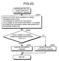
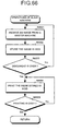
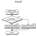
- the link copy mode is automatically executed.
- a total number of sheets to be printed is calculated based on a number of sheets of document and a specified number of sheets of document to be printed, and the link copy mode is automatically executed when the calculated total number of sheets to be printed is more than a prespecified number of sheets.
- a master machine calculates a total number of sheets to be printed based on a number of sheets of document and a specified number of sheets of document to be printed, and automatically executes the link copy mode when the calculated total number of sheets to be printed is more than a prespecified number of sheets.
- a local image formation apparatus calculates a total required number of image-forming operations based on a number of sheets of document, a number of sheets of document to be printed, and a specified image formation mode, and automatically executes the link copy mode when the calculate number of image-forming operations is more than a prespecified value.
- a master machine calculates a total required number of image-forming operations based on a number of sheets of document, a specified number of sheets of document to be printed, and a specified image-forming mode, and automatically executes the link copy mode when the calculated total number of image-forming operations requires a larger number of sheets of paper more than a prespecified value.
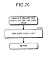
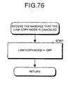
- the link copy mode is automatically executed and a printing job is finished, the link copy mode is canceled.
- a link copy mode shift request reporting unit sends a link copy mode shift request to other image formation apparatus connected thereto, and a link copy mode setting unit sets the link copy mode in response to the link copy mode shift request and based on a result of determination that a link copy mode shift request sent from other image formation apparatus can be accepted.
- a link mode shift determination unit determines in response to a link copy mode shift request sent from other image formation apparatus whether shift to the link copy mode is possible or not, and sends the result of determination to the other image formation apparatus.
- a link copy mode shift determination unit determines in response to a link copy mode shift request sent from a master machine whether shift to the link copy mode is possible or not, and sends the result of determination to the master machine.
- the link copy mode shift request reporting unit in the master machine sends a link copy mode shift request to the slave machine, and a link copy mode determination unit sets the link copy mode based on the result of determination sent from the slave machine that shift to the link copy mode is possible.
- one image formation apparatus is connected to other image formation apparatus peer to peer.
- a master machine is connected to a slave machine peer to peer.
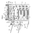
- Fig. 1 shows the configuration of the digital copyingmachine according to a first embodiment of the present invention.
- a not illustrated document having many pages placed with the image printed surface upward respectively on a document base 102 of an automatic document feeder (ADF) 101 are fed, paper by paper starting from the paper placed at the bottom, by a paper-feed roller 103 and a paper-feed belt 104 to a specified document reading position on a contact glass 105.
- ADF automatic document feeder
- the document paper fed onto the contact glass 105 is read by a reading unit 106, and is discharged by the paper-feed belt 104 and a paper-discharge roller 107.
- a document set detection sensor 108 When it is detected by a document set detection sensor 108 that another paper is present on the document base 102, the same series of operations performed with the previous paper.
- the paper-feed roller 103, paper-feed belt 104, and paper-discharge roller 107 are driven by a carrier motor not shown in this figure.
- a plurality of sheets of recording paper placed on a first tray 109, a second tray 110, and a third tray 111 are fed from a first paper-feed section 112, a second paper-feed section 112, and a third paper-feed section 114 respectively, transferred by a paper carrier unit 115 to a resist roller, and are carried up to a position just before a contact position with photosensitive drum 116.
- a document image read by the reading unit 106 is written as image data with a laser beam outputted from a writing unit 117 onto the photosensitive drum 116, and is visualized as a toner image by a development unit 118.
- the recording paper is restarted at a timing so that the resist roller comes to a specified position against the toner image, carried by a carrier belt 119 at a speed equal to a rotational speed of the photosensitive drum 116, and is subjected to the transfer processing, thus the toner image on the photosensitive drum 116 being transferred.
- the toner image transferred onto the recording paper is thermally fixed by a fixing unit 120.
- the recording paper with the image fixed thereon (this process is described as image formation hereinafter) is discharged by a paper-discharge unit 121 onto a finisher 122 which is a postprocessing device.
- the finisher 122 which is a postprocessing device, can guide recording paper carried thereto by a paper-discharge unit 121 in a main frame of the machine in a direction to a discharge paper tray 126 or to a staple processing section (at a bottom left corner in the figure).
- the finisher 122 guides the recording paper with a switch plate 124.
- the switch plate 124 By switching the switch plate 124 upward, the recording paper can be discharged via paper-discharge roller 123 and a carrier roller unit 132 to the normal discharge paper tray 126.
- the switch plate 125 downward the recording paper can be carried via carrier rollers 125 and 126 to a staple base 128.
- An edge of the recording paper placed on the staple base 128 is aligned by a paper-aligning jogger 129 each time a sheet of recording paper is discharged, and then a certain number of copies are prepared, the sheets are stapled by a stapler 130.
- a group of sheets of recording paper stapled by the stapler 130 is accommodated into a stapled discharge paper tray 131.
- the normal discharge paper tray 126 can be moved back and forth.
- the discharge paper tray 126 which can be moved back and forth, moves back and forth each time a document is copied, or each time a copy is sorted by an image memory 501 described later for sorting the discharged copies.
- recording paper fed from the first tray 109, second tray 110, and third tray 111 with an image formed thereon is not guided to the discharge paper tray 126, but is temporally stocked on a double-surface paper-feed unit 134 by setting a branch claw 133 for switching a path for each sheet of recording paper in the upper side.
- the recording paper temporally stocked in the double-surface paper feed unit 134 is again fed from the double-surface paper feed unit 134 with a toner image formed on the photosensitive drum 116 transferred thereon, and is guided to the discharge paper tray 126 by setting the branch claw 133 for switching a path for each sheet of recording paper in the lower side.
- the double-surface paper feed unit 134 is used when images are to be formed on both surfaces of recording paper.
- the photosensitive drum 116, carrier belt 119, fixing unit 120, a paper-discharge unit 121, and development unit 118 are driven by a not illustrated main motor, while the first paper-feed section 112, second paper-feed section 113, and third-paper feed section 114 are driven by a transfer drive by the main motor to each component via a not illustrated first paper-feed clutch, a second paper-feed clutch, and a third paper-feed clutch.
- a vertical carrier unit 115 is driven by a transfer drive by the main motor via a not illustrated intermediate clutch.
- the latent image as defined herein is a potential distribution generated by converting an image to optical data and irradiating the optical data onto a surface of the photosensitive drum 116.
- the reading unit 106 comprises a contact glass 105 on which a document is placed, and an optical scan system.
- the optical scan system comprises an exposure lamp 135, a first mirror 136, a lens 137, a CCD image sensor 138, a second mirror 139, and a third mirror 140.
- the exposure lamp 135 and first mirror 136 are fixed to a not illustrated first carriage, while the second mirror 139 and third mirror 140 are fixed on a not illustrated second carriage.
- the first and second carriages are mechanically scanned at a relative speed of 2 vs 1 so that the light path length does not change.
- This optical scan system is driven by a not illustrated scanner drive motor.
- the image is read by the CCD image sensor 138, and is converted to an electric signal.
- Magnification of the image can be changed by moving the lens 137 and CCD image sensor 138 in the left and right directions (in Fig. 1 ). Namely, positions of the lens 137 and CCD image sensor 138 in the left and right directions (for focusing) are set in correspondence to the specified magnification.
- the write unit 117 comprises a laser output unit 141, a focusing lens 142, and a mirror 143, and a not illustrated laser diode which is a source of laser beam having a specified wavelength and a not illustrated polygon mirror which is driven at a high and constant speed by a not illustrated polygon motor are provided in the laser output unit 141.
- a laser bean irradiated from the laser output unit 141 is reflected by the polygon mirror which rotates at a constant high speed, passes through the focusing lens 142, again reflected by the mirror 143, and focused on a surface of the photosensitive drum 116, thus an image being formed.
- the laser beams used for scanning is irradiated in a direction (main scanning direction) perpendicular to a direction in which the photosensitive drum 116 rotates, and is used for recording an image signal outputted from a selector of a image processing unit 402 described later line by line.
- main scanning direction perpendicular to a direction in which the photosensitive drum 116 rotates
- image signal outputted from a selector of a image processing unit 402 described later line by line.
- a laser beam outputted from the writing unit 117 is irradiated to the photosensitive drum 116.
- a beam sensor (not shown) which generates a main scanning synchronization signal is located at a position near one edge of the photosensitive drum 116 where the laser beam is irradiated. Timing control for starting image recording in the main scanning direction and generation of a control signal for input/output of an image signal described later are executed based on this main scanning synchronization signal.
- Fig. 2 shows the operation panel.
- the operation panel 201 comprises a print key 202, a clear/stop key 203, a ten-key 204, a liquid crystal touch panel 205, default settings key 207, and a mode clear key 208.
- the liquid crystal touch panel 205 is used to display various types of messages indicating, for instance, function keys 206, a number of copies to be prepared, and a state of a digital copying machine, or to input various types of information.
- Fig. 3 shows an example of a display screen of the liquid crystal touch panel 205 on the operation panel 201.
- the key is displayed in reverse vides.
- a screen for setting the functions is displayed when an operator touches the key.
- Fig. 3 there is a message area used for displaying such messages as "ready", and “wait” at the top left corner of the screen.
- a copy number display section which displays a number of set sheets.
- a sort mode key 304 used for specifying the processing to put copies page by page into the page order
- a stack mode key 303 used for specifying the processing to sort copies page by page
- a staple mode key 302 used for specifying the processing to staple the sorted copies into a bundle.
- a size change key used to set the magnification there are an same size key used to set a magnification to the same size, a size change key used to set the magnification, a two side/division key used for setting the two side copy mode, and a delete/move key used for setting a binding space mode or the like.
- selected modes are displayed in reverse video.
- keys each used for manually setting a paper-feed state are displayed as information indicating a number of available paper-feed trays.
- a size of each paper-feed tray (including information concerning whether the paper is placed with the longitudinal edge aligned along the vertical direction or horizontal direction), a residual quantity of paper in each tray, a type of paper, and other information are displayed in this section.
- the residual quantity of paper indicates the paper end state with the downward arrow, and the near end state with a horizontal bar.
- a selected mode is displayed in the inverted mode.
- Fig. 4 shows an example of a screen when the automatic paper selection mode is set.
- the screen is switched to the link copy mode setting screen as shown in Fig. 5 .
- this mode is canceled when the link copy mode 301 is pressed, and the screen shown in Fig. 4 is restored.
- Fig. 11 shows a control system for the digital copying machine, and as shown in this figure, a each system component is located around a system controller 401 controlling the entire digital copying machine.
- a system controller 401 Connected via a system bus to the system controller 401 are an image reading section 402, an image writing section 403, a memory unit 404, a CSS 407, a clock 408, and a serial interface 409.
- a user limiter 405, a person sensor 406, and the operation panel 201 are directly connected to the system controller 401.
- the image reading section 402, image writing section 403, and memory unit 404 are connected through an image data bus to each other.
- the memory unit 404 comprises a compression block, a DRAM block, a DMA block, and a serial trans-reception block.
- the DRAM block in the memory unit 404 stores therein an image signal read from the image reading section 402, and can transfer image data stored in the image writing section 403 in response to a request from the system controller 401.
- the compression block has a compression function based on the MH, MR, or MMR systems which are data compression systems generally used, and compresses an image once read to improve efficiency in use of a memory (DRAM). Rotation of an image is realized by changing an address read from the image writing section 403 and the direction. When it is required to realize the ordinary copy function, this memory unit 404 is not necessary.
- the clock 404 is required only to realize a weekly timer function such as booting a machine, or shutting down the machine with a prespecified time (preset time) comes.
- the person body sensor 406 is required only for realizing a function to cancel, in a preliminarily heating mode, the mode when a user comes near the machine.
- the CSS 407 has a function of remote diagnosis, namely a function to automatically report an error in the machine to a service center, or to monitor an operating state of the machine from a remote site. The functions may be installed only when the functions are required.
- Fig. 12 shows another example of configuration of a control system for the digital copying machine.
- the configuration is based on a centralized control system in which a CPU of the system controller 401 provides controls over the image reading section 402, image writing section 403, memory unit 404, and CSS 407, but the present invention is not limited to this configuration.
- the configuration may be based on a distributed control system in which each of the image reading section 402, image writing section 403, and memory unit 404 has a CPU respectively and a command from a system controller to each controller is delivered over a control signal line.
- Configuration of the control system for the digital copying machine is not limited to the first or second example, and any other configuration is allowable.
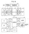
- Fig. 16 shows configuration of an image processing section (comprising the image reading section 402 and image writing section 403) according to the first embodiment of the present invention. Configuration of the image processing section is described below with reference to Fig. 16 .
- a laser beam irradiated from an exposure lamp lights up a surface of a document, and an image of the document is focused by a focusing lens (not shown) onto a CCD image sensor 138 of the reading unit 106.
- the CCD image sensor 138 in the reading unit 106 generates image data (an analog electric signal) by subjecting the received document image to photoelectric transfer, and the image data is converted by an A/D converter 503 to a digital signal.
- the digital signal is subjected to shading correction in a shading correction circuit 504, and then to MTF correction and ⁇ correction in an MTF ⁇ correction circuit 505.
- the selector 502 supplies image data inputted from the MTF ⁇ correction circuit 505 via a first print synthesis section 506 to a size-change circuit 508 via a second print synthesis section 507, or to a memory controller 510, and the image data having passed the size change circuit 508 is enlarged or compressed according to a magnification and is sent to the writing unit 117.
- Image data can be transacted bi-directionally between the memory controller 510 and the selector 502.
- the image processing unit IPU
- the image processing unit has a function of selectively inputting or outputting a plurality of types of data so that, in addition to the image data inputted from the reading unit 106, also image data supplied from outside via an I/O port 514 or a serial trans-reception block 515 such as data inputted from a data processing unit such as a personal computer can be processed.
- the image processing unit (IPU) further comprises a CPU 511 which sets various types of information (instructions) in the memory controller 510 or the like and provides controls over the reading unit 106 and writing unit 117, and a ROM 512 and a RAM 513 in which programs for the CPU 511 or data is stored.
- the CPU 511 can write data into or read data from the image memory 501 via the memory controller 510.
- Fig. 18 is a timing chart for image data for one page.
- a frame gate signal (described as /FGATE hereinafter) expresses a valid period in the auxiliary scanning direction for the image data for one page.
- a main scanning synchronization signal (described as /LSYNC hereinafter) is generated for one line, and the image data is validated at a specified clock after first rise of /LSYNC.
- a signal indicating that image data in the main scanning direction is valid is a line gate signal (described as /LGATE hereinafter).
- the /LGATE, /LSYNC, and /LGATE signals are synchronized to a pixel synchronization signal (described as VCLK hereinafter), and data for one pixel is sent within one cycle of VCLK.
- the IPU has a function of discretely generating the /FGATE, /LSYNC, /LGATE, and VCLK signals for image input and mage output respectively, and can realize various combinations of image input and output by executing phase adjustment or other necessary adjustment when it directly outputs the read document image (image data).
- Fig. 17 shows a detail configuration of the memory controller 510 and the image memory 501.
- the memory controller 510 has an input data selector 701, an image synthesis section 702, a primary compression/extension section 703, an output data selector 704, and a secondary compression/extension section 705.
- Control data for each of the system components above is set by the CPU 511.
- the address and data shown in Fig. 16 show an address of image data and the data. Data and address for control data inputted into or outputted from the CPU 511 are not shown in this figure.
- the image memory 501 comprises a primary memory 706 and a second memory 707.
- the primary memory 706 a device enabling high speed access to a DRAM or the like is used so that image data can be written into or red out from the image memory 501 substantially in synchronism to a transfer rate of the inputted image data.
- the primary memory 706 can simultaneously execute input and output of image data by dividing a memory area into a plurality of areas according to a volume of image data to be processed. (For that purpose, an interface section with the memory controller 510 is used, although not shown herein.)
- two pairs of address data line for read and write are connected to an interface section with the memory controller 510.
- an image can be outputted (read) from an area 2 while an image is inputted (written) into an area 1.
- the secondary memory 707 is a large capacity memory used to store therein data for synthesizing or sorting inputted images.
- data processing can be executed equivalently in both the primary memory 706 and secondary memory 707, and in addition the memory controller 510 can be controlled easily.
- a DRAM is rather expensive, so that, in this embodiment, data I/O is executed by using elements enabling high speed access only in the primary memory 706. It is needless to say that high speed elements such as a DRAM may be used not only in the primary memory 706, but also in the secondary memory 707.
- the image memory 501 As described above, by forming the image memory 501 with the primary memory 706 and secondary memory 707, it is possible to realize a digital copying machine which enables input/output, storage, and processing of a large quantity of image data with relatively simple configuration. Concentrated images generated by the concentrate copy function are written into and stored in the primary memory 706 in an arrayed form just like being written on a sheet of recording paper.
- the input data selector 701 selects image data to be written into an image memory (primary memory 706) from a plurality of data.
- the image data selected by the input data selector 701 is supplied to an image synthesis section 702.
- the image synthesis section 702 synthesizes the image data with data already stored in the image memory 501.
- Image data processed in the image synthesis section 702 is subjected to data compression by the primary compression/extension section 703, and the compressed data is written into the primary memory 706.
- the data written into the primary memory 706 is further subjected to compression by the secondary compression/extension section 705 according to the necessity, and is stored in the secondary memory 707.
- image data stored in the primarymemory 706 is readout.
- image data stored in the primary memory 706 is extended in the primary compression/extension section 703, and the extended data, or data obtained by synthesizing the extended data with input data is selected by the output data selector 704, thus the image data being outputted.
- the image synthesis section 702 executes such processing as synthesis of data stored in the primary memory 706 with inputted data (with an image data phase adjustment function) and selection of a destination to which the synthesized data is outputted (output of an image, write-back to the primary memory 706, and simultaneous output to both destinations for output) .
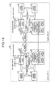
- Fig. 13 shows a copying machine network system in which a plurality of digital copying machine according to the first embodiment of the present invention are connected to each other (A digital copying machine constituting the copying machine network is described as "network copying machine" hereinafter).
- a digital copying machine constituting the copying machine network is described as "network copying machine” hereinafter).
- a plurality of digital copying machines are connected to each other through a network interface.
- Fig. 13 shows an example in which eight units of digital copying machines are networked.
- the number of units of digital copying machines connected to each other is not limited to the example described above. Any number of units can be connected to each other. Further, different types of digital copying machines may be connected to each other on the condition that mutual communications is possible between the digital copying machines.
- Ethernet Transmission Control Protocol/Internet Protocol
- OSI OpenSystemInterface
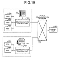
- Fig. 14 shows an example in which two units of digital copying machines (digital PPC-I) 1400, and (digital PPC-II) 1410 are connected to each other peer-to-peer.
- Hardware configuration of the digital copying machines 140010 of in Fig. 14 is the same as that of the digital copying machine shown in Fig. 11 .
- Image data is transferred via a serial trans-reception block between the digital copying machines 1400 and 1410, and the received image data is once stored in the DRAM block.
- control data such as control commands or set commands are transferred between the digital copying machines through the serial interface 409.
- serial interface 409 is used in this example, image data and control data may be transferred by using the SCSI (Small Computer System Interface).
- the link copy mode When the link copy mode is executed by the digital copying machines 1400, 1410, the machine in which the link copy key 310 is pressed to effect the link copy mode functions as a master machine (an operating machine).
- the master machine sends a request for linkage to a digital copying machine (slave machine) to be linked thereto and executed the link copy mode.
- image data for a document read by the master machine is transferred to the slave machine, and is printed by both the master machine and slave machine. Namely a copy job is shared by the master and slave machines.
- the digital copying machines 1400, 1410 are connected to each other peer-to-peer, so that each machine can function as both a master machine and a slave machine. In the following description, it is assumed that the digital copying machines 1400 functions as a master machine and the digital copying machine 1410 functions as a slave machine.
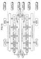
- FIG. 15 is a conceptual diagram showing software of the digital copying machines 1400, 14410 (digital PPC-I and digital PPC-II).
- copy application indicates an application for executing a copy sequence to execute a copy operation
- input/output control indicates a layer (device driver) for logically or physically converting data
- operation panel controller indicates a layer for executing MMI (Man Machine Interface) (a layer for executing such operations as LCD display, LED ON/OFF, and key entry scan at a logic level).
- MMI Man Machine Interface
- peripheral machine controller indicates a layer for providing controls over peripheral machines attached to a PPC such as an automatic two side copy unit, a sorter, or an ADF at a logic level
- image formation section controller such as an automatic two side copy unit, a sorter, or an ADF at a logic level
- image formation section controller “image reader controller”, and “memory unit” are as described above.
- the "demon process” is present there as an application for reading out image data stored in the memory unit when a print request is received from other machine on the network and transferring the image data to the "image formation section". It is needless to say that transfer of an image from the other machine on the network must be finished before an image is read from the memory unit and printed in the "demon process”.
- the operation panel, peripheral devices, image formation section, image reader, and memory unit are treated as resources owned by each PPC.
- the "digital PPC-I” shown in the figure executes a copy operation using each of the resources provided in itself (when the print start key is pressed"
- the "digital PPC-I” demands the "system controller” to allow use of each resource such as an "image formation device”, an “image reader”, “peripheral devices”, and “memory unit” according to the necessity.
- the system controller in the remote digital PPC (slave machine) arbitrates conflicts over the resources according to the request, and reports the result of arbitration to an application in the machine having sent the request.
- the remote digital PPC reads an image, stores the image in a memory unit in the remote digital PPC itself.
- the remote digital PPC transfers the image to a memory unit in a machine as a destination for remote output through an interface.
- the memory unit in the "digital PPC-II” can not be used excluding an application in the "digital PPC-II” (or digital PPCs other than the "digital PPC-I” when a plurality of digital PPCs are connected to each other on the network as shown in Fig. 13 ).
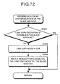
- Fig. 20 is a flow chart showing operations for determining whether operations in the link copy mode are possible or not according to the first embodiment of the present invention.
- the digital copying machine 1400 is in the link copy mode or not (S2001). Namely it is determined whether the link copy mode is set by pressing the link copy key 301 on the liquid crystal touch panel 205 of the operation panel 201.
- the processing in step S2006 described below is executed.
- the staple mode has been turned ON or not in the digital copying machine 1400 (master machine) (S2002).
- step S2006 When it is determined in this step that the staple mode is not ON, the processing in step S2006 described below is executed.
- the digital copying machine 1400 demands the digital copying machine (slave machine) 1410 to report whether any peripheral device is connected thereto or not (S2003).
- the slave digital copying machine 1410 sends information concerning connection of a peripheral equipments to the master digital copying machine 1400.
- the digital copying machine 1400 determines whether a finisher 122 is connected or not to the local device (master machine) (S2004). When it is determined that the finisher 122 is not connected thereto, the digital copying machine 1400 displays a message on the operation panel 201 mentioning that the copy operation is not possible (S2008) with the system control returned to an initial step of the operation flow.
- the digital copying machine 1400 determines whether the finisher 122 is connected to the slave digital copying machine 1410 or not (S2005). If it is determined that the finisher 122 is not connected to the slave machine, the message is displayed on the operation panel 201 mentioning that the copy operation is not possible (S2008) with the system control returned to an initial step of the operation flow.
- step S2005 When it is determined in step S2005 that the finisher 122 is connected to the slave digital copying machine 1410, the digital copying machine 1400 determines whether there is any other cause disabling a copy operation (such as paper jamming, open door, or paper end) or not (S2006). When it is determined in this step that there is no specific cause disabling a copy operation, a message mentioning that a copy operation is possible is displayed on the operation panel 201 (S2007) with the system control returned to an initial step of the operation flow.
- S2007 operation panel 201
- the operations described above are described in more detail below.
- the operations described above are executed when the operating mode is changed by an operator, or when an engine status (such as information on jamming, information on the door, information on supply (such as recording paper, or toner) changes.
- the master machine sends to the slave digital copying machine 1410 a request for reporting whether any peripheral device is connected to the slave machine or not to check what functions are available in the slave digital copying machine 1410. More specifically, the master digital copying machine 1400 requests the slave digital copying machine 1410 to check whether the finisher 122 with a stapler 130 loaded thereon is available in the slave digital copying machine 1410 or not.
- the staple mode can be executed.
- the staple mode can not be executed.
- the finisher 122 is not present in either one of the master digital copying machine 1400 and slave digital copying machine 1410, a message indicating that a copy operation is not possible is displayed on the operation panel 201.
- the finisher 122 is present in both of the master and slave machines 1400, 1410, then whether there is any other cause (such as paper has jammed, the door is open, or the paper is not available).
- a message indicating that a copy operation is not possible is displayed on the operation panel 201.
- a message indicating that a copy operation is possible is displayed on the operation panel 201.
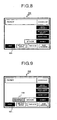
- Fig. 7 shows an example of display on the operation panel provided when the link copy mode and staple mode are set in a state where the finisher 122 is not connected to the slave digital copying machine 1410.
- the master digital copying machine 1400 determines whether the finisher 122 is present in the slave machine 1411 or not (S2103).
- the staple mode key is not displayed (S2105) with the system control returned to an initial step of the operation flow.
- the master digital copying machine 1400 displays the staple mode key 302 with the system control returned to an initial step of the operation flow.
- Fig. 8 shows an example of display on the operation panel 201 when the link copy mode is set in a state where the finisher 122 is connected to the slave 1410. Before the link copy mode is set, the staple mode key 302 is displayed as shown in Fig. 4 , but after the link copy mode is set, the staple mode key 302 is not displayed.
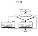
- Fig. 22 is a flow chart showing an example of the link copy mode (2) according to the first embodiment of the present invention.
- Fig. 22 shows the operations executed when the link copy key 301 is pressed and the link copy mode is set.
- the master digital copying machine 1400 at first demands the slave digital copying machine 1410 to report a connection state of a peripheral equipments (S2201).
- the slave digital copying machine 1410 sends to the master digital copying machine 1400 the information concerning a connection state of a peripheral equipments.
- the master digital copying machine 1400 determines whether the finisher 122 is present in the master digital copying machine 1400 or not (S2202).
- the master digital copying machine 1400 further determines whether the finisher 122 is present in the slave digital copying machine 1410 or not (S2203). When it is determined that the finisher 122 is not present in the slave digital copying machine 1410, the master digital copying machine 1400 displays a massage that the staple mode key 302 is invalid (S2205) with the system control returned to an initial step of the operation flow.
- the master digital copying machine 1400 displays a message that the staple mode key 302 is valid (S2204) with the system control returned to an initial step of the operation flow.
- Fig. 9 shows an example of display on the operation panel 201 when the link copy mode is set in the state where the finisher 122 is not connected to the salve device 1410.
- a half-tone display By differentiating the staple mode key 302 from other function keys (with, for instance, a half-tone display), invalidity of this key is indicated.
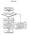
- Fig. 23 is a flow chart showing an example of operation (3) in the link copy mode according to the first embodiment of the present invention. This figure shows a case where the link copy key 301 is pressed and the link copy mode is effected.
- the digital copying machine (master machine) 1400 demands the slave digital copying machine 1410 to report whether any peripheral equipment is connected to the slave digital copying machine 1410 or not (S2301).
- the slave digital copying machine 1410 sends information concerning a connection state of the peripheral equipments to the master digital copying machine 1400.
- the master machine determines whether the staple mode is ON or not (S2302).
- Fig. 10 shows an example of display on the operation panel when the staple mode is independently selected.
- a second embodiment of the present invention is described below with reference to Fig. 24 to Fig. 38 .
- Basic configuration of the digital copying machine according to the second embodiment of the present invention is the same as that according to the first embodiment. Examples of operations of the digital copying machine shown in Fig. 14 are described herein.
- Fig. 24 is an example of a screen when the link copy key 301 is pressed the link copy mode is set.
- the screen is switched to a link copy mode set screen as shown in Fig. 24 when the link copy key 301 is pressed in the state as shown in Fig. 3 .
- the link copy mode set screen is selected by pressing a link device select key 2400 for each copying machine (8 units herein). After selection is made, when the set-end key 2410 is pressed, the screen is switched to that shown in Fig. 25 , and the link copy mode is set. With this operation, as shown on the screen in Fig. 25 , the link copy mode is effected, and such functions as auto-darkness selection, auto-paper selection, copying with the same size, and sorting can be used.
- the link copy mode is canceled when the link copy key 301 is pressed again, and then the screen shown in Fig. 3 is restored.
- Fig. 26 shows an example of a screen shown in a state where a size of recording paper is manually selected (not through automatic selection by a paper-size detection mechanism).
- This screen shows that "1" for size A4 in the horizontal posture has been manually selected with a manual paper-size select key 2601.
- Select keys for special paper trace paper, sheet for OHP, label paper or the like
- paper with size A4 in the vertical posture recycled paper with size A3 in the vertical posture
- paper size paper-size B5 in the horizontal posture are prepared as manual paper-size select keys 2601.
- Fig. 27 shows an example of a screen on which not-available paper-feed stages are displayed with a half brightness degree, and in the case as shown on this screen, a key for special paper with size A4 is displayed with a half brightness degree.
- a key for special paper with size A4 is displayed with a half brightness degree.
- Fig. 29 shows an example in which, when an operation in the link copy mode is started, if supply of recording paper is required in another device (slave machine) other than an operating device (master machine), the operation is terminated, and a message of, for instance, "refill the paper in the other machine" is provided as an alarm indicating necessity of supplying recording paper.
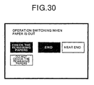
- Fig. 30 is an example of a set screen for switching an operation in the paper end state.
- a level for checking a quantity of remaining recording paper is set when the operation in the link copy mode is started. Namely an option whether a quantity of remaining paper is to be checked or not, and an option whether the check for a quantity of remaining paper is to be executed in the paper-end state, or paper near-end state. Shift to this screen can be executed by pressing the default settings key 207.
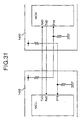
- Fig. 31 shows a first example of hardware configuration of a serial interface for the digital copying machines 1400, 1410.
- the master digital copying machine 1400 and slave digital copying machine 1410 have the same configuration of that of the digital copying machine described above, and are connected to each other pier-to-pier.
- the devices are differentiated as a master machine (the operating machine in Fig. 24 ) and a slave machine (corresponding to the copying machines 1, 4, 7 shown in Fig. 24 ) respectively.
- a TxD terminal for receiving serial data and an RxD terminal for receiving serial data in a USAT (universal asynchronous receiver-transceiver) of a MCU incorporated in the master digital copying machine 1400 and slave digital copyingmachine 1410 respectively are connected to each other in the crossed state, so that command transaction can be executed between the terminals.
- USAT universal asynchronous receiver-transceiver
- another signal line for checking whether power for a device in communication is ON or not is pulled up to Vcc in the device in communication, and pulled down in the local device, so that, when power for the device in communication is ON, a value read at an input port P10 indicates H level, and when power for the device is OFF, a value read at the input port P10 indicates L level. Because of this configuration, each equipment can determine whether power for a device in communication is ON or not by checking whether an input signal level at the input port P10 is high (H) or low (L).
- Fig. 32 shows a second example of hardware configuration of a serial interface for the digital copying machines 1400, 1410.
- two signal lines for checking that communications with a device in communication can be executed are prepared. With this signal line, an output port P20 of a local device is connected to an input port P10 of the device in communication.
- Each device executes various types of processing for initialization after power thereto is turned ON. In this step, and output level from the output port P20 is set at a level L. After this operation, such operations as initialization of the URAT and initialization of an interruption controller are executed. When the device is ready for receiving serial data, and output level from the output port P20 is set at a level H. With this operation, each device can determine whether power for a device in communication is ON or not by checking whether an input signal level at the input port P10 is high (H) or low (L).
- Fig. 33 shows a third example of hardware configuration of a serial interface for the digital copying machines 1400, 1410 shown in Fig. 14 .
- signal lines other than the serial communication line described above are omitted for cost reduction.
- whether a local device can communication with another device as an object for communications can be detected by transacting the communication connection check command between the devices.
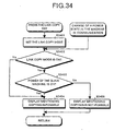
- Fig. 34 is a flow chart showing an example of operations in the master machine when the link copy key is pressed and when a power state in the slave machine changes.
- the digital copying machine 1400 determines whether the link copy mode has been set or not (S3402).
- the digital copying machine (master machine) 1400 determines whether the power of the slave digital copying machine 1410 is ON or not (S3403). Whether the power of the slave machine 1400 is ON or OFF is checked with the configuration shown in Fig. 31 or in Fig. 32 .
- step S3403 when it is determined that power of the slave digital copying machine 1410 is ON (a value read at the input port P10 indicates a level H), the master digital copying machine 1400 provides a display of, for instance, "ready” on the operation panel of the master digital copying machine 1400 (S3404), while the print key 202 is set in the print green state.
- the master digital copying machine 1400 determines that power of the slave machine is OFF (a value read at the input port P10 indicates a level L)
- the master digital copying machine 1400 provides a display such as "Wait” indicating that copying is not possible on the operation panel of the master digital copying machine 1400 (S3405), and the print key 202 is set in the print red state.
- step S3402 When a power state for the slave machine 1400 changes during the operation described above, the operation sequence in step S3402 and on is executed.
- the link copy mode is not set, however, the message of "ready” is provided regardless of whether power of the slave machine 1400 is ON or OFF, and the print key 202 is set in the print green state.
- Fig. 35 is a flow chart showing an example of the processing executed by the master machine when the link copy key is pressed and when the communication-ready state in the slave machine changes.
- the digital copying machine 1400 determines whether the link copy mode has been set or not (S3502).
- the digital copying machine 1400 master machine
- the digital copying machine 1400 further determines whether the slave digital copying machine 1410 is read for communication or not (S3503). Whether the slave machine 1400 is ready for communication or not is determined by transacting the communication connect command previously set in the configuration shown, for instance, in Fig. 33 between the master and slave machines.
- step S3503 when it is determined that the slave digital copying machine 1410 is ready for communication, the master digital copying machine 1400 displays a message indicating possibility of a copy operation on the operation panel (S3504) with the print key 202 set in the print green state.
- step S3505 when it is determined in step S3505 that the slave digital copying machine 1410 is not ready for communication (communication not-ready state), the master digital copying machine 1400 displays a message indicating impossibility of a copy operation such as "wait" on the operation panel (S3505) with the print key 202 set in the print red state.
- step S3502 When the communication ready state in the slave machine changes, the operation sequence in step S3502 and on is executed.
- the master machine displays a message of "ready" on the operation panel regardless of whether the slave machine is ready for communications or not with the print key 202 set in the print green state.
- Fig. 36 is a flow chart showing an example of operations by a master machine when the link copy key is pressed and when a communication error is detected.
- the master machine determines whether the link copy mode has been effected or not (S3602).
- the digital copying machine 1400 master machine further determines whether a communication error has occurred in the slave digital copying machine 1410 (S3603).
- step S3603 When it is determined in step S3603 that a communication error has not occurred in the slave digital copying machine 1410, the master digital copying machine 1400 displays a message indicating possibility of copying such as "ready” (S3604) with the print key 202 set in the print green state. On the contrary, when it is determined in step S3606 that a communication error has occurred in the slave digital copying machine 1410, the master digital copying machine 1400 displays a message indicating impossibility of copying such as "wait" on the operation panel of the master digital copying machine 1400 (S3605) with the print key 202 set in the print red state.
- step S3602 When a communication error in the slave digital copying machine 1410 is detected, the operating sequence in step S3602 and on is executed.
- the master machine displays a message indicating possibility of copying such as "ready" with the print key 202 set in the print green state.
- a master machine when a communication error occurs in a slave machine, a master machine inhibits a link copy operation. Because of this configuration, even when a linked device is at a remote site, it is possible to check whether a link copy operation can be executed or not only with a master machine currently being operated by a user and without directly checking whether a communication error has occurred in the slave machine or not, and the necessity of executing a copy operation again due to a communication error is eliminated, which insures the operability in the link copy mode.
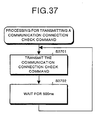
- Fig. 37 is a flow chart showing the processing for sending the communication connection check command for checking whether communications can be executed or not.
- the digital copying machines 1400, 1410 connected to each other mutually transmit the communication connection check command (S3701), wait for 500 ms (S3702), and then transmit the communication connection check command.
- the digital copying machines 1400, 1410 mutually transmit a communication connection check command once for every 500 ms through a serial communication line to each other.
- Fig. 38 is a flowchart showing an example of the processing for receiving the communication connection check command for checking whether communications can be executed or not. This processing is executed in each of the digital copying machines 1400, 1410. At first the digital copying machine determines whether the communication connection check command has been received or not (S3801). When it is determined in step S3801 that the communication connection check command has been received, the digital copying machine resets a timer for time counting (S3802), and detects the communication ready state (S3803).
- the digital copying machine determines whether one second has passed after the last command is received or not (S3804), and determines, after one second has passed, that the communication can not be performed (communication not-ready state) (S3805).
- a third embodiment is described below with reference to Fig. 39 to Fig. 44 .
- Configuration of the digital copying machine according to the third embodiment has the same configuration as that of the digital copying machine according to the second embodiment.
- operations in the link copy mode for inhibiting selection of the link copy mode when power for a slave machine is OFF, when the slave machine is not ready for communication, or when a communication error occurs in the slave machine.
- Example of operations of the digital copying machine system shown in Fig. 14 is described below.
- Fig. 39 is a flow chart showing the processing executed by the master digital copying machine 1400 when the link copy key 301 is pressed
- Fig. 40 is a flow chart showing the processing executed by the master machine when a power OFF state in the slave digital copying machine 1410 is detected.
- the master digital copying machine 1400 when the link copy key 301 is pressed, the master digital copying machine 1400 at first determines whether power of the slave digital copying machine 1410 is ON or not (S3901), and when it is determined that power of the slave digital copying machine 1410 is ON, the master digital copying machine 1400 sets the link copy mode (S3902). When it is determined that power of the slave digital copying machine 1410 is OFF (for instance, with the circuit configuration shown in Fig. 31 , and Fig. 32 ), the master digital copying machine 1400 cancels the link copy mode (S4001).
- Fig. 41 is a flow chart showing the processing executed by a master machine when the link copy key 301 is pressed
- Fig. 42 is a flow chart showing the processing executed by the master machine when a communication not-ready state in a slave machine is detected.
- the master key 1400 when the link copy key 301 is pressed, the master key 1400 at first determines whether the slave digital copying machine 1410 is ready for communications or not (S4101). When it is determined in step S4101 that the slave machine is ready for communication, the master digital copying machine 1400 sets the link copy mode (S4102). When it is determined in step S4101 that the slave machine is not ready for communications, the master machine cancels the link copy mode (S4201).
- Fig. 43 is a flow chart showing the processing executed by a master machine when the link copy key 301 is pressed
- Fig. 44 is a flow chart showing the processing executed by the master machine when a communication error is detected.
- the digital copying machine 1400 at first determines whether a communication error has occurred or not in the slave digital copyingmachine 1410 (S4301). When it is determined that a communication error has not occurred, the digital copying machine 1400 sets the link copy mode (S4302). When a communication error is detected during transaction of commands with the slave digital copying machine 1410, the master digital copying machine 1400 cancels the link copy mode (step S4401).
- a master machine when a communication error occurs in a slave machine, a master machine inhibits selection of the link copy mode. Because of this configuration, even when a linked device is at a remove site, it is possible to determine whether a link copy operation is possible or not only with the master machine currently being operated by a user and without directly checking whether a communication error has occurred in the slave machine or not, and further the necessity of executing a copy operation again when a communication error occurs is eliminated, which insures improved operability in the link copy mode. In addition, when a link copy operation is impossible, selection of the link copy mode is inhibited, so that it is possible to alert a user before selection of the link copy mode that a link copy operation is not possible, which insured further improved operability in the link copy mode.
- a fourth embodiment of the present invention is described with reference to Fig. 45 to Fig. 51 .
- Configuration of a digital copying machine according to the fourth embodiment is the same as that according to the second embodiment.
- a case where the link copy operation is started according to a change in a supply state (a state of recording paper used for printing, and toner), an error state of a print engine, a state of a display screen, and an operating state of the print engine in a slave machine as an object for a link copy operation is described.
- a supply state a state of recording paper used for printing, and toner
- Fig. 45 is a flow chart showing the processing for sending data on a state of a local machine to other machine(s) in communication. This processing is executed in the digital copying machines 1400, 1410 respectively.
- the digital copying machine determines whether any changed has occurred in relation to toner or recording paper in the machine or not, namely where a toner end/paper end state has occurred in the machine or not (S4501).
- a paper-end state in a paper-feed tray namely in first, second, and third trays 109, 110, and 111 is detected by the sensors (not shown) provided in the digital copying machine.
- a toner-end state can be detected by a toner sensor (not shown) or a darkness sensor provided in the development unit 118.
- the sensor mechanism is well known, and will not be described here.
- a print engine error is defined herein as an abnormal state causing influence over a printing operation of the device as a whole.
- the abnormal state as defined herein includes abnormality concerning carriage of recording paper (jamming, or failure in feeding recording paper), abnormality in rotation of a photosensitive drum 116, abnormality in a fixing unit, and abnormality in a post-processing unit or the like. Abnormalities concerning a scanner or an ADF each not required in the link copy mode is not included in the abnormality as defined herein.
- step S4503 When it is determined in step S4503 that a print engine error has occurred, the digital copying machine sends data on the print engine error (S4504), and further determines whether a display state of a screen of the operation panel has changed or not (S4505).
- the digital copying machine When it is determined that a screen display state has changed, the digital copying machine sends data on the current screen display state to a digital copying machine connected thereto (S4506).
- the screen display state as defined herein includes but not limited to a initialize screen for setting operating conditions of the device, and a maintenance mode screen (Refer to Fig. 48 ) for maintenance of the device.
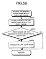
- the digital copying machine sends data on the screen display state, and then determines whether any change has occurred in an operating state of the print engine (S4507). When it is determined that an operating state of the print engine has changed, the digital copying machine sends data on the operating state of the print engine to a digital copying machine connected thereto (S4508).
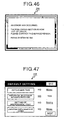
- Fig. 46 shows an example of screen display provided when an error has occurred in the print engine.
- the figure shows a case where an error (such as melting down of temperature fuse due to excessive temperature in fixing, or breakage of a fixing heater) has occurred, and a message of "The following section is out of order. Please contact a service person. Fixing system SC542) is displayed.
- an error such as melting down of temperature fuse due to excessive temperature in fixing, or breakage of a fixing heater
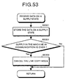
- Fig. 47 shows an example of screen display for selection of items and preset values when the device is initialized. This screen is displayed when the initialize key shown in Fig. 2 is pressed, and the normal copy screen is restored when the end key on the screen is pressed.
- the display screen in this figure shows a case where the auto-clear time is set to "60 sec”, preferential paper size selection is "not required”, a preferential tray is set to "Tray 1", and a limit of sheets to be copies is set to "50 sheets”.
- Fig. 48 shows an example of screen display showing a state where the maintenance mode has been set.
- a special key dedicated to setting of the maintenance mode is not provided so that a user will not carelessly try to effect this screen mode, and the screen shift is executed by pressing keys in the order which seldom occurs in the normal operation.
- the order of pressing keys is, for instance, "Mode clear” to "CL/STOP” and then to "#".
- the screen display in this figure shows a case where a resist adjustment value is set to "+1.5 mm", temperature for fixing to "185°C”, development bias to "550 V”, and magnification in the main scanning direction to "0.0 %" respectively.
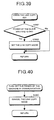
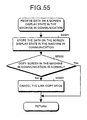
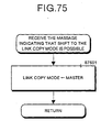
- Fig. 49 is a flow chart showing an example of the processing executed when the link copy key 301 is pressed.
- the digital copying machine 1400 sets the link copymode (S4901), and executes the processing for determining whether copying is possible or not (Refer to Fig. 51 ). This processing is described in detail later.
- Fig. 50 is a flow chart showing an example of the processing executed by a master machine when data on an operating state of a device in communication is received.
- the digital copying machine 1400 receives data on an operating state of the digital copying machine 1410 as a result of the transmission processing shown in Fig. 45 (S5001), and executes the processing for determining whether copying is possible or not (Refer to Fig. 51 ) (S5002). This processing is described in detail later.
- Fig. 51 is a flow chart showing the processing for determining whether copying is possible or not (S4902) shown in Fig. 49
- Fig. 50 is a flow chart showing contents of the processing for determining whether copying is possible or not shown in Fig. 50
- the digital copying machine 1400 at first determines whether there is any reason so that the machine can not perform the copy operation (S5101). When it is determined that local machine can not perform the copy operation, the digital copying machine 1400 unconditionally displays a message indicating that copying is not possible on the operation panel (S5108).
- the digital copying machine 1400 further determines whether the link copy mode has been effected or not (S5102). When it is determined that the link copy mode has not been set, the digital copying machine 1400 displays a message indicating that a copy operation is possible on the operation panel 201 (S5107).
- the digital copying machine 1400 further determines whether the digital copying machine to which the digital copying machine 1400 is to be connected is in the supply (recording paper, toner) end state or not (S5103). When it is determined that the digital copying machine 1410 is not in the supply end state, the digital copying machine 1400 further determines whether the digital copying machine 1410 is in the print engine error state or not (S5104). When it is determined in step S5104 that the digital copying machine 1410 is not in the print engine error state, the digital copying machine 1400 further determines whether the digital copying machine 1410 is displaying the normal copy screen or not (S5105).
- the digital copying machine 1400 When it is determined that the digital copyingmachine 1400 is displaying the normal copy screen, the digital copying machine 1400 further determines whether the print engine of the digital copying machine 1400 is operating or not (S5106). When it is determined in the step above that a print engine of the digital copying machine 1410 is not operating, the digital copying machine 1400 displays a message of, for instance, "ready" (S5107) on the operation panel.
- the digital copying machine 1400 successively accesses data on an operating state of the digital copying machine 1410, and displays a message indicating possibility of copying when the digital copying machine 1410 is not in the supply end or print engine error state and is displaying the normal copy screen, and simultaneously when a print engine of the digital copying machine 1410 is not operating.
- the digital copyingmachine 1400 displays a message indicating that copying is not possible on the operation panel 201 (S5108).
- a master machine when it is determined that a slave machine is in the supply end state, a master machine inhibits the link copy mode. Because of this configuration, even when a linked device is at a remote site, it is possible to determined whether a link copy operation can be executed or not only with the master machine currently being operated by a user and without directly checking a supply state in the slave machine, which insures improved operability in the link copy mode.
- a master machine inhibits a link copy operation, so that it is possible to determined whether a link copy operation can be executed or not only with the master machine currently being operated by a user and without directly checking a supply state in the slave machine, which insures improved operability in the link copy mode.
- the master machine inhibits a link copy operation, so that it is possible to determined whether a link copy operation can be executed or not only with the master machine currently being operated by a user and without directly checking a supply state in the slave machine, which insures improved operability in the link copy mode. Further, a demand for execution of a link copy operation is not sent during initialization or a maintenance work, so that it is possible to prevent initialization or a maintenance work from being interrupted.
- the master machine when a print engine of a slave machine is operating, the master machine inhibits a link copy operation, so that it is possible to determined whether a link copy operation can be executed or not only with the master machine currently being operated by a user and without directly checking a supply state in the slave machine, which insures improved operability in the link copy mode. Further, as a demand for a link copy operation is not sent from other devices while a print engine is operating, so that it is possible from a print job in execution from being affected by a request from other devices.
- Fig. 52 is a flow chart showing an example of processing executed when the link copy key 301 is pressed.
- the digital copying machine 1400 master machine at first determines whether a digital copying machine 1410 s an object for linkage (slave machine) is in the supply (recording paper, toner) end state or not (S5201). When it is determined that the digital copying machine 1410 is not in the supply end state, the digital copying machine 1400 further determines whether a print engine error has occurred in the digital copying machine 1410 or not (S5202).
- the digital copying machine 1400 further determines whether the digital copying machine 1410 is displaying the normal copy screen or not (S5203). When the digital copying machine 1410 is displaying the normal copy screen, the digital copyingmachine 1400 further determines whether a print engine of the digital copying machine 1410 is operating or not (S5204). When it is determined that a print engine of the digital copying machine 1410 is not operating, the digital copying machine 1400 sets the link copy mode (S5205).
- the digital copying machine 1400 determines an operating state of the digital copying machine 1410 connected thereto, and sets only in the case where the digital copying machine 1410 is not in the supply end state nor in the print error state, and also where the digital copying machine 1410 is displaying is not displaying a screen other than the normal copy screen and a print engine of the digital copying machine 1410 is not operating.
- Fig. 54 is a flow chart showing the processing executed by the master machine when data concerning a print engine error having occurred in other device in communication is received.
- the digital copying machine 1400 at first stores the contents (S5401).
- the digital copying machine 1400 further determines whether the digital copying machine 1410 is in the print engine error state or not (S5402), and when it is determined that a print engine error has occurred in the digital copying machine 1410, the digital copying machine 1400 cancels the link copy mode (S5403).
- a master machine inhibits selection of the link copy mode. Because of this configuration, even when a linked device is at a remote site, it is possible to determine whether a link copy operation is possible or not only with the master machine currently being operated by a user and without directly checking whether the slave machine is in the print engine error state or not, which insures improved operability in the link copy mode. Further, when a link copy mode is not allowable, selection of the link copy mode is inhibited, so that it is possible to alert user before selection of the link copy mode that a link copy operation is not possible, which insured further improved operability.
- Fig. 55 is a flow chart showing an example of the processing executed by a master machine when data concerning a screen display state of other device in communication is received.
- the digital copying machine 1400 at first stores the contents (S5501). The digital copying machine 1400 then determines whether the digital copyingmachine is displaying the normal copy screen or not (S5502). When it is determined that the digital copying machine 1410 is not displaying the normal copy screen, the digital copying machine cancels the link copy mode (S5503).
- the master machine inhibits selection of the link copy mode. Because of this configuration, even when a linked device is at a remove site, it is possible to determine whether a link copy operation is possible or not only with the master machine currently being operated by a user and without directly checking a state of a display screen of the slave machine, which insures improved operability in the link copy mode. When a link copy operation is not allowable, selection of the link copy mode is inhibited. Because of this feature, it is possible to alert a user before selection of the link copy mode that a link copy operation is not possible, which insured further improved operability. In addition, a demand of a link copy operation is not sent from other device during initialization or a maintenance work, so that the initialization or maintenance work is not interrupted.
- Fig. 56 is a flow chart showing an example of the processing executed by the master machine when data on an operating state of a print engine in the other device in communication.
- the digital copying machine 1400 at first stores the contents (S5601).
- the digital copying machine 1400 further determines whether a print engine of the digital copying machine 1410 is operating or not (S5602), when a print engine of the digital copying machine 1410 is operating, the digital copying machine 1400 cancels the link copy mode (S5603).
- a master machine inhibits selection of the link copy mode. Because of this configuration, it is possible to determine whether a link copy operation is possible or not only with the master machine currently being operated by a user and without directly checking an operating state of the slave machine, which insures operability in the link copy mode. When a link copy operation is not allowable, selection of the link copy mode is inhibited, so that it is possible to alert a user before selection of the link copy mode that a link copy operation is not possible, which insured further improved operability. In addition a demand for a link copy operation is not sent from other device when a print engine is operating, so that a printing job in executed is not affected by other devices.
- a sixth embodiment of the present invention is described hereinafter with reference to Fig. 57 to Fig. 67 .
- Configuration of a digital copying machine according to the sixth embodiment is the same as that in the third embodiment.
- the link copy mode is automatically selected based on data concerning a number of sheets to be printed, a number of sheets of document, a total number of images to be prepared or other factors.
- the master digital copying machine 1400 usually executes an operation for reading a document and an operation for printing the read image. Actually the master machine prints a scanned image as it is, and at the same time writes the image in a HDD 5700 having the same function as that of the primary memory 706 described above. After a first print is over, a next image is read out from the HDD 5700 to prepare a second copy, and then a third copy is prepared.
- the slave digital copying machine 1410 stores an image sent from the master digital copying machine 1400 in the HDD 5700. After the image is stored, an operation for printing is executed. After the first copy is printed, second and third copies are prepared successively. In the case described above, a half of a specified number of copies are prepared by each of the master and slave machines, but the allotment can freely be set, and even when a printing operation is interrupted in either one of the devices, a number of sheets for printing allocated to each device can easily be changed. In addition, a number of remaining copies to be prepared can be changed during interruption of the printing operation.
- Fig. 60 is a flow chart showing an example of the processed executed when the link copy key 301 is pressed.
- the digital copying machine determines whether the link copy mode has been set or not (S6001). When it is determined that the link copy mode has not been set, the digital copying machine sets the link copy mode (S6002), displays the link copy key 301 in the reverse video, and displays a message indicating that the link copy mode has been selected.
- the digital copying machine cancels the link copy mode when the link copy key 301 is pressed (S6003). Further, the digital copying machine cancels the inverted display of the link copy key 301 and displays a message that the link copy mode has been canceled.
- Fig. 61 is a flow chart showing a first example of operations executed by a master digital copying machine 1400 in the link copy mode when a start key 202 is pressed.
- the master digital copying machine 1400 at first resets the automatic linkage flag (S6101), and determines whether the link copy mode has been set or not (S6102). If the link copy mode has not been set, the master digital copying machine 1400 determines whether a number of set sheets is more than a specified value (three in this case) or not (S6103).
- the master digital copying machine 1400 sets the link copy mode (S6104), and set the automatic linkage flag (S6105). After the automatic linkage flat is set, or when it is determined in step S6102 that the link copy mode has not been set, or when it is determined in step S6103 that a number of set sheets is less than a specified value, the master digital copying machine 1400 reads the document (S6106), and stores the image in the HDD 5700 (S6107) .
- the master machine determines whether the link copy mode has been set or not (S6108). When it is determined that the link copy mode has been set, the master machine 1400 reads the image from the HHD 5700, and sends the image data to the slave digital copying machine 1410 (S6109). The master digital copying machine 1400 then determines whether the document has completely been read or not (S6110), and when it is determined that the document has completely been read, the master digital copying machine 1400 prints (copies) the image stored in the HDD 5700 onto recording paper. The master machine then determines whether the printing job is over or not (S6112), and when it is determined that the printing job is over, the master machine 1400 further determines whether the automatic linkage flag has been set or not (S6113). When it is determined that the automatic linkage flag is set, the master digital copying machine 1400 cancels the link copy mode (S6114).
- the master digital copying machine 1400 executes the processing for determining whether conditions for operations in the link copy mode are satisfied or not (Refer to Fig. 63 to Fig. 65 ) (S6206), and determines whether the conditions for operation in the link copy mode have been established or not (S6207).
- the master digital copying machine 1400 sets the link copy mode (S6208), and sets the automatic linkage flag (S6209).
- the master digital copying machine 1400 determines whether the link copy mode has been set or not (S6210).
- the master digital copying machine 1400 sends the image stored in the HDD 5700 to the slave digital copying machine 1410 for execution of printing (S6211). Further, the master digital copying machine 1400 prints (copies) the image stored in the HDD 577 on recording paper (S6212). Thus a printing job is shared by the master digital copying machine 1400 and slave digital copying machine 1410.
- the master digital copying machine 1400 determines whether the printing job has completely been finished or not (S6213), and when it is determined that the printing job has completely been finished, the master digital copying machine 1400 further determines whether the automatic linkage flag has been set or not (S6214). When it is determined that the automatic linkage flag has been set, the master digital copying machine 1400 cancels the link copy mode (S6215).
- Fig. 63 is a flow chart showing example 1 of the processing for determining whether conditions for operations in the link copy mode have been established or not in the step S6206 above.
- a criteria for determining whether the conditions for operations in the link copy mode or not is a number of sheets of document.
- the master machine at first determines whether a number of sheets of document is more than a specified value (five sheets in this case) or not (S6301). When it is determined that a number of sheets of document is five sheets or more, the master machine 140 determines that the conditions for operations in the link copy mode has been established, and displays a message indicating that "automatic linkage is to be realized" on the operation panel 201 (S6302). On the other hand, when it is determined that a number of sheets of document is less than "5", the master digital copying machine 1400 determines that the conditions for operations in the link copy mode have not been established, and displays a message indicating that "automatic linkage is not to be realized” on the operation panel 201 (S6303).
- Fig. 64 is a flow chart showing the processing for automatically determining whether conditions for operations in the link copy mode have been established or not in step S6201 described above.
- a criteria for determining whether the conditions for operations in the link copy mode is a total number of images.
- the link copy mode is automatically set, so that the link copy mode is set on accurate conditions, which insures improved productivity in printing. Further, even to a user who does not know a function for the link copy mode, the link copy mode is automatically effected, which makes it possible to realize the print processing with high productivity.
- Fig. 65 is a flow chart showing the example 3 of the processing for automatically determining whether conditions for operations in the link copy mode have been established or not.
- a criteria for automatically determining whether conditions for operations in the link copy mode have been established or not is a total number of operation for image formation.
- the link copy mode is automatically set. Because of this configuration, when the conditions for the link copy mode correspond to the concentrate mode, a printing job can be executed more accurately with high productivity. Further, even to a user who does not know a function for the link copy mode, the link copy mode is automatically effected, which makes it possible to realize the print processing with high productivity.
- Fig. 67 is a flow chart showing an example of an operation for outputting the automatic linkage display screen shown in Fig. 59 .
- the master digital copying machine 1400 determines whether the automatic linkage flag is ON or not (S6701). When it is determined that the automatic linkage flag is ON, the master digital copying machine 1400 displays a message of, for instance, "Automatically linked" on the operation panel (S6702) (Refer to Fig. 59 ). When the automatic linkage flag is OFF, the master digital copying machine 1400 deletes the message of "Automatically linked" on the operation panel 201 (S6703).
- a seventh embodiment of the present invention is described below with reference to Fig. 68 to Fig. 72 .
- digital copying machines connected to each other (a master machine and a slave machine) send the data related to their operating state to each other.
- a slave machine sends data on an operating state thereof to a master machine.
- Fig. 68 is a flow chart showing operations executed by a digital copying machine when the link copy key 301 is pressed.
- the digital copying machine determines whether the link copy mode has been set or not (step S6801).
- the digital copying machine starts functioning as a master machine in response to pressing of the link copy key 301 (S6802), and sends a request for shift to the link copy mode to another device to be linked thereto (a slave machine) (step S6803) with the system control returned to an initial stage of the operating sequence.
- step S6801 When it is determined in step S6801 that the link copy mode has been set with the local device having been as a master machine, the digital copying machine turns OFF the link copy mode (step S6804), and sends a request for canceling the link copy mode to the device in communication (slave machine) (step S6805) with the system control returned to an initial step of the operating sequence when the local machine is a slave machine the system control is returned to the initial step.
- Fig. 69 is a flow chart showing operations executed by a digital copying machine when a request for shift to the link copy mode is received by the digital copying machine.
- the digital copying machine sets the link copy mode (step S6901) with the system control returned to an initial step of the processing sequence. With this operation, this digital copying machine starts functioning as a slave machine.
- Fig. 70 is a flow chart showing operations executed by a slave machine when the slave machine receives a request for canceling the link copy mode from a master machine.
- the slave machine cancels the link copy mode (step S7001) with the system control returned to an initial step of the processing sequence.
- Fig. 71 is a flow chart showing operations executedby a digital copying machine when the operating state of the digital copying machine changes.
- the digital copying machine determines whether the machine has been specified as a slave machine with link copy mode ON or not (step S7101).
- the slave machine executes the same processing for sending data on an operating state of the device as that shown in Fig. 45 (step S7102) with the system control returned to an initial step of the processing sequence.
- data concerning a supply state is sent when a state of supply (such as toner or recording paper with a required size) changes, data on a print engine error when a print engine error occurs, data on a screen display state when a screen display state changes, and an operating state of a print engine when an operating state of a print engine changes to the master machine respectively. Otherwise (when the digital copying machine is specified as a master machine with the link copy mode ON, or when the link copy mode has not been set), the digital copying machine returns the system control in step S7101 to an initial step of the processing sequence.
- a state of supply such as toner or recording paper with a required size
- Fig. 72 is a flow chart showing operations executed by the master machine when the master machine receives data concerning an operating state of a slave machine.
- a slave machine only a slave machine sends data on an operating state of the slave machine to a master machine, and transmission of data on an operating state of a master machine is not required, which saves unnecessary operations in communication. Namely, a slave machine is not required to check an operating state of a master machine, which insured improved operability.
- a digital copying machine functioning as a master machine determines whether a link copy operation is possible or not.
- a slave machine determines whether a link copy operation is possible or not.
- Fig. 73 is a flow chart showing operations executedby a digital copying machine when the link copy key 301 is pressed.
- the digital copying machine determines whether the link copy mode has been set or not (step S7301).
- the digital copying machine sends a request for shift to the link copy mode to a device in communication as an object for linkage (slave machine) to set the link copy mode in response to pressing of the link copy key 301 (step S7302) with the system control returned to an initial step of the processing sequence.
- step S7301 When it is determined in step S7301 that the link copy mode has been set with the local device specified as a master machine, the digital copying machine sends a request for canceling the link copy mode to a device in communication as an object for linkage (slave machine) to cancel the link copy mode in response to pressing of the link copy key 301 (step S7303) with the system control returned to an initial step of the processing sequence.
- Fig. 74 is a flow chart showing operations executedby a digital copying machine when the digital copying machine receives a request for shift to the link copy mode.
- the digital copying machine determines whether shift to the link copy mode is possible or not (step S7401). More specifically, the digital copying machine determines whether shift to the link copy mode is possible or not by checking whether the device is in the supply (recording paper, toner) end state or not, whether the device is in the print engine error or not, whether the device is displaying the normal copy screen or not, or whether a print engine of the device is normally operating or not.
- the digital copying machine determines that shift to the link copy mode is possible when the device is not in the supply end state, nor in the print engine error state, and when the device is displaying the normal copy screen and a print engine of the device is not operating. When any one of the conditions that the device is in the supply end state or in the print engine error state, that the device is not displaying the normal copy screen, and that a print engine of the device is operating is satisfied, the digital copying machine determines that shift to the link copy mode is not possible.
- the digital copying machine sets the link copy mode and stars functioning as a slave machine (step S7402), and sends a message indicating the possibility of shift to the link copy mode to the digital copying machine having sent a request for shift to the link copy mode (step S7403) with the system control returned to an initial step of the processing sequence.
- the digital copying machine sends a message indicating impossibility of shift to the link copy mode to the digital copying machine having sent to the request for shift to the link copy mode.
- Fig. 75 is a flow chart showing operations executed when a digital copying machine having sent a request for shift to the link copy mode receives a message indicating possibility of shift to the link copy mode from a slave machine.
- the digital copying machine sets the link copy mode and starts functioning as a master machine (step S7501) with the system control returned to an initial step of the processing sequence.
- Fig. 76 shows operations executed when a master machine having sent a request for canceling the link copy mode receives a message indicating possibility of canceling the link copy mode from a slave machine.
- the slave machine determines whether the link copy mode can be canceled in the device or not, and returns the result of determination to the master machine.
- the master machine when the master machine receives the message indicating possibility of canceling the link copy mode from the slave machine (step S7601), the master machine cancels the link copy mode (step S7601) with the system control returned to an initial step of the processing sequence.
- a slave machine determines whether a link copy operation is possible or not, the slave machine is not required to send data concerning an operating state of the device to the master machine, which insures improved efficiency in communications.
- Types of the PPCs connected to the same communication unit 1001 may be different from each other, and further equipment other than the PPC can be connected to the communication control unit 1001. It is assumed herein for convenience of description that up to five units of PPC can be connected to one unit of communication control unit.
- the communication control unit and a plurality of PPCs are connected to each other in the multi-drop mode based on the RS-485 standard. Communications between the communication control unit and each PPC is controlled according to the basic type of data transfer control protocol. Communication between the communication control unit and any of the PPCs is enabled by establishing a data link based on the polling/selecting system under centralized control. In this control mode, the communication control unit functions as a control station. In each PPC, specific values can be set with an address set switch, and with this operation, a polling address and a selecting address for each PPC is decided.
- the present invention is not limited to the embodiments described above, and can be carried out modifying it according to the necessity within a gist of the invention.
- description of the above embodiments assumes use of two units of digital copying machines connected to each other (Refer to Fig. 14 ), but a number of digital copying machines connected to each other is not limited to two units, and three or more units of digital copying machine may be connected to each other for a copy operation in the link copy mode.
- one unit of digital copying machine functions as a master machine, and other two units of digital copying machine function as slave machines.
- the image formation apparatus (slave machine) according to the present invention
- a function available in a local device is reported to other image formation apparatus, and an image of a document read by and transferred from the other image formation apparatus is printed in the local machine. Because of this feature, when a user sets an operation mode which can not be executed in both of master and slave machines concurrently in a state where the link copy mode has been set, generation of a mistake in a copy operation can be prevented.
- a slave machine reports a function available in the slave machine to a master machine, and in a state where the link copy mode has been selected, when a function which can not be executed in the local machine or the slave machine is selected, the master machine inhibits the link copy operation. Because of this feature, when a user sets an operation mode which can not be executed in both of master and slave machines concurrently in a state where the link copy mode has been set, generation of a mistake in a copy operation can be prevented.
- a slave machine reports a function available in the slave machine to a master machine, and in a state where the link copy mode has been selected, when a function which can not be executed in the master machine or in the slave machine, the master machine does not display the select key for selecting the function. Because of this feature, when a user sets an operation mode which can not be executed in both of master and slave machines concurrently in a state where the link copy mode has been set, generation of a mistake in a copy operation can be prevented.
- a slave machine reports a function available in the slave machine to a master machine, and in a state where the link copy mode has been selected, when a function which can not be executed in the master machine or in the slave machine, the master key displays a message indicating that the select key for selecting the function is invalid. Because of this feature, when a user sets an operation mode which can not be executed in both of master and slave machines concurrently in a state where the link copy mode has been set, generation of a mistake in a copy operation can be prevented.
- the mode for executing the function is canceled. Because of this feature, a user can not set a mode which can not be executed in both of the master and slave machines concurrently, which insures improved operability in the link copy mode.
- a slave machine reports a function available in the slave machine to a master machine, and in a state where the link copy mode has been selected, when a function which can not be executed in the master machine or in the slave machine is selected, the master machine cancels the mode for executing the function. Because of this feature, a user can not set a mode which can not be executed in both of the master and slave machines concurrently, which insures improved operability in the link copy mode.
- the function includes a staple function. Because of this feature, the staple function can advantageously be used in addition to the advantages described above. 11 With the image formation system according to the present invention, the function includes a staple function. Because of this feature, the staple function can advantageously be used in addition to the advantages described above.
- the link copy operation is inhibited. Because of this feature, even when a linked device is at a remote site, it is possible to check whether a copy operation is possible or not only with the master machine currently being operated by a user and without directly checking an ON/OFF state of power for the slave machine, which insures improved operability in the link copy mode.
- a local machine reports a power ON/OFF state in the local machine to other image formation apparatus, and prints an image of a document read by and transferred from other image formation apparatus. Because of this feature, even when a linked device is at a remote site, it is possible to check whether a copy operation is possible or not only with the master machine currently being operated by a user and without directly checking an ON/OFF state of power for the slave machine, which insures improved operability in the link copy mode.
- a slave machine reports a power ON/OFF state in the slave machine to a master machine, and the master machine inhibits the link copy operation when the link copy mode is selected and a power for the slave machine is OFF. Because of this feature, even when a linked device is at a remote site, it is possible to check whether a copy operation is possible or not only with the master machine currently being operated by a user and without directly checking an ON/OFF state of power for the slave machine, which insures improved operability in the link copy mode.
- the link copy operation is inhibited. Because of this feature, even when a linked device is at a remote site, it is possible to check whether a copy operation is possible or not only with the master machine currently being operated by a user and without directly checking an ON/OFF state of power for the slave machine, which insures improved operability in the link copy mode.
- a local machine reports a communication-ready state in the local machine to other image formation apparatus, and prints an image of a document read by and transferred from the other image formation apparatus. Because of this feature, even when a linked device is at a remote site, it is possible to check whether a copy operation is possible or not only with the master machine currently being operated by a user and without directly checking an ON/OFF state of power for the slave machine, which insures improved operability in the link copy mode.
- a slave machine reports a communication-ready state in the slave machine to a master machine, and in a state where the link copy mode has been selected, when the slave machine is not ready for communications, the master machine inhibits the link copy operation. Because of this feature, even when a linked device is at a remote site, it is possible to check whether a copy operation is possible or not only with the master machine currently being operated by a user and without directly checking an ON/OFF state of power for the slave machine, which insures improved operability in the link copy mode.
- the link copy operation is inhibited. Because of this feature, even when a linked device is at a remote site, it is possible to check whether a copy operation is possible or not only with the master machine currently being operated by a user and without directly checking an ON/OFF state of power for the slave machine, and further the necessity of an operation for restarting a copy operation after a communication error is recovered is eliminated, which insures improved operability in the link copy mode.
- a local machine reports a communication error state in the local machine to other image formation apparatus(es), and prints an image of a document read by and transferred from the other image formation apparatus(es). Because of this feature, even when a linked device is at a remote site, it is possible to check whether a copy operation is possible or not only with the master machine currently being operated by a user and without directly checking an ON/OFF state of power for the slave machine, and further the necessity of an operation for restarting a copy operation after a communication error is recovered is eliminated, which insures improved operability in the link copy mode.
- a slave machine reports a communication error state in the slave machine to a master machine, and the master machine inhibits the link copy operation in a state where the link copy mode is selected when a communication error occurs in the slave machine. Because of this feature, even when a linked device is at a remote site, it is possible to check whether a copy operation is possible or not only with the master machine currently being operated by a user and without directly checking an ON/OFF state of power for the slave machine, and further the necessity of an operation for restarting a copy operation after a communication error is recovered is eliminated, which insures improved operability in the link copy mode.
- the image formation apparatus (master machine) according to the present invention
- a slave machine reports a power ON/OFF state in the slave machine to a master machine, and the master machine inhibits selection of the link copy mode when power for the slave machine is OFF. Because of this feature, even when a linked device is at a remote site, it is possible to determine whether a copy operation is possible or not only with the master machine currently being operated by a user and without directly checking a power ON/OFF state of a slave machine, which insures operability in the link copy mode. Further, when a link copy operation is not possible, selection of the link copy mode is inhibited, so that it is possible to alert a user before selection of the link copy mode that a link copy operation is not possible, which insures further improved operability.
- the image formation apparatus (master machine) according to the present invention
- selection of the link copy mode is inhibited. Because of this feature, even when a linked device is at a remote site, it is possible to determine whether a copy operation is possible or not only with the master machine currently being operated by a user and without directly checking a power ON/OFF state of a slave machine, which insures operability in the link copymode. Further, when a link copy operation is not possible, selection of the link copy mode is inhibited, so that it is possible to alert a user before selection of the link copy mode that a link copy operation is not possible, which insures further improved operability.
- a slave machine reports a communication-ready state in the slave machine to a master machine, and the master machine inhibits selection of the link copy mode when the slave machine is not ready for communications. Because of this feature, even when a linked device is at a remote site, it is possible to determine whether a copy operation is possible or not only with the master machine currently being operated by a user and without directly checking a power ON/OFF state of a slave machine, which insures operability in the link copymode. Further, when a link copy operation is not possible, selection of the link copy mode is inhibited, so that it is possible to alert a user before selection of the link copy mode that a link copy operation is not possible, which insures further improved operability.
- the image formation apparatus (master machine) according to the present invention
- selection of the link copy mode is inhibited. Because of this feature, even when a linked device is at a remote site, it is possible to determine whether a copy operation is possible or not only with the master machine currently being operated by a user and without directly checking a power ON/OFF state of a slave machine, which insures operability in the link copymode. Further, when a link copy operation is not possible, selection of the link copy mode is inhibited, so that it is possible to alert a user before selection of the link copy mode that a link copy operation is not possible, which insures further improved operability.
- a slave machine reports a communication error state in the slave machine to a master machine, and the master machine inhibits selection of the link copy mode when the slave machine is in the communication error state. Because of this feature, even when a link copy is located at a remote site, it is possible to determine whether a link copy operation is possible or not only with the master machine currently being operated by a user and without directly checking whether a communication error has occurred in the slave machine or not, and further the necessity of an operation for restarting a copy operation after the communication error is recovered, which insures improved operability in the link copy mode. In addition, selection of the link copy mode is inhibited when a link copy operation is not possible, so that it is possible to alert a user before selection of the link copy mode that a link copy operation is not possible, which insures further improved operability.
- a slave machine periodically transmits a communication connection check signal indicating whether connection has been established or not to a master machine, and the master machine receives the communication connection check signal and determines whether the slave machine is ready for communications or not. Because of this feature, a dedicated communication line is not necessary, which enables cost reduction for the entire system.
- the link copy operation is inhibited. Because of this feature, even when a linked device is located at a remote site, it is possible to determine whether a link copy operation is possible not only with the master machine currently being operated by user and without directly checking availability of supply in the salve device, which insures improved operability in the link copy mode.
- a local machine reports a supply state in the local machine to other image formation apparatus, and prints an image of a document read by and transferred from the image formation apparatus. Because of this feature, even when a linked device is located at a remote site, it is possible to determine whether a link copy operation is possible not only with the master machine currently being operated by user and without directly checking availability of supply in the salve device, which insures improved operability in the link copy mode.
- a slave machine reports a supply state in the slave machine to a master machine, and the master machine inhibits the link copy operation when the slave machine is in the supply-end state.
- the master machine prints an image read by and transferred from other image formation apparatus (es) . Because of this feature, even when a linked device is located at a remote site, it is possible to determine whether a link copy operation is possible not only with the master machine currently being operated by user and without directly checking availability of supply in the salve device, which insures improved operability in the link copy mode.
- a reporting unit reports, when a supply state in a local machine changes, the supply state in the local machine to other image formation apparatus(es). Because of this feature, in addition to the advantages described above, a time required for communication can be reduced.
- the link copy operation is inhibited when a print engine error occurs in other image formation apparatus. Because of this feature, even when a linked device is located at a remote site, it is possible to determine whether a link copy operation is possible not only with the master machine currently being operated by user and without directly checking availability of supply in the salve device, which insures improved operability in the link copy mode.
- a local machine reports an operating state of a print engine in the local machine to other image formation apparatus, and prints an image of a document read by and transferred from the other image formation apparatus. Because of this feature, even when a linked device is located at a remote site, it is possible to determine whether a link copy operation is possible not only with the master machine currently being operated by user and without directly checking availability of supply in the salve device, which insures improved operability in the link copy mode.
- a slave machine reports an operating state of a print engine in the slave machine to a master machine, and the master machine inhibits the link copy operation when an print engine error occurs in the slave machine. Because of this feature, even when a linked device is located at a remote site, it is possible to determine whether a link copy operation is possible not only with the master machine currently being operated by user and without directly checking availability of supply in the salve device, which insures improved operability in the link copy mode.
- the local machine reports the operating state of a print engine in the local machine to other image formation apparatus. Because of this feature, in addition to the advantage described above, a time required for communications can be reduced.
- the link copy operation is inhibited. Because of this feature, even when a linked device is located at a remote site, it is possible to determine whether a link copy operation is possible or not and without directly checking a screen display state in the slave machine, which insures improved operability in the link copy mode. Further, a demand for a link copy operation is never sent from other apparatus(es) during initialization or maintenance, so that an operation for initialization or maintenance is not interrupted.
- a local machine reports a screen display state in the local machine to other image formation apparatus, and prints an image of a document read by and transferred from the other image formation apparatus. Because of this feature, even when a linked device is located at a remote site, it is possible to determine whether a link copy operation is possible or not and without directly checking a screen display state in the slave machine, which insures improved operability in the link copy mode. Further, a demand for a link copy operation is never sent from other apparatus during initialization or maintenance, so that an operation for initialization or maintenance is not interrupted.
- a slave machine reports a screen display state in the slave machine to a master machine, and the master machine inhibits the link copy operation when the slave machine displays a screen other than the normal copy screen. Because of this feature, even when a linked device is located at a remote site, it is possible to determine whether a link copy operation is possible or not and without directly checking a screen display state in the slave machine, which insures improved operability in the link copy mode. Further, a demand for a link copy operation is never sent from other apparatus during initialization or maintenance, so that an operation for initialization or maintenance is not interrupted.
- the link copy operation is inhibited. Because of this feature, even when a linked device is located at a remote site, it is possible to determine whether a link copy operation is possible or not and without directly checking a screen display state in the slave machine, which insures improved operability in the link copy mode. Further, a demand for a link copy operation is never sent from other apparatus during initialization or maintenance, so that a trouble of giving influence over a printing job in executed can be prevented.
- a slave machine reports an operating state of a print engine in the slave machine to a master machine, and the master machine inhibits the link copy operation when the slave machine is executing a printing operation. Because of this feature, even when a linked device is located at a remote site, it is possible to determine whether a link copy operation is possible or not and without directly checking a screen display state in the slave machine, which insures improved operability in the link copy mode. Further, a demand for a link copy operation is never sent from other apparatus during initialization or maintenance, so that a trouble of giving influence over a printing job in executed can be prevented.
- a reporting unit reports, when an operating state of a print engine in a local machine changes, the operating state of a print engine in the local machine to other image formation apparatus. Because of this configuration, in addition to the advantages described above, a time required for communications can be reduced.
- the image formation apparatus (master machine) according to the present invention
- selection of the link copy mode is inhibited. Because of the feature, even when a linked device is located at a remote site, it is possible to determine whether a link copy operation is possible or not only with the master machine currently being operated by a user and without directly checking availability of a supply in a slave machine, which insures improved operability in the link copy mode. Further, when a link copy operation is not possible, selection of the link copy mode is inhibited, so that it is possible to alert a user before selection of the link copy mode that a link copy operation is not possible, which insures further improved operability.
- a slave machine reports a supply end state in the slave machine to a master machine, and the master machine inhibits selection of the link copy mode when the slave machine is in the supply end state. Because of the feature, even when a linked device is located at a remote site, it is possible to determine whether a link copy operation is possible or not only with the master machine currently being operated by a user and without directly checking availability of a supply in a slave machine, which insures improved operability in the link copy mode. Further, when a link copy operation is not possible, selection of the link copy mode is inhibited, so that it is possible to alert a user before selection of the link copy mode that a link copy operation is not possible, which insures further improved operability.
- the image formation apparatus (master machine) according to the present invention
- selection of the link copy mode is inhibited. Because of the feature, even when a linked device is located at a remote site, it is possible to determine whether a link copy operation is possible or not only with the master machine currently being operated by a user and without directly checking whether a print engine error has occurred in a slave machine or not, which insures improved operability in the link copy mode. Further, when a link copy operation is not possible, selection of the link copy mode is inhibited, so that it is possible to alert a user before selection of the link copy mode that a link copy operation is not possible, which insures further improved operability.
- a slave machine reports a print engine state in the slave machine to a master machine, and the master machine inhibits selection of the link copy mode when the slave machine is in the print engine error state. Because of this feature, even when a linked device is located at a remote site, it is possible to determined whether a link copy operation is possible or not only with the master machine currently being operated by a user and without directly checking whether a print engine error has occurred in the slave machine or not, which insured improved operability in the link copy mode. Further, when a link copy operation is not possible, selection of the link copy mode is inhibited, so that it is possible to alert a user before selection of the link copy mode that a link copy operation is not possible, which insures further improved operability.
- a slave machine reports a screen display state in the slave machine to a master machine, and the master machine inhibits selection of the link copy mode when the salve device displays a screen other than the normal copy screen. Because of this feature, even when a linked device is located at a remote site, it is possible to determine whether a link copy operation is possible or not only with the master machine currently being operated and without directly checking a display screen state in the slave machine, which insures improved operability in the link copy mode. Further, when a link copy operation is not possible, selection of the link copy mode is inhibited, so that it is possible to alert a user before selection of the link copy mode that a link copy operation is not possible, which insures further improved operability. In addition, a demand for a link copy operation is never sent during initialization or a maintenance work, so that interruption of initialization or maintenance work can be prevented.
- selection of the link copy mode is inhibited when other image formation apparatus are executing a printing operation. Because of this feature, even when a linked device is located at a remote site, it is possible to determine whether a link copy operation is possible or not only with the master machine currently being operated and without directly checking an operating state of a print engine in the slave machine, which insures improved operability in the link copy mode. Further, when a link copy operation is not possible, selection of the link copy mode is inhibited, so that it is possible to alert a user before selection of the link copy mode that a link copy operation is not possible, which insures further improved operability. In addition, a demand for a link copy operation is never sent when a print engine of the slave machine is operating, so that a trouble giving influence over a printing job in execution can be prevented.
- a slave machine reports an operating state of a print engine in the slave machine to a master machine, and the master machine inhibits selection of the link copy mode when the slave machine is executing a printing operation. Because of this feature, even when a linked device is located at a remote site, it is possible to determine whether a link copy operation is possible or not only with the master machine currently being operated and without directly checking an operating state of a print engine in the slave machine, which insures improved operability in the link copy mode. Further, when a link copy operation is not possible, selection of the link copy mode is inhibited, so that it is possible to alert a user before selection of the link copy mode that a link copy operation is not possible, which insures further improved operability. In addition, a demand for a link copy operation is never sent when a print engine of the slave machine is operating, so that a trouble giving influence over a printing job in execution can be prevented.
- the link copymode is automatically executed. Because of this feature, productivity in printing is improved. In addition, it is possible to automatically execute a link copy operation even to a user who does not know a function of the link copy mode, which realizes the print processing with high productivity.
- the link copy mode is automatically executed. Because of this feature, productivity in printing is improved. In addition, it is possible to automatically execute a link copy operation even to a user who does not know a function of the link copy mode, which realizes the print processing with high productivity.
- the link copymode is automatically executed. Because of this feature, productivity in printing is improved. In addition, it is possible to automatically execute a link copy operation even to a user who does not know a function of the link copy mode, which realizes the print processing with high productivity.
- a total number of sheets to be printed is calculated based on a number of sheets of document and a specified number of sheets of document to be printed, and the link copy mode is automatically executed when the calculated total number of sheets to be printed is more than a prespecified number of sheets. Because of this feature, operations in the link copy mode can be executed under more accurately conditions with improved productivity. Further, it is possible to automatically execute a link copy operation even to a user who does not know a function of the link copy mode, which realizes the print processing with high productivity.
- a master machine calculates a total number of sheets to be printed based on a number of sheets of document and a specified number of sheets of document to be printed, and automatically executes the link copy mode when the calculated total number of sheets to be printed is more than a prespecified number of sheets. Because of this feature, operations in the link copy mode can be executed under more accurately conditions with improved productivity. Further, it is possible to automatically execute a link copy operation even to a user who does not know a function of the link copy mode, which realizes the print processing with high productivity.
- a master machine calculates a total required number of image-forming operations based on a number of sheets of document, a number of sheets of document to be printed, and a specified image formation mode, and automatically executes the link copy mode when the calculate number of image-forming operations is more than a prespecified value. Because of this feature, conditions for enabling a link copy operation are more accurate as compared to those for the concentrate mode, and productivity in printing can be improved. Further, it is possible to automatically execute a link copy operation even to a user who does not know a function of the link copy mode, which realizes the print processing with high productivity.
- a master machine calculates a total required number of image-forming operations based on a number of sheets of document, a specified number of sheets of document to be printed, and a specified image-forming mode, and automatically executes the link copy mode when the calculated total number of image-forming operations requires a larger number of sheets of paper more than a prespecified value. Because of this feature, conditions for enabling a link copy operation are more accurate as compared to those for the concentrate mode, and productivity in printing can be improved. Further, it is possible to automatically execute a link copy operation even to a user who does not know a function of the link copy mode, which realizes the print processing with high productivity.
- a master machine displays a message indicating automatic execution of the link copy mode on a display unit when the link copy mode is automatically executed. Because of this feature, in addition to the advantages described above, it is possible to let a user know that a copy operation is automatically started in the link copy mode.
- the link copy mode is automatically executed and a printing job is finished, the link copy mode is canceled. Because of this feature, in addition to the advantages described above, a state where a linked device is occupied by other devices for a long time can be prevented.
- a master machine cancels the link copy mode when the master machine automatically executes the link copy mode and finishes a print job. Because of this feature, in addition to the advantages described above, a state where a linked device is occupied by other devices for a long time can be prevented.
- a link copy mode shift request reporting unit sends a link copy mode shift request to other image formation apparatus'connected thereto, and a link copy mode setting unit sets the link copy mode in response to the link copy mode shift request and based on a result of determination that a link copy mode shift request sent from other image formation apparatus can be accepted. Because of this feature, the communication efficiency in the link copy mode can be improved.
- a linkmode shift determination unit determines in response to a link copy mode shift request sent from other image formation apparatus whether shift to the link copy mode is possible or not, and sends the result of determination to the other image formation apparatus. Because of this feature, the communication efficiency in the link copy mode can be improved.
- a link copy mode shift determination unit determines in response to a link copy mode shift request sent from a master machine whether shift to the link copy mode is possible or not, and sends the result of determination to the master machine.
- the link copy mode shift request reporting unit in the master machine sends a link copy mode shift request to the slave machine, and a link copy mode determination unit sets the link copy mode based on the result of determination sent from the slave machine that shift to the link copy mode is possible. Because of this feature, the communication efficiency in the link copy mode can be improved.
- one image formation apparatus is connected to other image formation apparatus peer to peer. Because of this feature, an image formation apparatus can functions as either one of a master machine and a slave machine.
- a master machine is connected to a slave machine peer to peer. Because of this feature, in addition to the advantages described above, an image formation apparatus can functions as either one of a master machine and a slave machine.
Applications Claiming Priority (5)
| Application Number | Priority Date | Filing Date | Title |
|---|---|---|---|
| JP35940498 | 1998-12-17 | ||
| JP2300799 | 1999-01-29 | ||
| JP35247199A JP3732059B2 (ja) | 1998-12-17 | 1999-12-10 | 画像形成装置および画像形成システム |
| EP99310166A EP1014678B1 (de) | 1998-12-17 | 1999-12-17 | Bilderzeugungsgerät und System |
| EP04030817A EP1519559A3 (de) | 1998-12-17 | 1999-12-17 | Bilderzeugungsgerät und Bilderzeugungssystem |
Related Parent Applications (4)
| Application Number | Title | Priority Date | Filing Date |
|---|---|---|---|
| EP99310166A Division EP1014678B1 (de) | 1998-12-17 | 1999-12-17 | Bilderzeugungsgerät und System |
| EP99310166.6 Division | 1999-12-17 | ||
| EP04030817A Division EP1519559A3 (de) | 1998-12-17 | 1999-12-17 | Bilderzeugungsgerät und Bilderzeugungssystem |
| EP04030817.3 Division | 2004-12-27 |
Publications (3)
| Publication Number | Publication Date |
|---|---|
| EP2254326A2 true EP2254326A2 (de) | 2010-11-24 |
| EP2254326A3 EP2254326A3 (de) | 2012-07-04 |
| EP2254326B1 EP2254326B1 (de) | 2016-03-02 |
Family
ID=27284067
Family Applications (3)
| Application Number | Title | Priority Date | Filing Date |
|---|---|---|---|
| EP04030817A Ceased EP1519559A3 (de) | 1998-12-17 | 1999-12-17 | Bilderzeugungsgerät und Bilderzeugungssystem |
| EP99310166A Expired - Lifetime EP1014678B1 (de) | 1998-12-17 | 1999-12-17 | Bilderzeugungsgerät und System |
| EP10008987.9A Expired - Lifetime EP2254326B1 (de) | 1998-12-17 | 1999-12-17 | Bilderzeugungsgerät und Bilderzeugungssystem |
Family Applications Before (2)
| Application Number | Title | Priority Date | Filing Date |
|---|---|---|---|
| EP04030817A Ceased EP1519559A3 (de) | 1998-12-17 | 1999-12-17 | Bilderzeugungsgerät und Bilderzeugungssystem |
| EP99310166A Expired - Lifetime EP1014678B1 (de) | 1998-12-17 | 1999-12-17 | Bilderzeugungsgerät und System |
Country Status (5)
| Country | Link |
|---|---|
| US (2) | US7180628B1 (de) |
| EP (3) | EP1519559A3 (de) |
| JP (1) | JP3732059B2 (de) |
| CN (1) | CN1207888C (de) |
| DE (1) | DE69938489T2 (de) |
Families Citing this family (33)
| Publication number | Priority date | Publication date | Assignee | Title |
|---|---|---|---|---|
| US7079269B2 (en) * | 1998-03-19 | 2006-07-18 | Océ-Technologies B.V. | Interactive printing with a plurality of printer devices |
| JP3732059B2 (ja) * | 1998-12-17 | 2006-01-05 | 株式会社リコー | 画像形成装置および画像形成システム |
| US7190484B2 (en) * | 2000-02-29 | 2007-03-13 | Canon Kabushiki Kaisha | Cash operated image forming apparatus and its control method |
| US7336775B2 (en) * | 2001-10-30 | 2008-02-26 | Nikon Corporation | Image storage apparatus, image storage supporting apparatus, image storage system, image management apparatus and image saving apparatus |
| US20040032614A1 (en) * | 2002-06-28 | 2004-02-19 | Kazuyoshi Tanaka | Image forming apparatus and information sharing system for image forming apparatus |
| JP2005244497A (ja) | 2004-02-25 | 2005-09-08 | Matsushita Electric Ind Co Ltd | 複合機 |
| JP2005244489A (ja) * | 2004-02-25 | 2005-09-08 | Matsushita Electric Ind Co Ltd | 複合機 |
| JP3859651B2 (ja) | 2004-02-26 | 2006-12-20 | 松下電器産業株式会社 | 複合機 |
| CN100387433C (zh) | 2004-02-26 | 2008-05-14 | 松下电器产业株式会社 | 多功能装置 |
| JP4314178B2 (ja) | 2004-09-27 | 2009-08-12 | 株式会社リコー | 画像形成装置、サービス機能分割統治方法およびサービス機能分割統治プログラム |
| EP1829355B1 (de) * | 2004-12-22 | 2017-06-28 | Ricoh Company, Ltd. | Zustandsänderungsbenachrichtigung in ein system zur bereitstellung von bildverarbeitungsdiensten |
| JP2006270194A (ja) * | 2005-03-22 | 2006-10-05 | Fuji Xerox Co Ltd | 印刷システムおよび方法および印刷装置 |
| KR100740224B1 (ko) | 2005-06-29 | 2007-07-18 | 삼성전자주식회사 | 화상형성장치 및 그 트레이와의 통신방법 |
| JP4587894B2 (ja) * | 2005-07-07 | 2010-11-24 | シャープ株式会社 | 画像処理システム |
| JP2007058439A (ja) * | 2005-08-23 | 2007-03-08 | Sharp Corp | 画像処理システム |
| JP4300486B2 (ja) * | 2005-09-27 | 2009-07-22 | ブラザー工業株式会社 | 画像形成装置 |
| JP4476945B2 (ja) * | 2006-02-24 | 2010-06-09 | 京セラミタ株式会社 | 画像形成装置 |
| US20080291474A1 (en) * | 2007-05-25 | 2008-11-27 | Kabushiki Kaisha Toshiba | Print setting apparatus, print setting program, print setting method |
| JP5054469B2 (ja) * | 2007-09-04 | 2012-10-24 | 株式会社リコー | 画像形成装置 |
| DE102007052117A1 (de) * | 2007-10-30 | 2009-05-07 | Voith Patent Gmbh | Antriebsstrang, insbesondere für Lkw und Schienenfahrzeuge |
| JP4929140B2 (ja) * | 2007-12-05 | 2012-05-09 | キヤノン株式会社 | 媒体取り間違い通知・抑制装置及び方法 |
| JP2009260903A (ja) * | 2008-03-18 | 2009-11-05 | Ricoh Co Ltd | 画像処理装置、画像処理方法および画像処理プログラム |
| US8693012B2 (en) * | 2008-09-04 | 2014-04-08 | Xerox Corporation | Run cost optimization for multi-engine printing system |
| JP5262780B2 (ja) * | 2009-02-05 | 2013-08-14 | 富士ゼロックス株式会社 | 通信システムおよび処理プログラム |
| JP5370029B2 (ja) * | 2009-09-10 | 2013-12-18 | 株式会社リコー | 統合管理装置、統合管理システム、統合管理方法、統合管理プログラム、及びそのプログラムを記録した記録媒体 |
| US8706778B2 (en) * | 2009-12-22 | 2014-04-22 | Adobe Systems Incorporated | Methods and systems for an action-based interface for files and other assets |
| JP6007494B2 (ja) * | 2011-03-02 | 2016-10-12 | 株式会社リコー | 印刷ジョブ編集プログラム、印刷ジョブ編集装置、印刷ジョブ編集方法及び印刷システム |
| JP6314920B2 (ja) | 2015-06-25 | 2018-04-25 | 京セラドキュメントソリューションズ株式会社 | 画像形成装置 |
| US10185903B2 (en) * | 2016-10-06 | 2019-01-22 | Ricoh Company, Ltd. | Image forming output control device and non-transitory recording medium storing program |
| WO2018080520A1 (en) * | 2016-10-28 | 2018-05-03 | Hewlett-Packard Development Company, L.P. | Illumuniation source |
| EP3633980A4 (de) | 2017-06-01 | 2020-07-22 | Sony Corporation | Informationsverarbeitungsvorrichtung, informationsaufzeichnungsmedium, informationsverarbeitungsverfahren und programm |
| JP2020093503A (ja) * | 2018-12-14 | 2020-06-18 | シャープ株式会社 | 画像形成装置および画像形成装置システム |
| KR20200088692A (ko) * | 2019-01-15 | 2020-07-23 | 휴렛-팩커드 디벨롭먼트 컴퍼니, 엘.피. | 설치 환경에 기초한 옵션 설정 방법 |
Citations (2)
| Publication number | Priority date | Publication date | Assignee | Title |
|---|---|---|---|---|
| JPH0221190A (ja) | 1988-07-07 | 1990-01-24 | Kobe Steel Ltd | 高温高圧処理装置 |
| JPH05304575A (ja) | 1992-04-24 | 1993-11-16 | Sanyo Electric Co Ltd | デジタル複写装置 |
Family Cites Families (49)
| Publication number | Priority date | Publication date | Assignee | Title |
|---|---|---|---|---|
| US4791492A (en) * | 1983-04-12 | 1988-12-13 | Canon Kabushiki Kaisha | Image processing system |
| US4797706A (en) * | 1985-02-28 | 1989-01-10 | Canon Kabushiki Kaisha | Multi-unit image processing system with central control |
| US5294944A (en) | 1991-03-06 | 1994-03-15 | Ricoh Company, Ltd. | Color image forming apparatus having means for properly superimposing image colors on each other |
| JP2908657B2 (ja) | 1992-05-18 | 1999-06-21 | 株式会社リコー | 半導体レーザアレイ記録装置 |
| US5410416A (en) * | 1993-03-16 | 1995-04-25 | At&T Corp. | Simultaneous multi-access, low-speed/high-speed, multi-delivery fax gateway |
| JP3315474B2 (ja) | 1993-05-13 | 2002-08-19 | 株式会社リコー | 画像形成装置 |
| JPH07147615A (ja) | 1993-11-22 | 1995-06-06 | Canon Inc | 画像処理装置 |
| US5689755A (en) | 1994-04-21 | 1997-11-18 | Sharp Kabushiki Kaisha | Distributed interconnected image forming system |
| JP3476554B2 (ja) | 1994-08-26 | 2003-12-10 | 株式会社リコー | デジタル複写機およびその画像形成方法 |
| JP3461922B2 (ja) | 1994-09-01 | 2003-10-27 | 株式会社リコー | デジタル複写機 |
| JP3403830B2 (ja) | 1994-09-21 | 2003-05-06 | 株式会社リコー | デジタル複写機のネットワークシステム |
| JPH0897959A (ja) | 1994-09-22 | 1996-04-12 | Ricoh Co Ltd | デジタル複写機のネットワークシステム |
| JP3617686B2 (ja) * | 1994-09-26 | 2005-02-09 | 株式会社リコー | 画像形成装置及び画像形成装置管理システム |
| JPH0894778A (ja) | 1994-09-27 | 1996-04-12 | Ricoh Co Ltd | デジタル複写機のネットワークシステム |
| JPH08116429A (ja) | 1994-10-17 | 1996-05-07 | Ricoh Co Ltd | デジタル複写機のネットワークシステム |
| JPH08251346A (ja) | 1995-03-10 | 1996-09-27 | Ricoh Co Ltd | 遠隔画像形成システム |
| JP3325425B2 (ja) | 1995-03-14 | 2002-09-17 | 株式会社リコー | デジタル複写機ネットワークシステム |
| JPH08251321A (ja) | 1995-03-14 | 1996-09-27 | Ricoh Co Ltd | デジタル複写機ネットワークシステム |
| JP3703520B2 (ja) | 1995-04-20 | 2005-10-05 | 株式会社リコー | 遠隔画像形成システム |
| JP3315291B2 (ja) | 1995-05-18 | 2002-08-19 | 株式会社リコー | 画像形成ネットワーク装置 |
| JP3336162B2 (ja) | 1995-07-11 | 2002-10-21 | 株式会社リコー | デジタル複写機のネットワークシステム |
| JPH0927876A (ja) * | 1995-07-11 | 1997-01-28 | Konica Corp | 複写システム |
| JPH104467A (ja) | 1996-04-18 | 1998-01-06 | Ricoh Co Ltd | 画像形成装置 |
| US6476923B1 (en) * | 1996-06-05 | 2002-11-05 | John S. Cornell | Tandem printer printing apparatus |
| JPH1098577A (ja) | 1996-06-28 | 1998-04-14 | Toshiba Corp | 画像形成システムおよび画像形成処理制御方法 |
| US6081342A (en) * | 1996-07-22 | 2000-06-27 | Sharp Kabushiki Kaisha | Image forming system |
| JPH1095152A (ja) | 1996-09-25 | 1998-04-14 | Ricoh Co Ltd | 画像形成装置 |
| JP3537612B2 (ja) | 1996-10-07 | 2004-06-14 | 株式会社リコー | 画像形成システム |
| JP3531776B2 (ja) | 1996-10-07 | 2004-05-31 | 株式会社リコー | 画像形成システム |
| JPH10126547A (ja) | 1996-10-16 | 1998-05-15 | Ricoh Co Ltd | 画像形成装置 |
| JP3537108B2 (ja) | 1996-10-16 | 2004-06-14 | 株式会社リコー | 画像処理システム |
| JPH10126538A (ja) | 1996-10-22 | 1998-05-15 | Ricoh Co Ltd | デジタル複写機のネットワークシステム |
| JPH10126537A (ja) | 1996-10-22 | 1998-05-15 | Ricoh Co Ltd | 画像形成装置 |
| JPH10124266A (ja) | 1996-10-25 | 1998-05-15 | Ricoh Co Ltd | 画像処理システム |
| JPH10136143A (ja) | 1996-10-25 | 1998-05-22 | Ricoh Co Ltd | 画像処理システム |
| JPH10143026A (ja) | 1996-11-11 | 1998-05-29 | Ricoh Co Ltd | 画像処理システム |
| JPH10153928A (ja) | 1996-11-23 | 1998-06-09 | Ricoh Co Ltd | 複写機ネットワークシステム |
| JP3166971B2 (ja) * | 1997-04-01 | 2001-05-14 | 日本ビクター株式会社 | ディジタルデータ記録再生装置及び再生装置 |
| JP3855364B2 (ja) * | 1997-05-14 | 2006-12-06 | ブラザー工業株式会社 | メール印刷システム、記録媒体およびネットワークシステム |
| US6545768B1 (en) * | 1997-05-23 | 2003-04-08 | Minolta Co., Ltd. | Method and apparatus for transmitting image to external device |
| NL1006469C2 (nl) * | 1997-07-04 | 1999-01-05 | Oce Tech Bv | Printsysteem voor het printen van beelden op vellen overeenkomstig elektrische beeld- en besturingssignalen alsmede besturingsmiddelen geschikt voor toepassing in een dergelijk printsysteem. |
| JP4478222B2 (ja) * | 1997-09-24 | 2010-06-09 | キヤノン株式会社 | 画像形成システム、画像形成装置及びその制御方法 |
| US6597469B1 (en) * | 1998-01-08 | 2003-07-22 | Canon Kabushiki Kaisha | Image forming system, management method of number of outputs from image forming system, and medium storing program for executing the method |
| JPH11234490A (ja) | 1998-02-10 | 1999-08-27 | Ricoh Co Ltd | 画像形成装置 |
| EP0991228B1 (de) * | 1998-06-09 | 2006-11-15 | Canon Kabushiki Kaisha | Verfahren, Datenverarbeitungsgerät, System und Speichereinheit zum Ermöglichen einer direkten Kommunikation zwischen einem Bildlesegerät und einem Bildausgabegerät |
| US6556875B1 (en) * | 1998-06-30 | 2003-04-29 | Seiko Epson Corporation | Device control system |
| JP3732059B2 (ja) * | 1998-12-17 | 2006-01-05 | 株式会社リコー | 画像形成装置および画像形成システム |
| US6535906B1 (en) * | 1999-07-27 | 2003-03-18 | Nortel Networks Limited | System for controlling the effect of transmitting a document across a packet based network |
| JP2001178159A (ja) * | 1999-10-08 | 2001-06-29 | Denso Corp | 超音波モータとその製造方法 |
-
1999
- 1999-12-10 JP JP35247199A patent/JP3732059B2/ja not_active Expired - Lifetime
- 1999-12-16 US US09/461,738 patent/US7180628B1/en not_active Expired - Lifetime
- 1999-12-17 CN CNB991229819A patent/CN1207888C/zh not_active Expired - Lifetime
- 1999-12-17 EP EP04030817A patent/EP1519559A3/de not_active Ceased
- 1999-12-17 DE DE69938489T patent/DE69938489T2/de not_active Expired - Lifetime
- 1999-12-17 EP EP99310166A patent/EP1014678B1/de not_active Expired - Lifetime
- 1999-12-17 EP EP10008987.9A patent/EP2254326B1/de not_active Expired - Lifetime
-
2007
- 2007-01-08 US US11/620,742 patent/US7551307B2/en not_active Expired - Fee Related
Patent Citations (2)
| Publication number | Priority date | Publication date | Assignee | Title |
|---|---|---|---|---|
| JPH0221190A (ja) | 1988-07-07 | 1990-01-24 | Kobe Steel Ltd | 高温高圧処理装置 |
| JPH05304575A (ja) | 1992-04-24 | 1993-11-16 | Sanyo Electric Co Ltd | デジタル複写装置 |
Also Published As
| Publication number | Publication date |
|---|---|
| US7551307B2 (en) | 2009-06-23 |
| EP1519559A3 (de) | 2005-06-15 |
| US7180628B1 (en) | 2007-02-20 |
| EP2254326A3 (de) | 2012-07-04 |
| JP2000287012A (ja) | 2000-10-13 |
| EP2254326B1 (de) | 2016-03-02 |
| EP1014678B1 (de) | 2008-04-09 |
| CN1263412A (zh) | 2000-08-16 |
| JP3732059B2 (ja) | 2006-01-05 |
| EP1014678A2 (de) | 2000-06-28 |
| DE69938489D1 (de) | 2008-05-21 |
| EP1014678A3 (de) | 2003-01-22 |
| EP1519559A2 (de) | 2005-03-30 |
| CN1207888C (zh) | 2005-06-22 |
| DE69938489T2 (de) | 2009-06-04 |
| US20070109584A1 (en) | 2007-05-17 |
Similar Documents
| Publication | Publication Date | Title |
|---|---|---|
| EP1014678B1 (de) | Bilderzeugungsgerät und System | |
| US7728997B2 (en) | Digital copying machine, image formation system, and digital copying machine as slave machine | |
| EP1223744B1 (de) | Bilderzeugungssystem | |
| US6766118B2 (en) | Image forming system | |
| JPH10301451A (ja) | 画像形成装置 | |
| JP3895488B2 (ja) | デジタル複写機ネットワークシステム | |
| JP4090607B2 (ja) | 連結画像形成装置 | |
| CN100463487C (zh) | 图像形成装置及图像形成系统 | |
| JP3538325B2 (ja) | 画像形成装置のネットワークシステム | |
| JP2000347826A (ja) | 画像形成装置ネットワークシステムおよびその連結動作方法 | |
| JPH10274906A (ja) | 画像形成装置のネットワークシステム | |
| JP2000335057A (ja) | 画像形成システム及びその方法 | |
| JP3550494B2 (ja) | 画像形成装置 | |
| JP2002262006A (ja) | 画像形成装置 | |
| JP2000276310A (ja) | 画像形成システム | |
| JPH11127290A (ja) | 画像形成装置のネットワークシステム | |
| JPH11237812A (ja) | 画像形成装置 | |
| JPH10322533A (ja) | 複写機および複写機ネットワークシステム | |
| JP2001301283A (ja) | 画像形成装置、画像形成ネットワークシステムの制御方法およびその方法をコンピュータに実行させるプログラムを記録したコンピュータ読み取り可能な記録媒体 | |
| JP2001083847A (ja) | 画像形成装置ネットワークシステム | |
| JP2004159366A (ja) | 画像形成装置 | |
| JPH1165848A (ja) | 画像形成装置ネットワークシステム | |
| JPH118749A (ja) | 複写ネットワークシステム | |
| JPH10322488A (ja) | 画像形成装置および複写ネットワークシステム |
Legal Events
| Date | Code | Title | Description |
|---|---|---|---|
| PUAI | Public reference made under article 153(3) epc to a published international application that has entered the european phase |
Free format text: ORIGINAL CODE: 0009012 |
|
| AC | Divisional application: reference to earlier application |
Ref document number: 1519559 Country of ref document: EP Kind code of ref document: P Ref document number: 1014678 Country of ref document: EP Kind code of ref document: P |
|
| AK | Designated contracting states |
Kind code of ref document: A2 Designated state(s): DE ES FR GB IT NL |
|
| PUAL | Search report despatched |
Free format text: ORIGINAL CODE: 0009013 |
|
| AK | Designated contracting states |
Kind code of ref document: A3 Designated state(s): DE ES FR GB IT NL |
|
| RIC1 | Information provided on ipc code assigned before grant |
Ipc: H04N 1/32 20060101AFI20120529BHEP |
|
| 17P | Request for examination filed |
Effective date: 20130104 |
|
| 17Q | First examination report despatched |
Effective date: 20130806 |
|
| REG | Reference to a national code |
Ref country code: DE Ref legal event code: R079 Ref document number: 69945499 Country of ref document: DE Free format text: PREVIOUS MAIN CLASS: H04N0001320000 Ipc: H04N0001000000 |
|
| GRAP | Despatch of communication of intention to grant a patent |
Free format text: ORIGINAL CODE: EPIDOSNIGR1 |
|
| GRAC | Information related to communication of intention to grant a patent modified |
Free format text: ORIGINAL CODE: EPIDOSCIGR1 |
|
| RIC1 | Information provided on ipc code assigned before grant |
Ipc: H04N 1/32 20060101ALI20150609BHEP Ipc: H04N 1/00 20060101AFI20150609BHEP |
|
| GRAJ | Information related to disapproval of communication of intention to grant by the applicant or resumption of examination proceedings by the epo deleted |
Free format text: ORIGINAL CODE: EPIDOSDIGR1 |
|
| GRAP | Despatch of communication of intention to grant a patent |
Free format text: ORIGINAL CODE: EPIDOSNIGR1 |
|
| INTG | Intention to grant announced |
Effective date: 20150629 |
|
| INTG | Intention to grant announced |
Effective date: 20150722 |
|
| INTC | Intention to grant announced (deleted) | ||
| INTG | Intention to grant announced |
Effective date: 20150722 |
|
| GRAS | Grant fee paid |
Free format text: ORIGINAL CODE: EPIDOSNIGR3 |
|
| GRAA | (expected) grant |
Free format text: ORIGINAL CODE: 0009210 |
|
| AC | Divisional application: reference to earlier application |
Ref document number: 1014678 Country of ref document: EP Kind code of ref document: P Ref document number: 1519559 Country of ref document: EP Kind code of ref document: P |
|
| AK | Designated contracting states |
Kind code of ref document: B1 Designated state(s): DE ES FR GB IT NL |
|
| REG | Reference to a national code |
Ref country code: GB Ref legal event code: FG4D |
|
| REG | Reference to a national code |
Ref country code: DE Ref legal event code: R096 Ref document number: 69945499 Country of ref document: DE |
|
| REG | Reference to a national code |
Ref country code: NL Ref legal event code: MP Effective date: 20160302 |
|
| PG25 | Lapsed in a contracting state [announced via postgrant information from national office to epo] |
Ref country code: ES Free format text: LAPSE BECAUSE OF FAILURE TO SUBMIT A TRANSLATION OF THE DESCRIPTION OR TO PAY THE FEE WITHIN THE PRESCRIBED TIME-LIMIT Effective date: 20160302 |
|
| PG25 | Lapsed in a contracting state [announced via postgrant information from national office to epo] |
Ref country code: NL Free format text: LAPSE BECAUSE OF FAILURE TO SUBMIT A TRANSLATION OF THE DESCRIPTION OR TO PAY THE FEE WITHIN THE PRESCRIBED TIME-LIMIT Effective date: 20160302 |
|
| REG | Reference to a national code |
Ref country code: DE Ref legal event code: R097 Ref document number: 69945499 Country of ref document: DE |
|
| REG | Reference to a national code |
Ref country code: FR Ref legal event code: PLFP Year of fee payment: 18 |
|
| PG25 | Lapsed in a contracting state [announced via postgrant information from national office to epo] |
Ref country code: IT Free format text: LAPSE BECAUSE OF FAILURE TO SUBMIT A TRANSLATION OF THE DESCRIPTION OR TO PAY THE FEE WITHIN THE PRESCRIBED TIME-LIMIT Effective date: 20160302 |
|
| PLBE | No opposition filed within time limit |
Free format text: ORIGINAL CODE: 0009261 |
|
| STAA | Information on the status of an ep patent application or granted ep patent |
Free format text: STATUS: NO OPPOSITION FILED WITHIN TIME LIMIT |
|
| 26N | No opposition filed |
Effective date: 20161205 |
|
| REG | Reference to a national code |
Ref country code: FR Ref legal event code: PLFP Year of fee payment: 19 |
|
| PGFP | Annual fee paid to national office [announced via postgrant information from national office to epo] |
Ref country code: GB Payment date: 20171221 Year of fee payment: 19 |
|
| PGFP | Annual fee paid to national office [announced via postgrant information from national office to epo] |
Ref country code: DE Payment date: 20181210 Year of fee payment: 20 |
|
| PGFP | Annual fee paid to national office [announced via postgrant information from national office to epo] |
Ref country code: FR Payment date: 20181220 Year of fee payment: 20 |
|
| GBPC | Gb: european patent ceased through non-payment of renewal fee |
Effective date: 20181217 |
|
| REG | Reference to a national code |
Ref country code: DE Ref legal event code: R071 Ref document number: 69945499 Country of ref document: DE |
|
| PG25 | Lapsed in a contracting state [announced via postgrant information from national office to epo] |
Ref country code: GB Free format text: LAPSE BECAUSE OF NON-PAYMENT OF DUE FEES Effective date: 20181217 |