EP2000298A1 - Durchsichtige sperrfolie und verfahren zur herstellung einer durchsichtigen sperrfolie - Google Patents
Durchsichtige sperrfolie und verfahren zur herstellung einer durchsichtigen sperrfolie Download PDFInfo
- Publication number
- EP2000298A1 EP2000298A1 EP20070737586 EP07737586A EP2000298A1 EP 2000298 A1 EP2000298 A1 EP 2000298A1 EP 20070737586 EP20070737586 EP 20070737586 EP 07737586 A EP07737586 A EP 07737586A EP 2000298 A1 EP2000298 A1 EP 2000298A1
- Authority
- EP
- European Patent Office
- Prior art keywords
- transparent
- layer
- barrier sheet
- thin layer
- thin
- Prior art date
- Legal status (The legal status is an assumption and is not a legal conclusion. Google has not performed a legal analysis and makes no representation as to the accuracy of the status listed.)
- Withdrawn
Links
- 230000004888 barrier function Effects 0.000 title claims abstract description 116
- 238000004519 manufacturing process Methods 0.000 title abstract description 11
- 150000001875 compounds Chemical class 0.000 claims abstract description 61
- IQPQWNKOIGAROB-UHFFFAOYSA-N isocyanate group Chemical group [N-]=C=O IQPQWNKOIGAROB-UHFFFAOYSA-N 0.000 claims abstract description 18
- 125000002887 hydroxy group Chemical group [H]O* 0.000 claims abstract description 17
- 238000004132 cross linking Methods 0.000 claims abstract description 12
- 239000000758 substrate Substances 0.000 claims description 83
- 238000000034 method Methods 0.000 claims description 64
- 238000000151 deposition Methods 0.000 claims description 37
- 230000015572 biosynthetic process Effects 0.000 claims description 14
- 238000005755 formation reaction Methods 0.000 claims description 14
- 238000010438 heat treatment Methods 0.000 claims description 9
- 238000007740 vapor deposition Methods 0.000 claims description 5
- 230000001678 irradiating effect Effects 0.000 claims description 2
- 230000000379 polymerizing effect Effects 0.000 claims description 2
- 238000005452 bending Methods 0.000 abstract description 2
- 239000010409 thin film Substances 0.000 abstract 3
- 239000010410 layer Substances 0.000 description 190
- 239000012044 organic layer Substances 0.000 description 61
- 229920005989 resin Polymers 0.000 description 33
- 239000011347 resin Substances 0.000 description 33
- 230000008021 deposition Effects 0.000 description 25
- 239000007789 gas Substances 0.000 description 20
- 230000035699 permeability Effects 0.000 description 20
- -1 polyethylene terephthalate Polymers 0.000 description 18
- 230000008569 process Effects 0.000 description 17
- XLYOFNOQVPJJNP-UHFFFAOYSA-N water Chemical compound O XLYOFNOQVPJJNP-UHFFFAOYSA-N 0.000 description 15
- 239000000203 mixture Substances 0.000 description 13
- VYPSYNLAJGMNEJ-UHFFFAOYSA-N Silicium dioxide Chemical compound O=[Si]=O VYPSYNLAJGMNEJ-UHFFFAOYSA-N 0.000 description 12
- 238000011156 evaluation Methods 0.000 description 12
- QVGXLLKOCUKJST-UHFFFAOYSA-N atomic oxygen Chemical compound [O] QVGXLLKOCUKJST-UHFFFAOYSA-N 0.000 description 11
- 238000000576 coating method Methods 0.000 description 11
- 239000001301 oxygen Substances 0.000 description 11
- 229910052760 oxygen Inorganic materials 0.000 description 11
- LYCAIKOWRPUZTN-UHFFFAOYSA-N Ethylene glycol Chemical compound OCCO LYCAIKOWRPUZTN-UHFFFAOYSA-N 0.000 description 10
- 239000000463 material Substances 0.000 description 10
- 229910052751 metal Inorganic materials 0.000 description 10
- 239000002184 metal Substances 0.000 description 10
- 229910052814 silicon oxide Inorganic materials 0.000 description 10
- MTHSVFCYNBDYFN-UHFFFAOYSA-N diethylene glycol Chemical compound OCCOCCO MTHSVFCYNBDYFN-UHFFFAOYSA-N 0.000 description 9
- 230000000052 comparative effect Effects 0.000 description 8
- 229910052710 silicon Inorganic materials 0.000 description 8
- 235000019441 ethanol Nutrition 0.000 description 7
- 239000010703 silicon Substances 0.000 description 7
- LFQSCWFLJHTTHZ-UHFFFAOYSA-N Ethanol Chemical compound CCO LFQSCWFLJHTTHZ-UHFFFAOYSA-N 0.000 description 6
- KFZMGEQAYNKOFK-UHFFFAOYSA-N Isopropanol Chemical compound CC(C)O KFZMGEQAYNKOFK-UHFFFAOYSA-N 0.000 description 6
- XUIMIQQOPSSXEZ-UHFFFAOYSA-N Silicon Chemical compound [Si] XUIMIQQOPSSXEZ-UHFFFAOYSA-N 0.000 description 6
- PPBRXRYQALVLMV-UHFFFAOYSA-N Styrene Chemical compound C=CC1=CC=CC=C1 PPBRXRYQALVLMV-UHFFFAOYSA-N 0.000 description 6
- 239000011248 coating agent Substances 0.000 description 6
- 239000000178 monomer Substances 0.000 description 6
- TWNQGVIAIRXVLR-UHFFFAOYSA-N oxo(oxoalumanyloxy)alumane Chemical compound O=[Al]O[Al]=O TWNQGVIAIRXVLR-UHFFFAOYSA-N 0.000 description 6
- 230000005855 radiation Effects 0.000 description 6
- 238000007761 roller coating Methods 0.000 description 6
- 239000011135 tin Substances 0.000 description 6
- IJGRMHOSHXDMSA-UHFFFAOYSA-N Atomic nitrogen Chemical compound N#N IJGRMHOSHXDMSA-UHFFFAOYSA-N 0.000 description 5
- 229910052581 Si3N4 Inorganic materials 0.000 description 5
- 229910052782 aluminium Inorganic materials 0.000 description 5
- 239000011575 calcium Substances 0.000 description 5
- 239000011777 magnesium Substances 0.000 description 5
- 229920000139 polyethylene terephthalate Polymers 0.000 description 5
- 239000005020 polyethylene terephthalate Substances 0.000 description 5
- 238000002360 preparation method Methods 0.000 description 5
- HQVNEWCFYHHQES-UHFFFAOYSA-N silicon nitride Chemical compound N12[Si]34N5[Si]62N3[Si]51N64 HQVNEWCFYHHQES-UHFFFAOYSA-N 0.000 description 5
- 239000010936 titanium Substances 0.000 description 5
- XKRFYHLGVUSROY-UHFFFAOYSA-N Argon Chemical compound [Ar] XKRFYHLGVUSROY-UHFFFAOYSA-N 0.000 description 4
- 125000002723 alicyclic group Chemical group 0.000 description 4
- XAGFODPZIPBFFR-UHFFFAOYSA-N aluminium Chemical compound [Al] XAGFODPZIPBFFR-UHFFFAOYSA-N 0.000 description 4
- 125000003277 amino group Chemical group 0.000 description 4
- 238000001816 cooling Methods 0.000 description 4
- 230000006872 improvement Effects 0.000 description 4
- 229910052738 indium Inorganic materials 0.000 description 4
- 150000002739 metals Chemical class 0.000 description 4
- 238000004806 packaging method and process Methods 0.000 description 4
- 229920003023 plastic Polymers 0.000 description 4
- 238000006116 polymerization reaction Methods 0.000 description 4
- 239000011734 sodium Substances 0.000 description 4
- 229910052718 tin Inorganic materials 0.000 description 4
- ZWEHNKRNPOVVGH-UHFFFAOYSA-N 2-Butanone Chemical compound CCC(C)=O ZWEHNKRNPOVVGH-UHFFFAOYSA-N 0.000 description 3
- LCZVSXRMYJUNFX-UHFFFAOYSA-N 2-[2-(2-hydroxypropoxy)propoxy]propan-1-ol Chemical compound CC(O)COC(C)COC(C)CO LCZVSXRMYJUNFX-UHFFFAOYSA-N 0.000 description 3
- YMWUJEATGCHHMB-UHFFFAOYSA-N Dichloromethane Chemical compound ClCCl YMWUJEATGCHHMB-UHFFFAOYSA-N 0.000 description 3
- OKKJLVBELUTLKV-UHFFFAOYSA-N Methanol Chemical compound OC OKKJLVBELUTLKV-UHFFFAOYSA-N 0.000 description 3
- 239000004695 Polyether sulfone Substances 0.000 description 3
- DNIAPMSPPWPWGF-UHFFFAOYSA-N Propylene glycol Chemical compound CC(O)CO DNIAPMSPPWPWGF-UHFFFAOYSA-N 0.000 description 3
- WYURNTSHIVDZCO-UHFFFAOYSA-N Tetrahydrofuran Chemical group C1CCOC1 WYURNTSHIVDZCO-UHFFFAOYSA-N 0.000 description 3
- ATJFFYVFTNAWJD-UHFFFAOYSA-N Tin Chemical compound [Sn] ATJFFYVFTNAWJD-UHFFFAOYSA-N 0.000 description 3
- RTAQQCXQSZGOHL-UHFFFAOYSA-N Titanium Chemical compound [Ti] RTAQQCXQSZGOHL-UHFFFAOYSA-N 0.000 description 3
- YXFVVABEGXRONW-UHFFFAOYSA-N Toluene Chemical compound CC1=CC=CC=C1 YXFVVABEGXRONW-UHFFFAOYSA-N 0.000 description 3
- 230000002411 adverse Effects 0.000 description 3
- 229910052791 calcium Inorganic materials 0.000 description 3
- 238000006243 chemical reaction Methods 0.000 description 3
- 238000005336 cracking Methods 0.000 description 3
- 230000007547 defect Effects 0.000 description 3
- 229940079593 drug Drugs 0.000 description 3
- 239000003814 drug Substances 0.000 description 3
- 235000013305 food Nutrition 0.000 description 3
- 230000009477 glass transition Effects 0.000 description 3
- 238000004050 hot filament vapor deposition Methods 0.000 description 3
- 239000012535 impurity Substances 0.000 description 3
- 229910052809 inorganic oxide Inorganic materials 0.000 description 3
- 238000007689 inspection Methods 0.000 description 3
- 239000011254 layer-forming composition Substances 0.000 description 3
- 229910052749 magnesium Inorganic materials 0.000 description 3
- 150000004767 nitrides Chemical class 0.000 description 3
- 239000005022 packaging material Substances 0.000 description 3
- 229920003207 poly(ethylene-2,6-naphthalate) Polymers 0.000 description 3
- 229920001225 polyester resin Polymers 0.000 description 3
- 229920006393 polyether sulfone Polymers 0.000 description 3
- 239000011112 polyethylene naphthalate Substances 0.000 description 3
- 229920005672 polyolefin resin Polymers 0.000 description 3
- 229910052700 potassium Inorganic materials 0.000 description 3
- 239000002356 single layer Substances 0.000 description 3
- 229920005992 thermoplastic resin Polymers 0.000 description 3
- 229910052719 titanium Inorganic materials 0.000 description 3
- 238000001771 vacuum deposition Methods 0.000 description 3
- 229910052727 yttrium Inorganic materials 0.000 description 3
- ZWNMRZQYWRLGMM-UHFFFAOYSA-N 2,5-dimethylhexane-2,5-diol Chemical compound CC(C)(O)CCC(C)(C)O ZWNMRZQYWRLGMM-UHFFFAOYSA-N 0.000 description 2
- SVTBMSDMJJWYQN-UHFFFAOYSA-N 2-methylpentane-2,4-diol Chemical compound CC(O)CC(C)(C)O SVTBMSDMJJWYQN-UHFFFAOYSA-N 0.000 description 2
- ZOXJGFHDIHLPTG-UHFFFAOYSA-N Boron Chemical compound [B] ZOXJGFHDIHLPTG-UHFFFAOYSA-N 0.000 description 2
- OYPRJOBELJOOCE-UHFFFAOYSA-N Calcium Chemical compound [Ca] OYPRJOBELJOOCE-UHFFFAOYSA-N 0.000 description 2
- HEDRZPFGACZZDS-UHFFFAOYSA-N Chloroform Chemical compound ClC(Cl)Cl HEDRZPFGACZZDS-UHFFFAOYSA-N 0.000 description 2
- 206010073306 Exposure to radiation Diseases 0.000 description 2
- PEDCQBHIVMGVHV-UHFFFAOYSA-N Glycerine Chemical compound OCC(O)CO PEDCQBHIVMGVHV-UHFFFAOYSA-N 0.000 description 2
- DGAQECJNVWCQMB-PUAWFVPOSA-M Ilexoside XXIX Chemical compound C[C@@H]1CC[C@@]2(CC[C@@]3(C(=CC[C@H]4[C@]3(CC[C@@H]5[C@@]4(CC[C@@H](C5(C)C)OS(=O)(=O)[O-])C)C)[C@@H]2[C@]1(C)O)C)C(=O)O[C@H]6[C@@H]([C@H]([C@@H]([C@H](O6)CO)O)O)O.[Na+] DGAQECJNVWCQMB-PUAWFVPOSA-M 0.000 description 2
- FYYHWMGAXLPEAU-UHFFFAOYSA-N Magnesium Chemical compound [Mg] FYYHWMGAXLPEAU-UHFFFAOYSA-N 0.000 description 2
- IMNFDUFMRHMDMM-UHFFFAOYSA-N N-Heptane Chemical compound CCCCCCC IMNFDUFMRHMDMM-UHFFFAOYSA-N 0.000 description 2
- 229920002292 Nylon 6 Polymers 0.000 description 2
- 239000002202 Polyethylene glycol Substances 0.000 description 2
- 239000004642 Polyimide Substances 0.000 description 2
- 229920002396 Polyurea Polymers 0.000 description 2
- ZLMJMSJWJFRBEC-UHFFFAOYSA-N Potassium Chemical compound [K] ZLMJMSJWJFRBEC-UHFFFAOYSA-N 0.000 description 2
- 238000004833 X-ray photoelectron spectroscopy Methods 0.000 description 2
- 125000004036 acetal group Chemical group 0.000 description 2
- 239000000654 additive Substances 0.000 description 2
- 150000001298 alcohols Chemical class 0.000 description 2
- 150000004703 alkoxides Chemical class 0.000 description 2
- 229910052786 argon Inorganic materials 0.000 description 2
- IISBACLAFKSPIT-UHFFFAOYSA-N bisphenol A Chemical compound C=1C=C(O)C=CC=1C(C)(C)C1=CC=C(O)C=C1 IISBACLAFKSPIT-UHFFFAOYSA-N 0.000 description 2
- 229910052796 boron Inorganic materials 0.000 description 2
- WERYXYBDKMZEQL-UHFFFAOYSA-N butane-1,4-diol Chemical compound OCCCCO WERYXYBDKMZEQL-UHFFFAOYSA-N 0.000 description 2
- 229920002678 cellulose Polymers 0.000 description 2
- 239000001913 cellulose Substances 0.000 description 2
- 239000003795 chemical substances by application Substances 0.000 description 2
- 238000005229 chemical vapour deposition Methods 0.000 description 2
- 239000011247 coating layer Substances 0.000 description 2
- 238000001723 curing Methods 0.000 description 2
- JHIVVAPYMSGYDF-UHFFFAOYSA-N cyclohexanone Chemical compound O=C1CCCCC1 JHIVVAPYMSGYDF-UHFFFAOYSA-N 0.000 description 2
- SZXQTJUDPRGNJN-UHFFFAOYSA-N dipropylene glycol Chemical compound OCCCOCCCO SZXQTJUDPRGNJN-UHFFFAOYSA-N 0.000 description 2
- 208000028659 discharge Diseases 0.000 description 2
- 238000001035 drying Methods 0.000 description 2
- 230000000694 effects Effects 0.000 description 2
- 238000010894 electron beam technology Methods 0.000 description 2
- 238000000313 electron-beam-induced deposition Methods 0.000 description 2
- 230000001747 exhibiting effect Effects 0.000 description 2
- 239000011888 foil Substances 0.000 description 2
- 239000011521 glass Substances 0.000 description 2
- XXMIOPMDWAUFGU-UHFFFAOYSA-N hexane-1,6-diol Chemical compound OCCCCCCO XXMIOPMDWAUFGU-UHFFFAOYSA-N 0.000 description 2
- FUZZWVXGSFPDMH-UHFFFAOYSA-M hexanoate Chemical compound CCCCCC([O-])=O FUZZWVXGSFPDMH-UHFFFAOYSA-M 0.000 description 2
- WGCNASOHLSPBMP-UHFFFAOYSA-N hydroxyacetaldehyde Natural products OCC=O WGCNASOHLSPBMP-UHFFFAOYSA-N 0.000 description 2
- APFVFJFRJDLVQX-UHFFFAOYSA-N indium atom Chemical compound [In] APFVFJFRJDLVQX-UHFFFAOYSA-N 0.000 description 2
- 239000002346 layers by function Substances 0.000 description 2
- 239000000395 magnesium oxide Substances 0.000 description 2
- 229910044991 metal oxide Inorganic materials 0.000 description 2
- 150000004706 metal oxides Chemical class 0.000 description 2
- 229910052757 nitrogen Inorganic materials 0.000 description 2
- 229920005668 polycarbonate resin Polymers 0.000 description 2
- 239000004431 polycarbonate resin Substances 0.000 description 2
- 229920001223 polyethylene glycol Polymers 0.000 description 2
- 229920001721 polyimide Polymers 0.000 description 2
- 229920001451 polypropylene glycol Polymers 0.000 description 2
- 239000011591 potassium Substances 0.000 description 2
- 238000012545 processing Methods 0.000 description 2
- BDERNNFJNOPAEC-UHFFFAOYSA-N propan-1-ol Chemical compound CCCO BDERNNFJNOPAEC-UHFFFAOYSA-N 0.000 description 2
- 239000004576 sand Substances 0.000 description 2
- VSZWPYCFIRKVQL-UHFFFAOYSA-N selanylidenegallium;selenium Chemical compound [Se].[Se]=[Ga].[Se]=[Ga] VSZWPYCFIRKVQL-UHFFFAOYSA-N 0.000 description 2
- 229910052708 sodium Inorganic materials 0.000 description 2
- 239000007787 solid Substances 0.000 description 2
- 239000002904 solvent Substances 0.000 description 2
- 230000003595 spectral effect Effects 0.000 description 2
- 239000000126 substance Substances 0.000 description 2
- JBQYATWDVHIOAR-UHFFFAOYSA-N tellanylidenegermanium Chemical compound [Te]=[Ge] JBQYATWDVHIOAR-UHFFFAOYSA-N 0.000 description 2
- 238000002834 transmittance Methods 0.000 description 2
- ZIBGPFATKBEMQZ-UHFFFAOYSA-N triethylene glycol Chemical compound OCCOCCOCCO ZIBGPFATKBEMQZ-UHFFFAOYSA-N 0.000 description 2
- 125000000391 vinyl group Chemical group [H]C([*])=C([H])[H] 0.000 description 2
- 229920002554 vinyl polymer Polymers 0.000 description 2
- VWQVUPCCIRVNHF-UHFFFAOYSA-N yttrium atom Chemical compound [Y] VWQVUPCCIRVNHF-UHFFFAOYSA-N 0.000 description 2
- 229910052726 zirconium Inorganic materials 0.000 description 2
- ZWVMLYRJXORSEP-UHFFFAOYSA-N 1,2,6-Hexanetriol Chemical compound OCCCCC(O)CO ZWVMLYRJXORSEP-UHFFFAOYSA-N 0.000 description 1
- RYHBNJHYFVUHQT-UHFFFAOYSA-N 1,4-Dioxane Chemical compound C1COCCO1 RYHBNJHYFVUHQT-UHFFFAOYSA-N 0.000 description 1
- HHMXEQBOSDFMRV-UHFFFAOYSA-N 1-isocyanato-2-[(2-isocyanato-6-methylphenyl)-phenylmethyl]-3-methylbenzene Chemical compound CC1=CC=CC(N=C=O)=C1C(C=1C(=CC=CC=1C)N=C=O)C1=CC=CC=C1 HHMXEQBOSDFMRV-UHFFFAOYSA-N 0.000 description 1
- RWLALWYNXFYRGW-UHFFFAOYSA-N 2-Ethyl-1,3-hexanediol Chemical compound CCCC(O)C(CC)CO RWLALWYNXFYRGW-UHFFFAOYSA-N 0.000 description 1
- XNWFRZJHXBZDAG-UHFFFAOYSA-N 2-METHOXYETHANOL Chemical compound COCCO XNWFRZJHXBZDAG-UHFFFAOYSA-N 0.000 description 1
- SXFJDZNJHVPHPH-UHFFFAOYSA-N 3-methylpentane-1,5-diol Chemical compound OCCC(C)CCO SXFJDZNJHVPHPH-UHFFFAOYSA-N 0.000 description 1
- 241001502946 Aphanius dispar Species 0.000 description 1
- 229920001342 Bakelite® Polymers 0.000 description 1
- SDDLEVPIDBLVHC-UHFFFAOYSA-N Bisphenol Z Chemical compound C1=CC(O)=CC=C1C1(C=2C=CC(O)=CC=2)CCCCC1 SDDLEVPIDBLVHC-UHFFFAOYSA-N 0.000 description 1
- 229920002284 Cellulose triacetate Polymers 0.000 description 1
- 229910052684 Cerium Inorganic materials 0.000 description 1
- 229920000089 Cyclic olefin copolymer Polymers 0.000 description 1
- XDTMQSROBMDMFD-UHFFFAOYSA-N Cyclohexane Chemical compound C1CCCCC1 XDTMQSROBMDMFD-UHFFFAOYSA-N 0.000 description 1
- FBPFZTCFMRRESA-FSIIMWSLSA-N D-Glucitol Natural products OC[C@H](O)[C@H](O)[C@@H](O)[C@H](O)CO FBPFZTCFMRRESA-FSIIMWSLSA-N 0.000 description 1
- FBPFZTCFMRRESA-JGWLITMVSA-N D-glucitol Chemical compound OC[C@H](O)[C@@H](O)[C@H](O)[C@H](O)CO FBPFZTCFMRRESA-JGWLITMVSA-N 0.000 description 1
- JOYRKODLDBILNP-UHFFFAOYSA-N Ethyl urethane Chemical compound CCOC(N)=O JOYRKODLDBILNP-UHFFFAOYSA-N 0.000 description 1
- 239000005057 Hexamethylene diisocyanate Substances 0.000 description 1
- 229920000877 Melamine resin Polymers 0.000 description 1
- NTIZESTWPVYFNL-UHFFFAOYSA-N Methyl isobutyl ketone Chemical compound CC(C)CC(C)=O NTIZESTWPVYFNL-UHFFFAOYSA-N 0.000 description 1
- UIHCLUNTQKBZGK-UHFFFAOYSA-N Methyl isobutyl ketone Natural products CCC(C)C(C)=O UIHCLUNTQKBZGK-UHFFFAOYSA-N 0.000 description 1
- 229920002302 Nylon 6,6 Polymers 0.000 description 1
- CTQNGGLPUBDAKN-UHFFFAOYSA-N O-Xylene Chemical compound CC1=CC=CC=C1C CTQNGGLPUBDAKN-UHFFFAOYSA-N 0.000 description 1
- CBENFWSGALASAD-UHFFFAOYSA-N Ozone Chemical compound [O-][O+]=O CBENFWSGALASAD-UHFFFAOYSA-N 0.000 description 1
- ALQSHHUCVQOPAS-UHFFFAOYSA-N Pentane-1,5-diol Chemical compound OCCCCCO ALQSHHUCVQOPAS-UHFFFAOYSA-N 0.000 description 1
- 239000004697 Polyetherimide Substances 0.000 description 1
- 239000004698 Polyethylene Substances 0.000 description 1
- 239000004743 Polypropylene Substances 0.000 description 1
- 239000004793 Polystyrene Substances 0.000 description 1
- 229910052774 Proactinium Inorganic materials 0.000 description 1
- 229910020286 SiOxNy Inorganic materials 0.000 description 1
- ZJCCRDAZUWHFQH-UHFFFAOYSA-N Trimethylolpropane Chemical compound CCC(CO)(CO)CO ZJCCRDAZUWHFQH-UHFFFAOYSA-N 0.000 description 1
- 229920001807 Urea-formaldehyde Polymers 0.000 description 1
- BZHJMEDXRYGGRV-UHFFFAOYSA-N Vinyl chloride Chemical compound ClC=C BZHJMEDXRYGGRV-UHFFFAOYSA-N 0.000 description 1
- QCWXUUIWCKQGHC-UHFFFAOYSA-N Zirconium Chemical compound [Zr] QCWXUUIWCKQGHC-UHFFFAOYSA-N 0.000 description 1
- NNLVGZFZQQXQNW-ADJNRHBOSA-N [(2r,3r,4s,5r,6s)-4,5-diacetyloxy-3-[(2s,3r,4s,5r,6r)-3,4,5-triacetyloxy-6-(acetyloxymethyl)oxan-2-yl]oxy-6-[(2r,3r,4s,5r,6s)-4,5,6-triacetyloxy-2-(acetyloxymethyl)oxan-3-yl]oxyoxan-2-yl]methyl acetate Chemical compound O([C@@H]1O[C@@H]([C@H]([C@H](OC(C)=O)[C@H]1OC(C)=O)O[C@H]1[C@@H]([C@@H](OC(C)=O)[C@H](OC(C)=O)[C@@H](COC(C)=O)O1)OC(C)=O)COC(=O)C)[C@@H]1[C@@H](COC(C)=O)O[C@@H](OC(C)=O)[C@H](OC(C)=O)[C@H]1OC(C)=O NNLVGZFZQQXQNW-ADJNRHBOSA-N 0.000 description 1
- 238000005299 abrasion Methods 0.000 description 1
- 239000006096 absorbing agent Substances 0.000 description 1
- 238000010521 absorption reaction Methods 0.000 description 1
- DHKHKXVYLBGOIT-UHFFFAOYSA-N acetaldehyde Diethyl Acetal Natural products CCOC(C)OCC DHKHKXVYLBGOIT-UHFFFAOYSA-N 0.000 description 1
- 150000001241 acetals Chemical class 0.000 description 1
- 150000008065 acid anhydrides Chemical class 0.000 description 1
- NIXOWILDQLNWCW-UHFFFAOYSA-M acrylate group Chemical group C(C=C)(=O)[O-] NIXOWILDQLNWCW-UHFFFAOYSA-M 0.000 description 1
- 229920001893 acrylonitrile styrene Polymers 0.000 description 1
- 239000012790 adhesive layer Substances 0.000 description 1
- 230000032683 aging Effects 0.000 description 1
- 230000001476 alcoholic effect Effects 0.000 description 1
- 150000001338 aliphatic hydrocarbons Chemical class 0.000 description 1
- 125000003342 alkenyl group Chemical group 0.000 description 1
- 229920000180 alkyd Polymers 0.000 description 1
- 125000003368 amide group Chemical group 0.000 description 1
- 239000003963 antioxidant agent Substances 0.000 description 1
- 239000002216 antistatic agent Substances 0.000 description 1
- 239000012298 atmosphere Substances 0.000 description 1
- 230000001588 bifunctional effect Effects 0.000 description 1
- BMRWNKZVCUKKSR-UHFFFAOYSA-N butane-1,2-diol Chemical compound CCC(O)CO BMRWNKZVCUKKSR-UHFFFAOYSA-N 0.000 description 1
- 230000015556 catabolic process Effects 0.000 description 1
- 238000006757 chemical reactions by type Methods 0.000 description 1
- PMMYEEVYMWASQN-IMJSIDKUSA-N cis-4-Hydroxy-L-proline Chemical compound O[C@@H]1CN[C@H](C(O)=O)C1 PMMYEEVYMWASQN-IMJSIDKUSA-N 0.000 description 1
- 239000008199 coating composition Substances 0.000 description 1
- 238000012790 confirmation Methods 0.000 description 1
- 229920001577 copolymer Polymers 0.000 description 1
- 238000003851 corona treatment Methods 0.000 description 1
- 239000003431 cross linking reagent Substances 0.000 description 1
- 150000005676 cyclic carbonates Chemical group 0.000 description 1
- 125000004122 cyclic group Chemical group 0.000 description 1
- FOTKYAAJKYLFFN-UHFFFAOYSA-N decane-1,10-diol Chemical compound OCCCCCCCCCCO FOTKYAAJKYLFFN-UHFFFAOYSA-N 0.000 description 1
- 238000006731 degradation reaction Methods 0.000 description 1
- 238000011161 development Methods 0.000 description 1
- 230000018109 developmental process Effects 0.000 description 1
- 238000010586 diagram Methods 0.000 description 1
- 229910001873 dinitrogen Inorganic materials 0.000 description 1
- 238000003618 dip coating Methods 0.000 description 1
- 239000006185 dispersion Substances 0.000 description 1
- 238000004090 dissolution Methods 0.000 description 1
- 239000000975 dye Substances 0.000 description 1
- 238000001227 electron beam curing Methods 0.000 description 1
- 230000002708 enhancing effect Effects 0.000 description 1
- 125000003700 epoxy group Chemical group 0.000 description 1
- 239000003822 epoxy resin Substances 0.000 description 1
- RTZKZFJDLAIYFH-UHFFFAOYSA-N ether Substances CCOCC RTZKZFJDLAIYFH-UHFFFAOYSA-N 0.000 description 1
- 125000001033 ether group Chemical group 0.000 description 1
- 150000002170 ethers Chemical class 0.000 description 1
- 230000006355 external stress Effects 0.000 description 1
- 239000000446 fuel Substances 0.000 description 1
- 235000011187 glycerol Nutrition 0.000 description 1
- 150000002334 glycols Chemical class 0.000 description 1
- 150000002366 halogen compounds Chemical class 0.000 description 1
- LNEPOXFFQSENCJ-UHFFFAOYSA-N haloperidol Chemical compound C1CC(O)(C=2C=CC(Cl)=CC=2)CCN1CCCC(=O)C1=CC=C(F)C=C1 LNEPOXFFQSENCJ-UHFFFAOYSA-N 0.000 description 1
- 238000013007 heat curing Methods 0.000 description 1
- RRAMGCGOFNQTLD-UHFFFAOYSA-N hexamethylene diisocyanate Chemical compound O=C=NCCCCCCN=C=O RRAMGCGOFNQTLD-UHFFFAOYSA-N 0.000 description 1
- 239000003999 initiator Substances 0.000 description 1
- 229910010272 inorganic material Inorganic materials 0.000 description 1
- 239000011147 inorganic material Substances 0.000 description 1
- 239000010954 inorganic particle Substances 0.000 description 1
- 238000007733 ion plating Methods 0.000 description 1
- 125000000372 ketene acetal group Chemical group 0.000 description 1
- 150000002576 ketones Chemical class 0.000 description 1
- 125000000686 lactone group Chemical group 0.000 description 1
- WABPQHHGFIMREM-UHFFFAOYSA-N lead(0) Chemical compound [Pb] WABPQHHGFIMREM-UHFFFAOYSA-N 0.000 description 1
- 239000007788 liquid Substances 0.000 description 1
- 239000004973 liquid crystal related substance Substances 0.000 description 1
- 239000000314 lubricant Substances 0.000 description 1
- CPLXHLVBOLITMK-UHFFFAOYSA-N magnesium oxide Inorganic materials [Mg]=O CPLXHLVBOLITMK-UHFFFAOYSA-N 0.000 description 1
- AXZKOIWUVFPNLO-UHFFFAOYSA-N magnesium;oxygen(2-) Chemical compound [O-2].[Mg+2] AXZKOIWUVFPNLO-UHFFFAOYSA-N 0.000 description 1
- QSHDDOUJBYECFT-UHFFFAOYSA-N mercury Chemical compound [Hg] QSHDDOUJBYECFT-UHFFFAOYSA-N 0.000 description 1
- 229910052753 mercury Inorganic materials 0.000 description 1
- CERQOIWHTDAKMF-UHFFFAOYSA-M methacrylate group Chemical group C(C(=C)C)(=O)[O-] CERQOIWHTDAKMF-UHFFFAOYSA-M 0.000 description 1
- 238000002156 mixing Methods 0.000 description 1
- SLCVBVWXLSEKPL-UHFFFAOYSA-N neopentyl glycol Chemical compound OCC(C)(C)CO SLCVBVWXLSEKPL-UHFFFAOYSA-N 0.000 description 1
- 230000003287 optical effect Effects 0.000 description 1
- 125000002092 orthoester group Chemical group 0.000 description 1
- 125000003551 oxepanyl group Chemical group 0.000 description 1
- 125000003566 oxetanyl group Chemical group 0.000 description 1
- 125000000466 oxiranyl group Chemical group 0.000 description 1
- 238000012856 packing Methods 0.000 description 1
- WXZMFSXDPGVJKK-UHFFFAOYSA-N pentaerythritol Chemical compound OCC(CO)(CO)CO WXZMFSXDPGVJKK-UHFFFAOYSA-N 0.000 description 1
- 239000005011 phenolic resin Substances 0.000 description 1
- 239000000049 pigment Substances 0.000 description 1
- 238000009832 plasma treatment Methods 0.000 description 1
- 239000004033 plastic Substances 0.000 description 1
- 239000004014 plasticizer Substances 0.000 description 1
- 229920001643 poly(ether ketone) Polymers 0.000 description 1
- 229920003229 poly(methyl methacrylate) Polymers 0.000 description 1
- 229920002492 poly(sulfone) Polymers 0.000 description 1
- 229920000058 polyacrylate Polymers 0.000 description 1
- 229920001230 polyarylate Polymers 0.000 description 1
- 229920000647 polyepoxide Polymers 0.000 description 1
- 229920001601 polyetherimide Polymers 0.000 description 1
- 229920000573 polyethylene Polymers 0.000 description 1
- 239000004926 polymethyl methacrylate Substances 0.000 description 1
- 229920000098 polyolefin Polymers 0.000 description 1
- 229920001155 polypropylene Polymers 0.000 description 1
- 229920002223 polystyrene Polymers 0.000 description 1
- 239000004800 polyvinyl chloride Substances 0.000 description 1
- 229920000915 polyvinyl chloride Polymers 0.000 description 1
- XRVCFZPJAHWYTB-UHFFFAOYSA-N prenderol Chemical compound CCC(CC)(CO)CO XRVCFZPJAHWYTB-UHFFFAOYSA-N 0.000 description 1
- 229950006800 prenderol Drugs 0.000 description 1
- SCUZVMOVTVSBLE-UHFFFAOYSA-N prop-2-enenitrile;styrene Chemical compound C=CC#N.C=CC1=CC=CC=C1 SCUZVMOVTVSBLE-UHFFFAOYSA-N 0.000 description 1
- 239000011241 protective layer Substances 0.000 description 1
- 230000004044 response Effects 0.000 description 1
- 238000006748 scratching Methods 0.000 description 1
- 230000002393 scratching effect Effects 0.000 description 1
- 238000000926 separation method Methods 0.000 description 1
- 150000004760 silicates Chemical class 0.000 description 1
- 150000003384 small molecules Chemical class 0.000 description 1
- 239000000600 sorbitol Substances 0.000 description 1
- 238000005507 spraying Methods 0.000 description 1
- 238000004544 sputter deposition Methods 0.000 description 1
- 229910001220 stainless steel Inorganic materials 0.000 description 1
- 239000010935 stainless steel Substances 0.000 description 1
- 239000004575 stone Substances 0.000 description 1
- 230000003746 surface roughness Effects 0.000 description 1
- 238000004381 surface treatment Methods 0.000 description 1
- 229910052715 tantalum Inorganic materials 0.000 description 1
- 238000012360 testing method Methods 0.000 description 1
- YLQBMQCUIZJEEH-UHFFFAOYSA-N tetrahydrofuran Natural products C=1C=COC=1 YLQBMQCUIZJEEH-UHFFFAOYSA-N 0.000 description 1
- 238000001029 thermal curing Methods 0.000 description 1
- DVKJHBMWWAPEIU-UHFFFAOYSA-N toluene 2,4-diisocyanate Chemical compound CC1=CC=C(N=C=O)C=C1N=C=O DVKJHBMWWAPEIU-UHFFFAOYSA-N 0.000 description 1
- 238000012546 transfer Methods 0.000 description 1
- 239000013638 trimer Substances 0.000 description 1
- QXJQHYBHAIHNGG-UHFFFAOYSA-N trimethylolethane Chemical compound OCC(C)(CO)CO QXJQHYBHAIHNGG-UHFFFAOYSA-N 0.000 description 1
- 229920006337 unsaturated polyester resin Polymers 0.000 description 1
- 239000008096 xylene Substances 0.000 description 1
- 229910052725 zinc Inorganic materials 0.000 description 1
- 239000011701 zinc Substances 0.000 description 1
Images
Classifications
-
- C—CHEMISTRY; METALLURGY
- C23—COATING METALLIC MATERIAL; COATING MATERIAL WITH METALLIC MATERIAL; CHEMICAL SURFACE TREATMENT; DIFFUSION TREATMENT OF METALLIC MATERIAL; COATING BY VACUUM EVAPORATION, BY SPUTTERING, BY ION IMPLANTATION OR BY CHEMICAL VAPOUR DEPOSITION, IN GENERAL; INHIBITING CORROSION OF METALLIC MATERIAL OR INCRUSTATION IN GENERAL
- C23C—COATING METALLIC MATERIAL; COATING MATERIAL WITH METALLIC MATERIAL; SURFACE TREATMENT OF METALLIC MATERIAL BY DIFFUSION INTO THE SURFACE, BY CHEMICAL CONVERSION OR SUBSTITUTION; COATING BY VACUUM EVAPORATION, BY SPUTTERING, BY ION IMPLANTATION OR BY CHEMICAL VAPOUR DEPOSITION, IN GENERAL
- C23C14/00—Coating by vacuum evaporation, by sputtering or by ion implantation of the coating forming material
- C23C14/06—Coating by vacuum evaporation, by sputtering or by ion implantation of the coating forming material characterised by the coating material
- C23C14/0641—Nitrides
- C23C14/0652—Silicon nitride
-
- Y—GENERAL TAGGING OF NEW TECHNOLOGICAL DEVELOPMENTS; GENERAL TAGGING OF CROSS-SECTIONAL TECHNOLOGIES SPANNING OVER SEVERAL SECTIONS OF THE IPC; TECHNICAL SUBJECTS COVERED BY FORMER USPC CROSS-REFERENCE ART COLLECTIONS [XRACs] AND DIGESTS
- Y10—TECHNICAL SUBJECTS COVERED BY FORMER USPC
- Y10T—TECHNICAL SUBJECTS COVERED BY FORMER US CLASSIFICATION
- Y10T428/00—Stock material or miscellaneous articles
- Y10T428/31504—Composite [nonstructural laminate]
- Y10T428/31551—Of polyamidoester [polyurethane, polyisocyanate, polycarbamate, etc.]
Definitions
- the present invention relates to a transparent barrier sheet for packaging employed in the packaging fields of foods and medicines, or a transparent barrier sheet employed for members related to electronic equipment and a production method of the same.
- a transparent gas barrier layer body (corresponding to the transparent barrier material of the present invention) is known (refer, for example, to Patent Document 2) which incorporates a substrate composed of a transparent plastic material having, on at least one side, a thin deposition layer composed of inorganic oxides such as aluminum oxide, silicon oxide, or magnesium oxide, further having thereon a vacuum deposition curing coating layer composed of polymerizable monomers or oligomers having a polymerizable portion such as an acrylate group, a methacrylate group, or a vinyl group, or mixtures thereof.
- Patent Document 2 which incorporates a substrate composed of a transparent plastic material having, on at least one side, a thin deposition layer composed of inorganic oxides such as aluminum oxide, silicon oxide, or magnesium oxide, further having thereon a vacuum deposition curing coating layer composed of polymerizable monomers or oligomers having a polymerizable portion such as an acrylate group, a methacrylate group, or a vinyl group, or mixtures thereof.
- shrinkage of the layer prepared by cross-linking monomers having a radically polymerizable unsaturated double bond is more than that prior to polymerization, whereby the resultant transparent barrier sheet results in curling, and surface unevenness results due to separation of monomers from the layer. Furthermore, folding resistance is occasionally reduced to result in degradation of barrier properties due to cracking.
- Transparent barrier materials are known (refer, for example, to Patent Document 3) which are provided with a polyurea layer, which is prepared by cross-linking compounds having an amino group with compounds having an isocyanate group, employing a deposition polymerization method on the thin deposition layer, which is composed of inorganic oxides such as aluminum oxide or silicon oxide on at least one side of a substrate composed of a transparent plastic material.
- the polyurea layer, described in Patent Document 3 is prepared by cross-linking, commonly at a relatively high temperature, compounds having an amino group with compounds having an isocyanate group, whereby problems occur in which it is possible to employ the resultant layer only when the substrate sheet exhibits sufficient heat resistance.
- a transparent barrier sheet which incorporates a substrate having thereon at least one thin transparent inorganic layer and at least one thin organic layer, and which exhibits excellent folding resistance, enables the use of a common transparent substrate, and results in high barrier properties against gasses, as well as its production method.
- An object of the present invention is to provide a transparent barrier sheet which incorporates a substrate having thereon at least one thin transparent inorganic layer and at least one thin organic layer, and which exhibits excellent folding resistance, enables the use of a common transparent substrate, and results in high barrier properties against gasses, and a production method thereof.
- a transparent barrier sheet which incorporates a substrate having thereon at least one thin transparent inorganic layer and at least one thin organic layer, and which exhibits excellent folding resistance, resulting in high barrier properties against gasses for all-purpose. And a production method thereof was achieved. It widened the using conditions of the transparent barrier sheet, and the application fields thereof was enlarged.
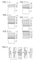
- Fig. 1 is a schematic sectional view showing one example of the layer configuration of the transparent barrier sheet of the present invention.
- Transparent barrier sheet 1a is constituted in such a manner that onto substrate 102, thin transparent inorganic layer 102 and thin transparent organic layer 103 are applied in that order.
- Fig. 1(b) is a transparent barrier sheet.
- Numeral 104 is a transparent primer layer provided between substrate 101 and thin transparent inorganic layer 102.
- Transparent primer layer 104 may be a single layer or if desired, a plurality of layers.
- transparent primer layer 104 it is possible to minimize defects of thin transparent inorganic layer 102 due to projections and foreign matter on substrate 101 to result in enhancement of the close contact between substrate 101 and thin transparent inorganic layer 102, and further to prepare a transparent barrier sheet exhibiting excellent folding resistance.
- Other numeral designations are as defined for Fig. 1(a) .
- 1c is a transparent barrier sheet.
- Thin transparent inorganic layer 102 is constituted in such a manner that when a combination of thin transparent inorganic layer 102 and thin transparent organic layer 103 is regarded as 1 unit, onto transparent primer layer 104 provided on substrate 101, 2 units are applied.
- the number of units applied onto transparent primer layer 104 provided on substrate 101 is preferably at least 2, is more preferably in the range of 2 - 10 units, but is most preferably in the range of 2 - 5 units. By applying at least 2 units, it is possible to enhance barrier properties and folding resistance under relatively high temperature and high humidity.
- Fig. 1(d) is a transparent barrier sheet.
- Transparent barrier sheet 1d is constituted as shown in Fig. 1(c) on both sides of substrate 101.
- Numeral 104' is a transparent primer layer, and 102' is a thin transparent inorganic layer, while 103' is a thin transparent organic layer.
- Other numeral designations are as defined for Fig. 1(a) .
- Transparent barrier sheet 1e is a transparent barrier sheet.
- Transparent barrier sheet 1e carries a layer configuration in which thin transparent inorganic layer 102 is applied onto thin transparent organic layer 103 of transparent barrier sheet 1b shown in Fig. 1(b) .
- By realizing the layer configuration shown in Fig. 1(e) it is possible to further enhance gas barrier properties.
- As shown in Figs. 1(a) - 1(e) by applying, a thin transparent inorganic layer and a thin transparent organic layer onto a substrate in the above order, it is possible to minimize problems such as cracking of the thin transparent inorganic layer applied to secure barrier properties even when external stress is applied.
- the transmittance of total radiation is commonly in the range of 50 - 95% as specified in JIS K 7105.
- the transparent barrier sheet of the present invention is constituted to incorporate a substrate having thereon at least one thin transparent inorganic layer and at least one thin transparent organic layer.
- the thickness of substrate 101 is preferably in the range of 6 - 400 ⁇ m, but is most preferably in the range of 25 - 100 ⁇ m.
- the transparent barrier sheet of the present invention When the transparent barrier sheet of the present invention is applied to electronic devices such as liquid crystal elements, color type solar cells, organic or inorganic ELs, electronic paper, or fuel cells, its thickness is appropriately selected depending on each of the uses.
- the thickness when employed in lieu of a glass substrate, in order to comply with the post-process which is made under the glass substrate specifications, the thickness is preferably in the range of 50 - 800 ⁇ m, but is most preferably in the range of 50 - 400 ⁇ m, which is relatively thick.
- the thickness of transparent primer layer 104 is preferably in the range of 0.05 - 5.0 ⁇ m, but is more preferably in the range of 0.1 - 2.0 ⁇ m.
- the thickness of thin transparent inorganic layer 102 is preferably 10 - 1,000 nm, but is more preferably 20 - 1,000 nm.
- the thickness of thin transparent organic layer 103 is preferably 50 nm - 5.0 ⁇ m, but is more preferably 50 nm - 2.0 ⁇ m.
- the thickness of the thin transparent organic layer which is to be the uppermost layer, is more than that of the lower thin transparent organic layer.
- the thickness of the thin transparent organic layer, other than the uppermost thin transparent organic layer are as follows.
- the thickness of the thin transparent inorganic layer is commonly 10 - 1,000 nm, but is preferably 20 - 500 nm.
- the thickness of the uppermost thin transparent organic layer is commonly 50 nm - 2.0 ⁇ m, but is preferably 50 nm - 1.0 ⁇ m by considering scratching resistance.
- the materials including the transparent barrier sheet shown in Fig. 1 are described below.
- Substrate sheets employed in the present invention may be used without any particular limitation as long as they result in neither dimensional deformation when the following production method is employed, nor curling after coating of a thin layer.
- resins to form the sheet may, for example, be polyester based resins such as polyethylene terephthalate (PET), or polyethylene naphthalate; polyolefin based resins such as polyethylene or polypropylene; styrene based resins such as polystyrene or acrylonitrile-styrene copolymers; acryl based resins such as polymethyl methacrylate or methacrylic acid-maleic acid copolymers; cellulose based resins such as triacetyl cellulose; vinyl based resins such as polyvinyl chloride; imido based resins such as polyimide, fluorinate polyimide, or polyetherimide; amido based resins such as nylon 6, nylon 66, or MXD nylon 6; polycarbonate resins composed
- Substrate sheets include those which have been stretched or not stretched as long as the object of the present invention is not adversely affected, and preferred are those which exhibit sufficient mechanical strength and dimensional stability. Of these, biaxially stretched polyethylene terephthalate or polyethylene naphthalate is preferred for the use of thin substrate sheets.
- polyester based resins such as polyethylene terephthalate or polyethylene naphthalate, polyarylate resins, polyether sulfone resins, polycarbonate resins, or alicyclic polyolefin resins are preferred in view of dimensional stability, chemical resistance, and heat resistance.
- additives may be added to substrate sheets of the present invention in a range which does not adversely affect the present invention.
- Cited as such additives may, for example, be plasticizers, dyes and pigments, antistatic agents, UV absorbers, antioxidants, minute inorganic particles, peeling enhancing agents, leveling agents, inorganic layer-shaped silicates, and lubricants.
- the substrate may be composed of any of the aforementioned single thermoplastic resins or may exhibit a multi-layer configuration which results via coating each of the quality-different thermoplastic resins. Either of the layer configurations may appropriately be selected and then employed.
- the transparent primer layer according to the present invention is provided to improve smoothness and adhesion properties of the substrate sheet when the thin transparent inorganic layer is applied.
- the following listed resin materials may be employed to prepare the transparent primer layer.
- the above-described resins include polyester based resins, urethane based resins, acryl based resins, styrene based resins, cellulose based resins, polyvinyl acetal based resins, and vinyl chloride based resins. It is possible to select and employ any appropriate one(s) from these.
- metal alkoxides are those metals with alcohol such as methyl alcohol, ethyl alcohol, or isopropyl alcohol, and listed as metals may be silicon, titanium, or zirconium.
- UV radiation curable resins or electron beam curable resins other than compounds such as styrene based monomers or compounds having an unsaturated double bond in the molecule such as acryl based monomers, selected and employed may be any suitable one(s) from compounds having an oxetane ring, which are employed to form the thin transparent organic layer described below, and compounds having an oxirane ring, or compounds having an alkenyl ether group, an allene ether group, a ketene acetal group, a tetrahydrofuran group, an oxepane group, a single ring acetal group, a double ring acetal group, a lactone group, a cyclic orthoester group, or a cyclic carbonate group.
- a composition prepared by combining the above compounds with cross-linking agents is applied onto substrate sheet to form a layer followed by curing, whereby it is possible to form a transparent primer layer.
- heat curable resins are suitably selected from combinations with compounds or resins having an epoxy group and an amino group, combinations of acid anhydrides with compounds or resins having an amino group, or combinations of compounds or resins having hydroxyl group with compounds or resins having an isocyanate group, other than heat curing resins such as phenol resins, epoxy resins, melamine resins, urea resins, unsaturated polyester, or alkyd resins, which are widely employed, and then employed.
- the thin transparent inorganic layers according to the present invention may be employed without particular limitation as long as they exhibit gas barrier properties and are transparent.
- Specific examples which form the thin inorganic layer include oxides incorporating at least one of Si, Al, In, Sn, Zn, Mg, Ca, K, Na, B, Ti, Pb, Zr, Y, In, Ce, and Ta, or nitrides and oxidized nitrides. Suitable ones may be selected and then employed. Further, when employed to confirm contents or applied to electronic devices, those, which have not clear maximum absorption wavelength in the visible region, are preferred.
- employed as inorganic oxides may be oxides of metals such as silicon (Si), aluminum (Al), Zinc (Zn), magnesium (Mg), calcium (Ca), potassium (K), tin (Sn), sodium (Na), boron (B), titanium (Ti), lead (Pb), zirconium (Zr), Yttrium (Y), or Indium (In).
- metals such as silicon (Si), aluminum (Al), Zinc (Zn), magnesium (Mg), calcium (Ca), potassium (K), tin (Sn), sodium (Na), boron (B), titanium (Ti), lead (Pb), zirconium (Zr), Yttrium (Y), or Indium (In).
- metal oxides are represented by MO X (in which M represents a metal element, and each value of X differs in the range depending on the metal element), such as SiO x , AlO X , or MgO X .
- the possible value range is as follows; 0 ⁇ X ⁇ 2 for silicon (Si), 0 ⁇ X ⁇ 1.5 for aluminum (Al), 0 ⁇ X ⁇ 1 for zinc (Zn), 0 ⁇ X ⁇ 1 for magnesium (Mg), 0 ⁇ X ⁇ 1 for calcium (Ca), 0 ⁇ X ⁇ 0.5 for potassium (K), 0 ⁇ X ⁇ 2 for tin (Sn), 0 ⁇ X ⁇ 0.5 for sodium (Na), 0 ⁇ X ⁇ 1.5 for boron (B), 0 ⁇ X ⁇ 2 for titanium (Ti), 0 ⁇ X ⁇ 1 for lead (Pb), 0 ⁇
- oxides of silicon (Si) and aluminum (Al) are preferred.
- SiO X silicon oxide
- AlO X aluminum oxide
- silicon nitrides are preferred. Further, as such mixtures, silicon nitride oxides are preferred. Silicon nitride oxide is represented by SiO x N y .
- an oxygen-rich layer is formed resulting in 1 ⁇ x ⁇ 2 and 0 ⁇ y ⁇ 1.
- a nitrogen-rich layer is formed resulting in 0 ⁇ x ⁇ 0.8 and 0.8 ⁇ y ⁇ 1.3.
- a thin transparent organic layer is formed by cross-linking a first compound having at least three isocyanate groups in its molecule, with a second compound having at least two hydroxyl groups in its molecule.
- first compound may, for example, be trimer adducts such as an adduct of 3-mol hexamethylene diisocyanate or an adduct of 3-mol 2,4-tolylene diisocyanate.
- trimer adducts such as an adduct of 3-mol hexamethylene diisocyanate or an adduct of 3-mol 2,4-tolylene diisocyanate.
- relatively low molecular weight compounds are preferred.
- Particularly preferred as such a first compound having at least three isocyanate groups in its molecule are those in which the ratio occupied by the isocyanate group is 30 - 65% by weight with respect to the compounds.
- Examples of such compounds may include 1,8-diisocyante-4-isocyantemethyl-octane (at an NCO content of 50.2% by weight and a molecular weight of 251.3), 2-isocyanateethyl-2,6-diisocyanate caproate (at an NCO content of 49.8% by weight and a molecular weight of 253.2), benzene-1,3,5-triisocyanate (at an NCO content of 62.7% by weight and a molecular weight of 201.1.), 1-methylbenzene-2,4,6-triisocyanate (at an NCO content of 58.6% by weight and a molecular weight of 215.2), 1,3,5-trimethylbenzene-2,4,6-triisocyante (at an NCO content of 51.8% by weight and a molecular weight of 243.2), diphenylmethane-2,4,4'-triisocyanate (at an NCO content of 43.3% by weight and a mole
- compounds having at least two hydroxyl groups in their molecule may be employed without particular limitation.
- compounds having at least two alcoholic hydroxyl groups in their molecule include diethylene glycol, triethylene glycol, polyethylene glycol, dipropylene glycol, tripropylene glycol, polypropylene glycol, 2,2-dimethyl-1,3-propanediol, 2,2-diethyl-1,3-propanediol, 2-buthyl-2-ethyl-1,3-propanediol, 1,2-butanediol, 1,4-butanediol, polytetramethylene glycol, 1,5-pentanediol, 2-methyl-2,4-pentanediol, 3-methyl-1,5-pentanediol, 1,6-hexanediol, 2-ethyl-1,3-hexanedi
- alcohols which are prepared by modifying the cited compounds, having at least two hydroxyl groups in their molecule with dihydric alcohol such as ethylene glycol, diethylene glycol, triethylene glycol, polyethylene glycol, propylene glycol, dipropylene glycol, tripropylene glycol, polypropylene glycol, or polytetramethylene glycol.
- dihydric alcohol such as ethylene glycol, diethylene glycol, triethylene glycol, polyethylene glycol, propylene glycol, dipropylene glycol, tripropylene glycol, polypropylene glycol, or polytetramethylene glycol.
- these compounds having at least two hydroxyl groups in their molecule may be employed individually or in combinations of at least two types. Further, upon considering leveling properties after formation of the deposition layer and ease of deposition, it is preferable to regulate the molecular weight within 100 - 2,000.
- the compounds having at least three hydroxyl groups in their molecule are capable of more easily undergoing three-dimensional cross-linking.
- tin or lead metal organic compounds known in the art are subjected to simultaneous deposition.
- Fig. 2 shows a schematic flow to produce a transparent barrier sheet of the present invention.
- Processes to produce the transparent barrier sheet of the present invention include a substrate supplying process, a primer layer forming process, a drying process, a transparent inorganic layer forming process, a transparent organic layer forming process, and a collection process.
- a primer layer forming process When no primer layer is formed, during production of the transparent barrier sheet of the layer configuration, for example, shown in Fig. 1(a) , the process may proceed from the substrate supplying process to the transparent inorganic layer forming process.
- thermoplastic resin materials supplied is a substrate prepared by employing the above-cited thermoplastic resin materials.
- the transparent primer layer composition is prepared by blending the above-mentioned transparent primer layer forming components or if desirable, dissolving them in solvents or dispersing them, and then applying on a substrate.
- a dispersion is required to form a liquid coating composition
- suitable homogenizers known in the art, such as a two-roller mill, a three-roller mill, a ball mill, a pebble mill, a COBOL mill, a tron mill, a sand mill, a sand grinder, a SQEVARI attritor, a high speed impeller homogenizer, a high speed stone mill, a high speed impact mill, DISPER, a high speed mixer, a homogenizer, an ultrasonic homogenizer, an open kneader, or a continuous kneader, and then employed.
- solvents to employ for dissolution when required: are water; ketones such as methyl ethyl ketone, methyl isobutyl ketone, or cyclohexanone; alcohols such as ethyl alcohol, n-propyl alcohol, or isopropyl alcohol; aliphatic hydrocarbons such as heptane or cyclohexane; aromatics such as toluene or xylene; glycols such as ethylene glycol or diethylene glycol; ether alcohols such as ethylene glycol monomethyl ether; ethers such as tetrahydrofuran, 1,3-dioxysolan or 1,4-dioxane; and halogen compounds such as dichloromethane or chloroform.
- ketones such as methyl ethyl ketone, methyl isobutyl ketone, or cyclohexanone
- alcohols such as ethyl alcohol, n-propyl alcohol, or isoprop
- the transparent primer layer forming composition prepared as above, onto a substrate sheet, employing, for example, a roller coating method, a gravure roller coating method, a direct gravure roller coating method, an air doctor coating method, a rod coating method, a kiss roller coating method, a squeezing roller coating method, a reverse roller coating method, a curtain flow coating method, a fountain method, a transfer coating method, a spray coating method, a dip coating method, or other appropriate methods.
- the resulting coating is heat-dried, followed by an aging treatment, whereby it is possible to apply a transparent primer layer onto a substrate sheet.
- the transparent primer layer forming composition when the transparent primer layer forming composition is applied onto a substrate sheet, it is preferable that after performing a suitable surface treatment selected from a flame treatment, an ozone treatment, a glow discharge treatment, a corona discharge treatment, a plasma treatment, a vacuum ultraviolet radiation exposure treatment, an electron beam exposure treatment, or a radiation exposure treatment, the transparent primer layer forming composition is applied onto a substrate sheet.
- a suitable surface treatment selected from a flame treatment, an ozone treatment, a glow discharge treatment, a corona discharge treatment, a plasma treatment, a vacuum ultraviolet radiation exposure treatment, an electron beam exposure treatment, or a radiation exposure treatment.
- the employed transparent primer layer forming components are the same as the thin transparent organic layer forming compositions, the same method as used to coat the thin transparent organic layer, to be described below, may be employed.
- a transparent primer layer formed on a substrate is further overcoated with a transparent inorganic thin layer by employing the above-described materials.
- the methods to form the transparent inorganic thin layer are not specifically limited.
- forming methods of the thin transparent inorganic layer may, for example, be a vacuum deposition method, a sputtering method, an ion plating method, a reactive plasma deposition method, an method employing an electron cyclotron resonance plasma, a plasma chemical vapor deposition method, a thermochemical vapor deposition method, a photochemical vapor deposition method, a catalytic chemical vapor deposition method, and a vacuum ultraviolet radiation chemical vapor deposition method.
- the thin transparent inorganic layer is formed employing at least one of the catalytic chemical vapor deposition method (namely a Cat-CPD method), the reactive plasma deposition method (namely an RPD method), and the electron cyclotron resonance (ECR) plasma deposition method, which result in a layer exhibiting a relatively flat and smooth surface due to relatively little surface roughness on the formed thin transparent inorganic layer.
- the catalytic chemical vapor deposition method namely a Cat-CPD method
- RPD method reactive plasma deposition method
- ECR electron cyclotron resonance
- a specific method and deposition device of the above catalytic chemical vapor deposition method may suitably be selected from those described, for example, in JP-A Nos. 2002-69644 , 2002-69646 , 2002-299259 , 2004-211160 , 2004-217966 , 2004-292877 , 2004-315899 , and 2005-179693 , and may then be employed upon improvement of the shape suitable for the purpose of the present invention.
- a specific method and deposition device of the reactive plasma vapor deposition method may suitably be selected from those described, for example, in JP-A Nos. 2001-262323 , 2001-295031 , 2001-348660 , 2001-348662 , 2002-30426 , 2002-53950 , 2002-60929 , 2002-115049 , 2002-180240 , 2002-217131 , 2002-249871 , 2003-105526 , 2004-76025 , and 2005-34831 , and may then be employed upon improvement of the shape suitable for the purpose of the present invention.
- a specific method and deposition device of the ECR plasma deposition method may suitably be selected from those described, for example, on pages 152 - 154 and 226 in Tatsuo Asagi, "Hakumaku Sakusei no Kiso (Basis of Thin Layer Formation)” (published by Nikkan Kogyo Shinbun Sha, March 1996 ), and in JP-A Nos.
- a thin transparent organic layer is applied onto a thin transparent inorganic layer which has been applied onto the transparent primer layer during the thin transparent inorganic layer forming process.
- An example as the deposition method of the thin transparent organic layer formed on the above-mentioned thin transparent inorganic layer may be a coating when the above primer layer is formed, or a deposition method.
- the transparent barrier sheet of the present invention it is preferable to employ the deposition method so that the thin transparent inorganic layer, functioning as a barrier layer, is not damaged.
- a thin transparent organic layer in such a manner that after applying, onto the thin transparent inorganic layer, compounds having at least three isocyanate groups in their molecule (being the first compounds) and compounds having at least two hydroxyl groups in their molecule (being the second compounds), employing a deposition method, a cross-linking reaction is performed via heating.
- the heating temperature varies depending on the types of the first compounds and the second compounds, whereby it is preferable that heating is carried out appropriately after determining optimal temperature.
- deposition conditions may be set individually. When no cross-linking reaction results and no problems occur at slight differences in the deposition rate of the above compounds, those deposition conditions may be set for the mixture as a composition.
- a specific method and layer forming device of the above-mentioned deposition method may suitably be selected from those described, for example, in JP-A Nos. 2-284485 , 5-125520 , 5-177163 , 5-311399 , 5-339389 , 6-116409 , 6-316757 , 7-26023 , 7-209863 , 9-143681 , 9-249851 , 9-272703 , 9-278805 , 9-279332 , 9-326389 , 10-92800 , 10-168559 , 10-289902 , 11-172418 , 2000-87224 , 2000-127186 , 2000-348971 , 2001-261867 , 2002-275619 , 2003-3250 , 2003-300273 , 2003-335880 , and 2005-14483 , as well as in Japanese Patent Publication Open to Public Inspection (under PCT Application) Nos. 8-503099 , and they may then be employed upon improvement of the shape suitable for the
- T (in K) represents a maximum attained temperature
- S (in seconds) represents a layer forming time.
- maximum attained temperature T (in K) and layer forming time S (in seconds) of the substrate during formation of the thin transparent organic layer and the thin transparent inorganic layer relates to a process to form a single layer.
- the above values represent layer forming conditions to form a single layer.
- the layer forming time as described herein, represents layer forming time at a certain point of the substrate. 1.41 ⁇ ( T ⁇ S ) / 1000 ⁇ 460 1.45 ⁇ ( T ⁇ S ) / 1000 ⁇ 350
- the maximum attained temperature T, in K of the substrate sheet it is preferable to regulate the maximum attained temperature T, in K of the substrate sheet to the range of 283 - 383 K, but is more preferably to regulate it to the range of 293 - 333 K. Further, it is more preferable that maximum attained temperatures T (in K) of the substrate sheet is within the range represented by following Formula (3): 0.54 ⁇ T / Tg ⁇ 0.98
- the transparent barrier sheet ( Fig. 1(b) ), incorporating a substrate coated thereon with the primer sheet, the thin transparent inorganic layer, and the thin transparent organic layer in that order, is collected. Further, it is possible to produce the transparent barrier sheet, shown in Fig. 1(a) , in such a manner that except for no use of the primer layer forming process, production is carried out under the same conditions as the transparent barrier sheet shown in Fig. 1(b) . It is possible to produce the transparent barrier sheet shown in Fig. 1(e) in such a manner that after forming the thin transparent organic layer, a thin transparent inorganic layer is again formed on the thin transparent organic layer during formation of the thin transparent inorganic layer.
- the transparent barrier sheet shown in Fig. 1(c) in such a manner that after completing the thin transparent organic layer forming process shown in the above figure, in the thin transparent inorganic layer forming process, a thin transparent inorganic layer and a thin transparent organic layer are again successively applied. It is possible to produce the transparent barrier sheet shown in Fig. 1(d) in such a manner that after achieving the layer configuration of the transparent barrier sheet shown in Fig. 1(c) , a transparent primer layer, a thin transparent inorganic layer, and a thin transparent organic layer are successively applied.
- the substrate employed in the production flow as shown in the above figure, may include sheets of film and long bands of film wound in a roll.
- the transparent primer layer, the thin transparent inorganic layer and the thin transparent organic layer are each subjected to batch processing.
- the thin transparent inorganic layer forming conditions match the thin transparent organic layer forming conditions, it is possible to continuously apply a thin transparent inorganic layer and a thin transparent organic layer onto a long band of film wound into a roll.
- the transparent barrier sheet of the present invention other than the essential layers, it is possible to also coat functional layers such as an antistatic layer, an adhesive layer, an electrically conductive lawyer, an antireflection layer, a UV radiation minimizing layer, or a near-infrared minimizing layer, which are provided when desired, employing any suitable method which is selected from the coating methods for thin transparent inorganic layer or thin transparent organic layers.
- functional layers such as an antistatic layer, an adhesive layer, an electrically conductive lawyer, an antireflection layer, a UV radiation minimizing layer, or a near-infrared minimizing layer
- a 100 ⁇ m thick polyether sulfone film (SUMILITE FS-5300, produced by Sumitomo Bakelite Co., Ltd.) was prepared as a substrate sheet. Its glass transition point Tg was 496 K.
- Cooling plate 10 was placed on the rear surface of the prepared substrate sheet and a thin transparent inorganic layer composed of silicon nitride oxide was formed employing a reaction type plasma deposition apparatus (downsized plasma layer forming apparatus of to 370 x 480 mm, produced by Sumitomo Heavy Industries Co., Ltd.), while employing silicon as a solid target.
- Table 1 shows film forming time S, layer thickness, maximum attained temperature of the substrate T and (T x S)/100 of each thin transparent inorganic layer.
- Cooling plate 10 was placed on the rear surface of the substrate onto which a thin transparent inorganic layer had been coated. In such a state, it was placed in a vacuum tank, and the interior pressure was reduced to the order of 10 -4 Pa.
- the maximum attained temperature during formation of the thin transparent organic layer was determined as follows. A thermo-label was adhered onto the surface of the formed layer and after forming the thin layer, temperature T (in K) was confirmed. The thickness of the thin transparent organic layer was represented by the values determined employing a spectral ellipsometer (FE-5000, produced by Otsuka Electronics Co., Ltd.). Radiation transmittance based on JIS K 7105 of prepared Sample Nos. 1-A - 1-F was within 83 - 88% (determined by HAZE COMPUTER HGM-2B, produced by Suga Test Instruments Co. Ltd.).
- a comparative transparent barrier sheet was prepared in the following manner, employing the same substrate as in Sample No. 1-A, and designated as No. 1-R.
- a layer forming apparatus in which a high pressure UV mercury lamp was installed in the interior of a vacuum deposition apparatus, equipped with a resistor heating terminal and an electron gun, was employed. Silicon oxide was employed to form an inorganic layer, while employed as an organic layer was a resin mixture to be cured, composed of 100 parts by weight of bifunctional dicyclopentadienyl diacrylate *1, and 1 part by weight of a photopolymerization initiator (IRUGACURE 907, produced by Ciba Specialty Chemicals, Inc.). A substrate was placed in a vacuum tank and the pressure was reduced to the order of 10 -4 Pa.
- Thin Transparent Inorganic Layer D composed of silicon oxide
- 60 nm Thin Transparent Inorganic Layer D composed of silicon oxide
- an electron beam deposition method employing silicon oxide as a target.
- resistor heating for the organic deposition source was initiated.
- the deposition shutter was opened, whereby a thin transparent organic layer of 1,000 nm was subjected to deposition.
- the UV lamp shutter was opened, and monomers were cured at an integral light anoint of 500 mJ/cm 2 , to form Thin Transparent Organic Layer E, whereby a comparative transparent barrier sheet was produced.
- a zero point was determined at 25 °C and 0% relative humidity, employing an oxygen permeability meter (OXTRAN 2/21, produced by MOCON Co.) and determined values thereafter were used.
- the oxygen permeability was shown in ml/m 2 ⁇ 24 hour ⁇ 25 °C.
- a biaxially stretched polyethylene terephthalate film (COSMOSHINE A-4300, produced by TOYOBO Co., Ltd.) was prepared.
- Transparent barrier sheets were then prepared in such a manner that Thin Transparent Inorganic Layer A and Thin Transparent Organic Layer B, each of which is shown in following 1) and 2) were applied onto the above substrate sheet coated with the primer layer to realize the layer configuration listed in Table 2, whereby Sample Nos. 2-A - 2-D were prepared.
- C represents the substrate sheet coated with the transparent primer layer.
- Thin Transparent Inorganic Layer A composed of silicon nitride, was formed employing an ECR plasma layer forming apparatus (AFTECH ER-1200, produced by NTT AFTY Corp.), while using silicon as a solid target under layer forming conditions at a microwave power of 500 W, an RF power of 500 W, and a layer forming pressure of 0.09 Pa, as well as under gas introduction conditions at an argon flow rate of 40 sccm and a nitrogen gas flow rate of 0.5 sccm.
- ECR plasma layer forming apparatus AFTECH ER-1200, produced by NTT AFTY Corp.
- Table 2 shows the thickness of the resulting thin transparent inorganic layer, the layer forming time, and maximum attained temperature T (in K) of the substrate sheet during formation of the layer. Maximum attained temperature T (in K) of the substrate sheet was evaluated in the same manner as in Example 1.
- the resultant substrate, coated with the thin transparent inorganic layer, was placed into a vacuum tank in such a manner that a 10 °C cooling plate was placed on the reverse side, and the pressure in the vacuum tank was reduced to the order of 10 -4 Pa. Thereafter, a compound having an isocyanate group and a compound having a hydroxyl group were each placed in a separate vessel. Subsequently, each vessel was subjected to resistor heating to 40 °C. When the impurities were completely evaporated, each vessel was heated to the temperature listed in Table 2. Thereafter, the deposition shutter was opened, whereby a thin transparent organic layer, which was prepared via deposition polymerization on the thin transparent inorganic layer, was formed. Table 1 shows the thickness of the resulting thin transparent organic layer, the layer forming time, and maximum attained temperature T (in K) of the substrate sheet.
- Transparent Barrier Sheet No. 2-R as a comparative sample was prepared as follows. The same substrate as Sample No. 2-A was employed. Subsequently, preparation was carried out up to Thin Transparent Organic Layer E which was the same as Comparative Sample No. 1-R of Example 1. Further, employing the same method as for Comparative Example 1, onto above Thin Transparent Organic Layer E, 60 nm Thin Transparent Inorganic Layer D composed of silicon oxide and 1,000 nm thick Thin Transparent Organic Layer E were applied, employing the electron beam deposition method and the organic deposition method, respectively, so that the layer configuration described in Table 2 was realized. Transparent Barrier Sheet No. 2-R, prepared via the above method, was evaluated for barrier properties and folding resistance, employing the same evaluation methods as for Example 1. Table 2 shows the results.
- Table 2 shows evaluation results of resulting Sample Nos. 2-A - 2-R for oxygen permeability and water vapor permeability, as gas barrier properties, as well as folding resistance, which were evaluated employing the same methods as for Example 1.
- oxygen permeability is in ml/m 2 ⁇ 24 hr ⁇ 25 °C
- water vapor permeability is in g/m 2 ⁇ 24 hr ⁇ 25 °C.
- Table 2 Inv. Inv. Inv. Inv. Comp. Transparent Barrier Sheet No.
Landscapes
- Chemical & Material Sciences (AREA)
- Chemical Kinetics & Catalysis (AREA)
- Engineering & Computer Science (AREA)
- Materials Engineering (AREA)
- Mechanical Engineering (AREA)
- Metallurgy (AREA)
- Organic Chemistry (AREA)
- Laminated Bodies (AREA)
- Polyurethanes Or Polyureas (AREA)
Applications Claiming Priority (2)
| Application Number | Priority Date | Filing Date | Title |
|---|---|---|---|
| JP2006082437 | 2006-03-24 | ||
| PCT/JP2007/053906 WO2007111076A1 (ja) | 2006-03-24 | 2007-03-01 | 透明バリア性シートおよび透明バリア性シートの製造方法 |
Publications (1)
| Publication Number | Publication Date |
|---|---|
| EP2000298A1 true EP2000298A1 (de) | 2008-12-10 |
Family
ID=38533821
Family Applications (1)
| Application Number | Title | Priority Date | Filing Date |
|---|---|---|---|
| EP20070737586 Withdrawn EP2000298A1 (de) | 2006-03-24 | 2007-03-01 | Durchsichtige sperrfolie und verfahren zur herstellung einer durchsichtigen sperrfolie |
Country Status (4)
| Country | Link |
|---|---|
| US (1) | US20070224428A1 (de) |
| EP (1) | EP2000298A1 (de) |
| JP (1) | JPWO2007111076A1 (de) |
| WO (1) | WO2007111076A1 (de) |
Families Citing this family (7)
| Publication number | Priority date | Publication date | Assignee | Title |
|---|---|---|---|---|
| JP2009133000A (ja) * | 2007-10-30 | 2009-06-18 | Fujifilm Corp | シリコン窒化物膜及びそれを用いたガスバリア膜、薄膜素子 |
| JP5281986B2 (ja) * | 2009-08-26 | 2013-09-04 | 富士フイルム株式会社 | 積層フィルムおよび複合フィルム |
| CN103079807A (zh) * | 2010-08-13 | 2013-05-01 | 旭硝子株式会社 | 层叠体和层叠体的制造方法 |
| JPWO2012147571A1 (ja) * | 2011-04-27 | 2014-07-28 | 旭硝子株式会社 | 積層体の製造方法 |
| US20150303336A1 (en) * | 2012-02-10 | 2015-10-22 | Arkema Inc. | Weatherable composite for flexible thin film photovoltaic and light emitting diode devices |
| JP5944304B2 (ja) * | 2012-12-13 | 2016-07-05 | 小島プレス工業株式会社 | ポリユリア及びその製造方法並びにコンデンサ素子及びその製造方法 |
| CN109267039B (zh) * | 2018-10-24 | 2019-11-29 | 江苏菲沃泰纳米科技有限公司 | 一种聚氨酯纳米涂层及其制备方法 |
Family Cites Families (81)
| Publication number | Priority date | Publication date | Assignee | Title |
|---|---|---|---|---|
| ATE107875T1 (de) * | 1987-11-18 | 1994-07-15 | Zeneca Ltd | Wässrige polyurethan dispersionen. |
| JP2782528B2 (ja) | 1989-04-26 | 1998-08-06 | 日本真空技術株式会社 | 有機圧電焦電体膜の形成方法 |
| JPH0660414B2 (ja) | 1989-09-27 | 1994-08-10 | 株式会社芦田 | Ecrプラズマcvd装置 |
| JPH0740569B2 (ja) | 1990-02-27 | 1995-05-01 | エイ・ティ・アンド・ティ・コーポレーション | Ecrプラズマ堆積方法 |
| JP2921137B2 (ja) | 1991-02-12 | 1999-07-19 | 富士電機株式会社 | 絶縁膜の形成方法 |
| JP2998257B2 (ja) | 1991-04-09 | 2000-01-11 | 富士電機株式会社 | 絶縁膜形成方法 |
| JP2601573B2 (ja) | 1991-07-01 | 1997-04-16 | 日本電信電話株式会社 | プラズマ処理におけるダメージ低減方法 |
| JP3042127B2 (ja) | 1991-09-02 | 2000-05-15 | 富士電機株式会社 | 酸化シリコン膜の製造方法および製造装置 |
| JP3072158B2 (ja) | 1991-09-12 | 2000-07-31 | 大阪瓦斯株式会社 | 薄膜形成方法 |
| JP2648746B2 (ja) | 1991-09-26 | 1997-09-03 | 株式会社ジーティシー | 絶縁膜形成方法 |
| JP3190386B2 (ja) | 1991-10-25 | 2001-07-23 | 松下電器産業株式会社 | 真空製膜装置 |
| JP2695324B2 (ja) | 1991-10-31 | 1997-12-24 | 富士通株式会社 | 半導体装置の製造方法 |
| JP3585504B2 (ja) | 1991-11-06 | 2004-11-04 | 株式会社アルバック | 多層膜コンデンサーの製造方法 |
| JP2796765B2 (ja) | 1991-12-19 | 1998-09-10 | 日本電信電話株式会社 | 薄膜形成装置 |
| JPH05177163A (ja) | 1991-12-27 | 1993-07-20 | Ulvac Japan Ltd | 合成樹脂被膜の形成方法 |
| JPH05311399A (ja) | 1992-05-12 | 1993-11-22 | Ulvac Japan Ltd | 有機焦電圧電体の形成方法 |
| JPH05339389A (ja) | 1992-05-26 | 1993-12-21 | Agency Of Ind Science & Technol | 高分子膜の形成方法 |
| US5260095A (en) | 1992-08-21 | 1993-11-09 | Battelle Memorial Institute | Vacuum deposition and curing of liquid monomers |
| JP3166379B2 (ja) | 1993-02-16 | 2001-05-14 | 富士電機株式会社 | 絶縁膜の製造方法および製造装置 |
| JP2916735B2 (ja) | 1993-03-24 | 1999-07-05 | 株式会社日本製鋼所 | プラズマ表面改質方法および装置 |
| JP2762013B2 (ja) | 1993-04-28 | 1998-06-04 | 川崎重工業株式会社 | 紫外レーザーによる有機多層膜製造方法 |
| JPH0726023A (ja) | 1993-07-14 | 1995-01-27 | Furukawa Electric Co Ltd:The | 有機高分子薄膜の作製方法 |
| JPH07209863A (ja) | 1994-01-20 | 1995-08-11 | Ulvac Japan Ltd | パターン形成方法 |
| JP3063519B2 (ja) | 1994-03-25 | 2000-07-12 | 住友金属工業株式会社 | 薄膜の形成方法 |
| JPH07335575A (ja) | 1994-06-14 | 1995-12-22 | Nippon Steel Corp | 薄膜の製造方法 |
| JP3208439B2 (ja) | 1994-09-07 | 2001-09-10 | 日本電信電話株式会社 | 膜形成用プラズマ装置 |
| JPH0917598A (ja) | 1995-06-29 | 1997-01-17 | Nippon Telegr & Teleph Corp <Ntt> | Ecrプラズマ加工装置およびecrプラズマ生成方法 |
| JP3863934B2 (ja) | 1995-11-14 | 2006-12-27 | 株式会社アルバック | 高分子薄膜の形成方法 |
| JPH09249851A (ja) | 1996-03-15 | 1997-09-22 | Ulvac Japan Ltd | 高分子薄膜の低比誘電率化方法及び層間絶縁膜の形成方法 |
| JP3623848B2 (ja) | 1996-04-05 | 2005-02-23 | 株式会社アルバック | 有機化合物用蒸発源及びこれを用いた蒸着重合装置 |
| JPH09278805A (ja) | 1996-04-12 | 1997-10-28 | Ulvac Japan Ltd | 蒸着重合方法 |
| JP3773587B2 (ja) | 1996-04-15 | 2006-05-10 | 株式会社アルバック | 有機化合物モノマーの精製方法 |
| JP3675958B2 (ja) | 1996-06-05 | 2005-07-27 | 株式会社アルバック | 耐湿性絶縁膜の形成方法及び層間絶縁膜の形成方法 |
| JP3516819B2 (ja) | 1996-09-12 | 2004-04-05 | 株式会社アルバック | モノマーの蒸発システム、同蒸発システムを備えた真空処理室、および有機化合物膜の成膜方法 |
| JP4059946B2 (ja) | 1996-12-06 | 2008-03-12 | 株式会社アルバック | 有機薄膜形成装置及び有機材料の再利用方法 |
| JPH10289902A (ja) | 1997-04-11 | 1998-10-27 | Ulvac Japan Ltd | 成膜装置 |
| JPH11172418A (ja) | 1997-12-12 | 1999-06-29 | Ulvac Corp | 成膜装置 |
| JP4112702B2 (ja) | 1998-09-11 | 2008-07-02 | 株式会社アルバック | 成膜装置 |
| JP2000127186A (ja) | 1998-10-28 | 2000-05-09 | Matsushita Electric Ind Co Ltd | 樹脂薄膜の製造方法 |
| JP2000348971A (ja) | 1999-06-04 | 2000-12-15 | Matsushita Electric Ind Co Ltd | 積層体の製造方法及び積層体の製造装置 |
| JP2001261867A (ja) | 2000-03-14 | 2001-09-26 | Dainippon Printing Co Ltd | 連続式蒸着重合法 |
| JP4017310B2 (ja) | 2000-03-23 | 2007-12-05 | 住友重機械工業株式会社 | 成膜装置 |
| JP2001295031A (ja) | 2000-04-14 | 2001-10-26 | Sumitomo Heavy Ind Ltd | 成膜装置及び方法 |
| JP2001348662A (ja) | 2000-06-05 | 2001-12-18 | Sumitomo Heavy Ind Ltd | 成膜方法及び装置 |
| JP4056680B2 (ja) | 2000-06-06 | 2008-03-05 | 住友重機械工業株式会社 | 成膜装置及び方法 |
| JP2002030426A (ja) | 2000-07-07 | 2002-01-31 | Sumitomo Heavy Ind Ltd | 成膜方法及び装置 |
| JP2002053950A (ja) | 2000-08-07 | 2002-02-19 | Sumitomo Heavy Ind Ltd | 絶縁体基板への成膜方法及び成膜装置 |
| JP2002060929A (ja) | 2000-08-10 | 2002-02-28 | Sumitomo Heavy Ind Ltd | Ito膜の成膜方法及び成膜装置 |
| JP2002069644A (ja) | 2000-08-29 | 2002-03-08 | Sony Corp | 薄膜製造装置および薄膜製造方法 |
| JP2002069646A (ja) | 2000-09-01 | 2002-03-08 | Sony Corp | 薄膜製造方法 |
| JP4553480B2 (ja) * | 2000-12-14 | 2010-09-29 | 東セロ株式会社 | 積層体 |
| JP2002180240A (ja) | 2000-12-20 | 2002-06-26 | Sumitomo Heavy Ind Ltd | 成膜装置 |
| JP3546019B2 (ja) | 2001-01-17 | 2004-07-21 | 住友重機械工業株式会社 | 成膜方法及び装置 |
| JP2002249871A (ja) | 2001-02-22 | 2002-09-06 | Sumitomo Heavy Ind Ltd | 成膜装置 |
| JP4195205B2 (ja) | 2001-03-16 | 2008-12-10 | 三井化学株式会社 | 有機高分子薄膜の作製方法 |
| JP2002299259A (ja) | 2001-03-30 | 2002-10-11 | Kyocera Corp | 薄膜形成方法 |
| JP2003003250A (ja) | 2001-06-22 | 2003-01-08 | Alps Electric Co Ltd | 真空蒸着重合装置及びこれを用いた有機被膜の形成方法 |
| JP2002115049A (ja) | 2001-08-31 | 2002-04-19 | Sumitomo Heavy Ind Ltd | 成膜方法及び装置 |
| JP2003105526A (ja) | 2001-09-26 | 2003-04-09 | Sumitomo Heavy Ind Ltd | 珪素化合物膜の成膜方法 |
| JP2003129236A (ja) | 2001-10-24 | 2003-05-08 | Nippon Telegr & Teleph Corp <Ntt> | 薄膜形成装置 |
| JP2003191370A (ja) * | 2001-12-26 | 2003-07-08 | Sumitomo Bakelite Co Ltd | 水蒸気バリア性プラスチックフィルム及びこれを用いたエレクトロルミネッセンス用ディスプレイ基板 |
| JP4083564B2 (ja) | 2001-12-26 | 2008-04-30 | 住友ベークライト株式会社 | 有機層の形成方法及びガスバリア性プラスチックフィルム |
| JP4059480B2 (ja) | 2002-03-26 | 2008-03-12 | 大日本印刷株式会社 | 積層体およびその製造方法 |
| JP4173679B2 (ja) | 2002-04-09 | 2008-10-29 | エム・イー・エス・アフティ株式会社 | Ecrプラズマ源およびecrプラズマ装置 |
| JP2003300273A (ja) | 2002-04-10 | 2003-10-21 | Ulvac Japan Ltd | 表面処理方法及び真空表面処理装置 |
| JP4381742B2 (ja) * | 2002-08-01 | 2009-12-09 | セントラル硝子株式会社 | 防曇性膜及びその形成方法並びに防曇性膜形成用塗布剤 |
| JP4538577B2 (ja) | 2002-08-09 | 2010-09-08 | 住友重機械工業株式会社 | 酸化亜鉛薄膜の成膜方法 |
| JP4148759B2 (ja) * | 2002-11-13 | 2008-09-10 | 三井化学株式会社 | ガスバリアフィルムの製造方法 |
| JP4144697B2 (ja) | 2002-12-27 | 2008-09-03 | 三井化学株式会社 | 化学蒸着方法および装置 |
| JP2004217966A (ja) | 2003-01-10 | 2004-08-05 | Mitsui Chemicals Inc | ガスバリア膜形成方法および装置 |
| JP4474840B2 (ja) | 2003-03-26 | 2010-06-09 | 株式会社石川製作所 | 窒化シリコン膜の製造方法 |
| JP4144705B2 (ja) | 2003-04-16 | 2008-09-03 | 三井化学株式会社 | ガスバリア膜形成方法 |
| JP2005014483A (ja) | 2003-06-27 | 2005-01-20 | Toppan Printing Co Ltd | 積層体の製造方法 |
| JP2005034831A (ja) | 2003-07-01 | 2005-02-10 | Sumitomo Heavy Ind Ltd | バリア多層膜及びその製造方法 |
| JP2005035204A (ja) * | 2003-07-17 | 2005-02-10 | Oike Ind Co Ltd | 透明導電ガスバリアフィルム |
| US7297414B2 (en) * | 2003-09-30 | 2007-11-20 | Fujifilm Corporation | Gas barrier film and method for producing the same |
| JP2005178010A (ja) | 2003-12-16 | 2005-07-07 | Toppan Printing Co Ltd | ガスバリア透明積層体 |
| JP4455039B2 (ja) | 2003-12-16 | 2010-04-21 | 株式会社マテリアルデザインファクトリ− | Si系有機・無機ハイブリッド膜の形成方法 |
| JP4227040B2 (ja) * | 2004-03-03 | 2009-02-18 | 富士フイルム株式会社 | ガスバリア性積層フィルムおよび該フィルムを用いた画像表示素子 |
| JP4268085B2 (ja) | 2004-04-16 | 2009-05-27 | 日本電信電話株式会社 | 酸窒化シリコン膜の形成方法及び形成装置 |
| US8252421B2 (en) * | 2006-09-22 | 2012-08-28 | Toray Industries, Inc. | Gas barrier film |
-
2007
- 2007-03-01 EP EP20070737586 patent/EP2000298A1/de not_active Withdrawn
- 2007-03-01 JP JP2008507401A patent/JPWO2007111076A1/ja active Pending
- 2007-03-01 WO PCT/JP2007/053906 patent/WO2007111076A1/ja not_active Ceased
- 2007-03-21 US US11/723,673 patent/US20070224428A1/en not_active Abandoned
Non-Patent Citations (1)
| Title |
|---|
| See references of WO2007111076A1 * |
Also Published As
| Publication number | Publication date |
|---|---|
| JPWO2007111076A1 (ja) | 2009-08-06 |
| US20070224428A1 (en) | 2007-09-27 |
| WO2007111076A1 (ja) | 2007-10-04 |
Similar Documents
| Publication | Publication Date | Title |
|---|---|---|
| EP2000297A1 (de) | Transparente sperrfolie und verfahren zur herstellung einer transparenten sperrfolie | |
| EP2000298A1 (de) | Durchsichtige sperrfolie und verfahren zur herstellung einer durchsichtigen sperrfolie | |
| JP4429515B2 (ja) | 高分子樹脂積層体、その製造方法、および該積層体からなる成形物 | |
| US20070224368A1 (en) | Transparent gas-barrier layered film | |
| EP2000300A1 (de) | Transparente sperrfolie und verfahren zu ihrer herstellung | |
| JP4536417B2 (ja) | ガスバリア性フィルム | |
| JP4118711B2 (ja) | 高分子樹脂積層体、およびその製造方法、ならびに車両用窓材 | |
| EP2000299A1 (de) | Transparente sperrfolie und verfahren zur herstellung einer transparenten sperrfolie | |
| JP4429514B2 (ja) | 高分子樹脂積層体及びその製造方法 | |
| CN1968807A (zh) | 透明阻气性积层薄膜 | |
| EP2000296A2 (de) | Transparente sperrfolie und verfahren zur herstellung einer transparenten sperrfolie | |
| JP7683774B2 (ja) | ガスバリア性積層体 | |
| JP4401592B2 (ja) | 高分子樹脂積層体及びそれからなる自動車用窓材 | |
| JP4542210B2 (ja) | プラスチック成形品 | |
| JP2004314469A (ja) | 高分子樹脂積層体および窓材 | |
| JP3723682B2 (ja) | 反射防止フイルム | |
| JPH11240103A (ja) | 透明被覆成形品 | |
| CN118679420A (zh) | 光学层叠体及其制造方法和包含其的智能窗 | |
| JP2000296579A (ja) | 被覆成形品およびその製造方法 | |
| JPH11314302A (ja) | プラスチック製品 | |
| JP2025507633A (ja) | 光学積層体およびその製造方法と、これを含むスマートウィンドウ | |
| JPH04214340A (ja) | 液晶表示パネル用フィルム | |
| JPH11240104A (ja) | 透明被覆成形品の製造方法 | |
| WO2021246295A1 (ja) | 成形用樹脂シートおよびそれを用いた成形品 | |
| WO2011132541A1 (ja) | 積層ポリエステルフィルム |
Legal Events
| Date | Code | Title | Description |
|---|---|---|---|
| PUAI | Public reference made under article 153(3) epc to a published international application that has entered the european phase |
Free format text: ORIGINAL CODE: 0009012 |
|
| 17P | Request for examination filed |
Effective date: 20080919 |
|
| AK | Designated contracting states |
Kind code of ref document: A1 Designated state(s): AT BE BG CH CY CZ DE DK EE ES FI FR GB GR HU IE IS IT LI LT LU LV MC NL PL PT RO SE SI SK TR |
|
| STAA | Information on the status of an ep patent application or granted ep patent |
Free format text: STATUS: THE APPLICATION HAS BEEN WITHDRAWN |
|
| 18W | Application withdrawn |
Effective date: 20090831 |