WO2012141407A2 - Lave-linge - Google Patents
Lave-linge Download PDFInfo
- Publication number
- WO2012141407A2 WO2012141407A2 PCT/KR2012/000365 KR2012000365W WO2012141407A2 WO 2012141407 A2 WO2012141407 A2 WO 2012141407A2 KR 2012000365 W KR2012000365 W KR 2012000365W WO 2012141407 A2 WO2012141407 A2 WO 2012141407A2
- Authority
- WO
- WIPO (PCT)
- Prior art keywords
- water
- drum
- vane
- washing
- turbo
- Prior art date
Links
- XLYOFNOQVPJJNP-UHFFFAOYSA-N water Substances O XLYOFNOQVPJJNP-UHFFFAOYSA-N 0.000 claims abstract description 452
- 238000005507 spraying Methods 0.000 claims abstract description 19
- 238000005406 washing Methods 0.000 claims description 219
- 238000000034 method Methods 0.000 claims description 55
- 239000007921 spray Substances 0.000 claims description 32
- 238000005192 partition Methods 0.000 claims description 8
- 239000003599 detergent Substances 0.000 description 62
- 238000001914 filtration Methods 0.000 description 56
- 238000002347 injection Methods 0.000 description 35
- 239000007924 injection Substances 0.000 description 35
- 238000001035 drying Methods 0.000 description 23
- 239000006185 dispersion Substances 0.000 description 17
- 230000018044 dehydration Effects 0.000 description 16
- 238000006297 dehydration reaction Methods 0.000 description 16
- 229920000742 Cotton Polymers 0.000 description 7
- 238000011109 contamination Methods 0.000 description 7
- 238000001514 detection method Methods 0.000 description 7
- 238000013021 overheating Methods 0.000 description 7
- 238000004140 cleaning Methods 0.000 description 6
- 230000009467 reduction Effects 0.000 description 6
- 239000000654 additive Substances 0.000 description 5
- 239000007844 bleaching agent Substances 0.000 description 5
- 230000000694 effects Effects 0.000 description 5
- 208000019585 progressive encephalomyelitis with rigidity and myoclonus Diseases 0.000 description 5
- 210000002268 wool Anatomy 0.000 description 5
- 230000008901 benefit Effects 0.000 description 4
- 230000008878 coupling Effects 0.000 description 4
- 238000010168 coupling process Methods 0.000 description 4
- 238000005859 coupling reaction Methods 0.000 description 4
- 239000006260 foam Substances 0.000 description 4
- 239000011521 glass Substances 0.000 description 4
- 238000001746 injection moulding Methods 0.000 description 4
- 230000008569 process Effects 0.000 description 4
- 238000000926 separation method Methods 0.000 description 4
- 239000008400 supply water Substances 0.000 description 4
- 230000001133 acceleration Effects 0.000 description 3
- 239000000356 contaminant Substances 0.000 description 3
- 239000002979 fabric softener Substances 0.000 description 3
- 238000003780 insertion Methods 0.000 description 3
- 230000037431 insertion Effects 0.000 description 3
- 230000002265 prevention Effects 0.000 description 3
- 241001085205 Prenanthella exigua Species 0.000 description 2
- 230000000996 additive effect Effects 0.000 description 2
- 230000015572 biosynthetic process Effects 0.000 description 2
- 238000010586 diagram Methods 0.000 description 2
- 238000007599 discharging Methods 0.000 description 2
- 230000006870 function Effects 0.000 description 2
- 239000000463 material Substances 0.000 description 2
- BDAGIHXWWSANSR-UHFFFAOYSA-N methanoic acid Natural products OC=O BDAGIHXWWSANSR-UHFFFAOYSA-N 0.000 description 2
- 238000002156 mixing Methods 0.000 description 2
- 230000004048 modification Effects 0.000 description 2
- 238000012986 modification Methods 0.000 description 2
- 238000011017 operating method Methods 0.000 description 2
- 230000002250 progressing effect Effects 0.000 description 2
- 229920003002 synthetic resin Polymers 0.000 description 2
- 239000000057 synthetic resin Substances 0.000 description 2
- OSWFIVFLDKOXQC-UHFFFAOYSA-N 4-(3-methoxyphenyl)aniline Chemical compound COC1=CC=CC(C=2C=CC(N)=CC=2)=C1 OSWFIVFLDKOXQC-UHFFFAOYSA-N 0.000 description 1
- 244000043261 Hevea brasiliensis Species 0.000 description 1
- 238000010793 Steam injection (oil industry) Methods 0.000 description 1
- 239000002253 acid Substances 0.000 description 1
- 235000019568 aromas Nutrition 0.000 description 1
- 230000004888 barrier function Effects 0.000 description 1
- 230000005540 biological transmission Effects 0.000 description 1
- 210000000988 bone and bone Anatomy 0.000 description 1
- 230000005587 bubbling Effects 0.000 description 1
- 230000003139 buffering effect Effects 0.000 description 1
- 230000008859 change Effects 0.000 description 1
- 238000002144 chemical decomposition reaction Methods 0.000 description 1
- 239000003795 chemical substances by application Substances 0.000 description 1
- 239000011248 coating agent Substances 0.000 description 1
- 238000000576 coating method Methods 0.000 description 1
- 239000002131 composite material Substances 0.000 description 1
- 230000006835 compression Effects 0.000 description 1
- 238000007906 compression Methods 0.000 description 1
- 238000007796 conventional method Methods 0.000 description 1
- 230000003247 decreasing effect Effects 0.000 description 1
- 238000013461 design Methods 0.000 description 1
- 238000000605 extraction Methods 0.000 description 1
- 235000019253 formic acid Nutrition 0.000 description 1
- 238000010438 heat treatment Methods 0.000 description 1
- 239000008236 heating water Substances 0.000 description 1
- 238000003475 lamination Methods 0.000 description 1
- 230000007246 mechanism Effects 0.000 description 1
- 239000000203 mixture Substances 0.000 description 1
- 229920003052 natural elastomer Polymers 0.000 description 1
- 229920001194 natural rubber Polymers 0.000 description 1
- 230000002093 peripheral effect Effects 0.000 description 1
- 230000000704 physical effect Effects 0.000 description 1
- 238000003825 pressing Methods 0.000 description 1
- 238000012545 processing Methods 0.000 description 1
- 238000004904 shortening Methods 0.000 description 1
- 238000012546 transfer Methods 0.000 description 1
Images


Classifications
-
- D—TEXTILES; PAPER
- D06—TREATMENT OF TEXTILES OR THE LIKE; LAUNDERING; FLEXIBLE MATERIALS NOT OTHERWISE PROVIDED FOR
- D06F—LAUNDERING, DRYING, IRONING, PRESSING OR FOLDING TEXTILE ARTICLES
- D06F17/00—Washing machines having receptacles, stationary for washing purposes, wherein the washing action is effected solely by circulation or agitation of the washing liquid
- D06F17/04—Washing machines having receptacles, stationary for washing purposes, wherein the washing action is effected solely by circulation or agitation of the washing liquid solely by water jets
-
- D—TEXTILES; PAPER
- D06—TREATMENT OF TEXTILES OR THE LIKE; LAUNDERING; FLEXIBLE MATERIALS NOT OTHERWISE PROVIDED FOR
- D06F—LAUNDERING, DRYING, IRONING, PRESSING OR FOLDING TEXTILE ARTICLES
- D06F33/00—Control of operations performed in washing machines or washer-dryers
- D06F33/30—Control of washing machines characterised by the purpose or target of the control
- D06F33/32—Control of operational steps, e.g. optimisation or improvement of operational steps depending on the condition of the laundry
- D06F33/34—Control of operational steps, e.g. optimisation or improvement of operational steps depending on the condition of the laundry of water filling
-
- D—TEXTILES; PAPER
- D06—TREATMENT OF TEXTILES OR THE LIKE; LAUNDERING; FLEXIBLE MATERIALS NOT OTHERWISE PROVIDED FOR
- D06B—TREATING TEXTILE MATERIALS USING LIQUIDS, GASES OR VAPOURS
- D06B1/00—Applying liquids, gases or vapours onto textile materials to effect treatment, e.g. washing, dyeing, bleaching, sizing or impregnating
- D06B1/08—Applying liquids, gases or vapours onto textile materials to effect treatment, e.g. washing, dyeing, bleaching, sizing or impregnating from outlets being in, or almost in, contact with the textile material
-
- D—TEXTILES; PAPER
- D06—TREATMENT OF TEXTILES OR THE LIKE; LAUNDERING; FLEXIBLE MATERIALS NOT OTHERWISE PROVIDED FOR
- D06F—LAUNDERING, DRYING, IRONING, PRESSING OR FOLDING TEXTILE ARTICLES
- D06F21/00—Washing machines with receptacles, e.g. perforated, having a rotary movement, e.g. oscillatory movement
- D06F21/02—Washing machines with receptacles, e.g. perforated, having a rotary movement, e.g. oscillatory movement about a horizontal axis
- D06F21/04—Washing machines with receptacles, e.g. perforated, having a rotary movement, e.g. oscillatory movement about a horizontal axis within an enclosing receptacle
-
- D—TEXTILES; PAPER
- D06—TREATMENT OF TEXTILES OR THE LIKE; LAUNDERING; FLEXIBLE MATERIALS NOT OTHERWISE PROVIDED FOR
- D06F—LAUNDERING, DRYING, IRONING, PRESSING OR FOLDING TEXTILE ARTICLES
- D06F33/00—Control of operations performed in washing machines or washer-dryers
- D06F33/30—Control of washing machines characterised by the purpose or target of the control
- D06F33/46—Control of the energy or water consumption
-
- D—TEXTILES; PAPER
- D06—TREATMENT OF TEXTILES OR THE LIKE; LAUNDERING; FLEXIBLE MATERIALS NOT OTHERWISE PROVIDED FOR
- D06F—LAUNDERING, DRYING, IRONING, PRESSING OR FOLDING TEXTILE ARTICLES
- D06F34/00—Details of control systems for washing machines, washer-dryers or laundry dryers
- D06F34/14—Arrangements for detecting or measuring specific parameters
- D06F34/18—Condition of the laundry, e.g. nature or weight
-
- D—TEXTILES; PAPER
- D06—TREATMENT OF TEXTILES OR THE LIKE; LAUNDERING; FLEXIBLE MATERIALS NOT OTHERWISE PROVIDED FOR
- D06F—LAUNDERING, DRYING, IRONING, PRESSING OR FOLDING TEXTILE ARTICLES
- D06F37/00—Details specific to washing machines covered by groups D06F21/00 - D06F25/00
- D06F37/26—Casings; Tubs
- D06F37/266—Gaskets mounted between tub and casing around the loading opening
-
- D—TEXTILES; PAPER
- D06—TREATMENT OF TEXTILES OR THE LIKE; LAUNDERING; FLEXIBLE MATERIALS NOT OTHERWISE PROVIDED FOR
- D06F—LAUNDERING, DRYING, IRONING, PRESSING OR FOLDING TEXTILE ARTICLES
- D06F37/00—Details specific to washing machines covered by groups D06F21/00 - D06F25/00
- D06F37/26—Casings; Tubs
- D06F37/267—Tubs specially adapted for mounting thereto components or devices not provided for in preceding subgroups
-
- D—TEXTILES; PAPER
- D06—TREATMENT OF TEXTILES OR THE LIKE; LAUNDERING; FLEXIBLE MATERIALS NOT OTHERWISE PROVIDED FOR
- D06F—LAUNDERING, DRYING, IRONING, PRESSING OR FOLDING TEXTILE ARTICLES
- D06F39/00—Details of washing machines not specific to a single type of machines covered by groups D06F9/00 - D06F27/00
- D06F39/08—Liquid supply or discharge arrangements
- D06F39/088—Liquid supply arrangements
-
- D06F39/40—
-
- D—TEXTILES; PAPER
- D06—TREATMENT OF TEXTILES OR THE LIKE; LAUNDERING; FLEXIBLE MATERIALS NOT OTHERWISE PROVIDED FOR
- D06F—LAUNDERING, DRYING, IRONING, PRESSING OR FOLDING TEXTILE ARTICLES
- D06F2101/00—User input for the control of domestic laundry washing machines, washer-dryers or laundry dryers
- D06F2101/20—Operation modes, e.g. delicate laundry washing programs, service modes or refreshment cycles
-
- D—TEXTILES; PAPER
- D06—TREATMENT OF TEXTILES OR THE LIKE; LAUNDERING; FLEXIBLE MATERIALS NOT OTHERWISE PROVIDED FOR
- D06F—LAUNDERING, DRYING, IRONING, PRESSING OR FOLDING TEXTILE ARTICLES
- D06F2103/00—Parameters monitored or detected for the control of domestic laundry washing machines, washer-dryers or laundry dryers
- D06F2103/02—Characteristics of laundry or load
- D06F2103/04—Quantity, e.g. weight or variation of weight
-
- D—TEXTILES; PAPER
- D06—TREATMENT OF TEXTILES OR THE LIKE; LAUNDERING; FLEXIBLE MATERIALS NOT OTHERWISE PROVIDED FOR
- D06F—LAUNDERING, DRYING, IRONING, PRESSING OR FOLDING TEXTILE ARTICLES
- D06F2103/00—Parameters monitored or detected for the control of domestic laundry washing machines, washer-dryers or laundry dryers
- D06F2103/18—Washing liquid level
-
- D—TEXTILES; PAPER
- D06—TREATMENT OF TEXTILES OR THE LIKE; LAUNDERING; FLEXIBLE MATERIALS NOT OTHERWISE PROVIDED FOR
- D06F—LAUNDERING, DRYING, IRONING, PRESSING OR FOLDING TEXTILE ARTICLES
- D06F2103/00—Parameters monitored or detected for the control of domestic laundry washing machines, washer-dryers or laundry dryers
- D06F2103/28—Air properties
- D06F2103/30—Pressure
-
- D—TEXTILES; PAPER
- D06—TREATMENT OF TEXTILES OR THE LIKE; LAUNDERING; FLEXIBLE MATERIALS NOT OTHERWISE PROVIDED FOR
- D06F—LAUNDERING, DRYING, IRONING, PRESSING OR FOLDING TEXTILE ARTICLES
- D06F2105/00—Systems or parameters controlled or affected by the control systems of washing machines, washer-dryers or laundry dryers
- D06F2105/02—Water supply
-
- D—TEXTILES; PAPER
- D06—TREATMENT OF TEXTILES OR THE LIKE; LAUNDERING; FLEXIBLE MATERIALS NOT OTHERWISE PROVIDED FOR
- D06F—LAUNDERING, DRYING, IRONING, PRESSING OR FOLDING TEXTILE ARTICLES
- D06F2105/00—Systems or parameters controlled or affected by the control systems of washing machines, washer-dryers or laundry dryers
- D06F2105/46—Drum speed; Actuation of motors, e.g. starting or interrupting
- D06F2105/48—Drum speed
-
- Y—GENERAL TAGGING OF NEW TECHNOLOGICAL DEVELOPMENTS; GENERAL TAGGING OF CROSS-SECTIONAL TECHNOLOGIES SPANNING OVER SEVERAL SECTIONS OF THE IPC; TECHNICAL SUBJECTS COVERED BY FORMER USPC CROSS-REFERENCE ART COLLECTIONS [XRACs] AND DIGESTS
- Y02—TECHNOLOGIES OR APPLICATIONS FOR MITIGATION OR ADAPTATION AGAINST CLIMATE CHANGE
- Y02B—CLIMATE CHANGE MITIGATION TECHNOLOGIES RELATED TO BUILDINGS, e.g. HOUSING, HOUSE APPLIANCES OR RELATED END-USER APPLICATIONS
- Y02B40/00—Technologies aiming at improving the efficiency of home appliances, e.g. induction cooking or efficient technologies for refrigerators, freezers or dish washers
Definitions
- the present invention relates to a washing machine.
- a washing machine is a device that separates contaminants on clothes, bedding, etc. (hereinafter, referred to as 'laundries') by using chemical decomposition of water and detergent and physical action such as friction between water and laundry.
- a washing machine has a basic structure in which a drum for receiving laundry is rotatably installed, and in addition, a type having a nozzle for spraying water into the drum has recently been released.
- the water sprayed through the nozzle interferes with the mechanisms around the nozzle, so that not only the sanitary problem in which water is scattered to an undesired place, but also the problem of wet laundry again due to the water droplets falling therefrom.
- the conventional washing machine has a limit to evenly wet the laundry by spraying water in one place or in one direction.
- the problem to be solved by the present invention is first, to provide a washing machine for spraying water more widely into the drum.
- the washing machine of the present invention is a casing; A tub disposed in the casing; A drum rotatably provided in the tub to accommodate laundry; And a swirl nozzle for rotating the water supplied in a predetermined direction and spraying the sprayed water into the drum through a discharge port, wherein the swirl nozzle forms a reflector formed in front of the discharge port so that water discharged from the discharge port may collide with and be dispersed.
- the washing machine of the present invention has an effect of spraying water more widely into the drum.
- the washing machine of the present invention has the effect of spraying more finer water into the drum.
- the washing machine of the present invention has an effect that the water is smoothly sprayed into the drum even in a low water pressure environment.
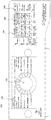
- FIG. 1 is a perspective view of a washing machine according to an embodiment of the present invention.
- FIG. 2 illustrates a main configuration of the washing machine shown in FIG. 1.
- FIG. 3 is a view illustrating a portion of the washing machine shown in FIG. 1;
- FIG. 4 shows the front view of FIG. 2.
- FIG. 6 illustrates a structure in which a circulation hose is fixed.
- FIG. 8A is a partial cutaway view of the vortex nozzle shown in FIG.
- FIG. 8B is a plan view of the nozzle unit of FIG. 7 viewed from above.
- FIG. 11 schematically illustrates a form in which washing water is sprayed through the gasket nozzles.
- FIG. 12 illustrates one embodiment of a control panel.
- FIG. 13 is a block diagram of a washing machine according to an embodiment of the present invention.
- FIG. 14 is a view showing the entire stroke of the washing method according to an embodiment of the present invention.
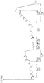
- FIG. 15 is a view showing the rotational speed of the drum in the combined stroke in the washing method shown in FIG.
- 16 is a flowchart illustrating a water pressure measuring method in a washing method according to an embodiment of the present invention.
- 17 is a flowchart illustrating a pump failure determination method in the laundry method according to an embodiment of the present invention.
- FIG. 18 is a flowchart illustrating a pump operating method in the laundry method according to an embodiment of the present invention.
- FIG. 19 is a flowchart illustrating a washing method of a HEAVY DUTY course in the washing method according to an embodiment of the present invention.
- FIG. 1 is a perspective view of a washing machine 100 according to an embodiment of the present invention.
- 2 illustrates a main configuration of the washing machine 100 shown in FIG. 1.
- 3 illustrates a part of the washing machine 100 shown in FIG. 1.
- 4 shows the front view of FIG. 2.
- 5 shows a gasket 120.
- washing machine 100 according to an embodiment of the present invention will be described with reference to FIGS. 1 to 5.
- the casing 110 forms the exterior of the washing machine 100, and a tub 132 containing water is suspended in the casing 110, and a drum 134 in which laundry is accommodated in the tub 132 is rotatable. It is provided.
- the heater 143 for heating the water contained in the tub 132 may be further provided.
- the casing 110 forms the exterior of the washing machine 100 and has a cabinet 111 having an open front and an upper surface, a base 113 supporting the cabinet 111 (see FIG. 4), and laundry to be allowed in and out.
- the laundry entrance hole may include a front cover 112 coupled to the front surface of the cabinet 111, and a top cover 116 provided above the cabinet 111.
- the front cover 112 may be rotatably provided with a door 118 for opening and closing the laundry access hole.
- the glass 118a may be provided in the door 118 to observe the laundry inside the drum 134 from the outside of the washing machine 100.
- the glass 118a may be formed in a convex shape, and the front end of the glass 118a may protrude to the inside of the drum 134 while the door 118 is closed.
- the detergent box 114 accommodates additives such as preliminary or main laundry detergents, fabric softeners, and bleaches, and is provided to be pulled out of the casing 110.
- the tub 132 may be suspended from the top cover 116 by a spring so that vibration generated when the drum 134 is rotated may be dampened, and a damper for supporting the tub 132 from the lower side may be further provided. .
- a plurality of holes are formed in the drum 134 to allow water to flow between the tub 132 and the drum 134, and the laundry may be lifted and dropped according to the rotation of the drum 134.
- One or more lifters 134a may be provided along the inner circumferential surface of the 134.
- the drum 134 may not be disposed completely horizontally, but may be disposed to have a predetermined inclination such that the rear portion of the drum 134 is lower than the horizontal.
- a motor providing a driving force for rotating the drum 134 may be provided.
- the driving force provided from the motor to the drum 134 may be divided into a direct drive method and an indirect drive method.
- the direct drive method the rotating shaft of the motor is directly coupled to the drum 134, and the rotating shaft of the motor and the center of the drum 134 are aligned on the same line.
- the washing machine 100 according to the present embodiment follows the direct driving method, and the drum 134 is rotated by the motor 141 provided in the space between the rear of the tub 132 and the cabinet 111. There is no need to be limited to this, and the indirect driving method described below is also possible.
- Indirect drive method is to rotate the drum 134 by using a power transmission means such as a belt (belt) or pulley (pully) to transfer the driving force provided from the motor, the rotation axis of the motor and the center of the drum 134 must be the same. It does not have to be aligned on line.
- a power transmission means such as a belt (belt) or pulley (pully) to transfer the driving force provided from the motor, the rotation axis of the motor and the center of the drum 134 must be the same. It does not have to be aligned on line.
- a gasket 120 is provided between the casing 110 and the tub 132.
- the gasket 120 prevents water stored in the tub 132 from leaking between the tub 132 and the casing 110.
- One side of the gasket 120 is coupled to the casing 110, the other side is coupled along the circumference of the open front portion of the tub 132.
- the gasket 120 serves to cushion the vibration by elastically folding in accordance with the vibration of the tub 132.
- the gasket 120 may be made of a deformable or flexible material having somewhat elasticity, and may be formed using natural rubber or synthetic resin.
- the washing machine 100 is connected to a hot water source (HW) for supplying hot water, a cold water source (CW) for supplying cold water, and a hot water hose (115a) and a cold water hose (115b), respectively, and a hot water hose (115a) and cold water.
- HW hot water source
- CW cold water source
- a hot water hose (115a) and a cold water hose (115b) respectively, and a hot water hose (115a) and cold water.
- Water introduced through the hose 115b is supplied to the detergent box 114, the steam generator 139, and / or the vortex nozzles 50 and 60 through proper control of the water supply unit 136.
- the water supplied through the cold water hose 115b is transferred to the detergent box 114, the steam generator 139 and / or the vortex nozzles 50 and 60 by the first to fourth water supply valves 136a to 136d. Can be supplied.
- the detergent box 114 is accommodated inside the detergent box housing 117.
- the detergent box housing 117 communicates with the tub 132 through the water supply bellows 133.
- the water supplied by the water supply unit 136 is mixed with the additive via the detergent box 114 and then flows into the tub 132 along the water supply bellows 133 connected to the detergent box housing 117.
- Examples of the additive contained in the detergent box 114 include a laundry detergent, a fabric softener, and a bleach agent.
- the detergent box 114 is provided with a plurality of compartments for accommodating the additives without being mixed with each other. Can be.
- the first water supply hose 131a, the second water supply hose 131b, and the third water supply hose 131c supply water to the detergent box 114, and each lake has a detergent to classify the additives according to their types.
- the first water supply valve 136a, the second water supply valve 136b, and the third water supply valve 136c intercept the first water supply hose 131a, the second water supply hose 131b, and the third water supply hose 131c, respectively. It is.
- the steam generator 139 is a device that generates steam by heating water. Water is supplied to the steam generator 139 through the fourth water supply hose 136d. The steam generated by the steam generator 139 is supplied to the steam nozzles 70 and 80 through the steam supply hose 137.
- the water supplied through the hot water hose 115a flows to the detergent box 114 through the fifth water supply hose 131e, and a hot water valve 136e for controlling the fifth water supply hose 131e may be provided.
- a distributor 119 may be connected to the third water supply hose 131c, and in this case, since water passing through the distributor 119 is distributed to the sixth water supply hose 131f and the seventh water supply hose 131g. , Injection through the vortex nozzles 50 and 60 and water supply via the detergent box 114 are simultaneously performed.
- the laundry in the drum 134 can be wetted effectively, and in particular, there is an advantage that the laundry can be sufficiently wetted with a small amount of water compared to the conventional method in which water supply is only via the detergent box 114.
- the pump 148 drains the water discharged from the tub 132 through the drainage bellows 147 to the outside through the drain hose 149, or the first gasket nozzle 160 and the second gasket nozzle 170. And a pair of circulation hoses 151 and 152 respectively connected to each other. Therefore, when the pump 148 is operated, injection through the gasket nozzles 160 and 170 is made.
- the pump 148 also functions as a drain pump and as a circulation pump.
- the pump for drainage and the pump for circulation are provided separately.
- the water pumped by the pump 148 is simultaneously supplied to the first circulation hose 151 and the second circulation hose 152. Therefore, spraying is simultaneously performed in both directions toward the laundry from the first gasket nozzle 160 and the second gasket nozzle 170.
- the pump 148 may include an impeller rotated by a motor and a pump housing in which the impeller is accommodated.
- the pump housing may include a first discharge port 148a and a second discharge port through which water conveyed by the rotation of the impeller is discharged.
- the discharge port 148b may be formed.
- the first circulation hose 151 may be connected to the first discharge port 148a, and the second circulation hose 148b may be connected to the second discharge port 148b. Since water is discharged from the pump 148 through two discharge ports 148a and 148b independent of each other, water may be supplied to the respective circulation hoses 151 and 152 at the same water pressure.
- FIG. 11 schematically illustrates a form in which washing water is sprayed through the gasket nozzles.
- the laundry 10 is lifted up and dropped by the lifter 134a, and at this time, the first gasket nozzle 160 and the second gasket nozzle ( 170 simultaneously sprays water toward the falling laundry 10.
- This method has an advantage of spraying water evenly toward the laundry 10 regardless of the direction of rotation of the drum 134.
- a distributor may be provided between the pump 148 and the circulation hoses 151 and 152 to alternately spray through the pair of gasket nozzles 160 and 170.
- the drying duct 138 guides the flow of air so that the air inside the tub 132 is discharged to the outside and guided back into the tub 132.
- the drying duct 138 may include a first drying duct 138a and a second drying duct 138b.
- the first drying duct 138a guides air from the tub 132 to the blower 142.
- the first drying duct 138a is connected to the tub 132 on the side where air is introduced and the blower 142 is connected to the side on which the air is discharged.
- the second drying duct 138b guides the air blown by the blower 142 into the tub 132.
- the second drying duct 138b is connected to the blower 142 at the side where air is introduced, and is connected to the gasket 120 or the tub 132 at the side where the air is discharged.
- a duct connecting portion 129 to which the second drying duct 138b is connected to the gasket 120 is formed.
- the duct connecting portion 129 communicates the inside of the drum 134 with the second drying duct 138b.
- An injection unit coupling part 125 to which an injection unit 161 to be described later may be coupled may be formed at an upper portion of the gasket 120, and the injection unit coupling part 125 may include a first insertion insert coupling part 60.
- the insertion hole 125a and the steam inlet pipe 70 may include a second insertion hole 125b into which the coupling is inserted.
- the blower 142 is to blow air to circulate along the drying duct 138, and may include a fan of a suitable type according to the arrangement of the first drying duct 138a and the second drying duct 138b.
- the blower 142 according to the present embodiment includes a centrifugal fan.
- the centrifugal fan is suitable for discharging air sucked from the lower side through the first drying duct 138a to the second drying duct 138b connected laterally.
- a drying heater (not shown) may be provided to remove moisture from the air flowing along the drying duct 138, and the drying heater is pressurized by the blower 142 in the drying duct 138.
- the air may be disposed inside the second drying duct 138b.
- the control panel 180 may include a course selector 182 that receives a course selection from a user, and an input / output unit 184 that receives various control commands from a user and displays an operating state of the washing machine 100.
- the control panel 180 will be described later in more detail with reference to FIG. 12.
- the gasket 120 laundry is separated from the drum 134 under the influence of the rotation of the drum 134, and is sandwiched between the gasket 120 and the casing 110, particularly the front cover 112, or the door 118 after washing is completed.
- the release preventing protrusion 121 may be formed to prevent the laundry from pouring when opened.
- the separation preventing protrusion 121 protrudes from the inner circumferential surface of the gasket 120 toward the laundry access hole.
- the anti-separation protrusion 121 may be formed at a plurality of positions, and in particular, may be respectively formed at positions symmetrical with respect to the vertical center line H of the gasket 120.
- the gasket 120 includes a plurality of gasket nozzles 160 and 170 for spraying water into the drum 134 and a plurality of connectors 123 and 124 for supplying water to the gasket nozzles corresponding to the plurality of gasket nozzles. It may include.
- the water is sprayed by the two gasket nozzles 160 and 170, but the scope of the present invention is not limited thereto, and the water is sprayed into the drum 134 in a plurality of directions. It is also possible to provide a gasket nozzle.
- the gasket nozzles 160 and 170 may be integrally formed with the gasket 120.
- the gasket nozzles 160 and 170 and the gasket 120 may be integrally formed through injection molding of a synthetic resin.
- the gasket nozzles 160 and 170 may protrude from the inner circumferential surface of the gasket 120, and connectors 123 and 124 connected to the circulation hoses 151 and 152 may be formed on the outer circumferential surface of the gasket 120.
- the connectors 123 and 124 connect the first connector 123 connecting the first gasket nozzle 160 and the first circulation hose 151, and the second gasket nozzle 170 and the second circulation hose 152.
- a second connector 124 may be included.
- the first gasket nozzle 160 or the second gasket nozzle 170 injects water into the drum 134, in particular, the water sprayed through the gasket nozzles 160, 170 is the drum 134 It is preferable to extend not only to the inner circumferential surface of the rear wall 134b. In particular, when a small amount of laundry is put into the drum 134, laundry is collected near the rear wall 134b of the drum 134 due to the rotation of the drum 134 or the tilt of the drum 134. The laundry may be wetted with water sprayed from the gasket nozzles 160 and 170.
- the water sprayed from the first gasket nozzle 160 and the water sprayed from the second gasket nozzle 170 are preferably crossed at least once before reaching the rear wall 134b of the drum 134. There is no intersection between the water streams sprayed from the first gasket nozzles 160 and the second gasket nozzles 170, respectively, so that each area of the gasket does not have more than an area where water does not reach the drum 134. This is to allow the sprayed water to reach a wider area even if the sprayed water from the nozzle crosses each other to some extent.
- the tub 132 may be provided with a waiter.
- a waiter is a weight having a considerable weight, and stability of the tub 132 may be maintained even when the drum 134 rotates due to the inertia weighted by the waiter.
- the waiter may be provided in plural on the front portion 132b of the tub 132, the washing machine 100 according to the present embodiment is higher than the horizontal centerline C of the tub 132, and is disposed on the vertical centerline H.
- Two upper waiters 146 are provided in left and right symmetrical forms, and the lower waiter 144 is provided at a lower center than the horizontal center line C of the tub 132.
- the first connector 123 and the second connector 124 may be disposed at both sides of the lower waiter 144, respectively.
- the first gasket nozzle 160 and the second gasket nozzle 170 may be arranged to be symmetrical with respect to the vertical centerline H passing through the center of the gasket 120 so that the washing water is evenly sprayed into the drum 134. have.
- first gasket nozzle 160 and the second gasket nozzle 170 may be provided at both sides of the lower portion of the gasket in a range not exceeding half the height of the gasket 120.
- the first gasket nozzle 160 sprays water upward from the lower left side of the gasket 120 toward the inside of the drum 134, and the second gasket nozzle 170 lower right of the gasket 120. Water is sprayed upwards toward the inside of the drum 134 (see FIG. 11).
- the laundry lifted and dropped by the lifter 134a passes through the spray region formed by the first gasket nozzle 160 and the second spray nozzle 170.
- the sprayed water exerts a strong impact on the laundry, thus making the laundry stretch, thereby improving the processing performance of the laundry.
- the tub 132 may have a holder 135 for fixing the circulation hoses 151 and 152.
- the holder 135 may include a pair of fixed ribs 135a and 135b protruding from the front portion 132b of the tub, and a circulation hose 151 and 152 between the pair of fixed ribs 135a and 135b. Is fixed to insert.
- the fixing ribs 135a and 135b have a bent shape. It is desirable to achieve.
- the clamp 154 is for fixing the circulation hoses 151 and 152 to the tub 132, and surrounds the circulation hoses 151 and 152.
- the boss 156 to which the clamp 154 is fixedly coupled may be formed on the lower outer side of the tub 132.
- the structure in which the circulation hoses 151 and 152 are fixed to the tub 132 by the fixing ribs 135a and 135b and the clamp 154 may be combined with the tub 132 even if vibration occurs during the operation of the washing machine 100. Since the circulation hoses 151 and 152 move integrally, the tension acting on the circulation hoses 151 and 152 can be reduced, thereby reducing the risk of disconnection.
- the circulation hoses 151 and 152 can be fixed through a simple process of fastening the clamp 154, thereby simplifying the assembly process. There is also a termination effect.
- the circulation hoses 151 and 152 may be connected to the connectors 123 and 124 by the connecting pipe 157.
- the circulation hoses 151 and 152 are made of a flexible material, and the connector 123 may also be formed integrally with the soft gasket 120.
- the connection pipe 157 is formed to be relatively hard, and both ends of the connection pipe 157 are connected to the circulation hoses 151 and 152 and the connectors 123 and 124, respectively.
- the fitting between the circulation hoses (151, 152) and the connector (123, 124) can be made easier.
- one end of the circulation hoses 151 and 152 into which the connector tube 157 is inserted is externalized.
- the clamp 158a and the clamp 158b which surrounds one end of the connector 123 and 124 into which the connection pipe 157 is inserted may be further provided.
- FIG. 7 illustrates the nozzle unit 161.
- FIG. 8A is a partial cutaway view of the vortex nozzles 50, 60 shown in FIG. 8B is a plan view of the nozzle unit 161 of FIG. 7 viewed from above.
- a nozzle unit 161 may be provided at an upper portion of the gasket 120.
- the nozzle unit 161 includes a vortex nozzle for injecting water into the drum 134 and a steam nozzle for injecting steam.
- the vortex nozzle and the steam nozzle may be made of a separate configuration independent of each other, of course, hereinafter, the nozzle unit 161 as an assembly of the vortex generating pipe 60, the nozzle cap 190 and the steam inlet pipe 70
- a configuration (50, 60) for generating vortices and injecting into the drum (134) among the configuration of the nozzle unit 161 is called a vortex nozzle (70, 80) for injecting steam into the drum (134)
- a steam nozzle a configuration for generating vortices and injecting into the drum (134)
- the vortex nozzles 50 and 60 convert water supplied through the feed hoses 131c and 131f into vortices and spray the same into the drum 134.
- the vortex nozzles 50 and 60 have a vortex generating pipe 60 connected to the sixth water supply hose 131f, and a vortex nozzle cap 50 for spraying water introduced through the vortex generating pipe 60 into the drum 134. ).
- Vortex nozzle cap 50 is formed on the discharge hole (52h) for discharging the water supplied through the vortex generating pipe (60), and the path of the water discharged through the discharge hole (52h) to move in the water direction It includes a reflector plate 55 that causes interference and allows the flow of water to be dispersed.
- the swirl nozzle cap 50 provides a predetermined space in which water is contained, and the predetermined space communicates with the outside through the discharge hole 52h.
- the water discharged through the discharge hole 52h flows along the discharge path 52 extending in an inclined downward direction and collides with and scatters the reflecting plate 55 formed at the end of the discharge path 52.
- the reflecting plate 55 does not extend in parallel with the water traveling direction along the discharge path 52, but the water flowing along the discharge path 52 may be dispersed by the reflecting plate 55. 52) is preferably formed at a predetermined angle.
- the vortex generating pipe 60 is connected to the sixth water supply passage 131f so as to form a flow path of water therein, and the water flow in the flow path forming tube 61 rotates in a predetermined direction.
- At least one vane for guiding When a plurality of vanes are provided, spaces in the flow path forming tube 61 are divided by each vane, and each space forms a flow path for guiding water independently of each other.
- first vanes 63 and second vanes 65 are rotated in the same direction is formed.
- the vane shaft 62 is formed at the center of the flow path forming tube 61, and the vanes 63 and 65 are formed by connecting the inner circumferential surface of the flow path forming tube 61 and the vane shaft 62.
- the vanes 63 and 65 are rotated along the circumference of the vane shaft 62, proceed in the longitudinal direction of the vane shaft 62, and the boundary at which the inner ends of the vanes 63 and 65 and the vane shaft 62 meet each other,
- the boundary between the outer ends of the vanes 63 and 65 and the flow path forming tube 61 forms a pair of spiral curves parallel to each other.
- water is guided along the vanes 63 and 65 and converted into vortices.
- the water converted into the vortex is evenly sprayed into the drum 134 by the rotational force.
- the vane shaft 62 does not need to extend to correspond to the entire length of the flow path forming tube 61, but is shorter than the entire length of the flow path forming tube 61 along the vane shaft 62, but has a flow path forming tube. It is preferable that the ends 63b and 65b of the vanes 63 and 65 at which the rotation of the water flow is terminated in the 61 extend to the end of the flow path forming tube 61.
- first vane 63 and the second vane 65 are formed such that there is no portion overlapping each other. Therefore, the positional relationship between the start end 63a of the first vane and the end 65b of the second vane, and the positional relationship between the end 63b of the first vane and the start end 65a of the second vane are relative.
- the rotational angle that proceeds from the start end 63a of the first vane to the end 63b and the rotational angle that proceeds from the start end 65a of the second vane to the end 65b are also relative to each other.
- the start end 65a and the end 65b of the second vane 65 may have a vane shaft ( It is to be formed in an area other than the area where the first vane 63 is formed on the plane viewed along the line 62, and the second vane 65 extends from the start end 65a to the end 65b.
- the rotation angle is rotated within the range excluding the rotation angle of 63), that is, the maximum value of (360-x) degrees.
- first vane (63) and the second vane (65) within the range that does not overlap each other, if any one structure is determined, according to the other start, end, extension length, maximum rotation angle, etc.
- the variable is limited within a certain range.
- Vortex generating tube 60 may be formed by injection molding, in which case, careful design is required for easy extraction from the mold in consideration of the structure of the vanes (63, 65) formed therein. As described above, not only do the first vanes 63 and the second vanes 65 overlap each other, but also the vanes 63a and the second vanes when viewed along the longitudinal direction of the vane shaft 62. It is preferable that a predetermined interval is formed between the end 65b of the vane, and similarly, a predetermined interval is also formed between the end 63b of the first vane and the start end 65a of the second vane.
- the interval between the start end 63a of the first vane and the end 65b of the second vane or the gap between the end 63b of the first vane and the start end 65a of the second vane is the core in the injection molding process. Since it is sufficient to move, it may have a small value, and the extension length or the rotation angle of the first vane 63 or the second vane 65 lost by this gap may be negligible.
- the first vane travels from the start end 63a to the end 63b so that each vane has the maximum extension length within the range that the first vane 63 and the second vane 65 do not overlap each other. Is substantially rotated 180 degrees, and the second vane may also be rotated 180 degrees from the start end 65a to the end 65b. (Strictly speaking, the start end 63a of the first vane and the end 65b of the second vane. The loss angle due to the interval between the gaps or the gap between the end 63b of the first vane and the gap 65a of the second vane is present, and the angle of rotation of each vane is less than 180 degrees.
- the first end 63a of the first vane and the first end 65a of the second vane are positioned to be symmetrical with respect to the vane axis 62, and the end 63b of the first vane and the end 65b of the second vane also have a vane axis ( 62) to be symmetrical relative to.
- FIG. 8B illustrates an angle (45 degrees) between the A1 and A2 angles formed between the discharge port 52h of the vortex nozzle cap 50 and the start end 63a of the first vane around the vane shaft 62. It is. This also indicates that the angle formed by the discharge port 52h and the end 63b of the first vane is 135 degrees.
- the reflector plate 55 may include a curved portion 53 for guiding the jetting direction of water collided with the reflecting plate 55 downward, and the curved portion 53 may have a first slope extending on both sides thereof, respectively. It may include a guide surface (53a) and the second falling guide surface (53b). Here, the first lower guide surface 53a and the second lower guide surface 53b may extend with different gradients.
- the gradient of the first lower guide surface 53a and the second lower guide surface 53b may be determined in consideration of the positions of the vortex nozzles 50 and 60 on the gasket 120. That is, when the vortex nozzles 50 and 60 are not located on the vertical center line H of the gasket 120 but are biased to one side, the first drop may be evenly sprayed into the drum 134.
- the gradient of the guide surface 53a and the second falling guide surface 53b can be set differently.
- the lower guide surface 53a for guiding the water sprayed into the region to which the vortex nozzles 50 and 60 belong to the vertical center line H has a larger gradient than the other lower guide surface 53b.
- steam nozzles 70, 80 are aligned on vertical centerline H of gasket 120. Therefore, the vortex nozzles 50 and 60 are disposed in the right region with respect to the vertical center line H, and the gradient of the first falling guide surface 53a through which most of the water injected into the right region is guided is lowered to the second lower portion. It was formed larger than the guide surface 53b.
- the vortex nozzles (50, 60) are arranged at a position biased to one side from the vertical center line (H) Even if it is, it is advantageous to avoid the separation prevention projections 121 formed in the positions symmetrically on both sides with respect to the vertical center line (H) so that the injection of water is made. Since the vortex nozzles 50 and 60 are not located on the vertical center line H, the positional relationship between the vortex nozzles 50 and 60 and one of the release preventing protrusions 121, and the vortex nozzles 50 and 60, Differences occur in the positional relationship between the other departure prevention protrusions 121.
- first lowering guide surface 53a and the second lowering guide surface 53b may be formed with a barrier rib that restricts lateral flow of water flowing along each of the guide surfaces.
- the partition wall may be formed on either the first lowering guide surface 53a or the second lowering guide surface 53b in consideration of the rotation direction of the water flow in the vortex generating pipe 60. That is, since the water flow in the vortex generating pipe 60 is rotated by the vanes 63 and 65, the flow rate of the water guided along the first lower guide surface 53a and the water guided along the second lower guide surface 53b.
- the flow rates have different sizes, and water may be scattered to the surrounding gasket 120 at the side where the water is guided at a relatively strong flow rate among the first lower guide surface 53a and the second lower guide surface 53b. have. Therefore, the partition wall 56 is formed on at least one of the first lowering guide surface 53a and the second lowering guide surface 53b, and in particular, the vane 53 of the first lowering guide surface 53a and the second lowering guide surface 53b. , Considering the rotational direction of 55, it is preferable to form the partition wall 56 on the side where the water of higher flow velocity is guided.
- the rotation direction of the water flow in the vortex generating pipe 60 is counterclockwise (looking from the upper side to the lower side based on FIG. 7), and correspondingly to the first lower guide surface A relatively large flow velocity of water is guided along the second descending guide surface 53b rather than 53a), and a partition wall 56 is formed on the second descending guide surface 53b.
- the first lowering guide surface 53a is formed to have a larger gradient than the second lowering guide surface 53b, and the partition wall 56 is formed on the second lowering guide surface 53b, but the first lowering guide surface 53a is formed. ), And whether the partition 56 is formed on the first lower guide surface 53a or the second lower guide surface 53b, or the second lower guide surface 53b. It is preferably determined in consideration of the above. These variables include the position of the vortex nozzles 50 and 60 on the gasket 120, the position of the release preventing protrusion 121, and the spray angle to avoid the door glass 118a protruding into the drum 134. Can be.
- the steam nozzles 70 and 80 spray the steam supplied through the steam supply hose 137 into the drum 134.
- a steam nozzle cap 80 having a steam inlet pipe 70 fixed to the gasket 120 and connected to the steam supply hose 137 and a steam injection hole 82h for injecting steam introduced through the steam inlet pipe 70. ) May be included.
- the steam nozzle cap 80 may be integrally formed with the vortex nozzle cap 50 to form the nozzle cap 190.
- the nozzle unit 161 may be formed of an assembly in which the vortex generating pipe 60, the steam inlet pipe 70, and the nozzle cap 190 are coupled to each other, respectively, injected into separate members.
- FIG. 9 shows a gasket nozzle. 10 is a cut along the line D-D of FIG.
- FIG. 11 schematically illustrates a form in which washing water is sprayed through the gasket nozzles.
- the gasket 120 includes a casing connection part 128 connected to the casing 110, in particular, the front cover 112, a tub connection part 126 connected to the tub 132, and
- the tub 132 may include a folding portion 127 folded in accordance with the vibration of the tub 132.
- the first gasket nozzle 160 and the second gasket nozzle 170 are arranged symmetrically with respect to the vertical center line H on the gasket 120, and the structure thereof is substantially the same, hereinafter, the second gasket nozzle ( 170) will be described as a reference.
- the gasket nozzle 170 has a spray guide surface 171 for deflecting the advancing direction of the water introduced through the inlet 177a communicating with the connector 124 so that the water is sprayed upward toward the inside of the drum 134.
- a plurality of protrusions 172 arranged along the width direction on the injection guide surface 171.
- the width of the injection guide surface 171 becomes wider gradually along the direction of travel of the water.
- the width of the injection guide surface 171 is D1 at a beginning end at which the water introduced from the inlet 177a starts to be guided, and separation of the guided water along the injection guide surface 171 is performed at the end of the injection.
- the width of is indicated by D2. (D1 ⁇ D2)
- the protrusions 172 are preferably formed close to the end of the injection guide surface 171.
- the width of the injection guide surface 171 at the end of the injection guide surface 171 may be maximum.
- the gasket nozzle 170 communicates with the connector 124 and restricts the lateral flow of the water discharged from the inlet 177a to the injection guide surface 171 and the inlet forming surface 177 having the inlet 177a formed therein.
- it may include a flow path reduction surface 174 to enhance the flow rate of water that proceeds toward the end of the injection guide surface 171. Water passing through the inlet 177a is guided along the flow path surrounded by the injection guide surface 171 and a pair of flow path reduction surfaces 174 respectively formed on both sides of the injection guide surface 171.
- the gap forming surface 173 spaces the injection guide surface 171 from the inlet forming surface 177 on which the inlet 177a is formed.
- the start end of the injection guide surface 171 is spaced apart from the inlet forming surface 177 by the height W of the inlet forming surface 177. Since the injection guide surface 171 is spaced apart from the inlet forming surface 177, it is easy to insert and remove a mold for forming the inlet 177a during injection molding of the gasket nozzle 170.
- the water flowing in through the connector 124 is discharged from the inlet 177a, the flow in the width direction is restricted by the channel reduction surface 174. Therefore, the water flow along the injection guide surface 171 may be a faster and more compressed state. In addition, even when the water pressure is low there is an effect that the water can be smoothly sprayed through the gasket nozzle (170).
- the injection guide surface 171 and the inlet port forming surface 177 are each formed in a shape that gradually widens from the start end to the end, connecting the both ends of the injection guide surface 171 and the inlet opening surface 177, respectively.
- a protrusion protruding from the virtual connection surface to the inside of the gasket nozzle 170 can be formed, in this case the inner width of the gasket nozzle 170 reduced by the protrusion
- the protrusion may include at least two surfaces 174 and 175 protruding inward from the virtual connection surface, and the injection guide surface 171 may be formed.
- the surface extending from the beginning of the can be defined as the channel reduction surface 174, the remaining surfaces 175, as a result of the formation of the channel reduction surface 174, the channel reduction surface 174 and the injection guide surface 171 or inlet formation
- the surfaces are formed subordinately for the connection between the surfaces 171.
- the flow path reducing surface 174 may be defined between two boundaries extending from the gap forming surface 173, and the first boundary 174a is the gap forming surface 173 and the jetting guide surface 171. From this point of contact, the width of the jetting guide surface 171 is extended and extends, and the second boundary 174b gradually reaches the first boundary 174a from the point where the gap forming surface 173 and the inlet forming surface 177 meet. It is extended as it converges. In this case, the first boundary 174a may extend from the start end of the injection guide surface 171.
- the gasket nozzle 170 protrudes from the inside of the gasket 120.
- the laundry is rotated together with the drum 134 and the outer curved portion 176 may be formed at both outer ends of the gasket nozzle 170 to minimize the damage of the laundry when the laundry is rotated.
- the outer curved portion 176 may have the smallest curvature value at a portion that meets the inner circumferential surface of the gasket 120.
- the gasket 120 may be formed with a nozzle avoiding part 127a which avoids the gasket nozzle 170 and forms a predetermined interval t between the gasket nozzle 170. Even if the gasket 120 is deformed during the vibration of the tub 132, the gasket 120 and the gasket nozzle are formed by the buffering effect due to the gap t formed between the nozzle avoiding part 127a and the gasket nozzle 170. Deformation due to the compression between the 170 and the resulting change in the injection direction of the gasket nozzle 170 can be prevented.
- the spray through the gasket nozzle 170 basically forms a water film having a significantly thinner thickness than the width thereof.
- the thickness of the water film is relatively thick between the projections 172 and the projections 172, and in a portion that rides over the projections 172. Since the thickness of the water film is thin, due to such a thickness difference of the water film, the final injection form is a form in which a plurality of main injection streams with strong water flow strength are connected by a thin water film.
- the water sprayed in this form can treat the contaminants accumulated in the laundry by the main jetting flow with a strong impact, and the washing force is improved by expanding the laundry, and the spraying area is still sufficiently secured by the water film. There is an advantage that can be.
- FIG. 12 illustrates a control panel of a washing machine according to an embodiment of the present invention.
- the control panel 180 is disposed above the front of the casing 110.
- the control panel 180 includes a course selection unit 182 for selecting a washing course by the user, a course display unit 181 for displaying a selectable washing course, and various operation commands such as operation time and reservation for each stroke. And an input / output unit 184 which displays the course information according to the course selection of the user or other information according to the input command and the operation state during the operation of the washing machine.
- the course selector 182 receives the washing course selected by the user.
- the course selector 182 may be formed of various types of input devices such as a button and a touch screen. In this embodiment, the course selector 182 is a knob.
- the washing course determines the stages of each stroke throughout the washing according to the type and function of the laundry.
- the cotton / normal (COTTON / NORMAL) course the towel (TOWELS) course, and the bulk (BULKY / LARGE) course , BRIGHT WHITE, SANITARY COURSE, ALLERGIENE COURSE, TUB CLEAN COURSE, HEAVY DUTY COURSE, PERM.
- PRESS COURSE HAND WASH / WOOL
- DELICATES course SPEED WASH course, DOWNLOAD course.
- Each course can be divided into washing administration, rinsing administration, dehydration administration, combined administration, etc., and each administration is performed by water supply, washing, rinsing, draining, dehydration and drying.
- the course display unit 181 displays a washing course selectable by the user through the course selector 182.
- the course display unit 181 may be integrated with the course selector 182 and implemented as a touch screen. In the present embodiment, the course display unit 181 may be printed and displayed around the knob selector 182.
- the course display unit 181 includes a cotton / normal course, a towel course, a bulk / large course, a white course, a sanitary course, and an allergiene.
- Course TUB CLEAN course, HEAVY DUTY course, PERM.PRESS course, HAND WASH / WOOL course, DELICATES course, SPEED WASH Course, DOWNLOAD course is displayed.
- the input / output unit 184 may be configured of a plurality of buttons and a screen or implemented as a touch screen.
- the input / output unit 184 circulates the water contained in the tub 132 by the washing time display unit 186 displaying the expected washing time, and sprays the drum 134 through the gasket nozzles 160 and 170 to wash the laundry.
- a turbo rinse is performed to circulate the water contained in the turbo washing and / or tub 132 and spray through the gasket nozzles 160 and 170 to rinse the laundry or the drum through the vortex nozzles 50 and 60 to convert the water into a vortex.
- 134 includes a turbo wash button 185 for setting up a turbo wash in which filtration rinsing is performed to rinse the laundry by spraying water.
- the washing time display unit 186 displays an estimated washing time before starting washing.
- the estimated washing time according to the washing course in which the course is input through the course selecting unit 182 is displayed.
- the turbo wash button 185 the changed estimated washing time according to the turbo wash is displayed.
- the washing time display unit 186 displays washing time remaining during washing.
- the turbo wash button 185 is a button for setting turbo wash by the user. When the user presses the turbo wash button 185, the turbo wash is set, and when pressed again, the turbo wash is released and the general wash is set. When the turbo wash is set, the turbo wash button 185 illuminates to indicate that the turbo wash is set.
- the washing time display unit 186 displays the changed estimated washing time.
- the expected wash time is reduced in the same wash course. Therefore, the estimated washing time displayed on the washing time display unit 186 is reduced when the turbo washing is set, and the expected washing time displayed on the washing time display unit 186 is increased when the washing of the turbo is released and the general washing is set.
- Turbo washing rotates the drum 134 in the selected washing course and circulates the water mixed with the laundry detergent and sprays the laundry through the gasket nozzles 160 and 170 into the drum 134 to wash the laundry.
- 134 is rotated to circulate the water mixed with the rinsing detergent to perform a turbo rinsing to spray into the drum 134 through the gasket nozzles (160, 170).
- a detailed description of the turbo washing and the turbo rinsing will be described later with reference to FIG. 14.
- Turbo washing rotates the drum 134 at high speed so that the laundry adheres to the drum 134 in the selected washing course and converts the water without mixing the detergent into the vortex through the vortex nozzles 50 and 60 to form the drum 134. It is to perform a filtration rinse to spray into. Detailed description of the filtration rinse will be described later with reference to FIG. 14.
- Turbo washing cannot be performed at all wash courses. Therefore, some washing courses cannot set up a turbo wash. In addition, turbo washing may be set as a default in certain washing courses or turbo washing may be released as a default in another washing course.
- the turbo wash button 185 is displayed with a tornado turbo wash icon indicating turbo wash.
- the course display unit 181 displays a turbo wash icon next to the name of the wash course for which turbo wash is selectable. That is, the washing course in which the turbo washing icon is not displayed on the course display unit 181 may not be turbo-washed.
- turbo washing can be set or not is set as shown in Table 1 below.
- turbo washing cannot be set in the HAND WASH / WOOL course and the DELICATES course. Therefore, when the HAND WASH / WOOL course and the DELICATES course are selected in the course selector 182, the turbo wash is not set even when the turbo wash button 185 is pressed.
- turbo wash setting is available and turbo wash is set by default. Accordingly, when the COTTON / NORMAL course and the PERM.PRESS course are selected in the course selector 182, the turbo wash is basically set, and the turbo wash button 185 is released.
- the DOWNLOAD course determines whether turbo washing can be set or not, depending on the course downloaded from the network or peripherals.
- FIG. 13 is a block diagram of a washing machine according to an embodiment of the present invention.
- the water level sensor 145 measures the level of water contained in the tub 132.
- the water level sensor 145 is a pressure sensor for measuring the air pressure in the water level sensor tube (not shown) connected to the tub 132 and measures the water level of the water contained in the tub 132 from the detected air pressure.
- the controller 199 controls the overall operation of the washing machine according to the operation command received by the course selector 182 and / or the input / output unit 184.
- the control unit 199 is preferably provided in the control panel 180.
- the controller 199 may be configured of a microcomputer and other electronic components that control the operation of the washing machine.
- the control unit 199 determines whether or not each stroke is in progress or water supply, washing, rinsing, and draining depending on whether or not the washing course selected through the course selection unit 182 and the turbo washing setting through the turbo washing button 185 are set. And, determine whether the operation, such as dehydration and drying, the number of iterations and the like, and performs this.
- the controller 199 controls the water supply unit 136, the motor 141, and the pump 148 according to whether the selected washing course or turbo washing is set.
- Figure 14 is a view showing the entire stroke of the washing method according to an embodiment of the present invention
- Figure 15 is a view showing the rotational speed of the drum during the complex stroke in the washing method shown in FIG.
- the washing method according to an embodiment of the present invention may be performed when the user sets turbo washing through the course selection unit 182 and / or the turbo washing button 185.
- a general cotton / normal course may be a washing method to be described later.
- the laundry administration 210 is a stroke for removing contaminants from the laundry by rotating the drum 134 after the water mixed with the laundry detergent is wetted with the laundry.
- the washing administration 210 includes a water supply 211, a turbo washing 212, and a drain 213.
- control unit 199 displays a washing icon on the progress display of the input / output unit 184 to indicate that the washing administration 210 is started.
- the water supply 211 supplies water into the tub 132 from an external water source.
- the water supply 211 includes a quantity detection 211a, an initial water supply 211b, a bubble core 211c, and an additional water supply 211d.
- the quantity detection 211a detects the amount of laundry contained in the drum 134 (hereinafter, referred to as 'capacity').
- the quantity can be measured in various ways. In this embodiment, after the motor 141 rotates the drum 134 at a constant speed for a predetermined time, the control unit 199 measures the deceleration time. Measure with
- the controller 199 may calculate an amount of air by measuring an acceleration time when accelerating the drum 134.
- the control unit 199 determines the amount of water supplied into the tub 132 at the time of the initial water supply 211b and the additional water supply 211d according to the detected quantity of water, and sprays the drum 134 during the filtration rinses 222 and 228 which will be described later. Determine the amount of water added and the other operating hours for each stroke.
- the initial water supply 211b supplies water mixed with a laundry detergent into the tub 132 and sprays water not mixed with the detergent into the drum 134.
- the control unit 199 opens the first water supply valve 136a of the water supply unit 136 so that water does not mix with the laundry detergent in the detergent box 114 and flows into the tub 132 through the water supply bellows 133.
- water may be mixed with the laundry detergent in the detergent box 114, and then introduced into the tub 132 through the water supply bellows 133.
- the first water supply valve 136a is opened so that water flows into the tub 132 may be divided into intermittent water and continuous water.
- the first water supply valve 136a is intermittently opened to supply water.
- the first water supply valve 136a is continuously opened to supply water.
- control unit 199 opens the third water supply valve 136c during the initial water supply 211b while spraying water into which the laundry detergent is not mixed into the drum 134 through the vortex nozzles 50 and 60.
- the second water supply valve 136b may be opened to mix water with the laundry detergent in the detergent box 114 and then flow into the tub 132 through the water supply bellows 133.
- the hot water valve 136e of the water supply unit 136 may be opened to introduce hot water into the tub 132.
- the initial water supply 211b proceeds until water reaches the target water level.
- the target water level is determined by the controller 199 according to the measured quantity or the selected course measured before the initial water supply 211b. In this embodiment, water rises slightly to the drum 134. The target water level is sufficient if the amount of water can be circulated at the time of bubbling 211c.
- the water level of the initial water supply 211b is preferably measured by the water level sensor 145.
- the controller 199 blocks the valve of the water supply unit 136 to finish the initial water supply 211b.
- the coating core 211c rotates the drum 134 by driving the motor 141 so that the water mixed with the laundry detergent is uniformly wetted with water and the laundry detergent is dissolved.
- the buoyancy control unit 199 may operate the pump 148 to circulate water along the circulation hoses 151 and 152 to be sprayed into the drum 134 through the gasket nozzles 160 and 170. have.
- the additional water supply 211d is to supply additional water into the tub 132 up to the target water level because the water is soaked in the laundry and the water level is lower than the target water level.
- the control unit 199 opens various valves of the first water supply valve 131a, the second water supply valve 131b, or the water supply unit 136, water is supplied from the external water supply bellows 133. Can be supplied through.
- the controller 199 blocks the various valves of the first water supply valve 131a, the second water supply valve 131b, or the water supply unit 136 to supply additional water 211d. To finish.
- the additional water supply 211d may be omitted since the water level is not lowered at the time of the lamination core 211c.
- the turbo washing 212 rotates the drum 134 containing laundry, circulates water mixed with laundry detergent, and sprays the drum 134 through the gasket nozzles 160 and 170 to remove contamination of the laundry.
- the control unit 199 controls the motor 141 to rotate the drum 134 at various speeds or directions to repeatedly wash the laundry. Applying mechanical force such as impact force removes laundry contamination.
- foam dispersion to be described later may be performed before the turbo washing 212.
- the controller 199 may allow the driving of the motor 141 to be rested for several seconds to several minutes.
- Turbo washing 212 is performed when the user sets turbo cleaning via course selector 182 and / or turbo wash button 185.
- control unit 199 operates the pump 148 to circulate water mixed with the laundry detergent in the tub 132 along the circulation hoses 151 and 152 through the gasket nozzles 160 and 170. Spray. If the amount of water circulated is too much foam can be generated a lot of water is preferably circulated to the extent possible.
- the pump 148 may be determined to be normal, and when the pump 148 is broken, the turbo washing may be canceled and general washing may be performed. Detailed description thereof will be described later with reference to FIG. 17.
- the pump 148 is operated when the motor 141 is stopped to prevent overheating and reduce the maximum power consumption. Can be. Detailed description thereof will be described later with reference to FIGS. 18 and 19.
- the control unit 199 opens the third water supply valve 131c of the water supply unit 136 so that water flows through the distributor 135 to the fifth water supply hose 131g, and then the detergent box 114 After mixing with the bleach may be introduced into the tub 132 through the water supply bellows 133. This bleach supply proceeds until the water level reaches the target level.
- the controller 199 blocks the third water supply valve 131c of the water supply unit 136.
- the supply of water mixed with bleach is preferably carried out in the last step of the turbo washing 212 just before the end of the turbo washing 212.
- the drain 213 discharges the water in the tub 132 to the outside.
- the control unit 199 operates the pump 148 to discharge the water in the tub 132 along the drain hose 149 to the outside during the drainage 213.
- the drum 134 may stop at the time of drainage 213, but may rotate while maintaining the speed at the time of turbo washing 212.
- the turbo washing 212 may proceed to general washing according to the setting of the turbo washing.
- the turbo washing 212 proceeds to general washing.
- control unit 199 rotates the drum 134 by controlling the motor 141, but does not operate the pump 148, so that water is not circulated and sprayed through the gasket nozzles 160 and 170.
- the complex stroke 220 is a stroke for removing the residual detergent of laundry and dewatering the laundry.
- a rinsing stroke and a dehydration stroke are combined.
- the composite stroke 220 is a podisic acid 221, filtration rinsing 222, simple dewatering 223, water supply 224, turbo rinsing 225, drainage 226, formic acid 227, filtration rinsing 228 ) And bone dehydration 229.
- the controller 199 preferably displays a rinsing and / or dehydration icon on the progress display of the input / output unit 184.
- Fossil dispersion 221 is to disperse laundry by repeating the deceleration while the drum 134 maintains a constant speed after acceleration.
- the filtration rinse 222 and / or the simple dewatering 223 may cause the laundry to deviate to one side due to entanglement of the laundry, an eccentricity of which one side becomes heavy with respect to the center of the drum may be caused. Since the eccentricity of the laundry causes noise and vibration during the high speed rotation of the drum 134, the laundry is uniformly distributed before the filtration rinse 222 and / or the simple dewatering 223.
- the foam dispersion 221 is repeated by accelerating and maintaining a constant speed after accelerating the drum 134 as shown in FIG.
- water may be sprayed toward the laundry through the gasket nozzles 160 and 170 or the vortex nozzles 50 and 60 during the podis dispersion 221.
- the filtration rinse 222 is sprayed into the drum through the vortex nozzles 50 and 60 when the drum 134 is rotated to rotate the laundry attached to the drum through the vortex nozzles 50 and 60, the water penetrates the laundry and the residual detergent and The contamination is removed.
- the control unit 199 controls the motor 141 to rotate the drum so that the laundry adheres to the drum 134, and the third water supply valve 131c is opened to allow the water to vortex the nozzles 50 and 60. It is sprayed into the drum 134 through.
- the control unit 199 operates the pump 148 so that the water in the tub 132 is discharged to the outside along the drain hose 149.
- Filtration rinse 222 is performed when the user sets turbo wash through course selector 182 and / or turbo wash button 185.
- the drum 134 is rotated at a speed of 1G, ie 108 rpm or more, where the laundry is attached to the drum 134 and rotated.
- Laundry during the filtration rinse 222 is preferably stuck to the drum 134 does not fall.
- the laundry does not fall from the drum 134, which includes some of the laundry falling for a while, which means that most of the laundry is stuck to the drum 134 for most of the time.
- the drum 134 is preferably maintained at a constant speed, and in some embodiments, the drum 134 may be accelerated. In the present embodiment, during the filtration rinse 222, the drum 134 is accelerated from 400 rpm to 600 rpm and then maintained at 600 rpm.
- Simple dewatering 223 is to rotate the drum 134 at high speed so that the water soaked in the laundry out.
- the control unit 199 stops the water injection by closing the third water supply valve 131c after the filtration rinse 222, and the drum at a speed higher than the speed at which the laundry adheres to the drum 134 and rotates without decelerating or stopping the drum 134. Rotate or accelerate 134 continuously.
- the expression “continuously” means that the drum 134 rotates without stopping between steps, and includes the speed of the drum 134 changing as the drum 134 accelerates or decelerates.
- the drum 134 is preferably rotated at about 700 rpm.
- the control unit 199 operates the pump 148 intermittently to discharge water in the tub 132 to the outside along the drain hose 149.
- the simple dewatering 223 does not perform podis dispersion separately between the filtration rinsing 222 and the simple dewatering 223 by accelerating and progressing the drum 134 without stopping or decelerating the drum 134 in the filtration rinsing 222. . That is, the filtration rinse 222 and the simple dewatering 223 are continuously performed without podis dispersion, thereby shortening the overall time and reducing porosity.
- the drum 134 may maintain the speed at which the laundry adheres to the drum 134 or more so that no dispersion is required. It is preferable. That is, the drum 134 from the filtration rinse 222 to the simple dehydration 223 is continuously rotated at a speed of 1 G, that is, 108 rpm or more, in which the laundry is attached to the drum 134 so that the laundry is not stuck to the drum 134. It is preferable not to.
- the above-described filtration rinse 222 is a process that is substantially performed in the simple dewatering 223.
- the control unit 199 controls the third water supply valve 131c.
- the filtration rinse 222 is performed while water is opened and water is injected into the drum 134 through the vortex nozzles 50 and 60. Accordingly, the filtration rinse 222 may be performed at any time when the drum 134 is accelerated or maintained in the simple dewatering 223 when the turbo washing is set, and may be performed in a plurality of times. That is, the filtration rinse 222 may be performed at any time in the middle of the simple dewatering 223 as well as after the dewatering 223 after the podis dispersion 221.
- the end of the simple dehydration 223 is not performed, and after the filtration rinse 222, the simple dehydration 223 is preferably resumed.
- the water supply 224 supplies water into the tub 132 from an external water source similarly to the water supply 211 of the washing stroke 210 described above.
- the water supply 224 may include an initial water supply, a buckle core, and an additional water supply.
- the control unit 199 opens the first water supply valve 136a and the second water supply valve 136b so that the water is mixed with the rinsing detergent in the detergent box 114 and then through the water supply bellows 133.
- Rinsing detergents are common in fabric softeners, but may be various functional detergents, such as detergents that produce other aromas.
- the third water supply valve 136c may be opened to spray water into which the laundry detergent is not mixed into the drum 134 through the vortex nozzles 50 and 60.
- the drum 134 is stopped at the water supply 224, but the water supply 224 is at a 1G speed at which the drum 134 rotates after the simple dewatering 223 and the laundry adheres to the drum 134, that is, 108 rpm or more. It may be performed after deceleration.
- the turbo rinse 225 rotates the drum 134 containing the laundry, circulates water mixed with the rinsing detergent, and sprays the drum 134 through the gasket nozzles 160 and 170 to remove residual detergent and contamination of the laundry.
- the control unit 199 controls the motor 141 to rotate the drum 134 at various speeds or directions to repeatedly wash and drop the laundry to apply mechanical force such as stretching force, friction force, and impact force to the laundry. Residual detergent and contamination of the laundry is removed.
- podis dispersion which will be described later, may be performed before the turbo rinse 225.
- the controller 199 may allow the driving of the motor 141 to be rested for several seconds to several minutes.
- the turbo rinse 225 is performed when the user sets the turbo wash through the course selector 182 and / or the turbo wash button 185.
- the turbo rinse 225 proceeds to the normal rinse.
- the control unit 199 rotates the drum 134 by controlling the motor 141 but does not operate the pump 148 so that water is not circulated and is not sprayed through the gasket nozzles 160 and 170.
- the control unit 199 operates the pump 148 to circulate water mixed with the rinsing detergent in the tub 132 along the circulation hoses 151 and 152 through the gasket nozzles 160 and 170. Spray. If the amount of water circulated is too much foam can be generated a lot of water is preferably circulated to the extent possible.
- the pump 148 may be determined to be normal, and when the pump 148 is broken, the turbo washing may be released and a general rinsing may be performed. Detailed description thereof will be described later with reference to FIG. 17.
- the pump 148 is operated when the motor 141 is stopped to prevent overheating and reduce the maximum power consumption. Can be. Detailed description thereof will be described later with reference to FIGS. 18 and 19.
- the drain 226 discharges the water in the tub 132 to the outside similarly to the drain 213 of the washing stroke 210 described above.
- the above-described water supply 224, turbo rinsing 225, and drainage 226 may be embodied or omitted in other forms.
- the water supply 224, the turbo rinsing 225, and the drainage 226 may be performed without the drum 134 being stopped due to the deceleration of the drum 134 after the simple dewatering 223. ) May be omitted.
- Fossil dispersion 227 disperses laundry by repeating the deceleration of the drum 134 while maintaining a constant speed after acceleration, similarly to the above-mentioned dispersion 221.
- Fo Dispersion 227 is to evenly distribute the laundry before the filtration rinse 228 and / or the main dewatering 228, it is repeated to accelerate the drum 134 as shown in Figure 15 after maintaining a constant speed Lose.
- water may be sprayed toward the laundry through the gasket nozzles 160 and 170 or the vortex nozzles 50 and 60 during the podis dispersion 227.
- the filtration rinse 228 is similar to the filtration rinse 222 described above, when the drum 134 is rotated and the laundry adheres to the drum, water is not mixed with the detergent and is sprayed into the drum so that the water penetrates the laundry, and the residual detergent and The contamination is removed.
- control unit 199 controls the motor 141 to rotate the drum so that the laundry adheres to the drum 134, and the third water supply valve 131c is opened to allow the water to vortex the nozzles 50 and 60. It is sprayed into the drum 134 through.
- control unit 199 operates the pump 148 so that the water in the tub 132 is discharged to the outside along the drain hose 149.
- Filtration rinse 228 is performed when the user sets turbo wash through course selector 182 and / or turbo wash button 185.
- the drum 134 is rotated at a speed of 108 rpm, which is a 1 G speed, that is, the speed of dispersing the laundry is attached to the drum 134.
- Laundry in the filtration rinse 228 is preferably attached to the drum 134 does not fall.
- the drum 134 is preferably maintained at a constant speed during the filtration rinse 228, and in some embodiments, the drum 134 may be accelerated. In the present embodiment, during the filtration rinse 228, the drum 134 is maintained at 1000 rpm and then accelerated at 1060 rpm.
- the main dewatering 229 rotates the drum 134 at high speed so that the water soaked in the laundry exits, similarly to the simple dewatering 223.
- the control unit 199 stops spraying water by closing the third water supply valve 131c after the filtration rinse 228, and the drum is rotated at or above the speed at which the laundry adheres to the drum 134 without decelerating or stopping the drum 134. Rotate or accelerate 134 continuously.
- the drum 134 In the main dewatering 229, it is preferable to rotate the drum 134 to a maximum speed of 1000 rpm or more so that the laundry is dried as much as possible. In this embodiment, the drum 134 rotates up to 1300 rpm.
- the control unit 199 intermittently operates the pump 148 at the time of the main dehydration 229 so that the water in the tub 132 is discharged to the outside along the drain hose 149.
- the main dewatering 229 does not carry out podispersion separately between the filtration rinsing 228 and the main dewatering 229 by accelerating and progressing the drum 134 without stopping or decelerating the drum 134 in the filtration rinse 228. .
- Filtration rinsing 228 and main dewatering 229 are performed continuously without podis dispersion, thereby reducing the overall time and reducing the porosity.
- the drum 134 maintains at least a speed at which laundry is attached to the drum 134 so that no dispersion is required even if the drum 134 decelerates between the filtration rinse 228 and the main dewatering 229. It is preferable. That is, from the filtration rinse 228 to the main dehydration 229, the drum 134 is continuously rotated at a speed of 1 G at which the laundry is attached to the drum 134, that is, 108 rpm or more, so that the laundry is not stuck to the drum 134. It is preferable not to.
- the above-described filtration rinse 228 is a process that is substantially performed in the main dehydration 229, and when the main dehydration 229 is performed after the podis dispersion 227, the control unit 199 opens the third water supply valve 131c. Filtration rinsing 228 is performed while opening so that water is sprayed into the drum 134 through the vortex nozzles 50, 60. Accordingly, the filtration rinse 228 may be performed at any time when the drum 134 is accelerated or maintained in the main dewatering 229 when the turbo washing is set, and may be performed in a plurality of times. That is, the filtration rinse 228 may be performed at any time in the middle of the dewatering 229 as well as after the dewatering 227 before the dewatering 229.
- the end of the main dehydration 229 is not performed, and after the filtration rinse 228, the main dehydration 229 is preferably resumed.
- drying may be performed to supply hot air into the drum 134 to dry the laundry.
- Each step of the complex stroke 220 described above may be modified or omitted.
- 16 is a flowchart illustrating a water pressure measuring method in a washing method according to an embodiment of the present invention.
- the user sets the turbo wash through the course selector 182 and / or the turbo wash button 185 (S310).
- Turbo washing rotates the drum 134 in the selected washing course and rotates the turbo washing and / or drum 134 which circulates water mixed with laundry detergent and sprays the drum 134 through the gasket nozzles 160 and 170.
- it is to perform a turbo rinsing to circulate the water mixed with the rinsing detergent is sprayed into the drum 134 through the gasket nozzles (160, 170).
- turbo cleaning is sprayed by the drum 134 in the selected washing course when the laundry is attached to the drum 134 to rotate the water is not mixed with detergent through the vortex nozzles (50, 60) into the drum (134) To perform a filtration rinse to rinse the laundry.
- the washing stroke 210 is started and water supply 211 is performed.
- the initial water supply 211b is performed after the quantity detection 211a is performed.
- the control unit 199 intermittently opens the first water supply valve 136a, intermittent water flow into the tub 132 through the water supply bellows 133 is performed (S320).
- the intermittent water supply is performed six times at 0.3 second intervals.
- control unit 199 After the intermittent water supply, the control unit 199 operates a timer to accumulate time, and opens the first water supply valve 136a to start continuous water supply of water into the tub 132 through the water supply bellows 133 ( S330).
- the timer is a time accumulator included in the controller 199 and starts with the start of the continuous water supply. When the continuous water starts, water is supplied into the tub 132.
- the controller 199 determines whether the water level of the water accommodated in the tub 132 measured by the water level sensor 145 reaches the target water level (S340). When the water level does not reach the target water level, the controller 199 continues the continuous water supply and continuously accumulates time with a timer.
- the controller 199 ends the continuous water supply and ends the timer (S350).
- the controller 199 closes the first water supply valve 136a and stops the timer to calculate the accumulated time.
- the controller 199 determines whether the continuous water supply time integrated in the timer is greater than the target time (S360). The controller 199 compares the continuous water supply time, which is the time taken for the water level in the tub 132 to reach the target water level, through the continuous water supply to the target time.
- the controller 199 determines that the water pressure of the cold water source C.W is normal and proceeds with the turbo washing (S390).
- the control unit 199 performs the turbo washing 213 at the washing stroke 210, and the filtration rinsing at the combined stroke 220 (222, 228), and turbo rinsing (225) Do this.
- the control unit 199 determines that the water pressure of the cold water source C.W is low and displays that the turbo washing is released (S370).
- the controller 199 releases the turbo washing, displays the turbo washing release on the input / output unit 184, or turns off the turbo washing button 185 several times.
- control unit 199 After the turbo washing is released, the control unit 199 performs general washing (S380). The control unit 199 performs general washing in the washing stroke 210 and does not perform filtration rinsing 222 and 228 in the complex stroke 220 and performs general rinsing.
- 17 is a flowchart illustrating a pump failure determination method in the laundry method according to an embodiment of the present invention.
- the user sets the turbo wash through the course selector 182 and / or the turbo wash button 185 (S410).
- Turbo washing rotates the drum 134 in the selected washing course and rotates the turbo washing and / or drum 134 which circulates water mixed with laundry detergent and sprays the drum 134 through the gasket nozzles 160 and 170.
- it is to perform a turbo rinsing to circulate the water mixed with the rinsing detergent is sprayed into the drum 134 through the gasket nozzles (160, 170).
- turbo cleaning is sprayed by the drum 134 in the selected washing course when the laundry is attached to the drum 134 to rotate the water is not mixed with detergent through the vortex nozzles (50, 60) into the drum (134) To perform a filtration rinse to rinse the laundry.
- the washing administration 210 is started, and the control unit 199 performs the water supply 211 (S420).
- the water supply 211 supplies water into the tub 132 from an external water source.
- the control unit 199 opens various valves of the water supply unit 136 such as the first water supply valve 131a or the second water supply valve 131b so that water from the external water source is supplied through the water supply bellows 133. To be supplied.
- the control unit 199 operates the pump 148 to circulate the water (S430).
- water mixed with laundry detergent in the tub 132 is circulated along the circulation hoses 151 and 152 and sprayed through the gasket nozzles 160 and 170.
- the controller 199 determines whether the water level of the water contained in the tub 132 measured by the water level sensor 145 is lower than the set water level (S440).
- the controller 199 determines whether the pump 148 is broken by comparing the measured water level of the water contained in the tub 132 measured by the water level sensor 145 when the pump 148 is operated.
- the controller 199 determines that the pump 148 is normally operated and proceeds with the turbo washing (S450).
- the controller 199 performs the turbo washing 213 when the measured water level is lower than the set water level.
- the control unit 199 performs filtration rinsing (222, 228), and turbo rinsing (225) in the complex stroke 220.
- the control unit 199 determines that the pump 148 is broken and stops the operation of the pump 148 to indicate that the turbo washing is released.
- the controller 199 stops the operation of the pump 148 when the measured water level is lower than the set water level.
- the controller 199 releases the turbo washing and displays the turbo washing release on the input / output unit 184 or turns off the turbo washing button 185 several times.
- the controller 199 performs additional water supply (S480). Since more water is required for general cleaning than turbo cleaning, the control unit 199 opens various valves of the water supply unit 136 such as the first water supply valve 131a or the second water supply valve 131b to supply water from an external source. Supply through the bellows 133.
- control unit 199 When the additional water supply is completed, the control unit 199 performs general washing (S490). The control unit 199 performs general washing. In addition, the control unit 199 does not perform the filtration rinses 222 and 228 in the complex stroke 220 and performs general rinsing.
- the washing method described above has been described based on the water supply 211 and the turbo washing 212 of the washing stroke 210 may be applied to the water supply 224 and the turbo rinsing 225 of the complex stroke 220.
- FIG. 18 is a flowchart illustrating a pump operating method in the laundry method according to an embodiment of the present invention.
- the user sets the turbo wash through the course selector 182 and / or the turbo wash button 185 (S510).
- Turbo washing rotates the drum 134 in the selected washing course and rotates the turbo washing and / or drum 134 which circulates water mixed with laundry detergent and sprays the drum 134 through the gasket nozzles 160 and 170.
- it is to perform a turbo rinsing to circulate the water mixed with the rinsing detergent is sprayed into the drum 134 through the gasket nozzles (160, 170).
- turbo cleaning is sprayed by the drum 134 in the selected washing course when the laundry is attached to the drum 134 to rotate the water is not mixed with detergent through the vortex nozzles (50, 60) into the drum (134) To perform a filtration rinse to rinse the laundry.
- the washing stroke 210 is started and water supply 211 is performed.
- the quantity detection 211a is performed (S520).
- the quantity detection 211a detects an amount of laundry, which is an amount of laundry contained in the drum 134.
- the controller 199 controls the motor 141 to rotate the drum 134 at a constant speed for a predetermined time, and then brakes to measure a deceleration time to measure a quantity.
- the controller 199 determines whether the detected amount is larger than the reference amount (S530). The controller 199 compares the detected quantity after the quantity detection 211a with the reference quantity.
- the turbo washing unit 212 or the turbo rinse 225 during the control unit 199 operates the pump 148 to operate the motor 141 to circulate the water (S540).
- the control unit 199 operates the motor 141 to operate the pump 148 when the drum 134 rotates to circulate water in the tub 132. 152 is circulated along and sprayed through the gasket nozzles 160 and 170.
- the control unit 199 When the detected amount is larger than the reference amount, when the turbo washing 212 or turbo rinsing 225, the control unit 199 operates the pump 148 to stop the motor 141 to circulate the water (S550). When the detected amount is larger than the reference amount, overheating may occur in the motor 141, and power consumption may increase. Accordingly, during turbo washing 212 or turbo rinsing 225, the control unit 199 stops the motor 141 and operates the pump 148 to circulate the water in the tub 132 when the drum 134 decelerates or stops. It circulates along the hoses 151 and 152 and sprays it into the drum 134 through the gasket nozzles 160 and 170. FIG. In this case, washing or rinsing performance is somewhat reduced, but it can prevent overheating and reduce the maximum power consumption.
- FIG. 19 is a flowchart illustrating a washing method of a HEAVY DUTY course in the washing method according to an embodiment of the present invention.
- the HEAVY DUTY course is set (S610).
- HEAVY DUTY COURSES may be chosen for heavy laundry or heavy contamination of the laundry.
- the turbo wash is off by default as described above.
- Turbo washing is released and the general washing is set (S620). If the user starts the wash while maintaining the normal wash, which is the default setting for the HEAVY DUTY course, the turbo wash is released and the normal wash is set.
- control unit 199 circulates water by operating the pump 148 when the motor 141 stops when washing or rinsing (S630).
- general washing is performed in place of the turbo washing 212 in another washing course and general rinsing is performed in place of the turbo rinsing 225, but in the HEAVY DUTY course, the washing of the turbo 212 and / or the turbo rinsing 225 is performed. This is done. In this case, filtration rinses 222 and 228 are not performed.
- the control unit 199 at the time of the turbo washing 212 or the turbo rinsing 225 stops the motor 141 and operates the pump 148 to decelerate the drum 134 or When stopped, water in the tub 132 is circulated along the circulation hoses 151 and 152 and sprayed into the drum 134 through the gasket nozzles 160 and 170.
Abstract
Priority Applications (8)
| Application Number | Priority Date | Filing Date | Title |
|---|---|---|---|
| CN201280024929.7A CN103562460B (zh) | 2011-04-14 | 2012-01-16 | 洗衣机 |
| EP12770822.0A EP2698466B1 (fr) | 2011-04-14 | 2012-01-16 | Lave-linge avec une buse de pulvérisation |
| US14/111,728 US9347164B2 (en) | 2011-04-14 | 2012-01-16 | Washer |
| KR1020137030164A KR101590372B1 (ko) | 2011-04-14 | 2012-01-16 | 세탁기 |
| AU2012243646A AU2012243646B2 (en) | 2011-04-14 | 2012-01-16 | Washer |
| BR112013026147-1A BR112013026147A2 (pt) | 2011-04-14 | 2012-01-16 | Máquina de lavar |
| JP2014505055A JP5798238B2 (ja) | 2011-04-14 | 2012-01-16 | 洗濯機 |
| RU2013150602/12A RU2564239C2 (ru) | 2011-04-14 | 2012-01-16 | Стиральная машина |
Applications Claiming Priority (2)
| Application Number | Priority Date | Filing Date | Title |
|---|---|---|---|
| US201161475653P | 2011-04-14 | 2011-04-14 | |
| US61/475,653 | 2011-04-14 |
Publications (2)
| Publication Number | Publication Date |
|---|---|
| WO2012141407A2 true WO2012141407A2 (fr) | 2012-10-18 |
| WO2012141407A3 WO2012141407A3 (fr) | 2012-11-22 |
Family
ID=47009785
Family Applications (5)
| Application Number | Title | Priority Date | Filing Date |
|---|---|---|---|
| PCT/KR2012/000365 WO2012141407A2 (fr) | 2011-04-14 | 2012-01-16 | Lave-linge |
| PCT/KR2012/000366 WO2012141408A2 (fr) | 2011-04-14 | 2012-01-16 | Lave-linge |
| PCT/KR2012/000367 WO2012141409A2 (fr) | 2011-04-14 | 2012-01-16 | Procédé de lavage |
| PCT/KR2012/000368 WO2012141410A2 (fr) | 2011-04-14 | 2012-01-16 | Procédé de lavage |
| PCT/KR2012/000369 WO2012141411A2 (fr) | 2011-04-14 | 2012-01-16 | Lave-linge |
Family Applications After (4)
| Application Number | Title | Priority Date | Filing Date |
|---|---|---|---|
| PCT/KR2012/000366 WO2012141408A2 (fr) | 2011-04-14 | 2012-01-16 | Lave-linge |
| PCT/KR2012/000367 WO2012141409A2 (fr) | 2011-04-14 | 2012-01-16 | Procédé de lavage |
| PCT/KR2012/000368 WO2012141410A2 (fr) | 2011-04-14 | 2012-01-16 | Procédé de lavage |
| PCT/KR2012/000369 WO2012141411A2 (fr) | 2011-04-14 | 2012-01-16 | Lave-linge |
Country Status (10)
| Country | Link |
|---|---|
| US (6) | US9534331B2 (fr) |
| EP (6) | EP2698463B1 (fr) |
| JP (6) | JP5801949B2 (fr) |
| KR (6) | KR101627201B1 (fr) |
| CN (6) | CN104233694B (fr) |
| AU (5) | AU2012243649B2 (fr) |
| BR (5) | BR112013026147A2 (fr) |
| ES (4) | ES2598836T3 (fr) |
| RU (5) | RU2544145C1 (fr) |
| WO (5) | WO2012141407A2 (fr) |
Cited By (2)
| Publication number | Priority date | Publication date | Assignee | Title |
|---|---|---|---|---|
| WO2016029553A1 (fr) * | 2014-08-28 | 2016-03-03 | 无锡小天鹅股份有限公司 | Pulvérisateur de lave-linge et lave-linge à tambour le comprenant |
| CN110352274A (zh) * | 2016-12-28 | 2019-10-18 | Lg电子株式会社 | 洗衣机 |
Families Citing this family (115)
| Publication number | Priority date | Publication date | Assignee | Title |
|---|---|---|---|---|
| KR20140140435A (ko) * | 2013-05-29 | 2014-12-09 | 삼성전자주식회사 | 세탁기 |
| KR102155003B1 (ko) * | 2013-10-24 | 2020-09-11 | 엘지전자 주식회사 | 세탁기 |
| KR101998895B1 (ko) * | 2014-03-20 | 2019-07-10 | 윤학균 | 빨래판을 구비한 세탁기의 세탁조 |
| JP6385146B2 (ja) * | 2014-06-06 | 2018-09-05 | アクア株式会社 | ドラム式洗濯機 |
| DE102014108591B4 (de) * | 2014-06-18 | 2016-10-20 | Miele & Cie. Kg | Verfahren zum Feuchtwaschen |
| CN104088113B (zh) * | 2014-07-15 | 2018-02-16 | 无锡飞翎电子有限公司 | 一种滚筒洗衣机负载大小识别方法 |
| CN106661806B (zh) * | 2014-08-18 | 2019-02-15 | 松下知识产权经营株式会社 | 洗衣机 |
| JP6551721B2 (ja) * | 2014-08-26 | 2019-07-31 | パナソニックIpマネジメント株式会社 | 洗濯機 |
| JP6427759B2 (ja) * | 2014-08-26 | 2018-11-28 | パナソニックIpマネジメント株式会社 | 洗濯機 |
| JP6573095B2 (ja) * | 2014-08-26 | 2019-09-11 | パナソニックIpマネジメント株式会社 | 洗濯機 |
| JP6439134B2 (ja) * | 2014-08-26 | 2018-12-19 | パナソニックIpマネジメント株式会社 | 洗濯機 |
| JP6311122B2 (ja) * | 2014-08-26 | 2018-04-18 | パナソニックIpマネジメント株式会社 | 洗濯機 |
| JP6551720B2 (ja) * | 2014-08-18 | 2019-07-31 | パナソニックIpマネジメント株式会社 | 洗濯機 |
| JP6311125B2 (ja) * | 2014-11-26 | 2018-04-18 | パナソニックIpマネジメント株式会社 | 洗濯機 |
| JP6506954B2 (ja) * | 2014-12-02 | 2019-04-24 | シャープ株式会社 | 洗濯機 |
| CN104438204A (zh) * | 2014-12-07 | 2015-03-25 | 重庆三好纸业有限公司 | 带有锥形转子的木片清洗装置 |
| CN104611884B (zh) * | 2015-02-26 | 2016-08-24 | 海信(山东)冰箱有限公司 | 一种滚筒洗衣机内筒及滚筒洗衣机 |
| EP3073006A1 (fr) * | 2015-03-27 | 2016-09-28 | Whirlpool Corporation | Procédé pour la détection de défaillance d'une pompe de recirculation dans un lave-linge et lave-linge utilisant un tel procédé |
| KR102439141B1 (ko) | 2015-04-01 | 2022-09-02 | 삼성전자주식회사 | 세탁기 및 세탁기의 제어 방법 |
| KR102378129B1 (ko) * | 2015-04-27 | 2022-03-24 | 엘지전자 주식회사 | 의류처리장치 |
| CN106480659B (zh) * | 2015-08-26 | 2020-05-08 | 青岛海尔滚筒洗衣机有限公司 | 一种洗衣机及其控制方法 |
| KR102376044B1 (ko) * | 2015-09-14 | 2022-03-18 | 엘지전자 주식회사 | 의류처리장치의 제어방법 |
| AU2016234988B2 (en) * | 2015-10-02 | 2018-08-02 | Lg Electronics Inc. | Washing machine |
| AU2016234990B2 (en) | 2015-10-02 | 2018-12-06 | Lg Electronics Inc. | Washing machine and method for controlling the same |
| KR101756412B1 (ko) * | 2015-10-02 | 2017-07-11 | 엘지전자 주식회사 | 세탁물 처리장치 |
| US10167589B2 (en) * | 2015-10-02 | 2019-01-01 | Lg Electronics Inc. | Method for controlling rinsing cycle of washing machine |
| US20170096769A1 (en) | 2015-10-02 | 2017-04-06 | Lg Electronics Inc. | Method for controlling washing machine |
| KR102549142B1 (ko) * | 2016-01-26 | 2023-06-30 | 삼성전자주식회사 | 세탁기 |
| AU2017214013B2 (en) * | 2016-02-01 | 2019-07-04 | Lg Electronics Inc. | Drum washing machine and method for cleaning tub thereof |
| US11326292B2 (en) | 2016-02-01 | 2022-05-10 | Lg Electronics Inc. | Drum washing machine and method for cleaning tub thereof |
| WO2017135603A1 (fr) * | 2016-02-01 | 2017-08-10 | 엘지전자 주식회사 | Machine à laver à tambour et procédé pour nettoyer sa cuve |
| KR102512212B1 (ko) * | 2016-02-23 | 2023-03-22 | 삼성전자주식회사 | 세탁기 및 그 제어방법 |
| US10982370B2 (en) * | 2016-03-08 | 2021-04-20 | Lg Electronics Inc. | Washing machine |
| DE102016211327A1 (de) * | 2016-06-24 | 2017-12-28 | BSH Hausgeräte GmbH | Haushaltsgerät mit verbessertem Drehwähler und Verfahren zum Betrieb des Haushaltsgerätes |
| KR102606118B1 (ko) * | 2016-09-01 | 2023-11-24 | 엘지전자 주식회사 | 세탁장치의 제어방법 |
| US10132021B2 (en) | 2016-09-02 | 2018-11-20 | Whirlpool Corporation | Laundry treating appliance door assembly comprising a plastic fishbowl |
| KR102578675B1 (ko) * | 2016-10-05 | 2023-09-13 | 엘지전자 주식회사 | 세탁기의 제어방법 |
| US11255039B2 (en) | 2016-12-28 | 2022-02-22 | Lg Electronics Inc. | Washing machine |
| KR102643584B1 (ko) * | 2016-12-28 | 2024-03-04 | 엘지전자 주식회사 | 세탁기 |
| KR102523465B1 (ko) * | 2017-11-09 | 2023-04-18 | 엘지전자 주식회사 | 의류처리장치 |
| KR102642445B1 (ko) * | 2016-12-28 | 2024-02-28 | 엘지전자 주식회사 | 세탁기 |
| CN108796953B (zh) * | 2017-04-28 | 2021-09-07 | 青岛海尔洗涤电器有限公司 | 一种自旋转喷淋装置及洗衣机 |
| CN108796952B (zh) * | 2017-04-28 | 2021-12-17 | 佛山海尔滚筒洗衣机有限公司 | 一种自旋转喷淋装置及洗衣机 |
| KR101926144B1 (ko) * | 2017-05-17 | 2019-02-26 | 엘지전자 주식회사 | 의류처리장치의 제어방법 |
| KR102368502B1 (ko) * | 2017-06-14 | 2022-02-28 | 주식회사 위니아전자 | 벽걸이형 세탁기 및 벽걸이형 세탁기의 세제함 |
| KR102486309B1 (ko) * | 2017-06-28 | 2023-01-10 | 삼성전자주식회사 | 세탁기 및 세탁기의 다이어프램 조립체 |
| KR102352398B1 (ko) * | 2017-08-04 | 2022-01-18 | 엘지전자 주식회사 | 의류처리장치 |
| KR102437695B1 (ko) | 2017-09-29 | 2022-08-29 | 삼성전자주식회사 | 거품발생장치 및 이를 구비한 세탁기 |
| KR102573125B1 (ko) | 2017-12-28 | 2023-08-30 | 엘지전자 주식회사 | 세탁기 |
| KR102459588B1 (ko) | 2018-01-05 | 2022-10-26 | 엘지전자 주식회사 | 세탁기의 제어방법 |
| EP3757269A4 (fr) * | 2018-02-22 | 2022-04-06 | LG Electronics Inc. | Appareil de lavage et son procédé de commande |
| CN111727284B (zh) | 2018-02-22 | 2023-09-05 | 伊莱克斯家用电器股份公司 | 配备有液体供应管线的洗衣机 |
| IT201800002846A1 (it) | 2018-02-23 | 2019-08-23 | Roberto Asara | "macchina lava bossoli automatica" |
| CN110295483B (zh) * | 2018-03-22 | 2021-06-04 | 苏州三星电子有限公司 | 门封组件及滚筒洗衣机 |
| CN110387699B (zh) * | 2018-04-16 | 2021-10-29 | 青岛海尔洗涤电器有限公司 | 滚筒洗衣机及其喷淋系统 |
| WO2019201119A1 (fr) * | 2018-04-16 | 2019-10-24 | 青岛海尔滚筒洗衣机有限公司 | Rondelle de chargement avant et son système de pulvérisation |
| KR102577756B1 (ko) * | 2018-04-24 | 2023-09-11 | 엘지전자 주식회사 | 세탁기의 제어방법 |
| CN110468558A (zh) * | 2018-05-10 | 2019-11-19 | 青岛海尔滚筒洗衣机有限公司 | 滚筒洗衣机及其喷淋系统和密封窗垫 |
| CN110468551B (zh) * | 2018-05-10 | 2021-11-05 | 青岛海尔洗涤电器有限公司 | 滚筒洗衣机及其喷淋控制方法 |
| KR102638187B1 (ko) * | 2018-06-04 | 2024-02-16 | 엘지전자 주식회사 | 개스킷에 형성된 복수의 순환 노즐로 순환수를 공급하는 노즐 급수관을 구비한 세탁기 및 상기 노즐 급수관의 제조방법 |
| KR102533498B1 (ko) | 2018-06-04 | 2023-05-17 | 엘지전자 주식회사 | 세탁기의 제어방법 |
| KR102535188B1 (ko) * | 2018-06-04 | 2023-05-19 | 엘지전자 주식회사 | 세탁기의 제어방법 |
| CN110607661A (zh) * | 2018-06-15 | 2019-12-24 | 青岛海尔滚筒洗衣机有限公司 | 滚筒洗衣机和洗衣机的喷嘴 |
| CN110607662A (zh) * | 2018-06-15 | 2019-12-24 | 青岛海尔滚筒洗衣机有限公司 | 滚筒洗衣机及其喷淋系统 |
| CN110607659A (zh) * | 2018-06-15 | 2019-12-24 | 青岛海尔滚筒洗衣机有限公司 | 滚筒洗衣机及其喷淋装置 |
| WO2020004907A1 (fr) * | 2018-06-27 | 2020-01-02 | Lg Electronics Inc. | Lave-linge et procédé d'assemblage d'un tel lave-linge |
| KR20200001495A (ko) * | 2018-06-27 | 2020-01-06 | 엘지전자 주식회사 | 세탁기 및 세탁기의 조립방법 |
| EP3587652A1 (fr) | 2018-06-27 | 2020-01-01 | LG Electronics Inc. -1- | Lave-linge |
| WO2020004905A1 (fr) | 2018-06-27 | 2020-01-02 | Lg Electronics Inc. | Lave-linge |
| WO2020004908A1 (fr) | 2018-06-27 | 2020-01-02 | Lg Electronics Inc. | Lave-linge |
| KR20200001496A (ko) | 2018-06-27 | 2020-01-06 | 엘지전자 주식회사 | 세탁기 |
| WO2020004909A1 (fr) * | 2018-06-27 | 2020-01-02 | Lg Electronics Inc. | Lave-linge |
| WO2020004911A1 (fr) | 2018-06-27 | 2020-01-02 | Lg Electronics Inc. | Lave-linge |
| US11377775B2 (en) * | 2018-06-27 | 2022-07-05 | Lg Electronics Inc. | Washing machine |
| JP7155303B2 (ja) * | 2018-06-27 | 2022-10-18 | エルジー エレクトロニクス インコーポレイティド | 洗濯機 |
| WO2020004906A1 (fr) * | 2018-06-27 | 2020-01-02 | Lg Electronics Inc. | Machine à laver |
| JP7208268B2 (ja) * | 2018-06-27 | 2023-01-18 | エルジー エレクトロニクス インコーポレイティド | 洗濯機 |
| JP7304368B2 (ja) * | 2018-06-27 | 2023-07-06 | エルジー エレクトロニクス インコーポレイティド | 洗濯機 |
| KR20200001497A (ko) * | 2018-06-27 | 2020-01-06 | 엘지전자 주식회사 | 세탁기 |
| CN110644199B (zh) * | 2018-06-27 | 2021-12-03 | Lg电子株式会社 | 洗衣机 |
| WO2020027542A1 (fr) | 2018-07-30 | 2020-02-06 | 엘지전자 주식회사 | Appareil de traitement de vêtements |
| KR102557579B1 (ko) * | 2018-08-23 | 2023-07-20 | 엘지전자 주식회사 | 의류 처리장치의 제어방법 |
| KR102598719B1 (ko) * | 2018-12-26 | 2023-11-06 | 엘지전자 주식회사 | 인덕션 히터를 갖는 세탁장치 및 이의 제어방법 |
| KR102598718B1 (ko) * | 2018-12-26 | 2023-11-06 | 엘지전자 주식회사 | 인덕션 히터를 갖는 세탁장치 및 이의 제어방법 |
| KR101992179B1 (ko) * | 2019-01-07 | 2019-06-24 | 엘지전자 주식회사 | 세탁기 |
| KR20210001726A (ko) * | 2019-06-28 | 2021-01-06 | 엘지전자 주식회사 | 세탁기의 제어방법 |
| KR20210004339A (ko) * | 2019-07-04 | 2021-01-13 | 엘지전자 주식회사 | 세탁기의 제어방법 |
| KR20210072496A (ko) * | 2019-12-09 | 2021-06-17 | 삼성전자주식회사 | 다이어프램 조립체 및 이를 포함하는 세탁기 |
| US11466393B2 (en) * | 2020-03-06 | 2022-10-11 | Whirlpool Corporation | Spray system for an appliance having a flexible spray membrane having a separable seam |
| US11591738B2 (en) * | 2020-06-25 | 2023-02-28 | Haier Us Appliance Solutions, Inc. | Optimizing soak time in a washing machine appliance |
| USD1002974S1 (en) * | 2020-08-06 | 2023-10-24 | Lg Electronics Inc. | Electronic washing machine |
| KR20220077432A (ko) * | 2020-12-02 | 2022-06-09 | 엘지전자 주식회사 | 의류처리장치 |
| USD1016422S1 (en) * | 2021-02-10 | 2024-02-27 | Lg Electronics Inc. | Electronic washing machine |
| USD1017169S1 (en) * | 2021-02-10 | 2024-03-05 | Lg Electronics Inc. | Electronic washing machine |
| USD1017170S1 (en) * | 2021-02-10 | 2024-03-05 | Lg Electronics Inc. | Electronic washing machine |
| USD1017171S1 (en) * | 2021-02-10 | 2024-03-05 | Lg Electronics Inc. | Electronic washing machine |
| KR20230001308A (ko) | 2021-06-28 | 2023-01-04 | 엘지전자 주식회사 | 의류처리장치 |
| KR20230001241A (ko) | 2021-06-28 | 2023-01-04 | 엘지전자 주식회사 | 의류처리장치 |
| KR20230001233A (ko) | 2021-06-28 | 2023-01-04 | 엘지전자 주식회사 | 의류처리장치 |
| KR20230001303A (ko) | 2021-06-28 | 2023-01-04 | 엘지전자 주식회사 | 의류처리장치 및 그 제어방법 |
| KR20230001237A (ko) | 2021-06-28 | 2023-01-04 | 엘지전자 주식회사 | 인터페이스 및 인터페이스가 구비된 의류처리장치 |
| KR20230001238A (ko) | 2021-06-28 | 2023-01-04 | 엘지전자 주식회사 | 인터페이스 및 인터페이스가 구비된 의류처리장치 |
| KR20230001240A (ko) | 2021-06-28 | 2023-01-04 | 엘지전자 주식회사 | 의류처리장치 |
| KR20230001310A (ko) | 2021-06-28 | 2023-01-04 | 엘지전자 주식회사 | 의류처리장치 |
| KR20230001242A (ko) | 2021-06-28 | 2023-01-04 | 엘지전자 주식회사 | 의류처리장치 |
| KR20230001235A (ko) | 2021-06-28 | 2023-01-04 | 엘지전자 주식회사 | 의류처리장치 |
| KR20230001288A (ko) | 2021-06-28 | 2023-01-04 | 엘지전자 주식회사 | 인터페이스 및 인터페이스가 구비된 의류처리장치 |
| KR20230001302A (ko) | 2021-06-28 | 2023-01-04 | 엘지전자 주식회사 | 의류처리장치 |
| KR20230001236A (ko) | 2021-06-28 | 2023-01-04 | 엘지전자 주식회사 | 의류처리장치 |
| KR20230001239A (ko) | 2021-06-28 | 2023-01-04 | 엘지전자 주식회사 | 인터페이스 및 인터페이스가 구비된 의류처리장치 |
| KR20230001311A (ko) | 2021-06-28 | 2023-01-04 | 엘지전자 주식회사 | 의류처리장치 |
| KR20230001234A (ko) | 2021-06-28 | 2023-01-04 | 엘지전자 주식회사 | 의류처리장치 |
| KR20230001232A (ko) | 2021-06-28 | 2023-01-04 | 엘지전자 주식회사 | 의류처리장치 |
| US11913155B2 (en) | 2021-11-15 | 2024-02-27 | Haier Us Appliance Solutions, Inc. | Method of controlling a filtration system in a laundry treatment appliance |
| KR102656207B1 (ko) * | 2022-12-09 | 2024-04-09 | 김종우 | 세탁기 내부 세척장치 |
Family Cites Families (93)
| Publication number | Priority date | Publication date | Assignee | Title |
|---|---|---|---|---|
| US1506722A (en) | 1919-10-16 | 1924-08-26 | Allis Chalmers Mfg Co | Method of producing spray nozzles |
| US2552398A (en) * | 1949-04-28 | 1951-05-08 | Blackstone Corp | Water inlet structure for washing machines |
| US3776460A (en) * | 1972-06-05 | 1973-12-04 | American Standard Inc | Spray nozzle |
| US4168033A (en) | 1977-07-06 | 1979-09-18 | Rain Bird Sprinkler Mfg. Corp. | Two-piece wear-resistant spray nozzle construction |
| JPS607676Y2 (ja) * | 1980-09-19 | 1985-03-14 | 三洋電機株式会社 | 脱水機の給水装置 |
| US4489574A (en) * | 1981-11-10 | 1984-12-25 | The Procter & Gamble Company | Apparatus for highly efficient laundering of textiles |
| US4809524A (en) * | 1986-05-30 | 1989-03-07 | Whirlpool Corporation | Means for inletting water into an automatic washer including a water inlet and louvered basket arrangement |
| JPS63114670A (ja) | 1986-10-31 | 1988-05-19 | Fujitsu Ltd | サ−マルヘツドの駆動回路 |
| JPH0539714Y2 (fr) * | 1987-01-21 | 1993-10-08 | ||
| DE3843386C2 (de) * | 1988-12-23 | 1996-04-25 | Aeg Hausgeraete Gmbh | Stirnseitig beschickbare Trommelwaschmaschine |
| JPH06335586A (ja) * | 1993-05-31 | 1994-12-06 | Power Fuiirudo:Kk | 洗濯機 |
| JP2987031B2 (ja) * | 1993-09-02 | 1999-12-06 | 株式会社日立製作所 | 洗濯機 |
| JP3585602B2 (ja) | 1995-09-26 | 2004-11-04 | シャープ株式会社 | 洗濯機の運転制御装置 |
| JP3311673B2 (ja) * | 1998-05-29 | 2002-08-05 | 三洋電機株式会社 | 洗濯機の運転方法 |
| JP3530076B2 (ja) * | 1999-07-02 | 2004-05-24 | シャープ株式会社 | ドラム式洗濯機 |
| JP3723014B2 (ja) * | 1999-07-16 | 2005-12-07 | 三菱電機株式会社 | 洗濯機の給水方法および給水装置 |
| JP4441025B2 (ja) * | 1999-12-15 | 2010-03-31 | Hoya株式会社 | 内視鏡用噴霧具 |
| TR200300616T1 (tr) * | 2000-08-07 | 2004-01-21 | Arçeli̇k A.Ş. | Bir entegre saptırıcılı ev cihazı. |
| KR100393994B1 (ko) | 2000-10-19 | 2003-08-09 | 엘지전자 주식회사 | 세탁기의 세탁수 재순환 장치 |
| CN1194129C (zh) * | 2001-01-19 | 2005-03-23 | 杭州松下家用电器有限公司 | 洗衣机的漂洗方法 |
| JP2002306891A (ja) | 2001-04-12 | 2002-10-22 | Sharp Corp | ドラム式乾燥洗濯機 |
| KR200269954Y1 (ko) | 2001-12-18 | 2002-03-27 | 박경서 | 급수 호스 위치 고정홀더 |
| KR100428507B1 (ko) | 2002-01-18 | 2004-04-29 | 삼성전자주식회사 | 드럼세탁기 |
| JP2004057821A (ja) | 2002-07-30 | 2004-02-26 | Lg Electron Inc | 洗濯機 |
| KR100484807B1 (ko) * | 2002-07-30 | 2005-04-22 | 엘지전자 주식회사 | 세탁기의 샤워 커넥터 |
| KR100479090B1 (ko) | 2002-11-28 | 2005-03-28 | 엘지전자 주식회사 | 세탁기의 수위 감지장치 |
| KR20040084150A (ko) * | 2003-03-26 | 2004-10-06 | 엘지전자 주식회사 | 세탁기용 배수 호스 |
| EP1475472A3 (fr) | 2003-04-25 | 2008-10-22 | Lg Electronics Inc. | Dispositif de mise en circulation d'eau de lavage pour les machines à laver et méthode de commande de celui-ci |
| ATE408460T1 (de) * | 2003-08-01 | 2008-10-15 | Lechler Gmbh | Düse zum besprühen einer fläche |
| JP2005052754A (ja) * | 2003-08-05 | 2005-03-03 | Matsushita Electric Ind Co Ltd | 噴霧ノズル |
| KR100688160B1 (ko) * | 2003-08-07 | 2007-03-02 | 엘지전자 주식회사 | 프론트 로딩 타입 드럼 세탁기 |
| KR20050015758A (ko) | 2003-08-07 | 2005-02-21 | 삼성전자주식회사 | 드럼 세탁기 및 그 제어방법 |
| JP2005058899A (ja) * | 2003-08-11 | 2005-03-10 | Ikeuchi:Kk | ワーラーおよびスプレーノズル |
| DE602004029123D1 (de) * | 2003-08-13 | 2010-10-28 | Lg Electronics Inc | Waschmaschine mit Dampferzeuger und Wasserzirkulation |
| KR101022226B1 (ko) | 2004-01-06 | 2011-03-17 | 삼성전자주식회사 | 세탁기 및 그 제어방법 |
| KR20050072294A (ko) | 2004-01-06 | 2005-07-11 | 삼성전자주식회사 | 세탁기 및 그 제어방법 |
| KR20050121052A (ko) * | 2004-06-21 | 2005-12-26 | 삼성전자주식회사 | 세탁기 |
| JP4379265B2 (ja) * | 2004-09-06 | 2009-12-09 | パナソニック株式会社 | ドラム式洗濯機 |
| KR101133613B1 (ko) * | 2004-09-17 | 2012-04-10 | 엘지전자 주식회사 | 세탁기의 세탁수 순환장치 |
| KR101157826B1 (ko) | 2004-10-26 | 2012-06-22 | 삼성전자주식회사 | 세탁기의 모터 제어장치 및 방법 |
| EP1861533B1 (fr) * | 2005-03-25 | 2014-11-26 | LG Electronics Inc. | Procede de lavage d'une machine a laver |
| AU2006225458B2 (en) * | 2005-03-25 | 2009-04-23 | Lg Electronics Inc. | Laundry machine and method for controlling the same |
| KR20060111286A (ko) | 2005-04-22 | 2006-10-27 | 삼성전자주식회사 | 헹굼제 투입장치를 갖춘 세탁기 및 그 제어방법 |
| KR20050044884A (ko) | 2005-04-27 | 2005-05-13 | 엘지전자 주식회사 | 증기분사식 드럼세탁기 |
| CN101775730B (zh) * | 2005-06-30 | 2012-10-24 | Lg电子株式会社 | 在洗衣机中使用虚拟形象来控制信息显示的方法 |
| US7426932B2 (en) * | 2005-09-23 | 2008-09-23 | General Electric Company | Spray fill device and method for using the same |
| US20070151311A1 (en) * | 2005-12-30 | 2007-07-05 | Mcallister Karl D | Fabric revitalizing system |
| CN1990940B (zh) * | 2005-12-31 | 2012-06-06 | 海尔集团公司 | 一种具有节水功能的全自动洗衣机及其节水控制方法 |
| DE102007007354B4 (de) | 2006-02-20 | 2013-10-10 | Lg Electronics Inc. | Wäschetrockner und Verfahren zur Steuerung |
| KR100662473B1 (ko) * | 2006-02-20 | 2007-01-02 | 엘지전자 주식회사 | 스팀발생장치를 이용한 건조기 |
| KR100830514B1 (ko) | 2006-06-12 | 2008-05-21 | 엘지전자 주식회사 | 건조기 및 그 제어방법 |
| EP1700943B1 (fr) | 2006-06-14 | 2009-04-01 | V-Zug AG | Machine à laver avec buse d'injection |
| JP4804269B2 (ja) * | 2006-08-23 | 2011-11-02 | 三洋電機株式会社 | 洗濯機 |
| JP2008054826A (ja) * | 2006-08-30 | 2008-03-13 | Sharp Corp | ドラム式洗濯機 |
| JP4972369B2 (ja) | 2006-09-20 | 2012-07-11 | 日立アプライアンス株式会社 | ドラム式洗濯機 |
| KR20080079458A (ko) | 2007-02-27 | 2008-09-01 | 삼성전자주식회사 | 세탁기 및 그 제어방법 |
| KR100964695B1 (ko) * | 2008-01-03 | 2010-06-21 | 엘지전자 주식회사 | 건조기 |
| US20090183319A1 (en) * | 2008-01-22 | 2009-07-23 | Samsung Electronics Co., Ltd. | Washing machine and rinsing control method thereof |
| JP4808224B2 (ja) * | 2008-01-22 | 2011-11-02 | 株式会社イースト | ドラム式洗濯乾燥機の排水管洗浄のための止水栓 |
| KR20090107164A (ko) * | 2008-04-08 | 2009-10-13 | 엘지전자 주식회사 | 세탁기 |
| KR20090107223A (ko) | 2008-04-08 | 2009-10-13 | 엘지전자 주식회사 | 세탁장치 |
| KR101526966B1 (ko) * | 2008-04-14 | 2015-06-11 | 엘지전자 주식회사 | 세탁기의 제어방법 |
| JP4325736B1 (ja) * | 2008-04-28 | 2009-09-02 | パナソニック株式会社 | ドラム式洗濯機 |
| WO2010008181A2 (fr) * | 2008-07-15 | 2010-01-21 | Lg Electronics Inc. | Machine à laver |
| KR101460540B1 (ko) | 2008-07-21 | 2014-11-12 | 삼성전자 주식회사 | 세탁기의 제어방법 |
| TR200805451A2 (tr) * | 2008-07-23 | 2010-02-22 | Bsh Ev Aletleri̇ San. Ve Ti̇c. A.Ş. | Bi̇r sprey terti̇batina sahi̇p çamaşir maki̇nesi̇ |
| KR20110016326A (ko) | 2009-08-11 | 2011-02-17 | 엘지전자 주식회사 | 세탁장치의 제어방법 |
| US8763184B2 (en) * | 2008-08-01 | 2014-07-01 | Lg Electronics Inc. | Control method of a laundry machine |
| JP2010094227A (ja) | 2008-10-15 | 2010-04-30 | Toshiba Corp | ドラム式洗濯機 |
| KR20100060907A (ko) | 2008-11-28 | 2010-06-07 | 삼성전자주식회사 | 전자동 세탁기 및 이의 제어방법 |
| EP2379789B1 (fr) * | 2008-12-30 | 2012-11-07 | Arçelik Anonim Sirketi | Appareil électroménager doté d'une fonction de verrouillage de touche |
| US8997533B2 (en) * | 2008-12-31 | 2015-04-07 | Lg Electronics Inc. | Laundry machine |
| KR101634171B1 (ko) | 2009-01-09 | 2016-06-28 | 엘지전자 주식회사 | 세탁기 |
| KR20100086888A (ko) | 2009-01-23 | 2010-08-02 | 엘지전자 주식회사 | 의류 처리장치 및 의류 처리장치의 기능 제어방법 |
| KR101590371B1 (ko) * | 2009-02-16 | 2016-02-02 | 엘지전자 주식회사 | 세탁물 처리기기 및 세탁방법 |
| CA2697330C (fr) * | 2009-03-20 | 2012-10-02 | Lg Electronics Inc. | Methode de lavage |
| AU2010201327B2 (en) * | 2009-04-03 | 2011-11-03 | Lg Electronics Inc. | Washing machine |
| KR101721868B1 (ko) * | 2009-07-28 | 2017-03-31 | 엘지전자 주식회사 | 세탁장치 |
| KR101389238B1 (ko) * | 2009-08-24 | 2014-04-24 | 가부시끼가이샤 도시바 | 드럼식 세탁기 |
| JP5279670B2 (ja) * | 2009-09-11 | 2013-09-04 | 株式会社東芝 | ドラム式洗濯機 |
| JP5299174B2 (ja) * | 2009-08-27 | 2013-09-25 | パナソニック株式会社 | ドラム式洗濯機 |
| US20120137740A1 (en) * | 2009-08-27 | 2012-06-07 | Panasonic Corporation | Drum type washing machine |
| KR101635873B1 (ko) | 2009-09-04 | 2016-07-20 | 엘지전자 주식회사 | 세탁장치 |
| JP4973707B2 (ja) | 2009-09-08 | 2012-07-11 | パナソニック株式会社 | ドラム式洗濯機 |
| JP5140050B2 (ja) * | 2009-09-14 | 2013-02-06 | 日立アプライアンス株式会社 | ドラム式洗濯機 |
| KR101687544B1 (ko) | 2009-09-21 | 2016-12-19 | 엘지전자 주식회사 | 세탁 방법 및 세탁기 |
| US8776297B2 (en) | 2009-10-13 | 2014-07-15 | Lg Electronics Inc. | Laundry treating apparatus and method |
| WO2011053091A2 (fr) | 2009-11-02 | 2011-05-05 | Lg Electronics Inc. | Machine à laver |
| WO2011078612A2 (fr) * | 2009-12-23 | 2011-06-30 | Lg Electronics Inc. | Procédé de lavage et machine à laver |
| US9080274B2 (en) * | 2009-12-23 | 2015-07-14 | Lg Electronics Inc. | Washing method and washing machine |
| JP2011169997A (ja) | 2010-02-17 | 2011-09-01 | Ricoh Co Ltd | 定着装置及び画像形成装置 |
| KR101397053B1 (ko) * | 2010-08-23 | 2014-05-20 | 엘지전자 주식회사 | 세탁기 |
| US20120246837A1 (en) | 2011-04-04 | 2012-10-04 | Whirlpool Corporation | Method and apparatus for rinsing laundry in a laundry treating appliance |
-
2012
- 2012-01-16 JP JP2014505057A patent/JP5801949B2/ja active Active
- 2012-01-16 WO PCT/KR2012/000365 patent/WO2012141407A2/fr active Application Filing
- 2012-01-16 CN CN201410484464.4A patent/CN104233694B/zh active Active
- 2012-01-16 RU RU2013150616/12A patent/RU2544145C1/ru active
- 2012-01-16 CN CN201280025186.5A patent/CN103547724B/zh active Active
- 2012-01-16 KR KR1020137030166A patent/KR101627201B1/ko active IP Right Grant
- 2012-01-16 AU AU2012243649A patent/AU2012243649B2/en active Active
- 2012-01-16 US US14/111,651 patent/US9534331B2/en active Active
- 2012-01-16 KR KR1020137030164A patent/KR101590372B1/ko active IP Right Grant
- 2012-01-16 KR KR1020137030163A patent/KR101593001B1/ko active IP Right Grant
- 2012-01-16 BR BR112013026147-1A patent/BR112013026147A2/pt not_active Application Discontinuation
- 2012-01-16 EP EP12771745.2A patent/EP2698463B1/fr active Active
- 2012-01-16 JP JP2014505055A patent/JP5798238B2/ja active Active
- 2012-01-16 JP JP2014505059A patent/JP5778856B2/ja active Active
- 2012-01-16 BR BR112013026148-0A patent/BR112013026148B1/pt active IP Right Grant
- 2012-01-16 EP EP12771109.1A patent/EP2698467B8/fr active Active
- 2012-01-16 JP JP2014505058A patent/JP5833738B2/ja active Active
- 2012-01-16 EP EP12770822.0A patent/EP2698466B1/fr active Active
- 2012-01-16 EP EP14184041.3A patent/EP2845941B1/fr active Active
- 2012-01-16 BR BR112013026146-3A patent/BR112013026146A2/pt not_active Application Discontinuation
- 2012-01-16 CN CN201280024939.0A patent/CN103562459B/zh active Active
- 2012-01-16 US US14/111,747 patent/US9512550B2/en active Active
- 2012-01-16 ES ES12771745.2T patent/ES2598836T3/es active Active
- 2012-01-16 AU AU2012243650A patent/AU2012243650B2/en active Active
- 2012-01-16 CN CN201280024929.7A patent/CN103562460B/zh active Active
- 2012-01-16 ES ES12771109.1T patent/ES2598833T3/es active Active
- 2012-01-16 AU AU2012243646A patent/AU2012243646B2/en active Active
- 2012-01-16 AU AU2012243647A patent/AU2012243647B2/en active Active
- 2012-01-16 EP EP12771536.5A patent/EP2698462B1/fr active Active
- 2012-01-16 US US14/111,728 patent/US9347164B2/en active Active
- 2012-01-16 ES ES12771536T patent/ES2791037T3/es active Active
- 2012-01-16 WO PCT/KR2012/000366 patent/WO2012141408A2/fr active Application Filing
- 2012-01-16 CN CN201280024888.1A patent/CN103562458B/zh active Active
- 2012-01-16 KR KR1020137030167A patent/KR101608660B1/ko active IP Right Grant
- 2012-01-16 CN CN201280024870.1A patent/CN103547726B/zh active Active
- 2012-01-16 WO PCT/KR2012/000367 patent/WO2012141409A2/fr active Application Filing
- 2012-01-16 ES ES12772000.1T patent/ES2602269T3/es active Active
- 2012-01-16 RU RU2013150607/12A patent/RU2546480C1/ru active
- 2012-01-16 BR BR112013026143-9A patent/BR112013026143A2/pt not_active Application Discontinuation
- 2012-01-16 JP JP2014505056A patent/JP5782179B2/ja active Active
- 2012-01-16 US US14/111,714 patent/US9394644B2/en active Active
- 2012-01-16 US US14/111,730 patent/US10077523B2/en active Active
- 2012-01-16 WO PCT/KR2012/000368 patent/WO2012141410A2/fr active Application Filing
- 2012-01-16 RU RU2013150614/12A patent/RU2562036C2/ru active
- 2012-01-16 AU AU2012243648A patent/AU2012243648B2/en active Active
- 2012-01-16 RU RU2013150602/12A patent/RU2564239C2/ru active
- 2012-01-16 KR KR1020137030165A patent/KR101595232B1/ko active IP Right Grant
- 2012-01-16 RU RU2013150619/12A patent/RU2553034C1/ru active
- 2012-01-16 EP EP12772000.1A patent/EP2698464B1/fr active Active
- 2012-01-16 WO PCT/KR2012/000369 patent/WO2012141411A2/fr active Application Filing
- 2012-01-16 BR BR112013026149-8A patent/BR112013026149A2/pt not_active Application Discontinuation
-
2014
- 2014-10-16 JP JP2014211600A patent/JP5986165B2/ja active Active
-
2015
- 2015-09-09 US US14/849,238 patent/US9765465B2/en active Active
- 2015-12-24 KR KR1020150185878A patent/KR101685358B1/ko active IP Right Grant
Non-Patent Citations (1)
| Title |
|---|
| None |
Cited By (4)
| Publication number | Priority date | Publication date | Assignee | Title |
|---|---|---|---|---|
| WO2016029553A1 (fr) * | 2014-08-28 | 2016-03-03 | 无锡小天鹅股份有限公司 | Pulvérisateur de lave-linge et lave-linge à tambour le comprenant |
| AU2014404792B2 (en) * | 2014-08-28 | 2018-11-01 | Wuxi Little Swan Electric Co., Ltd. | Washing machine sprayer apparatus and drum washing machine having same |
| CN110352274A (zh) * | 2016-12-28 | 2019-10-18 | Lg电子株式会社 | 洗衣机 |
| US11920278B2 (en) | 2016-12-28 | 2024-03-05 | Lg Electronics Inc. | Washing machine |
Also Published As
Similar Documents
| Publication | Publication Date | Title |
|---|---|---|
| WO2012141407A2 (fr) | Lave-linge | |
| WO2011053091A2 (fr) | Machine à laver | |
| WO2011078608A1 (fr) | Procédé de lavage doté d'un processus d'éco-rinçage et d'un processus intermédiaire | |
| WO2011078612A2 (fr) | Procédé de lavage et machine à laver | |
| WO2013151345A2 (fr) | Lave-linge et procédé de commande dudit lave-linge | |
| WO2017099393A1 (fr) | Appareil de séchage et machine à laver et sécher le comprenant | |
| WO2018124762A2 (fr) | Machine à laver | |
| WO2018124786A2 (fr) | Machine à laver | |
| WO2018088810A1 (fr) | Appareil de traitement de vêtements et procédé de commande d'un appareil de traitement de vêtements | |
| WO2015167073A1 (fr) | Machine à laver et son procédé de commande | |
| AU2019261205B2 (en) | Washing machine and control method thereof | |
| WO2013012247A2 (fr) | Machine à laver et procédé d'alimentation en eau de lavage de machine à laver | |
| WO2017119594A1 (fr) | Appareil de traitement du linge et procédé de commande de buse de nettoyage destiné audit appareil | |
| WO2021182767A1 (fr) | Appareil de traitement de vêtements et son procédé de commande | |
| WO2019045446A1 (fr) | Lave-linge et son procédé de commande | |
| WO2017217614A1 (fr) | Appareil de traitement de linge | |
| WO2020004908A1 (fr) | Lave-linge | |
| WO2017146472A1 (fr) | Machine à laver et son procédé de commande | |
| WO2020138901A1 (fr) | Lave-linge comprenant un dispositif de chauffage par induction et son procédé de commande | |
| EP3365487A1 (fr) | Machine à laver et son procédé de commande | |
| WO2018088814A1 (fr) | Compartiment à détergent et dispositif de traitement de vêtement le comprenant | |
| AU2019239493B2 (en) | Washing machine and method for controlling the same | |
| WO2020138914A1 (fr) | Machine à laver le linge comportant un dispositif de chauffage par induction et procédé de commande associé | |
| WO2021002639A1 (fr) | Lave-linge et procédé de commande de lave-linge | |
| WO2021187929A1 (fr) | Appareil de traitement de vêtements |
Legal Events
| Date | Code | Title | Description |
|---|---|---|---|
| 121 | Ep: the epo has been informed by wipo that ep was designated in this application |
Ref document number: 12770822 Country of ref document: EP Kind code of ref document: A2 |
|
| ENP | Entry into the national phase |
Ref document number: 2014505055 Country of ref document: JP Kind code of ref document: A |
|
| NENP | Non-entry into the national phase |
Ref country code: DE |
|
| REEP | Request for entry into the european phase |
Ref document number: 2012770822 Country of ref document: EP |
|
| ENP | Entry into the national phase |
Ref document number: 20137030164 Country of ref document: KR Kind code of ref document: A |
|
| ENP | Entry into the national phase |
Ref document number: 2013150602 Country of ref document: RU Kind code of ref document: A |
|
| ENP | Entry into the national phase |
Ref document number: 2012243646 Country of ref document: AU Date of ref document: 20120116 Kind code of ref document: A |
|
| REG | Reference to national code |
Ref country code: BR Ref legal event code: B01A Ref document number: 112013026147 Country of ref document: BR |
|
| WWE | Wipo information: entry into national phase |
Ref document number: 14111728 Country of ref document: US |
|
| REG | Reference to national code |
Ref country code: BR Ref legal event code: B01E Ref document number: 112013026147 Country of ref document: BR Free format text: APRESENTE DOCUMENTO DE PRIORIDADE US 61/475,653, UMA VEZ QUE NOS TERMOS DO ART. 16, 2O DA LPI E ART. 26 DA RESOLUCAO 77/2013, QUANDO A PRIORIDADE NAO FOR ENVIADA PARA A BIBLIOTECA DIGITAL DA OMPI, O DEPOSITANTE TEM QUE APRESENTA-LAS POR INTEIRO NA ENTRADA DA FASE NACIONAL |
|
| ENP | Entry into the national phase |
Ref document number: 112013026147 Country of ref document: BR Kind code of ref document: A2 Effective date: 20131010 |