WO2007114397A1 - 画像形成装置 - Google Patents
画像形成装置 Download PDFInfo
- Publication number
- WO2007114397A1 WO2007114397A1 PCT/JP2007/057310 JP2007057310W WO2007114397A1 WO 2007114397 A1 WO2007114397 A1 WO 2007114397A1 JP 2007057310 W JP2007057310 W JP 2007057310W WO 2007114397 A1 WO2007114397 A1 WO 2007114397A1
- Authority
- WO
- WIPO (PCT)
- Prior art keywords
- toner
- forming apparatus
- image forming
- image
- particles
- Prior art date
- Legal status (The legal status is an assumption and is not a legal conclusion. Google has not performed a legal analysis and makes no representation as to the accuracy of the status listed.)
- Ceased
Links
Classifications
-
- G—PHYSICS
- G03—PHOTOGRAPHY; CINEMATOGRAPHY; ANALOGOUS TECHNIQUES USING WAVES OTHER THAN OPTICAL WAVES; ELECTROGRAPHY; HOLOGRAPHY
- G03G—ELECTROGRAPHY; ELECTROPHOTOGRAPHY; MAGNETOGRAPHY
- G03G13/00—Electrographic processes using a charge pattern
- G03G13/06—Developing
- G03G13/08—Developing using a solid developer, e.g. powder developer
-
- G—PHYSICS
- G03—PHOTOGRAPHY; CINEMATOGRAPHY; ANALOGOUS TECHNIQUES USING WAVES OTHER THAN OPTICAL WAVES; ELECTROGRAPHY; HOLOGRAPHY
- G03G—ELECTROGRAPHY; ELECTROPHOTOGRAPHY; MAGNETOGRAPHY
- G03G15/00—Apparatus for electrographic processes using a charge pattern
- G03G15/06—Apparatus for electrographic processes using a charge pattern for developing
- G03G15/08—Apparatus for electrographic processes using a charge pattern for developing using a solid developer, e.g. powder developer
-
- G—PHYSICS
- G03—PHOTOGRAPHY; CINEMATOGRAPHY; ANALOGOUS TECHNIQUES USING WAVES OTHER THAN OPTICAL WAVES; ELECTROGRAPHY; HOLOGRAPHY
- G03G—ELECTROGRAPHY; ELECTROPHOTOGRAPHY; MAGNETOGRAPHY
- G03G9/00—Developers
- G03G9/08—Developers with toner particles
- G03G9/0819—Developers with toner particles characterised by the dimensions of the particles
Definitions
- the present invention relates to an image forming apparatus used for a copying machine, a printer, and the like.
- a latent image is formed by gathering a certain number of dot units, and a solid portion, a halftone portion, and a light portion. Is expressed by changing the dot density.
- the toner base particles are not arranged faithfully in the dot unit and the positional force in dot units is inconsistent at the position of the actually placed toner, the ratio of the dot density of the black part to the white part of the digital latent image.
- the gradation of the toner image corresponding to the above cannot be obtained.
- Patent Document 1 proposes a toner having an average particle size of 6 to 8 / ⁇ ⁇ , and attempts to form a latent image of fine dots with high reproducibility by reducing the particle size.
- Patent Document 2 a toner having a weight average particle diameter of 4 to 8 m is used.
- Patent Document 3 discloses a magnetic toner containing 17 to 60% by number of magnetic toner base particles having a particle size of 5 m or less.
- Patent Document 4 discloses toner base particles in which the content of toner base particles having a particle size of 2.0 to 4.0 m is 15 to 40% by number in the particle size distribution of the toner. Further, Patent Document 5 describes a toner in which particles of 5 m or less are about 15 to 65% by number. Further, Patent Documents 6 and 7 disclose similar toners. Further, Patent Document 8 contains 17 to 60% by weight of toner base particles having the following particle diameter, 1 to 30% by weight of toner base particles having a particle diameter of 8 to 12. A toner having a specific particle size distribution is described in which toner base particles having a particle size of 2.0% or less are contained, the volume average particle size is 4 to 10 ⁇ m, and the toner is 5 ⁇ m or less. It has been.
- Patent Document 1 JP-A-2-284158
- Patent Document 2 JP-A-5-119530
- Patent Document 3 Japanese Patent Laid-Open No. 1-221755
- Patent Document 4 Japanese Patent Laid-Open No. 6-289648
- Patent Document 5 Japanese Patent Laid-Open No. 2001-134005
- Patent Document 6 Japanese Patent Laid-Open No. 11 174731
- Patent Document 7 Japanese Patent Laid-Open No. 11-362389
- Patent Document 8 JP-A-2-000877
- the present invention has been made in view of the above-mentioned background art, and the problem is that the unevenness of the toner particle size distribution, the contamination of the image white background due to the good or bad matching between the toner and the photoreceptor, and the afterimage (Ghost), scattering in the device, streaks, blurring (solid followability), etc. can be improved, image quality can be improved, cleanability is good, dot missing does not occur to a low density, fine line reproducibility is also good, An object of the present invention is to provide an image forming apparatus which improves problems such as dirt during long-term use and has excellent image stability even when a high-speed printing press is used.
- the present invention provides an electrophotographic photosensitive member having a photosensitive layer on a conductive support, and an image forming apparatus provided with a toner for developing an electrostatic image, wherein the photosensitive layer of the electrophotographic photosensitive member is an acid paste.
- An electrostatic charge image developing toner containing phthalocyanine obtained through the steps, and wherein the electrostatic charge image developing toner contains toner base particles formed in an aqueous medium, wherein the toner has a volume median diameter ( Dv50) is 4. O / zm or more 7. O / zm or less, and the force is also the volume median diameter (Dv50) and particle size 2.
- Number of toners% OO / zm or more 3.56 m or less (Dns) An image forming apparatus characterized by satisfying the following formula (1) is provided:
- Dv50 represents the volume median diameter m) of the toner
- Dns shows the particle size 2. 00 m or more 3. 56 mu m number of the following toner 0/0. ]
- the present invention provides an electrophotographic photosensitive member having a photosensitive layer on a conductive support, and an image forming apparatus provided with an electrostatic charge image developing toner.
- a toner for developing an electrostatic charge image wherein the toner for developing an electrostatic charge image contains toner mother particles formed in an aqueous medium, and the volume median diameter (Dv50) of the toner is 4. O / zm or more 7. O / zm or less, and the force is also the relationship between the volume median diameter (Dv50) and the number% (Dns) of toner with a particle size of 2.00 or more and 3.56 ⁇ m or less
- An image forming apparatus characterized by satisfying the expression (1) is provided.
- the present invention relates to an electrophotographic photoreceptor having a photosensitive layer having a charge generation layer and a charge transport layer on a conductive support, and an image forming apparatus comprising a toner for developing an electrostatic charge image.
- the charge generation layer of the electrophotographic photoreceptor is a charge generation layer containing a charge generation material and a charge transport material, and the toner for developing an electrostatic charge image contains toner mother particles formed in an aqueous medium.
- Toner for developing electrostatic image which has a volume median diameter (Dv50) force of S4. O / zm or more and 7. O / zm or less.
- the present invention provides an image forming apparatus characterized in that the relationship of the number% (Dns) of toners not less than 2.00 m and not more than 3.56 ⁇ m satisfies the above formula (1).
- the present invention provides an electrophotographic photosensitive member having a photosensitive layer on a conductive support, and an image forming apparatus comprising an electrostatic charge image developing toner, wherein the photosensitive layer of the electrophotographic photosensitive member includes: The polarizability a cal by structure optimization calculation using semi-empirical molecular orbital calculation using AMI parameter satisfies 200 (A 3 )>a> 55 (A 3 ), and half using AMI parameter Dipole moment Peal by structure optimization calculation using empirical molecular orbital calculation contains an organic charge transport material satisfying 0.2 (D) ⁇ P ⁇ 2.1 (D), and the electrostatic charge image
- the toner for developing an image is a toner for developing an electrostatic image containing toner mother particles formed in an aqueous medium, and the volume median diameter (Dv50) of the toner is 4.
- Ru der the present invention is to provide an image forming apparatus characterized by.
- the matching between the toner and the photoconductor is good, it is possible to suppress the occurrence of dirt on the white background of the image, scattering in the apparatus, afterimage (ghost), streaks, blur (solid followability), and the like. Therefore, an image forming apparatus with excellent image stability that does not easily cause the above problems even during long-term use is provided. o
- an image forming apparatus in which image defects such as fogging, color fringing, and leakage are reduced can be supplied by a synergistic effect with the high blocking intermediate layer of the electrophotographic photosensitive member.
- FIG. 1 is a schematic view showing an example of a non-magnetic one-component toner developing device used in an image forming apparatus of the present invention.
- FIG. 2 is a schematic diagram of a main part configuration showing an example of an image forming apparatus of the present invention.
- FIG. 3 is a 1000 times SEM photograph of the toner (toner K) in Comparative toner production example 2.
- FIG. 4 is an SEM photograph 1000 times larger than the toner in Toner Production Example 7 (Toner H).
- FIG. 5 is a 1000 ⁇ SEM photograph showing the toner adhesion on the cleaning blade after the actual image evaluation of the toner (toner K) in Comparative toner production example 2.
- a method for producing an electrostatic image developing toner (hereinafter sometimes abbreviated as “toner”) used in the image forming apparatus of the present invention is particularly limited as long as it is formed in an aqueous medium. It is not a thing.
- the toner used in the image forming apparatus of the present invention has a configuration described below.
- the binder resin constituting the toner used in the image forming apparatus of the present invention it is known that it can be used as a toner.
- the colorant constituting the toner used in the image forming apparatus of the present invention may be appropriately selected from the strengths that are known to be usable for toner.
- the following yellow pigments, magenta pigments, and cyan pigments can be used.
- black pigments the ones that are bonbon black or yellow pigment Z magenta pigments Z cyan pigments that are mixed to black are used. Is done.
- carbon black as a black pigment exists as an aggregate of very fine primary particles, and when dispersed as a pigment dispersion, particle coarsening due to reaggregation tends to occur.
- the degree of reagglomeration of the carbon black particles is correlated with the amount of impurities contained in the carbon black (the degree of residual undecomposed organic matter), and if there are many impurities, coarsening due to reaggregation after dispersion is severe. Showed a trend.
- the UV absorbance of the toluene extract of carbon black measured by the following method is preferably 0.05 or less, and preferably 0.03 or less. .
- the carbon black of the channel method has many impurities and shows a tendency. Therefore, the carbon black in the present invention is preferably manufactured by the furnace method.
- UV-3100PC ultraviolet visible spectrophotometer
- yellow pigments for compound power S represented by condensed azo compounds, isoindolinone compounds and the like! Be beaten. Specifically ⁇ , CI pigment yellow 12, 13, 14, 15, 17, 62, 74, 83, 93, 94, 95, 109, 110, 111, 128, 129, 147, 150, 155, 168, 180, 194, etc. are preferably used.
- magenta pigments examples include condensed azo compounds, diketopyrrolopyrrole compounds, anthraquinones, quinacridone compounds, basic dye lake compounds, naphthol compounds, benzimidazolone compounds, thioindigo compounds, and perylene compounds. Used. Specifically, C.I. pigment red, 2, 3, 5, 6, 7, 23, 48: 2, 48: 3, 48: 4, 57: 1, 81: 1, 122, 144, 146 166, 169, 17.3, 184, 185, 202, 206, 207, 209, 220, 221, 238, 254, CI pigment violet 19, etc. are preferably used. Among these, quinacridone-based pigments represented by C. I. pigment red 122, 202, 207, 209 and C. I. pigment noorette 19 are particularly preferable. Among the quinacridone pigments, a compound represented by CI Pigment Red 122 is particularly preferable.
- cyan pigment copper phthalocyanine compounds and derivatives thereof, anthraquinone compounds, basic dye lake compounds, and the like can be used. Specifically, CI pigment blue 1, 15, 15: 1, 15: 2, 15: 3, 15: 4, 60, 62, 66 etc. and CI pigment green 7, 36 etc. are particularly suitably used. it can.
- a method of performing radical polymerization in an aqueous medium such as a suspension polymerization method or an emulsion polymerization aggregation method (hereinafter abbreviated as "polymerization method")
- the toner is abbreviated as “polymerized toner”), a chemical pulverization method typified by a melt suspension method, or the like can be suitably used.
- the method for producing the toner base particles so that the particle diameter of the toner falls within the specific range of the present invention.
- Preferred examples include a method in which a high shearing force is applied in the process to be generated and a dispersion stabilizer and the like are increased.
- a polymerization method such as the above-described suspension polymerization method and emulsion polymerization aggregation method, a chemical pulverization method represented by a melt suspension method, etc. Any production method can be used. However, in the “suspension polymerization method” and the “chemical pulverization method represented by the melt suspension method”, any size is larger than the toner base particle diameter. If the average particle size is to be reduced for adjustment, the particle size ratio on the small particle side tends to increase, and an excessive burden is imposed in the classification process.
- the particle size distribution is relatively sharp and the toner base particle size is adjusted from a smaller size to a larger size. Toner is obtained. Therefore, it is particularly preferable that the toner base particles used in the present invention are produced by an emulsion polymerization aggregation method for the above reasons.
- a toner When a toner is produced by an emulsion polymerization aggregation method, it usually has a polymerization process, a mixing process, an aggregation process, an aging process, and a washing / drying process. That is, generally, a dispersion liquid containing primary polymer particles obtained by emulsion polymerization is mixed with a dispersion liquid such as a colorant, a charge control agent, and wax, and the primary particles in the dispersion liquid are aggregated to form core particles.
- the toner mother particles can be obtained by washing and drying the particles obtained by adhering or adhering the fine particles of the resin, if necessary, and then fusing them.
- the binder resin constituting the polymer primary particles used in the emulsion polymerization aggregation method one or more polymerizable monomers that can be polymerized by the emulsion polymerization method may be appropriately used.
- the polymerizable monomer include “a polymerizable monomer having an acidic group” (hereinafter sometimes simply referred to as “acidic monomer”), “a polymerizable monomer having a basic group” (hereinafter simply referred to as “basic monomer”).
- Polymerizable monomer having a polar group (hereinafter sometimes referred to simply as “polar monomer”)) and “Polymerizable having neither an acidic group nor a basic group” It is preferable to use “monomer” (hereinafter sometimes referred to as “other monomer”) as the raw material polymerizable monomer.
- each polymerizable monomer may be added separately, or a plurality of polymerizable monomers may be mixed in advance and added simultaneously.
- the polymerizable monomer may be added as it is, or added as an emulsion prepared by mixing with water or an emulsifier in advance.
- the "acidic monomer” includes polymerizable monomers having a carboxyl group such as acrylic acid, methacrylic acid, itaconic acid, maleic acid, fumaric acid, and cinnamic acid, and polymerizable monomers having a sulfonic acid group such as sulfonated styrene.
- polymerizable monomers having a sulfonamide group such as monomers and bulubenzenesulfonamide.
- a “basic monomer” examples thereof include aromatic vinyl-containing compounds having an amino group such as aminostyrene, nitrogen-containing heterocyclic ring-containing polymerizable monomers such as bullypyridine and burpyrrolidone.
- These polar monomers may be used singly or in combination, and may exist as a salt with a counter ion. Among them, it is preferable to use an acidic monomer, and (meth) acrylic acid is more preferable.
- the ratio of the total amount of polar monomers in 100% by mass of the total polymerizable monomers constituting Noinda resin as the polymer primary particles is preferably 0.05% by mass or more, more preferably 0.3% by mass or more, Particularly preferably, it is 0.5% by mass or more, more preferably 1% by mass or more.
- the upper limit is preferably 10% by mass or less, more preferably 5% by mass or less, and particularly preferably 2% by mass or less. If it is in the above range, the dispersion stability of the resulting polymer primary particles will be improved, and the particle shape and particle diameter will be adjusted in the aggregation process! It becomes easy to go.
- Olether monomers include styrenes such as styrene, methyl styrene, chlorostyrene, dichlorostyrene, p-tert-butyl styrene, p-n-butyl styrene, p-n-nonanol styrene, and methyl acrylate.
- the polymerizable monomers may be used alone or in combination of two or more.
- an acidic monomer and another monomer in combination it is preferable to use an acidic monomer and another monomer in combination as an embodiment. More preferably, (meth) acrylic acid is used as the acidic monomer, and styrenes and other (meth) acrylic acid ester polymerizable monomers are used as the other monomers. It is better to use (meth) acrylic acid as the acidic monomer, and to use a combination of styrene and (meth) acrylic acid esters as the other monomer. Particularly preferred is (meth) acrylic acid as the acidic monomer. As other monomers It is better to use a combination of tylene and n-butyl acrylate.
- a crosslinked resin as the binder resin constituting the polymer primary particles.
- a polyfunctional monomer having radical polymerizability is used as a cross-linking agent shared with the above polymerizable monomer.
- the multifunctional monomer include di-benzene, hexanediol diatalate, ethylene glycol dimetatalate, diethylene glycol dimetatalate, diethylene glycol diatalate, triethylene glycol diatalate, neopentyl glycol dimetatalate, Neopentyl glycol recall acrylate, diallyl phthalate, and the like.
- a polymerizable monomer having a reactive group in a pendant group such as glycidyl metatalylate, methylol acrylamide, acrolein or the like can be used as a crosslinking agent.
- a polymerizable monomer having a reactive group in a pendant group such as glycidyl metatalylate, methylol acrylamide, acrolein or the like can be used as a crosslinking agent.
- dibutylbenzene and hexanediol diatalate are particularly preferred, which are preferably radically polymerizable difunctional monomers.
- the blending ratio of a crosslinking agent such as a multifunctional monomer in the total polymerizable monomer constituting the resin is preferably 0.005 mass. % Or more, more preferably 0.1% by mass or more, further preferably 0.3% by mass or more, preferably 5% by mass or less, more preferably 3% by mass or less, still more preferably 1% by mass. The following is desirable.
- a known emulsifier can be used as an emulsifier for emulsion polymerization.
- Examples of the cationic surfactant include dodecyl ammonium chloride, dodecyl ammonium bromide, dodecyl trimethyl ammonium chloride, dodecyl pyridinium chloride, dodecyl pyridinium bromide, hexadecyltrimethyl ammonium bromide and the like. Is mentioned.
- anionic surfactant examples include fatty acid soaps such as sodium stearate and sodium dodecanoate, sodium dodecyl sulfate, sodium dodecylbenzenesulfonate, sodium lauryl sulfate and the like.
- nonionic surfactants include polyoxyethylene dodecyl ether, polyoxyethylene hexadecyl ether, and polyoxyethylene nonyl phenyl ether.
- the amount of the emulsifier is usually 1 to: LO parts by weight with respect to 100 parts by weight of the polymerizable monomer, and these emulsifiers include, for example, polybulls such as partially or completely ken polyvinyl alcohol.
- polybulls such as partially or completely ken polyvinyl alcohol.
- alcohols and cellulose derivatives such as hydroxyethyl cellulose can be used in combination as protective colloids.
- Examples of the polymerization initiator include hydrogen peroxide; persulfates such as potassium persulfate; organic peroxides such as benzol peroxide and lauroyl baroxide; Azo compounds such as tolyl, 2,2, -azobis (2,4-dimethylvale-tolyl); redox initiators, etc. are used. One or more of them are usually used in an amount of about 0.1 to 3 parts by weight per 100 parts by weight of the polymerizable monomer. Among them, it is preferable that at least part or all of the initiator is hydrogen peroxide or organic peroxides.
- any of the above polymerization initiators may be added to the polymerization system at any time before, simultaneously with, or after addition of the polymerizable monomer, and these addition methods may be combined as necessary. Yes.
- a known chain transfer agent can be used as necessary.
- a chain transfer agent include tododecyl mercabtan, 2-mercaptoethanol. , Diisopropylxanthogen, carbon tetrachloride, trichlorobromomethane and the like.
- the chain transfer agent is usually used in an amount of 5% by mass or less based on the total polymerizable monomer, which may be used alone or in combination of two or more.
- a pH adjuster, a polymerization degree adjuster, an antifoaming agent and the like can be appropriately blended in the reaction system.
- Emulsion polymerization is a force for polymerizing the above polymerizable monomer in the presence of a polymerization initiator.
- Polymerization temperature is usually 50 to 120 ° C, preferably 60 to 100 ° C, more preferably 70 to 90 ° C. Is
- the volume average diameter (Mv) of the polymer primary particles obtained by emulsion polymerization is usually 0.02 m. Above, preferably 0.05 ⁇ m or more, more preferably 0.1 ⁇ m or more, usually 3 ⁇ m or less, preferably 2 ⁇ m or less, more preferably 1 ⁇ m or less. If the particle size is less than the above range, it may be difficult to control the aggregation rate. If the particle size exceeds the above range, the particle size of the toner obtained by aggregation is increased, and a toner having the desired particle size is obtained immediately. May be difficult.
- the Tg of the binder resin as the polymer primary particles in the present invention by DSC method is preferably 40 to 80 ° C, more preferably 55 to 65 ° C. If it is in this range, not only the preservation but also the cohesiveness is not impaired. If Tg is too high, a coagulant with poor cohesiveness must be added excessively or the coagulation temperature must be excessively increased. As a result, fine particles may be easily generated.
- the Tg of the binder resin overlaps with the heat amount change based on other components, for example, the melting peak of polylatatone or wax, and cannot be clearly determined, the toner should be removed with the other components removed. It means Tg when created.
- the acid value of the binder resin constituting the polymer primary particles is preferably 3 to 50 mgKOHZg, more preferably 5 to 30 mgKOH / g as a value measured by the method of JISK-0 070. It must be g! / ⁇ .
- the solid content concentration of the polymer primary particles in the "polymer primary particle dispersion" used in the present invention preferably has a lower limit of 14% by mass or more, preferably 21% by mass or more. More preferably.
- the upper limit is preferably 30% by mass or less, more preferably 25% by mass or less.
- a dispersion liquid containing primary polymer particles obtained by emulsion polymerization is mixed with a dispersion liquid such as a colorant, a charge control agent, and wax, and the primary particles in the dispersion liquid are mixed. It is preferable to obtain toner base particles by washing and drying the particles obtained by agglomerating into core particles and fixing or adhering the fine resin particles to the fused particles.
- the fine resin particles may be produced by the same method as the above polymer primary particles, and the structure thereof is not particularly limited.
- the ratio of the total amount of polar monomers in 100% by mass of the monomer is preferably 0.05% by mass or more, more preferably 0.1% by mass or more, and further preferably 0.2% by mass or more.
- the upper limit is preferably 3% by mass or less, more preferably 1.5% by mass or less.
- the ratio power of the total amount of polar monomers in 100% by mass of the total polymerizable monomer constituting the binder resin as the fine resin particles The binder as the primary polymer particle
- the total polymerizable monomer constituting the resin It is smaller than the proportion of the total amount of polar monomers in 100% by mass! It is easier to adjust the particle shape and particle size in the aggregation process! This is preferable in that it has excellent charging characteristics.
- the Tg of the binder resin as the fine resin particles is higher than the Tg of the binder resin as the polymer primary particles.
- the colorant is not particularly limited as long as it is a commonly used colorant.
- the above-mentioned pigments, carbon black such as furnace black and lamp black, magnetic colorants and the like can be mentioned.
- the content ratio of the colorant is not particularly limited as long as the obtained toner is an amount sufficient to form a visible image by development.For example, the range of 1 to 25 parts by weight in the toner is preferable, and more preferably 1 to 1 part by weight. 15 parts by weight, particularly preferably 3 to 12 parts by weight.
- the magnetic colorant which may have magnetism
- the magnetic colorant is a strong magnetic material exhibiting ferrimagnetism or fuemagnetism in the vicinity of 0 to 60 ° C, which is the use environment temperature of a printer, a copying machine or the like.
- Substances such as magnetite (Fe 2 O 3), maghematite ( ⁇ —Fe 2 O 3),
- Hexagonal ferrite such as 2 3 2 3, garnet type oxide such as Y Fe O and Sm Fe O, CrO etc.
- Rutile type oxides metals such as Cr, Mn, Fe, Co, Ni, or their ferromagnetic alloys, etc., exhibiting magnetism in the vicinity of 0 to 60 ° C., Among these, magnetite, magnetite, or an intermediate between magnetite and magnetite is preferable.
- the content of the magnetic powder in the toner is 0.2 to 10% by mass, preferably 0.5 ⁇ 8 mass%, more preferably 1-5 mass%.
- the content of the magnetic powder in the toner is usually 15% by mass or more, preferably 20% by mass or more, and usually 70% by mass or less, preferably 60% by mass or less. It is desirable to be. If the content of the magnetic powder is less than the above range, the magnetic force required for the magnetic toner may not be obtained, and if it exceeds the above range, fixing problems may be caused.
- a blending method of the colorant in the emulsion polymerization aggregation method usually, a polymer primary particle dispersion and a colorant dispersion are mixed to form a mixed dispersion, and then aggregated to obtain a particle aggregate.
- the colorant is preferably used in a state emulsified in water by a mechanical means such as a sand mill or a bead mill in the presence of an emulsifier.
- the colorant dispersion is preferably added with 10 to 30 parts by weight of the colorant and 1 to 15 parts by weight of the emulsifier with respect to 100 parts by weight of water.
- the particle size of the colorant in the colorant dispersion is monitored while being dispersed, and finally the volume average diameter (Mv) is set to 0.01 to 3111. It is preferable to control within the range of 0.05 to 0.5 m.
- the blending of the colorant dispersion at the time of emulsion aggregation is used by calculating so that it becomes 2 to L0 mass% in the finished toner base particles after aggregation.
- the toner used in the image forming apparatus of the present invention is preferably mixed with wax for imparting releasability.
- the wax may be contained in the primary polymer particles or in the fine resin particles. Any wax can be used as long as it has releasability, and is not particularly limited.
- olefinic waxes such as low molecular weight polyethylene, low molecular weight polypropylene, and copolymerized polyethylene; paraffin wax; long chain aliphatic groups such as behenyl behenate, montanate, stearyl stearate Ester waxes; plant waxes such as hydrogenated castor oil and carnauba wax; ketones having long chain alkyl groups such as distearyl ketone; silicones having alkyl groups; higher fatty acids such as stearic acid; long chain aliphatics such as eicosanol Alcohol; the power of polyhydric alcohols obtained from polyhydric alcohols such as glycerin and pentaerythritol and long chain fatty acids Rubonic acid esters or partial esters; higher fatty acid amides such as oleic acid amide and stearic acid amide; low molecular weight polyesters Is done.
- paraffin wax long chain aliphatic groups such as behenyl behen
- the melting point of the wax is preferably 30 ° C or higher, more preferably 40 ° C or higher, and particularly preferably 50 ° C or higher. Also, 100 ° C or less Preferred is 90 ° C or less, and more preferred is 80 ° C or less. If the melting point is too low, the wax is exposed on the surface after fixing, causing stickiness, and if the melting point is too high, the fixing property at low temperatures is poor. Further, as the wax compound species, among ester waxes that are preferably ester waxes obtained from aliphatic carboxylic acids and monohydric or polyhydric alcohols, those having 20 to C carbon atoms are preferred. .
- the above waxes may be used alone or in combination. Further, the melting point of the wax compound can be appropriately selected depending on the fixing temperature at which the toner is fixed.
- the amount of the wax used is preferably 4 to 20 parts by weight, particularly preferably 6 to 18 parts by weight, and more preferably 8 to 15 parts by weight with respect to 100 parts by weight of the toner. Usually, as the amount of wax used increases, the aggregation control tends to deteriorate and the particle size distribution tends to become broader.
- the volume median diameter (Dv50) of the toner is as follows, that is, when the toner has a small particle diameter, the exposure of the wax to the toner surface becomes extremely intense as the amount of wax used increases, and the toner Storage stability will deteriorate.
- the toner used in the image forming apparatus of the present invention has a particle size that does not cause the above-described deterioration in toner characteristics as compared with the conventional toner even when the amount of wax used is large as in the above range. It is a toner with a small particle size and a sharp distribution.
- the volume average diameter (Mv) in water is preferably 0.01 to 2. O / zm, more preferably 0.01 to 0.5 m. It is preferable to add the dispersed wax dispersion at the time of emulsion polymerization or in the coagulation step. In order to disperse the wax with a suitable dispersed particle diameter in the toner, it is preferable to add the wax as a seed during emulsion polymerization.
- the flux content in the polymer primary particles is preferably calculated to be 4 to 30% by mass, more preferably 5 to 20% by mass, and particularly preferably 7 to 15% by mass.
- wax is contained in the fine resin particles
- the content ratio of the wax in the entire fine resin particles is smaller than the content ratio of the fat in the entire polymer primary particles.
- wax contains fine particles When it is used, the fixability is improved, but the amount of fine powder generated tends to increase. The reason for this is that the fixing property is improved because the transfer speed of the wax to the toner surface is increased when it receives heat, but the particle size distribution of the resin fine particles can be improved by including the wax in the resin fine particles. It is thought to be difficult to control agglomeration due to widening, resulting in an increase in fine powder.
- the toner used in the present invention may be blended with a charge control agent in order to impart charge amount and charge stability.
- a charge control agent Conventionally known compounds are used as the charge control agent.
- a metal complex of hydroxycarboxylic acid a metal complex of an azo compound, a naphthol compound, a metal compound of a naphthol compound, a niggincin dye, a quaternary ammonium salt, and a mixture thereof.
- the blending amount of the charge control agent is preferably in the range of 0.1 to 5 parts by weight per 100 parts by weight of the resin.
- the charge control agent is contained in the toner in the emulsion polymerization aggregation method
- the charge control agent is blended with a polymerizable monomer or the like at the time of emulsion polymerization, or is aggregated with the polymer primary particles and the colorant or the like. It can be blended in a process or by blending after the primary particles of the polymer and the colorant are aggregated to obtain a particle size suitable for a toner.
- the charge control agent is preferably emulsified and dispersed in water using an emulsifier and used as an emulsified dispersion having a volume average diameter (Mv) of 0.01 ⁇ m to 3 ⁇ m.
- Mv volume average diameter
- the volume average diameter (Mv) of the polymer primary particles, the fine resin particles, the colorant particles, the wax particles, the charge control agent particles, etc. in the dispersion is determined by the method described in the examples. Is defined as the measured value.
- the above-described blending components such as the polymer primary particles, rosin fine particles, colorant particles, and, if necessary, the charge control agent and the wax may be simultaneously or The components are mixed sequentially, but a dispersion of each component, that is, a polymer primary particle dispersion, a resin fine particle dispersion, a colorant particle dispersion, a charge control agent dispersion, and a wax fine particle dispersion are prepared in advance. It is preferable to set it from the viewpoint of uniformity of composition and uniformity of particle size.
- the components contained in each dispersion are condensed. Since the collection speeds are different, it is preferable to add and mix continuously or intermittently over a certain period of time in order to achieve uniform aggregation. Since the suitable time required for the addition varies depending on the amount of the dispersion to be mixed, the solid concentration, and the like, it is preferable to adjust appropriately. For example, when the colorant particle dispersion is mixed with the polymer primary particle dispersion, it is preferably added over 3 minutes. Further, when mixing the fine resin particle dispersion with the core particles, it is preferable to add them over 3 minutes.
- the agglomeration treatment includes a heating method, a method of adding an electrolyte, a method of reducing the concentration of an emulsifier in the system, a method of combining these, and the like.
- the particle size of the particle agglomerates is controlled by the balance between the agglomeration force between the particles and the shearing force due to agitation.
- the cohesive force can be increased by the above method.
- the electrolyte in the case of agglomeration by adding an electrolyte may be either an organic salt or an inorganic salt. Specifically, NaCl, KC1, LiCl, NaSO, KSO, LiSO, CH COONa,
- Inorganic salts with monovalent metal cations such as C H SO Na; MgCl, CaCl, MgSO, C
- Inorganic salts having a trivalent metal cation of 4 4 2 4 3 2 4 3 are listed. Of these, when an inorganic salt having a divalent or higher polyvalent metal cation is used, it is preferable in terms of productivity because the aggregation rate is high, but on the other hand, it is not incorporated into the core particle! /, The polymer primary particle As a result, fine powder that does not reach the desired toner particle size is likely to be generated. Therefore, it is preferable to use an inorganic salt having a monovalent metal cation that is not so strong for agglomeration because the amount of fine powder generated can be suppressed.
- the amount of the electrolyte used varies depending on the type of electrolyte, target particle size, and the like, but is usually 0.05 to 25 parts by weight, preferably 0, per 100 parts by weight of the solid component of the mixed dispersion. 1 to 15 parts by weight, more preferably 0.1 to 10 parts by weight.
- the amount used is less than the above range, the progress of the agglutination reaction is delayed, and fine particles of 1 m or less remain after the agglomeration reaction, or the average particle size of the obtained particle aggregate does not reach the target particle size. If the above range is exceeded, rapid agglomeration tends to occur, making it difficult to control the particle size, and the resulting core particles may contain coarse particles or irregular shapes. May occur.
- the electrolyte is added not intermittently but intermittently or continuously over a certain period of time. Although the addition time varies depending on the amount used, it is more preferable to add over 0.5 minutes. Usually, when an electrolyte is added, abrupt aggregation starts as soon as the electrolyte is added, so that there is a tendency that a large amount of polymer primary particles, colorant particles, or aggregates left behind in the aggregation remain. These are considered to be one of the sources of fine powder. According to the above operation, uniform agglomeration can be performed without abrupt agglomeration, so that generation of fine powder can be prevented.
- the final temperature of the aggregation step when the electrolyte is added to perform aggregation is preferably 20 to 70 ° C, more preferably 30 to 60 ° C.
- controlling the temperature before the aggregation step is one of the methods for controlling the particle size within a specific range of the present invention.
- Some colorants added to the agglomeration step induce aggregation, such as the above electrolytes, and may aggregate without the addition of electrolyte. Therefore, the aggregation can be prevented by cooling the temperature of the polymer primary particle dispersion in advance when mixing the colorant dispersion. This aggregation causes fine powder to be generated.
- the polymer primary particles are preferably cooled in advance in the range of preferably 0 to 15 ° C, more preferably 0 to 12 ° C, and still more preferably 2 to 10 ° C.
- this method is not effective only when the electrolyte is added and agglomerated. It is also used for agglomeration without adding an electrolyte such as pH control or adding a polar organic solvent such as alcohol. It is not particularly limited to the aggregation method.
- the final temperature of the aggregation step is usually that of the polymer primary particles.
- the temperature range is (Tg-20 ° C) to Tg, and the range is preferably (Tg-10 ° C) to (Tg-5 ° C).
- a method for preventing sudden aggregation in order to prevent generation of fine powder there is a method of adding demineralized water or the like.
- the method of adding demineralized water or the like has a less agglomeration effect than the method of adding electrolyte, so it is not a method that is actively employed in terms of production efficiency. This may be preferable because a filtrate is obtained. However, this is very effective when fine aggregation control is required as in the present invention.
- there is a method of adding demineralized water after adding the electrolyte It is especially preferred in terms of ⁇ , which makes it easy to control agglomeration.
- the time required for the aggregation is optimized depending on the shape of the apparatus and the processing scale, but in order to reach the target particle size of the toner mother particles, the temperature during the operation to end the aggregation process
- the temperature during the operation to end the aggregation process For example, the time from the temperature 8 ° C lower than the temperature at which the core particle growth is stopped by adding an emulsifier, pH control, etc. (hereinafter referred to as the final aggregation temperature) to the final aggregation temperature is 30 minutes or more. It is more preferable to set it for 1 hour or more.
- toner mother particles can be formed by coating (adhering or fixing) resin fine particles on the surface of the core particles as necessary.
- the volume average diameter (Mv) of the fine particles of coconut resin is preferably 0.02 ⁇ m to 3 ⁇ m, more preferably 0.05 m to l.5 m.
- Mv volume average diameter
- the use of the above fine resin particles does not lead to a predetermined toner particle size! / And promotes the generation of fine powder. Therefore, the conventional toner coated with fine resin particles does not satisfy the predetermined toner particle size, and the amount of fine powder increases.
- the wax when the amount of the wax is increased, the high temperature fixability is improved, but the wax is likely to be exposed on the toner surface, so that the chargeability and heat resistance may be deteriorated. Deterioration of the performance can be prevented by coating the surface with fine resin particles not containing wax.
- step of starting the temperature rise after the addition of the emulsifier that is, when the aging step is carried out after abruptly reducing the cohesive force
- the fine particles of the resin once adhered are easily detached due to the rapid decrease. Therefore, aggregation It is preferable that the resin fine particles are adhered and then fused while the force is not reduced so much and the diameter growth of the particles is suppressed.
- Emulsion polymerization aggregation method in order to increase the stability of the particle aggregate obtained by agglomeration, an emulsifier and a pH adjuster are added as a dispersion stabilizer to reduce the cohesive force between the particles and stop the growth of the toner mother particles. After that, it is preferable to add an aging step for causing fusion between the aggregated particles.
- the amount of the emulsifier blended is not limited, but is preferably 0.1 parts by weight or more, more preferably 1 part by weight or more, even more preferably, with respect to 100 parts by weight of the solid component of the mixed dispersion. 3 parts by weight or more, preferably 20 parts by weight or less, more preferably 15 parts by weight or less, and still more preferably 10 parts by weight or less.
- an emulsifier or a pH adjuster is used as a method of controlling the particle size distribution of the small-sized toner used in the image forming apparatus of the present invention to a specific range, which means that the particle size distribution is a sharp shape.
- An example is a method in which the stirring speed is reduced before the step of adding the agent, that is, the shearing force by stirring is reduced. This method is preferably used when a system having a weak coagulation action, for example, an emulsifier or a pH adjuster is added at once to make a sudden transition to a stable (dispersed) system.
- the system tends to be inclined to agglomeration when the stirring rotational speed is decreased. Therefore, the particle diameter may be enlarged.
- the force capable of obtaining a toner having a specific particle size distribution used in the image forming apparatus of the present invention by the above-described method is controlled by the degree to which the rotational speed is reduced. Can be adjusted. For example, if the stirring rotation speed is reduced from 250 rpm to 150 rpm, a toner having a smaller particle size with a sharper particle size distribution than known toners can be provided, and the specific particle size distribution used in the image forming apparatus of the present invention can be obtained. Toner can be obtained. However, this value is naturally
- (c) It depends on the conditions.
- (c) it is preferably 1.0 to 2.5 mZ seconds, more preferably 1.5 to 2.2 mZ seconds. This is because, within the above range, a suitable shear rate that does not peel off and does not enlarge is given to the particles.
- the temperature of the ripening step is preferably not less than Tg of the binder resin as the polymer primary particles, more preferably not less than 5 ° C higher than the Tg, and preferably not less than 80 ° C higher than the Tg. Below the temperature, more preferably below 50 ° C above the Tg.
- the time required for the ripening process varies depending on the shape of the target toner, but usually 0.1 to 5 hours, preferably 1 after reaching the glass transition temperature of the polymer constituting the polymer primary particles. ⁇ Desirable to hold for 3 hours ,.
- the polymer primary particles in the aggregate are fused and integrated, and the shape of the toner base particles as the aggregate becomes close to a sphere.
- the particle aggregate before the aging process is considered to be an aggregate due to electrostatic or physical aggregation of the polymer primary particles.
- the polymer primary particles constituting the particle aggregate are fused together.
- the shape of the toner base particles can be made nearly spherical. According to such a ripening process, by controlling the temperature and time of the ripening process, the shape of the polymer primary particles is aggregated, the potato type with advanced fusion, the spherical form with further fusion. For example, various shapes of toner can be manufactured according to the purpose.
- the particle aggregate obtained through each of the above steps is subjected to solid Z liquid separation according to a known method, the particle aggregate is recovered, and then washed as necessary and then dried. Thus, the desired toner base particles can be obtained.
- the surface of the particles obtained by the emulsion polymerization aggregation method is further treated with a polymer as a main component by a method such as a spray dry method, an in-situ method, or a submerged particle coating method.
- the outer layer is preferably formed with a thickness of 0.01 to 0.5 m. It is also possible to use toner base particles.
- the average circularity measured using a flow type particle image analyzer FPIA-2100 is preferably 0.90 or more, more preferably 0.92 or more, and further preferably. 0.9 or higher. It seems that the closer to a sphere, the more easily the developability tends to be uniform, and the localization of the charge amount within the particle tends to be uniform.
- the circularity is preferably 0.98 or less, more preferably 0.97 or less.
- the peak molecular weight in the gel permeation chromatography (hereinafter sometimes abbreviated as "GPC") of the soluble content of the toner in tetrahydrofuran (hereinafter sometimes abbreviated as THF).
- GPC gel permeation chromatography
- THF tetrahydrofuran
- One force Preferably it is 30,000 or more, more preferably 40,000 or more, more preferably 50,000 or more, preferably 200,000 or less, more preferably 150,000 or less, more preferably 100,000 or less .
- the peak molecular weight is lower than the above range, the mechanical durability in the non-magnetic one-component development method may be deteriorated.
- the peak molecular weight is higher than the above range, the low temperature fixability and fixing The strength may be bad.
- the chargeability of the emulsion polymerization aggregation toner may be positively charged or negatively charged, but is preferably used as a negatively chargeable toner.
- the control of the chargeability of the toner can be adjusted by the selection and content of the charge control agent, the selection and blending amount of the external additive, and the like.
- the toner used in the image forming apparatus of the present invention is a toner for developing an electrostatic image containing toner mother particles formed in an aqueous medium, and has a volume median diameter (Dv50) of 4. 0 / zm or more 7. O / zm or less, and the relationship between the volume median diameter (Dv50) and the particle size 2.
- the number% (Dns) of toner of OO / zm or more and 56 ⁇ m or less It is essential to satisfy equation (1)
- Dv50 indicates the volume median diameter m of the toner
- Dns indicates the number% of the toner having a particle diameter of 2.OO / zm or more and 3.56 ⁇ m or less.
- the volume median diameter (Dv50) and Dns of the toner were measured by the method described in the Examples, and Is defined as measured.
- “toner” is obtained by blending “toner base particles” with an external additive, which will be described later, if necessary. Since the above Dv50 etc. are Dv50 etc. of “toner”, naturally “toner” is measured as a measurement sample.
- the toner used in the image forming apparatus of the present invention has a Dv50 of 4.0 ⁇ m or more and 7.0 ⁇ m or less. Within this range, a high-quality image can be sufficiently provided. 6. If the distance is 8 m or less, the above effect is achieved. Further, it is preferably 5. ⁇ ⁇ m or more in terms of reducing the amount of fine powder generated, and more preferably 5.4 m or more. Further, a toner having a Dns of 6% by number or less is preferable because it provides a higher quality image and hardly contaminates the image forming apparatus.
- the above-mentioned conditions of “formula (1), formula (1 ′), formula (2)”, “Dv50 is 5.0 m or more” and Z or “Dns is 6 number% or less” are combined. More preferably, it is satisfied.
- the toner used in the image forming apparatus of the present invention that satisfies the above conditions of the particle size distribution can be combined with a specific photoconductor to obtain high image quality, and even when a high-speed printer is used. In addition, it suppresses afterimage (ghost) and blurring (solid follow-up) with little dirt, and has excellent tallying properties.
- the particle size distribution is sharp, the charge amount distribution is very sharp, so that particles with a small charge amount do not cause smearing of the white background of the image or scatter and stain the inside of the device. In other words, particles with a large amount of charge remain undeveloped and may adhere to members such as blades and rollers, causing image defects such as streaks and blurring. There is no.
- the lower limit is set for measuring the toner particle size in the present invention. This is the measurement limit of the equipment used, and the upper limit is the critical value of the effect obtained from the results described in the examples. That is, when the number% of the toner having a particle size larger than 3.56 m is employed, the toner that exhibits the effect of the present invention and the toner that does not perform cannot be clearly distinguished by the formula.
- the aggregation speed is not high compared to the operation normally performed in the aggregation step.
- the operation where the rate of aggregation is not high include, for example, adding a dispersion or the like over a period of time in which the dispersion to be used is cooled in advance, employing an electrolyte that does not have a large aggregating action, or continuously using an electrolyte. There are various methods such as slowing down the temperature gradually, slowing the rate of temperature rise, increasing the time of aggregation.
- the agglomerated particles are difficult to re-disperse, and operations should be adopted! /.
- operations in which the agglomerated particles are difficult to redisperse include, for example, lowering the number of rotations of stirring, adding a dispersion stabilizer continuously or intermittently, and mixing the dispersion stabilizer and water in advance.
- the toner satisfying the above formula (1) undergoes a step of removing particles having a volume median diameter (Dv50) or less by operations such as classification of the finally obtained toner or toner base particles. It is preferable to get without.
- the toner base particles may be blended with a known external additive on the surface of the toner base particles to form a toner.
- External additives include alumina, silica, titania, zinc oxide, zirconium oxide, cerium oxide, talc, hydrated talcite, and other metal oxides and hydroxides, calcium titanate, strontium titanate, and barium titanate.
- Titanic acid metal salts such as titanium, nitrides such as titanium nitride and silicon nitride, carbides such as titanium carbide and silicon carbide, organic particles such as acrylic resin and melamine resin, etc. Is possible.
- the average primary particle diameter is preferably in the range of 1 to 500 nm, more preferably in the range of 5 to 100 nm. In addition, a small particle size and a large particle size are used in combination in the particle size range. It is also preferable.
- the total amount of the external additive is preferably in the range of 0.05 to 10 parts by weight, more preferably 0.1 to 5 parts by weight with respect to 100 parts by weight of the toner base particles.
- the toner of the present invention having the above particle size distribution obtained by the above method has a very sharp charge amount distribution as compared with a conventional toner.
- the charge amount distribution has a correlation with the particle size distribution of the toner, and when it has a broad particle size distribution like a conventional toner, the charge amount distribution is also broad.
- the charge amount distribution becomes broad the charge is so low that it can no longer be controlled by the development conditions of the toner device, the particle or charge is too high, and the proportion of particles increases, causing various image defects. It becomes. For example, particles with a small charge amount may cause stains on the white background of the image or may be scattered in the apparatus, and particles with a large charge amount may be undevelopment without being developed. It accumulates on members such as rollers and rollers and causes image defects such as streaks and fading due to fusion.
- the development process conditions are set so as to match the average value of the toner charge amount.
- the charge amount distribution is sharp as in the present invention, the developability can be controlled by bias adjustment or the like, and a clear image can be provided without contaminating the members of the image forming apparatus. .
- the standard deviation of the charge amount is preferably 1.0 to 2.0. Is 1.0 to 1.8, and more preferably 1.0 to 1.5.
- the lower limit is preferably 1.3 or more.
- the toner used in the image forming apparatus of the present invention contains a magnetic two-component developer coexisting with a carrier for transporting the toner to the electrostatic latent image portion by magnetic force, or contains magnetic powder in the toner.
- Non-magnetic one for a magnetic one-component developer, or no magnetic powder used in the developer Although it may be used for any component developer, it is particularly preferred to be used as a developer for a non-magnetic one-component development system in order to exhibit the effects of the present invention remarkably.
- the carrier that forms a developer by mixing with the toner may be a magnetic substance such as a known iron powder, ferrite, or magnetite carrier, or the like.
- the surface of which is coated with a resin or a magnetic resin carrier can be used.
- the carrier coating resin generally known styrene resin, acrylic resin, styrene acrylic copolymer resin, silicone resin, modified silicone resin, fluorine resin, etc. can be used. However, it is not limited to these.
- the average particle diameter of the carrier is not particularly limited, but those having an average particle diameter of 10 to 200 m are preferable. These carriers are preferably used in an amount of 5 to: LOO parts by weight with respect to 1 part by weight of the toner.
- the image forming apparatus of the present invention has an electrophotographic photosensitive member having a specific photosensitive layer on a conductive support.
- conductive support used for the photoreceptor for example, metal materials such as aluminum, aluminum alloy, stainless steel, copper and nickel, and conductive powders such as metal, carbon and tin oxide are added to impart conductivity.
- Mainly used are resin materials, resin materials such as aluminum, nickel and ITO (indium tin oxide) deposited or coated on the surface thereof, glass, paper and the like.
- a form a drum form, a sheet form, a belt form or the like is used.
- an anodic oxidation film is formed by anodizing in an acidic bath of chromic acid, sulfuric acid, oxalic acid, boric acid, sulfamic acid, etc., but anodizing treatment in sulfuric acid is preferable.
- anodizing treatment in sulfuric acid is preferable.
- the sulfuric acid concentration is 100 to 300 gZl
- the dissolved aluminum concentration is 2 to 15 gZl
- the liquid temperature is 15 to 30 ° C
- the electrolysis voltage is 10 to 20 V
- Flow density is preferably set in the range of 0. 5 ⁇ 2AZdm 2, but is not limited to the above conditions.
- the sealing treatment may be performed by a known method.
- the low-temperature sealing treatment is performed by immersing in an aqueous solution containing nickel fluoride as a main component, or a certain aqueous solution containing nickel acetate as a main component. High temperature sealing treatment soaked in is preferable.
- the concentration of the aqueous nickel fluoride solution used in the case of the low-temperature sealing treatment is within the range of 3 to 6 gZl of force that can be appropriately selected, more preferable results are obtained.
- the treatment temperature is 25 to 40 ° C, preferably 30 to 35 ° C, and the aqueous nickel fluoride pH is 4.5 to 6.5, The treatment is preferably in the range of 5.5 to 6.0.
- the pH regulator oxalic acid, boric acid, formic acid, acetic acid, sodium hydroxide, sodium acetate, aqueous ammonia and the like can be used.
- the treatment time is preferably in the range of 1 to 3 minutes per 1 m of film thickness of the coating.
- cobalt fluoride, cobalt acetate, nickel sulfate, a surfactant and the like may be added to the fluoride-aqueous solution. Subsequently, it is washed with water and dried to finish the low temperature sealing treatment.
- an aqueous metal salt solution such as nickel acetate, cobalt acetate, lead acetate, nickel acetate cobalt, barium nitrate, etc. In particular, it is preferable to use nickel acetate. ,. When using nickel acetate aqueous solution, the concentration is 5
- the treatment temperature is 80 to 100 ° C., preferably 90 to 98 ° C.
- the pH of the aqueous nickel acetate solution is preferably 5.0 to 6.0.
- ammonia water, sodium acetate, and the like can be used as the PH regulator.
- the treatment time is 10 minutes or longer, preferably 20 minutes or longer.
- sodium acetate, organic carboxylic acid, ionic surfactant, nonionic surfactant, etc. may be added to the nickel acetate aqueous solution in order to improve the film properties.
- it is washed with water and dried to finish the high temperature sealing treatment.
- the average thickness of the anodized coating is usually 20 m or less, particularly 7 m or less. It is preferable.
- the surface of the support may be smooth, or may be roughened by using a special cutting method or polishing. Further, it may be roughened by mixing particles having an appropriate particle size with the material constituting the support.
- the drawing tube can be used as it is without cutting.
- the treatment eliminates dirt and foreign matter deposits on the surface, small scratches, etc., resulting in a uniform and clean support. Since it is obtained, it is preferable.
- the conductive support preferably has a surface roughness Ra of 0.01 or more and 0.3 m or less. If Ra is less than 0.01 ⁇ m, adhesion may be deteriorated, and if it exceeds 0.3 m, image defects such as black spots tend to occur. The most preferred range for Ra is 0.01 force and 0.20 / z m.
- a method of cutting the support surface with a cutting tool or the like to roughen the surface, or by causing fine particles to collide with the support surface There are a sand blasting force method, a heating method using an ice particle cleaning device described in JP-A-4-204538, and a horn-caking method described in JP-A-9-236937. Also, an anodic oxidation method, alumite treatment method, puffing method, laser ablation method described in JP-A-4-233546, polishing tape method described in JP-A-8-1502, For example, the method of roller bar cinderage described in JP-A-8-1510 can be mentioned. However, the method for roughening the surface of the support is not limited thereto.
- Ra means arithmetic average roughness and represents the average value of absolute value deviation from the average line. Specifically, it is a value obtained by extracting the reference length from the roughness curve in the direction of the average line and summing up the absolute values of deviations from the average line of the extracted part to the measurement curve. In Examples described later, Ra was measured with a surface roughness meter (Surfcom 570A manufactured by Tokyo Seimitsu Co., Ltd.). However, other measuring instruments may be used as long as they produce the same result within the error range.
- Examples of the conductive material include a metal drum such as aluminum and nickel, aluminum, and acid tin Alternatively, a plastic drum deposited with indium oxide or the like, or a paper plastic drum coated with a conductive material can be used. Preferred materials for the conductive support are those with a specific resistance of 10 3 ⁇ cm or less at room temperature! /.
- the photoreceptor used in the image forming apparatus of the present invention preferably contains an undercoat layer.
- the undercoat layer preferably contains a binder resin and metal oxide particles having a refractive index of 2.0 or less.
- the volume average particle diameter of the secondary particles of the metal oxide aggregate in a liquid in which the undercoat layer is dispersed in a solvent in which methanol and 1-propanol are mixed at a weight ratio of 7: 3 is 0.1 ⁇ m or less.
- it is preferable that the 90% cumulative particle diameter is 0.3 ⁇ m or less.
- the volume average particle size is 0.09 m or less, and the cumulative 90% particle size is 0.2 m or less.
- volume average diameter is preferably 0.01 ⁇ m or more, and the cumulative 90% particle diameter is also 0.05 or more. Is preferred.
- metal oxide particles for the undercoat layer.
- any metal oxide particles that can be generally used for an electrophotographic photoreceptor can be used. More specifically, as the metal oxide particles, titanium oxide, aluminum oxide, silicon oxide, zirconium oxide, zirconium oxide, metal oxide particles containing one kind of metal element such as iron oxide, titanium, etc. Examples thereof include metal oxide particles containing a plurality of metal elements such as calcium oxide, strontium titanate, and barium titanate. Among these, metal oxide particles having a band gap of 2 to 4 eV are preferable. As the metal oxide particles, only one type of particles may be used, or a plurality of types of particles may be mixed and used. Among these metal oxide particles, titanium oxide, aluminum oxide, silicon oxide, and zinc oxide are preferable, and acid titanium and acid aluminum are preferable, and acid titanium is particularly preferable. .
- crystal form of the titanium oxide particles rutile, anatase, brookite, amorphous Any of these can be used.
- those having a plurality of crystal states from those having different crystal states may be included.
- the surface of the metal oxide particles may be subjected to various surface treatments. For example, treatment with inorganic substances such as acid tin, acid aluminum, antimony oxide, acid zirconium, and silicon oxide, or organic substances such as stearic acid, polyol, and organosilicon compound may be performed. In particular, in the case of using titanium oxide particles, it is preferable that the surface is treated with an organosilicon compound.
- inorganic substances such as acid tin, acid aluminum, antimony oxide, acid zirconium, and silicon oxide
- organic substances such as stearic acid, polyol, and organosilicon compound
- organosilicon compound examples include silicone oils such as dimethylpolysiloxane or methylhydrogenpolysiloxane, organosilanes such as methyldimethoxysilane and diphenyldimethoxysilane, silazanes such as hexamethyldisilazane, butyltrimethoxysilane, and ⁇ -mercaptopropyl.
- silicone oils such as dimethylpolysiloxane or methylhydrogenpolysiloxane
- organosilanes such as methyldimethoxysilane and diphenyldimethoxysilane
- silazanes such as hexamethyldisilazane
- butyltrimethoxysilane butyltrimethoxysilane
- ⁇ -mercaptopropyl Silane coupling agents such as trimethoxysilane and ⁇ -aminopropyltriethoxysilane are common, but the silane treating agent represented
- R 1 and R 2 each independently represents an alkyl group, and more specifically represents a methyl group or an ethyl group.
- R 3 is an alkyl group or an alkoxy group, and more specifically represents a group selected from the group consisting of a methyl group, an ethyl group, a methoxy group, and an ethoxy group.
- the outermost surface of these surface-treated particles is treated with such a treatment agent, but before the treatment, a treatment agent such as acid-aluminum, acid-silicon, or acid-zirconium is used. It does not matter if it is processed by For the titanium oxide particles, only one type of particle may be used, or a mixture of multiple types of particles may be used.
- the metal oxide particles to be used those having an average primary particle size of 500 nm or less are usually used, preferably those having a particle diameter of 1 nm to 100 nm, more preferably those having a particle diameter of 5 to 50 nm. This average primary particle diameter can be obtained from the arithmetic average value of the particle diameters directly observed by a transmission electron microscope (hereinafter sometimes referred to as “TEM”).
- TEM transmission electron microscope
- the metal oxide particles to be used those having various refractive indexes can be used, but any particles can be used as long as they can be usually used for an electrophotographic photoreceptor. Is available.
- refractive index of metal oxide particles is as shown in Table 1 below according to the force described in various publications, for example, the Filer Utilization Dictionary (edited by Filer Ikenkai, Taiseisha, 1994).
- the specific product name of the titanium oxide particles is the surface treatment, ultra-fine titanium oxide “TTO-55 ( ⁇ )”, Al ⁇ coating -Titanium oxide “TTO-55 (A)”, “ ⁇ -55 (B)”, ultrafine-titanium oxide “ ⁇ —55 (C)” surface-treated with stearic acid, Al ⁇ Ultra-fine titanium oxide “Cingle 0-55)” surface-treated with polysiloxane and organosiloxane, high-purity titanium oxide “CR-EL”, sulfuric acid method titanium oxide “R-550”, “R-580” , "R-630", “R-670”, “R-680”, “R-780", "A-100", “A-220”, “W-10”, chlorinated titanium oxide "CR” — 50 ”,“ CR—58 ”,“ CR—60 ”,“ CR—60—2 ”,“ CR—67 ”, conductive titanium oxide“ SN—100P ”,“ SN—100D ”,
- TR-700 surface treated with ZnO, SiO, Al O
- TR-840 surface treated with ZnO, SiO, Al O
- T 100SAS “ MT-500SAS ”(manufactured by Tika) and the like.
- Al oxide particles include "Aluminium Oxide C” (manufactured by Nippon Aerosil Co., Ltd.).
- Specific product names of silicon oxide particles include “200CF”, “R972” (manufactured by Nippon Aerosil Co., Ltd.), “KEP-30” (manufactured by Nippon Shokubai Co., Ltd.), and the like.
- tin oxide particles include rSN-100Pj (manufactured by Ishihara Sangyo Co., Ltd.).
- a specific trade name for the acid zinc particles is “MZ-305S” (manufactured by Teica), but the metal oxide particles usable in the present invention are limited to these. It is not a thing.
- the metal oxide particles should be used in the range of 0.5 to 4 parts by weight with respect to 1 part by weight of the binder resin. Is preferred.
- the binder resin used in the undercoat layer it is soluble in an organic solvent, which is usually used in a coating solution for forming an undercoat layer of an electrophotographic photosensitive member.
- an organic solvent which is usually used in a coating solution for forming an undercoat layer of an electrophotographic photosensitive member.
- binder resins examples include resins such as phenoxy, epoxy, polybutylpyrrolidone, polybutyl alcohol, casein, polyacrylic acid, celluloses, gelatin, denpun, polyurethane, polyimide, and polyamide. It can be used alone or in a cured form with a curing agent.
- polyamide resin in particular, an alcohol-soluble copolymer
- Polyamide resins such as amides and modified polyamides are preferred because they exhibit good dispersibility and coating properties.
- polyamide resin examples include so-called copolymer nylon obtained by copolymerization of 6 nylon, 66 nylon, 610 nylon, 11-nylon, 12-nylon, N-alkoxymethyl modified nylon, N alkoxyethyl, etc.
- examples thereof include alcohol-soluble nylon coffins of a type in which nylon is chemically modified, such as modified nylon.
- Specific product names include, for example, “CM4000”, “CM8000” (above, manufactured by Torayen Earth), “F-30:”, “MF-30”, “EF-30T” (above, manufactured by Nagase Chemtech). ) And the like.
- a copolymerized polyamide resin containing diamine represented by the following general formula (2) as a constituent component is particularly preferably used.
- Te R 4 to R 7 represents a hydrogen atom or an organic substituent.
- m and n each independently represents an integer of 0 to 4, and when there are a plurality of substituents, these substituents may be different from each other.
- a hydrocarbon group having 20 or less carbon atoms which may contain a hetero atom, is preferred, and a methyl group, an ethyl group, n- Alkyl groups such as propyl group and isopropyl group; alkoxy groups such as methoxy group, ethoxy group, n-propoxy group and isopropoxy group; aryl groups such as phenyl group, naphthyl group, anthryl group and pyrenyl group. And more preferably an alkyl group or an alkoxy group. Particularly preferred is a methyl group or an ethyl group.
- the copolymerized polyamide resin containing diamine represented by the formula (2) as a constituent component is a ratata such as ⁇ -butyroratam, ⁇ -one prolatatam, laurinolactam; 4 Dicarboxylic acids such as 1,4 butanedicarboxylic acid, 1,12 dodecanedicarboxylic acid, 1,20 eicosanedicarboxylic acid; 1,4 butanediamine, 1,6 hexamethylenediamine, 1,8-otatamethylenediamine, 1, 12 Diamines such as dodecandiamine; piperazine, etc. Can be used to copolymerize binary, ternary, quaternary, etc.
- the copolymerization ratio is not particularly limited, but usually the diamine component represented by the above formula is 5 to 40 mol%, preferably 5 to 30 mol%.
- the number average molecular weight of the copolymerized polyamide is preferably 10,000 to 50,000, and particularly preferably 15,000 to 35,000. If the number average molecular weight is too small or too large, it is difficult to maintain film uniformity.
- a conventional polyamide polycondensation method is appropriately applied, and a melt polymerization method, a solution polymerization method, an interfacial polymerization method, or the like is used.
- a monobasic acid such as acetic acid or benzoic acid, or a monoacid base such as hexylamine or arlin can be used as a molecular weight regulator.
- thermo stabilizer represented by sodium phosphite, sodium hypophosphite, phosphorous acid, hypophosphorous acid, hindered phenol, or other polymerization additives. is there .
- a thermal stabilizer represented by sodium phosphite, sodium hypophosphite, phosphorous acid, hypophosphorous acid, hindered phenol, or other polymerization additives.
- Specific examples of the copolymerized polyamide suitable for use in the present invention are shown below. However, in specific examples, the copolymerization ratio represents the monomer charge ratio (molar ratio).
- the electrophotographic photosensitive member used in the image forming apparatus of the present invention includes one or more types. It is preferable to contain a curable rosin.
- the curable resin preferably used in the undercoat layer is preferably a thermosetting resin, a photocurable resin, or an EB curable resin. In any case, after the application, a reaction between polymers occurs, crosslinking occurs, and the polymer is cured.
- Thermosetting resin is a general term for a type of resin that cures by chemical reaction with heat. Specific examples include phenol resin, urea resin, melamine resin, cured epoxy resin, urethane resin, and unsaturated polyester resin. Further, it is possible to impart curability by introducing a curable substituent into a normal thermoplastic polymer. In general, it is sometimes called a condensation-type cross-linking polymer, an addition-type cross-linking polymer, etc., and is a polymer having a three-dimensional cross-linked structure. Usually, during the production, the curable resin reacts with time, and the reaction rate and molecular weight increase. As a result, the elastic modulus increases, the specific volume decreases, and the solubility in the solvent greatly decreases.
- Phenolic resin is a synthetic resin made of phenol and formaldehyde, and has the advantage of being easy and clean.
- F formaldehyde
- an acid condition with an FZP molar ratio of about 0.6 to 1 is obtained, and with a base catalyst, an FZP molar ratio of 1 to 1 is obtained.
- About 3 coconut oil is produced.
- the urea resin is a synthetic resin formed by reacting urea with formalin, and has an advantage that it can be colored freely with a colorless and transparent solid.
- urea resin in general, in the reaction of urea with formaldehyde, polymethylene urea having no methylol group is produced under acidic conditions, and a mixture of methylol ureas is obtained under basic conditions.
- Melamine resin is a thermosetting resin obtained by the reaction of a melamine derivative and formaldehyde, and is more expensive than urea resin, but has excellent hardness, water resistance, and heat resistance.
- the cocoon also has the advantage that it is colorless and transparent and can be colored freely, and is excellent for laminating and bonding.
- Epoxy resin is a general term for thermosetting resins that can be cured by graft polymerization with epoxy groups remaining in the polymer. Prepolymers before graft polymerization are mixed with a curing agent and heat-cured to complete the product. Both commercialized resins are also called epoxy resins. Prepolymers are mainly liquid compounds with two or more epoxy groups in one molecule. By the reaction (mainly polyaddition) of this polymer and various hardeners, a three-dimensional polymer is formed and becomes a cured epoxy resin. The cured epoxy resin has good adhesion and adhesion, and is excellent in heat resistance, chemical resistance, and electrical stability.
- General-purpose epoxy resins are bisphenol A diglycidyl ether type, but there are glycidyl ester type and glycidylamine type resins and cyclic aliphatic epoxy resins.
- Typical examples of the curing agent include aliphatic or aromatic polyamines, acid anhydrides, polyphenols, etc., which react with an epoxy group with a weighting agent to increase the polymer and make it three-dimensional.
- Other hardeners include tertiary amines and Lewis acids.
- Urethane resin is a polymer compound obtained by copolymerizing a monomer with a urethane bond usually formed by condensation of an isocyanate group and an alcohol group. Usually, it is divided into a liquid main agent and a curing agent at room temperature. The two liquids are polymerized by stirring and mixing.
- Unsaturated polyester resin is divided into liquid resin and curing agent at room temperature, and the two liquids are polymerized by stirring and mixing. Although it has a feature of high transparency, there is a problem with dimensional stability, etc., in which shrinkage during polymerization curing is large. Since it is often sold in the form of volatile solvents, it gradually deforms as the solvent evaporates after curing.
- the photocurable resin was mixed with an oligomer (low polymer) such as epoxy acrylate or urethane acrylate, a reactive diluent (monomer), and a photopolymerization initiator (benzoin, acetophenone, etc.). Consists of things.
- a polymer other than the so-called curable resin in particular, a polyamide resin such as alcohol-soluble copolymer polyamide and the modified polyamide described above has good dispersibility and coatability. I like to show ⁇ .
- any organic solvent that can dissolve the binder resin for the undercoat layer can be used.
- alcohols having 5 or less carbon atoms such as methanol, ethanol, isopropyl alcohol, or normal propyl alcohol; black mouth form, 1,2-dichloroethane, dichloromethane, trichrene, carbon tetrachloride, 1,2-dichloro mouth propane Halogenated hydrocarbons such as: Nitrogen-containing organic solvents such as dimethylformamide; Aromatic hydrocarbons such as toluene and xylene. These can also be used as a mixed solvent mixed in any combination and in any proportion.
- the ratio of the organic solvent used in the undercoat layer-forming coating solution and the solid content of the binder resin, the acid and titanium particles varies depending on the coating method of the undercoat layer-forming coating solution, and is applied. Change the method appropriately so that a uniform coating film is formed.
- the coating liquid for forming the undercoat layer preferably contains metal oxide particles, but in this case, the metal oxide particles are dispersed in the coating liquid.
- the metal oxide particles are dispersed in the coating liquid.
- it is produced by wet-dispersing in an organic solvent with a known mechanical powdering device such as a ball mill, a sand grind mill, a planetary mill, or a ball mill.
- a dispersion medium it is preferable to disperse using a dispersion medium.
- any known dispersing device may be used as a dispersing device for dispersing using a dispersion medium, but a pebble mill, a ball mill, a sand mill, a screen mill, a gap mill, a vibration mill, a paint shaker, An attritor is mentioned.
- wet stirring ball mills such as sand mills, screen mills, and gap mills are used because of their desirable dispersion efficiency, fineness of the final particle size, and ease of continuous operation. It is done.
- These mills may be either vertical or horizontal.
- the disk shape of the mill can be any plate type, vertical pin type, horizontal pin type or the like.
- a liquid circulation type sand mill is used.
- the wet stirring ball mill includes a cylindrical stator, a slurry supply port provided at one end of the stator, a slurry discharge port provided at the other end of the stator, and a medium filled in the stator. Pins and disks for stirring and mixing the slurry supplied from the supply port Alternatively, it is connected to the air type rotor and the discharge port and rotates integrally with the rotor, or rotates independently of the rotor and separated into media and slurry by the action of centrifugal force.
- a wet stirring ball mill composed of an impeller-type separator that discharges slurry from a discharge port, and a hollow discharge port that connects the shaft center for rotating the separator to the discharge port are particularly preferable. Better ,.
- the slurry from which the media is separated by the separator is discharged through the shaft center. Since the centrifugal force does not act on the shaft center, the slurry has kinetic energy. However, it is discharged in the state. For this reason, kinetic energy is not wasted and useless power is not consumed.
- Such a wet stirring ball mill may be horizontally oriented, but is preferably vertically oriented in order to increase the media filling rate, and a discharge port is provided at the upper end of the mill. It is also desirable to provide a separator above the media filling level.
- the supply port is provided at the bottom of the mill.
- the supply port is composed of a valve seat and a V-shaped, trapezoidal, or cone-shaped valve body that is fitted to the valve seat so as to be movable up and down and can be in line contact with the edge of the valve seat.
- the raw slurry is supplied, but the media can be prevented from falling. To be. It is also possible to raise the valve body to widen the slit and discharge the media, or to lower the valve body to close the slit and seal the mill. Further, since the slit is formed by the edge of the valve body and the valve seat, even if the particles in the raw material slurry are difficult to stagnate, they are likely to come out vertically and are not easily clogged.
- the valve body is vibrated up and down by the vibration means, the coarse particles trapped in the slit can be pulled out of the slit, and the stagnation itself is hardly generated.
- the shearing force is applied to the raw material slurry by the vibration of the valve body to lower the viscosity, and the amount of raw material slurry passing through the slit, that is, the supply amount can be increased.
- vibration means for vibrating the valve body in addition to mechanical means such as a vibrator, means for changing the pressure of compressed air acting on the piston integrated with the valve body, such as a reciprocating compressor, compressed air
- An electromagnetic switching valve or the like for switching the intake / exhaust of can be used.
- Such a wet stirring ball mill is also provided with a screen for separating the media at the bottom and a product slurry take-out port so that the product slurry remaining in the mill can be taken out after pulverization. Desire! /
- the wet stirring ball mill applied to disperse the coating liquid for forming the undercoat layer which is preferably used, may be a screen or slit mechanism as the separator, but is of impeller type.
- a desired vertical type is preferable.
- the force required to place the wet-stir ball mill vertically and the separator at the top of the mill Especially when the media filling rate is set to 80-90%, the grinding is most efficient and the separator is more effective than the media filling level. It is possible to position it above, and it is possible to prevent the media from being discharged on the separator.
- wet stirring ball mill having such a structure examples include an Ultra Apex mill manufactured by Kotobuki Kogyo Co., Ltd.
- the ultrasonic treatment is to apply ultrasonic vibration to the coating solution for forming the undercoat layer, but there is no particular limitation on the vibration frequency, etc.
- ultrasonic waves are generated with an oscillator having a frequency of 10 kHz to 40 kHz, preferably 15 kHz to 35 kHz. Vibrate vibration.
- the output of the ultrasonic oscillator Although there is no particular limitation on the output of the ultrasonic oscillator, those of 100 W to 5 kW are usually used. In general, it is better to disperse a small amount of coating liquid with ultrasonic waves from a small output ultrasonic oscillator than to process a large amount of coating liquid with ultrasonic waves from a high output ultrasonic oscillator.
- the amount of the coating solution for forming the undercoat layer is preferably 1 to 50 L, more preferably 5 to 30 L, and particularly preferably 10 to 20 L.
- the output of the ultrasonic vibrator is preferably 200 W to 3 kW, more preferably 300 W to 2 kW, and particularly preferably 500 W to 1.5 kW.
- the method of applying ultrasonic vibration to the coating solution for forming the undercoat layer is not particularly limited, but the method of directly immersing the ultrasonic oscillator in the container containing the coating solution for forming the undercoat layer, the undercoat layer
- a method in which an ultrasonic oscillator is brought into contact with the outer wall of a container containing a forming coating solution, a method in which a solution containing an undercoat layer forming coating solution is immersed in a liquid that has been vibrated by an ultrasonic oscillator, etc. Is mentioned.
- liquids that have been vibrated by an ultrasonic oscillator are used.
- the method of immersing the solution containing the coating solution for forming the undercoat layer in the base is preferably used.
- the liquid to be vibrated by the ultrasonic oscillator includes water; alcohols such as methanol; aromatic hydrocarbons such as toluene; and fats and oils such as silicone oil. In view of cost, cleanability, etc., it is preferable to use water.
- the efficiency of ultrasonic treatment changes depending on the temperature of the liquid. Is preferably kept constant.
- the added ultrasonic vibration may increase the temperature of the liquid to which vibration is applied.
- the temperature of the liquid is preferably 5 to 60 ° C., preferably 10 to 50 ° C., more preferably 15 to 40 ° C., and preferably sonicated.
- a container for storing a coating solution for forming an undercoat layer during ultrasonic treatment it is usually used to contain a coating solution for forming an undercoat layer used for forming a photosensitive layer for an electrophotographic photoreceptor.
- Any container may be used as long as it is a container that can be used, but examples thereof include a resin container such as polyethylene and polypropylene, a glass container, and a metal can.
- metal cans are preferred, and 18 liter metal cans are preferably used as specified in JIS Z 1602. This is because it is strong against impacts that are hardly affected by organic solvents.
- the coating solution for forming the undercoat layer is used after being filtered as necessary in order to remove coarse particles.
- a filtration medium in this case, any filtration medium such as cellulose fiber, rosin fiber, glass fiber or the like usually used for filtration may be used.
- a so-called wind filter in which various fibers are wound around a core material is preferable because of a large filtration area and high efficiency.
- the core material any conventionally known core material can be used.
- a stainless steel core material, a core material made of resin not dissolved in a coating solution for forming an undercoat layer such as polypropylene, and the like can be used.
- the coating solution for forming the undercoat layer thus produced is used for forming an undercoat layer by further adding a binder or various auxiliary agents if desired.
- a dispersion medium having an average particle diameter of 5 ⁇ m to 200 ⁇ m. ! /
- Dispersion media usually has a shape close to a perfect sphere.
- an average particle diameter can be calculated
- an average particle diameter and sphericity can be measured by an image analysis apparatus represented by LUZEX50 manufactured by Reco.
- the average particle diameter of the dispersion medium is usually 5 ⁇ m to 200 ⁇ m, and more preferably 10 ⁇ m to 100 ⁇ m.
- a dispersion medium having a small particle size tends to give a uniform dispersion in a short time. However, if the particle size is excessively small, the mass of the dispersion medium becomes too small to perform efficient dispersion.
- the density of the dispersion medium is usually 5.5 gZcm 3 or more, preferably 5.9 gZcm 3 or more, more preferably 6. OgZcm 3 or more.
- dispersion using a higher density dispersion medium tends to give a uniform dispersion in a shorter time.
- the sphericity of the distributed media is preferably 1.08 or less, more preferably 1.07 or less.
- the material of the dispersion medium is insoluble in the coating solution for forming the undercoat layer and has a specific gravity larger than that of the coating solution for forming the undercoat layer, and reacts with the coating solution for forming the undercoat layer.
- Any known dispersion media can be used as long as it does not alter the coating solution for forming the undercoat layer.
- ceramic spheres are preferred, and in particular, zirconia fired balls are preferred. More specifically, it is particularly preferable to use the sintered zirconium beads described in Japanese Patent No. 3400836.
- the preferred undercoat layer is a dip coating, spray coating, nozzle coating, spiral coating, ring coating, bar coating coating, round coating coating, blade coating, etc., on the support. This is formed by applying a known coating method and then drying.
- Spray coating methods include air spray, airless spray, electrostatic air spray, electrostatic worker spray, rotary atomizing electrostatic spray, hot spray, and hot airless spray.
- rotary atomizing electrostatic sprays in consideration of the fine particle density and adhesion efficiency for obtaining a uniform film thickness.
- a photographic photoreceptor can be obtained.
- a method for applying the snail there is a method using a liquid injection coating machine or a curtain coating machine disclosed in Japanese Patent Laid-Open No. 52-119651, or a microscopic technique disclosed in Japanese Patent Laid-Open No. 1-231966. There are a method of continuously flying paint in a streak form from the opening, a method using a multi-nozzle body disclosed in Japanese Patent Laid-Open No. 3-193161, and the like.
- the total solid concentration of the coating solution for forming the undercoat layer is usually 1% by weight or more, preferably 10% by weight or more, and usually 50% by weight or less, preferably 35
- the viscosity is within the range of% by weight and the viscosity is preferably 0. ImPa's or more and lOOmPa's or less.
- the coated film is dried, but the drying temperature and time are adjusted so that necessary and sufficient drying is performed.
- the drying temperature is usually in the range of 100 to 250 ° C, preferably 110 ° C to 170 ° C, more preferably 115 ° C to 140 ° C.
- a hot air dryer, a steam dryer, an infrared dryer, and a far infrared dryer can be used.
- the photosensitive layer formed on the conductive support may have a single layer structure in which a charge generation material and a charge transport material are present in the same layer and dispersed in a binder resin, or a charge generation material. May be any one having a layered structure in which the charge generating layer dispersed in the binder and the charge transporting material dispersed in the binder resin are functionally separated.
- a charge generating substance and a dye / pigment as necessary.
- this include selenium and its alloys, cadmium sulfate, other inorganic photoconductive materials, phthalocyanine pigments, azo pigments, dithioketopyrrolopyrrole pigments, squalene pigments, quinacridone pigments, indigo pigments, Various photoconductive materials such as organic pigments such as perylene pigment, polycyclic quinone pigment, anthanthrone pigment, benzimidazole pigment In the present invention, organic pigments, phthalocyanine pigments, and azo pigments are preferably used.
- phthalocyanine examples include metal-free phthalocyanine, copper, indium, gallium, tin, titanium, zinc, vanadium, silicon, germanium, and other metals, or oxides, halides thereof, Various crystal forms of coordinated phthalocyanines such as hydroxides and alkoxides are used.
- 8 type), ⁇ type ( ⁇ type), D type ( ⁇ type) oxytitanium phthalocyanine, ⁇ type black gallium phthalocyanine, V type hydroxygallium phthalocyanine, G-type oxo gallium phthalocyanine dimer and the like are particularly preferable.
- the phthalocyanine used is preferably obtained through an acid paste process.
- the acid paste process (method) is a solution in which the phthalocyanine used is dissolved or suspended or dispersed in a strong acid, and the prepared solution is uniformly mixed with the strong acid, and the pigment is almost completely mixed.
- an insoluble medium for example, in the case of oxytitanium phthalocyanine, alcohols such as water, methanol, ethanol, propanol, ethylene glycol, ethylene glycol monomethyl ether, ethylene glycol jet alcohol, tetrahydrofuran, etc. This is a method of modifying pigments by releasing them into ethers and re-pigmenting them.
- the phthalocyanine obtained by the acid paste method may be used as it is, but usually it is preferably used after contacting with an organic solvent. Contact with an organic solvent is usually performed in the presence of water. Even if the water contained in the water-containing cake obtained by the acid paste method is used as the water to be present, the water-containing cake obtained by the acid paste method is dried and used to add new water during crystal conversion. However, if it is dried, the affinity between the pigment and water decreases, so it is contained in the water-containing cake obtained by the acid paste method without drying. It is preferable to use fresh water.
- any of a solvent compatible with water and a solvent incompatible with water can be used.
- the solvent compatible with water include cyclic ethers such as tetrahydrofuran, 1,4-dioxane, 1,3-dioxolane.
- solvents incompatible with water include aromatic hydrocarbon solvents such as toluene, naphthalene, and methylnaphthalene, black-ended toluene, o-dichlorotoluene, dichlorofluorobenzene, 1, 2—
- aromatic hydrocarbon solvents such as toluene, naphthalene, and methylnaphthalene
- black-ended toluene o-dichlorotoluene
- dichlorofluorobenzene 1, 2—
- halogenated solvents such as dichloroethane
- substituted aromatic solvents such as nitrobenzene, 1,2-methylenedioxybenzene, and acetophenone.
- 2-Dichlorotoluene, dichlorofluorobenzene, toluene, and naphthalene are more preferable in terms of stability and dispersion of the obtained crystals.
- the obtained crystal is subjected to a drying step, and the drying method can be dried by a known method such as air drying, heat drying, vacuum drying, freeze drying or the like.
- the strong acid a strong acid such as concentrated sulfuric acid, organic sulfonic acid, organic phosphonic acid, and trihalogenacetic acid is used. These strong acids can be used as a strong acid alone, a mixture of strong acids or a combination of a strong acid and an organic solvent.
- the type of strong acid is more preferably concentrated sulfuric acid in view of the production cost preferred by trihalogenated acetic acid and concentrated sulfuric acid.
- the concentration of concentrated sulfuric acid is preferably 90% or more. Concentrated sulfuric acid is preferred. It is.
- the temperature at which phthalocyanine is dissolved in the strong acid can be dissolved under the temperature conditions described in the known literature, but if the temperature is too high, the precursor phthalocyanine ring will open and decompose. Therefore, in consideration of the influence on the electrophotographic photosensitive member obtained preferably at 5 ° C. or less, 0 ° C. or less is more preferable.
- the amount of strong acid to be used can be used in any amount. If the amount is too small, the solubility of phthalocyanine deteriorates. Therefore, 5 parts by weight or more per 1 part by weight of the phthalocyanine precursor If the solid content is too high, the stirring efficiency will decrease. Is more preferably 20 parts by weight or more. In addition, if the amount of strong acid used is too large, the amount of waste acid increases. Therefore, 100 parts by weight or less is preferable, and 50 parts by weight or less is more preferable in consideration of production efficiency.
- Examples of the medium for releasing the acid solution of the obtained phthalocyanine include water, methanol, ethanol, 1-propanol, 2-propanol, and other polyalcohols such as ethylene glycol and glycerin, tetrahydrofuran, dioxane.
- cyclic ethers such as dioxolane and tetrahydropyran
- chain ethers such as ethylene glycol monomethyl ether and ethylene glycol jetyl ether can be used. May be used in combination.
- the particle shape, crystal state, etc. when re-pigmented change, and this history affects the electrophotographic photoreceptor characteristics of the final crystal obtained later.
- lower alcohols such as ethanol, 1 propanol and 2-propanol are preferred. Water is also preferred because of the productivity and cost.
- the cleaning medium is an aqueous solution of sodium hydroxide, aqueous solution of sodium hydroxide, aqueous solution of sodium bicarbonate, aqueous solution of sodium carbonate, aqueous solution of potassium carbonate, aqueous solution of sodium acetate, aqueous solution of ammonia, diluted hydrochloric acid, diluted nitric acid, diluted acetic acid, etc.
- Water such as ion-exchanged water, ion-exchanged water, etc., but the ionic substances remaining in the pigment often adversely affect the characteristics of the electrophotographic photosensitive member! Remove material, prefer water.
- the phthalocyanine used is oxytitanium phthalocyanine, and usually oxytitanium phthalocyanine obtained by the acid paste process has an amorphous force and peak without a clear diffraction peak. Has a low crystallinity with a very weak peak and a very large peak at half width.
- amorphous oxytitanium phthalocyanine obtained by the acid paste process or the low crystalline oxytitanium phthalocyanine is brought into contact with an organic solvent, thereby Clearly suitable oxytitanium phthalocyanine can be obtained.
- Oxytitanium phthalocyanine which is preferably used in the present invention, has a Bragg angle (2 0 ⁇ 0.2 °) of 27.3 ° in the powder X-ray diffraction spectrum by CuKa characteristic X-ray. Has a diffraction peak. Further, those having a clear diffraction peak at 9.0 ° to 9.8 ° are preferable. In particular, those having a peak at 9.0 °, 9.6 °, 9.5, 9.7 ° or the like are preferable.
- a crystal having a peak near 26.2 ° is inferior in crystal stability at the time of dispersion, and therefore it is preferable that no peak is present near 26.2 °.
- Dark decay when crystals with main diffraction peaks at 7 °, 11.6 °, 14.2 °, 18.0 °, 24.2 ° and 27.2 ° are used as electrophotographic photoreceptors, From the viewpoint of residual potential, more preferable.
- the particle size of these oxytitanium phthalocyanines varies greatly depending on the production method and crystal conversion method, but considering the dispersibility, the average primary particle size is preferably 500 nm or less from the viewpoint of coating film formability. It is preferably 250 nm or less.
- the chlorine content in the crystal is preferably 1.5% by mass or less.
- the chlorine content is determined from elemental analysis.
- a mass spectral intensity ratio of 0.070 or less is preferred. More preferably, the mass spectral intensity ratio is 0.060 or less, and particularly preferably 0.055 or less.
- mass spectral intensity ratio 0.02 or more is preferred.
- the amount of chloro substitution can be measured based on the method described in JP-A No. 2001-115054.
- the oxytitanium phthalocyanine may be substituted with, for example, a fluorine atom, a nitro group, and cyano other than chlorinated oxytitanium phthalocyanine.
- various oxytitanium phthalocyanine derivatives substituted with a substituent such as a sulfone group may be contained.
- the oxytitanium phthalocyanine that is preferably used in the present invention is obtained by, for example, synthesizing dichlorotitanium phthalocyanine from phthalato-tolyl and titanium halide as raw materials, and then hydrolyzing the dichlorotitanium phthalocyanine.
- Amorphous titanium phthalocyanine composition intermediate is produced by purification and amorphous oxytitanium obtained by amorphizing the obtained oxytitanium phthalocyanine composition intermediate
- the phthalocyanine composition can be produced by crystallization in a solvent.
- the titanium halide is preferably a titanium salt.
- a force including titanium tetrachloride, trisalt titanium and the like, particularly tetrasalt titanium is preferable.
- titanium tetrachloride When titanium tetrachloride is used, the content of chlorinated oxytitanium phthalocyanine contained in the obtained oxytitanium phthalocyanine composition can be easily controlled.
- the reaction temperature is usually 150 ° C or higher, preferably 180 ° C or higher, more preferably 190 ° C or higher in order to control the content of chlorinated oxytitanium phthalocyanine. It is carried out at a temperature not higher than ° C, preferably not higher than 250 ° C, more preferably not higher than 230 ° C.
- titanium salt is added to the mixture of the lid mouth-tolyl and the reaction solvent. Titanium chloride at this time may be added directly as long as it has a boiling point or less, or may be added in combination with the high boiling point solvent.
- the salt of tetrachloride titanium is 100 ° C or less
- the resulting dichlorotitanium phthalocyanine is hydrolyzed by heating, it is pulverized by a known mechanical pulverizer such as a paint shaker, ball mill, sand grind mill, etc., or dissolved in concentrated sulfuric acid and then solidified in cold water or the like. It is made amorphous by the so-called acid paste method (described above).
- the acid paste method is preferred from the viewpoints of sensitivity and environmental dependence.
- an oxytitanium phthalocyanine composition suitable for use in the present invention can be obtained.
- the solvent used include halogenated aromatic hydrocarbon solvents such as orthodichlorobenzene, chlorobenzene, and chloronaphthalene; halogenated hydrocarbon solvents such as chloroform and dichloroethane; methylnaphthalene and toluene.
- Aromatic solvents such as ethylene and xylene; ester solvents such as ethyl acetate and butyl acetate; ketone solvents such as methyl ethyl ketone and acetone; and methanol solvents such as methanol, ethanol, butanol, and pronoanol; Ether solvents such as ethino reetenore, propino ree tenole, butino les ether and ethylene glycol; monoterpene hydrocarbon solvents such as terpinolene and pinene; liquid paraffin etc. are preferably used, among which orthodichlorobenzene, toluene, Methyl naphthalene, ethyl acetate , Ether, pinene, etc. are preferable.
- X-ray powder X-ray diffraction spectrum can be measured according to a method usually used for powder X-ray diffraction measurement of solids.
- the phthalocyanine compound may be in a mixed crystal state.
- the phthalocyanine compound or the mixed crystal state that can be placed in the crystalline state here may be used by mixing each component later, or the phthalocyanine compound for synthesis, pigmentation, crystallization, etc.
- a mixed crystal state may be generated.
- acid paste treatment, grinding treatment, solvent treatment, and the like are known.
- two types of crystals are mixed, mechanically ground and made amorphous, and then converted to a specific crystal state by solvent treatment. The method of doing is mentioned.
- a bisazo pigment a trisazo pigment, or the like is preferably used.
- Examples of preferred azo pigments are shown below.
- Cp 1 to Cp 3 represent a coupler.
- the couplers Cp 1 to Cp 3 preferably have the following structures c
- binder resin used in the charge generation layer in the multilayer photoconductor examples include polyvinyl butyral resin, polybule formal resin, and partially acetal resin in which part of butyral is modified with formal, acetal, or the like.
- Polyvinyl cetal resin such as polyvinyl butyral resin, polyarylate resin, polycarbonate resin, polyester resin, modified ether polyester resin, phenoxy resin, polychlorinated bur resin, polychlorinated resin Reden resin, Polyacetate resin, Polystyrene resin, Acrylic resin, Metatalyl resin, Polyacrylamide resin, Polyamide resin, Polyburepyridine resin, Cellulosic resin, Polyurethane resin, Epoxy resin, Silicone resin, Polybulol alcohol resin, Polypyrrolidone resin, Casein Salt-Buhl Acetic acid butyl copolymer, hydroxy-modified vinyl chloride Vinyl acetate copolymer, carboxyl-modified vinyl chloride Vinyl acetate copolymer, or the like.
- Solvents used for preparing the coating liquid by dissolving the binder resin and dispersion media include, for example, saturated aliphatic solvents such as pentane, hexane, octane and nonane, toluene, xylene, Aromatic solvents such as chlorobenzene, dichlorobenzene and chloronaphthalene, aromatic solvents such as Rogeny ⁇ aromatic solvents, amide solvents such as dimethylformamide and N-methyl 2-pyrrolidone, methanol, ethanol, isopropanol, n —Alcohol solvents such as butanol and benzyl alcohol, aliphatic polyhydric alcohols such as glycerin and polyethylene glycol, chain chains such as acetone, cyclohexanone, methyl ethyl ketone, 4-methoxy-4-methyl-2-pentanone, etc.
- saturated aliphatic solvents such as pentane, hexane
- Branched and cyclic ketone solvents methyl formate, ethyl acetate , Ester solvents such as n-butyl acetate, methylene chloride, chloroform, halogenated hydrocarbon solvents such as 1,2-dichloroethane, jetyl ether, dimethoxyethane, tetrahydrofuran, 1,4 dioxane, methyl Chain-like and cyclic ether solvents such as cellosolve and ethylcellosolve, aprotic polar solvents such as acetonitrile, dimethyl sulfoxide, sulfolane, hexamethylphosphoric triamide, n-ptylamine, isoprono V-lamine, jetylamine, triethanolamine , Nitrogen-containing compounds such as ethylenediamine, triethylenediamine and triethylamine, mineral oil such as rigging-in, water and the like, and those which do not dissolve
- the mixing ratio (by weight) of the binder resin and the charge generation material is 10 to 1000 parts by weight with respect to 100 parts by weight of the binder resin.
- the thickness is preferably in the range of 30 to 500 weight percent, and the film thickness is usually 0.1 m force to 4 m, preferably 0.15 ⁇ m to 0.6 m. If the ratio of the charge generation material is too high, the stability of the coating solution is reduced due to problems such as aggregation of the charge generation material, while if it is too low, the sensitivity of the photoconductor is reduced. It is preferable to use it.
- a known dispersion method such as a ball mill dispersion method, an attritor dispersion method, or a sand mill dispersion method can be used.
- it is effective to make the particles finer to a particle size of not more than 0.3, preferably not more than 0.3 m, more preferably not more than 0.15 m.
- the laminated charge generation layer includes a force including the above-described charge generation agent.
- a preferable blending ratio is 0.1 mol or more and 5 mol or less of the charge transport agent with respect to 1 mol of the charge generating agent. More preferably, it is 0.2 mol or more, and more preferably 0.5 mol or more.
- the upper limit is preferably 3 mol or less, more preferably 2 mol or less, since the sensitivity may decrease if it is too large.
- the photosensitive layer formed on the conductive support may have a single layer structure in which a charge generation material and a charge transport material are present in the same layer and dispersed in a binder resin, or
- the charge generation material may be any layered structure in which a charge generation layer in which a charge generation material is dispersed in a binder and a charge transport layer in which a charge transport material is dispersed in a binder resin are functionally separated. Contains binder resin and other components used as needed.
- the charge transport layer is prepared by, for example, preparing a coating solution by dissolving or dispersing a charge transport material or the like and a binder resin in a solvent.
- a reverse lamination type photosensitive layer it can be obtained by coating and drying on a conductive support (on the intermediate layer when an intermediate layer is provided).
- the photoreceptor in the present invention preferably contains a charge transport agent having an ionization potential of 4.8 or more and 5.5 or less as a charge transport material.
- the ion potential can be measured easily using AC-1 (manufactured by Riken) in the atmosphere using powder or membrane. If the ionization potential is too small, it becomes weak against ozone or the like, so 4.9 or more is preferable, and more preferably 5.0 or more. If the value of the ion potential is too large, the charge injection efficiency such as the charge generating agent force is deteriorated, so 5.4 or less is preferable.
- the photoreceptor of the present invention preferably contains a compound represented by the general formula (5).
- Ar 1 to Ar 6 each independently represents an aromatic residue which may have a substituent or an aliphatic residue which may have a substituent
- X 1 represents an organic residue
- R 1 or R 4 each independently represents an organic group
- nl to n6 each independently represents an integer of 0 to 2.
- Ar 1 to Ar 6 each independently represents an aromatic residue that may have a substituent or an aliphatic residue that may have a substituent.
- aromatics include aromatic hydrocarbons such as benzene, naphthalene, anthracene, pyrene, perylene, phenanthrene and funolene len, aromatic compounds such as thiophene, pyrrole, carbazole and imidazole. Examples include a ring.
- the number of carbon atoms is preferably 5 to 20, more preferably 16 or less, and still more preferably 10 or less.
- the lower limit is preferably 6 or more from the viewpoint of electrical characteristics.
- an aromatic hydrocarbon residue is preferable, and a benzene residue is preferable.
- the specific aliphatic group preferably has 1 to 20 carbon atoms, more preferably 16 or less, and even more preferably 10 or less. In the case of saturated aliphatics, 6 or less carbon atoms are preferred. In the case of unsaturated aliphatics, 2 or more carbon atoms are preferred.
- saturated aliphatic groups include branched or straight chain alkanes such as methane, ethane, propane, isopropane, and isobutane.
- Examples of unsaturated aliphatic groups include alkenes such as ethylene and butylene. It is done.
- the substituents substituted for these are not particularly limited, but specifically, alkyl groups such as a methyl group, an ethyl group, a propyl group, and an isopropyl group; a alkenyl group such as an aryl group; Alkoxy groups such as methoxy group, ethoxy group, propoxy group; aryl groups such as phenyl group, indur group, naphthyl group, acenaphthyl group, phenanthryl group and pyrenyl group; heterocyclic rings such as indryl group, quinolyl group and carbazolyl group Groups. These substituents may be linked to each other to form a ring.
- the number of carbon atoms is preferably 1 or more, preferably 6 or less, more preferably 4 or less, especially 2 It is as follows.
- a substituent in the case of Ar 1 or Ar 4 force benzene residue, it is preferable to have a substituent.
- a preferable substituent is an alkyl group, and a methyl group is particularly preferable.
- Ar 5 to Ar 6 are benzene residues
- preferred substituents are methyl groups or methoxy groups.
- Ar 1 preferably has a fluorene structure.
- X 1 is an organic residue, for example, an aromatic residue, a saturated aliphatic residue, a heterocyclic residue, an ether, which may have a substituent.
- organic residues having a structure and organic residues having a dibule structure Preferred are organic residues having 1 to 15 carbon atoms, and among them, aromatic residues and saturated aliphatic residues are more preferred.
- the number of carbon atoms is preferably 6 or more and 14 or less, more preferably 10 or less.
- the number of carbon atoms is preferably 1 or more and 10 or less, more preferably 8 or less.
- This organic residue X 1 may have a substituent in the structure listed above. There are no particular restrictions on the substituents substituted for these, but alkyl groups such as methyl, ethyl, propyl, and isopropyl groups; alkenyl groups such as allyl groups; methoxy groups, ethoxy groups, and propoxy groups An aryl group such as a phenyl group, an indur group, a naphthyl group, a naphthabutyl group, a phenanthryl group, and a pyrenyl group; and a heterocyclic group such as an indolyl group, a quinolyl group, and a strong rubazolyl group.
- alkyl groups such as methyl, ethyl, propyl, and isopropyl groups
- alkenyl groups such as allyl groups
- An aryl group such as a phenyl
- substituents may be linked to each other or directly bonded to form a ring.
- These substituents preferably have 1 or more carbon atoms, preferably 10 or less carbon atoms, more preferably 6 or less carbon atoms, and particularly 3 or less carbon atoms. More specifically, a methyl group, an ethyl group, a butyl group, an isopropyl group, a methoxy group and the like are preferable.
- nl to n4 each independently represents an integer of 0 to 2. nl is preferably 1, and n2 is preferably 0 or 1.
- R 1 to R 4 are each independently an organic group.
- An organic group having 30 or less carbon atoms is preferable, and an organic group having 20 or less is more preferable.
- n5! And n6 each independently represents 0! When n5 is 0, it indicates a direct connection, and when n6 is 0, n5 is 0 forceps! / ⁇ .
- X 1 is preferably an aralkylidene group, an arylene group, or a group having an ether structure.
- the alkylidene group is preferably a group such as phenylmethylidene, 2-methylpropylidene, 2-methylbutylidene or cyclohexylidene.
- the arylene structure is preferably phenylene or naphthylene.
- Ar 5 is preferably a benzene residue or a fluorene residue.
- the benzene residue is preferably a methyl group or a methoxy group as a substituent that is preferably substituted with an alkyl group or an alkoxy group, and is at the p-position of the nitrogen atom. Is preferably substituted.
- X 1 is preferably a benzene residue.
- nl to n6 yarn alignment include the following.
- R may be the same or different. Specifically, it is a hydrogen atom or a substituent (the substituent is preferably an alkyl group, an alkoxy group, an aryl group, etc., particularly preferably a methyl group or a phenyl group).
- N is an integer from 0 to 2.
- the charge transport material is obtained by structure optimization calculation using semi-empirical molecular orbital calculation using the AMI parameter of the organic charge transporting material (hereinafter referred to as "semi-empirical molecular orbital calculation ( )) Polarizability (X cal, which satisfies the following formula: 200 (A 3 )> a cal> 55 (A 3 ), and the dipole moment Peal by semi-empirical molecular orbital calculation It is preferable to satisfy the following formula: 0.2 (D) ⁇ PcaK 2.1 (D)!
- Reason 1 Charge transport agents are often formed of carbon, hydrogen, oxygen, and nitrogen forces. These parameters are fixed, and the use of AMI is suitable for structural optimization! /, Predicted Is done.
- the polarizability a cal is preferably 70 or more, and more preferably 90 or more. Considering the effect of image change due to repetition, it is more preferably 180 or less, 150 or less is more preferable, and 130 or less is more preferable.
- the dipole moment Peal is preferably 0.4 (D) or more, more preferably 0.6 (D) or more in view of the memory by transfer. In view of mobility, it is more preferably 2.0 (D) or less, more preferably 1.7 (D) or less, and still more preferably 1.5 (D) or less. More preferably, it is 1.3 (D) or less.
- the compound of the general formula (5) may be used in combination with any known charge transporting substance.
- charge transport materials examples include electron-withdrawing compounds such as aromatic-to-toco compounds such as 2,4,7-tri-trifluoroenone, cyan compounds such as tetracyanoquinodimethane, and quinone compounds such as diphenoquinone.
- Substances force rubazole derivatives, indole derivatives, imidazole derivatives, oxazole derivatives, pyrazole derivatives, thiadiazole derivatives, heterocyclic compounds such as benzofuran derivatives, aniline derivatives, hydrazone derivatives, aromatic amine derivatives, stilbene derivatives, butadiene derivatives, enamines Derivatives and those in which a plurality of these compounds are combined, or electron-donating substances such as polymers having a group capable of acting on these compounds in the main chain or side chain are exemplified.
- a binder resin is used to disperse the compound in order to ensure film strength.
- a coating solution obtained by dissolving or dispersing the charge transport material and various binder resins in a solvent, and in the case of a single-layer type photoconductor, a charge generating material.
- charge transport materials and various binder resins as solvents It can be obtained by applying and drying a coating solution obtained by dissolving or dispersing.
- butadiene resin styrene resin, butyl acetate resin, salt vinyl resin, acrylate resin resin, methacrylic acid ester resin, butyl alcohol resin, Polymers and copolymers of vinyl compounds such as chilled vinyl ether, polyvinyl butyral resin, polybulal formal resin, partially modified polybulassal resin, polycarbonate resin, polyester resin, polyarylate resin, polyamide resin Polyurethane resin, cellulose ester resin, phenoxy resin, silicone resin, silicone alkyd resin, and poly-N-vinylcarbazole resin. These resins may be modified with a silicon reagent or the like.
- Interfacial polymerization is a polymerization method that utilizes a polycondensation reaction that proceeds at the interface of two or more solvents that are not mixed with each other (most of which are organic solvents and one water system).
- solvents that are not mixed with each other (most of which are organic solvents and one water system).
- dicarboxylic acid chloride is dissolved in an organic solvent
- glycol component is dissolved in alkaline water, etc.
- both liquids are mixed at room temperature to be separated into two phases.
- the polycondensation reaction proceeds, Generate polymer.
- other two components include phosgene and an aqueous glycol solution.
- the two components may be used as a polymerization field instead of being divided into two phases.
- the reaction solvent it is preferable to use two layers of an organic phase and an aqueous phase.
- the organic phase is preferably methylene chloride, and the aqueous phase is preferably an alkaline aqueous solution.
- the addition amount of the condensation catalyst is used in preferred instrument reaction using catalyst, 0. respect di old Nore a glycol component from 005 to 0. I mol 0/0, preferably about ⁇ or 0. 03 ⁇ 0. 08mol 0/0. If it exceeds 0.1 mol%, a great deal of labor may be required to extract and remove the catalyst in the washing step after polycondensation.
- the reaction temperature is preferably 80 ° C or lower, preferably 60 ° C or lower, more preferably in the range of 10 ° C to 50 ° C, and the reaction time depends on the reaction temperature.
- the reaction time is usually 0.5 minutes to 10 hours, preferably 1 minute to 2 hours. If the reaction temperature is too high, the side reaction cannot be controlled. On the other hand, if the reaction temperature is too low, the reaction control is favorable, but the refrigeration load may increase and the cost may increase accordingly.
- the concentration in the organic phase is about 10 to 40% by weight as long as the composition obtained is soluble.
- the ratio of the organic phase is preferably a volume ratio of 0.2 to 1.0 with respect to the aqueous solution of the diol in the alkali metal hydroxide solution, that is, the aqueous phase.
- the amount of the solvent is preferably adjusted so that the concentration of the resulting resin in the organic phase obtained by polycondensation is 5 to 30% by weight.
- the desired polycondensation is performed.
- the polymer produced by interfacial polymerization is particularly preferably polycarbonate resin or polyester resin (especially polyarylate resin).
- the polymer is preferably a polymer using aromatic diol as a raw material, and the aromatic diol structure is preferably represented by the following formula (A).
- X 2 represents a single bond or a linking group
- Y 1 to Y 8 each independently represent a hydrogen atom or a substituent having 20 or less atoms.
- X 2 is preferably a single bond or a linking group represented by the following structure. “Single bond” refers to the state in which the two right and left benzene rings in the formula (A) formed by the atom “X 2 ” are simply bonded by a single bond.
- R la and R are each independently a hydrogen atom or an alkyl having 1 to 20 carbon atoms.
- a polycarbonate having a bisphenol or a biphenol component having the following structural formula-Bonate resin and polyarylate resin are preferred in terms of sensitivity, residual potential, etc. ⁇ ⁇ is more preferred.
- a polycarbonate containing a bisphenol derivative having the following structure is preferred.
- polyester especially polyarylate.
- the following structure as the bisphenol component.
- the following structure is preferably used.
- terephthalic acid and isophthalic acid are used, it is preferable that the molar ratio of terephthalic acid is large.
- the ratio of the binder resin and the charge transport material used in the charge transport layer of the multilayer photoreceptor and the photosensitive layer of the single-layer photoreceptor is usually a binder resin in both the single layer and multilayer.
- the charge transport material is 20 parts by weight or more with respect to 100 parts by weight, and 30 parts by weight or more is preferred from the viewpoint of residual potential reduction. Furthermore, 40 parts by weight from the viewpoint of stability and charge mobility during repeated use. The above is more preferable.
- it is usually 150 parts by weight or less, and from the viewpoint of compatibility between the charge transport material and the binder resin, preferably 120 parts by weight or less, and further the printing durability. From the viewpoint of scratch resistance, which is more preferably 100 parts by weight or less, 80 parts by weight or less is particularly preferable.
- the charge generating substance is further dispersed in the charge transport medium having the above-mentioned mixing ratio.
- the particle size of the charge generation material is sufficiently small! It is necessary that the thickness be 1 ⁇ m or less, more preferably 0.5 ⁇ m or less. If the amount of the charge generating material dispersed in the photosensitive layer is too small, sufficient sensitivity cannot be obtained. If the amount is too large, there is an adverse effect on chargeability and sensitivity, for example, preferably 0.1 to 50% by weight. Is used, preferably in the range of 1 to 20% by weight.
- the film thickness of the photosensitive layer of the single layer type photoreceptor is usually 5 to: L00 ⁇ m, preferably 10 to 50 ⁇ m. Is usually in the range of 5-50 / ⁇ ⁇
- the force used is preferably 10 to 45 / ⁇ ⁇ from the viewpoint of long life and image stability, and more preferably 10 to 30 m from the viewpoint of high resolution.
- the photosensitive layer has well-known antioxidants, plasticizers, ultraviolet absorbers, etc. for improving film-forming properties, flexibility, coating properties, stain resistance, gas resistance, light resistance, etc.
- You may contain additives, such as an electron withdrawing compound, a leveling agent, and a visible light shading agent.
- the photosensitive layer may contain various additives such as a leveling agent, an acid proofing agent, and a sensitizer for improving the coating property, if necessary.
- the antioxidant include hindered phenol compounds and hindered amine compounds.
- the visible light shielding agent include various dye compounds and azo compounds
- the leveling agent include silicone oil and fluorine-based oil.
- the anti-oxidation agent is a kind of stabilizer added to prevent oxidation of members contained in the photoreceptor.
- Antioxidants have a function as radical scavengers, and specific examples include phenol derivatives, amine compounds, phosphonates, sulfur compounds, vitamins, vitamin derivatives, and the like. Of these, phenol derivatives, amine compounds, vitamins and the like are preferable. Particularly preferably, a hindered phenol or a trialkylamine derivative having a bulky substituent in the vicinity of the hydroxy group is preferred.
- an arylene compound derivative having two t-butyl groups at the o-position of a hydroxy group is preferred, which is preferably an arylide compound derivative having a t-butyl group at the o-position of the hydroxy group.
- the molecular weight of the antioxidant is too large, a problem may occur in the ability to prevent oxidation, and a compound having a molecular weight of 1500 or less, particularly a molecular weight of 1000 or less is preferred.
- the lower limit is 100 or more, preferably 150 or more, more preferably 200 or more.
- antioxidants that can be used in the present invention are shown below.
- the anti-oxidation agent that can be used in the present invention all of the materials known as anti-oxidation agents for plastics, rubber, petroleum, and fats, ultraviolet absorbers, and light stabilizers can be used.
- materials selected from the following compound group can be preferably used.
- hindered phenols shown below are preferable (hindered phenols indicate phenols having a bulky substituent near the hydroxy group).
- hindered phenols indicate phenols having a bulky substituent near the hydroxy group.
- Pentaerystyltetrakis [3— (3,5-Di-tert-butyl-4-hydroxyphenol) pionate],
- the amount of the antioxidant in the surface layer used in the image forming apparatus of the present invention is not particularly limited, but is 0.1 parts by weight per 100 parts by weight of the binder resin.
- the amount is preferably 20 parts by weight or less. In other cases, good electrical characteristics cannot be obtained. Particularly preferred is 1 part by weight or more. On the other hand, if the amount is too large, there is a problem in the printing durability as well as the electrical characteristics. Therefore, the amount is preferably 15 parts by weight or less, and more preferably 10 parts by weight or less.
- the photoreceptor has an electron-withdrawing compound.
- a sulfonic acid ester compound, a carboxylic acid ester compound, an organic cyano compound, a nitro compound, an aromatic halogen derivative, and the like are preferable, but particularly preferable.
- the electron withdrawing ability can be predicted by the value of the LUMO energy level.
- the LUMO energy level value by structure optimization using semi-empirical molecular orbital calculation using PM3 parameters hereinafter simply referred to as semiempirical molecular orbital calculation (PM3)) is 1.
- Compounds that are OeV are preferred.
- the absolute value of the LUMO energy level is more preferably L 5 eV or more, still more preferably 1.7 eV or more, and even more preferably 1.9 eV or more.
- the upper limit is preferably 2.7 eV or less, and more preferably 2.5 eV or less.
- PM3 was used as a Hamiltonian for the calculation of the electron withdrawing compound. The reason is as follows. In general, electron-withdrawing compounds often use hetero atoms such as sulfur and halogen in addition to carbon, nitrogen, oxygen, and hydrogen, and the parameters of these many atoms are determined by the least square method. PM3 is considered suitable for optimizing the structure of electron-withdrawing compounds.
- electron-withdrawing compound include the following compounds.
- the charge generation material and the charge transport material may be in any layer, but the outermost surface layer preferably contains fluorine atoms and silicon atoms from the viewpoint of toner transfer and improvement in cleaning properties. . These atoms may be contained in any material such as an additive, a charge generation material, a charge transport material, or a Noinda.
- the adhesion of the photoreceptor surface can be detected as surface free energy (synonymous with surface tension).
- the surface free energy value of the outermost surface layer is preferably in the range of 35 mN Zm to 65 mNZm. If it is too low, the toner may flow, and if it is too high, the transfer efficiency and cleaning performance of the toner may be deteriorated.
- the lower limit is preferably 40 mNZm or more, and the upper limit is preferably 55 mNZm or less, more preferably 50 mNZm or less.
- the surface free energy will be described below.
- the adhesion of foreign matter such as residual toner to the surface of the photoreceptor is a category of physical bonding and is caused by intermolecular force (van der Waals force).
- Surface free energy ( ⁇ ) is a phenomenon that the intermolecular force occurs on the outermost surface.
- ⁇ surface free energy
- the substance 1 when considering the attachment of foreign matter, moisture, etc. to the surface of the photoconductor in the image forming apparatus, the substance 1 may be the photoconductor and the substance 2 may be the foreign matter.
- the contact angle ⁇ can be directly measured for solid and liquid wetting.
- the photoconductor and toner in the invention are usually solid, and this case applies.
- the method for measuring the surface free energy can be calculated by measuring the adhesion to the reagent using a reagent having known surface free energy components of p, d, and h. Specifically, pure water, methylene iodide, a-bromonaphthalene is used as a reagent, and the contact angle meter CA-VP type manufactured by Kyowa Interface Co., Ltd. is used. Measure the corner, Surface free energy ⁇ was calculated using the surface free energy analysis software FAMAS manufactured by Kyowa Interface. In addition to the above reagents, p, d and h components may be used in appropriate combinations. In addition to the above-described measurement method, the measurement can be performed by a general method such as the Wilhelmy method (hanging plate method) or the Douny method.
- the area of the contact surface with the photoconductor increases in the same way, and it becomes strong wet. Become.
- the moisture is directly involved in the foreign matter adhering to the surface of the photoconductor or ⁇ wetting '' due to moisture directly on the surface of the photoconductor, the image becomes blurred, which is a cause of a so-called ⁇ high humidity flow ''! / RU
- the term “fixed period” as used herein refers to the period from the actual time when various substances adhere to the surface of the photoreceptor until the area of the interface with the photoreceptor increases due to diffusion and Z or further adhesion. Refers to the period of state.
- the characteristics related to cleaning within the above-mentioned range that is, “adhesion wetting” of foreign matter adhering to the photoconductor, and “extended wetting” are the practical cleaning characteristics, tallying device or photosensitivity. This is a major factor that affects the life of the body. Accordingly, the present inventors have considered that it is effective to define the surface free energy ⁇ of the photoreceptor, and have conducted intensive studies and found that an electrophotographic image with high image quality and high durability can be obtained.
- the substance 2, that is, the above-mentioned foreign matter may be toner, paper powder, moisture, silicone oil, and many other types.
- the surface free energy ⁇ is defined for the surface of the substance 1 on the side to be adhered.
- the above-mentioned substance 2 is supplied at any time during endurance, whereas the surface of the photoreceptor, which is substance 1, changes its ⁇ due to endurance. Picture In examining the durability of an electrophotographic apparatus for image formation, it is important to control the variation ⁇ .
- the cleaning performance of the photoconductor, especially the load for tiling the photoconductor is controlled.
- the inventors of the present invention can obtain a good cleaning property at a low load by setting the surface free energy ⁇ value of the photosensitive member in the range of 35 to 65 mNZm, more preferably 40 to 60 mNZm. I found out.
- the amount ⁇ ⁇ that changes with durability within a range of 25 mNZm, preferably within 15 mNZm fluctuations in the load on both the photoconductor and the cleaning device are suppressed, and the cleaning characteristics are stabilized over a long period of time.
- a protective layer is provided on the outermost surface layer of the photoreceptor in order to prevent the photosensitive layer from being worn or to prevent or reduce the deterioration of the photosensitive layer due to a discharge substance generated from a charger or the like. Also good.
- the protective layer is formed by containing a conductive material in a suitable binder resin, or a charge transporting ability such as a triphenylamine skeleton as described in JP-A-9 1190004 and JP-A-10-252377. The copolymer using the compound which has can be used.
- conductive materials include aromatic amino compounds such as TPD (N, N, 1-diphenyl-N, N, 1-bis (m-tolyl) benzidine), antimony oxide, indium oxide, tin oxide, titanium oxide, and oxide.
- TPD aromatic amino compounds
- antimony oxide indium oxide
- tin oxide titanium oxide
- metal oxides such as tin monoxide antimony, aluminum oxide, and zinc oxide can be used, but are not limited thereto.
- the binder resin used for the protective layer is polyamide resin, polyurethane resin, polyester resin, epoxy resin, polyketone resin, polycarbonate resin, polybulketone resin, polystyrene resin, polyacrylamide resin.
- a known rosin such as siloxane rosin can be used, and a skeleton having a charge transporting ability such as a triphenylamine skeleton as described in JP-A-9-190004 and JP-A-10-252377 can be used. This is achieved by using a copolymer of the above resin.
- the protective layer is preferably configured to have an electric resistance of 10 9 to ⁇ 0 14 ⁇ 'cm.
- the electrical resistance is higher than 10 14 ⁇ ⁇ cm, the residual potential increases and the image is rich in capri.
- the electrical resistance is lower than 10 9 ⁇ 'cm, the image is blurred and the resolution is reduced.
- the protective layer must be constructed so as not to substantially impede the transmission of light irradiated for image exposure.
- the surface layer is coated with fluorine-based resin, silicone resin, polyester. Tylene resin, polystyrene resin, etc. may be included. In addition, it may contain particles of these rosins and particles of inorganic compounds.
- Each layer constituting the photoconductor is formed by sequentially applying a coating solution containing the material constituting each layer onto the support using a known coating method and repeating the coating and drying process for each layer.
- the coating solution for forming a layer is used in the case of a charge transport layer of a single layer type photoreceptor or a multilayer type photoreceptor, and the solid content concentration is usually used in the range of 5 to 40% by weight. It is preferably used in the range of 35% by weight.
- the viscosity of the coating solution is usually in the range of 10 to 500 mPa's, but is preferably in the range of 50 to 400 mPa ⁇ s! /.
- the solid content concentration in the range of 1 to 10% of the force normally used in the range of 0.1 to 15% by weight.
- the viscosity of the coating solution is usually used in the range of 0.01 to 20 mPa's, but more preferably in the range of 0.1 to: LOmPa's.
- Application methods of the coating liquid include dip coating, spray coating, spinner coating, bead coating, wire bar coating, blade coating, roller coating, air knife coating, curtain coating. Other known coating methods can also be used.
- the coating solution is preferably dried by touching at room temperature and then heating and drying in a temperature range of 30 to 200 ° C for 1 minute to 2 hours with no air or air. Also, even if the heating temperature is constant, it can be changed while drying!
- Figure 1 shows the use of a non-magnetic one-component toner that can be used to perform the image forming method. It is explanatory drawing which shows an example of the developing device.
- the toner 16 built in the toner hopper 17 is forcibly brought to the roller-like sponge roller (toner replenishing auxiliary member) 14 by the stirring blade 15, and the toner is supplied to the sponge roller 14.
- the toner taken into the sponge roller 14 is conveyed to the toner conveying member 12 by the rotation of the sponge roller 14 in the direction of the arrow, and is rubbed and electrostatically or physically adsorbed.
- the electrostatic latent image is obtained, for example, by exposing a photoconductor to a 500V DC charge and then exposing it.
- the toner used in the image forming apparatus of the present invention has a sharp charge amount distribution, contamination (toner scattering) in the image forming apparatus caused by poorly charged toner is very small. This effect is particularly noticeable in a high-speed type image forming apparatus in which the developing process speed to the electrostatic latent image carrier is lOOmmZ seconds or more.
- the toner used in the image forming apparatus of the present invention has a sharp charge amount distribution, the developability is very low, and toner particles accumulate without being developed very much. In particular, the effect is exhibited in an image forming apparatus having a high toner consumption speed. Specifically, a toner used in an image forming apparatus that satisfies the following formula (3) is preferable in order to sufficiently exhibit the above-described effects of the present invention.
- print rate is the value obtained by dividing the total print area by the total area of the print medium for printed matter to determine the guaranteed number of sheets, which is the performance of the image forming apparatus.
- the “printing rate” for the printing percentage of “5%” is “0.05”.
- the toner used in the image forming apparatus of the present invention has a very sharp particle size distribution, the reproducibility of the latent image is very good. Therefore, the effect of the present invention is sufficiently exhibited particularly when used in an image forming apparatus having a resolution force of S600 dpi or more on the electrostatic latent image carrier.
- the image forming apparatus includes an electrophotographic photosensitive member 1, a charging device 2, an exposure device 3, and a developing device 4, and further includes a transfer device 5 and a cleaning device as necessary.
- a fixing device 6 and a fixing device 7 are provided.
- the electrophotographic photosensitive member 1 is not particularly limited as long as it is an electrophotographic photosensitive member used in the above-described image forming apparatus of the present invention.
- a cylindrical conductive support is used.
- a drum-shaped photoreceptor having the above-described photosensitive layer formed on the surface is shown.
- a charging device 2, an exposure device 3, a developing device 4, a transfer device 5 and a cleaning device 6 are arranged along the outer peripheral surface of the electrophotographic photosensitive member 1, respectively.
- the charging device 2 charges the electrophotographic photoreceptor 1 and uniformly charges the surface of the electrophotographic photoreceptor 1 to a predetermined potential.
- a roller-type charging device (charging roller) is shown as an example of the charging device 2, but other corona charging devices such as corotron and scorotron, and contact-type charging devices such as a charging brush are often used. Used.
- the electrophotographic photoreceptor 1 and the charging device 2 are designed to be removable from the main body of the image forming apparatus as a cartridge including both (hereinafter, referred to as a photoreceptor cartridge as appropriate). ing.
- the photoreceptor cartridge can be removed from the image forming apparatus main body, and another new photosensitive cartridge can be mounted on the image forming apparatus main body.
- the toner described later is often stored in the toner cartridge and designed to be removable from the main body of the image forming apparatus, and this toner cartridge is used when the toner in the toner cartridge is used up.
- the main body of the image forming apparatus can be removed and another new toner cartridge can be installed.
- the electrophotographic photosensitive member charging device 2 and a cartridge equipped with all the toner may be used.
- the type of the exposure apparatus 3 is not particularly limited as long as it can expose the electrophotographic photosensitive member 1 to form an electrostatic latent image on the photosensitive surface of the electrophotographic photosensitive member 1.
- Specific examples include laser lamps such as halogen lamps, fluorescent lamps, semiconductor lasers, and He-Ne lasers. The one, LED etc. are mentioned.
- exposure may be performed by a photoconductor internal exposure method.
- the light used for exposure is arbitrary power.For example, exposure is possible with monochromatic light with a wavelength of 700 nm to 850 nm, monochromatic light with a wavelength slightly shorter than 600 nm to 700 nm, or monochromatic light with a short wavelength of 300 nm to 500 nm. If you do.
- the wavelength is 700 ⁇ !
- an electrophotographic photoreceptor using an azo compound which preferably uses monochromatic light of 850 nm it is preferred to use monochromatic light having a wavelength of 700 nm or less.
- a monochromatic light having a wavelength of 500 nm or less may be sufficiently sensitive as a light source for light input. It is particularly preferable to use monochromatic light of ⁇ 500 nm as a light source for light input.
- the developing device 4 can use any device such as cascade development, one-component conductive toner image, two-component magnetic brush development, or other dry development methods, or a wet development method that is not particularly limited in type. .
- the developing device 4 includes a developing tank 41, an agitator 42, a supply roller 43, a developing roller 44, and a regulating member 45, and stores toner T inside the developing tank 41. Yes.
- a replenishing device (not shown) for replenishing toner T may be attached to the developing device 4 as necessary. This replenishing device is configured to replenish toner T from a container such as a bottle or a cartridge.
- the supply roller 43 is formed of a conductive sponge or the like.
- the developing roller 44 also has a metal roll such as iron, stainless steel, aluminum, nickel or the like, or a resin roll in which such a metal roll is coated with a silicone resin, a urethane resin, a fluorine resin, or the like. If necessary, the surface of the developing port 44 may be smoothed or roughened.
- the developing roller 44 is disposed between the electrophotographic photosensitive member 1 and the supply roller 43 and is in contact with the electrophotographic photosensitive member 1 and the supply roller 43, respectively.
- the supply roller 43 and the developing roller 44 are rotated by a rotation drive mechanism (not shown).
- the supply roller 43 carries the stored toner T and supplies it to the developing roller 44.
- the developing roller 44 carries the toner T supplied by the supply roller 43 and contacts the surface of the electrophotographic photoreceptor 1.
- the regulating member 45 is made of a resin blade such as silicone resin, urethane resin, stainless steel, It is formed of a metal blade such as lumi-um, copper, brass, phosphor bronze or the like, or a blade obtained by coating such a metal blade with resin.
- the regulating member 45 abuts on the developing roller 44 and is pressed against the developing roller 44 side with a predetermined force by a spring or the like (a general blade linear pressure is 5 to 500 gZcm). If necessary, the regulating member 45 may be provided with a function of imparting charging to the toner T by frictional charging with the toner T.
- the agitator 42 is rotated by a rotation drive mechanism, respectively, and agitates the toner T and conveys the toner T to the supply roller 43 side.
- Multiple agitators 42 may be provided with different blade shapes and sizes.
- the toner T has a small particle size of volume median diameter (Dv50) of 4.0 ⁇ m to 7.0 ⁇ m and has a specific particle size distribution as described above.
- the toner particles can be used in various shapes ranging from a nearly spherical shape to a shape in which the spherical force on the potato is also off.
- the polymerization toner is excellent in charging uniformity and transferability, and is suitably used for high image quality.
- the transfer device 5 uses a device using any method such as electrostatic transfer methods such as corona transfer, roller transfer, and belt transfer, pressure transfer method, and adhesive transfer method, which are not particularly limited in type. be able to.
- electrostatic transfer methods such as corona transfer, roller transfer, and belt transfer, pressure transfer method, and adhesive transfer method, which are not particularly limited in type. be able to.
- the transfer device 5 includes a transfer charger, a transfer roller, a transfer belt, and the like disposed so as to face the electrophotographic photoreceptor 1. This transfer device
- No. 5 applies a predetermined voltage value (transfer voltage) having a polarity opposite to the charging potential of the toner T, and transfers the toner image formed on the electrophotographic photosensitive member 1 to the recording paper (paper, medium) P. .
- the cleaning device 6 There are no particular restrictions on the cleaning device 6. Any cleaning device such as a brush cleaner, magnetic brush cleaner, electrostatic brush cleaner, magnetic roller cleaner, blade cleaner, etc. can be used.
- the cleaning device 6 scrapes off the residual toner adhering to the photoreceptor 1 with a cleaning member and collects the residual toner. However, if there is little or almost no toner remaining on the surface of the photoreceptor, the cleaning device 6 may be omitted.
- the fixing device 7 includes an upper fixing member (pressure roller) 71 and a lower fixing member (fixing roller) 72, and a heating device 73 is provided inside the fixing member 71 or 72.
- FIG. 1 shows an example in which a heating device 73 is provided inside the upper fixing member 71.
- the upper and lower fixing members 71 and 72 are placed on a metal pipe such as stainless steel or aluminum.
- a known heat fixing member may be used, such as a fixing roll coated with recon rubber, a fixing roll coated with Teflon (registered trademark) resin, and a fixing sheet.
- each of the fixing members 71 and 72 may be configured to supply a release agent such as silicone oil in order to improve the releasability, or may be configured to forcibly apply pressure to each other by a panel or the like.
- the fixing device is not particularly limited in its type, and fixing devices of any type such as heat roller fixing, flash fixing, oven fixing, pressure fixing, etc. can be provided.
- an image is recorded as follows. That is, first, the surface (photosensitive surface) of the photoreceptor 1 is charged to a predetermined potential (for example, ⁇ 600 V) by the charging device 2. At this time, charging may be performed by superimposing an AC voltage on a DC voltage that may be charged by a DC voltage. Subsequently, the photosensitive surface of the charged photoreceptor 1 is exposed by the exposure device 3 according to the image to be recorded, and an electrostatic latent image is formed on the photosensitive surface. Then, the developing device 4 develops the electrostatic latent image formed on the photosensitive surface of the photoreceptor 1.
- a predetermined potential for example, ⁇ 600 V
- the developing device 4 thins the toner T supplied by the supply roller 43 with a regulating member (developing blade) 45 and has a predetermined polarity (here, the same charge potential as the photosensitive member 1). Yes, negatively charged) and charged while being carried on the developing roller 44 and brought into contact with the surface of the photoreceptor 1.
- a toner image corresponding to the electrostatic latent image is formed on the photosensitive surface of the photoreceptor 1.
- the toner image is transferred to the recording paper P by the transfer device 5. Thereafter, the toner force remaining on the photosensitive surface of the photoreceptor 1 without being transferred is removed by the cleaning device 6.
- the final image is obtained by passing the fixing device 7 and thermally fixing the toner image onto the recording paper P.
- the image forming apparatus may be configured to perform, for example, a static elimination process.
- the neutralization step is a step of neutralizing the electrophotographic photosensitive member by exposing the electrophotographic photosensitive member, and a fluorescent lamp, LED, or the like is used as the neutralizing device.
- the light used in the static elimination process has an exposure energy that is at least three times that of the exposure light. Often the light is
- the image forming apparatus may be further modified.
- the image forming apparatus may be configured to perform a pre-exposure process, an auxiliary charging process, or the like, or may be configured to perform offset printing. Further, a full color tandem system configuration using a plurality of types of toners may be used.
- the volume average diameter (M) of particles having a volume average diameter (M) of less than 1 m is manufactured by Nikkiso Co., Ltd.
- Nanotrac 150 (hereinafter abbreviated as “Nanotrack”), according to the instruction manual of NanoTrack, using Nikkiso analysis software Microtrac Particle Analyzer VerlO.1.2.-019EE, the electrical conductivity is 0.5 SZcm ion-exchanged water was used as a dispersion medium, and the measurement was performed by the method described in the instruction manual under the following conditions or by inputting the following conditions.
- the measurement pretreatment for the finally obtained toner was as follows. In a cylindrical polyethylene (PE) beaker with an inner diameter of 47 mm and a height of 51 mm, 0.10 g of toner using a spatula and 20 mass 0 / oDBS aqueous solution using a syringe (Daiichi Kogyo Seiyaku Co., Ltd., Neogen) 0.15 g of S-20A) was added. At this time, toner and a 20% DBS aqueous solution were added only to the bottom of the beaker so that the toner would not scatter on the edges of the beaker. Next, the mixture was stirred for 3 minutes using a spatula until the toner and 20% DBS aqueous solution became a paste. At this time, the toner was prevented from being scattered on the edge of the beaker.
- PE polyethylene
- the filtrate obtained by filtering the agglomerated slurry with a 63- ⁇ m mesh was used as the “slurry liquid”.
- the volume median diameter (Dv50) of the particles is Beckman Coulter's Multisizer III (aperture diameter 100 m) (hereinafter abbreviated as "Multisizer 1"), and the dispersion medium is Isoton II.
- the above-mentioned “toner dispersion liquid” or “slurry liquid” was diluted to a dispersoid concentration of 0.03 mass% and measured with Multisizer III analysis software at a KD value of 118.5.
- the particle size range is from 2.00 force to 64.00 m, and this range is equidistant on a logarithmic scale.
- the volume median diameter (Dv50) was calculated by dividing the data into 256 divisions so as to be separated, and calculating them based on the statistical values based on the volume.
- the following procedure was performed.
- a cylindrical polyethylene (PE) beaker with an inner diameter of 47 mm and a height of 51 mm
- use a spatula to add 0.10 Og of toner and 20 mass 0 / oDBS aqueous solution using a syringe (Daiichi Kogyo Seiyaku Co., Ltd., Neogen) 0.15 g of S-20A) was added.
- toner and a 20% DBS aqueous solution were added only to the bottom of the beaker so that the toner would not scatter on the edges of the beaker.
- the mixture was stirred for 3 minutes using a spatula until the toner and 20% DBS aqueous solution became a paste. At this time, the toner was prevented from being scattered on the edge of the beaker.
- particle size 2. 00 mu m or more, 3. 56 mu m number of the following toner 0/0 (Dns) is Multisizer one
- the lower limit particle size of 2.00 ⁇ m is the detection limit of the multisizer of this measuring device, and the upper limit particle size of 3.56 m is the specified value of the channel in this measuring device multisizer.
- an area having a particle size of 2.00 m or more and 3.56 m or less is recognized as a fine powder area.
- the measured particle size range is from 2.00 force to 64.00 ⁇ m, and this range is discretized into 256 divisions so as to be equidistant on a logarithmic scale. Based on the number basis, the ratio of particle size components from 2.00 to 3.56 ⁇ m was calculated as “Dns”. [0334] ⁇ Measurement method and definition of average circularity>
- the “average circularity” in the present invention is measured as follows and is defined as follows.
- the toner base particles are dispersed in a dispersion medium (Isoton II, manufactured by Beckman Coulter, Inc.) so as to be in the range of 5720-7140 ZL, and a flow type particle image analyzer (FPIA2100, manufactured by Sysmetas) is used.
- FPIA2100 flow type particle image analyzer
- [Circularity] [Circular circumference of the same area as the projected particle area] Z [Circular circumference of the projected particle image] And measure 2000 ⁇ 2500 HPF detection numbers, and measure the circularity of each individual particle.
- the arithmetic mean (arithmetic mean) is displayed on the device as “average circularity”.
- Electrical conductivity is measured using a conductivity meter (a personal SC meter model SC manufactured by Yokogawa Electric Corporation).
- Seiko Instruments Inc. model: SSC5200
- endothermic curve when the temperature is raised from 10 ° C to 110 ° C at a rate of 10 ° CZ using the method described in the company's instruction manual
- the melting point peak temperature and the half peak width of the melting peak were measured, and then the crystallization temperature and the half peak of crystallization were determined from the exothermic curve when the temperature was lowered from 110 ° C to 10 ° C at a rate of 10 ° CZ.
- the value range was measured.
- Toner 0.8 gZ carrier (Powdertech ferrite carrier: F150) 19.2 g was placed in a glass sample bottle and stirred for 30 minutes at 250 rpm using a reciprocating shaker NR-1 (made by Taitec).
- the stirred toner Z carrier mixture was subjected to charge amount distribution measurement using an E-Spart charge amount distribution measuring device (manufactured by Hosokawa Micron Corporation).
- the value obtained by dividing the charge amount of each particle by the particle diameter from the obtained data (1 16. 197 CZ wn! To + 16. 197.
- the range of // ⁇ ⁇ is 0.2551. 128 discrete damage ij was obtained as a discrete deviation;), and the standard deviation of 3000 particle measurement results was obtained as the standard deviation of the charge amount.
- 80g of toner is used as an electrophotographic photosensitive member E1, which will be described later, with a non-magnetic one-component developing method, roller charging, rubber developing roller contact developing method, developing speed 164mm, second, belt transfer method, blade drum cleaning method It was loaded in a 600 dpi machine cartridge with a guaranteed life of 30000 sheets at a 5% printing rate, and 50 1% printing charts were printed continuously.
- the electrophotographic photoconductor E16 described later is used, with a non-magnetic one-component development system, roller charging, rubber development roller contact development system, development speed 100mm, second, belt transfer system, blade drum cleaning system It was loaded into a 600 dpi machine cartridge with a guaranteed life of 8000 sheets at 5% printing rate, and the 5% printing rate chart was continuously printed until the toner out indication was displayed.
- ⁇ Slight difference in image density, but usable level (95% to less than 98%)
- ⁇ Level that can be recognized as slightly different image density (85% to less than 95%)
- X Clear difference in image density
- ⁇ Slightly thin trailing edge, but usable level (70% or more and less than 80%)
- X Very thin trailing edge (less than 70%)
- Reactor equipped with a stirrer (3 blades), heating / cooling device, concentrating device, and raw material / auxiliary charging device (inner volume 21L, inner diameter 250mm, height 420mm), 20 parts by weight DBS aqueous solution 1.0 part , 312 parts of demineralized water was added, heated to 90 ° C under a nitrogen stream, and stirred with 8 parts by weight of aqueous hydrogen peroxide solution 3.2 parts, 8 parts by weight L (+)-ascorbic acid aqueous solution 3.2 parts was added all at once. The time point 5 minutes after the batch addition of these is designated as “polymerization start”.
- the above-mentioned pigment premix solution was supplied as a raw slurry to a wet bead mill, and one-pass dispersion was performed.
- the inner diameter of the stator is 75 mm
- the separator diameter is 60 mm
- the distance between the separator and the disk is 15 mm
- Zirca beads with a diameter of 100 ⁇ m are used as dispersion media (true density 6. OgZcm 3 ) was used.
- the effective internal volume of the stator is 0.5 L
- the media filling volume is 0.35 L, so the media filling rate is 70% by mass.
- the rotation speed of the rotor is constant (the peripheral speed of the rotor tip is 1 lmZ second), and the pigment premix liquid is continuously supplied from the supply port by a non-pulsating metering pump at a supply speed of 50 LZhr, and continuously from the discharge port.
- a black colorant dispersion A was obtained.
- the volume average diameter (Mv) of Colorant Dispersion A measured with Nanotrac was 150 nm, and the solid content concentration was 24.2% by mass.
- toner base particles A were produced by successively performing the following agglomeration step (core material agglomeration step and shell coating step), circular wrinkle step, washing step, and drying step.
- Polymer primary particle dispersion A1 95 parts as solids (998.2g as solids)
- Polymer primary particle dispersion A2 5 parts as solid content
- Colorant dispersion A 6 parts as colorant solids
- Polymer primary particle dispersions A1 and 20 in a mixer (volume 12L, inner diameter 208mm, height 355mm) equipped with a stirrer (double helical blade), heating / cooling device, concentrating device, and raw material / auxiliary charging device % DBS aqueous solution was charged and mixed uniformly at an internal temperature of 7 ° C for 5 minutes. Subsequently, a 5 mass% aqueous solution of ferrous sulfate was added to FeSO 7 while continuing stirring at 250 rpm at an internal temperature of 7 ° C.
- the polymer primary particle dispersion A2 was added over 3 minutes while maintaining the internal temperature at 54.0 ° C. and the rotation speed at 250 rpm, and held there for 60 minutes.
- the rotational speed was reduced to 150 rpm (a peripheral speed of the stirring blade tip: 1.56 mZ seconds, a stirring speed reduced by 40% relative to the rotational speed of the coagulation process), and then a 20% DBS aqueous solution (6 parts as solid content) was added.
- the mixture was added for 10 minutes, then heated to 81 ° C over 30 minutes, and heating and stirring were continued under these conditions until the average circularity reached 0.943. Thereafter, it was cooled to 30 ° C over 20 minutes to obtain a slurry.
- the obtained slurry was extracted and subjected to suction filtration with an aspirator using 5 types C (No. 5C manufactured by Toyo Roshi Kaisha, Ltd.) filter paper. Transfer the cake remaining on the filter paper to a stainless steel container with an internal volume of 10 L equipped with a stirrer (propeller blade), add 8 kg of ion exchange water with an electric conductivity of L SZcm, and stir at 50 rpm. With stirring for 30 minutes It was.
- 5 types C No. 5C manufactured by Toyo Roshi Kaisha, Ltd.
- the solid material obtained here was spread on a stainless steel vat so as to have a height of 20 mm, and dried in a blow dryer set at 40 ° C. for 48 hours to obtain toner base particles A.
- toner base particle A250g 1.55 g of Clariant H2000 silica as an external additive and 0.62 g of SMT150IB titer fine powder made by Tika are mixed, and sample mill (manufactured by Kyoritsu Riko Co., Ltd.) is used.
- sample mill manufactured by Kyoritsu Riko Co., Ltd.
- the toner A was obtained by mixing at 6000 rpm for 1 minute and sieving with 150 mesh.
- the “volume median diameter (Dv50)” measured using the Toner A multisizer obtained here is 5.54 m, and the number of toners with a particle size of 2.00 m to 3.56 m is 0. / 0 (Dns) ”was 3.83%, and the average circularity was 0.943.
- Polymer primary particle dispersions A1 and 20 in a mixer (volume 12L, inner diameter 208mm, height 355mm) equipped with a stirrer (double helical blade), heating / cooling device, concentrating device, and raw material / auxiliary charging device % DBS aqueous solution was charged and mixed uniformly at an internal temperature of 7 ° C for 5 minutes. continue While maintaining the internal temperature at 7 ° C and continuing stirring at 250 rpm, add 0.52 parts of 5 mass% aqueous solution of ferrous sulfate as FeSO ⁇ 7 ⁇ over 5 minutes, then colorant dispersion Spear over 5 minutes
- the polymer primary particle dispersion A2 was added over 3 minutes while maintaining the internal temperature at 55.0 ° C. and the rotation speed at 250 rpm, and held there for 60 minutes.
- the external additive process was changed to 1.41 g as an external additive, and the amount of SMT150IB titer fine powder was changed to 0.56 g. More toner B was obtained.
- volume median diameter measured using a Multisizer one resulting toner B is 5. 97 m, "particle diameter 2. 00 m or more 3. 56 m number of the following toner 0/0 (Dns) ”was 2.53%, and the average circularity was 0.943.
- the mixture was uniformly mixed at an internal temperature of 7 ° C, and a 0.5% by mass aqueous solution of aluminum sulfate was added dropwise over the course of 8 minutes under the same conditions. Part). After that, the internal temperature was raised to 57.0 ° C while maintaining the rotational speed of 250 rpm, and the volume median diameter (Dv50) was measured using a multisizer and grown to 6.72 ⁇ m.
- the polymer primary particle dispersion A2 was added over 3 minutes and held there for 60 minutes.
- the rotation speed was reduced to 150 rpm (a peripheral speed of the stirring blade tip: 1.56 mZ seconds, a stirring speed reduced by 40% with respect to the coagulation process rotation speed), and then a 20% DBS aqueous solution (6 parts as solid content) was added.
- the mixture was added for 10 minutes, then heated to 87 ° C over 30 minutes, and heating and stirring were continued until the average circularity reached 0.941. Then, it was cooled to 30 ° C over 20 minutes to obtain a slurry.
- Polymer primary particle dispersion A1 and 20% in a mixer (volume 12L, inner diameter 208mm, height 355mm) equipped with a stirrer (double helical blade), heating / cooling device, concentrator, and raw material / auxiliary charging device
- An aqueous DBS solution was charged and mixed uniformly at an internal temperature of 7 ° C for 5 minutes. Subsequently, while maintaining the internal temperature at 21 ° C. and continuing stirring at 250 rpm, 0.52 parts of 5 wt% aqueous solution of ferrous sulfate was added over 6 minutes as 6 SO ⁇ 7 ⁇ , and then the colorant was dispersed. Over 5 minutes
- the mixture was uniformly mixed at an internal temperature of 7 ° C, and a 0.5 mass% aqueous solution of aluminum sulfate was added dropwise over the course of 8 minutes under the same conditions. 0. 10 parts). After that, the internal temperature was raised to 54.0 ° C while maintaining the rotational speed of 250 rpm, and the volume median diameter (Dv50) was measured using a multisizer and grown to 5.34 ⁇ m.
- the polymer primary particle dispersion A2 was added over 3 minutes while maintaining the internal temperature at 54.0 ° C. and the rotation speed at 250 rpm, and held there for 60 minutes.
- toner D was obtained by the same external addition process as in “Production of Toner A” in Toner Production Example 1. [0389] ⁇ Analysis process
- the obtained volume median diameter measured using a Multisizer one toner D (Dv50) is 5. is 48 m, "particle diameter 2. 00 m or more 3. 56 m number of the following toner 0/0 (Dns) ”was 4.51%, and the average circularity was 0.943.
- Polymer primary particle dispersions A1 and 20 in a mixer (volume 12L, inner diameter 208mm, height 355mm) equipped with a stirrer (double helical blade), heating / cooling device, concentrating device, and raw material / auxiliary charging device % DBS aqueous solution was charged and mixed uniformly at an internal temperature of 7 ° C for 5 minutes.
- a mixer volume 12L, inner diameter 208mm, height 355mm
- a stirrer double helical blade
- heating / cooling device heating / cooling device
- concentrating device concentrating device
- raw material / auxiliary charging device % DBS aqueous solution was charged and mixed uniformly at an internal temperature of 7 ° C for 5 minutes.
- Add 5 mass% aqueous solution of ferrous sulfate as FeSO ⁇ 7 ⁇ add 0.52 parts over 5 minutes, and then color.
- the mixture was uniformly mixed at an internal temperature of 7 ° C, and a 0.5 mass% aqueous solution of aluminum sulfate was added dropwise over the course of 8 minutes under the same conditions. 0. 10 parts). After that, the internal temperature was raised to 55.0 ° C while maintaining the rotational speed of 250 rpm, and the volume median diameter (Dv50) was measured using a multisizer and grown to 5.86 ⁇ m.
- the polymer primary particle dispersion A2 was added over 3 minutes while maintaining the internal temperature at 55.0 ° C. and the rotation speed at 250 rpm, and held there for 60 minutes.
- the external additive process was changed to 1.41 g as an external additive, and the amount of SMT150IB titer fine powder was changed to 0.56 g. More toner E was obtained.
- the volume median diameter (Dv 50) measured using a multisizer of the developing toner E obtained here is 5.93 m, and the number of toners with a particle size of 2.00 m or more and 3.56 m or less is shown. 0/0 (Dn s) "is 3.62%, and an average circularity of 0.942.
- Polymer primary particle dispersions A1 and 20 in a mixer (volume 12L, inner diameter 208mm, height 355mm) equipped with a stirrer (double helical blade), heating / cooling device, concentrating device, and raw material / auxiliary charging device % DBS aqueous solution was charged and mixed uniformly at an internal temperature of 7 ° C for 5 minutes.
- a mixer volume 12L, inner diameter 208mm, height 355mm
- a stirrer double helical blade
- heating / cooling device heating / cooling device
- concentrating device concentrating device
- raw material / auxiliary charging device % DBS aqueous solution was charged and mixed uniformly at an internal temperature of 7 ° C for 5 minutes.
- Add 5 mass% aqueous solution of ferrous sulfate as FeSO ⁇ 7 ⁇ add 0.52 parts over 5 minutes, and then color.
- the mixture was uniformly mixed at an internal temperature of 7 ° C, and a 0.5 mass% aqueous solution of aluminum sulfate was added dropwise over the course of 8 minutes under the same conditions. 0. 10 parts). After that, the internal temperature was raised to 57.0 ° C while maintaining the rotational speed of 250 rpm, and the volume median diameter (Dv50) was measured using a multisizer and grown to 6.76 ⁇ m.
- the obtained volume median diameter measured using a Multisizer one toner F (Dv50) is 6. 77 m, "particle diameter 2. 00 m or more 3. 56 m number of the following toner 0/0 (Dns) ”was 2.48%, and the average circularity was 0.942.
- Polymer primary particle dispersions A1 and 20 in a mixer (volume 12L, inner diameter 208mm, height 355mm) equipped with a stirrer (double helical blade), heating / cooling device, concentrating device, and raw material / auxiliary charging device % DBS aqueous solution was charged and mixed uniformly at an internal temperature of 7 ° C for 5 minutes. Subsequently, while maintaining the internal temperature at 7 ° C and continuously stirring at 250 rpm, 0.52 parts of Fe SO ⁇ 7 ⁇ ⁇ was added all at once in 5 minutes, and the colorant was dispersed. Collect liquid mash in 5 minutes
- the mixture was uniformly mixed at an internal temperature of 21 ° C, and a 0.5% by weight aqueous solution of aluminum sulfate was added all at once in the same condition in 8 seconds (the solid content relative to the solid content of the resin was 0. 10 parts). That After that, the internal temperature was raised to 57.0 ° C while maintaining the rotational speed of 250 rpm, and the volume median diameter (Dv50) was measured using a multisizer and grown to 6.85 ⁇ m.
- the polymer primary particle dispersion A2 was added all at once in 8 seconds, and held there for 60 minutes.
- the volume median diameter (Dv 50) measured using the multi-sizer of the developing toner G obtained here is 6.79 m, and the number of toners with a particle size of 2.00 m to 3.56 m is shown.
- the toners A to F satisfying the formula (1) in the present invention could actually be produced by the production methods shown in Toner Production Examples 1 to 6.
- the charge amount distribution in which the standard deviation of the charge amount was sufficiently small was a sharp shape.
- this dispersion was heated to 90 ° C and a homogenizer (manufactured by Gorin, 15-M-8P A type) is used to start circulating emulsification under pressure of 25 MPa, measure the particle size with Nanotrac and disperse until the volume average particle size (Mv) reaches 250 nm.
- Nano track The volume average particle diameter (Mv) measured using 265nm is 265nm, and the solid content concentration is 22.3% by mass.
- Alkyl-modified silicone wax (thermal characteristics: melting point peak temperature 77 ° C, heat of fusion 97jZg, melting peak half width 10.9 ° C, crystallization temperature 61 ° C, crystallization peak half width 17.0 ° C) 27 parts ( 540g), 20% DBS aqueous solution 1.9 parts, desalted water 71. 1 part is placed in a 3L stainless steel container, heated to 90 ° C, and stirred for 10 minutes with a homomixer (Mark II f model, manufactured by Tokushu Kika Kogyo Co., Ltd.). Stir.
- a homomixer Mark II f model, manufactured by Tokushu Kika Kogyo Co., Ltd.
- a homogenizer manufactured by Gorin, 15-M 8PA type
- the above-mentioned pigment premix solution was supplied as a raw slurry to a wet bead mill to perform one-pass dispersion.
- the inner diameter of the stator is 75 mm ⁇
- the separator diameter is 60 mm ⁇
- the distance between the separator and the disk is 15 mm
- Zirca beads with a diameter of 100 ⁇ m as the dispersion media (true density 6. OgZcm 3 ) was used.
- the effective internal volume of the stator is 0.5 L
- the media filling volume is 0.35 L, so the media filling rate is 70% by mass.
- the rotation speed of the rotor is constant (the peripheral speed of the rotor tip is 1 lmZ second), and the pigment premix liquid is continuously supplied from the supply port by a non-pulsating metering pump at a supply speed of 50 LZhr, and continuously from the discharge port.
- a black colorant dispersion H was obtained.
- the volume average diameter (Mv) of Colorant Dispersion Liquid H measured with Nanotrac was 150 nm, and the solid content concentration was 24.2% by mass.
- toner base particles H were produced by carrying out the following agglomeration process (core material agglomeration process and shell coating process), circular wrinkle process, washing process, and drying process.
- Polymer primary particle dispersion HI 90 parts as solid (958.9 g as solid)
- Colorant dispersion H As colorant solids 4.4 parts
- Shape of stirring blade Double helical blade (diameter 190mm, height 270mm, width 20mm)
- the polymer primary particle dispersion H2 was continuously added over 6 minutes while maintaining the internal temperature at 54.0 ° C. and the rotation speed at 280 rpm, and maintained for 60 minutes. At this time, the particle's Dv50 is 5.34 ⁇ m.
- the obtained slurry was extracted and subjected to suction filtration with an aspirator using 5 types C (No. 5C manufactured by Toyo Roshi Kaisha, Ltd.) filter paper. Transfer the cake remaining on the filter paper to a stainless steel container with an internal volume of 10 L equipped with a stirrer (propeller blade), add 8 kg of ion-exchange water with an electric conductivity of L SZcm, and stir at 50 rpm. Thereafter, stirring was continued for 30 minutes.
- 5 types C No. 5C manufactured by Toyo Roshi Kaisha, Ltd.
- the solid material obtained here was spread on a stainless steel bat so as to have a height of 20 mm, and dried in an air dryer set at 40 ° C. for 48 hours, whereby toner mother particles H were obtained.
- Toner base particle H500g obtained 8.75 g of Clariant H30TD silica as an external additive was mixed and mixed with a 9 L Henschel mixer (Mitsui Mining Co., Ltd.) for 30 minutes at 3000 rpm.
- Toner H was obtained by mixing 1.4 g of HAP-05NP calcium phosphate, mixing at 3000 rpm for 10 minutes, and sieving with 200 mesh.
- the “volume median diameter (Dv50)” measured using the toner H multisizer obtained here was 5.26 m, and the number of toners with a particle size of 2.00 m to 3.56 m was 0. / 0 (Dns) '' The average circularity was 0.948.
- Polymer primary particle dispersion HI and 20 in a mixer (volume 12L, inner diameter 208mm, height 355mm) equipped with a stirrer (double helical blade), heating / cooling device, concentrating device, and raw material / auxiliary charging device % DBS aqueous solution was charged and mixed uniformly at an internal temperature of 10 ° C for 5 minutes. Subsequently, at an internal temperature of 10 ° C, the mixture was stirred at 280 rpm and 0.12 part of a 5% by weight aqueous solution of potassium sulfate was continuously added over 1 minute, and then colorant dispersion H was continuously added over 5 minutes. Evenly mixed at an internal temperature of 10 ° C.
- the polymer primary particle dispersion H2 was continuously added over 6 minutes while maintaining the internal temperature at 53.0 ° C. and the rotation speed of 280 rpm, and maintained for 90 minutes. At this time, the particle Dv50 is 6.23 ⁇ m.
- Toner base particle I500g thus obtained 7.5 g of Clariant H30TD silica was mixed as an external additive, mixed with a 9 L Henschel mixer (Mitsui Mining Co., Ltd.) at 3000 rpm for 30 minutes, and then HAP-05NP manufactured by Maruo Calcium Co. Toner I was obtained by mixing 1.2 g of calcium phosphate, mixing at 3000 rpm for 10 minutes, and sieving with 200 mesh.
- the “volume median diameter (Dv50)” measured using the obtained toner I multisizer is 6.16 m, and the number of toners with a particle size of 2.00 m to 3.56 m is 0. / 0 (Dns) ”was 2.79%, and the average circularity was 0.946.
- Polymer primary particle dispersion HI and 20 in a mixer (volume 12L, inner diameter 208mm, height 355mm) equipped with a stirrer (double helical blade), heating / cooling device, concentrator, and raw material / auxiliary charging device % DBS aqueous solution was charged and mixed uniformly at an internal temperature of 10 ° C for 10 minutes. Subsequently, at an internal temperature of 10 ° C, the mixture was stirred at 280 rpm and 0.12 part of a 5% by weight aqueous solution of potassium sulfate was continuously added over 1 minute, and then colorant dispersion H was continuously added over 5 minutes. Evenly mixed at an internal temperature of 10 ° C.
- the polymer primary particle dispersion H2 was kept for 6 minutes while maintaining the internal temperature at 53.0 ° C and the rotation speed of 280 rpm. Over the course of the process, it was held for 60 minutes. At this time, the particle Dv50 was 6.93 ⁇ m.
- the mixed aqueous solution of 20% DBS (6 parts as solids) and 0.04 part of water was heated to 90 ° C for 30 minutes, and then heated to 97 ° C over 60 minutes. The temperature was raised to C, and heating and stirring were continued under these conditions until the average circularity reached 0.945. Thereafter, the mixture was cooled to 20 ° C. over 10 minutes to obtain a slurry. At this time, the Dv50 of the particles was 6.93 ⁇ m, and the average circularity was 0.945.
- the washing and drying process was performed in the same manner as in Toner Production Example 7.
- toner base particles J500g 6.25g of Clariant H30TD silica as an external additive was mixed and mixed with 9L Henschel mixer (Mitsui Mining Co., Ltd.) for 30 minutes at 3000rpm. HAP-05NP calcium phosphate 1. Og was mixed, mixed at 3000 rpm for 10 minutes, and sieved with 200 mesh to obtain toner J.
- the “volume median diameter (Dv50)” measured using the obtained toner J multisizer is 6.97 m, and the number of toners with a particle size of 2.00 m to 3.56 m is 0. / 0 (Dns) ”was 1.85%, and the average circularity was 0.946.
- Polymer primary particle dispersion HI and 20 in a mixer (volume 12L, inner diameter 208mm, height 355mm) equipped with a stirrer (double helical blade), heating / cooling device, concentrator, and raw material / auxiliary charging device % DBS aqueous solution was charged and mixed uniformly at an internal temperature of 10 ° C for 10 minutes. Subsequently, the mixture was stirred at 280 rpm at an internal temperature of 10 ° C, and 0.12 part of a 5% by weight aqueous solution of potassium sulfate was added for 1 minute. The colorant dispersion H was continuously added over 5 minutes and mixed uniformly at an internal temperature of 10 ° C.
- the polymer primary particle dispersion H2 was added over 6 minutes while maintaining the internal temperature at 34.0 ° C. and the rotation speed of 280 rpm, and the state was maintained for 90 minutes.
- the “volume median diameter (Dv50)” measured using the obtained toner K multisizer is 5.31 m, and the number of toners having a particle size of 2.00 m to 3.56 m is 0. / 0 (Dns) "was 7.22%, and the average circularity was 0.949.
- Polymer primary particle dispersion HI and 20 in a mixer (volume 12L, inner diameter 208mm, height 355mm) equipped with a stirrer (double helical blade), heating / cooling device, concentrator, and raw material / auxiliary charging device % DBS aqueous solution was charged and mixed uniformly at an internal temperature of 10 ° C for 10 minutes. Subsequently, the mixture was stirred at 310 rpm at an internal temperature of 10 ° C, and a 5 mass% aqueous solution of potassium sulfate was used as KSO.
- the mixture was uniformly mixed at an internal temperature of 10 ° C.
- the polymer primary particle dispersion H2 was continuously added over 6 minutes while maintaining the internal temperature at 54.0 ° C. and the rotation speed of 310 rpm, and held there for 60 minutes. At this time, the particle has a Dv50 of 5.19 ⁇ m.
- the “volume median diameter (Dv50)” measured using the toner L multisizer obtained here is 5.18 m, and the number of toners having a particle size of 2.00 m to 3.56 m is 0. / 0 (Dns) "was 9.94%, and the average circularity was 0.940.
- Polymer primary particle dispersion HI and 20 in a mixer (volume 12L, inner diameter 208mm, height 355mm) equipped with a stirrer (double helical blade), heating / cooling device, concentrator, and raw material / auxiliary charging device % DBS aqueous solution was charged and mixed uniformly at an internal temperature of 10 ° C for 10 minutes. Subsequently, the mixture was stirred at 310 rpm at an internal temperature of 10 ° C, and a 5 mass% aqueous solution of potassium sulfate was used as KSO.
- the mixture was uniformly mixed at an internal temperature of 10 ° C.
- the polymer primary particle dispersion H2 was continuously added over 6 minutes while maintaining the internal temperature at 54.0 ° C. and the rotation speed of 310 rpm, and held there for 60 minutes. At this time, the particle Dv50 is 5.94 ⁇ m. there were.
- Toner M was obtained by mixing 1.2 g of HAP-05NP calcium phosphate, mixing at 3000 rpm for 10 minutes, and sieving with 200 mesh.
- the “volume median diameter (Dv50)” measured using the toner M multisizer obtained here was 5.92 m, and the number of toners with a particle size of 2.00 m to 3.56 m was 0. / 0 (Dns) ”was 5.22%, and the average circularity was 0.945.
- toner base particle O 3 parts of toner base particle O is mixed with 100 parts of toner base particle J of toner production example 9, 500 g of this toner base particle mixture is mixed with 6.25 g of Clariant H30TD silica as an external additive, and 9 L Henschel. After mixing at 3000 rpm for 30 minutes with a mixer (Mitsui Mining Co., Ltd.), Maruo Calcium Co., Ltd. HAP-05NP calcium phosphate 1. Og was mixed, mixed at 3000 rpm for 10 minutes, and sieved with 200 mesh to obtain toner N. It was.
- the “volume median diameter (Dv50)” measured using the toner N multisizer obtained here is 6.88 m, and the number of toners having a particle size of 2.00 m to 3.56 m is 0. / 0 (Dns) ”is 9.08%, and the average circularity is. 952.
- Toners H to N are evaluated for actual shooting in the above-mentioned actual shooting evaluation 2 using the photoconductor E 16 described later. It was. The results are shown in Table 3 below.
- FIG. 3 is a scanning electron micrograph (SEM photograph) of the toner of Toner Comparative Production Example 2 (Toner K) and FIG. 4 is Toner Production Example 7 (Toner H). Comparing the two, it was found that Fig. 3 (Toner Comparison Production Example 2) contained more fine powder of 3.56 / zm or less than Fig. 4 (Toner Production Example 7).
- Fig. 5 is an SEM photograph showing the state of toner adhesion on the cleaning blade after the actual image evaluation of the toner (toner K) in Toner Comparative Production Example 2.
- toner K toner Comparative Production Example 2.
- fine powder with a high adhesion of 3.56 m or less is positively deposited on the cleaning blade in the image forming apparatus, and the bulk is increased.
- the formation of a high-density embankment hindered toner transport.
- the part surrounded by the ellipse in Fig. 5 is the embankment where fine powder of 3.56 m or less is deposited.
- CG production example 1 production of CG1
- j8 type oxytitanium phthalocyanine was prepared. 18 parts of the obtained oxytitanium phthalocyanine was added to 720 parts of 95% concentrated sulfuric acid cooled to -10 ° C or lower. At this time, the sulfuric acid solution was slowly added so that the internal temperature did not exceed -5 ° C. After completion of the addition, the concentrated sulfuric acid solution was stirred at ⁇ 5 ° C. or lower for 2 hours.
- the concentrated sulfuric acid solution was filtered through a glass filter, the insoluble matter was filtered off, and then the concentrated sulfuric acid solution was discharged into 10800 parts of ice water to precipitate oxytitanium phthalocyanine, followed by stirring for 1 hour. After stirring, the solution was filtered off, and the obtained wet cake was washed again in 900 parts of water for 1 hour and filtered. By repeating this washing operation until the ionic conductivity of the filtrate reached 0.5 mSZm, 185 parts of a wet cake of low crystalline oxytitanium phthalocyanine was obtained (oxytitanium phthalocyanine content 9.5%).
- CG Production Example 1 Except that 50 parts of the low crystalline oxytitanium phthalocyanine wet cake obtained in CG Production Example 1 was dispersed in 500 parts of tetrahydrofuran (hereinafter sometimes abbreviated as THF) and stirred at room temperature for 1 hour. Similar to Production Example 1, Bragg angles (2 0 ⁇ 0.2 °) for CuKa characteristic X-rays (wavelength 1.541A) 9.5 °, 24.1 ° and 27.2 ° main diffraction peaks Three parts of oxytitanium phthalocyanine having the following (hereinafter, sometimes referred to as “CG2” t) were obtained.
- THF tetrahydrofuran
- 1,3-diiminoisoindoline 30 parts trisalt gallium 9.1 parts in quinoline 230 parts, reacted at 200 ° C. for 4 hours, the product obtained was filtered off, N , N-dimethylformamide and methanol, and then the wet cake was dried to obtain 28 parts of chlorogallium phthalocyanine crystals.
- a solution prepared by dissolving 3 parts of the obtained black-mouthed gallium phthalocyanine in 90 parts of concentrated sulfuric acid was dropped into a mixed solution of 25 parts of aqueous ammonia 180 parts and distilled water 60 parts to precipitate crystals, and the precipitated hydroxy Gallium phthalocyanine was sufficiently washed with distilled water and dried to obtain 2.6 parts of hydroxygallium phthalocyanine.
- CG Production Example 5 (Production of CG5) Dissolve and stir 10 parts of 3-hydroxynaphthalic anhydride and 5.7 parts of 3,4-diaminotoluene in a mixed solvent of 23 parts of glacial acetic acid and 115 parts of nitrobenzene for 2 hours at the boiling point of acetic acid. Reacted. After the reaction, the reaction mixture was cooled to room temperature, and the precipitated crystals were separated by filtration, washed with 20 parts of methanol, and dried.
- Cp 3 represents the following structure.
- Rutile-type titanium oxide with an average primary particle size of 40 nm (“TT055N” manufactured by Ishihara Sangyo Co., Ltd.) and 3% by weight of methyldimethoxysilane (“TSL81 17” manufactured by Toshiba Silicone Co., Ltd.) with respect to the titanium oxide.
- 1 kg of raw slurry made by mixing 50 parts of surface-treated titanium oxide obtained by mixing with a Henschel mixer and 120 parts of methanol, Zirco-Abyz (Nitsukato Co., Ltd.) with a diameter of about 100 ⁇ m YTZ) is used as a dispersion medium, and the ultracapex mill (UAM-015 type) manufactured by Kotobuki Kogyo Co., Ltd. with a mill volume of about 0.15L is used.
- the titanium oxide dispersion T1 was prepared by treatment.
- a mixed solvent of the above-mentioned titanium oxide dispersion and methanol Z1-propanol Z-toluene, and ⁇ -force prolatata [compound represented by the following formula ( ⁇ )] (bis (4 amino-3-methyl Lucyclohexyl) methane [compound represented by the following formula (B)] Z-hexamethylene diamine [compound represented by the following formula (C)] Z decamethylene dicarboxylic acid [compound represented by the following formula (D)] Zoctadecamethylenedicarboxylic acid [compound represented by the following formula (E)] is stirred while heating a pellet of a copolyamide having a composition molar ratio of 60% Z15% Z5% Z15% Z5%.
- ultrasonic dispersion with an ultrasonic oscillator with an output of 1200 W is performed for 1 hour, and further filtered through a PTFE membrane filter with a pore size of m (Advantech's Mytex LC) for surface treatment.
- Titanium Z copolymer polyamide has a weight ratio of 3Z1
- a mixed solvent of methanol Z1-propanol Ztoluene has a weight ratio of 7Z1Z2
- the solid content concentration is 18.0% by weight undercoat layer For formation To obtain a dispersion liquid A1.
- a dispersion liquid (charge generating material) was prepared by mixing the binder liquid obtained in the above, the above-mentioned micronization processing liquid, and 230 parts of 1,2 dimethoxyethane. [0499] The aluminum cylinder provided with the undercoat layer is dip-coated on this dispersion (charge generating material), and the charge is generated so that the film thickness after drying is 0.3 ⁇ ⁇ (0.3 gZm 2 ). A layer was made.
- Silicone oil as a leveling agent (trade name: KF96 manufactured by Shin-Etsu Chemical Co., Ltd.) The solution was dipped and applied onto the above-described charge generation layer so that the film thickness after drying was 18 m, to obtain a photoreceptor drum E1 having a laminated photosensitive layer.
- the surface property (surface free energy) of the obtained drum was determined by the method described above. The results are shown in Table 4.
- Photoconductor Production Example 2 instead of using 35 parts of CT-2, 55 parts were used, and it was manufactured as a Noinder resin by the method described in JP-A-2006-53549 instead of B-1.
- Photoreceptor E3 was produced in the same manner as Photoreceptor Production Example 2 except that polyarylate (B-2: viscosity average molecular weight of about 40,000) having the following structure as a repeating unit was used.
- Photoconductor Production Example 1 except that 0.03 part of Megafac (F-482: containing perfluoroalkyl group) manufactured by Dainippon Ink Co., Ltd. was added to the coating solution for charge transport layer used in Photoconductor Production Example 1.
- a photoconductor E5 was prepared in the same manner as in photoconductor production example 1.
- Photoconductor Production Example 2 0.3 parts of MegaFac (F-482: Perfluoroalkyl group-containing) manufactured by Dainippon Ink Co., Ltd. was added to the charge transport layer coating solution used in Photoconductor Production Example 2. Produced Photoreceptor E6 in the same manner as Photoreceptor Production Example 2.
- F-482 Perfluoroalkyl group-containing
Landscapes
- Physics & Mathematics (AREA)
- General Physics & Mathematics (AREA)
- Developing Agents For Electrophotography (AREA)
- Photoreceptors In Electrophotography (AREA)
Abstract
トナーの粒度分布のムラや、トナーと感光体のマッチングの良し悪しに起因する画像白地部の汚れ、装置内の飛散、スジ、カスレ等を抑制しつつ、画質を改良でき、クリーニング性も良好で、高速印刷機を使用した場合においても、長期使用時の汚れ等の問題を改良し、画像安定性に優れた画像形成装置を提供すること。
導電性支持体上に感光層を有する電子写真感光体、及び静電荷像現像用トナーを備えた画像形成装置において、該電子写真感光体の感光層が酸ペースト工程を経て得られるフタロシアニンを含有し、かつ、該静電荷像現像用トナーが、水系媒体中で形成したトナー母粒子を含有する静電荷像現像用トナーであって、トナーの体積中位径(Dv50)が4.0μm以上7.0μm以下であり、しかも、体積中位径(Dv50)と粒径2.00μm以上3.56μm以下のトナーの個数%(Dns)の関係が下記式(1)を満たすことを特徴とする、画像形成装置。
(1) Dns≦0.233EXP(17.3/Dv50)
Description
明 細 書
画像形成装置
技術分野
[0001] 本発明は、複写機やプリンタ一等に用いられる、画像形成装置に関する。
背景技術
[0002] 近年、電子写真複写機等の画像形成装置の用途は拡大しており、画像品質への 巿場の要望は一段と高い水準を求めるものになってきている。特に、事務用の書類 等においても、入力における写像技術、潜像形成技術の発展に加え、出力時におい ても、文字の象形の種類はより豊富に、より微細化されており、またプレゼンテーショ ンソフトウェアの普及と発達により、印刷画像に欠陥や不鮮明さの少ない、極めて高 画質な潜像の再現性が求められている。特に、画像形成装置を構成する潜像担持 体上の静電潜像が 100 m以下(凡そ 300dpi以上)の線画像の場合に用いる現像 剤としては、従来の粒径の大きなトナーでは、細線再現性が一般に悪ぐ線画像の鮮 明さが 、まだに充分とはいえな 、ものとなつて 、る。
[0003] 特に、デジタルな画像信号を使用している電子写真プリンターの如き画像形成装 置では、潜像は一定単位のドット単位が集まって形成されており、ベタ部、ハーフトー ン部及びライト部はドット密度をかえることによって表現されている。ところが、ドット単 位に忠実にトナー母粒子が配置されず、ドット単位の位置力も実際に定置されたトナ 一の位置に不整合が生じると、デジタル潜像の黒部と白部のドット密度の比に対応 するトナー画像の階調性が得られないという問題点がある。更に、画質を向上させる ために、ドットサイズを小さくして解像度を向上させる場合には、微小ドットから形成さ れる潜像の再現性が更に困難になり、解像度の高い階調性の悪い、シャープネスに 欠けた画像になる傾向が否めない。
[0004] そこで、現像剤の粒度分布を規制して、微小ドットの再現性をよくし画質の向上を意 図したものが提案されている。特許文献 1では、平均粒径が 6〜8 /ζ πιであるトナーが 提案され、粒径を細カゝくすることで微小ドットの潜像を再現性よく形成しょうとすること が試みられた。また、特許文献 2では、重量平均粒径 4〜8 mのトナーであって、更
に 5 μ m以下の粒径を有するトナー母粒子が 17〜60個数%含有されるトナー母粒 子が開示されている。また、特許文献 3には、粒径が 5 m以下の粒径を有する磁性 トナー母粒子が 17〜60個数%含有される磁性トナーが開示されている。特許文献 4 には、トナーの粒度分布において、 2. 0〜4. 0 mの粒径のトナー母粒子の含有率 が 15〜40個数%であるトナー母粒子が開示されている。更に、特許文献 5には 5 m以下の粒子が約 15〜65個数%であるトナーが記載されている。更に、特許文献 6 及び特許文献 7にも同様のトナーが開示されている。更に、特許文献 8には 以 下の粒径を有するトナー母粒子が 17〜60個数%含有され、 8〜12. の粒径を 有するトナー母粒子が 1〜30個数%含有され、 16 m以上の粒径を有するトナー母 粒子が 2. 0体積%以下含有され、体積平均粒径が 4〜10 μ mであり、 5 μ m以下の トナーにお 、て特定の粒度分布を有するトナーが記載されて 、る。
[0005] し力し、これらのトナーは何れも 3. 56 μ m以下の粒子の個数%が、本発明の式(1 )の右辺の上限を越えて多量に含むものであり、その意味するところは、粒径と微粉 の相対的な関係において、所定の粒径を有するトナーに対して微粉の割合が比較 的多量に残存するトナーであるということである。このようなトナーでは、依然微粉の 割合が多ぐ画像汚染が発生する等の課題が残っていた。
[0006] また、近年は画像品質への市場の要望と供に、高寿命化'高速印刷が求められて いる。しかし、これら要求特性も従来の画像形成装置では十分満たされるものではな かった。従来のトナーのように微粉が多いと、部材を汚染するために現像槽を早期に 交換する必要あり、高速印刷機に導入した場合は、トナー飛散が目立つという課題も めつに。
[0007] また、粒径の細か 、トナーとマッチングの良 、電子写真感光体の調製も、重要な課 題の一つであった。
特許文献 1 :特開平 2— 284158号公報
特許文献 2:特開平 5 - 119530号公報
特許文献 3:特開平 1― 221755号公報
特許文献 4:特開平 6 - 289648号公報
特許文献 5:特開 2001— 134005号公報
特許文献 6:特開平 11 174731号公報
特許文献 7:特開平 11― 362389号公報
特許文献 8 :特開平 2— 000877号公報
発明の開示
発明が解決しょうとする課題
[0008] 本発明は上記背景技術に鑑みてなされたものであり、その課題は、トナーの粒度分 布のムラや、トナーと感光体のマッチングの良し悪しに起因する画像白地部の汚れ、 残像 (ゴースト)、装置内の飛散、スジ、カスレ (ベタ追従性)等を抑制しつつ、画質を 改良でき、クリーニング性も良好で、ドット抜けが薄い濃度まで起こらず、細線再現性 も良好で、高速印刷機を使用した場合においても、長期使用時の汚れ等の問題を改 良し、かつ画像安定性に優れた画像形成装置を提供することにある。
課題を解決するための手段
[0009] 本発明者は、上記の課題を解決すべく鋭意検討を重ねた結果、トナー粒径に関し 特定の関係式を満たし、かつ、特定の電子写真感光体を使用した場合に上記課題 が解決できることを見出し、本発明を完成するに至った。
[0010] すなわち、本発明は、導電性支持体上に感光層を有する電子写真感光体、及び 静電荷像現像用トナーを備えた画像形成装置において、該電子写真感光体の感光 層が酸ペースト工程を経て得られるフタロシアニンを含有し、かつ、該静電荷像現像 用トナーが、水系媒体中で形成したトナー母粒子を含有する静電荷像現像用トナー であって、トナーの体積中位径(Dv50)が 4. O /z m以上 7. O /z m以下であり、し力も 、体積中位径(Dv50)と粒径 2. OO /z m以上 3. 56 m以下のトナーの個数% (Dns )の関係が下記式(1)を満たすことを特徴とする画像形成装置を提供するものである
(1) Dns≤0. 233EXP (17. 3/Dv50)
[式(1)中、 Dv50はトナーの体積中位径 m)を示し、 Dnsは粒径 2. 00 m以上 3 . 56 μ m以下のトナーの個数0 /0を示す。 ]
[0011] また、本発明は、導電性支持体上に感光層を有する電子写真感光体、及び静電荷 像現像用トナーを備えた画像形成装置において、該電子写真感光体の感光層がァ
ゾ化合物を含有し、かつ、該静電荷像現像用トナーが、水系媒体中で形成したトナ 一母粒子を含有する静電荷像現像用トナーであって、トナーの体積中位径 (Dv50) が 4. O /z m以上 7. O /z m以下であり、し力も、体積中位径(Dv50)と粒径 2. 00 以上 3. 56 μ m以下のトナーの個数% (Dns)の関係が上記式(1)を満たすことを特 徴とする画像形成装置を提供するものである。
[0012] また、本発明は、導電性支持体上に電荷発生層と電荷輸送層とを有する感光層を 有する電子写真感光体、及び静電荷像現像用トナーを備えた画像形成装置におい て、該電子写真感光体の電荷発生層が、電荷発生物質及び電荷輸送物質を含有 する電荷発生層であり、かつ、該静電荷像現像用トナーが、水系媒体中で形成したト ナー母粒子を含有する静電荷像現像用トナーであって、トナーの体積中位径 (Dv5 0)力 S4. O /z m以上 7. O /z m以下であり、し力も、体積中位径(Dv50)と粒径 2. 00 m以上 3. 56 μ m以下のトナーの個数% (Dns)の関係が上記式(1)を満たすことを 特徴とする画像形成装置を提供するものである。
[0013] また、本発明は、導電性支持体上に感光層を有する電子写真感光体、及び静電荷 像現像用トナーを備えた画像形成装置において、該電子写真感光体の有する感光 層が、 AMIパラメータを使った半経験的分子軌道計算を用いた構造最適化計算に よる分極率 a calが、 200 (A3) > a > 55 (A3)を満たし、かつ AMIパラメータを使つ た半経験的分子軌道計算を用いた構造最適化計算による双極子モーメント Pealが、 0. 2 (D) < P< 2. 1 (D)を満たす有機電荷輸送物質を含有し、かつ、該静電荷像現 像用トナーが、水系媒体中で形成したトナー母粒子を含有する静電荷像現像用トナ 一であって、トナーの体積中位径(Dv50)が 4. O /z m以上 7. O /z m以下であり、しか も、体積中位径(Dv50)と粒径 2. OO /z m以上 3. 56 m以下のトナーの個数% (Dn s)の関係が上記式(1)を満たすことを特徴とする画像形成装置を提供するものであ る。
発明の効果
[0014] 本発明によれば、トナーと感光体のマッチングが良好なため、画像白地部の汚れ、 装置内の飛散、残像 (ゴースト)、スジ、カスレ (ベタ追従性)等の発生を抑制し、長期 使用時においても上記問題が発生しにくぐ画像安定性に優れた画像形成装置を供
o
給することができる。また、ドット抜けが薄い濃度まで起こらず、細線再現性も良好な 画像形成装置を供給することができる。
[0015] 更に、近年開発がなされてきた高速印刷方法による画像形成時においても、トナー の粒径分布が狭ぐトナー粒径を小さくしても微粉が少ないため、トナー粉末の充填 率、すなわち、空間嵩密度が向上する。これに伴い、トナー母粒子同士の間隙に介 在する空気含有率が低減することとなるため、この空気による断熱効果が減少するこ とにより、熱容量が向上し、加熱による定着性が向上する。また、長期使用しても汚れ の発生がなぐ画像安定性に優れた画像形成装置を供給することができる。
[0016] 更に、電子写真感光体の高ブロッキング性中間層との相乗効果により、かぶり、色 ぼち、リーク等の画像欠陥が低減された画像形成装置を供給することができる。 図面の簡単な説明
[0017] [図 1]本発明の画像形成装置に用いられる非磁性一成分トナー現像装置の一例を示 す概略図である。
[図 2]本発明の画像形成装置の一例を示す要部構成の概略図である。
[図 3]トナー比較製造例 2のトナー(トナー K)の 1000倍の SEM写真である。
[図 4]トナー製造例 7のトナー(トナー H)の 1000倍の SEM写真である。
[図 5]トナー比較製造例 2のトナー(トナー K)の実写評価後のクリーニングブレード上 のトナーの付着状況を表わす 1000倍の SEM写真である。
符号の説明
静電潜像担持体
12 トナー搬送部材
13 弾性ブレード (トナー層厚規制部材)
14 スポンジローラー (トナー補給補助部材)
15 撹拌羽根
16 トナー
17 卜ナーホッパー
1 感光体 (電子写真感光体)
2 世 壮 、
3 露光装置 (露光部)
4 現像装置 (現像部)
5 転写装置
6 クリーニング装置 (タリー 'ユング
7 定着装置
41 現像槽
42 アジテータ
43 供給ローラー
44 現像ローラー
45 規制部材
71 上部定着部材 (加圧口 -ラー)
72 下部定着部材 (定着口 -ラー)
73 加熱装置
T トナー
P 記録紙 (用紙、媒体)
発明を実施するための最良の形態
[0019] 本発明の画像形成装置に用いられる静電荷像現像用トナー (以下、「トナー」と略 記する場合がある。)を製造する方法は、水系媒体中で形成すれば特に限定される ものではない。本発明の画像形成装置に用いられるトナーは以下に説明する構成を 有する。
ただし、以下に記載する構成要件の説明は本発明の実施形態の代表例であって、 本発明の趣旨を逸脱しない範囲において適宜変形して実施することができる。
[0020] <トナーの構成 >
本発明の画像形成装置に用いられるトナーを構成するバインダー榭脂としては、ト ナ一に用い得ることが知られて 、るもののな力から適宜選択して用いればょ 、。例え ば、スチレン系榭脂、塩ィ匕ビュル系榭脂、ロジン変性マレイン酸榭脂、フエノール榭 脂、エポキシ榭脂、飽和又は不飽和ポリエステル榭脂、ポリエチレン系榭脂、ポリプロ ピレン系榭脂、アイオノマー榭脂、ポリウレタン榭脂、シリコーン榭脂、ケトン樹脂、ェ
チレン一アタリレート共重合体、キシレン榭脂、ポリビュルプチラール榭脂、スチレン アクリル酸アルキル共重合体、スチレンーメタクリル酸アルキル共重合体、スチレン —アクリロニトリル共重合体、スチレン ブタジエン共重合体、スチレン 無水マレイ ン酸共重合体等を挙げることができる。これらの榭脂は単独で用いることも、いくつか を併用することちできる。
[0021] 本発明の画像形成装置に用いられるトナーを構成する着色剤としては、トナーに用 い得ることが知られているもののな力から適宜選択して用いればよい。例えば、以下 に示すイェロー顔料、マゼンタ顔料及びシアン顔料が挙げられ、黒色顔料としては力 一ボンブラック又は以下に示すイェロー顔料 Zマゼンタ顔料 Zシアン顔料を混合し て黒色に調色されたものが利用される。
[0022] このうち、黒色顔料としてカーボンブラックは、非常に微細な一次粒子の凝集体とし て存在し、顔料分散体として分散させたときに、再凝集による粒子の粗大化が発生し やすい。カーボンブラック粒子の再凝集の程度は、カーボンブラック中に含まれる不 純物量 (未分解有機物量の残留程度)の大小と相関が見られ、不純物が多いと分散 後の再凝集による粗大化が激しい傾向を示した。そして、不純物量の定量的な評価 として、以下の方法で測定されるカーボンブラックのトルエン抽出物の紫外線吸光度 が 0. 05以下であるのが好ましぐ 0. 03以下であるのがー層好ましい。一般に、チヤ ンネル法のカーボンブラックは不純物が多 、傾向を示すので、本発明におけるカー ボンブラックとしては、ファーネス法で製造されたものが好ま 、。
[0023] カーボンブラックの紫外線吸光度( λ c)は、次の方法で求める。まずカーボンブラッ ク 3gをトルエン 30mLに充分に分散、混合させて、続いてこの混合液を No. 5C濾紙 を使用して濾過する。その後、濾液を吸光部が lcm角の石英セルに入れて市販の 紫外線分光光度計を用いて波長 336nmの吸光度を測定した値( λ s)と、同じ方法 でリファレンスとしてトルエンのみの吸光度を測定した値 ( λ ο)から、紫外線吸光度は c = s- oで求める。市販の分光光度計としては、例えば島津製作所製紫外可 視分光光度計 (UV— 3100PC)等がある。
[0024] イェロー顔料としては、縮合ァゾ化合物、イソインドリノン化合物等に代表される化 合物力 S用!ヽられる。具体的に ίま、 C. I.ビグメントイエロー 12、 13、 14、 15、 17、 62、
74、 83、 93、 94、 95、 109、 110、 111、 128、 129、 147、 150、 155、 168、 180、 194等が好適に用いられる。
[0025] マゼンタ顔料としては、縮合ァゾ化合物、ジケトピロロピロール化合物、アンスラキノ ン、キナクリドンィ匕合物、塩基染料レーキゥ化合物、ナフトール化合物、ベンズイミダ ゾロン化合物、チォインジゴィ匕合物、ペリレンィ匕合物が用いられる。具体的には、 C. I .ビグメントレッド、 2、 3、 5、 6、 7、 23、 48 : 2, 48 : 3、 48 :4, 57 : 1、 81 : 1、 122、 144 、 146、 166、 169、 17. 3、 184、 185、 202、 206、 207、 209、 220、 221、 238、 2 54、 C. I.ビグメントバイオレット 19等が好適に用いられる。中でも C. I.ビグメントレツ ド 122、 202、 207、 209、 C. I.ピグメントノィォレット 19で示されるキナクリドン系顔 料が特に好ましい。キナクリドン系顔料の中でも、 C. I.ビグメントレッド 122で示され る化合物であるの力 特に好ましい。
[0026] シアン顔料としては、銅フタロシア-ンィ匕合物及びその誘導体、アンスラキノンィ匕合 物、塩基染料レーキ化合物等が利用できる。具体的には、 C. I.ビグメントブルー 1、 15、 15 : 1、 15 : 2、 15 : 3、 15 :4、 60、 62、 66等及び、 C. I.ビグメントグリーン 7、 36 等が特に好適に利用できる。
[0027] 水系媒体中でトナー母粒子を得る製造方法としては、懸濁重合法、乳化重合凝集 法等の水系媒体中でラジカル重合を行う方法 (以下、「重合法」と略記し、得られたト ナーを「重合トナー」と略記する)や、溶融懸濁法に代表される化学粉砕法等が好適 に使用できる。トナーの粒径を本発明の特定範囲にするようなトナー母粒子の製造 方法としては特に限定はされないが、例えば、重合トナーの製造工程において、懸 濁重合法の場合は、重合性モノマー滴が生成される工程で高いせん断力を与えたり 、分散安定剤等を増量させたりする方法等が好ましいものとして挙げられる。
[0028] 本発明における特定の粒径分布を有するトナーを得る方法としては、上記した懸濁 重合法、乳化重合凝集法等の重合法や、溶融懸濁法に代表される化学粉砕法等、 何れの製造方法をも使用することができるが、「懸濁重合法」や「溶融懸濁法に代表 される化学粉砕法」においては、何れも、トナー母粒子径より大きなサイズから小さな サイズへ調整させるため、平均粒子径を小さくしょうとすると小粒子側の粒子径割合 が増加する傾向にあり、分級工程等において過度の負担が強いられる。これに対し
て、乳化重合凝集法は、比較的粒子径分布がシャープで、かつ、トナー母粒子径ょ り小さなサイズから大きなサイズへ調整させるため、分級工程等の工程を介さずとも 整った粒子径分布をもつトナーが得られる。従って、以上の理由により、本発明にお いて用いられるトナー母粒子は、乳化重合凝集法により製造されることが特に好まし い。
[0029] 以下、その乳化重合凝集法により製造されるトナーについて更に詳細に説明する。
乳化重合凝集法によりトナーを製造する場合、通常、重合工程、混合工程、凝集ェ 程、熟成工程、洗浄 ·乾燥工程を有する。すなわち、一般的には乳化重合により得た 重合体一次粒子を含む分散液に、着色剤、帯電制御剤、ワックス等の分散液を混合 し、この分散液中の一次粒子を凝集させて芯粒子とし、必要に応じて榭脂微粒子等 を固着又は付着させた後に融着させて得られた粒子を洗浄、乾燥することによりトナ 一母粒子が得られる。
[0030] 乳化重合凝集法に用いられる重合体一次粒子を構成するバインダー榭脂は乳化 重合法により重合可能な 1種又は 2種以上の重合性モノマーを適宜用いればよい。 重合性モノマーとしては、例えば、「酸性基を有する重合性モノマー」(以下、単に「 酸性モノマー」と称すことがある)、「塩基性基を有する重合性モノマー」(以下、単に「 塩基性モノマー」等の「極性基を有する重合性モノマー」(以下、単に「極性モノマー」 と称すことがある)と称することがある)と、「酸性基及び塩基性基の何れをも有さない 重合性モノマー」(以下、「その他のモノマー」と称することがある)とを原料重合性モノ マーとして使用することが好ましい。この際、各重合性モノマーは別々に加えても、予 め複数の重合性モノマーを混合しておいて同時に添加してもよい。更に、重合性モノ マー添加途中で重合性モノマー組成を変化させることも可能である。また、重合性モ ノマ一はそのまま添加してもよいし、予め水や乳化剤等と混合、調製した乳化液とし て添カロすることもできる。
[0031] 「酸性モノマー」としては、アクリル酸、メタクリル酸、ィタコン酸、マレイン酸、フマル 酸、ケィ皮酸等のカルボキシル基を有する重合性モノマー、スルホン化スチレン等の スルホン酸基を有する重合性モノマー、ビュルベンゼンスルホンアミド等のスルホン アミド基を有する重合性モノマー等が挙げられる。また、「塩基性モノマー」としては、
アミノスチレン等のアミノ基を有する芳香族ビ-ルイ匕合物、ビュルピリジン、ビュルピロ リドン等の窒素含有複素環含有重合性モノマー等が挙げられる。
[0032] これら極性モノマーは、単独で用いても複数を混合して用いてもよぐまた、対ィォ ンを伴って塩として存在していてもよい。中でも、酸性モノマーを用いるのが好ましぐ より好ましくは、(メタ)アクリル酸であるのがよい。重合体一次粒子としてのノインダー 榭脂を構成する全重合性モノマー 100質量%中に占める極性モノマーの合計量の 割合は、好ましくは 0. 05質量%以上、より好ましくは 0. 3質量%以上、特に好ましく は 0. 5質量%以上、更に好ましくは 1質量%以上である。上限は、好ましくは 10質量 %以下、より好ましくは 5質量%以下、特に好ましくは 2質量%以下であることが望ま しい。上記範囲である場合、得られる重合体一次粒子の分散安定性が向上し、凝集 工程にお!ヽて粒子形状や粒子径の調整を行!ヽやすくなる。
[0033] 「その他のモノマー」としては、スチレン、メチルスチレン、クロロスチレン、ジクロロス チレン、 p—tert—ブチルスチレン、 p—n—ブチルスチレン、 p—n—ノニノレスチレン 等のスチレン類、アクリル酸メチル、アクリル酸ェチル、アクリル酸プロピル、アクリル 酸 n—ブチル、アクリル酸イソブチル、アクリル酸ヒドロキシェチル、アクリル酸ェチル へキシル等のアクリル酸エステル類、メタクリル酸メチル、メタクリル酸ェチル、メタタリ ル酸プロピル、メタクリル酸 n—ブチル、メタクリル酸イソブチル、メタクリル酸ヒドロキシ ェチル、メタクリル酸ェチルへキシル等のメタクリル酸エステル類、アクリルアミド、 N プロピルアクリルアミド、 N, N ジメチルアクリルアミド、 N, N ジプロピルアクリル アミド、 N, N ジブチルアクリルアミド、アクリル酸アミド等が挙げられる。重合性モノ マーは、単独で用いてもよぐまた複数を組み合わせて用いてもよい。
[0034] 本発明にお 、ては、上述した重合性モノマー等を組み合わせて用いる中でも、好 まし 、実施態様として酸性モノマーとその他のモノマーを組み合わせて用いるのがよ い。より好適には、酸性モノマーとして (メタ)アクリル酸を用い、その他のモノマーとし てスチレン類、(メタ)アクリル酸エステル類の中力 選択される重合性モノマーを用い るのがよぐ更に好適には酸性モノマーとして (メタ)アクリル酸を用い、その他のモノ マーとしてスチレンと (メタ)アクリル酸エステル類との組み合わせを用いるのがよぐ 特に好適には酸性モノマーとして (メタ)アクリル酸を用い、その他のモノマーとしてス
チレンとアクリル酸 n—ブチルとの組み合わせで用いるのがよい。
[0035] 更に、重合体一次粒子を構成するバインダー榭脂として架橋榭脂を用いることも好 ましい。その場合、上述の重合性モノマーと共用される架橋剤としてラジカル重合性 を有する多官能性モノマーが用いられる。多官能性モノマーとしては、例えば、ジビ -ルベンゼン、へキサンジオールジアタリレート、エチレングリコールジメタタリレート、 ジエチレングリコールジメタタリレート、ジエチレングリコールジアタリレート、トリエチレ ングリコールジアタリレート、ネオペンチルグリコールジメタタリレート、ネオペンチルグ リコールアタリレート、ジァリルフタレート等が挙げられる。また、架橋剤として反応性 基をペンダントグループに有する重合性モノマー、例えばグリシジルメタタリレート、メ チロールアクリルアミド、ァクロレイン等を用いることも可能である。中でもラジカル重 合性の 2官能性モノマーが好ましぐジビュルベンゼン、へキサンジオールジアタリレ ートが特に好ましい。
[0036] これら多官能性モノマー等の架橋剤は、単独で用いても複数を混合して用いてもよ い。重合体一次粒子を構成するバインダー榭脂として架橋榭脂を用いる場合は、榭 脂を構成する全重合性モノマー中に占める多官能性モノマー等の架橋剤の配合率 は、好ましくは 0. 005質量%以上、より好ましくは 0. 1質量%以上であり、更に好まし くは 0. 3質量%以上であり、好ましくは 5質量%以下、より好ましくは 3質量%以下、 更に好ましくは 1質量%以下であることが望ましい。
[0037] 乳化重合に用いる乳化剤としては公知のものが使用できる力 カチオン性界面活 性剤、ァ-オン性界面活性剤、ノ-オン性界面活性剤の中から選ばれる 1種又は 2 種以上の乳化剤を併用して用いることができる。
[0038] カチオン性界面活性剤としては、例えば、ドデシルアンモニゥムクロライド、ドデシル アンモ-ゥムブロマイド、ドデシルトリメチルアンモ -ゥムブロマイド、ドデシルピリジ- ゥムクロライド、ドデシルピリジニゥムブロマイド、へキサデシルトリメチルアンモニゥム ブロマイド等が挙げられる。
[0039] ァニオン性界面活性剤としては、例えば、ステアリン酸ナトリウム、ドデカン酸ナトリウ ム等の脂肪酸石けん、硫酸ドデシルナトリウム、ドデシルベンゼンスルホン酸ナトリウ ム、ラウリル硫酸ナトリウム等が挙げられる。
[0040] ノニオン界面活性剤としては、例えば、ポリオキシエチレンドデシルエーテル、ポリ ォキシエチレンへキサデシルエーテル、ポリオキシエチレンノニルフエニルエーテル
、ポリオキシエチレンラウリルエーテル、ポリオキシエチレンソルビタンモノォレアート エーテル、モノデカノィルショ糖等が挙げられる。
[0041] 乳化剤の使用量は、通常、重合性モノマー 100重量部に対して 1〜: LO重量部とさ れ、また、これらの乳化剤に、例えば、部分又は完全ケンィ匕ポリビニルアルコール等 のポリビュルアルコール類、ヒドロキシェチルセルロース等のセルロース誘導体類等 の 1種又は 2種以上を保護コロイドとして併用することができる。
[0042] 重合開始剤としては、例えば、過酸化水素;過硫酸カリウム等の過硫酸塩類;ベン ゾィルパーォキシド、ラウロイルバーオキシド等の有機過酸化物類; 2, 2'ーァゾビス イソブチ口-トリル、 2, 2,—ァゾビス(2, 4—ジメチルバレ口-トリル)等のァゾ系化合 物類;レドックス系開始剤等が用いられる。それらは 1種又は 2種以上が、通常、重合 性単量体 100重量部に対して 0. 1〜3重量部程度の量で用いられる。中でも、開始 剤としては少なくとも一部又は全部が過酸ィ匕水素又は有機過酸ィ匕物類であるのが好 ましい。
[0043] 前記重合開始剤は、何れも重合性モノマー添加前、添加と同時、添加後の何れの 時期に重合系に添加してもよぐ必要に応じてこれらの添加方法を組み合わせてもよ い。
[0044] 乳化重合に際しては、必要に応じて公知の連鎖移動剤を使用することもできるが、 その様な連鎖移動剤の具体的な例としては、 tードデシルメルカブタン、 2—メルカプ トエタノール、ジイソプロピルキサントゲン、四塩化炭素、トリクロロブロモメタン等が挙 げられる。連鎖移動剤は単独又は 2種類以上の併用でもよぐ全重合性モノマーに 対して通常 5質量%以下の範囲で用いられる。また、反応系には、更に、 pH調整剤 、重合度調節剤、消泡剤等を適宜配合することができる。
[0045] 乳化重合は、上記の重合性モノマーを重合開始剤の存在下で重合する力 重合 温度は、通常 50〜120°C、好ましくは 60〜100°C、更に好ましくは 70〜90°Cである
[0046] 乳化重合により得られた重合体一次粒子の体積平均径 (Mv)は、通常 0. 02 m
以上、好ましくは 0. 05 μ m以上、更に好ましくは 0. 1 μ m以上であり、通常 3 μ m以 下、好ましくは 2 μ m以下、更に好ましくは 1 μ m以下であることが望ましい。粒径が前 記範囲未満では、凝集速度の制御が困難となる場合があり、前記範囲超過では、凝 集して得られるトナーの粒径が大きくなりやすぐ目的とする粒径のトナーを得ること が困難となる場合がある。
[0047] 本発明における重合体一次粒子としてのバインダー榭脂の DSC法による Tgは、好 ましくは 40〜80°Cであり、より好ましくは 55〜65°Cである。この範囲内であれば、保 存性がよぐ加えて凝集性も損なわれない。 Tgが高すぎる場合は、凝集性が悪ぐ凝 集剤を過度に添加したり、凝集温度を過度に高くしたりしなくてはならず、その結果微 粉が発生しやすくなる場合がある。ここで、バインダー榭脂の Tgが他の成分に基づく 熱量変化、例えばポリラタトンやワックスの融解ピークと重なるために明確に判断でき ない場合には、このような他の成分を除いた状態でトナーを作成した際の Tgを意味 するものとする。
[0048] 本発明にお 、て、重合体一次粒子を構成するバインダー榭脂の酸価は、 JISK— 0 070の方法によって測定した値として、好ましくは 3〜50mgKOHZg、より好ましくは 5〜30mgKOH/gであるのがよ!/ヽ。
[0049] 本発明において使用する「重合体一次粒子の分散液」中の重合体一次粒子の固 形分濃度は、その下限値は 14質量%以上であることが好ましぐ 21質量%以上であ ることが更に好ましい。一方、その上限値は 30質量%以下が好ましぐ 25質量%以 下であることがより好ましい。上記範囲内であるとき、凝集工程において経験則的に 重合体一次粒子の凝集速度を調整しやすぐ結果として芯粒子の粒子径、粒子形状 、粒径分布を任意の範囲に調整することが容易となる。
[0050] 本発明にお 、ては、乳化重合により得た重合体一次粒子を含む分散液に、着色剤 、帯電制御剤、ワックス等の分散液を混合し、この分散液中の一次粒子を凝集させて 芯粒子とし、榭脂微粒子等を固着又は付着させた後に融着させて得られた粒子を洗 浄、乾燥することによりトナー母粒子が得ることが好ましい。
[0051] 榭脂微粒子は、上記重合体一次粒子と同様の方法で製造してもよぐその構成は 特に限定されな ヽが、榭脂微粒子としてのバインダー榭脂を構成する全重合性モノ
マー 100質量%中に占める極性モノマーの合計量の割合は、好ましくは 0. 05質量 %以上、より好ましくは 0. 1質量%以上、更に好ましくは 0. 2質量%以上である。上 限は、好ましくは 3質量%以下、より好ましくは 1. 5質量%以下であることが望ましい。 上記範囲である場合、得られる榭脂微粒子の分散安定性が向上し、凝集工程にお V、て粒子形状や粒子径の調整を行!、やすくなる。
[0052] また、榭脂微粒子としてのバインダー榭脂を構成する全重合性モノマー 100質量 %中に占める極性モノマーの合計量の割合力 重合体一次粒子としてのバインダー 榭脂を構成する全重合性モノマー 100質量%中に占める極性モノマーの合計量の 割合よりも小さ!ヽ方が、凝集工程にお!ヽて粒子形状や粒子径の調整を行!ヽやすくな り、微粉の発生が抑制でき、帯電特性に優れたものとなる点で好ましい。
[0053] また、榭脂微粒子としてのバインダー榭脂の Tgが、重合体一次粒子としてのバイン ダー榭脂の Tgよりも高い方が、保存安定性等の点から好ましい。
[0054] 着色剤としては、通常用いられる着色剤であればよぐ特に限定はされない。例え ば、前述した顔料、ファーネスブラックやランプブラック等のカーボンブラック、磁性着 色剤等が挙げられる。前記着色剤の含有割合は、得られるトナーが現像により可視 像を形成するのに十分な量であればよぐ例えば、トナー中に 1〜25重量部の範囲 が好ましぐ更に好ましくは 1〜15重量部、特に好ましくは 3〜 12重量部である。
[0055] 前記着色剤は磁性を有していてもよぐ磁性着色剤としては、プリンター、複写機等 の使用環境温度である 0〜60°C付近においてフェリ磁性又はフエ口磁性を示す強磁 性物質、具体的には、例えば、マグネタイト (Fe O )、マグへマタイト(γ— Fe O ) ,
3 4 2 3 マグネタイトとマグへマタイトの中間物や混合物、 M Fe O、式中、 Mは、 Mg、 Mn x 3-x 4
、 Fe、 Co、 Ni、 Cu、 Zn、 Cd等のスピネルフェライト、 BaO- 6Fe O、 SrO - 6Fe O
2 3 2 3 等の 6方晶フェライト、 Y Fe O 、 Sm Fe O 等のガーネット型酸化物、 CrO等の
3 5 12 3 5 12 2 ルチル型酸化物、及び、 Cr、 Mn、 Fe、 Co、 Ni等の金属又はそれらの強磁性合金等 のうち 0〜60°C付近において磁性を示すものが挙げられ、中でも、マグネタイト、マグ へマタイト、又はマグネタイトとマグへマタイトの中間体が好ましい。
[0056] 非磁性トナーとしての特性を持たせつつ、飛散防止や帯電制御等の観点で含有す る場合は、トナー中の前記磁性粉の含有量は、 0. 2〜10質量%、好ましくは 0. 5〜
8質量%、より好ましくは 1〜5質量%である。また、磁性トナーとして使用する場合は 、トナー中の前記磁性粉の含有量は、通常 15質量%以上、好ましくは 20質量%以 上であり、通常 70質量%以下、好ましくは 60質量%以下であることが望ましい。磁性 粉の含有量が前記範囲未満であると、磁性トナーとして必要な磁力が得られない場 合があり、前記範囲超過では、定着性不良の原因となる場合がある。
[0057] 乳化重合凝集法における着色剤の配合方法としては、通常、重合体一次粒子分散 液と着色剤分散液とを混合して混合分散液とした後、これを凝集させて粒子凝集体と する。着色剤は、乳化剤の存在下で水中にサンドミル、ビーズミル等の機械的手段に より乳化させた状態で用いるのが好ましい。この際、着色剤分散液は、水 100重量部 に対して、着色剤を 10〜30重量部、乳化剤を 1〜15重量部加えるのがよい。なお、 着色剤分散液中の着色剤の粒径を分散途中でモニターしながら行い、最終的にそ の体積平均径(Mv)を 0. 01〜3 111とするのカ^ょく、ょり好適には0. 05〜0. 5 m の範囲に制御するのがよい。乳化凝集時における着色剤分散液の配合は、凝集後 のでき上がりのトナー母粒子中に 2〜: L0質量%となるように計算して用いられる。
[0058] 本発明の画像形成装置に用いられるトナーには、離型性付与のためワックスを配 合することが好ましい。ワックスは重合体一次粒子に含有させても、榭脂微粒子に含 有させてもよい。ワックスとしては、離型性を有するものであればいかなるものも使用 可能であり、特に限定はされない。具体的には、低分子量ポリエチレン、低分子量ポ リプロピレン、共重合ポリエチレン等のォレフィン系ワックス;パラフィンワックス;ベヘン 酸べへニル、モンタン酸エステル、ステアリン酸ステアリル等の長鎖脂肪族基を有す るエステル系ワックス;水添ひまし油、カルナバワックス等の植物系ワックス;ジステアリ ルケトン等の長鎖アルキル基を有するケトン;アルキル基を有するシリコーン;ステアリ ン酸等の高級脂肪酸;エイコサノール等の長鎖脂肪族アルコール;グリセリン、ペンタ エリスリトール等の多価アルコールと長鎖脂肪酸により得られる多価アルコールの力 ルボン酸エステル、又は部分エステル;ォレイン酸アミド、ステアリン酸アミド等の高級 脂肪酸アミド;低分子量ポリエステル等が例示される。
[0059] これらのワックスの中で定着性を改善するためには、ワックスの融点は 30°C以上が 好ましぐ 40°C以上が更に好ましぐ 50°C以上が特に好ましい。また、 100°C以下が
好ましぐ 90°C以下が更に好ましぐ 80°C以下が特に好ましい。融点が低すぎると定 着後にワックスが表面に露出しベたつきを生じやすぐ融点が高すぎると低温での定 着性が劣る。また更に、ワックスの化合物種としては、脂肪族カルボン酸と一価若しく は多価アルコールとから得られるエステル系ワックスが好ましぐエステル系ワックスの 中でも炭素数が 20〜: LOOのものが好ましい。
[0060] 上記ワックスは単独で用いてもよぐ混合して用いてもよい。また、トナーを定着する 定着温度により、ワックス化合物の融点を適宜選択することができる。ワックスの使用 量はトナー 100重量部に対して、好ましくは 4〜20重量部、特に好ましくは 6〜18重 量部、更に好ましくは 8〜15重量部である。通常、ワックスの使用量の増加に伴い凝 集制御が悪ィ匕して粒子径分布がブロードになる傾向にある。また、トナーの体積中位 径 (Dv50)が 以下の場合、即ち、トナーが小粒径である場合には、ワックスの 使用量の増加に伴いワックスのトナー表面への露出が極端に激しくなりトナーの保存 安定性が悪くなる。本発明の画像形成装置に用いられるトナーは、上記範囲のよう〖こ ワックスの使用量が多い場合であっても、従来のトナーと比較して上記トナー特性の 悪ィ匕を招くことがない粒度分布がシャープな小粒径のトナーである。
[0061] 乳化重合凝集法におけるワックスの配合方法としては、予め水中に体積平均径 (M v) 0. 01〜2. O /z m、より好ましくは 0. 01〜0. 5 mに孚 Lィ匕分散したワックス分散液 を乳化重合時に添加する力 又は凝集工程で添加することが好ましい。トナー中に 好適な分散粒径でワックスを分散させるためには、乳化重合時にワックスをシードとし て添加することが好ましい。シードとして添加することにより、ワックスが内包された重 合体一次粒子が得られるので、ワックスがトナー表面に多量に存在することがなぐト ナ一の帯電性や耐熱性の悪化を抑制することができる。重合体一次粒子に占めるヮ ックス含有量は、好ましくは 4〜30質量%、より好ましくは 5〜20質量%、特に好まし くは 7〜15質量%となるよう計算して用いられる。
[0062] また、榭脂微粒子中にワックスを含有させてもよぐその場合も重合体一次粒子を得 る場合と同様に、乳化重合時にワックスをシードとして添加することが好ましい。榭脂 微粒子全体中に占めるワックスの含有割合は、重合体一次粒子全体中に占めるヮッ タスの含有量割合よりも小さい方が好ましい。一般に、榭脂微粒子中にワックスを含
有せしめる場合は、定着性は向上する力 その反面微粉の発生量が多くなる傾向に ある。その理由は、定着性については、熱を受けた際にワックスのトナー表面への移 動速度が速くなるため向上するが、ワックスを榭脂微粒子中に含有させることにより榭 脂微粒子の粒度分布が広くなるため凝集制御が難しくなり、その結果、微粉の増加 を招くためと考えられる。
[0063] 本発明に用いられるトナーには、帯電量、帯電安定性付与のため、帯電制御剤を 配合してもよい。帯電制御剤としては、従来公知の化合物が使用される。例えば、ヒド ロキシカルボン酸の金属錯体、ァゾ化合物の金属錯体、ナフトール系化合物、ナフト ール系化合物の金属化合物、ニグ口シン系染料、第 4級アンモニゥム塩及びこれらの 混合物が挙げられる。帯電制御剤の配合量は榭脂 100重量部に対し、 0. 1〜5重量 部の範囲が好ましい。
[0064] 乳化重合凝集法にお!ヽてトナー中に帯電制御剤を含有させる場合は、乳化重合 時に重合性モノマー等とともに帯電制御剤を配合するか、重合体一次粒子及び着色 剤等とともに凝集工程で配合するか、重合体一次粒子及び着色剤等を凝集させてほ ぼトナーとして適当な粒径となった後に配合する等の方法によって配合することがで きる。これらのうち、帯電制御剤を、乳化剤を用いて水中で乳化分散させ、体積平均 径 (Mv) 0. 01 ^ m〜3 μ mの乳化分散液として使用することが好まし 、。乳化凝集 時における帯電制御剤分散液の配合は、凝集後のでき上がりのトナー母粒子中に 0 . 1〜5質量%となるように計算して用いられる。
[0065] 上記の分散液中の、重合体一次粒子、榭脂微粒子、着色剤粒子、ワックス粒子、 帯電制御剤粒子等の体積平均径 (Mv)は、実施例に記載の方法でナノトラックを用 いて測定し、その測定値として定義される。
[0066] 乳化重合凝集法における凝集工程にお!ヽては、上述の、重合体一次粒子、榭脂 微粒子、着色剤粒子、必要に応じて帯電制御剤、ワックス等の配合成分は、同時に 又は逐次に混合するが、予めそれぞれの成分の分散液、即ち、重合体一次粒子分 散液、榭脂微粒子分散液、着色剤粒子分散液、帯電制御剤分散液、ワックス微粒子 分散液を作製しておくことが組成の均一性及び粒径の均一性の観点で好ましい。
[0067] また、これら異なる種類の分散液を混合する際、各分散液中に含まれる成分の凝
集速度が異なるため、凝集を均一に行うために、連続的又は断続的に、ある程度時 間をかけて添加して混合することが好ましい。添加に要する好適な時間は、混合する 分散液の量や固形濃度等に応じて変化するため、適宜調整して行うことが好ましい。 例えば、重合体一次粒子分散液に着色剤粒子分散液を混合する場合には、 3分間 以上かけて添加するのが好ましい。また、芯粒子に対して榭脂微粒子分散液を混合 する際も、 3分間以上かけて添加することが好ましい。
[0068] 前記の凝集処理は通常攪拌槽内で、加熱する方法、電解質を加える方法、系内の 乳化剤の濃度を低減する方法、これらを組み合わせる方法等がある。一次粒子を攪 拌下に凝集してほぼトナーの大きさに近い粒子凝集体を得ようとする場合、粒子同士 の凝集力と攪拌による剪断力とのバランスから粒子凝集体の粒径が制御されるが、 上記方法によって凝集力を大きくすることができる。
[0069] 電解質を添加して凝集を行う場合の電解質としては、有機塩、無機塩の何れでもよ いが、具体的には、 NaCl、 KC1、 LiCl、 Na SO、 K SO、 Li SO、 CH COONa、
2 4 2 4 2 4 3
C H SO Na等の 1価の金属カチオンを有する無機塩; MgCl、 CaCl、 MgSO、 C
6 5 3 2 2 4 aSO、 ZnSO等の 2価の金属カチオンを有する無機塩; Al (SO;) 、 Fe (SO )等
4 4 2 4 3 2 4 3 の 3価の金属カチオンを有する無機塩等が挙げられる。これらのうち、 2価以上の多 価の金属カチオンを有する無機塩を用いる場合、凝集速度が速くなり生産性の点で 好ま 、が、一方で芯粒子に取り込まれな!/、重合体一次粒子等の量が増加するため 、結果として所望のトナー粒径に至らない微粉が発生しやすくなる。従って、凝集作 用のそれほど強くない 1価の金属カチオンを有する無機塩を用いることが、上記微粉 の発生量を抑えられる点で好ま 、。
[0070] 前記電解質の使用量は、電解質の種類、目的とする粒径等によって異なるが、混 合分散液の固形成分 100重量部に対して、通常 0. 05〜25重量部、好ましくは 0. 1 〜15重量部、更に好ましくは 0. 1〜10重量部である。使用量が前記範囲未満の場 合は、凝集反応の進行が遅くなり凝集反応後も 1 m以下の微粉が残ったり、得られ た粒子凝集体の平均粒径が目的の粒径に達しない等の問題を生じる場合があり、前 記範囲超過の場合は、急速な凝集となりやすく粒径の制御が困難となり、得られた芯 粒子中に粗粉や不定形のものが含まれる等の問題を生じる場合がある。
[0071] また、電解質の添加方法は、一度に加えずに、断続的又は連続的にある程度の時 間をかけて添加することが好ましい。この添カ卩時間は使用量等に応じて変化するが、 0. 5分間以上かけて添加することがより好ましい。通常、電解質を加えると、その途端 に急な凝集が始まるため、凝集に取り残される重合体一次粒子、着色剤粒子、又は その凝集物等が多く残存する傾向にある。そしてこれらが微粉の発生元の一つと考 えられる。上記操作によれば、急な凝集をせずに均一な凝集を行うことができるため 、微粉の発生を防ぐことができる。
[0072] また、電解質を加えて凝集を行う場合の凝集工程の最終温度は、 20〜70°Cが好 ましぐ 30〜60°Cが更に好ましい。ここで、凝集工程前の温度を制御することも本発 明の特定範囲の粒径に制御する方法の一つである。凝集工程に加える着色剤の中 には、上記電解質のように凝集を誘発させるものがあり、電解質を加えずとも凝集す ることがある。そこで、着色剤分散液の混合時に予め、重合体一次粒子分散液の温 度を冷やしておくことで、上記凝集を防ぐことができる。この凝集が微粉を発生させる 原因となる。本発明では、重合体 1次粒子を予め、好ましくは 0〜15°C、より好ましく は 0〜12°C、より更に好ましくは 2〜10°Cの範囲に冷やしておくのがよい。尚、この方 法は電解質を加えて凝集を行う場合にのみに効果があるものではなぐ pHの制御や アルコール等の極性有機溶媒を加える等の電解質を加えずに凝集を行う方法にも 用いられ、特に凝集方法に限定されるものではない。
[0073] 加熱によって凝集を行う場合の凝集工程の最終温度は、通常、重合体一次粒子の
(Tg-20°C)〜Tgの温度範囲であり、 (Tg- 10°C)〜(Tg— 5°C)の範囲であること が好ましい。
[0074] また、微粉の発生を防ぐために急な凝集を防ぐ方法とてしては、脱塩水等を加える 方法がある。脱塩水等を添加する方法は、電解質を添加する方法に比べて凝集作 用がそれほど強くないため、生産効率上積極的に採用される方法ではなぐ寧ろ、そ の後の濾過工程等で多量の濾液が得られてしまうため好ましくな 、場合がある。とこ ろが、本発明のように微妙な凝集制御が求められる場合には、非常に効果的である。 また、本発明においては、上記加熱する方法や電解質を加える方法等と組み合わせ て採用することが好ましい。このとき、電解質を加えた後に脱塩水を添加する方法が
凝集を制御しやす ヽと 、う点で特に好ま 、。
[0075] 凝集に要する時間は装置形状や処理スケールにより最適化されるが、トナー母粒 子の粒径を目的とする粒径に到達するためには、凝集工程を終了させる操作時の温 度、例えば、乳化剤の添加、 pH制御等により芯粒子の成長を止める操作時の温度( 以下、凝集最終温度と称す。)より 8°C低い温度から凝集最終温度までの時間を 30 分以上とすることが好ましぐ 1時間以上とすることが更に好ましい。上記時間を長く することで残存する重合体一次粒子、着色剤粒子、又はその凝集物等が取り残され ることなく、目的とする芯粒子に取り込まれたり、それら同士が凝集したりして目的の 芯粒子になる。
[0076] 本発明にお ヽては、芯粒子の表面に、必要に応じて榭脂微粒子を被覆 (付着又は 固着)してトナー母粒子を形成することができる。榭脂微粒子の体積平均径 (Mv)は 、好ましくは 0. 02 μ m〜3 μ m、より好ましくは 0. 05 m〜l. 5 mである。一般に 上記榭脂微粒子の使用は所定のトナー粒径に至らな!/、微粉の発生を助長させる。 従って、従来の榭脂微粒子で被覆したトナーは所定のトナー粒径に満たな 、微粉量 が多くなる。
[0077] 本発明において、ワックスの配合量を多くした場合、高温定着性は向上するものの ワックスがトナー表面に露出しやすくなるため帯電性や耐熱性が悪ィ匕する場合がある 力 芯粒子の表面を、ワックスを含有しない榭脂微粒子で被覆することにより性能の 悪化を防止できる。
[0078] しカゝしながら、高温定着性を向上させる目的で榭脂微粒子にもワックスを含有させ る場合は、一旦芯粒子の表面に付着した榭脂微粒子が剥がれ落ちやすい。この理 由は、上述した前記榭脂微粒子の粒径分布が広くなるため、付着力の弱い大粒径の 榭脂微粒子が存在するためである。そこで、その剥がれ落ちを少なくするために、榭 脂微粒子が表面に付着した粒子が分散している液中に、分散安定剤と水を予め混 ぜてお 、た水溶液を添加しながら昇温することが好ま 、。
[0079] 従来の方法である「乳化剤の添加後に昇温を開始する工程」を採用した場合、すな わち、凝集力を急激に下げた後に熟成工程を行った場合は、その凝集力の急激な 低下のため一度付着した榭脂微粒子が離脱しやすくなる場合がある。従って、凝集
力をそれほど落とすことなぐかつ、粒子の径成長を抑えつつ、榭脂微粒子を付着し た後、融着することが好ましい。
[0080] 乳化重合凝集法にお!ヽては、凝集で得られた粒子凝集体の安定性を増すために 、分散安定剤として、乳化剤や pH調整剤を添加して粒子同士の凝集力を低下させト ナー母粒子の成長を止めた後に、凝集した粒子間の融着を起こす熟成工程を加え ることが好ましい。
[0081] 乳化剤を配合する場合の配合量は限定されないが、混合分散液の固形成分 100 重量部に対して、好ましくは 0. 1重量部以上、より好ましくは 1重量部以上、更に好ま しくは 3重量部以上であり、また、好ましくは 20重量部以下、より好ましくは 15重量部 以下、更に好ましくは 10重量部以下である。凝集工程以降、熟成工程の完了前の間 に乳化剤を添加するカゝ、凝集液の pH値を上げることにより、凝集工程で凝集した粒 子凝集体同士の凝集等を抑制することができ、熟成工程後のトナー中に粗大粒子が 生じることを抑制できる。
[0082] ここで、本発明の画像形成装置に用いられる小粒径トナーにぉ 、て粒度分布がシ ヤープであることを意味する特定範囲の粒径に制御する方法として、乳化剤や pH調 整剤を添加する工程の前に攪拌回転数を低下させる、即ち、攪拌による剪断力を下 げる方法が挙げられる。この方法は凝集作用が弱い系、例えば乳化剤や pH調整剤 を一度に添加して急激に安定 (分散)な系へ移行させた場合に採用することが好まし い。上述したように、例えば、分散安定剤と水を予め混ぜておいた水溶液を添加しな 力 Sら昇温する方法を採用した場合に、攪拌回転数を低下させると系が凝集へ傾き過 ぎるため、粒子径の肥大を招く場合がある。
[0083] 一例として上記の方法により本発明の画像形成装置に用いられる特定の粒径分布 のトナーを得ることができる力 更に述べると、この回転数を落とす程度によって、微 粉粒子の含有量を調節することができる。例えば、攪拌回転数を 250rpmから 150rp mに低下させると、公知のトナーより粒度分布がシャープな小粒径のトナーを与える ことができ、本発明の画像形成装置に用いられる特定の粒径分布のトナーを得ること ができる。ただし、この値は当然、
(a)攪拌容器の直径 (所謂一般的な円筒形として)と攪拌羽根の最大径 (及びその相
対的な比)
(b)攪拌容器の高さ
(C)攪拌羽根先端の周速
(d)攪拌羽根の形状
(e)攪拌容器内の羽根の位置
等の条件によって異なってくる。(c)については、 1. 0〜2. 5mZ秒であることが好ま しぐより好ましくは 1. 5〜2. 2mZ秒である。上記の範囲内であれば、剥がれ落ちも せず、肥大もしない好適な剪断速度を粒子に対して与えるからである。
[0084] 熟成工程の温度は、好ましくは重合体一次粒子としてのバインダー榭脂の Tg以上 、より好ましくは前記 Tgより 5°C高い温度以上であり、また、好ましくは前記 Tgより 80 °C高い温度以下、より好ましくは前記 Tgより 50°C高い温度以下である。また、熟成ェ 程に要する時間は、目的とするトナーの形状により異なるが、重合体一次粒子を構成 する重合体のガラス転移温度以上に到達した後、通常 0. 1〜5時間、好ましくは 1〜 3時間保持することが望ま 、。
[0085] このような加熱処理により、凝集体における重合体一次粒子同士の融着一体化が なされ、凝集体としてのトナー母粒子形状も球形に近いものとなる。熟成工程前の粒 子凝集体は、重合体一次粒子の静電的又は物理的凝集による集合体であると考え られる力 熟成工程後は、粒子凝集体を構成する重合体一次粒子は互いに融着し ており、トナー母粒子の形状も球状に近いものとすることが可能となる。この様な熟成 工程によれば、熟成工程の温度及び時間等を制御することにより、重合体一次粒子 が凝集した形状である葡萄型、融着が進んだジャガイモ型、更に融着が進んだ球状 等、目的に応じて様々な形状のトナーを製造することができる。
[0086] 上記の各工程を経ることにより得た粒子凝集体は、公知の方法に従って固 Z液分 離し、粒子凝集体を回収し、次いで、これを必要に応じて洗浄した後、乾燥すること により目的とするトナー母粒子を得ることができる。
[0087] また、前記の乳化重合凝集法により得られた粒子の表面に、例えば、スプレードラ ィ法、 in— situ法、又は液中粒子被覆法等の方法によって、更に、重合体を主成分 とする外層を、好ましくは 0. 01〜0. 5 mの厚みで形成させることによって、カプセ
ル化されたトナー母粒子とすることもできる。
る。
[0088] また、乳化重合凝集法トナーにおいては、フロー式粒子像分析装置 FPIA— 2100 を用いて測定した平均円形度が好ましくは 0. 90以上、より好ましくは 0. 92以上、更 に好ましくは 0. 94以上である。球形に近いほど粒子内での帯電量の局在化が起こり にくぐ現像性が均一になる傾向にあると考えられるが、完全な球状トナーを作ること はクリーニング性を悪ィ匕させるため前記平均円形度は好ましくは 0. 98以下、より好ま しくは 0. 97以下である。
[0089] また、トナーのテトラヒドロフラン (以下適宜、 THFと略す場合がある)に対する可溶 分のゲルパーミエーシヨンクロマトグラフィー(以下、「GPC」と略す場合がある)にお けるピーク分子量のうち少なくとも 1つ力 好ましくは 3万以上、より好ましくは 4万以上 、更に好ましくは 5万以上であり、好ましくは 20万以下、より好ましくは 15万以下、更 に好ましくは 10万以下であることが望ましい。ピーク分子量が何れも前記範囲より低 い場合は、非磁性一成分現像方式における機械的耐久性が悪化する場合があり、ピ ーク分子量が何れも前記範囲より高い場合は、低温定着性や定着強度が悪ィ匕する 場合がある。
[0090] 乳化重合凝集法トナーの帯電性は、正帯電であっても負帯電であってもよいが、負 帯電性トナーとして用いることが好ましい。トナーの帯電性の制御は、帯電制御剤の 選択及び含有量、外添剤の選択及び配合量等によって調整することができる。
[0091] 本発明の画像形成装置に用いられるトナーは、水系媒体中で形成したトナー母粒 子を含有する静電荷像現像用トナーであって、トナーの体積中位径 (Dv50)が 4. 0 /z m以上 7. O /z m以下であり、力つ、体積中位径(Dv50)と粒径 2. OO /z m以上 3. 56 μ m以下のトナーの個数% (Dns)の関係が下記式(1)を満たすことが必須である
(1) Dns≤0. 233EXP (17. 3/Dv50)
[式中、 Dv50はトナーの体積中位径 m)を示し、 Dnsは粒径 2. OO /z m以上 3. 5 6 μ m以下のトナーの個数%を示す。 ]
[0092] トナーの体積中位径 (Dv50)及び Dnsは、実施例に記載の方法で測定され、その
ように測定されたものとして定義される。本発明においては、「トナー」は、「トナー母 粒子」に、要すれば後述する外添剤等を配合させて得られるものである。上記の Dv5 0等は「トナー」の Dv50等であるから、当然「トナー」を測定試料として測定する。
[0093] また、 Dv50と Dnsの関係が下記式(1 ' )を満たすトナーが好ましい。
( 1 ' ) Dns≤0. 110EXP ( 19. 9/Dv50)
[0094] 式(1)において、左辺の「Dns」が、右辺より大きいと、すなわち、特定領域の粗粉 の量が多!、ことを意味し、画像汚染等が発生する場合がある。
[0095] 更に、 Dv50と Dnsの関係が下記式(2)を満たすトナーが好ましい。
(2) 0. 0517EXP (22. 4/Dv50)≤Dns
[0096] Dnsが上記式(1)を満たすときに、前述した本発明の効果を奏し、(1 ' )及び Z又 は(2)を満たすときに、より顕著な効果を奏して、本発明の課題を解決することができ る。なお、式(1)、式(1 ' )及び式(2)中、「EXP」は「Exponential」を示す。すなわち自 然対数の底であり、その右側は指数である。
[0097] 本発明の画像形成装置に用いられるトナーの Dv50は 4. 0 μ m以上 7. 0 μ m以下 である。この範囲であれば、高画質の画像を十分に提供することができる。 6. 8 m 以下であると、より上記効果を奏する。また、微粉の発生量を低減させる点で 5. Ο μ m以上であることが好ましぐ 5. 4 m以上であることがより好ましい。また、 Dnsが 6 個数%以下であるトナーが、より高画質の画像を提供したり、画像形成装置を汚染し 難いという点で好ましい。また、上記、「式(1)、式(1 ' )、式(2)」、かつ、「Dv50が 5. 0 m以上」及び Z又は「Dnsが 6個数%以下」なる条件は組み合わされて満たされ ていることが更に好ましい。
[0098] 上記粒径分布の条件を満たした本発明の画像形成装置に用いられるトナーは、特 定の感光体と組み合わせて高画質が得られる上、高速印刷機を使用した場合にお いても、汚れが少なぐ残像 (ゴースト)及びカスレ(ベタ追従性)を抑制し、タリーニン グ性に優れている。また、粒径分布がシャープであることにより帯電量分布が非常に シャープであるので、帯電量の小さい粒子が画像白地部の汚れを引き起こしたり、飛 散して装置内を汚したりせず、また、帯電量の大きい粒子が現像されないまま層規制 ブレードやローラー等の部材に付着してスジやかすれ等の画像欠陥を引き起こすこ
とがない。
[0099] また、トナーの個数% (Dns)として、粒径 2. 00 μ m以上 3. 56 μ m以下を規定した 理由について、下限値については、本発明におけるトナー粒径を測定するのに用い た装置の測定限界であり、上限値は実施例に記載の結果より得られた効果の臨界値 である。すなわち、粒径が 3. 56 mより大きいところまでのトナーの個数%を採用す ると、本発明の効果を奏するトナーと奏さないトナーを式によって明確に分けることが できない。
[0100] 上記式(1)を満たすトナーを得るには、凝集工程において通常行う操作と比較して 凝集の速度が高くない操作を採用するのがよい。前記凝集の速度が高くない操作と しては、例えば、使用する分散液を予め冷やしておぐ時間をかけて分散液等を添加 する、凝集作用の大きくない電解質等を採用する、電解質を連続的或いは断続的に カロえる、昇温する速度を遅くする、凝集する時間を長くする、等がある。また、熟成ェ 程にぉ 、ては凝集した粒子が再分散し難 、操作を採用するのがよ!/、。前記凝集した 粒子が再分散しにくい操作としては、例えば、攪拌する回転数を下げる、分散安定剤 を連続的或いは断続的に加える、分散安定剤と水を予め混ぜておぐ等がある。また 、上記式(1)を満たすトナーは、最終的に得られたトナー、或いはトナー母粒子を分 級等の操作によって、それらの体積中位径 (Dv50)以下の粒子を除去する工程を経 ずに得られることが好まし 、。
[0101] トナー母粒子には、流動性や現像性を制御する為に、トナー母粒子表面に公知の 外添剤が配合されてトナーとなっていてもよい。外添剤としては、アルミナ、シリカ、チ タニア、酸化亜鉛、酸化ジルコニウム、酸化セリウム、タルク、ハイド口タルサイト等の 金属酸化物や水酸化物、チタン酸カルシウム、チタン酸ストロンチウム、チタン酸バリ ゥム等のチタン酸金属塩、窒化チタン、窒化珪素等の窒化物、炭化チタン、炭化珪 素等の炭化物、アクリル系榭脂ゃメラミン榭脂等の有機粒子等が挙げられ、複数組 み合わせることが可能である。中でも、シリカ、チタ-ァ、アルミナが好ましぐまた、例 えばシランカップリング剤やシリコーンオイル等で表面処理されたものがより好ましい 。その平均一次粒子径は l〜500nmの範囲が好ましぐより好ましくは 5〜100nmの 範囲がよい。また、前記粒径範囲において小粒径のものと大粒径のものとを併用する
ことも好ましい。外添剤の配合量の総量は、トナー母粒子 100重量部に対して 0. 05 〜10重量部の範囲が好ましぐより好ましくは 0. 1〜5重量部である。
[0102] 上記方法で得られた上記粒径分布を有する本発明におけるトナーは、従来のトナ 一と比較して帯電量分布が非常にシャープである。帯電量分布はトナーの粒度分布 と相関があり、従来のトナーのようなブロードの粒度分布を有する場合、その帯電量 分布もブロードになる。帯電量分布がブロードになると、そのトナー用装置の有する 現像条件で制御できなくなる程の、帯電の低!、粒子や帯電の高!、粒子の割合が増 カロして、種々の画像欠陥の原因となる。例えば、帯電量の小さい粒子は、画像白地 部の汚れを引き起こしたり、装置内に飛散したりして汚れの原因になり、また帯電量 の大きい粒子は、現像されないまま現像槽中の層規制ブレードやローラー等の部材 に蓄積し、融着によるスジやかすれ等の画像欠陥を引き起こす原因となる。
[0103] 画像形成装置における現像プロセスの設計において、トナー帯電量の平均値に適 合するようにその現像プロセス条件が設定されており、力かる平均値力 帯電量が大 きく外れているトナーは、かかる画像形成装置では飛散ゃスジ ·かすれ等の画像欠陥 を引き起こすこととなり、装置とのマッチングがよくないということになる。一方、本発明 のように帯電量分布がシャープであれば、バイアス調整等で現像性のコントロールも 可能になり、画像形成装置の部材を汚染することなぐ鮮明な画像を与えることがで きるのである。
[0104] 本発明の画像形成装置に用いられるトナーの「帯電量分布」を示す数値の 1つ「帯 電量の標準偏差」は、 1. 0乃至 2. 0であることが好ましぐより好ましくは 1. 0乃至 1. 8であり、より更に好ましくは 1. 0乃至 1. 5である。上記上限値を超える場合は、層規 制ブレードにトナーが付着して搬送され難くなり、付着したトナーが更に搬送されるト ナーを塞き止めてしま 、、画像形成装置内の部材を汚染してしま 、好ましくな 、場合 がある。また、上記下限値を下まわる場合は、工業上見地から好ましくない場合があ る。下限値については、 1. 3以上であることが好ましい。
[0105] 本発明の画像形成装置に用いられるトナーは、トナーを磁力により静電潜像部に 搬送するためのキャリアを共存させた磁性二成分現像剤用、又は、磁性粉をトナー 中に含有させた磁性一成分現像剤用、又は、現像剤に磁性粉を用いない非磁性一
成分現像剤用の何れに用いてもよいが、本発明の効果を顕著に発現するためには、 特に非磁性一成分現像方式用の現像剤として用いるのが好まし 、。
[0106] 前記磁性二成分現像剤として用いる場合には、トナーと混合して現像剤を形成す るキャリアとしては、公知の鉄粉系、フェライト系、マグネタイト系キャリア等の磁性物 質又は、それらの表面に榭脂コーティングを施したものや磁性榭脂キャリアを用いる ことができる。キャリアの被覆榭脂としては、一般的に知られているスチレン系榭脂、 アクリル榭脂、スチレンアクリル共重合榭脂、シリコーン系榭脂、変性シリコーン系榭 脂、フッ素系榭脂等が利用できるが、これらに限定されるものではない。キャリアの平 均粒径は、特に制限はないが 10〜200 mの平均粒径を有するものが好ましい。こ れらのキャリアは、トナー 1重量部に対して 5〜: LOO重量部使用する事が好ましい。
[0107] <電子写真感光体の構成 >
本発明の画像形成装置は、導電性支持体上に特定の感光層をもつ電子写真感光 体を有する。
[0108] <導電性支持体 >
感光体に用いる導電性支持体としては、例えばアルミニウム、アルミニウム合金、ス テンレス鋼、銅、ニッケル等の金属材料や、金属、カーボン、酸化錫等の導電性粉体 を添加して導電性を付与した榭脂材料や、アルミニウム、ニッケル、 ITO (酸化インジ ゥム酸化錫)等の導電性材料をその表面に蒸着又は塗布した榭脂、ガラス、紙等が 主として使用される。形態としては、ドラム状、シート状、ベルト状等のものが用いられ る。金属材料の導電性支持体に、導電性 ·表面性等の制御のためや欠陥被覆のた めに。適当な抵抗値をもつ導電性材料を塗布したものでもよ 、。
[0109] 導電性支持体としてアルミニウム合金等の金属材料を用いた場合、陽極酸化被膜 を施してカゝら用いることが好ましい。陽極酸ィ匕被膜を施した場合、公知の方法により 封孔処理を施すのが望ま ヽ。
[0110] 例えば、クロム酸、硫酸、シユウ酸、ホウ酸、スルファミン酸等の酸性浴中で、陽極酸 化処理することにより陽極酸化被膜が形成されるが、硫酸中での陽極酸化処理がよ り良好な結果を与える。硫酸中での陽極酸化の場合、硫酸濃度は 100〜300gZl、 溶存アルミニウム濃度は 2〜15gZl、液温は 15〜30°C、電解電圧は 10〜20V、電
流密度は 0. 5〜2AZdm2の範囲内に設定されるのが好ましいが、前記条件に限定 されるものではない。
[0111] このようにして形成された陽極酸ィ匕被膜に対して、封孔処理を行なうことが好ましい 。封孔処理は、公知の方法で行われればよいが、例えば、主成分としてフッ化ニッケ ルを含有する水溶液中に浸漬させる低温封孔処理、ある ヽは主成分として酢酸ニッ ケルを含有する水溶液中に浸漬させる高温封孔処理が好まし ヽ。
[0112] 上記低温封孔処理の場合に使用されるフッ化ニッケル水溶液濃度は、適宜選べる 力 3〜6gZlの範囲で使用された場合、より好ましい結果が得られる。また、封孔処 理をスムーズに進めるために、処理温度としては、 25〜40°C、好ましくは 30〜35°C で、また、フッ化ニッケル水溶液 pHは、 4. 5〜6. 5、好ましくは 5. 5〜6. 0の範囲で 処理するのがよい。 pH調節剤としては、シユウ酸、ホウ酸、ギ酸、酢酸、水酸化ナトリ ゥム、酢酸ナトリウム、アンモニア水等を用いることができる。処理時間は、被膜の膜 厚 1 mあたり 1〜3分の範囲で処理することが好ましい。なお、被膜物性を更に改良 するためにフッ化コバルト、酢酸コバルト、硫酸ニッケル、界面活性剤等をフッ化-ッ ケル水溶液に添加しておいてもよい。次いで水洗、乾燥して低温封孔処理を終える。 前記高温封孔処理の場合の封孔剤としては、酢酸ニッケル、酢酸コバルト、酢酸鉛、 酢酸ニッケル コバルト、硝酸バリウム等の金属塩水溶液を用いることができる力 特 に酢酸ニッケルを用いるのが好まし 、。酢酸ニッケル水溶液を用いる場合の濃度は 5
〜20gZlの範囲内で使用するのが好ましい。処理温度は 80〜100°C、好ましくは 9 0〜98°Cで、また、酢酸ニッケル水溶液の pHは 5. 0〜6. 0の範囲で処理するのが 好ましい。ここで PH調節剤としてはアンモニア水、酢酸ナトリウム等を用いることがで きる。処理時間は 10分以上、好ましくは 20分以上処理するのが好ましい。なお、この 場合も被膜物性を改良するために酢酸ナトリウム、有機カルボン酸、ァ-オン系界面 活性剤、ノ-オン系界面活性剤等を酢酸ニッケル水溶液に添加してもよい。次いで 水洗、乾燥して高温封孔処理を終える。平均膜厚が厚い場合には、封孔液の高濃 度化、高温 '長時間処理により強い封孔条件を必要とする。従って生産性が悪くなる と共に、被膜表面にシミ、汚れ、粉ふきといつた表面欠陥を生じやすくなる。このような 点から、陽極酸ィ匕被膜の平均膜厚は通常 20 m以下、特に 7 m以下で形成され
ることが好ましい。
[0113] 支持体表面は、平滑であってもよいし、特別な切削方法を用いたり、研磨処理した りすることにより、粗面化されていてもよい。また、支持体を構成する材料に適当な粒 径の粒子を混合することによって、粗面化されたものであってもよい。また、安価化の ためには切削処理を施さず、引き抜き管をそのまま使用することも可能である。特に 引き抜き加工、インパクト加工、しごき加工等の非切削アルミニウム支持体を用いる場 合、処理により、表面に存在した汚れや異物等の付着物、小さな傷等が無くなり、均 一で清浄な支持体が得られるので好ましい。具体的には、導電性支持体はその表面 粗さ Raが 0. 01以上、 0. 3 m以下であることが好ましい。 Raが 0. 01 μ m未満では 接着性が悪くなる可能性があり、 0. 3 mを超えると黒ポチ等の画像欠陥が発生し やすい。 Raの最も好ましい範囲は 0. 01力ら 0. 20 /z mである。
[0114] 導電性支持体の表面粗さを上記範隨こ加工するには、切削工具等で支持体表面 を削り粗面化する方法や、微細な粒子を支持体表面に衝突させることによる、サンド ブラスト力卩ェの方法、特開平 4— 204538号公報に記載の氷粒子洗浄装置による加 ェの方法、特開平 9— 236937号公報に記載のホー-ングカ卩ェの方法等がある。ま た、陽極酸化法、アルマイト処理法、パフ加工法、あるいは、特開平 4 233546号 公報に記載のレーザー溶発法による方法、特開平 8— 1502号公報に記載の研磨テ ープによる方法、特開平 8— 1510号公報に記載のローラバ-シンダカ卩ェの方法等 が挙げられる。しかし、支持体の表面を荒らす方法としてはこれらに限定されるもので はない。
[0115] [表面粗さの定義と測定法]
表面粗さ Raは、算術平均粗さを意味し、平均線から絶対値偏差の平均値を表して いる。具体的には、粗さ曲線から、その平均線の方向に基準長さだけ抜き取り、この 抜き取り部分の平均線から、測定曲線までの偏差の絶対値を合計し、平均した値で ある。後述の実施例では、上記 Raを表面粗さ計 (東京精密社製 サーフコム 570A) で測定した。但し、誤差範囲内で同一の結果を生じる測定器であれば、他の測定器 を用いてもよい。
[0116] 導電性の材料としてはアルミニウム、ニッケル等の金属ドラム、アルミニウム、酸ィ匕錫
、酸化インジユウム等を蒸着したプラスチックドラム、又は導電性物質を塗布した紙' プラスチックドラムを使用することができる。導電性支持体の原料としては常温で比抵 抗 103 Ω cm以下のものが好まし!/、。
[0117] <下引き層 >
本発明の画像形成装置に用いられる感光体は、下引き層を含有することが好まし い。この下引き層が、バインダー榭脂と屈折率 2. 0以下の金属酸化物粒子を含有す ることが好ましい。また、該下引き層をメタノールと 1 プロパノールとを 7 : 3の重量比 で混合した溶媒に分散した液中の金属酸化物凝集体二次粒子の体積平均粒子径 が 0. 1 μ m以下であって、且つ、累積 90%粒子径が 0. 3 μ m以下であることが好ま しい。
更に好ましくは、体積平均粒子径が 0. 09 m以下であって、且つ、累積 90%粒 子径が 0. 2 m以下であることが好ましい。
また、体積平均径が小さすぎると、クリーニング不良、装置汚染を引き起こす可能性 があり、体積平均粒子径は 0. 01 μ m以上が好ましぐ累積 90%粒子径も 0. 05 以上であることが好ましい。
[0118] <金属酸化物 >
本発明においては、下引き層に、金属酸化物粒子を使用することが好ましい。金属 酸ィ匕物粒子としては、通常電子写真感光体に使用可能な如何なる金属酸ィ匕物粒子 も使用することができる。金属酸ィ匕物粒子として、より具体的には、酸化チタン、酸ィ匕 アルミニウム、酸化珪素、酸ィ匕ジルコニウム、酸化亜鉛、酸化鉄等の 1種の金属元素 を含む金属酸化物粒子、チタン酸カルシウム、チタン酸ストロンチウム、チタン酸バリ ゥム等の複数の金属元素を含む金属酸ィ匕物粒子が挙げられる。これらの中でもバン ドギャップが 2〜4eVの金属酸化物粒子が好ましい。金属酸化物粒子は、一種類の 粒子のみを用いてもよいし、複数の種類の粒子を混合して用いてもよい。これらの金 属酸化物粒子の中でも、酸化チタン、酸化アルミニウム、酸化珪素、酸化亜鉛が好ま しぐより好ましくは酸ィ匕チタン、酸ィ匕アルミニウムである、特には酸ィ匕チタンが好まし い。
[0119] 酸化チタン粒子の結晶型としては、ルチル、アナターゼ、ブルッカイト、アモルファス
の何れも用いることができる。また、これらの結晶状態の異なるものから、複数の結晶 状態のものが含まれて 、てもよ 、。
[0120] 金属酸ィ匕物粒子は、その表面に種々の表面処理を行ってもよい。例えば、酸ィ匕錫 、酸ィ匕アルミニウム、酸化アンチモン、酸ィ匕ジルコニウム、酸化珪素等の無機物、又 はステアリン酸、ポリオール、有機珪素化合物等の有機物による処理を施していても よい。特に、酸ィ匕チタン粒子を用いる場合には、有機珪素化合物により表面処理され ていることが好ましい。有機珪素化合物としては、ジメチルポリシロキサン又は、メチ ル水素ポリシロキサン等のシリコーンオイル及びメチルジメトキシシラン、ジフエ-ルジ ジメトキシシラン等オルガノシラン、へキサメチルジシラザン等のシラザン、ビュルトリメ トキシシラン、 γ—メルカプトプロピルトリメトキシシラン、 γ—ァミノプロピルトリエトキシ シラン等のシランカップリング剤等が一般的であるが下記一般式(1)の構造で表され るシラン処理剤が金属酸化物粒子との反応性も良く最も良好な処理剤である。
[0121] [化 1]
R1
Η—— Si—— OR2 ( 1 )
R3
[0122] 式中、 R1及び R2は、それぞれ独立してアルキル基を表し、より具体的にはメチル基 又はェチル基を示す。 R3は、アルキル基又はアルコキシ基であって、より具体的には 、メチル基、ェチル基、メトキシ基及びエトキシ基よりなる群より選ばれた基を示す。な お、これらの表面処理された粒子の最表面はこのような処理剤で処理されているが、 該処理のその前に酸ィ匕アルミ、酸ィ匕珪素又は酸ィ匕ジルコニウム等の処理剤等で処 理されていても構わない。酸ィ匕チタン粒子は、一種類の粒子のみを用いてもよいし、 複数の種類の粒子を混合して用いてもょ 、。
[0123] 使用する金属酸化物粒子は、通常、平均一次粒子径が 500nm以下のものが用い られ、好ましくは lnm〜100nmのものが用いられ、より好ましくは 5〜50nmのものが 用いられる。この平均一次粒子径は、透過型電子顕微鏡(Transmission electron m icloscope,以下、「TEM」ということがある)により直接観察される粒子の径の算術平 均値によって求めることが可能である。
[0124] また、使用する金属酸ィ匕物粒子としては種々の屈折率を有するものが利用可能で あるが、通常電子写真感光体に用いることのできるものであれば、どのようなものも使 用可能である。好ましくは、屈折率 1. 4以上であって、屈折率 3. 0以下のものが用い られる。金属酸化物粒子の屈折率は、各種の刊行物に記載されている力 例えばフ イラ一活用辞典 (フイラ一研究会編、大成社、 1994)によれば下記表 1のようになって いる。
[0125] [表 1]

[0126] 金属酸ィ匕物粒子のうち、酸ィ匕チタン粒子の具体的な商品名としては、表面処理を 施して 、な 、超微粒子酸化チタン「TTO— 55 (Ν)」、 Al Ο被覆を施した超微粒子 酸ィ匕チタン「TTO— 55 (A)」、「ΤΤΟ— 55 (B)」、ステアリン酸で表面処理を施した 超微粒子酸化チタン「ΤΤΟ— 55 (C)」、 Al Οとオルガノシロキサンで表面処理を施 した超微粒子酸ィ匕チタン「丁丁0— 55 )」、高純度酸化チタン「CR—EL」、硫酸法 酸ィ匕チタン「R— 550」、「R— 580」、「R— 630」、「R— 670」、「R— 680」、「R— 78 0」、「A— 100」、「A— 220」、「W— 10」、塩素法酸化チタン「CR— 50」、「CR— 58 」、「CR— 60」、「CR— 60— 2」、「CR— 67」、導電性酸化チタン「SN— 100P」、「S N— 100D」、「ET— 300W」(以上、石原産業社製)や、「R— 60」、「A— 110」、「A — 150」等の酸化チタンをはじめ、 Al O被覆を施した「SR— 1」、「R— GL」、「R— 5
N」、「R— 5N— 2」、「R— 52N」、「RK— 1」、「A— SP」、 SiO、 Al O被覆を施した
「R— GX」、「R— 7E」、 ZnO、 SiO、 Al O被覆を施した「R— 650」、 ZrO、 Al O
2 2 3 2 2 3 被覆を施した「R— 61N」(以上、堺化学工業社製)、また、 SiO、 Al Oで表面処理
2 2 3
された「TR—700」、 ZnO、 SiO、 Al Oで表面処理された「TR—840」、「TA—50
2 2 3
0」の他、「TA—100」、「TA— 200」、「TA— 300」等表面未処理の酸化チタン、 Al
2
Oで表面処理を施した「TA— 400」(以上、富士チタン工業社製)、表面処理を施し
3
ていない「MT— 150W」、「MT—500B」、 SiO、 Al Oで表面処理された「MT— 1
2 2 3
00SA」、「MT— 500SA」、 SiO、 Al Oとオルガノシロキサンで表面処理された「M
2 2 3
T 100SAS」、「MT— 500SAS」(ティカ社製)等が挙げられる。
[0127] また、酸化アルミニウム粒子の具体的な商品名としては、「Aluminium Oxide C 」(日本ァエロジル社製)等が挙げられる。
[0128] また、酸ィ匕珪素粒子の具体的な商品名としては、「200CF」、「R972」 (日本ァエロ ジル社製)、「KEP— 30」(日本触媒社製)等が挙げられる。
また、酸化スズ粒子の具体的な商品名としては、 rSN- 100Pj (石原産業社製)等 が挙げられる。そして、酸ィ匕亜鉛粒子の具体的な商品名としては「MZ— 305S」(テ イカ社製)が挙げられるが、本発明において使用可能な金属酸ィ匕物粒子は、これら に限定されるものではない。
[0129] 本発明における電子写真感光体の下引き層形成用塗布液において、バインダー 榭脂 1重量部に対して、金属酸化物粒子は、 0. 5重量部〜 4重量部の範囲で用いる ことが好ましい。
[0130] <バインダー榭脂 >
下引き層において使用されるバインダー榭脂としては、電子写真感光体の下引き 層形成用塗布液に通常用いられる、有機溶剤に可溶であって、且つ形成後の下引 き層が、感光層形成用の塗布液に用いられる有機溶剤に不溶であるか、溶解性が低 ぐ実質上混合しないものであれば、特に限定されるものではない。
[0131] このようなバインダー榭脂としては例えば、フエノキシ、エポキシ、ポリビュルピロリド ン、ポリビュルアルコール、カゼイン、ポリアクリル酸、セルロース類、ゼラチン、デンプ ン、ポリウレタン、ポリイミド、ポリアミド等の樹脂が単独あるいは硬化剤とともに硬化し た形で使用できるが、中でも、ポリアミド榭脂、特に、アルコール可溶性の共重合ポリ
アミド、変性ポリアミド等のポリアミド榭脂は、良好な分散性及び塗布性を示し好まし い。
[0132] ポリアミド榭脂としては例えば、 6 ナイロン、 66 ナイロン、 610 ナイロン、 11— ナイロン、 12—ナイロン等を共重合させた、いわゆる共重合ナイロンや、 N—アルコキ シメチル変性ナイロン、 N アルコキシェチル変性ナイロンのようにナイロンを化学的 に変性させたタイプ等のアルコール可溶性ナイロン榭脂を挙げることができる。具体 的な商品名としては、例えば「CM4000」、「CM8000」(以上、東レネ土製)、「F— 30 :」、「MF— 30」、「EF— 30T」(以上、ナガセケムテック社製)等が挙げられる。
[0133] これらポリアミド榭脂の中でも、下記一般式 (2)で表されるジァミンを構成成分として 含む共重合ポリアミド榭脂が特に好ましく用いられる。
[化 2]

[0134] 上記式 (2)にお 、て R4〜R7は、水素原子又は有機置換基を表す。 m、 nはそれぞ れ独立に 0〜4の整数を表し、置換基が複数の場合それらの置換基は互いに異なつ ていてもよい。 R4〜R7で表される有機置換基としては、炭素数 20以下の、ヘテロ原 子を含んでいても構わない炭化水素基が好ましぐより好ましくは、メチル基、ェチル 基、 n—プロピル基、イソプロピル基等のアルキル基;メトキシ基、エトキシ基、 n—プロ ポキシ基、イソプロポキシ基等のアルコキシ基;フエ-ル基、ナフチル基、アントリル基 、ピレニル基等のァリール基が挙げられ、更に好ましくはアルキル基、又はアルコキ シ基である。特に好ましくは、メチル基又はェチル基である。
[0135] 前記式(2)で表されるジァミンを構成成分として含む共重合ポリアミド榭脂は、他に ί列免ば、 γ ブチロラタタム、 ε一力プロラタタム、ラウリノレラクタム等のラタタム類; 1, 4 ブタンジカルボン酸、 1, 12 ドデカンジカルボン酸、 1, 20 アイコサンジカル ボン酸等のジカルボン酸類; 1, 4 ブタンジァミン、 1, 6 へキサメチレンジァミン、 1 , 8—オタタメチレンジァミン、 1, 12 ドデカンジァミン等のジァミン類;ピぺラジン等
を組み合わせて、 2元、 3元、 4元等に共重合させたものが挙げられる。この共重合比 率について特に限定はないが、通常、前記式で表されるジァミン成分が 5〜40mol %であり、好ましくは 5〜30mol%である。
[0136] 共重合ポリアミドの数平均分子量としては、 10000〜50000が好ましぐ特に好適 には 15000〜35000である。数平均分子量が小さすぎても、大きすぎても膜の均一 性を保つことが難しくなりやすい。共重合ポリアミドの製造方法には特に制限はなぐ 通常のポリアミドの重縮合方法が適宜適用され、溶融重合法、溶液重合法、界面重 合法等が用いられる。また重合に際して、酢酸や安息香酸等の一塩基酸、あるいは 、へキシルァミン、ァ-リン等の一酸塩基を、分子量調節剤としてカ卩えることも何らさし つかえない。
[0137] また、亜リン酸ソーダ、次亜リン酸ソーダ、亜リン酸、次亜リン酸、ヒンダードフエノー ルに代表される熱安定剤、あるいは、その他の重合添加剤を加えることも可能である 。本発明で使用されるのが好適な共重合ポリアミドの具体例を以下に示す。但し具体 例中、共重合比率はモノマーの仕込み比率 (モル比率)を表す。
[0138] [化 3]
《くポリアミドの具体例〉〉 >
①

[0139] また、本発明の画像形成装置に用いられる電子写真感光体には、一種類以上の
硬化性榭脂を含有することが好ましい。特に下引き層に使用されることが好ましぐ該 硬化性榭脂には、熱硬化性榭脂、光硬化性榭脂、 EB硬化性榭脂等が使用されるこ とが好ましい。何れの場合も、塗布後に、ポリマー間等での反応がおこり、架橋が起こ つて、ポリマーが硬化する。
[0140] ここで、硬化性榭脂の具体例について説明する。熱硬化性榭脂は、熱によってィ匕 学反応をおこして硬化するタイプの榭脂の総称である。具体的には、フエノール榭脂 •尿素樹脂 'メラミン榭脂、エポキシ榭脂硬化物、ウレタン榭脂、不飽和ポリエステル 榭脂等がある。また、通常の熱可塑性ポリマーに、硬化性置換基を導入して、硬化性 を持たせることも可能である。一般的には、縮合系橋掛けポリマー、付加系足掛けポ リマー等と呼ばれることもあり、 3次元的に架橋構造を持つポリマーである。通常、製 造の際には、硬化性榭脂は時間の経過とともに反応が進行し、反応率と分子量が増 える。これにより、弾性率は増加し比容積は減少し、溶媒に対する溶解度が大きく減 少する。
[0141] 次に、一般的な熱硬化性榭脂について、説明する。フ ノール榭脂とは、フエノー ル類とホルムアルデヒド力もつくられた合成樹脂であり、安ぐきれいに形がつくれると いう利点を有する。一般的に、フ ノール (P)とホルムアルデヒド (F)の反応では、酸 性条件では、 FZPモル比が 0. 6〜1程度のものが得られ、塩基触媒では、 FZPモ ル比が 1〜3程度の榭脂が生成する。
[0142] また、尿素樹脂は、尿素とホルマリンとを反応させてできる合成樹脂であり、無色透 明な固体で色を自由につけることができるという利点を有する。一般的に、尿素と、ホ ルムアルデヒドとの反応では、酸性条件では、メチロール基を持たないポリメチレン尿 素が生成し、塩基性下では、メチロール尿素類の混合物が得られる。
[0143] また、メラミン榭脂は、メラミン誘導体とホルムアルデヒドとの反応によりえられる熱硬 化性榭脂であり、尿素樹脂よりも高価であるが、硬度、耐水性、耐熱性にすぐれ、し カゝも無色透明で着色が自由にできるという利点を有し、積層、接着用として優れる。
[0144] また、エポキシ榭脂は、高分子内に残存させたエポキシ基でグラフト重合させること で硬化させることが可能な熱硬化性榭脂の総称である。グラフト重合前のプレボリマ 一と硬化剤を混合して熱硬化処理を行うと製品として完成するが、プレボリマーも製
品化した榭脂も両者ともエポキシ榭脂と呼ばれる。プレボリマーは、 1分子中に 2個以 上のエポキシ基を有する、主として、液状の化合物である。このポリマーと、種々の硬 ィ匕剤の反応(主として重付加)により、三次元ポリマーが生成し、エポキシ榭脂硬化物 となる。エポキシ榭脂硬化物は、接着性、密着性が良好で、耐熱性、耐薬品性、電気 安定性に優れている。汎用のエポキシ榭脂は、ビスフエノール Aのジグリジルエーテ ル系のものであるが、他に、グリシジルエステル系、グリシジルァミン系の榭脂や、環 状脂肪族エポキシ榭脂等がある。硬化剤としては、脂肪族若しくは芳香族ポリアミン、 酸無水物、ポリフエノール等が代表的なもので、これらは、エポキシ基と重付カ卩により 反応して、高分子化、三次元化する。他の硬化剤としては、第 3級ァミン、ルイス酸等 もめる。
[0145] また、ウレタン榭脂とは、通常イソシァネート基とアルコール基が縮合してできるウレ タン結合でモノマーを共重合させた高分子化合物である。通常、常温で液体の主剤 と硬化剤に分かれており、その 2液を攪拌混合することで重合させ固体とする。
[0146] また、不飽和ポリエステル榭脂は、常温で液体の榭脂と硬化剤に分かれており、そ の 2液を攪拌混合することで重合させ固体とする。透明度が高いという特長を持つが 、重合硬化時の縮みが大きぐ寸法安定性等については問題がある。しばしば揮発 性溶剤が混入された形で販売されているため、硬化後も溶剤の揮発に伴い、徐々に 変形する。
[0147] 光硬化性榭脂は、エポキシアタリレート、ウレタンアタリレート等のオリゴマー (低重 合体)、反応性希釈剤 (モノマー)、及び光重合開始剤 (ベンゾイン系、ァセトフエノン 系等)を混合したものから成る。
[0148] この他にも、ジビュルベンゼン、エチレングリコールジメタタリレート等の多官能モノ マーを共重合するもの等を利用した、付加系足掛けポリマー等もある。
[0149] また、いわゆる、硬化型榭脂以外のポリマーを併用することが好ましぐ特には、ァ ルコール可溶性の共重合ポリアミド、前記変性ポリアミド等のポリアミド榭脂は、良好 な分散性及び塗布性を示し好まし ヽ。
[0150] 下引き層形成用塗布液に用いる有機溶媒としては、下引き層用のバインダー榭脂 を溶解することができる有機溶媒であれば、どのようなものでも使用することができる。
具体的には、メタノール、エタノール、イソプロピルアルコール又はノルマルプロピル アルコール等の炭素数 5以下のアルコール類;クロ口ホルム、 1, 2—ジクロロェタン、 ジクロロメタン、トリクレン、四塩化炭素、 1, 2—ジクロ口プロパン等のハロゲンィ匕炭化 水素類;ジメチルホルムアミド等の含窒素有機溶媒類;トルエン、キシレン等の芳香族 炭化水素類が挙げられる。これらを、任意の組み合わせ及び任意の割合で混合した 混合溶媒としても用いることができる。また、単独では下引き層用のバインダー榭脂を 溶解しな 、有機溶媒であっても、例えば上記の有機溶媒との混合溶媒とすることで 該バインダー榭脂を溶解可能で有れば、使用することができる。一般に、混合溶媒を 用いた方が塗布ムラを少なくすることができる。
[0151] 下引き層形成用塗布液に用いる有機溶媒と、バインダー榭脂、酸ィ匕チタン粒子等 の固形分の量比は、下引き層形成用塗布液の塗布方法により異なり、適用する塗布 方法にお!ヽて均一な塗膜が形成されるように適宜変更して用いればょ ヽ。
[0152] また、下引き層形成用塗布液は、金属酸ィ匕物粒子を含有するものが好ましいが、こ の場合、該金属酸化物粒子は塗布液中に分散されて存在する。塗布液中に金属酸 化物粒子を分散させるには、例えば、ボールミル、サンドグラインドミル、遊星ミル、口 ールミル等の公知の機械的な粉碎装置で有機溶媒中にて湿式分散することにより製 造することができるが、分散メディアを利用して分散することが好ましい。
[0153] 分散メディアを利用して分散する分散装置としては、公知のどのような分散装置を 用いても構わないが、ぺブルミル、ボールミル、サンドミル、スクリーンミル、ギャップミ ル、振動ミル、ペイントシェーカー、アトライター等が挙げられる。これらの中でも塗布 液を循環させて分散できるものが好ましぐ分散効率、到達粒径の細かさ、連続運転 の容易さ等の点から、湿式攪拌ボールミル、例えばサンドミル、スクリーンミル、ギヤッ プミルが用いられる。これらのミルは、縦型、横型何れのものでもよい。また、ミルのデ イスク形状は、平板型、垂直ピン型、水平ピン型等任意のものを使用できる。好ましく は、液循環型のサンドミルが用いられる。
[0154] 前記湿式攪拌ボールミルとしては、円筒形のステータと、ステータの一端に設けら れるスラリーの供給口と、ステータの他端に設けられるスラリーの排出口と、ステータ 内に充填されるメディアと供給口より供給されたスラリーを攪拌混合するピン、ディスク
或いはァ-ユーラタイプのロータと、排出口に連結され、かつロータと一体をなして回 転するか、或いはロータとは別個に独立して回転し、遠心力の作用によりメディアとス ラリーに分離して、スラリーを排出口より排出させるインペラタイプのセパレータとから なる湿式攪拌ボールミルにぉ 、て、セパレータを回転駆動するシャフトの軸心を上記 排出口に通ずる中空な排出口としたものが特に好まし 、。
[0155] このような湿式攪拌ボールミルによれば、セパレータによりメディアを分離したスラリ 一はシャフトの軸心を通って排出される力 軸心では遠心力が作用しないため、スラ リーは運動エネルギーを有しな 、状態で排出される。このために運動エネルギーが 無駄に放出されず、無駄な動力が消費されなくなる。
[0156] このような湿式攪拌ボールミルは、横向きでもよいが、メディアの充填率を多くする ために好ましくは縦向きで、排出口がミル上端に設けられる。またセパレータもメディ ァ充填レベルより上方に設けるのが望ましい。排出口をミル上端に設ける場合、供給 口はミル底部に設けられる。好ましい態様において、供給口は弁座と、弁座に昇降可 能に嵌合し、弁座のエッジと線接触が可能な V形、台形或いはコーン状の弁体とより 構成され、弁座のエッジと V形、台形或いはコーン状の弁体との間にメディアが通過 し得ないような環状のスリットを形成することにより、原料スラリーは供給されるが、メデ ィァの落ち込みは防止できるようにされる。また弁体を上昇させることによりスリットを 広げてメディアを排出させたり、或いは弁体を降下させることによりスリットを閉じてミル を密閉させることが可能である。更にスリットは弁体と弁座のエッジで形成されるため 、原料スラリー中の租粒子が嚙み込み難ぐ嚙み込んでも上下に抜け出し易く詰まり を生じにくい。
[0157] また、弁体を振動手段により上下に振動させるようにすれば、スリットに嚙み込んだ 粗粒子をスリットより抜け出させることができるうえ、嚙み込み自体が生じ難くなる。し 力も弁体の振動により原料スラリーに剪断力が加わって粘度が低下し、上記スリット への原料スラリー通過量、すなわち供給量を増カロさせることができる。弁体を振動さ せる振動手段としては、バイブレータ等の機械的手段のほか、弁体と一体をなすビス トンに作用する圧縮空気の圧力を変動させる手段、例えば往復動型の圧縮機、圧縮 空気の吸排を切換える電磁切換弁等を用いることができる。
[0158] このような湿式攪拌ボールミルにはまた、底部にメディアを分離するスクリーンと、製 品スラリーの取出し口を設け、粉砕終了後、ミル内に残留する製品スラリーを取り出 せるようにするのが望まし!/、。
[0159] 本発明において、使用が好適な、下引き層形成用塗布液を分散するのに適用され る湿式攪拌ボールミルは、セパレータがスクリーンやスリット機構であってもよいが、ィ ンペラタイプのものが望ましぐ縦型であることが好ましい。湿式攪拌ボールミルは縦 向きにし、セパレータをミル上部に設けることが望まれる力 特にメディアの充填率を 80〜90%に設定すると、粉砕が最も効率的に行われるうえ、セパレータをメディア充 填レベルより上方に位置させることが可能となり、メディアがセパレータに乗って排出 されるのを防止することができる効果もある。
このような構造を有する湿式撹拌ボールミルとしては、具体的には例えば寿工業社 製のウルトラァペックスミルが挙げられる。
[0160] 分散メディアを用いた分散処理後、該分散メディアを分離,除去し、更に超音波処 理することが好ましい。超音波処理は、下引き層形成用塗布液に超音波振動を加え るものであるが、振動周波数等には特に制限はなぐ通常、周波数 10kHz〜40kHz 、好ましくは 15kHz〜35kHzの発振器により超音波振動をカ卩える。
[0161] 超音波発振機の出力に特に制限はないが、通常 100W〜5kWのものが用いられ る。通常、多量の塗布液を大出力の超音波発振機による超音波で処理するよりも、 少量の塗布液を小出力の超音波発振機による超音波で処理する方が分散効率が良 いため、一度に処理する下引き層形成用塗布液の量は、 1〜50Lが好ましぐより好 ましくは 5〜30Lであって、特には 10〜20Lが好ましい。また、この場合の超音波発 振機の出力は、 200W〜3kWが好ましぐより好ましくは 300W〜2kWであって、特 には 500W〜1. 5kWが好ましい。
[0162] 下引き層形成用塗布液に超音波振動を加える方法に特に制限はないが、下引き 層形成用塗布液を納めた容器中に超音波発振機を直接浸漬する方法、下引き層形 成用塗布液を納めた容器外壁に超音波発振機を接触させる方法、超音波発振機に より振動を加えた液体の中に下引き層形成用塗布液を納めた溶液を浸漬する方法 等が挙げられる。これらの方法の中でも、超音波発振機により振動を加えた液体の中
に下引き層形成用塗布液を納めた溶液を浸漬する方法が好適に用いられる。この場 合、超音波発振機により振動を加える液体としては、水;メタノール等のアルコール類 ;トルエン等の芳香族炭化水素類;シリコーンオイル等の油脂類が挙げられるが、製 造上の安全性、コスト、洗浄性等を勘案すれば、水を用いることが好ましい。超音波 発振機により振動を加えた液体の中に下引き層形成用塗布液を納めた溶液を浸漬 する方法では、該液体の温度により超音波処理の効率が変化するため、該液体の温 度を一定に保つことが好ましい。加えた超音波振動により振動を加えた液体の温度 が上昇することがある。該液体の温度は、通常は 5〜60°C、好ましくは 10〜50°C、よ り好ましくは 15〜40°Cの温度範囲にぉ 、て超音波処理することが好ま 、。
[0163] 超音波処理する際に下引き層形成用塗布液を納める容器としては、電子写真感光 体用の感光層を形成するのに用いられる下引き層形成用塗布液を入れるのに通常 用いられる容器であればどのような容器でも構わないが、ポリエチレン、ポリプロピレ ン等の樹脂製の容器や、ガラス製容器、金属製の缶が挙げられる。これらの中では 金属製の缶が好ましぐ特に、 JIS Z 1602 に規定される、 18リットル金属製缶が 好適に用いられる。有機溶媒に侵され難ぐ衝撃に強いからである。
[0164] 下引き層形成用塗布液は、粗大な粒子を除去するために、必要に応じて濾過した 後使用される。この場合の濾過メディアとしては、通常濾過するために用いられる、セ ルロース繊維、榭脂繊維、ガラス繊維等、何れの濾過材を用いても構わない。濾過メ ディアの形態としては、濾過面積が大きく効率がよいこと等の理由により、芯材に各 種繊維を巻き付けた、いわゆるワインドフィルターが好ましい。芯材としては従前公知 の何れの芯材も用いることができる力 ステンレスの芯材、ポリプロピレン等の下引き 層形成用塗布液に溶解しない榭脂製の芯材等が挙げられる。
[0165] このようにして製造された下引き層形成用塗布液は、所望により更に結着剤や種々 の助剤等を添加して、下引き層の形成に用いる。
[0166] 酸ィ匕チタン粒子等の金属酸ィ匕物粒子を下引き層用塗布液中に分散させるには、平 均粒子径 5 μ m〜200 μ mの分散メディアを用いることが好まし!/、。
分散メディアは通常、真球に近い形状をしているため、例え «JIS Z 8801 : 200
0等に記載のふるいによりふるい分けする方法や、画像解析により測定することにより
平均粒子径を求めることができ、アルキメデス法により密度を測定することができる。 具体的には例えば、 -レコ社製の LUZEX50等に代表される画像解析装置により、 平均粒子径と真球度を測定することが可能である。分散メディアの平均粒子径として は、通常 5 μ m〜200 μ mのものが用いられ、特に 10 μ m〜100 μ mであるのがより 好ましい。一般に小さな粒径の分散メディアの方が、短時間で均一な分散液を与える 傾向があるが、過度に粒径が小さくなると分散メディアの質量が小さくなりすぎて効率 よい分散ができなくなる。
[0167] 分散メディアの密度としては、通常 5. 5gZcm3以上のものが用いられ、好ましくは 5 . 9gZcm3以上、より好ましくは 6. OgZcm3以上のものが用いられる。一般に、より高 密度の分散メディアを使用して分散した方が短時間で均一な分散液を与える傾向が ある。分散メディアの真球度としては、 1. 08以下のものが好ましぐより好ましくは 1. 07以下の真球度を持つ分散メディアを用いる。
[0168] 分散メディアの材質としては、下引き層形成用塗布液に不溶、且つ、比重が下引き 層形成用塗布液より大きなものであって、下引き層形成用塗布液と反応したり、下引 き層形成用塗布液を変質させたりしな!ヽものであれば、公知の如何なる分散メディア も使用することができ、クローム球 (玉軸受用鋼球)、カーボン球 (炭素鋼球)等のスチ ール球;ステンレス球;窒化珪素球、炭化珪素、ジルコユア、アルミナ等のセラミック球 ;窒化チタン、炭窒化チタン等の膜でコーティングされた球等が挙げられる。これらの 中でもセラミック球が好ましぐ特にはジルコユア焼成ボールが好ましい。より具体的 には、特許第 3400836号公報に記載のジルコユア焼成ビーズを用いることが特に 好ましい。
[0169] <下引き層形成方法 >
本発明において、好適な、下引き層は、下引き層形成用塗布液を支持体上に浸漬 塗布、スプレー塗布、ノズル塗布、スパイラル塗布、リング塗布、バーコート塗布、口 ールコート塗布、ブレード塗布等の公知の塗布方法により塗布し、乾燥すること〖こより 形成される。
[0170] スプレー塗布法としては、エアスプレー、エアレススプレー、静電エアスプレー、静 電工アレススプレー、回転霧化式静電スプレー、ホットスプレー、ホットエアレススプレ
一等があるが、均一な膜厚を得るための微粒ィ匕度、付着効率等を考えると回転霧化 式静電スプレーにお 、て、再公表平 1 - 805198号公報に開示されて ヽる搬送方法 、すなわち円筒状ワークを回転させながらその軸方向に間隔を開けることなく連続し て搬送することにより、総合的に高い付着効率で膜厚の均一性に優れた下引き層を 有する電子写真感光体を得ることができる。
[0171] スノ ィラル塗布法としては、特開昭 52— 119651号公報に開示されている注液塗 布機又はカーテン塗布機を用いた方法、特開平 1— 231966号公報に開示されてい る微小開口部から塗料を筋状に連続して飛翔させる方法、特開平 3— 193161号公 報に開示されて 、るマルチノズル体を用いた方法等がある。
[0172] 浸漬塗布法の場合、通常、下引き層形成用塗布液の全固形分濃度は、通常 1重量 %以上、好ましくは 10重量%以上であって、通常 50重量%以下、好ましくは 35重量 %以下の範囲とし、粘度は、好ましくは 0. ImPa's以上であって、 lOOmPa's以下 の範囲とする。
[0173] その後塗布膜を乾燥するが、必要且つ充分な乾燥が行われる様に乾燥温度、時 間を調整する。乾燥温度は通常 100〜250°C、好ましくは 110°C〜170°C、更に好 ましくは 115°C〜140°Cの範囲である。乾燥方法としては、熱風乾燥機、蒸気乾燥機 、赤外線乾燥機及び遠赤外線乾燥機を用いることができる。
[0174] <電荷発生物質 >
導電性支持体上に形成された感光層としては、電荷発生物質と電荷輸送物質が同 一層に存在し、バインダー榭脂中に分散された単層構造のものであっても、若しくは 電荷発生物質がバインダー中に分散された電荷発生層と電荷輸送物質がバインダ ー榭脂中に分散された電荷輸送層とに機能分離された積層構造のものの何れであ つてもよい。
[0175] 本発明においては、必要に応じて、電荷発生物質、染顔料を使用することが好まし い。この例としては、例えばセレニウム及びその合金、硫ィ匕カドミウム、その他無機系 光導電材料、フタロシアニン顔料、ァゾ顔料、ジチオケトビロロピロール顔料、スクァ レン (スクァリリウム)顔料、キナクリドン顔料、インジゴ顔料、ペリレン顔料、多環キノン 顔料、アントアントロン顔料、ベンズイミダゾール顔料等の有機顔料等各種光導電材
料が使用でき、本発明においては、特に有機顔料、更にはフタロシアニン顔料、ァゾ 顔料が使用されて 、ることが好ま 、。
[0176] 使用されるフタロシアニンとしては、具体的には、無金属フタロシアニン、銅、インジ ゥム、ガリウム、錫、チタン、亜鉛、バナジウム、シリコン、ゲルマニウム等の金属、又は その酸化物、ハロゲン化物、水酸化物、アルコキシド等の配位したフタロシアニン類 の各種結晶型が使用される。特に、感度の高い結晶型である X型、 τ型無金属フタ ロシアニン、 Α型 (別称 |8型)、 B型 (別称 α型)、 D型 (別称 Υ型)等のチタ-ルフタ口 シァニン(別称:ォキシチタニウムフタロシアニン)、バナジルフタロシアニン、クロロイ ンジゥムフタロシアニン、 Π型等のクロ口ガリウムフタロシアニン、 V型等のヒドロキシガリ ゥムフタロシアニン、 G型、 I型等の μ—ォキソ一ガリウムフタロシア-ンニ量体、 II型 等の ーオキソーアルミニウムフタロシア-ンニ量体が好適である。なお、これらのフ タロシアニンのうち、 Α型( |8型)、 Β型( α型)、 D型 (Υ型)ォキシチタニウムフタロシア ニン、 Π型クロ口ガリウムフタロシアニン、 V型ヒドロキシガリウムフタロシアニン、 G型 ォキソ ガリウムフタロシア-ンニ量体等が特に好ましい。
[0177] 使用されるフタロシアニンは、酸ペースト工程を経て得られたものであることが好まし い。酸ペースト工程 (法)とは、使用されるフタロシア-ンを強酸に溶解若しくは、懸濁 、分散させた溶液を調製し、その調製した溶液を、強酸と均一に混じり、顔料がほと んど溶解しない媒体中(例えば、ォキシチタニウムフタロシアニンの場合は水、メタノ ール、エタノール、プロパノール等のアルコール類、エチレングリコーノレ、エチレング リコーノレモノメチエーテル、エチレングリコールジェチノレエ一テル、テトラヒドロフラン 等のエーテル類等)に放出し、再顔料化させることにより顔料を改質する方法である
[0178] 酸ペースト法により得られたフタロシアニンは、そのまま使用してもよいが、通常、有 機溶媒と接触させた後に、使用することが好ましい。通常有機溶媒との接触は水の存 在下で行われる。存在させる水は酸ペースト法により得られた含水ケーキ中に含まれ た水を用いても、酸ペースト法に得られた含水ケーキをいつたん乾燥させ、結晶変換 時に新たに水を追加して用いてもよいが、乾燥させてしまうと顔料と水との親和性が 低下することから、乾燥させずに酸ペースト法により得られた含水ケーキ中に含まれ
た水を用 、て行うのが好まし 、。
[0179] 結晶変換に用いることができる溶媒としては、水と相溶性のある溶媒、水と非相溶の 溶媒の何れでも可能である。水と相溶性のある溶媒の好適な例としてはテトラヒドロフ ラン、 1, 4—ジォキサン、 1, 3—ジォキソラン等の環状エーテルが挙げられる。また、 水と非相溶の溶媒の好適な例としては、トルエン、ナフタレン、メチルナフタレン等の 芳香族炭化水素系溶媒、クロ口トルエン、 o—ジクロロトルエン、ジクロロフルォロベン ゼン、 1, 2—ジクロロェタン等のハロゲン系溶媒、ニトロベンゼン、 1, 2—メチレンジ ォキシベンゼン、ァセトフヱノン等の置換芳香族系溶媒が挙げられる。中でも環状ェ 一テル、クロ口トルエン、ハロゲンィ匕炭化水素溶媒、芳香族炭化水素系溶媒が得られ た結晶の電子写真特性が良好であり好ましぐテトラヒドロフラン、 o—ジクロ口べンゼ ン、 1, 2—ジクロロトルエン、ジクロロフルォロベンゼン、トルエン、ナフタレンが、得ら れた結晶の分散時の安定性と!/、う点でより好ま 、。
[0180] 結晶変換後、得られた結晶は、乾燥工程を行うことになるが、乾燥方法は送風乾燥 、加熱乾燥、真空乾燥、凍結乾燥等の公知の方法で乾燥することが可能である。
[0181] ここで、該強酸としては、濃硫酸、有機スルホン酸、有機ホスホン酸、トリハロゲンィ匕 酢酸等の強酸が使用される。これら強酸は、強酸単独、若しくは強酸同士の混合使 用、又は強酸と有機溶媒の組み合わせ等で用いることが可能である。強酸の種類は フタロシアニンの溶解性を考慮すると、トリハロゲン化酢酸、濃硫酸が好ましぐ生産 コストを考慮すると、濃硫酸がより好ましい。濃硫酸の濃度は、フタロシアニン前駆体 の溶解性を考慮すると、 90%以上の濃硫酸が好ましぐ濃硫酸の濃度が低いと生産 効率が低下することから、より好ましくは 95%以上の濃硫酸である。
[0182] 強酸にフタロシアニンを溶解させる温度は、公知文献に掲載されている温度条件で 溶解させることが可能であるが、温度が高すぎると前駆体のフタロシアニン環が開環 し、分解してしまうことから、 5°C以下が好ましぐ得られる電子写真感光体に及ぼす 影響を考慮すると 0°C以下がより好ましい。
[0183] 用いる強酸の量は、任意の量で用いることが可能である力 少なすぎるとフタロシア ニンの溶解性が悪くなることから、フタロシアニン前駆体 1重量部に対して 5重量部以 上、溶液中の固形分濃度が高すぎると撹拌効率が低下することから 15重量部以上
が好ましぐより好ましくは 20重量部以上である。また、強酸使用量が多すぎると、廃 棄酸量が増えることから、 100重量部以下が好ましぐまた生産効率を考慮すると 50 重量部以下がより好ましい。
[0184] 得られたフタロシアニンの酸溶液を放出する媒体の種類としては、水、メタノール、 エタノーノレ、 1—プロパノーノレ、 2—プロパノーノレ等のァノレコーノレ、エチレングリコーノレ 、グリセリン等の多価アルコール、テトラヒドロフラン、ジォキサン、ジォキソラン、テトラ ヒドロピラン等の環状エーテル、エチレングリコールモノメチルエーテル、エチレングリ コールジェチルエーテル等の鎖状 エーテル等が挙げられ、公知の方法同様に、 放出媒体は単一種で用いても、 2種類以上を混合して使用してもよい。用いる媒体種 により再顔料化された際の粒子形状、結晶状態等が変化し、この履歴が後に得られ る最終結晶の電子写真感光体特性に影響を与えることから、好ましくは、水、メタノー ル、エタノール、 1 プロパノール、 2—プロパノール等の低級アルコール類が好まし ぐ生産性、コストの面力も水がより好ましい。
[0185] フタロシアニンの濃硫酸溶液を放出媒体に放出し、再顔料ィ匕されたフタロシアニン は濾別によりウエットケーキとして濾別される力 このウエットケーキは放出媒体中に 存在した、濃硫酸の硫酸イオン等の不純物を多く含むことから、再顔料化された後に 、洗浄媒体で洗浄を行う。洗浄を行う媒体は、水酸化ナトリウム水溶液、水酸化力リウ ム水溶液、炭酸水素ナトリウム水溶液、炭酸ナトリウム水溶液、炭酸カリウム水溶液、 酢酸ナトリウム水溶液、アンモニア水溶液等のアルカリ性水溶液、希塩酸、希硝酸、 希酢酸等の酸性水溶液、イオン交換水等の水等が挙げられるが、顔料中に残存した イオン性物質は電子写真感光体特性に悪影響を与える場合が多!、ことから、イオン 交換水等のイオン性の物質を取り除 、た水が好まし 、。
[0186] ここで、使用されるフタロシアニンとしては、ォキシチタニウムフタロシアニンであるこ と力 子ましく、通常、酸ペースト工程により得られるォキシチタニウムフタロシアニンは 明確な回折ピークを有さないアモルファス力、ピークは有する力 その強度が非常に 弱ぐ半価幅の非常に大きいピークを有する低結晶性のものである。
[0187] 酸ペースト工程により得られたアモルファスォキシチタニウムフタロシアニン、又は 低結晶性のォキシチタニウムフタロシアニンを有機溶媒に接触させることにより、本発
明に好適なォキシチタニウムフタロシアニンを得ることができる。
[0188] 本発明において、使用が好適な、ォキシチタニウムフタロシアニンは、 CuK a特性 X線による粉末 X線回折スペクトルにおいて、ブラッグ角(2 0 ±0. 2° ) 27. 3° に明 瞭な回折ピークを有する。そして、更に、 9. 0° 〜9. 8° に明瞭な回折ピークを有す るものが好ましい。特には、 9. 0° 、 9. 6° 、 9. 5、又は 9. 7° 等にピークを有するも のは好ましい。
[0189] 他の回折ピークとしては 26. 2° 付近にピークを有する結晶は分散時の結晶安定 性に劣ることから、 26. 2° 付近にはピークを有さないことが好ましい。なかでも、 7. 3 ° 、 9. 6° 、 11. 6° 、 14. 2° 、 18. 0° 、 24. 1° 及び 27. 2° 、又は 7. 3° 、 9. 5° 、 9. 7° 、 11. 6° 、 14. 2° 、 18. 0° 、 24. 2° 及び 27. 2° に主たる回折ピ ークを有する結晶が電子写真感光体として用いた場合の暗減衰、残留電位の観点 力 より好ましい。
[0190] これらォキシチタニウムフタロシアニンの粒子径は製法、結晶変換方法によって大 きく異なるが、分散性を考慮すると、平均 1次粒子径として、 500nm以下が好ましぐ 塗布成膜性の面からは 250nm以下であることが好ましい。
[0191] また、該ォキシチタニウムフタロシアニンにおいては、結晶内の塩素含有量が 1. 5 質量%以下であることが好ましい。該塩素含有量は元素分析から求められる。また、 該ォキシチタニウムフタロシアニン結晶内においては、下記式(3)で表される塩素化 ォキシチタニウムフタロシアニンの割合力 下記式 (4)で表される無置換ォキシチタ -ゥムフタロシアニンに対して、マススペクトル強度比で、 0. 070以下であるものが好 ましい。より好ましくはマススペクトル強度比が 0. 060以下であり、特に好ましくは 0. 055以下である。製造の際、非晶質ィ匕に乾式摩砕法を用いる場合は、マススペクトル 強度比が 0. 02以上が好ましぐ非晶質ィ匕に酸ペースト法を用いる場合は、 0. 03以 上が好ましい。クロル置換量は、特開 2001— 115054号の手法に基づいて測定で きる。
[0192] [化 4]

mix: 610 m/z: 576
[0193] また、該ォキシチタニウムフタロシアニンは、塩素化ォキシチタニウムフタロシアニン 以外に、例えば、フッ素原子、ニトロ基、シァノ等で置換されているものでも構わない 。また、スルホン基等の置換基で置換された、各種ォキシチタニウムフタロシアニン誘 導体を含有しても構わない。
[0194] 本発明において、使用が好適な、ォキシチタニウムフタロシアニンは、例えば、フタ 口-トリルとハロゲン化チタンを原料として、ジクロロチタニウムフタロシアニンを合成し たのち、該ジクロ口チタニウムフタロシアニンを加水分解し精製することによりォキシチ タ -ゥムフタロシアニン組成物中間体を製造し、得られたォキシチタニウムフタロシア ニン組成物中間体を非晶質ィ匕して得られた非晶質ィ匕ォキシチタニウムフタロシア- ン組成物を、溶媒中で結晶化することにより製造することができる。
[0195] ハロゲン化チタンとしては、チタン塩ィ匕物が好ましい。チタン塩ィ匕物としては、四塩 化チタン、三塩ィ匕チタン等が挙げられる力 特に四塩ィ匕チタンが好ましい。四塩化チ タンを用いると、得られるォキシチタニウムフタロシアニン組成物に含まれる塩素化ォ キシチタニウムフタロシアニンの含有量を、容易に制御することができる。
[0196] 反応温度は、通常 150°C以上、好ましくは 180°C以上、塩素化ォキシチタニウムフ タロシアニンの含有量を制御するために、より好ましくは 190°C以上であって、通常 3 00°C以下、好ましく 250°C以下、より好ましくは 230°C以下で行われる。通常、チタン 塩ィ匕物は、フタ口-トリルと反応溶媒との混合体に添加される。この際のチタン塩化物 は、その沸点以下であれば直接添加しても、前記高沸点溶媒と混合して添加しても よい。
[0197] 例えば、反応溶剤としてジァリールアルカンを用い、フタ口-トリルと四塩ィ匕チタンを 用いてォキシチタニウムフタロシアニンを製造するとき、四塩ィ匕チタンを 100°C以下
の低温と 180°C以上の高温で分割して添加することにより、本発明において、使用が 好適なォキシチタニウムフタロシアニンの製造をすることができる。
[0198] 得られたジクロロチタニウムフタロシアニンの加熱加水分解処理を行った後、ペイン トシエーカー、ボールミル、サンドグラインドミル等の公知の機械的粉砕装置による粉 砕、又は濃硫酸に溶解した後に冷水中等で固体として得る 、わゆる(前述の)酸ぺー スト法等により、非晶質化する。感度、環境依存等の観点から、酸ペースト法が好まし い。
[0199] 得られた非晶質ォキシチタニウムフタロシアニン組成物を、公知の溶媒により結晶 ィ匕させることにより、本発明において、使用が好適な、ォキシチタニウムフタロシア二 ン組成物を得ることができる。用いる溶媒としては、具体的には、オルトジクロロベン ゼン、クロ口ベンゼン、クロロナフタレンのようなハロゲン系芳香族炭化水素溶媒;クロ 口ホルム、ジクロロェタンのようなハロゲン系炭化水素溶媒;メチルナフタレン、トルェ ン、キシレンのような芳香族炭化水素溶媒;酢酸ェチル、酢酸ブチル、のようなエステ ル系溶媒;メチルェチルケトン、アセトン等のケトン溶媒、メタノール、エタノール、ブタ ノーノレ、プロノ ノーノレ等のァノレコーノレ、ェチノレエーテノレ、プロピノレエーテノレ、ブチノレ エーテル、エチレングリコール等のエーテル系溶媒;テルピノレン、ピネン等のモノテ ルペン系炭化水素溶媒;流動パラフィン等が好適に用いられ、中でもオルトジクロロ ベンゼン、トルエン、メチルナフタレン、酢酸ェチル、ブチルエーテル、ピネン、等が 好ましい。
[0200] ォキシチタニウムフタロシアニンの CuK a特性 X線による粉末 X線回折スペクトルは 、通常固体の粉末 X線回折測定に用いられる方法に従って測定することができる。
[0201] フタロシアニン化合物は混晶状態でもよい。ここでのフタロシア-ンィ匕合物ないしは 結晶状態に置ける混晶状態として、それぞれの構成要素を後から混合して用いても よいし、合成、顔料化、結晶化等のフタロシア-ンィ匕合物の製造'処理工程において 混晶状態を生じせしめたものでもよい。このような処理としては、酸ペースト処理、磨 砕処理、溶剤処理等が知られている。混晶状態を生じさせるためには、特開平 10— 48859号公報記載のように、 2種類の結晶を混合後に機械的に摩砕、不定形化した 後に、溶剤処理によって特定の結晶状態に変換する方法が挙げられる。
[0202] また、ァゾ顔料を併用する場合には、ビスァゾ顔料、トリスァゾ顔料等が好適に用い られる。好ましいァゾ顔料の例を下記に示す。下記一般式において、 Cp1ないし Cp3 は、カップラーを表す。
[0203] [化 5]

[0204] カップラー Cp1ないし Cp3としては、好ましくは以下構造を示すものである c
[化 6]


[0206] 結着榭脂を溶解させ、塗布液の作製に用いられる溶媒、分散媒としては例えば、ぺ ンタン、へキサン、オクタン、ノナン等の飽和脂肪族系溶媒、トルエン、キシレン、了二 ソール等の芳香族系溶媒、クロ口ベンゼン、ジクロロベンゼン、クロロナフタレン等の ノ、ロゲンィ匕芳香族系溶媒、ジメチルホルムアミド、 N—メチル 2—ピロリドン等のアミ ド系溶媒、メタノール、エタノール、イソプロパノール、 n—ブタノール、ベンジルアルコ ール等のアルコール系溶媒、グリセリン、ポリエチレングリコール等の脂肪族多価ァ ルコール類、アセトン、シクロへキサノン、メチルェチルケトン、 4ーメトキシー 4ーメチ ルー 2—ペンタノン等の鎖状、分岐、及び環状ケトン系溶媒、ギ酸メチル、酢酸ェチ
ル、酢酸 n ブチル等のエステル系溶媒、塩化メチレン、クロ口ホルム、 1, 2—ジクロ ロェタン等のハロゲン化炭化水素系溶媒、ジェチルエーテル、ジメトキシェタン、テト ラヒドロフラン、 1, 4 ジォキサン、メチルセルソルブ、ェチルセルソルブ等の鎖状、 及び環状エーテル系溶媒、ァセトニトリル、ジメチルスルホキシド、スルフォラン、へキ サメチルリン酸トリアミド等の非プロトン性極性溶媒、 n—プチルァミン、イソプロノ V— ルァミン、ジェチルァミン、トリエタノールァミン、エチレンジァミン、トリエチレンジアミ ン、トリェチルァミン等の含窒素化合物、リグ口イン等の鉱油、水等が挙げられ、後述 する下引き層を溶解しないものが好ましく用いられる。またこれらは単独、又は 2種以 上を併用しても用いることが可能である。
[0207] 積層型感光体の電荷発生層にお!/ヽて、前記結着樹脂と電荷発生物質との配合比 ( 重量)は、バインダー榭脂 100重量部に対して 10から 1000重量部、好ましくは 30か ら 500重量咅の範囲であり、その膜厚は通常 0. 1 m力ら 4 m、好ましくは 0. 15 μ mから 0. 6 mである。電荷発生物質の比率が高すぎる場合は電荷発生物質の凝 集等の問題により塗布液の安定性が低下し、一方低すぎる場合は感光体としての感 度の低下をまねくことから、前記範囲で使用することが好ましい。前記電荷発生物質 を分散させる方法としては、ボールミル分散法、アトライター分散法、サンドミル分散 法等の公知の分散方法を用いることができる。この際粒子を 0. 以下、好ましく は 0. 3 m以下、より好ましくは 0. 15 m以下の粒子サイズに微細化することが有 効である。
[0208] また、積層型の電荷発生層にお 、ては、前述の電荷発生剤を含む力 後述の電荷 輸送剤を含むことが、細線再現性の観点カゝら好ましい。好ましい配合比としては、電 荷発生剤 1モルに対し、電荷輸送剤を 0. 1モル以上 5モル以下である。更に好ましく は、 0. 2モル以上であり、更に好ましくは、 0. 5モル以上である。上限は、大きすぎる と、感度が低下する場合があるため、好ましくは 3モル以下であり、更に好ましくは 2モ ル以下である。
[0209] <電荷輸送物質 >
導電性支持体上に形成された感光層としては、電荷発生物質と電荷輸送物質が同 一層に存在し、バインダー榭脂中に分散された単層構造のものであっても、若しくは
電荷発生物質がバインダー中に分散された電荷発生層と電荷輸送物質がバインダ ー榭脂中に分散された電荷輸送層とに機能分離された積層構造のものの何れであ つてもよいが、通常はバインダー榭脂と、必要に応じて使用されるその他の成分とを 含有する。該電荷輸送層は、具体的には、例えば電荷輸送物質等とバインダー榭脂 とを溶剤に溶解又は分散して塗布液を作製し、これを順積層型感光層の場合には電 荷発生層上に、また、逆積層型感光層の場合には導電性支持体上に(中間層を設 ける場合は中間層上に)塗布、乾燥して得ることができる。
[0210] 本発明における感光体は、電荷輸送物質として、イオン化ポテンシャル 4. 8以上、 5. 5以下の電荷輸送剤を含有することが好ましい。イオンィ匕ポテンシャルは、 AC— 1 (理研製)を使用して、簡便に、大気中で、粉体、又は、膜を使用して、測定すること ができる。イオン化ポテンシャルが小さすぎると、オゾン等に弱くなるため、 4. 9以上 が好ましぐ更に好ましくは 5. 0以上である。イオンィ匕ポテンシャルの値が大きすぎる と、電荷発生剤力ゝらの電荷の注入効率が悪くなるため、 5. 4以下が好ましい。
[0211] 具体的には、本発明における感光体においては、一般式(5)に示される化合物を 含有することが好ましい。

[一般式(5)において、 Ar1ないし Ar6は各々独立に、置換基を有してもよい芳香族 残基、又は、置換基を有してもよい脂肪族残基を表し、 X1は有機残基を表し、 R1ない し R4は各々独立に、有機基を表し、 nlないし n6は各々独立に、 0ないし 2の整数を 表す。]
[0212] 一般式(5)において、 Ar1ないし Ar6は各々独立に、置換基を有してもよい芳香族 残基、又は、置換基を有してもよい脂肪族残基を表す。具体的な芳香族としては、ベ ンゼン、ナフタレン、アントラセン、ピレン、ペリレン、フエナントレン、フノレ才レン等の芳 香族炭化水素、チォフェン、ピロール、カルバゾール、イミダゾール、等の芳香族複
素環等が挙げられる。炭素数としては、 5ないし 20が好ましぐ更に好ましくは、 16以 下であり、更に好ましくは、 10以下である。下限は、電気特性の観点から、 6以上が 好ましい。特に、好ましくは、芳香族炭化水素残基であり、ベンゼン残基であることが 好ましい。
[0213] また、具体的な脂肪族としては、炭素数としては、 1ないし 20が好ましぐ更に好まし くは、 16以下であり、更に好ましくは、 10以下である。飽和脂肪族の場合は、炭素数 6以下が好ましぐ不飽和脂肪族の場合は、炭素数 2以上が好ましい。飽和脂肪族と しては、メタン、ェタン、プロパン、イソプロパン、イソブタン、等の分岐、あるいは直鎖 アルカン類等が挙げられ、不飽和脂肪族としては、エチレン、ブチレン等のアルケン 類等が挙げられる。
[0214] また、これらに置換する置換基としては、特に制限はないが、具体的には、メチル基 、ェチル基、プロピル基、イソプロピル基等のアルキル基;ァリル基等のァルケ-ル基 ;メトキシ基、エトキシ基、プロポキシ基等のアルコキシ基;フエ-ル基、インデュル基、 ナフチル基、ァセナフチル基、フエナントリル基、ピレニル基等のァリール基;インドリ ル基、キノリル基、カルバゾリル基等の複素環基が挙げられる。また、これら置換基は 、連結基、又は直接結合して環を形成してもよい。
[0215] また、これらの置換基は、導入することにより、分子内電荷を調節し、電荷移動度を 増大させる効果がある一方で、嵩が大きくなりすぎると、分子内の共役面の歪み、分 子間立体反発によって力えって電荷移動度を下げるため、好ましくは炭素原子数 1 以上であって、好ましくは炭素原子数 6以下、より好ましくは炭素原子数 4以下、特に は炭素原子数 2以下である。
[0216] また、置換基を有する場合は、複数の置換基を有するのは、結晶析出をさけるので 、好ましいが、多すぎると分子内の共役面の歪み、分子間立体反発によってかえって 電荷移動度を下げるため、好ましくは一つの環につき、 2個以下である。そして、感光 層中における安定性を向上させ、電気特性を向上させるため、立体的に嵩高くない ものが好ましぐより具体的には、メチル基、ェチル基、ブチル基、イソプロピル基又 はメトキシ基が好ましい。
[0217] 特に、 Ar1な 、し Ar4力 ベンゼン残基である場合は、置換基を有することが好ましく
、この場合好ましい置換基は、アルキル基であり、中でもメチル基が好ましい。また、
Ar5ないし Ar6が、ベンゼン残基である場合、好ましい置換基は、メチル基又はメトキ シ基である。特には、一般式(5)中、 Ar1が、フルオレン構造を有することが好ましい
[0218] また、一般式 (5)中、 X1は、有機残基であり、例えば、置換基を有してもよい、芳香 族残基、飽和脂肪族残基、複素環残基、エーテル構造を有する有機残基、ジビュル 構造を有する有機残基等が挙げられる。好ましくは、炭素数 1ないし 15以下の有機 残基であり、中でも、芳香族残基、飽和脂肪族残基がより好ましい。芳香族残基の場 合、炭素数 6以上 14以下であることが好ましぐ更に好ましくは、 10以下である。また 、飽和脂肪族残基の場合、炭素数 1以上 10以下であることが好ましぐ更に好ましく は、 8以下である。
[0219] この有機残基 X1は、上に挙げた構造に置換基を有していてもよい。これらに置換す る置換基としては、特に制限はないが、メチル基、ェチル基、プロピル基、イソプロピ ル基等のアルキル基;ァリル基等のァルケ-ル基;メトキシ基、エトキシ基、プロポキシ 基等のアルコキシ基;フエ-ル基、インデュル基、ナフチル基、ァセナフチル基、フエ ナントリル基、ピレニル基等のァリール基;インドリル基、キノリル基、力ルバゾリル基等 の複素環基が挙げられる。また、これら置換基は、連結基、又は直接結合して環を形 成してもよい。また、これらの置換基は、好ましくは炭素原子数 1以上であって、好ま しくは炭素原子数 10以下、より好ましくは炭素原子数 6以下、特には炭素原子数 3以 下である。より具体的には、メチル基、ェチル基、ブチル基、イソプロピル基、メトキシ 基等が好ましい。
[0220] また、置換基を有する場合は、複数の置換基を有するのは、結晶析出をさけるので 、好ましいが、多すぎると分子内の共役面の歪み、分子間立体反発によって、力えつ て電荷移動度を下げるため、好ましくは一つの X1にっき、 2個以下である。
[0221] nlないし n4は、各々独立に、 0ないし 2の整数を表す。 nlは、好ましくは 1であり、 n 2は、好ましくは 0又は 1である。
[0222] R1ないし R4は、各々独立に、有機基である。好ましくは、炭素数 30以下の有機基 であり、更に好ましくは、 20以下の有機基である。
[0223] n5な!、し n6は、各々独立に、 0な!、し 2を表す。 n5が 0の場合は直結を表し、 n6が 0の場合は、 n5は 0力 子まし!/ヽ。 n5、 n6力 ^ともに 1の場合、 X1はァノレキリデン基、ァリ 一レン基、若しくは、エーテル構造を有する基であることが好ましい。また、アルキリデ ン基としては、フエ-ルメチリデン、 2—メチルプロピリデン、 2—メチルブチリデン、シ クロへキシリデン等の基が好ましい。また、ァリーレンの構造としては、フエ二レン、ナ フチレン等が好ましい。また、エーテル構造を有する基としては、 O CH—O—
2 等が好ましい。
[0224] n5、 n6がともに 0である場合は、 Ar5は、ベンゼン残基又はフルオレン残基であるこ とが好ましい。ベンゼン残基である場合、該ベンゼン残基は、アルキル基、またはァ ルコキシ基で置換されていることが好ましぐ置換基として更に好ましくは、メチル基 又はメトキシ基であり、窒素原子の p位に置換することが好ましい。 n6が 2の場合は、 X1は、ベンゼン残基であることが好ましい。
[0225] nlないし n6の具体的な糸且合せの一例としては、以下が挙げられる。
il n2 n3 n4 n5 n6
1 0 0 0 0 0
1 1 0 0 0 0
1 0 1 0 0 1
1 1 1 1 0 1
2 2 0 0 0 0
1 0 0 0 0 0
2 2 2 2 1 1
1 1 1 0 2 1
1 1 1 1 1 2
[0226] 本発明における電荷輸送物質として、好適な構造の具体例を以下に示す。
[化 8]
§3

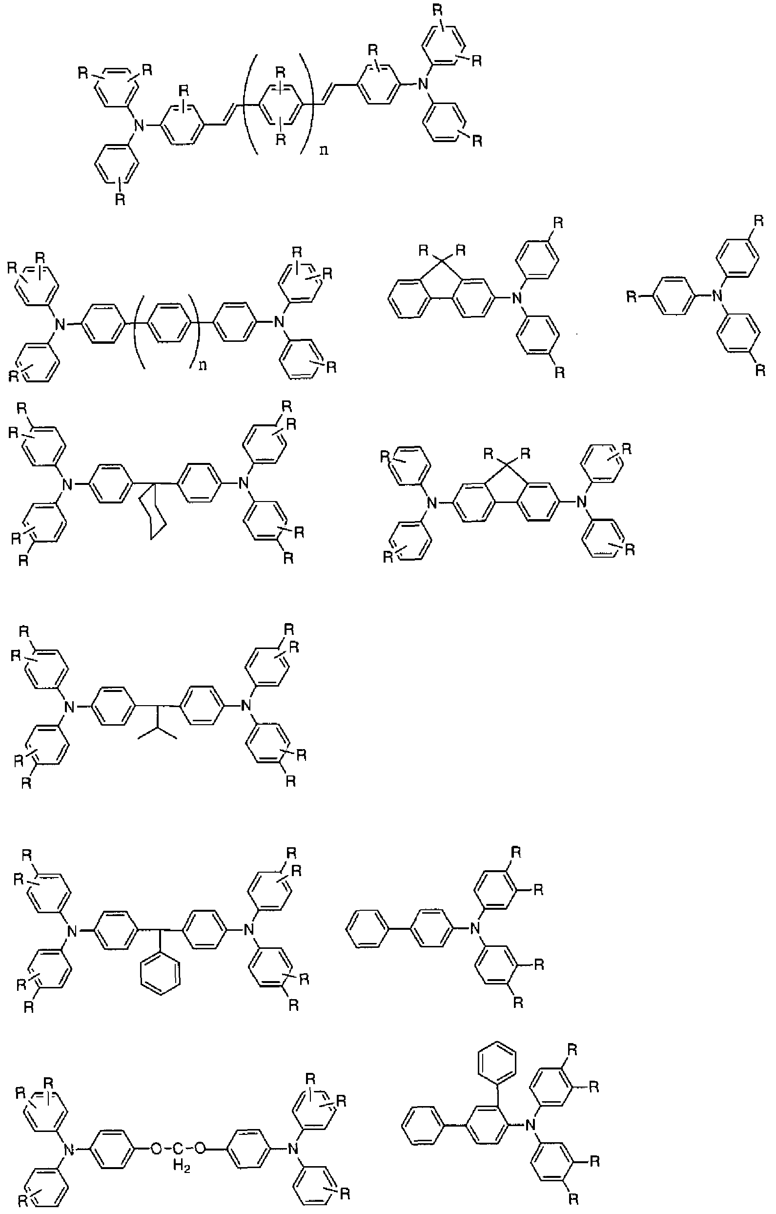
[0228] [化 10]


[0229] 上記式中、 Rは同一でも、それぞれ異なっていても構わない。具体的には、水素原 子又は、置換基 (置換基としては、アルキル基、アルコキシ基、ァリール基等が好まし い。特に好ましくは、メチル基、フエ-ル基である)である。また、 nは 0ないし 2の整数 である。
[0230] また、電荷輸送物質が、該有機電荷輸送物質の AMIパラメータを使った半経験的 分子軌道計算を用いた構造最適化計算による(以下、これを単に、「半経験的分子 軌道計算 (AMI)による」とする)分極率 (X calにつ 、て、次式、 200 (A3) > a cal> 55 (A3)を満たし、かつ半経験的分子軌道計算による双極子モーメント Pealについ て、次式、 0. 2 (D) < PcaK 2. 1 (D) を満たすことが好まし!/、。
[0231] 過去において、電荷輸送物質の計算に、 PM3を使用していた報告例があつたが、 本発明においては、 AMIを利用した。理由としては、以下が挙げられる。
[0232] 理由 1 電荷輸送剤は、炭素、水素、酸素、窒素力 形成されていることが多ぐこ れらのパラメータが固定されて 、る AMIの利用は、構造最適化に適して!/、ると予測
される。
理由 2 双極子モーメントを計算するのに必要な電荷分布計算において、 AMIは 、 PM3等より信用度が高い。
[0233] 分極率 a calは、細線再現性を鑑みた場合、好ましくは、 70以上であり、更に好まし くは、 90以上である。繰返しによる画像変化の効果を考えた場合、更に好ましくは、 1 80以下であり、 150以下が好ましぐ更に好ましくは、 130以下である。双極子モーメ ント Pealについては、転写によるメモリを鑑みた場合、 0. 4 (D)以上が好ましぐ更に 好ましくは、 0. 6 (D)以上である。移動度を鑑みた場合、更に好ましくは、 2. 0 (D)以 下であり、更に好ましくは、 1. 7 (D)以下であり、更に好ましくは、 1. 5 (D)以下であり 、更に好ましくは、 1. 3 (D)以下である。
[0234] また、一般式 (5)の化合物と、任意の公知の電荷輸送物質を併用しても構わない。
公知の電荷輸送物質の例としては、 2, 4, 7—トリ-トロフルォレノン等の芳香族-ト 口化合物、テトラシァノキノジメタン等のシァノ化合物、ジフエノキノン等のキノンィ匕合 物等の電子吸引性物質、力ルバゾール誘導体、インドール誘導体、イミダゾール誘 導体、ォキサゾール誘導体、ピラゾール誘導体、チアジアゾール誘導体、ベンゾフラ ン誘導体等の複素環化合物、ァニリン誘導体、ヒドラゾン誘導体、芳香族ァミン誘導 体、スチルベン誘導体、ブタジエン誘導体、ェナミン誘導体及びこれらの化合物の複 数種が結合したもの、あるいはこれらの化合物力 なる基を主鎖又は側鎖に有する 重合体等の電子供与性物質等が挙げられる。これらの中でも、力ルバゾール誘導体 、芳香族ァミン誘導体、スチルベン誘導体、ブタジエン誘導体、ェナミン誘導体、又 は、これらの化合物の複数種が結合したものが好ましい。これらの電荷輸送物質は、 何れ力 1種を単独で用いてもよぐ 2種以上を任意の組み合わせで併用してもよ 、。
[0235] <バインダー榭脂 >
電荷発生層と電荷輸送層を有する機能分離型感光体の電荷輸送層、及び単層型 感光体の感光層形成の際は、膜強度確保のため、化合物を分散させるためバインダ 一樹脂が使用される。機能分離型感光体の電荷輸送層の場合、電荷輸送物質と各 種バインダー樹脂とを溶剤に溶解、あるいは分散してえられる塗布液を、また、単層 型感光体の場合、電荷発生物質と電荷輸送物質と各種バインダー榭脂とを溶剤に
溶解、あるいは分散して得られる塗布液を塗布、乾燥して得ることができる。ノ^ンダ ー榭脂としては、例えば、ブタジエン榭脂、スチレン榭脂、酢酸ビュル榭脂、塩ィ匕ビ ニル榭脂、アクリル酸エステル榭脂、メタクリル酸エステル榭脂、ビュルアルコール榭 脂、ェチルビニルエーテル等のビニル化合物の重合体及び共重合体、ポリビニルブ チラール榭脂、ポリビュルホルマール榭脂、部分変性ポリビュルァセタール、ポリ力 ーボネート榭脂、ポリエステル榭脂、ポリアリレート榭脂、ポリアミド榭脂、ポリウレタン 榭脂、セルロースエステル榭脂、フエノキシ榭脂、シリコーン榭脂、シリコーン アル キッド榭脂、ポリ N ビニルカルバゾール榭脂等が挙げられる。これら榭脂は珪素 試薬等で修飾されて 、てもよ 、。
[0236] 特に、本発明においては、界面重合で得られた一種類以上のポリマーを含有する ことが好ましい。界面重合とは、互いに混ざり合わない 2つ以上の溶媒 (多くは、有機 溶媒一水系)の界面で進行される重縮合反応を利用する重合法である。例えば、ジ カルボン酸塩化物を有機溶媒に、グリコール成分をアルカリ水等に溶力して、常温で 両液を混合させて、 2相にわけ、その界面で、重縮合反応を進ませて、ポリマーを生 成させる。他の 2成分の例としては、ホスゲンとグリコール水溶液等が挙げられる。ま た、ポリカーボネートオリゴマーを界面重合で縮合する場合のように、 2成分をそれぞ れ、 2相に分けるのではなぐ界面を重合の場として利用する場合もある。
[0237] 反応溶媒としては、有機相と、水相の二層を使用するのは好ましぐ有機相としては 、メチレンクロライド、水相は、アルカリ性水溶液が好ましい。反応時に、触媒を使用 することが好ましぐ反応で使用する縮合触媒の添加量は、グリコール成分であるジ 才ーノレに対して 0. 005〜0. lmol0/0程度、好ましく ίま 0. 03〜0. 08mol0/0である。 0 . lmol%を超えると、重縮合後の洗浄工程で触媒の抽出除去に多大の労力を要す る場合がある。
[0238] 反応温度は、 80°C以下、好ましくは 60°C以下、更に好ましくは 10°C〜50°Cの範囲 にあることが好ましぐまた反応時間は反応温度によっても左右されるが、通常 0. 5分 〜10時間、好ましくは 1分〜 2時間である。反応温度が高すぎると、副反応の制御が できず、一方、低すぎると、反応制御上は好ましい状況ではあるが、冷凍負荷が増大 して、その分コストアップとなる場合がある。
[0239] また、有機相中の濃度は、得られる組成物が可溶な範囲であればよぐ具体的には、 10〜40重量%程度である。有機相の割合はジオールのアルカリ金属水酸化物水溶 液、すなわち水相に対して 0. 2〜1. 0の容積比であることが好ましい。
[0240] また、重縮合によって得られる有機相中の生成樹脂の濃度が 5〜30重量%となるよう に溶媒の量が調整されるのが好ましい。し力る後、新たに水及びアルカリ金属水酸化 物を含む水相を加え、更に重縮合条件を整えるために、好ましくは縮合触媒を添カロ して界面重縮合法に従い、所期の重縮合を完結させる。重縮合時の有機相と水相の 割合は容積比で有機相:水相 = 1: 0. 2〜 1程度が好ま 、。
[0241] 界面重合により生成する該ポリマーとしては、ポリカーボネート榭脂、ポリエステル 榭脂 (特にポリアリレート榭脂が好ましい)が特に好ましい。該ポリマーは、芳香族ジォ ールを原料とするポリマーであることが好ましく、好まし 、芳香族ジオール構造として は、下記式 (A)で表されるものである。
[0242] [化 11]

[式 (A)中、 X2は単結合又は連結基を示し、 Y1ないし Y8は各々独立に、水素原子又 は原子数 20以下の置換基を示す。 ]
[0243] また、式 (A)中、 X2は単結合又は以下の構造で表される連結基であることが好まし い。「単結合」とは、「X2」なる原子がなぐ式 (A)中の左右 2つのベンゼン環を、単に 単結合で結合した状態を!、う。
[0244] [化 12]

上記構造中、 Rla及び R ま、それぞれ独立に、水素原子、炭素数 1〜20のアルキ
ル基、置換されていてもよいァリール基、又は、ハロゲン化アルキル基を示し、 Zは、 炭素数 4〜20の置換されて 、てもよ 、炭化水素基を示す。
[0245] 特に、下記構造式を有するビスフエノール又はビフエノール成分が含有されるポリ力 ーボネート榭脂、ポリアリレート榭脂が、感度、残留電位等の点から好ましぐなかでも 移動度の面力もポリカーボネート榭脂がより好ましい。
[0246] ポリカーボネート榭脂に好適に用いることのできるビスフエノール、ビフエノールの構 造を以下に例示する。本例示は、趣旨を明確にするために行うものであり、本発明の 趣旨に反しない限りは例示される構造に限定されるものではない。
[0247] [化 13]

特に、本発明の効果を最大限に発揮するためには、以下構造を示すビスフエノ ル誘導体を含有するポリカーボネートが好まし ヽ。
[化 14]


酸成分としては、以下構造を用いることが好ましい。
[化 16]
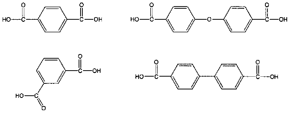
[0250] また、テレフタル酸とイソフタル酸を使用する際は、テレフタル酸のモル比が多 、方 が好ましい。
[0251] 積層型感光体の電荷輸送層、及び単層型感光体の感光層に使用されるバインダ ー榭脂と電荷輸送物質の割合は、単層型、積層型共に、通常、バインダー榭脂 100 重量部に対して電荷輸送物質が 20重量部以上であって、残留電位低減の観点から 30重量部以上が好ましぐ更に繰り返し使用時の安定性、電荷移動度の観点から、 40重量部以上がより好ましい。また、一方で感光層の熱安定性の観点から、通常は 150重量部以下、更に電荷輸送物質とバインダー榭脂の相溶性の観点からは好まし くは 120重量部以下、更に耐刷性の観点からは 100重量部以下がより好ましぐ耐傷 性の観点からは 80重量部以下がとりわけ好ましい。
[0252] 単層型感光体の場合には、上記のような配合比の電荷輸送媒体中に、更に前記の 電荷発生物質が分散される。その場合の電荷発生物質の粒子径は充分小さ!ヽこと が必要であり、好ましくは 1 μ m以下が好ましぐより好ましくは 0. 5 μ m以下である。 感光層内に分散される電荷発生物質は少なすぎると充分な感度が得られず、多すぎ ると帯電性の低下、感度の低下の弊害があり、例えば、好ましくは 0. 1〜50重量% の範囲、好ましくは 1〜20重量%の範囲で使用される。
[0253] 単層型感光体の感光層の膜厚は、通常 5〜: L00 μ m、好ましくは 10〜50 μ mの範 囲で使用され、順積層型感光体の電荷輸送層の膜厚は、通常 5〜50 /ζ πιの範囲で
用いられる力 長寿命、画像安定性の観点からは、好ましくは 10〜45 /ζ πι、高解像 度の観点からは 10〜30 mがより好ましい。
[0254] なお、感光層には成膜性、可撓性、塗布性、耐汚染性、耐ガス性、耐光性等を向 上させるために周知の酸化防止剤、可塑剤、紫外線吸収剤、電子吸引性化合物、レ ベリング剤、可視光遮光剤等の添加物を含有させてもよい。また感光層には必要に 応じて塗布性を改善するためのレべリング剤や酸ィヒ防止剤、増感剤等の各種添加剤 を含んでいてもよい。酸化防止剤の例としては、ヒンダードフエノール化合物、ヒンダ 一ドアミンィ匕合物等が挙げられる。また可視光遮光剤の例としては、各種の色素化合 物、ァゾィ匕合物等が挙げられ、レべリング剤の例としては、シリコーンオイル、フッ素 系オイル等が挙げられる。
[0255] <酸化防止剤 >
酸ィ匕防止剤は、感光体に含まれる部材の酸化を防止するために添加される安定剤 の一種である。酸ィ匕防止剤は、ラジカル補足剤としての機能があり、具体的には、フ ェノール誘導体、アミンィ匕合物、ホスホン酸エステル、硫黄化合物、ビタミン、ビタミン 誘導体等が挙げられる。この中でも、フ ノール誘導体、アミンィ匕合物、ビタミン等は、 好ましい。特に好ましくは、嵩高い置換基を、ヒドロキシ基近辺に有する、ヒンダードフ ェノール、又は、トリアルキルアミン誘導体等が好ましい。特には、ヒドロキシ基の o位 に、 t ブチル基を有するァリールイ匕合物誘導体が好ましぐヒドロキシ基の o位に、 t ブチル基を 2つ有するァリールイ匕合物誘導体が好ましい。
[0256] また、該酸化防止剤は、分子量は大きすぎると、酸ィ匕防止能に問題が生じることが あり、分子量 1500以下、特には、分子量 1000以下の化合物が好ましい。下限は、 1 00以上、好ましくは、 150以上が好ましぐ更に好ましくは、 200以上が好ましい。
[0257] 以下、本発明に使用できる酸化防止剤を示す。本発明に使用できる酸ィ匕防止剤と しては、プラスチック、ゴム、石油、油脂類の酸ィ匕防止剤、紫外線吸収剤、光安定剤 として公知の材料すベては用いることができる力 とりわけ次に示す化合物群より選 ばれる材料が好ましく使用できる。
[0258] (1)特開昭 57— 122444号公報に記載のフエノール類、特開昭 60— 188956号公 報に記載のフエノール誘導体及び特開昭 63— 18356号公報に記載のビンダードフ
エノーノレ類。
(2)特開昭 57— 122444号公報に記載のパラフエ-レンジアミン類、特開昭 60— 18 8956号公報に記載のパラフエ-レンジァミン誘導体及び特開昭 63— 18356号公 報に記載のパラフエ-レンジアミン類。
(3)特開昭 57— 122444号公報に記載のハイドロキノン類、特開昭 60— 188956号 公報に記載のハイドロキノン誘導体及び特開昭 63— 18356号公報に記載のハイド ロキノン類。
(4)特開昭 57— 188956号公報に記載のィォゥ化合物及び特開昭 63— 18356号 公報に記載の有機ィォゥ化合物類。
(5)特開昭 57— 122444号公報に記載の有機リンィ匕合物及び特開昭 63— 18356 号公報に記載の有機リン化合物類。
(6)特開昭 57— 122444号公報に記載のヒドロキシァ-ソール類。
(7)特開昭 63— 18355号公報に記載の特定の骨格構造を有するピぺリジン誘導体 及びォキソピペラジン誘導体。
(8)特開昭 60— 188956号公報に記載のカロチン類、アミン類、トコフエロール類、 N i (II)錯体、スルフイド類等。
また、特に好ましくは、以下に示す、ヒンダードフエノール類が好ましい(ヒンダードフ ェノールとは、嵩高い置換基を、ヒドロキシ基近辺に有する、フエノール類を示す)。 ジブチルヒドロキシトルエン、
2, 2' ーメチレンビス(6— t—ブチルー 4 メチルフエノール)、
4, 4' ーブチリデンビス(6— t—ブチルー 3—メチルフエノール)、
4, 4' ーチォビス(6— t—ブチルー 3—メチルフエノール)、
2, 2' ーブチリデンビス(6— t—ブチルー 4 メチルフエノール)、
a—トコフエノール、 13—トコフエノール、 2, 2, 4 トリメチル 6 ヒドロキシ一 7— t ーブチノレクロマン、
ペンタエリスチルテトラキス [3— (3, 5—ジ tーブチルー 4ーヒドロキシフエ-ル)プ 口ピオネート]、
2, 2'—チオジェチレンビス [3— (3, 5 ジ tーブチルー 4ーヒドロキシフエ-ル)プ
口ピオネート]、
1, 6 へキサンジオールビス [3—(3, 5 ジ tーブチルー 4ーヒドロキシフエ-ル) プロピオネート]、
ブチルヒドロキシァ二ノール、ジブチルヒドロキシァ二ノール、
ォクタデシル 3 , 5—ジー tert ブチル 4 ヒドロキシヒドロシンナメート
(Octadecyl— 3,5— di— tert— butyl— 4— hydroxyhyarocinnamate)
1, 3, 5 トリメチルー 2, 4, 6 トリス一(3, 5 ジ一 tert—ブチル 4 ヒドロキシべ ンジノレ) ベンゼン
U,3 , 5— trimethyl— 2 ,4, 6— tris— (3 , 5— di— tert— butyl— 4— nydroxybenzyl)— benzene)
[0260] 上記、ヒンダードフエノール類の中でも、以下の化合物が特に好まし!/、。
ォクタデシル 3 , 5—ジー tert ブチル 4 ヒドロキシヒドロシンナメート
(Octadecyl— 3,5— di— tert— butyl— 4— hydroxyhyarocinnamate)
1, 3, 5 トリメチルー 2, 4, 6 トリス一(3, 5 ジ一 tert—ブチル 4 ヒドロキシべ ンジノレ) ベンゼン
U,3 , 5— trimethyl— 2 ,4, 6— tris— (3 , 5— di— tert— butyl— 4— nydroxybenzyl)— benzene)
[0261] これらの化合物はゴム、プラスチック、油脂類等の酸ィ匕防止剤として知られており、 市販品として手に入るものもある。
[0262] 本発明の画像形成装置に用!、られる感光体にお!、て表面層中の前記酸化防止剤 の量は、特に制限されないが、バインダ榭脂 100 重量部当り 0. 1重量部以上、 20 重量部以下が好ましい。この範囲以外の場合、良好な電気特性が得られない。特に 好ましくは、 1重量部以上である。また、多すぎると、電気特性だけでなぐ耐刷性にも 問題を起こすので、好ましくは、 15部重量以下であり、更に好ましくは、 10重量部以 下である。
[0263] <電子吸引性化合物 >
感光体には、電子吸引性の化合物を有することが好ましぐ具体的には、スルホン 酸エステル化合物、カルボン酸エステル化合物、有機シァノ化合物、ニトロ化合物、 芳香族ハロゲン誘導体等は好ましいが、特に好ましくは、スルホン酸エステル化合物 、有機シァノ化合物、であり、特に、スルホン酸エステル化合物が好ましい。
[0264] 電子吸引能力は、 LUMOのエネルギーレベルの値で予見することも可能であると 考えられる。特に、 PM3パラメータを使った半経験的分子軌道計算を用いた構造最 適化による(以下これを単に、半経験的分子軌道計算(PM3)によるとする) LUMO のエネルギーレベルの値が— 1. OeV〜一 3. OeVである化合物は好ましい。 LUM Oのエネルギーレベルの絶対値力 1. OeVよりも小さくなると、電子吸引性の効き目 があまり期待できず、 3. OeVを超えると、帯電の悪化が懸念される。 LUMOのエネ ルギーレベルの絶対値は、より好ましくは、 L 5eV以上であり、更に好ましくは、 1. 7 eV以上であり、更に好ましくは、 1. 9eV以上である。上限は、 2. 7eV以下が好ましく 、更に好ましくは、 2. 5eV以下である。
[0265] 電子吸引性ィ匕合物の計算には、ハミルトニアンとして PM3を利用した。理由は、以 下である。通常、電子吸引性ィ匕合物は、炭素、窒素、酸素、水素、以外に、硫黄、ハ ロゲン等のへテロ原子を使うことがあり、これら多くの原子のパラメータを最小二乗法 で定めた PM3は、電子吸引性化合物の構造最適化に適していると考えられる。
[0266] 電子吸引性ィ匕合物としては、具体的には、以下化合物が挙げられる。
[化 17]


<最表面層 >
前記電荷発生物質、電荷輸送物質は、どのような層にあってもよいが、最表面層に は、フッ素原子、珪素原子が存在していることが、トナー転写、クリーニング性向上の 観点から好ましい。これらの原子は、添加剤でも、電荷発生物質でも、電荷輸送物質 でも、ノインダ一等の何れの物質に含まれて 、ても構わな 、。
また、感光体表面の持つ付着性は、表面自由エネルギー (表面張力と同義)として 、検出することが可能である。最表面層の表面自由エネルギーの値としては、 35mN Zmないし 65mNZmの範囲であることが好ましい。低すぎると、トナーが流れてしま う可能性があり、また、高すぎると、トナーの転写効率、クリーニング性悪ィヒを招く可能 性がある。下限として、好ましくは、 40mNZm以上であり、上限としては好ましくは、 55mNZm以下であり、更に好ましくは、 50mNZm以下である。
[0268] [表面自由エネノレギー]
以下、表面自由エネルギーについて述べる。感光体表面と残留トナー等の異物の 付着は、物理結合の範疇であり分子間力(van der Waals力)が原因である。その 分子間力が最表面において起こす現象として表面自由エネルギー( γ )がある。物質 の「濡れ」には、大別して 3種類ある。物質 1が物質 2に付着する「付着濡れ」、物質 1 が物質 2上に広がる「拡張濡れ」、物質 1が物質 2に浸ったり、染み込んだりする「浸漬 濡れ」である。
[0269] 付着濡れについて、表面自由エネルギー( γ )と濡れ性に関して、 Youngの式から 物質 1と物質 2との関係は、下記のようになる。
[0270] [数 1] γχ = Y2 *COS$n + Υη 式(Η )
Ύ :物質 1表面の表面自由エネルギー
Ύ :物質 2の表面自由エネルギー
2
γ :物質 1Ζ物質 2の界面自由エネルギー
12
Θ :物質 1Z物質 2の接触角
12
[0271] 上記式(1 1)において、画像形成装置内の感光体表面への異物や水分等の付 着を考える場合は、物質 1を感光体、物質 2を異物とすればよい。
[0272] 式(1— 1)より、濡れ難くする、つまり 0 を大きくする為には、感光体とトナーの「濡
12
れ仕事」であるところの感光体表面の表面自由エネルギー γ を大きくし、 γ と γ を
1 2 12 小さくしてやることが有効である。
[0273] 電子写真のクリーニング工程において、感光体の表面自由エネルギー γ を制御 することにより、結果として式(1— 1)の右辺の付着状態を制御できる。また、耐久に おいて、トナーやその他の異物は逐次、新たに供給される物であり、 y
2は一定と考 えることができる。一方、感光体は耐久によりその表面自由エネルギー γ が変化す る。 γ が だけ変化することにより、結果として式(1 1)の右辺の値も変化する 。すなわち異物が感光体表面に付着する状態が変化し、結果としてクリーニング性や クリーニング機構への負荷に変化が生じる。言葉を変えれば、 を規定することに
より、感光体のクリーニング性、すなわちクリーニングされ易さを一定に保持し得ると いうことである。
[0274] ここで、固体と液体の濡れに関しては、その接触角 Θ を直接測定することができる
12
1S 感光体とトナーのように、固体と固体の場合は、接触角 Θ を測定し得ない。本
12
発明における感光体とトナーは、通常ともに固体であり、このケースに該当する。
[0275] 北崎寧昭、畑敏雄らは、日本接着協会紙 8 (3)、 131〜141 (1972)で、界面自由 エネルギー(界面張力と同義)に関し、非極性な分子間力について述べた Forkesの 理論に対し、更に、極性又は水素結合性の分子間力による成分にまで拡張できるこ とが示している。この拡張 Forkes理論により、各物質の表面自由エネルギーを 2ない し 3成分で求めることができる。下に、付着濡れの場合を例に、 3成分の理論につい て記す。この理論は下記の如き仮定の基で成り立つている。
[0276] 1.表面自由エネルギー( γ )の加算則
γ = γ + γ + γ 式 (1— 2)
0 d:分散成分 (非極性のぬれ =付着)
Ύ Ρ : 双極子成分 (極性によるぬれ =付着)
γ 11:水素結合成分 (水素結合によるぬれ =付着)
[0277] これを ForkeS理論に適用して、 2つの物質の界面自由エネルギー γ は、下記の
12 様になる。
[数 2] γη = + - 2'(^ ' 2つ —2 ' (^ —2 · ' …式 (1 -3) 更に、
[数 3] }…式(1 -4)
[0278] 表面自由エネルギーの測定方法は、 p、 d、 hの表面自由エネルギー各成分が既知 の試薬を使用し、該試薬との付着性を測定し、算出することができる。具体的には、 試薬に純水、ヨウ化メチレン、 a—ブロモナフタレンを使用し、協和界面社製の自動 接触角計 CA— VP型を使用して、上記各試薬の感光体表面への接触角を測定し、
協和界面社製の表面自由エネルギー解析ソフト FAMASにて表面自由エネルギー γを算出した。試薬は上記のほかにも、 p、 d、 hの各成分が適宜な組み合わせのもの を使用すればよい。また測定方法も、上記の他にも一般的な手法の、例えばウィルへ ルミ法 (つり板法)、ドウ'ヌィ法等で測定することにより行うことができる。
[0279] 先に述べたように、「濡れ」には複数の種類があるが、感光体表面にトナーが固着、 融着する場合には、感光体表面に残留したトナーが感光体に付着し、クリーニング、 帯電等の工程を繰り返しているうち、該トナーが感光体表面に被膜状に広がり、付着 力が強度になることによる影響が大きい。いわゆる「付着濡れ」に相当する。
[0280] また、紙粉やロジン、タルク等の、異物の固着等の場合も同様に付着後、感光体と の接触面 (以下「界面」と称する)の面積が増大して強固な濡れになる。更に感光体 表面に付着した異物に、また感光体表面へ直接水分が関与し「濡れ」ることは、画像 がぼやけたようになる、 、わゆる「高湿流れ」の要因となって!/、る。
[0281] これらの異物に関して、電子写真の画像形成の工程上、トナーを含む様々な物質 がー且は感光体表面に付着する。これらのうち、転写材に転写されきらな力つた、い わゆる「残トナー」や他の異物を、一定期間以内にクリーニング、すなわち除去する必 要がある。ここで言う一定期間とは、様々な物質が一旦は感光体表面に付着する実 時から、該付着物が、拡散且つ Z又は更なる付着により、感光体との界面の面積が 増加するまでの状態の期間を指す。
[0282] 上記の範囲の状態内でのクリーニングにかかる特性、すなわち先ず感光体へ付着 した異物の「付着濡れ」、更に「拡張濡れ」が、実用上のクリーニング特性や、タリー二 ング装置或いは感光体の寿命にかかる、大きな要因となる。従って、本発明者らは、 感光体の表面自由エネルギー γについて、規定することが有効であると考え、鋭意 検討を行い、高画質且つ高耐久な電子写真画像を得ることができることを見出した。 特に、物質 2、すなわち前述の異物としてはトナー、紙粉、水分、シリコーンオイルそ の他の多種類が考えられる。
[0283] 本発明においては、付着される側である所の物質 1の感光体表面に付いて、その 表面自由エネルギー Ύ を規定した。また、上記の物質 2は耐久中、随時供給される ものであるのに対し、物質 1である感光体表面は耐久により、その γ が変化する。画
像形成用の電子写真装置としての耐久性を検討するに当り、その変動分△ γ 制 御することが重要である。
[0284] [制御]
高画質な画像を安定して得る為に、感光体のクリーニング性、特に感光体をタリー ニングする負荷を制御する。本発明者らは、鋭意検討の結果、感光体の表面自由ェ ネルギー γの値を 35ないし 65mNZmの範囲、より好ましくは 40ないし 60mNZm に規定することにより、低負荷で良好なクリーニング性が得られることを見出した。ま た、耐久により変化する量△ γを 25mNZm以内、好ましくは 15mNZm以内の範 囲で使用することにより、感光体とクリーニング装置双方への負荷の変動を抑止し、 長期にわたりクリーニング特性を安定せしめた
[0285] 特に、感光体の最表面層には、感光層の損耗を防止したり、帯電器等からの発生 する放電物質等による感光層の劣化を防止,軽減する目的で保護層を設けてもよい 。保護層は導電性材料を適当な結着樹脂中に含有させて形成するか、特開平 9 1 90004号公報、特開平 10— 252377号公報の記載のようなトリフエ-ルァミン骨格 等の電荷輸送能を有する化合物を用いた共重合体を用いることができる。導電性材 料としては、 TPD (N, N,一ジフエ-ルー N, N,一ビス一(m トリル)ベンジジン)等 の芳香族ァミノ化合物、酸化アンチモン、酸化インジウム、酸化錫、酸化チタン、酸化 錫一酸ィ匕アンチモン、酸化アルミ、酸ィ匕亜鉛等の金属酸ィ匕物等を用いることが可能 であるが、これに限定されるものではない。
[0286] 保護層に用いる結着榭脂としてはポリアミド榭脂、ポリウレタン榭脂、ポリエステル榭 脂、エポキシ榭脂、ポリケトン樹脂、ポリカーボネート榭脂、ポリビュルケトン樹脂、ポリ スチレン榭脂、ポリアクリルアミド榭脂、シロキサン榭脂等の公知の榭脂を用いること ができ、また、特開平 9— 190004号公報、特開平 10— 252377号公報の記載のよ うなトリフ ニルァミン骨格等の電荷輸送能を有する骨格と上記樹脂の共重合体を用 いることちでさる。
[0287] 上記保護層は電気抵抗が 109〜: ί014Ω 'cmとなるように構成することが好ましく。電 気抵抗が 1014Ω · cmより高くなると残留電位が上昇しカプリの多い画像となってしま い、一方 109Ω 'cmより低くなると画像のボケ、解像度の低下が生じてしまう。また、保
護層は像露光に照射される光の透過を実質上妨げないように構成されなければなら ない。
[0288] また、感光体表面の摩擦抵抗や、摩耗を低減、トナーの感光体から転写ベルト、紙 への転写効率を高める等の目的で、表面層にフッ素系榭脂、シリコーン榭脂、ポリエ チレン榭脂、ポリスチレン榭脂等を含んでいてもよい。また、これらの榭脂からなる粒 子や無機化合物の粒子を含んで 、てもよ 、。
[0289] <層形成方法 >
感光体を構成する各層は、各層を構成する材料を含有する塗布液を、支持体上に 公知の塗布方法を用い、各層ごとに塗布 ·乾燥工程を繰り返し、順次塗布していくこ とにより形成される。
[0290] 層形成用の塗布液は、単層型感光体及び積層型感光体の電荷輸送層の場合に は、固形分濃度を、通常 5〜40重量%の範囲で用いられるが、 10〜35重量%の範 囲で使用するのが好ましい。また、該塗布液の粘度は、通常 10〜500mPa' sの範囲 で用いられるが、 50〜400mPa · sの範囲とするのが好まし!/、。
[0291] 積層型感光体の電荷発生層の場合には、固形分濃度を、通常 0. 1〜15重量%の 範囲で使用される力 1〜10%の範囲で使用することがより好ましい。塗布液の粘度 は、通常 0. 01〜20mPa ' sの範囲で使用されるが、 0. 1〜: LOmPa ' sの範囲で使用 されることがより好ましい。
[0292] 塗布液の塗布方法としては、浸漬コーティング法、スプレーコーティング法、スピナ 一コーティング法、ビードコーティング法、ワイヤーバーコーティング法、ブレードコー ティング法、ローラーコーティング法、エアーナイフコーティング法、カーテンコーティ ング法等が挙げられる力 他の公知のコーティング法を用いることも可能である。
[0293] 塗布液の乾燥は室温における指触乾燥後、 30〜200°Cの温度範囲で、 1分から 2 時間の間、無風、又は送風下で加熱乾燥させることが好ましい。また加熱温度は一 定であっても、乾燥時に変更させながら行なってもよ!/、。
[0294] <画像形成装置 >
図面により、本発明の画像形成装置を使用した画像形成方法を更に詳細に説明す る。図 1は、画像形成方法の遂行に用いることのできる非磁性一成分トナーを使用し
た現像装置の一例を示す説明図である。図 1において、トナーホッパー 17に内蔵さ れているトナー 16は、撹拌羽根 15によりローラー状のスポンジローラー(トナー補給 補助部材) 14に強制的に寄せられ、トナーはスポンジローラー 14に供給される。そし て、スポンジローラー 14に取り込まれたトナーは、スポンジローラー 14が矢印方向に 回転することにより、トナー搬送部材 12に運ばれ、摩擦され、静電的又は物理的に 吸着し、トナー搬送部材 12が矢印方向に強く回転し、スチール性の弾性ブレード (ト ナ一層厚規制部材) 13により均一なトナー薄層が形成されるとともに摩擦帯電する。 その後、トナー搬送部材 12と接触している静電潜像担持体 11の表面に運ばれ、潜 像が現像される。静電潜像は例えば有機感光体に 500Vの DC帯電をした後、露光 して得られる。
[0295] 本発明の画像形成装置に用いられるトナーは、帯電量分布がシャープであるため 、帯電不良のトナーが原因で起こる画像形成装置内の汚染 (トナー飛散)が非常に 少な ヽ。これは特に静電潜像担持体への現像プロセススピードが lOOmmZ秒以上 である高速タイプの画像形成装置においてその効果が顕著に発現される。
[0296] また、本発明の画像形成装置に用いられるトナーは、帯電量分布がシャープである ため、現像性が非常によぐ現像しないで蓄積していくトナー粒子が非常に少ない、 これは、特にトナーの消費スピードが速い画像形成装置においてその効果が発揮さ れるものである。具体的に示すと、下記式(3)を満足する画像形成装置に用いるトナ 一であることが、本発明の上記効果を充分に発揮させるために好ましいものである。
[0297] (3) 現像剤を充填する現像機の保証寿命枚数 (枚) X印字率≥ 500 (枚)
式 (3)において、「印字率」は、画像形成装置の性能である保証寿命枚数を決定す るための印刷物にお!、て、印字部分面積の総和を印字媒体の全面積で除した値で 表され、例えば、「5%」の印字%の「印字率」は「0. 05」である。
[0298] 更に、本発明の画像形成装置に用いられるトナーは粒径の分布が非常にシャープ であるため、潜像の再現性が非常によい。従って特に、静電潜像担持体への解像度 力 S600dpi以上である画像形成装置に用いる時に、本発明の効果が充分に発揮され る。
[0299] 次に、本発明の画像形成装置の電子写真プロセス周辺の形態について、装置の
要部構成を示す図 2を用いて説明する。但し、実施の形態は以下の説明に限定され るものではなぐ本発明の要旨を逸脱しない限り任意に変形して実施することができ る。
[0300] 図 2に示すように、画像形成装置は、電子写真感光体 1、帯電装置 2、露光装置 3 及び現像装置 4を備えて構成され、更に、必要に応じて転写装置 5、クリーニング装 置 6及び定着装置 7が設けられる。
[0301] 電子写真感光体 1は、上述した本発明の画像形成装置に用いられる電子写真感 光体であれば特に制限はないが、図 2ではその一例として、円筒状の導電性支持体 の表面に上述した感光層を形成したドラム状の感光体を示して 、る。この電子写真 感光体 1の外周面に沿って、帯電装置 2、露光装置 3、現像装置 4、転写装置 5及び クリーニング装置 6がそれぞれ配置されて 、る。
[0302] 帯電装置 2は、電子写真感光体 1を帯電させるもので、電子写真感光体 1の表面を 所定電位に均一帯電させる。図 2では帯電装置 2の一例としてローラー型の帯電装 置(帯電ローラー)を示して 、るが、他にもコロトロンゃスコロトロン等のコロナ帯電装 置、帯電ブラシ等の接触型帯電装置等がよく用いられる。
[0303] なお、電子写真感光体 1及び帯電装置 2は、多くの場合、この両方を備えたカートリ ッジ (以下適宜、感光体カートリッジという)として、画像形成装置の本体から取り外し 可能に設計されている。そして、例えば電子写真感光体 1や帯電装置 2が劣化した 場合に、この感光体カートリッジを画像形成装置本体から取り外し、別の新しい感光 体カートリッジを画像形成装置本体に装着することができるようになって!/、る。また、 後述するトナーについても、多くの場合、トナーカートリッジ中に蓄えられて、画像形 成装置本体から取り外し可能に設計され、使用しているトナーカートリッジ中のトナー が無くなった場合に、このトナーカートリッジを画像形成装置本体力 取り外し、別の 新しいトナーカートリッジを装着することができるようになつている。更に、電子写真感 光体 帯電装置 2、トナーが全て備えられたカートリッジを用いることもある。
[0304] 露光装置 3は、電子写真感光体 1に露光を行なって電子写真感光体 1の感光面に 静電潜像を形成することができるものであれば、その種類に特に制限はない。具体 例としては、ハロゲンランプ、蛍光灯、半導体レーザー、 He— Neレーザー等のレー
ザ一、 LED等が挙げられる。また、感光体内部露光方式によって露光を行なうように してもよい。露光を行なう際の光は任意である力 例えば、波長が 700nm〜850nm の単色光、波長 600nm〜700nmのやや短波長寄りの単色光、波長 300nm〜500 nmの短波長の単色光等で露光を行なえばょ 、。
[0305] 特に、電荷発生物質としてフタロシアニン化合物を使用する電子写真感光体の場 合には、波長 700ηπ!〜 850nmの単色光を用いることが好ましぐァゾィ匕合物を用い る電子写真感光体の場合には、波長 700nm以下の単色光を用いることが好ま 、。 ァゾィ匕合物を用いる電子写真感光体の場合には、波長 500nm以下の単色光を光 入力用光源としても充分な感度を有する場合があるため、波長 380ηπ!〜 500nmの 単色光を光入力用光源として用いることは特に好適である。
[0306] 現像装置 4は、その種類に特に制限はなぐカスケード現像、一成分導電トナー現 像、二成分磁気ブラシ現像等の乾式現像方式や、湿式現像方式等の任意の装置を 用いることができる。図 2では、現像装置 4は、現像槽 41、アジテータ 42、供給ローラ 一 43、現像ローラー 44、及び、規制部材 45からなり、現像槽 41の内部にトナー Tを 貯留している構成となっている。また、必要に応じ、トナー Tを補給する補給装置(図 示せず)を現像装置 4に付帯させてもよい。この補給装置は、ボトル、カートリッジ等の 容器からトナー Tを補給することが可能に構成される。
[0307] 供給ローラー 43は、導電性スポンジ等から形成される。現像ローラー 44は、鉄、ス テンレス鋼、アルミニウム、ニッケル等の金属ロール、又はこうした金属ロールにシリコ ーン榭脂、ウレタン榭脂、フッ素榭脂等を被覆した榭脂ロール等力もなる。この現像口 一ラー 44の表面には、必要に応じて、平滑力卩ェゃ粗面カ卩ェをカ卩えてもよい。
現像ローラー 44は、電子写真感光体 1と供給ローラー 43との間に配置され、電子 写真感光体 1及び供給ローラー 43に各々当接している。供給ローラー 43及び現像 ローラー 44は、回転駆動機構(図示せず)によって回転される。供給ローラー 43は、 貯留されているトナー Tを担持して、現像ローラー 44に供給する。現像ローラー 44は 、供給ローラー 43によって供給されるトナー Tを担持して、電子写真感光体 1の表面 に接触させる。
[0308] 規制部材 45は、シリコーン榭脂ゃウレタン榭脂等の榭脂ブレード、ステンレス鋼、ァ
ルミ-ゥム、銅、真鍮、リン青銅等の金属ブレード、又はこうした金属ブレードに榭脂 を被覆したブレード等により形成されている。この規制部材 45は、現像ローラー 44に 当接し、ばね等によって、現像ローラー 44側に所定の力で押圧 (一般的なブレード 線圧は 5〜500gZcm)される。必要に応じて、この規制部材 45に、トナー Tとの摩擦 帯電によりトナー Tに帯電を付与する機能を具備させてもよい。
[0309] アジテータ 42は、回転駆動機構によってそれぞれ回転されており、トナー Tを攪拌 するとともに、トナー Tを供給ローラー 43側に搬送する。アジテータ 42は、羽根形状、 大きさ等を違えて複数設けてもょ ヽ。
[0310] トナー Tは、体積中位径(Dv50)が 4. 0 μ m〜7. 0 μ mの小粒径のもので、前記し た特定の粒径分布を有するものが使用される。また、トナーの粒子の形状は球形に 近いものからポテト上の球形力も外れたものまで様々に使用することができる。重合ト ナ一は、帯電均一性、転写性に優れ、高画質化に好適に用いられる。
[0311] 転写装置 5は、その種類に特に制限はなぐコロナ転写、ローラー転写、ベルト転写 等の静電転写法、圧力転写法、粘着転写法等、任意の方式を用いた装置を使用す ることができる。ここでは、転写装置 5が電子写真感光体 1に対向して配置された転写 チャージヤー、転写ローラー、転写ベルト等から構成されるものとする。この転写装置
5は、トナー Tの帯電電位とは逆極性で所定電圧値 (転写電圧)を印加し、電子写真 感光体 1に形成されたトナー像を記録紙 (用紙、媒体) Pに転写するものである。
[0312] クリーニング装置 6について特に制限はなぐブラシクリーナー、磁気ブラシクリーナ 一、静電ブラシクリーナー、磁気ローラークリーナー、ブレードクリーナー等、任意の クリーニング装置を用いることができる。クリーニング装置 6は、感光体 1に付着してい る残留トナーをクリーニング部材で搔き落とし、残留トナーを回収するものである。伹 し、感光体表面に残留するトナーが少ないか、殆ど無い場合には、クリーニング装置 6は無くても構わない。
[0313] 定着装置 7は、上部定着部材 (加圧ローラー) 71及び下部定着部材 (定着ローラー ) 72から構成され、定着部材 71又は 72の内部には加熱装置 73がそなえられている 。なお、図 1では、上部定着部材 71の内部に加熱装置 73がそなえられた例を示す。 上部及び下部の各定着部材 71、 72は、ステンレス、アルミニウム等の金属素管にシ
リコンゴムを被覆した定着ロール、更にテフロン (登録商標)榭脂で被覆した定着ロー ル、定着シート等が公知の熱定着部材を使用することができる。更に、各定着部材 7 1、 72は、離型性を向上させる為にシリコーンオイル等の離型剤を供給する構成とし てもよぐパネ等により互いに強制的に圧力を加える構成としてもよい。
[0314] 記録紙 P上に転写されたトナーは、所定温度に加熱された上部定着部材 71と下部 定着部材 72との間を通過する際、トナーが溶融状態まで熱加熱され、通過後冷却さ れて記録紙 P上にトナーが定着される。なお、定着装置についてもその種類に特に 限定はなぐここで用いたものをはじめ、熱ローラー定着、フラッシュ定着、オーブン 定着、圧力定着等、任意の方式による定着装置を設けることができる。
[0315] 以上のように構成された電子写真装置では、次のようにして画像の記録が行なわれ る。即ち、まず感光体 1の表面 (感光面)力 帯電装置 2によって所定の電位 (例えば -600V)に帯電される。この際、直流電圧により帯電させてもよぐ直流電圧に交流 電圧を重畳させて帯電させてもよい。続いて、帯電された感光体 1の感光面を、記録 すべき画像に応じて露光装置 3により露光し、感光面に静電潜像を形成する。そして 、その感光体 1の感光面に形成された静電潜像の現像を、現像装置 4で行なう。
[0316] 現像装置 4は、供給ローラー 43により供給されるトナー Tを、規制部材 (現像ブレー ド) 45により薄層化するとともに、所定の極性 (ここでは感光体 1の帯電電位と同極性 であり、負極性)に摩擦帯電させ、現像ローラー 44に担持しながら搬送して、感光体 1の表面に接触させる。現像ローラー 44に担持された帯電トナー Tが感光体 1の表面 に接触すると、静電潜像に対応するトナー像が感光体 1の感光面に形成される。そし てこのトナー像は、転写装置 5によって記録紙 Pに転写される。この後、転写されずに 感光体 1の感光面に残留しているトナー力、クリーニング装置 6で除去される。
[0317] トナー像の記録紙 P上への転写後、定着装置 7を通過させてトナー像を記録紙 P上 へ熱定着することで、最終的な画像が得られる。
[0318] なお、画像形成装置は、上述した構成に加え、例えば除電工程を行なうことができ る構成としてもよい。除電工程は、電子写真感光体に露光を行なうことで電子写真感 光体の除電を行なう工程であり、除電装置としては、蛍光灯、 LED等が使用される。 また除電工程で用いる光は、強度としては露光光の 3倍以上の露光エネルギーを有
する光である場合が多い。
[0319] また、画像形成装置は更に変形して構成してもよぐ例えば、前露光工程、補助帯 電工程等の工程を行なうことができる構成としたり、オフセット印刷を行なう構成とした り、更には複数種のトナーを用いたフルカラータンデム方式の構成としてもよい。
[0320] また、物理的、電気的に表面性の優れた、本発明の画像形成装置に用いられる上 記感光体と上記トナーとを併用することにより、画像特性が優れ、画像汚れも少なぐ また、転写効率の高いシステムを構築することができる。
実施例
[0321] 以下、本発明を実施例により更に具体的に説明するが、本発明はその要旨を越え ない限り、以下の実施例に限定されるものではない。以下の例で「部」とあるのは「重 量部」を意味する。
[0322] <体積平均径 (M )の測定方法と定義 >
V
1 m未満の体積平均径 (M )を有する粒子の体積平均径 (M )は、日機装社製、
V V
型式: Microtrac Nanotrac 150 (以下、「ナノトラック」と略記する)を用いて、ナノトラッ クの取り扱い説明書に従い、日機装社製の解析ソフト Microtrac Particle Analyzer VerlO.1.2.- 019EEを用い、電気伝導度が 0. 5 SZcmのイオン交換水を分散媒に 用い、それぞれ、下記の条件で又は下記の条件を入力し、取り扱い説明書に記載さ れた方法で測定した。
[0323] ワックス分散液及び重合体一次粒子分散液につ!、ては、
•溶媒屈折率: 1. 333
•測定時間 :100秒
•測定回数 :1回
•粒子屈折率: 1. 59
'透過性 :透過
,形状 :真球形
,密度 :1. 04
[0324] 顔料プレミックス液及び着色剤分散液につ!ヽては、
•溶媒屈折率: 1. 333
•測定時間 :100秒
•測定回数 :1回
•粒子屈折率: 1. 59
,透過性 :吸収
,形状 :非球形
,密度 :1. 00
[0325] <体積中位径 (Dv50)の測定方法と定義 >
最終的に得られたトナーの測定前処理は、次の様にした。内径 47mm、高さ 51m mの円筒形のポリエチレン(PE)製ビーカーに、スパチュラ一を用いてトナーを 0. 10 0g、スポイトを用いて 20質量0/ oDBS水溶液 (第一工業製薬社製、ネオゲン S— 20A )を 0. 15g添加した。この際、ビーカーの縁等にトナーが飛び散らない様にビーカー の底部にのみトナー及び 20%DBS水溶液を入れた。次に、スパチュラ一を用いてト ナ一と 20%DBS水溶液がペースト状になるまで 3分間攪拌した。この際もビーカー の縁等にトナーが飛び散らない様にした。
[0326] 続、て、分散媒ァイソトン II (ベックマンコールター社製)を 30g添カ卩し、スパチュラ一 を用いて 2分間攪拌し全体を目視で均一な溶液とした。次に、長さ 31mm直径 6mm のフッ素榭脂コート回転子をビーカーの中に入れて、スターラーを用いて 400rpmで 20分間分散させた。この際、 3分間に 1回の割合でスパチュラ一を用いて気液界面と ビーカーの縁に目視で観察される巨視的な粒をビーカー内部に落とし込み均一な分 散液となるようにした。続いて、これを目開き 63 μ mのメッシュで濾過し、得られたろ 液を「トナー分散液」とした。
[0327] なお、トナー母粒子の製造工程中の粒径の測定については、凝集中のスラリーを 6 3 μ mのメッシュで濾過したろ液を「スラリー液」とした。
[0328] 粒子の体積中位径 (Dv50)はベックマンコールター社製マルチサイザ一 III (ァパー チヤ一径 100 m) (以下、「マルチサイザ一」と略記する)を用い、分散媒にはァイソ トン IIを用い、上述の「トナー分散液」又は「スラリー液」を、分散質濃度 0. 03質量% になるように希釈して、マルチサイザ一 III解析ソフトで、 KD値は 118. 5として測定し た。測定粒子径範囲は 2. 00力ら 64. 00 mまでとし、この範囲を対数目盛で等間
隔となるように 256分割に離散化し、それらの体積基準での統計値をもとに算出した ものを体積中位径 (Dv50)とした。
[0329] <粒径 2. 00 μ m以上、 3. 56 μ m以下のトナーの個数% (Dns)の測定方法と定義
>
外添工程を経たトナーの測定前処理として次の様にした。内径 47mm、高さ 51m mの円筒形のポリエチレン(PE)製ビーカーに、スパチュラ一を用いてトナーを 0. 10 Og、スポイトを用いて 20質量0/ oDBS水溶液 (第一工業製薬社製、ネオゲン S— 20A )を 0. 15g添加した。この際、ビーカーの縁等にトナーが飛び散らない様にビーカー の底部にのみトナー及び 20%DBS水溶液を入れた。次に、スパチュラ一を用いてト ナ一と 20%DBS水溶液がペースト状になるまで 3分間攪拌した。この際もビーカー の縁等にトナーが飛び散らない様にした。
[0330] 続いて、分散媒ァイソトン IIを 30g添加し、スパチュラ一を用いて 2分間攪拌し、全体 を目視で均一な溶液とした。次に、長さ 31mm直径 6mmのフッ素榭脂コート回転子 をビーカーの中に入れて、スターラーを用いて 400rpmで 20分間分散させた。この 際、 3分間に 1回の割合でスパチュラ一を用いて気液界面とビーカーの縁に目視で 観察される巨視的な粒をビーカー内部に落とし込み、均一な分散液となるようにした 。続いて、これを目開き 63 mのメッシュで濾過し、得られたろ液をトナー分散液とし た。
[0331] 粒径 2. 00 μ m以上、 3. 56 μ m以下のトナーの個数0 /0 (Dns)は、マルチサイザ一
(アパーチャ一径 100 m)を用い、分散媒にはァイソトン IIを用い、上述の「トナー分 散液」又は「スラリー液」を、分散質濃度 0. 03質量%になるように希釈して、マルチサ ィザー III解析ソフトで、 KD値は 118. 5として測定した。
[0332] 下限の粒径 2. 00 μ mは本測定装置マルチサイザ一の検出限界であり、上限の粒 径 3. 56 mは本測定装置マルチサイザ一におけるチャンネルの規定値である。本 発明では、この粒径 2. 00 m以上、 3. 56 m以下の領域を微粉領域と認定した。
[0333] 測定粒子径範囲は、 2. 00力ら 64. 00 μ mまでとし、この範囲を対数目盛で等間 隔となるように 256分割に離散化し、それらの個数基準での統計値をもとに、 2. 00か ら 3. 56 μ mまでの粒径成分の割合を個数基準で算出して「Dns」とした。
[0334] <平均円形度の測定方法と定義 >
本発明における「平均円形度」は、以下のように測定し、以下のように定義する。す なわち、トナー母粒子を分散媒 (アイソトン II、ベックマンコールター社製)に、 5720〜 7140個 Z Lの範囲になるように分散させ、フロー式粒子像分析装置 (シスメッタス 社製、 FPIA2100)を用いて、以下の装置条件にて測定を行い、その値を「平均円 形度」と定義する。本発明においては、同様の測定を 3回行い、 3個の「平均円形度」 の相加平均値を、「平均円形度」として採用する。
'モード : HPF
•HPF分析量 :0. 35 /z L
•HPF検出個数: 2000〜2500個
[0335] 以下は、上記装置で測定され、上記装置内で自動的に計算されて表示されるもの であるが、「円形度」は下記式で定義される。
[円形度] = [粒子投影面積と同じ面積の円の周長] Z [粒子投影像の周長] そして、 HPF検出個数である 2000〜2500個を測定し、この個々の粒子の円形度の 算術平均 (相加平均)が「平均円形度」として装置に表示される。
[0336] <電気伝導度の測定方法 >
電気伝導度の測定は、導電率計 (横河電機社製のパーソナル SCメータモデル SC
72と検出器 SC72SN—11)を用いて、取扱説明書通り常法に従って行った。
[0337] <融点ピーク温度、融解ピーク半値幅、結晶化温度、及び結晶化ピーク半値幅の測 定方法 >
セイコーインスツルメンッ社製、型式: SSC5200を用い、同社の取り扱い説明書に 記載された方法で、 10°Cから 110°Cまで、 10°CZ分の速度で昇温させた際の吸熱 曲線より、融点ピーク温度、融解ピーク半値幅を測定し、続いて、 110°Cから 10°Cま で 10°CZ分の速度で降温させた際の発熱曲線より、結晶化温度、結晶化ピーク半 値幅を測定した。
[0338] <固形分濃度の測定方法 >
ケット科学研究所社製 固形分濃度測定機 INFRARED MOISTURE DETE RMINATION BALANCE 型式 FD— 100を用い、固形分を含んだ試料 1. OOg
を天秤上に精秤し、ヒーター温度 300°C、加熱時間 90分の条件で固形分濃度を測 し 7こ。
[0339] <帯電量分布 (帯電量の標準偏差)の測定方法 >
トナー 0. 8gZキャリア (パウダーテック社製フェライトキャリア: F150) 19. 2gをガラ ス製のサンプル瓶に入れ、レシプロシェーカー NR— 1 (タイテック社製)を用い 250rp mで 30分間撹拌した。撹拌したトナー Zキャリア混合物を E— Spart帯電量分布測 定装置 (ホソカワミクロン社製)を用いて帯電量分布測定を行った。得られたデータか ら個々の粒子についてその帯電量を粒子直径で除した値(一 16. 197CZ w n!〜 + 16. 197。/ /ζ πιの範囲を 0. 2551。/ /ζ πι毎に 128分害 ijに離散ィ匕;)を求め、 3000 個の粒子測定結果の標準偏差を求めて、帯電量の標準偏差とした。
[0340] <実写評価の方法 >
[実写評価 1]
トナー 80gを、感光体として、後述する電子写真感光体 E1を用い、非磁性一成分 現像方式、ローラー帯電、ゴム現像ローラー接触現像方式、現像速度 164mm,秒 、ベルト転写方式、ブレードドラムクリーニング方式で、 5%印字率での保証寿命枚数 30000枚の、 600dpiマシンのカートリッジに装填し、 1%印字率のチャートを 50枚連 続印字した。
[0341] [実写評価 2]
トナー 200gを感光体として、後述する電子写真感光体 E16を用い、非磁性一成分 現像方式で、ローラー帯電、ゴム現像ローラー接触現像方式、現像速度 100mm, 秒、ベルト転写方式、ブレードドラムクリーニング方式で、 5%印字率での保証寿命枚 数 8000枚の、 600dpiマシンのカートリッジに装填し、 5%印字率のチャートをトナー 切れの表示が出るまで連続印字した。
[0342] <汚れ >
後述する電子写真感光体 E1を用いた「実写評価 1」で、 50枚印字後の画像の汚れ を目視観察し、下記の基準で判定した。
◎:全く汚れなし
〇:微少に汚れあるが使用可能なレベル
Δ:部分的にうつすらと汚れて!/、る
X:部分的ある 、は全体的にはっきり汚れが確認できる。
一:未評価
[0343] く残像 (ゴースト)〉
後述する電子写真感光体 E16を用いた「実写評価 2」で、ベタ画像を印字し、先端 部分の画像濃度と、そこから現像ローラー 2周分後に印字された部分の画像濃度を それぞれ X— rite 938 (X— Rite社製)で測定し、 2周分後の画像濃度の先端部分 に対する比(%)を求めた。
◎:全く問題なし (98%以上)
〇:微少に画像濃度差あるが使用可能なレベル(95%以上 98%未満) △:やや画像濃度に差あると認知できるレベル (85%以上 95%未満) X:画像濃度にはっきりと差があるレベル (85%未満)
[0344] <かすれ (ベタ追従性) >
後述する電子写真感光体 E16を用いた「実写評価 2」で、ベタ画像を印字し、先端 部分の画像濃度と、後端部分の画像濃度をそれぞれ X— rite 938 (X— Rite社製) で測定し後端部の画像濃度の先端部に対する比(%)を求めた。
◎:全く問題なし (80%以上)
〇:微少に後端が薄 、が使用可能なレベル (70%以上 80%未満) X:後端がかなり薄いレベル (70%未満)
[0345] くクリーニング'性 >
後述する電子写真感光体 E16を用いた「実写評価 2」で、 8000枚印字後の画像の 汚れを目視観察し、ドラムクリーニング不良による画像の汚れがな 、かどうか確認した
〇:汚れなし
△:部分的にうつすらと汚れて 、る
X:部分的ある 、は全体的にはっきり汚れが確認できる。
[0346] トナー製造例 1
<ワックス ·長鎖重合性単量体分散液 A1の調製 >
ノ《ラフィンワックス(日本精鎩社製 HNP— 9、表面張力 23. 5mNZm、熱特性:融 点ピーク温度 82°C、融解熱量 220jZg、融解ピーク半値幅 8. 2°C、結晶化温度 66 °C、結晶化ピーク半値幅 13. 0°C) 27部(540g)、ステアリルアタリレート (東京化成 社製) 2. 8部、 20質量%ドデシルベンゼンスルホン酸ナトリウム水溶液 (第一工業製 薬社製、ネオゲン S20A) (以下、「20%DBS水溶液」と略記する) 1. 9部、脱塩水 6 8. 3部を 90°Cに加熱して、ホモミキサー (特殊機化工業社製 マーク II fモデル)を 用い 10分間攪拌した。
[0347] 次いでこの分散液を 90°Cに加熱し、ホモジナイザー(ゴーリン社製、 15-M-8P A型)を用いて 25MPaの加圧条件で循環乳化を開始し、ナノトラックで粒子径を測定 し体積平均径 (Mv)が 250nmになるまで分散して、ワックス '長鎖重合性単量体分 散液 A1 (エマルシヨン固形分濃度 = 30. 2質量%)を作製した。
[0348] <重合体一次粒子分散液 A1の調製 >
攪拌装置 (3枚翼)、加熱冷却装置、濃縮装置、及び各原料 ·助剤仕込み装置を備 えた反応器(内容積 21L、内径 250mm、高さ 420mm)に、上記ワックス '長鎖重合 性単量体分散液 A1 35. 6部(712. 12g)、脱塩水 259部を仕込み、攪拌しながら 窒素気流下で 90°Cに昇温した。
[0349] その後、上記液の攪拌を続けたまま、そこへ下記の「重合性モノマー類等」と「乳化 剤水溶液」との混合物を 5時間かけて添加した。この混合物を滴下開始した時間を「 重合開始」とし、下記の「開始剤水溶液」を重合開始 30分後から 4. 5時間かけて添 加し、更に重合開始 5時間後から、下記の「追カ卩開始剤水溶液」を 2時間かけて添カロ し、更に攪拌を続けたまま内温 90°Cのまま 1時間保持した。
[0350] [重合性モノマー類等]
スチレン 76. 8部 (1535. Og)
ァクジノレ酸ブチノレ 23. 2
アクリル酸 1. 5部
へキサンジオールジアタリレート 0. 7部
トリクロロブロモメタン 1. 0咅
[0351] L化剤水溶液]
20%DBS水溶液 1. 0部
脱塩水 67. 1部
[0352] [開始剤水溶液]
8質量%過酸化水素水溶液 15. 5部
8質量%L ( + ) -ァスコルビン酸水溶液 15. 5部
[0353] [追加開始剤水溶液]
8質量%L ( + )—ァスコルビン酸水溶液 14. 2部
[0354] 重合反応終了後冷却し、乳白色の重合体一次粒子分散液 A1を得た。ナノトラック を用いて測定した体積平均径 (Mv)は 280nmであり、固形分濃度は 21. 1質量%で あった。
[0355] <重合体一次粒子分散液 A2の調製 >
攪拌装置 (3枚翼)、加熱冷却装置、濃縮装置及び各原料 ·助剤仕込み装置を備え た反応器(内容積 21L、内径 250mm、高さ 420mm)に、 20質量%DBS水溶液 1. 0部、脱塩水 312部を仕込み、窒素気流下で 90°Cに昇温し、攪拌しながら 8質量% 過酸化水素水溶液 3. 2部、 8質量%L ( + )—ァスコルビン酸水溶液 3. 2部を一括添 加した。これらを一括添加した時から 5分後の時点を「重合開始」とする。
[0356] 下記の「重合性モノマー類等」と「乳化剤水溶液」との混合物を、重合開始から 5時 間かけて、また、下記の「開始剤水溶液」を重合開始力も 6時間かけて添加し、その 後、更に攪拌しながら内温 90°Cのまま 1時間保持した。
[0357] [重合性モノマー類等]
スチレン 92. 5部 (1850. Og)
アクリル酸ブチル 7. 5部
アクリル酸 0. 5部
トリクロロブロモメタン 0. 5咅
[0358] L化剤水溶液]
20%DBS水溶液 1. 5部
脱塩水 66. 0
[0359] [開始剤水溶液]
8質量%過酸化水素水溶液 18. 9部
8質量%L ( + ) -ァスコルビン酸水溶液 18. 9部
[0360] 重合反応終了後冷却し、乳白色の重合体一次粒子分散液 A2を得た。ナノトラック を用いて測定した体積平均径 (Mv)は 290nmであり、固形分濃度は 19. 0質量%で めつに。
[0361] <着色剤分散液 Aの調製 >
攪拌機 (プロペラ翼)を備えた内容積 300Lの容器に、トルエン抽出液の紫外線吸 光度が 0. 02であり、真密度が 1. 8gZcm3のファーネス法で製造されたカーボンブ ラック(三菱化学社製、三菱カーボンブラック MA100S) 20部(40kg)、 20%DBS水 溶液 1部、非イオン界面活性剤 (花王社製、ェマルゲン 120)4部、電気伝導度が 2 SZcmのイオン交換水 75部を加えて予備分散して顔料プレミックス液を得た。ナノト ラックで測定した顔料プレミックス後の分散液中カーボンブラックの体積平均径 (Mv) は 90 μ mであった。
[0362] 上記顔料プレミックス液を原料スラリーとして湿式ビーズミルに供給し、ワンパス分 散を行った。なお、ステータの内径は φ 75mm,セパレータの径が φ 60mm,セパレ ータとディスク間の間隔は 15mmとし、分散用のメディアとして直径が 100 μ mのジル コ-ァビーズ (真密度 6. OgZcm3)を用いた。ステータの有効内容積は 0. 5Lであり 、メディアの充填容積は 0. 35Lとしたので、メディア充填率は 70質量%である。ロー タの回転速度を一定 (ロータ先端の周速が 1 lmZ秒)として、供給口より前記顔料プ レミックス液を無脈動定量ポンプにより供給速度 50LZhrで連続的に供給し、排出 口より連続的に排出する事により黒色の着色剤分散液 Aを得た。着色剤分散液 Aを ナノトラックで測定した体積平均径 (Mv)は 150nmであり、固形分濃度は 24. 2質量 %であった。
[0363] <トナー母粒子 Aの製造 >
下記の各成分を用いて、以下の凝集工程 (コア材凝集工程及びシェル被覆工程) 、円形ィ匕工程、洗浄工程、乾燥工程を連続して実施することによりトナー母粒子 Aを 製造した。
重合体一次粒子分散液 A1 固形分として 95部 (固形分として 998. 2g)
重合体一次粒子分散液 A2 固形分として 5部
着色剤分散液 A 着色剤固形分として 6部
20%DBS水溶液 コア材凝集工程では、固形分として 0. 2部
20%DBS水溶液 円形ィ匕工程では、固形分として 6部
[0364] 〇コア材凝集工程
攪拌装置 (ダブルヘリカル翼)、加熱冷却装置、濃縮装置、及び各原料 ·助剤仕込 み装置を備えた混合器 (容積 12L、内径 208mm、高さ 355mm)に重合体一次粒子 分散液 A1と 20%DBS水溶液を仕込み、内温 7°Cで 5分間均一に混合した。続いて 内温 7°Cで、 250rpmで攪拌を続けながら硫酸第一鉄の 5質量%水溶液を FeSO · 7
4
Η Οとして 0. 52部を 5分かけて添加してから、着色剤分散液 Αを 5分かけて添加し、
2
内温 7°Cで均一に混合し、更に同一の条件のまま、 0. 5質量%硫酸アルミニウム水 溶液を 8分かけて滴下した (榭脂固形分に対しての固形分が 0. 10部)。その後、回 転数 250rpmのまま内温を 54. 0°Cに昇温し、マルチサイザ一を用いて体積中位径( Dv50)を測定し 5. 32 μ mまで成長させた。
[0365] 〇シェル被覆工程
その後、内温 54. 0°C、回転数 250rpmのまま、重合体一次粒子分散液 A2を 3分 かけて添加してそのまま 60分保持した。
[0366] 〇円形化工程
続いて、回転数を 150rpm (攪拌羽根先端の周速 1. 56mZ秒、凝集工程回転数 に対して 40%減の攪拌速度)に落としてから、 20%DBS水溶液(固形分として 6部) を 10分かけて添カ卩し、その後 30分かけて 81°Cに昇温して、平均円形度が 0. 943に なるまで、この条件で加熱及び攪拌を続けた。その後 20分かけて 30°Cまで冷却し、 スラリーを得た。
[0367] 〇洗净工程
得られたスラリーを抜き出し、 5種 C (東洋濾紙社製 No5C)のろ紙を用いてァスピ レーターにより吸引ろ過をした。ろ紙上に残ったケーキを、攪拌機 (プロペラ翼)を備 えた内容積 10Lのステンレス容器に移し、電気伝導度が: L SZcmのイオン交換水 8kgを加え 50rpmで攪拌する事により均一に分散させ、その後 30分間攪拌したまま
とした。
[0368] その後、再度 5種 C (東洋濾紙社製 No5C)の濾紙を用いてァスピレーターにより 吸引ろ過をし、再度ろ紙上に残った固形物を、攪拌機 (プロペラ翼)を備え電気伝導 度が: L S/cmのイオン交換水 8kgの入った内容積 10Lの容器に移し、 50rpmで攪 拌する事により均一に分散させ 30分間攪拌したままとした。この工程を 5回繰り返し たところ、ろ液の電気伝導度は 2 SZcmとなった。
[0369] 〇乾燥工程
ここで得られた固形物をステンレス製バットに高さ 20mmとなる様に敷き詰め、 40°C に設定された送風乾燥機内で 48時間乾燥することにより、トナー母粒子 Aを得た。
[0370] <トナー Aの製造 >
〇外添工程
得られたトナー母粒子 A250gに、外添剤としてクラリアント社製 H2000シリカ 1. 55 gとティカ社製 SMT150IBチタ-ァ微粉末 0. 62gを混ぜて、サンプルミル (協立理 工社製)で、 6000rpmで 1分間混合し、 150メッシュで篩別してトナー Aを得た。
[0371] 〇分析工程
ここで得られたトナー Aのマルチサイザ一を用いて測定した「体積中位径 (Dv50)」 は 5. 54 mであり、「粒径 2. 00 m以上 3. 56 m以下のトナーの個数0 /0 (Dns)」 は 3. 83%であり、平均円形度は 0. 943であった。
[0372] トナー製造例 2
<トナー母粒子 Bの製造 >
「トナー母粒子 Aの製造」の凝集工程 (コア材凝集工程及びシェル被覆工程)、円形 化工程、洗浄工程、乾燥工程において、「コア材凝集工程」、「シェル被覆工程」及び 「円形ィヒ工程」を下記の様に変更したこと以外は全てトナー製造例 1の「トナー母粒子 Aの製造」と同様の操作によりトナー母粒子 Bを得た。
[0373] 〇コア材凝集工程
攪拌装置 (ダブルヘリカル翼)、加熱冷却装置、濃縮装置、及び各原料 ·助剤仕込 み装置を備えた混合器 (容積 12L、内径 208mm、高さ 355mm)に重合体一次粒子 分散液 A1と 20%DBS水溶液を仕込み、内温 7°Cで 5分間均一に混合した。続いて
内温 7°Cに保持し、 250rpmで攪拌を続けながら、第一硫酸鉄の 5質量%水溶液を F eSO · 7Η Οとして 0. 52部を 5分かけて添加し、その後、着色剤分散液 Αを 5分かけ
4 2
て添加し、内温 7°Cで均一に混合し、更に同一の条件のまま 0. 5質量%硫酸アルミ -ゥム水溶液を 8分かけて滴下した (榭脂固形分に対しての固形分が 0. 10部)。そ の後、回転数 250rpmのまま内温を 55. 0°Cに昇温し、マルチサイザ一を用いて体 積中位径(Dv50)を測定し 5. 86 μ mまで成長させた。
[0374] 〇シェル被覆工程
その後、内温 55. 0°C、回転数 250rpmのまま、重合体一次粒子分散液 A2を 3分 かけて添加してそのまま 60分保持した。
[0375] 〇円形化工程
続いて回転数を 150rpm (攪拌羽根先端の周速 1. 56mZ秒、凝集工程回転数 に対して 40%減の攪拌速度)に落としてから、 20%DBS水溶液(固形分として 6部) を 10分かけて添カ卩し、その後 30分かけて 84°Cに昇温して、平均円形度が 0. 942に なるまで加熱及び攪拌を続けた。その後 20分かけて 30°Cまで冷却しスラリーを得た
[0376] <トナー Bの製造 >
その後、外添剤として H2000シリカの量を 1. 41gに変更し、 SMT150IBチタ-ァ 微粉末の量を 0. 56gに変更した以外は、「トナー Aの製造」と同じ外添工程の操作に よりトナー Bを得た。
[0377] 〇分析工程
ここで得られたトナー Bのマルチサイザ一を用いて測定した体積中位径 (Dv50)は 5. 97 mであり、「粒径 2. 00 m以上 3. 56 m以下のトナーの個数0 /0 (Dns)」は 2. 53%であり、平均円形度は 0. 943であった。
[0378] トナー製造例 3
<トナー母粒子 Cの製造 >
「トナー母粒子 Aの製造」の凝集工程 (コア材凝集工程及びシェル被覆工程)、円形 化工程、洗浄工程、乾燥工程において、「コア材凝集工程」、「シェル被覆工程」及び 「円形ィヒ工程」を下記の様に変更したこと以外は全てトナー製造例 1の「トナー母粒子
Aの製造」と同様の操作によりトナー母粒子 Cを得た。
[0379] 〇コア材凝集工程
攪拌装置 (ダブルヘリカル翼)、加熱冷却装置、濃縮装置及び各原料 ·助剤仕込み 装置を備えた混合器 (容積 12L、内径 208mm、高さ 355mm)に重合体一次粒子分 散液 A1と 20%DBS水溶液を仕込み、内温 7°Cで 5分間均一に混合した。続いて内 温 7°Cに保持し、 250rpmで攪拌を続けながら第一硫酸鉄の 5質量%水溶液を FeS 04- 7H Oとして 0. 52部を 5分かけて添加してから、着色剤分散液 Aを 5分かけて添
2
加し、内温 7°Cで均一に混合し、更に同一の条件のまま 0. 5質量%硫酸アルミニウム 水溶液を 8分かけて滴下した (榭脂固形分に対しての固形分が 0. 10部)。その後、 回転数 250rpmのまま内温を 57. 0°Cに昇温し、マルチサイザ一を用いて体積中位 径(Dv50)を測定し 6. 72 μ mまで成長させた。
[0380] 〇シェル被覆工程
その後、内温 57. 0°C、回転数 250rpmのまま、重合体一次粒子分散液 A2を 3分 かけて添加してそのまま 60分保持した。
[0381] 〇円形化工程
続いて、回転数を 150rpm (攪拌羽根先端の周速 1. 56mZ秒、凝集工程回転数 に対して 40%減の攪拌速度)に落としてから、 20%DBS水溶液(固形分として 6部) を 10分かけて添カ卩し、その後 30分かけて 87°Cに昇温して平均円形度が 0. 941に なるまで加熱及び攪拌を続けた。その後 20分かけて 30°Cまで冷却しスラリーを得た
[0382] <トナー Cの製造 >
その後、外添剤として H2000シリカの量を 1. 25gに変更し、 SMT150IBチタ-ァ 微粉末の量を 0. 50gに変更した以外は、「トナー Aの製造」と同じ外添工程の操作に よりトナー Cを得た。
[0383] 〇分析工程
ここで得られたトナー Cのマルチサイザ一を用いて測定した体積中位径 (Dv50)は 6. 75 mであり、「粒径 2. 00 m以上 3. 56 m以下のトナーの個数0 /0 (Dns)」は 1. 83%であり、平均円形度は 0. 942であった。
[0384] トナー製造例 4
<トナー母粒子 Dの製造 >
「トナー母粒子 Aの製造」の凝集工程 (コア材凝集工程及びシェル被覆工程)、円形 化工程、洗浄工程、乾燥工程において、「コア材凝集工程」、「シェル被覆工程」及び 「円形ィヒ工程」を下記の様に変更したこと以外は全てトナー製造例 1の「トナー母粒子 Aの製造」と同様の操作によりトナー母粒子 Dを得た。
[0385] 〇コア材凝集工程
攪拌装置 (ダブルヘリカル翼)、加熱冷却装置、濃縮装置及び各原料 ·助剤仕込み 装置を備えた混合器 (容積 12L、内径 208mm、高さ 355mm)に重合体一次粒子分 散液 A1と 20%DBS水溶液を仕込み、内温 7°Cで 5分間均一に混合した。続いて内 温 21°Cに保持し、 250rpmで攪拌を続けながら第一硫酸鉄の5質量%水溶液を 6 SO · 7Η Οとして 0. 52部を 5分かけて添加してから、着色剤分散液 Αを 5分かけて
4 2
添加し、内温 7°Cで均一に混合し、更に同一の条件のまま 0. 5質量%硫酸アルミ- ゥム水溶液を 8分かけて滴下した (榭脂固形分に対しての固形分が 0. 10部)。その 後、回転数 250rpmのまま内温を 54. 0°Cに昇温し、マルチサイザ一を用いて体積 中位径(Dv50)を測定し 5. 34 μ mまで成長させた。
[0386] 〇シェル被覆工程
その後、内温 54. 0°C、回転数 250rpmのまま、重合体一次粒子分散液 A2を 3分 かけて添加してそのまま 60分保持した。
[0387] 〇円形化工程
続いて回転数を 220rpm (攪拌羽根先端の周速 2. 28mZ秒、凝集工程回転数 に対して 12%減の攪拌速度)に落としてから、 20%DBS水溶液(固形分として 6部) を 10分かけて添カ卩し、その後 30分かけて 81°Cに昇温して、平均円形度が 0. 942に なるまで加熱及び攪拌を続けた。その後、 20分かけて 30°Cまで冷却しスラリーを得 た。
[0388] <トナー Dの製造 >
その後、トナー製造例 1における「トナー Aの製造」と同じ外添工程の操作によりトナ 一 Dを得た。
[0389] 〇分析工程
ここで得られたトナー Dのマルチサイザ一を用いて測定した体積中位径 (Dv50)は 5. 48 mであり、「粒径 2. 00 m以上 3. 56 m以下のトナーの個数0 /0 (Dns)」は 4. 51%であり、平均円形度は 0. 943であった。
[0390] トナー製造例 5
<トナー母粒子 Eの製造 >
「トナー母粒子 Aの製造」の凝集工程 (コア材凝集工程及びシェル被覆工程)、円形 化工程、洗浄工程、乾燥工程において、「コア材凝集工程」、「シェル被覆工程」及び 「円形ィヒ工程」を下記の様に変更したこと以外は全てトナー製造例 1の「トナー母粒子 Aの製造」と同様の操作によりトナー母粒子 Eを得た。
[0391] 〇コア材凝集工程
攪拌装置 (ダブルヘリカル翼)、加熱冷却装置、濃縮装置、及び各原料 ·助剤仕込 み装置を備えた混合器 (容積 12L、内径 208mm、高さ 355mm)に重合体一次粒子 分散液 A1と 20%DBS水溶液を仕込み、内温 7°Cで 5分間均一に混合した。続いて 内温 21°Cに保持し、 250rpmで攪拌を続けながら第一硫酸鉄の5質量%水溶液を F eSO · 7Η Οとして 0. 52部を 5分かけて添カ卩してから、着色剤分散液 Αを 5分かけて
4 2
添加し、内温 7°Cで均一に混合し、更に同一の条件のまま 0. 5質量%硫酸アルミ- ゥム水溶液を 8分かけて滴下した (榭脂固形分に対しての固形分が 0. 10部)。その 後、回転数 250rpmのまま内温を 55. 0°Cに昇温し、マルチサイザ一を用いて体積 中位径(Dv50)を測定し 5. 86 μ mまで成長させた。
[0392] 〇シェル被覆工程
その後、内温 55. 0°C、回転数 250rpmのまま、重合体一次粒子分散液 A2を 3分 かけて添加してそのまま 60分保持した。
[0393] 〇円形化工程
続いて、回転数を 220rpm (攪拌羽根先端の周速 2. 28mZ秒、凝集工程回転数 に対して 12%減の攪拌速度)に落としてから、 20%DBS水溶液(固形分として 6部) を 10分かけて添カ卩し、その後 30分かけて 84°Cに昇温して平均円形度が 0. 941に なるまで加熱及び攪拌を続けた。その後 20分かけて 30°Cまで冷却しスラリーを得た
[0394] <トナー Eの製造 >
その後、外添剤として H2000シリカの量を 1. 41gに変更し、 SMT150IBチタ-ァ 微粉末の量を 0. 56gに変更した以外は、「トナー Aの製造」と同じ外添工程の操作に よりトナー Eを得た。
[0395] 〇分析工程
ここで得られた現像用トナー Eのマルチサイザ一を用いて測定した体積中位径 (Dv 50)は 5. 93 mであり、「粒径 2. 00 m以上 3. 56 m以下のトナーの個数0 /0 (Dn s)」は 3. 62%であり、平均円形度は 0. 942であった。
[0396] トナー製造例 6
<トナー母粒子 Fの製造 >
「トナー母粒子 Aの製造」の凝集工程 (コア材凝集工程及びシェル被覆工程)、円形 化工程、洗浄工程、乾燥工程において、「コア材凝集工程」、「シェル被覆工程」及び 「円形ィヒ工程」を下記の様に変更したこと以外は全てトナー製造例 1の「トナー母粒子 Aの製造」と同様の操作によりトナー母粒子 Fを得た。
[0397] 〇コア材凝集工程
攪拌装置 (ダブルヘリカル翼)、加熱冷却装置、濃縮装置、及び各原料 ·助剤仕込 み装置を備えた混合器 (容積 12L、内径 208mm、高さ 355mm)に重合体一次粒子 分散液 A1と 20%DBS水溶液を仕込み、内温 7°Cで 5分間均一に混合した。続いて 内温 21°Cに保持し、 250rpmで攪拌を続けながら第一硫酸鉄の5質量%水溶液を F eSO · 7Η Οとして 0. 52部を 5分かけて添カ卩してから、着色剤分散液 Αを 5分かけて
4 2
添加し、内温 7°Cで均一に混合し、更に同一の条件のまま 0. 5質量%硫酸アルミ- ゥム水溶液を 8分かけて滴下した (榭脂固形分に対しての固形分が 0. 10部)。その 後、回転数 250rpmのまま内温を 57. 0°Cに昇温し、マルチサイザ一を用いて体積 中位径(Dv50)を測定し 6. 76 μ mまで成長させた。
[0398] 〇シェル被覆工程
その後、内温 57. 0°C、回転数 250rpmのまま、重合体一次粒子分散液 A2を 3分 かけて添加してそのまま 60分保持した。
[0399] 〇円形化工程
続いて、回転数を 220rpm (攪拌羽根先端の周速 2. 28mZ秒、凝集工程回転数 に対して 12%減の攪拌速度)に落としてから、 20%DBS水溶液(固形分として 6部) を 10分かけて添カ卩し、その後 30分かけて 87°Cに昇温して平均円形度が 0. 941に なるまで加熱及び攪拌を続けた。その後 20分かけて 30°Cまで冷却しスラリーを得た
[0400] <トナー Fの製造 >
その後、外添剤として H2000シリカの量を 1. 25gに変更し、 SMT150IBチタ-ァ 微粉末の量を 0. 50gに変更した以外は、「トナー Aの製造」と同じ外添工程の操作に よりトナー Fを得た。
[0401] 〇分析工程
ここで得られたトナー Fのマルチサイザ一を用いて測定した体積中位径 (Dv50)は 6. 77 mであり、「粒径 2. 00 m以上 3. 56 m以下のトナーの個数0 /0 (Dns)」は 2. 48%であり、平均円形度は 0. 942であった。
[0402] トナー比較製造例 1
<トナー母粒子 Gの製造 >
「トナー母粒子 Aの製造」の凝集工程 (コア材凝集工程及びシェル被覆工程)、円形 化工程、洗浄工程、乾燥工程において、「コア材凝集工程」、「シェル被覆工程」及び 「円形ィヒ工程」を下記の様に変更したこと以外は全てトナー製造例 1の「トナー母粒子 Aの製造」と同様の操作によりトナー母粒子 Gを得た。
[0403] 〇コア材凝集工程
攪拌装置 (ダブルヘリカル翼)、加熱冷却装置、濃縮装置、及び各原料 ·助剤仕込 み装置を備えた混合器 (容積 12L、内径 208mm、高さ 355mm)に重合体一次粒子 分散液 A1と 20%DBS水溶液を仕込み、内温 7°Cで 5分間均一に混合した。続いて 内温 7°Cに保持し、 250rpmで攪拌を続けながら第一硫酸鉄の 5質量%水溶液を Fe SO · 7Η Οとして 0. 52部を 5分で一括添加してから、着色剤分散液 Αを 5分で一括
4 2
添加し、内温 21°Cで均一に混合し、更に同一の条件のまま 0. 5質量%硫酸アルミ- ゥム水溶液を 8秒で一括添加した (榭脂固形分に対しての固形分が 0. 10部)。その
後、回転数 250rpmのまま内温を 57. 0°Cに昇温し、マルチサイザ一を用いて体積 中位径(Dv50)を測定し 6. 85 μ mまで成長させた。
[0404] 〇シェル被覆工程
その後、内温 57. 0°C、回転数 250rpmのまま、重合体一次粒子分散液 A2を 8秒 で一括添加してそのまま 60分保持した。
[0405] 〇円形化工程
続いて、回転数を 250rpm (攪拌羽根先端の周速 2. 59mZ秒、凝集工程回転数 と同じ攪拌速度)のまま、 20%DBS水溶液(固形分として 6部)を 10分かけて添加し
、その後 30分かけて 87°Cに昇温して平均円形度が 0. 942になるまで加熱及び攪拌 を続けた。その後 20分かけて 30°Cまで冷却し、スラリーを得た。
[0406] <トナー Gの製造 >
その後、外添剤として H2000シリカの量を 1. 25gに変更し、 SMT150IBチタ-ァ 微粉末の量を 0. 50gに変更した以外は、「トナー Aの製造」と同じ外添工程の操作に よりトナー Gを得た。
[0407] 〇分析工程
ここで得られた現像用トナー Gのマルチサイザ一を用いて測定した体積中位径 (Dv 50)は 6. 79 mであり、「粒径 2. 00 m以上 3. 56 m以下のトナーの個数0 /0 (Dn s)」は 4. 52%であり、平均円形度は 0. 943であった。
[0408] トナー A〜Gを用いて、感光体として後述する E1を用い、「汚れ」を、前記「実写評 価 1」の方法で評価した。結果を以下の表 2に示す。
[表 2]
円形化工程 体粬中位後 i JMffl Jtt. / "^IF?
¾¾ X U
トナ- での回転數 Dns
N o . (攪拌羽根 (Dv50) (權電量の 汚れ
(%)
先端の周速) ( μ m) 標準儷差 >
A
実施例 1 5, 54 3. 83 L 64 一
ISOrpm
Μ 2 B 5, 97 ·. !^ 1. 66 ―
( 1. 56m/秒)
C :
舆施例 3 6. 75 L 83 1, 6S ◎ 実旌阀 4 D 5. 48 4. 51 1. 94 ―
E 220rpm
実施例 5 5. 93 3. 62 1. 91 ―
(2. 28m/秒)
実施倒 6 F 6. 77 2. 48 1. 92 o
G 250rpra
比敕例 1 (2. 59m/秒) 6. 79 4, 52 2. 60 X
[0409] 上記表 2の結果から明らかなように、本発明における式(1)を満たすトナー A〜Fは 、トナー製造例 1〜6に示した製造方法によって実際に製造できた。そして、式(1)を 満たすトナー A〜Fは全て、帯電量の標準偏差が充分小さぐ帯電量分布がシヤー プであった。また、後述の感光体 E1と組み合わせた実写評価 1において、全く汚れ が見られな 、か、微少な汚れはあるが使用可能なレベルであった(実施例 3及び実 施例 6)。
[0410] 一方、式(1)を満たさないトナー Gは、帯電量の標準偏差が大きぐ帯電量分布が シャープでなかった。また、後述の感光体 E1と組み合わせた実写評価 1においても、 全体的にはっきり汚れが確認できた (比較例 1)。
[0411] トナー製造例 7
<ワックス ·長鎖重合性単量体分散液 H 1の調製 >
ノ《ラフィンワックス(日本精鎩社製 HNP— 9、表面張力 23. 5mNZm、熱特性:融 点ピーク温度 82°C、融解ピーク半値幅 8. 2°C、結晶化温度 66°C、結晶化ピーク半 値幅 13. 0°C) 27部(540g)、ステアリルアタリレート (東京化成社製) 2. 8部、 20%D BS水溶液 1. 9部、脱塩水 68. 3部を 90°Cに加熱して、ホモミキサー(特殊機化工業 社製 マーク II fモデル)を用い 10分間攪拌した。
[0412] 次いでこの分散液を 90°Cに加熱し、ホモジナイザー(ゴーリン社製、 15-M-8P
A型)を用いて 25MPaの加圧条件で循環乳化を開始し、ナノトラックで粒子径を測定 し体積平均径 (Mv)が 250nmになるまで分散して、ワックス '長鎖重合性単量体分 散液 HI (エマルシヨン固形分濃度 = 30. 2質量0 /0)を作製した。
[0413] <重合体一次粒子分散液 HIの調製 >
攪拌装置 (3枚翼)、加熱冷却装置及び各原料 ·助剤仕込み装置を備えた反応器( 内容積 21L、内径 250mm、高さ 420mm)に、上記ワックス ·長鎖重合性単量体分散 液 HI 35. 6部(712. 12g)、脱塩水 259部を仕込み、攪拌しながら窒素気流下で 90°Cに昇温した。
[0414] その後、上記液の攪拌を続けたまま、そこへ下記の「重合性モノマー類等」と「乳化 剤水溶液」との混合物を 5時間かけて添加した。この混合物を滴下開始した時間を「 重合開始」とし、下記の「開始剤水溶液」を重合開始 30分後から 4. 5時間かけて添 加し、更に重合開始 5時間後から、下記の「追カ卩開始剤水溶液」を 2時間かけて添カロ し、更に攪拌を続けたまま内温 90°Cのまま 1時間保持した。
[0415] [重合性モノマー類等]
スチレン 76. 8部 (1535. Og)
ァクジノレ酸ブチノレ 23. 2
アクリル酸 1. 5部
へキサンジオールジアタリレート 0. 7部
トリクロロブロモメタン 1. 0咅
[0416] L化剤水溶液]
20%DBS水溶液 1. 0部
脱塩水 67. 1部
[0417] [開始剤水溶液]
8質量%過酸化水素水溶液 15. 5部
8質量%L ( + ) -ァスコルビン酸水溶液 15. 5部
[0418] [追加開始剤水溶液]
8質量%L ( + )—ァスコルビン酸水溶液 14. 2部
[0419] 重合反応終了後冷却し、乳白色の重合体一次粒子分散液 HIを得た。ナノトラック
を用いて測定した体積平均径 (Mv)は 265nmであり、固形分濃度は 22. 3質量%で めつに。
[0420] <シリコーンワックス分散液 H2の調製 >
アルキル変性シリコーンワックス (熱特性:融点ピーク温度 77°C、融解熱量 97jZg 、融解ピーク半値幅 10. 9°C、結晶化温度 61°C、結晶化ピーク半値幅 17. 0°C) 27 部(540g)、 20%DBS水溶液 1. 9部、脱塩水 71. 1部を 3Lのステンレス容器に入れ 90°Cに加熱してホモミキサー(特殊機化工業社製 マーク II fモデル)で 10分間攪 拌した。次いでこの分散液を 99°Cに加熱し、ホモジナイザー(ゴーリン社製、 15— M 8PA型)を用いて 45MPaの加圧条件で循環乳化を開始し、ナノトラックで測定し ながら体積平均粒径 (MV)が 240nmになるまで分散してシリコーンワックス分散液 H 2 (エマルシヨン固形分濃度 = 27. 3%)を作製した。
[0421] <重合体一次粒子分散液 H2の調製 >
攪拌装置 (3枚翼)、加熱冷却装置及び各原料 ·助剤仕込み装置を備えた反応器( 内容積 21L、内径 250mm、高さ 420mm)に、シリコーンワックス分散液 H2を 23. 3 部 (466g)、 20%DBS水溶液 1. 0部、脱塩水 324部を仕込み、窒素気流下で 90°C に昇温し、攪拌しながら 8%過酸ィ匕水素水溶液 3. 2部、 8%L ( + )—ァスコルビン酸 水溶液 3. 2部を一括添加した。これらを一括添加した時から 5分後の時点を「重合開 始」とする。
[0422] 下記の「重合性モノマー類等」と「乳化剤水溶液」との混合物を、重合開始から 5時 間かけて、また、下記の「開始剤水溶液」を重合開始力も 6時間かけて添加し、その 後、更に攪拌しながら内温 90°Cのまま 1時間保持した。
[0423] [重合性モノマー類等]
スチレン 92. 5部 (1850. Og)
アクリル酸ブチル 7. 5部
アクリル酸 1. 5部
トリクロロブロモメタン 0. 6部
[0424] L化剤水溶液]
20%DBS水溶液 1. 0部
脱塩水 67. 0部
[0425] [開始剤水溶液]
8質量%過酸化水素水溶液 18. 9部
8質量%L ( + ) -ァスコルビン酸水溶液 18. 9部
[0426] 重合反応終了後冷却し、乳白色の重合体一次粒子分散液 H2を得た。ナノトラック を用いて測定した体積平均径 (Mv)は 290nmであり、固形分濃度は 19. 0質量%で めつに。
[0427] <着色剤分散液 Hの調製 >
攪拌機 (プロペラ翼)を備えた内容積 300Lの容器に、トルエン抽出液の紫外線吸 光度が 0. 02であり、真密度が 1. 8gZcm3のファーネス法で製造されたカーボンブ ラック(三菱化学社製、三菱カーボンブラック MA100S) 20部(40kg)、 20%DBS水 溶液 1部、非イオン界面活性剤 (花王社製、ェマルゲン 120) 4部、電気伝導度が 2 SZcmのイオン交換水 75部を加えて予備分散して顔料プレミックス液を得た。ナノト ラックで測定した顔料プレミックス後の分散液中カーボンブラックの体積平均径 (Mv) は 90 μ mであった。
[0428] 上記顔料プレミックス液を原料スラリーとして湿式ビーズミルに供給し、ワンパス分 散を行った。なお、ステータの内径は 75mm φ、セパレータの径が 60mm φ、セパレ ータとディスク間の間隔は 15mmとし、分散用のメディアとして直径が 100 μ mのジル コ-ァビーズ (真密度 6. OgZcm3)を用いた。ステータの有効内容積は 0. 5Lであり 、メディアの充填容積は 0. 35Lとしたので、メディア充填率は 70質量%である。ロー タの回転速度を一定 (ロータ先端の周速が 1 lmZ秒)として、供給口より前記顔料プ レミックス液を無脈動定量ポンプにより供給速度 50LZhrで連続的に供給し、排出 口より連続的に排出する事により黒色の着色剤分散液 Hを得た。着色剤分散液 Hを ナノトラックで測定した体積平均径 (Mv)は 150nmであり、固形分濃度は 24. 2質量 %であった。
[0429] <トナー母粒子 Hの製造 >
下記の各成分を用いて、以下の凝集工程 (コア材凝集工程及びシェル被覆工程) 、円形ィ匕工程、洗浄工程、乾燥工程を実施することによりトナー母粒子 Hを製造した
重合体一次粒子分散液 HI 固形分として 90部 (固形分として 958. 9g) 重合体一次粒子分散液 H2 固形分として 10部
着色剤分散液 H 着色剤固形分として 4. 4部
20%DBS水溶液 コア材凝集工程では、固形分として 0. 15部
20%DBS水溶液 円形ィ匕工程では、固形分として 6部
[0430] 〇コア材凝集工程
攪拌装置 (ダブルヘリカル翼)、加熱冷却装置及び各原料'助剤仕込み装置を備え た混合器 (容積 12L、内径 208mm、高さ 355mm)に重合体一次粒子分散液 HIと 2 0%DBS水溶液を仕込み、内温 10°Cで 10分間均一に混合した。続いて内温 10°C で、 280rpmで攪拌させて、硫酸カリウムの 5質量%水溶液を、 K SOとして 0. 12部
2 4
を 1分かけて連続添加してから、着色剤分散液 Hを 5分かけて連続添加し、内温 10 °Cで均一に混合した。
[0431] その後、脱塩水 100部を 30分かけて連続添カ卩してから、回転数 280rpmのまま内 温を 48. 0°Cに 67分かけて昇温 (0. 5°CZ分)した。次いで、 30分毎に 1°C昇温した 後(0. 03°CZ分)、 54. 0°Cで保持し、マルチサイザ一を用いて体積中位径(Dv50 )を測定し 5. 15 mまで成長させた。
[0432] この時の攪拌条件は以下の通りである。
(1)攪拌容器の直径 (所謂一般的な円筒形として): 208mm
(2)攪拌容器の高さ: 355mm
(3)攪拌羽根先端の周速 : 280rpm、すなわち 2. 78mZ秒。
(4)攪拌羽根の形状:ダブルヘリカル翼(直径 190mm、高さ 270mm、幅 20mm)
(5)攪拌容器内の羽根の位置: 容器の底から 5mm上に配置。
[0433] 〇シェル被覆工程
その後、内温 54. 0°C、回転数 280rpmのまま、重合体一次粒子分散液 H2を 6分 かけて連続添カ卩してそのまま 60分保持した。このとき、粒子の Dv50が 5. 34 μ mで めつに。
[0434] 〇円形化工程
続いて、 20%DBS水溶液(固形分として 6部)と水 0. 04部の混合水溶液を 30分か けて添カ卩しながら 83°Cに昇温し、その後、 30分毎に 1°C昇温させ 88°Cまで昇温して 、 3. 5時間かけて平均円形度が 0. 939になるまで、この条件で加熱及び攪拌を続け た。その後、 10分かけて 20°Cまで冷却し、スラリーを得た。このとき、粒子の Dv50は 5. 33 /z m、平均円形度 0. 937であった。
[0435] 〇洗浄工程
得られたスラリーを抜き出し、 5種 C (東洋濾紙社製 No5C)のろ紙を用いてァスピ レーターにより吸引ろ過をした。ろ紙上に残ったケーキを、攪拌機 (プロペラ翼)を備 えた内容積 10Lのステンレス容器に移し、電気伝導度が: L SZcmのイオン交換水 8kgを加え 50rpmで攪拌する事により均一に分散させ、その後 30分間攪拌したまま とした。
[0436] その後、再度 5種 C (東洋濾紙社製 No5C)の濾紙を用いてァスピレーターにより 吸引ろ過をし、再度ろ紙上に残った固形物を、攪拌機 (プロペラ翼)を備え電気伝導 度が: L S/cmのイオン交換水 8kgの入った内容積 10Lの容器に移し、 50rpmで攪 拌する事により均一に分散させ 30分間攪拌したままとした。この工程を 5回繰り返し たところ、ろ液の電気伝導度は 2 SZcmとなった。
[0437] 〇乾燥工程
ここで得られた固形物をステンレス製バットに高さ 20mmとなる様に敷き詰め、 40°C に設定された送風乾燥機内で 48時間乾燥することにより、トナー母粒子 Hを得た。
[0438] <トナー Hの製造 >
〇外添工程
得られたトナー母粒子 H500gに、外添剤としてクラリアント社製 H30TDシリカ 8. 75 gを混ぜて、 9Lヘンシェルミキサー(三井鉱山社製)で、 3000rpmで 30分間混合し た後、丸尾カルシウム社製 HAP— 05NPリン酸カルシウム 1. 4gを混ぜて、 3000rp mで 10分間混合し、 200メッシュで篩別してトナー Hを得た。
[0439] 〇分析工程
ここで得られたトナー Hのマルチサイザ一を用いて測定した「体積中位径 (Dv50)」 は 5. 26 mであり、「粒径 2. 00 m以上 3. 56 m以下のトナーの個数0 /0 (Dns)」
は 5. 87%であり、平均円形度は 0. 948であった。
[0440] トナー製造例 8
<トナー母粒子 Iの製造 >
「トナー母粒子 Hの製造」の凝集工程 (コア材凝集工程及びシェル被覆工程)、円 形化工程、洗浄工程、乾燥工程において、「コア材凝集工程」、「シェル被覆工程」及 び「円形ィヒ工程」を下記の様に変更したこと以外は全てトナー製造例 7の「トナー母粒 子 Hの製造」と同様の操作によりトナー母粒子 Iを得た。
[0441] 〇コア材凝集工程
攪拌装置 (ダブルヘリカル翼)、加熱冷却装置、濃縮装置、及び各原料 ·助剤仕込 み装置を備えた混合器 (容積 12L、内径 208mm、高さ 355mm)に重合体一次粒子 分散液 HIと 20%DBS水溶液を仕込み、内温 10°Cで 5分間均一に混合した。続い て内温 10°Cで、 280rpmで攪拌させて硫酸カリウムの 5質量%水溶液 0. 12部を 1分 かけて連続添加してから、着色剤分散液 Hを 5分かけて連続添加し、内温 10°Cで均 一に混合した。その後、脱塩水 100部を 26分かけて連続添加してから、回転数 280r pmのまま内温を 52. 0°Cに 64分力けて昇温し (0. 5°CZ分)した。次いで 30分かけ て 1°C昇温した後(0. 03°CZ分)、 110分間保持し、マルチサイザ一を用いて体積 中位径 (Dv50)を測定し 5. 93 mまで成長させた。この時の攪拌条件はトナー製造 ί列 7と同じとした。
[0442] 〇シェル被覆工程
その後、内温 53. 0°C、回転数 280rpmのまま、重合体一次粒子分散液 H2を 6分 かけて連続添カ卩してそのまま 90分保持した。このとき、粒子の Dv50は 6. 23 μ mで めつに。
[0443] 〇円形化工程
続いて、 20%DBS水溶液(固形分として 6部)と水 0. 04部の混合水溶液を 30分か けて添カ卩しながら 85°Cに昇温し、その後、 130分かけて 92°Cまで昇温して、平均円 形度が 0. 943になるまで、この条件で加熱及び攪拌を続けた。その後、 10分かけて 20°Cまで冷却し、スラリーを得た。このとき、粒子の Dv50は 6. 17 m、平均円形度 0. 945であった。洗浄 '乾燥'外添工程はトナー製造例 7と同様の方法で行った。
[0444] 〇外添工程
得られたトナー母粒子 I500gに、外添剤としてクラリアント社製 H30TDシリカ 7. 5g を混ぜて、 9Lヘンシェルミキサー(三井鉱山社製)で 3000rpmで 30分間混合した後 、丸尾カルシウム社製 HAP— 05NPリン酸カルシウム 1. 2gを混ぜて、 3000rpmで 1 0分間混合し、 200メッシュで篩別してトナー Iを得た。
[0445] 〇分析工程
ここで得られたトナー Iのマルチサイザ一を用いて測定した「体積中位径 (Dv50)」 は 6. 16 mであり、「粒径 2. 00 m以上 3. 56 m以下のトナーの個数0 /0 (Dns)」 は 2. 79%であり、平均円形度は 0. 946であった。
[0446] トナー製造例 9
<トナー母粒子 Jの製造 >
「トナー母粒子 Hの製造」の凝集工程 (コア材凝集工程及びシェル被覆工程)、円 形化工程、洗浄工程、乾燥工程において、「コア材凝集工程」、「シェル被覆工程」及 び「円形ィヒ工程」を下記の様に変更したこと以外は全てトナー製造例 7の「トナー母粒 子 Hの製造」と同様の操作によりトナー母粒子 Jを得た。
[0447] 〇コア材凝集工程
攪拌装置 (ダブルヘリカル翼)、加熱冷却装置、濃縮装置、及び各原料 ·助剤仕込 み装置を備えた混合器 (容積 12L、内径 208mm、高さ 355mm)に重合体一次粒子 分散液 HIと 20%DBS水溶液を仕込み、内温 10°Cで 10分間均一に混合した。続い て内温 10°Cで、 280rpmで攪拌させて硫酸カリウムの 5質量%水溶液 0. 12部を 1分 かけて連続添加してから、着色剤分散液 Hを 5分かけて連続添加し、内温 10°Cで均 一に混合した。その後、脱塩水 0. 5部の 26分かけて連続添加してから、回転数 280 rpmのまま内温を 52. 0°Cに 64分力けて昇温(0. 5°CZ分)した。次いで、 30分かけ て 1°C昇温した後(0. 03°CZ分)、 130分間保持し、マルチサイザ一を用いて体積 中位径 (Dv50)を測定し 6. 60 mまで成長させた。この時の攪拌条件はトナー製造 ί列 7と同じとした。
[0448] 〇シェル被覆工程
その後、内温 53. 0°C、回転数 280rpmのまま、重合体一次粒子分散液 H2を 6分
かけて連続添カ卩してそのまま 60分保持した。このとき、粒子の Dv50が 6. 93 μ mで めつに。
[0449] 〇円形化工程
続いて、 20%DBS水溶液(固形分として 6部)と水 0. 04部の混合水溶液を 30分か けて添カ卩しながら 90°Cに昇温し、その後、 60分かけて 97°Cまで昇温して、平均円形 度が 0. 945になるまで、この条件で加熱及び攪拌を続けた。その後、 10分かけて 20 °Cまで冷却し、スラリーを得た。このとき、粒子の Dv50は 6. 93 μ m、平均円形度 0. 945であった。洗浄'乾燥工程はトナー製造例 7と同様の方法で行った。
[0450] 〇外添工程
得られたトナー母粒子 J500gに、外添剤としてクラリアント社製 H30TDシリカ 6. 25 gを混ぜて、 9Lヘンシェルミキサー(三井鉱山社製)で、 3000rpmで 30分間混合し た後、丸尾カルシウム社製 HAP— 05NPリン酸カルシウム 1. Ogを混ぜて、 3000rp mで 10分間混合し、 200メッシュで篩別してトナー Jを得た。
[0451] 〇分析工程
ここで得られたトナー Jのマルチサイザ一を用いて測定した「体積中位径 (Dv50)」 は 6. 97 mであり、「粒径 2. 00 m以上 3. 56 m以下のトナーの個数0 /0 (Dns)」 は 1. 85%であり、平均円形度は 0. 946であった。
[0452] トナー比較製造例 2
<トナー母粒子 Oの製造 >
「トナー母粒子 Hの製造」の凝集工程 (コア材凝集工程及びシェル被覆工程)、円 形化工程、洗浄工程、乾燥工程において、「コア材凝集工程」、「シェル被覆工程」及 び「円形ィヒ工程」を下記の様に変更したこと以外は全てトナー製造例 7の「トナー母粒 子 Hの製造」と同様の操作によりトナー母粒子 Oを得た。
[0453] 〇コア材凝集工程
攪拌装置 (ダブルヘリカル翼)、加熱冷却装置、濃縮装置、及び各原料 ·助剤仕込 み装置を備えた混合器 (容積 12L、内径 208mm、高さ 355mm)に重合体一次粒子 分散液 HIと 20%DBS水溶液を仕込み、内温 10°Cで 10分間均一に混合した。続い て内温 10°Cで、 280rpmで攪拌させて硫酸カリウムの 5質量%水溶液 0. 12部を 1分
かけて連続添加してから、着色剤分散液 Hを 5分かけて連続添加し、内温 10°Cで均 一に混合した。その後、脱塩水 100部を 30分かけて連続添加してから、回転数 280r pmのまま内温を 34. 0°Cに 40分かけて昇温した(0. 6°CZ分)。次いで 20分間保持 し、マルチサイザ一を用いて体積中位径 (Dv50)を測定し 3. 81 mまで成長させた
[0454] 〇シェル被覆工程
その後、内温 34. 0°C、回転数 280rpmのまま、重合体一次粒子分散液 H2を 6分 かけて添加してそのまま 90分保持した。
[0455] 〇円形化工程
続いて、回転数を 280rpm (凝集工程回転数と同じ攪拌速度)のまま、 20%DBS水 溶液(固形分として 6部)を 10分かけて添加し、その後 30分かけて 76°Cに昇温して 平均円形度が 0. 962になるまで加熱及び攪拌を続けた。その後 10分かけて 20°Cま で冷却し、スラリーを得た。
[0456] <トナー Kの製造 >
その後、トナー製造例 7のトナー母粒子 Hを 100部に、上記トナー母粒子 Oを 1部混 合して、このトナー母粒子混合物 K500gに、外添剤としてクラリアント社製 H30TDシ リカ 8. 75gを混ぜて、 9Lヘンシェルミキサー(三井鉱山社製)で、 3000rpmで 30分 間混合した後、丸尾カルシウム社製 HAP— 05NPリン酸カルシウム 1. 4gを混ぜて、 3000rpmで 10分間混合し、 200メッシュで篩別してトナー Kを得た。
[0457] 〇分析工程
ここで得られたトナー Kのマルチサイザ一を用いて測定した「体積中位径 (Dv50)」 は 5. 31 mであり、「粒径 2. 00 m以上 3. 56 m以下のトナーの個数0 /0 (Dns)」 は 7. 22%であり、平均円形度は 0. 949であった。
[0458] トナー比較製造例 3
<トナー母粒子 Lの製造 >
「トナー母粒子 Hの製造」の凝集工程 (コア材凝集工程及びシェル被覆工程)、円 形化工程、洗浄工程、乾燥工程において、「コア材凝集工程」、「シェル被覆工程」及 び「円形ィヒ工程」を下記の様に変更したこと以外は全てトナー製造例 7の「トナー母粒
子 Hの製造」と同様の操作によりトナー母粒子 Lを得た。
[0459] 〇コア材凝集工程
攪拌装置 (ダブルヘリカル翼)、加熱冷却装置、濃縮装置、及び各原料 ·助剤仕込 み装置を備えた混合器 (容積 12L、内径 208mm、高さ 355mm)に重合体一次粒子 分散液 HIと 20%DBS水溶液を仕込み、内温 10°Cで 10分間均一に混合した。続い て内温 10°Cで、 310rpmで攪拌させて、硫酸カリウムの 5質量%水溶液を K SOとし
2 4 て 0. 12部を 1分かけて連続添加してから、着色剤分散液 Hを 5分かけて連続添加し
、内温 10°Cで均一に混合した。
[0460] その後、脱塩水 100部を 30分かけて連続添カ卩してから、回転数 310rpmのまま内 温を 48. 0°Cに 67分かけて昇温 (0. 5°CZ分)した。次いで 30分毎に 1°C昇温した 後(0. 03°CZ分)、 53. 0°Cで保持し、マルチサイザ一を用いて体積中位径(Dv50
)を測定し 5. 08 μ mまで成長させた。
[0461] この時の攪拌条件は、以下の(3)以外はトナー製造例 7と同様にして行った。
(3)攪拌羽根先端の周速 : 310rpm、すなわち 3. 08mZ秒。
[0462] 〇シェル被覆工程
その後、内温 54. 0°C、回転数 310rpmのまま、重合体一次粒子分散液 H2を 6分 かけて連続添カ卩してそのまま 60分保持した。このとき、粒子の Dv50が 5. 19 μ mで めつに。
[0463] 〇円形化工程
続いて、 20%DBS水溶液(固形分として 6部)と水 0. 04部の混合水溶液を 30分か けて添カ卩しながら 83°Cに昇温し、その後、 30分毎に 1°C昇温させ 90°Cまで昇温して
、 2. 5時間かけて平均円形度が 0. 939になるまで、この条件で加熱及び攪拌を続け た。その後、 10分かけて 20°Cまで冷却し、スラリーを得た。このとき、粒子の Dv50は
5. 18 ^ m,平均円形度 0. 940であった。洗浄.乾燥工程はトナー製造例 7と同様の 方法で行った。
[0464] 〇外添工程
得られたトナー母粒子 L500gに、外添剤としてクラリアント社製 H30TDシリカ 8. 7
5gを混ぜて、 9Lヘンシェルミキサー(三井鉱山社製)で、 3000rpmで 30分間混合し
た後、丸尾カルシウム社製 HAP— 05NPリン酸カルシウム 1. 4gを混ぜて、 3000rp mで 10分間混合し、 200メッシュで篩別してトナー Lを得た。
[0465] 〇分析工程
ここで得られたトナー Lのマルチサイザ一を用いて測定した「体積中位径 (Dv50)」 は 5. 18 mであり、「粒径 2. 00 m以上 3. 56 m以下のトナーの個数0 /0 (Dns)」 は 9. 94%であり、平均円形度は 0. 940であった。
[0466] トナー比較製造例 4
<トナー母粒子 Mの製造 >
「トナー母粒子 Hの製造」の凝集工程 (コア材凝集工程及びシェル被覆工程)、円 形化工程、洗浄工程、乾燥工程において、「コア材凝集工程」、「シェル被覆工程」及 び「円形ィヒ工程」を下記の様に変更したこと以外は全てトナー製造例 7の「トナー母粒 子 Hの製造」と同様の操作によりトナー母粒子 Mを得た。
[0467] 〇コア材凝集工程
攪拌装置 (ダブルヘリカル翼)、加熱冷却装置、濃縮装置、及び各原料 ·助剤仕込 み装置を備えた混合器 (容積 12L、内径 208mm、高さ 355mm)に重合体一次粒子 分散液 HIと 20%DBS水溶液を仕込み、内温 10°Cで 10分間均一に混合した。続い て内温 10°Cで、 310rpmで攪拌させて硫酸カリウムの 5質量%水溶液を K SOとし
2 4 て 0. 12部を 1分かけて連続添加してから、着色剤分散液 Hを 5分かけて連続添加し
、内温 10°Cで均一に混合した。
[0468] その後、脱塩水 100部を 30分かけて連続添カ卩してから、回転数 310rpmのまま内 温を 52. 0°Cに 56分かけて昇温 (0. 8°CZ分)した。次いで、 30分毎に 1°C昇温した 後(0. 03°CZ分)、 54. 0°Cで保持し、マルチサイザ一を用いて体積中位径(Dv50
)を測定し 5. 96 μ mまで成長させた。
[0469] この時の攪拌条件は、以下の(3)以外はトナー製造例 7と同様にして行った。
(3)攪拌羽根先端の周速 : 310rpm、すなわち 3. 08mZ秒。
[0470] 〇シェル被覆工程
その後、内温 54. 0°C、回転数 310rpmのまま、重合体一次粒子分散液 H2を 6分 かけて連続添カ卩してそのまま 60分保持した。このとき、粒子の Dv50が 5. 94 μ mで
あった。
[0471] 〇円形化工程
続いて、 20%DBS水溶液(固形分として 6部)と水 0. 04部の混合水溶液を 30分か けて添カ卩しながら 88°Cに昇温し、その後、 30分毎に 1°C昇温させ 90°Cまで昇温して 、 2時間かけて平均円形度が 0. 940になるまで、この条件で加熱及び攪拌を続けた 。その後、 10分かけて 20°Cまで冷却し、スラリーを得た。このとき、粒子の Dv50は 5. 88 ^ m,平均円形度 0. 943であった。洗浄 ·乾燥工程はトナー製造例 7と同様の方 法で行った。
[0472] 〇外添工程
得られたトナー母粒子 M500gに、外添剤としてクラリアント社製 H30TDシリカ 7. 5 gを混ぜて、 9Lヘンシェルミキサー(三井鉱山社製)で、 3000rpmで 30分間混合し た後、丸尾カルシウム社製 HAP— 05NPリン酸カルシウム 1. 2gを混ぜて、 3000rp mで 10分間混合し、 200メッシュで篩別してトナー Mを得た。
[0473] 〇分析工程
ここで得られたトナー Mのマルチサイザ一を用いて測定した「体積中位径 (Dv50)」 は 5. 92 mであり、「粒径 2. 00 m以上 3. 56 m以下のトナーの個数0 /0 (Dns)」 は 5. 22%であり、平均円形度は 0. 945であった。
[0474] トナー比較製造例 5
トナー製造例 9のトナー母粒子 J100部に、トナー母粒子 Oを 3部混合して、このトナ 一母粒子混合物 500gに、外添剤としてクラリアント社製 H30TDシリカ 6. 25gを混ぜ て、 9Lヘンシェルミキサー(三井鉱山社製)で、 3000rpmで 30分間混合した後、丸 尾カルシウム社製 HAP— 05NPリン酸カルシウム 1. Ogを混ぜて、 3000rpmで 10分 間混合し、 200メッシュで篩別してトナー Nを得た。
[0475] 〇分析工程
ここで得られたトナー Nのマルチサイザ一を用いて測定した「体積中位径 (Dv50)」 は 6. 88 mであり、「粒径 2. 00 m以上 3. 56 m以下のトナーの個数0 /0 (Dns)」 は 9. 08%であり、平均円形度は。. 952であった。
[0476] トナー H〜Nを、後述の感光体 E 16を用いた前記実写評価 2で実写評価を行なつ
た。結果を以下の表 3に示す。
[表 3]

[0477] 実施例 7〜9は何れも、残像 (ゴースト)、カスレ(ベタ追従性)及びクリーニング性が 全て良好であった。一方、比較例 2〜5は何れも、残像 (ゴースト)、カスレ(ベタ追従 性)及びクリーニング性の全てに優れたものはなかった。トナー H、 I、 Jは、後述の感 光体 E16と組み合わせて使用すると優れた実写性能を有する力 トナー K、 L、 M、 Nは、後述の感光体 E16と組み合わせて使用しても実写性能に劣っていることが分 かった。
[0478] 図 3はトナー比較製造例 2 (トナー K)、図 4はトナー製造例 7 (トナー H)のトナーの 走査型電子顕微鏡写真 (SEM写真)である。両者を比較すると、図 3 (トナー比較製 造例 2)は、図 4 (トナー製造例 7)と比べて、 3. 56 /z m以下の微粉が多く存在するこ とが分力つた。
[0479] 図 5は、トナー比較製造例 2のトナー(トナー K)の実写評価後、クリーニングブレー ド上のトナーの付着状況を表わす SEM写真である。このような微粉が多 、トナーを 長時間印字すると、図 5に示すように、画像形成装置内のクリーニングブレード上に 付着力が高い 3. 56 m以下の微粉が積極的に堆積して、嵩密度の高い堤防を形 成してトナーの搬送を阻害していることが分力つた。図 5中の楕円で囲まれた部分が 、 3. 56 m以下の微粉が堆積した堤防である。
[0480] <感光体製造例 >
CG製造例 1 (CG1の製造)
特開平 10— 007925号公報に記載の「粗 TiOPcの製造例」、「実施例 1」の順に従 つて、 j8型ォキシチタニウムフタロシアニンを調製した。得られたォキシチタニウムフ タロシアニン 18部を、—10°C以下に冷却した 95%濃硫酸 720部中に添加した。この とき硫酸溶液の内温が— 5°Cを超えないようにゆっくりと添加した。添加終了後、濃硫 酸溶液を— 5°C以下で 2時間撹拌した。撹拌後、濃硫酸溶液をガラスフィルターで濾 過し、不溶分を濾別後、濃硫酸溶液を氷水 10800部中に放出することにより、ォキシ チタニウムフタロシアニンを析出させ、放出後 1時間撹拌した。撹拌後、溶液を濾別し 、得られたウエットケーキを再度水 900部中で 1時間洗浄し、濾過を行った。この洗浄 操作を濾液のイオン伝導度が 0. 5mSZmになるまで繰り返すことにより、低結晶性 ォキシチタニウムフタロシアニンのウエットケーキを 185部得た(ォキシチタニウムフタ ロシアニン含有率 9. 5%)。
[0481] 得られた低結晶性ォキシチタニウムフタロシアニンのウエットケーキ 93部を水 190 部中に添加し、室温で 30分撹拌した。その後、 o—ジクロロベンゼン 39部を添加し、 更に室温で 1時間撹拌した。撹拌後、水を分離し、 MeOH134部を添加し、室温で 1 時間撹拌洗浄した。洗浄後、濾別し、再度 MeOH134部を用いて 1時間撹拌洗浄後 、濾別し、真空乾燥機で加熱乾燥することにより、 CuK a特性 X線 (波長 1. 541A) に対するブラッグ角(2 0 ±0. 2° ) 9. 5° 、24. 1° 及び 27. 2° に主たる回折ピー クを有するォキシチタニウムフタロシアニン (以下、「CG1」ということがある)を 7. 8部 得た。得られたォキシチタニウムフタロシアニンに含まれるクロ口ォキシチタニウムフタ ロシアニンの含有量を、特開 2001— 115054号公報に記載の手法 (マススペクトル 法)を用いて調べたところ、ォキシチタニウムフタロシアニンに対し、強度比 0. 003以 下であることを確認した。
[0482] CG製造例 2 (CG2の製造)
CG製造例 1で得られた低結晶性ォキシチタニウムフタロシアニンのウエットケーキ 5 0部をテトラヒドロフラン (以下、 THFと略記することがある) 500部中に分散し、室温 で 1時間攪拌する以外は、製造例 1と同様に、 CuK a特性 X線 (波長 1. 541A)に対 するブラッグ角(2 0 ±0. 2° ) 9. 5° 、24. 1° 及び 27. 2° に主たる回折ピークを 有するォキシチタニウムフタロシアニン (以下、「CG2」 t 、うことがある)を 3部得た。
得られたォキシチタニウムフタロシアニンに含まれるクロ口ォキシチタニウムフタロシア ニンの含有量を、特開 2001— 115054に記載の手法(マススペクトル)を用いて調べ たところ、ォキシチタニウムフタロシアニンに対し、強度比 0. 003以下であることを確 した 0
[0483] CG製造例 3 (CG3の製造)
特開平 2001— 115054、実施例 1に記載の手法で作製された β型ォキシチタ-ゥ ムフタロシアニンを使用する以外は、 CG製造例 1と同様にして CuK o;特性 X線 (波 長 1. 541 A)【こ対するブラッグ角(2 0 ±0. 2° ) 9. 5° 、 24. 1。 及び 27. 2° 【こ主 たる回折ピークを有するォキシチタニウムフタロシアニン (以下、「CG3」 t 、うことがあ る)を 3部得た。得られたォキシチタニウムフタロシアニンに含まれるクロ口ォキシチタ -ゥムフタロシアニンの含有量を、特開 2001— 115054号に記載の手法(マススぺク トル)を用いて調べたところ、ォキシチタニウムフタロシアニンに対し、強度比 0. 05で あることを確認した。
[0484] CG製造例 4 (CG4の製造)
1, 3—ジィミノイソインドリン 30部、三塩ィ匕ガリウム 9. 1部をキノリン 230部中に入れ 、 200°Cにおいて 4時間反応させた後、得られた生成物を濾別し、 N, N—ジメチル ホルムアミド及びメタノールで洗浄し、次いで、湿ケーキを乾燥することによりクロロガ リウムフタロシアニンの結晶 28部を得た。
[0485] 得られたクロ口ガリウムフタロシアニン 3部を濃硫酸 90部に溶解させた溶液を、 25% アンモニア水 180部と蒸留水 60部の混合溶液に滴下して結晶を析出させ、析出した ヒドロキシガリウムフタロシアニンを蒸留水で十分に洗浄し、乾燥することによりヒドロキ シガリウムフタロシアニン 2. 6部を得た。
[0486] 得られたヒドロキシガリウムフタロシアニン 2部を N, N—ジメチルホルムアミド 38部と ともに、ボールミルで 24時間湿式粉砕処理を行った。次いで、湿式粉砕後のヒドロキ シガリウムフタロシアニンスラリー 40部を、イオン交換水で洗浄、固形分を濾別し、真 空乾燥機を用いて 60°Cで 48時間乾燥することによりヒドロキシガリウムフタロシアニン 結晶(以下、「CG4」ということがある) 1. 9部を得た。
[0487] CG製造例 5 (CG5の製造)
3—ヒドロキシナフタル酸無水物 10部及び、 3, 4—ジァミノトルエン 5. 7部を氷酢酸 23部と、ニトロベンゼン 115部との混合溶媒中に溶解攪拌し、酢酸沸点下にて、 2時 間反応させた。反応後室温に冷却し、析出した結晶を濾別し、メタノール 20部にて洗 浄した後、乾燥した。
[0488] 得られた固体 3部を N—メチルピロリドン 300部中に溶解し、ついで、 2—(m—アミ ノフエ-ル)一 5— (p—ァミノフエ-ル)一 1, 3, 4—ォキサジァゾ一ルのテトラゾ-ゥム ホウフッ化水素酸塩 2. 1部と N—メチルピロリドン 30部との混合液を滴下し、 30分間 撹拌した。ついで、同温度下、酢酸ナトリウム飽和水溶液 7部をゆっくりと滴下し、カツ プリング反応させた。滴下終了後、 2時間同温度下、撹拌を続け、終了後、固体を濾 取し、水、 N—メチルピロリドン、メタノールにより洗浄後、乾燥し、下記 8種化合物の 組成物(以下、「CG5」 t 、うことがある)を得た。
[0489] [化 18]

[0490] CG製造例 6 (CG6の製造)
3—ヒドロキシナフタル酸無水物 10部及び、 o—フエ-レンジァミン 5. 7部を氷酢酸 23部と、ニトロベンゼン 115部との混合溶媒中に溶解攪拌し、酢酸沸点下にて、 2時 間反応させた。反応後室温に冷却し、析出した結晶を濾別し、メタノール 20部にて洗
浄した後、乾燥した。
[0491] 得られた固体 2部及び 3 ヒドロキシー2 ナフタァ -リド 1部を N—メチルピロリドン 300咅中【こ溶解し、つ 、で、 2, 5 ヒ、、ス(p ァミノフエ二ノレ) 1, 3, 4一才キサジァ ゾールのテトラゾ-ゥムホウフッ化水素酸塩 2. 1部と N メチルピロリドン 30部との混 合液を滴下し、 30分間撹拌した。ついで、同温度下、酢酸ナトリウム飽和水溶液 7部 をゆっくりと滴下し、カップリング反応させた。滴下終了後、 2時間同温度下、撹拌を 続け、終了後、固体を濾取し、水、 N—メチルピロリドン、メタノールにより洗浄後、乾 燥し、下記化合物の組成物(以下、「CG6」 t 、うことがある)を得た。
[0492] [化 19]

[0493] Cp3、 Cp4は、下記構造を表す。
[化 20]

[0494] <感光体製造例 >
感光体製造例 1
[下引き層用塗布液]
平均一次粒子径 40nmのルチル型酸ィ匕チタン (石原産業社製「TT055N」)と、該 酸ィ匕チタンに対して 3重量%のメチルジメトキシシラン (東芝シリコーン社製「TSL81 17」)とを、ヘンシェルミキサーにて混合して得られた表面処理酸ィ匕チタン 50部と、メ タノール 120部を混合してなる原料スラリー lkgを、直径約 100 μ mのジルコ-アビ ーズ (ニツカトー社製 YTZ)を分散メディアとして、ミル容積約 0. 15Lの寿工業社製 ウルトラァペックスミル(UAM— 015型)を用い、ロータ周速 10mZ秒、液流量 10kg Z時間の液循環状態で 1時間分散処理し、酸化チタン分散液 T1を作製した。
[0495] 前記酸化チタン分散液と、メタノール Z1—プロパノール Zトルエンの混合溶媒、及 び、 ε—力プロラタタム [下記式 (Α)で表わされる化合物] Ζビス (4 アミノー 3—メチ
ルシクロへキシル)メタン [下記式 (B)で表わされる化合物] Zへキサメチレンジァミン [下記式 (C)で表わされる化合物] Zデカメチレンジカルボン酸 [下記式 (D)で表わさ れる化合物] Zォクタデカメチレンジカルボン酸 [下記式 (E)で表わされる化合物]の 組成モル比率が、 60%Z15%Z5%Z15%Z5%力もなる共重合ポリアミドのペレ ットとを加熱しながら撹拌、混合してポリアミドペレットを溶解させた後、出力 1200W の超音波発振器による超音波分散処理を 1時間行い、更に孔径 mの PTFE製メ ンブレンフィルター(アドバンテック社製 マイテックス LC)により濾過し、表面処理 酸ィ匕チタン Z共重合ポリアミドを重量比が 3Z1であり、メタノール Z1—プロパノール Zトルエンの混合溶媒の重量比が 7Z1Z2であって、含有する固形分の濃度が 18. 0重量%の下引き層形成用分散液 A1を得た。
[0496] [化 21]

C D E

[0497] この下引き層形成用分散液 Alを、陽極酸ィ匕されていないアルミニウムシリンダー( 外径 30mm、厚さ 1. Omm:表面粗さ Ra=0. 02 m)に浸漬塗布し、加熱乾燥して 、乾燥後の膜厚が 1. となるように下引き層を設けた。
[0498] 次に、電荷発生物質として、 CG製造例 1で製造したォキシチタニウムフタロシア- ン (塩素量:元素分析値 0. 1%以下) 20部と 1, 2 ジメトキシェタン 280部を混合し、 サンドグラインドミルで 2時間粉砕して微粒ィ匕分散処理を行なった。続、てポリビュル プチラール (電気化学工業社製、商品名「デンカブチラール」 # 6000C) 10部と、 1, 2 ジメトキシェタン 253部と、 4—メトキシ一 4—メチル 2 ペンタノン 85部とを混合 して得られたバインダー液と、前記微細化処理液と、 230部の 1, 2 ジメトキシェタン とを混合して分散液 (電荷発生材)を調製した。
[0499] この分散液 (電荷発生材)に、下引き層を設けた前記アルミニウムシリンダーを浸漬 塗布し、乾燥後の膜厚が 0. 3 ^ πι(0. 3gZm2)となるように電荷発生層を作製した。
[0500] 次に、電荷輸送物質として下記化合物 CT 1 (イオン化ポテンシャル = 5. 24eV、
a cal= 56 (A3)、 Pcal= l. 4 (D) )を 60部と、電子受容性化合物 AC— 1 (LUMO のエネルギーレベル = 1. 52eV)を 0. 5部と、バインダー榭脂として下記構造を繰 り返し単位として持つポリカーボネート(B— 1 :粘度平均分子量約 30, 000、 m:n= 1 : 1、特願 2002— 3828実施例 5に記載の手法に従って重合) 100部と、
[0501] [化 22]

[0503] レべリング剤としてシリコーンオイル (商品名 KF96 信越ィ匕学工業社製) 0. 05部と を、テトラヒドロフラン Zトルエン (8Z2)混合溶媒 640部に溶解させて調製した電荷 輸送層用塗布液を、上述の電荷発生層上に、乾燥後の膜厚が 18 mとなるように浸 漬塗布し、積層型感光層を有する感光体ドラム E1を得た。得られたドラムの表面性( 表面自由エネルギー)を、前述の方法により求めた。結果を表 4に記す。
[0504] 感光体製造例 2
感光体製造例 1において、 CT— 1を使用する代わりに、下記化合物 CT— 2 (イオン 化ポテンシャル 5. 19eV、 a cal= 105 (A3)、 Pcal= l. 8 (D) ) 35部を使用する以 外は、感光体製造例 1と同様にして、感光体 E2を作製した。
[化 24]

[0505] 感光体製造例 3
感光体製造例 2において、 CT— 2を 35部使用するかわりに、 55部使用し、ノイン ダー榭脂として、 B— 1のかわりに、特開 2006— 53549号公報に記載の手法で製造 した、下記構造を繰り返し単位として持つポリアリレート (B- 2 :粘度平均分子量約 4 0, 000)を使用する以外は、感光体製造例 2と同様にして、感光体 E3を作製した。
[化 25]

B-2
[0506] 感光体製造例 4
感光体製造例 1において、 CT— 1を使用する代わりに、下記化合物 CT— 3 (イオン ィ匕ポテンシャル 5. 37eV、 a cal = 52(A3)、 Pcal=0. 6 (D) )を 40部、下記化合 物 CT— 4 (イオン化ポテンシャル 5. 09eV、 a cal = 86 (A3)、 Pcal = 2. 1 (D) )を 10部使用し、ノインダー榭脂として、 B— 1のかわりに、下記構造を繰り返し単位とし て持つポリカーボネート(B— 3 :粘度平均分子量約 40, 000) 100部を使用する以外 は、感光体製造例 1と同様にして、感光体 E4を作製した。
[化 26]


B-3
[0508] 感光体製造例 5
感光体製造例 1において、大日本インキ社製、メガファック (F— 482 :パーフルォロ アルキル基含有) 0. 03部を、感光体製造例 1で用いた電荷輸送層用塗布液に添加 する以外は、感光体製造例 1と同様にして感光体 E5を作製した。
[0509] 感光体製造例 6
感光体製造例 2において、大日本インキ社製、メガファック (F— 482 :パーフルォロ アルキル基含有) 0. 3部を、感光体製造例 2で用いた電荷輸送層用塗布液に添カロ する以外は、感光体製造例 2と同様にして感光体 E6を作製した。
[0510] 感光体製造例 7
メチルトリメトキシシラン 180g、 2 プロパノールの 3%酢酸水溶液 30gを室温下、 2 4時間攪拌し、シランィ匕合物のオリゴマー溶液を作成した。この溶液に、 N, N ビス( 4 ヒドロキシメチル一フエ-ル) p トルイジン 60g、下記構造を持つヒンダードフ
ェノール lg、アルミニウムトリスァセチルァセトナート 3gをカ卩え、 2時間攪拌し、ガラス フィルターにてろ過して、保護層用塗布液を調製した。この液を感光体 E2の上にス プレー塗布し、膜厚 1 μ mの層を形成した後、加熱乾燥して感光体 E7を作製した。
[0511] [化 28]

[0512] 感光体製造例 8
感光体製造例 1において、 CT— 1を使用する代わりに、下記化合物 CT— 5 (イオン ィ匕ポテンシャル 5. 19eV、 a cal= 58 (A3)、 Pcal= l. 3 (D) )を 40部使用し、 AC— 1の代わりに AC— 2 (LUMOのエネルギーレベル =— 1. 36eV)を使用し、 B— 1を 使用する代わりに B— 4 (粘度平均分子量約 50, 000、m:n= 9 : l)を使用する以外 は、感光体製造例 1と同様にして、感光体 E8を作製した。
[化 29]

感光体製造例 1において、 CT— 1を使用する代わりに、下記化合物 CT— 6 (イオン ィ匕ポテンシャル 5. 27eV、 a cal= 70(A3)、 Pcal= l. 4 (D) ) 60部を使用し、 AC— 1の代わりに AC— 3 (LUMOのエネルギーレベル = 2. 41eV) 0. 5部を使用する 以外は、感光体製造例 1と同様にして、感光体 E9を作製した。
[0514] [化 30]

[0515] 感光体製造例 10
感光体製造例 1において、 CT 1を使用する代わりに、下記化合物 CT 7を 45部 使用し、 AC— 1の代わりに下記化合物 AC— 4 (LUMOのエネルギーレベル = 1. 80eV、 a cal=63 (A3)、 Pcal= 2. 6 (D) ) 0. 5部を使用し、 B— 1を使用する代わり に B— 4を 80部、及び下記化合物 B— 5 (テレフタル酸、イソフタル酸成分が 1: 1)を 2 0部使用する以外は、感光体製造例 1と同様にして、感光体 E8を作製した。
[0516] [化 31]

B-5
[0517] 感光体製造例 11
感光体製造例 1において、 CT 1を使用する代わりに、下記化合物 CT 8を 40部 、及び CT— 9 (IP = 5. 18eV、 a cal = 66 ( A3)、 Pcal= 1. 4 (D) )を 20部使用し、 AC 1の代わりに下記化合物 AC— 5 (LUMOのエネルギーレベル = 2. 06eV) を 0. 5部使用し、 B—1を使用する代わりに B— 4を 50部、及び下記化合物 B— 6 (M v=40000)を 50部使用する以外は、感光体製造例 1と同様にして、感光体 E11を 作製した。
[0518] [化 32]

[0519] [化 33]

AC-4
[0520] 感光体製造例 12
感光体製造例 1にお 、て、 CG製造例 1で製造したフタロシアニンを使用する代わり に、 CG製造例 2で製造したフタロシアニンを使用する以外は、感光体製造例 1と同 様にして、感光体 E12を作製した。
[0521] 感光体製造例 13
感光体製造例 1にお 、て、 CG製造例 1で製造したフタロシアニンを使用する代わり に、 CG製造例 3で製造したフタロシアニンを使用する以外は、感光体製造例 1と同 様にして、感光体 E13を作製した。
[0522] 感光体製造例 14
感光体製造例 1にお 、て、 CG製造例 1で製造したフタロシアニンを使用する代わり に、 CG製造例 4で製造したフタロシアニンを使用する以外は、感光体製造例 1と同 様にして、感光体 E14を作製した。
[0523] 感光体製造例 15
感光体製造例 2にお ゝて使用した分散液 (電荷発生材)を使用する代わりに、下記 分散液を使用する以外は、感光体製造例 2と同様にして、感光体 E15を作製した。
[0524] (分散液)
電荷発生物質として、 CG製造例 1で製造したォキシチタニウムフタロシアニン (塩 素量:元素分析値 0. 1%以下) 20部と 1, 2—ジメトキシェタン 280部を混合し、サン ドグラインドミルで 2時間粉砕して微粒ィ匕分散処理を行なった。続いて、ポリビュルブ チラール (電気化学工業社製、商品名「デンカブチラール」 # 6000C) 10部と、 1, 2 ージメトキシェタン 253部と、 4ーメトキシー4ーメチルー 2—ペンタノン 85部とを混合 して得られたバインダー液と、前記微粒化処理液と、前記 CT— 2を 20部と、 230部 の 1 , 2—ジメトキシェタンとを混合して分散液 (電荷発生材)を調製した。
[0525] 感光体製造例 16
10%の酸化アンチモンを含有する酸化スズで被覆した酸化チタン粉体 50部、レゾ ール型フエノール榭脂 25部、メチルセ口ソルブ 20部、メタノール 5部及びシリコーン オイル(ポリジメチルシロキサン'ポリオキシアルキレン共重合体、平均分子量 3, 000 ) 0. 002部を、 φ lmmガラスビーズを用いたサンドミルで 2時間分散して導電層用塗 料を調製した。外径 30mm、長さ 260. 5mm、肉厚 0. 75mmのアルミ-ゥムシリンダ 一上に、該導電層用塗料を浸漬法で塗布し、 150°Cで 30分間乾燥させ、膜厚が 12 . 5 /z mの導電層を形成した。導電層上に、感光体製造例 1で使用したものと同じ共 重合ポリアミド 40. 0部をメチルアルコール 412部、 n—ブチルアルコール 206部力も なる混合溶媒に溶解した溶液を浸漬法で塗布し、 100°Cで 10分間乾燥して、膜厚が 0. 65 mの中間層を形成した。
[0526] 次に、 CuK a特性 X線回折におけるブラッグ角 2 0 ±0. 2° の 7. 4° 及び 28. 2 ° に強 、ピークを有するヒドロキシガリウムフタロシアニン結晶(CG製造例 4で製造し た CG4) 3. 5部を、ポリビュルプチラール (電気化学工業社製、商品名「デンカブチ ラール」 # 6000C) 1部をシクロへキサノン 19部に溶解した榭脂溶液と混合し、 φ lm mガラスビーズを用いたサンドミルで 3時間分散して分散液を作り、これにシクロへキ サノン 69部と酢酸ェチル 132部を加えて希釈し塗布液を調製し、それを用いて膜厚 が 0. 3 μ mの電荷発生層を形成した。
[0527] 次に、電荷発生層上に 2— (ジ— 4 トリル)—ァミノ 9, 9 ジメチルフルオレン 9 部、 5—(ァミノべンジリデン) 5H ジベンゾ [a, d]シクロペンテン 1部及びポリアリ レート(B— 5 :粘度平均分子量 96, 000) 10部をモノクロ口ベンゼン 50部及びジクロ ロメタン 50部カゝらなる混合溶媒に溶解して塗料を調製し、この塗料を電荷発生層上 に浸漬法で塗布し、 120°Cで 2時間乾燥して、膜厚が 15 mの電荷輸送層を形成し 、感光体 E16を作製した。
[0528] 感光体製造例 17
感光体製造例 9にお 、て、 CG製造例 1で製造したフタロシアニンを使用する代わり に、 CG製造例 5で製造したァゾ組成物 10部を使用する以外は、感光体製造例 9と 同様にして、感光体 E17を作製した。
[0529] 感光体製造例 18
感光体製造例 9にお 、て、 CG製造例 1で製造したフタロシアニンを使用する代わり に、 CG製造例 6で製造したァゾ組成物 10部を使用する以外は、感光体製造例 9と 同様にして、感光体 E18を作製した。
[0530] 感光体比較製造例 1
感光体製造例 1にお 、て、 CG製造例 1で製造したフタロシアニンを使用する代わり に、特許第 3451751号製造例に従い製造したフタロシアニンを使用する以外は、感 光体製造例 1と同様にして、感光体 P1を作製した。
[0531] 感光体比較製造例 2
感光体製造例 4にお 、て、 CG製造例 1で製造したフタロシアニンを使用する代わり に、特許第 3451751号製造例に従い製造したフタロシアニンを使用する以外は、感 光体製造例 4と同様にして、感光体 P2を作製した。
[0532] [表 4]

[0533] <実写評価 3 >
A3印刷対応である市販のタンデム型 LEDカラープリンター MICROLINE Pro 9800PS— E ( (株)沖データ社製)用のブラックドラムカートリッジ、及び、ブラックトナ 一カートリッジに、前記感光体 E1〜E16、および P1〜P2に用いたアルミ-ゥムシリン ダ一の全長を、当該プリンター用に適合する全長に変えた以外は、同様にして製造 した感光体及びトナーを、それぞれ搭載し、該カートリッジを上記プリンターに装着し た。なお、用いた感光体は、全長以外は、前記感光体 E1〜E16、 P1〜P2と同じで あるので、それぞれ前記感光体と同様に E1〜E16、 P1〜P2とする。
[0534] MICROLINE Pro 9800PS— Eの仕様:
4連タンデム カラー 36ppm、モノクロ 40ppm
600dpi〜 1200dpi
接触ローラー帯電 (直流電圧印加)
LED露光
除電光あり
[0535] この画像形成装置を用いて、グラデーション画像 (日本画像学会テストチャート)を 1 000枚プリントアウトした後に、白地画像及びグラデーション画像(日本画像学会テス トチャート)をプリントアウトし、白地画像のカプリ値、及び、グラデーション画像でのド ット抜けを評価した。この結果を以下の表 5に示す。
[0536] 「カプリ値」は、標準サンプルの白度が 94. 4となるように白度計を調節し、この白度 計を用いて印刷前の紙の白度を測定し、その同じ紙に対し、全面白色となる信号を 上述のレーザープリンタに入力することにより印刷を行い、その後この紙の白度を再 度測定し、印刷前と印刷後の白度の差を測定することにより求めた。この値が大きい ということは、印刷後の紙は、微小黒点が多く黒ずんでいる、つまり画質が悪いという ことになる。
[0537] グラデーション画像については、どの濃度規格までがドット抜けすることなく印字さ れたかで評価し、ドット抜けすることなく印字された最も低い濃度規格を「対応濃度」と する。対応濃度が小さいほど、より薄い部分まで描画できており良好だということにな る。
[0538] また、細線再現性の評価を、 1000枚印刷終了時点で、かぶり、飛び散りの評価に 引き続き行った。まず、潜像のライン幅が 0. 20mmになるように露光して、定着画像 を測定用サンプルとした。このとき、線幅の測定位置はトナーの細線画像の幅方向に 凹凸があるため、凹凸の平均的線幅をもって測定点とした。細線再現性の評価は、 線幅測定値の、潜像線幅 (0. 20mm)に対する比 (線幅比)を算出することによって 評価した。
[0539] 細線再現性の評価基準を以下に示す。
線幅測定値の、潜像線幅に対する比 (線幅比)が、
A : 1. 1未満である。
B : 1. 1以上、 1. 2未満である。
C : 1. 2以上、 1. 3未満である。
D : 1. 3以上である。
[表 5]

[実写評価 4]
トナー製造例又はトナー比較製造例で製造したトナー A、 G、並びに、感光体 Elを
、 A3印刷対応である市販のタンデム型 LEDカラープリンター MICROLINE Pro
9800PS— E ( (株)沖データ社製)用のブラックドラムカートリッジ、及び、ブラックトナ 一カートリッジにそれぞれ搭載し、該カートリッジを上記プリンターに装着した。そして
、この装置のクリーニングブレードを取り除いた後、実写評価 3と同様に画像の評価を 行ったところ、トナー Aを使用した場合は、実写評価 3と大きな変化は現れな力 たが 、トナー Gを使用した場合は、大きな画像劣化が認められた。
[0542] [表 6]

[0543] [実写評価 5]
得られたトナー Aを非磁性一成分 (感光体 E1使用)でゴム現像ローラー接触現像 方式、現像速度 164mmZs、ベルト転写方式で、 5%印字率での保証寿命枚数 300 00枚の 600dpiマシンのカートリッジに装填し、 1%印字率のチャートを 50枚連続印 字して画像の汚れを目視観察したところ、肉眼でははつきりした汚れは認められなか つた o
[0544] 上記の結果力も明らかなように、式(1)を満たすトナー A〜Fは全て、帯電量の標準 偏差が充分小さぐ帯電量分布がシャープであった。また、中間層を有する電子写真 感光体を用いた実写評価においても、全く汚れが見られないか、微少な汚れはある が使用可能なレベルであった。
[0545] 一方、式(1)を満たさないトナー Gを用いた画像形成装置は帯電量の標準偏差が 大きぐ帯電量分布がシャープでな力つた。また、実写評価においても、本発明の画 像形成装置に用いられる電子写真感光体を使用することによる相乗効果を確認でき た。
[0546] [実写評価 6]
A3印刷対応である MICROLINE Pro 9800PS— E (沖データ社製)の露光部 を改造し、日進電子社製、小型スポット照射型青色 LED (B3MP 8: 470nm)が感 光体に照射できるようにした。この改造装置に、トナー C、感光体ドラム E17、 E18を 装着し、線を描かせたところ、良好な画像が得られた。また、上記小型スポット照射型 青色 LEDに、ストロボ照明電源 LPS— 203KSを接続し、点を書力せたところ、直径 8 mmの点画像を得ることができた。
[0547] [実写評価 7]
感光体 E16を、ヒューレットパッカード社製 HP— 4600改造機に導入し、現像剤とし て、前記で製造したトナー Bを導入し、印刷したところ、良好な画像が得られた。
[0548] 種々のマシンを使用した種々の実写条件による実写評価 1ないし実写評価 7にお いて、本発明における特定の粒径分布を有するトナーと、特定の感光層を有する感 光体の組み合わせでは何れもその相乗効果を発揮して良好な実写特性を示した。 一方、トナー又は感光体の何れかが本発明の要件を満たさない組み合わせは良好 な実写特性を示さなカゝつた。
産業上の利用可能性
[0549] 本発明の画像形成装置は、長期使用時の画像安定性に優れているため、一般の プリンター、複写機等への利用はもちろんのこと、近年開発がなされてきた高解像度 、高寿命、高速印刷による画像形成方法等にも広く利用されるものである。 なお、 2006年 3月 30曰に出願された曰本特許出願 2006- 092751号の明細書、 特許請求の範囲、図面及び要約書の全内容をここに引用し、本発明の明細書の開 示として、取り入れるものである。
Claims
[式(1)中、 Dv50はトナーの体積中位径 m)を示し、 Dnsは粒径 2. 00 m以上 3 . 56 μ m以下のトナーの個数0 /0を示す。 ]
[2] 導電性支持体上に感光層を有する電子写真感光体、及び静電荷像現像用トナー を備えた画像形成装置において、該電子写真感光体の感光層がァゾ化合物を含有 し、かつ、該静電荷像現像用トナーが、水系媒体中で形成したトナー母粒子を含有 する静電荷像現像用トナーであって、トナーの体積中位径 (Dv50)が 4. O /z m以上 7. 0 μ m以下であり、し力も、体積中位径(Dv50)と粒径 2. 00 μ m以上 3. 56 m 以下のトナーの個数% (Dns)の関係が下記式(1)を満たすことを特徴とする、画像 形成装置。
( 1) Dns≤0. 233EXP ( 17. 3/Dv50)
[式(1)中、 Dv50はトナーの体積中位径 m)を示し、 Dnsは粒径 2. 00 m以上 3 . 56 μ m以下のトナーの個数0 /0を示す。 ]
[3] 導電性支持体上に電荷発生層と電荷輸送層とを有する感光層を有する電子写真 感光体、及び静電荷像現像用トナーを備えた画像形成装置において、該電子写真 感光体の電荷発生層が、電荷発生物質及び電荷輸送物質を含有する電荷発生層 であり、かつ、該静電荷像現像用トナーが、水系媒体中で形成したトナー母粒子を含 有する静電荷像現像用トナーであって、トナーの体積中位径 (Dv50)が 4. O /z m以 上 7. O /z m以下であり、し力も、体積中位径(Dv50)と粒径 2. OO /z m以上 3. 56 m以下のトナーの個数% (Dns)の関係が下記式(1)を満たすことを特徴とする、画
像形成装置。
(1) Dns≤0. 233EXP (17. 3/Dv50)
[式(1)中、 Dv50はトナーの体積中位径 m)を示し、 Dnsは粒径 2. 00 m以上 3
. 56 μ m以下のトナーの個数0 /0を示す。 ]
[4] 導電性支持体上に感光層を有する電子写真感光体、及び静電荷像現像用トナー を備えた画像形成装置において、該電子写真感光体の有する感光層が、 AMIパラ メータを使った半経験的分子軌道計算を用いた構造最適化計算による分極率 α cal 力 200 (A3) > a cal> 55 (A3)を満たし、かつ AMIパラメータを使った半経験的 分子軌道計算を用いた構造最適化計算による双極子モーメント Pealが、 0. 2 (D)く Pcal< 2. 1 (D)を満たす有機電荷輸送物質を含有し、かつ、該静電荷像現像用ト ナ一が、水系媒体中で形成したトナー母粒子を含有する静電荷像現像用トナーであ つて、トナーの体積中位径(Dv50)が 4. 以上 7. 以下であり、し力も、体 積中位径(Dv50)と粒径 2. 00 m以上 3. 56 m以下のトナーの個数0 /0 (Dns)の 関係が下記式 (1)を満たすことを特徴とする、画像形成装置。
(1) Dns≤0. 233EXP (17. 3/Dv50)
[式(1)中、 Dv50はトナーの体積中位径 m)を示し、 Dnsは粒径 2. 00 m以上 3 . 56 μ m以下のトナーの個数0 /0を示す。 ]
[5] 前記静電荷像現像用トナーにおいて、体積中位径 (Dv50)と粒径 2. 00 m以上 3. 56 μ m以下のトナーの個数% (Dns)の関係が下記式(2)を満たすことを特徴と する請求項 1ないし 4の何れ力 1項に記載の画像形成装置。
(2) 0. 0517EXP (22. 4/Dv50)≤Dns
[6] 前記静電荷像現像用トナーの体積中位径 (Dv50)が 5. 4 m以上であることを特 徴とする請求項 1ないし 5の何れ力 1項に記載の画像形成装置。
[7] 前記静電荷像現像用トナーにおいて、粒径 2. m以上 3. 56 m以下のトナ 一の個数% (Dns)が 6個数%以下であることを特徴とする請求項 1ないし 6の何れか
1項に記載の画像形成装置。
[8] 前記静電荷像現像用トナーの製造において、トナー母粒子が、水系媒体中でラジ カル重合を行うことにより製造されたトナー母粒子であることを特徴とする請求項 1な
V、し 7の何れ力 1項に記載の画像形成装置。
[9] 前記静電荷像現像用トナーの製造において、トナー母粒子が、乳化重合凝集法に より製造されたトナー母粒子であることを特徴とする請求項 8に記載の画像形成装置
[10] 前記トナー母粒子が、芯粒子に榭脂微粒子を固着又は付着されたものであることを 特徴とする請求項 1ないし 9の何れか 1項に記載の画像形成装置。
[11] 前記榭脂微粒子が、ワックスを含有していることを特徴とする請求項 10に記載の画 像形成装置。
[12] 前記芯粒子が少なくとも重合体一次粒子より構成されるものであって、榭脂微粒子 としてのバインダー榭脂を構成する全重合性モノマー 100質量0 /0中に占める極性モ ノマーの合計量の割合が、芯粒子を構成する重合体一次粒子としてのバインダー榭 脂を構成する全重合性モノマー 100質量%中に占める極性モノマーの合計量の割 合よりも小さいことを特徴とする請求項 10又は 11に記載の画像形成装置。
[13] 前記静電荷像現像用トナーにおいて、ワックス成分を、該トナー 100重量部に対し て、 4〜20重量部含有することを特徴とする請求項 1ないし 12の何れか 1項に記載の 画像形成装置。
[14] 潜像担持体への現像プロセススピードが lOOmmZsec以上である画像形成装置 であることを特徴とする請求項 1ないし 13の何れか 1項に記載の画像形成装置。
[15] 下記式(3)を満足する画像形成装置であることを特徴とする請求項 1な!ヽし 14の何 れか 1項に記載の画像形成装置。
(3) 現像剤を充填する現像機の保証寿命枚数 (枚) X印字率≥ 500 (枚)
[16] 潜像担持体への解像度が 600dpi以上である画像形成装置であることを特徴とする 請求項 1ないし 15の何れか 1項に記載の画像形成装置。
[17] 前記静電荷像現像用トナーの製造において、前記静電荷像現像用トナー或いはト ナー母粒子の体積中位径 (Dv50)以下の粒子を除去する工程を経ずに得られた静 電荷像現像用トナーであることを特徴とする請求項 1ないし 16の何れか 1項に記載の 画像形成装置。
[18] 前記静電荷像現像用トナーにおいて、帯電量の標準偏差が 1. 0ないし 2. 0である
ことを特徴とする請求項 1ないし 17の何れか 1項に記載の画像形成装置。
静電潜像を形成する露光手段の露光波長が 380〜500nmの単色光であることを 特徴とする請求項 1ないし 18の何れか 1項に記載の画像形成装置。
Priority Applications (3)
| Application Number | Priority Date | Filing Date | Title |
|---|---|---|---|
| US12/295,320 US8064796B2 (en) | 2006-03-30 | 2007-03-30 | Image forming apparatus |
| US12/849,461 US8221950B2 (en) | 2006-03-30 | 2010-08-03 | Image forming apparatus |
| US12/849,499 US8211602B2 (en) | 2006-03-30 | 2010-08-03 | Image forming apparatus |
Applications Claiming Priority (2)
| Application Number | Priority Date | Filing Date | Title |
|---|---|---|---|
| JP2006-092751 | 2006-03-30 | ||
| JP2006092751 | 2006-03-30 |
Related Child Applications (3)
| Application Number | Title | Priority Date | Filing Date |
|---|---|---|---|
| US12/295,320 A-371-Of-International US8064796B2 (en) | 2006-03-30 | 2007-03-30 | Image forming apparatus |
| US12/849,461 Division US8221950B2 (en) | 2006-03-30 | 2010-08-03 | Image forming apparatus |
| US12/849,499 Division US8211602B2 (en) | 2006-03-30 | 2010-08-03 | Image forming apparatus |
Publications (1)
| Publication Number | Publication Date |
|---|---|
| WO2007114397A1 true WO2007114397A1 (ja) | 2007-10-11 |
Family
ID=38563655
Family Applications (4)
| Application Number | Title | Priority Date | Filing Date |
|---|---|---|---|
| PCT/JP2007/057281 Ceased WO2007114388A1 (ja) | 2006-03-30 | 2007-03-30 | 静電荷像現像用トナー |
| PCT/JP2007/057313 Ceased WO2007114399A1 (ja) | 2006-03-30 | 2007-03-30 | 画像形成装置 |
| PCT/JP2007/057310 Ceased WO2007114397A1 (ja) | 2006-03-30 | 2007-03-30 | 画像形成装置 |
| PCT/JP2007/057309 Ceased WO2007114396A1 (ja) | 2006-03-30 | 2007-03-30 | 画像形成装置 |
Family Applications Before (2)
| Application Number | Title | Priority Date | Filing Date |
|---|---|---|---|
| PCT/JP2007/057281 Ceased WO2007114388A1 (ja) | 2006-03-30 | 2007-03-30 | 静電荷像現像用トナー |
| PCT/JP2007/057313 Ceased WO2007114399A1 (ja) | 2006-03-30 | 2007-03-30 | 画像形成装置 |
Family Applications After (1)
| Application Number | Title | Priority Date | Filing Date |
|---|---|---|---|
| PCT/JP2007/057309 Ceased WO2007114396A1 (ja) | 2006-03-30 | 2007-03-30 | 画像形成装置 |
Country Status (4)
| Country | Link |
|---|---|
| US (10) | US20090053634A1 (ja) |
| JP (2) | JP2013077018A (ja) |
| CN (2) | CN101410762A (ja) |
| WO (4) | WO2007114388A1 (ja) |
Cited By (2)
| Publication number | Priority date | Publication date | Assignee | Title |
|---|---|---|---|---|
| JP2012037614A (ja) * | 2010-08-04 | 2012-02-23 | Mitsubishi Chemicals Corp | 画像形成装置 |
| JP2016206549A (ja) * | 2015-04-27 | 2016-12-08 | 京セラドキュメントソリューションズ株式会社 | 積層型電子写真感光体、プロセスカートリッジ、及び画像形成装置 |
Families Citing this family (53)
| Publication number | Priority date | Publication date | Assignee | Title |
|---|---|---|---|---|
| PT1793187E (pt) * | 2004-09-21 | 2012-03-05 | Joan Vives Iglesias | Processo e máquina destinados à sinterização e/ou secagem de materiais em pó utilizando uma radiação infravermelha |
| US20090053634A1 (en) | 2006-03-30 | 2009-02-26 | Mitsubishi Chemical Corporation | Image Forming Apparatus |
| CN102103348B (zh) * | 2007-01-09 | 2012-12-26 | 柯尼卡美能达商用科技株式会社 | 中间转印体、使用其的图像形成方法以及图像形成装置 |
| WO2009038202A1 (ja) * | 2007-09-20 | 2009-03-26 | Mitsubishi Chemical Corporation | 静電荷像現像用トナー、静電荷像現像用トナーを用いたカートリッジ及び画像形成装置 |
| JP4696174B2 (ja) * | 2009-04-23 | 2011-06-08 | キヤノン株式会社 | 電子写真感光体の製造方法 |
| JP5081271B2 (ja) * | 2009-04-23 | 2012-11-28 | キヤノン株式会社 | 電子写真感光体、プロセスカートリッジおよび電子写真装置 |
| JP5510115B2 (ja) * | 2010-03-18 | 2014-06-04 | 富士ゼロックス株式会社 | 静電荷像現像用トナー、静電荷像現像用現像剤、トナーカートリッジ、プロセスカートリッジ、画像形成方法および画像形成装置 |
| DK3521210T3 (da) | 2010-07-22 | 2020-04-14 | K Fee System Gmbh | Portionskapsel med stregkode |
| US20120156608A1 (en) * | 2010-12-21 | 2012-06-21 | Konica Minolta Business Technologies, Inc. | Toner for electrostatic image development |
| JP2012155251A (ja) * | 2011-01-28 | 2012-08-16 | Canon Inc | 現像装置及び画像形成装置 |
| CN102193354B (zh) * | 2011-05-17 | 2012-08-22 | 湖北鼎龙化学股份有限公司 | 双组分显影剂 |
| DE102011076750A1 (de) | 2011-05-31 | 2012-12-06 | Osram Opto Semiconductors Gmbh | Optoelektronisches Bauelement und Verfahren zum Herstellen eines optoelektronischen Bauelements |
| DK3226075T3 (en) | 2011-08-19 | 2018-12-10 | Hewlett Packard Development Co | TONER CONTAINER |
| US8741532B2 (en) * | 2011-09-30 | 2014-06-03 | Xerox Corporation | Toner with improved charging |
| KR101935464B1 (ko) * | 2011-10-26 | 2019-01-07 | 삼성디스플레이 주식회사 | 색필터 및 색필터 표시판 |
| WO2013146234A1 (ja) | 2012-03-30 | 2013-10-03 | 三菱化学株式会社 | 静電荷像現像用トナー |
| DE102012105282A1 (de) | 2012-06-18 | 2013-12-19 | K-Fee System Gmbh | Portionskapsel und Verfahren zur Herstellung eines Getränks mit einer Portionskapsel |
| JP5909468B2 (ja) * | 2012-08-31 | 2016-04-26 | 富士フイルム株式会社 | 分散組成物、これを用いた硬化性組成物、透明膜、マイクロレンズ、及び固体撮像素子 |
| CN102998917B (zh) * | 2012-11-20 | 2014-12-10 | 宁波舜韵光电科技有限公司 | 一种三层涂布工艺及其制备得到的感光鼓 |
| DE102012223291A1 (de) | 2012-12-14 | 2014-06-18 | K-Fee System Gmbh | Portionskapsel und Verfahren zur Herstellung eines Getränks mit einer Portionskapsel |
| JP6094546B2 (ja) * | 2014-08-25 | 2017-03-15 | コニカミノルタ株式会社 | 画像形成方法、トナーセットおよび白色トナー |
| CN104614957A (zh) * | 2015-02-11 | 2015-05-13 | 珠海思美亚碳粉有限公司 | 碳粉及其制造方法 |
| RU2017133486A (ru) | 2015-02-27 | 2019-03-27 | К-Фее Зюстем Гмбх | Порционная капсула с прикрепленным посредством термосварки фильтрующим элементом |
| JP2016206608A (ja) * | 2015-04-28 | 2016-12-08 | 株式会社沖データ | クリーニングブレード及び画像形成装置 |
| JP6575144B2 (ja) * | 2015-05-28 | 2019-09-18 | 富士ゼロックス株式会社 | 画像形成装置及び画像形成方法 |
| JP6575146B2 (ja) * | 2015-05-29 | 2019-09-18 | 富士ゼロックス株式会社 | 画像形成装置及び画像形成方法 |
| JP6580714B2 (ja) | 2015-06-10 | 2019-09-25 | ケイ‐フィー システム ゲーエムベーハー | 3層不織布を用いたポーションカプセル |
| CN107848699A (zh) | 2015-07-13 | 2018-03-27 | K-Fee系统股份有限公司 | 具有切口的过滤元件 |
| JP2017024285A (ja) * | 2015-07-23 | 2017-02-02 | 株式会社Jvcケンウッド | 印刷装置,印刷システム,印刷方法,及びカードの製造方法 |
| MX2018002991A (es) | 2015-09-18 | 2018-05-02 | K Fee System Gmbh | Adaptador para una capsula monodosis. |
| KR101763166B1 (ko) * | 2016-09-22 | 2017-08-03 | 한국과학기술원 | 회전 방식을 이용한 박막 코팅 방법 및 박막 코팅 장치 |
| US12227323B2 (en) | 2018-07-27 | 2025-02-18 | Gcs German Capsule Solution Gmbh | Method for producing a portion capsule |
| JP7180175B2 (ja) * | 2018-07-31 | 2022-11-30 | 京セラドキュメントソリューションズ株式会社 | 画像形成装置及び画像形成方法 |
| JP7180176B2 (ja) * | 2018-07-31 | 2022-11-30 | 京セラドキュメントソリューションズ株式会社 | 電子写真感光体 |
| JP7180174B2 (ja) * | 2018-07-31 | 2022-11-30 | 京セラドキュメントソリューションズ株式会社 | 画像形成装置及び画像形成方法 |
| US12459728B2 (en) | 2018-11-22 | 2025-11-04 | Gcs German Capsule Solution Gmbh | Seal for a single serve capsule |
| KR102776321B1 (ko) | 2019-09-27 | 2025-03-07 | 주식회사 엘지화학 | 변성 공액디엔계 중합체 및 이를 포함하는 고무 조성물 |
| KR20210037163A (ko) | 2019-09-27 | 2021-04-06 | 주식회사 엘지화학 | 변성 공액디엔계 중합체 및 이를 포함하는 고무 조성물 |
| KR102838741B1 (ko) | 2019-09-27 | 2025-07-29 | 주식회사 엘지화학 | 변성 공액디엔계 중합체 및 이를 포함하는 고무 조성물 |
| KR102800784B1 (ko) | 2019-09-27 | 2025-04-29 | 주식회사 엘지화학 | 변성 공액디엔계 중합체 및 이를 포함하는 고무 조성물 |
| KR102585915B1 (ko) | 2019-10-30 | 2023-10-10 | 주식회사 엘지화학 | 변성 공액디엔계 중합체 및 이를 포함하는 고무 조성물 |
| EP4095166A4 (en) | 2020-01-20 | 2023-06-28 | LG Chem, Ltd. | Modified conjugated diene-based polymer, method for preparing same, and rubber composition comprising same |
| KR102844806B1 (ko) | 2020-01-29 | 2025-08-12 | 주식회사 엘지화학 | 변성 공액디엔계 중합체 및 이를 포함하는 고무 조성물 |
| KR102939645B1 (ko) | 2020-09-09 | 2026-03-17 | 주식회사 엘지화학 | 공액디엔계 엘라스토머 및 이를 포함하는 고무 조성물 |
| KR102932659B1 (ko) | 2020-09-09 | 2026-03-03 | 주식회사 엘지화학 | 공액디엔계 엘라스토머 및 이를 포함하는 고무 조성물 |
| KR102939644B1 (ko) | 2020-09-09 | 2026-03-17 | 주식회사 엘지화학 | 공액디엔계 엘라스토머 및 이를 포함하는 고무 조성물 |
| KR102855060B1 (ko) | 2020-09-09 | 2025-09-04 | 주식회사 엘지화학 | 공액디엔계 엘라스토머 및 이를 포함하는 고무 조성물 |
| KR102942735B1 (ko) | 2020-09-09 | 2026-03-23 | 주식회사 엘지화학 | 공액디엔계 엘라스토머 및 이를 포함하는 고무 조성물 |
| KR102948008B1 (ko) | 2020-09-09 | 2026-04-06 | 주식회사 엘지화학 | 공액디엔계 엘라스토머 및 이를 포함하는 고무 조성물 |
| KR102939646B1 (ko) | 2020-09-09 | 2026-03-17 | 주식회사 엘지화학 | 공액디엔계 엘라스토머 및 이를 포함하는 고무 조성물 |
| KR20220033244A (ko) | 2020-09-09 | 2022-03-16 | 주식회사 엘지화학 | 공액디엔계 엘라스토머 및 이를 포함하는 고무 조성물 |
| KR102939127B1 (ko) | 2020-09-09 | 2026-03-13 | 주식회사 엘지화학 | 공액디엔계 엘라스토머 및 이를 포함하는 고무 조성물 |
| CN114044684A (zh) * | 2021-12-31 | 2022-02-15 | 西安宏星电子浆料科技股份有限公司 | 一种ltcc生瓷带、用于制备其的浆料及方法 |
Citations (11)
| Publication number | Priority date | Publication date | Assignee | Title |
|---|---|---|---|---|
| JPH03113465A (ja) * | 1989-09-28 | 1991-05-14 | Hitachi Metals Ltd | 重合トナーの製造方法 |
| JPH1010778A (ja) * | 1996-06-24 | 1998-01-16 | Dainippon Ink & Chem Inc | トナーの製法 |
| JPH10198068A (ja) * | 1996-12-28 | 1998-07-31 | Canon Inc | 二成分現像剤、現像方法及び画像形成方法 |
| JPH10239906A (ja) * | 1997-02-28 | 1998-09-11 | Canon Inc | 電子写真用トナー及びその製造方法 |
| JP2000147801A (ja) * | 1998-11-12 | 2000-05-26 | Canon Inc | 電子写真感光体、プロセスカートリッジ及び電子写真装置 |
| JP2001175024A (ja) * | 1999-12-21 | 2001-06-29 | Mitsubishi Chemicals Corp | 静電荷像現像用トナー |
| JP2001265058A (ja) * | 2000-03-15 | 2001-09-28 | Canon Inc | トナー粒子の製造方法、磁性トナー及び画像形成方法 |
| JP2003255567A (ja) * | 2002-02-28 | 2003-09-10 | Konica Corp | 画像形成方法、画像形成装置及びプロセスカートリッジと、電子写真感光体 |
| JP2004302310A (ja) * | 2003-03-31 | 2004-10-28 | Nippon Zeon Co Ltd | 重合トナーの製造方法 |
| JP2005077461A (ja) * | 2003-08-28 | 2005-03-24 | Konica Minolta Business Technologies Inc | 画像形成装置及び画像形成方法 |
| JP2006072386A (ja) * | 2005-11-07 | 2006-03-16 | Mitsubishi Chemicals Corp | 画像形成装置 |
Family Cites Families (126)
| Publication number | Priority date | Publication date | Assignee | Title |
|---|---|---|---|---|
| US63090A (en) * | 1867-03-19 | Improved pbess strainer | ||
| US63094A (en) * | 1867-03-19 | John t | ||
| JPS56143443A (en) * | 1980-04-11 | 1981-11-09 | Fuji Photo Film Co Ltd | Electrically conductive support for electrophotographic material |
| US4775605A (en) * | 1986-01-09 | 1988-10-04 | Ricoh Co., Ltd. | Layered photosensitive material for electrophotography |
| JP2807459B2 (ja) * | 1987-11-02 | 1998-10-08 | 日立化成工業 株式会社 | 電子写真感光体 |
| JP2518874B2 (ja) | 1987-11-19 | 1996-07-31 | 三田工業株式会社 | 電子写真用感光体の製造方法 |
| JP2763318B2 (ja) * | 1988-02-24 | 1998-06-11 | キヤノン株式会社 | 非磁性トナー及び画像形成方法 |
| JPH0810342B2 (ja) | 1988-02-29 | 1996-01-31 | キヤノン株式会社 | 画像形成方法及び画像形成装置 |
| JPH0682227B2 (ja) | 1989-04-26 | 1994-10-19 | キヤノン株式会社 | 磁性現像剤 |
| US5262267A (en) * | 1989-04-26 | 1993-11-16 | Canon Kabushiki Kaisha | Magnetic developer, image forming method and image forming apparatus |
| EP0395026B1 (en) | 1989-04-26 | 1995-09-27 | Canon Kabushiki Kaisha | Magnetic developer, image forming method and image forming apparatus |
| JP2785354B2 (ja) * | 1989-07-18 | 1998-08-13 | 三菱化学株式会社 | 電子写真感光体 |
| JP2759510B2 (ja) | 1989-07-28 | 1998-05-28 | キヤノン株式会社 | 現像剤及び画像形成方法 |
| JP2759509B2 (ja) | 1989-07-28 | 1998-05-28 | キヤノン株式会社 | 現像剤及び画像形成方法 |
| US5210617A (en) * | 1989-07-28 | 1993-05-11 | Canon Kabushiki Kaisha | Developer for developing electrostatic images and image forming apparatus |
| JP2783659B2 (ja) | 1989-07-28 | 1998-08-06 | キヤノン株式会社 | 静電荷像現像用現像剤、画像形成装置、装置ユニット及びファクシミリ装置 |
| US5139914A (en) | 1989-07-28 | 1992-08-18 | Canon Kabushiki Kaisha | Developer for developing electrostatic images and image forming apparatus |
| JP2789702B2 (ja) * | 1989-08-11 | 1998-08-20 | 三菱化学株式会社 | 電子写真用感光体 |
| US5135829A (en) * | 1989-10-23 | 1992-08-04 | Ricoh Company, Ltd. | Electrophotographic photoconductor having intermediate layer comprising modified indium oxide |
| JPH03145678A (ja) | 1989-10-31 | 1991-06-20 | Mita Ind Co Ltd | 補給用トナー及び現像方法 |
| US5051328A (en) * | 1990-05-15 | 1991-09-24 | Xerox Corporation | Photosensitive imaging member with a low-reflection ground plane |
| US5160487A (en) * | 1990-09-04 | 1992-11-03 | Hitachi Chemical Company, Ltd. | Electrophotographic member |
| JP3054880B2 (ja) | 1991-02-28 | 2000-06-19 | キヤノン株式会社 | 負帯電性現像剤及び画像形成方法 |
| JPH04353860A (ja) * | 1991-05-30 | 1992-12-08 | Canon Inc | 電子写真感光体、該電子写真感光体を備えた電子写真装置並びにファクシミリ |
| JP2953124B2 (ja) * | 1991-07-23 | 1999-09-27 | 三菱化学株式会社 | 電子写真感光体 |
| JP2942037B2 (ja) | 1991-10-30 | 1999-08-30 | キヤノン株式会社 | 現像剤及び加熱定着方法 |
| US5215839A (en) * | 1991-12-23 | 1993-06-01 | Xerox Corporation | Method and system for reducing surface reflections from an electrophotographic imaging member |
| JP2770870B2 (ja) * | 1992-01-31 | 1998-07-02 | キヤノン株式会社 | アルミニウム管の製造方法、その製造方法により製造された電子写真感光体およびその電子写真感光体を有する電子写真装置 |
| JP3155856B2 (ja) * | 1992-04-23 | 2001-04-16 | キヤノン株式会社 | 電子写真感光体、該電子写真感光体を有する電子写真装置及び装置ユニット |
| JPH05323654A (ja) * | 1992-05-21 | 1993-12-07 | Toshiba Corp | トナー、トナーの製造方法及び画像形成装置 |
| FI92592C (fi) | 1992-10-16 | 1994-12-12 | Neste Oy | Menetelmä maitohappopohjaisen polyuretaanin valmistamiseksi |
| US5723241A (en) * | 1992-12-28 | 1998-03-03 | Minolta Co., Ltd. | Photosensitive member comprising thick photosensitive layer formed on anodized aluminum layer |
| JP2814872B2 (ja) * | 1993-03-25 | 1998-10-27 | 富士ゼロックス株式会社 | ヒドロキシガリウムフタロシアニン結晶、その製造方法およびそれを用いた電子写真感光体 |
| JP2967318B2 (ja) | 1993-03-31 | 1999-10-25 | キヤノン株式会社 | 現像剤及び現像方法 |
| JP3029180B2 (ja) | 1993-05-20 | 2000-04-04 | キヤノン株式会社 | 電子写真用キャリア、二成分系現像剤及び画像形成方法 |
| US5512402A (en) * | 1993-05-20 | 1996-04-30 | Canon Kabushiki Kaisha | Carrier for electrophotography, two-component type developer, and image forming method |
| US5567558A (en) * | 1995-03-30 | 1996-10-22 | Xerox Corporation | Imaging member with hydroxygallium phthalocyanine type A,B,C or D |
| US7344810B2 (en) * | 1995-08-09 | 2008-03-18 | Minolta Co., Ltd. | Photosensitive member |
| JP3952071B2 (ja) | 1995-08-30 | 2007-08-01 | 三菱化学株式会社 | 電子写真装置 |
| JP4274250B2 (ja) | 1996-03-28 | 2009-06-03 | 三菱電機株式会社 | 冷凍装置 |
| JPH10111577A (ja) * | 1996-08-08 | 1998-04-28 | Canon Inc | 電子写真感光体、該電子写真感光体を有するプロセスカートリッジ及び電子写真装置 |
| JPH10177267A (ja) * | 1996-12-17 | 1998-06-30 | Fuji Electric Co Ltd | 電子写真用感光体 |
| JP4259628B2 (ja) * | 1997-04-16 | 2009-04-30 | 三菱化学株式会社 | 電子写真感光体 |
| JPH10288846A (ja) * | 1997-04-16 | 1998-10-27 | Mitsubishi Chem Corp | 電子写真感光体 |
| US5932384A (en) * | 1997-05-14 | 1999-08-03 | Mitsubishi Chemical Corporation | Electrophotographic photoreceptor |
| DE69818912T2 (de) * | 1997-06-18 | 2004-08-19 | Canon K.K. | Toner, Zweikomponenten-Entwickler und Bilderzeugungsverfahren |
| JP3684074B2 (ja) | 1997-06-18 | 2005-08-17 | キヤノン株式会社 | トナー、二成分系現像剤及び画像形成方法 |
| JP3145678B2 (ja) | 1998-03-27 | 2001-03-12 | 住友重機械工業株式会社 | 電動射出成形機 |
| US6610453B2 (en) * | 1998-06-24 | 2003-08-26 | Mitsubishi Chemical Corporation | Toner for the development of electrostatic image and process for the preparation thereof |
| US6221547B1 (en) * | 1998-08-31 | 2001-04-24 | Bridgestone Corporation | Electrically conductive resin composition and photosensitive drum made therewith |
| JP4137319B2 (ja) * | 1998-11-16 | 2008-08-20 | コニカミノルタホールディングス株式会社 | 静電荷像現像用トナーおよび画像形成方法 |
| JP2000267331A (ja) | 1999-03-12 | 2000-09-29 | Fuji Xerox Co Ltd | 静電荷像現像用トナー及びその製造方法、静電荷像現像剤並びに画像形成方法 |
| JP3773238B2 (ja) | 1999-04-30 | 2006-05-10 | 株式会社リコー | 電子写真感光体、その物を有するプロセスカートリッジ及び電子写真装置 |
| JP3692865B2 (ja) | 1999-11-01 | 2005-09-07 | 三菱化学株式会社 | 静電荷像現像用トナー |
| EP1109069B1 (en) * | 1999-12-15 | 2005-07-27 | Mitsubishi Chemical Corporation | Toner for the development of electrostatic image and method for producing the same |
| JP3780136B2 (ja) * | 2000-01-06 | 2006-05-31 | キヤノン株式会社 | 画像形成装置 |
| DE60111436T2 (de) * | 2000-02-21 | 2006-05-11 | Canon K.K. | Entwickler, Bildherstellungsverfahren und Prozesskartusche |
| US6500596B2 (en) * | 2000-02-29 | 2002-12-31 | Mitsubishi Chemical Corporation | Method for producing an electrostatic image developing toner |
| JP3868180B2 (ja) * | 2000-03-22 | 2007-01-17 | 三菱化学株式会社 | 電子写真感光体 |
| JP2001272809A (ja) | 2000-03-28 | 2001-10-05 | Konica Corp | 画像形成方法、及び画像形成装置 |
| JP4488470B2 (ja) * | 2000-04-17 | 2010-06-23 | 株式会社リコー | 画像形成システム及び画像形成装置及び電子写真感光体 |
| JP3993987B2 (ja) | 2000-05-12 | 2007-10-17 | 三菱化学株式会社 | 画像形成方法及び画像形成装置 |
| US6287742B1 (en) * | 2000-05-16 | 2001-09-11 | Matsci Solutions, Inc. | Toner compositions and method of producing toner for developing latent electrostatic images |
| US6255027B1 (en) * | 2000-05-22 | 2001-07-03 | Xerox Corporation | Blocking layer with light scattering particles having coated core |
| US6156468A (en) * | 2000-05-22 | 2000-12-05 | Xerox Corporation | Blocking layer with light scattering particles having rough surface |
| JP2002006545A (ja) | 2000-06-19 | 2002-01-09 | Mitsubishi Chemicals Corp | 静電荷像現像用トナーの製造方法及び静電荷像現像用トナー |
| JP2002131957A (ja) * | 2000-10-30 | 2002-05-09 | Canon Inc | 画像形成方法及び画像形成装置 |
| JP2002202624A (ja) | 2000-10-31 | 2002-07-19 | Mitsubishi Chemicals Corp | 静電荷像現像用トナー及びその製造方法 |
| JP2002189307A (ja) | 2000-12-21 | 2002-07-05 | Mitsubishi Chemicals Corp | 電子写真感光体、電荷輸送層用塗布液及び電子写真感光体の製造方法 |
| JPWO2002056116A1 (ja) * | 2001-01-05 | 2004-05-20 | 株式会社リコー | 電子写真用トナー |
| US6383699B1 (en) * | 2001-01-24 | 2002-05-07 | Xerox Corporation | Photoreceptor with charge blocking layer containing quaternary ammonium salts |
| JP3829626B2 (ja) * | 2001-01-30 | 2006-10-04 | コニカミノルタホールディングス株式会社 | 電子写真感光体、画像形成装置及びプロセスカートリッジ |
| US6677091B2 (en) * | 2001-03-22 | 2004-01-13 | Ricoh Company, Ltd. | Electrophotographic photoreceptor and electrophotographic apparatus |
| JP2002296829A (ja) | 2001-03-30 | 2002-10-09 | Konica Corp | 画像形成方法及びトナー |
| JP2003149847A (ja) * | 2001-11-09 | 2003-05-21 | Fuji Xerox Co Ltd | 画像形成装置及びプロセスカートリッジ |
| EP1324139A3 (en) * | 2001-12-06 | 2003-10-22 | Ricoh Company, Ltd. | Electrophotographic photoconductor, process cartridge, image forming apparatus and image forming method |
| JP4136622B2 (ja) | 2001-12-11 | 2008-08-20 | 株式会社リコー | 画像形成装置及びプロセスカートリッジ |
| US6824939B2 (en) | 2001-12-11 | 2004-11-30 | Ricoh Company Limited | Electrophotographic image forming method and apparatus |
| JP2003186235A (ja) | 2001-12-21 | 2003-07-03 | Konica Corp | 画像形成方法及び画像形成装置 |
| JP2003195713A (ja) * | 2001-12-26 | 2003-07-09 | Canon Inc | 電子写真装置 |
| JP2003228187A (ja) * | 2002-02-01 | 2003-08-15 | Fuji Denki Gazo Device Kk | 電子写真感光体およびこの感光体を備えた電子写真装置 |
| JP4032168B2 (ja) | 2002-03-05 | 2008-01-16 | コニカミノルタホールディングス株式会社 | 画像形成方法及び画像形成装置 |
| JP2004021045A (ja) | 2002-06-18 | 2004-01-22 | Mitsubishi Chemicals Corp | 電子写真感光体 |
| US7157201B2 (en) * | 2002-06-28 | 2007-01-02 | Ricoh Company, Ltd. | Toner for developing latent electrostatic image, container having the same, developer using the same, process for developing using the same, image-forming process using the same, image-forming apparatus using the same, and image-forming process cartridge using the same |
| JP3979205B2 (ja) | 2002-07-15 | 2007-09-19 | コニカミノルタホールディングス株式会社 | 画像形成方法及び画像形成装置 |
| JP2004061560A (ja) | 2002-07-24 | 2004-02-26 | Ricoh Co Ltd | 画像形成装置およびプロセスユニット |
| JP2004070142A (ja) | 2002-08-08 | 2004-03-04 | Canon Inc | 電子写真感光体及びその製造方法 |
| JP4280991B2 (ja) | 2002-12-25 | 2009-06-17 | Dic株式会社 | トナー用帯電制御剤の微粉砕方法、及び該方法を用いた静電荷像現像用トナーの製造方法 |
| JP4143767B2 (ja) | 2003-03-19 | 2008-09-03 | 株式会社オフィス・イチマルハチ | 遺体の腐敗防止方法 |
| JP4407332B2 (ja) | 2003-03-20 | 2010-02-03 | 三菱化学株式会社 | 電子写真感光体 |
| WO2004088431A1 (ja) | 2003-03-31 | 2004-10-14 | Zeon Corporation | トナー及び画像形成方法 |
| JP4323871B2 (ja) * | 2003-06-11 | 2009-09-02 | キヤノン株式会社 | 画像形成装置 |
| JP2005031120A (ja) | 2003-07-07 | 2005-02-03 | Ricoh Co Ltd | 画像形成装置及びこれに用いるトナー |
| JP2005039535A (ja) | 2003-07-15 | 2005-02-10 | Rohm Co Ltd | 画像読み取り装置 |
| US7276318B2 (en) * | 2003-11-26 | 2007-10-02 | Canon Kabushiki Kaisha | Electrophotographic photosensitive member, and electrophotographic apparatus and process cartridge which make use of the same |
| JP4208740B2 (ja) | 2004-02-26 | 2009-01-14 | キヤノン株式会社 | 電子写真感光体、プロセスカートリッジおよび電子写真装置 |
| JP2005258147A (ja) | 2004-03-12 | 2005-09-22 | Canon Inc | 画像形成装置、及びプロセスカートリッジ |
| JP2006003885A (ja) | 2004-05-18 | 2006-01-05 | Mitsubishi Chemicals Corp | 電子写真感光体、電子写真感光体カートリッジ及び画像形成装置 |
| US7399568B2 (en) * | 2004-06-25 | 2008-07-15 | Canon Kabushiki Kaisha | Carrier for electrophotographic developer |
| JP2006011137A (ja) * | 2004-06-28 | 2006-01-12 | Seiko Epson Corp | トナーの製造方法 |
| JP4260706B2 (ja) | 2004-08-04 | 2009-04-30 | 株式会社リコー | 静電荷像現像用トナーの製造方法 |
| JP4774202B2 (ja) * | 2004-08-10 | 2011-09-14 | 三菱化学株式会社 | 電子写真感光体並びにそれを用いた電子写真感光体カートリッジ及び画像形成装置 |
| JP2006071665A (ja) | 2004-08-31 | 2006-03-16 | Ricoh Co Ltd | 電子写真感光体、該感光体を用いた画像形成装置及びプロセスカートリッジ |
| JP4401904B2 (ja) | 2004-09-03 | 2010-01-20 | キヤノン株式会社 | 静電荷現像用トナー及び画像形成方法 |
| JP2006084938A (ja) | 2004-09-17 | 2006-03-30 | Konica Minolta Business Technologies Inc | 画像形成装置及び画像形成方法 |
| JP4541814B2 (ja) * | 2004-09-17 | 2010-09-08 | 株式会社リコー | トナー及びその製造方法、並びに、画像形成方法 |
| JP2006119616A (ja) | 2004-09-21 | 2006-05-11 | Kao Corp | トナーの製造方法 |
| JP2006091175A (ja) | 2004-09-21 | 2006-04-06 | Kao Corp | トナーの製造方法 |
| US7449275B2 (en) | 2004-09-21 | 2008-11-11 | Kao Corporation | Process for preparing toner |
| US20060093955A1 (en) * | 2004-11-01 | 2006-05-04 | Kohichi Ohshima | Image forming method, and image forming apparatus and process cartridge using the image forming method |
| KR101256243B1 (ko) * | 2004-11-19 | 2013-04-17 | 미쓰비시 가가꾸 가부시키가이샤 | 언더코팅층 형성용 도포액 및 그 도포액을 도포하여 이루어지는 언더코팅층을 갖는 전자 사진 감광체 |
| US7550245B2 (en) * | 2004-12-28 | 2009-06-23 | Ricoh Company, Ltd. | Toner and production method of the same, and image forming method |
| US7466326B2 (en) * | 2005-01-21 | 2008-12-16 | Konica Minolta Business Technologies, Inc. | Image forming method and image forming apparatus |
| JP4793913B2 (ja) * | 2005-03-04 | 2011-10-12 | 株式会社リコー | 画像形成装置 |
| JP2006243417A (ja) * | 2005-03-04 | 2006-09-14 | Ricoh Co Ltd | 画像形成装置及び画像形成方法 |
| JP3113465U (ja) | 2005-06-08 | 2005-09-08 | 株式会社サイバーガジェット | ポケットタイプ機器の収納ケース |
| US7378212B2 (en) * | 2005-07-01 | 2008-05-27 | Konica Minolta Business Technologies, Inc. | Image forming method, photoreceptor |
| US7462433B2 (en) * | 2005-08-26 | 2008-12-09 | Xerox Corporation | Photoreceptor additive |
| US20090053634A1 (en) | 2006-03-30 | 2009-02-26 | Mitsubishi Chemical Corporation | Image Forming Apparatus |
| EP2019338B1 (en) * | 2006-05-18 | 2013-07-03 | Mitsubishi Chemical Corporation | Electrophotographic photosensitive body, image forming device, and electrophotographic cartridge |
| CN101449210B (zh) * | 2006-05-18 | 2011-12-21 | 三菱化学株式会社 | 电子照相感光体和导电性基体的制造方法以及成像装置和电子照相盒 |
| CN101443708A (zh) * | 2006-05-18 | 2009-05-27 | 三菱化学株式会社 | 底涂层形成用涂布液、底涂层形成用涂布液的制造方法、电子照相感光体、成像装置和电子照相盒 |
| CN101449211B (zh) * | 2006-05-18 | 2012-03-07 | 三菱化学株式会社 | 电子照相感光体、成像装置和电子照相盒 |
| US20100183330A1 (en) | 2007-06-12 | 2010-07-22 | Mitsubishi Chemical Corporation | Image-forming apparatus and cartridge |
| JP4891285B2 (ja) * | 2008-04-04 | 2012-03-07 | 富士ゼロックス株式会社 | 画像形成装置 |
| US20100086866A1 (en) * | 2008-10-08 | 2010-04-08 | Xerox Corporation | Undercoat layers comprising silica microspheres |
-
2007
- 2007-03-30 US US12/295,469 patent/US20090053634A1/en not_active Abandoned
- 2007-03-30 US US12/295,448 patent/US20090291379A1/en not_active Abandoned
- 2007-03-30 US US12/281,705 patent/US20090041500A1/en not_active Abandoned
- 2007-03-30 CN CN200780010537.4A patent/CN101410762A/zh active Pending
- 2007-03-30 WO PCT/JP2007/057281 patent/WO2007114388A1/ja not_active Ceased
- 2007-03-30 US US12/295,320 patent/US8064796B2/en active Active
- 2007-03-30 WO PCT/JP2007/057313 patent/WO2007114399A1/ja not_active Ceased
- 2007-03-30 WO PCT/JP2007/057310 patent/WO2007114397A1/ja not_active Ceased
- 2007-03-30 CN CN200780011285.7A patent/CN101410763B/zh active Active
- 2007-03-30 WO PCT/JP2007/057309 patent/WO2007114396A1/ja not_active Ceased
-
2010
- 2010-08-03 US US12/849,499 patent/US8211602B2/en active Active
- 2010-08-03 US US12/849,461 patent/US8221950B2/en not_active Expired - Fee Related
-
2011
- 2011-09-14 US US13/232,021 patent/US8974998B2/en active Active
- 2011-09-20 US US13/237,180 patent/US20120039630A1/en not_active Abandoned
-
2012
- 2012-10-16 US US13/652,494 patent/US20130059250A1/en not_active Abandoned
- 2012-11-21 US US13/682,942 patent/US8741530B2/en active Active
- 2012-12-17 JP JP2012274208A patent/JP2013077018A/ja active Pending
-
2013
- 2013-12-20 JP JP2013263659A patent/JP2014098910A/ja active Pending
Patent Citations (11)
| Publication number | Priority date | Publication date | Assignee | Title |
|---|---|---|---|---|
| JPH03113465A (ja) * | 1989-09-28 | 1991-05-14 | Hitachi Metals Ltd | 重合トナーの製造方法 |
| JPH1010778A (ja) * | 1996-06-24 | 1998-01-16 | Dainippon Ink & Chem Inc | トナーの製法 |
| JPH10198068A (ja) * | 1996-12-28 | 1998-07-31 | Canon Inc | 二成分現像剤、現像方法及び画像形成方法 |
| JPH10239906A (ja) * | 1997-02-28 | 1998-09-11 | Canon Inc | 電子写真用トナー及びその製造方法 |
| JP2000147801A (ja) * | 1998-11-12 | 2000-05-26 | Canon Inc | 電子写真感光体、プロセスカートリッジ及び電子写真装置 |
| JP2001175024A (ja) * | 1999-12-21 | 2001-06-29 | Mitsubishi Chemicals Corp | 静電荷像現像用トナー |
| JP2001265058A (ja) * | 2000-03-15 | 2001-09-28 | Canon Inc | トナー粒子の製造方法、磁性トナー及び画像形成方法 |
| JP2003255567A (ja) * | 2002-02-28 | 2003-09-10 | Konica Corp | 画像形成方法、画像形成装置及びプロセスカートリッジと、電子写真感光体 |
| JP2004302310A (ja) * | 2003-03-31 | 2004-10-28 | Nippon Zeon Co Ltd | 重合トナーの製造方法 |
| JP2005077461A (ja) * | 2003-08-28 | 2005-03-24 | Konica Minolta Business Technologies Inc | 画像形成装置及び画像形成方法 |
| JP2006072386A (ja) * | 2005-11-07 | 2006-03-16 | Mitsubishi Chemicals Corp | 画像形成装置 |
Cited By (2)
| Publication number | Priority date | Publication date | Assignee | Title |
|---|---|---|---|---|
| JP2012037614A (ja) * | 2010-08-04 | 2012-02-23 | Mitsubishi Chemicals Corp | 画像形成装置 |
| JP2016206549A (ja) * | 2015-04-27 | 2016-12-08 | 京セラドキュメントソリューションズ株式会社 | 積層型電子写真感光体、プロセスカートリッジ、及び画像形成装置 |
Also Published As
| Publication number | Publication date |
|---|---|
| WO2007114396A1 (ja) | 2007-10-11 |
| US20120045246A1 (en) | 2012-02-23 |
| US8974998B2 (en) | 2015-03-10 |
| CN101410763B (zh) | 2011-08-31 |
| US8064796B2 (en) | 2011-11-22 |
| US20130143156A1 (en) | 2013-06-06 |
| US8211602B2 (en) | 2012-07-03 |
| US20130059250A1 (en) | 2013-03-07 |
| WO2007114399A1 (ja) | 2007-10-11 |
| US20100316411A1 (en) | 2010-12-16 |
| US8221950B2 (en) | 2012-07-17 |
| US20090180807A1 (en) | 2009-07-16 |
| WO2007114388A1 (ja) | 2007-10-11 |
| JP2014098910A (ja) | 2014-05-29 |
| US20090053634A1 (en) | 2009-02-26 |
| US8741530B2 (en) | 2014-06-03 |
| US20090291379A1 (en) | 2009-11-26 |
| CN101410762A (zh) | 2009-04-15 |
| US20120039630A1 (en) | 2012-02-16 |
| CN101410763A (zh) | 2009-04-15 |
| JP2013077018A (ja) | 2013-04-25 |
| US20100316412A1 (en) | 2010-12-16 |
| US20090041500A1 (en) | 2009-02-12 |
Similar Documents
| Publication | Publication Date | Title |
|---|---|---|
| WO2007114397A1 (ja) | 画像形成装置 | |
| JP5272321B2 (ja) | 画像形成装置 | |
| US8871413B2 (en) | Toners for electrostatic-image development, cartridge employing toner for electrostatic-image development, and image-forming apparatus | |
| CN101681135B (zh) | 图像形成装置和处理盒 | |
| JP5365077B2 (ja) | 電子写真感光体、電子写真カートリッジ、及び画像形成装置 | |
| JP5347245B2 (ja) | 電子写真感光体、電子写真感光体カートリッジ及び画像形成装置 | |
| JP5672107B2 (ja) | 電子写真感光体、電子写真カートリッジ、及び画像形成装置 | |
| JP2014063180A (ja) | 画像形成装置及びカートリッジ | |
| JP2009104125A (ja) | 画像形成装置及びカートリッジ | |
| JP2009104126A (ja) | 画像形成装置及びカートリッジ | |
| JP2007293322A (ja) | 画像形成装置 | |
| JP5561003B2 (ja) | 画像形成装置 | |
| JP2007293321A (ja) | 画像形成装置 | |
| JP2008299215A (ja) | 電子写真感光体、電子写真カートリッジ、および画像形成装置 | |
| JP5365175B2 (ja) | 電子写真感光体、電子写真感光体カートリッジ及び画像形成装置 | |
| JP5585707B2 (ja) | 画像形成装置及び電子写真カートリッジ | |
| JP5470739B2 (ja) | 電子写真感光体、画像形成装置及び電子写真カートリッジ | |
| JP5556052B2 (ja) | 電子写真感光体、画像形成装置及びカートリッジ | |
| JP5560585B2 (ja) | 電子写真感光体、画像形成装置及びカートリッジ | |
| JP2009020506A (ja) | 画像形成装置及び電子写真感光体カートリッジ | |
| JP2008151876A (ja) | 画像形成装置及び電子写真感光体カートリッジ | |
| JP5565504B2 (ja) | 電子写真感光体、電子写真感光体カートリッジ及び画像形成装置 | |
| JP2009128587A (ja) | 電子写真感光体、画像形成装置及び電子写真感光体カートリッジ | |
| JP2009104123A (ja) | 画像形成装置及びカートリッジ | |
| JP2009020177A (ja) | 電子写真感光体、該電子写真感光体を備える感光体カートリッジ及び画像形成装置 |
Legal Events
| Date | Code | Title | Description |
|---|---|---|---|
| 121 | Ep: the epo has been informed by wipo that ep was designated in this application |
Ref document number: 07740746 Country of ref document: EP Kind code of ref document: A1 |
|
| NENP | Non-entry into the national phase |
Ref country code: DE |
|
| WWE | Wipo information: entry into national phase |
Ref document number: 12295320 Country of ref document: US |
|
| 122 | Ep: pct application non-entry in european phase |
Ref document number: 07740746 Country of ref document: EP Kind code of ref document: A1 |