EP4306478A2 - Handhabungsroboter und verfahren zum abrufen eines inventarartikels auf basis des handhabungsroboters - Google Patents
Handhabungsroboter und verfahren zum abrufen eines inventarartikels auf basis des handhabungsroboters Download PDFInfo
- Publication number
- EP4306478A2 EP4306478A2 EP23213684.6A EP23213684A EP4306478A2 EP 4306478 A2 EP4306478 A2 EP 4306478A2 EP 23213684 A EP23213684 A EP 23213684A EP 4306478 A2 EP4306478 A2 EP 4306478A2
- Authority
- EP
- European Patent Office
- Prior art keywords
- inventory item
- storage unit
- manipulator
- reference line
- temporary storage
- Prior art date
- Legal status (The legal status is an assumption and is not a legal conclusion. Google has not performed a legal analysis and makes no representation as to the accuracy of the status listed.)
- Pending
Links
- 238000000034 method Methods 0.000 title claims abstract description 81
- 239000000463 material Substances 0.000 claims abstract description 146
- 238000001514 detection method Methods 0.000 claims description 114
- 230000008569 process Effects 0.000 claims description 7
- 230000007246 mechanism Effects 0.000 description 49
- 230000001360 synchronised effect Effects 0.000 description 29
- 230000032258 transport Effects 0.000 description 14
- 239000006096 absorbing agent Substances 0.000 description 13
- 230000035939 shock Effects 0.000 description 13
- 238000009434 installation Methods 0.000 description 12
- 238000010586 diagram Methods 0.000 description 10
- 230000005540 biological transmission Effects 0.000 description 8
- 230000009467 reduction Effects 0.000 description 6
- 229910000831 Steel Inorganic materials 0.000 description 4
- 239000010959 steel Substances 0.000 description 4
- 230000000712 assembly Effects 0.000 description 3
- 238000000429 assembly Methods 0.000 description 3
- 230000008878 coupling Effects 0.000 description 3
- 238000010168 coupling process Methods 0.000 description 3
- 238000005859 coupling reaction Methods 0.000 description 3
- 230000000149 penetrating effect Effects 0.000 description 2
- 238000003466 welding Methods 0.000 description 2
- 230000003044 adaptive effect Effects 0.000 description 1
- 238000005516 engineering process Methods 0.000 description 1
- 230000014509 gene expression Effects 0.000 description 1
- 230000004048 modification Effects 0.000 description 1
- 238000012986 modification Methods 0.000 description 1
- 239000007787 solid Substances 0.000 description 1
Images


Classifications
-
- G—PHYSICS
- G06—COMPUTING; CALCULATING OR COUNTING
- G06K—GRAPHICAL DATA READING; PRESENTATION OF DATA; RECORD CARRIERS; HANDLING RECORD CARRIERS
- G06K17/00—Methods or arrangements for effecting co-operative working between equipments covered by two or more of main groups G06K1/00 - G06K15/00, e.g. automatic card files incorporating conveying and reading operations
- G06K17/0022—Methods or arrangements for effecting co-operative working between equipments covered by two or more of main groups G06K1/00 - G06K15/00, e.g. automatic card files incorporating conveying and reading operations arrangements or provisious for transferring data to distant stations, e.g. from a sensing device
- G06K17/0025—Methods or arrangements for effecting co-operative working between equipments covered by two or more of main groups G06K1/00 - G06K15/00, e.g. automatic card files incorporating conveying and reading operations arrangements or provisious for transferring data to distant stations, e.g. from a sensing device the arrangement consisting of a wireless interrogation device in combination with a device for optically marking the record carrier
-
- B—PERFORMING OPERATIONS; TRANSPORTING
- B65—CONVEYING; PACKING; STORING; HANDLING THIN OR FILAMENTARY MATERIAL
- B65G—TRANSPORT OR STORAGE DEVICES, e.g. CONVEYORS FOR LOADING OR TIPPING, SHOP CONVEYOR SYSTEMS OR PNEUMATIC TUBE CONVEYORS
- B65G1/00—Storing articles, individually or in orderly arrangement, in warehouses or magazines
- B65G1/02—Storage devices
- B65G1/04—Storage devices mechanical
- B65G1/0407—Storage devices mechanical using stacker cranes
- B65G1/0435—Storage devices mechanical using stacker cranes with pulling or pushing means on either stacking crane or stacking area
-
- G—PHYSICS
- G06—COMPUTING; CALCULATING OR COUNTING
- G06Q—INFORMATION AND COMMUNICATION TECHNOLOGY [ICT] SPECIALLY ADAPTED FOR ADMINISTRATIVE, COMMERCIAL, FINANCIAL, MANAGERIAL OR SUPERVISORY PURPOSES; SYSTEMS OR METHODS SPECIALLY ADAPTED FOR ADMINISTRATIVE, COMMERCIAL, FINANCIAL, MANAGERIAL OR SUPERVISORY PURPOSES, NOT OTHERWISE PROVIDED FOR
- G06Q10/00—Administration; Management
- G06Q10/08—Logistics, e.g. warehousing, loading or distribution; Inventory or stock management
-
- B—PERFORMING OPERATIONS; TRANSPORTING
- B65—CONVEYING; PACKING; STORING; HANDLING THIN OR FILAMENTARY MATERIAL
- B65G—TRANSPORT OR STORAGE DEVICES, e.g. CONVEYORS FOR LOADING OR TIPPING, SHOP CONVEYOR SYSTEMS OR PNEUMATIC TUBE CONVEYORS
- B65G1/00—Storing articles, individually or in orderly arrangement, in warehouses or magazines
- B65G1/02—Storage devices
- B65G1/04—Storage devices mechanical
- B65G1/0492—Storage devices mechanical with cars adapted to travel in storage aisles
-
- B—PERFORMING OPERATIONS; TRANSPORTING
- B65—CONVEYING; PACKING; STORING; HANDLING THIN OR FILAMENTARY MATERIAL
- B65G—TRANSPORT OR STORAGE DEVICES, e.g. CONVEYORS FOR LOADING OR TIPPING, SHOP CONVEYOR SYSTEMS OR PNEUMATIC TUBE CONVEYORS
- B65G1/00—Storing articles, individually or in orderly arrangement, in warehouses or magazines
- B65G1/02—Storage devices
- B65G1/04—Storage devices mechanical
- B65G1/0407—Storage devices mechanical using stacker cranes
- B65G1/0421—Storage devices mechanical using stacker cranes with control for stacker crane operations
-
- B—PERFORMING OPERATIONS; TRANSPORTING
- B25—HAND TOOLS; PORTABLE POWER-DRIVEN TOOLS; MANIPULATORS
- B25J—MANIPULATORS; CHAMBERS PROVIDED WITH MANIPULATION DEVICES
- B25J13/00—Controls for manipulators
- B25J13/08—Controls for manipulators by means of sensing devices, e.g. viewing or touching devices
-
- B—PERFORMING OPERATIONS; TRANSPORTING
- B25—HAND TOOLS; PORTABLE POWER-DRIVEN TOOLS; MANIPULATORS
- B25J—MANIPULATORS; CHAMBERS PROVIDED WITH MANIPULATION DEVICES
- B25J19/00—Accessories fitted to manipulators, e.g. for monitoring, for viewing; Safety devices combined with or specially adapted for use in connection with manipulators
- B25J19/02—Sensing devices
-
- B—PERFORMING OPERATIONS; TRANSPORTING
- B25—HAND TOOLS; PORTABLE POWER-DRIVEN TOOLS; MANIPULATORS
- B25J—MANIPULATORS; CHAMBERS PROVIDED WITH MANIPULATION DEVICES
- B25J5/00—Manipulators mounted on wheels or on carriages
- B25J5/007—Manipulators mounted on wheels or on carriages mounted on wheels
-
- B—PERFORMING OPERATIONS; TRANSPORTING
- B25—HAND TOOLS; PORTABLE POWER-DRIVEN TOOLS; MANIPULATORS
- B25J—MANIPULATORS; CHAMBERS PROVIDED WITH MANIPULATION DEVICES
- B25J9/00—Programme-controlled manipulators
- B25J9/0009—Constructional details, e.g. manipulator supports, bases
-
- B—PERFORMING OPERATIONS; TRANSPORTING
- B25—HAND TOOLS; PORTABLE POWER-DRIVEN TOOLS; MANIPULATORS
- B25J—MANIPULATORS; CHAMBERS PROVIDED WITH MANIPULATION DEVICES
- B25J9/00—Programme-controlled manipulators
- B25J9/16—Programme controls
- B25J9/1656—Programme controls characterised by programming, planning systems for manipulators
- B25J9/1664—Programme controls characterised by programming, planning systems for manipulators characterised by motion, path, trajectory planning
-
- B—PERFORMING OPERATIONS; TRANSPORTING
- B65—CONVEYING; PACKING; STORING; HANDLING THIN OR FILAMENTARY MATERIAL
- B65G—TRANSPORT OR STORAGE DEVICES, e.g. CONVEYORS FOR LOADING OR TIPPING, SHOP CONVEYOR SYSTEMS OR PNEUMATIC TUBE CONVEYORS
- B65G1/00—Storing articles, individually or in orderly arrangement, in warehouses or magazines
- B65G1/02—Storage devices
- B65G1/04—Storage devices mechanical
- B65G1/137—Storage devices mechanical with arrangements or automatic control means for selecting which articles are to be removed
- B65G1/1373—Storage devices mechanical with arrangements or automatic control means for selecting which articles are to be removed for fulfilling orders in warehouses
- B65G1/1375—Storage devices mechanical with arrangements or automatic control means for selecting which articles are to be removed for fulfilling orders in warehouses the orders being assembled on a commissioning stacker-crane or truck
-
- B—PERFORMING OPERATIONS; TRANSPORTING
- B66—HOISTING; LIFTING; HAULING
- B66F—HOISTING, LIFTING, HAULING OR PUSHING, NOT OTHERWISE PROVIDED FOR, e.g. DEVICES WHICH APPLY A LIFTING OR PUSHING FORCE DIRECTLY TO THE SURFACE OF A LOAD
- B66F9/00—Devices for lifting or lowering bulky or heavy goods for loading or unloading purposes
- B66F9/06—Devices for lifting or lowering bulky or heavy goods for loading or unloading purposes movable, with their loads, on wheels or the like, e.g. fork-lift trucks
- B66F9/063—Automatically guided
-
- B—PERFORMING OPERATIONS; TRANSPORTING
- B66—HOISTING; LIFTING; HAULING
- B66F—HOISTING, LIFTING, HAULING OR PUSHING, NOT OTHERWISE PROVIDED FOR, e.g. DEVICES WHICH APPLY A LIFTING OR PUSHING FORCE DIRECTLY TO THE SURFACE OF A LOAD
- B66F9/00—Devices for lifting or lowering bulky or heavy goods for loading or unloading purposes
- B66F9/06—Devices for lifting or lowering bulky or heavy goods for loading or unloading purposes movable, with their loads, on wheels or the like, e.g. fork-lift trucks
- B66F9/075—Constructional features or details
- B66F9/0755—Position control; Position detectors
-
- B—PERFORMING OPERATIONS; TRANSPORTING
- B66—HOISTING; LIFTING; HAULING
- B66F—HOISTING, LIFTING, HAULING OR PUSHING, NOT OTHERWISE PROVIDED FOR, e.g. DEVICES WHICH APPLY A LIFTING OR PUSHING FORCE DIRECTLY TO THE SURFACE OF A LOAD
- B66F9/00—Devices for lifting or lowering bulky or heavy goods for loading or unloading purposes
- B66F9/06—Devices for lifting or lowering bulky or heavy goods for loading or unloading purposes movable, with their loads, on wheels or the like, e.g. fork-lift trucks
- B66F9/075—Constructional features or details
- B66F9/08—Masts; Guides; Chains
-
- B—PERFORMING OPERATIONS; TRANSPORTING
- B66—HOISTING; LIFTING; HAULING
- B66F—HOISTING, LIFTING, HAULING OR PUSHING, NOT OTHERWISE PROVIDED FOR, e.g. DEVICES WHICH APPLY A LIFTING OR PUSHING FORCE DIRECTLY TO THE SURFACE OF A LOAD
- B66F9/00—Devices for lifting or lowering bulky or heavy goods for loading or unloading purposes
- B66F9/06—Devices for lifting or lowering bulky or heavy goods for loading or unloading purposes movable, with their loads, on wheels or the like, e.g. fork-lift trucks
- B66F9/075—Constructional features or details
- B66F9/12—Platforms; Forks; Other load supporting or gripping members
- B66F9/122—Platforms; Forks; Other load supporting or gripping members longitudinally movable
-
- B—PERFORMING OPERATIONS; TRANSPORTING
- B66—HOISTING; LIFTING; HAULING
- B66F—HOISTING, LIFTING, HAULING OR PUSHING, NOT OTHERWISE PROVIDED FOR, e.g. DEVICES WHICH APPLY A LIFTING OR PUSHING FORCE DIRECTLY TO THE SURFACE OF A LOAD
- B66F9/00—Devices for lifting or lowering bulky or heavy goods for loading or unloading purposes
- B66F9/06—Devices for lifting or lowering bulky or heavy goods for loading or unloading purposes movable, with their loads, on wheels or the like, e.g. fork-lift trucks
- B66F9/075—Constructional features or details
- B66F9/12—Platforms; Forks; Other load supporting or gripping members
- B66F9/14—Platforms; Forks; Other load supporting or gripping members laterally movable, e.g. swingable, for slewing or transverse movements
- B66F9/141—Platforms; Forks; Other load supporting or gripping members laterally movable, e.g. swingable, for slewing or transverse movements with shuttle-type movement
-
- B—PERFORMING OPERATIONS; TRANSPORTING
- B66—HOISTING; LIFTING; HAULING
- B66F—HOISTING, LIFTING, HAULING OR PUSHING, NOT OTHERWISE PROVIDED FOR, e.g. DEVICES WHICH APPLY A LIFTING OR PUSHING FORCE DIRECTLY TO THE SURFACE OF A LOAD
- B66F9/00—Devices for lifting or lowering bulky or heavy goods for loading or unloading purposes
- B66F9/06—Devices for lifting or lowering bulky or heavy goods for loading or unloading purposes movable, with their loads, on wheels or the like, e.g. fork-lift trucks
- B66F9/075—Constructional features or details
- B66F9/12—Platforms; Forks; Other load supporting or gripping members
- B66F9/19—Additional means for facilitating unloading
- B66F9/195—Additional means for facilitating unloading for pushing the load
-
- B—PERFORMING OPERATIONS; TRANSPORTING
- B25—HAND TOOLS; PORTABLE POWER-DRIVEN TOOLS; MANIPULATORS
- B25J—MANIPULATORS; CHAMBERS PROVIDED WITH MANIPULATION DEVICES
- B25J15/00—Gripping heads and other end effectors
- B25J15/0014—Gripping heads and other end effectors having fork, comb or plate shaped means for engaging the lower surface on a object to be transported
-
- B—PERFORMING OPERATIONS; TRANSPORTING
- B25—HAND TOOLS; PORTABLE POWER-DRIVEN TOOLS; MANIPULATORS
- B25J—MANIPULATORS; CHAMBERS PROVIDED WITH MANIPULATION DEVICES
- B25J9/00—Programme-controlled manipulators
- B25J9/10—Programme-controlled manipulators characterised by positioning means for manipulator elements
- B25J9/104—Programme-controlled manipulators characterised by positioning means for manipulator elements with cables, chains or ribbons
-
- B—PERFORMING OPERATIONS; TRANSPORTING
- B25—HAND TOOLS; PORTABLE POWER-DRIVEN TOOLS; MANIPULATORS
- B25J—MANIPULATORS; CHAMBERS PROVIDED WITH MANIPULATION DEVICES
- B25J9/00—Programme-controlled manipulators
- B25J9/16—Programme controls
- B25J9/1628—Programme controls characterised by the control loop
- B25J9/1638—Programme controls characterised by the control loop compensation for arm bending/inertia, pay load weight/inertia
-
- B—PERFORMING OPERATIONS; TRANSPORTING
- B25—HAND TOOLS; PORTABLE POWER-DRIVEN TOOLS; MANIPULATORS
- B25J—MANIPULATORS; CHAMBERS PROVIDED WITH MANIPULATION DEVICES
- B25J9/00—Programme-controlled manipulators
- B25J9/16—Programme controls
- B25J9/1679—Programme controls characterised by the tasks executed
-
- B—PERFORMING OPERATIONS; TRANSPORTING
- B65—CONVEYING; PACKING; STORING; HANDLING THIN OR FILAMENTARY MATERIAL
- B65G—TRANSPORT OR STORAGE DEVICES, e.g. CONVEYORS FOR LOADING OR TIPPING, SHOP CONVEYOR SYSTEMS OR PNEUMATIC TUBE CONVEYORS
- B65G1/00—Storing articles, individually or in orderly arrangement, in warehouses or magazines
- B65G1/02—Storage devices
- B65G1/04—Storage devices mechanical
- B65G1/137—Storage devices mechanical with arrangements or automatic control means for selecting which articles are to be removed
-
- B—PERFORMING OPERATIONS; TRANSPORTING
- B65—CONVEYING; PACKING; STORING; HANDLING THIN OR FILAMENTARY MATERIAL
- B65G—TRANSPORT OR STORAGE DEVICES, e.g. CONVEYORS FOR LOADING OR TIPPING, SHOP CONVEYOR SYSTEMS OR PNEUMATIC TUBE CONVEYORS
- B65G2203/00—Indexing code relating to control or detection of the articles or the load carriers during conveying
- B65G2203/02—Control or detection
- B65G2203/0208—Control or detection relating to the transported articles
- B65G2203/0216—Codes or marks on the article
-
- B—PERFORMING OPERATIONS; TRANSPORTING
- B65—CONVEYING; PACKING; STORING; HANDLING THIN OR FILAMENTARY MATERIAL
- B65G—TRANSPORT OR STORAGE DEVICES, e.g. CONVEYORS FOR LOADING OR TIPPING, SHOP CONVEYOR SYSTEMS OR PNEUMATIC TUBE CONVEYORS
- B65G2203/00—Indexing code relating to control or detection of the articles or the load carriers during conveying
- B65G2203/04—Detection means
- B65G2203/041—Camera
-
- G—PHYSICS
- G06—COMPUTING; CALCULATING OR COUNTING
- G06T—IMAGE DATA PROCESSING OR GENERATION, IN GENERAL
- G06T7/00—Image analysis
- G06T7/70—Determining position or orientation of objects or cameras
-
- Y—GENERAL TAGGING OF NEW TECHNOLOGICAL DEVELOPMENTS; GENERAL TAGGING OF CROSS-SECTIONAL TECHNOLOGIES SPANNING OVER SEVERAL SECTIONS OF THE IPC; TECHNICAL SUBJECTS COVERED BY FORMER USPC CROSS-REFERENCE ART COLLECTIONS [XRACs] AND DIGESTS
- Y02—TECHNOLOGIES OR APPLICATIONS FOR MITIGATION OR ADAPTATION AGAINST CLIMATE CHANGE
- Y02P—CLIMATE CHANGE MITIGATION TECHNOLOGIES IN THE PRODUCTION OR PROCESSING OF GOODS
- Y02P90/00—Enabling technologies with a potential contribution to greenhouse gas [GHG] emissions mitigation
- Y02P90/60—Electric or hybrid propulsion means for production processes
Definitions
- the present application relates to the field of intelligent warehousing technologies, and in particular, to a handling robot and a method for retrieving an inventory item based on the handling robot.
- Intelligent warehousing is a link in the logistics process.
- the application of intelligent warehousing ensures the speed and accuracy of data input in all aspects of warehouse management of inventory items, thereby ensuring that an enterprise can grasp the real data of the inventory in a timely and accurate manner, and reasonably maintain and control inventory of the enterprise. It is also convenient to manage a batch, a shelf life, etc. of inventory items through scientific coding. Using a location management function of the SNHGES system, it is possible to grasp current location of all inventory items in time, which is conducive to improve an efficiency of warehouse management.
- a handling robot plays an important role in intelligent warehousing.
- the handling robot replaces manual handling of the inventory items.
- the inventor found that the quantity of the inventory items that can be loaded by an existing handling robot equipped with a shelf is too few and the efficient is low.
- embodiments of the present application provide a handling robot and a method for retrieving an inventory item based on the handling robot, which can load a large number of inventory items.
- a method for retrieving an inventory item based on a handling robot where the handling robot includes a storage frame; a material handling device that is installed on the storage frame and includes a telescopic arm and a manipulator installed on telescopic arm; and the method for retrieving an inventory item includes: driving, by the telescopic arm, the manipulator to extend to a preset position of a warehouse shelf along a preset horizontal reference line; loading, by the manipulator that is remained on a horizontal plane where the reference line is located, an inventory item located at the preset position; driving, by the telescopic arm, the manipulator loaded with the inventory item to move to the storage frame along the reference line; unloading, by the manipulator that is remained on the horizontal plane where the reference line is located, the inventory item to the storage frame.
- the handling robot further includes: a lifting assembly installed between the storage frame and the material handling device; the method for retrieving an inventory item further includes: before the telescopic arm drives the manipulator to extend to the preset position of the warehouse shelf along the reference line, driving, by the lifting assembly, the material handling device to move in a vertical direction so that the manipulator horizontally faces to the preset position.
- the storage frame includes: a plurality of storage units distributed in the vertical direction; the method for retrieving an inventory item further includes: before the telescopic arm drives the manipulator loaded with the inventory item to move to the storage frame along the reference line, driving, by the lifting assembly, the material handling device to move in the vertical direction so that the material handling device horizontally faces to a corresponding storage unit.
- the handling robot further includes: a movable chassis equipped with the storage frame; the method for retrieving an inventory item further includes: before the lifting assembly drives the material handling device to move in the vertical direction so that the material handling device horizontally faces to the preset position, causing the movable chassis to move to a preset range in front of the warehouse shelf.
- the handling robot further includes: a detection device installed on the material handling device; the method for retrieving an inventory item further includes: before the telescopic arm drives the manipulator to extend to the preset position of the warehouse shelf along the reference line, and after the lifting assembly drives the telescopic arm to move in the vertical direction so that the material handling device horizontally faces to the preset position, detecting, by the detection device, position information of the material handling device relative to the inventory item, and adjusting, by the handling robot, a posture of fetching the inventory item according to the position information of the material handling device relative to the inventory item.
- the movable chassis can move along its travelling direction;
- the position information of the material handling device relative to the inventory item includes a first position offset between the inventory item and the reference line in the travelling direction;
- the adjusting, by the handling robot, a posture of fetching the inventory item according to the position information of the material handling device relative to the inventory item includes: causing the movable chassis to move along the travelling direction according to the first position offset, so that the first position offset is smaller than a first error value.
- the position information of the material handling device relative to the inventory item includes a second position offset between the inventory item and the reference line in the vertical direction
- the adjusting, by the handling robot, a posture of fetching the inventory item according to the position information of the material handling device relative to the inventory item includes: driving, by the lifting assembly, the material handling device to move in the vertical direction according to the second position offset, so that the second position offset is smaller than a second error value.
- the position information of the material handling device relative to the inventory item includes a distance between the inventory item and the manipulator along the reference line; the adjusting, by the handling robot, a posture of fetching the inventory item according to the position information of the material handling device relative to the inventory item, includes: adjusting an extension amount of the telescopic arm along the reference line according to the distance, so that the extension amount is larger than the distance.
- the detection device includes: an image acquisition device; when the image acquisition device acquires image information of the inventory item, the detection device detects the position information of the material handling device relative to the inventory item.
- a surface of the inventory item facing the handling robot is attached with a two-dimensional code label; when the image acquisition device acquires the image information of the inventory item, information provided by the two-dimensional code label is collected, to obtain the position information of the material handling device relative to the inventory item.
- the material handling device further includes: a temporary storage unit, the temporary storage unit being provided with the telescopic arm and the detection device;
- the method for retrieving an inventory item further includes: before the telescopic arm drives the manipulator loaded with the inventory item to move to the storage frame along the reference line, driving, by the telescopic arm, the manipulator loaded with the inventory item to retract to the temporary storage unit along the reference line; unloading, by the manipulator that is remained on the horizontal plane where the reference line is located, the inventory item to the temporary storage unit; and loading, by the manipulator that is remained on the horizontal plane where the reference line is located, the inventory item located on the temporary storage unit.
- the material handling device further includes: a fork comprising the telescopic arm, the temporary storage unit, the detection device and the manipulator; a support bracket installed on the storage frame; a rotation assembly installed between the fork and the support bracket; the method for retrieving an inventory item further includes: after the manipulator that is remained on the horizontal plane where the reference line is located loads the inventory item located on the temporary storage unit, and before the telescopic arm drives the manipulator loaded with the inventory item to move to the storage frame along reference line, driving, by the rotation assembly, the telescopic arm to rotate around the vertical direction to a preset angle, so that the material handling device is oriented towards the storage frame.
- the position information of the material handling device relative to the inventory item includes: a deflection amount between the inventory item and the reference line in a horizontal direction; the adjusting, by the handling robot, a posture of fetching the inventory item according to the position information of the material handling device relative to the inventory item includes: driving, by the rotation assembly, the fork to rotate around the vertical direction according to the second position offset, so that the deflection amount is smaller than a third error value.
- the handling robot further includes: a deflection detection device connected between the fork and the support bracket; the driving, by the rotation assembly, the fork to rotate around the vertical direction includes: when the deflection detection device detects that the fork has not yet rotated to the preset angle, driving, by the rotation assembly, the fork to continue to rotate; when the deflection detection device detects that the fork has rotated over the preset angle, driving, by the rotation assembly, the fork to rotate in a reverse direction; and when the deflection detection device detects that the fork rotates to the preset angle, causing the rotation assembly to stop rotating.
- a deflection detection device connected between the fork and the support bracket
- the driving, by the rotation assembly, the fork to rotate around the vertical direction includes: when the deflection detection device detects that the fork has not yet rotated to the preset angle, driving, by the rotation assembly, the fork to continue to rotate; when the deflection detection device detects that the fork has rotated over the preset angle, driving,
- the deflection detection device includes a first sensor provided with a first detection range; a second sensor provided with a second detection range; when the first sensor detects the fork in the first detection range, and the second sensor does not detect the fork in the second detection range, the deflection detection device detects that the fork has not yet rotated to the preset angle; when the first sensor does not detect the fork in the first detection range, and the second sensor detects the fork in the second detection range, the deflection detection device detects that the fork has rotated over the preset angle; and when the first sensor detects the fork in the first detection range, and the second sensor detects the fork in the second detection range, the deflection detection device detects that the fork rotates to the preset angle.
- the inventory item includes a first inventory item and a second inventory item;
- the preset position includes a first preset position and a second preset position, and the first inventory item is located at the first preset position, the second inventory item is located at the second preset position;
- the storage frame includes a first storage unit and a second storage unit; when there is the second inventory item back behind the first inventory item, the method for retrieving an inventory item further includes: driving, by the telescopic arm, the manipulator to extend to the first preset position of the warehouse shelf along the reference line; loading, by the manipulator that is remained on the horizontal plane where the reference line is located, the first inventory item located at the first preset position; driving, by the telescopic arm, the manipulator loaded with the first inventory item to move to the first storage unit; unloading, by the manipulator that is remained on the horizontal plane where the reference line is located, the first inventory item to the first storage unit; driving, by the telescopic arm, the manipulator to move to the second preset position of the warehouse
- the method for retrieving an inventory item further includes: driving, by the telescopic arm, the manipulator to move to the first storage unit along the horizontal plane where the reference line is located; driving, by the telescopic arm, the manipulator to be remained on the horizontal plane where the reference line is located and to load the first inventory item located at the first storage unit; driving, by the telescopic arm, the manipulator loaded with the first inventory item to move to the first preset position of the warehouse shelf along the reference line; and unloading, by the manipulator that is remained along the reference line, the first inventory item to the first preset position of the warehouse shelf.
- the method for retrieving an inventory item further includes: driving, by the telescopic arm, the manipulator to move to the first storage unit along the reference line; driving, by the telescopic arm, the manipulator to be remained on the horizontal plane where the reference line is located, to load the first inventory item located at the first storage unit; driving, by the telescopic arm, the manipulator loaded with the first inventory item to move to the second preset position of the warehouse shelf along the reference line; and unloading, by the manipulator that is remained on the horizontal plane where the reference line is located, the first inventory item to the second preset position of the warehouse shelf.
- the method for retrieving an inventory item further includes: uploading current position information of the first inventory item.
- the present application provides a method for retrieving an inventory item based on a handling robot, where the handling robot includes: a storage frame; and a material handling device installed on the storage frame, the material handling device including a telescopic arm and a manipulator installed on the telescopic arm; the method for retrieving an inventory item includes: driving, by the telescopic arm, the manipulator to extend to a preset position of a warehouse shelf along a preset horizontal reference line; loading, by the manipulator that is remained along the reference line, the inventory item located at the preset position; driving, by the telescopic arm, the manipulator loaded with the inventory item to move to the storage frame along the reference line; unloading, by the manipulator that is remained along the reference line, the inventory item to the storage frame.
- the above method can realize moving the inventory item into the storage frame along the preset horizontal reference line, occupying a small space of the storage frame in the vertical direction, and loading a larger number of inventory items.
- a handling robot including: a movable chassis; a storage frame, installed on the movable chassis, and provided with a plurality of storage units distributed in a vertical direction, each storage unit being configured to place an inventory item; a material handling device for transporting the inventory item between a warehouse shelf and any one of the storage units, the material handling device having a preset horizontal reference line, and comprising a pusher assembly that is movable relative to the storage frame along the reference line; and a lifting assembly for driving the material handling device to move in the vertical direction, so that any one of the storage units is located on the reference line; when one of the storage units is located on the reference line, the pusher assembly pushes the inventory item to a corresponding storage unit along the reference line, or the pusher assembly pulls the inventory item located at the corresponding storage unit away therefrom
- the material handling device further includes a temporary storage unit; the temporary storage unit is configured to temporarily store an inventory item that is to be transported between the warehouse shelf and any one of the storage units, and the temporary storage unit has the reference line; when one of the storage units is located on the reference line, the pusher assembly may push an inventory item located on the temporary storage unit to a corresponding storage unit along the reference line, or the pusher assembly may pull an inventory item on a corresponding storage unit to the temporary storage unit.
- the material handling device further includes a telescopic arm.
- the telescopic arm includes an outer arm section and an inner arm section, the outer arm section is fixedly installed to the temporary storage unit, and the inner arm section is installed to the outer arm section; the pusher assembly is installed to the inner arm section; the inner arm section can move relative to the outer arm section along the reference line, so that the pusher assembly can move relative to the storage frame along the reference line.
- the pusher assembly includes a manipulator; the manipulator is installed at an end of the inner arm section, so that the manipulator can move relative to the storage frame along the reference line, and the manipulator can unfold or fold relative to the inner arm section; when the manipulator folds relative to the inner arm section, an end of the inner arm section installed with the manipulator moves to another side from one side of the inventory item on the storage unit or the warehouse shelf that are located on the reference line, so that the manipulator unfolded relative to the inner arm section pulls a corresponding inventory item to the temporary storage unit.
- the pusher assembly further includes a fixed push rod; the fixed push rod is installed at an end of the inner arm section away from the manipulator, so that the fixed push rod can move relative to the storage frame along the reference line.
- the fixed push rod is configured to push the inventory item placed on the temporary storage unit to the storage unit located on the reference line, or to push the inventory item placed on the temporary storage unit to an empty position of the warehouse shelf.
- the pusher assembly further includes a push rod driving device; the push rod driving device is connected to the manipulator, and is configured to drive the manipulator to rotate relative to the inner arm section, so that the manipulator can fold or unfold relative to the inner arm section.
- the telescopic arm further includes a middle arm section, a flat belt pulley, and an open-loop flat belt;
- the middle arm section is installed between the inner arm section and the outer arm section, and the middle arm section can move relative to the outer arm section along the reference line, and the inner arm section can move relative to the middle arm section along the reference line;
- the flat belt pulley is installed on the middle arm section;
- a middle part of the open-loop flat belt is arranged to be bent and sleeved over the flat belt pulley, so that both ends of the open-loop flat belt are oppositely arranged, one end being fixedly connected to the outer arm section, and the other end being fixedly connected to the inner arm section; when the middle arm section moves at a first speed relative to the outer arm section along the reference line, the inner arm section moves at a second speed relative to the outer arm section along the reference line, and the second speed is twice the first speed.
- the material handling device includes a support bracket, a fork, and a rotation assembly; the support bracket is installed on the movable chassis, and the lifting assembly is configured to drive the support bracket to move in the vertical direction;
- the fork includes the temporary storage unit, the telescopic arm and the pusher assembly;
- the rotation assembly includes a first rotating member and a second rotating member; the first rotating member is installed to the support bracket; the second rotating member is installed to the temporary storage unit, and can rotate in a vertically set rotation axis relative to the first rotating member, so that the fork can rotate around the rotation axis relative to the support bracket.
- the material handling device further includes a detection device; the detection device is configured to detect whether a corresponding warehouse shelf or storage unit is located on the reference line.
- the detection device includes an image acquisition device; the image acquisition device is configured to acquire image information of the inventory item to detect whether the corresponding warehouse shelf or storage unit is located on the reference line.
- the handling robot includes: a movable chassis; a storage frame installed on the movable chassis, and provided with a plurality of storage units distributed in a vertical direction, each storage unit being configured to place an inventory item; a material handling device, configured to transport the inventory item between a warehouse shelf and any one of the storage units, having a preset horizontal reference line, and including a pusher assembly, the pusher assembly being movable relative to the storage frame along the reference line; a lifting assembly for driving the material handling device to move in a vertical direction, so that any one of the storage units is located on the reference line; when one of the storage units is located on the reference line, the pusher assembly can push the inventory item to a corresponding storage unit along the reference line, or pull an inventory item located on a corresponding storage unit away.
- An inventory item can be pushed into or pulled from the storage unit in the above manner, so that a distance between each two adjacent storage units is small, and more storage units can be placed in the
- an embodiment of the present application provides a handling robot 100, which can be applied to an intelligent warehousing system, an intelligent logistics system, an intelligent sorting system, etc.
- the handling robot 100 applied to the intelligent warehousing system will be taken as an example for detailed description.
- the intelligent warehousing system is provided with a warehouse shelf, and the warehouse shelf is provided with a preset position for placing an inventory item.
- the inventory item may be a single object or multiple objects.
- the handling robot 100 includes a movable chassis 10, a storage frame 20, a material handling device 30, and a lifting assembly 40. Where the storage frame 20, the material handling device 30 and the lifting assembly 40 are all installed to the movable chassis 10.
- the movable chassis 10 is configured to realize a moving function of the handling robot 100.
- the movable chassis 10 includes a bracket assembly 11, a driven wheel 12, a driving wheel assembly 13 and a guiding device 14. Wherein, the driven wheel 12, the driving wheel assembly 13 and the guiding device 14 are all installed to the bracket assembly 11.
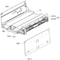
- the bracket assembly 11 is assembled by welding a steel beam, a steel plate and a skin, and the bracket assembly 11 includes a base 110 and a standing frame 111.
- the standing frame 111 is installed to the base 110.
- the base 110 includes a base body 112, a shaft seat 113, and a shock absorber bracket 114.
- the shaft seat 113 is installed to the base body 112, and the shock absorber bracket 114 is also installed to the base body 112.
- the base body 112 is a horizontally arranged rectangular plate having a symmetrical axis S1, and the base body 112 includes a first surface 1120 and a second surface 1121 that are oppositely arranged.
- the base body 112 is provided with a driven wheel installation socket 1122, a driving wheel installation socket 1123, and a guiding device installation socket 1124.
- the driven wheel installation socket 1122 is provided on a first surface 1120 of the base body 112, and are configured to install the driven wheel 12.
- the driving wheel installation socket 1123 is arranged as penetrating through the first surface 1120 and the second surface 1121 of the base body 112, and the driving wheel installation socket 1123 is configured to accommodate the driving wheel assembly 13.
- the guiding device installation socket 1124 is arranged as penetrating through the first surface 1120 and the second surface 1121 of the base body 112, and the guiding device installation socket 1124 is configured to install the guiding device 14.
- the shaft seat 113 and the shock absorber bracket 114 are both installed to the second surface 1121 of the base body 112, and both the shaft seat 113 and the shock absorber bracket 114 are configured to install the driving wheel assembly 13 together.
- the driven wheel installation socket 1122 for installing the driven wheel 12 and the driving wheel installation socket 1123 for accommodating the driving wheel assembly 13 a ground clearance and a centroid height of the movable chassis 10 can be controlled, so that the grip of the movable chassis 10 is improved, and the stability of movement of the movable chassis 10 is improved.
- the standing frame 111 is installed to the second surface 1121 of the base body 112, and the standing frame 111 includes vertical columns 115 and horizontal columns 116 installed to the vertical columns 115.
- the vertical columns 115 is vertically arranged and installed to the second surface 1121 of the base body 112, and two vertical columns are symmetrically distributed relative to a symmetrical axis S 1.
- a surface of each vertical column 115 facing another vertical column 115 is provided with a guide rail along a vertical direction, and the material handling device 30 is installed to guide rails of the two vertical columns, so that the material handling device 30 can move relative to the vertical columns 115 along the vertical direction.
- the number of the guide rail is not limited to two.
- the number of the guide rail may be one, three, or more than three, as long as there is at least one.
- the horizontal columns 116 are horizontally arranged and are connected between two vertical columns 115, and a plurality of horizontal columns 116 are distributed in a vertical direction.
- the four driven wheels 12 are distributed in a first rectangle, and one of symmetrical axes of the first rectangle coincides with the symmetrical axis S 1.
- the four driven wheels 12 support the bracket assembly 11.
- the number of the driven wheel 12 is not limited to four, for example, the number of the driven wheel 12 may also be three, four or more than, as long as there are at least three.
- the driven wheel 12 is a universal wheel.
- the driven wheel 12 is not limited to a universal wheel.
- the driven wheel 12 may be a wheel body with a steering bracket (refer to a rear wheel set of an automobile), as long as the driven wheel 12 has a steering function.
- the driving wheel assembly 13 is configured to drive the movable chassis 10 to move, the driving wheel assembly 13 is installed to the base 110.
- Two driving wheel assemblies 13 are symmetrically distributed relative to the symmetrical axis S 1, and any one of the driving wheel assemblies 13 is located between two driven wheels 12.
- each driving wheel assembly 13 includes a driving wheel bracket 130, a driving wheel body 131, a hub driving device 132, and a hub reduction device 133.
- the driving wheel body 131 is installed to the driving wheel bracket 130, and the driving wheel body 131 can rotate around a rotation axis S2 relative to the driving wheel bracket 130, the rotation axis S2 being horizontal and perpendicular to the symmetrical axis S 1, so that the movable chassis 10 can be movable.
- An output end of the hub driving device 132 is connected to an input end of the hub reduction device 133, and an output end of the hub reduction device 133 is connected to the driving wheel body 131 by a flange, the hub driving device 132 is configured to provide a first driving force for rotation of the driving wheel body 131 around the rotation axis S2, and the hub reduction device 133 is configured to transmit the first driving force.
- the hub reduction device 133 may be omitted.
- the output end of the hub driving device 132 is directly connected to the driving wheel body 131 by a flange, so that the driving wheel body 131 can rotate around the rotation axis S2.
- the output end of the hub reduction device 133 or the output end of the hub driving device 132 are connected to the driving wheel body 131 by a flange, which can improve the reliability of the connection to the driving wheel body 131 and realize a stable installation of the driving wheel body 131, not easy to be detached.
- the hub driving devices 132 of two driving wheel assemblies 13 are used to perform independent driving controls, and two driving wheel bodies 131 may have different rotational speeds, so that the movable chassis 10 turns toward a side of one driving wheel body 131 with a lower rotational speed, to realize a turning function of the movable chassis 10.
- the driving wheel bracket 130 includes a hub bracket 134, an axle body 135, and a shock absorber 136. Where one end of the driving wheel bracket 130 is arranged near the first axis S 1, and the other end is arranged away from the first axis S 1.
- the driving wheel body 131 is installed to an end of the hub bracket 134 away from the symmetrical axis S1.
- the axle body 135 is connected to the hub bracket 134, and the axle body 135 is arranged to be parallel to the symmetrical axis S1.
- the axle body 135 is installed to the shaft seat 113 so that the driving wheel assembly 13 can rotate around the axle body 135 relative to the base body 112.
- One end of the shock absorber 136 is hinged to an end of the shock absorber bracket 114 away from the base body 112, so that the shock absorber 136 can rotate around the first axis S3 that is parallel to the axle body 135, relative to the base body 112; and the other end of the shock absorber 136 is hinged to an end of the hub bracket 134 away from the axle body 135, so that the shock absorber 136 can rotate around the second axis that is parallel to the axle body 135, relative to the hub bracket 134, and the shock absorber bracket 114, the hub bracket 134, and the shock absorber 136 form a triangular structure.
- the shock absorber 136 can buffer a part of the eccentric force, to further improve the stability of movement of the movable chassis 10.
- the hub driving device 132 is a first motor.
- the hub driving device 132 is not limited to the first motor.
- the hub driving device 132 may also be an air motor, a hydraulic transmission system, etc.
- the guiding device 14 is installed to the second surface 1121 of the base body 131 through a guiding device bracket.
- the guiding device 14 is a camera, and a lens of the camera is oriented toward the guiding device installation socket 1124, for identifying a two-dimensional code attached on the ground so that the movable chassis 10 travels along a preset path.
- the guiding device 14 is not limited to the camera.
- the guiding device 14 may be a laser guiding device that travels along a laser beam.
- the guiding device 14 is a short wave receiving device, which realizes a guiding function by receiving a specific short wave signal, and so on.
- the storage frame 20 includes a vertical pole 21, a horizontal pole 22 and a storage unit 23.
- the vertical pole 21 is vertically arranged and installed to the second surface 1121 of the base body 112, and two vertical poles 21 are symmetrically distributed relative to the symmetrical axis S 1.
- the horizontal pole 22 is horizontally arranged and is connected between the two vertical poles 21. Both the number of the horizontal pole 22 and the number of the storage unit 23 correspond to the number of the horizontal column 116.
- One horizontal pole 22 and one corresponding horizontal column 116 support one corresponding storage unit 23, and each storage unit 23 is provided for accommodating an inventory item.
- a vertical height of any one of horizontal poles 22 is lower than a vertical height of a corresponding horizontal column 116, so that a corresponding storage unit 23 inclines from a side at which the corresponding horizontal column 116 is located to a side at which a corresponding horizontal pole 22 is located, so that an inventory item placed in the storage unit is not easy to slip off from the side at which the horizontal column 116 is located.
- each storage unit 23 includes a plate body 24 and a surrounding plate 25.
- the surrounding plate 25 is arranged around an edge of the plate body 24, and leaves an open at a side near the horizontal column 116, the surrounding plate 25 can prevent an inventory item sliding off from the plate body 24, and the inventory item can be pushed into or pulled away from the plate body 24 through the open.
- the material handling device 30 is configured to transport an inventory item between the warehouse shelf and any one of the storage units of the storage frame 20.
- the material handling device 30 can move along the vertical direction so that a position of the material handling device 30 is horizontally opposite to any one of the storage units.
- the material handling device 30 is configured to transport the inventory item between a preset position of the warehouse shelf and any one of the storage units.
- the material handling device 30 includes a support bracket 31, a fork 32, a rotation assembly 33, and a detection device 34.
- the rotation assembly 33 is installed between the support bracket 31 and the fork 32, so that the fork 32 can rotate around a vertically set rotation axis S5 relative to the support bracket 31, the detection device 34 is configured to detect position information of the material handling device 30 relative to the inventory item.
- the support bracket 31 is assembled by welding a steel beam and a steel plate, and is a horizontal arranged plate structure, and an end of the support bracket 31 near the standing frame 111 is provided with a slide 310.
- Two slides 310 are symmetrically distributed relative to the symmetrical axis S1, each slide 310 is installed to a corresponding guide rail, and moves along the guide rail, and the fork 32 installed to the support bracket 31 moves along the vertical direction relative to the storage frame 20.
- the fork 32 is configured to transport the inventory item between the preset position of the warehouse shelf and any one of the storage units, and the fork 32 includes a temporary storage unit 35, a telescopic arm 36, and a pusher assembly 37.
- the temporary storage unit 35 has a reference line S6
- the telescopic arm 36 is installed to the temporary storage unit 35, and is separated from the reference line S6 by a preset distance
- the pusher assembly 37 is installed to the telescopic arm 36, and the telescopic arm 36 drives the pusher assembly 37 to move in a direction parallel to the reference line S6.
- any one of the storage units may locates on the reference line S6.
- the pusher assembly 37 may push the inventory item located on the temporary storage unit to the corresponding storage unit along the reference line S6, or the pusher assembly 37 may pull the inventory item on the corresponding storage unit to the temporary storage unit 35.
- the pusher assembly 37 is further configured to pull the inventory item located on the warehouse shelf to the temporary storage unit, or push the inventory item located on the temporary storage unit to a preset position of the warehouse shelf.
- the fork 32 is not limited to using the pusher assembly 37 to pull the inventory item on the warehouse shelf to the temporary storage unit 35, or to push the inventory item on the temporary storage unit 35 to a preset position on the warehouse shelf.
- the fork 32 further includes a pickup component for transporting the inventory item on the warehouse shelf to the temporary storage unit.
- the pickup component clamps the inventory item on the warehouse shelf to the temporary storage unit by clamping.
- the pickup component lifts the inventory item from the warehouse shelf to the temporary storage unit by lifting, and so on.
- the temporary storage unit 35 is a horizontally arranged rectangular plate structure, has the reference line S6, and is configured to temporarily store an inventory item to be transported between the warehouse shelf and any one of the storage units 23.
- the fork 32 first transports the inventory item on the warehouse shelf to the temporary storage unit 35, and then the fork 32 transports the inventory item on the temporary storage unit 35 to any one of the storage units 23 of the storage frame 20; and vice versa, and due to space limitations, no description is repeated here.
- the temporary storage unit 35 in a first aspect, it can transport an inventory item on one storage unit 23 to another storage unit 23, having a wide range of applications; in a second aspect, it can be realized that any storage unit does not need to be located on the reference line S6 with the warehouse shelf at the same time, and there is no need for adaptive adjustment between the warehouse shelf and the storage frame 20, which makes the handling robot 100 has strong compatibility and can be adapted to different environments, and also since there is no need to modify the warehouse shelf and the storage frame 20, the economy is better; and in a third aspect, the temporary storage unit can also store the inventory item for a long time, so that the maximum load capacity of the handling robot 100 is expanded.
- Two telescopic arms 36 are symmetrically distributed relative to the reference line S6.
- the number of the telescopic arms 36 is not limited to two, for example, the number of the telescopic arm 36 may be one.
- Each telescopic arm 36 includes an outer arm section 360, a middle arm section 361, an inner arm section 362, a middle arm section driving assembly 363, and an inner arm section driving assembly 364.
- the middle arm section 361 is installed to the outer arm section 360, and the middle arm section 361 can move relative to the outer arm section 360 along the reference line S6
- the inner arm section 362 is installed to the middle arm section 361, and the inner arm section 362 can move relative to the middle arm section 361 along the reference line S6
- the middle arm section driving assembly 363 is configured to drive the middle arm section 361 to move relative to the outer arm section 360 along the reference line S6
- the inner arm section driving assembly 364 is configured to drive the inner arm section 362 to move relative to the middle arm section 361 along the reference line S6.
- the inner arm section 362 overlaps with the outer arm section 360.
- the inner arm section 362 is separated from the outer arm section 360 in a direction along the reference line S6.
- the middle arm section 361 and the inner arm section driving assembly 364 may be omitted.
- the inner arm section 362 is installed to the outer arm section 360, and the inner arm section 362 can move relative to the outer arm section 360 along the reference line S3, and the middle arm section driving assembly 363 is configured to drive the inner arm section 362 to move relative to the outer arm section 360 along the reference line S6.
- the middle arm section driving assembly 363 includes a sprocket wheel mechanism 3630 and a middle arm section driving device 3631. Where an output end of the middle arm section driving device 3631 is connected to a driving sprocket wheel of the sprocket wheel mechanism 3630, the middle arm section driving device 3631 is configured to drive the driving sprocket wheel to rotate, and the middle arm section 361 fixedly is connected to a roller chain of the sprocket wheel mechanism 3630, and the sprocket wheel mechanism 3630 can drive the middle arm section 361 to move relative to the outer arm section 360 along the reference line S6.
- the sprocket wheel mechanism 3630 may be replaced with a pulley mechanism or the like.
- the middle arm section driving device 3631 is a second motor.
- the middle arm section driving device 3631 is not limited to a motor.
- the middle arm section driving device 3631 may also be an air motor, a hydraulic transmission system, or the like.
- the inner arm section driving assembly 364 includes a movable pulley 3640 and a strop 3641.
- the movable pulley 3640 is installed to the middle arm section 362, and a middle part of the strop 3641 is arranged to be bent so that two ends of the strop 3641 are oppositely arranged, that is, the strop 3641 is U-shaped, and the middle part of the strop 3641 is sleeved over the movable pulley 3640, one end of the strop 3641 is fixedly connected to the outer arm section 360, the other end of the strop 3641 is fixedly connected to the inner arm section 362, and the movable pulley 3640 and the strop 3641 form a movable pulley structure, and when the middle arm section 361 moves at a first speed relative to the outer arm section 360 along the reference line S6, the inner arm section 362 moves at a second speed relative to the outer arm section 360 along the reference line S6, the second speed
- the movable pulley 3640 is a flat belt pulley
- the strop 3641 is an open-loop flat belt.
- the movable pulley 3640 and the strop 3641 are not limited to the flat belt pulley and the open-loop flat belt.
- the movable pulley 3640 is a sprocket wheel
- strop 3641 is a roller chain.
- the pusher assembly 37 includes a fixed push rod 370, a manipulator 371, and a push rod driving device 372.
- Two ends of the fixed push rod 370 are respectively installed at opposite ends of the two inner arm sections 362, and two manipulators 371 are respectively installed at ends of the inner arm sections 362 away from the fixed push rod 370, and the manipulators 371 can fold or unfold relative to the inner arm sections 362, and the push rod driving device 372 is configured to drive the manipulators 371 to fold or unfold relative to the inner arm sections 362.
- the temporary storage unit is located between the two ends of the inner arm section 362 in a direction along the reference line S6.
- the push rod driving device 372 includes a third motor, and an end of the manipulator 371 is installed at an output end of the third motor, and the third motor is configured to drive the manipulator 371 to rotate relative to the inner arm section 362 around the third axis S7 that is parallel to the reference line S6, so that the manipulator 371 unfolds or folds relative to the inner arm section 362.
- the end of the inner arm section 362 installed with the manipulator 371 can move from a side of the corresponding inventory item facing the temporary storage unit to a side of the corresponding inventory item away from the temporary storage unit along the reference line S6, so that the manipulator 371 relative to the inner arm section 362 may pull the corresponding inventory item to the temporary storage unit along the reference line S6.
- an inventory item is located on the reference line S6, where the so-called inventory item may be an inventory item on the warehouse shelf or an inventory item on the storage unit, as long as the inventory item is located on the reference line S6.
- the fixed push rod 370 can push the inventory item located on the temporary storage unit 35 to a preset position of the warehouse shelf.
- the fixed push rod can push the inventory item that is temporarily stored on the temporary storage unit 35 to a corresponding storage unit 23 along the reference line S6.
- the manipulator 371 when the fixed push rod 370 pushes the inventory item, the manipulator 371 can fold relative to the inner arm section 362 or unfold relative to the inner arm section 362, and when the fixed push rod 370 completes the pushing of the inventory item and is reset, the manipulator 371 folds relative to the inner arm section 362.
- the temporary storage unit 35 can be omitted.
- the temporary storage unit 35 has basically the same structure as the storage unit 23 or the warehouse shelf, and the position of the temporary storage unit 35 can be directly replaced with the storage unit 23.
- each storage unit is located on the same horizontal plane as a corresponding warehouse shelf.
- the fixed push rod 370 may push the inventory item placed on the corresponding storage unit 23 to the preset position of the corresponding warehouse shelf, or the manipulator 371 unfolded relative to the inner arm section 362 pulls the inventory item located on the corresponding warehouse shelf to the corresponding storage unit 23.
- the fixed push rod 370 may be omitted.
- the manipulator includes a pushing surface and a pulling surface, which are oppositely arranged, where the pushing surface is oriented toward one end of the reference line, and the pulling surface is oriented toward the other end of the reference line.
- the inner arm section 362 installed with the manipulator 371 can move to either side of the inventory item (located on the temporary storage unit, the storage unit, or the warehouse shelf) by the manipulator 371 folded relative to the inner arm section 362, and the manipulator 371 unfolded relative to the inner arm section 362 can push the inventory item to the temporary storage unit 35, the storage unit 23 or the preset position of the warehouse shelf via the pushing surface, or pull the inventory item to the temporary storage unit 35, the storage unit 23 or the preset position of the warehouse shelf via the pulling surface.
- the rotation assembly 33 is configured to rotate the fork 32 relative to the storage frame 20 around a vertical direction, so that any two or three of any storage unit 23, the warehouse shelves and the reference line S6 may not be located in the same vertical plane.
- the rotation assembly 33 includes a rotation mechanism 330, a rotation driving mechanism 331, a deflection detection device, and a rotation limit device.
- the rotation mechanism 330 is installed between the fork 32 and the support bracket 31, the rotation mechanism 330 can rotate around the rotation axis S5, and the rotation driving mechanism is configured to drive the rotation mechanism 330 to rotate around the rotation axis S5, and the deflection detection device is configured to control the rotation driving mechanism 331.
- the rotation mechanism 330 includes a first rotation member 3300 and a second rotation member 3301, where the first rotation member 3300 is installed to a surface of the support bracket 31 facing the fork 32, and the second rotation member 3301 is installed to the first rotation member 3300, and the second rotation member 3301 can rotate around the rotation axis S5 relative to the first rotation member 3300, and the fork 32 is installed to the second rotation member 3301.
- the first rotation member 3300 is a slewing bearing inner ring
- a center line of the slewing bearing inner ring is coaxial with the rotation axis S5
- the second rotation member 3301 is a slewing bearing outer ring
- the slewing bearing outer ring is sleeved on the slewing bearing inner ring, so that the slewing bearing outer ring can rotate around the rotation axis S5 relative to the slewing bearing inner ring, and the slewing bearing outer ring and the slewing bearing inner ring support the fork 32 together.
- first rotation member 3300 and the second rotation member 3301 are not limited to a combination of the slewing bearing inner ring and the slewing bearing outer ring.
- the rotation driving mechanism 331 includes an outer ring gear 3310, a rotation driving gear 3311, and a rotation driving device.
- the outer ring gear 3310 is fixedly connected to the second rotation member 3301, and the outer ring gear 3310 is coaxial with the rotation axis S5.
- An output end of the rotation driving device is connected to the rotation driving gear 3311, and the rotation driving device is configured to drive the rotation driving gear 3311 to rotate, so that the outer ring gear 3310 that is engaged with the rotation driving gear 3311 rotates around the rotation axis S5, and drives the second rotation member 3301 fixedly connected to the outer ring gear 3310 to rotate around the rotation axis S4.
- the outer ring gear 3310 is integrally formed with the slewing bearing outer ring.
- the rotation driving mechanism 331 is not limited to the outer ring gear 3310 and the rotation driving gear 3311.
- the rotation driving mechanism is a worm gear mechanism, a gear set, or a planetary gear mechanism.
- the rotation driving device is a fourth motor. It should be understood that, according to an actual situation, the rotation driving device may also be a linear motor, an air motor, a hydraulic drive system, etc.
- the rotation limit device includes a first limit post 3320, a second limit bar 3321, and a limit block 3322.
- the first limit bar 3320 and the second limit bar 3321 are both installed to the surface of the support bracket 31 facing the fork 32, and the first limit bar 3320 and the second limit bar 3321 are circumferentially distributed around the rotation axis S5, and the limit block 3322 is installed to a surface of the fork 32 facing the support bracket 31, the limit block 3322 can abut against the first limit bar 3320 and the second limit bar 3321, respectively, enabling the rotation mechanism 330 to rotate around the rotation axis S5 within a preset angle range, to drive the fork 32 to rotate to a preset angle, and the preset angle is within the preset angle range.
- the deflection detection device is configured to detect whether the fork 32 rotates to the preset angle.
- the deflection detection device When the deflection detection device detects that the fork has not yet rotated to the preset angle, the deflection detection device controls the rotation assembly to drive the fork to continue to rotate.
- the deflection detection device When the deflection detection device detects that the fork rotates over the preset position, the deflection detection device controls the rotation assembly to drive the fork to rotate in a reverse direction.
- the deflection detection device When the deflection detection device detects that the fork rotates to the preset angle, the deflection detection device controls the rotation assembly to stop rotating.
- the deflection detection device includes a first sensor 3330, a second sensor 3331 and a rotation controller, where the first sensor 3330 and the second sensor 3331 are both connected to the rotation controller.
- the first sensor 3330 is provided with a first detection range.
- the first sensor 3330 is configured to detect the fork 32 within the first detection range.
- the second sensor 3331 is provided with a second detection range.
- the second sensor 3331 is configured to detect the fork 32 within the second detection range.
- the rotation controller is connected to the rotation driving device, and is configured to control the fork 32 to rotate around the rotation axis S5 through the rotation driving device.
- the first sensor 3330 detects the fork 32 in the first detection range, and the second sensor 3331 does not detect the fork 32 in the second detection range, the fork 32 has not yet rotated to the preset angle.
- the fork 32 has rotated over the preset angle.
- the fork 32 rotates to the preset angle.
- the first sensor 3330 is a first proximity switch, and the first proximity switch is installed to the surface of the fork 32 facing the support bracket 31.
- the second sensor 3331 is a second proximity switch, the second proximity switch and the first proximity switch are installed to the surface of the support bracket 31, and the first proximity switch and the second proximity switch are circumferentially distributed around the rotation axis S5.
- the rotation controller further includes a detection board 3333, the detection board 33 is installed to the surface of the support bracket 31 facing the fork 32, and the detection board 3333 is arranged to be bend around the rotation axis S5.
- the first proximity switch faces the detection board 3333, and the second proximity switch does not face the detection board 3333.
- the first proximity switch does not face the detection board 3333, but the second proximity switch faces the detection board 3333.
- the first proximity switch faces one end of the detection board 3333
- the second proximity switch faces the other end of the detection board 3333.
- the rotation assembly 33 may be omitted, and the material handling robot may adjust a horizontal orientation of the fork 32 by the movable chassis 10 to replace the function of the rotation assembly, as long as a storage unit 23 and a corresponding warehouse shelf are located on the reference line S6 at the same time.
- the movable chassis 10 and the lifting assembly 40 work so that a storage unit 23 and a corresponding warehouse shelf are located at the reference line S6, one end of the inner arm section 362 installed with the manipulator 371 first passes the corresponding storage unit 23, and then the manipulator 371 unfolded relative to the inner arm section 362 pulls the inventory item to the corresponding storage unit, and then continues to pull to the temporary storage unit 35; and the fixed push rod 370 pushes the inventory item located on the temporary storage unit 35 to the corresponding storage unit 23, and then continues to push the inventory item located on the corresponding storage unit 23 to the preset position of the corresponding warehouse shelf. Since the inventory item first passes through the corresponding storage unit 23 or the corresponding warehouse shelf, then reaches the temporary storage unit 35, the temporary storage unit 35 may be omitted in this embodiment.
- the detection device 34 is configured to detect the position information of the material handling device relative to the inventory item, i.e., to determine whether the storage unit 23, the preset position of the warehouse shelf and the inventory item are located on the reference line S6.
- the position information of the material handling device relative to the inventory item includes a first position offset between the inventory item and the reference line in the travelling direction, and a second position offset between the inventory item and the reference line in the vertical direction, the distance between the inventory item and the manipulator along the reference line, and the deflection amount between the inventory item and the reference line in the horizontal direction.
- the position information of the material handling device relative to the inventory item includes the first position offset between the inventory item and the reference line in travelling direction.
- the detection device includes a camera device 340, a primary lighting equipment 341, and a secondary lighting equipment 342.
- the camera device 340 is installed to a surface of the temporary storage unit 35 facing the support bracket 31, and a lens of the camera device 340 is in the same direction as the direction of the extension of the telescopic arm 36.
- the camera device 340 is configured to acquire image information, such as, shooting the two-dimensional code on the warehouse shelf or the two-dimensional code attached on the inventory item, so as to determine whether the storage unit, the preset position of the warehouse shelf, and the inventory item are on the reference line S6.
- the camera device 340 is configured to determine the position of the inventory item relative to the warehouse shelf and the position of the inventory item relative to the storage frame 20 through an image difference algorithm, and so on.
- the camera device 340 may be replaced with a laser guiding device, an infrared sensor, and etc.
- the primary lighting equipment 341 is installed to the temporary storage unit 35, and is located on one side of the primary lighting equipment 341 away from the camera device 340.
- the primary lighting equipment 341 and the lens of the camera device 340 have the same orientation.
- the primary lighting equipment 341 is configured to compensate for light, so that the camera device 340 can clearly shoot the two-dimensional code on the warehouse shelf or the inventory item.
- the secondary lighting equipment 342 is installed on the support bracket 31, two secondary lighting equipments 342 are distributed relative to the symmetrical axis S1, and the orientation of each secondary lighting equipment 342 is inclined upward, and is arranged back to the other lighting equipment 342.
- the fork rotates around the rotation axis S5 until the camera device 340 is located above one secondary lighting equipment 342, and then the one secondary lighting equipment 342 can further perform light compensation on the camera device 340, so that the handling robot 100 can be adapted to different lighting environments, such as day and night.
- the secondary lighting equipment 342 is arranged to be inclined, so that the light emitted by the secondary lighting equipment 342 is not easily all reflected to the lens of the camera device 340, resulting in excessive light compensation.
- the lifting assembly 40 is configured to drive the material handling device 30 to move relative to the storage frame 20 in the vertical direction.
- the lifting assembly 40 includes a lifting transmission mechanism and a lifting drive mechanism 42, where the lifting drive mechanism 42 is configured to provide a second driving force for movement of the material handling device 30 relative to the storage frame 20 in the vertical direction, and the lifting transmission mechanism is configured to transmit the second driving force to the material handling device 30.
- the lifting transmission mechanism includes two sets of synchronous wheel mechanisms 43.
- the two sets of synchronous wheel mechanisms 43 are installed to two opposite surfaces of the two vertical columns 115, respectively.
- Each set of synchronous wheel mechanism 43 includes a driving synchronous wheel 430, a tension wheel 431 and a synchronous belt 432, where the driving synchronous wheel 430 is installed at one end of the vertical columns 115 near the base body 112, the tension wheel 431 is installed at one end of the vertical columns 115 away from the base body 112, the tension wheel 431 and the driving synchronous wheel 430 are sleeved on the synchronous belt 432, and the lifting drive mechanism 42 is connected to the driving synchronous wheel 430, and is configured to drive the driving synchronous wheel 430 to rotate.
- the driving synchronous wheel 430 drives the synchronous belt 432 to move in the vertical direction, so that the support bracket 31 fixedly connected to the synchronous belt 432 synchronously moves in the vertical direction.
- each synchronous wheel mechanism 43 is connected with a counterweight 433.
- Each counterweight 433 has a certain mass, is installed on a counterweight rail of a corresponding vertical column 115, and can move relative to the corresponding vertical column 115 in the vertical direction.
- the counterweight 433 can act as a buffer, and reduce the load of the lifting drive mechanism 42.
- the number of the synchronous wheel mechanisms 43 is not limited to two, for example, the number of the synchronous wheel mechanisms 43 may be one, two or more as long as there is at least one.
- the lifting transmission mechanism is not limited to the synchronous wheel mechanism 43, for example, the lifting transmission mechanism may also be a sprocket wheel mechanism, or a gear rack mechanism, a turbine worm mechanism, a lifting screw mechanism, and so on.
- the lifting drive mechanism Since the support bracket 31 supports the fork, the lifting drive mechanism has a large load during the transport of the inventory item. In order to ensure that the material handling device can smoothly lift, two synchronization wheel mechanisms have a high synchronization rate.
- the lifting drive mechanism 42 includes a lifting driving device 420, a driving shaft 421, a driving gear, and a driven gear (both the driving gear and the driven gear are installed in the gearbox 422 in the figure), where two ends of the driving shaft 421 are connected to two driving synchronous wheels 430 of the two synchronous wheel mechanisms 43 through flat keys, and the driving shaft 421 transmits a torque to the driving synchronous wheel 430 through the flat keys, so that the driving synchronous wheels 430 of the two synchronous wheel mechanisms 43 can rotate synchronously, which allows the material handling device 30 to smoothly move in the vertical direction.
- the driven gear is sleeved between two shafts of the driving shaft 421, and the driving gear engages with the driven gear to transmit the driving force of the lifting driving device 420.
- the synchronous wheel mechanism 43 may be replaced with a sprocket wheel mechanism, or a gear rack set, or the like.
- short shafts at both ends of the driving shaft 421 are coaxially connected by a coupling, where one end of one short shaft facing away from the coupling is connected to the driving synchronous wheel 430 of one synchronous wheel mechanism 43, and one end of the other short shaft facing away from the coupling is connected to the driving synchronous wheel 430 of the other synchronous wheel mechanism 43, which can further ensure the synchronization rate of the two driving synchronous wheels 430.
- the lifting driving device 420 is a fifth motor. It should be understood that, according to an actual situation, the lifting drive device is not limited to the fifth motor.
- the lifting driving device may also be an air motor, hydraulic transmission system, etc.
- the handling robot 100 specifically involves the following several processes: The handling robot 100 transports the inventory item on the warehouse shelf to the temporary storage unit.
- the movable chassis 10 drives the handling robot 100 to move to a warehouse shelf where an inventory item is placed, where the movable chassis 10 is guided by the guiding device 14 so that the movable chassis 10 travels along a specified path, and when reaching the warehouse shelf where the inventory item is placed, the movable chassis 10 is stationary relative to the warehouse shelf;
- the lifting assembly 40 drives the fork 32 to move relative to the warehouse shelf in the vertical direction, so that the reference line S6 of the fork 32 is on the same horizontal plane as the inventory item;
- the fork 32 rotates around the vertically set rotation axis S5 so that the inventory item is on the reference line S6;
- the telescopic arm 36 extends along the reference line, where the manipulator 371 installed at one end of the inner arm section 362 folds relative to the inner arm section 362, and the one end of the inner arm section 362 installed
- the handling robot 100 transports an inventory item in the temporary storage unit to a storage pallet.
- the fork 32 rotates relative to the storage frame 20 around the rotation axis S5 until the reference line S6 of the fork 32 is on the same vertical plane as the storage unit (in an embodiment provided by the present application, when the reference line S6 of the fork 32 is on the same vertical plane as the storage unit, the fork 32 is at a benchmark angle relative to the support bracket 31);
- the lifting assembly 40 drives the fork 32 to move in the vertical direction, so that one storage unit is located on the reference line S6;
- the telescopic arm 36 extends along the reference line S6 so that the fixed push rod 370 installed at an end of the inner arm section 362 facing away from the manipulator 371 pushes the inventory item located in the temporary storage unit into a corresponding storage unit.
- the handling robot 100 transports an inventory item in a storage pallet to the temporary storage unit.
- the fork 32 rotates relative to the storage frame 20 around the rotation axis S5 until the reference line S6 of the fork 32 is on the same vertical plane as the storage unit;
- the lifting assembly 40 drives the fork 31 to move in the vertical direction so that one storage unit is located on the reference line S6;
- the telescopic arm 36 extends along the reference line, where the manipulator 371 installed at one end of the inner arm section 362 folds relative to the inner arm section 362, and one end of the inner arm section 362 installed with the manipulator 371 moves from the side of the inventory item facing the temporary storage unit to the side of the inventory item facing away the temporary storage unit; in step 5, the manipulator 371 unfolds relative to the inner arm section 362, and then the telescopic arm 36 is retracted so that the manipulator 371 pulls the inventory item into the temporary storage unit.
- the handling robot 100 transports the inventory item in the temporary storage unit to the warehouse shelf.
- step 1 the movable chassis 10 drives the handling robot 100 to move to a preset position of the warehouse shelf, where the movable chassis 10 is guided by the guiding device 14 to allow the movable chassis 10 to travel along a specified path, and when reaching the warehouse shelf, the movable chassis 10 is stationary relative to the warehouse shelf; in step 2, the lifting assembly 40 drives the fork 32 to move relative to the warehouse shelf in the vertical direction, so that the reference line S6 of the fork 32 is on the same horizontal plane as the preset position; in step 3, the fork 32 rotates around the vertically set rotation axis S5 so that the preset position is on the reference line S6; in step 4, the telescopic arm 36 extends along the reference line S6, so that the fixed push rod 370 installed at an end of the inner arm section 362 facing away the manipulator 371 pushes the inventory item located in the temporary storage unit to the preset position of the warehouse shelf.
- An embodiment of the present application provides a handling robot 100, the handling robot 100 includes: a movable chassis 10; a storage frame 20, installed on the movable chassis 10, and provided with a plurality of storage units 23 distributed in a vertical direction, each storage unit 23 being configured to place an inventory item; a material handing device 30, configured to transport an inventory item between a warehouse shelf and any one of the storage units 23, where the material handling device 30 has a preset horizontal reference line S6, and the material handling device 30 includes a pusher assembly, the pusher assembly can move relative to the storage frame along the reference line; and a lifting assembly, configured to drive the material handling device to move in a vertical direction so that any one of the storage units is located on the reference line.
- the pusher assembly can push the inventory item to a corresponding storage unit along the reference line, or the pusher assembly can pull the inventory item located on the corresponding storage unit away therefrom.
- the handling robot 100 equipped with the storage frame 20 can load a large number of inventory items.
- an inventory item is pushed into or pulled away a storage unit, so that a distance between each two adjacent storage units is small, and more storage units can be placed in the handling robot with the same vertical height, increasing the maximum load capacity.
- the inventory item transported by the material handling device 30 each time may be a single object or several separated objects.
- the material handling device 30 transports the inventory item from the warehouse shelf
- a plurality of objects on the warehouse shelf are sequentially arranged along the reference line S6.
- One end of the inner arm section 362 installed with the manipulator 371 moves from the front side of the closest object to the back side of the farthest object, and then the manipulator 371 pulls the plurality of objects together away the warehouse shelf.
- Step 201 driving, by the telescopic arm, the manipulator to extend to the preset position of the warehouse shelf along the preset horizontal reference line.
- Step 202 loading, by the manipulator that is remained on the horizontal plane where the reference line is located, an inventory item located at the preset position.
- the manipulator is configured to pull the inventory item.
- the manipulator may be in various forms.
- the manipulator may be in the form of clip or pallet, but is not limited thereto.
- the manipulator drags the inventory item.
- the manipulator can clamp the inventory item, or support the inventory item from under, etc., as long as the manipulator can drive the inventory item to move along the reference line.
- Step 203 driving, by the telescopic arm, the manipulator loaded with the inventory item to move to the storage frame along the reference line.
- Step 204 unloading, by the manipulator that is remained on the horizontal plane where the reference line is located, the inventory item to the storage frame.
- a lifting assembly is added to drive the material handling device to move in the vertical direction.
- the reference line can be on the same horizontal plane with the inventory item located at any height.
- the method for retrieving an inventory item further includes: Step 2005: driving, by the lifting assembly, the material handling device to move in the vertical direction, so that the manipulator is horizontally opposed to the preset position.
- the storage frame is provided with a plurality of storage units distributed in a vertical direction. Under the condition of providing the lifting assembly, the lifting assembly can also be fully utilized.
- the method for retrieving an inventory item further includes: Step 2025: driving, by the lifting assembly, the material handling device to move in the vertical direction, so that the material handling device is horizontally opposed to a corresponding storage unit.
- the material handling device is opposed to any corresponding storage unit through the lifting assembly, and then the inventory item can be stored in the corresponding storage unit.
- the handling robot is equipped with the movable chassis, and can move between different warehouse shelves, so that the handling robot can realize the function of transporting the inventory item between different warehouse shelves.
- the method for retrieving an inventory item further includes: Step 2004: moving the movable chassis to a preset range in front of the warehouse shelf.
- the warehouse shelf here may be a warehouse shelf in which an inventory item to be transported is placed, or a warehouse shelf in which an inventory item to be transported needs to be placed.
- the material handling device needs to be aligned with the inventory item, i.e., keeping the inventory item on the reference line, it needs to perform alignment by the lifting assembly in the vertical direction, and perform adjustment by the movable chassis in the horizontal direction, so that the inventory item is located on the reference line in the horizontal direction, improving an accuracy of the manipulator for loading the inventory item.
- the material handling device is provided with a detection device for detecting a position of the material handling device relative to the inventory item, i.e., detecting whether the inventory item is on the reference line.
- the method for retrieving an inventory item further includes: Step 2026: detecting, by the detection device, position information of the material handling device relative to the inventory item, and adjusting, by the handling robot, a posture of fetching the inventory item according to the position information of the material handling device relative to the inventory item.
- an adjustment of the position of the reference line only by the movable chassis has a low efficiency. This is due to a low efficiency of turning of the present movable chassis on one hand, and a high load of the handling robot and not high accuracy of the movement of the handling robot on the other hand, thereby the adjustment of the position of the reference line only by the movable chassis having a low efficiency.
- the movable chassis is provided with a travelling direction, and the movable chassis has the highest efficiency when moving in the travelling direction.
- the position information of the material handling device relative to the inventory item includes a first position offset between the inventory item and the reference line in the travelling direction.
- step 2026 the adjusting, by the handling robot, a posture of fetching the inventory item according to the position information of the material handling device relative to the inventory item includes: Step 2026A: causing the movable chassis to move in the travelling direction according to the first position offset, so that the first position offset is smaller than a first error value.
- the first error value is set. As long as an actual error, i.e., the first position offset, is smaller than the first error value, it can be considered that the movable chassis moves into place.
- a person skilled in the art can set the first error value in the handling robot in advance according to an actual situation.
- the position information of the material handling device relative to the inventory item includes a second position offset between the inventory item and the reference line in the vertical direction.
- step 2026 the adjusting, by the handling robot, a posture of fetching the inventory item according to the position information of the material handling device relative to the inventory item includes: Step 2026B: driving, by the lifting assembly, the material handling device to move in the vertical direction according to the second position offset, so that the second position offset is smaller than a second error value.
- step 2025 the material handling device has achieved a preliminary lifting, but the inventory item has not been accurately positioned on the reference line, and by fine-tuning, the reference line can be located near the middle of the inventory item, to improve the accuracy of retrieving the inventory item.
- a person skilled in the art can set the second error value in the handling robot in advance according to an actual situation.
- the position information of the material handling device relative to the inventory item includes a distance between the inventory item and the manipulator along the reference line.
- step 2026 the adjusting, by the handling robot, a posture of fetching the inventory item according to the position information of the material handling device relative to the inventory item includes: Step 2026C: adjusting an extension amount of the telescopic arm along the reference line according to the distance, so that the extension amount is larger than the distance.
- the detection device is an image acquisition device. It should be understood that, according to an actual situation, the detection device can also be in other forms.
- the material handling device id provided with a laser transmitter and a laser receiver, and the inventory item is provided with a reflective surface, and the positioning of the material handling device relative to the inventory item can be realized by the laser transmitter emitting a laser to the reflective surface, and the laser reflected by the reflective surface entering the laser receiver.
- the material handling device is provided with a radio frequency transmitter, and the inventory item is attached with an electronic label, and the position relationship between the material handling device and the inventory item can be determined by radio frequency identification.
- the detection device detects the position information of the material handling device relative to the inventory item.
- a surface of the inventory item facing to the handling robot is attached with a two-dimensional code label; when the image acquisition device acquires the image information of the inventory item, the information provided by the two-dimensional code label is collected, to obtain the position information of the material handling device relative to the inventory item.
- the method for retrieving an inventory item further includes: Step 2026: driving, by the telescopic arm, the manipulator loaded with the inventory item to retract to the temporary storage unit along the reference line.
- Step 2027 unloading, by the manipulator that is remained on the horizontal plane where the reference line is located, the inventory item to the temporary storage unit.
- Step 2028 loading, by the manipulator that is remained on the horizontal plane where the reference line is located, the inventory item located on the temporary storage unit.
- the inventory item on the warehouse shelf is first transported to the temporary storage unit, and then the lifting assembly lifts or lower to make the temporary storage unit and one storage unit located at the same height, transporting the inventory item to the corresponding storage unit.
- the method for retrieving an inventory item further includes: Step 2029: driving, by the rotation assembly, the telescopic arm to rotate to a preset angle around a vertical direction, so that the material handling device is oriented towards the storage frame.
- the position information of the material handling device relative to the inventory item includes a deflection amount between the inventory item and the reference line in the horizontal direction.
- step 2026 the adjusting, by the handling robot, a posture of fetching the inventory item according to the position information of the material handling device relative to the inventory item includes: Step 2026D: driving, by the rotation assembly, the fork to rotate around a vertical direction according to the second position offset, so that the deflection amount is smaller than a third error value.
- a person skilled in the art may set the third error value in the handling robot in advance according to an actual situation.
- the rotation requires a high precision and requires a high speed to improve efficiency, but it is difficult for the fork to stop at a preset angle due to the inertia during the rotation.
- the driving, by the rotation assembly, the fork to rotate around a vertical direction includes: when the deflection detection device detects that the fork has not yet rotated to the preset angle, driving, by the rotation assembly, the fork to continue to rotate; when the deflection detection device detects that the fork has rotated over the preset angle, driving, by the rotation assembly, the fork to rotate in a reverse direction; and when the deflection detection device detects that the fork rotates to the preset angle, causing the rotation assembly to stop rotating.
- the deflection detection device controls the rotations of the fork, and makes the fork to rotate to the preset angle.
- the deflection detection device includes: a first sensor provided with a first detection range; and a second sensor provided with a second detection range.
- the deflection detection device detects the fork has not yet rotated to the preset angle.
- the deflection detection device detects the fork has rotated over the preset angle.
- the deflection detection device detects the fork rotates to the preset angle.
- inventory items are placed in positions at two different depths of the warehouse shelf, which may decrease an aisle for the handling robot and improve the utilization rate of the warehouse in the horizontal space.
- the inventory item includes a first inventory item and a second inventory item.
- the preset position includes a first preset position and a second preset position.
- the first inventory item is located at the first preset position, and the second inventory item is located at the second preset position.
- the storage frame includes a first storage unit and a second storage unit.
- the method for retrieving an inventory item further includes:
- first inventory item is transported to the first storage unit, and then the second inventory item is transported to the second storage unit.
- the method for retrieving an inventory item further includes:
- the method for retrieving an inventory item further includes:
- the inventory items correspond to positions of the warehouse shelf one by one.
- the method for retrieving an inventory item further includes: Step 3013: uploading current position information of the first inventory item.
- the present application provides a method for retrieving an inventory item based on a handling robot, where the handling robot includes: a storage frame; a material handling device installed on the storage frame and including a telescopic arm and a manipulator installed to the telescopic arm; the method for retrieving an inventory item includes: driving, by the telescopic arm, the manipulator to extend to a preset position of a warehouse shelf along a preset horizontal reference line; loading, by the manipulator that is remained on the reference line, the inventory item in the preset position; driving, by the telescopic arm, the manipulator loaded with the inventory item to move to the storage frame along the reference line, and unloading, by the manipulator that is remained on the reference line, the inventory item to the storage frame.
- the inventory item can be moved to the storage frame along the preset horizontal reference line, the occupied space of the storage frame in the vertical direction is less and a larger number of inventory items can be loaded.
- the following enumerated aspects 1 to 31 are also relevant for the present disclosure as part of the specification which must not be confused with the appended claims (that follow after the specification):
Applications Claiming Priority (4)
| Application Number | Priority Date | Filing Date | Title |
|---|---|---|---|
| CN201711135812.7A CN108069180A (zh) | 2017-11-14 | 2017-11-14 | 机器人 |
| CN201711141498.3A CN108122016B (zh) | 2017-11-14 | 2017-11-14 | 自动存取货物的方法和装置 |
| PCT/CN2018/104654 WO2019095804A1 (zh) | 2017-11-14 | 2018-09-07 | 一种搬运机器人以及基于搬运机器人的取货方法 |
| EP18879979.5A EP3712815B1 (de) | 2017-11-14 | 2018-09-07 | Transportroboter und auf transportroboter basierendes aufnahmeverfahren |
Related Parent Applications (2)
| Application Number | Title | Priority Date | Filing Date |
|---|---|---|---|
| EP18879979.5A Division EP3712815B1 (de) | 2017-11-14 | 2018-09-07 | Transportroboter und auf transportroboter basierendes aufnahmeverfahren |
| EP18879979.5A Division-Into EP3712815B1 (de) | 2017-11-14 | 2018-09-07 | Transportroboter und auf transportroboter basierendes aufnahmeverfahren |
Publications (2)
| Publication Number | Publication Date |
|---|---|
| EP4306478A2 true EP4306478A2 (de) | 2024-01-17 |
| EP4306478A3 EP4306478A3 (de) | 2024-03-20 |
Family
ID=66538872
Family Applications (4)
| Application Number | Title | Priority Date | Filing Date |
|---|---|---|---|
| EP18878478.9A Pending EP3710381A4 (de) | 2017-11-14 | 2018-09-07 | Automatisch geführtes, für ein lager ausgelegtes fahrzeug |
| EP18879979.5A Active EP3712815B1 (de) | 2017-11-14 | 2018-09-07 | Transportroboter und auf transportroboter basierendes aufnahmeverfahren |
| EP23213684.6A Pending EP4306478A3 (de) | 2017-11-14 | 2018-09-07 | Handhabungsroboter und verfahren zum abrufen eines inventarartikels auf basis des handhabungsroboters |
| EP20847847.9A Pending EP4005948A4 (de) | 2017-11-14 | 2020-07-29 | Verfahren zur steuerung eines lagerroboters zum lagern und abrufen von lagerbestand |
Family Applications Before (2)
| Application Number | Title | Priority Date | Filing Date |
|---|---|---|---|
| EP18878478.9A Pending EP3710381A4 (de) | 2017-11-14 | 2018-09-07 | Automatisch geführtes, für ein lager ausgelegtes fahrzeug |
| EP18879979.5A Active EP3712815B1 (de) | 2017-11-14 | 2018-09-07 | Transportroboter und auf transportroboter basierendes aufnahmeverfahren |
Family Applications After (1)
| Application Number | Title | Priority Date | Filing Date |
|---|---|---|---|
| EP20847847.9A Pending EP4005948A4 (de) | 2017-11-14 | 2020-07-29 | Verfahren zur steuerung eines lagerroboters zum lagern und abrufen von lagerbestand |
Country Status (13)
| Country | Link |
|---|---|
| US (4) | US11718472B2 (de) |
| EP (4) | EP3710381A4 (de) |
| JP (7) | JP6838178B2 (de) |
| KR (8) | KR102332766B1 (de) |
| CN (5) | CN114021680A (de) |
| AU (5) | AU2018368406B2 (de) |
| CA (3) | CA3152890C (de) |
| DE (3) | DE202018006724U1 (de) |
| MY (2) | MY188417A (de) |
| NZ (2) | NZ765310A (de) |
| RU (3) | RU2754121C1 (de) |
| SG (2) | SG11202004492WA (de) |
| WO (3) | WO2019095803A1 (de) |
Families Citing this family (89)
| Publication number | Priority date | Publication date | Assignee | Title |
|---|---|---|---|---|
| US10459450B2 (en) * | 2017-05-12 | 2019-10-29 | Autonomy Squared Llc | Robot delivery system |
| US11396424B2 (en) | 2017-11-14 | 2022-07-26 | Hai Robotics Co., Ltd. | Handling robot |
| NZ765310A (en) * | 2017-11-14 | 2022-04-29 | Hai Robotics Co Ltd | Automated guided vehicle designed for warehouse |
| US20220371821A1 (en) | 2017-11-14 | 2022-11-24 | Hai Robotics Co., Ltd. | Handling robot |
| US11465840B2 (en) | 2017-11-14 | 2022-10-11 | Hai Robotics Co., Ltd. | Handling robot |
| WO2019117844A1 (en) * | 2017-12-11 | 2019-06-20 | Daniel Theobald | Autonomous device for transporting items |
| EP3797082A1 (de) * | 2018-05-22 | 2021-03-31 | Pick8Ship Technology AG | Transferstation für frachtumschlag und verfahren zur sortierung von frachtbehältern |
| US11400599B2 (en) * | 2019-01-30 | 2022-08-02 | Lg Electronics Inc. | Stock management robot |
| US11542135B2 (en) | 2019-02-01 | 2023-01-03 | Hai Robotics Co., Ltd. | Handling robot |
| CN209758195U (zh) * | 2019-02-01 | 2019-12-10 | 深圳市海柔创新科技有限公司 | 一种搬运机器人 |
| US11597598B2 (en) | 2019-02-01 | 2023-03-07 | Hai Robotics Co., Ltd. | Handling robot |
| USD918281S1 (en) * | 2019-03-13 | 2021-05-04 | Shenzhen Hairou Innovation Technology Co., Ltd. | Warehouse robot |
| CN112116283B (zh) * | 2019-06-21 | 2024-04-09 | 杭州海康威视数字技术股份有限公司 | 一种物流信息采集方法、视频搜索方法、装置及电子设备 |
| EP4023570A4 (de) * | 2019-08-30 | 2022-11-30 | Hai Robotics Co., Ltd. | Sortierroboter und sortierverfahren |
| US11807451B2 (en) | 2019-09-17 | 2023-11-07 | Hai Robotics Co., Ltd. | Fork and carrying robot |
| CN211056639U (zh) * | 2019-09-17 | 2020-07-21 | 深圳市海柔创新科技有限公司 | 货叉及搬运机器人 |
| CN111559536A (zh) * | 2019-09-18 | 2020-08-21 | 深圳市今天国际物流技术股份有限公司 | 软包电池换盘与装盘方法,软包电池机械手和存储介质 |
| EP3984918A4 (de) * | 2019-09-30 | 2022-11-30 | Hai Robotics Co., Ltd. | Handlingroboter, verfahren zum aufnehmen von waren, warennachfüll- oder rückgabeverfahren und intelligentes lagersystem |
| JP7429289B2 (ja) * | 2019-10-23 | 2024-02-07 | シャンハイ クイックトロン インテリジェント テクノロジー カンパニー リミテッド | 伸縮装置及び搬送ロボット |
| US11164226B2 (en) * | 2019-11-01 | 2021-11-02 | AiFi Inc. | Method and system for managing product items in a store |
| CN211197466U (zh) | 2019-11-19 | 2020-08-07 | 深圳市海柔创新科技有限公司 | 一种搬运装置及具有此搬运装置的搬运机器人 |
| WO2021098782A1 (zh) * | 2019-11-19 | 2021-05-27 | 深圳市海柔创新科技有限公司 | 搬运装置及搬运机器人 |
| EP4063300A4 (de) * | 2019-11-19 | 2023-01-18 | DSC Logistics (Beijing) Co., Ltd. | Tragvorrichtung, tragroboter, zählverfahren und zählsystem |
| CN111646082B (zh) * | 2019-11-29 | 2022-11-11 | 北京极智嘉科技股份有限公司 | 容器存储系统、仓储系统、机器人控制方法和机器人 |
| US11420823B1 (en) | 2019-12-12 | 2022-08-23 | Amazon Technologies, Inc. | Consolidation and transportation of items |
| US11230435B1 (en) * | 2019-12-12 | 2022-01-25 | Amazon Technologies, Inc. | Multi-asin consolidation and transportation system |
| CN111137610A (zh) * | 2019-12-26 | 2020-05-12 | 北京极智嘉科技有限公司 | 一种基于密集存储的货箱搬运方法及装置 |
| EP4119470A4 (de) * | 2020-03-09 | 2023-12-20 | Hai Robotics Co., Ltd. | Trageroboter, system und verfahren sowie lade- und entladevorrichtung, system und verfahren des trageroboters |
| JP7402996B2 (ja) | 2020-03-09 | 2023-12-21 | ハイ ロボティクス カンパニー リミテッド | 搬送ロボットを制御する方法及び装置、並びに立設架台、搬送ロボット |
| CN111232524B (zh) * | 2020-03-09 | 2023-06-13 | 深圳市海柔创新科技有限公司 | 一种控制搬运机器人的方法、装置及搬运机器人 |
| CN113493171B (zh) * | 2020-03-19 | 2023-05-02 | 深圳市泓腾生物科技有限公司 | 一种笼具智能夹持装置 |
| CN111348367A (zh) * | 2020-04-27 | 2020-06-30 | 北京极智嘉科技有限公司 | 一种取货箱设备 |
| GB2594516A (en) * | 2020-05-01 | 2021-11-03 | Edwards Vacuum Llc | Transport device and method of moving vacuum system components in a confined space |
| CN113657821A (zh) * | 2020-05-12 | 2021-11-16 | 北京京东乾石科技有限公司 | 一种入库方法和装置 |
| CN111824668B (zh) * | 2020-07-08 | 2022-07-19 | 北京极智嘉科技股份有限公司 | 机器人以及基于机器人的容器存入、取出方法 |
| CN111908383B (zh) * | 2020-08-18 | 2023-07-18 | 诺力智能装备股份有限公司 | 一种托盘联动校准装置及方法 |
| CN112027472B (zh) * | 2020-09-08 | 2021-12-31 | 北京极智嘉科技股份有限公司 | 一种仓库搬运调度系统及控制方法 |
| CN114379969B (zh) * | 2020-10-16 | 2023-06-27 | 北京极智嘉科技股份有限公司 | 库存容器操作系统和方法 |
| US11887048B2 (en) | 2020-10-28 | 2024-01-30 | United Parcel Service Of America, Inc. | Locating, identifying, and shifting objects in automated or semi-automated fashion including during transit |
| US20220129832A1 (en) * | 2020-10-28 | 2022-04-28 | United Parcel Service Of America, Inc. | Locating, identifying, and shifting objects in automated or semi-automated fashion including during transit |
| CN112249117A (zh) * | 2020-10-29 | 2021-01-22 | 付桂华 | 一种混凝土板转运装置及其转运方法 |
| KR20220066714A (ko) * | 2020-11-16 | 2022-05-24 | 삼성에스디에스 주식회사 | 무인 운반 장치 및 이를 이용한 전극 릴 코어 운반 방법 |
| CN112499079B (zh) * | 2020-11-17 | 2022-01-28 | 温州职业技术学院 | 一种基于互联网的仓储管理系统 |
| EP4247595A1 (de) * | 2020-11-18 | 2023-09-27 | The Rubic Technologies Inc. | Robotervorrichtungen, systeme und verfahren zum bewegen von objekten |
| CN114506610B (zh) * | 2020-11-20 | 2023-09-26 | 深圳市海柔创新科技有限公司 | 空间分配方法、货物存放方法、装置、机器人和仓储系统 |
| CN114516506A (zh) * | 2020-11-20 | 2022-05-20 | 深圳市海柔创新科技有限公司 | 货物整理方法、设备、仓储系统及存储介质 |
| CN112407727B (zh) * | 2020-11-20 | 2022-12-27 | 深圳市海柔创新科技有限公司 | 货物存放方法、装置、机器人、仓储系统和存储介质 |
| CN112659834A (zh) * | 2020-12-23 | 2021-04-16 | 神华铁路装备有限责任公司 | 减震结构及自动导引运载车 |
| CN114684744A (zh) * | 2020-12-30 | 2022-07-01 | 深圳市海柔创新科技有限公司 | 货叉组件及搬运机器人 |
| CN112720578B (zh) * | 2020-12-30 | 2022-06-07 | 炬星科技(深圳)有限公司 | 一种机器人采集位置信息的方法、终端及存储介质 |
| CN112830237A (zh) * | 2021-01-13 | 2021-05-25 | 广东智源机器人科技有限公司 | 移动控制方法、装置、设备以及烹饪系统 |
| US20240092579A1 (en) * | 2021-01-21 | 2024-03-21 | Beijing Geekplus Technology Co., Ltd. | Container conveying system and robot |
| CN112757253A (zh) * | 2021-01-27 | 2021-05-07 | 德鲁动力科技(成都)有限公司 | 一种智能搬运机器人 |
| JP2022124852A (ja) * | 2021-02-16 | 2022-08-26 | トヨタ自動車株式会社 | 搬送システム及び搬送方法 |
| CN113086467B (zh) * | 2021-03-24 | 2023-05-23 | 北京极智嘉科技股份有限公司 | 机器人以及基于机器人的料箱检测方法 |
| USD999798S1 (en) * | 2021-04-07 | 2023-09-26 | Hai Robotics Co., Ltd. | Storage robot |
| KR102326542B1 (ko) | 2021-05-13 | 2021-11-12 | 공부식 | 아파트 자재 거래 시스템 |
| CN113200275B (zh) * | 2021-05-20 | 2023-02-28 | 深圳市库宝软件有限公司 | 货箱整理方法、装置、设备、仓储系统及存储介质 |
| CN113247493B (zh) * | 2021-06-08 | 2021-09-21 | 山东明基环境发展有限公司 | 垃圾车对接系统及其工作方法 |
| CN113335827B (zh) * | 2021-06-18 | 2023-03-14 | 深圳市海柔创新科技有限公司 | 物料调整方法及设备 |
| CN113479822B (zh) * | 2021-08-04 | 2023-02-10 | 杭州海康机器人股份有限公司 | 搬运装置 |
| CN113734319A (zh) * | 2021-09-03 | 2021-12-03 | 昆山合泰智能科技发展有限公司 | 一种掩膜版搬运车 |
| JP1717350S (ja) * | 2021-09-14 | 2022-06-14 | ストレージロボット | |
| JP1717349S (ja) * | 2021-09-14 | 2022-06-14 | ストレージロボット | |
| USD995596S1 (en) * | 2021-09-14 | 2023-08-15 | Hai Robotics Co., Ltd. | Warehouse robot |
| USD1009962S1 (en) * | 2021-10-19 | 2024-01-02 | Hai Robotics Co., Ltd. | Warehouse robot |
| USD1015396S1 (en) * | 2021-10-19 | 2024-02-20 | Hai Robotics Co., Ltd. | Warehouse robot |
| JP1729966S (ja) * | 2021-10-28 | 2022-11-15 | 搬送ロボット | |
| WO2023074957A1 (ko) * | 2021-10-29 | 2023-05-04 | 엘지전자 주식회사 | 배송 로봇 |
| USD995594S1 (en) * | 2021-11-02 | 2023-08-15 | Hai Robotics Co., Ltd. | Warehouse robot |
| USD995595S1 (en) * | 2021-11-02 | 2023-08-15 | Hai Robotics Co., Ltd. | Warehouse robot |
| CN114445971B (zh) * | 2021-11-04 | 2022-11-29 | 湖南开放大学(湖南省干部教育培训网络学院) | 一种用于网络销售的智能化快递屋 |
| CN114084564B (zh) * | 2021-12-01 | 2024-02-27 | 合肥市极点智库智能装备有限公司 | 一种高精度窄巷道自然导航agv |
| CN114291472B (zh) * | 2021-12-31 | 2023-12-26 | 西安航天动力研究所 | 一种自动上下料的多层转运装置 |
| CN114261673B (zh) * | 2022-01-18 | 2023-10-27 | 广东电网有限责任公司 | 一种agv轨道辅助装置 |
| JP7240038B1 (ja) | 2022-01-27 | 2023-03-15 | ユーピーアール株式会社 | 荷物位置管理システム |
| USD1010702S1 (en) * | 2022-02-28 | 2024-01-09 | Hai Robotics Co., Ltd. | Warehousing robot |
| JP1746230S (ja) * | 2022-03-30 | 2023-06-13 | 搬送ロボット | |
| CN114701783A (zh) * | 2022-04-01 | 2022-07-05 | 普罗格智芯科技(湖北)有限公司 | 一种智能仓储系统及其自动取放货的方法 |
| CN114988038A (zh) * | 2022-06-20 | 2022-09-02 | 北京京东乾石科技有限公司 | 一种无人搬运设备 |
| CN115123763A (zh) * | 2022-06-27 | 2022-09-30 | 东风汽车集团股份有限公司 | 自动引导运输车及其控制方法、集配系统及集配方法 |
| WO2024021395A1 (zh) * | 2022-07-25 | 2024-02-01 | 上海快仓智能科技有限公司 | 搬运装置、搬运机器人及仓储系统 |
| KR102620930B1 (ko) * | 2022-09-27 | 2024-01-08 | 현대글로비스 주식회사 | 무인택배함용 핸들러장치 |
| CN115357033B (zh) * | 2022-10-21 | 2023-01-10 | 合肥焕智科技有限公司 | 一种面向于agv机器人的作业控制方法 |
| CN115520416A (zh) * | 2022-11-09 | 2022-12-27 | 苏州鸿昱莱机电科技有限公司 | 一种三轴加料装钵机及其操作方法 |
| CN116331829B (zh) * | 2023-05-29 | 2023-07-25 | 中国农业大学烟台研究院 | 一种基于计算机的工业运载机器人 |
| CN116923944B (zh) * | 2023-09-11 | 2024-01-05 | 北京大学 | 一种基于视觉识别的前置仓配货机器人 |
| CN117088027B (zh) * | 2023-09-25 | 2024-03-12 | 滁州赛迩斯数字技术有限公司 | 一种巷道堆垛机 |
| CN117550274B (zh) * | 2024-01-11 | 2024-03-22 | 天津联汇智造科技有限公司 | 一种半成品自动取放货系统及方法 |
Family Cites Families (145)
| Publication number | Priority date | Publication date | Assignee | Title |
|---|---|---|---|---|
| US3556329A (en) * | 1969-09-18 | 1971-01-19 | Dresser Ind | Stacker crane with an extensible load support means |
| US3549025A (en) * | 1969-10-09 | 1970-12-22 | Clark Equipment Co | Side loader device |
| US3727778A (en) * | 1971-07-08 | 1973-04-17 | Drexel Ind Inc | Material handling system |
| JPS5316732Y2 (de) | 1973-05-17 | 1978-05-04 | ||
| JPS5160504A (ja) | 1974-11-25 | 1976-05-26 | Kazumi Maemoto | Kikaishikijidohantenteepurekoodaa |
| SU867871A1 (ru) * | 1979-08-06 | 1981-09-30 | Центральный научно-исследовательский институт материалов и технологии тяжелого и транспортного машиностроения | Кран-штабелер дл обслуживани много русных стеллажей |
| GB2080265A (en) * | 1980-07-03 | 1982-02-03 | Farr Kenneth | Warehousing |
| US4458808A (en) * | 1981-05-26 | 1984-07-10 | Loomer Weston R | Shuttle table drive mechanism |
| US4492504A (en) * | 1981-12-07 | 1985-01-08 | Bell & Howell Company | Materials handling system |
| JPS6160504A (ja) * | 1984-09-03 | 1986-03-28 | Hitachi Ltd | 移動体の移動停止制御方法 |
| EP0235488B1 (de) * | 1986-09-19 | 1990-01-24 | REDOUTE CATALOGUE Société Anonyme: | Rechnergesteuertes Kommissionierlager |
| SU1370017A1 (ru) | 1986-08-20 | 1988-01-30 | Предприятие П/Я В-8733 | Телескопический захват |
| GB2201938B (en) * | 1987-03-11 | 1991-09-04 | Honda Motor Co Ltd | Automated loading/unloading equipment |
| DE3725795A1 (de) | 1987-08-04 | 1989-02-16 | Messerschmitt Boelkow Blohm | Fahrerloses foerderfahrzeug |
| JPH01111611A (ja) | 1987-10-19 | 1989-04-28 | Nippon Kinsen Kikai Kk | 硬貨包装機 |
| US5104277A (en) * | 1989-04-06 | 1992-04-14 | Hewlett-Packard Company | Method and apparatus for automatically changing printed circuit board test fixtures |
| JPH03152007A (ja) * | 1989-11-08 | 1991-06-28 | Yonei:Kk | 走行型入出庫クレーン |
| CH680212A5 (en) | 1990-03-16 | 1992-07-15 | Fritschi Ag Hugo | Shelf service equipment for high level shelf storage - enables bundles to circulate on intermediate storage conveyor which allows access to other bundles behind them |
| JPH0747403B2 (ja) * | 1990-05-22 | 1995-05-24 | インベストロニカ・ソシエダッド・アノニマ | プログラム制御による箱、コンテナ等の操作・移送装置 |
| JPH06239410A (ja) | 1993-02-10 | 1994-08-30 | Hitachi Ltd | 入出庫作業用クレーンの制御方法 |
| JP3152007B2 (ja) | 1993-03-30 | 2001-04-03 | 株式会社ノーリツ | 浴槽水位の循環判定方法 |
| IT1266108B1 (it) | 1993-07-15 | 1996-12-20 | Nordica Spa | Struttura di scarpone da sci a tenuta laterale migliorata |
| CA2144886A1 (en) * | 1995-03-17 | 1996-09-18 | William J. Doherty | Video camera guidance system for forklifts |
| JPH1111611A (ja) * | 1997-06-26 | 1999-01-19 | Toyota Autom Loom Works Ltd | ダブルリーチ式自動倉庫 |
| JP3887904B2 (ja) * | 1997-09-10 | 2007-02-28 | 株式会社豊田自動織機 | スタッカクレーン用移載装置の制御装置 |
| DE29808762U1 (de) * | 1998-04-30 | 1998-11-05 | Indumat Gmbh & Co Kg | Fahrerloses Transportfahrzeug |
| GB2336838B (en) * | 1998-04-30 | 2001-11-21 | Indumat Gmbh & Co Kg | Driverless transport vehicle |
| CN2348704Y (zh) | 1998-05-22 | 1999-11-17 | 张俊生 | 一种伸缩式货叉 |
| US7096489B2 (en) | 2000-08-28 | 2006-08-22 | Sony Corporation | System and method for interactive television |
| DE60235963D1 (de) | 2001-02-16 | 2010-05-27 | Toyoda Automatic Loom Works | Kamerahebevorrichtung und lasthandhabungstragvorrichtung eines hubwagens und hubwagen |
| JP3682547B2 (ja) * | 2001-07-16 | 2005-08-10 | 村田機械株式会社 | 無人搬送車システム |
| JP2003237908A (ja) | 2002-02-15 | 2003-08-27 | Murata Mach Ltd | スタッカークレーン |
| JP4029644B2 (ja) | 2002-03-29 | 2008-01-09 | 株式会社ダイフク | 物品保管設備 |
| US6923612B2 (en) * | 2002-03-29 | 2005-08-02 | TGW Transportgeräte GmbH & Co. KG | Load-handling system and telescopic arm therefor |
| FR2844258B1 (fr) | 2002-09-06 | 2005-06-03 | Recif Sa | Systeme de transport et stockage de conteneurs de plaques de semi-conducteur, et mecanisme de transfert |
| KR100880291B1 (ko) * | 2002-10-11 | 2009-01-23 | 브룩스 오토메이션, 인크. | 자동 재료 핸들링 시스템 |
| US7344037B1 (en) * | 2002-11-18 | 2008-03-18 | Mi-Jack Products, Inc. | Inventory storage and retrieval system and method with guidance for load-handling vehicle |
| US7386798B1 (en) | 2002-12-30 | 2008-06-10 | Aol Llc | Sharing on-line media experiences |
| FI20030748A0 (fi) | 2003-05-20 | 2003-05-20 | Jl Suunnittelu Lakome Oy | Menetelmä ja laitteisto monikehävarastointiin |
| AT500228B1 (de) | 2003-05-20 | 2007-07-15 | Tgw Transportgeraete Gmbh | Teleskopschubarm, insbesondere für eine lastaufnahmevorrichtung |
| US7591630B2 (en) * | 2003-08-29 | 2009-09-22 | Casepick Systems, Llc | Materials-handling system using autonomous transfer and transport vehicles |
| JP2006088235A (ja) * | 2004-09-21 | 2006-04-06 | Hirata Corp | 基板移載ロボット装置 |
| CN2766681Y (zh) | 2004-12-15 | 2006-03-29 | 郑善兴 | 具有存、取货暂存区的升降式立体货柜 |
| JP4756367B2 (ja) | 2006-08-17 | 2011-08-24 | 株式会社ダイフク | 物品収納設備 |
| FR2905886B1 (fr) * | 2006-09-14 | 2008-11-21 | Abb Mc Soc Par Actions Simplif | Station de travail avec support de pieces multiface et procede de pilotage d'une telle station |
| US7561008B2 (en) | 2006-10-31 | 2009-07-14 | Azure Dynamics, Inc. | Filter package |
| JP5229442B2 (ja) * | 2007-03-27 | 2013-07-03 | いすゞ自動車株式会社 | 無人搬送車体 |
| DE102007029887A1 (de) * | 2007-06-28 | 2009-01-02 | Still Wagner Gmbh | Flurförderzeug, Lagersystem und Verfahren zur Zielfindung in Lagersystemen |
| CN101397118A (zh) | 2007-09-28 | 2009-04-01 | 中国国际海运集装箱(集团)股份有限公司 | 堆垛机 |
| DE102007063553A1 (de) * | 2007-12-21 | 2009-07-16 | Viastore Systems Gmbh | Regalbediengerät und Verfahren zum Betreiben eines Regalbediengerätes |
| CA2720316A1 (en) | 2008-04-01 | 2009-10-08 | Beijing Shengtianyi Parking Management Co., Ltd. | Multi-purpose load lifting working platform or/and composite bridge structure |
| JP5294450B2 (ja) | 2008-08-18 | 2013-09-18 | 住友重機械工業株式会社 | ロール移載装置 |
| JP5432917B2 (ja) * | 2008-10-27 | 2014-03-05 | デマティック アカウンティング サービシーズ ゲーエムベーハー | 立体自動倉庫用の移載シャトル |
| CN101412491B (zh) | 2008-11-24 | 2011-02-16 | 北京康拓红外技术有限公司 | 堆垛机货叉机构 |
| US9321591B2 (en) * | 2009-04-10 | 2016-04-26 | Symbotic, LLC | Autonomous transports for storage and retrieval systems |
| TWI615337B (zh) * | 2009-04-10 | 2018-02-21 | 辛波提克有限責任公司 | 自動化貨箱儲存系統及處理被建構成托板化負荷以在儲存設施往返運送的貨箱之方法 |
| JP2011020794A (ja) | 2009-07-15 | 2011-02-03 | Murata Machinery Ltd | 移載装置 |
| EP2336838A1 (de) | 2009-12-15 | 2011-06-22 | Robert Bosch GmbH | Verfahren und Steuervorrichtung für die Ausrichtung eines Verfahrtisches in einem elektrochemischen Strukturnachbildungsverfahren |
| JP5598543B2 (ja) | 2010-06-17 | 2014-10-01 | 村田機械株式会社 | 移載装置および移載方法 |
| ES2351003B1 (es) * | 2010-06-29 | 2011-08-12 | Mecalux, S.A. | Transelevador para la manipulación de paletas, dispositivo de extracción de paletas y sistema de almacenamiento de mercancías. |
| JP2012056661A (ja) * | 2010-09-07 | 2012-03-22 | Toyota Industries Corp | 荷物移送用ロボットと該ロボットの制御方法 |
| JP2012093278A (ja) * | 2010-10-28 | 2012-05-17 | Toyota Industries Corp | 寸法測定装置および寸法測定装置を備えた荷搬送ロボット |
| PL393225A1 (pl) | 2010-12-13 | 2012-06-18 | Piotr Garmulewicz | Automat załadowczo - wyładowczy |
| TWI599530B (zh) * | 2010-12-15 | 2017-09-21 | 辛波提克有限責任公司 | 自主式輸運車輛 |
| DE102011002322A1 (de) | 2011-04-28 | 2012-10-31 | Hartmut Lang | Regalbedienvorrichtung für ein Regallager und Verfahren zum Betrieb einer Regalbedienvorrichtung |
| JP5413413B2 (ja) * | 2011-07-19 | 2014-02-12 | 村田機械株式会社 | 自動倉庫 |
| US9067744B2 (en) * | 2011-10-17 | 2015-06-30 | Kabushiki Kaisha Yaskawa Denki | Robot system, robot, and sorted article manufacturing method |
| ES2516822T3 (es) * | 2012-02-29 | 2014-10-31 | Carefusion Germany 326 Gmbh | Procedimiento para manejar un dispositivo de preparación de pedidos farmacéuticos |
| WO2014003417A1 (ko) | 2012-06-25 | 2014-01-03 | 한양대학교 산학협력단 | 액정 표시 장치 |
| US9701471B2 (en) * | 2012-08-31 | 2017-07-11 | Murata Machinery, Ltd. | Transfer device |
| JP6003419B2 (ja) | 2012-09-06 | 2016-10-05 | 村田機械株式会社 | 移載装置 |
| JP5930051B2 (ja) | 2012-09-06 | 2016-06-08 | 村田機械株式会社 | 移載装置 |
| CN102825496A (zh) * | 2012-09-13 | 2012-12-19 | 山东法因数控机械股份有限公司 | 一种工件的自动上下料机器人 |
| CN103723421B (zh) | 2012-10-11 | 2016-04-13 | 贵阳普天物流技术有限公司 | 多层穿梭存取搬运装置 |
| NO335839B1 (no) * | 2012-12-10 | 2015-03-02 | Jakob Hatteland Logistics As | Robot for transport av lagringsbeholdere |
| CN203229120U (zh) | 2012-12-25 | 2013-10-09 | 云南昆船设计研究院 | 一种自动存取不同规格箱体的多层穿梭车 |
| TWI594933B (zh) * | 2013-03-15 | 2017-08-11 | 辛波提克有限責任公司 | 自動化貯藏及取放系統 |
| US9393686B1 (en) * | 2013-03-15 | 2016-07-19 | Industrial Perception, Inc. | Moveable apparatuses having robotic manipulators and conveyors to facilitate object movement |
| US9785911B2 (en) * | 2013-07-25 | 2017-10-10 | I AM Robotics, LLC | System and method for piece-picking or put-away with a mobile manipulation robot |
| JP6523296B2 (ja) * | 2013-09-13 | 2019-05-29 | シムボティック エルエルシー | 自動保管および取出システム |
| US9835448B2 (en) | 2013-11-29 | 2017-12-05 | Hewlett-Packard Development Company, L.P. | Hologram for alignment |
| JP6245975B2 (ja) | 2013-12-25 | 2017-12-13 | トーヨーカネツソリューションズ株式会社 | Ar/vrを利用した物品収納補助装置及びシステム |
| JP6416590B2 (ja) * | 2014-03-31 | 2018-10-31 | パナソニック インテレクチュアル プロパティ コーポレーション オブ アメリカPanasonic Intellectual Property Corporation of America | 物管理システムおよび運搬ロボット |
| DE102014007539A1 (de) * | 2014-05-22 | 2015-11-26 | Daimler Ag | Vorrichtung und Verfahren zum Kommissionieren von Ladungsträgern, insbesondere Kleinladungsträgern |
| KR101676715B1 (ko) * | 2014-12-04 | 2016-11-17 | 주식회사 에스에프에이 | 스토커 시스템 및 그 제어방법 |
| US9850079B2 (en) * | 2015-01-23 | 2017-12-26 | Symbotic, LLC | Storage and retrieval system transport vehicle |
| US9656806B2 (en) * | 2015-02-13 | 2017-05-23 | Amazon Technologies, Inc. | Modular, multi-function smart storage containers |
| CN104777835A (zh) | 2015-03-11 | 2015-07-15 | 武汉汉迪机器人科技有限公司 | 一种全向自动叉车及3d立体视觉导航定位方法 |
| GB201504172D0 (en) * | 2015-03-12 | 2015-04-29 | Translift Bendi Ltd | Fork lift trucks |
| WO2016151505A1 (en) * | 2015-03-23 | 2016-09-29 | Manpat Rajesh | Robotic drive unit with robotic inventory elevator |
| EP3274938A4 (de) * | 2015-03-23 | 2019-03-20 | Manpat, Rajesh | Verfahren und system zur optimierung der bewegung von produkten mittels robotischer antriebseinheiten in einer lagerumgebung |
| JP6332115B2 (ja) | 2015-04-06 | 2018-05-30 | 株式会社ダイフク | 物品収納設備 |
| AT516410B1 (de) | 2015-04-22 | 2016-05-15 | Tgw Mechanics Gmbh | Verfahren zum Einlagern von Stückgütern in ein Lagerregal und Lagersystem |
| CN204588619U (zh) | 2015-04-29 | 2015-08-26 | 张爱峰 | 新型叉装机伸缩臂 |
| CN104875177B (zh) | 2015-05-19 | 2017-03-22 | 上海交通大学 | 智能图书管理机器人 |
| KR101677497B1 (ko) | 2015-05-22 | 2016-11-21 | 주식회사 에스엠코어 | 스태커 크레인의 로딩장치 |
| CN104966186A (zh) * | 2015-07-06 | 2015-10-07 | 苏州华拓信息技术有限公司 | 一种新型物联仓储方法 |
| US10198706B2 (en) | 2015-07-31 | 2019-02-05 | Locus Robotics Corp. | Operator identification and performance tracking |
| CN204873745U (zh) | 2015-08-17 | 2015-12-16 | 西安航天自动化股份有限公司 | 用于智能仓储堆垛机的双向伸缩式货叉 |
| CA3192629A1 (en) * | 2015-09-11 | 2017-03-16 | Berkshire Grey Operating Company, Inc. | Robotic systems and methods for identifying and processing a variety of objects |
| US10370201B2 (en) * | 2015-11-13 | 2019-08-06 | Kabushiki Kaisha Toshiba | Transporting apparatus and transporting method |
| JP6485333B2 (ja) | 2015-11-18 | 2019-03-20 | 株式会社ダイフク | 物品移載装置及び物品搬送設備 |
| CN205438526U (zh) * | 2015-12-31 | 2016-08-10 | 天津禹汀科技有限公司 | 一种搬运机器人 |
| EP3192616A1 (de) * | 2016-01-14 | 2017-07-19 | Magazino GmbH | Roboter zum aufnehmen und transportieren von objekten und verfahren zur verwendung solch eines roboters |
| CN105600253B (zh) | 2016-01-29 | 2018-05-29 | 安徽工程大学 | 一种自助快递寄取装置 |
| US20170322561A1 (en) | 2016-05-03 | 2017-11-09 | Bby Solutions, Inc. | Robotic inventory dispensary operational enhancements |
| CN105774859B (zh) | 2016-05-03 | 2018-07-06 | 哈尔滨工大服务机器人有限公司 | 一种用于两轮差动的悬挂结构和小车 |
| CN105775544B (zh) | 2016-05-11 | 2018-05-11 | 深圳普智联科机器人技术有限公司 | 具有简便定位功能的仓储系统和提取货物方法 |
| CN105752888B (zh) | 2016-05-11 | 2018-03-13 | 深圳普智联科机器人技术有限公司 | 具有简便定位功能的机器人叉车 |
| CA3222202A1 (en) * | 2016-05-23 | 2017-11-30 | Crown Equipment Corporation | Systems and methods for use of a materials handling vehicle in a warehouse environment |
| CN105945935A (zh) * | 2016-06-24 | 2016-09-21 | 山东交通学院 | 一种多单元直线驱动三活动度装载机器人 |
| JP2019530035A (ja) * | 2016-06-30 | 2019-10-17 | ボサ ノバ ロボティクス アイピー, インク.Bossa Nova Robotics Ip, Inc. | 在庫追跡のための複数のカメラシステム |
| CN106379681B (zh) * | 2016-07-11 | 2018-09-07 | 黄金刚 | 一种智能仓储机器人、系统及系统控制方法 |
| CN106005866B (zh) * | 2016-07-19 | 2018-08-24 | 青岛海通机器人系统有限公司 | 一种基于移动机器人的智能仓储系统 |
| US10071856B2 (en) * | 2016-07-28 | 2018-09-11 | X Development Llc | Inventory management |
| CN106081455B (zh) | 2016-07-29 | 2018-08-07 | 深圳普智联科机器人技术有限公司 | 一种基于横梁式仓储货架的仓储机器人叉车 |
| CN106044645B (zh) * | 2016-08-02 | 2018-07-17 | 诺力机械股份有限公司 | 一种基于二维码定位的货物托盘存取系统、及其存取方法 |
| CN106276011A (zh) | 2016-08-26 | 2017-01-04 | 无锡卓信信息科技股份有限公司 | 一种基于移动机器人的仓库货物查找控制系统 |
| US10589931B2 (en) | 2016-09-30 | 2020-03-17 | Staples, Inc. | Hybrid modular storage fetching system |
| CN109791477A (zh) * | 2016-09-30 | 2019-05-21 | 史泰博公司 | 混合式模块化存储提取系统 |
| US10683171B2 (en) * | 2016-09-30 | 2020-06-16 | Staples, Inc. | Hybrid modular storage fetching system |
| WO2018064839A1 (zh) | 2016-10-09 | 2018-04-12 | 浙江国自机器人技术有限公司 | 一种库存物品管理系统、搬运机器人及其搬运货架的方法 |
| CN106426077A (zh) | 2016-10-14 | 2017-02-22 | 苏州得尔达国际物流有限公司 | 一种智能仓库搬运机器人 |
| CN106429148A (zh) * | 2016-10-26 | 2017-02-22 | 长沙开元仪器股份有限公司 | 一种存储装置 |
| CN206373907U (zh) * | 2016-12-08 | 2017-08-04 | 天津职业技术师范大学 | 一种基于rfid技术的智能物流配送机器人 |
| SG11201906596SA (en) * | 2017-01-16 | 2019-08-27 | Zhejiang Guozi Robotics Co Ltd | Robot for carrying container |
| CN106927179B (zh) * | 2017-01-16 | 2019-03-19 | 黄金刚 | 一种智能仓储系统的控制方法 |
| CN108341201A (zh) | 2017-01-16 | 2018-07-31 | 浙江国自机器人技术有限公司 | 一种用于物流仓储搬运货物的自动引导设备 |
| CN206569571U (zh) * | 2017-01-16 | 2017-10-20 | 浙江国自机器人技术有限公司 | 一种搬运货箱的机器人 |
| EP3574382A4 (de) * | 2017-01-24 | 2020-10-21 | Oceaneering International, Inc. | Automatisiertes geführtes fahrzeug und verfahren zur verwendung |
| CN106892014B (zh) | 2017-02-22 | 2019-08-13 | 华中科技大学 | 一种适用于旋转阶梯的行星轮式越障机器人 |
| US10343881B2 (en) | 2017-04-24 | 2019-07-09 | Ching Qing Guo | Automatic batch picking robot |
| EP3653541A4 (de) | 2017-07-11 | 2021-03-24 | Zhejiang Guozi Robotics Co., Ltd. | System und verfahren zur auftragsdurchführung |
| CN107226310A (zh) | 2017-07-13 | 2017-10-03 | 武汉九州通物流有限公司 | 一种agv拆零拣选小车及方法 |
| CN107336212A (zh) * | 2017-07-25 | 2017-11-10 | 芜湖超源力工业设计有限公司 | 一种搬运机器人 |
| DE102017219739A1 (de) | 2017-11-07 | 2019-05-09 | Vetter Industrie GmbH | Heb- und senkbare Lastaufnahmemittel mit einer Kabelführung in teleskopierbaren Gabelzinken |
| NZ765310A (en) | 2017-11-14 | 2022-04-29 | Hai Robotics Co Ltd | Automated guided vehicle designed for warehouse |
| CN108122016B (zh) * | 2017-11-14 | 2020-11-17 | 东莞市海柔智能科技有限公司 | 自动存取货物的方法和装置 |
| CN108069180A (zh) | 2017-11-14 | 2018-05-25 | 深圳市海柔创新科技有限公司 | 机器人 |
| CN207684811U (zh) | 2017-11-27 | 2018-08-03 | 天津纳诺泰克科技有限公司 | 一种折叠升降式叉车辅助支架 |
| US10613533B1 (en) * | 2017-12-11 | 2020-04-07 | Amazon Technologies, Inc. | Autonomous delivery and retrieval of inventory holders at transfer locations |
| CN108190341A (zh) | 2018-02-02 | 2018-06-22 | 尊道(上海)自动化设备有限公司 | 一种四向行走提升物流搬运仓储车 |
| CN108408316A (zh) * | 2018-04-26 | 2018-08-17 | 北京极智嘉科技有限公司 | 搬运设备 |
| US11427405B1 (en) | 2018-07-13 | 2022-08-30 | Vecna Robotics, Inc. | System and method of retrieving containers in a hybrid environment |
| CN209023571U (zh) | 2018-09-07 | 2019-06-25 | 深圳市海柔创新科技有限公司 | 一种搬运机器人 |
-
2018
- 2018-09-07 NZ NZ765310A patent/NZ765310A/en unknown
- 2018-09-07 EP EP18878478.9A patent/EP3710381A4/de active Pending
- 2018-09-07 SG SG11202004492WA patent/SG11202004492WA/en unknown
- 2018-09-07 DE DE202018006724.5U patent/DE202018006724U1/de active Active
- 2018-09-07 US US16/476,126 patent/US11718472B2/en active Active
- 2018-09-07 KR KR1020207016862A patent/KR102332766B1/ko active IP Right Grant
- 2018-09-07 KR KR1020227010494A patent/KR102488994B1/ko active IP Right Grant
- 2018-09-07 CA CA3152890A patent/CA3152890C/en active Active
- 2018-09-07 DE DE202018006723.7U patent/DE202018006723U1/de active Active
- 2018-09-07 EP EP18879979.5A patent/EP3712815B1/de active Active
- 2018-09-07 SG SG11202004495PA patent/SG11202004495PA/en unknown
- 2018-09-07 RU RU2020119332A patent/RU2754121C1/ru active
- 2018-09-07 KR KR1020217038361A patent/KR102439052B1/ko active IP Right Grant
- 2018-09-07 KR KR1020207004553A patent/KR102332706B1/ko active IP Right Grant
- 2018-09-07 JP JP2019572756A patent/JP6838178B2/ja active Active
- 2018-09-07 WO PCT/CN2018/104652 patent/WO2019095803A1/en unknown
- 2018-09-07 KR KR1020217037858A patent/KR102385397B1/ko active IP Right Grant
- 2018-09-07 CA CA3082510A patent/CA3082510C/en active Active
- 2018-09-07 CN CN202111449841.7A patent/CN114021680A/zh active Pending
- 2018-09-07 RU RU2020119331A patent/RU2751736C1/ru active
- 2018-09-07 CA CA3084526A patent/CA3084526C/en active Active
- 2018-09-07 MY MYPI2020002359A patent/MY188417A/en unknown
- 2018-09-07 JP JP2020545419A patent/JP6970831B2/ja active Active
- 2018-09-07 AU AU2018368406A patent/AU2018368406B2/en active Active
- 2018-09-07 EP EP23213684.6A patent/EP4306478A3/de active Pending
- 2018-09-07 MY MYPI2020002371A patent/MY189257A/en unknown
- 2018-09-07 AU AU2018368407A patent/AU2018368407B2/en active Active
- 2018-09-07 CN CN201880073998.4A patent/CN111433139A/zh active Pending
- 2018-09-07 KR KR1020237027633A patent/KR20230125336A/ko not_active Application Discontinuation
- 2018-09-07 DE DE202018006768.7U patent/DE202018006768U1/de active Active
- 2018-09-07 NZ NZ765306A patent/NZ765306A/en unknown
- 2018-09-07 WO PCT/CN2018/104654 patent/WO2019095804A1/zh unknown
- 2018-09-07 KR KR1020237001257A patent/KR102568369B1/ko active IP Right Grant
- 2018-09-07 CN CN201880024747.7A patent/CN110537189B/zh active Active
-
2019
- 2019-07-31 CN CN201921248682.2U patent/CN210557157U/zh not_active Ceased
- 2019-07-31 CN CN201910703479.8A patent/CN110498172A/zh active Pending
-
2020
- 2020-05-13 US US15/931,496 patent/US11104514B2/en active Active
- 2020-06-10 RU RU2021120451A patent/RU2765396C2/ru active
- 2020-07-29 EP EP20847847.9A patent/EP4005948A4/de active Pending
- 2020-07-29 JP JP2022506403A patent/JP7359940B2/ja active Active
- 2020-07-29 KR KR1020227002267A patent/KR20220024865A/ko unknown
- 2020-07-29 WO PCT/CN2020/105514 patent/WO2021018193A1/zh unknown
-
2021
- 2021-02-09 JP JP2021019123A patent/JP7183317B2/ja active Active
- 2021-07-26 US US17/385,811 patent/US20210354915A1/en active Pending
- 2021-10-29 JP JP2021177325A patent/JP7223099B2/ja active Active
- 2021-11-12 AU AU2021266330A patent/AU2021266330B2/en active Active
-
2022
- 2022-01-27 US US17/585,828 patent/US20220153522A1/en active Pending
- 2022-05-13 AU AU2022203237A patent/AU2022203237B2/en active Active
- 2022-11-21 JP JP2022185896A patent/JP7446394B2/ja active Active
-
2023
- 2023-02-02 JP JP2023014611A patent/JP2023041865A/ja active Pending
- 2023-08-10 AU AU2023214308A patent/AU2023214308A1/en active Pending
Also Published As
Similar Documents
| Publication | Publication Date | Title |
|---|---|---|
| US11104514B2 (en) | Handling robot and method for retrieving inventory item based on handling robot | |
| US11465840B2 (en) | Handling robot | |
| US11396424B2 (en) | Handling robot | |
| US11794996B2 (en) | Handling robot | |
| RU2772360C2 (ru) | Погрузочно-разгрузочный робот | |
| US20240043207A1 (en) | Handling robot | |
| JP2024055927A (ja) | 搬送ロボット |
Legal Events
| Date | Code | Title | Description |
|---|---|---|---|
| PUAI | Public reference made under article 153(3) epc to a published international application that has entered the european phase |
Free format text: ORIGINAL CODE: 0009012 |
|
| STAA | Information on the status of an ep patent application or granted ep patent |
Free format text: STATUS: REQUEST FOR EXAMINATION WAS MADE |
|
| 17P | Request for examination filed |
Effective date: 20231201 |
|
| AC | Divisional application: reference to earlier application |
Ref document number: 3712815 Country of ref document: EP Kind code of ref document: P |
|
| AK | Designated contracting states |
Kind code of ref document: A2 Designated state(s): AL AT BE BG CH CY CZ DE DK EE ES FI FR GB GR HR HU IE IS IT LI LT LU LV MC MK MT NL NO PL PT RO RS SE SI SK SM TR |
|
| REG | Reference to a national code |
Ref country code: DE Ref legal event code: R079 Free format text: PREVIOUS MAIN CLASS: B66F0009120000 Ipc: G06K0017000000 |
|
| PUAL | Search report despatched |
Free format text: ORIGINAL CODE: 0009013 |
|
| AK | Designated contracting states |
Kind code of ref document: A3 Designated state(s): AL AT BE BG CH CY CZ DE DK EE ES FI FR GB GR HR HU IE IS IT LI LT LU LV MC MK MT NL NO PL PT RO RS SE SI SK SM TR |
|
| RIC1 | Information provided on ipc code assigned before grant |
Ipc: B66F 9/12 20060101ALI20240213BHEP Ipc: B66F 9/08 20060101ALI20240213BHEP Ipc: B66F 9/06 20060101ALI20240213BHEP Ipc: B65G 1/137 20060101ALI20240213BHEP Ipc: G06Q 10/08 20240101ALI20240213BHEP Ipc: B65G 1/04 20060101ALI20240213BHEP Ipc: G06K 17/00 20060101AFI20240213BHEP |
|
| REG | Reference to a national code |
Ref country code: HK Ref legal event code: DE Ref document number: 40098020 Country of ref document: HK |