EP4122883A1 - Carbon-polymer complex and adsorbent comprising the same - Google Patents
Carbon-polymer complex and adsorbent comprising the same Download PDFInfo
- Publication number
- EP4122883A1 EP4122883A1 EP22187989.3A EP22187989A EP4122883A1 EP 4122883 A1 EP4122883 A1 EP 4122883A1 EP 22187989 A EP22187989 A EP 22187989A EP 4122883 A1 EP4122883 A1 EP 4122883A1
- Authority
- EP
- European Patent Office
- Prior art keywords
- porous carbon
- carbon material
- carbon
- polymer complex
- specific surface
- Prior art date
- Legal status (The legal status is an assumption and is not a legal conclusion. Google has not performed a legal analysis and makes no representation as to the accuracy of the status listed.)
- Pending
Links
Images


Classifications
-
- B—PERFORMING OPERATIONS; TRANSPORTING
- B01—PHYSICAL OR CHEMICAL PROCESSES OR APPARATUS IN GENERAL
- B01J—CHEMICAL OR PHYSICAL PROCESSES, e.g. CATALYSIS OR COLLOID CHEMISTRY; THEIR RELEVANT APPARATUS
- B01J20/00—Solid sorbent compositions or filter aid compositions; Sorbents for chromatography; Processes for preparing, regenerating or reactivating thereof
- B01J20/02—Solid sorbent compositions or filter aid compositions; Sorbents for chromatography; Processes for preparing, regenerating or reactivating thereof comprising inorganic material
- B01J20/20—Solid sorbent compositions or filter aid compositions; Sorbents for chromatography; Processes for preparing, regenerating or reactivating thereof comprising inorganic material comprising free carbon; comprising carbon obtained by carbonising processes
-
- B—PERFORMING OPERATIONS; TRANSPORTING
- B01—PHYSICAL OR CHEMICAL PROCESSES OR APPARATUS IN GENERAL
- B01J—CHEMICAL OR PHYSICAL PROCESSES, e.g. CATALYSIS OR COLLOID CHEMISTRY; THEIR RELEVANT APPARATUS
- B01J20/00—Solid sorbent compositions or filter aid compositions; Sorbents for chromatography; Processes for preparing, regenerating or reactivating thereof
- B01J20/28—Solid sorbent compositions or filter aid compositions; Sorbents for chromatography; Processes for preparing, regenerating or reactivating thereof characterised by their form or physical properties
- B01J20/28014—Solid sorbent compositions or filter aid compositions; Sorbents for chromatography; Processes for preparing, regenerating or reactivating thereof characterised by their form or physical properties characterised by their form
- B01J20/28033—Membrane, sheet, cloth, pad, lamellar or mat
-
- B—PERFORMING OPERATIONS; TRANSPORTING
- B01—PHYSICAL OR CHEMICAL PROCESSES OR APPARATUS IN GENERAL
- B01J—CHEMICAL OR PHYSICAL PROCESSES, e.g. CATALYSIS OR COLLOID CHEMISTRY; THEIR RELEVANT APPARATUS
- B01J20/00—Solid sorbent compositions or filter aid compositions; Sorbents for chromatography; Processes for preparing, regenerating or reactivating thereof
- B01J20/28—Solid sorbent compositions or filter aid compositions; Sorbents for chromatography; Processes for preparing, regenerating or reactivating thereof characterised by their form or physical properties
- B01J20/28054—Solid sorbent compositions or filter aid compositions; Sorbents for chromatography; Processes for preparing, regenerating or reactivating thereof characterised by their form or physical properties characterised by their surface properties or porosity
- B01J20/28057—Surface area, e.g. B.E.T specific surface area
- B01J20/28059—Surface area, e.g. B.E.T specific surface area being less than 100 m2/g
-
- B—PERFORMING OPERATIONS; TRANSPORTING
- B01—PHYSICAL OR CHEMICAL PROCESSES OR APPARATUS IN GENERAL
- B01J—CHEMICAL OR PHYSICAL PROCESSES, e.g. CATALYSIS OR COLLOID CHEMISTRY; THEIR RELEVANT APPARATUS
- B01J20/00—Solid sorbent compositions or filter aid compositions; Sorbents for chromatography; Processes for preparing, regenerating or reactivating thereof
- B01J20/28—Solid sorbent compositions or filter aid compositions; Sorbents for chromatography; Processes for preparing, regenerating or reactivating thereof characterised by their form or physical properties
- B01J20/28054—Solid sorbent compositions or filter aid compositions; Sorbents for chromatography; Processes for preparing, regenerating or reactivating thereof characterised by their form or physical properties characterised by their surface properties or porosity
- B01J20/28069—Pore volume, e.g. total pore volume, mesopore volume, micropore volume
- B01J20/28071—Pore volume, e.g. total pore volume, mesopore volume, micropore volume being less than 0.5 ml/g
-
- C—CHEMISTRY; METALLURGY
- C01—INORGANIC CHEMISTRY
- C01B—NON-METALLIC ELEMENTS; COMPOUNDS THEREOF; METALLOIDS OR COMPOUNDS THEREOF NOT COVERED BY SUBCLASS C01C
- C01B32/00—Carbon; Compounds thereof
-
- C—CHEMISTRY; METALLURGY
- C01—INORGANIC CHEMISTRY
- C01B—NON-METALLIC ELEMENTS; COMPOUNDS THEREOF; METALLOIDS OR COMPOUNDS THEREOF NOT COVERED BY SUBCLASS C01C
- C01B32/00—Carbon; Compounds thereof
- C01B32/30—Active carbon
-
- C—CHEMISTRY; METALLURGY
- C01—INORGANIC CHEMISTRY
- C01B—NON-METALLIC ELEMENTS; COMPOUNDS THEREOF; METALLOIDS OR COMPOUNDS THEREOF NOT COVERED BY SUBCLASS C01C
- C01B32/00—Carbon; Compounds thereof
- C01B32/30—Active carbon
- C01B32/312—Preparation
- C01B32/318—Preparation characterised by the starting materials
-
- C—CHEMISTRY; METALLURGY
- C01—INORGANIC CHEMISTRY
- C01B—NON-METALLIC ELEMENTS; COMPOUNDS THEREOF; METALLOIDS OR COMPOUNDS THEREOF NOT COVERED BY SUBCLASS C01C
- C01B32/00—Carbon; Compounds thereof
- C01B32/30—Active carbon
- C01B32/312—Preparation
- C01B32/336—Preparation characterised by gaseous activating agents
-
- H—ELECTRICITY
- H01—ELECTRIC ELEMENTS
- H01G—CAPACITORS; CAPACITORS, RECTIFIERS, DETECTORS, SWITCHING DEVICES OR LIGHT-SENSITIVE DEVICES, OF THE ELECTROLYTIC TYPE
- H01G11/00—Hybrid capacitors, i.e. capacitors having different positive and negative electrodes; Electric double-layer [EDL] capacitors; Processes for the manufacture thereof or of parts thereof
- H01G11/22—Electrodes
- H01G11/24—Electrodes characterised by structural features of the materials making up or comprised in the electrodes, e.g. form, surface area or porosity; characterised by the structural features of powders or particles used therefor
-
- H—ELECTRICITY
- H01—ELECTRIC ELEMENTS
- H01G—CAPACITORS; CAPACITORS, RECTIFIERS, DETECTORS, SWITCHING DEVICES OR LIGHT-SENSITIVE DEVICES, OF THE ELECTROLYTIC TYPE
- H01G11/00—Hybrid capacitors, i.e. capacitors having different positive and negative electrodes; Electric double-layer [EDL] capacitors; Processes for the manufacture thereof or of parts thereof
- H01G11/22—Electrodes
- H01G11/30—Electrodes characterised by their material
- H01G11/32—Carbon-based
- H01G11/34—Carbon-based characterised by carbonisation or activation of carbon
-
- H—ELECTRICITY
- H01—ELECTRIC ELEMENTS
- H01M—PROCESSES OR MEANS, e.g. BATTERIES, FOR THE DIRECT CONVERSION OF CHEMICAL ENERGY INTO ELECTRICAL ENERGY
- H01M10/00—Secondary cells; Manufacture thereof
- H01M10/05—Accumulators with non-aqueous electrolyte
- H01M10/052—Li-accumulators
- H01M10/0525—Rocking-chair batteries, i.e. batteries with lithium insertion or intercalation in both electrodes; Lithium-ion batteries
-
- H—ELECTRICITY
- H01—ELECTRIC ELEMENTS
- H01M—PROCESSES OR MEANS, e.g. BATTERIES, FOR THE DIRECT CONVERSION OF CHEMICAL ENERGY INTO ELECTRICAL ENERGY
- H01M4/00—Electrodes
- H01M4/02—Electrodes composed of, or comprising, active material
- H01M4/36—Selection of substances as active materials, active masses, active liquids
- H01M4/58—Selection of substances as active materials, active masses, active liquids of inorganic compounds other than oxides or hydroxides, e.g. sulfides, selenides, tellurides, halogenides or LiCoFy; of polyanionic structures, e.g. phosphates, silicates or borates
- H01M4/583—Carbonaceous material, e.g. graphite-intercalation compounds or CFx
- H01M4/587—Carbonaceous material, e.g. graphite-intercalation compounds or CFx for inserting or intercalating light metals
-
- B—PERFORMING OPERATIONS; TRANSPORTING
- B01—PHYSICAL OR CHEMICAL PROCESSES OR APPARATUS IN GENERAL
- B01J—CHEMICAL OR PHYSICAL PROCESSES, e.g. CATALYSIS OR COLLOID CHEMISTRY; THEIR RELEVANT APPARATUS
- B01J20/00—Solid sorbent compositions or filter aid compositions; Sorbents for chromatography; Processes for preparing, regenerating or reactivating thereof
- B01J20/28—Solid sorbent compositions or filter aid compositions; Sorbents for chromatography; Processes for preparing, regenerating or reactivating thereof characterised by their form or physical properties
- B01J20/28054—Solid sorbent compositions or filter aid compositions; Sorbents for chromatography; Processes for preparing, regenerating or reactivating thereof characterised by their form or physical properties characterised by their surface properties or porosity
- B01J20/28057—Surface area, e.g. B.E.T specific surface area
- B01J20/28061—Surface area, e.g. B.E.T specific surface area being in the range 100-500 m2/g
-
- C—CHEMISTRY; METALLURGY
- C01—INORGANIC CHEMISTRY
- C01P—INDEXING SCHEME RELATING TO STRUCTURAL AND PHYSICAL ASPECTS OF SOLID INORGANIC COMPOUNDS
- C01P2006/00—Physical properties of inorganic compounds
- C01P2006/12—Surface area
-
- C—CHEMISTRY; METALLURGY
- C01—INORGANIC CHEMISTRY
- C01P—INDEXING SCHEME RELATING TO STRUCTURAL AND PHYSICAL ASPECTS OF SOLID INORGANIC COMPOUNDS
- C01P2006/00—Physical properties of inorganic compounds
- C01P2006/14—Pore volume
-
- H—ELECTRICITY
- H01—ELECTRIC ELEMENTS
- H01M—PROCESSES OR MEANS, e.g. BATTERIES, FOR THE DIRECT CONVERSION OF CHEMICAL ENERGY INTO ELECTRICAL ENERGY
- H01M4/00—Electrodes
- H01M4/02—Electrodes composed of, or comprising, active material
- H01M2004/021—Physical characteristics, e.g. porosity, surface area
-
- H—ELECTRICITY
- H01—ELECTRIC ELEMENTS
- H01M—PROCESSES OR MEANS, e.g. BATTERIES, FOR THE DIRECT CONVERSION OF CHEMICAL ENERGY INTO ELECTRICAL ENERGY
- H01M4/00—Electrodes
- H01M4/02—Electrodes composed of, or comprising, active material
- H01M2004/026—Electrodes composed of, or comprising, active material characterised by the polarity
- H01M2004/027—Negative electrodes
-
- H—ELECTRICITY
- H01—ELECTRIC ELEMENTS
- H01M—PROCESSES OR MEANS, e.g. BATTERIES, FOR THE DIRECT CONVERSION OF CHEMICAL ENERGY INTO ELECTRICAL ENERGY
- H01M2220/00—Batteries for particular applications
- H01M2220/30—Batteries in portable systems, e.g. mobile phone, laptop
-
- Y—GENERAL TAGGING OF NEW TECHNOLOGICAL DEVELOPMENTS; GENERAL TAGGING OF CROSS-SECTIONAL TECHNOLOGIES SPANNING OVER SEVERAL SECTIONS OF THE IPC; TECHNICAL SUBJECTS COVERED BY FORMER USPC CROSS-REFERENCE ART COLLECTIONS [XRACs] AND DIGESTS
- Y02—TECHNOLOGIES OR APPLICATIONS FOR MITIGATION OR ADAPTATION AGAINST CLIMATE CHANGE
- Y02E—REDUCTION OF GREENHOUSE GAS [GHG] EMISSIONS, RELATED TO ENERGY GENERATION, TRANSMISSION OR DISTRIBUTION
- Y02E60/00—Enabling technologies; Technologies with a potential or indirect contribution to GHG emissions mitigation
- Y02E60/10—Energy storage using batteries
-
- Y—GENERAL TAGGING OF NEW TECHNOLOGICAL DEVELOPMENTS; GENERAL TAGGING OF CROSS-SECTIONAL TECHNOLOGIES SPANNING OVER SEVERAL SECTIONS OF THE IPC; TECHNICAL SUBJECTS COVERED BY FORMER USPC CROSS-REFERENCE ART COLLECTIONS [XRACs] AND DIGESTS
- Y02—TECHNOLOGIES OR APPLICATIONS FOR MITIGATION OR ADAPTATION AGAINST CLIMATE CHANGE
- Y02E—REDUCTION OF GREENHOUSE GAS [GHG] EMISSIONS, RELATED TO ENERGY GENERATION, TRANSMISSION OR DISTRIBUTION
- Y02E60/00—Enabling technologies; Technologies with a potential or indirect contribution to GHG emissions mitigation
- Y02E60/13—Energy storage using capacitors
Definitions
- This invention relates to porous carbon materials making use of plant-derived materials as raw materials and their production process, and also to a carbon-porous complex and adsorbent.
- lithium ion secondary batteries which employ lithium as an electrode reactant in a charge-discharge reaction and use its occlusion and release
- lithium ion secondary batteries are highly prospective because they provide large energy density compared with lead batteries and nickel-cadmium batteries.
- carbon materials are extensively used as anode active materials at anodes (see, for example, Japanese Patent Laid-Open No. Sho 62-090863 ).
- Such carbon materials to keep production costs low and to provide improved battery characteristics are, for example, cokes such as pitch coke, needle coke and petroleum coke and baked products of organic high-molecular compounds as obtained by baking and carbonizing furan resins, natural high-molecular materials and the like at appropriate temperatures (see, for example, Japanese Patent Laid-Open No. Hei 4-308670 ). Further, a technology that bakes an organic high-molecular compound to produce a porous carbon material having three-dimensional regularity is disclosed, for example, in Japanese Patent Laid-Open No. 2005-262324 , which also suggests that the porous carbon material is usable as an anode active material.
- carbon materials obtained by baking crystalline celluloses are also used as anode active materials as such crystalline celluloses vary less in crystalline degree in comparison with synthesized high-molecular compounds (see, for example, Japanese Patent Laid-Open No. Hei 2-054866 ). These carbon materials can obtain large charge capacity compared with cokes. In the carbon materials obtained by baking the crystalline celluloses, however, occluded lithium ions are not readily releasable. High charging efficiency is, therefore, hardly available, resulting in the observation of a tendency that as a whole battery, the energy density becomes smaller.
- a carrier that can control the release rate of the drug. Adsorption of the drug on such a carrier makes it possible to continuously release the drug at a predetermined constant level.
- a drug-carrier complex can be used, for example, as a transdermal preparation having transdermal absorbability and topical action that deliver the drug through the skin, or as an oral preparation.
- the carrier is composed, for example, of carbon having nontoxicity and chemical resistance, an inorganic material such as alumina or silica, or an organic material such as cellulose or polyethylene oxide.
- porous carbon materials for adsorbents orally administrable in kidney diseases and liver diseases there are also outstanding strong desires for the development of porous carbon materials for adsorbents orally administrable in kidney diseases and liver diseases, the development of porous carbon materials for the purpose of adsorption of a protein or virus that gives deleterious effects to the body or as medical adsorbent preparations having still better adsorption performance, and the development of porous carbon materials suited for use as carriers capable of adequately controlling the drug release rate.
- An object of the present invention is, therefore, to provide a porous carbon material, which has high functionality, can obtain excellent characteristics when used, for example, in an electrochemical device such as a battery like a lithium ion secondary battery or an electric double layer capacitor, and is excellent in adsorption performance and drug release performance, and its production process, and a carbon-polymer complex comprising such a material, and an adsorbent comprising such a carbon-polymer complex.
- a porous carbon material used in the present invention to achieve the above-described objects is obtainable from a plant-derived material having a silicon (Si) content of at least 5 wt% as a raw material, and has a value of specific surface area of at least 10 m 2 /g as measured by the nitrogen BET method, a silicon (Si) content of at most 1 wt% and a pore volume of at least 0.1 cm 3 /g as measured by the BJH method and MP method.
- the content of magnesium (Mg) is at least 0.01 wt% but at most 3 wt%
- the content of potassium (K) is at least 0.01 wt% but at most 3 wt%
- the content of calcium (Ca) is at least 0.05 wt% but at most 3 wt%.
- a process according to the present invention for producing a porous carbon material from a plant-derived material as a raw material to achieve the above-described object comprises carbonizing the plant-derived material at 800°C to 1,400°C and then applying a treatment with an acid or alkali.
- carbonizing generally means to subject an organic substance (a "plant-derived material” in the present invention) to heat treatment to convert it into a carbonaceous material (see, for example, JIS M 0104-1984).
- an atmosphere for carbonization an oxygen-free atmosphere can be mentioned.
- a vacuum atmosphere an inert gas atmosphere such as nitrogen gas or argon gas, or an atmosphere that brings a plant-derived material into such a form as if it has been roasted in a covered pan can be mentioned.
- a ramp-up rate to a carbonization temperature 1°C/min or higher, preferably 3°C/min or higher, more preferably 5°C/min or higher, each under such an atmosphere, can be mentioned.
- an upper limit to the carbonization time 10 hours, preferably 7 hours, more preferably 5 hours can be mentioned, although the upper limit is not limited to such time.
- a lower limit to the carbonization time can be the time in which the plant-derived material can be surely carbonized.
- the plant-derived material may be ground into a desired particle size as desired, and in addition, classification may be conducted. Furthermore, the plant-derived material may be washed beforehand.
- the process may be practiced in such an embodiment that activation treatment is applied subsequent to the treatment with the acid or alkali.
- This embodiment can increase micropores (to be described subsequently herein) the pore sizes of which are smaller than 2 nm.
- an activation treatment method a gas activation method or a chemical activation method can be mentioned.
- gas activation method as used herein means a method that oxygen, steam, carbon dioxide gas, air or the like is used as an activator and a porous carbon material is heated in such an atmosphere at 700°C to 1,000°C for several tens minutes to several hours to develop a microstructure by volatile components and carbon molecules in the porous carbon material.
- the heating temperature may be chosen as desired based on the kind of the plant-derived material, the kind and concentration of the gas, and so on. Preferably, however, the heating temperature may be at least 800°C but at most 950°C.
- chemical activation method means a method that activation is effected using zinc chloride, iron chloride, calcium phosphate, calcium hydroxide, magnesium carbonate, potassium carbonate, sulfuric acid or the like in place of oxygen or steam employed in the gas activation method, washing is conducted with hydrochloric acid, the pH is adjusted with an aqueous alkaline solution, and drying is performed.
- silicon components in the plant-derived material after its carbonization are removed by the treatment with the acid or alkali.
- oxidized silicon compounds such as silicon dioxides, silicon oxide and silicon oxide salts can be mentioned.
- the process may feature that the content of silicon (Si) in the plant-derived material is at least 5 wt% and that in the porous carbon material, the value of specific surface area is at least 10 m2/g as measured by the nitrogen BET method, the content of silicon (Si) is at most 1 wt%, and the volume of pores is at least 0.1 cm3/g as measured by the BJH method and MP method.
- the content of magnesium (Mg) is at least 0.01 wt% but at most 3 wt%
- the content of potassium (K) is at least 0.01 wt% but at most 3 wt%
- the content of calcium (Ca) is at least 0.05 wt% but at most 3 wt%.
- a heat treatment precarbonization treatment
- a temperature for example, 400°C to 700°C
- a temperature for the carbonization in an oxygen-free state for example, 400°C to 700°C
- tar components which may be formed in the course of the carbonization can be extracted, and as a result, the tar components which may be formed in the course of the carbonization can be decreased or eliminated.
- the oxygen-free state can be achieved, for example, by using an inert gas atmosphere such as nitrogen gas or argon gas, a vacuum atmosphere, or an atmosphere that brings a plant-derived material into such a form as if it has been roasted in a covered pan.
- the plant-derived material may preferably be immersed, before its carbonization, in an alcohol (for example, methyl alcohol, ethyl alcohol or isopropyl alcohol) to decrease mineral components and water contained in the plant-derived material or to avoid the occurrence of an unpleasant smell in the course of the carbonization, although it depends on the plant-derived material to be employed.
- the precarbonization treatment may be conducted after the immersion.
- heat treatment may preferably be applied in an inert gas
- plants that abundantly produce pyrolignous acid tar and light-weight oil fractions
- materials to which the alcohol pretreatment may preferably be applied on the other hand, seaweeds that abundantly contain iodine and various minerals can be mentioned, for example.
- grain husk or straw of rice (rice plant), barley, wheat, rye, barnyard grass or foxtail millet, reed, or seaweed stem can be mentioned as the plant-derived material.
- the plant-derived material is not limited to such materials, and in addition to them, vascular plants, ferns and mosses which grow on land, algae, and seaweeds can also be mentioned, for example. It is to be noted that as a raw material, these materials may be used singly or plural ones of them may be used in combination. Further, no particular limitation is imposed on the shape or form of the plant-derived material.
- grain husk or straw may be used as it is, or may be used in the form of a dried product. It is also possible to use one subjected to one or more of various treatments such as fermentation processing, roasting processing and extraction processing in the processing of food or beverage such as beer or liquor. Especially from the viewpoint of achieving the recycling of an industrial waste as a resource, it is preferred to use straw or grain hull after processing such as threshing. Straw or grain hull after such processing can be obtained in a large volume and with ease, for example, from agricultural cooperatives, brewing companies or food companies.
- porous carbon material and its production process according to the present invention will collectively be called simply “the present invention” in the following description.
- the porous carbon material according to the present invention including the above-described various preferred embodiments and features, and the porous carbon materials obtained by the production process according to the present invention will collectively be called simply “the porous carbon material according to the present invention.”
- the material obtained after carbonizing the plant-derived material at 800°C to 1,400°C but before applying the acid or alkali treatment will be called “the porous carbon material precursor” or "the carbonaceous material.”
- nonmetal elements such as phosphorus (P) and sulfur (S) and metal elements such as transition elements
- the content of phosphorus (P) can be at least 0.01 wt% but at most 3 wt%
- sulfur (S) can be at least 0.01 wt% but at most 3 wt%.
- Mg magnesium
- K potassium
- Ca calcium
- the porous carbon material may also contain one or more elements other than the above-described elements, and the above-described content ranges of the various elements may vary depending on the application of the porous carbon material.
- the analysis of various elements can be performed by energy dispersion spectroscopy (EDS) while using, for example, an energy dispersive X-ray analyzer (for example, JED-2200F manufactured by JEOL Ltd. (trademark)).
- EDS energy dispersion spectroscopy
- an energy dispersive X-ray analyzer for example, JED-2200F manufactured by JEOL Ltd. (trademark)
- the scanning voltage and irradiation current can be set, for example, at 15 kV and 13 ⁇ A, respectively.
- phosphorus (P) and sulfur (S) may preferably be contained in the porous carbon material from the viewpoint of improving characteristics such as capacity and cycling characteristics.
- the porous carbon material according to the present invention is used as an anode active material in a lithium ion secondary battery, for example, the inclusion of phosphorus (P) in the porous carbon material can obtain a high lithium doping level. As a result, an improvement can be achieved in battery capacity.
- the inclusion of sulfur (S) in the porous carbon material according to the present invention can suppress the decomposition of an electrolyte solution, thereby making it possible to achieve improvements in cycling characteristics and high-temperature characteristics.
- porous carbon material according to the present invention can be used to selectively adsorb various unnecessary molecules in the body. Therefore, the porous carbon material according to the present invention can be used as orally-administrable adsorbent preparations or medical adsorbent preparations for medical internal medicines or the like useful for the treatment and prevention of diseases.
- the adsorbent according to the present invention can include an adsorbent for adsorbing creatinine, an adsorbent for adsorbing alizarin cyanine green, an adsorbent for adsorbing lysozyme, an adsorbent for adsorbing albumin, and an adsorbent for adsorbing an organic substance (for example, an organic molecule or protein) having a number average molecular weight of 1 ⁇ 103 to 1 ⁇ 104, all of which comprise the porous carbon material according to the present invention.
- an organic substance for example, an organic molecule or protein having a number average molecular weight of 1 ⁇ 103 to 1 ⁇ 104, all of which comprise the porous carbon material according to the present invention.
- the porous carbon material according to the present invention can also be used as a packing material (adsorbent) for blood purification columns.
- the porous carbon material according to the present invention can also be applied as an adsorbent in various masks such as, for example, anti-pollinosis masks, and can adsorb, for example, proteins.
- the mask according to the present invention can be designed in a form provided with an adsorbent which comprises the porous carbon material according to the present invention.
- the porous carbon material according to the present invention can also be applied to adsorbing sheets.
- the adsorbing sheet according to the present invention can be designed in a form comprising a sheet-shaped member, which comprises the porous carbon material according to the present invention, and a support member supporting the sheet-shaped member thereon. Still furthermore, the porous carbon material according to the present invention can also be used as a water-purifying adsorbent for purifying water. It is to be noted that a chemical treatment or molecule modification may be applied to the surfaces of the porous carbon material according to the present invention.
- the chemical treatment can be, for example, a treatment that forms carboxyl groups on the surfaces by treatment with nitric acid.
- various functional groups such as hydroxyl groups, carboxyl groups, ketone groups or ester groups can be formed in the surfaces of the porous carbon material.
- a molecule modification is also feasible by chemically reacting the porous carbon material with a chemical species or protein having one or more reactable hydroxyl groups, carboxyl groups, amino groups and/or the like.
- the carrier according to the present invention for carrying a drug thereon can be formed from the porous carbon material according to the present invention. Described specifically, when the porous carbon material according to the present invention is assumed to amount to one hundred parts by weight, a complex capable of releasing the drug (a drug-carrier complex capable of adequately controlling the release rate of the drug) can be obtained by adsorbing and carrying one parts by weight to two hundred parts by weight of the drug on the porous carbon material according to the present invention.
- Such a drug-carrier complex comprises the porous carbon material according to the present invention and the drug, and can take such a form that as the weight ratio of the porous carbon material to the drug, the drug amounts to one parts by weight to two hundred parts by weight when the porous carbon material according to the present invention is assumed to amount to one hundred parts by weight.
- organic molecules, polymer molecules and proteins can be mentioned.
- specific examples can include, but are not limited to, pentoxifylline, prazosin, acyclovir, nifedipine, diltiazem, naproxen, ibuprofen, flurbiprofen, ketoprofen, fenoprofen, indomethacin, diclofenac, fentiazac, estradiol valerate, metoprolol, sulpiride, captopril, cimetidine, zidovudine, nicardipine, terfenadine, atenolol, salbutamol, carbamazepine, ranitidine, enalapril, simvastatin, fluoxetine, alprazolam, famotidine, ganciclovir, famciclovir, spironolactone,
- a porous carbon material-drug complex can be obtained by dissolving such a drug in an organic solvent which can dissolve the drug, immersing the porous carbon material according to the present invention in the resultant solution, and then eliminating the solvent and any extra solute.
- organic solvents can include water, methyl alcohol, ethyl alcohol, isopropyl alcohol, butyl alcohol, acetone, ethyl acetate, chloroform, 2-chloromethane, 1-chloromethane, hexane, tetrahydrofuran, pyridine, and the like.
- the porous carbon material according to the present invention has numerous pores. Contained as pores are "mesopores" the pore sizes of which range from 2 nm to 50 nm and "micropores" the pore sizes of which are smaller than 2 nm. Specifically, pores the pore sizes of which are, for example, 20 nm and smaller are contained numerously as mesopores, with pores the pore sizes of which are 10 nm and smaller being contained particularly numerously. As micropores, on the other hand, pores of 1.9 nm or so in pore size, pores of 1.5 nm or so in pore size and pores of from 0.8 nm to 1 nm or so in pore size are contained numerously. In the porous carbon material according to the present invention, the pore size as measured by BJH method and MP method is at least 0.1 cm3/g, with at least 0.3 cm3/g being still more preferred.
- the value of specific surface area as measured by the nitrogen BET method (which may hereinafter be called simply "the value of specific surface area”) may be preferably at least 50 m2/g, more preferably at least 100 m2/g to obtain still better functionality.
- the porous carbon material according to the present invention is used in an electrochemical device such as a battery (nonaqueous electrolyte secondary battery) like a lithium ion secondary battery or an electric double layer capacitor, for example, the area of an electric double layer to be formed at an interface between the porous carbon material and an electrolyte solution upon charging or discharging becomes sufficiently large by controlling the value of its specific surface area to 10 m2/g or greater, preferably 50 m2/g or greater, more preferably 100 m2/g or greater so that a large capacity can be obtained.
- a battery nonaqueous electrolyte secondary battery
- an electric double layer capacitor for example, the area of an electric double layer to be formed at an interface between the porous carbon material and an electrolyte solution upon charging or discharging becomes sufficiently large by controlling the value of its specific surface area to 10 m2/g or greater, preferably 50 m2/g or greater, more preferably 100 m2/g or greater so that a large capacity can be obtained.
- the nitrogen BET method means a method that measures an adsorption isotherm by adsorbing nitrogen as adsorbed molecules on an adsorbent (the porous carbon material in this context), desorbing it from the adsorbent, and analyzing measured data on the basis of a BET equation represented by the equation (1), and based on this method, a specific surface area, pore volume and the like can be calculated. Specifically, upon calculation of a value of specific surface area by the nitrogen BET method, an adsorption isotherm is first obtained by adsorbing nitrogen as adsorbed molecules on an adsorbent (the porous carbon material) and then desorbing it from the adsorbent.
- an adsorbed volume V at a relative pressure preset as a relative pressure for the calculation of pore volume is determined, for example, by linearly interpolating the adsorption data of a determined adsorption isotherm. From this adsorbed volume V, the pore volume V p can be calculated based on the equation (4) (see pages 62-65 of the Analysis Software Manual for BELSORP-mini and BELSORP manufactured by BEL Japan, Inc.). It is to be noted that a pore volume based on the nitrogen BET method may hereinafter be called simply "a pore volume.”
- V p V / 22414 ⁇ M g / ⁇ g
- the pore sizes of mesopores can be calculated, for example, as a distribution of pores from a rate of change in pore volume relative to the pore sizes on the basis of the BJH method.
- the BJH method is a method widely employed as a pore distribution analysis method. Upon conducting a pore distribution analysis on the basis of the BJH method, a desorption isotherm is first determined by causing adsorption and desorption of nitrogen as adsorptive molecules on an adsorbent (porous carbon material).
- the thickness of an adsorbed layer upon stepwise desorption of adsorptive molecules for example, nitrogen
- adsorptive molecules for example, nitrogen
- a pore distribution curve can then be obtained from the pore radius and pore volume by plotting the rate of change in pore volume (dV p/ dr p ) against the pore size (2r p ) (see pages 85-88 of the Analysis Software Manual for BELSORP-mini and BELSORP manufactured by BEL Japan, Inc . ) .
- r p t + r k
- V pn R n ⁇ dV n ⁇ R n ⁇ dt n ⁇ c ⁇ ⁇ A pj
- R n r pn 2 / r kn ⁇ 1 + dt n 2
- the pore sizes of micropores can be calculated, for example, as a distribution of pores from a rate of change in pore volume relative to the pore sizes on the basis of the MP method.
- an adsorption isotherm is first determined by causing adsorption of nitrogen on an adsorbent (porous carbon material). This adsorption isotherm is then converted into a pore volume against the thickness t of the adsorbed layer (plotted against t).
- the porous carbon material precursor is treated with an acid or alkali.
- an acid or alkali a method that immerses the porous carbon material precursor in an aqueous solution of the acid or alkali or a method that reacts the porous carbon material precursor with the acid or alkali in a vapor phase can be mentioned.
- the acid can be, for example, a fluorine compound that shows acidity, such as hydrogen fluoride, hydrofluoric acid, ammonium fluoride, calcium fluoride or sodium fluoride.
- the fluorine element is needed to be in an amount 4 times as much as the silicon element in the silicon component contained in the porous carbon material precursor, and the concentration of an aqueous solution of the fluorine compound may preferably be 10 wt% or higher.
- the silicon component for example, silicon dioxide
- silicon dioxide reacts with hydrofluoric acid as shown by the chemical equation (1) or chemical equation (2), and is eliminated as hexafluorosilicic acid (H 2 SiF 6 ) or silicon tetrafluoride (SiF 4 ) so that a porous carbon material can be obtained. It is then necessary to conduct washing and drying.
- the alkali can be, for example, sodium hydroxide.
- the pH of the aqueous solution is needed to be 11 or higher.
- the silicon component for example, silicon dioxide
- heating of the aqueous solution of sodium hydroxide causes silicon dioxide to react as indicated by the chemical equation (3) so that silicon dioxide is eliminated as sodium silicate (Na 2 SiO 3 ) to obtain a porous carbon material.
- Example 1 relates to a porous carbon material according to the present invention.
- rice (rice plant) husk was used as a plant-derived material which is a raw material for a porous carbon material.
- the porous carbon material of Example 1 was obtained by carbonizing the rice husk as a raw material into a carbonaceous material (porous carbon material precursor) and then applying an acid treatment.
- a heating treatment (precarbonizing treatment) was first applied to the rice husk (grown in Kagoshima Prefecture, husk of the Isehikari variety), which had been ground, in an inert gas. Specifically, the rice husk was heated and charred at 500°C for 5 hours in a nitrogen gas stream to obtain a charred material. It is to be noted that by conducting such a treatment, tar components which would be formed in the subsequent carbonization can be decreased or eliminated.
- the charred material (10 g) was placed in an alumina-made crucible, and was heated to 1,000°C at a ramp-up rate of 5°C/min in a nitrogen gas stream (10 L/min).
- the charred material was then carbonized at 1,000°C for 5 hours into a carbonaceous material (porous carbon material precursor), which was thereafter allowed to cool down to room temperature. It is to be noted that during the carbonization and cooling, nitrogen gas was caused to flow continuously.
- the porous carbon material precursor was then immersed overnight in a 46 vol% aqueous solution of hydrofluoric acid to conduct its acid treatment, followed by washing with water and ethyl alcohol until pH 7 was reached. By finally conducting drying, it was possible to obtain the porous carbon material of Example 1.
- Example 2 Using the same raw material as in Example 1, a porous carbon material was obtained as Comparative Example 1 based on a similar procedure as in Example 1 except that the acid treatment was not conducted.
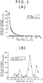
- Example 1 and Comparative Example 1 With respect to the porous carbon materials of Example 1 and Comparative Example 1, their specific surface areas and pore volumes were measured. The results shown in Table 1 were obtained. With respect to the porous carbon materials of Example 1 and Comparative Example 1, the pore size distributions of their mesopores and micropores were measured. The results shown in FIGS. (A) and (B) of FIG. 1 were obtained.
- Nitrogen adsorption and desorption tests were conducted using BELSORP-mini (manufactured by BEL Japan Inc.) as a measuring instrument for the determination of the specific surface areas and pore volumes. As a measuring condition, the measurement equilibrium relative pressure (p/p 0 ) was set at 0.01 to 0.95. Based on the BELSORP Analysis Software, the specific surface areas and pore volumes were calculated. Further, nitrogen adsorption and desorption tests were conducted using the above-mentioned measuring instrument, and the pore size distributions of the mesopores and micropores were calculated by the BELSORP Analysis Software on the basis of the BJH method and MP method. It is to be noted that in Examples, Comparative Examples and Referential Examples to be described subsequently herein, the measurements of specific surfaces areas and pore volumes and pore size distributions of mesopores and micropores were conducted by similar methods.
- the specific surface area and pore volume of the porous carbon material of Example 1 in which the acid treatment was conducted were considerably large compared with the specific surface area and pore volume of the porous carbon material of Comparative Example 1 in which no acid treatment was conducted, and the value of specific surface area was 400 m 2 /g or greater and the value of pore volume was 0.1 cm 3 /g or greater. It was also found that as shown in FIG. (A) of FIG. 1 , the porous carbon material of Example 1 contained many mesopores of 20 nm and smaller in pore size, especially many mesopores of 10 nm and smaller in pore size compared with the porous carbon material of Comparative Example 1. It was also found that as shown in FIG. (B) of FIG.
- the porous carbon material of Example 1 contained many micropores of approx. 1.9 nm in pore size, many micropores of approx. 1.5 nm in pore size and many micropores of approx. 0.8 nm to 1 nm in pore size compared with the porous carbon material of Comparative Example 1.
- Example 1 and Comparative Example 1 were also subjected to an elemental analysis, and the results shown in Table 2 were obtained. It is to be noted that using an energy dispersive X-ray analyzer (JED-2200F manufactured by JEOL Ltd. (trademark)) as a measuring instrument for elemental analysis, each element was quantitated by energy dispersion spectroscopy (EDS) and its content was then calculated in terms of percentage by weight (wt%). As measurement conditions, the scanning voltage and irradiation current were set at 15 kV and 13 ⁇ A, respectively. They were set likewise in the subsequent Examples and Comparative Examples.
- JED-2200F energy dispersive X-ray analyzer
- EDS energy dispersion spectroscopy
- the porous carbon material of Example 1 in which the acid treatment was conducted was lower in the contents of silicon (Si), oxygen (O), potassium (K), calcium (Ca) and sodium (Na) than the porous carbon material of Comparative Example 1 in which no acid treatment was conducted.
- the contents of silicon (Si) and oxygen (O) substantially decreased in Example 1 than in Comparative Example 1, and became 1 wt% or lower.
- the contents of phosphorus (P) and sulfur (S) increased more in Example 1 than in Comparative Example 1.
- the content of phosphorus (P) becomes at least 0.01 wt% but at most 3 wt% and the content of sulfur (S) becomes at least 0.01 wt% but at most 3 wt%.
- carbon (C) was most abundant and carbon (C) amounted to 90% or more of the other elements.
- silicon is contained as an amorphous silica component in rice husk, and the content of silicon in the rice husk as the raw material was 9.4 wt%.
- Example 1 As the porous carbon material of Example 1 substantially decreased in the contents of silicon (Si) and oxygen (O) than the porous carbon material of Comparative Example 1, it was also suggested from the analysis results of Example 1 that silicon dioxide was abundantly contained in the carbonaceous material (porous carbon material precursor). It is, accordingly, suggested that the treatment of a porous carbon material precursor with an acid eliminates contained silicon components such as silicon dioxide and contributes to an increase in the value of specific surface area. Further, it has been confirmed that by the treatment with an acid, mesopores and micropores increase. Similar suggestions and confirmation were derived from the Examples to be described subsequently herein. Similar results were also obtained with a porous carbon material obtained by conducting a treatment with an alkali (base) such as an aqueous solution of sodium hydroxide as an alternative to aqueous solution of hydrofluoric acid.
- an alkali base
- Example 2 is a modification of Example 1.
- straw of rice plant grown in Kagoshima Prefecture; the Isehikari variety
- the porous carbon material of Example 2 was obtained by carbonizing the straw as a raw material into a carbonaceous material (porous carbon material precursor) and then applying an acid treatment. It is to be noted that a similar process as in Example 1 was employed for the production of the porous carbon material.
- a porous carbon material was obtained as Comparative Example 2 based on a similar procedure as in Example 1 except that the acid treatment was not conducted.
- Example 2 With respect to the porous carbon materials of Example 2 and Comparative Example 2, their specific surface areas and pore volumes were measured. The results shown in Table 1 were obtained. The pore size distributions of their mesopores and micropores were also measured. The results shown in FIGS. (A) and (B) of FIG. 2 were obtained.
- the specific surface area and pore volume of the porous carbon material of Example 2 in which the acid treatment was conducted were considerably large compared with the specific surface area and pore volume of the porous carbon material of Comparative Example 2 in which no acid treatment was conducted and that the value of specific surface area was 100 m 2 /g or greater and the value of pore volume was 0.1 cm 3 /g or greater.
- the porous carbon material of Example 2 contained many mesopores of 20 nm and smaller in pore size, especially many mesopores of 10 nm and smaller in pore size compared with the porous carbon material of Comparative Example 2. It was also found that as shown in FIG.
- the porous carbon material of Example 2 contained many micropores of approx. 1.9 nm in pore size, many micropores of approx. 1.5 nm in pore size and many micropores of approx. 0.8 nm to 1 nm in pore size compared with the porous carbon material of Comparative Example 2.
- Example 2 The porous carbon materials of Example 2 and Comparative Example 2 were also subjected to an elemental analysis, and the results shown in Table 2 were obtained.
- the porous carbon material of Example 2 in which the acid treatment was conducted was lower in the contents of silicon (Si), oxygen (O), magnesium (Mg), potassium (K) and sodium (Na) than the porous carbon material of Comparative Example 2 in which no acid treatment was conducted.
- the contents of silicon (Si) and oxygen (O) substantially decreased in Example 2 than in Comparative Example 2, and became 1 wt% or lower.
- the contents of phosphorus (P), sulfur (S) and calcium (Ca) increased more in Example 2 than in Comparative Example 2.
- the content of silicon (Si) also becomes 1 wt% or lower
- the content of magnesium (Mg) also becomes at least 0.01 wt% but at most 3 wt%
- the content of potassium (K) also becomes at least 0.01 wt% but at most 3 wt%
- the content of calcium (Ca) also becomes at least 0.05 wt% but at most 3 wt%.
- the content of phosphorus (P) becomes at least 0.01 wt% but at most 3 wt% and the content of sulfur (S) becomes at least 0.01 wt% but at most 3 wt%.
- carbon (C) was most abundant and carbon (C) amounted to 90% or more of the other elements.
- silicon is contained as an amorphous silica component in straw, and the content of silicon in the straw as the raw material was 6.8 wt%.
- Example 3 is also a modification of Example 1.
- grass reed cut in December, 2006 in Aoba Ward, Yokohama City; withered in winter
- the porous carbon material of Example 3 was obtained by carbonizing the grass reed as a raw material into a carbonaceous material (porous carbon material precursor) and then applying an acid treatment. It is to be noted that a similar process as in Example 1 was employed for the production of the porous carbon material.
- a porous carbon material was obtained as Comparative Example 3 based on a similar procedure as in Example 1 except that the acid treatment was not conducted.
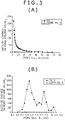
- Example 3 With respect to the porous carbon materials of Example 3 and Comparative Example 3, their specific surface areas and pore volumes were measured. The results shown in Table 1 were obtained. The pore size distributions of their mesopores and micropores were also measured. The results shown in FIGS. (A) and (B) of FIG. 3 were obtained.
- the specific surface area and pore volume of the porous carbon material of Example 3 in which the acid treatment was conducted were considerably large compared with the specific surface area and pore volume of the porous carbon material of Comparative Example 3 in which no acid treatment was conducted and that the value of specific surface area was 100 m 2 /g or greater and the value of pore volume was 0.1 cm 3 /g or greater. It was also found that as shown in FIG. (A) of FIG. 3 , the porous carbon material of Example 3 contained many mesopores of 20 nm and smaller in pore size, especially many mesopores of 10 nm and smaller in pore size compared with the porous carbon material of Comparative Example 3. It was also found that as shown in FIG.
- the porous carbon material of Example 3 contained many micropores of approx. 1.9 nm in pore size, many micropores of approx. 1.5 nm in pore size, many micropores of approx. 1.3 nm in pore size and many micropores of approx. 0.8 nm to 1 nm in pore size compared with the porous carbon material of Comparative Example 3.
- Example 3 The porous carbon materials of Example 3 and Comparative Example 3 were also subjected to an elemental analysis, and the results shown in Table 2 were obtained.
- the porous carbon material of Example 3 in which the acid treatment was conducted was lower in the contents of silicon (Si) and oxygen (O) than the porous carbon material of Comparative Example 3 in which no acid treatment was conducted.
- the contents of silicon (Si) and oxygen (O) substantially decreased in Example 3 than in Comparative Example 3, and became 1 wt% or lower.
- the contents of phosphorus (P), sulfur (S), potassium (K) and calcium (Ca) increased more in Example 3 than in Comparative Example 3.
- the content of silicon (Si) also becomes 1 wt% or lower
- the content of magnesium (Mg) also becomes 0.01 wt% or higher but 3 wt% or lower
- the content of potassium (K) also becomes at least 0.01 wt% but at most 3 wt%
- the content of calcium (Ca) also becomes at least 0.05 wt% but at most 3 wt%.
- the content of phosphorus (P) becomes at least 0.01 wt% but at most 3 wt% and the content of sulfur (S) becomes at least 0.01 wt% but at most 3 wt%.
- carbon (C) was most abundant and carbon (C) amounted to 90% or more of the other elements.
- silicon is contained as an amorphous silica component in reed, and the content of silicon in the reed as the raw material was 4.8 wt%.
- Example 4 is also a modification of Example 1.
- seaweed stem grown in the Sanriku district of Iwate Prefecture
- the porous carbon material of Example 4 was obtained by carbonizing the seaweed stem as a raw material into a carbonaceous material (porous carbon material precursor) and then applying an acid treatment.
- the seaweed stem was first heated, for example, at a temperature of 500°C or so to char the same.
- the seaweed stem as a raw material may be treated with an alcohol, for example.
- an alcohol for example.
- the method that immerses the seaweed stem in ethyl alcohol or the like can be mentioned.
- the water contained in the raw material can be decreased, and at the same time, non-carbon elements and mineral components which would be contained in a porous carbon material to be obtained finally can be dissolved out.
- this alcohol treatment it is also possible to reduce the occurrence of gas during carbonization. More specifically, the seaweed stem was immersed for 48 hours in ethyl alcohol.
- porous carbon material precursor was then immersed overnight in a 46 vol% aqueous solution of hydrofluoric acid to conduct its acid treatment, followed by washing with water and ethyl alcohol until pH 7 was reached. By finally conducting drying, it was possible to obtain the porous carbon material of Example 4.
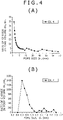
- the porous carbon material of Example 4 contained many mesopores of 20 nm to 25 nm in pore size and many mesopores of 15 nm and smaller in pore size. It was also found that as shown in FIG. (B) of FIG. 4 , the porous carbon material of Example 4 contained many micropores of approx. 1.8 nm to 2.0 nm in pore size, many micropores of approx.
- pores in various porous carbon materials were measured by the mercury penetration method. Specifically, using a mercury porosimeter (PASCAL440; manufactured by Thermo Electric Corporation), measurements were conducted by the mercury penetration method. The measurement range of pores was set at 10 ⁇ m to 2 nm. The results are shown in FIG. 5 .
- the samples of the various porous carbon materials are as shown below in Table 3. It was confirmed that the pore volumes of the porous carbon materials according to the present invention as determined by the mercury penetration method were significantly increased by the application of an acid treatment with an aqueous solution of hydrofluoric acid (expressed as "hydrofluoric acid treatment" in the table).
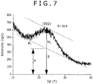
- FIG. 6 results of evaluations of the various porous carbon materials by powder X-ray diffractometry are shown in FIG. 6 .
- an X-ray diffractometer RINT-TTRII manufactured by RIGAKU Corporation was used, and Cu-K ⁇ radiation was employed as an X-ray source. It is to be noted that the wavelength was 0.15405 nm.
- the applied voltage was set at 50 kilovolts, and the scanning step was set at 0.04°.
- the porous carbon materials according to the present invention (the sample a, sample b, sample e, sample f, sample g, and sample h shown in Table 3) were confirmed to be higher in crystallinity than the commercially-available activated carbon (Referential Example 6-2) from the intensities of diffraction peaks around 25° diffraction angle 2e [diffraction peaks of (002) planes].
- the R value is, for example, 1.5 or greater, more specifically, 1.8 or greater.
- Example 5 to Example 8 a description will next be made about application examples of the porous carbon materials described in Example 1 to Example 4.
- lithium ion secondary batteries were fabricated as electrochemical devices.
- Anode active material layers were formed with the porous carbon materials described in Example 1 to Example 4, respectively.
- a schematic cross-sectional view of each lithium ion secondary battery is depicted in FIG. 8 , and an enlarged view of a portion of a rolled electrode stack depicted in FIG. 8 is illustrated in FIG. 9 .
- the capacity of an anode is expressed by a capacity component based on occlusion and release of lithium as an electrode reactant, and the lithium ion secondary battery has a battery structure called the so-called cylindrical type.
- a rolled electrode stack 20 with a cathode 21 and an anode 22 rolled with a separator 23 interposed therebetween and a pair of insulating plates 12, 13 are accommodated inside a substantially hollow cylindrical battery can 11.
- the battery can 11 is made, for example, of iron to which nickel plating has been applied, is closed at an end portion thereof, and is open at an opposite end portion thereof to form an open end portion.
- the paired insulating plates 12, 13 are arranged such that they hold the rolled electrode stack 20 therebetween and are located at right angles to a rolled peripheral wall thereof.
- a battery cover 14 and a safety valve mechanism 15 and a positive temperature coefficient (PTC) device 16 which are arranged inside the battery cover 14, are assembled by staking them together via a gasket 17, so that the interior of the battery can 11 is sealed.
- the battery cover 14 is made of a similar material as the battery can 11, for example.
- the safety valve mechanism 15 is electrically connected to the battery cover 14 by way of the positive temperature coefficient device 16.
- the safety valve mechanism 15 is constructed such that, if the internal pressure rises to a predetermined level or higher due to internal short-circuiting, heating from the outside, or the like, a disk plate 15A is bulged out to cut off the electrical connection between the battery cover 14 and the rolled electrode stack 20.
- the gasket 17 is made, for example, of an insulating material, and is coated at its surfaces with asphalt.
- a center pin 24 is centrally inserted in the rolled electrode stack 20.
- a cathode lead 25 made of aluminum or the like is connected to the cathode 21, while an anode lead 26 made of nickel or the like is connected to the anode 22.
- the cathode lead 25 is welded to the safety valve mechanism 15, and therefore, is electrically connected to the battery cover 14.
- the anode lead 26 is welded to the battery can 11.
- cathode active material layers 21B are arranged, for example, on both sides of a cathode current collector 21A having the opposite sides in pair. It is to be noted that a cathode active material layer 21B may be arranged on only one side of the cathode current collector 21A.
- the cathode current collector 21A is made of a metal material such as, for example, aluminum, nickel or stainless steel.
- the cathode active material layers 21B contain, as a cathode active material, any one, two or more of cathode materials capable of occluding and releasing lithium as the electrode reactant.
- the cathode active material layers 21B may contain a conductive agent, a binder and/or the like as needed.
- a lithium-containing compound As a cathode material capable of occluding and releasing lithium, a lithium-containing compound can be mentioned, for example. With the lithium-containing compound, a high energy density can be obtained.
- the lithium-containing compound can be, for example, a lithium composite oxide containing lithium and a transition metal element, or a phosphate compound containing lithium and a transition metal element.
- As the transition metal element at least one of cobalt, nickel, manganese and iron can be mentioned in particular. With such a lithium-containing compound, a still higher voltage can be obtained.
- Its chemical formula can be represented, for example, by Li x M1O 2 or Li y M2PO 4 . In these chemical formulas, M1 and M2 represent one or more transition metal elements.
- the values of x and y differ depending on the charge-discharge state of the battery, but in general, 0.05 ⁇ x ⁇ 1.10 and 0.05 ⁇ y ⁇ 1.10.
- the lithium composite oxide containing lithium and the transition metal element can be, for example, a lithium-cobalt composite oxide (Li x CoO 2 ), lithium-nickel composite oxide (Li x NiO 2 ), lithium-nickel-cobalt composite oxide (Li x Ni (1-z) Co z O 2 (z ⁇ 1)), or lithium-nickel-cobalt-manganese composite oxide (Li x Ni (1-v-w) Co v Mn w O 2 (v+w ⁇ 1)); a lithium-manganese composite oxide (LiMn 2 O 4 ) having the spinel structure; or the like.
- a nickel-containing, lithium composite oxide is preferred.
- lithium-iron-phosphate compound LiFePO 4
- lithium-iron-manganese-phosphate compound LiFe( 1-u )Mn u PO 4 (u ⁇ 1)
- an oxide such as titanium oxide, vanadium oxide or manganese dioxide, a disulfide such as iron disulfide, titanium disulfide or molybdenum disulfide, a chalcogenated compound such as niobium selenide, sulfur, or a conductive polymer such as polyaniline or polythiophene can also be mentioned, for example.
- anode active material layers 22B are arranged, for example, on both sides of an anode current collector 22A having the opposite sides in pair. It is to be noted that an anode active material layer 22B may be arranged on only one side of the anode current collector 22A.
- the anode current collector 22A is made of a metal material such as, for example, copper (Cu), nickel or stainless steel.
- the anode active material layers 22B contain, as an anode active material, an anode material capable of occluding and releasing lithium as the electrode reactant, and in addition, may contain a conductive agent, a binder and/or the like as needed.
- the anode active material layers 22B are composed of one of the porous carbon materials described in Example 1 to Example 4. With the use of one of the porous carbon materials described in Example 1 to Example 4, the changes in crystalline structure, which occur upon charging and discharging, can be controlled to very little, thereby making it possible to obtain a high energy density. Moreover, the acceptability of lithium is high and the deposition of lithium is inhibited, so that the reduction in discharge capacity can be suppressed. Owing to these, improvements can be achieved in cycling characteristics and storage characteristics. It is to be noted that the anode active material layers 22B may also contain one or more anode materials, which can occlude and release lithium, together with one of the porous carbon materials of Example 1 to Example 4.
- a carbon material such as graphite, carbon black or Ketjenblack can be mentioned, for example. They may be used either singly, or plural ones of them may be used in combination.
- the conductive agent can also be any metal material insofar as it is a material having electrical conductivity, a conductive polymer, or the like.
- a synthetic rubber such as a styrene-butadiene-based rubber, fluorinated rubber or ethylenepropylene-diene or a polymer material such as polyfluorinated vinylidene can be mentioned. They may be used either singly, or plural ones of them may be used in combination.
- the separator 23 isolates the cathode 21 and the anode 22 from each other, and allows lithium ions to pass therethrough while preventing short-circuiting of a current due to a contact between both electrodes.
- the separator 23 is formed, for example, of a porous membrane made of a synthetic resin comprising polytetrafluoroethylene, polypropylene or polyethylene or the like, or a porous membrane made of ceramics, or may have a structure that two or more of these porous membranes are laminated.
- a polyolefin-made, porous membrane is preferred because it is excellent in short-circuit preventing effect and can achieve an improvement in the safety of the lithium ion secondary battery owing to the shutdown effect.
- polyethylene is a preferred material because it can obtain the shutdown effect in a temperature range of 100°C or higher but 160°C or lower and is excellent in electrochemical stability.
- polypropylene is also preferred.
- a resin copolymerized with polyethylene or polypropylene or a resin obtained by blending polyethylene or polypropylene can also be used insofar as the resin is provided with chemical stability.
- the separator 23 is impregnated with an electrolyte solution as a liquid electrolyte. In the electrolyte solution, a solvent and an electrolyte salt dissolved in the solvent are contained.
- the solvent contains, for example, a nonaqueous solvent such as an organic solvent.
- a nonaqueous solvent such as an organic solvent.
- the nonaqueous solvent can include ethylene carbonate, propylene carbonate, butylene carbonate, dimethyl carbonate, diethyl carbonate, ethyl methyl carbonate, methyl propyl carbonate, ⁇ -butyrolactone, ⁇ -valerolactone, 1,2-dimethoxyethane, tetrahydrofuran, 2-methyltetrahydrofuran, tetrahydropyran, 1,3-dioxolane, 4-methyl-1,3-dioxolane, 1,3-dioxane, 1,4-dioxane, methyl acetate, ethyl acetate, methyl propionate, ethyl propionate, methyl butyrate, methyl isobutyrate, methyl trimethylacetate, ethyl trimethylacetate, ace
- nonaqueous solvents may be used either singly, or plural ones of them may be used in combination.
- the solvent may preferably contain at least one nonaqueous solvent selected from the group consisting of ethylene carbonate, propylene carbonate, dimethyl carbonate, diethyl carbonate and ethyl methyl carbonate. With such a solvent, sufficient cycling characteristics are obtained.
- a mixture of a high-viscosity (high permittivity) solvent for example, the relative permittivity ⁇ of which is 30 or higher
- a low-viscosity solvent for example, the viscosity of which is 1 mPa ⁇ s or lower
- dimethyl carbonate, ethyl methyl carbonate or diethyl carbonate such as dimethyl carbonate, ethyl methyl carbonate or diethyl carbonate.
- the electrolyte salt contains, for example, one or more light metal salts such as lithium salts.
- the lithium salts can be, for example, lithium hexafluorophosphate (LiPF 6 ), lithium tetrafluoroborate (LiBF 4 ), lithium perchlorate (LiClO 4 ), lithium hexafluoroarsenate (LiAsF 6 ), lithium tetraphenylborate (LiB(C 6 H 5 ) 4 ), lithium methanesulfonate (LiCH 3 SO 3 ), lithium trifluoromethanesulfonate (LiCF 3 SO 3 ), lithium tetrachloroaluminate (LiAlCl 4 ), dilithium hexafluorosilicate (Li 2 SiF 6 ), lithium chloride (LiCl), and lithium bromide (LiBr). They may be used singly, or plural ones of them may be used in combination.
- the content of the electrolyte salt may preferably be in a range of at least 0.3 mol/kg but at most 3.0 mol/kg based on the solvent. Outside this range, the ionic conductivity is extremely lowered, leading to a potential problem that the capacity characteristic and the like may not be obtained fully.
- the lithium ion secondary battery can be fabricated, for example, as follows.
- the cathode active material layers 21B are first formed on both sides of the cathode current collector 21A to prepare the cathode 21.
- a cathode mix which is a mixture of powder of a cathode active material, a conductive agent and a binder is dispersed in a solvent to prepare a paste-like slurry of the cathode mix.
- the slurry of the cathode mix is coated on the cathode current collector 21A and is then dried, compression forming is performed.
- the anode active material layers 22B are also formed on both sides of the anode current collector 22A to prepare the anode 22.
- an anode mix which is a mixture of one of the porous carbon materials described in Example 1 to Example 4, a conductive agent and a binder is dispersed in a solvent to prepare a paste-like slurry of the anode mix.
- a conductive agent and a binder is dispersed in a solvent to prepare a paste-like slurry of the anode mix.
- the slurry of the anode mix is coated on the anode current collector 22A and is then dried, compression forming is performed.
- the cathode lead 25 is welded to the cathode current collector 21A, and the anode lead 26 is welded to the anode current collector 22A.
- the cathode 21 and anode 22 are rolled with the separator 23 interposed therebetween to form the rolled electrode stack 20.
- the cathode lead 25 is welded at an end portion thereof to the safety valve mechanism 15 and the anode lead 26 is welded at an end portion thereof to the battery can 11
- the rolled electrode stack 20 is accommodated inside the battery can 11 while holding it between the paired insulating plates 12, 13.
- An electrolyte solution is then charged into the battery can 11 to have the separator 23 impregnated with the electrolyte solution.
- the battery cover 14, safety valve mechanism 15 and positive temperature coefficient device 16 are fixed in the open end portion of the battery can 11 by staking them by way of the gasket 17. In this manner, the lithium ion secondary battery depicted in FIG. 8 and FIG. 9 can be completed.
- lithium ions are released, for example, from the cathode 21 and are occluded in the anode 22 via the electrolyte solution.
- lithium ions are released, for example, from the anode 22 and are occluded in the cathode 21 via the electrolyte solution.
- anode active material is composed of one of the porous carbon materials of Example 1 to Example 4 in the lithium ion secondary battery, excellent characteristics are obtained.
- Example 6 relates to the adsorbent according to the present invention.
- a porous carbon material [a plant-derived material as a raw material for the porous carbon material was the same rice husk as in Example 1 (grown in Kagoshima Prefecture, rice husk of Isehikari variety)] was applied as a porous carbon material for selectively adsorbing various unnecessary molecules in the body. With respect to various substances, their adsorbed amounts per unit weight of the porous carbon material were measured.
- the porous carbon material (0.010 g) was added, followed by shaking at 37 ⁇ 2°C for 1 hour. Subsequent to the shaking, the porous carbon material was removed from the solution by using a polytetrafluoroethylene-made membrane filter having 500- ⁇ m pores. The absorbance of the filtrate was measured by a UV-visible absorbance measurement to determine the molar concentration of the aqueous solution. By a comparison with the molar concentration of the initial aqueous solution before the adsorption, the adsorbed amount was calculated. The adsorbed amount per gram of the porous carbon material was calculated based on the following formula.
- Adsorbed amount per gram of porous carbon material molecular weight of solute ⁇ molar concentration of aqueous solution before adsorption ⁇ molar concentration of aqueous solution after adsorption / amount of porous carbon material per 1,000 mL
- Example 6 the porous carbon materials shown below in Table 6 were produced. It is to be noted that Example 6-1 in Table 6 is a porous carbon material produced by the same procedure as in Example 1 (except that the carbonization temperature and the carbonization time were set at 800°C and 1 hour, respectively) and that in Example 6-2, Example 6-3, Example 6-4 and Example 6-5, the activation treatments shown in Table 6 were applied to the porous carbon material of Example 6-1, respectively. It is also to be noted that in Example 6-2, a microstructure was allowed to develop with volatile components and carbon molecules in the porous carbon material by using oxygen as an activator and heating the porous carbon material at 900°C for 2 hours in air.
- Example 6-3 to Example 6-5 microstructure were allowed to develop with volatile components and carbon molecules in the porous carbon material by using steam as an activator and heating the porous carbon material at 900°C for 30 minutes, 1 hour and 2 hours, respectively, under a steam atmosphere.
- the measurement results of specific surface area and the measurement results of pore volume are also shown in Table 6. It is appreciated from Table 6 that in Example 6-3 to Example 6-5, the value of specific surface area and the value of pore volume increased with the time of the activation treatment.
- the adsorbed amounts (g) of creatinine, adsorbed amounts (g) of alizarin cyanine green, adsorbed amounts of lysozyme (g) and adsorbed amounts of albumin (g) per gram of the porous carbon material or activated carbon are shown below in Table 8, Table 9, Table 10 and Table 11.
- Adsorbed amounts (g) of alizarin cyanine green per gram of the porous carbon material or the like Number average molecular weight of alizarin cyanine green: 623 [Table 9] Adsorbed amount of alizarin cyanine green (g) Specific surface area (m 2 /g) Pore volume (cm 3 /g) Ex. 6-1 104.18 589 0.60 Ex. 6-3 162.26 727 0.63 Ex. 6-4 177.18 836 0.66 Ex. 6-5 201.18 930 0.80 Ref. Ex. 6-1 82.82 1231 0.57 Ref. Ex. 6-3 47.62 885 0.40 Ref. Ex. 6-4 56.42 1079 0.60
- Adsorbed amounts (g) of lysozyme per gram of the porous carbon material or the like Number average molecular weight of lysozyme: 14,307 [Table 10] Adsorbed amount of lysozyme (g) Specific surface area (m 2 /g) Pore volume (cm 3 /g) Ex. 6-1 214.36 589 0.60 Ex. 6-2 488.96 951 1.68 Ex. 6-3 179.92 727 0.63 Ex. 6-4 179.57 836 0.66 Ex. 6-5 190.23 930 0.80 Ref. Ex. 6-1 84.02 1231 0.57 Ref. Ex. 6-2 109.54 1584 0.79 Ref. Ex. 6-3 91.66 885 0.40 Ref.
- Example 6-5 It was recognized from Table 8 that in each of Example 6-1, Example 6-3, Example 6-4 and Example 6-5, the adsorbed amount of creatinine per gram of the porous carbon material tended to increase with the value of specific surface area and the value of pore volume of the porous carbon material, and moreover, a good correlation was observed therebetween. In each of the referential examples, on the other hand, no good correlation was observed between the adsorbed amount of creatinine per gram of the activated carbon and the value of specific area and the value of pore volume of the activated carbon probably due to the difference in the production procedure.
- Example 6-5 It was also recognized from Table 9 that in each of Example 6-1, Example 6-3, Example 6-4 and Example 6-5, the adsorbed amount of alizarin cyanine green per gram of the porous carbon material tended to increase with the value of specific surface area and the value of pore volume of the porous carbon material, and moreover, a good correlation was observed therebetween. Further, the examples showed greater adsorbed amounts than the referential examples.
- Example 6-1 the adsorbed amount of lysozyme per gram of the porous carbon material remained substantially at a constant value without depending much on the value of specific surface area and the value of pore volume of the porous carbon material in Example 6-1, Example 6-3, Example 6-4 and Example 6-5. Further, the examples showed greater adsorbed amounts than the referential examples. Example 6-2 showed a significantly large adsorbed amount compared with the other examples and the referential examples.
- Example 6-1 the adsorbed amount of albumin per gram of the porous carbon material did not depend on the value of specific surface area and the value of pore volume of the porous carbon material in Example 6-1, Example 6-2, Example 6-3, Example 6-4 and Example 6-5.
- the porous carbon materials of Example 6-1 and Example 6-2 showed significantly great adsorbed amounts. Further, Example 6-1 and Example 6-2 showed greater adsorbed amounts than the referential examples.
- each porous carbon material differs depending on the differences of the porous carbon material in its parameters such as specific surface area and pore volume, the differences of the porous carbon material in its physical surface conditions and chemical surface conditions, the differences of chemical interaction between the porous carbon material and the adsorbed material, and the differences of the porous carbon material in its production procedure. Further, a difference was observed especially between the behavior of a porous carbon material upon adsorption of molecules having a small molecular weight and the behavior of the porous carbon material upon adsorption of molecules having a large molecular weight.
- the porous carbon materials according to the present invention adsorb substances having medium molecular weights or large molecular weights still better.
- the parameters such as specific surface area and pore volume, and production procedure of a porous carbon material on the basis of various tests, molecules can, therefore, be selectively adsorbed by the porous carbon material. Therefore, the adsorbent according to the present invention is expected to bring about significant advantageous effects in various medical applications which require adsorption.
- Example 7 relates to the carrier according to the present invention for carrying a drug thereon.
- a porous carbon material a plant-derived material as a raw material for the porous carbon material was the same rice husk as in Example 1 (grown in Kagoshima Prefecture, rice husk of Isehikari variety)] was used as a carrier for a drug in a drug release preparation that can appropriately control the release rate of the drug.
- ibuprofen a non-steroidal anti-inflammatory drug, NSAID
- the porous carbon material (0.10 g) obtained by the same procedure as in Example 1 (except that the carbonization temperature and carbonization time were set at 800°C and 1 hour, respectively) was immersed overnight in a 0.10 g:10 mL solution of ibuprofen and hexane. Subsequently, filtration was conducted by a membrane filter, followed by vacuum drying at 40°C. The resulting complex of the porous carbon material and ibuprofen was mixed in a phosphate buffer (pH 7.3; 40 mL), and the concentrations of ibuprofen at respective times were measured by ultraviolet spectroscopy and were then calculated. It is to be noted that the value of specific surface area and the value of pore volume of the porous carbon material of Example 7 are as shown under Example 6-1 in Table 6.
- Example 7 Using the activated carbon (0.10 g) of Referential Example 6-1 shown in Table 7, an activated carbon-ibuprofen complex was obtained by the same procedure as in Example 7. As Comparative Example 7, the resulting activated carbon-ibuprofen complex was mixed in a phosphate buffer (pH 7.3; 40 mL), and the concentrations of ibuprofen at respective times were measured by ultraviolet spectroscopy and were then calculated. It is to be noted that the value of specific surface area and the value of pore volume of the activated carbon are as shown below. Porous carbon material of Example 7 Activated carbon of Comparative Example 7 Specific surface area: 589 m 2 /g 1321 m 2 /g Pore volume: 0.60 cm 3 /g 0.57 cm 3 /g
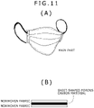
- Example 8 relates to the mask and adsorbing sheet according to the present invention.
- a porous carbon material [a plant-derived material as a raw material for the porous carbon material was the same rice husk as in Example 1 (grown in Kagoshima Prefecture, rice husk of Isehikari variety)] was applied as an adsorbent to an anti-pollinosis mask.
- a schematic of the anti-pollinosis mask is shown in FIG. (A) of FIG. 11
- the schematic cross-sectional structure of a main part (adsorbing sheet) of the anti-pollinosis mask is illustrated in FIG. (B) of FIG. 11 .
- the main part of the anti-pollinosis mask has a structure that the porous carbon material in the form of a sheet is held between a nonwoven fabric and another nonwoven fabric both of which are made of cellulose.
- a nonwoven fabric and another nonwoven fabric both of which are made of cellulose are made of cellulose.
- the adsorbing sheet of Example 8 is formed of a sheet-shaped member, which is made of the porous carbon material produced from the same rice husk as in Example 1 (specifically, a carbon-polymer complex containing carboxynitrocellulose as a binder), and a support member supporting the sheet-shaped member thereon (specifically, nonwoven fabrics which as a support member, hold the sheet-shaped member therebetween).
- the porous carbon material according to the present invention as an adsorbent to various masks such as an anti-pollinosis mask, the masks are considered to be able to effectively adsorb pollen, for example, by adsorbing the pollen at protein sites thereof on the porous carbon material.
- the application of the porous carbon material according to the present invention is, however, not necessarily limited to batteries, and can be applied to electrochemical devices other than batteries. For example, electric double layer capacitors and the like can be mentioned.
- Group-1A elements such as sodium and potassium and Group-2A elements such as magnesium and calcium in the short-form periodic table, and light metals such as aluminum may also be used.
- the porous carbon material according to the present invention can also be used as an anode active material.
- Example 6-1 can be applied to Example 5 and Example 8
- the porous carbon materials described in Example 6-2, Example 6-3, Example 6-4 and Example 6-5 and subjected to the respective activation treatments can be applied to Example 5, Example 7 and Example 8, the porous carbon materials described in Example 1 to Example 4 can be applied to Example 6 and Example 7, and the porous carbon materials described in Example 2 to Example 4 can be applied to Example 8.
- silicon is contained at 5 wt% or more.
- the silicon contained in the plant-derived material is not converted into silicon carbide (SiC) but is converted into silicon components (oxidized silicon compounds) such as silicon dioxide (SiO x ), silicon oxide and silicon oxide salts.
- the silicon components such as the silicon dioxide, the silicon oxide and the silicon oxide salts in the next step by the treatment with the acid, or alkali(base)
- a large value of specific surface area as determined by the nitrogen BET method can be obtained accordingly.
- the carbonization at a temperature in this range provides non-graphitizable carbon, thereby making it possible to obtain excellent cycling characteristics when employed in electrochemical devices.
- the value of specific surface area as determined by the nitrogen BET method is 10 m 2 /g or more, the content of silicon is 1 wt% or lower, and the volume of pores as determined by the BJH method or MP method is 0.1 cm 3 or more.
- Excellent functionality is therefore available.
- excellent characteristics can be obtained when the porous carbon material according to the present invention is used in an electrochemical device such as, for example, a battery like a lithium ion secondary battery (nonaqueous electrolyte secondary battery) or an electric double layer capacitor.
- the porous carbon material is also provided with excellent functionality.
- the porous carbon material according to the present invention is optimal, for example, as a porous carbon material for orally-administrable adsorbent preparation, also as a porous carbon material intended to adsorb proteins or viruses, also as a porous carbon material which composes the drug release preparation capable of appropriately controlling the drug release rate, and also as an adsorbent in masks and as an adsorbent in adsorbing sheets.
- Embodiments of the invention may have the combinations of characteristics described in the following clauses.
Applications Claiming Priority (5)
| Application Number | Priority Date | Filing Date | Title |
|---|---|---|---|
| JP2007098421 | 2007-04-04 | ||
| JP2008059052A JP4618308B2 (ja) | 2007-04-04 | 2008-03-10 | 多孔質炭素材料及びその製造方法、並びに、吸着剤、マスク、吸着シート及び担持体 |
| PCT/JP2008/056752 WO2008123606A1 (ja) | 2007-04-04 | 2008-04-04 | 多孔質炭素材料及びその製造方法、並びに、吸着剤、マスク、吸着シート及び担持体 |
| EP08739858.2A EP2060535B1 (en) | 2007-04-04 | 2008-04-04 | Porous carbon materials and production process thereof,and adsorbents, masks, adsorbing sheets and carriers |
| EP15189534.9A EP3006399A1 (en) | 2007-04-04 | 2008-04-04 | Porous carbon material, process for producing the same, adsorbent, mask, adsorbent sheet and supporting member |
Related Parent Applications (2)
| Application Number | Title | Priority Date | Filing Date |
|---|---|---|---|
| EP15189534.9A Division EP3006399A1 (en) | 2007-04-04 | 2008-04-04 | Porous carbon material, process for producing the same, adsorbent, mask, adsorbent sheet and supporting member |
| EP08739858.2A Division EP2060535B1 (en) | 2007-04-04 | 2008-04-04 | Porous carbon materials and production process thereof,and adsorbents, masks, adsorbing sheets and carriers |
Publications (1)
| Publication Number | Publication Date |
|---|---|
| EP4122883A1 true EP4122883A1 (en) | 2023-01-25 |
Family
ID=39831061
Family Applications (3)
| Application Number | Title | Priority Date | Filing Date |
|---|---|---|---|
| EP22187989.3A Pending EP4122883A1 (en) | 2007-04-04 | 2008-04-04 | Carbon-polymer complex and adsorbent comprising the same |
| EP08739858.2A Active EP2060535B1 (en) | 2007-04-04 | 2008-04-04 | Porous carbon materials and production process thereof,and adsorbents, masks, adsorbing sheets and carriers |
| EP15189534.9A Pending EP3006399A1 (en) | 2007-04-04 | 2008-04-04 | Porous carbon material, process for producing the same, adsorbent, mask, adsorbent sheet and supporting member |
Family Applications After (2)
| Application Number | Title | Priority Date | Filing Date |
|---|---|---|---|
| EP08739858.2A Active EP2060535B1 (en) | 2007-04-04 | 2008-04-04 | Porous carbon materials and production process thereof,and adsorbents, masks, adsorbing sheets and carriers |
| EP15189534.9A Pending EP3006399A1 (en) | 2007-04-04 | 2008-04-04 | Porous carbon material, process for producing the same, adsorbent, mask, adsorbent sheet and supporting member |
Country Status (9)
| Country | Link |
|---|---|
| US (5) | US10714750B2 (ja) |
| EP (3) | EP4122883A1 (ja) |
| JP (1) | JP4618308B2 (ja) |
| KR (1) | KR101451996B1 (ja) |
| CN (2) | CN103936003B (ja) |
| BR (1) | BRPI0803095B1 (ja) |
| CA (1) | CA2659765A1 (ja) |
| RU (3) | RU2425800C2 (ja) |
| WO (1) | WO2008123606A1 (ja) |
Families Citing this family (121)
| Publication number | Priority date | Publication date | Assignee | Title |
|---|---|---|---|---|
| JP5152276B2 (ja) * | 2007-04-04 | 2013-02-27 | ソニー株式会社 | 多孔質炭素材料、吸着剤、充填剤、マスク、吸着シート及び担持体 |
| JP5533912B2 (ja) * | 2007-04-04 | 2014-06-25 | ソニー株式会社 | 二次電池用電極材料及びその製造方法、並びに、電気二重層キャパシタ用材料及びその製造方法 |
| JP5152275B2 (ja) * | 2007-04-04 | 2013-02-27 | ソニー株式会社 | 多孔質炭素材料、吸着剤、充填剤、マスク、吸着シート及び担持体 |
| JP4618308B2 (ja) | 2007-04-04 | 2011-01-26 | ソニー株式会社 | 多孔質炭素材料及びその製造方法、並びに、吸着剤、マスク、吸着シート及び担持体 |
| JP5168240B2 (ja) * | 2008-07-31 | 2013-03-21 | ソニー株式会社 | 吸着剤、クレンジング剤、腎臓疾患治療薬、及び、機能性食品 |
| RU2478393C2 (ru) * | 2008-07-31 | 2013-04-10 | Сони Корпорейшн | Адсорбент, моющее средство, лекарственное средство при почечной недостаточности и функциональное питание |
| JP5471142B2 (ja) | 2008-09-29 | 2014-04-16 | ソニー株式会社 | 多孔質炭素材料複合体及びその製造方法、並びに、吸着剤、化粧料、浄化剤及び光触媒複合材料 |
| US20100216014A1 (en) * | 2009-02-24 | 2010-08-26 | Eveready Battery Company, Inc. | Closure Assembly for Electrochemical Cells |
| JP2011171035A (ja) * | 2010-02-17 | 2011-09-01 | Furukawa Battery Co Ltd:The | 鉛蓄電池用負極板及び鉛蓄電池 |
| JP5931326B2 (ja) * | 2010-02-23 | 2016-06-08 | カルゴンカーボンジャパン株式会社 | 電気二重層キャパシタ用活性炭 |
| JP2011225521A (ja) * | 2010-03-30 | 2011-11-10 | Sony Corp | 殺菌剤、光触媒複合材料、吸着剤及び浄化剤 |
| JP5742395B2 (ja) * | 2010-06-14 | 2015-07-01 | ソニー株式会社 | 画像表示用微粒子及びその製造方法、電気泳動分散液、並びに、画像表示装置 |
| JP2012045538A (ja) * | 2010-07-29 | 2012-03-08 | Sony Corp | ニコチンの吸着剤、キノリンの吸着剤、ベンゾピレンの吸着剤、トルイジンの吸着剤及び発癌性物質の吸着剤 |
| JP5984352B2 (ja) * | 2010-10-12 | 2016-09-06 | フタムラ化学株式会社 | 経口投与用医薬用吸着剤の製造方法 |
| WO2012092210A1 (en) * | 2010-12-28 | 2012-07-05 | Energ2 Technologies, Inc. | Carbon materials comprising enhanced electrochemical properties |
| JP5899885B2 (ja) | 2011-01-31 | 2016-04-06 | ソニー株式会社 | 燃料電池、燃料電池の製造方法、電子機器、ニコチンアミドアデニンジヌクレオチド固定化電極、ニコチンアミドアデニンジヌクレオチド固定化担体、酵素反応利用装置、タンパク質固定化電極およびタンパク質固定化担体 |
| JP2012167030A (ja) * | 2011-02-10 | 2012-09-06 | Sony Corp | コレステロール低下薬、中性脂肪低下薬、血糖値低下薬、コレステロール吸着剤、吸着剤、中性脂肪吸着剤、健康食品、健康補助食品、栄養機能食品、特定保健用食品、医薬部外品、及び、医薬品 |
| JP6218355B2 (ja) * | 2011-02-10 | 2017-10-25 | ソニー株式会社 | 濾材 |
| JP6402864B2 (ja) * | 2011-02-10 | 2018-10-10 | ソニー株式会社 | 空気浄化用の多孔質炭素材料の製造方法、空気浄化用のフィルターを構成する多孔質炭素材料の製造方法、水浄化用の多孔質炭素材料の製造方法、水浄化用のカートリッジを構成する多孔質炭素材料の製造方法、及び、多孔質炭素材料の製造方法 |
| JP2012179588A (ja) * | 2011-02-10 | 2012-09-20 | Sony Corp | 酸化ストレス物質除去方法、酸化還元電位低下方法、濾材及び水 |
| JP2016144807A (ja) * | 2011-02-21 | 2016-08-12 | ソニー株式会社 | 空気浄化装置、空気浄化用のカートリッジ、水浄化装置、水浄化用のカートリッジ、空気浄化用のフィルター及びマスク |
| JP5929148B2 (ja) * | 2011-02-21 | 2016-06-01 | ソニー株式会社 | ウイルス及び/又は細菌を吸着する吸着剤、炭素/ポリマー複合体及び吸着シート |
| EA019913B1 (ru) * | 2011-03-17 | 2014-07-30 | Республиканское Государственное Предприятие На Праве Хозяйственного Ведения "Институт Проблем Горения" | Способ получения мезопористого углеродного сорбента "инго-1" |
| JP2012211043A (ja) * | 2011-03-31 | 2012-11-01 | Sony Corp | 多孔質炭素材料、吸着剤、経口投与吸着剤、医療用吸着剤、血液浄化カラム用の充填剤、水浄化用吸着剤、クレンジング剤、担持体、薬剤徐放剤、細胞培養足場材、マスク、炭素/ポリマー複合体、吸着シート、及び、機能性食品 |
| EP2694202B1 (en) * | 2011-04-08 | 2015-05-06 | Republican State Enterprise, Based On The Right Of Economic Management, "Al-Farabi Kazakh National University" | Method for production of "ingo-2" carbon enterosorbent |
| JP5810652B2 (ja) * | 2011-06-13 | 2015-11-11 | ソニー株式会社 | 液体塗布用繊維複合体 |
| JP2013021260A (ja) * | 2011-07-14 | 2013-01-31 | Sony Corp | 電磁波吸収材及びその製造方法、フレキシブルプリント配線板、並びに、電子機器 |
| DE102011051888A1 (de) * | 2011-07-15 | 2013-01-17 | Vera Margraf-Gerdau | Adsorptionsvlies, insbesondere zur Adsorption von petrochemischen Substanzen aus flüssigen Phasen und/oder zur Adsorption von Geruchsstoffen aus Gasphasen mit zumindest einem Spinnvlies und Verfahren zur Herstellung eines Adsorptionsvlieses |
| JP2013081912A (ja) * | 2011-10-12 | 2013-05-09 | Sony Corp | 吸着剤及びその製造方法、並びに、水浄化用吸着剤、マスク及び吸着シート |
| CN103100369A (zh) * | 2011-11-10 | 2013-05-15 | 中国科学院生态环境研究中心 | 利用稻壳活性炭制备生活污水生物处理技术基质的方法 |
| CN102583333B (zh) * | 2012-01-18 | 2016-04-13 | 黑龙江大学 | 以玉米秸秆为碳源合成用于超级电容器电极材料的多孔纳米石墨片的方法 |
| JP6021947B2 (ja) * | 2012-02-16 | 2016-11-09 | ローベルト ボツシユ ゲゼルシヤフト ミツト ベシユレンクテル ハフツングRobert Bosch Gmbh | リチウム−硫黄電池に使用される硫黄含有複合材、それを含む電極材料およびリチウム−硫黄電池 |
| JP6065007B2 (ja) * | 2012-06-20 | 2017-01-25 | 住友電気工業株式会社 | 金属ケイ素及び多孔質炭素の製造方法 |
| JP6088164B2 (ja) * | 2012-07-03 | 2017-03-01 | 公立大学法人 滋賀県立大学 | 吸着ボード |
| JP6011787B2 (ja) * | 2012-08-09 | 2016-10-19 | ソニー株式会社 | 電極材料及びその製造方法、並びに、リチウム−硫黄二次電池 |
| TW201419640A (zh) * | 2012-09-06 | 2014-05-16 | Kureha Corp | 非水電解質二次電池負極用碳質材料之製造方法 |
| US20150188137A1 (en) * | 2012-09-06 | 2015-07-02 | Kureha Corporation | Carbonaceous material for anode of nonaqueous electrolyte secondary battery, and method for manufacturing the same |
| TWI502797B (zh) * | 2012-10-01 | 2015-10-01 | Asahi Chemical Ind | An electrode for a storage element, and a nonaqueous lithium type storage element |
| CN102942176B (zh) * | 2012-12-04 | 2014-06-25 | 西北师范大学 | 棉纤维炭基材料的制备方法及其作为超级电容器电极材料的应用 |
| JP6467921B2 (ja) * | 2012-12-27 | 2019-02-13 | 株式会社村田製作所 | 二次電池用の電極材料及びその製造方法、並びに、二次電池 |
| WO2014112401A1 (ja) * | 2013-01-18 | 2014-07-24 | ソニー株式会社 | 電極用複合材料及びその製造方法並びに二次電池 |
| JP2014154225A (ja) * | 2013-02-05 | 2014-08-25 | Sony Corp | 電極材料、電極及び電池 |
| JP2014176821A (ja) * | 2013-03-15 | 2014-09-25 | Sony Corp | 吸着材料 |
| DE102013204799A1 (de) | 2013-03-19 | 2014-09-25 | Wacker Chemie Ag | Si/C-Komposite als Anodenmaterialien für Lithium-Ionen-Batterien |
| RU2527221C1 (ru) * | 2013-04-09 | 2014-08-27 | Открытое акционерное общество "Электростальское научно-производственное объединение "Неорганика" (ОАО "ЭНПО "Неорганика") | Способ получения активного угля из растительных отходов |
| CN103236560B (zh) * | 2013-04-16 | 2016-06-08 | 浙江大学 | 一种锂硫电池的硫/碳复合正极材料及其制备方法和应用 |
| RU2534801C1 (ru) * | 2013-06-03 | 2014-12-10 | Федеральное государственное автономное образовательное учреждение высшего профессионального образования "Северный (Арктический) федеральный университет имени М.В. Ломоносова" (САФУ) | Способ получения активного угля |
| JP6314382B2 (ja) * | 2013-07-25 | 2018-04-25 | 株式会社村田製作所 | リチウム−硫黄二次電池用の電極材料及びリチウム−硫黄二次電池並びにリチウム−硫黄二次電池用の電極材料の製造方法 |
| CN103426650A (zh) * | 2013-08-22 | 2013-12-04 | 吉林大学 | 基于稻壳基活性炭材料的不对称型电化学超级电容器 |
| KR101580094B1 (ko) * | 2013-12-26 | 2015-12-24 | 고려대학교 산학협력단 | 해조류를 이용한 이종 원소 함유 다공성 탄소체 및 이의 제조방법 |
| KR101898359B1 (ko) * | 2014-02-04 | 2018-09-12 | 미쓰이 가가쿠 가부시키가이샤 | 리튬이온 이차 전지용 음극, 리튬이온 이차 전지, 리튬이온 이차 전지용 음극용 합재 페이스트 및 리튬이온 이차 전지용 음극의 제조 방법 |
| JP2015172161A (ja) * | 2014-03-12 | 2015-10-01 | 東洋炭素株式会社 | 多孔質炭素シート |
| US11253839B2 (en) | 2014-04-29 | 2022-02-22 | Archer-Daniels-Midland Company | Shaped porous carbon products |
| CN115178255A (zh) | 2014-04-29 | 2022-10-14 | 阿彻丹尼尔斯米德兰公司 | 炭黑基成型多孔产物 |
| CN105098183A (zh) * | 2014-05-21 | 2015-11-25 | 长春市朗欢科技有限公司 | 以稻壳为原料制备锂离子电池碳负极材料 |
| RU2567311C1 (ru) * | 2014-06-30 | 2015-11-10 | Федеральное государственное бюджетное образовательное учреждение высшего профессионального образования "Астраханский государственный университет" | Способ получения углерод-минерального сорбента из тростника южного для очистки водных сред от органических и неорганических соединений |
| CN104300124B (zh) * | 2014-07-22 | 2017-12-15 | 电子科技大学 | 二氧化硅/碳复合物的制备方法及在锂/钠离子电池中的应用 |
| CN104118863B (zh) * | 2014-08-04 | 2015-11-04 | 安徽工业大学 | 一种离子液体活化稻壳制备超级电容器用多孔炭材料的方法 |
| TWI599092B (zh) | 2014-08-08 | 2017-09-11 | Kureha Corp | Non-Aqueous Electrolyte Secondary Battery Negative Carbonaceous Material |
| TWI604655B (zh) * | 2014-08-08 | 2017-11-01 | Kureha Corp | Non-aqueous electrolyte secondary battery negative carbonaceous material |
| TWI565654B (zh) | 2014-08-08 | 2017-01-11 | Kureha Corp | Production method of carbonaceous material for negative electrode of nonaqueous electrolyte secondary battery and carbonaceous material for negative electrode of nonaqueous electrolyte secondary battery |
| CN107251275A (zh) * | 2015-02-19 | 2017-10-13 | 株式会社理光 | 非水电解液蓄电元件 |
| TWI726887B (zh) | 2015-06-12 | 2021-05-11 | 日商可樂麗股份有限公司 | 電子材料用碳質材料及其製造方法 |
| JP6180681B1 (ja) * | 2015-09-30 | 2017-08-16 | 株式会社クレハ | 非水電解質二次電池負極用炭素質材料及びその製造方法 |
| US10464048B2 (en) | 2015-10-28 | 2019-11-05 | Archer-Daniels-Midland Company | Porous shaped metal-carbon products |
| US10722867B2 (en) | 2015-10-28 | 2020-07-28 | Archer-Daniels-Midland Company | Porous shaped carbon products |
| JP7133121B2 (ja) * | 2015-11-10 | 2022-09-08 | 三重県 | もみ殻または稲わら炭化物を利用した非水電解液二次電池用の負極活物質 |
| KR102139318B1 (ko) * | 2015-12-25 | 2020-08-03 | 칭화 유니버시티 셴젠 대학원 | 나트륨 이온 전지 전극 재료 및 그의 제작방법 |
| CN105514438B (zh) * | 2015-12-25 | 2019-05-17 | 清华大学深圳研究生院 | 钠离子电池电极材料、电极及电池 |
| MY186965A (en) | 2016-01-19 | 2021-08-26 | Dexerials Corp | Porous carbon material, method for manufacturing same, filter, sheet, and catalyst carrier |
| JP6175552B2 (ja) | 2016-01-19 | 2017-08-02 | デクセリアルズ株式会社 | 多孔質炭素材料、及びその製造方法、並びにフィルター、シート、及び触媒用担体 |
| CN105536818A (zh) * | 2016-01-26 | 2016-05-04 | 裴卿 | 一种磺酸型固体酸的制备方法及利用废塑料制备燃料油的方法 |
| WO2017146044A1 (ja) | 2016-02-23 | 2017-08-31 | ソニー株式会社 | 固形化された多孔質炭素材料及びその製造方法 |
| US11155063B2 (en) | 2016-03-25 | 2021-10-26 | Mitsui Chemicals, Inc. | Stretchable structure, multilayered stretchable sheet, spun yarn, and fiber structure |
| JP6867574B2 (ja) * | 2016-04-21 | 2021-04-28 | 国立大学法人秋田大学 | リチウムイオン電池およびリチウムイオンキャパシタ用負極活物質 |
| CN106082193B (zh) * | 2016-06-14 | 2018-03-16 | 陕西科技大学 | 一种以藻类植物为碳源制备多级结构碳材料的方法 |
| CN106099110B (zh) * | 2016-07-11 | 2018-09-21 | 杭州电子科技大学 | 一种利用水藻作碳源制备Li-S电池正极材料的方法 |
| JP6733443B2 (ja) * | 2016-09-08 | 2020-07-29 | 株式会社Gsユアサ | 複合電極材料、負極、及び非水電解質二次電池 |
| JP6450352B2 (ja) * | 2016-09-26 | 2019-01-09 | デクセリアルズ株式会社 | 多孔質炭素材料、及びその製造方法、並びに合成反応用触媒 |
| EP3568881A4 (en) * | 2017-01-12 | 2021-11-24 | Calix Ltd | ACCUMULATOR AND CATALYST MATERIALS AND THE DEVICE FOR THE PRODUCTION THEREOF |
| JP7148396B2 (ja) * | 2017-06-15 | 2022-10-05 | 積水化学工業株式会社 | 炭素材料、蓄電デバイス用電極材料、並びに蓄電デバイス |
| CN107522198A (zh) * | 2017-07-31 | 2017-12-29 | 西安理工大学 | 基于樱花的生物质多孔碳及碳硫复合材料的制备方法 |
| JP6894795B2 (ja) * | 2017-08-01 | 2021-06-30 | 株式会社ダイセル | ナノダイヤモンド粒子分級方法およびナノダイヤモンド粒子製造方法 |
| CN107500263B (zh) * | 2017-08-03 | 2021-11-12 | 南京师范大学 | 一种稻壳衍生硬碳的制备方法及其所得材料和应用 |
| WO2019050347A1 (ko) | 2017-09-08 | 2019-03-14 | 주식회사 엘지화학 | 산화금속-실리카 복합 에어로겔의 제조방법 및 이로부터 제조된 산화금속-실리카 복합 에어로겔 |
| EP3476818A1 (en) * | 2017-10-27 | 2019-05-01 | Heraeus Battery Technology GmbH | A process for the preparation of a porous carbon material using an improved carbon source |
| KR102256534B1 (ko) * | 2017-11-08 | 2021-05-25 | 삼성에스디아이 주식회사 | 리튬 이차 전지용 음극 활물질 및 이를 포함하는 리튬 이차 전지 |
| CN107970893A (zh) * | 2017-11-29 | 2018-05-01 | 广西大学 | 一种茉莉花基多孔炭MOFs复合材料及其制备方法 |
| CN108172758B (zh) * | 2017-12-01 | 2020-07-31 | 昆明理工大学 | 一种回收过期四环素类抗生素药品的新应用 |
| CN111511683A (zh) * | 2017-12-27 | 2020-08-07 | 株式会社可乐丽 | 活性炭及其制造方法 |
| WO2019131209A1 (ja) * | 2017-12-27 | 2019-07-04 | 株式会社クラレ | 活性炭およびその製法 |
| CN108217646A (zh) * | 2018-01-05 | 2018-06-29 | 珠海市吉林大学无机合成与制备化学重点实验室 | 一种多孔硅碳复合材料的制备方法 |
| WO2019235429A1 (ja) * | 2018-06-05 | 2019-12-12 | 東洋紡株式会社 | 吸着シート、吸着シートの製造方法、および、吸着素子 |
| WO2019241463A1 (en) * | 2018-06-14 | 2019-12-19 | Carbon Technology Holdings, LLC | Biogenic porous carbon silicon dioxide compositions and methods of making and using same |
| JP7312393B2 (ja) * | 2018-06-29 | 2023-07-21 | ジカンテクノ株式会社 | 炭素素材の製造方法 |
| JP7043361B2 (ja) * | 2018-07-10 | 2022-03-29 | 日東電工株式会社 | 2次電池用ガス吸着シート |
| CN108923036A (zh) * | 2018-07-17 | 2018-11-30 | 浙江大学山东工业技术研究院 | 碳-锂复合粉末及其制备方法、锂金属二次电池电极的制备方法 |
| JP7349988B2 (ja) * | 2018-07-20 | 2023-09-25 | 株式会社クラレ | 炭素質材料、その製造方法、電気化学デバイス用電極活物質、電気化学デバイス用電極および電気化学デバイス |
| GB2584615C (en) * | 2019-05-20 | 2023-10-25 | Nexeon Ltd | Electroactive materials for metal-ion batteries |
| GB2580033B (en) | 2018-12-19 | 2021-03-10 | Nexeon Ltd | Electroactive materials for metal-Ion batteries |
| GB201818232D0 (en) | 2018-11-08 | 2018-12-26 | Nexeon Ltd | Electroactive materials for metal-ion batteries |
| CN109742384B (zh) * | 2019-01-07 | 2021-05-11 | 中国矿业大学 | 一种生物质多孔碳用作钾离子电池负极的方法 |
| CN109796004A (zh) * | 2019-03-26 | 2019-05-24 | 成都大学 | 一种锂电池负极材料及其制备方法和包含该负极材料的锂电池 |
| RU2725255C1 (ru) * | 2019-06-04 | 2020-06-30 | федеральное государственное автономное образовательное учреждение высшего образования "Российский университет дружбы народов" (РУДН) | Способ получения диоксида кремния |
| JP2021016844A (ja) * | 2019-07-23 | 2021-02-15 | デクセリアルズ株式会社 | 健康有害物質除去剤及び健康食品 |
| RU2758314C2 (ru) * | 2019-11-07 | 2021-10-28 | Татьяна Николаевна Овчинникова | Способ получения полимеров на основе лактонов и их смесей |
| CN110935235B (zh) * | 2019-11-29 | 2021-12-14 | 厦门保瑞达环保科技有限公司 | 一种高精度过滤毡及其制备方法 |
| EP4084026A4 (en) * | 2019-12-25 | 2024-02-21 | Kuraray Co | CARBON MATERIAL, PRODUCTION METHOD THEREFOR, ACTIVE MATERIAL OF ELECTRODE FOR DOUBLE LAYER ELECTRIC CAPACITORS, ELECTRODE FOR DOUBLE LAYER ELECTRIC CAPACITOR AND ELECTRIC DOUBLE LAYER CAPACITOR |
| CN114929623A (zh) | 2020-01-23 | 2022-08-19 | 索尼集团公司 | 多孔材料的制造方法、由此获得的多孔材料以及用于制造多孔材料的Si源组合物 |
| US10964940B1 (en) | 2020-09-17 | 2021-03-30 | Nexeon Limited | Electroactive materials for metal-ion batteries |
| CN111816845A (zh) * | 2020-07-01 | 2020-10-23 | 肇庆理士电源技术有限公司 | 基于多孔活性炭材料的铅碳电池极板及其制备方法 |
| CN112079343A (zh) * | 2020-08-14 | 2020-12-15 | 广州大学 | 一种三维多孔碳的制备方法及其制成的电池负极和电池 |
| JP2023166640A (ja) * | 2020-10-12 | 2023-11-22 | Tdk株式会社 | 電気二重層キャパシタ |
| JP2023550398A (ja) * | 2020-11-18 | 2023-12-01 | インテグリス・インコーポレーテッド | 改質されたカーボン吸着剤 |
| CN113178564B (zh) * | 2021-04-25 | 2023-01-03 | 陈庆 | 一种二氧化硅-碳复合材料及其制备方法和应用 |
| WO2022270539A1 (ja) * | 2021-06-22 | 2022-12-29 | 昭和電工株式会社 | 複合炭素粒子およびその用途 |
| KR102614766B1 (ko) * | 2021-08-17 | 2023-12-19 | 한국화학연구원 | 다공성 탄소 구조체 제조방법, 이로부터 제조된 다공성 탄소 구조체 및 이를 포함하는 리튬 황 전지 |
| CN114177884A (zh) * | 2021-11-19 | 2022-03-15 | 天津工业大学 | 三维整体型纤维状多孔碳材料、制备方法及应用 |
| CN115028167B (zh) * | 2022-05-12 | 2023-04-25 | 西南科技大学 | 一种分级多孔生物质碳材料的制备方法及储能应用 |
| CN115231570B (zh) * | 2022-09-01 | 2023-08-15 | 江苏海洋大学 | 一种吸附剂活性炭颗粒及其制备方法 |
| CN116282013B (zh) * | 2023-02-28 | 2024-01-16 | 广州市帝东环保科技有限公司 | 一种高效vocs吸附用活性炭制备方法 |
Citations (18)
| Publication number | Priority date | Publication date | Assignee | Title |
|---|---|---|---|---|
| JPS565994B2 (ja) | 1975-09-11 | 1981-02-07 | ||
| JPS6211611A (ja) | 1985-07-10 | 1987-01-20 | ロ−ム株式会社 | 半導体ペレツトの製造方法 |
| JPS6290863A (ja) | 1985-05-10 | 1987-04-25 | Asahi Chem Ind Co Ltd | 二次電池 |
| JPH0254866A (ja) | 1988-08-18 | 1990-02-23 | Mitsubishi Petrochem Co Ltd | 二次電池 |
| JPH03223105A (ja) * | 1990-01-29 | 1991-10-02 | Tokai Carbon Co Ltd | 低密度多孔質炭素粒の製造方法 |
| JPH04308670A (ja) | 1991-04-05 | 1992-10-30 | Sanyo Electric Co Ltd | 二次電池 |
| JPH05139712A (ja) * | 1991-11-19 | 1993-06-08 | Koa Oil Co Ltd | 導電性多孔質炭素材の製造方法 |
| JPH06191962A (ja) * | 1992-12-25 | 1994-07-12 | New Oji Paper Co Ltd | 多孔質炭素材料の製造方法 |
| WO1996027911A1 (en) | 1995-03-06 | 1996-09-12 | Sony Corporation | Negative electrode material for secondary cell for nonaqueous electrolytic solution, process for the production thereof, and secondary cell for nonaqueous electrolytic solution using it |
| US5727544A (en) * | 1994-06-03 | 1998-03-17 | Cleantec Co., Ltd. | Mask maintaining warmth in nasal area |
| CN1203887A (zh) * | 1998-06-12 | 1999-01-06 | 吉林大学 | 超高比表面积活性炭的制备 |
| US6303249B1 (en) * | 1996-06-28 | 2001-10-16 | Kureha Kogaku Kogyo Kabushiki Kaisha | Carbonaceous electrode material for secondary battery and process for production thereof |
| US20030022787A1 (en) * | 2001-04-11 | 2003-01-30 | Westvaco Corporation | Method of making shaped activated carbon |
| JP2003104710A (ja) * | 2001-09-27 | 2003-04-09 | Kyocera Corp | 固形状活性炭及びその製造方法並びにそれを用いた電気二重層コンデンサおよびその製造方法 |
| JP3694305B2 (ja) | 2002-01-23 | 2005-09-14 | バイオ ドリームズ カンパニー,リミティッド | 徐放性農薬及びその製造方法 |
| JP2005262324A (ja) | 2004-03-16 | 2005-09-29 | Yokohama Tlo Co Ltd | 多孔質炭素材料 |
| JP3719790B2 (ja) | 1995-10-03 | 2005-11-24 | 呉羽化学工業株式会社 | 非水溶媒系二次電池の電極用炭素質材料及びその製造方法、並びに非水溶媒系二次電池 |
| JP2005343885A (ja) | 2004-05-07 | 2005-12-15 | Japan Science & Technology Agency | 薬物カーボンナノホーン複合体とその製造方法 |
Family Cites Families (44)
| Publication number | Priority date | Publication date | Assignee | Title |
|---|---|---|---|---|
| JPS4712104B1 (ja) | 1967-10-31 | 1972-04-15 | ||
| JPS531194A (en) | 1976-06-25 | 1978-01-07 | Kyowa Hakko Kogyo Co Ltd | Granular activated carbon |
| JPS5673542A (en) * | 1979-11-22 | 1981-06-18 | Kureha Chem Ind Co Ltd | Adsorbent |
| US4379077A (en) * | 1980-10-31 | 1983-04-05 | Diamond Shamrock Corporation | Active carbon conditioning process |
| JPS6052120B2 (ja) * | 1982-06-04 | 1985-11-18 | タテホ化学工業株式会社 | 炭化珪素の製造方法 |
| JPH0297414A (ja) * | 1988-10-01 | 1990-04-10 | Kansai Coke & Chem Co Ltd | 高品質活性炭の製造法 |
| EP0492081A1 (en) * | 1990-12-24 | 1992-07-01 | Corning Incorporated | Activated carbon structures |
| RU2064429C1 (ru) * | 1992-04-09 | 1996-07-27 | Владимир Васильевич Стрелко | Углеродный сорбент и способ его получения |
| JP2506600B2 (ja) | 1992-09-30 | 1996-06-12 | 工業技術院長 | 多孔性シリカ−炭素複合体及びその製造方法 |
| US5306675A (en) * | 1992-10-28 | 1994-04-26 | Corning Incorporated | Method of producing crack-free activated carbon structures |
| US5710092A (en) * | 1993-10-25 | 1998-01-20 | Westvaco Corporation | Highly microporous carbon |
| JP3446771B2 (ja) | 1993-12-09 | 2003-09-16 | 三菱瓦斯化学株式会社 | 高比表面積炭素材料の製造方法 |
| JP2844303B2 (ja) | 1994-02-18 | 1999-01-06 | 日本酸素株式会社 | リチウム二次電池 |
| JP2844302B2 (ja) | 1994-02-18 | 1999-01-06 | 日本酸素株式会社 | リチウム二次電池用の炭素負極材及びその製造方法 |
| AU1800595A (en) * | 1994-03-01 | 1995-09-18 | BFB-Burgenlandische Forschungs-, Entwicklungs-und Betriebsgesellschaft fur Biomassenutzung Gesellschaft m.b.H. | Method of extracting high-grade activated carbon from reeds and/or straw |
| JPH089790A (ja) | 1994-06-28 | 1996-01-16 | Shiyooshin:Kk | 農耕車輌の案内軌道 |
| RU2061656C1 (ru) * | 1994-08-29 | 1996-06-10 | Институт химии Дальневосточного отделения РАН | Способ получения аморфного диоксида кремния из рисовой шелухи |
| US5883040A (en) * | 1995-05-31 | 1999-03-16 | The Curators Of The University Of Missouri | Activated carbon produced from agricultural residues |
| US6060424A (en) * | 1995-09-28 | 2000-05-09 | Westvaco Corporation | High energy density carbons for use in double layer energy storage devices |
| US5696199A (en) * | 1995-12-07 | 1997-12-09 | Minnesota Mining And Manufacturing Company | Pressure-sensitive adhesive polyacrylate polymer and method of making |
| US6114280A (en) | 1996-05-06 | 2000-09-05 | Agritec, Inc. | Highly activated carbon from caustic digestion of rice hull ash and method |
| JP2001089119A (ja) | 1999-04-30 | 2001-04-03 | Adchemco Corp | 炭素質材料およびその製造方法およびこれを用いた電気二重層キャパシタ |
| JP2002128514A (ja) | 2000-10-16 | 2002-05-09 | Nisshinbo Ind Inc | 炭素質材料、電気二重層キャパシタ用分極性電極及び電気二重層キャパシタ |
| JP4937443B2 (ja) | 2000-10-26 | 2012-05-23 | フジライト工業株式会社 | 環境改善材 |
| JP2002362915A (ja) | 2001-06-11 | 2002-12-18 | Showa Denko Kk | 炭素材及びその製造方法並びにその用途 |
| RU2277967C2 (ru) * | 2001-07-17 | 2006-06-20 | Зи-Вей ЛИАНГ | Способ окислительной термохимической сушки для изменения гидрофильных/гидрофобных свойств натуральных органических веществ |
| BR0318104A (pt) | 2003-02-21 | 2006-02-07 | Procter & Gamble | Processos para a fabricação de materiais de filtros para água e filtros para água |
| RU2237013C1 (ru) * | 2003-02-27 | 2004-09-27 | Общество с ограниченной ответственностью "Научно-производственная группа "Ренари" | Способ приготовления активированного угля из растительного сырья |
| RU2259875C2 (ru) * | 2003-09-18 | 2005-09-10 | Общество с ограниченной ответственностью "Научно-производственная группа "Ренари" | Сорбент для удаления нефти и нефтепродуктов из жидких сред и способ его получения из шелухи риса |
| KR100708642B1 (ko) | 2003-11-21 | 2007-04-18 | 삼성에스디아이 주식회사 | 중형다공성 탄소 분자체 및 이를 사용한 담지촉매 |
| JP3828136B2 (ja) * | 2003-12-05 | 2006-10-04 | 日本植生株式会社 | 養殖場用浄化材およびこれを用いた養殖場浄化方法並びに養殖場浄化装置 |
| WO2005053846A1 (ja) * | 2003-12-05 | 2005-06-16 | Nisshoku Corporation | 陰イオン吸着炭素材料とその製造方法および製造装置 |
| US7541312B2 (en) | 2004-03-18 | 2009-06-02 | Tda Research, Inc. | Porous carbons from carbohydrates |
| JP4724390B2 (ja) * | 2004-07-16 | 2011-07-13 | エナックス株式会社 | リチウムイオン二次電池用負極炭素材料、及びその製造方法 |
| JP2006056750A (ja) | 2004-08-20 | 2006-03-02 | Shinshu Univ | 多孔質炭素材料およびその製造方法 |
| JP2006331823A (ja) * | 2005-05-26 | 2006-12-07 | Hitachi Plant Technologies Ltd | リチウム二次電池用負極材料とその製造方法及びリチウム二次電池 |
| KR100751350B1 (ko) | 2005-11-29 | 2007-08-22 | 삼성에스디아이 주식회사 | 헤테로원자 함유 중형 다공성 탄소, 그 제조방법 및 이를이용한 연료전지 |
| JP2007246378A (ja) | 2006-03-20 | 2007-09-27 | Gun Ei Chem Ind Co Ltd | 活性炭の製造方法 |
| JP4963616B2 (ja) | 2006-03-23 | 2012-06-27 | Jx日鉱日石エネルギー株式会社 | 炭化水素油中の微量成分を除去する吸着剤及びその製造方法 |
| JP4618308B2 (ja) * | 2007-04-04 | 2011-01-26 | ソニー株式会社 | 多孔質炭素材料及びその製造方法、並びに、吸着剤、マスク、吸着シート及び担持体 |
| JP5152275B2 (ja) | 2007-04-04 | 2013-02-27 | ソニー株式会社 | 多孔質炭素材料、吸着剤、充填剤、マスク、吸着シート及び担持体 |
| JP5152276B2 (ja) | 2007-04-04 | 2013-02-27 | ソニー株式会社 | 多孔質炭素材料、吸着剤、充填剤、マスク、吸着シート及び担持体 |
| JP5929148B2 (ja) * | 2011-02-21 | 2016-06-01 | ソニー株式会社 | ウイルス及び/又は細菌を吸着する吸着剤、炭素/ポリマー複合体及び吸着シート |
| JP6191962B2 (ja) | 2014-01-17 | 2017-09-06 | 独立行政法人 国立印刷局 | 立体的効果を有する貴重印刷物 |
-
2008
- 2008-03-10 JP JP2008059052A patent/JP4618308B2/ja active Active
- 2008-04-04 CA CA002659765A patent/CA2659765A1/en not_active Abandoned
- 2008-04-04 CN CN201410128813.9A patent/CN103936003B/zh active Active
- 2008-04-04 CN CNA2008800004984A patent/CN101541676A/zh active Pending
- 2008-04-04 WO PCT/JP2008/056752 patent/WO2008123606A1/ja active Application Filing
- 2008-04-04 EP EP22187989.3A patent/EP4122883A1/en active Pending
- 2008-04-04 KR KR1020087029509A patent/KR101451996B1/ko active IP Right Grant
- 2008-04-04 RU RU2008147726/05A patent/RU2425800C2/ru not_active IP Right Cessation
- 2008-04-04 EP EP08739858.2A patent/EP2060535B1/en active Active
- 2008-04-04 EP EP15189534.9A patent/EP3006399A1/en active Pending
- 2008-04-04 US US12/308,161 patent/US10714750B2/en active Active
- 2008-04-04 BR BRPI0803095A patent/BRPI0803095B1/pt active IP Right Grant
-
2011
- 2011-04-11 RU RU2011114111/05A patent/RU2488555C2/ru not_active IP Right Cessation
- 2011-04-11 RU RU2011114113/05A patent/RU2488556C2/ru not_active IP Right Cessation
-
2017
- 2017-01-27 US US15/417,756 patent/US10756346B2/en active Active
-
2020
- 2020-06-05 US US16/894,190 patent/US20200303738A1/en active Pending
- 2020-06-12 US US16/900,268 patent/US11545665B2/en active Active
-
2022
- 2022-12-29 US US18/091,176 patent/US11955638B2/en active Active
Patent Citations (18)
| Publication number | Priority date | Publication date | Assignee | Title |
|---|---|---|---|---|
| JPS565994B2 (ja) | 1975-09-11 | 1981-02-07 | ||
| JPS6290863A (ja) | 1985-05-10 | 1987-04-25 | Asahi Chem Ind Co Ltd | 二次電池 |
| JPS6211611A (ja) | 1985-07-10 | 1987-01-20 | ロ−ム株式会社 | 半導体ペレツトの製造方法 |
| JPH0254866A (ja) | 1988-08-18 | 1990-02-23 | Mitsubishi Petrochem Co Ltd | 二次電池 |
| JPH03223105A (ja) * | 1990-01-29 | 1991-10-02 | Tokai Carbon Co Ltd | 低密度多孔質炭素粒の製造方法 |
| JPH04308670A (ja) | 1991-04-05 | 1992-10-30 | Sanyo Electric Co Ltd | 二次電池 |
| JPH05139712A (ja) * | 1991-11-19 | 1993-06-08 | Koa Oil Co Ltd | 導電性多孔質炭素材の製造方法 |
| JPH06191962A (ja) * | 1992-12-25 | 1994-07-12 | New Oji Paper Co Ltd | 多孔質炭素材料の製造方法 |
| US5727544A (en) * | 1994-06-03 | 1998-03-17 | Cleantec Co., Ltd. | Mask maintaining warmth in nasal area |
| WO1996027911A1 (en) | 1995-03-06 | 1996-09-12 | Sony Corporation | Negative electrode material for secondary cell for nonaqueous electrolytic solution, process for the production thereof, and secondary cell for nonaqueous electrolytic solution using it |
| JP3719790B2 (ja) | 1995-10-03 | 2005-11-24 | 呉羽化学工業株式会社 | 非水溶媒系二次電池の電極用炭素質材料及びその製造方法、並びに非水溶媒系二次電池 |
| US6303249B1 (en) * | 1996-06-28 | 2001-10-16 | Kureha Kogaku Kogyo Kabushiki Kaisha | Carbonaceous electrode material for secondary battery and process for production thereof |
| CN1203887A (zh) * | 1998-06-12 | 1999-01-06 | 吉林大学 | 超高比表面积活性炭的制备 |
| US20030022787A1 (en) * | 2001-04-11 | 2003-01-30 | Westvaco Corporation | Method of making shaped activated carbon |
| JP2003104710A (ja) * | 2001-09-27 | 2003-04-09 | Kyocera Corp | 固形状活性炭及びその製造方法並びにそれを用いた電気二重層コンデンサおよびその製造方法 |
| JP3694305B2 (ja) | 2002-01-23 | 2005-09-14 | バイオ ドリームズ カンパニー,リミティッド | 徐放性農薬及びその製造方法 |
| JP2005262324A (ja) | 2004-03-16 | 2005-09-29 | Yokohama Tlo Co Ltd | 多孔質炭素材料 |
| JP2005343885A (ja) | 2004-05-07 | 2005-12-15 | Japan Science & Technology Agency | 薬物カーボンナノホーン複合体とその製造方法 |
Non-Patent Citations (2)
| Title |
|---|
| WEIBING XINGJ.S. XUETAO ZHENGA. GIBAUDJ.R. DAHN, J. ELECTROCHEM. SOC., vol. 143, 1996, pages 3482 |
| WIGMANS ET AL: "Industrial aspects of production and use of activated carbons", CARBON, ELSEVIER OXFORD, GB, vol. 27, no. 1, 1 January 1989 (1989-01-01), pages 13 - 22, XP025444720, ISSN: 0008-6223, [retrieved on 19890101], DOI: 10.1016/0008-6223(89)90152-8 * |
Also Published As
| Publication number | Publication date |
|---|---|
| US11545665B2 (en) | 2023-01-03 |
| JP4618308B2 (ja) | 2011-01-26 |
| RU2008147726A (ru) | 2010-06-10 |
| CN103936003B (zh) | 2016-03-23 |
| EP3006399A1 (en) | 2016-04-13 |
| CN101541676A (zh) | 2009-09-23 |
| CA2659765A1 (en) | 2008-10-16 |
| US10756346B2 (en) | 2020-08-25 |
| US20100069507A1 (en) | 2010-03-18 |
| JP2008273816A (ja) | 2008-11-13 |
| EP2060535A1 (en) | 2009-05-20 |
| BRPI0803095B1 (pt) | 2018-10-09 |
| BRPI0803095A2 (pt) | 2011-08-30 |
| US20230147545A1 (en) | 2023-05-11 |
| KR20100014074A (ko) | 2010-02-10 |
| US20200303738A1 (en) | 2020-09-24 |
| CN103936003A (zh) | 2014-07-23 |
| RU2488556C2 (ru) | 2013-07-27 |
| EP2060535A4 (en) | 2012-01-04 |
| US20200313187A1 (en) | 2020-10-01 |
| RU2011114113A (ru) | 2012-10-20 |
| EP2060535B1 (en) | 2016-01-06 |
| US20170141396A1 (en) | 2017-05-18 |
| WO2008123606A1 (ja) | 2008-10-16 |
| RU2011114111A (ru) | 2012-10-20 |
| RU2488555C2 (ru) | 2013-07-27 |
| US11955638B2 (en) | 2024-04-09 |
| US10714750B2 (en) | 2020-07-14 |
| KR101451996B1 (ko) | 2014-10-21 |
| RU2425800C2 (ru) | 2011-08-10 |
Similar Documents
| Publication | Publication Date | Title |
|---|---|---|
| US11955638B2 (en) | Sheet-shaped member | |
| JP6347282B2 (ja) | 多孔質炭素材料の製造方法 | |
| JP5152275B2 (ja) | 多孔質炭素材料、吸着剤、充填剤、マスク、吸着シート及び担持体 | |
| JP4187804B2 (ja) | 非水溶媒系二次電池の電極用炭素質材料及びその製造方法、並びに非水溶媒系二次電池 | |
| EP0817295B1 (en) | Carbonaceous electrode material for secondary battery and process for production thereof | |
| JP5152276B2 (ja) | 多孔質炭素材料、吸着剤、充填剤、マスク、吸着シート及び担持体 | |
| EP0767505B1 (en) | Carbonaceous electrode material for secondary battery and process for production thereof | |
| JP2007031233A (ja) | 黒鉛材料の製造方法 | |
| KR20200087076A (ko) | 리튬 이온 전지용 가스 흡수재 | |
| WO2022163595A1 (ja) | 二次電池用負極活物質および二次電池 | |
| JP2022050907A (ja) | 二次電池 |
Legal Events
| Date | Code | Title | Description |
|---|---|---|---|
| PUAI | Public reference made under article 153(3) epc to a published international application that has entered the european phase |
Free format text: ORIGINAL CODE: 0009012 |
|
| STAA | Information on the status of an ep patent application or granted ep patent |
Free format text: STATUS: REQUEST FOR EXAMINATION WAS MADE |
|
| 17P | Request for examination filed |
Effective date: 20220731 |
|
| AC | Divisional application: reference to earlier application |
Ref document number: 2060535 Country of ref document: EP Kind code of ref document: P Ref document number: 3006399 Country of ref document: EP Kind code of ref document: P |
|
| AK | Designated contracting states |
Kind code of ref document: A1 Designated state(s): DE FR GB |