EP2644121A2 - Tissue thickness compensator comprising tissue ingrowth features - Google Patents
Tissue thickness compensator comprising tissue ingrowth features Download PDFInfo
- Publication number
- EP2644121A2 EP2644121A2 EP13161473.7A EP13161473A EP2644121A2 EP 2644121 A2 EP2644121 A2 EP 2644121A2 EP 13161473 A EP13161473 A EP 13161473A EP 2644121 A2 EP2644121 A2 EP 2644121A2
- Authority
- EP
- European Patent Office
- Prior art keywords
- staple
- view
- staple cartridge
- staples
- layer
- Prior art date
- Legal status (The legal status is an assumption and is not a legal conclusion. Google has not performed a legal analysis and makes no representation as to the accuracy of the status listed.)
- Granted
Links
- 239000011159 matrix material Substances 0.000 claims abstract description 356
- 239000000560 biocompatible material Substances 0.000 claims abstract description 29
- 230000001413 cellular effect Effects 0.000 claims abstract description 9
- 230000002349 favourable effect Effects 0.000 claims abstract description 7
- 239000000463 material Substances 0.000 claims description 402
- 239000003814 drug Substances 0.000 claims description 193
- 239000000835 fiber Substances 0.000 claims description 66
- 210000001519 tissue Anatomy 0.000 description 1792
- 239000010410 layer Substances 0.000 description 895
- 230000014759 maintenance of location Effects 0.000 description 615
- 238000010304 firing Methods 0.000 description 332
- 239000012636 effector Substances 0.000 description 320
- 239000002585 base Substances 0.000 description 141
- 238000005520 cutting process Methods 0.000 description 126
- 229920000954 Polyglycolide Polymers 0.000 description 95
- 239000004633 polyglycolic acid Substances 0.000 description 94
- 230000036961 partial effect Effects 0.000 description 86
- 230000033001 locomotion Effects 0.000 description 85
- 239000000853 adhesive Substances 0.000 description 76
- 230000001070 adhesive effect Effects 0.000 description 76
- 229920001610 polycaprolactone Polymers 0.000 description 76
- 239000004632 polycaprolactone Substances 0.000 description 75
- 238000000034 method Methods 0.000 description 70
- 239000000203 mixture Substances 0.000 description 68
- 229920000747 poly(lactic acid) Polymers 0.000 description 59
- 238000010586 diagram Methods 0.000 description 55
- 229920000117 poly(dioxanone) Polymers 0.000 description 51
- 230000008569 process Effects 0.000 description 48
- 238000007906 compression Methods 0.000 description 45
- 230000006835 compression Effects 0.000 description 45
- -1 for example Substances 0.000 description 45
- 230000007246 mechanism Effects 0.000 description 43
- 238000003780 insertion Methods 0.000 description 42
- 230000037431 insertion Effects 0.000 description 42
- 239000012530 fluid Substances 0.000 description 38
- 239000005014 poly(hydroxyalkanoate) Substances 0.000 description 38
- 229920000642 polymer Polymers 0.000 description 36
- 239000006260 foam Substances 0.000 description 34
- 238000011068 loading method Methods 0.000 description 32
- 239000004627 regenerated cellulose Substances 0.000 description 29
- JVTAAEKCZFNVCJ-REOHCLBHSA-N L-lactic acid Chemical compound C[C@H](O)C(O)=O JVTAAEKCZFNVCJ-REOHCLBHSA-N 0.000 description 27
- 239000007800 oxidant agent Substances 0.000 description 27
- 229920003023 plastic Polymers 0.000 description 27
- 239000004033 plastic Substances 0.000 description 27
- 229920001432 poly(L-lactide) Polymers 0.000 description 27
- 229920002463 poly(p-dioxanone) polymer Polymers 0.000 description 25
- 239000000622 polydioxanone Substances 0.000 description 25
- 229920000903 polyhydroxyalkanoate Polymers 0.000 description 25
- 230000001681 protective effect Effects 0.000 description 25
- 230000000717 retained effect Effects 0.000 description 23
- 239000002131 composite material Substances 0.000 description 21
- 239000011148 porous material Substances 0.000 description 20
- SCRCZNMJAVGGEI-UHFFFAOYSA-N 1,4-dioxane-2,5-dione;oxepan-2-one Chemical compound O=C1COC(=O)CO1.O=C1CCCCCO1 SCRCZNMJAVGGEI-UHFFFAOYSA-N 0.000 description 19
- 239000004626 polylactic acid Substances 0.000 description 19
- LCSKNASZPVZHEG-UHFFFAOYSA-N 3,6-dimethyl-1,4-dioxane-2,5-dione;1,4-dioxane-2,5-dione Chemical group O=C1COC(=O)CO1.CC1OC(=O)C(C)OC1=O LCSKNASZPVZHEG-UHFFFAOYSA-N 0.000 description 18
- RTAQQCXQSZGOHL-UHFFFAOYSA-N Titanium Chemical compound [Ti] RTAQQCXQSZGOHL-UHFFFAOYSA-N 0.000 description 18
- 230000007423 decrease Effects 0.000 description 18
- 239000010936 titanium Substances 0.000 description 18
- 229910001220 stainless steel Inorganic materials 0.000 description 17
- 239000010935 stainless steel Substances 0.000 description 17
- 102000009123 Fibrin Human genes 0.000 description 16
- 108010073385 Fibrin Proteins 0.000 description 16
- BWGVNKXGVNDBDI-UHFFFAOYSA-N Fibrin monomer Chemical compound CNC(=O)CNC(=O)CN BWGVNKXGVNDBDI-UHFFFAOYSA-N 0.000 description 16
- 238000005538 encapsulation Methods 0.000 description 16
- 229950003499 fibrin Drugs 0.000 description 16
- 238000004519 manufacturing process Methods 0.000 description 15
- 239000013543 active substance Substances 0.000 description 14
- 239000000017 hydrogel Substances 0.000 description 14
- 229910052751 metal Inorganic materials 0.000 description 14
- 239000002184 metal Substances 0.000 description 14
- 108010035532 Collagen Proteins 0.000 description 13
- 102000008186 Collagen Human genes 0.000 description 13
- 229920001436 collagen Polymers 0.000 description 13
- 229920001577 copolymer Polymers 0.000 description 13
- 239000002874 hemostatic agent Substances 0.000 description 13
- 210000003739 neck Anatomy 0.000 description 13
- 229940124597 therapeutic agent Drugs 0.000 description 13
- 108010010803 Gelatin Proteins 0.000 description 12
- 229920000159 gelatin Polymers 0.000 description 12
- 239000008273 gelatin Substances 0.000 description 12
- 235000019322 gelatine Nutrition 0.000 description 12
- 235000011852 gelatine desserts Nutrition 0.000 description 12
- 239000004094 surface-active agent Substances 0.000 description 12
- XLYOFNOQVPJJNP-UHFFFAOYSA-N water Substances O XLYOFNOQVPJJNP-UHFFFAOYSA-N 0.000 description 12
- 230000015572 biosynthetic process Effects 0.000 description 11
- 239000006261 foam material Substances 0.000 description 11
- 150000004676 glycans Chemical class 0.000 description 11
- 229920001282 polysaccharide Polymers 0.000 description 11
- 239000005017 polysaccharide Substances 0.000 description 11
- 230000004044 response Effects 0.000 description 11
- 238000003466 welding Methods 0.000 description 11
- 102000016942 Elastin Human genes 0.000 description 10
- 108010014258 Elastin Proteins 0.000 description 10
- 108090000288 Glycoproteins Proteins 0.000 description 10
- 102000003886 Glycoproteins Human genes 0.000 description 10
- 102000016611 Proteoglycans Human genes 0.000 description 10
- 108010067787 Proteoglycans Proteins 0.000 description 10
- 229940030225 antihemorrhagics Drugs 0.000 description 10
- 210000004369 blood Anatomy 0.000 description 10
- 239000008280 blood Substances 0.000 description 10
- 239000002775 capsule Substances 0.000 description 10
- 229920002549 elastin Polymers 0.000 description 10
- 229920001198 elastomeric copolymer Polymers 0.000 description 10
- 239000011859 microparticle Substances 0.000 description 10
- 239000002105 nanoparticle Substances 0.000 description 10
- 102000004169 proteins and genes Human genes 0.000 description 10
- 108090000623 proteins and genes Proteins 0.000 description 10
- 230000008093 supporting effect Effects 0.000 description 10
- 229910052719 titanium Inorganic materials 0.000 description 10
- 238000004891 communication Methods 0.000 description 9
- 238000007373 indentation Methods 0.000 description 9
- 230000001225 therapeutic effect Effects 0.000 description 9
- PAPBSGBWRJIAAV-UHFFFAOYSA-N ε-Caprolactone Chemical compound O=C1CCCCCO1 PAPBSGBWRJIAAV-UHFFFAOYSA-N 0.000 description 9
- 229910001200 Ferrotitanium Inorganic materials 0.000 description 8
- 239000004696 Poly ether ether ketone Substances 0.000 description 8
- 108090000190 Thrombin Proteins 0.000 description 8
- 239000004599 antimicrobial Substances 0.000 description 8
- 210000004027 cell Anatomy 0.000 description 8
- 230000000994 depressogenic effect Effects 0.000 description 8
- 229920002530 polyetherether ketone Polymers 0.000 description 8
- 239000000126 substance Substances 0.000 description 8
- 229960004072 thrombin Drugs 0.000 description 8
- 238000012546 transfer Methods 0.000 description 8
- RKDVKSZUMVYZHH-UHFFFAOYSA-N 1,4-dioxane-2,5-dione Chemical compound O=C1COC(=O)CO1 RKDVKSZUMVYZHH-UHFFFAOYSA-N 0.000 description 7
- 230000008901 benefit Effects 0.000 description 7
- 230000005540 biological transmission Effects 0.000 description 7
- 238000010168 coupling process Methods 0.000 description 7
- 238000010828 elution Methods 0.000 description 7
- 230000002439 hemostatic effect Effects 0.000 description 7
- JJTUDXZGHPGLLC-UHFFFAOYSA-N lactide Chemical compound CC1OC(=O)C(C)OC1=O JJTUDXZGHPGLLC-UHFFFAOYSA-N 0.000 description 7
- KBOPZPXVLCULAV-UHFFFAOYSA-N mesalamine Chemical compound NC1=CC=C(O)C(C(O)=O)=C1 KBOPZPXVLCULAV-UHFFFAOYSA-N 0.000 description 7
- 239000002245 particle Substances 0.000 description 7
- 230000000149 penetrating effect Effects 0.000 description 7
- 229920001296 polysiloxane Polymers 0.000 description 7
- 239000000843 powder Substances 0.000 description 7
- 208000011231 Crohn disease Diseases 0.000 description 6
- 230000008878 coupling Effects 0.000 description 6
- 238000005859 coupling reaction Methods 0.000 description 6
- 238000001746 injection moulding Methods 0.000 description 6
- 230000003993 interaction Effects 0.000 description 6
- 239000007787 solid Substances 0.000 description 6
- 239000000758 substrate Substances 0.000 description 6
- YFHICDDUDORKJB-UHFFFAOYSA-N trimethylene carbonate Chemical compound O=C1OCCCO1 YFHICDDUDORKJB-UHFFFAOYSA-N 0.000 description 6
- VPVXHAANQNHFSF-UHFFFAOYSA-N 1,4-dioxan-2-one Chemical compound O=C1COCCO1 VPVXHAANQNHFSF-UHFFFAOYSA-N 0.000 description 5
- BQCADISMDOOEFD-UHFFFAOYSA-N Silver Chemical compound [Ag] BQCADISMDOOEFD-UHFFFAOYSA-N 0.000 description 5
- XEFQLINVKFYRCS-UHFFFAOYSA-N Triclosan Chemical compound OC1=CC(Cl)=CC=C1OC1=CC=C(Cl)C=C1Cl XEFQLINVKFYRCS-UHFFFAOYSA-N 0.000 description 5
- 239000012190 activator Substances 0.000 description 5
- 239000012298 atmosphere Substances 0.000 description 5
- QVGXLLKOCUKJST-UHFFFAOYSA-N atomic oxygen Chemical compound [O] QVGXLLKOCUKJST-UHFFFAOYSA-N 0.000 description 5
- 229920001971 elastomer Polymers 0.000 description 5
- 230000006870 function Effects 0.000 description 5
- 239000000499 gel Substances 0.000 description 5
- 239000004310 lactic acid Substances 0.000 description 5
- 239000000314 lubricant Substances 0.000 description 5
- 239000001301 oxygen Substances 0.000 description 5
- 229910052760 oxygen Inorganic materials 0.000 description 5
- 230000003068 static effect Effects 0.000 description 5
- 238000001356 surgical procedure Methods 0.000 description 5
- 229920001059 synthetic polymer Polymers 0.000 description 5
- 229960003500 triclosan Drugs 0.000 description 5
- IJGRMHOSHXDMSA-UHFFFAOYSA-N Atomic nitrogen Chemical compound N#N IJGRMHOSHXDMSA-UHFFFAOYSA-N 0.000 description 4
- CURLTUGMZLYLDI-UHFFFAOYSA-N Carbon dioxide Chemical compound O=C=O CURLTUGMZLYLDI-UHFFFAOYSA-N 0.000 description 4
- AOJJSUZBOXZQNB-TZSSRYMLSA-N Doxorubicin Chemical compound O([C@H]1C[C@@](O)(CC=2C(O)=C3C(=O)C=4C=CC=C(C=4C(=O)C3=C(O)C=21)OC)C(=O)CO)[C@H]1C[C@H](N)[C@H](O)[C@H](C)O1 AOJJSUZBOXZQNB-TZSSRYMLSA-N 0.000 description 4
- MHAJPDPJQMAIIY-UHFFFAOYSA-N Hydrogen peroxide Chemical compound OO MHAJPDPJQMAIIY-UHFFFAOYSA-N 0.000 description 4
- JVTAAEKCZFNVCJ-UHFFFAOYSA-N Lactic Acid Natural products CC(O)C(O)=O JVTAAEKCZFNVCJ-UHFFFAOYSA-N 0.000 description 4
- 238000013459 approach Methods 0.000 description 4
- 230000001580 bacterial effect Effects 0.000 description 4
- 230000003115 biocidal effect Effects 0.000 description 4
- 230000000740 bleeding effect Effects 0.000 description 4
- 210000001124 body fluid Anatomy 0.000 description 4
- 239000011248 coating agent Substances 0.000 description 4
- 238000000576 coating method Methods 0.000 description 4
- 239000013536 elastomeric material Substances 0.000 description 4
- 210000002429 large intestine Anatomy 0.000 description 4
- 239000007788 liquid Substances 0.000 description 4
- 229960004963 mesalazine Drugs 0.000 description 4
- 230000035515 penetration Effects 0.000 description 4
- 239000004417 polycarbonate Substances 0.000 description 4
- 229920000515 polycarbonate Polymers 0.000 description 4
- 230000002028 premature Effects 0.000 description 4
- 230000002829 reductive effect Effects 0.000 description 4
- 230000000284 resting effect Effects 0.000 description 4
- 229920002994 synthetic fiber Polymers 0.000 description 4
- KIUKXJAPPMFGSW-DNGZLQJQSA-N (2S,3S,4S,5R,6R)-6-[(2S,3R,4R,5S,6R)-3-Acetamido-2-[(2S,3S,4R,5R,6R)-6-[(2R,3R,4R,5S,6R)-3-acetamido-2,5-dihydroxy-6-(hydroxymethyl)oxan-4-yl]oxy-2-carboxy-4,5-dihydroxyoxan-3-yl]oxy-5-hydroxy-6-(hydroxymethyl)oxan-4-yl]oxy-3,4,5-trihydroxyoxane-2-carboxylic acid Chemical compound CC(=O)N[C@H]1[C@H](O)O[C@H](CO)[C@@H](O)[C@@H]1O[C@H]1[C@H](O)[C@@H](O)[C@H](O[C@H]2[C@@H]([C@@H](O[C@H]3[C@@H]([C@@H](O)[C@H](O)[C@H](O3)C(O)=O)O)[C@H](O)[C@@H](CO)O2)NC(C)=O)[C@@H](C(O)=O)O1 KIUKXJAPPMFGSW-DNGZLQJQSA-N 0.000 description 3
- JJTUDXZGHPGLLC-IMJSIDKUSA-N 4511-42-6 Chemical compound C[C@@H]1OC(=O)[C@H](C)OC1=O JJTUDXZGHPGLLC-IMJSIDKUSA-N 0.000 description 3
- OUYCCCASQSFEME-QMMMGPOBSA-N L-tyrosine Chemical compound OC(=O)[C@@H](N)CC1=CC=C(O)C=C1 OUYCCCASQSFEME-QMMMGPOBSA-N 0.000 description 3
- 102100022365 NAD(P)H dehydrogenase [quinone] 1 Human genes 0.000 description 3
- 239000004698 Polyethylene Substances 0.000 description 3
- 239000002202 Polyethylene glycol Substances 0.000 description 3
- 239000004743 Polypropylene Substances 0.000 description 3
- FAPWRFPIFSIZLT-UHFFFAOYSA-M Sodium chloride Chemical compound [Na+].[Cl-] FAPWRFPIFSIZLT-UHFFFAOYSA-M 0.000 description 3
- 238000010521 absorption reaction Methods 0.000 description 3
- 230000004913 activation Effects 0.000 description 3
- 230000000845 anti-microbial effect Effects 0.000 description 3
- 108010066657 azoreductase Proteins 0.000 description 3
- 238000005219 brazing Methods 0.000 description 3
- 238000004140 cleaning Methods 0.000 description 3
- 230000000112 colonic effect Effects 0.000 description 3
- 239000004020 conductor Substances 0.000 description 3
- 238000013270 controlled release Methods 0.000 description 3
- 238000011443 conventional therapy Methods 0.000 description 3
- 230000001419 dependent effect Effects 0.000 description 3
- 230000009477 glass transition Effects 0.000 description 3
- 229920002674 hyaluronan Polymers 0.000 description 3
- 229960003160 hyaluronic acid Drugs 0.000 description 3
- 239000007943 implant Substances 0.000 description 3
- 229960000598 infliximab Drugs 0.000 description 3
- 235000014655 lactic acid Nutrition 0.000 description 3
- 239000007769 metal material Substances 0.000 description 3
- 238000000465 moulding Methods 0.000 description 3
- 229920000728 polyester Polymers 0.000 description 3
- 229920000573 polyethylene Polymers 0.000 description 3
- 229920001223 polyethylene glycol Polymers 0.000 description 3
- 229920000139 polyethylene terephthalate Polymers 0.000 description 3
- 239000005020 polyethylene terephthalate Substances 0.000 description 3
- 229920000223 polyglycerol Polymers 0.000 description 3
- 229920001155 polypropylene Polymers 0.000 description 3
- 229920002635 polyurethane Polymers 0.000 description 3
- 239000004814 polyurethane Substances 0.000 description 3
- 229940002612 prodrug Drugs 0.000 description 3
- 239000000651 prodrug Substances 0.000 description 3
- 230000005855 radiation Effects 0.000 description 3
- 239000012858 resilient material Substances 0.000 description 3
- 239000005060 rubber Substances 0.000 description 3
- 239000000565 sealant Substances 0.000 description 3
- 229940116351 sebacate Drugs 0.000 description 3
- CXMXRPHRNRROMY-UHFFFAOYSA-L sebacate(2-) Chemical compound [O-]C(=O)CCCCCCCCC([O-])=O CXMXRPHRNRROMY-UHFFFAOYSA-L 0.000 description 3
- 229910052709 silver Inorganic materials 0.000 description 3
- 239000004332 silver Substances 0.000 description 3
- 239000002356 single layer Substances 0.000 description 3
- 208000024891 symptom Diseases 0.000 description 3
- 238000002560 therapeutic procedure Methods 0.000 description 3
- 210000003813 thumb Anatomy 0.000 description 3
- 238000013519 translation Methods 0.000 description 3
- OUYCCCASQSFEME-UHFFFAOYSA-N tyrosine Natural products OC(=O)C(N)CC1=CC=C(O)C=C1 OUYCCCASQSFEME-UHFFFAOYSA-N 0.000 description 3
- MZOFCQQQCNRIBI-VMXHOPILSA-N (3s)-4-[[(2s)-1-[[(2s)-1-[[(1s)-1-carboxy-2-hydroxyethyl]amino]-4-methyl-1-oxopentan-2-yl]amino]-5-(diaminomethylideneamino)-1-oxopentan-2-yl]amino]-3-[[2-[[(2s)-2,6-diaminohexanoyl]amino]acetyl]amino]-4-oxobutanoic acid Chemical compound OC[C@@H](C(O)=O)NC(=O)[C@H](CC(C)C)NC(=O)[C@H](CCCN=C(N)N)NC(=O)[C@H](CC(O)=O)NC(=O)CNC(=O)[C@@H](N)CCCCN MZOFCQQQCNRIBI-VMXHOPILSA-N 0.000 description 2
- FHVDTGUDJYJELY-UHFFFAOYSA-N 6-{[2-carboxy-4,5-dihydroxy-6-(phosphanyloxy)oxan-3-yl]oxy}-4,5-dihydroxy-3-phosphanyloxane-2-carboxylic acid Chemical compound O1C(C(O)=O)C(P)C(O)C(O)C1OC1C(C(O)=O)OC(OP)C(O)C1O FHVDTGUDJYJELY-UHFFFAOYSA-N 0.000 description 2
- CIWBSHSKHKDKBQ-JLAZNSOCSA-N Ascorbic acid Natural products OC[C@H](O)[C@H]1OC(=O)C(O)=C1O CIWBSHSKHKDKBQ-JLAZNSOCSA-N 0.000 description 2
- 241000894006 Bacteria Species 0.000 description 2
- OYPRJOBELJOOCE-UHFFFAOYSA-N Calcium Chemical compound [Ca] OYPRJOBELJOOCE-UHFFFAOYSA-N 0.000 description 2
- 229920002134 Carboxymethyl cellulose Polymers 0.000 description 2
- 229920003043 Cellulose fiber Polymers 0.000 description 2
- 239000001856 Ethyl cellulose Substances 0.000 description 2
- ZZSNKZQZMQGXPY-UHFFFAOYSA-N Ethyl cellulose Chemical compound CCOCC1OC(OC)C(OCC)C(OCC)C1OC1C(O)C(O)C(OC)C(CO)O1 ZZSNKZQZMQGXPY-UHFFFAOYSA-N 0.000 description 2
- 239000004812 Fluorinated ethylene propylene Substances 0.000 description 2
- 229930182566 Gentamicin Natural products 0.000 description 2
- CEAZRRDELHUEMR-URQXQFDESA-N Gentamicin Chemical compound O1[C@H](C(C)NC)CC[C@@H](N)[C@H]1O[C@H]1[C@H](O)[C@@H](O[C@@H]2[C@@H]([C@@H](NC)[C@@](C)(O)CO2)O)[C@H](N)C[C@@H]1N CEAZRRDELHUEMR-URQXQFDESA-N 0.000 description 2
- PEDCQBHIVMGVHV-UHFFFAOYSA-N Glycerine Chemical compound OCC(O)CO PEDCQBHIVMGVHV-UHFFFAOYSA-N 0.000 description 2
- 229930192392 Mitomycin Natural products 0.000 description 2
- NWIBSHFKIJFRCO-WUDYKRTCSA-N Mytomycin Chemical compound C1N2C(C(C(C)=C(N)C3=O)=O)=C3[C@@H](COC(N)=O)[C@@]2(OC)[C@@H]2[C@H]1N2 NWIBSHFKIJFRCO-WUDYKRTCSA-N 0.000 description 2
- 239000004677 Nylon Substances 0.000 description 2
- 229920002732 Polyanhydride Polymers 0.000 description 2
- 229920001710 Polyorthoester Polymers 0.000 description 2
- WCUXLLCKKVVCTQ-UHFFFAOYSA-M Potassium chloride Chemical compound [Cl-].[K+] WCUXLLCKKVVCTQ-UHFFFAOYSA-M 0.000 description 2
- 229910000831 Steel Inorganic materials 0.000 description 2
- 108010022394 Threonine synthase Proteins 0.000 description 2
- 108060008682 Tumor Necrosis Factor Proteins 0.000 description 2
- 102000000852 Tumor Necrosis Factor-alpha Human genes 0.000 description 2
- 229920004738 ULTEM® Polymers 0.000 description 2
- 239000002253 acid Substances 0.000 description 2
- 230000009471 action Effects 0.000 description 2
- 229940009456 adriamycin Drugs 0.000 description 2
- 229940072056 alginate Drugs 0.000 description 2
- 235000010443 alginic acid Nutrition 0.000 description 2
- 229920000615 alginic acid Polymers 0.000 description 2
- 239000003242 anti bacterial agent Substances 0.000 description 2
- 239000002246 antineoplastic agent Substances 0.000 description 2
- 229960005070 ascorbic acid Drugs 0.000 description 2
- 235000010323 ascorbic acid Nutrition 0.000 description 2
- 239000011668 ascorbic acid Substances 0.000 description 2
- 230000000712 assembly Effects 0.000 description 2
- 238000000429 assembly Methods 0.000 description 2
- 229920000249 biocompatible polymer Polymers 0.000 description 2
- 230000004071 biological effect Effects 0.000 description 2
- 239000011575 calcium Substances 0.000 description 2
- 229910052791 calcium Inorganic materials 0.000 description 2
- 239000001569 carbon dioxide Substances 0.000 description 2
- 229910002092 carbon dioxide Inorganic materials 0.000 description 2
- 239000001768 carboxy methyl cellulose Substances 0.000 description 2
- 235000010948 carboxy methyl cellulose Nutrition 0.000 description 2
- 239000008112 carboxymethyl-cellulose Substances 0.000 description 2
- 229940105329 carboxymethylcellulose Drugs 0.000 description 2
- 229910010293 ceramic material Inorganic materials 0.000 description 2
- DQLATGHUWYMOKM-UHFFFAOYSA-L cisplatin Chemical compound N[Pt](N)(Cl)Cl DQLATGHUWYMOKM-UHFFFAOYSA-L 0.000 description 2
- 229960004316 cisplatin Drugs 0.000 description 2
- 230000001186 cumulative effect Effects 0.000 description 2
- 230000000881 depressing effect Effects 0.000 description 2
- 238000013461 design Methods 0.000 description 2
- 102000004419 dihydrofolate reductase Human genes 0.000 description 2
- 201000010099 disease Diseases 0.000 description 2
- 208000037265 diseases, disorders, signs and symptoms Diseases 0.000 description 2
- 239000013013 elastic material Substances 0.000 description 2
- 239000000806 elastomer Substances 0.000 description 2
- 235000019325 ethyl cellulose Nutrition 0.000 description 2
- 229920001249 ethyl cellulose Polymers 0.000 description 2
- 229920000295 expanded polytetrafluoroethylene Polymers 0.000 description 2
- 238000001125 extrusion Methods 0.000 description 2
- 239000007789 gas Substances 0.000 description 2
- 229960002518 gentamicin Drugs 0.000 description 2
- 238000000227 grinding Methods 0.000 description 2
- 230000000025 haemostatic effect Effects 0.000 description 2
- 230000035876 healing Effects 0.000 description 2
- 230000023597 hemostasis Effects 0.000 description 2
- JYGXADMDTFJGBT-VWUMJDOOSA-N hydrocortisone Chemical compound O=C1CC[C@]2(C)[C@H]3[C@@H](O)C[C@](C)([C@@](CC4)(O)C(=O)CO)[C@@H]4[C@@H]3CCC2=C1 JYGXADMDTFJGBT-VWUMJDOOSA-N 0.000 description 2
- WQYVRQLZKVEZGA-UHFFFAOYSA-N hypochlorite Chemical class Cl[O-] WQYVRQLZKVEZGA-UHFFFAOYSA-N 0.000 description 2
- 230000006698 induction Effects 0.000 description 2
- 239000003112 inhibitor Substances 0.000 description 2
- 238000002347 injection Methods 0.000 description 2
- 239000007924 injection Substances 0.000 description 2
- 230000001788 irregular Effects 0.000 description 2
- TYQCGQRIZGCHNB-JLAZNSOCSA-N l-ascorbic acid Chemical compound OC[C@H](O)[C@H]1OC(O)=C(O)C1=O TYQCGQRIZGCHNB-JLAZNSOCSA-N 0.000 description 2
- 230000000670 limiting effect Effects 0.000 description 2
- 238000012423 maintenance Methods 0.000 description 2
- 230000013011 mating Effects 0.000 description 2
- GLVAUDGFNGKCSF-UHFFFAOYSA-N mercaptopurine Chemical compound S=C1NC=NC2=C1NC=N2 GLVAUDGFNGKCSF-UHFFFAOYSA-N 0.000 description 2
- 229960004857 mitomycin Drugs 0.000 description 2
- 238000012986 modification Methods 0.000 description 2
- 230000004048 modification Effects 0.000 description 2
- 239000002991 molded plastic Substances 0.000 description 2
- 229910052757 nitrogen Inorganic materials 0.000 description 2
- 229920001778 nylon Polymers 0.000 description 2
- 229920009441 perflouroethylene propylene Polymers 0.000 description 2
- 150000003904 phospholipids Chemical class 0.000 description 2
- 229920001308 poly(aminoacid) Polymers 0.000 description 2
- 229920001195 polyisoprene Polymers 0.000 description 2
- 229920001343 polytetrafluoroethylene Polymers 0.000 description 2
- 239000004810 polytetrafluoroethylene Substances 0.000 description 2
- 229920002620 polyvinyl fluoride Polymers 0.000 description 2
- 230000002035 prolonged effect Effects 0.000 description 2
- 239000011241 protective layer Substances 0.000 description 2
- 230000006825 purine synthesis Effects 0.000 description 2
- 230000009467 reduction Effects 0.000 description 2
- NZCRJKRKKOLAOJ-XRCRFVBUSA-N rifaximin Chemical compound OC1=C(C(O)=C2C)C3=C4N=C5C=C(C)C=CN5C4=C1NC(=O)\C(C)=C/C=C/[C@H](C)[C@H](O)[C@@H](C)[C@@H](O)[C@@H](C)[C@H](OC(C)=O)[C@H](C)[C@@H](OC)\C=C\O[C@@]1(C)OC2=C3C1=O NZCRJKRKKOLAOJ-XRCRFVBUSA-N 0.000 description 2
- 229960003040 rifaximin Drugs 0.000 description 2
- 238000000926 separation method Methods 0.000 description 2
- 239000011780 sodium chloride Substances 0.000 description 2
- MWNQXXOSWHCCOZ-UHFFFAOYSA-L sodium;oxido carbonate Chemical compound [Na+].[O-]OC([O-])=O MWNQXXOSWHCCOZ-UHFFFAOYSA-L 0.000 description 2
- 239000000243 solution Substances 0.000 description 2
- 239000010959 steel Substances 0.000 description 2
- 238000003860 storage Methods 0.000 description 2
- NCEXYHBECQHGNR-QZQOTICOSA-N sulfasalazine Chemical compound C1=C(O)C(C(=O)O)=CC(\N=N\C=2C=CC(=CC=2)S(=O)(=O)NC=2N=CC=CC=2)=C1 NCEXYHBECQHGNR-QZQOTICOSA-N 0.000 description 2
- 239000000725 suspension Substances 0.000 description 2
- 230000002459 sustained effect Effects 0.000 description 2
- 238000013268 sustained release Methods 0.000 description 2
- 239000012730 sustained-release form Substances 0.000 description 2
- 230000001960 triggered effect Effects 0.000 description 2
- MYPYJXKWCTUITO-UHFFFAOYSA-N vancomycin Natural products O1C(C(=C2)Cl)=CC=C2C(O)C(C(NC(C2=CC(O)=CC(O)=C2C=2C(O)=CC=C3C=2)C(O)=O)=O)NC(=O)C3NC(=O)C2NC(=O)C(CC(N)=O)NC(=O)C(NC(=O)C(CC(C)C)NC)C(O)C(C=C3Cl)=CC=C3OC3=CC2=CC1=C3OC1OC(CO)C(O)C(O)C1OC1CC(C)(N)C(O)C(C)O1 MYPYJXKWCTUITO-UHFFFAOYSA-N 0.000 description 2
- 230000002792 vascular Effects 0.000 description 2
- 239000011800 void material Substances 0.000 description 2
- LNAZSHAWQACDHT-XIYTZBAFSA-N (2r,3r,4s,5r,6s)-4,5-dimethoxy-2-(methoxymethyl)-3-[(2s,3r,4s,5r,6r)-3,4,5-trimethoxy-6-(methoxymethyl)oxan-2-yl]oxy-6-[(2r,3r,4s,5r,6r)-4,5,6-trimethoxy-2-(methoxymethyl)oxan-3-yl]oxyoxane Chemical compound CO[C@@H]1[C@@H](OC)[C@H](OC)[C@@H](COC)O[C@H]1O[C@H]1[C@H](OC)[C@@H](OC)[C@H](O[C@H]2[C@@H]([C@@H](OC)[C@H](OC)O[C@@H]2COC)OC)O[C@@H]1COC LNAZSHAWQACDHT-XIYTZBAFSA-N 0.000 description 1
- LOGFVTREOLYCPF-KXNHARMFSA-N (2s,3r)-2-[[(2r)-1-[(2s)-2,6-diaminohexanoyl]pyrrolidine-2-carbonyl]amino]-3-hydroxybutanoic acid Chemical compound C[C@@H](O)[C@@H](C(O)=O)NC(=O)[C@H]1CCCN1C(=O)[C@@H](N)CCCCN LOGFVTREOLYCPF-KXNHARMFSA-N 0.000 description 1
- MSTNYGQPCMXVAQ-RYUDHWBXSA-N (6S)-5,6,7,8-tetrahydrofolic acid Chemical compound C([C@H]1CNC=2N=C(NC(=O)C=2N1)N)NC1=CC=C(C(=O)N[C@@H](CCC(O)=O)C(O)=O)C=C1 MSTNYGQPCMXVAQ-RYUDHWBXSA-N 0.000 description 1
- FFJCNSLCJOQHKM-CLFAGFIQSA-N (z)-1-[(z)-octadec-9-enoxy]octadec-9-ene Chemical compound CCCCCCCC\C=C/CCCCCCCCOCCCCCCCC\C=C/CCCCCCCC FFJCNSLCJOQHKM-CLFAGFIQSA-N 0.000 description 1
- RYHBNJHYFVUHQT-UHFFFAOYSA-N 1,4-Dioxane Chemical compound C1COCCO1 RYHBNJHYFVUHQT-UHFFFAOYSA-N 0.000 description 1
- KKGSHHDRPRINNY-UHFFFAOYSA-N 1,4-dioxan-2-one Chemical compound O=C1COCCO1.O=C1COCCO1 KKGSHHDRPRINNY-UHFFFAOYSA-N 0.000 description 1
- MFRCZYUUKMFJQJ-UHFFFAOYSA-N 1,4-dioxane-2,5-dione;1,3-dioxan-2-one Chemical compound O=C1OCCCO1.O=C1COC(=O)CO1 MFRCZYUUKMFJQJ-UHFFFAOYSA-N 0.000 description 1
- IXPNQXFRVYWDDI-UHFFFAOYSA-N 1-methyl-2,4-dioxo-1,3-diazinane-5-carboximidamide Chemical compound CN1CC(C(N)=N)C(=O)NC1=O IXPNQXFRVYWDDI-UHFFFAOYSA-N 0.000 description 1
- JRWROCIMSDXGOZ-UHFFFAOYSA-N 4-tert-butyl-n-[4-chloro-2-(1-oxidopyridin-1-ium-4-carbonyl)phenyl]benzenesulfonamide Chemical compound C1=CC(C(C)(C)C)=CC=C1S(=O)(=O)NC1=CC=C(Cl)C=C1C(=O)C1=CC=[N+]([O-])C=C1 JRWROCIMSDXGOZ-UHFFFAOYSA-N 0.000 description 1
- 229910000984 420 stainless steel Inorganic materials 0.000 description 1
- 229910000825 440 stainless steel Inorganic materials 0.000 description 1
- 229910001094 6061 aluminium alloy Inorganic materials 0.000 description 1
- 229910001008 7075 aluminium alloy Inorganic materials 0.000 description 1
- BOJKULTULYSRAS-OTESTREVSA-N Andrographolide Chemical compound C([C@H]1[C@]2(C)CC[C@@H](O)[C@]([C@H]2CCC1=C)(CO)C)\C=C1/[C@H](O)COC1=O BOJKULTULYSRAS-OTESTREVSA-N 0.000 description 1
- BSYNRYMUTXBXSQ-UHFFFAOYSA-N Aspirin Chemical compound CC(=O)OC1=CC=CC=C1C(O)=O BSYNRYMUTXBXSQ-UHFFFAOYSA-N 0.000 description 1
- 208000004434 Calcinosis Diseases 0.000 description 1
- UXVMQQNJUSDDNG-UHFFFAOYSA-L Calcium chloride Chemical compound [Cl-].[Cl-].[Ca+2] UXVMQQNJUSDDNG-UHFFFAOYSA-L 0.000 description 1
- 239000004343 Calcium peroxide Substances 0.000 description 1
- OKTJSMMVPCPJKN-UHFFFAOYSA-N Carbon Chemical compound [C] OKTJSMMVPCPJKN-UHFFFAOYSA-N 0.000 description 1
- 229940122444 Chemokine receptor antagonist Drugs 0.000 description 1
- 239000004971 Cross linker Substances 0.000 description 1
- 229920004937 Dexon® Polymers 0.000 description 1
- 108090000790 Enzymes Proteins 0.000 description 1
- 102000004190 Enzymes Human genes 0.000 description 1
- 235000009161 Espostoa lanata Nutrition 0.000 description 1
- 240000001624 Espostoa lanata Species 0.000 description 1
- JOYRKODLDBILNP-UHFFFAOYSA-N Ethyl urethane Chemical compound CCOC(N)=O JOYRKODLDBILNP-UHFFFAOYSA-N 0.000 description 1
- 229920003136 Eudragit® L polymer Polymers 0.000 description 1
- 229920003137 Eudragit® S polymer Polymers 0.000 description 1
- IWDQPCIQCXRBQP-UHFFFAOYSA-M Fenaminosulf Chemical compound [Na+].CN(C)C1=CC=C(N=NS([O-])(=O)=O)C=C1 IWDQPCIQCXRBQP-UHFFFAOYSA-M 0.000 description 1
- AEMRFAOFKBGASW-UHFFFAOYSA-N Glycolic acid Polymers OCC(O)=O AEMRFAOFKBGASW-UHFFFAOYSA-N 0.000 description 1
- 229920000544 Gore-Tex Polymers 0.000 description 1
- 239000008961 HMPL-004 Substances 0.000 description 1
- 244000043261 Hevea brasiliensis Species 0.000 description 1
- 229920000663 Hydroxyethyl cellulose Polymers 0.000 description 1
- 239000004354 Hydroxyethyl cellulose Substances 0.000 description 1
- DGAQECJNVWCQMB-PUAWFVPOSA-M Ilexoside XXIX Chemical compound C[C@@H]1CC[C@@]2(CC[C@@]3(C(=CC[C@H]4[C@]3(CC[C@@H]5[C@@]4(CC[C@@H](C5(C)C)OS(=O)(=O)[O-])C)C)[C@@H]2[C@]1(C)O)C)C(=O)O[C@H]6[C@@H]([C@H]([C@@H]([C@H](O6)CO)O)O)O.[Na+] DGAQECJNVWCQMB-PUAWFVPOSA-M 0.000 description 1
- 102000008394 Immunoglobulin Fragments Human genes 0.000 description 1
- 108010021625 Immunoglobulin Fragments Proteins 0.000 description 1
- 206010061218 Inflammation Diseases 0.000 description 1
- 108010041012 Integrin alpha4 Proteins 0.000 description 1
- 102000003777 Interleukin-1 beta Human genes 0.000 description 1
- 108090000193 Interleukin-1 beta Proteins 0.000 description 1
- UETNIIAIRMUTSM-UHFFFAOYSA-N Jacareubin Natural products CC1(C)OC2=CC3Oc4c(O)c(O)ccc4C(=O)C3C(=C2C=C1)O UETNIIAIRMUTSM-UHFFFAOYSA-N 0.000 description 1
- FBOZXECLQNJBKD-ZDUSSCGKSA-N L-methotrexate Chemical compound C=1N=C2N=C(N)N=C(N)C2=NC=1CN(C)C1=CC=C(C(=O)N[C@@H](CCC(O)=O)C(O)=O)C=C1 FBOZXECLQNJBKD-ZDUSSCGKSA-N 0.000 description 1
- SPAGIJMPHSUYSE-UHFFFAOYSA-N Magnesium peroxide Chemical compound [Mg+2].[O-][O-] SPAGIJMPHSUYSE-UHFFFAOYSA-N 0.000 description 1
- 241001529936 Murinae Species 0.000 description 1
- CMWTZPSULFXXJA-UHFFFAOYSA-N Naproxen Natural products C1=C(C(C)C(O)=O)C=CC2=CC(OC)=CC=C21 CMWTZPSULFXXJA-UHFFFAOYSA-N 0.000 description 1
- 229920002292 Nylon 6 Polymers 0.000 description 1
- 229920002302 Nylon 6,6 Polymers 0.000 description 1
- 208000012868 Overgrowth Diseases 0.000 description 1
- 208000034530 PLAA-associated neurodevelopmental disease Diseases 0.000 description 1
- 239000002033 PVDF binder Substances 0.000 description 1
- 229920003171 Poly (ethylene oxide) Polymers 0.000 description 1
- 229930182556 Polyacetal Natural products 0.000 description 1
- 239000004952 Polyamide Substances 0.000 description 1
- 229920000331 Polyhydroxybutyrate Polymers 0.000 description 1
- 108010093965 Polymyxin B Proteins 0.000 description 1
- 229920001213 Polysorbate 20 Polymers 0.000 description 1
- 239000004793 Polystyrene Substances 0.000 description 1
- 239000004792 Prolene Substances 0.000 description 1
- 239000005708 Sodium hypochlorite Substances 0.000 description 1
- 229920002125 Sokalan® Polymers 0.000 description 1
- 210000001744 T-lymphocyte Anatomy 0.000 description 1
- 229910001069 Ti alloy Inorganic materials 0.000 description 1
- 239000004775 Tyvek Substances 0.000 description 1
- 229920000690 Tyvek Polymers 0.000 description 1
- 108010059993 Vancomycin Proteins 0.000 description 1
- 230000002745 absorbent Effects 0.000 description 1
- 239000002250 absorbent Substances 0.000 description 1
- 229960001138 acetylsalicylic acid Drugs 0.000 description 1
- 230000003213 activating effect Effects 0.000 description 1
- 229960002964 adalimumab Drugs 0.000 description 1
- 230000006978 adaptation Effects 0.000 description 1
- 239000003570 air Substances 0.000 description 1
- 125000001931 aliphatic group Chemical group 0.000 description 1
- 229910052783 alkali metal Inorganic materials 0.000 description 1
- OFCNXPDARWKPPY-UHFFFAOYSA-N allopurinol Chemical compound OC1=NC=NC2=C1C=NN2 OFCNXPDARWKPPY-UHFFFAOYSA-N 0.000 description 1
- 229960003459 allopurinol Drugs 0.000 description 1
- 229910045601 alloy Inorganic materials 0.000 description 1
- 239000000956 alloy Substances 0.000 description 1
- 229910052782 aluminium Inorganic materials 0.000 description 1
- XAGFODPZIPBFFR-UHFFFAOYSA-N aluminium Chemical compound [Al] XAGFODPZIPBFFR-UHFFFAOYSA-N 0.000 description 1
- 229960000723 ampicillin Drugs 0.000 description 1
- AVKUERGKIZMTKX-NJBDSQKTSA-N ampicillin Chemical compound C1([C@@H](N)C(=O)N[C@H]2[C@H]3SC([C@@H](N3C2=O)C(O)=O)(C)C)=CC=CC=C1 AVKUERGKIZMTKX-NJBDSQKTSA-N 0.000 description 1
- 239000003945 anionic surfactant Substances 0.000 description 1
- 230000000844 anti-bacterial effect Effects 0.000 description 1
- 229940124599 anti-inflammatory drug Drugs 0.000 description 1
- 230000003110 anti-inflammatory effect Effects 0.000 description 1
- 239000003963 antioxidant agent Substances 0.000 description 1
- 235000006708 antioxidants Nutrition 0.000 description 1
- 229940072224 asacol Drugs 0.000 description 1
- 210000003567 ascitic fluid Anatomy 0.000 description 1
- 229960002170 azathioprine Drugs 0.000 description 1
- LMEKQMALGUDUQG-UHFFFAOYSA-N azathioprine Chemical compound CN1C=NC([N+]([O-])=O)=C1SC1=NC=NC2=C1NC=N2 LMEKQMALGUDUQG-UHFFFAOYSA-N 0.000 description 1
- 229940064856 azulfidine Drugs 0.000 description 1
- 229960004168 balsalazide Drugs 0.000 description 1
- IPOKCKJONYRRHP-FMQUCBEESA-N balsalazide Chemical compound C1=CC(C(=O)NCCC(=O)O)=CC=C1\N=N\C1=CC=C(O)C(C(O)=O)=C1 IPOKCKJONYRRHP-FMQUCBEESA-N 0.000 description 1
- 230000004888 barrier function Effects 0.000 description 1
- 239000011324 bead Substances 0.000 description 1
- 238000005452 bending Methods 0.000 description 1
- 210000000941 bile Anatomy 0.000 description 1
- 229920002988 biodegradable polymer Polymers 0.000 description 1
- 239000004621 biodegradable polymer Substances 0.000 description 1
- 230000008512 biological response Effects 0.000 description 1
- 229920001400 block copolymer Polymers 0.000 description 1
- 230000000903 blocking effect Effects 0.000 description 1
- 239000007767 bonding agent Substances 0.000 description 1
- 230000001680 brushing effect Effects 0.000 description 1
- 230000002308 calcification Effects 0.000 description 1
- 239000001110 calcium chloride Substances 0.000 description 1
- 229910001628 calcium chloride Inorganic materials 0.000 description 1
- LHJQIRIGXXHNLA-UHFFFAOYSA-N calcium peroxide Chemical compound [Ca+2].[O-][O-] LHJQIRIGXXHNLA-UHFFFAOYSA-N 0.000 description 1
- 235000019402 calcium peroxide Nutrition 0.000 description 1
- 229910052799 carbon Inorganic materials 0.000 description 1
- 239000003054 catalyst Substances 0.000 description 1
- 239000003093 cationic surfactant Substances 0.000 description 1
- 230000030833 cell death Effects 0.000 description 1
- 210000002421 cell wall Anatomy 0.000 description 1
- 229920002678 cellulose Polymers 0.000 description 1
- 239000001913 cellulose Substances 0.000 description 1
- 235000010980 cellulose Nutrition 0.000 description 1
- 210000001175 cerebrospinal fluid Anatomy 0.000 description 1
- 229960003115 certolizumab pegol Drugs 0.000 description 1
- 239000003795 chemical substances by application Substances 0.000 description 1
- 239000002559 chemokine receptor antagonist Substances 0.000 description 1
- 229960005091 chloramphenicol Drugs 0.000 description 1
- WIIZWVCIJKGZOK-RKDXNWHRSA-N chloramphenicol Chemical compound ClC(Cl)C(=O)N[C@H](CO)[C@H](O)C1=CC=C([N+]([O-])=O)C=C1 WIIZWVCIJKGZOK-RKDXNWHRSA-N 0.000 description 1
- 239000000701 coagulant Substances 0.000 description 1
- 239000003086 colorant Substances 0.000 description 1
- 150000001875 compounds Chemical class 0.000 description 1
- 239000012141 concentrate Substances 0.000 description 1
- 238000010276 construction Methods 0.000 description 1
- 238000010924 continuous production Methods 0.000 description 1
- 230000008602 contraction Effects 0.000 description 1
- 238000007796 conventional method Methods 0.000 description 1
- 238000001816 cooling Methods 0.000 description 1
- 230000003111 delayed effect Effects 0.000 description 1
- 229960001259 diclofenac Drugs 0.000 description 1
- DCOPUUMXTXDBNB-UHFFFAOYSA-N diclofenac Chemical compound OC(=O)CC1=CC=CC=C1NC1=C(Cl)C=CC=C1Cl DCOPUUMXTXDBNB-UHFFFAOYSA-N 0.000 description 1
- 238000007598 dipping method Methods 0.000 description 1
- VTIIJXUACCWYHX-UHFFFAOYSA-L disodium;carboxylatooxy carbonate Chemical compound [Na+].[Na+].[O-]C(=O)OOC([O-])=O VTIIJXUACCWYHX-UHFFFAOYSA-L 0.000 description 1
- 238000006073 displacement reaction Methods 0.000 description 1
- 238000002224 dissection Methods 0.000 description 1
- 238000004090 dissolution Methods 0.000 description 1
- 229960003722 doxycycline Drugs 0.000 description 1
- XQTWDDCIUJNLTR-CVHRZJFOSA-N doxycycline monohydrate Chemical compound O.O=C1C2=C(O)C=CC=C2[C@H](C)[C@@H]2C1=C(O)[C@]1(O)C(=O)C(C(N)=O)=C(O)[C@@H](N(C)C)[C@@H]1[C@H]2O XQTWDDCIUJNLTR-CVHRZJFOSA-N 0.000 description 1
- 229940079593 drug Drugs 0.000 description 1
- 239000000975 dye Substances 0.000 description 1
- 230000000694 effects Effects 0.000 description 1
- 239000008151 electrolyte solution Substances 0.000 description 1
- 238000002674 endoscopic surgery Methods 0.000 description 1
- 229940088598 enzyme Drugs 0.000 description 1
- HQQADJVZYDDRJT-UHFFFAOYSA-N ethene;prop-1-ene Chemical group C=C.CC=C HQQADJVZYDDRJT-UHFFFAOYSA-N 0.000 description 1
- 230000016691 extracellular matrix constituent secretion Effects 0.000 description 1
- 230000002550 fecal effect Effects 0.000 description 1
- 239000002657 fibrous material Substances 0.000 description 1
- 239000000945 filler Substances 0.000 description 1
- 229940063190 flagyl Drugs 0.000 description 1
- 238000007667 floating Methods 0.000 description 1
- 238000009472 formulation Methods 0.000 description 1
- 230000002496 gastric effect Effects 0.000 description 1
- 210000001035 gastrointestinal tract Anatomy 0.000 description 1
- 239000011521 glass Substances 0.000 description 1
- 239000003292 glue Substances 0.000 description 1
- 235000011187 glycerol Nutrition 0.000 description 1
- 238000010438 heat treatment Methods 0.000 description 1
- 208000007386 hepatic encephalopathy Diseases 0.000 description 1
- 229960000890 hydrocortisone Drugs 0.000 description 1
- 235000019447 hydroxyethyl cellulose Nutrition 0.000 description 1
- 229940071826 hydroxyethyl cellulose Drugs 0.000 description 1
- QWPPOHNGKGFGJK-UHFFFAOYSA-N hypochlorous acid Chemical compound ClO QWPPOHNGKGFGJK-UHFFFAOYSA-N 0.000 description 1
- 239000002955 immunomodulating agent Substances 0.000 description 1
- 229940121354 immunomodulator Drugs 0.000 description 1
- 230000001976 improved effect Effects 0.000 description 1
- 230000006872 improvement Effects 0.000 description 1
- 230000001939 inductive effect Effects 0.000 description 1
- 208000015181 infectious disease Diseases 0.000 description 1
- 230000004054 inflammatory process Effects 0.000 description 1
- 230000000977 initiatory effect Effects 0.000 description 1
- 210000004347 intestinal mucosa Anatomy 0.000 description 1
- 235000000396 iron Nutrition 0.000 description 1
- 239000002648 laminated material Substances 0.000 description 1
- 238000002357 laparoscopic surgery Methods 0.000 description 1
- 238000012830 laparoscopic surgical procedure Methods 0.000 description 1
- 238000003698 laser cutting Methods 0.000 description 1
- 229940013926 lialda Drugs 0.000 description 1
- 230000007774 longterm Effects 0.000 description 1
- 210000004880 lymph fluid Anatomy 0.000 description 1
- 229960004995 magnesium peroxide Drugs 0.000 description 1
- 230000036244 malformation Effects 0.000 description 1
- 210000004379 membrane Anatomy 0.000 description 1
- 239000012528 membrane Substances 0.000 description 1
- 229960001428 mercaptopurine Drugs 0.000 description 1
- 229960000485 methotrexate Drugs 0.000 description 1
- 229920000609 methyl cellulose Polymers 0.000 description 1
- 239000001923 methylcellulose Substances 0.000 description 1
- 235000010981 methylcellulose Nutrition 0.000 description 1
- 230000005012 migration Effects 0.000 description 1
- 238000013508 migration Methods 0.000 description 1
- 238000012978 minimally invasive surgical procedure Methods 0.000 description 1
- GKTNLYAAZKKMTQ-UHFFFAOYSA-N n-[bis(dimethylamino)phosphinimyl]-n-methylmethanamine Chemical compound CN(C)P(=N)(N(C)C)N(C)C GKTNLYAAZKKMTQ-UHFFFAOYSA-N 0.000 description 1
- 229960002009 naproxen Drugs 0.000 description 1
- CMWTZPSULFXXJA-VIFPVBQESA-N naproxen Chemical compound C1=C([C@H](C)C(O)=O)C=CC2=CC(OC)=CC=C21 CMWTZPSULFXXJA-VIFPVBQESA-N 0.000 description 1
- 229960005027 natalizumab Drugs 0.000 description 1
- 229920003052 natural elastomer Polymers 0.000 description 1
- 229920001194 natural rubber Polymers 0.000 description 1
- 230000007935 neutral effect Effects 0.000 description 1
- 239000002736 nonionic surfactant Substances 0.000 description 1
- 235000015097 nutrients Nutrition 0.000 description 1
- 229920002114 octoxynol-9 Polymers 0.000 description 1
- 229960004110 olsalazine Drugs 0.000 description 1
- QQBDLJCYGRGAKP-FOCLMDBBSA-N olsalazine Chemical compound C1=C(O)C(C(=O)O)=CC(\N=N\C=2C=C(C(O)=CC=2)C(O)=O)=C1 QQBDLJCYGRGAKP-FOCLMDBBSA-N 0.000 description 1
- 238000002355 open surgical procedure Methods 0.000 description 1
- 239000011368 organic material Substances 0.000 description 1
- 150000001451 organic peroxides Chemical class 0.000 description 1
- 229940072223 pentasa Drugs 0.000 description 1
- 150000002978 peroxides Chemical class 0.000 description 1
- 239000000049 pigment Substances 0.000 description 1
- 210000002381 plasma Anatomy 0.000 description 1
- 210000004623 platelet-rich plasma Anatomy 0.000 description 1
- 229950010732 poliglecaprone Drugs 0.000 description 1
- 229920001245 poly(D,L-lactide-co-caprolactone) Polymers 0.000 description 1
- 229920001279 poly(ester amides) Polymers 0.000 description 1
- 229920006211 poly(glycolic acid-co-trimethylene carbonate) Polymers 0.000 description 1
- 229920002492 poly(sulfone) Polymers 0.000 description 1
- 239000004584 polyacrylic acid Substances 0.000 description 1
- 229920002647 polyamide Polymers 0.000 description 1
- 229920001230 polyarylate Polymers 0.000 description 1
- 229920006149 polyester-amide block copolymer Polymers 0.000 description 1
- 239000002861 polymer material Substances 0.000 description 1
- 229920000024 polymyxin B Polymers 0.000 description 1
- 229960005266 polymyxin b Drugs 0.000 description 1
- 229920000259 polyoxyethylene lauryl ether Polymers 0.000 description 1
- 239000000256 polyoxyethylene sorbitan monolaurate Substances 0.000 description 1
- 235000010486 polyoxyethylene sorbitan monolaurate Nutrition 0.000 description 1
- 229920006324 polyoxymethylene Polymers 0.000 description 1
- 229920001451 polypropylene glycol Polymers 0.000 description 1
- 229920000166 polytrimethylene carbonate Polymers 0.000 description 1
- 239000004800 polyvinyl chloride Substances 0.000 description 1
- 229920000131 polyvinylidene Polymers 0.000 description 1
- 229920002981 polyvinylidene fluoride Polymers 0.000 description 1
- 239000001103 potassium chloride Substances 0.000 description 1
- 235000011164 potassium chloride Nutrition 0.000 description 1
- 239000006041 probiotic Substances 0.000 description 1
- 235000018291 probiotics Nutrition 0.000 description 1
- 230000002250 progressing effect Effects 0.000 description 1
- 230000000750 progressive effect Effects 0.000 description 1
- 230000035755 proliferation Effects 0.000 description 1
- 125000001436 propyl group Chemical group [H]C([*])([H])C([H])([H])C([H])([H])[H] 0.000 description 1
- 230000002787 reinforcement Effects 0.000 description 1
- 210000003296 saliva Anatomy 0.000 description 1
- 239000012266 salt solution Substances 0.000 description 1
- 239000012056 semi-solid material Substances 0.000 description 1
- 229940009188 silver Drugs 0.000 description 1
- 229910052708 sodium Inorganic materials 0.000 description 1
- 239000011734 sodium Substances 0.000 description 1
- 235000010413 sodium alginate Nutrition 0.000 description 1
- 239000000661 sodium alginate Substances 0.000 description 1
- 229940005550 sodium alginate Drugs 0.000 description 1
- UKLNMMHNWFDKNT-UHFFFAOYSA-M sodium chlorite Chemical compound [Na+].[O-]Cl=O UKLNMMHNWFDKNT-UHFFFAOYSA-M 0.000 description 1
- 229960002218 sodium chlorite Drugs 0.000 description 1
- SUKJFIGYRHOWBL-UHFFFAOYSA-N sodium hypochlorite Chemical compound [Na+].Cl[O-] SUKJFIGYRHOWBL-UHFFFAOYSA-N 0.000 description 1
- 229960005076 sodium hypochlorite Drugs 0.000 description 1
- 229960001922 sodium perborate Drugs 0.000 description 1
- 229940045872 sodium percarbonate Drugs 0.000 description 1
- YKLJGMBLPUQQOI-UHFFFAOYSA-M sodium;oxidooxy(oxo)borane Chemical compound [Na+].[O-]OB=O YKLJGMBLPUQQOI-UHFFFAOYSA-M 0.000 description 1
- 210000004872 soft tissue Anatomy 0.000 description 1
- 239000011343 solid material Substances 0.000 description 1
- 239000002904 solvent Substances 0.000 description 1
- 238000009987 spinning Methods 0.000 description 1
- 238000005507 spraying Methods 0.000 description 1
- 239000003381 stabilizer Substances 0.000 description 1
- 230000000087 stabilizing effect Effects 0.000 description 1
- 238000007655 standard test method Methods 0.000 description 1
- 230000001954 sterilising effect Effects 0.000 description 1
- 238000004659 sterilization and disinfection Methods 0.000 description 1
- 238000006467 substitution reaction Methods 0.000 description 1
- 229960002211 sulfapyridine Drugs 0.000 description 1
- 229960001940 sulfasalazine Drugs 0.000 description 1
- NCEXYHBECQHGNR-UHFFFAOYSA-N sulfasalazine Natural products C1=C(O)C(C(=O)O)=CC(N=NC=2C=CC(=CC=2)S(=O)(=O)NC=2N=CC=CC=2)=C1 NCEXYHBECQHGNR-UHFFFAOYSA-N 0.000 description 1
- 229960000894 sulindac Drugs 0.000 description 1
- MLKXDPUZXIRXEP-MFOYZWKCSA-N sulindac Chemical compound CC1=C(CC(O)=O)C2=CC(F)=CC=C2\C1=C/C1=CC=C(S(C)=O)C=C1 MLKXDPUZXIRXEP-MFOYZWKCSA-N 0.000 description 1
- 230000001629 suppression Effects 0.000 description 1
- 230000003874 surgical anastomosis Effects 0.000 description 1
- 210000001179 synovial fluid Anatomy 0.000 description 1
- 238000003786 synthesis reaction Methods 0.000 description 1
- 239000005460 tetrahydrofolate Substances 0.000 description 1
- 239000003106 tissue adhesive Substances 0.000 description 1
- 239000002407 tissue scaffold Substances 0.000 description 1
- 230000005945 translocation Effects 0.000 description 1
- 230000032258 transport Effects 0.000 description 1
- 229940046728 tumor necrosis factor alpha inhibitor Drugs 0.000 description 1
- 239000002452 tumor necrosis factor alpha inhibitor Substances 0.000 description 1
- AQLJVWUFPCUVLO-UHFFFAOYSA-N urea hydrogen peroxide Chemical compound OO.NC(N)=O AQLJVWUFPCUVLO-UHFFFAOYSA-N 0.000 description 1
- 210000002700 urine Anatomy 0.000 description 1
- LSGOVYNHVSXFFJ-UHFFFAOYSA-N vanadate(3-) Chemical compound [O-][V]([O-])([O-])=O LSGOVYNHVSXFFJ-UHFFFAOYSA-N 0.000 description 1
- 229960003165 vancomycin Drugs 0.000 description 1
- MYPYJXKWCTUITO-LYRMYLQWSA-O vancomycin(1+) Chemical compound O([C@@H]1[C@@H](O)[C@H](O)[C@@H](CO)O[C@H]1OC1=C2C=C3C=C1OC1=CC=C(C=C1Cl)[C@@H](O)[C@H](C(N[C@@H](CC(N)=O)C(=O)N[C@H]3C(=O)N[C@H]1C(=O)N[C@H](C(N[C@@H](C3=CC(O)=CC(O)=C3C=3C(O)=CC=C1C=3)C([O-])=O)=O)[C@H](O)C1=CC=C(C(=C1)Cl)O2)=O)NC(=O)[C@@H](CC(C)C)[NH2+]C)[C@H]1C[C@](C)([NH3+])[C@H](O)[C@H](C)O1 MYPYJXKWCTUITO-LYRMYLQWSA-O 0.000 description 1
- 230000035899 viability Effects 0.000 description 1
- 239000002759 woven fabric Substances 0.000 description 1
Images


Classifications
-
- A—HUMAN NECESSITIES
- A61—MEDICAL OR VETERINARY SCIENCE; HYGIENE
- A61B—DIAGNOSIS; SURGERY; IDENTIFICATION
- A61B17/00—Surgical instruments, devices or methods, e.g. tourniquets
- A61B17/10—Surgical instruments, devices or methods, e.g. tourniquets for applying or removing wound clamps, e.g. containing only one clamp or staple; Wound clamp magazines
- A61B17/105—Wound clamp magazines
-
- A—HUMAN NECESSITIES
- A61—MEDICAL OR VETERINARY SCIENCE; HYGIENE
- A61B—DIAGNOSIS; SURGERY; IDENTIFICATION
- A61B17/00—Surgical instruments, devices or methods, e.g. tourniquets
- A61B17/00491—Surgical glue applicators
-
- A—HUMAN NECESSITIES
- A61—MEDICAL OR VETERINARY SCIENCE; HYGIENE
- A61B—DIAGNOSIS; SURGERY; IDENTIFICATION
- A61B17/00—Surgical instruments, devices or methods, e.g. tourniquets
- A61B17/064—Surgical staples, i.e. penetrating the tissue
- A61B17/0643—Surgical staples, i.e. penetrating the tissue with separate closing member, e.g. for interlocking with staple
-
- A—HUMAN NECESSITIES
- A61—MEDICAL OR VETERINARY SCIENCE; HYGIENE
- A61B—DIAGNOSIS; SURGERY; IDENTIFICATION
- A61B17/00—Surgical instruments, devices or methods, e.g. tourniquets
- A61B17/064—Surgical staples, i.e. penetrating the tissue
- A61B17/0644—Surgical staples, i.e. penetrating the tissue penetrating the tissue, deformable to closed position
-
- A—HUMAN NECESSITIES
- A61—MEDICAL OR VETERINARY SCIENCE; HYGIENE
- A61B—DIAGNOSIS; SURGERY; IDENTIFICATION
- A61B17/00—Surgical instruments, devices or methods, e.g. tourniquets
- A61B17/068—Surgical staplers, e.g. containing multiple staples or clamps
-
- A—HUMAN NECESSITIES
- A61—MEDICAL OR VETERINARY SCIENCE; HYGIENE
- A61B—DIAGNOSIS; SURGERY; IDENTIFICATION
- A61B17/00—Surgical instruments, devices or methods, e.g. tourniquets
- A61B17/068—Surgical staplers, e.g. containing multiple staples or clamps
- A61B17/072—Surgical staplers, e.g. containing multiple staples or clamps for applying a row of staples in a single action, e.g. the staples being applied simultaneously
- A61B17/07207—Surgical staplers, e.g. containing multiple staples or clamps for applying a row of staples in a single action, e.g. the staples being applied simultaneously the staples being applied sequentially
-
- A—HUMAN NECESSITIES
- A61—MEDICAL OR VETERINARY SCIENCE; HYGIENE
- A61B—DIAGNOSIS; SURGERY; IDENTIFICATION
- A61B17/00—Surgical instruments, devices or methods, e.g. tourniquets
- A61B17/068—Surgical staplers, e.g. containing multiple staples or clamps
- A61B17/072—Surgical staplers, e.g. containing multiple staples or clamps for applying a row of staples in a single action, e.g. the staples being applied simultaneously
- A61B17/07292—Reinforcements for staple line, e.g. pledgets
-
- A—HUMAN NECESSITIES
- A61—MEDICAL OR VETERINARY SCIENCE; HYGIENE
- A61B—DIAGNOSIS; SURGERY; IDENTIFICATION
- A61B17/00—Surgical instruments, devices or methods, e.g. tourniquets
- A61B17/11—Surgical instruments, devices or methods, e.g. tourniquets for performing anastomosis; Buttons for anastomosis
- A61B17/115—Staplers for performing anastomosis in a single operation
- A61B17/1155—Circular staplers comprising a plurality of staples
-
- A—HUMAN NECESSITIES
- A61—MEDICAL OR VETERINARY SCIENCE; HYGIENE
- A61B—DIAGNOSIS; SURGERY; IDENTIFICATION
- A61B17/00—Surgical instruments, devices or methods, e.g. tourniquets
- A61B17/28—Surgical forceps
- A61B17/29—Forceps for use in minimally invasive surgery
- A61B17/2909—Handles
-
- A—HUMAN NECESSITIES
- A61—MEDICAL OR VETERINARY SCIENCE; HYGIENE
- A61B—DIAGNOSIS; SURGERY; IDENTIFICATION
- A61B17/00—Surgical instruments, devices or methods, e.g. tourniquets
- A61B2017/00004—(bio)absorbable, (bio)resorbable, resorptive
-
- A—HUMAN NECESSITIES
- A61—MEDICAL OR VETERINARY SCIENCE; HYGIENE
- A61B—DIAGNOSIS; SURGERY; IDENTIFICATION
- A61B17/00—Surgical instruments, devices or methods, e.g. tourniquets
- A61B2017/00477—Coupling
-
- A—HUMAN NECESSITIES
- A61—MEDICAL OR VETERINARY SCIENCE; HYGIENE
- A61B—DIAGNOSIS; SURGERY; IDENTIFICATION
- A61B17/00—Surgical instruments, devices or methods, e.g. tourniquets
- A61B17/00491—Surgical glue applicators
- A61B2017/00495—Surgical glue applicators for two-component glue
-
- A—HUMAN NECESSITIES
- A61—MEDICAL OR VETERINARY SCIENCE; HYGIENE
- A61B—DIAGNOSIS; SURGERY; IDENTIFICATION
- A61B17/00—Surgical instruments, devices or methods, e.g. tourniquets
- A61B2017/00526—Methods of manufacturing
-
- A—HUMAN NECESSITIES
- A61—MEDICAL OR VETERINARY SCIENCE; HYGIENE
- A61B—DIAGNOSIS; SURGERY; IDENTIFICATION
- A61B17/00—Surgical instruments, devices or methods, e.g. tourniquets
- A61B2017/00526—Methods of manufacturing
- A61B2017/0053—Loading magazines or sutures into applying tools
-
- A—HUMAN NECESSITIES
- A61—MEDICAL OR VETERINARY SCIENCE; HYGIENE
- A61B—DIAGNOSIS; SURGERY; IDENTIFICATION
- A61B17/00—Surgical instruments, devices or methods, e.g. tourniquets
- A61B2017/00743—Type of operation; Specification of treatment sites
- A61B2017/00818—Treatment of the gastro-intestinal system
-
- A—HUMAN NECESSITIES
- A61—MEDICAL OR VETERINARY SCIENCE; HYGIENE
- A61B—DIAGNOSIS; SURGERY; IDENTIFICATION
- A61B17/00—Surgical instruments, devices or methods, e.g. tourniquets
- A61B2017/00831—Material properties
- A61B2017/00884—Material properties enhancing wound closure
-
- A—HUMAN NECESSITIES
- A61—MEDICAL OR VETERINARY SCIENCE; HYGIENE
- A61B—DIAGNOSIS; SURGERY; IDENTIFICATION
- A61B17/00—Surgical instruments, devices or methods, e.g. tourniquets
- A61B2017/00831—Material properties
- A61B2017/00893—Material properties pharmaceutically effective
-
- A—HUMAN NECESSITIES
- A61—MEDICAL OR VETERINARY SCIENCE; HYGIENE
- A61B—DIAGNOSIS; SURGERY; IDENTIFICATION
- A61B17/00—Surgical instruments, devices or methods, e.g. tourniquets
- A61B17/068—Surgical staplers, e.g. containing multiple staples or clamps
- A61B17/072—Surgical staplers, e.g. containing multiple staples or clamps for applying a row of staples in a single action, e.g. the staples being applied simultaneously
- A61B2017/07214—Stapler heads
- A61B2017/07228—Arrangement of the staples
-
- A—HUMAN NECESSITIES
- A61—MEDICAL OR VETERINARY SCIENCE; HYGIENE
- A61B—DIAGNOSIS; SURGERY; IDENTIFICATION
- A61B17/00—Surgical instruments, devices or methods, e.g. tourniquets
- A61B17/068—Surgical staplers, e.g. containing multiple staples or clamps
- A61B17/072—Surgical staplers, e.g. containing multiple staples or clamps for applying a row of staples in a single action, e.g. the staples being applied simultaneously
- A61B2017/07214—Stapler heads
- A61B2017/07235—Stapler heads containing different staples, e.g. staples of different shapes, sizes or materials
-
- A—HUMAN NECESSITIES
- A61—MEDICAL OR VETERINARY SCIENCE; HYGIENE
- A61B—DIAGNOSIS; SURGERY; IDENTIFICATION
- A61B17/00—Surgical instruments, devices or methods, e.g. tourniquets
- A61B17/068—Surgical staplers, e.g. containing multiple staples or clamps
- A61B17/072—Surgical staplers, e.g. containing multiple staples or clamps for applying a row of staples in a single action, e.g. the staples being applied simultaneously
- A61B2017/07214—Stapler heads
- A61B2017/07242—Stapler heads achieving different staple heights during the same shot, e.g. using an anvil anvil having different heights or staples of different sizes
-
- A—HUMAN NECESSITIES
- A61—MEDICAL OR VETERINARY SCIENCE; HYGIENE
- A61B—DIAGNOSIS; SURGERY; IDENTIFICATION
- A61B17/00—Surgical instruments, devices or methods, e.g. tourniquets
- A61B17/068—Surgical staplers, e.g. containing multiple staples or clamps
- A61B17/072—Surgical staplers, e.g. containing multiple staples or clamps for applying a row of staples in a single action, e.g. the staples being applied simultaneously
- A61B2017/07214—Stapler heads
- A61B2017/0725—Stapler heads with settable gap between anvil and cartridge, e.g. for different staple heights at different shots
-
- A—HUMAN NECESSITIES
- A61—MEDICAL OR VETERINARY SCIENCE; HYGIENE
- A61B—DIAGNOSIS; SURGERY; IDENTIFICATION
- A61B17/00—Surgical instruments, devices or methods, e.g. tourniquets
- A61B17/068—Surgical staplers, e.g. containing multiple staples or clamps
- A61B17/072—Surgical staplers, e.g. containing multiple staples or clamps for applying a row of staples in a single action, e.g. the staples being applied simultaneously
- A61B2017/07214—Stapler heads
- A61B2017/07257—Stapler heads characterised by its anvil
- A61B2017/07264—Stapler heads characterised by its anvil characterised by its staple forming cavities, e.g. geometry or material
-
- A—HUMAN NECESSITIES
- A61—MEDICAL OR VETERINARY SCIENCE; HYGIENE
- A61B—DIAGNOSIS; SURGERY; IDENTIFICATION
- A61B17/00—Surgical instruments, devices or methods, e.g. tourniquets
- A61B17/068—Surgical staplers, e.g. containing multiple staples or clamps
- A61B17/072—Surgical staplers, e.g. containing multiple staples or clamps for applying a row of staples in a single action, e.g. the staples being applied simultaneously
- A61B2017/07214—Stapler heads
- A61B2017/07271—Stapler heads characterised by its cartridge
-
- A—HUMAN NECESSITIES
- A61—MEDICAL OR VETERINARY SCIENCE; HYGIENE
- A61B—DIAGNOSIS; SURGERY; IDENTIFICATION
- A61B17/00—Surgical instruments, devices or methods, e.g. tourniquets
- A61B17/068—Surgical staplers, e.g. containing multiple staples or clamps
- A61B17/072—Surgical staplers, e.g. containing multiple staples or clamps for applying a row of staples in a single action, e.g. the staples being applied simultaneously
- A61B2017/07214—Stapler heads
- A61B2017/07278—Stapler heads characterised by its sled or its staple holder
-
- A—HUMAN NECESSITIES
- A61—MEDICAL OR VETERINARY SCIENCE; HYGIENE
- A61B—DIAGNOSIS; SURGERY; IDENTIFICATION
- A61B17/00—Surgical instruments, devices or methods, e.g. tourniquets
- A61B17/068—Surgical staplers, e.g. containing multiple staples or clamps
- A61B17/072—Surgical staplers, e.g. containing multiple staples or clamps for applying a row of staples in a single action, e.g. the staples being applied simultaneously
- A61B2017/07214—Stapler heads
- A61B2017/07285—Stapler heads characterised by its cutter
-
- A—HUMAN NECESSITIES
- A61—MEDICAL OR VETERINARY SCIENCE; HYGIENE
- A61B—DIAGNOSIS; SURGERY; IDENTIFICATION
- A61B17/00—Surgical instruments, devices or methods, e.g. tourniquets
- A61B17/28—Surgical forceps
- A61B17/29—Forceps for use in minimally invasive surgery
- A61B2017/2901—Details of shaft
- A61B2017/2908—Multiple segments connected by articulations
-
- A—HUMAN NECESSITIES
- A61—MEDICAL OR VETERINARY SCIENCE; HYGIENE
- A61B—DIAGNOSIS; SURGERY; IDENTIFICATION
- A61B17/00—Surgical instruments, devices or methods, e.g. tourniquets
- A61B17/28—Surgical forceps
- A61B17/29—Forceps for use in minimally invasive surgery
- A61B17/2909—Handles
- A61B2017/2912—Handles transmission of forces to actuating rod or piston
- A61B2017/2919—Handles transmission of forces to actuating rod or piston details of linkages or pivot points
-
- A—HUMAN NECESSITIES
- A61—MEDICAL OR VETERINARY SCIENCE; HYGIENE
- A61B—DIAGNOSIS; SURGERY; IDENTIFICATION
- A61B17/00—Surgical instruments, devices or methods, e.g. tourniquets
- A61B17/28—Surgical forceps
- A61B17/29—Forceps for use in minimally invasive surgery
- A61B17/2909—Handles
- A61B2017/2912—Handles transmission of forces to actuating rod or piston
- A61B2017/2923—Toothed members, e.g. rack and pinion
-
- A—HUMAN NECESSITIES
- A61—MEDICAL OR VETERINARY SCIENCE; HYGIENE
- A61B—DIAGNOSIS; SURGERY; IDENTIFICATION
- A61B17/00—Surgical instruments, devices or methods, e.g. tourniquets
- A61B17/28—Surgical forceps
- A61B17/29—Forceps for use in minimally invasive surgery
- A61B2017/2926—Details of heads or jaws
- A61B2017/2927—Details of heads or jaws the angular position of the head being adjustable with respect to the shaft
-
- A—HUMAN NECESSITIES
- A61—MEDICAL OR VETERINARY SCIENCE; HYGIENE
- A61B—DIAGNOSIS; SURGERY; IDENTIFICATION
- A61B17/00—Surgical instruments, devices or methods, e.g. tourniquets
- A61B17/28—Surgical forceps
- A61B17/29—Forceps for use in minimally invasive surgery
- A61B2017/2926—Details of heads or jaws
- A61B2017/2932—Transmission of forces to jaw members
- A61B2017/2933—Transmission of forces to jaw members camming or guiding means
- A61B2017/2936—Pins in guiding slots
-
- A—HUMAN NECESSITIES
- A61—MEDICAL OR VETERINARY SCIENCE; HYGIENE
- A61B—DIAGNOSIS; SURGERY; IDENTIFICATION
- A61B17/00—Surgical instruments, devices or methods, e.g. tourniquets
- A61B17/32—Surgical cutting instruments
- A61B2017/320052—Guides for cutting instruments
-
- Y—GENERAL TAGGING OF NEW TECHNOLOGICAL DEVELOPMENTS; GENERAL TAGGING OF CROSS-SECTIONAL TECHNOLOGIES SPANNING OVER SEVERAL SECTIONS OF THE IPC; TECHNICAL SUBJECTS COVERED BY FORMER USPC CROSS-REFERENCE ART COLLECTIONS [XRACs] AND DIGESTS
- Y10—TECHNICAL SUBJECTS COVERED BY FORMER USPC
- Y10T—TECHNICAL SUBJECTS COVERED BY FORMER US CLASSIFICATION
- Y10T428/00—Stock material or miscellaneous articles
- Y10T428/24—Structurally defined web or sheet [e.g., overall dimension, etc.]
- Y10T428/24058—Structurally defined web or sheet [e.g., overall dimension, etc.] including grain, strips, or filamentary elements in respective layers or components in angular relation
- Y10T428/24124—Fibers
-
- Y—GENERAL TAGGING OF NEW TECHNOLOGICAL DEVELOPMENTS; GENERAL TAGGING OF CROSS-SECTIONAL TECHNOLOGIES SPANNING OVER SEVERAL SECTIONS OF THE IPC; TECHNICAL SUBJECTS COVERED BY FORMER USPC CROSS-REFERENCE ART COLLECTIONS [XRACs] AND DIGESTS
- Y10—TECHNICAL SUBJECTS COVERED BY FORMER USPC
- Y10T—TECHNICAL SUBJECTS COVERED BY FORMER US CLASSIFICATION
- Y10T428/00—Stock material or miscellaneous articles
- Y10T428/24—Structurally defined web or sheet [e.g., overall dimension, etc.]
- Y10T428/24273—Structurally defined web or sheet [e.g., overall dimension, etc.] including aperture
- Y10T428/24322—Composite web or sheet
- Y10T428/24331—Composite web or sheet including nonapertured component
-
- Y—GENERAL TAGGING OF NEW TECHNOLOGICAL DEVELOPMENTS; GENERAL TAGGING OF CROSS-SECTIONAL TECHNOLOGIES SPANNING OVER SEVERAL SECTIONS OF THE IPC; TECHNICAL SUBJECTS COVERED BY FORMER USPC CROSS-REFERENCE ART COLLECTIONS [XRACs] AND DIGESTS
- Y10—TECHNICAL SUBJECTS COVERED BY FORMER USPC
- Y10T—TECHNICAL SUBJECTS COVERED BY FORMER US CLASSIFICATION
- Y10T428/00—Stock material or miscellaneous articles
- Y10T428/24—Structurally defined web or sheet [e.g., overall dimension, etc.]
- Y10T428/24479—Structurally defined web or sheet [e.g., overall dimension, etc.] including variation in thickness
- Y10T428/24612—Composite web or sheet
Definitions
- the present invention relates to surgical instruments and, in various embodiments, to surgical cutting and stapling instruments and staple cartridges therefor that are designed to cut and staple tissue..
- FIG. 1 is a cross-sectional view of a surgical instrument embodiment
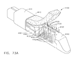
- FIG. 1A is a perspective view of one embodiment of an implantable staple cartridge
- FIGS. 1B-1E illustrate portions of an end effector clamping and stapling tissue with an implantable staple cartridge
- FIG. 2 is a partial cross-sectional side view of another end effector coupled to a portion of a surgical instrument with the end effector supporting a surgical staple cartridge and with the anvil thereof in an open position;
- FIG. 3 is another partial cross-sectional side view of the end effector of FIG. 2 in a closed position
- FIG. 4 is another partial cross-sectional side view of the end effector of FIGS. 2 and 3 as the knife bar is starting to advance through the end effector;
- FIG. 5 is another partial cross-sectional side view of the end effector of FIGS. 2-4 with the knife bar partially advanced therethrough;
- FIG. 6 is a perspective view of an alternative staple cartridge embodiment installed in a surgical cutting and stapling device
- FIG. 7 is a top view of the surgical staple cartridge and elongated channel of the device depicted in FIG. 6 ;
- FIG. 8 is a top view of another surgical staple cartridge embodiment installed in an elongated channel of an end effector
- FIG. 9 is a bottom view of an anvil
- FIG. 10 is a partial perspective view of a plurality of staples forming a portion of a staple line
- FIG. 11 is another partial perspective view of the staple line of FIG. 10 with the staples thereof after being formed by being contacted by the anvil of the surgical cutting and stapling device;
- FIG. 12 is a partial perspective view of alternative staples forming a portion of another staple line
- FIG 13 is a partial perspective view of alternative staples forming a portion of another staple line
- FIG. 14 is a partial perspective view of alternative staples forming a portion of another staple line embodiment
- FIG. 15 is a cross-sectional view of an end effector supporting a staple cartridge
- FIG. 16 is a cross-sectional view of the elongated channel portion of the end effector of FIG. 15 after the implantable staple cartridge body portion and staples have been removed therefrom;
- FIG. 17 is a cross-sectional view of an end effector supporting another staple cartridge
- FIGS. 18A-18D diagram the deformation of a surgical staple positioned within a collapsible staple cartridge body in accordance with at least one embodiment
- FIG. 19A is a diagram illustrating a staple positioned in a crushable staple cartridge body
- FIG. 19B is a diagram illustrating the crushable staple cartridge body of FIG. 19A being crushed by an anvil
- FIG. 19C is a diagram illustrating the crushable staple cartridge body of FIG. 19A being further crushed by the anvil;
- FIG. 19D is a diagram illustrating the staple of FIG. 19A in a fully formed configuration and the crushable staple cartridge of FIG. 19A in a fully crushed condition;
- FIG. 20 is a diagram depicting a staple positioned against a staple cartridge support surface and illustrating potential relative movement therebetween;
- FIG. 21 is a cross-sectional view of a staple cartridge support surface comprising a slot, or trough, configured to stabilize the base of the staple of FIG. 20 ;
- FIG. 22 is a cross-sectional view of a staple comprising an overmolded crown and a slot, or trough, configured to receive a portion of the crown in accordance with at least one alternative embodiment
- FIG. 23 is a top view of a staple cartridge in accordance with at least one embodiment comprising staples embedded in a collapsible staple cartridge body;
- FIG. 24 is an elevational view of the staple cartridge of FIG. 23 ;
- FIG. 25 is an elevational view of a staple cartridge in accordance with at least one embodiment comprising a protective layer surrounding staples positioned within a collapsible staple cartridge body;
- FIG. 26 is a cross-sectional view of the staple cartridge of FIG. 25 taken along line 26-26 in FIG. 25 ;
- FIG. 27 is an elevational view of a staple cartridge in accordance with at least one embodiment comprising staples at least partially extending outside of a collapsible staple cartridge body and a protective layer surrounding the staple cartridge body;
- FIG. 28 is a cross-sectional view of the staple cartridge of FIG. 27 taken along line 28-28 in FIG. 27 ;
- FIG. 29 is a partial break-away view of a staple cartridge in accordance with at least one embodiment comprising staples at least partially embedded in a collapsible staple cartridge body, the staples being at least partially positioned in a staple cavity void in the staple cartridge body;
- FIG. 30 is a cross-sectional view of the staple cartridge of FIG. 29 taken along line 30-30 in FIG. 29 ;
- FIG. 31 is a partial break-away view of a staple cartridge in accordance with at least one embodiment
- FIG. 32 is a partial break-away view of a staple cartridge in accordance with at least one embodiment comprising staples at least partially embedded within a collapsible staple cartridge body and an alignment matrix connecting the staples and aligning the staples with respect to each other;
- FIG. 33 is a cross-sectional view of the staple cartridge of FIG. 32 taken along line 33-33 in FIG. 32 ;
- FIG. 34 is partial cut-away view of an inner layer of a compressible staple cartridge body
- FIG. 35 is a diagram illustrating the inner layer of FIG. 34 compressed between a transfer plate and a support plate;
- FIG. 36 is a diagram illustrating staples being inserted into the compressed inner layer of FIG. 35 ;
- FIG. 37 is a diagram of the support plate of FIG. 35 being removed away from the inner layer
- FIG. 38 is a diagram of a subassembly comprising the inner layer of FIG. 34 and the staples of FIG. 36 being inserted into an outer layer;
- FIG. 39 is a diagram illustrating the outer layer of FIG. 38 being sealed to form a sealed staple cartridge
- FIG. 40 is a cross-sectional view of the sealed staple cartridge of FIG. 39 ;
- FIG. 41 is a cross-sectional view of a staple cartridge and staple cartridge channel in accordance with at least one embodiment
- FIG. 42 is a diagram illustrating a portion of the staple cartridge of FIG. 41 in a deformed state
- FIG. 43 is an elevational view of an end effector of a surgical stapler comprising an anvil in an open position and a staple cartridge positioned within a staple cartridge channel;
- FIG. 44 is an elevational view of the end effector of FIG. 43 illustrating the anvil in a closed position and the staple cartridge compressed between the anvil and the staple cartridge channel;
- FIG. 45 is an elevational view of the end effector of FIG. 43 illustrating the staple cartridge of FIG. 43 positioned within the staple cartridge channel in an alternative manner;
- FIG. 46 is a cross-sectional view of an end effector of a surgical stapler comprising a compressible staple cartridge positioned within a staple cartridge channel and a piece of buttress material attached to an anvil;
- FIG. 47 is a cross-sectional view of the end effector of FIG. 46 illustrating the anvil in a closed position
- FIG. 48 is a cross-sectional view of an alternative embodiment of an end effector of a surgical stapler comprising a staple cartridge comprising a water impermeable layer;
- FIG. 49 is a cross-sectional view of another alternative embodiment of an end effector of a surgical stapler
- FIG. 50 is a cross-sectional view of an alternative embodiment of an end effector of a surgical stapler comprising a stepped anvil and a staple cartridge comprising a stepped cartridge body;
- FIG. 51 is a cross-sectional view of another alternative embodiment of an end effector of a surgical stapler
- FIG. 52 is a cross-sectional view of an alternative embodiment of an end effector of a surgical stapler comprising inclined tissue-contacting surfaces;
- FIG. 53 is a cross-sectional view of another alternative embodiment of an end effector of a surgical stapler comprising inclined tissue-contacting surfaces;
- FIG. 54 is a cross-sectional view of an alternative embodiment of an end effector of a surgical stapler comprising a support insert configured to support a staple cartridge;
- FIG. 55 is a cross-sectional view of an alternative embodiment of an end effector of a surgical stapler comprising a staple cartridge comprising a plurality of compressible layers;
- FIG. 56 is a cross-sectional view of an alternative embodiment of an end effector of a surgical stapler comprising a staple cartridge comprising a stepped compressible cartridge body;
- FIG. 57 is a cross-sectional view of another alternative embodiment of an end effector of a surgical stapler comprising a staple cartridge comprising a stepped compressible cartridge body;
- FIG. 58 is a cross-sectional view of an alternative embodiment of an end effector of a surgical stapler comprising a staple cartridge comprising a curved tissue-contacting surface;
- FIG. 59 is a cross-sectional view of an alternative embodiment of an end effector of a surgical stapler comprising a staple cartridge having an inclined tissue-contacting surface;
- FIG. 60 is a cross-sectional view of a compressible staple cartridge comprising staples and at least one medicament stored therein;
- FIG. 61 is a diagram illustrating the compressible staple cartridge of FIG. 60 after it has been compressed and the staples contained therein have been deformed;
- FIG. 62 is a partial cut-away view of a staple cartridge in accordance with at least one embodiment
- FIG. 63 is a cross-sectional view of the staple cartridge of FIG. 62 ;
- FIG. 64 is a perspective view of an implanted staple cartridge in accordance with at least one alternative embodiment
- FIG. 65 is a cross-sectional view of the implanted staple cartridge of FIG. 64 ;
- FIG. 66 is a perspective view of an alternative embodiment of a staple cartridge comprising deformable members extending from an outer layer of the staple cartridge;
- FIG. 67 is a perspective view of an alternative embodiment of a staple cartridge comprising an outer layer of the staple cartridge being assembled to an inner layer;
- FIG. 68 is a cross-sectional view of an alternative embodiment of a staple cartridge comprising a plurality of staples, a compressible layer, and a pledget layer;
- FIG. 69 is a perspective view of the pledget layer of FIG. 68 ;
- FIG. 70 is a perspective view of a pledget singulated from the pledget layer of FIG. 68 and a staple aligned with a groove in the pledget;
- FIG. 71 is a perspective view of two connected pledgets from the pledget layer of FIG. 68 ;
- FIG. 72 is a perspective view of a pledget support frame of the pledget layer of FIG. 68 being removed from the singulated pledgets;
- FIG. 73 is an exploded perspective view of an alternative embodiment of a compressible staple cartridge comprising staples therein and a system for driving the staples against an anvil;
- FIG. 73A is a partial cut-away view of an alternative embodiment of the staple cartridge of FIG. 73 ;
- FIG. 74 is a cross-sectional view of the staple cartridge of FIG. 73 ;
- FIG. 75 is an elevational view of a sled configured to traverse the staple cartridge of FIG. 73 and move the staples to toward the anvil;
- FIG. 76 is a diagram of a staple driver which can be lifted toward the anvil by the sled of FIG. 75 ;
- FIG. 77 is a break-away view of a staple cartridge in accordance with at least one alternative embodiment comprising staples positioned within staple drivers;
- FIG. 78 is a cross-sectional view of the staple cartridge of FIG. 77 positioned within a staple cartridge channel;
- FIG. 79 is a cross-sectional view of the staple cartridge of FIG. 77 illustrating an anvil moved into a closed position and staples contained within the staple cartridge deformed by the anvil;
- FIG. 80 is a cross-sectional view of the staple cartridge of FIG. 77 illustrating the staples moved upwardly toward the anvil;
- FIG. 81 is a perspective view of an alternative embodiment of a staple cartridge comprising straps connecting the flexible sides of the staple cartridge;
- FIG. 82 is a perspective view of a sled and cutting member assembly
- FIG. 83 is a diagram of the sled and cutting member assembly of FIG. 82 being used to lift the staples of the staple cartridge of FIG. 77 ;
- FIG. 84 is a diagram illustrating a sled configured to engage and lift staples toward an anvil and a lock-out system configured to selectively permit the sled to move distally;
- FIGS. 85A-85C illustrate the progression of a staple being inserted into a staple crown
- FIG. 86 is a cross-sectional view of a staple cartridge comprising a support pan or retainer
- FIG. 87 is a partial cross-sectional view of a compressible staple cartridge in accordance with at least one alternative embodiment
- FIG. 88 is a diagram illustrating the staple cartridge of FIG. 87 in an implanted condition
- FIG. 89 is a partial cut-away view of a compressible staple cartridge in accordance with at least one alternative embodiment
- FIG. 90 is a partial cross-sectional view of the staple cartridge of FIG. 89 ;
- FIG. 91 is a diagram illustrating the staple cartridge of FIG. 89 in an implanted condition
- FIG. 92 is a partial cross-sectional view of a crushable staple cartridge in accordance with at least one alternative embodiment
- FIG. 93 is a partial cut-away view of a collapsible staple cartridge in accordance with at least one embodiment comprising a plurality of collapsible elements
- FIG. 94 is a perspective view of a collapsible element of FIG. 93 in an uncollapsed state
- FIG. 95 is a perspective view of the collapsible element of FIG. 94 in a collapsed state
- FIG. 96A is a partial cross-sectional view of an end effector of a surgical stapling instrument comprising a jaw, a staple cartridge channel positioned opposite the jaw, and a staple cartridge positioned within the staple cartridge channel, wherein the jaw comprises a retention matrix attached thereto;
- FIG. 96B is a partial cross-sectional view of the end effector of FIG. 96A illustrating the jaw being moved toward the staple cartridge channel, the staple cartridge being compressed by the anvil and the retention matrix, and a staple at least partially extending through tissue positioned intermediate the retention matrix and the staple cartridge;
- FIG. 96C is a partial cross-sectional view of the end effector of FIG. 96A illustrating the jaw in a final position and the retention matrix engaged with the staple of FIG. 96B ;
- FIG. 96D is a partial cross-sectional view of the end effector of FIG. 96A illustrating the jaw and the staple cartridge channel being moved away from the implanted staple cartridge and retention matrix;
- FIG. 97 is a perspective view of a retention aperture of a retention matrix in accordance with at least one alternative embodiment comprising a plurality of retention members configured to engage a fastener leg extending therethrough;
- FIG. 98 is a perspective view of a retention aperture of a retention matrix in accordance with at least one alternative embodiment comprising six retention members;
- FIG. 99 is a perspective view of a retention aperture of a retention matrix in accordance with at least one alternative embodiment comprising eight retention members;
- FIG. 100 is a perspective view of a retention aperture of a retention matrix in accordance with at least one alternative embodiment comprising a plurality of retention members configured to engage a fastener leg extending therethrough;
- FIG. 101 is a perspective view of a retention aperture of a retention matrix in accordance with at least one alternative embodiment comprising six retention members;
- FIG. 102 is a perspective view of a retention aperture of a retention matrix in accordance with at least one alternative embodiment comprising eight retention members;
- FIG. 103 is a perspective view of a retention aperture of a retention matrix in accordance with at least one alternative embodiment comprising a plurality of retention members that have been stamped from a sheet of metal;
- FIG. 104 is a perspective view of a retention aperture of a retention matrix in accordance with at least one alternative embodiment comprising a plurality of apertures extending around the perimeter of the retention aperture;
- FIG. 105 is a top view of a retention aperture of a retention matrix in accordance with at least one alternative embodiment
- FIG. 106 is a top view of a retention aperture of a retention matrix in accordance with at least one alternative embodiment
- FIG. 107 is a top view of a retention aperture of a retention matrix in accordance with at least one alternative embodiment
- FIG. 108 is a top view of a retention aperture of a retention matrix in accordance with at least one alternative embodiment
- FIG. 109 is a top view of a retention aperture of a retention matrix in accordance with at least one alternative embodiment
- FIG. 110 is a top view of a retention aperture of a retention matrix comprising a retention tab extending into the retention aperture in accordance with at least one embodiment
- FIG. 111 is a top view of a retention aperture of a retention matrix comprising a retention tab extending into the retention aperture in accordance with at least one alternative embodiment
- FIG. 112 is a perspective view of a fastening system comprising a plurality of staples, a retention matrix engaged with the staples, and an alignment matrix configured to align the staples;
- FIG. 113 is a perspective view of the retention matrix of FIG. 112 ;
- FIG. 114 is a perspective view of the alignment matrix of FIG. 112 ;
- FIG. 115 is a partial top view of the retention matrix of FIG. 112 engaged with the staples of FIG. 112 ;
- FIG. 116 is a partial bottom view of the retention matrix of FIG. 112 engaged with the staples of FIG. 112 ;
- FIG. 117 is a partial elevational view of the fastening system of FIG. 112 ;
- FIG. 118 is a partial perspective view of the fastening system of FIG. 112 ;
- FIG. 119 is a partial cross-sectional view of the retention matrix of FIG. 112 engaged with the staples of FIG. 112 ;
- FIG. 120 is a partial cross-sectional view of the fastening system of FIG. 112 ;
- FIG. 121 is a perspective view of the fastening system of FIG. 112 further comprising protective caps assembled to the legs of the staples;
- FIG. 122 is a bottom perspective view of the fastening system arrangement of FIG. 121 ;
- FIG. 123 is a partial perspective view of the fastening system arrangement of FIG. 121 ;
- FIG. 124 is a partial cross-sectional view of the fastening system arrangement of FIG. 121 ;
- FIG. 125 is an elevational view of an end effector in accordance with at least one embodiment comprising a jaw in an open position, a retention matrix and a plurality of protective caps positioned in the jaw, and a staple cartridge positioned in a staple cartridge channel;
- FIG. 126 is an elevational view of the end effector of FIG. 125 in a closed position
- FIG. 127 is an elevational view of the end effector of FIG. 125 in a fired position
- FIG. 128 is an elevational view of the retention matrix and protective caps of FIG. 125 assembled to the staple cartridge of FIG. 125 ;
- FIG. 129 is a detail view of the arrangement of FIG. 128 ;
- FIG. 130 is an elevational view of the end effector of FIG. 125 illustrating the jaw in an open position with thinner tissue positioned between the retention matrix and the staple cartridge;
- FIG. 131 is an elevational view of the end effector of FIG. 125 illustrating the jaw in a closed position against the thinner tissue of FIG. 130 ;
- FIG. 132 is an elevational view of the end effector of FIG. 125 illustrating the jaw in a fired position to capture the thinner tissue of FIG. 130 between the retention matrix and the staple cartridge;
- FIG. 133 is an elevational view of the retention matrix and the protective caps of FIG. 125 assembled to the staple cartridge of FIG. 125 with the thin tissue of FIG. 130 positioned therebetween;
- FIG. 134 is a detail view of the arrangement of FIG. 133 ;
- FIG. 135 is a cross-sectional view of a protective cap positioned on the tip of a staple leg in accordance with at least one alternative embodiment
- FIG. 136 is a perspective view of a plurality of protective caps embedded within a sheet of material
- FIG. 137 is a perspective view of a jaw comprising a plurality of recesses configured to receive a plurality of protective caps therein;
- FIG. 138 is a detail view of a portion of a jaw comprising a sheet covering the protective caps positioned within the jaw of FIG. 137 ;
- FIG. 139 is a cross-sectional view of a protective cap positioned on a tip of a staple leg in accordance with at least one alternative embodiment wherein the protective cap comprises an interior forming surface;
- FIG. 140 is another cross-sectional view of the protective cap of FIG. 139 illustrating the staple leg being deformed against the forming surface;
- FIG. 141 is a top view of an alternative embodiment of a retention matrix comprising a plurality of connected matrix elements
- FIG. 142 is a top view of an alternative embodiment of a retention matrix comprising a plurality of connected matrix elements
- FIG. 143 is a top view of an alternative embodiment of a retention matrix comprising a plurality of connected matrix elements
- FIG. 144 is a top view of an alternative embodiment of an array of retention matrices comprising a plurality of connected matrix elements
- FIG. 145 is a top view of an alternative embodiment of a retention matrix comprising a plurality of connected matrix elements
- FIG. 146 is a partial exploded view of a jaw comprising a retention matrix including a compressible cover
- FIG. 147 is a detail view of the retention matrix of FIG. 146 ;
- FIG. 148 is a partial cross-sectional view of a fastening system comprising a retention matrix including a compressible layer and a plurality of cells encapsulating one or more medicaments;
- FIG. 149 is a diagram illustrating staple legs which have pierced the cells of FIG. 148 as they are being engaged with the retention matrix;
- FIG. 150 is a partial cross-sectional view of a fastening system comprising a retention matrix including a compressible layer;
- FIG. 151 is an elevational view of a fastener cartridge insertion assembly comprising a holder, a first fastener cartridge, and a second fastener cartridge;
- FIG. 152 is an elevational view of an end effector of a surgical stapler comprising a first jaw and a second jaw, the second jaw being illustrated in an open configuration;
- FIG. 153 is an elevational view of the end effector of FIG. 152 illustrating the second jaw in a closed configuration and the fastener cartridge insertion assembly of FIG. 151 being used to load the first jaw with the first cartridge and the second jaw with the second cartridge;
- FIG. 154 is an elevational view of the loaded end effector of FIG. 153 illustrating the cartridge insertion assembly removed from the end effector, the second jaw in an open configuration once again, and tissue positioned intermediate the first jaw and the second jaw;
- FIG. 155 is an elevational view of the loaded end effector of FIG. 154 in a fired configuration
- FIG. 156 is an elevational view of the first cartridge and the second cartridge in an implanted condition
- FIG. 157 is an elevational view of the end effector of FIG. 152 illustrating a portion of the first cartridge still engaged with the first jaw in accordance with at least one embodiment
- FIG. 158 is an elevational view of an alternative embodiment of a fastener cartridge insertion assembly comprising a holder, a first fastener cartridge, and a second fastener cartridge;
- FIG. 159 is an elevational view of the fastener cartridge insertion assembly of FIG. 158 being used to load a first jaw of an end effector with the first cartridge and a second jaw with the second cartridge;
- FIG. 160 is a cross-sectional view of the loaded end effector of FIG. 159 ;
- FIG. 161 is a perspective view of a surgical stapler comprising a bottom jaw and a top jaw in accordance with at least one embodiment illustrated with portions of the surgical stapler removed;
- FIG. 162 is a perspective view of the surgical stapler of FIG. 161 with the top jaw removed;
- FIG. 163 is a perspective view of a slidable anvil system of the top jaw of the surgical stapler of FIG. 161 comprising a first slidable anvil and a second slidable anvil;
- FIG. 164 is an end view of the slidable anvil system of FIG. 163 ;
- FIG. 165 is a top view of the slidable anvil system of FIG. 163 ;
- FIG. 166 is a diagram illustrating the slidable anvil system of FIG. 163 in an unfired condition
- FIG. 167 is a diagram illustrating the first slidable anvil of the slidable anvil system of FIG. 163 in an unfired position and staples positioned within the bottom jaw in an undeployed position;
- FIG. 168 is a diagram illustrating the staples in the bottom jaw in a deployed configuration and the first slidable anvil of FIG. 167 being pulled proximally to deform a first group of staple legs of the staples;
- FIG. 169 is a diagram illustrating the first group of staples of FIG. 168 deformed to a fully deformed state
- FIG. 170 is a diagram illustrating the second slidable anvil of the slidable anvil system of FIG. 163 being pushed distally to deform a second group of staple legs;
- FIG. 171 is a partial perspective view of an anvil comprising a plurality of forming pockets in at least one embodiment
- FIG. 172 is a cross-sectional end view of the anvil of FIG. 171 ;
- FIG. 173 is a diagram illustrating a first step in manufacturing the forming pockets of FIG. 171 ;
- FIG. 174 is a diagram illustrating a second step in manufacturing the forming pockets of FIG. 171 ;
- FIG. 175 is a top view of the forming pocket arrangement of the anvil of FIG. 171 ;
- FIG. 176 is a diagram illustrating a first step of a manufacturing process for producing an anvil
- FIG. 177 is a diagram illustrating a second step in the manufacturing process of FIG. 176 ;
- FIG. 178 is a diagram illustrating a third step in the manufacturing process of FIG. 176 ;
- FIG. 179 is a left front perspective view of a surgical stapling and severing instrument with a handle portion including a link triggered automatic retraction and a ratcheting manual retraction mechanism;
- FIG. 180 is a right aft perspective view of the surgical stapling and severing instrument of FIG. 179 with a portion of an elongate shaft cut away and a right half shell of a handle housing removed to expose an automatic end-of-firing travel retraction mechanism and a manual firing retraction mechanism;
- FIG. 181 is a right aft perspective disassembled view of the handle portion and an elongate shaft of the surgical stapling and severing instrument of FIG. 179 ;
- FIG. 182 is a right aft perspective view of the surgical stapling and severing instrument of FIG. 31 with a right half shell and outer portions of the implement portion removed to expose the closure and firing mechanisms in an initial state;
- FIG. 183 is a right side view in elevation of the partially disassembled surgical stapling and severing instrument of FIG. 182 ;
- FIG. 184 is a right aft perspective view of the partially disassembled surgical stapling and severing instrument of FIG. 182 with a closure mechanism closed and clamped and the side pawl firing mechanism completing a first stroke and with a manual retraction mechanism removed to expose a distal link of the linked rack that triggers automatic retraction of the firing mechanism;
- FIG. 185 is a right aft perspective view of the partially disassembled surgical stapling and severing instrument of FIG. 183 with the side pawl firing mechanism disengaged and the distal link approaching automatic retraction;
- FIG. 186 is left side view in elevation of the partially disassembled surgical stapling and severing instrument of FIG. 183 in an initial state of end effector open and anti-backup mechanism engaged;
- FIG. 187 is a left side detail view of the right half shell and an anti-backup release lever of the handle portion of FIG. 186 ;
- FIG. 188 is a left side detail view in elevation of the disassembled surgical stapling and severing instrument of FIG. 179 with the closure trigger clamped, the firing trigger performing a final stroke and the distal link positioned to trip automatic retraction;
- FIG. 189 is a left side detail in elevation of the disassembled surgical stapling and severing instrument of FIG. 188 immediately after the distal link has actuated and locked forward the anti-backup release lever, allowing the linked rack to retract;
- FIG. 190 is a right disassembled perspective view of the idler and aft gears and manual retraction lever and ratcheting pawl of a manual retraction mechanism of the surgical stapling and severing instrument of FIG. 179 ;
- FIG. 191 is a right perspective view of the manual retraction mechanism of FIG. 190 with the manual retraction lever partially cut away to expose a smaller diameter ratchet gear on the aft gear engaging the ratcheting pawl;
- FIG. 192 is a partially disassembled left side view in elevation of a surgical stapling and severing instrument of FIG. 179 with the anti-backup mechanism engaged to a fully fired linked rack that is disconnected from a combination tension/compression spring prior to actuation of the manual retraction lever of FIG. 190 ;
- FIG. 193 is a partially disassembled left side view in elevation of the surgical stapling and severing instrument of FIG. 192 with hidden portions of the anti-backup release lever, aft gear, and manual firing release lever shown in phantom;
- FIG. 194 is a partially disassembled left side view in elevation of the surgical stapling and severing instrument of FIG. 193 after actuation of the manual firing release lever has manually retracted the link rack;
- FIG. 195 is a partially disassembled left side view in elevation of the surgical stapling and severing instrument of FIG. 194 with the linked rack omitted depicting the manual firing release lever disengaging the anti-backup mechanism;
- FIG. 196 is a left side detail view of an alternative anti-backup release lever and handle housing for the surgical stapling and severing instrument of FIG. 179 ;
- FIG. 197 is a left perspective disassembled view of the alternative anti-backup release lever, aft gear axle, and automatic retraction cam wheel of FIG. 196 ;
- FIG. 198 is a right side view in elevation of the alternative anti-backup release mechanism of FIG. 196 with the linked rack in a retracted position and the anti-backup release lever proximally positioned with the anti-backup plate engaged to the firing rod;
- FIG. 198A is a right detail side view in elevation of the aft gear, automatic retraction cam wheel and distal-most link of FIG. 198 ;
- FIG. 199 is a right side view in elevation of the anti-backup release mechanism of FIG. 198 after a first firing stroke
- FIG. 199A is a right detail side view in elevation of the aft gear, automatic retraction cam wheel and a second link of FIG. 199 ;
- FIG. 200 is a right side view in elevation of the anti-backup release mechanism of FIG. 199 after a second firing stroke
- FIG. 200A is a right detail side view in elevation of the aft gear, automatic retraction cam wheel and third link of FIG. 200 ;
- FIG. 201 is a right detail side view in elevation of the anti-backup release mechanism of FIG. 200 after a third firing and final stroke;
- FIG. 201A is a right detail side view in elevation of the aft gear, automatic retraction cam wheel and proximal-most fourth link of FIG. 201 ;
- FIG. 202 is a right side view in elevation of the automatic release mechanism of FIG. 201 after a further firing stroke causes the automatic retraction cam wheel to distally slide and lock the anti-backup release lever, disengaging the anti-backup mechanism;
- FIG. 203 is a left, front perspective view of an open staple applying assembly with a right half portion of a replaceable staple cartridge included in a staple channel;
- FIG. 204 is an exploded perspective view of the staple applying assembly of FIG. 203 with a complete replaceable staple cartridge and an nonarticulating shaft configuration;
- FIG. 205 is a perspective view of a two-piece knife and firing bar ("E-beam") of the staple applying assembly of FIG. 203 ;
- FIG. 206 is a perspective view of a wedge sled of a staple cartridge of a staple applying assembly
- FIG. 207 is a left side view in elevation taken in longitudinal cross section along a centerline line 207-207 of the staple applying assembly of FIG. 203 ;
- FIG. 208 is a perspective view of the open staple applying assembly of FIG. 203 without the replaceable staple cartridge, a portion of the staple channel proximate to a middle pin of two-piece knife and firing bar, and without a distal portion of a staple channel;
- FIG. 209 is a front view in elevation taken in cross section along line 209-209 of the staple applying assembly of FIG. 203 depicting internal staple drivers of the staple cartridge and portions of the two-piece knife and firing bar;
- FIG. 210 is a left side view in elevation taken generally along the longitudinal axis of line 207-207 of a closed staple applying assembly of FIG. 203 to include center contact points between the two-piece knife and wedge sled but also laterally offset to show staples and staple drivers within the staple cartridge;
- FIG. 211 is a left side detail view in elevation of the staple applying assembly of FIG. 210 with the two-piece knife retracted slightly more as typical for staple cartridge replacement;
- FIG. 212 is a left side detail view in elevation of the staple applying assembly of FIG. 211 with the two-piece knife beginning to fire, corresponding to the configuration depicted in FIG. 210 ;
- FIG. 213 is a left side cross-sectional view in elevation of the closed staple applying assembly of FIG. 210 after the two-piece knife and firing bar has distally fired;
- FIG. 214 is a left side cross-sectional view in elevation of the closed staple applying assembly of FIG. 213 after firing of the staple cartridge and retraction of the two-piece knife;
- FIG. 215 is a left side cross-sectional detail view in elevation of the staple applying assembly of FIG. 214 with the two-piece knife allowed to drop into a lockout position;
- FIG. 216 is a perspective view of a staple cartridge comprising a rigid support portion and a compressible tissue thickness compensator for use with a surgical stapling instrument in accordance with at least one embodiment of the invention
- FIG. 217 is a partially exploded view of the staple cartridge of FIG. 216 ;
- FIG. 218 is a fully exploded view of the staple cartridge of FIG. 216 ;
- FIG. 219 is another exploded view of the staple cartridge of FIG. 216 without a warp covering the tissue thickness compensator;
- FIG. 220 is a perspective view of a cartridge body, or support portion, of the staple cartridge of FIG. 216 ;
- FIG. 221 is a top perspective view of a sled movable within the staple cartridge of FIG. 216 to deploy staples from the staple cartridge;
- FIG. 222 is a bottom perspective view of the sled of FIG. 221 ;
- FIG. 223 is an elevational view of the sled of FIG. 221 ;
- FIG. 224 is a top perspective view of a driver configured to support one or more staples and to be lifted upwardly by the sled of FIG. 221 to eject the staples from the staple cartridge;
- FIG. 225 is a bottom perspective view of the driver of FIG. 224 ;
- FIG. 226 is a wrap configured to at least partially surround a compressible tissue thickness compensator of a staple cartridge
- FIG. 227 is a partial cut away view of a staple cartridge comprising a rigid support portion and a compressible tissue thickness compensator illustrated with staples being moved from an unfired position to a fired position during a first sequence;
- FIG. 228 is an elevational view of the staple cartridge of FIG. 227 ;
- FIG. 229 is a detail elevational view of the staple cartridge of FIG. 227 ;
- FIG. 230 is a cross-sectional end view of the staple cartridge of FIG. 227 ;
- FIG. 231 is a bottom view of the staple cartridge of FIG. 227 ;
- FIG. 232 is a detail bottom view of the staple cartridge of FIG. 227 ;
- FIG. 233 is a longitudinal cross-sectional view of an anvil in a closed position and a staple cartridge comprising a rigid support portion and a compressible tissue thickness compensator illustrated with staples being moved from an unfired position to a fired position during a first sequence;
- FIG. 234 is another cross-sectional view of the anvil and the staple cartridge of FIG. 233 illustrating the anvil in an open position after the firing sequence has been completed;
- FIG. 235 is a partial detail view of the staple cartridge of FIG. 233 illustrating the staples in an unfired position
- FIG. 236 is a cross-sectional elevational view of a staple cartridge comprising a rigid support portion and a compressible tissue thickness compensator illustrating the staples in an unfired position;
- FIG. 237 is a detail view of the staple cartridge of FIG. 236 ;
- FIG. 238 is an elevational view of an anvil in an open position and a staple cartridge comprising a rigid support portion and a compressible tissue thickness compensator illustrating the staples in an unfired position;
- FIG. 239 is an elevational view of an anvil in a closed position and a staple cartridge comprising a rigid support portion and a compressible tissue thickness compensator illustrating the staples in an unfired position and tissue captured between the anvil and the tissue thickness compensator;
- FIG. 240 is a detail view of the anvil and staple cartridge of FIG. 239 ;
- FIG. 241 is an elevational view of an anvil in a closed position and a staple cartridge comprising a rigid support portion and a compressible tissue thickness compensator illustrating the staples in an unfired position illustrating thicker tissue positioned between the anvil and the staple cartridge;
- FIG. 242 is a detail view of the anvil and staple cartridge of FIG. 241 ;
- FIG. 243 is an elevational view of the anvil and staple cartridge of FIG. 241 illustrating tissue having different thicknesses positioned between the anvil and the staple cartridge;
- FIG. 244 is a detail view of the anvil and staple cartridge of FIG. 241 as illustrated in FIG. 243 ;
- FIG. 245 is a diagram illustrating a tissue thickness compensator which is compensating for different tissue thickness captured within different staples
- FIG. 246 is a diagram illustrating a tissue thickness compensator applying a compressive pressure to one or more vessels that have been transected by a staple line;
- FIG. 247 is a diagram illustrating a circumstance wherein one or more staples have been improperly formed
- FIG. 248 is a diagram illustrating a tissue thickness compensator which could compensate for improperly formed staples
- FIG. 249 is a diagram illustrating a tissue thickness compensator positioned in a region of tissue in which multiple staples lines have intersected;
- FIG. 250 is a diagram illustrating tissue captured within a staple
- FIG. 251 is a diagram illustrating tissue and a tissue thickness compensator captured within a staple
- FIG. 252 is a diagram illustrating tissue captured within a staple
- FIG. 253 is a diagram illustrating thick tissue and a tissue thickness compensator captured within a staple
- FIG. 254 is a diagram illustrating thin tissue and a tissue thickness compensator captured within a staple
- FIG. 255 is a diagram illustrating tissue having an intermediate thickness and a tissue thickness compensator captured within a staple
- FIG. 256 is a diagram illustrating tissue having another intermediate thickness and a tissue thickness compensator captured within a staple
- FIG. 257 is a diagram illustrating thick tissue and a tissue thickness compensator captured within a staple
- FIG. 258 is a partial cross-sectional view of an end effector of a surgical stapling instrument illustrating a firing bar and staple-firing sled in a retracted, unfired position;
- FIG. 259 is another partial cross-sectional view of the end effector of FIG. 258 illustrating the firing bar and the staple-firing sled in a partially advanced position;
- FIG. 260 is a cross-sectional view of the end effector of FIG. 258 illustrating the firing bar in a fully advanced, or fired, position;
- FIG. 261 is a cross-sectional view of the end effector of FIG. 258 illustrating the firing bar in a retracted position after being fired and the staple-firing sled left in its fully fired position;
- FIG. 262 is a detail view of the firing bar in the retracted position of FIG. 261 ;
- FIG. 263 is a partial cross-sectional view of an end effector of a surgical stapling instrument including a staple cartridge comprising a tissue thickness compensator and staples at least partially positioned therein;
- FIG. 264 is another partial cross-sectional view of the end effector of FIG. 263 illustrating the staples at least partially moved and/or rotated relative to an anvil positioned opposite the staple cartridge;
- FIG. 265 is a partial cross-sectional view of an end effector of a surgical stapling instrument in accordance with at least one embodiment
- FIG. 266 is a partial cross-sectional view of an end effector in accordance with at least one alternative embodiment
- FIG. 267 is a partial cross-sectional view of an end effector in accordance with another alternative embodiment
- FIG. 268 is a perspective view of an end effector of a surgical stapling instrument in accordance with at least one embodiment
- FIG. 269 is a partial cross-sectional view of the end effector of FIG. 268 illustrated in a flexed condition
- FIG. 270 is a partial cross-sectional view of the end effector of FIG. 269 in a released condition
- FIG. 271 is a perspective view of an end effector comprising a tissue thickness compensator sock
- FIG. 272 is a rear perspective of the tissue thickness compensator sock in FIG. 271 ;
- FIG. 273 is a perspective view of an end effector comprising a plurality of rails extending from a support portion and a tissue thickness compensator having a longitudinal cavity defined therein;
- FIG. 274 is a perspective view of the tissue thickness compensator of FIG. 273 ;
- FIG. 275 is a perspective view of an end effector comprising a plurality of teeth extending from a support portion and a tissue thickness compensator engaged therewith;
- FIG. 276 is a perspective view of an anvil comprising a pocket array in accordance with at least one embodiment
- FIG. 277 is a partial detail view of the anvil of FIG. 276 ;
- FIG. 278 is a partial longitudinal cross-sectional view of the anvil of FIG. 276 ;
- FIG. 279 is a transverse cross-sectional view of the anvil of FIG. 276 ;
- FIG. 280 is an elevational view of a fired staple comprising a substantially B-shaped configuration
- FIG. 281 is an elevational view of a fired staple comprising one leg deformed inwardly and one leg deformed outwardly;
- FIG. 282 is an elevational view of a fired staple comprising both legs formed outwardly;
- FIG. 283 is a partial perspective view of a support portion of a staple cartridge comprising detachable and/or displaceable staple leg guides;
- FIG. 284 is a partial cross-sectional view of the staple cartridge of FIG. 283 illustrating staples being deployed from the staple cartridge;
- FIG. 285 is a detail view of the cross-sectional view of FIG. 284 after the staple cartridge has been fired;
- FIG. 286 is an exploded view of a staple cartridge including a tissue thickness compensator comprising voids defined therein;
- FIG. 287 is a diagram illustrating the tissue thickness compensator of FIG. 286 implanted against tissue
- FIG. 288 is another diagram illustrating the tissue thickness compensator of FIG. 286 implanted against tissue
- FIG. 289 is a cross-sectional perspective view of a staple cartridge comprising lateral retention members extending from a support portion thereof configured to hold a tissue thickness compensator in position;
- FIG. 290 is a cross-sectional view of the staple cartridge of FIG. 289 being utilized to staple tissue;
- FIG. 291 is another cross-sectional view of the staple cartridge of FIG. 289 illustrating the support portion being moved away from the implanted tissue thickness compensator;
- FIG. 292 is a cross-sectional perspective view of a staple cartridge comprising lateral retention members configured to hold a tissue thickness compensator to a support portion;
- FIG. 293 is a cross-sectional view of the staple cartridge of FIG. 292 being utilized to staple tissue;
- FIG. 294 is another cross-sectional view of the staple cartridge of FIG. 292 illustrating the support portion being moved away from the implanted tissue thickness compensator;
- FIG. 295 is a cross-sectional detail view of a retainer holding a tissue thickness compensator to a support portion of a staple cartridge in accordance with at least one embodiment
- FIG. 296 is partial cut-away view of a staple cartridge comprising staple drivers having different heights in accordance with at least one embodiment
- FIG. 296A is a diagram illustrating the staple drivers of FIG. 296 and staples having different unfired heights supported thereon;
- FIG. 297 is a diagram illustrating a tissue thickness compensator comprising a varying thickness, staple drivers having different heights, and staples having different unformed heights;
- FIG. 298 is a diagram illustrating the staples and the tissue thickness compensator of FIG. 297 implanted to tissue;
- FIG. 299 is a partial cross-sectional view of a staple cartridge comprising a tissue thickness compensator comprising a varying thickness in accordance with at least one embodiment
- FIG. 300 is a cross-sectional view of an end effector of a surgical stapling instrument in an open configuration
- FIG. 301 is cross-sectional view of the end effector of FIG. 300 illustrated in a partially-fired configuration
- FIG. 302 is a cross-sectional view of the end effector of FIG. 300 illustrated in a re-opened configuration
- FIG. 303 is a cross-sectional view of an end effector of a surgical stapling instrument comprising staple drivers having different heights and a contoured deck surface in accordance with at least one embodiment;
- FIG. 304 is a cross-sectional view of an end effector of a surgical stapling instrument comprising staple drivers having different heights and a stepped deck surface in accordance with at least one embodiment
- FIG. 305 is a perspective view of a staple cartridge being loaded into an effector of a surgical stapling instrument utilizing a staple cartridge applicator;
- FIG. 306 is a bottom perspective view of the staple cartridge applicator of FIG. 305 ;
- FIG. 307 is a side view of the staple cartridge applicator of FIG. 305 assembled to a staple cartridge
- FIG. 308 is a cross-sectional view of the assembly of FIG. 307 ;
- FIG. 309 is a perspective view of a staple cartridge applicator assembly further including an upper tissue thickness compensator positioned on the top surface of the staple cartridge applicator in accordance with at least one embodiment
- FIG. 310 is an exploded view of the upper tissue thickness compensator and the staple cartridge applicator of FIG. 309 ;
- FIG. 310A is an exploded view of a staple cartridge applicator assembly comprising a pull member configured to detach an upper tissue thickness compensator adhered to the staple cartridge applicator;
- FIG. 311 is a partial exploded view of a staple cartridge applicator assembly in accordance with at least one alternative embodiment
- FIG. 312 is a perspective view of a staple cartridge applicator assembly comprising an upper tissue thickness compensator including a plurality of retention features extending therefrom and a staple cartridge comprising a lower tissue thickness compensator;
- FIG. 313 is an elevational view of the staple cartridge applicator assembly of FIG. 312 positioned within a staple cartridge channel and an anvil being closed onto the staple cartridge applicator assembly;
- FIG. 314 is an elevational view of the anvil of FIG. 313 in a re-opened position and the staple cartridge applicator of FIG. 312 being removed from the end effector;
- FIG. 314A is a cross-sectional view of tissue positioned intermediate the upper tissue thickness compensator and the lower tissue thickness compensator of FIG. 312 ;
- FIG. 314B is a cross-sectional view illustrating the upper tissue thickness compensator and the lower tissue thickness compensator stapled to the tissue and severed by a cutting member;
- FIG. 315 is a diagram illustrating a tissue thickness compensator being inserted into an anvil in accordance with at least one embodiment
- FIG. 316 is a cross-sectional view of the tissue thickness compensator of FIG. 315 ;
- FIG. 317 is an exploded view of a tissue thickness compensator and an anvil in accordance with at least one alternative embodiment
- FIG. 318 is a perspective view of staple cartridge applicator assembly comprising an upper tissue thickness compensator configured to be attached to an anvil in accordance with at least one embodiment
- FIG. 319 is an elevational view of the staple cartridge applicator assembly of FIG. 318 positioned within a staple cartridge channel and an anvil being moved toward the upper tissue thickness compensator;
- FIG. 320 illustrates the staple cartridge applicator of FIG. 318 being removed from the end effector after the upper tissue thickness compensator has been engaged with the anvil;
- FIG. 321 is a cross-sectional end view of the anvil being moved toward the upper tissue thickness compensator of FIG. 318 ;
- FIG. 322 is a cross-sectional end view of the anvil engaged with the upper tissue thickness compensator
- FIG. 323 is a cross-sectional view of an end effector of a surgical stapling instrument comprising a staple cartridge including a segmentable tissue thickness compensator attached to a support portion of the staple cartridge by a plurality of fasteners;
- FIG. 324 is a cross-sectional view of the end effector of FIG. 323 illustrating a firing member in a partially-fired position
- FIG. 325 is a cross-sectional view of the end effector of FIG. 323 illustrating the support portion being moved away from the partially-implanted tissue thickness compensator;
- FIG. 326 is a partial perspective view of the support portion of FIG. 323 ;
- FIG. 327 is a perspective view of a staple-deploying sled in accordance with at least one embodiment
- FIG. 328 is an elevational view of the sled of FIG. 327 ;
- FIG. 329 is a perspective view of an end effector of a surgical stapling instrument comprising a staple cartridge including a tissue thickness compensator and a plurality of staple guides positioned on the tissue thickness compensator;
- FIG. 330 is a partial cross-sectional view of the tissue thickness compensator and the staple guides of FIG. 329 in an unfired configuration
- FIG. 331 is a partial cross-sectional view of the tissue thickness compensator and the staple guides of FIG. 329 in a fired configuration
- FIG. 332 is a cross-sectional view of a staple cartridge comprising a tissue thickness compensator and a support portion in accordance with at least one embodiment
- FIG. 333 is a partial cross-sectional view of a tissue thickness compensator, a staple guide layer, and a staple in an unfired position;
- FIG. 334 is a partial cross-sectional view of a tissue thickness compensator, a staple guide layer, and a staple in an unfired position in accordance with at least one alternative embodiment
- FIG. 335 is a partial cross-sectional view of a tissue thickness compensator, a staple guide layer, and a staple in an unfired position in accordance with at least one alternative embodiment
- FIG. 336 is a partial cross-sectional view of a tissue thickness compensator, a staple guide layer, and a staple in an unfired position in accordance with at least one alternative embodiment
- FIG. 337 is a partial cross-sectional view of a tissue thickness compensator, a staple guide layer, and a staple in an unfired position in accordance with at least one alternative embodiment
- FIG. 338 is a partial cross-sectional view of a tissue thickness compensator, a staple guide layer, and a staple in an unfired position in accordance with at least one alternative embodiment
- FIG. 339 is a partial cross-sectional view of a tissue thickness compensator, a staple guide layer, and a staple in an unfired position in accordance with at least one alternative embodiment
- FIG. 340 is a detail view of a region surrounding a tip of the staple of FIG. 339 ;
- FIG. 341 is a partial cross-sectional view of a tissue thickness compensator, a staple guide layer, and a staple in an unfired position in accordance with at least one alternative embodiment
- FIG. 342 is a detail view of a region surrounding a tip of the staple of FIG. 341 ;
- FIG. 343 is a partial cross-sectional view of a tissue thickness compensator, a staple guide layer, and a staple in an unfired position in accordance with at least one alternative embodiment
- FIG. 344 is a perspective view of a staple guide layer and a plurality of staples in an unfired position in accordance with at least one alternative embodiment
- FIG. 345 is an end view of a tissue thickness compensator configured to be used with a circular surgical stapler
- FIG. 346 is a perspective view of the tissue thickness compensator and the circular surgical stapler of FIG. 345 ;
- FIG. 347 is an end view of a tissue thickness compensator configured to be used with a circular surgical stapler in accordance with at least one alternative embodiment
- FIG. 348 is a perspective view of the tissue thickness compensator and the circular surgical stapler of FIG. 347 ;
- FIG. 349 is an end view of a tissue thickness compensator configured to be used with a circular surgical stapler
- FIG. 350 is an end view of the tissue thickness compensator of FIG. 349 in a partially expanded configuration
- FIG. 351 is an elevational view of a surgical stapling instrument comprising a staple cartridge in accordance with at least one embodiment
- FIG. 352 is an end view of the surgical stapling instrument of FIG. 351 positioned relative to tissue;
- FIG. 353 is an end view of the surgical stapling instrument of FIG. 351 further comprising a tissue thickness compensator positioned between the staple cartridge and the tissue;
- FIG. 354 is a partial perspective view of staples deployed into tissue from the surgical stapling instrument of FIG. 351 without a tissue thickness compensator;
- FIG. 355 is a partial perspective view of staples deployed into tissue from the surgical stapling instrument of FIG. 351 with a tissue thickness compensator;
- FIG. 356 is a partial cross-sectional view of the end effector of the surgical stapling instrument of FIG. 351 comprising an anvil plate in a first position;
- FIG. 357 is a partial cross-sectional view of the end effector of the surgical stapling instrument of FIG. 351 illustrating the anvil plate of FIG. 356 in a second position;
- FIG. 358 is a cross-sectional view of an end effector of a surgical stapling instrument comprising a staple cartridge including a gap setting element;
- FIG. 359 is a perspective view illustrating a firing member cutting the gap setting element of FIG. 358 at the end of firing stroke of the firing member;
- FIG. 360 is a cross-sectional view of an end effector of a surgical stapling instrument comprising a staple cartridge including a flexible nose;
- FIG. 361 is a cross-sectional view of the end effector of FIG. 360 illustrating the nose in a flexed configuration
- FIG. 362 is a cross-sectional view of an end effector of a surgical stapling instrument comprising a staple cartridge including a slidable portion;
- FIG. 363 is a cross-sectional view of the end effector of FIG. 362 illustrating the slidable portion slid distally;
- FIG. 364 is a cross-sectional view of an end effector of a surgical stapling instrument comprising a support portion comprising an inclined deck surface and a tissue thickness compensator comprising a varying thickness;
- FIG. 365 is a cross-sectional view of an end effector of a surgical stapling instrument comprising a support portion comprising an inclined deck surface and a tissue thickness compensator comprising a uniform thickness;
- FIG. 366 is a perspective view of a staple cartridge comprising a tissue thickness compensator having a varying thickness
- FIG. 367 is an end view of the staple cartridge of FIG. 366 ;
- FIG. 368 is a cross-sectional perspective view of a tissue thickness compensator comprising longitudinal layers
- FIG. 369 is a cross-sectional perspective view of a tissue thickness compensator comprising a plurality of layers in accordance with at least one alternative embodiment
- FIG. 370 is a perspective view of a disposable loading unit comprising retention members configured to releasably hold a tissue thickness compensator thereto;
- FIG. 371 is a perspective view of a tissue thickness compensator including retention members configured to releasably hold the tissue thickness compensator to a disposable loading unit;
- FIG. 372 is a perspective view of the tissue thickness compensator of FIG. 371 attached to a disposable loading unit;
- FIG. 373 is an end view of the disposable loading unit of FIG. 372 ;
- FIG. 374 is a perspective view of a tissue thickness compensator including retention members configured to releasably hold the tissue thickness compensator to a disposable loading unit;
- FIG. 375 is a perspective view of the tissue thickness compensator of FIG. 374 attached to a disposable loading unit;
- FIG. 376 is an end view of the disposable loading unit of FIG. 375 ;
- FIG. 377 is a perspective view of a tissue thickness compensator including a retention member configured to releasably hold the tissue thickness compensator to a disposable loading unit;
- FIG. 378 is a perspective view of the tissue thickness compensator of FIG. 377 attached to a disposable loading unit;
- FIG. 379 is a perspective view of a tissue thickness compensator applicator positioned within an effector of a disposable loading unit
- FIG. 380 is a top perspective view of the tissue thickness compensator applicator of FIG. 379 ;
- FIG. 381 is a bottom perspective view of the tissue thickness compensator applicator of FIG. 379 ;
- FIG. 382 is a perspective view of a tissue thickness compensator applicator positioned within an effector of a disposable loading unit in accordance with at least one alternative embodiment
- FIG. 383 is a top perspective view of the tissue thickness compensator applicator of FIG. 382 ;
- FIG. 384 is a bottom perspective view of the tissue thickness compensator applicator of FIG. 382 ;
- FIG. 385 is an elevational view of a disposable loading unit including a pivotable jaw configured to support a staple cartridge;
- FIG. 386 is a cross-sectional view of a staple cartridge comprising a tissue thickness compensator attached to a support portion of the staple cartridge in accordance with at least one embodiment
- FIG. 387 is a cross-sectional view of a staple cartridge comprising a tissue thickness compensator attached to a support portion of the staple cartridge in accordance with at least one embodiment
- FIG. 388 is a cross-sectional view of a staple cartridge comprising a tissue thickness compensator attached to a support portion of the staple cartridge in accordance with at least one embodiment
- FIG. 389 is a perspective view of the tissue thickness compensator of FIG. 387 ;
- FIG. 390 is an exploded view of a retainer assembly including a retainer and two tissue thickness compensators in accordance with at least one embodiment
- FIG. 391 is a perspective view of the retainer assembly shown in FIG. 390 ;
- FIG. 392 is a perspective view of an anvil with which the retainer assembly of FIG. 390 may be used;
- FIG. 393 is an illustration depicting the retainer assembly shown in FIG. 390 being inserted in an end effector of a surgical stapler which includes an anvil and a staple cartridge;
- FIG. 394 is a side view of the retainer assembly shown in FIG. 390 engaged with the staple cartridge of FIG. 393 ;
- FIG. 395 is a side view of the retainer assembly shown in FIG. 390 engaged with the staple cartridge and the anvil of FIG. 393 illustrating the anvil in a closed position;
- FIG. 396 is a side view of the retainer assembly of FIG. 390 being removed from the end effector of FIG. 393 ;
- FIG. 397 is a perspective view of a retainer
- FIG. 398 is a side view of the retainer of FIG. 397 with tissue thickness compensators attached to bottom and top surfaces thereof illustrating one of the tissue thickness compensators engaged with a staple cartridge in a surgical stapler comprising an anvil;
- FIG. 399 is a side view illustrating the anvil of FIG. 398 in a closed position
- FIG. 400 is an exploded perspective view of a retainer and a tissue thickness compensator in accordance with at least one embodiment
- FIG. 401 is an exploded perspective view of the tissue thickness compensator of FIG. 400 and an anvil of a surgical stapler;
- FIG. 402 is an exploded top perspective view of a retainer and a tissue thickness compensator in accordance with at least one embodiment
- FIG. 403 is an exploded bottom perspective view of the retainer and tissue thickness compensator of FIG. 402 ;
- FIG. 404 is a top perspective view of the retainer and tissue thickness compensator of FIG. 402 engaged with a surgical stapler;
- FIG. 405 is a bottom perspective view of the retainer and tissue thickness compensator of FIG. 402 engaged with the surgical stapler of FIG. 404 ;
- FIG. 406 is a side view of the retainer and tissue thickness compensator of FIG. 402 engaged with the surgical stapler of FIG. 404 ;
- FIG. 407 is a bottom perspective view of the retainer and tissue thickness compensator of FIG. 402 illustrating the tissue thickness compensator attached to the anvil of the surgical stapler of FIG. 404 ;
- FIG. 408 is a top perspective view of the retainer and tissue thickness compensator of FIG. 402 illustrating the tissue thickness compensator attached to the anvil of FIG. 407 ;
- FIG. 409 is a side view of the tissue thickness compensator of FIG. 402 attached to the anvil of FIG. 407 ;
- FIG. 410 is a cross-sectional view of the retainer and tissue thickness compensator of FIGS. 402 and 403 attached to a staple cartridge and channel of a surgical stapler;
- FIG. 411 is a cross-sectional view of the retainer and tissue thickness compensator of FIGS. 402 and 403 attached to the staple cartridge and channel of the surgical stapler of FIG. 410 illustrating an anvil of the surgical stapler engaged with the tissue thickness compensator;
- FIG. 412 is a cross-sectional view of the tissue thickness compensator of FIG. 402 attached to the anvil of the surgical stapler and being moved away from the retainer;
- FIG. 413 is a side cross-sectional view of a retainer assembly comprising a retainer, tissue thickness compensators mounted on first and second surfaces of the retainer, and connectors passing through holes in the retainer in accordance with at least one embodiment;
- FIG. 414 is a perspective view of the retainer assembly of FIG. 413 illustrated with a portion of a tissue thickness compensator removed for the purposes of illustration;
- FIG. 415 is a side view of the retainer assembly of FIG. 413 engaged with a surgical stapler comprising an anvil illustrated in an open position;
- FIG. 416 is a side view of the retainer assembly of FIG. 413 and the anvil of FIG. 415 illustrated in a closed position;
- FIG. 417 is a side view of the retainer assembly of FIG. 413 illustrating the retainer being removed from between the tissue thickness compensators of the retainer assembly;
- FIG. 418 is a side view of the retainer removed from the tissue thickness compensators of FIG. 413 ;
- FIG. 419 is a perspective view of a retainer configured to engage an anvil of a surgical stapler in accordance with at least one embodiment
- FIG. 420 is a top view of the retainer of FIG. 419 ;
- FIG. 421 is a side view of the retainer of FIG. 419 ;
- FIG. 422 is a bottom view of the retainer of FIG. 419 ;
- FIG. 423 illustrates a retainer assembly comprising the retainer of FIG. 419 and a tissue thickness compensator being attached to a staple cartridge for a surgical stapler;
- FIG. 424 illustrates the retainer assembly and staple cartridge of FIG. 423 engaging an anvil of an end effector of a surgical stapler
- FIG. 425 illustrates the retainer assembly and staple cartridge of FIG. 423 engaging the anvil of the end effector of the surgical stapler of FIG. 424 ;
- FIG. 426 illustrates the retainer assembly and staple cartridge of FIG. 423 engaged on the anvil of the surgical stapler of FIG. 424 ;
- FIG. 427 illustrates the retainer assembly and staple cartridge of FIG. 423 engaged on the anvil of the surgical stapler of FIG. 424 and the anvil being moved into a closed position;
- FIG. 428 illustrates the anvil of the surgical stapler of FIG. 424 in an open position with the tissue thickness compensator attached thereto and the retainer engaged with the staple cartridge channel of the surgical stapler;
- FIG. 429 illustrates the retainer of FIG. 423 engaged with the staple cartridge channel of the surgical stapler of FIG. 424 and the anvil in an open position
- FIG. 430 is a cross-sectional view of a retainer including a tissue thickness compensator comprising protrusions or wings configured to engage an anvil of a surgical stapler;
- FIG. 431 is a cross-sectional view of a retainer including a tissue thickness compensator comprising a sock configured to engage an anvil of a surgical stapler;
- FIG. 432 is a perspective view of a retainer that includes two plates connected by a hinge according to at least one embodiment
- FIG. 433 is a side view of the retainer of FIG. 432 ;
- FIG. 434 is a rear perspective view of an embodiment of an insertion tool configured for use with the retainer of FIG. 432 ;
- FIG. 435 is a top perspective view of the insertion tool of FIG. 434 ;
- FIG. 436 is a rear perspective view of the insertion tool of FIG. 434 with a portion of the insertion tool removed for purposes of illustration;
- FIG. 437 is a side view of the insertion tool of FIG. 434 with a portion of the insertion tool removed for purposes of illustration;
- FIG. 438 is a top view of the insertion tool of FIG. 434 ;
- FIG. 439 is a perspective view of a retainer assembly comprising the retainer of FIG. 432 , a tissue thickness compensator positioned on the retainer, a staple cartridge positioned on the retainer, and the insertion tool of FIG. 434 engaged with the retainer, wherein a portion of the insertion tool is removed for purposes of illustration;
- FIG. 440 is a side view of a retainer assembly comprising the retainer of FIG. 432 , a tissue thickness compensator positioned on the retainer, and the insertion tool of FIG. 434 engaged with the retainer, wherein a portion of the insertion tool is removed for purposes of illustration;
- FIG. 441 illustrates the retainer assembly of FIG. 439 being inserted into a surgical instrument comprising an anvil and a staple cartridge channel, wherein a portion of the insertion tool is removed for the purposes of illustration;
- FIG. 442 illustrates the retainer assembly of FIG. 439 being inserted into a surgical instrument comprising an anvil and a staple cartridge channel, wherein a portion of the insertion tool is removed for the purposes of illustration;
- FIG. 443 illustrates the insertion tool of FIG. 434 being moved relative to the retainer to engage the staple cartridge in the staple cartridge channel and to engage the tissue thickness compensator with the anvil, wherein a portion of the insertion tool is removed for the purposes of illustration;
- FIG. 444 illustrates the insertion tool of FIG. 434 being moved relative to the retainer to disengage the retainer from the tissue thickness compensator and from the staple cartridge, wherein a portion of the insertion tool is removed for the purposes of illustration;
- FIG. 445 is a cross-sectional view of a tissue thickness compensator attached to an anvil of a surgical stapling instrument in accordance with at least one embodiment
- FIG. 446 is a diagram illustrating deformed staples at least partially capturing the tissue thickness compensator of FIG. 445 therein;
- FIG. 447 is a cross-sectional view of an end effector of a surgical stapling instrument including a staple cartridge comprising a first tissue thickness compensator and an anvil comprising a second tissue thickness compensator in accordance with at least one embodiment;
- FIG. 448 is a cross-sectional view of the end effector of FIG. 447 illustrating staples from the staple cartridge moved from an unfired position to a fired position;
- FIG. 449 is a perspective view of a tissue thickness compensator attached to an anvil of an end effector wherein the tissue thickness compensator comprises a plurality of capsules in accordance with at least one embodiment
- FIG. 449A is a partial perspective view of the tissue thickness compensator of FIG. 449 ;
- FIG. 450 is a cross-sectional view of staples being moved from an unfired position to a fired position to puncture the capsules of the tissue thickness compensator of FIG. 449 ;
- FIG. 451 is an exploded view of an anvil and a tissue thickness compensator in accordance with at least one embodiment
- FIG. 452 is a cross-sectional view of an anvil comprising a plurality of staple forming pockets and a tissue thickness compensator comprising a plurality of capsules aligned with the forming pockets in accordance with at least one embodiment;
- FIG. 453 is a detail view of the capsules of the tissue thickness compensator of FIG. 452 ;
- FIG. 454 is a diagram illustrating the anvil and the tissue thickness compensator of FIG. 452 positioned relative to tissue which is to be stapled by staples from a staple cartridge positioned on the opposite side of the tissue;
- FIG. 455 is a diagram illustrating the anvil of FIG. 452 moved toward the staple cartridge of FIG. 454 and staples partially fired from the staple cartridge;
- FIG. 456 is a diagram illustrating the staples of FIG. 455 in a fully-fired configuration and the capsules of the tissue thickness compensator of FIG. 452 in a ruptured state;
- FIG. 457 is a diagram illustrating a staple of FIG. 455 in a misfired condition
- FIG. 458 is a diagram illustrating the staples of FIG. 455 in a fully-fired configuration and the tissue thickness compensator of FIG. 452 in at least partially transected condition;
- FIG. 459 is a cross-sectional perspective view of an alternative embodiment of a tissue thickness compensator in accordance with at least one embodiment
- FIG. 460 is a perspective view of an alternative embodiment of a tissue thickness compensator comprising a plurality of capsules aligned with a cutting member of a surgical stapling instrument;
- FIG. 461 is a detail view of the capsules of FIG. 460 ;
- FIG. 462 is a cross-sectional view of the tissue thickness compensator of FIG. 460 comprising a plurality of capsules aligned with a knife slot of an anvil of a surgical stapling instrument;
- FIGS. 463 and 464 illustrate an alternative embodiment of a tissue thickness compensator being attached to an anvil
- FIG. 465 is a cross-sectional exploded view of an anvil and a compensator in accordance with at least one embodiment
- FIG. 466 illustrates the compensator of FIG. 465 attached to the anvil
- FIG. 467 is a partial perspective view of a tissue thickness compensator and a cutting member incising the tissue thickness compensator in accordance with at least one embodiment
- FIG. 468 is a partial cross-sectional view of an alternative embodiment of a tissue thickness compensator in accordance with at least one embodiment
- FIG. 469 is a partial cross-sectional view of another alternative embodiment of a tissue thickness compensator in accordance with at least one embodiment
- FIG. 470 is an illustration depicting a tissue thickness compensator comprising a plurality of irregular and/or asymmetrical cavities in accordance with various embodiments
- FIG. 471 is a partial cut-away view of a tissue thickness compensator attached to an anvil of a surgical stapling instrument in accordance with at least one embodiment
- FIG. 472 is a perspective view of a seamless extruded casing, or outer tube, of a tissue thickness compensator in accordance with at least one embodiment
- FIG. 473 is a perspective view of another seamless extruded casing, or outer tube, of a tissue thickness compensator in accordance with at least one embodiment
- FIG. 474 is a perspective view of oxidized regenerated cellulose fibers
- FIG. 475 is a perspective view of oxidized regenerated cellulose fibers which are shorter than the fibers of FIG. 474 ;
- FIG. 476 is a diagram illustrating the fibers of FIG. 474 being woven into a strand utilizing the fibers of FIG. 475 ;
- FIG. 477 depicts the strand of FIG. 476 being fluffed and at least partially cut
- FIG. 478 depicts a grasper inserted through a casing, or outer tube, of a tissue thickness compensator and positioned to grasp the strand of FIG. 476 ;
- FIG. 479 illustrates the grasper of FIG. 478 being withdrawn from the casing and the strand of FIG. 476 being pulled through the casing;
- FIG. 480 illustrates the casing and the strand of FIG. 479 being segmented
- FIG. 481 illustrates the ends of the casing being heat-welded and/or sealed
- FIG. 482 illustrates a process for creating a tissue thickness compensator without lateral seams
- FIG. 483 illustrates an anvil of a surgical stapling instrument and a plurality of compensators which can be selectively attached to the anvil, wherein each of the compensators comprises an array of capillary channels;
- FIG. 484 is a plan view of a compensator configured to be attached to an anvil
- FIG. 485 is a detail view of a portion of the compensator of FIG. 484 ;
- FIG. 486 is a perspective view of an end effector of a surgical stapling instrument
- FIG. 487 is another perspective view of the end effector of FIG. 486 illustrating a fluid being placed on a tissue thickness compensator of the end effector;
- FIG. 488 is another perspective view of the end effector of FIG. 488 illustrating a compensator attached to an anvil of the end effector;
- FIG. 489 is a detail view of an array of capillary channels on the compensator of FIG. 488 ;
- FIG. 490 is an exploded view of a compensator comprising a plurality of layers in accordance with at least one embodiment
- FIG. 491 is an exploded view of a compensator and an anvil of a surgical stapling instrument in accordance with at least one embodiment
- FIG. 492 is a partial cross-sectional view of the compensator and the anvil of FIG. 491 ;
- FIG. 493 is an exploded view of a compensator comprising a cellular ingrowth matrix in accordance with at least one embodiment
- FIG. 494 is a perspective view of the compensator of FIG. 493 ;
- FIG. 495 is a perspective view of a fibrous layer of material for a compensator
- FIG. 496 is a perspective view of a plurality of fibrous layers stacked on one another in accordance with at least one embodiment
- FIG. 497 is a perspective view of another plurality of fibrous layers stacked on one another in accordance with at least one embodiment
- FIG. 498 is a perspective view of a fibrous layer of material for a compensator
- FIG. 499 is a perspective view of a plurality of fibrous layers stacked on one another wherein the fibers are arranged in different directions in accordance with at least one embodiment
- FIG. 500 is a perspective view of another plurality of fibrous layers stacked on one another in accordance with at least one embodiment
- FIG. 501 is a perspective view of an end effector insert and an end effector of a surgical instrument in accordance with at least one embodiment
- FIG. 502 is an elevational view of a tissue thickness compensator positioned in an end effector of a surgical instrument in accordance with at least one embodiment
- FIG. 503 is an elevational view of a tissue thickness compensator positioned in the end effector of the surgical instrument in accordance with at least one embodiment
- FIG. 504 is a perspective view of a sleeve positioned on an anvil for the end effector of the surgical instrument in accordance with at least one embodiment
- FIG. 505 is a plan view of a pronged portion of the sleeve of FIG. 504 ;
- FIG. 506 is an elevational view of the pronged portion of the sleeve of FIG. 504 ;
- FIG. 507 is an end view of the pronged portion of the sleeve of FIG. 504 ;
- FIG. 508 is a perspective view of the pronged portion of the sleeve of FIG. 504 ;
- FIG. 509 is a plan view of a tissue compensator of a sleeve in accordance with at least one embodiment
- FIG. 510 is a perspective view of the tissue compensator of FIG. 509 ;
- FIG. 511 is an elevational view of the tissue compensator of FIG. 509 ;
- FIG. 512 is a plan view of a tissue compensator of a sleeve in accordance with at least one embodiment
- FIG. 513 is a perspective view of the tissue compensator of FIG. 512 ;
- FIG. 514 is an elevational view of the tissue compensator of FIG. 512 ;
- FIG. 515 is a perspective view of a nose of the sleeve of FIG. 504 ;
- FIG. 516 is another perspective view of the nose of FIG. 515 ;
- FIG. 517 is a plan view of the nose of FIG. 515 depicting the inner geometry in phantom lines;
- FIG. 518 is an elevational view of the nose of FIG. 515 depicting the inner geometry in phantom lines;
- FIG. 519 is another perspective view of the sleeve of FIG. 504 positioned on the anvil;
- FIG. 520 is a plan view of the sleeve of FIG. 504 positioned on the anvil;
- FIG. 521 is an elevational view of the sleeve of FIG. 504 positioned on the anvil;
- FIG. 522 is a plan view of the sleeve of FIG. 504 positioned on the anvil depicting a translating firing bar shown in phantom lines;
- FIG. 523 is an elevational view of the sleeve of FIG. 504 positioned on the anvil depicting a translating firing bar shown in phantom lines;
- FIG. 524 is a plan view of the sleeve of FIG. 504 positioned on the anvil depicting the release of the nose from the sleeve;
- FIG. 525 is an elevational view of the sleeve of FIG. 504 positioned on the anvil depicting the release of the nose from the sleeve;
- FIG. 526 is a plan view of the sleeve of FIG. 504 positioned on the anvil depicting the firing bar in phantom lines and the release of the nose from the sleeve;
- FIG. 527 is an elevational view of the sleeve of FIG. 504 positioned on the anvil depicting the firing bar in phantom lines and the release of the nose from the sleeve;
- FIG. 528 is a partial perspective view of the sleeve, the anvil, and the firing bar of FIG. 526 ;
- FIG. 529 is another partial perspective view of the sleeve, the anvil, and the firing bar of FIG. 526 ;
- FIG. 530 is an elevational cross-sectional view of the sleeve and the anvil of FIG. 504 ;
- FIG. 531 is an elevational cross-sectional view of the anvil of FIG. 504 depicting the release of the tissue compensator from the sleeve;
- FIG. 532 is a plan view of an end effector insert in accordance with at least one embodiment
- FIG. 533 is an elevational view of the end effector insert of FIG. 532 ;
- FIG. 534 is a perspective view of the end effector insert of FIG. 534 ;
- FIG. 535 is a partial perspective view of the end effector insert of FIG. 532 depicting the end effector insert engaging the anvil of the end effector of a surgical instrument;
- FIG. 536 is a partial perspective view of the end effector insert of FIG. 532 depicting the end effector insert engaging the staple cartridge of the end effector of a surgical instrument;
- FIG. 537 is an elevational view of the end effector insert of FIG. 532 depicting the end effector insert engaging the end effector of a surgical instrument;
- FIG. 538 is an elevational view of the end effector insert of FIG. 532 positioned in the end effector of a surgical instrument;
- FIG. 539 is a perspective view of a tissue thickness compensator positioned in the end effector of a surgical instrument in accordance with at least one embodiment illustrated with a portion of the tissue thickness compensator cut away;
- FIG. 540 is a perspective view of the tissue thickness compensator of FIG. 539 secured to the anvil of the end effector by a static charge;
- FIG. 541 is a perspective view of the tissue thickness compensator of FIG. 539 secured to the anvil of the end effector by suction elements;
- FIG. 542 is a perspective view of the tissue thickness compensator of FIG. 539 secured to the anvil of the end effector by hook and loop fasteners;
- FIG. 543 is a partial perspective view of the tissue thickness compensator of FIG. 539 secured to the anvil of the end effector by a band;
- FIG. 544 is a partial perspective view of the tissue thickness compensator of FIG. 539 secured to the anvil of the end effector by a sock at the distal end of the tissue thickness compensator;
- FIG. 545 is a perspective partial cross-sectional view of a tissue thickness compensator secured to the anvil of the end effector of a surgical instrument in accordance with at least one embodiment
- FIG. 546 is an elevational cross-sectional view of the tissue thickness compensator of FIG. 545 ;
- FIG. 547 is another elevational cross-sectional view of the tissue thickness compensator of FIG. 545 ;
- FIG. 548 is an elevational cross-sectional view of a tissue thickness compensator secured to the anvil of the end effector of a surgical instrument depicting a latch in a closed position in accordance with at least one embodiment
- FIG. 549 is an elevational cross-sectional view the tissue thickness compensator of FIG. 548 depicting the latch in the open position;
- FIG. 550 is an elevational cross-sectional view of a tissue thickness compensator secured to the anvil of the end effector of a surgical instrument in accordance with at least one embodiment
- FIG. 551 is an elevational cross-sectional view of a tissue thickness compensator secured to the anvil of the end effector of a surgical instrument in accordance with at least one embodiment
- FIG. 552 is an elevational cross-sectional view of a tissue thickness compensator secured to the anvil of the end effector of a surgical instrument in accordance with at least one embodiment
- FIG. 553 is an elevational cross-sectional view of a tissue thickness compensator secured to the anvil of the end effector of the surgical instrument in accordance with at least one embodiment
- FIG. 554 is a perspective cross-sectional exploded view of a tissue thickness compensator secured to an anvil of an end effector of the surgical instrument in accordance with at least one embodiment
- FIG. 555 is a perspective view of the tissue thickness compensator of FIG. 554 depicting movement of the tissue thickness compensator towards the anvil;
- FIG. 556 is an elevational cross-sectional view of the tissue thickness compensator of FIG. 554 engaged with the anvil;
- FIG. 557 is a perspective cross-sectional view of a tissue thickness compensator secured to the anvil of the end effector of a surgical instrument in accordance with at least one embodiment
- FIG. 558 is a perspective cross-sectional exploded view of the tissue thickness compensator and the anvil of FIG. 557 ;
- FIG. 559 is an elevational view of a tissue thickness compensator in accordance with at least one embodiment
- FIG. 560 is a perspective view of the tissue thickness compensator of FIG. 559 ;
- FIG. 561 is another perspective of the tissue thickness compensator of FIG. 559 ;
- FIG. 562 is a perspective view of the tissue thickness compensator of FIG. 559 depicting movement of the tissue thickness compensator towards the anvil of the end effector of a surgical instrument;
- FIG. 563 is a plan cross-sectional view of the tissue thickness compensator of FIG. 559 positioned on the anvil;
- FIG. 564 is a perspective view of the tissue thickness compensator of FIG. 559 positioned on the anvil;
- FIG. 565 is a perspective view of the tissue thickness compensator of FIG. 559 positioned on the anvil illustrating a cutting element severing the tissue thickness compensator;
- FIG. 566 is a cross-sectional elevational view of an end effector of a surgical stapling instrument comprising an anvil and a chargeable layer in accordance with at least one embodiment
- FIG. 567 is a bottom view of the anvil and the chargeable layer of FIG. 566 ;
- FIG. 568 is an exploded view of the anvil and the chargeable layer of FIG. 566 and a tissue thickness compensator releasably attachable to the chargeable layer;
- FIG. 569 is a perspective view of a tissue thickness compensator in accordance with at least one embodiment
- FIG. 570 is a plan view of the tissue thickness compensator of FIG. 569 ;
- FIG. 569A is a perspective view of a tissue thickness compensator in accordance with at least one alternative embodiment
- FIG. 570A is a plan view of the tissue thickness compensator of FIG. 569A ;
- FIG. 571 is a perspective view of a tissue thickness compensator in accordance with at least one alternative embodiment
- FIG. 572 is a plan view of the tissue thickness compensator of FIG. 571 ;
- FIG. 573 is a perspective view of a tissue thickness compensator in accordance with at least one embodiment
- FIG. 574 is a perspective view of a tissue thickness compensator attached to an anvil in accordance with at least one embodiment
- FIG. 575 is a cross-sectional view of the anvil and the tissue thickness compensator of FIG. 574 ;
- FIG. 576 is a cross-sectional view of the tissue thickness compensator of FIG. 574 ;
- FIG. 577 is a perspective view of a tissue thickness compensator attached to an anvil in accordance with at least one alternative embodiment
- FIG. 578 is a cross-sectional view of the anvil and the tissue thickness compensator of FIG. 577 ;
- FIG. 579 is a cross-sectional view of the tissue thickness compensator of FIG. 577 in an open configuration
- FIG. 580 is a perspective view of a tissue thickness compensator attached to an anvil in accordance with at least one alternative embodiment
- FIG. 581 is a cross-sectional view of the anvil and the tissue thickness compensator of FIG. 580 ;
- FIG. 582 is a perspective view of a tissue thickness compensator attached to an anvil in accordance with at least one alternative embodiment
- FIG. 583 is a cross-sectional view of the anvil and the tissue thickness compensator of FIG. 582 ;
- FIG. 584 is a perspective view of a tissue thickness compensator attached to an anvil in accordance with at least one alternative embodiment
- FIG. 585 is a cross-sectional view of the anvil and the tissue thickness compensator of FIG. 584 ;
- FIG. 586 is a perspective view of a tissue thickness compensator attached to an anvil in accordance with at least one alternative embodiment.
- FIG. 587 is a cross-sectional view of the anvil and the tissue thickness compensator of FIG. 586 .
- any of the methods disclosed or claimed herein for manufacturing, forming or otherwise producing an article or product may be employed to manufacture, form or otherwise produce all or part of the article or product in question, and where such a method is employed to manufacture, form or otherwise produce part of the article or product in question, the remainder of the article or product may be produced in any way, including by employing any of the other methods disclosed and claimed herein for manufacturing, forming or otherwise producing the article or product, and the various parts so produced may be combined in any manner.
- any article or product disclosed or claimed herein may exist alone, or in combination with, or as an integral part of any other article or product so disclosed with which it is compatible.
- proximal and distal are used herein with reference to a clinician manipulating the handle portion of the surgical instrument.
- proximal referring to the portion closest to the clinician and the term “distal” referring to the portion located away from the clinician.
- distal referring to the portion located away from the clinician.
- spatial terms such as “vertical”, “horizontal”, “up”, and “down” may be used herein with respect to the drawings.
- surgical instruments are used in many orientations and positions, and these terms are not intended to be limiting and/or absolute.
- Various exemplary devices and methods are provided for performing laparoscopic and minimally invasive surgical procedures.
- the various methods and devices disclosed herein can be used in numerous surgical procedures and applications, including in connection with open surgical procedures.
- the various instruments disclosed herein can be inserted into a body in any way, such as through a natural orifice, through an incision or puncture hole formed in tissue, etc.
- the working portions or end effector portions of the instruments can be inserted directly into a patient's body or can be inserted through an access device that has a working channel through which the end effector and elongated shaft of a surgical instrument can be advanced.
- FIG. 1 depicts a surgical instrument 10 that is capable of practicing several unique benefits.
- the surgical stapling instrument 10 is designed to manipulate and/or actuate various forms and sizes of end effectors 12 that are operably attached thereto.
- the end effector 12 includes an elongated channel 14 that forms a lower jaw 13 of the end effector 12.
- the elongated channel 14 is configured to support an "implantable" staple cartridge 30 and also movably support an anvil 20 that functions as an upper jaw 15 of the end effector 12.
- the elongated channel 14 may be fabricated from, for example, 300 & 400 Series, 17-4 & 17-7 stainless steel, titanium, etc. and be formed with spaced side walls 16.
- the anvil 20 may be fabricated from, for example, 300 & 400 Series, 17-4 & 17-7 stainless steel, titanium, etc. and have a staple forming undersurface, generally labeled as 22 that has a plurality of staple forming pockets 23 formed therein. See FIGS. 1B-1E .
- the anvil 20 has a bifurcated ramp assembly 24 that protrudes proximally therefrom.
- An anvil pin 26 protrudes from each lateral side of the ramp assembly 24 to be received within a corresponding slot or opening 18 in the side walls 16 of the elongated channel 14 to facilitate its movable or pivotable attachment thereto.
- implantable staple cartridge 30 is shown.
- the staple cartridge 30 has a body portion 31 that consists of a compressible hemostat material such as, for example, oxidized regenerated cellulose ("ORC") or a bio-absorbable foam in which lines of unformed metal staples 32 are supported.
- a compressible hemostat material such as, for example, oxidized regenerated cellulose ("ORC") or a bio-absorbable foam in which lines of unformed metal staples 32 are supported.
- the entire cartridge may be coated or wrapped in a biodegradable film 38 such as a polydioxanon film sold under the trademark PDS® or with a Polyglycerol sebacate (PGS) film or other biodegradable films formed from PGA (Polyglycolic acid, marketed under the trade mark Vicryl), PCL (Polycaprolactone), PLA or PLLA (Polylactic acid), PHA (polyhydroxyalkanoate), PGCL (poliglecaprone 25, sold under the trademark Monocryl) or a composite of PGA, PCL, PLA, PDS that would be impermeable until ruptured.
- PGA Polyglycolic acid, marketed under the trade mark Vicryl
- PCL Polycaprolactone
- PLA or PLLA Polylactic acid
- PHA polyhydroxyalkanoate
- PGCL poliglecaprone 25, sold under the trademark Monocryl
- the body 31 of staple cartridge 30 is sized to be removably supported within the elongated channel 14 as shown such that each staple 32 therein is aligned with corresponding staple forming pockets 23 in the anvil when the anvil 20 is driven into forming contact with the staple cartridge 30.
- the end effector 12 is manipulated to capture or clamp the target tissue between an upper face 36 of the staple cartridge 30 and the staple forming surface 22 of the anvil 20.
- the staples 32 are formed by moving the anvil 20 in a path that is substantially parallel to the elongated channel 14 to bring the staple forming surface 22 and, more particularly, the staple forming pockets 23 therein into substantially simultaneous contact with the upper face 36 of the staple cartridge 30.
- the legs 34 of the staples 32 contact a corresponding staple forming pocket 23 in anvil 20 which serves to bend the staple legs 34 over to form the staples 32 into a "B shape". Further movement of the anvil 20 toward the elongated channel 14 will further compress and form the staples 32 to a desired final formed height "FF".
- FIGS. 1B-1E The above-described staple forming process is generally depicted in FIGS. 1B-1E .
- FIG. 1B illustrates the end effector 12 with target tissue "T" between the anvil 20 and the upper face 36 of the implantable staple cartridge 30.
- FIG. 1C illustrates the initial clamping position of the anvil 20 wherein the anvil has 20 been closed onto the target tissue "T” to clamp the target tissue "T” between the anvil 20 and the upper face 36 of the staple cartridge 30.
- FIG. 1D illustrates the initial staple formation wherein the anvil 20 has started to compress the staple cartridge 30 such that the legs 34 of the staples 32 are starting to be formed by the staple forming pockets 23 in the anvil 20.
- FIG. 1B illustrates the end effector 12 with target tissue "T" between the anvil 20 and the upper face 36 of the implantable staple cartridge 30.
- FIG. 1C illustrates the initial clamping position of the anvil 20 wherein the anvil has 20 been closed onto the target tissue "T” to clamp the
- FIG. 1E illustrates the staple 32 in its final formed condition through the target tissue "T” with the anvil 20 removed for clarity purposes.
- the surgeon will move the anvil 20 to the open position to enable the cartridge body 31 and the staples 32 to remain affixed to the target tissue while the end effector 12 is being withdrawn from the patient.
- the end effector 12 forms all of the staples simultaneously as the two jaws 13, 15 are clamped together.
- the remaining "crushed" body materials 31 act as both a hemostat (the ORC) and a staple line reinforcement (PGA , PDS or any of the other film compositions mentioned above 38).
- implantable staple cartridges are distinguishable from prior cartridge arrangements that remain positioned within the end effector in their entirety after they have been fired.
- the end effector 12 is configured to be coupled to an elongated shaft assembly 40 that protrudes from a handle assembly 100.
- the end effector 12 (when closed) and the elongated shaft assembly 40 may have similar cross-sectional shapes and be sized to operably pass through a trocar tube or working channel in another form of access instrument.
- the term "operably pass” means that the end effector and at least a portion of the elongated shaft assembly may be inserted through or passed through the channel or tube opening and can be manipulated therein as needed to complete the surgical stapling procedure.
- the jaws 13 and 15 of the end effector 12 may provide the end effector with a roughly circular cross-sectional shape that facilitates its passage through a circular passage/opening.
- the end effectors of the present invention, as well as the elongated shaft assemblies could conceivably be provided with other cross-sectional shapes that could otherwise pass through access passages and openings that have non-circular cross-sectional shapes.
- an overall size of a cross-section of a closed end effector will be related to the size of the passage or opening through which it is intended to pass.
- one end effector for example, may be referred to as a "5mm" end effector which means it can operably pass through an opening that is at least approximately 5mm in diameter.
- the elongated shaft assembly 40 may have an outer diameter that is substantially the same as the outer diameter of the end effector 12 when in a closed position.
- a 5mm end effector may be coupled to an elongated shaft assembly 40 that has 5mm cross-sectional diameter.
- a 10mm end effector may be attached to an elongated shaft that has a 5mm cross-sectional diameter.
- the elongated shaft assembly 40 may have a 10mm (or larger) cross-sectional diameter, but may also be able to actuate a 5mm or 10mm end effector. Accordingly, the outer shaft 40 may have an outer diameter that is the same as or is different from the outer diameter of a closed end effector 12 attached thereto.
- the elongated shaft assembly 40 extends distally from the handle assembly 100 in a generally straight line to define a longitudinal axis A-A.
- the elongated shaft assembly 40 may be approximately 9-16 inches (229-406mm) long.
- the elongated shaft assembly 40 may be provided in other lengths or may have joints therein or be otherwise configured to facilitate articulation of the end effector 12 relative to other portions of the shaft or handle assembly as will be discussed in further detail below.
- the elongated shaft assembly 40 includes a spine member 50 that extends from the handle assembly 100 to the end effector 12.
- the proximal end of the elongated channel 14 of the end effector 12 has a pair of retention trunnions 17 protruding therefrom that are sized to be received within corresponding trunnion openings or cradles 52 that are provided in a distal end of the spine member 50 to enable the end effector 12 to be removably coupled the elongated shaft assembly 40.
- the spine member 50 may be fabricated from, for example, 6061 or 7075 aluminum, stainless steel, titanium, etc.
- the handle assembly 100 comprises a pistol grip-type housing that may be fabricated in two or more pieces for assembly purposes.
- the handle assembly 100 as shown comprises a right hand case member 102 and a left hand case member (not illustrated) that are molded or otherwise fabricated from a polymer or plastic material and are designed to mate together.
- Such case members may be attached together by snap features, pegs and sockets molded or otherwise formed therein and/or by adhesive, screws, etc.
- the spine member 50 has a proximal end 54 that has a flange 56 formed thereon.
- the flange 56 is configured to be rotatably supported within a groove 106 formed by mating ribs 108 that protrude inwardly from each of the case members 102, 104.
- Such arrangement facilitates the attachment of the spine member 50 to the handle assembly 100 while enabling the spine member 50 to be rotated relative to the handle assembly 100 about the longitudinal axis A-A in a 360° path.
- the spine member 50 passes through and is supported by a mounting bushing 60 that is rotatably affixed to the handle assembly 100.
- the mounting bushing 60 has a proximal flange 62 and a distal flange 64 that define a rotational groove 65 that is configured to rotatably receive a nose portion 101 of the handle assembly 100 therebetween.
- the spine member 50 is non-rotatably pinned to the mounting bushing 60 by a spine pin 66.
- a rotation knob 70 is attached to the mounting bushing 60.
- the rotation knob 70 has a hollow mounting flange portion 72 that is sized to receive a portion of the mounting bushing 60 therein.
- the rotation knob 70 may be fabricated from, for example, glass or carbon filled Nylon, polycarbonate, Ultem®, etc. and is affixed to the mounting bushing 60 by the spine pin 66 as well.
- an inwardly protruding retention flange 74 is formed on the mounting flange portion 72 and is configured to extend into a radial groove 68 formed in the mounting bushing 60.
- the surgeon may rotate the spine member 50 (and the end effector 12 attached thereto) about longitudinal axis A-A in a 360° path by grasping the rotation knob 70 and rotating it relative to the handle assembly 100.
- the anvil 20 is retained in an open position by an anvil spring 21 and/or another biasing arrangement.
- the anvil 20 is selectively movable from the open position to various closed or clamping and firing positions by a firing system, generally designated as 109.
- the firing system 109 includes a "firing member" 110 which comprises a hollow firing tube 110.
- the hollow firing tube 110 is axially movable on the spine member 50 and thus forms the outer portion of the elongated shaft assembly 40.
- the firing tube 110 may be fabricated from a polymer or other suitable material and have a proximal end that is attached to a firing yoke 114 of the firing system 109.
- the firing yoke 114 may be over-molded to the proximal end of the firing tube 110.
- other fastener arrangements may be employed.
- the firing yoke 114 may be rotatably supported within a support collar 120 that is configured to move axially within the handle assembly 100.
- the support collar 120 has a pair of laterally extending fins that are sized to be slidably received within fin slots formed in the right and left hand case members.
- the support collar 120 may slide axially within the handle housing 100 while enabling the firing yoke 114 and firing tube 110 to rotate relative thereto about the longitudinal axis A-A.
- a longitudinal slot is provided through the firing tube 110 to enable the spine pin 66 to extend therethrough into the spine member 50 while facilitating the axial travel of the firing tube 110 on the spine member 50.
- the firing system 109 further comprises a firing trigger 130 which serves to control the axial travel of the firing tube 110 on the spine member 50. See FIG. 1 .
- a firing trigger 130 which serves to control the axial travel of the firing tube 110 on the spine member 50. See FIG. 1 .
- Such axial movement in the distal direction of the firing tube 110 into firing interaction with the anvil 20 is referred to herein as "firing motion”.
- the firing trigger 130 is movably or pivotally coupled to the handle assembly 100 by a pivot pin 132.
- a torsion spring 135 is employed to bias the firing trigger 130 away from the pistol grip portion 107 of the handle assembly 100 to an un-actuated "open" or starting position.
- FIG. 1 As can be seen in FIG.
- the firing trigger 130 has an upper portion 134 that is movably attached to (pinned) firing links 136 that are movably attached to (pinned) the support collar 120.
- movement of the firing trigger 130 from the starting position ( FIG. 1 ) toward an ending position adjacent the pistol grip portion 107 of the handle assembly 100 will cause the firing yoke 114 and the firing tube 110 to move in the distal direction "DD".
- Movement of the firing trigger 130 away from the pistol grip portion 107 of the handle assembly 100 (under the bias of the torsion spring 135) will cause the firing yoke 114 and firing tube 110 to move in the proximal direction "PD" on the spine member 50.
- the surgical instrument 10 when used in connection with a first firing adapter 140, may be used with a 5mm end effector 12 that is approximately 20mm long (or in other lengths) which supports an implantable staple cartridge 30.
- Such end effector size may be particularly well-suited, for example, to complete relatively fine dissection and vascular transactions.
- the surgical instrument 10 may also be employed, for example, in connection with other sizes of end effectors and staple cartridges by replacing the first firing adapter 140 with a second firing adapter.
- the elongated shaft assembly 40 may configured to be attached to only one form or size of end effector.
- the coupling process is commenced by inserting the retention trunnions 17 on the elongated channel 14 into the trunnion cradles 52 in the spine member 50. Thereafter, the surgeon advances the firing trigger 130 toward the pistol grip 107 of the housing assembly 100 to distally advance the firing tube 110 and the first firing adapter 140 over a proximal end portion 47 of the elongated channel 14 to thereby retain the trunnions 17 in their respective cradles 52. Such position of the first firing adapter 140 over the trunnions 17 is referred to herein as the "coupled position".
- the present invention may also have an end effector locking assembly for locking the firing trigger 130 in position after an end effector 12 has been attached to the spine member 50.
- one embodiment of the end effector locking assembly 160 includes a retention pin 162 that is movably supported in the upper portion 134 of the firing trigger 130.
- the firing tube 110 must initially be advanced distally to the coupled position wherein the first firing adapter 140 retains the retention trunnions 17 of the end effector 12 in the trunnion cradles 52 in the spine member 50. The surgeon advances the firing adapter 140 distally to the coupled position by pulling the firing trigger 130 from the starting position toward the pistol grip 107.
- the retention pin 162 is moved distally until the firing tube 110 has advanced the first firing adapter 140 to the coupled position at which point the retention pin 162 is biased into a locking cavity 164 formed in the case member.
- the pin 162 may make an audible "click” or other sound, as well as provide a tactile indication to the surgeon that the end effector 12 has been "locked” onto the spine member 50.
- the surgeon cannot inadvertently continue to actuate the firing trigger 130 to start to form staples 32 in the end effector 12 without intentionally biasing the retention pin 162 out of the locking cavity 164.
- the surgeon releases the firing trigger 130 when in the coupled position it is retained in that position by the retention pin 162 to prevent the firing trigger 130 from returning to the starting position and thereby releasing the end effector 12 from the spine member 50.
- the present invention may further include a firing system lock button 137 that is pivotally attached to the handle assembly 100.
- the firing system lock button 137 has a latch 138 formed on a distal end thereof that is oriented to engage the firing yoke 114 when the firing release button is in a first latching position.
- a latch spring 139 serves to bias the firing system lock button 137 to the first latching position.
- the latch 138 serves to engage the firing yoke 114 at a point where the position of the firing yoke 114 on the spine member 50 corresponds to a point wherein the first firing adapter 140 is about to distally advance up the clamping ramp 28 on the anvil 20. It will be understood that, as the first firing adapter 140 advances axially up the clamping ramp 28, the anvil 20 will move in a path such that its staple forming surface portion 22 is substantially parallel to the upper face 36 of the staple cartridge 30.
- the staple forming process is commenced by first depressing the firing system lock button 137 to enable the firing yoke 114 to be further moved distally on the spine member 50 and ultimately compress the anvil 20 into the staple cartridge 30.
- the surgeon continues to actuate the firing trigger 130 towards the pistol grip 107 thereby driving the first staple collar 140 up the corresponding staple forming ramp 29 to force the anvil 20 into forming contact with the staples 32 in the staple cartridge 30.
- the firing system lock button 137 prevents the inadvertent forming of the staples 32 until the surgeon is ready to start that process. In this embodiment, the surgeon must depress the firing system lock button 137 before the firing trigger 130 may be further actuated to begin the staple forming process.
- the surgical instrument 10 may be solely used as a tissue stapling device if so desired.
- the present invention may also include a tissue cutting system, generally designated as 170.
- the tissue cutting system 170 comprises a knife member 172 that may be selectively advanced from an un-actuated position adjacent the proximal end of the end effector 12 to an actuated position by actuating a knife advancement trigger 200.
- the knife member 172 is movably supported within the spine member 50 and is attached or otherwise protrudes from a knife rod 180.
- the knife member 172 may be fabricated from, for example, 420 or 440 stainless steel with a hardness of greater than 38HRC (Rockwell Hardness C-scale) and have a tissue cutting edge 176 formed on the distal end 174 thereof and be configured to slidably extend through a slot in the anvil 20 and a centrally disposed slot 33 in the staple cartridge 30 to cut through tissue that is clamped in the end effector 12.
- the knife rod 180 extends through the spine member 50 and has a proximal end portion which drivingly interfaces with a knife transmission that is operably attached to the knife advance trigger 200.
- the knife advance trigger 200 is attached to pivot pin 132 such that it may be pivoted or otherwise actuated without actuating the firing trigger 130.
- a first knife gear 192 is also attached to the pivot pin 132 such that actuation of the knife advance trigger 200 also pivots the first knife gear 192.
- a firing return spring 202 is attached between the first knife gear 192 and the handle housing 100 to bias the knife advancement trigger 200 to a starting or un-actuated position.
- the knife transmission also include a second knife gear 194 that is rotatably supported on a second gear spindle and in meshing engagement with the first knife gear 192.
- the second knife gear 194 is in meshing engagement with a third knife gear 196 that is supported on a third gear spindle.
- Also supported on the third gear spindle 195 is a fourth knife gear 198.
- the fourth knife gear 198 is adapted to drivingly engage a series of annular gear teeth or rings on a proximal end of the knife rod 180.
- such arrangement enables the fourth knife gear 198 to axially drive the knife rod 180 in the distal direction "DD" or proximal direction “PD” while enabling the firing rod 180 to rotate about longitudinal axis A-A with respect to the fourth knife gear 198. Accordingly, the surgeon may axially advance the firing rod 180 and ultimately the knife member 172 distally by pulling the knife advancement trigger 200 towards the pistol grip 107 of the handle assembly 100.
- the present invention further include a knife lockout system 210 that prevents the advancement of the knife member 172 unless the firing trigger 130 has been pulled to the fully fired position. Such feature will therefore prevent the activation of the knife advancement system 170 unless the staples have first been fired or formed into the tissue.
- various implementations of the knife lockout system 210 comprise a knife lockout bar 211 that is pivotally supported within the pistol grip portion 107 of the handle assembly 100.
- the knife lockout bar 211 has an activation end 212 that is adapted to be engaged by the firing trigger 130 when the firing trigger 130 is in the fully fired position.
- the knife lockout bar 211 has a retaining hook 214 on its other end that is adapted to hookingly engage a latch rod 216 on the first cut gear 192.
- a knife lock spring 218 is employed to bias the knife lockout bar 211 to a "locked" position wherein the retaining hook 214 is retained in engagement with the latch rod 216 to thereby prevent actuation of the knife advancement trigger 200 unless the firing trigger 130 is in the fully fired position.
- the surgeon may depress the firing trigger release button 167 to enable the firing trigger 130 to return to the starting position under the bias of the torsion spring 135 which enables the anvil 20 to be biased to an open position under the bias of spring 21.
- the surgeon may withdraw the end effector 12 leaving the implantable staple cartridge 30 and staples 32 behind.
- the surgeon will return the anvil 20 to the closed position by activating the firing trigger 130 to enable the end effector 12 to be withdrawn out through the passage or working channel.
- the surgeon activates the knife advancement trigger 200 in the above-described manner to drive the knife bar 172 through the target tissue to the end of the end effector. Thereafter, the surgeon may release the knife advancement trigger 200 to enable the firing return spring 202 to cause the firing transmission to return the knife bar 172 to the starting (un-actuated) position. Once the knife bar 172 has been returned to the starting position, the surgeon may open the end effector jaws 13, 15 to release the implantable cartridge 30 within the patient and then withdraw the end effector 12 from the patient.
- such surgical instruments facilitate the use of small implantable staple cartridges that may be inserted through relatively smaller working channels and passages, while providing the surgeon with the option to fire the staples without cutting tissue or if desired to also cut tissue after the staples have been fired.
- Various unique and novel embodiments of the present invention employ a compressible staple cartridge that supports staples in a substantially stationary position for forming contact by the anvil.
- the anvil is driven into the unformed staples wherein, for example, the degree of staple formation attained is dependent upon how far the anvil is driven into the staples.
- Such an arrangement provides the surgeon with the ability to adjust the amount of forming or firing pressure applied to the staples and thereby alter the final formed height of the staples.
- surgical stapling arrangements can employ staple driving elements which can lift the staples toward the anvil.
- the amount of firing motion that is applied to the movable anvil is dependent upon the degree of actuation of the firing trigger. For example, if the surgeon desires to attain only partially formed staples, then the firing trigger is only partially depressed inward towards the pistol grip 107. To attain more staple formation, the surgeon simply compresses the firing trigger further which results in the anvil being further driven into forming contact with the staples.
- the term "forming contact" means that the staple forming surface or staple forming pockets have contacted the ends of the staple legs and have started to form or bend the legs over into a formed position.
- the degree of staple formation refers to how far the staple legs have been folded over and ultimately relates to the forming height of the staple as referenced above.
- FIGS. 2 and 3 illustrate an alternative end effector 12" that is similar to the end effector 12' described above, except with the following differences that are configured to accommodate a knife bar 172'.
- the knife bar 172' is coupled to or protrudes from a knife rod 180 and is otherwise operated in the above described manner with respect to the knife bar 172.
- the knife bar 172' is long enough to traverse the entire length of the end effector 12" and therefore, a separate distal knife member is not employed in the end effector 12".
- the knife bar 172' has an upper transverse member 173' and a lower transverse member 175' formed thereon.
- the upper transverse member 173' is oriented to slidably transverse a corresponding elongated slot 250 in anvil 20" and the lower transverse member 175' is oriented to traverse an elongated slot 252 in the elongated channel 14" of the end effector 12".
- a disengagement slot (not shown) is also provide din the anvil 20" such that when the knife bar 172' has been driven to an ending position with thin end effector 12", the upper transverse member 173' drops through the corresponding slot to enable the anvil 20" to move to the open position to disengage the stapled and cut tissue.
- the anvil 20" may be otherwise identical to anvil 20 described above and the elongated channel 14" may be otherwise identical to elongated channel 14 described above.
- the anvil 20" is biased to a fully open position ( FIG. 2 ) by a spring or other opening arrangement (not shown).
- the anvil 20" is moved between the open and fully clamped positions by the axial travel of the firing adapter 150 in the manner described above.
- the surgeon may then advance the knife bar 172" distally in the manner described above. If the surgeon desires to use the end effector as a grasping device to manipulate tissue, the firing adapter may be moved proximally to allow the anvil 20" to move away from the elongated channel 14" as represented in FIG. 4 in broken lines.
- the unique and novel features of the various surgical staple cartridges and the surgical instruments of the present invention enable the staples in those cartridges to be arranged in one or more linear or non-linear lines.
- a plurality of such staple lines may be provided on each side of an elongated slot that is centrally disposed within the staple cartridge for receiving the tissue cutting member therethrough.
- the staples in one line may be substantially parallel with the staples in adjacent line(s) of staples, but offset therefrom.
- one or more lines of staples may be non-linear in nature. That is, the base of at least one staple in a line of staples may extend along an axis that is substantially transverse to the bases of other staples in the same staple line.
- the lines of staples on each side of the elongated slot may have a zigzag appearance.
- Such non-linear staple arrangements may attain better tissue fastening results with less staples than various linear staple arrangements employed in prior staple cartridges.
- FIG. 6 illustrates use of a surgical staple cartridge embodiment 900 in an end effector embodiment 612'.
- an embodiment of the surgical staple cartridge 900 has a cartridge body 902 that has a centrally disposed elongated slot 904 extending through a proximal end 903 to an area adjacent a distal end 905.
- the elongated slot 904 is configured to permit a knife body to axially move therethrough during a tissue cutting operation in the manner described above.
- the cartridge body 902 consists of a compressible hemostat material such as, for example, oxidized regenerated cellulose ("ORC") or a bio-absorbable foam fabricated from, for example, PGA (Polyglycolic acid, sold under the trademark Vicryl), PCL (polycaprolactone), PLA or PLLA (Polyactic acid), PDS, (Polydioxanone), PHA (polyhydroxyalkanoate), PGCL (poliglecaprone 25, sold under the trademark Monocryl) or a composite of PGA, PCL, PLA and PDS in which lines 920, 930 of unformed staples 922 are supported.
- ORC oxidized regenerated cellulose
- the cartridge body 902 may be fabricated from other materials that serve to support the unformed staples 922 in a desired orientation such that they may be compressed as the anvil 910' is brought into contact therewith.
- the staple cartridge 900 is implantable and is left attached to the stapled tissue after the stapling procedure has been completed.
- the entire cartridge 900 may be coated or wrapped in a biodegradable film 906 such as a polydioxanon film sold under the trademark PDS® or with a Polyglycerol sebacate (PGS) film or other biodegradable films fabricated from, for example, PGA (Polyglycolic acid, marketed under the trade mark Vicryl), PCL (Polycaprolactone), PLA or PLLA (Polylactic acid), PHA (polyhydroxyalkanoate), PGCL (poliglecaprone 25, sold under the trademark Monocryl) or a composite of PGA, PCL, PLA, PDS that would be impermeable until ruptured.
- the cartridge body 902 of staple cartridge 900 is sized to be removably supported within the elongated channel of the end effector 612'.
- the surgical staple cartridge 900 operably supports a first line 920 of staples 922 on one lateral side 907 of the elongated slot 904 and a second line 930 of staples 922 on the other lateral side 909 of the elongated slot 904.
- the staples 922 may be fabricated from a metal material such as, for example, Titanium, Titanium alloys ( e.g., 6AI-4V Titanium, 3al-2.5V Titanium), Stainless Steel, etc. and have a staple base 924 and two upstanding staple legs 926 protruding therefrom. Each staple leg 926 may have a tissue-piercing tip 928 formed thereon.
- the staple base 924 of at least one staple 922 overlaps the staple base of another staple 922.
- the staple base 924 of each staple 922 overlaps the staple bases 924 of two adjacent staples 922, except for the base 924 of the last staple 922 on each end of the first staple line 920. See FIG. 10 .
- the first staple line 920 has a substantially non-linear shape. More particularly, when viewed from above, the first staple line 920 has a substantially zigzag appearance.
- the anvil 90 has two sequential longitudinal staple forming pockets 912 that each has a substantial zigzag shape that corresponds to the shape of the first line 920 of staples 922 such that, when the anvil 910 is brought into forming contact with the staples 922, the legs 926 thereof are formed as shown in FIG. 11 .
- the distal leg of one staple shares the same pocket as the proximal leg of the next staple longitudinally.
- Such arrangement allows for a denser pocket pattern, even to a point where the staples themselves interact (e.g., are folded over one another).
- This embodiment of the present invention has a spacing arrangement from 0 to 0.02 inches of interference/overlap (essentially a -0.020") because one staple mates with the next staple, for example. Such arrangements allow for 15-30% more staples in the same space. Furthermore, when the staples interlock, there is less need for multiple lateral rows of staples. Prior arrangements commonly employ three rows on each side of the tissue cut line to prevent the existing of an open path through which blood may pass. Lines of interlocking staples are less likely to leave paths through which blood may pass. Another distinct advantage provided by the various interlocking staple arrangements of the present invention relates to improved "burst strength" which relates to the amount of force required to tear a staple line open.
- Another staple forming pocket arrangement may comprise a common staple forming pocket.
- common staple forming pocket means that one forming pocket can form all of the staples in a single line of staples as opposed to prior anvil designs wherein a discrete forming pocket is provided for each leg of each staple to be formed.
- FIG. 12 illustrates yet another staple embodiment 922' wherein the base 924' has an offset portion 929 to facilitate a tighter overlap of the bases 924'.
- the staple cartridge 900 has a second line 930 of staples 922 supported on a second lateral side 909 of the elongated slot 904.
- the second line 930 of staples 922 is substantially identical to the first line 920 of staples 922.
- the anvil 910 has a second common staple forming pocket 912 that corresponds to the second line of staples 930 for forming contact therewith.
- the second line 930 of staples 922 may differ from the first line 920 of staples in shape and, perhaps, number of staples.
- FIG. 8 illustrates a surgical staple cartridge 900' that is substantially identical to the staple cartridge 900 described above, with the exception of the lines 920', 930' of staples 922 supported therein.
- the line 920' of staples 922 are arranged relative to each other such that a base axis S-S of at least one staple base 924 is substantially transverse to the base axis S-S of the staple base 924 of at least one other adjacent staple 922.
- Such predetermined pattern of staples when viewed from above, comprises a substantially zigzag arrangement.
- the respective bases 924 of staples 922 may additionally have a base support member 927 overmolded thereon as shown.
- the base support member 927 may be fabricated from, for example, non-absorbable plastic such as Polyether ether ketone "PEEK” or absorbable plastic such as, for example, Polyglycolic acid “PGA", Polylactic acid “PLA” or “PLLA”, Polydioxanone “PDS”, PCL (polycaprolactone), PHA (polyhydroxyalkanoate), PGCL (poliglecaprone 25, sold under the trademark Monocryl) or various composite mixes if PGS, PDS, PLA, PGA, and PCL.
- the base support members 927 facilitate interlocking between the staples without making the staples themselves overlap. Thus, such arrangements could form staples with "B" shapes or inverted “W” shapes without the legs of the staples themselves overlapping. However, the crowns are connected by the base support members so they act like overlapping staples. Such arrangements allow the combined pockets to have two discrete paths for each leg.
- FIG. 14 employs a staple line 920" wherein the legs 926 of adjacent staples 922 are coupled together by a coupler portion 929 molded or otherwise attached thereto.
- Each coupler portion 929 may be fabricated from, for example, Polyether ether ketone "PEEK” or absorbable plastic such as, for example, Polyglycolic acid “PGA”, Polylactic acid “PLA” or “PLLA”, Polydioxanone “PDS”, PCL (polycaprolactone), PHA (polyhydroxyalkanoate), PGCL (poliglecaprone 25, sold under the trademark Monocryl) or various composite mixes if PGS, PDS, PLA, PGA, and PCL.
- PEEK Polyether ether ketone
- absorbable plastic such as, for example, Polyglycolic acid "PGA”, Polylactic acid “PLA” or “PLLA”, Polydioxanone “PDS”, PCL (polycaprolactone), PHA (polyhydroxyalkanoate), PGCL (poli
- FIGS. 15 and 16 illustrate another surgical staple cartridge 940 embodiment supported in an elongated channel 14 of a surgical instrument 10.
- the surgical staple cartridge 940 includes a cartridge body 942 that has a centrally disposed elongated slot 944 extending at least partially therethrough.
- the elongated slot 944 is configured to permit a knife body of the surgical instrument 10 to axially move therethrough during a tissue cutting operation in the manner described above.
- the cartridge body 942 consists of a compressible hemostat material such as, for example, oxidized regenerated cellulose ("ORC”) or a bio-absorbable foam of the types described above or below in which lines 946, 948, 950, 952 of unformed staples 922 are supported.
- ORC oxidized regenerated cellulose
- the entire cartridge 940 may be coated or wrapped in a biodegradable film 954 such as a polydioxanon film sold under the trademark PDS® or with a Polyglycerol sebacate (PGS) film or other biodegradable films fabricated from, for example, PGA (Polyglycolic acid, marketed under the trade mark Vicryl), PCL (Polycaprolactone), PLA or PLLA (Polylactic acid), PHA (polyhydroxyalkanoate), PGCL (poliglecaprone 25, sold under the trademark Monocryl) or a composite of PGA, PCL, PLA, PDS that would be impermeable until ruptured.
- PGA Polyglycolic acid, marketed under the trade mark Vicryl
- PCL Polycaprolactone
- PLA or PLLA Polylactic acid
- PHA polyhydroxyalkanoate
- PGCL poliglecaprone 25, sold under the trademark Monocryl
- the cartridge 940 further includes a cartridge support member 960 that is coupled to the cartridge body 942.
- the cartridge support member 960 may be fabricated from a rigid material such as, for example, Titanium, Stainless Steel, aluminum, any alloy of the foregoing, etc. and may be partially embedded within the cartridge body 942.
- the cartridge support member 960 may be held in place by, for example, film 954.
- film 954 Alternatively, where a limited bond is desired, sporadic use of cyanoacylate could be used to "glue" the two components together.
- the cartridge body 942 may be heated and “welded” or “fused” to the cartridge support member 960.
- the cartridge support member 960 forms at least a portion of the bottom surface of the cartridge body 942 for mating with the elongated channel 14.
- the cartridge support member 960 has one or more snap features 962 protruding therefrom for releasably coupling the cartridge support member 960 to the elongated channel 14.
- Other forms of snap features/fastener arrangements may be employed for releasably coupling the cartridge support member 960 to the elongated channel 14.
- the cartridge support member 960 has a series of support ridges 964, 966, 968, 970, 972, 974, 976 formed thereon to provide some lateral support to the bases 924 of the staples 922 in the staple lines 946, 948, 950, 952 as shown in FIG. 15 .
- the support ridges are substantially coextensive with the staple lines.
- FIG. 17 illustrates an alternative staple cartridge embodiment 940' that is substantially identical to cartridge 940, except for the inclusion of upstanding fin portions 978, 979, 980, 981, 982, 983 that protrude from the support ridges 964, 966, 968, 970, 972, 976, respectively to provide additional lateral support to the staples 922.
- the fin portions may be integrally formed with the cartridge support member 960 and have a height that is about 1 ⁇ 2 or less of the height of the cartridge.
- any standing features supporting the foam cannot extend above the maximum compression height of the foam.
- the fins would between 66% of the uncompressed height, all the way down to 10% of uncompressed height.
- the anvil 20 is opened and the end effector 12 is pulled away from the stapled tissue.
- the cartridge body 942 remains fastened to the stapled tissue and is then separated from the cartridge support member 960 which remains coupled to the elongated channel 14.
- the cartridge support member 960 is provided with a color that differs from the color of the material comprising the cartridge body 942 as well as the color of the elongated channel 14. Such arrangement provides the surgeon with an easily recognizable indication that no staple cartridge is present within the end effector.
- the surgeon will not inadvertently attempt to reinsert/use the end effector without first installing a new staple cartridge therein. To do so, the surgeon simply disconnects the snap features of the cartridge support member 960 from the elongated channel 14 to enable the cartridge support member 960 of a new staple cartridge 940 to be placed therein. While the staple cartridges 940, 940' have been explained with reference to surgical instrument 10, it will be understood that those cartridges may be effectively employed with many of the other surgical instruments disclosed herein without departing from the spirit and scope of the present invention.
- a staple cartridge can comprise a cartridge body and a plurality of staples stored within the cartridge body.
- the staple cartridge can be introduced into a surgical site and positioned on a side of the tissue being treated.
- a staple-forming anvil can be positioned on the opposite side of the tissue.
- the anvil can be carried by a first jaw and the staple cartridge can be carried by a second jaw, wherein the first jaw and/or the second jaw can be moved toward the other.
- a staple cartridge can comprise a cartridge body which can be compressed, crushed, and/or collapsed by the anvil when the anvil is moved from an open position into a closed position.
- the staples positioned within the cartridge body can be deformed by the anvil.
- the jaw supporting the staple cartridge can be moved toward the anvil into a closed position. In either event, the staples can be deformed while they are at least partially positioned within the cartridge body.
- the staples may not eject from the staple cartridge while, in other cases, the staples can be ejected from the staple cartridge along with a portion of the cartridge body.
- a compressible staple cartridge such as staple cartridge 1000, for example, can comprise a compressible, implantable cartridge body 1010 and, in addition, a plurality of staples 1020 positioned in the compressible cartridge body 1010, although only one staple 1020 is depicted in FIGS. 18A-18D.
- FIG. 18A illustrates the staple cartridge 1000 supported by a staple cartridge support, or staple cartridge channel, 1030, wherein the staple cartridge 1000 is illustrated in an uncompressed condition.
- the anvil 1040 may or may not be in contact with the tissue T.
- the anvil 1040 can be moved from an open position into contact with the tissue T as illustrated in FIG. 18B and position the tissue T against the cartridge body 1010.
- the staple cartridge body 1010 may be subjected to little, if any, compressive force or pressure at such point and the staples 1020 may remain in an unformed, or unfired, condition.
- the staple cartridge body 1010 can comprise one or more layers and the staple legs 1021 of staples 1020 can extend upwardly through these layers.
- the cartridge body 1010 can comprise a first layer 1011, a second layer 1012, a third layer 1013, wherein the second layer 1012 can be positioned intermediate the first layer 1011 and the third layer 1013, and a fourth layer 1014, wherein the third layer 1013 can be positioned intermediate the second layer 1012 and the fourth layer 1014.
- the bases 1022 of the staples 1020 can be positioned within cavities 1015 in the fourth layer 1014 and the staple legs 1021 can extend upwardly from the bases 1022 and through the fourth layer 1014, the third layer 1013, and the second layer 1012, for example.
- each deformable leg 1021 can comprise a tip, such as sharp tip 1023, for example, which can be positioned in the second layer 1012, for example, when the staple cartridge 1000 is in an uncompressed condition.
- the tips 1023 may not extend into and/or through the first layer 1011, wherein, the tips 1023 may not protrude through the tissue-contacting surface 1019 when the staple cartridge 1000 is in an uncompressed condition.
- the sharp tips 1023 may be positioned in the third layer 1013, and/or any other suitable layer, when the staple cartridge is in an uncompressed condition.
- a cartridge body of a staple cartridge may have any suitable number of layers such as less than four layers or more than four layers, for example.
- the first layer 1011 can be comprised of a buttress material and/or plastic material, such as polydioxanone (PDS) and/or polyglycolic acid (PGA), for example
- the second layer 1012 can be comprised of a bioabsorbable foam material and/or a compressible hemostatic material, such as oxidized regenerated cellulose (ORC), for example.
- PDS polydioxanone
- PGA polyglycolic acid
- ORC oxidized regenerated cellulose
- one or more of the first layer 1011, the second layer 1012, the third layer 1013, and the fourth layer 1014 may hold the staples 1020 within the staple cartridge body 1010 and, in addition, maintain the staples 1020 in alignment with one another.
- the third layer 1013 can be comprised of a buttress material, or a fairly incompressible or inelastic material, which can be configured to hold the staple legs 1021 of the staples 1020 in position relative to one another. Furthermore, the second layer 1012 and the fourth layer 1014, which are positioned on opposite sides of the third layer 1013, can stabilize, or reduce the movement of, the staples 1020 even though the second layer 1012 and the fourth layer 1014 can be comprised of a compressible foam or elastic material.
- the staple tips 1023 of the staple legs 1021 can be at least partially embedded in the first layer 1011. For example, the first layer 1011 and the third layer 1013 can be configured to co-operatively and firmly hold the staple legs 1021 in position.
- the first layer 1011 and the third layer 1013 can each be comprised of a sheet of bioabsorbable plastic, such as polyglycolic acid (PGA) which is marketed under the trade name Vicryl, polylactic acid (PLA or PLLA), polydioxanone (PDS), polyhydroxyalkanoate (PHA), poliglecaprone 25 (PGCL) which is marketed under the trade name Monocryl, polycaprolactone (PCL), and/or a composite of PGA, PLA, PDS, PHA, PGCL and/or PCL, for example, and the second layer 1012 and the fourth layer 1014 can each be comprised of at least one hemostatic material or agent.
- PGA polyglycolic acid
- Vicryl polylactic acid
- PDS polydioxanone
- PHA polyhydroxyalkanoate
- PGCL poliglecaprone 25
- PCL Monocryl
- PCL polycaprolactone
- the second layer 1012 and the fourth layer 1014 can each be comprised of
- the second layer 1012 can be substantially more compressible than the first layer 1011.
- the second layer 1012 can be about twice as compressible, about three times as compressible, about four times as compressible, about five times as compressible, and/or about ten times as compressible, for example, as the first layer 1011.
- the second layer 1012 may compress about two times, about three times, about four times, about five times, and/or about ten times as much as first layer 1011, for a given force.
- the second layer 1012 can be between about twice as compressible and about ten times as compressible, for example, as the first layer 1011.
- the second layer 1012 can comprise a plurality of air voids defined therein, wherein the amount and/or size of the air voids in the second layer 1012 can be controlled in order to provide a desired compressibility of the second layer 1012.
- the third layer 1013 can be compressible
- the fourth layer 1014 can be substantially more compressible than the third layer 1013.
- the fourth layer 1014 can be about twice as compressible, about three times as compressible, about four times as compressible, about five times as compressible, and/or about ten times as compressible, for example, as the third layer 1013.
- the fourth layer 1014 may compress about two times, about three times, about four times, about five times, and/or about ten times as much as third layer 1013, for a given force.
- the fourth layer 1014 can be between about twice as compressible and about ten times as compressible, for example, as the third layer 1013.
- the fourth layer 1014 can comprise a plurality of air voids defined therein, wherein the amount and/or size of the air voids in the fourth layer 1014 can be controlled in order to provide a desired compressibility of the fourth layer 1014.
- the compressibility of a cartridge body, or cartridge body layer can be expressed in terms of a compression rate, i.e., a distance in which a layer is compressed for a given amount of force.
- a compression rate i.e., a distance in which a layer is compressed for a given amount of force.
- a layer having a high compression rate will compress a larger distance for a given amount of compressive force applied to the layer as compared to a layer having a lower compression rate.
- the second layer 1012 can have a higher compression rate than the first layer 1011 and, similarly, the fourth layer 1014 can have a higher compression rate than the third layer 1013.
- the second layer 1012 and the fourth layer 1014 can be comprised of the same material and can comprise the same compression rate.
- the second layer 1012 and the fourth layer 1014 can be comprised of materials having different compression rates.
- the first layer 1011 and the third layer 1013 can be comprised of the same material and can comprise the same compression rate.
- the anvil 1040 can contact tissue T and apply a compressive force to the tissue T and the staple cartridge 1000, as illustrated in FIG. 18C .
- the anvil 1040 can push the top surface, or tissue-contacting surface 1019, of the cartridge body 1010 downwardly toward the staple cartridge support 1030.
- the staple cartridge support 1030 can comprise a cartridge support surface 1031 which can be configured to support the staple cartridge 1000 as the staple cartridge 1000 is compressed between the cartridge support surface 1031 and the tissue-contacting surface 1041 of anvil 1040. Owing to the pressure applied by the anvil 1040, the cartridge body 1010 can be compressed and the anvil 1040 can come into contact with the staples 1020.
- the compression of the cartridge body 1010 and the downward movement of the tissue-contacting surface 1019 can cause the tips 1023 of the staple legs 1021 to pierce the first layer 1011 of cartridge body 1010, pierce the tissue T, and enter into forming pockets 1042 in the anvil 1040.
- the tips 1023 can contact the walls defining the forming pockets 1042 and, as a result, the legs 1021 can be deformed or curled inwardly, for example, as illustrated in FIG. 18C .
- the bases 1022 of the staples 1020 can be in contact with or supported by the staple cartridge support 1030.
- the staple cartridge support 1030 can comprise a plurality of support features, such as staple support grooves, slots, or troughs 1032, for example, which can be configured to support the staples 1020, or at least the bases 1022 of the staples 1020, as the staples 1020 are being deformed.
- the cavities 1015 in the fourth layer 1014 can collapse as a result of the compressive force applied to the staple cartridge body 1010.
- the staple cartridge body 1010 can further comprise one or more voids, such as voids 1016, for example, which may or may not comprise a portion of a staple positioned therein, that can be configured to allow the cartridge body 1010 to collapse.
- the cavities 1015 and/or the voids 1016 can be configured to collapse such that the walls defining the cavities and/or walls deflect downwardly and contact the cartridge support surface 1031 and/or contact a layer of the cartridge body 1010 positioned underneath the cavities and/or voids.
- the second layer 1012 and the fourth layer 1014 have been substantially compressed by the compressive pressure applied by the anvil 1040. It may also be noted that the first layer 1011 and the third layer 1013 have been compressed as well. As the anvil 1040 is moved into its closed position, the anvil 1040 may continue to further compress the cartridge body 1010 by pushing the tissue-contacting surface 1019 downwardly toward the staple cartridge support 1030. As the cartridge body 1010 is further compressed, the anvil 1040 can deform the staples 1020 into their completely-formed shape as illustrated in FIG. 18D . Referring to FIG.
- each staple 1020 can be deformed downwardly toward the base 1022 of each staple 1020 in order to capture at least a portion of the tissue T, the first layer 1011, the second layer 1012, the third layer 1013, and the fourth layer 1014 between the deformable legs 1021 and the base 1022.
- FIGS. 18C and 18D it is further evident that the second layer 1012 and the fourth layer 1014 have been further substantially compressed by the compressive pressure applied by the anvil 1040. It may also be noted upon comparing FIGS. 18C and 18D that the first layer 1011 and the third layer 1013 have been further compressed as well.
- the anvil 1040 can be lifted away from the tissue T and the staple cartridge support 1030 can be moved away, and/or detached from, the staple cartridge 1000.
- the cartridge body 1010 can be implanted with the staples 1020.
- the implanted cartridge body 1010 can support the tissue along the staple line.
- a hemostatic agent, and/or any other suitable therapeutic medicament, contained within the implanted cartridge body 1010 can treat the tissue over time.
- a hemostatic agent as mentioned above, can reduce the bleeding of the stapled and/or incised tissue while a bonding agent or tissue adhesive can provide strength to the tissue over time.
- the implanted cartridge body 1010 can be comprised of materials such as ORC (oxidized regenerated cellulous), protein matrix, polyglycolic acid (PGA) which is marketed under the trade name Vicryl, polylactic acid (PLA or PLLA), polydioxanone (PDS), polyhydroxyalkanoate (PHA), poliglecaprone 25 (PGCL) which is marketed under the trade name Monocryl, polycaprolactone (PCL), and/or a composite of PGA, PLA, PDS, PHA, PGCL and/or PCL, for example.
- the cartridge body 1010 can comprise an antibiotic and/or anti-microbial material, such as colloidal silver and/or triclosan, for example, which can reduce the possibility of infection in the surgical site.
- the layers of the cartridge body 1010 can be connected to one another.
- the second layer 1012 can be adhered to the first layer 1011
- the third layer 1013 can be adhered to the second layer 1012
- the fourth layer 1014 can be adhered to the third layer 1013 utilizing at least one adhesive, such as fibrin and/or protein hydrogel, for example.
- the layers of the cartridge body 1010 can be connected together by interlocking mechanical features.
- the first layer 1011 and the second layer 1012 can each comprise corresponding interlocking features, such as a tongue and groove arrangement and/or a dovetail joint arrangement, for example.
- the staple cartridge 1000 can comprise one or more rivets, for example, which can extend through one or more layers of the cartridge body 1010.
- each rivet can comprise a first end, or head, positioned adjacent to the first layer 1011 and a second head positioned adjacent to the fourth layer 1014 which can be either assembled to or formed by a second end of the rivet.
- the rivets can compress the cartridge body 1010 such that the heads of the rivets can be recessed relative to the tissue-contacting surface 1019 and/or the bottom surface 1018 of the cartridge body 1010, for example.
- the rivets can be comprised of a bioabsorbable material, such as polyglycolic acid (PGA) which is marketed under the trade name Vicryl, polylactic acid (PLA or PLLA), polydioxanone (PDS), polyhydroxyalkanoate (PHA), poliglecaprone 25 (PGCL) which is marketed under the trade name Monocryl, polycaprolactone (PCL), and/or a composite of PGA, PLA, PDS, PHA, PGCL and/or PCL, for example.
- PGA polyglycolic acid
- PDS polydioxanone
- PHA polyhydroxyalkanoate
- PCL poliglecaprone 25
- PCL Monocryl
- PCL polycaprolactone
- the layers of the cartridge body 1010 may not be connected to one another other than by the staples 1020 contained therein.
- the frictional engagement between the staple legs 1021 and the cartridge body 1010 can hold the layers of the cartridge body 1010 together and, once the staples have been formed, the layers can be captured within the staples 1020.
- At least a portion of the staple legs 1021 can comprise a roughened surface or rough coating which can increase the friction forces between the staples 1020 and the cartridge body 1010.
- a surgical instrument can comprise a first jaw including the staple cartridge support 1030 and a second jaw including the anvil 1040.
- the staple cartridge 1000 can comprise one or more retention features which can be configured to engage the staple cartridge support 1030 and, as a result, releasably retain the staple cartridge 1000 to the staple cartridge support 1030.
- the staple cartridge 1000 can be adhered to the staple cartridge support 1030 by at least one adhesive, such as fibrin and/or protein hydrogel, for example.
- the second jaw can be moved into a closed position opposite the first jaw, for example, such that the first and second jaws can be inserted through a trocar into a surgical site.
- the trocar can define an approximately 5mm aperture, or cannula, through which the first and second jaws can be inserted.
- the second jaw can be moved into a partially-closed position intermediate the open position and the closed position which can allow the first and second jaws to be inserted through the trocar without deforming the staples 1020 contained in the staple cartridge body 1010.
- the anvil 1040 may not apply a compressive force to the staple cartridge body 1010 when the second jaw is in its partially-closed intermediate position while, the anvil 1040 can compress the staple cartridge body 1010 when the second jaw is in its partially-closed intermediate position.
- the anvil 1040 can compress the staple cartridge body 1010 when it is in such an intermediate position, the anvil 1040 may not sufficiently compress the staple cartridge body 1010 such that the anvil 1040 comes into contact with the staples 1020 and/or such that the staples 1020 are deformed by the anvil 1040.
- the second jaw can be opened once again and the anvil 1040 and the staple cartridge 1000 can be positioned relative to the targeted tissue as described above.
- an end effector of a surgical stapler can comprise an implantable staple cartridge 1100 positioned intermediate an anvil 1140 and a staple cartridge support 1130.
- the anvil 1140 can comprise a tissue-contacting surface 1141
- the staple cartridge 1100 can comprise a tissue-contacting surface 1119
- the staple cartridge support 1130 can comprise a support surface 1131 which can be configured to support the staple cartridge 1100.
- the anvil 1140 can be utilized to position the tissue T against the tissue contacting surface 1119 of staple cartridge 1100 without deforming the staple cartridge 1100 and, when the anvil 1140 is in such a position, the tissue-contacting surface 1141 can be positioned a distance 1101a away from the staple cartridge support surface 1131 and the tissue-contacting surface 1119 can be positioned a distance 1102a away from the staple cartridge support surface 1131. Thereafter, as the anvil 1140 is moved toward the staple cartridge support 1130, referring now to FIG. 19B , the anvil 1140 can push the top surface, or tissue-contacting surface 1119, of staple cartridge 1100 downwardly and compress the first layer 1111 and the second layer 1112 of cartridge body 1110.
- the second layer 1112 can be crushed and the legs 1121 of staples 1120 can pierce the first layer 1111 and enter into the tissue T.
- the staples 1120 can be at least partially positioned within staple cavities, or voids, 1115 in the second layer 1112 and, when the second layer 1112 is compressed, the staple cavities 1115 can collapse and, as a result, allow the second layer 1112 to collapse around the staples 1120.
- the second layer 1112 can comprise cover portions 1116 which can extend over the staple cavities 1115 and enclose, or at least partially enclose, the staple cavities 1115.
- FIG. 19B illustrates the cover portions 1116 being crushed downwardly into the staple cavities 1115.
- the second layer 1112 can comprise one or more weakened portions which can facilitate the collapse of the second layer 1112.
- weakened portions can comprise score marks, perforations, and/or thin cross-sections, for example, which can facilitate a controlled collapse of the cartridge body 1110.
- the first layer 1111 can comprise one or more weakened portions which can facilitate the penetration of the staple legs 1121 through the first layer 1111.
- such weakened portions can comprise score marks, perforations, and/or thin cross-sections, for example, which can be aligned, or at least substantially aligned, with the staple legs 1121.
- the anvil 1140 When the anvil 1140 is in a partially closed, unfired position, referring again to FIG. 19A , the anvil 1140 can be positioned a distance 1101a away from the cartridge support surface 1131 such that a gap is defined therebetween. This gap can be filled by the staple cartridge 1100, having a staple cartridge height 1102a, and the tissue T. As the anvil 1140 is moved downwardly to compress the staple cartridge 1100, referring again to FIG. 19B , the distance between the tissue contacting surface 1141 and the cartridge support surface 1131 can be defined by a distance 1101b which is shorter than the distance 1101a.
- the gap between the tissue-contacting surface 1141 of anvil 1140 and the cartridge support surface 1131, defined by distance 1101b, may be larger than the original, undeformed staple cartridge height 1102a.
- the second layer 1112 can continue to collapse and the distance between the staple legs 1121 and the forming pockets 1142 can decrease.
- the distance between the tissue-contacting surface 1141 and the cartridge support surface 1131 can decrease to a distance 1101c which may be greater than, equal to, or less than the original, undeformed cartridge height 1102a.
- the anvil 1140 can be moved into a final, fired position in which the staples 1120 have been fully formed, or at least formed to a desired height.
- the tissue-contacting surface 1141 of anvil 1140 can be a distance 1101d away from the cartridge support surface 1131, wherein the distance 1101 d can be shorter than the original, undeformed cartridge height 1102a.
- the staple cavities 1115 may be fully, or at least substantially, collapsed and the staples 1120 may be completely, or at least substantially, surrounded by the collapsed second layer 1112. In various circumstances, the anvil 1140 can be thereafter moved away from the staple cartridge 1100.
- the cartridge body 1110 can at least partially re-expand in various locations, i.e., locations intermediate adjacent staples 1120, for example.
- the crushed cartridge body 1110 may not resiliently re-expand.
- the formed staples 1120 and, in addition, the cartridge body 1110 positioned intermediate adjacent staples 1120 may apply pressure, or compressive forces, to the tissue T which may provide various therapeutic benefits.
- each staple 1120 can comprise staple legs 1121 extending therefrom.
- staples 1120 are depicted as comprising two staple legs 1121, various staples can be utilized which can comprise one staple leg or, alternatively, more than two staple legs, such as three staple legs or four staple legs, for example.
- each staple leg 1121 can be embedded in the second layer 1112 of the cartridge body 1110 such that the staples 1120 are secured within the second layer 1112.
- the staples 1120 can be inserted into the staple cavities 1115 in cartridge body 1110 such that the tips 1123 of the staple legs 1121 enter into the cavities 1115 before the bases 1122.
- the tips 1123 can be pressed into the cover portions 1116 and incise the second layer 1112.
- the staples 1120 can be seated to a sufficient depth within the second layer 1112 such that the staples 1120 do not move, or at least substantially move, relative to the second layer 1112.
- the staples 1120 can be seated to a sufficient depth within the second layer 1112 such that the bases 1122 are positioned or embedded within the staple cavities 1115.
- the bases 1122 may not be positioned or embedded within the second layer 1112. Referring again to FIG. 19A , the bases 1122 may extend below the bottom surface 1118 of the cartridge body 1110. The bases 1122 can rest on, or can be directly positioned against, the cartridge support surface 1130.
- the cartridge support surface 1130 can comprise support features extending therefrom and/or defined therein wherein, for example, the bases 1122 of the staples 1120 may be positioned within and supported by one or more support grooves, slots, or troughs, 1132, for example, in the staple cartridge support 1130, as described in greater detail further below.
- the bases 1122 of the staples 1120 can be positioned directly against the support surface 1131 of staple cartridge support 1130.
- the staple bases 1122 may move or slide along the staple cartridge support surface 1131. Such sliding can occur when the anvil 1140 is pressed against the tips 1123 of the staple legs 1121 during the staple forming process.
- the staple cartridge support 1130 can comprise one or more support slots 1132 therein which can be configured to eliminate, or at least reduce, the relative movement between the staple bases 1122 and the cartridge support surface 1131.
- each support slot 1132 can be defined by a surface contour which matches, or at least substantially matches, the contour of the bottom surface of the staple positioned therein.
- the bottom surface 1124 of the base 1122 depicted in FIG. 21 can comprise a circular, or at least substantially circular, surface and the support slot 1132 can also comprise a circular, or at least substantially circular, surface.
- the surface defining the slot 1132 can be defined by a radius of curvature which is greater than or equal to a radius of curvature which defines bottom surface 1124.
- the slots 1132 may assist in preventing or reducing relative sliding movement between the staples 1120 and the staple cartridge support 1130, the slots 1132 may also be configured to prevent or reduce relative rotational movement between the staples 1120 and the staple cartridge support 1130. More particularly, the slots 1132 can be configured to closely receive the bases 1122 in order to prevent or reduce the rotation of the staples 1120 about axes 1129, for example, such that the staples 1120 do not rotate or twist when they are being deformed.
- each staple 1120 can be formed from a round, or an at least substantially round, wire.
- the legs and the base of each staple can be formed from a wire having a non-circular cross-section, such as a rectangular cross-section, for example.
- the staple cartridge support 1130 can comprise corresponding non-circular slots, such as rectangular slots, for example, configured to receive the bases of such staples.
- each staple 1120 can comprise a crown, such as a crown 1125, for example, overmolded onto a base 1122 wherein each crown 1125 can be positioned within a support slot in the staple cartridge support 1130.
- each crown 1125 can comprise a square and/or rectangular cross-section, for example, which can be configured to be received within square and/or rectangular slots 1134, for example, in the staple cartridge support 1130.
- the crowns 1125 can be comprised of a bioabsorbable plastic, such as polyglycolic acid (PGA) which is marketed under the trade name Vicryl, polylactic acid (PLA or PLLA), polydioxanone (PDS), polyhydroxyalkanoate (PHA), poliglecaprone 25 (PGCL) which is marketed under the trade name Monocryl, polycaprolactone (PCL), and/or a composite of PGA, PLA, PDS, PHA, PGCL and/or PCL, for example, and can be formed around the bases 1122 of the staples 1120 by an injection molding process, for example.
- PGA polyglycolic acid
- PDS polydioxanone
- PHA polyhydroxyalkanoate
- PCL poliglecaprone 25
- PCL poly
- the slots 1134 can further comprise lead-ins, or bevels, 1135 which can be configured to facilitate the insertion of the crowns 1125 into the slots 1134.
- the bases and/or crowns of the staples 1120 may be positioned within the slots 1134 when the staple cartridge 1100 is assembled to the staple cartridge support 1130.
- the crowns 1125 of the staples 1120 may be aligned with the slots 1134 when the staple cartridge 1100 is assembled to the staple cartridge support 1130.
- the crowns 1125 may not enter into the slots 1134 until a compressive force is applied to the staple legs 1121 and the bases and/or crowns of the staples 1120 are pushed downwardly into the slots 1134.
- a staple cartridge such as staple cartridge 1200, for example, can comprise a compressible, implantable cartridge body 1210 comprising an outer layer 1211 and an inner layer 1212. Similar to the above, the staple cartridge 1200 can comprise a plurality of staples 1220 positioned within the cartridge body 1210.
- each staple 1220 can comprise a base 1222 and one or more staple legs 1221 extending therefrom.
- the staple legs 1221 can be inserted into the inner layer 1212 and seated to a depth in which the bases 1222 of the staples 1220 abut and/or are positioned adjacent to the bottom surface 1218 of the inner layer 1212, for example.
- the inner layer 1212 does not comprise staple cavities configured to receive a portion of the staples 1220 while, alternatively, the inner layer 1212 can comprise such staple cavities.
- the inner layer 1212 can be comprised of a compressible material, such as bioabsorbable foam and/or oxidized regenerated cellulose (ORC), for example, which can be configured to allow the cartridge body 1210 to collapse when a compressive load is applied thereto.
- the inner layer 1212 can be comprised of a lyophilized foam comprising polylactic acid (PLA) and/or polyglycolic acid (PGA), for example.
- the ORC may be commercially available under the trade name Surgicel and can comprise a loose woven fabric (like a surgical sponge), loose fibers (like a cotton ball), and/or a foam.
- the inner layer 1212 can be comprised of a material including medicaments, such as freeze-dried thrombin and/or fibrin, for example, contained therein and/or coated thereon which can be water-activated and/or activated by fluids within the patient's body, for example.
- the freeze-dried thrombin and/or fibrin can be held on a Vicryl (PGA) matrix, for example.
- PGA Vicryl
- the activatable medicaments can be unintentionally activated when the staple cartridge 1200 is inserted into a surgical site within the patient, for example.
- the outer layer 1211 can be comprised of a water impermeable, or at least substantially water impermeable, material such that liquids do not come into contact with, or at least substantially contact, the inner layer 1212 until after the cartridge body 1210 has been compressed and the staple legs have penetrated the outer layer 1211 and/or after the outer layer 1211 has been incised in some fashion.
- the outer layer 1211 can be comprised of a buttress material and/or plastic material, such as polydioxanone (PDS) and/or polyglycolic acid (PGA), for example.
- PDS polydioxanone
- PGA polyglycolic acid
- the outer layer 1211 can comprise a wrap which surrounds the inner layer 1212 and the staples 1220. More particularly, the staples 1220 can be inserted into the inner layer 1212 and the outer layer 1211 can be wrapped around the subassembly comprising the inner layer 1212 and the staples 1220 and then sealed.
- a staple cartridge such as staple cartridge 1300, can comprise a compressible, implantable cartridge body 1310 including an outer layer 1311 and an inner layer 1312. Similar to the above, the staple cartridge 1300 can further comprise staples 1320 positioned within the cartridge body 1310 wherein each staple 1320 can comprise a base 1322 and one or more legs 1321 extending therefrom. Similar to staple cartridge 1200, the bases 1322 of staples 1320 can extend below the bottom surface 1318 of the inner layer 1312 and the outer layer 1311 can surround the bases 1322.
- the outer layer 1311 can be sufficiently flexible so as to envelop each staple base 1322 such that the outer layer 1311 conforms to the contour of the bases 1322.
- the outer layer 1211 can be sufficiently rigid such that it extends around the bases 1222 without conforming to each base 1222.
- the outer layer 1311 can be positioned intermediate the bases 1322 of staples 1320 and a staple cartridge support surface, such as support surfaces 1031 or 1131, for example, supporting the staple cartridge 1300.
- the outer layer 1311 can be positioned intermediate the bases 1322 and support slots, such as slots 1032 or 1132, for example, defined in the staple cartridge support surface.
- the outer layer 1311 can be configured to limit the movement of the bases 1322 and/or increase the coefficient of friction between the bases 1322 and the staple cartridge support surface and/or support slots in order to reduce relative movement therebetween.
- the outer layer of a staple cartridge such as staple cartridge 1400, for example, may not entirely surround the staples positioned therein.
- an outer layer 1411 of a compressible, implantable cartridge body 1410 may be assembled to the inner layer 1412 before the staple legs 1421 of staples 1420 are inserted into the cartridge body 1410.
- the bases 1422 of staples 1420 may extend outside of the outer layer 1411 and, for example, the bases 1422 may be positioned directly into the support slots 1032 or 1132 within the staple cartridge support surfaces 1031 or 1131, for example.
- the staple legs 1421 may incise the outer layer 1411 when they are inserted therethrough.
- the holes created by the staple legs 1421 may closely surround the staple legs 1421 such that very little, if any, fluid can leak between the staple legs 1421 and the outer layer 1411 which can reduce the possibility of, or prevent, the medicament contained within the staple cartridge body 1410 from being activated and/or leaking out of the cartridge body 1410 prematurely.
- a staple cartridge such as staple cartridge 1500, for example, may comprise a compressible, implantable cartridge body 1510 comprising staple cavities 1515 which can be configured to receive at least a portion of the staples 1520 therein.
- a top portion of the staple legs 1521 of the staples 1520 may be embedded in the inner layer 1512 while a bottom portion of the staple legs 1521, and the bases 1522, may be positioned within the staple cavities 1515.
- the bases 1522 may be entirely positioned in the staple cavities 1515 or the bases 1522 may at least partially extend below the bottom surface 1518 of the inner layer 1512.
- the outer layer 1511 may enclose the inner layer 1512 and the staples 1520 positioned therein.
- a staple cartridge 1600 may comprise staples 1620 positioned within staple cavities 1615 in a compressible, implantable cartridge body 1610 wherein at least a portion of the staples 1620 are not enclosed by the outer layer 1611.
- each staple 1620 can comprise staple legs 1621 which are at least partially embedded in the inner layer 1612 and, in addition, bases 1622 which extend outwardly around the outer layer 1611.
- a staple cartridge such as staple cartridge 1700, for example, can comprise a compressible, implantable cartridge body 1710 and a plurality of staples 1720 at least partially positioned within the cartridge body 1710.
- the cartridge body 1710 can comprise an outer layer 1711, an inner layer 1712, and, in addition, an alignment matrix 1740 which can be configured to align and/or retain the staples 1720 in position within the cartridge body 1710.
- the inner layer 1712 can comprise a recess 1741 which can be configured to receive the alignment matrix 1740 therein.
- the alignment matrix 1140 can be press-fit within the recess 1741 and/or otherwise suitably secured to the inner layer 1712 utilizing at least one adhesive, such as fibrin and/or protein hydrogel, for example.
- each staple 1720 can comprise a base 1722 and one or more legs 1721 extending from the base 1722, wherein at least a portion of the staple legs 1721 can extend through the alignment matrix 1740.
- the alignment matrix 1740 can further comprise a plurality of apertures and/or slots, for example, extending therethrough which can be configured to receive the staple legs 1721 therein.
- each aperture can be configured to closely receive a staple leg 1721 such that there is little, if any, relative movement between the staple leg 1721 and the sidewalls of the aperture.
- the alignment matrix apertures may not extend entirely through the alignment matrix 1740 and the staple legs 1721 may be required to incise the alignment matrix 1740 as the staple legs 1721 are pushed therethrough.
- the alignment matrix 1740 can be comprised of a molded plastic body which, for example, can be stiffer or less compressible than the inner layer 1712 and/or the outer layer 1711.
- the alignment matrix 1740 can be comprised of a plastic material and/or any other suitable material, such as polydioxanone (PDS) and/or polyglycolic acid (PGA), for example.
- PDS polydioxanone
- PGA polyglycolic acid
- the alignment matrix 1740 can be assembled to the inner layer 1712 and the staple legs 1721 can thereafter be inserted through the alignment matrix 1740 and embedded into the inner layer 1712.
- the bottom surface 1742 of the alignment matrix 1740 can comprise one or more grooves, slots, or troughs, for example, which can be configured to at least partially receive the bases 1722 of the staples 1720.
- the outer layer 1711 can then be placed around the subassembly comprising the inner layer 1712, the alignment matrix 1740, and the staples 1720.
- the outer layer 1711 can be placed around a subassembly comprising the inner layer 1712 and the alignment matrix 1740 wherein the staples 1720 can be thereafter inserted through the outer layer 1711, the alignment matrix 1740, and the inner layer 1712.
- the inner layer 1712, the alignment matrix 1740, and/or the outer layer 1711 can be configured to retain the staples 1720 in position until and/or after they are deformed by an anvil as described above.
- the alignment matrix 1740 can serve to hold the staples 1720 in place before the staple cartridge 1700 is implanted within a patient and, in addition, secure the tissue along the staple line after the staple cartridge 1700 has been implanted.
- the staples 1720 may be secured within the alignment matrix 1740 without being embedded in the inner layer 1712 and/or the outer layer 1711, for example.
- a staple cartridge such as staple cartridge 1800, for example, can be assembled by compressing an inner layer 1812, inserting staples, such as staples 1820, for example, into the inner layer 1812, and wrapping the inner layer 1812 with an outer layer 1811.
- a compressible inner layer 1812 is illustrated as comprising a plurality of staple cavities 1815 defined therein, although alternatives are envisioned in which the inner layer 1812 does not comprise staple cavities, as described above.
- the compressible inner layer 1812 can be positioned intermediate a transfer plate 1850 and a support plate 1860 and compressed between the compression surfaces 1852 and 1862 thereof, respectively. As illustrated in FIG.
- the top and bottom surfaces of the inner layer 1812 can be compressed toward one another and, in response thereto, the inner layer 1812 can bulge outwardly in the lateral directions.
- the inner layer 1812 can be compressed to a height which is approximately one-third of its original height, for example, and can have a height or thickness between approximately 0.06" and approximately 0.08" in its compressed state, for example.
- the transfer plate 1850 can further comprise a plurality of staples, such as staples 1820, for example, positioned within a plurality of staple wells 1853.
- the transfer plate 1850 can further comprise a plurality of drivers 1851 which can be configured to push the staples 1820 upwardly and out of the staple wells 1853.
- the drivers 1851 can be utilized to push the staple legs 1821 of the staples 1820 into and through the compressed inner layer 1812.
- the drivers 1851 can be configured such that the top surfaces thereof are positioned flush, or at least nearly flush, with the compression surface 1852 of the transfer plate 1850 when the staples 1820 have been fully deployed from the staple wells 1853 of transfer plate 1850.
- the support plate 1860 can comprise a plurality of receiving apertures 1861 which can be configured to receive the staple legs 1821, or at least the tips of the staple legs 1821, after they are pushed through the inner layer 1812.
- the receiving apertures 1861 may be necessitated where the inner layer 1812 has been compressed to a height which is shorter than the height of the staples 1820 and, thus, when the staples 1820 have been fully ejected from the staple wells 1853, the staple legs 1821 may protrude from the top surface of the compressed inner layer 1812.
- the inner layer 1812 may be compressed to a height which is taller than the height of the staples 1820 and, as a result, the receiving apertures 1861 in support plate 1860 may be unnecessary.
- the support plate 1860 can be moved away from the transfer plate 1850 in order to allow the inner layer 1812 to decompress.
- the inner layer 1812 can resiliently re-expand to its original, or at least near-original, uncompressed height.
- the height of the inner layer 1812 can increase such that it exceeds the height of the staples 1820 and such that the staple legs 1821 of the staples 1820 no longer protrude from the top surface of the inner layer 1812.
- the receiving apertures 1861 can be configured to hold the staple legs 1821 in position at least until the support plate 1860 has been sufficiently moved away such that the legs 1821 are no longer positioned within the receiving apertures 1861. In such circumstances, the receiving apertures 1861 can assist in maintaining the relative alignment of the staples 1820 within the inner layer 1812 as it re-expands.
- the inner layer 1812 and the staples 1820 positioned therein can comprise a subassembly 1801 which, referring now to FIG. 38 , can be inserted into an outer layer 1811, for example.
- the outer layer 1811 can comprise a cavity 1802 defined therein which can be configured to receive the subassembly 1801 therein.
- a tool such as pliers 1855, for example, can be utilized to pull the outer layer 1811 onto the subassembly 1801.
- the outer layer 1811 can be sealed.
- the outer layer 1811 can be sealed utilizing the application of heat energy to a portion thereof.
- the outer layer 1811 can be comprised of a plastic material wherein the open end of the outer layer 1811 can be heat-staked by one or more heated elements, or irons, 1856 in order to bond and/or seal the perimeter of the open end of the outer layer 1811 together.
- an excess portion 1857 of the outer layer 1811 can be removed and the staple cartridge 1800 can then be used as described herein.
- a staple cartridge can be positioned within and/or secured to a staple cartridge attachment portion.
- a staple cartridge attachment portion can comprise a staple cartridge channel, such as staple cartridge channel 1930, for example, which can be configured to receive at least a portion of a staple cartridge, such as staple cartridge 1900, for example, therein.
- the staple cartridge channel 1930 can comprise a bottom support surface 1931, a first lateral support wall 1940, and a second lateral support wall 1941.
- the staple cartridge 1900 can be positioned within the staple cartridge channel 1930 such that the staple cartridge 1900 is positioned against and/or adjacent to the bottom support surface 1931 and positioned intermediate the first lateral support wall 1940 and the second lateral support wall 1941.
- the first lateral support wall 1940 and the second lateral support wall 1941 can define a lateral gap therebetween.
- the staple cartridge 1900 can comprise a lateral width 1903 which is the same as and/or wider than the lateral gap defined between the support walls 1940 and 1941 such that a compressible, implantable cartridge body 1910 of the staple cartridge 1900 can fit securely between the walls 1940 and 1941.
- the lateral width 1903 of the staple cartridge 1900 can be shorter than the gap defined between the first and second side walls 1940 and 1941.
- At least a portion of the walls 1940 and 1941 and the bottom support surface 1931 can be defined by a stamped metal channel or, alternatively, at least a portion of the lateral support wall 1940 and/or lateral support wall 1941 can be comprised of a flexible material, such as an elastomeric material, for example.
- the first side wall 1940 and the second side wall 1941 of the staple cartridge channel 1930 can each be comprised of a rigid portion 1933 extending upwardly from the bottom support surface 1931 and a flexible portion 1934 extending upwardly from the rigid portions 1933.
- the cartridge body 1910 of staple cartridge 1900 can be comprised of one or more compressible layers, such as first layer 1911 and second layer 1912, for example.
- first layer 1911 and second layer 1912 for example.
- the side portions of the cartridge body 1910 can expand laterally.
- the staple cartridge 1930 is comprised of rigid side walls, the lateral expansion of the cartridge body 1910 can be prevented, or at least limited, by the rigid side walls and, as a result, a significant amount of internal pressure, or stress, can be developed within the cartridge body 1910.
- the flexible side walls can be configured to flex laterally and permit the side portions of the cartridge body 1910 to expand laterally, thereby reducing the internal pressure, or stress, generated within the cartridge body 1910.
- the cartridge channel does not comprise lateral side walls, or comprises lateral sidewalls which are relatively shorter than the staple cartridge, the side portions of the staple cartridge may expand laterally uninhibited, or at least substantially uninhibited.
- a staple cartridge channel 2030 can comprise lateral sidewalls 2040 and 2041 which can be entirely comprised of a flexible material, such as an elastomeric material, for example.
- the staple cartridge channel 2030 can further comprise lateral slots 2033 extending along the sides of the bottom support surface 2031 of the staple cartridge channel 2030 which can be configured to receive and secure at least a portion of the lateral sidewalls 2040 and 2041 therein.
- the lateral side walls 2040 and 2041 can be secured in the slots 2033 via a snap-fit and/or press-fit arrangement while, the lateral side walls 2040 and 2041 can be secured in the slots 2033 by one or more adhesives.
- the sidewalls 2040 and 2041 may be detachable from the bottom support surface 2031 during use. In any event, a compressible, implantable cartridge body 2010 can be detached and/or disengaged from the lateral side walls 2040 and 2041 when the cartridge body 2010 is implanted with the staples 2020.
- a surgical instrument can comprise a shaft 2150 and an end effector extending from the distal end of the shaft 2150.
- the end effector can comprise, similar to the above, a staple cartridge channel 2130, an anvil 2140 movable between an open position and a closed position, and a staple cartridge 2100 positioned intermediate the staple cartridge channel 2130 and the anvil 2140.
- the staple cartridge 2100 can comprise a compressible, implantable cartridge body 2110 and a plurality of staples 2120 positioned in the cartridge body 2110.
- the staple cartridge channel 2130 can comprise, one, a bottom support surface 2131 against which the staple cartridge 2100 can be positioned, two, a distal end 2135 and, three, a proximal end 2136.
- the staple cartridge 2100 can comprise a first end 2105 which can be positionable in the distal end 2135 of the staple cartridge channel 2130 and a second end 2106 which can be positionable in the proximal end 2136 of the staple cartridge channel 2130.
- the distal end 2135 of the staple cartridge channel 2130 can comprise at least one distal retention feature, such as a retention wall 2137, for example, and, similarly, the proximal end 2136 can comprise at least one proximal retention feature, such as a retention wall 2138, for example.
- the distal retention wall 2137 and the proximal retention wall 2138 can define a gap therebetween which can be equal to or less than the length of the staple cartridge 2100 such that the staple cartridge 2100 can fit securely within the staple cartridge channel 2130 when the staple cartridge 2100 is inserted therein.
- a staple cartridge such as staple cartridge 1200, for example, can comprise a flat, or at least substantially flat, tissue-contacting surface 1219.
- the staple cartridge body 1210 of staple cartridge 1200 can comprise a first end 1205 which can be defined by a first height, or thickness, 1207 and a second end 1206 which can be defined by a second height, or thickness, 1208, wherein the first height 1207 can be equal to, or at least substantially equal to, the second height 1208.
- the cartridge body 1210 can comprise a constant, or at least substantially constant, height, or thickness, between the first end 1205 and the second end 1206.
- the tissue-contacting surface 1219 can be parallel, or at least substantially parallel, to the bottom surface 1218 of the cartridge body 1210.
- the first end 2105 of the cartridge body 2110 of staple cartridge 2100 can be defined by a first height 2107 which is different than a second height 2108 of the second end 2106.
- the first height 2107 is larger than the second height 2108, although the second height 2108 could be larger than the first height 2107 alternatively.
- the height of the cartridge body 2110 can decrease linearly and/or geometrically between the first end 2105 and the second end 2106.
- the tissue-contacting surface 2119, which extends between the first end 2105 and the second end 2106 can be oriented along an angle defined therebetween.
- the tissue-contacting surface 2119 may not be parallel to the bottom surface 2118 of the cartridge body 2110 and/or parallel to the support surface 2131 of the staple cartridge channel 2130.
- the anvil 2140 can comprise a tissue-contacting surface 2141 which can be parallel, or at least substantially parallel, to the support surface 2131 of the staple cartridge channel 2130 when the anvil 2140 is in a closed position, as illustrated in FIG. 44 .
- the anvil 2140 can be configured to compress the first end 2105 of the staple cartridge 2100 more than the second end 2106 owing to the taller height of the first end 2105 and the shorter height of the second end 2106.
- the pressure generated within the tissue T and the cartridge 2100 can be greater at the distal end of the end effector than the proximal end of the end effector. More particularly, when the tissue T between the anvil 2140 and the staple cartridge 2100 has a substantially constant thickness, the tissue T positioned intermediate the distal end 2145 of the anvil 2140 and the first end 2105 of the staple cartridge 2100 can be more compressed than the tissue T positioned intermediate the proximal end 2146 of the anvil 2140 and the second end 2106 of the staple cartridge 2100.
- a pressure gradient can be generated within the tissue T between the proximal end and the distal end of the end effector. More particularly, when the tissue T between the anvil 2140 and the staple cartridge 2100 has a substantially constant thickness and the height of the staple cartridge 2100 decreases linearly from the distal end to the proximal end of the end effector, the pressure within the tissue T can decrease linearly from the distal end of the end effector to the proximal end of the end effector.
- the pressure within the tissue T can decrease geometrically from the distal end of the end effector to the proximal end of the end effector.
- the tissue T positioned intermediate the staple cartridge 2100 and the anvil 2140 may not have a constant thickness throughout.
- the tissue T positioned between the proximal end 2146 of the anvil 2140 and the second end 2106 of the staple cartridge 2100 may be thicker than the tissue T positioned between the distal end 2145 of the anvil 2140 and the first end 2105 of the staple cartridge 2100.
- the thicker tissue T may be generally positioned above the shorter proximal end 2106 of the staple cartridge 2100 and the thinner tissue T may be generally positioned above the taller distal end 2105.
- the firing collar 2152 of the shaft 2150 can be advanced distally along the shaft spine 2151 such that the firing collar 2152 engages the cam portion 2143 of the anvil 2140 and rotates the anvil 2140 toward the staple cartridge 2100 as illustrated in FIG. 44 .
- the tissue T may be compressed between the tissue-contacting surfaces 2119 and 2141 and, even though the height of the staple cartridge 2100 may not be constant between the proximal and distal ends of the end effector, the pressure or compressive forces applied to the tissue T may be constant, or at least substantially constant, thereacross.
- the cumulative, or summed, height of the tissue T and the staple cartridge 2100 may be constant, or at least substantially constant, between the proximal and distal ends of the end effector and, as a result, the compression of this cumulative height by the anvil 2140 may be constant, or at least substantially constant, thereacross.
- the staple cartridge 2100 can comprise an asymmetrical configuration.
- the height of the staple cartridge 2100 at the first end 2105 thereof may be higher than the height of the staple cartridge 2100 at the second end 2106 thereof.
- the staple cartridge 2100 and/or the staple cartridge channel 2130 can comprise one or more alignment and/or retention features which can be configured to assure that the staple cartridge 2100 can only be positioned within the staple cartridge channel 2130 in one orientation, i.e., an orientation in which the first end 2105 is positioned in the distal end 2135 of the staple cartridge channel 2130 and the second end 2106 is positioned in the proximal end 2136.
- the staple cartridge 2100 and/or the staple cartridge channel 2130 can comprise one or more alignment and/or retention features which can be configured to permit the staple cartridge 2100 to be positioned within the staple cartridge channel 2130 in more than one orientation.
- the staple cartridge 2100 can be positioned within the staple cartridge channel 2130 such that the first end 2105 of the staple cartridge 2100 can be positioned in the proximal end 2136 of the staple cartridge channel 2130 and the second end 2106 can be positioned in the distal end 2135.
- the shorter height of the staple cartridge 2100 can be positioned proximate the distal retention wall 2137 and the taller height of the staple cartridge 2100 can be positioned proximate to the proximal retention wall 2138.
- the staple cartridge 2100 can be suitably arranged to apply a constant, or at least substantially constant, clamping pressure to tissue T having a thicker portion within the distal end of the end effector and a thinner portion within the proximal end of the end effector.
- the staple cartridge 2100 can be selectively oriented within the staple cartridge channel 2130.
- the alignment and/or retention features of the staple cartridge 2100 can be symmetrical and a surgeon can selectively orient the staple cartridge 2100 within the staple cartridge channel 2130 in the orientations depicted in FIG. 43 and FIG. 45 , for example.
- the implantable cartridge body 2110 can comprise a longitudinal axis 2109 which, when the staple cartridge 2100 is positioned in the staple cartridge channel 2130, can extend between the proximal and distal ends of the end effector.
- the thickness of the cartridge body 2110 can generally decrease and/or generally increase between the first end 2105 and the second end 2106 along the longitudinal axis 2109.
- the distance, or height, between the bottom surface 2118 and the tissue-contacting surface 2119 can generally decrease and/or generally increase between the first end 2105 and the second end 2106.
- the thickness of the cartridge body 2110 can both increase and decrease along the longitudinal axis 2109.
- the thickness of the cartridge body 2110 can comprise one or more portions which increase in thickness and one or more portions which can decrease in thickness.
- the staple cartridge 2100 can comprise a plurality of staples 2120 positioned therein.
- the staples 2120 can be deformed when the anvil 2140 is moved into a closed position.
- Each staple 2120 can have the same, or at least substantially the same, height.
- the height of a staple can be measured from the bottom of the base of the staple to the top, or tip, of the tallest leg of the staple, for example.
- a staple cartridge can comprise a first group of staples having a first staple height which are positioned in a first portion of a compressible cartridge body and a second group of staples having a second staple height which are positioned in a second portion of the compressible cartridge body.
- the first staple height can be taller than the second staple height and the first group of staples can be positioned in the first end 2105 of the staple cartridge 2100 while the second group of staples can be positioned in the second end 2106.
- the taller first group of staples can be positioned in the second end 2106 of the staple cartridge 2100 while the shorter second group of staples can be positioned in the first end 2105.
- a plurality of staple groups each group having a different staple height, can be utilized.
- a third group having an intermediate staple height can be positioned in the cartridge body 2110 intermediate the first group of staples and the second group of staples.
- each staple within a staple row in the staple cartridge can comprise a different staple height.
- the tallest staple within a staple row can be positioned on a first end of a staple row and the shortest staple can be positioned on an opposite end of the staple row.
- the staples positioned intermediate the tallest staple and the shortest staple can be arranged such that the staple heights descend between the tallest staple and the shortest staple, for example.
- an end effector of a surgical stapler can comprise an anvil 2240, a staple cartridge channel 2230, and a staple cartridge 2200 supported by the staple cartridge channel 2230.
- the staple cartridge 2200 can comprise a compressible, implantable cartridge body 2210 and a plurality of staples, such as staples 2220a and staples 2220b, for example, positioned therein.
- the staple cartridge channel 2230 can comprise a cartridge support surface 2231 and a plurality of staple support slots, such as support slots 2232a and 2232b, for example, defined therein.
- the staple cartridge 2200 can comprise two outer rows of staples 2220a and two inner rows of staples 2220b, wherein the support slots 2232a can be configured to support the staples 2220a and the support slots 2232b can be configured to support the staples 2220b.
- the anvil 2240 can comprise a plurality of staple forming pockets 2242 defined therein which can be configured to receive and deform the staples 2220a and 2220b when the anvil 2240 is moved toward the staple cartridge 2200.
- the bottom surfaces of the support slots 2232a can be a first distance 2201a away from the top surfaces of the staple forming pockets 2242 while the bottom surfaces of the support slots 2232b can be a second distance 2201b away from the top surfaces of the staple forming pockets 2242.
- the support slots 2232b are positioned closer to the anvil 2240 owing to the raised step in the support surface 2231 in which they are defined. Owing to the different distances 2201a and 2201b, the outer rows of staples 2220a and the inner rows of staples 2220b can be deformed to different formed heights. In various circumstances, staples deformed to different formed heights can apply different clamping pressures or forces to the tissue T being stapled.
- the staples can begin with different unformed staple heights.
- the outer staples 2220a can have an initial, unformed height which is greater than the initial, unformed height of the inner staples 2220b.
- the inner staples 2220b which have a shorter unformed height than the outer staples 2220a, can also have a shorter formed height than the outer staples 2220b.
- the inner staples 2220b may have a taller unformed height than the outer staples 2220a yet have a shorter deformed staple height than the outer staples 2220a.
- the anvil 2240 can be moved into a closed position, as illustrated in FIG. 47 , in order to compress the cartridge body 2210 and deform the staples 2220a and 2220b.
- a surgical stapler comprising the end effector depicted in FIGS 46 and 47 , for example, can further comprise a cutting member which can be configured to transect the tissue T positioned intermediate the anvil 2240 and the staple cartridge 2200.
- the anvil 2240, the staple cartridge channel 2230 and/or the staple cartridge 2200 can define a slot configured to slidably receive a cutting member therein.
- the anvil 2240 can comprise a slot portion 2249
- the staple cartridge channel 2230 can comprise a slot portion 2239
- the staple cartridge 2200 can comprise a slot portion 2203 which can be aligned, or at least substantially aligned, with one another when the anvil 2240 is in a closed, or at least substantially closed, position.
- the cutting member can be moved from the proximal end of the end effector toward the distal end of the end effector after the anvil 2240 has been closed and the staples 2220a, 2220b have been deformed.
- the cutting member can be moved independently of the staple deformation process.
- the cutting member can be advanced at the same time that the staples are being deformed. In any event, the cutting member can be configured to incise the tissue along a path positioned intermediate the inner rows of staples 2220b.
- the inner staples 2220b can be formed to a shorter height than the outer staples 2220a wherein the inner staples 2220b can apply a larger clamping pressure or force to the tissue adjacent to the cut line created by the cutting member.
- the larger clamping pressure or force created by the inner staples 2220b can provide various therapeutic benefits such as reducing bleeding from the incised tissue T while the smaller clamping pressure created by the outer staples 2220a can provide flexibility within the stapled tissue.
- the anvil 2240 can further comprise at least one piece of buttress material, such as buttress material 2260, for example, attached thereto.
- the legs of the staples 2220a, 2220b can be configured to incise the buttress material 2260 and/or pass through apertures in the buttress material 2260 when the staple cartridge 2200 is compressed by the anvil 2240 and thereafter contact the staple forming pockets 2242 in the anvil 2240.
- the legs of the staples 2220a, 2220b can contact and/or incise the buttress material 2260 once again.
- the buttress material 2260 can improve the hemostasis of and/or provide strength to the tissue being stapled.
- the bottom surface of the cartridge body 2210 can comprise a stepped contour which matches, or at least substantially matches, the stepped contour of the cartridge support surface 2231.
- the bottom surface of the cartridge body 2210 can deform to match, or at least substantially match, the contour of the cartridge support surface 2231.
- an end effector similar to the end effector depicted in FIG. 46 , for example, can comprise a staple cartridge 2300 positioned therein.
- the staple cartridge 2300 can comprise a compressible, implantable body 2310 comprising an inner layer 2312 and an outer layer 2311 wherein, further to the above, the outer layer 2311 can be comprised of a water impermeable material.
- the outer layer 2311 can extend around the staples 2220a, 2220b and can be positioned intermediate the staples 2220a, 2220b and the support slots 2232a, 2232b, respectively.
- an end effector similar to the end effector depicted in FIG. 46 , for example, can comprise a staple cartridge 2400 positioned therein.
- the compressible, implantable cartridge body 2410 of staple cartridge 2400 can comprise an inner layer 2412 and an outer layer 2411; however;
- the cartridge body 2410 may not comprise a cutting member slot therein.
- the cutting member may be required to incise the inner layer 2412 and/or the outer layer 2411, for example, as it is advanced through the staple cartridge.
- an end effector of a surgical stapler can comprise an anvil 2540, a staple cartridge channel 2530, and a staple cartridge 2500 positioned in the staple cartridge channel 2530.
- the staple cartridge 2500 can comprise a compressible, implantable cartridge body 2510, outer rows of staples 2220a, and inner rows of staples 2220b.
- the staple cartridge channel 2530 can comprise a flat, or an at least substantially flat, cartridge support surface 2531 and staple support slots 2532 defined therein.
- the anvil 2540 can comprise a stepped surface 2541 and a plurality of staple forming pockets, such as forming pockets 2542a and 2542b, for example, defined therein.
- the forming pockets 2542a and the support slots 2532 can define a distance therebetween which is greater than the distance between the forming pockets 2452b and the support slots 2532.
- the anvil 2540 can further comprise a piece of buttress material 2560 attached to the stepped surface 2541 of the anvil 2540.
- the buttress material 2560 can conform, or at least substantially conform, to the stepped surface 2541.
- the buttress material 2560 can be removably attached to the surface 2541 by at least one adhesive, such as fibrin and/or protein hydrogel, for example.
- the cartridge body 2510 can also comprise a stepped profile which, for example, parallels, or at least substantially parallels, the stepped surface 2541 of the anvil 2540.
- the anvil 2540 can comprise steps 2548 extending toward the staple cartridge 2500 wherein the steps 2548 can comprise a step height which equals, or at least substantially equals, the step height of the steps 2508 extending from the cartridge body 2510.
- the amount of the compressible cartridge body 2510 that can be captured in the first staples 2220a can be different than the amount of the compressible cartridge body 2510 that can be captured in the second staples 2220b, for example.
- an end effector can comprise an anvil 2640, a staple cartridge channel 2530, and a staple cartridge 2600 positioned therebetween.
- the staple cartridge 2600 can comprise a compressible, implantable cartridge body 2610 including an inner layer 2612, an outer layer 2611, and a plurality of staples, such as staples 2220a and 2200b, for example, positioned therein.
- the anvil 2640 can comprise a plurality of staple forming pockets 2642 in surface 2641 and the staple cartridge channel 2530 can comprise a plurality of staple forming slots 2532 defined in the support surface 2531. As illustrated in FIG.
- the anvil surface 2641 can be parallel, or at least substantially parallel, to the cartridge support surface 2531 wherein each forming pocket 2642 can be positioned an equal, or at least substantially equal, distance away from an opposing and corresponding staple support slot 2532.
- the staple cartridge 2600 can comprise staples having the same, or at least substantially the same, initial, unformed staple height and, in addition, the same, or at least substantially the same, formed staple height.
- the outer rows of staples can comprise staples 2220a and the inner rows of staples can comprise staples 2220b wherein, as discussed above, the staples 2220a and 2220b can have different unformed staple heights.
- the staples 2220a and 2220b can be formed such that they have the same, or at least substantially the same, formed staple height.
- the formed outer staples 2220a and the inner staples 2220b may have the same, or at least substantially the same, amount of compressible cartridge body 2610 contained therein; however, as the outer staples 2220a have a taller unformed staple height than the inner staples 2220b and may have the same formed staple height nonetheless, a greater clamping pressure can be generated in the outer staples 2220a than the inner staples 2220b, for example.
- an end effector of a surgical stapler can comprise an anvil 2740, a staple cartridge channel 2530, and a staple cartridge 2700 positioned within the staple cartridge channel 2530.
- the staple cartridge 2700 can comprise a compressible, implantable cartridge body 2710 comprising an inner layer 2712, an outer layer 2711, and a plurality of staples, such as staples 2220a and 2220b, for example, positioned therein.
- the thickness of the cartridge body 2710 can vary across its width.
- the cartridge body 2710 can comprise a center portion 2708 and side portions 2709, wherein the center portion 2708 can comprise a thickness which is greater than the thickness of the side portions 2709.
- the thickest portion of the cartridge body 2710 can be located at the center portion 2708 while the thinnest portion of the cartridge body 2710 can be located at the side portions 2709.
- the thickness of the cartridge body 2710 can decrease gradually between the center portion 2708 and the side portions 2709.
- the thickness of the cartridge body 2710 can decrease linearly and/or geometrically between the center portion 2708 and the side portions 2709.
- the tissue-contacting surface 2719 of cartridge body 2710 can comprise two inclined, or angled, surfaces which slope downwardly from the center portion 2708 toward the side portions 2709.
- the anvil 2740 can comprise two inclined, or angled, surfaces which parallel, or at least substantially parallel, the inclined tissue-contacting surfaces 2719.
- the anvil 2740 can further comprise at least one piece of buttress material 2760 attached to the inclined surfaces of the anvil 2740.
- the inner rows of staples in the staple cartridge 2700 can comprise the taller staples 2220a and the outer rows of staples can comprise the shorter staples 2220b.
- the taller staples 2220a can be positioned within and/or adjacent to the thicker center portion 2708 while the staples 2220b can be positioned within and/or adjacent to the side portions 2709.
- the taller staples 2220a can capture more material of the implantable cartridge body 2710 than the shorter staples 2220b. Such circumstances could result in the staples 2220a applying a greater clamping pressure to the tissue T than the staples 2220b.
- the taller staples 2220a may capture more material of the cartridge body 2710 therein than the shorter staples 2220b, the taller staples 2220a may have a taller formed staple height than the shorter staples 2220b owing to the inclined arrangement of the staple forming pockets 2742a and 2742b.
- Such considerations can be utilized to achieve a desired clamping pressure within the tissue captured by the staples 2220a and 2220b wherein, as a result, the clamping pressure in the staples 2220a can be greater than, less than, or equal to the clamping pressure applied to the tissue by the staples 2220b, for example.
- the shorter staples 2220b can be positioned within and/or adjacent to the thicker center portion 2708 of the cartridge body 2710 and the taller staples 2220a can be positioned within and/or adjacent to the thinner side portions 2709.
- the staple cartridge 2700 may comprise additional rows of staples, such as staple rows positioned intermediate the inner and outer rows of staples, for example.
- the intermediate staple rows can comprise staples having an unformed staple height which is intermediate the unformed staple heights of the staples 2220a and 2220b and a formed staple height which is intermediate the formed staple heights of the staples 2220a and 2220b, for example.
- an end effector of a surgical stapler can comprise an anvil 2840, a staple cartridge channel 2530, and a staple cartridge 2800 positioned within the staple cartridge channel 2530.
- the staple cartridge 2800 can comprise a compressible, implantable cartridge body 2810 comprising an inner layer 2812, an outer layer 2811, and a plurality of staples, such as staples 2220a and 2220b, for example, positioned therein.
- the thickness of the cartridge body 2810 can vary across its width.
- the cartridge body 2810 can comprise a center portion 2808 and side portions 2809, wherein the center portion 2808 can comprise a thickness which is less than the thickness of the side portions 2809.
- the thinnest portion of the cartridge body 2810 can be located at the center portion 2808 while the thickest portion of the cartridge body 2810 can be located at the side portions 2809.
- the thickness of the cartridge body 2810 can increase gradually between the center portion 2808 and the side portions 2809.
- the thickness of the cartridge body 2810 can increase linearly and/or geometrically between the center portion 2808 and the side portions 2809.
- the tissue-contacting surface 2819 of cartridge body 2810 can comprise two inclined, or angled, surfaces which slope upwardly from the center portion 2808 toward the side portions 2809.
- the anvil 2840 can comprise two inclined, or angled, surfaces which parallel, or at least substantially parallel, the inclined tissue-contacting surfaces 2819.
- the anvil 2840 can further comprise at least one piece of buttress material 2860 attached to the inclined surfaces of the anvil 2840.
- the outer rows of staples in the staple cartridge 2800 can comprise the taller staples 2220a and the inner rows of staples can comprise the shorter staples 2220b.
- the taller staples 2220a can be positioned within and/or adjacent to the thicker side portions 2809 while the staples 2220b can be positioned within and/or adjacent to the center portion 2808.
- the taller staples 2220a can capture more material of the implantable cartridge body 2810 than the shorter staples 2220b.
- the staple cartridge channel 2230 can comprise a stepped support surface 2231 which can be configured to support the staples 2220a and 2220b at different heights with respect the anvil 2240.
- the staple cartridge channel 2230 can be comprised of metal and the steps in the support surface 2231 may be formed in the support surface 2231 by a grinding operation, for example.
- an end effector of a surgical instrument can comprise a staple cartridge channel 2930 comprising a support insert 2935 positioned therein.
- the staple cartridge channel 2930 can be formed such that it has a flat, or at least substantially flat, support surface 2931, for example, which can be configured to support the insert 2935 which comprises the stepped surfaces for supporting the staples 2220a and 2220b of the staple cartridge 2200 at different heights.
- the insert 2935 can comprise a flat, or at least substantially flat, bottom surface which can be positioned against the support surface 2931.
- the insert 2935 can further comprise support slots, grooves, or troughs 2932a and 2932b which can be configured to support the staples 2220a and 2220b, respectively, at different heights.
- the insert 2935 can comprise a knife slot 2939 defined therein which can be configured to permit a cutting member to pass therethrough.
- the staple cartridge channel 2930 can be comprised of the same material as or a different material than the support insert 2935.
- the staple cartridge channel 2930 and the support insert 2935 can both be comprised of metal, for example, while, alternatively, the staple cartridge channel 2930 can be comprised of metal, for example, and the support insert 2935 can be comprised of plastic, for example.
- the support insert 2935 can be fastened and/or welded into the staple cartridge channel 2930.
- the support insert 2935 can be snap-fit and/or press-fit into the staple cartridge channel 2930.
- the support insert 2935 can be secured in the staple cartridge channel 2930 using an adhesive.
- an end effector of a surgical stapler can comprise an anvil 3040, a staple cartridge channel 3030, and a compressible, implantable staple cartridge 3000 positioned in the staple cartridge channel 3030.
- the anvil 3040 can comprise a plurality of staple-forming pockets 3042 defined therein and a knife slot 3049 which can be configured to slidably receive a cutting member therein.
- the staple cartridge channel 3030 can comprise a plurality of staple support slots 3032 defined therein and a knife slot 3039 which can also be configured to slidably receive a cutting member therein.
- the staple cartridge 3000 can comprise a first layer 3011, a second layer 3012, and a plurality of staples, such as staples 3020a and 3020b, for example, positioned therein.
- the staples 3020a can comprise an unformed staple height which is taller than the unformed staple height of the staples 3020b.
- the first layer 3011 can be comprised of a first compressible material and the second layer 3012 can be comprised of a second compressible material.
- the first compressible material can be compressed at a rate which is higher than the second compressible material while, the first compressible material can be compressed at a rate which is lower than the second compressible material.
- the first compressible material can be comprised of a resilient material which can comprise a first spring rate and the second compressible material can be comprised of a resilient material which can comprise a second spring rate which is different than the first spring rate.
- the first compressible material can comprise a spring rate which is greater than the spring rate of the second compressible material.
- the first compressible material can comprise a spring rate which is less than the spring rate of the second compressible material.
- the first compressible layer can comprise a first stiffness and the second compressible layer can comprise a second stiffness, wherein the first stiffness is different than the second stiffness.
- the first compressible layer can comprise a stiffness which is greater than the stiffness of the second compressible layer.
- the first compressible layer can comprise a stiffness which is less than the stiffness of the second compressible layer.
- the second layer 3012 of the staple cartridge 3000 can comprise a constant, or at least substantially constant, thickness across the width thereof.
- the first layer 3011 can comprise a thickness which varies across the width thereof.
- the first layer 3011 can comprise one or more steps 3008 which can increase the thickness of the cartridge body 3010 in certain portions of the cartridge body 3010, such as the center portion, for example.
- the shorter staples 3020b can be positioned in or aligned with the steps 3008, i.e., the thicker portions of the cartridge body 3010, and the taller staples 3020a can be positioned in or aligned with the thinner portions of the cartridge body 3010.
- the stiffness of the cartridge body 3010 can be greater along the inner rows of staples 3020b than the outer rows of staples 3020a.
- the first layer 3011 can be connected to the second layer 3012.
- the first layer 3011 and the second layer 3012 can comprise interlocking features which can retain the layers 3011 and 3012 together.
- the first layer 3011 can comprise a first laminate and the second layer 3012 can comprise a second laminate, wherein the first laminate can be adhered to the second laminate by one or more adhesives.
- the staple cartridge 3000 can comprise a knife slot 3003 which can be configured to slidably receive a cutting member therein.
- a staple cartridge 3100 can comprise a compressible, implantable cartridge body 3110 comprising a single layer of compressible material and, in addition, a plurality of staples, such as staples 3020b, for example, positioned therein.
- the thickness of the cartridge body 3110 can vary across the width thereof.
- the cartridge body 3110 can comprise steps 3108 extending along the side portions thereof.
- a staple cartridge 3200 can comprise a compressible, implantable cartridge body 3210 comprising a single layer of compressible material and, in addition, a plurality of staples, such as staples 3020b, for example, positioned therein.
- the thickness of the cartridge body 3210 can vary across the width thereof.
- a staple cartridge 3300 can comprise a compressible, implantable cartridge body 3310 wherein, similar to the above, the thickness of the cartridge body 3310 can vary across the width thereof.
- the thickness of the cartridge body 3310 can increase geometrically between the side portions and the center portion of the cartridge body 3310.
- the thickness of the cartridge body 3310 can be defined by an arcuate or curved profile and can comprise an arcuate or curved tissue-contacting surface 3319.
- the thickness of the cartridge body 3310, and the contour of the tissue-contacting surface 3319 can be defined by one radius of curvature or, alternatively, by several radiuses of curvature, for example.
- a staple cartridge 3400 can comprise a compressible, implantable cartridge body 3410 wherein the thickness of the cartridge body 3410 can increase linearly, or at least substantially linearly, between the side portions and the center portion of the cartridge body 3410.
- a staple cartridge 3500 can comprise a compressible, implantable cartridge body 3510 and a plurality of staples 3520 positioned therein.
- the implantable cartridge body 3510 can comprise a first inner layer 3512, a second inner layer 3513, and an outer layer 3511.
- the first inner layer 3512 can comprise a first thickness and the second inner layer 3513 can comprise a second thickness wherein the second inner layer 3513 can be thicker than the first inner layer 3512.
- the first inner layer 3512 can be thicker than the second inner layer 3513.
- the first inner layer 3512 can have the same, or at least substantially the same, thickness as the second inner layer 3513.
- Each staple 3520 can comprise a base 3522 and one or more deformable legs 3521 extending from the base 3522.
- each leg 3521 can comprise a tip 3523 which is embedded in the first inner layer 3511 and, in addition, each base 3522 of the staples 3520 can be embedded in the second inner layer 3512.
- the first inner layer 3512 and/or the second inner layer 3513 can comprise at least one medicament stored therein and, the outer layer 3511 can encapsulate and seal the first inner layer 3512 and the second inner layer 3513 such that the medicament does not flow out of the staple cartridge body 3510 until after the outer layer 3511 has been punctured by the staples 3520.
- an anvil can be pushed downwardly against tissue positioned against the tissue-contacting surface 3519 of staple cartridge 3500 such that the cartridge body 3510 is compressed and the surface 3519 is moved downwardly toward, and at least partially below, the staple tips 3523 such that the tips 3523 rupture or puncture the outer layer 3511.
- the at least one medicament M can flow out of the cartridge body 3510 around the staple legs 3521.
- additional compression of the cartridge body 3510 can squeeze additional medicament M out of the cartridge body 3510 as illustrated in FIG. 61 .
- the outer layer 3511 can comprise a water impermeable, or at least substantially impermeable, wrap which can configured to, one, keep the medicament from prematurely flowing out of the staple cartridge 3500 and, two, prevent fluids within a surgical site, for example, from prematurely entering into the staple cartridge 3500.
- the first inner layer 3512 can comprise a first medicament stored, or absorbed, therein and the second inner layer 3513 can comprise a second medicament stored, or absorbed, therein, wherein the second medicament can be different than the first medicament.
- An initial compression of the cartridge body 3510 which causes the rupture of the outer layer 3511, can generally express the first medicament out of the first inner layer 3512 and a subsequent compression of the cartridge body 3510 can generally express the second medicament out of the second inner layer 3513.
- portions of the first medicament and the second medicament may be expressed simultaneously although a majority of the medicament that is initially expressed can be comprised of the first medicament and a majority of the medicament subsequently expressed thereafter can be comprised of the second medicament.
- the first inner layer 3512 can be comprised of a more compressible material than the second inner layer 3513 such that the initial compression forces or pressure, which can be lower than the subsequent compression forces or pressure, can cause a larger initial deflection within the first inner layer 3512 than the second inner layer 3513. This larger initial deflection within the first inner layer 3512 can cause a larger portion of the first medicament to be expressed from the first inner layer 3512 than the second medicament from the second inner layer 3513.
- the first inner layer 3512 can be more porous and/or more flexible than the second inner layer 3513.
- the first inner layer 3512 can comprise a plurality of pores, or voids, 3508 defined therein and the second inner layer 3513 can comprise a plurality of pores, or voids, 3509 defined therein wherein, the pores 3508 can be configured to store the first medicament in the first inner layer 3512 and the pores 3509 can be configured to store the second medicament in the second inner layer 3513.
- the size and density of the pores 3508 within the first inner layer 3512 and the pores 3509 within the second inner layer 3513 can be selected so as to provide a desired result described herein.
- the outer layer 3511, the first inner layer 3512, and/or the second inner layer 3513 can be comprised of a bioabsorbable material.
- the first inner layer 3512 can be comprised of a first bioabsorbable material
- the second inner layer 3513 can be comprised of a second bioabsorbable material
- the outer layer 3511 can be comprised of a third bioabsorbable material, wherein the first bioabsorbable material, the second bioabsorbable material, and/or the third bioabsorbable material can be comprised of different materials.
- the first bioabsorbable material can be bioabsorbed at a first rate
- the second bioabsorbable material can be bioabsorbed at a second rate
- the third bioabsorbable material can be bioabsorbed at a third rate, wherein the first rate, the second rate, and/or the third rate can be different.
- a rate can be defined as the amount of material mass that is absorbed by a patient's body over a unit of time.
- the bodies of different patients may absorb different materials at different rates and, thus, such rates may be expressed as average rates in order to account for such variability.
- a faster rate may be a rate in which more mass is bioabsorbed for a unit of time than a slower rate.
- the first inner layer 3512 and/or the second inner layer 3513 can be comprised of a material which bioabsorbs faster than the material comprising the outer layer 3511.
- the first inner layer 3512 and/or the second inner layer 3513 can be comprised of a bioabsorbable foam, tissue sealant, and/or hemostatic material, such as oxidized regenerated cellulose (ORC), for example
- the outer layer 3511 can be comprised of a buttress material and/or plastic material, such as polyglycolic acid (PGA) which is marketed under the trade name Vicryl, polylactic acid (PLA or PLLA), polydioxanone (PDS), polyhydroxyalkanoate (PHA), poliglecaprone 25 (PGCL) which is marketed under the trade name Monocryl, polycaprolactone (PCL), and/or a composite of PGA, PLA, PDS, PHA, PGCL and/or PCL, for example.
- the first inner layer 3512 and/or the second inner layer 3513 can
- the outer layer 3511 can buttress or structurally reinforce the tissue within the staple line as it heals.
- One of the first inner layer 3512 and the second inner layer 3513 can be comprised of a material which can be bioabsorbed faster than the other such that, one of the layers can provide an initial release of a therapeutic material and the other layer can provide a sustained release of the same therapeutic material and/or a different therapeutic material.
- the rate in which a therapeutic material can be released from a layer 3512, 3513 can be a function of the bioabsorbability of the substrate layer in which the medicament is absorbed or dispersed.
- the substrate comprising the first inner layer 3512 can be bioabsorbed faster than the substrate comprising the second inner layer 3513 and, as a result, a medicament can be release from the first inner layer 3512 faster than the second inner layer 3513, for example.
- one or more of the layers 3511, 3512, and 3513 of the cartridge body 3510 can be adhered to one another by at least one adhesive, such as fibrin and/or protein hydrogel, for example.
- the adhesive can be water soluble and can be configured to release the connection between the layers as the staple cartridge 3500 is being implanted and/or some time thereafter.
- the adhesive can be configured to bioabsorb faster than the outer layer 3511, the first inner layer 3512, and/or the second inner layer 3513.
- a staple cartridge such as staple cartridge 3600, for example, can comprise a cartridge body 3610 including a compressible first layer 3611, a second layer 3612 attached to the first layer 3611, and a removable compressible layer 3613 attached to the second layer 3612.
- the first layer 3611 can be comprised of a compressible foam material
- the second layer 3612 can comprise a laminate material adhered to the first layer 3611 utilizing one or more adhesives
- the third layer 3613 can comprise a compressible foam material removably adhered to the second layer 3612 utilizing one or more adhesives, for example.
- the staple cartridge 3600 can further comprise a plurality of staples, such as staples 3620, for example, positioned in the cartridge body 3610.
- each staple 3620 can comprise a base 3622 positioned in the third layer 3613 and one or more deformable legs 3621 extending upwardly from the base 3622 through the second layer 3612 and into the first layer 3611, for example.
- the top surface 3619 of the staple cartridge body 3610 can be pushed downwardly by an anvil until the staple legs 3621 penetrate through the top surface 3619 and the targeted tissue and contact the anvil. After the staple legs 3621 have been sufficiently deformed, the anvil can be moved away from the staple cartridge 3600 such that the compressible layers thereof can at least partially re-expand.
- the third layer 3613 can be comprised of an absorbent material, such as protein hydrogel, for example, which can draw blood away from the stapled tissue.
- the third layer 3613 can be comprised of a hemostatic material and/or tissue sealant, such as freeze-dried thrombin and/or fibrin, for example, which can be configured to reduce the bleeding from the tissue.
- the third layer 3613 may provide a structural support to the first layer 3611 and the second layer 3612 wherein the third layer 3613 may be comprised of a bioabsorbable material and/or a non-bioabsorbable material.
- the third layer 3613 can be detached from the second layer 3612 after the staple cartridge 3610 has been implanted.
- the surgeon can elect whether to remove the third layer 3613 of the cartridge body 3610.
- the third layer 3613 can be configured to be removed from the second layer 3612 in one piece.
- the first layer 3611 can be comprised of a first foam material and the third layer 3613 can be comprised of a second foam material which can be different than the first foam material.
- the first foam material can have a first density and the second foam material can have a second density wherein the first density can be different than the second density.
- the second density can be higher than the first density wherein, as a result, the third layer 3613 may be less compressible, or have a lower compression rate, than the first layer 3611.
- the first density can be higher than the second density wherein, as a result, the first layer 3611 may be less compressible, or have a lower compression rate, than the third layer 3613.
- a staple cartridge 3700 can comprise a cartridge body 3710 comprising a first compressible foam layer 3711, a second layer 3712 attached to the first layer 3711, and a detachable third compressible foam layer 3713 removably attached to the second layer 3712.
- the third layer 3713 can comprise a plurality of staple receiving slots, or cut-outs, 3709 which can each be configured to receive at least a portion of a staple 3620, such as a staple base 3622, for example, therein.
- the staples 3620 can be configured to slide within the staple receiving slots 3709 or, stated another way, the third layer 3713 can be configured to slide relative to the staples 3620 when the staple cartridge 3700 is positioned against the targeted tissue and compressed by an anvil, for example.
- the receiving slots 3709 can be configured such that there is clearance between the staples 3620 and the side walls of the receiving slots 3709. For example, as a result of the above, the staples 3620 may not capture a portion of the third layer 3713 therein when the staples 3620 are deformed, as illustrated in FIGS. 64 and 65 .
- the ends of the staple receiving slots 3709 adjacent to the second layer 3712 can be closed by a portion of the third layer 3713 and, as a result, at least a portion of the third layer 3713 can be captured within the staples 3620 when they are deformed.
- the third layer 3713 can comprise one or more perforations and/or score marks 3708, for example, which can be configured to permit the third layer 3713 to be removed from the second layer 3712 in two or more pieces as illustrated in FIG. 64 . In FIG. 64 , one of the pieces of the third layer 3713 is illustrated as being removed by a tool 3755.
- the perforations 3708 can be arranged along a line positioned intermediate a first row of staples and a second row of staples.
- the bases 3622 of the staples 3620 can be positioned within the receiving slots 3709 wherein, the side walls of the receiving slots 3709 can be configured to contact and releasable retain the staple legs 3621 in position.
- the third layer 3713 can comprise an elongated slot surrounding all of the staples within a staple line.
- a staple cartridge comprising four staple rows for example, can comprise an elongate slot aligned with each staple row in the bottom layer of the staple cartridge.
- at least a portion of the staple cartridge 3600 and/or the staple cartridge 3700 can be implanted within a patient and at least a portion of the staple cartridge can be removable from the patient. Referring again to FIGS.
- the first layer 3711 and the second layer 3712 can be captured within the staples 3620 and can be implanted with the staples 3620, whereas the third layer 3713 can be optionally removed or detached from the staple cartridge 3700.
- the removal of a portion of the implanted staple cartridge can reduce the amount of material that the patient's body has to reabsorb which can provide various therapeutic benefits.
- the detached staple cartridge portion can be removed from the surgical site through a trocar, such as a trocar having a 5 mm aperture, for example.
- a cartridge body can comprise more than one layer that can be removed.
- the cartridge body 3710 can comprise a fourth layer wherein the third layer of 3713 of the cartridge body 3710 can be comprised of a hemostatic material and the fourth layer can be comprised of a support layer.
- a surgeon can remove the support layer and then elect whether to remove the hemostatic layer, for example.
- a staple cartridge such as staple cartridge 3800, for example, can comprise a cartridge body 3810 including an outer layer 3811 and an inner layer 3812.
- the inner layer 3812 can be comprised of a compressible foam material and the outer layer 3811 can be at least partially wrapped around the inner layer 3812.
- the outer layer 3811 can comprise a first portion 3811a configured to be positioned on a first side of the inner layer 3812 and a second portion 3811b configured to be positioned on a second side of the inner layer 3812 wherein the first portion 3811a and the second portion 3811b can be connected by a flexible hinge, such as hinge 3809, for example.
- At least one adhesive such as fibrin and/or protein hydrogel, for example, can be applied to the first side and/or the second side of the inner layer 3812 in order to secure the portions of the outer layer 3811 thereto.
- the outer layer 3811 can comprise one or more fastening members extending therefrom.
- the outer layer 3811 can comprise a plurality of deformable legs 3821 extending from one side of the outer layer 3811 which can be seated in the compressible inner layer 3812.
- the legs 3821 may not protrude from the second side of the inner layer 3812 while, alternatively, the legs 3821 may at least partially protrude from the inner layer 3812.
- the legs 3821 can be configured to pierce the inner layer 3812 and the second portion 3811b of the outer layer 3811.
- the second portion 3811b of the outer layer 3811 can comprise apertures, such as apertures 3808, for example defined therein which can be configured to receive the staple legs 3821.
- At least portions of the staple cartridge 3800 can comprise a knife slot 3803 which can be configured to slidably receive a cutting member therein.
- the knife slot 3803 may not extend entirely through the thickness of the cartridge body 3810 and, as a result, the cutting member may incise the cartridge body 3810 as it is moved relative thereto.
- a staple cartridge 3900 can comprise, similar to staple cartridge 3800, a cartridge body 3910 including an inner layer 3812 and an outer layer 3811, wherein the outer layer 3811 can comprise a first portion 3811a positioned adjacent to the first side of the inner layer 3812 and a second portion 3811b positioned adjacent to the second side of the inner layer 3812. Similar to the above, the outer layer 3811 can comprise one or more fastening members extending therefrom. For example, the outer layer 3811 can comprise a plurality of deformable legs 3921 extending from one side of the outer layer 3811 which can be seated in the compressible inner layer 3812.
- Each deformable leg 3921 can comprise at least one hook or barb 3923 protruding therefrom which can be configured to engage the second portion 3811b of the outer layer 3811 and, as a result, retain the outer layer 3811 to the inner layer 3812.
- the barbs 3923 can be configured to protrude from the second side of the inner layer 3812 and extend through the apertures 3808 in the second portion 3811b of the outer layer 3811 such that the barbs 3923 can engage the outside surface of the outer layer 3811 and lock the outer layer 3811 to the inner layer 3812.
- the inner layer 3812 may be at least partially compressed in order to cause the barbs to protrude therefrom and enter into the apertures 3808.
- the staple cartridge 3900 can be at least partially precompressed when it is inserted into a staple cartridge, for example.
- at least a portion of the legs 3921 can be embedded within the first portion 3811a of the outer layer 3811 wherein, the outer layer 3811 can be comprised of a plastic material, such as polydioxanone (PDS) and/or polyglycolic acid (PGA), for example, and the plastic material can be overmolded around at least a portion of the legs 3921.
- PDS polydioxanone
- PGA polyglycolic acid
- a staple cartridge such as staple cartridge 4000, for example, can comprise a cartridge body 4010 including a compressible first layer 4011 and a second layer 4012 and, in addition, a plurality of staples 4020 positioned within the cartridge body 4010.
- each staple 4020 can comprise a base 4022 and at least one deformable leg 4023 extending from the base 4022.
- the staple cartridge 4000 can be positioned between a staple cartridge channel 4030 and an anvil 4040 of an end effector of a surgical stapler wherein the second layer 4012 of the cartridge body 4010 and/or the bases 4022 of the staples 4020 can be positioned against the staple cartridge channel 4030.
- the second layer 4012 can comprise a layer of pledgets 4060 interconnected to one another by a pledget support frame 4061.
- the pledgets 4060 and the pledget support frame 4061 can be comprised of a molded plastic material, such as polyglycolic acid (PGA), for example.
- PGA polyglycolic acid
- Each pledget 4060 can comprise one or more apertures or slots 4062 which can be configured to receive a staple leg 4021 extending therethrough as illustrated in FIGS. 70 and 71 .
- Each pledget 4060 can further comprise a receiving slot 4063 defined therein which can be configured to receive a base 4022 of a staple 4020.
- the pledgets 4060 and/or pledget support fame 4061 can comprise a plurality of score marks, perforations, or the like which can be configured to allow the pledgets 4060 to become detached from the pledget support frame 4061 at a desired location.
- one or more pledgets 4060 can be connected to one another along a line comprising perforations and/or score marks 4064, for example.
- the compressible foam layer 4011 can be positioned against the targeted tissue T and the cartridge body 4010 can be compressed by the anvil 4040 such that the anvil 4040 can deform the staples 4020.
- the staple legs 4021 of each staple 4020 can capture the tissue T, a portion of the first layer 4011, and a pledget 4060 within the deformed staple.
- the pledget support frame 4061 can be detached from the pledgets 4060 and/or the pledgets 4060 can be detached from one another.
- the pledgets 4060 can be detached from the frame 4061 and/or each other when the staples 4020 are being deformed by the anvil 4040 as described above.
- the staples of a staple cartridge can be fully formed by an anvil when the anvil is moved into a closed position.
- the staples of a staple cartridge such as staple cartridge 4100, for example, can be deformed by an anvil when the anvil is moved into a closed position and, in addition, by a staple driver system which moves the staples toward the closed anvil.
- the staple cartridge 4100 can comprise a compressible cartridge body 4110 which can be comprised of a foam material, for example, and a plurality of staples 4120 at least partially positioned within the compressible cartridge body 4110.
- the staple driver system can comprise a driver holder 4160, a plurality of staple drivers 4162 positioned within the driver holder 4160, and a staple cartridge pan 4180 which can be configured to retain the staple drivers 4162 in the driver holder 4160.
- the staple drivers 4162 can be positioned within one or more slots 4163 in the driver holder 4160 wherein the sidewalls of the slots 4163 can assist in guiding the staple drivers 4162 upwardly toward the anvil.
- the staples 4120 can be supported within the slots 4163 by the staple drivers 4162 wherein, the staples 4120 can be entirely positioned in the slots 4163 when the staples 4120 and the staple drivers 4162 are in their unfired positions.
- the staples 4120 can extend upwardly through the open ends 4161 of slots 4163 when the staples 4120 and staple drivers 4162 are in their unfired positions.
- the bases of the staples 4120 can be positioned within the driver holder 4160 and the tips of the staples 4120 can be embedded within the compressible cartridge body 4110.
- Approximately one-third of the height of the staples 4120 can be positioned within the driver holder 4160 and approximately two-thirds of the height of the staples 4120 can be positioned within the cartridge body 4110.
- the staple cartridge 4100 can further comprise a water impermeable wrap or membrane 4111 surrounding the cartridge body 4110 and the driver holder 4160, for example.
- the staple cartridge 4100 can be positioned within a staple cartridge channel, for example, and the anvil can be moved toward the staple cartridge 4100 into a closed position.
- the anvil can contact and compress the compressible cartridge body 4110 when the anvil is moved into its closed position.
- the anvil may not contact the staples 4120 when the anvil is in its closed position.
- the anvil may contact the legs of the staples 4120 and at least partially deform the staples 4120 when the anvil is moved into its closed position.
- the staple cartridge 4100 can further comprise one or more sleds 4170 which can be advanced longitudinally within the staple cartridge 4100 such that the sleds 4170 can sequentially engage the staple drivers 4162 and move the staple drivers 4162 and the staples 4120 toward the anvil.
- the sleds 4170 can slide between the staple cartridge pan 4180 and the staple drivers 4162. Where the closure of the anvil has started the forming process of the staples 4120, the upward movement of the staples 4120 toward the anvil can complete the forming process and deform the staples 4120 to their fully formed, or at least desired, height. Where the closure of the anvil has not deformed the staples 4120, the upward movement of the staples 4120 toward the anvil can initiate and complete the forming process and deform the staples 4120 to their fully formed, or at least desired, height.
- the sleds 4170 can be advanced from a proximal end of the staple cartridge 4100 to a distal end of the staple cartridge 4100 such that the staples 4120 positioned in the proximal end of the staple cartridge 4100 are fully formed before the staples 4120 positioned in the distal end of the staple cartridge 4100 are fully formed.
- the sleds 4170 can each comprise at least one angled or inclined surface 4711 which can be configured to slide underneath the staple drivers 4162 and lift the staple drivers 4162 as illustrated in FIG. 76 .
- the staples 4120 can be formed in order to capture at least a portion of the tissue T and at least a portion of the compressible cartridge body 4110 of the staple cartridge 4100 therein.
- the anvil and the staple cartridge channel 4130 of the surgical stapler can be moved away from the implanted staple cartridge 4100.
- the cartridge pan 4180 can be fixedly engaged with the staple cartridge channel 4130 wherein, as a result, the cartridge pan 4180 can become detached from the compressible cartridge body 4110 as the staple cartridge channel 4130 is pulled away from the implanted cartridge body 4110.
- the cartridge pan 4180 can comprise opposing side walls 4181 between which the cartridge body 4110 can be removably positioned.
- the compressible cartridge body 4110 can be compressed between the side walls 4181 such that the cartridge body 4110 can be removably retained therebetween during use and releasably disengaged from the cartridge pan 4180 as the cartridge pan 4180 is pulled away.
- the driver holder 4160 can be connected to the cartridge pan 4180 such that the driver holder 4160, the drivers 4162, and/or the sleds 4170 can remain in the cartridge pan 4180 when the cartridge pan 4180 is removed from the surgical site.
- the drivers 4162 can be ejected from the driver holder 4160 and left within the surgical site.
- the drivers 4162 can be comprised of a bioabsorbable material, such as polyglycolic acid (PGA) which is marketed under the trade name Vicryl, polylactic acid (PLA or PLLA), polydioxanone (PDS), polyhydroxyalkanoate (PHA), poliglecaprone 25 (PGCL) which is marketed under the trade name Monocryl, polycaprolactone (PCL), and/or a composite of PGA, PLA, PDS, PHA, PGCL and/or PCL, for example.
- PGA polyglycolic acid
- PDS polydioxanone
- PHA polyhydroxyalkanoate
- PGCL poliglecaprone 25
- the drivers 4162 can be attached to the staples 4120 such that the drivers 4162 are deployed with the staples 4120.
- each driver 4162 can comprise a trough configured to receive the bases of the staples 4120, for example, wherein, the troughs can be configured to receive the staple bases in a press-
- the driver holder 4160 and/or the sleds 4170 can be ejected from the cartridge pan 4180.
- the sleds 4170 can slide between the cartridge pan 4180 and the driver holder 4160 such that, as the sleds 4170 are advanced in order to drive the staple drivers 4162 and staples 4120 upwardly, the sleds 4170 can move the driver holder 4160 upwardly out of the cartridge pan 4180 as well.
- the driver holder 4160 and/or the sleds 4170 can be comprised of a bioabsorbable material, such as polyglycolic acid (PGA) which is marketed under the trade name Vicryl, polylactic acid (PLA or PLLA), polydioxanone (PDS), polyhydroxyalkanoate (PHA), poliglecaprone 25 (PGCL) which is marketed under the trade name Monocryl, polycaprolactone (PCL), and/or a composite of PGA, PLA, PDS, PHA, PGCL and/or PCL, for example.
- the sleds 4170 can be integrally formed and/or attached to a drive bar, or cutting member, which pushes the sleds 4170 through the staple cartridge 4100.
- the sleds 4170 may not be ejected from the cartridge pan 4180 and may remain with the surgical stapler while, in other cases in which the sleds 4170 are not attached to the drive bar, the sleds 4170 may be left in the surgical site.
- the compressibility of the cartridge body 4110 can allow thicker staple cartridges to be used within an end effector of a surgical stapler as the cartridge body 4110 can compress, or shrink, when the anvil of the stapler is closed.
- taller staples such as staples having an approximately 0.18" staple height, for example, could be used, wherein approximately 0.12" of the staple height can be positioned within the compressible layer 4110 and wherein the compressible layer 4110 can have an uncompressed height of approximately 0.14", for example.
- a staple cartridge such as staple cartridge 4200, for example, can comprise a compressible cartridge body 4210, a plurality of staples 4220 positioned therein, and a plurality of flexible lateral support members 4234.
- the staple cartridge 4200 can be positioned intermediate an anvil 4240 and a staple cartridge channel 4230 wherein, the lateral support members 4234 can be attached to the staple cartridge channel 4230.
- the anvil 4240 is moved downwardly to compress the cartridge body 4210 and at least partially deform the staples 4220, as illustrated in FIG. 79 , the side portions of the cartridge body 4210 can bulge laterally and push the lateral support members 4234 outwardly.
- the lateral support members 4234 can be attached to the cartridge body 4210 and, when the cartridge body 4210 bulges laterally as described above, the lateral support members 4234 can detach from the cartridge body 4210 as illustrated in FIG. 79 .
- the lateral support members 4234 can be adhered to the cartridge body 4210 utilizing at least one adhesive, such as fibrin and/or protein hydrogel, for example. Similar to the above, the closing of the anvil 4240 may only partially deform the staples 4220, wherein the formation of the staples 4220 can be completed by the advancement of one or more sleds 4270 through the staple cartridge 4200 as illustrated in FIG. 80 . Referring now to FIGS.
- the sleds 4270 can be advanced from a proximal end of the staple cartridge 4200 to a distal end of the staple cartridge 4200 by a cutting member 4280.
- the cutting member 4280 can comprise a cutting element, or knife, 4283, which can be advanced through the tissue T and/or the compressible cartridge body 4210.
- the cutting member 4280 can comprise camming members 4282 which can travel along the outside surfaces of the jaws 4230 and 4240 and move or hold the jaws in position.
- the staples 4220 can be formed into their final shapes at the same time, or at least substantially the same time, as the tissue T is incised.
- the sleds 4270 can be positioned distally with respect to the knife 4283 such that the tissue T is only incised when the proceeding portion of the tissue has been fully stapled, for example.
- the sleds 4270 can comprise separate slidable members which are advanced together by the cutting member 4280.
- the sleds 4270 can be contained within the staple cartridge 4200 and the cutting member 4280 can be advanced into the staple cartridge 4200 by a firing bar 4281 such that the cutting member 4280 engages the sleds 4270 and advances the sleds 4270 distally.
- the sleds 4270 can be connected to one another.
- each sled 4270 can comprise an angled surface, or cam, 4271 which can be configured to lift the staples 4220 aligned within a staple row.
- the angled surfaces 4271 can be integrally formed with the cutting member 4280.
- each staple 4200 can comprise a base, at least one deformable member extending from the base, and a crown 4229 overmolded onto and/or positioned around at least a portion of the base and/or the deformable members of the staple 4200.
- crowns 4229 can be configured to be driven directly by a sled 4270, for example.
- the crowns 4229 of staples 4220 can be configured such that the angled surfaces 4271 of the sleds 4270 can slide underneath and directly contact the crowns 4229 without a staple driver positioned therebetween.
- each crown 4229 can comprise at least one co-operating angled or inclined surface which can be engaged by an angled surface 4271 of the sleds 4270 such that the co-operating angled surfaces can drive the staples 4220 upwardly when the sleds 4270 are slid underneath the staples 4220.
- a staple cartridge such as staple cartridge 4300, for example, can comprise a compressible body 4310 and a plurality of staples 4320 positioned within the compressible body 4310.
- the staple cartridge 4300 can comprise flexible lateral supports 4334 which can be attached to a staple cartridge channel and/or adhered to the compressible body 4310.
- the flexible lateral supports 4334 can be connected together by one or more struts, or connection members, 4335 which can be configured to hold the lateral supports 4334 together.
- the connection members 4335 can be configured to prevent, or at least inhibit, the lateral supports 4334 from becoming prematurely detached from the cartridge body 4310.
- connection members 4335 can be configured to hold the lateral supports 4334 together after the staple cartridge 4300 has been compressed by an anvil. In such cases, the lateral supports 4334 can resist the lateral bulging, or displacement, of the lateral portions of the cartridge body 4310.
- a cutting member, such as cutting member 4280, for example, can be configured to transect the connection members 4335 as the cutting member 4280 is moved distally within the cartridge body 4310.
- the cutting member 4280 can be configured to push one or more sleds, such as sleds 4270, for example, distally in order to form the staples 4320 against an anvil.
- connection members 4335 in co-operation with the lateral supports 4334, can prevent, or at least reduce, the lateral movement of the compressible cartridge body 4310 and, concurrently, prevent, or at least reduce, the lateral movement of the staples 4320 positioned within the cartridge body 4310. In such circumstances, the connection members 4335 can hold the staples 4320 in position until after they are deformed and the connection members 4335 can be thereafter cut to release the lateral portions of the cartridge body 4310.
- the lateral supports 4334 can be connected to the staple cartridge channel and, as a result, can be removed from the surgical site with the staple cartridge channel after the staple cartridge 4300 has been implanted.
- the lateral supports 4334 can be comprised of an implantable material and can be left within a surgical site.
- the connection members 4335 can be positioned intermediate the cartridge body 4310 and the tissue T and, after the connection members 4335 have been detached from the lateral supports 4334, the connections members 4335 can remain implanted in the patient.
- the connection members 4335 can be comprised of an implantable material and, the connection members 4335 can be comprised of the same material as the lateral supports 4334, for example.
- connection members 4335 and/or lateral supports 4334 can be comprised of a flexible bioabsorbable material such as polyglycolic acid (PGA) which is marketed under the trade name Vicryl, polylactic acid (PLA or PLLA), polydioxanone (PDS), polyhydroxyalkanoate (PHA), poliglecaprone 25 (PGCL) which is marketed under the trade name Monocryl, polycaprolactone (PCL), and/or a composite of PGA, PLA, PDS, PHA, PGCL and/or PCL, for example.
- a connection member can comprise a sheet of material connecting the lateral supports 4334.
- a staple cartridge can comprise connection members extending across the top surface of the cartridge body 4310 and, in addition, connection members extending around the bottom surface of the cartridge body 4310.
- a staple cartridge can comprise staples, such as staples 4420, for example, which can comprise a wire portion inserted into a crown portion.
- the wire portion can be comprised of metal, such as titanium and/or stainless steel, for example, and/or plastic, such as polydioxanone (PDS) and/or polyglycolic acid (PGA), for example.
- the crown portion can be comprised of metal, such as titanium and/or stainless steel, for example, and/or plastic, such as polydioxanone (PDS) and/or polyglycolic acid (PGA), for example.
- each staple 4420 can comprise a base 4422 and deformable legs 4421 extending from the base 4422 wherein the crown portion of each staple 4420 can comprise a crown 4429 which can be configured to receive at least a portion of a base 4422 therein.
- the legs 4421 of the wire portion can be inserted into an opening 4426 in a crown 4429 wherein the opening 4426 can be configured to guide the legs 4421 into a base chamber 4427.
- the wire portion can be further inserted into the crown 4429 such that the legs 4421 exit the base chamber 4427 and the base 4422 of the wire portion enters into the base chamber 4427.
- the base chamber 4427 can be configured such that the wire portion is rotated within the crown 4429 as the base 4422 enters into the base chamber 4427 such that the staple legs 4421 are pointed in an upward, or at least substantially upward, direction.
- the crown 4429 can comprise exit holes 4425 which can be configured to receive the staple legs 4421 therein.
- a surgical stapler can comprise a sled 4470 configured to transverse the staple cartridge 4400 and staple cartridge channel 4430 and move the staples 4420 contained within the cartridge body 4410 toward an anvil.
- the sled 4470 can be moved from a proximal end of the staple cartridge channel 4430 to a distal end of the cartridge channel 4430 in order to implant the cartridge body 4410 and the staples 4420.
- the sled 4470 can be retracted or returned to the proximal end of the cartridge channel 4430 and another staple cartridge 4400 can be inserted into the cartridge channel 4430. Once the new staple cartridge 4400 has been positioned within the cartridge channel 4430, the sled 4470 can be advanced distally once again.
- the surgical stapler may comprise one or more lock-out features which can prevent the sled 4470 from being advanced distally once again without a new staple cartridge 4400 being positioned within the cartridge channel 4430.
- the staple cartridge channel 4430 can comprise a lock-out shoulder 4439 which can be configured to prevent, or at least limit, the distal movement of the sled 4470. More particularly, the sled 4470 can be configured to abut the shoulder 4439 unless the sled 4470 is at least partially lifted upwardly over the shoulder 4439 by a lift feature 4428, for example, extending between the proximal-most staples 4420 within a staple cartridge 4400.
- the sled 4470 cannot be advanced.
- an expended staple cartridge 4400 is present within the cartridge channel 4430, or no staple cartridge 4400 is present in the cartridge channel 4430 at all, the sled 4470 cannot be advanced within the cartridge channel 4430.
- a staple cartridge such as staple cartridge 4500, for example, can be positioned within a staple cartridge channel 4530 and can comprise a compressible cartridge body 4510, a plurality of staples 4520 positioned within the cartridge body 4510, and a cartridge pan, or retainer, 4580.
- the compressible cartridge body 4510 can comprise an outer layer 4511 and an inner layer 4512 wherein, the outer layer 4511 can sealingly enclose the inner layer 4512.
- the outer layer 4511 can extend between the inner layer 4512 and the cartridge pan 4580.
- the outer layer 4511 may only partially surround the inner layer 4512 and, for example, the outer layer 4511 and the cartridge pan 4580 can co-operate to encompass, or at least substantially encompass, the inner layer 4512.
- the staples 4520 can be supported by the cartridge pan 4580 wherein the cartridge pan 4580 can comprise one or more staple support channels configured to support the staples 4520.
- the cartridge pan 4580 can be attached to the cartridge body 4510 wherein, for example, the cartridge body 4510 can be compressed laterally between opposing side walls of the cartridge pan 4580.
- the side walls of the cartridge pan 4580 can support the cartridge body 4510 laterally and, for example, the cartridge pan 4580 can comprise one or more walls, or fins, 4582 extending upwardly from the bottom support 4583 into the cartridge body 4510.
- the cartridge body 4510 can comprise one or more slots, or channels, therein which can be configured to receive and/or interlock with the walls 4582.
- the walls 4582 can extend partially, or almost entirely, through the cartridge body 4510.
- the walls 4582 can extend longitudinally through the staple cartridge 4500 between a first row of staples 4520 and a second row of staples 4520.
- the cartridge body 4510 and/or the cartridge pan 4580 can comprise co-operating retention features which can provide a snap-fit between the cartridge pan 4580 and the cartridge body 4510.
- the staple cartridge 4500 can be positioned within the cartridge channel 4530 such that the cartridge pan 4580 is positioned against and/or attached to the cartridge channel 4530.
- the cartridge pan 4580 can be detachably coupled to the cartridge channel 4530 such that, after the staple cartridge 4500 has been compressed by the anvil 4540 and the staples 4520 have been deformed, the cartridge pan 4580 can detach from the cartridge channel 4530 and can be implanted with the cartridge body 4510.
- the cartridge pan 4580 can be comprised of a bioabsorbable material such as polyglycolic acid (PGA) which is marketed under the trade name Vicryl, polylactic acid (PLA or PLLA), polydioxanone (PDS), polyhydroxyalkanoate (PHA), poliglecaprone 25 (PGCL) which is marketed under the trade name Monocryl, polycaprolactone (PCL), and/or a composite of PGA, PLA, PDS, PHA, PGCL and/or PCL, for example.
- PGA polyglycolic acid
- Vicryl polylactic acid
- PDS polydioxanone
- PHA polyhydroxyalkanoate
- PCL poliglecaprone 25
- PCL polycaprolactone
- a surgical stapler can further comprise a firing mechanism and/or driver which can be slid intermediate the staple cartridge channel 4530 and a bottom drive surface on the cartridge pan 4580 which can be configured to lift or eject the cartridge pan 4580 from the cartridge channel 4530.
- the cartridge body 4510 can be detachably coupled to the cartridge pan 4580 such that, after the staple cartridge 4500 has been compressed by the anvil 4540 and the staples 4520 have been deformed, the cartridge body 4510 can detach from the cartridge pan 4580.
- the cartridge pan 4580 can remain fixedly engaged with the cartridge channel 4530 such that the cartridge pan 4580 is removed from the surgical site with the cartridge channel 4530.
- a surgical stapler can further comprise a firing mechanism and/or driver which can be slid intermediate the staple cartridge pan 4580 and a bottom drive surface on the cartridge body 4510 which can be configured to lift or eject the cartridge body 4510 from the cartridge pan 4580.
- the staple cartridge 4500 can further comprise staple drivers positioned intermediate the cartridge pan 4580 and the staples 4520 such that, as the firing mechanism is slid distally, the staple drivers and the staples 4520 can be driven upwardly toward the anvil.
- the staple drivers can be at least partially embedded within the compressible cartridge body 4510.
- the staple cartridge 4500 can comprise a lock-out feature which can be configured to prevent, or at least limit, the distal movement of a cutting member unless a unfired staple cartridge 4500 has been positioned within the staple cartridge channel 4530.
- the staple cartridge pan 4580 can comprise a surface which lifts the cutting member upwardly and over a locking surface within the staple cartridge channel 4530, for example. In the event that a staple cartridge 4500 comprising a cartridge pan 4580 is not present in the cartridge channel 4530, the cutting member cannot be advanced.
- the proximal-most staples, and/or any other suitable staples, within a staple cartridge 4500 can comprise a lifting surface which can sufficiently lift the cutting member over the locking surface.
- various portions of the staple cartridge 4500 can be comprised of materials having different colors.
- a surgeon may be able to visually identify when an unfired and/or fired staple cartridge is present in the staple cartridge channel 4530.
- the outer layer 4511 of the cartridge body 4510 may have a first color
- the cartridge pan 4580 may have a second color
- the staple cartridge channel 4530 may have a third color.
- the surgeon may know that an unfired cartridge 4500 is present in the staple cartridge channel 4530; in the event that the surgeon sees the second color, the surgeon may know that a fired cartridge 4500 is present in the staple cartridge channel 4530 and that the remaining cartridge pan 4580 needs to be removed; and in the event that the surgeon sees the third color, the surgeon may know that no portion of a staple cartridge 4500 remains within the cartridge channel 4530.
- a staple cartridge such as staple cartridge 4600, for example, can comprise a compressible, implantable cartridge body 4610 and a plurality of staples 4620 positioned therein.
- the cartridge body 4610 can comprise an outer layer 4611 and an inner layer 4612.
- the inner layer 4612 can comprise a plurality of pockets, such as pockets, or cavities, 4615, for example, defined therein which can facilitate the collapse of the cartridge body 4610.
- the inner layer 4612 can comprise a corrugated, or honeycomb-configured, lattice which can be configured to withstand a compressive force, or pressure, as long as the compressive force, or pressure, does not exceed a certain threshold value.
- the inner layer 4612 can deform at a linear, or at least substantially linear, rate with respect to the compressive force, or pressure, being applied. After the compressive force, or pressure, has exceeded the threshold value, the inner layer 4612 can suddenly succumb to large deflections and collapse, or buckle, as a result of the compressive load.
- the lattice of the inner layer 4612 can be comprised of a plurality of sub-layers 4612a which can be connected together. Each sub-layer 4612a can comprise a plurality of alternating furrows and ridges, or waves, which can be aligned with the alternating furrows and ridges of an adjacent sub-layer 4612a.
- the furrows of a first sub-layer 4612a can be positioned adjacent to the ridges of a second sub-layer 4612a and, similarly, the ridges of the first sub-layer 4612a can be positioned adjacent to the furrows of the second sub-layer 4612a.
- the adjacent sub-layers 4612a can be adhered to one another and/or the outer layer 4611 by at least one adhesive, such as fibrin and/or protein hydrogel, for example.
- FIG. 88 illustrates the staple cartridge 4600 after the cartridge body 4610 has been collapsed and the staples 4620 have been deformed in order to capture and hold tissue T against the cartridge body 4610.
- a staple cartridge such as staple cartridge 4700, for example, can comprise a compressible, implantable cartridge body 4710 and a plurality of staples 4720 positioned within the cartridge body 4710.
- the cartridge body 4710 can comprise an outer layer 4711 and an inner layer 4712, wherein the inner layer 4712 can comprise a plurality of sub-layers 4712a.
- each sub-layer 4712a can comprise alternating furrows 4717 and ridges 4718 which can be aligned with one another to define pockets, or cavities, 4715 therebetween.
- the furrows 4717 and/or the ridges 4718 can extend along axes which are parallel to one another and/or parallel to a longitudinal axis 4709.
- the staples 4720 can be aligned in a plurality of staple rows which can extend along axes which are parallel to one another and/or parallel to the longitudinal axis 4709.
- the staples 4620 contained in the cartridge body 4600 can extend along axes which are traverse or perpendicular with respect to the axes defined by the furrows and ridges of the sub-layers 4612a. Referring again to FIGS.
- the staples 4720 can extend through the furrows 4717 and the ridges 4718 wherein friction forces between the staples 4720 and the sub-layers 4712a can hold the staples 4720 within the cartridge body 4710.
- the plurality of sub-layers 4712a can be comprised of a buttress material and/or plastic material, such as polydioxanone (PDS) and/or polyglycolic acid (PGA), for example, which can be configured to hold the staples 4720 in an upright orientation, for example, and/or hold the staples 4720 in alignment with respect to each other as illustrated in FIGS. 89 and 90.
- FIG. 91 illustrates the staple cartridge 4700 after the cartridge body 4710 has been collapsed and the staples 4720 have been deformed in order to capture and hold tissue T against the cartridge body 4710.
- the cartridge body 4710 can resiliently or elastically collapse when it is compressed.
- the waves formed within each sub-layer 4712a by the furrows 4717 and the ridges 4718 can be flattened, or at least substantially flattened, when the cartridge body 4710 is compressed which can collapse, or at least substantially collapse, the cavities 4715 defined therebetween.
- the cartridge body 4710, or at least portions of the cartridge body 4710 can resiliently or elastically re-expand after the compressive force, or pressure, has been removed from the cartridge body 4710.
- connections between the furrows 4717 and the ridges 4718 of adjacent sub-layers 4712a can remain intact, or at least substantially intact, when the cartridge body 4710 is compressed such that, after the compression force has been removed from the cartridge body 4710, the sub-layers 4712a can bias themselves away from each other and, as a result, at least partially re-expand the cartridge body 4710.
- the cartridge body 4710 can be plastically deformed, or crushed, when it is compressed and, as a result, the cartridge body 4710 may not re-expand after the compressive force, or pressure, has been removed from the cartridge body 4710.
- a staple cartridge such as staple cartridge 4800
- a staple cartridge 4800 can comprise a crushable cartridge body 4810 comprising an outer layer 4811 and an inner layer 4812, wherein the inner layer 4812 can comprise a corrugated, honeycomb-configured, lattice having a plurality of pockets, or cavities, 4815 defined therein.
- the walls defining the lattice of inner layer 4812 can comprise one or more weakened, or thin, cross-sections 4819 which can be configured to allow the walls defining the lattice to break when the cartridge body 4810 is compressed. In such circumstances, the cartridge body 4810 can be crushed when the staple cartridge 4800 is implanted.
- a staple cartridge such as staple cartridge 4900, for example, can comprise a cartridge body 4910 comprising an outer layer 4911 and a plurality of collapsible elements 4912 positioned intermediate top and bottom portions of the outer layer 4911, for example.
- the staple cartridge 4900 can further comprise a plurality of staples 4920, wherein each staple 4920 can be positioned in a collapsible element 4912.
- each collapsible element 4912 can comprise a first portion 4912a, a second portion 4012b, and a third portion 4012c which can co-operate to define a cavity 4915 therein which is configured to receive a staple 4920.
- the staple cartridge 4900 can be positioned within a staple cartridge channel and a compressive force can be applied to the tissue contacting surface 4919 in order to compress the cartridge body 4910. As the tissue contacting surface 4919 is moved downwardly, the collapsible elements 4912 can collapse.
- each collapsible element 4912 can collapse into a corresponding first portion 4912a and, similarly, the third portion 4912c of each collapsible element 4912 can collapse into a corresponding second portion 4912b.
- the staples 4920 positioned within the collapsible elements 4912 can be deformed, as illustrated in FIG. 95 .
- each collapsible element 4912 can be frictionally engaged and/or press-fit within a corresponding first portion 4912a such that, once the compressive force applied to the collapsible element 4912 exceeds the retention force retaining the first portion 4912a and the second portion 4912b in their extended position ( FIG. 94 ), the first portion 4912a and the second portion 4912b can begin to slide relative to one another.
- each collapsible element 4912 can be frictionally engaged and/or press-fit within a corresponding second portion 4912b such that, once the compressive force applied to the collapsible element 4912 exceeds the retention force retaining the second portion 4912b and the third portion 4912c in their extended position ( FIG. 94 ), the second portion 4912b and the third portion 4912c can begin to slide relative to one another.
- a staple cartridge can comprise a plurality of staples therein.
- such staples can be comprised of a metal wire deformed into a substantially U-shaped configuration having two staple legs.
- staples can comprise different configurations such as two or more wires that have been joined together having three or more staple legs.
- the wire, or wires, used to form the staples can comprise a round, or at least substantially round, cross-section.
- the staple wires can comprise any other suitable cross-section, such as square and/or rectangular cross-sections, for example.
- the staples can be comprised of plastic wires.
- the staples can be comprised of plastic-coated metal wires.
- a cartridge can comprise any suitable type of fastener in addition to or in lieu of staples.
- a fastener can comprise pivotable arms which are folded when engaged by an anvil.
- Two-part fasteners could be utilized.
- a staple cartridge can comprise a plurality of first fastener portions and an anvil can comprise a plurality of second fastener portions which are connected to the first fastener portions when the anvil is compressed against the staple cartridge.
- a sled or driver can be advanced within a staple cartridge in order to complete the forming process of the staples.
- a sled or driver can be advanced within an anvil in order to move one or more forming members downwardly into engagement with the opposing staple cartridge and the staples, or fasteners, positioned therein.
- a staple cartridge can comprise four rows of staples stored therein.
- the four staple rows can be arranged in two inner staple rows and two outer staple rows.
- an inner staple row and an outer staple row can be positioned on a first side of a cutting member, or knife, slot within the staple cartridge and, similarly, an inner staple row and an outer staple row can be positioned on a second side of the cutting member, or knife, slot.
- a staple cartridge may not comprise a cutting member slot; however, such a staple cartridge may comprise a designated portion configured to be incised by a cutting member in lieu of a staple cartridge slot.
- the inner staple rows can be arranged within the staple cartridge such that they are equally, or at least substantially equally, spaced from the cutting member slot.
- a staple cartridge can comprise more than or less than four rows of staples stored within a staple cartridge.
- a staple cartridge can comprise six rows of staples.
- the staple cartridge can comprise three rows of staples on a first side of a cutting member slot and three rows of staples on a second side of the cutting member slot.
- a staple cartridge may comprise an odd number of staple rows.
- a staple cartridge may comprise two rows of staples on a first side of a cutting member slot and three rows of staples on a second side of the cutting member slot.
- the staple rows can comprise staples having the same, or at least substantially the same, unformed staple height.
- one or more of the staple rows can comprise staples having a different unformed staple height than the other staples.
- the staples on a first side of a cutting member slot may have a first unformed height and the staples on a second side of a cutting member slot may have a second unformed height which is different than the first height, for example.
- an end effector of a surgical stapler can comprise a cartridge attachment portion, such as staple cartridge channel 5030, for example, a fastener cartridge removably positioned in the staple cartridge channel 5030, such as staple cartridge 5000, for example, and a jaw 5040 positioned opposite the staple cartridge 5000 and the staple cartridge channel 5030.
- the staple cartridge 5000 can comprise a compressible body 5010 and a plurality of staples 5020, and/or any other suitable fasteners, at least partially positioned in the compressible body 5010.
- each staple 5020 can comprise a base 5022 and, in addition, legs 5021 extending upwardly from the base 5022, wherein at least a portion of the legs 5021 can be embedded in the cartridge body 5010.
- the compressible body 5010 can comprise a top, or tissue-contacting, surface 5019 and a bottom surface 5018, wherein the bottom surface 5018 can be positioned against and supported by a support surface 5031 of the staple cartridge channel 5030.
- the support surface 5031 can comprise a plurality of support slots 5032 ( FIG. 96D ), for example, defined therein which can be configured to receive and support the bases 5022 of the staples 5020.
- the end effector of the surgical stapler can further comprise a retention matrix, such as retention matrix 5050, for example, which can be configured to engage the staples 5020 and capture tissue therebetween.
- retention matrix 5050 can be removably mounted to the jaw 5040.
- the jaw 5040, and the retention matrix 5050 attached thereto can be moved toward the staple cartridge 5000 and the staple cartridge channel 5030.
- the jaw 5040 can be moved downwardly along an axis 5099 such that the jaw 5040 and the staple cartridge channel 5030 remain parallel, or at least substantially parallel, to one another as the jaw 5040 is closed.
- the jaw 5040 can be closed in a manner such that a tissue-contacting surface 5051 of the retention matrix 5050 is parallel, or at least substantially parallel, to the tissue-contacting surface 5019 of the staple cartridge 5000 as the jaw 5040 is moved toward the staple cartridge 5000.
- the retention matrix 5050 can be detachably secured to the jaw 5040 such that there is little, if any, relative movement between the retention matrix 5050 and the jaw 5040 when the retention matrix 5050 is attached to the jaw 5040.
- the jaw 5040 can comprise one or more retention features which can be configured to hold the retention matrix 5050 in position.
- the retention matrix 5050 can be snap-fit and/or press-fit into the jaw 5040.
- the retention matrix 5050 can be adhered to the jaw 5040 utilizing at least one adhesive.
- the jaw 5040 can be moved into a position in which the retention matrix 5050 is in contact with the tissue T and the tissue T is positioned against the tissue-contacting surface 5019 of the staple cartridge 5000.
- the compressible body 5010 of the staple cartridge 5000 may or may not be compressed by the jaw 5040.
- the legs 5021 of the staples 5200 may not protrude through the tissue-contacting surface 5019 of the staple cartridge 5000 as illustrated in FIG. 96A .
- the jaw 5040 can hold the tissue T against the compressible body 5010 without engaging the retention matrix 5050 with the staples 5020. These can permit a surgeon to open and close the jaw 5040 multiple times in order to obtain a desired positioning of the end effector within a surgical site, for example, without damaging the tissue T.
- the staple tips 5023 can protrude from the tissue-contacting surface 5019 prior to the cartridge body 5010 being compressed by the anvil 5040.
- the jaw 5040 can be moved downwardly toward the staple cartridge channel 5030 such that the compressible body 5010 is compressed by the anvil 5040 and such that the tissue-contacting surface 5019 is pushed downwardly relative to the staples 5020.
- the tips 5023 of the staple legs 5021 can pierce the tissue-contacting surface 5019 and pierce at least a portion of the tissue T.
- the retention matrix 5050 may be positioned above the staples 5020 such that the retention apertures 5052 of retention matrix 5050 are aligned, or at least substantially aligned, with the tips 5023 of the staple legs 5021.
- the staple legs 5021 of staples 5020 can enter into the retention apertures 5052.
- the staple legs 5021 can engage the side walls of the retention apertures 5052.
- the retention matrix 5050 can comprise one or more retention members extending into and/or around the retention apertures 5052 which can engage the staple legs 5021. In either event, the staple legs 5021 can be retained in the retention apertures 5052. In various circumstances, the tips 5023 of the staple legs 5021 can enter into the retention apertures 5052 and can frictionally engage the retention members and/or the side walls of the apertures 5052.
- the staple legs 5021 can slide relative to the side walls and/or the retention members.
- sliding friction forces can be created between the staple legs 5021 and the retention matrix 5050 wherein such sliding friction forces can resist the insertion of the retention matrix 5050 onto the staples 5020.
- the sliding friction forces between the retention matrix 5050 and the staples 5020 can be constant, or at least substantially constant, as the retention matrix 5050 is slid downwardly along the staple legs 5021 of the staples 5020.
- the sliding friction forces may increase and/or decrease as the retention matrix 5050 is slid downwardly along the staple legs 5021 owing to variations in geometry of the staple legs 5021, the retention apertures 5052, and/or the retention members extending into and/or around the retention apertures 5052, for example.
- the insertion of the retention matrix 5050 onto the staples 5020 can also be resisted by the compressible body 5010 of the staple cartridge 5000.
- the compressible body 5010 can be comprised of an elastic material, for example, which can apply a resistive force to the retention matrix 5050 which increases as the distance in which the compressible body 5010 is compressed increases.
- the increase in the resistive force generated by the cartridge body 5010 can be linearly proportional, or at least substantially linearly proportional, with respect to the distance in which the cartridge body 5010 is compressed.
- the increase in the resistive force generated by the cartridge body 5010 can be geometrically proportional with respect to the distance in which the cartridge body 5010 is compressed.
- a sufficient firing force can be applied to the jaw 5040 and the retention matrix 5050 in order to overcome the resistive and friction forces described above.
- the retention matrix 5050 can be seated to any suitable depth with respect to the staples 5020.
- the retention matrix 5050 can be seated to a depth with respect to the bases 5022 of the staples 5020 in order to secure two or more layers of tissue together and generate compressive forces, or pressure, within the tissue.
- the system comprising the retention matrix 5050 and the staples 5020 can allow a surgeon to select the amount of compressive forces, or pressure, that is applied the tissue by selecting the depth in which the retention matrix 5050 is seated.
- the retention matrix 5050 can be pushed downwardly toward the staple bases 5022 of the staples 5020 until the retention matrix 5050 is seated a certain depth 5011 away from the bottom of the support slots 5032, wherein a shorter depth 5011 can result in higher compressive forces, or pressure, being applied to the tissue T than a taller depth 5011 which can result in lower compressive forces, or pressure, being applied to the tissue T.
- the compressive forces, or pressures, applied to the tissue T can be linearly proportional, or at least substantially linearly proportional, to the depth 5011 in which the retention matrix 5050 is seated.
- the compressive forces, or pressure, applied to the tissue T can depend on the thickness of the tissue T positioned between the retention matrix 5050 and the staple cartridge 5020. More particularly, for a given distance 5011, the presence of thicker tissue T can result in higher compression forces, or pressure, than the presence of thinner tissue T.
- a surgeon can adjust the depth in which the retention matrix 5050 is seated in order to account for thicker and/or thinner tissue positioned within the end effector and to apply a certain or predetermined pressure to the tissue T regardless of the tissue thickness. For example, the surgeon can seat the retention matrix 5050 to a shorter depth 5011 when fastening thinner tissue T or a taller depth 5011 when fastening thicker tissue T in order to arrive at the same, or at least substantially the same, compression pressure within the tissue. Further to the above, a surgeon can selectively determine the amount of compressive pressure to apply to the tissue T positioned between the retention matrix 5050 and the staple cartridge 5010.
- a surgeon can engage the retention matrix 5050 with the staples 5020 and position the retention matrix 5050 a first distance away from the bases 5022 of the staples 5020 in order to apply a first compressive pressure to the tissue.
- the surgeon can alternatively position the retention matrix 5050 a second distance away from the bases 5022, which is shorter than the first distance, in order to apply a second compressive pressure to the tissue which is greater than the first pressure.
- the surgeon can alternatively position the retention matrix 5050 a third distance away from the bases 5022, which is shorter than the second distance, in order to apply a third compressive pressure to the tissue which is greater than the second pressure.
- the fastening system comprising the retention matrix 5050 and the staples 5020 can be configured to permit a surgeon to apply a wide range of compressive pressures to the targeted tissue.
- the staple legs 5021 can be inserted through the retention matrix 5050 such that the staple leg tips 5023 extend above the top surface of the retention matrix 5050.
- the jaw 5040 can further comprise clearance apertures 5042 defined therein which can be configured to receive the staple leg tips 5023 as they pass through the retention apertures 5052 in the retention matrix 5050.
- the clearance apertures 5042 can be aligned with the retention apertures 5052 such that the legs 5021 do not contact the jaw 5040.
- the clearance apertures 5042 can have a sufficient depth such that the staple legs 5021 do not contact the jaw 5040 regardless of the distance in which the retention matrix 5050 is seated.
- the staple cartridge channel 5030 and the jaw 5040 can be moved away from the tissue T. More particularly, the staple cartridge channel 5030 can be detached from the implanted staple cartridge 5000 and the anvil 5040 can be detached from the implanted retention matrix 5050. As the jaw 5040 is moved away from the retention matrix 5050 and the staple supports 5032 are moved away from the staple bases 5022, the distance 5011 between the retention matrix 5050 and the bottom of the bases 5022 can be maintained even though the jaw 5040 and the staple cartridge channel 5030 are no longer providing support thereto.
- the static friction forces between the staple legs 5021 and the retention matrix 5050 can be sufficient to maintain the retention matrix 5050 in position despite a biasing force being applied to the retention matrix 5050 by the compressed cartridge body 5010 and/or the compressed tissue T.
- the cartridge body 5010 can be comprised of a resilient material which, when compressed, can apply an elastic biasing force to the retention matrix 5050 and the staples 5020 in a manner which tends to push the retention matrix 5050 and the staples 5020 apart, although such movement is opposed by the frictional engagement between the staple legs 5021 and the retention matrix 5050.
- a retention matrix can comprise a plurality of retention apertures, wherein each retention aperture can be configured to receive a leg of a fastener therein.
- a portion of a retention matrix 5150 is illustrated therein which can comprise a retention aperture 5152 defined by a perimeter 5156.
- the perimeter 5156 of the aperture 5152 can comprise a circular, or at least substantially circular, profile and/or any other suitable profile.
- the retention matrix 5150 can comprise one or more retention members, such as retention members 5153, for example, which extend into the aperture 5152 and can be configured to engage a fastener leg when the fastener leg is inserted therethrough.
- each retention member 5153 can comprise a cantilever which extends inwardly toward a center axis 5159, i.e., toward the center of the aperture 5152.
- each cantilever can comprise a first end which is attached to the retention matrix body 5158 and a second end which forms the perimeter 5156 of the retention aperture 5152.
- the perimeter 5156 of a retention aperture 5152 can be defined by a first diameter, or width
- a fastener leg can be defined by a second diameter, or width, wherein the second diameter can be larger than the first diameter.
- the fastener leg can be configured to contact and deflect one or more of the retention members 5153 in order to increase the diameter of the retention aperture 5152 as the fastener leg is being inserted therethrough.
- the fastener leg can define a perimeter which is larger than the perimeter 5156 of the retention aperture 5152 such that the fastener leg can expand the perimeter 5156 when the fastener leg is inserted therein.
- the aperture 5152 can be defined by the deformable members 5153, wherein each deformable member 5153 can be configured to deflect relative to, or independently of, the other deformable members 5153.
- adjacent deformable members 5153 can be separated by slots 5154 which can be configured to permit each deformable member 5153 to flex relative to the others.
- Each slot 5154 can comprise a first end 5155 in the retention matrix body 5158, a second end opening into the retention aperture 5152, and a constant, or at least substantially constant, width extending between the first end 5155 and the second end.
- the width of each slot 5154 may not be constant and each slot 5154 may increase and/or decrease in width between the first and second ends thereof.
- the first ends 5155 of the slots 5154 can comprise an enlarged portion, such as a circular portion, which can provide, one, strain relief to the bases of the deformable members 5153 attached to the retention matrix body 5158 and, two, means for increasing the flexibility of the deformable members 5153.
- the geometry of the deformable members 5153, and/or slots 5154, can be selected so as to provide the deformable members 5153 with a desired flexibility.
- the slots 5154 can be lengthened in order to create longer deformable members 5153 which can be more flexible than deformable members 5153 having a shorter length.
- each deformable member 5153 can be selected so as to provide a desired flexibility thereof More particularly, deformable members having a thinner width can be more flexible than deformable members having a thicker width.
- the first ends of the cantilevers of deformable members 5153 attached to the retention matrix body 5158 can be wider than the second ends of the cantilevers.
- the cantilevers can be tapered in a linear, or at least substantially linear, manner between the first and second ends thereof.
- the retention matrix body 5158 can comprise a flat, or at least substantially flat, sheet of material having a tissue-contacting surface 5151 and a top surface 5157.
- the tissue-contacting surface 5151 and the top surface 5157 can be parallel, or at least substantially parallel, to one another.
- each deformable member 5153 can comprise a first portion 5153a and a second portion 5153b, wherein the first portion 5153a can extend in a first direction and the second portion 5153b can extend in a different, or second, direction.
- the retention matrix body 5158 can define a plane and the first portions 5153a of the deformable members 5153 can lie within such a plane.
- the second portions 5153b of the deformable members 5153 can extend at an angle relative to the first portions 5153a.
- the second portions 5153b can extend in directions which are pointed away from the top surface 5157 of the retention matrix body 5158 and, the second portions 5153b can converge toward the central axis 5159 of the retention aperture 5152.
- the second portions 5153b can be configured to deflect away from the central axis 5159 when the fastener leg is inserted therethrough.
- the deformable members 5153 can deform in a direction which is generally away from the bases 5122 of the staples 5120.
- the deformable members 5153 can deflect in a general direction which is the same as, or at least substantially the same as, the direction in which the staple legs 5021 are being inserted.
- the second portions 5153b of the deformable members 5153 can each comprise a sharp tip, for example, which can be configured to slide against a staple leg 5021 as the staple leg 5021 is inserted therein.
- the sharp tips of the second portions 5153b can also be configured to bite into the staple leg 5021 in the event that the staple leg 5021 were to be pulled in the opposite direction, i.e., in a direction which would remove the staple leg 5021 from the retention aperture 5052.
- the second portions 5153b can be inclined at an angle relative to the side of the staple leg 5021 which is greater than 90 degrees and, as a result, the second portions 5153b may dig, or burrow, into the side of the staple leg 5021 when the staple leg 5021 experiences a force which tends to withdraw the staple leg 5021 from the retention aperture 5052.
- the staple legs 5021 can comprise indentations and/or concavities, such as microindentations, for example, in the surfaces thereof which can be configured to receive the tips of the deformable members 5053, for example, therein.
- the tips of the deformable members 5053 can catch in and burrow into the indentations in the staple legs 5021 when a withdrawing force is applied to the staple legs 5021.
- the second portions 5153b can be more permissive to the insertion of a staple leg 5021 within a retention aperture 5152 and more resistive to withdrawal of the staple leg 5021.
- the force required to insert a staple leg 5021 into a retention aperture 5022 may be less than the force required to remove the staple leg 5021 from the retention aperture 5022.
- the force needed to remove the staple leg 5021 from the retention aperture 5022 can be approximately 50 percent greater than the force needed to insert the staple leg 5021 into the retention aperture 5022, for example.
- the force needed to remove the staple leg 5021 may between approximately 10 percent and approximately 100 percent greater than the force needed to insert the staple leg 5021, for example.
- the force needed to remove the staple leg 5021 may be approximately 100 percent, approximately 150 percent, approximately 200 percent, and/or greater than approximately 200 percent larger than the force needed to insert the staple leg 5021, for example.
- the second portions 5153b can be arranged circumferentially around the aperture 5152 and can define a pocket therebetween. More particularly, the second portions 5153b can define a pocket 5160 which can be configured to receive the tip of the fastener leg when it is inserted into the retention aperture 5152.
- the second portions 5153b of the deformable members 5153 can comprise an annular, or an at least substantially annular, contour which can co-operatively define an annular, or at least substantially annular, profile of the pocket 1560, for example.
- the second portions 5153b can define a conical or frustoconical pocket.
- the pocket can be defined by a suitable number of deformable members, such as four deformable members 5153 ( FIG.
- a retention matrix such as retention matrix 5250
- the deformable members of a retention matrix can form a pyramidal shape, or an at least substantially pyramidal shape, for example.
- a retention matrix 5250 can comprise a plurality of retention apertures, such as retention aperture 5252, for example, which can be defined by a perimeter 5256.
- the perimeter 5256 can comprise a polygonal, or at least substantially polygonal, profile and/or any other suitable profile.
- the retention matrix 5250 can comprise one or more retention members, such as retention members 5253, for example, which extend into the aperture 5252 and can be configured to engage a fastener leg when the fastener leg is inserted therethrough.
- each retention member 5253 can comprise a cantilever which extends inwardly toward a center axis 5259, i.e., toward the center of the aperture 5252.
- each cantilever can comprise a first end which is attached to the retention matrix body 5258 and a second end which forms the perimeter 5256 of the retention aperture 5252.
- the perimeter 5256 of a retention aperture 5252 can be defined by a first diameter, or width, and a fastener leg can be defined by a second diameter, or width, wherein the second diameter can be larger than the first diameter.
- the fastener leg can be configured to contact and deflect one or more of the retention members 5253 in order to increase the diameter of the retention aperture 5252 as the fastener leg is being inserted therethrough.
- the fastener leg can define a perimeter which is larger than the perimeter 5256 of the retention aperture 5252 such that the fastener leg can expand the perimeter 5256 when the fastener leg is inserted therein.
- the aperture 5252 can be defined by the deformable members 5253, wherein each deformable member 5253 can be configured to deflect relative to, or independently of, the other deformable members 5253.
- adjacent deformable members 5253 can be separated by slots 5254 which can be configured to permit each deformable member 5253 to flex relative to the others.
- the retention matrix body 5258 can comprise a flat, or at least substantially flat, sheet of material having a tissue-contacting surface 5251 and a top surface 5257.
- the tissue-contacting surface 5251 and the top surface 5257 can be parallel, or at least substantially parallel, to one another.
- each deformable member 5253 can comprise a first portion 5253a and a second portion 5253b, wherein the first portion 5253a can extend in a first direction and the second portion 5253b can extend in a different, or second, direction.
- the retention matrix body 5258 can define a plane and the first portions 5253a of the deformable members 5253 can lie within such a plane.
- the second portions 5253b of the deformable members 5253 can extend at an angle relative to the first portions 5253a.
- the second portions 5253b can extend in directions which are pointed away from the top surface 5257 of the retention matrix body 5258 and, the second portions 5253b can converge toward the central axis 5259 of the retention aperture 5252.
- the second portions 5253b can be configured to deflect away from the central axis 5259 when the fastener leg is inserted therethrough.
- the second portions 5253b can be arranged circumferentially around the aperture 5252 and can define a pocket therebetween. More particularly, the second portions 5253b can define a pocket which can be configured to receive the tip of the fastener leg when it is inserted into the retention aperture 5252.
- the second portions 5253b of the deformable members 5253 can define a polygonal, or an at least substantially polygonal, pocket, for example.
- the pocket can be defined by a suitable number of deformable members, such as four deformable members 5253 ( FIG. 100 ) which can define a square, six deformable members 5253 ( FIG. 101 ) which can define a hexagon, or eight deformable members 5253 ( FIG. 102 ) which can define an octagon, for example.
- a retention matrix such as retention matrix 5350, for example, can be formed from a flat, or an at least substantially flat, sheet of material such as titanium and/or stainless steel, for example.
- a plurality of apertures 5352 can be formed in the body 5358 of the retention matrix 5350 by one or more stamping processes.
- the sheet of material can be positioned in a stamping die which, when actuated, can punch out certain portions of the material in order to form slots 5354, apertures 5355 of slots 5354, and/or the perimeter 5356 of the retention aperture 5352, for example.
- the stamping die can also be configured to bend the deformable members 5353 in a suitable configuration.
- a retention matrix such as retention matrix 5450, for example, can comprise a plurality of retention apertures 5452. Similar to the above, the perimeter 5456 of each retention aperture 5452 can be defined by a plurality of deformable members 5453 separated by slots, or slits, 5454. For example, the entirety of each deformable member 5453 can be bent upwardly wherein the free ends of the cantilevers comprising the deformable members 5453 can define the perimeter 5456.
- the retention matrix 5450 can comprise a plurality of apertures 5455 surrounding, or at least substantially surrounding, the retention aperture 5452.
- the apertures 5455 can be arranged in a circular array surrounding or enclosing a perimeter defined by the fixed ends of the cantilevers of the deformable members 5453.
- Each aperture 5455 can comprise a circular, or at least substantially circular, perimeter and/or any other suitable perimeter.
- the apertures 5455 can provide, one, strain relief to the bases of the deformable members 5453 attached to the retention matrix body 5458 and, two, means for increasing the flexibility of the deformable members 5453.
- larger apertures 5455 can provide more flexibility to the deformable members 5453 as compared to smaller apertures 5455.
- apertures 5455 which are closer to the deformable members 5453 can provide more flexibility as compared to apertures 5455 which are further away.
- a retention matrix such as retention matrix 5550, for example, can comprise a plurality of retention apertures 5552.
- Each retention aperture 5552 can comprise an elongate slot 5554 having enlarged circular, or at least substantially circular, ends 5555.
- the ends 5555 can be defined by a diameter which is wider than the slot 5554.
- the elongate slot 5554 and the ends 5555 can positioned along, and/or centered along, a longitudinal axis 5559.
- the slot 5554 and the ends 5555 can define two opposing tabs 5553 which can be configured to engage a leg of a fastener and deflect as the fastener leg is inserted therethrough.
- Ends 5555 having a larger perimeter, or diameter can define longer tabs 5553 which can be more flexible than tabs 5553 defined by ends 5555 having a smaller perimeter, or diameter.
- the ends 5555 can have the same perimeter and diameter and, for example, each tab 5553 can be symmetrical about an axis which is perpendicular, or at least substantially perpendicular, to the longitudinal axis 5559.
- the ends 5555 can have different perimeters and/or diameters wherein, each tab 5553 may not be symmetrical about its axis.
- the tabs 5553 may twist about their axes as the fastener leg is inserted through the retention aperture 5552. Referring now to FIG.
- a retention matrix such as retention matrix 5650, for example, can comprise a plurality of retention apertures 5652.
- Each retention aperture 5652 can comprise an elongate slot 5654 comprising circular, or at least substantially circular, ends 5655.
- the elongate slot 5654 and the ends 5655 can be positioned along, and/or centered along, a longitudinal axis 5659.
- each end 5655 can be defined by a diameter which is the same as, or at least substantially the same as, the width of the slot 5654.
- a retention matrix such as retention matrix 5750, for example, can comprise a plurality of retention apertures 5752.
- Each retention aperture 5752 can comprise a plurality of slots, such as slots 5754, for example, having enlarged ends 5755.
- the slots 5754 and the ends 5755 can be positioned along and/or centered along longitudinal axes 5759.
- the axes 5759 can extend in directions which are perpendicular or transverse to one another.
- the slots 5754 and the ends 5755 can define four tabs 5753, for example, which can be configured to engage a fastener leg and deflect when the fastener leg is inserted through the retention aperture 5752.
- Each tab 5753 can comprise a triangular, or at least substantially triangular, configuration, such as an equilateral triangle, for example.
- a retention matrix such as retention matrix 5850, for example, can comprise a plurality of retention apertures 5852.
- Each retention aperture 5852 can comprise a plurality of slots, such as slots 5854, for example, having ends 5855, wherein the slots 5854 and the ends 5855 can be positioned along and/or centered along longitudinal axes 5859.
- the axes 5859 can extend in directions which are perpendicular or transverse to one another.
- the slots 5854 and the ends 5855 can define tabs 5853 which can be configured to engage a fastener leg and deflect when the fastener leg is inserted through the retention aperture 5852.
- Each tab 5853 can comprise an arcuate profile. More particularly, each tab 5853 can comprise a curved end, as opposed to a pointed end depicted in FIG. 105 , which can be configured to contact the fastener leg.
- a retention matrix such as retention matrix 5950, for example, can comprise a plurality of retention apertures 5952.
- Each retention aperture 5952 can comprise a plurality of slots, such as slots 5954, for example, wherein each slot 5954 can extend along, and/or can be centered along, an axis 5959.
- the axes 5959 can be transverse to each other and, for example, the axes 5959 can be arranged such that all of the axes 5959 extend through a center of the retention aperture 5952 and are spaced equidistantly, or at least substantially equidistantly, from each other.
- Each slot 5954 can comprise an open end facing the center of the retention aperture 5952 and a second, or closed, end 5955 at the opposite end of the slot 5954. Similar to the above, the slots 5954 and the ends 5955 can define three tabs 5953, for example, which can be configured to engage a fastener leg and deflect when the fastener leg is inserted into the retention aperture 5952. Optionally, each tab 5953 can comprise an arcuate configuration extending between adjacent ends 5955 of the slots 5954.
- a retention matrix such as retention matrix 6050, for example, can comprise a plurality of retention apertures 6052.
- Each retention aperture 6052 can comprise a tab 6053 which can be configured to engage a fastener leg and to deflect when the fastener leg is inserted into the retention aperture 6052.
- the tab 6053 can comprise a base fixed to the retention matrix body 6058 and a free end comprising an arcuate or curved profile 6056 which can be configured to contact the fastener leg.
- the fastener leg can be a staple leg comprised of a round wire wherein the curved profile 6056 can be configured to match, or at least substantially match, a curved outer surface of the round wire.
- the retention matrix body 6058 can comprise a plurality of slots 6054 and apertures 6055 which can be configured to define the tab 6053 and various portions of the retention aperture 6052.
- the tab 6053 can comprise a rectangular configuration comprising parallel, or at least substantially parallel, sides.
- a retention matrix such as retention matrix 6150, for example, can comprise a plurality of retention apertures 6152.
- Each retention aperture 6152 can comprise a tab 6153 which can be configured to engage a fastener leg and to deflect when the fastener leg is inserted into the retention aperture 6152.
- the tab 6153 can comprise a base fixed to the retention matrix body 6158 and a free end comprising an arcuate or curved profile 6156 which can be configured to contact the fastener leg.
- the retention matrix body 6158 can comprise a plurality of slots 6154 and apertures 6155 which can be configured to define the tab 6153 and various portions of the retention aperture 6152.
- the tab 6153 can comprise a tapered configuration comprising arcuate sides.
- the tab 6153 can taper geometrically with the base being wider than the free end, for example.
- a fastening system can comprise a plurality of staples comprising staple legs which are inserted through a plurality of retention apertures in a retention matrix.
- the staples can be held in a first jaw and the retention matrix can be held in a second jaw, wherein at least one of the first jaw and the second jaw can be moved toward the other.
- the staples positioned within the first jaw can be secured therein such that the staple legs are aligned with the retention apertures when the retention matrix is engaged with the staple legs.
- a fastener system can comprise a staple cartridge 6200, for example, positioned in a first jaw of a surgical stapler and a retention matrix 6250, for example, positioned in a second jaw of the surgical stapler.
- the retention matrix 6250 can comprise a plurality of retention apertures 6252, wherein each retention aperture 6252 can comprise a perimeter 6256 defined by one or more deflectable members 6253.
- the deflectable members 6253 defining each aperture 6252 can define a pocket 6201.
- each pocket 6201 can comprise a curved and/or concave surface, for example, which can be configured to guide a tip of a staple leg into the aperture 6252 in the event that the staple leg is misaligned with the retention aperture 6252 and initially contacts the deflectable members 6253 and/or the tissue-contacting surface 6251, for example.
- the fastening system can further comprise a plurality of staples 6220 comprising staple legs 6221 which can be inserted through the retention apertures 6252 in the retention matrix 6250.
- each staple 6220 can comprise a substantially U-shaped configuration, for example, comprising a base 6222 from which the staple legs 6221 can extend upwardly.
- the retention apertures 6252 in the retention matrix 6250 can be arranged in two parallel, or at least substantially parallel, longitudinal rows, for example, which can extend along, or parallel to, a longitudinal axis of the retention matrix.
- each staple 6220 in a first row can be offset, or staggered, with respect to the retention apertures 6252 in a second row.
- each staple 6220 can comprise a first staple leg 6221 positioned in a retention aperture 6252 in the first row of and a second staple leg 6221 positioned in a retention aperture 6252 in the second row wherein, as a result, the bases 6222 can extend in a direction which is transverse to the longitudinal axis of the retention matrix 6250.
- the staples 6220 can be parallel, or at least substantially parallel, to one another.
- a base 6222a of a staple 6220a be parallel to, or at least substantially parallel to, a base 6222b of a staple 6220b which can be parallel to, or at least substantially parallel to, a base 6222c of a staple 6220c, for example.
- the staple legs 6221a of staple 6220a can define a plane which is parallel to, or at least substantially parallel to, a plane defined by the staple legs 6221b of staple 6220b which can be parallel to, or at least substantially parallel to, a plane defined by the staple legs 6221 of staple 6220c, for example.
- the staple cartridge 6200 can comprise a plurality of staples 6220 and, in addition, an alignment matrix 6260 comprising a plurality of alignment guides, such as slots, grooves, and/or apertures, for example, which can be configured to align the staples 6220.
- the alignment matrix 6260 can be configured such that the staple legs 6221 of the staples 6220 are aligned with the retention apertures 6252 in the retention matrix 6250 before the retention matrix 6250 is engaged with the staple legs 6221.
- the alignment matrix 6260 can comprise a plurality of alignment apertures 6262 which can be configured to closely receive the staple legs 6221 of the staples 6220.
- each staple 6220 can comprise a base 6222 and two staple legs 6221 extending from the base 6222 wherein the bases 6222 of the staples 6220 can extend around a bottom surface 6264 of the retention matrix 6260 and the staple legs 6221 can extend upwardly through the alignment apertures 6262.
- Each alignment aperture 6262 can be circular, or at least substantially circular, and can be defined by a diameter which is equal to or slightly larger than the diameter of the staple leg 6221 extending therethrough.
- the alignment matrix 6260 can further comprise a plurality of raised members 6263 which can extend upwardly from the top surface 6261 of the alignment matrix 6260 and surround, or at least partially surround, the alignment apertures 6262.
- the raised members 6263 can provide for longer alignment apertures 6262 wherein, in various circumstances, longer apertures 6262 can provide more control over the alignment of the staple legs 6221 than shorter apertures 6262.
- a first jaw supporting the staple cartridge 6200 can be positioned on one side of the tissue that is to be stapled and a second jaw supporting the retention matrix 6250 can be positioned on the other side of the tissue.
- the second jaw and the retention matrix 6250 can be moved toward the staple cartridge 6200.
- the staple legs 6221 are being inserted through the retention apertures 6252 of the retention matrix 6250a tissue-contacting, or bottom, surface 6251 of the retention matrix 6250 can contact the tissue and press the tissue against the tissue-contacting, or top, surface 6261 of the alignment matrix 6260.
- the staple cartridge 6200 can further comprise a compressible cartridge body positioned above the top surface 6261 of the alignment matrix 6260, for example, which can contact the tissue.
- the alignment matrix 6260 can further comprise one or more apertures 6203 defined therein which, when the alignment matrix 6260 is positioned against tissue, can be configured to receive a portion of the tissue therein.
- a compressible cartridge body is positioned above and/or against the alignment matrix 6260, a portion of the compressible cartridge body can enter into the apertures 6203 when the cartridge body is compressed.
- the retention matrix 6250 can comprise a plurality of apertures 6202 which can be configured to receive at least a portion of the tissue therein when the retention matrix 6250 is positioned against the tissue.
- a fastening system comprising the staple cartridge 6200 and the retention matrix 6250 may further comprise a plurality of protective caps or covers, such as caps 6270, for example, which can be assembled to the staple legs 6221 protruding above the retention matrix 6250.
- each cap 6270 can entirely, or at least partially, cover the sharp end of a staple leg 6221 such that the sharp end does not contact tissue positioned adjacent thereto.
- each cap 6270 can comprise an aperture 6271 defined therein which can be configured to closely receive a tip of a staple leg 6221 therein.
- the caps 6270 can be comprised of an elastomeric material, such as silicone, polyisoprene, sanoprene, and/or natural rubber, for example.
- the aperture 6271 can comprise a perimeter or diameter which is smaller than the perimeter or diameter of the staple leg 6221 inserted therein.
- the aperture 6271 in the protective cap 6270 can expand in order to receive the staple leg 6221 therein.
- the caps 6270 may not comprise apertures and the tips of the staple legs 6221 can be configured to incise the caps 6270 as the legs 6221 are inserted therein.
- each cap 6270 can be seated onto a staple leg 6221 until the base 6272 of the cap 6270 abuts, or is positioned adjacent to, the top surface 6257 of the retention matrix 6250.
- the caps 6270 can be configured such that they are seated snugly onto the tips of the staple legs 6221 such that they are not easily removed therefrom.
- Each cap 6270 can comprise a conical, or at least substantially conical, outer surface, for example.
- the caps 6270 can comprise any suitable shape, such as shapes comprising a parabolic, or at least substantially parabolic, outer surface, for example.
- the fastener system described above, for example, could be deployed using the surgical stapler depicted in FIGS. 125-127 , for example.
- the end effector can comprise a first jaw, or staple cartridge channel, 6230 which can be configured to support the staple cartridge 6200 therein and a second jaw 6240 which can be configured to support the retention matrix 6250 and the plurality of protective caps 6270.
- FIG. 125 which illustrates the second jaw 6240 in an open configuration
- the jaws 6230 and 6240 can be positioned relative to tissue T such that the tissue T is positioned intermediate the retention matrix 6250 and the staple cartridge 6200.
- the staple cartridge 6200 can further comprise a compressible cartridge body, such as cartridge body 6210, for example, in which the staples 6220 and the alignment matrix 6260 can be positioned.
- the tissue T can be positioned against a top surface of the cartridge body 6210.
- the second jaw 6240 can comprise a plurality of recesses, or apertures, 6245 configured to receive the plurality of protective caps 6270 and, in addition, one or more retention features, or retainers, which can be configured to hold the retention matrix 6250 in position over the caps 6270.
- the retention matrix 6250 can be configured to retain the caps 6270 in the apertures 6245.
- each aperture 6245 can be configured to receive a portion of, or the entirety of, a cap 6270 therein.
- the apertures 6245 can be sufficiently sized and configured such that the caps 6270 can be secured therein by at least one of a press-fit and/or snap fit arrangement, for example.
- At least one adhesive could be utilized to secure the caps 6270 in the apertures 6245.
- such an adhesive could be selected such that caps 6270 can detach from the second jaw 6240 after the caps 6270 have been engaged with the staple legs 6221 and the second jaw 6240 is moved away from the implanted fastener assembly.
- the second jaw 6240 can further comprise at least one cover sheet 6246 which can be assembled to the second jaw 6240 and can extend over and retain the caps 6270 in the apertures 6245.
- at least a portion of the cover sheet 6246 can be secured to the jaw 6240 utilizing at least one adhesive, for example.
- the cover sheet 6246 can be at least partially detached from the jaw 6240 before the end effector is inserted into a surgical site.
- the cover sheet 6246 can be comprised of an implantable material, such as PDS and/or PGA, for example, which can be incised by the staple legs 6221 as the staple legs 6221 emerge from the retention matrix 6250.
- the cover sheet 6246 can be secured in the fastening system intermediate the covers 6270 and the retention matrix 6250.
- the jaw 6240 can be moved from an open position to a closed position in which the tissue T is positioned against the retention matrix 6250 and the cartridge body 6210. In such a position, the retention matrix 6250 may not yet be engaged with the staples 6220.
- the jaw 6240 can be moved between its open position and its closed position by an actuator 6235.
- the jaw 6240 can comprise a distal pin 6243 and a proximal pin 6244 extending therefrom, wherein the distal pin 6243 can slide vertically, or at least substantially vertically, within a distal slot 6233 defined in the cartridge channel 6230, and wherein the proximal pin 6244 can slide vertically, or at least substantially vertically, within a proximal slot 6234 which is also defined in the staple cartridge channel 6230.
- the actuator 6235 can be retracted proximally in order to drive the pins 6243 and 6244 into the upper ends of their respective slots 6233 and 6234 as illustrated in FIG. 126 .
- the actuator 6235 can comprise a distal drive slot 6236 and a proximal drive slot 6237, wherein the sidewalls of the drive slots 6236 and 6237 can be configured to contact the distal pin 6243 and the proximal pin 6244, respectively, and drive the pins 6243 and 6244 upwardly as the actuator 6235 is moved proximally.
- the distal pin 6243 can slide up an inclined first portion 6236a of the distal drive slot 6236 into an intermediate, or second, portion 6236b and, similarly, the proximal pin 6244 can slide up an inclined first portion 6237a of the distal drive slot 6237 into an intermediate, or second, portion 6237b.
- the jaw 6240 can be rotated downwardly toward the tissue T into a closed position.
- the actuator 6235 can be pulled further proximally in order to push the second jaw 6240 downwardly toward the first jaw 6230, compress the cartridge body 6210, and engage the retention matrix 6250 and the plurality of protective caps 6270 with the staple legs of the staples 6220.
- the additional proximal movement of the actuator 6235 can cause the sidewalls of the drive slots 6236 and 6237 to contact the pins 6243 and 6244, respectively, and drive the pins 6243 and 6244 downwardly toward the bottom ends of the slots 6233 and 6234, respectively.
- the actuator 6235 can be pulled proximally such that, one, the distal pin 6243 exits the second portion 6236b of the drive slot 6236 and enters into an inclined third portion 6236c and, similarly, the proximal pin 6244 exits the second portion 6237b of the drive slot 6237 and enters into an inclined third portion 6237c.
- the second jaw 6240 can move downwardly toward the first jaw 6230 into a fired position.
- the second jaw 6240 can be moved downwardly such that the retention matrix 6250 remains parallel, or at least substantially parallel, to the top surface of the cartridge body 6210 and/or parallel, or at least substantially parallel, to the alignment matrix 6260.
- the second jaw 6240 can be returned to an open, or an at least substantially open, position.
- the actuator 6235 can be pushed distally in order to drive the pins 6243 and 6244 to the top ends of the slots 6233 and 6234, respectively, and then driven downwardly toward the bottom ends of the slots 6233 and 6234 once the pins have passed through the intermediate portions 6236b and 6237b of the respective drive slots 6236 and 6237.
- the first jaw 6230 can be detached from the implanted staple cartridge 6200 and the first and second jaws 6230, 6240 can be removed away from the implanted fastener assembly, as illustrated in FIG. 128 .
- the pins 6243 and 6244 are not illustrated as being seated in the very bottoms of their respective slots 6233 and 6234 even though the retention matrix 6250 and the caps 6270 have been engaged with the staple legs 6221. Such circumstances can arise when thick tissue T is positioned between the retention matrix 6250 and the cartridge body 6210. In circumstances where thinner tissue T is positioned between the retention matrix 6250 and the cartridge body 6210, referring now to FIG. 130 , the pins 6243 and 6244 can be drive further downwardly into their respective slots 6233 and 6234 as illustrated in FIG. 132 .
- the actuator 6235 can be pulled proximally in order to drive the pins 6243 and 6244 upwardly and downwardly through the progressions described above and illustrated in FIGS. 130-132 and, owing to the thinner tissue T, the retention matrix 6250 and the protective caps 6270 can be driven further onto the staple legs 6221 of the staples 6220, as illustrated in FIGS. 133 and 134 .
- the same, or at least substantially the same, compressive pressure can be obtained in the fastened tissue regardless of whether the tissue captured within the end effector is thick or thin.
- the adjustability afforded by the retention matrix 6250 can allow a surgeon can select whether to apply a larger compressive pressure or a smaller compressive pressure to the tissue by selecting the depth to which the retention matrix 6250 is seated.
- the range in which the retention matrix 6250 can be seated onto the staple legs 6221 can be determined by the lengths, or ranges, of the slots 6233 and 6234, for example.
- the protective caps 6270 can be comprised of a soft or flexible material, for example, which can be configured to grip the ends of the staple legs 6221.
- the protective caps 6270 can be comprised of a bioabsorbable plastic, polyglycolic acid (PGA) which is marketed under the trade name Vicryl, polylactic acid (PLA or PLLA), polydioxanone (PDS), polyhydroxyalkanoate (PHA), poliglecaprone 25 (PGCL) which is marketed under the trade name Monocryl, polycaprolactone (PCL), and/or a composite of PGA, PLA, PDS, PHA, PGCL and/or PCL, for example, and/or a biocompatible metal, such as titanium and/or stainless steel, for example.
- PGA polyglycolic acid
- PDS polydioxanone
- PHA polyhydroxyalkanoate
- PGCL poliglecaprone 25
- PCL Monocryl
- PCL polycaprolactone
- each cap 6270 can be unconnected to the other caps 6270.
- one or more caps 6270 can be mounted to the retention matrix 6250.
- the caps 6270 can be connected to the retention matrix 6250 by at least one adhesive, for example, wherein the apertures 6271 in the caps 6270 can be aligned, or at least substantially aligned, with the retention apertures 6252 in the retention matrix 6270.
- a protective cap such as a cap 6370, for example, can define an inner cavity, or dome, 6374 which can be configured to receive a tip of a staple leg 6221, for example, therein.
- the cap 6370 can comprise a bottom 6372 and an aperture 6371 extending through the bottom 6372.
- the aperture 6371 can be defined by one or more deflectable members 6373 which can be configured to deflect when the staple leg 6221 is inserted therethrough.
- Two or more caps 6370 can be connected together to form an array of caps 6370.
- a plurality of caps 6370 can be connected together by a sheet of material 6375.
- the sheet 6375 can be sufficiently rigid in order to maintain a desired arrangement and/or alignment of the caps 6370.
- the caps 6370 can be comprised of a biocompatible metal, such as titanium and/or stainless steel, for example, and the sheet 6375 can be comprised of a bioabsorbable plastic, polyglycolic acid (PGA) which is marketed under the trade name Vicryl, polylactic acid (PLA or PLLA), polydioxanone (PDS), polyhydroxyalkanoate (PHA), poliglecaprone 25 (PGCL) which is marketed under the trade name Monocryl, polycaprolactone (PCL), and/or a composite of PGA, PLA, PDS, PHA, PGCL and/or PCL, for example.
- PGA polyglycolic acid
- PDS polydioxanone
- PHA polyhydroxyalkanoate
- PCL poliglecaprone 25
- a sheet 6375 can be comprised of a bioabsorbable material including an anti-microbial agent, such as colloidal silver and/or triclosan, for example, stored and/or dispersed therein which can be released as the sheet 6375 is bioabsorbed, for example.
- an anti-microbial agent such as colloidal silver and/or triclosan
- the sheet 6375 can be injection molded around the caps 6370 utilizing an injection molding process, for example, such that the caps 6370 are embedded in the sheet 6375.
- the sheet 6375 can be molded utilizing an injection molding process, for example, wherein apertures 6376 can be formed in the sheet 6375 during the injection molding process and/or after the injection molding process utilizing a stamping process, for example.
- the caps 6370 can be inserted into and secured in the apertures 6376 utilizing a press-fit and/or snap-fit interconnection and/or at least one adhesive.
- Each cap 6370 can comprise an annular groove surrounding, or at least partially surrounding, the perimeter of the cap 6370 which can be configured to receive the perimeter of an aperture 6376 therein.
- the sheet 6375 can be comprised of a flexible and/or pliable material which can permit relative movement between the caps 6370.
- the flexible sheet 6375 can be comprised of a rubber, plastic, and/or silicone material, for example, and the caps 6370 can be comprised of a rigid material, such as metal, for example.
- the flexible material can be molded around the caps 6370.
- the caps 6370 can be pressed into a pre-molded sheet 6375, for example.
- the durometer of the flexible material can be selected to provide a desired stiffness of the sheet 6375.
- the sheet 6375 can be configured such that it comprises a flexible band.
- the sheet 6375 can facilitate the assembly of the caps 6370 into an end effector as a plurality of the caps 6370 can be positioned and/or aligned simultaneously within the end effector. Furthermore, the sheet 6375 connecting the caps 6370, once implanted, can strengthen or bolster the tissue along the staple line, for example. In addition to or in lieu of a sheet connecting the caps 6370, the caps 6370 can be connected together by a plurality of links. For example, such links can be flexible and can permit relative movement between the caps 6370.
- a protective cap such as cap 6470, for example, can comprise a forming surface which can be configured to deform a tip of a staple leg.
- the cap 6470 can comprise a base 6472 which can include an aperture 6471 extending therethrough.
- the aperture 6471 can be configured to closely receive a staple leg, such as a staple leg 6221, for example, therein.
- the aperture 6471 can be defined by a diameter or perimeter which can be equal to or larger than the diameter or perimeter of the staple leg 6221.
- the cap 6470 can further comprise a cavity, or dome, 6474 which can be configured to receive the tip of the staple leg 6221 as it is inserted into the cap 6470. Referring primarily to FIG.
- the cap 6470 can further comprise an anvil, or forming surface, 6473 which can be configured to deflect and deform the staple leg 6221.
- the forming surface 6473 can be curved and/or concave, for example, and can be configured to curl the staple leg 6221 as it is inserted into the cap 6470.
- the staple leg 6221 can be sufficiently deformed such that it cannot be withdrawn through the aperture 6471 and, as a result, the cap 6470 can become locked to the staple leg 6221.
- the base 6472 of the cap 6470 can define a lip extending around the aperture 6471 which can prevent the deformed staple leg 6221 from being removed from the cavity 6474.
- one or more caps 6470 can prevent, or inhibit, a retention matrix, such as retention matrix 6250, for example, from backing up or being disengaged from the staples 6220.
- the cap 6470 can be symmetrically, or at least substantially symmetrically, formed, and the aperture 6471 can be located along a central axis 6479 extending through the cap 6470.
- the aperture 6471 can be offset with respect to the central axis 6479.
- the offset aperture 6471 can allow the staple leg 6221 to contact a side of the forming surface 6473 and curl over to the other side of the forming surface 6473 instead of contacting the center of the forming surface 6473, as may occur in embodiments comprising a centered aperture 6471 mentioned above.
- a retention matrix such as retention matrix 6250, for example, can be comprised of a sheet of material and a plurality of retention apertures 6252 extending therethrough.
- the sheet of material comprising the retention matrix 6250 can be rigid or substantially inflexible.
- a retention matrix can be comprised of an array of retention matrix elements and a plurality of flexible connectors, or links, connecting the retention matrix elements.
- a retention matrix, or a portion of retention matrix, 6550 can comprise a plurality of element bodies 6505 which can be connected together by one or more connecting links 6507.
- Each element body 6505 can comprise a plurality of deformable members 6553 which define a retention aperture 6552 therein.
- the element bodies 6505 and the connecting links 6507 of a retention matrix 6550 can be integrally formed and can comprise a unitary piece of material.
- the retention matrix 6550 can be stamped or cast, for example, from a metal material, such as titanium and/or stainless steel, for example.
- the retention matrix 6550 can be comprised of plastic, such as polyetheretherketone (PEEK), polypropylene which is marketed under the trade name Prolene, polyester, polyethylene terephthalate which is marketed under the trade names Ethibond and Mersilene, polyvinylidene fluoride, polyvinylidene fluoride-co-hexafluoropropylene, poly hexafluoropropylene-VDF which is marketed under the trade name Pronova, and/or long-chain aliphatic polymers Nylon 6 and Nylon 6,6 which are marketed under the trade names Ethilon & Nurolon, for example, and can be formed by an injection molding process, for example.
- PEEK polyetheretherketone
- Prolene polypropylene
- polyester polyethylene terephthalate
- Ethibond and Mersilene polyvinylidene fluoride
- polyvinylidene fluoride-co-hexafluoropropylene poly hexafluoro
- the element bodies 6505 may not be integrally formed with the connecting links 6507. According to the invention, a plurality of singular element bodies 6505 can be produced which are subsequently connected together and embedded in a retention matrix.
- the element bodies 6505 can be stamped from a metal material, such as titanium and/or stainless steel, for example, and placed in a plastic injection mold wherein a plastic material can be injected into the mold to form, one, a rim 6506 of material surrounding, or at least partially surrounding, the element bodies 6505 and, two, connecting links 6507 extending from the rims 6506.
- one or more connector lattices can be formed comprising apertures defined within a plurality of rims 6506 wherein each such aperture can be configured to receive an element body 6505 therein.
- Each element body 6505 can comprise a circular, or at least substantially circular, outer perimeter and, similarly, each rim 6506 can define a circular, or at least substantially circular, aperture therein, wherein the diameter of the aperture can be equal to or smaller than the diameter of the element body 6505.
- the element bodies 6505 can be press-fit or embedded into the apertures in the rims 6505.
- the element bodies 6505 can be secured in the apertures utilizing at least one adhesive.
- a retention matrix can comprise a plurality of element bodies 6505 and a plurality of connecting links 6507 which can connect the element bodies 6505 in any suitable array, such as those illustrated in FIGS. 142-145 , for example.
- the connecting links 6507 can be configured to allow the element bodies 6505 and the retention apertures 6552 to move relative to one another.
- the lattice of element bodies 6505 and connecting links 6507 comprising the retention matrix 6550 once engaged with tissue, can be configured to stretch, twist, contract, and/or otherwise flex in order to permit at least some movement within the tissue yet, at the same time, resist larger movements thereof.
- each connecting link 6507 can comprise a flexible member configured to stretch, twist, and/or contract in order to permit the retention matrix 6550 to flex intermediate the matrix retention elements 6505, for example.
- each link 6507 extending from a rim 6506 can be defined by a width which is narrower than the width of the element body 6505 and/or the rim 6506.
- one or more links 6507 can comprise straight portions which extend along a line between adjacent element bodies 6506, for example.
- each link 6507 can comprise a first end attached to a first rim 6506 and a second end attached to a second rim 6506.
- two or more links 6507 can be connected to one another.
- two or more links 6507 can be connected at an intermediate hinge 6509, for example.
- the hinge 6509 can comprise a reduction in cross-sectional thickness in one or more directions as compared to the cross-sectional thickness of the links 6507 which can permit the connected links 6507 to move relative to each other, for example.
- the retention matrix 6550 can further comprise hinges 6508 which can connect the links 6507 to the rims 6506 and permit relative movement between the links 6507 and the rims 6506. Similar to hinges 6509, hinges 6508 can comprise a reduction in cross-sectional thickness in one or more directions as compared to the cross-sectional thickness of the links 6507, for example.
- the connected links 6507 can extend in different directions.
- a first link 6507 can extend in a first direction and a second link 6507 can extend in a second direction, wherein the first direction can be different than the second direction.
- the first link 6507 can extend along a first line and the second link 6507 can extend along a second line, wherein the first line and the second line can intersect each other at an angle, such as approximately 30 degrees, approximately 45 degrees, approximately 60 degrees, and/or approximately 90 degrees, for example.
- the hinges 6508 and/or hinges 6509 can comprise living hinges which can permit the links 6507 to move relative to each other a number of times without breaking.
- the hinges 6508 and/or hinges 6509 can comprise frangible, or easily-breakable, portions which can break when flexed too far and/or flexed too many times.
- frangible portions can permit one or more portions of the retention matrix 6550 to break away from another portion of the retention matrix 6550.
- the hinges 6508 and/or hinges 6509 can comprise sections of the retention matrix 6550 which are easier to incise than the other portions of the retention matrix 6550.
- an implanted retention matrix, and the tissue fastened by the implanted retention matrix may oftentimes by incised by a cutting member for various reasons and, in order to facilitate such cross-cutting, the hinges 6508 and/or hinges 6509 can provide avenues, or thin sections, through which a cutting member can more easily pass through the retention matrix 6550, for example.
- the connecting links 6507 can comprise one or more coined features or material upsets, for example, defined therein which can facilitate the bending, breakage, and/or incision of the connecting links 6507.
- a retention matrix can comprise a plurality of retention matrix elements, such as matrix element bodies 6505, for example, which can be embedded in a flexible sheet, or band, of material.
- a flexible sheet of material can be formed from a bioabsorbable, elastomeric material, such as silicone, for example, wherein the flexible sheet can be produced with a plurality of apertures defined therein.
- a solid flexible sheet can be molded and a plurality of apertures can be punched out of the flexible sheet.
- the flexible sheet can be molded and the apertures defined therein can be formed during the molding process.
- the retention matrix elements 6505 for example, can be inserted into and retained within the flexible sheet.
- the flexible sheet can be formed around the matrix elements 6505.
- the flexible sheet can be comprised of a woven mesh, for example, and/or any other suitable material. Such a woven mesh, further to the above, may be easy to cross-cut.
- a fastener system comprising a retention matrix, such as retention matrix 6250, for example, can further comprise a cover, such as cover 6670, for example, which can cover the tips of the staple legs 6221 when they extend above the top surface 6257 of the retention matrix 6250.
- the cover 6670 can be attached to the retention matrix 6250.
- the cover 6670 and/or the retention matrix 6250 can comprise retention features which can be configured to retain the cover 6670 to the retention matrix 6250.
- At least one adhesive can be utilized to adhere the cover 6670 to the retention matrix 6250.
- the cover 6670 can be comprised of a single layer, although the cover 6670 is illustrated as comprising two layers as described in greater detail further below.
- the tips of the staple legs 6221 can extend through a bottom surface 6673 of the cover 6670; however, the cover 6670 can comprise a sufficient thickness such that the staple tips do not extend through the top surface 6675 of the cover 6670.
- the tips of the staple legs 6221 may not protrude from the cover 6670.
- the cover 6670 can comprise a plurality of layers.
- the cover 6670 can comprise a first layer 6671 and a second layer 6672.
- the first layer 6671 and the second layer 6672 can be attached to one another wherein, the second layer 6672 can comprise a bottom surface 6676 which is adhered to the first layer 6671.
- the first layer 6671 and the second layer 6672 can comprise different thicknesses while, They can comprise the same thickness.
- the first layer 6671 and the second layer 6672 can comprise substantially the same width and/or length.
- the layers 6671 and 6672 can comprise different widths and/or lengths.
- the first layer 6671 can be comprised of a compressible foam, mesh material, and/or hydrogel, for example, which can be incised by the staple legs 6211.
- the second layer 6672 can be comprise of a tougher material, or skin, such as PGA and/or PDS, for example, and/or any suitable buttress material.
- the staple legs 6221 can be configured to penetrate the first layer 6671; however, the staple legs 6221 may be unable to penetrate the second layer 6672.
- the second layer 6672 can be comprised of a material having a sufficient resiliency and/or toughness which can permit the second layer 6672 to be contacted and displaced by the staple leg 6221 but not be incised, or only marginally incised, by the staple tip of the staple leg 6221.
- a cover can comprise more than two layers wherein one or more of such layers may be penetration-resistant.
- the retention matrix 6250 can be positioned against the tissue to be fastened and pushed downwardly such that the staple legs 6221 of the staples 6220 are pushed through the tissue T and the retention apertures 6252 in the retention matrix 6250 and enter into the first layer 6271 of the cover 6270.
- a jaw 6640 can be configured to hold more than one retention matrix 6250 and cover 6670.
- the jaw 6640 can comprise two channels 6679 which each can be configured to receive a cover 6670 therein and a retention matrix 6250 positioned thereover such that the tissue-contacting surface 6251 of each retention matrix 6250 depends downwardly from the bottom of the jaw 6240.
- a retention matrix 6250 and a cover 6270 can be housed in the jaw 6640 on each side of a knife slot 6678.
- both retention matrices 6250 and covers 6670 can be deployed simultaneously and/or to the same depth with respect to opposing staple cartridges, such as cartridges 6200, for example, positioned thereacross.
- the fastened tissue can be incised along a cutting line by a cutting member that traverses the knife slot 6678 wherein the jaw 6640 can then be re-opened.
- the covers 6670 may not be attached to the retention matrix 6250.
- the covers 6670 can be positioned in the channels 6679 and can be retained in the channels 6679 by the retention matrices 6250 which can be secured to the jaw 6640.
- the each retention matrix 6250 can be wider and/or longer than their respective covers 6670 such that the retention matrices 6250 can retain the entirety of their covers 6670 in position.
- Each retention matrix 6250 can comprise the same width and/or length as their respective cover 6670, for example.
- a fastener system can comprise a layer of material which can be attached to a retention matrix, such as retention matrix 6250, for example.
- a layer of material 6870 can be attached to the bottom surface 6251 of the retention matrix 6250.
- the layer 6870 and/or the retention matrix 6250 can comprise retention features which can be configured to retain the layer 6870 to the retention matrix 6250.
- At least one adhesive can be utilized to adhere the layer 6870 to the retention matrix 6250.
- the layer 6870 can comprise a bottom, or tissue-contacting, surface 6873 which can be configured to contact the tissue T when the retention matrix 6250 is moved downwardly toward the staples 6220 to engage the retention apertures 6252 with the staple legs 6221.
- the layer 6870 can be comprised of a compressible material, such as a bioabsorbable foam, for example, which can be compressed between the bottom surface 6251 of the retention matrix 6250 and the tissue T.
- the layer 6870 can further comprise at least one medicament stored and/or absorbed therein which can be expressed from the layer 6870 as the layer 6870 is compressed.
- the medicament can comprise at least one tissue sealant, hemostatic agent, and/or anti-microbial material, such as ionized silver and/or triclosan, for example.
- the compression of the layer 6870 can squeeze the medicament from the layer 6870 such that the entirety of, or at least a significant portion of, the surface of the tissue T is covered with the medicament.
- the medicament can flow down the staple legs 6221 and treat the tissue that has just been incised by the staple legs 6221, for example.
- the body of the retention matrix 6250 can comprise a first layer which is comprised of a biocompatible material, such as titanium and/or stainless steel, for example, and the bottom layer 6870 can comprise a second layer comprised of a bioabsorbable material, such as oxidized regenerated cellulose (ORC), biologically active agents like fibrin and/or thrombin (either in their liquid state or freeze dried), glycerin, absorbable porcine gelatin in either flue or foam configurations, and/or anti-microbials, such as ionized silver and/or triclosan, for example.
- a bioabsorbable material such as oxidized regenerated cellulose (ORC), biologically active agents like fibrin and/or thrombin (either in their liquid state or freeze dried), glycerin, absorbable porcine gelatin in either flue or foam configurations, and/or anti-microbials, such as ionized silver and/or triclosan, for example.
- ORC oxidized
- Additional bioabsorbable materials can comprise Surgicel Nu-Knit, Surgicel Fibrillar, collagen/ORC which is a hybrid with a built in collagen matrix and is marketed under the trade name Promogran, polyglycolic acid (PGA) which is marketed under the trade name Vicryl, polylactic acid (PLA or PLLA), polydioxanone (PDS), polyhydroxyalkanoate (PHA), poliglecaprone 25 (PGCL) which is marketed under the trade name Monocryl, polycaprolactone (PCL), and/or a composite of PGA, PLA, PDS, PHA, PGCL and/or PCL, for example.
- PGA polyglycolic acid
- PDS polydioxanone
- PHA polyhydroxyalkanoate
- PCL poliglecaprone 25
- PCL Monocryl
- PCL polycaprolactone
- a first layer comprising a first medicament could be attached to the retention matrix 6250 and a second layer comprising a second, or different, medicament could be attached to the first layer.
- a plurality of layers could be used wherein each layer can comprise a different medicament and/or a different combination of medicaments contained therein.
- a fastener system can comprise a layer of material 6770 attached to the bottom surface 6251 of the retention matrix 6250.
- the layer 6770 and/or the retention matrix 6250 can comprise retention features which can be configured to retain the layer 6770 to the retention matrix 6250.
- At least one adhesive can be utilized to adhere the layer 6770 to the retention matrix 6250.
- the layer 6770 can comprise a bottom, or tissue-contacting, surface 6773 which can be configured to contact the tissue T when the retention matrix 6250 is moved downwardly toward the staples 6220 to engage the retention apertures 6252 with the staple legs 6221.
Abstract
Description
- The present invention relates to surgical instruments and, in various embodiments, to surgical cutting and stapling instruments and staple cartridges therefor that are designed to cut and staple tissue..
- The following is a non-exhaustive list of embodiments of the present invention that are or may be claimed.
- 1. A compensator attachable to an anvil of a fastening instrument, wherein the anvil includes a forming surface, and wherein the compensator comprises:
- a support layer configured to be attached to the anvil;
- a scaffold attached to the support layer, the scaffold comprising:
- a plurality of scaffold layers comprised of a biocompatible material; and
- a plurality of cavities, wherein the layers and the cavities define a matrix favorable to tissue and cellular ingrowth.
- 2. The compensator of
Embodiment 1, wherein each scaffold layer is comprised of a fiber weave. - 3. The compensator of
Embodiment 1 orEmbodiment 2, wherein the plurality of scaffold layers comprises a first layer and a second layer, wherein the first layer comprises a first pattern of fibers and the second layer comprises a second pattern of fibers, and wherein the first pattern of fibers is different than the second pattern of fibers. - 4. The compensator of any preceding Embodiment, wherein the plurality of scaffold layers comprises a first layer and a second layer, wherein the first layer comprises fibers oriented in a first direction, wherein the second layer comprises fibers oriented in a second direction, and wherein the first direction is oblique to the second direction.
- 5. The compensator of any preceding Embodiment, further comprising a medicament contained within the plurality of scaffold layers.
- 6. The compensator of any preceding Embodiment, wherein the plurality of scaffold layers comprises a first layer and a second layer, wherein the first layer is comprised of a first material and the second layer is comprised of a second material, and wherein the first material is different than the second material.
- 7. The compensator of any preceding Embodiment, wherein the plurality of scaffold layers comprises a first layer and a second layer, wherein a first medicament is absorbed within the first layer and a second medicament is absorbed within the second layer, and wherein the first medicament is different than the second medicament.
- 8. The compensator of any preceding Embodiment, wherein the scaffold comprises an outer surface, and wherein each cavity comprises an opening in the outer surface.
- 9. A compensator attachable to an anvil of a fastening instrument, wherein the anvil includes a forming surface, and wherein the compensator comprises:
- an attachment layer configured to be attached to the anvil;
- a structural matrix attached to the attachment layer, the structural matrix comprising:
- a plurality of matrix layers comprised of a biocompatible material; and
- a plurality of wells, wherein the matrix layers and the wells define a structural support favorable to tissue and cellular ingrowth.
- 10. The compensator of
Embodiment 9, wherein each matrix layer is comprised of a fiber weave. - 11. The compensator of
Embodiment 9 orEmbodiment 10, wherein the plurality of matrix layers comprises a first layer and a second layer, wherein the first layer comprises a first pattern of fibers and the second layer comprises a second pattern of fibers, and wherein the first pattern of fibers is different than the second pattern of fibers. - 12. The compensator of any one of Embodiments 9-11, wherein the plurality of matrix layers comprises a first layer and a second layer, wherein the first layer comprises fibers oriented in a first direction, wherein the second layer comprises fibers oriented in a second direction, and wherein the first direction is oblique to the second direction.
- 13. The compensator of any one of Embodiments 9-12, further comprising a medicament contained within the plurality of matrix layers.
- 14. The compensator of any one of Embodiments 9-13, wherein the plurality of matrix layers comprises a first layer and a second layer, wherein the first layer is comprised of a first material and the second layer is comprised of a second material, and wherein the first material is different than the second material.
- 15. The compensator of any one of Embodiments 9-14, wherein the plurality of matrix layers comprises a first layer and a second layer, wherein a first medicament is absorbed within the first layer and a second medicament is absorbed within the second layer, and wherein the first medicament is different than the second medicament.
- 16. The compensator of any one of Embodiments 9-15, wherein the structural matrix comprises an outer surface, and wherein each well comprises an opening in the outer surface.
- 17. A stapling assembly for use with a fastening instrument, the stapling assembly, comprising:
- an anvil comprising a forming surface;
- a compensator comprising:
- a support layer attached to the anvil;
- a scaffold attached to the support layer, the scaffold comprising:
- a plurality of scaffold layers comprised of a biocompatible material;
- a medicament embedded in the scaffold layers; and
- a plurality of cavities, wherein the layers and the cavities define a matrix favorable to tissue and cellular ingrowth.
- The features and advantages of this invention, and the manner of attaining them, will become more apparent and the invention itself will be better understood by reference to the following description of embodiments of the invention taken in conjunction with the accompanying drawings, wherein:
-
FIG. 1 is a cross-sectional view of a surgical instrument embodiment; -
FIG. 1A is a perspective view of one embodiment of an implantable staple cartridge; -
FIGS. 1B-1E illustrate portions of an end effector clamping and stapling tissue with an implantable staple cartridge; -
FIG. 2 is a partial cross-sectional side view of another end effector coupled to a portion of a surgical instrument with the end effector supporting a surgical staple cartridge and with the anvil thereof in an open position; -
FIG. 3 is another partial cross-sectional side view of the end effector ofFIG. 2 in a closed position; -
FIG. 4 is another partial cross-sectional side view of the end effector ofFIGS. 2 and 3 as the knife bar is starting to advance through the end effector; -
FIG. 5 is another partial cross-sectional side view of the end effector ofFIGS. 2-4 with the knife bar partially advanced therethrough; -
FIG. 6 is a perspective view of an alternative staple cartridge embodiment installed in a surgical cutting and stapling device; -
FIG. 7 is a top view of the surgical staple cartridge and elongated channel of the device depicted inFIG. 6 ; -
FIG. 8 is a top view of another surgical staple cartridge embodiment installed in an elongated channel of an end effector; -
FIG. 9 is a bottom view of an anvil; -
FIG. 10 is a partial perspective view of a plurality of staples forming a portion of a staple line; -
FIG. 11 is another partial perspective view of the staple line ofFIG. 10 with the staples thereof after being formed by being contacted by the anvil of the surgical cutting and stapling device; -
FIG. 12 is a partial perspective view of alternative staples forming a portion of another staple line; -
FIG 13 is a partial perspective view of alternative staples forming a portion of another staple line; -
FIG. 14 is a partial perspective view of alternative staples forming a portion of another staple line embodiment; -
FIG. 15 is a cross-sectional view of an end effector supporting a staple cartridge; -
FIG. 16 is a cross-sectional view of the elongated channel portion of the end effector ofFIG. 15 after the implantable staple cartridge body portion and staples have been removed therefrom; -
FIG. 17 is a cross-sectional view of an end effector supporting another staple cartridge; -
FIGS. 18A-18D diagram the deformation of a surgical staple positioned within a collapsible staple cartridge body in accordance with at least one embodiment; -
FIG. 19A is a diagram illustrating a staple positioned in a crushable staple cartridge body; -
FIG. 19B is a diagram illustrating the crushable staple cartridge body ofFIG. 19A being crushed by an anvil; -
FIG. 19C is a diagram illustrating the crushable staple cartridge body ofFIG. 19A being further crushed by the anvil; -
FIG. 19D is a diagram illustrating the staple ofFIG. 19A in a fully formed configuration and the crushable staple cartridge ofFIG. 19A in a fully crushed condition; -
FIG. 20 is a diagram depicting a staple positioned against a staple cartridge support surface and illustrating potential relative movement therebetween; -
FIG. 21 is a cross-sectional view of a staple cartridge support surface comprising a slot, or trough, configured to stabilize the base of the staple ofFIG. 20 ; -
FIG. 22 is a cross-sectional view of a staple comprising an overmolded crown and a slot, or trough, configured to receive a portion of the crown in accordance with at least one alternative embodiment; -
FIG. 23 is a top view of a staple cartridge in accordance with at least one embodiment comprising staples embedded in a collapsible staple cartridge body; -
FIG. 24 is an elevational view of the staple cartridge ofFIG. 23 ; -
FIG. 25 is an elevational view of a staple cartridge in accordance with at least one embodiment comprising a protective layer surrounding staples positioned within a collapsible staple cartridge body; -
FIG. 26 is a cross-sectional view of the staple cartridge ofFIG. 25 taken along line 26-26 inFIG. 25 ; -
FIG. 27 is an elevational view of a staple cartridge in accordance with at least one embodiment comprising staples at least partially extending outside of a collapsible staple cartridge body and a protective layer surrounding the staple cartridge body; -
FIG. 28 is a cross-sectional view of the staple cartridge ofFIG. 27 taken along line 28-28 inFIG. 27 ; -
FIG. 29 is a partial break-away view of a staple cartridge in accordance with at least one embodiment comprising staples at least partially embedded in a collapsible staple cartridge body, the staples being at least partially positioned in a staple cavity void in the staple cartridge body; -
FIG. 30 is a cross-sectional view of the staple cartridge ofFIG. 29 taken along line 30-30 inFIG. 29 ; -
FIG. 31 is a partial break-away view of a staple cartridge in accordance with at least one embodiment; -
FIG. 32 is a partial break-away view of a staple cartridge in accordance with at least one embodiment comprising staples at least partially embedded within a collapsible staple cartridge body and an alignment matrix connecting the staples and aligning the staples with respect to each other; -
FIG. 33 is a cross-sectional view of the staple cartridge ofFIG. 32 taken along line 33-33 inFIG. 32 ; -
FIG. 34 is partial cut-away view of an inner layer of a compressible staple cartridge body; -
FIG. 35 is a diagram illustrating the inner layer ofFIG. 34 compressed between a transfer plate and a support plate; -
FIG. 36 is a diagram illustrating staples being inserted into the compressed inner layer ofFIG. 35 ; -
FIG. 37 is a diagram of the support plate ofFIG. 35 being removed away from the inner layer; -
FIG. 38 is a diagram of a subassembly comprising the inner layer ofFIG. 34 and the staples ofFIG. 36 being inserted into an outer layer; -
FIG. 39 is a diagram illustrating the outer layer ofFIG. 38 being sealed to form a sealed staple cartridge; -
FIG. 40 is a cross-sectional view of the sealed staple cartridge ofFIG. 39 ; -
FIG. 41 is a cross-sectional view of a staple cartridge and staple cartridge channel in accordance with at least one embodiment; -
FIG. 42 is a diagram illustrating a portion of the staple cartridge ofFIG. 41 in a deformed state; -
FIG. 43 is an elevational view of an end effector of a surgical stapler comprising an anvil in an open position and a staple cartridge positioned within a staple cartridge channel; -
FIG. 44 is an elevational view of the end effector ofFIG. 43 illustrating the anvil in a closed position and the staple cartridge compressed between the anvil and the staple cartridge channel; -
FIG. 45 is an elevational view of the end effector ofFIG. 43 illustrating the staple cartridge ofFIG. 43 positioned within the staple cartridge channel in an alternative manner; -
FIG. 46 is a cross-sectional view of an end effector of a surgical stapler comprising a compressible staple cartridge positioned within a staple cartridge channel and a piece of buttress material attached to an anvil; -
FIG. 47 is a cross-sectional view of the end effector ofFIG. 46 illustrating the anvil in a closed position; -
FIG. 48 is a cross-sectional view of an alternative embodiment of an end effector of a surgical stapler comprising a staple cartridge comprising a water impermeable layer; -
FIG. 49 is a cross-sectional view of another alternative embodiment of an end effector of a surgical stapler; -
FIG. 50 is a cross-sectional view of an alternative embodiment of an end effector of a surgical stapler comprising a stepped anvil and a staple cartridge comprising a stepped cartridge body; -
FIG. 51 is a cross-sectional view of another alternative embodiment of an end effector of a surgical stapler; -
FIG. 52 is a cross-sectional view of an alternative embodiment of an end effector of a surgical stapler comprising inclined tissue-contacting surfaces; -
FIG. 53 is a cross-sectional view of another alternative embodiment of an end effector of a surgical stapler comprising inclined tissue-contacting surfaces; -
FIG. 54 is a cross-sectional view of an alternative embodiment of an end effector of a surgical stapler comprising a support insert configured to support a staple cartridge; -
FIG. 55 is a cross-sectional view of an alternative embodiment of an end effector of a surgical stapler comprising a staple cartridge comprising a plurality of compressible layers; -
FIG. 56 is a cross-sectional view of an alternative embodiment of an end effector of a surgical stapler comprising a staple cartridge comprising a stepped compressible cartridge body; -
FIG. 57 is a cross-sectional view of another alternative embodiment of an end effector of a surgical stapler comprising a staple cartridge comprising a stepped compressible cartridge body; -
FIG. 58 is a cross-sectional view of an alternative embodiment of an end effector of a surgical stapler comprising a staple cartridge comprising a curved tissue-contacting surface; -
FIG. 59 is a cross-sectional view of an alternative embodiment of an end effector of a surgical stapler comprising a staple cartridge having an inclined tissue-contacting surface; -
FIG. 60 is a cross-sectional view of a compressible staple cartridge comprising staples and at least one medicament stored therein; -
FIG. 61 is a diagram illustrating the compressible staple cartridge ofFIG. 60 after it has been compressed and the staples contained therein have been deformed; -
FIG. 62 is a partial cut-away view of a staple cartridge in accordance with at least one embodiment; -
FIG. 63 is a cross-sectional view of the staple cartridge ofFIG. 62 ; -
FIG. 64 is a perspective view of an implanted staple cartridge in accordance with at least one alternative embodiment; -
FIG. 65 is a cross-sectional view of the implanted staple cartridge ofFIG. 64 ; -
FIG. 66 is a perspective view of an alternative embodiment of a staple cartridge comprising deformable members extending from an outer layer of the staple cartridge; -
FIG. 67 is a perspective view of an alternative embodiment of a staple cartridge comprising an outer layer of the staple cartridge being assembled to an inner layer; -
FIG. 68 is a cross-sectional view of an alternative embodiment of a staple cartridge comprising a plurality of staples, a compressible layer, and a pledget layer; -
FIG. 69 is a perspective view of the pledget layer ofFIG. 68 ; -
FIG. 70 is a perspective view of a pledget singulated from the pledget layer ofFIG. 68 and a staple aligned with a groove in the pledget; -
FIG. 71 is a perspective view of two connected pledgets from the pledget layer ofFIG. 68 ; -
FIG. 72 is a perspective view of a pledget support frame of the pledget layer ofFIG. 68 being removed from the singulated pledgets; -
FIG. 73 is an exploded perspective view of an alternative embodiment of a compressible staple cartridge comprising staples therein and a system for driving the staples against an anvil; -
FIG. 73A is a partial cut-away view of an alternative embodiment of the staple cartridge ofFIG. 73 ; -
FIG. 74 is a cross-sectional view of the staple cartridge ofFIG. 73 ; -
FIG. 75 is an elevational view of a sled configured to traverse the staple cartridge ofFIG. 73 and move the staples to toward the anvil; -
FIG. 76 is a diagram of a staple driver which can be lifted toward the anvil by the sled ofFIG. 75 ; -
FIG. 77 is a break-away view of a staple cartridge in accordance with at least one alternative embodiment comprising staples positioned within staple drivers; -
FIG. 78 is a cross-sectional view of the staple cartridge ofFIG. 77 positioned within a staple cartridge channel; -
FIG. 79 is a cross-sectional view of the staple cartridge ofFIG. 77 illustrating an anvil moved into a closed position and staples contained within the staple cartridge deformed by the anvil; -
FIG. 80 is a cross-sectional view of the staple cartridge ofFIG. 77 illustrating the staples moved upwardly toward the anvil; -
FIG. 81 is a perspective view of an alternative embodiment of a staple cartridge comprising straps connecting the flexible sides of the staple cartridge; -
FIG. 82 is a perspective view of a sled and cutting member assembly; -
FIG. 83 is a diagram of the sled and cutting member assembly ofFIG. 82 being used to lift the staples of the staple cartridge ofFIG. 77 ; -
FIG. 84 is a diagram illustrating a sled configured to engage and lift staples toward an anvil and a lock-out system configured to selectively permit the sled to move distally; -
FIGS. 85A-85C illustrate the progression of a staple being inserted into a staple crown; -
FIG. 86 is a cross-sectional view of a staple cartridge comprising a support pan or retainer; -
FIG. 87 is a partial cross-sectional view of a compressible staple cartridge in accordance with at least one alternative embodiment; -
FIG. 88 is a diagram illustrating the staple cartridge ofFIG. 87 in an implanted condition; -
FIG. 89 is a partial cut-away view of a compressible staple cartridge in accordance with at least one alternative embodiment; -
FIG. 90 is a partial cross-sectional view of the staple cartridge ofFIG. 89 ; -
FIG. 91 is a diagram illustrating the staple cartridge ofFIG. 89 in an implanted condition; -
FIG. 92 is a partial cross-sectional view of a crushable staple cartridge in accordance with at least one alternative embodiment; -
FIG. 93 is a partial cut-away view of a collapsible staple cartridge in accordance with at least one embodiment comprising a plurality of collapsible elements; -
FIG. 94 is a perspective view of a collapsible element ofFIG. 93 in an uncollapsed state; -
FIG. 95 is a perspective view of the collapsible element ofFIG. 94 in a collapsed state; -
FIG. 96A is a partial cross-sectional view of an end effector of a surgical stapling instrument comprising a jaw, a staple cartridge channel positioned opposite the jaw, and a staple cartridge positioned within the staple cartridge channel, wherein the jaw comprises a retention matrix attached thereto; -
FIG. 96B is a partial cross-sectional view of the end effector ofFIG. 96A illustrating the jaw being moved toward the staple cartridge channel, the staple cartridge being compressed by the anvil and the retention matrix, and a staple at least partially extending through tissue positioned intermediate the retention matrix and the staple cartridge; -
FIG. 96C is a partial cross-sectional view of the end effector ofFIG. 96A illustrating the jaw in a final position and the retention matrix engaged with the staple ofFIG. 96B ; -
FIG. 96D is a partial cross-sectional view of the end effector ofFIG. 96A illustrating the jaw and the staple cartridge channel being moved away from the implanted staple cartridge and retention matrix; -
FIG. 97 is a perspective view of a retention aperture of a retention matrix in accordance with at least one alternative embodiment comprising a plurality of retention members configured to engage a fastener leg extending therethrough; -
FIG. 98 is a perspective view of a retention aperture of a retention matrix in accordance with at least one alternative embodiment comprising six retention members; -
FIG. 99 is a perspective view of a retention aperture of a retention matrix in accordance with at least one alternative embodiment comprising eight retention members; -
FIG. 100 is a perspective view of a retention aperture of a retention matrix in accordance with at least one alternative embodiment comprising a plurality of retention members configured to engage a fastener leg extending therethrough; -
FIG. 101 is a perspective view of a retention aperture of a retention matrix in accordance with at least one alternative embodiment comprising six retention members; -
FIG. 102 is a perspective view of a retention aperture of a retention matrix in accordance with at least one alternative embodiment comprising eight retention members; -
FIG. 103 is a perspective view of a retention aperture of a retention matrix in accordance with at least one alternative embodiment comprising a plurality of retention members that have been stamped from a sheet of metal; -
FIG. 104 is a perspective view of a retention aperture of a retention matrix in accordance with at least one alternative embodiment comprising a plurality of apertures extending around the perimeter of the retention aperture; -
FIG. 105 is a top view of a retention aperture of a retention matrix in accordance with at least one alternative embodiment; -
FIG. 106 is a top view of a retention aperture of a retention matrix in accordance with at least one alternative embodiment; -
FIG. 107 is a top view of a retention aperture of a retention matrix in accordance with at least one alternative embodiment; -
FIG. 108 is a top view of a retention aperture of a retention matrix in accordance with at least one alternative embodiment; -
FIG. 109 is a top view of a retention aperture of a retention matrix in accordance with at least one alternative embodiment; -
FIG. 110 is a top view of a retention aperture of a retention matrix comprising a retention tab extending into the retention aperture in accordance with at least one embodiment; -
FIG. 111 is a top view of a retention aperture of a retention matrix comprising a retention tab extending into the retention aperture in accordance with at least one alternative embodiment; -
FIG. 112 is a perspective view of a fastening system comprising a plurality of staples, a retention matrix engaged with the staples, and an alignment matrix configured to align the staples; -
FIG. 113 is a perspective view of the retention matrix ofFIG. 112 ; -
FIG. 114 is a perspective view of the alignment matrix ofFIG. 112 ; -
FIG. 115 is a partial top view of the retention matrix ofFIG. 112 engaged with the staples ofFIG. 112 ; -
FIG. 116 is a partial bottom view of the retention matrix ofFIG. 112 engaged with the staples ofFIG. 112 ; -
FIG. 117 is a partial elevational view of the fastening system ofFIG. 112 ; -
FIG. 118 is a partial perspective view of the fastening system ofFIG. 112 ; -
FIG. 119 is a partial cross-sectional view of the retention matrix ofFIG. 112 engaged with the staples ofFIG. 112 ; -
FIG. 120 is a partial cross-sectional view of the fastening system ofFIG. 112 ; -
FIG. 121 is a perspective view of the fastening system ofFIG. 112 further comprising protective caps assembled to the legs of the staples; -
FIG. 122 is a bottom perspective view of the fastening system arrangement ofFIG. 121 ; -
FIG. 123 is a partial perspective view of the fastening system arrangement ofFIG. 121 ; -
FIG. 124 is a partial cross-sectional view of the fastening system arrangement ofFIG. 121 ; -
FIG. 125 is an elevational view of an end effector in accordance with at least one embodiment comprising a jaw in an open position, a retention matrix and a plurality of protective caps positioned in the jaw, and a staple cartridge positioned in a staple cartridge channel; -
FIG. 126 is an elevational view of the end effector ofFIG. 125 in a closed position; -
FIG. 127 is an elevational view of the end effector ofFIG. 125 in a fired position; -
FIG. 128 is an elevational view of the retention matrix and protective caps ofFIG. 125 assembled to the staple cartridge ofFIG. 125 ; -
FIG. 129 is a detail view of the arrangement ofFIG. 128 ; -
FIG. 130 is an elevational view of the end effector ofFIG. 125 illustrating the jaw in an open position with thinner tissue positioned between the retention matrix and the staple cartridge; -
FIG. 131 is an elevational view of the end effector ofFIG. 125 illustrating the jaw in a closed position against the thinner tissue ofFIG. 130 ; -
FIG. 132 is an elevational view of the end effector ofFIG. 125 illustrating the jaw in a fired position to capture the thinner tissue ofFIG. 130 between the retention matrix and the staple cartridge; -
FIG. 133 is an elevational view of the retention matrix and the protective caps ofFIG. 125 assembled to the staple cartridge ofFIG. 125 with the thin tissue ofFIG. 130 positioned therebetween; -
FIG. 134 is a detail view of the arrangement ofFIG. 133 ; -
FIG. 135 is a cross-sectional view of a protective cap positioned on the tip of a staple leg in accordance with at least one alternative embodiment; -
FIG. 136 is a perspective view of a plurality of protective caps embedded within a sheet of material; -
FIG. 137 is a perspective view of a jaw comprising a plurality of recesses configured to receive a plurality of protective caps therein; -
FIG. 138 is a detail view of a portion of a jaw comprising a sheet covering the protective caps positioned within the jaw ofFIG. 137 ; -
FIG. 139 is a cross-sectional view of a protective cap positioned on a tip of a staple leg in accordance with at least one alternative embodiment wherein the protective cap comprises an interior forming surface; -
FIG. 140 is another cross-sectional view of the protective cap ofFIG. 139 illustrating the staple leg being deformed against the forming surface; -
FIG. 141 is a top view of an alternative embodiment of a retention matrix comprising a plurality of connected matrix elements; -
FIG. 142 is a top view of an alternative embodiment of a retention matrix comprising a plurality of connected matrix elements; -
FIG. 143 is a top view of an alternative embodiment of a retention matrix comprising a plurality of connected matrix elements; -
FIG. 144 is a top view of an alternative embodiment of an array of retention matrices comprising a plurality of connected matrix elements; -
FIG. 145 is a top view of an alternative embodiment of a retention matrix comprising a plurality of connected matrix elements; -
FIG. 146 is a partial exploded view of a jaw comprising a retention matrix including a compressible cover; -
FIG. 147 is a detail view of the retention matrix ofFIG. 146 ; -
FIG. 148 is a partial cross-sectional view of a fastening system comprising a retention matrix including a compressible layer and a plurality of cells encapsulating one or more medicaments; -
FIG. 149 is a diagram illustrating staple legs which have pierced the cells ofFIG. 148 as they are being engaged with the retention matrix; -
FIG. 150 is a partial cross-sectional view of a fastening system comprising a retention matrix including a compressible layer; -
FIG. 151 is an elevational view of a fastener cartridge insertion assembly comprising a holder, a first fastener cartridge, and a second fastener cartridge; -
FIG. 152 is an elevational view of an end effector of a surgical stapler comprising a first jaw and a second jaw, the second jaw being illustrated in an open configuration; -
FIG. 153 is an elevational view of the end effector ofFIG. 152 illustrating the second jaw in a closed configuration and the fastener cartridge insertion assembly ofFIG. 151 being used to load the first jaw with the first cartridge and the second jaw with the second cartridge; -
FIG. 154 is an elevational view of the loaded end effector ofFIG. 153 illustrating the cartridge insertion assembly removed from the end effector, the second jaw in an open configuration once again, and tissue positioned intermediate the first jaw and the second jaw; -
FIG. 155 is an elevational view of the loaded end effector ofFIG. 154 in a fired configuration; -
FIG. 156 is an elevational view of the first cartridge and the second cartridge in an implanted condition; -
FIG. 157 is an elevational view of the end effector ofFIG. 152 illustrating a portion of the first cartridge still engaged with the first jaw in accordance with at least one embodiment; -
FIG. 158 is an elevational view of an alternative embodiment of a fastener cartridge insertion assembly comprising a holder, a first fastener cartridge, and a second fastener cartridge; -
FIG. 159 is an elevational view of the fastener cartridge insertion assembly ofFIG. 158 being used to load a first jaw of an end effector with the first cartridge and a second jaw with the second cartridge; -
FIG. 160 is a cross-sectional view of the loaded end effector ofFIG. 159 ; -
FIG. 161 is a perspective view of a surgical stapler comprising a bottom jaw and a top jaw in accordance with at least one embodiment illustrated with portions of the surgical stapler removed; -
FIG. 162 is a perspective view of the surgical stapler ofFIG. 161 with the top jaw removed; -
FIG. 163 is a perspective view of a slidable anvil system of the top jaw of the surgical stapler ofFIG. 161 comprising a first slidable anvil and a second slidable anvil; -
FIG. 164 is an end view of the slidable anvil system ofFIG. 163 ; -
FIG. 165 is a top view of the slidable anvil system ofFIG. 163 ; -
FIG. 166 is a diagram illustrating the slidable anvil system ofFIG. 163 in an unfired condition; -
FIG. 167 is a diagram illustrating the first slidable anvil of the slidable anvil system ofFIG. 163 in an unfired position and staples positioned within the bottom jaw in an undeployed position; -
FIG. 168 is a diagram illustrating the staples in the bottom jaw in a deployed configuration and the first slidable anvil ofFIG. 167 being pulled proximally to deform a first group of staple legs of the staples; -
FIG. 169 is a diagram illustrating the first group of staples ofFIG. 168 deformed to a fully deformed state; -
FIG. 170 is a diagram illustrating the second slidable anvil of the slidable anvil system ofFIG. 163 being pushed distally to deform a second group of staple legs; -
FIG. 171 is a partial perspective view of an anvil comprising a plurality of forming pockets in at least one embodiment; -
FIG. 172 is a cross-sectional end view of the anvil ofFIG. 171 ; -
FIG. 173 is a diagram illustrating a first step in manufacturing the forming pockets ofFIG. 171 ; -
FIG. 174 is a diagram illustrating a second step in manufacturing the forming pockets ofFIG. 171 ; -
FIG. 175 is a top view of the forming pocket arrangement of the anvil ofFIG. 171 ; -
FIG. 176 is a diagram illustrating a first step of a manufacturing process for producing an anvil; -
FIG. 177 is a diagram illustrating a second step in the manufacturing process ofFIG. 176 ; -
FIG. 178 is a diagram illustrating a third step in the manufacturing process ofFIG. 176 ; -
FIG. 179 is a left front perspective view of a surgical stapling and severing instrument with a handle portion including a link triggered automatic retraction and a ratcheting manual retraction mechanism; -
FIG. 180 is a right aft perspective view of the surgical stapling and severing instrument ofFIG. 179 with a portion of an elongate shaft cut away and a right half shell of a handle housing removed to expose an automatic end-of-firing travel retraction mechanism and a manual firing retraction mechanism; -
FIG. 181 is a right aft perspective disassembled view of the handle portion and an elongate shaft of the surgical stapling and severing instrument ofFIG. 179 ; -
FIG. 182 is a right aft perspective view of the surgical stapling and severing instrument ofFIG. 31 with a right half shell and outer portions of the implement portion removed to expose the closure and firing mechanisms in an initial state; -
FIG. 183 is a right side view in elevation of the partially disassembled surgical stapling and severing instrument ofFIG. 182 ; -
FIG. 184 is a right aft perspective view of the partially disassembled surgical stapling and severing instrument ofFIG. 182 with a closure mechanism closed and clamped and the side pawl firing mechanism completing a first stroke and with a manual retraction mechanism removed to expose a distal link of the linked rack that triggers automatic retraction of the firing mechanism; -
FIG. 185 is a right aft perspective view of the partially disassembled surgical stapling and severing instrument ofFIG. 183 with the side pawl firing mechanism disengaged and the distal link approaching automatic retraction; -
FIG. 186 is left side view in elevation of the partially disassembled surgical stapling and severing instrument ofFIG. 183 in an initial state of end effector open and anti-backup mechanism engaged; -
FIG. 187 is a left side detail view of the right half shell and an anti-backup release lever of the handle portion ofFIG. 186 ; -
FIG. 188 is a left side detail view in elevation of the disassembled surgical stapling and severing instrument ofFIG. 179 with the closure trigger clamped, the firing trigger performing a final stroke and the distal link positioned to trip automatic retraction; -
FIG. 189 is a left side detail in elevation of the disassembled surgical stapling and severing instrument ofFIG. 188 immediately after the distal link has actuated and locked forward the anti-backup release lever, allowing the linked rack to retract; -
FIG. 190 is a right disassembled perspective view of the idler and aft gears and manual retraction lever and ratcheting pawl of a manual retraction mechanism of the surgical stapling and severing instrument ofFIG. 179 ; -
FIG. 191 is a right perspective view of the manual retraction mechanism ofFIG. 190 with the manual retraction lever partially cut away to expose a smaller diameter ratchet gear on the aft gear engaging the ratcheting pawl; -
FIG. 192 is a partially disassembled left side view in elevation of a surgical stapling and severing instrument ofFIG. 179 with the anti-backup mechanism engaged to a fully fired linked rack that is disconnected from a combination tension/compression spring prior to actuation of the manual retraction lever ofFIG. 190 ; -
FIG. 193 is a partially disassembled left side view in elevation of the surgical stapling and severing instrument ofFIG. 192 with hidden portions of the anti-backup release lever, aft gear, and manual firing release lever shown in phantom; -
FIG. 194 is a partially disassembled left side view in elevation of the surgical stapling and severing instrument ofFIG. 193 after actuation of the manual firing release lever has manually retracted the link rack; -
FIG. 195 is a partially disassembled left side view in elevation of the surgical stapling and severing instrument ofFIG. 194 with the linked rack omitted depicting the manual firing release lever disengaging the anti-backup mechanism; -
FIG. 196 is a left side detail view of an alternative anti-backup release lever and handle housing for the surgical stapling and severing instrument ofFIG. 179 ; -
FIG. 197 is a left perspective disassembled view of the alternative anti-backup release lever, aft gear axle, and automatic retraction cam wheel ofFIG. 196 ; -
FIG. 198 is a right side view in elevation of the alternative anti-backup release mechanism ofFIG. 196 with the linked rack in a retracted position and the anti-backup release lever proximally positioned with the anti-backup plate engaged to the firing rod; -
FIG. 198A is a right detail side view in elevation of the aft gear, automatic retraction cam wheel and distal-most link ofFIG. 198 ; -
FIG. 199 is a right side view in elevation of the anti-backup release mechanism ofFIG. 198 after a first firing stroke; -
FIG. 199A is a right detail side view in elevation of the aft gear, automatic retraction cam wheel and a second link ofFIG. 199 ; -
FIG. 200 is a right side view in elevation of the anti-backup release mechanism ofFIG. 199 after a second firing stroke; -
FIG. 200A is a right detail side view in elevation of the aft gear, automatic retraction cam wheel and third link ofFIG. 200 ; -
FIG. 201 is a right detail side view in elevation of the anti-backup release mechanism ofFIG. 200 after a third firing and final stroke; -
FIG. 201A is a right detail side view in elevation of the aft gear, automatic retraction cam wheel and proximal-most fourth link ofFIG. 201 ; -
FIG. 202 is a right side view in elevation of the automatic release mechanism ofFIG. 201 after a further firing stroke causes the automatic retraction cam wheel to distally slide and lock the anti-backup release lever, disengaging the anti-backup mechanism; -
FIG. 203 is a left, front perspective view of an open staple applying assembly with a right half portion of a replaceable staple cartridge included in a staple channel; -
FIG. 204 is an exploded perspective view of the staple applying assembly ofFIG. 203 with a complete replaceable staple cartridge and an nonarticulating shaft configuration; -
FIG. 205 is a perspective view of a two-piece knife and firing bar ("E-beam") of the staple applying assembly ofFIG. 203 ; -
FIG. 206 is a perspective view of a wedge sled of a staple cartridge of a staple applying assembly; -
FIG. 207 is a left side view in elevation taken in longitudinal cross section along a centerline line 207-207 of the staple applying assembly ofFIG. 203 ; -
FIG. 208 is a perspective view of the open staple applying assembly ofFIG. 203 without the replaceable staple cartridge, a portion of the staple channel proximate to a middle pin of two-piece knife and firing bar, and without a distal portion of a staple channel; -
FIG. 209 is a front view in elevation taken in cross section along line 209-209 of the staple applying assembly ofFIG. 203 depicting internal staple drivers of the staple cartridge and portions of the two-piece knife and firing bar; -
FIG. 210 is a left side view in elevation taken generally along the longitudinal axis of line 207-207 of a closed staple applying assembly ofFIG. 203 to include center contact points between the two-piece knife and wedge sled but also laterally offset to show staples and staple drivers within the staple cartridge; -
FIG. 211 is a left side detail view in elevation of the staple applying assembly ofFIG. 210 with the two-piece knife retracted slightly more as typical for staple cartridge replacement; -
FIG. 212 is a left side detail view in elevation of the staple applying assembly ofFIG. 211 with the two-piece knife beginning to fire, corresponding to the configuration depicted inFIG. 210 ; -
FIG. 213 is a left side cross-sectional view in elevation of the closed staple applying assembly ofFIG. 210 after the two-piece knife and firing bar has distally fired; -
FIG. 214 is a left side cross-sectional view in elevation of the closed staple applying assembly ofFIG. 213 after firing of the staple cartridge and retraction of the two-piece knife; -
FIG. 215 is a left side cross-sectional detail view in elevation of the staple applying assembly ofFIG. 214 with the two-piece knife allowed to drop into a lockout position; -
FIG. 216 is a perspective view of a staple cartridge comprising a rigid support portion and a compressible tissue thickness compensator for use with a surgical stapling instrument in accordance with at least one embodiment of the invention; -
FIG. 217 is a partially exploded view of the staple cartridge ofFIG. 216 ; -
FIG. 218 is a fully exploded view of the staple cartridge ofFIG. 216 ; -
FIG. 219 is another exploded view of the staple cartridge ofFIG. 216 without a warp covering the tissue thickness compensator; -
FIG. 220 is a perspective view of a cartridge body, or support portion, of the staple cartridge ofFIG. 216 ; -
FIG. 221 is a top perspective view of a sled movable within the staple cartridge ofFIG. 216 to deploy staples from the staple cartridge; -
FIG. 222 is a bottom perspective view of the sled ofFIG. 221 ; -
FIG. 223 is an elevational view of the sled ofFIG. 221 ; -
FIG. 224 is a top perspective view of a driver configured to support one or more staples and to be lifted upwardly by the sled ofFIG. 221 to eject the staples from the staple cartridge; -
FIG. 225 is a bottom perspective view of the driver ofFIG. 224 ; -
FIG. 226 is a wrap configured to at least partially surround a compressible tissue thickness compensator of a staple cartridge; -
FIG. 227 is a partial cut away view of a staple cartridge comprising a rigid support portion and a compressible tissue thickness compensator illustrated with staples being moved from an unfired position to a fired position during a first sequence; -
FIG. 228 is an elevational view of the staple cartridge ofFIG. 227 ; -
FIG. 229 is a detail elevational view of the staple cartridge ofFIG. 227 ; -
FIG. 230 is a cross-sectional end view of the staple cartridge ofFIG. 227 ; -
FIG. 231 is a bottom view of the staple cartridge ofFIG. 227 ; -
FIG. 232 is a detail bottom view of the staple cartridge ofFIG. 227 ; -
FIG. 233 is a longitudinal cross-sectional view of an anvil in a closed position and a staple cartridge comprising a rigid support portion and a compressible tissue thickness compensator illustrated with staples being moved from an unfired position to a fired position during a first sequence; -
FIG. 234 is another cross-sectional view of the anvil and the staple cartridge ofFIG. 233 illustrating the anvil in an open position after the firing sequence has been completed; -
FIG. 235 is a partial detail view of the staple cartridge ofFIG. 233 illustrating the staples in an unfired position; -
FIG. 236 is a cross-sectional elevational view of a staple cartridge comprising a rigid support portion and a compressible tissue thickness compensator illustrating the staples in an unfired position; -
FIG. 237 is a detail view of the staple cartridge ofFIG. 236 ; -
FIG. 238 is an elevational view of an anvil in an open position and a staple cartridge comprising a rigid support portion and a compressible tissue thickness compensator illustrating the staples in an unfired position; -
FIG. 239 is an elevational view of an anvil in a closed position and a staple cartridge comprising a rigid support portion and a compressible tissue thickness compensator illustrating the staples in an unfired position and tissue captured between the anvil and the tissue thickness compensator; -
FIG. 240 is a detail view of the anvil and staple cartridge ofFIG. 239 ; -
FIG. 241 is an elevational view of an anvil in a closed position and a staple cartridge comprising a rigid support portion and a compressible tissue thickness compensator illustrating the staples in an unfired position illustrating thicker tissue positioned between the anvil and the staple cartridge; -
FIG. 242 is a detail view of the anvil and staple cartridge ofFIG. 241 ; -
FIG. 243 is an elevational view of the anvil and staple cartridge ofFIG. 241 illustrating tissue having different thicknesses positioned between the anvil and the staple cartridge; -
FIG. 244 is a detail view of the anvil and staple cartridge ofFIG. 241 as illustrated inFIG. 243 ; -
FIG. 245 is a diagram illustrating a tissue thickness compensator which is compensating for different tissue thickness captured within different staples; -
FIG. 246 is a diagram illustrating a tissue thickness compensator applying a compressive pressure to one or more vessels that have been transected by a staple line; -
FIG. 247 is a diagram illustrating a circumstance wherein one or more staples have been improperly formed; -
FIG. 248 is a diagram illustrating a tissue thickness compensator which could compensate for improperly formed staples; -
FIG. 249 is a diagram illustrating a tissue thickness compensator positioned in a region of tissue in which multiple staples lines have intersected; -
FIG. 250 is a diagram illustrating tissue captured within a staple; -
FIG. 251 is a diagram illustrating tissue and a tissue thickness compensator captured within a staple; -
FIG. 252 is a diagram illustrating tissue captured within a staple; -
FIG. 253 is a diagram illustrating thick tissue and a tissue thickness compensator captured within a staple; -
FIG. 254 is a diagram illustrating thin tissue and a tissue thickness compensator captured within a staple; -
FIG. 255 is a diagram illustrating tissue having an intermediate thickness and a tissue thickness compensator captured within a staple; -
FIG. 256 is a diagram illustrating tissue having another intermediate thickness and a tissue thickness compensator captured within a staple; -
FIG. 257 is a diagram illustrating thick tissue and a tissue thickness compensator captured within a staple; -
FIG. 258 is a partial cross-sectional view of an end effector of a surgical stapling instrument illustrating a firing bar and staple-firing sled in a retracted, unfired position; -
FIG. 259 is another partial cross-sectional view of the end effector ofFIG. 258 illustrating the firing bar and the staple-firing sled in a partially advanced position; -
FIG. 260 is a cross-sectional view of the end effector ofFIG. 258 illustrating the firing bar in a fully advanced, or fired, position; -
FIG. 261 is a cross-sectional view of the end effector ofFIG. 258 illustrating the firing bar in a retracted position after being fired and the staple-firing sled left in its fully fired position; -
FIG. 262 is a detail view of the firing bar in the retracted position ofFIG. 261 ; -
FIG. 263 is a partial cross-sectional view of an end effector of a surgical stapling instrument including a staple cartridge comprising a tissue thickness compensator and staples at least partially positioned therein; -
FIG. 264 is another partial cross-sectional view of the end effector ofFIG. 263 illustrating the staples at least partially moved and/or rotated relative to an anvil positioned opposite the staple cartridge; -
FIG. 265 is a partial cross-sectional view of an end effector of a surgical stapling instrument in accordance with at least one embodiment; -
FIG. 266 is a partial cross-sectional view of an end effector in accordance with at least one alternative embodiment; -
FIG. 267 is a partial cross-sectional view of an end effector in accordance with another alternative embodiment; -
FIG. 268 is a perspective view of an end effector of a surgical stapling instrument in accordance with at least one embodiment; -
FIG. 269 is a partial cross-sectional view of the end effector ofFIG. 268 illustrated in a flexed condition; -
FIG. 270 is a partial cross-sectional view of the end effector ofFIG. 269 in a released condition; -
FIG. 271 is a perspective view of an end effector comprising a tissue thickness compensator sock; -
FIG. 272 is a rear perspective of the tissue thickness compensator sock inFIG. 271 ; -
FIG. 273 is a perspective view of an end effector comprising a plurality of rails extending from a support portion and a tissue thickness compensator having a longitudinal cavity defined therein; -
FIG. 274 is a perspective view of the tissue thickness compensator ofFIG. 273 ; -
FIG. 275 is a perspective view of an end effector comprising a plurality of teeth extending from a support portion and a tissue thickness compensator engaged therewith; -
FIG. 276 is a perspective view of an anvil comprising a pocket array in accordance with at least one embodiment; -
FIG. 277 is a partial detail view of the anvil ofFIG. 276 ; -
FIG. 278 is a partial longitudinal cross-sectional view of the anvil ofFIG. 276 ; -
FIG. 279 is a transverse cross-sectional view of the anvil ofFIG. 276 ; -
FIG. 280 is an elevational view of a fired staple comprising a substantially B-shaped configuration; -
FIG. 281 is an elevational view of a fired staple comprising one leg deformed inwardly and one leg deformed outwardly; -
FIG. 282 is an elevational view of a fired staple comprising both legs formed outwardly; -
FIG. 283 is a partial perspective view of a support portion of a staple cartridge comprising detachable and/or displaceable staple leg guides; -
FIG. 284 is a partial cross-sectional view of the staple cartridge ofFIG. 283 illustrating staples being deployed from the staple cartridge; -
FIG. 285 is a detail view of the cross-sectional view ofFIG. 284 after the staple cartridge has been fired; -
FIG. 286 is an exploded view of a staple cartridge including a tissue thickness compensator comprising voids defined therein; -
FIG. 287 is a diagram illustrating the tissue thickness compensator ofFIG. 286 implanted against tissue; -
FIG. 288 is another diagram illustrating the tissue thickness compensator ofFIG. 286 implanted against tissue; -
FIG. 289 is a cross-sectional perspective view of a staple cartridge comprising lateral retention members extending from a support portion thereof configured to hold a tissue thickness compensator in position; -
FIG. 290 is a cross-sectional view of the staple cartridge ofFIG. 289 being utilized to staple tissue; -
FIG. 291 is another cross-sectional view of the staple cartridge ofFIG. 289 illustrating the support portion being moved away from the implanted tissue thickness compensator; -
FIG. 292 is a cross-sectional perspective view of a staple cartridge comprising lateral retention members configured to hold a tissue thickness compensator to a support portion; -
FIG. 293 is a cross-sectional view of the staple cartridge ofFIG. 292 being utilized to staple tissue; -
FIG. 294 is another cross-sectional view of the staple cartridge ofFIG. 292 illustrating the support portion being moved away from the implanted tissue thickness compensator; -
FIG. 295 is a cross-sectional detail view of a retainer holding a tissue thickness compensator to a support portion of a staple cartridge in accordance with at least one embodiment; -
FIG. 296 is partial cut-away view of a staple cartridge comprising staple drivers having different heights in accordance with at least one embodiment; -
FIG. 296A is a diagram illustrating the staple drivers ofFIG. 296 and staples having different unfired heights supported thereon; -
FIG. 297 is a diagram illustrating a tissue thickness compensator comprising a varying thickness, staple drivers having different heights, and staples having different unformed heights; -
FIG. 298 is a diagram illustrating the staples and the tissue thickness compensator ofFIG. 297 implanted to tissue; -
FIG. 299 is a partial cross-sectional view of a staple cartridge comprising a tissue thickness compensator comprising a varying thickness in accordance with at least one embodiment; -
FIG. 300 is a cross-sectional view of an end effector of a surgical stapling instrument in an open configuration; -
FIG. 301 is cross-sectional view of the end effector ofFIG. 300 illustrated in a partially-fired configuration; -
FIG. 302 is a cross-sectional view of the end effector ofFIG. 300 illustrated in a re-opened configuration; -
FIG. 303 is a cross-sectional view of an end effector of a surgical stapling instrument comprising staple drivers having different heights and a contoured deck surface in accordance with at least one embodiment; -
FIG. 304 is a cross-sectional view of an end effector of a surgical stapling instrument comprising staple drivers having different heights and a stepped deck surface in accordance with at least one embodiment; -
FIG. 305 is a perspective view of a staple cartridge being loaded into an effector of a surgical stapling instrument utilizing a staple cartridge applicator; -
FIG. 306 is a bottom perspective view of the staple cartridge applicator ofFIG. 305 ; -
FIG. 307 is a side view of the staple cartridge applicator ofFIG. 305 assembled to a staple cartridge; -
FIG. 308 is a cross-sectional view of the assembly ofFIG. 307 ; -
FIG. 309 is a perspective view of a staple cartridge applicator assembly further including an upper tissue thickness compensator positioned on the top surface of the staple cartridge applicator in accordance with at least one embodiment; -
FIG. 310 is an exploded view of the upper tissue thickness compensator and the staple cartridge applicator ofFIG. 309 ; -
FIG. 310A is an exploded view of a staple cartridge applicator assembly comprising a pull member configured to detach an upper tissue thickness compensator adhered to the staple cartridge applicator; -
FIG. 311 is a partial exploded view of a staple cartridge applicator assembly in accordance with at least one alternative embodiment; -
FIG. 312 is a perspective view of a staple cartridge applicator assembly comprising an upper tissue thickness compensator including a plurality of retention features extending therefrom and a staple cartridge comprising a lower tissue thickness compensator; -
FIG. 313 is an elevational view of the staple cartridge applicator assembly ofFIG. 312 positioned within a staple cartridge channel and an anvil being closed onto the staple cartridge applicator assembly; -
FIG. 314 is an elevational view of the anvil ofFIG. 313 in a re-opened position and the staple cartridge applicator ofFIG. 312 being removed from the end effector; -
FIG. 314A is a cross-sectional view of tissue positioned intermediate the upper tissue thickness compensator and the lower tissue thickness compensator ofFIG. 312 ; -
FIG. 314B is a cross-sectional view illustrating the upper tissue thickness compensator and the lower tissue thickness compensator stapled to the tissue and severed by a cutting member; -
FIG. 315 is a diagram illustrating a tissue thickness compensator being inserted into an anvil in accordance with at least one embodiment; -
FIG. 316 is a cross-sectional view of the tissue thickness compensator ofFIG. 315 ; -
FIG. 317 is an exploded view of a tissue thickness compensator and an anvil in accordance with at least one alternative embodiment; -
FIG. 318 is a perspective view of staple cartridge applicator assembly comprising an upper tissue thickness compensator configured to be attached to an anvil in accordance with at least one embodiment; -
FIG. 319 is an elevational view of the staple cartridge applicator assembly ofFIG. 318 positioned within a staple cartridge channel and an anvil being moved toward the upper tissue thickness compensator; -
FIG. 320 illustrates the staple cartridge applicator ofFIG. 318 being removed from the end effector after the upper tissue thickness compensator has been engaged with the anvil; -
FIG. 321 is a cross-sectional end view of the anvil being moved toward the upper tissue thickness compensator ofFIG. 318 ; -
FIG. 322 is a cross-sectional end view of the anvil engaged with the upper tissue thickness compensator; -
FIG. 323 is a cross-sectional view of an end effector of a surgical stapling instrument comprising a staple cartridge including a segmentable tissue thickness compensator attached to a support portion of the staple cartridge by a plurality of fasteners; -
FIG. 324 is a cross-sectional view of the end effector ofFIG. 323 illustrating a firing member in a partially-fired position; -
FIG. 325 is a cross-sectional view of the end effector ofFIG. 323 illustrating the support portion being moved away from the partially-implanted tissue thickness compensator; -
FIG. 326 is a partial perspective view of the support portion ofFIG. 323 ; -
FIG. 327 is a perspective view of a staple-deploying sled in accordance with at least one embodiment; -
FIG. 328 is an elevational view of the sled ofFIG. 327 ; -
FIG. 329 is a perspective view of an end effector of a surgical stapling instrument comprising a staple cartridge including a tissue thickness compensator and a plurality of staple guides positioned on the tissue thickness compensator; -
FIG. 330 is a partial cross-sectional view of the tissue thickness compensator and the staple guides ofFIG. 329 in an unfired configuration; -
FIG. 331 is a partial cross-sectional view of the tissue thickness compensator and the staple guides ofFIG. 329 in a fired configuration; -
FIG. 332 is a cross-sectional view of a staple cartridge comprising a tissue thickness compensator and a support portion in accordance with at least one embodiment; -
FIG. 333 is a partial cross-sectional view of a tissue thickness compensator, a staple guide layer, and a staple in an unfired position; -
FIG. 334 is a partial cross-sectional view of a tissue thickness compensator, a staple guide layer, and a staple in an unfired position in accordance with at least one alternative embodiment; -
FIG. 335 is a partial cross-sectional view of a tissue thickness compensator, a staple guide layer, and a staple in an unfired position in accordance with at least one alternative embodiment; -
FIG. 336 is a partial cross-sectional view of a tissue thickness compensator, a staple guide layer, and a staple in an unfired position in accordance with at least one alternative embodiment; -
FIG. 337 is a partial cross-sectional view of a tissue thickness compensator, a staple guide layer, and a staple in an unfired position in accordance with at least one alternative embodiment; -
FIG. 338 is a partial cross-sectional view of a tissue thickness compensator, a staple guide layer, and a staple in an unfired position in accordance with at least one alternative embodiment; -
FIG. 339 is a partial cross-sectional view of a tissue thickness compensator, a staple guide layer, and a staple in an unfired position in accordance with at least one alternative embodiment; -
FIG. 340 is a detail view of a region surrounding a tip of the staple ofFIG. 339 ; -
FIG. 341 is a partial cross-sectional view of a tissue thickness compensator, a staple guide layer, and a staple in an unfired position in accordance with at least one alternative embodiment; -
FIG. 342 is a detail view of a region surrounding a tip of the staple ofFIG. 341 ; -
FIG. 343 is a partial cross-sectional view of a tissue thickness compensator, a staple guide layer, and a staple in an unfired position in accordance with at least one alternative embodiment; -
FIG. 344 is a perspective view of a staple guide layer and a plurality of staples in an unfired position in accordance with at least one alternative embodiment; -
FIG. 345 is an end view of a tissue thickness compensator configured to be used with a circular surgical stapler; -
FIG. 346 is a perspective view of the tissue thickness compensator and the circular surgical stapler ofFIG. 345 ; -
FIG. 347 is an end view of a tissue thickness compensator configured to be used with a circular surgical stapler in accordance with at least one alternative embodiment; -
FIG. 348 is a perspective view of the tissue thickness compensator and the circular surgical stapler ofFIG. 347 ; -
FIG. 349 is an end view of a tissue thickness compensator configured to be used with a circular surgical stapler; -
FIG. 350 is an end view of the tissue thickness compensator ofFIG. 349 in a partially expanded configuration; -
FIG. 351 is an elevational view of a surgical stapling instrument comprising a staple cartridge in accordance with at least one embodiment; -
FIG. 352 is an end view of the surgical stapling instrument ofFIG. 351 positioned relative to tissue; -
FIG. 353 is an end view of the surgical stapling instrument ofFIG. 351 further comprising a tissue thickness compensator positioned between the staple cartridge and the tissue; -
FIG. 354 is a partial perspective view of staples deployed into tissue from the surgical stapling instrument ofFIG. 351 without a tissue thickness compensator; -
FIG. 355 is a partial perspective view of staples deployed into tissue from the surgical stapling instrument ofFIG. 351 with a tissue thickness compensator; -
FIG. 356 is a partial cross-sectional view of the end effector of the surgical stapling instrument ofFIG. 351 comprising an anvil plate in a first position; -
FIG. 357 is a partial cross-sectional view of the end effector of the surgical stapling instrument ofFIG. 351 illustrating the anvil plate ofFIG. 356 in a second position; -
FIG. 358 is a cross-sectional view of an end effector of a surgical stapling instrument comprising a staple cartridge including a gap setting element; -
FIG. 359 is a perspective view illustrating a firing member cutting the gap setting element ofFIG. 358 at the end of firing stroke of the firing member; -
FIG. 360 is a cross-sectional view of an end effector of a surgical stapling instrument comprising a staple cartridge including a flexible nose; -
FIG. 361 is a cross-sectional view of the end effector ofFIG. 360 illustrating the nose in a flexed configuration; -
FIG. 362 is a cross-sectional view of an end effector of a surgical stapling instrument comprising a staple cartridge including a slidable portion; -
FIG. 363 is a cross-sectional view of the end effector ofFIG. 362 illustrating the slidable portion slid distally; -
FIG. 364 is a cross-sectional view of an end effector of a surgical stapling instrument comprising a support portion comprising an inclined deck surface and a tissue thickness compensator comprising a varying thickness; -
FIG. 365 is a cross-sectional view of an end effector of a surgical stapling instrument comprising a support portion comprising an inclined deck surface and a tissue thickness compensator comprising a uniform thickness; -
FIG. 366 is a perspective view of a staple cartridge comprising a tissue thickness compensator having a varying thickness; -
FIG. 367 is an end view of the staple cartridge ofFIG. 366 ; -
FIG. 368 is a cross-sectional perspective view of a tissue thickness compensator comprising longitudinal layers; -
FIG. 369 is a cross-sectional perspective view of a tissue thickness compensator comprising a plurality of layers in accordance with at least one alternative embodiment; -
FIG. 370 is a perspective view of a disposable loading unit comprising retention members configured to releasably hold a tissue thickness compensator thereto; -
FIG. 371 is a perspective view of a tissue thickness compensator including retention members configured to releasably hold the tissue thickness compensator to a disposable loading unit; -
FIG. 372 is a perspective view of the tissue thickness compensator ofFIG. 371 attached to a disposable loading unit; -
FIG. 373 is an end view of the disposable loading unit ofFIG. 372 ; -
FIG. 374 is a perspective view of a tissue thickness compensator including retention members configured to releasably hold the tissue thickness compensator to a disposable loading unit; -
FIG. 375 is a perspective view of the tissue thickness compensator ofFIG. 374 attached to a disposable loading unit; -
FIG. 376 is an end view of the disposable loading unit ofFIG. 375 ; -
FIG. 377 is a perspective view of a tissue thickness compensator including a retention member configured to releasably hold the tissue thickness compensator to a disposable loading unit; -
FIG. 378 is a perspective view of the tissue thickness compensator ofFIG. 377 attached to a disposable loading unit; -
FIG. 379 is a perspective view of a tissue thickness compensator applicator positioned within an effector of a disposable loading unit; -
FIG. 380 is a top perspective view of the tissue thickness compensator applicator ofFIG. 379 ; -
FIG. 381 is a bottom perspective view of the tissue thickness compensator applicator ofFIG. 379 ; -
FIG. 382 is a perspective view of a tissue thickness compensator applicator positioned within an effector of a disposable loading unit in accordance with at least one alternative embodiment; -
FIG. 383 is a top perspective view of the tissue thickness compensator applicator ofFIG. 382 ; -
FIG. 384 is a bottom perspective view of the tissue thickness compensator applicator ofFIG. 382 ; -
FIG. 385 is an elevational view of a disposable loading unit including a pivotable jaw configured to support a staple cartridge; -
FIG. 386 is a cross-sectional view of a staple cartridge comprising a tissue thickness compensator attached to a support portion of the staple cartridge in accordance with at least one embodiment; -
FIG. 387 is a cross-sectional view of a staple cartridge comprising a tissue thickness compensator attached to a support portion of the staple cartridge in accordance with at least one embodiment; -
FIG. 388 is a cross-sectional view of a staple cartridge comprising a tissue thickness compensator attached to a support portion of the staple cartridge in accordance with at least one embodiment; -
FIG. 389 is a perspective view of the tissue thickness compensator ofFIG. 387 ; -
FIG. 390 is an exploded view of a retainer assembly including a retainer and two tissue thickness compensators in accordance with at least one embodiment; -
FIG. 391 is a perspective view of the retainer assembly shown inFIG. 390 ; -
FIG. 392 is a perspective view of an anvil with which the retainer assembly ofFIG. 390 may be used; -
FIG. 393 is an illustration depicting the retainer assembly shown inFIG. 390 being inserted in an end effector of a surgical stapler which includes an anvil and a staple cartridge; -
FIG. 394 is a side view of the retainer assembly shown inFIG. 390 engaged with the staple cartridge ofFIG. 393 ; -
FIG. 395 is a side view of the retainer assembly shown inFIG. 390 engaged with the staple cartridge and the anvil ofFIG. 393 illustrating the anvil in a closed position; -
FIG. 396 is a side view of the retainer assembly ofFIG. 390 being removed from the end effector ofFIG. 393 ; -
FIG. 397 is a perspective view of a retainer; -
FIG. 398 is a side view of the retainer ofFIG. 397 with tissue thickness compensators attached to bottom and top surfaces thereof illustrating one of the tissue thickness compensators engaged with a staple cartridge in a surgical stapler comprising an anvil; -
FIG. 399 is a side view illustrating the anvil ofFIG. 398 in a closed position; -
FIG. 400 is an exploded perspective view of a retainer and a tissue thickness compensator in accordance with at least one embodiment; -
FIG. 401 is an exploded perspective view of the tissue thickness compensator ofFIG. 400 and an anvil of a surgical stapler; -
FIG. 402 is an exploded top perspective view of a retainer and a tissue thickness compensator in accordance with at least one embodiment; -
FIG. 403 is an exploded bottom perspective view of the retainer and tissue thickness compensator ofFIG. 402 ; -
FIG. 404 is a top perspective view of the retainer and tissue thickness compensator ofFIG. 402 engaged with a surgical stapler; -
FIG. 405 is a bottom perspective view of the retainer and tissue thickness compensator ofFIG. 402 engaged with the surgical stapler ofFIG. 404 ; -
FIG. 406 is a side view of the retainer and tissue thickness compensator ofFIG. 402 engaged with the surgical stapler ofFIG. 404 ; -
FIG. 407 is a bottom perspective view of the retainer and tissue thickness compensator ofFIG. 402 illustrating the tissue thickness compensator attached to the anvil of the surgical stapler ofFIG. 404 ; -
FIG. 408 is a top perspective view of the retainer and tissue thickness compensator ofFIG. 402 illustrating the tissue thickness compensator attached to the anvil ofFIG. 407 ; -
FIG. 409 is a side view of the tissue thickness compensator ofFIG. 402 attached to the anvil ofFIG. 407 ; -
FIG. 410 is a cross-sectional view of the retainer and tissue thickness compensator ofFIGS. 402 and 403 attached to a staple cartridge and channel of a surgical stapler; -
FIG. 411 is a cross-sectional view of the retainer and tissue thickness compensator ofFIGS. 402 and 403 attached to the staple cartridge and channel of the surgical stapler ofFIG. 410 illustrating an anvil of the surgical stapler engaged with the tissue thickness compensator; -
FIG. 412 is a cross-sectional view of the tissue thickness compensator ofFIG. 402 attached to the anvil of the surgical stapler and being moved away from the retainer; -
FIG. 413 is a side cross-sectional view of a retainer assembly comprising a retainer, tissue thickness compensators mounted on first and second surfaces of the retainer, and connectors passing through holes in the retainer in accordance with at least one embodiment; -
FIG. 414 is a perspective view of the retainer assembly ofFIG. 413 illustrated with a portion of a tissue thickness compensator removed for the purposes of illustration; -
FIG. 415 is a side view of the retainer assembly ofFIG. 413 engaged with a surgical stapler comprising an anvil illustrated in an open position; -
FIG. 416 is a side view of the retainer assembly ofFIG. 413 and the anvil ofFIG. 415 illustrated in a closed position; -
FIG. 417 is a side view of the retainer assembly ofFIG. 413 illustrating the retainer being removed from between the tissue thickness compensators of the retainer assembly; -
FIG. 418 is a side view of the retainer removed from the tissue thickness compensators ofFIG. 413 ; -
FIG. 419 is a perspective view of a retainer configured to engage an anvil of a surgical stapler in accordance with at least one embodiment; -
FIG. 420 is a top view of the retainer ofFIG. 419 ; -
FIG. 421 is a side view of the retainer ofFIG. 419 ; -
FIG. 422 is a bottom view of the retainer ofFIG. 419 ; -
FIG. 423 illustrates a retainer assembly comprising the retainer ofFIG. 419 and a tissue thickness compensator being attached to a staple cartridge for a surgical stapler; -
FIG. 424 illustrates the retainer assembly and staple cartridge ofFIG. 423 engaging an anvil of an end effector of a surgical stapler; -
FIG. 425 illustrates the retainer assembly and staple cartridge ofFIG. 423 engaging the anvil of the end effector of the surgical stapler ofFIG. 424 ; -
FIG. 426 illustrates the retainer assembly and staple cartridge ofFIG. 423 engaged on the anvil of the surgical stapler ofFIG. 424 ; -
FIG. 427 illustrates the retainer assembly and staple cartridge ofFIG. 423 engaged on the anvil of the surgical stapler ofFIG. 424 and the anvil being moved into a closed position; -
FIG. 428 illustrates the anvil of the surgical stapler ofFIG. 424 in an open position with the tissue thickness compensator attached thereto and the retainer engaged with the staple cartridge channel of the surgical stapler; -
FIG. 429 illustrates the retainer ofFIG. 423 engaged with the staple cartridge channel of the surgical stapler ofFIG. 424 and the anvil in an open position; -
FIG. 430 is a cross-sectional view of a retainer including a tissue thickness compensator comprising protrusions or wings configured to engage an anvil of a surgical stapler; -
FIG. 431 is a cross-sectional view of a retainer including a tissue thickness compensator comprising a sock configured to engage an anvil of a surgical stapler; -
FIG. 432 is a perspective view of a retainer that includes two plates connected by a hinge according to at least one embodiment; -
FIG. 433 is a side view of the retainer ofFIG. 432 ; -
FIG. 434 is a rear perspective view of an embodiment of an insertion tool configured for use with the retainer ofFIG. 432 ; -
FIG. 435 is a top perspective view of the insertion tool ofFIG. 434 ; -
FIG. 436 is a rear perspective view of the insertion tool ofFIG. 434 with a portion of the insertion tool removed for purposes of illustration; -
FIG. 437 is a side view of the insertion tool ofFIG. 434 with a portion of the insertion tool removed for purposes of illustration; -
FIG. 438 is a top view of the insertion tool ofFIG. 434 ; -
FIG. 439 is a perspective view of a retainer assembly comprising the retainer ofFIG. 432 , a tissue thickness compensator positioned on the retainer, a staple cartridge positioned on the retainer, and the insertion tool ofFIG. 434 engaged with the retainer, wherein a portion of the insertion tool is removed for purposes of illustration; -
FIG. 440 is a side view of a retainer assembly comprising the retainer ofFIG. 432 , a tissue thickness compensator positioned on the retainer, and the insertion tool ofFIG. 434 engaged with the retainer, wherein a portion of the insertion tool is removed for purposes of illustration; -
FIG. 441 illustrates the retainer assembly ofFIG. 439 being inserted into a surgical instrument comprising an anvil and a staple cartridge channel, wherein a portion of the insertion tool is removed for the purposes of illustration; -
FIG. 442 illustrates the retainer assembly ofFIG. 439 being inserted into a surgical instrument comprising an anvil and a staple cartridge channel, wherein a portion of the insertion tool is removed for the purposes of illustration; -
FIG. 443 illustrates the insertion tool ofFIG. 434 being moved relative to the retainer to engage the staple cartridge in the staple cartridge channel and to engage the tissue thickness compensator with the anvil, wherein a portion of the insertion tool is removed for the purposes of illustration; -
FIG. 444 illustrates the insertion tool ofFIG. 434 being moved relative to the retainer to disengage the retainer from the tissue thickness compensator and from the staple cartridge, wherein a portion of the insertion tool is removed for the purposes of illustration; -
FIG. 445 is a cross-sectional view of a tissue thickness compensator attached to an anvil of a surgical stapling instrument in accordance with at least one embodiment; -
FIG. 446 is a diagram illustrating deformed staples at least partially capturing the tissue thickness compensator ofFIG. 445 therein; -
FIG. 447 is a cross-sectional view of an end effector of a surgical stapling instrument including a staple cartridge comprising a first tissue thickness compensator and an anvil comprising a second tissue thickness compensator in accordance with at least one embodiment; -
FIG. 448 is a cross-sectional view of the end effector ofFIG. 447 illustrating staples from the staple cartridge moved from an unfired position to a fired position; -
FIG. 449 is a perspective view of a tissue thickness compensator attached to an anvil of an end effector wherein the tissue thickness compensator comprises a plurality of capsules in accordance with at least one embodiment; -
FIG. 449A is a partial perspective view of the tissue thickness compensator ofFIG. 449 ; -
FIG. 450 is a cross-sectional view of staples being moved from an unfired position to a fired position to puncture the capsules of the tissue thickness compensator ofFIG. 449 ; -
FIG. 451 is an exploded view of an anvil and a tissue thickness compensator in accordance with at least one embodiment; -
FIG. 452 is a cross-sectional view of an anvil comprising a plurality of staple forming pockets and a tissue thickness compensator comprising a plurality of capsules aligned with the forming pockets in accordance with at least one embodiment; -
FIG. 453 is a detail view of the capsules of the tissue thickness compensator ofFIG. 452 ; -
FIG. 454 is a diagram illustrating the anvil and the tissue thickness compensator ofFIG. 452 positioned relative to tissue which is to be stapled by staples from a staple cartridge positioned on the opposite side of the tissue; -
FIG. 455 is a diagram illustrating the anvil ofFIG. 452 moved toward the staple cartridge ofFIG. 454 and staples partially fired from the staple cartridge; -
FIG. 456 is a diagram illustrating the staples ofFIG. 455 in a fully-fired configuration and the capsules of the tissue thickness compensator ofFIG. 452 in a ruptured state; -
FIG. 457 is a diagram illustrating a staple ofFIG. 455 in a misfired condition; -
FIG. 458 is a diagram illustrating the staples ofFIG. 455 in a fully-fired configuration and the tissue thickness compensator ofFIG. 452 in at least partially transected condition; -
FIG. 459 is a cross-sectional perspective view of an alternative embodiment of a tissue thickness compensator in accordance with at least one embodiment; -
FIG. 460 is a perspective view of an alternative embodiment of a tissue thickness compensator comprising a plurality of capsules aligned with a cutting member of a surgical stapling instrument; -
FIG. 461 is a detail view of the capsules ofFIG. 460 ; -
FIG. 462 is a cross-sectional view of the tissue thickness compensator ofFIG. 460 comprising a plurality of capsules aligned with a knife slot of an anvil of a surgical stapling instrument; -
FIGS. 463 and 464 illustrate an alternative embodiment of a tissue thickness compensator being attached to an anvil; -
FIG. 465 is a cross-sectional exploded view of an anvil and a compensator in accordance with at least one embodiment; -
FIG. 466 illustrates the compensator ofFIG. 465 attached to the anvil; -
FIG. 467 is a partial perspective view of a tissue thickness compensator and a cutting member incising the tissue thickness compensator in accordance with at least one embodiment; -
FIG. 468 is a partial cross-sectional view of an alternative embodiment of a tissue thickness compensator in accordance with at least one embodiment; -
FIG. 469 is a partial cross-sectional view of another alternative embodiment of a tissue thickness compensator in accordance with at least one embodiment; -
FIG. 470 is an illustration depicting a tissue thickness compensator comprising a plurality of irregular and/or asymmetrical cavities in accordance with various embodiments; -
FIG. 471 is a partial cut-away view of a tissue thickness compensator attached to an anvil of a surgical stapling instrument in accordance with at least one embodiment; -
FIG. 472 is a perspective view of a seamless extruded casing, or outer tube, of a tissue thickness compensator in accordance with at least one embodiment; -
FIG. 473 is a perspective view of another seamless extruded casing, or outer tube, of a tissue thickness compensator in accordance with at least one embodiment; -
FIG. 474 is a perspective view of oxidized regenerated cellulose fibers; -
FIG. 475 is a perspective view of oxidized regenerated cellulose fibers which are shorter than the fibers ofFIG. 474 ; -
FIG. 476 is a diagram illustrating the fibers ofFIG. 474 being woven into a strand utilizing the fibers ofFIG. 475 ; -
FIG. 477 depicts the strand ofFIG. 476 being fluffed and at least partially cut; -
FIG. 478 depicts a grasper inserted through a casing, or outer tube, of a tissue thickness compensator and positioned to grasp the strand ofFIG. 476 ; -
FIG. 479 illustrates the grasper ofFIG. 478 being withdrawn from the casing and the strand ofFIG. 476 being pulled through the casing; -
FIG. 480 illustrates the casing and the strand ofFIG. 479 being segmented; -
FIG. 481 illustrates the ends of the casing being heat-welded and/or sealed; -
FIG. 482 illustrates a process for creating a tissue thickness compensator without lateral seams; -
FIG. 483 illustrates an anvil of a surgical stapling instrument and a plurality of compensators which can be selectively attached to the anvil, wherein each of the compensators comprises an array of capillary channels; -
FIG. 484 is a plan view of a compensator configured to be attached to an anvil; -
FIG. 485 is a detail view of a portion of the compensator ofFIG. 484 ; -
FIG. 486 is a perspective view of an end effector of a surgical stapling instrument; -
FIG. 487 is another perspective view of the end effector ofFIG. 486 illustrating a fluid being placed on a tissue thickness compensator of the end effector; -
FIG. 488 is another perspective view of the end effector ofFIG. 488 illustrating a compensator attached to an anvil of the end effector; -
FIG. 489 is a detail view of an array of capillary channels on the compensator ofFIG. 488 ; -
FIG. 490 is an exploded view of a compensator comprising a plurality of layers in accordance with at least one embodiment; -
FIG. 491 is an exploded view of a compensator and an anvil of a surgical stapling instrument in accordance with at least one embodiment; -
FIG. 492 is a partial cross-sectional view of the compensator and the anvil ofFIG. 491 ; -
FIG. 493 is an exploded view of a compensator comprising a cellular ingrowth matrix in accordance with at least one embodiment; -
FIG. 494 is a perspective view of the compensator ofFIG. 493 ; -
FIG. 495 is a perspective view of a fibrous layer of material for a compensator; -
FIG. 496 is a perspective view of a plurality of fibrous layers stacked on one another in accordance with at least one embodiment; -
FIG. 497 is a perspective view of another plurality of fibrous layers stacked on one another in accordance with at least one embodiment; -
FIG. 498 is a perspective view of a fibrous layer of material for a compensator; -
FIG. 499 is a perspective view of a plurality of fibrous layers stacked on one another wherein the fibers are arranged in different directions in accordance with at least one embodiment; -
FIG. 500 is a perspective view of another plurality of fibrous layers stacked on one another in accordance with at least one embodiment; -
FIG. 501 is a perspective view of an end effector insert and an end effector of a surgical instrument in accordance with at least one embodiment; -
FIG. 502 is an elevational view of a tissue thickness compensator positioned in an end effector of a surgical instrument in accordance with at least one embodiment; -
FIG. 503 is an elevational view of a tissue thickness compensator positioned in the end effector of the surgical instrument in accordance with at least one embodiment; -
FIG. 504 is a perspective view of a sleeve positioned on an anvil for the end effector of the surgical instrument in accordance with at least one embodiment; -
FIG. 505 is a plan view of a pronged portion of the sleeve ofFIG. 504 ; -
FIG. 506 is an elevational view of the pronged portion of the sleeve ofFIG. 504 ; -
FIG. 507 is an end view of the pronged portion of the sleeve ofFIG. 504 ; -
FIG. 508 is a perspective view of the pronged portion of the sleeve ofFIG. 504 ; -
FIG. 509 is a plan view of a tissue compensator of a sleeve in accordance with at least one embodiment; -
FIG. 510 is a perspective view of the tissue compensator ofFIG. 509 ; -
FIG. 511 is an elevational view of the tissue compensator ofFIG. 509 ; -
FIG. 512 is a plan view of a tissue compensator of a sleeve in accordance with at least one embodiment; -
FIG. 513 is a perspective view of the tissue compensator ofFIG. 512 ; -
FIG. 514 is an elevational view of the tissue compensator ofFIG. 512 ; -
FIG. 515 is a perspective view of a nose of the sleeve ofFIG. 504 ; -
FIG. 516 is another perspective view of the nose ofFIG. 515 ; -
FIG. 517 is a plan view of the nose ofFIG. 515 depicting the inner geometry in phantom lines; -
FIG. 518 is an elevational view of the nose ofFIG. 515 depicting the inner geometry in phantom lines; -
FIG. 519 is another perspective view of the sleeve ofFIG. 504 positioned on the anvil; -
FIG. 520 is a plan view of the sleeve ofFIG. 504 positioned on the anvil; -
FIG. 521 is an elevational view of the sleeve ofFIG. 504 positioned on the anvil; -
FIG. 522 is a plan view of the sleeve ofFIG. 504 positioned on the anvil depicting a translating firing bar shown in phantom lines; -
FIG. 523 is an elevational view of the sleeve ofFIG. 504 positioned on the anvil depicting a translating firing bar shown in phantom lines; -
FIG. 524 is a plan view of the sleeve ofFIG. 504 positioned on the anvil depicting the release of the nose from the sleeve; -
FIG. 525 is an elevational view of the sleeve ofFIG. 504 positioned on the anvil depicting the release of the nose from the sleeve; -
FIG. 526 is a plan view of the sleeve ofFIG. 504 positioned on the anvil depicting the firing bar in phantom lines and the release of the nose from the sleeve; -
FIG. 527 is an elevational view of the sleeve ofFIG. 504 positioned on the anvil depicting the firing bar in phantom lines and the release of the nose from the sleeve; -
FIG. 528 is a partial perspective view of the sleeve, the anvil, and the firing bar ofFIG. 526 ; -
FIG. 529 is another partial perspective view of the sleeve, the anvil, and the firing bar ofFIG. 526 ; -
FIG. 530 is an elevational cross-sectional view of the sleeve and the anvil ofFIG. 504 ; -
FIG. 531 is an elevational cross-sectional view of the anvil ofFIG. 504 depicting the release of the tissue compensator from the sleeve; -
FIG. 532 is a plan view of an end effector insert in accordance with at least one embodiment; -
FIG. 533 is an elevational view of the end effector insert ofFIG. 532 ; -
FIG. 534 is a perspective view of the end effector insert ofFIG. 534 ; -
FIG. 535 is a partial perspective view of the end effector insert ofFIG. 532 depicting the end effector insert engaging the anvil of the end effector of a surgical instrument; -
FIG. 536 is a partial perspective view of the end effector insert ofFIG. 532 depicting the end effector insert engaging the staple cartridge of the end effector of a surgical instrument; -
FIG. 537 is an elevational view of the end effector insert ofFIG. 532 depicting the end effector insert engaging the end effector of a surgical instrument; -
FIG. 538 is an elevational view of the end effector insert ofFIG. 532 positioned in the end effector of a surgical instrument; -
FIG. 539 is a perspective view of a tissue thickness compensator positioned in the end effector of a surgical instrument in accordance with at least one embodiment illustrated with a portion of the tissue thickness compensator cut away; -
FIG. 540 is a perspective view of the tissue thickness compensator ofFIG. 539 secured to the anvil of the end effector by a static charge; -
FIG. 541 is a perspective view of the tissue thickness compensator ofFIG. 539 secured to the anvil of the end effector by suction elements; -
FIG. 542 is a perspective view of the tissue thickness compensator ofFIG. 539 secured to the anvil of the end effector by hook and loop fasteners; -
FIG. 543 is a partial perspective view of the tissue thickness compensator ofFIG. 539 secured to the anvil of the end effector by a band; -
FIG. 544 is a partial perspective view of the tissue thickness compensator ofFIG. 539 secured to the anvil of the end effector by a sock at the distal end of the tissue thickness compensator; -
FIG. 545 is a perspective partial cross-sectional view of a tissue thickness compensator secured to the anvil of the end effector of a surgical instrument in accordance with at least one embodiment; -
FIG. 546 is an elevational cross-sectional view of the tissue thickness compensator ofFIG. 545 ; -
FIG. 547 is another elevational cross-sectional view of the tissue thickness compensator ofFIG. 545 ; -
FIG. 548 is an elevational cross-sectional view of a tissue thickness compensator secured to the anvil of the end effector of a surgical instrument depicting a latch in a closed position in accordance with at least one embodiment; -
FIG. 549 is an elevational cross-sectional view the tissue thickness compensator ofFIG. 548 depicting the latch in the open position; -
FIG. 550 is an elevational cross-sectional view of a tissue thickness compensator secured to the anvil of the end effector of a surgical instrument in accordance with at least one embodiment; -
FIG. 551 is an elevational cross-sectional view of a tissue thickness compensator secured to the anvil of the end effector of a surgical instrument in accordance with at least one embodiment; -
FIG. 552 is an elevational cross-sectional view of a tissue thickness compensator secured to the anvil of the end effector of a surgical instrument in accordance with at least one embodiment; -
FIG. 553 is an elevational cross-sectional view of a tissue thickness compensator secured to the anvil of the end effector of the surgical instrument in accordance with at least one embodiment; -
FIG. 554 is a perspective cross-sectional exploded view of a tissue thickness compensator secured to an anvil of an end effector of the surgical instrument in accordance with at least one embodiment; -
FIG. 555 is a perspective view of the tissue thickness compensator ofFIG. 554 depicting movement of the tissue thickness compensator towards the anvil; -
FIG. 556 is an elevational cross-sectional view of the tissue thickness compensator ofFIG. 554 engaged with the anvil; -
FIG. 557 is a perspective cross-sectional view of a tissue thickness compensator secured to the anvil of the end effector of a surgical instrument in accordance with at least one embodiment; -
FIG. 558 is a perspective cross-sectional exploded view of the tissue thickness compensator and the anvil ofFIG. 557 ; -
FIG. 559 is an elevational view of a tissue thickness compensator in accordance with at least one embodiment; -
FIG. 560 is a perspective view of the tissue thickness compensator ofFIG. 559 ; -
FIG. 561 is another perspective of the tissue thickness compensator ofFIG. 559 ; -
FIG. 562 is a perspective view of the tissue thickness compensator ofFIG. 559 depicting movement of the tissue thickness compensator towards the anvil of the end effector of a surgical instrument; -
FIG. 563 is a plan cross-sectional view of the tissue thickness compensator ofFIG. 559 positioned on the anvil; -
FIG. 564 is a perspective view of the tissue thickness compensator ofFIG. 559 positioned on the anvil; -
FIG. 565 is a perspective view of the tissue thickness compensator ofFIG. 559 positioned on the anvil illustrating a cutting element severing the tissue thickness compensator; -
FIG. 566 is a cross-sectional elevational view of an end effector of a surgical stapling instrument comprising an anvil and a chargeable layer in accordance with at least one embodiment; -
FIG. 567 is a bottom view of the anvil and the chargeable layer ofFIG. 566 ; -
FIG. 568 is an exploded view of the anvil and the chargeable layer ofFIG. 566 and a tissue thickness compensator releasably attachable to the chargeable layer; -
FIG. 569 is a perspective view of a tissue thickness compensator in accordance with at least one embodiment; -
FIG. 570 is a plan view of the tissue thickness compensator ofFIG. 569 ; -
FIG. 569A is a perspective view of a tissue thickness compensator in accordance with at least one alternative embodiment; -
FIG. 570A is a plan view of the tissue thickness compensator ofFIG. 569A ; -
FIG. 571 is a perspective view of a tissue thickness compensator in accordance with at least one alternative embodiment; -
FIG. 572 is a plan view of the tissue thickness compensator ofFIG. 571 ; -
FIG. 573 is a perspective view of a tissue thickness compensator in accordance with at least one embodiment; -
FIG. 574 is a perspective view of a tissue thickness compensator attached to an anvil in accordance with at least one embodiment; -
FIG. 575 is a cross-sectional view of the anvil and the tissue thickness compensator ofFIG. 574 ; -
FIG. 576 is a cross-sectional view of the tissue thickness compensator ofFIG. 574 ; -
FIG. 577 is a perspective view of a tissue thickness compensator attached to an anvil in accordance with at least one alternative embodiment; -
FIG. 578 is a cross-sectional view of the anvil and the tissue thickness compensator ofFIG. 577 ; -
FIG. 579 is a cross-sectional view of the tissue thickness compensator ofFIG. 577 in an open configuration; -
FIG. 580 is a perspective view of a tissue thickness compensator attached to an anvil in accordance with at least one alternative embodiment; -
FIG. 581 is a cross-sectional view of the anvil and the tissue thickness compensator ofFIG. 580 ; -
FIG. 582 is a perspective view of a tissue thickness compensator attached to an anvil in accordance with at least one alternative embodiment; -
FIG. 583 is a cross-sectional view of the anvil and the tissue thickness compensator ofFIG. 582 ; -
FIG. 584 is a perspective view of a tissue thickness compensator attached to an anvil in accordance with at least one alternative embodiment; -
FIG. 585 is a cross-sectional view of the anvil and the tissue thickness compensator ofFIG. 584 ; -
FIG. 586 is a perspective view of a tissue thickness compensator attached to an anvil in accordance with at least one alternative embodiment; and -
FIG. 587 is a cross-sectional view of the anvil and the tissue thickness compensator ofFIG. 586 . - Corresponding reference characters indicate corresponding parts throughout the several views. The exemplifications set out herein illustrate certain embodiments of the invention, in one form, and such exemplifications are not to be construed as limiting the scope of the invention in any manner.
- The Applicant of the present application also owns the U.S. Patent Applications identified below which are each herein incorporated by reference in their respective entirety:
-
U.S. Patent Application Serial No. 12/894,311 , entitled SURGICAL INSTRUMENTS WITH RECONFIGURABLE SHAFT SEGMENTS (Attorney Docket No. END6734USNP/100058); -
U.S. Patent Application Serial No. 12/894,340 , entitled SURGICAL STAPLE CARTRIDGES SUPPORTING NON-LINEARLY ARRANGED STAPLES AND SURGICAL STAPLING INSTRUMENTS WITH COMMON STAPLE-FORMING POCKETS (Attorney Docket No. END6735USNP/100059); -
U.S. Patent Application Serial No. 12/894,327 , entitled JAW CLOSURE ARRANGEMENTS FOR SURGICAL INSTRUMENTS (Attorney Docket No. END6736USNP/100060); -
U.S. Patent Application Serial No. 12/894,351 , entitled SURGICAL CUTTING AND FASTENING INSTRUMENTS WITH SEPARATE AND DISTINCT FASTENER DEPLOYMENT AND TISSUE CUTTING SYSTEMS (Attorney Docket No. END6839USNP/100524); -
U.S. Patent Application Serial No. 12/894,338 , entitled IMPLANTABLE FASTENER CARTRIDGE HAVING A NON-UNIFORM ARRANGEMENT (Attorney Docket No. END6840USNP/100525); -
U.S. Patent Application Serial No. 12/894,369 , entitled IMPLANTABLE FASTENER CARTRIDGE COMPRISING A SUPPORT RETAINER (Attorney Docket No. END6841USNP/100526); -
U.S. Patent Application Serial No. 12/894,312 , entitled IMPLANTABLE FASTENER CARTRIDGE COMPRISING MULTIPLE LAYERS (Attorney Docket No. END6842USNP/100527); -
U.S. Patent Application Serial No. 12/894,377 , entitled SELECTIVELY ORIENTABLE IMPLANTABLE FASTENER CARTRIDGE (Attorney Docket No. END6843USNP/100528); -
U.S. Patent Application Serial No. 12/894,339 , entitled SURGICAL STAPLING INSTRUMENT WITH COMPACT ARTICULATION CONTROL ARRANGEMENT (Attorney Docket No. END6847USNP/100532); -
U.S. Patent Application Serial No. 12/894,360 , entitled SURGICAL STAPLING INSTRUMENT WITH A VARIABLE STAPLE FORMING SYSTEM (Attorney Docket No. END6848USNP/100533); -
U.S. Patent Application Serial No. 12/894,322 , entitled SURGICAL STAPLING INSTRUMENT WITH INTERCHANGEABLE STAPLE CARTRIDGE ARRANGEMENTS (Attorney Docket No. END6849USNP/100534); -
U.S. Patent Application Serial No. 12/894,350 , entitled SURGICAL STAPLE CARTRIDGES WITH DETACHABLE SUPPORT STRUCTURES AND SURGICAL STAPLING INSTRUMENTS WITH SYSTEMS FOR PREVENTING ACTUATION MOTIONS WHEN A CARTRIDGE IS NOT PRESENT (Attorney Docket No. END6855USNP/100540); -
U.S. Patent Application Serial No. 12/894,383 , entitled IMPLANTABLE FASTENER CARTRIDGE COMPRISING BIOABSORBABLE LAYERS (Attorney Docket No. END6856USNP/100541); -
U.S. Patent Application Serial No. 12/894,389 , entitled COMPRESSIBLE FASTENER CARTRIDGE (Attorney Docket No. END6857USNP/100542); -
U.S. Patent Application Serial No. 12/894,345 , entitled FASTENERS SUPPORTED BY A FASTENER CARTRIDGE SUPPORT (Attorney Docket No. END6858USNP/100543); -
U.S. Patent Application Serial No. 12/894,306 , entitled COLLAPSIBLE FASTENER CARTRIDGE (Attorney Docket No. END6859USNP/100544); -
U.S. Patent Application Serial No. 12/894,318 , entitled FASTENER SYSTEM COMPRISING A PLURALITY OF CONNECTED RETENTION MATRIX ELEMENTS (Attorney Docket No. END6860USNP/100546); -
U.S. Patent Application Serial No. 12/894,330 , entitled FASTENER SYSTEM COMPRISING A RETENTION MATRIX AND AN ALIGNMENT MATRIX (Attorney Docket No. END6861USNP/100547); -
U.S. Patent Application Serial No. 12/894,361 , entitled FASTENER SYSTEM COMPRISING A RETENTION MATRIX (Attorney Docket No. END6862USNP/100548); -
U.S. Patent Application Serial No. 12/894,367 , entitled FASTENING INSTRUMENT FOR DEPLOYING A FASTENER SYSTEM COMPRISING A RETENTION MATRIX (Attorney Docket No. END6863USNP/100549); -
U.S. Patent Application Serial No. 12/894,388 , entitled FASTENER SYSTEM COMPRISING A RETENTION MATRIX AND A COVER (Attorney Docket No. END6864USNP/100550); -
U.S. Patent Application Serial No. 12/894,376 , entitled FASTENER SYSTEM COMPRISING A PLURALITY OF FASTENER CARTRIDGES (Attorney Docket No. END6865USNP/100551); -
U.S. Patent Application Serial No. 13/097,865 , entitled SURGICAL STAPLER ANVIL COMPRISING A PLURALITY OF FORMING POCKETS (Attorney Docket No. END6735USCIP1/100059CIP1); -
U.S. Patent Application Serial No. 13/097,936 , entitled TISSUE THICKNESS COMPENSATOR FOR A SURGICAL STAPLER (Attorney Docket No. END6736USCIP1/100060CIP1); -
U.S. Patent Application Serial No. 13/097,954 , entitled STAPLE CARTRIDGE COMPRISING A VARIABLE THICKNESS COMPRESSIBLE PORTION (Attorney Docket No. END6840USCIP1/100525CIP1); -
U.S. Patent Application Serial No. 13/097,856 , entitled STAPLE CARTRIDGE COMPRISING STAPLES POSITIONED WITHIN A COMPRESSIBLE PORTION THEREOF (Attorney Docket No. END6841USCIP1/100526CIP1); -
U.S. Patent Application Serial No. 13/097,928 , entitled TISSUE THICKNESS COMPENSATOR COMPRISING DETACHABLE PORTIONS (Attorney Docket No. END6842USCIP1/100527CIP1); -
U.S. Patent Application Serial No. 13/097,891 , entitled TISSUE THICKNESS COMPENSATOR FOR A SURGICAL STAPLER COMPRISING AN ADJUSTABLE ANVIL (Attorney Docket No. END6843USCIP1/100528CIP1); -
U.S. Patent Application Serial No. 13/097,948 , entitled STAPLE CARTRIDGE COMPRISING AN ADJUSTABLE DISTAL PORTION (Attorney Docket No. END6847USCIP1/100532CIP1); -
U.S. Patent Application Serial No. 13/097,907 , entitled COMPRESSIBLE STAPLE CARTRIDGE ASSEMBLY (Attorney Docket No. END6848USCIP1/100533CIP1); -
U.S. Patent Application Serial No. 13/097,861 , entitled TISSUE THICKNESS COMPENSATOR COMPRISING PORTIONS HAVING DIFFERENT PROPERTIES (Attorney Docket No. END6849USCIP1/100534CIP1); -
U.S. Patent Application Serial No. 13/097,869 , entitled STAPLE CARTRIDGE LOADING ASSEMBLY (Attorney Docket No. END6855USCIP1/100540CIP1); -
U.S. Patent Application Serial No. 13/097,917 , entitled COMPRESSIBLE STAPLE CARTRIDGE COMPRISING ALIGNMENT MEMBERS (Attorney Docket No. END6856USCIP1/100541CIP1); -
U.S. Patent Application Serial No. 13/097,873 , entitled STAPLE CARTRIDGE COMPRISING A RELEASABLE PORTION (Attorney Docket No. END6857USCIP1/100542CIP1); -
U.S. Patent Application Serial No. 13/097,938 , entitled STAPLE CARTRIDGE COMPRISING COMPRESSIBLE DISTORTION RESISTANT COMPONENTS (Attorney Docket No. END6858USCIP1/100543CIP1); -
U.S. Patent Application Serial No. 13/097,924 , entitled STAPLE CARTRIDGE COMPRISING A TISSUE THICKNESS COMPENSATOR (Attorney Docket No. END6859USCIP1/100544CIP1); -
U.S. Patent Application Serial No. 13/242,029 , entitled SURGICAL STAPLER WITH FLOATING ANVIL (Attorney Docket No. END6841USCIP2/100526CIP2); -
U.S. Patent Application Serial No. 13/242,066 , entitled CURVED END EFFECTOR FOR A STAPLING INSTRUMENT (Attorney Docket No. END6841USCIP3/100526CIP3); -
U.S. Patent Application Serial No. 13/242,086 , entitled STAPLE CARTRIDGE INCLUDING COLLAPSIBLE DECK (Attorney Docket No. END7020USNP/110374); -
U.S. Patent Application Serial No. 13/241,912 , entitled STAPLE CARTRIDGE INCLUDING COLLAPSIBLE DECK ARRANGEMENT (Attorney Docket No. END7019USNP/110375); -
U.S. Patent Application Serial No. 13/241,922 , entitled SURGICAL STAPLER WITH STATIONARY STAPLE DRIVERS (Attorney Docket No. END7013USNP/110377); -
U.S. Patent Application Serial No. 13/241,637 , entitled SURGICAL INSTRUMENT WITH TRIGGER ASSEMBLY FOR GENERATING MULTIPLE ACTUATION MOTIONS (Attorney Docket No. END6888USNP3/110378); and -
U.S. Patent Application Serial No. 13/241,629 , entitled SURGICAL INSTRUMENT WITH SELECTIVELY ARTICULATABLE END EFFECTOR (Attorney Docket No. END6888USNP2/110379). - The Applicant of the present application also owns the U.S. Patent Applications identified below which were filed on even date herewith and which are each herein incorporated by reference in their respective entirety:
- U.S. Application Serial No. , entitled TISSUE THICKNESS COMPENSATOR COMPRISING A PLURALITY OF CAPSULES, (Attorney Docket No. END6864USCIP1/100550CIP1);
- U.S. Application Serial No. , entitled TISSUE THICKNESS COMPENSATOR COMPRISING A PLURALITY OF LAYERS, (Attorney Docket No. END6864USCIP2/100550CIP2);
- U.S. Application Serial No. , entitled EXPANDABLE TISSUE THICKNESS COMPENSATOR, (Attorney Docket No. END6843USCIP2/100528CIP2).
- U.S. Application Serial No. , entitled TISSUE THICKNESS COMPENSATOR COMPRISING A RESERVOIR, (Attorney Docket No. END6843USCIP3/100528CIP3);
- U.S. Application Serial No. , entitled RETAINER ASSEMBLY INCLUDING A TISSUE THICKNESS COMPENSATOR, (Attorney Docket No. END6843USCIP4/100528CIP4);
- U.S. Application Serial No. , entitled TISSUE THICKNESS COMPENSATOR COMPRISING AT LEAST ONE MEDICAMENT, (Attorney Docket No. END6843USCIP5/100528CIP5);
- U.S. Application Serial No. , entitled TISSUE THICKNESS COMPENSATOR COMPRISING CONTROLLED RELEASE AND EXPANSION, (Attorney Docket No. END6843USCIP6/100528CIP6);
- U.S. Application Serial No. , entitled TISSUE THICKNESS COMPENSATOR COMPRISING FIBERS TO PRODUCE A RESILIENT LOAD, (Attorney Docket No. END6843USCIP7/100528CIP7);
- U.S. Application Serial No. , entitled TISSUE THICKNESS COMPENSATOR COMPRISING STRUCTURE TO PRODUCE A RESILIENT LOAD, (Attorney Docket No. END6843USCIP8/100528CIP8);
- U.S. Application Serial No. , entitled TISSUE THICKNESS COMPENSATOR COMPRISING RESILIENT MEMBERS, (Attorney Docket No. END6843USCIP9/100528CIP9);
- U.S. Application Serial No. , entitled METHODS FOR FORMING TISSUE THICKNESS COMPENSATOR ARRANGEMENTS FOR SURGICAL STAPLERS, (Attorney Docket No. END6843USCIP10/100528CP10);
- U.S. Application Serial No. , entitled TISSUE THICKNESS COMPENSATORS, (Attorney Docket No. END6843USCIP11/100528CP11);
- U.S. Application Serial No. , entitled LAYERED TISSUE THICKNESS COMPENSATOR, (Attorney Docket No. END6843USCIP12/100528CP12);
- U.S. Application Serial No. , entitled TISSUE THICKNESS COMPENSATORS FOR CIRCULAR SURGICAL STAPLERS, (Attorney Docket No. END6843USCIP13/100528CP13);
- U.S. Application Serial No. , entitled TISSUE THICKNESS COMPENSATOR COMPRISING CAPSULES DEFINING A LOW PRESSURE ENVIRONMENT, (Attorney Docket No. END7100USNP/110601);
- U.S. Application Serial No. , entitled TISSUE THICKNESS COMPENSATOR COMPRISED OF A PLURALITY OF MATERIALS, (Attorney Docket No. END7101USNP/110602);
- U.S. Application Serial No. , entitled MOVABLE MEMBER FOR USE WITH A TISSUE THICKNESS COMPENSATOR, (Attorney Docket No. END7107USNP/110603);
- U.S. Application Serial No. , entitled TISSUE THICKNESS COMPENSATOR COMPRISING A PLURALITY OF MEDICAMENTS, (Attorney Docket No. END7102USNP/110604);
- U.S. Application Serial No. , entitled TISSUE THICKNESS COMPENSATOR AND METHOD FOR MAKING THE SAME, (Attorney Docket No. END7103USNP/110605);
- U.S. Application Serial No. , entitled TISSUE THICKNESS COMPENSATOR COMPRISING CHANNELS, (Attorney Docket No. END7104USNP/110606); and
- U.S. Application Serial No. , entitled DEVICES AND METHODS FOR ATTACHING TISSUE THICKNESS COMPENSATING MATERIALS TO SURGICAL STAPLING INSTRUMENTS, (Attorney Docket No. END7106USNP/110608).
- Certain exemplary embodiments will now be described to provide an overall understanding of the principles of the structure, function, manufacture, and use of the devices and methods disclosed herein. One or more examples of these embodiments are illustrated in the accompanying drawings. Those of ordinary skill in the art will understand that the devices and methods specifically described herein and illustrated in the accompanying drawings are nonlimiting exemplary embodiments. The features illustrated or described in connection with one exemplary embodiment may be combined with the features of other embodiments. Such modifications and variations are included within the scope of the present invention.
- Any of the methods disclosed or claimed herein for manufacturing, forming or otherwise producing an article or product, may be employed to manufacture, form or otherwise produce all or part of the article or product in question, and where such a method is employed to manufacture, form or otherwise produce part of the article or product in question, the remainder of the article or product may be produced in any way, including by employing any of the other methods disclosed and claimed herein for manufacturing, forming or otherwise producing the article or product, and the various parts so produced may be combined in any manner. Similarly, any article or product disclosed or claimed herein may exist alone, or in combination with, or as an integral part of any other article or product so disclosed with which it is compatible. Thus, the particular features, structures, or characteristics illustrated or described in connection with one article, product or method may be combined, in whole or in part, with the features structures, or characteristics of one or more other compatible articles, products or methods without limitation. Such modifications and variations are included within the scope of the present invention.
- Where it is disclosed herein, either with reference to a particular figure or otherwise, that a certain embodiment of the invention or a certain article, product or method may comprise certain structures, characteristics or features, it will be understood by the reader that this signifies that those structures, characteristics or features may be embodied in the article, product or method in question in any compatible combination. In particular, such a disclosure of a number of optional structures, characteristics or features shall be understood also to disclose all of those structures, characteristics or features in combination, except in the case of structures, characteristics or features that are disclosed as alternatives to one another. Where such structures, characteristics or features are disclosed as alternatives to one another, this shall be understood to disclose those alternatives as being substitutions for each other.
- The terms "proximal" and "distal" are used herein with reference to a clinician manipulating the handle portion of the surgical instrument. The term "proximal" referring to the portion closest to the clinician and the term "distal" referring to the portion located away from the clinician. It will be further appreciated that, for convenience and clarity, spatial terms such as "vertical", "horizontal", "up", and "down" may be used herein with respect to the drawings. However, surgical instruments are used in many orientations and positions, and these terms are not intended to be limiting and/or absolute.
- Various exemplary devices and methods are provided for performing laparoscopic and minimally invasive surgical procedures. However, the reader will readily appreciate that the various methods and devices disclosed herein can be used in numerous surgical procedures and applications, including in connection with open surgical procedures. As the present Detailed Description proceeds, the reader will further appreciate that the various instruments disclosed herein can be inserted into a body in any way, such as through a natural orifice, through an incision or puncture hole formed in tissue, etc. The working portions or end effector portions of the instruments can be inserted directly into a patient's body or can be inserted through an access device that has a working channel through which the end effector and elongated shaft of a surgical instrument can be advanced.
- Turning to the Drawings wherein like numerals denote like components throughout the several views,
FIG. 1 depicts asurgical instrument 10 that is capable of practicing several unique benefits. Thesurgical stapling instrument 10 is designed to manipulate and/or actuate various forms and sizes ofend effectors 12 that are operably attached thereto. InFIGS. 1-1E , for example, theend effector 12 includes anelongated channel 14 that forms alower jaw 13 of theend effector 12. Theelongated channel 14 is configured to support an "implantable"staple cartridge 30 and also movably support ananvil 20 that functions as anupper jaw 15 of theend effector 12. - The
elongated channel 14 may be fabricated from, for example, 300 & 400 Series, 17-4 & 17-7 stainless steel, titanium, etc. and be formed with spacedside walls 16. Theanvil 20 may be fabricated from, for example, 300 & 400 Series, 17-4 & 17-7 stainless steel, titanium, etc. and have a staple forming undersurface, generally labeled as 22 that has a plurality ofstaple forming pockets 23 formed therein. SeeFIGS. 1B-1E . In addition, theanvil 20 has a bifurcatedramp assembly 24 that protrudes proximally therefrom. Ananvil pin 26 protrudes from each lateral side of theramp assembly 24 to be received within a corresponding slot or opening 18 in theside walls 16 of theelongated channel 14 to facilitate its movable or pivotable attachment thereto. - Various forms of implantable staple cartridges may be employed with the surgical instruments disclosed herein. Specific staple cartridge configurations and constructions will be discussed in further detail below. However, In
FIG. 1A , animplantable staple cartridge 30 is shown. Thestaple cartridge 30 has abody portion 31 that consists of a compressible hemostat material such as, for example, oxidized regenerated cellulose ("ORC") or a bio-absorbable foam in which lines ofunformed metal staples 32 are supported. In order to prevent the staple from being affected and the hemostat material from being activated during the introduction and positioning process, the entire cartridge may be coated or wrapped in abiodegradable film 38 such as a polydioxanon film sold under the trademark PDS® or with a Polyglycerol sebacate (PGS) film or other biodegradable films formed from PGA (Polyglycolic acid, marketed under the trade mark Vicryl), PCL (Polycaprolactone), PLA or PLLA (Polylactic acid), PHA (polyhydroxyalkanoate), PGCL (poliglecaprone 25, sold under the trademark Monocryl) or a composite of PGA, PCL, PLA, PDS that would be impermeable until ruptured. Thebody 31 ofstaple cartridge 30 is sized to be removably supported within theelongated channel 14 as shown such that each staple 32 therein is aligned with correspondingstaple forming pockets 23 in the anvil when theanvil 20 is driven into forming contact with thestaple cartridge 30. - In use, once the
end effector 12 has been positioned adjacent the target tissue, theend effector 12 is manipulated to capture or clamp the target tissue between anupper face 36 of thestaple cartridge 30 and thestaple forming surface 22 of theanvil 20. Thestaples 32 are formed by moving theanvil 20 in a path that is substantially parallel to theelongated channel 14 to bring thestaple forming surface 22 and, more particularly, thestaple forming pockets 23 therein into substantially simultaneous contact with theupper face 36 of thestaple cartridge 30. As theanvil 20 continues to move into thestaple cartridge 30, thelegs 34 of thestaples 32 contact a correspondingstaple forming pocket 23 inanvil 20 which serves to bend thestaple legs 34 over to form thestaples 32 into a "B shape". Further movement of theanvil 20 toward theelongated channel 14 will further compress and form thestaples 32 to a desired final formed height "FF". - The above-described staple forming process is generally depicted in
FIGS. 1B-1E . For example,FIG. 1B illustrates theend effector 12 with target tissue "T" between theanvil 20 and theupper face 36 of theimplantable staple cartridge 30.FIG. 1C illustrates the initial clamping position of theanvil 20 wherein the anvil has 20 been closed onto the target tissue "T" to clamp the target tissue "T" between theanvil 20 and theupper face 36 of thestaple cartridge 30.FIG. 1D illustrates the initial staple formation wherein theanvil 20 has started to compress thestaple cartridge 30 such that thelegs 34 of thestaples 32 are starting to be formed by thestaple forming pockets 23 in theanvil 20.FIG. 1E illustrates the staple 32 in its final formed condition through the target tissue "T" with theanvil 20 removed for clarity purposes. Once thestaples 32 have been formed and fastened to the target tissue "T", the surgeon will move theanvil 20 to the open position to enable thecartridge body 31 and thestaples 32 to remain affixed to the target tissue while theend effector 12 is being withdrawn from the patient. Theend effector 12 forms all of the staples simultaneously as the twojaws body materials 31 act as both a hemostat (the ORC) and a staple line reinforcement (PGA , PDS or any of the other film compositions mentioned above 38). Also, since thestaples 32 never have to leave thecartridge body 31 during forming, the likelihood of thestaples 32 being malformed during forming is minimized. As used herein the term "implantable" means that, in addition to the staples, the cartridge body materials that support the staples will also remain in the patient and may eventually be absorbed by the patient's body. Such implantable staple cartridges are distinguishable from prior cartridge arrangements that remain positioned within the end effector in their entirety after they have been fired. - In various implementations, the
end effector 12 is configured to be coupled to anelongated shaft assembly 40 that protrudes from ahandle assembly 100. The end effector 12 (when closed) and theelongated shaft assembly 40 may have similar cross-sectional shapes and be sized to operably pass through a trocar tube or working channel in another form of access instrument. As used herein, the term "operably pass" means that the end effector and at least a portion of the elongated shaft assembly may be inserted through or passed through the channel or tube opening and can be manipulated therein as needed to complete the surgical stapling procedure. When in a closed position, thejaws end effector 12 may provide the end effector with a roughly circular cross-sectional shape that facilitates its passage through a circular passage/opening. However, the end effectors of the present invention, as well as the elongated shaft assemblies, could conceivably be provided with other cross-sectional shapes that could otherwise pass through access passages and openings that have non-circular cross-sectional shapes. Thus, an overall size of a cross-section of a closed end effector will be related to the size of the passage or opening through which it is intended to pass. Thus, one end effector for example, may be referred to as a "5mm" end effector which means it can operably pass through an opening that is at least approximately 5mm in diameter. - The
elongated shaft assembly 40 may have an outer diameter that is substantially the same as the outer diameter of theend effector 12 when in a closed position. For example, a 5mm end effector may be coupled to anelongated shaft assembly 40 that has 5mm cross-sectional diameter. However, as the present Detailed Description proceeds, it will become apparent that the present invention may be effectively used in connection with different sizes of end effectors. For example, a 10mm end effector may be attached to an elongated shaft that has a 5mm cross-sectional diameter. Conversely, for those applications wherein a 10mm or larger access opening or passage is provided, theelongated shaft assembly 40 may have a 10mm (or larger) cross-sectional diameter, but may also be able to actuate a 5mm or 10mm end effector. Accordingly, theouter shaft 40 may have an outer diameter that is the same as or is different from the outer diameter of aclosed end effector 12 attached thereto. - As depicted, the
elongated shaft assembly 40 extends distally from thehandle assembly 100 in a generally straight line to define a longitudinal axis A-A. For example, theelongated shaft assembly 40 may be approximately 9-16 inches (229-406mm) long. However, theelongated shaft assembly 40 may be provided in other lengths or may have joints therein or be otherwise configured to facilitate articulation of theend effector 12 relative to other portions of the shaft or handle assembly as will be discussed in further detail below. Theelongated shaft assembly 40 includes aspine member 50 that extends from thehandle assembly 100 to theend effector 12. The proximal end of theelongated channel 14 of theend effector 12 has a pair ofretention trunnions 17 protruding therefrom that are sized to be received within corresponding trunnion openings or cradles 52 that are provided in a distal end of thespine member 50 to enable theend effector 12 to be removably coupled theelongated shaft assembly 40. Thespine member 50 may be fabricated from, for example, 6061 or 7075 aluminum, stainless steel, titanium, etc. - The
handle assembly 100 comprises a pistol grip-type housing that may be fabricated in two or more pieces for assembly purposes. For example, thehandle assembly 100 as shown comprises a righthand case member 102 and a left hand case member (not illustrated) that are molded or otherwise fabricated from a polymer or plastic material and are designed to mate together. Such case members may be attached together by snap features, pegs and sockets molded or otherwise formed therein and/or by adhesive, screws, etc. Thespine member 50 has a proximal end 54 that has aflange 56 formed thereon. Theflange 56 is configured to be rotatably supported within a groove 106 formed bymating ribs 108 that protrude inwardly from each of thecase members 102, 104. Such arrangement facilitates the attachment of thespine member 50 to thehandle assembly 100 while enabling thespine member 50 to be rotated relative to thehandle assembly 100 about the longitudinal axis A-A in a 360° path. - As can be further seen in
FIG. 1 , thespine member 50 passes through and is supported by a mountingbushing 60 that is rotatably affixed to thehandle assembly 100. The mountingbushing 60 has a proximal flange 62 and adistal flange 64 that define arotational groove 65 that is configured to rotatably receive a nose portion 101 of thehandle assembly 100 therebetween. Such arrangement enables the mountingbushing 60 to rotate about longitudinal axis A-A relative to thehandle assembly 100. Thespine member 50 is non-rotatably pinned to the mountingbushing 60 by aspine pin 66. In addition, arotation knob 70 is attached to the mountingbushing 60. For example, therotation knob 70 has a hollow mountingflange portion 72 that is sized to receive a portion of the mountingbushing 60 therein. Therotation knob 70 may be fabricated from, for example, glass or carbon filled Nylon, polycarbonate, Ultem®, etc. and is affixed to the mountingbushing 60 by thespine pin 66 as well. In addition, an inwardly protrudingretention flange 74 is formed on the mountingflange portion 72 and is configured to extend into aradial groove 68 formed in the mountingbushing 60. Thus, the surgeon may rotate the spine member 50 (and theend effector 12 attached thereto) about longitudinal axis A-A in a 360° path by grasping therotation knob 70 and rotating it relative to thehandle assembly 100. - The
anvil 20 is retained in an open position by ananvil spring 21 and/or another biasing arrangement. Theanvil 20 is selectively movable from the open position to various closed or clamping and firing positions by a firing system, generally designated as 109. Thefiring system 109 includes a "firing member" 110 which comprises ahollow firing tube 110. Thehollow firing tube 110 is axially movable on thespine member 50 and thus forms the outer portion of theelongated shaft assembly 40. The firingtube 110 may be fabricated from a polymer or other suitable material and have a proximal end that is attached to a firing yoke 114 of thefiring system 109. For example, the firing yoke 114 may be over-molded to the proximal end of the firingtube 110. However, other fastener arrangements may be employed. - As can be seen in
FIG. 1 , the firing yoke 114 may be rotatably supported within a support collar 120 that is configured to move axially within thehandle assembly 100. The support collar 120 has a pair of laterally extending fins that are sized to be slidably received within fin slots formed in the right and left hand case members. Thus, the support collar 120 may slide axially within thehandle housing 100 while enabling the firing yoke 114 and firingtube 110 to rotate relative thereto about the longitudinal axis A-A. According to the invention, a longitudinal slot is provided through the firingtube 110 to enable thespine pin 66 to extend therethrough into thespine member 50 while facilitating the axial travel of the firingtube 110 on thespine member 50. - The
firing system 109 further comprises afiring trigger 130 which serves to control the axial travel of the firingtube 110 on thespine member 50. SeeFIG. 1 . Such axial movement in the distal direction of the firingtube 110 into firing interaction with theanvil 20 is referred to herein as "firing motion". As can be seen inFIG. 1 , the firingtrigger 130 is movably or pivotally coupled to thehandle assembly 100 by apivot pin 132. Atorsion spring 135 is employed to bias the firingtrigger 130 away from thepistol grip portion 107 of thehandle assembly 100 to an un-actuated "open" or starting position. As can be seen inFIG. 1 , the firingtrigger 130 has anupper portion 134 that is movably attached to (pinned) firinglinks 136 that are movably attached to (pinned) the support collar 120. Thus, movement of the firingtrigger 130 from the starting position (FIG. 1 ) toward an ending position adjacent thepistol grip portion 107 of thehandle assembly 100 will cause the firing yoke 114 and thefiring tube 110 to move in the distal direction "DD". Movement of the firingtrigger 130 away from thepistol grip portion 107 of the handle assembly 100 (under the bias of the torsion spring 135) will cause the firing yoke 114 and firingtube 110 to move in the proximal direction "PD" on thespine member 50. - The present invention may be employed with different sizes and configurations of implantable staple cartridges. For example, the
surgical instrument 10, when used in connection with afirst firing adapter 140, may be used with a5mm end effector 12 that is approximately 20mm long (or in other lengths) which supports animplantable staple cartridge 30. Such end effector size may be particularly well-suited, for example, to complete relatively fine dissection and vascular transactions. However, as will be discussed in further detail below, thesurgical instrument 10 may also be employed, for example, in connection with other sizes of end effectors and staple cartridges by replacing thefirst firing adapter 140 with a second firing adapter. As an additional alternative, theelongated shaft assembly 40 may configured to be attached to only one form or size of end effector. - One method of removably coupling the
end effector 12 to thespine member 50 will now be explained. The coupling process is commenced by inserting theretention trunnions 17 on theelongated channel 14 into the trunnion cradles 52 in thespine member 50. Thereafter, the surgeon advances the firingtrigger 130 toward thepistol grip 107 of thehousing assembly 100 to distally advance the firingtube 110 and thefirst firing adapter 140 over aproximal end portion 47 of theelongated channel 14 to thereby retain thetrunnions 17 in theirrespective cradles 52. Such position of thefirst firing adapter 140 over thetrunnions 17 is referred to herein as the "coupled position". The present invention may also have an end effector locking assembly for locking the firingtrigger 130 in position after anend effector 12 has been attached to thespine member 50. - More specifically, one embodiment of the end effector locking assembly 160 includes a
retention pin 162 that is movably supported in theupper portion 134 of the firingtrigger 130. As discussed above, the firingtube 110 must initially be advanced distally to the coupled position wherein thefirst firing adapter 140 retains theretention trunnions 17 of theend effector 12 in the trunnion cradles 52 in thespine member 50. The surgeon advances the firingadapter 140 distally to the coupled position by pulling the firingtrigger 130 from the starting position toward thepistol grip 107. As the firingtrigger 130 is initially actuated, theretention pin 162 is moved distally until the firingtube 110 has advanced thefirst firing adapter 140 to the coupled position at which point theretention pin 162 is biased into a locking cavity 164 formed in the case member. Optionally, when theretention pin 162 enters into the locking cavity 164, thepin 162 may make an audible "click" or other sound, as well as provide a tactile indication to the surgeon that theend effector 12 has been "locked" onto thespine member 50. In addition, the surgeon cannot inadvertently continue to actuate thefiring trigger 130 to start to formstaples 32 in theend effector 12 without intentionally biasing theretention pin 162 out of the locking cavity 164. Similarly, if the surgeon releases the firingtrigger 130 when in the coupled position, it is retained in that position by theretention pin 162 to prevent thefiring trigger 130 from returning to the starting position and thereby releasing theend effector 12 from thespine member 50. - The present invention may further include a firing
system lock button 137 that is pivotally attached to thehandle assembly 100. In one form, the firingsystem lock button 137 has alatch 138 formed on a distal end thereof that is oriented to engage the firing yoke 114 when the firing release button is in a first latching position. As can be seen inFIG. 1 , alatch spring 139 serves to bias the firingsystem lock button 137 to the first latching position. In various circumstances, thelatch 138 serves to engage the firing yoke 114 at a point where the position of the firing yoke 114 on thespine member 50 corresponds to a point wherein thefirst firing adapter 140 is about to distally advance up theclamping ramp 28 on theanvil 20. It will be understood that, as thefirst firing adapter 140 advances axially up theclamping ramp 28, theanvil 20 will move in a path such that its staple formingsurface portion 22 is substantially parallel to theupper face 36 of thestaple cartridge 30. - After the
end effector 12 has been coupled to thespine member 50, the staple forming process is commenced by first depressing the firingsystem lock button 137 to enable the firing yoke 114 to be further moved distally on thespine member 50 and ultimately compress theanvil 20 into thestaple cartridge 30. After depressing the firingsystem lock button 137, the surgeon continues to actuate thefiring trigger 130 towards thepistol grip 107 thereby driving thefirst staple collar 140 up the corresponding staple forming ramp 29 to force theanvil 20 into forming contact with thestaples 32 in thestaple cartridge 30. The firingsystem lock button 137 prevents the inadvertent forming of thestaples 32 until the surgeon is ready to start that process. In this embodiment, the surgeon must depress the firingsystem lock button 137 before the firingtrigger 130 may be further actuated to begin the staple forming process. - The
surgical instrument 10 may be solely used as a tissue stapling device if so desired. However, the present invention may also include a tissue cutting system, generally designated as 170. In at least one form, thetissue cutting system 170 comprises aknife member 172 that may be selectively advanced from an un-actuated position adjacent the proximal end of theend effector 12 to an actuated position by actuating aknife advancement trigger 200. Theknife member 172 is movably supported within thespine member 50 and is attached or otherwise protrudes from aknife rod 180. Theknife member 172 may be fabricated from, for example, 420 or 440 stainless steel with a hardness of greater than 38HRC (Rockwell Hardness C-scale) and have atissue cutting edge 176 formed on the distal end 174 thereof and be configured to slidably extend through a slot in theanvil 20 and a centrally disposedslot 33 in thestaple cartridge 30 to cut through tissue that is clamped in theend effector 12. Theknife rod 180 extends through thespine member 50 and has a proximal end portion which drivingly interfaces with a knife transmission that is operably attached to theknife advance trigger 200. Theknife advance trigger 200 is attached to pivotpin 132 such that it may be pivoted or otherwise actuated without actuating the firingtrigger 130. According to the invention, afirst knife gear 192 is also attached to thepivot pin 132 such that actuation of theknife advance trigger 200 also pivots thefirst knife gear 192. A firingreturn spring 202 is attached between thefirst knife gear 192 and thehandle housing 100 to bias theknife advancement trigger 200 to a starting or un-actuated position. - The knife transmission also include a
second knife gear 194 that is rotatably supported on a second gear spindle and in meshing engagement with thefirst knife gear 192. Thesecond knife gear 194 is in meshing engagement with athird knife gear 196 that is supported on a third gear spindle. Also supported on the third gear spindle 195 is a fourth knife gear 198. The fourth knife gear 198 is adapted to drivingly engage a series of annular gear teeth or rings on a proximal end of theknife rod 180. Thus, such arrangement enables the fourth knife gear 198 to axially drive theknife rod 180 in the distal direction "DD" or proximal direction "PD" while enabling the firingrod 180 to rotate about longitudinal axis A-A with respect to the fourth knife gear 198. Accordingly, the surgeon may axially advance the firingrod 180 and ultimately theknife member 172 distally by pulling theknife advancement trigger 200 towards thepistol grip 107 of thehandle assembly 100. - The present invention further include a
knife lockout system 210 that prevents the advancement of theknife member 172 unless the firingtrigger 130 has been pulled to the fully fired position. Such feature will therefore prevent the activation of theknife advancement system 170 unless the staples have first been fired or formed into the tissue. As can be seen inFIG. 1 , various implementations of theknife lockout system 210 comprise aknife lockout bar 211 that is pivotally supported within thepistol grip portion 107 of thehandle assembly 100. Theknife lockout bar 211 has anactivation end 212 that is adapted to be engaged by the firingtrigger 130 when the firingtrigger 130 is in the fully fired position. In addition, theknife lockout bar 211 has a retaininghook 214 on its other end that is adapted to hookingly engage alatch rod 216 on thefirst cut gear 192. Aknife lock spring 218 is employed to bias theknife lockout bar 211 to a "locked" position wherein the retaininghook 214 is retained in engagement with thelatch rod 216 to thereby prevent actuation of theknife advancement trigger 200 unless the firingtrigger 130 is in the fully fired position. - After the staples have been "fired" (formed) into the target tissue, the surgeon may depress the firing trigger release button 167 to enable the
firing trigger 130 to return to the starting position under the bias of thetorsion spring 135 which enables theanvil 20 to be biased to an open position under the bias ofspring 21. When in the open position, the surgeon may withdraw theend effector 12 leaving theimplantable staple cartridge 30 andstaples 32 behind. In applications wherein the end effector was inserted through a passage, working channel, etc. the surgeon will return theanvil 20 to the closed position by activating the firingtrigger 130 to enable theend effector 12 to be withdrawn out through the passage or working channel. If, however, the surgeon desires to cut the target tissue after firing the staples, the surgeon activates theknife advancement trigger 200 in the above-described manner to drive theknife bar 172 through the target tissue to the end of the end effector. Thereafter, the surgeon may release theknife advancement trigger 200 to enable the firingreturn spring 202 to cause the firing transmission to return theknife bar 172 to the starting (un-actuated) position. Once theknife bar 172 has been returned to the starting position, the surgeon may open theend effector jaws implantable cartridge 30 within the patient and then withdraw theend effector 12 from the patient. Thus, such surgical instruments facilitate the use of small implantable staple cartridges that may be inserted through relatively smaller working channels and passages, while providing the surgeon with the option to fire the staples without cutting tissue or if desired to also cut tissue after the staples have been fired. - Various unique and novel embodiments of the present invention employ a compressible staple cartridge that supports staples in a substantially stationary position for forming contact by the anvil. The anvil is driven into the unformed staples wherein, for example, the degree of staple formation attained is dependent upon how far the anvil is driven into the staples. Such an arrangement provides the surgeon with the ability to adjust the amount of forming or firing pressure applied to the staples and thereby alter the final formed height of the staples. In other The present invention, surgical stapling arrangements can employ staple driving elements which can lift the staples toward the anvil. These are described in greater detail further below.
- Optionally, with regard to the above, the amount of firing motion that is applied to the movable anvil is dependent upon the degree of actuation of the firing trigger. For example, if the surgeon desires to attain only partially formed staples, then the firing trigger is only partially depressed inward towards the
pistol grip 107. To attain more staple formation, the surgeon simply compresses the firing trigger further which results in the anvil being further driven into forming contact with the staples. As used herein, the term "forming contact" means that the staple forming surface or staple forming pockets have contacted the ends of the staple legs and have started to form or bend the legs over into a formed position. The degree of staple formation refers to how far the staple legs have been folded over and ultimately relates to the forming height of the staple as referenced above. Those of ordinary skill in the art will further understand that, because theanvil 20 moves in a substantially parallel relationship with respect to the staple cartridge as the firing motions are applied thereto, the staples are formed substantially simultaneously with substantially the same formed heights. -
FIGS. 2 and 3 illustrate analternative end effector 12" that is similar to the end effector 12' described above, except with the following differences that are configured to accommodate a knife bar 172'. The knife bar 172' is coupled to or protrudes from aknife rod 180 and is otherwise operated in the above described manner with respect to theknife bar 172. However, in this embodiment, the knife bar 172' is long enough to traverse the entire length of theend effector 12" and therefore, a separate distal knife member is not employed in theend effector 12". The knife bar 172' has an upper transverse member 173' and a lower transverse member 175' formed thereon. The upper transverse member 173' is oriented to slidably transverse a correspondingelongated slot 250 inanvil 20" and the lower transverse member 175' is oriented to traverse anelongated slot 252 in theelongated channel 14" of theend effector 12". A disengagement slot (not shown) is also provide din theanvil 20" such that when the knife bar 172' has been driven to an ending position withthin end effector 12", the upper transverse member 173' drops through the corresponding slot to enable theanvil 20" to move to the open position to disengage the stapled and cut tissue. Theanvil 20" may be otherwise identical toanvil 20 described above and theelongated channel 14" may be otherwise identical toelongated channel 14 described above. - In these embodiments, the
anvil 20" is biased to a fully open position (FIG. 2 ) by a spring or other opening arrangement (not shown). Theanvil 20" is moved between the open and fully clamped positions by the axial travel of the firingadapter 150 in the manner described above. Once the firingadapter 150 has been advanced to the fully clamped position (FIG. 3 ), the surgeon may then advance theknife bar 172" distally in the manner described above. If the surgeon desires to use the end effector as a grasping device to manipulate tissue, the firing adapter may be moved proximally to allow theanvil 20" to move away from theelongated channel 14" as represented inFIG. 4 in broken lines. In this embodiment, as theknife bar 172" moves distally, the upper transverse member 173' and the lower transverse member 175' draw theanvil 20" andelongated channel 14" together to achieve the desired staple formation as theknife bar 172" is advanced distally through theend effector 12". SeeFIG. 5 . Thus, in this embodiment, staple formation occurs simultaneously with tissue cutting, but the staples themselves may be sequentially formed as theknife bar 172" is driven distally. - The unique and novel features of the various surgical staple cartridges and the surgical instruments of the present invention enable the staples in those cartridges to be arranged in one or more linear or non-linear lines. A plurality of such staple lines may be provided on each side of an elongated slot that is centrally disposed within the staple cartridge for receiving the tissue cutting member therethrough. In one arrangement, for example, the staples in one line may be substantially parallel with the staples in adjacent line(s) of staples, but offset therefrom. As an additional alternative, one or more lines of staples may be non-linear in nature. That is, the base of at least one staple in a line of staples may extend along an axis that is substantially transverse to the bases of other staples in the same staple line. For example, as will be discussed in further detail below, alternatively, the lines of staples on each side of the elongated slot may have a zigzag appearance. Such non-linear staple arrangements may attain better tissue fastening results with less staples than various linear staple arrangements employed in prior staple cartridges.
-
FIG. 6 illustrates use of a surgicalstaple cartridge embodiment 900 in an end effector embodiment 612'. As can be seen inFIGS. 6 and7 , an embodiment of the surgicalstaple cartridge 900 has acartridge body 902 that has a centrally disposedelongated slot 904 extending through aproximal end 903 to an area adjacent adistal end 905. Theelongated slot 904 is configured to permit a knife body to axially move therethrough during a tissue cutting operation in the manner described above. Thecartridge body 902 consists of a compressible hemostat material such as, for example, oxidized regenerated cellulose ("ORC") or a bio-absorbable foam fabricated from, for example, PGA (Polyglycolic acid, sold under the trademark Vicryl), PCL (polycaprolactone), PLA or PLLA (Polyactic acid), PDS, (Polydioxanone), PHA (polyhydroxyalkanoate), PGCL (poliglecaprone 25, sold under the trademark Monocryl) or a composite of PGA, PCL, PLA and PDS in which lines 920, 930 ofunformed staples 922 are supported. However, thecartridge body 902 may be fabricated from other materials that serve to support theunformed staples 922 in a desired orientation such that they may be compressed as the anvil 910' is brought into contact therewith. Thestaple cartridge 900 is implantable and is left attached to the stapled tissue after the stapling procedure has been completed. In order to prevent thestaples 922 from being affected and the hemostat material from being activated during the introduction and positioning process, theentire cartridge 900 may be coated or wrapped in abiodegradable film 906 such as a polydioxanon film sold under the trademark PDS® or with a Polyglycerol sebacate (PGS) film or other biodegradable films fabricated from, for example, PGA (Polyglycolic acid, marketed under the trade mark Vicryl), PCL (Polycaprolactone), PLA or PLLA (Polylactic acid), PHA (polyhydroxyalkanoate), PGCL (poliglecaprone 25, sold under the trademark Monocryl) or a composite of PGA, PCL, PLA, PDS that would be impermeable until ruptured. Thecartridge body 902 ofstaple cartridge 900 is sized to be removably supported within the elongated channel of the end effector 612'. - In
FIGS. 6 ,10, and 11 , the surgicalstaple cartridge 900 operably supports afirst line 920 ofstaples 922 on onelateral side 907 of theelongated slot 904 and asecond line 930 ofstaples 922 on the otherlateral side 909 of theelongated slot 904. Thestaples 922 may be fabricated from a metal material such as, for example, Titanium, Titanium alloys ( e.g., 6AI-4V Titanium, 3al-2.5V Titanium), Stainless Steel, etc. and have astaple base 924 and two upstandingstaple legs 926 protruding therefrom. Eachstaple leg 926 may have a tissue-piercingtip 928 formed thereon. In thefirst line 920 ofstaples 922, thestaple base 924 of at least onestaple 922 overlaps the staple base of anotherstaple 922. Preferably, thestaple base 924 of each staple 922 overlaps thestaple bases 924 of twoadjacent staples 922, except for thebase 924 of thelast staple 922 on each end of the firststaple line 920. SeeFIG. 10 . Thus, the firststaple line 920 has a substantially non-linear shape. More particularly, when viewed from above, the firststaple line 920 has a substantially zigzag appearance. - As can be seen in
FIG. 9 , the anvil 90 has two sequential longitudinalstaple forming pockets 912 that each has a substantial zigzag shape that corresponds to the shape of thefirst line 920 ofstaples 922 such that, when theanvil 910 is brought into forming contact with thestaples 922, thelegs 926 thereof are formed as shown inFIG. 11 . Thus, the distal leg of one staple shares the same pocket as the proximal leg of the next staple longitudinally. Such arrangement allows for a denser pocket pattern, even to a point where the staples themselves interact (e.g., are folded over one another). In prior staple pocket arrangements, in general, there has to be between 0.005 and 0.015 inches of metal/space from one set of pockets to the next. This embodiment of the present invention, however, has a spacing arrangement from 0 to 0.02 inches of interference/overlap (essentially a -0.020") because one staple mates with the next staple, for example. Such arrangements allow for 15-30% more staples in the same space. Furthermore, when the staples interlock, there is less need for multiple lateral rows of staples. Prior arrangements commonly employ three rows on each side of the tissue cut line to prevent the existing of an open path through which blood may pass. Lines of interlocking staples are less likely to leave paths through which blood may pass. Another distinct advantage provided by the various interlocking staple arrangements of the present invention relates to improved "burst strength" which relates to the amount of force required to tear a staple line open. - Another staple forming pocket arrangement may comprise a common staple forming pocket. As used herein, the term "common staple forming pocket" means that one forming pocket can form all of the staples in a single line of staples as opposed to prior anvil designs wherein a discrete forming pocket is provided for each leg of each staple to be formed.
-
FIG. 12 illustrates yet another staple embodiment 922' wherein the base 924' has an offsetportion 929 to facilitate a tighter overlap of the bases 924'. As indicated above, thestaple cartridge 900 has asecond line 930 ofstaples 922 supported on a secondlateral side 909 of theelongated slot 904. Thesecond line 930 ofstaples 922 is substantially identical to thefirst line 920 ofstaples 922. Thus, theanvil 910 has a second commonstaple forming pocket 912 that corresponds to the second line ofstaples 930 for forming contact therewith. Alternatively, however, thesecond line 930 ofstaples 922 may differ from thefirst line 920 of staples in shape and, perhaps, number of staples. -
FIG. 8 illustrates a surgical staple cartridge 900' that is substantially identical to thestaple cartridge 900 described above, with the exception of the lines 920', 930' ofstaples 922 supported therein. For example, in this embodiment, the line 920' ofstaples 922 are arranged relative to each other such that a base axis S-S of at least onestaple base 924 is substantially transverse to the base axis S-S of thestaple base 924 of at least one otheradjacent staple 922. Such predetermined pattern of staples, when viewed from above, comprises a substantially zigzag arrangement. InFIG. 13 , therespective bases 924 ofstaples 922 may additionally have abase support member 927 overmolded thereon as shown. Thebase support member 927 may be fabricated from, for example, non-absorbable plastic such as Polyether ether ketone "PEEK" or absorbable plastic such as, for example, Polyglycolic acid "PGA", Polylactic acid "PLA" or "PLLA", Polydioxanone "PDS", PCL (polycaprolactone), PHA (polyhydroxyalkanoate), PGCL (poliglecaprone 25, sold under the trademark Monocryl) or various composite mixes if PGS, PDS, PLA, PGA, and PCL. Thebase support members 927 facilitate interlocking between the staples without making the staples themselves overlap. Thus, such arrangements could form staples with "B" shapes or inverted "W" shapes without the legs of the staples themselves overlapping. However, the crowns are connected by the base support members so they act like overlapping staples. Such arrangements allow the combined pockets to have two discrete paths for each leg. -
FIG. 14 employs astaple line 920" wherein thelegs 926 ofadjacent staples 922 are coupled together by acoupler portion 929 molded or otherwise attached thereto. Eachcoupler portion 929 may be fabricated from, for example, Polyether ether ketone "PEEK" or absorbable plastic such as, for example, Polyglycolic acid "PGA", Polylactic acid "PLA" or "PLLA", Polydioxanone "PDS", PCL (polycaprolactone), PHA (polyhydroxyalkanoate), PGCL (poliglecaprone 25, sold under the trademark Monocryl) or various composite mixes if PGS, PDS, PLA, PGA, and PCL. Suchstaple line 920" has substantial zigzag appearance when viewed from above. While the various surgicalstaple cartridge embodiments 900, 900' have been explained with reference to use with the end effector 612', it will be understood that thestaple cartridges 900, 900' may be effectively employed with the various other end effectors and surgical instruments described hereinabove, with appropriate staple forming pocket arrangements being provided in the anvils of those instruments in order to achieved the desired amount of staple formation upon movement of the anvils into forming contact with the staples. -
FIGS. 15 and 16 illustrate another surgicalstaple cartridge 940 embodiment supported in anelongated channel 14 of asurgical instrument 10. The surgicalstaple cartridge 940 includes acartridge body 942 that has a centrally disposedelongated slot 944 extending at least partially therethrough. Theelongated slot 944 is configured to permit a knife body of thesurgical instrument 10 to axially move therethrough during a tissue cutting operation in the manner described above. Thecartridge body 942 consists of a compressible hemostat material such as, for example, oxidized regenerated cellulose ("ORC") or a bio-absorbable foam of the types described above or below in which lines 946, 948, 950, 952 ofunformed staples 922 are supported. In order to prevent thestaples 922 from being affected and the hemostat material from being activated during the introduction and positioning process, theentire cartridge 940 may be coated or wrapped in abiodegradable film 954 such as a polydioxanon film sold under the trademark PDS® or with a Polyglycerol sebacate (PGS) film or other biodegradable films fabricated from, for example, PGA (Polyglycolic acid, marketed under the trade mark Vicryl), PCL (Polycaprolactone), PLA or PLLA (Polylactic acid), PHA (polyhydroxyalkanoate), PGCL (poliglecaprone 25, sold under the trademark Monocryl) or a composite of PGA, PCL, PLA, PDS that would be impermeable until ruptured. - In
FIG. 15 , thecartridge 940 further includes acartridge support member 960 that is coupled to thecartridge body 942. Thecartridge support member 960 may be fabricated from a rigid material such as, for example, Titanium, Stainless Steel, aluminum, any alloy of the foregoing, etc. and may be partially embedded within thecartridge body 942. Thecartridge support member 960 may be held in place by, for example,film 954. Alternatively, where a limited bond is desired, sporadic use of cyanoacylate could be used to "glue" the two components together. As an additional alternative, thecartridge body 942 may be heated and "welded" or "fused" to thecartridge support member 960. Thecartridge support member 960 forms at least a portion of the bottom surface of thecartridge body 942 for mating with theelongated channel 14. Thecartridge support member 960 has one or more snap features 962 protruding therefrom for releasably coupling thecartridge support member 960 to theelongated channel 14. Other forms of snap features/fastener arrangements may be employed for releasably coupling thecartridge support member 960 to theelongated channel 14. - The
cartridge support member 960 has a series ofsupport ridges bases 924 of thestaples 922 in thestaple lines FIG. 15 . Thus, the support ridges are substantially coextensive with the staple lines.FIG. 17 illustrates an alternative staple cartridge embodiment 940' that is substantially identical tocartridge 940, except for the inclusion ofupstanding fin portions support ridges staples 922. The fin portions may be integrally formed with thecartridge support member 960 and have a height that is about ½ or less of the height of the cartridge. Thus, For example, any standing features supporting the foam cannot extend above the maximum compression height of the foam. Thus, if the cartridge is designed, for example, to compress to 1/3 of its original height when fired, the fins would between 66% of the uncompressed height, all the way down to 10% of uncompressed height. - In use, once the
staples 922 have been formed through contact with theanvil 20 in the manner described above, theanvil 20 is opened and theend effector 12 is pulled away from the stapled tissue. As theend effector 12 is pulled away from the stapled tissue, thecartridge body 942 remains fastened to the stapled tissue and is then separated from thecartridge support member 960 which remains coupled to theelongated channel 14. Thecartridge support member 960 is provided with a color that differs from the color of the material comprising thecartridge body 942 as well as the color of theelongated channel 14. Such arrangement provides the surgeon with an easily recognizable indication that no staple cartridge is present within the end effector. Thus, the surgeon will not inadvertently attempt to reinsert/use the end effector without first installing a new staple cartridge therein. To do so, the surgeon simply disconnects the snap features of thecartridge support member 960 from theelongated channel 14 to enable thecartridge support member 960 of anew staple cartridge 940 to be placed therein. While thestaple cartridges 940, 940' have been explained with reference tosurgical instrument 10, it will be understood that those cartridges may be effectively employed with many of the other surgical instruments disclosed herein without departing from the spirit and scope of the present invention. - According to the invention, a staple cartridge can comprise a cartridge body and a plurality of staples stored within the cartridge body. In use, the staple cartridge can be introduced into a surgical site and positioned on a side of the tissue being treated. In addition, a staple-forming anvil can be positioned on the opposite side of the tissue. The anvil can be carried by a first jaw and the staple cartridge can be carried by a second jaw, wherein the first jaw and/or the second jaw can be moved toward the other. Once the staple cartridge and the anvil have been positioned relative to the tissue, the staples can be ejected from the staple cartridge body such that the staples can pierce the tissue and contact the staple-forming anvil. Once the staples have been deployed from the staple cartridge body, the staple cartridge body can then be removed from the surgical site. The staple cartridge, or at least a portion of a staple cartridge, can be implanted with the staples. For example, as described in greater detail further below, a staple cartridge can comprise a cartridge body which can be compressed, crushed, and/or collapsed by the anvil when the anvil is moved from an open position into a closed position. When the cartridge body is compressed, crushed, and/or collapsed, the staples positioned within the cartridge body can be deformed by the anvil. Alternatively, the jaw supporting the staple cartridge can be moved toward the anvil into a closed position. In either event, the staples can be deformed while they are at least partially positioned within the cartridge body. In some cases, the staples may not eject from the staple cartridge while, in other cases, the staples can be ejected from the staple cartridge along with a portion of the cartridge body.
- Referring now to
FIGS. 18A-18D , a compressible staple cartridge, such asstaple cartridge 1000, for example, can comprise a compressible,implantable cartridge body 1010 and, in addition, a plurality ofstaples 1020 positioned in thecompressible cartridge body 1010, although only onestaple 1020 is depicted inFIGS. 18A-18D. FIG. 18A illustrates thestaple cartridge 1000 supported by a staple cartridge support, or staple cartridge channel, 1030, wherein thestaple cartridge 1000 is illustrated in an uncompressed condition. In such an uncompressed condition, theanvil 1040 may or may not be in contact with the tissue T. In use, theanvil 1040 can be moved from an open position into contact with the tissue T as illustrated inFIG. 18B and position the tissue T against thecartridge body 1010. Even though theanvil 1040 can position the tissue T against a tissue-contactingsurface 1019 ofstaple cartridge body 1010, referring again toFIG. 18B , thestaple cartridge body 1010 may be subjected to little, if any, compressive force or pressure at such point and thestaples 1020 may remain in an unformed, or unfired, condition. As illustrated inFIGS. 18A and 18B , thestaple cartridge body 1010 can comprise one or more layers and thestaple legs 1021 ofstaples 1020 can extend upwardly through these layers. Thecartridge body 1010 can comprise afirst layer 1011, asecond layer 1012, athird layer 1013, wherein thesecond layer 1012 can be positioned intermediate thefirst layer 1011 and thethird layer 1013, and afourth layer 1014, wherein thethird layer 1013 can be positioned intermediate thesecond layer 1012 and thefourth layer 1014. Thebases 1022 of thestaples 1020 can be positioned withincavities 1015 in thefourth layer 1014 and thestaple legs 1021 can extend upwardly from thebases 1022 and through thefourth layer 1014, thethird layer 1013, and thesecond layer 1012, for example. Optionally, eachdeformable leg 1021 can comprise a tip, such assharp tip 1023, for example, which can be positioned in thesecond layer 1012, for example, when thestaple cartridge 1000 is in an uncompressed condition. For example, thetips 1023 may not extend into and/or through thefirst layer 1011, wherein, thetips 1023 may not protrude through the tissue-contactingsurface 1019 when thestaple cartridge 1000 is in an uncompressed condition. Thesharp tips 1023 may be positioned in thethird layer 1013, and/or any other suitable layer, when the staple cartridge is in an uncompressed condition. Alternatively, a cartridge body of a staple cartridge may have any suitable number of layers such as less than four layers or more than four layers, for example. - Optionally, as described in greater detail below, the
first layer 1011 can be comprised of a buttress material and/or plastic material, such as polydioxanone (PDS) and/or polyglycolic acid (PGA), for example, and thesecond layer 1012 can be comprised of a bioabsorbable foam material and/or a compressible hemostatic material, such as oxidized regenerated cellulose (ORC), for example. Optionally, one or more of thefirst layer 1011, thesecond layer 1012, thethird layer 1013, and thefourth layer 1014 may hold thestaples 1020 within thestaple cartridge body 1010 and, in addition, maintain thestaples 1020 in alignment with one another. Thethird layer 1013 can be comprised of a buttress material, or a fairly incompressible or inelastic material, which can be configured to hold thestaple legs 1021 of thestaples 1020 in position relative to one another. Furthermore, thesecond layer 1012 and thefourth layer 1014, which are positioned on opposite sides of thethird layer 1013, can stabilize, or reduce the movement of, thestaples 1020 even though thesecond layer 1012 and thefourth layer 1014 can be comprised of a compressible foam or elastic material. Thestaple tips 1023 of thestaple legs 1021 can be at least partially embedded in thefirst layer 1011. For example, thefirst layer 1011 and thethird layer 1013 can be configured to co-operatively and firmly hold thestaple legs 1021 in position. Thefirst layer 1011 and thethird layer 1013 can each be comprised of a sheet of bioabsorbable plastic, such as polyglycolic acid (PGA) which is marketed under the trade name Vicryl, polylactic acid (PLA or PLLA), polydioxanone (PDS), polyhydroxyalkanoate (PHA), poliglecaprone 25 (PGCL) which is marketed under the trade name Monocryl, polycaprolactone (PCL), and/or a composite of PGA, PLA, PDS, PHA, PGCL and/or PCL, for example, and thesecond layer 1012 and thefourth layer 1014 can each be comprised of at least one hemostatic material or agent. - Although the
first layer 1011 can be compressible, thesecond layer 1012 can be substantially more compressible than thefirst layer 1011. For example, thesecond layer 1012 can be about twice as compressible, about three times as compressible, about four times as compressible, about five times as compressible, and/or about ten times as compressible, for example, as thefirst layer 1011. Stated another way, thesecond layer 1012 may compress about two times, about three times, about four times, about five times, and/or about ten times as much asfirst layer 1011, for a given force. Thesecond layer 1012 can be between about twice as compressible and about ten times as compressible, for example, as thefirst layer 1011. Thesecond layer 1012 can comprise a plurality of air voids defined therein, wherein the amount and/or size of the air voids in thesecond layer 1012 can be controlled in order to provide a desired compressibility of thesecond layer 1012. Similar to the above, although thethird layer 1013 can be compressible, thefourth layer 1014 can be substantially more compressible than thethird layer 1013. For example, thefourth layer 1014 can be about twice as compressible, about three times as compressible, about four times as compressible, about five times as compressible, and/or about ten times as compressible, for example, as thethird layer 1013. Stated another way, thefourth layer 1014 may compress about two times, about three times, about four times, about five times, and/or about ten times as much asthird layer 1013, for a given force. Thefourth layer 1014 can be between about twice as compressible and about ten times as compressible, for example, as thethird layer 1013. Thefourth layer 1014 can comprise a plurality of air voids defined therein, wherein the amount and/or size of the air voids in thefourth layer 1014 can be controlled in order to provide a desired compressibility of thefourth layer 1014. In various circumstances, the compressibility of a cartridge body, or cartridge body layer, can be expressed in terms of a compression rate, i.e., a distance in which a layer is compressed for a given amount of force. For example, a layer having a high compression rate will compress a larger distance for a given amount of compressive force applied to the layer as compared to a layer having a lower compression rate. This being said, thesecond layer 1012 can have a higher compression rate than thefirst layer 1011 and, similarly, thefourth layer 1014 can have a higher compression rate than thethird layer 1013. Thesecond layer 1012 and thefourth layer 1014 can be comprised of the same material and can comprise the same compression rate. Thesecond layer 1012 and thefourth layer 1014 can be comprised of materials having different compression rates. Similarly, thefirst layer 1011 and thethird layer 1013 can be comprised of the same material and can comprise the same compression rate. Thefirst layer 1011 and thethird layer 1013 can be comprised of materials having different compression rates. - As the
anvil 1040 is moved toward its closed position, theanvil 1040 can contact tissue T and apply a compressive force to the tissue T and thestaple cartridge 1000, as illustrated inFIG. 18C . In such circumstances, theanvil 1040 can push the top surface, or tissue-contactingsurface 1019, of thecartridge body 1010 downwardly toward thestaple cartridge support 1030. Thestaple cartridge support 1030 can comprise acartridge support surface 1031 which can be configured to support thestaple cartridge 1000 as thestaple cartridge 1000 is compressed between thecartridge support surface 1031 and the tissue-contactingsurface 1041 ofanvil 1040. Owing to the pressure applied by theanvil 1040, thecartridge body 1010 can be compressed and theanvil 1040 can come into contact with thestaples 1020. More particularly, the compression of thecartridge body 1010 and the downward movement of the tissue-contactingsurface 1019 can cause thetips 1023 of thestaple legs 1021 to pierce thefirst layer 1011 ofcartridge body 1010, pierce the tissue T, and enter into formingpockets 1042 in theanvil 1040. As thecartridge body 1010 is further compressed by theanvil 1040, thetips 1023 can contact the walls defining the formingpockets 1042 and, as a result, thelegs 1021 can be deformed or curled inwardly, for example, as illustrated inFIG. 18C . As thestaple legs 1021 are being deformed, as also illustrated inFIG. 18C , thebases 1022 of thestaples 1020 can be in contact with or supported by thestaple cartridge support 1030. Optionally, as described in greater detail below, thestaple cartridge support 1030 can comprise a plurality of support features, such as staple support grooves, slots, ortroughs 1032, for example, which can be configured to support thestaples 1020, or at least thebases 1022 of thestaples 1020, as thestaples 1020 are being deformed. As also illustrated inFIG. 18C , thecavities 1015 in thefourth layer 1014 can collapse as a result of the compressive force applied to thestaple cartridge body 1010. In addition to thecavities 1015, thestaple cartridge body 1010 can further comprise one or more voids, such asvoids 1016, for example, which may or may not comprise a portion of a staple positioned therein, that can be configured to allow thecartridge body 1010 to collapse. Thecavities 1015 and/or thevoids 1016 can be configured to collapse such that the walls defining the cavities and/or walls deflect downwardly and contact thecartridge support surface 1031 and/or contact a layer of thecartridge body 1010 positioned underneath the cavities and/or voids. - Upon comparing
FIG. 18B and FIG. 18C , it is evident that thesecond layer 1012 and thefourth layer 1014 have been substantially compressed by the compressive pressure applied by theanvil 1040. It may also be noted that thefirst layer 1011 and thethird layer 1013 have been compressed as well. As theanvil 1040 is moved into its closed position, theanvil 1040 may continue to further compress thecartridge body 1010 by pushing the tissue-contactingsurface 1019 downwardly toward thestaple cartridge support 1030. As thecartridge body 1010 is further compressed, theanvil 1040 can deform thestaples 1020 into their completely-formed shape as illustrated inFIG. 18D . Referring toFIG. 18D , thelegs 1021 of each staple 1020 can be deformed downwardly toward thebase 1022 of each staple 1020 in order to capture at least a portion of the tissue T, thefirst layer 1011, thesecond layer 1012, thethird layer 1013, and thefourth layer 1014 between thedeformable legs 1021 and thebase 1022. Upon comparingFIGS. 18C and 18D , it is further evident that thesecond layer 1012 and thefourth layer 1014 have been further substantially compressed by the compressive pressure applied by theanvil 1040. It may also be noted upon comparingFIGS. 18C and 18D that thefirst layer 1011 and thethird layer 1013 have been further compressed as well. After thestaples 1020 have been completely, or at least sufficiently, formed, theanvil 1040 can be lifted away from the tissue T and thestaple cartridge support 1030 can be moved away, and/or detached from, thestaple cartridge 1000. As depicted inFIG. 18D , and as a result of the above, thecartridge body 1010 can be implanted with thestaples 1020. In various circumstances, the implantedcartridge body 1010 can support the tissue along the staple line. In some circumstances, a hemostatic agent, and/or any other suitable therapeutic medicament, contained within the implantedcartridge body 1010 can treat the tissue over time. A hemostatic agent, as mentioned above, can reduce the bleeding of the stapled and/or incised tissue while a bonding agent or tissue adhesive can provide strength to the tissue over time. The implantedcartridge body 1010 can be comprised of materials such as ORC (oxidized regenerated cellulous), protein matrix, polyglycolic acid (PGA) which is marketed under the trade name Vicryl, polylactic acid (PLA or PLLA), polydioxanone (PDS), polyhydroxyalkanoate (PHA), poliglecaprone 25 (PGCL) which is marketed under the trade name Monocryl, polycaprolactone (PCL), and/or a composite of PGA, PLA, PDS, PHA, PGCL and/or PCL, for example. In certain circumstances, thecartridge body 1010 can comprise an antibiotic and/or anti-microbial material, such as colloidal silver and/or triclosan, for example, which can reduce the possibility of infection in the surgical site. - The layers of the
cartridge body 1010 can be connected to one another. Thesecond layer 1012 can be adhered to thefirst layer 1011, thethird layer 1013 can be adhered to thesecond layer 1012, and thefourth layer 1014 can be adhered to thethird layer 1013 utilizing at least one adhesive, such as fibrin and/or protein hydrogel, for example. Although not illustrated, the layers of thecartridge body 1010 can be connected together by interlocking mechanical features. For example, thefirst layer 1011 and thesecond layer 1012 can each comprise corresponding interlocking features, such as a tongue and groove arrangement and/or a dovetail joint arrangement, for example. Similarly, thesecond layer 1012 and thethird layer 1013 can each comprise corresponding interlocking features while thethird layer 1013 and thefourth layer 1014 can each comprise corresponding interlocking features. Although not illustrated, thestaple cartridge 1000 can comprise one or more rivets, for example, which can extend through one or more layers of thecartridge body 1010. For example, each rivet can comprise a first end, or head, positioned adjacent to thefirst layer 1011 and a second head positioned adjacent to thefourth layer 1014 which can be either assembled to or formed by a second end of the rivet. Owing to the compressible nature of thecartridge body 1010, the rivets can compress thecartridge body 1010 such that the heads of the rivets can be recessed relative to the tissue-contactingsurface 1019 and/or thebottom surface 1018 of thecartridge body 1010, for example. For example, the rivets can be comprised of a bioabsorbable material, such as polyglycolic acid (PGA) which is marketed under the trade name Vicryl, polylactic acid (PLA or PLLA), polydioxanone (PDS), polyhydroxyalkanoate (PHA), poliglecaprone 25 (PGCL) which is marketed under the trade name Monocryl, polycaprolactone (PCL), and/or a composite of PGA, PLA, PDS, PHA, PGCL and/or PCL, for example. The layers of thecartridge body 1010 may not be connected to one another other than by thestaples 1020 contained therein. For example, the frictional engagement between thestaple legs 1021 and thecartridge body 1010, for example, can hold the layers of thecartridge body 1010 together and, once the staples have been formed, the layers can be captured within thestaples 1020. At least a portion of thestaple legs 1021 can comprise a roughened surface or rough coating which can increase the friction forces between thestaples 1020 and thecartridge body 1010. - As described above, a surgical instrument can comprise a first jaw including the
staple cartridge support 1030 and a second jaw including theanvil 1040. Optionally, as described in greater detail further below, thestaple cartridge 1000 can comprise one or more retention features which can be configured to engage thestaple cartridge support 1030 and, as a result, releasably retain thestaple cartridge 1000 to thestaple cartridge support 1030. Thestaple cartridge 1000 can be adhered to thestaple cartridge support 1030 by at least one adhesive, such as fibrin and/or protein hydrogel, for example. In use, in at least one circumstance, especially in laparoscopic and/or endoscopic surgery, the second jaw can be moved into a closed position opposite the first jaw, for example, such that the first and second jaws can be inserted through a trocar into a surgical site. For example, the trocar can define an approximately 5mm aperture, or cannula, through which the first and second jaws can be inserted. The second jaw can be moved into a partially-closed position intermediate the open position and the closed position which can allow the first and second jaws to be inserted through the trocar without deforming thestaples 1020 contained in thestaple cartridge body 1010. For example, theanvil 1040 may not apply a compressive force to thestaple cartridge body 1010 when the second jaw is in its partially-closed intermediate position while, theanvil 1040 can compress thestaple cartridge body 1010 when the second jaw is in its partially-closed intermediate position. Even though theanvil 1040 can compress thestaple cartridge body 1010 when it is in such an intermediate position, theanvil 1040 may not sufficiently compress thestaple cartridge body 1010 such that theanvil 1040 comes into contact with thestaples 1020 and/or such that thestaples 1020 are deformed by theanvil 1040. Once the first and second jaws have been inserted through the trocar into the surgical site, the second jaw can be opened once again and theanvil 1040 and thestaple cartridge 1000 can be positioned relative to the targeted tissue as described above. - Referring now to
FIGS. 19A-19D , an end effector of a surgical stapler can comprise animplantable staple cartridge 1100 positioned intermediate ananvil 1140 and astaple cartridge support 1130. Similar to the above, theanvil 1140 can comprise a tissue-contactingsurface 1141, thestaple cartridge 1100 can comprise a tissue-contactingsurface 1119, and thestaple cartridge support 1130 can comprise asupport surface 1131 which can be configured to support thestaple cartridge 1100. Referring toFIG. 19A , theanvil 1140 can be utilized to position the tissue T against thetissue contacting surface 1119 ofstaple cartridge 1100 without deforming thestaple cartridge 1100 and, when theanvil 1140 is in such a position, the tissue-contactingsurface 1141 can be positioned adistance 1101a away from the staplecartridge support surface 1131 and the tissue-contactingsurface 1119 can be positioned adistance 1102a away from the staplecartridge support surface 1131. Thereafter, as theanvil 1140 is moved toward thestaple cartridge support 1130, referring now toFIG. 19B , theanvil 1140 can push the top surface, or tissue-contactingsurface 1119, ofstaple cartridge 1100 downwardly and compress thefirst layer 1111 and thesecond layer 1112 ofcartridge body 1110. As thelayers FIG. 19B , thesecond layer 1112 can be crushed and thelegs 1121 ofstaples 1120 can pierce thefirst layer 1111 and enter into the tissue T. For example, thestaples 1120 can be at least partially positioned within staple cavities, or voids, 1115 in thesecond layer 1112 and, when thesecond layer 1112 is compressed, thestaple cavities 1115 can collapse and, as a result, allow thesecond layer 1112 to collapse around thestaples 1120. Thesecond layer 1112 can comprisecover portions 1116 which can extend over thestaple cavities 1115 and enclose, or at least partially enclose, thestaple cavities 1115.FIG. 19B illustrates thecover portions 1116 being crushed downwardly into thestaple cavities 1115. Thesecond layer 1112 can comprise one or more weakened portions which can facilitate the collapse of thesecond layer 1112. Optionally, such weakened portions can comprise score marks, perforations, and/or thin cross-sections, for example, which can facilitate a controlled collapse of thecartridge body 1110. Thefirst layer 1111 can comprise one or more weakened portions which can facilitate the penetration of thestaple legs 1121 through thefirst layer 1111. Optionally, such weakened portions can comprise score marks, perforations, and/or thin cross-sections, for example, which can be aligned, or at least substantially aligned, with thestaple legs 1121. - When the
anvil 1140 is in a partially closed, unfired position, referring again toFIG. 19A , theanvil 1140 can be positioned adistance 1101a away from thecartridge support surface 1131 such that a gap is defined therebetween. This gap can be filled by thestaple cartridge 1100, having astaple cartridge height 1102a, and the tissue T. As theanvil 1140 is moved downwardly to compress thestaple cartridge 1100, referring again toFIG. 19B , the distance between thetissue contacting surface 1141 and thecartridge support surface 1131 can be defined by adistance 1101b which is shorter than thedistance 1101a. In various circumstances, the gap between the tissue-contactingsurface 1141 ofanvil 1140 and thecartridge support surface 1131, defined bydistance 1101b, may be larger than the original, undeformedstaple cartridge height 1102a. As theanvil 1140 is moved closer to thecartridge support surface 1131, referring now toFIG. 19C , thesecond layer 1112 can continue to collapse and the distance between thestaple legs 1121 and the formingpockets 1142 can decrease. Similarly, the distance between the tissue-contactingsurface 1141 and thecartridge support surface 1131 can decrease to adistance 1101c which may be greater than, equal to, or less than the original,undeformed cartridge height 1102a. Referring now toFIG. 19D , theanvil 1140 can be moved into a final, fired position in which thestaples 1120 have been fully formed, or at least formed to a desired height. In such a position, the tissue-contactingsurface 1141 ofanvil 1140 can be adistance 1101d away from thecartridge support surface 1131, wherein thedistance 1101 d can be shorter than the original,undeformed cartridge height 1102a. As also illustrated inFIG. 19D , thestaple cavities 1115 may be fully, or at least substantially, collapsed and thestaples 1120 may be completely, or at least substantially, surrounded by the collapsedsecond layer 1112. In various circumstances, theanvil 1140 can be thereafter moved away from thestaple cartridge 1100. Once theanvil 1140 has been disengaged from thestaple cartridge 1100, thecartridge body 1110 can at least partially re-expand in various locations, i.e., locations intermediateadjacent staples 1120, for example. The crushedcartridge body 1110 may not resiliently re-expand. The formedstaples 1120 and, in addition, thecartridge body 1110 positioned intermediateadjacent staples 1120 may apply pressure, or compressive forces, to the tissue T which may provide various therapeutic benefits. - As discussed above, referring again to
FIG. 19A , each staple 1120 can comprisestaple legs 1121 extending therefrom. Althoughstaples 1120 are depicted as comprising twostaple legs 1121, various staples can be utilized which can comprise one staple leg or, alternatively, more than two staple legs, such as three staple legs or four staple legs, for example. As illustrated inFIG. 19A , eachstaple leg 1121 can be embedded in thesecond layer 1112 of thecartridge body 1110 such that thestaples 1120 are secured within thesecond layer 1112. Thestaples 1120 can be inserted into thestaple cavities 1115 incartridge body 1110 such that thetips 1123 of thestaple legs 1121 enter into thecavities 1115 before thebases 1122. After thetips 1123 have been inserted into thecavities 1115, thetips 1123 can be pressed into thecover portions 1116 and incise thesecond layer 1112. Thestaples 1120 can be seated to a sufficient depth within thesecond layer 1112 such that thestaples 1120 do not move, or at least substantially move, relative to thesecond layer 1112. Thestaples 1120 can be seated to a sufficient depth within thesecond layer 1112 such that thebases 1122 are positioned or embedded within thestaple cavities 1115. Alternatively, thebases 1122 may not be positioned or embedded within thesecond layer 1112. Referring again toFIG. 19A , thebases 1122 may extend below thebottom surface 1118 of thecartridge body 1110. Thebases 1122 can rest on, or can be directly positioned against, thecartridge support surface 1130. Thecartridge support surface 1130 can comprise support features extending therefrom and/or defined therein wherein, for example, thebases 1122 of thestaples 1120 may be positioned within and supported by one or more support grooves, slots, or troughs, 1132, for example, in thestaple cartridge support 1130, as described in greater detail further below. - Further to the above, referring now to
FIG. 20 , thebases 1122 of thestaples 1120 can be positioned directly against thesupport surface 1131 ofstaple cartridge support 1130. Optionally, including where thestaple bases 1122 comprise circular or arcuate bottom surfaces 1124, for example, thestaple bases 1122 may move or slide along the staplecartridge support surface 1131. Such sliding can occur when theanvil 1140 is pressed against thetips 1123 of thestaple legs 1121 during the staple forming process. As described above and referring now toFIG. 21 , thestaple cartridge support 1130 can comprise one ormore support slots 1132 therein which can be configured to eliminate, or at least reduce, the relative movement between thestaple bases 1122 and thecartridge support surface 1131. For example, eachsupport slot 1132 can be defined by a surface contour which matches, or at least substantially matches, the contour of the bottom surface of the staple positioned therein. For example, thebottom surface 1124 of the base 1122 depicted inFIG. 21 can comprise a circular, or at least substantially circular, surface and thesupport slot 1132 can also comprise a circular, or at least substantially circular, surface. For example, the surface defining theslot 1132 can be defined by a radius of curvature which is greater than or equal to a radius of curvature which definesbottom surface 1124. Although theslots 1132 may assist in preventing or reducing relative sliding movement between thestaples 1120 and thestaple cartridge support 1130, theslots 1132 may also be configured to prevent or reduce relative rotational movement between thestaples 1120 and thestaple cartridge support 1130. More particularly, theslots 1132 can be configured to closely receive thebases 1122 in order to prevent or reduce the rotation of thestaples 1120 aboutaxes 1129, for example, such that thestaples 1120 do not rotate or twist when they are being deformed. - Further to the above, each staple 1120 can be formed from a round, or an at least substantially round, wire. The legs and the base of each staple can be formed from a wire having a non-circular cross-section, such as a rectangular cross-section, for example. For example, the
staple cartridge support 1130 can comprise corresponding non-circular slots, such as rectangular slots, for example, configured to receive the bases of such staples. Referring now toFIG. 22 , each staple 1120 can comprise a crown, such as acrown 1125, for example, overmolded onto abase 1122 wherein eachcrown 1125 can be positioned within a support slot in thestaple cartridge support 1130. For example, eachcrown 1125 can comprise a square and/or rectangular cross-section, for example, which can be configured to be received within square and/orrectangular slots 1134, for example, in thestaple cartridge support 1130. Thecrowns 1125 can be comprised of a bioabsorbable plastic, such as polyglycolic acid (PGA) which is marketed under the trade name Vicryl, polylactic acid (PLA or PLLA), polydioxanone (PDS), polyhydroxyalkanoate (PHA), poliglecaprone 25 (PGCL) which is marketed under the trade name Monocryl, polycaprolactone (PCL), and/or a composite of PGA, PLA, PDS, PHA, PGCL and/or PCL, for example, and can be formed around thebases 1122 of thestaples 1120 by an injection molding process, for example. Various crowns and methods for forming various crowns are disclosed inU.S. Patent Application Serial No. 11/541,123 FIG. 22 , theslots 1134 can further comprise lead-ins, or bevels, 1135 which can be configured to facilitate the insertion of thecrowns 1125 into theslots 1134. The bases and/or crowns of thestaples 1120 may be positioned within theslots 1134 when thestaple cartridge 1100 is assembled to thestaple cartridge support 1130. Thecrowns 1125 of thestaples 1120 may be aligned with theslots 1134 when thestaple cartridge 1100 is assembled to thestaple cartridge support 1130. For example, thecrowns 1125 may not enter into theslots 1134 until a compressive force is applied to thestaple legs 1121 and the bases and/or crowns of thestaples 1120 are pushed downwardly into theslots 1134. - Referring now to
FIGS. 23 and 24 , a staple cartridge, such asstaple cartridge 1200, for example, can comprise a compressible,implantable cartridge body 1210 comprising anouter layer 1211 and aninner layer 1212. Similar to the above, thestaple cartridge 1200 can comprise a plurality ofstaples 1220 positioned within thecartridge body 1210. Optionally, each staple 1220 can comprise abase 1222 and one or morestaple legs 1221 extending therefrom. For example, thestaple legs 1221 can be inserted into theinner layer 1212 and seated to a depth in which thebases 1222 of thestaples 1220 abut and/or are positioned adjacent to thebottom surface 1218 of theinner layer 1212, for example. InFIGS. 23 and 24 , theinner layer 1212 does not comprise staple cavities configured to receive a portion of thestaples 1220 while, alternatively, theinner layer 1212 can comprise such staple cavities. Further to the above, theinner layer 1212 can be comprised of a compressible material, such as bioabsorbable foam and/or oxidized regenerated cellulose (ORC), for example, which can be configured to allow thecartridge body 1210 to collapse when a compressive load is applied thereto. Theinner layer 1212 can be comprised of a lyophilized foam comprising polylactic acid (PLA) and/or polyglycolic acid (PGA), for example. The ORC may be commercially available under the trade name Surgicel and can comprise a loose woven fabric (like a surgical sponge), loose fibers (like a cotton ball), and/or a foam. Theinner layer 1212 can be comprised of a material including medicaments, such as freeze-dried thrombin and/or fibrin, for example, contained therein and/or coated thereon which can be water-activated and/or activated by fluids within the patient's body, for example. For example, the freeze-dried thrombin and/or fibrin can be held on a Vicryl (PGA) matrix, for example. In certain circumstances, however, the activatable medicaments can be unintentionally activated when thestaple cartridge 1200 is inserted into a surgical site within the patient, for example. Referring again toFIGS. 23 and 24 , theouter layer 1211 can be comprised of a water impermeable, or at least substantially water impermeable, material such that liquids do not come into contact with, or at least substantially contact, theinner layer 1212 until after thecartridge body 1210 has been compressed and the staple legs have penetrated theouter layer 1211 and/or after theouter layer 1211 has been incised in some fashion. Theouter layer 1211 can be comprised of a buttress material and/or plastic material, such as polydioxanone (PDS) and/or polyglycolic acid (PGA), for example. Theouter layer 1211 can comprise a wrap which surrounds theinner layer 1212 and thestaples 1220. More particularly, thestaples 1220 can be inserted into theinner layer 1212 and theouter layer 1211 can be wrapped around the subassembly comprising theinner layer 1212 and thestaples 1220 and then sealed. - Referring now to
FIGS. 25 and 26 , a staple cartridge, such asstaple cartridge 1300, for example, can comprise a compressible,implantable cartridge body 1310 including anouter layer 1311 and aninner layer 1312. Similar to the above, thestaple cartridge 1300 can further comprisestaples 1320 positioned within thecartridge body 1310 wherein each staple 1320 can comprise abase 1322 and one ormore legs 1321 extending therefrom. Similar tostaple cartridge 1200, thebases 1322 ofstaples 1320 can extend below thebottom surface 1318 of theinner layer 1312 and theouter layer 1311 can surround thebases 1322. For example, theouter layer 1311 can be sufficiently flexible so as to envelop eachstaple base 1322 such that theouter layer 1311 conforms to the contour of thebases 1322. Alternatively, referring again toFIG. 24 , theouter layer 1211 can be sufficiently rigid such that it extends around thebases 1222 without conforming to eachbase 1222. In any event, theouter layer 1311 can be positioned intermediate thebases 1322 ofstaples 1320 and a staple cartridge support surface, such assupport surfaces staple cartridge 1300. For example, theouter layer 1311 can be positioned intermediate thebases 1322 and support slots, such asslots outer layer 1311 can be configured to limit the movement of thebases 1322 and/or increase the coefficient of friction between thebases 1322 and the staple cartridge support surface and/or support slots in order to reduce relative movement therebetween. Alternatively, referring now toFIGS. 27 and 28 , the outer layer of a staple cartridge, such asstaple cartridge 1400, for example, may not entirely surround the staples positioned therein. For example, anouter layer 1411 of a compressible,implantable cartridge body 1410 may be assembled to theinner layer 1412 before thestaple legs 1421 ofstaples 1420 are inserted into thecartridge body 1410. As a result of the above, thebases 1422 ofstaples 1420 may extend outside of theouter layer 1411 and, for example, thebases 1422 may be positioned directly into thesupport slots cartridge support surfaces staple legs 1421 may incise theouter layer 1411 when they are inserted therethrough. In various circumstances, the holes created by thestaple legs 1421 may closely surround thestaple legs 1421 such that very little, if any, fluid can leak between thestaple legs 1421 and theouter layer 1411 which can reduce the possibility of, or prevent, the medicament contained within thestaple cartridge body 1410 from being activated and/or leaking out of thecartridge body 1410 prematurely. - As discussed above, referring again to
FIGS. 23 and 24 , thelegs 1221 of thestaples 1220 can be embedded within thecartridge body 1210 and thebases 1222 ofstaples 1220 may extend outwardly from thebottom surface 1218 of theinner layer 1212. Further to the above, theinner layer 1212 may not comprise staple cavities configured to receive thestaples 1220. Alternatively, referring now toFIGS. 29 and 30 , a staple cartridge, such asstaple cartridge 1500, for example, may comprise a compressible,implantable cartridge body 1510 comprisingstaple cavities 1515 which can be configured to receive at least a portion of thestaples 1520 therein. For example, a top portion of thestaple legs 1521 of thestaples 1520 may be embedded in theinner layer 1512 while a bottom portion of thestaple legs 1521, and thebases 1522, may be positioned within thestaple cavities 1515. Thebases 1522 may be entirely positioned in thestaple cavities 1515 or thebases 1522 may at least partially extend below thebottom surface 1518 of theinner layer 1512. Similar to the above, theouter layer 1511 may enclose theinner layer 1512 and thestaples 1520 positioned therein. Alternatively, referring now toFIG. 31 , astaple cartridge 1600 may comprisestaples 1620 positioned withinstaple cavities 1615 in a compressible,implantable cartridge body 1610 wherein at least a portion of thestaples 1620 are not enclosed by theouter layer 1611. For example, each staple 1620 can comprise staple legs 1621 which are at least partially embedded in theinner layer 1612 and, in addition,bases 1622 which extend outwardly around theouter layer 1611. - Referring now to
FIGS. 32 and 33 , a staple cartridge, such asstaple cartridge 1700, for example, can comprise a compressible,implantable cartridge body 1710 and a plurality ofstaples 1720 at least partially positioned within thecartridge body 1710. Thecartridge body 1710 can comprise anouter layer 1711, aninner layer 1712, and, in addition, analignment matrix 1740 which can be configured to align and/or retain thestaples 1720 in position within thecartridge body 1710. Theinner layer 1712 can comprise arecess 1741 which can be configured to receive thealignment matrix 1740 therein. Thealignment matrix 1140 can be press-fit within therecess 1741 and/or otherwise suitably secured to theinner layer 1712 utilizing at least one adhesive, such as fibrin and/or protein hydrogel, for example. Therecess 1741 can be configured such that thebottom surface 1742 ofalignment matrix 1740 is aligned, or at least substantially aligned, with thebottom surface 1718 of theinner layer 1712. Thebottom surface 1742 of the alignment matrix can be recessed with respect to and/or extend from thebottom surface 1718 of thesecond layer 1712. Optionally, each staple 1720 can comprise abase 1722 and one ormore legs 1721 extending from thebase 1722, wherein at least a portion of thestaple legs 1721 can extend through thealignment matrix 1740. Thealignment matrix 1740 can further comprise a plurality of apertures and/or slots, for example, extending therethrough which can be configured to receive thestaple legs 1721 therein. For example, each aperture can be configured to closely receive astaple leg 1721 such that there is little, if any, relative movement between thestaple leg 1721 and the sidewalls of the aperture. The alignment matrix apertures may not extend entirely through thealignment matrix 1740 and thestaple legs 1721 may be required to incise thealignment matrix 1740 as thestaple legs 1721 are pushed therethrough. - The
alignment matrix 1740 can be comprised of a molded plastic body which, for example, can be stiffer or less compressible than theinner layer 1712 and/or theouter layer 1711. For example, thealignment matrix 1740 can be comprised of a plastic material and/or any other suitable material, such as polydioxanone (PDS) and/or polyglycolic acid (PGA), for example. Thealignment matrix 1740 can be assembled to theinner layer 1712 and thestaple legs 1721 can thereafter be inserted through thealignment matrix 1740 and embedded into theinner layer 1712. Thebottom surface 1742 of thealignment matrix 1740 can comprise one or more grooves, slots, or troughs, for example, which can be configured to at least partially receive thebases 1722 of thestaples 1720. Similar to the above, theouter layer 1711 can then be placed around the subassembly comprising theinner layer 1712, thealignment matrix 1740, and thestaples 1720. Alternatively, theouter layer 1711 can be placed around a subassembly comprising theinner layer 1712 and thealignment matrix 1740 wherein thestaples 1720 can be thereafter inserted through theouter layer 1711, thealignment matrix 1740, and theinner layer 1712. In any event, as a result of the above, theinner layer 1712, thealignment matrix 1740, and/or theouter layer 1711 can be configured to retain thestaples 1720 in position until and/or after they are deformed by an anvil as described above. For example, thealignment matrix 1740 can serve to hold thestaples 1720 in place before thestaple cartridge 1700 is implanted within a patient and, in addition, secure the tissue along the staple line after thestaple cartridge 1700 has been implanted. Thestaples 1720 may be secured within thealignment matrix 1740 without being embedded in theinner layer 1712 and/or theouter layer 1711, for example. - Referring now to
FIGS. 34-40 , a staple cartridge, such asstaple cartridge 1800, for example, can be assembled by compressing aninner layer 1812, inserting staples, such asstaples 1820, for example, into theinner layer 1812, and wrapping theinner layer 1812 with anouter layer 1811. Referring primarily toFIG. 34 , a compressibleinner layer 1812 is illustrated as comprising a plurality ofstaple cavities 1815 defined therein, although alternatives are envisioned in which theinner layer 1812 does not comprise staple cavities, as described above. Referring now toFIG. 35 , the compressibleinner layer 1812 can be positioned intermediate atransfer plate 1850 and asupport plate 1860 and compressed between thecompression surfaces FIG. 35 , the top and bottom surfaces of theinner layer 1812 can be compressed toward one another and, in response thereto, theinner layer 1812 can bulge outwardly in the lateral directions. Theinner layer 1812 can be compressed to a height which is approximately one-third of its original height, for example, and can have a height or thickness between approximately 0.06" and approximately 0.08" in its compressed state, for example. As also illustrated inFIG. 35 , thetransfer plate 1850 can further comprise a plurality of staples, such asstaples 1820, for example, positioned within a plurality ofstaple wells 1853. In addition, thetransfer plate 1850 can further comprise a plurality ofdrivers 1851 which can be configured to push thestaples 1820 upwardly and out of thestaple wells 1853. Referring now toFIG. 36 , thedrivers 1851 can be utilized to push thestaple legs 1821 of thestaples 1820 into and through the compressedinner layer 1812. Thedrivers 1851 can be configured such that the top surfaces thereof are positioned flush, or at least nearly flush, with thecompression surface 1852 of thetransfer plate 1850 when thestaples 1820 have been fully deployed from thestaple wells 1853 oftransfer plate 1850. As also illustrated inFIG. 36 , thesupport plate 1860 can comprise a plurality of receivingapertures 1861 which can be configured to receive thestaple legs 1821, or at least the tips of thestaple legs 1821, after they are pushed through theinner layer 1812. The receivingapertures 1861, or the like, may be necessitated where theinner layer 1812 has been compressed to a height which is shorter than the height of thestaples 1820 and, thus, when thestaples 1820 have been fully ejected from thestaple wells 1853, thestaple legs 1821 may protrude from the top surface of the compressedinner layer 1812. Theinner layer 1812 may be compressed to a height which is taller than the height of thestaples 1820 and, as a result, the receivingapertures 1861 insupport plate 1860 may be unnecessary. - After the
staples 1820 have been inserted into theinner layer 1812, referring now toFIG. 37 , thesupport plate 1860 can be moved away from thetransfer plate 1850 in order to allow theinner layer 1812 to decompress. In such circumstances, theinner layer 1812 can resiliently re-expand to its original, or at least near-original, uncompressed height. As theinner layer 1812 re-expands, the height of theinner layer 1812 can increase such that it exceeds the height of thestaples 1820 and such that thestaple legs 1821 of thestaples 1820 no longer protrude from the top surface of theinner layer 1812. In various circumstances, the receivingapertures 1861 can be configured to hold thestaple legs 1821 in position at least until thesupport plate 1860 has been sufficiently moved away such that thelegs 1821 are no longer positioned within the receivingapertures 1861. In such circumstances, the receivingapertures 1861 can assist in maintaining the relative alignment of thestaples 1820 within theinner layer 1812 as it re-expands. In various circumstances, theinner layer 1812 and thestaples 1820 positioned therein can comprise asubassembly 1801 which, referring now toFIG. 38 , can be inserted into anouter layer 1811, for example. For example, theouter layer 1811 can comprise acavity 1802 defined therein which can be configured to receive thesubassembly 1801 therein. In various circumstances, a tool, such aspliers 1855, for example, can be utilized to pull theouter layer 1811 onto thesubassembly 1801. Once thesubassembly 1801 has been sufficiently positioned within theouter layer 1811, referring now toFIG. 39 , theouter layer 1811 can be sealed. Theouter layer 1811 can be sealed utilizing the application of heat energy to a portion thereof. More particularly, theouter layer 1811 can be comprised of a plastic material wherein the open end of theouter layer 1811 can be heat-staked by one or more heated elements, or irons, 1856 in order to bond and/or seal the perimeter of the open end of theouter layer 1811 together. For example, referring now toFIG. 40 , anexcess portion 1857 of theouter layer 1811 can be removed and thestaple cartridge 1800 can then be used as described herein. - As described above, a staple cartridge can be positioned within and/or secured to a staple cartridge attachment portion. Referring now to
FIGS. 41 and 42 , a staple cartridge attachment portion can comprise a staple cartridge channel, such asstaple cartridge channel 1930, for example, which can be configured to receive at least a portion of a staple cartridge, such asstaple cartridge 1900, for example, therein. Thestaple cartridge channel 1930 can comprise abottom support surface 1931, a firstlateral support wall 1940, and a secondlateral support wall 1941. In use, thestaple cartridge 1900 can be positioned within thestaple cartridge channel 1930 such that thestaple cartridge 1900 is positioned against and/or adjacent to thebottom support surface 1931 and positioned intermediate the firstlateral support wall 1940 and the secondlateral support wall 1941. The firstlateral support wall 1940 and the secondlateral support wall 1941 can define a lateral gap therebetween. For example, thestaple cartridge 1900 can comprise alateral width 1903 which is the same as and/or wider than the lateral gap defined between thesupport walls implantable cartridge body 1910 of thestaple cartridge 1900 can fit securely between thewalls lateral width 1903 of thestaple cartridge 1900 can be shorter than the gap defined between the first andsecond side walls walls bottom support surface 1931 can be defined by a stamped metal channel or, alternatively, at least a portion of thelateral support wall 1940 and/orlateral support wall 1941 can be comprised of a flexible material, such as an elastomeric material, for example. Referring primarily toFIG. 41 , thefirst side wall 1940 and thesecond side wall 1941 of thestaple cartridge channel 1930 can each be comprised of arigid portion 1933 extending upwardly from thebottom support surface 1931 and aflexible portion 1934 extending upwardly from therigid portions 1933. - Further to the above, the
cartridge body 1910 ofstaple cartridge 1900 can be comprised of one or more compressible layers, such asfirst layer 1911 andsecond layer 1912, for example. When thecartridge body 1910 is compressed against thebottom support surface 1931 by an anvil, as described above, the side portions of thecartridge body 1910 can expand laterally. Where thestaple cartridge 1930 is comprised of rigid side walls, the lateral expansion of thecartridge body 1910 can be prevented, or at least limited, by the rigid side walls and, as a result, a significant amount of internal pressure, or stress, can be developed within thecartridge body 1910. Where at least a portion of thestaple cartridge 1930 is comprised of flexible side walls, the flexible side walls can be configured to flex laterally and permit the side portions of thecartridge body 1910 to expand laterally, thereby reducing the internal pressure, or stress, generated within thecartridge body 1910. Where the cartridge channel does not comprise lateral side walls, or comprises lateral sidewalls which are relatively shorter than the staple cartridge, the side portions of the staple cartridge may expand laterally uninhibited, or at least substantially uninhibited. In any event, referring now toFIG. 42 , astaple cartridge channel 2030 can compriselateral sidewalls 2040 and 2041 which can be entirely comprised of a flexible material, such as an elastomeric material, for example. Thestaple cartridge channel 2030 can further compriselateral slots 2033 extending along the sides of thebottom support surface 2031 of thestaple cartridge channel 2030 which can be configured to receive and secure at least a portion of thelateral sidewalls 2040 and 2041 therein. Thelateral side walls 2040 and 2041 can be secured in theslots 2033 via a snap-fit and/or press-fit arrangement while, thelateral side walls 2040 and 2041 can be secured in theslots 2033 by one or more adhesives. Thesidewalls 2040 and 2041 may be detachable from thebottom support surface 2031 during use. In any event, a compressible, implantable cartridge body 2010 can be detached and/or disengaged from thelateral side walls 2040 and 2041 when the cartridge body 2010 is implanted with the staples 2020. - Referring now to
FIG. 43 , a surgical instrument can comprise ashaft 2150 and an end effector extending from the distal end of theshaft 2150. The end effector can comprise, similar to the above, astaple cartridge channel 2130, ananvil 2140 movable between an open position and a closed position, and astaple cartridge 2100 positioned intermediate thestaple cartridge channel 2130 and theanvil 2140. Also similar to the above, thestaple cartridge 2100 can comprise a compressible,implantable cartridge body 2110 and a plurality ofstaples 2120 positioned in thecartridge body 2110. Thestaple cartridge channel 2130 can comprise, one, abottom support surface 2131 against which thestaple cartridge 2100 can be positioned, two, adistal end 2135 and, three, aproximal end 2136. As illustrated inFIG. 43 , thestaple cartridge 2100 can comprise afirst end 2105 which can be positionable in thedistal end 2135 of thestaple cartridge channel 2130 and asecond end 2106 which can be positionable in theproximal end 2136 of thestaple cartridge channel 2130. Thedistal end 2135 of thestaple cartridge channel 2130 can comprise at least one distal retention feature, such as aretention wall 2137, for example, and, similarly, theproximal end 2136 can comprise at least one proximal retention feature, such as aretention wall 2138, for example. For example, thedistal retention wall 2137 and theproximal retention wall 2138 can define a gap therebetween which can be equal to or less than the length of thestaple cartridge 2100 such that thestaple cartridge 2100 can fit securely within thestaple cartridge channel 2130 when thestaple cartridge 2100 is inserted therein. - Referring again to
FIGS. 23 and 24 , a staple cartridge, such asstaple cartridge 1200, for example, can comprise a flat, or at least substantially flat, tissue-contacting surface 1219. For example, thestaple cartridge body 1210 ofstaple cartridge 1200 can comprise afirst end 1205 which can be defined by a first height, or thickness, 1207 and asecond end 1206 which can be defined by a second height, or thickness, 1208, wherein thefirst height 1207 can be equal to, or at least substantially equal to, thesecond height 1208. Thecartridge body 1210 can comprise a constant, or at least substantially constant, height, or thickness, between thefirst end 1205 and thesecond end 1206. For example, the tissue-contacting surface 1219 can be parallel, or at least substantially parallel, to thebottom surface 1218 of thecartridge body 1210. Referring once again toFIG. 43 , thefirst end 2105 of thecartridge body 2110 ofstaple cartridge 2100 can be defined by afirst height 2107 which is different than asecond height 2108 of thesecond end 2106. As illustrated, thefirst height 2107 is larger than thesecond height 2108, although thesecond height 2108 could be larger than thefirst height 2107 alternatively. The height of thecartridge body 2110 can decrease linearly and/or geometrically between thefirst end 2105 and thesecond end 2106. For example, the tissue-contactingsurface 2119, which extends between thefirst end 2105 and thesecond end 2106, can be oriented along an angle defined therebetween. For example, the tissue-contactingsurface 2119 may not be parallel to thebottom surface 2118 of thecartridge body 2110 and/or parallel to thesupport surface 2131 of thestaple cartridge channel 2130. - Referring again to
FIGS. 43 and 44 , theanvil 2140 can comprise a tissue-contactingsurface 2141 which can be parallel, or at least substantially parallel, to thesupport surface 2131 of thestaple cartridge channel 2130 when theanvil 2140 is in a closed position, as illustrated inFIG. 44 . When theanvil 2140 is in a closed position, theanvil 2140 can be configured to compress thefirst end 2105 of thestaple cartridge 2100 more than thesecond end 2106 owing to the taller height of thefirst end 2105 and the shorter height of thesecond end 2106. In some circumstances, including circumstances where the tissue T positioned intermediate thetissue contacting surfaces cartridge 2100 can be greater at the distal end of the end effector than the proximal end of the end effector. More particularly, when the tissue T between theanvil 2140 and thestaple cartridge 2100 has a substantially constant thickness, the tissue T positioned intermediate thedistal end 2145 of theanvil 2140 and thefirst end 2105 of thestaple cartridge 2100 can be more compressed than the tissue T positioned intermediate theproximal end 2146 of theanvil 2140 and thesecond end 2106 of thestaple cartridge 2100. According to the invention, a pressure gradient can be generated within the tissue T between the proximal end and the distal end of the end effector. More particularly, when the tissue T between theanvil 2140 and thestaple cartridge 2100 has a substantially constant thickness and the height of thestaple cartridge 2100 decreases linearly from the distal end to the proximal end of the end effector, the pressure within the tissue T can decrease linearly from the distal end of the end effector to the proximal end of the end effector. Similarly, when the tissue T between theanvil 2140 and thestaple cartridge 2100 has a substantially constant thickness and the height of thestaple cartridge 2100 decreases geometrically from the distal end to the proximal end of the end effector, the pressure within the tissue T can decrease geometrically from the distal end of the end effector to the proximal end of the end effector. - Referring again to
FIG. 43 , the tissue T positioned intermediate thestaple cartridge 2100 and theanvil 2140 may not have a constant thickness throughout. In at least one such circumstance, the tissue T positioned between theproximal end 2146 of theanvil 2140 and thesecond end 2106 of thestaple cartridge 2100 may be thicker than the tissue T positioned between thedistal end 2145 of theanvil 2140 and thefirst end 2105 of thestaple cartridge 2100. In such circumstances, as a result, the thicker tissue T may be generally positioned above the shorterproximal end 2106 of thestaple cartridge 2100 and the thinner tissue T may be generally positioned above the tallerdistal end 2105. In use, thefiring collar 2152 of theshaft 2150 can be advanced distally along theshaft spine 2151 such that thefiring collar 2152 engages thecam portion 2143 of theanvil 2140 and rotates theanvil 2140 toward thestaple cartridge 2100 as illustrated inFIG. 44 . Once theanvil 2140 has been rotated into a fully-closed position, the tissue T may be compressed between the tissue-contactingsurfaces staple cartridge 2100 may not be constant between the proximal and distal ends of the end effector, the pressure or compressive forces applied to the tissue T may be constant, or at least substantially constant, thereacross. More particularly, as the thinner tissue T may be associated with the taller height of thestaple cartridge 2100 and the thicker tissue T may be associated with the shorter height of thestaple cartridge 2100, the cumulative, or summed, height of the tissue T and thestaple cartridge 2100 may be constant, or at least substantially constant, between the proximal and distal ends of the end effector and, as a result, the compression of this cumulative height by theanvil 2140 may be constant, or at least substantially constant, thereacross. - Referring again to
FIGS. 43 and 44 , thestaple cartridge 2100 can comprise an asymmetrical configuration. For example, for example, the height of thestaple cartridge 2100 at thefirst end 2105 thereof may be higher than the height of thestaple cartridge 2100 at thesecond end 2106 thereof. Thestaple cartridge 2100 and/or thestaple cartridge channel 2130 can comprise one or more alignment and/or retention features which can be configured to assure that thestaple cartridge 2100 can only be positioned within thestaple cartridge channel 2130 in one orientation, i.e., an orientation in which thefirst end 2105 is positioned in thedistal end 2135 of thestaple cartridge channel 2130 and thesecond end 2106 is positioned in theproximal end 2136. Alternatively, thestaple cartridge 2100 and/or thestaple cartridge channel 2130 can comprise one or more alignment and/or retention features which can be configured to permit thestaple cartridge 2100 to be positioned within thestaple cartridge channel 2130 in more than one orientation. Referring now toFIG. 45 , for example, thestaple cartridge 2100 can be positioned within thestaple cartridge channel 2130 such that thefirst end 2105 of thestaple cartridge 2100 can be positioned in theproximal end 2136 of thestaple cartridge channel 2130 and thesecond end 2106 can be positioned in thedistal end 2135. Optionally, as a result, the shorter height of thestaple cartridge 2100 can be positioned proximate thedistal retention wall 2137 and the taller height of thestaple cartridge 2100 can be positioned proximate to theproximal retention wall 2138. For example, thestaple cartridge 2100 can be suitably arranged to apply a constant, or at least substantially constant, clamping pressure to tissue T having a thicker portion within the distal end of the end effector and a thinner portion within the proximal end of the end effector. Thestaple cartridge 2100, for example, can be selectively oriented within thestaple cartridge channel 2130. For example, the alignment and/or retention features of thestaple cartridge 2100 can be symmetrical and a surgeon can selectively orient thestaple cartridge 2100 within thestaple cartridge channel 2130 in the orientations depicted inFIG. 43 andFIG. 45 , for example. - Further to the above, the
implantable cartridge body 2110 can comprise a longitudinal axis 2109 which, when thestaple cartridge 2100 is positioned in thestaple cartridge channel 2130, can extend between the proximal and distal ends of the end effector. The thickness of thecartridge body 2110 can generally decrease and/or generally increase between thefirst end 2105 and thesecond end 2106 along the longitudinal axis 2109. For example, the distance, or height, between thebottom surface 2118 and the tissue-contactingsurface 2119 can generally decrease and/or generally increase between thefirst end 2105 and thesecond end 2106. The thickness of thecartridge body 2110 can both increase and decrease along the longitudinal axis 2109. For example, the thickness of thecartridge body 2110 can comprise one or more portions which increase in thickness and one or more portions which can decrease in thickness. Thestaple cartridge 2100 can comprise a plurality ofstaples 2120 positioned therein. In use, as described above, thestaples 2120 can be deformed when theanvil 2140 is moved into a closed position. Eachstaple 2120 can have the same, or at least substantially the same, height. For example, the height of a staple can be measured from the bottom of the base of the staple to the top, or tip, of the tallest leg of the staple, for example. - The staples within a staple cartridge can have different staple heights. For example, a staple cartridge can comprise a first group of staples having a first staple height which are positioned in a first portion of a compressible cartridge body and a second group of staples having a second staple height which are positioned in a second portion of the compressible cartridge body. The first staple height can be taller than the second staple height and the first group of staples can be positioned in the
first end 2105 of thestaple cartridge 2100 while the second group of staples can be positioned in thesecond end 2106. Alternatively, the taller first group of staples can be positioned in thesecond end 2106 of thestaple cartridge 2100 while the shorter second group of staples can be positioned in thefirst end 2105. A plurality of staple groups, each group having a different staple height, can be utilized. For example, a third group having an intermediate staple height can be positioned in thecartridge body 2110 intermediate the first group of staples and the second group of staples. Optionally, each staple within a staple row in the staple cartridge can comprise a different staple height. The tallest staple within a staple row can be positioned on a first end of a staple row and the shortest staple can be positioned on an opposite end of the staple row. For example, the staples positioned intermediate the tallest staple and the shortest staple can be arranged such that the staple heights descend between the tallest staple and the shortest staple, for example. - Referring now to
FIG. 46 , an end effector of a surgical stapler can comprise ananvil 2240, astaple cartridge channel 2230, and astaple cartridge 2200 supported by thestaple cartridge channel 2230. Thestaple cartridge 2200 can comprise a compressible,implantable cartridge body 2210 and a plurality of staples, such asstaples 2220a andstaples 2220b, for example, positioned therein. Thestaple cartridge channel 2230 can comprise acartridge support surface 2231 and a plurality of staple support slots, such assupport slots staple cartridge 2200 can comprise two outer rows ofstaples 2220a and two inner rows ofstaples 2220b, wherein thesupport slots 2232a can be configured to support thestaples 2220a and thesupport slots 2232b can be configured to support thestaples 2220b. Referring toFIGS. 46 and 47 , theanvil 2240 can comprise a plurality ofstaple forming pockets 2242 defined therein which can be configured to receive and deform thestaples anvil 2240 is moved toward thestaple cartridge 2200. For example, the bottom surfaces of thesupport slots 2232a can be afirst distance 2201a away from the top surfaces of thestaple forming pockets 2242 while the bottom surfaces of thesupport slots 2232b can be asecond distance 2201b away from the top surfaces of thestaple forming pockets 2242. For example, thesupport slots 2232b are positioned closer to theanvil 2240 owing to the raised step in thesupport surface 2231 in which they are defined. Owing to thedifferent distances staples 2220a and the inner rows ofstaples 2220b can be deformed to different formed heights. In various circumstances, staples deformed to different formed heights can apply different clamping pressures or forces to the tissue T being stapled. In addition to the above, the staples can begin with different unformed staple heights. For example, referring again toFIG. 46 , theouter staples 2220a can have an initial, unformed height which is greater than the initial, unformed height of theinner staples 2220b. As illustrated inFIGS. 46 and 47 , theinner staples 2220b, which have a shorter unformed height than theouter staples 2220a, can also have a shorter formed height than theouter staples 2220b. Alternatively, theinner staples 2220b may have a taller unformed height than theouter staples 2220a yet have a shorter deformed staple height than theouter staples 2220a. - Further to the above, the
anvil 2240 can be moved into a closed position, as illustrated inFIG. 47 , in order to compress thecartridge body 2210 and deform thestaples FIGS 46 and 47 , for example, can further comprise a cutting member which can be configured to transect the tissue T positioned intermediate theanvil 2240 and thestaple cartridge 2200. For example, theanvil 2240, thestaple cartridge channel 2230 and/or thestaple cartridge 2200 can define a slot configured to slidably receive a cutting member therein. More particularly, theanvil 2240 can comprise aslot portion 2249, thestaple cartridge channel 2230 can comprise aslot portion 2239, and thestaple cartridge 2200 can comprise aslot portion 2203 which can be aligned, or at least substantially aligned, with one another when theanvil 2240 is in a closed, or at least substantially closed, position. The cutting member can be moved from the proximal end of the end effector toward the distal end of the end effector after theanvil 2240 has been closed and thestaples staples 2220b. - Optionally, as illustrated in
FIG. 47 , theinner staples 2220b can be formed to a shorter height than theouter staples 2220a wherein theinner staples 2220b can apply a larger clamping pressure or force to the tissue adjacent to the cut line created by the cutting member. For example, the larger clamping pressure or force created by theinner staples 2220b can provide various therapeutic benefits such as reducing bleeding from the incised tissue T while the smaller clamping pressure created by theouter staples 2220a can provide flexibility within the stapled tissue. Referring again toFIGS. 46 and 47 , theanvil 2240 can further comprise at least one piece of buttress material, such as buttressmaterial 2260, for example, attached thereto. For example, the legs of thestaples material 2260 and/or pass through apertures in the buttressmaterial 2260 when thestaple cartridge 2200 is compressed by theanvil 2240 and thereafter contact thestaple forming pockets 2242 in theanvil 2240. As the legs of thestaples material 2260 once again. The buttressmaterial 2260 can improve the hemostasis of and/or provide strength to the tissue being stapled. - Referring again to
FIGS. 46 and 47 , the bottom surface of thecartridge body 2210 can comprise a stepped contour which matches, or at least substantially matches, the stepped contour of thecartridge support surface 2231. The bottom surface of thecartridge body 2210 can deform to match, or at least substantially match, the contour of thecartridge support surface 2231. Referring now toFIG. 48 , an end effector, similar to the end effector depicted inFIG. 46 , for example, can comprise a staple cartridge 2300 positioned therein. The staple cartridge 2300 can comprise a compressible,implantable body 2310 comprising aninner layer 2312 and anouter layer 2311 wherein, further to the above, theouter layer 2311 can be comprised of a water impermeable material. Theouter layer 2311 can extend around thestaples staples support slots FIG. 49 , an end effector, similar to the end effector depicted inFIG. 46 , for example, can comprise a staple cartridge 2400 positioned therein. Similar to the staple cartridge 2300, the compressible,implantable cartridge body 2410 of staple cartridge 2400 can comprise aninner layer 2412 and anouter layer 2411; however; Thecartridge body 2410 may not comprise a cutting member slot therein. For example, the cutting member may be required to incise theinner layer 2412 and/or theouter layer 2411, for example, as it is advanced through the staple cartridge. - Referring now to
FIG. 50 , an end effector of a surgical stapler can comprise ananvil 2540, astaple cartridge channel 2530, and astaple cartridge 2500 positioned in thestaple cartridge channel 2530. Similar to the above, thestaple cartridge 2500 can comprise a compressible,implantable cartridge body 2510, outer rows ofstaples 2220a, and inner rows ofstaples 2220b. Thestaple cartridge channel 2530 can comprise a flat, or an at least substantially flat,cartridge support surface 2531 andstaple support slots 2532 defined therein. Theanvil 2540 can comprise a steppedsurface 2541 and a plurality of staple forming pockets, such as formingpockets pockets 2542a and thesupport slots 2532 can define a distance therebetween which is greater than the distance between the forming pockets 2452b and thesupport slots 2532. Theanvil 2540 can further comprise a piece of buttress material 2560 attached to the steppedsurface 2541 of theanvil 2540. For example, the buttressmaterial 2560 can conform, or at least substantially conform, to the steppedsurface 2541. The buttressmaterial 2560 can be removably attached to thesurface 2541 by at least one adhesive, such as fibrin and/or protein hydrogel, for example. Thecartridge body 2510 can also comprise a stepped profile which, for example, parallels, or at least substantially parallels, the steppedsurface 2541 of theanvil 2540. More particularly, theanvil 2540 can comprisesteps 2548 extending toward thestaple cartridge 2500 wherein thesteps 2548 can comprise a step height which equals, or at least substantially equals, the step height of thesteps 2508 extending from thecartridge body 2510. For example, as a result of the above, the amount of thecompressible cartridge body 2510 that can be captured in thefirst staples 2220a can be different than the amount of thecompressible cartridge body 2510 that can be captured in thesecond staples 2220b, for example. - Referring now to
FIG. 51 , an end effector can comprise ananvil 2640, astaple cartridge channel 2530, and astaple cartridge 2600 positioned therebetween. Thestaple cartridge 2600 can comprise a compressible,implantable cartridge body 2610 including aninner layer 2612, anouter layer 2611, and a plurality of staples, such asstaples 2220a and 2200b, for example, positioned therein. Theanvil 2640 can comprise a plurality ofstaple forming pockets 2642 insurface 2641 and thestaple cartridge channel 2530 can comprise a plurality ofstaple forming slots 2532 defined in thesupport surface 2531. As illustrated inFIG. 51 , theanvil surface 2641 can be parallel, or at least substantially parallel, to thecartridge support surface 2531 wherein each formingpocket 2642 can be positioned an equal, or at least substantially equal, distance away from an opposing and correspondingstaple support slot 2532. Thestaple cartridge 2600 can comprise staples having the same, or at least substantially the same, initial, unformed staple height and, in addition, the same, or at least substantially the same, formed staple height. The outer rows of staples can comprisestaples 2220a and the inner rows of staples can comprisestaples 2220b wherein, as discussed above, thestaples anvil 2640 is moved toward thestaple cartridge 2600 into a closed position, thestaples outer staples 2220a and theinner staples 2220b may have the same, or at least substantially the same, amount ofcompressible cartridge body 2610 contained therein; however, as theouter staples 2220a have a taller unformed staple height than theinner staples 2220b and may have the same formed staple height nonetheless, a greater clamping pressure can be generated in theouter staples 2220a than theinner staples 2220b, for example. - Referring now to
FIG. 52 , an end effector of a surgical stapler can comprise ananvil 2740, astaple cartridge channel 2530, and astaple cartridge 2700 positioned within thestaple cartridge channel 2530. Similar to the above, thestaple cartridge 2700 can comprise a compressible,implantable cartridge body 2710 comprising aninner layer 2712, anouter layer 2711, and a plurality of staples, such asstaples cartridge body 2710 can vary across its width. For example, thecartridge body 2710 can comprise acenter portion 2708 andside portions 2709, wherein thecenter portion 2708 can comprise a thickness which is greater than the thickness of theside portions 2709. The thickest portion of thecartridge body 2710 can be located at thecenter portion 2708 while the thinnest portion of thecartridge body 2710 can be located at theside portions 2709. For example, the thickness of thecartridge body 2710 can decrease gradually between thecenter portion 2708 and theside portions 2709. The thickness of thecartridge body 2710 can decrease linearly and/or geometrically between thecenter portion 2708 and theside portions 2709. For example, the tissue-contactingsurface 2719 ofcartridge body 2710 can comprise two inclined, or angled, surfaces which slope downwardly from thecenter portion 2708 toward theside portions 2709. Theanvil 2740 can comprise two inclined, or angled, surfaces which parallel, or at least substantially parallel, the inclined tissue-contactingsurfaces 2719. Theanvil 2740 can further comprise at least one piece of buttress material 2760 attached to the inclined surfaces of theanvil 2740. - Further to the above, the inner rows of staples in the
staple cartridge 2700 can comprise thetaller staples 2220a and the outer rows of staples can comprise theshorter staples 2220b. Thetaller staples 2220a can be positioned within and/or adjacent to thethicker center portion 2708 while thestaples 2220b can be positioned within and/or adjacent to theside portions 2709. For example, as a result of the above, thetaller staples 2220a can capture more material of theimplantable cartridge body 2710 than theshorter staples 2220b. Such circumstances could result in thestaples 2220a applying a greater clamping pressure to the tissue T than thestaples 2220b. Even though thetaller staples 2220a may capture more material of thecartridge body 2710 therein than theshorter staples 2220b, thetaller staples 2220a may have a taller formed staple height than theshorter staples 2220b owing to the inclined arrangement of thestaple forming pockets staples staples 2220a can be greater than, less than, or equal to the clamping pressure applied to the tissue by thestaples 2220b, for example. As an alternative to the end effector illustrated inFIG. 52 , theshorter staples 2220b can be positioned within and/or adjacent to thethicker center portion 2708 of thecartridge body 2710 and thetaller staples 2220a can be positioned within and/or adjacent to thethinner side portions 2709. Furthermore, although thestaple cartridge 2700 is depicted as comprising inner and outer rows of staples, thestaple cartridge 2700 may comprise additional rows of staples, such as staple rows positioned intermediate the inner and outer rows of staples, for example. For example, the intermediate staple rows can comprise staples having an unformed staple height which is intermediate the unformed staple heights of thestaples staples - Referring now to
FIG. 53 , an end effector of a surgical stapler can comprise ananvil 2840, astaple cartridge channel 2530, and astaple cartridge 2800 positioned within thestaple cartridge channel 2530. Similar to the above, thestaple cartridge 2800 can comprise a compressible,implantable cartridge body 2810 comprising aninner layer 2812, anouter layer 2811, and a plurality of staples, such asstaples cartridge body 2810 can vary across its width. For example, thecartridge body 2810 can comprise acenter portion 2808 andside portions 2809, wherein thecenter portion 2808 can comprise a thickness which is less than the thickness of theside portions 2809. The thinnest portion of thecartridge body 2810 can be located at thecenter portion 2808 while the thickest portion of thecartridge body 2810 can be located at theside portions 2809. For example, the thickness of thecartridge body 2810 can increase gradually between thecenter portion 2808 and theside portions 2809. The thickness of thecartridge body 2810 can increase linearly and/or geometrically between thecenter portion 2808 and theside portions 2809. For example, the tissue-contactingsurface 2819 ofcartridge body 2810 can comprise two inclined, or angled, surfaces which slope upwardly from thecenter portion 2808 toward theside portions 2809. Theanvil 2840 can comprise two inclined, or angled, surfaces which parallel, or at least substantially parallel, the inclined tissue-contactingsurfaces 2819. Theanvil 2840 can further comprise at least one piece of buttress material 2860 attached to the inclined surfaces of theanvil 2840. Further to the above, the outer rows of staples in thestaple cartridge 2800 can comprise thetaller staples 2220a and the inner rows of staples can comprise theshorter staples 2220b. Thetaller staples 2220a can be positioned within and/or adjacent to thethicker side portions 2809 while thestaples 2220b can be positioned within and/or adjacent to thecenter portion 2808. For example, as a result of the above, thetaller staples 2220a can capture more material of theimplantable cartridge body 2810 than theshorter staples 2220b. - As described above with regard to
FIG. 46 , for example, thestaple cartridge channel 2230 can comprise a steppedsupport surface 2231 which can be configured to support thestaples anvil 2240. Thestaple cartridge channel 2230 can be comprised of metal and the steps in thesupport surface 2231 may be formed in thesupport surface 2231 by a grinding operation, for example. Referring now toFIG. 54 , an end effector of a surgical instrument can comprise astaple cartridge channel 2930 comprising a support insert 2935 positioned therein. More particularly, thestaple cartridge channel 2930 can be formed such that it has a flat, or at least substantially flat,support surface 2931, for example, which can be configured to support the insert 2935 which comprises the stepped surfaces for supporting thestaples staple cartridge 2200 at different heights. For example, the insert 2935 can comprise a flat, or at least substantially flat, bottom surface which can be positioned against thesupport surface 2931. The insert 2935 can further comprise support slots, grooves, ortroughs staples knife slot 2939 defined therein which can be configured to permit a cutting member to pass therethrough. Thestaple cartridge channel 2930 can be comprised of the same material as or a different material than the support insert 2935. Thestaple cartridge channel 2930 and the support insert 2935 can both be comprised of metal, for example, while, alternatively, thestaple cartridge channel 2930 can be comprised of metal, for example, and the support insert 2935 can be comprised of plastic, for example. The support insert 2935 can be fastened and/or welded into thestaple cartridge channel 2930. The support insert 2935 can be snap-fit and/or press-fit into thestaple cartridge channel 2930. The support insert 2935 can be secured in thestaple cartridge channel 2930 using an adhesive. - Referring now to
FIG. 55 , an end effector of a surgical stapler can comprise ananvil 3040, astaple cartridge channel 3030, and a compressible,implantable staple cartridge 3000 positioned in thestaple cartridge channel 3030. Similar to the above, theanvil 3040 can comprise a plurality of staple-formingpockets 3042 defined therein and aknife slot 3049 which can be configured to slidably receive a cutting member therein. Also similar to the above, thestaple cartridge channel 3030 can comprise a plurality ofstaple support slots 3032 defined therein and aknife slot 3039 which can also be configured to slidably receive a cutting member therein. Thestaple cartridge 3000 can comprise afirst layer 3011, asecond layer 3012, and a plurality of staples, such asstaples staples 3020a can comprise an unformed staple height which is taller than the unformed staple height of thestaples 3020b. Thefirst layer 3011 can be comprised of a first compressible material and thesecond layer 3012 can be comprised of a second compressible material. The first compressible material can be compressed at a rate which is higher than the second compressible material while, the first compressible material can be compressed at a rate which is lower than the second compressible material. The first compressible material can be comprised of a resilient material which can comprise a first spring rate and the second compressible material can be comprised of a resilient material which can comprise a second spring rate which is different than the first spring rate. The first compressible material can comprise a spring rate which is greater than the spring rate of the second compressible material. The first compressible material can comprise a spring rate which is less than the spring rate of the second compressible material. The first compressible layer can comprise a first stiffness and the second compressible layer can comprise a second stiffness, wherein the first stiffness is different than the second stiffness. The first compressible layer can comprise a stiffness which is greater than the stiffness of the second compressible layer. The first compressible layer can comprise a stiffness which is less than the stiffness of the second compressible layer. - Referring again to
FIG. 55 , thesecond layer 3012 of thestaple cartridge 3000 can comprise a constant, or at least substantially constant, thickness across the width thereof. Thefirst layer 3011 can comprise a thickness which varies across the width thereof. For example, thefirst layer 3011 can comprise one ormore steps 3008 which can increase the thickness of thecartridge body 3010 in certain portions of thecartridge body 3010, such as the center portion, for example. Referring again toFIG. 55 , theshorter staples 3020b can be positioned in or aligned with thesteps 3008, i.e., the thicker portions of thecartridge body 3010, and thetaller staples 3020a can be positioned in or aligned with the thinner portions of thecartridge body 3010. Optionally, as a result of the thicker and thinner portions of thecartridge body 3010, the stiffness of thecartridge body 3010 can be greater along the inner rows ofstaples 3020b than the outer rows ofstaples 3020a. Thefirst layer 3011 can be connected to thesecond layer 3012. For example, thefirst layer 3011 and thesecond layer 3012 can comprise interlocking features which can retain thelayers first layer 3011 can comprise a first laminate and thesecond layer 3012 can comprise a second laminate, wherein the first laminate can be adhered to the second laminate by one or more adhesives. Thestaple cartridge 3000 can comprise aknife slot 3003 which can be configured to slidably receive a cutting member therein. - Referring now to
FIG. 56 , astaple cartridge 3100 can comprise a compressible,implantable cartridge body 3110 comprising a single layer of compressible material and, in addition, a plurality of staples, such asstaples 3020b, for example, positioned therein. The thickness of thecartridge body 3110 can vary across the width thereof. For example, thecartridge body 3110 can comprisesteps 3108 extending along the side portions thereof. Referring now toFIG. 57 , astaple cartridge 3200 can comprise a compressible,implantable cartridge body 3210 comprising a single layer of compressible material and, in addition, a plurality of staples, such asstaples 3020b, for example, positioned therein. The thickness of thecartridge body 3210 can vary across the width thereof. For example, thecartridge body 3210 can comprise steps 3208 extending along the center portion thereof Referring now toFIG. 58 , astaple cartridge 3300 can comprise a compressible,implantable cartridge body 3310 wherein, similar to the above, the thickness of thecartridge body 3310 can vary across the width thereof. The thickness of thecartridge body 3310 can increase geometrically between the side portions and the center portion of thecartridge body 3310. For example, the thickness of thecartridge body 3310 can be defined by an arcuate or curved profile and can comprise an arcuate or curved tissue-contactingsurface 3319. The thickness of thecartridge body 3310, and the contour of the tissue-contactingsurface 3319, can be defined by one radius of curvature or, alternatively, by several radiuses of curvature, for example. Referring now toFIG. 59 , astaple cartridge 3400 can comprise a compressible,implantable cartridge body 3410 wherein the thickness of thecartridge body 3410 can increase linearly, or at least substantially linearly, between the side portions and the center portion of thecartridge body 3410. - Referring now to
FIG. 60 , astaple cartridge 3500 can comprise a compressible,implantable cartridge body 3510 and a plurality ofstaples 3520 positioned therein. Theimplantable cartridge body 3510 can comprise a firstinner layer 3512, a secondinner layer 3513, and anouter layer 3511. The firstinner layer 3512 can comprise a first thickness and the secondinner layer 3513 can comprise a second thickness wherein the secondinner layer 3513 can be thicker than the firstinner layer 3512. Alternatively, the firstinner layer 3512 can be thicker than the secondinner layer 3513. As a further alternative, the firstinner layer 3512 can have the same, or at least substantially the same, thickness as the secondinner layer 3513. Eachstaple 3520 can comprise abase 3522 and one or moredeformable legs 3521 extending from thebase 3522. Optionally, eachleg 3521 can comprise atip 3523 which is embedded in the firstinner layer 3511 and, in addition, eachbase 3522 of thestaples 3520 can be embedded in the secondinner layer 3512. The firstinner layer 3512 and/or the secondinner layer 3513 can comprise at least one medicament stored therein and, theouter layer 3511 can encapsulate and seal the firstinner layer 3512 and the secondinner layer 3513 such that the medicament does not flow out of thestaple cartridge body 3510 until after theouter layer 3511 has been punctured by thestaples 3520. More particularly, further to the above, an anvil can be pushed downwardly against tissue positioned against the tissue-contactingsurface 3519 ofstaple cartridge 3500 such that thecartridge body 3510 is compressed and thesurface 3519 is moved downwardly toward, and at least partially below, thestaple tips 3523 such that thetips 3523 rupture or puncture theouter layer 3511. After theouter layer 3511 has been breached by thestaple legs 3521, the at least one medicament M can flow out of thecartridge body 3510 around thestaple legs 3521. In various circumstances, additional compression of thecartridge body 3510 can squeeze additional medicament M out of thecartridge body 3510 as illustrated inFIG. 61 . - Referring again to
FIG. 60 , theouter layer 3511 can comprise a water impermeable, or at least substantially impermeable, wrap which can configured to, one, keep the medicament from prematurely flowing out of thestaple cartridge 3500 and, two, prevent fluids within a surgical site, for example, from prematurely entering into thestaple cartridge 3500. The firstinner layer 3512 can comprise a first medicament stored, or absorbed, therein and the secondinner layer 3513 can comprise a second medicament stored, or absorbed, therein, wherein the second medicament can be different than the first medicament. An initial compression of thecartridge body 3510, which causes the rupture of theouter layer 3511, can generally express the first medicament out of the firstinner layer 3512 and a subsequent compression of thecartridge body 3510 can generally express the second medicament out of the secondinner layer 3513. In such cases, however, portions of the first medicament and the second medicament may be expressed simultaneously although a majority of the medicament that is initially expressed can be comprised of the first medicament and a majority of the medicament subsequently expressed thereafter can be comprised of the second medicament. Further to the above, the firstinner layer 3512 can be comprised of a more compressible material than the secondinner layer 3513 such that the initial compression forces or pressure, which can be lower than the subsequent compression forces or pressure, can cause a larger initial deflection within the firstinner layer 3512 than the secondinner layer 3513. This larger initial deflection within the firstinner layer 3512 can cause a larger portion of the first medicament to be expressed from the firstinner layer 3512 than the second medicament from the secondinner layer 3513. The firstinner layer 3512 can be more porous and/or more flexible than the secondinner layer 3513. For example, the firstinner layer 3512 can comprise a plurality of pores, or voids, 3508 defined therein and the secondinner layer 3513 can comprise a plurality of pores, or voids, 3509 defined therein wherein, thepores 3508 can be configured to store the first medicament in the firstinner layer 3512 and thepores 3509 can be configured to store the second medicament in the secondinner layer 3513. The size and density of thepores 3508 within the firstinner layer 3512 and thepores 3509 within the secondinner layer 3513 can be selected so as to provide a desired result described herein. - Referring again to
FIGS. 60 and 61 , theouter layer 3511, the firstinner layer 3512, and/or the secondinner layer 3513 can be comprised of a bioabsorbable material. The firstinner layer 3512 can be comprised of a first bioabsorbable material, the secondinner layer 3513 can be comprised of a second bioabsorbable material, and theouter layer 3511 can be comprised of a third bioabsorbable material, wherein the first bioabsorbable material, the second bioabsorbable material, and/or the third bioabsorbable material can be comprised of different materials. The first bioabsorbable material can be bioabsorbed at a first rate, the second bioabsorbable material can be bioabsorbed at a second rate, and the third bioabsorbable material can be bioabsorbed at a third rate, wherein the first rate, the second rate, and/or the third rate can be different. For example, when a material is bioabsorbed at a particular rate, such a rate can be defined as the amount of material mass that is absorbed by a patient's body over a unit of time. As it is known, the bodies of different patients may absorb different materials at different rates and, thus, such rates may be expressed as average rates in order to account for such variability. In any event, a faster rate may be a rate in which more mass is bioabsorbed for a unit of time than a slower rate. Referring again toFIGS. 60 and 61 , the firstinner layer 3512 and/or the secondinner layer 3513 can be comprised of a material which bioabsorbs faster than the material comprising theouter layer 3511. For example, the firstinner layer 3512 and/or the secondinner layer 3513 can be comprised of a bioabsorbable foam, tissue sealant, and/or hemostatic material, such as oxidized regenerated cellulose (ORC), for example, and theouter layer 3511 can be comprised of a buttress material and/or plastic material, such as polyglycolic acid (PGA) which is marketed under the trade name Vicryl, polylactic acid (PLA or PLLA), polydioxanone (PDS), polyhydroxyalkanoate (PHA), poliglecaprone 25 (PGCL) which is marketed under the trade name Monocryl, polycaprolactone (PCL), and/or a composite of PGA, PLA, PDS, PHA, PGCL and/or PCL, for example. In such cases, the firstinner layer 3512 and/or the secondinner layer 3513 can immediately treat the tissue and can reduce bleeding from the tissue, for example, wherein the outer layer 3514 can provide longer-term structural support and can be bioabsorbed at a slower rate. - Owing to the slower rate of bioabsorbability of the
outer layer 3511, further to the above, theouter layer 3511 can buttress or structurally reinforce the tissue within the staple line as it heals. One of the firstinner layer 3512 and the secondinner layer 3513 can be comprised of a material which can be bioabsorbed faster than the other such that, one of the layers can provide an initial release of a therapeutic material and the other layer can provide a sustained release of the same therapeutic material and/or a different therapeutic material. For example, the rate in which a therapeutic material can be released from alayer inner layer 3512 can be bioabsorbed faster than the substrate comprising the secondinner layer 3513 and, as a result, a medicament can be release from the firstinner layer 3512 faster than the secondinner layer 3513, for example. Optionally, as described herein, one or more of thelayers cartridge body 3510 can be adhered to one another by at least one adhesive, such as fibrin and/or protein hydrogel, for example. The adhesive can be water soluble and can be configured to release the connection between the layers as thestaple cartridge 3500 is being implanted and/or some time thereafter. For example, the adhesive can be configured to bioabsorb faster than theouter layer 3511, the firstinner layer 3512, and/or the secondinner layer 3513. - Referring now to
FIGS. 62 and 63 , a staple cartridge, such asstaple cartridge 3600, for example, can comprise acartridge body 3610 including a compressiblefirst layer 3611, asecond layer 3612 attached to thefirst layer 3611, and a removablecompressible layer 3613 attached to thesecond layer 3612. For example, thefirst layer 3611 can be comprised of a compressible foam material, thesecond layer 3612 can comprise a laminate material adhered to thefirst layer 3611 utilizing one or more adhesives, and thethird layer 3613 can comprise a compressible foam material removably adhered to thesecond layer 3612 utilizing one or more adhesives, for example. Thestaple cartridge 3600 can further comprise a plurality of staples, such asstaples 3620, for example, positioned in thecartridge body 3610. For example, each staple 3620 can comprise a base 3622 positioned in thethird layer 3613 and one or moredeformable legs 3621 extending upwardly from thebase 3622 through thesecond layer 3612 and into thefirst layer 3611, for example. In use, further to the above, thetop surface 3619 of thestaple cartridge body 3610 can be pushed downwardly by an anvil until thestaple legs 3621 penetrate through thetop surface 3619 and the targeted tissue and contact the anvil. After thestaple legs 3621 have been sufficiently deformed, the anvil can be moved away from thestaple cartridge 3600 such that the compressible layers thereof can at least partially re-expand. In various circumstances, the insertion of the staples through the tissue can cause the tissue to bleed. Thethird layer 3613 can be comprised of an absorbent material, such as protein hydrogel, for example, which can draw blood away from the stapled tissue. In addition to or in lieu of the above, thethird layer 3613 can be comprised of a hemostatic material and/or tissue sealant, such as freeze-dried thrombin and/or fibrin, for example, which can be configured to reduce the bleeding from the tissue. Thethird layer 3613 may provide a structural support to thefirst layer 3611 and thesecond layer 3612 wherein thethird layer 3613 may be comprised of a bioabsorbable material and/or a non-bioabsorbable material. In any event, thethird layer 3613 can be detached from thesecond layer 3612 after thestaple cartridge 3610 has been implanted. Where thethird layer 3613 comprises an implantable-quality material, the surgeon can elect whether to remove thethird layer 3613 of thecartridge body 3610. Thethird layer 3613 can be configured to be removed from thesecond layer 3612 in one piece. - The
first layer 3611 can be comprised of a first foam material and thethird layer 3613 can be comprised of a second foam material which can be different than the first foam material. The first foam material can have a first density and the second foam material can have a second density wherein the first density can be different than the second density. For example, the second density can be higher than the first density wherein, as a result, thethird layer 3613 may be less compressible, or have a lower compression rate, than thefirst layer 3611. Alternatively, the first density can be higher than the second density wherein, as a result, thefirst layer 3611 may be less compressible, or have a lower compression rate, than thethird layer 3613. Referring now toFIGS. 64 and65 , astaple cartridge 3700, similar to thestaple cartridge 3600, can comprise acartridge body 3710 comprising a firstcompressible foam layer 3711, asecond layer 3712 attached to thefirst layer 3711, and a detachable thirdcompressible foam layer 3713 removably attached to thesecond layer 3712. For example, thethird layer 3713 can comprise a plurality of staple receiving slots, or cut-outs, 3709 which can each be configured to receive at least a portion of astaple 3620, such as astaple base 3622, for example, therein. Thestaples 3620 can be configured to slide within thestaple receiving slots 3709 or, stated another way, thethird layer 3713 can be configured to slide relative to thestaples 3620 when thestaple cartridge 3700 is positioned against the targeted tissue and compressed by an anvil, for example. The receivingslots 3709 can be configured such that there is clearance between thestaples 3620 and the side walls of the receivingslots 3709. For example, as a result of the above, thestaples 3620 may not capture a portion of thethird layer 3713 therein when thestaples 3620 are deformed, as illustrated inFIGS. 64 and65 . The ends of thestaple receiving slots 3709 adjacent to thesecond layer 3712 can be closed by a portion of thethird layer 3713 and, as a result, at least a portion of thethird layer 3713 can be captured within thestaples 3620 when they are deformed. In any event, thethird layer 3713 can comprise one or more perforations and/or scoremarks 3708, for example, which can be configured to permit thethird layer 3713 to be removed from thesecond layer 3712 in two or more pieces as illustrated inFIG. 64 . InFIG. 64 , one of the pieces of thethird layer 3713 is illustrated as being removed by atool 3755. Theperforations 3708 can be arranged along a line positioned intermediate a first row of staples and a second row of staples. - Referring again to
FIGS. 64 and65 , thebases 3622 of thestaples 3620 can be positioned within the receivingslots 3709 wherein, the side walls of the receivingslots 3709 can be configured to contact and releasable retain thestaple legs 3621 in position. Although not illustrated, thethird layer 3713 can comprise an elongated slot surrounding all of the staples within a staple line. For example, a staple cartridge comprising four staple rows, for example, can comprise an elongate slot aligned with each staple row in the bottom layer of the staple cartridge. Further to the above, at least a portion of thestaple cartridge 3600 and/or thestaple cartridge 3700 can be implanted within a patient and at least a portion of the staple cartridge can be removable from the patient. Referring again toFIGS. 64 and65 , thefirst layer 3711 and thesecond layer 3712 can be captured within thestaples 3620 and can be implanted with thestaples 3620, whereas thethird layer 3713 can be optionally removed or detached from thestaple cartridge 3700. In various circumstances, the removal of a portion of the implanted staple cartridge can reduce the amount of material that the patient's body has to reabsorb which can provide various therapeutic benefits. In the event that a portion of a staple cartridge is detached and removed, such as by alaparoscopic tool 3755, for example, the detached staple cartridge portion can be removed from the surgical site through a trocar, such as a trocar having a 5 mm aperture, for example. A cartridge body can comprise more than one layer that can be removed. For example, thecartridge body 3710 can comprise a fourth layer wherein the third layer of 3713 of thecartridge body 3710 can be comprised of a hemostatic material and the fourth layer can be comprised of a support layer. For example, a surgeon can remove the support layer and then elect whether to remove the hemostatic layer, for example. - Referring now to
FIG. 66 , a staple cartridge, such asstaple cartridge 3800, for example, can comprise acartridge body 3810 including anouter layer 3811 and aninner layer 3812. Theinner layer 3812 can be comprised of a compressible foam material and theouter layer 3811 can be at least partially wrapped around theinner layer 3812. Theouter layer 3811 can comprise afirst portion 3811a configured to be positioned on a first side of theinner layer 3812 and asecond portion 3811b configured to be positioned on a second side of theinner layer 3812 wherein thefirst portion 3811a and thesecond portion 3811b can be connected by a flexible hinge, such ashinge 3809, for example. For example, at least one adhesive, such as fibrin and/or protein hydrogel, for example, can be applied to the first side and/or the second side of theinner layer 3812 in order to secure the portions of theouter layer 3811 thereto. Theouter layer 3811 can comprise one or more fastening members extending therefrom. For example, theouter layer 3811 can comprise a plurality ofdeformable legs 3821 extending from one side of theouter layer 3811 which can be seated in the compressibleinner layer 3812. For example, thelegs 3821 may not protrude from the second side of theinner layer 3812 while, alternatively, thelegs 3821 may at least partially protrude from theinner layer 3812. When thecompressible cartridge body 3810 is compressed, in use, thelegs 3821 can be configured to pierce theinner layer 3812 and thesecond portion 3811b of theouter layer 3811. Thesecond portion 3811b of theouter layer 3811 can comprise apertures, such asapertures 3808, for example defined therein which can be configured to receive thestaple legs 3821. At least portions of thestaple cartridge 3800 can comprise aknife slot 3803 which can be configured to slidably receive a cutting member therein. For example, theknife slot 3803 may not extend entirely through the thickness of thecartridge body 3810 and, as a result, the cutting member may incise thecartridge body 3810 as it is moved relative thereto. - Referring now to
FIG. 67 , astaple cartridge 3900 can comprise, similar tostaple cartridge 3800, acartridge body 3910 including aninner layer 3812 and anouter layer 3811, wherein theouter layer 3811 can comprise afirst portion 3811a positioned adjacent to the first side of theinner layer 3812 and asecond portion 3811b positioned adjacent to the second side of theinner layer 3812. Similar to the above, theouter layer 3811 can comprise one or more fastening members extending therefrom. For example, theouter layer 3811 can comprise a plurality ofdeformable legs 3921 extending from one side of theouter layer 3811 which can be seated in the compressibleinner layer 3812. Eachdeformable leg 3921 can comprise at least one hook or barb 3923 protruding therefrom which can be configured to engage thesecond portion 3811b of theouter layer 3811 and, as a result, retain theouter layer 3811 to theinner layer 3812. For example, the barbs 3923 can be configured to protrude from the second side of theinner layer 3812 and extend through theapertures 3808 in thesecond portion 3811b of theouter layer 3811 such that the barbs 3923 can engage the outside surface of theouter layer 3811 and lock theouter layer 3811 to theinner layer 3812. In order to construct thestaple cartridge 3900, theinner layer 3812 may be at least partially compressed in order to cause the barbs to protrude therefrom and enter into theapertures 3808. For example, thestaple cartridge 3900 can be at least partially precompressed when it is inserted into a staple cartridge, for example. Further to the above, at least a portion of thelegs 3921 can be embedded within thefirst portion 3811a of theouter layer 3811 wherein, theouter layer 3811 can be comprised of a plastic material, such as polydioxanone (PDS) and/or polyglycolic acid (PGA), for example, and the plastic material can be overmolded around at least a portion of thelegs 3921. - Referring now to
FIGS. 68-72 , a staple cartridge, such asstaple cartridge 4000, for example, can comprise acartridge body 4010 including a compressiblefirst layer 4011 and asecond layer 4012 and, in addition, a plurality ofstaples 4020 positioned within thecartridge body 4010. Referring toFIG. 70 , each staple 4020 can comprise abase 4022 and at least one deformable leg 4023 extending from thebase 4022. Referring toFIG. 68 , thestaple cartridge 4000 can be positioned between astaple cartridge channel 4030 and ananvil 4040 of an end effector of a surgical stapler wherein thesecond layer 4012 of thecartridge body 4010 and/or thebases 4022 of thestaples 4020 can be positioned against thestaple cartridge channel 4030. Referring now toFIG. 69 , thesecond layer 4012 can comprise a layer ofpledgets 4060 interconnected to one another by apledget support frame 4061. For example, thepledgets 4060 and thepledget support frame 4061 can be comprised of a molded plastic material, such as polyglycolic acid (PGA), for example. Eachpledget 4060 can comprise one or more apertures orslots 4062 which can be configured to receive astaple leg 4021 extending therethrough as illustrated inFIGS. 70 and 71 . Eachpledget 4060 can further comprise areceiving slot 4063 defined therein which can be configured to receive abase 4022 of astaple 4020. Referring again toFIG. 69 , thepledgets 4060 and/orpledget support fame 4061 can comprise a plurality of score marks, perforations, or the like which can be configured to allow thepledgets 4060 to become detached from thepledget support frame 4061 at a desired location. Similarly, referring toFIG. 71 , one ormore pledgets 4060 can be connected to one another along a line comprising perforations and/or scoremarks 4064, for example. In use, thecompressible foam layer 4011 can be positioned against the targeted tissue T and thecartridge body 4010 can be compressed by theanvil 4040 such that theanvil 4040 can deform thestaples 4020. When thestaples 4020 are deformed, thestaple legs 4021 of each staple 4020 can capture the tissue T, a portion of thefirst layer 4011, and apledget 4060 within the deformed staple. When thestaple cartridge channel 4030 is moved away from the implantedstaple cartridge 4060, for example, thepledget support frame 4061 can be detached from thepledgets 4060 and/or thepledgets 4060 can be detached from one another. In certain circumstances, thepledgets 4060 can be detached from theframe 4061 and/or each other when thestaples 4020 are being deformed by theanvil 4040 as described above. - As described herein, the staples of a staple cartridge can be fully formed by an anvil when the anvil is moved into a closed position. Alternatively, referring now to
FIGS. 73-76 , the staples of a staple cartridge, such asstaple cartridge 4100, for example, can be deformed by an anvil when the anvil is moved into a closed position and, in addition, by a staple driver system which moves the staples toward the closed anvil. Thestaple cartridge 4100 can comprise acompressible cartridge body 4110 which can be comprised of a foam material, for example, and a plurality ofstaples 4120 at least partially positioned within thecompressible cartridge body 4110. The staple driver system can comprise adriver holder 4160, a plurality ofstaple drivers 4162 positioned within thedriver holder 4160, and astaple cartridge pan 4180 which can be configured to retain thestaple drivers 4162 in thedriver holder 4160. For example, thestaple drivers 4162 can be positioned within one ormore slots 4163 in thedriver holder 4160 wherein the sidewalls of theslots 4163 can assist in guiding thestaple drivers 4162 upwardly toward the anvil. Thestaples 4120 can be supported within theslots 4163 by thestaple drivers 4162 wherein, thestaples 4120 can be entirely positioned in theslots 4163 when thestaples 4120 and thestaple drivers 4162 are in their unfired positions. Alternatively, at least a portion of thestaples 4120 can extend upwardly through the open ends 4161 ofslots 4163 when thestaples 4120 andstaple drivers 4162 are in their unfired positions. For example, referring primarily now toFIG. 74 , the bases of thestaples 4120 can be positioned within thedriver holder 4160 and the tips of thestaples 4120 can be embedded within thecompressible cartridge body 4110. Approximately one-third of the height of thestaples 4120 can be positioned within thedriver holder 4160 and approximately two-thirds of the height of thestaples 4120 can be positioned within thecartridge body 4110. Referring toFIG. 73A , thestaple cartridge 4100 can further comprise a water impermeable wrap ormembrane 4111 surrounding thecartridge body 4110 and thedriver holder 4160, for example. - In use, the
staple cartridge 4100 can be positioned within a staple cartridge channel, for example, and the anvil can be moved toward thestaple cartridge 4100 into a closed position. The anvil can contact and compress thecompressible cartridge body 4110 when the anvil is moved into its closed position. The anvil may not contact thestaples 4120 when the anvil is in its closed position. The anvil may contact the legs of thestaples 4120 and at least partially deform thestaples 4120 when the anvil is moved into its closed position. In either event, thestaple cartridge 4100 can further comprise one ormore sleds 4170 which can be advanced longitudinally within thestaple cartridge 4100 such that thesleds 4170 can sequentially engage thestaple drivers 4162 and move thestaple drivers 4162 and thestaples 4120 toward the anvil. Thesleds 4170 can slide between thestaple cartridge pan 4180 and thestaple drivers 4162. Where the closure of the anvil has started the forming process of thestaples 4120, the upward movement of thestaples 4120 toward the anvil can complete the forming process and deform thestaples 4120 to their fully formed, or at least desired, height. Where the closure of the anvil has not deformed thestaples 4120, the upward movement of thestaples 4120 toward the anvil can initiate and complete the forming process and deform thestaples 4120 to their fully formed, or at least desired, height. Thesleds 4170 can be advanced from a proximal end of thestaple cartridge 4100 to a distal end of thestaple cartridge 4100 such that thestaples 4120 positioned in the proximal end of thestaple cartridge 4100 are fully formed before thestaples 4120 positioned in the distal end of thestaple cartridge 4100 are fully formed. Referring toFIG. 75 , thesleds 4170 can each comprise at least one angled orinclined surface 4711 which can be configured to slide underneath thestaple drivers 4162 and lift thestaple drivers 4162 as illustrated inFIG. 76 . - Further to the above, the
staples 4120 can be formed in order to capture at least a portion of the tissue T and at least a portion of thecompressible cartridge body 4110 of thestaple cartridge 4100 therein. After thestaples 4120 have been formed, the anvil and thestaple cartridge channel 4130 of the surgical stapler can be moved away from the implantedstaple cartridge 4100. In various circumstances, thecartridge pan 4180 can be fixedly engaged with thestaple cartridge channel 4130 wherein, as a result, thecartridge pan 4180 can become detached from thecompressible cartridge body 4110 as thestaple cartridge channel 4130 is pulled away from the implantedcartridge body 4110. Referring again toFIG. 73 , thecartridge pan 4180 can comprise opposingside walls 4181 between which thecartridge body 4110 can be removably positioned. For example, thecompressible cartridge body 4110 can be compressed between theside walls 4181 such that thecartridge body 4110 can be removably retained therebetween during use and releasably disengaged from thecartridge pan 4180 as thecartridge pan 4180 is pulled away. For example, thedriver holder 4160 can be connected to thecartridge pan 4180 such that thedriver holder 4160, thedrivers 4162, and/or thesleds 4170 can remain in thecartridge pan 4180 when thecartridge pan 4180 is removed from the surgical site. Thedrivers 4162 can be ejected from thedriver holder 4160 and left within the surgical site. For example, thedrivers 4162 can be comprised of a bioabsorbable material, such as polyglycolic acid (PGA) which is marketed under the trade name Vicryl, polylactic acid (PLA or PLLA), polydioxanone (PDS), polyhydroxyalkanoate (PHA), poliglecaprone 25 (PGCL) which is marketed under the trade name Monocryl, polycaprolactone (PCL), and/or a composite of PGA, PLA, PDS, PHA, PGCL and/or PCL, for example. Thedrivers 4162 can be attached to thestaples 4120 such that thedrivers 4162 are deployed with thestaples 4120. For example, eachdriver 4162 can comprise a trough configured to receive the bases of thestaples 4120, for example, wherein, the troughs can be configured to receive the staple bases in a press-fit and/or snap-fit manner. - Further to the above, the
driver holder 4160 and/or thesleds 4170 can be ejected from thecartridge pan 4180. For example, thesleds 4170 can slide between thecartridge pan 4180 and thedriver holder 4160 such that, as thesleds 4170 are advanced in order to drive thestaple drivers 4162 andstaples 4120 upwardly, thesleds 4170 can move thedriver holder 4160 upwardly out of thecartridge pan 4180 as well. For example, thedriver holder 4160 and/or thesleds 4170 can be comprised of a bioabsorbable material, such as polyglycolic acid (PGA) which is marketed under the trade name Vicryl, polylactic acid (PLA or PLLA), polydioxanone (PDS), polyhydroxyalkanoate (PHA), poliglecaprone 25 (PGCL) which is marketed under the trade name Monocryl, polycaprolactone (PCL), and/or a composite of PGA, PLA, PDS, PHA, PGCL and/or PCL, for example. Thesleds 4170 can be integrally formed and/or attached to a drive bar, or cutting member, which pushes thesleds 4170 through thestaple cartridge 4100. In such cases, thesleds 4170 may not be ejected from thecartridge pan 4180 and may remain with the surgical stapler while, in other cases in which thesleds 4170 are not attached to the drive bar, thesleds 4170 may be left in the surgical site. In any event, further to the above, the compressibility of thecartridge body 4110 can allow thicker staple cartridges to be used within an end effector of a surgical stapler as thecartridge body 4110 can compress, or shrink, when the anvil of the stapler is closed. As a result of the staples being at least partially deformed upon the closure of the anvil, taller staples, such as staples having an approximately 0.18" staple height, for example, could be used, wherein approximately 0.12" of the staple height can be positioned within thecompressible layer 4110 and wherein thecompressible layer 4110 can have an uncompressed height of approximately 0.14", for example. - Referring now to
FIGS. 77-80 , a staple cartridge, such asstaple cartridge 4200, for example, can comprise acompressible cartridge body 4210, a plurality ofstaples 4220 positioned therein, and a plurality of flexiblelateral support members 4234. Referring now toFIG. 78 , thestaple cartridge 4200 can be positioned intermediate ananvil 4240 and astaple cartridge channel 4230 wherein, thelateral support members 4234 can be attached to thestaple cartridge channel 4230. When theanvil 4240 is moved downwardly to compress thecartridge body 4210 and at least partially deform thestaples 4220, as illustrated inFIG. 79 , the side portions of thecartridge body 4210 can bulge laterally and push thelateral support members 4234 outwardly. For example, thelateral support members 4234 can be attached to thecartridge body 4210 and, when thecartridge body 4210 bulges laterally as described above, thelateral support members 4234 can detach from thecartridge body 4210 as illustrated inFIG. 79 . Thelateral support members 4234 can be adhered to thecartridge body 4210 utilizing at least one adhesive, such as fibrin and/or protein hydrogel, for example. Similar to the above, the closing of theanvil 4240 may only partially deform thestaples 4220, wherein the formation of thestaples 4220 can be completed by the advancement of one ormore sleds 4270 through thestaple cartridge 4200 as illustrated inFIG. 80 . Referring now toFIGS. 82 and 83 , thesleds 4270 can be advanced from a proximal end of thestaple cartridge 4200 to a distal end of thestaple cartridge 4200 by a cuttingmember 4280. For example, the cuttingmember 4280 can comprise a cutting element, or knife, 4283, which can be advanced through the tissue T and/or thecompressible cartridge body 4210. The cuttingmember 4280 can comprisecamming members 4282 which can travel along the outside surfaces of thejaws staples 4220 can be formed into their final shapes at the same time, or at least substantially the same time, as the tissue T is incised. For example, thesleds 4270 can be positioned distally with respect to theknife 4283 such that the tissue T is only incised when the proceeding portion of the tissue has been fully stapled, for example. - Referring again to
FIGS. 82 and 83 , thesleds 4270 can comprise separate slidable members which are advanced together by the cuttingmember 4280. For example, thesleds 4270 can be contained within thestaple cartridge 4200 and the cuttingmember 4280 can be advanced into thestaple cartridge 4200 by afiring bar 4281 such that the cuttingmember 4280 engages thesleds 4270 and advances thesleds 4270 distally. Thesleds 4270 can be connected to one another. In either event, eachsled 4270 can comprise an angled surface, or cam, 4271 which can be configured to lift thestaples 4220 aligned within a staple row. Theangled surfaces 4271 can be integrally formed with the cuttingmember 4280. Referring again toFIGS. 82 and 83 , each staple 4200 can comprise a base, at least one deformable member extending from the base, and acrown 4229 overmolded onto and/or positioned around at least a portion of the base and/or the deformable members of thestaple 4200. Optionally,such crowns 4229 can be configured to be driven directly by asled 4270, for example. More particularly, thecrowns 4229 ofstaples 4220 can be configured such that theangled surfaces 4271 of thesleds 4270 can slide underneath and directly contact thecrowns 4229 without a staple driver positioned therebetween. In such cases, eachcrown 4229 can comprise at least one co-operating angled or inclined surface which can be engaged by anangled surface 4271 of thesleds 4270 such that the co-operating angled surfaces can drive thestaples 4220 upwardly when thesleds 4270 are slid underneath thestaples 4220. - Referring now to
FIG. 81 , a staple cartridge, such asstaple cartridge 4300, for example, can comprise acompressible body 4310 and a plurality ofstaples 4320 positioned within thecompressible body 4310. Similar to the above, thestaple cartridge 4300 can comprise flexible lateral supports 4334 which can be attached to a staple cartridge channel and/or adhered to thecompressible body 4310. In addition to the above, the flexible lateral supports 4334 can be connected together by one or more struts, or connection members, 4335 which can be configured to hold the lateral supports 4334 together. In use, theconnection members 4335 can be configured to prevent, or at least inhibit, the lateral supports 4334 from becoming prematurely detached from thecartridge body 4310. Theconnection members 4335 can be configured to hold the lateral supports 4334 together after thestaple cartridge 4300 has been compressed by an anvil. In such cases, the lateral supports 4334 can resist the lateral bulging, or displacement, of the lateral portions of thecartridge body 4310. A cutting member, such as cuttingmember 4280, for example, can be configured to transect theconnection members 4335 as the cuttingmember 4280 is moved distally within thecartridge body 4310. For example, the cuttingmember 4280 can be configured to push one or more sleds, such assleds 4270, for example, distally in order to form thestaples 4320 against an anvil. Thesleds 4270 can lead thecutting edge 4283 such that the cuttingmember 4280 does not transect aconnection member 4335 until thestaples 4320 adjacent to thatconnection member 4335 have been fully formed, or at least formed to a desired height. In various circumstances, theconnection members 4335, in co-operation with the lateral supports 4334, can prevent, or at least reduce, the lateral movement of thecompressible cartridge body 4310 and, concurrently, prevent, or at least reduce, the lateral movement of thestaples 4320 positioned within thecartridge body 4310. In such circumstances, theconnection members 4335 can hold thestaples 4320 in position until after they are deformed and theconnection members 4335 can be thereafter cut to release the lateral portions of thecartridge body 4310. As mentioned above, the lateral supports 4334 can be connected to the staple cartridge channel and, as a result, can be removed from the surgical site with the staple cartridge channel after thestaple cartridge 4300 has been implanted. The lateral supports 4334 can be comprised of an implantable material and can be left within a surgical site. Theconnection members 4335 can be positioned intermediate thecartridge body 4310 and the tissue T and, after theconnection members 4335 have been detached from the lateral supports 4334, theconnections members 4335 can remain implanted in the patient. For example, theconnection members 4335 can be comprised of an implantable material and, theconnection members 4335 can be comprised of the same material as the lateral supports 4334, for example. Theconnection members 4335 and/orlateral supports 4334 can be comprised of a flexible bioabsorbable material such as polyglycolic acid (PGA) which is marketed under the trade name Vicryl, polylactic acid (PLA or PLLA), polydioxanone (PDS), polyhydroxyalkanoate (PHA), poliglecaprone 25 (PGCL) which is marketed under the trade name Monocryl, polycaprolactone (PCL), and/or a composite of PGA, PLA, PDS, PHA, PGCL and/or PCL, for example. According to the invention, a connection member can comprise a sheet of material connecting the lateral supports 4334. A staple cartridge can comprise connection members extending across the top surface of thecartridge body 4310 and, in addition, connection members extending around the bottom surface of thecartridge body 4310. - Referring now to
FIG. 84 , a staple cartridge can comprise staples, such asstaples 4420, for example, which can comprise a wire portion inserted into a crown portion. The wire portion can be comprised of metal, such as titanium and/or stainless steel, for example, and/or plastic, such as polydioxanone (PDS) and/or polyglycolic acid (PGA), for example. The crown portion can be comprised of metal, such as titanium and/or stainless steel, for example, and/or plastic, such as polydioxanone (PDS) and/or polyglycolic acid (PGA), for example. The wire portion of each staple 4420 can comprise abase 4422 anddeformable legs 4421 extending from thebase 4422 wherein the crown portion of each staple 4420 can comprise acrown 4429 which can be configured to receive at least a portion of a base 4422 therein. In order to assemble the portions of each staple 4420, referring now toFIGS. 85A-85C , thelegs 4421 of the wire portion can be inserted into anopening 4426 in acrown 4429 wherein theopening 4426 can be configured to guide thelegs 4421 into abase chamber 4427. The wire portion can be further inserted into thecrown 4429 such that thelegs 4421 exit thebase chamber 4427 and thebase 4422 of the wire portion enters into thebase chamber 4427. For example, thebase chamber 4427 can be configured such that the wire portion is rotated within thecrown 4429 as thebase 4422 enters into thebase chamber 4427 such that thestaple legs 4421 are pointed in an upward, or at least substantially upward, direction. Referring again toFIG. 84 , thecrown 4429 can compriseexit holes 4425 which can be configured to receive thestaple legs 4421 therein. - Further to the above, a surgical stapler can comprise a
sled 4470 configured to transverse the staple cartridge 4400 andstaple cartridge channel 4430 and move thestaples 4420 contained within the cartridge body 4410 toward an anvil. In various circumstances, thesled 4470 can be moved from a proximal end of thestaple cartridge channel 4430 to a distal end of thecartridge channel 4430 in order to implant the cartridge body 4410 and thestaples 4420. In certain circumstances, thesled 4470 can be retracted or returned to the proximal end of thecartridge channel 4430 and another staple cartridge 4400 can be inserted into thecartridge channel 4430. Once the new staple cartridge 4400 has been positioned within thecartridge channel 4430, thesled 4470 can be advanced distally once again. The surgical stapler may comprise one or more lock-out features which can prevent thesled 4470 from being advanced distally once again without a new staple cartridge 4400 being positioned within thecartridge channel 4430. For example, referring again toFIG. 84 , thestaple cartridge channel 4430 can comprise a lock-outshoulder 4439 which can be configured to prevent, or at least limit, the distal movement of thesled 4470. More particularly, thesled 4470 can be configured to abut theshoulder 4439 unless thesled 4470 is at least partially lifted upwardly over theshoulder 4439 by alift feature 4428, for example, extending between theproximal-most staples 4420 within a staple cartridge 4400. Stated another way, absent the presence of theproximal-most staples 4420 in a new staple cartridge 4400, thesled 4470 cannot be advanced. Thus, when an expended staple cartridge 4400 is present within thecartridge channel 4430, or no staple cartridge 4400 is present in thecartridge channel 4430 at all, thesled 4470 cannot be advanced within thecartridge channel 4430. - Further to the above, referring now to
FIG. 86 , a staple cartridge, such as staple cartridge 4500, for example, can be positioned within astaple cartridge channel 4530 and can comprise acompressible cartridge body 4510, a plurality ofstaples 4520 positioned within thecartridge body 4510, and a cartridge pan, or retainer, 4580. Thecompressible cartridge body 4510 can comprise anouter layer 4511 and aninner layer 4512 wherein, theouter layer 4511 can sealingly enclose theinner layer 4512. For example, theouter layer 4511 can extend between theinner layer 4512 and thecartridge pan 4580. Theouter layer 4511 may only partially surround theinner layer 4512 and, for example, theouter layer 4511 and thecartridge pan 4580 can co-operate to encompass, or at least substantially encompass, theinner layer 4512. Further to the above, thestaples 4520 can be supported by thecartridge pan 4580 wherein thecartridge pan 4580 can comprise one or more staple support channels configured to support thestaples 4520. Thecartridge pan 4580 can be attached to thecartridge body 4510 wherein, for example, thecartridge body 4510 can be compressed laterally between opposing side walls of thecartridge pan 4580. The side walls of thecartridge pan 4580 can support thecartridge body 4510 laterally and, for example, thecartridge pan 4580 can comprise one or more walls, or fins, 4582 extending upwardly from thebottom support 4583 into thecartridge body 4510. For example, thecartridge body 4510 can comprise one or more slots, or channels, therein which can be configured to receive and/or interlock with thewalls 4582. Thewalls 4582 can extend partially, or almost entirely, through thecartridge body 4510. For example, thewalls 4582 can extend longitudinally through the staple cartridge 4500 between a first row ofstaples 4520 and a second row ofstaples 4520. - The
cartridge body 4510 and/or thecartridge pan 4580 can comprise co-operating retention features which can provide a snap-fit between thecartridge pan 4580 and thecartridge body 4510. The staple cartridge 4500 can be positioned within thecartridge channel 4530 such that thecartridge pan 4580 is positioned against and/or attached to thecartridge channel 4530. Thecartridge pan 4580 can be detachably coupled to thecartridge channel 4530 such that, after the staple cartridge 4500 has been compressed by theanvil 4540 and thestaples 4520 have been deformed, thecartridge pan 4580 can detach from thecartridge channel 4530 and can be implanted with thecartridge body 4510. For example, thecartridge pan 4580 can be comprised of a bioabsorbable material such as polyglycolic acid (PGA) which is marketed under the trade name Vicryl, polylactic acid (PLA or PLLA), polydioxanone (PDS), polyhydroxyalkanoate (PHA), poliglecaprone 25 (PGCL) which is marketed under the trade name Monocryl, polycaprolactone (PCL), and/or a composite of PGA, PLA, PDS, PHA, PGCL and/or PCL, for example. A surgical stapler can further comprise a firing mechanism and/or driver which can be slid intermediate thestaple cartridge channel 4530 and a bottom drive surface on thecartridge pan 4580 which can be configured to lift or eject thecartridge pan 4580 from thecartridge channel 4530. Thecartridge body 4510 can be detachably coupled to thecartridge pan 4580 such that, after the staple cartridge 4500 has been compressed by theanvil 4540 and thestaples 4520 have been deformed, thecartridge body 4510 can detach from thecartridge pan 4580. For example, thecartridge pan 4580 can remain fixedly engaged with thecartridge channel 4530 such that thecartridge pan 4580 is removed from the surgical site with thecartridge channel 4530. A surgical stapler can further comprise a firing mechanism and/or driver which can be slid intermediate thestaple cartridge pan 4580 and a bottom drive surface on thecartridge body 4510 which can be configured to lift or eject thecartridge body 4510 from thecartridge pan 4580. For example, the staple cartridge 4500 can further comprise staple drivers positioned intermediate thecartridge pan 4580 and thestaples 4520 such that, as the firing mechanism is slid distally, the staple drivers and thestaples 4520 can be driven upwardly toward the anvil. For example, the staple drivers can be at least partially embedded within thecompressible cartridge body 4510. - Optionally, similar to the above, the staple cartridge 4500 can comprise a lock-out feature which can be configured to prevent, or at least limit, the distal movement of a cutting member unless a unfired staple cartridge 4500 has been positioned within the
staple cartridge channel 4530. Thestaple cartridge pan 4580 can comprise a surface which lifts the cutting member upwardly and over a locking surface within thestaple cartridge channel 4530, for example. In the event that a staple cartridge 4500 comprising acartridge pan 4580 is not present in thecartridge channel 4530, the cutting member cannot be advanced. The proximal-most staples, and/or any other suitable staples, within a staple cartridge 4500 can comprise a lifting surface which can sufficiently lift the cutting member over the locking surface. In addition to or in lieu of the above, various portions of the staple cartridge 4500 can be comprised of materials having different colors. In such cases, a surgeon may be able to visually identify when an unfired and/or fired staple cartridge is present in thestaple cartridge channel 4530. For example, theouter layer 4511 of thecartridge body 4510 may have a first color, thecartridge pan 4580 may have a second color, and thestaple cartridge channel 4530 may have a third color. In the event that the surgeon sees the first color, the surgeon may know that an unfired cartridge 4500 is present in thestaple cartridge channel 4530; in the event that the surgeon sees the second color, the surgeon may know that a fired cartridge 4500 is present in thestaple cartridge channel 4530 and that the remainingcartridge pan 4580 needs to be removed; and in the event that the surgeon sees the third color, the surgeon may know that no portion of a staple cartridge 4500 remains within thecartridge channel 4530. - Referring now to
FIG. 87 , a staple cartridge, such asstaple cartridge 4600, for example, can comprise a compressible,implantable cartridge body 4610 and a plurality ofstaples 4620 positioned therein. Thecartridge body 4610 can comprise anouter layer 4611 and aninner layer 4612. Theinner layer 4612 can comprise a plurality of pockets, such as pockets, or cavities, 4615, for example, defined therein which can facilitate the collapse of thecartridge body 4610. For example, theinner layer 4612 can comprise a corrugated, or honeycomb-configured, lattice which can be configured to withstand a compressive force, or pressure, as long as the compressive force, or pressure, does not exceed a certain threshold value. When the threshold value has not been exceeded, theinner layer 4612 can deform at a linear, or at least substantially linear, rate with respect to the compressive force, or pressure, being applied. After the compressive force, or pressure, has exceeded the threshold value, theinner layer 4612 can suddenly succumb to large deflections and collapse, or buckle, as a result of the compressive load. The lattice of theinner layer 4612 can be comprised of a plurality of sub-layers 4612a which can be connected together. Each sub-layer 4612a can comprise a plurality of alternating furrows and ridges, or waves, which can be aligned with the alternating furrows and ridges of anadjacent sub-layer 4612a. For example, the furrows of afirst sub-layer 4612a can be positioned adjacent to the ridges of asecond sub-layer 4612a and, similarly, the ridges of thefirst sub-layer 4612a can be positioned adjacent to the furrows of thesecond sub-layer 4612a. The adjacent sub-layers 4612a can be adhered to one another and/or theouter layer 4611 by at least one adhesive, such as fibrin and/or protein hydrogel, for example.FIG. 88 illustrates thestaple cartridge 4600 after thecartridge body 4610 has been collapsed and thestaples 4620 have been deformed in order to capture and hold tissue T against thecartridge body 4610. - Referring now to
FIGS. 89-91 , a staple cartridge, such asstaple cartridge 4700, for example, can comprise a compressible,implantable cartridge body 4710 and a plurality ofstaples 4720 positioned within thecartridge body 4710. Similar to the above, thecartridge body 4710 can comprise anouter layer 4711 and aninner layer 4712, wherein theinner layer 4712 can comprise a plurality of sub-layers 4712a. Also similar to the above, each sub-layer 4712a can comprise alternatingfurrows 4717 andridges 4718 which can be aligned with one another to define pockets, or cavities, 4715 therebetween. For example, thefurrows 4717 and/or theridges 4718 can extend along axes which are parallel to one another and/or parallel to alongitudinal axis 4709. Thestaples 4720 can be aligned in a plurality of staple rows which can extend along axes which are parallel to one another and/or parallel to thelongitudinal axis 4709. Alternatively, referring again toFIGS. 87 and 88 , thestaples 4620 contained in thecartridge body 4600 can extend along axes which are traverse or perpendicular with respect to the axes defined by the furrows and ridges of the sub-layers 4612a. Referring again toFIGS. 89-91 , thestaples 4720 can extend through thefurrows 4717 and theridges 4718 wherein friction forces between thestaples 4720 and the sub-layers 4712a can hold thestaples 4720 within thecartridge body 4710. The plurality of sub-layers 4712a can be comprised of a buttress material and/or plastic material, such as polydioxanone (PDS) and/or polyglycolic acid (PGA), for example, which can be configured to hold thestaples 4720 in an upright orientation, for example, and/or hold thestaples 4720 in alignment with respect to each other as illustrated inFIGS. 89 and90. FIG. 91 illustrates thestaple cartridge 4700 after thecartridge body 4710 has been collapsed and thestaples 4720 have been deformed in order to capture and hold tissue T against thecartridge body 4710. - Referring again to
FIGS. 89-91 , thecartridge body 4710 can resiliently or elastically collapse when it is compressed. For example, the waves formed within eachsub-layer 4712a by thefurrows 4717 and theridges 4718 can be flattened, or at least substantially flattened, when thecartridge body 4710 is compressed which can collapse, or at least substantially collapse, thecavities 4715 defined therebetween. In various circumstances, thecartridge body 4710, or at least portions of thecartridge body 4710, can resiliently or elastically re-expand after the compressive force, or pressure, has been removed from thecartridge body 4710. For example, the connections between thefurrows 4717 and theridges 4718 of adjacent sub-layers 4712a can remain intact, or at least substantially intact, when thecartridge body 4710 is compressed such that, after the compression force has been removed from thecartridge body 4710, the sub-layers 4712a can bias themselves away from each other and, as a result, at least partially re-expand thecartridge body 4710. Thecartridge body 4710 can be plastically deformed, or crushed, when it is compressed and, as a result, thecartridge body 4710 may not re-expand after the compressive force, or pressure, has been removed from thecartridge body 4710. Referring now toFIG. 92 , a staple cartridge, such asstaple cartridge 4800, for example, can comprise acrushable cartridge body 4810 comprising anouter layer 4811 and aninner layer 4812, wherein theinner layer 4812 can comprise a corrugated, honeycomb-configured, lattice having a plurality of pockets, or cavities, 4815 defined therein. The walls defining the lattice ofinner layer 4812 can comprise one or more weakened, or thin, cross-sections 4819 which can be configured to allow the walls defining the lattice to break when thecartridge body 4810 is compressed. In such circumstances, thecartridge body 4810 can be crushed when thestaple cartridge 4800 is implanted. - Referring now to
FIGS. 93-95 , a staple cartridge, such asstaple cartridge 4900, for example, can comprise acartridge body 4910 comprising anouter layer 4911 and a plurality ofcollapsible elements 4912 positioned intermediate top and bottom portions of theouter layer 4911, for example. Referring primarily toFIGS. 93 and 94 , thestaple cartridge 4900 can further comprise a plurality ofstaples 4920, wherein each staple 4920 can be positioned in acollapsible element 4912. More particularly, eachcollapsible element 4912 can comprise afirst portion 4912a, a second portion 4012b, and a third portion 4012c which can co-operate to define acavity 4915 therein which is configured to receive astaple 4920. In use, further to the above, thestaple cartridge 4900 can be positioned within a staple cartridge channel and a compressive force can be applied to thetissue contacting surface 4919 in order to compress thecartridge body 4910. As thetissue contacting surface 4919 is moved downwardly, thecollapsible elements 4912 can collapse. In such circumstances, thesecond portion 4912b of eachcollapsible element 4912 can collapse into a correspondingfirst portion 4912a and, similarly, thethird portion 4912c of eachcollapsible element 4912 can collapse into a correspondingsecond portion 4912b. As thecartridge body 4910 is compressed and thecollapsible elements 4912 are collapsed, thestaples 4920 positioned within thecollapsible elements 4912 can be deformed, as illustrated inFIG. 95 . Thesecond portion 4912b of eachcollapsible element 4912 can be frictionally engaged and/or press-fit within a correspondingfirst portion 4912a such that, once the compressive force applied to thecollapsible element 4912 exceeds the retention force retaining thefirst portion 4912a and thesecond portion 4912b in their extended position (FIG. 94 ), thefirst portion 4912a and thesecond portion 4912b can begin to slide relative to one another. Similarly, thethird portion 4912c of eachcollapsible element 4912 can be frictionally engaged and/or press-fit within a correspondingsecond portion 4912b such that, once the compressive force applied to thecollapsible element 4912 exceeds the retention force retaining thesecond portion 4912b and thethird portion 4912c in their extended position (FIG. 94 ), thesecond portion 4912b and thethird portion 4912c can begin to slide relative to one another. - As described herein, a staple cartridge can comprise a plurality of staples therein. Optionally, such staples can be comprised of a metal wire deformed into a substantially U-shaped configuration having two staple legs. Alternatives are envisioned in which staples can comprise different configurations such as two or more wires that have been joined together having three or more staple legs. The wire, or wires, used to form the staples can comprise a round, or at least substantially round, cross-section. The staple wires can comprise any other suitable cross-section, such as square and/or rectangular cross-sections, for example. The staples can be comprised of plastic wires. The staples can be comprised of plastic-coated metal wires. According to the invention, a cartridge can comprise any suitable type of fastener in addition to or in lieu of staples. For example, such a fastener can comprise pivotable arms which are folded when engaged by an anvil. Two-part fasteners could be utilized. For example, a staple cartridge can comprise a plurality of first fastener portions and an anvil can comprise a plurality of second fastener portions which are connected to the first fastener portions when the anvil is compressed against the staple cartridge. As described above, a sled or driver can be advanced within a staple cartridge in order to complete the forming process of the staples. A sled or driver can be advanced within an anvil in order to move one or more forming members downwardly into engagement with the opposing staple cartridge and the staples, or fasteners, positioned therein.
- As described herein, a staple cartridge can comprise four rows of staples stored therein. The four staple rows can be arranged in two inner staple rows and two outer staple rows. For example, an inner staple row and an outer staple row can be positioned on a first side of a cutting member, or knife, slot within the staple cartridge and, similarly, an inner staple row and an outer staple row can be positioned on a second side of the cutting member, or knife, slot. A staple cartridge may not comprise a cutting member slot; however, such a staple cartridge may comprise a designated portion configured to be incised by a cutting member in lieu of a staple cartridge slot. The inner staple rows can be arranged within the staple cartridge such that they are equally, or at least substantially equally, spaced from the cutting member slot. Similarly, the outer staple rows can be arranged within the staple cartridge such that they are equally, or at least substantially equally, spaced from the cutting member slot. According to the invention, a staple cartridge can comprise more than or less than four rows of staples stored within a staple cartridge. A staple cartridge can comprise six rows of staples. For example, the staple cartridge can comprise three rows of staples on a first side of a cutting member slot and three rows of staples on a second side of the cutting member slot. A staple cartridge may comprise an odd number of staple rows. For example, a staple cartridge may comprise two rows of staples on a first side of a cutting member slot and three rows of staples on a second side of the cutting member slot. The staple rows can comprise staples having the same, or at least substantially the same, unformed staple height. Alternatively, one or more of the staple rows can comprise staples having a different unformed staple height than the other staples. For example, the staples on a first side of a cutting member slot may have a first unformed height and the staples on a second side of a cutting member slot may have a second unformed height which is different than the first height, for example.
- Referring now to
FIGS. 96A-96D , an end effector of a surgical stapler can comprise a cartridge attachment portion, such asstaple cartridge channel 5030, for example, a fastener cartridge removably positioned in thestaple cartridge channel 5030, such asstaple cartridge 5000, for example, and ajaw 5040 positioned opposite thestaple cartridge 5000 and thestaple cartridge channel 5030. Thestaple cartridge 5000 can comprise acompressible body 5010 and a plurality ofstaples 5020, and/or any other suitable fasteners, at least partially positioned in thecompressible body 5010. For example, each staple 5020 can comprise abase 5022 and, in addition,legs 5021 extending upwardly from thebase 5022, wherein at least a portion of thelegs 5021 can be embedded in thecartridge body 5010. Thecompressible body 5010 can comprise a top, or tissue-contacting,surface 5019 and abottom surface 5018, wherein thebottom surface 5018 can be positioned against and supported by asupport surface 5031 of thestaple cartridge channel 5030. Similar to the above, thesupport surface 5031 can comprise a plurality of support slots 5032 (FIG. 96D ), for example, defined therein which can be configured to receive and support thebases 5022 of thestaples 5020. The end effector of the surgical stapler can further comprise a retention matrix, such asretention matrix 5050, for example, which can be configured to engage thestaples 5020 and capture tissue therebetween. For example, theretention matrix 5050 can be removably mounted to thejaw 5040. In use, once thestaple cartridge 5000 has been positioned within thestaple cartridge channel 5030, thejaw 5040, and theretention matrix 5050 attached thereto, can be moved toward thestaple cartridge 5000 and thestaple cartridge channel 5030. Thejaw 5040 can be moved downwardly along anaxis 5099 such that thejaw 5040 and thestaple cartridge channel 5030 remain parallel, or at least substantially parallel, to one another as thejaw 5040 is closed. More particularly, for example, thejaw 5040 can be closed in a manner such that a tissue-contactingsurface 5051 of theretention matrix 5050 is parallel, or at least substantially parallel, to the tissue-contactingsurface 5019 of thestaple cartridge 5000 as thejaw 5040 is moved toward thestaple cartridge 5000. - Referring now to
FIG. 96A , theretention matrix 5050 can be detachably secured to thejaw 5040 such that there is little, if any, relative movement between theretention matrix 5050 and thejaw 5040 when theretention matrix 5050 is attached to thejaw 5040. Thejaw 5040 can comprise one or more retention features which can be configured to hold theretention matrix 5050 in position. For example, theretention matrix 5050 can be snap-fit and/or press-fit into thejaw 5040. Theretention matrix 5050 can be adhered to thejaw 5040 utilizing at least one adhesive. In any event, thejaw 5040 can be moved into a position in which theretention matrix 5050 is in contact with the tissue T and the tissue T is positioned against the tissue-contactingsurface 5019 of thestaple cartridge 5000. When the tissue T is positioned against thestaple cartridge 5000 by thejaw 5040, thecompressible body 5010 of thestaple cartridge 5000 may or may not be compressed by thejaw 5040. In either circumstance, thelegs 5021 of the staples 5200 may not protrude through the tissue-contactingsurface 5019 of thestaple cartridge 5000 as illustrated inFIG. 96A . Furthermore, as also illustrated inFIG. 96A , thejaw 5040 can hold the tissue T against thecompressible body 5010 without engaging theretention matrix 5050 with thestaples 5020. These can permit a surgeon to open and close thejaw 5040 multiple times in order to obtain a desired positioning of the end effector within a surgical site, for example, without damaging the tissue T. Alternatives are envisioned, however, where thestaple tips 5023 can protrude from the tissue-contactingsurface 5019 prior to thecartridge body 5010 being compressed by theanvil 5040. Once the end effector has been suitably positioned, referring now toFIG. 96B , thejaw 5040 can be moved downwardly toward thestaple cartridge channel 5030 such that thecompressible body 5010 is compressed by theanvil 5040 and such that the tissue-contactingsurface 5019 is pushed downwardly relative to thestaples 5020. As the tissue-contactingsurface 5019 is pushed downwardly, thetips 5023 of thestaple legs 5021 can pierce the tissue-contactingsurface 5019 and pierce at least a portion of the tissue T. In such circumstances, theretention matrix 5050 may be positioned above thestaples 5020 such that theretention apertures 5052 ofretention matrix 5050 are aligned, or at least substantially aligned, with thetips 5023 of thestaple legs 5021. - As the
retention matrix 5050 is pushed downwardly along theaxis 5099, referring now toFIG. 96C , thestaple legs 5021 ofstaples 5020 can enter into theretention apertures 5052. Thestaple legs 5021 can engage the side walls of theretention apertures 5052. As described in greater detail below, theretention matrix 5050 can comprise one or more retention members extending into and/or around theretention apertures 5052 which can engage thestaple legs 5021. In either event, thestaple legs 5021 can be retained in theretention apertures 5052. In various circumstances, thetips 5023 of thestaple legs 5021 can enter into theretention apertures 5052 and can frictionally engage the retention members and/or the side walls of theapertures 5052. As theretention matrix 5050 is pushed toward thebases 5022 of thestaples 5020, thestaple legs 5021 can slide relative to the side walls and/or the retention members. As a result of the above, sliding friction forces can be created between thestaple legs 5021 and theretention matrix 5050 wherein such sliding friction forces can resist the insertion of theretention matrix 5050 onto thestaples 5020. The sliding friction forces between theretention matrix 5050 and thestaples 5020 can be constant, or at least substantially constant, as theretention matrix 5050 is slid downwardly along thestaple legs 5021 of thestaples 5020. The sliding friction forces may increase and/or decrease as theretention matrix 5050 is slid downwardly along thestaple legs 5021 owing to variations in geometry of thestaple legs 5021, theretention apertures 5052, and/or the retention members extending into and/or around theretention apertures 5052, for example. The insertion of theretention matrix 5050 onto thestaples 5020 can also be resisted by thecompressible body 5010 of thestaple cartridge 5000. More particularly, thecompressible body 5010 can be comprised of an elastic material, for example, which can apply a resistive force to theretention matrix 5050 which increases as the distance in which thecompressible body 5010 is compressed increases. For example, the increase in the resistive force generated by thecartridge body 5010 can be linearly proportional, or at least substantially linearly proportional, with respect to the distance in which thecartridge body 5010 is compressed. The increase in the resistive force generated by thecartridge body 5010 can be geometrically proportional with respect to the distance in which thecartridge body 5010 is compressed. - Further to the above, a sufficient firing force can be applied to the
jaw 5040 and theretention matrix 5050 in order to overcome the resistive and friction forces described above. In use, theretention matrix 5050 can be seated to any suitable depth with respect to thestaples 5020. Theretention matrix 5050 can be seated to a depth with respect to thebases 5022 of thestaples 5020 in order to secure two or more layers of tissue together and generate compressive forces, or pressure, within the tissue. In various circumstances, the system comprising theretention matrix 5050 and thestaples 5020 can allow a surgeon to select the amount of compressive forces, or pressure, that is applied the tissue by selecting the depth in which theretention matrix 5050 is seated. For example, theretention matrix 5050 can be pushed downwardly toward thestaple bases 5022 of thestaples 5020 until theretention matrix 5050 is seated acertain depth 5011 away from the bottom of thesupport slots 5032, wherein ashorter depth 5011 can result in higher compressive forces, or pressure, being applied to the tissue T than ataller depth 5011 which can result in lower compressive forces, or pressure, being applied to the tissue T. The compressive forces, or pressures, applied to the tissue T can be linearly proportional, or at least substantially linearly proportional, to thedepth 5011 in which theretention matrix 5050 is seated. In various circumstances, the compressive forces, or pressure, applied to the tissue T can depend on the thickness of the tissue T positioned between theretention matrix 5050 and thestaple cartridge 5020. More particularly, for a givendistance 5011, the presence of thicker tissue T can result in higher compression forces, or pressure, than the presence of thinner tissue T. - In various circumstances, further to the above, a surgeon can adjust the depth in which the
retention matrix 5050 is seated in order to account for thicker and/or thinner tissue positioned within the end effector and to apply a certain or predetermined pressure to the tissue T regardless of the tissue thickness. For example, the surgeon can seat theretention matrix 5050 to ashorter depth 5011 when fastening thinner tissue T or ataller depth 5011 when fastening thicker tissue T in order to arrive at the same, or at least substantially the same, compression pressure within the tissue. Further to the above, a surgeon can selectively determine the amount of compressive pressure to apply to the tissue T positioned between theretention matrix 5050 and thestaple cartridge 5010. In various circumstances, a surgeon can engage theretention matrix 5050 with thestaples 5020 and position the retention matrix 5050 a first distance away from thebases 5022 of thestaples 5020 in order to apply a first compressive pressure to the tissue. The surgeon can alternatively position the retention matrix 5050 a second distance away from thebases 5022, which is shorter than the first distance, in order to apply a second compressive pressure to the tissue which is greater than the first pressure. The surgeon can alternatively position the retention matrix 5050 a third distance away from thebases 5022, which is shorter than the second distance, in order to apply a third compressive pressure to the tissue which is greater than the second pressure. The fastening system comprising theretention matrix 5050 and thestaples 5020 can be configured to permit a surgeon to apply a wide range of compressive pressures to the targeted tissue. - Referring now to
FIG. 96D , thestaple legs 5021 can be inserted through theretention matrix 5050 such that thestaple leg tips 5023 extend above the top surface of theretention matrix 5050. Referring again toFIG. 96C , thejaw 5040 can further compriseclearance apertures 5042 defined therein which can be configured to receive thestaple leg tips 5023 as they pass through theretention apertures 5052 in theretention matrix 5050. For example, theclearance apertures 5042 can be aligned with theretention apertures 5052 such that thelegs 5021 do not contact thejaw 5040. Theclearance apertures 5042 can have a sufficient depth such that thestaple legs 5021 do not contact thejaw 5040 regardless of the distance in which theretention matrix 5050 is seated. After theretention matrix 5050 has been engaged with thestaples 5020 and seated to a desired position, referring now toFIG. 96D , thestaple cartridge channel 5030 and thejaw 5040 can be moved away from the tissue T. More particularly, thestaple cartridge channel 5030 can be detached from the implantedstaple cartridge 5000 and theanvil 5040 can be detached from the implantedretention matrix 5050. As thejaw 5040 is moved away from theretention matrix 5050 and the staple supports 5032 are moved away from thestaple bases 5022, thedistance 5011 between theretention matrix 5050 and the bottom of thebases 5022 can be maintained even though thejaw 5040 and thestaple cartridge channel 5030 are no longer providing support thereto. The static friction forces between thestaple legs 5021 and theretention matrix 5050 can be sufficient to maintain theretention matrix 5050 in position despite a biasing force being applied to theretention matrix 5050 by thecompressed cartridge body 5010 and/or the compressed tissue T. For example, thecartridge body 5010 can be comprised of a resilient material which, when compressed, can apply an elastic biasing force to theretention matrix 5050 and thestaples 5020 in a manner which tends to push theretention matrix 5050 and thestaples 5020 apart, although such movement is opposed by the frictional engagement between thestaple legs 5021 and theretention matrix 5050. - Optionally, as described above, a retention matrix can comprise a plurality of retention apertures, wherein each retention aperture can be configured to receive a leg of a fastener therein. Referring now to
FIG. 97 , a portion of aretention matrix 5150 is illustrated therein which can comprise aretention aperture 5152 defined by aperimeter 5156. Theperimeter 5156 of theaperture 5152 can comprise a circular, or at least substantially circular, profile and/or any other suitable profile. Theretention matrix 5150 can comprise one or more retention members, such asretention members 5153, for example, which extend into theaperture 5152 and can be configured to engage a fastener leg when the fastener leg is inserted therethrough. For example, eachretention member 5153 can comprise a cantilever which extends inwardly toward acenter axis 5159, i.e., toward the center of theaperture 5152. Optionally, each cantilever can comprise a first end which is attached to theretention matrix body 5158 and a second end which forms theperimeter 5156 of theretention aperture 5152. Theperimeter 5156 of aretention aperture 5152 can be defined by a first diameter, or width, and a fastener leg can be defined by a second diameter, or width, wherein the second diameter can be larger than the first diameter. For example, the fastener leg can be configured to contact and deflect one or more of theretention members 5153 in order to increase the diameter of theretention aperture 5152 as the fastener leg is being inserted therethrough. Further to the above, the fastener leg can define a perimeter which is larger than theperimeter 5156 of theretention aperture 5152 such that the fastener leg can expand theperimeter 5156 when the fastener leg is inserted therein. - Referring again to
FIG. 97 , theaperture 5152 can be defined by thedeformable members 5153, wherein eachdeformable member 5153 can be configured to deflect relative to, or independently of, the otherdeformable members 5153. For example, adjacentdeformable members 5153 can be separated byslots 5154 which can be configured to permit eachdeformable member 5153 to flex relative to the others. Eachslot 5154 can comprise afirst end 5155 in theretention matrix body 5158, a second end opening into theretention aperture 5152, and a constant, or at least substantially constant, width extending between thefirst end 5155 and the second end. Alternatively, the width of eachslot 5154 may not be constant and eachslot 5154 may increase and/or decrease in width between the first and second ends thereof. The first ends 5155 of theslots 5154 can comprise an enlarged portion, such as a circular portion, which can provide, one, strain relief to the bases of thedeformable members 5153 attached to theretention matrix body 5158 and, two, means for increasing the flexibility of thedeformable members 5153. The geometry of thedeformable members 5153, and/orslots 5154, can be selected so as to provide thedeformable members 5153 with a desired flexibility. For example, theslots 5154 can be lengthened in order to create longerdeformable members 5153 which can be more flexible thandeformable members 5153 having a shorter length. The width of eachdeformable member 5153 can be selected so as to provide a desired flexibility thereof More particularly, deformable members having a thinner width can be more flexible than deformable members having a thicker width. Referring again toFIG. 97 , the first ends of the cantilevers ofdeformable members 5153 attached to theretention matrix body 5158 can be wider than the second ends of the cantilevers. For example, the cantilevers can be tapered in a linear, or at least substantially linear, manner between the first and second ends thereof. - Referring again to
FIG. 97 , theretention matrix body 5158 can comprise a flat, or at least substantially flat, sheet of material having a tissue-contactingsurface 5151 and atop surface 5157. For example, the tissue-contactingsurface 5151 and thetop surface 5157 can be parallel, or at least substantially parallel, to one another. Optionally, eachdeformable member 5153 can comprise afirst portion 5153a and asecond portion 5153b, wherein thefirst portion 5153a can extend in a first direction and thesecond portion 5153b can extend in a different, or second, direction. For example, theretention matrix body 5158 can define a plane and thefirst portions 5153a of thedeformable members 5153 can lie within such a plane. Thesecond portions 5153b of thedeformable members 5153 can extend at an angle relative to thefirst portions 5153a. For example, thesecond portions 5153b can extend in directions which are pointed away from thetop surface 5157 of theretention matrix body 5158 and, thesecond portions 5153b can converge toward thecentral axis 5159 of theretention aperture 5152. In any event, thesecond portions 5153b can be configured to deflect away from thecentral axis 5159 when the fastener leg is inserted therethrough. Where astaple leg 5021 of astaple 5020 is inserted into aretention aperture 5152, thedeformable members 5153 can deform in a direction which is generally away from the bases 5122 of the staples 5120. As a result, thedeformable members 5153 can deflect in a general direction which is the same as, or at least substantially the same as, the direction in which thestaple legs 5021 are being inserted. - Referring again to FIG. BD, the
second portions 5153b of thedeformable members 5153 can each comprise a sharp tip, for example, which can be configured to slide against astaple leg 5021 as thestaple leg 5021 is inserted therein. The sharp tips of thesecond portions 5153b can also be configured to bite into thestaple leg 5021 in the event that thestaple leg 5021 were to be pulled in the opposite direction, i.e., in a direction which would remove thestaple leg 5021 from theretention aperture 5052. In certain circumstances, thesecond portions 5153b can be inclined at an angle relative to the side of thestaple leg 5021 which is greater than 90 degrees and, as a result, thesecond portions 5153b may dig, or burrow, into the side of thestaple leg 5021 when thestaple leg 5021 experiences a force which tends to withdraw thestaple leg 5021 from theretention aperture 5052. Thestaple legs 5021 can comprise indentations and/or concavities, such as microindentations, for example, in the surfaces thereof which can be configured to receive the tips of the deformable members 5053, for example, therein. For example, the tips of the deformable members 5053 can catch in and burrow into the indentations in thestaple legs 5021 when a withdrawing force is applied to thestaple legs 5021. Optionally, as a result of the burrowing of thesecond portions 5153b into thestaple legs 5021, forces acting to remove thestaple legs 5021 from theretention apertures 5022 may only seat thesecond portions 5153b deeper into thestaple legs 5021 and increase the force required to remove thestaple legs 5021. Furthermore, owing to the upward inclination of thesecond portions 5153b, thesecond portions 5153b can be more permissive to the insertion of astaple leg 5021 within aretention aperture 5152 and more resistive to withdrawal of thestaple leg 5021. As a result, the force required to insert astaple leg 5021 into aretention aperture 5022 may be less than the force required to remove thestaple leg 5021 from theretention aperture 5022. The force needed to remove thestaple leg 5021 from theretention aperture 5022 can be approximately 50 percent greater than the force needed to insert thestaple leg 5021 into theretention aperture 5022, for example. Alternatively, the force needed to remove thestaple leg 5021 may between approximately 10 percent and approximately 100 percent greater than the force needed to insert thestaple leg 5021, for example. The force needed to remove thestaple leg 5021 may be approximately 100 percent, approximately 150 percent, approximately 200 percent, and/or greater than approximately 200 percent larger than the force needed to insert thestaple leg 5021, for example. - Referring again to
FIG. 97 , thesecond portions 5153b can be arranged circumferentially around theaperture 5152 and can define a pocket therebetween. More particularly, thesecond portions 5153b can define a pocket 5160 which can be configured to receive the tip of the fastener leg when it is inserted into theretention aperture 5152. Thesecond portions 5153b of thedeformable members 5153 can comprise an annular, or an at least substantially annular, contour which can co-operatively define an annular, or at least substantially annular, profile of the pocket 1560, for example. For example, thesecond portions 5153b can define a conical or frustoconical pocket. The pocket can be defined by a suitable number of deformable members, such as four deformable members 5153 (FIG. 97 ), six deformable members 5153 (FIG. 98 ), or eight deformable members 5153 (FIG. 99 ), for example. Referring now toFIG. 100 , the deformable members of a retention matrix, such asretention matrix 5250, for example, can form a pyramidal shape, or an at least substantially pyramidal shape, for example. According to the invention, aretention matrix 5250 can comprise a plurality of retention apertures, such asretention aperture 5252, for example, which can be defined by aperimeter 5256. Theperimeter 5256 can comprise a polygonal, or at least substantially polygonal, profile and/or any other suitable profile. Theretention matrix 5250 can comprise one or more retention members, such asretention members 5253, for example, which extend into theaperture 5252 and can be configured to engage a fastener leg when the fastener leg is inserted therethrough. For example, eachretention member 5253 can comprise a cantilever which extends inwardly toward acenter axis 5259, i.e., toward the center of theaperture 5252. Optionally, each cantilever can comprise a first end which is attached to theretention matrix body 5258 and a second end which forms theperimeter 5256 of theretention aperture 5252. Theperimeter 5256 of aretention aperture 5252 can be defined by a first diameter, or width, and a fastener leg can be defined by a second diameter, or width, wherein the second diameter can be larger than the first diameter. For example, the fastener leg can be configured to contact and deflect one or more of theretention members 5253 in order to increase the diameter of theretention aperture 5252 as the fastener leg is being inserted therethrough. Further to the above, the fastener leg can define a perimeter which is larger than theperimeter 5256 of theretention aperture 5252 such that the fastener leg can expand theperimeter 5256 when the fastener leg is inserted therein. - Referring again to
FIG. 100 , theaperture 5252 can be defined by thedeformable members 5253, wherein eachdeformable member 5253 can be configured to deflect relative to, or independently of, the otherdeformable members 5253. For example, adjacentdeformable members 5253 can be separated byslots 5254 which can be configured to permit eachdeformable member 5253 to flex relative to the others. Theretention matrix body 5258 can comprise a flat, or at least substantially flat, sheet of material having a tissue-contactingsurface 5251 and atop surface 5257. For example, the tissue-contactingsurface 5251 and thetop surface 5257 can be parallel, or at least substantially parallel, to one another. Optionally, eachdeformable member 5253 can comprise afirst portion 5253a and asecond portion 5253b, wherein thefirst portion 5253a can extend in a first direction and thesecond portion 5253b can extend in a different, or second, direction. For example, theretention matrix body 5258 can define a plane and thefirst portions 5253a of thedeformable members 5253 can lie within such a plane. Thesecond portions 5253b of thedeformable members 5253 can extend at an angle relative to thefirst portions 5253a. For example, thesecond portions 5253b can extend in directions which are pointed away from thetop surface 5257 of theretention matrix body 5258 and, thesecond portions 5253b can converge toward thecentral axis 5259 of theretention aperture 5252. In any event, thesecond portions 5253b can be configured to deflect away from thecentral axis 5259 when the fastener leg is inserted therethrough. Referring again toFIG. 100 , thesecond portions 5253b can be arranged circumferentially around theaperture 5252 and can define a pocket therebetween. More particularly, thesecond portions 5253b can define a pocket which can be configured to receive the tip of the fastener leg when it is inserted into theretention aperture 5252. Thesecond portions 5253b of thedeformable members 5253 can define a polygonal, or an at least substantially polygonal, pocket, for example. The pocket can be defined by a suitable number of deformable members, such as four deformable members 5253 (FIG. 100 ) which can define a square, six deformable members 5253 (FIG. 101 ) which can define a hexagon, or eight deformable members 5253 (FIG. 102 ) which can define an octagon, for example. - Referring now to
FIG. 103 , a retention matrix, such asretention matrix 5350, for example, can be formed from a flat, or an at least substantially flat, sheet of material such as titanium and/or stainless steel, for example. For example, a plurality ofapertures 5352 can be formed in thebody 5358 of theretention matrix 5350 by one or more stamping processes. The sheet of material can be positioned in a stamping die which, when actuated, can punch out certain portions of the material in order to formslots 5354,apertures 5355 ofslots 5354, and/or theperimeter 5356 of theretention aperture 5352, for example. The stamping die can also be configured to bend thedeformable members 5353 in a suitable configuration. For example, the stamping die can deform thesecond portions 5353b upwardly relative to thefirst portions 5353a along acrease line 5353c. Referring now toFIG. 104 , a retention matrix, such asretention matrix 5450, for example, can comprise a plurality ofretention apertures 5452. Similar to the above, theperimeter 5456 of eachretention aperture 5452 can be defined by a plurality ofdeformable members 5453 separated by slots, or slits, 5454. For example, the entirety of eachdeformable member 5453 can be bent upwardly wherein the free ends of the cantilevers comprising thedeformable members 5453 can define theperimeter 5456. Theretention matrix 5450 can comprise a plurality ofapertures 5455 surrounding, or at least substantially surrounding, theretention aperture 5452. For example, theapertures 5455 can be arranged in a circular array surrounding or enclosing a perimeter defined by the fixed ends of the cantilevers of thedeformable members 5453. Eachaperture 5455 can comprise a circular, or at least substantially circular, perimeter and/or any other suitable perimeter. In use, theapertures 5455 can provide, one, strain relief to the bases of thedeformable members 5453 attached to theretention matrix body 5458 and, two, means for increasing the flexibility of thedeformable members 5453. Optionally,larger apertures 5455 can provide more flexibility to thedeformable members 5453 as compared tosmaller apertures 5455. Furthermore,apertures 5455 which are closer to thedeformable members 5453 can provide more flexibility as compared toapertures 5455 which are further away. - Referring now to
FIG. 105 , a retention matrix, such asretention matrix 5550, for example, can comprise a plurality ofretention apertures 5552. Eachretention aperture 5552 can comprise anelongate slot 5554 having enlarged circular, or at least substantially circular, ends 5555. For example, theends 5555 can be defined by a diameter which is wider than theslot 5554. Theelongate slot 5554 and theends 5555 can positioned along, and/or centered along, alongitudinal axis 5559. Theslot 5554 and theends 5555 can define two opposingtabs 5553 which can be configured to engage a leg of a fastener and deflect as the fastener leg is inserted therethrough.Ends 5555 having a larger perimeter, or diameter, can definelonger tabs 5553 which can be more flexible thantabs 5553 defined byends 5555 having a smaller perimeter, or diameter. The ends 5555 can have the same perimeter and diameter and, for example, eachtab 5553 can be symmetrical about an axis which is perpendicular, or at least substantially perpendicular, to thelongitudinal axis 5559. Alternatively, theends 5555 can have different perimeters and/or diameters wherein, eachtab 5553 may not be symmetrical about its axis. For example, thetabs 5553 may twist about their axes as the fastener leg is inserted through theretention aperture 5552. Referring now toFIG. 106 , a retention matrix, such asretention matrix 5650, for example, can comprise a plurality ofretention apertures 5652. Eachretention aperture 5652 can comprise anelongate slot 5654 comprising circular, or at least substantially circular, ends 5655. For example, theelongate slot 5654 and theends 5655 can be positioned along, and/or centered along, alongitudinal axis 5659. Optionally, eachend 5655 can be defined by a diameter which is the same as, or at least substantially the same as, the width of theslot 5654. - Referring now to
FIG. 107 , a retention matrix, such asretention matrix 5750, for example, can comprise a plurality ofretention apertures 5752. Eachretention aperture 5752 can comprise a plurality of slots, such asslots 5754, for example, having enlarged ends 5755. For example, theslots 5754 and theends 5755 can be positioned along and/or centered alonglongitudinal axes 5759. Theaxes 5759 can extend in directions which are perpendicular or transverse to one another. Theslots 5754 and theends 5755 can define fourtabs 5753, for example, which can be configured to engage a fastener leg and deflect when the fastener leg is inserted through theretention aperture 5752. Eachtab 5753 can comprise a triangular, or at least substantially triangular, configuration, such as an equilateral triangle, for example. Alternatively, referring now toFIG. 108 , a retention matrix, such asretention matrix 5850, for example, can comprise a plurality ofretention apertures 5852. Eachretention aperture 5852 can comprise a plurality of slots, such asslots 5854, for example, having ends 5855, wherein theslots 5854 and theends 5855 can be positioned along and/or centered alonglongitudinal axes 5859. Theaxes 5859 can extend in directions which are perpendicular or transverse to one another. Theslots 5854 and theends 5855 can definetabs 5853 which can be configured to engage a fastener leg and deflect when the fastener leg is inserted through theretention aperture 5852. Eachtab 5853 can comprise an arcuate profile. More particularly, eachtab 5853 can comprise a curved end, as opposed to a pointed end depicted inFIG. 105 , which can be configured to contact the fastener leg. - Referring now to
FIG. 109 , a retention matrix, such asretention matrix 5950, for example, can comprise a plurality ofretention apertures 5952. Eachretention aperture 5952 can comprise a plurality of slots, such asslots 5954, for example, wherein eachslot 5954 can extend along, and/or can be centered along, anaxis 5959. Theaxes 5959 can be transverse to each other and, for example, theaxes 5959 can be arranged such that all of theaxes 5959 extend through a center of theretention aperture 5952 and are spaced equidistantly, or at least substantially equidistantly, from each other. Eachslot 5954 can comprise an open end facing the center of theretention aperture 5952 and a second, or closed,end 5955 at the opposite end of theslot 5954. Similar to the above, theslots 5954 and theends 5955 can define threetabs 5953, for example, which can be configured to engage a fastener leg and deflect when the fastener leg is inserted into theretention aperture 5952. Optionally, eachtab 5953 can comprise an arcuate configuration extending betweenadjacent ends 5955 of theslots 5954. Referring now toFIG. 110 , a retention matrix, such asretention matrix 6050, for example, can comprise a plurality ofretention apertures 6052. Eachretention aperture 6052 can comprise atab 6053 which can be configured to engage a fastener leg and to deflect when the fastener leg is inserted into theretention aperture 6052. For example, thetab 6053 can comprise a base fixed to the retention matrix body 6058 and a free end comprising an arcuate orcurved profile 6056 which can be configured to contact the fastener leg. The fastener leg can be a staple leg comprised of a round wire wherein thecurved profile 6056 can be configured to match, or at least substantially match, a curved outer surface of the round wire. - Referring again to
FIG. 110 , the retention matrix body 6058 can comprise a plurality ofslots 6054 andapertures 6055 which can be configured to define thetab 6053 and various portions of theretention aperture 6052. Thetab 6053 can comprise a rectangular configuration comprising parallel, or at least substantially parallel, sides. Referring now toFIG. 111 , a retention matrix, such asretention matrix 6150, for example, can comprise a plurality ofretention apertures 6152. Eachretention aperture 6152 can comprise atab 6153 which can be configured to engage a fastener leg and to deflect when the fastener leg is inserted into theretention aperture 6152. For example, thetab 6153 can comprise a base fixed to the retention matrix body 6158 and a free end comprising an arcuate orcurved profile 6156 which can be configured to contact the fastener leg. The retention matrix body 6158 can comprise a plurality ofslots 6154 andapertures 6155 which can be configured to define thetab 6153 and various portions of theretention aperture 6152. Thetab 6153 can comprise a tapered configuration comprising arcuate sides. For example, thetab 6153 can taper geometrically with the base being wider than the free end, for example. - Optionally, as described above, a fastening system can comprise a plurality of staples comprising staple legs which are inserted through a plurality of retention apertures in a retention matrix. As described in greater detail below, the staples can be held in a first jaw and the retention matrix can be held in a second jaw, wherein at least one of the first jaw and the second jaw can be moved toward the other. In various circumstances, the staples positioned within the first jaw can be secured therein such that the staple legs are aligned with the retention apertures when the retention matrix is engaged with the staple legs. Referring to
FIGS. 112 and113 , a fastener system can comprise astaple cartridge 6200, for example, positioned in a first jaw of a surgical stapler and aretention matrix 6250, for example, positioned in a second jaw of the surgical stapler. Referring now toFIGS. 119 and120 , further to the above, theretention matrix 6250 can comprise a plurality ofretention apertures 6252, wherein eachretention aperture 6252 can comprise aperimeter 6256 defined by one or moredeflectable members 6253. For example, further to the above, thedeflectable members 6253 defining eachaperture 6252 can define apocket 6201. Optionally, eachpocket 6201 can comprise a curved and/or concave surface, for example, which can be configured to guide a tip of a staple leg into theaperture 6252 in the event that the staple leg is misaligned with theretention aperture 6252 and initially contacts thedeflectable members 6253 and/or the tissue-contactingsurface 6251, for example. - Further to the above, the fastening system can further comprise a plurality of
staples 6220 comprisingstaple legs 6221 which can be inserted through theretention apertures 6252 in theretention matrix 6250. For example, each staple 6220 can comprise a substantially U-shaped configuration, for example, comprising a base 6222 from which thestaple legs 6221 can extend upwardly. Referring now toFIGS. 115 and116 , theretention apertures 6252 in theretention matrix 6250 can be arranged in two parallel, or at least substantially parallel, longitudinal rows, for example, which can extend along, or parallel to, a longitudinal axis of the retention matrix. Theretention apertures 6252 in a first row can be offset, or staggered, with respect to theretention apertures 6252 in a second row. For example, each staple 6220 can comprise a firststaple leg 6221 positioned in aretention aperture 6252 in the first row of and a secondstaple leg 6221 positioned in aretention aperture 6252 in the second row wherein, as a result, thebases 6222 can extend in a direction which is transverse to the longitudinal axis of theretention matrix 6250. For example, thestaples 6220 can be parallel, or at least substantially parallel, to one another. More particularly, abase 6222a of astaple 6220a be parallel to, or at least substantially parallel to, abase 6222b of a staple 6220b which can be parallel to, or at least substantially parallel to, abase 6222c of a staple 6220c, for example. Thestaple legs 6221a of staple 6220a can define a plane which is parallel to, or at least substantially parallel to, a plane defined by thestaple legs 6221b of staple 6220b which can be parallel to, or at least substantially parallel to, a plane defined by thestaple legs 6221 of staple 6220c, for example. - Referring now to
FIGS. 112 and114 , thestaple cartridge 6200 can comprise a plurality ofstaples 6220 and, in addition, analignment matrix 6260 comprising a plurality of alignment guides, such as slots, grooves, and/or apertures, for example, which can be configured to align thestaples 6220. In various circumstances, thealignment matrix 6260 can be configured such that thestaple legs 6221 of thestaples 6220 are aligned with theretention apertures 6252 in theretention matrix 6250 before theretention matrix 6250 is engaged with thestaple legs 6221. Referring now toFIGS. 117 and118 , thealignment matrix 6260 can comprise a plurality ofalignment apertures 6262 which can be configured to closely receive thestaple legs 6221 of thestaples 6220. For example, each staple 6220 can comprise abase 6222 and twostaple legs 6221 extending from thebase 6222 wherein thebases 6222 of thestaples 6220 can extend around abottom surface 6264 of theretention matrix 6260 and thestaple legs 6221 can extend upwardly through thealignment apertures 6262. Eachalignment aperture 6262 can be circular, or at least substantially circular, and can be defined by a diameter which is equal to or slightly larger than the diameter of thestaple leg 6221 extending therethrough. Thealignment matrix 6260 can further comprise a plurality of raisedmembers 6263 which can extend upwardly from thetop surface 6261 of thealignment matrix 6260 and surround, or at least partially surround, thealignment apertures 6262. The raisedmembers 6263 can provide forlonger alignment apertures 6262 wherein, in various circumstances,longer apertures 6262 can provide more control over the alignment of thestaple legs 6221 thanshorter apertures 6262. - In use, a first jaw supporting the
staple cartridge 6200 can be positioned on one side of the tissue that is to be stapled and a second jaw supporting theretention matrix 6250 can be positioned on the other side of the tissue. Once the jaws have been suitably positioned relative to the tissue, the second jaw and theretention matrix 6250 can be moved toward thestaple cartridge 6200. As thestaple legs 6221 are being inserted through theretention apertures 6252 of the retention matrix 6250a tissue-contacting, or bottom,surface 6251 of theretention matrix 6250 can contact the tissue and press the tissue against the tissue-contacting, or top,surface 6261 of thealignment matrix 6260. Alternatively, as described in greater detail further below, thestaple cartridge 6200 can further comprise a compressible cartridge body positioned above thetop surface 6261 of thealignment matrix 6260, for example, which can contact the tissue. Referring again toFIGS. 114 and118 , thealignment matrix 6260 can further comprise one ormore apertures 6203 defined therein which, when thealignment matrix 6260 is positioned against tissue, can be configured to receive a portion of the tissue therein. Where a compressible cartridge body is positioned above and/or against thealignment matrix 6260, a portion of the compressible cartridge body can enter into theapertures 6203 when the cartridge body is compressed. Similarly, theretention matrix 6250 can comprise a plurality ofapertures 6202 which can be configured to receive at least a portion of the tissue therein when theretention matrix 6250 is positioned against the tissue. - As the
staple legs 6221 of thestaples 6220 are inserted through theretention apertures 6252 of theretention matrix 6250, further to the above, the tips of thestaple legs 6221 may protrude upwardly from thetop surface 6257 of theretention matrix 6250. In various circumstances, as described above, the tips of thestaple legs 6221 may remain unbent after they have been inserted through theretention apertures 6252. Referring now toFIGS. 121-124 , a fastening system comprising thestaple cartridge 6200 and theretention matrix 6250 may further comprise a plurality of protective caps or covers, such ascaps 6270, for example, which can be assembled to thestaple legs 6221 protruding above theretention matrix 6250. Optionally, eachcap 6270 can entirely, or at least partially, cover the sharp end of astaple leg 6221 such that the sharp end does not contact tissue positioned adjacent thereto. Referring now toFIG. 124 , eachcap 6270 can comprise anaperture 6271 defined therein which can be configured to closely receive a tip of astaple leg 6221 therein. Thecaps 6270 can be comprised of an elastomeric material, such as silicone, polyisoprene, sanoprene, and/or natural rubber, for example. Theaperture 6271 can comprise a perimeter or diameter which is smaller than the perimeter or diameter of thestaple leg 6221 inserted therein. For example, theaperture 6271 in theprotective cap 6270 can expand in order to receive thestaple leg 6221 therein. Alternatively, thecaps 6270 may not comprise apertures and the tips of thestaple legs 6221 can be configured to incise thecaps 6270 as thelegs 6221 are inserted therein. In any event, eachcap 6270 can be seated onto astaple leg 6221 until thebase 6272 of thecap 6270 abuts, or is positioned adjacent to, thetop surface 6257 of theretention matrix 6250. In various circumstances, thecaps 6270 can be configured such that they are seated snugly onto the tips of thestaple legs 6221 such that they are not easily removed therefrom. Eachcap 6270 can comprise a conical, or at least substantially conical, outer surface, for example. Thecaps 6270 can comprise any suitable shape, such as shapes comprising a parabolic, or at least substantially parabolic, outer surface, for example. - The fastener system described above, for example, could be deployed using the surgical stapler depicted in
FIGS. 125-127 , for example. The end effector can comprise a first jaw, or staple cartridge channel, 6230 which can be configured to support thestaple cartridge 6200 therein and asecond jaw 6240 which can be configured to support theretention matrix 6250 and the plurality ofprotective caps 6270. Referring primarily toFIG. 125 , which illustrates thesecond jaw 6240 in an open configuration, thejaws retention matrix 6250 and thestaple cartridge 6200. Optionally, as discussed above, thestaple cartridge 6200 can further comprise a compressible cartridge body, such ascartridge body 6210, for example, in which thestaples 6220 and thealignment matrix 6260 can be positioned. For example, the tissue T can be positioned against a top surface of thecartridge body 6210. Thesecond jaw 6240 can comprise a plurality of recesses, or apertures, 6245 configured to receive the plurality ofprotective caps 6270 and, in addition, one or more retention features, or retainers, which can be configured to hold theretention matrix 6250 in position over thecaps 6270. For example, theretention matrix 6250 can be configured to retain thecaps 6270 in theapertures 6245. Referring now toFIG. 137 , eachaperture 6245 can be configured to receive a portion of, or the entirety of, acap 6270 therein. Theapertures 6245 can be sufficiently sized and configured such that thecaps 6270 can be secured therein by at least one of a press-fit and/or snap fit arrangement, for example. At least one adhesive could be utilized to secure thecaps 6270 in theapertures 6245. For example, such an adhesive could be selected such thatcaps 6270 can detach from thesecond jaw 6240 after thecaps 6270 have been engaged with thestaple legs 6221 and thesecond jaw 6240 is moved away from the implanted fastener assembly. Referring now toFIG. 138 , thesecond jaw 6240 can further comprise at least onecover sheet 6246 which can be assembled to thesecond jaw 6240 and can extend over and retain thecaps 6270 in theapertures 6245. For example, at least a portion of thecover sheet 6246 can be secured to thejaw 6240 utilizing at least one adhesive, for example. In use, thecover sheet 6246 can be at least partially detached from thejaw 6240 before the end effector is inserted into a surgical site. Thecover sheet 6246 can be comprised of an implantable material, such as PDS and/or PGA, for example, which can be incised by thestaple legs 6221 as thestaple legs 6221 emerge from theretention matrix 6250. For example, thecover sheet 6246 can be secured in the fastening system intermediate thecovers 6270 and theretention matrix 6250. - Further to the above, referring now to
FIG. 126 , thejaw 6240 can be moved from an open position to a closed position in which the tissue T is positioned against theretention matrix 6250 and thecartridge body 6210. In such a position, theretention matrix 6250 may not yet be engaged with thestaples 6220. Thejaw 6240 can be moved between its open position and its closed position by anactuator 6235. For example, thejaw 6240 can comprise adistal pin 6243 and aproximal pin 6244 extending therefrom, wherein thedistal pin 6243 can slide vertically, or at least substantially vertically, within adistal slot 6233 defined in thecartridge channel 6230, and wherein theproximal pin 6244 can slide vertically, or at least substantially vertically, within aproximal slot 6234 which is also defined in thestaple cartridge channel 6230. In use, theactuator 6235 can be retracted proximally in order to drive thepins respective slots FIG. 126 . For example, theactuator 6235 can comprise adistal drive slot 6236 and aproximal drive slot 6237, wherein the sidewalls of thedrive slots distal pin 6243 and theproximal pin 6244, respectively, and drive thepins actuator 6235 is moved proximally. More particularly, as theactuator 6235 is moved proximally, thedistal pin 6243 can slide up an inclinedfirst portion 6236a of thedistal drive slot 6236 into an intermediate, or second,portion 6236b and, similarly, theproximal pin 6244 can slide up an inclinedfirst portion 6237a of thedistal drive slot 6237 into an intermediate, or second,portion 6237b. As thepins jaw 6240 can be rotated downwardly toward the tissue T into a closed position. - Further to the above, referring now to
FIG. 127 , theactuator 6235 can be pulled further proximally in order to push thesecond jaw 6240 downwardly toward thefirst jaw 6230, compress thecartridge body 6210, and engage theretention matrix 6250 and the plurality ofprotective caps 6270 with the staple legs of thestaples 6220. For example, the additional proximal movement of theactuator 6235 can cause the sidewalls of thedrive slots pins pins slots actuator 6235 can be pulled proximally such that, one, thedistal pin 6243 exits thesecond portion 6236b of thedrive slot 6236 and enters into an inclinedthird portion 6236c and, similarly, theproximal pin 6244 exits thesecond portion 6237b of thedrive slot 6237 and enters into an inclinedthird portion 6237c. As thepins second jaw 6240 can move downwardly toward thefirst jaw 6230 into a fired position. For example, thesecond jaw 6240 can be moved downwardly such that theretention matrix 6250 remains parallel, or at least substantially parallel, to the top surface of thecartridge body 6210 and/or parallel, or at least substantially parallel, to thealignment matrix 6260. In any event, once theretention matrix 6250 and theprotective caps 6270 have been engaged with thestaple legs 6221 of thestaples 6220, as illustrated inFIG. 129 , thesecond jaw 6240 can be returned to an open, or an at least substantially open, position. For example, theactuator 6235 can be pushed distally in order to drive thepins slots slots intermediate portions respective drive slots second jaw 6240 has been opened, thefirst jaw 6230 can be detached from the implantedstaple cartridge 6200 and the first andsecond jaws FIG. 128 . - Referring to
FIG. 127 once again, the reader will note that thepins respective slots retention matrix 6250 and thecaps 6270 have been engaged with thestaple legs 6221. Such circumstances can arise when thick tissue T is positioned between theretention matrix 6250 and thecartridge body 6210. In circumstances where thinner tissue T is positioned between theretention matrix 6250 and thecartridge body 6210, referring now toFIG. 130 , thepins respective slots FIG. 132 . In general, for example, theactuator 6235 can be pulled proximally in order to drive thepins FIGS. 130-132 and, owing to the thinner tissue T, theretention matrix 6250 and theprotective caps 6270 can be driven further onto thestaple legs 6221 of thestaples 6220, as illustrated inFIGS. 133 and 134 . Optionally, as a result of the adjustability afforded by theretention matrix 6250, the same, or at least substantially the same, compressive pressure can be obtained in the fastened tissue regardless of whether the tissue captured within the end effector is thick or thin. The adjustability afforded by theretention matrix 6250 can allow a surgeon can select whether to apply a larger compressive pressure or a smaller compressive pressure to the tissue by selecting the depth to which theretention matrix 6250 is seated. For example, the range in which theretention matrix 6250 can be seated onto thestaple legs 6221 can be determined by the lengths, or ranges, of theslots - Optionally, as described above, the
protective caps 6270 can be comprised of a soft or flexible material, for example, which can be configured to grip the ends of thestaple legs 6221. Theprotective caps 6270 can be comprised of a bioabsorbable plastic, polyglycolic acid (PGA) which is marketed under the trade name Vicryl, polylactic acid (PLA or PLLA), polydioxanone (PDS), polyhydroxyalkanoate (PHA), poliglecaprone 25 (PGCL) which is marketed under the trade name Monocryl, polycaprolactone (PCL), and/or a composite of PGA, PLA, PDS, PHA, PGCL and/or PCL, for example, and/or a biocompatible metal, such as titanium and/or stainless steel, for example. As illustrated inFIG. 124 , eachcap 6270 can be unconnected to theother caps 6270. Alternatively, one ormore caps 6270 can be mounted to theretention matrix 6250. For example, thecaps 6270 can be connected to theretention matrix 6250 by at least one adhesive, for example, wherein theapertures 6271 in thecaps 6270 can be aligned, or at least substantially aligned, with theretention apertures 6252 in theretention matrix 6270. Referring now toFIG. 135 , a protective cap, such as acap 6370, for example, can define an inner cavity, or dome, 6374 which can be configured to receive a tip of astaple leg 6221, for example, therein. For example, thecap 6370 can comprise a bottom 6372 and anaperture 6371 extending through the bottom 6372. Theaperture 6371 can be defined by one or moredeflectable members 6373 which can be configured to deflect when thestaple leg 6221 is inserted therethrough. Two ormore caps 6370, for example, can be connected together to form an array ofcaps 6370. For example, referring now toFIG. 136 , a plurality ofcaps 6370 can be connected together by a sheet ofmaterial 6375. Thesheet 6375 can be sufficiently rigid in order to maintain a desired arrangement and/or alignment of thecaps 6370. Thecaps 6370 can be comprised of a biocompatible metal, such as titanium and/or stainless steel, for example, and thesheet 6375 can be comprised of a bioabsorbable plastic, polyglycolic acid (PGA) which is marketed under the trade name Vicryl, polylactic acid (PLA or PLLA), polydioxanone (PDS), polyhydroxyalkanoate (PHA), poliglecaprone 25 (PGCL) which is marketed under the trade name Monocryl, polycaprolactone (PCL), and/or a composite of PGA, PLA, PDS, PHA, PGCL and/or PCL, for example. According to the invention, asheet 6375 can be comprised of a bioabsorbable material including an anti-microbial agent, such as colloidal silver and/or triclosan, for example, stored and/or dispersed therein which can be released as thesheet 6375 is bioabsorbed, for example. - Further to the above, the
sheet 6375 can be injection molded around thecaps 6370 utilizing an injection molding process, for example, such that thecaps 6370 are embedded in thesheet 6375. Thesheet 6375 can be molded utilizing an injection molding process, for example, whereinapertures 6376 can be formed in thesheet 6375 during the injection molding process and/or after the injection molding process utilizing a stamping process, for example. In either event, thecaps 6370 can be inserted into and secured in theapertures 6376 utilizing a press-fit and/or snap-fit interconnection and/or at least one adhesive. Eachcap 6370 can comprise an annular groove surrounding, or at least partially surrounding, the perimeter of thecap 6370 which can be configured to receive the perimeter of anaperture 6376 therein. Thesheet 6375 can be comprised of a flexible and/or pliable material which can permit relative movement between thecaps 6370. For example, theflexible sheet 6375 can be comprised of a rubber, plastic, and/or silicone material, for example, and thecaps 6370 can be comprised of a rigid material, such as metal, for example. For example, similar to the above, the flexible material can be molded around thecaps 6370. Thecaps 6370 can be pressed into apre-molded sheet 6375, for example. The durometer of the flexible material can be selected to provide a desired stiffness of thesheet 6375. Thesheet 6375 can be configured such that it comprises a flexible band. In any event, thesheet 6375 can facilitate the assembly of thecaps 6370 into an end effector as a plurality of thecaps 6370 can be positioned and/or aligned simultaneously within the end effector. Furthermore, thesheet 6375 connecting thecaps 6370, once implanted, can strengthen or bolster the tissue along the staple line, for example. In addition to or in lieu of a sheet connecting thecaps 6370, thecaps 6370 can be connected together by a plurality of links. For example, such links can be flexible and can permit relative movement between thecaps 6370. - Referring now to
FIGS. 139 and 140 , a protective cap, such ascap 6470, for example, can comprise a forming surface which can be configured to deform a tip of a staple leg. For example, thecap 6470 can comprise a base 6472 which can include anaperture 6471 extending therethrough. Theaperture 6471 can be configured to closely receive a staple leg, such as astaple leg 6221, for example, therein. Theaperture 6471 can be defined by a diameter or perimeter which can be equal to or larger than the diameter or perimeter of thestaple leg 6221. Thecap 6470 can further comprise a cavity, or dome, 6474 which can be configured to receive the tip of thestaple leg 6221 as it is inserted into thecap 6470. Referring primarily toFIG. 140 , thecap 6470 can further comprise an anvil, or forming surface, 6473 which can be configured to deflect and deform thestaple leg 6221. In various circumstances, the formingsurface 6473 can be curved and/or concave, for example, and can be configured to curl thestaple leg 6221 as it is inserted into thecap 6470. Thestaple leg 6221 can be sufficiently deformed such that it cannot be withdrawn through theaperture 6471 and, as a result, thecap 6470 can become locked to thestaple leg 6221. For example, thebase 6472 of thecap 6470 can define a lip extending around theaperture 6471 which can prevent the deformedstaple leg 6221 from being removed from thecavity 6474. In various circumstances, as a result of the above, one ormore caps 6470 can prevent, or inhibit, a retention matrix, such asretention matrix 6250, for example, from backing up or being disengaged from thestaples 6220. Optionally, although not illustrated, thecap 6470 can be symmetrically, or at least substantially symmetrically, formed, and theaperture 6471 can be located along acentral axis 6479 extending through thecap 6470. Alternatively, referring again toFIG. 139 , theaperture 6471 can be offset with respect to thecentral axis 6479. For example, the offsetaperture 6471 can allow thestaple leg 6221 to contact a side of the formingsurface 6473 and curl over to the other side of the formingsurface 6473 instead of contacting the center of the formingsurface 6473, as may occur in embodiments comprising acentered aperture 6471 mentioned above. - Optionally, as discussed above, a retention matrix, such as
retention matrix 6250, for example, can be comprised of a sheet of material and a plurality ofretention apertures 6252 extending therethrough. The sheet of material comprising theretention matrix 6250 can be rigid or substantially inflexible. Alternatively, a retention matrix can be comprised of an array of retention matrix elements and a plurality of flexible connectors, or links, connecting the retention matrix elements. Referring now toFIG. 141 , a retention matrix, or a portion of retention matrix, 6550 can comprise a plurality ofelement bodies 6505 which can be connected together by one or more connectinglinks 6507. Eachelement body 6505 can comprise a plurality ofdeformable members 6553 which define aretention aperture 6552 therein. Theelement bodies 6505 and the connectinglinks 6507 of aretention matrix 6550 can be integrally formed and can comprise a unitary piece of material. Theretention matrix 6550 can be stamped or cast, for example, from a metal material, such as titanium and/or stainless steel, for example. Theretention matrix 6550 can be comprised of plastic, such as polyetheretherketone (PEEK), polypropylene which is marketed under the trade name Prolene, polyester, polyethylene terephthalate which is marketed under the trade names Ethibond and Mersilene, polyvinylidene fluoride, polyvinylidene fluoride-co-hexafluoropropylene, poly hexafluoropropylene-VDF which is marketed under the trade name Pronova, and/or long-chain aliphatic polymers Nylon 6 and Nylon 6,6 which are marketed under the trade names Ethilon & Nurolon, for example, and can be formed by an injection molding process, for example. Theelement bodies 6505 may not be integrally formed with the connectinglinks 6507. According to the invention, a plurality ofsingular element bodies 6505 can be produced which are subsequently connected together and embedded in a retention matrix. For example, theelement bodies 6505 can be stamped from a metal material, such as titanium and/or stainless steel, for example, and placed in a plastic injection mold wherein a plastic material can be injected into the mold to form, one, arim 6506 of material surrounding, or at least partially surrounding, theelement bodies 6505 and, two, connectinglinks 6507 extending from therims 6506. Alternatively, one or more connector lattices can be formed comprising apertures defined within a plurality ofrims 6506 wherein each such aperture can be configured to receive anelement body 6505 therein. Eachelement body 6505 can comprise a circular, or at least substantially circular, outer perimeter and, similarly, eachrim 6506 can define a circular, or at least substantially circular, aperture therein, wherein the diameter of the aperture can be equal to or smaller than the diameter of theelement body 6505. For example, theelement bodies 6505 can be press-fit or embedded into the apertures in therims 6505. Theelement bodies 6505 can be secured in the apertures utilizing at least one adhesive. - Further to the above, a retention matrix can comprise a plurality of
element bodies 6505 and a plurality of connectinglinks 6507 which can connect theelement bodies 6505 in any suitable array, such as those illustrated inFIGS. 142-145 , for example. Regardless of the pattern of the array, the connectinglinks 6507 can be configured to allow theelement bodies 6505 and theretention apertures 6552 to move relative to one another. For example, the lattice ofelement bodies 6505 and connectinglinks 6507 comprising theretention matrix 6550, once engaged with tissue, can be configured to stretch, twist, contract, and/or otherwise flex in order to permit at least some movement within the tissue yet, at the same time, resist larger movements thereof. Optionally, each connectinglink 6507 can comprise a flexible member configured to stretch, twist, and/or contract in order to permit theretention matrix 6550 to flex intermediate thematrix retention elements 6505, for example. Referring again toFIG. 141 , eachlink 6507 extending from arim 6506 can be defined by a width which is narrower than the width of theelement body 6505 and/or therim 6506. Referring toFIGS. 142-145 , one ormore links 6507 can comprise straight portions which extend along a line betweenadjacent element bodies 6506, for example. For example, eachlink 6507 can comprise a first end attached to afirst rim 6506 and a second end attached to asecond rim 6506. Referring once again toFIG. 141 , two ormore links 6507 can be connected to one another. For example, two ormore links 6507 can be connected at anintermediate hinge 6509, for example. Thehinge 6509 can comprise a reduction in cross-sectional thickness in one or more directions as compared to the cross-sectional thickness of thelinks 6507 which can permit theconnected links 6507 to move relative to each other, for example. Theretention matrix 6550 can further comprisehinges 6508 which can connect thelinks 6507 to therims 6506 and permit relative movement between thelinks 6507 and therims 6506. Similar tohinges 6509, hinges 6508 can comprise a reduction in cross-sectional thickness in one or more directions as compared to the cross-sectional thickness of thelinks 6507, for example. - Further to the above, the
connected links 6507 can extend in different directions. For example, afirst link 6507 can extend in a first direction and asecond link 6507 can extend in a second direction, wherein the first direction can be different than the second direction. Thefirst link 6507 can extend along a first line and thesecond link 6507 can extend along a second line, wherein the first line and the second line can intersect each other at an angle, such as approximately 30 degrees, approximately 45 degrees, approximately 60 degrees, and/or approximately 90 degrees, for example. Thehinges 6508 and/or hinges 6509 can comprise living hinges which can permit thelinks 6507 to move relative to each other a number of times without breaking. Thehinges 6508 and/or hinges 6509 can comprise frangible, or easily-breakable, portions which can break when flexed too far and/or flexed too many times. For example, such frangible portions can permit one or more portions of theretention matrix 6550 to break away from another portion of theretention matrix 6550. Thehinges 6508 and/or hinges 6509, for example, can comprise sections of theretention matrix 6550 which are easier to incise than the other portions of theretention matrix 6550. More particularly, an implanted retention matrix, and the tissue fastened by the implanted retention matrix, may oftentimes by incised by a cutting member for various reasons and, in order to facilitate such cross-cutting, thehinges 6508 and/or hinges 6509 can provide avenues, or thin sections, through which a cutting member can more easily pass through theretention matrix 6550, for example. Further to the above, the connectinglinks 6507 can comprise one or more coined features or material upsets, for example, defined therein which can facilitate the bending, breakage, and/or incision of the connectinglinks 6507. - According to the invention, a retention matrix can comprise a plurality of retention matrix elements, such as
matrix element bodies 6505, for example, which can be embedded in a flexible sheet, or band, of material. A flexible sheet of material can be formed from a bioabsorbable, elastomeric material, such as silicone, for example, wherein the flexible sheet can be produced with a plurality of apertures defined therein. For example, a solid flexible sheet can be molded and a plurality of apertures can be punched out of the flexible sheet. Alternatively, the flexible sheet can be molded and the apertures defined therein can be formed during the molding process. In either event, theretention matrix elements 6505, for example, can be inserted into and retained within the flexible sheet. Alternatively, similar to the above, the flexible sheet can be formed around thematrix elements 6505. The flexible sheet can be comprised of a woven mesh, for example, and/or any other suitable material. Such a woven mesh, further to the above, may be easy to cross-cut. - Referring now to
FIGS. 146 and147 , a fastener system comprising a retention matrix, such asretention matrix 6250, for example, can further comprise a cover, such ascover 6670, for example, which can cover the tips of thestaple legs 6221 when they extend above thetop surface 6257 of theretention matrix 6250. Thecover 6670 can be attached to theretention matrix 6250. Thecover 6670 and/or theretention matrix 6250 can comprise retention features which can be configured to retain thecover 6670 to theretention matrix 6250. At least one adhesive can be utilized to adhere thecover 6670 to theretention matrix 6250. Thecover 6670 can be comprised of a single layer, although thecover 6670 is illustrated as comprising two layers as described in greater detail further below. Referring primarily toFIG. 147 , the tips of thestaple legs 6221 can extend through abottom surface 6673 of thecover 6670; however, thecover 6670 can comprise a sufficient thickness such that the staple tips do not extend through thetop surface 6675 of thecover 6670. For example, as a result, the tips of thestaple legs 6221 may not protrude from thecover 6670. Thecover 6670 can comprise a plurality of layers. For example, thecover 6670 can comprise afirst layer 6671 and asecond layer 6672. Thefirst layer 6671 and thesecond layer 6672 can be attached to one another wherein, thesecond layer 6672 can comprise abottom surface 6676 which is adhered to thefirst layer 6671. Thefirst layer 6671 and thesecond layer 6672 can comprise different thicknesses while, They can comprise the same thickness. Thefirst layer 6671 and thesecond layer 6672 can comprise substantially the same width and/or length. Alternatively, thelayers - Further to the above, the
first layer 6671 can be comprised of a compressible foam, mesh material, and/or hydrogel, for example, which can be incised by the staple legs 6211. Thesecond layer 6672 can be comprise of a tougher material, or skin, such as PGA and/or PDS, for example, and/or any suitable buttress material. For example, thestaple legs 6221 can be configured to penetrate thefirst layer 6671; however, thestaple legs 6221 may be unable to penetrate thesecond layer 6672. Thesecond layer 6672 can be comprised of a material having a sufficient resiliency and/or toughness which can permit thesecond layer 6672 to be contacted and displaced by thestaple leg 6221 but not be incised, or only marginally incised, by the staple tip of thestaple leg 6221. Although not illustrated, a cover can comprise more than two layers wherein one or more of such layers may be penetration-resistant. In use, for example, theretention matrix 6250 can be positioned against the tissue to be fastened and pushed downwardly such that thestaple legs 6221 of thestaples 6220 are pushed through the tissue T and theretention apertures 6252 in theretention matrix 6250 and enter into thefirst layer 6271 of thecover 6270. The tips of thestaple legs 6221 may not enter, or at least substantially enter, into thesecond layer 6272 of thecover 6270. After theretention matrix 6250 has been suitably positioned, thejaw 6240 can be opened and thecover 6670 and theretention matrix 6250 can detach from thejaw 6240 as illustrated inFIG. 146 . As illustrated inFIG. 146 , ajaw 6640 can be configured to hold more than oneretention matrix 6250 andcover 6670. For example, thejaw 6640 can comprise twochannels 6679 which each can be configured to receive acover 6670 therein and aretention matrix 6250 positioned thereover such that the tissue-contactingsurface 6251 of eachretention matrix 6250 depends downwardly from the bottom of thejaw 6240. For example, aretention matrix 6250 and acover 6270 can be housed in thejaw 6640 on each side of aknife slot 6678. In use, bothretention matrices 6250 and covers 6670 can be deployed simultaneously and/or to the same depth with respect to opposing staple cartridges, such ascartridges 6200, for example, positioned thereacross. Thereafter, the fastened tissue can be incised along a cutting line by a cutting member that traverses theknife slot 6678 wherein thejaw 6640 can then be re-opened. Thecovers 6670 may not be attached to theretention matrix 6250. For example, thecovers 6670 can be positioned in thechannels 6679 and can be retained in thechannels 6679 by theretention matrices 6250 which can be secured to thejaw 6640. The eachretention matrix 6250 can be wider and/or longer than theirrespective covers 6670 such that theretention matrices 6250 can retain the entirety of theircovers 6670 in position. Eachretention matrix 6250 can comprise the same width and/or length as theirrespective cover 6670, for example. - Optionally, as described above, a fastener system can comprise a layer of material which can be attached to a retention matrix, such as
retention matrix 6250, for example. Referring now toFIG. 150 , a layer ofmaterial 6870 can be attached to thebottom surface 6251 of theretention matrix 6250. Thelayer 6870 and/or theretention matrix 6250 can comprise retention features which can be configured to retain thelayer 6870 to theretention matrix 6250. At least one adhesive can be utilized to adhere thelayer 6870 to theretention matrix 6250. In any event, thelayer 6870 can comprise a bottom, or tissue-contacting, surface 6873 which can be configured to contact the tissue T when theretention matrix 6250 is moved downwardly toward thestaples 6220 to engage theretention apertures 6252 with thestaple legs 6221. For example, thelayer 6870 can be comprised of a compressible material, such as a bioabsorbable foam, for example, which can be compressed between thebottom surface 6251 of theretention matrix 6250 and the tissue T. Thelayer 6870 can further comprise at least one medicament stored and/or absorbed therein which can be expressed from thelayer 6870 as thelayer 6870 is compressed. The medicament can comprise at least one tissue sealant, hemostatic agent, and/or anti-microbial material, such as ionized silver and/or triclosan, for example. The compression of thelayer 6870 can squeeze the medicament from thelayer 6870 such that the entirety of, or at least a significant portion of, the surface of the tissue T is covered with the medicament. Furthermore, as thelayer 6870 is compressed and thestaple legs 6221 penetrate the tissue T and thelayer 6870, the medicament can flow down thestaple legs 6221 and treat the tissue that has just been incised by thestaple legs 6221, for example. The body of theretention matrix 6250 can comprise a first layer which is comprised of a biocompatible material, such as titanium and/or stainless steel, for example, and thebottom layer 6870 can comprise a second layer comprised of a bioabsorbable material, such as oxidized regenerated cellulose (ORC), biologically active agents like fibrin and/or thrombin (either in their liquid state or freeze dried), glycerin, absorbable porcine gelatin in either flue or foam configurations, and/or anti-microbials, such as ionized silver and/or triclosan, for example. Additional bioabsorbable materials can comprise Surgicel Nu-Knit, Surgicel Fibrillar, collagen/ORC which is a hybrid with a built in collagen matrix and is marketed under the trade name Promogran, polyglycolic acid (PGA) which is marketed under the trade name Vicryl, polylactic acid (PLA or PLLA), polydioxanone (PDS), polyhydroxyalkanoate (PHA), poliglecaprone 25 (PGCL) which is marketed under the trade name Monocryl, polycaprolactone (PCL), and/or a composite of PGA, PLA, PDS, PHA, PGCL and/or PCL, for example. Although only onelayer 6870 is illustrated inFIG. 150 , any suitable number of layers could be used. A first layer comprising a first medicament could be attached to theretention matrix 6250 and a second layer comprising a second, or different, medicament could be attached to the first layer. For example, a plurality of layers could be used wherein each layer can comprise a different medicament and/or a different combination of medicaments contained therein. - Referring now to
FIG. 148 , a fastener system can comprise a layer ofmaterial 6770 attached to thebottom surface 6251 of theretention matrix 6250. Thelayer 6770 and/or theretention matrix 6250 can comprise retention features which can be configured to retain thelayer 6770 to theretention matrix 6250. At least one adhesive can be utilized to adhere thelayer 6770 to theretention matrix 6250. In any event, thelayer 6770 can comprise a bottom, or tissue-contacting,surface 6773 which can be configured to contact the tissue T when theretention matrix 6250 is moved downwardly toward thestaples 6220 to engage theretention apertures 6252 with thestaple legs 6221. For example, thelayer 6770 can be comprised of a compressible material, such as a bioabsorbable foam, for example, which can be compressed between thesurface 6251 of theretention matrix 6250 and the tissue T. Thelayer 6770 can further comprise one or more encapsulations, or cells, 6774 which can be configured to store at least one medicament therein. Referring toFIG. 149 , theencapsulations 6774 can be aligned, or at least substantially aligned, with theretention apertures 6252 such that, when thestaple legs 6221 are pushed through the tissue T and thelayer 6770, thestaple legs 6221 can puncture and/or otherwise rupture theencapsulations 6774. After theencapsulations 6774 have been ruptured, the at least one medicament M stored in theencapsulations 6774 can flow out onto the tissue T. For example, the medicament M can comprise a fluid which can flow or wick down thestaple legs 6221 and treat the tissue T that was just incised by the staple legs. As a result of the above, the medicament stored within theencapsulations 6774 can provide a localized treatment to the tissue. Theencapsulations 6774 in thesheet 6770 can comprise different medicaments stored therein. For example, a first group ofencapsulations 6774 can comprise a first medicament, or a first combination of medicaments, stored therein and a second group of encapsulations can comprise a different medicament, or a different combination of medicaments, stored therein. Thelayer 6770 can be comprised of a flexible silicone sheet and theencapsulations 6774 can represent voids in the silicone sheet. For example, the silicone sheet can comprise two layers that can be attached to one another wherein theencapsulations 6774 can be defined between the two layers. Thelayer 6770 can comprise one or more thin sections or weakened portions, such as partial perforations, for example, which can facilitate the incision of thelayer 6770 and the rupture of theencapsulations 6774 by thelegs 6221. At least a portion of theencapsulations 6774 can be positioned withindomes 6777, wherein thedomes 6777 can extend upwardly from thesheet 6770. For example, thedomes 6777 and/or at least a portion of theencapsulations 6774 can be positioned within thepockets 6201 formed within theretention matrix 6250. Theencapsulations 6774 may comprise discrete cells which are unconnected to each other. Alternatively, one or more of theencapsulations 6774 can be in fluid communication with each other via one or more passageways, conduits, and/or channels, for example, extending through thelayer 6770. The disclosure ofU.S. Patent No. 7,780,685 , entitled ADHESIVE AND MECHANICAL FASTENER, which issued on August 24, 2010, is hereby incorporated by reference in its entirety. - Further to the above, a staple cartridge comprising a cartridge body, staples, and/or an alignment matrix therein can be loaded into a first jaw of an end effector and, similarly, a retention matrix and/or one or more covers can be loaded into a second jaw of the end effector. Referring now to
FIG. 151 , an instrument, such ascartridge loader 6990, for example, can be used to insert two or more fastener cartridges into an end effector at the same. Thecartridge loader 6990 can comprise ahandle 6991 and acartridge carrier 6992, wherein thecartridge carrier 6992 can comprise a first retention portion configured to retain thecartridge body 6210 of thestaple cartridge 6200 thereto and, in addition, a second retention portion configured to retain acartridge body 6980 which supports, one, a plurality ofprotective caps 6270 therein and, two, aretention matrix 6250 along the bottom surface thereof, for example. The first and second retention portions can each comprise one or more retention members configured to releasably engage thecartridge bodies FIGS. 152 and153 , an end effector can comprise a first, or bottom,jaw 6230 and a second, or top,jaw 6940, wherein thestaple cartridge 6200 can be loaded into thefirst jaw 6230 and thecartridge body 6980 can be loaded into thesecond jaw 6940. In various circumstances, thetop jaw 6940 can be rotated from an open position (FIG. 152 ) to a closed position (FIG. 153 ) by anactuator 6235, wherein the operation of theactuator 6235 is described above and is not repeated herein for the sake of brevity. Once thetop jaw 6940 is in its closed position, referring now toFIG. 153 , thedistal end 6993 of thecartridge carrier 6992 can be inserted into the end effector such that thestaple cartridge 6200 is slid through thedistal end 6938 of thefirst jaw 6930 and into a first attachment portion, or channel, 6939 in thefirst jaw 6230. Similarly, thedistal end 6993 of thecartridge carrier 6992 can be inserted into the end effector such that thecartridge body 6980 is slid through thedistal end 6948 of thesecond jaw 6940 and into a second attachment portion, or channel, 6949 in thesecond jaw 6940. A surgeon, or other clinician, holding thehandle 6991 of thecartridge loader 6990 can push thestaple cartridge 6200 and thecartridge body 6980 through thechannels staple cartridge 6200 and thecartridge body 6980 are fully seated therein. - As the
staple cartridge 6200 and thecartridge body 6980 are being seated, thestaple cartridge 6200 and thecartridge body 6980 can each engage one or more retention portions in theirrespective jaws staple cartridge 6200 and thecartridge body 6980 have been seated, referring now toFIG. 154 , thecartridge loader 6990 can be detached from thestaple cartridge 6200 and thecartridge body 6980 and removed from the end effector. For example, the retention force holding thestaple cartridge 6200 in thefirst jaw 6230 can be greater than the retention force holding thestaple cartridge 6200 to thecartridge carrier 6992 such that, as thecartridge carrier 6992 is pulled distally out of the end effector, thestaple cartridge 6200 can remain behind in thefirst jaw 6230. Similarly, the retention force holding thecartridge body 6980 in thesecond jaw 6940 can be greater than the retention force holding thecartridge body 6940 to thecartridge carrier 6992 such that, as thecartridge carrier 6992 is pulled distally out of the end effector, thecartridge body 6940 can remain behind in thesecond jaw 6940. Once thecartridge loader 6990 has been removed from the end effector, the loadedfirst jaw 6230 and the loadedsecond jaw 6940 can be positioned relative to the tissue T that is to be stapled. Referring now toFIG. 155 , thesecond jaw 6940 can be moved from an open position (FIG. 154 ) to a fired position (FIG. 155 ) in order to engage theretention matrix 6250 and the plurality ofprotective caps 6270 carried by thecartridge body 6980 with thestaples 6220 positioned within thestaple cartridge 6200. - Referring now to
FIGS. 156 and 157 , thesecond jaw 6940 can be re-opened and the plurality ofprotective caps 6270 and theretention matrix 6250 can detach from thecartridge body 6980 such that thecaps 6270 and theretention matrix 6250 can remain engaged with the tissue T and thestaple cartridge 6200. Thecartridge body 6980 can comprise a plurality of pockets in which the plurality ofcaps 6270 can be removably positioned and one or more retention slots configured to removably retain theretention matrix 6250 thereto. The retention members of thesecond jaw 6940 engaged with thecartridge body 6980 can retain thecartridge body 6980 in thesecond jaw 6940 after thesecond jaw 6940 has been opened. Thecartridge body 6980 can be configured to tear as thesecond jaw 6940 is opened such that a portion of thecartridge body 6980 is implanted with thecaps 6270 and theretention matrix 6250 and a portion of thecartridge body 6980 remains in thesecond jaw 6940. Similarly, referring again toFIGS. 156 and 157 , the retention members of thefirst jaw 6230 engaged with thecartridge body 6210 can retain thecartridge body 6210 in thefirst jaw 6230 after thesecond jaw 6940 has been opened. Thecartridge body 6210 can be configured to tear as thefirst jaw 6230 is pulled away from the implantedcartridge 6200 such that a portion of thecartridge body 6210 is implanted with thestaples 6220 andalignment matrix 6260 and a portion of thecartridge body 6210 remains in thefirst jaw 6230. Referring now toFIGS. 158-160 , a staple cartridge, such asstaple cartridge 6900, for example, can comprise one or morelongitudinal retention slots 6913 extending along the length of thecartridge body 6910 which, when thestaple cartridge 6900 is inserted into ajaw 6930, for example, can be configured to receive one or morelongitudinal retention rails 6916 extending from thejaw 6930 therein. In use, an end of theretention slots 6913 can be aligned with the distal ends of theretention rails 6916 before thestaple cartridge 6900 is slid through thedistal end 6938 of theretention channel 6939, for example. - Referring again to
FIG. 160 , thejaw 6940 can comprise tworetention channels 6949, wherein eachretention channel 6949 can be configured to receive acartridge body 6980 comprising a plurality ofcaps 6270 and aretention matrix 6250 therein. Eachcartridge body 6980 can comprise one or morelongitudinal retention shoulders 6917 which can be configured to be slid along one or morelongitudinal retention rails 6918 of thesecond jaw 6940 as thecartridge bodies 6980 are inserted into theirrespective retention channels 6949 injaw 6940. The retention rails 6918 and theretention shoulders 6917 can co-operate to retain thecartridge body 6980 in thesecond jaw 6940 as thecartridge bodies 6980 are detached from thecaps 6270 and theretention matrix 6250 stored therein. Referring now toFIG. 159 , thesecond jaw 6940 can further comprise one or more distal bumps, or retention members, 6915 extending therefrom which can be configured to removably lock thecartridge bodies 6980 in their respective retention channels. For example, thesecond jaw 6940 can comprise adistal bump 6915 configured and positioned relative to eachretention channel 6949 such that eachcartridge body 6980 can flex around thebumps 6915 as thecartridge bodies 6980 are being inserted into thechannels 6949 wherein, just as thecartridge bodies 6915 are being fully seated in thechannels 6949, the distal ends of thecartridge bodies 6980 can clear and snap over thebumps 6915. In order to remove thecartridge bodies 6980 after they have been expended, as described above, thecartridge bodies 6980 can be pulled back over thebumps 6915 and removed from theretention channels 6949. Similar to the above, thefirst jaw 6930 can comprise one or moredistal retention bumps 6914 extending therefrom which can be configured to be received in one or more retention grooves, or slots, 6912 (FIG. 158 ) in thecartridge body 6910 when thestaple cartridge 6900 has been fully seated. - Further to the above, a first fastener cartridge comprising a plurality of first fasteners positioned therein can be positioned in a first jaw of a surgical fastening device and a second fastener cartridge comprising a plurality of second fasteners positioned therein can be positioned in a second jaw of the surgical fastening device. In use, the first jaw and/or the second jaw can be moved toward the other in order to engage the first fasteners with the second fasteners and secure tissue therebetween. The first fastener cartridge and the second fastener cartridge can be engaged with each other as the first fasteners are engaged with the second fasteners. The body of the first fastener cartridge can be comprised of a first compressible material and the body of the second fastener cartridge can be comprised of a second compressible material, wherein the first body and/or the second body can be compressed against the tissue being fastened. After the tissue has been fastened, the first jaw can be moved away from the implanted first fastener cartridge and the second jaw can be moved away from the implanted second fastener cartridge. Thereafter, the first jaw can be reloaded with another first fastener cartridge, or the like, and the second jaw can be reloaded with another second fastener cartridge, or the like, and the surgical fastening instrument can be reused. While staples can be used, alternatives are envisioned comprising other types of fasteners, such as two-part fasteners which are locked together when they are engaged with one another, for example. For example, the first fastener cartridge can comprise a first storage portion for storing the first fastener portions and the second fastener cartridge can comprise a second storage portion for storing the second fastener portions. The fastening systems described herein can utilize fasteners comprising any suitable type of material and/or form. The fasteners can comprise penetrating members. Such penetrating members could be comprised of a polymer, a composite, and/or a multi-layered substrate, for example. An example of a multi-layered substrate could be a wire or a sheet substrate with an elastomeric or polymeric coating. It could be a thin sheet formed such that penetrating members are oriented perpendicular, or at least substantially perpendicular, to the connecting member. The penetrating members could comprise a rectangular profile, semi-circular profile, and/or any beam profile. The fasteners described herein can be manufactured utilizing any suitable process, such as a wire extruding process, for example. Another possibility is the use of microfabrication to create hollow penetrating members. These penetrating members could be fabricated from a process which is different than a wire extruded process and could use a combination of materials.
- As described above, the tips of staple legs protruding through a retention matrix can be covered by one or more caps and/or covers. The tips of the staple legs can be deformed after they have been inserted through the retention matrix. A jaw holding the retention matrix can further comprise anvil pockets positioned above and/or aligned with the retention apertures which can be configured to deform the staple legs as they protrude above the retention matrix. The staple legs of each staple can be curled inwardly toward each other and/or toward the center of the staple, for example. Alternatively, one or more of the staple legs of a staple can be curled outwardly away from the other staple legs and/or away from the center of the staple. Optionally, regardless of the direction in which the staple legs are curled, the tips of the staple legs can contact the body of the retention matrix and may not re-enter the tissue that has been fastened by the staples. The deformation of the staple legs after they have passed through the retention matrix can lock the retention matrix in position.
- Referring now to
FIGS. 161 and162 , a surgical stapling instrument, such assurgical stapler 7000, for example, can comprise afirst jaw 7030 and asecond jaw 7040, wherein thesecond jaw 7040 can be moved toward and away from thefirst jaw 7030 by the movement ofactuator 6235. The operation ofactuator 6235 is described above and is not repeated herein for the sake of brevity. Thefirst jaw 7030 can comprise adistal end 7031 and aproximal end 7032, wherein thefirst jaw 7030 can define a channel extending between thedistal end 7031 and theproximal end 7032 which is configured to receive a staple cartridge. For the purposes of illustration, the cartridge body of such a staple cartridge is not depicted inFIG. 161 , although such a staple cartridge can comprise a cartridge body,staples 6220 positioned within the cartridge body, andstaple drivers 7012 positioned underneath thestaples 6220. Although not illustrated inFIG. 161 for the sake of clarity, thesecond jaw 7040 can be configured to hold a retention matrix, such asretention matrix 6250, for example, over thestaples 6220 and/or move the retention matrix into engagement with the legs of thestaples 6220 as described above. Thesurgical stapler 7000 can further comprise asled 7010 positioned in thefirst jaw 7030 which can be slid from thedistal end 7031 of thefirst jaw 7030 toward theproximal end 7032, for example, and lift thestaple drivers 7012, and the staple 6220 supported thereon, toward the retention matrix and thesecond jaw 7040. Alternatively, thesled 7010 can be moved from theproximal end 7032 toward thedistal end 7031 in order to deploy the staples 6020, for example. Thesled 7010 can comprise one or more inclined ramps, or cams, 7011 which can be configured to slide underneath thestaple drivers 7012 and lift thestaple drivers 7012 upwardly. Thesurgical stapler 7000 can further comprise a pull, or push, rod operably coupled to thesled 7010 which can be moved proximally and/or distally by an actuator located on a handle and/or shaft of thesurgical stapler 7000, for example. - Referring again to
FIG. 161 , thesecond jaw 7040 of thesurgical stapler 7000 can comprise aframe 7041, adistal end 7048, and aproximal end 7049 positioned opposite thedistal end 7048. Thesecond jaw 7040 can further comprise a guide system comprising one or more guide rails, such asguide rails frame 7041 which, as described in greater detail further below, can be configured to guide one or more anvils, or cams, which can engage and deform the staple legs of thestaples 6220 after thestaple legs 6221 of thestaples 6220 have passed through the retention matrix. For example, theguide rails frame 7041, around adistal post 7047, and back along the top portion or surface of theframe 7041, for example. Optionally, as mentioned above and referring primarily now toFIGS. 163 and165 , thesecond jaw 7040 can further comprise one or more anvils, or cams, such asfirst anvil 7050 andsecond anvil 7060, for example, which can be moved longitudinally along thesecond jaw 7040 in order to deform the legs of thestaples 6220 after they have passed through the retention matrix. Thesurgical stapler 7000 can further comprise a first anvil driver, or actuator, 7051 connected to and/or operably coupled to thefirst anvil 7050 which can be configured to pull thefirst anvil 7050 proximally and/or push thefirst anvil 7050 distally. Similarly, thesurgical stapler 7000 can further comprise a second anvil driver, or actuator, connected to and/or operably coupled to thesecond anvil 7060 which can be configured to push thesecond anvil 7060 distally and/or pull thesecond anvil 7060 proximally. Thefirst anvil 7050 can compriseguide slots 7052 and thesecond anvil 7060 can compriseguide slots 7062 which can each be configured to slidably receiveguide rail 7045 orguide rail 7046 therein. For example, theguide rails guide slots - Further to the above, the
first anvil 7050 can be pulled proximally and thesecond anvil 7060 can be pulled distally. Referring toFIG. 161 , theguide rails distal post 7047 can comprise a pulley system configured to pull thesecond anvil 7060 distally and/or pull thesecond anvil 7060 proximally. For example, theguide rail 7045 and theguide rail 7046 can comprise a continuous wire or cable extending around thedistal post 7047, wherein a portion of the continuous wire can be pulled in order to cycle the wire around thedistal post 7047. Theguide rail 7046, for example, can be mounted to thesecond anvil 7060 such that, when the continuous cable is cycled in a first direction, thesecond anvil 7060 can be pulled distally toward thedistal end 7048 of thejaw 7040 and, when the continuous cable is cycled in a second, or opposite, direction, thesecond anvil 7060 can be pulled proximally toward theproximal end 7049. Referring now toFIG. 163 , theguide rail 7046 can be secured within aguide slot 7062 such that a pulling force can be transmitted therebetween. For example, theguide rail 7045 can be configured to slide within theother guide slot 7062. Thefirst anvil 7050 may operate independently of thesecond anvil 7060 and the pulley system and theguide slots 7052 defined in thefirst anvil 7050 may be configured to slidably receive theguide rails guide rails top jaw 7040. The continuous cable can also be sufficiently flexible in order to accommodate the vertical movement of thesecond anvil 7060 toward and away from thebottom jaw 7030, which is described in greater detail further below. - Referring again to
FIGS. 163 and165 , thefirst anvil 7050 can comprisecam followers 7055 extending therefrom which can be configured to ride in one or more cam slots, or guide slots, such as cam slot 7070 (FIG. 166 ), for example, defined in theframe 7041 of thesecond jaw 7040. More particularly, theframe 7041 can comprise afirst cam slot 7070 extending longitudinally along a first side of theframe 7041 and asecond cam 7070 extending longitudinally along a second, or opposite, side of theframe 7041, wherein thecam followers 7055 extending from a first side of thefirst anvil 7050 can ride in thefirst cam slot 7070 and thecam followers 7055 extending from a second side of thefirst anvil 7050 can ride in thesecond cam slot 7070. For example, the contours of eachcam slot 7070 can be identical, or at least substantially identical, and can be aligned, or at least substantially aligned, with one another. Similarly, thesecond anvil 7060 can comprisecam followers 7065 extending therefrom which can be configured to ride in the cam slots 7070 (FIG. 166 ) defined in theframe 7041 of thesecond jaw 7040. More particularly, thecam followers 7065 extending from a first side of thesecond anvil 7060 can ride in thefirst cam slot 7070 and thecam followers 7065 extending from a second side of thesecond anvil 7060 can ride in thesecond cam slot 7070. In use, thecam followers 7055 of thefirst anvil 7050 and thecam followers 7065 of thesecond anvil 7060 can slide within thecam slots 7070 such thatfirst anvil 7050 and thesecond anvil 7060 follow the contours of thecam slots 7070 as thefirst anvil 7050 and thesecond anvil 7060 are pulled proximally and/or pushed distally. Optionally, eachcam slot 7070 can comprise a plurality of dwell, or upper,portions 7071 and a plurality of driver, or lower,portions 7072 which can be configured to move theanvils bottom jaw 7030, at the same time that theanvils distal end 7048 and theproximal end 7049 of theframe 7041, as described in greater detail further below. - When the
surgical stapler 7000 is in an unfired condition, referring toFIG. 166 , thefirst anvil 7050 can be positioned at thedistal end 7048 of theframe 7041 and thesecond anvil 7060 can be positioned at theproximal end 7049 of theframe 7041; furthermore, referring now toFIG. 167 , thestaples 6220 positioned in thefirst jaw 7030 may not yet be inserted into the tissue T and/or the retention matrix positioned thereabove when thesurgical stapler 7000 is in an unfired condition. In use, referring now toFIG. 168 , thestaples 6220 can be driven upwardly within thestaple cavities 7033 of a staple cartridge by thestaple drivers 7012 and, in addition, thefirst anvil 7050 can be moved proximally from thedistal end 7048 of theframe 7041 toward thedistal end 7049 in order to engage thestaple legs 6221 of thestaples 6220. Thestaples 6220 can be driven upwardly before thefirst anvil 7050 is engaged with thestaple legs 6221 thereof. Optionally, all of thestaples 6220 may be deployed upwardly by thesled 7010 before thefirst anvil 7050 is advanced into contact with thestaple legs 6221 or, alternatively, thesled 7010 may be moved proximally at the same time that thefirst anvil 7050 is moved proximally, although thesled 7010 may sufficiently lead thefirst anvil 7050 in order to deploy thestaples 6220 ahead of thefirst anvil 7050. Optionally, as illustrated inFIG. 168 , thecam slots 7070 can be configured and arranged such that the forming surfaces, such as forming, or camming, surfaces 7053 and 7054, for example, of thefirst cam 7050 can contact at least some of thestaple legs 6221 when thefirst cam 7050 is passing through a dwell, or upper, position. In various circumstances, thecam followers 7055 of thefirst anvil 7050 can each be positioned in adwell portion 7071 of thecam slots 7070 such that the formingsurfaces staple legs 6221 are only partially deformed when theanvil 7050 passes thereby in the dwell position. As thefirst cam 7050 is moved further along thecam slots 7070, as illustrated inFIG. 169 , thecam followers 7055 of thefirst anvil 7050 can be driven into driven, or lower,portions 7072 of thecam slots 7070 such that the formingsurfaces first anvil 7050 is progressed further along thecam slots 7070, thefirst anvil 7050 can be driven vertically upwardly into another set ofdwell portions 7071 of thecam slots 7070. As illustrated inFIGS. 168 and169 , the reader will note that thefirst anvil 7050 may only engage some of the staple legs and not others. For example, thefirst anvil 7050 can be configured to only deform a group of staple legs comprising the distalstaple legs 6221 of thestaples 6220, for example. For example, thefirst anvil 7050 can be configured to deform the distalstaple legs 6221 toward the center of thestaples 6220. Optionally, each proximalstaple leg 6221 can be contacted twice by thefirst anvil 7050, i.e., by a first formingsurface 7053 and by a second formingsurface 7054 aligned with the first formingsurface 7053. For example, the first formingsurfaces 7053 can deform the distalstaple legs 6221 into a partially-deformed configuration when thefirst anvil 7050 is in a dwell, or upper, position and the second formingsurfaces 7054 can deform the distalstaple legs 6221 into a fully-formed configuration when thefirst anvil 7050 is moved into a driven, or lower, position. Referring now toFIGS. 163 and164 , thefirst anvil 7050 can comprise a plurality of first formingsurfaces 7053 and a plurality of second formingsurfaces 7054 in order to deform the distalstaple legs 6221 ofstaples 6220 when thestaple legs 6221 are arranged in more than one row or line. Optionally, as described in greater detail further below, the proximalstaple legs 6221 of the staples 6020 can be deformed by thesecond anvil 7060, for example. - Further to the above, the
first anvil 7050 can be moved from thedistal end 7048 of theframe 7041 to theproximal end 7049 in order to deform all of the distalstaple legs 6221 of thestaples 6220. As the reader will note, thefirst anvil 7050 can be moved up and down relative to the undeformed proximalstaple legs 6221 and, in order to accommodate such relative movement, thefirst anvil 7050 can comprise one or more clearance slots 7057 (FIG. 165 ) which can be configured to receive the unbent proximalstaple legs 6221 as thefirst anvil 7050 bends the distalstaple legs 6221. Similarly, referring again toFIG. 163 , thesecond anvil 7060 can comprise aclearance slot 7067 which can be configured to accommodate the vertical movement of thefirst cam actuator 7051 which moves up and down as thefirst anvil 7050 is moved between its dwell and driven positions as described above. After all of the distalstaple legs 6221 have been bent, thesecond anvil 7060 can be moved from theproximal end 7049 of theframe 7041 to thedistal end 7048 by theanvil actuator 7061. Similar to the above, referring now toFIG. 170 , thecam followers 7065 of thesecond anvil 7060 can slide within thecam slots 7070 such that thesecond anvil 7060 is moved between dwell, or upper, positions and driven, or lower, positions in order to deform the proximalstaple legs 6221 inwardly toward the centers of thestaples 6220, for example. Similar to the above, thesecond anvil 7060 can comprise a plurality of first forming, or camming, surfaces 7063 and a plurality of second forming, or camming, surfaces 7064 which can each be configured to at least partially deform and/or completely deform one or more of the proximal staple legs 6021. Referring again toFIG. 164 , thesecond anvil 7060 can comprise a plurality of first formingsurface 7063 and a plurality of second formingsurfaces 7064 which can be configured to deform the proximalstaple legs 6221 ofstaples 6220 arranged in a plurality of rows, or lines, for example. As also illustrated inFIG. 164 , the first formingsurfaces 7063 and the second formingsurfaces 7064 of thesecond anvil 7060 may not be aligned with the first formingsurfaces 7053 and the second formingsurfaces 7054 of thefirst anvil 7050 wherein, as a result, theproximal legs 6221 of thestaples 6220 may be positioned in different rows, or lines, than thedistal legs 6221 of thestaples 6220. As the reader will also note, thesecond anvil 7060 can push thefirst anvil 7050 as thesecond anvil 7060 is moved distally. For example, thesecond anvil 7060 can push thefirst anvil 7050 back into thedistal end 7048 of theframe 7041 such that thefirst anvil 7050 can be returned to its initial, or unfired, position. After all of the proximalstaple legs 6221 of thestaples 6220 have been deformed, thesecond anvil 7060 can be retracted proximally and returned to its initial, or unfired, position. In this way, thesurgical stapler 7000 can be reset such that a new staple cartridge can be positioned in thefirst jaw 7030 and a new retention matrix can be positioned in thesecond jaw 7040 in order to use thesurgical stapler 7000 once again. - Optionally, as described above, a surgical stapler can comprise two or more anvils which can travel longitudinally in order to engage the legs of a plurality of staples in a transverse direction. A surgical stapler can comprise an anvil which is moved proximally, for example, in order to deform a first group of staple legs and distally, for example, in order to deform a second group of staple legs. For example, such an anvil can comprise forming surfaces facing proximally and forming surfaces facing distally, for example.
- Referring now to
FIG. 171 , an anvil, such asanvil 7140, for example, can comprise a bottom, or tissue-contacting,surface 7141 and a plurality of formingpockets 7142 defined therein. Theanvil 7140 can comprise more than one plate, such aspocket plates 7143, for example, which can be welded into aframe 7144. For example, eachpocket plate 7143 can be positioned in aplate channel 7145 in theframe 7144 and welded to theframe 7144 through aweld slot 7146 extending through theframe 7144 in order to form alongitudinal weld 7147. In various circumstances, thelongitudinal weld 7147 can comprise a continuous weld extending along the entire length of theweld slot 7146 or a series of spaced-apart spot welds extending along the length thereof, for example. Optionally, eachpocket plate 7143 can comprise two or more plate portions that have been welded together. For example, eachpocket plate 7143 can comprise afirst plate portion 7143a and asecond plate portion 7143b which can be welded together along aseam 7148. Thefirst plate portion 7143a and thesecond plate portion 7143b of eachplate 7143 can be welded together before theplates 7143 are welded into theplate channels 7145 in theframe 7144. For example, thefirst plate portion 7143a and thesecond plate portion 7143b can comprise co-operating profiles, such as the toothed profiles illustrated inFIG. 171 , for example, which can be fitted together to form atight seam 7148. Eachplate 7143 can comprise a height of approximately .02", for example, which can be taller than the depth of theplate channels 7145 such that the tissue-contactingsurfaces 7141 thereof extend from the frame 7044 of theanvil 7040. Referring now toFIG. 172 , theplates 7143 can be connected together by at least oneweld 7149 at the distal ends of theplates 7143, for example. - As illustrated in
FIGS. 171 and 172 , eachpocket plate 7143 can comprise a plurality of formingpockets 7142 defined therein. The formingpockets 7142 can be formed in theplates 7143 by any suitable manufacturing process, such as a grinding process and/or electrode-burning process, for example. For example, referring now toFIGS. 173 and 174 , each formingpocket 7142 can be manufactured by first forming adeep well 7150, then forming an arcuate orcurved surface 7151 surrounding thedeep well 7150, and then forming a stapleleg guide groove 7152 in thecurved surface 7151, for example. Alternatively, these steps can be performed in any suitable order. Referring now toFIG. 175 , thestaple forming pockets 7142 can be formed such that theinner edges 7153 of the forming pockets are separated by a consistent, or at least substantially consistent,gap 7154. For example, thegap 7154 can be approximately .008", for example. Furthermore, for example, the formingpockets 7142 can be positioned along two or more rows, or lines, the centerlines of which can be separated by a consistent, or at least substantially consistent,spacing 7155. For example, thespacing 7155 between the centerlines can be approximately .035", for example. Referring again toFIG. 175 , each formingpocket 7142 can taper between anarrow width 7156 and awide width 7157. For example, thenarrow width 7156 can be approximately .045" and thewide width 7157 can be approximately .075", for example. Theplates 7143 can be comprised of the same material as theframe 7144. For example, theplates 7143 and theframe 7144 can both be comprised of stainless steel, such as a 300 series or a 400 series stainless steel, for example, and/or titanium, for example. Alternatively, theplates 7143 and theframe 7144 can be comprised of different materials. For example, theplates 7143 can be comprised of a ceramic material, for example, and theframe 7144 can be comprised of a stainless steel and/or titanium, for example. In various circumstances, depending on the materials used, at least one brazing process could be used to secure theplates 7143 in theframe 7144 in addition to or in lieu of the welding processes described above, for example. - Referring now to
FIGS. 176-178 , an anvil 7240 can comprise aframe 7244 and a plurality ofpocket plates 7243 which can be inserted into theframe 7244. Similar to the above, eachpocket plate 7243 can comprise a plurality of formingpockets 7242 defined therein. Theanvil frame 7244 can compriseretention slots 7246 defined therein which can each be configured to receive aretention rail 7247 extending from apocket plate 7243. In order to assemble thepocket plates 7243 to theanvil frame 7244, theside walls 7245 of theanvil frame 7244 can be flexed or splayed outwardly, as illustrated inFIG. 177 , in order to widen theretention slots 7246 such that eachretention slot 7246 can receive aretention rail 7247 of apocket plate 7243 therein. Once theretention rails 7247 have been positioned in theretention slots 7246, theside walls 7245 can be released, as illustrated inFIG. 178 , thereby allowing theframe 7244 to resiliently contract and/or return to its unflexed state. In such circumstances, theretention slots 7246 can contract and thereby capture theretention rails 7247 therein. The retention rails 7247 and/or theretention slots 7246 can comprise one or more co-operating tapered surfaces which, after the flexedretention slots 7246 have been released, can form a taper-lock engagement which can retain theretention rails 7247 in theretention slots 7246. Similar to the above, thepocket plates 7243 can be comprised of the same material as or a different material than theframe 7244. For example, theplates 7243 can be comprised of a ceramic material, for example, and theframe 7244 can be comprised of a stainless steel and/or titanium, for example. In various circumstances, depending on the materials used, at least one brazing process and/or at least one welding process, for example, could be used to secure theplates 7243 in theframe 7244. - In
FIGS. 179 and180 , a surgical stapling and severinginstrument 8010 can comprise ananvil 8014 which may be repeatably opened and closed about its pivotal attachment to anelongate staple channel 8016. Astaple applying assembly 8012 can comprise theanvil 8014 and thechannel 8016, wherein theassembly 8012 can be proximally attached to theelongate shaft 8018 forming an implementportion 8022. When thestaple applying assembly 8012 is closed, or at least substantially closed, the implementportion 8022 can present a sufficiently small cross-section suitable for inserting thestaple applying assembly 8012 through a trocar. Theassembly 8012 can be manipulated by ahandle 8020 connected to theshaft 8018. Thehandle 8020 can comprise user controls such as arotation knob 8030 that rotates theelongate shaft 8018 andstaple applying assembly 8012 about a longitudinal axis of theshaft 8018. Aclosure trigger 8026, which can pivot in front of apistol grip 8036 about a closure trigger pin 8152 (FIG. 181 ) engaged laterally across thehandle housing 8154, can be depressed to close thestaple applying assembly 8012. According to the invention, aclosure release button 8038 can be outwardly presented on thehandle 8020 when theclosure trigger 8026 is clamped such that therelease button 8038 can be depressed to unclamp theclosure trigger 8026 and open thestaple applying assembly 8012, as described in greater detail below. Afiring trigger 8034, which can pivot in front of theclosure trigger 8026, can cause thestaple applying assembly 8012 to simultaneously sever and staple tissue clamped therein. In various circumstances, as described in greater detail below, multiple firing strokes can be employed using thefiring trigger 8034 to reduce the amount of force required to be applied by the surgeon's hand per stroke. Thehandle 8020 can comprise rotatable right and/orleft indicator wheels 8040, 8041 (FIG. 181 ) which can indicate the firing progress. For instance, full firing travel may require three full firing strokes of firingtrigger 8034 and thus theindicator wheels trigger 8034. As described in greater detail below, a manualfiring release lever 8042 can allow the firing system to be retracted before full firing travel has been completed, if desired, and, in addition, the firingrelease lever 8042 can allow a surgeon, or other clinician, to retract the firing system in the event that the firing system binds and/or fails. - With reference to
FIGS. 179 and181 , theelongate shaft 8018 can comprise an outer structure including a longitudinallyreciprocating closure tube 8024 that pivots theanvil 8014 toward its close position in response to the proximal depression of theclosure trigger 8026 ofhandle 8020. Theelongate channel 8018 can be connected to thehandle 8020 by a frame 8028 (FIG. 181 ) that is internal to theclosure tube 8024. Theframe 8028 can be rotatably engaged to thehandle 8020 so that the rotation of the rotation knob 8030 (FIG. 179 ) can rotate the implementportion 8022. With particular reference toFIG. 181 , therotation knob 8030 can be comprised of two half-shells which can include one or moreinward projections 8031 that can extend through one or moreelongate side openings 8070 in theclosure tube 8024 and engage theframe 8028. As a result of the above, therotation knob 8030 and theframe 8028 can be rotated together, or synchronously, such that the rotated position ofknob 8030 determines the rotated position of the implementportion 8022. The longitudinal length of thelonger opening 8070 is sufficiently long to allow the longitudinal closure motion, and opening motion, of theclosure tube 8024. With regard to generating the closure motion ofclosure tube 8024, referring primarily toFIGS. 181 and183 , anupper portion 8160 of theclosure trigger 8026 can push forward aclosure yoke 8162 via aclosure link 8164. Theclosure link 8164 is pivotally attached at its distal end by aclosure yoke pin 8166 to theclosure yoke 8162 and is pivotally attached at its proximal end by aclosure link pin 8168. Theclosure trigger 8026 can be urged to an open position by a closure trigger tension spring 8246 that is connected proximally to theupper portion 8160 of theclosure trigger 8026 and ahandle housing 8154 formed by right and lefthalf shells closure trigger 8026 in order to advance theyoke 8162,closure link 8164, and theclosure tube 8024 distally. - As the
closure trigger 8026 is actuated, or depressed, as described above, theclosure release button 8038 can be positioned such that the surgeon, or other clinician, can push theclosure release button 8038, if desired, and allow theclosure trigger 8026, and the rest of the surgical instrument, to return to an unactuated state. Theclosure release button 8038 can be connected to apivoting locking arm 8172 by a centrallateral pivot 8173 such that motion can be transferred between therelease button 8038 and thelocking arm 8172. Referring again toFIG. 181 , acompression spring 8174 can bias theclosure release button 8038 proximally, i.e., clockwise about the centrallateral pivot 8173 as viewed from the right and theupper portion 8160 of theclosure trigger 8026 can include aproximal crest 8170 with anaft notch 8171. As theclosure trigger 8026 is depressed, the pivotinglocking arm 8172 can ride upon theproximal crest 8170 and when theclosure trigger 8026 reaches its fully depressed position, it should be appreciated that theaft notch 8171 is presented below the pivotinglocking arm 8172 which drops into and locks against theaft notch 8171 under the urging of thecompression spring 8174. At such point, manual depression of theclosure release button 8038 rotates the pivotinglocking arm 8172 upward and out ofaft notch 8171 thereby unlocking theclosure trigger 8026 and allowing theclosure trigger 8026 to be returned to its unclamped position. - Once the
closure trigger 8026 is proximally clamped, as discussed above, thefiring trigger 8034 can be drawn toward thepistol grip 8036 in order to advance afiring rod 8032 distally from thehandle 8020. Thefiring trigger 8034 can pivot about afiring trigger pin 8202 that laterally traverses and is engaged with the right and lefthalf shells handle 8020. Thefiring trigger 8034, when actuated, can advance a linkedtransmission firing mechanism 8150. The linkedtransmission firing mechanism 8150 can be urged into a retracted, unfired, position by aspring 8184 that is, one, attached to thepistol grip 8036 of thehandle 8020 and, two, attached to one of the links, for example, of the linkedtransmission firing mechanism 8150 as described in greater detail below. Thespring 8184 can comprise anonmoving end 8186 connected to thehousing 8154 and a movingend 8188 connected to aproximal end 8190 of asteel band 8192. A distally-disposedend 8194 of thesteel band 8192 can be attached to anattachment feature 8195 on afront link 8196a of a plurality oflinks 8196a -8196d that form a linkedrack 8200. Linkedrack 8200 can be flexible such that it can readily retract into thepistol grip 8036 and minimize the length of thehandle 8020 and yet form a straight rigid rack assembly that may transfer a significant firing force to and/or through thefiring rod 8032. As described in greater detail below, thefiring trigger 8034 can be engaged with afirst link 8196a during a first actuation of thefiring trigger 8034, engaged with asecond link 8196b during a second actuation of thefiring trigger 8034, engaged with athird link 8196c during a third actuation of thefiring trigger 8034, and engaged with afourth link 8196d during a fourth actuation of thefiring trigger 8034, wherein each actuation of thefiring trigger 8034 can advance the linkedrack 8200 distally an incremental amount. Further to the above, the multiple strokes of firing trigger 1034 can rotate the right and leftindicator gauge wheels rack 8200 has been advanced. - Referring now to
FIGS. 181 and183 , ananti-backup mechanism 8250 can prevent the combination tension/compression spring 8184 from retracting the linkedrack 8200 between firing strokes. According to the invention, acoupling slide tube 8131 abuts thefirst link 8196a and connects to thefiring rod 8032 to communicate the firing motion. Thefiring rod 8032 extends proximally out of a proximal end of theframe 8028 and through a throughhole 8408 of ananti-backup plate 8266. The throughhole 8408 is sized to slidingly receive thefiring rod 8032 when perpendicularly aligned but to bind when tipped. Alower tab attachment 8271 extends proximally from a lower lip of the proximal end of theframe 8028, extending through an aperture 8269 on a lower edge of theanti-backup plate 8266. Thislower tab attachment 8271 draws the lower portion of theanti-backup plate 8266 proximate to theframe 8028 so that theanti-backup plate 8266 is perpendicular when thefiring rod 8032 is distally advanced and allowed to tip top aft into a binding state when thefiring rod 8032 attempts to retract. Ananti-backup compression spring 8264 is distally constrained by the proximal end of theframe 8028 and proximally abuts a top portion of theanti-backup plate 8266, biasing theanti-backup plate 8266 to a locking state. Opposing the spring bias, ananti-backup cam tube 8268 slidingly encompasses thecoupling slide tube 8131 and abuts theanti-backup plate 8266. A proximally projectinganti-backup yoke 8256 attached to theanti-backup cam tube 8268 extends overtop of theclosure yoke 8162. - Referring to
FIG. 181 , a link triggeredautomatic retraction mechanism 8289 is incorporated into the surgical stapling and severinginstrument 8010 to cause knife retraction at the end of full firing travel. To that end, thedistal link 8196d includes atang 8290 that projects upwardly when thedistal link 8196d is advanced into rack channel 8291 (FIG. 181 ) formed in theclosure yoke 8162. Thistang 8290 is aligned to activate a bottomproximal cam 8292 on an anti-backup release lever 8248 (FIG. 186 ). With particular reference toFIGS. 186 and187 , structures formed in the right and lefthalf shells anti-backup release lever 8248. Apin receptacle 8296 andcircular pin 8293 formed respectively between right and lefthalf shells elongate aperture 8294 formed in theanti-backup release lever 8248 distal to the bottomproximal cam 8292, thus allowing longitudinal translation as well as rotation about thecircular pin 8293. In theright half shell 8156, a proximallyopen channel 8295 includes a proximalhorizontal portion 8295a that communicates with an upwardly and distally angledportion 8295b that receives a rightward aft pin 8297 (FIG. 187 ) near the proximal end of theanti-backup release lever 8248, thus imparting an upward rotation as theanti-backup release lever 8248 reaches the distal most portion of its translation. A blocking structure formed in theright half shell 8156 proximal to theanti-backup release lever 8248 prevents proximal movement thereof once assembled to maintain rightwardaft pin 8297 in the proximallyopen channel 8295. - Further to the above, as depicted in
FIGS. 187 and188 , adistal end 8254 of theanti-backup release lever 8248 thus is urged distally and downwardly, causing arightward front pin 8298 to drop into distallyopen step structure 8299 formed in theright half shell 8156, which is urged into this engagement by a compression spring 8300 (FIG. 188 ) hooked to aleftward hook 8301 on theanti-backup release lever 8248 between therightward front pin 8298 and the longitudinallyelongate aperture 8294. The other end of thecompression spring 8300 is attached to a hook 8302 (FIGS. 186 ,188 ,189 ) formed in theright half shell 8156 in a more proximal and lower position just above theclosure yoke 8266. Thecompression spring 8300 thus pulls thedistal end 8254 of theanti-backup release lever 8248 down and aft, which results in therightward front pin 8298 locking into the distallyopen step structure 8299 when distally advanced. Thus, once tripped, referring toFIG. 189 , theanti-backup release lever 8248 remains forward holding theanti-backup plate 8266 perpendicularly and thus allowing the linkedrack 8200 to be retracted. When theclosure yoke 8266 is subsequently retracted when unclamping theend effector 8012, an upwardly projectingreset tang 8303 on theclosure yoke 8266 contacts a bottom distal cam 8305 of theanti-backup release lever 8248, lifting therightward front pin 8298 out of the distallyopen step structure 8299 so that theanti-backup compression spring 8264 can proximally push theanti-backup cam tube 8268 and theanti-backup release lever 8248 to their retracted positions (FIG. 186 ). - Referring to
FIGS. 179 and189 , thefiring trigger 8034 can be operably engaged to the linkedrack 8200 in any suitable manner. With particular reference toFIGS. 180 and185 , thefiring trigger 8034 pivots about afiring trigger pin 8202 that is connected to thehousing 8154. Anupper portion 8204 of thefiring trigger 8034 moves distally about the firingtrigger pin 8202 as thefiring trigger 8034 is depressed towardspistol grip 8036, stretching a proximally placed firing trigger tension spring 8206 (FIG. 181 ) proximally connected between theupper portion 8204 of thefiring trigger 8034 and thehousing 8154. Theupper portion 8204 of thefiring trigger 8034 engages the linkedrack 8200 during each firing trigger depression via a spring biasedside pawl mechanism 8210. When the firing trigger is released, the side pawl mechanism is disengaged from the linkedrack 8200 and the firing trigger can be returned to an undepressed, or unfired, position. In use, a ramped right-side track formed by a proximally and rightwardly facingbeveled surface 8284 in each of thelinks 8196a-8196d is engaged by aside pawl assembly 8285. In particular, a pawl slide 8270 (FIGS. 181 and183 ) has right and leftlower guides 8272 that slide respectively in a left track 8274 (FIG. 181 ) formed in theclosure yoke 8266 below therack channel 8291 and aright track 8275 in aclosure yoke rail 8276 that parallelsrack channel 8291 and is attached to arack channel cover 8277 that closes a rightwardly open portion of therack channel 8291 in theclosure yoke 8266 that is distal to the travel of the pawl slide 8270. InFIGS. 181 ,182 , and185 , acompression spring 8278 is attached between ahook 8279 on a top proximal position on theclosure yoke rail 8276 and ahook 8280 on a distal right-side of the pawl slide 8270, which keeps the pawl slide 8270 drawn proximally into contact with theupper portion 8204 of thefiring trigger 8034. - With particular reference to
FIG. 181 , apawl block 8318 sits on the pawl slide 8270 pivoting about avertical aft pin 8320 that passes through a left proximal corner ofpawl block 8318 and pawl slide 8270. A kick-out block recess 8322 is formed on a distal portion of a top surface of theblock 8318 to receive a kick-outblock 8324 pivotally pinned therein by a vertical pin 8326 whose bottom tip extends into apawl spring recess 8328 on a top surface of the pawl slide 8270. Apawl spring 8330 in thepawl spring recess 8328 extends to the right of the vertical front pin 8326 urging thepawl block 8318 to rotate counterclockwise when viewed from above into engagement with the ramped right-side track 8282. Asmall coil spring 8332 in the kick-out block recess 8322 urges the kick-outblock 8324 to rotate clockwise when viewed from above, its proximal end urged into contact with acontoured lip 8334 formed in theclosure yoke 8266 above therack channel 8291. As shown inFIG. 184 , the stronger mechanical advantage of thepawl spring 8330 over thesmall coil spring 8332 means that thepawl block 8318 tends toward engagement with the kick-outblock 8324 rotated clockwise. InFIG. 185 , as thefiring trigger 8034 is fully depressed and begins to be release, the kick-outblock 8324 encounters aridge 8336 in thecontoured lip 8334 as the pawl slide 8270 retracts, forcing the kick-outblock 8324 to rotate clockwise when viewed from above and thereby kicking out thepawl block 8318 from engagement with the linkedrack 8200. The shape of the kick-out block recess 8322 stops the clockwise rotation of the kick-outblock 8324 to a perpendicular orientation to thecontoured lip 8334 maintaining this disengagement during the full retraction and thereby eliminating a ratcheting noise. - In
FIGS. 181 ,183 ,190 , and195 , the surgical stapling and severinginstrument 8010 can include amanual retraction mechanism 8500 that provides for a manual release of the firing mechanism, manual retraction, and in one version (FIGS. 196-202 ) further performs automatic retraction at the end of full firing travel. Referring now toFIGS. 181 ,190 , and191 , in particular, afront idler gear 8220 is engaged with a toothed upper,left surface 8222 of the linkedrack 8200 wherein thefront idler gear 8220 also engages anaft idler gear 8230 having a smaller right-side ratchet gear 8231. Both thefront idler gear 8220 andaft idler gear 8230 are rotatably connected to thehandle housing 8154 respectively onfront idler axle 8232 andaft idler axle 8234. Each end of theaft axle 8232 extend through the respective right and lefthousing half shells indicator gauge wheels aft axle 8234 is free spinning in thehandle housing 8154 and has a keyed engagement to theaft gear 8230, theindicator gauge wheels aft gear 8230. The gear relationship between the linkedrack 8200,idler gear 8220 andaft gear 8230 may be advantageously selected so that the toothedupper surface 8222 has tooth dimensions that are suitably strong and that theaft gear 8230 makes no more than one revolution during the full firing travel of the linkedtransmission firing mechanism 8150. In addition togear mechanism 8502 visually indicating the firing travel, or progress, thegear mechanism 8502 can also be used to manual retract the knife. The smaller right-side ratchet gear 8231 of theaft idler gear 8230 extends into ahub 8506 of themanual retraction lever 8042, specifically aligned with a vertical longitudinally-aligned slot 8508 (FIG. 190 ) bisecting thehub 8506. A lateral throughhole 8510 of thehub 8506 communicates with anupper recess 8512. Afront portion 8514 is shaped to receive a proximally directedlocking pawl 8516 that pivots about a rightwardlateral pin 8518 formed in a distal end of theupper recess 8512. Anaft portion 8520 is shaped to receive an L-shaped spring tab 8522 that urges thelocking pawl 8516 downward into engagement with the right-sidesmaller ratchet gear 8231. A hold-up structure 8524 (FIGS. 186 and193 ) projects from theright half shell 8156 into theupper recess 8512 holding up thelocking pawl 8516 from engaging the smaller right-side ratchet gear 8231 when themanual retraction lever 8042 is down (FIG. 193 ). A coil spring 8525 (FIG. 181 ) urges themanual retraction lever 8042 down. - In use, as depicted in
FIGS. 192 and193 , the combination tension/compression spring 8184 may become disconnected with the linked rack distally positioned. InFIGS. 194 and195 , as themanual retraction lever 8042 is raised, thelocking pawl 8516 rotates clockwise and no longer is held up by the hold-upstructure 8524 and engages the smaller right-sideratcheting gear 8231, rotating theaft idler gear 8230 clockwise when viewed from the left. Thus, theforward idler gear 8220 responds counterclockwise retracting the linkedrack 8200. In addition, a rightwardcurved ridge 8510 projects out from thehub 8506, sized to contact and distally move theanti-backup release lever 8248 to release theanti-backup mechanism 8250 as themanual retraction lever 8042 is rotated. - In
FIGS. 196-202 , anautomatic retraction mechanism 8600 for a surgical stapling and severinginstrument 8010a can incorporate automatic retraction at the end of full firing travel into afront idler gear 8220a having atooth 8602 that moves within acircular groove 8604 in acam wheel 8606 until encountering ablockage 8608 after nearly a full rotation corresponding to three firing strokes. In such circumstances, rightwardridge 8610 is rotated upward into contact abottom cam recess 8612 to distally move ananti-backup release lever 8248a. With particular reference toFIG. 197 , theanti-backup release lever 8248a includes thedistal end 8254 that operates as previously described. Thecircular pin 8293 andpin receptacle 8296 formed between right andleft half shells rectangular aperture 8294a formed in theanti-backup release lever 8248a aft of thebottom cam 8192, thus allowing longitudinal translation as well as downward locking motion of thedistal end 8254 of theanti-backup release lever 8248a. In theright half shell 8156, a horizontal proximallyopen channel 8295a receives therightward aft pin 8297 near the proximal end of theanti-backup release lever 8248a. - In operation, before firing in
FIGS. 198, 198A , the linkedrack 8200 and theanti-backup cam tube 8268 are in a retracted position, locking theanti-backup mechanism 8250 as theanti-backup compression spring 8264 proximally tips theanti-backup plate 8266. Theautomatic retraction mechanism 8600 is at an initial state with theanti-backup release lever 8248a retracted withlink 8196a in contact with theforward idler gear 8220a. Thetooth 8602 is at a six o'clock position with full travel of thecircular groove 8604 progressing counterclockwise thereof with therightward ridge 8610 just proximal to thetooth 8602. InFIGS. 199, 199A , one firing stroke has occurred moving up onedistal link 8196b into contact with theforward idler gear 8220a. Thetooth 8602 has progressed one third of a turn through thecircular groove 8604 of theimmobile cam wheel 8606. InFIGS. 200, 200A , a second firing stroke has occurred moving up onemore link 8196c into contact with theforward idler gear 8220a. Thetooth 8602 has progressed two thirds of a turn through thecircular groove 8604 of theimmobile cam wheel 8606. InFIGS. 201, 201A , a third firing stroke has occurred moving up onedistal link 8196d into contact with theforward idler gear 8220a. Thetooth 8602 has progressed fully around thecircular groove 8604 into contact with theblockage 8608 initiating counterclockwise rotation (when viewed from the right) of thecam wheel 8606 bringing therightward ridge 8608 into contact with theanti-backup release lever 8248a. InFIG. 202 , theanti-backup release lever 8248a has moved distally in response thereto, locking the rightwardfront pin 8298 into the distallyopen step structure 8299 and releasing theanti-backup mechanism 8250. Similar surgical stapling instruments are disclosed inU.S. Patent No. 7,083,075, which issued on August 1, 2006 , the entire disclosure of which is incorporated by reference herein. - Referring to
FIG. 203 , thestaple applying assembly 9012 of asurgical stapling instrument 9010 accomplishes the functions of clamping onto tissue, driving staples and severing tissue by two distinct motions transferred longitudinally down theshaft 9016 relative to ashaft frame 9070. Thisshaft frame 9070 is proximally attached to a handle of a surgical stapling instrument and is coupled thereto for rotation about a longitudinal axis. An illustrative multistroke handle for the surgical stapling and severing instrument is described in greater detail in the co-pending and co-owned U.S. patent application entitled SURGICAL STAPLING INSTRUMENT INCORPORATING A MULTISTROKE FIRING POSITION INDICATOR AND RETRACTION MECHANISM, Ser. No.10/374,026 10/441,632 - With particular reference to
FIG. 204 , the distal end of theshaft frame 9070 is attached to thestaple channel 9018. Theanvil 9022 has aproximal pivoting end 9072 that is pivotally received within aproximal end 9074 of thestaple channel 9018, just distal to its engagement to theshaft frame 9070. When theanvil 9022 is pivoted downwardly, theanvil 9022 moves atissue contacting surface 9028 and formingpockets 9026 toward an opposing staple cartridge, described in greater detail further below. The pivotingend 9072 of theanvil 9022 includes a closure feature 9076 proximate but distal to its pivotal attachment with thestaple channel 9018. Thus, aclosure tube 9078, whose distal end includes ahorseshoe aperture 9080 that engages this closure feature 9076, selectively imparts an opening motion to theanvil 9022 during proximal longitudinal motion and a closing motion to theanvil 9022 during distal longitudinal motion of theclosure tube 9078 sliding over theshaft frame 9070 in response to a closure trigger, similar to the above. Theshaft frame 9070 encompasses and guides a firing motion from the handle through a longitudinally reciprocating, two-piece knife andfiring bar 9090. In particular, theshaft frame 9070 includes a longitudinalfiring bar slot 9092 that receives a proximal portion of the two-piece knife andfiring bar 9090, specifically a laminatetapered firing bar 9094. It should be appreciated that the laminatedtapered firing bar 9094 may be substituted with a solid firing bar and/or any other suitable materials. - An E-beam 9102 is the distal portion of the two-piece knife and
firing bar 9090, which facilitates separate closure and firing as well as spacing of theanvil 9022 from theelongate staple channel 9018 during firing. With particular reference toFIGS. 204 and205 , in addition to any attachment treatment such as brazing or an adhesive, the knife andfiring bar 9090 are formed of a femalevertical attachment aperture 9104 proximally formed in theE-beam 9102 that receives a correspondingmale attachment member 9106 distally presented by the laminatedtapered firing bar 9094, allowing each portion to be formed of a selected material and process suitable for their disparate functions (e.g., strength, flexibility, friction). The E-beam 9102 may be advantageously formed of a material having suitable material properties for forming a pair oftop pins 9110, a pair ofmiddle pins 9112 and a bottom pin orfoot 9114, as well as being able to acquire asharp cutting edge 9116. In addition, integrally formed and proximally projectingtop guide 9118 andmiddle guide 9120 bracketing each vertical end of thecutting edge 9116 further define atissue staging area 9122 assisting in guiding tissue to thesharp cutting edge 9116 prior to being severed. Themiddle guide 9120 also serves to engage and fire thestaple applying apparatus 9012 by abutting a steppedcentral member 9124 of a wedge sled 9126 (FIG. 206 ) that effects staple formation by thestaple applying assembly 9012, as described in greater detail below. Forming these features (e.g.,top pins 9110,middle pins 9112, and bottom foot 9114) integrally with theE-beam 9102 facilitates manufacturing at tighter tolerances relative to one another as compared to being assembled from a plurality of parts, ensuring desired operation during firing and/or effective interaction with various lockout features of thestaple applying assembly 9012. - In
FIGS. 207 and208 , thestaple applying assembly 9012 is shown open, with theE-beam 9102 fully retracted. During assembly, thelower foot 9114 of theE-beam 9102 is dropped through a widenedhole 9130 in thestaple channel 9018 and theE-beam 9102 is then advanced such that theE-beam 9102 slides distally along alower track 9132 formed in thestaple channel 9018. In particular, thelower track 9132 includes anarrow slot 9133 that opens up as a widenedslot 9134 on an undersurface of thestaple channel 9018 to form an inverted T-shape in lateral cross section, as depicted particularly inFIGS. 208 and209 , which communicates with thewidened hole 9130. Once assembled, the components proximally coupled to the laminatetapered firing bar 9094 do not allow thelower foot 9114 to proximally travel again to the widenedhole 9130 to permit disengagement. Referring toFIG. 210 , the laminate taperedfiring bar 9094 facilitates insertion of thestaple applying assembly 9012 through a trocar. In particular, a more distal,downward projection 9136 raises theE-beam 9102 when fully retracted. This is accomplished by placement of thedownward projection 9136 at a point where it cams upwardly on a proximal edge of the widenedhole 9130 in thestaple channel 9018. Referring now toFIG. 211 , the laminate taperedfiring bar 9094 also enhances operation of certain lockout features that may be incorporated into thestaple channel 9018 by including a more proximalupward projection 9138 that is urged downwardly by theshaft frame 9070 during an initial portion of the firing travel. In particular, alateral bar 9140 is defined between a pair ofsquare apertures 9142 in the shaft frame 9070 (FIG. 204 ). Aclip spring 9144 that encompasses thelateral bar 9140 downwardly urges a portion of the laminate taperedfiring bar 9094 projecting distally out of the longitudinalfiring bar slot 9092, which ensures certain advantageous lockout features are engaged when appropriate. This urging is more pronounced or confined solely to that portion of the firing travel when theupward projection 9138 contacts theclip spring 9144. - In
FIGS. 207 and208 , theE-beam 9102 is retracted with thetop pins 9110 thereof residing within ananvil pocket 9150 near the pivoting proximal end of theanvil 9022. A downwardly open vertical anvil slot 9152 (FIG. 203 ) laterally widens in theanvil 9022 into an anvilinternal track 9154 that captures thetop pins 9110 of theE-beam 9102 as they distally advance during firing, as depicted inFIGS. 210 and 211 , affirmatively spacing theanvil 9022 from thestaple channel 9018. Thus, with theE-beam 9102 retracted, the surgeon is able to repeatably open and close thestaple applying assembly 9012 until satisfied with the placement and orientation of tissue captured therein for stapling and severing, yet the E-beam 9102 assists in proper positioning of tissue even for astaple applying assembly 9012 of reduced diameter and correspondingly reduced rigidity. InFIGS. 203 ,204 ,206 ,207 ,209 , and215 , thestaple applying assembly 9012 is shown with thereplaceable staple cartridge 9020 that includes thewedge sled 9126. Longitudinally aligned and parallel plurality of downwardly open wedge slots 9202 (FIG. 209 ) receiverespective wedges 9204 integral to thewedge sled 9126. InFIGS. 209-211 , thewedge sled 9126 thus cams upwardly a plurality ofstaple drivers 9206 that are vertically slidable within staple driver recesses 9208. In this illustrative version, eachstaple driver 9206 includes two vertical prongs, each translating upwardly into a respective staple hole 9210, orcavity 9024, to upwardly force out and deform astaple 9023 resting thereupon against a staple forming surface 9214 (FIG. 211 ) of theanvil 9022. A central firing recess 9216 (FIG. 204 ) defined within thestaple cartridge 9020 proximate to thestaple channel 9018 allows the passage of the bottom, horizontal portion 9218 (FIG. 206 ) of thewedge sled 9126 as well as themiddle pins 9112 of theE-beam 9102. Specifically, a staple cartridge tray 9220 (FIGS. 204 ,209 ) attaches to and underlies a polymerstaple cartridge body 9222 that has the staple driver recesses 9208, staple holes 9210, andcentral firing recess 9216 formed therein. Asstaples 9023 are thus formed to either side, thesharp cutting edge 9116 enters a vertical throughslot 9230 passing through the longitudinal axis of thestaple cartridge 9020, excepting only a most distal end thereof. - Firing the
staple applying assembly 9012 begins as depicted inFIG. 211 with the two-piece knife and firingbar 9090 proximally drawn until thedownward projection 9136 cams themiddle guide 9120 on the E-beam 9102 upward and aft, allowing anew staple cartridge 9020 to be inserted into thestaple channel 9018 when theanvil 9022 is open as depicted inFIGS. 203 and207 . InFIG. 212 , the two-piece knife and firingbar 9090 has been distally advanced a small distance, allowing thedownward projection 9136 to drop into the widenedhole 9130 of thelower track 9132 under the urging of theclip spring 9144 against theupward projection 9138 of the laminate taperedfiring bar 9094. Themiddle guide 9120 prevents further downward rotation by resting upon the steppedcentral member 9124 of thewedge sled 9126, thus maintaining themiddle pin 9112 of the E-beam within thecentral firing recess 9216. InFIG. 213 , the two-piece knife and firingbar 9090 has been distally fired, advancing thewedge sled 9126 to cause formation ofstaples 9023 while severingtissue 9242 clamped between theanvil 9022 andstaple cartridge 9020 with thesharp cutting edge 9116. Thereafter, inFIG. 214 , the two-piece knife and firingbar 9090 is retracted, leaving thewedge sled 9126 distally positioned. InFIG. 215 , themiddle pin 9112 is allowed to translate down into alockout recess 9240 formed in the staple channel 9018 (also seeFIGS. 208 ,211 ). Thus, the operator would receive a tactile indication as themiddle pin 9112 encounters the distal edge of thelockout recess 9240 when the wedge sled 9126 (not shown inFIG. 215 ) is not proximally positioned (i.e., missingstaple cartridge 9020 or spent staple cartridge 9020). Similar surgical stapling instruments are disclosed inU.S. Patent No. 7,380,696, which issued on June 3, 2008 , the entire disclosure of which is incorporated by reference herein. - Optionally, as described above, a staple cartridge can comprise a cartridge body including a plurality of staple cavities defined therein. The cartridge body can comprise a deck and a top deck surface wherein each staple cavity can define an opening in the deck surface. As also described above, a staple can be positioned within each staple cavity such that the staples are stored within the cartridge body until they are ejected therefrom. Prior to being ejected from the cartridge body, the staples can be contained with the cartridge body such that the staples do not protrude above the deck surface. As the staples are positioned below the deck surface, In such cases, the possibility of the staples becoming damaged and/or prematurely contacting the targeted tissue can be reduced. In various circumstances, the staples can be moved between an unfired position in which they do not protrude from the cartridge body and a fired position in which they have emerged from the cartridge body and can contact an anvil positioned opposite the staple cartridge. The anvil, and/or the forming pockets defined within the anvil, can be positioned a predetermined distance above the deck surface such that, as the staples are being deployed from the cartridge body, the staples are deformed to a predetermined formed height. In some circumstances, the thickness of the tissue captured between the anvil and the staple cartridge may vary and, as a result, thicker tissue may be captured within certain staples while thinner tissue may be captured within certain other staples. In either event, the clamping pressure, or force, applied to the tissue by the staples may vary from staple to staple or vary between a staple on one end of a staple row and a staple on the other end of the staple row, for example. In certain circumstances, the gap between the anvil and the staple cartridge deck can be controlled such that the staples apply a certain minimum clamping pressure within each staple. In some such circumstances, however, significant variation of the clamping pressure within different staples may still exist.
- As described herein, a staple cartridge can comprise means for compensating for the thickness of the tissue captured within the staples deployed from the staple cartridge. Referring to
FIG. 216 , a staple cartridge, such asstaple cartridge 10000, for example, can include a rigid first portion, such assupport portion 10010, for example, and a compressible second portion, such astissue thickness compensator 10020, for example. Referring primarily toFIG. 218 , thesupport portion 10010 can comprise a cartridge body, atop deck surface 10011, and a plurality ofstaple cavities 10012 wherein, similar to the above, eachstaple cavity 10012 can define an opening in thedeck surface 10011. Astaple 10030, for example, can be removably positioned in eachstaple cavity 10012. For example, referring primarily toFIG. 245 and as described in greater detail below, each staple 10030 can comprise abase 10031 and one ormore legs 10032 extending from thebase 10031. Prior to thestaples 10030 being deployed, as also described in greater detail below, thebases 10031 of thestaples 10030 can be supported by staple drivers positioned within thesupport portion 10010 and, concurrently, thelegs 10032 of thestaples 10030 can be at least partially contained within thestaple cavities 10012. Thestaples 10030 can be deployed between an unfired position and a fired position such that thelegs 10032 move through thetissue thickness compensator 10020, penetrate through a top surface of thetissue thickness compensator 10020, penetrate the tissue T, and contact an anvil positioned opposite thestaple cartridge 10000. As thelegs 10032 are deformed against the anvil, thelegs 10032 of each staple 10030 can capture a portion of thetissue thickness compensator 10020 and a portion of the tissue T within eachstaple 10030 and apply a compressive force to the tissue. Further to the above, thelegs 10032 of each staple 10030 can be deformed downwardly toward thebase 10031 of the staple to form astaple entrapment area 10039 in which the tissue T and thetissue thickness compensator 10020 can be captured. In various circumstances, thestaple entrapment area 10039 can be defined between the inner surfaces of thedeformed legs 10032 and the inner surface of thebase 10031. The size of the entrapment area for a staple can depend on several factors such as the length of the legs, the diameter of the legs, the width of the base, and/or the extent in which the legs are deformed, for example. - Previously, a surgeon was often required to select the appropriate staples having the appropriate staple height for the tissue being stapled. For example, a surgeon could select tall staples for use with thick tissue and short staples for use with thin tissue. In some circumstances, however, the tissue being stapled did not have a consistent thickness and, thus, some staples were unable to achieve the desired fired configuration. For example,
FIG. 250 illustrates a tall staple used in thin tissue. Referring now toFIG. 251 , when a tissue thickness compensator, such astissue thickness compensator 10020, for example, is used with thin tissue, for example, the larger staple may be formed to a desired fired configuration. - Owing to the compressibility of the tissue thickness compensator, the tissue thickness compensator can compensate for the thickness of the tissue captured within each staple. More particularly, referring now to
FIGS. 245 and 246 , a tissue thickness compensator, such astissue thickness compensator 10020, for example, can consume larger and/or smaller portions of thestaple entrapment area 10039 of each staple 10030 depending on the thickness and/or type of tissue contained within thestaple entrapment area 10039. For example, if thinner tissue T is captured within astaple 10030, thetissue thickness compensator 10020 can consume a larger portion of thestaple entrapment area 10039 as compared to circumstances where thicker tissue T is captured within thestaple 10030. Correspondingly, if thicker tissue T is captured within astaple 10030, thetissue thickness compensator 10020 can consume a smaller portion of thestaple entrapment area 10039 as compared to the circumstances where thinner tissue T is captured within thestaple 10030. In this way, the tissue thickness compensator can compensate for thinner tissue and/or thicker tissue and assure that a compressive pressure is applied to the tissue irrespective, or at least substantially irrespective, of the tissue thickness captured within the staples. In addition to the above, thetissue thickness compensator 10020 can compensate for different types, or compressibilities, of tissues captured withindifferent staples 10030. Referring now toFIG. 246 , thetissue thickness compensator 10020 can apply a compressive force to vascular tissue T which can include vessels V and, as a result, restrict the flow of blood through the less compressible vessels V while still applying a desired compressive pressure to the surrounding tissue T. In various circumstances, further to the above, thetissue thickness compensator 10020 can also compensate for malformed staples. Referring toFIG. 247 , the malformation ofvarious staples 10030 can result in largerstaple entrapment areas 10039 being defined within such staples. Owing to the resiliency of thetissue thickness compensator 10020, referring now toFIG. 248 , thetissue thickness compensator 10020 positioned withinmalformed staples 10030 may still apply a sufficient compressive pressure to the tissue T even though thestaple entrapment areas 10039 defined within suchmalformed staples 10030 may be enlarged. In various circumstances, thetissue thickness compensator 10020 located intermediateadjacent staples 10030 can be biased against the tissue T by properly-formedstaples 10030 surrounding amalformed staple 10030 and, as a result, apply a compressive pressure to the tissue surrounding and/or captured within themalformed staple 10030, for example. In various circumstances, a tissue thickness compensator can compensate for different tissue densities which can arise due to calcifications, fibrous areas, and/or tissue that has been previously stapled or treated, for example. - According to the invention, a fixed, or unchangeable, tissue gap can be defined between the support portion and the anvil and, as a result, the staples may be deformed to a predetermined height regardless of the thickness of the tissue captured within the staples. When a tissue thickness compensator is used in such cases, the tissue thickness compensator can adapt to the tissue captured between the anvil and the support portion staple cartridge and, owing to the resiliency of the tissue thickness compensator, the tissue thickness compensator can apply an additional compressive pressure to the tissue. Referring now to
FIGS. 252-257 , astaple 10030 has been formed to a predefined height H. With regard toFIG. 252 , a tissue thickness compensator has not been utilized and the tissue T consumes the entirety of thestaple entrapment area 10039. With regard toFIG. 259 , a portion of atissue thickness compensator 10020 has been captured within thestaple 10030, compressed the tissue T, and consumed at least a portion of thestaple entrapment area 10039. Referring now toFIG. 254 , thin tissue T has been captured within thestaple 10030. In this embodiment, the compressed tissue T has a height of approximately 2/9H and the compressedtissue thickness compensator 10020 has a height of approximately 7/9H, for example. Referring now toFIG. 255 , tissue T having an intermediate thickness has been captured within thestaple 10030. In this embodiment, the compressed tissue T has a height of approximately 4/9H and the compressedtissue thickness compensator 10020 has a height of approximately 5/9H, for example. Referring now toFIG. 256 , tissue T having an intermediate thickness has been captured within thestaple 10030. In this embodiment, the compressed tissue T has a height of approximately 2/3H and the compressedtissue thickness compensator 10020 has a height of approximately 1/3H, for example. Referring now toFIG. 255 , thick tissue T has been captured within thestaple 10030. In this embodiment, the compressed tissue T has a height of approximately 8/9H and the compressedtissue thickness compensator 10020 has a height of approximately 1/9H, for example. In various circumstances, the tissue thickness compensator can comprise a compressed height which comprises approximately 10% of the staple entrapment height, approximately 20% of the staple entrapment height, approximately 30% of the staple entrapment height, approximately 40% of the staple entrapment height, approximately 50% of the staple entrapment height, approximately 60% of the staple entrapment height, approximately 70% of the staple entrapment height, approximately 80% of the staple entrapment height, and/or approximately 90% of the staple entrapment height, for example. - The
staples 10030 can comprise any suitable unformed height. Thestaples 10030 can comprise an unformed height between approximately 2 mm and approximately 4.8 mm, for example. Thestaples 10030 can comprise an unformed height of approximately 2.0 mm, approximately 2.5 mm, approximately 3.0 mm, approximately 3.4 mm, approximately 3.5 mm, approximately 3.8 mm, approximately 4.0 mm, approximately 4.1 mm, and/or approximately 4.8 mm, for example. The height H to which the staples can be deformed can be dictated by the distance between thedeck surface 10011 of thesupport portion 10010 and the opposing anvil. The distance between thedeck surface 10011 and the tissue-contacting surface of the anvil can be approximately 0.097", for example. The height H can also be dictated by the depth of the forming pockets defined within the anvil. The forming pockets can have a depth measured from the tissue-contacting surface, for example. Optionally, as described in greater detail below, thestaple cartridge 10000 can further comprise staple drivers which can lift thestaples 10030 toward the anvil and, lift, or "overdrive", the staples above thedeck surface 10011. In such cases, the height H to which thestaples 10030 are formed can also be dictated by the distance in which thestaples 10030 are overdriven. For example, thestaples 10030 can be overdriven by approximately .028", for example, and can result in thestaples 10030 being formed to a height of approximately 0.189", for example. Thestaples 10030 can be formed to a height of approximately 0.8 mm, approximately 1.0 mm, approximately 1.5 mm, approximately 1.8 mm, approximately 2.0 mm, and/or approximately 2.25 mm, for example. The staples can be formed to a height between approximately 2.25 mm and approximately 3.0 mm, for example. Further to the above, the height of the staple entrapment area of a staple can be determined by the formed height of the staple and the width, or diameter, of the wire comprising the staple. The height of thestaple entrapment area 10039 of astaple 10030 can comprise the formed height H of the staple less two diameter widths of the wire. The staple wire can comprise a diameter of approximately 0.0089", for example. The staple wire can comprise a diameter between approximately 0.0069" and approximately 0.0119", for example. For example, the formed height H of astaple 10030 can be approximately 0.189" and the staple wire diameter can be approximately 0.0089" resulting in a staple entrapment height of approximately 0.171", for example. - Further to the above, the tissue thickness compensator can comprise an uncompressed, or pre-deployed, height and can be configured to deform to one of a plurality of compressed heights. The tissue thickness compensator can comprise an uncompressed height of approximately 0.125", for example. The tissue thickness compensator can comprise an uncompressed height of greater than or equal to approximately 0.080", for example. The tissue thickness compensator can comprise an uncompressed, or pre-deployed, height which is greater than the unfired height of the staples. The uncompressed, or pre-deployed, height of the tissue thickness compensator can be approximately 10% taller, approximately 20% taller, approximately 30% taller, approximately 40% taller, approximately 50% taller, approximately 60% taller, approximately 70% taller, approximately 80% taller, approximately 90% taller, and/or approximately 100% taller than the unfired height of the staples, for example. The uncompressed, or pre-deployed, height of the tissue thickness compensator can be up to approximately 100% taller than the unfired height of the staples, for example. The uncompressed, or pre-deployed, height of the tissue thickness compensator can be over 100% taller than the unfired height of the staples, for example. The tissue thickness compensator can comprise an uncompressed height which is equal to the unfired height of the staples. The tissue thickness compensator can comprise an uncompressed height which is less than the unfired height of the staples. The uncompressed, or pre-deployed, height of the thickness compensator can be approximately 10% shorter, approximately 20% shorter, approximately 30% shorter, approximately 40% shorter, approximately 50% shorter, approximately 60% shorter, approximately 70% shorter, approximately 80% shorter, and/or approximately 90% shorter than the unfired height of the staples, for example. The compressible second portion can comprise an uncompressed height which is taller than an uncompressed height of the tissue T being stapled. The tissue thickness compensator can comprise an uncompressed height which is equal to an uncompressed height of the tissue T being stapled. The tissue thickness compensator can comprise an uncompressed height which is shorter than an uncompressed height of the tissue T being stapled.
- As described above, a tissue thickness compensator can be compressed within a plurality of formed staples regardless of whether thick tissue or thin tissue is captured within the staples. For example, the staples within a staple line, or row, can be deformed such that the staple entrapment area of each staple comprises a height of approximately 2.0 mm, for example, wherein the tissue T and the tissue thickness compensator can be compressed within this height. In certain circumstances, the tissue T can comprise a compressed height of approximately 1.75 mm within the staple entrapment area while the tissue thickness compensator can comprise a compressed height of approximately 0.25 mm within the staple entrapment area, thereby totaling the approximately 2.0 mm staple entrapment area height, for example. In certain circumstances, the tissue T can comprise a compressed height of approximately 1.50 mm within the staple entrapment area while the tissue thickness compensator can comprise a compressed height of approximately 0.50 mm within the staple entrapment area, thereby totaling the approximately 2.0 mm staple entrapment area height, for example. In certain circumstances, the tissue T can comprise a compressed height of approximately 1.25 mm within the staple entrapment area while the tissue thickness compensator can comprise a compressed height of approximately 0.75 mm within the staple entrapment area, thereby totaling the approximately 2.0 mm staple entrapment area height, for example. In certain circumstances, the tissue T can comprise a compressed height of approximately 1.0 mm within the staple entrapment area while the tissue thickness compensator can comprise a compressed height of approximately 1.0 mm within the staple entrapment area, thereby totaling the approximately 2.0 mm staple entrapment area height, for example. In certain circumstances, the tissue T can comprise a compressed height of approximately 0.75 mm within the staple entrapment area while the tissue thickness compensator can comprise a compressed height of approximately 1.25 mm within the staple entrapment area, thereby totaling the approximately 2.0 mm staple entrapment area height, for example. In certain circumstances, the tissue T can comprise a compressed height of approximately 1.50 mm within the staple entrapment area while the tissue thickness compensator can comprise a compressed height of approximately 0.50 mm within the staple entrapment area, thereby totaling the approximately 2.0 mm staple entrapment area height, for example. In certain circumstances, the tissue T can comprise a compressed height of approximately 0.25 mm within the staple entrapment area while the tissue thickness compensator can comprise a compressed height of approximately 1.75 mm within the staple entrapment area, thereby totaling the approximately 2.0 mm staple entrapment area height, for example.
- Further to the above, the tissue thickness compensator can comprise an uncompressed height which is less than the fired height of the staples. The tissue thickness compensator can comprise an uncompressed height which is equal to the fired height of the staples. The tissue thickness compensator can comprise an uncompressed height which is taller than the fired height of the staples. For example, the uncompressed height of a tissue thickness compensator can comprise a thickness which is approximately 110% of the formed staple height, approximately 120% of the formed staple height, approximately 130% of the formed staple height, approximately 140% of the formed staple height, approximately 150% of the formed staple height, approximately 160% of the formed staple height, approximately 170% of the formed staple height, approximately 180% of the formed staple height, approximately 190% of the formed staple height, and/or approximately 200% of the formed staple height, for example. The tissue thickness compensator can comprise an uncompressed height which is more than twice the fired height of the staples. The tissue thickness compensator can comprise a compressed height which is from approximately 85% to approximately 150% of the formed staple height, for example. Optionally, as described above, the tissue thickness compensator can be compressed between an uncompressed thickness and a compressed thickness. The compressed thickness of a tissue thickness compensator can be approximately 10% of its uncompressed thickness, approximately 20% of its uncompressed thickness, approximately 30% of its uncompressed thickness, approximately 40% of its uncompressed thickness, approximately 50% of its uncompressed thickness, approximately 60% of its uncompressed thickness, approximately 70% of its uncompressed thickness, approximately 80% of its uncompressed thickness, and/ or approximately 90% of its uncompressed thickness, for example. The uncompressed thickness of the tissue thickness compensator can be approximately two times, approximately ten times, approximately fifty times, and/or approximately one hundred times thicker than its compressed thickness, for example. The compressed thickness of the tissue thickness compensator can be between approximately 60% and approximately 99% of its uncompressed thickness. The uncompressed thickness of the tissue thickness compensator can be at least 50% thicker than its compressed thickness. The uncompressed thickness of the tissue thickness compensator can be up to one hundred times thicker than its compressed thickness. The compressible second portion can be elastic, or at least partially elastic, and can bias the tissue T against the deformed legs of the staples. For example, the compressible second portion can resiliently expand between the tissue T and the base of the staple in order to push the tissue T against the legs of the staple. As discussed in further detail below, the tissue thickness compensator can be positioned intermediate the tissue T and the deformed staple legs. In various circumstances, as a result of the above, the tissue thickness compensator can be configured to consume any gaps within the staple entrapment area.
- The tissue thickness compensator may comprise a polymeric composition. The polymeric composition may comprise one or more synthetic polymer and/or one or more non-synthetic polymer. The synthetic polymer may comprise a synthetic absorbable polymer and/or a synthetic non-absorbable polymer. The polymeric composition may comprise a biocompatible foam, for example. The biocompatible foam may comprise a porous, open cell foam and/or a porous, closed cell foam, for example. The biocompatible foam can have a uniform pore morphology or may have a gradient pore morphology (i.e. small pores gradually increasing in size to large pores across the thickness of the foam in one direction). The polymeric composition may comprise one or more of a porous scaffold, a porous matrix, a gel matrix, a hydrogel matrix, a solution matrix, a filamentous matrix, a tubular matrix, a composite matrix, a membranous matrix, a biostable polymer, and a biodegradable polymer, and combinations thereof For example, the tissue thickness compensator may comprise a foam reinforced by a filamentous matrix or may comprise a foam having an additional hydrogel layer that expands in the presence of bodily fluids to further provide the compression on the tissue. According to the invention, a tissue thickness compensator could also be comprised of a coating on a material and/or a second or third layer that expands in the presence of bodily fluids to further provide the compression on the tissue. Such a layer could be a hydrogel that could be a synthetic and/or naturally derived material and could be either biodurable and/or biodegradable, for example. A tissue thickness compensator could be reinforced with fibrous non-woven materials or fibrous mesh type elements, for example, that can provide additional flexibility, stiffness, and/or strength. According to the invention, a tissue thickness compensator that has a porous morphology which exhibits a gradient structure such as, for example, small pores on one surface and larger pores on the other surface. Such morphology could be more optimal for tissue in-growth or hemostatic behavior. Further, the gradient could be also compositional with a varying bio-absorption profile. A short term absorption profile may be preferred to address hemostasis while a long term absorption profile may address better tissue healing without leakages.
- Examples of non-synthetic polymers include, but are not limited to, lypholized polysaccharide, glycoprotein, elastin, proteoglycan, gelatin, collagen, and oxidized regenerated cellulose (ORC). Examples of synthetic absorbable polymers include, but are not limited to, poly(lactic acid) (PLA), poly(L-lactic acid) (PLLA), polycaprolactone (PCL), polyglycolic acid (PGA), poly(trimethylene carbonate) (TMC), polyethylene terephthalate (PET), polyhydroxyalkanoate (PHA), a copolymer of glycolide and ε-caprolactone (PGCL), a copolymer of glycolide and-trimethylene carbonate, poly(glycerol sebacate) (PGS), polydioxanone, poly(orthoesters), polyanhydrides, polysaccharides, poly(ester-amides), tyrosine-based polyarylates, tyrosine-based polyiminocarbonates, tyrosine-based polycarbonates, poly(D,L-lactide-urethane), poly(B-hydroxybutyrate), poly(E-caprolactone), polyethyleneglycol (PEG), poly[bis(carboxylatophenoxy) phosphazene], poly(amino acids), pseudo-poly(amino acids), absorbable polyurethanes, and combinations thereof. The polymeric composition may comprise from approximately 50% to approximately 90% by weight of the polymeric composition of PLLA and approximately 50% to approximately 10% by weight of the polymeric composition of PCL, for example. The polymeric composition may comprise approximately 70% by weight of PLLA and approximately 30% by weight of PCL, for example. The polymeric composition may comprise from approximately 55% to approximately 85% by weight of the polymeric composition of PGA and 15% to 45% by weight of the polymeric composition of PCL, for example. The polymeric composition may comprise approximately 65% by weight of PGA and approximately 35% by weight of PCL, for example. The polymeric composition may comprise from approximately 90% to approximately 95% by weight of the polymeric composition of PGA and approximately 5% to approximately 10% by weight of the polymeric composition of PLA, for example.
- The synthetic absorbable polymer may comprise a bioabsorbable, biocompatible elastomeric copolymer. Suitable bioabsorbable, biocompatible elastomeric copolymers include but are not limited to copolymers of epsilon-caprolactone and glycolide (preferably having a mole ratio of epsilon-caprolactone to glycolide of from about 30:70 to about 70:30, preferably 35:65 to about 65:35, and more preferably 45:55 to 35:65); elastomeric copolymers of epsilon-caprolactone and lactide, including L-lactide, D-lactide blends thereof or lactic acid copolymers (preferably having a mole ratio of epsilon-caprolactone to lactide of from about 35:65 to about 65:35 and more preferably 45:55 to 30:70) elastomeric copolymers of p-dioxanone (1,4-dioxan-2-one) and lactide including L-lactide, D-lactide and lactic acid (preferably having a mole ratio of p-dioxanone to lactide of from about 40:60 to about 60:40); elastomeric copolymers of epsilon-caprolactone and p-dioxanone (preferably having a mole ratio of epsilon-caprolactone to p-dioxanone of from about 30:70 to about 70:30); elastomeric copolymers of p-dioxanone and trimethylene carbonate (preferably having a mole ratio of p-dioxanone to trimethylene carbonate of from about 30:70 to about 70:30); elastomeric copolymers of trimethylene carbonate and glycolide (preferably having a mole ratio of trimethylene carbonate to glycolide of from about 30:70 to about 70:30); elastomeric copolymer of trimethylene carbonate and lactide including L-lactide, D-lactide, blends thereof or lactic acid copolymers (preferably having a mole ratio of trimethylene carbonate to lactide of from about 30:70 to about 70:30) and blends thereof. The elastomeric copolymer may be a copolymer of glycolide and epsilon-caprolactone. Alternatively, the elastomeric copolymer is a copolymer of lactide and epsilon-caprolactone.
- The disclosures of
U.S. Patent No. 5,468,253 , entitled ELASTOMERIC MEDICAL DEVICE, which issued on November 21, 1995, andU.S. Patent No. 6,325,810 , entitled FOAM BUTTRESS FOR STAPLING APPARATUS, which issued on December 4, 2001, are hereby incorporated by reference in their respective entireties. - The synthetic absorbable polymer may comprise one or more of 90/10 poly(glycolide-L-lactide) copolymer, commercially available from Ethicon, Inc. under the trade designation VICRYL (polyglactic 910), polyglycolide, commercially available from American Cyanamid Co. under the trade designation DEXON, polydioxanone, commercially available from Ethicon, Inc. under the trade designation PDS, poly(glycolide-trimethylene carbonate) random block copolymer, commercially available from American Cyanamid Co. under the trade designation MAXON, 75/25 poly(glycolide-E-caprolactone-poliglecaprolactone 25) copolymer, commercially available from Ethicon under the trade designation MONOCRYL, for example.
- Examples of synthetic non-absorbable polymers include, but are not limited to, foamed polyurethane, polypropylene (PP), polyethylene (PE), polycarbonate, polyamides, such as nylon, polyvinylchloride (PVC), polymethylmetacrylate (PMMA), polystyrene (PS), polyester, polyetheretherketone (PEEK), polytetrafluoroethylene (PTFE), polytrifluorochloroethylene (PTFCE), polyvinylfluoride (PVF), fluorinated ethylene propylene (FEP), polyacetal, polysulfone, and combinations thereof. The synthetic non-absorbable polymers may include, but are not limited to, foamed elastomers and porous elastomers, such as, for example, silicone, polyisoprene, and rubber. The synthetic polymers may comprise expanded polytetrafluoroethylene (ePTFE), commercially available from W. L. Gore & Associates, Inc. under the trade designation GORE-TEX Soft Tissue Patch and co-polyetherester urethane foam commercially available from Polyganics under the trade designation NASOPORE.
- The polymeric composition of a tissue thickness compensator may be characterized by percent porosity, pore size, and/or hardness, for example. The polymeric composition may have a percent porosity from approximately 30% by volume to approximately 99% by volume, for example. The polymeric composition may have a percent porosity from approximately 60% by volume to approximately 98% by volume, for example. The polymeric composition may have a percent porosity from approximately 85% by volume to approximately 97% by volume, for example. The polymeric composition may comprise approximately 70% by weight of PLLA and approximately 30% by weight of PCL, for example, and can comprise approximately 90% porosity by volume, for example. For example, as a result, the polymeric composition would comprise approximately 10% copolymer by volume. The polymeric composition may comprise approximately 65% by weight of PGA and approximately 35% by weight of PCL, for example, and can have a percent porosity from approximately 93% by volume to approximately 95% by volume, for example. The polymeric composition may comprise a greater than 85% porosity by volume. The polymeric composition may have a pore size from approximately 5 micrometers to approximately 2000 micrometers, for example. The polymeric composition may have a pore size between approximately 10 micrometers to approximately 100 micrometers, for example. For example, the polymeric composition can comprise a copolymer of PGA and PCL, for example. The polymeric composition may have a pore size between approximately 100 micrometers to approximately 1000 micrometers, for example. For example, the polymeric composition can comprise a copolymer of PLLA and PCL, for example. According to certain aspects, the hardness of a polymeric composition may be expressed in terms of the Shore Hardness, which can defined as the resistance to permanent indentation of a material as determined with a durometer, such as a Shore Durometer. In order to assess the durometer value for a given material, a pressure is applied to the material with a durometer indenter foot in accordance with ASTM procedure D2240-00, entitled, "Standard Test Method for Rubber Property-Durometer Hardness", the entirety of which is incorporated herein by reference. The durometer indenter foot may be applied to the material for a sufficient period of time, such as 15 seconds, for example, wherein a reading is then taken from the appropriate scale. Depending on the type of scale being used, a reading of 0 can be obtained when the indenter foot completely penetrates the material, and a reading of 100 can be obtained when no penetration into the material occurs. This reading is dimensionless. The durometer may be determined in accordance with any suitable scale, such as Type A and/or Type OO scales, for example, in accordance with ASTM D2240-00. The polymeric composition of a tissue thickness compensator may have a Shore A hardness value from approximately 4 A to approximately 16 A, for example, which is approximately 45 OO to approximately 65 OO on the Shore OO range. For example, the polymeric composition can comprise a PLLA/PCL copolymer or a PGA/PCL copolymer, for example. The polymeric composition of a tissue thickness compensator may have a Shore A Hardness value of less than 15 A. The polymeric composition of a tissue thickness compensator may have a Shore A Hardness value of less than 10 A. The polymeric composition of a tissue thickness compensator may have a Shore A Hardness value of less than 5 A. The polymeric material may have a Shore OO composition value from approximately 35 OO to approximately 75 OO, for example.
- The polymeric composition may have at least two of the above-identified properties. The polymeric composition may have at least three of the above-identified properties. The polymeric composition may have a porosity from 85% to 97% by volume, a pore size from 5 micrometers to 2000 micrometers, and a Shore A hardness value from 4 A to 16 A and Shore OO hardness value from 45 OO to 65 OO, for example. The polymeric composition may comprise 70% by weight of the polymeric composition of PLLA and 30% by weight of the polymeric composition of PCL having a porosity of 90% by volume, a pore size from 100 micrometers to 1000 micrometers, and a Shore A hardness value from 4 A to 16 A and Shore OO hardness value from 45 OO to 65 OO, for example. The polymeric composition may comprise 65% by weight of the polymeric composition of PGA and 35% by weight of the polymeric composition of PCL having a porosity from 93% to 95% by volume, a pore size from 10 micrometers to 100 micrometers, and a Shore A hardness value from 4 A to 16 A and Shore OO hardness value from 45 OO to 65 OO, for example.
- The polymeric composition may comprise a pharmaceutically active agent. The polymeric composition may release a therapeutically effective amount of the pharmaceutically active agent. The pharmaceutically active agent may be released as the polymeric composition is desorbed/absorbed. The pharmaceutically active agent may be released into fluid, such as, for example, blood, passing over or through the polymeric composition. Examples of pharmaceutically active agents may include, but are not limited to, hemostatic agents and drugs, such as, for example, fibrin, thrombin, and oxidized regenerated cellulose (ORC); anti-inflammatory drugs, such as, for example, diclofenac, aspirin, naproxen, sulindac, and hydrocortisone; antibiotic and antimicrobial drug or agents, such as, for example, triclosan, ionic silver, ampicillin, gentamicin, polymyxin B, chloramphenicol; and anticancer agents, such as, for example, cisplatin, mitomycin, adriamycin.
- Referring now to
FIG. 216 , a staple cartridge, such asstaple cartridge 10000, for example, can comprise asupport portion 10010 and a compressibletissue thickness compensator 10020. Referring now toFIGS. 218-220 , thesupport portion 10010 can comprise adeck surface 10011 and a plurality ofstaple cavities 10012 defined within thesupport portion 10010. Eachstaple cavity 10012 can be sized and configured to removably store a staple, such as astaple 10030, for example, therein. Thestaple cartridge 10000 can further comprise a plurality ofstaple drivers 10040 which can each be configured to support one ormore staples 10030 within thestaple cavities 10012 when thestaples 10030 and thestaple drivers 10040 are in their unfired positions. For example, referring primarily toFIGS. 224 and 225 , eachstaple driver 10040 can comprise one or more cradles, or troughs, 10041, for example, which can be configured to support the staples and limit relative movement between thestaples 10030 and thestaple drivers 10040. Referring again toFIG. 218 , thestaple cartridge 10000 can further comprise a staple-firingsled 10050 which can be moved from aproximal end 10001 to adistal end 10002 of the staple cartridge in order to sequentially lift thestaple drivers 10040 and thestaples 10030 from their unfired positions toward an anvil positioned opposite thestaple cartridge 10000. Referring primarily toFIGS. 218 and220 , each staple 10030 can comprise abase 10031 and one ormore legs 10032 extending from thebase 10031 wherein each staple can be at least one of substantially U-shaped and substantially V-shaped, for example. Thestaples 10030 can be configured such that the tips of thestaple legs 10032 are recessed with respect to thedeck surface 10011 of thesupport portion 10010 when thestaples 10030 are in their unfired positions. Thestaples 10030 can be configured such that the tips of thestaple legs 10032 are flush with respect to thedeck surface 10011 of thesupport portion 10010 when thestaples 10030 are in their unfired positions. Thestaples 10030 can be configured such that the tips of thestaple legs 10032, or at least some portion of thestaple legs 10032, extend above thedeck surface 10011 of thesupport portion 10010 when thestaples 10030 are in their unfired positions. In such cases, thestaple legs 10032 can extend into and can be embedded within thetissue thickness compensator 10020 when thestaples 10030 are in their unfired positions. For example, thestaple legs 10032 can extend above thedeck surface 10011 by approximately 0.075", for example. Thestaple legs 10032 can extend above thedeck surface 10011 by a distance between approximately 0.025" and approximately 0.125", for example. Further to the above, thetissue thickness compensator 10020 can comprise an uncompressed thickness between approximately 0.08" and approximately 0.125", for example. - In use, further to the above and referring primarily to
FIG. 233 , an anvil, such as anvil, 10060, for example, can be moved into a closed position opposite thestaple cartridge 10000. As described in greater detail below, theanvil 10060 can position tissue against thetissue thickness compensator 10020 and compress thetissue thickness compensator 10020 against thedeck surface 10011 of thesupport portion 10010, for example. Once theanvil 10060 has been suitably positioned, thestaples 10030 can be deployed, as also illustrated inFIG. 233 . Optionally, as mentioned above, the staple-firingsled 10050 can be moved from theproximal end 10001 of thestaple cartridge 10000 toward thedistal end 10002, as illustrated inFIG. 234 . As thesled 10050 is advanced, thesled 10050 can contact thestaple drivers 10040 and lift thestaple drivers 10040 upwardly within thestaple cavities 10012. Thesled 10050 and thestaple drivers 10040 can each comprise one or more ramps, or inclined surfaces, which can co-operate to move thestaple drivers 10040 upwardly from their unfired positions. For example, referring toFIGS. 221-225 , eachstaple driver 10040 can comprise at least oneinclined surface 10042 and thesled 10050 can comprise one or moreinclined surfaces 10052 which can be configured such that theinclined surfaces 10052 can slide under theinclined surface 10042 as thesled 10050 is advanced distally within the staple cartridge. As thestaple drivers 10040 are lifted upwardly within theirrespective staple cavities 10012, thestaple drivers 10040 can lift thestaples 10030 upwardly such that thestaples 10030 can emerge from theirstaple cavities 10012 through openings in thestaple deck 10011. During an exemplary firing sequence, referring primarily toFIGS. 227-229 , thesled 10050 canfirst contact staple 10030a and begin to lift the staple 10030a upwardly. As thesled 10050 is advanced further distally, thesled 10050 can begin to liftstaples FIG. 229 , thesled 10050 can drive thestaples 10030 upwardly such that thelegs 10032 of the staples contact the opposing anvil, are deformed to a desired shape, and ejected therefrom thesupport portion 10010. In various circumstances, thesled 10030 can move several staples upwardly at the same time as part of a firing sequence. With regard to the firing sequence illustrated inFIG. 229 , thestaples support portion 10010, thestaples support portion 10010, and thestaples - As discussed above, and referring to
FIG. 235 , thestaple legs 10032 of thestaples 10030 can extend above thedeck surface 10011 of thesupport portion 10010 when thestaples 10030 are in their unfired positions. With further regard to this firing sequence illustrated inFIG. 229 , thestaples staple legs 10032 extend above thedeck surface 10011 and into thetissue thickness compensator 10020. The tips of thestaple legs 10032, or any other portion of thestaple legs 10032, may not protrude through a top tissue-contactingsurface 10021 of thetissue thickness compensator 10020 when thestaples 10030 are in their unfired positions. As thestaples 10030 are moved from their unfired positions to their fired positions, as illustrated inFIG. 229 , the tips of the staple legs can protrude through the tissue-contactingsurface 10032. The tips of thestaple legs 10032 can comprise sharp tips which can incise and penetrate thetissue thickness compensator 10020. Thetissue thickness compensator 10020 can comprise a plurality of apertures which can be configured to receive thestaple legs 10032 and allow thestaple legs 10032 to slide relative to thetissue thickness compensator 10020. Thesupport portion 10010 can further comprise a plurality ofguides 10013 extending from thedeck surface 10011. Theguides 10013 can be positioned adjacent to the staple cavity openings in thedeck surface 10011 such that thestaple legs 10032 can be at least partially supported by theguides 10013. Aguide 10013 can be positioned at a proximal end and/or a distal end of a staple cavity opening. According to the invention, afirst guide 10013 can be positioned at a first end of each staple cavity opening and asecond guide 10013 can be positioned at a second end of each staple cavity opening such that eachfirst guide 10013 can support a firststaple leg 10032 of astaple 10030 and eachsecond guide 10013 can support a secondstaple leg 10032 of the staple. Referring toFIG. 235 , eachguide 10013 can comprise a groove or slot, such asgroove 10016, for example, within which astaple leg 10032 can be slidably received. Optionally, eachguide 10013 can comprise a cleat, protrusion, and/or spike that can extend from thedeck surface 10011 and can extend into thetissue thickness compensator 10020. As discussed in greater detail below, the cleats, protrusions, and/or spikes can reduce relative movement between thetissue thickness compensator 10020 and thesupport portion 10010. The tips of thestaple legs 10032 may be positioned within theguides 10013 and may not extend above the top surfaces of theguides 10013 when thestaples 10030 are in their unfired position. For example, theguides 10013 can define a guide height and thestaples 10030 may not extend above this guide height when they are in their unfired position. - According to the invention, a tissue thickness compensator, such as
tissue thickness compensator 10020, for example, can be comprised of a single sheet of material. A tissue thickness compensator can comprise a continuous sheet of material which can cover the entiretop deck surface 10011 of thesupport portion 10010 or, alternatively, cover less than theentire deck surface 10011. The sheet of material can cover the staple cavity openings in thesupport portion 10010 while, alternatively, the sheet of material can comprise openings which can be aligned, or at least partially aligned, with the staple cavity openings. According to the invention, a tissue thickness compensator can be comprised of multiple layers of material. Referring now toFIG. 217 , a tissue thickness compensator can comprise a compressible core and a wrap surrounding the compressible core. Awrap 10022 can be configured to releasably hold the compressible core to thesupport portion 10010. For example, thesupport portion 10010 can comprise one or more projections, such as projections 10014 (FIG. 220 ), for example, extending therefrom which can be received within one or more apertures and/or slots, such asapertures 10024, for example, defined in thewrap 10022. Theprojections 10014 and theapertures 10024 can be configured such that theprojections 10014 can retain thewrap 10022 to thesupport portion 10010. The ends of theprojections 10014 can be deformed, such as by a heat-stake process, for example, in order to enlarge the ends of theprojections 10014 and, as a result, limit the relative movement between thewrap 10022 and thesupport portion 10010. Thewrap 10022 can comprise one ormore perforations 10025 which can facilitate the release of thewrap 10022 from thesupport portion 10010, as illustrated inFIG. 217 . Referring now toFIG. 226 , a tissue thickness compensator can comprise awrap 10222 including a plurality ofapertures 10223, wherein theapertures 10223 can be aligned, or at least partially aligned, with the staple cavity openings in thesupport portion 10010. The core of the tissue thickness compensator can also comprise apertures which are aligned, or at least partially aligned, with theapertures 10223 in thewrap 10222. Alternatively, the core of the tissue thickness compensator can comprise a continuous body and can extend underneath theapertures 10223 such that the continuous body covers the staple cavity openings in thedeck surface 10011. - Optionally, as described above, a tissue thickness compensator can comprise a wrap for releasably holding a compressible core to the
support portion 10010. For example, referring toFIG. 218 , a staple cartridge can further compriseretainer clips 10026 which can be configured to inhibit the wrap, and the compressible core, from prematurely detaching from thesupport portion 10010. Optionally, eachretainer clip 10026 can compriseapertures 10028 which can be configured to receive theprojections 10014 extending from thesupport portion 10010 such that the retainer clips 10026 can be retained to thesupport portion 10010. The retainer clips 10026 can each comprise at least onepan portion 10027 which can extend underneath thesupport portion 10010 and can support and retain thestaple drivers 10040 within thesupport portion 10010. As described above, a tissue thickness compensator can be removably attached to thesupport portion 10010 by thestaples 10030. More particularly, as also described above, the legs of thestaples 10030 can extend into thetissue thickness compensator 10020 when thestaples 10030 are in their unfired position and, as a result, releasably hold thetissue thickness compensator 10020 to thesupport portion 10010. The legs of thestaples 10030 can be in contact with the sidewalls of theirrespective staple cavities 10012 wherein, owing to friction between thestaple legs 10032 and the sidewalls, thestaples 10030 and thetissue thickness compensator 10020 can be retained in position until thestaples 10030 are deployed from thestaple cartridge 10000. When thestaples 10030 are deployed, thetissue thickness compensator 10020 can be captured within thestaples 10030 and held against the stapled tissue T. When the anvil is thereafter moved into an open position to release the tissue T, thesupport portion 10010 can be moved away from thetissue thickness compensator 10020 which has been fastened to the tissue. An adhesive can be utilized to removably hold thetissue thickness compensator 10020 to thesupport portion 10010. A two-part adhesive can be utilized wherein, a first part of the adhesive can be placed on thedeck surface 10011 and a second part of the adhesive can be placed on thetissue thickness compensator 10020 such that, when thetissue thickness compensator 10020 is placed against thedeck surface 10011, the first part can contact the second part to active the adhesive and detachably bond thetissue thickness compensator 10020 to thesupport portion 10010. Optionally, any other suitable means could be used to detachably retain the tissue thickness compensator to the support portion of a staple cartridge. - Further to the above, the
sled 10050 can be advanced from theproximal end 10001 to thedistal end 10002 to fully deploy all of thestaples 10030 contained within thestaple cartridge 10000. Referring now toFIGS. 258-262 , thesled 10050 can be advanced distally within alongitudinal cavity 10016 within thesupport portion 10010 by a firing member, or knife bar, 10052 of a surgical stapler. In use, thestaple cartridge 10000 can be inserted into a staple cartridge channel in a jaw of the surgical stapler, such asstaple cartridge channel 10070, for example, and the firingmember 10052 can be advanced into contact with thesled 10050, as illustrated inFIG. 258 . As thesled 10050 is advanced distally by the firingmember 10052, thesled 10050 can contact the proximal-most staple driver, or drivers, 10040 and fire, or eject, thestaples 10030 from thecartridge body 10010, as described above. As illustrated inFIG. 258 , the firingmember 10052 can further comprise acutting edge 10053 which can be advanced distally through a knife slot in thesupport portion 10010 as thestaples 10030 are being fired. According to the invention, a corresponding knife slot can extend through the anvil positioned opposite thestaple cartridge 10000 such that, thecutting edge 10053 can extend between the anvil and thesupport portion 10010 and incise the tissue and the tissue thickness compensator positioned therebetween. In various circumstances, thesled 10050 can be advanced distally by the firingmember 10052 until thesled 10050 reaches thedistal end 10002 of thestaple cartridge 10000, as illustrated inFIG. 260 . At such point, the firingmember 10052 can be retracted proximally. Thesled 10050 can be retracted proximally with the firingmember 10052 but referring now toFIG. 261 , thesled 10050 can be left behind in thedistal end 10002 of thestaple cartridge 10000 when the firingmember 10052 is retracted. Once the firingmember 10052 has been sufficiently retracted, the anvil can be re-opened, thetissue thickness compensator 10020 can be detached from thesupport portion 10010, and the remaining non-implanted portion of the expendedstaple cartridge 10000, including thesupport portion 10010, can be removed from thestaple cartridge channel 10070. - After the expended
staple cartridge 10000 has been removed from the staple cartridge channel, further to the above, anew staple cartridge 10000, or any other suitable staple cartridge, can be inserted into thestaple cartridge channel 10070. Further to the above, thestaple cartridge channel 10070, the firingmember 10052, and/or thestaple cartridge 10000 can comprise co-operating features which can prevent the firingmember 10052 from being advanced distally a second, or subsequent, time without a new, or unfired,staple cartridge 10000 positioned in thestaple cartridge channel 10070. More particularly, referring again toFIG. 258 , as the firingmember 10052 is advanced into contact with thesled 10050 and, when thesled 10050 is in its proximal unfired position, asupport nose 10055 of the firing member10052 can be positioned on and/or over asupport ledge 10056 on thesled 10050 such that the firingmember 10052 is held in a sufficient upward position to prevent a lock, or beam, 10054 extending from the firingmember 10052 from dropping into a lock recess defined within the staple cartridge channel. As thelock 10054 will not drop into the lock recess, in such circumstances, thelock 10054 may not abut adistal sidewall 10057 of the lock recess as the firingmember 10052 is advanced. As the firingmember 10052 pushes thesled 10050 distally, the firingmember 10052 can be supported in its upward firing position owing to thesupport nose 10055 resting on thesupport ledge 10056. When the firingmember 10052 is retracted relative to thesled 10050, as discussed above and illustrated inFIG. 261 , the firingmember 10052 can drop downwardly from its upward position as thesupport nose 10055 is no longer resting on thesupport ledge 10056 of thesled 10050. For example, the surgical staple can comprise aspring 10058, and/or any other suitable biasing element, which can be configured to bias the firingmember 10052 into its downward position. Once the firingmember 10052 has been completely retracted, as illustrated inFIG. 262 , the firingmember 10052 cannot be advanced distally through the spentstaple cartridge 10000 once again. More particularly, the firingmember 10052 can't be held in its upper position by thesled 10050 as thesled 10050, at this point in the operating sequence, has been left behind at thedistal end 10002 of thestaple cartridge 10000. Thus, as mentioned above, in the event that the firingmember 10052 is advanced once again without replacing the staple cartridge, thelock beam 10054 will contact thesidewall 10057 of the lock recess which will prevent the firingmember 10052 from being advanced distally into thestaple cartridge 10000 once again. Stated another way, once the spentstaple cartridge 10000 has been replaced with a new staple cartridge, the new staple cartridge will have a proximally-positionedsled 10050 which can hold the firingmember 10052 in its upper position and allow the firingmember 10052 to be advanced distally once again. - As described above, the
sled 10050 can be configured to move thestaple drivers 10040 between a first, unfired position and a second, fired position in order to ejectstaples 10030 from thesupport portion 10010. Thestaple drivers 10040 can be contained within thestaple cavities 10012 after thestaples 10030 have been ejected from thesupport portion 10010. Thesupport portion 10010 can comprise one or more retention features which can be configured to block thestaple drivers 10040 from being ejected from, or falling out of, thestaple cavities 10012. Alternatively, thesled 10050 can be configured to eject thestaple drivers 10040 from thesupport portion 10010 with thestaples 10030. For example, thestaple drivers 10040 can be comprised of a bioabsorbable and/or biocompatible material, such as Ultem, for example. The staple drivers can be attached to thestaples 10030. For example, a staple driver can be molded over and/or around the base of each staple 10030 such that the driver is integrally formed with the staple.U.S. Patent Application Serial No. 11/541,123 - In various circumstances, further to the above, a compressible tissue thickness compensator can move, twist, and/or deflect relative to the underlying rigid support portion of a staple cartridge. The support portion, and/or any other suitable portion of the staple cartridge, can comprise one or more features configured to limit relative movement between the tissue thickness compensator and the support portion. As described above, at least a portion of the
staples 10030 can extend above thedeck surface 10011 of thesupport portion 10010 wherein, in certain circumstances, referring now toFIGS. 263 and 264 , lateral forces applied to atissue thickness compensator 10120, for example, can be resisted by thestaples 10030 and/or thecleats 10013 extending from thesupport portion 10010, for example. In various circumstances, thestaples 10030 may tilt and/or bend within thestaple cavities 10012 while resisting the lateral movement of thetissue thickness compensator 10120 wherein, thestaple cavities 10012 and thestaples 10030 can be sized and configured to maintain the relative alignment between thelegs 10032 of thestaples 10030 and the formingpockets 10062 in the opposinganvil 10060 such that thestaples 10000 are properly formed during the staple forming process. Thestaples 10030 and/or thecleats 10013 can be configured to prevent or at least limit lateral distortion within thetissue thickness compensator 10020, as illustrated inFIG. 264 . For example, thestaples 10030 and/orcleats 10013, for example, can be configured to stiffen, or limit the lateral and/or longitudinal movement of, a first, or tissue-contacting,surface 10021 of the tissue thickness compensator relative to a second, or bottom, surface 10029. According to the invention, a staple cartridge, and/or a staple cartridge channel in which the staple cartridge is positioned, can comprise at least one distortion minimizing member which can extend upwardly to limit the lateral and/or longitudinal movement, or distortion, of a tissue thickness compensator. A wrap at least partially surrounding a tissue thickness compensator, as discussed above, may also prevent, or at least limit, the lateral and/or longitudinal movement, or distortion, of the tissue thickness compensator. - Referring again to
FIGS. 263 and 264 , a tissue thickness compensator, such astissue thickness compensator 10120, for example, can comprise acore 10128 and askin 10122. Theskin 10122 and thecompressible core 10128 can be comprised of different materials or, alternatively, of the same material. In either event, theskin 10122 can have a higher density than thecore 10128. In circumstances where theskin 10122 comprises the top of thetissue thickness compensator 10120, the tips of thestaple legs 10032 can be embedded in theskin 10122. Where a skin comprises the bottom of thetissue thickness compensator 10120, thestaple legs 10032 can extend through the skin and into the core. In either event, the skin of the tissue thickness compensator can assist in holding thestaple legs 10032 in alignment with the formingpockets 10062 of theanvil 10060. Theskin 10122 can comprise a density which is approximately 10% greater than the density of thecore 10128, approximately 20% greater than the density of thecore 10128, approximately 30% greater than the density of thecore 10128, approximately 40% greater than the density of thecore 10128, approximately 50% greater than the density of thecore 10128, approximately 60% greater than the density of thecore 10128, approximately 70% greater than the density of thecore 10128, approximately 80% greater than the density of thecore 10128, approximately 90% greater than the density of thecore 10128, and/or approximately 100% greater than the density of thecore 10128, for example. Theskin 10122 can comprise a density which is more than the density of thecore 10128 and less than twice the density of thecore 10128, for example. Theskin 10122 can comprise a density which is over twice the density of thecore 10128, for example. Further to the above, theskin 10122 and thecore 10128 can be formed, or manufactured, simultaneously. For example, a fluid comprising any suitable material disclosed herein can be poured into a dish or mold and, while the fluid solidifies, the fluid can form a skin, or layer, which has a higher density than the remainder of the material. Optionally, multiple layers within a material can be formed by utilizing a process in which one or more subsequent layers of material are poured onto a previously cured layer. Two or more layers can be bonded to each other with an adhesive, for example. Two or more layers can be attached to each other by one or more fasteners and/or one or more mechanical interlocking features, for example. For example, adjacent layers can be connected together by one or more dovetail joints, for example. The skin can comprise a sealed surface which can prevent, or at least limit, the flow of fluid therethrough. The skin can comprise an open cell porous structure, for example. - Further to the above, the skin can be cut off of the tissue thickness compensator. The tissue thickness compensator can be cut from a larger block of material such that the tissue thickness compensator does not comprise a skin. For example, the tissue thickness compensator can be comprised of a homogenous, or at least substantially homogeneous, material, comprising large pores, for example.
- According to the invention, a staple cartridge can comprise a plurality of staple cavities each containing a staple positioned therein wherein the staple cavities can be arranged in a plurality of rows, and wherein an anvil positioned opposite the staple cartridge can comprise a plurality of forming pockets which correspond to the staple cavities in the staple cartridge. Stated another way, the anvil can comprise a plurality of forming pocket rows wherein each forming pocket can be positioned opposite a staple cavity in the staple cartridge. Optionally, each forming pocket can comprise two forming cups configured to receive the
staple legs 10032 of astaple 10030 wherein each forming cup is configured to receive astaple leg 10032 and form or curl thestaple leg 10032 toward the otherstaple leg 10032, for example. In various circumstances, thelegs 10032 may miss or not properly enter into the forming cups and, as a result, thestaple legs 10032 may become malformed during the firing sequence. As described herein, an anvil can comprise an array, or grid, of forming pockets which are each configured to receive and form a staple leg. For example, the array of forming pockets can comprise a quantity of forming pockets that exceeds the quantity of staples contained within the staple cartridge. A staple cartridge can comprise six longitudinal rows of staple cavities, for example, wherein the anvil can comprise six rows of forming pockets aligned with the six rows of staple cavities and, in addition, forming pockets positioned intermediate the rows of forming pockets. For example, on one side of the anvil, the anvil can comprise a first row of forming pockets which can be positioned over a first row of staple cavities, a second row of forming pockets which can be positioned over a second row of staple cavities that is adjacent to the first row of staple cavities, and, in addition, a row of forming pockets positioned intermediate the first row of forming pockets and the second row of forming pockets. Referring now toFIGS. 276-279 , ananvil 10260 can comprise six rows of formingpockets 10261 which can be configured to be placed over six corresponding rows of staple cavities in thestaple cartridge 10200. For example, rows of intermediate formingpockets 10262 can be positioned intermediate and/or adjacent to the rows of formingpockets 10261. Referring now toFIGS. 277 ,278, and 280 , each formingpocket distal portion 10263 which can be configured to form or curl astaple leg 10032 proximally and aproximal portion 10264 which can be configured to form or curl astaple leg 10032 distally. In various other circumstances, thestaples 10030 can be formed in a variety of other ways. For example, astaple 10030 can be formed such that oneleg 10032 is formed outwardly and theother leg 10032 is formed inwardly (FIG. 281 ), or such that bothlegs 10032 are formed outwardly (FIG. 282 ) depending on, one, which forming cups that thestaple legs 10032 enter into and/or, two, whether thelegs 10032 enter into theproximal portion 10263 or the distal portion 10064 of each forming cup, for example. - Further to the above, each forming
pocket 10261 and/or formingpocket 10262 can comprise a triangular or diamond-like shape, for example. Eachdistal portion 10263 and/or eachproximal portion 10264 of the forming pockets can comprise a triangular shape wherein, for example, the triangular shapes of thedistal portions 10263 and theproximal portions 10264 can be arranged such that they have vertices pointing in opposite directions. An anvil can comprise an array of substantially square forming pockets, for example. For example, the forming surface of each square forming pocket can comprise an arcuate surface that extends between the sides of the square. An anvil can comprise an array of circular or spherical dimples, for example. Further to the above, the formingpockets 10261 can be positioned along one or more lines and, similarly, the formingpockets 10262 can also be positioned along one or more lines. Alternatively, the formingpockets 10261 and/or the formingpockets 10262 can be arranged in one or more circular rows. For example, the formingpockets 10261 can be arranged along a primary circumference and the formingpockets 10262 can be arranged along a different circumference. The primary circumference and the different circumference can be concentric, or at least substantially concentric. The formingpockets 10262 can be arranged along an inner circumference positioned radially inwardly with respect to the primary circumference and/or an outer circumference positioned radially outwardly with respect to the primary circumference, for example. The primary circumference can be defined by a primary diameter, the inner circumference can be defined by an inner diameter, and the outer circumference can be defined by an outer diameter. For example, the inner diameter can be shorter than the primary diameter and the outer diameter can be longer than the primary diameter. - Optionally, as described above, an anvil can be moved from an open position to a closed position in order to compress tissue against the tissue thickness compensator of a staple cartridge, such as
tissue thickness compensator 10020, for example. In various circumstances, the tissue thickness compensator can be positioned adjacent to the support portion of the staple cartridge prior to the tissue thickness compensator being positioned relative to the tissue. Thetissue thickness compensator 10020 can be in a position in which it abuts the support portion 10018 prior to the anvil being moved into its closed position. Thetissue thickness compensator 10020 can be in a position in which a gap is present between thetissue thickness compensator 10020 and the support portion 10018. For example, the anvil can displace the tissue and thetissue thickness compensator 10020 downwardly until thetissue thickness compensator 10020 abuts the support portion 10018 wherein, at such point, the anvil can be moved into is closed position and generate compression within the tissue. In the event that a surgeon is not satisfied with the positioning of the tissue between the anvil and the staple cartridge, the surgeon can open the anvil, adjust the position of the anvil and the staple cartridge, and close the anvil once again. Owing to such positioning and re-positioning of the staple cartridge relative to the tissue, in various circumstances, the distal end of thetissue thickness compensator 10020 may become dislodged from thesupport portion 10010, for example. In some such circumstances, the distal end of thetissue thickness compensator 10020 can contact the tissue and peel away from, or roll relative to, thesupport portion 10010. Optionally, as described in greater detail below, a staple cartridge can comprise one or more features configured to releasably retain a tissue thickness compensator to an underlying support portion of the staple cartridge - Referring now to
FIG. 265 , astaple cartridge 10300 can comprise asupport portion 10310, atissue thickness compensator 10320 supported by thesupport portion 10310, and adistal end 10302 which includes anose 10303 configured to releasably hold adistal end 10325 of thetissue thickness compensator 10320 in position. Thenose 10303 can comprise aslot 10305 configured to receive thedistal end 10325 of thetissue thickness compensator 10320. Thedistal end 10325 can be compressed, or wedged, within theslot 10305 such that thedistal end 10325 can be held in place as thestaple cartridge 10300 is positioned relative to the tissue. For example, theslot 10305 can be oriented in a direction which is parallel, or at least substantially parallel, to the deck surface 10311 of thesupport portion 10310. Theslot 10305 can be horizontal with respect to the deck surface 10311. Alternatively, referring now toFIG. 266 , astaple cartridge 10400 can comprise a support portion, atissue thickness compensator 10420 supported by support portion, and adistal end 10402 which includes anose 10403 configured to releasably hold thedistal end 10425 of thetissue thickness compensator 10420 in position. Thedistal end 10425 can comprise a projection extending therefrom and thenose 10403 can comprise avertical slot 10405 configured to receive the projection of thedistal end 10425. Thedistal end 10425, and/or the projection extending therefrom, can be compressed, or wedged, within theslot 10405 such that thedistal end 10425 can be held in place as thestaple cartridge 10400 is positioned relative to the tissue. Thetissue thickness compensator 10420 can comprise a slot, such asslot 10429, for example, which can be configured to receive at least a portion of thenose 10403 therein. Theslot 10405 can be oriented in a direction which is perpendicular, or at least substantially perpendicular, to the deck surface 10411 of the support portion. Referring now toFIG. 267 , astaple cartridge 10500 can comprise a support portion, atissue thickness compensator 10520 supported by the support portion, and adistal end 10502 which includes a nose configured to releasably hold thedistal end 10525 of thetissue thickness compensator 10520 in position. The nose can comprise avertical slot 10505 configured to receive thedistal end 10525 of thetissue thickness compensator 10520. Thedistal end 10525 can be compressed, or wedged, within theslot 10505 such that thedistal end 10525 can be held in place as thestaple cartridge 10500 is positioned relative to the tissue. - Referring again to
FIG. 265 , thetissue thickness compensator 10320 can comprise atop surface 10324 which can be positioned above thetop surface 10304 of thenose 10303. Another example in which the top surface of a tissue thickness compensator is positioned above the nose of the staple cartridge is illustrated inFIG. 238 , wherein thetop surface 10721 of thetissue thickness compensator 10720 is positioned above thetop surface 10004 of thenose 10003, for example. In use, referring once again toFIG. 265 , tissue can slide over thetop surface 10304 of thenose 10303 and, in some circumstance, the tissue can contact thedistal end 10325 of thetissue thickness compensator 10320 and can apply a force to thetissue thickness compensator 10320 tending to peel thetissue thickness compensator 10320 away from thesupport portion 10310. This peel force can be resisted by the portion of thedistal end 10325 wedged within thenose 10303. In any event, once the tissue has been suitably positioned relative to thestaple cartridge 13000, an anvil can be rotated into a closed position to compress the tissue and thetissue thickness compensator 10320 against thesupport portion 10310. For example, the anvil can be rotated into a position in which the anvil contacts thetop surface 10304 of thenose 10303 and, as a result, the anvil can be prevented from rotating further. In various circumstances, owing to thetop surface 10324 of thetissue thickness compensator 10320 being positioned above thetop surface 10304 of thenose 10303, thetop surface 10324 can be pushed downwardly toward thesupport portion 10310 as the anvil is being closed and, in some circumstances, thetop surface 10324 can be pushed below thetop surface 10304 of thenose 10303, for example. After the staples contained within thestaple cartridge 10300 have been deployed and thetissue thickness compensator 10320 has been incised, as described herein, thesupport portion 10310 and thenose 10303 can be moved away from thetissue thickness compensator 10320 such that thedistal end 10325 of thetissue thickness compensator 10320 can slide out of theslot 10305. - As described above, an anvil, such as
anvil 10060, for example, can be rotated into a closed position in which theanvil 10060 contacts thetop nose surface 10004 of a staple cartridge, such asstaple cartridge 10000, for example. Once the anvil has reached its closed position, the amount in which a tissue thickness compensator, such astissue thickness compensator 10020, for example, is compressed will depend on, among other things, the uncompressed thickness, or height, of the tissue thickness compensator and the thickness of the tissue. Referring now toFIGS. 236 and 237 , atissue thickness compensator 10920 can comprise a top surface which is flush, or at least substantially flush, with thetop surface 10004 of thenose 10003. In such cases, the top surface of thetissue thickness compensator 10920 can be pushed below thetop surface 10004 of thenose 10003. Referring now toFIGS. 241 and 242 , a tissue thickness compensator, such astissue thickness compensator 10820, for example, can comprise atop surface 10821 which is positioned below thetop nose surface 10004 prior to thetissue thickness compensator 10820 being compressed by the tissue T andanvil 10060. In the circumstances where the tissue T is relatively thin, as illustrated inFIGS. 239 and 240 , thetissue thickness compensator 10920 may undergo relatively little compression. Referring now toFIGS. 241 and 242 , thetissue thickness compensator 10820 may undergo a larger compression when the tissue T is relatively thicker. In the circumstances where the tissue T has both thin sections and thicker sections, as illustrated inFIGS. 243 and 244 , thetissue thickness compensator 10820 may be compressed a larger amount when it is positioned under the thicker tissue T and a lesser amount when it is positioned under the thinner tissue T, for example. In this way, as described above, the tissue thickness compensator can compensate for different tissue thicknesses. - Referring now to
FIGS. 268-270 , a surgical stapling instrument can comprise, one, acartridge channel 16670 configured to receive astaple cartridge 16600 and, two, ananvil 16660 pivotably coupled to thecartridge channel 16670. Thestaple cartridge 16600 can comprise asupport portion 16610 and atissue thickness compensator 16620 wherein adistal end 16625 of thetissue thickness compensator 16620 can be releasably held to thesupport portion 16610 by anose 16603 at thedistal end 16602 of thestaple cartridge 16600. Thenose 16603 can comprise aslot 16605 and can be comprised of a flexible material. In use, referring primarily toFIG. 269 , thenose 16603 can be flexed downwardly in order to expand the opening ofslot 16605. Thenose 16603 can comprise notches or cut-outs 16606 which can be configured to permit thenose 16603 to flex downwardly. In any event, in various circumstances, the expanded opening of theslot 16605 can facilitate the insertion of thedistal end 16625 of thetissue thickness compensator 16620 into theslot 16605. Once thetissue thickness compensator 16620 has been suitably positioned, thenose 16603 can be released and, owing to the resiliency of the material comprising thenose 16603, thenose 16603 can return, or at least substantially return, to its unflexed condition and trap thedistal end 16625 of thetissue thickness compensator 16620 against thedeck surface 16611, as illustrated inFIG. 270 . In use, similar to the above, thedistal end 16625 can be pulled out of theslot 16605 when thesupport portion 16610 is moved away from the stapled tissue. In various circumstances, theflexible nose 16603 can be configured to deflect as thetissue thickness compensator 16620 is detached from thesupport portion 16610. Referring again toFIG. 270 , thetissue thickness compensator 16620 can comprise atop surface 16621 which is aligned, or at least substantially aligned, with atop surface 16604 of thenose 16603. - Referring to
FIG. 271 , a surgical stapling instrument can comprise, one, achannel 10770 configured to receive astaple cartridge 10700 and, two, ananvil 10760 rotatably coupled to thechannel 10770. Thestaple cartridge 10700 can comprise asupport portion 10710 and atissue thickness compensator 10720. Thetissue thickness compensator 10720 can be held in position by anose sock 10703 which can be slid over thesupport portion 10710. Referring primarily toFIG. 272 , thenose sock 10703 can comprise one ormore side slots 10707 which can be configured to removably receive one or more attachment rails extending along thesupport portion 10710, for example. Thetissue thickness compensator 10720 can be positioned intermediate theside slots 10707. Thenose sock 10703 can further comprise a distal end 10702 and acavity 10706 defined in the distal end 10702 wherein thecavity 10706 can also be configured to receive at least a portion of thesupport portion 10710, for example, therein. In use, thenose sock 10703 can be slid onto thesupport portion 10710 in a distal to proximal direction. Thetissue thickness compensator 10720 can be removably mounted to thenose sock 10703 such that, after staples have been fired through thetissue thickness compensator 10720, thetissue thickness compensator 10720 can detach from thenose sock 10703 as thesupport portion 10710 and thenose sock 10703 are moved away from thetissue thickness compensator 10720. Thetop surface 10721 of thetissue thickness compensator 10720 can be positioned below thetop surface 10704 of thenose 10703. - Referring now to
FIGS. 273 and 274 , a surgical stapling instrument can comprise, one, astaple cartridge channel 11070 configured to receive astaple cartridge 11000 and, two, ananvil 11060 rotatably coupled to thechannel 11070. Thestaple cartridge 11000 can comprise asupport portion 11010 and atissue thickness compensator 11020. Thetissue thickness compensator 11020 can be held in position by a one or morelongitudinal rails 11019 extending from thedeck 11011 of thesupport portion 11010. Thelongitudinal rails 11019 can be embedded within thetissue thickness compensator 11020. Referring primarily toFIG. 274 , thetissue thickness compensator 11020 can comprise alongitudinal recess 11029 which can be configured to receive thelongitudinal rails 11019. For example, therecess 11029 can be sized and configured to receive therails 11019 in a press-fit arrangement, for example. Such features, further to the above, can be configured to prevent, or at least limit, relative lateral movement between thetissue thickness compensator 11020 and thesupport portion 11010 and, in addition, limit the pre-mature release of thetissue thickness compensator 11020 from thesupport portion 11010, for example. Referring now toFIG. 275 , a surgical stapling instrument can comprise, one, astaple cartridge channel 11170 configured to receive astaple cartridge 11100 and, two, ananvil 11160 rotatably coupled to thechannel 11170. Thestaple cartridge 11100 can comprise asupport portion 11110 and atissue thickness compensator 11120. Thetissue thickness compensator 11120 can be held in position by one or more longitudinal rows of spikes, or teeth, 11119 extending from thedeck 11111 of thesupport portion 11110. The longitudinal rows ofspikes 11119 can be embedded within thetissue thickness compensator 11120. - With regard to
FIG. 273 , further to the above, thetissue thickness compensator 11020 of thestaple cartridge 11000 can be progressively released from thesupport portion 11010 as the staples are ejected from thestaple cavities 10012 defined therein. More particularly, further to the above, the staples positioned in thestaple cavities 10012 can be ejected sequentially between theproximal end 11001 of thestaple cartridge 11000 and thedistal end 11002 of thestaple cartridge 11000 such that, as the staples are being ejected, the staples can apply an upward biasing force to thetissue thickness compensator 11020 which acts to push thetissue thickness compensator 11020 off of therails 11019. In such circumstances, theproximal end 11006 of thetissue thickness compensator 11020 can be released from thesupport portion 11010 as the staples are ejected from the proximal-moststaple cavities 10012. Thetissue thickness compensator 11020 can then be progressively released from thesupport portion 11010 as the staples are progressively ejected from thesupport portion 11010 between theproximal end 11001 and thedistal end 11002 of thestaple cartridge 11000. When the staples positioned within the distal-moststaple cavities 10012 are ejected from thesupport portion 11010, thedistal end 11007 of thetissue thickness compensator 11020 can be released from thesupport portion 11010. With regard toFIG. 275 , thetissue thickness compensator 11120 can be progressively released from thespikes 1119 extending from thesupport portion 11110 as the staples are progressively ejected from the staple cartridge between theproximal end 11101 and thedistal end 11102. - As discussed above, a tissue thickness compensator can be progressively released from the support portion of a staple cartridge as the staples are progressively ejected from the support portion and contact the tissue thickness compensator. The legs of the staple, such as
staple legs 10032, for example, may be able to pass through the tissue thickness compensator without releasing the tissue thickness compensator from the support portion. In such cases, the tissue thickness compensator may remain engaged with the support portion until the bases of the staples, such asbases 10031, contact the tissue thickness compensator and push it upwardly. Optionally, however, cleats and/or other retention features extending from the support portion, for example, may oppose the release of the tissue thickness compensator from the support portion. As described in greater detail below, a support portion can comprise retention features which can be configured to progressively release a tissue thickness compensator from the support portion as the staples are progressively fired from the staple cartridge. Referring now toFIG. 283 , a staple cartridge, such as staple cartridge 11200, for example, can comprise asupport portion 11210 including retention features 11213 which can be configured to releasably hold a tissue thickness compensator 11220 (FIG. 284 ) to thesupport portion 11210. The retention features 11213 can be positioned at the ends of eachstaple cavity 11212, for example, wherein eachretention feature 11213 can comprise aguide groove 11216 defined therein which is configured to slidably receive astaple leg 10032 of astaple 10030. In such cases, both thestaple legs 10032 and the retention features 11213 can be configured to releasably retain thetissue thickness compensator 11220 to thesupport portion 11210. In use, referring now toFIG. 284 ,staple drivers 10040 contained within thesupport portion 11210 can be driven upwardly by asled 10050, as described above, wherein thestaple drivers 10040 can be configured to contact the retention features 11213, at least partially detach the retention features 11213 from thesupport portion 11210, and displace the retention features 11213 outwardly and away from thestaples 10030 and thestaple cavities 11212. When the retention features 11213 are detached from thesupport portion 11210 and/or displaced outwardly, as illustrated inFIG. 284 , the retention features 11213 may no longer be able to retain thetissue thickness compensator 11220 to thesupport portion 11210 and, as a result, thetissue thickness compensator 11220 can be released from thesupport portion 11210. Similar to the above, thetissue thickness compensator 11220 can be progressively released from thesupport portion 11210 as thestaples 10030 are progressively ejected from the staple cartridge toward an anvil, such asanvil 11260, for example. Thestaple drivers 10040 may contact the retention features 11213 when the top surfaces of thestaple drivers 10040 become co-planar, or at least substantially co-planar, with thedeck surface 11211 of thesupport portion 11210, for example. In such cases, thetissue thickness compensator 11220 may be released from thesupport portion 11210 at the same time as and/or just before thestaples 10030 are formed to their fully-formed, or fully-fired, configuration. For example, referring primarily toFIG. 285 , thedrivers 10040 can be overdriven such that they are pushed above thedeck surface 11211 to fully form thestaples 10030 and, during the process of being overdriven, break the retention features 11213 away from thesupport portion 11210. Referring again toFIG. 284 , the retention features 11213 may extend over, or overhang, into thestaple cavities 11212 prior to being detached or displaced outwardly such that thedrivers 10040 can contact the retention features 11213 just as thedrivers 10040 reach thedeck surface 11211. In any event, once thetissue thickness compensator 11220 has been released from thesupport portion 11210, referring now toFIG. 285 , thesupport portion 11210 can be moved away from the implantedtissue thickness compensator 11220. - As described above, a compressible tissue thickness compensator of a staple cartridge can be progressively released from a support portion, or cartridge body, of the staple cartridge as the staples are fired, or deployed, from the staple cartridge. In various circumstances, such a release can comprise a progressive loosening of the tissue thickness compensator from the support portion wherein, in some circumstances, a complete detachment of the tissue thickness compensator from the support portion may not occur until the anvil is opened and the support portion is moved away from the implanted tissue thickness compensator. Referring now to
FIG. 289 , a staple cartridge, such asstaple cartridge 11300, for example, can comprise atissue thickness compensator 11320 which is releasably retained to asupport portion 11310. Thesupport portion 11310 can comprise a plurality ofretention members 11313 extending therefrom which are configured to releasably compress and hold the longitudinal sides of thetissue thickness compensator 11320 to thesupport portion 11310. For example, eachretention member 11313 can comprise an inwardly-facing channel orslot 11316 which can be configured to receive the longitudinal sides of thetissue thickness compensator 11320 therein. In various circumstances, a plurality ofretention members 11313 can extend along a first longitudinal side of thesupport portion 11310 and a plurality ofretention members 11313 can extend along a second longitudinal side of thesupport portion 11310 wherein, in certain circumstances, theretention members 11313 can be configured to prevent, or at least limit, relative lateral movement between thetissue thickness compensator 11320 and thesupport portion 11310 and, in addition, prevent, or at least limit, the premature release of thetissue thickness compensator 11320 from thesupport portion 11310. Theretention members 11313 can be integrally formed with thesupport portion 11310 and, referring toFIG. 290 , theretention members 11313 can be configured to detach, or at least partially detach, from thesupport portion 11310 in order to allow thetissue thickness compensator 11320 to detach from thesupport portion 11310, as illustrated inFIG. 291 , for example. An anvil, such asanvil 11360, for example, can be configured to compress thetissue thickness compensator 11320 and, in response to pressure generated within thetissue thickness compensator 11320, thetissue thickness compensator 11320 can expand laterally to at least partially detach, or disengage, theretention members 11313 from thetissue thickness compensator 11320. The advancement of a knife member, discussed above, through theanvil 11360 and thestaple cartridge 11300 can deploy the staples contained therein and, simultaneously, squeeze theanvil 11360 and thestaple cartridge 11300 closer to one another which can apply an added compressive pressure to thetissue thickness compensator 11320 and thereby cause theretention members 11313 to sequentially detach as the knife member passes through thestaple cartridge 11300. - Referring now to
FIGS. 292-294 , a staple cartridge, such asstaple cartridge 11400, for example, can comprise atissue thickness compensator 11420 removably attached to asupport portion 11410. Thestaple cartridge 11400 can comprise one ormore retainer bars 11413 which can be configured to hold the longitudinal sides of thetissue thickness compensator 11420 to thedeck surface 11411. For example, eachretainer bar 11413 can comprise opposingarms 11418 which can define achannel 11416 therebetween. In such cases, one of thearms 11418 can be configured to extend over thetissue thickness compensator 11420 and theother arm 11418 can be configured to extend under alip 11419 extending from thesupport portion 11410. Referring primarily toFIG. 292 , thechannel 11416 of eachretainer bar 11413 can be sized and configured to apply a compressive force to the longitudinal sides of thetissue thickness compensator 11420 prior to thestaple cartridge 11400 being used. During use, referring primarily toFIG. 293 , thestaple cartridge 11400 can be positioned within a staple cartridge channel and, once thestaple cartridge 11400 has been suitably positioned, an anvil, such asanvil 11460, for example, can be moved into a position in which it can compress thetissue thickness compensator 11420. Similar to the above, thethickness tissue compensator 11420, when compressed, can expand laterally, or outwardly, and, as a result, detach the retainer bars 11413 from thestaple cartridge 11400. The closing of theanvil 11460 may not detach, or may not completely detach, the retainer bars 11413 from the staple cartridge. For example, the advancement of a firing bar, described above, through thestaple cartridge 11400 can deploy thestaples 10030 from thesupport portion 11410 and, simultaneously, squeeze theanvil 11460 and thestaple cartridge 11400 closer together to apply a compressive force to thetissue thickness compensator 11420 that is sufficient to cause thetissue thickness compensator 11420 to expand laterally and detach the retainer bars 11413 from thestaple cartridge 11400. Once the retainer bars 11413 have been detached from thestaple cartridge 11400, referring toFIG. 294 , thesupport portion 11410 can be moved away from the implantedtissue thickness compensator 11420 and removed from the surgical site. Alternatively, referring now toFIG. 295 , a staple cartridge 11400' can comprise retainer bars 11413' which, similar to the above, can comprise arms 11418' extending therefrom. For example, each of the arms 11418' can comprise a wedge-lock bevel 11417' which can be configured to releasably latch the retainer bars 11413' to the staple cartridge 11400'. More particularly, the support portion 11410' of the staple cartridge 11400'can comprise undercuts 11419' which, in co-operation with the wedge-lock bevels 11417', can be configured to releasably retain the retainer bars 11413' to thestaple cartridge 11400 and inhibit thetissue thickness compensator 11420 from being prematurely detached from the support portion 11410'. During use, similar to the above, the retainer bars 11413' can be detached from the staple cartridge 11400' when a sufficient compressive force is applied to thetissue thickness compensator 11420, for example. - In various circumstances, as described above and referring again to
FIGS. 259 and 260 , thesled 10050 of thestaple cartridge 10000 and the firingmember 10052 of a surgical stapling instrument can be moved from theproximal end 10001 of thestaple cartridge 10000 to the distal end 10002 (FIG. 219 ) of thestaple cartridge 10000 in order to deploy thestaples 10030 from thesupport portion 10010. In at least one such circumstance, each staple 10030 can be moved from an unfired position to a fired position and ejected from thesupport portion 10010 to capture the entirety of thetissue thickness compensator 10020 against the tissue positioned between theanvil 10060 and thestaple cartridge 10000. In certain circumstances, a surgeon may not need to fire all of thestaples 10030 from thestaple cartridge 10000 and the surgeon may stop the progression of thesled 10050 and the firingbar 10052 at a point located intermediate theproximal end 10001 and thedistal end 10002 of thestaple cartridge 10000. In such circumstances, thetissue thickness compensator 10020 may only be partially implanted to the tissue T and, in order to detach the unimplanted portion of thetissue thickness compensator 10020 from thesupport portion 10010, the surgeon can pull thesupport portion 10010 away from the partially implantedtissue thickness compensator 10020 such that the unimplanted portion peels or pulls off of thesupport portion 10010. While These are suitable in various circumstances, an improvement is illustrated inFIGS. 300-302 wherein a tissue thickness compensator, such astissue thickness compensator 11520 ofstaple cartridge 11500, for example, can comprise a plurality of connected segments which can be configured to detach from one another. For example, thetissue thickness compensator 11520 can comprise a first, or proximal-most,segment 11520a, asecond segment 11520b removably connected to thefirst segment 11520a, athird segment 11520c removably connected to thesecond segment 11520b, afourth segment 11520d removably connected to thethird segment 11520c, and afifth segment 11520e removably connected to thefourth segment 11520d, for example. Thetissue thickness compensator 11520 can comprise at least onethin section 11529 positioned intermediate any twoadjacent segments 11520a-11520e which can be configured to define a pre-determined rupture or separation point in which the tissue thickness compensator segments can separate from one another. A tissue thickness compensator can include any suitable arrangement of perforations, thin sections, and/or any other means for creating a separation point within the tissue thickness compensator. Referring primarily toFIG. 301 , ananvil 11560 is illustrated in a closed position and the firingmember 10052 is illustrated as having been partially advanced through thestaple cartridge 11500 such that thestaples 10030 underlying the first segment11520a, thesecond segment 11520b, and thethird segment 11520c have been fired to capture thetissue thickness compensator 11520 against the tissue T. In such a position, the firingmember 10052 has not yet been advanced to deploy thestaples 10030 underlying thefourth segment 11520d and thefifth segment 11520e, for example. Referring now toFIG. 302 , theanvil 11560 has been moved into an open position and thesupport portion 11510 of thestaple cartridge 11500 has been moved away from the portion of thetissue thickness compensator 11520 that has been implanted. As illustrated inFIG. 302 , the thin section 11529 (FIG. 300 ) located intermediate thethird segment 11520c and thefourth segment 11520d has allowed the unimplanted portion of thetissue thickness compensator 11520 to separate from the implanted portion. - Further to the above, a staple cartridge can comprise a plurality of fasteners configured to releasably hold a tissue thickness compensator to a support portion of the staple cartridge. The support portion can comprise a plurality of apertures defined in the deck surface, for example, wherein the fasteners can extend through the tissue thickness compensator and can be releasably retained in the support portion apertures. In use, the fasteners can be progressively released from the support portion as the staples are progressively ejected from the support portion. For example, the fasteners can be implanted with the tissue thickness compensator and, the fasteners can be comprised of at least one bioabsorbable material, for example. The fasteners can detach from the support portion after the tissue thickness compensator has been at least partially implanted and as the support portion is moved away from the implanted tissue thickness compensator. Referring now to
FIGS. 323-325 , a staple cartridge, such asstaple cartridge 11600, for example, can comprise atissue thickness compensator 11620 releasably mounted to asupport portion 11610 by a plurality offasteners 11613. Eachfastener 11613 can comprise afirst end 11618 embedded within and/or otherwise engaged with thetissue thickness compensator 11620, asecond end 11618 engaged with thesupport portion 11610, and aconnector 11616 which connects thefirst end 11618 to thesecond end 11618. Thefasteners 11613 can extend through aknife slot 11615 defined in thesupport portion 11610. In use, the firingmember 10052, described above, can move a knife edge through theknife slot 11615 in thesupport portion 11610 and incise thefasteners 11613 in order to release thetissue thickness compensator 11620 from thesupport portion 11610. For example, the firingbar 10052 can be advanced from aproximal end 11601 of thestaple cartridge 11600 to adistal end 11602 of thestaple cartridge 11600 in order to, one, advance thesled 10050 distally and progressively fire thestaples 10030, as discussed above, and, two, progressively incise and/or break thefasteners 11613 to progressively release thetissue thickness compensator 11620 from thesupport portion 11610. Similar to the above, thetissue thickness compensator 11620 can comprise a plurality ofdetachable segments 11620a-11620e which can each be held to supportportion 11610 by one ormore fasteners 11613, for example. In the event that the firingmember 10052 is stopped intermediate theproximal end 11601 and thedistal end 11602 of thestaple cartridge 11600, as illustrated inFIG. 324 , thefasteners 11613 can assist in holding the unimplanted portion of thetissue thickness compensator 11620 to thesupport portion 11610 after theanvil 11660 is opened and thesupport portion 11610 is moved away from the tissue T, as illustrated inFIG. 325 . Further to the above, thecutting edge 10053 of the firingmember 10052 can be configured to incise and/or break thefasteners 11613. Alternatively, referring now toFIGS. 327 and 328 , a staple-deploying sled, such assled 11650, for example, can comprise aknife edge 11653 which can be configured to incise theconnectors 11616 of thefasteners 11613 as thesled 11650 traverses thestaple cartridge 11600. For example, eachconnector 11616 can comprise a cylindrical member extending between the T-shaped ends 11618 of thefasteners 11613 wherein theknife edge 11653 can comprise aconcave profile 11653 which can be configured to receive thecylindrical connector 11616, for example. - As discussed above, a staple cartridge can be loaded into a staple cartridge channel of a surgical stapling instrument. In various circumstances, a surgeon, or other clinician, may insert the staple cartridge into the staple cartridge channel by placing a downward force onto the staple cartridge to lock the staple cartridge in place. In some such circumstances, the clinician may place their thumb, for example, on the top surface of the staple cartridge to apply such a downward force. The top surface of the staple cartridge may comprise the top surface of a tissue thickness compensator wherein, as described above, the tissue thickness compensator can be compressible and, the downward force applied to tissue thickness compensator can cause the tissue thickness compensator to compress to the point in which the clinician's thumb comes into contact with the tips of the staples stored within the support portion. According to the invention, a staple cartridge applicator can be utilized to insert a staple cartridge into a staple cartridge channel which can be configured to prevent, or at least limit, the possibility of the clinician touching the staples in the staple cartridge. After the staple cartridge has been suitably positioned within the staple cartridge channel, as described in greater detail below, the applicator can be detached from the staple cartridge.
- Referring now to
FIGS. 305 and 306 , a staple cartridge applicator can comprise a rigid cover, such ascover 10080, for example, which can be attached to astaple cartridge 10000. Further to the above, thecover 10080 can be configured to prevent, or at least inhibit, a clinician's thumb, for example, from contacting the tips of thestaples 10030 positioned within thestaple cartridge 10000 when thestaple cartridge 10000 is inserted into a staple cartridge channel. Referring now toFIGS. 307 and 308 , thecover 10080 can extend over thetop surface 10021, or at least a portion of thetop surface 10021, of thetissue thickness compensator 10020 and can include, one, abottom surface 10081 which can extend over and/or abut thetissue thickness compensator 10020 and, two, atop surface 10082 which can provide a pushing surface for the clinician to apply a downward force thereto, for example. In use, the clinician can grab ahandle portion 10084 of thecover 10080, align thesupport portion 10010 of thestaple cartridge 10000 with the staple cartridge channel, and at least partially insert thestaple cartridge 10000 within the staple cartridge channel. Thereafter, the clinician can completely seat thestaple cartridge 10000 in the staple cartridge channel by applying the downward force to thetop surface 10082 of thecover 10880 which can, Transmit the downward force directly to thesupport portion 10010. For example, thecover 10080 can compriseproximal supports 10087 which can extend downwardly and contact thedeck surface 10011 of the support portion. Thecover 10080 can further comprise adistal support portion 10083 which can be configured to abut thenose 10003. When a downward force is applied thecover 10080, the downward force can be transmitted through theproximal supports 10087 and/or thedistal support portion 10083 without transmitting, or at least without substantially transmitting, the downward force to thesupport portion 10010 through thetissue thickness compensator 10020. In various circumstances, as a result of the above, the clinician may not directly contact thetissue thickness compensator 10020. Also as a result of the above, thecover 10080 may not compress, or at least substantially compress, thetissue thickness compensator 10020 as thestaple cartridge 10000 is being inserted into the staple cartridge channel. According to the invention, a cover can comprise any suitable number of supports which are configured to transmit a downward force to the support portion without transmitting, or at least substantially transmitting, the downward force through the tissue thickness compensator. The supports can extend around the distal end, the proximal end, and/or the longitudinal sides of the tissue thickness compensator. The supports can extend through the tissue thickness compensator. For example, the supports can extend through apertures within the tissue thickness compensator and abut the deck of the support portion. At least some of the supports may not be in contact with the deck before the downward force is applied to the cover; however, the cover can be configured to flex, or move, downwardly until the supports contact the deck of the support portion. At such point, the downward flexure, or movement, of the cover can be impeded, or at least substantially impeded, from flexing further. - As described above, the
cover 10080 can be attached to thestaple cartridge 10000 and can be used to manipulate the position of thestaple cartridge 10000. Thecover 10080 can comprise any suitable number of gripping members which can be configured to releasably hold thecover 10080 to thesupport portion 10010 of thestaple cartridge 10000, for example. For example, thecover 10080 can further comprise one or more retention members, such aslatch arms 10088 and/or 10089, for example. Thelatch arms 10089 can be configured to extend around the sides of thenose 10003 and engage the bottom surface 10009 (FIG. 306 ) of thenose 10003. Similarly, thelatch arms 10088 can extend around the sides oflock projections 10008 extending from thesupport portion 10010 and engage the bottom surfaces of thelock projections 10008. These latch arms can be configured to position thecover 10080 over the zone or region in which the staples are stored within thesupport portion 10010. In any event, once thestaple cartridge 10000 has been suitably positioned, thecover 10080 can be detached from thestaple cartridge 10000. The clinician can apply an upward lifting force to thehandle 10084 in order to detach the distal end of thecover 10080 from thedistal end 10002 of thestaple cartridge 10000. For example, thelatch arms handle 10084 is lifted upwardly such that thelatch arms lock projections 10008 and thenose 10003, respectively. Thereafter, the proximal end of thecover 10080 can be lifted away from theproximal end 10001 of the staple cartridge and thecover 10080 can be moved away from thestaple cartridge 10000. - Referring now to
FIGS. 309 and310 , a staple cartridge applicator, such asstaple cartridge applicator 10680, for example, can be configured to position an upper tissue thickness compensator, such astissue thickness compensator 10690, for example, relative to an anvil in addition to positioning a staple cartridge, such asstaple cartridge 10600, for example, within a staple cartridge channel. Similar to the above, theapplicator 10680 can comprise latcharms 10688 which can be releasably engaged withlock projections 10608 extending from asupport portion 10610 of thestaple cartridge 10600 such that theapplicator 10680 can be maintained in position over atissue thickness compensator 10620 of thestaple cartridge 10600. The uppertissue thickness compensator 10690 can be removably attached to thestaple cartridge applicator 10680 such that the anvil of a surgical instrument, such asanvil 10060, for example, can be closed onto theapplicator 10680, engage thetissue thickness compensator 10690, and detach thetissue thickness compensator 10690 from theapplicator 10680. Thetissue thickness compensator 10690 and/or theanvil 10060 can comprise one or more retention features which can be configured to releasably hold thetissue thickness compensator 10690 to theanvil 10060. For example, thetissue thickness compensator 10690 can comprise alongitudinal rail 10695, for example, extending from thetop surface 10691 of thetissue thickness compensator 10690 which can be received within alongitudinal knife slot 10065 defined within theanvil 10060. Thetissue thickness compensator 10690 and thelongitudinal rail 10695 can be comprised of any suitable compressible material, such as those described in the this patent application, for example, wherein thelongitudinal rail 10695 can be compressed and/or wedged within theknife slot 10065, for example. Once theanvil 10060 has been engaged with thetissue thickness compensator 10690, theanvil 10060 can be returned to an open position and, in such circumstances, thetissue thickness compensator 10690 can detach from theapplicator 10680. Thereafter, theapplicator 10680 can be detached from thestaple cartridge 10600 such that theanvil 10060 and thestaple cartridge 10600 can be positioned relative to the tissue that is to be stapled and/or incised. In use, a staple-deploying sled, such as sled 10050 (FIG. 236 ), for example, can be advanced distally through thestaple cartridge 10600 by a firing member 10052 (FIG. 236 ), for example, in order to eject the staples from thestaple cartridge 10060, as outlined above. As the staples are deformed, each staple can capture a portion of thetissue thickness compensator 10690 against the top surface of the tissue and a portion of thetissue thickness compensator 10620 against the bottom surface of the tissue. At the same time, the firingmember 10052 can advance a knife edge 10053 (FIG. 236 ) through thetissue thickness compensator 10620 and/or thetissue thickness compensator 10690 wherein, theknife edge 10053 can be advanced through thelongitudinal rail 10695 in order to incise therail 10695 and progressively detach thetissue thickness compensator 10690 from theanvil 10060. After the staples have been deployed, theanvil 10060 can be re-opened and moved away from the implantedtissue thickness compensator 10690 and, similarly, thesupport portion 10610 of thestaple cartridge 10600 can be moved away from the implantedtissue thickness compensator 10620. Further to the above, thetissue thickness compensator 10620 and/or thetissue thickness compensator 10690 can comprise a plurality of detachable segments which can be configured to separate from one another in the event that only portions of thetissue thickness compensators - Further to the above, the
applicator 10680 can comprise one or more retention features which can be configured to releasably hold thetissue thickness compensator 10690 to theapplicator 10680. For example, referring primarily toFIG. 310 , theapplicator 10680 can comprise alongitudinal retention rail 10685 which can be configured to be received in alongitudinal retention slot 10694 defined in thebottom surface 10692 of thetissue thickness compensator 10690 in a press-fit manner, for example. In various circumstances, theretention rail 10685 and theretention slot 10694 can be configured to retain thetissue thickness compensator 10690 to theapplicator 10680 until a sufficient upward lifting force is applied to thetissue thickness compensator 10690 by theanvil 10060, as described above. For example, theretention rail 10685 extending from theapplicator 10680 can further comprise end stops 10686 positioned at the proximal and distal ends of theretention rail 10685 which can be configured to prevent, or at least limit, relative longitudinal movement between thetissue thickness compensator 10690 and theapplicator 10680. Referring again toFIG. 310 , one or more adhesives, such as longitudinaladhesive strips 10693, for example, can be placed on thecontact surface 10691 of thetissue thickness compensator 10690 such that, when theanvil 10060 contacts thetissue thickness compensator 10690, as described above, the adhesive can releasably attach thetissue thickness compensator 10690 to theanvil 10060. Optionally, one or more adhesives can be utilized in addition to or in lieu of the compressible retention features described above, for example. One or more adhesives can be utilized to releasably hold a tissue thickness compensator to a staple cartridge applicator. Referring now toFIG. 310A , thecover 10080, for example, can include one or moreadhesive pads 12185 which can be configured to releasably retain an upper tissue thickness compensator, such astissue thickness compensator 12190, for example, to thetop surface 10082 of thecover 10080. For example, similar to the above, an anvil can be closed onto to thetissue thickness compensator 12190 to engage thelongitudinal retention rail 12195 of thetissue thickness compensator 12190. A release mechanism can be positioned intermediate thetissue thickness compensator 12190 and thecover 10080 which can be utilized to break the adhesive bonds holding thetissue thickness compensator 12190 to thecover 10080 and detach thetissue thickness compensator 12190 from thecover 10080. The release mechanism can comprise apull tab 12196 and aloop 12197 wherein theloop 12197 can comprise first and second ends which are attached to thepull tab 12196. Theloop 12197 can comprise a suture, for example, which can define a perimeter which circumscribes theadhesive pads 12185 such that, when thepull tab 12196 is pulled distally, the suture can slide between thetissue thickness compensator 12190 and thecover 10080 and contact thetissue pads 12185. In such circumstances, the suture can at least one of separate theadhesive pads 12185 from thetissue thickness compensator 12190, separate theadhesive pads 12185 from thecover 10080, and/or sever theadhesive pads 12185, for example. - Referring now to
FIG. 311 , a staple cartridge can comprise asupport portion 10710, for example, which, similar to the above, can comprise alongitudinal knife slot 10715 extending therethrough. For example, a staple cartridge applicator, such asapplicator 10780, for example, can comprise a longitudinal retention andalignment member 10786 which can extend into theknife slot 10715 in thesupport portion 10710. Theretention member 10786 can be configured to engage the sidewalls of theknife slot 10715 in a press-fit manner, for example, such that theapplicator 10780 can be releasably retained to thesupport portion 10710. Optionally, although not illustrated, a first portion of a tissue thickness compensator can be positioned on a first side of theretention member 10786 and a second portion of the tissue thickness compensator can be positioned on an opposite, or second, side of theretention member 10786. Similar to the above, the first and second portions of the tissue thickness compensator can be mounted to thesupport portion 10710 of the staple cartridge viaretention members 10013, for example. Also similar to the above, an uppertissue thickness compensator 10790 can be removably mounted to theapplicator 10780 via alongitudinal retention member 10785 extending from theloading surface 10782 of theapplicator 10780 wherein theretention member 10785 can be releasably press-fit into alongitudinal slot 10794 defined in thebottom surface 10792 of thetissue thickness compensator 10790, for example. Optionally, also similar to the above, thetissue thickness compensator 10790 can further comprise alongitudinal retention member 10795 extending from thetop surface 10791 of thetissue thickness compensator 10790 which can be releasably retained in thelongitudinal knife slot 10065 defined in theanvil 10060, for example. For example, thelongitudinal retention member 10795 can comprise a wedge-shaped cross-section comprising a top portion which is larger than a bottom portion, wherein the bottom portion can attach theretention member 10795 to thetissue thickness compensator 10790, for example. - Referring now to
FIGS. 312 and313 , astaple cartridge 10800 comprising asupport portion 10810 and atissue thickness compensator 10820 can be loaded into a staple cartridge channel with astaple cartridge applicator 10880, for example. Similar to the above, thestaple cartridge applicator 10880 can also be configured to position an uppertissue thickness compensator 10890, for example, relative to an anvil, such asanvil 10060, for example, such that, when theanvil 10060 is closed, theanvil 10060 can contact and engage thetissue thickness compensator 10890. Thetissue thickness compensator 10890 can comprise a plurality ofretention legs 10895 extending from thetop surface 10891 of thetissue thickness compensator 10890 which can be configured to be engage theanvil 10060 and releasably retain thetissue thickness compensator 10890 to theanvil 10060. For example, thelegs 10895 can be arranged in a longitudinal row wherein eachleg 10895 can comprise at least one foot configured to enter into and engage theknife slot 10065 defined in theanvil 10060. Some of the feet oflegs 10895 can extend in one direction while other feet can extend in another direction. Some of the feet can extend in opposite directions. In any event, once theanvil 10060 has been engaged with thetissue thickness compensator 10890, referring now toFIGS. 313 and 314 , theanvil 10060 can be reopened and the clinician can move thestaple cartridge applicator 10880 away from thetissue thickness compensators FIG. 314A , the uppertissue thickness compensator 10890 can be positioned on a first side of the targeted tissue and thetissue thickness compensator 10820, which can comprise a lower tissue thickness compensator, can be positioned on a second side of the tissue. After thetissue thickness compensators FIG. 314B , a knife edge of a firing member, such asknife edge 10053, for example, can be advanced through the tissue and the tissue thickness compensators. Referring now toFIG. 318 , a staple cartridge applicator, such asapplicator 12280, for example, can comprise atissue thickness compensator 12290 detachably mounted thereto which can be, similar to the above, inserted into a staple cartridge channel, as illustrated inFIG. 319 , and engaged by theanvil 10060 when theanvil 10060 is moved into a closed position. For example, thetissue thickness compensator 12290 can comprise a plurality ofretention members 12295 extending upwardly from thetop surface 12291 of thetissue thickness compensator 12290 wherein eachretention member 12295 can comprise a plurality offlexible legs 12296 which can be configured to be inserted into theknife slot 10065 in theanvil 10060. Referring primarily toFIGS. 321 and 322 , theflexible legs 12296 of eachretention member 12295 can be separated by agap 12298 such that, as thelegs 12296 are inserted into theknife slot 10065, thelegs 12296 can flex inwardly and then resiliently return outwardly once the enlarged feet of theflexible legs 12296 have passed through theknife slot 10065. The enlarged feet of theflexible legs 12296 can flex behind opposingretention lips 12297 defined in theanvil 10060 and, as a result of the interaction of thelegs 12296 and thelips 12297, thetissue thickness compensator 12290 can be retained to theanvil 10060. Thereafter, thestaple cartridge applicator 12280 can be moved away from thetissue thickness compensator 12290, as illustrated inFIG. 320 . In use, once thetissue thickness compensator 12290 has been implanted against the tissue by staples deployed fromstaple cartridge 10000, for example, theanvil 10060 can be re-opened and, as theanvil 10060 is moved away from the implantedtissue thickness compensator 12290, thelegs 12296 of theretention members 12995 can flex inwardly such that they can be pulled out of theknife slot 10065. - Referring now to
FIGS. 315 and 316 , a tissue thickness compensator, such astissue thickness compensator 11990, for example, can be loaded longitudinally into an anvil, such asanvil 11960, for example. More particularly, thetissue thickness compensator 11990 can comprise one or morelongitudinal rails 11995 which can be inserted into a distal opening in aknife slot 11965 of theanvil 11960 and then pushed proximally until thetissue thickness compensator 11990 has been properly seated in theanvil 11960. For example, eachrail 11995 can comprise alongitudinal retention foot 11996 which can be positioned behind alongitudinal retention lip 11997 which at least partially defines theknife slot 11965, for example. As illustrated inFIG. 316 , thefeet 11996 can extend in opposite directions in order to be positioned behindretention lips 11997 positioned on the opposite sides of theknife slot 11965. According to the invention, alongitudinal gap 11998 can be defined between therails 11995 which can be configured to permit therails 11995 to flex inwardly toward one another when thetissue thickness compensator 11990 is detached from theanvil 11960. Referring now toFIG. 317 , a tissue thickness compensator, such astissue thickness compensator 12090, for example, can comprise one ormore lock arms 12098 which can extend around the sides of an anvil, such asanvil 12060, for example. In use, thelock arms 12098 can engage theanvil 12060 and releasably retain thetissue thickness compensator 12090 to theanvil 12060. For example, theanvil 12060 can comprise one or more notches, or lock shoulders, 12097, for example, which can each be configured to receive a foot extending from alock arm 12098. In use, thearms 12098 can flex outwardly and detach from theanvil 12060 when theanvil 12060 is moved away from thetissue thickness compensator 12090 after thetissue thickness compensator 12090 has been at least partially implanted. - As described above, a surgical stapling instrument can comprise a staple cartridge channel configured to receive a staple cartridge, an anvil rotatably coupled to the staple cartridge channel, and a firing member comprising a knife edge which is movable relative to the anvil and the staple cartridge channel. In use, a staple cartridge can be positioned within the staple cartridge channel and, after the staple cartridge has been at least partially expended, the staple cartridge can be removed from the staple cartridge channel and replaced with a new staple cartridge. For example, the staple cartridge channel, the anvil, and/or the firing member of the surgical stapling instrument may be re-used with the replacement staple cartridge. Alternatively, a staple cartridge may comprise a part of a disposable loading unit assembly which can include a staple cartridge channel, an anvil, and/or a firing member, for example, which can be replaced along with the staple cartridge as part of replacing the disposable loading unit assembly. Certain disposable loading unit assemblies are disclosed in
U.S. Patent Application Serial No. 12/031,817 , entitled END EFFECTOR COUPLING ARRANGEMENTS FOR A SURGICAL CUTTING AND STAPLING INSTRUMENT, which was filed on February 15, 2008, the entire disclosure of which is incorporated by reference herein. Referring now toFIG. 370 , a disposable loading unit, such asdisposable loading unit 12500, for example, can comprise asupport portion 12510, ananvil 12560 rotatably coupled to thesupport portion 12510, and anelongate shaft 12570 extending from thesupport portion 12510. Similar to the staple cartridges described herein, thesupport portion 12510 can comprise a plurality ofstaple cavities 10012 and a staple, such as astaple 10030, for example, positioned in eachstaple cavity 10012, for example. Thedisposable loading unit 12500 can further comprise a firingmember 12552 which can be advanced distally in order to move theanvil 12560 from an open position, as illustrated inFIG. 370 , to a closed position. Thedisposable loading unit 12500 can further comprise atissue thickness compensator 12520 positioned on and/or attached to thesupport portion 12510 wherein, when theanvil 12560 is in its closed position, theanvil 12560 can be positioned opposite thetissue thickness compensator 12520 and, in some cases, theanvil 12560 can at least partially compress thetissue thickness compensator 12520 when theanvil 12560 is in its closed position. In either event, the firingmember 12552 can be advanced further in order to eject the staples from thesupport portion 12510. As the staples are ejected, the staples can be deformed by theanvil 12560 and trap at least a portion of thetissue thickness compensator 12520 therein. Thereafter, the firingmember 12552 can be retracted proximally, theanvil 12560 can be re-opened, and thesupport portion 12510 can be moved away from the implantedtissue thickness compensator 12520. - Further to the above, the
tissue thickness compensator 12520 can be detachably mounted to thesupport portion 12510. For example, thesupport portion 12510 can comprise alongitudinal retention rail 12526 mounted to each side thereof wherein eachrail 12526 can comprise one ormore apertures 12528 which can be configured to receive at least a portion of thetissue thickness compensator 12520 therein. Once thetissue thickness compensator 12520 has been at least partially implanted, thetissue thickness compensator 12520 can pull out of theapertures 12528 as thesupport portion 12510 is moved away. Referring now toFIGS. 371-373 , adisposable loading unit 12600 can comprise asupport portion 12610, atissue thickness compensator 12620 detachably mounted to thesupport portion 12610, and one ormore retention rails 12626 which can be configured to extend under thetissue thickness compensator 12620 and mount thetissue thickness compensator 12620 to thesupport portion 12610. Eachretention rail 12626 can comprise a plurality of retention hooks 12628, for example, which can be engaged to thesupport portion 12610 viaretention slots 12614, for example, defined in thesupport portion 12610. In use, for example, thetissue thickness compensator 12620 can be configured to detach from the retention rails 12626 after thetissue thickness compensator 12620 has been at least partially implanted and thesupport portion 12610 is moved away from thetissue thickness compensator 12620. Referring now toFIGS. 374-376 , adisposable loading unit 12700 can comprise one ormore retention rails 12726 which can each comprise abottom bar 12725 which can extend under the tissue thickness compensator 12720 and atop bar 12727 which can extend over the top surface 12621 of thetissue thickness compensator 12620. Thetissue thickness compensator 12620 can be at least partially compressed between thetop bars 12727 and the bottom bars 12725 such that the retention rails 12726 can releasably hold thetissue thickness compensator 12620 relative to thesupport portion 12610. For example, eachretention rail 12726 can comprise one or more retention hooks 12728 which can be engaged with thesupport portion 12610 to retain the retention rails 12726 to thesupport portion 12610. - Referring now to
FIGS. 377 and 378 , adisposable loading unit 12800 can comprise aretention member 12822 which can be configured to mount atissue thickness compensator 12620 to thesupport portion 12610. For example, theretention member 12822 can comprise a sheet of material positioned against thedeck surface 12611 of the support portion wherein thetissue thickness compensator 12620 can be attached to the sheet of material by at least one adhesive, for example. Theretention member 12822 can further comprise alongitudinal retention rail 12825 configured to extend downwardly into aknife slot 12615 defined in thesupport portion 12610. For example, theretention rail 12825 can be sized and configured such that it is compressed between the sidewalls of theknife slot 12615. In use, the firingmember 12552 can comprise a knife edge which can pass through theknife slot 12615 as the firingmember 12552 is advanced distally and transect thetissue thickness compensator 12620 and theretention rail 12825 longitudinally. Also, in use, the staples ejected from thesupport portion 12610 can penetrate theretention member 12822, the tissue thickness compensator 12820, and the tissue positioned between the tissue thickness compensator 12820 and theanvil 12560. Theretention member 12822 can be comprised of a biocompatible and/or bioabsorbable material. Theretention member 12822 can be comprised of a sufficiently compressible material to comprise a tissue thickness compensator underlying thetissue thickness compensator 12620. Referring now toFIGS. 379-381 , adisposable loading unit 12900 can comprise a loading assembly including abottom portion 12922 which can be removably attached to thesupport portion 12610, atop portion 12990 which can be removably attached to theanvil 12560, and a flexible joint 12991 connecting thebottom portion 12922 and thetop portion 12990. Similar to the above, alongitudinal retention rail 12825 can extend downwardly from thebottom portion 12922 and into theknife slot 12615 defined in thesupport portion 12610 such that thebottom portion 12922 can be releasably retained to thesupport portion 12610. Similarly, alongitudinal retention rail 12995 can extend upwardly from thetop portion 12990 into a knife slot defined in theanvil 12560 such that thetop portion 12990 can be releasably retained to theanvil 12560. As illustrated inFIGS. 380 and 381 , atissue thickness compensator 12620 can be mounted to thebottom portion 12922 of the loading assembly wherein, in order to position thetissue thickness compensator 12620 relative to thesupport portion 12610, a clinician could flex thetop portion 12990 and thebottom portion 12922 toward one another, position the loading assembly between theanvil 12560 and thesupport portion 12610, and release the flexed loading assembly such that it can resiliently expand and bias thetop portion 12990 against theanvil 12560 and thebottom portion 12922 against thesupport portion 12610. Referring now toFIGS. 382-384 , the loading assembly can further comprise one or more latch hooks, such as latch hooks 12994, for example, extending therefrom which can be configured to releasably connect thetop portion 12990 to theanvil 12560 and/or releasably connect thebottom portion 12922 to thesupport portion 12610. - Referring now to
FIG. 385 , adisposable loading unit 15900, for example, can comprise ananvil 15960 and astaple cartridge channel 15970 wherein thestaple cartridge channel 15970 can rotate relative to theanvil 15960. For example, theanvil 15960 may not be able to rotate. Tissue can be positioned between theanvil 15960 and thestaple cartridge channel 15970 and, thereafter, thestaple cartridge channel 15970 can be rotated toward the tissue to clamp the tissue against the anvil. For example, thedisposable loading unit 15900 can further comprise atissue thickness compensator 15920 which can be configured to contact the tissue. - As discussed above and referring to
FIG. 332 , a staple cartridge, such asstaple cartridge 10000, for example, can comprise asupport portion 10010 and atissue thickness compensator 10020 wherein a plurality ofstaples 10030 can be at least partially stored in thesupport portion 10010 and can extend into thetissue thickness compensator 10020 when thestaples 10030 are in their unfired position. The tips of thestaples 10030 do not protrude from thetissue thickness compensator 10020 when thestaples 10030 are in their unfired positions. As thestaples 10030 are moved from their unfired positions to their fired positions by thestaple drivers 10040, as discussed above, the tips of thestaples 10030 can penetrate through thetissue thickness compensator 10020 and/or penetrate through the upper layer, or skin, 10022. Alternatively, the tips of thestaples 10030 can protrude through the top surface of thetissue thickness compensator 10020 and/orskin 10022 when thestaples 10030 are in their unfired position. In either event, thestaples 10030, as they extend upwardly out of thesupport portion 10010 prior to being deployed, may tilt and/or deflect relative to the support portion, as also discussed above. Referring now toFIG. 329 , a staple cartridge, such asstaple cartridge 13000, for example, can comprise a plurality of guide members, or retainers, which can be configured to limit relative movement between thesupport portion 13010 of thestaple cartridge 13000 and the tips of the staples positioned therein. Referring primarily toFIG. 330 , thestaple cartridge 13000 can comprise atissue thickness compensator 13020 mounted to asupport portion 13010 and, in addition, a plurality ofpledgets 13022 attached to thetop surface 13021 of thetissue thickness compensator 13020. Optionally, eachpledget 13022 can comprise a plurality ofapertures 13029 defined therein which can be configured to slidably receive and/or guide thelegs 13022 of a staple 13030 therein. In addition to or in lieu of the apertures, a pledget can comprise any suitable opening such as a slot, guide, and/or groove, for example, which can be configured to slidably receive and/or guide thelegs 13022. As illustrated inFIG. 330 , the tips of thestaple legs 13032 can be positioned within theapertures 13029 when thestaples 13030 are in their unfired positions. For example, the tips of thestaple legs 13032 can protrude above thepledgets 13022 when the staples are in their unfired position. The tips of thestaple legs 13032 may be positioned just below thepledgets 13022 when thestaples 13030 are in their unfired positions such that, when thestaples 13030 are moved upwardly through thetissue thickness compensator 13020, thestaple legs 13032 can enter into theapertures 13029 of thepledgets 13022 and slide therethrough. In any event, when thelegs 13032 of thestaples 13030 are positioned within the pledgets, the lateral and/or longitudinal movement of thestaple legs 13032 can be limited without preventing the upward movement of thestaple legs 13032 when thestaples 13030 are deployed. When thestaples 13030 are deployed, referring now toFIG. 331 , thestaple legs 13032 can slide upwardly through thepledgets 13022 to penetrate the tissue T, contact an anvil positioned opposite thestaple cartridge 13030, and deform downwardly to capture the tissue T and thetissue thickness compensator 13030 therein. - Further to the above, the
pledgets 13022 can be attached to thetissue thickness compensator 13020 utilizing at least one biocompatible and/or bioabsorbable adhesive, for example. Thepledgets 13022, and/or a retention member extending from each pledget, can be at least partially embedded within thetissue thickness compensator 13020. For example, thetissue thickness compensator 13020 can comprise pockets defined therein which are configured to at least partially receive apledget 13022. Thetissue thickness compensator 13020 can be integrally molded, or formed around, thepledgets 13022 during a molding manufacturing process. Thepledgets 13022 may comprise discrete retainers that can move independently of one another. Referring primarily toFIG. 330 , eachpledget 13022 can comprise interlocking and/or keyed features which can be configured to permit and, to a certain extent, limit relative lateral and longitudinal movement between thepledgets 13022. For example, eachpledget 13022 can comprise aprojection 13026 and one ormore recesses 13027, for example, wherein theprojection 13026 of afirst pledget 13022 can be positioned within and/or aligned with respect to the recesses of 13027 of adjacent second andthird pledgets 13022. Optionally, gaps can be present betweenadjacent pledgets 13022 which can permit thepledgets 13022 to move or slide relative to one another until they contact anadjacent pledget 13022. Thepledgets 13022 can be loosely interconnected. Thepledgets 13022 can be detachably connected to one another. For example, thepledgets 13022 can be manufactured as a sheet of interconnected pledgets wherein, when a sufficient force is applied to the sheet, one or more of thepledgets 13022 can break away from the others. Referring again toFIG. 329 , afirst sheet 13024 ofpledgets 13022 can be positioned on a first side of alongitudinal slot 13025 and asecond sheet 13024 ofpledgets 13022 can be positioned on a second side ofslot 13025. Further to the above, thelongitudinal slot 13025 extending through thetissue thickness compensator 13020 can be configured to facilitate the passage of a knife edge of a firing member through thetissue thickness compensator 13020 and, as the firing member passes thereby, the firing member can apply a compressive force to thesheets 13024 and separate or singulate at least some of thepledgets 13022. - The
pledgets 13022 can be comprised of a biocompatible and/or bioabsorbable plastic, for example. Thepledgets 13022 can be comprised of a solid material, a semi-solid material, and/or a flexible material, for example. Thepledgets 13022 can be embedded within a tissue thickness compensator such that thepledgets 13022 move with the tissue thickness compensator. For example, thepledgets 13022 can be sufficiently flexible such that they can flex with the top surface of the tissue thickness compensator. Thepledgets 13022 can be configured to remain embedded in the tissue thickness compensator while, thepledgets 13022 can be configured to pop out of, or detach from, the tissue thickness compensator. Thepledges 13022 can comprise a top surface which is flush with the top surface of the tissue thickness compensator. The top surfaces of thepledgets 13022 can be positioned above and/or below the top surface of the tissue thickness compensator. The top surfaces of thepledgets 13022 can be disposed such that they are visible when viewing the top surface of the tissue thickness compensator while, alternatively, the top surfaces of thepledgets 13022 can be positioned below a layer of the tissue thickness compensator, for example. Guide features can be molded into the top surface of a tissue thickness compensator, for example. For example, the tissue thickness compensator may not comprise a composite material and may comprise a unitary piece of material, for example. - Referring now to
FIG. 338 , a staple cartridge can comprise atissue thickness compensator 13620 and a skin, or top layer, 13621, for example. For example, one or more pledgets, or retainers, 13622, for example, can be embedded in theskin 13621. Each retainer 13622 can comprise one ormore apertures 13629 defined therein which can be configured to receive thestaple legs 13032 ofstaples 13030 therein when thestaples 13030 are in their unfired position, as illustrated inFIG. 338 . In use, further to the above, thestaple legs 10032 can slide through theapertures 13629 when thestaples 13030 are moved from their unfired position to their fired position until thebases 13031 of thestaples 13030 contact thetissue thickness compensator 13620 and compress at least a portion of thetissue thickness compensator 13620 against the bottom surfaces of the pledgets 13622, for example. Referring now toFIG. 333 , a staple cartridge can comprise atissue thickness compensator 13120 and a skin, or top layer, 13122, for example. For example, thetissue thickness compensator 13120 can comprise conical bumps, projections, and/orprotrusions 13128, for example, which can extend upwardly from thetop surface 13121 of thetissue thickness compensator 13120. Theprojections 13128 can be configured to receive and envelop the tips of thestaple legs 13032 of thestaples 13030 when thestaples 13030 are in their unfired position, as illustrated inFIG. 333 . Thetop layer 13122 can also comprise conical bumps, projections, and/orprotrusions 13129 which can be aligned, or at least substantially aligned, with theprojections 13128. In use, thestaple legs 10032 can penetrate theprojections tissue thickness compensator 13120. Referring now toFIG. 337 , a staple cartridge can comprise atissue thickness compensator 13520 and a skin, or top layer, 13522, for example. For example, theskin 13522 can comprise conical bumps, projections, and/orprotrusions 13529, for example, which can extend upwardly from thetop surface 13521 of thetissue thickness compensator 13520. Similar to the above, theprojections 13529 can be configured to receive and envelop the tips of thestaple legs 13032 of thestaples 13030 when thestaples 13030 are in their unfired position, as illustrated inFIG. 337 . In use, thestaple legs 10032 can penetrate theprojections 13529 and emerge from theskin 13522. - Referring now to
FIG. 334 , a staple cartridge can comprise atissue thickness compensator 13220 and a skin, or top layer, 13222, for example. For example, thetissue thickness compensator 13220 can comprise conical dimples and/or recesses 13128, for example, which can extend downwardly into thetop surface 13221 of thetissue thickness compensator 13220. The tips of thestaple legs 13032 can extend through therecesses 13128 when thestaples 13030 are in their unfired position, as illustrated inFIG. 334 . Thetop layer 13222 can also comprise conical dimples and/orrecesses 13229 which can be aligned, or at least substantially aligned, with therecesses 13228. Referring now toFIG. 335 , a staple cartridge can comprise atissue thickness compensator 13320 and a skin, or top layer, 13322, for example. For example, theskin 13320 can comprisethick portions 13329 which can extend downwardly into thetop surface 13321 of thetissue thickness compensator 13320. In various circumstances, thethick portions 13329 can be configured to receive at least a portion of thestaple legs 13032 of thestaples 13030 therein when thestaples 13030 are in their unfired position, as illustrated inFIG. 335 . In such cases, thethick portions 13329 can hold thestaple legs 13032 in position such that thelegs 13032 are aligned, or at least substantially aligned, with the staple-forming pockets of an anvil positioned opposite thetissue thickness compensator 13320. Referring now toFIG. 336 , a staple cartridge can comprise atissue thickness compensator 13420 and a skin, or top layer, 13422, for example. For example, theskin 13422 can comprisethick portions 13429 which can extend upwardly from thetop surface 13421 of thetissue thickness compensator 13420. In various circumstances, thethick portions 13429 can be configured to receive at least a portion of thestaple legs 13032 of thestaples 13030 therein when thestaples 13030 are in their unfired position, as illustrated inFIG. 336 . In such cases, thethick portions 13429 can hold thestaple legs 13032 in position such that thelegs 13032 are aligned, or at least substantially aligned, with the staple-forming pockets of an anvil positioned opposite thetissue thickness compensator 13420. - Referring now to
FIGS. 339 and 340 , a staple cartridge can comprise atissue thickness compensator 13720 and a skin, or top layer, 13721, for example. For example, thetissue thickness compensator 13720 can comprise pyramidal and/or stepped bumps, projections, and/orprotrusions 13728, for example, which can extend upwardly from thetop surface 13721 of thetissue thickness compensator 13720. Theprojections 13728 can be configured to receive and envelop the tips of thestaple legs 13032 of thestaples 13030 when thestaples 13030 are in their unfired position, as illustrated inFIG. 340 . Similarly, thetop layer 13721 can comprise pyramidal and/or stepped bumps, projections, and/orprotrusions 13729 which can be aligned, or at least substantially aligned, with theprojections 13728. Theskin 13721 can further comprise one ormore teeth 13727 extending upwardly from theprojections 13729 which can be configured to engage tissue positioned against thetop layer 13721 and prevent, or at least limit, relative lateral and/or longitudinal movement between the tissue, thetop layer 13721, and/or the tips of thestaple legs 13032. In use, thestaple legs 13032 can penetrate theprojections tissue thickness compensator 13720 when thestaples 13030 are moved from their unfired positions to their fired positions. Referring now toFIGS. 341 and 342 , a staple cartridge can comprise atissue thickness compensator 13820 and a skin, or top layer, 13821, for example. For example, thetissue thickness compensator 13820 can comprise pyramidal and/or stepped bumps, projections, and/orprotrusions 13828, for example, which can extend upwardly from thetop surface 13821 of thetissue thickness compensator 13820. Theprojections 13828 can be configured to receive and envelop the tips of thestaple legs 13032 of thestaples 13030 when thestaples 13030 are in their unfired position, as illustrated inFIG. 342 . Similarly, thetop layer 13821 can comprise pyramidal and/or stepped bumps, projections, and/orprotrusions 13829 which can be aligned, or at least substantially aligned, with theprojections 13828. Thetop layer 13821 can further comprise one ormore teeth 13827 extending downwardly into thetissue thickness compensator 13820 which can be configured to prevent, or at least limit, relative lateral and/or longitudinal movement between thetop layer 13821 and thetissue thickness compensator 13820, for example. In use, thestaple legs 10032 can penetrate theprojections tissue thickness compensator 13820 when thestaples 13030 are moved from their unfired positions and their fired positions. - Referring now to
FIG. 343 , a staple cartridge can comprise a tissue thickness compensator, such astissue thickness compensator 13920, for example, which can includeridges 13923 andvalleys 13924 defined therein wherein, thevalleys 13924 can be defined between theridges 13923. Optionally, eachridge 13923 can comprise the same height, substantially the same height, or different heights. Similarly, eachvalley 13924 can comprise the same depth, substantially the same depth, or different depths. According to the invention, a plurality ofstaples 13030 can be at least partially stored within thetissue thickness compensator 13920 such that the tips of thestaples 13030 can be positioned within theridges 13923. For example, thestaple legs 13032 of thestaples 13030 may not protrude from thetissue thickness compensator 13920 and/or a skin, or top layer, 13921 attached to thetissue thickness compensator 13920, for example, when thestaples 13030 are stored in their unfired position. Theridges 13923 and/or thevalleys 13924 can extend laterally across the staple cartridge. For example, the staple cartridge can comprise a longitudinal knife slot wherein theridges 13923 and thevalleys 13924 can extend in a direction which is transverse and/or perpendicular to the knife slot. In various circumstances, theridges 13923 can be configured to hold the tips of thestaple legs 13032 in position until thestaples 13030 are moved from their unfired position into their fired position. Referring now toFIG. 344 , a tissue thickness compensator, and/or a skin covering a tissue thickness compensator, can comprise longitudinal ridges and/or valleys. For example, a tissue thickness compensator can comprise a top surface defined byridges 14023 andvalleys 14024, wherein thevalleys 14024 can be defined between theridges 14023, for example. The tissue thickness compensator can comprise askin 14021 which can include a plurality ofapertures 14029 defined therein which can each be configured to receive astaple leg 13032. Theapertures 14029 can be defined in theridges 14023 wherein the tips of thestaple legs 13032 may be positioned below thepeaks 14028 of theridges 14029, positioned flush with thepeaks 14028, and/or positioned above thepeaks 14028. In addition to or in lieu of the above, theapertures 14029 can be defined in thevalleys 14024, for example. Each aperture can be surrounded, or at least partially surrounded, by an embossment, for example, which can strengthen the skin and/or tissue thickness compensator surrounding the apertures. In any event, further to the above, theskin 14021 can be attached to a tissue thickness compensator in any suitable manner, including using at least one adhesive, for example. - As described above and referring again to
FIG. 233 , a surgical stapling instrument can comprise an anvil, such asanvil 10060, for example, which can be moved between an open position and a closed position in order to compress tissue T against thetissue thickness compensator 10020 of astaple cartridge 10000, for example. In various circumstances, theanvil 10060 can be rotated toward thestaple cartridge 10000 until its downward movement is stopped by some portion of thestaple cartridge 10000 and/or some portion of the channel in which thestaple cartridge 10000 is positioned. In at least one such circumstance, theanvil 10060 can be rotated downwardly until its downward movement is resisted by thenose 10003 of thestaple cartridge 10000 and/or the tissue T positioned intermediate thenose 10003 and thestaple cartridge 10000. In some circumstances, theanvil 10060 may sufficiently compress thetissue thickness compensator 10020 to permit the tissue T to contact the tips of thestaples 10030. In certain circumstances, depending on the thickness of the tissue T, theanvil 10060 may sufficiently compress thetissue thickness compensator 10020 such that theanvil 10060 comes into contact with thestaples 10030 by the time theanvil 10060 has reached its fully closed position. Stated another way, in such circumstances, theanvil 10060 may deform thestaples 10030 prior to the firingmember 10052 being advanced into thestaple cartridge 10000 to fire thestaples 10030. Such circumstances may be acceptable in some cases; however, referring now toFIGS. 358 and 359 , alternatives are envisioned in which a distal gap-setting element, such aselement 10059, for example, can be utilized to limit the distance in which theanvil 10060 can be closed prior to the firingbar 10052 being advanced into thestaple cartridge 10000. Theelement 10059 can extend upwardly from thetop surface 10021 of thetissue thickness compensator 10020 such that the downward movement of theanvil 10060 can be arrested as the tissue T is compressed against theelement 10059 and a resistive force is generated therebetween. In use, as described above, the firingmember 10052 can be advanced distally into thestaple cartridge 10000 toward thedistal end 10002 of thestaple cartridge 10000 in order to eject thestaples 10030 from thesupport portion 10010. Simultaneously, the firingmember 10052 can engage theanvil 10060 and position the anvil 10060 a desired distance from the deck surface 10011 (FIG. 218 ) of thesupport portion 10010 over thestaples 10030 being formed. In this way, the firingmember 10052 can control the distance, or gap, between the tissue-contacting surface of theanvil 10060 and thedeck surface 10011 at a particular location, wherein this particular location can be advanced distally as the firingmember 10052 is advanced distally. In various circumstances, this gap distance may be shorter than the gap between theanvil 10060 and thedeck surface 10011 being controlled or dictated by the distal gap-settingelement 10059 at the distal end of thetissue thickness compensator 10020. Referring now toFIG. 359 , theknife edge 10053 of the firingmember 10052 can be configured to transect the distal gap-settingelement 10059 when the firingmember 10052 reaches the distal end of thetissue thickness compensator 10020 such that, after theelement 10059 has been transected, the firingmember 10052 can pull theanvil 10060 downwardly toward thesupport portion 10010 and close the gap to the desired gap height when firing thestaples 10030 at the distal end of thestaple cartridge 10000. Alternatively, a distal gap-setting element can be configured to collapse as the firing member approaches the distal end of the staple cartridge. For example, the distal gap-setting element can comprise a column which can provide resistance to the anvil as described above and then suddenly buckle once the buckling strength of the gap-setting element has been reached when the firing member approaches the distal end of the staple cartridge. This buckling force can be approximately 10 lbf, for example. A gap setting element can be configured to drop downwardly into the deck of the support portion when a force exceeding a predetermined amount is applied to the gap setting element, for example. The distal gap can be controlled by the nose of the staple cartridge. For example, the downward movement of theanvil 10060 can be limited by the nose until the firing member has reached the distal end of the cartridge wherein, at such point, the compressive force applied to the nose can cause the nose to collapse. The nose can comprise a cavity defined by cavity walls which can allow the cavity to collapse once the compressive force applied thereto has exceed a predetermined force. For example, the cavity can be defined by collapsible walls. - Optionally, as described above, an anvil, such as
anvil 10060, for example, can be moved between an open position and a closed position in order to compress a tissue thickness compensator between the anvil and the support portion of a staple cartridge. In certain circumstances, referring now toFIGS. 360 and 361 , the tissue thickness compensator of a staple cartridge, such astissue thickness compensator 14120 ofstaple cartridge 14100, for example, may expand laterally and/or longitudinally when thetissue thickness compensator 14120 is compressed against asupport portion 14110 of thestaple cartridge 14100. The ends and/or sides of thetissue thickness compensator 14120 may not be constrained by thesupport portion 14110 and/or theanvil 10060 and, as a result, thetissue thickness compensator 14120 can expand in those directions without generating a compressive pressure, or at least an undesirable compressive pressure, within thetissue thickness compensator 14120. In such cases, a firing member, such as firing member 10052 (FIG. 236 ), for example, passing through thetissue thickness compensator 14120 may not be unduly impeded by an undesirable compressive pressure within thetissue thickness compensator 14120, for example. Alternatively, referring again toFIG. 360 , thedistal end 14125 of thetissue thickness compensator 14120 may be constrained by thenose 14103 of thestaple cartridge 14100, for example. In this particular embodiment, similar to the above, thedistal end 14125 of thetissue thickness compensator 14120 may be constrained by thenose 14103 in order to reduce the possibility of thetissue thickness compensator 14120 from becoming prematurely detached from thesupport portion 14110. In any event, as a result of the above, a large internal pressure can be generated within thedistal end 14125 which can impede the advancement of the firingmember 10052, especially when the firingmember 10052 reaches thedistal end 14125. More particularly, in certain circumstances, the firingmember 10052 can push, plow, and/or displace thetissue thickness compensator 14120 distally as it transects thetissue thickness compensator 14120 and, as a result, an even larger internal pressure can be created within thedistal end 14125 of thetissue thickness compensator 14120. In order to at least partially dissipate this pressure within thetissue thickness compensator 14120, thenose 14103 can be comprised of a flexible material which can allow thenose 14103 to flex distally, for example, and create additional space for thetissue thickness compensator 14120. Referring now toFIGS. 362 and 363 , the nose of a staple cartridge can comprise a portion which can slide distally. More particularly, thenose 14203 of thestaple cartridge 14200 can comprise aslidable portion 14204 which can be slidably connected to thenose 14203 such that, when theanvil 10060 is closed and/or the firingmember 10052 is advanced into the distal end of thestaple cartridge 14200, theslidable portion 14204 can slide distally and create additional room for thetissue thickness compensator 14200 and at least partially alleviate the internal pressure therein. One of thenose 14203 and theslidable portion 14204 can comprise one or more rails and the other of thenose 14203 and theslidable portion 14204 can comprise one or more channels configured to slidably receive the rails therein. For example, the channels and rails can be configured to co-operatively limit the movement of theslidable portion 14204 to a longitudinal distal path, for example. - In various circumstances, further to the above, certain staples, such as the distal-most staples within a staple cartridge, for example, can capture a larger portion of a tissue thickness compensator than the proximal staples within the staple cartridge. In such circumstances, as a result, a large clamping pressure can be applied to the tissue captured within the distal staples as compared to the proximal staples. These circumstances can arise when at least a portion of the tissue thickness compensator is shifted to and/or gathered at the distal end of the staple cartridge during use, as described above, even though the tissue thickness compensator may be comprised of a substantially homogenous material having a substantially constant thickness. In various circumstances, it may be desirable for certain staples to apply a higher clamping pressure to the tissue than other staples wherein a support portion and/or a tissue thickness compensator can be constructed and arranged to control which staples may apply the higher clamping pressure to the tissue and which staples may apply a lower clamping pressure to the tissue. Referring now to
FIG. 364 , astaple cartridge 14300 can comprise asupport portion 14310 and, in addition, a tissue thickness compensator 14320 positioned on thedeck surface 14311 of thesupport portion 14310. As compared to other embodiments disclosed in this application which comprise asupport portion 14310 having a flat, or at least substantially flat, deck surface, thedeck surface 14311 can be inclined and/or declined between thedistal end 14305 and theproximal end 14306 of thesupport portion 14310. Thedeck surface 14311 of thesupport portion 14310 can comprise a deck height at itsdistal end 14305 which is shorter than the deck height at itsproximal end 14306. For example, thestaples 10030 at the distal end of thestaple cartridge 14300 can extend above the deck surface 14311 a larger distance than thestaples 10030 at the proximal end. Alternatively, the deck surface of a support portion can comprise a height at its distal end which is taller than its height at its proximal end. Referring again toFIG. 364 , the tissue thickness compensator 14320 may comprise a thickness which is different along the longitudinal length thereof The tissue thickness compensator 14320 can comprise a thickness at itsdistal end 14325 which is thicker than itsproximal end 14326, for example. For example, thetissue thickness compensator 14322 can comprise abottom surface 14322 which can be inclined or declined to match, or at least substantially match, the inclined or declineddeck surface 14311 of thesupport portion 14310. As a result, the top, or tissue-contacting,surface 14321 of the tissue thickness compensator 14320 can comprise a flat, or at least substantially flat, surface upon which the tissue T can be positioned. In any event, as the tissue thickness compensator 14320 is thicker at itsdistal end 14325, thedistal staples 10030 can capture a larger portion of the tissue thickness compensator 14320 therein than theproximal staples 10030 and, as a result, thedistal staples 10030 can apply a larger compressive force to the tissue T, especially when the gap distance between theanvil 10060 and thedeck surface 14311 is constant, or at least substantially constant, at the proximal and distal ends of the staple cartridge. In certain circumstances, however, theanvil 10060 may not reach a fully closed position and, as a result, the gap distance between theanvil 10060 and thedeck surface 14311 may be larger at the distal end of thestaple cartridge 14300 than the proximal end. In various circumstances, thedistal staples 10030 may not be fully formed and, as a result, thedistal staples 10030 may not apply the desired clamping pressure to the tissue T. Where the tissue thickness compensator is thicker at the distal end of the staple cartridge, the tissue thickness compensator may compensate for the underforming of the staples and apply a sufficient pressure to the tissue T. - Referring now to
FIG. 365 , a staple cartridge, such as staple cartridge 14400, for example, can comprise asupport portion 14410 and, in addition, atissue thickness compensator 14420 positioned on thedeck surface 14411 of thesupport portion 14410. Similar to the above, thedeck surface 14411 can be inclined and/or declined such that, the distal end 14405 of thesupport portion 14410 can have a deck height which is shorter than the deck height at theproximal end 14406, for example. Thetissue thickness compensator 14420 can comprise a constant, or at least substantially constant, thickness along the length thereof and, as a result, the top, or tissue-contacting,surface 14421 of thetissue thickness compensator 14420 may parallel, or at least substantially parallel, the contour of thedeck surface 14411. Thestaples 10030 of the staple cartridge 14400 can be completely embedded within thetissue thickness compensator 14420 and thesupport portion 14410 when thestaples 10030 are in their unfired position. Thestaples 10030 positioned at the proximal end of the staple cartridge 14400 may be completely embedded within thetissue thickness compensator 14420 and thesupport portion 14410 when thestaples 10030 are in their unfired position whereas, due to the declined slope of thedeck 14411 andtop surface 14421, the tips ofcertain staples 10030, including thestaples 10030 positioned at the distal end of the staple cartridge 14400, can protrude through thetop surface 14421 of thetissue thickness compensator 14420 when thestaples 10030 are in their unfired position. - Optionally, as described above, a tissue thickness compensator can be comprised of a single material wherein the entirety of the tissue thickness compensator can have the same, or at least substantially the same, material properties, such as density, stiffness, spring rate, durometer, and/or elasticity, for example, throughout. Alternatively, referring now to
FIG. 368 , a tissue thickness compensator, such astissue thickness compensator 14520, for example, can comprise a plurality of materials or layers of materials. Thetissue thickness compensator 14520 can comprise a first, or central, layer 14520a, second, or intermediate, layers 14520b attached to the first layer 14520a on opposite sides thereof, and a third, or outer layer 14520c attached to each of the second layers 14520b. The intermediate layers 14520b can be attached to the central layer 14520a utilizing at least one adhesive and, similarly, the outer layers 14520c can be attached thesecond layers 14520 utilizing at least one adhesive. In addition to or in lieu of an adhesive, the layers 14520a-14520c can be held together by one or more interlocking features and/or fasteners, for example. In any event, the inner layer 14520a can be comprised of a first material having a first set of material properties, the intermediate layers 14520b can be comprised of a second material having a second set of material properties, and the outer layers 14520c can be comprised of a third material having a third set of material properties, for example. These sets of material properties can include density, stiffness, spring rate, durometer, and/or elasticity, for example. A staple cartridge can comprise six rows ofstaples 10030, for example, wherein a row ofstaples 10030 can be at least partially positioned in each of the outer layers 14520c and each of the inner layers 14520b, for example, and wherein two rows ofstaples 10030 can be at least partially positioned with the inner layer 14520a. In use, similar to the above, thestaples 10030 can be ejected from the staple cartridge such that thestaple legs 10032 of thestaples 10030 penetrate thetop surface 14521 of thetissue thickness compensator 14520, penetrate tissue positioned against thetop surface 14521 by an anvil, and then contact the anvil such that thelegs 10032 are deformed to capture thetissue thickness compensator 14520 and the tissue within thestaples 10030. Also similar to the above, thetissue thickness compensator 14520 can be transected by a firing member as the firing member is advanced through the staple cartridge. For example, the firing member can transect the inner layer 14520a, and the tissue, along a path defined byaxis 14529, for example. - Further to the above, the rows of
staples 10030 positioned within the inner layer 14520a can comprise the staple rows which are closest to the edges of the transected tissue. Correspondingly, the rows ofstaples 10030 positioned within the outer layers 14520c can comprise the staple rows which are furthest away from the edges of the transected tissue. The first material comprising the inner layer 14520a may comprise a density which is higher than the density of the second material comprising the intermediate layers 14520b and, similarly, the density of the second material may be higher than the density of the third material comprising the outer layers 14520c, for example. In various circumstances, as a result, larger compressive forces can be created within thestaples 10030 positioned within the inner layer 14520a as compared to the compressive forces generated within thestaples 10030 positioned within the intermediate layers 14520b and the outer layers 14520c. Similarly, larger compressive forces can be created within thestaples 10030 positioned within the intermediate layers 14520b as compared to compressive forces created within thestaples 10030 positioned within the outer layers 14520c, for example. Alternatively, the first material comprising the inner layer 14520a may comprise a density which is lower than the density of the second material comprising the intermediate layers 14520b and, similarly, the density of the second material may be lower than the density of the third material comprising the outer layers 14520c, for example. In various circumstances, as a result, larger compressive forces can be created within thestaples 10030 positioned within the outer layers 14520c as compared to the compressive forces created within thestaples 10030 positioned within the intermediate layers 14520b and the inner layer 14520a. Similarly, larger compressive forces can be created within thestaples 10030 positioned within the intermediate layers 14520b as compared to the compressive forces created within thestaples 10030 positioned within the inner layer 14520a, for example. Alternatively, any other suitable arrangement of layers, materials, and/or material properties could be utilized. In any event, the layers 14520a-14520c of thetissue thickness compensator 14520 can be configured to remain attached to one another after they have been implanted. The layers 14520a-14520c of thetissue thickness compensator 14520 can be configured to detach from one another after they have been implanted. For example, the layers 14520a-14520c can be bonded together utilizing one or more bioabsorbable adhesives which can initially hold the layers together and then allow the layers to release from one another over time. - As described above, a tissue thickness compensator of a staple cartridge, such as
tissue thickness compensator 14520, for example, can comprise a plurality of longitudinal layers. Alternatively, referring now toFIG. 369 , a staple cartridge can comprise a tissue thickness compensator, such astissue thickness compensator 14620, for example, which can comprise a plurality of horizontal layers. For example, thetissue thickness compensator 14620 can comprise a first, or bottom, layer 14620a, a second, or intermediate, layer 14620b attached to the bottom layer 14620a, and a third, or top, layer 14620c attached to the intermediate layer 14620b. The first layer 14620a can comprise a flat, or substantially flat, bottom surface 14626a and a triangular, or pyramidal, top surface 14625a, for example. For example, the second layer 14620b can comprise a triangular, or pyramidal, bottom surface 14626b which can be configured to parallel and abut the top surface 14625a of the first layer 14620a. Similar to the above, the second layer 14620b can comprise a triangular, or pyramidal, top surface 14625b which can parallel and abut a bottom triangular, or pyramidal, bottom surface 14626c of the third layer 14620c, for example. The top surface of the third layer 14626c can comprise a flat, or at least substantially flat, tissue-contactingsurface 14621. Also similar to the above, thetissue thickness compensator 14620 can be configured to at least partially store six rows of staples, such asstaples 10030, for example, therein wherein a firing member can transect thetissue thickness compensator 14620 between the two innermost staple rows along a path extending throughaxis 14629, for example. Similar to the above, each layer 14620a, 14620b, and 14620c can be comprised of a different material which can comprise different material properties and, as a result of the triangular, or pyramidal, configuration of the layers 14620a-14620c, thetissue thickness compensator 14620 can have different overall properties at various locations therewithin. For example, the outermost rows ofstaples 10030 may capture more of the third layer 14620c than the first layer 14620a therein whereas the innermost rows ofstaples 10030 may capture less of the third layer 14620c than the first layer 14620a and, as a result, thetissue thickness compensator 14620 may compress the tissue captured within theoutermost staples 10030 differently than the tissue captured within theinnermost staples 10030, for example, even though thetissue thickness compensator 14620 may have the same, or at least substantially the same, overall thickness thereacross. - Referring now to
FIG. 286 , a tissue thickness compensator of a staple cartridge, such astissue thickness compensator 14720 ofstaple cartridge 14700, for example, can comprise voids, pockets, channels, and/or grooves, for example, defined therein which can vary the thickness of thetissue thickness compensator 14720. For example, thetissue thickness compensator 14720 can be positioned against thedeck surface 14711 of asupport portion 14710 of thestaple cartridge 14700 such that voids 14723 defined in thebottom surface 14722 of thetissue thickness compensator 14720 can overlie certainstaple cavities 10012, but not others. Thevoids 14723 can extend transversely to theknife slot 14715 of thesupport portion 14710, perpendicular to theknife slot 14715, and/or parallel to theknife slot 14715, for example. Thevoids 14723 can define a tread pattern in thebottom surface 14722 of thetissue thickness compensator 14720. In any event, when staples, such asstaples 10030, for example, are deployed from thesupport portion 14710, referring now toFIGS. 287 and288 ,certain staples 10030 can capture thetissue thickness compensator 14720 within a region containing a void 14723 whileother staples 10030 can capture thetissue thickness compensator 14720 within a region positioned intermediate thevoids 14723. In addition to or in lieu of the above, thetissue thickness compensator 14720 can comprise voids, pockets, channels, and/or grooves, for example, defined in the top, or tissue-contacting,surface 14721. Referring now toFIGS. 366 and 367 , astaple cartridge 14800 can comprise atissue thickness compensator 14820 which can include a plurality oftreads 14823 extending at least one of upwardly from atop surface 14821 of thetissue thickness compensator 14820, inwardly toward acentral groove 14825, and/or distally toward the distal end of thestaple cartridge 14800, for example. For example, thetreads 14823 can be separated by channels, slots, and/or grooves, such aschannels 14824, for example. In various circumstances, as a result of the above, the overall thickness of the tissue thickness compensator can vary between staple rows and/or vary between the staples within a staple row. In certain circumstances, the treads, or thick portions, can be constructed and arranged such that they can flow in a desire direction, such as inwardly, for example, when the tissue thickness compensator is compressed. - Referring now to
FIG. 303 , a staple cartridge, such asstaple cartridge 14900, for example, can comprise asupport portion 14910 and, in addition, atissue thickness compensator 14920 positioned against thesupport portion 14910. Similar to the above, thesupport portion 14910 can comprise staple drivers which can be lifted upwardly by a staple-deploying sled in order to lift staples, such asstaples 10030, for example, at least partially positioned within thesupport portion 14910 toward an anvil, such asanvil 10060, for example, positioned opposite thestaple cartridge 14900. Thesupport portion 14910 can comprise six rows of staple cavities, such as two outer rows of staple cavities, two inner rows of staple cavities, and two intermediate rows of staple cavities positioned intermediate the inner rows and the outer rows, for example, wherein theanvil 10060 can comprise six rows of formingpockets 10062 aligned, or at least substantially aligned, with the staple cavities. The inner rows of staple cavities can includestaple drivers 14940a positioned therein, the intermediate rows of staple cavities can includestaple drivers 14940b positioned therein, and the outer rows of staple cavities can includestaple drivers 14940c positioned therein, wherein each of thestaple drivers 14940a can include acradle 14949a configured to support astaple 10030, wherein each of thestaple drivers 14940b can include acradle 14949b configured to support astaple 10030, and wherein each of thestaple drivers 14940c can include acradle 14949c configured to support astaple 10030. In their unfired positions, i.e., when thestaple drivers 14940a-14940c are sitting on driver supports 14926 which extend underneath thesupport portion 14910, thecradles 14949a of thestaple drivers 14940a can be positioned closer to theanvil 10060 than thecradles 14949b of thestaple drivers 14940b and thecradles 14949c of thestaple drivers 14940c. In such a position, a first forming distance can be defined between thecradles 14949a and the formingpockets 10062 positioned over thecradles 14949a, a second forming distance can be defined between thecradles 14949b and the formingpockets 10062 positioned over thecradles 14949b, and a third forming distance can be defined between thecradles 14949c and the formingpockets 10062 positioned over thecradles 14949c, wherein, the first forming distance can be shorter than the second forming distance and the second forming distance can be shorter than the third forming distance, for example. When thestaple drivers 14940a-14940c are moved from their unfired positions (FIG. 303 ) to their fired positions, eachstaple driver 14940a-14940c can be moved upwardly an equal, or an at least substantially equal, distance toward theanvil 10060 by the staple-deploying sled such that thefirst drivers 14940a drive theirrespective staples 10030 to a first formed height, thesecond drivers 14940b drive theirrespective staples 10030 to a second formed height, and thethird drivers 14940c drive theirrespective staples 10030 to a third formed height, wherein the first formed height can be shorter than the second formed height and the second formed height can be shorter than the third formed height, for example. Various alternatives are envisioned in which thefirst staple drivers 14940a are displaced upwardly a first distance, thesecond staple drivers 14940b are displaced upwardly a second distance, and thethird staple drivers 14940c are displaced upwardly a third distance, wherein one or more of the first distance, the second distance, and the third distance can be different. - Referring again to
FIG. 303 , thedeck surface 14911 of thesupport portion 14910 can vary in height with respect to the tissue-contactingsurface 10061 of theanvil 10060. This height variation can occur laterally and, the height of thedeck surface 14911 surrounding the inner rows of staple cavities can be higher than thedeck surface 14911 surrounding the outer rows of staple cavities, for example. Thebottom surface 14922 of thetissue thickness compensator 14920 can be configured to parallel, or at least substantially parallel, thedeck surface 14911 of thesupport portion 14910. Further to the above, thetissue thickness compensator 14920 can also vary in thickness wherein, the top, or tissue-contacting,surface 14921 of thetissue thickness compensator 14920 can slope inwardly from the outside or lateral edges thereof For example, as a result of the above, thetissue thickness compensator 14920 can be thinner in a region positioned over the inner rows of staple cavities and thicker in a region positioned over the outer rows of staple cavities, for example. Referring now toFIG. 304 , the deck surface of asupport portion 15010 can comprise a stepped deck surface, for example, wherein the highest steps of the stepped surface can surround the inner rows of staple cavities and the lowest steps of the stepped surface can surround the outer rows of staple cavities, for example. For example, steps having an intermediate height can surround the intermediate rows of staple cavities. A tissue thickness compensator, such astissue thickness compensator 15020, for example, can comprise a bottom surface which can parallel and abut the deck surface of thesupport portion 15010. The top, or tissue-contacting,surface 15021 of the tissue thickness compensator can comprise an arcuate, parabolic, and/or curved surface, for example, which, for example, can extend from a first lateral side of thetissue thickness compensator 15020 to a second lateral side of thetissue thickness compensator 15020 with an apex aligned, or at least substantially aligned, with the center of thestaple cartridge 15000, for example. Referring now toFIG. 299 , astaple cartridge 15300, for example, can comprise asupport portion 15310, a plurality ofstaple drivers 15340 movably positioned within staple cavities defined in thesupport portion 15310, and atissue thickness compensator 15320 positioned above thedeck surface 15311 of thesupport portion 15310. Thestaple cartridge 15300 can further comprise one or morebottom pan portions 15326 which can be attached to thesupport portion 15310 and extend around the bottom of thesupport portion 15310 and support thedrivers 15340, and staples 15330, in their unfired positions. As a staple-deploying sled is advanced through the staple cartridge, the sled can also be supported by thebottom pan portions 15326 as the sled lifts thestaple drivers 15340 and the staples 15330 upwardly through thetissue thickness compensator 15320. Thetissue thickness compensator 15320 can comprise a first, or inner, portion 15322a positioned over an inner row of staple cavities, a second, orintermediate portion 15322b positioned over an intermediate row of staple cavities, and a third, or outer,portion 15322c positioned over a row of staple cavities, wherein the inner portion 15322a can be thicker than theintermediate portion 15322b and theintermediate portion 15322b can be thicker than theouter portion 15322c, for example. Thetissue thickness compensator 15320 can comprise longitudinal channels, for example, defined therein which can create thethinner portions tissue thickness compensator 15320. Alternatively, the longitudinal channels can be defined in the top surface and/or the bottom surface of a tissue thickness compensator. Thetop surface 15321 of thetissue thickness compensator 15320 can comprise a flat, or at least substantially flat, surface, for example. - Referring now to
FIG. 296 , a staple cartridge can comprise a tissue thickness compensator, such astissue thickness compensator 15120, for example, which can comprise a plurality of portions having different thicknesses. Thetissue thickness compensator 15120 can comprise a first, or inner,portion 15122a which can have a first thickness, second, or intermediate,portions 15122b extending from thefirst portion 15122b which can each have a second thickness, and third, or outer,portions 15122c extending from thesecond portions 15122b which can each have a third thickness. For example, the third thickness can be thicker than the second thickness and the second thickness can be thicker than the first thickness, for example, although any suitable thicknesses could be utilized. Theportions 15122a-15122c of thetissue thickness compensator 15120 can comprise steps having different thickness. Similar to the above, a staple cartridge can comprise several rows ofstaples 10030 and a plurality of staple drivers having different heights which can deform thestaples 10030 to different formed heights. Also similar to the above, the staple cartridge can comprise firststaple drivers 15140a which can drive thestaples 10030 supported thereon to a first formed height,second staple drivers 15140b which can drive thestaples 10030 supported thereon to a second formed height, and third staple drivers which can drive thestaples 10030 supported thereon to a third formed height, wherein the first formed height can be shorter than the second formed height and the second formed height can be shorter than the third formed height, for example. Optionally, as illustrated inFIG. 296 , each staple 10030 can comprise the same, or substantially the same, unformed, or unfired, height. Alternatively, referring now toFIG. 296A , thefirst drivers 15140a, thesecond drivers 15140b, and/or thethird drivers 15140c can support staples having different unformed heights. For example, thefirst staple drivers 15140a can supportstaples 15130a having a first unformed height, thesecond staple drivers 15140b can supportstaples 15130b having a second unformed height, and thethird staple drivers 15140c can supportstaples 15130c having a third unformed height, wherein the first unformed height can be shorter than the second unformed height and the second unformed height can be shorter than the third unformed height, for example. Referring again toFIG. 296A , the tips of thestaples staples FIG. 297 , a staple cartridge can include atissue thickness compensator 15220 having a plurality of portions having different thickness which can be implanted against the tissue T by thestaples FIG. 298 , thestaples first staples 15130a can be formed to a first formed height, thesecond staples 15130b can be formed to a second formed height, and thethird staples 15130c can be formed to a third formed height, and wherein the first formed height can be shorter than the second formed height and the second formed height can be shorter than the third formed height, for example. Alternatives are envisioned in which thestaples - Optionally, as described above, the anvil of a surgical stapling instrument can be moved between an open position and a closed position. In such circumstances, the tissue-contacting surface of the anvil can be moved into its final, or forming, position as the anvil is moved into its closed position. Once the anvil is in its closed position, the tissue-contacting surface may no longer be adjustable. Alternatively, referring now to
FIG. 351 , a surgical stapler, such assurgical stapler 15500, for example, can comprise ananvil channel 15560 and an adjustable tissue-contactinganvil adjustment plate 15561 positioned within theanvil channel 15560. In such cases, theanvil plate 15561 can be raised and/or lowered within theanvil channel 15560 in order to adjust the position of the tissue-contacting surface of theanvil plate 15561 relative to a staple cartridge positioned opposite theanvil plate 15561. Thesurgical stapler 15500 can comprise anadjustment slide 15564 which, referring toFIGS. 356 and 357 , can be slid intermediate theanvil channel 15560 and theanvil plate 15561 in order to control the distance between theanvil plate 15561 and the staple cartridge. Referring again toFIGS. 351 and 352 , thesurgical stapler 15500 can further comprise anactuator 15562 coupled to theadjustment slide 15564 which can be slid proximally in order to slide theadjustment slide 15564 proximally and/or slid distally in order to slide theadjustment slide 15564 distally. Referring again toFIGS. 356 and 357 , theactuator 15562 can be slid between two or more pre-defined positions in order to adjust theanvil plate 15561 between two or more positions, respectively. Such pre-defined positions can be demarcated on thesurgical stapler 15500 as demarcations 15563 (FIG. 351 ), for example. Referring toFIG. 357 , theadjustment slide 15564 can comprise a plurality of support surfaces, such as first support surface 15565a, second support surface 15565b, and third support surface 15565c, for example, which can be aligned with a plurality of plate positioning surfaces, such as first positioning surface 15569a, second positioning surface 15569b, and third positioning surface 15569c, respectively, on the backside of theanvil plate 15561 in order to position theanvil plate 15561 in a first position. In order to position theanvil plate 15561 in a second position, theactuator 15562 and theslide 15564 can be slid proximally, for example, in order to realign the support surfaces 15565a-15565c of theslide 15564 relative to the positioning surfaces 15569a-15569c of theanvil plate 15561. More particularly, referring toFIG. 356 , theslide 15564 can be slid distally such that the first support surface 15565a of theslide 15564 can be positioned behind the second positioning surface 15569b of theanvil plate 15561 and such that the second support surface 15565b of theslide 15564 can be positioned behind the third positioning surface 15569c of theanvil plate 15561 in order to move theanvil plate 15561 closer to the staple cartridge. When theanvil plate 15561 is moved from its first position to its second position, in such circumstances, theadjustable anvil plate 15561 can further compress the tissue T positioned between theanvil plate 15561 and the staple cartridge. In addition to the above, the formed height of the staples can be controlled by the position of theanvil plate 15561 relative to the staple cartridge as the forming pockets defined in theanvil plate 15561 will move closer to and/or further away from the staple cartridge when theanvil plate 15561 is adjusted. Although only two positions are discussed above, theslide 15564 can be slid into a suitable number of positions to move theanvil plate 15561 closer to and/or away from the staple cartridge. In any event, once theanvil plate 15561 has been suitably positioned, a staple-deployingsled 15550 can be slid distally within the staple cartridge in order to liftstaple drivers 15540 andstaples 15530 toward theanvil plate 15561 and staple the tissue T, as illustrated inFIG. 354 . Similar surgical staplers are disclosed inU.S Patent Application Serial No. 13/036,647 , entitled SURGICAL STAPLING INSTRUMENT, which was filed on February 28, 2011, the entire disclosure of which is incorporated by reference herein. - Referring now to
FIG. 353 , a staple cartridge can be positioned within astaple cartridge channel 15570 of thesurgical stapler 15500 which can comprise a tissue thickness compensator, such astissue thickness compensator 15520, for example. When theanvil plate 15561 is moved toward the staple cartridge, as described above, theanvil plate 15561 can compress thetissue thickness compensator 15520 and/or the tissue T positioned intermediate theanvil plate 15561 and thetissue thickness compensator 15520. As thestaples 15530 are deployed from the staple cartridge, referring toFIG. 355 , thestaples 15530 can compress and implant thetissue thickness compensator 15520 against the tissue T. Optionally, when theanvil plate 15561 is positioned against theslide 15564 and tissue has not yet been placed between theanvil plate 15561 and thetissue thickness compensator 15520, a gap can be defined between theanvil plate 15561 and thetop surface 15521 of thetissue thickness compensator 15520 when theanvil plate 15561 is in a first position. When theanvil plate 15561 is moved into a second position, theanvil plate 15561 can contact thetissue thickness compensator 15520. Alternatively, when theanvil plate 15561 is positioned against theslide 15564 and tissue has not yet been placed between theanvil plate 15561 and thetissue thickness compensator 15520, a gap can be defined between theanvil plate 15561 and thetop surface 15521 of thetissue thickness compensator 15520 when theanvil plate 15561 is in a first position and/or a second position. For example, theanvil plate 15561 may not come into contact with thetissue thickness compensator 15520. Alternatively, when theanvil plate 15561 is positioned against theslide 15564 and tissue has not yet been placed between theanvil plate 15561 and thetissue thickness compensator 15520, theanvil plate 15561 can be in contact with thetop surface 15521 of thetissue thickness compensator 15520 regardless of whether theanvil plate 15561 is in a first position and/or a second position, for example. Although only two positions for theanvil plate 15611 are described herein, theanvil plate 15611 may be positioned, or indexed, into any suitable number of positions. - Optionally, as a result of the above, a surgical stapling instrument can comprise means for adjusting the formed height of the staples which can, in various circumstance, compensate for different tissue thicknesses. In addition, the surgical stapling instrument can comprise other means for compensating for different tissue thicknesses and/or thickness variations within the tissue, for example. For example, the
anvil plate 15561 can be adjusted upwardly, or away, from the opposing staple cartridge to increase the formed, or fired, height of the staples. Correspondingly, theanvil plate 15561 can be adjusted downwardly, or toward, the opposing staple cartridge to decrease the formed, or fired, height of the staples. The adjustment of theanvil plate 15561, for example, can adjust the gap between the forming pockets defined in theanvil plate 15561 and the fired height of the staple drivers or, more specifically, the fired height of the staple driver cradles, for example. Even with such a capacity to adjust the formed height of the staples to account for thicker and/or thinner tissue, for example, a tissue thickness compensator can also compensate for thicker and/or thinner tissue and/or compensate for thickness variations within the tissue, as described above. In such cases, a surgeon can be afforded with several compensation means within the same surgical stapling instrument. - As described above, a surgical stapling instrument can utilize a staple cartridge having a linear arrangement of staple cavities and staples wherein a firing member can be advanced distally through the staple cartridge to deploy the staples from the staple cavities. A staple cartridge can comprise rows of staple cavities and staples which are curved. Referring now to
FIGS. 345 and 346 , a surgical stapling instrument, such asstapler 15600, for example, can comprise one or more circular or annular rows of staple cavities defined in a circular orannular support portion 15610. Such circular staple rows can comprise a circular row of innerstaple cavities 15612 and a circular row of outerstaple cavities 15613, for example. For example, the circular rows of staple cavities can surround a circular orannular aperture 15615 defined in thestapler 15600 which can house a circular or annular knife movably positioned therein. In use, tissue can be positioned against thedeck surface 15611 of thesupport portion 15610 and an anvil (not illustrated) can be assembled to thesurgical stapler 15600 via an actuator extending through and/or positioned within theaperture 15615 such that, when the actuator is actuated, the anvil can be clamped toward thesupport portion 15610 and compress the tissue against thedeck surface 15611. Once the tissue has been sufficiently compressed, the staples positioned within thestaple cavities support portion 15610 and through the tissue such that the staples can contact the anvil and be sufficiently deformed to capture the tissue therein. As the staples are being fired and/or after the staples have been fired, the circular knife can be advanced to transect the tissue. Thereafter, the anvil can be moved away from thesupport portion 15610 and/or detached from thesurgical stapler 15600 such that the anvil and thesurgical stapler 15600 can be removed from the surgical site. Suchsurgical staplers 15600 and such surgical techniques can be utilized to join two portions of a large intestine, for example. In various circumstances, the circular staple lines may be configured to hold the portions of the large intestine together while the tissue heals and, at the same time, permit the portions of the large intestine to resiliently expand. Similar surgical stapling instruments and surgical techniques are disclosed inU.S. Patent No. 5,285,945 , entitled SURGICAL ANASTOMOSIS STAPLING INSTRUMENT, which issued on February 15, 1994, the entire disclosure of which is incorporated by reference herein. - Further to the above, a tissue thickness compensator may be positioned against and/or attached to the
support portion 15610 of thesurgical stapler 15600, for example. The tissue thickness compensator can be comprised of a circular or annular ring of material comprising an inner radius and an outer radius, for example. In certain circumstances, tissue can be positioned against this ring of material and, when the anvil is used to move the tissue toward thesupport portion 15610, the tissue thickness compensator can be compressed between the tissue and thedeck surface 15611. During use, the staples can be fired through the tissue thickness compensator and the tissue such that the staples can contact the anvil and deform to their fired position to capture portions of the tissue and the tissue thickness compensator within the staples. In various circumstances, further to the above, the ring of material comprising the tissue thickness compensator must be sufficiently resilient to permit the portions of the large intestine surrounding the staple lines to expand. Referring again toFIGS. 345 and 346 , a flexibletissue thickness compensator 15620 can comprise a circular or annular flexibleinner ring 15624, for example, which, for example, can define a circular orannular aperture 15625. Theinner ring 15624 may be configured such that it is not captured within staples deployed from thesurgical stapler 15600; rather, theinner ring 15624 may be positioned radially inwardly with respect to the inner row ofstaple cavities 15612. For example, thetissue thickness compensator 15620 can comprise a plurality of tags, such asinner tags 15622 andouter tags 15623, for example, extending therefrom such that the tags can be at least partially captured within the staples as they are being deformed. More particularly, referring primarily toFIG. 345 , eachinner tag 15622 can comprise a head which is positioned over astaple cavity 15612 defined in thesurgical stapler 15600 wherein the head can be attached to theinner ring 15624 by aneck 15626, for example, and, similarly, eachouter tag 15623 can comprise a head which is positioned over astaple cavity 15613 defined in thesurgical stapler 15600 wherein the head can be attached to theinner ring 15624 by a neck 15627, for example. The heads of theinner tags 15622 and theouter tags 15623 can comprise any suitable shape, such as round, oval, and/or elliptical, for example. Thenecks 15626 and/or 15627 can also comprise any suitable shape wherein, the necks 15627 connecting the heads of theouter tags 15623 to theinner ring 15624 can be configured to extend between adjacentinner staple cavities 15612 in thesupport portion 15610 such that the necks 15627 are not captured within the staples deployed from theinner staple cavities 15612. - Referring now to
FIGS. 347 and 348 , a flexibletissue thickness compensator 15720 can comprise a circular or annular flexibleouter ring 15724, for example. Theouter ring 15724 may be configured such that it is not captured within staples deployed from thesurgical stapler 15600; rather, theouter ring 15724 may be positioned radially outwardly with respect to the outer row ofstaple cavities 15613. For example, thetissue thickness compensator 15720 can comprise a plurality of tags, such asinner tags 15622 andouter tags 15623, for example, extending therefrom such that the tags can be at least partially captured within the staples as they are being deformed. More particularly, referring primarily toFIG. 347 , eachinner tag 15622 can comprise a head which is positioned over astaple cavity 15612 defined in thesurgical stapler 15600 wherein the head can be attached to theouter ring 15724 by aneck 15726, for example, and, similarly, eachouter tag 15623 can comprise a head which is positioned over astaple cavity 15613 defined in thesurgical stapler 15600 wherein the head can be attached to theouter ring 15724 by aneck 15727, for example. The heads of theinner tags 15622 and theouter tags 15623 can comprise any suitable shape, such as round, oval, and/or elliptical, for example. Thenecks 15726 and/or 15727 can also comprise any suitable shape wherein, thenecks 15726 connecting the heads of theinner tags 15622 to theouter ring 15724 can be configured to extend between adjacent outerstaple cavities 15613 such that thenecks 15726 are not captured within the staples deployed from theouter staple cavities 15613. Alternatively, a tissue thickness compensator can comprise a circular or annular flexible inner ring, a circular or annular flexible outer ring, and, in addition, a plurality of tags which can be connected to the inner ring and/or the outer ring. Certain tags can be connected to the inner ring and certain other tags can be connected to the outer ring. At least some of the tags can be connected to both the inner ring and the outer ring. In any event, further to the above, theinner ring 15624 of thetissue thickness compensator 15620, theouter ring 15724 of thetissue thickness compensator 15720, and/or any other suitable tissue thickness compensator, can be configured to resiliently expand and/or contract in order to accommodate the expansion and/or contraction of the tissue that it has been implanted against. Furthermore, although various embodiments are described herein as comprising circular or annular support rings, a tissue thickness compensator can comprise any suitably-shaped support structure for connecting the tags thereto. Further to the above, the circular knife advanced by the surgical stapler to cut the tissue captured between the anvil and the support portion can also cut the buttress material. For example, the knife can separate the inner support ring from the tags by cutting the necks thereof, for example. - Further to the above, a tissue thickness compensator can comprise detachable and/or relatively movable positions which can be configured to allow the tissue thickness compensator to expand and/or contract in order to accommodate the movement of the tissue that it has been implanted against. Referring now to
FIGS. 349 and 350 , a circular or annulartissue thickness compensator 15820 can be positioned against and/or supported by thedeck surface 15611 of thesurgical stapler 15600 which can be held in an unexpanded position (FIG. 349 ) as it is being implanted against the tissue and, after thetissue thickness compensator 15820 has been implanted, thetissue thickness compensator 15820 can be configured to expand outwardly, as illustrated inFIG. 350 . Thetissue thickness compensator 15820 can comprise a plurality ofarcuate portions 15822 which can be connected together by aninner ring 15824, for example. Thearcuate portions 15822 can be separated from one another byseams 15828. Alternatively, thearcuate portions 15822 may be connected to one another wherein, for example, an arrangement of perforations may permit thearcuate portions 15822 to separate from one another. In either event, thearcuate portions 15822 can each comprise interlocking features, such asprojections 15826 andnotches 15823, for example, which can co-operate to limit relative movement between thearcuate portions 15822 prior to thetissue thickness compensator 15820 being implanted. Further to the above, eacharcuate portion 15822 can be connected to theinner ring 15824 by one ormore connectors 15827, for example, which can be configured to releasably hold thearcuate portions 15822 in position. After the staples, such asstaples 10030, for example, stored within thesupport portion 15610 have been utilized to implant thetissue thickness compensator 15620 against the tissue, referring primarily toFIG. 350 , theconnectors 15827 can detach from theinner ring 15824 and allow thetissue thickness compensator 15820 to at least partially expand to accommodate movement within the underlying tissue. In various circumstances, all of thearcuate portions 15822 may detach from theinner ring 15824 while, in other circumstances, only some of thearcuate portions 15822 may detach from theinner ring 15824. Alternatively, thearcuate portions 15822 can be connected by flexible sections which can permit thearcuate portions 15822 to move relative to each other but not detach from one another. For example, the flexible sections may not receive staples therein and can be configured to stretch and/or contract to accommodate the relative movement of thearcuate portions 15822. InFIGS. 349 and 350 , thetissue thickness compensator 15820 can comprise eightarcuate portions 15822, for example. Alternatively, a tissue thickness compensator can comprise any suitable number of arcuate portions, such as two or more arcuate portions, for example. - Further to the above, a
tissue thickness compensator support portion 15610 of thesurgical instrument 15600. Optionally, similar to the above, the formed, or fired, height of the staples can be adjusted by moving the anvil toward and/or away from thesupport portion 15610. More particularly, the anvil can be moved closer to thesupport portion 15610 to decrease the formed height of the staples while, correspondingly, the anvil can be moved further away from thesupport portion 15610 to increase the formed height of the staples. In such cases, as a result, a surgeon can adjust the anvil away from thesupport portion 15610 to account for thick tissue and toward thesupport portion 15610 to account for thin tissue. In various other circumstances, the surgeon may decide not to adjust the anvil at all and rely on the tissue thickness compensator to account for the thinner and/or thicker tissue. Optionally, as a result, thesurgical instrument 15600 can comprise at least two means for compensating for different tissue thicknesses and/or variations in the tissue thickness. - Optionally, as described above, a tissue thickness compensator can be attached to a support portion of a staple cartridge. The bottom surface of the tissue thickness compensator can comprise one of a layer of hooks or a layer of loops while a deck surface on the support portion can comprise the other one of the layer of hooks and the layer of loops. For example, the hooks and the loops can be configured to engage one another and releasably retain the tissue thickness compensator to the support portion. Optionally, each hook can comprise an enlarged head extending from a neck, for example. A plurality of pads comprising the loops, for example, can be bonded to the bottom surface of the tissue thickness compensator while a plurality of pads comprising the hooks can be bonded to the deck surface of the support portion. The support portion can comprise one or more apertures and/or recesses, for example, which can be configured to receive an insert therein comprising hooks and/or loops. In addition to or in lieu of the above, a tissue thickness compensator can be removably mounted to an anvil utilizing such hook and loop arrangements, for example. The hooks and loops can comprise fibrous surfaces, for example.
- Optionally, as described above, a staple cartridge can comprise a support portion and a tissue thickness compensator attached to the support portion. As also described above, the support portion can comprise a longitudinal slot configured to receive a cutting member therein and the tissue thickness compensator can comprise a retention member that can be retained in the longitudinal slot. Referring now to
FIG. 386 , astaple cartridge 16000 can comprise asupport portion 16010 including adeck surface 16011 and alongitudinal slot 16015. Thestaple cartridge 16000 can further comprise atissue thickness compensator 16020 positioned above thedeck surface 16011. Thetissue thickness compensator 16020 can include alongitudinal retention member 16025 which extends downwardly into thelongitudinal slot 16015. For example, theretention member 16025 can be pressed into theslot 16015 such that the interaction between theretention member 16025 and theslot 16015 can resist relative movement between thesupport portion 16010 and thetissue thickness compensator 16020. The body of thetissue thickness compensator 16020 can be comprised of a first material and theretention member 16025 can be comprised of a second, or different, material. The body of thetissue thickness compensator 16020 can be comprised of a material having a first durometer and theretention member 16025 can be comprised of a material having a second durometer, wherein the second durometer can be higher than the first durometer, for example. In use, thestaples 10030 can be pushed upwardly bystaple drivers 10040 such that the tips of thestaples 10030 can push through the body of thetissue thickness compensator 16020 and emerge from thetissue contacting surface 16021 and capture at least a portion of thetissue thickness compensator 16020 against the targeted tissue. According to the invention, a cutting member passing through theslot 16015 can transect theretention member 16025 as thestaples 10030 are being deployed. Once thetissue thickness compensator 16020 has been implanted, theretention member 16025 can be pulled out of theslot 16015. The body of thetissue thickness compensator 16020 can be configured to detach from theretention member 16025. - Referring now to
FIGS. 387 and 389 , astaple cartridge 17000 can comprise asupport portion 17010 including adeck surface 17011 and alongitudinal slot 17015. Thestaple cartridge 17000 can further comprise atissue thickness compensator 17020 positioned above thedeck surface 17011. Thetissue thickness compensator 17020 can include alongitudinal retention member 17025 which extends downwardly into thelongitudinal slot 17015. For example, theretention member 17025 can be pressed into theslot 17015 such that the interaction between theretention member 17025 and theslot 17015 can resist relative movement between thesupport portion 17010 and thetissue thickness compensator 17020. Theretention member 17025 can extend through the entirety of thetissue thickness compensator 17020 to thetop surface 17021 thereof whereinbody portions 17024 of thetissue thickness compensator 17020 can be attached to opposite sides of theretention member 17025. For example, theretention member 17025 can also be configured to resist the lateral deflection, for example, of thetissue thickness compensator 17020. Thebody portions 17024 can be comprised of a first material and theretention member 17025 can be comprised of a second, or different, material. Thebody portions 17024 can be comprised of a material having a first durometer and theretention member 17025 can be comprised of a material having a second durometer, wherein the second durometer can be higher than the first durometer, for example. Further to the above, a cutting member passing through theslot 17015 can transect theretention member 17025 as thestaples 10030 are being deployed. Once thetissue thickness compensator 17020 has been implanted, theretention member 17025 can be pulled out of theslot 17015. Thebody portions 17024 can be configured to detach from theretention member 17025. - Referring now to
FIG. 388 , a staple cartridge 18000 can comprise asupport portion 18010 including adeck surface 18011 and alongitudinal slot 18015. The staple cartridge 18000 can further comprise atissue thickness compensator 18020 positioned above thedeck surface 18011. Thetissue thickness compensator 18020 can include alongitudinal retention member 18025 which extends downwardly into thelongitudinal slot 18015. For example, theretention member 18025 can be pressed into theslot 18015 such that the interaction between theretention member 18025 and theslot 18015 can resist relative movement between thesupport portion 18010 and thetissue thickness compensator 18020. Theretention member 18025 can extend through the entirety of thetissue thickness compensator 18020 to thetop surface 18021 thereof whereinbody portions 18024 of thetissue thickness compensator 18020 can be attached to opposite sides of theretention member 18025. Theretention member 18025 can comprise anenlarged portion 18026 which can be received in acavity 18016 defined in theslot 18015. For example, theenlarged portion 18026 can resist the withdrawal of theretention member 18025 from theslot 18015. - Referring now to
FIG. 445 , a tissue thickness compensator, such astissue thickness compensator 22020, for example, can be attached to an anvil of a surgical stapling instrument, such asanvil 22060, for example. Thetissue thickness compensator 22020 can include, acavity 22024 defined between afirst film 22026 and asecond film 22027, wherein at least portions of thefirst film 22026 are attached to thesecond film 22027. For example, thefirst film 22026 can be attached to thesecond film 22027 alonglateral seams first film 22026 can be attached to thesecond film 22027 along a sealed perimeter in order to sealingly enclose thecavity 22024. Thefirst film 22026 and thesecond film 22027 can be thermally welded along thelateral seams films FIG. 445 , theanvil 22060 can comprise a plurality ofstaple forming pockets 22062 which can each be configured to receive and deform the leg of staple wherein, thesecond film 22027 can compriseprojections 22022 which can extend into the forming pockets 22062. Theprojections 22022 can be sized and configured such that they fit snugly within the formingpockets 22062 and can retain thetissue thickness compensator 22020 to theanvil 22060. As illustrated, theanvil 22060 can comprise six rows of formingpockets 22062 wherein thetissue thickness compensator 22020 can similarly comprise six rows ofprojections 22022 which are aligned with the formingpockets 22062, for example. Other embodiments comprising more than or less than six rows of formingpockets 22062 and/orprojections 22022 could be utilized. One or more adhesives could be utilized to retain thetissue thickness compensator 22020 to the anvil 20060. - As discussed above, the
tissue thickness compensator 22020 can comprise acavity 22024 defined therein. Thecavity 22024 can extend longitudinally along theanvil 22060. Referring again toFIG. 445 , thetissue thickness compensator 22020 can comprise a compressible material positioned within thecavity 22024. Referring now toFIG. 446 , staples, such asstaples 22030, for example, can be ejected from a staple cartridge such that thestaples 22030 penetrate the tissue T and then penetrate thetissue thickness compensator 22020 before contacting theanvil 22060. As the legs of thestaples 22030 are deformed by theanvil 22060, the legs can be turned downwardly to repenetrate thetissue thickness compensator 22020 once again. In any event, once thestaples 22030 have penetrated thetissue thickness compensator 22020, one or more fluids contained in thecavity 22024, for example, can flow or weep out of thetissue thickness compensator 22020 and onto the tissue T. Thecavity 22024 can comprise one or more powders contained therein which can escape thecavity 22024 once thetissue thickness compensator 22020 has been at least partially ruptured by thestaples 22030, for example. According to the invention, amaterial 22025 positioned within thecavity 22024 can be compressed or squeezed within thestaples 22030 when thestaples 22030 are deformed into their fired configurations such that, a fluid stored within thematerial 22025 can be expressed from thematerial 22025, for example. Referring again toFIG. 446 , thestaples 22030 can also be configured to capture a tissue thickness compensator, such ascompensator 22029, for example, removably attached to the staple cartridge against the other side of the tissue T. - Further to the above, the
material 22025 can comprise freeze-dried thrombin, freeze-dried fibrin, and/or small fiber non-woven oxidized regenerated cellulose, for example. Thematerial 22025 can comprise a compressed powder wafer. The sealedcavity 22024 can comprise an internal atmosphere having a pressure below that of the atmosphere surrounding thetissue thickness compensator 22020. In such a case, the pressure difference between the atmosphere in theinternal cavity 22024 and the atmosphere can cause thefilms 22027 and 22028 to be drawn inwardly. When theinternal cavity 22024 is ruptured by thestaples 22030, as described above, the vacuum within theinternal cavity 22024 can equalize with the surrounding atmosphere and thematerial 22025 can escape theinternal cavity 22024, as also described above. In such circumstances, thetissue thickness compensator 22020 can expand and apply a compressive force to the tissue T captured within the staples 20030. Where thematerial 22025 is vacuum-packed within thetissue thickness compensator 22020, thematerial 22025 can expand after theinternal cavity 22024 has been punctured. Thefilms film tissue thickness compensator 22020, including thematerial 22025, can be transected by a cutting element as thestaples 22030 are fired from their staple cartridge. - Referring again to
FIG. 445 , thecavity 22024 and thematerial 22025 of thetissue thickness compensator 22020 can be positioned underneath the inner four rows ofstaple forming pockets 22062 while theseams pockets 22062. In such cases, the staples in the outer rows of staples may not engage thematerial 22025 and, thus, they may not capture thematerial 22025 therein. Rather, such staples may only capture thefilms seams FIGS. 447 and448 , atissue thickness compensator 22120 can comprise, similar to the above, afirst film 22126, asecond film 22127, and a plurality ofmaterials 22125a-d captured between thefirst film 22126 and thesecond film 22127. For example, referring primarily toFIG. 447 , thefirst material 22125a can be aligned with an outer row ofstaples 22030 instaple cartridge 22000 and an outer row ofstaple cavities 22062 inanvil 22060, thesecond material 22125b and thethird material 22125c can each be aligned with two inner rows ofstaples 22030 andstaple cavities 22062, and the fourth material 22126d can be aligned with another outer row ofstaples 22030 andstaple cavities 22062. In such a case, referring now toFIG. 448 , all of thestaples 22030 can be arranged such that they can capture at least one of thematerials 22125a-22125d therein. As illustrated inFIGS. 447 and448 , further to the above, thestaples 22030 can be lifted upwardly between an unfired position and a fired position bystaple drivers 22040 positioned within thestaple cartridge 22000. - Referring again to
FIGS. 447 and448 , thelayers materials 22125a-d can be positioned. Thelayers lateral seams materials 22125a-22125d can be sealed within separate cavities while, alternatively, two or more of thematerials 22125a-22125d can be sealed within the same cavity. Thematerials 22125a-22125d can be comprised of the same material or materials while, alternatively, one or more of thematerials 22125a-22125d can be comprised of different materials. One or more of thematerials 22125a-22125d can be comprised of sodium sterate and/or LAE, for example. Thematerials 22125a-22125d can comprise a lubricant. In such cases, the legs of thestaples 22030 can be exposed to the lubricant when the staple legs penetrate thematerials 22125a-22125d of thetissue thickness compensator 22120. After the legs pass through thetissue thickness compensator 22120, the legs can contact theanvil 22060 wherein the lubricant can reduce the coefficient of friction, and the friction forces, between the staple legs and theanvil 22060. In such circumstances, the force needed to fire thestaples 22030 can be reduced. Owing to the position of thetissue thickness compensator 22120 against theanvil 22060, the staple legs of thestaples 22030 can contact theanvil 22060 directly after exiting thetissue thickness compensator 22120 thereby reducing the possibility that the lubricant may be wiped off the staple legs before they contact theanvil 22060. Similarly, the staple legs of thestaples 22030 can contact theanvil 22060 directly after being exposed to one or medicaments in thetissue thickness compensator 22120 thereby reducing the possibility that medicaments may be wiped off the staple legs before they re-enter the tissue T. In some circumstances, the staple legs can re-enter thetissue thickness compensator 22120 as the staple legs are being deformed downwardly such that the staple legs can be re-exposed to the medicaments before re-entering the tissue T, for example. Optionally, similar to the above, thesecond film 22127 can comprise a plurality ofprojections 22122, for example, which can be snugly received within thestaple cavities 22062 in order to retain thetissue thickness compensator 22120 to theanvil 22060, for example. - Referring now to
FIGS. 449 and450 , an end effector of a surgical stapling instrument can comprise a tissue thickness compensator, such ascompensator 22220, for example, which can comprise a plurality ofcavities 22222 aligned with thestaple forming pockets 22062 of theanvil 22060. Thecompensator 22220 can be comprised of a first, or bottom,layer 22226 and a second, or top,layer 22227 wherein thefirst layer 22226 and/or thesecond layer 22227 can comprise a plurality of raised portions or partial bubbles which can define thecavities 22222. As illustrated inFIG. 449 , thecompensator 22220 can be attached to theanvil 22060 such that thecavities 22222 are aligned, or at least substantially aligned, with thestaple forming pockets 22062 of theanvil 22060. Optionally, eachcavity 22222 can include one or more medicaments contained therein, such as, for example, oxidized regenerated cellulose, calcium, and/or alginate. In use, Eachcavity 22222 can be in a sealed, unpunctured state prior to being punctured by thestaples 22030 ejected from thestaple cartridge 22000, for example. After the legs of thestaples 22030 have passed through the tissue T, referring now toFIG. 450 , each staple leg can pierce and penetrate thefirst layer 22226 and enter into acavity 22222 where the staple leg can then pass through one or more medicaments contained therein before piercing and penetrating thesecond layer 22227. Similar to the above, the legs of thestaples 22030 can then contact theanvil 22060. - The
cavities 22222 can maintain the one or more medicaments stored therein in a dry or an at least substantially dry state before being ruptured. After acavity 22222 has been ruptured, a fluid, such as blood, for example, can enter into thecavity 22222 and mix with the one or more medicaments. The mixture of the fluid with a medicament can cause the medicament to expand within thecavity 22222 wherein, for example, the medicament can comprise at least one hydrogel, for example. The medicament can comprise at least one haemostatic material, for example. Thefirst layer 22226 and/or thesecond layer 22227 can be comprised of a flexible material which can stretch to accommodate the expansion of the medicament. Thelayers staples 22030, for example. In various circumstances, the expansion of the medicament can cause thecavities 22222 to burst. A first group ofcavities 22222 can comprise a first medicament therein while a second group ofcavities 22222 can comprise a second medicament therein, for example. For example, the first medicament can be configured to expand a first amount and/or at a first rate while the second medicament can be configured to expand a second amount and/or at a second rate, for example, wherein the first amount can be different than the second amount and/or the first rate can be different than the second rate. Further to the above, one ormore cavities 22222 can include two or more medicaments stored in each cavity wherein the medicaments can comprise a first medicament and a second medicament, for example. Acavity 22222 can maintain the first medicament and the second medicament in a dry, or an at least substantially dry, state before being ruptured. After thecavity 22222 has been ruptured, as described above, blood, for example, can enter into thecavity 22222 and mix with the first and second medicaments wherein, the first and second medicaments can form a gel which expands. - Referring now to
FIGS. 451-453 , a tissue thickness compensator, such ascompensator 22320, for example, can comprise a plurality offirst cavities 22322a and a plurality ofsecond cavities 22322b which can be aligned withstaple forming pockets FIG. 452 , thestaple forming pockets anvil 22060. More particularly, the formingpockets 22062a can be defined infirst surfaces 22069a ofanvil 22060 and the formingpockets 22062b can be defined insecond surfaces 22069b wherein thefirst surfaces 22069a can be positioned offset, or higher, with respect to thesecond surfaces 22069b, for example. Thefirst cavities 22322a of thetissue thickness compensator 22320 can be larger than thesecond cavities 22322b wherein, for example, thefirst cavities 22322a can extend higher than thesecond cavities 22322b. As a result of the above, thefirst cavities 22322a can extend upwardly into the firststaple forming pockets 22062a while, concurrently, thesecond cavities 22322b can extend upwardly into the secondstaple forming pockets 22062b. Optionally, each of thefirst cavities 22322a can be configured to contain a larger quantity of a medicament than thesecond cavities 22322b, for example. Alternatively, thefirst cavities 22322a and thesecond cavities 22322b can contain the same, or at least substantially the same, amount of medicament therein even though thecavities - Further to the above, the
first cavities 22322a can be arranged in certain rows while thesecond cavities 22322b can be arranged in different rows. A tissue thickness compensator can comprise cavities aligned with each forming pocket while, alternatively, referring toFIG. 459 , a tissue thickness compensator, such ascompensator 22420, for example, may comprise cavities aligned with only some of the forming pockets. Referring again toFIG. 452 , thecompensator 22320 can be attached to theanvil 22060. Thecavities 22322a and/or thecavities 22322b can be configured such that fit snugly withinstaple forming pockets 22062a and/or 22062b, respectively. Thecompensator 22320 can be assembled to theanvil 22060 such that thesecond layer 22327 of thecompensator 22320 is positioned against thesecond surfaces 22069b of theanvil 22060. Alternatively, referring now toFIGS. 454 and 455 , thecompensator 22320 can be positioned adjacent to theanvil 22060 such that thecompensator 22320 can abut theanvil 22060 when theanvil 22060 is displaced toward thestaple cartridge 22000 to compress the tissue T therebetween. Once thestaples 22030 have been fired from thestaple cartridge 22000 and deformed by theanvil 22060, referring now toFIG. 456 , thecompensator 22320 can be trapped against the tissue T by thestaples 22030 and theanvil 22060 can be moved away from thecompensator 22320. In certain circumstances, referring now toFIG. 457 , one or more of thestaples 22030 may not be properly deformed by theanvil 22030. In such circumstances, referring now toFIG. 458 , the cavities in the tissue thickness compensator which overlie the misfired or misformed staples may not be pierced when the staples are fired. For example, the tissue thickness compensator may be comprised of a bioabsorbable material which can dissolve and subsequently release the medicament contained in the unpierced cavities. - Further to the above, the
first cavities 22322a and/or thesecond cavities 22322b of thetissue thickness compensator 22320 can comprise a gas, such as air, carbon dioxide, and/or nitrogen, for example, sealed therein. Thecavities 22322a and/or 22322b can comprise bubbles which can be popped when thestaples 22030 are fired through thecavities cavities staples 22030 may be misfired, as described above, and thecavities cavities - As discussed above, referring now to
FIG. 460 , a surgical stapling instrument can comprise a firing member, such as firingmember 22080, for example, which can include a cutting member, or cutting edge, 22081 which can be advanced through the tissue T and one or more tissue thickness compensators as the firingmember 22080 is advanced through thecartridge 22000 to deploy thestaples 22030 therefrom. Referring primarily toFIG. 462 , a compensator, such ascompensator 22520, for example, can be attached to theanvil 22060 of the surgical stapling instrument wherein theanvil 22060 can include aknife slot 22061 sized and configured to receive at least a portion of the cuttingmember 22081. Similarly, thestaple cartridge 22000 can comprise aknife slot 22011 which can also be sized and configured to receive at least a portion of the cuttingmember 22081. Referring again toFIG. 460 , thecompensator 22520 can comprise one or more cavities, such ascavities 22522, for example, positioned along acutting line 22521 of thecompensator 22520 wherein thecavities 22522 can be aligned with theknife slot 22061 defined in theanvil 22060. As the cuttingmember 22081 is progressed distally through thestaple cartridge 22000 to deploy thestaples 22030, the cuttingmember 22081 can incise the tissue T and thecavities 22522 of thecompensator 22520. Similar to the above, referring primarily toFIG. 461 , eachcavity 22522 can define a sealedcavity 22524 which can contain one ormore medicaments 22525 therein. One or more of thecavities 22522 can be configured to contain a fluid which can be released when thecavities 22522 are at least partially incised by the cuttingmember 22081. In various circumstances, the cuttingmember 22081 can sequentially incise thecavities 22522 and, as a result, sequentially release the medicaments contained therein. - Referring primarily to
FIG. 462 , thecompensator 22520 can comprise lateral projections, or wings, 22529 that extend along the sides thereof. Theprojections 22529 can be secured to the anvil surfaces 22069a and/oranvil surfaces 22069b utilizing one or more adhesives, for example. Theprojections 22522 can be sized and configured to fit snugly within theknife slot 22061 of theanvil 22060 such that, for example, theprojections 22522 can retain thecompensator 22520 to theanvil 22060. Thelateral projections 22529 can be sized and configured such that they extend over, or overlie, thestaple forming pockets 22062b and/or thestaple forming pockets 22062a. Alternatively, referring now toFIGS. 463 and 464 , acompensator 22620 can compriselateral projections 22629 that do not extend over, or overlie, thestaple forming pockets anvil 22060 and/or any other staple forming pockets, for example. For example, thecompensator 22620 may not be captured within astaple 22030 ejected from thestaple cartridge 22030. In any event, referring again toFIG. 460 , the cuttingmember 22081 can transect thecompensator 22520 as thecompensator 22520 is being secured to the tissue T by thestaples 22030. In such cases, thecompensator 22520 can detach from theanvil 22060 and remain with the tissue T. Referring again to thecompensator 22620 illustrated inFIGS. 463 and 464 , thestaples 22030 may not secure thecompensator 22620 to theanvil 22060 and, may remain attached to theanvil 22060 after the cuttingmember 22081 has transected thecompensator 22620. - Referring now to
FIGS. 465 and 466 , an end effector of a surgical stapling instrument can comprise a tissue thickness compensator, such ascompensator 22720, for example, which can be attached to, or can be configured to be attached to, an anvil, such asanvil 22760, among others. Similar to the above, theanvil 22760 can comprise a plurality ofstaple forming pockets 22762 and alongitudinal knife slot 22761 configured to receive a cutting member therein as the cutting member is advanced through the end effector. Thecompensator 22720 can comprise afirst film layer 22726 and asecond film layer 22727 which can be attached to one another to define acavity 22724. For example, thefirst film layer 22726 can be attached to thesecond film layer 22727 along a sealedouter perimeter 22728 wherein the sealedouter perimeter 22728 can contain at least onemedicament 22725 in thecavity 22724, for example. As illustrated inFIG. 466 , thecavity 22724 and themedicament 22725 can extend under all of thestaple cavities 22762 and, the sealedperimeter 22728 can be positioned laterally with respect to the outermoststaple cavities 22762. Thecompensator 22720 can further comprise alongitudinal rib 22721, for example, which can be configured to extend upwardly into theknife slot 22761. For example, therib 22721 can be sized and configured to fit snugly within theknife slot 22761 in order to secure thecompensator 22720 to theanvil 22760. Therib 22721 can be configured to align or center thecompensator 22720 with theanvil 22760. Similarly, referring toFIG. 467 , atissue thickness compensator 22820 can comprise aretention rib 22821 which can be positioned within theknife slot 22761, for example, in order to secure thecompensator 22820 to theanvil 22760. Referring again toFIG. 466 , as a cutting member is advanced through theknife slot 22761, in various circumstances, the cutting member can transect therib 22721 and release thecompensator 22720 from theanvil 22760. Such a cutting member is depicted inFIG. 467 as part of firingmember 22080, for example. - Referring again to
FIG. 467 , thetissue thickness compensator 22820 can comprise afirst layer 22826 and asecond layer 22827 which can be configured and arranged to define a plurality offirst packets 22824a and a plurality ofsecond packets 22824b. Each of thefirst packets 22824a can be configured to contain a first medicament and each of thesecond packets 22824b can be configured to contain a second medicament, wherein the second medicament can be different than the first medicament. Thefirst packets 22824a and thesecond packets 22824b can be arranged in an alternating arrangement. For example, thefirst packets 22824a and thesecond packets 22824b can extend laterally across thetissue thickness compensator 22820 such that asecond packet 22824b is positioned intermediate twofirst packets 22824a and afirst packet 22824a is positioned intermediate twosecond packets 22824b, for example. As the cuttingmember 22080 is progressed through thecompensator 22820, as illustrated inFIG. 467 , the cuttingmember 22080 can transect afirst packet 22824a, followed by asecond packet 22824b, followed by afirst packet 22824a, followed by asecond packet 22824b, and so forth. Correspondingly, In such cases, the cuttingmember 22080 can sequentially release the first medicament contained in afirst packet 22824a and the second medicament contained in asecond packet 22824b in an alternating arrangement, for example. Where thefirst packets 22824a and thesecond packets 22824b are positioned adjacent to one another, the first medicament can be configured to mix with the second medicament when they are released from their respectivefirst packets 22824a andsecond packets 22824b. For example, the advancement of the cutting member through thecompensator 22820 can mix the first medicament with the second medicament. - Further to the above, the first medicament can comprise a first powder while the second medicament can comprise a second powder. The first medicament and/or the second medicament can be comprised of a haemostatic material, oxidized regenerated cellulose, alginate, and/or calcium, for example. The first medicament and/or the second medicament can comprise a fluid. One or more of the
first packets 22824a and/or one or more of thesecond packets 22824b can comprise a lubricant which can reduce the force needed to advance the firingmember 22080 through thecompensator 22820 and/or the tissue T. Thefirst film layer 22826 and/or thesecond film layer 22827 can be comprised of a bioabsorbable material, such as PDS, for example. Thefirst film layer 22826 and thesecond film layer 22827 can be attached to one another such that thefirst packets 22824a are sealed from thesecond packets 22824b prior to being incised by the firingmember 22080. Thefirst packets 22824a and/or the second packets 22825b can comprise a certain burst strength in order to withstand a certain burst pressure. More particularly, when an anvil, such asanvil 22760, for example, moves thecompensator 22820 toward a staple cartridge positioned opposite theanvil 22760, thepackets packets anvil 22760 can then be pushed, or clamped, downwardly toward the staple cartridge in order to compress the tissue positioned therebetween. In such circumstances, thepackets packets 22824a and/orpackets 22824b to remain intact until they are incised by the cuttingmember 22080 and/or punctured by staples fired from the staple cartridge. In certain other circumstances, it may be desirable for thepackets 22824a and/or thepackets 22824b to burst from the compressive clamping load applied thereto. - As discussed above, the
first packets 22824a and the second packets 22842b can extend laterally across thecompensator 22820. Thefirst packets 22824a can extend alongtransverse axes 22823a while thesecond packets 22824b can extend alongtransverse axes 22823b, for example. Thefirst axes 22823a and/or thesecond axes 22823b can be perpendicular, or at least substantially perpendicular, to alongitudinal axis 22083 of thecompensator 22820. For example, thelongitudinal axis 22083 can define the cutting path of the firingmember 22080. Thefirst axes 22823a and/or thesecond axes 22823b may not be perpendicular to thelongitudinal axis 22083 and may be skew with respect to thelongitudinal axis 22083. Optionally, as discussed above, thefirst packets 22824a and thesecond packets 22824b can be arranged in an alternating arrangement. Alternatively, any other suitable arrangement of thefirst packets 22824a and thesecond packets 22824b may be utilized. For instance, a sequence of packets arranged in a tissue thickness compensator could include afirst packet 22824a, asecond packet 22824b, asecond packet 22824b, and afirst packet 22824a. A tissue thickness compensator can further comprise a plurality of third packets comprising a third medicament which is different than the first medicament and the second medicament. For example, the first packets, the second packets, and the third packets can be arranged in an alternating arrangement. For instance, a sequence of packets arranged in a tissue thickness compensator could include a first packet, followed by a second packet, which is followed by a third packet, for example. - Referring again to
FIG. 467 , thefirst packets 22824a and/or thesecond packets 22824b of thetissue thickness compensator 22820 can define U-shaped, or at least substantially U-shaped, cross-sections, for example. Referring now toFIG. 468 , thepackets 22924 of atissue thickness compensator 22920 can define circular, or at least substantially circular, cross-sections, for example. Referring now toFIG. 469 , thepackets 23024 of atissue thickness compensator 23020 can define oval and/or elliptical cross-sections, for example. Referring again toFIG. 467 , thefirst cavities 22824a and thesecond cavities 22824b can comprise symmetrical, or at least nearly symmetrical, configurations which are defined in parallel, or at least substantially parallel, rows. Alternatively, referring now toFIG. 470 , a tissue thickness compensator, such ascompensator 23120, for example, can compriseasymmetrical cavities 23122 defined therein which can have an irregular and/or non-repeating pattern, for example. For example, each of thecavities 23122 can contain one or more different medicaments therein. - Referring now to
FIG. 471 , a tissue thickness compensator, such astissue thickness compensator 23220, for example, can comprise acasing 23226 which defines acavity 23224 therein and amaterial 23225 positioned within thecavity 23224. Thecasing 23226 can be comprised of a resorbable polymer, PDS, PGA, PLLA, Cap Gly, and/or PCL, for example, while thematerial 23225 could be comprised of a haemostatic agent, oxidized regenerated cellulose, Hercules, fibrin, and/or thrombin, for example, which can take any suitable form such as a powder, a fiber, and/or a gel, for example. Thecasing 23226 can be manufactured utilizing an extrusion process. In such cases, thecasing 23226 can comprise a constant, or an at least substantially constant, cross-section along the length thereof which can be created without having to weld a seam together. For example, thecavity 23224 can be defined by a sidewall extending around the entire perimeter thereof without openings defined therein. Thecasing 23226 can be comprised of a mesh and/or a straw-like material having openings defined therein. Openings can be cut in thecasing 23226 by a laser cutting process and/or a die cutting process, for example. - As part of manufacturing the
material 23225, referring now toFIGS. 474-476 , a yarn strand can be created utilizing fibers and/or a fibrous material, such as oxidized regenerated cellulose, for example.Longer fibers 23325, depicted inFIG. 474 , andshorter fibers 23425, depicted inFIG. 475 , can be mixed together as illustrated inFIG. 476 to form the yarn strand ofmaterial 23225. The yarn strand can be drawn and/or placed under tension in order to stretch the fibers contained therein in a longitudinal direction. Referring now toFIG. 477 , the yarn strand ofmaterial 23225 can be fluffed bygraspers 23290 which can grasp and twist thematerial 23225 to increase the volume of the yarn strand. For example, thegraspers 23290 can fluff thematerial 23225 as the yarn strand is moving relative to thegraspers 23290, for example. Referring again toFIG. 477 , cuttingmembers 23291 could be utilized to make small incisions and/or micro-cuts, for example, in the yarn strand ofmaterial 23225. Similar to the above, the cuttingmembers 23291 can cut thematerial 23225 as the yarn strand is moving relative to the cuttingmembers 23291. The yarn strand ofmaterial 23225 can be fluffed before the above-described incisions are made while, alternatively, the yarn strand ofmaterial 23225 could be incised before it is fluffed. - Once the yarn strand of
material 23225 has been suitably prepared, thematerial 23225 can be positioned within thecasing 23226. Referring now toFIG. 478 , two ormore casings 23226 could be formed together as part of an extrusion process, discussed above, wherein thecasings 23226 can be connected together as part of atube 23227. The yarn strand ofmaterial 23225 can be positioned within, or drawn into, thecavity 23224 defined in thetube 23227. The yarn strand ofmaterial 23225 can be positioned adjacent to and/or within a firstopen end 23221 of thecavity 23224 wherein agrasper 23292 can be inserted through a secondopen end 23222 of thecavity 23224. Thegrasper 23292 can then be pushed through thecavity 23224 until thejaws 23292a of thegrasper 23292 pass through, and/or are positioned relative to, the firstopen end 23222 such thatgrasper jaws 23292a can be manipulated to grasp the yarn strand ofmaterial 23225. A grasper may comprise a hook member, for example, which can be configured to grasp the yarn strand ofmaterial 23225. In any event, once thegrasper 23292 has sufficiently grasped the yarn strand ofmaterial 23225, thegrasper 23292 can be drawn back into thecavity 23224 in order to pull the yarn strand ofmaterial 23225 into thecavity 23224. Thegrasper 23292 can be configured to twist the yarn strand ofmaterial 23225 before, during, and/or after the yarn strand is pulled into thetube 23227. - Once the yarn strand of
material 23225 has been suitably positioned within thetube 23227, thegrasper 23292 can then be operated to release the yarn strand ofmaterial 23225. The yarn strand can be released before the yarn strand has been pulled through the secondopen end 23222 of thetube 23227 while, alternatively, the yarn strand can be released after the yarn strand has been pulled through the secondopen end 23222, as illustrated inFIG. 479 . In certain circumstances, the yarn strand can be pulled through the secondopen end 23222 such that, when the yarn strand is released, the yarn strand can shrink, or spring back, into thetube 23227 through the secondopen end 23222. In various circumstances, the yarn strand can be cut at a location adjacent to the firstopen end 23221 such that, similar to the above, the yarn strand can shrink, or spring back, into thetube 23227 through the firstopen end 23222. In various circumstances, further to the above, thegrasper 23292 can apply a tension force to the yarn strand ofmaterial 23225 such that when thegrasper 23292 releases the yarn strand and/or when the yarn strand is cut, the tension force within the yarn strand can be relieved thereby allowing the yarn strand to contract. - Once the yarn strand of
material 23225 has been sufficiently positioned within thetube 23227, referring now toFIG. 480 , thetube 23227 and thematerial 23225 can be cut into a plurality of segments, wherein each segment can be made into atissue thickness compensator 23220, for example. Thecavity 23224 extending through thecover 23226 of each such segment can comprise an open end on opposite ends thereof. For example, one or both of the open ends can be closed and/or sealed by a heat-staking, heat-welding, and/or laser welding process, for example. Referring toFIG. 481 , a segment comprising acover 23226 and a portion of thematerial 23225 therein can be positioned within a die configured to close and/or seal the open ends of thecover 23226. More particularly, the die can comprise abase 23294 and amovable portion 23296, for example, wherein the segment can be positioned within acavity 23295 defined in thebase 23294. Once positioned, themovable portion 23296 can be moved downwardly to apply a force to the segment. Optionally, heat can be applied to the segment via thebase 23294 and/or themovable portion 23296 wherein the heat and/or the force applied to the segment can distort thecover 23226. More specifically, themovable portion 23296 can define apocket 23297 which can be contoured to apply a clamping force to certain portions of thecover 23226, such as the open ends thereof, in order to close, flatten, and/or neck down such portions of thetissue thickness compensator 23220. For instance, thepocket 23297 can be configured to form the closed ends 23228 of thetissue thickness compensator 23220 and flatten the portion of thetissue thickness compensator 23220 positioned intermediate the closed ends 23228. After thetissue thickness compensator 23220 has been suitably formed, themovable portion 23296 can be moved to an open position and thetissue thickness compensator 23220 can be removed from the die. Thetissue thickness compensator 23220 can then be positioned in a cooling container wherein thecompensator 23220 can be permitted to cool to room temperature and/or any other suitable temperature. - Alternatively, further to the above, the
tube 23227 can be positioned within a heat-forming die after thematerial 23225 has been positioned therein. After thetube 23227, and thematerial 23225 positioned therein, have been formed, thetube 23227 and thematerial 23225 can then be segmented into a plurality oftissue thickness compensators 23220, for example. Referring again toFIG. 471 , thetissue thickness compensator 23220 can comprise lateral wings, or clips, 23229 which can be configured to be attached to theanvil 22060, for example. For example, thelateral wings 23229 can be formed in thecover 23226 when thetissue thickness compensator 23220 is formed between thedie portions FIG. 472 , atissue thickness compensator 23320 can compriselateral wings 23329 extending fromcover 23326. Referring now toFIG. 473 , atissue thickness compensator 23420 can comprise acover 23426 having one or more lateralflexible joints 23428, for example, which can permit thecover 23426 to flex and flatten when it is subjected to a compressive pressure in the heat-forming die described above. Optionally, as a result of the above, thetissue thickness compensator 23220 may not comprise lateral seams. In such cases, referring again toFIG. 471 , thematerial 23225 may extend to the lateral edges of theanvil 22060, for example. - As described above, a yarn strand can be pulled through a tube and then cut to length to form one or more tissue thickness compensators. Further to the above, a yarn strand can be pulled or pushed through a tube utilizing a rigid strand of material. A rigid strand of polymer material, such as PCL, for example, can be heated above its glass transition temperature and stretched into a deformed shape. For example, the rigid strand can comprise an undeformed serpentine shape which, when stretched into its deformed shape, can comprise a straight, or at least substantially straight, shape, for example. Thereafter, the rigid strand can be cooled below the glass transition temperature of the material while the rigid strand is constrained so that the rigid strand can maintain its deformed shape. Once the rigid strand is in its deformed shape, ORC fibers, for example, can be formed around the rigid strand. An ORC yarn strand, for example, can be wound around, flocked, and/or folded over the rigid strand. Alternatively, the rigid strand can be inserted into ORC fibers, for example. The rigid strand can comprise a sticky surface which can be rolled and/or dipped within the ORC fibers. In any event, the rigid strand and the ORC fibers can then be inserted into a tube, similar to the above, and reheated above the glass transition temperature of the rigid strand. In such circumstances, the rigid strand can be unconstrained, or at least substantially unconstrained, and can be permitted to return, or at least substantially return, to its original undeformed shape. For example, the rigid strand can contract when returning to its original shape and retract the ORC fibers into the tube. The center of the tube can be clamped to hold the rigid strand and the ORC fibers in the center of the tube as the rigid tube contracts. Similar to the above, the ends of the tube can be sealed to enclose the rigid strand and the ORC fibers therein.
- Referring now to
FIG. 573 , atissue thickness compensator 33320 can comprise ashell 33326, a compressible core positioned within theshell 33326, and closed ends 33328 which can be configured to contain the compressible core within theshell 33326. Further to the above, theshell 33326 can be produced from a continuous extruding process and can comprise a continuous cross-sectional shape along the length thereof. Referring now toFIGS. 574-576 , atissue thickness compensator 33420 can comprise ashell 33426, acavity 33424 defined in theshell 33426, and acore 33425 positioned within thecavity 33424. For example, theshell 33426 can comprise a film body formed from a continuous extruded shape and thecore 33425 can comprise a fibrous medicament core, such as ORC, for example. Theshell 33426 can comprise one or moreflexible legs 33423 which can be configured to extend into aknife slot 22063 defined in theanvil 22060 and releasably retain thetissue thickness compensator 33420 to theanvil 22060. Referring now toFIGS. 577-579 , atissue thickness compensator 33520 can comprise ashell 33526, acavity 33524 defined in theshell 33526, and acore 33425 positioned within thecavity 33524. For example, theshell 33526 can comprise a film body formed from a continuous extruded shape and thecore 33425 can comprise a fibrous medicament core, such as ORC, for example. Theshell 33526 can comprise one ormore retention members 33528 which can be configured to extend around the outside surface of theanvil 22060 and releasably retain thetissue thickness compensator 33520 to theanvil 22060. For example, referring primarily toFIG. 579 , theshell 33526 can comprisemovable portions 33527 and agap 33523 defined between themovable portions 33527 wherein, after thetissue thickness compensator 33520 has detached from theanvil 22060, themovable portions 33527 can spring open to expose thecore 33425 contained therein. Referring now toFIGS. 580-581 , atissue thickness compensator 33620 can comprise ashell 33626, acavity 33424 defined in theshell 33626, and acore 33425 positioned within thecavity 33424. For example, theshell 33626 can comprise a film body formed from a continuous extruded shape and thecore 33425 can comprise a fibrous medicament core, such as ORC, for example. Theshell 33626 can comprise athin section 33623 which can be aligned with theknife slot 22063 defined in theanvil 22060 such that a cutting member passing through thetissue thickness compensator 33620 can pass through thethin section 33623 and reduce the force or energy needed to transect thetissue thickness compensator 33620. Referring now toFIGS. 582-583 , atissue thickness compensator 33720 can comprise ashell 33726, acavity 33424 defined in theshell 33726, and acore 33425 positioned within thecavity 33424. For example, theshell 33726 can comprise a film body formed from a continuous extruded shape and thecore 33425 can comprise a fibrous medicament core, such as ORC, for example. Theshell 33726 can comprise one or more retention members 33723 which can be configured to wrap around the outside surface of theanvil 22060 and releasably retain thetissue thickness compensator 33720 to theanvil 22060. Referring now toFIGS. 584-585 , atissue thickness compensator 33820 can comprise ashell 33826, acavity 33424 defined in theshell 33826, and acore 33425 positioned within thecavity 33424. For example, theshell 33826 can comprise a film body formed from a continuous extruded shape and thecore 33425 can comprise a fibrous medicament core, such as ORC, for example. Theshell 33826 can comprise a substantiallyrectangular cavity 33424 and a substantially flattissue contacting surface 33829 as opposed to thearcuate cavity 33424 and tissue contacting surface depicted inFIG. 583 , for example. Referring now toFIGS. 586-587 , atissue thickness compensator 33920 can comprise ashell 33926, a plurality ofcavities 33924 defined in theshell 33926, and acore 33925 positioned within each of thecavities 33924. For example, theshell 33926 can comprise a film body formed from a continuous extruded shape and thecores 33925 can each comprise a fibrous medicament core, such as ORC, for example. Thecores 33925 can be comprised of different materials. Theshell 33926 can comprise one ormore retention members 33923 which can be configured to extend into theknife slot 22063 of theanvil 22060. - Referring now to
FIG. 482 , a tissue thickness compensator can be formed utilizing a folding process. According to the invention, amaterial 23525, such as oxidized regenerated cellulose, for example, can be placed on acover sheet 23526 which can be folded and then sealed in order to encapsulate thematerial 23525. For example, thecover sheet 23526 can be comprised of cap gly, for example. A continuous process can be utilized in which thecover sheet 23526 can be passed under ahopper 23592 which is configured to dispense thematerial 23525 onto thecover sheet 23526. For example, thecover sheet 23526 can be flattened between aroller 23591 and ananvil 23590 before thematerial 23525 is placed onto thecover sheet 23526. Thematerial 23525 may be placed on one side, or half, of thecover sheet 23526 wherein the other side, or half, of thecover sheet 23526 can be folded, or flipped, over thematerial 23525. Before, during, and/or after thematerial 23525 has been placed on thecover sheet 23526, thecover sheet 23526 can be folded, or at least partially folded. Theanvil 23590, for example, can comprise acam surface 23594 which can be configured to lift an edge or side of the longitudinally movingcover sheet 23526 and then fold thecover sheet 23526 in half, for example. Thecam surface 23594 can comprise a three-dimensional cam, or barrel cam, which progressively lifts and turns a portion of thecover sheet 23526 as thecover sheet 23526 passes by thecam surface 23594. - After the
cover sheet 23526 has been folded over thematerial 23525, the foldedcover sheet 23526 and thematerial 23525 positioned therein can pass through adie 23593 which can, compress and/or compact the foldedcover sheet 23526 and thematerial 23525 to form atube 23527. The edges of the foldedcover sheet 23526 can be sealed closed utilizing any suitable process such as thermal welding and/or laser welding, for example. Thetube 23527 can be further flattened by one ormore rollers 23595, for example, before the sidewall of thetube 23527 has been sealed. Thetube 23527 can be further flattened by one or more rollers after the sidewall of thetube 23527 has been sealed. In any event, thetube 23527 can be segmented into portions to create separate tissue thickness compensators. The ends of the tissue thickness compensators can be sealed utilizing any suitable process such as thermal welding and/or laser welding, for example, while, alternatively, one or both of the ends of the tissue thickness compensator can remain in an open configuration, for example. - Referring now to
FIG. 483 , a compensator can be attached to an anvil, such asanvil 22060, for example, wherein the compensator can be configured to store at least one medicament therein. Acompensator 23620 can comprise acentral body portion 23626 andlateral attachment portions 23628 which can be configured to be attached to theanvil 22060. Thecompensator 23620 can further comprise an array ofcapillary channels 23627 defined in atissue contacting surface 23625 of thecompensator 23620 wherein thecapillary channels 23627 can be configured to store one or medicaments therein. For example, the medicament can comprise a fluid which, owing to fluid tension forces, can be retained between the sidewalls of thecapillary channels 23627. In various circumstances, the medicament can be applied to thecompensator 23620 before thecompensator 23620 is attached to theanvil 22060 while, in some circumstances, the medicament can be applied to thecompensator 23620 after it has been attached to theanvil 22060, for example. In any event, thecompensator 23620 can be configured to contact tissue positioned between theanvil 22060 and a staple cartridge positioned opposite theanvil 22060 wherein the medicament stored in thecapillary channels 23627 can flow onto the tissue. In various circumstances, the medicament can flow within thecapillary channels 23627. - Referring again to the
compensator 23620 illustrated inFIG. 483 , the array ofcapillary channels 23627 can be constructed and arranged in a cross-hatched pattern wherein a first quantity ofchannels 23627 can extend in a first direction and a second quantity ofchannels 23627 can extend in a second direction. The first quantity ofchannels 23627 can intersect and can be in fluid communication with the second quantity ofchannels 23627. Referring now toFIG. 484 , acompensator 23920 can comprise abody 23926 which includes an array ofcapillary channels 23927 defined in a tissue-contactingsurface 23925. Thechannels 23927 can be defined along linear paths while, thechannels 23927 can be defined along non-linear paths. A first quantity ofchannels 23927 can extend alongaxes 23923 while a second quantity ofchannels 23927 can extend alongaxes 23924, for example, wherein theaxes 23923 can extend in different directions than theaxes 23924. Theaxes 23923 can be perpendicular, or at least substantially perpendicular, to theaxes 23924 wherein, thechannels 23627 can defineislands 23922 therebetween. For example, the top surfaces of theislands 23922 can define thetissue contacting surface 23925 of thecompensator 23920. Thecompensator 23920 can comprise alongitudinal axis 23921 and thechannels 23627 can extend in directions which are transverse or skew with respect to thelongitudinal axis 23921. Referring again toFIG. 483 , acompensator 23720 can comprise abody 23726 and a plurality ofcapillary channels 23727 defined in thebody 23726. Thecompensator 23720 can further comprise alongitudinal channel 23721 which can be in fluid communication with thecapillary channels 23727. Optionally, one or medicaments can be stored in thelongitudinal channel 23721 wherein the medicaments can flow between thechannel 23721 and thecapillary channels 23727, for example. Thechannel 23721 can define a longitudinal protrusion which can extend upwardly into alongitudinal knife slot 22061 defined in theanvil 22060. - As discussed above, referring again to
FIG. 483 , an array of capillary channels defined in a compensator can comprise a cross-hatched pattern. Alternatively, however, an array of capillary channels can comprise any suitable shape or configuration. For example, referring tocompensator 23820 illustrated inFIG. 483 , thechannels 23827 defined in thebody 23826 of thecompensator 23820 can comprise parallel, diagonal channels which converge toward and/or diverge away from acentral channel 23821, for example. Referring now toFIG. 487 , an end effector of a surgical stapling instrument can include astaple cartridge 24000 including atissue thickness compensator 24010 wherein, thetissue thickness compensator 24010 can include at least one medicament, such asmedicament 24001, for example, therein and/or thereon. Referring now toFIG. 488 , acompensator 24020 attached to ananvil 24060, for example, can be moved into a closed position in order to place thecompensator 24020 in contact with thetissue thickness compensator 24010. In such circumstances, themedicament 24001, for example, can be transferred from thetissue thickness compensator 24010 to thecompensator 24020. Referring now toFIG. 489 , thecompensator 24020 can comprise atissue contacting surface 24025 which can be brought into contact with thetissue thickness compensator 24010 wherein, themedicament 24001 can flow intocapillary channels 24027 defined in thetissue contacting surface 24025. Referring now toFIG. 486 , thecompensator 24020 can include at least one medicament, such asmedicament 24002, for example, thereon and/or therein which can be transferred from thecompensator 24020 to thetissue thickness compensator 24010. - Referring now to
FIGS. 569 and 570 , atissue thickness compensator 33020 can comprise a plurality of channels and/or wells defined in the surface thereof. Thetissue thickness compensator 33020 can comprise alongitudinal channel 33026 that extends along a longitudinal axis defined through thetissue thickness compensator 33020. For example, the end of thelongitudinal channel 33026 can be in fluid communication with the perimeter of thetissue thickness compensator 33020. Thetissue thickness compensator 33020 can further comprise a plurality ofwells 33022 and, in addition, a plurality ofdiagonal channels 33024 which are in fluid communication with thewells 33022 and thelongitudinal channel 33026. Thetissue thickness compensator 33020 can further comprise a plurality of inlet-outlet channels 33027 which can be in fluid communication with thewells 33022 and the perimeter of thetissue thickness compensator 33020. Optionally, as a result of the above, fluids can flow into and/or out of thetissue thickness compensator 33020 before, during, and/or after it has been implanted against a patient's tissue. The pattern ofchannels wells 33022 defined in the tissue-contactingsurface 33025 of thetissue thickness compensator 33020 can define gripping edges which can be configured to contact the tissue and limit slipping between thetissue thickness compensator 33020 and the tissue. Referring now toFIGS. 569A and 570A , atissue thickness compensator 33120 can comprise a plurality of circular channels defined in the surface thereof. Thetissue thickness compensator 33120 can comprise concentriccircular channels 33127 which comprise openings defined in the perimeter of thetissue thickness compensator 33120. Similar to the above, fluids can flow into and/or out of thetissue thickness compensator 33120 through thechannels 33127. Thetissue thickness compensator 33120 can comprise concentriccircular channels 33122 which may not include openings defined in the perimeter of thetissue thickness compensator 33120. Referring now toFIGS. 571 and 572 , atissue thickness compensator 33220 can comprise a plurality ofridges 33227 extending therefrom which can be configured to grip tissue that is positioned against thetissue thickness compensator 33220. Theridges 33227 can be straight or theridges 33227 can comprise a curved contour, for example. Although the ridges and channels described above may be useful for tissue thickness compensators, such ridges and channels could be utilized with any suitable bioabsorbable and/or biocompatible layer. - According to the invention, a compensator can be comprised of a plurality of layers. The compensator can comprise a first layer and a second layer attached to the first layer, for example. The first layer can comprise a tissue contacting surface and a plurality of capillary channels defined in the tissue contacting surface. The first layer can also comprise capillary channels defined in a side which faces the second layer and faces opposite the tissue contacting surface. The second layer can comprise capillary channels defined therein. Wells can be defined between the first layer and the second layer of the compensator. The capillary channels can be formed in the layers of the compensator utilizing any suitable process, such as during a molding process in which the layers are formed and/or during a heat-staking process, for example. A heat-staking process can be utilized to attach the layers of the compensator to one another, for example. For example, the layers can be comprised of a material which can become deformable when heat is applied thereto, such as CAP/GLY (36/64), for example. In any event, the capillary channels defined in the tissue contacting surface of the compensator can define gripping surfaces therebetween which can improve the grip, or control, that can be applied to tissue positioned between the anvil and the staple cartridge of the surgical stapling instrument. Stated another way, the capillary channels defined in the tissue-contacting surface of a compensator can decrease the area in which the compensator can contact the tissue. In such circumstances, the smaller contact area can result in higher contact pressures between the compensator and the tissue for a given force. In various circumstances, the higher contact pressures can reduce slipping between the compensator and the tissue.
- Optionally, one or medicaments can be positioned within the capillary channels and/or voids defined within and/or between the first layer and the second layer. The plurality of layers comprising a compensator can comprise a pack of therapeutic layers, or therapies. For instance, a first layer can be comprised of a first medicament and a second layer can be comprised of a second medicament, wherein the first medicament can be different than the second medicament. For example, capillary channels defined in the first layer can store a third medicament and capillary channels defined in the second layer can store a fourth medicament, wherein the first, second, third, and/or fourth medicaments can be different, for example. The first, second, third, and/or fourth medicaments can be different, for example. Referring now to
FIG. 490 , acompensator 24120 can comprise a plurality of layers, such as layers 24121-24125, for example. Thefirst layer 24121 and/or thefifth layer 24125 can comprise a flat sheet of material between which thesecond layer 24122, thethird layer 24123, and/or thefourth layer 24124 can be sandwiched. Optionally, one or more of the layers 24121-24125 can comprise one ormore channels 24127 defined therein. Thechannels 24127 can extend from one end of thecompensator 24120 to the other end and, thechannels 24127 can extend between one side of thecompensator 24120 to the other. Thechannels 24127 can extend in any suitable direction between any suitable sides and/or ends of thecompensator 24120. Referring now toFIGS. 493 and 494 , acompensator 24820 can comprise two or moreinner layers 24827 which can definelateral channels 24822, for example, which extend from one side of thecompensator 24820 to the other. Referring again toFIG. 490 , thechannels 24127 defined in one of the layers 24121-24125 can be aligned with the channels defined in a layer positioned adjacent thereto. Thechannels 24127 defined in one of the layers 24121-24125 can face, or open toward, a flat surface on a layer positioned adjacent thereto. Referring again toFIG. 490 , one or more of the layers 24121-24125 can comprise at least one well 24129 defined therein. Thewells 24129 can be in fluid communication with one or more of thechannels 24127 defined in the layer. Similar to the above, thewells 24129 can comprise an opening which opens toward, or faces, an adjacent layer wherein the adjacent layer can cover the opening. - Further to the above, the
channels 24127 and/or thewells 24129 can be configured to contain one or medicaments therein. Thechannels 24127 can comprise one or more open ends which can permit a medicament to flow out of thechannels 24127. Similarly, thechannels 24127 can include one or more openings which can be configured to permit a fluid, such as blood, for example, to flow into thechannels 24127. In such cases, the fluid can flow into thecompensator 24120, absorb at least a portion of a medicament and/or a layer 24121-24125, and then flow out of thecompensator 24120. Referring again toFIGS. 493 and 494 , thecompensator 24820 can compriseapertures 24828 defined inouter layers 24826, for example. Referring again toFIG. 490 , the layers 24121-24125 can be comprised of any suitable material, such as a bioabsorbable polymer, PLA, and/or PGA, for example. All of the layers 24121-24125 can be comprised of the same material. Alternatively, one or more of the layers 24121-24125 could be comprised of different materials. Optionally, one or more of the layers 24121-24125 can include throughholes 24128 extending therethrough which can be configured to permit fluids, such as blood, for example, to flow into thechannels 24127, wells 24126, and/or between two or more of the layers 24121-21135, for example. One or more of the layers 24121-24125 can be connected to each other utilizing a heat-welding and/or laser-welding process, for example. In such cases, the fluid, or fluids, flowing into thecompensator 24120 can dissolve the welded portions of the layers 24121-24125 and permit the layers 24121-24125 to separate and/or delaminate. One or more of the layers 24121-24125 can be comprised of a material which dissolves at a faster rate and/or a slower rate than the material, or materials, comprising the other layers 24121-24125. For example, the inner layers 24122-24124 of thecompensator 24120 can be comprised of a material which dissolves at a faster rate than the material, or materials, which comprise theouter layers compensator 24120 can maintain a consistent, or at least substantially consistent, general shape while the interior of thecompensator 24120 is dissolved away. The outermost layers of a compensator can be comprised of a material which dissolves at a faster rate than the material, or materials, which comprise the innermost layers of the compensator, for example. The layers can comprise sheets of material having a thickness between approximately 1 mil and approximately 4 mils, for example. - Referring now to
FIGS. 491 and 492 , a compensator, such ascompensator 24220, for example, can comprise asupport layer 24226 which can be configured to be attached to an anvil, such asanvil 22060, for example, and/or a staple cartridge. Thecompensator 24220 can further comprise ascaffold 24222 attached to thesupport layer 24226 wherein thescaffold 24222 can comprise a plurality of scaffold layers 24227. The scaffold can comprise a three-dimensional structural matrix, for example. Optionally, each of the scaffold layers 24227 can be comprised of a plurality of fibers. Referring now toFIG. 495 , eachscaffold layer 24227 can be comprised of a fiber weave including a first plurality offibers 24228 extending in a first direction and a second plurality offibers 24229 extending in a second, or different, direction. Each fiber weave can comprise a plurality of pockets, or cavities, 24223 wherein thelayers 24227, thefibers cavities 24223 can define a matrix favorable to tissue and cellular ingrowth. Thefibers scaffold 24222, ECM secretion, and/or the proliferation of structural support cells, for example. - Further to the above, the
support layer 24226 can be configured to structurally support thescaffold 24222. Thescaffold 24222 can be attached to thesupport layer 24226 utilizing one or more bioabsorbable adhesives, for example. Similarly, thesupport layer 24226 can be attached to an anvil or a staple cartridge utilizing one or more biocompatible adhesives, for example. Thelayers 24227 of thescaffold 24222 can be arranged, or stacked, in any suitable manner. Eachlayer 24227 can comprise a pattern of fibers wherein thelayers 24227 can be arranged in thescaffold 24222 such that the patterns of thelayers 24227 are aligned with each other. Referring toFIG. 496 , thelayers 24227 can be stacked on one another such that thefibers 24228 in afirst layer 24227 are aligned with thefibers 24228 in asecond layer 24227. Likewise, thelayers 24227 can be stacked on one another such that thefibers 24229 in thefirst layer 24227 are aligned with thefibers 24229 in thesecond layer 24227. Referring now toFIG. 497 , ascaffold 24422 can comprise a plurality ofscaffold layers 24427 wherein thefibers 24429 in eachscaffold layer 24427 are oriented in the same direction, such as a longitudinal direction, for example. Referring now toFIG. 499 , eachscaffold layer 24227 can comprise a pattern of fibers wherein thelayers 24227 can be arranged in ascaffold 24322 such that the patterns of thelayers 24227 are not aligned with each other. Thelayers 24227 can be stacked on one another such that thefibers 24228 in afirst layer 24227 extend in a direction which is transverse to or oblique with thefibers 24228 in asecond layer 24227. Likewise, thelayers 24227 can be stacked on one another such that thefibers 24229 in thefirst layer 24227 extend in a direction which is transverse to or oblique with thefibers 24229 in thesecond layer 24227. Referring now toFIG. 500 , ascaffold 24522 can comprise a plurality ofscaffold layers 24427 which are oriented such that thefibers 24229 in eachscaffold layer 24427 are oriented in different directions, for example. - Further to the above, a
first scaffold layer 24227 of ascaffold 24222, for example, can be comprised of a first material while asecond scaffold layer 24227 of thescaffold 24222 can be comprised of a second, or different, material. The first material can comprise a first medicament while the second material can comprise a second, or different, medicament, for example. Further to the above, afirst scaffold layer 24227 of ascaffold 24222, for example, can comprise a first medicament absorbed into the fibers thereof while asecond scaffold layer 24227 of thescaffold 24222 can comprise a second, or different, medicament absorbed into the fibers thereof, for example. The first material can comprise a first medicament while the second material can comprise a second, or different, medicament, for example. A scaffold can comprise any suitable number of layers having any suitable density of fibers which are comprised of any suitable number of materials. - Tissue thickness compensators may be installed in a surgical device, such as a surgical cutting and stapling device, for example, utilizing a retainer. The retainer can include a gripping surface and enable a surgeon, nurse, technician, or other person to align one or more of the tissue thickness compensators with features of the surgical instrument, such as an anvil and/or a staple cartridge, for example. The retainer may include features that align the one or more tissue thickness compensators by engaging a staple cartridge of the surgical instrument. The retainer may include features that align one or more tissue thickness compensators by engaging an anvil of a surgical instrument. A staple cartridge for the surgical instrument may be included with the retainer and engaging the retainer with the surgical instrument can install the staple cartridge in the surgical instrument and align one or more of the tissue thickness compensators. After the tissue thickness compensators have been aligned with and attached to the surgical instrument, the retainer may be detached from the tissue thickness compensators and then removed from the surgical instrument.
-
FIGS. 390-396 illustrate an embodiment of aretainer 19000 that may be used to attach a firsttissue thickness compensator 19002 to ananvil 19040 and a secondtissue thickness compensator 19004 to astaple cartridge 19050 of a surgical stapler, for example. Aretainer assembly 19060 can be provided which includes theretainer 19000, the firsttissue thickness compensator 19002, and the secondtissue thickness compensator 19004. In use, generally, theretainer assembly 19060 may be inserted between theanvil 19040 and a channel configured to support thestaple cartridge 19050. Thereafter, theanvil 19040 can be closed. By closing theanvil 19040, theanvil 19040 can push downwardly onto the firsttissue thickness compensator 19002 such that the firsttissue thickness compensator 19002 may be attached to theanvil 19040. Closing theanvil 19040 pushes downwardly on theretainer 19000 and seats thestaple cartridge 19050 into the channel of the surgical instrument. When theanvil 19040 is reopened, the firsttissue thickness compensator 19002 can detach from theretainer 19000 and when theretainer 19000 is subsequently removed from the surgical device, theretainer 19000 can detach from the secondtissue thickness compensator 19004. The surgical device is then ready for use with the firsttissue thickness compensator 19002 attached to theanvil 19040 and the secondtissue thickness compensator 19004 attached to thestaple cartridge 19050. - Referring to
FIG. 390 , theretainer 19000 may include agrip 19014 by which a person, such as a surgeon, nurse, or technician preparing surgical instruments may grasp theretainer 19000. Theretainer 19000 may include afirst surface 19001 on which a firsttissue thickness compensator 19002 may be positioned and an opposingsecond surface 19003 on which a secondtissue thickness compensator 19004 may be positioned. Optionally, one or more adhesives can be applied to thefirst surface 19001 and/or thesecond surface 19003 for attaching the first and secondtissue thickness compensators retainer 19000 also may include clips that can engage astaple cartridge 19050 of the surgical device, for example. Referring toFIG. 393 , theretainer 19000 may includedistal clips 19108 configured to engage arecess 19056 at a distal end of thestaple cartridge 19050 and/or proximal clips 19106 configured engage a ridge oredge 19054 on thestaple cartridge 19050. - Referring to
FIG. 390 , the firsttissue thickness compensator 19002 may include a retainer-facingsurface 19006 and an anvil-facingsurface 19010. The retainer-facingsurface 19006 can be attached to thefirst surface 19001 of theretainer 19000 by adhesives and/or engagement features, for example. The anvil-facingsurface 19010 may include at least one adhesive thereon which can attach the firsttissue thickness compensator 19002 to theanvil 19040 of the surgical device. For example, the adhesive can comprise an activatable adhesive that may adhere to a staple forming surface 19044 (FIG. 392 ) of theanvil 19040. - Referring to
FIGS. 390 and392-395 , the anvil-facingsurface 19010 of the first tissue thickness compensator may include engagement features 19020 that engage similar engagement features 19042 on theanvil 19040. Thus, a first retention force can retain the firsttissue thickness compensator 19002 to theretainer 19000 and a second retention force can retain the firsttissue thickness compensator 19002 to theanvil 19040. The second retention force can be greater than the first retention force such that the firsttissue thickness compensator 19002 can remain attached to theanvil 19040 and separate from theretainer 19000 when theretainer 19000 is removed from the end effector. - Referring again to
FIG. 390 , the secondtissue thickness compensator 19004 may include a retainer-facingsurface 19008 and a staple-cartridge-facingsurface 19012. The retainer-facingsurface 19006 can be attached to thefirst surface 19001 of theretainer 19000 by one or more adhesives and/or engagement features. The staple-cartridge-facingsurface 19012 may include an adhesive thereon which can attach the secondtissue thickness compensator 19004 to thestaple cartridge 19050 of the surgical device. For example, referring toFIG. 393 , the adhesive may adhere the secondtissue thickness compensator 19004 to astaple deck 19052 of thestaple cartridge 19050. The staple-cartridge-facingsurface 19012 also may include engagement features that engage co-operating engagement features on thestaple cartridge 19050. Thus, a first retention force can retain the secondtissue thickness compensator 19004 to theretainer 19000 and a second retention force can retain the secondtissue thickness compensator 19004 to thestaple cartridge 19050. The second retention force can be greater than the first retention force such that the secondtissue thickness compensator 19004 can remain attached to thestaple cartridge 19050 and separate from theretainer 19000 when theretainer 19000 is removed from the end effector. - As shown in
FIG. 393 , theretainer assembly 19060 may be attached to astaple cartridge 19050 as indicated by arrow A. As described above,distal clips 19018 on theretainer 19000 may engage arecess 19056 in the staple cartridge andproximal clips 19016 on the retainer may engage the edge orridge 19054 on thestaple cartridge 19050. At such point, theretainer 19000 is attached to thestaple cartridge 19050, as shown inFIG. 394 , and the secondtissue thickness compensator 19004 can be attached to thestaple cartridge 19050. As shown inFIG. 395 , closure of theanvil 19040 of the surgical device in the direction of arrow B may bring asurface 19044 of the anvil, such as a staple-forming surface and/or a tissue contacting surface, for example, into contact with the firsttissue thickness compensator 19002. As described above, theanvil 19040 contacting the firsttissue thickness compensator 19002 can cause the firsttissue thickness compensator 19002 to become attached to theanvil 19040. - After the
retainer assembly 19060 has been attached to thestaple cartridge 19050 and theanvil 19040 has been closed, the firsttissue thickness compensator 19002 can be attached to theanvil 19040 and the secondtissue thickness compensator 19004 can be attached to thestaple cartridge 19050. As described above, the retention force retaining the firsttissue thickness compensator 19002 to theretainer 19000 can be less than the retention force holding the firsttissue thickness compensator 19002 to theanvil 19040. Thus, when theanvil 19040 is reopened, the firsttissue thickness compensator 19002 can detach from theretainer 19000 and remain with theanvil 19040, as shown inFIG. 396 . As also described above, the retention force retaining the secondtissue thickness compensator 19004 to theretainer 19000 can be less than the retention force holding the firsttissue thickness compensator 19004 to thestaple cartridge 19050. Thus, when theretainer 19000 is removed in the directions of arrows C and D inFIG. 396 , theretainer 19000 can detach from the secondtissue thickness compensator 19004. The surgical stapler shown inFIG. 396 includes the firsttissue thickness compensator 19002 attached to theanvil 19040 and the secondtissue thickness compensator 19004 attached to thestaple cartridge 19050 and is ready for use. -
FIGS. 390-396 show theretainer 19000 being used with a firsttissue thickness compensator 19002 and a secondtissue thickness compensator 19004. Theretainer 19000 may also be used with only one of the firsttissue thickness compensator 19002 and the secondtissue thickness compensator 19004. For example, the firsttissue thickness compensator 19002 may be omitted. -
FIGS. 397-399 show an embodiment of aretainer 19100 that can include engagement features 19108 on asurface 19101. As shown inFIGS. 398 and 399 , the engagement features 19108 on theretainer 19100 engage co-operating engagement features 19109 on a firsttissue thickness compensator 19102. -
FIGS. 400-401 show an embodiment of aretainer 19200 that may include asurface 19202 configured to align and attach atissue thickness compensator 19210 to ananvil 19230. Theretainer 19200 may include alignment pegs 19204 extending from thesurface 19202. Theretainer 19200 shown inFIGS. 400 and401 includes four alignment pegs 19204, but more or fewer alignment pegs 19204 may be present. Referring toFIG. 401 , thetissue thickness compensator 19210 can include abody 19212 that includesholes 19216 that can be located such that they that correspond to the locations of the alignment pegs 19204 extending from theretainer 19200. Eachhole 19216 in thetissue thickness compensator 19210 fits over analignment peg 19204, and owing to a close fit between theholes 19216 and thepegs 19204, thetissue thickness compensator 19210 can be aligned with theretainer 19200. Optionally, eachhole 19216 may be slightly smaller than itscorresponding peg 19204 such that eachhole 19216 stretches when placed on itspeg 19204. Such stretching can hold theholes 19216 on thepegs 19204. Eachhole 19216 may include an adhesive therein to create a releasable bond between thepegs 19204 and thetissue thickness compensator 19210. - The
tissue thickness compensator 19220 may includetabs 19220 extending from abody 19212 of thetissue thickness compensator 19220 which can be configured to be received byslots 19234 in ananvil 19230. Theslots 19234 in theanvil 19230 may be located in astaple forming surface 19232, for example. After theretainer 19200 has been attached to a staple cartridge, similar to the above, theanvil 19230 can be closed against thetissue thickness compensator 19210 on theretainer 19200. As theanvil 19230 is closed, referring toFIG. 401 , thetabs 19220 on thetissue thickness compensator 19210 can engage theslots 19234, thereby attaching thetissue thickness compensator 19210 to theanvil 19230. Referring primarily toFIG. 400 , eachtab 19220 may include a taperedportion 19222 that guides thetab 19220 into theslots 19234 of theanvil 19230. The taperedportion 19222 can include sloped walls and may increase in cross-sectional area along the length thereof. Abase portion 19226 of eachtab 19220 may have a smaller cross-sectional area than the largest cross-sectional area of the taperedportion 19222. The taperedportion 19222 may comprise alock surface 19224 wherein, when atab 19220 enters aslot 19234, thelock surface 19224 can catch on alip 19235 in theslot 19234. As a result, thelock surface 19224 can hold thetab 19220 within theslot 19234 and thereby hold thetissue thickness compensator 19210 to theanvil 19230.Slots 19228 defined in thetissue thickness compensator 19210 and extending between thetabs 19220 can enable thetabs 19220 to flex inwardly and fit within theslots 19234. Thetabs 19220 being held with theslots 19234 can define a first retention force that retains thetissue thickness compensator 19210 to theanvil 19230 and theholes 19216 in thetissue thickness compensator 19210 being held on thepegs 19204 can define a second retention force. The first retention force can be greater than the second retention force such that thetissue thickness compensator 19210 can remain attached to theanvil 19230 and separate from theretainer 19200 when theretainer 19200 is removed from the end effector. - The
body 19212 of thetissue thickness compensator 19210 inFIGS. 400 and401 also may defineslots 19214 therewithin. Theslots 19214 may be aligned along a longitudinal axis of thetissue thickness compensator 19210. For example, theslots 19214 may be arranged on a longitudinal axis such that theslots 19214 are aligned with a longitudinal path of a cutting blade of the surgical device when thetissue thickness compensator 19210 is attached to ananvil 19230. Theslots 19214 may reduce the amount of energy required by the cutting blade to cut through thetissue thickness compensator 19210. -
FIGS. 402-412 show an embodiment of aretainer 19300 that includesclips 19310 which are configured to retain atissue thickness compensator 19340 on afirst surface 19302 of theretainer 19300. When ananvil 19360 is closed on theretainer 19300, similar to the above, theanvil 19360 can push and displace theclips 19310 outwardly and, as a result, disengage theretainer 19300 from thetissue thickness compensator 19340. Thetissue thickness compensator 19340 can attach to theanvil 19360 when theanvil 19360 is pressed against thetissue thickness compensator 19340 and moved away from theretainer 19300 when theanvil 19360 is reopened. - The
retainer 19300 may include staplecartridge mounting clips FIGS. 390-399 . In addition to thefirst surface 19302 described above, theretainer 19300 also may include asecond surface 19304 that may be configured to carry a second tissue thickness compensator. Thesecond surface 19304 may include an alignment feature, such as, for example, a raisedridge 19308. The raisedridge 19308 may engage a slot in a second tissue thickness compensator and/or a slot in astaple cartridge 19370, for example. - Referring to
FIGS. 404-406 , in use, theretainer 19300 may be attached to astaple cartridge 19370 byclips tissue thickness compensator 19340 can be positioned on thefirst surface 19302 at theretainer 19300 and can be held in place byclips 19310. Referring primarily toFIGS. 410-412 , each clip includes a flat 19313 that can clamp the firsttissue thickness compensator 19340 against thefirst surface 19302 of theretainer 19300. Eachclip 19310 can include an inward-facing tapered orcurved surface 19311. As theanvil 19360 moves in the direction of arrow E, referring toFIG. 411 ,edges 19366 of theanvil 19360 can contact the inward-facingcurved surfaces 19311 of theclips 19310. As theanvil 19360 continues to move in the direction of arrow E, interference between theedges 19366 of theanvil 19360 and thecurved surfaces 19311 of theclips 19310 can push theclips 19310 outwardly in the direction of arrow F, as illustrated inFIG. 411 . As theclips 19310 move in the direction of arrow F, the firsttissue thickness compensator 19340 is freed from theflats 19313 of theclips 19310. - As the
anvil 19360 continues to move in the direction of arrow E, it also contacts and attaches to thetissue thickness compensator 19340. For example, as theanvil 19360 moves in the direction of arrow E, an engagement feature, such as, for example, a raisedridge 19344, on thetissue thickness compensator 19340 engages achannel 19364 in theanvil 19360. The raisedridge 19344 may be configured to have an interference fit with thechannel 19364 such that thetissue thickness compensator 19340 becomes attached to theanvil 19360. Thetissue thickness compensator 19340 may include an adhesive that adheres to surfaces of theanvil 19360. The raisedridge 19344 may include an adhesive that adheres to surfaces of thechannel 19364. Likewise, surfaces of thebody 19342 of thetissue thickness compensator 19340 may include an adhesive that adheres to asurface 19362 of theanvil 19360. After thetissue thickness compensator 19340 is attached to theanvil 19360, thetissue thickness compensator 19340 can lift from theretainer 19300 and remain with theanvil 19360 as theanvil 19360 returns to its open position by moving in the direction of arrow G, as illustrated inFIG. 412 . -
FIG. 413 shows a cross-sectional side view of an embodiment of aretainer 19400. A firsttissue thickness compensator 19410 is positioned on afirst side 19402 of theretainer 19400 and a secondtissue thickness compensator 19420 is positioned on an opposingsecond side 19404 of theretainer 19400. Theretainer 19400 defines one ormore holes 19406 extending therethrough. The firsttissue thickness compensator 19410 and the secondtissue thickness compensator 19420 are connected through the holes byconnectors 19430 which extend through theholes 19406. The firsttissue thickness compensator 19410, the secondtissue thickness compensator 19420, and theconnectors 19430 all may be formed of a unitary material. For example, the firsttissue thickness compensator 19410, the secondtissue thickness compensator 19420, and theconnectors 19430 may be overmolded onto theretainer 19400. Alternatively, theconnectors 19430 may be formed as part of one of the tissue thickness compensators, such as, for example, the firsttissue thickness compensator 19410. Theconnectors 19430 may be passed through theholes 19406 and then attached to the remaining tissue thickness compensator, such as, for example, the secondtissue thickness compensator 19420. Theconnectors 19430 may be attached to the secondtissue thickness compensator 19420, for example, by using an adhesive or by using an interference fit between an end of the connector and a receiving port (not shown) in the secondtissue thickness compensator 19420. Theconnectors 19430 may be separate components that are placed into theholes 19406 and to which the firsttissue thickness compensator 19410 and the secondtissue thickness compensator 19410 may be attached, for example, by using adhesives or interference fits between ends of theconnectors 19430 and receiving ports in the firsttissue thickness compensator 19410 and the secondtissue thickness compensator 19420. - After the
retainer 19400 has been placed on astaple cartridge 19450, for example, ananvil 19440 of the surgical device can be moved in the direction of arrow H into a closed position. An adhesive and/or engagement features on asurface 19414 of the firsttissue thickness compensator 19410 can attach the firsttissue thickness compensator 19410 to theanvil 19440 when theanvil 19440 closes. Likewise, an adhesive and/or engagement features on asurface 19424 of the secondtissue thickness compensator 19420 can attach the secondtissue thickness compensator 19420 to thestaple cartridge 19450. After theanvil 19440 is closed and the first and secondtissue thickness compensators anvil 19440 andstaple cartridge 19450, respectively, theretainer 19400 may be pulled in the direction of arrow I (FIG. 417 ) to remove theretainer 19400 from between the firsttissue thickness compensator 19410 and the secondtissue thickness compensator 19420 and to break theconnectors 19430. As shown inFIG. 418 , after theconnectors 19430 are broken and theretainer 19400 has been removed, theanvil 19440 may be reopened, and the firsttissue thickness compensator 19410 will be attached to theanvil 19440 and the secondtissue thickness compensator 19420 will be attached to thestaple cartridge 19450. - According to the invention, a proximal portion 19407 of each
hole 19406 in theretainer 19400 may include a cutting edge. When the retainer is pulled in the direction of arrow I (FIG. 417 ), a pulling force is transmitted through the proximal portion 19407 of theholes 19406 to break the connectors. A cutting edge at the proximal portion 19407 of eachhole 19406 will concentrate the transmitted force on a relatively small area of each connector. As a result, the connectors will break more easily and a lower pulling force may be required to remove theretainer 19400 from between the firsttissue thickness compensator 19410 and the secondtissue thickness compensator 19420. - As described above, a retainer assembly can comprise a retainer positioned between a first tissue thickness compensator and a second tissue thickness compensator wherein, after the two tissue thickness compensators have been inserted into and attached to an end effector of a surgical instrument, the retainer can be pulled from between the tissue thickness compensators and removed from the end effector. The retainer can provide a barrier between the first and second tissue thickness compensators. Once the retainer is removed from between the first and second tissue thickness compensators, substances in and/or on the first tissue thickness compensator can react with substances in and/or on the second tissue thickness compensator, for example. One or both of the tissue thickness compensators can include a film that can encase substances within the tissue thickness compensators. The films can be attached to the retainer wherein, when the retainer is pulled from between the tissue thickness compensators, as described above, the retainer can pull the films away from the tissue thickness compensators to expose the substances contained therein. At such point, the substances within each of the tissue thickness compensators can interact with each other.
-
FIGS. 419-429 illustrate an embodiment of a retainer that engages an anvil of a surgical device, such as, for example, a surgical stapler. The retainer may align a first tissue thickness compensator with the anvil and a second tissue thickness compensator with a staple cartridge. Closing the anvil causes the first tissue thickness compensator to attach to the anvil and the second tissue thickness compensator to attach to the staple cartridge. The retainer also may carry the staple cartridge with a tissue thickness compensator optionally disposed between the retainer and the staple cartridge. Closing the anvil causes the staple cartridge to attach to a channel of the surgical stapler and causes the first tissue thickness compensator to attach to the anvil. -
FIGS. 419-422 show an embodiment of aretainer 19500. Theretainer 19500 includes agrip 19502 by which a surgeon, nurse, technician, or other person may manipulate theretainer 19500. Thegrip 19502 may include a textured surface, such as raisedportions 19503, for example, which may provide a better gripping surface. Theretainer 19500 can include asurface 19504 on which a tissue thickness compensator may be mounted. Thesurface 19504 may include one ormore projections 19506 wherein theprojections 19506 may engage recesses in the tissue thickness compensator and align the tissue thickness compensator relative to thesurface 19504 of theretainer 19500. The recesses in the tissue thickness compensator may be slightly smaller than theprojections 19506 such that, when engaged with the recesses, theprojections 19506 can hold the tissue thickness compensator to thesurface 19504. Theprojections 19506 may pass through holes in the tissue thickness compensator and engage a slot, such as, for example, acutting blade slot 19558 inanvil 19550 shown inFIG. 424 , thereby aligning the tissue thickness compensator with theretainer 19500 and also providing additional alignment of theretainer 19500 with theanvil 19550. Thetissue thickness compensator 19540 may include an adhesive and/or engagement features, described above, on asurface 19542 for attaching the tissue thickness compensator to ananvil 19550. - As shown in
FIG. 423a staple cartridge 19530 may be attached to theretainer 19500. Thestaple cartridge 19530 can be attached to theretainer 19500 byclips retainer 19500.Clips 19512 on theretainer 19500 can engage aslot 19534 in thestaple cartridge 19530.Clips 19510 of theretainer 19500 can surround thebottom 19532 of thestaple cartridge 19532. According to the invention, a second tissue thickness compensator may be attached to thestaple cartridge 19530. A second tissue thickness compensator may be attached to astaple deck 19536 of thestaple cartridge 19530. - As shown in
FIGS. 424 and 425 , aretainer assembly 19590 comprising theretainer 19500, atissue thickness compensator 19540, and astaple cartridge 19530, can slide onto theanvil 19550 of a surgical device, such as a surgical stapler, in the direction of arrow L. Theguide tabs 19508 on theretainer 19500 can surroundedges 19552 of theanvil 19550 and position theretainer assembly 19590 relative to theanvil 19550. After theretainer assembly 19590 is engaged on theanvil 19550, as shown inFIGS. 426 and 427 , the anvil can be closed in the direction of arrow M. Closure of theanvil 19550 can position thestaple cartridge 19530 in achannel 19560 of the surgical device. Closure of theanvil 19550 can cause theclips 19510 extending from theretainer 19500 to engage aridge 19562 of thechannel 19560 in order to securely position thestaple cartridge 19530 in thechannel 19560. When theanvil 19550 is reopened in the direction of arrow N, referring now toFIGS. 428 and 429 , thetissue thickness compensator 19540 can remain attached to theanvil 19550 and separates from theretainer 19500. Theretainer 19500 then can be removed from the surgical instrument in the direction of arrow O (FIGS. 428 and 429 ) leaving thestaple cartridge 19530 in thechannel 19560 of the surgical device and atissue thickness compensator 19540 attached to theanvil 19550. -
FIGS. 430 and 431 show examples of two alternative embodiments oftissue thickness compensators FIG. 430 is a cross-sectional view of atissue thickness compensator 19570 attached to aretainer 19501 wherein thetissue thickness compensator 19570 can includeprotrusions 19574 which can contactedges 19552 of theanvil 19550 and partially surround anexterior surface 19556 of theanvil 19550. The protrusions can grip theanvil 19550 and/or be attached to theanvil 19550 utilizing one or more adhesives. In order to release thetissue thickness compensator 19570 from theanvil 19550 after thecompensator 19570 has been implanted against a patient's tissue, theprotrusions 19574 can flex outwardly from theanvil 19550 thereby enabling thetissue thickness compensator 19570 to be pulled away from theanvil 19550.FIG. 431 is a cross-sectional view of atissue thickness compensator 19580 attached to theretainer 19501 shown inFIG. 430 . Thetissue thickness compensator 19580 includes asock 19584 that can surround theanvil 19550 to align thetissue thickness compensator 19580 with theanvil 19550 and/or to retain thetissue thickness compensator 19580 on theanvil 19550. Thesock 19584 can retain thetissue thickness compensator 19580 on theanvil 19550. In order to detach thesock 19584 from theanvil 19550, thetissue thickness compensator 19580 can tear away from thesock 19584 atperforations 19586, for example. Thus, thesock 19584 can remain on theanvil 19550 while the remainder of thetissue thickness compensator 19580 can remain stapled to the patient tissue. - A tissue thickness compensator, such as
tissue thickness compensator 19570, for example, can include an interior portion that comprises a biocompatible substance positioned therein. The biocompatible substance can include an anti-inflammatory, a coagulant, and/or an antibiotic, for example. According to the invention, a body, such as a wafer, for example can be inserted into the interior portion within the tissue thickness compensator. For example, the wafer may be inserted through an open end of the tissue thickness compensator into a cavity defined therein. The wafer may be held within the cavity of the tissue thickness compensator by an interference fit. Steps for assembling the wafer into the tissue thickness compensator can include a first step of heating the tissue thickness compensator such that the tissue thickness compensator expands. When the tissue thickness compensator expands, the cavity defined therein can also expand. When the tissue thickness compensator is in an expanded state, according to a second step, the wafer may be inserted into the cavity. Then, as the tissue thickness compensator cools, according to a third step, the cavity can shrink onto the wafer and hold the wafer in place within the cavity. -
FIGS. 432-444 illustrate an embodiment of a retainer comprising a separate insertion tool. The insertion tool can be used to insert an assembly into a surgical instrument, such as a surgical stapler, for example. The insertion tool can also press a staple cartridge and one or more tissue thickness compensators of the retainer assembly into position within the surgical instrument. Referring toFIGS. 432 and 433 , aretainer 19600 may include afirst plate 19620 and asecond plate 19622. Thefirst plate 19620 and thesecond plate 19622 may be connected by ahinge 19612. Thehinge 19612 can position thefirst plate 19620 at an angle relative to thesecond plate 19622 and can also enable thefirst plate 19620 to rotate relative to thesecond plate 19622 about thehinge 19612. - The
first plate 19620 can include an outward-facingsurface 19604 and an inward-facingsurface 19606. Likewise, thesecond plate 19622 may include an outward-facingsurface 19610 and an inward-facingsurface 19608. The inward-facingsurface 19606 of thefirst plate 19620 may include acam protrusion 19614. Similarly, the inward-facingsurface 19608 of thesecond plate 19622 may include acam protrusion 19616. Referring toFIGS. 439-444 , outward-facingsurface 19604 of the first plate may include a tissue thickness compensator positioned thereon. Outward-facing surface 19601 of thesecond plate 19622 may also include a tissue thickness compensator positioned thereon. The tissue thickness compensators may be attached to theouter surfaces retention members 12295 described above with respect toFIGS. 318-322 . Theretainer 19600 can includeclips 19618 extending from thesecond plate 19622 which can be configured to engage astaple cartridge 19690, as shown inFIGS. 439 and441-444 . - Referring now to
FIGS. 434-438 , aninsertion tool 19630 can include afirst end 19632 and asecond end 19634. Thefirst end 19632 can be large enough to be gripped by a surgeon, nurse, and/or technician, for example. Thesecond end 19634 defines acavity 19640 wherein the cavity can include acam 19648 positioned therein. A first side of thecam 19648 may include afirst lobe 19642, asecond lobe 19644, and afirst anti-lobe 19646 positioned therebetween. A second side of thecam 19648 can include athird lobe 19643, afourth lobe 19645, and asecond anti-lobe 19647 positioned therebetween. For example, the lobes and the anti-lobes can be arranged in a mirror-image manner. In other words, thefirst lobe 19642 may be arranged on the first side of thecam 19648 directly opposite thethird lobe 19643 on the second side of thecam 19648. Likewise, thesecond lobe 19644 may be arranged on the first side of thecam 19648 directly opposite thefourth lobe 19645 on the second side of thecam 19648. Further, the first anti-lobe 19464 may be arranged on the first side of thecam 19648 directly opposite thesecond anti-lobe 19647 on the second side of thecam 19648. - In use, the
second end 19634 of theinsertion tool 19630 is placed between thefirst plate 19620 and thesecond plate 19622 of theretainer 19600 such that thecam protrusion 19614 on thefirst plate 19620 is engaged withanti-lobe 19646 andcam protrusion 19616 on thesecond plate 19622 is engaged withanti-lobe 19647, for example. As shown inFIGS. 441 and 442 , aninsertion assembly 19700, which includes theretainer 19600, theinsertion tool 19630, one or more tissue thickness compensators, andstaple cartridge 19690 can be inserted into a surgical instrument. The surgical instrument, such as a surgical stapler, may include achannel 19740, which is configured to receive thestaple cartridge 19690, and ananvil 19720. Theinsertion assembly 19700 can be inserted into the surgical instrument in the direction of arrow P (FIG. 442 ) to lock thestaple cartridge 19690 into thechannel 19740. In such a position, thecams anti-lobes - After the
staple cartridge 19690 is locked into thechannel 19740, as shown inFIG. 443 , theinsertion tool 19600 can continue to be moved in the direction of arrow Q relative to the surgical instrument. Further movement of theinsertion tool 19600 in the direction of arrow Q can align thefirst lobe 19642 with thefirst cam protrusion 19614 and thethird lobe 19634 with thesecond cam protrusion 19616. Such an alignment can cause theretainer plates hinge 19612 in the direction of arrow R (FIG. 443 ). In such circumstances, theretainer plate 19620 and thetissue thickness compensator 19670 can move toward theanvil 19720 and theretainer plate 19622 can move toward and contact theanvil 19720. Optionally, as a result of the above, thetissue thickness compensator 19670 can be seated on theanvil 19720. After thetissue thickness compensator 19670 is attached to theanvil 19720, theinsertion tool 19630 may be retracted or moved in the direction of arrow S (shown inFIG. 444 ). Movement of theinsertion tool 19630 in the direction of arrow S can cause thecam protrusions 19614 an 19616 to disengage from thefirst lobe 19642 and thethird lobe 19643, respectively, and become re-aligned with thefirst anti-lobe 19646 and thesecond anti-lobe 19647, respectively. Thesecond lobe 19642 and thefourth lobe 19645 can abut thecam protrusions insertion tool 19630 from completely separating from theretainer 19600. With thecam protrusions anti-lobes first plate 19620 can at least partially rotate toward thesecond plate 19622 about thehinge 19612 and away from theanvil 19720. Theretainer 19600 can also be detached from the channel 19740and then removed in the direction of arrow S leaving thetissue thickness compensator 19670 attached to theanvil 19720, for example. - As described herein, a retainer assembly can be utilized to install one or more tissue thickness compensators into an end effector of a surgical stapling instrument. A retainer assembly can install layers besides tissue thickness compensators into a surgical instrument. The layers may include an absorbable material and/or a biocompatible material, for example.
- Referring to
FIG. 501 , anend effector 12 can be configured to receive anend effector insert 25002. Theend effector 12 can comprise alower jaw 25070 and ananvil 25060 that is configured to pivot relative to thelower jaw 25070. Theend effector insert 25002 can comprise astaple cartridge 25000 that is pivotably connected to ananvil insert 25004. Theend effector 12 can be configured to receive theend effector insert 25002 such that thestaple cartridge 25000 fits within astaple cartridge channel 25072 of thelower jaw 25070, for example, and theanvil insert 25004 contacts theanvil 25060, for example. Thelower jaw 25070 can comprise a plurality of securingmembers 25074 configured to secure thestaple cartridge 25000 to thestaple cartridge channel 25072. Theanvil insert 25004 can comprise at least one retaining protrusion configured to engage at least one retaining groove in theanvil 25060. Theanvil insert 25004 can be configured to correspondingly pivot towards thestaple cartridge 25000 when theanvil 25060 pivots towards thelower jaw 25070, as described in greater detail herein. - Referring still to
FIG. 501 , theend effector insert 25002 can further comprise aretainer 25010. Theretainer 25010 can securely engage at least one of thestaple cartridge 25000 and theanvil insert 25004. Theretainer 25010 can comprise at least one securingclip 25012 that can clip, engage, snap, clamp, and / or hook thestaple cartridge 25000. As illustrated inFIG. 501 , theretainer 25010 can comprise two securingclips 25012 on each longitudinal side thereof, for example. For example, the securingclips 25012 can be configured to clip onto a portion of thestaple cartridge 25000, for example. According to the invention, a tissue thickness compensator can be held in position relative to theend effector insert 25002 by theretainer 25010. For example, a tissue thickness compensator can be positioned between theretainer 25010 and thestaple cartridge 25000. - Optionally, when an operator is inserting the
end effector insert 25002 into theend effector 12, theretainer 25010 can provide a solid or substantially solid element for the operator to grasp. Furthermore, theretainer 25010 can prevent premature deformation of a tissue thickness compensator that is confined by theretainer 25010, for example. Theretainer 25010 can be removed from theend effector 12 prior to utilizing theend effector 12 to cut and/or fasten tissue. Alternatively, theretainer 25010 can remain positioned in theend effector 12. For example, theretainer 25010 can be transected by the cutting element 25052 (FIG. 536 ) as staples are fired from staples cavities 25002 (FIG. 536 ) in thestaple cartridge 25000. Theretainer 25010 can comprise a polymeric composition, such as a bioabsorbable, biocompatible elastomeric polymer, for example. Theretainer 25010 can further comprise a bioabsorbable polymer, such as, for example, lyophilized polysaccharide, glycoprotein, elastin, proteoglycan, gelatin, collagen, and / or oxidized regenerated cellulose (ORC), for example. Theretainer 25010 can comprise at least one therapeutic agent such as a pharmaceutically active agent or medicament. - Referring to
FIG. 502 , anend effector 26012 can comprise ananvil 26060 and alower jaw 26070. According to the invention, atissue compensator 26020 can be releasably secured to theanvil 26060, thelower jaw 26070, and / or both theanvil 26060 and thelower jaw 26070. For example, afirst tissue compensator 26020 can be releasably secured to a staple cartridge 26000 in thelower jaw 26070 and asecond tissue compensator 26022 can be releasably secured to theanvil 26060. The first andsecond tissue compensators second tissue compensators second tissue compensators second tissue compensators - The
tissue compensator firm tip first tip 26024 can be positioned at the distal end of thefirst tissue compensator 26020 and asecond tip 26026 can be positioned at the distal end of thesecond tissue compensator 26022. Thetips tissue compensators tips tissue compensators tissue compensators FIG. 503 , theend effector 12 can comprise afirst tissue compensator 25020 releasably secured to thestaple cartridge 25000 in thelower jaw 25070 and asecond tissue compensator 25022 releasably secured to theanvil 25060. According to the invention, atip 25026 can be positioned at the distal end of thesecond tissue compensator 25022. Thetip 25026 can be positioned adjacent to a deformable and / or resilient portion of thetissue compensator 25022. Thetip 25026 can extend over and / or around a portion of thetissue compensator 25022, such that thetip 25026 protects the distal end and an intermediate portion of thetissue compensator 25022. - Referring to
FIGS. 504-531 , asleeve 27010 can be configured to engage theanvil 25060 of theend effector 12 of a surgical instrument, for example. Thesleeve 27010 can comprise a pronged portion 27040 (FIGS. 505-508 ), a nose 27080 (FIGS. 515-518 ) and a compensator 27120 (FIGS. 509-511 ). Thesleeve 27010 can be configured to release acompensator 27020 when a translating firing bar 25052 (FIG. 525 ) approaches the distal end of theend effector 12. Thecompensator 27020 can be deformable and / or resilient, similar to at least one tissue thickness compensator described herein. For example, thecompensator 27020 can comprise a polymeric composition, such as a bioabsorbable, biocompatible elastomeric polymer, for example. Thecompensator 27020 can further comprise a bioabsorbable polymer, such as, for example, lyophilized polysaccharide, glycoprotein, elastin, proteoglycan, gelatin, collagen, and / or oxidized regenerated cellulose (ORC), for example. Thecompensator 27020 can comprise at least one therapeutic agent such as a pharmaceutically active agent or medicament. Referring primarily toFIG. 504 , thepronged portion 27040 can be positioned on and / or around anouter surface 25061 of theanvil 25060. Thenose 27080 of thesleeve 27010 can be positioned at and / or around a distal portion of theanvil 25060. Thecompensator 27020 can be positioned on and / or around an inner surface of theanvil 25060. - Referring still to
FIG. 504 , thepronged portion 27040 can comprise at least oneprong 27042a. Optionally, as illustrated inFIGS. 505-508 , thepronged portion 27040 can comprise afirst prong 27042a and asecond prong 27042b. Theprongs first prong 27042a can be asymmetrical relative to thesecond prong 27042b. The first and / orsecond prongs prong narrowed end 27048. Referring primarily toFIG. 507 , thepronged portion 27040 can be contoured, for example. Referring again toFIG. 504 , the contour of thepronged portion 27040 can match or substantially match a contour of theouter surface 25061 of theanvil 25060, for example. Referring primarily toFIGS. 507 and 508 , thepronged portion 27040 can also comprise at least onecatch 27044a extending from thefirst prong 27042a. Afirst catch 27044a can be positioned on a first side of thepronged portion 27040 and asecond catch 27044b can be positioned on a second side of thepronged portion 27040. Thecatches pronged portion 27040, for example. Thecatches pronged portion 27040, such as along the first and / orsecond prongs catches pronged portion 27040 and / or along a shorter length of thepronged portion 27040. A plurality ofcatches FIG. 508 , thefirst catch 27044a can comprise afirst catch extension 27046a and / or thesecond catch 27044b can comprise asecond catch extension 27046b. Thefirst catch extension 27046a can protrude from at least a portion of thecatch 27044a and thesecond catch extension 27046b can protrude from at least a portion of thecatch 27044b, for example. Further, thefirst catch extension 27046a and thesecond catch extension 27046b can each be configured to engage a gap 27128 (FIG. 510 ) in thecompensator 27020, as described in greater detail herein. - Referring now to
FIG. 530 , thecompensator 27020 for thesleeve 27010 can comprise alongitudinal protrusion 27024 and anedge 27026 on each longitudinal side of thecompensator 27020. Thecompensator 27020 can be positioned adjacent to an inner surface 25063 of theanvil 25060. Further, when thesleeve 27010 is positioned on theanvil 25060, thelongitudinal protrusion 27024 can be substantially aligned with and / or positioned within alongitudinal slot 25062 in theanvil 25060. Theedges 27026 of thecompensator 27020 can at least partially wrap around theanvil 25060 towards theouter surface 25061 thereof. Referring primarily toFIGS. 509-511 , acompensator 27120 for asleeve 27110 can comprise abody 27122 having alongitudinal protrusion 27124 that extends along at least a portion of thebody 27122. Thelongitudinal protrusion 27124 can define a longitudinal path along the midline of thebody 27122, for example. Thelongitudinal protrusion 27124 can be received by the longitudinal slot 25062 (FIG. 530 ) in theanvil 25060 when thesleeve 27110 is positioned on theanvil 25060. Referring primarily toFIG. 511 , thelongitudinal protrusion 27124 can comprise a rounded projection. For example, the cross-section of thelongitudinal protrusion 27124 can form an arc and / or partial ring. Alternatively, thelongitudinal protrusion 27124 can comprise an angular and / or stepped projection. Thecompensator 27120 can further comprise anedge 27126, which can be straight, bent, fluted, wavy, and / or zigzagged, for example. Theedge 27126 can comprisegaps 27128 that can be configured to receive thecatch extensions FIG. 508 ) when the assembledsleeve 27110 is positioned on theanvil 25060. Thecatch extensions gap 27128 to engage theanvil 25060 such that thecatch extensions sleeve 27110 to theanvil 25060, for example. - Referring primarily to
FIGS. 512-514 , acompensator 27220 for asleeve 27210 can comprise abody 27222 comprising alongitudinal protrusion 27224 extending along at least a portion of thebody 27222. Optionally, similar to the above, thelongitudinal protrusion 27224 can be received by the longitudinal slot 25062 (FIG. 531 ) in theanvil 25060 when thesleeve 27210 is positioned on theanvil 25060. Referring primarily toFIG. 514 , thelongitudinal protrusion 27224 can comprise an angular projection such that the cross-section of the protrusion 70224 forms a substantially rectangular shape. Thecompensator 27220 can further comprise anedge 27226, which can be straight, bent, fluted, wavy, and / or zigzagged, for example. Theedge 27226 can comprisegaps 27228 that can be configured to receive thecatch extensions FIG. 508 ) when the assembledsleeve 27210 is positioned on theanvil 25060. Thecatch extensions gaps 27228 and engage theanvil 25060 such that thecatch extensions sleeve 27210 to theanvil 25060, for example. Thecompensator 27220 can further comprise a plurality ofribs 27229 that laterally traverse thebody 27222 of thecompensator 27220. Theribs 27229 can support thebody 27222 of thecompensator 27220 when thesleeve 27210 is positioned on theanvil 25060 and / or when thecompensator 27220 contacts tissue. - Referring to
FIGS. 515-519 , thenose 27080 of thesleeve 27010 can comprise analignment ridge 27082 that can be substantially aligned with the longitudinal slot 25062 (FIG. 530 ) in theanvil 25060. When thealignment ridge 27082 is aligned with thelongitudinal slot 25062 and when thesleeve 27010 is positioned on theanvil 25060, thenose 27082 can at least partially surround a distal portion of thepronged portion 27040 of thesleeve 27010. For example, thenarrowed end 27048 of eachprong nose 27080 when thesleeve 27010 is positioned on theanvil 25060. As described in greater detail herein, thenose 27080 can flex theprongs nose 27080. Furthermore, as illustrated inFIG. 519 , when the narrowed ends 27048 of thepronged portion 27040 are positioned within thenose 27080, thecatches pronged portion 27040 can engage theedges 27026 of thecompensator 27020, for example. As a result of such engagement, thecompensator 27010 can be secured to theanvil 25060. - Referring to
FIGS. 520-524 , when thenose 27080 is engaged with thepronged portion 27040 of thesleeve 27010, thecompensator 27020 can be secured to theanvil 25060. Thenose 27080 can remain engaged with thepronged portion 27040 as the firingbar 25050 translates along a portion of thelongitudinal slot 25062 in theanvil 25060. Referring now toFIGS. 524-529 , when the cuttingelement 25052 on the firingbar 25050, and/or any other suitable portion of the firingbar 25050, such as retainingflange 25054, for example, approaches the distal end of theanvil 25060, the firingbar 25050 can disengage thenose 27080 from thepronged portion 27040. The firingbar 25050 can, for example, contact thenose 27080 and push thenose 27080 off of theanvil 25060 such that thenose 27080 becomes disconnected from thepronged portion 27040 of thesleeve 27010. Referring now toFIG. 531 , when thenose 27080 is disengaged with thepronged portion 27040, the first andsecond prongs anvil 25060. For example, when the pronged portion 27070 is engaged with thenose 27080, theprongs anvil 25060 and held in such a position by thenose 27080. Theprongs nose 27080 such that theprongs nose 27080 is disengaged from theprongs prongs prongs bar 25050 once thenose 27080 is disengaged therefrom. When theprongs anvil 25060, thecatches prong compensator 27020, which can allow thecompensator 27020 to be released from theanvil 25060. - Referring to
FIGS. 532-538 , theend effector 12 of a surgical instrument, for example, can be configured to receive anend effector insert 28010. Theend effector insert 28010 can comprise acompensator body 28012 and at least oneclip end effector insert 28010 can comprise aproximal clip 28014b at the proximal end of thecompensator body 28012 and adistal clip 28014a at the distal end of thecompensator body 28012, for example. Referring primarily toFIG. 535 , thedistal clip 28014a can be secured to theanvil 25060 of theend effector 12 at or near the distal end of theanvil 25060. For example, thedistal clip 28014a can be substantially aligned with and / or partially positioned within thelongitudinal slot 25062 of theanvil 25060. Referring primarily toFIG. 536 , theproximal clip 28014b can be secured to astaple cartridge 25000 in thelower jaw 25070 of the end effector 12 (FIG. 537 ). Theproximal clip 28014b can be secured to thestaple cartridge 25000 at or near the proximal end of thestaple cartridge 25000. For example, theproximal clip 28014b can be substantially aligned with and / or positioned within alongitudinal slot 25004 in thestaple cartridge 25000. - Referring now to
FIGS. 537 and 538 , theend effector insert 28010 can be inserted into theend effector 12 of a surgical instrument. Optionally, at least a portion of theend effector insert 28010, such as thecompensator body 28012,distal clips 28014a, and / orproximal clip 28014b, can be deformable and / or resilient, for example. When theend effector insert 28010 is inserted into theend effector 12, the distal and / or theproximal clips clips clips end effector insert 28010 is positioned within theend effector 12, theend effector insert 28010 can apply a spring load to theend effector 12. Theend effector insert 28010 can be solid or substantially solid such that an operator can grasp theinsert 28010 when the operator is inserting theend effector insert 28010 andstaple cartridge 25000 into theend effector 12. - The
end effector insert 28010 can be removed from theend effector 12 prior to cutting and / or fastening operations of theend effector 12. Alternatively, theend effector insert 28010 can remain positioned in theend effector 12 during cutting and / or firing operations. For example, theend effector insert 28010 can be transected by the cuttingelement 25052 as staples are fired from their staples cavities 25002 (FIG. 536 ) in thestaple cartridge 25000. Theend effector insert 28010 can comprise a tissue thickness compensation material, similar to at least one of the tissue thickness compensators described herein. For example, theend effector insert 28010 can comprise a polymeric composition, such as a bioabsorbable, biocompatible elastomeric polymer, for example. Theend effector insert 28010 can further comprise a bioabsorbable polymer, such as, for example, lyophilized polysaccharide, glycoprotein, elastin, proteoglycan, gelatin, collagen, and / or oxidized regenerated cellulose (ORC), for example. Theend effector insert 28010 can comprise at least one therapeutic agent such as a pharmaceutically active agent or medicament. - Referring to
FIGS. 539-544 , atissue thickness compensator 29020 can be positioned in theend effector 12 of a surgical instrument. Thetissue thickness compensator 29020 can be substantially similar to at least one of the tissue thickness compensators described herein. For example, thetissue thickness compensator 29020 can be sufficiently deformable and resilient such that deformation of thetissue thickness compensator 29020 generates a springback or restoring force. Referring primarily toFIG. 540 , a static charge can attract thetissue thickness compensator 29020 to theanvil 25060 of theend effector 12 such that the static charge secures thetissue thickness compensator 29020 to theanvil 25060. The static charge can be neutralized such that theanvil 25060 releases thetissue thickness compensator 29020. Additionally or alternatively, referring now toFIG. 541 , thetissue thickness compensator 29020 can be secured to theanvil 25060 by at least onesuction element 29022. For example, a plurality ofmicro-suction elements 29022 on a surface of thetissue thickness compensator 29020 can releasably secure thetissue thickness compensator 29020 to theanvil 25060. Additionally or alternatively, referring toFIG. 542 , hook andloop fasteners 29024 can secure thetissue thickness compensator 29020 to theanvil 25060. For example, a surface of thetissue thickness compensator 29020 can comprise a plurality ofhook fasteners 29024a and a surface of theanvil 25060 can comprise a plurality ofloop fasteners 29024b, for example. Thehook fasteners 29024a can engage theloop fasteners 29024b such that thetissue thickness compensator 29020 is releasably secured to theanvil 25060. - Additionally or alternatively, referring now to
FIG. 543 , thetissue thickness compensator 29020 can be secured to theanvil 25060 by aband 29026. Theband 29026 can comprise an elastomeric polymer and / or can be tied or knotted around theanvil 25060. When theband 29026 is removed from theanvil 25060, thetissue thickness compensator 29020 can be released from theanvil 25060. To facilitate removal of theband 29026, it can be stretched and / or cut, for example. According to the invention, a plurality ofbands 29026 can secure thetissue thickness compensator 29020 to theanvil 25060. Alternatively or additionally, referring now toFIG. 544 , thetissue thickness compensator 29020 can be secured to theanvil 25060 by asock 29028 positioned at the distal end of thetissue thickness compensator 29020. Thesock 29028 can be configured to receive the distal end of theanvil 25060 therein, for example. Analignment ledge 29029 on thetissue thickness compensator 29020 can be aligned with and / or positioned within thelongitudinal slot 25062 in theanvil 25060. For example, thealignment ledge 29029 can slide within thelongitudinal slot 25062 as thetissue thickness compensator 29020 is positioned on and / or removed from theanvil 25060. - Referring to
FIGS. 545-547 , atissue thickness compensator 30020 can be positioned on theanvil 25060 of theend effector 12 of the surgical instrument. Thetissue thickness compensator 30020 can comprise abody 30022 and apocket 30024. Acompensator material 30026 can be retained between thebody 30022 and thepocket 30024, for example. Thecompensator material 30026 can comprise a bioabsorbable polymer, such as, for example, lyophilized polysaccharide, glycoprotein, elastin, proteoglycan, gelatin, collagen, and / or oxidized regenerated cellulose (ORC), for example. Additionally or alternatively, thecompensator material 30026 can comprise at least one therapeutic agent such as a pharmaceutically active agent or medicament. Thetissue thickness compensator 30020 can be deformable and / or resilient, similar to at least one tissue thickness compensator described herein. For example, thetissue thickness compensator 30020 can comprise a polymeric composition, such as a bioabsorbable, biocompatible elastomeric polymer, for example. Thetissue thickness compensator 30020 can further comprise a bioabsorbable polymer, such as, for example, lyophilized polysaccharide, glycoprotein, elastin, proteoglycan, gelatin, collagen, and / or oxidized regenerated cellulose (ORC), for example. - Referring primarily to
FIG. 546 , thebody 30022 of thetissue thickness compensator 30020 can comprise analignment element 30028 that can be received within thelongitudinal slot 25062 of theanvil 25060 when thetissue thickness compensator 30020 is secured to theanvil 25060. Thebody 30022 can comprise a stepped thickness such that the geometry of thebody 30022 substantially corresponds with the geometry of theanvil 25060. Further, thebody 30022 can compriselongitudinal flanges 30029. For example, alongitudinal flange 30029 can extend along each longitudinal side of thebody 30022 of thetissue thickness compensator 30020, for example. Thelongitudinal flanges 30029 can at least partially wrap around theanvil 25060 to secure thetissue thickness compensator 30020 to theanvil 25060. Further, thelongitudinal flanges 30029 can be sufficiently resilient such that thelongitudinal flanges 30029 can flex to accommodate and / or engage theanvil 25060, for example. Thelongitudinal flanges 30029 can exert a clamping force on theanvil 25060 when theflanges 30029 engage theanvil 25060. Thepocket 30024 can comprise anindentation 30025. When thetissue thickness compensator 30020 is secured to theanvil 25060, theindentation 30025 can be substantially aligned with thelongitudinal slot 25062 in theanvil 25060, for example. Thetissue thickness compensator 30020 can be thinner at theindentation 30025 such that the translating cutting element 25052 (FIG. 536 ) severs thetissue thickness compensator 30020 where it is thinner. - Referring now to
FIGS. 548 and 549 , atissue thickness compensator 30120 can comprise abody 30122 that is configured to retaincompensation material 30026 therein. Thetissue thickness compensator 30120 can comprise analignment element 30128, anindentation 30125, and / orlongitudinal flanges 30129. Thetissue thickness compensator 30120 can also comprise alatch 30124 that can be moved between an open position and a closed position. When thelatch 30124 is in the closed position, as illustrated inFIG. 548 , thecompensation material 30026 can be enclosed within thebody 30122 of thetissue thickness compensator 30120 and, when thelatch 30124 is in the open position, as illustrated inFIG. 549 , thecompensation material 30026 can escape from thebody 30122. Similar to at least one of the tissue thickness compensators described herein, thetissue thickness compensator 30120 can be deformable and / or resilient. For example, thetissue thickness compensator 30120 can comprise a polymeric composition, such as a bioabsorbable, biocompatible elastomeric polymer, for example. Thetissue thickness compensator 30120 can further comprise a bioabsorbable polymer, such as, for example, lyophilized polysaccharide, glycoprotein, elastin, proteoglycan, gelatin, collagen, and / or oxidized regenerated cellulose (ORC), for example. Owing to the resiliency of thetissue thickness compensator 30120, at least a portion of thebody 30122 can be flexed to move thelatch 30124 between the open position and the closed position. Thebody 30122 of thetissue thickness compensator 30120 can remain attached to the anvil when the anvil is removed from the surgical site. For example, thebody 30122 can be configured to tear away from any staples that may have captured thebody 30122 therein. - Referring to
FIG. 550 , atissue thickness compensator 30220 can comprise abody 30222 and apocket 30224. Thecompensator material 30026 can be retained between thebody 30222 and thepocket 30224, for example. Thetissue thickness compensator 30220 can comprise an alignment element, an indentation, and / orlongitudinal flanges 30229. Further, at least onelongitudinal flange 30229 can comprise a groove, or slot, 30228, which can be configured to receive atab 30225 extending from thepocket 30224 of thetissue thickness compensator 30220. In such a case, engagement of thegroove 30228 and thetab 30225 can connect thebody 30222 and thepocket 30224. Further, in such a case, thegroove 30028 andtab 30025 connection can enclose and / or retain thecompensation material 30026 within thetissue thickness compensator 30220. Referring now toFIG. 551a pocket 30324 of atissue thickness compensator 30320 can comprise ananchor 30325 extending therefrom. Further, thetissue thickness compensator 30320 can comprise abody 30322 having anopening 30328. Theanchor 30325 can extend from thepocket 30324 to engage theopening 30328 in thebody 30322. In such an arrangement, thepocket 30324 and thebody 30222 can encase thecompensation material 30026 therebetween. Thetissue thickness compensator 30320 can further comprise one ormore flanges 30229 which can be mounted to the anvil in order to retain thebody 30322 to the anvil. - Referring now to
FIG. 552 , atissue thickness compensator 30420 can comprise abody 30422 and apocket 30424. Thecompensation material 30026 can be retained between thebody 30422 and thepocket 30424 of thetissue thickness compensator 30420. Thebody 30422 can comprise anorifice 30428 and thepocket 30424 can comprise ananchor 30425. Theanchor 30425 can extend from thepocket 30424 and through theorifice 30428 of thebody 30422, for example. Theanchor 30425 can engage theanvil 25060 when thetissue thickness compensator 30420 is secured to theanvil 25060, for example. Theanchor 30525 can be sufficiently deformable and resilient such that theanchor 30425 flexes when it engages theanvil 25060. Further, the flexedanchor 30425 can apply a clamping force to theanvil 25060 to secure or assist in securing thetissue thickness compensator 30420 to theanvil 25060. Alternatively, an anchor may not extend completely through an orifice in the compensator body. Referring toFIG. 553 , ananchor 30525 on apocket 30524 of atissue thickness compensator 30520 can engage anorifice 30528 in abody 30522 of thetissue thickness compensator 30520. Theanchor 30525 can engage theorifice 30528 to secure thepocket 30524 to thebody 30522. For example, theorifice 30528 can comprise a necked portion that extends to a socket. Theanchor 30525 can comprise securing edge, which can pass through the necked portion and engage the socket to secure the anchor 20525 within theorifice 30528. Thetissue thickness compensator 30520 can also comprise an alignment element, an indentation, and / orlongitudinal flanges 30529, for example. - Referring to
FIGS. 554-556 , atissue thickness compensator 31020 can be configured to engage ananvil 31060 of anend effector 31012 of a surgical instrument. Thetissue thickness compensator 31020 can comprise anouter film 31022, aninner film 31024 and acompensation material 31026 positioned therebetween. Thetissue thickness compensator 31020 can be deformable and / or resilient, similar to at least one of the tissue thickness compensators described herein. For example, thecompensation material 31026 can comprise a polymeric composition, such as a bioabsorbable, biocompatible elastomeric polymer, for example. Thetissue thickness compensator 31020 can further comprise a bioabsorbable polymer such as, for example, lyophilized polysaccharide, glycoprotein, elastin, proteoglycan, gelatin, collagen, and / or oxidized regenerated cellulose (ORC), for example. Thetissue thickness compensator 31020 can comprise at least one therapeutic agent such as a pharmaceutically active agent or medicament. The compensation material 31206 of thetissue thickness compensator 31020 can comprise a therapeutic agent. - The
inner film 31024 can be positioned adjacent to staple formingpockets 31066 in theanvil 31060, for example. Referring primarily toFIG. 554 , theinner film 31024 can comprise a stepped geometry such that the geometry of theinner film 31024 substantially corresponds to the geometry of theanvil 31060. Theinner film 31024 can further comprise analignment ridge 31028, which can be substantially aligned with and / or parallel to alongitudinal slot 31062 in theanvil 31060, for example. As described in greater detail herein, theinner film 31024 can comprise aninner flange 31025 extending from each longitudinal side of theinner film 31024 and terminating in acatch 31027. Theouter film 31022 can comprise abody 31021 and at least oneouter flange 31023, for example. Optionally, anouter flange 31023 can extend from each longitudinal side of thebody 31021, for example. Theouter flange 31023 can be secured to theinner flange 31025 such that thecompensation material 31026 is retained between theouter film 31022 and theinner film 31024. - Referring primarily to
FIG. 556 , theanvil 31060 can comprise anouter surface 31061 and at least onegroove 31064 along at least a portion of theouter surface 31061. According to the invention, acatch 31027 on theinner flange 31025 of theinner film 31024 can be positioned within agroove 31064. Referring toFIG. 555 , for example, thetissue thickness compensator 31020 can be slid around theanvil 31060. Thegrooves 31064 on theanvil 31060 can extend to the distal end of theanvil 31060. In such cases, thecatches 31027 of thetissue thickness compensator 31020 can slide into thegrooves 31064 and along a length of thetissue thickness compensator 31020. - Referring now to
FIGS. 557 and558 , atissue thickness compensator 31120 can comprise acompensation material 31026 and at least oneconnector 31124. Eachconnector 31124 can extend around thecompensation material 31026 and can terminate in acatch 31127 on opposite ends thereof. Thecatches 31127 can be positioned within thegrooves 31064 of theanvil 31060 to fasten thetissue thickness compensator 31120 to theanvil 31060. The grooves 31164 on theanvil 31060 can extend to the distal end of theanvil 31060. In such cases, thecatches 31127 of theconnectors 31124 can slide into thegrooves 31064. Alternatively, the connectors 31224 can be resilient such that they can flex and snap around theanvil 31060. In use, the connectors 31224 can hold thecompensation material 31026 in place until thecompensation material 31026 detaches from theanvil 31060. In certain circumstances, the connectors 31224 can remain attached to theanvil 31060 and can be removed from the surgical site with the anvil. In certain other circumstances, the connectors 31224 can detach from theanvil 31060 and can be implanted with thecompensation material 31026. - Referring to
FIGS. 559-565 , atissue thickness compensator 32020 can comprise abody portion 32022, at least onelongitudinal flange 32024, and at least onepocket 32026. Thetissue thickness compensator 31020 can be deformable and / or resilient, similar to at least one of the tissue thickness compensators described herein. For example, thecompensation material 31026 can comprise a polymeric composition such as a bioabsorbable, biocompatible elastomeric polymer, for example. Thetissue thickness compensator 31020 can further comprise a bioabsorbable polymer such as, for example, lyophilized polysaccharide, glycoprotein, elastin, proteoglycan, gelatin, collagen, and / or oxidized regenerated cellulose (ORC), for example. Thelongitudinal flange 32024 can extend along each longitudinal side of thebody portion 32022. Referring primarily toFIG. 562 , thelongitudinal flanges 32024 of thetissue thickness compensator 32020 can be configured to engage theanvil 25060. For example, thetissue thickness compensator 32020 can slide onto theanvil 25060 and thelongitudinal flanges 32024 and can at least partially wrap around a portion of theanvil 25060. In such cases, theflanges 32024 can secure thetissue thickness compensator 32020 to theanvil 25060, for example. Optionally, when thetissue thickness compensator 32020 is secured to the anvil, thebody portion 32022 of thetissue thickness compensator 32020 can overlapstaple forming pockets 25066 on the inner surface of theanvil 25060. - Further to the above a plurality of
pockets 32026 can laterally traverse thebody portion 32022. Referring primarily toFIG. 563 , the plurality ofpockets 32026 can comprise at least one therapeutic agent such as a pharmaceutically active agent or medicament. According to the invention, a plurality offirst pockets 32026a can comprise a first therapeutic agent or combination thereof and a plurality ofsecond pockets 32026b can comprise a second therapeutic agent or combination thereof. Thefirst pockets 32026a and thesecond pockets 32026b can be alternatingly positioned along thebody portion 32022, for example. Further, when the first therapeutic agent is released from thefirst pocket 32026a and the second therapeutic agent is released from thesecond pocket 32026b, the first and second therapeutic agents can be configured to react with each other. Referring toFIG. 565 , thepockets 32026 can release the therapeutic agent(s) retained therein when the cuttingelement 25052 on the firingbar 25050 translates along thelongitudinal slot 25062 in theanvil 25060, for example. - Referring now to
FIG. 566 , an end effector of a surgical stapling instrument can comprise ananvil 32560 and astaple cartridge 32500 comprising a tissue thickness compensator 32520. Similar to the above, thestaple cartridge 32500 can comprise a plurality ofstaples 32530 at least partially contained therein which can be ejected therefrom to capture the tissue thickness compensator 32520 therein. Also similar to the above, thestaples 32530 can penetrate the tissue thickness compensator 32520 and contactstaple forming pockets 32562 defined in theanvil 32560. Referring now toFIG. 568 , theanvil 32560 can further comprise alayer 32570 attached thereto which can be configured to retain atissue thickness compensator 32580 to theanvil 32560. For example, thelayer 32570 can comprise a chargeable layer which can be configured to hold and/or generate an electrostatic charge and attract thetissue thickness compensator 32580 thereto. More specifically, Van der Waals molecular forces, whether actively or passively actuated, for example, can hold thetissue thickness compensator 32580 to thelayer 32570. Thechargeable layer 32570 can be in electrical communication with a handle of the surgical stapling instrument which can comprise a control configured to selectively couple thechargeable layer 32570 with a power source and, as a result, allow an electrostatic charge to be selectively generated within thechargeable layer 32570. For example, thechargeable layer 32570 can comprise conductive electrodes embedded within a polymer, for example. In any event, the statically-chargedlayer 32570 can attract oppositely-charged particles in thetissue thickness compensator 32580 and hold thetissue thickness compensator 32580 to the anvil. Referring now toFIG. 567 , thechargeable layer 32570 can comprise a grid, or lattice, ofconductors 32571 which are in electrical communication with one another. For example, the conductors can be positioned and arranged such that they surround thestaple forming pockets 32562 defined in theanvil 32560. In such cases,staples 32530 can be ejected from thestaple cartridge 32500 and then deformed by theanvil 32560 without capturing theconductors 32571 therein. In various circumstances, thechargeable layer 32570 can be uncoupled from the power source after thestaples 32530 have been engaged with thetissue thickness compensator 32580 such that the electrostatic charge in thelayer 32570 can dissipate. In certain other circumstances, thechargeable layer 32570 can be uncoupled from the power source prior to thestaples 32530 being fired. In any event, as the electrostatic charge dissipates, theanvil 32560 can be re-opened and thelayer 32570 can be moved away from thetissue thickness compensator 32580. The electrostatic charge may need to dissipate completely before thelayer 32570 can be detached from thetissue thickness compensator 32580 while, alternatively, thelayer 32570 can be detached from thetissue thickness compensator 32580 before the electrostatic charge in thelayer 32570 has completely dissipated. As a result of the above, thetissue thickness compensator 32580 can be attached to theanvil 32560 without the use of a chemical adhesive. - Further to the above, the
layer 32570 can also provide feedback capability to the handle of the surgical stapling instrument. For example, thelayer 32570 can be pressure sensitive and can be configured to detect the clamping pressure being applied thereto by theanvil 32560, for example. - Further to the above, a tissue thickness compensator can be comprised of a biocompatible material. The biocompatible material, such as, a foam, may comprise tackifiers, surfactants, fillers, cross-linkers, pigments, dyes, antioxidants and other stabilizers and/or combinations thereof to provide desired properties to the material. A biocompatible foam may comprise a surfactant. The surfactant may be applied to the surface of the material and/or dispersed within the material. Without wishing to be bound to any particular theory, the surfactant applied to the biocompatible material may reduce the surface tension of the fluids contacting the material. For example, the surfactant may reduce the surface tension of water contacting the material to accelerate the penetration of water into the material. The water may act as a catalyst. The surfactant may increase the hydrophilicity of the material.
- The surfactant may comprise an anionic surfactant, a cationic surfactant, and/or a nonionic surfactant. Examples surfactants include, but are not limited to polyacrylic acid, methalose, methyl cellulose, ethyl cellulose, propyl cellulose, hydroxy ethyl cellulose, carboxy methyl cellulose, polyoxyethylene cetyl ether, polyoxyethylene lauryl ether, polyoxyethylene octyl ether, polyoxyethylene octylphenyl ether, polyoxyethylene oleyl ether, polyoxyethylene sorbitan monolaurate, polyoxyethylene stearyl ether, polyoxyethylene nonylphenyl ether, dialkylphenoxy poly(ethyleneoxy) ethanol, and polyoxamers, and combinations thereof. The surfactant may comprise a copolymer of polyethylene glycol and polypropylene glycol. The surfactant may comprise a phospholipid surfactant. The phospholipid surfactant may provide antibacterial stabilizing properties and/or disperse other materials in the biocompatible material.
The tissue thickness compensator may comprise at least one medicament. The tissue thickness compensator may comprise one or more of the natural materials, non-synthetic materials, and/or synthetic materials described herein. The tissue thickness compensator may comprise a biocompatible foam comprising gelatin, collagen, hyaluronic acid, oxidized regenerated cellulose, polyglycolic acid, polycaprolactone, polylactic acid, polydioxanone, polyhydroxyalkanoate, poliglecaprone, and combinations thereof. The tissue thickness compensator may comprise a film comprising the at least one medicament. The tissue thickness compensator may comprise a biodegradable film comprising the at least one medicament. The medicament may comprise a liquid, gel, and/or powder. The medicaments may comprise anticancer agents, such as, for example, cisplatin, mitomycin, and/or adriamycin. - The tissue thickness compensator may comprise a biodegradable material to provide controlled elution or release of the at least one medicament as the biodegradable material degrades. The biodegradable material may degrade may decompose, or loses structural integrity, when the biodegradable material contacts an activator, such as, for example an activator fluid. The activator fluid may comprise saline or any other electrolyte solution, for example. The biodegradable material may contact the activator fluid by conventional techniques, including, but not limited to spraying, dipping, and/or brushing. In use, for example, a surgeon may dip an end effector and/or a staple cartridge comprising the tissue thickness compensator comprising the at least one medicament into an activator fluid comprising a salt solution, such as sodium chloride, calcium chloride, and/or potassium chloride. The tissue thickness compensator may release the medicament as the tissue thickness compensator degrades. The elution or release of the medicament from the tissue thickness compensator may be characterized by a rapid initial elution or release rate and a slower sustained elution or release rate.
- According to the invention, a tissue thickness compensator, for example, can be comprised of a biocompatible material which may comprise an oxidizing agent. The oxidizing agent may be an organic peroxide and/or an inorganic peroxide. Examples of oxidizing agents may include, but are not limited to, hydrogen peroxide, urea peroxide, calcium peroxide, and magnesium peroxide, and sodium percarbonate. The oxidizing agent may comprise peroxygen-based oxidizing agents and hypohalite-based oxidizing agents, such as, for example, hydrogen peroxide, hypochlorous acid, hypochlorites, hypocodites, and percarbonates. The oxidizing agent may comprise alkali metal chlorites, hypochlorites and perborates, such as, for example, sodium chlorite, sodium hypochlorite and sodium perborate. The oxidizing agent may comprise vanadate. The oxidizing agent may comprise ascorbic acid. The oxidizing agent may comprise an active oxygen generator. According to the invention, a tissue scaffold may comprise the biocompatible material comprising an oxidizing agent.
- The biocompatible material may comprise a liquid, gel, and/or powder. The oxidizing agent may comprise microparticles and/or nanoparticles, for example. For example, the oxidizing agent may be milled into microparticles and/or nanoparticles. The oxidizing agent may be incorporated into the biocompatible material by suspending the oxidizing agent in a polymer solution. The oxidizing agent may be incorporated into the biocompatible material during the lyophylization process. After lyophylization, the oxidizing agent may be attached to the cell walls of the biocompatible material to interact with the tissue upon contact. The oxidizing agent may not be chemically bonded to the biocompatible material. A percarbonate dry power may be embedded within a biocompatible foam to provide a prolonged biological effect by the slow release of oxygen. A percarbonate dry power may be embedded within a polymeric fiber in a non-woven structure to provide a prolonged biological effect by the slow release of oxygen. The biocompatible material may comprise an oxidizing agent and a medicament, such as, for example, doxycycline and ascorbic acid.
- The biocompatible material may comprise a rapid release oxidizing agent and/or a slower sustained release oxidizing agent. The elution or release of the oxidizing agent from the biocompatible material may be characterized by a rapid initial elution or release rate and a slower sustained elution or release rate. The oxidizing agent may generate oxygen when the oxidizing agent contacts bodily fluid, such as, for example, water. Examples of bodily fluids may include, but are not limited to, blood, plasma, peritoneal fluid, cerebral spinal fluid, urine, lymph fluid, synovial fluid, vitreous fluid, saliva, gastrointestinal luminal contents, and/or bile. Without wishing to be bound to any particular theory, the oxidizing agent may reduce cell death, enhance tissue viability and/or maintain the mechanical strength of the tissue to tissue that may be damaged during cutting and/or stapling.
- The biocompatible material may comprise at least one microparticle and/or nanoparticle. The biocompatible material may comprise one or more of the natural materials, non-synthetic materials, and synthetic materials described herein. The biocompatible material may comprise particles having a mean diameter of about 10 nm to about 100 nm and/or about 10 µm to about 100 µm, such as, for example, 45-50 nm and/or 45-50 µm. The biocompatible material may comprise biocompatible foam comprising at least one microparticle and/or nanoparticle embedded therein. The microparticle and/or nanoparticle may not be chemically bonded to the biocompatible material. The microparticle and/or nanoparticle may provide controlled release of the medicament. The microparticle and/or nanoparticle may comprise at least one medicament. The microparticle and/or nanoparticle may comprise a hemostatic agent, an anti-microbial agent, and/or an oxidizing agent, for example. The tissue thickness compensator may comprise a biocompatible foam comprising an hemostatic agent comprising oxidized regenerated cellulose, an anti-microbial agent comprising doxycline and/or Gentamicin, and/or an oxidizing agent comprising a percarbant. The microparticle and/or nanoparticle may provide controlled release of the medicament up to three days, for example.
- The microparticle and/or nanoparticle may be embedded in the biocompatible material during a manufacturing process. For example, a biocompatible polymer, such as, for example, a PGA/PCL, may contact a solvent, such as, for example, dioxane to form a mixture. The biocompatible polymer may be ground to form particles. Dry particles, with or without ORC particles, may be contacted with the mixture to form a suspension. The suspension may be lyophilized to form a biocompatible foam comprising PGA/PCL having dry particles and/or ORC particles embedded therein.
- The tissue thickness compensators or layers disclosed herein can be comprised of an absorbable polymer, for example. A tissue thickness compensator can be comprised of foam, film, fibrous woven, fibrous non-woven PGA, PGA/PCL (Poly( glycolic acid-co-caprolactone)), PLA/PCL (Poly( lactic acid-co- polycaprolactone)), PLLA/PCL, PGA/TMC (Poly(glycolic acid-co-trimethylene carbonate)), PDS, PEPBO or other absorbable polyurethane, polyester, polycarbonate, Polyorthoesters, Polyanhydrides, Polyesteramides, and/or Polyoxaesters, for example. According to the invention, a tissue thickness compensator can be comprised of PGA/PLA (Poly(glycolic acid-co-lactic acid)) and/or PDS/PLA (Poly(p-dioxanone-co-lactic acid)), for example. According to the invention, a tissue thickness compensator can be comprised of an organic material, for example. A tissue thickness compensator can be comprised of Carboxymethyl Cellulose, Sodium Alginate, Cross-linked Hyaluronic Acid, and/or Oxidized regenerated cellulose, for example. According to the invention, a tissue thickness compensator can comprise a durometer in the 3-7 Shore A (30-50 Shore OO) ranges with a maximum stiffness of 15 Shore A (65 Shore OO), for example. A tissue thickness compensator can undergo 40% compression under 3 lbf load, 60% compression under 6 lbf load, and/or 80% compression under 20 lbf load, for example. One or more gasses, such as air, nitrogen, carbon dioxide, and/or oxygen, for example, can be bubbled through and/or contained within the tissue thickness compensator. A tissue thickness compensator can comprise beads therein which comprise between approximately 50% and approximately 75% of the material stiffness comprising the tissue thickness compensator.
- According to the invention, a tissue thickness compensator can comprise hyaluronic acid, nutrients, fibrin, thrombin, platelet rich plasma, Sulfasalazine (Azulfidine® - 5ASA+Sulfapyridine diazo bond))- prodrug - colonic bacterial (Azoreductase), Mesalamine (5ASA with different prodrug configurations for delayed release), asacol® (5ASA + Eudragit-S coated-pH > 7 (coating dissolution)), Pentasa® (5ASA+ ethylcellulose coated-time/pH dependent slow release), Mesasal® (5ASA + Eudragit-L coated-pH> 6), Olsalazine (5ASA + 5ASA- colonic bacterial (Azoreductase)), Balsalazide (5ASA + 4Aminobenzoyl-B-alanine) - colonic bacterial (Azoreductase)), Granulated mesalamine, Lialda (delay and SR formulation of mesalamine), HMPL-004 (herbal mixture that may inhibit TNF-alpha, interleukin-1 beta, and nuclear-kappa B activation), CCX282-B (oral chemokine receptor antagonist that interferes with trafficking of T lymphocytes into the intestinal mucosa), Rifaximin (nonabsorbable broad-spectrum antibiotic ), Infliximab, murine chymieric (monoclonal antibody directed against TNF-alpha-approved for reducing signs/symptoms and maintaining clinical remission in adult/pediatric patients with moderate/severe luminal and fistulizing Crohn's disease who have had inadequate response to conventional therapy), adalimumab, Total Human IgG1 (anti-TNF-alpha monoclonal antibody - approved for reducing signs/symptoms of Crohn's disease, and for the induction and maintenance of clinical remission in adult patients with moderate/severe active Crohn's disease with inadequate response to conventional therapies, or who become intolerant to Infliximab), Certolizumab pegoll, humanized anti-TNF FAB' (monoclonal antibody fragment linked to polyethylene glycol- approved for reducing signs/symptoms of Crohn's disease and for the induction and maintenance of response in adult patients w/ moderate/severe disease with inadequate response to conventional therapies), Natalizumab, First non-TNF-alpha inhibitor (biologic compound approved for Crohn's disease), Humanized monoclonal IgG4 antibody (directed against alpha-4 integrin - FDA approved for inducing and maintaining clinical response and remission in patients with moderate/severe disease with evidence of inflammation and who have had inadequate response to or are unable to tolerate conventional Crohn's therapies and inhibitors of TNF-alpha), concomitant Immunomodulators potentially given with Infliximab, azathioprine 6-Mercaptopurine (purine synthesis inhibitor - prodrug), Methotrexate (binds dihydrofolate reductase (DHFR) enzyme that participates in tetrahydrofolate synthesis, inhibits all purine synthesis), allopurinol and Thioprine therapy, PPI, H2 for acid suppression to protect the healing line, C-Diff- Flagyl, Vancomycin (fecal translocation treatment; probiotics; repopulation of normal endoluminal flora), and/or Rifaximin (treatment of bacterial overgrowth (notably hepatic encephalopathy); not absorbed in GI tract with action on intraluminal bacteria), for example.
- As described herein, a tissue thickness compensator can compensate for variations in the thickness of tissue that is captured within the staples ejected from a staple cartridge and/or contained within a staple line, for example. Stated another way, certain staples within a staple line can capture thick portions of the tissue while other staples within the staple line can capture thin portions of the tissue. In such circumstances, the tissue thickness compensator can assume different heights or thicknesses within the staples and apply a compressive force to the tissue captured within the staples regardless of whether the captured tissue is thick or thin. According to the invention, a tissue thickness compensator can compensate for variations in the hardness of the tissue. For instance, certain staples within a staple line can capture highly compressible portions of the tissue while other staples within the staple line can capture portions of the tissue which are less compressible. In such circumstances, the tissue thickness compensator can be configured to assume a smaller height within the staples that have captured tissue having a lower compressibility, or higher hardness, and, correspondingly, a larger height within the staples that have captured tissue having a higher compressibility, or lower hardness, for example. In any event, a tissue thickness compensator, regardless of whether it compensates for variations in tissue thickness and/or variations in tissue hardness, for example, can be referred to as a 'tissue compensator' and/or as a 'compensator', for example.
- The devices disclosed herein can be designed to be disposed of after a single use, or they can be designed to be used multiple times. In either case, however, the device can be reconditioned for reuse after at least one use. Reconditioning can include any combination of the steps of disassembly of the device, followed by cleaning or replacement of particular pieces, and subsequent reassembly. In particular, the device can be disassembled, and any number of the particular pieces or parts of the device can be selectively replaced or removed in any combination. Upon cleaning and/or replacement of particular parts, the device can be reassembled for subsequent use either at a reconditioning facility, or by a surgical team immediately prior to a surgical procedure. Those skilled in the art will appreciate that reconditioning of a device can utilize a variety of techniques for disassembly, cleaning/replacement, and reassembly. Use of such techniques, and the resulting reconditioned device, are all within the scope of the present application.
- Preferably, the invention described herein will be processed before surgery. First, a new or used instrument is obtained and if necessary cleaned. The instrument can then be sterilized. In one sterilization technique, the instrument is placed in a closed and sealed container, such as a plastic or TYVEK bag. The container and instrument are then placed in a field of radiation that can penetrate the container, such as gamma radiation, x-rays, or high-energy electrons. The radiation kills bacteria on the instrument and in the container. The sterilized instrument can then be stored in the sterile container. The sealed container keeps the instrument sterile until it is opened in the medical facility.
- Any patent, publication, or other disclosure material, in whole or in part, that is said to be incorporated by reference herein is incorporated herein only to the extent that the incorporated materials does not conflict with existing definitions, statements, or other disclosure material set forth in this disclosure. As such, and to the extent necessary, the disclosure as explicitly set forth herein supersedes any conflicting material incorporated herein by reference. Any material, or portion thereof, that is said to be incorporated by reference herein, but which conflicts with existing definitions, statements, or other disclosure material set forth herein will only be incorporated to the extent that no conflict arises between that incorporated material and the existing disclosure material.
- While this invention has been described as having exemplary designs, the present invention may be further modified within the spirit and scope of the disclosure. This application is therefore intended to cover any variations, uses, or adaptations of the invention using its general principles. Further, this application is intended to cover such departures from the present disclosure as come within known or customary practice in the art to which this invention pertains.
Claims (10)
- A compensator attachable to an anvil of a fastening instrument, wherein the anvil includes a forming surface, and wherein the compensator comprises:an attachment layer configured to be attached to the anvil;a scaffold attached to the support layer, the scaffold comprising:a plurality of scaffold layers comprised of a biocompatible material; anda plurality of cavities, wherein the layers and the cavities define a matrix favorable to tissue and cellular ingrowth.
- The compensator of Claim 1, wherein each scaffold layer is comprised of a fiber weave.
- The compensator of Claim 1 or Claim 2, wherein the plurality of scaffold layers comprises a first layer and a second layer, wherein the first layer comprises a first pattern of fibers and the second layer comprises a second pattern of fibers, and wherein the first pattern of fibers is different than the second pattern of fibers.
- The compensator of any preceding Claim, wherein the plurality of scaffold layers comprises a first layer and a second layer, wherein the first layer comprises fibers oriented in a first direction, wherein the second layer comprises fibers oriented in a second direction, and wherein the first direction is oblique to the second direction.
- The compensator of any preceding Claim, further comprising a medicament contained within the plurality of scaffold layers.
- The compensator of any preceding Claim, wherein the plurality of scaffold layers comprises a first layer and a second layer, wherein the first layer is comprised of a first material and the second layer is comprised of a second material, and wherein the first material is different than the second material.
- The compensator of any preceding Claim, wherein the plurality of scaffold layers comprises a first layer and a second layer, wherein a first medicament is absorbed within the first layer and a second medicament is absorbed within the second layer, and wherein the first medicament is different than the second medicament.
- The compensator of any preceding Claim, wherein the scaffold comprises an outer surface, and wherein each cavity comprises an opening in the outer surface.
- The compensator of any preceding claim, wherein:the scaffold is a structural matrix;the scaffold layers are matrix layers comprised of the biocompatible material;the cavities are wells; andthe structural matrix defined by the matrix layers and the wells is favorable to tissue and cellular ingrowth.
- A stapling assembly for use with a fastening instrument, the stapling assembly, comprising:an anvil comprising a forming surface;a compensator according to any preceding claim, in which the attachment layer is attached to the anvil and a medicament is embedded in the scaffold layers.
Applications Claiming Priority (2)
| Application Number | Priority Date | Filing Date | Title |
|---|---|---|---|
| US13/433,126 US9320523B2 (en) | 2012-03-28 | 2012-03-28 | Tissue thickness compensator comprising tissue ingrowth features |
| US13/433,114 US9386988B2 (en) | 2010-09-30 | 2012-03-28 | Retainer assembly including a tissue thickness compensator |
Publications (3)
| Publication Number | Publication Date |
|---|---|
| EP2644121A2 true EP2644121A2 (en) | 2013-10-02 |
| EP2644121A3 EP2644121A3 (en) | 2016-01-06 |
| EP2644121B1 EP2644121B1 (en) | 2022-09-21 |
Family
ID=50732697
Family Applications (3)
| Application Number | Title | Priority Date | Filing Date |
|---|---|---|---|
| EP13161473.7A Active EP2644121B1 (en) | 2012-03-28 | 2013-03-27 | Tissue thickness compensator comprising tissue ingrowth features |
| EP22179028.0A Pending EP4134015A1 (en) | 2012-03-28 | 2013-03-27 | Retainer assembley including a tissue thickness compensator |
| EP13161472.9A Active EP2644120B1 (en) | 2012-03-28 | 2013-03-27 | Retainer assembly including a tissue thickness compensator |
Family Applications After (2)
| Application Number | Title | Priority Date | Filing Date |
|---|---|---|---|
| EP22179028.0A Pending EP4134015A1 (en) | 2012-03-28 | 2013-03-27 | Retainer assembley including a tissue thickness compensator |
| EP13161472.9A Active EP2644120B1 (en) | 2012-03-28 | 2013-03-27 | Retainer assembly including a tissue thickness compensator |
Country Status (4)
| Country | Link |
|---|---|
| US (4) | US9386988B2 (en) |
| EP (3) | EP2644121B1 (en) |
| CN (1) | CN104334094B (en) |
| WO (2) | WO2013148771A2 (en) |
Cited By (9)
| Publication number | Priority date | Publication date | Assignee | Title |
|---|---|---|---|---|
| EP3530212A1 (en) * | 2018-02-21 | 2019-08-28 | Ethicon LLC | Knitted tissue scaffolds |
| USD885574S1 (en) | 2018-02-21 | 2020-05-26 | Ethicon Llc | Knitted tissue scaffold |
| US10966722B2 (en) | 2014-06-10 | 2021-04-06 | Ethicon Llc | Adjunct materials and methods of using same in surgical methods for tissue sealing |
| US11446027B2 (en) | 2020-11-25 | 2022-09-20 | Cilag Gmbh International | Compressible knitted adjuncts with surface features |
| US11648007B2 (en) | 2020-11-25 | 2023-05-16 | Cilag Gmbh International | Compressible knitted adjuncts with varying fiber features |
| US11678883B2 (en) | 2020-11-25 | 2023-06-20 | Cilag Gmbh International | Compressible knitted adjuncts with varying interconnections |
| US11690617B2 (en) | 2020-11-25 | 2023-07-04 | Cilag Gmbh International | Compressible knitted adjuncts with finished edges |
| US11707279B2 (en) | 2020-11-25 | 2023-07-25 | Cilag Gmbh International | Compressible knitted adjuncts with finished edges |
| US11708652B2 (en) | 2018-02-21 | 2023-07-25 | Cilag Gmbh International | Knitted tissue scaffolds |
Families Citing this family (917)
| Publication number | Priority date | Publication date | Assignee | Title |
|---|---|---|---|---|
| US5865361A (en) | 1997-09-23 | 1999-02-02 | United States Surgical Corporation | Surgical stapling apparatus |
| EP1515645B1 (en) | 2002-06-17 | 2006-08-16 | Tyco Healthcare Group Lp | Annular support structures |
| US9060770B2 (en) | 2003-05-20 | 2015-06-23 | Ethicon Endo-Surgery, Inc. | Robotically-driven surgical instrument with E-beam driver |
| US20070084897A1 (en) | 2003-05-20 | 2007-04-19 | Shelton Frederick E Iv | Articulating surgical stapling instrument incorporating a two-piece e-beam firing mechanism |
| US8215531B2 (en) | 2004-07-28 | 2012-07-10 | Ethicon Endo-Surgery, Inc. | Surgical stapling instrument having a medical substance dispenser |
| US8905977B2 (en) | 2004-07-28 | 2014-12-09 | Ethicon Endo-Surgery, Inc. | Surgical stapling instrument having an electroactive polymer actuated medical substance dispenser |
| US11896225B2 (en) | 2004-07-28 | 2024-02-13 | Cilag Gmbh International | Staple cartridge comprising a pan |
| US7845536B2 (en) | 2004-10-18 | 2010-12-07 | Tyco Healthcare Group Lp | Annular adhesive structure |
| US7938307B2 (en) | 2004-10-18 | 2011-05-10 | Tyco Healthcare Group Lp | Support structures and methods of using the same |
| US9364229B2 (en) | 2005-03-15 | 2016-06-14 | Covidien Lp | Circular anastomosis structures |
| US11246590B2 (en) | 2005-08-31 | 2022-02-15 | Cilag Gmbh International | Staple cartridge including staple drivers having different unfired heights |
| US10159482B2 (en) | 2005-08-31 | 2018-12-25 | Ethicon Llc | Fastener cartridge assembly comprising a fixed anvil and different staple heights |
| US7673781B2 (en) | 2005-08-31 | 2010-03-09 | Ethicon Endo-Surgery, Inc. | Surgical stapling device with staple driver that supports multiple wire diameter staples |
| US7669746B2 (en) | 2005-08-31 | 2010-03-02 | Ethicon Endo-Surgery, Inc. | Staple cartridges for forming staples having differing formed staple heights |
| US8800838B2 (en) | 2005-08-31 | 2014-08-12 | Ethicon Endo-Surgery, Inc. | Robotically-controlled cable-based surgical end effectors |
| US9237891B2 (en) | 2005-08-31 | 2016-01-19 | Ethicon Endo-Surgery, Inc. | Robotically-controlled surgical stapling devices that produce formed staples having different lengths |
| US7934630B2 (en) | 2005-08-31 | 2011-05-03 | Ethicon Endo-Surgery, Inc. | Staple cartridges for forming staples having differing formed staple heights |
| US11484312B2 (en) | 2005-08-31 | 2022-11-01 | Cilag Gmbh International | Staple cartridge comprising a staple driver arrangement |
| US20070106317A1 (en) | 2005-11-09 | 2007-05-10 | Shelton Frederick E Iv | Hydraulically and electrically actuated articulation joints for surgical instruments |
| US8763879B2 (en) | 2006-01-31 | 2014-07-01 | Ethicon Endo-Surgery, Inc. | Accessing data stored in a memory of surgical instrument |
| US7845537B2 (en) | 2006-01-31 | 2010-12-07 | Ethicon Endo-Surgery, Inc. | Surgical instrument having recording capabilities |
| US7753904B2 (en) | 2006-01-31 | 2010-07-13 | Ethicon Endo-Surgery, Inc. | Endoscopic surgical instrument with a handle that can articulate with respect to the shaft |
| US8186555B2 (en) | 2006-01-31 | 2012-05-29 | Ethicon Endo-Surgery, Inc. | Motor-driven surgical cutting and fastening instrument with mechanical closure system |
| US20110290856A1 (en) | 2006-01-31 | 2011-12-01 | Ethicon Endo-Surgery, Inc. | Robotically-controlled surgical instrument with force-feedback capabilities |
| US8820603B2 (en) | 2006-01-31 | 2014-09-02 | Ethicon Endo-Surgery, Inc. | Accessing data stored in a memory of a surgical instrument |
| US9861359B2 (en) | 2006-01-31 | 2018-01-09 | Ethicon Llc | Powered surgical instruments with firing system lockout arrangements |
| US11278279B2 (en) | 2006-01-31 | 2022-03-22 | Cilag Gmbh International | Surgical instrument assembly |
| US11224427B2 (en) | 2006-01-31 | 2022-01-18 | Cilag Gmbh International | Surgical stapling system including a console and retraction assembly |
| US20120292367A1 (en) | 2006-01-31 | 2012-11-22 | Ethicon Endo-Surgery, Inc. | Robotically-controlled end effector |
| US20110024477A1 (en) | 2009-02-06 | 2011-02-03 | Hall Steven G | Driven Surgical Stapler Improvements |
| US20110006101A1 (en) | 2009-02-06 | 2011-01-13 | EthiconEndo-Surgery, Inc. | Motor driven surgical fastener device with cutting member lockout arrangements |
| US8708213B2 (en) | 2006-01-31 | 2014-04-29 | Ethicon Endo-Surgery, Inc. | Surgical instrument having a feedback system |
| US11793518B2 (en) | 2006-01-31 | 2023-10-24 | Cilag Gmbh International | Powered surgical instruments with firing system lockout arrangements |
| US8161977B2 (en) | 2006-01-31 | 2012-04-24 | Ethicon Endo-Surgery, Inc. | Accessing data stored in a memory of a surgical instrument |
| US7793813B2 (en) | 2006-02-28 | 2010-09-14 | Tyco Healthcare Group Lp | Hub for positioning annular structure on a surgical device |
| US8992422B2 (en) | 2006-03-23 | 2015-03-31 | Ethicon Endo-Surgery, Inc. | Robotically-controlled endoscopic accessory channel |
| US8236010B2 (en) | 2006-03-23 | 2012-08-07 | Ethicon Endo-Surgery, Inc. | Surgical fastener and cutter with mimicking end effector |
| US8322455B2 (en) | 2006-06-27 | 2012-12-04 | Ethicon Endo-Surgery, Inc. | Manually driven surgical cutting and fastening instrument |
| US10568652B2 (en) | 2006-09-29 | 2020-02-25 | Ethicon Llc | Surgical staples having attached drivers of different heights and stapling instruments for deploying the same |
| US10130359B2 (en) | 2006-09-29 | 2018-11-20 | Ethicon Llc | Method for forming a staple |
| US8348131B2 (en) | 2006-09-29 | 2013-01-08 | Ethicon Endo-Surgery, Inc. | Surgical stapling instrument with mechanical indicator to show levels of tissue compression |
| US7845535B2 (en) | 2006-10-06 | 2010-12-07 | Tyco Healthcare Group Lp | Surgical instrument having a plastic surface |
| CA2665206C (en) | 2006-10-26 | 2015-04-14 | Tyco Healthcare Group Lp | Methods of using shape memory alloys for buttress attachment |
| US7845533B2 (en) | 2007-06-22 | 2010-12-07 | Tyco Healthcare Group Lp | Detachable buttress material retention systems for use with a surgical stapling device |
| US11291441B2 (en) | 2007-01-10 | 2022-04-05 | Cilag Gmbh International | Surgical instrument with wireless communication between control unit and remote sensor |
| US8652120B2 (en) | 2007-01-10 | 2014-02-18 | Ethicon Endo-Surgery, Inc. | Surgical instrument with wireless communication between control unit and sensor transponders |
| US8459520B2 (en) | 2007-01-10 | 2013-06-11 | Ethicon Endo-Surgery, Inc. | Surgical instrument with wireless communication between control unit and remote sensor |
| US8684253B2 (en) | 2007-01-10 | 2014-04-01 | Ethicon Endo-Surgery, Inc. | Surgical instrument with wireless communication between a control unit of a robotic system and remote sensor |
| US8540128B2 (en) | 2007-01-11 | 2013-09-24 | Ethicon Endo-Surgery, Inc. | Surgical stapling device with a curved end effector |
| US11039836B2 (en) | 2007-01-11 | 2021-06-22 | Cilag Gmbh International | Staple cartridge for use with a surgical stapling instrument |
| EP3087929B1 (en) | 2007-03-06 | 2020-04-29 | Covidien LP | Surgical stapling apparatus |
| US7438209B1 (en) | 2007-03-15 | 2008-10-21 | Ethicon Endo-Surgery, Inc. | Surgical stapling instruments having a releasable staple-forming pocket |
| US8893946B2 (en) | 2007-03-28 | 2014-11-25 | Ethicon Endo-Surgery, Inc. | Laparoscopic tissue thickness and clamp load measuring devices |
| US8038045B2 (en) | 2007-05-25 | 2011-10-18 | Tyco Healthcare Group Lp | Staple buttress retention system |
| US11857181B2 (en) | 2007-06-04 | 2024-01-02 | Cilag Gmbh International | Robotically-controlled shaft based rotary drive systems for surgical instruments |
| US7832408B2 (en) | 2007-06-04 | 2010-11-16 | Ethicon Endo-Surgery, Inc. | Surgical instrument having a directional switching mechanism |
| US8931682B2 (en) | 2007-06-04 | 2015-01-13 | Ethicon Endo-Surgery, Inc. | Robotically-controlled shaft based rotary drive systems for surgical instruments |
| US8534528B2 (en) | 2007-06-04 | 2013-09-17 | Ethicon Endo-Surgery, Inc. | Surgical instrument having a multiple rate directional switching mechanism |
| US7665646B2 (en) | 2007-06-18 | 2010-02-23 | Tyco Healthcare Group Lp | Interlocking buttress material retention system |
| US8408439B2 (en) | 2007-06-22 | 2013-04-02 | Ethicon Endo-Surgery, Inc. | Surgical stapling instrument with an articulatable end effector |
| US7753245B2 (en) | 2007-06-22 | 2010-07-13 | Ethicon Endo-Surgery, Inc. | Surgical stapling instruments |
| US8062330B2 (en) | 2007-06-27 | 2011-11-22 | Tyco Healthcare Group Lp | Buttress and surgical stapling apparatus |
| US11849941B2 (en) | 2007-06-29 | 2023-12-26 | Cilag Gmbh International | Staple cartridge having staple cavities extending at a transverse angle relative to a longitudinal cartridge axis |
| US8061576B2 (en) | 2007-08-31 | 2011-11-22 | Tyco Healthcare Group Lp | Surgical instrument |
| US8561870B2 (en) | 2008-02-13 | 2013-10-22 | Ethicon Endo-Surgery, Inc. | Surgical stapling instrument |
| US8540133B2 (en) | 2008-09-19 | 2013-09-24 | Ethicon Endo-Surgery, Inc. | Staple cartridge |
| US7766209B2 (en) | 2008-02-13 | 2010-08-03 | Ethicon Endo-Surgery, Inc. | Surgical stapling instrument with improved firing trigger arrangement |
| US8453908B2 (en) | 2008-02-13 | 2013-06-04 | Ethicon Endo-Surgery, Inc. | Surgical stapling instrument with improved firing trigger arrangement |
| US8622274B2 (en) | 2008-02-14 | 2014-01-07 | Ethicon Endo-Surgery, Inc. | Motorized cutting and fastening instrument having control circuit for optimizing battery usage |
| US8573465B2 (en) | 2008-02-14 | 2013-11-05 | Ethicon Endo-Surgery, Inc. | Robotically-controlled surgical end effector system with rotary actuated closure systems |
| US7866527B2 (en) | 2008-02-14 | 2011-01-11 | Ethicon Endo-Surgery, Inc. | Surgical stapling apparatus with interlockable firing system |
| US8636736B2 (en) | 2008-02-14 | 2014-01-28 | Ethicon Endo-Surgery, Inc. | Motorized surgical cutting and fastening instrument |
| US8459525B2 (en) | 2008-02-14 | 2013-06-11 | Ethicon Endo-Sugery, Inc. | Motorized surgical cutting and fastening instrument having a magnetic drive train torque limiting device |
| US7819298B2 (en) | 2008-02-14 | 2010-10-26 | Ethicon Endo-Surgery, Inc. | Surgical stapling apparatus with control features operable with one hand |
| US9179912B2 (en) | 2008-02-14 | 2015-11-10 | Ethicon Endo-Surgery, Inc. | Robotically-controlled motorized surgical cutting and fastening instrument |
| US8758391B2 (en) | 2008-02-14 | 2014-06-24 | Ethicon Endo-Surgery, Inc. | Interchangeable tools for surgical instruments |
| US8752749B2 (en) | 2008-02-14 | 2014-06-17 | Ethicon Endo-Surgery, Inc. | Robotically-controlled disposable motor-driven loading unit |
| US8657174B2 (en) | 2008-02-14 | 2014-02-25 | Ethicon Endo-Surgery, Inc. | Motorized surgical cutting and fastening instrument having handle based power source |
| US8584919B2 (en) | 2008-02-14 | 2013-11-19 | Ethicon Endo-Sugery, Inc. | Surgical stapling apparatus with load-sensitive firing mechanism |
| US7793812B2 (en) | 2008-02-14 | 2010-09-14 | Ethicon Endo-Surgery, Inc. | Disposable motor-driven loading unit for use with a surgical cutting and stapling apparatus |
| RU2493788C2 (en) | 2008-02-14 | 2013-09-27 | Этикон Эндо-Серджери, Инк. | Surgical cutting and fixing instrument, which has radio-frequency electrodes |
| US20090206131A1 (en) | 2008-02-15 | 2009-08-20 | Ethicon Endo-Surgery, Inc. | End effector coupling arrangements for a surgical cutting and stapling instrument |
| US10390823B2 (en) | 2008-02-15 | 2019-08-27 | Ethicon Llc | End effector comprising an adjunct |
| US8608044B2 (en) | 2008-02-15 | 2013-12-17 | Ethicon Endo-Surgery, Inc. | Feedback and lockout mechanism for surgical instrument |
| US11272927B2 (en) | 2008-02-15 | 2022-03-15 | Cilag Gmbh International | Layer arrangements for surgical staple cartridges |
| PL3476312T3 (en) | 2008-09-19 | 2024-03-11 | Ethicon Llc | Surgical stapler with apparatus for adjusting staple height |
| US7857186B2 (en) | 2008-09-19 | 2010-12-28 | Ethicon Endo-Surgery, Inc. | Surgical stapler having an intermediate closing position |
| US7988028B2 (en) | 2008-09-23 | 2011-08-02 | Tyco Healthcare Group Lp | Surgical instrument having an asymmetric dynamic clamping member |
| US8628544B2 (en) | 2008-09-23 | 2014-01-14 | Covidien Lp | Knife bar for surgical instrument |
| US8210411B2 (en) | 2008-09-23 | 2012-07-03 | Ethicon Endo-Surgery, Inc. | Motor-driven surgical cutting instrument |
| US9005230B2 (en) | 2008-09-23 | 2015-04-14 | Ethicon Endo-Surgery, Inc. | Motorized surgical instrument |
| US9050083B2 (en) | 2008-09-23 | 2015-06-09 | Ethicon Endo-Surgery, Inc. | Motorized surgical instrument |
| US11648005B2 (en) | 2008-09-23 | 2023-05-16 | Cilag Gmbh International | Robotically-controlled motorized surgical instrument with an end effector |
| US9386983B2 (en) | 2008-09-23 | 2016-07-12 | Ethicon Endo-Surgery, Llc | Robotically-controlled motorized surgical instrument |
| US8608045B2 (en) | 2008-10-10 | 2013-12-17 | Ethicon Endo-Sugery, Inc. | Powered surgical cutting and stapling apparatus with manually retractable firing system |
| US20100147921A1 (en) * | 2008-12-16 | 2010-06-17 | Lee Olson | Surgical Apparatus Including Surgical Buttress |
| US8414577B2 (en) | 2009-02-05 | 2013-04-09 | Ethicon Endo-Surgery, Inc. | Surgical instruments and components for use in sterile environments |
| US8517239B2 (en) | 2009-02-05 | 2013-08-27 | Ethicon Endo-Surgery, Inc. | Surgical stapling instrument comprising a magnetic element driver |
| US8397971B2 (en) | 2009-02-05 | 2013-03-19 | Ethicon Endo-Surgery, Inc. | Sterilizable surgical instrument |
| US8444036B2 (en) | 2009-02-06 | 2013-05-21 | Ethicon Endo-Surgery, Inc. | Motor driven surgical fastener device with mechanisms for adjusting a tissue gap within the end effector |
| BRPI1008667A2 (en) | 2009-02-06 | 2016-03-08 | Ethicom Endo Surgery Inc | improvement of the operated surgical stapler |
| US8365972B2 (en) | 2009-03-31 | 2013-02-05 | Covidien Lp | Surgical stapling apparatus |
| US9486215B2 (en) | 2009-03-31 | 2016-11-08 | Covidien Lp | Surgical stapling apparatus |
| US7967179B2 (en) | 2009-03-31 | 2011-06-28 | Tyco Healthcare Group Lp | Center cinch and release of buttress material |
| US8016178B2 (en) | 2009-03-31 | 2011-09-13 | Tyco Healthcare Group Lp | Surgical stapling apparatus |
| US9693772B2 (en) | 2009-10-15 | 2017-07-04 | Covidien Lp | Staple line reinforcement for anvil and cartridge |
| US9610080B2 (en) | 2009-10-15 | 2017-04-04 | Covidien Lp | Staple line reinforcement for anvil and cartridge |
| US10842485B2 (en) | 2009-10-15 | 2020-11-24 | Covidien Lp | Brachytherapy buttress |
| US8157151B2 (en) | 2009-10-15 | 2012-04-17 | Tyco Healthcare Group Lp | Staple line reinforcement for anvil and cartridge |
| US10293553B2 (en) | 2009-10-15 | 2019-05-21 | Covidien Lp | Buttress brachytherapy and integrated staple line markers for margin identification |
| US20150231409A1 (en) | 2009-10-15 | 2015-08-20 | Covidien Lp | Buttress brachytherapy and integrated staple line markers for margin identification |
| US8899466B2 (en) | 2009-11-19 | 2014-12-02 | Ethicon Endo-Surgery, Inc. | Devices and methods for introducing a surgical circular stapling instrument into a patient |
| US8851354B2 (en) | 2009-12-24 | 2014-10-07 | Ethicon Endo-Surgery, Inc. | Surgical cutting instrument that analyzes tissue thickness |
| US8220688B2 (en) | 2009-12-24 | 2012-07-17 | Ethicon Endo-Surgery, Inc. | Motor-driven surgical cutting instrument with electric actuator directional control assembly |
| US8608046B2 (en) | 2010-01-07 | 2013-12-17 | Ethicon Endo-Surgery, Inc. | Test device for a surgical tool |
| US8783543B2 (en) | 2010-07-30 | 2014-07-22 | Ethicon Endo-Surgery, Inc. | Tissue acquisition arrangements and methods for surgical stapling devices |
| US8672207B2 (en) | 2010-07-30 | 2014-03-18 | Ethicon Endo-Surgery, Inc. | Transwall visualization arrangements and methods for surgical circular staplers |
| US8360296B2 (en) | 2010-09-09 | 2013-01-29 | Ethicon Endo-Surgery, Inc. | Surgical stapling head assembly with firing lockout for a surgical stapler |
| US8632525B2 (en) | 2010-09-17 | 2014-01-21 | Ethicon Endo-Surgery, Inc. | Power control arrangements for surgical instruments and batteries |
| US9289212B2 (en) | 2010-09-17 | 2016-03-22 | Ethicon Endo-Surgery, Inc. | Surgical instruments and batteries for surgical instruments |
| US9877720B2 (en) | 2010-09-24 | 2018-01-30 | Ethicon Llc | Control features for articulating surgical device |
| US8733613B2 (en) | 2010-09-29 | 2014-05-27 | Ethicon Endo-Surgery, Inc. | Staple cartridge |
| US9332974B2 (en) | 2010-09-30 | 2016-05-10 | Ethicon Endo-Surgery, Llc | Layered tissue thickness compensator |
| US9216019B2 (en) | 2011-09-23 | 2015-12-22 | Ethicon Endo-Surgery, Inc. | Surgical stapler with stationary staple drivers |
| US9314246B2 (en) | 2010-09-30 | 2016-04-19 | Ethicon Endo-Surgery, Llc | Tissue stapler having a thickness compensator incorporating an anti-inflammatory agent |
| US9241714B2 (en) | 2011-04-29 | 2016-01-26 | Ethicon Endo-Surgery, Inc. | Tissue thickness compensator and method for making the same |
| US8893949B2 (en) | 2010-09-30 | 2014-11-25 | Ethicon Endo-Surgery, Inc. | Surgical stapler with floating anvil |
| US11812965B2 (en) | 2010-09-30 | 2023-11-14 | Cilag Gmbh International | Layer of material for a surgical end effector |
| US9220501B2 (en) | 2010-09-30 | 2015-12-29 | Ethicon Endo-Surgery, Inc. | Tissue thickness compensators |
| US11925354B2 (en) | 2010-09-30 | 2024-03-12 | Cilag Gmbh International | Staple cartridge comprising staples positioned within a compressible portion thereof |
| US9113862B2 (en) | 2010-09-30 | 2015-08-25 | Ethicon Endo-Surgery, Inc. | Surgical stapling instrument with a variable staple forming system |
| US10945731B2 (en) | 2010-09-30 | 2021-03-16 | Ethicon Llc | Tissue thickness compensator comprising controlled release and expansion |
| US8740038B2 (en) | 2010-09-30 | 2014-06-03 | Ethicon Endo-Surgery, Inc. | Staple cartridge comprising a releasable portion |
| US9566061B2 (en) | 2010-09-30 | 2017-02-14 | Ethicon Endo-Surgery, Llc | Fastener cartridge comprising a releasably attached tissue thickness compensator |
| US11298125B2 (en) | 2010-09-30 | 2022-04-12 | Cilag Gmbh International | Tissue stapler having a thickness compensator |
| US9629814B2 (en) | 2010-09-30 | 2017-04-25 | Ethicon Endo-Surgery, Llc | Tissue thickness compensator configured to redistribute compressive forces |
| US9517063B2 (en) | 2012-03-28 | 2016-12-13 | Ethicon Endo-Surgery, Llc | Movable member for use with a tissue thickness compensator |
| US9386988B2 (en) | 2010-09-30 | 2016-07-12 | Ethicon End-Surgery, LLC | Retainer assembly including a tissue thickness compensator |
| US9364233B2 (en) | 2010-09-30 | 2016-06-14 | Ethicon Endo-Surgery, Llc | Tissue thickness compensators for circular surgical staplers |
| AU2011308701B2 (en) | 2010-09-30 | 2013-11-14 | Ethicon Endo-Surgery, Inc. | Fastener system comprising a retention matrix and an alignment matrix |
| US9307989B2 (en) | 2012-03-28 | 2016-04-12 | Ethicon Endo-Surgery, Llc | Tissue stapler having a thickness compensator incorportating a hydrophobic agent |
| US9414838B2 (en) | 2012-03-28 | 2016-08-16 | Ethicon Endo-Surgery, Llc | Tissue thickness compensator comprised of a plurality of materials |
| US10123798B2 (en) | 2010-09-30 | 2018-11-13 | Ethicon Llc | Tissue thickness compensator comprising controlled release and expansion |
| US9301753B2 (en) | 2010-09-30 | 2016-04-05 | Ethicon Endo-Surgery, Llc | Expandable tissue thickness compensator |
| US8695866B2 (en) | 2010-10-01 | 2014-04-15 | Ethicon Endo-Surgery, Inc. | Surgical instrument having a power control circuit |
| US9084602B2 (en) | 2011-01-26 | 2015-07-21 | Covidien Lp | Buttress film with hemostatic action for surgical stapling apparatus |
| US8479968B2 (en) | 2011-03-10 | 2013-07-09 | Covidien Lp | Surgical instrument buttress attachment |
| US9033204B2 (en) | 2011-03-14 | 2015-05-19 | Ethicon Endo-Surgery, Inc. | Circular stapling devices with tissue-puncturing anvil features |
| US8926598B2 (en) | 2011-03-15 | 2015-01-06 | Ethicon Endo-Surgery, Inc. | Surgical instruments with articulatable and rotatable end effector |
| US8800841B2 (en) | 2011-03-15 | 2014-08-12 | Ethicon Endo-Surgery, Inc. | Surgical staple cartridges |
| US9044229B2 (en) | 2011-03-15 | 2015-06-02 | Ethicon Endo-Surgery, Inc. | Surgical fastener instruments |
| AU2012250197B2 (en) | 2011-04-29 | 2017-08-10 | Ethicon Endo-Surgery, Inc. | Staple cartridge comprising staples positioned within a compressible portion thereof |
| US9072535B2 (en) | 2011-05-27 | 2015-07-07 | Ethicon Endo-Surgery, Inc. | Surgical stapling instruments with rotatable staple deployment arrangements |
| US11207064B2 (en) | 2011-05-27 | 2021-12-28 | Cilag Gmbh International | Automated end effector component reloading system for use with a robotic system |
| US8833632B2 (en) | 2011-09-06 | 2014-09-16 | Ethicon Endo-Surgery, Inc. | Firing member displacement system for a stapling instrument |
| US9050084B2 (en) | 2011-09-23 | 2015-06-09 | Ethicon Endo-Surgery, Inc. | Staple cartridge including collapsible deck arrangement |
| US8740036B2 (en) | 2011-12-01 | 2014-06-03 | Covidien Lp | Surgical instrument with actuator spring arm |
| US9237892B2 (en) | 2011-12-14 | 2016-01-19 | Covidien Lp | Buttress attachment to the cartridge surface |
| US9351732B2 (en) | 2011-12-14 | 2016-05-31 | Covidien Lp | Buttress attachment to degradable polymer zones |
| US8967448B2 (en) | 2011-12-14 | 2015-03-03 | Covidien Lp | Surgical stapling apparatus including buttress attachment via tabs |
| US9351731B2 (en) | 2011-12-14 | 2016-05-31 | Covidien Lp | Surgical stapling apparatus including releasable surgical buttress |
| US9010608B2 (en) | 2011-12-14 | 2015-04-21 | Covidien Lp | Releasable buttress retention on a surgical stapler |
| US9113885B2 (en) | 2011-12-14 | 2015-08-25 | Covidien Lp | Buttress assembly for use with surgical stapling device |
| US9010612B2 (en) | 2012-01-26 | 2015-04-21 | Covidien Lp | Buttress support design for EEA anvil |
| US9010609B2 (en) | 2012-01-26 | 2015-04-21 | Covidien Lp | Circular stapler including buttress |
| US9326773B2 (en) | 2012-01-26 | 2016-05-03 | Covidien Lp | Surgical device including buttress material |
| US9931116B2 (en) | 2012-02-10 | 2018-04-03 | Covidien Lp | Buttress composition |
| US9044230B2 (en) | 2012-02-13 | 2015-06-02 | Ethicon Endo-Surgery, Inc. | Surgical cutting and fastening instrument with apparatus for determining cartridge and firing motion status |
| US9078653B2 (en) | 2012-03-26 | 2015-07-14 | Ethicon Endo-Surgery, Inc. | Surgical stapling device with lockout system for preventing actuation in the absence of an installed staple cartridge |
| JP6105041B2 (en) | 2012-03-28 | 2017-03-29 | エシコン・エンド−サージェリィ・インコーポレイテッドEthicon Endo−Surgery,Inc. | Tissue thickness compensator containing capsules defining a low pressure environment |
| MX353040B (en) | 2012-03-28 | 2017-12-18 | Ethicon Endo Surgery Inc | Retainer assembly including a tissue thickness compensator. |
| BR112014024102B1 (en) | 2012-03-28 | 2022-03-03 | Ethicon Endo-Surgery, Inc | CLAMP CARTRIDGE ASSEMBLY FOR A SURGICAL INSTRUMENT AND END ACTUATOR ASSEMBLY FOR A SURGICAL INSTRUMENT |
| US9198662B2 (en) | 2012-03-28 | 2015-12-01 | Ethicon Endo-Surgery, Inc. | Tissue thickness compensator having improved visibility |
| US11871901B2 (en) | 2012-05-20 | 2024-01-16 | Cilag Gmbh International | Method for situational awareness for surgical network or surgical network connected device capable of adjusting function based on a sensed situation or usage |
| US9101358B2 (en) | 2012-06-15 | 2015-08-11 | Ethicon Endo-Surgery, Inc. | Articulatable surgical instrument comprising a firing drive |
| US9289256B2 (en) | 2012-06-28 | 2016-03-22 | Ethicon Endo-Surgery, Llc | Surgical end effectors having angled tissue-contacting surfaces |
| US9028494B2 (en) | 2012-06-28 | 2015-05-12 | Ethicon Endo-Surgery, Inc. | Interchangeable end effector coupling arrangement |
| US20140001231A1 (en) | 2012-06-28 | 2014-01-02 | Ethicon Endo-Surgery, Inc. | Firing system lockout arrangements for surgical instruments |
| US9561038B2 (en) | 2012-06-28 | 2017-02-07 | Ethicon Endo-Surgery, Llc | Interchangeable clip applier |
| BR112014032776B1 (en) | 2012-06-28 | 2021-09-08 | Ethicon Endo-Surgery, Inc | SURGICAL INSTRUMENT SYSTEM AND SURGICAL KIT FOR USE WITH A SURGICAL INSTRUMENT SYSTEM |
| US9101385B2 (en) | 2012-06-28 | 2015-08-11 | Ethicon Endo-Surgery, Inc. | Electrode connections for rotary driven surgical tools |
| US11202631B2 (en) | 2012-06-28 | 2021-12-21 | Cilag Gmbh International | Stapling assembly comprising a firing lockout |
| US8747238B2 (en) | 2012-06-28 | 2014-06-10 | Ethicon Endo-Surgery, Inc. | Rotary drive shaft assemblies for surgical instruments with articulatable end effectors |
| EP2866686A1 (en) | 2012-06-28 | 2015-05-06 | Ethicon Endo-Surgery, Inc. | Empty clip cartridge lockout |
| US9204879B2 (en) | 2012-06-28 | 2015-12-08 | Ethicon Endo-Surgery, Inc. | Flexible drive member |
| US20140001234A1 (en) | 2012-06-28 | 2014-01-02 | Ethicon Endo-Surgery, Inc. | Coupling arrangements for attaching surgical end effectors to drive systems therefor |
| US9649111B2 (en) | 2012-06-28 | 2017-05-16 | Ethicon Endo-Surgery, Llc | Replaceable clip cartridge for a clip applier |
| US9072536B2 (en) | 2012-06-28 | 2015-07-07 | Ethicon Endo-Surgery, Inc. | Differential locking arrangements for rotary powered surgical instruments |
| US9119657B2 (en) | 2012-06-28 | 2015-09-01 | Ethicon Endo-Surgery, Inc. | Rotary actuatable closure arrangement for surgical end effector |
| US9125662B2 (en) | 2012-06-28 | 2015-09-08 | Ethicon Endo-Surgery, Inc. | Multi-axis articulating and rotating surgical tools |
| US9572576B2 (en) | 2012-07-18 | 2017-02-21 | Covidien Lp | Surgical apparatus including surgical buttress |
| US20140048580A1 (en) | 2012-08-20 | 2014-02-20 | Covidien Lp | Buttress attachment features for surgical stapling apparatus |
| US9161753B2 (en) | 2012-10-10 | 2015-10-20 | Covidien Lp | Buttress fixation for a circular stapler |
| US9386985B2 (en) | 2012-10-15 | 2016-07-12 | Ethicon Endo-Surgery, Llc | Surgical cutting instrument |
| US20140131418A1 (en) | 2012-11-09 | 2014-05-15 | Covidien Lp | Surgical Stapling Apparatus Including Buttress Attachment |
| US9192384B2 (en) | 2012-11-09 | 2015-11-24 | Covidien Lp | Recessed groove for better suture retention |
| CN104114109B (en) * | 2012-11-30 | 2017-08-29 | 捷锐士阿希迈公司(以奥林巴斯美国外科技术名义) | Apparatus and method for the pipe sleeve part with drive shaft |
| US9844408B2 (en) | 2012-11-30 | 2017-12-19 | Gyrus Acmi, Inc. | Replacable debrider blade module with latching mechanism |
| US9295466B2 (en) | 2012-11-30 | 2016-03-29 | Covidien Lp | Surgical apparatus including surgical buttress |
| US9681936B2 (en) | 2012-11-30 | 2017-06-20 | Covidien Lp | Multi-layer porous film material |
| US9402627B2 (en) | 2012-12-13 | 2016-08-02 | Covidien Lp | Folded buttress for use with a surgical apparatus |
| CN103156660B (en) * | 2012-12-26 | 2015-05-06 | 苏州天臣国际医疗科技有限公司 | Circular tube type anastomat |
| US9204881B2 (en) | 2013-01-11 | 2015-12-08 | Covidien Lp | Buttress retainer for EEA anvil |
| US9433420B2 (en) | 2013-01-23 | 2016-09-06 | Covidien Lp | Surgical apparatus including surgical buttress |
| US9192383B2 (en) | 2013-02-04 | 2015-11-24 | Covidien Lp | Circular stapling device including buttress material |
| US9414839B2 (en) | 2013-02-04 | 2016-08-16 | Covidien Lp | Buttress attachment for circular stapling device |
| US20140224857A1 (en) | 2013-02-08 | 2014-08-14 | Ethicon Endo-Surgery, Inc. | Staple cartridge comprising a compressible portion |
| US9386984B2 (en) | 2013-02-08 | 2016-07-12 | Ethicon Endo-Surgery, Llc | Staple cartridge comprising a releasable cover |
| RU2661147C2 (en) * | 2013-02-08 | 2018-07-11 | Этикон Эндо-Серджери, Инк. | Fastener cartridge comprising releasably attached tissue thickness compensator |
| JP6293793B2 (en) * | 2013-02-08 | 2018-03-14 | エシコン・エンド−サージェリィ・インコーポレイテッドEthicon Endo−Surgery,Inc. | Surgical end effector having a removable material layer and the same material layer |
| MX2015010280A (en) * | 2013-02-08 | 2016-04-04 | Ethicon Endo Surgery Inc | Surgical stapling cartridge with layer retention features. |
| BR112015018723B1 (en) * | 2013-02-08 | 2022-05-10 | Ethicon Endo-Surgery, Inc | Staple and layer cartridge set for use with a surgical stapler |
| BR112015018796B8 (en) | 2013-02-08 | 2022-10-18 | Ethicon Endo Surgery Inc | STAPLER CARTRIDGE FOR USE WITH A SURGICAL STAPLER COMPRISING AN ANvil |
| US9504470B2 (en) * | 2013-02-25 | 2016-11-29 | Covidien Lp | Circular stapling device with buttress |
| US9517065B2 (en) | 2013-02-28 | 2016-12-13 | Ethicon Endo-Surgery, Llc | Integrated tissue positioning and jaw alignment features for surgical stapler |
| US10092292B2 (en) | 2013-02-28 | 2018-10-09 | Ethicon Llc | Staple forming features for surgical stapling instrument |
| US20140239047A1 (en) | 2013-02-28 | 2014-08-28 | Covidien Lp | Adherence concepts for non-woven absorbable felt buttresses |
| BR112015021098B1 (en) | 2013-03-01 | 2022-02-15 | Ethicon Endo-Surgery, Inc | COVERAGE FOR A JOINT JOINT AND SURGICAL INSTRUMENT |
| US9307986B2 (en) | 2013-03-01 | 2016-04-12 | Ethicon Endo-Surgery, Llc | Surgical instrument soft stop |
| MX364729B (en) | 2013-03-01 | 2019-05-06 | Ethicon Endo Surgery Inc | Surgical instrument with a soft stop. |
| US9782173B2 (en) | 2013-03-07 | 2017-10-10 | Covidien Lp | Circular stapling device including buttress release mechanism |
| US9706993B2 (en) * | 2013-03-08 | 2017-07-18 | Covidien Lp | Staple cartridge with shipping wedge |
| US20140263552A1 (en) | 2013-03-13 | 2014-09-18 | Ethicon Endo-Surgery, Inc. | Staple cartridge tissue thickness sensor system |
| US9668729B2 (en) | 2013-03-13 | 2017-06-06 | Covidien Lp | Surgical stapling apparatus |
| US9629628B2 (en) | 2013-03-13 | 2017-04-25 | Covidien Lp | Surgical stapling apparatus |
| US9717498B2 (en) | 2013-03-13 | 2017-08-01 | Covidien Lp | Surgical stapling apparatus |
| US9814463B2 (en) | 2013-03-13 | 2017-11-14 | Covidien Lp | Surgical stapling apparatus |
| US9592056B2 (en) * | 2013-03-14 | 2017-03-14 | Covidien Lp | Powered stapling apparatus |
| US9888919B2 (en) | 2013-03-14 | 2018-02-13 | Ethicon Llc | Method and system for operating a surgical instrument |
| US9629629B2 (en) | 2013-03-14 | 2017-04-25 | Ethicon Endo-Surgey, LLC | Control systems for surgical instruments |
| US9572577B2 (en) | 2013-03-27 | 2017-02-21 | Ethicon Endo-Surgery, Llc | Fastener cartridge comprising a tissue thickness compensator including openings therein |
| US9332984B2 (en) | 2013-03-27 | 2016-05-10 | Ethicon Endo-Surgery, Llc | Fastener cartridge assemblies |
| US9795384B2 (en) | 2013-03-27 | 2017-10-24 | Ethicon Llc | Fastener cartridge comprising a tissue thickness compensator and a gap setting element |
| US20140291379A1 (en) | 2013-03-27 | 2014-10-02 | Ethicon Endo-Surgery, Inc. | Tissue thickness compensator comprising a cutting member path |
| US9867612B2 (en) | 2013-04-16 | 2018-01-16 | Ethicon Llc | Powered surgical stapler |
| BR112015026109B1 (en) | 2013-04-16 | 2022-02-22 | Ethicon Endo-Surgery, Inc | surgical instrument |
| US9574644B2 (en) | 2013-05-30 | 2017-02-21 | Ethicon Endo-Surgery, Llc | Power module for use with a surgical instrument |
| US9775609B2 (en) | 2013-08-23 | 2017-10-03 | Ethicon Llc | Tamper proof circuit for surgical instrument battery pack |
| MX369362B (en) | 2013-08-23 | 2019-11-06 | Ethicon Endo Surgery Llc | Firing member retraction devices for powered surgical instruments. |
| US9662108B2 (en) | 2013-08-30 | 2017-05-30 | Covidien Lp | Surgical stapling apparatus |
| US20140171986A1 (en) | 2013-09-13 | 2014-06-19 | Ethicon Endo-Surgery, Inc. | Surgical Clip Having Comliant Portion |
| US9655620B2 (en) | 2013-10-28 | 2017-05-23 | Covidien Lp | Circular surgical stapling device including buttress material |
| CA2926748A1 (en) | 2013-11-04 | 2015-05-07 | Covidien Lp | Surgical fastener applying apparatus |
| US10517593B2 (en) | 2013-11-04 | 2019-12-31 | Covidien Lp | Surgical fastener applying apparatus |
| CN105682570B (en) | 2013-11-04 | 2019-02-01 | 柯惠Lp公司 | Surgical fasteners bringing device |
| US9867613B2 (en) | 2013-12-19 | 2018-01-16 | Covidien Lp | Surgical staples and end effectors for deploying the same |
| US20150173756A1 (en) | 2013-12-23 | 2015-06-25 | Ethicon Endo-Surgery, Inc. | Surgical cutting and stapling methods |
| US9681870B2 (en) | 2013-12-23 | 2017-06-20 | Ethicon Llc | Articulatable surgical instruments with separate and distinct closing and firing systems |
| US20150173749A1 (en) | 2013-12-23 | 2015-06-25 | Ethicon Endo-Surgery, Inc. | Surgical staples and staple cartridges |
| US9839428B2 (en) | 2013-12-23 | 2017-12-12 | Ethicon Llc | Surgical cutting and stapling instruments with independent jaw control features |
| US9642620B2 (en) | 2013-12-23 | 2017-05-09 | Ethicon Endo-Surgery, Llc | Surgical cutting and stapling instruments with articulatable end effectors |
| US9724092B2 (en) | 2013-12-23 | 2017-08-08 | Ethicon Llc | Modular surgical instruments |
| US9962161B2 (en) | 2014-02-12 | 2018-05-08 | Ethicon Llc | Deliverable surgical instrument |
| US9848874B2 (en) | 2014-02-14 | 2017-12-26 | Covidien Lp | Small diameter endoscopic stapler |
| US9757124B2 (en) | 2014-02-24 | 2017-09-12 | Ethicon Llc | Implantable layer assemblies |
| CN106413577B (en) * | 2014-02-24 | 2019-12-03 | 伊西康内外科有限责任公司 | Implantable layer and the method for changing the implantable layer being used together with reuse surgical fasteners tool |
| BR112016019387B1 (en) | 2014-02-24 | 2022-11-29 | Ethicon Endo-Surgery, Llc | SURGICAL INSTRUMENT SYSTEM AND FASTENER CARTRIDGE FOR USE WITH A SURGICAL FIXING INSTRUMENT |
| WO2015134682A1 (en) * | 2014-03-04 | 2015-09-11 | Maquet Cardiovascular Llc | Surgical implant and method and instrument for installing the same |
| US10499908B2 (en) | 2014-03-04 | 2019-12-10 | Maquet Cardiovascular Llc | Surgical implant and method and instrument for installing the same |
| BR112016021943B1 (en) | 2014-03-26 | 2022-06-14 | Ethicon Endo-Surgery, Llc | SURGICAL INSTRUMENT FOR USE BY AN OPERATOR IN A SURGICAL PROCEDURE |
| US10028761B2 (en) | 2014-03-26 | 2018-07-24 | Ethicon Llc | Feedback algorithms for manual bailout systems for surgical instruments |
| US9820738B2 (en) | 2014-03-26 | 2017-11-21 | Ethicon Llc | Surgical instrument comprising interactive systems |
| US9913642B2 (en) | 2014-03-26 | 2018-03-13 | Ethicon Llc | Surgical instrument comprising a sensor system |
| US9826977B2 (en) | 2014-03-26 | 2017-11-28 | Ethicon Llc | Sterilization verification circuit |
| US9757126B2 (en) | 2014-03-31 | 2017-09-12 | Covidien Lp | Surgical stapling apparatus with firing lockout mechanism |
| JP6636452B2 (en) | 2014-04-16 | 2020-01-29 | エシコン エルエルシーEthicon LLC | Fastener cartridge including extension having different configurations |
| US11517315B2 (en) | 2014-04-16 | 2022-12-06 | Cilag Gmbh International | Fastener cartridges including extensions having different configurations |
| US9801628B2 (en) | 2014-09-26 | 2017-10-31 | Ethicon Llc | Surgical staple and driver arrangements for staple cartridges |
| US20150297225A1 (en) | 2014-04-16 | 2015-10-22 | Ethicon Endo-Surgery, Inc. | Fastener cartridges including extensions having different configurations |
| JP6532889B2 (en) | 2014-04-16 | 2019-06-19 | エシコン エルエルシーEthicon LLC | Fastener cartridge assembly and staple holder cover arrangement |
| JP6612256B2 (en) | 2014-04-16 | 2019-11-27 | エシコン エルエルシー | Fastener cartridge with non-uniform fastener |
| US9668733B2 (en) | 2014-04-21 | 2017-06-06 | Covidien Lp | Stapling device with features to prevent inadvertent firing of staples |
| US9861366B2 (en) | 2014-05-06 | 2018-01-09 | Covidien Lp | Ejecting assembly for a surgical stapler |
| CN106687052B (en) | 2014-05-15 | 2019-12-10 | 柯惠Lp公司 | Surgical fastener applying apparatus |
| CN106572852B (en) * | 2014-06-10 | 2019-12-10 | 伊西康内外科有限责任公司 | Device for sealing staples in tissue |
| US9936954B2 (en) | 2014-06-10 | 2018-04-10 | Ethicon Llc | Devices and methods for sealing staples in tissue |
| CN107155296B (en) * | 2014-06-10 | 2020-07-14 | 伊西康内外科有限责任公司 | Device for sealing staples in tissue |
| US20150351753A1 (en) * | 2014-06-10 | 2015-12-10 | Ethicon Endo-Surgery, Inc. | Methods and Devices for Reinforcing a Staple Line |
| US10045781B2 (en) | 2014-06-13 | 2018-08-14 | Ethicon Llc | Closure lockout systems for surgical instruments |
| US9730694B2 (en) * | 2014-07-01 | 2017-08-15 | Covidien Lp | Loading unit including shipping assembly |
| US20160066913A1 (en) | 2014-09-05 | 2016-03-10 | Ethicon Endo-Surgery, Inc. | Local display of tissue parameter stabilization |
| US11311294B2 (en) | 2014-09-05 | 2022-04-26 | Cilag Gmbh International | Powered medical device including measurement of closure state of jaws |
| BR112017004361B1 (en) | 2014-09-05 | 2023-04-11 | Ethicon Llc | ELECTRONIC SYSTEM FOR A SURGICAL INSTRUMENT |
| KR20240042093A (en) * | 2014-09-15 | 2024-04-01 | 어플라이드 메디컬 리소시스 코포레이션 | Surgical stapler with self-adjusting staple height |
| US10105142B2 (en) | 2014-09-18 | 2018-10-23 | Ethicon Llc | Surgical stapler with plurality of cutting elements |
| CN107427300B (en) | 2014-09-26 | 2020-12-04 | 伊西康有限责任公司 | Surgical suture buttress and buttress material |
| US11523821B2 (en) | 2014-09-26 | 2022-12-13 | Cilag Gmbh International | Method for creating a flexible staple line |
| US10076325B2 (en) | 2014-10-13 | 2018-09-18 | Ethicon Llc | Surgical stapling apparatus comprising a tissue stop |
| US9924944B2 (en) | 2014-10-16 | 2018-03-27 | Ethicon Llc | Staple cartridge comprising an adjunct material |
| US10517594B2 (en) | 2014-10-29 | 2019-12-31 | Ethicon Llc | Cartridge assemblies for surgical staplers |
| US11141153B2 (en) | 2014-10-29 | 2021-10-12 | Cilag Gmbh International | Staple cartridges comprising driver arrangements |
| US11504192B2 (en) | 2014-10-30 | 2022-11-22 | Cilag Gmbh International | Method of hub communication with surgical instrument systems |
| US9844376B2 (en) | 2014-11-06 | 2017-12-19 | Ethicon Llc | Staple cartridge comprising a releasable adjunct material |
| JP6351174B2 (en) * | 2014-11-19 | 2018-07-04 | 株式会社Ihi | Construction method of cylindrical tank |
| US10736636B2 (en) | 2014-12-10 | 2020-08-11 | Ethicon Llc | Articulatable surgical instrument system |
| US10188385B2 (en) | 2014-12-18 | 2019-01-29 | Ethicon Llc | Surgical instrument system comprising lockable systems |
| US10117649B2 (en) | 2014-12-18 | 2018-11-06 | Ethicon Llc | Surgical instrument assembly comprising a lockable articulation system |
| BR112017012996B1 (en) | 2014-12-18 | 2022-11-08 | Ethicon Llc | SURGICAL INSTRUMENT WITH AN ANvil WHICH IS SELECTIVELY MOVABLE ABOUT AN IMMOVABLE GEOMETRIC AXIS DIFFERENT FROM A STAPLE CARTRIDGE |
| US9987000B2 (en) | 2014-12-18 | 2018-06-05 | Ethicon Llc | Surgical instrument assembly comprising a flexible articulation system |
| US9844374B2 (en) | 2014-12-18 | 2017-12-19 | Ethicon Llc | Surgical instrument systems comprising an articulatable end effector and means for adjusting the firing stroke of a firing member |
| US9844375B2 (en) | 2014-12-18 | 2017-12-19 | Ethicon Llc | Drive arrangements for articulatable surgical instruments |
| US10085748B2 (en) | 2014-12-18 | 2018-10-02 | Ethicon Llc | Locking arrangements for detachable shaft assemblies with articulatable surgical end effectors |
| US10245027B2 (en) | 2014-12-18 | 2019-04-02 | Ethicon Llc | Surgical instrument with an anvil that is selectively movable about a discrete non-movable axis relative to a staple cartridge |
| US10835216B2 (en) | 2014-12-24 | 2020-11-17 | Covidien Lp | Spinneret for manufacture of melt blown nonwoven fabric |
| US10470767B2 (en) | 2015-02-10 | 2019-11-12 | Covidien Lp | Surgical stapling instrument having ultrasonic energy delivery |
| US10039545B2 (en) | 2015-02-23 | 2018-08-07 | Covidien Lp | Double fire stapling |
| US10085749B2 (en) | 2015-02-26 | 2018-10-02 | Covidien Lp | Surgical apparatus with conductor strain relief |
| US10285698B2 (en) | 2015-02-26 | 2019-05-14 | Covidien Lp | Surgical apparatus |
| US10226250B2 (en) | 2015-02-27 | 2019-03-12 | Ethicon Llc | Modular stapling assembly |
| US10182816B2 (en) | 2015-02-27 | 2019-01-22 | Ethicon Llc | Charging system that enables emergency resolutions for charging a battery |
| US10180463B2 (en) | 2015-02-27 | 2019-01-15 | Ethicon Llc | Surgical apparatus configured to assess whether a performance parameter of the surgical apparatus is within an acceptable performance band |
| US11154301B2 (en) | 2015-02-27 | 2021-10-26 | Cilag Gmbh International | Modular stapling assembly |
| US9993248B2 (en) | 2015-03-06 | 2018-06-12 | Ethicon Endo-Surgery, Llc | Smart sensors with local signal processing |
| US10687806B2 (en) | 2015-03-06 | 2020-06-23 | Ethicon Llc | Adaptive tissue compression techniques to adjust closure rates for multiple tissue types |
| US9895148B2 (en) | 2015-03-06 | 2018-02-20 | Ethicon Endo-Surgery, Llc | Monitoring speed control and precision incrementing of motor for powered surgical instruments |
| JP2020121162A (en) | 2015-03-06 | 2020-08-13 | エシコン エルエルシーEthicon LLC | Time dependent evaluation of sensor data to determine stability element, creep element and viscoelastic element of measurement |
| US10052044B2 (en) | 2015-03-06 | 2018-08-21 | Ethicon Llc | Time dependent evaluation of sensor data to determine stability, creep, and viscoelastic elements of measures |
| US9924961B2 (en) | 2015-03-06 | 2018-03-27 | Ethicon Endo-Surgery, Llc | Interactive feedback system for powered surgical instruments |
| US10617412B2 (en) | 2015-03-06 | 2020-04-14 | Ethicon Llc | System for detecting the mis-insertion of a staple cartridge into a surgical stapler |
| US10045776B2 (en) | 2015-03-06 | 2018-08-14 | Ethicon Llc | Control techniques and sub-processor contained within modular shaft with select control processing from handle |
| US9901342B2 (en) | 2015-03-06 | 2018-02-27 | Ethicon Endo-Surgery, Llc | Signal and power communication system positioned on a rotatable shaft |
| US9808246B2 (en) | 2015-03-06 | 2017-11-07 | Ethicon Endo-Surgery, Llc | Method of operating a powered surgical instrument |
| US10245033B2 (en) | 2015-03-06 | 2019-04-02 | Ethicon Llc | Surgical instrument comprising a lockable battery housing |
| US10441279B2 (en) | 2015-03-06 | 2019-10-15 | Ethicon Llc | Multiple level thresholds to modify operation of powered surgical instruments |
| US9918717B2 (en) | 2015-03-18 | 2018-03-20 | Covidien Lp | Pivot mechanism for surgical device |
| US10136891B2 (en) | 2015-03-25 | 2018-11-27 | Ethicon Llc | Naturally derived bioabsorbable polymer gel adhesive for releasably attaching a staple buttress to a surgical stapler |
| US10548593B2 (en) * | 2015-03-25 | 2020-02-04 | Ethicon Llc | Flowable bioabsorbable polymer adhesive for releasably attaching a staple buttress to a surgical stapler |
| US10390825B2 (en) | 2015-03-31 | 2019-08-27 | Ethicon Llc | Surgical instrument with progressive rotary drive systems |
| US10463368B2 (en) | 2015-04-10 | 2019-11-05 | Covidien Lp | Endoscopic stapler |
| WO2016164519A1 (en) | 2015-04-10 | 2016-10-13 | Covidien Lp | Surgical stapler with integrated bladder |
| US10117650B2 (en) | 2015-05-05 | 2018-11-06 | Covidien Lp | Adapter assembly and loading units for surgical stapling devices |
| US10299789B2 (en) | 2015-05-05 | 2019-05-28 | Covidie LP | Adapter assembly for surgical stapling devices |
| US10039532B2 (en) | 2015-05-06 | 2018-08-07 | Covidien Lp | Surgical instrument with articulation assembly |
| JP6511608B2 (en) * | 2015-05-15 | 2019-05-15 | 株式会社神戸製鋼所 | Isostatic pressure device and pressure processing method using the same |
| US10172615B2 (en) | 2015-05-27 | 2019-01-08 | Covidien Lp | Multi-fire push rod stapling device |
| US10349941B2 (en) | 2015-05-27 | 2019-07-16 | Covidien Lp | Multi-fire lead screw stapling device |
| US10178992B2 (en) | 2015-06-18 | 2019-01-15 | Ethicon Llc | Push/pull articulation drive systems for articulatable surgical instruments |
| US10548599B2 (en) | 2015-07-20 | 2020-02-04 | Covidien Lp | Endoscopic stapler and staple |
| US9987012B2 (en) | 2015-07-21 | 2018-06-05 | Covidien Lp | Small diameter cartridge design for a surgical stapling instrument |
| US10064622B2 (en) | 2015-07-29 | 2018-09-04 | Covidien Lp | Surgical stapling loading unit with stroke counter and lockout |
| US10045782B2 (en) | 2015-07-30 | 2018-08-14 | Covidien Lp | Surgical stapling loading unit with stroke counter and lockout |
| US10835249B2 (en) | 2015-08-17 | 2020-11-17 | Ethicon Llc | Implantable layers for a surgical instrument |
| US10166023B2 (en) | 2015-08-24 | 2019-01-01 | Ethicon Llc | Method of applying a buttress to a surgical stapler end effector |
| US11039832B2 (en) * | 2015-08-24 | 2021-06-22 | Cilag Gmbh International | Surgical stapler buttress applicator with spent staple cartridge lockout |
| CN108348233B (en) | 2015-08-26 | 2021-05-07 | 伊西康有限责任公司 | Surgical staple strip for allowing changing staple characteristics and achieving easy cartridge loading |
| MX2022009705A (en) | 2015-08-26 | 2022-11-07 | Ethicon Llc | Surgical staples comprising hardness variations for improved fastening of tissue. |
| JP6858754B2 (en) * | 2015-08-26 | 2021-04-14 | エシコン エルエルシーEthicon LLC | Staple cartridge assembly with various tissue compression gaps and staple molding gaps |
| US11103248B2 (en) | 2015-08-26 | 2021-08-31 | Cilag Gmbh International | Surgical staples for minimizing staple roll |
| US10213520B2 (en) * | 2015-08-31 | 2019-02-26 | Ethicon Llc | Surgical adjuncts having medicants controllably releasable therefrom |
| US10569071B2 (en) | 2015-08-31 | 2020-02-25 | Ethicon Llc | Medicant eluting adjuncts and methods of using medicant eluting adjuncts |
| US10076329B2 (en) * | 2015-08-31 | 2018-09-18 | Ethicon Llc | Adjunct material to promote tissue growth in a colon |
| US10245034B2 (en) | 2015-08-31 | 2019-04-02 | Ethicon Llc | Inducing tissue adhesions using surgical adjuncts and medicants |
| MX2022006191A (en) | 2015-09-02 | 2022-06-16 | Ethicon Llc | Surgical staple configurations with camming surfaces located between portions supporting surgical staples. |
| US10314587B2 (en) | 2015-09-02 | 2019-06-11 | Ethicon Llc | Surgical staple cartridge with improved staple driver configurations |
| US10085751B2 (en) | 2015-09-23 | 2018-10-02 | Ethicon Llc | Surgical stapler having temperature-based motor control |
| US10076326B2 (en) | 2015-09-23 | 2018-09-18 | Ethicon Llc | Surgical stapler having current mirror-based motor control |
| US10105139B2 (en) | 2015-09-23 | 2018-10-23 | Ethicon Llc | Surgical stapler having downstream current-based motor control |
| US10363036B2 (en) | 2015-09-23 | 2019-07-30 | Ethicon Llc | Surgical stapler having force-based motor control |
| US10327769B2 (en) | 2015-09-23 | 2019-06-25 | Ethicon Llc | Surgical stapler having motor control based on a drive system component |
| US10238386B2 (en) | 2015-09-23 | 2019-03-26 | Ethicon Llc | Surgical stapler having motor control based on an electrical parameter related to a motor current |
| US10299878B2 (en) | 2015-09-25 | 2019-05-28 | Ethicon Llc | Implantable adjunct systems for determining adjunct skew |
| US11890015B2 (en) | 2015-09-30 | 2024-02-06 | Cilag Gmbh International | Compressible adjunct with crossing spacer fibers |
| US10980539B2 (en) | 2015-09-30 | 2021-04-20 | Ethicon Llc | Implantable adjunct comprising bonded layers |
| US10736633B2 (en) | 2015-09-30 | 2020-08-11 | Ethicon Llc | Compressible adjunct with looping members |
| US10172620B2 (en) | 2015-09-30 | 2019-01-08 | Ethicon Llc | Compressible adjuncts with bonding nodes |
| US10213204B2 (en) | 2015-10-02 | 2019-02-26 | Covidien Lp | Micro surgical instrument and loading unit for use therewith |
| US11141159B2 (en) | 2015-10-15 | 2021-10-12 | Cilag Gmbh International | Surgical stapler end effector with multi-staple driver crossing center line |
| US10342535B2 (en) * | 2015-10-15 | 2019-07-09 | Ethicon Llc | Method of applying staples to liver and other organs |
| US10772632B2 (en) | 2015-10-28 | 2020-09-15 | Covidien Lp | Surgical stapling device with triple leg staples |
| US10441286B2 (en) * | 2015-10-29 | 2019-10-15 | Ethicon Llc | Multi-layer surgical stapler buttress assembly |
| US10314588B2 (en) | 2015-10-29 | 2019-06-11 | Ethicon Llc | Fluid penetrable buttress assembly for a surgical stapler |
| WO2017079044A1 (en) * | 2015-11-06 | 2017-05-11 | Intuitive Surgical Operations, Inc. | Knife with mechanical fuse |
| US10595864B2 (en) | 2015-11-24 | 2020-03-24 | Covidien Lp | Adapter assembly for interconnecting electromechanical surgical devices and surgical loading units, and surgical systems thereof |
| US10111660B2 (en) | 2015-12-03 | 2018-10-30 | Covidien Lp | Surgical stapler flexible distal tip |
| US10368865B2 (en) | 2015-12-30 | 2019-08-06 | Ethicon Llc | Mechanisms for compensating for drivetrain failure in powered surgical instruments |
| US10265068B2 (en) | 2015-12-30 | 2019-04-23 | Ethicon Llc | Surgical instruments with separable motors and motor control circuits |
| US10292704B2 (en) | 2015-12-30 | 2019-05-21 | Ethicon Llc | Mechanisms for compensating for battery pack failure in powered surgical instruments |
| US10966717B2 (en) | 2016-01-07 | 2021-04-06 | Covidien Lp | Surgical fastener apparatus |
| US10660623B2 (en) | 2016-01-15 | 2020-05-26 | Covidien Lp | Centering mechanism for articulation joint |
| US11213293B2 (en) | 2016-02-09 | 2022-01-04 | Cilag Gmbh International | Articulatable surgical instruments with single articulation link arrangements |
| CN108882932B (en) | 2016-02-09 | 2021-07-23 | 伊西康有限责任公司 | Surgical instrument with asymmetric articulation configuration |
| US10588625B2 (en) | 2016-02-09 | 2020-03-17 | Ethicon Llc | Articulatable surgical instruments with off-axis firing beam arrangements |
| US10349937B2 (en) | 2016-02-10 | 2019-07-16 | Covidien Lp | Surgical stapler with articulation locking mechanism |
| US10420559B2 (en) | 2016-02-11 | 2019-09-24 | Covidien Lp | Surgical stapler with small diameter endoscopic portion |
| US11224426B2 (en) | 2016-02-12 | 2022-01-18 | Cilag Gmbh International | Mechanisms for compensating for drivetrain failure in powered surgical instruments |
| US10448948B2 (en) | 2016-02-12 | 2019-10-22 | Ethicon Llc | Mechanisms for compensating for drivetrain failure in powered surgical instruments |
| US10258331B2 (en) | 2016-02-12 | 2019-04-16 | Ethicon Llc | Mechanisms for compensating for drivetrain failure in powered surgical instruments |
| US10278703B2 (en) * | 2016-03-21 | 2019-05-07 | Ethicon, Inc. | Temporary fixation tools for use with circular anastomotic staplers |
| US20170281182A1 (en) * | 2016-04-01 | 2017-10-05 | Ethicon, Inc. | Anastomotic Stapling Reinforcing Buttress and Methods of Deployment |
| US10617413B2 (en) | 2016-04-01 | 2020-04-14 | Ethicon Llc | Closure system arrangements for surgical cutting and stapling devices with separate and distinct firing shafts |
| US11284890B2 (en) | 2016-04-01 | 2022-03-29 | Cilag Gmbh International | Circular stapling system comprising an incisable tissue support |
| US10307159B2 (en) | 2016-04-01 | 2019-06-04 | Ethicon Llc | Surgical instrument handle assembly with reconfigurable grip portion |
| US11045191B2 (en) | 2016-04-01 | 2021-06-29 | Cilag Gmbh International | Method for operating a surgical stapling system |
| US10485542B2 (en) | 2016-04-01 | 2019-11-26 | Ethicon Llc | Surgical stapling instrument comprising multiple lockouts |
| US10456137B2 (en) | 2016-04-15 | 2019-10-29 | Ethicon Llc | Staple formation detection mechanisms |
| US11179150B2 (en) | 2016-04-15 | 2021-11-23 | Cilag Gmbh International | Systems and methods for controlling a surgical stapling and cutting instrument |
| US10426467B2 (en) | 2016-04-15 | 2019-10-01 | Ethicon Llc | Surgical instrument with detection sensors |
| US10357247B2 (en) | 2016-04-15 | 2019-07-23 | Ethicon Llc | Surgical instrument with multiple program responses during a firing motion |
| US10405859B2 (en) | 2016-04-15 | 2019-09-10 | Ethicon Llc | Surgical instrument with adjustable stop/start control during a firing motion |
| US10828028B2 (en) | 2016-04-15 | 2020-11-10 | Ethicon Llc | Surgical instrument with multiple program responses during a firing motion |
| US11607239B2 (en) | 2016-04-15 | 2023-03-21 | Cilag Gmbh International | Systems and methods for controlling a surgical stapling and cutting instrument |
| US10335145B2 (en) | 2016-04-15 | 2019-07-02 | Ethicon Llc | Modular surgical instrument with configurable operating mode |
| US10492783B2 (en) | 2016-04-15 | 2019-12-03 | Ethicon, Llc | Surgical instrument with improved stop/start control during a firing motion |
| US10426469B2 (en) | 2016-04-18 | 2019-10-01 | Ethicon Llc | Surgical instrument comprising a primary firing lockout and a secondary firing lockout |
| US11317917B2 (en) | 2016-04-18 | 2022-05-03 | Cilag Gmbh International | Surgical stapling system comprising a lockable firing assembly |
| US20170296173A1 (en) | 2016-04-18 | 2017-10-19 | Ethicon Endo-Surgery, Llc | Method for operating a surgical instrument |
| US10561419B2 (en) | 2016-05-04 | 2020-02-18 | Covidien Lp | Powered end effector assembly with pivotable channel |
| US11065022B2 (en) | 2016-05-17 | 2021-07-20 | Covidien Lp | Cutting member for a surgical instrument |
| US10959731B2 (en) | 2016-06-14 | 2021-03-30 | Covidien Lp | Buttress attachment for surgical stapling instrument |
| US10542979B2 (en) | 2016-06-24 | 2020-01-28 | Ethicon Llc | Stamped staples and staple cartridges using the same |
| USD850617S1 (en) | 2016-06-24 | 2019-06-04 | Ethicon Llc | Surgical fastener cartridge |
| CN109310431B (en) | 2016-06-24 | 2022-03-04 | 伊西康有限责任公司 | Staple cartridge comprising wire staples and punch staples |
| USD826405S1 (en) | 2016-06-24 | 2018-08-21 | Ethicon Llc | Surgical fastener |
| USD822206S1 (en) | 2016-06-24 | 2018-07-03 | Ethicon Llc | Surgical fastener |
| USD847989S1 (en) | 2016-06-24 | 2019-05-07 | Ethicon Llc | Surgical fastener cartridge |
| US10707531B1 (en) | 2016-09-27 | 2020-07-07 | New Dominion Enterprises Inc. | All-inorganic solvents for electrolytes |
| US11642126B2 (en) | 2016-11-04 | 2023-05-09 | Covidien Lp | Surgical stapling apparatus with tissue pockets |
| US10631857B2 (en) | 2016-11-04 | 2020-04-28 | Covidien Lp | Loading unit for surgical instruments with low profile pushers |
| US10492784B2 (en) | 2016-11-08 | 2019-12-03 | Covidien Lp | Surgical tool assembly with compact firing assembly |
| US11026686B2 (en) | 2016-11-08 | 2021-06-08 | Covidien Lp | Structure for attaching buttress to anvil and/or cartridge of surgical stapling instrument |
| US10463371B2 (en) | 2016-11-29 | 2019-11-05 | Covidien Lp | Reload assembly with spent reload indicator |
| JP7010956B2 (en) | 2016-12-21 | 2022-01-26 | エシコン エルエルシー | How to staple tissue |
| US10898186B2 (en) | 2016-12-21 | 2021-01-26 | Ethicon Llc | Staple forming pocket arrangements comprising primary sidewalls and pocket sidewalls |
| US10426471B2 (en) | 2016-12-21 | 2019-10-01 | Ethicon Llc | Surgical instrument with multiple failure response modes |
| CN110099619B (en) | 2016-12-21 | 2022-07-15 | 爱惜康有限责任公司 | Lockout device for surgical end effector and replaceable tool assembly |
| US10993715B2 (en) | 2016-12-21 | 2021-05-04 | Ethicon Llc | Staple cartridge comprising staples with different clamping breadths |
| US10980536B2 (en) | 2016-12-21 | 2021-04-20 | Ethicon Llc | No-cartridge and spent cartridge lockout arrangements for surgical staplers |
| US11419606B2 (en) | 2016-12-21 | 2022-08-23 | Cilag Gmbh International | Shaft assembly comprising a clutch configured to adapt the output of a rotary firing member to two different systems |
| US10888322B2 (en) | 2016-12-21 | 2021-01-12 | Ethicon Llc | Surgical instrument comprising a cutting member |
| US10537325B2 (en) | 2016-12-21 | 2020-01-21 | Ethicon Llc | Staple forming pocket arrangement to accommodate different types of staples |
| US10639034B2 (en) | 2016-12-21 | 2020-05-05 | Ethicon Llc | Surgical instruments with lockout arrangements for preventing firing system actuation unless an unspent staple cartridge is present |
| US10485543B2 (en) | 2016-12-21 | 2019-11-26 | Ethicon Llc | Anvil having a knife slot width |
| US20180168618A1 (en) | 2016-12-21 | 2018-06-21 | Ethicon Endo-Surgery, Llc | Surgical stapling systems |
| US11684367B2 (en) | 2016-12-21 | 2023-06-27 | Cilag Gmbh International | Stepped assembly having and end-of-life indicator |
| US10542982B2 (en) | 2016-12-21 | 2020-01-28 | Ethicon Llc | Shaft assembly comprising first and second articulation lockouts |
| US10945727B2 (en) | 2016-12-21 | 2021-03-16 | Ethicon Llc | Staple cartridge with deformable driver retention features |
| US10610224B2 (en) | 2016-12-21 | 2020-04-07 | Ethicon Llc | Lockout arrangements for surgical end effectors and replaceable tool assemblies |
| BR112019011947A2 (en) | 2016-12-21 | 2019-10-29 | Ethicon Llc | surgical stapling systems |
| US10758230B2 (en) | 2016-12-21 | 2020-09-01 | Ethicon Llc | Surgical instrument with primary and safety processors |
| US10687810B2 (en) | 2016-12-21 | 2020-06-23 | Ethicon Llc | Stepped staple cartridge with tissue retention and gap setting features |
| US20180168648A1 (en) | 2016-12-21 | 2018-06-21 | Ethicon Endo-Surgery, Llc | Durability features for end effectors and firing assemblies of surgical stapling instruments |
| US10835246B2 (en) | 2016-12-21 | 2020-11-17 | Ethicon Llc | Staple cartridges and arrangements of staples and staple cavities therein |
| US10695055B2 (en) | 2016-12-21 | 2020-06-30 | Ethicon Llc | Firing assembly comprising a lockout |
| US20180168615A1 (en) | 2016-12-21 | 2018-06-21 | Ethicon Endo-Surgery, Llc | Method of deforming staples from two different types of staple cartridges with the same surgical stapling instrument |
| US11134942B2 (en) | 2016-12-21 | 2021-10-05 | Cilag Gmbh International | Surgical stapling instruments and staple-forming anvils |
| US10709901B2 (en) | 2017-01-05 | 2020-07-14 | Covidien Lp | Implantable fasteners, applicators, and methods for brachytherapy |
| US10874768B2 (en) | 2017-01-20 | 2020-12-29 | Covidien Lp | Drug eluting medical device |
| US10952767B2 (en) | 2017-02-06 | 2021-03-23 | Covidien Lp | Connector clip for securing an introducer to a surgical fastener applying apparatus |
| US10485544B2 (en) * | 2017-02-17 | 2019-11-26 | Ethicon Llc | End effector having extension features for mating with adjuncts |
| US10881402B2 (en) * | 2017-02-17 | 2021-01-05 | Ethicon Llc | Surgical end effector adjunct attachment |
| US11202632B2 (en) * | 2017-02-17 | 2021-12-21 | Cilag Gmbh International | Adjunct material with mating features |
| US20180235618A1 (en) | 2017-02-22 | 2018-08-23 | Covidien Lp | Loading unit for surgical instruments with low profile pushers |
| US10849621B2 (en) | 2017-02-23 | 2020-12-01 | Covidien Lp | Surgical stapler with small diameter endoscopic portion |
| US11350915B2 (en) | 2017-02-23 | 2022-06-07 | Covidien Lp | Surgical stapler with small diameter endoscopic portion |
| US10925607B2 (en) | 2017-02-28 | 2021-02-23 | Covidien Lp | Surgical stapling apparatus with staple sheath |
| US10299790B2 (en) | 2017-03-03 | 2019-05-28 | Covidien Lp | Adapter with centering mechanism for articulation joint |
| US10368868B2 (en) | 2017-03-09 | 2019-08-06 | Covidien Lp | Structure for attaching buttress material to anvil and cartridge of surgical stapling instrument |
| US10792060B2 (en) | 2017-03-14 | 2020-10-06 | Gyrus Acmi, Inc. | Instrument with a controlled jaw movement |
| US10660641B2 (en) | 2017-03-16 | 2020-05-26 | Covidien Lp | Adapter with centering mechanism for articulation joint |
| US11096610B2 (en) | 2017-03-28 | 2021-08-24 | Covidien Lp | Surgical implants including sensing fibers |
| US10603035B2 (en) | 2017-05-02 | 2020-03-31 | Covidien Lp | Surgical loading unit including an articulating end effector |
| US11324502B2 (en) | 2017-05-02 | 2022-05-10 | Covidien Lp | Surgical loading unit including an articulating end effector |
| US10524784B2 (en) | 2017-05-05 | 2020-01-07 | Covidien Lp | Surgical staples with expandable backspan |
| US10390826B2 (en) | 2017-05-08 | 2019-08-27 | Covidien Lp | Surgical stapling device with elongated tool assembly and methods of use |
| US10420551B2 (en) | 2017-05-30 | 2019-09-24 | Covidien Lp | Authentication and information system for reusable surgical instruments |
| US10478185B2 (en) | 2017-06-02 | 2019-11-19 | Covidien Lp | Tool assembly with minimal dead space |
| US20180353175A1 (en) * | 2017-06-13 | 2018-12-13 | Ethicon Llc | Surgical Fastener with Broad Spectrum MMP Inhibitors |
| US11058804B2 (en) | 2017-06-13 | 2021-07-13 | Ethicon Llc | Surgical fastener device for the prevention of ECM degradation |
| US10939911B2 (en) | 2017-06-13 | 2021-03-09 | Ethicon Llc | Surgical stapler with end effector coating |
| USD890784S1 (en) | 2017-06-20 | 2020-07-21 | Ethicon Llc | Display panel with changeable graphical user interface |
| US10888321B2 (en) | 2017-06-20 | 2021-01-12 | Ethicon Llc | Systems and methods for controlling velocity of a displacement member of a surgical stapling and cutting instrument |
| US10624633B2 (en) | 2017-06-20 | 2020-04-21 | Ethicon Llc | Systems and methods for controlling motor velocity of a surgical stapling and cutting instrument |
| US11382638B2 (en) | 2017-06-20 | 2022-07-12 | Cilag Gmbh International | Closed loop feedback control of motor velocity of a surgical stapling and cutting instrument based on measured time over a specified displacement distance |
| US10813639B2 (en) | 2017-06-20 | 2020-10-27 | Ethicon Llc | Closed loop feedback control of motor velocity of a surgical stapling and cutting instrument based on system conditions |
| US10881396B2 (en) | 2017-06-20 | 2021-01-05 | Ethicon Llc | Surgical instrument with variable duration trigger arrangement |
| US10881399B2 (en) | 2017-06-20 | 2021-01-05 | Ethicon Llc | Techniques for adaptive control of motor velocity of a surgical stapling and cutting instrument |
| USD879809S1 (en) | 2017-06-20 | 2020-03-31 | Ethicon Llc | Display panel with changeable graphical user interface |
| US10980537B2 (en) | 2017-06-20 | 2021-04-20 | Ethicon Llc | Closed loop feedback control of motor velocity of a surgical stapling and cutting instrument based on measured time over a specified number of shaft rotations |
| US10307170B2 (en) | 2017-06-20 | 2019-06-04 | Ethicon Llc | Method for closed loop control of motor velocity of a surgical stapling and cutting instrument |
| US11517325B2 (en) | 2017-06-20 | 2022-12-06 | Cilag Gmbh International | Closed loop feedback control of motor velocity of a surgical stapling and cutting instrument based on measured displacement distance traveled over a specified time interval |
| US10646220B2 (en) | 2017-06-20 | 2020-05-12 | Ethicon Llc | Systems and methods for controlling displacement member velocity for a surgical instrument |
| US10368864B2 (en) | 2017-06-20 | 2019-08-06 | Ethicon Llc | Systems and methods for controlling displaying motor velocity for a surgical instrument |
| US11071554B2 (en) | 2017-06-20 | 2021-07-27 | Cilag Gmbh International | Closed loop feedback control of motor velocity of a surgical stapling and cutting instrument based on magnitude of velocity error measurements |
| USD879808S1 (en) | 2017-06-20 | 2020-03-31 | Ethicon Llc | Display panel with graphical user interface |
| US10390841B2 (en) | 2017-06-20 | 2019-08-27 | Ethicon Llc | Control of motor velocity of a surgical stapling and cutting instrument based on angle of articulation |
| US11653914B2 (en) | 2017-06-20 | 2023-05-23 | Cilag Gmbh International | Systems and methods for controlling motor velocity of a surgical stapling and cutting instrument according to articulation angle of end effector |
| US10327767B2 (en) | 2017-06-20 | 2019-06-25 | Ethicon Llc | Control of motor velocity of a surgical stapling and cutting instrument based on angle of articulation |
| US10779820B2 (en) | 2017-06-20 | 2020-09-22 | Ethicon Llc | Systems and methods for controlling motor speed according to user input for a surgical instrument |
| US11090046B2 (en) | 2017-06-20 | 2021-08-17 | Cilag Gmbh International | Systems and methods for controlling displacement member motion of a surgical stapling and cutting instrument |
| US11141154B2 (en) | 2017-06-27 | 2021-10-12 | Cilag Gmbh International | Surgical end effectors and anvils |
| US10993716B2 (en) | 2017-06-27 | 2021-05-04 | Ethicon Llc | Surgical anvil arrangements |
| US10856869B2 (en) | 2017-06-27 | 2020-12-08 | Ethicon Llc | Surgical anvil arrangements |
| US11324503B2 (en) | 2017-06-27 | 2022-05-10 | Cilag Gmbh International | Surgical firing member arrangements |
| US11266405B2 (en) | 2017-06-27 | 2022-03-08 | Cilag Gmbh International | Surgical anvil manufacturing methods |
| US10772629B2 (en) | 2017-06-27 | 2020-09-15 | Ethicon Llc | Surgical anvil arrangements |
| US11564686B2 (en) | 2017-06-28 | 2023-01-31 | Cilag Gmbh International | Surgical shaft assemblies with flexible interfaces |
| USD906355S1 (en) | 2017-06-28 | 2020-12-29 | Ethicon Llc | Display screen or portion thereof with a graphical user interface for a surgical instrument |
| US10716614B2 (en) | 2017-06-28 | 2020-07-21 | Ethicon Llc | Surgical shaft assemblies with slip ring assemblies with increased contact pressure |
| US11246592B2 (en) | 2017-06-28 | 2022-02-15 | Cilag Gmbh International | Surgical instrument comprising an articulation system lockable to a frame |
| USD869655S1 (en) | 2017-06-28 | 2019-12-10 | Ethicon Llc | Surgical fastener cartridge |
| US11259805B2 (en) | 2017-06-28 | 2022-03-01 | Cilag Gmbh International | Surgical instrument comprising firing member supports |
| US11389161B2 (en) | 2017-06-28 | 2022-07-19 | Cilag Gmbh International | Surgical instrument comprising selectively actuatable rotatable couplers |
| US10786253B2 (en) | 2017-06-28 | 2020-09-29 | Ethicon Llc | Surgical end effectors with improved jaw aperture arrangements |
| USD851762S1 (en) | 2017-06-28 | 2019-06-18 | Ethicon Llc | Anvil |
| US10211586B2 (en) | 2017-06-28 | 2019-02-19 | Ethicon Llc | Surgical shaft assemblies with watertight housings |
| USD854151S1 (en) | 2017-06-28 | 2019-07-16 | Ethicon Llc | Surgical instrument shaft |
| US10765427B2 (en) | 2017-06-28 | 2020-09-08 | Ethicon Llc | Method for articulating a surgical instrument |
| US10903685B2 (en) | 2017-06-28 | 2021-01-26 | Ethicon Llc | Surgical shaft assemblies with slip ring assemblies forming capacitive channels |
| EP3420947B1 (en) | 2017-06-28 | 2022-05-25 | Cilag GmbH International | Surgical instrument comprising selectively actuatable rotatable couplers |
| US11007022B2 (en) | 2017-06-29 | 2021-05-18 | Ethicon Llc | Closed loop velocity control techniques based on sensed tissue parameters for robotic surgical instrument |
| US10398434B2 (en) | 2017-06-29 | 2019-09-03 | Ethicon Llc | Closed loop velocity control of closure member for robotic surgical instrument |
| US10258418B2 (en) | 2017-06-29 | 2019-04-16 | Ethicon Llc | System for controlling articulation forces |
| US10898183B2 (en) | 2017-06-29 | 2021-01-26 | Ethicon Llc | Robotic surgical instrument with closed loop feedback techniques for advancement of closure member during firing |
| US10932772B2 (en) | 2017-06-29 | 2021-03-02 | Ethicon Llc | Methods for closed loop velocity control for robotic surgical instrument |
| US11471155B2 (en) | 2017-08-03 | 2022-10-18 | Cilag Gmbh International | Surgical system bailout |
| US11944300B2 (en) | 2017-08-03 | 2024-04-02 | Cilag Gmbh International | Method for operating a surgical system bailout |
| US11304695B2 (en) | 2017-08-03 | 2022-04-19 | Cilag Gmbh International | Surgical system shaft interconnection |
| US10849625B2 (en) | 2017-08-07 | 2020-12-01 | Covidien Lp | Surgical buttress retention systems for surgical stapling apparatus |
| US10945733B2 (en) | 2017-08-23 | 2021-03-16 | Covidien Lp | Surgical buttress reload and tip attachment assemblies for surgical stapling apparatus |
| US10624636B2 (en) | 2017-08-23 | 2020-04-21 | Covidien Lp | Surgical stapling device with floating staple cartridge |
| US10806452B2 (en) | 2017-08-24 | 2020-10-20 | Covidien Lp | Loading unit for a surgical stapling instrument |
| USD917500S1 (en) | 2017-09-29 | 2021-04-27 | Ethicon Llc | Display screen or portion thereof with graphical user interface |
| US10765429B2 (en) | 2017-09-29 | 2020-09-08 | Ethicon Llc | Systems and methods for providing alerts according to the operational state of a surgical instrument |
| US10743872B2 (en) | 2017-09-29 | 2020-08-18 | Ethicon Llc | System and methods for controlling a display of a surgical instrument |
| USD907647S1 (en) | 2017-09-29 | 2021-01-12 | Ethicon Llc | Display screen or portion thereof with animated graphical user interface |
| US10729501B2 (en) | 2017-09-29 | 2020-08-04 | Ethicon Llc | Systems and methods for language selection of a surgical instrument |
| US11399829B2 (en) | 2017-09-29 | 2022-08-02 | Cilag Gmbh International | Systems and methods of initiating a power shutdown mode for a surgical instrument |
| USD907648S1 (en) | 2017-09-29 | 2021-01-12 | Ethicon Llc | Display screen or portion thereof with animated graphical user interface |
| US10796471B2 (en) | 2017-09-29 | 2020-10-06 | Ethicon Llc | Systems and methods of displaying a knife position for a surgical instrument |
| US10993759B2 (en) * | 2017-10-20 | 2021-05-04 | Ethicon, Inc. | Hypothermic linear surgical staplers and methods of use |
| US11311342B2 (en) | 2017-10-30 | 2022-04-26 | Cilag Gmbh International | Method for communicating with surgical instrument systems |
| US11564756B2 (en) | 2017-10-30 | 2023-01-31 | Cilag Gmbh International | Method of hub communication with surgical instrument systems |
| US11801098B2 (en) | 2017-10-30 | 2023-10-31 | Cilag Gmbh International | Method of hub communication with surgical instrument systems |
| US11406390B2 (en) | 2017-10-30 | 2022-08-09 | Cilag Gmbh International | Clip applier comprising interchangeable clip reloads |
| US11317919B2 (en) | 2017-10-30 | 2022-05-03 | Cilag Gmbh International | Clip applier comprising a clip crimping system |
| US11510741B2 (en) | 2017-10-30 | 2022-11-29 | Cilag Gmbh International | Method for producing a surgical instrument comprising a smart electrical system |
| US11134944B2 (en) | 2017-10-30 | 2021-10-05 | Cilag Gmbh International | Surgical stapler knife motion controls |
| US11229436B2 (en) | 2017-10-30 | 2022-01-25 | Cilag Gmbh International | Surgical system comprising a surgical tool and a surgical hub |
| US11911045B2 (en) | 2017-10-30 | 2024-02-27 | Cllag GmbH International | Method for operating a powered articulating multi-clip applier |
| US11759224B2 (en) | 2017-10-30 | 2023-09-19 | Cilag Gmbh International | Surgical instrument systems comprising handle arrangements |
| US11291510B2 (en) | 2017-10-30 | 2022-04-05 | Cilag Gmbh International | Method of hub communication with surgical instrument systems |
| US11090075B2 (en) | 2017-10-30 | 2021-08-17 | Cilag Gmbh International | Articulation features for surgical end effector |
| US10842490B2 (en) | 2017-10-31 | 2020-11-24 | Ethicon Llc | Cartridge body design with force reduction based on firing completion |
| US10779903B2 (en) | 2017-10-31 | 2020-09-22 | Ethicon Llc | Positive shaft rotation lock activated by jaw closure |
| US10925603B2 (en) | 2017-11-14 | 2021-02-23 | Covidien Lp | Reload with articulation stabilization system |
| US10863987B2 (en) | 2017-11-16 | 2020-12-15 | Covidien Lp | Surgical instrument with imaging device |
| US11141151B2 (en) | 2017-12-08 | 2021-10-12 | Covidien Lp | Surgical buttress for circular stapling |
| US10779826B2 (en) | 2017-12-15 | 2020-09-22 | Ethicon Llc | Methods of operating surgical end effectors |
| US10743875B2 (en) | 2017-12-15 | 2020-08-18 | Ethicon Llc | Surgical end effectors with jaw stiffener arrangements configured to permit monitoring of firing member |
| US11071543B2 (en) | 2017-12-15 | 2021-07-27 | Cilag Gmbh International | Surgical end effectors with clamping assemblies configured to increase jaw aperture ranges |
| US10966718B2 (en) | 2017-12-15 | 2021-04-06 | Ethicon Llc | Dynamic clamping assemblies with improved wear characteristics for use in connection with electromechanical surgical instruments |
| US11006955B2 (en) | 2017-12-15 | 2021-05-18 | Ethicon Llc | End effectors with positive jaw opening features for use with adapters for electromechanical surgical instruments |
| US10869666B2 (en) | 2017-12-15 | 2020-12-22 | Ethicon Llc | Adapters with control systems for controlling multiple motors of an electromechanical surgical instrument |
| US11197670B2 (en) | 2017-12-15 | 2021-12-14 | Cilag Gmbh International | Surgical end effectors with pivotal jaws configured to touch at their respective distal ends when fully closed |
| US11033267B2 (en) | 2017-12-15 | 2021-06-15 | Ethicon Llc | Systems and methods of controlling a clamping member firing rate of a surgical instrument |
| US10828033B2 (en) | 2017-12-15 | 2020-11-10 | Ethicon Llc | Handheld electromechanical surgical instruments with improved motor control arrangements for positioning components of an adapter coupled thereto |
| US10743874B2 (en) | 2017-12-15 | 2020-08-18 | Ethicon Llc | Sealed adapters for use with electromechanical surgical instruments |
| US10687813B2 (en) | 2017-12-15 | 2020-06-23 | Ethicon Llc | Adapters with firing stroke sensing arrangements for use in connection with electromechanical surgical instruments |
| US10779825B2 (en) | 2017-12-15 | 2020-09-22 | Ethicon Llc | Adapters with end effector position sensing and control arrangements for use in connection with electromechanical surgical instruments |
| US10729509B2 (en) | 2017-12-19 | 2020-08-04 | Ethicon Llc | Surgical instrument comprising closure and firing locking mechanism |
| US11045270B2 (en) | 2017-12-19 | 2021-06-29 | Cilag Gmbh International | Robotic attachment comprising exterior drive actuator |
| US10835330B2 (en) | 2017-12-19 | 2020-11-17 | Ethicon Llc | Method for determining the position of a rotatable jaw of a surgical instrument attachment assembly |
| USD910847S1 (en) | 2017-12-19 | 2021-02-16 | Ethicon Llc | Surgical instrument assembly |
| US11020112B2 (en) | 2017-12-19 | 2021-06-01 | Ethicon Llc | Surgical tools configured for interchangeable use with different controller interfaces |
| US10716565B2 (en) | 2017-12-19 | 2020-07-21 | Ethicon Llc | Surgical instruments with dual articulation drivers |
| US11576668B2 (en) | 2017-12-21 | 2023-02-14 | Cilag Gmbh International | Staple instrument comprising a firing path display |
| US11129680B2 (en) | 2017-12-21 | 2021-09-28 | Cilag Gmbh International | Surgical instrument comprising a projector |
| US11311290B2 (en) | 2017-12-21 | 2022-04-26 | Cilag Gmbh International | Surgical instrument comprising an end effector dampener |
| US11076853B2 (en) | 2017-12-21 | 2021-08-03 | Cilag Gmbh International | Systems and methods of displaying a knife position during transection for a surgical instrument |
| US11304745B2 (en) | 2017-12-28 | 2022-04-19 | Cilag Gmbh International | Surgical evacuation sensing and display |
| US11304720B2 (en) | 2017-12-28 | 2022-04-19 | Cilag Gmbh International | Activation of energy devices |
| US10892995B2 (en) | 2017-12-28 | 2021-01-12 | Ethicon Llc | Surgical network determination of prioritization of communication, interaction, or processing based on system or device needs |
| US11464535B2 (en) | 2017-12-28 | 2022-10-11 | Cilag Gmbh International | Detection of end effector emersion in liquid |
| US11896322B2 (en) | 2017-12-28 | 2024-02-13 | Cilag Gmbh International | Sensing the patient position and contact utilizing the mono-polar return pad electrode to provide situational awareness to the hub |
| US11896443B2 (en) | 2017-12-28 | 2024-02-13 | Cilag Gmbh International | Control of a surgical system through a surgical barrier |
| US11076921B2 (en) | 2017-12-28 | 2021-08-03 | Cilag Gmbh International | Adaptive control program updates for surgical hubs |
| US11147607B2 (en) | 2017-12-28 | 2021-10-19 | Cilag Gmbh International | Bipolar combination device that automatically adjusts pressure based on energy modality |
| US11432885B2 (en) | 2017-12-28 | 2022-09-06 | Cilag Gmbh International | Sensing arrangements for robot-assisted surgical platforms |
| US11596291B2 (en) | 2017-12-28 | 2023-03-07 | Cilag Gmbh International | Method of compressing tissue within a stapling device and simultaneously displaying of the location of the tissue within the jaws |
| US11160605B2 (en) | 2017-12-28 | 2021-11-02 | Cilag Gmbh International | Surgical evacuation sensing and motor control |
| US11291495B2 (en) | 2017-12-28 | 2022-04-05 | Cilag Gmbh International | Interruption of energy due to inadvertent capacitive coupling |
| US11410259B2 (en) | 2017-12-28 | 2022-08-09 | Cilag Gmbh International | Adaptive control program updates for surgical devices |
| US11284936B2 (en) | 2017-12-28 | 2022-03-29 | Cilag Gmbh International | Surgical instrument having a flexible electrode |
| US11166772B2 (en) | 2017-12-28 | 2021-11-09 | Cilag Gmbh International | Surgical hub coordination of control and communication of operating room devices |
| US11234756B2 (en) | 2017-12-28 | 2022-02-01 | Cilag Gmbh International | Powered surgical tool with predefined adjustable control algorithm for controlling end effector parameter |
| US11045591B2 (en) | 2017-12-28 | 2021-06-29 | Cilag Gmbh International | Dual in-series large and small droplet filters |
| US11446052B2 (en) | 2017-12-28 | 2022-09-20 | Cilag Gmbh International | Variation of radio frequency and ultrasonic power level in cooperation with varying clamp arm pressure to achieve predefined heat flux or power applied to tissue |
| US11100631B2 (en) | 2017-12-28 | 2021-08-24 | Cilag Gmbh International | Use of laser light and red-green-blue coloration to determine properties of back scattered light |
| US11304763B2 (en) | 2017-12-28 | 2022-04-19 | Cilag Gmbh International | Image capturing of the areas outside the abdomen to improve placement and control of a surgical device in use |
| US10944728B2 (en) | 2017-12-28 | 2021-03-09 | Ethicon Llc | Interactive surgical systems with encrypted communication capabilities |
| US11304699B2 (en) | 2017-12-28 | 2022-04-19 | Cilag Gmbh International | Method for adaptive control schemes for surgical network control and interaction |
| US11324557B2 (en) | 2017-12-28 | 2022-05-10 | Cilag Gmbh International | Surgical instrument with a sensing array |
| US11273001B2 (en) | 2017-12-28 | 2022-03-15 | Cilag Gmbh International | Surgical hub and modular device response adjustment based on situational awareness |
| US11376002B2 (en) | 2017-12-28 | 2022-07-05 | Cilag Gmbh International | Surgical instrument cartridge sensor assemblies |
| US11058498B2 (en) | 2017-12-28 | 2021-07-13 | Cilag Gmbh International | Cooperative surgical actions for robot-assisted surgical platforms |
| US20190201039A1 (en) | 2017-12-28 | 2019-07-04 | Ethicon Llc | Situational awareness of electrosurgical systems |
| US20190201139A1 (en) | 2017-12-28 | 2019-07-04 | Ethicon Llc | Communication arrangements for robot-assisted surgical platforms |
| US10932872B2 (en) | 2017-12-28 | 2021-03-02 | Ethicon Llc | Cloud-based medical analytics for linking of local usage trends with the resource acquisition behaviors of larger data set |
| US10849697B2 (en) | 2017-12-28 | 2020-12-01 | Ethicon Llc | Cloud interface for coupled surgical devices |
| US11364075B2 (en) | 2017-12-28 | 2022-06-21 | Cilag Gmbh International | Radio frequency energy device for delivering combined electrical signals |
| US11571234B2 (en) | 2017-12-28 | 2023-02-07 | Cilag Gmbh International | Temperature control of ultrasonic end effector and control system therefor |
| US11529187B2 (en) | 2017-12-28 | 2022-12-20 | Cilag Gmbh International | Surgical evacuation sensor arrangements |
| US11266468B2 (en) | 2017-12-28 | 2022-03-08 | Cilag Gmbh International | Cooperative utilization of data derived from secondary sources by intelligent surgical hubs |
| US11678881B2 (en) | 2017-12-28 | 2023-06-20 | Cilag Gmbh International | Spatial awareness of surgical hubs in operating rooms |
| US11576677B2 (en) | 2017-12-28 | 2023-02-14 | Cilag Gmbh International | Method of hub communication, processing, display, and cloud analytics |
| US11589888B2 (en) | 2017-12-28 | 2023-02-28 | Cilag Gmbh International | Method for controlling smart energy devices |
| US11818052B2 (en) | 2017-12-28 | 2023-11-14 | Cilag Gmbh International | Surgical network determination of prioritization of communication, interaction, or processing based on system or device needs |
| US11602393B2 (en) | 2017-12-28 | 2023-03-14 | Cilag Gmbh International | Surgical evacuation sensing and generator control |
| US11069012B2 (en) | 2017-12-28 | 2021-07-20 | Cilag Gmbh International | Interactive surgical systems with condition handling of devices and data capabilities |
| US11666331B2 (en) | 2017-12-28 | 2023-06-06 | Cilag Gmbh International | Systems for detecting proximity of surgical end effector to cancerous tissue |
| US11132462B2 (en) | 2017-12-28 | 2021-09-28 | Cilag Gmbh International | Data stripping method to interrogate patient records and create anonymized record |
| US11659023B2 (en) | 2017-12-28 | 2023-05-23 | Cilag Gmbh International | Method of hub communication |
| US11423007B2 (en) | 2017-12-28 | 2022-08-23 | Cilag Gmbh International | Adjustment of device control programs based on stratified contextual data in addition to the data |
| US11253315B2 (en) | 2017-12-28 | 2022-02-22 | Cilag Gmbh International | Increasing radio frequency to create pad-less monopolar loop |
| US11937769B2 (en) | 2017-12-28 | 2024-03-26 | Cilag Gmbh International | Method of hub communication, processing, storage and display |
| US11672605B2 (en) | 2017-12-28 | 2023-06-13 | Cilag Gmbh International | Sterile field interactive control displays |
| US10892899B2 (en) | 2017-12-28 | 2021-01-12 | Ethicon Llc | Self describing data packets generated at an issuing instrument |
| US11308075B2 (en) | 2017-12-28 | 2022-04-19 | Cilag Gmbh International | Surgical network, instrument, and cloud responses based on validation of received dataset and authentication of its source and integrity |
| US11096693B2 (en) | 2017-12-28 | 2021-08-24 | Cilag Gmbh International | Adjustment of staple height of at least one row of staples based on the sensed tissue thickness or force in closing |
| US11419630B2 (en) | 2017-12-28 | 2022-08-23 | Cilag Gmbh International | Surgical system distributed processing |
| US11317937B2 (en) | 2018-03-08 | 2022-05-03 | Cilag Gmbh International | Determining the state of an ultrasonic end effector |
| US11389164B2 (en) | 2017-12-28 | 2022-07-19 | Cilag Gmbh International | Method of using reinforced flexible circuits with multiple sensors to optimize performance of radio frequency devices |
| US11633237B2 (en) | 2017-12-28 | 2023-04-25 | Cilag Gmbh International | Usage and technique analysis of surgeon / staff performance against a baseline to optimize device utilization and performance for both current and future procedures |
| US11179208B2 (en) | 2017-12-28 | 2021-11-23 | Cilag Gmbh International | Cloud-based medical analytics for security and authentication trends and reactive measures |
| US11903601B2 (en) | 2017-12-28 | 2024-02-20 | Cilag Gmbh International | Surgical instrument comprising a plurality of drive systems |
| US11559307B2 (en) | 2017-12-28 | 2023-01-24 | Cilag Gmbh International | Method of robotic hub communication, detection, and control |
| US11832840B2 (en) | 2017-12-28 | 2023-12-05 | Cilag Gmbh International | Surgical instrument having a flexible circuit |
| US11540855B2 (en) | 2017-12-28 | 2023-01-03 | Cilag Gmbh International | Controlling activation of an ultrasonic surgical instrument according to the presence of tissue |
| US11612444B2 (en) | 2017-12-28 | 2023-03-28 | Cilag Gmbh International | Adjustment of a surgical device function based on situational awareness |
| US11419667B2 (en) | 2017-12-28 | 2022-08-23 | Cilag Gmbh International | Ultrasonic energy device which varies pressure applied by clamp arm to provide threshold control pressure at a cut progression location |
| US11864728B2 (en) | 2017-12-28 | 2024-01-09 | Cilag Gmbh International | Characterization of tissue irregularities through the use of mono-chromatic light refractivity |
| US11051876B2 (en) | 2017-12-28 | 2021-07-06 | Cilag Gmbh International | Surgical evacuation flow paths |
| US11464559B2 (en) | 2017-12-28 | 2022-10-11 | Cilag Gmbh International | Estimating state of ultrasonic end effector and control system therefor |
| US10987178B2 (en) | 2017-12-28 | 2021-04-27 | Ethicon Llc | Surgical hub control arrangements |
| US10758310B2 (en) | 2017-12-28 | 2020-09-01 | Ethicon Llc | Wireless pairing of a surgical device with another device within a sterile surgical field based on the usage and situational awareness of devices |
| US11278281B2 (en) | 2017-12-28 | 2022-03-22 | Cilag Gmbh International | Interactive surgical system |
| US11857152B2 (en) | 2017-12-28 | 2024-01-02 | Cilag Gmbh International | Surgical hub spatial awareness to determine devices in operating theater |
| US11179175B2 (en) | 2017-12-28 | 2021-11-23 | Cilag Gmbh International | Controlling an ultrasonic surgical instrument according to tissue location |
| US11424027B2 (en) | 2017-12-28 | 2022-08-23 | Cilag Gmbh International | Method for operating surgical instrument systems |
| US11109866B2 (en) | 2017-12-28 | 2021-09-07 | Cilag Gmbh International | Method for circular stapler control algorithm adjustment based on situational awareness |
| US11056244B2 (en) | 2017-12-28 | 2021-07-06 | Cilag Gmbh International | Automated data scaling, alignment, and organizing based on predefined parameters within surgical networks |
| US11832899B2 (en) | 2017-12-28 | 2023-12-05 | Cilag Gmbh International | Surgical systems with autonomously adjustable control programs |
| US11202570B2 (en) | 2017-12-28 | 2021-12-21 | Cilag Gmbh International | Communication hub and storage device for storing parameters and status of a surgical device to be shared with cloud based analytics systems |
| US11744604B2 (en) | 2017-12-28 | 2023-09-05 | Cilag Gmbh International | Surgical instrument with a hardware-only control circuit |
| US11311306B2 (en) | 2017-12-28 | 2022-04-26 | Cilag Gmbh International | Surgical systems for detecting end effector tissue distribution irregularities |
| US10966791B2 (en) | 2017-12-28 | 2021-04-06 | Ethicon Llc | Cloud-based medical analytics for medical facility segmented individualization of instrument function |
| US11786245B2 (en) | 2017-12-28 | 2023-10-17 | Cilag Gmbh International | Surgical systems with prioritized data transmission capabilities |
| US10943454B2 (en) | 2017-12-28 | 2021-03-09 | Ethicon Llc | Detection and escalation of security responses of surgical instruments to increasing severity threats |
| US11559308B2 (en) | 2017-12-28 | 2023-01-24 | Cilag Gmbh International | Method for smart energy device infrastructure |
| US11786251B2 (en) | 2017-12-28 | 2023-10-17 | Cilag Gmbh International | Method for adaptive control schemes for surgical network control and interaction |
| US20190201146A1 (en) | 2017-12-28 | 2019-07-04 | Ethicon Llc | Safety systems for smart powered surgical stapling |
| US11257589B2 (en) | 2017-12-28 | 2022-02-22 | Cilag Gmbh International | Real-time analysis of comprehensive cost of all instrumentation used in surgery utilizing data fluidity to track instruments through stocking and in-house processes |
| US10945732B2 (en) | 2018-01-17 | 2021-03-16 | Covidien Lp | Surgical stapler with self-returning assembly |
| US10682139B2 (en) * | 2018-02-11 | 2020-06-16 | Chul Hi Park | Device and method for assisting selection of surgical staple height |
| US11065000B2 (en) | 2018-02-22 | 2021-07-20 | Covidien Lp | Surgical buttresses for surgical stapling apparatus |
| CA3090020A1 (en) | 2018-03-02 | 2019-09-06 | Covidien Lp | Surgical stapling instrument |
| US11464532B2 (en) | 2018-03-08 | 2022-10-11 | Cilag Gmbh International | Methods for estimating and controlling state of ultrasonic end effector |
| US11259830B2 (en) | 2018-03-08 | 2022-03-01 | Cilag Gmbh International | Methods for controlling temperature in ultrasonic device |
| US11589915B2 (en) | 2018-03-08 | 2023-02-28 | Cilag Gmbh International | In-the-jaw classifier based on a model |
| US11129611B2 (en) | 2018-03-28 | 2021-09-28 | Cilag Gmbh International | Surgical staplers with arrangements for maintaining a firing member thereof in a locked configuration unless a compatible cartridge has been installed therein |
| US11090047B2 (en) | 2018-03-28 | 2021-08-17 | Cilag Gmbh International | Surgical instrument comprising an adaptive control system |
| US11471156B2 (en) | 2018-03-28 | 2022-10-18 | Cilag Gmbh International | Surgical stapling devices with improved rotary driven closure systems |
| US11259806B2 (en) | 2018-03-28 | 2022-03-01 | Cilag Gmbh International | Surgical stapling devices with features for blocking advancement of a camming assembly of an incompatible cartridge installed therein |
| US11207067B2 (en) | 2018-03-28 | 2021-12-28 | Cilag Gmbh International | Surgical stapling device with separate rotary driven closure and firing systems and firing member that engages both jaws while firing |
| US11096688B2 (en) | 2018-03-28 | 2021-08-24 | Cilag Gmbh International | Rotary driven firing members with different anvil and channel engagement features |
| US11278280B2 (en) | 2018-03-28 | 2022-03-22 | Cilag Gmbh International | Surgical instrument comprising a jaw closure lockout |
| US10973520B2 (en) | 2018-03-28 | 2021-04-13 | Ethicon Llc | Surgical staple cartridge with firing member driven camming assembly that has an onboard tissue cutting feature |
| US11219453B2 (en) | 2018-03-28 | 2022-01-11 | Cilag Gmbh International | Surgical stapling devices with cartridge compatible closure and firing lockout arrangements |
| US10758237B2 (en) | 2018-04-30 | 2020-09-01 | Covidien Lp | Circular stapling apparatus with pinned buttress |
| US11432818B2 (en) | 2018-05-09 | 2022-09-06 | Covidien Lp | Surgical buttress assemblies |
| US11426163B2 (en) | 2018-05-09 | 2022-08-30 | Covidien Lp | Universal linear surgical stapling buttress |
| US11284896B2 (en) | 2018-05-09 | 2022-03-29 | Covidien Lp | Surgical buttress loading and attaching/detaching assemblies |
| US10849622B2 (en) | 2018-06-21 | 2020-12-01 | Covidien Lp | Articulated stapling with fire lock |
| US11219460B2 (en) | 2018-07-02 | 2022-01-11 | Covidien Lp | Surgical stapling apparatus with anvil buttress |
| US10736631B2 (en) | 2018-08-07 | 2020-08-11 | Covidien Lp | End effector with staple cartridge ejector |
| US11291440B2 (en) | 2018-08-20 | 2022-04-05 | Cilag Gmbh International | Method for operating a powered articulatable surgical instrument |
| US10779821B2 (en) | 2018-08-20 | 2020-09-22 | Ethicon Llc | Surgical stapler anvils with tissue stop features configured to avoid tissue pinch |
| US11045192B2 (en) | 2018-08-20 | 2021-06-29 | Cilag Gmbh International | Fabricating techniques for surgical stapler anvils |
| US11039834B2 (en) | 2018-08-20 | 2021-06-22 | Cilag Gmbh International | Surgical stapler anvils with staple directing protrusions and tissue stability features |
| USD914878S1 (en) | 2018-08-20 | 2021-03-30 | Ethicon Llc | Surgical instrument anvil |
| US11083458B2 (en) | 2018-08-20 | 2021-08-10 | Cilag Gmbh International | Powered surgical instruments with clutching arrangements to convert linear drive motions to rotary drive motions |
| US10842492B2 (en) | 2018-08-20 | 2020-11-24 | Ethicon Llc | Powered articulatable surgical instruments with clutching and locking arrangements for linking an articulation drive system to a firing drive system |
| US11324501B2 (en) | 2018-08-20 | 2022-05-10 | Cilag Gmbh International | Surgical stapling devices with improved closure members |
| US10856870B2 (en) | 2018-08-20 | 2020-12-08 | Ethicon Llc | Switching arrangements for motor powered articulatable surgical instruments |
| US11253256B2 (en) | 2018-08-20 | 2022-02-22 | Cilag Gmbh International | Articulatable motor powered surgical instruments with dedicated articulation motor arrangements |
| US10912559B2 (en) | 2018-08-20 | 2021-02-09 | Ethicon Llc | Reinforced deformable anvil tip for surgical stapler anvil |
| US11207065B2 (en) | 2018-08-20 | 2021-12-28 | Cilag Gmbh International | Method for fabricating surgical stapler anvils |
| US10849620B2 (en) | 2018-09-14 | 2020-12-01 | Covidien Lp | Connector mechanisms for surgical stapling instruments |
| US10806459B2 (en) | 2018-09-14 | 2020-10-20 | Covidien Lp | Drug patterned reinforcement material for circular anastomosis |
| US11510669B2 (en) | 2020-09-29 | 2022-11-29 | Covidien Lp | Hand-held surgical instruments |
| US10952729B2 (en) * | 2018-10-03 | 2021-03-23 | Covidien Lp | Universal linear buttress retention/release assemblies and methods |
| US11090051B2 (en) | 2018-10-23 | 2021-08-17 | Covidien Lp | Surgical stapling device with floating staple cartridge |
| US11197673B2 (en) | 2018-10-30 | 2021-12-14 | Covidien Lp | Surgical stapling instruments and end effector assemblies thereof |
| US11166724B2 (en) | 2018-12-28 | 2021-11-09 | Cilag Gmbh International | Adhesive distribution on buttress for surgical stapler |
| US11116505B2 (en) * | 2018-12-28 | 2021-09-14 | Cilag Gmbh International | Applicator for surgical stapler buttress |
| US10912563B2 (en) | 2019-01-02 | 2021-02-09 | Covidien Lp | Stapling device including tool assembly stabilizing member |
| US11357503B2 (en) | 2019-02-19 | 2022-06-14 | Cilag Gmbh International | Staple cartridge retainers with frangible retention features and methods of using same |
| US11317915B2 (en) | 2019-02-19 | 2022-05-03 | Cilag Gmbh International | Universal cartridge based key feature that unlocks multiple lockout arrangements in different surgical staplers |
| US11751872B2 (en) * | 2019-02-19 | 2023-09-12 | Cilag Gmbh International | Insertable deactivator element for surgical stapler lockouts |
| US11331100B2 (en) | 2019-02-19 | 2022-05-17 | Cilag Gmbh International | Staple cartridge retainer system with authentication keys |
| US11369377B2 (en) | 2019-02-19 | 2022-06-28 | Cilag Gmbh International | Surgical stapling assembly with cartridge based retainer configured to unlock a firing lockout |
| US11344297B2 (en) | 2019-02-28 | 2022-05-31 | Covidien Lp | Surgical stapling device with independently movable jaws |
| US11259808B2 (en) | 2019-03-13 | 2022-03-01 | Covidien Lp | Tool assemblies with a gap locking member |
| US11147551B2 (en) | 2019-03-25 | 2021-10-19 | Cilag Gmbh International | Firing drive arrangements for surgical systems |
| US11172929B2 (en) | 2019-03-25 | 2021-11-16 | Cilag Gmbh International | Articulation drive arrangements for surgical systems |
| US11696761B2 (en) | 2019-03-25 | 2023-07-11 | Cilag Gmbh International | Firing drive arrangements for surgical systems |
| US11147553B2 (en) | 2019-03-25 | 2021-10-19 | Cilag Gmbh International | Firing drive arrangements for surgical systems |
| US11284892B2 (en) | 2019-04-01 | 2022-03-29 | Covidien Lp | Loading unit and adapter with modified coupling assembly |
| US11284893B2 (en) | 2019-04-02 | 2022-03-29 | Covidien Lp | Stapling device with articulating tool assembly |
| US11241228B2 (en) | 2019-04-05 | 2022-02-08 | Covidien Lp | Surgical instrument including an adapter assembly and an articulating surgical loading unit |
| US11730472B2 (en) | 2019-04-25 | 2023-08-22 | Covidien Lp | Surgical system and surgical loading units thereof |
| US11432816B2 (en) | 2019-04-30 | 2022-09-06 | Cilag Gmbh International | Articulation pin for a surgical instrument |
| US11426251B2 (en) | 2019-04-30 | 2022-08-30 | Cilag Gmbh International | Articulation directional lights on a surgical instrument |
| US11452528B2 (en) | 2019-04-30 | 2022-09-27 | Cilag Gmbh International | Articulation actuators for a surgical instrument |
| US11903581B2 (en) | 2019-04-30 | 2024-02-20 | Cilag Gmbh International | Methods for stapling tissue using a surgical instrument |
| US11471157B2 (en) | 2019-04-30 | 2022-10-18 | Cilag Gmbh International | Articulation control mapping for a surgical instrument |
| US11253254B2 (en) | 2019-04-30 | 2022-02-22 | Cilag Gmbh International | Shaft rotation actuator on a surgical instrument |
| US11648009B2 (en) | 2019-04-30 | 2023-05-16 | Cilag Gmbh International | Rotatable jaw tip for a surgical instrument |
| US11596403B2 (en) | 2019-05-08 | 2023-03-07 | Covidien Lp | Surgical stapling device |
| US11478245B2 (en) | 2019-05-08 | 2022-10-25 | Covidien Lp | Surgical stapling device |
| USD964564S1 (en) | 2019-06-25 | 2022-09-20 | Cilag Gmbh International | Surgical staple cartridge retainer with a closure system authentication key |
| USD952144S1 (en) | 2019-06-25 | 2022-05-17 | Cilag Gmbh International | Surgical staple cartridge retainer with firing system authentication key |
| USD950728S1 (en) | 2019-06-25 | 2022-05-03 | Cilag Gmbh International | Surgical staple cartridge |
| US11638587B2 (en) | 2019-06-28 | 2023-05-02 | Cilag Gmbh International | RFID identification systems for surgical instruments |
| US11399837B2 (en) | 2019-06-28 | 2022-08-02 | Cilag Gmbh International | Mechanisms for motor control adjustments of a motorized surgical instrument |
| US11553971B2 (en) | 2019-06-28 | 2023-01-17 | Cilag Gmbh International | Surgical RFID assemblies for display and communication |
| US11051807B2 (en) | 2019-06-28 | 2021-07-06 | Cilag Gmbh International | Packaging assembly including a particulate trap |
| US11291451B2 (en) | 2019-06-28 | 2022-04-05 | Cilag Gmbh International | Surgical instrument with battery compatibility verification functionality |
| US11478241B2 (en) | 2019-06-28 | 2022-10-25 | Cilag Gmbh International | Staple cartridge including projections |
| US11497492B2 (en) | 2019-06-28 | 2022-11-15 | Cilag Gmbh International | Surgical instrument including an articulation lock |
| US11684434B2 (en) | 2019-06-28 | 2023-06-27 | Cilag Gmbh International | Surgical RFID assemblies for instrument operational setting control |
| US11376098B2 (en) | 2019-06-28 | 2022-07-05 | Cilag Gmbh International | Surgical instrument system comprising an RFID system |
| US11426167B2 (en) | 2019-06-28 | 2022-08-30 | Cilag Gmbh International | Mechanisms for proper anvil attachment surgical stapling head assembly |
| US11627959B2 (en) | 2019-06-28 | 2023-04-18 | Cilag Gmbh International | Surgical instruments including manual and powered system lockouts |
| US11523822B2 (en) | 2019-06-28 | 2022-12-13 | Cilag Gmbh International | Battery pack including a circuit interrupter |
| US11246678B2 (en) | 2019-06-28 | 2022-02-15 | Cilag Gmbh International | Surgical stapling system having a frangible RFID tag |
| US11298132B2 (en) | 2019-06-28 | 2022-04-12 | Cilag GmbH Inlernational | Staple cartridge including a honeycomb extension |
| US11771419B2 (en) | 2019-06-28 | 2023-10-03 | Cilag Gmbh International | Packaging for a replaceable component of a surgical stapling system |
| US11219455B2 (en) | 2019-06-28 | 2022-01-11 | Cilag Gmbh International | Surgical instrument including a lockout key |
| US11259803B2 (en) | 2019-06-28 | 2022-03-01 | Cilag Gmbh International | Surgical stapling system having an information encryption protocol |
| US11660163B2 (en) | 2019-06-28 | 2023-05-30 | Cilag Gmbh International | Surgical system with RFID tags for updating motor assembly parameters |
| US11224497B2 (en) | 2019-06-28 | 2022-01-18 | Cilag Gmbh International | Surgical systems with multiple RFID tags |
| US11241235B2 (en) | 2019-06-28 | 2022-02-08 | Cilag Gmbh International | Method of using multiple RFID chips with a surgical assembly |
| US11298127B2 (en) | 2019-06-28 | 2022-04-12 | Cilag GmbH Interational | Surgical stapling system having a lockout mechanism for an incompatible cartridge |
| US11464601B2 (en) | 2019-06-28 | 2022-10-11 | Cilag Gmbh International | Surgical instrument comprising an RFID system for tracking a movable component |
| JP2022541384A (en) * | 2019-07-24 | 2022-09-26 | ボストン サイエンティフィック サイムド,インコーポレイテッド | Device to conclude the organization |
| US11224424B2 (en) | 2019-08-02 | 2022-01-18 | Covidien Lp | Linear stapling device with vertically movable knife |
| US11284894B2 (en) * | 2019-08-05 | 2022-03-29 | Chul Hi Park | Device and method for assisting selection of surgical staple height |
| US11197669B2 (en) * | 2019-10-09 | 2021-12-14 | Chul Hi Park | Device and method for assisting selection of surgical staple height |
| US11406385B2 (en) | 2019-10-11 | 2022-08-09 | Covidien Lp | Stapling device with a gap locking member |
| US11571208B2 (en) | 2019-10-11 | 2023-02-07 | Covidien Lp | Surgical buttress loading units |
| US11123068B2 (en) | 2019-11-08 | 2021-09-21 | Covidien Lp | Surgical staple cartridge |
| US11707274B2 (en) | 2019-12-06 | 2023-07-25 | Covidien Lp | Articulating mechanism for surgical instrument |
| JP7397646B2 (en) * | 2019-12-12 | 2023-12-13 | グンゼ株式会社 | Suture reinforcement material for automatic suture device |
| US11523824B2 (en) | 2019-12-12 | 2022-12-13 | Covidien Lp | Anvil buttress loading for a surgical stapling apparatus |
| US11109862B2 (en) | 2019-12-12 | 2021-09-07 | Covidien Lp | Surgical stapling device with flexible shaft |
| US11737747B2 (en) | 2019-12-17 | 2023-08-29 | Covidien Lp | Hand-held surgical instruments |
| US11931033B2 (en) | 2019-12-19 | 2024-03-19 | Cilag Gmbh International | Staple cartridge comprising a latch lockout |
| US11446029B2 (en) | 2019-12-19 | 2022-09-20 | Cilag Gmbh International | Staple cartridge comprising projections extending from a curved deck surface |
| US11304696B2 (en) | 2019-12-19 | 2022-04-19 | Cilag Gmbh International | Surgical instrument comprising a powered articulation system |
| US11529139B2 (en) | 2019-12-19 | 2022-12-20 | Cilag Gmbh International | Motor driven surgical instrument |
| US11234698B2 (en) | 2019-12-19 | 2022-02-01 | Cilag Gmbh International | Stapling system comprising a clamp lockout and a firing lockout |
| US11559304B2 (en) | 2019-12-19 | 2023-01-24 | Cilag Gmbh International | Surgical instrument comprising a rapid closure mechanism |
| US11701111B2 (en) | 2019-12-19 | 2023-07-18 | Cilag Gmbh International | Method for operating a surgical stapling instrument |
| US11844520B2 (en) | 2019-12-19 | 2023-12-19 | Cilag Gmbh International | Staple cartridge comprising driver retention members |
| US11291447B2 (en) | 2019-12-19 | 2022-04-05 | Cilag Gmbh International | Stapling instrument comprising independent jaw closing and staple firing systems |
| US11529137B2 (en) | 2019-12-19 | 2022-12-20 | Cilag Gmbh International | Staple cartridge comprising driver retention members |
| US11576672B2 (en) | 2019-12-19 | 2023-02-14 | Cilag Gmbh International | Surgical instrument comprising a closure system including a closure member and an opening member driven by a drive screw |
| US11911032B2 (en) | 2019-12-19 | 2024-02-27 | Cilag Gmbh International | Staple cartridge comprising a seating cam |
| US11504122B2 (en) | 2019-12-19 | 2022-11-22 | Cilag Gmbh International | Surgical instrument comprising a nested firing member |
| US11607219B2 (en) | 2019-12-19 | 2023-03-21 | Cilag Gmbh International | Staple cartridge comprising a detachable tissue cutting knife |
| US11464512B2 (en) | 2019-12-19 | 2022-10-11 | Cilag Gmbh International | Staple cartridge comprising a curved deck surface |
| US11452524B2 (en) | 2020-01-31 | 2022-09-27 | Covidien Lp | Surgical stapling device with lockout |
| US11278282B2 (en) | 2020-01-31 | 2022-03-22 | Covidien Lp | Stapling device with selective cutting |
| US11890014B2 (en) | 2020-02-14 | 2024-02-06 | Covidien Lp | Cartridge holder for surgical staples and having ridges in peripheral walls for gripping tissue |
| US11344301B2 (en) | 2020-03-02 | 2022-05-31 | Covidien Lp | Surgical stapling device with replaceable reload assembly |
| US11344302B2 (en) | 2020-03-05 | 2022-05-31 | Covidien Lp | Articulation mechanism for surgical stapling device |
| US11707278B2 (en) | 2020-03-06 | 2023-07-25 | Covidien Lp | Surgical stapler tool assembly to minimize bleeding |
| US11246593B2 (en) | 2020-03-06 | 2022-02-15 | Covidien Lp | Staple cartridge |
| US11357505B2 (en) | 2020-03-10 | 2022-06-14 | Covidien Lp | Surgical stapling apparatus with firing lockout mechanism |
| US11317911B2 (en) | 2020-03-10 | 2022-05-03 | Covidien Lp | Tool assembly with replaceable cartridge assembly |
| US11406383B2 (en) | 2020-03-17 | 2022-08-09 | Covidien Lp | Fire assisted powered EGIA handle |
| US11547407B2 (en) | 2020-03-19 | 2023-01-10 | Covidien Lp | Staple line reinforcement for surgical stapling apparatus |
| US11426159B2 (en) | 2020-04-01 | 2022-08-30 | Covidien Lp | Sled detection device |
| US11331098B2 (en) | 2020-04-01 | 2022-05-17 | Covidien Lp | Sled detection device |
| US11504117B2 (en) | 2020-04-02 | 2022-11-22 | Covidien Lp | Hand-held surgical instruments |
| US11337699B2 (en) | 2020-04-28 | 2022-05-24 | Covidien Lp | Magnesium infused surgical buttress for surgical stapler |
| US11937794B2 (en) | 2020-05-11 | 2024-03-26 | Covidien Lp | Powered handle assembly for surgical devices |
| US11191537B1 (en) | 2020-05-12 | 2021-12-07 | Covidien Lp | Stapling device with continuously parallel jaws |
| US11406387B2 (en) | 2020-05-12 | 2022-08-09 | Covidien Lp | Surgical stapling device with replaceable staple cartridge |
| US11534167B2 (en) | 2020-05-28 | 2022-12-27 | Covidien Lp | Electrotaxis-conducive stapling |
| USD975851S1 (en) | 2020-06-02 | 2023-01-17 | Cilag Gmbh International | Staple cartridge |
| USD966512S1 (en) | 2020-06-02 | 2022-10-11 | Cilag Gmbh International | Staple cartridge |
| USD975278S1 (en) | 2020-06-02 | 2023-01-10 | Cilag Gmbh International | Staple cartridge |
| USD975850S1 (en) | 2020-06-02 | 2023-01-17 | Cilag Gmbh International | Staple cartridge |
| USD976401S1 (en) | 2020-06-02 | 2023-01-24 | Cilag Gmbh International | Staple cartridge |
| USD974560S1 (en) | 2020-06-02 | 2023-01-03 | Cilag Gmbh International | Staple cartridge |
| USD967421S1 (en) | 2020-06-02 | 2022-10-18 | Cilag Gmbh International | Staple cartridge |
| US11191538B1 (en) | 2020-06-08 | 2021-12-07 | Covidien Lp | Surgical stapling device with parallel jaw closure |
| US11844517B2 (en) | 2020-06-25 | 2023-12-19 | Covidien Lp | Linear stapling device with continuously parallel jaws |
| US11324500B2 (en) | 2020-06-30 | 2022-05-10 | Covidien Lp | Surgical stapling device |
| US11517305B2 (en) | 2020-07-09 | 2022-12-06 | Covidien Lp | Contoured staple pusher |
| US11446028B2 (en) | 2020-07-09 | 2022-09-20 | Covidien Lp | Tool assembly with pivotable clamping beam |
| US20220031351A1 (en) | 2020-07-28 | 2022-02-03 | Cilag Gmbh International | Surgical instruments with differential articulation joint arrangements for accommodating flexible actuators |
| US11266402B2 (en) | 2020-07-30 | 2022-03-08 | Covidien Lp | Sensing curved tip for surgical stapling instruments |
| US11439392B2 (en) | 2020-08-03 | 2022-09-13 | Covidien Lp | Surgical stapling device and fastener for pathological exam |
| US11395654B2 (en) | 2020-08-07 | 2022-07-26 | Covidien Lp | Surgical stapling device with articulation braking assembly |
| US11602342B2 (en) | 2020-08-27 | 2023-03-14 | Covidien Lp | Surgical stapling device with laser probe |
| US11707276B2 (en) | 2020-09-08 | 2023-07-25 | Covidien Lp | Surgical buttress assemblies and techniques for surgical stapling |
| US11766261B2 (en) * | 2020-09-16 | 2023-09-26 | Cilag Gmbh International | Apparatus and method to apply buttress to end effector of surgical stapler via fixed base |
| US11678878B2 (en) | 2020-09-16 | 2023-06-20 | Covidien Lp | Articulation mechanism for surgical stapling device |
| US11660092B2 (en) | 2020-09-29 | 2023-05-30 | Covidien Lp | Adapter for securing loading units to handle assemblies of surgical stapling instruments |
| US11406384B2 (en) | 2020-10-05 | 2022-08-09 | Covidien Lp | Stapling device with drive assembly stop member |
| US11576674B2 (en) | 2020-10-06 | 2023-02-14 | Covidien Lp | Surgical stapling device with articulation lock assembly |
| US11399833B2 (en) | 2020-10-19 | 2022-08-02 | Covidien Lp | Anvil buttress attachment for surgical stapling apparatus |
| US11931025B2 (en) | 2020-10-29 | 2024-03-19 | Cilag Gmbh International | Surgical instrument comprising a releasable closure drive lock |
| US11779330B2 (en) | 2020-10-29 | 2023-10-10 | Cilag Gmbh International | Surgical instrument comprising a jaw alignment system |
| US11517390B2 (en) | 2020-10-29 | 2022-12-06 | Cilag Gmbh International | Surgical instrument comprising a limited travel switch |
| US11896217B2 (en) | 2020-10-29 | 2024-02-13 | Cilag Gmbh International | Surgical instrument comprising an articulation lock |
| US11452526B2 (en) | 2020-10-29 | 2022-09-27 | Cilag Gmbh International | Surgical instrument comprising a staged voltage regulation start-up system |
| USD1013170S1 (en) | 2020-10-29 | 2024-01-30 | Cilag Gmbh International | Surgical instrument assembly |
| US11534259B2 (en) | 2020-10-29 | 2022-12-27 | Cilag Gmbh International | Surgical instrument comprising an articulation indicator |
| US11617577B2 (en) | 2020-10-29 | 2023-04-04 | Cilag Gmbh International | Surgical instrument comprising a sensor configured to sense whether an articulation drive of the surgical instrument is actuatable |
| USD980425S1 (en) | 2020-10-29 | 2023-03-07 | Cilag Gmbh International | Surgical instrument assembly |
| US11717289B2 (en) | 2020-10-29 | 2023-08-08 | Cilag Gmbh International | Surgical instrument comprising an indicator which indicates that an articulation drive is actuatable |
| US11844518B2 (en) | 2020-10-29 | 2023-12-19 | Cilag Gmbh International | Method for operating a surgical instrument |
| US11890007B2 (en) | 2020-11-18 | 2024-02-06 | Covidien Lp | Stapling device with flex cable and tensioning mechanism |
| US11653920B2 (en) | 2020-12-02 | 2023-05-23 | Cilag Gmbh International | Powered surgical instruments with communication interfaces through sterile barrier |
| US11944296B2 (en) | 2020-12-02 | 2024-04-02 | Cilag Gmbh International | Powered surgical instruments with external connectors |
| US11678882B2 (en) | 2020-12-02 | 2023-06-20 | Cilag Gmbh International | Surgical instruments with interactive features to remedy incidental sled movements |
| US11744581B2 (en) | 2020-12-02 | 2023-09-05 | Cilag Gmbh International | Powered surgical instruments with multi-phase tissue treatment |
| US11653915B2 (en) | 2020-12-02 | 2023-05-23 | Cilag Gmbh International | Surgical instruments with sled location detection and adjustment features |
| US11890010B2 (en) | 2020-12-02 | 2024-02-06 | Cllag GmbH International | Dual-sided reinforced reload for surgical instruments |
| US11627960B2 (en) | 2020-12-02 | 2023-04-18 | Cilag Gmbh International | Powered surgical instruments with smart reload with separately attachable exteriorly mounted wiring connections |
| US11737751B2 (en) | 2020-12-02 | 2023-08-29 | Cilag Gmbh International | Devices and methods of managing energy dissipated within sterile barriers of surgical instrument housings |
| US11849943B2 (en) | 2020-12-02 | 2023-12-26 | Cilag Gmbh International | Surgical instrument with cartridge release mechanisms |
| US11737774B2 (en) | 2020-12-04 | 2023-08-29 | Covidien Lp | Surgical instrument with articulation assembly |
| US11819200B2 (en) | 2020-12-15 | 2023-11-21 | Covidien Lp | Surgical instrument with articulation assembly |
| US11553914B2 (en) | 2020-12-22 | 2023-01-17 | Covidien Lp | Surgical stapling device with parallel jaw closure |
| US11534170B2 (en) | 2021-01-04 | 2022-12-27 | Covidien Lp | Anvil buttress attachment for surgical stapling apparatus |
| US11759206B2 (en) | 2021-01-05 | 2023-09-19 | Covidien Lp | Surgical stapling device with firing lockout mechanism |
| US11744582B2 (en) | 2021-01-05 | 2023-09-05 | Covidien Lp | Surgical stapling device with firing lockout mechanism |
| US11759207B2 (en) | 2021-01-27 | 2023-09-19 | Covidien Lp | Surgical stapling apparatus with adjustable height clamping member |
| US11517313B2 (en) | 2021-01-27 | 2022-12-06 | Covidien Lp | Surgical stapling device with laminated drive member |
| US11723657B2 (en) | 2021-02-26 | 2023-08-15 | Cilag Gmbh International | Adjustable communication based on available bandwidth and power capacity |
| US11793514B2 (en) | 2021-02-26 | 2023-10-24 | Cilag Gmbh International | Staple cartridge comprising sensor array which may be embedded in cartridge body |
| US11812964B2 (en) | 2021-02-26 | 2023-11-14 | Cilag Gmbh International | Staple cartridge comprising a power management circuit |
| US11950779B2 (en) | 2021-02-26 | 2024-04-09 | Cilag Gmbh International | Method of powering and communicating with a staple cartridge |
| US11696757B2 (en) | 2021-02-26 | 2023-07-11 | Cilag Gmbh International | Monitoring of internal systems to detect and track cartridge motion status |
| US11950777B2 (en) | 2021-02-26 | 2024-04-09 | Cilag Gmbh International | Staple cartridge comprising an information access control system |
| US11701113B2 (en) | 2021-02-26 | 2023-07-18 | Cilag Gmbh International | Stapling instrument comprising a separate power antenna and a data transfer antenna |
| US11744583B2 (en) | 2021-02-26 | 2023-09-05 | Cilag Gmbh International | Distal communication array to tune frequency of RF systems |
| US11925349B2 (en) | 2021-02-26 | 2024-03-12 | Cilag Gmbh International | Adjustment to transfer parameters to improve available power |
| US11751869B2 (en) | 2021-02-26 | 2023-09-12 | Cilag Gmbh International | Monitoring of multiple sensors over time to detect moving characteristics of tissue |
| US11749877B2 (en) | 2021-02-26 | 2023-09-05 | Cilag Gmbh International | Stapling instrument comprising a signal antenna |
| US11730473B2 (en) | 2021-02-26 | 2023-08-22 | Cilag Gmbh International | Monitoring of manufacturing life-cycle |
| US11717300B2 (en) | 2021-03-11 | 2023-08-08 | Covidien Lp | Surgical stapling apparatus with integrated visualization |
| US11717291B2 (en) | 2021-03-22 | 2023-08-08 | Cilag Gmbh International | Staple cartridge comprising staples configured to apply different tissue compression |
| US11826042B2 (en) | 2021-03-22 | 2023-11-28 | Cilag Gmbh International | Surgical instrument comprising a firing drive including a selectable leverage mechanism |
| US11737749B2 (en) | 2021-03-22 | 2023-08-29 | Cilag Gmbh International | Surgical stapling instrument comprising a retraction system |
| US11723658B2 (en) | 2021-03-22 | 2023-08-15 | Cilag Gmbh International | Staple cartridge comprising a firing lockout |
| US11806011B2 (en) | 2021-03-22 | 2023-11-07 | Cilag Gmbh International | Stapling instrument comprising tissue compression systems |
| US11759202B2 (en) | 2021-03-22 | 2023-09-19 | Cilag Gmbh International | Staple cartridge comprising an implantable layer |
| US11826012B2 (en) | 2021-03-22 | 2023-11-28 | Cilag Gmbh International | Stapling instrument comprising a pulsed motor-driven firing rack |
| US11744603B2 (en) | 2021-03-24 | 2023-09-05 | Cilag Gmbh International | Multi-axis pivot joints for surgical instruments and methods for manufacturing same |
| US11793516B2 (en) | 2021-03-24 | 2023-10-24 | Cilag Gmbh International | Surgical staple cartridge comprising longitudinal support beam |
| US11944336B2 (en) | 2021-03-24 | 2024-04-02 | Cilag Gmbh International | Joint arrangements for multi-planar alignment and support of operational drive shafts in articulatable surgical instruments |
| US11786239B2 (en) | 2021-03-24 | 2023-10-17 | Cilag Gmbh International | Surgical instrument articulation joint arrangements comprising multiple moving linkage features |
| US11849944B2 (en) | 2021-03-24 | 2023-12-26 | Cilag Gmbh International | Drivers for fastener cartridge assemblies having rotary drive screws |
| US11786243B2 (en) | 2021-03-24 | 2023-10-17 | Cilag Gmbh International | Firing members having flexible portions for adapting to a load during a surgical firing stroke |
| US11896219B2 (en) | 2021-03-24 | 2024-02-13 | Cilag Gmbh International | Mating features between drivers and underside of a cartridge deck |
| US11896218B2 (en) | 2021-03-24 | 2024-02-13 | Cilag Gmbh International | Method of using a powered stapling device |
| US11832816B2 (en) | 2021-03-24 | 2023-12-05 | Cilag Gmbh International | Surgical stapling assembly comprising nonplanar staples and planar staples |
| US11857183B2 (en) | 2021-03-24 | 2024-01-02 | Cilag Gmbh International | Stapling assembly components having metal substrates and plastic bodies |
| US11903582B2 (en) | 2021-03-24 | 2024-02-20 | Cilag Gmbh International | Leveraging surfaces for cartridge installation |
| US11849945B2 (en) | 2021-03-24 | 2023-12-26 | Cilag Gmbh International | Rotary-driven surgical stapling assembly comprising eccentrically driven firing member |
| US11497495B2 (en) | 2021-03-31 | 2022-11-15 | Covidien Lp | Continuous stapler strip for use with a surgical stapling device |
| US11666330B2 (en) | 2021-04-05 | 2023-06-06 | Covidien Lp | Surgical stapling device with lockout mechanism |
| US11576670B2 (en) | 2021-05-06 | 2023-02-14 | Covidien Lp | Surgical stapling device with optimized drive assembly |
| US11812956B2 (en) | 2021-05-18 | 2023-11-14 | Covidien Lp | Dual firing radial stapling device |
| US11696755B2 (en) | 2021-05-19 | 2023-07-11 | Covidien Lp | Surgical stapling device with reload assembly removal lockout |
| US11510673B1 (en) | 2021-05-25 | 2022-11-29 | Covidien Lp | Powered stapling device with manual retraction |
| US11771423B2 (en) | 2021-05-25 | 2023-10-03 | Covidien Lp | Powered stapling device with manual retraction |
| US11701119B2 (en) | 2021-05-26 | 2023-07-18 | Covidien Lp | Powered stapling device with rack release |
| US20220378425A1 (en) | 2021-05-28 | 2022-12-01 | Cilag Gmbh International | Stapling instrument comprising a control system that controls a firing stroke length |
| US11576675B2 (en) | 2021-06-07 | 2023-02-14 | Covidien Lp | Staple cartridge with knife |
| US11596399B2 (en) | 2021-06-23 | 2023-03-07 | Covidien Lp | Anvil buttress attachment for surgical stapling apparatus |
| US11510670B1 (en) | 2021-06-23 | 2022-11-29 | Covidien Lp | Buttress attachment for surgical stapling apparatus |
| US11672538B2 (en) | 2021-06-24 | 2023-06-13 | Covidien Lp | Surgical stapling device including a buttress retention assembly |
| US11707275B2 (en) | 2021-06-29 | 2023-07-25 | Covidien Lp | Asymmetrical surgical stapling device |
| US11617579B2 (en) | 2021-06-29 | 2023-04-04 | Covidien Lp | Ultra low profile surgical stapling instrument for tissue resections |
| US11602344B2 (en) | 2021-06-30 | 2023-03-14 | Covidien Lp | Surgical stapling apparatus with firing lockout assembly |
| US11678879B2 (en) | 2021-07-01 | 2023-06-20 | Covidien Lp | Buttress attachment for surgical stapling apparatus |
| US11684368B2 (en) | 2021-07-14 | 2023-06-27 | Covidien Lp | Surgical stapling device including a buttress retention assembly |
| US11540831B1 (en) | 2021-08-12 | 2023-01-03 | Covidien Lp | Staple cartridge with actuation sled detection |
| US11779334B2 (en) | 2021-08-19 | 2023-10-10 | Covidien Lp | Surgical stapling device including a manual retraction assembly |
| US11576671B1 (en) | 2021-08-20 | 2023-02-14 | Covidien Lp | Small diameter linear surgical stapling apparatus |
| US11707277B2 (en) | 2021-08-20 | 2023-07-25 | Covidien Lp | Articulating surgical stapling apparatus with pivotable knife bar guide assembly |
| US11801052B2 (en) | 2021-08-30 | 2023-10-31 | Covidien Lp | Assemblies for surgical stapling instruments |
| US11864761B2 (en) | 2021-09-14 | 2024-01-09 | Covidien Lp | Surgical instrument with illumination mechanism |
| US11660094B2 (en) | 2021-09-29 | 2023-05-30 | Covidien Lp | Surgical fastening instrument with two-part surgical fasteners |
| US11653922B2 (en) | 2021-09-29 | 2023-05-23 | Covidien Lp | Surgical stapling device with firing lockout mechanism |
| US11849949B2 (en) | 2021-09-30 | 2023-12-26 | Covidien Lp | Surgical stapling device with firing lockout member |
| US11717299B2 (en) * | 2021-10-12 | 2023-08-08 | Covidien Lp | Surgical stapling device with probiotics |
| US11751875B2 (en) | 2021-10-13 | 2023-09-12 | Coviden Lp | Surgical buttress attachment assemblies for surgical stapling apparatus |
| US11957337B2 (en) | 2021-10-18 | 2024-04-16 | Cilag Gmbh International | Surgical stapling assembly with offset ramped drive surfaces |
| US11877745B2 (en) | 2021-10-18 | 2024-01-23 | Cilag Gmbh International | Surgical stapling assembly having longitudinally-repeating staple leg clusters |
| US11937816B2 (en) | 2021-10-28 | 2024-03-26 | Cilag Gmbh International | Electrical lead arrangements for surgical instruments |
| US11950781B2 (en) | 2021-10-29 | 2024-04-09 | Cilag Gmbh International | Discrete adjunct attachment features for surgical stapler |
| US20230140285A1 (en) | 2021-10-29 | 2023-05-04 | Cilag Gmbh International | Compressible adjunct for surgical stapler |
| US20230139479A1 (en) | 2021-10-29 | 2023-05-04 | Cilag Gmbh International | Displaceable adjunct attachment features for surgical stapler |
| US11806017B2 (en) | 2021-11-23 | 2023-11-07 | Covidien Lp | Anvil buttress loading system for surgical stapling apparatus |
| US20230301675A1 (en) | 2022-03-25 | 2023-09-28 | Cilag Gmbh International | Surgical stapler features for stapling variable thickness tissue |
| US20230301656A1 (en) | 2022-03-25 | 2023-09-28 | Cilag Gmbh International | Tissue cushion adjuncts for surgical stapler end effector |
| US20230301674A1 (en) | 2022-03-25 | 2023-09-28 | Cilag Gmbh International | Tissue cushion adjunct for surgical stapler end effector |
| US20230320742A1 (en) | 2022-03-25 | 2023-10-12 | Cilag Gmbh International | Tissue cushion adjunct with staple leg support features for surgical stapler end effector |
| US20230301657A1 (en) | 2022-03-25 | 2023-09-28 | Cilag Gmbh International | Thermally formed tissue cushion adjunct for surgical stapler end effector |
Citations (7)
| Publication number | Priority date | Publication date | Assignee | Title |
|---|---|---|---|---|
| US3181708A (en) | 1963-05-27 | 1965-05-04 | Symington Wayne Corp | Automatic coupler |
| US5285945A (en) | 1991-08-23 | 1994-02-15 | Ethicon, Inc. | Surgical anastomosis stapling instrument |
| US5468253A (en) | 1993-01-21 | 1995-11-21 | Ethicon, Inc. | Elastomeric medical device |
| US6325810B1 (en) | 1999-06-30 | 2001-12-04 | Ethicon, Inc. | Foam buttress for stapling apparatus |
| US7083075B2 (en) | 2003-09-29 | 2006-08-01 | Ethicon Endo-Surgery, Inc. | Multi-stroke mechanism with automatic end of stroke retraction |
| US7380696B2 (en) | 2003-05-20 | 2008-06-03 | Ethicon Endo-Surgery, Inc. | Articulating surgical stapling instrument incorporating a two-piece E-beam firing mechanism |
| US7780685B2 (en) | 2006-11-09 | 2010-08-24 | Ethicon Endo-Surgery, Inc. | Adhesive and mechanical fastener |
Family Cites Families (6598)
| Publication number | Priority date | Publication date | Assignee | Title |
|---|---|---|---|---|
| US1314601A (en) | 1919-09-02 | Flexible shaft | ||
| US66052A (en) | 1867-06-25 | smith | ||
| US1306107A (en) | 1919-06-10 | Assigotob to amebxcak | ||
| US2120951A (en) | 1938-06-14 | Steering repeater compass | ||
| DE273689C (en) | 1913-08-07 | 1914-05-08 | ||
| US662587A (en) | 1900-05-18 | 1900-11-27 | Charles Chandler Blake | Insulated support for electric conductors. |
| US670748A (en) | 1900-10-25 | 1901-03-26 | Paul Weddeler | Flexible shafting. |
| US719487A (en) | 1901-09-16 | 1903-02-03 | William E Minor | Dilator. |
| US804229A (en) | 1904-07-27 | 1905-11-14 | Thomas C Hutchinson | Forceps and the like. |
| US903739A (en) | 1908-07-30 | 1908-11-10 | William Lesemann | Gearing. |
| US951393A (en) | 1909-04-06 | 1910-03-08 | John N Hahn | Staple. |
| FR459743A (en) | 1912-09-14 | 1913-11-12 | Bariquant Et Marre Des Atel | Flexible transmission |
| US1082105A (en) | 1912-10-17 | 1913-12-23 | George A Anderson | Releasable driving mechanism. |
| US1075556A (en) | 1913-05-12 | 1913-10-14 | American Carbon & Battery Company | Battery. |
| US1188721A (en) | 1915-05-05 | 1916-06-27 | Frank Bittner | Pipe-wrench. |
| US1466128A (en) | 1921-11-28 | 1923-08-28 | Baker Bros | Drill-press control |
| US1677337A (en) | 1924-09-27 | 1928-07-17 | Thomas E Grove | Antrum drill |
| US1849427A (en) | 1927-10-17 | 1932-03-15 | Westminster Tool And Electric | Handle of tools driven by flexible shafts |
| US1794907A (en) | 1929-07-19 | 1931-03-03 | Joseph N Kelly | Worm and gear |
| US1944116A (en) | 1930-05-26 | 1934-01-16 | Edward A Stratman | Lever locking device |
| US1954048A (en) | 1931-01-06 | 1934-04-10 | Jeffrey Mfg Co | Tool holder |
| US1912783A (en) | 1931-04-20 | 1933-06-06 | Meyer Josephine | Sanitary pad holder |
| US2028635A (en) | 1933-09-11 | 1936-01-21 | Wappler Frederick Charles | Forcipated surgical instrument |
| US2037727A (en) | 1934-12-27 | 1936-04-21 | United Shoe Machinery Corp | Fastening |
| US2132295A (en) | 1937-05-05 | 1938-10-04 | Hawkins Earl | Stapling device |
| US2211117A (en) | 1937-09-06 | 1940-08-13 | Rieter Joh Jacob & Cie Ag | Device for drawing rovings in speeders and spinning machines |
| US2256295A (en) | 1937-11-26 | 1941-09-16 | H A Douglas Mfg Co | Electric switch |
| US2161632A (en) | 1937-12-20 | 1939-06-06 | Martin L Nattenheimer | Fastening device |
| US2214870A (en) | 1938-08-10 | 1940-09-17 | William J West | Siding cutter |
| US2224108A (en) | 1939-04-15 | 1940-12-03 | Ingersoll Milling Machine Co | Machine tool |
| US2224882A (en) | 1939-08-01 | 1940-12-17 | Herbert G Peck | Umbrella |
| US2329440A (en) | 1941-04-02 | 1943-09-14 | Bocjl Corp | Fastener |
| US2318379A (en) | 1941-04-17 | 1943-05-04 | Walter S Davis | Suture package |
| US2406389A (en) | 1942-11-30 | 1946-08-27 | Lee Engineering Res Corp | Electric motor |
| US2420552A (en) | 1942-12-05 | 1947-05-13 | Gen Electric | Driving mechanism |
| US2377581A (en) | 1944-03-09 | 1945-06-05 | Matthew J Shaffrey | Divided nut construction |
| US2441096A (en) | 1944-09-04 | 1948-05-04 | Singer Mfg Co | Control means for portable electric tools |
| US2448741A (en) | 1945-04-25 | 1948-09-07 | American Cystoscope Makers Inc | Endoscopic surgical instrument |
| US2578686A (en) | 1945-04-27 | 1951-12-18 | Tubing Appliance Co Inc | Open-sided-socket ratchet wrench |
| US2450527A (en) | 1945-10-27 | 1948-10-05 | P & V Quicklocking Co | Semiautomatic coupling |
| US2507872A (en) | 1946-01-18 | 1950-05-16 | Unsinger Ap Corp | Implement or toolholder |
| US2491872A (en) | 1946-06-15 | 1949-12-20 | Int Resistance Co | Liquid cooled resistor |
| US2526902A (en) | 1947-07-31 | 1950-10-24 | Norman C Rublee | Insulating staple |
| US2527256A (en) | 1947-11-07 | 1950-10-24 | Earle R Jackson | Connector for brushes, brooms, and the like |
| FR999646A (en) | 1949-11-16 | 1952-02-04 | Cable clamp device | |
| US2742955A (en) | 1951-01-13 | 1956-04-24 | Richard A Dominguez | Collapsible seat structure |
| US2638901A (en) | 1951-07-30 | 1953-05-19 | Everett D Sugarbaker | Surgical clamp |
| US2701489A (en) | 1951-09-12 | 1955-02-08 | Leonard C Osborn | Cam-actuated slidable jaw wrench |
| US2674149A (en) | 1952-03-01 | 1954-04-06 | Jerry S Benson | Multiple pronged fastener device with spreading means |
| US2711461A (en) | 1953-12-24 | 1955-06-21 | Singer Mfg Co | Portable electric tool handle assemblies |
| US2724289A (en) | 1954-04-27 | 1955-11-22 | Janette Electric Mfg Co | Coupling apparatus |
| US2804848A (en) | 1954-09-30 | 1957-09-03 | Chicago Pneumatic Tool Co | Drilling apparatus |
| FR1112936A (en) | 1954-10-20 | 1956-03-20 | Electric motor and three-speed control enclosed in a sheath | |
| US2887004A (en) | 1954-11-04 | 1959-05-19 | William H Stewart | Staple having flat depressed head with reinforcing ridge |
| US2825178A (en) | 1955-10-07 | 1958-03-04 | Havilah S Hawkins | Articulated toy set of building blocks |
| US2808482A (en) | 1956-04-12 | 1957-10-01 | Miniature Switch Corp | Toggle switch construction |
| US2853074A (en) | 1956-06-15 | 1958-09-23 | Edward A Olson | Stapling instrument for surgical purposes |
| US2856192A (en) | 1956-10-29 | 1958-10-14 | Hi Shear Rivet Tool Company | Collet with spring jaws |
| US3060972A (en) | 1957-08-22 | 1962-10-30 | Bausch & Lomb | Flexible tube structures |
| US3972734A (en) | 1957-12-27 | 1976-08-03 | Catalyst Research Corporation | Thermal deferred action battery |
| US2959974A (en) | 1958-05-28 | 1960-11-15 | Melvin H Emrick | Forward and reverse friction drive tapping attachment |
| DE1775926U (en) | 1958-06-11 | 1958-10-16 | Rudolf W Dipl Ing Ihmig | BALLPOINT REFILL. |
| US2957353A (en) | 1958-08-26 | 1960-10-25 | Teleflex Inc | Connector |
| US3032769A (en) | 1959-08-18 | 1962-05-08 | John R Palmer | Method of making a bracket |
| US3078465A (en) | 1959-09-09 | 1963-02-26 | Bobrov Boris Sergueevitch | Instrument for stitching gastric stump |
| US3080564A (en) | 1959-09-10 | 1963-03-12 | Strekopitov Alexey Alexeevich | Instrument for stitching hollow organs |
| GB939929A (en) | 1959-10-30 | 1963-10-16 | Vasilii Fedotovich Goodov | Instrument for stitching blood vessels, intestines, bronchi and other soft tissues |
| US3079606A (en) | 1960-01-04 | 1963-03-05 | Bobrov Boris Sergeevich | Instrument for placing lateral gastrointestinal anastomoses |
| US3075062A (en) | 1960-02-02 | 1963-01-22 | J B T Instr Inc | Toggle switch |
| US3035256A (en) | 1960-02-02 | 1962-05-15 | Thompson Ramo Wooldridge Inc | Remote frequency indicator |
| US4034143A (en) | 1960-02-24 | 1977-07-05 | Catalyst Research Corporation | Thermal deferred action battery with interconnecting, foldable electrodes |
| SU143738A1 (en) | 1960-06-15 | 1960-11-30 | А.А. Стрекопытов | Method of suturing lung tissue by double-sided immersion sutures |
| US3026744A (en) | 1960-07-14 | 1962-03-27 | Cutler Hammer Inc | Motor operated and overriding manual drive for rotatable shaft operated devices |
| US3204731A (en) | 1961-05-26 | 1965-09-07 | Gardner Denver Co | Positive engaging jaw clutch or brake |
| US3196869A (en) | 1962-06-13 | 1965-07-27 | William M Scholl | Buttress pad and method of making the same |
| US3166072A (en) | 1962-10-22 | 1965-01-19 | Jr John T Sullivan | Barbed clips |
| US3180236A (en) | 1962-12-20 | 1965-04-27 | Beckett Harcum Co | Fluid motor construction |
| US3252643A (en) | 1962-12-24 | 1966-05-24 | Strekopytov Alexey Alexcevich | Instrument for suturing living tissue |
| US3266494A (en) | 1963-08-26 | 1966-08-16 | Possis Machine Corp | Powered forceps |
| US3317105A (en) | 1964-03-25 | 1967-05-02 | Niiex Khirurgicheskoi Apparatu | Instrument for placing lateral intestinal anastomoses |
| US3269630A (en) | 1964-04-30 | 1966-08-30 | Fleischer Harry | Stapling instrument |
| US3269631A (en) | 1964-06-19 | 1966-08-30 | Takaro Timothy | Surgical stapler |
| US3359978A (en) | 1964-10-26 | 1967-12-26 | Jr Raymond M Smith | Guide needle for flexible catheters |
| US3317103A (en) | 1965-05-03 | 1967-05-02 | Cullen | Apparatus for handling hose or similar elongate members |
| US3275211A (en) | 1965-05-10 | 1966-09-27 | United States Surgical Corp | Surgical stapler with replaceable cartridge |
| US3357296A (en) | 1965-05-14 | 1967-12-12 | Keuneth W Lefever | Staple fastener |
| US3315863A (en) | 1965-07-06 | 1967-04-25 | United States Surgical Corp | Medical instrument |
| US3726755A (en) | 1966-09-29 | 1973-04-10 | Owens Corning Fiberglass Corp | High-strength foam material |
| US3509629A (en) | 1966-10-01 | 1970-05-05 | Mitsubishi Electric Corp | Portable and adjustable contra-angle dental instrument |
| US3494533A (en) | 1966-10-10 | 1970-02-10 | United States Surgical Corp | Surgical stapler for stitching body organs |
| US3490675A (en) | 1966-10-10 | 1970-01-20 | United States Surgical Corp | Instrument for placing lateral gastrointestinal anastomoses |
| GB1210522A (en) | 1966-10-10 | 1970-10-28 | United States Surgical Corp | Instrument for placing lateral gastro-intestinal anastomoses |
| US3377893A (en) | 1967-03-06 | 1968-04-16 | John A. Shorb | Wrench having pivoted jaws adjustable by a lockable exterior camming sleeve |
| US3499591A (en) | 1967-06-23 | 1970-03-10 | United States Surgical Corp | Instrument for placing lateral gastro-intestinal anastomoses |
| NL6710441A (en) * | 1967-07-28 | 1969-01-30 | ||
| US3480193A (en) | 1967-09-15 | 1969-11-25 | Robert E Ralston | Power-operable fastener applying device |
| DE1791114B1 (en) | 1967-09-19 | 1971-12-02 | Vnii Chirurgitscheskoj Apparat | Surgical device for stapling tissues |
| US3503396A (en) | 1967-09-21 | 1970-03-31 | American Hospital Supply Corp | Atraumatic surgical clamp |
| GB1217159A (en) | 1967-12-05 | 1970-12-31 | Coventry Gauge & Tool Co Ltd | Torque limiting device |
| US3583393A (en) | 1967-12-26 | 1971-06-08 | Olympus Optical Co | Bendable tube assembly |
| JPS4711908Y1 (en) | 1968-01-18 | 1972-05-02 | ||
| DE1775926A1 (en) | 1968-08-28 | 1972-01-27 | Ver Deutsche Metallwerke Ag | Verfaerkungen for plastic Bowden cable guide hoses without wire reinforcement |
| US3568675A (en) | 1968-08-30 | 1971-03-09 | Clyde B Harvey | Fistula and penetrating wound dressing |
| US3551987A (en) | 1968-09-12 | 1971-01-05 | Jack E Wilkinson | Stapling clamp for gastrointestinal surgery |
| US4369013A (en) | 1969-02-13 | 1983-01-18 | Velo-Bind, Inc. | Bookbinding strips |
| US3640317A (en) | 1969-03-21 | 1972-02-08 | Jack Panfili | Clip for closing fragile stuffed casings |
| US3661339A (en) | 1969-03-27 | 1972-05-09 | Nippon Kogaku Kk | Film rewinding mechanism for cameras |
| US3797494A (en) | 1969-04-01 | 1974-03-19 | Alza Corp | Bandage for the administration of drug by controlled metering through microporous materials |
| US3572159A (en) | 1969-06-12 | 1971-03-23 | Teleflex Inc | Motion transmitting remote control assembly |
| US3635394A (en) | 1969-07-30 | 1972-01-18 | Rohe Scientific Corp | Automated clinical laboratory |
| US3604561A (en) | 1969-08-07 | 1971-09-14 | Codman & Shurtleff | Multiple stapler cartridge |
| US3643851A (en) | 1969-08-25 | 1972-02-22 | United States Surgical Corp | Skin stapler |
| US3688966A (en) | 1969-11-10 | 1972-09-05 | Spotnails | Magazine and feed assembly for a fastener-driving tool |
| US3709221A (en) | 1969-11-21 | 1973-01-09 | Pall Corp | Microporous nonadherent surgical dressing |
| US3598943A (en) | 1969-12-01 | 1971-08-10 | Illinois Tool Works | Actuator assembly for toggle switch |
| US3744495A (en) | 1970-01-02 | 1973-07-10 | M Johnson | Method of securing prolapsed vagina in cattle |
| US3608549A (en) | 1970-01-15 | 1971-09-28 | Merrill Edward Wilson | Method of administering drugs and capsule therefor |
| US3662939A (en) | 1970-02-26 | 1972-05-16 | United States Surgical Corp | Surgical stapler for skin and fascia |
| FR2084475A5 (en) | 1970-03-16 | 1971-12-17 | Brumlik George | |
| US3618842A (en) | 1970-03-20 | 1971-11-09 | United States Surgical Corp | Surgical stapling cartridge with cylindrical driving cams |
| US3902247A (en) | 1970-05-15 | 1975-09-02 | Siemens Ag | Device for operating dental hand pieces |
| US3638652A (en) | 1970-06-01 | 1972-02-01 | James L Kelley | Surgical instrument for intraluminal anastomosis |
| US3695646A (en) | 1970-06-18 | 1972-10-03 | Metal Matic Inc | Ball and socket pipe joint with clip spring |
| US3685250A (en) | 1970-07-09 | 1972-08-22 | Woodman Co | Cam interrupted sealing jaws for product stripping |
| US3661666A (en) | 1970-08-06 | 1972-05-09 | Philip Morris Inc | Method for making swab applicators |
| US3650453A (en) | 1970-08-13 | 1972-03-21 | United States Surgical Corp | Staple cartridge with drive belt |
| US3740994A (en) | 1970-10-13 | 1973-06-26 | Surgical Corp | Three stage medical instrument |
| BE758685A (en) | 1970-10-14 | 1971-05-10 | Vnii Khirurgicheskoi Apparatur | SURGICAL APPARATUS FOR TISSUE SUTURE WITH STAPLES |
| US3717294A (en) | 1970-12-14 | 1973-02-20 | Surgical Corp | Cartridge and powering instrument for stapling skin and fascia |
| US3837555A (en) | 1970-12-14 | 1974-09-24 | Surgical Corp | Powering instrument for stapling skin and fascia |
| US3799151A (en) | 1970-12-21 | 1974-03-26 | Olympus Optical Co | Controllably bendable tube of an endoscope |
| US3727904A (en) | 1971-03-12 | 1973-04-17 | E Gabbey | Concentricity coil for screw threads |
| US3746002A (en) | 1971-04-29 | 1973-07-17 | J Haller | Atraumatic surgical clamp |
| US3724237A (en) | 1971-06-07 | 1973-04-03 | Black & Decker Mfg Co | Attachment coupling for power tool |
| US3836171A (en) | 1971-07-07 | 1974-09-17 | Tokai Rika Co Ltd | Safety belt locking device |
| CA960189A (en) | 1971-07-12 | 1974-12-31 | Hilti Aktiengesellschaft | Nail holder assembly |
| US3752161A (en) | 1971-08-02 | 1973-08-14 | Minnesota Mining & Mfg | Fluid operated surgical tool |
| US3747692A (en) | 1971-08-30 | 1973-07-24 | Parrott Bell Seltzer Park & Gi | Stonesetter{40 s hand tool |
| US3851196A (en) | 1971-09-08 | 1974-11-26 | Xynetics Inc | Plural axis linear motor structure |
| US3747603A (en) | 1971-11-03 | 1973-07-24 | B Adler | Cervical dilators |
| US3883624A (en) | 1971-11-18 | 1975-05-13 | Grandview Ind Limited | Recovery and utilization of scrap in production of foamed thermoplastic polymeric products |
| US3734207A (en) | 1971-12-27 | 1973-05-22 | M Fishbein | Battery powered orthopedic cutting tool |
| US3825007A (en) | 1972-01-07 | 1974-07-23 | R Rand | Pledgets |
| US3940844A (en) | 1972-02-22 | 1976-03-02 | Pci Group, Inc. | Method of installing an insulating sleeve on a staple |
| US3751902A (en) | 1972-02-22 | 1973-08-14 | Emhart Corp | Apparatus for installing insulation on a staple |
| US4198734A (en) | 1972-04-04 | 1980-04-22 | Brumlik George C | Self-gripping devices with flexible self-gripping means and method |
| GB1339394A (en) | 1972-04-06 | 1973-12-05 | Vnii Khirurgicheskoi Apparatur | Dies for surgical stapling instruments |
| USRE28932E (en) | 1972-09-29 | 1976-08-17 | United States Surgical Corporation | Surgical stapling instrument |
| US3819100A (en) | 1972-09-29 | 1974-06-25 | United States Surgical Corp | Surgical stapling instrument |
| US3892228A (en) | 1972-10-06 | 1975-07-01 | Olympus Optical Co | Apparatus for adjusting the flexing of the bending section of an endoscope |
| US3821919A (en) | 1972-11-10 | 1974-07-02 | Illinois Tool Works | Staple |
| US3887393A (en) | 1972-12-15 | 1975-06-03 | Bell & Howell Co | Battery holder assembly |
| US3822818A (en) | 1973-02-20 | 1974-07-09 | A Strekopytov | Surgical instrument for joining osseous tissues by staples |
| US3959879A (en) | 1973-02-26 | 1976-06-01 | Rockwell International Corporation | Electrically powered grass trimmer |
| US3944163A (en) | 1973-03-24 | 1976-03-16 | Kabushiki Kaisha Tokai Rika Denki Seisakusho | Seat belt retractor |
| US3826978A (en) | 1973-04-03 | 1974-07-30 | Dynalysis Of Princeton | Waveguide refractometer |
| US3863940A (en) | 1973-04-04 | 1975-02-04 | Philip T Cummings | Wide opening collet |
| US3808452A (en) | 1973-06-04 | 1974-04-30 | Gte Automatic Electric Lab Inc | Power supply system having redundant d. c. power supplies |
| SU511939A1 (en) | 1973-07-13 | 1976-04-30 | Центральная Научно-Исследовательская Лаборатория При 4-М Главном Управлении | Apparatus for imposing arcuate suture on the greater curvature of the stomach |
| JPS5033988U (en) | 1973-07-21 | 1975-04-11 | ||
| US3885491A (en) | 1973-12-21 | 1975-05-27 | Illinois Tool Works | Locking staple |
| US3899829A (en) | 1974-02-07 | 1975-08-19 | Fred Storm Ind Designs Inc | Holder and actuator means for surgical instruments |
| JPS552966Y2 (en) | 1974-02-08 | 1980-01-24 | ||
| JPS543B2 (en) | 1974-02-28 | 1979-01-05 | ||
| US3952747A (en) | 1974-03-28 | 1976-04-27 | Kimmell Jr Garman O | Filter and filter insertion instrument |
| US3863639A (en) | 1974-04-04 | 1975-02-04 | Richard N Kleaveland | Disposable visceral retainer |
| CA1015829A (en) | 1974-05-23 | 1977-08-16 | Kurt Pokrandt | Current sensing circuitry |
| US4169990A (en) | 1974-06-24 | 1979-10-02 | General Electric Company | Electronically commutated motor |
| US4459519A (en) | 1974-06-24 | 1984-07-10 | General Electric Company | Electronically commutated motor systems and control therefor |
| US3894174A (en) | 1974-07-03 | 1975-07-08 | Emhart Corp | Insulated staple and method of making the same |
| US3973179A (en) | 1974-08-23 | 1976-08-03 | The Black And Decker Manufacturing Company | Modular cordless tools |
| US3993072A (en) | 1974-08-28 | 1976-11-23 | Alza Corporation | Microporous drug delivery device |
| DE2442260A1 (en) | 1974-09-04 | 1976-03-18 | Bosch Gmbh Robert | CRAFT MACHINE |
| US3955581A (en) | 1974-10-18 | 1976-05-11 | United States Surgical Corporation | Three-stage surgical instrument |
| DE2530261C2 (en) | 1974-10-22 | 1986-10-23 | Asea S.p.A., Mailand/Milano | Programming device for a manipulator |
| US4129059A (en) | 1974-11-07 | 1978-12-12 | Eck William F Van | Staple-type fastener |
| US3950686A (en) | 1974-12-11 | 1976-04-13 | Trw Inc. | Series redundant drive system |
| US3999110A (en) | 1975-02-06 | 1976-12-21 | The Black And Decker Manufacturing Company | Battery pack and latch |
| GB1491083A (en) | 1975-03-19 | 1977-11-09 | Newage Kitchens Ltd | Joint assemblies |
| US4108211A (en) | 1975-04-28 | 1978-08-22 | Fuji Photo Optical Co., Ltd. | Articulated, four-way bendable tube structure |
| SU566574A1 (en) | 1975-05-04 | 1977-07-30 | Всесоюзный научно-исследовательский и испытательный институт медицинской техники | Apparatus for applying linear agraffe suture on organs and tissue |
| US4185701A (en) | 1975-05-19 | 1980-01-29 | Sps Technologies, Inc. | Tightening apparatus |
| US4060089A (en) | 1975-09-03 | 1977-11-29 | United States Surgical Corporation | Surgical fastening method and device therefor |
| US4027746A (en) | 1975-09-05 | 1977-06-07 | Shimano Industrial Company, Limited | Center-pull type caliper brake for a bicycle |
| US4085337A (en) | 1975-10-07 | 1978-04-18 | Moeller Wolfgang W | Electric drill multi-functional apparatus |
| US4047654A (en) | 1976-06-23 | 1977-09-13 | Alfredo Alvarado | Surgical stapler |
| DE2628508A1 (en) | 1976-06-25 | 1977-12-29 | Hilti Ag | SWIVEL NUT WITH TWO U-SHAPED DISCS |
| US4054108A (en) | 1976-08-02 | 1977-10-18 | General Motors Corporation | Internal combustion engine |
| US4100820A (en) | 1976-09-13 | 1978-07-18 | Joel Evett | Shift lever and integral handbrake apparatus |
| AU518664B2 (en) | 1976-10-08 | 1981-10-15 | K. Jarvik Robert | Surgical' clip applicator |
| US4127227A (en) | 1976-10-08 | 1978-11-28 | United States Surgical Corporation | Wide fascia staple cartridge |
| US4226242A (en) | 1977-09-13 | 1980-10-07 | United States Surgical Corporation | Repeating hemostatic clip applying instruments and multi-clip cartridges therefor |
| DE2649052C2 (en) | 1976-10-28 | 1979-01-25 | Roland Offsetmaschinenfabrik Faber & Schleicher Ag, 6050 Offenbach | Device for switching off the bearing play on printing cylinders of printing machines, in particular rotary offset printing machines |
| SU674747A1 (en) | 1976-11-24 | 1979-07-25 | Всесоюзный научно-исследовательский и испытательный институт медицинской техники | Apparatus for mechanical suturing of tissues |
| FR2446509A1 (en) | 1977-04-29 | 1980-08-08 | Garret Roger | PROGRAMMER |
| SU728848A1 (en) | 1977-05-24 | 1980-04-25 | Всесоюзный научно-исследовательский и испытательный институт медицинской техники | Surgical suturing arrangement |
| US4304236A (en) | 1977-05-26 | 1981-12-08 | United States Surgical Corporation | Stapling instrument having an anvil-carrying part of particular geometric shape |
| US4573468A (en) | 1977-05-26 | 1986-03-04 | United States Surgical Corporation | Hollow body organ stapling instrument and disposable cartridge employing relief vents |
| US4135517A (en) | 1977-07-21 | 1979-01-23 | Minnesota Mining And Manufacturing Company | Femoral prosthesis trial fitting device |
| US4452376A (en) | 1977-08-05 | 1984-06-05 | Charles H. Klieman | Hemostatic clip applicator |
| CA1124605A (en) | 1977-08-05 | 1982-06-01 | Charles H. Klieman | Surgical stapler |
| US4169476A (en) | 1977-08-12 | 1979-10-02 | Wolf Medical Instruments Corporation | Applicator for surgical clip |
| USD261356S (en) | 1977-09-07 | 1981-10-20 | Ofrex Group Limited | Strip of insulated cable clips |
| US5133727A (en) | 1990-05-10 | 1992-07-28 | Symbiosis Corporation | Radial jaw biopsy forceps |
| US6264617B1 (en) | 1977-09-12 | 2001-07-24 | Symbiosis Corporation | Radial jaw biopsy forceps |
| US4154122A (en) | 1977-09-16 | 1979-05-15 | Severin Hubert J | Hand-powered tool |
| US4106620A (en) | 1977-10-03 | 1978-08-15 | Brimmer Frances M | Surgical blade dispenser |
| JPS6060024B2 (en) | 1977-10-19 | 1985-12-27 | 株式会社日立製作所 | Engine control method |
| US4203444A (en) | 1977-11-07 | 1980-05-20 | Dyonics, Inc. | Surgical instrument suitable for closed surgery such as of the knee |
| US4241861A (en) | 1977-12-20 | 1980-12-30 | Fleischer Harry N | Scissor-type surgical stapler |
| US4160857A (en) | 1978-02-16 | 1979-07-10 | Codman & Shurtleff, Inc. | Canister and removable battery pack unit therefor |
| US4900303A (en) | 1978-03-10 | 1990-02-13 | Lemelson Jerome H | Dispensing catheter and method |
| US4190042A (en) | 1978-03-16 | 1980-02-26 | Manfred Sinnreich | Surgical retractor for endoscopes |
| US4321002A (en) | 1978-03-27 | 1982-03-23 | Minnesota Mining And Manufacturing Company | Medical stapling device |
| US4207898A (en) | 1978-03-27 | 1980-06-17 | Senco Products, Inc. | Intralumenal anastomosis surgical stapling instrument |
| US4274304A (en) | 1978-03-29 | 1981-06-23 | Cooper Industries, Inc. | In-line reversing mechanism |
| SU1036324A1 (en) | 1978-03-31 | 1983-08-23 | Всесоюзный научно-исследовательский и испытательный институт медицинской техники | Surgical suturing device |
| US4198982A (en) | 1978-03-31 | 1980-04-22 | Memorial Hospital For Cancer And Allied Diseases | Surgical stapling instrument and method |
| US4191377A (en) | 1978-04-03 | 1980-03-04 | Bally Manufacturing Corporation | Indexing means for rotating drums of amusement apparatus |
| GB2024012B (en) | 1978-04-10 | 1982-07-28 | Johnson & Johnson | Oxygen-generating surgical dressing |
| DE2815486C2 (en) | 1978-04-10 | 1986-10-30 | Thermo Murg KG Apparatebau, 7886 Murg | Burner furnace |
| US4180285A (en) | 1978-05-11 | 1979-12-25 | Reneau Bobby J | Articulated ball connector for use with pipeline |
| DE2839990C2 (en) | 1978-09-14 | 1980-05-14 | Audi Nsu Auto Union Ag, 7107 Neckarsulm | Method for remelt hardening the surface of a workpiece rotating about its axis of rotation, which surface is at a different distance from the axis of rotation |
| US4321746A (en) | 1978-11-01 | 1982-03-30 | White Consolidated Industries, Inc. | Tool changer for vertical boring machine |
| SU886897A1 (en) | 1978-12-25 | 1981-12-07 | Всесоюзный Научно-Исследовательский Институт Медицинской Техники | Surgical apparatus for applying side gastroenterostomy |
| SE419421B (en) | 1979-03-16 | 1981-08-03 | Ove Larson | RESIDENTIAL ARM IN SPECIAL ROBOT ARM |
| SU886900A1 (en) | 1979-03-26 | 1981-12-07 | Всесоюзный научно-исследовательский и испытательный институт медицинской техники | Surgical apparatus for applying line sutures |
| US4340331A (en) | 1979-03-26 | 1982-07-20 | Savino Dominick J | Staple and anviless stapling apparatus therefor |
| JPS55138634A (en) | 1979-04-16 | 1980-10-29 | Kansai Electric Power Co Inc:The | Fault diagnosis apparatus of apparatus |
| US4512038A (en) | 1979-04-27 | 1985-04-23 | University Of Medicine And Dentistry Of New Jersey | Bio-absorbable composite tissue scaffold |
| US4261244A (en) | 1979-05-14 | 1981-04-14 | Senco Products, Inc. | Surgical staple |
| US4274398A (en) | 1979-05-14 | 1981-06-23 | Scott Jr Frank B | Surgical retractor utilizing elastic tubes frictionally held in spaced notches |
| US4289131A (en) | 1979-05-17 | 1981-09-15 | Ergo Instruments, Inc. | Surgical power tool |
| US4272662A (en) | 1979-05-21 | 1981-06-09 | C & K Components, Inc. | Toggle switch with shaped wire spring contact |
| US4275813A (en) | 1979-06-04 | 1981-06-30 | United States Surgical Corporation | Coherent surgical staple array |
| US4272002A (en) | 1979-07-23 | 1981-06-09 | Lawrence M. Smith | Internal surgical stapler |
| US4296654A (en) | 1979-08-20 | 1981-10-27 | Mercer Albert E | Adjustable angled socket wrench extension |
| US4250436A (en) | 1979-09-24 | 1981-02-10 | The Singer Company | Motor braking arrangement and method |
| SU942719A1 (en) | 1979-11-23 | 1982-07-15 | Всесоюзный научно-исследовательский и испытательный институт медицинской техники | Surgical suturing apparatus for application of linear sutures |
| US4357940A (en) | 1979-12-13 | 1982-11-09 | Detroit Neurosurgical Foundation | Tissue pneumatic separator structure |
| SU1022703A1 (en) | 1979-12-20 | 1983-06-15 | Всесоюзный научно-исследовательский и испытательный институт медицинской техники | Device for correcting and fixing vertebral column of patients ill with scoliosis surgical apparatus for applying compression sutures |
| CA1205525A (en) | 1980-02-01 | 1986-06-03 | Russell H. Taggart | Current detector |
| US4278091A (en) | 1980-02-01 | 1981-07-14 | Howmedica, Inc. | Soft tissue retainer for use with bone implants, especially bone staples |
| AU534210B2 (en) | 1980-02-05 | 1984-01-12 | United States Surgical Corporation | Surgical staples |
| US4429695A (en) | 1980-02-05 | 1984-02-07 | United States Surgical Corporation | Surgical instruments |
| US4376380A (en) | 1980-02-05 | 1983-03-15 | John D. Brush & Co., Inc. | Combination lock |
| JPS56112235A (en) | 1980-02-07 | 1981-09-04 | Vnii Ispytatel Med Tech | Surgical suturing implement for suturing staple |
| SU1042742A1 (en) | 1980-02-08 | 1983-09-23 | Всесоюзный Научно-Исследовательский Институт Клинической И Экспериментальной Хирургии | Surgical suturing apparatus for application of linear suture |
| US4368731A (en) | 1980-02-12 | 1983-01-18 | Schramm Heinrich W | Pistol-type syringe |
| US4396139A (en) | 1980-02-15 | 1983-08-02 | Technalytics, Inc. | Surgical stapling system, apparatus and staple |
| US4317451A (en) | 1980-02-19 | 1982-03-02 | Ethicon, Inc. | Plastic surgical staple |
| US4312363A (en) | 1980-02-26 | 1982-01-26 | Senco Products, Inc. | Surgical tissue thickness measuring instrument |
| US4319576A (en) | 1980-02-26 | 1982-03-16 | Senco Products, Inc. | Intralumenal anastomosis surgical stapling instrument |
| US4289133A (en) | 1980-02-28 | 1981-09-15 | Senco Products, Inc. | Cut-through backup washer for the scalpel of an intraluminal surgical stapling instrument |
| US4361057A (en) | 1980-02-28 | 1982-11-30 | John Sigan | Handlebar adjusting device |
| US4296881A (en) | 1980-04-03 | 1981-10-27 | Sukoo Lee | Surgical stapler using cartridge |
| US4428376A (en) | 1980-05-02 | 1984-01-31 | Ethicon Inc. | Plastic surgical staple |
| US4331277A (en) | 1980-05-23 | 1982-05-25 | United States Surgical Corporation | Self-contained gas powered surgical stapler |
| US5445604A (en) | 1980-05-22 | 1995-08-29 | Smith & Nephew Associated Companies, Ltd. | Wound dressing with conformable elastomeric wound contact layer |
| US4293604A (en) | 1980-07-11 | 1981-10-06 | Minnesota Mining And Manufacturing Company | Flocked three-dimensional network mat |
| US4380312A (en) | 1980-07-17 | 1983-04-19 | Minnesota Mining And Manufacturing Company | Stapling tool |
| US4606343A (en) | 1980-08-18 | 1986-08-19 | United States Surgical Corporation | Self-powered surgical fastening instrument |
| US4328839A (en) | 1980-09-19 | 1982-05-11 | Drilling Development, Inc. | Flexible drill pipe |
| US4353371A (en) | 1980-09-24 | 1982-10-12 | Cosman Eric R | Longitudinally, side-biting, bipolar coagulating, surgical instrument |
| DE3036217C2 (en) | 1980-09-25 | 1986-12-18 | Siemens AG, 1000 Berlin und 8000 München | Remote-controlled medical device |
| US4349028A (en) | 1980-10-03 | 1982-09-14 | United States Surgical Corporation | Surgical stapling apparatus having self-contained pneumatic system for completing manually initiated motion sequence |
| AU542936B2 (en) | 1980-10-17 | 1985-03-28 | United States Surgical Corporation | Self centering staple |
| JPS5778844A (en) | 1980-11-04 | 1982-05-17 | Kogyo Gijutsuin | Lasre knife |
| US4430997A (en) | 1980-11-19 | 1984-02-14 | Ethicon, Inc. | Multiple clip applier |
| US4500024A (en) | 1980-11-19 | 1985-02-19 | Ethicon, Inc. | Multiple clip applier |
| US4347450A (en) | 1980-12-10 | 1982-08-31 | Colligan Wallace M | Portable power tool |
| SU1235495A1 (en) | 1980-12-29 | 1986-06-07 | Всесоюзный научно-исследовательский и испытательный институт медицинской техники | Apparatus for placing compression anastomoses |
| US4451743A (en) | 1980-12-29 | 1984-05-29 | Citizen Watch Company Limited | DC-to-DC Voltage converter |
| US4409057A (en) | 1981-01-19 | 1983-10-11 | Minnesota Mining & Manufacturing Company | Staple supporting and removing strip |
| US4394613A (en) | 1981-01-19 | 1983-07-19 | California Institute Of Technology | Full-charge indicator for battery chargers |
| US4382326A (en) | 1981-01-19 | 1983-05-10 | Minnesota Mining & Manufacturing Company | Staple supporting and staple removing strip |
| US4348603A (en) | 1981-01-29 | 1982-09-07 | Black & Decker Inc. | Printed-circuit board and trigger-switch arrangement for a portable electric tool |
| FR2499395A1 (en) | 1981-02-10 | 1982-08-13 | Amphoux Andre | DEFORMABLE CONDUIT SUCH AS GAS FLUID SUCTION ARM |
| FR2499782A1 (en) | 1981-02-11 | 1982-08-13 | Faiveley Sa | METHOD FOR ADJUSTING THE POWER SUPPLY OF A DC MOTOR AND DEVICE FOR IMPLEMENTING SAID METHOD |
| US4379457A (en) | 1981-02-17 | 1983-04-12 | United States Surgical Corporation | Indicator for surgical stapler |
| US4350151A (en) | 1981-03-12 | 1982-09-21 | Lone Star Medical Products, Inc. | Expanding dilator |
| SU1009439A1 (en) | 1981-03-24 | 1983-04-07 | Предприятие П/Я Р-6094 | Surgical suturing device for application of anastomosis on digestive tract |
| US4389963A (en) | 1981-03-26 | 1983-06-28 | Pearson Richard W | Apparatus and method for monitoring periodic dispensation of pills |
| US4526174A (en) | 1981-03-27 | 1985-07-02 | Minnesota Mining And Manufacturing Company | Staple and cartridge for use in a tissue stapling device and a tissue closing method |
| SU982676A1 (en) | 1981-04-07 | 1982-12-23 | Всесоюзный научно-исследовательский и испытательный институт медицинской техники | Surgical cramp |
| DE3115192C2 (en) | 1981-04-15 | 1983-05-19 | Christian Prof. Dr.med. 2400 Lübeck Krüger | Medical instrument |
| US4406621A (en) | 1981-05-04 | 1983-09-27 | Young Dental Manufacturing Company, Inc. | Coupling ensemble for dental handpiece |
| US4383634A (en) | 1981-05-26 | 1983-05-17 | United States Surgical Corporation | Surgical stapler apparatus with pivotally mounted actuator assemblies |
| JPS57211361A (en) | 1981-06-23 | 1982-12-25 | Terumo Corp | Liquid injecting apparatus |
| US4485816A (en) | 1981-06-25 | 1984-12-04 | Alchemia | Shape-memory surgical staple apparatus and method for use in surgical suturing |
| US4421264A (en) | 1981-06-26 | 1983-12-20 | International Business Machines Corporation | Variable thickness set compensation for stapler |
| US4486928A (en) | 1981-07-09 | 1984-12-11 | Magnavox Government And Industrial Electronics Company | Apparatus for tool storage and selection |
| FR2509490B1 (en) | 1981-07-09 | 1985-02-22 | Tractel Sa | RELEASE MECHANISM FOR TRACTION EQUIPMENT ACTING ON A CABLE THROUGH IT |
| US4373147A (en) | 1981-07-23 | 1983-02-08 | General Signal Corporation | Torque compensated electric motor |
| US4475679A (en) | 1981-08-07 | 1984-10-09 | Fleury Jr George J | Multi-staple cartridge for surgical staplers |
| US4417890A (en) | 1981-08-17 | 1983-11-29 | Baxter Travenol Laboratories, Inc. | Antibacterial closure |
| US4632290A (en) | 1981-08-17 | 1986-12-30 | United States Surgical Corporation | Surgical stapler apparatus |
| US4576167A (en) | 1981-09-03 | 1986-03-18 | United States Surgical Corporation | Surgical stapler apparatus with curved shaft |
| US4461305A (en) | 1981-09-04 | 1984-07-24 | Cibley Leonard J | Automated biopsy device |
| JPS5844033A (en) | 1981-09-11 | 1983-03-14 | 富士写真光機株式会社 | Adaptor type treating tool introducing apparatus for endoscope |
| AU548370B2 (en) | 1981-10-08 | 1985-12-05 | United States Surgical Corporation | Surgical fastener |
| JPS5861747A (en) | 1981-10-08 | 1983-04-12 | 馬渕 健一 | Beauty tool |
| EP0077526B1 (en) | 1981-10-15 | 1987-09-16 | Olympus Optical Co., Ltd. | Endoscope system with an electric bending mechanism |
| US4483562A (en) | 1981-10-16 | 1984-11-20 | Arnold Schoolman | Locking flexible shaft device with live distal end attachment |
| US4809695A (en) | 1981-10-21 | 1989-03-07 | Owen M. Gwathmey | Suturing assembly and method |
| US4416276A (en) | 1981-10-26 | 1983-11-22 | Valleylab, Inc. | Adaptive, return electrode monitoring system |
| US4415112A (en) | 1981-10-27 | 1983-11-15 | United States Surgical Corporation | Surgical stapling assembly having resiliently mounted anvil |
| JPS5878639A (en) | 1981-11-04 | 1983-05-12 | オリンパス光学工業株式会社 | Endoscope |
| US4423456A (en) | 1981-11-13 | 1983-12-27 | Medtronic, Inc. | Battery reversal protection |
| JPS5887494U (en) | 1981-12-05 | 1983-06-14 | 株式会社モリタ製作所 | Speed control device for small medical motors |
| US4442964A (en) | 1981-12-07 | 1984-04-17 | Senco Products, Inc. | Pressure sensitive and working-gap controlled surgical stapling instrument |
| US4724840A (en) | 1982-02-03 | 1988-02-16 | Ethicon, Inc. | Surgical fastener applier with rotatable front housing and laterally extending curved needle for guiding a flexible pusher |
| US4586502A (en) | 1982-02-03 | 1986-05-06 | Ethicon, Inc. | Surgical instrument actuator with non-collinear hydraulic pistons |
| US4471781A (en) | 1982-02-03 | 1984-09-18 | Ethicon, Inc. | Surgical instrument with rotatable front housing and latch mechanism |
| US4448194A (en) | 1982-02-03 | 1984-05-15 | Ethicon, Inc. | Full stroke compelling mechanism for surgical instrument with drum drive |
| US4478220A (en) | 1982-02-05 | 1984-10-23 | Ethicon, Inc. | Ligating clip cartridge |
| US4480641A (en) | 1982-02-05 | 1984-11-06 | Ethicon, Inc. | Tip configuration for a ligating clip applier |
| US4471780A (en) | 1982-02-05 | 1984-09-18 | Ethicon, Inc. | Multiple ligating clip applier instrument |
| DE3204532C2 (en) | 1982-02-10 | 1983-12-08 | B. Braun Melsungen Ag, 3508 Melsungen | Surgical skin staple |
| SU1114405A1 (en) | 1982-02-23 | 1984-09-23 | Всесоюзный научно-исследовательский и испытательный институт медицинской техники | Surgical suturing apparatus for placing compression anastomoses on the organs of digestive tract |
| US4425915A (en) | 1982-02-26 | 1984-01-17 | Ethicon, Inc. | Surgical clip applier with in-line cartridge and interruptable biased feeder |
| DE3210466A1 (en) | 1982-03-22 | 1983-09-29 | Peter Dipl.-Kfm. Dr. 6230 Frankfurt Gschaider | Method and device for carrying out handling processes |
| USD278081S (en) | 1982-04-02 | 1985-03-19 | United States Surgical Corporation | Linear anastomosis surgical staple cartridge |
| US4408692A (en) | 1982-04-12 | 1983-10-11 | The Kendall Company | Sterile cover for instrument |
| US4523707A (en) | 1982-05-04 | 1985-06-18 | Blake Joseph W Iii | Surgical stapler |
| US4664305A (en) | 1982-05-04 | 1987-05-12 | Blake Joseph W Iii | Surgical stapler |
| US4485817A (en) | 1982-05-28 | 1984-12-04 | United States Surgical Corporation | Surgical stapler apparatus with flexible shaft |
| US4473077A (en) | 1982-05-28 | 1984-09-25 | United States Surgical Corporation | Surgical stapler apparatus with flexible shaft |
| US4467805A (en) | 1982-08-25 | 1984-08-28 | Mamoru Fukuda | Skin closure stapling device for surgical procedures |
| US4488523A (en) | 1982-09-24 | 1984-12-18 | United States Surgical Corporation | Flexible, hydraulically actuated device for applying surgical fasteners |
| JPS5949356U (en) | 1982-09-25 | 1984-04-02 | 新正工業株式会社 | Cassette type battery case |
| US4476864A (en) | 1982-09-29 | 1984-10-16 | Jirayr Tezel | Combined multiple punch and single punch hair transplant cutting device |
| FR2534801A1 (en) | 1982-10-21 | 1984-04-27 | Claracq Michel | DEVICE FOR PARTIALLY OCCLUDING A VESSEL, PARTICULARLY OF THE CAUDAL CAVE VEIN, AND CONSTITUENT PART THEREOF |
| US4604786A (en) | 1982-11-05 | 1986-08-12 | The Grigoleit Company | Method of making a composite article including a body having a decorative metal plate attached thereto |
| US4790225A (en) | 1982-11-24 | 1988-12-13 | Panduit Corp. | Dispenser of discrete cable ties provided on a continuous ribbon of cable ties |
| US4676245A (en) | 1983-02-09 | 1987-06-30 | Mamoru Fukuda | Interlocking surgical staple assembly |
| JPS59163608A (en) | 1983-03-08 | 1984-09-14 | Hitachi Koki Co Ltd | Jigsaw |
| JPS59168848A (en) | 1983-03-11 | 1984-09-22 | エチコン・インコ−ポレ−テツド | Antiseptic surgical apparatus made of nonmetal having affinity to organism |
| US4652820A (en) | 1983-03-23 | 1987-03-24 | North American Philips Corporation | Combined position sensor and magnetic motor or bearing |
| US4506671A (en) | 1983-03-30 | 1985-03-26 | United States Surgical Corporation | Apparatus for applying two-part surgical fasteners |
| US4569346A (en) | 1983-03-30 | 1986-02-11 | United States Surgical Corporation | Safety apparatus for surgical occluding and cutting device |
| US4556058A (en) | 1983-08-17 | 1985-12-03 | United States Surgical Corporation | Apparatus for ligation and division with fixed jaws |
| US4481458A (en) | 1983-04-11 | 1984-11-06 | Levitt-Safety Limited | Miners lamp power pack |
| US4530357A (en) | 1983-04-18 | 1985-07-23 | Pawloski James A | Fluid actuated orthopedic tool |
| GB2138298B (en) | 1983-04-21 | 1986-11-05 | Hundon Forge Ltd | Pellet implanter |
| US4522327A (en) | 1983-05-18 | 1985-06-11 | United States Surgical Corporation | Surgical fastener applying apparatus |
| US4527724A (en) | 1983-06-10 | 1985-07-09 | Senmed, Inc. | Disposable linear surgical stapling instrument |
| US4573469A (en) | 1983-06-20 | 1986-03-04 | Ethicon, Inc. | Two-piece tissue fastener with coinable leg staple and retaining receiver and method and instrument for applying same |
| US4531522A (en) | 1983-06-20 | 1985-07-30 | Ethicon, Inc. | Two-piece tissue fastener with locking top and method for applying same |
| GR81919B (en) | 1983-06-20 | 1984-12-12 | Ethicon Inc | |
| US4693248A (en) | 1983-06-20 | 1987-09-15 | Ethicon, Inc. | Two-piece tissue fastener with deformable retaining receiver |
| US4532927A (en) | 1983-06-20 | 1985-08-06 | Ethicon, Inc. | Two-piece tissue fastener with non-reentry bent leg staple and retaining receiver |
| US4548202A (en) | 1983-06-20 | 1985-10-22 | Ethicon, Inc. | Mesh tissue fasteners |
| DE3325282C2 (en) | 1983-07-13 | 1986-09-25 | Howmedica International, Inc., 2301 Schönkirchen | Procedure for charging an accumulator |
| SU1175891A1 (en) | 1983-08-16 | 1985-08-30 | Предприятие П/Я А-7840 | Device for moulding articles |
| US4944443A (en) | 1988-04-22 | 1990-07-31 | Innovative Surgical Devices, Inc. | Surgical suturing instrument and method |
| US4669647A (en) | 1983-08-26 | 1987-06-02 | Technalytics, Inc. | Surgical stapler |
| US4530453A (en) | 1983-10-04 | 1985-07-23 | United States Surgical Corporation | Surgical fastener applying apparatus |
| US4667674A (en) | 1983-10-04 | 1987-05-26 | United States Surgical Corporation | Surgical fastener exhibiting improved hemostasis |
| US4589416A (en) | 1983-10-04 | 1986-05-20 | United States Surgical Corporation | Surgical fastener retainer member assembly |
| US4505414A (en) | 1983-10-12 | 1985-03-19 | Filipi Charles J | Expandable anvil surgical stapler |
| US4610383A (en) | 1983-10-14 | 1986-09-09 | Senmed, Inc. | Disposable linear surgical stapler |
| US4571213A (en) | 1983-11-17 | 1986-02-18 | Nikko Co., Ltd. | Direction-converting device for a toy car |
| JPS60113007A (en) | 1983-11-24 | 1985-06-19 | Nissan Motor Co Ltd | Control device of intake and exhaust valve in internal- combustion engine |
| US4565109A (en) | 1983-12-27 | 1986-01-21 | Tsay Chi Chour | Instantaneous direction changing rotation mechanism |
| US4576165A (en) | 1984-01-23 | 1986-03-18 | United States Surgical Corporation | Surgical ligation and cutting device with safety means |
| US4635638A (en) | 1984-02-07 | 1987-01-13 | Galil Advanced Technologies Ltd. | Power-driven gripping tool particularly useful as a suturing device |
| US4589870A (en) | 1984-02-21 | 1986-05-20 | Indicon, Inc. | Incremental actuator for syringe |
| USD287278S (en) | 1984-02-21 | 1986-12-16 | Senmed, Inc. | Flexible surgical stapler |
| JPS60137406U (en) | 1984-02-24 | 1985-09-11 | シ−アイ化成株式会社 | magnetic sheet |
| US4600037A (en) | 1984-03-19 | 1986-07-15 | Texas Eastern Drilling Systems, Inc. | Flexible drill pipe |
| US4612933A (en) | 1984-03-30 | 1986-09-23 | Senmed, Inc. | Multiple-load cartridge assembly for a linear surgical stapling instrument |
| US4608980A (en) | 1984-04-13 | 1986-09-02 | Osada Electric Co., Ltd. | Laser hand piece |
| US4619391A (en) | 1984-04-18 | 1986-10-28 | Acme United Corporation | Surgical stapling instrument |
| US4607638A (en) | 1984-04-20 | 1986-08-26 | Design Standards Corporation | Surgical staples |
| JPS60232124A (en) | 1984-05-04 | 1985-11-18 | 旭光学工業株式会社 | Curving operation apparatus of endoscope |
| US4894051A (en) | 1984-05-14 | 1990-01-16 | Surgical Systems & Instruments, Inc. | Atherectomy system with a biasing sleeve and method of using the same |
| US5002553A (en) | 1984-05-14 | 1991-03-26 | Surgical Systems & Instruments, Inc. | Atherectomy system with a clutch |
| US4628636A (en) | 1984-05-18 | 1986-12-16 | Holmes-Hally Industries, Inc. | Garage door operator mechanism |
| DE3419477C1 (en) | 1984-05-24 | 1985-11-28 | Hörmann KG Antriebs- und Steuerungstechnik, 4834 Harsewinkel | Gearbox for converting a rotary into a translatory movement |
| US5464013A (en) | 1984-05-25 | 1995-11-07 | Lemelson; Jerome H. | Medical scanning and treatment system and method |
| US4781186A (en) | 1984-05-30 | 1988-11-01 | Devices For Vascular Intervention, Inc. | Atherectomy device having a flexible housing |
| GB8417562D0 (en) | 1984-07-10 | 1984-08-15 | Surgical Design Services | Fasteners |
| DE3426173A1 (en) | 1984-07-16 | 1986-01-23 | Hilti Ag, Schaan | DRIVING DEVICE FOR FASTENING ELEMENTS, LIKE NAILS, CLIPS AND THE LIKE |
| IN165375B (en) | 1984-07-16 | 1989-10-07 | Ethicon Inc | |
| US4591085A (en) | 1984-07-16 | 1986-05-27 | Ethicon, Inc. | Surgical instrument for applying fasteners, said instrument having an improved trigger interlocking mechanism (Case VI) |
| US4605004A (en) | 1984-07-16 | 1986-08-12 | Ethicon, Inc. | Surgical instrument for applying fasteners said instrument including force supporting means (case IV) |
| US4741336A (en) | 1984-07-16 | 1988-05-03 | Ethicon, Inc. | Shaped staples and slotted receivers (case VII) |
| US4585153A (en) | 1984-07-16 | 1986-04-29 | Ethicon, Inc. | Surgical instrument for applying two-piece fasteners comprising frictionally held U-shaped staples and receivers (Case III) |
| US4607636A (en) | 1984-07-16 | 1986-08-26 | Ethicon, Inc. | Surgical instrument for applying fasteners having tissue locking means for maintaining the tissue in the instrument while applying the fasteners (case I) |
| DE3427329A1 (en) | 1984-07-25 | 1986-01-30 | Mannesmann Kienzle GmbH, 7730 Villingen-Schwenningen | METHOD FOR POSITIONING A SWITCH ASSOCIATED WITH A SPEED LIMITER |
| US4655222A (en) | 1984-07-30 | 1987-04-07 | Ethicon, Inc. | Coated surgical staple |
| US4671445A (en) | 1984-08-09 | 1987-06-09 | Baxter Travenol Laboratories, Inc. | Flexible surgical stapler assembly |
| US4754909A (en) | 1984-08-09 | 1988-07-05 | Barker John M | Flexible stapler |
| US4589582A (en) | 1984-08-23 | 1986-05-20 | Senmed, Inc. | Cartridge and driver assembly for a surgical stapling instrument |
| US4560915A (en) | 1984-08-23 | 1985-12-24 | Wen Products, Inc. | Electronic charging circuit for battery operated appliances |
| IL73079A (en) | 1984-09-26 | 1989-01-31 | Porat Michael | Gripper means for medical instruments |
| USD286180S (en) | 1984-10-16 | 1986-10-14 | United States Surgical Corporation | Surgical fastener |
| US4566620A (en) | 1984-10-19 | 1986-01-28 | United States Surgical Corporation | Articulated surgical fastener applying apparatus |
| US4580712A (en) | 1984-10-19 | 1986-04-08 | United States Surgical Corporation | Surgical fastener applying apparatus with progressive application of fastener |
| US4573622A (en) | 1984-10-19 | 1986-03-04 | United States Surgical Corporation | Surgical fastener applying apparatus with variable fastener arrays |
| US4633874A (en) | 1984-10-19 | 1987-01-06 | Senmed, Inc. | Surgical stapling instrument with jaw latching mechanism and disposable staple cartridge |
| US4767044A (en) | 1984-10-19 | 1988-08-30 | United States Surgical Corporation | Surgical fastener applying apparatus |
| US4605001A (en) | 1984-10-19 | 1986-08-12 | Senmed, Inc. | Surgical stapling instrument with dual staple height mechanism |
| US4633861A (en) | 1984-10-19 | 1987-01-06 | Senmed, Inc. | Surgical stapling instrument with jaw clamping mechanism |
| US4608981A (en) | 1984-10-19 | 1986-09-02 | Senmed, Inc. | Surgical stapling instrument with staple height adjusting mechanism |
| IT1180106B (en) | 1984-11-05 | 1987-09-23 | Olivetti & Co Spa | CIRCUIT FOR PILOTING ELECTRIC MOTORS OF TABULATION SELECTION AND INTERLINE OF A ELECTRONIC WRITING MACHINE |
| US4787387A (en) | 1984-11-08 | 1988-11-29 | American Cyanamid Company | Surgical closure element |
| US4949707A (en) | 1984-11-08 | 1990-08-21 | Minnesota Scientific, Inc. | Retractor apparatus |
| DE3543096A1 (en) | 1984-12-05 | 1986-06-05 | Olympus Optical Co., Ltd., Tokio/Tokyo | DEVICE FOR THE CRUSHING OF STONES, LIKE KIDNEY AND GALLET STONES OR THE LIKE |
| US4646722A (en) | 1984-12-10 | 1987-03-03 | Opielab, Inc. | Protective endoscope sheath and method of installing same |
| SU1271497A1 (en) | 1985-01-07 | 1986-11-23 | Научно-производственное объединение "Мединструмент" | Apparatus for bringing together the wound edges |
| US4828542A (en) | 1986-08-29 | 1989-05-09 | Twin Rivers Engineering | Foam substrate and micropackaged active ingredient particle composite dispensing materials |
| US4671278A (en) | 1985-01-14 | 1987-06-09 | Thomas J. Fogarty | Scalp hemostatic clip and dispenser therefor |
| US4641076A (en) | 1985-01-23 | 1987-02-03 | Hall Surgical-Division Of Zimmer, Inc. | Method and apparatus for sterilizing and charging batteries |
| US4705038A (en) | 1985-01-23 | 1987-11-10 | Dyonics, Inc. | Surgical system for powered instruments |
| US4643173A (en) | 1985-01-29 | 1987-02-17 | Bell John H | Heated traction belt |
| JPS61129692U (en) | 1985-02-02 | 1986-08-14 | ||
| US4651734A (en) | 1985-02-08 | 1987-03-24 | The United States Of America As Represented By The United States Department Of Energy | Electrosurgical device for both mechanical cutting and coagulation of bleeding |
| JPH0663165B2 (en) * | 1985-11-20 | 1994-08-17 | ユニ・チヤ−ム株式会社 | Nonwoven fabric manufacturing method and apparatus |
| US4569469A (en) | 1985-02-15 | 1986-02-11 | Minnesota Mining And Manufacturing Company | Bone stapler cartridge |
| IL74405A0 (en) | 1985-02-21 | 1985-05-31 | Moshe Meller | Illuminated dental drill |
| US4617935A (en) * | 1985-03-12 | 1986-10-21 | Ndm Corporation | Medical electrode |
| JPS61209647A (en) | 1985-03-14 | 1986-09-17 | 須广 久善 | Incision opening retractor for connecting blood vessel |
| JPS635697Y2 (en) | 1985-04-04 | 1988-02-17 | ||
| JPS61235446A (en) | 1985-04-11 | 1986-10-20 | Karupu Kogyo Kk | Jacket tube for industrial robot |
| SU1377052A1 (en) | 1985-04-17 | 1988-02-28 | Всесоюзный онкологический научный центр | Arrangement for connecting hollow organs |
| US4833937A (en) | 1985-04-22 | 1989-05-30 | Shimano Industrial Company Limited | Adjusting device for a control cable for a bicycle |
| US4807628A (en) | 1985-04-26 | 1989-02-28 | Edward Weck & Company, Inc. | Method and apparatus for storing, dispensing, and applying surgical staples |
| DE3515659C1 (en) | 1985-05-02 | 1986-08-28 | Goetze Ag, 5093 Burscheid | Piston ring |
| US4671280A (en) | 1985-05-13 | 1987-06-09 | Ethicon, Inc. | Surgical fastening device and method for manufacture |
| US4642618A (en) | 1985-07-23 | 1987-02-10 | Ibm Corporation | Tool failure detector |
| US5012411A (en) | 1985-07-23 | 1991-04-30 | Charles J. Policastro | Apparatus for monitoring, storing and transmitting detected physiological information |
| US4665916A (en) | 1985-08-09 | 1987-05-19 | United States Surgical Corporation | Surgical stapler apparatus |
| US4643731A (en) | 1985-08-16 | 1987-02-17 | Alza Corporation | Means for providing instant agent from agent dispensing system |
| US4750902A (en) | 1985-08-28 | 1988-06-14 | Sonomed Technology, Inc. | Endoscopic ultrasonic aspirators |
| US4750488A (en) | 1986-05-19 | 1988-06-14 | Sonomed Technology, Inc. | Vibration apparatus preferably for endoscopic ultrasonic aspirator |
| US4728020A (en) | 1985-08-30 | 1988-03-01 | United States Surgical Corporation | Articulated surgical fastener applying apparatus |
| CH670753A5 (en) | 1985-09-10 | 1989-07-14 | Vnii Ispytatel Med Tech | |
| SU1377053A1 (en) | 1985-10-02 | 1988-02-28 | В. Г. Сахаутдинов, Р. А. Талипов, Р. М. Халиков и 3. X. Гарифуллин | Surgical suturing apparatus |
| US4610250A (en) | 1985-10-08 | 1986-09-09 | United States Surgical Corporation | Two-part surgical fastener for fascia wound approximation |
| US4715520A (en) | 1985-10-10 | 1987-12-29 | United States Surgical Corporation | Surgical fastener applying apparatus with tissue edge control |
| US4721099A (en) | 1985-10-30 | 1988-01-26 | Kabushiki Kaisha Machida Seisakusho | Operating mechanism for bendable section of endoscope |
| DE3671185D1 (en) | 1985-12-06 | 1990-06-21 | Desoutter Ltd | TWO-SPEED TRANSMISSION. |
| SU1333319A2 (en) | 1985-12-10 | 1987-08-30 | Петрозаводский государственный университет им.О.В.Куусинена | Suture appliance for hollow organs |
| US4634419A (en) | 1985-12-13 | 1987-01-06 | Cooper Lasersonics, Inc. | Angulated ultrasonic surgical handpieces and method for their production |
| USD297764S (en) | 1985-12-18 | 1988-09-20 | Ethicon, Inc. | Surgical staple cartridge |
| US4679719A (en) | 1985-12-27 | 1987-07-14 | Senco Products, Inc. | Electronic control for a pneumatic fastener driving tool |
| USD286442S (en) | 1985-12-31 | 1986-10-28 | United States Surgical Corporation | Surgical fastener |
| US4763669A (en) | 1986-01-09 | 1988-08-16 | Jaeger John C | Surgical instrument with adjustable angle of operation |
| DE3603121A1 (en) | 1986-02-01 | 1987-10-29 | Hoermann Kg Antrieb Steuertec | DEVICE FOR CONVERTING A ROTATORY STRETCHABLE TO A TRANSLATORY MOVEMENT BY MEANS OF TWO STORAGE DRUMS |
| US4728876A (en) | 1986-02-19 | 1988-03-01 | Minnesota Mining And Manufacturing Company | Orthopedic drive assembly |
| US4672964A (en) | 1986-02-21 | 1987-06-16 | Dee Robert N | Scalpel with universally adjustable blade |
| US4662555A (en) | 1986-03-11 | 1987-05-05 | Edward Weck & Company, Inc. | Surgical stapler |
| US4675944A (en) | 1986-03-17 | 1987-06-30 | Wells Daryl F | Pneumatic meat saw |
| JPS62221897A (en) | 1986-03-24 | 1987-09-29 | Mitsubishi Electric Corp | Motor control apparatus |
| US4903697A (en) | 1986-03-27 | 1990-02-27 | Semion Resnick | Cartridge assembly for a surgical stapling instrument |
| US4700703A (en) | 1986-03-27 | 1987-10-20 | Semion Resnick | Cartridge assembly for a surgical stapling instrument |
| US4909789A (en) | 1986-03-28 | 1990-03-20 | Olympus Optical Co., Ltd. | Observation assisting forceps |
| US4827911A (en) | 1986-04-02 | 1989-05-09 | Cooper Lasersonics, Inc. | Method and apparatus for ultrasonic surgical fragmentation and removal of tissue |
| US4988334A (en) | 1986-04-09 | 1991-01-29 | Valleylab, Inc. | Ultrasonic surgical system with aspiration tubulation connector |
| US4747820A (en) | 1986-04-09 | 1988-05-31 | Cooper Lasersonics, Inc. | Irrigation/aspiration manifold and fittings for ultrasonic surgical aspiration system |
| JPS62170011U (en) | 1986-04-16 | 1987-10-28 | ||
| AU7286587A (en) | 1986-04-21 | 1987-11-24 | Globe Control Finanzaktiengesellschaft | Anastomosis process and device |
| SU1561964A1 (en) | 1986-04-24 | 1990-05-07 | Благовещенский государственный медицинский институт | Surgical suturing apparatus |
| US4688555A (en) | 1986-04-25 | 1987-08-25 | Circon Corporation | Endoscope with cable compensating mechanism |
| US4691703A (en) | 1986-04-25 | 1987-09-08 | Board Of Regents, University Of Washington | Thermal cautery system |
| EP0251444A1 (en) | 1986-04-30 | 1988-01-07 | Minnesota Mining And Manufacturing Company | Anvil assembly |
| FR2598905B1 (en) | 1986-05-22 | 1993-08-13 | Chevalier Jean Michel | DEVICE FOR INTERRUPTING THE CIRCULATION OF A FLUID IN A FLEXIBLE WALL CONDUIT, IN PARTICULAR A HOLLOW VISCERE AND CLIP ASSEMBLY COMPRISING THIS DEVICE |
| US4709120A (en) | 1986-06-06 | 1987-11-24 | Pearson Dean C | Underground utility equipment vault |
| USD298967S (en) | 1986-06-09 | 1988-12-13 | Ethicon, Inc. | Surgical staple cartridge |
| US5190544A (en) | 1986-06-23 | 1993-03-02 | Pfizer Hospital Products Group, Inc. | Modular femoral fixation system |
| US4744363A (en) | 1986-07-07 | 1988-05-17 | Hasson Harrith M | Intra-abdominal organ stabilizer, retractor and tissue manipulator |
| DE8620714U1 (en) | 1986-08-01 | 1986-11-20 | C. & E. Fein Gmbh & Co, 7000 Stuttgart, De | |
| US4727308A (en) | 1986-08-28 | 1988-02-23 | International Business Machines Corporation | FET power converter with reduced switching loss |
| US4743214A (en) | 1986-09-03 | 1988-05-10 | Tai Cheng Yang | Steering control for toy electric vehicles |
| US4875486A (en) | 1986-09-04 | 1989-10-24 | Advanced Techtronics, Inc. | Instrument and method for non-invasive in vivo testing for body fluid constituents |
| US4890613A (en) | 1986-09-19 | 1990-01-02 | Ethicon, Inc. | Two piece internal organ fastener |
| US4893622A (en) | 1986-10-17 | 1990-01-16 | United States Surgical Corporation | Method of stapling tubular body organs |
| US4752024A (en) | 1986-10-17 | 1988-06-21 | Green David T | Surgical fastener and surgical stapling apparatus |
| CH674058A5 (en) | 1986-10-22 | 1990-04-30 | Festo Kg | |
| US4933843A (en) | 1986-11-06 | 1990-06-12 | Storz Instrument Company | Control system for ophthalmic surgical instruments |
| US4970656A (en) | 1986-11-07 | 1990-11-13 | Alcon Laboratories, Inc. | Analog drive for ultrasonic probe with tunable phase angle |
| US4954960A (en) | 1986-11-07 | 1990-09-04 | Alcon Laboratories | Linear power control for ultrasonic probe with tuned reactance |
| JPH0418209Y2 (en) | 1986-11-14 | 1992-04-23 | ||
| JPH0755222B2 (en) | 1986-12-12 | 1995-06-14 | オリンパス光学工業株式会社 | Treatment tool |
| SE457680B (en) | 1987-01-15 | 1989-01-16 | Toecksfors Verkstads Ab | ELECTRONIC SWITCH INCLUDING ONE IN A MUCH MOVABLE MANUAL |
| US4832158A (en) | 1987-01-20 | 1989-05-23 | Delaware Capital Formation, Inc. | Elevator system having microprocessor-based door operator |
| US4865030A (en) | 1987-01-21 | 1989-09-12 | American Medical Systems, Inc. | Apparatus for removal of objects from body passages |
| EP0302093A4 (en) | 1987-02-10 | 1989-08-30 | Vaso Products Australia Pty Lt | Venous cuff applicator, cartridge and cuff. |
| US4873977A (en) | 1987-02-11 | 1989-10-17 | Odis L. Avant | Stapling method and apparatus for vesicle-urethral re-anastomosis following retropubic prostatectomy and other tubular anastomosis |
| US4719917A (en) | 1987-02-17 | 1988-01-19 | Minnesota Mining And Manufacturing Company | Surgical staple |
| US5217478A (en) | 1987-02-18 | 1993-06-08 | Linvatec Corporation | Arthroscopic surgical instrument drive system |
| GB8704265D0 (en) | 1987-02-24 | 1987-04-01 | Yang T H | Manual electric tools(1) |
| US4950268A (en) | 1987-02-27 | 1990-08-21 | Xintec Corporation | Laser driver and control circuit |
| DE3807004A1 (en) | 1987-03-02 | 1988-09-15 | Olympus Optical Co | ULTRASONIC TREATMENT DEVICE |
| DE3709067A1 (en) | 1987-03-19 | 1988-09-29 | Ewald Hensler | Medical, especially surgical, instrument |
| US5001649A (en) | 1987-04-06 | 1991-03-19 | Alcon Laboratories, Inc. | Linear power control for ultrasonic probe with tuned reactance |
| US4730726A (en) | 1987-04-21 | 1988-03-15 | United States Surgical Corporation | Sealed sterile package |
| US4777780A (en) | 1987-04-21 | 1988-10-18 | United States Surgical Corporation | Method for forming a sealed sterile package |
| SU1443874A1 (en) | 1987-04-23 | 1988-12-15 | Всесоюзный научно-исследовательский и испытательный институт медицинской техники | Surgical apparatus for applying compression anastomoses |
| JPS63270040A (en) | 1987-04-28 | 1988-11-08 | Haruo Takase | Suturing method and device in surgical operation |
| US4941623A (en) | 1987-05-12 | 1990-07-17 | United States Surgical Corporation | Stapling process and device for use on the mesentery of the abdomen |
| US5542949A (en) | 1987-05-14 | 1996-08-06 | Yoon; Inbae | Multifunctional clip applier instrument |
| US4928699A (en) | 1987-05-18 | 1990-05-29 | Olympus Optical Co., Ltd. | Ultrasonic diagnosis device |
| US4838859A (en) | 1987-05-19 | 1989-06-13 | Steve Strassmann | Steerable catheter |
| US5285944A (en) | 1987-05-26 | 1994-02-15 | United States Surgical Corporation | Surgical stapler apparatus |
| US5158222A (en) | 1987-05-26 | 1992-10-27 | United States Surgical Corp. | Surgical stapler apparatus |
| USD309350S (en) | 1987-06-01 | 1990-07-17 | Pfizer Hospital Products Group, Inc. | Surgical sternotomy band tightening instrument |
| US4844068A (en) | 1987-06-05 | 1989-07-04 | Ethicon, Inc. | Bariatric surgical instrument |
| US4761326A (en) | 1987-06-09 | 1988-08-02 | Precision Fabrics Group, Inc. | Foam coated CSR/surgical instrument wrap fabric |
| SU1475611A1 (en) | 1987-06-10 | 1989-04-30 | Предприятие П/Я А-3697 | Device for joining tubular organs |
| US4930503A (en) | 1987-06-11 | 1990-06-05 | Pruitt J Crayton | Stapling process and device for use on the mesenteries of the abdomen |
| US5027834A (en) | 1987-06-11 | 1991-07-02 | United States Surgical Corporation | Stapling process for use on the mesenteries of the abdomen |
| US4848637A (en) | 1987-06-11 | 1989-07-18 | Pruitt J Crayton | Staple device for use on the mesenteries of the abdomen |
| US4773420A (en) | 1987-06-22 | 1988-09-27 | U.S. Surgical Corporation | Purse string applicator |
| JPS63318824A (en) | 1987-06-22 | 1988-12-27 | Oki Electric Ind Co Ltd | Capacity coupled rotary coupler |
| DE3723310A1 (en) | 1987-07-15 | 1989-01-26 | John Urquhart | PHARMACEUTICAL PREPARATION AND METHOD FOR THE PRODUCTION THEREOF |
| US4817643A (en) | 1987-07-30 | 1989-04-04 | Olson Mary Lou C | Chinese finger cuff dental floss |
| US5158567A (en) | 1987-09-02 | 1992-10-27 | United States Surgical Corporation | One-piece surgical staple |
| US4821939A (en) | 1987-09-02 | 1989-04-18 | United States Surgical Corporation | Staple cartridge and an anvilless surgical stapler |
| SU1509051A1 (en) | 1987-09-14 | 1989-09-23 | Институт прикладной физики АН СССР | Appliance for suturing organs |
| GB2209673B (en) | 1987-09-15 | 1991-06-12 | Wallace Ltd H G | Catheter and cannula assembly |
| US5025559A (en) | 1987-09-29 | 1991-06-25 | Food Industry Equipment International, Inc. | Pneumatic control system for meat trimming knife |
| US4931047A (en) | 1987-09-30 | 1990-06-05 | Cavitron, Inc. | Method and apparatus for providing enhanced tissue fragmentation and/or hemostasis |
| US5015227A (en) | 1987-09-30 | 1991-05-14 | Valleylab Inc. | Apparatus for providing enhanced tissue fragmentation and/or hemostasis |
| US4921479A (en) | 1987-10-02 | 1990-05-01 | Joseph Grayzel | Catheter sheath with longitudinal seam |
| US4834096A (en) | 1987-10-26 | 1989-05-30 | Edward Weck Incorporated | Plastic ligating clips |
| US4805617A (en) | 1987-11-05 | 1989-02-21 | Ethicon, Inc. | Surgical fastening systems made from polymeric materials |
| US4830855A (en) | 1987-11-13 | 1989-05-16 | Landec Labs, Inc. | Temperature-controlled active agent dispenser |
| FR2622429A1 (en) | 1987-11-16 | 1989-05-05 | Blagoveschensky G | SURGICAL SUTURE APPARATUS |
| GB2212433B (en) | 1987-11-16 | 1992-07-29 | Canon Kk | A sheet stapler |
| US5106627A (en) | 1987-11-17 | 1992-04-21 | Brown University Research Foundation | Neurological therapy devices |
| US5018515A (en) | 1987-12-14 | 1991-05-28 | The Kendall Company | See through absorbent dressing |
| US5062491A (en) | 1987-12-23 | 1991-11-05 | Honda Giken Kogyo Kabushiki Kaisha | Apparatus for controlling nut runner |
| US4834720A (en) | 1987-12-24 | 1989-05-30 | Becton, Dickinson And Company | Implantable port septum |
| US4951860A (en) | 1987-12-28 | 1990-08-28 | Edward Weck & Co. | Method and apparatus for storing, dispensing and applying surgical staples |
| US4819853A (en) | 1987-12-31 | 1989-04-11 | United States Surgical Corporation | Surgical fastener cartridge |
| USD316875S (en) | 1988-01-11 | 1991-05-14 | Eastman Kodak Company | Electro-optical display for cameras or the like |
| US5030226A (en) | 1988-01-15 | 1991-07-09 | United States Surgical Corporation | Surgical clip applicator |
| US5084057A (en) | 1989-07-18 | 1992-01-28 | United States Surgical Corporation | Apparatus and method for applying surgical clips in laparoscopic or endoscopic procedures |
| US5197970A (en) | 1988-01-15 | 1993-03-30 | United States Surgical Corporation | Surgical clip applicator |
| US5383881A (en) | 1989-07-18 | 1995-01-24 | United States Surgical Corporation | Safety device for use with endoscopic instrumentation |
| GB8800909D0 (en) | 1988-01-15 | 1988-02-17 | Ethicon Inc | Gas powered surgical stapler |
| US5100420A (en) | 1989-07-18 | 1992-03-31 | United States Surgical Corporation | Apparatus and method for applying surgical clips in laparoscopic or endoscopic procedures |
| JPH01182196A (en) | 1988-01-18 | 1989-07-20 | Sanshin Ind Co Ltd | Auxiliary shift device |
| US4870966A (en) | 1988-02-01 | 1989-10-03 | American Cyanamid Company | Bioabsorbable surgical device for treating nerve defects |
| DE3805179A1 (en) | 1988-02-19 | 1989-08-31 | Wolf Gmbh Richard | DEVICE WITH A ROTATING DRIVEN SURGICAL INSTRUMENT |
| US5060658A (en) | 1988-02-23 | 1991-10-29 | Vance Products Incorporated | Fine-needle aspiration cell sampling apparatus |
| US4860644A (en) | 1988-02-29 | 1989-08-29 | Donaldson Company, Inc. | Articulatable fume exhauster trunk |
| US4827552A (en) | 1988-03-14 | 1989-05-09 | Better Health Concepts, Inc. | Rotary electric toothbrush |
| FR2628488B1 (en) | 1988-03-14 | 1990-12-28 | Ecia Equip Composants Ind Auto | QUICK ATTACHMENT OF THE IMPROVED BAYONET TYPE |
| US4862891A (en) | 1988-03-14 | 1989-09-05 | Canyon Medical Products | Device for sequential percutaneous dilation |
| US4790314A (en) | 1988-03-16 | 1988-12-13 | Kenneth Weaver | Orifice dilator |
| US4805823A (en) | 1988-03-18 | 1989-02-21 | Ethicon, Inc. | Pocket configuration for internal organ staplers |
| US4856078A (en) | 1988-03-23 | 1989-08-08 | Zenith Electronics Corporation | DC fan speed control |
| FR2631396B1 (en) | 1988-05-11 | 1991-01-04 | Marot Jacques | ASSEMBLY DEVICE FOR REMOVABLE OR MODULAR ELEMENTS |
| US4933800A (en) | 1988-06-03 | 1990-06-12 | Yang Tai Her | Motor overload detection with predetermined rotation reversal |
| US4880015A (en) | 1988-06-03 | 1989-11-14 | Nierman David M | Biopsy forceps |
| GB2220919B (en) | 1988-06-10 | 1992-04-08 | Seikosha Kk | Automatic feeder |
| JPH01313783A (en) | 1988-06-14 | 1989-12-19 | Philips Kk | Measuring circuit for capacity of battery |
| US5193731A (en) | 1988-07-01 | 1993-03-16 | United States Surgical Corporation | Anastomosis surgical stapling instrument |
| KR920001244Y1 (en) | 1988-07-06 | 1992-02-20 | 이재희 | Stapler |
| US4919039A (en) | 1988-07-25 | 1990-04-24 | General Electric Company | Hydraulic turning gear |
| US5185717A (en) | 1988-08-05 | 1993-02-09 | Ryoichi Mori | Tamper resistant module having logical elements arranged in multiple layers on the outer surface of a substrate to protect stored information |
| US5444113A (en) | 1988-08-08 | 1995-08-22 | Ecopol, Llc | End use applications of biodegradable polymers |
| ES2011110A6 (en) | 1988-09-02 | 1989-12-16 | Lopez Hervas Pedro | Hydraulic device with flexible body for surgical anastomosts |
| CA1327424C (en) | 1988-09-16 | 1994-03-08 | James C. Armour | Compact tampon applicator |
| DE3831607A1 (en) | 1988-09-17 | 1990-03-22 | Haubold Kihlberg Gmbh | STRIKE DEVICE OPERATED BY COMPRESSED AIR WITH BLEEDING VALVE FOR THE MAIN VALVE |
| US5024671A (en) | 1988-09-19 | 1991-06-18 | Baxter International Inc. | Microporous vascular graft |
| US5071052A (en) | 1988-09-22 | 1991-12-10 | United States Surgical Corporation | Surgical fastening apparatus with activation lockout |
| US5024652A (en) | 1988-09-23 | 1991-06-18 | Dumenek Vladimir A | Ophthalmological device |
| DE3832528C1 (en) | 1988-09-24 | 1989-11-16 | Fresenius Ag, 6380 Bad Homburg, De | |
| US4869415A (en) | 1988-09-26 | 1989-09-26 | Ethicon, Inc. | Energy storage means for a surgical stapler |
| US4948327A (en) | 1988-09-28 | 1990-08-14 | Crupi Jr Theodore P | Towing apparatus for coupling to towed vehicle undercarriage |
| CA1308782C (en) | 1988-10-13 | 1992-10-13 | Gyrus Medical Limited | Screening and monitoring instrument |
| JP2625176B2 (en) | 1988-10-14 | 1997-07-02 | 株式会社テック | Rechargeable electric razor |
| US4892244A (en) | 1988-11-07 | 1990-01-09 | Ethicon, Inc. | Surgical stapler cartridge lockout device |
| US4962681A (en) | 1988-11-09 | 1990-10-16 | Yang Tai Her | Modular manual electric appliance |
| ES2078231T3 (en) | 1988-11-11 | 1995-12-16 | United States Surgical Corp | SURGERY INSTRUMENT. |
| US5197648A (en) | 1988-11-29 | 1993-03-30 | Gingold Bruce S | Surgical stapling apparatus |
| US4915100A (en) | 1988-12-19 | 1990-04-10 | United States Surgical Corporation | Surgical stapler apparatus with tissue shield |
| US4978333A (en) | 1988-12-20 | 1990-12-18 | Valleylab, Inc. | Resonator for surgical handpiece |
| US4986808A (en) | 1988-12-20 | 1991-01-22 | Valleylab, Inc. | Magnetostrictive transducer |
| US5098360A (en) | 1988-12-26 | 1992-03-24 | Tochigifujisangyo Kabushiki Kaisha | Differential gear with limited slip and locking mechanism |
| US5108368A (en) | 1990-01-04 | 1992-04-28 | Pilot Cardiovascular System, Inc. | Steerable medical device |
| US5111987A (en) | 1989-01-23 | 1992-05-12 | Moeinzadeh Manssour H | Semi-disposable surgical stapler |
| US5089606A (en) | 1989-01-24 | 1992-02-18 | Minnesota Mining And Manufacturing Company | Water-insoluble polysaccharide hydrogel foam for medical applications |
| US4919679A (en) | 1989-01-31 | 1990-04-24 | Osteonics Corp. | Femoral stem surgical instrument system |
| US5077506A (en) | 1989-02-03 | 1991-12-31 | Dyonics, Inc. | Microprocessor controlled arthroscopic surgical system |
| US5061269A (en) | 1989-02-07 | 1991-10-29 | Joseph J. Berke | Surgical rongeur power grip structure and method |
| DE69019213T2 (en) | 1989-02-22 | 1995-10-26 | United States Surgical Corp | Skin clip. |
| US4930674A (en) | 1989-02-24 | 1990-06-05 | Abiomed, Inc. | Surgical stapler |
| US5186711A (en) | 1989-03-07 | 1993-02-16 | Albert Einstein College Of Medicine Of Yeshiva University | Hemostasis apparatus and method |
| IT1234756B (en) | 1989-03-17 | 1992-05-26 | Orthofix Srl | EXTERNAL FIXER PARTICULARLY SUITABLE TO BE APPLIED ON THE BASINS. |
| US5522817A (en) | 1989-03-31 | 1996-06-04 | United States Surgical Corporation | Absorbable surgical fastener with bone penetrating elements |
| US5062563A (en) | 1989-04-10 | 1991-11-05 | United States Surgical Corporation | Fascia stapler |
| US5104397A (en) | 1989-04-14 | 1992-04-14 | Codman & Shurtleff, Inc. | Multi-position latching mechanism for forceps |
| US5038247A (en) | 1989-04-17 | 1991-08-06 | Delco Electronics Corporation | Method and apparatus for inductive load control with current simulation |
| US5119009A (en) | 1989-04-20 | 1992-06-02 | Motorola, Inc. | Lithium battery deactivator |
| US5164652A (en) | 1989-04-21 | 1992-11-17 | Motorola, Inc. | Method and apparatus for determining battery type and modifying operating characteristics |
| US6200320B1 (en) | 1989-04-24 | 2001-03-13 | Gary Karlin Michelson | Surgical rongeur |
| US5009661A (en) | 1989-04-24 | 1991-04-23 | Michelson Gary K | Protective mechanism for surgical rongeurs |
| AU5534090A (en) | 1989-05-03 | 1990-11-29 | Intra-Sonix, Inc. | Instrument and method for intraluminally relieving stenosis |
| US5222976A (en) | 1989-05-16 | 1993-06-29 | Inbae Yoon | Suture devices particularly useful in endoscopic surgery |
| SU1708312A1 (en) | 1989-05-16 | 1992-01-30 | Всесоюзный научно-исследовательский и испытательный институт медицинской техники | Surgical apparatus for suturing bone tissue |
| US4955959A (en) | 1989-05-26 | 1990-09-11 | United States Surgical Corporation | Locking mechanism for a surgical fastening apparatus |
| US5100422A (en) | 1989-05-26 | 1992-03-31 | Impra, Inc. | Blood vessel patch |
| US5505363A (en) | 1989-05-26 | 1996-04-09 | United States Surgical Corporation | Surgical staples with plated anvils |
| US5106008A (en) | 1989-05-26 | 1992-04-21 | United States Surgical Corporation | Locking mechanism for a surgical fastening apparatus |
| US4978049A (en) | 1989-05-26 | 1990-12-18 | United States Surgical Corporation | Three staple drive member |
| US5031814A (en) | 1989-05-26 | 1991-07-16 | United States Surgical Corporation | Locking mechanism for surgical fastening apparatus |
| US5318221A (en) | 1989-05-26 | 1994-06-07 | United States Surgical Corporation | Apparatus and method for placing staples in laparoscopic or endoscopic procedures |
| US5413268A (en) | 1989-05-26 | 1995-05-09 | United States Surgical Corporation | Apparatus and method for placing stables in laparoscopic or endoscopic procedures |
| US5040715B1 (en) | 1989-05-26 | 1994-04-05 | United States Surgical Corp | Apparatus and method for placing staples in laparoscopic or endoscopic procedures |
| US5104400A (en) | 1989-05-26 | 1992-04-14 | Impra, Inc. | Blood vessel patch |
| US5035040A (en) | 1989-05-30 | 1991-07-30 | Duo-Fast Corporation | Hog ring fastener, tool and methods |
| FR2647683B1 (en) | 1989-05-31 | 1993-02-12 | Kyocera Corp | BLOOD WATERPROOFING / COAGULATION DEVICE OUTSIDE BLOOD VESSELS |
| JPH034831A (en) | 1989-06-01 | 1991-01-10 | Toshiba Corp | Endoscope device |
| US4946067A (en) | 1989-06-07 | 1990-08-07 | Wickes Manufacturing Company | Inflation valve with actuating lever interlock |
| US4987049A (en) | 1989-07-21 | 1991-01-22 | Konica Corporation | Image-receiving element for heat transfer type dye image |
| US5009222A (en) | 1989-07-24 | 1991-04-23 | Her Ming Long | Diving case massager |
| USD327323S (en) | 1989-08-02 | 1992-06-23 | Ethicon,Inc. | Combination skin stapler and rotating head |
| US6004330A (en) | 1989-08-16 | 1999-12-21 | Medtronic, Inc. | Device or apparatus for manipulating matter |
| US4932960A (en) | 1989-09-01 | 1990-06-12 | United States Surgical Corporation | Absorbable surgical fastener |
| DE3929575A1 (en) | 1989-09-06 | 1991-03-07 | Vascomed Kathetertech | DILATATION CATHETER FOR EXTENDING BLOOD VESSELS WITH MOTOR DRIVE |
| US5155941A (en) | 1989-09-18 | 1992-10-20 | Olympus Optical Co., Ltd. | Industrial endoscope system having a rotary treatment member |
| US4965709A (en) | 1989-09-25 | 1990-10-23 | General Electric Company | Switching converter with pseudo-resonant DC link |
| US4984564A (en) | 1989-09-27 | 1991-01-15 | Frank Yuen | Surgical retractor device |
| CH677728A5 (en) | 1989-10-17 | 1991-06-28 | Bieffe Medital Sa | |
| US4949927A (en) | 1989-10-17 | 1990-08-21 | John Madocks | Articulable column |
| US5264218A (en) | 1989-10-25 | 1993-11-23 | C. R. Bard, Inc. | Modifiable, semi-permeable, wound dressing |
| GB8924806D0 (en) | 1989-11-03 | 1989-12-20 | Neoligaments Ltd | Prosthectic ligament system |
| US5188126A (en) | 1989-11-16 | 1993-02-23 | Fabian Carl E | Surgical implement detector utilizing capacitive coupling |
| US5239981A (en) | 1989-11-16 | 1993-08-31 | Effner Biomet Gmbh | Film covering to protect a surgical instrument and an endoscope to be used with the film covering |
| US5176677A (en) | 1989-11-17 | 1993-01-05 | Sonokinetics Group | Endoscopic ultrasonic rotary electro-cauterizing aspirator |
| JPH0737603Y2 (en) | 1989-11-30 | 1995-08-30 | 晴夫 高瀬 | Surgical suture instrument |
| US5893863A (en) | 1989-12-05 | 1999-04-13 | Yoon; Inbae | Surgical instrument with jaws and movable internal hook member for use thereof |
| US5922001A (en) | 1989-12-05 | 1999-07-13 | Yoon; Inbae | Surgical instrument with jaws and a movable internal blade member and method for use thereof |
| JPH0527929Y2 (en) | 1989-12-19 | 1993-07-16 | ||
| US5098004A (en) | 1989-12-19 | 1992-03-24 | Duo-Fast Corporation | Fastener driving tool |
| US5156609A (en) | 1989-12-26 | 1992-10-20 | Nakao Naomi L | Endoscopic stapling device and method |
| US5109722A (en) | 1990-01-12 | 1992-05-05 | The Toro Company | Self-detenting transmission shift key |
| US5195968A (en) | 1990-02-02 | 1993-03-23 | Ingemar Lundquist | Catheter steering mechanism |
| US6033378A (en) | 1990-02-02 | 2000-03-07 | Ep Technologies, Inc. | Catheter steering mechanism |
| JP3021571B2 (en) | 1990-07-31 | 2000-03-15 | オリンパス光学工業株式会社 | Ultrasound surgical handpiece |
| AU7082091A (en) | 1990-02-13 | 1991-08-15 | Ethicon Inc. | Rotating head skin stapler |
| US5100042A (en) | 1990-03-05 | 1992-03-31 | United States Surgical Corporation | Surgical fastener apparatus |
| US5217457A (en) | 1990-03-15 | 1993-06-08 | Valleylab Inc. | Enhanced electrosurgical apparatus |
| US5088997A (en) | 1990-03-15 | 1992-02-18 | Valleylab, Inc. | Gas coagulation device |
| US5244462A (en) | 1990-03-15 | 1993-09-14 | Valleylab Inc. | Electrosurgical apparatus |
| US5014899A (en) | 1990-03-30 | 1991-05-14 | United States Surgical Corporation | Surgical stapling apparatus |
| SU1722476A1 (en) | 1990-04-02 | 1992-03-30 | Свердловский Филиал Научно-Производственного Объединения "Фтизиопульмонология" | Appliance for temporary occlusion of tubular organs |
| US5005754A (en) | 1990-04-04 | 1991-04-09 | Ethicon, Inc. | Bladder and mandrel for use with surgical stapler |
| US5002543A (en) | 1990-04-09 | 1991-03-26 | Bradshaw Anthony J | Steerable intramedullary fracture reduction device |
| US5343391A (en) | 1990-04-10 | 1994-08-30 | Mushabac David R | Device for obtaining three dimensional contour data and for operating on a patient and related method |
| US5124990A (en) | 1990-05-08 | 1992-06-23 | Caterpillar Inc. | Diagnostic hardware for serial datalink |
| US5613499A (en) | 1990-05-10 | 1997-03-25 | Symbiosis Corporation | Endoscopic biopsy forceps jaws and instruments incorporating same |
| US5454378A (en) | 1993-02-11 | 1995-10-03 | Symbiosis Corporation | Biopsy forceps having a detachable proximal handle and distal jaws |
| US5431645A (en) | 1990-05-10 | 1995-07-11 | Symbiosis Corporation | Remotely activated endoscopic tools such as endoscopic biopsy forceps |
| US5331971A (en) | 1990-05-10 | 1994-07-26 | Symbiosis Corporation | Endoscopic surgical instruments |
| US5086401A (en) | 1990-05-11 | 1992-02-04 | International Business Machines Corporation | Image-directed robotic system for precise robotic surgery including redundant consistency checking |
| AU630294B2 (en) | 1990-05-11 | 1992-10-22 | Sumitomo Bakelite Company Limited | Surgical ultrasonic horn |
| US5290271A (en) | 1990-05-14 | 1994-03-01 | Jernberg Gary R | Surgical implant and method for controlled release of chemotherapeutic agents |
| US5116349A (en) | 1990-05-23 | 1992-05-26 | United States Surgical Corporation | Surgical fastener apparatus |
| US5396635A (en) | 1990-06-01 | 1995-03-07 | Vadem Corporation | Power conservation apparatus having multiple power reduction levels dependent upon the activity of the computer system |
| US5074454A (en) | 1990-06-04 | 1991-12-24 | Peters Ronald L | Surgical stapler |
| US5342395A (en) | 1990-07-06 | 1994-08-30 | American Cyanamid Co. | Absorbable surgical repair devices |
| NL9001564A (en) | 1990-07-09 | 1992-02-03 | Optische Ind De Oude Delft Nv | BODY CONTAINABLE TUBE EQUIPPED WITH A MANIPULATOR. |
| SU1752361A1 (en) | 1990-07-10 | 1992-08-07 | Производственное Объединение "Челябинский Тракторный Завод Им.В.И.Ленина" | Surgical sutural material |
| US5483630A (en) | 1990-07-12 | 1996-01-09 | Hitachi, Ltd. | Method and apparatus for representing motion of multiple-jointed object, computer graphic apparatus, and robot controller |
| RU2008830C1 (en) | 1990-07-13 | 1994-03-15 | Константин Алексеевич Додонов | Electrosurgical apparatus |
| US5163598A (en) | 1990-07-23 | 1992-11-17 | Rudolph Peters | Sternum stapling apparatus |
| US5033552A (en) | 1990-07-24 | 1991-07-23 | Hu Cheng Te | Multi-function electric tool |
| US5234447A (en) | 1990-08-28 | 1993-08-10 | Robert L. Kaster | Side-to-end vascular anastomotic staple apparatus |
| US5094247A (en) | 1990-08-31 | 1992-03-10 | Cordis Corporation | Biopsy forceps with handle having a flexible coupling |
| US5389102A (en) | 1990-09-13 | 1995-02-14 | United States Surgical Corporation | Apparatus and method for subcuticular stapling of body tissue |
| US5253793A (en) | 1990-09-17 | 1993-10-19 | United States Surgical Corporation | Apparatus for applying two-part surgical fasteners |
| US5156614A (en) | 1990-09-17 | 1992-10-20 | United States Surgical Corporation | Apparatus for applying two-part surgical fasteners |
| US5156315A (en) | 1990-09-17 | 1992-10-20 | United States Surgical Corporation | Arcuate apparatus for applying two-part surgical fasteners |
| US5653373A (en) | 1990-09-17 | 1997-08-05 | United States Surgical Corporation | Arcuate apparatus for applying two-part surgical fasteners |
| US5104025A (en) | 1990-09-28 | 1992-04-14 | Ethicon, Inc. | Intraluminal anastomotic surgical stapler with detached anvil |
| US5080556A (en) | 1990-09-28 | 1992-01-14 | General Electric Company | Thermal seal for a gas turbine spacer disc |
| DE9117288U1 (en) | 1990-10-05 | 1999-10-21 | United States Surgical Corp | Surgical stapling instrument |
| US5088979A (en) | 1990-10-11 | 1992-02-18 | Wilson-Cook Medical Inc. | Method for esophageal invagination and devices useful therein |
| US5042707A (en) | 1990-10-16 | 1991-08-27 | Taheri Syde A | Intravascular stapler, and method of operating same |
| USD330699S (en) | 1990-10-19 | 1992-11-03 | W. W. Cross, Inc. | Insulated staple |
| FR2668361A1 (en) | 1990-10-30 | 1992-04-30 | Mai Christian | OSTEOSYNTHESIS CLIP AND PLATE WITH SELF-RETENTIVE DYNAMIC COMPRESSION. |
| US5344454A (en) | 1991-07-24 | 1994-09-06 | Baxter International Inc. | Closed porous chambers for implanting tissue in a host |
| US5658307A (en) | 1990-11-07 | 1997-08-19 | Exconde; Primo D. | Method of using a surgical dissector instrument |
| GB9025131D0 (en) | 1990-11-19 | 1991-01-02 | Ofrex Group Holdings Plc | Improvements in or relating to a stapling machine |
| US5129570A (en) | 1990-11-30 | 1992-07-14 | Ethicon, Inc. | Surgical stapler |
| JPH06506366A (en) | 1990-12-06 | 1994-07-21 | ダブリュ.エル.ゴア アンド アソシエーツ,インコーポレイティド | Implantable bioabsorbable components |
| CA2055943C (en) | 1990-12-06 | 2003-09-23 | Daniel P. Rodak | Surgical fastening apparatus with locking mechanism |
| US5470009A (en) | 1990-12-06 | 1995-11-28 | United States Surgical Corporation | Surgical fastening apparatus with locking mechanism |
| USRE36720E (en) | 1990-12-13 | 2000-05-30 | United States Surgical Corporation | Apparatus and method for applying latchless surgical clips |
| US5209747A (en) | 1990-12-13 | 1993-05-11 | Knoepfler Dennis J | Adjustable angle medical forceps |
| US7384417B2 (en) | 1990-12-14 | 2008-06-10 | Cucin Robert L | Air-powered tissue-aspiration instrument system employing curved bipolar-type electro-cauterizing dual cannula assembly |
| US5122156A (en) | 1990-12-14 | 1992-06-16 | United States Surgical Corporation | Apparatus for securement and attachment of body organs |
| CA2098721C (en) | 1990-12-18 | 2002-10-22 | Alan K. Plyley | Safety device for a surgical stapler cartridge |
| US5083695A (en) | 1990-12-18 | 1992-01-28 | Minnesota Mining And Manufacturing Company | Stapler and firing device |
| US5141144A (en) | 1990-12-18 | 1992-08-25 | Minnesota Mining And Manufacturing Company | Stapler and firing device |
| CA2055985A1 (en) | 1990-12-20 | 1992-06-21 | Daniel Shichman | Fascia clip |
| US5195505A (en) | 1990-12-27 | 1993-03-23 | United States Surgical Corporation | Surgical retractor |
| EP0566694A1 (en) | 1991-01-09 | 1993-10-27 | EndoMedix Corporation | Method and device for intracorporeal liquidization of tissue and/or intracorporeal fragmentation of calculi during endoscopic surgical procedures |
| US5354303A (en) | 1991-01-09 | 1994-10-11 | Endomedix Corporation | Devices for enclosing, manipulating, debulking and removing tissue through minimal incisions |
| US5222963A (en) | 1991-01-17 | 1993-06-29 | Ethicon, Inc. | Pull-through circular anastomosic intraluminal stapler with absorbable fastener means |
| US5188111A (en) | 1991-01-18 | 1993-02-23 | Catheter Research, Inc. | Device for seeking an area of interest within a body |
| US5425355A (en) | 1991-01-28 | 1995-06-20 | Laserscope | Energy discharging surgical probe and surgical process having distal energy application without concomitant proximal movement |
| US5342385A (en) | 1991-02-05 | 1994-08-30 | Norelli Robert A | Fluid-expandable surgical retractor |
| CA2060635A1 (en) | 1991-02-12 | 1992-08-13 | Keith D'alessio | Bioabsorbable medical implants |
| US5690675A (en) | 1991-02-13 | 1997-11-25 | Fusion Medical Technologies, Inc. | Methods for sealing of staples and other fasteners in tissue |
| DE4104755A1 (en) | 1991-02-15 | 1992-08-20 | Heidmueller Harald | SURGICAL INSTRUMENT |
| US5156151A (en) | 1991-02-15 | 1992-10-20 | Cardiac Pathways Corporation | Endocardial mapping and ablation system and catheter probe |
| US5329923A (en) | 1991-02-15 | 1994-07-19 | Lundquist Ingemar H | Torquable catheter |
| US5168605A (en) | 1991-02-15 | 1992-12-08 | Russell Bartlett | Method and apparatus for securing a tarp |
| AU1102192A (en) | 1991-02-19 | 1992-08-27 | Ethicon Inc. | Surgical staple for insertion into tissue |
| US5571285A (en) | 1991-02-19 | 1996-11-05 | Ethicon, Inc. | Surgical staple for insertion into tissue |
| US5324489A (en) | 1991-03-04 | 1994-06-28 | Johnson & Johnson Medical, Inc. | Medical instrument sterilization container with a contaminant plug |
| US5219111A (en) | 1991-03-11 | 1993-06-15 | Ethicon, Inc. | Pneumatically actuated linear stapling device |
| JPH0747031B2 (en) | 1991-03-12 | 1995-05-24 | 株式会社江川 | Equipment for preparing restorations for crown restoration |
| US5438997A (en) | 1991-03-13 | 1995-08-08 | Sieben; Wayne | Intravascular imaging apparatus and methods for use and manufacture |
| US5353798A (en) | 1991-03-13 | 1994-10-11 | Scimed Life Systems, Incorporated | Intravascular imaging apparatus and methods for use and manufacture |
| US5445155A (en) | 1991-03-13 | 1995-08-29 | Scimed Life Systems Incorporated | Intravascular imaging apparatus and methods for use and manufacture |
| CA2061885A1 (en) | 1991-03-14 | 1992-09-15 | David T. Green | Approximating apparatus for surgical jaw structure |
| US5336232A (en) | 1991-03-14 | 1994-08-09 | United States Surgical Corporation | Approximating apparatus for surgical jaw structure and method of using the same |
| JP2760666B2 (en) | 1991-03-15 | 1998-06-04 | 株式会社東芝 | Method and apparatus for controlling PWM converter |
| US5170925A (en) | 1991-03-18 | 1992-12-15 | Ethicon, Inc. | Laparoscopic stapler with knife means |
| US5217453A (en) | 1991-03-18 | 1993-06-08 | Wilk Peter J | Automated surgical system and apparatus |
| SU1814161A1 (en) | 1991-03-19 | 1993-05-07 | Penzen Nii Elektronno Mekh Pri | Electric motor |
| US5300087A (en) | 1991-03-22 | 1994-04-05 | Knoepfler Dennis J | Multiple purpose forceps |
| US5171253A (en) | 1991-03-22 | 1992-12-15 | Klieman Charles H | Velcro-like closure system with absorbable suture materials for absorbable hemostatic clips and surgical strips |
| USD338729S (en) | 1991-03-22 | 1993-08-24 | Ethicon, Inc. | Linear surgical stapler |
| US5065929A (en) | 1991-04-01 | 1991-11-19 | Ethicon, Inc. | Surgical stapler with locking means |
| US5470010A (en) | 1991-04-04 | 1995-11-28 | Ethicon, Inc. | Multiple fire endoscopic stapling mechanism |
| US5171247A (en) | 1991-04-04 | 1992-12-15 | Ethicon, Inc. | Endoscopic multiple ligating clip applier with rotating shaft |
| US5246156A (en) | 1991-09-12 | 1993-09-21 | Ethicon, Inc. | Multiple fire endoscopic stapling mechanism |
| US5359993A (en) | 1992-12-31 | 1994-11-01 | Symbiosis Corporation | Apparatus for counting the number of times a medical instrument has been used |
| US5171249A (en) | 1991-04-04 | 1992-12-15 | Ethicon, Inc. | Endoscopic multiple ligating clip applier |
| JPH05226945A (en) | 1991-04-09 | 1993-09-03 | Olympus Optical Co Ltd | Voltage current conversion circuit and differential amplifier circuit having same circuit |
| JPH05208014A (en) | 1991-04-10 | 1993-08-20 | Olympus Optical Co Ltd | Treating tool |
| US5297714A (en) | 1991-04-17 | 1994-03-29 | Ethicon, Inc. | Surgical staple with modified "B" shaped configuration |
| US5339799A (en) | 1991-04-23 | 1994-08-23 | Olympus Optical Co., Ltd. | Medical system for reproducing a state of contact of the treatment section in the operation unit |
| USD337962S (en) | 1991-04-25 | 1993-08-03 | Raymond Corporation | Material handling vehicle operator display |
| US5180375A (en) | 1991-05-02 | 1993-01-19 | Feibus Miriam H | Woven surgical drain and woven surgical sponge |
| US5338317A (en) | 1991-05-03 | 1994-08-16 | Vance Products Incorporated | Rotational surgical instrument handle |
| US5257713A (en) | 1991-05-07 | 1993-11-02 | United States Surgical Corporation | Surgical fastening device |
| AU671685B2 (en) | 1991-05-14 | 1996-09-05 | United States Surgical Corporation | Surgical stapler with spent cartridge sensing and lockout means |
| US5413267A (en) | 1991-05-14 | 1995-05-09 | United States Surgical Corporation | Surgical stapler with spent cartridge sensing and lockout means |
| US5137198A (en) | 1991-05-16 | 1992-08-11 | Ethicon, Inc. | Fast closure device for linear surgical stapling instrument |
| DE4116343A1 (en) | 1991-05-18 | 1992-11-19 | Bosch Gmbh Robert | HAND-MADE ELECTRIC TOOL, ESPECIALLY DRILLING MACHINE |
| US5181514A (en) | 1991-05-21 | 1993-01-26 | Hewlett-Packard Company | Transducer positioning system |
| FI93607C (en) | 1991-05-24 | 1995-05-10 | John Koivukangas | Cutting Remedy |
| JP2581082Y2 (en) | 1991-05-24 | 1998-09-17 | 三洋電機株式会社 | Battery device |
| FR2677167B1 (en) | 1991-05-29 | 1994-07-08 | Dav | ELECTRIC SWITCH, PARTICULARLY FOR THE CONTROL OF AUTOMOTIVE EQUIPMENT AND ACCESSORIES. |
| US5527264A (en) | 1991-05-29 | 1996-06-18 | Origin Medsystem, Inc. | Methods of using endoscopic inflatable retraction devices |
| US5370134A (en) | 1991-05-29 | 1994-12-06 | Orgin Medsystems, Inc. | Method and apparatus for body structure manipulation and dissection |
| US5361752A (en) | 1991-05-29 | 1994-11-08 | Origin Medsystems, Inc. | Retraction apparatus and methods for endoscopic surgery |
| US5258010A (en) | 1991-05-30 | 1993-11-02 | United States Surgical Corporation | Anvilless surgical apparatus for applying surgical fasteners |
| US5190517A (en) | 1991-06-06 | 1993-03-02 | Valleylab Inc. | Electrosurgical and ultrasonic surgical system |
| US5221036A (en) | 1991-06-11 | 1993-06-22 | Haruo Takase | Surgical stapler |
| US5190560A (en) | 1991-06-20 | 1993-03-02 | Woods John B | Instrument for ligation and castration |
| US5262678A (en) | 1991-06-21 | 1993-11-16 | Lutron Electronics Co., Inc. | Wallbox-mountable switch and dimmer |
| US5268622A (en) | 1991-06-27 | 1993-12-07 | Stryker Corporation | DC powered surgical handpiece having a motor control circuit |
| US5207697A (en) | 1991-06-27 | 1993-05-04 | Stryker Corporation | Battery powered surgical handpiece |
| US5735290A (en) | 1993-02-22 | 1998-04-07 | Heartport, Inc. | Methods and systems for performing thoracoscopic coronary bypass and other procedures |
| US5176688A (en) | 1991-07-17 | 1993-01-05 | Perinchery Narayan | Stone extractor and method |
| US5190657A (en) * | 1991-07-22 | 1993-03-02 | Lydall, Inc. | Blood filter and method of filtration |
| US5135483A (en) | 1991-07-22 | 1992-08-04 | Dow Corning Wright Corporation | Atherectomy device with a removable drive system |
| US5261877A (en) | 1991-07-22 | 1993-11-16 | Dow Corning Wright | Method of performing a thrombectomy procedure |
| US5173133A (en) | 1991-07-23 | 1992-12-22 | United States Surgical Corporation | Method for annealing stapler anvils |
| US6773458B1 (en) | 1991-07-24 | 2004-08-10 | Baxter International Inc. | Angiogenic tissue implant systems and methods |
| US5187422A (en) | 1991-07-31 | 1993-02-16 | Stryker Corporation | Charger for batteries of different type |
| US5490819A (en) | 1991-08-05 | 1996-02-13 | United States Surgical Corporation | Articulating endoscopic surgical apparatus |
| US5391180A (en) | 1991-08-05 | 1995-02-21 | United States Surgical Corporation | Articulating endoscopic surgical apparatus |
| US5383888A (en) | 1992-02-12 | 1995-01-24 | United States Surgical Corporation | Articulating endoscopic surgical apparatus |
| US5251801A (en) | 1991-08-05 | 1993-10-12 | Edward Weck Incorporated | Surgical stapler |
| AU2063592A (en) | 1991-08-09 | 1993-02-11 | Emerson Electric Co. | Cordless power tool |
| US5282829A (en) | 1991-08-15 | 1994-02-01 | United States Surgical Corporation | Hollow body implants |
| US5302148A (en) | 1991-08-16 | 1994-04-12 | Ted Heinz | Rotatable demountable blocks of several shapes on a central elastic anchor |
| US5333773A (en) | 1991-08-23 | 1994-08-02 | Ethicon, Inc. | Sealing means for endoscopic surgical anastomosis stapling instrument |
| US5350104A (en) | 1991-08-23 | 1994-09-27 | Ethicon, Inc. | Sealing means for endoscopic surgical anastomosis stapling instrument |
| US5259835A (en) | 1991-08-29 | 1993-11-09 | Tri-Point Medical L.P. | Wound closure means and method using flowable adhesive |
| US5263973A (en) | 1991-08-30 | 1993-11-23 | Cook Melvin S | Surgical stapling method |
| US5142932A (en) | 1991-09-04 | 1992-09-01 | The United States Of America As Represented By The Administrator Of The National Aeronautics And Space Administration | Flexible robotic arm |
| US5200280A (en) | 1991-09-05 | 1993-04-06 | Black & Decker Inc. | Terminal cover for a battery pack |
| IT1251206B (en) | 1991-09-18 | 1995-05-04 | Magneti Marelli Spa | ELECTRICAL SYSTEM OF A MOTOR VEHICLE, INCLUDING AT LEAST A SUPER CAPACITOR. |
| US5476479A (en) | 1991-09-26 | 1995-12-19 | United States Surgical Corporation | Handle for endoscopic surgical instruments and jaw structure |
| CA2075319C (en) | 1991-09-26 | 1998-06-30 | Ernie Aranyi | Handle for surgical instruments |
| US5431654A (en) | 1991-09-30 | 1995-07-11 | Stryker Corporation | Bone cement injector |
| US5220269A (en) | 1991-10-04 | 1993-06-15 | Innova Electronics Corporation | Power supply unit |
| US5369565A (en) | 1991-10-04 | 1994-11-29 | Innova Electronics Corp. | Modular power supply system |
| JP2817749B2 (en) | 1991-10-07 | 1998-10-30 | 三菱電機株式会社 | Laser processing equipment |
| US5697909A (en) | 1992-01-07 | 1997-12-16 | Arthrocare Corporation | Methods and apparatus for surgical cutting |
| USD347474S (en) | 1991-10-11 | 1994-05-31 | Ethicon, Inc. | Endoscopic stapler |
| USD348930S (en) | 1991-10-11 | 1994-07-19 | Ethicon, Inc. | Endoscopic stapler |
| US5275608A (en) | 1991-10-16 | 1994-01-04 | Implemed, Inc. | Generic endoscopic instrument |
| CA2075141C (en) | 1991-10-17 | 1998-06-30 | Donald A. Morin | Anvil for surgical staplers |
| US5356064A (en) | 1991-10-18 | 1994-10-18 | United States Surgical Corporation | Apparatus and method for applying surgical staples to attach an object to body tissue |
| US5474223A (en) | 1991-10-18 | 1995-12-12 | United States Surgical Corporation | Surgical fastener applying apparatus |
| AU660712B2 (en) | 1991-10-18 | 1995-07-06 | United States Surgical Corporation | Apparatus for applying surgical fasteners |
| US5366134A (en) | 1991-10-18 | 1994-11-22 | United States Surgical Corporation | Surgical fastening apparatus |
| US6250532B1 (en) | 1991-10-18 | 2001-06-26 | United States Surgical Corporation | Surgical stapling apparatus |
| US5497933A (en) | 1991-10-18 | 1996-03-12 | United States Surgical Corporation | Apparatus and method for applying surgical staples to attach an object to body tissue |
| CA2075227C (en) | 1991-10-18 | 2004-02-10 | Robert J. Geiste | Surgical fastening apparatus with shipping interlock |
| US5711472A (en) | 1991-10-18 | 1998-01-27 | United States Surgical Corporation | Self contained gas powered surgical apparatus |
| US5308576A (en) | 1991-10-18 | 1994-05-03 | United States Surgical Corporation | Injection molded anvils |
| AU657364B2 (en) | 1991-10-18 | 1995-03-09 | United States Surgical Corporation | Self contained gas powered surgical apparatus |
| US5431322A (en) | 1991-10-18 | 1995-07-11 | United States Surgical Corporation | Self contained gas powered surgical apparatus |
| US5289963A (en) | 1991-10-18 | 1994-03-01 | United States Surgical Corporation | Apparatus and method for applying surgical staples to attach an object to body tissue |
| US5312023A (en) | 1991-10-18 | 1994-05-17 | United States Surgical Corporation | Self contained gas powered surgical apparatus |
| US5307976A (en) | 1991-10-18 | 1994-05-03 | Ethicon, Inc. | Linear stapling mechanism with cutting means |
| US5395312A (en) | 1991-10-18 | 1995-03-07 | Desai; Ashvin | Surgical tool |
| DE537571T1 (en) | 1991-10-18 | 1993-10-14 | United States Surgical Corp | Device for attaching surgical fasteners. |
| US5579978A (en) | 1991-10-18 | 1996-12-03 | United States Surgical Corporation | Apparatus for applying surgical fasteners |
| US5332142A (en) | 1991-10-18 | 1994-07-26 | Ethicon, Inc. | Linear stapling mechanism with cutting means |
| US5326013A (en) | 1991-10-18 | 1994-07-05 | United States Surgical Corporation | Self contained gas powered surgical apparatus |
| US5443198A (en) | 1991-10-18 | 1995-08-22 | United States Surgical Corporation | Surgical fastener applying apparatus |
| CA2078794C (en) | 1991-10-18 | 1998-10-06 | Frank J. Viola | Locking device for an apparatus for applying surgical fasteners |
| US5397046A (en) | 1991-10-18 | 1995-03-14 | United States Surgical Corporation | Lockout mechanism for surgical apparatus |
| US5478003A (en) | 1991-10-18 | 1995-12-26 | United States Surgical Corporation | Surgical apparatus |
| US5364001A (en) | 1991-10-18 | 1994-11-15 | United States Surgical Corporation | Self contained gas powered surgical apparatus |
| EP0540461A1 (en) | 1991-10-29 | 1993-05-05 | SULZER Medizinaltechnik AG | Sterile puncturing apparatus for blood vessels with non-sterile ultrasound probe and device for preparing the apparatus |
| US5197649A (en) | 1991-10-29 | 1993-03-30 | The Trustees Of Columbia University In The City Of New York | Gastrointestinal endoscoptic stapler |
| US5290310A (en) | 1991-10-30 | 1994-03-01 | Howmedica, Inc. | Hemostatic implant introducer |
| US5350400A (en) | 1991-10-30 | 1994-09-27 | American Cyanamid Company | Malleable, bioabsorbable, plastic staple; and method and apparatus for deforming such staple |
| US5240163A (en) | 1991-10-30 | 1993-08-31 | American Cyanamid Company | Linear surgical stapling instrument |
| DE69233321T2 (en) | 1991-10-30 | 2005-03-17 | Sherwood Services Ag | Stapler comprising staples made of stretchable bioabsorbable plastic |
| JPH05123325A (en) | 1991-11-01 | 1993-05-21 | Olympus Optical Co Ltd | Treating tool |
| US5713896A (en) | 1991-11-01 | 1998-02-03 | Medical Scientific, Inc. | Impedance feedback electrosurgical system |
| US5665085A (en) | 1991-11-01 | 1997-09-09 | Medical Scientific, Inc. | Electrosurgical cutting tool |
| DE69232781T2 (en) | 1991-11-01 | 2003-08-07 | Medical Scient Inc | ELECTROSURGICAL CUTTING TOOL |
| US5531744A (en) | 1991-11-01 | 1996-07-02 | Medical Scientific, Inc. | Alternative current pathways for bipolar surgical cutting tool |
| US5741271A (en) | 1991-11-05 | 1998-04-21 | Nakao; Naomi L. | Surgical retrieval assembly and associated method |
| US5395034A (en) | 1991-11-07 | 1995-03-07 | American Cyanamid Co. | Linear surgical stapling instrument |
| JP3530528B2 (en) | 1991-11-08 | 2004-05-24 | ボストン サイエンティフィック リミテッド | Ablation electrode with insulated temperature sensing element |
| US5383874A (en) | 1991-11-08 | 1995-01-24 | Ep Technologies, Inc. | Systems for identifying catheters and monitoring their use |
| RU2069981C1 (en) | 1991-11-15 | 1996-12-10 | Ялмар Яковлевич Татти | Surgical suture appliance |
| DE59207554D1 (en) | 1991-11-15 | 1997-01-02 | Erhard Schoendorf | ELECTROTHERAPY DEVICE |
| US5236629A (en) | 1991-11-15 | 1993-08-17 | Xerox Corporation | Conductive composite particles and processes for the preparation thereof |
| US5242456A (en) | 1991-11-21 | 1993-09-07 | Kensey Nash Corporation | Apparatus and methods for clamping tissue and reflecting the same |
| US5173053A (en) | 1991-11-26 | 1992-12-22 | Caterpillar Inc. | Electrical connector for an electromechanical device |
| US5439467A (en) | 1991-12-03 | 1995-08-08 | Vesica Medical, Inc. | Suture passer |
| US5458579A (en) | 1991-12-31 | 1995-10-17 | Technalytics, Inc. | Mechanical trocar insertion apparatus |
| WO1993013704A1 (en) | 1992-01-09 | 1993-07-22 | Endomedix Corporation | Bi-directional miniscope |
| US5433721A (en) | 1992-01-17 | 1995-07-18 | Ethicon, Inc. | Endoscopic instrument having a torsionally stiff drive shaft for applying fasteners to tissue |
| US5383880A (en) | 1992-01-17 | 1995-01-24 | Ethicon, Inc. | Endoscopic surgical system with sensing means |
| US5631973A (en) | 1994-05-05 | 1997-05-20 | Sri International | Method for telemanipulation with telepresence |
| US6963792B1 (en) | 1992-01-21 | 2005-11-08 | Sri International | Surgical method |
| WO1993013718A1 (en) | 1992-01-21 | 1993-07-22 | Valleylab, Inc. | Electrosurgical control for a trocar |
| ATE155059T1 (en) | 1992-01-21 | 1997-07-15 | Stanford Res Inst Int | TELEOPERATOR SYSTEM AND TELEPRESENCE METHOD |
| US5284128A (en) | 1992-01-24 | 1994-02-08 | Applied Medical Resources Corporation | Surgical manipulator |
| US5271543A (en) | 1992-02-07 | 1993-12-21 | Ethicon, Inc. | Surgical anastomosis stapling instrument with flexible support shaft and anvil adjusting mechanism |
| WO1993015648A1 (en) | 1992-02-07 | 1993-08-19 | Wilk Peter J | Endoscope with disposable insertion member |
| WO1993015850A1 (en) | 1992-02-07 | 1993-08-19 | Valleylab, Inc. | Ultrasonic surgical apparatus |
| US5348259A (en) | 1992-02-10 | 1994-09-20 | Massachusetts Institute Of Technology | Flexible, articulable column |
| US5514157A (en) | 1992-02-12 | 1996-05-07 | United States Surgical Corporation | Articulating endoscopic surgical apparatus |
| US5350355A (en) | 1992-02-14 | 1994-09-27 | Automated Medical Instruments, Inc. | Automated surgical instrument |
| US5626595A (en) | 1992-02-14 | 1997-05-06 | Automated Medical Instruments, Inc. | Automated surgical instrument |
| JPH07503869A (en) | 1992-02-14 | 1995-04-27 | ボード・オヴ・リージェンツ,ザ・ユニヴァーシティ・オヴ・テキサス・システム | Multiphasic bioerodible implant materials or carriers and methods of manufacture and use thereof |
| US5261922A (en) | 1992-02-20 | 1993-11-16 | Hood Larry L | Improved ultrasonic knife |
| US5282806A (en) | 1992-08-21 | 1994-02-01 | Habley Medical Technology Corporation | Endoscopic surgical instrument having a removable, rotatable, end effector assembly |
| CA2089999A1 (en) | 1992-02-24 | 1993-08-25 | H. Jonathan Tovey | Resilient arm mesh deployer |
| DE4305667B4 (en) | 1992-02-24 | 2007-11-29 | Syron Engineering & Manufacturing, LLC, Saline | Joint element for a ball joint |
| US5658238A (en) | 1992-02-25 | 1997-08-19 | Olympus Optical Co., Ltd. | Endoscope apparatus capable of being switched to a mode in which a curvature operating lever is returned and to a mode in which the curvature operating lever is not returned |
| US5282826A (en) | 1992-03-05 | 1994-02-01 | Quadtello Corporation | Dissector for endoscopic and laparoscopic use |
| US5352235A (en) | 1992-03-16 | 1994-10-04 | Tibor Koros | Laparoscopic grasper and cutter |
| GR1002537B (en) | 1992-03-30 | 1997-01-27 | Ethicon Inc. | Surgical staple for insertion into tissue. |
| US5484095A (en) | 1992-03-31 | 1996-01-16 | United States Surgical Corporation | Apparatus for endoscopically applying staples individually to body tissue |
| US5281216A (en) | 1992-03-31 | 1994-01-25 | Valleylab, Inc. | Electrosurgical bipolar treating apparatus |
| US5478308A (en) | 1992-04-02 | 1995-12-26 | New Dimensions In Medicine, Inc. | Wound packing and package therefor |
| US5223675A (en) | 1992-04-02 | 1993-06-29 | Taft Anthony W | Cable fastener |
| DE4211230C2 (en) | 1992-04-03 | 1997-06-26 | Ivoclar Ag | Rechargeable light curing device |
| US5314424A (en) | 1992-04-06 | 1994-05-24 | United States Surgical Corporation | Surgical instrument locking mechanism |
| US5411481A (en) | 1992-04-08 | 1995-05-02 | American Cyanamid Co. | Surgical purse string suturing instrument and method |
| WO1993020886A1 (en) | 1992-04-13 | 1993-10-28 | Ep Technologies, Inc. | Articulated systems for cardiac ablation |
| US5563481A (en) | 1992-04-13 | 1996-10-08 | Smith & Nephew Endoscopy, Inc. | Brushless motor |
| US5602449A (en) | 1992-04-13 | 1997-02-11 | Smith & Nephew Endoscopy, Inc. | Motor controlled surgical system and method having positional control |
| FR2689749B1 (en) | 1992-04-13 | 1994-07-22 | Toledano Haviv | FLEXIBLE SURGICAL STAPLING INSTRUMENT FOR CIRCULAR ANASTOMOSES. |
| US5314466A (en) | 1992-04-13 | 1994-05-24 | Ep Technologies, Inc. | Articulated unidirectional microwave antenna systems for cardiac ablation |
| US5672945A (en) | 1992-04-13 | 1997-09-30 | Smith & Nephew Endoscopy, Inc. | Motor controlled surgical system and method having self clearing motor control |
| US5236440A (en) | 1992-04-14 | 1993-08-17 | American Cyanamid Company | Surgical fastener |
| US5318589A (en) | 1992-04-15 | 1994-06-07 | Microsurge, Inc. | Surgical instrument for endoscopic surgery |
| DK50592A (en) | 1992-04-15 | 1993-10-16 | Jane Noeglebaek Christensen | BACENTIAL TRAINING APPARATUS |
| US5620459A (en) | 1992-04-15 | 1997-04-15 | Microsurge, Inc. | Surgical instrument |
| US5355897A (en) | 1992-04-16 | 1994-10-18 | Ethicon, Inc. | Method of performing a pyloroplasty/pylorectomy using a stapler having a shield |
| US5603318A (en) | 1992-04-21 | 1997-02-18 | University Of Utah Research Foundation | Apparatus and method for photogrammetric surgical localization |
| US5417203A (en) | 1992-04-23 | 1995-05-23 | United States Surgical Corporation | Articulating endoscopic surgical apparatus |
| US5261135A (en) | 1992-05-01 | 1993-11-16 | Mitchell Brent R | Screw gun router for drywall installation |
| US5443463A (en) | 1992-05-01 | 1995-08-22 | Vesta Medical, Inc. | Coagulating forceps |
| AU662407B2 (en) | 1992-05-06 | 1995-08-31 | Ethicon Inc. | Endoscopic ligation and division instrument |
| US5484451A (en) | 1992-05-08 | 1996-01-16 | Ethicon, Inc. | Endoscopic surgical instrument and staples for applying purse string sutures |
| US5211655A (en) | 1992-05-08 | 1993-05-18 | Hasson Harrith M | Multiple use forceps for endoscopy |
| US5242457A (en) | 1992-05-08 | 1993-09-07 | Ethicon, Inc. | Surgical instrument and staples for applying purse string sutures |
| US5258007A (en) | 1992-05-14 | 1993-11-02 | Robert F. Spetzler | Powered surgical instrument |
| US5389098A (en) | 1992-05-19 | 1995-02-14 | Olympus Optical Co., Ltd. | Surgical device for stapling and/or fastening body tissues |
| JPH0630945A (en) | 1992-05-19 | 1994-02-08 | Olympus Optical Co Ltd | Suturing apparatus |
| US5344059A (en) | 1992-05-19 | 1994-09-06 | United States Surgical Corporation | Surgical apparatus and anvil delivery system therefor |
| US5405378A (en) | 1992-05-20 | 1995-04-11 | Strecker; Ernst P. | Device with a prosthesis implantable in the body of a patient |
| US5197966A (en) | 1992-05-22 | 1993-03-30 | Sommerkamp T Greg | Radiodorsal buttress blade plate implant for repairing distal radius fractures |
| US5192288A (en) | 1992-05-26 | 1993-03-09 | Origin Medsystems, Inc. | Surgical clip applier |
| US5906625A (en) | 1992-06-04 | 1999-05-25 | Olympus Optical Co., Ltd. | Tissue-fixing surgical instrument, tissue-fixing device, and method of fixing tissue |
| JPH0647050A (en) | 1992-06-04 | 1994-02-22 | Olympus Optical Co Ltd | Tissue suture and ligature device |
| US5658300A (en) | 1992-06-04 | 1997-08-19 | Olympus Optical Co., Ltd. | Tissue fixing surgical instrument, tissue-fixing device, and method of fixing tissues |
| US5279416A (en) | 1992-06-05 | 1994-01-18 | Edward Weck Incorporated | Ligating device cartridge with separable retainer |
| US5361902A (en) | 1992-06-05 | 1994-11-08 | Leonard Bloom | Surgical blade dispenser and disposal system for use during an operating procedure and method thereof |
| JP3442423B2 (en) | 1992-06-05 | 2003-09-02 | 積水化学工業株式会社 | Simple corset and simple corset stuck body |
| US5236424A (en) | 1992-06-05 | 1993-08-17 | Cardiac Pathways Corporation | Catheter with retractable cannula for delivering a plurality of chemicals |
| US5389072A (en) | 1992-06-05 | 1995-02-14 | Mircor Biomedical, Inc. | Mechanism for manipulating a tool and flexible elongate device using the same |
| US7928281B2 (en) | 1992-06-19 | 2011-04-19 | Arizant Technologies Llc | Wound covering |
| US5263629A (en) | 1992-06-29 | 1993-11-23 | Ethicon, Inc. | Method and apparatus for achieving hemostasis along a staple line |
| US5258012A (en) | 1992-06-30 | 1993-11-02 | Ethicon, Inc. | Surgical fasteners |
| US5258009A (en) | 1992-06-30 | 1993-11-02 | American Cyanamid Company | Malleable, bioabsorbable,plastic staple having a knotted configuration; and method and apparatus for deforming such staple |
| US5221281A (en) | 1992-06-30 | 1993-06-22 | Valleylab Inc. | Electrosurgical tubular trocar |
| US5341807A (en) | 1992-06-30 | 1994-08-30 | American Cardiac Ablation Co., Inc. | Ablation catheter positioning system |
| US5368606A (en) | 1992-07-02 | 1994-11-29 | Marlow Surgical Technologies, Inc. | Endoscopic instrument system |
| US5222975A (en) | 1992-07-13 | 1993-06-29 | Lawrence Crainich | Surgical staples |
| JPH0636757A (en) | 1992-07-21 | 1994-02-10 | Ricoh Co Ltd | Battery packing device |
| US5360428A (en) | 1992-07-22 | 1994-11-01 | Hutchinson Jr William B | Laparoscopic instrument with electrical cutting wires |
| US5313967A (en) | 1992-07-24 | 1994-05-24 | Medtronic, Inc. | Helical guidewire |
| US5258008A (en) | 1992-07-29 | 1993-11-02 | Wilk Peter J | Surgical stapling device and associated method |
| US5330486A (en) | 1992-07-29 | 1994-07-19 | Wilk Peter J | Laparoscopic or endoscopic anastomosis technique and associated instruments |
| US5511564A (en) | 1992-07-29 | 1996-04-30 | Valleylab Inc. | Laparoscopic stretching instrument and associated method |
| US5657429A (en) | 1992-08-10 | 1997-08-12 | Computer Motion, Inc. | Automated endoscope system optimal positioning |
| US5524180A (en) | 1992-08-10 | 1996-06-04 | Computer Motion, Inc. | Automated endoscope system for optimal positioning |
| US5762458A (en) | 1996-02-20 | 1998-06-09 | Computer Motion, Inc. | Method and apparatus for performing minimally invasive cardiac procedures |
| WO1994004938A1 (en) | 1992-08-14 | 1994-03-03 | British Telecommunications Public Limited Company | Position location system |
| US5375588A (en) | 1992-08-17 | 1994-12-27 | Yoon; Inbae | Method and apparatus for use in endoscopic procedures |
| US5291133A (en) | 1992-08-24 | 1994-03-01 | General Motors Corporation | Multi-bit encoder signal conditioning circuit having common mode disturbance compensation |
| US5308358A (en) | 1992-08-25 | 1994-05-03 | Bond Albert L | Rigid-shaft surgical instruments that can be disassembled for improved cleaning |
| DE4228909C2 (en) | 1992-08-28 | 1994-06-09 | Ethicon Gmbh | Endoscopic instrument for the application of ligature binders and ligature binders |
| US5308353A (en) | 1992-08-31 | 1994-05-03 | Merrimac Industries, Inc. | Surgical suturing device |
| US5630782A (en) | 1992-09-01 | 1997-05-20 | Adair; Edwin L. | Sterilizable endoscope with separable auxiliary assembly |
| CA2143639C (en) | 1992-09-01 | 2004-07-20 | Edwin L. Adair | Sterilizable endoscope with separable disposable tube assembly |
| CA2104345A1 (en) | 1992-09-02 | 1994-03-03 | David T. Green | Surgical clamp apparatus |
| US5368215A (en) | 1992-09-08 | 1994-11-29 | United States Surgical Corporation | Surgical apparatus and detachable anvil rod therefor |
| US5285381A (en) | 1992-09-09 | 1994-02-08 | Vanderbilt University | Multiple control-point control system and method of use |
| US5772597A (en) | 1992-09-14 | 1998-06-30 | Sextant Medical Corporation | Surgical tool end effector |
| CA2437777C (en) | 1992-09-21 | 2006-11-28 | United States Surgical Corporation | Device for applying a meniscal staple |
| US5485952A (en) | 1992-09-23 | 1996-01-23 | United States Surgical Corporation | Apparatus for applying surgical fasteners |
| US5465819A (en) | 1992-09-29 | 1995-11-14 | Borg-Warner Automotive, Inc. | Power transmitting assembly |
| US5281400A (en) | 1992-09-30 | 1994-01-25 | Carr Metal Products | Plastic autoclave tray and lid combination |
| US5573169A (en) | 1992-10-02 | 1996-11-12 | United States Surgical Corporation | Apparatus for applying two-part surgical fasteners in laparoscopic or endoscopic procedures |
| US5423471A (en) | 1992-10-02 | 1995-06-13 | United States Surgical Corporation | Apparatus for applying two-part surgical fasteners in laparoscopic or endoscopic procedures |
| US5383460A (en) | 1992-10-05 | 1995-01-24 | Cardiovascular Imaging Systems, Inc. | Method and apparatus for ultrasound imaging and atherectomy |
| US5368599A (en) | 1992-10-08 | 1994-11-29 | United States Surgical Corporation | Surgical fastening apparatus with suture array |
| US5569161A (en) | 1992-10-08 | 1996-10-29 | Wendell V. Ebling | Endoscope with sterile sleeve |
| US5431323A (en) | 1992-10-09 | 1995-07-11 | Ethicon, Inc. | Endoscopic surgical instrument with pivotable and rotatable staple cartridge |
| US5330502A (en) | 1992-10-09 | 1994-07-19 | Ethicon, Inc. | Rotational endoscopic mechanism with jointed drive mechanism |
| US5626587A (en) | 1992-10-09 | 1997-05-06 | Ethicon Endo-Surgery, Inc. | Method for operating a surgical instrument |
| US5454824A (en) | 1992-10-09 | 1995-10-03 | United States Surgical Corporation | Fragmentable ring applier |
| US5286253A (en) | 1992-10-09 | 1994-02-15 | Linvatec Corporation | Angled rotating surgical instrument |
| US5662662A (en) | 1992-10-09 | 1997-09-02 | Ethicon Endo-Surgery, Inc. | Surgical instrument and method |
| US5601224A (en) | 1992-10-09 | 1997-02-11 | Ethicon, Inc. | Surgical instrument |
| US5374277A (en) | 1992-10-09 | 1994-12-20 | Ethicon, Inc. | Surgical instrument |
| US5381943A (en) | 1992-10-09 | 1995-01-17 | Ethicon, Inc. | Endoscopic surgical stapling instrument with pivotable and rotatable staple cartridge |
| US5222945A (en) | 1992-10-13 | 1993-06-29 | Basnight Robert W | Hypodermic syringe with protective shield |
| US5350391A (en) | 1992-10-19 | 1994-09-27 | Benedetto Iacovelli | Laparoscopic instruments |
| US5718548A (en) | 1992-10-20 | 1998-02-17 | Clipmaster Corporation Pty Ltd | Staple assembly |
| CA2108605A1 (en) | 1992-10-21 | 1994-04-22 | Nagabhushanam Totakura | Bioabsorbable foam pledget |
| US5309927A (en) | 1992-10-22 | 1994-05-10 | Ethicon, Inc. | Circular stapler tissue retention spring method |
| US5578052A (en) | 1992-10-27 | 1996-11-26 | Koros; Tibor | Insulated laparoscopic grasper with removable shaft |
| US5259366A (en) | 1992-11-03 | 1993-11-09 | Boris Reydel | Method of using a catheter-sleeve assembly for an endoscope |
| US5409498A (en) | 1992-11-05 | 1995-04-25 | Ethicon, Inc. | Rotatable articulating endoscopic fastening instrument |
| GB2272159A (en) | 1992-11-10 | 1994-05-11 | Andreas G Constantinides | Surgical/diagnostic aid |
| IL103737A (en) | 1992-11-13 | 1997-02-18 | Technion Res & Dev Foundation | Stapler device particularly useful in medical suturing |
| US5441483A (en) | 1992-11-16 | 1995-08-15 | Avitall; Boaz | Catheter deflection control |
| US5389104A (en) | 1992-11-18 | 1995-02-14 | Symbiosis Corporation | Arthroscopic surgical instruments |
| US5346504A (en) | 1992-11-19 | 1994-09-13 | Ethicon, Inc. | Intraluminal manipulator with a head having articulating links |
| JP2554851B2 (en) | 1992-11-30 | 1996-11-20 | ヴァリーラブ・インコーポレーテッド | Surgical ultrasonic handpiece and energy initiator maintaining vibration and linear dynamics |
| US5372602A (en) | 1992-11-30 | 1994-12-13 | Device For Vascular Intervention, Inc. | Method of removing plaque using catheter cutter with torque control |
| US5333422A (en) | 1992-12-02 | 1994-08-02 | The United States Of America As Represented By The United States Department Of Energy | Lightweight extendable and retractable pole |
| US5769640A (en) | 1992-12-02 | 1998-06-23 | Cybernet Systems Corporation | Method and system for simulating medical procedures including virtual reality and control method and system for use therein |
| US5400267A (en) | 1992-12-08 | 1995-03-21 | Hemostatix Corporation | Local in-device memory feature for electrically powered medical equipment |
| US5356006A (en) | 1992-12-16 | 1994-10-18 | Ethicon, Inc. | Sterile package for surgical devices |
| US5330487A (en) | 1992-12-17 | 1994-07-19 | Tfi Acquistion Corp. | Drive mechanism for surgical instruments |
| JP3042816B2 (en) | 1992-12-18 | 2000-05-22 | 矢崎総業株式会社 | Power supply connector |
| US5403312A (en) | 1993-07-22 | 1995-04-04 | Ethicon, Inc. | Electrosurgical hemostatic device |
| US5807393A (en) | 1992-12-22 | 1998-09-15 | Ethicon Endo-Surgery, Inc. | Surgical tissue treating device with locking mechanism |
| US5558671A (en) | 1993-07-22 | 1996-09-24 | Yates; David C. | Impedance feedback monitor for electrosurgical instrument |
| FR2699806B1 (en) | 1992-12-30 | 1995-03-24 | Duthoit Francois | Instrument, intended in particular to allow the extraction of pathological venous sections such as varicose veins. |
| US5313935A (en) | 1992-12-31 | 1994-05-24 | Symbiosis Corporation | Apparatus for counting the number of times a surgical instrument has been used |
| EP0604789A1 (en) | 1992-12-31 | 1994-07-06 | K. Widmann Ag | Surgical clamping element for making a purse string |
| US5236269A (en) | 1993-01-14 | 1993-08-17 | Mattel, Inc. | Battery-powered dispenser for hot melt adhesive |
| US5358510A (en) | 1993-01-26 | 1994-10-25 | Ethicon, Inc. | Two part surgical fastener |
| JP2857555B2 (en) | 1993-01-27 | 1999-02-17 | 三菱電機株式会社 | Electric power steering device |
| CA2114282A1 (en) | 1993-01-28 | 1994-07-29 | Lothar Schilder | Multi-layered implant |
| EP0613661B1 (en) | 1993-01-29 | 1998-04-15 | Smith & Nephew, Inc. | Rotatable curved instrument |
| US5336229A (en) | 1993-02-09 | 1994-08-09 | Laparomed Corporation | Dual ligating and dividing apparatus |
| US5304204A (en) | 1993-02-09 | 1994-04-19 | Ethicon, Inc. | Receiverless surgical fasteners |
| US5383895A (en) | 1993-02-10 | 1995-01-24 | Unisurge, Inc. | Endoscopic surgical grasper and method |
| US5263937A (en) | 1993-02-11 | 1993-11-23 | Shipp John I | Trocar with profile to reduce insertion force |
| US5553624A (en) | 1993-02-11 | 1996-09-10 | Symbiosis Corporation | Endoscopic biopsy forceps jaws and instruments incorporating same |
| US5342381A (en) | 1993-02-11 | 1994-08-30 | Everest Medical Corporation | Combination bipolar scissors and forceps instrument |
| JPH06237937A (en) | 1993-02-12 | 1994-08-30 | Olympus Optical Co Ltd | Suturing device for surgery |
| DE4304571A1 (en) | 1993-02-16 | 1994-08-18 | Mdc Med Diagnostic Computing | Procedures for planning and controlling a surgical procedure |
| US5403276A (en) | 1993-02-16 | 1995-04-04 | Danek Medical, Inc. | Apparatus for minimally invasive tissue removal |
| US5613937A (en) | 1993-02-22 | 1997-03-25 | Heartport, Inc. | Method of retracting heart tissue in closed-chest heart surgery using endo-scopic retraction |
| JPH08502438A (en) | 1993-02-22 | 1996-03-19 | ヴァリーラブ・インコーポレーテッド | Laparoscopic distraction tension retractor device and method |
| US5749968A (en) | 1993-03-01 | 1998-05-12 | Focal, Inc. | Device for priming for improved adherence of gels to substrates |
| US5643294A (en) | 1993-03-01 | 1997-07-01 | United States Surgical Corporation | Surgical apparatus having an increased range of operability |
| JP2672713B2 (en) | 1993-03-02 | 1997-11-05 | ホロビーム インコーポレイティド | Surgical equipment |
| US5342396A (en) | 1993-03-02 | 1994-08-30 | Cook Melvin S | Staples |
| DE4306786C1 (en) | 1993-03-04 | 1994-02-10 | Wolfgang Daum | Hand-type surgical manipulator for areas hard to reach - has distal components actuated by fingers via Bowden cables |
| US5336130A (en) | 1993-03-04 | 1994-08-09 | Metal-Fab, Inc. | Adjustable exhauster arm assembly |
| US5431676A (en) | 1993-03-05 | 1995-07-11 | Innerdyne Medical, Inc. | Trocar system having expandable port |
| US5397324A (en) | 1993-03-10 | 1995-03-14 | Carroll; Brendan J. | Surgical stapler instrument and method for vascular hemostasis |
| DE4308454A1 (en) | 1993-03-17 | 1994-09-22 | Ferdinand Dr Koeckerling | Surgical suture clip, in particular tobacco pouch suture clip |
| US5360305A (en) | 1993-03-19 | 1994-11-01 | Duo-Fast Corporation | Clinch staples and method of manufacturing and applying clinch staples |
| US5343382A (en) | 1993-04-05 | 1994-08-30 | Delco Electronics Corp. | Adaptive current control |
| US5312329A (en) | 1993-04-07 | 1994-05-17 | Valleylab Inc. | Piezo ultrasonic and electrosurgical handpiece |
| US5456917A (en) | 1993-04-12 | 1995-10-10 | Cambridge Scientific, Inc. | Method for making a bioerodible material for the sustained release of a medicament and the material made from the method |
| US5303606A (en) | 1993-04-15 | 1994-04-19 | Kokinda Mark A | Anti-backlash nut having a free floating insert for applying an axial force to a lead screw |
| USD352780S (en) | 1993-04-19 | 1994-11-22 | Valleylab Inc. | Combined suction, irrigation and electrosurgical handle |
| US5370645A (en) | 1993-04-19 | 1994-12-06 | Valleylab Inc. | Electrosurgical processor and method of use |
| US5540375A (en) | 1993-04-20 | 1996-07-30 | United States Surgical Corporation | Endoscopic stapler |
| ES2109539T3 (en) | 1993-04-20 | 1998-01-16 | United States Surgical Corp | SURGICAL STAPLER. |
| CA2121861A1 (en) | 1993-04-23 | 1994-10-24 | William D. Fox | Mechanical morcellator |
| JPH06304176A (en) | 1993-04-27 | 1994-11-01 | Olympus Optical Co Ltd | Suturing and ligating device |
| US5467911A (en) | 1993-04-27 | 1995-11-21 | Olympus Optical Co., Ltd. | Surgical device for stapling and fastening body tissues |
| EP0622048B1 (en) | 1993-04-27 | 1997-05-21 | American Cyanamid Company | Automatic laparoscopic ligation clip applicator |
| US5464300A (en) | 1993-04-29 | 1995-11-07 | Crainich; Lawrence | Medical instrument and coupling apparatus for same |
| US5407293A (en) | 1993-04-29 | 1995-04-18 | Crainich; Lawrence | Coupling apparatus for medical instrument |
| US5431668A (en) | 1993-04-29 | 1995-07-11 | Ethicon, Inc. | Ligating clip applier |
| DE69414244T2 (en) | 1993-04-30 | 1999-04-22 | United States Surgical Corp | SURGICAL INSTRUMENT WITH A SWIVELING JAW STRUCTURE |
| US5447265A (en) | 1993-04-30 | 1995-09-05 | Minnesota Mining And Manufacturing Company | Laparoscopic surgical instrument with a mechanism for preventing its entry into the abdominal cavity once it is depleted and removed from the abdominal cavity |
| US6716232B1 (en) | 1993-04-30 | 2004-04-06 | United States Surgical Corporation | Surgical instrument having an articulated jaw structure and a detachable knife |
| GB9309142D0 (en) | 1993-05-04 | 1993-06-16 | Gyrus Medical Ltd | Laparoscopic instrument |
| GB9309151D0 (en) | 1993-05-04 | 1993-06-16 | Zeneca Ltd | Syringes and syringe pumps |
| US5364003A (en) | 1993-05-05 | 1994-11-15 | Ethicon Endo-Surgery | Staple cartridge for a surgical stapler |
| US5415334A (en) | 1993-05-05 | 1995-05-16 | Ethicon Endo-Surgery | Surgical stapler and staple cartridge |
| US5509918A (en) | 1993-05-11 | 1996-04-23 | David Romano | Method and apparatus for drilling a curved bore in an object |
| US5449370A (en) | 1993-05-12 | 1995-09-12 | Ethicon, Inc. | Blunt tipped ultrasonic trocar |
| US5352229A (en) | 1993-05-12 | 1994-10-04 | Marlowe Goble E | Arbor press staple and washer and method for its use |
| US5388748A (en) | 1993-05-13 | 1995-02-14 | Avery Dennison Corp. | Electric powered apparatus for dispensing individual plastic fasteners from fastener stock |
| JP2665052B2 (en) | 1993-05-14 | 1997-10-22 | エスアールアイ インターナショナル | Remote center positioning device |
| US6406472B1 (en) | 1993-05-14 | 2002-06-18 | Sri International, Inc. | Remote center positioner |
| US5549621A (en) | 1993-05-14 | 1996-08-27 | Byron C. Sutherland | Apparatus and method for performing vertical banded gastroplasty |
| US5791231A (en) | 1993-05-17 | 1998-08-11 | Endorobotics Corporation | Surgical robotic system and hydraulic actuator therefor |
| JPH06327684A (en) | 1993-05-19 | 1994-11-29 | Olympus Optical Co Ltd | Surgical suture instrument |
| CA2124109A1 (en) | 1993-05-24 | 1994-11-25 | Mark T. Byrne | Endoscopic surgical instrument with electromagnetic sensor |
| JP3172977B2 (en) | 1993-05-26 | 2001-06-04 | 富士重工業株式会社 | In-vehicle battery capacity meter |
| US5601604A (en) | 1993-05-27 | 1997-02-11 | Inamed Development Co. | Universal gastric band |
| US5404870A (en) | 1993-05-28 | 1995-04-11 | Ethicon, Inc. | Method of using a transanal inserter |
| US5489290A (en) | 1993-05-28 | 1996-02-06 | Snowden-Pencer, Inc. | Flush port for endoscopic surgical instruments |
| US5381649A (en) | 1993-06-04 | 1995-01-17 | Webb; Stephen A. | Medical staple forming die and punch |
| US5443197A (en) | 1993-06-16 | 1995-08-22 | United States Surgical Corporation | Locking mechanism for a skin stapler cartridge |
| RU2066128C1 (en) | 1993-06-21 | 1996-09-10 | Иван Александрович Корольков | Surgical suture appliance |
| US5409703A (en) | 1993-06-24 | 1995-04-25 | Carrington Laboratories, Inc. | Dried hydrogel from hydrophilic-hygroscopic polymer |
| US5354215A (en) | 1993-06-24 | 1994-10-11 | Viracola Joseph R | Circuit interconnect for a power tool |
| US5341724A (en) | 1993-06-28 | 1994-08-30 | Bronislav Vatel | Pneumatic telescoping cylinder and method |
| US5651762A (en) | 1993-07-09 | 1997-07-29 | Bridges; Doye R. | Apparatus for holding intestines out of an operative field |
| US6063025A (en) | 1993-07-09 | 2000-05-16 | Bioenterics Corporation | Apparatus for holding intestines out of an operative field |
| GB9314391D0 (en) | 1993-07-12 | 1993-08-25 | Gyrus Medical Ltd | A radio frequency oscillator and an electrosurgical generator incorporating such an oscillator |
| DE4323585A1 (en) | 1993-07-14 | 1995-01-19 | Delma Elektro Med App | Bipolar high-frequency surgical instrument |
| US5478354A (en) | 1993-07-14 | 1995-12-26 | United States Surgical Corporation | Wound closing apparatus and method |
| US5501654A (en) | 1993-07-15 | 1996-03-26 | Ethicon, Inc. | Endoscopic instrument having articulating element |
| DE4323815C2 (en) | 1993-07-15 | 1997-09-25 | Siemens Ag | Method and device for the hygienic preparation of medical, in particular dental, instruments |
| DE9310601U1 (en) | 1993-07-15 | 1993-09-02 | Siemens Ag | Cassette for holding medical, in particular dental, instruments |
| US5805140A (en) | 1993-07-16 | 1998-09-08 | Immersion Corporation | High bandwidth force feedback interface using voice coils and flexures |
| DE69429350T2 (en) | 1993-07-21 | 2002-08-22 | Klieman Charles H | SURGICAL INSTRUMENT FOR ENDOSCOPIC AND GENERAL OPERATIONS |
| US5827323A (en) | 1993-07-21 | 1998-10-27 | Charles H. Klieman | Surgical instrument for endoscopic and general surgery |
| CA2124505C (en) | 1993-07-21 | 2000-01-04 | William A. S. Buxton | User interface having simultaneously movable tools and cursor |
| US5582617A (en) | 1993-07-21 | 1996-12-10 | Charles H. Klieman | Surgical instrument for endoscopic and general surgery |
| US5792165A (en) | 1993-07-21 | 1998-08-11 | Charles H. Klieman | Endoscopic instrument with detachable end effector |
| US5693051A (en) | 1993-07-22 | 1997-12-02 | Ethicon Endo-Surgery, Inc. | Electrosurgical hemostatic device with adaptive electrodes |
| US5817093A (en) | 1993-07-22 | 1998-10-06 | Ethicon Endo-Surgery, Inc. | Impedance feedback monitor with query electrode for electrosurgical instrument |
| GR940100335A (en) | 1993-07-22 | 1996-05-22 | Ethicon Inc. | Electrosurgical device for placing staples. |
| US5810811A (en) | 1993-07-22 | 1998-09-22 | Ethicon Endo-Surgery, Inc. | Electrosurgical hemostatic device |
| US5709680A (en) | 1993-07-22 | 1998-01-20 | Ethicon Endo-Surgery, Inc. | Electrosurgical hemostatic device |
| US5688270A (en) | 1993-07-22 | 1997-11-18 | Ethicon Endo-Surgery,Inc. | Electrosurgical hemostatic device with recessed and/or offset electrodes |
| JPH079622U (en) | 1993-07-27 | 1995-02-10 | 和光化成工業株式会社 | Vehicle sun visor holder structure |
| US5372596A (en) | 1993-07-27 | 1994-12-13 | Valleylab Inc. | Apparatus for leakage control and method for its use |
| US5441494A (en) | 1993-07-29 | 1995-08-15 | Ethicon, Inc. | Manipulable hand for laparoscopy |
| US5503320A (en) | 1993-08-19 | 1996-04-02 | United States Surgical Corporation | Surgical apparatus with indicator |
| US5447417A (en) | 1993-08-31 | 1995-09-05 | Valleylab Inc. | Self-adjusting pump head and safety manifold cartridge for a peristaltic pump |
| USD357981S (en) | 1993-09-01 | 1995-05-02 | United States Surgical Corporation | Surgical stapler |
| DE4432596A1 (en) | 1993-09-16 | 1995-03-23 | Whitaker Corp | Modular electrical contact arrangement |
| US5441193A (en) | 1993-09-23 | 1995-08-15 | United States Surgical Corporation | Surgical fastener applying apparatus with resilient film |
| DE69426414T2 (en) | 1993-09-24 | 2001-05-03 | Takiron Co | IMPLANT MATERIAL |
| US5419766A (en) | 1993-09-28 | 1995-05-30 | Critikon, Inc. | Catheter with stick protection |
| US5405344A (en) | 1993-09-30 | 1995-04-11 | Ethicon, Inc. | Articulable socket joint assembly for an endoscopic instrument for surgical fastner track therefor |
| CA2133159A1 (en) | 1993-09-30 | 1995-03-31 | Eric J. Butterfield | Surgical instrument having improved manipulating means |
| DE4333983A1 (en) | 1993-10-05 | 1995-04-06 | Delma Elektro Med App | High frequency electrosurgical instrument |
| US5542594A (en) | 1993-10-06 | 1996-08-06 | United States Surgical Corporation | Surgical stapling apparatus with biocompatible surgical fabric |
| CA2132917C (en) | 1993-10-07 | 2004-12-14 | John Charles Robertson | Circular anastomosis device |
| US5496312A (en) | 1993-10-07 | 1996-03-05 | Valleylab Inc. | Impedance and temperature generator control |
| US5439155A (en) | 1993-10-07 | 1995-08-08 | United States Surgical Corporation | Cartridge for surgical fastener applying apparatus |
| US6210403B1 (en) | 1993-10-07 | 2001-04-03 | Sherwood Services Ag | Automatic control for energy from an electrosurgical generator |
| US5725554A (en) | 1993-10-08 | 1998-03-10 | Richard-Allan Medical Industries, Inc. | Surgical staple and stapler |
| US5487499A (en) | 1993-10-08 | 1996-01-30 | United States Surgical Corporation | Surgical apparatus for applying surgical fasteners including a counter |
| US5607436A (en) | 1993-10-08 | 1997-03-04 | United States Surgical Corporation | Apparatus for applying surgical clips |
| US5560532A (en) | 1993-10-08 | 1996-10-01 | United States Surgical Corporation | Apparatus and method for applying surgical staples to body tissue |
| US5562682A (en) | 1993-10-08 | 1996-10-08 | Richard-Allan Medical Industries, Inc. | Surgical Instrument with adjustable arms |
| RU2098025C1 (en) | 1993-10-11 | 1997-12-10 | Аркадий Вениаминович Дубровский | Rotary device |
| US5556416A (en) | 1993-10-12 | 1996-09-17 | Valleylab, Inc. | Endoscopic instrument |
| US5724025A (en) | 1993-10-21 | 1998-03-03 | Tavori; Itzchak | Portable vital signs monitor |
| US5427298A (en) | 1993-10-28 | 1995-06-27 | Tegtmeier; C. Allen | Method and apparatus for indicating quantity of fasteners in a fastening device |
| GB9322464D0 (en) | 1993-11-01 | 1993-12-22 | Gyrus Medical Ltd | Electrosurgical apparatus |
| US5571100B1 (en) | 1993-11-01 | 1998-01-06 | Gyrus Medical Ltd | Electrosurgical apparatus |
| JP3414455B2 (en) | 1993-11-02 | 2003-06-09 | オリンパス光学工業株式会社 | Suture device |
| US5376095A (en) | 1993-11-04 | 1994-12-27 | Ethicon Endo-Surgery | Endoscopic multi-fire flat stapler with low profile |
| US5531305A (en) | 1993-11-05 | 1996-07-02 | Borg-Warner Automotive, Inc. | Synchronizer clutch assembly for multiple ratio gearing |
| US5487377A (en) | 1993-11-05 | 1996-01-30 | Clinical Innovation Associates, Inc. | Uterine manipulator and manipulator tip assembly |
| US5658298A (en) | 1993-11-09 | 1997-08-19 | Inamed Development Company | Laparoscopic tool |
| US5562690A (en) | 1993-11-12 | 1996-10-08 | United States Surgical Corporation | Apparatus and method for performing compressional anastomoses |
| US5503635A (en) | 1993-11-12 | 1996-04-02 | United States Surgical Corporation | Apparatus and method for performing compressional anastomoses |
| US5449355A (en) | 1993-11-24 | 1995-09-12 | Valleylab Inc. | Retrograde tissue splitter and method |
| US5633374A (en) | 1993-11-26 | 1997-05-27 | The Upjohn Company | Pyrimidine, cyanoguanidines as K-channel blockers |
| DE4340707C2 (en) | 1993-11-30 | 1997-03-27 | Wolf Gmbh Richard | manipulator |
| US5514129A (en) | 1993-12-03 | 1996-05-07 | Valleylab Inc. | Automatic bipolar control for an electrosurgical generator |
| US5465894A (en) | 1993-12-06 | 1995-11-14 | Ethicon, Inc. | Surgical stapling instrument with articulated stapling head assembly on rotatable and flexible support shaft |
| US5405073A (en) | 1993-12-06 | 1995-04-11 | Ethicon, Inc. | Flexible support shaft assembly |
| US5543695A (en) | 1993-12-15 | 1996-08-06 | Stryker Corporation | Medical instrument with programmable torque control |
| US5743456A (en) | 1993-12-16 | 1998-04-28 | Stryker Corporation | Hand actuable surgical handpiece |
| US5470008A (en) | 1993-12-20 | 1995-11-28 | United States Surgical Corporation | Apparatus for applying surgical fasteners |
| US5422567A (en) | 1993-12-27 | 1995-06-06 | Valleylab Inc. | High frequency power measurement |
| US5564658A (en) | 1993-12-29 | 1996-10-15 | B-Line Systems, Inc. | Support system for data transmission lines |
| US5643293A (en) | 1993-12-29 | 1997-07-01 | Olympus Optical Co., Ltd. | Suturing instrument |
| WO1995017855A1 (en) | 1993-12-30 | 1995-07-06 | Valleylab, Inc. | Bipolar ultrasonic surgery |
| US5441191A (en) | 1993-12-30 | 1995-08-15 | Linden; Gerald E. | Indicating "staples low" in a paper stapler |
| WO1995018572A1 (en) | 1994-01-04 | 1995-07-13 | Alpha Surgical Technologies, Inc. | Stapling device |
| US5437681A (en) | 1994-01-13 | 1995-08-01 | Suturtek Inc. | Suturing instrument with thread management |
| US5452837A (en) | 1994-01-21 | 1995-09-26 | Ethicon Endo-Surgery, Inc. | Surgical stapler with tissue gripping ridge |
| US5382247A (en) | 1994-01-21 | 1995-01-17 | Valleylab Inc. | Technique for electrosurgical tips and method of manufacture and use |
| DE9490471U1 (en) | 1994-01-31 | 1996-09-26 | Valleylab Inc | Telescopic bipolar electrode for non-invasive medical procedures |
| US5597107A (en) | 1994-02-03 | 1997-01-28 | Ethicon Endo-Surgery, Inc. | Surgical stapler instrument |
| US5465895A (en) | 1994-02-03 | 1995-11-14 | Ethicon Endo-Surgery, Inc. | Surgical stapler instrument |
| US5487500A (en) | 1994-02-03 | 1996-01-30 | Ethicon Endo-Surgery, Inc. | Surgical stapler instrument |
| US5452836A (en) | 1994-02-07 | 1995-09-26 | Ethicon Endo-Surgery, Inc. | Surgical stapling instrument with improved jaw closure and staple firing actuator mechanism |
| US5527320A (en) | 1994-02-10 | 1996-06-18 | Pilling Weck Inc. | Surgical clip applying instrument |
| US5503638A (en) | 1994-02-10 | 1996-04-02 | Bio-Vascular, Inc. | Soft tissue stapling buttress |
| US5413107A (en) | 1994-02-16 | 1995-05-09 | Tetrad Corporation | Ultrasonic probe having articulated structure and rotatable transducer head |
| US5508080A (en) | 1994-02-17 | 1996-04-16 | Takashimaya Nippatsu Kogyo Co. Ltd. | Flexible laminated surface material and method of producing the same |
| US5507773A (en) | 1994-02-18 | 1996-04-16 | Ethicon Endo-Surgery | Cable-actuated jaw assembly for surgical instruments |
| US5431666A (en) | 1994-02-24 | 1995-07-11 | Lasersurge, Inc. | Surgical suture instrument |
| JPH0833642A (en) | 1994-02-25 | 1996-02-06 | Ethicon Endo Surgery Inc | Improved anvil receiving port for surgical stapler |
| WO1995023557A1 (en) | 1994-03-01 | 1995-09-08 | United States Surgical Corporation | Surgical stapler with anvil sensor and lockout |
| CA2143560C (en) | 1994-03-02 | 2007-01-16 | Mark Fogelberg | Sterile occlusion fasteners and instrument and method for their placement |
| US5445142A (en) | 1994-03-15 | 1995-08-29 | Ethicon Endo-Surgery, Inc. | Surgical trocars having optical tips defining one or more viewing ports |
| DE9404459U1 (en) | 1994-03-16 | 1994-07-14 | Renz Chr Gmbh & Co | Device for packaging binding elements |
| CA2144211C (en) | 1994-03-16 | 2005-05-24 | David T. Green | Surgical instruments useful for endoscopic spinal procedures |
| US5484398A (en) | 1994-03-17 | 1996-01-16 | Valleylab Inc. | Methods of making and using ultrasonic handpiece |
| JP3421117B2 (en) | 1994-03-17 | 2003-06-30 | テルモ株式会社 | Surgical instruments |
| RU2052979C1 (en) | 1994-03-22 | 1996-01-27 | Товарищество с ограниченной ответственностью "Дипы" ЛТД | Apparatus for application of clamping clips and magazine for suturing staples or clamping clips |
| US5561881A (en) | 1994-03-22 | 1996-10-08 | U.S. Philips Corporation | Electric toothbrush |
| US5472442A (en) | 1994-03-23 | 1995-12-05 | Valleylab Inc. | Moveable switchable electrosurgical handpiece |
| US5860581A (en) | 1994-03-24 | 1999-01-19 | United States Surgical Corporation | Anvil for circular stapler |
| US5541376A (en) | 1994-03-28 | 1996-07-30 | Valleylab Inc | Switch and connector |
| CA2145723A1 (en) | 1994-03-30 | 1995-10-01 | Steven W. Hamblin | Surgical stapling instrument with remotely articulated stapling head assembly on rotatable support shaft |
| US5715987A (en) | 1994-04-05 | 1998-02-10 | Tracor Incorporated | Constant width, adjustable grip, staple apparatus and method |
| US5695524A (en) | 1994-04-05 | 1997-12-09 | Tracor Aerospace, Inc. | Constant width, adjustable grip, staple apparatus and method |
| CA2144818C (en) | 1994-04-07 | 2006-07-11 | Henry Bolanos | Graduated anvil for surgical stapling instruments |
| US5415335A (en) | 1994-04-07 | 1995-05-16 | Ethicon Endo-Surgery | Surgical stapler cartridge containing lockout mechanism |
| US5626979A (en) | 1994-04-08 | 1997-05-06 | Sony Corporation | Battery device and electronic equipment employing the battery device as power source |
| US5653677A (en) | 1994-04-12 | 1997-08-05 | Fuji Photo Optical Co. Ltd | Electronic endoscope apparatus with imaging unit separable therefrom |
| JPH07285089A (en) | 1994-04-14 | 1995-10-31 | Mitsubishi Heavy Ind Ltd | Pentadactylic hand arm mechanism |
| US5529235A (en) | 1994-04-28 | 1996-06-25 | Ethicon Endo-Surgery, Inc. | Identification device for surgical instrument |
| US5470007A (en) | 1994-05-02 | 1995-11-28 | Minnesota Mining And Manufacturing Company | Laparoscopic stapler with overload sensor and interlock |
| US5489058A (en) | 1994-05-02 | 1996-02-06 | Minnesota Mining And Manufacturing Company | Surgical stapler with mechanisms for reducing the firing force |
| US5474566A (en) | 1994-05-05 | 1995-12-12 | United States Surgical Corporation | Self-contained powered surgical apparatus |
| US5628446A (en) | 1994-05-05 | 1997-05-13 | United States Surgical Corporation | Self-contained powered surgical apparatus |
| CA2148667A1 (en) | 1994-05-05 | 1995-11-06 | Carlo A. Mililli | Self-contained powered surgical apparatus |
| US5843021A (en) | 1994-05-09 | 1998-12-01 | Somnus Medical Technologies, Inc. | Cell necrosis apparatus |
| US5498164A (en) | 1994-05-09 | 1996-03-12 | Ward; Mark C. | Automotive steering column electrical connector |
| US5480409A (en) | 1994-05-10 | 1996-01-02 | Riza; Erol D. | Laparoscopic surgical instrument |
| US5782749A (en) | 1994-05-10 | 1998-07-21 | Riza; Erol D. | Laparoscopic surgical instrument with adjustable grip |
| US6704210B1 (en) | 1994-05-20 | 2004-03-09 | Medtronic, Inc. | Bioprothesis film strip for surgical stapler and method of attaching the same |
| USRE38335E1 (en) | 1994-05-24 | 2003-11-25 | Endius Incorporated | Surgical instrument |
| US5510138A (en) | 1994-05-24 | 1996-04-23 | Delco Electronics Corporation | Hot melt conformal coating materials |
| US5454827A (en) | 1994-05-24 | 1995-10-03 | Aust; Gilbert M. | Surgical instrument |
| CA2150507C (en) | 1994-05-30 | 1999-05-18 | Soichiro Kawakami | Rechargeable batteries |
| US5814057A (en) * | 1994-06-03 | 1998-09-29 | Gunze Limited | Supporting element for staple region |
| GB9411429D0 (en) | 1994-06-08 | 1994-07-27 | Seton Healthcare Group Plc | Wound dressings |
| US5553675A (en) | 1994-06-10 | 1996-09-10 | Minnesota Mining And Manufacturing Company | Orthopedic surgical device |
| US5522831A (en) | 1994-06-13 | 1996-06-04 | Dennis R. Sleister | Incising trocar and cannula assembly |
| US5473204A (en) | 1994-06-16 | 1995-12-05 | Temple; Thomas D. | Time delay switch |
| US5881943A (en) | 1994-06-17 | 1999-03-16 | Heartport, Inc. | Surgical anastomosis apparatus and method thereof |
| US5732872A (en) | 1994-06-17 | 1998-03-31 | Heartport, Inc. | Surgical stapling instrument |
| CA2192819A1 (en) | 1994-06-17 | 1995-12-28 | Christopher Francis Heck | Surgical stapling instrument and method thereof |
| US5800429A (en) | 1994-06-24 | 1998-09-01 | Somnus Medical Technologies, Inc. | Noninvasive apparatus for ablating turbinates |
| US5558665A (en) | 1994-06-24 | 1996-09-24 | Archimedes Surgical, Inc. | Surgical instrument and method for intraluminal retraction of an anatomic structure |
| US5807376A (en) | 1994-06-24 | 1998-09-15 | United States Surgical Corporation | Apparatus and method for performing surgical tasks during laparoscopic procedures |
| US5651821A (en) | 1994-06-27 | 1997-07-29 | Ricoh Company, Ltd. | Battery disposal and collection apparatus |
| DE4422621C1 (en) | 1994-06-28 | 1995-08-31 | Aesculap Ag | Surgical instrument for gripping, transporting or fixing objects |
| GB9413070D0 (en) | 1994-06-29 | 1994-08-17 | Gyrus Medical Ltd | Electrosurgical apparatus |
| US5833695A (en) | 1994-07-13 | 1998-11-10 | Yoon; Inbae | Surgical stapling system and method of applying staples from multiple staple cartridges |
| US5551622A (en) | 1994-07-13 | 1996-09-03 | Yoon; Inbae | Surgical stapler |
| US5623582A (en) | 1994-07-14 | 1997-04-22 | Immersion Human Interface Corporation | Computer interface or control input device for laparoscopic surgical instrument and other elongated mechanical objects |
| US5533521A (en) | 1994-07-15 | 1996-07-09 | United States Surgical Corporation | Interchangeable tissue measuring device |
| US5629577A (en) | 1994-07-15 | 1997-05-13 | Micro Medical Devices | Miniature linear motion actuator |
| US5712460A (en) | 1994-07-19 | 1998-01-27 | Linvatec Corporation | Multi-function surgical device control system |
| US5544802A (en) | 1994-07-27 | 1996-08-13 | Crainich; Lawrence | Surgical staple and stapler device therefor |
| US5583114A (en) | 1994-07-27 | 1996-12-10 | Minnesota Mining And Manufacturing Company | Adhesive sealant composition |
| DE9412228U1 (en) | 1994-07-28 | 1994-09-22 | Loctite Europa Eeig | Peristaltic pump for precise dosing of small amounts of liquid |
| US5582907A (en) | 1994-07-28 | 1996-12-10 | Pall Corporation | Melt-blown fibrous web |
| AU694225B2 (en) | 1994-08-02 | 1998-07-16 | Ethicon Endo-Surgery, Inc. | Ultrasonic hemostatic and cutting instrument |
| US5607303A (en) | 1994-08-03 | 1997-03-04 | Nakamura; Shoukou | Accessory apparatus of dentistry drills for putting oral cavity organs out of way |
| RU2104671C1 (en) | 1994-08-03 | 1998-02-20 | Виктор Алексеевич Липатов | Surgical suturing device |
| EP0699418A1 (en) | 1994-08-05 | 1996-03-06 | United States Surgical Corporation | Self-contained powered surgical apparatus |
| US5507426A (en) | 1994-08-05 | 1996-04-16 | United States Surgical Corporation | Apparatus for applying surgical fasteners |
| US5779130A (en) | 1994-08-05 | 1998-07-14 | United States Surgical Corporation | Self-contained powered surgical apparatus |
| US5509916A (en) | 1994-08-12 | 1996-04-23 | Valleylab Inc. | Laser-assisted electrosurgery system |
| US5480089A (en) | 1994-08-19 | 1996-01-02 | United States Surgical Corporation | Surgical stapler apparatus with improved staple pockets |
| CA2146508C (en) | 1994-08-25 | 2006-11-14 | Robert H. Schnut | Anvil for circular stapler |
| US6120433A (en) | 1994-09-01 | 2000-09-19 | Olympus Optical Co., Ltd. | Surgical manipulator system |
| JPH08136626A (en) | 1994-09-16 | 1996-05-31 | Seiko Epson Corp | Residual capacity meter for battery, and method for calculating residual capacity of battery |
| US5609601A (en) | 1994-09-23 | 1997-03-11 | United States Surgical Corporation | Endoscopic surgical apparatus with rotation lock |
| US5569284A (en) | 1994-09-23 | 1996-10-29 | United States Surgical Corporation | Morcellator |
| DE4434864C2 (en) | 1994-09-29 | 1997-06-19 | United States Surgical Corp | Surgical staple applicator with interchangeable staple magazine |
| US5916225A (en) | 1994-09-29 | 1999-06-29 | Surgical Sense, Inc. | Hernia mesh patch |
| US5571116A (en) | 1994-10-02 | 1996-11-05 | United States Surgical Corporation | Non-invasive treatment of gastroesophageal reflux disease |
| US5685474A (en) | 1994-10-04 | 1997-11-11 | United States Surgical Corporation | Tactile indicator for surgical instrument |
| US5797538A (en) | 1994-10-05 | 1998-08-25 | United States Surgical Corporation | Articulating apparatus for applying surgical fasteners to body tissue |
| US5901895A (en) | 1994-10-05 | 1999-05-11 | United States Surgical Corporation | Articulating apparatus for applying surgical fasteners to body tissue |
| US5540374A (en) | 1994-10-06 | 1996-07-30 | Minnesota Mining And Manufacturing Company | Bone stapler cartridge |
| CA2157744C (en) | 1994-10-07 | 2005-08-23 | Charles R. Sherts | Endoscopic vascular suturing apparatus |
| EP0705571A1 (en) | 1994-10-07 | 1996-04-10 | United States Surgical Corporation | Self-contained powered surgical apparatus |
| US5571090A (en) | 1994-10-07 | 1996-11-05 | United States Surgical Corporation | Vascular suturing apparatus |
| US5575805A (en) | 1994-10-07 | 1996-11-19 | Li Medical Technologies, Inc. | Variable tip-pressure surgical grasper |
| US5562694A (en) | 1994-10-11 | 1996-10-08 | Lasersurge, Inc. | Morcellator |
| US5718714A (en) | 1994-10-11 | 1998-02-17 | Circon Corporation | Surgical instrument with removable shaft assembly |
| CN1163558A (en) | 1994-10-11 | 1997-10-29 | 查尔斯·H·克利曼 | Endoscopic instrument with detachable end effector |
| US5591170A (en) | 1994-10-14 | 1997-01-07 | Genesis Orthopedics | Intramedullary bone cutting saw |
| US5599852A (en) | 1994-10-18 | 1997-02-04 | Ethicon, Inc. | Injectable microdispersions for soft tissue repair and augmentation |
| US5752973A (en) | 1994-10-18 | 1998-05-19 | Archimedes Surgical, Inc. | Endoscopic surgical gripping instrument with universal joint jaw coupler |
| AU706434B2 (en) | 1994-10-18 | 1999-06-17 | Ethicon Inc. | Injectable liquid copolymers for soft tissue repair and augmentation |
| US5549627A (en) | 1994-10-21 | 1996-08-27 | Kieturakis; Maciej J. | Surgical instruments and method for applying progressive intracorporeal traction |
| JP3115197B2 (en) | 1994-10-21 | 2000-12-04 | 本田技研工業株式会社 | Automotive display device |
| US5620454A (en) | 1994-10-25 | 1997-04-15 | Becton, Dickinson And Company | Guarded surgical scalpel |
| USD381077S (en) | 1994-10-25 | 1997-07-15 | Ethicon Endo-Surgery | Multifunctional surgical stapling instrument |
| US5575789A (en) | 1994-10-27 | 1996-11-19 | Valleylab Inc. | Energizable surgical tool safety device and method |
| US5549637A (en) | 1994-11-10 | 1996-08-27 | Crainich; Lawrence | Articulated medical instrument |
| JPH08136628A (en) | 1994-11-11 | 1996-05-31 | Fujitsu Ltd | Device for monitoring capacity of battery |
| US5989244A (en) | 1994-11-15 | 1999-11-23 | Gregory; Kenton W. | Method of use of a sheet of elastin or elastin-based material |
| US5891558A (en) | 1994-11-22 | 1999-04-06 | Tissue Engineering, Inc. | Biopolymer foams for use in tissue repair and reconstruction |
| US5709934A (en) | 1994-11-22 | 1998-01-20 | Tissue Engineering, Inc. | Bipolymer foams having extracellular matrix particulates |
| US6206897B1 (en) | 1994-12-02 | 2001-03-27 | Ethicon, Inc. | Enhanced visualization of the latching mechanism of latching surgical devices |
| US5868760A (en) | 1994-12-07 | 1999-02-09 | Mcguckin, Jr.; James F. | Method and apparatus for endolumenally resectioning tissue |
| US7235089B1 (en) | 1994-12-07 | 2007-06-26 | Boston Scientific Corporation | Surgical apparatus and method |
| US5569270A (en) | 1994-12-13 | 1996-10-29 | Weng; Edward E. | Laparoscopic surgical instrument |
| US5988479A (en) | 1994-12-13 | 1999-11-23 | United States Surgical Corporation | Apparatus for applying surgical fasteners |
| US5636779A (en) | 1994-12-13 | 1997-06-10 | United States Surgical Corporation | Apparatus for applying surgical fasteners |
| JPH08164141A (en) | 1994-12-13 | 1996-06-25 | Olympus Optical Co Ltd | Treating tool |
| US5541489A (en) | 1994-12-15 | 1996-07-30 | Intel Corporation | Smart battery power availability feature based on battery-specific characteristics |
| US5632432A (en) | 1994-12-19 | 1997-05-27 | Ethicon Endo-Surgery, Inc. | Surgical instrument |
| US5713505A (en) | 1996-05-13 | 1998-02-03 | Ethicon Endo-Surgery, Inc. | Articulation transmission mechanism for surgical instruments |
| US5704534A (en) | 1994-12-19 | 1998-01-06 | Ethicon Endo-Surgery, Inc. | Articulation assembly for surgical instruments |
| US5492671A (en) | 1994-12-20 | 1996-02-20 | Zimmer, Inc. | Sterilization case and method of sterilization |
| US5628743A (en) | 1994-12-21 | 1997-05-13 | Valleylab Inc. | Dual mode ultrasonic surgical apparatus |
| GB9425781D0 (en) | 1994-12-21 | 1995-02-22 | Gyrus Medical Ltd | Electrosurgical instrument |
| US5613966A (en) | 1994-12-21 | 1997-03-25 | Valleylab Inc | System and method for accessory rate control |
| AU701320B2 (en) | 1994-12-22 | 1999-01-28 | Ethicon Endo-Surgery, Inc. | Impedance feedback monitor with query electrode for electrosurgical instrument |
| US5695494A (en) | 1994-12-22 | 1997-12-09 | Valleylab Inc | Rem output stage topology |
| US5620452A (en) | 1994-12-22 | 1997-04-15 | Yoon; Inbae | Surgical clip with ductile tissue penetrating members |
| US5466020A (en) | 1994-12-30 | 1995-11-14 | Valleylab Inc. | Bayonet connector for surgical handpiece |
| US5713895A (en) | 1994-12-30 | 1998-02-03 | Valleylab Inc | Partially coated electrodes |
| US6430298B1 (en) | 1995-01-13 | 2002-08-06 | Lonnie Joe Kettl | Microphone mounting structure for a sound amplifying respirator and/or bubble suit |
| US5637110A (en) | 1995-01-31 | 1997-06-10 | Stryker Corporation | Electrocautery surgical tool with relatively pivoted tissue engaging jaws |
| CA2168404C (en) | 1995-02-01 | 2007-07-10 | Dale Schulze | Surgical instrument with expandable cutting element |
| JPH10503408A (en) | 1995-02-03 | 1998-03-31 | ヴァリーラブ・インコーポレーテッド | Electrosurgical suction device combined with pencil |
| USD372086S (en) | 1995-02-03 | 1996-07-23 | Valleylab Inc. | Aspirator attachment for a surgical device |
| AU4763296A (en) | 1995-02-03 | 1996-08-21 | Inbae Yoon | Cannula with distal end valve |
| US5669907A (en) | 1995-02-10 | 1997-09-23 | Valleylab Inc. | Plasma enhanced bipolar electrosurgical system |
| DE69610723T2 (en) | 1995-02-10 | 2001-10-18 | Raymond Corp | Industrial truck with internal temperature monitoring |
| US6409722B1 (en) | 1998-07-07 | 2002-06-25 | Medtronic, Inc. | Apparatus and method for creating, maintaining, and controlling a virtual electrode used for the ablation of tissue |
| US5695504A (en) | 1995-02-24 | 1997-12-09 | Heartport, Inc. | Devices and methods for performing a vascular anastomosis |
| US6110187A (en) | 1995-02-24 | 2000-08-29 | Heartport, Inc. | Device and method for minimizing heart displacements during a beating heart surgical procedure |
| US5669904A (en) | 1995-03-07 | 1997-09-23 | Valleylab Inc. | Surgical gas plasma ignition apparatus and method |
| US6213999B1 (en) | 1995-03-07 | 2001-04-10 | Sherwood Services Ag | Surgical gas plasma ignition apparatus and method |
| US5735445A (en) | 1995-03-07 | 1998-04-07 | United States Surgical Corporation | Surgical stapler |
| US5681341A (en) | 1995-03-14 | 1997-10-28 | Origin Medsystems, Inc. | Flexible lifting apparatus |
| DE19509116C2 (en) | 1995-03-16 | 2000-01-05 | Deutsch Zentr Luft & Raumfahrt | Flexible structure |
| DE19509115C2 (en) | 1995-03-16 | 1997-11-27 | Deutsche Forsch Luft Raumfahrt | Surgical device for preparing an anastomosis using minimally invasive surgical techniques |
| US5575799A (en) | 1995-03-30 | 1996-11-19 | United States Surgical Corporation | Articulating surgical apparatus |
| AU5528296A (en) | 1995-03-31 | 1996-10-16 | Rockwell International Corporation | Yoke connections for universal joints |
| US5599350A (en) | 1995-04-03 | 1997-02-04 | Ethicon Endo-Surgery, Inc. | Electrosurgical clamping device with coagulation feedback |
| US5618307A (en) | 1995-04-03 | 1997-04-08 | Heartport, Inc. | Clamp assembly and method of use |
| US6056735A (en) | 1996-04-04 | 2000-05-02 | Olympus Optical Co., Ltd. | Ultrasound treatment system |
| US6669690B1 (en) | 1995-04-06 | 2003-12-30 | Olympus Optical Co., Ltd. | Ultrasound treatment system |
| US5619992A (en) | 1995-04-06 | 1997-04-15 | Guthrie; Robert B. | Methods and apparatus for inhibiting contamination of reusable pulse oximetry sensors |
| US5624452A (en) | 1995-04-07 | 1997-04-29 | Ethicon Endo-Surgery, Inc. | Hemostatic surgical cutting or stapling instrument |
| DE69625660T2 (en) | 1995-04-21 | 2003-11-06 | Gore & Ass | DISPENSING DEVICE FOR SURGICAL FIXING PLATES |
| JPH08289895A (en) | 1995-04-21 | 1996-11-05 | Olympus Optical Co Ltd | Suture device |
| US5553765A (en) | 1995-04-28 | 1996-09-10 | Ethicon Endo-Surgery, Inc. | Surgical stapler with improved operating lever mounting arrangement |
| US5773991A (en) | 1995-05-02 | 1998-06-30 | Texas Instruments Incorporated | Motor current sense circuit using H bridge circuits |
| US5657417A (en) | 1995-05-02 | 1997-08-12 | Burndy Corporation | Control for battery powered tool |
| US6575969B1 (en) | 1995-05-04 | 2003-06-10 | Sherwood Services Ag | Cool-tip radiofrequency thermosurgery electrode system for tumor ablation |
| JP3526487B2 (en) | 1995-05-08 | 2004-05-17 | 株式会社伊垣医療設計 | Medical sutures |
| JP3795100B2 (en) | 1995-05-08 | 2006-07-12 | 株式会社伊垣医療設計 | Medical suture material |
| WO1996035464A1 (en) | 1995-05-12 | 1996-11-14 | Perkins Rodney C | Translumenal circumferential injector |
| US5540705A (en) | 1995-05-19 | 1996-07-30 | Suturtek, Inc. | Suturing instrument with thread management |
| CA2176047C (en) | 1995-05-22 | 2000-04-11 | Mohi Sobhani | Spring loaded rotary connector |
| US6123241A (en) | 1995-05-23 | 2000-09-26 | Applied Tool Development Corporation | Internal combustion powered tool |
| US5630540A (en) | 1995-05-24 | 1997-05-20 | United States Surgical Corporation | Surgical staple and staple drive member |
| US5678748A (en) | 1995-05-24 | 1997-10-21 | Vir Engineering | Surgical stapler with improved safety mechanism |
| US5628745A (en) | 1995-06-06 | 1997-05-13 | Bek; Robin B. | Exit spark control for an electrosurgical generator |
| CA2220909C (en) | 1995-06-06 | 2001-02-27 | Valleylab, Inc. | Digital waveform generation for electrosurgical generators |
| US5720744A (en) | 1995-06-06 | 1998-02-24 | Valleylab Inc | Control system for neurosurgery |
| AU5700796A (en) | 1995-06-06 | 1996-12-24 | Valleylab, Inc. | Power control for an electrosurgical generator |
| US5599344A (en) | 1995-06-06 | 1997-02-04 | Valleylab Inc. | Control apparatus for electrosurgical generator power output |
| US5614887A (en) | 1995-06-07 | 1997-03-25 | Buchbinder; Dale | Patient monitoring system and method thereof |
| US5814038A (en) | 1995-06-07 | 1998-09-29 | Sri International | Surgical manipulator for a telerobotic system |
| US5649956A (en) | 1995-06-07 | 1997-07-22 | Sri International | System and method for releasably holding a surgical instrument |
| US5667864A (en) | 1995-06-07 | 1997-09-16 | Landoll; Leo M. | Absorbant laminates and method of making same |
| US5620326A (en) | 1995-06-09 | 1997-04-15 | Simulab Corporation | Anatomical simulator for videoendoscopic surgical training |
| DE19521257C2 (en) | 1995-06-10 | 1999-01-28 | Winter & Ibe Olympus | Surgical forceps |
| FR2735350B1 (en) | 1995-06-15 | 1997-12-26 | Maurice Lanzoni | DEVICE FOR DEVELOPING EFFORTS OF A CUTTER |
| US5849011A (en) | 1995-06-19 | 1998-12-15 | Vidamed, Inc. | Medical device with trigger actuation assembly |
| EP1050278A1 (en) | 1995-06-23 | 2000-11-08 | Gyrus Medical Limited | An electrosurgical instrument |
| GB9600377D0 (en) | 1996-01-09 | 1996-03-13 | Gyrus Medical Ltd | Electrosurgical instrument |
| US6293942B1 (en) | 1995-06-23 | 2001-09-25 | Gyrus Medical Limited | Electrosurgical generator method |
| GB9604770D0 (en) | 1995-06-23 | 1996-05-08 | Gyrus Medical Ltd | An electrosurgical generator and system |
| US6780180B1 (en) | 1995-06-23 | 2004-08-24 | Gyrus Medical Limited | Electrosurgical instrument |
| US6015406A (en) | 1996-01-09 | 2000-01-18 | Gyrus Medical Limited | Electrosurgical instrument |
| CN1095641C (en) | 1995-06-23 | 2002-12-11 | 盖拉斯医疗有限公司 | Electrosurgical instrument |
| GB9526627D0 (en) | 1995-12-29 | 1996-02-28 | Gyrus Medical Ltd | An electrosurgical instrument and an electrosurgical electrode assembly |
| US6185356B1 (en) | 1995-06-27 | 2001-02-06 | Lumitex, Inc. | Protective cover for a lighting device |
| US6077280A (en) | 1995-06-29 | 2000-06-20 | Thomas Jefferson University | Surgical clamp |
| EP0861048A4 (en) | 1995-07-03 | 2000-05-17 | Dirk A Frater | System for mounting bolster material on tissue staplers |
| US5878607A (en) | 1995-07-06 | 1999-03-09 | Johnson & Johnson Professional, Inc. | Surgical cast cutter |
| USRE38708E1 (en) | 1995-07-11 | 2005-03-01 | United States Surgical Corporation | Disposable loading unit for surgical stapler |
| US5752644A (en) | 1995-07-11 | 1998-05-19 | United States Surgical Corporation | Disposable loading unit for surgical stapler |
| US5591187A (en) | 1995-07-14 | 1997-01-07 | Dekel; Moshe | Laparoscopic tissue retrieval device and method |
| US5706998A (en) | 1995-07-17 | 1998-01-13 | United States Surgical Corporation | Surgical stapler with alignment pin locking mechanism |
| CN1193899A (en) | 1995-07-18 | 1998-09-23 | G·U·爱德华兹 | Flexible shaft |
| US5749896A (en) | 1995-07-18 | 1998-05-12 | Cook; Melvin S. | Staple overlap |
| US6447518B1 (en) | 1995-07-18 | 2002-09-10 | William R. Krause | Flexible shaft components |
| US5556020A (en) | 1995-07-21 | 1996-09-17 | Hou; Chang F. | Power staple gun |
| US5810855A (en) * | 1995-07-21 | 1998-09-22 | Gore Enterprise Holdings, Inc. | Endoscopic device and method for reinforcing surgical staples |
| US5702409A (en) | 1995-07-21 | 1997-12-30 | W. L. Gore & Associates, Inc. | Device and method for reinforcing surgical staples |
| JP3264607B2 (en) | 1995-07-28 | 2002-03-11 | 株式会社モリタ製作所 | Motor control device for dental handpiece |
| US6023638A (en) | 1995-07-28 | 2000-02-08 | Scimed Life Systems, Inc. | System and method for conducting electrophysiological testing using high-voltage energy pulses to stun tissue |
| US5810846A (en) | 1995-08-03 | 1998-09-22 | United States Surgical Corporation | Vascular hole closure |
| RU2110965C1 (en) | 1995-08-03 | 1998-05-20 | Ярослав Петрович Кулик | Apparatus for laparoscopic interventions |
| US5549583A (en) | 1995-08-04 | 1996-08-27 | Adam Spence Corporation | Surgical connector |
| JP3359472B2 (en) | 1995-08-07 | 2002-12-24 | 京セラ株式会社 | Battery pack |
| US5611709A (en) | 1995-08-10 | 1997-03-18 | Valleylab Inc | Method and assembly of member and terminal |
| US5715988A (en) | 1995-08-14 | 1998-02-10 | United States Surgical Corporation | Surgical stapler with lockout mechanism |
| US5718359A (en) | 1995-08-14 | 1998-02-17 | United States Of America Surgical Corporation | Surgical stapler with lockout mechanism |
| US5839639A (en) | 1995-08-17 | 1998-11-24 | Lasersurge, Inc. | Collapsible anvil assembly and applicator instrument |
| US5931853A (en) | 1995-08-25 | 1999-08-03 | Mcewen; James A. | Physiologic tourniquet with safety circuit |
| US6032849A (en) | 1995-08-28 | 2000-03-07 | United States Surgical | Surgical stapler |
| US5782396A (en) | 1995-08-28 | 1998-07-21 | United States Surgical Corporation | Surgical stapler |
| US5762256A (en) | 1995-08-28 | 1998-06-09 | United States Surgical Corporation | Surgical stapler |
| US5574431A (en) | 1995-08-29 | 1996-11-12 | Checkpoint Systems, Inc. | Deactivateable security tag |
| US5664404A (en) | 1995-08-31 | 1997-09-09 | Ethicon, Inc. | Automatic zipper package winding and packaging machine |
| US5891094A (en) | 1995-09-07 | 1999-04-06 | Innerdyne, Inc. | System for direct heating of fluid solution in a hollow body organ and methods |
| US5667526A (en) | 1995-09-07 | 1997-09-16 | Levin; John M. | Tissue retaining clamp |
| US6075441A (en) | 1996-09-05 | 2000-06-13 | Key-Trak, Inc. | Inventoriable-object control and tracking system |
| DE19534043A1 (en) | 1995-09-14 | 1997-03-20 | Carisius Christensen Gmbh Dr | Surgical machine with inductively stored electric energy driven electric motor |
| DE19534112A1 (en) | 1995-09-14 | 1997-03-20 | Wolf Gmbh Richard | Endoscopic instrument with steerable distal end |
| US5776130A (en) | 1995-09-19 | 1998-07-07 | Valleylab, Inc. | Vascular tissue sealing pressure control |
| US5827271A (en) | 1995-09-19 | 1998-10-27 | Valleylab | Energy delivery system for vessel sealing |
| US5704087A (en) | 1995-09-19 | 1998-01-06 | Strub; Richard | Dental care apparatus and technique |
| US5662667A (en) | 1995-09-19 | 1997-09-02 | Ethicon Endo-Surgery, Inc. | Surgical clamping mechanism |
| US5814055A (en) | 1995-09-19 | 1998-09-29 | Ethicon Endo-Surgery, Inc. | Surgical clamping mechanism |
| US5797959A (en) | 1995-09-21 | 1998-08-25 | United States Surgical Corporation | Surgical apparatus with articulating jaw structure |
| US5797927A (en) | 1995-09-22 | 1998-08-25 | Yoon; Inbae | Combined tissue clamping and suturing instrument |
| DE19535179A1 (en) | 1995-09-22 | 1997-03-27 | Wolf Gmbh Richard | Angled pipe and process for its manufacture |
| US5772659A (en) | 1995-09-26 | 1998-06-30 | Valleylab Inc. | Electrosurgical generator power control circuit and method |
| US5702387A (en) | 1995-09-27 | 1997-12-30 | Valleylab Inc | Coated electrosurgical electrode |
| US5732821A (en) | 1995-09-28 | 1998-03-31 | Biomet, Inc. | System for sterilizing medical devices |
| US5707392A (en) | 1995-09-29 | 1998-01-13 | Symbiosis Corporation | Hermaphroditic stamped forceps jaw for disposable endoscopic biopsy forceps and method of making the same |
| US5796188A (en) | 1995-10-05 | 1998-08-18 | Xomed Surgical Products, Inc. | Battery-powered medical instrument with power booster |
| US5804726A (en) | 1995-10-16 | 1998-09-08 | Mtd Products Inc. | Acoustic signature analysis for a noisy enviroment |
| US5809441A (en) | 1995-10-19 | 1998-09-15 | Case Corporation | Apparatus and method of neutral start control of a power transmission |
| US5697542A (en) | 1995-10-19 | 1997-12-16 | Ethicon Endo-Surgery, Inc. | Endoscopic surgical stapler with compact profile |
| US5653721A (en) | 1995-10-19 | 1997-08-05 | Ethicon Endo-Surgery, Inc. | Override mechanism for an actuator on a surgical instrument |
| US5997552A (en) | 1995-10-20 | 1999-12-07 | United States Surgical Corporation | Meniscal fastener applying device |
| US5700270A (en) | 1995-10-20 | 1997-12-23 | United States Surgical Corporation | Surgical clip applier |
| US5839369A (en) | 1995-10-20 | 1998-11-24 | Eastman Kodak Company | Method of controlled laser imaging of zirconia alloy ceramic lithographic member to provide localized melting in exposed areas |
| GB9521772D0 (en) | 1995-10-24 | 1996-01-03 | Gyrus Medical Ltd | An electrosurgical instrument |
| US5651491A (en) | 1995-10-27 | 1997-07-29 | United States Surgical Corporation | Surgical stapler having interchangeable loading units |
| US5941442A (en) | 1995-10-27 | 1999-08-24 | United States Surgical | Surgical stapler |
| CA2188738A1 (en) | 1995-10-27 | 1997-04-28 | Lisa W. Heaton | Surgical stapler having interchangeable loading units |
| US5804936A (en) | 1995-10-31 | 1998-09-08 | Smith & Nephew, Inc. | Motor controlled surgical system |
| US5827298A (en) | 1995-11-17 | 1998-10-27 | Innovasive Devices, Inc. | Surgical fastening system and method for using the same |
| US5860953A (en) | 1995-11-21 | 1999-01-19 | Catheter Imaging Systems, Inc. | Steerable catheter having disposable module and sterilizable handle and method of connecting same |
| US5746770A (en) | 1995-11-22 | 1998-05-05 | Zeitels; Jerrold Roy | Endoscopic retriever |
| JPH09149941A (en) | 1995-12-01 | 1997-06-10 | Tokai Rika Co Ltd | Sensor for intra-corporeal medical instrument |
| US5658281A (en) | 1995-12-04 | 1997-08-19 | Valleylab Inc | Bipolar electrosurgical scissors and method of manufacture |
| US5656917A (en) | 1995-12-14 | 1997-08-12 | Motorola, Inc. | Battery identification apparatus and associated method |
| US5638582A (en) | 1995-12-20 | 1997-06-17 | Flexible Steel Lacing Company | Belt fastener with pre-set staples |
| US5865638A (en) | 1995-12-21 | 1999-02-02 | Alcoa Fujikura Ltd. | Electrical connector |
| US5971916A (en) | 1995-12-27 | 1999-10-26 | Koren; Arie | Video camera cover |
| BR9612395A (en) | 1995-12-29 | 1999-07-13 | Gyrus Medical Ltd | Electrosurgical instrument and an electrosurgical electrode set |
| US6090106A (en) | 1996-01-09 | 2000-07-18 | Gyrus Medical Limited | Electrosurgical instrument |
| US6013076A (en) | 1996-01-09 | 2000-01-11 | Gyrus Medical Limited | Electrosurgical instrument |
| GB9600354D0 (en) | 1996-01-09 | 1996-03-13 | Gyrus Medical Ltd | Electrosurgical instrument |
| US5683432A (en) | 1996-01-11 | 1997-11-04 | Medtronic, Inc. | Adaptive, performance-optimizing communication system for communicating with an implanted medical device |
| US5755717A (en) | 1996-01-16 | 1998-05-26 | Ethicon Endo-Surgery, Inc. | Electrosurgical clamping device with improved coagulation feedback |
| US5738648A (en) | 1996-01-23 | 1998-04-14 | Valleylab Inc | Method and apparatus for a valve and irrigator |
| USD395645S (en) | 1996-01-24 | 1998-06-30 | Pacesetter, Inc. | Display screen with an icon |
| US6015417A (en) | 1996-01-25 | 2000-01-18 | Reynolds, Jr.; Walker | Surgical fastener |
| DE19603889C2 (en) | 1996-02-03 | 1999-05-06 | Aesculap Ag & Co Kg | Surgical application device |
| US7166117B2 (en) | 1996-02-07 | 2007-01-23 | Hellenkamp Johann F | Automatic surgical device and control assembly for cutting a cornea |
| US20070244496A1 (en) | 1996-02-07 | 2007-10-18 | Hellenkamp Johann F | Automatic surgical device and control assembly for cutting a cornea |
| GB9602580D0 (en) | 1996-02-08 | 1996-04-10 | Dual Voltage Ltd | Plastics flexible core |
| US5624398A (en) | 1996-02-08 | 1997-04-29 | Symbiosis Corporation | Endoscopic robotic surgical tools and methods |
| US5620289A (en) | 1996-02-09 | 1997-04-15 | Curry; Rinda M. | Colored staples |
| US5749889A (en) | 1996-02-13 | 1998-05-12 | Imagyn Medical, Inc. | Method and apparatus for performing biopsy |
| WO1997029680A1 (en) | 1996-02-13 | 1997-08-21 | Imagyn Medical, Inc. | Surgical access device and method of constructing same |
| US5713128A (en) | 1996-02-16 | 1998-02-03 | Valleylab Inc | Electrosurgical pad apparatus and method of manufacture |
| US6436107B1 (en) | 1996-02-20 | 2002-08-20 | Computer Motion, Inc. | Method and apparatus for performing minimally invasive surgical procedures |
| US5894843A (en) | 1996-02-20 | 1999-04-20 | Cardiothoracic Systems, Inc. | Surgical method for stabilizing the beating heart during coronary artery bypass graft surgery |
| US6699177B1 (en) | 1996-02-20 | 2004-03-02 | Computer Motion, Inc. | Method and apparatus for performing minimally invasive surgical procedures |
| US5820009A (en) | 1996-02-20 | 1998-10-13 | Richard-Allan Medical Industries, Inc. | Articulated surgical instrument with improved jaw closure mechanism |
| CA2197614C (en) | 1996-02-20 | 2002-07-02 | Charles S. Taylor | Surgical instruments and procedures for stabilizing the beating heart during coronary artery bypass graft surgery |
| US5725536A (en) | 1996-02-20 | 1998-03-10 | Richard-Allen Medical Industries, Inc. | Articulated surgical instrument with improved articulation control mechanism |
| US6063095A (en) | 1996-02-20 | 2000-05-16 | Computer Motion, Inc. | Method and apparatus for performing minimally invasive surgical procedures |
| US6010054A (en) | 1996-02-20 | 2000-01-04 | Imagyn Medical Technologies | Linear stapling instrument with improved staple cartridge |
| US5855583A (en) | 1996-02-20 | 1999-01-05 | Computer Motion, Inc. | Method and apparatus for performing minimally invasive cardiac procedures |
| US5762255A (en) | 1996-02-20 | 1998-06-09 | Richard-Allan Medical Industries, Inc. | Surgical instrument with improvement safety lockout mechanisms |
| US5797537A (en) | 1996-02-20 | 1998-08-25 | Richard-Allan Medical Industries, Inc. | Articulated surgical instrument with improved firing mechanism |
| US5716370A (en) | 1996-02-23 | 1998-02-10 | Williamson, Iv; Warren | Means for replacing a heart valve in a minimally invasive manner |
| US6402780B2 (en) | 1996-02-23 | 2002-06-11 | Cardiovascular Technologies, L.L.C. | Means and method of replacing a heart valve in a minimally invasive manner |
| US5891160A (en) | 1996-02-23 | 1999-04-06 | Cardiovascular Technologies, Llc | Fastener delivery and deployment mechanism and method for placing the fastener in minimally invasive surgery |
| US5868664A (en) | 1996-02-23 | 1999-02-09 | Envision Medical Corporation | Electrically isolated sterilizable endoscopic video camera head |
| US5800379A (en) | 1996-02-23 | 1998-09-01 | Sommus Medical Technologies, Inc. | Method for ablating interior sections of the tongue |
| DE29603447U1 (en) | 1996-02-26 | 1996-04-18 | Aesculap Ag | Drilling machine for surgical purposes |
| US6099537A (en) | 1996-02-26 | 2000-08-08 | Olympus Optical Co., Ltd. | Medical treatment instrument |
| US5951575A (en) | 1996-03-01 | 1999-09-14 | Heartport, Inc. | Apparatus and methods for rotationally deploying needles |
| US5810721A (en) | 1996-03-04 | 1998-09-22 | Heartport, Inc. | Soft tissue retractor and method for providing surgical access |
| US5673842A (en) | 1996-03-05 | 1997-10-07 | Ethicon Endo-Surgery | Surgical stapler with locking mechanism |
| US5697543A (en) | 1996-03-12 | 1997-12-16 | Ethicon Endo-Surgery, Inc. | Linear stapler with improved firing stroke |
| US5605272A (en) | 1996-03-12 | 1997-02-25 | Ethicon Endo-Surgery, Inc. | Trigger mechanism for surgical instruments |
| US5810240A (en) | 1996-03-15 | 1998-09-22 | United States Surgical Corporation | Surgical fastener applying device |
| IL117607A0 (en) | 1996-03-21 | 1996-07-23 | Dev Of Advanced Medical Produc | Surgical stapler and method of surgical fastening |
| WO1997035533A1 (en) | 1996-03-25 | 1997-10-02 | Enrico Nicolo | Surgical mesh prosthetic material and methods of use |
| US5747953A (en) | 1996-03-29 | 1998-05-05 | Stryker Corporation | Cordless, battery operated surical tool |
| US5772099A (en) | 1996-04-01 | 1998-06-30 | United States Surgical Corporation | Surgical fastening apparatus with alignment pin |
| USD416089S (en) | 1996-04-08 | 1999-11-02 | Richard-Allan Medical Industries, Inc. | Endoscopic linear stapling and dividing surgical instrument |
| US5785232A (en) | 1996-04-17 | 1998-07-28 | Vir Engineering | Surgical stapler |
| US5728121A (en) | 1996-04-17 | 1998-03-17 | Teleflex Medical, Inc. | Surgical grasper devices |
| US5836503A (en) | 1996-04-22 | 1998-11-17 | United States Surgical Corporation | Insertion device for surgical apparatus |
| US6149660A (en) | 1996-04-22 | 2000-11-21 | Vnus Medical Technologies, Inc. | Method and apparatus for delivery of an appliance in a vessel |
| JP3791856B2 (en) | 1996-04-26 | 2006-06-28 | オリンパス株式会社 | Medical suture device |
| US6050472A (en) | 1996-04-26 | 2000-04-18 | Olympus Optical Co., Ltd. | Surgical anastomosis stapler |
| US5880733A (en) | 1996-04-30 | 1999-03-09 | Microsoft Corporation | Display system and method for displaying windows of an operating system to provide a three-dimensional workspace for a computer system |
| US5928137A (en) | 1996-05-03 | 1999-07-27 | Green; Philip S. | System and method for endoscopic imaging and endosurgery |
| US6221007B1 (en) | 1996-05-03 | 2001-04-24 | Philip S. Green | System and method for endoscopic imaging and endosurgery |
| US5741305A (en) | 1996-05-06 | 1998-04-21 | Physio-Control Corporation | Keyed self-latching battery pack for a portable defibrillator |
| DE19618291A1 (en) | 1996-05-07 | 1998-01-29 | Storz Karl Gmbh & Co | Instrument with a bendable handle |
| US5823066A (en) | 1996-05-13 | 1998-10-20 | Ethicon Endo-Surgery, Inc. | Articulation transmission mechanism for surgical instruments |
| US5797900A (en) | 1996-05-20 | 1998-08-25 | Intuitive Surgical, Inc. | Wrist mechanism for surgical instrument for performing minimally invasive surgery with enhanced dexterity and sensitivity |
| US5792135A (en) | 1996-05-20 | 1998-08-11 | Intuitive Surgical, Inc. | Articulated surgical instrument for performing minimally invasive surgery with enhanced dexterity and sensitivity |
| US5772379A (en) | 1996-05-24 | 1998-06-30 | Evensen; Kenneth | Self-filling staple fastener |
| JPH09323068A (en) | 1996-06-07 | 1997-12-16 | Chowa Kogyo Kk | Method for controlling phase difference of eccentric weight for excitation and mechanism for controlling the same phase |
| US6119913A (en) | 1996-06-14 | 2000-09-19 | Boston Scientific Corporation | Endoscopic stapler |
| GB2314274A (en) | 1996-06-20 | 1997-12-24 | Gyrus Medical Ltd | Electrode construction for an electrosurgical instrument |
| US5735874A (en) | 1996-06-21 | 1998-04-07 | Ethicon Endo-Surgery, Inc. | Variable position handle locking mechanism |
| US6911916B1 (en) | 1996-06-24 | 2005-06-28 | The Cleveland Clinic Foundation | Method and apparatus for accessing medical data over a network |
| US5736271A (en) | 1996-06-28 | 1998-04-07 | Telxon Corporation | Battery pack for portable electronic device |
| US5853366A (en) | 1996-07-08 | 1998-12-29 | Kelsey, Inc. | Marker element for interstitial treatment and localizing device and method using same |
| US5782748A (en) | 1996-07-10 | 1998-07-21 | Symbiosis Corporation | Endoscopic surgical instruments having detachable proximal and distal portions |
| US5732712A (en) | 1996-07-12 | 1998-03-31 | Adair; Edwin L. | Sterile encapsulated operating room video monitor and video monitor support device |
| US5957831A (en) | 1996-07-12 | 1999-09-28 | Adair; Edwin L. | Sterile encapsulated endoscopic video monitor |
| US5812188A (en) | 1996-07-12 | 1998-09-22 | Adair; Edwin L. | Sterile encapsulated endoscopic video monitor |
| US5765565A (en) | 1996-07-12 | 1998-06-16 | Adair; Edwin L. | Sterile encapsulated operating room video monitor and video monitor support device |
| US5702408A (en) | 1996-07-17 | 1997-12-30 | Ethicon Endo-Surgery, Inc. | Articulating surgical instrument |
| US6083234A (en) | 1996-07-23 | 2000-07-04 | Surgical Dynamics, Inc. | Anastomosis instrument and method |
| US6024748A (en) | 1996-07-23 | 2000-02-15 | United States Surgical Corporation | Singleshot anastomosis instrument with detachable loading unit and method |
| US6440146B2 (en) | 1996-07-23 | 2002-08-27 | United States Surgical Corporation | Anastomosis instrument and method |
| US5785647A (en) | 1996-07-31 | 1998-07-28 | United States Surgical Corporation | Surgical instruments useful for spinal surgery |
| US6054142A (en) | 1996-08-01 | 2000-04-25 | Cyto Therapeutics, Inc. | Biocompatible devices with foam scaffolds |
| JP3752737B2 (en) | 1996-08-12 | 2006-03-08 | トヨタ自動車株式会社 | Angular velocity detector |
| US6017354A (en) | 1996-08-15 | 2000-01-25 | Stryker Corporation | Integrated system for powered surgical tools |
| US5830598A (en) | 1996-08-15 | 1998-11-03 | Ericsson Inc. | Battery pack incorporating battery pack contact assembly and method |
| USD393067S (en) | 1996-08-27 | 1998-03-31 | Valleylab Inc. | Electrosurgical pencil |
| US5997528A (en) | 1996-08-29 | 1999-12-07 | Bausch & Lomb Surgical, Inc. | Surgical system providing automatic reconfiguration |
| US5873885A (en) | 1996-08-29 | 1999-02-23 | Storz Instrument Company | Surgical handpiece |
| US6065679A (en) | 1996-09-06 | 2000-05-23 | Ivi Checkmate Inc. | Modular transaction terminal |
| US6364888B1 (en) | 1996-09-09 | 2002-04-02 | Intuitive Surgical, Inc. | Alignment of master and slave in a minimally invasive surgical apparatus |
| US5730758A (en) | 1996-09-12 | 1998-03-24 | Allgeyer; Dean O. | Staple and staple applicator for use in skin fixation of catheters |
| US20050143769A1 (en) | 2002-08-19 | 2005-06-30 | White Jeffrey S. | Ultrasonic dissector |
| US5833696A (en) | 1996-10-03 | 1998-11-10 | United States Surgical Corporation | Apparatus for applying surgical clips |
| US6109500A (en) | 1996-10-04 | 2000-08-29 | United States Surgical Corporation | Lockout mechanism for a surgical stapler |
| US6036667A (en) | 1996-10-04 | 2000-03-14 | United States Surgical Corporation | Ultrasonic dissection and coagulation system |
| US5843132A (en) | 1996-10-07 | 1998-12-01 | Ilvento; Joseph P. | Self-contained, self-powered temporary intravenous pacing catheter assembly |
| US5904647A (en) | 1996-10-08 | 1999-05-18 | Asahi Kogyo Kabushiki Kaisha | Treatment accessories for an endoscope |
| US5851179A (en) | 1996-10-10 | 1998-12-22 | Nellcor Puritan Bennett Incorporated | Pulse oximeter sensor with articulating head |
| JP3091420B2 (en) | 1996-10-18 | 2000-09-25 | 株式会社貝印刃物開発センター | Endoscope treatment tool |
| US5752965A (en) | 1996-10-21 | 1998-05-19 | Bio-Vascular, Inc. | Apparatus and method for producing a reinforced surgical fastener suture line |
| US5769892A (en) | 1996-10-22 | 1998-06-23 | Mitroflow International Inc. | Surgical stapler sleeve for reinforcing staple lines |
| US6043626A (en) | 1996-10-29 | 2000-03-28 | Ericsson Inc. | Auxiliary battery holder with multicharger functionality |
| US6162537A (en) | 1996-11-12 | 2000-12-19 | Solutia Inc. | Implantable fibers and medical articles |
| WO1998022028A1 (en) | 1996-11-15 | 1998-05-28 | Michael Stuart Gardner | Ear tag applicator |
| US6033105A (en) | 1996-11-15 | 2000-03-07 | Barker; Donald | Integrated bone cement mixing and dispensing system |
| US6165184A (en) | 1996-11-18 | 2000-12-26 | Smith & Nephew, Inc. | Systems methods and instruments for minimally invasive surgery |
| ATE320217T1 (en) | 1996-11-18 | 2006-04-15 | Univ Massachusetts | SYSTEMS AND INSTRUMENTS FOR MINIMALLY INVASIVE SURGERY |
| US6159224A (en) | 1996-11-27 | 2000-12-12 | Yoon; Inbae | Multiple needle suturing instrument and method |
| US5993466A (en) | 1997-06-17 | 1999-11-30 | Yoon; Inbae | Suturing instrument with multiple rotatably mounted spreadable needle holders |
| FR2756574B1 (en) | 1996-11-29 | 1999-01-08 | Staubli Lyon | SELECTION DEVICE, THREE POSITION WEAPON MECHANICS AND WEAVING MACHINE EQUIPPED WITH SUCH WEAPON MECHANICS |
| US6165188A (en) | 1996-12-02 | 2000-12-26 | Angiotrax, Inc. | Apparatus for percutaneously performing myocardial revascularization having controlled cutting depth and methods of use |
| US5899915A (en) | 1996-12-02 | 1999-05-04 | Angiotrax, Inc. | Apparatus and method for intraoperatively performing surgery |
| US6102926A (en) | 1996-12-02 | 2000-08-15 | Angiotrax, Inc. | Apparatus for percutaneously performing myocardial revascularization having means for sensing tissue parameters and methods of use |
| US5766186A (en) | 1996-12-03 | 1998-06-16 | Simon Fraser University | Suturing device |
| US6162211A (en) | 1996-12-05 | 2000-12-19 | Thermolase Corporation | Skin enhancement using laser light |
| CA2224366C (en) | 1996-12-11 | 2006-10-31 | Ethicon, Inc. | Meniscal repair device |
| US6331181B1 (en) | 1998-12-08 | 2001-12-18 | Intuitive Surgical, Inc. | Surgical robotic tools, data architecture, and use |
| US6132368A (en) | 1996-12-12 | 2000-10-17 | Intuitive Surgical, Inc. | Multi-component telepresence system and method |
| US8206406B2 (en) | 1996-12-12 | 2012-06-26 | Intuitive Surgical Operations, Inc. | Disposable sterile surgical adaptor |
| US6019780A (en) | 1996-12-17 | 2000-02-01 | Tnco, Inc. | Dual pin and groove pivot for micro-instrument |
| GB9626512D0 (en) | 1996-12-20 | 1997-02-05 | Gyrus Medical Ltd | An improved electrosurgical generator and system |
| IL119883A0 (en) | 1996-12-23 | 1997-03-18 | Dev Of Advanced Medical Produc | Connector of rod posts in surgical stapler apparatus |
| US5966126A (en) | 1996-12-23 | 1999-10-12 | Szabo; Andrew J. | Graphic user interface for database system |
| US6063098A (en) | 1996-12-23 | 2000-05-16 | Houser; Kevin | Articulable ultrasonic surgical apparatus |
| US5849023A (en) | 1996-12-27 | 1998-12-15 | Mericle; Robert William | Disposable remote flexible drive cutting apparatus |
| US6007521A (en) | 1997-01-07 | 1999-12-28 | Bidwell; Robert E. | Drainage catheter system |
| DE19700402C2 (en) | 1997-01-08 | 1999-12-30 | Ferdinand Peer | Instrument to compensate for hand tremors when manipulating fine structures |
| US5931847A (en) | 1997-01-09 | 1999-08-03 | Ethicon Endo-Surgery, Inc. | Surgical cutting instrument with improved cutting edge |
| US6074401A (en) | 1997-01-09 | 2000-06-13 | Coalescent Surgical, Inc. | Pinned retainer surgical fasteners, instruments and methods for minimally invasive vascular and endoscopic surgery |
| JPH10200699A (en) | 1997-01-16 | 1998-07-31 | Ricoh Co Ltd | Servo controller in scanner of image formation device |
| US5769748A (en) | 1997-01-16 | 1998-06-23 | Hughes Electronics Corporation | Gimbal employing differential combination of offset drives |
| GB2323744B (en) | 1997-01-17 | 1999-03-24 | Connell Anne O | Method of supporting unknown addresses in an interface for data transmission in an asynchronous transfer mode |
| US6485667B1 (en) | 1997-01-17 | 2002-11-26 | Rayonier Products And Financial Services Company | Process for making a soft, strong, absorbent material for use in absorbent articles |
| US5784934A (en) | 1997-01-30 | 1998-07-28 | Shinano Pneumatic Industries, Inc. | Ratchet wrench with pivotable head |
| US5908402A (en) | 1997-02-03 | 1999-06-01 | Valleylab | Method and apparatus for detecting tube occlusion in argon electrosurgery system |
| US6545384B1 (en) | 1997-02-07 | 2003-04-08 | Sri International | Electroactive polymer devices |
| US6376971B1 (en) | 1997-02-07 | 2002-04-23 | Sri International | Electroactive polymer electrodes |
| US5899824A (en) | 1997-02-12 | 1999-05-04 | Accudart Corporation | Snap-fit dart and adapter |
| DE19705737C2 (en) | 1997-02-14 | 2000-04-27 | Spinnerei C B Goeldner Gmbh & | Medical absorbent and process for its manufacture |
| US5797637A (en) | 1997-02-21 | 1998-08-25 | Ervin; Scott P. | Roll mover and method of using |
| DE19707373C1 (en) | 1997-02-25 | 1998-02-05 | Storz Karl Gmbh & Co | Releasable connection of two tube shaft instruments or instrument parts |
| US5907211A (en) | 1997-02-28 | 1999-05-25 | Massachusetts Institute Of Technology | High-efficiency, large stroke electromechanical actuator |
| IT1291164B1 (en) | 1997-03-04 | 1998-12-29 | Coral Spa | UNIVERSAL DUCT FOR THE CONVEYANCE OF HARMFUL SMOKES OR GAS FROM A WORKING PLACE. |
| US7083613B2 (en) | 1997-03-05 | 2006-08-01 | The Trustees Of Columbia University In The City Of New York | Ringed forceps |
| US6626901B1 (en) | 1997-03-05 | 2003-09-30 | The Trustees Of Columbia University In The City Of New York | Electrothermal instrument for sealing and joining or cutting tissue |
| CA2666051A1 (en) | 1997-03-05 | 1998-09-11 | The Trustees Of Columbia University In The City Of New York | Electrothermal device for sealing and joining or cutting tissue |
| US5908149A (en) | 1997-03-12 | 1999-06-01 | Ethicon Endo-Surgery, Inc. | Skin stapler with multi-directional release mechanism |
| US5810821A (en) | 1997-03-28 | 1998-09-22 | Biomet Inc. | Bone fixation screw system |
| ES2296330T3 (en) | 1997-03-31 | 2008-04-16 | Kabushikikaisha Igaki Iryo Sekkei | SUTURE HOLDING ELEMENT FOR USE IN MEDICAL TREATMENTS. |
| US6050172A (en) | 1997-04-04 | 2000-04-18 | Emhart Glass S.A. | Pneumatically operated mechanism |
| US5843169A (en) | 1997-04-08 | 1998-12-01 | Taheri; Syde A. | Apparatus and method for stapling graft material to a blood vessel wall while preserving the patency of orifices |
| US5846254A (en) | 1997-04-08 | 1998-12-08 | Ethicon Endo-Surgery, Inc. | Surgical instrument for forming a knot |
| US6033399A (en) | 1997-04-09 | 2000-03-07 | Valleylab, Inc. | Electrosurgical generator with adaptive power control |
| US6270916B1 (en) | 1997-04-10 | 2001-08-07 | Alcatel | Complete discharge device for lithium battery |
| USD462758S1 (en) | 1997-04-14 | 2002-09-10 | Baxter International Inc. | Pistol grip manually operable irrigation surgical instrument |
| RU2144791C1 (en) | 1997-04-14 | 2000-01-27 | Дубровский Аркадий Вениаминович | Gently sloping turning device |
| TW473600B (en) | 1997-04-15 | 2002-01-21 | Swagelok Co | Tube fitting, rear ferrule for a two ferrule tube fitting and ferrule for a tube fitting and a non-flared tube fitting |
| US5919198A (en) | 1997-04-17 | 1999-07-06 | Ethicon Endo-Surgery, Inc. | Disposable cartridge with drivers |
| DE29720616U1 (en) | 1997-04-18 | 1998-08-20 | Kaltenbach & Voigt | Handpiece for medical purposes, in particular for a medical or dental treatment facility, preferably for machining a tooth root canal |
| US5893855A (en) | 1997-04-18 | 1999-04-13 | Jacobs; Robert A. | Surgical stapler |
| US5893878A (en) | 1997-04-24 | 1999-04-13 | Pierce; Javin | Micro traumatic tissue manipulator apparatus |
| GB9708268D0 (en) | 1997-04-24 | 1997-06-18 | Gyrus Medical Ltd | An electrosurgical instrument |
| JPH10296660A (en) | 1997-04-25 | 1998-11-10 | Hitachi Koki Co Ltd | Battery type portable tool |
| US5906577A (en) | 1997-04-30 | 1999-05-25 | University Of Massachusetts | Device, surgical access port, and method of retracting an incision into an opening and providing a channel through the incision |
| US6157169A (en) | 1997-04-30 | 2000-12-05 | Samsung Electronics Co., Ltd. | Monitoring technique for accurately determining residual capacity of a battery |
| US6017358A (en) | 1997-05-01 | 2000-01-25 | Inbae Yoon | Surgical instrument with multiple rotatably mounted offset end effectors |
| US6037724A (en) | 1997-05-01 | 2000-03-14 | Osteomed Corporation | Electronic controlled surgical power tool |
| US5922003A (en) | 1997-05-09 | 1999-07-13 | Xomed Surgical Products, Inc. | Angled rotary tissue cutting instrument and method of fabricating the same |
| US6867248B1 (en) | 1997-05-12 | 2005-03-15 | Metabolix, Inc. | Polyhydroxyalkanoate compositions having controlled degradation rates |
| USH1904H (en) | 1997-05-14 | 2000-10-03 | Ethicon Endo-Surgery, Inc. | Electrosurgical hemostatic method and device |
| USH2037H1 (en) | 1997-05-14 | 2002-07-02 | David C. Yates | Electrosurgical hemostatic device including an anvil |
| US7048716B1 (en) | 1997-05-15 | 2006-05-23 | Stanford University | MR-compatible devices |
| US5817091A (en) | 1997-05-20 | 1998-10-06 | Medical Scientific, Inc. | Electrosurgical device having a visible indicator |
| DE19721076A1 (en) | 1997-05-20 | 1998-11-26 | Trw Repa Gmbh | Method for producing a rope section with a fastening element for a vehicle occupant restraint system, and rope section produced with this method |
| US5997952A (en) | 1997-05-23 | 1999-12-07 | The Dow Chemical Company | Fast-setting latex coating and formulations |
| US5899914A (en) | 1997-06-11 | 1999-05-04 | Endius Incorporated | Surgical instrument |
| US5851212A (en) | 1997-06-11 | 1998-12-22 | Endius Incorporated | Surgical instrument |
| US6231565B1 (en) | 1997-06-18 | 2001-05-15 | United States Surgical Corporation | Robotic arm DLUs for performing surgical tasks |
| US5947996A (en) | 1997-06-23 | 1999-09-07 | Medicor Corporation | Yoke for surgical instrument |
| US5849020A (en) | 1997-06-30 | 1998-12-15 | Ethicon Endo-Surgery, Inc. | Inductively coupled electrosurgical instrument |
| US5951552A (en) | 1997-06-30 | 1999-09-14 | Ethicon Endo-Surgery, Inc. | Capacitively coupled cordless electrosurgical instrument |
| US7021878B1 (en) | 1997-07-03 | 2006-04-04 | Trackers Company | Categorizing fasteners and construction connectors using visual identifiers |
| US6049145A (en) | 1997-07-07 | 2000-04-11 | Motorola, Inc. | Tamper proof safety circuit |
| FR2765794B1 (en) | 1997-07-11 | 1999-09-03 | Joel Bardeau | DRAINAGE DEVICE, PARTICULARLY FOR COVERING |
| US6338737B1 (en) | 1997-07-17 | 2002-01-15 | Haviv Toledano | Flexible annular stapler for closed surgery of hollow organs |
| GB9900964D0 (en) | 1999-01-15 | 1999-03-10 | Gyrus Medical Ltd | An electrosurgical system |
| DE69824851T2 (en) | 1997-07-18 | 2005-07-21 | Gyrus Medical Ltd., St. Mellons | AN ELECTRO-SURGICAL INSTRUMENT |
| US5937951A (en) | 1997-07-18 | 1999-08-17 | Ethicon Endo-Surgery, Inc. | Skin stapler with rack and pinion staple feed mechanism |
| US6923803B2 (en) | 1999-01-15 | 2005-08-02 | Gyrus Medical Limited | Electrosurgical system and method |
| US7278994B2 (en) | 1997-07-18 | 2007-10-09 | Gyrus Medical Limited | Electrosurgical instrument |
| JP2001510066A (en) | 1997-07-18 | 2001-07-31 | ガイラス・メディカル・リミテッド | Electrosurgical instrument |
| AU733337B2 (en) | 1997-07-18 | 2001-05-10 | Gyrus Medical Limited | An electrosurgical instrument |
| DE19731021A1 (en) | 1997-07-18 | 1999-01-21 | Meyer Joerg | In vivo degradable metallic implant |
| GB2327352A (en) | 1997-07-18 | 1999-01-27 | Gyrus Medical Ltd | Electrosurgical instrument |
| CA2297122A1 (en) | 1997-07-24 | 1999-02-04 | James F. Mcguckin, Jr. | Stationary central tunnel dialysis catheter with optional separable sheath |
| US6532958B1 (en) | 1997-07-25 | 2003-03-18 | Minnesota Innovative Technologies & Instruments Corporation | Automated control and conservation of supplemental respiratory oxygen |
| US5948030A (en) | 1997-07-25 | 1999-09-07 | General Motors Corporation | Steering angle determaination method and apparatus |
| US6371114B1 (en) | 1998-07-24 | 2002-04-16 | Minnesota Innovative Technologies & Instruments Corporation | Control device for supplying supplemental respiratory oxygen |
| AU8592898A (en) | 1997-07-25 | 1999-02-16 | Minnesota Innovative Technologies & Instruments Corporation (Miti) | Control device for supplying supplemental respiratory oxygen |
| AU8586298A (en) | 1997-07-25 | 1999-02-16 | University Of Massachusetts | Designed protein pores as components for biosensors |
| ES2223134T3 (en) | 1997-07-29 | 2005-02-16 | Thomas & Betts International, Inc. | IMPROVED DISTRIBUTOR DEVICE FOR SUPPLY CABLE STRIPS. |
| JP3811291B2 (en) | 1998-07-02 | 2006-08-16 | オリンパス株式会社 | Endoscope system |
| US5878938A (en) | 1997-08-11 | 1999-03-09 | Ethicon Endo-Surgery, Inc. | Surgical stapler with improved locking mechanism |
| US5904702A (en) | 1997-08-14 | 1999-05-18 | University Of Massachusetts | Instrument for thoracic surgical procedures |
| US6024750A (en) | 1997-08-14 | 2000-02-15 | United States Surgical | Ultrasonic curved blade |
| US6024764A (en) | 1997-08-19 | 2000-02-15 | Intermedics, Inc. | Apparatus for imparting physician-determined shapes to implantable tubular devices |
| US6211626B1 (en) | 1997-08-26 | 2001-04-03 | Color Kinetics, Incorporated | Illumination components |
| US6083223A (en) | 1997-08-28 | 2000-07-04 | Baker; James A. | Methods and apparatus for welding blood vessels |
| AUPO889497A0 (en) | 1997-09-01 | 1997-09-25 | N.J. Phillips Pty. Limited | An applicator |
| US6731976B2 (en) | 1997-09-03 | 2004-05-04 | Medtronic, Inc. | Device and method to measure and communicate body parameters |
| US6267761B1 (en) | 1997-09-09 | 2001-07-31 | Sherwood Services Ag | Apparatus and method for sealing and cutting tissue |
| EP2130506B1 (en) | 1997-09-10 | 2011-06-29 | Covidien AG | Bipolar electrode instrument with removable electrode assembly |
| US6162208A (en) | 1997-09-11 | 2000-12-19 | Genzyme Corporation | Articulating endoscopic implant rotator surgical apparatus and method for using same |
| US5980569A (en) | 1997-09-19 | 1999-11-09 | United States Surgical Corp. | Prosthetic valve holder and method of use |
| EP2362284B1 (en) | 1997-09-19 | 2015-05-20 | Massachusetts Institute Of Technology | Robotic apparatus |
| US6214001B1 (en) | 1997-09-19 | 2001-04-10 | Oratec Interventions, Inc. | Electrocauterizing tool for orthopedic shave devices |
| US6017356A (en) | 1997-09-19 | 2000-01-25 | Ethicon Endo-Surgery Inc. | Method for using a trocar for penetration and skin incision |
| US20040236352A1 (en) | 1997-09-22 | 2004-11-25 | Yulun Wang | Method and apparatus for performing minimally invasive cardiac procedures |
| US5865361A (en) | 1997-09-23 | 1999-02-02 | United States Surgical Corporation | Surgical stapling apparatus |
| US5921956A (en) | 1997-09-24 | 1999-07-13 | Smith & Nephew, Inc. | Surgical instrument |
| EP1026982B8 (en) | 1997-09-29 | 2006-01-18 | Boston Scientific Scimed, Inc. | Intravascular imaging guidewire |
| US6173074B1 (en) | 1997-09-30 | 2001-01-09 | Lucent Technologies, Inc. | Acoustic signature recognition and identification |
| US6174318B1 (en) | 1998-04-23 | 2001-01-16 | Scimed Life Systems, Inc. | Basket with one or more moveable legs |
| EP1018949B1 (en) | 1997-10-02 | 2005-08-24 | Boston Scientific Limited | Device for delivering fiber material into a body |
| GB2329840C (en) | 1997-10-03 | 2007-10-05 | Johnson & Johnson Medical | Biopolymer sponge tubes |
| US7030904B2 (en) | 1997-10-06 | 2006-04-18 | Micro-Medical Devices, Inc. | Reduced area imaging device incorporated within wireless endoscopic devices |
| US5984949A (en) | 1997-10-06 | 1999-11-16 | Levin; John M. | Tissue hooks and tools for applying same |
| US5944172A (en) | 1997-10-06 | 1999-08-31 | Allen-Bradley Company, Llc | Biasing assembly for a switching device |
| US6139546A (en) | 1997-10-06 | 2000-10-31 | Somnus Medical Technologies, Inc. | Linear power control with digital phase lock |
| US5993464A (en) | 1998-01-23 | 1999-11-30 | Ethicon Endo-Surgery, Inc. | Surgical stapling instrument |
| US6066144A (en) | 1997-10-07 | 2000-05-23 | Ethicon Endo-Surgery, Inc. | Surgical anastomosis method |
| AU1187899A (en) | 1997-10-09 | 1999-05-03 | Camran Nezhat | Methods and systems for organ resection |
| US6206894B1 (en) | 1997-10-09 | 2001-03-27 | Ethicon Endo-Surgery, Inc. | Electrically powered needle holder to assist in suturing |
| US5947984A (en) | 1997-10-10 | 1999-09-07 | Ethicon Endo-Surger, Inc. | Ultrasonic clamp coagulator apparatus having force limiting clamping mechanism |
| US6171316B1 (en) | 1997-10-10 | 2001-01-09 | Origin Medsystems, Inc. | Endoscopic surgical instrument for rotational manipulation |
| US5893835A (en) | 1997-10-10 | 1999-04-13 | Ethicon Endo-Surgery, Inc. | Ultrasonic clamp coagulator apparatus having dual rotational positioning |
| US6241723B1 (en) | 1997-10-15 | 2001-06-05 | Team Medical Llc | Electrosurgical system |
| US6117148A (en) | 1997-10-17 | 2000-09-12 | Ravo; Biagio | Intraluminal anastomotic device |
| US6511468B1 (en) | 1997-10-17 | 2003-01-28 | Micro Therapeutics, Inc. | Device and method for controlling injection of liquid embolic composition |
| US6224617B1 (en) | 1997-10-17 | 2001-05-01 | Angiotrax, Inc. | Methods and apparatus for defibrillating a heart refractory to electrical stimuli |
| US6142149A (en) | 1997-10-23 | 2000-11-07 | Steen; Scot Kenneth | Oximetry device, open oxygen delivery system oximetry device and method of controlling oxygen saturation |
| US5903117A (en) | 1997-10-28 | 1999-05-11 | Xomed Surgical Products, Inc. | Method and adaptor for connecting a powered surgical instrument to a medical console |
| USD422545S (en) | 1997-10-30 | 2000-04-11 | Lear Automotive Dearborn, Inc. | Icon for vehicle speedometer display |
| JP4121615B2 (en) | 1997-10-31 | 2008-07-23 | オリンパス株式会社 | Endoscope |
| US6086600A (en) | 1997-11-03 | 2000-07-11 | Symbiosis Corporation | Flexible endoscopic surgical instrument for invagination and fundoplication |
| US6050996A (en) | 1997-11-12 | 2000-04-18 | Sherwood Services Ag | Bipolar electrosurgical instrument with replaceable electrodes |
| US6187003B1 (en) | 1997-11-12 | 2001-02-13 | Sherwood Services Ag | Bipolar electrosurgical instrument for sealing vessels |
| US7435249B2 (en) | 1997-11-12 | 2008-10-14 | Covidien Ag | Electrosurgical instruments which reduces collateral damage to adjacent tissue |
| US5946978A (en) | 1997-11-13 | 1999-09-07 | Shimano Inc. | Cable adjustment device |
| US6228083B1 (en) | 1997-11-14 | 2001-05-08 | Sherwood Services Ag | Laparoscopic bipolar electrosurgical instrument |
| FR2771145B1 (en) | 1997-11-19 | 2000-02-25 | Car X | FLEXIBLE SHEATH WITH BELLOWS FOR ARTICULATED JOINT AND TOOLS FOR PLACING THIS SHEATH |
| US6010513A (en) | 1997-11-26 | 2000-01-04 | Bionx Implants Oy | Device for installing a tissue fastener |
| US6273876B1 (en) | 1997-12-05 | 2001-08-14 | Intratherapeutics, Inc. | Catheter segments having circumferential supports with axial projection |
| US6254642B1 (en) * | 1997-12-09 | 2001-07-03 | Thomas V. Taylor | Perorally insertable gastroesophageal anti-reflux valve prosthesis and tool for implantation thereof |
| US6068627A (en) | 1997-12-10 | 2000-05-30 | Valleylab, Inc. | Smart recognition apparatus and method |
| US6171330B1 (en) | 1997-12-15 | 2001-01-09 | Sofradim Production | Pneumatic surgical instrument for the distribution and placement of connecting or fastening means |
| DE69826110T2 (en) | 1997-12-16 | 2005-01-20 | B. Braun Celsa | MEDICAL DEVICE FOR TREATING DAMAGE TO AN ANATOMICAL LINE |
| US6472784B2 (en) | 1997-12-16 | 2002-10-29 | Fred N. Miekka | Methods and apparatus for increasing power of permanent magnet motors |
| US6055062A (en) | 1997-12-19 | 2000-04-25 | Hewlett-Packard Company | Electronic printer having wireless power and communications connections to accessory units |
| EP0923907A1 (en) | 1997-12-19 | 1999-06-23 | Gyrus Medical Limited | An electrosurgical instrument |
| US6228089B1 (en) | 1997-12-19 | 2001-05-08 | Depuy International Limited | Device for positioning and guiding a surgical instrument during orthopaedic interventions |
| JPH11178833A (en) | 1997-12-24 | 1999-07-06 | Olympus Optical Co Ltd | Ultrasonic treatment implement |
| US6033427A (en) | 1998-01-07 | 2000-03-07 | Lee; Benjamin I. | Method and device for percutaneous sealing of internal puncture sites |
| US6620166B1 (en) | 1998-01-09 | 2003-09-16 | Ethicon, Inc. | Suture buttress system |
| US6245081B1 (en) | 1998-01-09 | 2001-06-12 | Steven M. Bowman | Suture buttress |
| US6156056A (en) | 1998-01-09 | 2000-12-05 | Ethicon, Inc. | Suture buttress |
| GB2336214A (en) | 1998-01-16 | 1999-10-13 | David William Taylor | Preventionof multiple use of limited use devices |
| US6200311B1 (en) | 1998-01-20 | 2001-03-13 | Eclipse Surgical Technologies, Inc. | Minimally invasive TMR device |
| US6148979A (en) | 1998-01-20 | 2000-11-21 | Brigham Young University | Compliant overrunning clutch with centrifugal throw-out |
| US6072299A (en) | 1998-01-26 | 2000-06-06 | Medtronic Physio-Control Manufacturing Corp. | Smart battery with maintenance and testing functions |
| US6096074A (en) | 1998-01-27 | 2000-08-01 | United States Surgical | Stapling apparatus and method for heart valve replacement |
| US6228454B1 (en) | 1998-02-02 | 2001-05-08 | Fort James Corporation | Sheet material having weakness zones and a system for dispensing the material |
| US6165175A (en) | 1999-02-02 | 2000-12-26 | Ethicon Endo-Surgery, Inc. | RF bipolar mesentery takedown device including improved bipolar end effector |
| US6296640B1 (en) | 1998-02-06 | 2001-10-02 | Ethicon Endo-Surgery, Inc. | RF bipolar end effector for use in electrosurgical instruments |
| US6457625B1 (en) | 1998-02-17 | 2002-10-01 | Bionx Implants, Oy | Device for installing a tissue fastener |
| US7052499B2 (en) | 1998-02-18 | 2006-05-30 | Walter Lorenz Surgical, Inc. | Method and apparatus for bone fracture fixation |
| US6645201B1 (en) | 1998-02-19 | 2003-11-11 | Curon Medical, Inc. | Systems and methods for treating dysfunctions in the intestines and rectum |
| US7169141B2 (en) | 1998-02-24 | 2007-01-30 | Hansen Medical, Inc. | Surgical instrument |
| US7090683B2 (en) | 1998-02-24 | 2006-08-15 | Hansen Medical, Inc. | Flexible instrument |
| US8414598B2 (en) | 1998-02-24 | 2013-04-09 | Hansen Medical, Inc. | Flexible instrument |
| US7789875B2 (en) | 1998-02-24 | 2010-09-07 | Hansen Medical, Inc. | Surgical instruments |
| US6843793B2 (en) | 1998-02-24 | 2005-01-18 | Endovia Medical, Inc. | Surgical instrument |
| US6554844B2 (en) | 1998-02-24 | 2003-04-29 | Endovia Medical, Inc. | Surgical instrument |
| US7775972B2 (en) | 1998-02-24 | 2010-08-17 | Hansen Medical, Inc. | Flexible instrument |
| US7713190B2 (en) | 1998-02-24 | 2010-05-11 | Hansen Medical, Inc. | Flexible instrument |
| US20020095175A1 (en) | 1998-02-24 | 2002-07-18 | Brock David L. | Flexible instrument |
| US20020087048A1 (en) | 1998-02-24 | 2002-07-04 | Brock David L. | Flexible instrument |
| US6183442B1 (en) | 1998-03-02 | 2001-02-06 | Board Of Regents Of The University Of Texas System | Tissue penetrating device and methods for using same |
| US5909062A (en) | 1998-03-10 | 1999-06-01 | Krietzman; Mark Howard | Secondary power supply for use with handheld illumination devices |
| RU2141279C1 (en) | 1998-03-11 | 1999-11-20 | Кондратюк Георгий Константинович | Multipurpose attachment |
| US6099551A (en) | 1998-03-12 | 2000-08-08 | Shelhigh, Inc. | Pericardial strip and stapler assembly for dividing and sealing visceral tissues and method of use thereof |
| US7491232B2 (en) | 1998-09-18 | 2009-02-17 | Aptus Endosystems, Inc. | Catheter-based fastener implantation apparatus and methods with implantation force resolution |
| US6042601A (en) | 1998-03-18 | 2000-03-28 | United States Surgical Corporation | Apparatus for vascular hole closure |
| US6592538B1 (en) | 1998-03-20 | 2003-07-15 | New York Society For The Ruptured And Crippled Maintaining The Hospital For Special Surgery | Dynamic orthopedic braces |
| US20020025921A1 (en) | 1999-07-26 | 2002-02-28 | Petito George D. | Composition and method for growing, protecting, and healing tissues and cells |
| GB9807303D0 (en) | 1998-04-03 | 1998-06-03 | Gyrus Medical Ltd | An electrode assembly for an electrosurgical instrument |
| WO1999048430A1 (en) | 1998-03-26 | 1999-09-30 | Gyrus Medical Limited | An electrosurgical instrument |
| US7500988B1 (en) | 2000-11-16 | 2009-03-10 | Cordis Corporation | Stent for use in a stent graft |
| GB2335858A (en) | 1998-04-03 | 1999-10-06 | Gyrus Medical Ltd | Resectoscope having pivoting electrode assembly |
| US6347241B2 (en) | 1999-02-02 | 2002-02-12 | Senorx, Inc. | Ultrasonic and x-ray detectable biopsy site marker and apparatus for applying it |
| US6001112A (en) | 1998-04-10 | 1999-12-14 | Endicor Medical, Inc. | Rotational atherectomy device |
| US6482217B1 (en) | 1998-04-10 | 2002-11-19 | Endicor Medical, Inc. | Neuro thrombectomy catheter |
| US6249076B1 (en) | 1998-04-14 | 2001-06-19 | Massachusetts Institute Of Technology | Conducting polymer actuator |
| US6047861A (en) | 1998-04-15 | 2000-04-11 | Vir Engineering, Inc. | Two component fluid dispenser |
| FR2777443B1 (en) | 1998-04-21 | 2000-06-30 | Tornier Sa | ANCILLARY FOR THE PLACEMENT AND REMOVAL OF AN IMPLANT AND MORE PARTICULARLY A SUTURE ANCHOR |
| US6450989B2 (en) | 1998-04-27 | 2002-09-17 | Artemis Medical, Inc. | Dilating and support apparatus with disease inhibitors and methods for use |
| US6023641A (en) | 1998-04-29 | 2000-02-08 | Medtronic, Inc. | Power consumption reduction in medical devices employing multiple digital signal processors |
| US6003517A (en) | 1998-04-30 | 1999-12-21 | Ethicon Endo-Surgery, Inc. | Method for using an electrosurgical device on lung tissue |
| US6030384A (en) | 1998-05-01 | 2000-02-29 | Nezhat; Camran | Bipolar surgical instruments having focused electrical fields |
| US6514252B2 (en) | 1998-05-01 | 2003-02-04 | Perfect Surgical Techniques, Inc. | Bipolar surgical instruments having focused electrical fields |
| US6010520A (en) | 1998-05-01 | 2000-01-04 | Pattison; C. Phillip | Double tapered esophageal dilator |
| US6171305B1 (en) | 1998-05-05 | 2001-01-09 | Cardiac Pacemakers, Inc. | RF ablation apparatus and method having high output impedance drivers |
| US6558378B2 (en) | 1998-05-05 | 2003-05-06 | Cardiac Pacemakers, Inc. | RF ablation system and method having automatic temperature control |
| US6517566B1 (en) | 1998-05-11 | 2003-02-11 | Surgical Connections, Inc. | Devices and methods for treating e.g. urinary stress incontinence |
| US6062360A (en) | 1998-05-13 | 2000-05-16 | Brunswick Corporation | Synchronizer for a gear shift mechanism for a marine propulsion system |
| US6039126A (en) | 1998-05-15 | 2000-03-21 | Hsieh; An-Fu | Multi-usage electric tool with angle-changeable grip |
| US6165929A (en) | 1998-05-18 | 2000-12-26 | Phillips Petroleum Company | Compositions that can produce polymers |
| US6261679B1 (en) | 1998-05-22 | 2001-07-17 | Kimberly-Clark Worldwide, Inc. | Fibrous absorbent material and methods of making the same |
| US7022131B1 (en) | 1998-05-29 | 2006-04-04 | By-Pass Inc. | Methods and devices for vascular surgery |
| US20050283188A1 (en) | 1998-05-29 | 2005-12-22 | By-Pass, Inc. | Vascular closure device |
| US6309403B1 (en) | 1998-06-01 | 2001-10-30 | Board Of Trustees Operating Michigan State University | Dexterous articulated linkage for surgical applications |
| AU761192B2 (en) | 1998-06-10 | 2003-05-29 | Converge Medical, Inc. | Sutureless anastomosis systems |
| JP3331172B2 (en) | 1998-06-12 | 2002-10-07 | 旭光学工業株式会社 | Endoscope foreign matter collection tool |
| JP2000002228A (en) | 1998-06-12 | 2000-01-07 | Chuo Spring Co Ltd | Terminal end structure of pull cable |
| US6585144B2 (en) | 1998-06-19 | 2003-07-01 | Acimed Life Systems, Inc. | Integrated surgical staple retainer for a full thickness resectioning device |
| US6126058A (en) | 1998-06-19 | 2000-10-03 | Scimed Life Systems, Inc. | Method and device for full thickness resectioning of an organ |
| US6478210B2 (en) | 2000-10-25 | 2002-11-12 | Scimed Life Systems, Inc. | Method and device for full thickness resectioning of an organ |
| US6601749B2 (en) | 1998-06-19 | 2003-08-05 | Scimed Life Systems, Inc. | Multi fire full thickness resectioning device |
| US6629630B2 (en) | 1998-06-19 | 2003-10-07 | Scimed Life Systems, Inc. | Non-circular resection device and endoscope |
| US6018227A (en) | 1998-06-22 | 2000-01-25 | Stryker Corporation | Battery charger especially useful with sterilizable, rechargeable battery packs |
| US5941890A (en) | 1998-06-26 | 1999-08-24 | Ethicon Endo-Surgery, Inc. | Implantable surgical marker |
| US6309400B2 (en) | 1998-06-29 | 2001-10-30 | Ethicon Endo-Surgery, Inc. | Curved ultrasonic blade having a trapezoidal cross section |
| CA2276313C (en) | 1998-06-29 | 2008-01-29 | Ethicon Endo-Surgery, Inc. | Balanced ultrasonic blade including a plurality of balance asymmetries |
| CA2276316C (en) | 1998-06-29 | 2008-02-12 | Ethicon Endo-Surgery, Inc. | Method of balancing asymmetric ultrasonic surgical blades |
| US6066132A (en) | 1998-06-30 | 2000-05-23 | Ethicon, Inc. | Articulating endometrial ablation device |
| US6228098B1 (en) | 1998-07-10 | 2001-05-08 | General Surgical Innovations, Inc. | Apparatus and method for surgical fastening |
| JP3806518B2 (en) | 1998-07-17 | 2006-08-09 | オリンパス株式会社 | Endoscopic treatment device |
| US6352503B1 (en) | 1998-07-17 | 2002-03-05 | Olympus Optical Co., Ltd. | Endoscopic surgery apparatus |
| US5977746A (en) | 1998-07-21 | 1999-11-02 | Stryker Corporation | Rechargeable battery pack and method for manufacturing same |
| US6157303A (en) | 1998-07-24 | 2000-12-05 | Terrapin Communications Inc. | Water safety portable transmitter and receiver |
| JP2000055752A (en) | 1998-08-03 | 2000-02-25 | Kayaba Ind Co Ltd | Torque detecting device |
| WO2000007503A1 (en) | 1998-08-04 | 2000-02-17 | Intuitive Surgical, Inc. | Manipulator positioning linkage for robotic surgery |
| US6818018B1 (en) | 1998-08-14 | 2004-11-16 | Incept Llc | In situ polymerizable hydrogels |
| TR200200088T2 (en) | 1998-08-14 | 2002-06-21 | Verigen Transplantation Service International (Vtsi) Ag | Methods for chondrocyte cell transplantation; instruments and substances |
| DE19836950B4 (en) | 1998-08-17 | 2004-09-02 | Deutsches Zentrum für Luft- und Raumfahrt e.V. | Surgical instrument in the form of a suturing device |
| DE19837258A1 (en) | 1998-08-17 | 2000-03-02 | Deutsch Zentr Luft & Raumfahrt | Device for operating a surgical instrument for anastomosis of hollow organs |
| US6554798B1 (en) | 1998-08-18 | 2003-04-29 | Medtronic Minimed, Inc. | External infusion device with remote programming, bolus estimator and/or vibration alarm capabilities |
| US6050989A (en) | 1998-08-24 | 2000-04-18 | Linvatec Corporation | Angularly adjustable powered surgical handpiece |
| US6458147B1 (en) | 1998-11-06 | 2002-10-01 | Neomend, Inc. | Compositions, systems, and methods for arresting or controlling bleeding or fluid leakage in body tissue |
| USH2086H1 (en) * | 1998-08-31 | 2003-10-07 | Kimberly-Clark Worldwide | Fine particle liquid filtration media |
| US6726651B1 (en) | 1999-08-04 | 2004-04-27 | Cardeon Corporation | Method and apparatus for differentially perfusing a patient during cardiopulmonary bypass |
| US6131790A (en) | 1998-09-02 | 2000-10-17 | Piraka; Hadi A. | Surgical stapler and cartridge |
| DE19840163A1 (en) | 1998-09-03 | 2000-03-16 | Webasto Karosseriesysteme | Drive device and method for adjusting a vehicle part |
| US6924781B1 (en) | 1998-09-11 | 2005-08-02 | Visible Tech-Knowledgy, Inc. | Smart electronic label employing electronic ink |
| JP4153167B2 (en) | 1998-09-15 | 2008-09-17 | メドトロニック・インコーポレーテッド | Method and apparatus for temporarily securing a local area of tissue |
| FR2783429B1 (en) | 1998-09-18 | 2002-04-12 | Imedex Biomateriaux | BICOMPOSITE COLLAGENIC MATERIAL, ITS OBTAINING PROCESS AND ITS THERAPEUTIC APPLICATIONS |
| US6402748B1 (en) | 1998-09-23 | 2002-06-11 | Sherwood Services Ag | Electrosurgical device having a dielectrical seal |
| US6445530B1 (en) | 1998-09-25 | 2002-09-03 | Seagate Technology Llc | Class AB H-bridge using current sensing MOSFETs |
| JP3766552B2 (en) | 1998-10-01 | 2006-04-12 | 富士写真フイルム株式会社 | Film unit with lens with data imprinting device |
| US6262216B1 (en) | 1998-10-13 | 2001-07-17 | Affymetrix, Inc. | Functionalized silicon compounds and methods for their synthesis and use |
| US6245084B1 (en) | 1998-10-20 | 2001-06-12 | Promex, Inc. | System for controlling a motor driven surgical cutting instrument |
| US5951574A (en) | 1998-10-23 | 1999-09-14 | Ethicon Endo-Surgery, Inc. | Multiple clip applier having a split feeding mechanism |
| WO2000024330A1 (en) | 1998-10-23 | 2000-05-04 | Sherwood Services Ag | Open vessel sealing forceps with disposable electrodes |
| US7137980B2 (en) | 1998-10-23 | 2006-11-21 | Sherwood Services Ag | Method and system for controlling output of RF medical generator |
| EP1595508B1 (en) | 1998-10-23 | 2009-04-08 | Covidien AG | Endoscopic bipolar electrosurgical forceps |
| WO2000024322A1 (en) | 1998-10-23 | 2000-05-04 | Applied Medical Resources Corporation | Surgical grasper with inserts and method of using same |
| US7267677B2 (en) | 1998-10-23 | 2007-09-11 | Sherwood Services Ag | Vessel sealing instrument |
| DE69942436D1 (en) | 1998-10-23 | 2010-07-08 | Boston Scient Ltd | Improved system for intraluminal imaging |
| US6398779B1 (en) | 1998-10-23 | 2002-06-04 | Sherwood Services Ag | Vessel sealing system |
| US6270508B1 (en) | 1998-10-26 | 2001-08-07 | Charles H. Klieman | End effector and instrument for endoscopic and general surgery needle control |
| JP2000210299A (en) | 1999-01-20 | 2000-08-02 | Olympus Optical Co Ltd | Surgical operation instrument |
| DE19851291A1 (en) | 1998-11-06 | 2000-01-05 | Siemens Ag | Data input unit suitable for use in operating theatre |
| JP3034508B1 (en) | 1998-11-12 | 2000-04-17 | 本田技研工業株式会社 | Motor drive |
| US6887710B2 (en) | 1998-11-13 | 2005-05-03 | Mesosystems Technology, Inc. | Robust system for screening mail for biological agents |
| US6249105B1 (en) | 1998-11-13 | 2001-06-19 | Neal Andrews | System and method for detecting performance components of a battery pack |
| US6398726B1 (en) | 1998-11-20 | 2002-06-04 | Intuitive Surgical, Inc. | Stabilizer for robotic beating-heart surgery |
| US6459926B1 (en) | 1998-11-20 | 2002-10-01 | Intuitive Surgical, Inc. | Repositioning and reorientation of master/slave relationship in minimally invasive telesurgery |
| US6659939B2 (en) | 1998-11-20 | 2003-12-09 | Intuitive Surgical, Inc. | Cooperative minimally invasive telesurgical system |
| US6102271A (en) | 1998-11-23 | 2000-08-15 | Ethicon Endo-Surgery, Inc. | Circular stapler for hemorrhoidal surgery |
| US6200330B1 (en) | 1998-11-23 | 2001-03-13 | Theodore V. Benderev | Systems for securing sutures, grafts and soft tissue to bone and periosteum |
| US6723106B1 (en) | 1998-11-23 | 2004-04-20 | Microdexterity Systems, Inc. | Surgical manipulator |
| US6142933A (en) | 1998-11-23 | 2000-11-07 | Ethicon Endo-Surgery, Inc. | Anoscope for hemorrhoidal surgery |
| US6167185A (en) | 1998-11-24 | 2000-12-26 | Jds Fitel Inc. | Adjustable optical attenuator |
| US7537564B2 (en) | 1998-12-01 | 2009-05-26 | Atropos Limited | Wound retractor device |
| US7125403B2 (en) | 1998-12-08 | 2006-10-24 | Intuitive Surgical | In vivo accessories for minimally invasive robotic surgery |
| US6620173B2 (en) | 1998-12-08 | 2003-09-16 | Intuitive Surgical, Inc. | Method for introducing an end effector to a surgical site in minimally invasive surgery |
| US6309397B1 (en) | 1999-12-02 | 2001-10-30 | Sri International | Accessories for minimally invasive robotic surgery and methods |
| JP2000171730A (en) | 1998-12-08 | 2000-06-23 | Olympus Optical Co Ltd | Battery type portable endoscopic device |
| US6522906B1 (en) | 1998-12-08 | 2003-02-18 | Intuitive Surgical, Inc. | Devices and methods for presenting and regulating auxiliary information on an image display of a telesurgical system to assist an operator in performing a surgical procedure |
| JP4233656B2 (en) | 1998-12-11 | 2009-03-04 | ジョンソン・エンド・ジョンソン株式会社 | Automatic anastomosis instrument and guide balloon attachable to the anastomosis instrument |
| US6828902B2 (en) | 1998-12-14 | 2004-12-07 | Soundcraft, Inc. | Wireless data input to RFID reader |
| JP2002532857A (en) | 1998-12-15 | 2002-10-02 | エレクトリック・フューエル・リミテッド | Battery pack design for metal-air batteries |
| US6887244B1 (en) | 1998-12-16 | 2005-05-03 | Medtronic, Inc. | Cordless surgical handpiece with disposable battery; and method |
| US6126670A (en) | 1998-12-16 | 2000-10-03 | Medtronic, Inc. | Cordless surgical handpiece with disposable battery; and method |
| DE19858512C1 (en) | 1998-12-18 | 2000-05-25 | Storz Karl Gmbh & Co Kg | Bipolar medical instrument for minimally invasive surgery for endoscopic operations; has mutually insulated leads passing through tubular shaft to conductor elements on linked jaw parts |
| DE19860444C2 (en) | 1998-12-28 | 2001-03-29 | Storz Karl Gmbh & Co Kg | Handle for a medical tubular shaft instrument |
| DE19860611C1 (en) | 1998-12-29 | 2000-03-23 | Fraunhofer Ges Forschung | Particulate polymer foam product molding process for impact resisting cushions, models, prototypes, involving shaping and microwave fusing of foam particles in evacuated bag |
| US6806867B1 (en) | 1998-12-31 | 2004-10-19 | A.T.X. International, Inc. | Palm pad system |
| US6147135A (en) | 1998-12-31 | 2000-11-14 | Ethicon, Inc. | Fabrication of biocompatible polymeric composites |
| US6113618A (en) | 1999-01-13 | 2000-09-05 | Stryker Corporation | Surgical saw with spring-loaded, low-noise cutting blade |
| US20040030333A1 (en) | 1999-01-15 | 2004-02-12 | Gyrus Medical Ltd. | Electrosurgical system and method |
| US7001380B2 (en) | 1999-01-15 | 2006-02-21 | Gyrus Medical Limited | Electrosurgical system and method |
| US6554861B2 (en) | 1999-01-19 | 2003-04-29 | Gyrus Ent L.L.C. | Otologic prosthesis |
| US6273252B1 (en) | 1999-01-20 | 2001-08-14 | Burke H. Mitchell | Protective covering for a hand-held device |
| ES2153313B1 (en) | 1999-01-21 | 2001-11-16 | Biomed S A | APPARATUS FOR THE GUIDED APPLICATION OF A RETRACTABLE CLAMP FOR THE PRECUTE CLOSURE OF ORIFICES, INCISIONS OR LACERATIONS IN VESSELS, DUCTS OR ANATOMICAL STRUCTURES, HUMAN RETRACTABLE AND PROCEDURE FOR APPLICATION. |
| US6394998B1 (en) | 1999-01-22 | 2002-05-28 | Intuitive Surgical, Inc. | Surgical tools for use in minimally invasive telesurgical applications |
| US8529588B2 (en) | 1999-01-25 | 2013-09-10 | Applied Medical Resources Corporation | Multiple clip applier apparatus and method |
| DE19905085A1 (en) | 1999-01-29 | 2000-08-03 | Black & Decker Inc N D Ges D S | Battery operated, hand-held power tool |
| US6387113B1 (en) | 1999-02-02 | 2002-05-14 | Biomet, Inc. | Method and apparatus for repairing a torn meniscus |
| US6174309B1 (en) | 1999-02-11 | 2001-01-16 | Medical Scientific, Inc. | Seal & cut electrosurgical instrument |
| DE19906191A1 (en) | 1999-02-15 | 2000-08-17 | Ingo F Herrmann | Mouldable endoscope for transmitting light and images with supplementary device has non-round cross section along longitudinal section for inserting in human or animal body opening |
| US6295888B1 (en) | 1999-02-16 | 2001-10-02 | Shimano Inc. | Gear indicator for a bicycle |
| US6083242A (en) | 1999-02-17 | 2000-07-04 | Holobeam, Inc. | Surgical staples with deformation zones of non-uniform cross section |
| US6065919A (en) | 1999-02-18 | 2000-05-23 | Peck; Philip D. | Self-tapping screw with an improved thread design |
| USD429252S (en) | 1999-02-22 | 2000-08-08 | 3Com Corporation | Computer icon for a display screen |
| US6806808B1 (en) | 1999-02-26 | 2004-10-19 | Sri International | Wireless event-recording device with identification codes |
| US6582427B1 (en) | 1999-03-05 | 2003-06-24 | Gyrus Medical Limited | Electrosurgery system |
| US6398781B1 (en) | 1999-03-05 | 2002-06-04 | Gyrus Medical Limited | Electrosurgery system |
| US6666875B1 (en) | 1999-03-05 | 2003-12-23 | Olympus Optical Co., Ltd. | Surgical apparatus permitting recharge of battery-driven surgical instrument in noncontact state |
| GB9905211D0 (en) | 1999-03-05 | 1999-04-28 | Gyrus Medical Ltd | Electrosurgery system and instrument |
| US20020022836A1 (en) | 1999-03-05 | 2002-02-21 | Gyrus Medical Limited | Electrosurgery system |
| GB9905209D0 (en) | 1999-03-05 | 1999-04-28 | Gyrus Medical Ltd | Electrosurgery system |
| GB9905210D0 (en) | 1999-03-05 | 1999-04-28 | Gyrus Medical Ltd | Electrosurgical system |
| US6190386B1 (en) | 1999-03-09 | 2001-02-20 | Everest Medical Corporation | Electrosurgical forceps with needle electrodes |
| US6159146A (en) | 1999-03-12 | 2000-12-12 | El Gazayerli; Mohamed Mounir | Method and apparatus for minimally-invasive fundoplication |
| US6179776B1 (en) | 1999-03-12 | 2001-01-30 | Scimed Life Systems, Inc. | Controllable endoscopic sheath apparatus and related method of use |
| US6512360B1 (en) | 1999-03-15 | 2003-01-28 | Amiteq Co., Ltd | Self-induction-type stroke sensor |
| DE19912038C1 (en) | 1999-03-17 | 2001-01-25 | Storz Karl Gmbh & Co Kg | Handle for a medical instrument |
| US6470207B1 (en) | 1999-03-23 | 2002-10-22 | Surgical Navigation Technologies, Inc. | Navigational guidance via computer-assisted fluoroscopic imaging |
| JP2000271141A (en) | 1999-03-23 | 2000-10-03 | Olympus Optical Co Ltd | Operation device |
| PT1163019E (en) | 1999-03-25 | 2007-12-06 | Metabolix Inc | Medical devices and applications of polyhydroxyalkanoate polymers |
| US6186957B1 (en) | 1999-03-30 | 2001-02-13 | Michael W. Milam | Stethoscope cover |
| US6416486B1 (en) | 1999-03-31 | 2002-07-09 | Ethicon Endo-Surgery, Inc. | Ultrasonic surgical device having an embedding surface and a coagulating surface |
| US6120462A (en) | 1999-03-31 | 2000-09-19 | Ethicon Endo-Surgery, Inc. | Control method for an automated surgical biopsy device |
| US6086544A (en) | 1999-03-31 | 2000-07-11 | Ethicon Endo-Surgery, Inc. | Control apparatus for an automated surgical biopsy device |
| WO2000057796A1 (en) | 1999-03-31 | 2000-10-05 | Rosenblatt Peter L | Systems and methods for soft tissue reconstruction |
| JP2000287987A (en) | 1999-04-01 | 2000-10-17 | Olympus Optical Co Ltd | Chargeable battery type medical treatment apparatus |
| DE19915291A1 (en) | 1999-04-03 | 2000-10-05 | Gardena Kress & Kastner Gmbh | Pipe connector comprises two connecting sections and locking sleeve which can be slid back to undo joint, sleeve and one part of the coupling having stops which fit into sockets on other part to lock connector together |
| US6228084B1 (en) | 1999-04-06 | 2001-05-08 | Kirwan Surgical Products, Inc. | Electro-surgical forceps having recessed irrigation channel |
| US6565554B1 (en) | 1999-04-07 | 2003-05-20 | Intuitive Surgical, Inc. | Friction compensation in a minimally invasive surgical apparatus |
| US6594552B1 (en) | 1999-04-07 | 2003-07-15 | Intuitive Surgical, Inc. | Grip strength with tactile feedback for robotic surgery |
| US6424885B1 (en) | 1999-04-07 | 2002-07-23 | Intuitive Surgical, Inc. | Camera referenced control in a minimally invasive surgical apparatus |
| ATE492219T1 (en) | 1999-04-09 | 2011-01-15 | Evalve Inc | DEVICE FOR HEART VALVE OPERATION |
| US7666204B2 (en) | 1999-04-09 | 2010-02-23 | Evalve, Inc. | Multi-catheter steerable guiding system and methods of use |
| US10327743B2 (en) | 1999-04-09 | 2019-06-25 | Evalve, Inc. | Device and methods for endoscopic annuloplasty |
| US6182673B1 (en) | 1999-04-12 | 2001-02-06 | Mike Kindermann Marketing/Vertriebs Gmbh | Dump facility for cassette sewage tanks |
| US6308089B1 (en) | 1999-04-14 | 2001-10-23 | O.B. Scientific, Inc. | Limited use medical probe |
| US6689153B1 (en) | 1999-04-16 | 2004-02-10 | Orthopaedic Biosystems Ltd, Inc. | Methods and apparatus for a coated anchoring device and/or suture |
| US7160311B2 (en) | 1999-04-16 | 2007-01-09 | Integrated Vascular Interventional Technologies, L.C. (Ivit Lc) | Locking compression plate anastomosis apparatus |
| US6248117B1 (en) | 1999-04-16 | 2001-06-19 | Vital Access Corp | Anastomosis apparatus for use in intraluminally directed vascular anastomosis |
| US6569173B1 (en) | 1999-12-14 | 2003-05-27 | Integrated Vascular Interventional Technologies, L.C. | Compression plate anastomosis apparatus |
| JP2000304153A (en) | 1999-04-19 | 2000-11-02 | Honda Motor Co Ltd | Electromagnet actuator driving device |
| US6319510B1 (en) | 1999-04-20 | 2001-11-20 | Alayne Yates | Gum pad for delivery of medication to mucosal tissues |
| US6325805B1 (en) | 1999-04-23 | 2001-12-04 | Sdgi Holdings, Inc. | Shape memory alloy staple |
| US20050222665A1 (en) | 1999-04-23 | 2005-10-06 | Ernest Aranyi | Endovascular fastener applicator |
| US6181105B1 (en) | 1999-04-26 | 2001-01-30 | Exonix Corporation | Self contained transportable power source maintenance and charge |
| TNSN00088A1 (en) | 1999-04-26 | 2002-05-30 | Int Paper Co | VARIABLE MOTION SYSTEM AND METHOD |
| DE59900101D1 (en) | 1999-04-29 | 2001-06-28 | Storz Karl Gmbh & Co Kg | Medical instrument for tissue preparation |
| US6383201B1 (en) | 1999-05-14 | 2002-05-07 | Tennison S. Dong | Surgical prosthesis for repairing a hernia |
| JP4503725B2 (en) | 1999-05-17 | 2010-07-14 | オリンパス株式会社 | Endoscopic treatment device |
| US6921412B1 (en) | 1999-05-18 | 2005-07-26 | Cryolife, Inc. | Self-supporting, shaped, three-dimensional biopolymeric materials and methods |
| AU5150600A (en) | 1999-05-18 | 2000-12-05 | Vascular Innovations, Inc. | Tissue punch |
| GB9911954D0 (en) | 1999-05-21 | 1999-07-21 | Gyrus Medical Ltd | Electrosurgery system and instrument |
| US6063020A (en) | 1999-05-21 | 2000-05-16 | Datex-Ohmeda, Inc. | Heater door safety interlock for infant warming apparatus |
| GB9911956D0 (en) | 1999-05-21 | 1999-07-21 | Gyrus Medical Ltd | Electrosurgery system and method |
| US6547786B1 (en) | 1999-05-21 | 2003-04-15 | Gyrus Medical | Electrosurgery system and instrument |
| US6762339B1 (en) | 1999-05-21 | 2004-07-13 | 3M Innovative Properties Company | Hydrophilic polypropylene fibers having antimicrobial activity |
| US6454781B1 (en) | 1999-05-26 | 2002-09-24 | Ethicon Endo-Surgery, Inc. | Feedback control in an ultrasonic surgical instrument for improved tissue effects |
| DE19924311A1 (en) | 1999-05-27 | 2000-11-30 | Walter A Rau | Clip cutting device to cut body tissue and place staple on at least one side of cut line; has clamp head with staples and pressure plate part, with collagen and fibrin fleece underlay covering staples |
| US6409724B1 (en) | 1999-05-28 | 2002-06-25 | Gyrus Medical Limited | Electrosurgical instrument |
| GB9912625D0 (en) | 1999-05-28 | 1999-07-28 | Gyrus Medical Ltd | An electrosurgical generator and system |
| GB9912627D0 (en) | 1999-05-28 | 1999-07-28 | Gyrus Medical Ltd | An electrosurgical instrument |
| US7032798B2 (en) | 1999-06-02 | 2006-04-25 | Power Medical Interventions, Inc. | Electro-mechanical surgical device |
| US7751870B2 (en) | 2002-01-30 | 2010-07-06 | Power Medical Interventions, Llc | Surgical imaging device |
| US8025199B2 (en) | 2004-02-23 | 2011-09-27 | Tyco Healthcare Group Lp | Surgical cutting and stapling device |
| US6517565B1 (en) | 1999-06-02 | 2003-02-11 | Power Medical Interventions, Inc. | Carriage assembly for controlling a steering wire steering mechanism within a flexible shaft |
| US6716233B1 (en) | 1999-06-02 | 2004-04-06 | Power Medical Interventions, Inc. | Electromechanical driver and remote surgical instrument attachment having computer assisted control capabilities |
| US6443973B1 (en) | 1999-06-02 | 2002-09-03 | Power Medical Interventions, Inc. | Electromechanical driver device for use with anastomosing, stapling, and resecting instruments |
| US6491201B1 (en) | 2000-02-22 | 2002-12-10 | Power Medical Interventions, Inc. | Fluid delivery mechanism for use with anastomosing, stapling, and resecting instruments |
| US7695485B2 (en) | 2001-11-30 | 2010-04-13 | Power Medical Interventions, Llc | Surgical device |
| US7951071B2 (en) | 1999-06-02 | 2011-05-31 | Tyco Healthcare Group Lp | Moisture-detecting shaft for use with an electro-mechanical surgical device |
| US8241322B2 (en) | 2005-07-27 | 2012-08-14 | Tyco Healthcare Group Lp | Surgical device |
| US6315184B1 (en) | 1999-06-02 | 2001-11-13 | Powermed, Inc. | Stapling device for use with an electromechanical driver device for use with anastomosing, stapling, and resecting instruments |
| US6793652B1 (en) | 1999-06-02 | 2004-09-21 | Power Medical Interventions, Inc. | Electro-mechanical surgical device |
| US8229549B2 (en) | 2004-07-09 | 2012-07-24 | Tyco Healthcare Group Lp | Surgical imaging device |
| US6264087B1 (en) | 1999-07-12 | 2001-07-24 | Powermed, Inc. | Expanding parallel jaw device for use with an electromechanical driver device |
| US6981941B2 (en) | 1999-06-02 | 2006-01-03 | Power Medical Interventions | Electro-mechanical surgical device |
| US6223833B1 (en) | 1999-06-03 | 2001-05-01 | One World Technologies, Inc. | Spindle lock and chipping mechanism for hammer drill |
| EP1058177A1 (en) | 1999-06-04 | 2000-12-06 | Alps Electric Co., Ltd. | Input device for game machine |
| GB9913652D0 (en) | 1999-06-11 | 1999-08-11 | Gyrus Medical Ltd | An electrosurgical generator |
| US6273902B1 (en) | 1999-06-18 | 2001-08-14 | Novare Surgical Systems, Inc. | Surgical clamp having replaceable pad |
| SE519023C2 (en) | 1999-06-21 | 2002-12-23 | Micromuscle Ab | Catheter-borne microsurgical tool kit |
| US6494888B1 (en) | 1999-06-22 | 2002-12-17 | Ndo Surgical, Inc. | Tissue reconfiguration |
| US7637905B2 (en) | 2003-01-15 | 2009-12-29 | Usgi Medical, Inc. | Endoluminal tool deployment system |
| FR2795301B1 (en) | 1999-06-25 | 2001-08-31 | Prec | ENDOSCOPIC SURGERY INSTRUMENT |
| US6257351B1 (en) | 1999-06-29 | 2001-07-10 | Microaire Surgical Instruments, Inc. | Powered surgical instrument having locking systems and a clutch mechanism |
| US6333029B1 (en) | 1999-06-30 | 2001-12-25 | Ethicon, Inc. | Porous tissue scaffoldings for the repair of regeneration of tissue |
| US6488196B1 (en) | 1999-06-30 | 2002-12-03 | Axya Medical, Inc. | Surgical stapler and method of applying plastic staples to body tissue |
| US6175290B1 (en) | 1999-06-30 | 2001-01-16 | Gt Development Corporation | Contactless stalk mounted control switch |
| US6355699B1 (en) | 1999-06-30 | 2002-03-12 | Ethicon, Inc. | Process for manufacturing biomedical foams |
| US6306424B1 (en) | 1999-06-30 | 2001-10-23 | Ethicon, Inc. | Foam composite for the repair or regeneration of tissue |
| US6104304A (en) | 1999-07-06 | 2000-08-15 | Conexant Systems, Inc. | Self-test and status reporting system for microcontroller-controlled devices |
| US6117158A (en) | 1999-07-07 | 2000-09-12 | Ethicon Endo-Surgery, Inc. | Ratchet release mechanism for hand held instruments |
| JP3293802B2 (en) | 1999-07-07 | 2002-06-17 | エスエムシー株式会社 | Chuck with position detection function |
| US6168605B1 (en) | 1999-07-08 | 2001-01-02 | Ethicon Endo-Surgery, Inc. | Curved laparoscopic scissor having arcs of curvature |
| JP2001035827A (en) | 1999-07-16 | 2001-02-09 | Memc Kk | High concentration ozone water, preparation method thereof and cleaning method using the same |
| RU2161450C1 (en) | 1999-07-22 | 2001-01-10 | Каншин Николай Николаевич | Surgical suturing device |
| US6436110B2 (en) | 1999-07-23 | 2002-08-20 | Ethicon, Inc. | Method of securing a graft using a graft fixation device |
| US6402766B2 (en) | 1999-07-23 | 2002-06-11 | Ethicon, Inc. | Graft fixation device combination |
| US7285131B1 (en) | 1999-07-28 | 2007-10-23 | Cardica, Inc. | System for performing anastomosis |
| US7682368B1 (en) | 1999-07-28 | 2010-03-23 | Cardica, Inc. | Anastomosis tool actuated with stored energy |
| US20050154406A1 (en) | 1999-07-28 | 2005-07-14 | Cardica, Inc. | Method for anastomosing vessels |
| US7063712B2 (en) | 2001-04-27 | 2006-06-20 | Cardica, Inc. | Anastomosis method |
| US6391038B2 (en) | 1999-07-28 | 2002-05-21 | Cardica, Inc. | Anastomosis system and method for controlling a tissue site |
| US7766924B1 (en) | 1999-07-28 | 2010-08-03 | Cardica, Inc. | System for performing anastomosis |
| DE19935725C2 (en) | 1999-07-29 | 2003-11-13 | Wolf Gmbh Richard | Medical instrument, especially a rectoscope |
| DE19935904C1 (en) | 1999-07-30 | 2001-07-12 | Karlsruhe Forschzent | Applicator tip of a surgical applicator for placing clips / clips for the connection of tissue |
| US6927315B1 (en) | 1999-07-30 | 2005-08-09 | 3M Innovative Properties Company | Adhesive composite having distinct phases |
| US20020116063A1 (en) | 1999-08-02 | 2002-08-22 | Bruno Giannetti | Kit for chondrocyte cell transplantation |
| US6788018B1 (en) | 1999-08-03 | 2004-09-07 | Intuitive Surgical, Inc. | Ceiling and floor mounted surgical robot set-up arms |
| WO2001008717A1 (en) | 1999-08-03 | 2001-02-08 | Smith & Nephew, Inc. | Controlled release implantable devices |
| US6527785B2 (en) | 1999-08-03 | 2003-03-04 | Onux Medical, Inc. | Surgical suturing instrument and method of use |
| US6767352B2 (en) | 1999-08-03 | 2004-07-27 | Onux Medical, Inc. | Surgical suturing instrument and method of use |
| IT1307263B1 (en) | 1999-08-05 | 2001-10-30 | Sorin Biomedica Cardio Spa | ANGIOPLASTIC STENT WITH RESTENOSIS ANTAGONIST ACTION, RELATED KIT AND COMPONENTS. |
| US6488659B1 (en) | 1999-08-05 | 2002-12-03 | Biocardia, Inc. | System and method for delivering thermally sensitive and reverse-thermal gelation materials |
| CN1378445B (en) | 1999-08-06 | 2013-02-06 | 得克萨斯系统大学评议会 | Drug releasing biodegradable fiber implant |
| US6358197B1 (en) | 1999-08-13 | 2002-03-19 | Enteric Medical Technologies, Inc. | Apparatus for forming implants in gastrointestinal tract and kit for use therewith |
| US6666860B1 (en) | 1999-08-24 | 2003-12-23 | Olympus Optical Co., Ltd. | Electric treatment system |
| JP2001069758A (en) | 1999-08-26 | 2001-03-16 | Asahi Optical Co Ltd | Power supply unit for endoscope |
| US6338738B1 (en) | 1999-08-31 | 2002-01-15 | Edwards Lifesciences Corp. | Device and method for stabilizing cardiac tissue |
| DE19941859C2 (en) | 1999-09-02 | 2002-06-13 | Siemens Audiologische Technik | Digital hearing aid |
| US6611793B1 (en) | 1999-09-07 | 2003-08-26 | Scimed Life Systems, Inc. | Systems and methods to identify and disable re-use single use devices based on detecting environmental changes |
| US6237604B1 (en) | 1999-09-07 | 2001-05-29 | Scimed Life Systems, Inc. | Systems and methods for preventing automatic identification of re-used single use devices |
| US6387092B1 (en) | 1999-09-07 | 2002-05-14 | Scimed Life Systems, Inc. | Systems and methods to identify and disable re-used single use devices based on time elapsed from first therapeutic use |
| ATE363235T1 (en) | 1999-09-09 | 2007-06-15 | Tuebingen Scient Medical Gmbh | SURGICAL INSTRUMENT FOR MINIMALLY INVASIVE PROCEDURES |
| US6077290A (en) | 1999-09-10 | 2000-06-20 | Tnco, Incorporated | Endoscopic instrument with removable front end |
| US6104162A (en) | 1999-09-11 | 2000-08-15 | Sainsbury; Simon R. | Method and apparatus for multi-power source for power tools |
| US7662161B2 (en) | 1999-09-13 | 2010-02-16 | Rex Medical, L.P | Vascular hole closure device |
| US7267679B2 (en) | 1999-09-13 | 2007-09-11 | Rex Medical, L.P | Vascular hole closure device |
| US6317616B1 (en) | 1999-09-15 | 2001-11-13 | Neil David Glossop | Method and system to facilitate image guided surgery |
| US6636412B2 (en) | 1999-09-17 | 2003-10-21 | Taser International, Inc. | Hand-held stun gun for incapacitating a human target |
| US7075770B1 (en) | 1999-09-17 | 2006-07-11 | Taser International, Inc. | Less lethal weapons and methods for halting locomotion |
| US6356072B1 (en) | 1999-09-24 | 2002-03-12 | Jacob Chass | Hall effect sensor of displacement of magnetic core |
| US6358224B1 (en) | 1999-09-24 | 2002-03-19 | Tyco Healthcare Group Lp | Irrigation system for endoscopic surgery |
| JP2001087272A (en) | 1999-09-24 | 2001-04-03 | Motoko Iwabuchi | Automatic suturing unit for excising living body tissue |
| US6458142B1 (en) | 1999-10-05 | 2002-10-01 | Ethicon Endo-Surgery, Inc. | Force limiting mechanism for an ultrasonic surgical instrument |
| US6325811B1 (en) | 1999-10-05 | 2001-12-04 | Ethicon Endo-Surgery, Inc. | Blades with functional balance asymmetries for use with ultrasonic surgical instruments |
| CA2322061A1 (en) | 1999-10-05 | 2001-04-05 | Anil K. Nalagatla | Stapling instrument having two staple forming surfaces |
| JP4233742B2 (en) | 1999-10-05 | 2009-03-04 | エシコン・エンド−サージェリィ・インコーポレイテッド | Connecting curved clamp arms and tissue pads used with ultrasonic surgical instruments |
| US6312435B1 (en) | 1999-10-08 | 2001-11-06 | Intuitive Surgical, Inc. | Surgical instrument with extended reach for use in minimally invasive surgery |
| US6206903B1 (en) | 1999-10-08 | 2001-03-27 | Intuitive Surgical, Inc. | Surgical tool with mechanical advantage |
| BR0014683A (en) | 1999-10-14 | 2002-06-11 | Atropos Ltd | Injury retractor |
| EP1092487A3 (en) | 1999-10-15 | 2004-08-25 | Gustav Klauke GmbH | Pressing tool with pressure jaws |
| US7887535B2 (en) | 1999-10-18 | 2011-02-15 | Covidien Ag | Vessel sealing wave jaw |
| US6320123B1 (en) | 1999-10-20 | 2001-11-20 | Steven S. Reimers | System and method for shielding electrical components from electromagnetic waves |
| US6749560B1 (en) | 1999-10-26 | 2004-06-15 | Circon Corporation | Endoscope shaft with slotted tube |
| US6780151B2 (en) | 1999-10-26 | 2004-08-24 | Acmi Corporation | Flexible ureteropyeloscope |
| US6471659B2 (en) | 1999-12-27 | 2002-10-29 | Neothermia Corporation | Minimally invasive intact recovery of tissue |
| EP1095627A1 (en) | 1999-10-27 | 2001-05-02 | Everest Medical Corporation | Electrosurgical probe for surface treatment |
| DE19951940C2 (en) | 1999-10-28 | 2001-11-29 | Karlsruhe Forschzent | Clamping device that can be used endoscopically |
| US6716215B1 (en) | 1999-10-29 | 2004-04-06 | Image-Guided Neurologics | Cranial drill with sterile barrier |
| SE515391C2 (en) | 1999-11-08 | 2001-07-23 | Tagmaster Ab | Identification tag and reader with interference protection |
| DE19954497C1 (en) | 1999-11-11 | 2001-04-19 | Norbert Lemke | Electrical apparatus operating device for use in sterile area uses magnetic field device within sterile device cooperating with magnetic field sensor outside sterile area |
| US6666846B1 (en) | 1999-11-12 | 2003-12-23 | Edwards Lifesciences Corporation | Medical device introducer and obturator and methods of use |
| US6482063B1 (en) | 1999-11-18 | 2002-11-19 | Charles Raymond Frigard | Articulating blocks toy |
| GB9927338D0 (en) | 1999-11-18 | 2000-01-12 | Gyrus Medical Ltd | Electrosurgical system |
| DE19955412A1 (en) | 1999-11-18 | 2001-05-23 | Hilti Ag | Drilling and chiseling device |
| US6592572B1 (en) | 1999-11-22 | 2003-07-15 | Olympus Optical Co., Ltd. | Surgical operation apparatus |
| US6324339B1 (en) | 1999-11-29 | 2001-11-27 | Eveready Battery Company, Inc. | Battery pack including input and output waveform modification capability |
| US6494896B1 (en) | 1999-11-30 | 2002-12-17 | Closure Medical Corporation | Applicator for laparoscopic or endoscopic surgery |
| US20020022810A1 (en) | 1999-12-07 | 2002-02-21 | Alex Urich | Non-linear flow restrictor for a medical aspiration system |
| US6184655B1 (en) | 1999-12-10 | 2001-02-06 | Stryker Corporation | Battery charging system with internal power manager |
| US6352532B1 (en) | 1999-12-14 | 2002-03-05 | Ethicon Endo-Surgery, Inc. | Active load control of ultrasonic surgical instruments |
| US6736825B2 (en) | 1999-12-14 | 2004-05-18 | Integrated Vascular Interventional Technologies, L C (Ivit Lc) | Paired expandable anastomosis devices and related methods |
| US6432065B1 (en) | 1999-12-17 | 2002-08-13 | Ethicon Endo-Surgery, Inc. | Method for using a surgical biopsy system with remote control for selecting and operational mode |
| TW429637B (en) | 1999-12-17 | 2001-04-11 | Synergy Scientech Corp | Electrical energy storage device |
| US6428487B1 (en) | 1999-12-17 | 2002-08-06 | Ethicon Endo-Surgery, Inc. | Surgical biopsy system with remote control for selecting an operational mode |
| USD535657S1 (en) | 1999-12-20 | 2007-01-23 | Apple Computer, Inc. | User interface for computer display |
| US6254619B1 (en) | 1999-12-28 | 2001-07-03 | Antoine Garabet | Microkeratome |
| US6942674B2 (en) | 2000-01-05 | 2005-09-13 | Integrated Vascular Systems, Inc. | Apparatus and methods for delivering a closure device |
| US6197042B1 (en) | 2000-01-05 | 2001-03-06 | Medical Technology Group, Inc. | Vascular sheath with puncture site closure apparatus and methods of use |
| US6364828B1 (en) | 2000-01-06 | 2002-04-02 | Hubert K. Yeung | Elongated flexible inspection neck |
| RU2181566C2 (en) | 2000-01-10 | 2002-04-27 | Дубровский Аркадий Вениаминович | Controllable pivoting mechanism |
| US6361546B1 (en) | 2000-01-13 | 2002-03-26 | Endotex Interventional Systems, Inc. | Deployable recoverable vascular filter and methods for use |
| US6770078B2 (en) | 2000-01-14 | 2004-08-03 | Peter M. Bonutti | Movable knee implant and methods therefor |
| US8221402B2 (en) | 2000-01-19 | 2012-07-17 | Medtronic, Inc. | Method for guiding a medical device |
| US6699214B2 (en) | 2000-01-19 | 2004-03-02 | Scimed Life Systems, Inc. | Shear-sensitive injectable delivery system |
| DE60133179T2 (en) | 2000-01-20 | 2009-04-30 | Bioaccess, Inc. | METHOD AND DEVICE FOR INTRODUCING A NON-STERILE COMPONENT IN A STERILE DEVICE |
| US6193129B1 (en) | 2000-01-24 | 2001-02-27 | Ethicon Endo-Surgery, Inc. | Cutting blade for a surgical anastomosis stapling instrument |
| HU225908B1 (en) | 2000-01-24 | 2007-12-28 | Ethicon Endo Surgery Europe | Surgical circular stapling head |
| DE10003020C2 (en) | 2000-01-25 | 2001-12-06 | Aesculap Ag & Co Kg | Bipolar barrel instrument |
| US6377011B1 (en) | 2000-01-26 | 2002-04-23 | Massachusetts Institute Of Technology | Force feedback user interface for minimally invasive surgical simulator and teleoperator and other similar apparatus |
| US20010034530A1 (en) | 2000-01-27 | 2001-10-25 | Malackowski Donald W. | Surgery system |
| JP2001208655A (en) | 2000-01-28 | 2001-08-03 | Rion Co Ltd | Failure diagnostic method and its apparatus |
| US6429611B1 (en) | 2000-01-28 | 2002-08-06 | Hui Li | Rotary and linear motor |
| DE10004264C2 (en) | 2000-02-01 | 2002-06-13 | Storz Karl Gmbh & Co Kg | Device for the intracorporeal, minimally invasive treatment of a patient |
| MXPA02007506A (en) | 2000-02-04 | 2004-08-23 | Imagyn Medical Technologies Ca | Surgical clip applier. |
| US20040068307A1 (en) | 2000-02-08 | 2004-04-08 | Gyrus Medical Limited | Surgical instrument |
| GB0223348D0 (en) | 2002-10-08 | 2002-11-13 | Gyrus Medical Ltd | A surgical instrument |
| US6758846B2 (en) | 2000-02-08 | 2004-07-06 | Gyrus Medical Limited | Electrosurgical instrument and an electrosurgery system including such an instrument |
| GB0002849D0 (en) | 2000-02-08 | 2000-03-29 | Gyrus Medical Ltd | An electrosurgical instrument and an electosurgery system including such an instrument |
| US20040181219A1 (en) | 2000-02-08 | 2004-09-16 | Gyrus Medical Limited | Electrosurgical instrument and an electrosugery system including such an instrument |
| US6756705B2 (en) | 2000-02-10 | 2004-06-29 | Tri-Tech., Inc | Linear stepper motor |
| US7963964B2 (en) | 2000-02-10 | 2011-06-21 | Santilli Albert N | Surgical clamp assembly with electrodes |
| US6589164B1 (en) | 2000-02-15 | 2003-07-08 | Transvascular, Inc. | Sterility barriers for insertion of non-sterile apparatus into catheters or other medical devices |
| US6911033B2 (en) | 2001-08-21 | 2005-06-28 | Microline Pentax Inc. | Medical clip applying device |
| US6306149B1 (en) | 2000-02-15 | 2001-10-23 | Microline, Inc. | Medical clip device with cyclical pusher mechanism |
| US6569171B2 (en) | 2001-02-28 | 2003-05-27 | Microline, Inc. | Safety locking mechanism for a medical clip device |
| DE10007919C2 (en) | 2000-02-21 | 2003-07-17 | Wolf Gmbh Richard | Forceps for free preparation of tissue in a body cavity |
| ATE522179T1 (en) | 2000-02-22 | 2011-09-15 | Tyco Healthcare | ELECTROMECHANICAL DRIVE DEVICE AND REMOTE-CONTROLLED SURGICAL DEVICE ATTACHMENT WITH COMPUTER-ASSISTED CONTROL POSSIBILITIES |
| US7803151B2 (en) | 2001-12-04 | 2010-09-28 | Power Medical Interventions, Llc | System and method for calibrating a surgical instrument |
| US6533157B1 (en) | 2000-02-22 | 2003-03-18 | Power Medical Interventions, Inc. | Tissue stapling attachment for use with an electromechanical driver device |
| US7770773B2 (en) | 2005-07-27 | 2010-08-10 | Power Medical Interventions, Llc | Surgical device |
| US6488197B1 (en) | 2000-02-22 | 2002-12-03 | Power Medical Interventions, Inc. | Fluid delivery device for use with anastomosing resecting and stapling instruments |
| US6348061B1 (en) | 2000-02-22 | 2002-02-19 | Powermed, Inc. | Vessel and lumen expander attachment for use with an electromechanical driver device |
| GB0004179D0 (en) | 2000-02-22 | 2000-04-12 | Gyrus Medical Ltd | Tissue resurfacing |
| US6723091B2 (en) | 2000-02-22 | 2004-04-20 | Gyrus Medical Limited | Tissue resurfacing |
| US6629974B2 (en) | 2000-02-22 | 2003-10-07 | Gyrus Medical Limited | Tissue treatment method |
| US7335199B2 (en) | 2000-02-22 | 2008-02-26 | Rhytec Limited | Tissue resurfacing |
| US8016855B2 (en) | 2002-01-08 | 2011-09-13 | Tyco Healthcare Group Lp | Surgical device |
| US6603050B2 (en) | 2000-02-23 | 2003-08-05 | Uxb International, Inc. | Destruction of energetic materials |
| US6582441B1 (en) | 2000-02-24 | 2003-06-24 | Advanced Bionics Corporation | Surgical insertion tool |
| WO2001062173A2 (en) | 2000-02-25 | 2001-08-30 | The Board Of Trustees Of The Leland Stanford Junior University | Methods and apparatuses for maintaining a trajectory in sterotaxi for tracking a target inside a body |
| US6273897B1 (en) | 2000-02-29 | 2001-08-14 | Ethicon, Inc. | Surgical bettress and surgical stapling apparatus |
| US6463824B1 (en) | 2000-02-29 | 2002-10-15 | S-B Power Tool Company | Right angle attachment for power hand tool |
| US6904909B2 (en) | 2000-03-04 | 2005-06-14 | Emphasys Medical, Inc. | Methods and devices for use in performing pulmonary procedures |
| ES2316441T3 (en) | 2000-03-06 | 2009-04-16 | Tyco Healthcare Group Lp | APPARATUS TO PERFORM A PROCEDURE OF BAIPAS IN A DIGESTIVE SYSTEM. |
| US6953461B2 (en) | 2002-05-16 | 2005-10-11 | Tissuelink Medical, Inc. | Fluid-assisted medical devices, systems and methods |
| US6763307B2 (en) | 2000-03-06 | 2004-07-13 | Bioseek, Inc. | Patient classification |
| US6423079B1 (en) | 2000-03-07 | 2002-07-23 | Blake, Iii Joseph W | Repeating multi-clip applier |
| USD455758S1 (en) | 2000-03-08 | 2002-04-16 | Ethicon Endo-Surgery, Inc. | Operational mode icon for a display screen of a control unit for a surgical device |
| GB0005897D0 (en) | 2000-03-10 | 2000-05-03 | Black & Decker Inc | Power tool |
| US6663623B1 (en) | 2000-03-13 | 2003-12-16 | Olympus Optical Co., Ltd. | Electric surgical operation apparatus |
| US6525499B2 (en) | 2000-03-15 | 2003-02-25 | Keihin Corporation | System for controlling vehicle power sliding door |
| US6510854B2 (en) | 2000-03-16 | 2003-01-28 | Gyrus Medical Limited | Method of treatment of prostatic adenoma |
| IL138632A (en) | 2000-09-21 | 2008-06-05 | Minelu Zonnenschein | Multiple view endoscopes |
| JP4477280B2 (en) | 2000-03-16 | 2010-06-09 | メディガス リミテッド | Gastric fistula wall forming device |
| US7819799B2 (en) | 2000-03-16 | 2010-10-26 | Immersion Medical, Inc. | System and method for controlling force applied to and manipulation of medical instruments |
| IL139788A (en) | 2000-11-20 | 2006-10-05 | Minelu Zonnenschein | Stapler for endoscopes |
| US6770070B1 (en) | 2000-03-17 | 2004-08-03 | Rita Medical Systems, Inc. | Lung treatment apparatus and method |
| US9314339B2 (en) | 2000-03-27 | 2016-04-19 | Formae, Inc. | Implants for replacing cartilage, with negatively-charged hydrogel surfaces and flexible matrix reinforcement |
| DE10015398A1 (en) | 2000-03-28 | 2001-10-11 | Bosch Gmbh Robert | Electrical device, especially hand-held tool, has connection point for transfer of information via information link for evaluation in power supply unit |
| JP2001276091A (en) | 2000-03-29 | 2001-10-09 | Toshiba Corp | Medical manipulator |
| US6778846B1 (en) | 2000-03-30 | 2004-08-17 | Medtronic, Inc. | Method of guiding a medical device and system regarding same |
| US6802822B1 (en) | 2000-03-31 | 2004-10-12 | 3M Innovative Properties Company | Dispenser for an adhesive tissue sealant having a flexible link |
| AU2001249752A1 (en) | 2000-03-31 | 2001-10-15 | Rita Medical Systems, Inc. | Tissue biopsy and treatment apparatus and method |
| JP2001275941A (en) | 2000-03-31 | 2001-10-09 | Olympus Optical Co Ltd | Motor-driven bending endoscopic apparatus |
| US6837846B2 (en) | 2000-04-03 | 2005-01-04 | Neo Guide Systems, Inc. | Endoscope having a guide tube |
| US20050085693A1 (en) | 2000-04-03 | 2005-04-21 | Amir Belson | Activated polymer articulated instruments and methods of insertion |
| US6858005B2 (en) | 2000-04-03 | 2005-02-22 | Neo Guide Systems, Inc. | Tendon-driven endoscope and methods of insertion |
| US8888688B2 (en) | 2000-04-03 | 2014-11-18 | Intuitive Surgical Operations, Inc. | Connector device for a controllable instrument |
| US6984203B2 (en) | 2000-04-03 | 2006-01-10 | Neoguide Systems, Inc. | Endoscope with adjacently positioned guiding apparatus |
| IL135571A0 (en) | 2000-04-10 | 2001-05-20 | Doron Adler | Minimal invasive surgery imaging system |
| US6517528B1 (en) | 2000-04-13 | 2003-02-11 | Scimed Life Systems, Inc. | Magnetic catheter drive shaft clutch |
| JP4716594B2 (en) | 2000-04-17 | 2011-07-06 | オリンパス株式会社 | Endoscope |
| USD445745S1 (en) | 2000-04-18 | 2001-07-31 | Honda Giken Kogyo Kabushiki Kaisha | Indicator icon for a vehicle display screen |
| US6415542B1 (en) | 2000-04-19 | 2002-07-09 | International Business Machines Corporation | Location-based firearm discharge prevention |
| WO2001082812A1 (en) | 2000-04-27 | 2001-11-08 | Medtronic, Inc. | Vibration sensitive ablation apparatus and method |
| US6905498B2 (en) | 2000-04-27 | 2005-06-14 | Atricure Inc. | Transmural ablation device with EKG sensor and pacing electrode |
| RU2187249C2 (en) | 2000-04-27 | 2002-08-20 | Общество с ограниченной ответственностью "ЭНДОМЕДИУМ+" | Surgical instrument |
| US6412639B1 (en) | 2000-04-28 | 2002-07-02 | Closure Medical Corporation | Medical procedure kit having medical adhesive |
| US6387114B2 (en) | 2000-04-28 | 2002-05-14 | Scimed Life Systems, Inc. | Gastrointestinal compression clips |
| DE10058796A1 (en) | 2000-05-09 | 2001-11-15 | Heidelberger Druckmasch Ag | Saddle stitcher with separate drives |
| FR2808674B1 (en) | 2000-05-12 | 2002-08-02 | Cie Euro Etude Rech Paroscopie | GASTROPLASTY RING WITH GRIPPED LEGS |
| US6305891B1 (en) | 2000-05-15 | 2001-10-23 | Mark S. Burlingame | Fastening device and a spacer, and a method of using the same |
| US6361542B1 (en) | 2000-05-17 | 2002-03-26 | Prism Enterprises, Inc. | Obstetrical vacuum extractor cup with force measuring capabilities |
| US6819269B2 (en) | 2000-05-17 | 2004-11-16 | Omega Patents, L.L.C. | Vehicle tracker including battery monitoring feature and related methods |
| US6485503B2 (en) | 2000-05-19 | 2002-11-26 | Coapt Systems, Inc. | Multi-point tissue tension distribution device, a brow and face lift variation, and a method of tissue approximation using the device |
| US7510566B2 (en) | 2000-05-19 | 2009-03-31 | Coapt Systems, Inc. | Multi-point tissue tension distribution device and method, a chin lift variation |
| US7172615B2 (en) | 2000-05-19 | 2007-02-06 | Coapt Systems, Inc. | Remotely anchored tissue fixation device |
| US6419695B1 (en) | 2000-05-22 | 2002-07-16 | Shlomo Gabbay | Cardiac prosthesis for helping improve operation of a heart valve |
| DE10026683C2 (en) | 2000-05-30 | 2003-07-10 | Ethicon Endo Surgery Europe | Surgical stapling device |
| US6805273B2 (en) | 2002-11-04 | 2004-10-19 | Federico Bilotti | Surgical stapling instrument |
| WO2001093025A2 (en) | 2000-06-01 | 2001-12-06 | Allegrix, Inc. | Systems and methods for application service provision |
| US6602262B2 (en) | 2000-06-02 | 2003-08-05 | Scimed Life Systems, Inc. | Medical device having linear to rotation control |
| US6306423B1 (en) | 2000-06-02 | 2001-10-23 | Allergan Sales, Inc. | Neurotoxin implant |
| US6883199B1 (en) | 2000-06-06 | 2005-04-26 | Koninklijke Philips Electronics, N.V. | Short-life power toothbrush for trial use |
| US6527782B2 (en) | 2000-06-07 | 2003-03-04 | Sterotaxis, Inc. | Guide for medical devices |
| GB0014059D0 (en) | 2000-06-09 | 2000-08-02 | Chumas Paul D | Method and apparatus |
| GB0014120D0 (en) | 2000-06-10 | 2000-08-02 | Sinton Richard T | Hand instrument |
| US6492785B1 (en) | 2000-06-27 | 2002-12-10 | Deere & Company | Variable current limit control for vehicle electric drive system |
| DE10031436A1 (en) | 2000-06-28 | 2002-01-10 | Alexander Von Fuchs | Anti-slip protection for a housing head of medical instruments |
| US6863694B1 (en) | 2000-07-03 | 2005-03-08 | Osteotech, Inc. | Osteogenic implants derived from bone |
| JP3789733B2 (en) | 2000-07-06 | 2006-06-28 | アルプス電気株式会社 | Compound operation switch |
| DE10033344B4 (en) | 2000-07-08 | 2011-04-07 | Robert Bosch Gmbh | Method and device for evaluating a sensor signal |
| US6660008B1 (en) | 2001-06-07 | 2003-12-09 | Opus Medical, Inc. | Method and apparatus for attaching connective tissues to bone using a suture anchoring device |
| JP3897962B2 (en) | 2000-07-19 | 2007-03-28 | 株式会社モリタ製作所 | Identification-type instrument body, identification-type adapter, identification-type tube, and medical device using these |
| AU2001280635B2 (en) | 2000-07-20 | 2006-09-21 | Kinetic Surgical Llc | Hand-actuated articulating surgical tool |
| US20100241137A1 (en) | 2000-07-20 | 2010-09-23 | Mark Doyle | Hand-actuated articulating surgical tool |
| EP1303222A1 (en) | 2000-07-21 | 2003-04-23 | Atropos Limited | A cannula |
| US6447799B1 (en) | 2000-07-24 | 2002-09-10 | Joseph M. Ullman | Thromboplastic system |
| AU2001279026B2 (en) | 2000-07-25 | 2005-12-22 | Angiodynamics, Inc. | Apparatus for detecting and treating tumors using localized impedance measurement |
| US6494882B1 (en) | 2000-07-25 | 2002-12-17 | Verimetra, Inc. | Cutting instrument having integrated sensors |
| US6902560B1 (en) | 2000-07-27 | 2005-06-07 | Intuitive Surgical, Inc. | Roll-pitch-roll surgical tool |
| US6746443B1 (en) | 2000-07-27 | 2004-06-08 | Intuitive Surgical Inc. | Roll-pitch-roll surgical tool |
| US6392854B1 (en) | 2000-07-27 | 2002-05-21 | Motorola, Inc. | Method and system for testing continuity of a motor and associated drive circuitry |
| US6585664B2 (en) | 2000-08-02 | 2003-07-01 | Ethicon Endo-Surgery, Inc. | Calibration method for an automated surgical biopsy device |
| US8366787B2 (en) | 2000-08-04 | 2013-02-05 | Depuy Products, Inc. | Hybrid biologic-synthetic bioabsorbable scaffolds |
| JP5162782B2 (en) | 2000-08-07 | 2013-03-13 | 株式会社小松製作所 | Work machine display |
| JP2002054903A (en) | 2000-08-10 | 2002-02-20 | Nippon Densan Corp | Displacement detecting device |
| JP2002051974A (en) | 2000-08-14 | 2002-02-19 | Fuji Photo Optical Co Ltd | Endoscope manipulator |
| US6572629B2 (en) | 2000-08-17 | 2003-06-03 | Johns Hopkins University | Gastric reduction endoscopy |
| GB0020461D0 (en) | 2000-08-18 | 2000-10-11 | Oliver Crispin Consulting Ltd | Improvements in and relating to the robotic positioning of a work tool to a sensor |
| US6533723B1 (en) | 2000-08-25 | 2003-03-18 | Ge Marquette Medical Systems, Inc. | Multiple-link cable management apparatus |
| EP1313401A4 (en) | 2000-08-30 | 2006-09-20 | Cerebral Vascular Applic Inc | Medical instrument |
| US6876850B2 (en) | 2000-08-30 | 2005-04-05 | Sony Corporation | Communication apparatus and communication method |
| JP2002074322A (en) | 2000-08-31 | 2002-03-15 | Sony Corp | Information processor, method for processing information and data recording medium |
| US6767356B2 (en) | 2000-09-01 | 2004-07-27 | Angiolink Corporation | Advanced wound site management systems and methods |
| US20040093024A1 (en) | 2000-09-01 | 2004-05-13 | James Lousararian | Advanced wound site management systems and methods |
| GB0021799D0 (en) | 2000-09-05 | 2000-10-18 | Gyrus Medical Ltd | Electrosurgery system |
| AU2001288945A1 (en) | 2000-09-07 | 2002-03-22 | Eva Arkin | Fluorescent surgical device |
| JP2002078674A (en) | 2000-09-08 | 2002-03-19 | Fuji Photo Optical Co Ltd | Curved surface structure of endoscope |
| EP1294288B1 (en) | 2000-09-08 | 2011-03-30 | Abbott Vascular Inc. | Surgical staple |
| US6712773B1 (en) | 2000-09-11 | 2004-03-30 | Tyco Healthcare Group Lp | Biopsy system |
| JP4297603B2 (en) | 2000-09-19 | 2009-07-15 | 株式会社トップ | Surgical stapler |
| EP1322236B1 (en) | 2000-09-24 | 2007-08-15 | Medtronic, Inc. | Motor control system for a surgical handpiece |
| WO2002026143A1 (en) | 2000-09-27 | 2002-04-04 | Applied Medical Resources | Surgical apparatus with detachable handle assembly |
| US6755843B2 (en) | 2000-09-29 | 2004-06-29 | Olympus Optical Co., Ltd. | Endoscopic suturing device |
| US6296607B1 (en) | 2000-10-20 | 2001-10-02 | Praxis, Llc. | In situ bulking device |
| JP4014792B2 (en) | 2000-09-29 | 2007-11-28 | 株式会社東芝 | manipulator |
| MXPA03003003A (en) | 2000-10-04 | 2003-07-14 | Synthes Ag | Device for supplying an electro-pen with electrical energy. |
| US7007176B2 (en) | 2000-10-10 | 2006-02-28 | Primarion, Inc. | System and method for highly phased power regulation using adaptive compensation control |
| US6817508B1 (en) | 2000-10-13 | 2004-11-16 | Tyco Healthcare Group, Lp | Surgical stapling device |
| WO2003079909A2 (en) | 2002-03-19 | 2003-10-02 | Tyco Healthcare Group, Lp | Surgical fastener applying apparatus |
| US7407076B2 (en) | 2000-10-13 | 2008-08-05 | Tyco Healthcare Group Lp | Surgical stapling device |
| AU2002211761B2 (en) | 2000-10-13 | 2006-04-27 | Covidien Lp | Surgical fastener applying apparatus |
| US7334717B2 (en) | 2001-10-05 | 2008-02-26 | Tyco Healthcare Group Lp | Surgical fastener applying apparatus |
| US6773438B1 (en) | 2000-10-19 | 2004-08-10 | Ethicon Endo-Surgery | Surgical instrument having a rotary lockout mechanism |
| US6551333B2 (en) | 2000-10-19 | 2003-04-22 | Ethicon Endo-Surgery, Inc. | Method for attaching hernia mesh |
| US7485124B2 (en) | 2000-10-19 | 2009-02-03 | Ethicon Endo-Surgery, Inc. | Surgical instrument having a fastener delivery mechanism |
| US7473221B2 (en) | 2000-10-19 | 2009-01-06 | Applied Medical Resources Corporation | Surgical access apparatus and method |
| US6945981B2 (en) | 2000-10-20 | 2005-09-20 | Ethicon-Endo Surgery, Inc. | Finger operated switch for controlling a surgical handpiece |
| US6908472B2 (en) | 2000-10-20 | 2005-06-21 | Ethicon Endo-Surgery, Inc. | Apparatus and method for altering generator functions in an ultrasonic surgical system |
| US20040267310A1 (en) | 2000-10-20 | 2004-12-30 | Racenet David C | Directionally biased staple and anvil assembly for forming the staple |
| US7273483B2 (en) | 2000-10-20 | 2007-09-25 | Ethicon Endo-Surgery, Inc. | Apparatus and method for alerting generator functions in an ultrasonic surgical system |
| US6656177B2 (en) | 2000-10-23 | 2003-12-02 | Csaba Truckai | Electrosurgical systems and techniques for sealing tissue |
| US6913608B2 (en) | 2000-10-23 | 2005-07-05 | Viacor, Inc. | Automated annular plication for mitral valve repair |
| US6500176B1 (en) | 2000-10-23 | 2002-12-31 | Csaba Truckai | Electrosurgical systems and techniques for sealing tissue |
| US7665995B2 (en) | 2000-10-23 | 2010-02-23 | Toly Christopher C | Medical training simulator including contact-less sensors |
| US20020188287A1 (en) | 2001-05-21 | 2002-12-12 | Roni Zvuloni | Apparatus and method for cryosurgery within a body cavity |
| US6605090B1 (en) | 2000-10-25 | 2003-08-12 | Sdgi Holdings, Inc. | Non-metallic implant devices and intra-operative methods for assembly and fixation |
| US6793661B2 (en) | 2000-10-30 | 2004-09-21 | Vision Sciences, Inc. | Endoscopic sheath assemblies having longitudinal expansion inhibiting mechanisms |
| US6893435B2 (en) | 2000-10-31 | 2005-05-17 | Gyrus Medical Limited | Electrosurgical system |
| GB0026586D0 (en) | 2000-10-31 | 2000-12-13 | Gyrus Medical Ltd | An electrosurgical system |
| US6843789B2 (en) | 2000-10-31 | 2005-01-18 | Gyrus Medical Limited | Electrosurgical system |
| FR2815842B1 (en) | 2000-10-31 | 2003-05-09 | Assist Publ Hopitaux De Paris | MECHANICAL STAPLER FOR RECTUM SURGERY |
| US20030139741A1 (en) | 2000-10-31 | 2003-07-24 | Gyrus Medical Limited | Surgical instrument |
| JP2002149860A (en) | 2000-11-07 | 2002-05-24 | Japan Institute Of Plant Maintenance | Maintenance and management method for facility in manufacturing business and maintenance and management support system |
| JP2002143078A (en) | 2000-11-08 | 2002-05-21 | Olympus Optical Co Ltd | Outside tube for endoscope |
| US6749600B1 (en) | 2000-11-15 | 2004-06-15 | Impulse Dynamics N.V. | Braided splittable catheter sheath |
| US6506197B1 (en) | 2000-11-15 | 2003-01-14 | Ethicon, Inc. | Surgical method for affixing a valve to a heart using a looped suture combination |
| JP3822433B2 (en) | 2000-11-16 | 2006-09-20 | オリンパス株式会社 | TREATMENT TOOL, TREATMENT TOOL CONTROL DEVICE AND MEDICAL TREATMENT SYSTEM |
| US6498480B1 (en) | 2000-11-22 | 2002-12-24 | Wabash Technologies, Inc. | Magnetic non-contacting rotary transducer |
| US8286845B2 (en) | 2000-11-27 | 2012-10-16 | Boston Scientific Scimed, Inc. | Full thickness resection device control handle |
| US6520971B1 (en) | 2000-11-27 | 2003-02-18 | Scimed Life Systems, Inc. | Full thickness resection device control handle |
| US6821282B2 (en) | 2000-11-27 | 2004-11-23 | Scimed Life Systems, Inc. | Full thickness resection device control handle |
| JP2002159500A (en) | 2000-11-28 | 2002-06-04 | Koseki Ika Kk | Ligament fixing system |
| WO2002043569A2 (en) | 2000-11-28 | 2002-06-06 | Intuitive Surgical, Inc. | Endoscopic beating-heart stabilizer and vessel occlusion fastener |
| US7081114B2 (en) | 2000-11-29 | 2006-07-25 | St. Jude Medical, Atrial Fibrillation Division, Inc. | Electrophysiology/ablation catheter having lariat configuration of variable radius |
| US6899915B2 (en) | 2000-11-29 | 2005-05-31 | President And Fellows Of Harvard College | Methods and compositions for culturing a biological tooth |
| JP2002170622A (en) | 2000-11-30 | 2002-06-14 | Sumitomo Wiring Syst Ltd | Connector |
| US6398795B1 (en) | 2000-11-30 | 2002-06-04 | Scimed Life Systems, Inc. | Stapling and cutting in resectioning for full thickness resection devices |
| US6439446B1 (en) | 2000-12-01 | 2002-08-27 | Stephen J. Perry | Safety lockout for actuator shaft |
| US6569085B2 (en) | 2001-08-16 | 2003-05-27 | Syntheon, Llc | Methods and apparatus for delivering a medical instrument over an endoscope while the endoscope is in a body lumen |
| US20020138086A1 (en) | 2000-12-06 | 2002-09-26 | Robert Sixto | Surgical clips particularly useful in the endoluminal treatment of gastroesophageal reflux disease (GERD) |
| US6588931B2 (en) | 2000-12-07 | 2003-07-08 | Delphi Technologies, Inc. | Temperature sensor with flexible circuit substrate |
| EP1341484B1 (en) | 2000-12-08 | 2009-05-06 | Osteotech, Inc. | Implant for orthopedic applications |
| US6599323B2 (en) | 2000-12-21 | 2003-07-29 | Ethicon, Inc. | Reinforced tissue implants and methods of manufacture and use |
| CA2365376C (en) | 2000-12-21 | 2006-03-28 | Ethicon, Inc. | Use of reinforced foam implants with enhanced integrity for soft tissue repair and regeneration |
| US6406440B1 (en) | 2000-12-21 | 2002-06-18 | Ethicon Endo-Surgery, Inc. | Specimen retrieval bag |
| US20020127265A1 (en) | 2000-12-21 | 2002-09-12 | Bowman Steven M. | Use of reinforced foam implants with enhanced integrity for soft tissue repair and regeneration |
| US6852330B2 (en) | 2000-12-21 | 2005-02-08 | Depuy Mitek, Inc. | Reinforced foam implants with enhanced integrity for soft tissue repair and regeneration |
| US20020185514A1 (en) | 2000-12-22 | 2002-12-12 | Shane Adams | Control module for flywheel operated hand tool |
| US6503259B2 (en) | 2000-12-27 | 2003-01-07 | Ethicon, Inc. | Expandable anastomotic device |
| KR100498302B1 (en) | 2000-12-27 | 2005-07-01 | 엘지전자 주식회사 | Copacity variable motor for linear compressor |
| US6840938B1 (en) | 2000-12-29 | 2005-01-11 | Intuitive Surgical, Inc. | Bipolar cauterizing instrument |
| US7041868B2 (en) | 2000-12-29 | 2006-05-09 | Kimberly-Clark Worldwide, Inc. | Bioabsorbable wound dressing |
| US6482200B2 (en) | 2001-01-03 | 2002-11-19 | Ronald D. Shippert | Cautery apparatus and method |
| WO2002053808A1 (en) | 2001-01-03 | 2002-07-11 | Wen Lu | Stable conjugated polymer electrochromic devices incorporating ionic liquids |
| EP1349492A2 (en) | 2001-01-04 | 2003-10-08 | Medtronic, Inc. | Implantable medical device with sensor |
| AU2002251732A1 (en) | 2001-01-04 | 2002-08-28 | Becomm Corporation | Universal media bar for controlling different types of media |
| US7037314B2 (en) | 2001-01-09 | 2006-05-02 | Armstrong David N | Multiple band ligator and anoscope system and method for using same |
| US20020133131A1 (en) | 2001-01-09 | 2002-09-19 | Krishnakumar Rangachari | Absorbent material incorporating synthetic fibers and process for making the material |
| EP1399201B1 (en) | 2001-01-11 | 2012-04-11 | Given Imaging Ltd. | Device for in-vivo procedures |
| US6439439B1 (en) | 2001-01-12 | 2002-08-27 | Telios Orthopedic Systems, Inc. | Bone cement delivery apparatus and hand-held fluent material dispensing apparatus |
| US6494885B1 (en) | 2001-01-17 | 2002-12-17 | Avtar S. Dhindsa | Endoscopic stone extraction device with rotatable basket |
| US6695774B2 (en) | 2001-01-19 | 2004-02-24 | Endactive, Inc. | Apparatus and method for controlling endoscopic instruments |
| JP4121730B2 (en) | 2001-01-19 | 2008-07-23 | 富士通コンポーネント株式会社 | Pointing device and portable information device |
| US6620161B2 (en) | 2001-01-24 | 2003-09-16 | Ethicon, Inc. | Electrosurgical instrument with an operational sequencing element |
| US6554829B2 (en) | 2001-01-24 | 2003-04-29 | Ethicon, Inc. | Electrosurgical instrument with minimally invasive jaws |
| CA2435209C (en) | 2001-01-24 | 2009-08-25 | Tyco Healthcare Group Lp | Anastomosis instrument and method for performing same |
| US6626834B2 (en) | 2001-01-25 | 2003-09-30 | Shane Dunne | Spiral scanner with electronic control |
| US20020111624A1 (en) | 2001-01-26 | 2002-08-15 | Witt David A. | Coagulating electrosurgical instrument with tissue dam |
| US20020134811A1 (en) | 2001-01-29 | 2002-09-26 | Senco Products, Inc. | Multi-mode power tool utilizing attachment |
| WO2002060653A2 (en) | 2001-01-29 | 2002-08-08 | The Acrobot Company Limited | Active-constraint robots |
| US20020103494A1 (en) | 2001-01-31 | 2002-08-01 | Pacey John Allen | Percutaneous cannula delvery system for hernia patch |
| EP1359851B1 (en) | 2001-01-31 | 2010-09-22 | Rex Medical, Inc. | Apparatus for stapling and resectioning gastro-edophageal tissue |
| US8313496B2 (en) | 2001-02-02 | 2012-11-20 | Lsi Solutions, Inc. | System for endoscopic suturing |
| US6997931B2 (en) | 2001-02-02 | 2006-02-14 | Lsi Solutions, Inc. | System for endoscopic suturing |
| US9050192B2 (en) | 2001-02-05 | 2015-06-09 | Formae, Inc. | Cartilage repair implant with soft bearing surface and flexible anchoring device |
| JP3939158B2 (en) | 2001-02-06 | 2007-07-04 | オリンパス株式会社 | Endoscope device |
| US6723109B2 (en) | 2001-02-07 | 2004-04-20 | Karl Storz Endoscopy-America, Inc. | Deployable surgical clamp with delivery/retrieval device and actuator |
| US20080214967A1 (en) | 2004-02-17 | 2008-09-04 | Ernest Aranyi | Ultrasonic surgical instrument |
| US6302743B1 (en) | 2001-02-09 | 2001-10-16 | Pen-Li Chiu | Electric outlet assembly with rotary receptacles |
| US7699835B2 (en) | 2001-02-15 | 2010-04-20 | Hansen Medical, Inc. | Robotically controlled surgical instruments |
| EP3097863A1 (en) | 2001-02-15 | 2016-11-30 | Hansen Medical, Inc. | Flexible instrument |
| US7766894B2 (en) | 2001-02-15 | 2010-08-03 | Hansen Medical, Inc. | Coaxial catheter system |
| US20030135204A1 (en) | 2001-02-15 | 2003-07-17 | Endo Via Medical, Inc. | Robotically controlled medical instrument with a flexible section |
| AU2002251958A1 (en) | 2001-02-15 | 2002-09-04 | Brock Rogers Surgical, Inc. | Surgical master/slave system |
| US7008433B2 (en) | 2001-02-15 | 2006-03-07 | Depuy Acromed, Inc. | Vertebroplasty injection device |
| DE10108732A1 (en) | 2001-02-23 | 2002-09-05 | Philips Corp Intellectual Pty | Device with a magnetic position sensor |
| US6533784B2 (en) | 2001-02-24 | 2003-03-18 | Csaba Truckai | Electrosurgical working end for transecting and sealing tissue |
| US6775575B2 (en) | 2001-02-26 | 2004-08-10 | D. Bommi Bommannan | System and method for reducing post-surgical complications |
| EP1234587B1 (en) | 2001-02-26 | 2005-11-23 | Ethicon, Inc. | Biocompatible foam composite |
| USD454951S1 (en) | 2001-02-27 | 2002-03-26 | Visionary Biomedical, Inc. | Steerable catheter |
| EP1372488B1 (en) | 2001-02-27 | 2008-02-13 | Tyco Healthcare Group Lp | External mixer assembly |
| US7139016B2 (en) | 2001-02-28 | 2006-11-21 | Eastman Kodak Company | Intra-oral camera system with chair-mounted display |
| US6682527B2 (en) | 2001-03-13 | 2004-01-27 | Perfect Surgical Techniques, Inc. | Method and system for heating tissue with a bipolar instrument |
| US6551356B2 (en) | 2001-03-19 | 2003-04-22 | Ethicon, Inc. | Pocketed hernia repair |
| US6582387B2 (en) | 2001-03-20 | 2003-06-24 | Therox, Inc. | System for enriching a bodily fluid with a gas |
| US20020135474A1 (en) | 2001-03-21 | 2002-09-26 | Sylliassen Douglas G. | Method and device for sensor-based power management of a consumer electronic device |
| US6802844B2 (en) | 2001-03-26 | 2004-10-12 | Nuvasive, Inc | Spinal alignment apparatus and methods |
| US7605826B2 (en) | 2001-03-27 | 2009-10-20 | Siemens Corporate Research, Inc. | Augmented reality guided instrument positioning with depth determining graphics |
| JP2002282269A (en) | 2001-03-28 | 2002-10-02 | Gc Corp | Pin for fixing dental tissue regenerated membrane |
| US7097644B2 (en) | 2001-03-30 | 2006-08-29 | Ethicon Endo-Surgery, Inc. | Medical device with improved wall construction |
| US20030181900A1 (en) | 2002-03-25 | 2003-09-25 | Long Gary L. | Endoscopic ablation system with a plurality of electrodes |
| US6861954B2 (en) | 2001-03-30 | 2005-03-01 | Bruce H. Levin | Tracking medical products with integrated circuits |
| US6769590B2 (en) | 2001-04-02 | 2004-08-03 | Susan E. Vresh | Luminal anastomotic device and method |
| US6605669B2 (en) | 2001-04-03 | 2003-08-12 | E. I. Du Pont De Nemours And Company | Radiation-curable coating compounds |
| EP2397080B1 (en) | 2001-04-03 | 2018-08-01 | Covidien LP | Surgical stapling device |
| CA2443628A1 (en) | 2001-04-05 | 2002-10-17 | John Martin Heasley | General field isolation rubber dam |
| US7101371B2 (en) | 2001-04-06 | 2006-09-05 | Dycus Sean T | Vessel sealer and divider |
| DE60121229T2 (en) | 2001-04-06 | 2007-05-24 | Sherwood Services Ag | DEVICE FOR SEALING AND SHARING A VESSEL WITH NON-LASTING END STOP |
| US7090673B2 (en) | 2001-04-06 | 2006-08-15 | Sherwood Services Ag | Vessel sealer and divider |
| US7101372B2 (en) | 2001-04-06 | 2006-09-05 | Sherwood Sevices Ag | Vessel sealer and divider |
| DE10117597C1 (en) | 2001-04-07 | 2002-11-28 | Itt Mfg Enterprises Inc | Switch |
| US6638285B2 (en) | 2001-04-16 | 2003-10-28 | Shlomo Gabbay | Biological tissue strip and system and method to seal tissue |
| JP2002314298A (en) | 2001-04-18 | 2002-10-25 | Matsushita Electric Ind Co Ltd | Device for packaging electronic component |
| DE60218240T2 (en) | 2001-04-18 | 2007-11-22 | Olympus Corporation | Surgical instrument |
| US6994708B2 (en) | 2001-04-19 | 2006-02-07 | Intuitive Surgical | Robotic tool with monopolar electro-surgical scissors |
| US7367973B2 (en) | 2003-06-30 | 2008-05-06 | Intuitive Surgical, Inc. | Electro-surgical instrument with replaceable end-effectors and inhibited surface conduction |
| US6783524B2 (en) | 2001-04-19 | 2004-08-31 | Intuitive Surgical, Inc. | Robotic surgical tool with ultrasound cauterizing and cutting instrument |
| US7824401B2 (en) | 2004-10-08 | 2010-11-02 | Intuitive Surgical Operations, Inc. | Robotic tool with wristed monopolar electrosurgical end effectors |
| US20040110439A1 (en) | 2001-04-20 | 2004-06-10 | Chaikof Elliot L | Native protein mimetic fibers, fiber networks and fabrics for medical use |
| WO2002085254A1 (en) | 2001-04-20 | 2002-10-31 | The Research Foundation Of State University Of Newyork | Apparatus and method for fixation of vascular grafts |
| ES2307745T3 (en) | 2001-04-20 | 2008-12-01 | Power Medical Interventions, Inc. | IMAGE FORMATION DEVICE. |
| US6620111B2 (en) | 2001-04-20 | 2003-09-16 | Ethicon Endo-Surgery, Inc. | Surgical biopsy device having automatic rotation of the probe for taking multiple samples |
| JP4453801B2 (en) | 2001-04-20 | 2010-04-21 | パワー メディカル インターベンションズ, エルエルシー | Bipolar or ultrasonic surgical device |
| BR0209198A (en) | 2001-04-26 | 2004-06-08 | Control Delivery Sys Inc | Synthesis methods of phenol-containing compounds |
| US20020188170A1 (en) | 2001-04-27 | 2002-12-12 | Santamore William P. | Prevention of myocardial infarction induced ventricular expansion and remodeling |
| US20020158593A1 (en) | 2001-04-27 | 2002-10-31 | Henderson Jeffery L. | Circuit for controlling dynamic braking of a motor shaft in a power tool |
| US7225959B2 (en) | 2001-04-30 | 2007-06-05 | Black & Decker, Inc. | Portable, battery-powered air compressor for a pneumatic tool system |
| US6535764B2 (en) | 2001-05-01 | 2003-03-18 | Intrapace, Inc. | Gastric treatment and diagnosis device and method |
| NZ511444A (en) | 2001-05-01 | 2004-01-30 | Deep Video Imaging Ltd | Information display |
| US6913579B2 (en) | 2001-05-01 | 2005-07-05 | Surgrx, Inc. | Electrosurgical working end and method for obtaining tissue samples for biopsy |
| US6586898B2 (en) | 2001-05-01 | 2003-07-01 | Magnon Engineering, Inc. | Systems and methods of electric motor control |
| DE10121305A1 (en) | 2001-05-02 | 2002-12-12 | Ethicon Endo Surgery Europe | Surgical instrument |
| US6349868B1 (en) | 2001-05-03 | 2002-02-26 | Chris A. Mattingly | Multipurpose stapler |
| ATE412372T1 (en) | 2001-05-06 | 2008-11-15 | Stereotaxis Inc | CATHETER ADVANCEMENT SYSTEM |
| US6656193B2 (en) | 2001-05-07 | 2003-12-02 | Ethicon Endo-Surgery, Inc. | Device for attachment of buttress material to a surgical fastening device |
| US6503257B2 (en) | 2001-05-07 | 2003-01-07 | Ethicon Endo-Surgery, Inc. | Method for releasing buttress material attached to a surgical fastening device |
| US6827725B2 (en) | 2001-05-10 | 2004-12-07 | Gyrus Medical Limited | Surgical instrument |
| WO2002089686A1 (en) | 2001-05-10 | 2002-11-14 | Rita Medical Systems, Inc. | Rf tissue ablation apparatus and method |
| US6588277B2 (en) | 2001-05-21 | 2003-07-08 | Ethicon Endo-Surgery | Method for detecting transverse mode vibrations in an ultrasonic hand piece/blade |
| US6630047B2 (en) | 2001-05-21 | 2003-10-07 | 3M Innovative Properties Company | Fluoropolymer bonding composition and method |
| US20020177848A1 (en) | 2001-05-24 | 2002-11-28 | Csaba Truckai | Electrosurgical working end for sealing tissue |
| US20050020960A1 (en) | 2001-05-24 | 2005-01-27 | Brugger James M. | Blood treatment cartridge and blood processing machine with slot |
| US6766957B2 (en) | 2001-05-25 | 2004-07-27 | Sony Corporation | Optical device for bar-code reading, method for manufacturing an optical device, and light projection/receiving package |
| US6558400B2 (en) | 2001-05-30 | 2003-05-06 | Satiety, Inc. | Obesity treatment tools and methods |
| ATE451068T1 (en) | 2001-06-07 | 2009-12-15 | Kaltenbach & Voigt | MEDICAL OR DENTAL MEDICAL INSTRUMENT AND/OR SUPPLY DEVICE AND/OR CARE DEVICE FOR THE MEDICAL OR DENTAL MEDICAL INSTRUMENT |
| IES20010547A2 (en) | 2001-06-07 | 2002-12-11 | Christy Cummins | Surgical Staple |
| US7041068B2 (en) | 2001-06-12 | 2006-05-09 | Pelikan Technologies, Inc. | Sampling module device and method |
| US7371403B2 (en) | 2002-06-14 | 2008-05-13 | Providence Health System-Oregon | Wound dressing and method for controlling severe, life-threatening bleeding |
| EP1406545B1 (en) | 2001-06-14 | 2015-10-28 | Endoevolution, Llc | Apparatus and method for surgical suturing with thread management |
| US20030040670A1 (en) | 2001-06-15 | 2003-02-27 | Assaf Govari | Method for measuring temperature and of adjusting for temperature sensitivity with a medical device having a position sensor |
| DE20121753U1 (en) | 2001-06-15 | 2003-04-17 | Bema Gmbh & Co Kg Endochirurgi | Handle for a surgical instrument comprises a locking device having a sliding element attached to one handle part and axially moving in a clamping housing attached to the other handle part |
| USD465226S1 (en) | 2001-06-18 | 2002-11-05 | Bellsouth Intellecutal Property Corporation | Display screen with a user interface icon |
| CN1554061A (en) | 2001-06-20 | 2004-12-08 | ͨ��ҽ�ƹ�˾ | A method and system for integrated medical tracking |
| US7000911B2 (en) | 2001-06-22 | 2006-02-21 | Delaware Capital Formation, Inc. | Motor pack for automated machinery |
| CA2814279C (en) | 2001-06-22 | 2015-12-29 | Tyco Healthcare Group Lp | Electro-mechanical surgical device with data memory unit |
| US6726706B2 (en) | 2001-06-26 | 2004-04-27 | Steven Dominguez | Suture tape and method for use |
| US20050182298A1 (en) | 2002-12-06 | 2005-08-18 | Intuitive Surgical Inc. | Cardiac tissue ablation instrument with flexible wrist |
| EP1408846B1 (en) | 2001-06-29 | 2012-03-07 | Intuitive Surgical Operations, Inc. | Platform link wrist mechanism |
| US6817974B2 (en) | 2001-06-29 | 2004-11-16 | Intuitive Surgical, Inc. | Surgical tool having positively positionable tendon-actuated multi-disk wrist joint |
| US20060178556A1 (en) | 2001-06-29 | 2006-08-10 | Intuitive Surgical, Inc. | Articulate and swapable endoscope for a surgical robot |
| US20060199999A1 (en) | 2001-06-29 | 2006-09-07 | Intuitive Surgical Inc. | Cardiac tissue ablation instrument with flexible wrist |
| US20040243147A1 (en) | 2001-07-03 | 2004-12-02 | Lipow Kenneth I. | Surgical robot and robotic controller |
| US7607189B2 (en) | 2004-07-14 | 2009-10-27 | Colgate-Palmolive | Oral care implement |
| JP3646162B2 (en) | 2001-07-04 | 2005-05-11 | 独立行政法人産業技術総合研究所 | Transplant for cartilage tissue regeneration |
| CN2488482Y (en) | 2001-07-05 | 2002-05-01 | 天津市华志计算机应用有限公司 | Joint locking mechanism for mechanical arm |
| US6696814B2 (en) | 2001-07-09 | 2004-02-24 | Tyco Electronics Corporation | Microprocessor for controlling the speed and frequency of a motor shaft in a power tool |
| ES2393918T3 (en) | 2001-07-09 | 2013-01-02 | Covidien Lp | Clip or clip applier at right angles |
| US7137949B2 (en) | 2001-07-13 | 2006-11-21 | United States Surgical Corporation | Surgical instrument |
| US8025896B2 (en) | 2001-07-16 | 2011-09-27 | Depuy Products, Inc. | Porous extracellular matrix scaffold and method |
| US20050027307A1 (en) | 2001-07-16 | 2005-02-03 | Schwartz Herbert Eugene | Unitary surgical device and method |
| EP1416880B1 (en) | 2001-07-16 | 2011-03-02 | DePuy Products, Inc. | Cartilage repair apparatus |
| US7056123B2 (en) | 2001-07-16 | 2006-06-06 | Immersion Corporation | Interface apparatus with cable-driven force feedback and grounded actuators |
| IL144446A0 (en) | 2001-07-19 | 2002-05-23 | Prochon Biotech Ltd | Plasma protein matrices and methods for their preparation |
| DE50109817D1 (en) | 2001-07-19 | 2006-06-22 | Hilti Ag | Bolt setting tool with setting depth control |
| US7510534B2 (en) | 2001-07-20 | 2009-03-31 | Ethicon Endo-Surgery, Inc. | Method for operating biopsy device |
| US7011668B2 (en) | 2001-07-23 | 2006-03-14 | Dvl Acquistion Sub, Inc. | Surgical suturing instrument and method of use |
| JP3646163B2 (en) | 2001-07-31 | 2005-05-11 | 国立大学法人 東京大学 | Active forceps |
| US6755854B2 (en) | 2001-07-31 | 2004-06-29 | Advanced Cardiovascular Systems, Inc. | Control device and mechanism for deploying a self-expanding medical device |
| DE20112837U1 (en) | 2001-08-02 | 2001-10-04 | Aesculap Ag & Co Kg | Forceps or tweezers shaped surgical instrument |
| US7208005B2 (en) | 2001-08-06 | 2007-04-24 | The Penn State Research Foundation | Multifunctional tool and method for minimally invasive surgery |
| JP4235105B2 (en) | 2001-08-07 | 2009-03-11 | 並木精密宝石株式会社 | Magnetic microencoder and micromotor |
| ATE347862T1 (en) | 2001-08-07 | 2007-01-15 | Univ Medisch Centrum Utrecht | DEVICE FOR CONNECTING A SURGICAL DEVICE TO A STABLE BASE |
| CA2456424C (en) | 2001-08-08 | 2011-09-27 | Stryker Corporation | Surgical cutting accessory with internal memory |
| US6592608B2 (en) | 2001-12-07 | 2003-07-15 | Biopsy Sciences, Llc | Bioabsorbable sealant |
| DE10139153A1 (en) | 2001-08-09 | 2003-02-27 | Ingo F Herrmann | Disposable endoscope sheath |
| IES20010748A2 (en) | 2001-08-09 | 2003-02-19 | Christy Cummins | Surgical Stapling Device and Method |
| JP3926119B2 (en) | 2001-08-10 | 2007-06-06 | 株式会社東芝 | Medical manipulator |
| ATE333094T1 (en) | 2001-08-10 | 2006-08-15 | Hoffmann La Roche | METHOD FOR PRODUCING PROTEIN-LOADED MICROPARTICLES |
| US6705503B1 (en) | 2001-08-20 | 2004-03-16 | Tricord Solutions, Inc. | Electrical motor driven nail gun |
| US6692507B2 (en) | 2001-08-23 | 2004-02-17 | Scimed Life Systems, Inc. | Impermanent biocompatible fastener |
| US7563862B2 (en) | 2001-08-24 | 2009-07-21 | Neuren Pharmaceuticals Limited | Neural regeneration peptides and methods for their use in treatment of brain damage |
| US6929641B2 (en) | 2001-08-27 | 2005-08-16 | Gyrus Medical Limited | Electrosurgical system |
| WO2004078051A2 (en) | 2001-08-27 | 2004-09-16 | Gyrus Medial Limited | Electrosurgical system |
| US6966907B2 (en) | 2001-08-27 | 2005-11-22 | Gyrus Medical Limited | Electrosurgical generator and system |
| US6808525B2 (en) | 2001-08-27 | 2004-10-26 | Gyrus Medical, Inc. | Bipolar electrosurgical hook probe for cutting and coagulating tissue |
| DE60239778D1 (en) | 2001-08-27 | 2011-06-01 | Gyrus Medical Ltd | Electrosurgical device |
| GB0425051D0 (en) | 2004-11-12 | 2004-12-15 | Gyrus Medical Ltd | Electrosurgical generator and system |
| US7344532B2 (en) | 2001-08-27 | 2008-03-18 | Gyrus Medical Limited | Electrosurgical generator and system |
| US7282048B2 (en) | 2001-08-27 | 2007-10-16 | Gyrus Medical Limited | Electrosurgical generator and system |
| US6629988B2 (en) | 2001-08-28 | 2003-10-07 | Ethicon, Inc. | Composite staple for completing an anastomosis |
| US6755338B2 (en) | 2001-08-29 | 2004-06-29 | Cerebral Vascular Applications, Inc. | Medical instrument |
| US20030045835A1 (en) | 2001-08-30 | 2003-03-06 | Vascular Solutions, Inc. | Method and apparatus for coagulation and closure of pseudoaneurysms |
| NL1018874C2 (en) | 2001-09-03 | 2003-03-05 | Michel Petronella Hub Vleugels | Surgical instrument. |
| JP2003070804A (en) | 2001-09-05 | 2003-03-11 | Olympus Optical Co Ltd | Remote medical support system |
| US6747121B2 (en) | 2001-09-05 | 2004-06-08 | Synthes (Usa) | Poly(L-lactide-co-glycolide) copolymers, methods for making and using same, and devices containing same |
| JP4857504B2 (en) | 2001-09-10 | 2012-01-18 | マックス株式会社 | Electric stapler staple detection mechanism |
| KR100431690B1 (en) | 2001-09-12 | 2004-05-17 | 김중한 | Apparatus for binding wire |
| US6802843B2 (en) | 2001-09-13 | 2004-10-12 | Csaba Truckai | Electrosurgical working end with resistive gradient electrodes |
| US6799669B2 (en) | 2001-09-13 | 2004-10-05 | Siemens Vdo Automotive Corporation | Dynamic clutch control |
| US6773409B2 (en) | 2001-09-19 | 2004-08-10 | Surgrx Llc | Surgical system for applying ultrasonic energy to tissue |
| US6955864B1 (en) | 2001-09-21 | 2005-10-18 | Defibtech, Llc | Medical device battery pack with active status indication |
| GB2379878B (en) | 2001-09-21 | 2004-11-10 | Gyrus Medical Ltd | Electrosurgical system and method |
| US6587750B2 (en) | 2001-09-25 | 2003-07-01 | Intuitive Surgical, Inc. | Removable infinite roll master grip handle and touch sensor for robotic surgery |
| DE10147145C2 (en) | 2001-09-25 | 2003-12-18 | Kunz Reiner | Multi-function instrument for micro-invasive surgery |
| US6578751B2 (en) | 2001-09-26 | 2003-06-17 | Scimed Life Systems, Inc. | Method of sequentially firing staples using springs and a rotary or linear shutter |
| JP3557186B2 (en) | 2001-09-26 | 2004-08-25 | 三洋電機株式会社 | DC-DC converter |
| US7344533B2 (en) | 2001-09-28 | 2008-03-18 | Angiodynamics, Inc. | Impedance controlled tissue ablation apparatus and method |
| US7108701B2 (en) | 2001-09-28 | 2006-09-19 | Ethicon, Inc. | Drug releasing anastomosis devices and methods for treating anastomotic sites |
| SE523684C2 (en) | 2001-10-04 | 2004-05-11 | Isaberg Rapid Ab | Control device for a drive motor in a stapler |
| EP1437970B1 (en) | 2001-10-05 | 2010-12-08 | Tyco Healthcare Group LP | Tilt top anvil for a surgical fastener device |
| DE60204158T2 (en) | 2001-10-05 | 2006-02-02 | SurModics, Inc., Eden Prairie | COATINGS WITH IMMOBILIZED PARTICLES AND USES THEREOF |
| JP4245480B2 (en) | 2001-10-05 | 2009-03-25 | タイコ ヘルスケア グループ エルピー | Surgical stapling apparatus and method |
| US6835173B2 (en) | 2001-10-05 | 2004-12-28 | Scimed Life Systems, Inc. | Robotic endoscope |
| US6770027B2 (en) | 2001-10-05 | 2004-08-03 | Scimed Life Systems, Inc. | Robotic endoscope with wireless interface |
| WO2003030743A2 (en) | 2001-10-05 | 2003-04-17 | Tyco Healthcare Group Lp | Surgical stapling device |
| US6929644B2 (en) | 2001-10-22 | 2005-08-16 | Surgrx Inc. | Electrosurgical jaw structure for controlled energy delivery |
| US7070597B2 (en) | 2001-10-18 | 2006-07-04 | Surgrx, Inc. | Electrosurgical working end for controlled energy delivery |
| US20050267464A1 (en) | 2001-10-18 | 2005-12-01 | Surgrx, Inc. | Electrosurgical instrument and method of use |
| US10285694B2 (en) | 2001-10-20 | 2019-05-14 | Covidien Lp | Surgical stapler with timer and feedback display |
| US7052454B2 (en) | 2001-10-20 | 2006-05-30 | Applied Medical Resources Corporation | Sealed surgical access device |
| US7464847B2 (en) | 2005-06-03 | 2008-12-16 | Tyco Healthcare Group Lp | Surgical stapler with timer and feedback display |
| US6905497B2 (en) | 2001-10-22 | 2005-06-14 | Surgrx, Inc. | Jaw structure for electrosurgical instrument |
| US7083619B2 (en) | 2001-10-22 | 2006-08-01 | Surgrx, Inc. | Electrosurgical instrument and method of use |
| US6770072B1 (en) | 2001-10-22 | 2004-08-03 | Surgrx, Inc. | Electrosurgical jaw structure for controlled energy delivery |
| US7311709B2 (en) | 2001-10-22 | 2007-12-25 | Surgrx, Inc. | Electrosurgical instrument and method of use |
| US7011657B2 (en) | 2001-10-22 | 2006-03-14 | Surgrx, Inc. | Jaw structure for electrosurgical instrument and method of use |
| US7354440B2 (en) | 2001-10-22 | 2008-04-08 | Surgrx, Inc. | Electrosurgical instrument and method of use |
| US7041102B2 (en) | 2001-10-22 | 2006-05-09 | Surgrx, Inc. | Electrosurgical working end with replaceable cartridges |
| US6926716B2 (en) | 2001-11-09 | 2005-08-09 | Surgrx Inc. | Electrosurgical instrument |
| US7125409B2 (en) | 2001-10-22 | 2006-10-24 | Surgrx, Inc. | Electrosurgical working end for controlled energy delivery |
| US20030216732A1 (en) | 2002-05-20 | 2003-11-20 | Csaba Truckai | Medical instrument with thermochromic or piezochromic surface indicators |
| US6677687B2 (en) | 2001-10-23 | 2004-01-13 | Sun Microsystems, Inc. | System for distributing power in CPCI computer architecture |
| WO2003054849A1 (en) | 2001-10-23 | 2003-07-03 | Immersion Corporation | Method of using tactile feedback to deliver silent status information to a user of an electronic device |
| US20060020336A1 (en) | 2001-10-23 | 2006-01-26 | Liddicoat John R | Automated annular plication for mitral valve repair |
| FR2831417B1 (en) | 2001-10-30 | 2004-08-06 | Eurosurgical | SURGICAL INSTRUMENT |
| JP2003135473A (en) | 2001-11-01 | 2003-05-13 | Mizuho Co Ltd | Active forceps for endoscopic surgery |
| AUPR865901A0 (en) | 2001-11-02 | 2002-01-24 | Poly Systems Pty Ltd | Projectile firing device |
| FR2832262A1 (en) | 2001-11-09 | 2003-05-16 | France Telecom | METHOD AND DEVICE FOR SUPPLYING ELECTRICAL ENERGY TO AN APPARATUS |
| US6716223B2 (en) | 2001-11-09 | 2004-04-06 | Micrus Corporation | Reloadable sheath for catheter system for deploying vasoocclusive devices |
| US7061292B2 (en) | 2001-11-09 | 2006-06-13 | The Regents Of The University Of Colorado | Adaptive voltage regulator for powered digital devices |
| US8089509B2 (en) | 2001-11-09 | 2012-01-03 | Karl Storz Imaging, Inc. | Programmable camera control unit with updatable program |
| US6471106B1 (en) | 2001-11-15 | 2002-10-29 | Intellectual Property Llc | Apparatus and method for restricting the discharge of fasteners from a tool |
| US6993200B2 (en) | 2001-11-20 | 2006-01-31 | Sony Corporation | System and method for effectively rendering high dynamic range images |
| GB2382226A (en) | 2001-11-20 | 2003-05-21 | Black & Decker Inc | Switch mechanism for a power tool |
| US6997935B2 (en) | 2001-11-20 | 2006-02-14 | Advanced Medical Optics, Inc. | Resonant converter tuning for maintaining substantially constant phaco handpiece power under increased load |
| JP2003164066A (en) | 2001-11-21 | 2003-06-06 | Hitachi Koki Co Ltd | Battery pack |
| US6605078B2 (en) | 2001-11-26 | 2003-08-12 | Scimed Life Systems, Inc. | Full thickness resection device |
| DE10158246C1 (en) | 2001-11-28 | 2003-08-21 | Ethicon Endo Surgery Europe | Surgical stapling instrument |
| US9320503B2 (en) | 2001-11-28 | 2016-04-26 | Medtronic Vascular, Inc. | Devices, system, and methods for guiding an operative tool into an interior body region |
| US20070073389A1 (en) | 2001-11-28 | 2007-03-29 | Aptus Endosystems, Inc. | Endovascular aneurysm devices, systems, and methods |
| US6671185B2 (en) | 2001-11-28 | 2003-12-30 | Landon Duval | Intelligent fasteners |
| DE60238362D1 (en) | 2001-11-29 | 2010-12-30 | Max Co Ltd | Electric stapler |
| JP2003170381A (en) | 2001-11-30 | 2003-06-17 | Seiko Epson Corp | Operating device |
| US7591818B2 (en) | 2001-12-04 | 2009-09-22 | Endoscopic Technologies, Inc. | Cardiac ablation devices and methods |
| US10098640B2 (en) | 2001-12-04 | 2018-10-16 | Atricure, Inc. | Left atrial appendage devices and methods |
| US7542807B2 (en) | 2001-12-04 | 2009-06-02 | Endoscopic Technologies, Inc. | Conduction block verification probe and method of use |
| US7367939B2 (en) | 2004-06-14 | 2008-05-06 | Ethicon Endo-Surgery, Inc. | Rotational, translational and torqueing control members for an endoscopic instrument |
| US7918867B2 (en) | 2001-12-07 | 2011-04-05 | Abbott Laboratories | Suture trimmer |
| US20030121586A1 (en) | 2001-12-11 | 2003-07-03 | 3M Innovative Properties Company | Tack-on-pressure films for temporary surface protection and surface modification |
| US7131978B2 (en) | 2001-12-11 | 2006-11-07 | Dvl Acquisition Sub, Inc. | Surgical suturing instrument and method of use |
| GB2383006A (en) | 2001-12-13 | 2003-06-18 | Black & Decker Inc | Mechanism for use in a power tool and a power tool including such a mechanism |
| US20030114851A1 (en) | 2001-12-13 | 2003-06-19 | Csaba Truckai | Electrosurgical jaws for controlled application of clamping pressure |
| US6723087B2 (en) | 2001-12-14 | 2004-04-20 | Medtronic, Inc. | Apparatus and method for performing surgery on a patient |
| US6974462B2 (en) | 2001-12-19 | 2005-12-13 | Boston Scientific Scimed, Inc. | Surgical anchor implantation device |
| US7122028B2 (en) | 2001-12-19 | 2006-10-17 | Allegiance Corporation | Reconfiguration surgical apparatus |
| US6939358B2 (en) | 2001-12-20 | 2005-09-06 | Gore Enterprise Holdings, Inc. | Apparatus and method for applying reinforcement material to a surgical stapler |
| US7729742B2 (en) | 2001-12-21 | 2010-06-01 | Biosense, Inc. | Wireless position sensor |
| EP1465555B1 (en) | 2001-12-21 | 2015-05-06 | QuickRing Medical Technologies Ltd. | Implantation system for annuloplasty rings |
| DE10163106A1 (en) | 2001-12-24 | 2003-07-10 | Univ Hannover | Medical implants, prostheses, prosthesis parts, medical instruments, devices and aids made of a halide-modified magnesium material |
| RU2225170C2 (en) | 2001-12-25 | 2004-03-10 | Дубровский Аркадий Вениаминович | Instrument having rotation device |
| US6942662B2 (en) | 2001-12-27 | 2005-09-13 | Gyrus Group Plc | Surgical Instrument |
| US20060264929A1 (en) | 2001-12-27 | 2006-11-23 | Gyrus Group Plc | Surgical system |
| GB0425842D0 (en) | 2004-11-24 | 2004-12-29 | Gyrus Group Plc | An electrosurgical instrument |
| GB0130975D0 (en) | 2001-12-27 | 2002-02-13 | Gyrus Group Plc | A surgical instrument |
| WO2003055402A1 (en) | 2001-12-27 | 2003-07-10 | Gyrus Group Plc | A surgical instrument |
| US6729119B2 (en) | 2001-12-28 | 2004-05-04 | The Schnipke Family Limited Liability Company | Robotic loader for surgical stapling cartridge |
| US6913594B2 (en) | 2001-12-31 | 2005-07-05 | Biosense Webster, Inc. | Dual-function catheter handle |
| US6602252B2 (en) | 2002-01-03 | 2003-08-05 | Starion Instruments Corporation | Combined dissecting, cauterizing, and stapling device |
| US6740030B2 (en) | 2002-01-04 | 2004-05-25 | Vision Sciences, Inc. | Endoscope assemblies having working channels with reduced bending and stretching resistance |
| CN1764416A (en) | 2002-01-09 | 2006-04-26 | 新引导系统公司 | Apparatus and method for endoscopic colectomy |
| US6985870B2 (en) | 2002-01-11 | 2006-01-10 | Baxter International Inc. | Medication delivery system |
| JP2005515031A (en) | 2002-01-16 | 2005-05-26 | イーバ コーポレイション | Catheter handpiece device and method of using the device |
| WO2003061104A1 (en) | 2002-01-16 | 2003-07-24 | Toyota Jidosha Kabushiki Kaisha | Voltage converter control apparatus, voltage conversion method, storage medium, program, drive system, and vehicle having the drive system |
| US6869435B2 (en) | 2002-01-17 | 2005-03-22 | Blake, Iii John W | Repeating multi-clip applier |
| US6999821B2 (en) | 2002-01-18 | 2006-02-14 | Pacesetter, Inc. | Body implantable lead including one or more conductive polymer electrodes and methods for fabricating same |
| US7091412B2 (en) | 2002-03-04 | 2006-08-15 | Nanoset, Llc | Magnetically shielded assembly |
| EP1474031B1 (en) | 2002-01-22 | 2012-01-11 | Surgrx, Inc. | Electrosurgical instrument and method of use |
| US6676660B2 (en) | 2002-01-23 | 2004-01-13 | Ethicon Endo-Surgery, Inc. | Feedback light apparatus and method for use with an electrosurgical instrument |
| DE10203282A1 (en) | 2002-01-29 | 2003-08-21 | Behrens Ag Friedrich Joh | Fasteners and process for its manufacture |
| US7530985B2 (en) | 2002-01-30 | 2009-05-12 | Olympus Corporation | Endoscopic suturing system |
| US7501198B2 (en) | 2002-02-07 | 2009-03-10 | Linvatec Corporation | Sterile transfer battery container |
| US20030149406A1 (en) | 2002-02-07 | 2003-08-07 | Lucie Martineau | Multi-layer dressing as medical drug delivery system |
| WO2003068046A2 (en) | 2002-02-13 | 2003-08-21 | Applied Medical Resources Corporation | Tissue fusion/welder apparatus corporation |
| EP1336392A1 (en) | 2002-02-14 | 2003-08-20 | John S. Geis | Body vessel support and catheter system |
| US7494499B2 (en) | 2002-02-15 | 2009-02-24 | Olympus Corporation | Surgical therapeutic instrument |
| US6524180B1 (en) | 2002-02-19 | 2003-02-25 | Maury Simms | Adjustable duct assembly for fume and dust removal |
| CN101898004A (en) | 2002-02-20 | 2010-12-01 | 21世纪国际新技术株式会社 | The device of drug administration |
| US6646307B1 (en) | 2002-02-21 | 2003-11-11 | Advanced Micro Devices, Inc. | MOSFET having a double gate |
| US7400752B2 (en) | 2002-02-21 | 2008-07-15 | Alcon Manufacturing, Ltd. | Video overlay system for surgical apparatus |
| US7197965B1 (en) | 2002-02-25 | 2007-04-03 | Anderson Steven P | Hinged socket wrench speed handle |
| US6847190B2 (en) | 2002-02-26 | 2005-01-25 | Linvatec Corporation | Method and apparatus for charging sterilizable rechargeable batteries |
| US6747300B2 (en) | 2002-03-04 | 2004-06-08 | Ternational Rectifier Corporation | H-bridge drive utilizing a pair of high and low side MOSFETs in a common insulation housing |
| US8010180B2 (en) | 2002-03-06 | 2011-08-30 | Mako Surgical Corp. | Haptic guidance system and method |
| TW200304608A (en) | 2002-03-06 | 2003-10-01 | Z Kat Inc | System and method for using a haptic device in combination with a computer-assisted surgery system |
| US7831292B2 (en) | 2002-03-06 | 2010-11-09 | Mako Surgical Corp. | Guidance system and method for surgical procedures with improved feedback |
| EP1497080A4 (en) | 2002-03-07 | 2007-09-26 | Tricord Solutions Inc | Enhanced electrical motor driven nail gun |
| USD473239S1 (en) | 2002-03-08 | 2003-04-15 | Dca Design International Limited | Portion of a display panel with a computer icon image |
| US7289139B2 (en) | 2002-03-12 | 2007-10-30 | Karl Storz Imaging, Inc. | Endoscope reader |
| GB0206208D0 (en) | 2002-03-15 | 2002-05-01 | Gyrus Medical Ltd | A surgical instrument |
| US7193519B2 (en) | 2002-03-18 | 2007-03-20 | Optim, Inc. | Reusable instruments and related systems and methods |
| US7660988B2 (en) | 2002-03-18 | 2010-02-09 | Cognomina, Inc. | Electronic notary |
| US9155544B2 (en) | 2002-03-20 | 2015-10-13 | P Tech, Llc | Robotic systems and methods |
| US7247161B2 (en) | 2002-03-22 | 2007-07-24 | Gyrus Ent L.L.C. | Powered surgical apparatus, method of manufacturing powered surgical apparatus, and method of using powered surgical apparatus |
| USD484977S1 (en) | 2002-03-22 | 2004-01-06 | Gyrus Ent L.L.C. | Surgical tool blade holder |
| USD484596S1 (en) | 2002-03-22 | 2003-12-30 | Gyrus Ent L.L.C. | Surgical tool blade holder |
| USD478986S1 (en) | 2002-03-22 | 2003-08-26 | Gyrus Ent L.L.C. | Surgical tool |
| USD478665S1 (en) | 2002-03-22 | 2003-08-19 | Gyrus Ent L.L.C. | Disposable trigger |
| USD484595S1 (en) | 2002-03-22 | 2003-12-30 | Gyrus Ent L.L.C. | Surgical tool blade holder |
| USD484243S1 (en) | 2002-03-22 | 2003-12-23 | Gyrus Ent L.L.C. | Surgical tool blade holder |
| US7137981B2 (en) | 2002-03-25 | 2006-11-21 | Ethicon Endo-Surgery, Inc. | Endoscopic ablation system with a distally mounted image sensor |
| JP4071642B2 (en) | 2002-03-25 | 2008-04-02 | 株式会社リコー | Paper processing apparatus and image forming system |
| US6991146B2 (en) | 2002-03-25 | 2006-01-31 | Design Circle, Inc. | Stapler having detached base |
| US7128748B2 (en) | 2002-03-26 | 2006-10-31 | Synovis Life Technologies, Inc. | Circular stapler buttress combination |
| AU2003228445A1 (en) | 2002-04-04 | 2003-10-27 | W.R. Grace And Company | Tissue composites and uses thereof |
| EP1492585B1 (en) | 2002-04-09 | 2016-06-22 | Jae Hwang Kim | Indwelling fecal diverting device |
| JP2003300416A (en) | 2002-04-10 | 2003-10-21 | Kyowa Sangyo Kk | Vehicle sunvisor |
| WO2003086206A1 (en) | 2002-04-11 | 2003-10-23 | Tyco Healthcare Group, Lp | Surgical stapling apparatus including an anvil and cartridge each having cooperating mating surfaces |
| WO2003088844A1 (en) | 2002-04-15 | 2003-10-30 | Cook Biotech Incorporated | Apparatus and method for producing a reinforced surgical staple line |
| WO2003088854A1 (en) | 2002-04-15 | 2003-10-30 | Tyco Healthcare Group, Lp | Instrument introducer |
| EP2404555B1 (en) | 2002-04-16 | 2017-03-15 | Covidien LP | Surgical stapler and method |
| US7547287B2 (en) | 2002-04-19 | 2009-06-16 | Pelikan Technologies, Inc. | Method and apparatus for penetrating tissue |
| WO2004001373A2 (en) | 2002-04-22 | 2003-12-31 | Marcio Marc Abreu | Apparatus and method for measuring biologic parameters |
| US6846811B2 (en) | 2002-04-22 | 2005-01-25 | Wisconsin Alumni Research Foundation | (20S) 1α-hydroxy-2α-methyl and 2β-methyl-19-nor-vitamin D3 and their uses |
| US8241308B2 (en) | 2002-04-24 | 2012-08-14 | Boston Scientific Scimed, Inc. | Tissue fastening devices and processes that promote tissue adhesion |
| AU2003234239A1 (en) | 2002-04-24 | 2003-11-10 | Surgical Connections, Inc. | Resection and anastomosis devices and methods |
| US7161580B2 (en) | 2002-04-25 | 2007-01-09 | Immersion Corporation | Haptic feedback using rotary harmonic moving mass |
| WO2003090630A2 (en) | 2002-04-25 | 2003-11-06 | Tyco Healthcare Group, Lp | Surgical instruments including micro-electromechanical systems (mems) |
| AU2003234088A1 (en) | 2002-04-25 | 2003-11-10 | Terumo Kabushiki Kaisha | Organism tissue suturing apparatus |
| US6692692B2 (en) | 2002-04-29 | 2004-02-17 | Eric J. Stetzel | Dental drill sterilization through application of high amperage current |
| US6969385B2 (en) | 2002-05-01 | 2005-11-29 | Manuel Ricardo Moreyra | Wrist with decoupled motion transmission |
| US7101394B2 (en) | 2002-05-02 | 2006-09-05 | Boston Scientific Scimed, Inc. | Energetically-controlled delivery of biologically active material from an implanted medical device |
| US7674270B2 (en) | 2002-05-02 | 2010-03-09 | Laparocision, Inc | Apparatus for positioning a medical instrument |
| US7215517B2 (en) | 2002-05-08 | 2007-05-08 | Seiko Epson Corporation | Constant-voltage switching power supply provided with overvoltage output protecting circuit, and electronic apparatus provided with overvoltage protecting circuit |
| JP4350646B2 (en) | 2002-05-08 | 2009-10-21 | ラディ・メディカル・システムズ・アクチェボラーグ | Decomposable medical sealing device |
| AU2002349503A1 (en) | 2002-05-09 | 2003-11-11 | Toshiyuki Kameyama | Cartridge for stapler and stapler |
| ES2268357T3 (en) | 2002-05-10 | 2007-03-16 | Tyco Healthcare Group Lp | ELECTROCHIRURGICAL STAPLERING DEVICE. |
| ES2503550T3 (en) | 2002-05-10 | 2014-10-07 | Covidien Lp | Surgical stapling device that has a material applicator set for wound closure |
| CA2485107C (en) | 2002-05-10 | 2011-07-12 | Tyco Healthcare Group Lp | Surgical stapling apparatus having a wound closure material applicator assembly |
| US6736854B2 (en) | 2002-05-10 | 2004-05-18 | C. R. Bard, Inc. | Prosthetic repair fabric with erosion resistant edge |
| TWI237916B (en) | 2002-05-13 | 2005-08-11 | Sun Bridge Corp | Cordless device system |
| AU2003234551A1 (en) | 2002-05-13 | 2003-11-11 | Tyco Healthcare Group, Lp | Surgical stapler and disposable loading unit having different size staples |
| US20040254455A1 (en) | 2002-05-15 | 2004-12-16 | Iddan Gavriel J. | Magneic switch for use in a system that includes an in-vivo device, and method of use thereof |
| US20040158261A1 (en) | 2002-05-15 | 2004-08-12 | Vu Dinh Q. | Endoscopic device for spill-proof laparoscopic ovarian cystectomy |
| AU2003241479B2 (en) | 2002-05-16 | 2008-08-28 | Scott Laboratories, Inc. | System and method for permitting sterile operation of a sedation and analgesia system |
| US7968569B2 (en) | 2002-05-17 | 2011-06-28 | Celgene Corporation | Methods for treatment of multiple myeloma using 3-(4-amino-1-oxo-1,3-dihydro-isoindol-2-yl)-piperidine-2,6-dione |
| US7967839B2 (en) | 2002-05-20 | 2011-06-28 | Rocky Mountain Biosystems, Inc. | Electromagnetic treatment of tissues and cells |
| US8147421B2 (en) | 2003-01-15 | 2012-04-03 | Nuvasive, Inc. | System and methods for determining nerve direction to a surgical instrument |
| US6638297B1 (en) | 2002-05-30 | 2003-10-28 | Ethicon Endo-Surgery, Inc. | Surgical staple |
| US7075412B1 (en) | 2002-05-30 | 2006-07-11 | Thingmagic L.L.C. | Methods and apparatus for operating a radio device |
| WO2008033873A2 (en) | 2006-09-12 | 2008-03-20 | Vidacare Corporation | Medical procedures trays and related methods |
| US6989034B2 (en) | 2002-05-31 | 2006-01-24 | Ethicon, Inc. | Attachment of absorbable tissue scaffolds to fixation devices |
| US7056330B2 (en) | 2002-05-31 | 2006-06-06 | Ethicon Endo-Surgery, Inc. | Method for applying tissue fastener |
| US20030225439A1 (en) | 2002-05-31 | 2003-12-04 | Cook Alonzo D. | Implantable product with improved aqueous interface characteristics and method for making and using same |
| US6769594B2 (en) | 2002-05-31 | 2004-08-03 | Tyco Healthcare Group, Lp | End-to-end anastomosis instrument and method for performing same |
| US6543456B1 (en) | 2002-05-31 | 2003-04-08 | Ethicon Endo-Surgery, Inc. | Method for minimally invasive surgery in the digestive system |
| US7004174B2 (en) | 2002-05-31 | 2006-02-28 | Neothermia Corporation | Electrosurgery with infiltration anesthesia |
| US6861142B1 (en) | 2002-06-06 | 2005-03-01 | Hills, Inc. | Controlling the dissolution of dissolvable polymer components in plural component fibers |
| DE60320484T2 (en) | 2002-06-07 | 2009-05-14 | Black & Decker Inc., Newark | Powered tool with blocking device |
| JP3738843B2 (en) | 2002-06-11 | 2006-01-25 | ソニー株式会社 | Image detection apparatus, image detection method, and image detection program |
| US20050137455A1 (en) | 2002-06-13 | 2005-06-23 | Usgi Medical Corp. | Shape lockable apparatus and method for advancing an instrument through unsupported anatomy |
| US7166133B2 (en) | 2002-06-13 | 2007-01-23 | Kensey Nash Corporation | Devices and methods for treating defects in the tissue of a living being |
| US6790173B2 (en) | 2002-06-13 | 2004-09-14 | Usgi Medical, Inc. | Shape lockable apparatus and method for advancing an instrument through unsupported anatomy |
| US7717873B2 (en) | 2002-06-14 | 2010-05-18 | Mcneil-Ppc, Inc. | Applicator device for suppositories and the like |
| JP4464816B2 (en) | 2002-06-14 | 2010-05-19 | パワー メディカル インターベンションズ, エルエルシー | Surgical device |
| EP1719461B1 (en) | 2002-06-17 | 2009-06-03 | Tyco Healthcare Group Lp | Annular support structures |
| EP1515645B1 (en) | 2002-06-17 | 2006-08-16 | Tyco Healthcare Group Lp | Annular support structures |
| US7063671B2 (en) | 2002-06-21 | 2006-06-20 | Boston Scientific Scimed, Inc. | Electronically activated capture device |
| US20030234194A1 (en) | 2002-06-21 | 2003-12-25 | Clark Dan Warren | Protective shield for a patient control unit |
| US6635838B1 (en) | 2002-06-24 | 2003-10-21 | Brent A. Kornelson | Switch actuating device and method of mounting same |
| RU2284160C2 (en) | 2002-06-24 | 2006-09-27 | Аркадий Вениаминович Дубровский | Device for rotating remote control instrument |
| US6726705B2 (en) | 2002-06-25 | 2004-04-27 | Incisive Surgical, Inc. | Mechanical method and apparatus for bilateral tissue fastening |
| US7112214B2 (en) | 2002-06-25 | 2006-09-26 | Incisive Surgical, Inc. | Dynamic bioabsorbable fastener for use in wound closure |
| US7220260B2 (en) | 2002-06-27 | 2007-05-22 | Gyrus Medical Limited | Electrosurgical system |
| US9126317B2 (en) | 2002-06-27 | 2015-09-08 | Snap-On Incorporated | Tool apparatus system and method of use |
| GB2390024B (en) | 2002-06-27 | 2005-09-21 | Gyrus Medical Ltd | Electrosurgical system |
| US7699856B2 (en) | 2002-06-27 | 2010-04-20 | Van Wyk Robert A | Method, apparatus, and kit for thermal suture cutting |
| AUPS322702A0 (en) | 2002-06-28 | 2002-07-18 | Cochlear Limited | Cochlear implant electrode array |
| US8287561B2 (en) | 2002-06-28 | 2012-10-16 | Boston Scientific Scimed, Inc. | Balloon-type actuator for surgical applications |
| US7033356B2 (en) | 2002-07-02 | 2006-04-25 | Gyrus Medical, Inc. | Bipolar electrosurgical instrument for cutting desiccating and sealing tissue |
| US20040006340A1 (en) | 2002-07-02 | 2004-01-08 | Gyrus Medical, Inc. | Bipolar electrosurgical instrument for cutting, desiccating and sealing tissue |
| US6932218B2 (en) | 2002-07-03 | 2005-08-23 | Monica Rich Kosann Photography Llc | Folding photo case |
| CA2490581A1 (en) | 2002-07-03 | 2004-01-15 | Christy Cummins | Surgical stapling device |
| US20040006335A1 (en) | 2002-07-08 | 2004-01-08 | Garrison Lawrence L. | Cauterizing surgical saw |
| US7029439B2 (en) | 2002-07-09 | 2006-04-18 | Welch Allyn, Inc. | Medical diagnostic instrument |
| US7035762B2 (en) | 2002-07-11 | 2006-04-25 | Alcatel Canada Inc. | System and method for tracking utilization data for an electronic device |
| US20060089535A1 (en) | 2002-07-11 | 2006-04-27 | Dan Raz | Piston-actuated endoscopic steering system |
| US20040006860A1 (en) | 2002-07-15 | 2004-01-15 | Haytayan Harry M. | Method and apparatus for attaching structural components with fasteners |
| US20040166169A1 (en) | 2002-07-15 | 2004-08-26 | Prasanna Malaviya | Porous extracellular matrix scaffold and method |
| US7769427B2 (en) | 2002-07-16 | 2010-08-03 | Magnetics, Inc. | Apparatus and method for catheter guidance control and imaging |
| US7054696B2 (en) | 2002-07-18 | 2006-05-30 | Black & Decker Inc. | System and method for data retrieval in AC power tools via an AC line cord |
| IL150853A0 (en) | 2002-07-22 | 2003-02-12 | Niti Medical Technologies Ltd | Imppoved intussusception and anastomosis apparatus |
| JP2005533893A (en) | 2002-07-22 | 2005-11-10 | アスペン・エアロジェルズ・インコーポレーテッド | Polyimide aerogels, carbon aerogels, metal carbide aerogels and methods for their production. |
| JP4046569B2 (en) | 2002-07-30 | 2008-02-13 | オリンパス株式会社 | Surgical instrument |
| DE60336923D1 (en) | 2002-07-31 | 2011-06-09 | Tyco Healthcare | Cover for a tool element and actuator for the cover |
| US8016881B2 (en) | 2002-07-31 | 2011-09-13 | Icon Interventional Systems, Inc. | Sutures and surgical staples for anastamoses, wound closures, and surgical closures |
| JP4063166B2 (en) | 2002-07-31 | 2008-03-19 | 日産自動車株式会社 | Electric motor control device |
| US6960894B2 (en) | 2002-08-01 | 2005-11-01 | Stryker Corporation | Cordless, powered surgical tool |
| US7179223B2 (en) | 2002-08-06 | 2007-02-20 | Olympus Optical Co., Ltd. | Endoscope apparatus having an internal channel |
| JP4142369B2 (en) | 2002-08-07 | 2008-09-03 | オリンパス株式会社 | Endoscopic treatment system |
| US6969395B2 (en) | 2002-08-07 | 2005-11-29 | Boston Scientific Scimed, Inc. | Electroactive polymer actuated medical devices |
| US9271753B2 (en) | 2002-08-08 | 2016-03-01 | Atropos Limited | Surgical device |
| US6720734B2 (en) | 2002-08-08 | 2004-04-13 | Datex-Ohmeda, Inc. | Oximeter with nulled op-amp current feedback |
| EP2070487B1 (en) | 2002-08-13 | 2014-03-05 | NeuroArm Surgical, Ltd. | Microsurgical robot system |
| US6863668B2 (en) | 2002-08-16 | 2005-03-08 | Edwards Lifesciences Corporation | Articulation mechanism for medical devices |
| US20040044295A1 (en) | 2002-08-19 | 2004-03-04 | Orthosoft Inc. | Graphical user interface for computer-assisted surgery |
| IL159830A0 (en) | 2002-08-21 | 2004-07-25 | Neothermia Corp | Minimally invasive intact recovery of tissue |
| US7494460B2 (en) | 2002-08-21 | 2009-02-24 | Medtronic, Inc. | Methods and apparatus providing suction-assisted tissue engagement through a minimally invasive incision |
| WO2004019803A1 (en) | 2002-08-28 | 2004-03-11 | Heribert Schmid | Dental treatment system |
| US20040044364A1 (en) | 2002-08-29 | 2004-03-04 | Devries Robert | Tissue fasteners and related deployment systems and methods |
| US6784775B2 (en) | 2002-08-29 | 2004-08-31 | Ljm Associates, Inc. | Proximity safety switch suitable for use in a hair dryer for disabling operation |
| US6981978B2 (en) | 2002-08-30 | 2006-01-03 | Satiety, Inc. | Methods and devices for maintaining a space occupying device in a relatively fixed location within a stomach |
| US7174636B2 (en) | 2002-09-04 | 2007-02-13 | Scimed Life Systems, Inc. | Method of making an embolic filter |
| DE10240719B4 (en) | 2002-09-04 | 2006-01-19 | Hilti Ag | Electric hand tool with soft start |
| US20040049121A1 (en) | 2002-09-06 | 2004-03-11 | Uri Yaron | Positioning system for neurological procedures in the brain |
| AU2003263099A1 (en) | 2002-09-06 | 2004-03-29 | C.R. Bard, Inc. | External endoscopic accessory control system |
| WO2004021894A1 (en) | 2002-09-09 | 2004-03-18 | Brian Kelleher | Device and method for endoluminal therapy |
| US6925849B2 (en) | 2002-09-10 | 2005-08-09 | Acco Brands, Inc. | Stapler anvil |
| US6895176B2 (en) | 2002-09-12 | 2005-05-17 | General Electric Company | Method and apparatus for controlling electronically commutated motor operating characteristics |
| US8298161B2 (en) | 2002-09-12 | 2012-10-30 | Intuitive Surgical Operations, Inc. | Shape-transferring cannula system and method of use |
| US7096972B2 (en) | 2002-09-17 | 2006-08-29 | Orozco Jr Efrem | Hammer drill attachment |
| KR100450086B1 (en) | 2002-09-18 | 2004-09-30 | 삼성테크윈 주식회사 | Means for containing batteries |
| JP3680050B2 (en) | 2002-09-18 | 2005-08-10 | 株式会社東芝 | Medical manipulator and control method thereof |
| GB0221707D0 (en) | 2002-09-18 | 2002-10-30 | Gyrus Medical Ltd | Electrical system |
| US8454628B2 (en) | 2002-09-20 | 2013-06-04 | Syntheon, Llc | Surgical fastener aligning instrument particularly for transoral treatment of gastroesophageal reflux disease |
| US7001408B2 (en) | 2002-09-20 | 2006-02-21 | Ethicon Endo-Surgery,Inc. | Surgical device with expandable member |
| US7033378B2 (en) | 2002-09-20 | 2006-04-25 | Id, Llc | Surgical fastener, particularly for the endoluminal treatment of gastroesophageal reflux disease (GERD) |
| US7256695B2 (en) | 2002-09-23 | 2007-08-14 | Microstrain, Inc. | Remotely powered and remotely interrogated wireless digital sensor telemetry system |
| US6814154B2 (en) | 2002-09-23 | 2004-11-09 | Wen San Chou | Power tool having automatically selective driving direction |
| WO2004028402A2 (en) | 2002-09-26 | 2004-04-08 | Bioaccess, Inc. | Orthopedic medical device with unitary components |
| US8100823B2 (en) | 2002-09-27 | 2012-01-24 | Surgitech, Llc | Surgical file system with a visualization instrument |
| WO2004032783A1 (en) | 2002-09-27 | 2004-04-22 | Aesculap Ag & Co. Kg | Set of instruments for performing a surgical operation |
| EP1549200A4 (en) | 2002-09-30 | 2008-05-07 | Sightline Techn Ltd | Piston-actuated endoscopic tool |
| US7326203B2 (en) | 2002-09-30 | 2008-02-05 | Depuy Acromed, Inc. | Device for advancing a functional element through tissue |
| US7087054B2 (en) | 2002-10-01 | 2006-08-08 | Surgrx, Inc. | Electrosurgical instrument and method of use |
| US20040068161A1 (en) | 2002-10-02 | 2004-04-08 | Couvillon Lucien Alfred | Thrombolysis catheter |
| US20040068224A1 (en) | 2002-10-02 | 2004-04-08 | Couvillon Lucien Alfred | Electroactive polymer actuated medication infusion pumps |
| JP4049217B2 (en) | 2002-10-02 | 2008-02-20 | イーメックス株式会社 | Conductive polymer molded article and apparatus using laminate |
| JP3912251B2 (en) | 2002-10-02 | 2007-05-09 | 株式会社日立製作所 | manipulator |
| US6836611B2 (en) | 2002-10-03 | 2004-12-28 | J. W. Speaker Corporation | Light guide and lateral illuminator |
| AU2003279152B2 (en) | 2002-10-04 | 2008-12-11 | Covidien Lp | Tool assembly for surgical stapling device |
| ES2398459T3 (en) | 2002-10-04 | 2013-03-19 | Covidien Lp | Tool set for a surgical stapling device |
| US7083626B2 (en) | 2002-10-04 | 2006-08-01 | Applied Medical Resources Corporation | Surgical access device with pendent valve |
| US7135027B2 (en) | 2002-10-04 | 2006-11-14 | Baxter International, Inc. | Devices and methods for mixing and extruding medically useful compositions |
| WO2004032760A2 (en) | 2002-10-04 | 2004-04-22 | Tyco Healthcare Group, Lp | Pneumatic powered surgical stapling device |
| US7276068B2 (en) | 2002-10-04 | 2007-10-02 | Sherwood Services Ag | Vessel sealing instrument with electrical cutting mechanism |
| AU2012268848B2 (en) | 2002-10-04 | 2016-01-28 | Covidien Lp | Surgical stapler with universal articulation and tissue pre-clamp |
| EP1545338B1 (en) | 2002-10-04 | 2009-04-15 | Tyco Healthcare Group Lp | Surgical stapling device |
| ES2385543T3 (en) | 2002-10-04 | 2012-07-26 | Tyco Healthcare Group Lp | Surgical stapler with universal joint and prior tissue support |
| US7041088B2 (en) | 2002-10-11 | 2006-05-09 | Ethicon, Inc. | Medical devices having durable and lubricious polymeric coating |
| US20040070369A1 (en) | 2002-10-11 | 2004-04-15 | Makita Corporation | Adapters for battery chargers |
| US6958035B2 (en) | 2002-10-15 | 2005-10-25 | Dusa Pharmaceuticals, Inc | Medical device sheath apparatus and method of making and using same |
| US7023159B2 (en) | 2002-10-18 | 2006-04-04 | Black & Decker Inc. | Method and device for braking a motor |
| US20040092992A1 (en) | 2002-10-23 | 2004-05-13 | Kenneth Adams | Disposable battery powered rotary tissue cutting instruments and methods therefor |
| US8100872B2 (en) | 2002-10-23 | 2012-01-24 | Tyco Healthcare Group Lp | Medical dressing containing antimicrobial agent |
| JP4086621B2 (en) | 2002-10-28 | 2008-05-14 | 株式会社トップ | Surgical instrument handle structure |
| JP2006512427A (en) | 2002-10-28 | 2006-04-13 | タイコ ヘルスケア グループ エルピー | Fast-curing composition |
| US6923093B2 (en) | 2002-10-29 | 2005-08-02 | Rizwan Ullah | Tool drive system |
| US7083620B2 (en) | 2002-10-30 | 2006-08-01 | Medtronic, Inc. | Electrosurgical hemostat |
| US20040085180A1 (en) | 2002-10-30 | 2004-05-06 | Cyntec Co., Ltd. | Current sensor, its production substrate, and its production process |
| US20090149871A9 (en) | 2002-11-01 | 2009-06-11 | Jonathan Kagan | Devices and methods for treating morbid obesity |
| US7037344B2 (en) | 2002-11-01 | 2006-05-02 | Valentx, Inc. | Apparatus and methods for treatment of morbid obesity |
| US8142515B2 (en) | 2002-11-04 | 2012-03-27 | Sofradim Production | Prosthesis for reinforcement of tissue structures |
| US20040218451A1 (en) | 2002-11-05 | 2004-11-04 | Said Joe P. | Accessible user interface and navigation system and method |
| US6884392B2 (en) | 2002-11-12 | 2005-04-26 | Minntech Corporation | Apparatus and method for steam reprocessing flexible endoscopes |
| US6951562B2 (en) | 2002-11-13 | 2005-10-04 | Ralph Fritz Zwirnmann | Adjustable length tap and method for drilling and tapping a bore in bone |
| WO2004045374A2 (en) | 2002-11-14 | 2004-06-03 | Ethicon Endo-Surgery, Inc. | Methods and devices for detecting tissue cells |
| US20050256452A1 (en) | 2002-11-15 | 2005-11-17 | Demarchi Thomas | Steerable vascular sheath |
| DE10253572A1 (en) | 2002-11-15 | 2004-07-29 | Vega Grieshaber Kg | Wireless communication |
| US7211092B2 (en) | 2002-11-19 | 2007-05-01 | Pilling Weck Incorporated | Automated-feed surgical clip applier and related methods |
| AU2003295878B2 (en) | 2002-11-22 | 2008-07-10 | Covidien Lp | Sheath introduction apparatus and method |
| CN1486667A (en) | 2002-11-22 | 2004-04-07 | Endoscope system with disposable sheath | |
| US20040101822A1 (en) | 2002-11-26 | 2004-05-27 | Ulrich Wiesner | Fluorescent silica-based nanoparticles |
| DE10257760A1 (en) | 2002-11-26 | 2004-06-17 | Stefan Koscher | Surgical instrument |
| US20040102783A1 (en) | 2002-11-27 | 2004-05-27 | Sutterlin Chester E. | Powered Kerrison-like Rongeur system |
| US6801009B2 (en) | 2002-11-27 | 2004-10-05 | Siemens Vdo Automotive Inc. | Current limitation process of brush and brushless DC motors during severe voltage changes |
| AU2003293191B2 (en) | 2002-11-29 | 2008-08-07 | William E. Cohn | Apparatus and method for manipulating tissue |
| AU2003286425A1 (en) | 2002-12-05 | 2004-06-23 | Cardio Incorporated | Layered bioresorbable implant |
| US7386365B2 (en) | 2004-05-04 | 2008-06-10 | Intuitive Surgical, Inc. | Tool grip calibration for robotic surgery |
| KR100486596B1 (en) | 2002-12-06 | 2005-05-03 | 엘지전자 주식회사 | Apparatus and control method for driving of reciprocating compressor |
| JP3686947B2 (en) | 2002-12-09 | 2005-08-24 | 国立大学法人 東京大学 | High-rigid forceps tip structure for active forceps and active forceps including the same |
| US8712549B2 (en) | 2002-12-11 | 2014-04-29 | Proteus Digital Health, Inc. | Method and system for monitoring and treating hemodynamic parameters |
| CN100369637C (en) | 2002-12-16 | 2008-02-20 | 郡是株式会社 | Medical film |
| US20060100649A1 (en) | 2002-12-17 | 2006-05-11 | Hart Charles C | Surgical staple-clip and applier |
| US20040122419A1 (en) | 2002-12-18 | 2004-06-24 | Ceramoptec Industries, Inc. | Medical device recognition system with write-back feature |
| JP2006510879A (en) | 2002-12-18 | 2006-03-30 | コーニンクレッカ フィリップス エレクトロニクス エヌ ヴィ | Magnetic position sensor |
| US20040147909A1 (en) | 2002-12-20 | 2004-07-29 | Gyrus Ent L.L.C. | Surgical instrument |
| US7507459B2 (en) | 2002-12-20 | 2009-03-24 | The Procter & Gamble Company | Compression resistant nonwovens |
| US7343920B2 (en) | 2002-12-20 | 2008-03-18 | Toby E Bruce | Connective tissue repair system |
| US7348763B1 (en) | 2002-12-20 | 2008-03-25 | Linvatec Corporation | Method for utilizing temperature to determine a battery state |
| US7682686B2 (en) | 2002-12-20 | 2010-03-23 | The Procter & Gamble Company | Tufted fibrous web |
| US7249267B2 (en) | 2002-12-21 | 2007-07-24 | Power-One, Inc. | Method and system for communicating filter compensation coefficients for a digital power control system |
| US20040119185A1 (en) | 2002-12-23 | 2004-06-24 | Chen Ching Hsi | Method for manufacturing opened-cell plastic foams |
| US6931830B2 (en) | 2002-12-23 | 2005-08-23 | Chase Liao | Method of forming a wire package |
| US7131445B2 (en) | 2002-12-23 | 2006-11-07 | Gyrus Medical Limited | Electrosurgical method and apparatus |
| US6863924B2 (en) | 2002-12-23 | 2005-03-08 | Kimberly-Clark Worldwide, Inc. | Method of making an absorbent composite |
| GB0230055D0 (en) | 2002-12-23 | 2003-01-29 | Gyrus Medical Ltd | Electrosurgical method and apparatus |
| US20040186349A1 (en) | 2002-12-24 | 2004-09-23 | Usgi Medical Corp. | Apparatus and methods for achieving endoluminal access |
| JP2004208922A (en) | 2002-12-27 | 2004-07-29 | Olympus Corp | Medical apparatus, medical manipulator and control process for medical apparatus |
| JP4160381B2 (en) | 2002-12-27 | 2008-10-01 | ローム株式会社 | Electronic device having audio output device |
| US7455687B2 (en) | 2002-12-30 | 2008-11-25 | Advanced Cardiovascular Systems, Inc. | Polymer link hybrid stent |
| US7914561B2 (en) | 2002-12-31 | 2011-03-29 | Depuy Spine, Inc. | Resilient bone plate and screw system allowing bi-directional assembly |
| JP2004209042A (en) | 2003-01-06 | 2004-07-29 | Olympus Corp | Ultrasonic treatment apparatus |
| EP1581128B1 (en) | 2003-01-09 | 2007-05-30 | Gyrus Medical Limited | An electrosurgical generator |
| US7195627B2 (en) | 2003-01-09 | 2007-03-27 | Gyrus Medical Limited | Electrosurgical generator |
| GB0426648D0 (en) | 2004-12-03 | 2005-01-05 | Gyrus Medical Ltd | An electrosurgical generator |
| US7287682B1 (en) | 2003-01-20 | 2007-10-30 | Hazem Ezzat | Surgical device and method |
| US7028570B2 (en) | 2003-01-21 | 2006-04-18 | Honda Motor Co., Ltd. | Transmission |
| US20040143297A1 (en) | 2003-01-21 | 2004-07-22 | Maynard Ramsey | Advanced automatic external defibrillator powered by alternative and optionally multiple electrical power sources and a new business method for single use AED distribution and refurbishment |
| US6821284B2 (en) | 2003-01-22 | 2004-11-23 | Novare Surgical Systems, Inc. | Surgical clamp inserts with micro-tractive surfaces |
| US6960220B2 (en) | 2003-01-22 | 2005-11-01 | Cardia, Inc. | Hoop design for occlusion device |
| US6852122B2 (en) | 2003-01-23 | 2005-02-08 | Cordis Corporation | Coated endovascular AAA device |
| US20040225186A1 (en) | 2003-01-29 | 2004-11-11 | Horne Guy E. | Composite flexible endoscope insertion shaft with tubular substructure |
| US7341591B2 (en) | 2003-01-30 | 2008-03-11 | Depuy Spine, Inc. | Anterior buttress staple |
| JP2004229976A (en) | 2003-01-31 | 2004-08-19 | Nippon Zeon Co Ltd | Forceps type electrical operative instrument |
| EP1442720A1 (en) | 2003-01-31 | 2004-08-04 | Tre Esse Progettazione Biomedica S.r.l | Apparatus for the maneuvering of flexible catheters in the human cardiovascular system |
| US6968908B2 (en) | 2003-02-05 | 2005-11-29 | Makita Corporation | Power tools |
| US7067038B2 (en) | 2003-02-06 | 2006-06-27 | The Procter & Gamble Company | Process for making unitary fibrous structure comprising randomly distributed cellulosic fibers and non-randomly distributed synthetic fibers |
| US7045026B2 (en) | 2003-02-06 | 2006-05-16 | The Procter & Gamble Company | Process for making a fibrous structure comprising cellulosic and synthetic fibers |
| US20090318557A1 (en) | 2003-12-22 | 2009-12-24 | Stockel Richard F | Dermatological compositions |
| CN100389934C (en) | 2003-02-07 | 2008-05-28 | 美克司株式会社 | Staple refill, stapler, and cartridge |
| WO2004071284A1 (en) | 2003-02-11 | 2004-08-26 | Olympus Corporation | Overtube, producing method and placing method of the same, and method of treating intra-abdominal cavity |
| US7169146B2 (en) | 2003-02-14 | 2007-01-30 | Surgrx, Inc. | Electrosurgical probe and method of use |
| CN100442622C (en) | 2003-02-18 | 2008-12-10 | 美商波特-凯博公司 | Over current protective amperage control for battery of electric tool |
| US20040167572A1 (en) | 2003-02-20 | 2004-08-26 | Roth Noah M. | Coated medical devices |
| WO2004073753A2 (en) | 2003-02-20 | 2004-09-02 | Sherwood Services Ag | Motion detector for controlling electrosurgical output |
| US7083615B2 (en) | 2003-02-24 | 2006-08-01 | Intuitive Surgical Inc | Surgical tool having electrocautery energy supply conductor with inhibited current leakage |
| US7252641B2 (en) | 2003-02-25 | 2007-08-07 | Ethicon Endo-Surgery, Inc. | Method of operating a biopsy device |
| EP1596745B1 (en) | 2003-02-25 | 2016-02-17 | Tria Beauty, Inc. | Self-contained, diode-laser-based dermatologic treatment apparatus |
| JP4754474B2 (en) | 2003-02-25 | 2011-08-24 | エシコン・エンド−サージェリィ・インコーポレイテッド | Biopsy device with variable speed cutter |
| JP4231707B2 (en) | 2003-02-25 | 2009-03-04 | オリンパス株式会社 | Capsule medical device |
| EP2604216B1 (en) | 2003-02-25 | 2018-08-22 | Tria Beauty, Inc. | Self-contained, diode-laser-based dermatologic treatment apparatus |
| US7476237B2 (en) | 2003-02-27 | 2009-01-13 | Olympus Corporation | Surgical instrument |
| US7331340B2 (en) | 2003-03-04 | 2008-02-19 | Ivax Corporation | Medicament dispensing device with a display indicative of the state of an internal medicament reservoir |
| CA2515239A1 (en) | 2003-03-04 | 2004-10-21 | Steven P. Anderson | Hinged socket wrench speed handle |
| JP4484228B2 (en) | 2003-03-05 | 2010-06-16 | ジャイラス メディカル リミテッド | Electrosurgical generator and electrosurgical system |
| US7368124B2 (en) | 2003-03-07 | 2008-05-06 | Depuy Mitek, Inc. | Method of preparation of bioabsorbable porous reinforced tissue implants and implants thereof |
| US8197837B2 (en) | 2003-03-07 | 2012-06-12 | Depuy Mitek, Inc. | Method of preparation of bioabsorbable porous reinforced tissue implants and implants thereof |
| IL154814A0 (en) | 2003-03-09 | 2003-10-31 | Edward G Shifrin | Sternal closure system, method and apparatus therefor |
| US7126879B2 (en) | 2003-03-10 | 2006-10-24 | Healthtrac Systems, Inc. | Medication package and method |
| FR2852226B1 (en) | 2003-03-10 | 2005-07-15 | Univ Grenoble 1 | LOCALIZED MEDICAL INSTRUMENT WITH ORIENTABLE SCREEN |
| US20060064086A1 (en) | 2003-03-13 | 2006-03-23 | Darren Odom | Bipolar forceps with multiple electrode array end effector assembly |
| CA2519445C (en) | 2003-03-17 | 2012-06-12 | Tyco Healthcare Group, Lp | Endoscopic tissue removal apparatus and method |
| CA2433205A1 (en) | 2003-03-18 | 2004-09-18 | James Alexander Keenan | Drug delivery, bodily fluid drainage, and biopsy device with enhanced ultrasonic visibility |
| US6928902B1 (en) | 2003-03-20 | 2005-08-16 | Luis P. Eyssallenne | Air powered wrench device with pivotable head and method of using |
| US20060041188A1 (en) | 2003-03-25 | 2006-02-23 | Dirusso Carlo A | Flexible endoscope |
| US20040193189A1 (en) | 2003-03-25 | 2004-09-30 | Kortenbach Juergen A. | Passive surgical clip |
| ES2354613T3 (en) | 2003-03-26 | 2011-03-16 | Tyco Healthcare Group Lp | POWER STORED IN A SPRING WITH CONTROLLED RELEASE. |
| DK1617993T3 (en) | 2003-03-28 | 2014-05-26 | Milliken & Co | Core and fiber reinforced composite panels |
| US7572298B2 (en) | 2003-03-28 | 2009-08-11 | Ethicon, Inc. | Implantable medical devices and methods for making same |
| DE10314072B4 (en) | 2003-03-28 | 2009-01-15 | Aesculap Ag | Surgical instrument |
| US7014640B2 (en) | 2003-03-28 | 2006-03-21 | Depuy Products, Inc. | Bone graft delivery device and method of use |
| US7527632B2 (en) | 2003-03-31 | 2009-05-05 | Cordis Corporation | Modified delivery device for coated medical devices |
| US7295893B2 (en) | 2003-03-31 | 2007-11-13 | Kabushiki Kaisha Toshiba | Manipulator and its control apparatus and method |
| JP3944108B2 (en) | 2003-03-31 | 2007-07-11 | 株式会社東芝 | Power transmission mechanism and manipulator for medical manipulator |
| JP3752494B2 (en) | 2003-03-31 | 2006-03-08 | 株式会社東芝 | Master-slave manipulator, control device and control method thereof |
| DE10314827B3 (en) | 2003-04-01 | 2004-04-22 | Tuebingen Scientific Surgical Products Gmbh | Surgical instrument used in minimal invasive surgery comprises an effector-operating gear train having a push bar displaceably arranged in a tubular shaft and lying in contact with a push bolt interacting with an engaging element |
| DE10324844A1 (en) | 2003-04-01 | 2004-12-23 | Tuebingen Scientific Surgical Products Gmbh | Surgical instrument with instrument handle and zero point adjustment |
| DE10330604A1 (en) | 2003-04-01 | 2004-10-28 | Tuebingen Scientific Surgical Products Gmbh | Surgical instrument |
| US7591783B2 (en) | 2003-04-01 | 2009-09-22 | Boston Scientific Scimed, Inc. | Articulation joint for video endoscope |
| US20040199181A1 (en) | 2003-04-02 | 2004-10-07 | Knodel Bryan D. | Surgical device for anastomosis |
| US20040197375A1 (en) | 2003-04-02 | 2004-10-07 | Alireza Rezania | Composite scaffolds seeded with mammalian cells |
| US20040243163A1 (en) | 2003-04-02 | 2004-12-02 | Gyrus Ent L.L.C | Surgical instrument |
| US20070010702A1 (en) | 2003-04-08 | 2007-01-11 | Xingwu Wang | Medical device with low magnetic susceptibility |
| US20040204735A1 (en) | 2003-04-11 | 2004-10-14 | Shiroff Jason Alan | Subcutaneous dissection tool incorporating pharmacological agent delivery |
| US20040230230A1 (en) | 2003-04-11 | 2004-11-18 | Lindstrom Curtis Charles | Methods and systems involving subcutaneous electrode positioning relative to a heart |
| US6754959B1 (en) | 2003-04-15 | 2004-06-29 | Guiette, Iii William E. | Hand-held, cartridge-actuated cutter |
| US20050116673A1 (en) | 2003-04-18 | 2005-06-02 | Rensselaer Polytechnic Institute | Methods and systems for controlling the operation of a tool |
| US8377029B2 (en) | 2003-04-23 | 2013-02-19 | Otsuka Pharmaceutical Factory, Inc. | Drug solution filling plastic ampoule and process for producing the same |
| CN100515381C (en) | 2003-04-23 | 2009-07-22 | 株式会社大塚制药工厂 | Drug solution filling plastic ampoule and production method therefor |
| JP2006525087A (en) | 2003-04-25 | 2006-11-09 | アプライド メディカル リソーシーズ コーポレイション | Steerable torsion-proof sheath member |
| US8714429B2 (en) | 2003-04-29 | 2014-05-06 | Covidien Lp | Dissecting tip for surgical stapler |
| US9597078B2 (en) | 2003-04-29 | 2017-03-21 | Covidien Lp | Surgical stapling device with dissecting tip |
| TWI231076B (en) | 2003-04-29 | 2005-04-11 | Univ Nat Chiao Tung | Evanescent-field optical amplifiers and lasers |
| US20040243151A1 (en) | 2003-04-29 | 2004-12-02 | Demmy Todd L. | Surgical stapling device with dissecting tip |
| RU32984U1 (en) | 2003-04-30 | 2003-10-10 | Институт экспериментальной ветеринарии Сибири и Дальнего Востока СО РАСХН | CUTIMETER |
| US7147638B2 (en) | 2003-05-01 | 2006-12-12 | Sherwood Services Ag | Electrosurgical instrument which reduces thermal damage to adjacent tissue |
| US7160299B2 (en) | 2003-05-01 | 2007-01-09 | Sherwood Services Ag | Method of fusing biomaterials with radiofrequency energy |
| US8128624B2 (en) | 2003-05-01 | 2012-03-06 | Covidien Ag | Electrosurgical instrument that directs energy delivery and protects adjacent tissue |
| DE602004005845T2 (en) | 2003-05-06 | 2007-12-20 | Enpath Medical, Inc., Minneapolis | ROTATING TUBE GUIDE |
| JP4391762B2 (en) | 2003-05-08 | 2009-12-24 | オリンパス株式会社 | Surgical instrument |
| CA2525218C (en) | 2003-05-09 | 2010-10-05 | Tyco Healthcare Group Lp | Anastomotic staple with fluid dispensing capillary |
| US6722550B1 (en) | 2003-05-09 | 2004-04-20 | Illinois Tool Works Inc. | Fuel level indicator for combustion tools |
| US7404449B2 (en) | 2003-05-12 | 2008-07-29 | Bermingham Construction Limited | Pile driving control apparatus and pile driving system |
| US7025775B2 (en) | 2003-05-15 | 2006-04-11 | Applied Medical Resources Corporation | Surgical instrument with removable shaft apparatus and method |
| US7615003B2 (en) | 2005-05-13 | 2009-11-10 | Ethicon Endo-Surgery, Inc. | Track for medical devices |
| US7431694B2 (en) | 2003-05-16 | 2008-10-07 | Ethicon Endo-Surgery, Inc. | Method of guiding medical devices |
| US7815565B2 (en) | 2003-05-16 | 2010-10-19 | Ethicon Endo-Surgery, Inc. | Endcap for use with an endoscope |
| JP4444961B2 (en) | 2003-05-19 | 2010-03-31 | テレフオンアクチーボラゲット エル エム エリクソン(パブル) | Determining the channel rating of a transmission channel |
| US20070010838A1 (en) | 2003-05-20 | 2007-01-11 | Shelton Frederick E Iv | Surgical stapling instrument having a firing lockout for an unclosed anvil |
| US9060770B2 (en) | 2003-05-20 | 2015-06-23 | Ethicon Endo-Surgery, Inc. | Robotically-driven surgical instrument with E-beam driver |
| US7380695B2 (en) | 2003-05-20 | 2008-06-03 | Ethicon Endo-Surgery, Inc. | Surgical stapling instrument having a single lockout mechanism for prevention of firing |
| US7140528B2 (en) | 2003-05-20 | 2006-11-28 | Ethicon Endo-Surgery, Inc. | Surgical stapling instrument having an electroactive polymer actuated single lockout mechanism for prevention of firing |
| US7044352B2 (en) | 2003-05-20 | 2006-05-16 | Ethicon Endo-Surgery, Inc. | Surgical stapling instrument having a single lockout mechanism for prevention of firing |
| US6978921B2 (en) | 2003-05-20 | 2005-12-27 | Ethicon Endo-Surgery, Inc. | Surgical stapling instrument incorporating an E-beam firing mechanism |
| US7286850B2 (en) | 2003-05-20 | 2007-10-23 | Agere Systems Inc. | Wireless communication module system and method for performing a wireless communication |
| US7143923B2 (en) | 2003-05-20 | 2006-12-05 | Ethicon Endo-Surgery, Inc. | Surgical stapling instrument having a firing lockout for an unclosed anvil |
| US20070084897A1 (en) | 2003-05-20 | 2007-04-19 | Shelton Frederick E Iv | Articulating surgical stapling instrument incorporating a two-piece e-beam firing mechanism |
| US6988649B2 (en) | 2003-05-20 | 2006-01-24 | Ethicon Endo-Surgery, Inc. | Surgical stapling instrument having a spent cartridge lockout |
| USD502994S1 (en) | 2003-05-21 | 2005-03-15 | Blake, Iii Joseph W | Repeating multi-clip applier |
| US7410483B2 (en) | 2003-05-23 | 2008-08-12 | Novare Surgical Systems, Inc. | Hand-actuated device for remote manipulation of a grasping tool |
| US8100824B2 (en) | 2003-05-23 | 2012-01-24 | Intuitive Surgical Operations, Inc. | Tool with articulation lock |
| US7090637B2 (en) | 2003-05-23 | 2006-08-15 | Novare Surgical Systems, Inc. | Articulating mechanism for remote manipulation of a surgical or diagnostic tool |
| NL1023532C2 (en) | 2003-05-26 | 2004-11-29 | Innosource B V | Speed control for a brushless DC motor. |
| US7413563B2 (en) | 2003-05-27 | 2008-08-19 | Cardia, Inc. | Flexible medical device |
| US6921397B2 (en) | 2003-05-27 | 2005-07-26 | Cardia, Inc. | Flexible delivery device |
| US7583063B2 (en) | 2003-05-27 | 2009-09-01 | Pratt & Whitney Canada Corp. | Architecture for electric machine |
| US6965183B2 (en) | 2003-05-27 | 2005-11-15 | Pratt & Whitney Canada Corp. | Architecture for electric machine |
| DE602004006866T2 (en) | 2003-05-28 | 2008-02-07 | Koninklijke Philips Electronics N.V. | DEVICE WITH A MOVABLE LAY FOR STUDYING PERSONS |
| DE10325393B3 (en) | 2003-05-28 | 2005-01-05 | Karl Storz Gmbh & Co. Kg | retractor |
| JP3521910B1 (en) | 2003-05-29 | 2004-04-26 | 清輝 司馬 | External forceps channel device for endoscope |
| US7346344B2 (en) | 2003-05-30 | 2008-03-18 | Aol Llc, A Delaware Limited Liability Company | Identity-based wireless device configuration |
| US6796921B1 (en) | 2003-05-30 | 2004-09-28 | One World Technologies Limited | Three speed rotary power tool |
| US20040247415A1 (en) | 2003-06-04 | 2004-12-09 | Mangone Peter G. | Slotted fastener and fastening method |
| US8007511B2 (en) | 2003-06-06 | 2011-08-30 | Hansen Medical, Inc. | Surgical instrument design |
| US7850621B2 (en) | 2003-06-06 | 2010-12-14 | Pelikan Technologies, Inc. | Method and apparatus for body fluid sampling and analyte sensing |
| WO2004110553A1 (en) | 2003-06-09 | 2004-12-23 | The University Of Cincinnati | Actuation mechanisms for a heart actuation device |
| US7043852B2 (en) | 2003-06-09 | 2006-05-16 | Mitutoyo Corporation | Measuring instrument |
| EP1635702A4 (en) | 2003-06-11 | 2009-01-21 | Pelikan Technologies Inc | Method and apparatus for body fluid sampling and analyte sensing |
| US7156846B2 (en) | 2003-06-13 | 2007-01-02 | Sherwood Services Ag | Vessel sealer and divider for use with small trocars and cannulas |
| US7597693B2 (en) | 2003-06-13 | 2009-10-06 | Covidien Ag | Vessel sealer and divider for use with small trocars and cannulas |
| DE10326677A1 (en) | 2003-06-13 | 2005-01-20 | Zf Friedrichshafen Ag | planetary gear |
| US20040254590A1 (en) | 2003-06-16 | 2004-12-16 | Hoffman Gary H. | Method and instrument for the performance of stapled anastamoses |
| US7905902B2 (en) | 2003-06-16 | 2011-03-15 | Ethicon Endo-Surgery, Inc. | Surgical implant with preferential corrosion zone |
| US20060052825A1 (en) | 2003-06-16 | 2006-03-09 | Ransick Mark H | Surgical implant alloy |
| US7862546B2 (en) | 2003-06-16 | 2011-01-04 | Ethicon Endo-Surgery, Inc. | Subcutaneous self attaching injection port with integral moveable retention members |
| US20060052824A1 (en) | 2003-06-16 | 2006-03-09 | Ransick Mark H | Surgical implant |
| US7038421B2 (en) | 2003-06-17 | 2006-05-02 | International Business Machines Corporation | Method and system for multiple servo motor control |
| AU2012200594B2 (en) | 2003-06-17 | 2014-03-27 | Covidien Lp | Surgical stapling device |
| US7494039B2 (en) | 2003-06-17 | 2009-02-24 | Tyco Healthcare Group Lp | Surgical stapling device |
| US20040260315A1 (en) | 2003-06-17 | 2004-12-23 | Dell Jeffrey R. | Expandable tissue support member and method of forming the support member |
| WO2004112618A2 (en) | 2003-06-17 | 2004-12-29 | Tyco Healthcare Group, Lp | Surgical stapling device |
| EP2633822B1 (en) | 2003-06-20 | 2015-09-23 | Covidien LP | Surgical stapling device |
| JP4665432B2 (en) | 2003-06-20 | 2011-04-06 | 日立工機株式会社 | Combustion power tool |
| WO2004112652A2 (en) | 2003-06-20 | 2004-12-29 | Medtronic Vascular, Inc. | Device, system, and method for contracting tissue in a mammalian body |
| US20060154546A1 (en) | 2003-06-25 | 2006-07-13 | Andover Coated Products, Inc. | Air permeable pressure-sensitive adhesive tapes |
| GB0314863D0 (en) | 2003-06-26 | 2003-07-30 | Univ Dundee | Medical apparatus and method |
| SE526852C2 (en) | 2003-06-26 | 2005-11-08 | Kongsberg Automotive Ab | Method and arrangement for controlling DC motor |
| DE10328934B4 (en) | 2003-06-27 | 2005-06-02 | Christoph Zepf | Motor drive for surgical instruments |
| JP2005013573A (en) | 2003-06-27 | 2005-01-20 | Olympus Corp | Electronic endoscope system |
| US9002518B2 (en) | 2003-06-30 | 2015-04-07 | Intuitive Surgical Operations, Inc. | Maximum torque driving of robotic surgical tools in robotic surgical systems |
| DE102004063606B4 (en) | 2004-02-20 | 2015-10-22 | Carl Zeiss Meditec Ag | Holding device, in particular for a medical-optical instrument, with a device for active vibration damping |
| US8226715B2 (en) | 2003-06-30 | 2012-07-24 | Depuy Mitek, Inc. | Scaffold for connective tissue repair |
| US6998816B2 (en) | 2003-06-30 | 2006-02-14 | Sony Electronics Inc. | System and method for reducing external battery capacity requirement for a wireless card |
| US7126303B2 (en) | 2003-07-08 | 2006-10-24 | Board Of Regents Of The University Of Nebraska | Robot for surgical applications |
| US7147648B2 (en) | 2003-07-08 | 2006-12-12 | Board Of Supervisors Of Louisiana State University And Agricultural And Mechanical College | Device for cutting and holding a cornea during a transplant procedure |
| US7042184B2 (en) | 2003-07-08 | 2006-05-09 | Board Of Regents Of The University Of Nebraska | Microrobot for surgical applications |
| US20050010213A1 (en) | 2003-07-08 | 2005-01-13 | Depuy Spine, Inc. | Attachment mechanism for surgical instrument |
| US7213736B2 (en) | 2003-07-09 | 2007-05-08 | Ethicon Endo-Surgery, Inc. | Surgical stapling instrument incorporating an electroactive polymer actuated firing bar track through an articulation joint |
| US6786382B1 (en) | 2003-07-09 | 2004-09-07 | Ethicon Endo-Surgery, Inc. | Surgical stapling instrument incorporating an articulation joint for a firing bar track |
| US6964363B2 (en) | 2003-07-09 | 2005-11-15 | Ethicon Endo-Surgery, Inc. | Surgical stapling instrument having articulation joint support plates for supporting a firing bar |
| US7055731B2 (en) | 2003-07-09 | 2006-06-06 | Ethicon Endo-Surgery Inc. | Surgical stapling instrument incorporating a tapered firing bar for increased flexibility around the articulation joint |
| US7111769B2 (en) | 2003-07-09 | 2006-09-26 | Ethicon Endo-Surgery, Inc. | Surgical instrument incorporating an articulation mechanism having rotation about the longitudinal axis |
| US6981628B2 (en) | 2003-07-09 | 2006-01-03 | Ethicon Endo-Surgery, Inc. | Surgical instrument with a lateral-moving articulation control |
| DE50301234D1 (en) | 2003-07-15 | 2005-10-27 | Univ Dundee | Medical gripping and / or cutting instrument |
| US7066879B2 (en) | 2003-07-15 | 2006-06-27 | The Trustees Of Columbia University In The City Of New York | Insertable device and system for minimal access procedure |
| US7931695B2 (en) | 2003-07-15 | 2011-04-26 | Kensey Nash Corporation | Compliant osteosynthesis fixation plate |
| EP2620104A3 (en) | 2003-07-16 | 2014-05-14 | Covidien LP | Surgical stapling device with tissue tensioner |
| KR100582697B1 (en) | 2003-07-16 | 2006-05-23 | 동경 엘렉트론 주식회사 | Transportation apparatus and drive mechanism |
| DK1647286T3 (en) | 2003-07-17 | 2010-11-29 | Gunze Kk | Seam reinforcing material for automatic sewing |
| US7183737B2 (en) | 2003-07-17 | 2007-02-27 | Asmo Co., Ltd. | Motor control device and motor control method |
| JP4124041B2 (en) | 2003-07-18 | 2008-07-23 | 日立工機株式会社 | DC power supply with charging function |
| US7354398B2 (en) | 2003-07-18 | 2008-04-08 | Pentax Corporation | Capsule-type device and capsule-type device controlling system |
| US7712182B2 (en) | 2003-07-25 | 2010-05-11 | Milwaukee Electric Tool Corporation | Air flow-producing device, such as a vacuum cleaner or a blower |
| US6949196B2 (en) | 2003-07-28 | 2005-09-27 | Fkos, Llc | Methods and systems for improved dosing of a chemical treatment, such as chlorine dioxide, into a fluid stream, such as a wastewater stream |
| US7121773B2 (en) | 2003-08-01 | 2006-10-17 | Nitto Kohki Co., Ltd. | Electric drill apparatus |
| US20050033136A1 (en) | 2003-08-01 | 2005-02-10 | Assaf Govari | Catheter with electrode strip |
| JP4472395B2 (en) | 2003-08-07 | 2010-06-02 | オリンパス株式会社 | Ultrasonic surgery system |
| US20050032511A1 (en) | 2003-08-07 | 2005-02-10 | Cardiac Pacemakers, Inc. | Wireless firmware download to an external device |
| FI120333B (en) * | 2003-08-20 | 2009-09-30 | Bioretec Oy | A porous medical device and a method of making it |
| US7313430B2 (en) | 2003-08-28 | 2007-12-25 | Medtronic Navigation, Inc. | Method and apparatus for performing stereotactic surgery |
| JP3853807B2 (en) | 2003-08-28 | 2006-12-06 | 本田技研工業株式会社 | Sound vibration analysis apparatus, sound vibration analysis method, computer-readable recording medium recording sound vibration analysis program, and program for sound vibration analysis |
| US7686201B2 (en) | 2003-09-01 | 2010-03-30 | Tyco Healthcare Group Lp | Circular stapler for hemorrhoid operations |
| JP4190983B2 (en) | 2003-09-04 | 2008-12-03 | ジョンソン・エンド・ジョンソン株式会社 | Staple device |
| CA2439536A1 (en) | 2003-09-04 | 2005-03-04 | Jacek Krzyzanowski | Variations of biopsy jaw and clevis and method of manufacture |
| US7205959B2 (en) | 2003-09-09 | 2007-04-17 | Sony Ericsson Mobile Communications Ab | Multi-layered displays providing different focal lengths with optically shiftable viewing formats and terminals incorporating the same |
| JP4722849B2 (en) | 2003-09-12 | 2011-07-13 | マイルストーン サイアンティフィック インク | Drug injection device that identifies tissue using pressure sensing |
| US20050058890A1 (en) | 2003-09-15 | 2005-03-17 | Kenneth Brazell | Removable battery pack for a portable electric power tool |
| DK1662971T3 (en) | 2003-09-15 | 2011-08-29 | Allergan Inc | Fastening system for an implantable device |
| US7547312B2 (en) * | 2003-09-17 | 2009-06-16 | Gore Enterprise Holdings, Inc. | Circular stapler buttress |
| US20050059997A1 (en) | 2003-09-17 | 2005-03-17 | Bauman Ann M. | Circular stapler buttress |
| US20090325859A1 (en) | 2003-09-19 | 2009-12-31 | Northwestern University | Citric acid polymers |
| JP4533695B2 (en) | 2003-09-23 | 2010-09-01 | オリンパス株式会社 | Treatment endoscope |
| US7000819B2 (en) | 2003-09-29 | 2006-02-21 | Ethicon Endo-Surgery, Inc. | Surgical stapling instrument having multistroke firing incorporating a traction-biased ratcheting mechanism |
| US6959852B2 (en) | 2003-09-29 | 2005-11-01 | Ethicon Endo-Surgery, Inc. | Surgical stapling instrument with multistroke firing incorporating an anti-backup mechanism |
| US6905057B2 (en) | 2003-09-29 | 2005-06-14 | Ethicon Endo-Surgery, Inc. | Surgical stapling instrument incorporating a firing mechanism having a linked rack transmission |
| US7303108B2 (en) | 2003-09-29 | 2007-12-04 | Ethicon Endo-Surgery, Inc. | Surgical stapling instrument incorporating a multi-stroke firing mechanism with a flexible rack |
| US7434715B2 (en) | 2003-09-29 | 2008-10-14 | Ethicon Endo-Surgery, Inc. | Surgical stapling instrument having multistroke firing with opening lockout |
| US7094202B2 (en) | 2003-09-29 | 2006-08-22 | Ethicon Endo-Surgery, Inc. | Method of operating an endoscopic device with one hand |
| US7364061B2 (en) | 2003-09-29 | 2008-04-29 | Ethicon Endo-Surgery, Inc. | Surgical stapling instrument incorporating a multistroke firing position indicator and retraction mechanism |
| DE20321117U1 (en) | 2003-09-29 | 2005-12-22 | Robert Bosch Gmbh | Cordless drill/driver, comprising spring supported switch extending across full front of handle |
| US20050070929A1 (en) | 2003-09-30 | 2005-03-31 | Dalessandro David A. | Apparatus and method for attaching a surgical buttress to a stapling apparatus |
| JP4296894B2 (en) | 2003-09-30 | 2009-07-15 | 東海ゴム工業株式会社 | Fluid transfer tube bracket |
| US20050075561A1 (en) | 2003-10-01 | 2005-04-07 | Lucent Medical Systems, Inc. | Method and apparatus for indicating an encountered obstacle during insertion of a medical device |
| US7202576B1 (en) | 2003-10-03 | 2007-04-10 | American Power Conversion Corporation | Uninterruptible power supply systems and enclosures |
| US7556647B2 (en) | 2003-10-08 | 2009-07-07 | Arbor Surgical Technologies, Inc. | Attachment device and methods of using the same |
| US7533906B2 (en) | 2003-10-14 | 2009-05-19 | Water Pik, Inc. | Rotatable and pivotable connector |
| US7914543B2 (en) | 2003-10-14 | 2011-03-29 | Satiety, Inc. | Single fold device for tissue fixation |
| US7097650B2 (en) | 2003-10-14 | 2006-08-29 | Satiety, Inc. | System for tissue approximation and fixation |
| US20060161050A1 (en) | 2003-10-15 | 2006-07-20 | John Butler | A surgical sealing device |
| US7029435B2 (en) | 2003-10-16 | 2006-04-18 | Granit Medical Innovation, Llc | Endoscope having multiple working segments |
| AU2004281833B2 (en) | 2003-10-17 | 2010-07-01 | Covidien Lp | Surgical stapling device |
| US9055943B2 (en) | 2007-09-21 | 2015-06-16 | Covidien Lp | Hand held surgical handle assembly, surgical adapters for use between surgical handle assembly and surgical end effectors, and methods of use |
| US9113880B2 (en) | 2007-10-05 | 2015-08-25 | Covidien Lp | Internal backbone structural chassis for a surgical device |
| US8806973B2 (en) | 2009-12-02 | 2014-08-19 | Covidien Lp | Adapters for use between surgical handle assembly and surgical end effector |
| US10588629B2 (en) | 2009-11-20 | 2020-03-17 | Covidien Lp | Surgical console and hand-held surgical device |
| US7296722B2 (en) | 2003-10-17 | 2007-11-20 | Tyco Healthcare Group Lp | Surgical fastener applying apparatus with controlled beam deflection |
| US10041822B2 (en) | 2007-10-05 | 2018-08-07 | Covidien Lp | Methods to shorten calibration times for powered devices |
| AU2004281832B2 (en) | 2003-10-17 | 2010-11-18 | Covidien Lp | Surgical stapling device with independent tip rotation |
| US10105140B2 (en) | 2009-11-20 | 2018-10-23 | Covidien Lp | Surgical console and hand-held surgical device |
| US20090090763A1 (en) | 2007-10-05 | 2009-04-09 | Tyco Healthcare Group Lp | Powered surgical stapling device |
| USD509589S1 (en) | 2003-10-17 | 2005-09-13 | Tyco Healthcare Group, Lp | Handle for surgical instrument |
| USD509297S1 (en) | 2003-10-17 | 2005-09-06 | Tyco Healthcare Group, Lp | Surgical instrument |
| US8968276B2 (en) | 2007-09-21 | 2015-03-03 | Covidien Lp | Hand held surgical handle assembly, surgical adapters for use between surgical handle assembly and surgical end effectors, and methods of use |
| US7840253B2 (en) | 2003-10-17 | 2010-11-23 | Medtronic Navigation, Inc. | Method and apparatus for surgical navigation |
| US10022123B2 (en) | 2012-07-09 | 2018-07-17 | Covidien Lp | Surgical adapter assemblies for use between surgical handle assembly and surgical end effectors |
| US20050090817A1 (en) | 2003-10-22 | 2005-04-28 | Scimed Life Systems, Inc. | Bendable endoscopic bipolar device |
| EP1675499B1 (en) | 2003-10-23 | 2011-10-19 | Covidien AG | Redundant temperature monitoring in electrosurgical systems for safety mitigation |
| US20050214318A1 (en) | 2003-10-23 | 2005-09-29 | Nmk Research, Llc | Immunogenic composition and method of developing a vaccine based on fusion protein |
| WO2005039835A1 (en) | 2003-10-24 | 2005-05-06 | The University Of Western Ontario | Force reflective robotic control system and minimally invasive surgical device |
| US7190147B2 (en) | 2003-10-24 | 2007-03-13 | Eagle-Picher Technologies, Llc | Battery with complete discharge device |
| AU2004284018C1 (en) | 2003-10-28 | 2010-10-07 | Ibex Industries Limited | Powered hand tool |
| US7338513B2 (en) | 2003-10-30 | 2008-03-04 | Cambridge Endoscopic Devices, Inc. | Surgical instrument |
| US7842028B2 (en) | 2005-04-14 | 2010-11-30 | Cambridge Endoscopic Devices, Inc. | Surgical instrument guide device |
| CA2544109C (en) | 2003-10-30 | 2012-05-29 | Mcneil-Ppc, Inc. | Composite materials comprising metal-loaded nanoparticles |
| US7147650B2 (en) | 2003-10-30 | 2006-12-12 | Woojin Lee | Surgical instrument |
| US7686826B2 (en) | 2003-10-30 | 2010-03-30 | Cambridge Endoscopic Devices, Inc. | Surgical instrument |
| JP2005131163A (en) | 2003-10-31 | 2005-05-26 | Olympus Corp | External channel for endoscope |
| JP2005131212A (en) | 2003-10-31 | 2005-05-26 | Olympus Corp | External channel for endoscope and endoscope device |
| JP2005131173A (en) | 2003-10-31 | 2005-05-26 | Olympus Corp | Externally mounted channel for endoscope |
| JP2005131211A (en) | 2003-10-31 | 2005-05-26 | Olympus Corp | Externally mounted channel for endoscope |
| JP2005131164A (en) | 2003-10-31 | 2005-05-26 | Olympus Corp | External channel for endoscope |
| US20050096683A1 (en) | 2003-11-01 | 2005-05-05 | Medtronic, Inc. | Using thinner laminations to reduce operating temperature in a high speed hand-held surgical power tool |
| JP2005137423A (en) | 2003-11-04 | 2005-06-02 | Olympus Corp | External channel for endoscope and branch member for external channel |
| US7397364B2 (en) | 2003-11-11 | 2008-07-08 | Biosense Webster, Inc. | Digital wireless position sensor |
| CA2544749A1 (en) | 2003-11-12 | 2005-05-26 | Applied Medical Resources Corporation | Overmolded grasper jaw |
| US20050108643A1 (en) | 2003-11-17 | 2005-05-19 | Nokia Corporation | Topographic presentation of media files in a media diary application |
| WO2005050378A2 (en) | 2003-11-18 | 2005-06-02 | Burke Robert M Ii | System for regulating access to and distributing content in a network |
| US6899593B1 (en) | 2003-11-18 | 2005-05-31 | Dieter Moeller | Grinding apparatus for blending defects on turbine blades and associated method of use |
| DE10353846A1 (en) | 2003-11-18 | 2005-06-16 | Maquet Gmbh & Co. Kg | Method of preparation of equipment intended for the performance of medical or surgical procedures |
| JP4594612B2 (en) | 2003-11-27 | 2010-12-08 | オリンパス株式会社 | Insertion aid |
| GB0327904D0 (en) | 2003-12-02 | 2004-01-07 | Qinetiq Ltd | Gear change mechanism |
| US8257393B2 (en) | 2003-12-04 | 2012-09-04 | Ethicon, Inc. | Active suture for the delivery of therapeutic fluids |
| US8389588B2 (en) | 2003-12-04 | 2013-03-05 | Kensey Nash Corporation | Bi-phasic compressed porous reinforcement materials suitable for implant |
| US8133500B2 (en) | 2003-12-04 | 2012-03-13 | Kensey Nash Bvf Technology, Llc | Compressed high density fibrous polymers suitable for implant |
| GB2408936B (en) | 2003-12-09 | 2007-07-18 | Gyrus Group Plc | A surgical instrument |
| US7439354B2 (en) | 2003-12-11 | 2008-10-21 | E.I. Du Pont De Nemours And Company | Process for preparing amide acetals |
| US7378817B2 (en) | 2003-12-12 | 2008-05-27 | Microsoft Corporation | Inductive power adapter |
| US7317955B2 (en) | 2003-12-12 | 2008-01-08 | Conmed Corporation | Virtual operating room integration |
| MXPA06006362A (en) | 2003-12-12 | 2006-08-23 | Automated Merchandising System | Adjustable storage rack for a vending machine. |
| US7375493B2 (en) | 2003-12-12 | 2008-05-20 | Microsoft Corporation | Inductive battery charger |
| US20050131457A1 (en) | 2003-12-15 | 2005-06-16 | Ethicon, Inc. | Variable stiffness shaft |
| US7604118B2 (en) | 2003-12-15 | 2009-10-20 | Panasonic Corporation | Puncture needle cartridge and lancet for blood collection |
| JP4460890B2 (en) | 2003-12-15 | 2010-05-12 | 衛 光石 | Multi-DOF manipulator |
| US8221424B2 (en) | 2004-12-20 | 2012-07-17 | Spinascope, Inc. | Surgical instrument for orthopedic surgery |
| EP1701672A4 (en) | 2003-12-19 | 2011-04-27 | Osteotech Inc | Tissue-derived mesh for orthopedic regeneration |
| US7091191B2 (en) | 2003-12-19 | 2006-08-15 | Ethicon, Inc. | Modified hyaluronic acid for use in musculoskeletal tissue repair |
| JP4552435B2 (en) | 2003-12-22 | 2010-09-29 | 住友化学株式会社 | Oxime production method |
| US7742036B2 (en) | 2003-12-22 | 2010-06-22 | Immersion Corporation | System and method for controlling haptic devices having multiple operational modes |
| US8590764B2 (en) | 2003-12-24 | 2013-11-26 | Boston Scientific Scimed, Inc. | Circumferential full thickness resectioning device |
| DE10361942A1 (en) | 2003-12-24 | 2005-07-21 | Restate Patent Ag | Radioopaque marker for medical implants |
| JP4398716B2 (en) | 2003-12-24 | 2010-01-13 | 呉羽テック株式会社 | Highly stretchable nonwoven fabric provided with a clear embossed pattern and method for producing the same |
| CN1634601A (en) | 2003-12-26 | 2005-07-06 | 吉林省中立实业有限公司 | Method for sterilizing medical appliance |
| US7618427B2 (en) | 2003-12-29 | 2009-11-17 | Ethicon Endo-Surgery, Inc. | Device and method for intralumenal anastomosis |
| US6988650B2 (en) | 2003-12-30 | 2006-01-24 | Ethicon Endo-Surgery, Inc. | Retaining pin lever advancement mechanism for a curved cutter stapler |
| US7207472B2 (en) | 2003-12-30 | 2007-04-24 | Ethicon Endo-Surgery, Inc. | Cartridge with locking knife for a curved cutter stapler |
| US7204404B2 (en) | 2003-12-30 | 2007-04-17 | Ethicon Endo-Surgery, Inc. | Slotted pins guiding knife in a curved cutter stapler |
| US20050145672A1 (en) | 2003-12-30 | 2005-07-07 | Schwemberger Richard F. | Curved cutter stapler with aligned tissue retention feature |
| US7147139B2 (en) | 2003-12-30 | 2006-12-12 | Ethicon Endo-Surgery, Inc | Closure plate lockout for a curved cutter stapler |
| US20050139636A1 (en) | 2003-12-30 | 2005-06-30 | Schwemberger Richard F. | Replaceable cartridge module for a surgical stapling and cutting instrument |
| US7766207B2 (en) | 2003-12-30 | 2010-08-03 | Ethicon Endo-Surgery, Inc. | Articulating curved cutter stapler |
| US7134587B2 (en) | 2003-12-30 | 2006-11-14 | Ethicon Endo-Surgery, Inc. | Knife retraction arm for a curved cutter stapler |
| US7147140B2 (en) | 2003-12-30 | 2006-12-12 | Ethicon Endo - Surgery, Inc. | Cartridge retainer for a curved cutter stapler |
| US7549563B2 (en) | 2003-12-30 | 2009-06-23 | Ethicon Endo-Surgery, Inc. | Rotating curved cutter stapler |
| US20050143759A1 (en) | 2003-12-30 | 2005-06-30 | Kelly William D. | Curved cutter stapler shaped for male pelvis |
| US20050191936A1 (en) | 2004-01-07 | 2005-09-01 | Marine Jon C. | Doll |
| US6995729B2 (en) | 2004-01-09 | 2006-02-07 | Biosense Webster, Inc. | Transponder with overlapping coil antennas on a common core |
| TWI228850B (en) | 2004-01-14 | 2005-03-01 | Asia Optical Co Inc | Laser driver circuit for burst mode and making method thereof |
| US7146191B2 (en) | 2004-01-16 | 2006-12-05 | United States Thermoelectric Consortium | Wireless communications apparatus and method |
| US20050197859A1 (en) | 2004-01-16 | 2005-09-08 | Wilson James C. | Portable electronic data storage and retreival system for group data |
| GB2410161B (en) | 2004-01-16 | 2008-09-03 | Btg Int Ltd | Method and system for calculating and verifying the integrity of data in data transmission system |
| US7219980B2 (en) | 2004-01-21 | 2007-05-22 | Silverbrook Research Pty Ltd | Printhead assembly with removable cover |
| PL1670362T3 (en) | 2004-01-23 | 2011-05-31 | Apollo Endosurgery Inc | Implantable device fastening system and methods of use |
| US20050171522A1 (en) | 2004-01-30 | 2005-08-04 | Christopherson Mark A. | Transurethral needle ablation system with needle position indicator |
| JP2005211455A (en) | 2004-01-30 | 2005-08-11 | Olympus Corp | Surgical excision apparatus |
| US7204835B2 (en) | 2004-02-02 | 2007-04-17 | Gyrus Medical, Inc. | Surgical instrument |
| DE102004005709A1 (en) | 2004-02-05 | 2005-08-25 | Polydiagnost Gmbh | Endoscope with a flexible probe |
| US20050177176A1 (en) | 2004-02-05 | 2005-08-11 | Craig Gerbi | Single-fold system for tissue approximation and fixation |
| DE102004029611A1 (en) | 2004-02-06 | 2005-08-25 | Restate Patent Ag | Implant for e.g. releasing active substances into a vessel through which body fluids flow, comprises a base consisting of a biodegradable material as the carrier of the active substances |
| JP4845382B2 (en) | 2004-02-06 | 2011-12-28 | キヤノン株式会社 | Image processing apparatus, control method therefor, computer program, and computer-readable storage medium |
| KR100855957B1 (en) | 2004-02-09 | 2008-09-02 | 삼성전자주식회사 | Solid state image sensing device compensating brightness of the side display area and driving method thereof |
| US11395865B2 (en) | 2004-02-09 | 2022-07-26 | DePuy Synthes Products, Inc. | Scaffolds with viable tissue |
| EP1718359B1 (en) | 2004-02-10 | 2011-11-23 | Synecor, LLC | Intravascular delivery system for therapeutic agents |
| GB0403020D0 (en) | 2004-02-11 | 2004-03-17 | Pa Consulting Services | Portable charging device |
| US7979137B2 (en) | 2004-02-11 | 2011-07-12 | Ethicon, Inc. | System and method for nerve stimulation |
| AU2005214041B2 (en) | 2004-02-12 | 2011-08-25 | Spr Therapeutics, Inc. | Portable assemblies, systems and methods for providing functional or therapeutic neuromuscular stimulation |
| EP1563791B1 (en) | 2004-02-17 | 2007-04-18 | Tyco Healthcare Group Lp | Surgical stapling apparatus with locking mechanism |
| US7172104B2 (en) | 2004-02-17 | 2007-02-06 | Tyco Healthcare Group Lp | Surgical stapling apparatus |
| US7886952B2 (en) | 2004-02-17 | 2011-02-15 | Tyco Healthcare Group Lp | Surgical stapling apparatus with locking mechanism |
| AU2005215811A1 (en) | 2004-02-17 | 2005-09-01 | Cook Biotech Incorporated | Medical devices and methods for applying bolster material |
| ES2282940T3 (en) | 2004-02-17 | 2007-10-16 | Tyco Healthcare Group Lp | APPLICATION FOR THE APPLICATION OF SURGICAL STAPLES WITH BLOCKING MECHANISM. |
| EP1563792B1 (en) | 2004-02-17 | 2007-04-18 | Tyco Healthcare Group Lp | Surgical stapling apparatus with locking mechanism |
| US20100191292A1 (en) | 2004-02-17 | 2010-07-29 | Demeo Joseph | Oriented polymer implantable device and process for making same |
| US6953138B1 (en) | 2004-02-18 | 2005-10-11 | Frank W. Dworak | Surgical stapler anvil with nested staple forming pockets |
| US7086267B2 (en) | 2004-02-18 | 2006-08-08 | Frank W. Dworak | Metal-forming die and method for manufacturing same |
| US20050182443A1 (en) | 2004-02-18 | 2005-08-18 | Closure Medical Corporation | Adhesive-containing wound closure device and method |
| US20050187545A1 (en) | 2004-02-20 | 2005-08-25 | Hooven Michael D. | Magnetic catheter ablation device and method |
| US8046049B2 (en) | 2004-02-23 | 2011-10-25 | Biosense Webster, Inc. | Robotically guided catheter |
| US20050186240A1 (en) | 2004-02-23 | 2005-08-25 | Ringeisen Timothy A. | Gel suitable for implantation and delivery system |
| GB2411527B (en) | 2004-02-26 | 2006-06-28 | Itt Mfg Enterprises Inc | Electrical connector |
| JP2005279253A (en) | 2004-03-02 | 2005-10-13 | Olympus Corp | Endoscope |
| US7780662B2 (en) | 2004-03-02 | 2010-08-24 | Covidien Ag | Vessel sealing system using capacitive RF dielectric heating |
| US20050209614A1 (en) | 2004-03-04 | 2005-09-22 | Fenter Felix W | Anastomosis apparatus and methods with computer-aided, automated features |
| US8052636B2 (en) | 2004-03-05 | 2011-11-08 | Hansen Medical, Inc. | Robotic catheter system and methods |
| US20060100610A1 (en) | 2004-03-05 | 2006-05-11 | Wallace Daniel T | Methods using a robotic catheter system |
| US7972298B2 (en) | 2004-03-05 | 2011-07-05 | Hansen Medical, Inc. | Robotic catheter system |
| US9028511B2 (en) | 2004-03-09 | 2015-05-12 | Ethicon Endo-Surgery, Inc. | Devices and methods for placement of partitions within a hollow body organ |
| US8449560B2 (en) | 2004-03-09 | 2013-05-28 | Satiety, Inc. | Devices and methods for placement of partitions within a hollow body organ |
| US8252009B2 (en) | 2004-03-09 | 2012-08-28 | Ethicon Endo-Surgery, Inc. | Devices and methods for placement of partitions within a hollow body organ |
| EP1722705A2 (en) | 2004-03-10 | 2006-11-22 | Depuy International Limited | Orthopaedic operating systems, methods, implants and instruments |
| JP4610934B2 (en) | 2004-06-03 | 2011-01-12 | オリンパス株式会社 | Surgical instrument |
| EP1723913A1 (en) | 2004-03-10 | 2006-11-22 | Olympus Corporation | Treatment tool for surgery |
| US20050203550A1 (en) | 2004-03-11 | 2005-09-15 | Laufer Michael D. | Surgical fastener |
| GB2412232A (en) | 2004-03-15 | 2005-09-21 | Ims Nanofabrication Gmbh | Particle-optical projection system |
| US7118528B1 (en) | 2004-03-16 | 2006-10-10 | Gregory Piskun | Hemorrhoids treatment method and associated instrument assembly including anoscope and cofunctioning tissue occlusion device |
| FI20040415A (en) | 2004-03-18 | 2005-09-19 | Stora Enso Oyj | Prepared food packaging and process for its preparation |
| ATE499902T1 (en) | 2004-03-18 | 2011-03-15 | Contipi Ltd | DEVICE FOR PREVENTING URINARY INCONTINENCE IN WOMEN |
| US8181840B2 (en) | 2004-03-19 | 2012-05-22 | Tyco Healthcare Group Lp | Tissue tensioner assembly and approximation mechanism for surgical stapling device |
| US7093492B2 (en) | 2004-03-19 | 2006-08-22 | Mechworks Systems Inc. | Configurable vibration sensor |
| ES2400050T3 (en) | 2004-03-19 | 2013-04-05 | Covidien Lp | Anvil set with improved cutting ring |
| US7625388B2 (en) | 2004-03-22 | 2009-12-01 | Alcon, Inc. | Method of controlling a surgical system based on a load on the cutting tip of a handpiece |
| CA2560323C (en) | 2004-03-22 | 2014-01-07 | Bodymedia, Inc. | Non-invasive temperature monitoring device |
| DE102004014011A1 (en) | 2004-03-23 | 2005-10-20 | Airtec Pneumatic Gmbh | Multifunctional therapy device for shock wave or massage therapy comprises a module with a housing containing a rear and a front cylinder head and a cylinder tube, a piston, a control unit, a piston rod, and an adaptable treatment head |
| JP4727158B2 (en) | 2004-03-23 | 2011-07-20 | オリンパス株式会社 | Endoscope system |
| TWI234339B (en) | 2004-03-25 | 2005-06-11 | Richtek Techohnology Corp | High-efficiency voltage transformer |
| EP1584300A3 (en) | 2004-03-30 | 2006-07-05 | Kabushiki Kaisha Toshiba | Manipulator apparatus |
| DE102004015667B3 (en) | 2004-03-31 | 2006-01-19 | Sutter Medizintechnik Gmbh | Bipolar double jointed instrument |
| US7331403B2 (en) | 2004-04-02 | 2008-02-19 | Black & Decker Inc. | Lock-out for activation arm mechanism in a power tool |
| EP1584418B1 (en) | 2004-04-02 | 2008-05-07 | BLACK & DECKER INC. | Fastening tool with mode selector switch |
| US7036680B1 (en) | 2004-04-07 | 2006-05-02 | Avery Dennison Corporation | Device for dispensing plastic fasteners |
| JP2005296412A (en) | 2004-04-13 | 2005-10-27 | Olympus Corp | Endoscopic treatment apparatus |
| WO2006033671A2 (en) | 2004-04-15 | 2006-03-30 | Wilson-Cook Medical Inc. | Endoscopic surgical access devices and methods of articulating an external accessory channel |
| US6960107B1 (en) | 2004-04-16 | 2005-11-01 | Brunswick Corporation | Marine transmission with a cone clutch used for direct transfer of torque |
| WO2005102193A2 (en) | 2004-04-19 | 2005-11-03 | Acumed, Llc | Placement of fasteners into bone |
| US7361168B2 (en) | 2004-04-21 | 2008-04-22 | Acclarent, Inc. | Implantable device and methods for delivering drugs and other substances to treat sinusitis and other disorders |
| US7758612B2 (en) | 2004-04-27 | 2010-07-20 | Tyco Healthcare Group Lp | Surgery delivery device and mesh anchor |
| US7377918B2 (en) | 2004-04-28 | 2008-05-27 | Gyrus Medical Limited | Electrosurgical method and apparatus |
| US7948381B2 (en) | 2004-04-30 | 2011-05-24 | Binforma Group Limited Liability Company | Reversibly deactivating a radio frequency identification data tag |
| US7098794B2 (en) | 2004-04-30 | 2006-08-29 | Kimberly-Clark Worldwide, Inc. | Deactivating a data tag for user privacy or tamper-evident packaging |
| US7151455B2 (en) | 2004-04-30 | 2006-12-19 | Kimberly-Clark Worldwide, Inc. | Activating a data tag by load or orientation or user control |
| US7336183B2 (en) | 2004-04-30 | 2008-02-26 | Kimberly-Clark Worldwide, Inc. | Decommissioning an electronic data tag |
| CA2562096A1 (en) | 2004-05-03 | 2005-11-24 | Ams Research Corporation | Surgical implants and related methods |
| US7348875B2 (en) | 2004-05-04 | 2008-03-25 | Battelle Memorial Institute | Semi-passive radio frequency identification (RFID) tag with active beacon |
| US7435257B2 (en) | 2004-05-05 | 2008-10-14 | Direct Flow Medical, Inc. | Methods of cardiac valve replacement using nonstented prosthetic valve |
| US20050251063A1 (en) | 2004-05-07 | 2005-11-10 | Raghuveer Basude | Safety device for sampling tissue |
| US7736374B2 (en) | 2004-05-07 | 2010-06-15 | Usgi Medical, Inc. | Tissue manipulation and securement system |
| EP1750595A4 (en) | 2004-05-07 | 2008-10-22 | Valentx Inc | Devices and methods for attaching an endolumenal gastrointestinal implant |
| US8333764B2 (en) | 2004-05-12 | 2012-12-18 | Medtronic, Inc. | Device and method for determining tissue thickness and creating cardiac ablation lesions |
| US20050267529A1 (en) | 2004-05-13 | 2005-12-01 | Heber Crockett | Devices, systems and methods for tissue repair |
| US8251891B2 (en) | 2004-05-14 | 2012-08-28 | Nathan Moskowitz | Totally wireless electronically embedded action-ended endoscope utilizing differential directional illumination with digitally controlled mirrors and/or prisms |
| JP2005328882A (en) | 2004-05-18 | 2005-12-02 | Olympus Corp | Treatment instrument for endoscope, and endoscopic system |
| US7158032B2 (en) | 2004-05-20 | 2007-01-02 | Xerox Corporation | Diagnosis of programmable modules |
| US7260431B2 (en) | 2004-05-20 | 2007-08-21 | Cardiac Pacemakers, Inc. | Combined remodeling control therapy and anti-remodeling therapy by implantable cardiac device |
| GB2414185A (en) | 2004-05-20 | 2005-11-23 | Gyrus Medical Ltd | Morcellating device using cutting electrodes on end-face of tube |
| JP2005335432A (en) | 2004-05-24 | 2005-12-08 | Nissan Motor Co Ltd | Rear wheel steering control device |
| IES20040368A2 (en) | 2004-05-25 | 2005-11-30 | James E Coleman | Surgical stapler |
| IL162187A (en) | 2004-05-27 | 2010-05-31 | Elazar Sonnenschein | Stapling device |
| US7450991B2 (en) | 2004-05-28 | 2008-11-11 | Advanced Neuromodulation Systems, Inc. | Systems and methods used to reserve a constant battery capacity |
| US7828808B2 (en) | 2004-06-07 | 2010-11-09 | Novare Surgical Systems, Inc. | Link systems and articulation mechanisms for remote manipulation of surgical or diagnostic tools |
| DE102004027850A1 (en) | 2004-06-08 | 2006-01-05 | Henke-Sass Wolf Gmbh | Bendable section of an introducer tube of an endoscope and method for its manufacture |
| US7695493B2 (en) | 2004-06-09 | 2010-04-13 | Usgi Medical, Inc. | System for optimizing anchoring force |
| US7446131B1 (en) | 2004-06-10 | 2008-11-04 | The United States Of America As Represented By The Secretary Of Agriculture | Porous polymeric matrices made of natural polymers and synthetic polymers and optionally at least one cation and methods of making |
| GB2415140A (en) | 2004-06-18 | 2005-12-21 | Gyrus Medical Ltd | A surgical instrument |
| US20050283226A1 (en) | 2004-06-18 | 2005-12-22 | Scimed Life Systems, Inc. | Medical devices |
| US8663245B2 (en) | 2004-06-18 | 2014-03-04 | Medtronic, Inc. | Device for occlusion of a left atrial appendage |
| US7331406B2 (en) | 2004-06-21 | 2008-02-19 | Duraspin Products Llc | Apparatus for controlling a fastener driving tool, with user-adjustable torque limiting control |
| USD530339S1 (en) | 2004-06-23 | 2006-10-17 | Cellco Partnership | Animated icon for a cellularly communicative electronic device |
| MXPA06015146A (en) | 2004-06-24 | 2007-10-23 | Philip L Gildenberg | Semi-robotic suturing device. |
| USD511525S1 (en) | 2004-06-24 | 2005-11-15 | Verizon Wireless | Icon for the display screen of a cellulary communicative electronic device |
| US7229408B2 (en) | 2004-06-30 | 2007-06-12 | Ethicon, Inc. | Low profile surgical retractor |
| WO2006005061A2 (en) | 2004-06-30 | 2006-01-12 | Sitzmann James V | Medical devices for minimally invasive surgeries and other internal procedures |
| US7059508B2 (en) | 2004-06-30 | 2006-06-13 | Ethicon Endo-Surgery, Inc. | Surgical stapling instrument incorporating an uneven multistroke firing mechanism having a rotary transmission |
| US7367485B2 (en) | 2004-06-30 | 2008-05-06 | Ethicon Endo-Surgery, Inc. | Surgical stapling instrument incorporating a multistroke firing mechanism having a rotary transmission |
| EP3278763B1 (en) | 2004-07-02 | 2020-08-05 | Discus Dental, LLC | Illumination system for dentistry applications |
| US7443547B2 (en) | 2004-07-03 | 2008-10-28 | Science Forge, Inc. | Portable electronic faxing, scanning, copying, and printing device |
| US7966236B2 (en) | 2004-07-07 | 2011-06-21 | Ubs Financial Services Inc. | Method and system for real time margin calculation |
| US7472624B2 (en) | 2004-07-07 | 2009-01-06 | Ventra Group Inc. | Push to release brake actuating assembly for a vehicle |
| JP4257270B2 (en) | 2004-07-14 | 2009-04-22 | オリンパス株式会社 | Biological tissue suturing method and biological tissue suturing device |
| US7485133B2 (en) | 2004-07-14 | 2009-02-03 | Warsaw Orthopedic, Inc. | Force diffusion spinal hook |
| US20060020258A1 (en) | 2004-07-20 | 2006-01-26 | Medtronic, Inc. | Surgical apparatus with a manually actuatable assembly and a method of operating same |
| JP4596844B2 (en) | 2004-07-23 | 2010-12-15 | テルモ株式会社 | Medical article and ordering system for medical article |
| US20090078736A1 (en) | 2004-07-26 | 2009-03-26 | Van Lue Stephen J | Surgical stapler with magnetically secured components |
| RU42750U1 (en) | 2004-07-26 | 2004-12-20 | Альбертин Сергей Викторович | DEVICE FOR DOSED SUBMISSION OF SUBSTANCES |
| US8075476B2 (en) | 2004-07-27 | 2011-12-13 | Intuitive Surgical Operations, Inc. | Cannula system and method of use |
| US8057508B2 (en) | 2004-07-28 | 2011-11-15 | Ethicon Endo-Surgery, Inc. | Surgical instrument incorporating an electrically actuated articulation locking mechanism |
| US7862579B2 (en) | 2004-07-28 | 2011-01-04 | Ethicon Endo-Surgery, Inc. | Electroactive polymer-based articulation mechanism for grasper |
| US7143926B2 (en) | 2005-02-07 | 2006-12-05 | Ethicon Endo-Surgery, Inc. | Surgical stapling instrument incorporating a multi-stroke firing mechanism with return spring rotary manual retraction system |
| US7143925B2 (en) | 2004-07-28 | 2006-12-05 | Ethicon Endo-Surgery, Inc. | Surgical instrument incorporating EAP blocking lockout mechanism |
| AU2005203215B2 (en) | 2004-07-28 | 2011-06-09 | Ethicon Endo-Surgery, Inc. | Surgical instrument incorporating an electrically actuated pivoting articulation mechanism |
| CA2512948C (en) | 2004-07-28 | 2013-10-01 | Ethicon Endo-Surgery, Inc. | Surgical stapling instrument having an electroactive polymer actuated medical substance dispenser |
| US8215531B2 (en) | 2004-07-28 | 2012-07-10 | Ethicon Endo-Surgery, Inc. | Surgical stapling instrument having a medical substance dispenser |
| US7354447B2 (en) | 2005-11-10 | 2008-04-08 | Ethicon Endo-Surgery, Inc. | Disposable loading unit and surgical instruments including same |
| US7506790B2 (en) | 2004-07-28 | 2009-03-24 | Ethicon Endo-Surgery, Inc. | Surgical instrument incorporating an electrically actuated articulation mechanism |
| US7407074B2 (en) | 2004-07-28 | 2008-08-05 | Ethicon Endo-Surgery, Inc. | Electroactive polymer-based actuation mechanism for multi-fire surgical fastening instrument |
| US8317074B2 (en) | 2004-07-28 | 2012-11-27 | Ethicon Endo-Surgery, Inc. | Electroactive polymer-based articulation mechanism for circular stapler |
| US7487899B2 (en) | 2004-07-28 | 2009-02-10 | Ethicon Endo-Surgery, Inc. | Surgical instrument incorporating EAP complete firing system lockout mechanism |
| US7147138B2 (en) | 2004-07-28 | 2006-12-12 | Ethicon Endo-Surgery, Inc. | Surgical stapling instrument having an electroactive polymer actuated buttress deployment mechanism |
| US11896225B2 (en) | 2004-07-28 | 2024-02-13 | Cilag Gmbh International | Staple cartridge comprising a pan |
| US7513408B2 (en) | 2004-07-28 | 2009-04-07 | Ethicon Endo-Surgery, Inc. | Multiple firing stroke surgical instrument incorporating electroactive polymer anti-backup mechanism |
| US20060025812A1 (en) | 2004-07-28 | 2006-02-02 | Ethicon Endo-Surgery, Inc. | Surgical instrument incorporating an electrically actuated pivoting articulation mechanism |
| US8905977B2 (en) | 2004-07-28 | 2014-12-09 | Ethicon Endo-Surgery, Inc. | Surgical stapling instrument having an electroactive polymer actuated medical substance dispenser |
| US7857183B2 (en) | 2004-07-28 | 2010-12-28 | Ethicon Endo-Surgery, Inc. | Surgical instrument incorporating an electrically actuated articulation mechanism |
| US7407077B2 (en) | 2004-07-28 | 2008-08-05 | Ethicon Endo-Surgery, Inc. | Electroactive polymer-based actuation mechanism for linear surgical stapler |
| DE202004012389U1 (en) | 2004-07-30 | 2004-09-30 | Aesculap Ag & Co. Kg | Surgical machine has brushless electric motor with space vector pulse width modulation control using rotor position sensing by reverse EMF during coil disconnection |
| DE102004038414A1 (en) | 2004-07-30 | 2006-03-23 | Aesculap Ag & Co. Kg | Surgical machine and method for operating a surgical machine |
| US7210609B2 (en) | 2004-07-30 | 2007-05-01 | Tools For Surgery, Llc | Stapling apparatus having a curved anvil and driver |
| WO2006015319A2 (en) | 2004-07-30 | 2006-02-09 | Power Medical Interventions, Inc. | Flexible shaft extender and method of using same |
| DE102004038415A1 (en) | 2004-07-30 | 2006-03-23 | Aesculap Ag & Co. Kg | Surgical machine and method for controlling and / or regulating a surgical machine |
| DK1774037T3 (en) | 2004-08-06 | 2011-08-15 | Genentech Inc | Analyzes and approaches using biomarkers |
| CN2716900Y (en) | 2004-08-09 | 2005-08-10 | 陈永 | Novel feeling mouse |
| US7779737B2 (en) | 2004-08-12 | 2010-08-24 | The Chisel Works, LLC. | Multi-axis panel saw |
| CA2576441A1 (en) | 2004-08-17 | 2006-03-02 | Tyco Healthcare Group Lp | Stapling support structures |
| AU2005277542B2 (en) | 2004-08-19 | 2011-11-17 | Covidien Lp | Water-swellable copolymers and articles and coating made therefrom |
| US7395116B2 (en) | 2004-08-19 | 2008-07-01 | Medtronic, Inc. | Lead body-to-connector transition zone |
| US7644016B2 (en) | 2004-08-25 | 2010-01-05 | Warsaw Orthopedic, Inc. | Automated pass-through surgical instrument tray reader |
| DE102004041871B4 (en) | 2004-08-27 | 2014-01-30 | W.O.M. World Of Medicine Ag | Method for producing an autoclavable remote control and autoclavable remote control |
| US7182239B1 (en) | 2004-08-27 | 2007-02-27 | Myers Stephan R | Segmented introducer device for a circular surgical stapler |
| US8157839B2 (en) | 2004-08-31 | 2012-04-17 | Wadsworth Medical Technologies, Inc. | Systems and methods for closing a tissue opening |
| JP4976296B2 (en) | 2004-08-31 | 2012-07-18 | サージカル ソリューションズ リミテッド ライアビリティ カンパニー | Medical device having a bent shaft |
| US8657808B2 (en) | 2004-08-31 | 2014-02-25 | Medtronic, Inc. | Surgical apparatus including a hand-activated, cable assembly and method of using same |
| DE102004042886A1 (en) | 2004-09-04 | 2006-03-30 | Roche Diagnostics Gmbh | Lancet device for creating a puncture wound |
| WO2006029092A1 (en) | 2004-09-05 | 2006-03-16 | Gateway Plastics, Inc. | Closure for a container |
| US7128254B2 (en) | 2004-09-07 | 2006-10-31 | Ethicon Endo-Surgery, Inc. | Surgical stapling instrument incorporating a multistroke firing mechanism having a rotary slip-clutch transmission |
| KR100646762B1 (en) | 2004-09-10 | 2006-11-23 | 인하대학교 산학협력단 | A staple for operation and a stapler for operation provided with the same |
| MX2007002841A (en) | 2004-09-10 | 2007-04-30 | Ethicon Endo Surgery Inc | Surgical stapling instrument. |
| US7162758B2 (en) | 2004-09-14 | 2007-01-16 | Skinner Lyle J | Multipurpose gripping tool |
| US7391164B2 (en) | 2004-09-15 | 2008-06-24 | Research In Motion Limited | Visual notification methods for candy-bar type cellphones |
| US7726171B2 (en) | 2004-09-15 | 2010-06-01 | Ao Technology Ag | Device and process for calibrating geometrical measurements of surgical tools and orienting the same in space |
| JP2006081687A (en) | 2004-09-15 | 2006-03-30 | Max Co Ltd | Medical stapler |
| US8123764B2 (en) | 2004-09-20 | 2012-02-28 | Endoevolution, Llc | Apparatus and method for minimally invasive suturing |
| GB0519252D0 (en) | 2005-09-21 | 2005-10-26 | Dezac Ltd | Laser hair removal device |
| US7540872B2 (en) | 2004-09-21 | 2009-06-02 | Covidien Ag | Articulating bipolar electrosurgical instrument |
| US20070055305A1 (en) | 2004-09-23 | 2007-03-08 | Guido Schnyder | Biodegradable and/or bioabsorbable member for vascular sealing |
| US7336184B2 (en) | 2004-09-24 | 2008-02-26 | Intel Corporation | Inertially controlled switch and RFID tag |
| US20070016272A1 (en) | 2004-09-27 | 2007-01-18 | Thompson Russell B | Systems and methods for treating a hollow anatomical structure |
| US7422582B2 (en) | 2004-09-29 | 2008-09-09 | Stryker Corporation | Control console to which powered surgical handpieces are connected, the console configured to simultaneously energize more than one and less than all of the handpieces |
| JP5047797B2 (en) | 2004-09-30 | 2012-10-10 | コヴァロン・テクノロジーズ・インコーポレーテッド | Non-adhesive elastic gelatin matrix |
| DE602004012622T2 (en) | 2004-09-30 | 2009-04-16 | Ethicon Endo-Surgery, Inc., Cincinnati | SURGICAL CLASS INSTRUMENT |
| US9261172B2 (en) | 2004-09-30 | 2016-02-16 | Intuitive Surgical Operations, Inc. | Multi-ply strap drive trains for surgical robotic arms |
| US20070187857A1 (en) | 2004-09-30 | 2007-08-16 | Riley Susan L | Methods for making and using composites, polymer scaffolds, and composite scaffolds |
| US10646292B2 (en) | 2004-09-30 | 2020-05-12 | Intuitive Surgical Operations, Inc. | Electro-mechanical strap stack in robotic arms |
| FR2876020B1 (en) | 2004-10-06 | 2007-03-09 | Sofradim Production Sa | APPARATUS FOR STORAGE, DISTRIBUTION AND INSTALLATION OF SURGICAL ATTACHES |
| US20120046547A1 (en) | 2004-10-06 | 2012-02-23 | Guided Therapy Systems, Llc | System and method for cosmetic treatment |
| USD541418S1 (en) | 2004-10-06 | 2007-04-24 | Sherwood Services Ag | Lung sealing device |
| CA2869759A1 (en) | 2004-10-08 | 2006-04-20 | Tyco Healthcare Group Lp | Apparatus for applying surgical clips |
| EP3162309B1 (en) | 2004-10-08 | 2022-10-26 | Ethicon LLC | Ultrasonic surgical instrument |
| US9763668B2 (en) | 2004-10-08 | 2017-09-19 | Covidien Lp | Endoscopic surgical clip applier |
| US8409222B2 (en) | 2004-10-08 | 2013-04-02 | Covidien Lp | Endoscopic surgical clip applier |
| CA2583247C (en) | 2004-10-08 | 2013-06-25 | Tyco Healthcare Group Lp | Endoscopic surgical clip applier |
| US7819886B2 (en) | 2004-10-08 | 2010-10-26 | Tyco Healthcare Group Lp | Endoscopic surgical clip applier |
| WO2006044581A2 (en) | 2004-10-13 | 2006-04-27 | Medtronic, Inc. | Single-use transurethral needle ablation device |
| US8372094B2 (en) | 2004-10-15 | 2013-02-12 | Covidien Lp | Seal element for anastomosis |
| US20100331883A1 (en) | 2004-10-15 | 2010-12-30 | Schmitz Gregory P | Access and tissue modification systems and methods |
| US8257356B2 (en) | 2004-10-15 | 2012-09-04 | Baxano, Inc. | Guidewire exchange systems to treat spinal stenosis |
| US7845536B2 (en) | 2004-10-18 | 2010-12-07 | Tyco Healthcare Group Lp | Annular adhesive structure |
| WO2006044693A2 (en) | 2004-10-18 | 2006-04-27 | Black & Decker Inc. | Cordless power system |
| AU2005295476B2 (en) | 2004-10-18 | 2011-03-24 | Covidien Lp | Extraluminal sealant applicator and method |
| ES2389208T3 (en) | 2004-10-18 | 2012-10-24 | Tyco Healthcare Group Lp | Annular adhesive structure |
| JP5001848B2 (en) | 2004-10-18 | 2012-08-15 | タイコ ヘルスケア グループ リミテッド パートナーシップ | Surgical fasteners coated with wound treatment material |
| US7455682B2 (en) | 2004-10-18 | 2008-11-25 | Tyco Healthcare Group Lp | Structure containing wound treatment material |
| EP1802239B1 (en) | 2004-10-18 | 2015-03-25 | Covidien LP | Apparatus for applying wound treatment material using tissue-penetrating needles |
| US7938307B2 (en) | 2004-10-18 | 2011-05-10 | Tyco Healthcare Group Lp | Support structures and methods of using the same |
| US7717313B2 (en) | 2004-10-18 | 2010-05-18 | Tyco Healthcare Group Lp | Surgical apparatus and structure for applying sprayable wound treatment material |
| EP1804682B1 (en) | 2004-10-18 | 2017-11-29 | Covidien LP | Structure for applying sprayable wound treatment material |
| US9070068B2 (en) | 2004-10-19 | 2015-06-30 | Michael E. Coveley | Passive tamper-resistant seal and applications therefor |
| DE102004052204A1 (en) | 2004-10-19 | 2006-05-04 | Karl Storz Gmbh & Co. Kg | Deflectible endoscopic instrument |
| US7582086B2 (en) | 2004-10-20 | 2009-09-01 | Atricure, Inc. | Surgical clamp |
| US8128662B2 (en) | 2004-10-20 | 2012-03-06 | Vertiflex, Inc. | Minimally invasive tooling for delivery of interspinous spacer |
| HUE026731T2 (en) | 2004-10-20 | 2016-07-28 | Ethicon Inc | A reinforced absorbable multilayered fabric for use in medical devices and method of manufacture |
| US20060087746A1 (en) | 2004-10-22 | 2006-04-27 | Kenneth Lipow | Remote augmented motor-sensory interface for surgery |
| US9463012B2 (en) | 2004-10-26 | 2016-10-11 | P Tech, Llc | Apparatus for guiding and positioning an implant |
| US20060086032A1 (en) | 2004-10-27 | 2006-04-27 | Joseph Valencic | Weapon and input device to record information |
| WO2006050524A1 (en) | 2004-11-02 | 2006-05-11 | Medtronic, Inc. | Techniques for data retention upon detection of an event in an implantable medical device |
| US20060097699A1 (en) | 2004-11-05 | 2006-05-11 | Mathews Associates, Inc. | State of charge indicator for battery |
| US20060106369A1 (en) | 2004-11-12 | 2006-05-18 | Desai Jaydev P | Haptic interface for force reflection in manipulation tasks |
| KR20060046933A (en) | 2004-11-12 | 2006-05-18 | 노틸러스효성 주식회사 | Multi-protecting device of personal identification number-pad module |
| CN2738962Y (en) | 2004-11-15 | 2005-11-09 | 胡建坤 | Electric shaver and electric shaver with charger |
| US20060226957A1 (en) | 2004-11-15 | 2006-10-12 | Miller Ronald H | Health care operating system with radio frequency information transfer |
| US7492261B2 (en) | 2004-11-22 | 2009-02-17 | Warsaw Orthopedic, Inc. | Control system for an RFID-based system for assembling and verifying outbound surgical equipment corresponding to a particular surgery |
| US7641671B2 (en) | 2004-11-22 | 2010-01-05 | Design Standards Corporation | Closing assemblies for clamping device |
| US7182763B2 (en) | 2004-11-23 | 2007-02-27 | Instrasurgical, Llc | Wound closure device |
| EP1838223A2 (en) | 2004-11-23 | 2007-10-03 | Novare Surgical Systems, Inc. | Articulating mechanisms and link systems with torque transmission in remote manipulation of instruments and tools |
| US9700334B2 (en) | 2004-11-23 | 2017-07-11 | Intuitive Surgical Operations, Inc. | Articulating mechanisms and link systems with torque transmission in remote manipulation of instruments and tools |
| GB0425843D0 (en) | 2004-11-24 | 2004-12-29 | Gyrus Group Plc | An electrosurgical instrument |
| US7255012B2 (en) | 2004-12-01 | 2007-08-14 | Rosemount Inc. | Process fluid flow device with variable orifice |
| CA2526541C (en) | 2004-12-01 | 2013-09-03 | Tyco Healthcare Group Lp | Novel biomaterial drug delivery and surface modification compositions |
| CA2589143A1 (en) | 2004-12-02 | 2006-06-08 | Baylor University | Exercise circuit system and method |
| JP2006158525A (en) | 2004-12-03 | 2006-06-22 | Olympus Medical Systems Corp | Ultrasonic surgical apparatus, and method of driving ultrasonic treatment instrument |
| DE602005021249D1 (en) | 2004-12-09 | 2010-06-24 | Stryker Corp | WIRELESS SYSTEM FOR THE PROVISION OF INSTRUMENT AND IMPLANT DATA TO A SURGICAL NAVIGATION DEVICE |
| US7328829B2 (en) | 2004-12-13 | 2008-02-12 | Niti Medical Technologies Ltd. | Palm size surgical stapler for single hand operation |
| US7121446B2 (en) | 2004-12-13 | 2006-10-17 | Niti Medical Technologies Ltd. | Palm-size surgical stapler for single hand operation |
| US7568619B2 (en) | 2004-12-15 | 2009-08-04 | Alcon, Inc. | System and method for identifying and controlling ophthalmic surgical devices and components |
| US7384403B2 (en) | 2004-12-17 | 2008-06-10 | Depuy Products, Inc. | Wireless communication system for transmitting information from a medical device |
| US7678121B1 (en) | 2004-12-23 | 2010-03-16 | Cardica, Inc. | Surgical stapling tool |
| US7896869B2 (en) | 2004-12-29 | 2011-03-01 | Depuy Products, Inc. | System and method for ensuring proper medical instrument use in an operating room |
| US20060142772A1 (en) | 2004-12-29 | 2006-06-29 | Ralph James D | Surgical fasteners and related implant devices having bioabsorbable components |
| US7611474B2 (en) | 2004-12-29 | 2009-11-03 | Ethicon Endo-Surgery, Inc. | Core sampling biopsy device with short coupled MRI-compatible driver |
| US7419321B2 (en) | 2005-01-05 | 2008-09-02 | Misha Tereschouk | Hand applicator of encapsulated liquids |
| US8182422B2 (en) | 2005-12-13 | 2012-05-22 | Avantis Medical Systems, Inc. | Endoscope having detachable imaging device and method of using |
| US7118020B2 (en) | 2005-01-05 | 2006-10-10 | Chung-Heng Lee | Stapler |
| JP4681961B2 (en) | 2005-01-14 | 2011-05-11 | オリンパスメディカルシステムズ株式会社 | Surgical instrument |
| US7713542B2 (en) | 2005-01-14 | 2010-05-11 | Ada Foundation | Three dimensional cell protector/pore architecture formation for bone and tissue constructs |
| US7686804B2 (en) | 2005-01-14 | 2010-03-30 | Covidien Ag | Vessel sealer and divider with rotating sealer and cutter |
| US20060161185A1 (en) | 2005-01-14 | 2006-07-20 | Usgi Medical Inc. | Methods and apparatus for transmitting force to an end effector over an elongate member |
| WO2006079260A1 (en) | 2005-01-26 | 2006-08-03 | Suzhou Touchstone International Medical Science Co., Ltd | A rotatable cutter head of a surgical stapler |
| US20060167471A1 (en) | 2005-01-27 | 2006-07-27 | Vector Surgical | Surgical marker |
| US20060173470A1 (en) | 2005-01-31 | 2006-08-03 | Oray B N | Surgical fastener buttress material |
| US20060176031A1 (en) | 2005-02-04 | 2006-08-10 | Ess Technology, Inc. | Dual output switching regulator and method of operation |
| US20060176242A1 (en) | 2005-02-08 | 2006-08-10 | Blue Belt Technologies, Inc. | Augmented reality device and method |
| US8007440B2 (en) | 2005-02-08 | 2011-08-30 | Volcano Corporation | Apparatus and methods for low-cost intravascular ultrasound imaging and for crossing severe vascular occlusions |
| WO2006085389A1 (en) | 2005-02-09 | 2006-08-17 | Johnson & Johnson Kabushiki Kaisha | Stapling instrument |
| EP1690638A1 (en) | 2005-02-09 | 2006-08-16 | BLACK & DECKER INC. | Power tool gear-train and torque overload clutch therefor |
| JP2006218129A (en) | 2005-02-10 | 2006-08-24 | Olympus Corp | Surgery supporting system |
| US7706853B2 (en) | 2005-02-10 | 2010-04-27 | Terumo Cardiovascular Systems Corporation | Near infrared spectroscopy device with reusable portion |
| GB2423199B (en) | 2005-02-11 | 2009-05-13 | Pa Consulting Services | Power supply systems for electrical devices |
| EP1854170B8 (en) | 2005-02-11 | 2018-10-17 | Meggitt SA | Microstrip patch antenna for high temperature environments |
| JP2006218228A (en) | 2005-02-14 | 2006-08-24 | Olympus Corp | Battery unit, battery device having the same, medical instrument and endoscope |
| US20060180633A1 (en) | 2005-02-17 | 2006-08-17 | Tyco Healthcare Group, Lp | Surgical staple |
| US7654431B2 (en) | 2005-02-18 | 2010-02-02 | Ethicon Endo-Surgery, Inc. | Surgical instrument with guided laterally moving articulation member |
| US7572285B2 (en) | 2005-02-18 | 2009-08-11 | Smiths Medical Asd, Inc. | System for providing actuated optimal inflation to multiple temperature regulated blankets and method therefor |
| US7559450B2 (en) | 2005-02-18 | 2009-07-14 | Ethicon Endo-Surgery, Inc. | Surgical instrument incorporating a fluid transfer controlled articulation mechanism |
| US7780054B2 (en) | 2005-02-18 | 2010-08-24 | Ethicon Endo-Surgery, Inc. | Surgical instrument with laterally moved shaft actuator coupled to pivoting articulation joint |
| US7559452B2 (en) | 2005-02-18 | 2009-07-14 | Ethicon Endo-Surgery, Inc. | Surgical instrument having fluid actuated opposing jaws |
| US20060289602A1 (en) | 2005-06-23 | 2006-12-28 | Ethicon Endo-Surgery, Inc. | Surgical instrument with articulating shaft with double pivot closure and single pivot frame ground |
| US7784662B2 (en) | 2005-02-18 | 2010-08-31 | Ethicon Endo-Surgery, Inc. | Surgical instrument with articulating shaft with single pivot closure and double pivot frame ground |
| US7878981B2 (en) | 2005-03-01 | 2011-02-01 | Checkpoint Surgical, Llc | Systems and methods for intra-operative stimulation |
| GB2423931B (en) | 2005-03-03 | 2009-08-26 | Michael John Radley Young | Ultrasonic cutting tool |
| EP1858565B1 (en) | 2005-03-04 | 2021-08-11 | C.R. Bard, Inc. | Access port identification systems and methods |
| US7699846B2 (en) | 2005-03-04 | 2010-04-20 | Gyrus Ent L.L.C. | Surgical instrument and method |
| US7674263B2 (en) | 2005-03-04 | 2010-03-09 | Gyrus Ent, L.L.C. | Surgical instrument and method |
| US20060217729A1 (en) | 2005-03-09 | 2006-09-28 | Brasseler Usa Medical Llc | Surgical apparatus and tools for same |
| US20060206100A1 (en) | 2005-03-09 | 2006-09-14 | Brasseler Usa Medical Llc | Surgical apparatus and power module for same, and a method of preparing a surgical apparatus |
| US20060201989A1 (en) | 2005-03-11 | 2006-09-14 | Ojeda Herminio F | Surgical anvil and system for deploying the same |
| US7064509B1 (en) | 2005-03-14 | 2006-06-20 | Visteon Global Technologies, Inc. | Apparatus for DC motor position detection with capacitive ripple current extraction |
| US9364229B2 (en) | 2005-03-15 | 2016-06-14 | Covidien Lp | Circular anastomosis structures |
| US20070203510A1 (en) | 2006-02-28 | 2007-08-30 | Bettuchi Michael J | Annular disk for reduction of anastomotic tension and methods of using the same |
| US7942890B2 (en) | 2005-03-15 | 2011-05-17 | Tyco Healthcare Group Lp | Anastomosis composite gasket |
| AU2012200178B2 (en) | 2005-03-15 | 2013-07-11 | Covidien Lp | Anastomosis composite gasket |
| CN2785249Y (en) | 2005-03-16 | 2006-05-31 | 刘文辉 | H bridge power module bypassing circuit in H bridge series connection voltage type inverter |
| US7431230B2 (en) | 2005-03-16 | 2008-10-07 | Medtronic Ps Medical, Inc. | Apparatus and method for bone morselization for surgical grafting |
| US7784663B2 (en) | 2005-03-17 | 2010-08-31 | Ethicon Endo-Surgery, Inc. | Surgical stapling instrument having load sensing control circuitry |
| EP1885258A2 (en) | 2005-03-17 | 2008-02-13 | Stryker Corporation | Surgical tool arrangement |
| JP4887838B2 (en) | 2005-03-18 | 2012-02-29 | 株式会社ジェイ・エム・エス | Method for producing porous body and porous body using the same |
| US7116100B1 (en) | 2005-03-21 | 2006-10-03 | Hr Textron, Inc. | Position sensing for moveable mechanical systems and associated methods and apparatus |
| CN2796654Y (en) | 2005-03-21 | 2006-07-19 | 强生(上海)医疗器材有限公司 | Linear cutting and suturing instrument |
| US20070049966A1 (en) | 2005-03-22 | 2007-03-01 | Frank Bonadio | Surgical instrument |
| US20060252993A1 (en) | 2005-03-23 | 2006-11-09 | Freed David I | Medical devices and systems |
| US7670337B2 (en) | 2005-03-25 | 2010-03-02 | Boston Scientific Scimed, Inc. | Ablation probe having a plurality of arrays of electrodes |
| US7918848B2 (en) | 2005-03-25 | 2011-04-05 | Maquet Cardiovascular, Llc | Tissue welding and cutting apparatus and method |
| ATE543455T1 (en) | 2005-03-29 | 2012-02-15 | Toshiba Kk | MANIPULATOR |
| JP2006271697A (en) | 2005-03-29 | 2006-10-12 | Fujinon Corp | Electronic endoscope |
| US9138226B2 (en) | 2005-03-30 | 2015-09-22 | Covidien Lp | Cartridge assembly for a surgical stapling device |
| US8945095B2 (en) | 2005-03-30 | 2015-02-03 | Intuitive Surgical Operations, Inc. | Force and torque sensing for surgical instruments |
| JP4857585B2 (en) | 2005-04-04 | 2012-01-18 | 日立工機株式会社 | Cordless power tool |
| WO2006108144A2 (en) * | 2005-04-06 | 2006-10-12 | Boston Scientific Scimed, Inc. | Systems, devices, and methods for sub-urethral support |
| US7780055B2 (en) | 2005-04-06 | 2010-08-24 | Tyco Healthcare Group Lp | Loading unit having drive assembly locking mechanism |
| US7408310B2 (en) | 2005-04-08 | 2008-08-05 | Lg Electronics Inc. | Apparatus for controlling driving of reciprocating compressor and method thereof |
| US20060241691A1 (en) | 2005-04-12 | 2006-10-26 | Wilk Patent, Llc | Medical treatment method and device utilizing magnetic elements |
| US7211979B2 (en) | 2005-04-13 | 2007-05-01 | The Broad Of Trustees Of The Leland Stanford Junior University | Torque-position transformer for task control of position controlled robots |
| US7297149B2 (en) | 2005-04-14 | 2007-11-20 | Ethicon Endo-Surgery, Inc. | Surgical clip applier methods |
| US7699860B2 (en) | 2005-04-14 | 2010-04-20 | Ethicon Endo-Surgery, Inc. | Surgical clip |
| US8523882B2 (en) | 2005-04-14 | 2013-09-03 | Ethicon Endo-Surgery, Inc. | Clip advancer mechanism with alignment features |
| US8038686B2 (en) | 2005-04-14 | 2011-10-18 | Ethicon Endo-Surgery, Inc. | Clip applier configured to prevent clip fallout |
| US7731724B2 (en) | 2005-04-14 | 2010-06-08 | Ethicon Endo-Surgery, Inc. | Surgical clip advancement and alignment mechanism |
| EP3095379A1 (en) | 2005-04-15 | 2016-11-23 | Surgisense Corporation | Surgical instruments with sensors for detecting tissue properties, and systems using such instruments |
| EP1871242B1 (en) | 2005-04-16 | 2017-09-27 | Aesculap AG | Surgical machine and method for controlling and/or regulating the same |
| AU2006239877B2 (en) | 2005-04-21 | 2012-11-01 | Boston Scientific Scimed, Inc. | Control methods and devices for energy delivery |
| CA2603773A1 (en) | 2005-04-26 | 2006-11-02 | Rimon Therapeutics Ltd. | Pro-angiogenic polymer scaffolds |
| US8268344B2 (en) | 2005-04-27 | 2012-09-18 | The Regents Of The University Of Michigan | Particle-containing complex porous materials |
| US7837694B2 (en) | 2005-04-28 | 2010-11-23 | Warsaw Orthopedic, Inc. | Method and apparatus for surgical instrument identification |
| US20060244460A1 (en) | 2005-04-29 | 2006-11-02 | Weaver Jeffrey S | System and method for battery management |
| US8084001B2 (en) | 2005-05-02 | 2011-12-27 | Cornell Research Foundation, Inc. | Photoluminescent silica-based sensors and methods of use |
| DE102005020377B4 (en) | 2005-05-02 | 2021-08-12 | Robert Bosch Gmbh | Method for operating an electric machine tool |
| US20100016888A1 (en) | 2005-05-05 | 2010-01-21 | Allison Calabrese | Surgical Gasket |
| US20100012703A1 (en) | 2005-05-05 | 2010-01-21 | Allison Calabrese | Surgical Gasket |
| US20090177226A1 (en) | 2005-05-05 | 2009-07-09 | Jon Reinprecht | Bioabsorbable Surgical Compositions |
| US20100100124A1 (en) | 2005-05-05 | 2010-04-22 | Tyco Healthcare Group Lp | Bioabsorbable surgical composition |
| US20060252990A1 (en) | 2005-05-06 | 2006-11-09 | Melissa Kubach | Systems and methods for endoscope integrity testing |
| US7418078B2 (en) | 2005-05-06 | 2008-08-26 | Siemens Medical Solutions Usa, Inc. | Spot-size effect reduction |
| US7806871B2 (en) | 2005-05-09 | 2010-10-05 | Boston Scientific Scimed, Inc. | Method and device for tissue removal and for delivery of a therapeutic agent or bulking agent |
| CA2606941C (en) | 2005-05-10 | 2015-06-23 | Cardinal Health 303, Inc. | Medication safety system featuring a multiplexed rfid interrogator panel |
| JP5144504B2 (en) | 2005-05-11 | 2013-02-13 | メイヨ・ファウンデーション・フォー・メディカル・エデュケーション・アンド・リサーチ | Device for visceral surgery |
| JP4339275B2 (en) | 2005-05-12 | 2009-10-07 | 株式会社エスティック | Method and apparatus for controlling impact type screw fastening device |
| US7648457B2 (en) | 2005-05-13 | 2010-01-19 | Ethicon Endo-Surgery, Inc. | Method of positioning a device on an endoscope |
| US20060258904A1 (en) | 2005-05-13 | 2006-11-16 | David Stefanchik | Feeding tube and track |
| US8108072B2 (en) | 2007-09-30 | 2012-01-31 | Intuitive Surgical Operations, Inc. | Methods and systems for robotic instrument tool tracking with adaptive fusion of kinematics information and image information |
| US7557534B2 (en) | 2005-05-17 | 2009-07-07 | Milwaukee Electric Tool Corporation | Power tool, battery, charger and method of operating the same |
| EP1723914A1 (en) | 2005-05-17 | 2006-11-22 | Ethicon Endo-Surgery, Inc. | Surgical stapler having a plastic closure plate |
| US7415827B2 (en) | 2005-05-18 | 2008-08-26 | United Technologies Corporation | Arrangement for controlling fluid jets injected into a fluid stream |
| DE102005000062A1 (en) | 2005-05-18 | 2006-11-23 | Hilti Ag | Electrically operated tacker |
| US8840876B2 (en) | 2005-05-19 | 2014-09-23 | Ethicon, Inc. | Antimicrobial polymer compositions and the use thereof |
| US7682561B2 (en) | 2005-05-19 | 2010-03-23 | Sage Products, Inc. | Needleless hub disinfection device and method |
| US20060263444A1 (en) | 2005-05-19 | 2006-11-23 | Xintian Ming | Antimicrobial composition |
| US7758594B2 (en) | 2005-05-20 | 2010-07-20 | Neotract, Inc. | Devices, systems and methods for treating benign prostatic hyperplasia and other conditions |
| US20060264831A1 (en) | 2005-05-20 | 2006-11-23 | Medtronic, Inc. | Portable therapy delivery device with fluid delivery |
| US8157815B2 (en) | 2005-05-20 | 2012-04-17 | Neotract, Inc. | Integrated handle assembly for anchor delivery system |
| US20060261763A1 (en) | 2005-05-23 | 2006-11-23 | Masco Corporation | Brushed motor position control based upon back current detection |
| CA2508161C (en) | 2005-05-24 | 2010-03-30 | Lawrence Wayne Vereschagin | Automatic banding device and method |
| CN101184445B (en) | 2005-05-25 | 2010-05-19 | 佳乐医疗公司 | Surgical instrument |
| US20060271042A1 (en) | 2005-05-26 | 2006-11-30 | Gyrus Medical, Inc. | Cutting and coagulating electrosurgical forceps having cam controlled jaw closure |
| DE202005009061U1 (en) | 2005-05-31 | 2006-10-12 | Karl Storz Gmbh & Co. Kg | Clip and clip setter for closing blood vessels |
| JP2006334029A (en) | 2005-05-31 | 2006-12-14 | Olympus Medical Systems Corp | Surgical operation apparatus |
| US7722610B2 (en) | 2005-06-02 | 2010-05-25 | Tyco Healthcare Group Lp | Multiple coil staple and staple applier |
| US20060291981A1 (en) | 2005-06-02 | 2006-12-28 | Viola Frank J | Expandable backspan staple |
| WO2006132992A2 (en) | 2005-06-03 | 2006-12-14 | Tyco Healthcare Group Lp | Battery powered surgical instrument |
| US11291443B2 (en) | 2005-06-03 | 2022-04-05 | Covidien Lp | Surgical stapler with timer and feedback display |
| US7909191B2 (en) | 2005-06-03 | 2011-03-22 | Greatbatch Ltd. | Connectable instrument trays for creating a modular case |
| US20060276726A1 (en) | 2005-06-03 | 2006-12-07 | Holsten Henry E | Tissue tension detection system |
| US7717312B2 (en) | 2005-06-03 | 2010-05-18 | Tyco Healthcare Group Lp | Surgical instruments employing sensors |
| AU2012203035B2 (en) | 2005-06-03 | 2014-10-23 | Covidien Lp | Surgical stapler with timer and feedback display |
| US7330004B2 (en) | 2005-06-06 | 2008-02-12 | Lutron Electronics Co., Inc. | Method and apparatus for quiet variable motor speed control |
| US7824579B2 (en) | 2005-06-07 | 2010-11-02 | E. I. Du Pont De Nemours And Company | Aluminum thick film composition(s), electrode(s), semiconductor device(s) and methods of making thereof |
| TW200642841A (en) | 2005-06-08 | 2006-12-16 | Nanoforce Technologies Corp | After glow lighting film having UV filtering and explosion-proof |
| US7265374B2 (en) | 2005-06-10 | 2007-09-04 | Arima Computer Corporation | Light emitting semiconductor device |
| US7295907B2 (en) | 2005-06-14 | 2007-11-13 | Trw Automotive U.S. Llc | Recovery of calibrated center steering position after loss of battery power |
| EP1736112B1 (en) | 2005-06-20 | 2011-08-17 | Heribert Schmid | Medical device |
| US7655003B2 (en) | 2005-06-22 | 2010-02-02 | Smith & Nephew, Inc. | Electrosurgical power control |
| EP2449986A1 (en) | 2005-06-28 | 2012-05-09 | Stryker Corporation | Method of mixing medical surgical cement with a power tool that includes monitoring the current drawn by the power tool during the mixing process |
| KR100846472B1 (en) | 2005-06-29 | 2008-07-17 | 엘지전자 주식회사 | Linear Motor |
| US7898198B2 (en) | 2005-06-29 | 2011-03-01 | Drs Test & Energy Management, Llc | Torque controller in an electric motor |
| US8100133B2 (en) | 2005-06-30 | 2012-01-24 | Intuitive Surgical Operations | Indicator for tool state and communication in multi-arm robotic telesurgery and method of use |
| US9597063B2 (en) | 2006-06-28 | 2017-03-21 | Abbott Laboratories | Expandable introducer sheath to preserve guidewire access |
| US20070005002A1 (en) | 2005-06-30 | 2007-01-04 | Intuitive Surgical Inc. | Robotic surgical instruments for irrigation, aspiration, and blowing |
| USD605201S1 (en) | 2005-07-01 | 2009-12-01 | Roche Diagnostics Operations, Inc. | Image for a risk evaluation system for a portion of a computer screen |
| US7709136B2 (en) | 2005-07-01 | 2010-05-04 | Perimeter Technologies Incorporated | Battery pack assembly |
| US20080312686A1 (en) | 2005-07-01 | 2008-12-18 | Abbott Laboratories | Antimicrobial closure element and closure element applier |
| KR100751733B1 (en) | 2005-07-07 | 2007-08-24 | 한국과학기술연구원 | Method of preparing porous polymer scaffold for tissue engineering using gel spinning technique |
| JP4879645B2 (en) | 2005-07-12 | 2012-02-22 | ローム株式会社 | Motor drive device and electric apparatus using the same |
| US7837685B2 (en) | 2005-07-13 | 2010-11-23 | Covidien Ag | Switch mechanisms for safe activation of energy on an electrosurgical instrument |
| US8409175B2 (en) | 2005-07-20 | 2013-04-02 | Woojin Lee | Surgical instrument guide device |
| JP4756943B2 (en) | 2005-07-22 | 2011-08-24 | オリンパス株式会社 | Endoscopic suturing device |
| US7871416B2 (en) | 2005-07-22 | 2011-01-18 | Phillips Edward H | Clamp device to plicate the stomach |
| WO2007014215A2 (en) | 2005-07-22 | 2007-02-01 | Berg Howard K | Ultrasonic scalpel device |
| US7597699B2 (en) | 2005-07-25 | 2009-10-06 | Rogers William G | Motorized surgical handpiece |
| US7554343B2 (en) | 2005-07-25 | 2009-06-30 | Piezoinnovations | Ultrasonic transducer control method and system |
| US9554803B2 (en) | 2005-07-26 | 2017-01-31 | Ethicon Endo-Surgery, Llc | Electrically self-powered surgical instrument with manual release |
| US8028885B2 (en) | 2006-05-19 | 2011-10-04 | Ethicon Endo-Surgery, Inc. | Electric surgical instrument with optimized power supply and drive |
| US8627995B2 (en) | 2006-05-19 | 2014-01-14 | Ethicon Endo-Sugery, Inc. | Electrically self-powered surgical instrument with cryptographic identification of interchangeable part |
| US10314583B2 (en) | 2005-07-26 | 2019-06-11 | Ethicon Llc | Electrically self-powered surgical instrument with manual release |
| US8627993B2 (en) | 2007-02-12 | 2014-01-14 | Ethicon Endo-Surgery, Inc. | Active braking electrical surgical instrument and method for braking such an instrument |
| US7959050B2 (en) | 2005-07-26 | 2011-06-14 | Ethicon Endo-Surgery, Inc | Electrically self-powered surgical instrument with manual release |
| US7479608B2 (en) | 2006-05-19 | 2009-01-20 | Ethicon Endo-Surgery, Inc. | Force switch |
| US8579176B2 (en) | 2005-07-26 | 2013-11-12 | Ethicon Endo-Surgery, Inc. | Surgical stapling and cutting device and method for using the device |
| US9662116B2 (en) | 2006-05-19 | 2017-05-30 | Ethicon, Llc | Electrically self-powered surgical instrument with cryptographic identification of interchangeable part |
| US8679154B2 (en) | 2007-01-12 | 2014-03-25 | Ethicon Endo-Surgery, Inc. | Adjustable compression staple and method for stapling with adjustable compression |
| US8123523B2 (en) | 2005-07-26 | 2012-02-28 | Angstrom Manufacturing, Inc. | Prophy angle and adapter |
| JP4336386B2 (en) | 2005-07-26 | 2009-09-30 | エシコン エンド−サージェリー,インク. | Surgical stapling and cutting device and method of using the device |
| JP5043842B2 (en) | 2005-07-27 | 2012-10-10 | タイコ ヘルスケア グループ リミテッド パートナーシップ | Shaft for electromechanical surgical device |
| WO2007014353A2 (en) | 2005-07-27 | 2007-02-01 | Power Medical Interventions, Inc. | System and method for forming staple pockets of a surgical stapler |
| CN101262984B (en) | 2005-07-27 | 2012-06-06 | Tyco医疗健康集团 | Staple pocket arrangement for surgical stapler |
| US7604668B2 (en) | 2005-07-29 | 2009-10-20 | Gore Enterprise Holdings, Inc. | Composite self-cohered web materials |
| WO2007016101A1 (en) | 2005-07-29 | 2007-02-08 | Alcon, Inc. | Method and system for configuring and data populating a surgical device |
| AU2006276044B2 (en) | 2005-07-29 | 2010-02-11 | W. L. Gore & Associates, Inc. | Highly porous self-cohered web materials having haemostatic properties |
| US8048503B2 (en) | 2005-07-29 | 2011-11-01 | Gore Enterprise Holdings, Inc. | Highly porous self-cohered web materials |
| US20070026040A1 (en) | 2005-07-29 | 2007-02-01 | Crawley Jerald M | Composite self-cohered web materials |
| US20070027551A1 (en) | 2005-07-29 | 2007-02-01 | Farnsworth Ted R | Composite self-cohered web materials |
| US20070026039A1 (en) | 2005-07-29 | 2007-02-01 | Drumheller Paul D | Composite self-cohered web materials |
| US7655288B2 (en) | 2005-07-29 | 2010-02-02 | Gore Enterprise Holdings, Inc. | Composite self-cohered web materials |
| US7655584B2 (en) | 2005-07-29 | 2010-02-02 | Gore Enterprise Holdings, Inc. | Highly porous self-cohered web materials |
| US20070155010A1 (en) | 2005-07-29 | 2007-07-05 | Farnsworth Ted R | Highly porous self-cohered fibrous tissue engineering scaffold |
| US20070027468A1 (en) | 2005-08-01 | 2007-02-01 | Wales Kenneth S | Surgical instrument with an articulating shaft locking mechanism |
| BRPI0520473A2 (en) | 2005-08-01 | 2009-05-12 | Miret Lab | preservative systems comprising cationic surfactants |
| JP4675709B2 (en) | 2005-08-03 | 2011-04-27 | 株式会社リコー | Optical scanning apparatus and image forming apparatus |
| US7641092B2 (en) | 2005-08-05 | 2010-01-05 | Ethicon Endo - Surgery, Inc. | Swing gate for device lockout in a curved cutter stapler |
| US7559937B2 (en) | 2005-08-09 | 2009-07-14 | Towertech Research Group | Surgical fastener apparatus and reinforcing material |
| US7101187B1 (en) | 2005-08-11 | 2006-09-05 | Protex International Corp. | Rotatable electrical connector |
| US7407075B2 (en) | 2005-08-15 | 2008-08-05 | Tyco Healthcare Group Lp | Staple cartridge having multiple staple sizes for a surgical stapling instrument |
| US7398908B2 (en) | 2005-08-15 | 2008-07-15 | Tyco Healthcare Group Lp | Surgical stapling instruments including a cartridge having multiple staple sizes |
| US8579178B2 (en) | 2005-08-15 | 2013-11-12 | Covidien Lp | Surgical stapling instruments including a cartridge having multiple staples sizes |
| US7401721B2 (en) | 2005-08-15 | 2008-07-22 | Tyco Healthcare Group Lp | Surgical stapling instruments including a cartridge having multiple staple sizes |
| US7388484B2 (en) | 2005-08-16 | 2008-06-17 | Honeywell International Inc. | Conductive tamper switch for security devices |
| DE102005038919A1 (en) | 2005-08-17 | 2007-03-15 | BSH Bosch und Siemens Hausgeräte GmbH | Electric motor kitchen appliance with electrical or electronic interlock |
| US7771440B2 (en) | 2005-08-18 | 2010-08-10 | Ethicon Endo-Surgery, Inc. | Method and apparatus for endoscopically performing gastric reduction surgery in a single pass |
| JP4402629B2 (en) | 2005-08-19 | 2010-01-20 | オリンパスメディカルシステムズ株式会社 | Ultrasonic coagulation and incision device |
| US8657814B2 (en) | 2005-08-22 | 2014-02-25 | Medtronic Ablation Frontiers Llc | User interface for tissue ablation system |
| US9661991B2 (en) | 2005-08-24 | 2017-05-30 | Koninklijke Philips N.V. | System, method and devices for navigated flexible endoscopy |
| US7828794B2 (en) | 2005-08-25 | 2010-11-09 | Covidien Ag | Handheld electrosurgical apparatus for controlling operating room equipment |
| US20070191868A1 (en) | 2005-08-25 | 2007-08-16 | Microline Pentax Inc. | Indicating system for clip applying device |
| US20080177392A1 (en) | 2005-08-30 | 2008-07-24 | Williams Michael S | Closed system artificial intervertebral disc |
| US9237891B2 (en) | 2005-08-31 | 2016-01-19 | Ethicon Endo-Surgery, Inc. | Robotically-controlled surgical stapling devices that produce formed staples having different lengths |
| US10159482B2 (en) | 2005-08-31 | 2018-12-25 | Ethicon Llc | Fastener cartridge assembly comprising a fixed anvil and different staple heights |
| US7934630B2 (en) | 2005-08-31 | 2011-05-03 | Ethicon Endo-Surgery, Inc. | Staple cartridges for forming staples having differing formed staple heights |
| US11484312B2 (en) | 2005-08-31 | 2022-11-01 | Cilag Gmbh International | Staple cartridge comprising a staple driver arrangement |
| US8800838B2 (en) | 2005-08-31 | 2014-08-12 | Ethicon Endo-Surgery, Inc. | Robotically-controlled cable-based surgical end effectors |
| US7500979B2 (en) | 2005-08-31 | 2009-03-10 | Ethicon Endo-Surgery, Inc. | Surgical stapling device with multiple stacked actuator wedge cams for driving staple drivers |
| US7669746B2 (en) | 2005-08-31 | 2010-03-02 | Ethicon Endo-Surgery, Inc. | Staple cartridges for forming staples having differing formed staple heights |
| US11246590B2 (en) | 2005-08-31 | 2022-02-15 | Cilag Gmbh International | Staple cartridge including staple drivers having different unfired heights |
| US7673781B2 (en) | 2005-08-31 | 2010-03-09 | Ethicon Endo-Surgery, Inc. | Surgical stapling device with staple driver that supports multiple wire diameter staples |
| CN2815700Y (en) | 2005-09-01 | 2006-09-13 | 煜日升电子(深圳)有限公司 | Electric book binding machine |
| US20070051375A1 (en) | 2005-09-06 | 2007-03-08 | Milliman Keith L | Instrument introducer |
| US7778004B2 (en) | 2005-09-13 | 2010-08-17 | Taser International, Inc. | Systems and methods for modular electronic weaponry |
| US20070135803A1 (en) | 2005-09-14 | 2007-06-14 | Amir Belson | Methods and apparatus for performing transluminal and other procedures |
| US7472815B2 (en) | 2005-09-21 | 2009-01-06 | Ethicon Endo-Surgery, Inc. | Surgical stapling instruments with collapsible features for controlling staple height |
| CA2520413C (en) | 2005-09-21 | 2016-10-11 | Sherwood Services Ag | Bipolar forceps with multiple electrode array end effector assembly |
| US7407078B2 (en) | 2005-09-21 | 2008-08-05 | Ehthicon Endo-Surgery, Inc. | Surgical stapling instrument having force controlled spacing end effector |
| WO2007033414A1 (en) | 2005-09-21 | 2007-03-29 | Bhc Pharmaceuticals Pty Ltd | Cutting instrument |
| EP1767163A1 (en) | 2005-09-22 | 2007-03-28 | Sherwood Services AG | Bipolar forceps with multiple electrode array end effector assembly |
| US7772725B2 (en) | 2005-09-22 | 2010-08-10 | Eastman Kodak Company | Apparatus and method for current control in H-Bridge load drivers |
| US7691106B2 (en) | 2005-09-23 | 2010-04-06 | Synvasive Technology, Inc. | Transverse acting surgical saw blade |
| US7451904B2 (en) | 2005-09-26 | 2008-11-18 | Ethicon Endo-Surgery, Inc. | Surgical stapling instrument having end effector gripping surfaces |
| JP4190530B2 (en) | 2005-09-26 | 2008-12-03 | オリンパスメディカルシステムズ株式会社 | Ultrasonic diagnostic equipment |
| JP2007097252A (en) | 2005-09-27 | 2007-04-12 | Nayuta:Kk | Power unit and its bidirectional step-up/step-down converter |
| JP4927371B2 (en) | 2005-09-28 | 2012-05-09 | 興和株式会社 | Intraocular lens |
| KR100699467B1 (en) | 2005-09-28 | 2007-03-26 | 삼성전자주식회사 | RF-ID tag, RF-ID privacy protection system and method thereof |
| US7357287B2 (en) | 2005-09-29 | 2008-04-15 | Ethicon Endo-Surgery, Inc. | Surgical stapling instrument having preloaded firing assistance mechanism |
| US8079950B2 (en) | 2005-09-29 | 2011-12-20 | Intuitive Surgical Operations, Inc. | Autofocus and/or autoscaling in telesurgery |
| ES2381560T3 (en) | 2005-09-30 | 2012-05-29 | Covidien Ag | Insulating sleeve for electrosurgical forceps |
| DE102005047320A1 (en) | 2005-09-30 | 2007-04-05 | Biotronik Crm Patent Ag | Detector for atrial flicker and flutter |
| AU2006222753B2 (en) | 2005-09-30 | 2012-09-27 | Ethicon Endo-Surgery, Inc. | Electroactive polymer-based actuation mechanism for linear surgical stapler |
| US7722607B2 (en) | 2005-09-30 | 2010-05-25 | Covidien Ag | In-line vessel sealer and divider |
| US20070078484A1 (en) | 2005-10-03 | 2007-04-05 | Joseph Talarico | Gentle touch surgical instrument and method of using same |
| US20080190989A1 (en) | 2005-10-03 | 2008-08-14 | Crews Samuel T | Endoscopic plication device and method |
| US9055942B2 (en) | 2005-10-03 | 2015-06-16 | Boston Scienctific Scimed, Inc. | Endoscopic plication devices and methods |
| US7635074B2 (en) | 2005-10-04 | 2009-12-22 | Tyco Healthcare Group Lp | Staple drive assembly |
| US7641091B2 (en) | 2005-10-04 | 2010-01-05 | Tyco Healthcare Group Lp | Staple drive assembly |
| US8096459B2 (en) | 2005-10-11 | 2012-01-17 | Ethicon Endo-Surgery, Inc. | Surgical stapler with an end effector support |
| EP1948112A4 (en) | 2005-10-11 | 2011-04-13 | Podaima Blake | Smart medical compliance method and system |
| AU2006228045B2 (en) | 2005-10-14 | 2011-11-24 | Covidien Lp | Apparatus for laparoscopic or endoscopic procedures |
| US7704207B2 (en) | 2005-10-14 | 2010-04-27 | Applied Medical Resources Corporation | Circular surgical retractor |
| CA2563147C (en) | 2005-10-14 | 2014-09-23 | Tyco Healthcare Group Lp | Surgical stapling device |
| US20080086034A1 (en) | 2006-08-29 | 2008-04-10 | Baxano, Inc. | Tissue Access Guidewire System and Method |
| US8266232B2 (en) | 2005-10-15 | 2012-09-11 | International Business Machines Corporation | Hardware processing of commands within virtual client computing environment |
| US20070173870A2 (en) | 2005-10-18 | 2007-07-26 | Jaime Zacharias | Precision Surgical System |
| US7966269B2 (en) | 2005-10-20 | 2011-06-21 | Bauer James D | Intelligent human-machine interface |
| US20070244471A1 (en) | 2005-10-21 | 2007-10-18 | Don Malackowski | System and method for managing the operation of a battery powered surgical tool and the battery used to power the tool |
| CN101341643B (en) | 2005-10-21 | 2012-04-18 | 史赛克公司 | Charger for recharging batteries exposed to harsh environments |
| US20070103437A1 (en) | 2005-10-26 | 2007-05-10 | Outland Research, Llc | Haptic metering for minimally invasive medical procedures |
| US8080004B2 (en) | 2005-10-26 | 2011-12-20 | Earl Downey | Laparoscopic surgical instrument |
| US7850623B2 (en) | 2005-10-27 | 2010-12-14 | Boston Scientific Scimed, Inc. | Elongate medical device with continuous reinforcement member |
| EP1780867B1 (en) | 2005-10-28 | 2016-11-30 | Black & Decker Inc. | Battery pack for cordless power tools |
| EP2919295B1 (en) | 2005-10-31 | 2018-08-29 | Black & Decker, Inc. | Method of arranging the components of a battery pack |
| US7656131B2 (en) | 2005-10-31 | 2010-02-02 | Black & Decker Inc. | Methods of charging battery packs for cordless power tool systems |
| CN101030709A (en) | 2005-11-01 | 2007-09-05 | 布莱克和戴克公司 | Recharging battery group and operation system |
| US20070102472A1 (en) | 2005-11-04 | 2007-05-10 | Ethicon Endo-Surgery, Inc. | Electrosurgical stapling instrument with disposable severing / stapling unit |
| US8182444B2 (en) | 2005-11-04 | 2012-05-22 | Medrad, Inc. | Delivery of agents such as cells to tissue |
| US7607557B2 (en) | 2005-11-04 | 2009-10-27 | Ethicon Endo-Surgery, Inc. | Surgical stapling instruments structured for pump-assisted delivery of medical agents |
| US7673783B2 (en) | 2005-11-04 | 2010-03-09 | Ethicon Endo-Surgery, Inc. | Surgical stapling instruments structured for delivery of medical agents |
| US7328828B2 (en) | 2005-11-04 | 2008-02-12 | Ethicon Endo-Surgery, Inc, | Lockout mechanisms and surgical instruments including same |
| US20070106113A1 (en) | 2005-11-07 | 2007-05-10 | Biagio Ravo | Combination endoscopic operative delivery system |
| US20070106317A1 (en) | 2005-11-09 | 2007-05-10 | Shelton Frederick E Iv | Hydraulically and electrically actuated articulation joints for surgical instruments |
| US7799039B2 (en) | 2005-11-09 | 2010-09-21 | Ethicon Endo-Surgery, Inc. | Surgical instrument having a hydraulically actuated end effector |
| US7673780B2 (en) | 2005-11-09 | 2010-03-09 | Ethicon Endo-Surgery, Inc. | Articulation joint with improved moment arm extension for articulating an end effector of a surgical instrument |
| CN2868212Y (en) | 2005-11-11 | 2007-02-14 | 钟李宽 | Random-replaceable laparoscope surgical forceps |
| WO2007059233A2 (en) | 2005-11-15 | 2007-05-24 | Johns Hopkins University | An active cannula for bio-sensing and surgical intervention |
| PL1785703T3 (en) | 2005-11-15 | 2012-07-31 | Mettler Toledo Gmbh | Method for monitoring and/or determining the condition of a force measuring device and force measuring device |
| US7272002B2 (en) | 2005-11-16 | 2007-09-18 | Adc Dsl Systems, Inc. | Auxiliary cooling methods and systems for electrical device housings |
| US20090216113A1 (en) | 2005-11-17 | 2009-08-27 | Eric Meier | Apparatus and Methods for Using an Electromagnetic Transponder in Orthopedic Procedures |
| US20070118115A1 (en) | 2005-11-22 | 2007-05-24 | Sherwood Services Ag | Bipolar electrosurgical sealing instrument having an improved tissue gripping device |
| US7896895B2 (en) | 2005-11-23 | 2011-03-01 | Ethicon Endo-Surgery, Inc. | Surgical clip and applier device and method of use |
| US7651017B2 (en) | 2005-11-23 | 2010-01-26 | Ethicon Endo-Surgery, Inc. | Surgical stapler with a bendable end effector |
| US7246734B2 (en) | 2005-12-05 | 2007-07-24 | Ethicon Endo-Surgery, Inc. | Rotary hydraulic pump actuated multi-stroke surgical instrument |
| DE102005058107A1 (en) | 2005-12-05 | 2007-07-26 | Müller, Erich Johann, Dr. med. | Surgical processing tool |
| EP1957695B1 (en) | 2005-12-07 | 2011-02-09 | Ramot at Tel-Aviv University Ltd. | Drug-delivering composite structures |
| US8498691B2 (en) | 2005-12-09 | 2013-07-30 | Hansen Medical, Inc. | Robotic catheter system and methods |
| US8190238B2 (en) | 2005-12-09 | 2012-05-29 | Hansen Medical, Inc. | Robotic catheter system and methods |
| CN2868208Y (en) | 2005-12-14 | 2007-02-14 | 苏州天臣国际医疗科技有限公司 | Tubular binding instrument having automatic safety unit |
| US20070135686A1 (en) | 2005-12-14 | 2007-06-14 | Pruitt John C Jr | Tools and methods for epicardial access |
| US7955322B2 (en) | 2005-12-20 | 2011-06-07 | Intuitive Surgical Operations, Inc. | Wireless communication in a robotic surgical system |
| WO2007111749A2 (en) | 2005-12-20 | 2007-10-04 | Intuitive Surgical, Inc. | Method for handling an operator command exceeding a medical device state limitation in a medical robotic system |
| US8672922B2 (en) | 2005-12-20 | 2014-03-18 | Intuitive Surgical Operations, Inc. | Wireless communication in a robotic surgical system |
| JP5101519B2 (en) | 2005-12-20 | 2012-12-19 | インテュイティブ サージカル インコーポレイテッド | Equipment interface for robotic surgery system |
| US7464845B2 (en) | 2005-12-22 | 2008-12-16 | Welcome Co., Ltd. | Hand-held staple gun having a safety device |
| RU61114U1 (en) | 2005-12-23 | 2007-02-27 | Мирзакарим Санакулович Норбеков | DEVICE FOR THE DEVELOPMENT OF BRAIN ACTIVITY |
| WO2007074647A1 (en) | 2005-12-26 | 2007-07-05 | Nitto Kohki Co., Ltd. | Portable drilling machine |
| WO2007074430A1 (en) | 2005-12-28 | 2007-07-05 | Given Imaging Ltd. | Device, system and method for activation of an in vivo device |
| US20100145146A1 (en) | 2005-12-28 | 2010-06-10 | Envisionier Medical Technologies, Inc. | Endoscopic digital recording system with removable screen and storage device |
| TWI288526B (en) | 2005-12-30 | 2007-10-11 | Yen Sun Technology Corp | Speed transmission control circuit of a brushless DC motor |
| US8628518B2 (en) | 2005-12-30 | 2014-01-14 | Intuitive Surgical Operations, Inc. | Wireless force sensor on a distal portion of a surgical instrument and method |
| US7930065B2 (en) | 2005-12-30 | 2011-04-19 | Intuitive Surgical Operations, Inc. | Robotic surgery system including position sensors using fiber bragg gratings |
| US7481824B2 (en) | 2005-12-30 | 2009-01-27 | Ethicon Endo-Surgery, Inc. | Surgical instrument with bending articulation controlled articulation pivot joint |
| US7553173B2 (en) | 2005-12-30 | 2009-06-30 | Click, Inc. | Vehicle connector lockout apparatus and method of using same |
| USD552623S1 (en) | 2006-01-04 | 2007-10-09 | Microsoft Corporation | User interface for a portion of a display screen |
| US7955257B2 (en) | 2006-01-05 | 2011-06-07 | Depuy Spine, Inc. | Non-rigid surgical retractor |
| JP4597871B2 (en) | 2006-01-05 | 2010-12-15 | 富士フイルム株式会社 | Digital camera |
| US7835823B2 (en) | 2006-01-05 | 2010-11-16 | Intuitive Surgical Operations, Inc. | Method for tracking and reporting usage events to determine when preventive maintenance is due for a medical robotic system |
| US8202535B2 (en) | 2006-01-06 | 2012-06-19 | Acelrx Pharmaceuticals, Inc. | Small-volume oral transmucosal dosage forms |
| US7670334B2 (en) | 2006-01-10 | 2010-03-02 | Ethicon Endo-Surgery, Inc. | Surgical instrument having an articulating end effector |
| KR100752548B1 (en) | 2006-01-10 | 2007-08-29 | (주)이앤아이 | Hybrid motor and controlling apparatus and method controlling thereof |
| DE102006001677B3 (en) | 2006-01-12 | 2007-05-03 | Gebr. Brasseler Gmbh & Co. Kg | Surgical connection device e.g. for removable connection of hand piece to surgical instrument, has recess in which coupling part of instrument can be inserted and at wall on inside of recess resting recess is provided |
| WO2007080783A1 (en) | 2006-01-13 | 2007-07-19 | Olympus Medical Systems Corp. | Rotary self-running endoscope system, program, and method of driving rotary self-running endoscope system |
| US20120064483A1 (en) | 2010-09-13 | 2012-03-15 | Kevin Lint | Hard-wired and wireless system with footswitch for operating a dental or medical treatment apparatus |
| US20070173872A1 (en) | 2006-01-23 | 2007-07-26 | Ethicon Endo-Surgery, Inc. | Surgical instrument for cutting and coagulating patient tissue |
| US20070173813A1 (en) | 2006-01-24 | 2007-07-26 | Sherwood Services Ag | System and method for tissue sealing |
| CA2574934C (en) | 2006-01-24 | 2015-12-29 | Sherwood Services Ag | System and method for closed loop monitoring of monopolar electrosurgical apparatus |
| US8147485B2 (en) | 2006-01-24 | 2012-04-03 | Covidien Ag | System and method for tissue sealing |
| US8248232B2 (en) | 2006-01-25 | 2012-08-21 | Greatbatch Ltd. | Hermetically sealed RFID microelectronic chip connected to a biocompatible RFID antenna |
| US7705559B2 (en) | 2006-01-27 | 2010-04-27 | Stryker Corporation | Aseptic battery with a removal cell cluster, the cell cluster configured for charging in a socket that receives a sterilizable battery |
| AU2007210030B2 (en) | 2006-01-27 | 2013-09-26 | Intuitive Surgical Operations, Inc. | Apparatus and method for tissue closure |
| US20070198039A1 (en) | 2006-01-27 | 2007-08-23 | Wilson-Cook Medical, Inc. | Intragastric device for treating obesity |
| US8161977B2 (en) | 2006-01-31 | 2012-04-24 | Ethicon Endo-Surgery, Inc. | Accessing data stored in a memory of a surgical instrument |
| US7891531B1 (en) | 2006-01-31 | 2011-02-22 | Ward Gary L | Sub-miniature surgical staple cartridge |
| US7766210B2 (en) | 2006-01-31 | 2010-08-03 | Ethicon Endo-Surgery, Inc. | Motor-driven surgical cutting and fastening instrument with user feedback system |
| US7770775B2 (en) | 2006-01-31 | 2010-08-10 | Ethicon Endo-Surgery, Inc. | Motor-driven surgical cutting and fastening instrument with adaptive user feedback |
| US20120292367A1 (en) | 2006-01-31 | 2012-11-22 | Ethicon Endo-Surgery, Inc. | Robotically-controlled end effector |
| US11793518B2 (en) | 2006-01-31 | 2023-10-24 | Cilag Gmbh International | Powered surgical instruments with firing system lockout arrangements |
| US7845537B2 (en) | 2006-01-31 | 2010-12-07 | Ethicon Endo-Surgery, Inc. | Surgical instrument having recording capabilities |
| US9861359B2 (en) | 2006-01-31 | 2018-01-09 | Ethicon Llc | Powered surgical instruments with firing system lockout arrangements |
| US11224427B2 (en) | 2006-01-31 | 2022-01-18 | Cilag Gmbh International | Surgical stapling system including a console and retraction assembly |
| US20070175950A1 (en) | 2006-01-31 | 2007-08-02 | Shelton Frederick E Iv | Disposable staple cartridge having an anvil with tissue locator for use with a surgical cutting and fastening instrument and modular end effector system therefor |
| US11278279B2 (en) | 2006-01-31 | 2022-03-22 | Cilag Gmbh International | Surgical instrument assembly |
| US8708213B2 (en) | 2006-01-31 | 2014-04-29 | Ethicon Endo-Surgery, Inc. | Surgical instrument having a feedback system |
| US8186555B2 (en) | 2006-01-31 | 2012-05-29 | Ethicon Endo-Surgery, Inc. | Motor-driven surgical cutting and fastening instrument with mechanical closure system |
| US7644848B2 (en) | 2006-01-31 | 2010-01-12 | Ethicon Endo-Surgery, Inc. | Electronic lockouts and surgical instrument including same |
| US7422139B2 (en) | 2006-01-31 | 2008-09-09 | Ethicon Endo-Surgery, Inc. | Motor-driven surgical cutting fastening instrument with tactile position feedback |
| US8763879B2 (en) | 2006-01-31 | 2014-07-01 | Ethicon Endo-Surgery, Inc. | Accessing data stored in a memory of surgical instrument |
| US7568603B2 (en) | 2006-01-31 | 2009-08-04 | Ethicon Endo-Surgery, Inc. | Motor-driven surgical cutting and fastening instrument with articulatable end effector |
| US20110006101A1 (en) | 2009-02-06 | 2011-01-13 | EthiconEndo-Surgery, Inc. | Motor driven surgical fastener device with cutting member lockout arrangements |
| US20110024477A1 (en) | 2009-02-06 | 2011-02-03 | Hall Steven G | Driven Surgical Stapler Improvements |
| US20070175955A1 (en) | 2006-01-31 | 2007-08-02 | Shelton Frederick E Iv | Surgical cutting and fastening instrument with closure trigger locking mechanism |
| US7464849B2 (en) | 2006-01-31 | 2008-12-16 | Ethicon Endo-Surgery, Inc. | Electro-mechanical surgical instrument with closure system and anvil alignment components |
| US7575144B2 (en) | 2006-01-31 | 2009-08-18 | Ethicon Endo-Surgery, Inc. | Surgical fastener and cutter with single cable actuator |
| US7464846B2 (en) | 2006-01-31 | 2008-12-16 | Ethicon Endo-Surgery, Inc. | Surgical instrument having a removable battery |
| US7416101B2 (en) | 2006-01-31 | 2008-08-26 | Ethicon Endo-Surgery, Inc. | Motor-driven surgical cutting and fastening instrument with loading force feedback |
| US20070175951A1 (en) | 2006-01-31 | 2007-08-02 | Shelton Frederick E Iv | Gearing selector for a powered surgical cutting and fastening instrument |
| US7639598B2 (en) | 2006-01-31 | 2009-12-29 | Szabolcs Sovenyi | Simultaneous full-duplex communication over a single electrical conductor |
| GB2435214B (en) | 2006-01-31 | 2010-01-20 | Michael John Radley Young | Ultrasonic Cutting Tool |
| US8820603B2 (en) | 2006-01-31 | 2014-09-02 | Ethicon Endo-Surgery, Inc. | Accessing data stored in a memory of a surgical instrument |
| US20110290856A1 (en) | 2006-01-31 | 2011-12-01 | Ethicon Endo-Surgery, Inc. | Robotically-controlled surgical instrument with force-feedback capabilities |
| US7753904B2 (en) | 2006-01-31 | 2010-07-13 | Ethicon Endo-Surgery, Inc. | Endoscopic surgical instrument with a handle that can articulate with respect to the shaft |
| US7595642B2 (en) | 2006-02-01 | 2009-09-29 | Qualcomm Incorporated | Battery management system for determining battery charge sufficiency for a task |
| US7422138B2 (en) | 2006-02-01 | 2008-09-09 | Ethicon Endo-Surgery, Inc. | Elliptical intraluminal surgical stapler for anastomosis |
| US9629626B2 (en) | 2006-02-02 | 2017-04-25 | Covidien Lp | Mechanically tuned buttress material to assist with proper formation of surgical element in diseased tissue |
| US8062236B2 (en) | 2006-02-02 | 2011-11-22 | Tyco Healthcare Group, Lp | Method and system to determine an optimal tissue compression time to implant a surgical element |
| EP1815950A1 (en) | 2006-02-03 | 2007-08-08 | The European Atomic Energy Community (EURATOM), represented by the European Commission | Robotic surgical system for performing minimally invasive medical procedures |
| EP1837041A1 (en) | 2006-03-20 | 2007-09-26 | Tissuemed Limited | Tissue-adhesive materials |
| GB0602192D0 (en) | 2006-02-03 | 2006-03-15 | Tissuemed Ltd | Tissue-adhesive materials |
| WO2007092852A2 (en) | 2006-02-06 | 2007-08-16 | Mynosys Cellular Devices, Inc. | Microsurgical cutting instruments |
| US20070185545A1 (en) | 2006-02-06 | 2007-08-09 | Medtronic Emergency Response Systems, Inc. | Post-download patient data protection in a medical device |
| DE102006005998B4 (en) | 2006-02-08 | 2008-05-08 | Schnier, Dietmar, Dr. | Nut with at least two parts |
| WO2007095005A1 (en) | 2006-02-10 | 2007-08-23 | Z-Medica Corporation | Agents and devices for providing blood clotting functions to wounds |
| US7854735B2 (en) | 2006-02-16 | 2010-12-21 | Ethicon Endo-Surgery, Inc. | Energy-based medical treatment system and method |
| US7893586B2 (en) | 2006-02-20 | 2011-02-22 | Black & Decker Inc. | DC motor with dual commutator bar set and selectable series and parallel connected coils |
| US20070208375A1 (en) | 2006-02-23 | 2007-09-06 | Kouji Nishizawa | Surgical device |
| JP4910423B2 (en) | 2006-02-27 | 2012-04-04 | ソニー株式会社 | Battery pack, electronic device, and battery remaining amount detection method |
| US8500628B2 (en) | 2006-02-28 | 2013-08-06 | Olympus Endo Technology America, Inc. | Rotate-to-advance catheterization system |
| US20070208359A1 (en) | 2006-03-01 | 2007-09-06 | Hoffman Douglas B | Method for stapling tissue |
| US20070207010A1 (en) | 2006-03-03 | 2007-09-06 | Roni Caspi | Split nut with magnetic coupling |
| US8585753B2 (en) | 2006-03-04 | 2013-11-19 | John James Scanlon | Fibrillated biodegradable prosthesis |
| US8706316B1 (en) | 2006-03-14 | 2014-04-22 | Snap-On Incorporated | Method and system for enhanced scanner user interface |
| US7955380B2 (en) | 2006-03-17 | 2011-06-07 | Medtronic Vascular, Inc. | Prosthesis fixation apparatus and methods |
| US7771396B2 (en) | 2006-03-22 | 2010-08-10 | Ethicon Endo-Surgery, Inc. | Intubation device for enteral feeding |
| US8721630B2 (en) | 2006-03-23 | 2014-05-13 | Ethicon Endo-Surgery, Inc. | Methods and devices for controlling articulation |
| US20110163146A1 (en) | 2006-03-23 | 2011-07-07 | Ortiz Mark S | Surgical Stapling And Cuttting Device |
| US8348959B2 (en) | 2006-03-23 | 2013-01-08 | Symmetry Medical Manufacturing, Inc. | Angled surgical driver |
| US8992422B2 (en) | 2006-03-23 | 2015-03-31 | Ethicon Endo-Surgery, Inc. | Robotically-controlled endoscopic accessory channel |
| US8236010B2 (en) | 2006-03-23 | 2012-08-07 | Ethicon Endo-Surgery, Inc. | Surgical fastener and cutter with mimicking end effector |
| JP4689511B2 (en) | 2006-03-24 | 2011-05-25 | 株式会社エヌ・ティ・ティ・ドコモ | Portable base station equipment |
| US20070270660A1 (en) | 2006-03-29 | 2007-11-22 | Caylor Edward J Iii | System and method for determining a location of an orthopaedic medical device |
| US9675375B2 (en) | 2006-03-29 | 2017-06-13 | Ethicon Llc | Ultrasonic surgical system and method |
| WO2007123770A2 (en) | 2006-03-31 | 2007-11-01 | Automated Medical Instruments, Inc. | System and method for advancing, orienting, and immobilizing on internal body tissue a catheter or therapeutic device |
| US20090020958A1 (en) | 2006-03-31 | 2009-01-22 | Soul David F | Methods and apparatus for operating an internal combustion engine |
| US7836400B2 (en) | 2006-03-31 | 2010-11-16 | Research In Motion Limited | Snooze support for event reminders |
| JP4102409B2 (en) | 2006-04-03 | 2008-06-18 | オリンパス株式会社 | Suture and ligature applier |
| US7635922B2 (en) | 2006-04-03 | 2009-12-22 | C.E. Niehoff & Co. | Power control system and method |
| US8485970B2 (en) | 2008-09-30 | 2013-07-16 | Ethicon Endo-Surgery, Inc. | Surgical access device |
| US20100081883A1 (en) | 2008-09-30 | 2010-04-01 | Ethicon Endo-Surgery, Inc. | Methods and devices for performing gastroplasties using a multiple port access device |
| US8915842B2 (en) | 2008-07-14 | 2014-12-23 | Ethicon Endo-Surgery, Inc. | Methods and devices for maintaining visibility and providing irrigation and/or suction during surgical procedures |
| US8926506B2 (en) | 2009-03-06 | 2015-01-06 | Ethicon Endo-Surgery, Inc. | Methods and devices for providing access into a body cavity |
| WO2007115402A1 (en) | 2006-04-07 | 2007-10-18 | Société De Commercialisation Des Produits De La Recherche Appliquée Socpra Sciences Et Génie S.E.C. | Integrated cement delivery system for bone augmentation procedures and methods |
| AU2007238826B2 (en) | 2006-04-11 | 2012-09-13 | Kpr U.S., Llc | Wound dressings with anti-microbial and zinc-containing agents |
| KR101019341B1 (en) | 2006-04-11 | 2011-03-07 | 닛본 세이고 가부시끼가이샤 | Electric power steering device and method of assembling the same |
| KR100739165B1 (en) | 2006-04-13 | 2007-07-13 | 엘지전자 주식회사 | Driving control apparatus and method for linear compressor |
| US7741273B2 (en) | 2006-04-13 | 2010-06-22 | Warsaw Orthopedic, Inc. | Drug depot implant designs |
| US20070243227A1 (en) | 2006-04-14 | 2007-10-18 | Michael Gertner | Coatings for surgical staplers |
| US7450010B1 (en) | 2006-04-17 | 2008-11-11 | Tc License Ltd. | RFID mutual authentication verification session |
| US8267849B2 (en) | 2006-04-18 | 2012-09-18 | Wazer David E | Radioactive therapeutic fastening instrument |
| US8398668B2 (en) | 2006-04-19 | 2013-03-19 | Vibrynt, Inc. | Devices and methods for treatment of obesity |
| AU2007250136B2 (en) | 2006-04-20 | 2011-05-26 | Illinois Tool Works Inc. | Fastener-driving tool having trigger control mechanism for alternatively permitting bump firing and sequential firing modes of operation |
| US20070246505A1 (en) * | 2006-04-24 | 2007-10-25 | Medical Ventures Inc. | Surgical buttress assemblies and methods of uses thereof |
| US8518024B2 (en) | 2006-04-24 | 2013-08-27 | Transenterix, Inc. | System and method for multi-instrument surgical access using a single access port |
| US7650185B2 (en) | 2006-04-25 | 2010-01-19 | Cardiac Pacemakers, Inc. | System and method for walking an implantable medical device from a sleep state |
| US7278563B1 (en) | 2006-04-25 | 2007-10-09 | Green David T | Surgical instrument for progressively stapling and incising tissue |
| JP4566943B2 (en) | 2006-04-26 | 2010-10-20 | 株式会社マキタ | Charger |
| CA2645737A1 (en) | 2006-04-28 | 2007-11-08 | Biomagnesium Systems Ltd. | Biodegradable magnesium alloys and uses thereof |
| US7691103B2 (en) | 2006-04-29 | 2010-04-06 | Board Of Regents, The University Of Texas System | Devices for use in transluminal and endoluminal surgery |
| WO2007131110A2 (en) | 2006-05-03 | 2007-11-15 | Raptor Ridge, Llc | Systems and methods of tissue closure |
| US20070260132A1 (en) | 2006-05-04 | 2007-11-08 | Sterling Bernhard B | Method and apparatus for processing signals reflecting physiological characteristics from multiple sensors |
| US20070262592A1 (en) | 2006-05-08 | 2007-11-15 | Shih-Ming Hwang | Mounting plate for lock and lock therewith |
| WO2007129121A1 (en) | 2006-05-08 | 2007-11-15 | Tayside Health Board | Device and method for improved surgical suturing |
| JP2007306710A (en) | 2006-05-11 | 2007-11-22 | Mitsubishi Electric Corp | Motor-driven power steering system |
| JP4829005B2 (en) | 2006-05-12 | 2011-11-30 | テルモ株式会社 | manipulator |
| JP4584186B2 (en) | 2006-05-15 | 2010-11-17 | トヨタ自動車株式会社 | Failure diagnosis method and failure diagnosis apparatus |
| JP2007312515A (en) | 2006-05-18 | 2007-11-29 | Sony Corp | Switching power supply device, electronic apparatus, and method for controlling switching power circuit |
| US7552854B2 (en) | 2006-05-19 | 2009-06-30 | Applied Medical Resources Corporation | Surgical stapler with firing lock mechanism |
| JP4891397B2 (en) | 2006-05-19 | 2012-03-07 | エシコン エンド−サージェリー,インク. | Electric surgical instrument |
| AU2007254159B2 (en) | 2006-05-19 | 2013-07-04 | Mako Surgical Corp. | System and method for verifying calibration of a surgical device |
| CA2851239C (en) | 2006-05-19 | 2017-09-26 | Ethicon Endo-Surgery Inc. | Electrical surgical instrument |
| US7586289B2 (en) | 2006-05-23 | 2009-09-08 | Ultralife Corporation | Complete discharge device |
| US8105350B2 (en) | 2006-05-23 | 2012-01-31 | Cambridge Endoscopic Devices, Inc. | Surgical instrument |
| US20070275035A1 (en) | 2006-05-24 | 2007-11-29 | Microchips, Inc. | Minimally Invasive Medical Implant Devices for Controlled Drug Delivery |
| US20070276409A1 (en) | 2006-05-25 | 2007-11-29 | Ethicon Endo-Surgery, Inc. | Endoscopic gastric restriction methods and devices |
| WO2007140331A2 (en) | 2006-05-25 | 2007-12-06 | Medtronic, Inc. | Methods of using high intensity focused ultrasound to form an ablated tissue area containing a plurality of lesions |
| US20090188964A1 (en) | 2006-06-01 | 2009-07-30 | Boris Orlov | Membrane augmentation, such as of for treatment of cardiac valves, and fastening devices for membrane augmentation |
| EP3192463A1 (en) | 2006-06-02 | 2017-07-19 | Ethicon Endo-Surgery, Inc. | Surgical device |
| CA2608791C (en) | 2006-06-02 | 2013-11-12 | Tyco Healthcare Group Lp | Surgical stapler with timer and feedback display |
| US7615067B2 (en) | 2006-06-05 | 2009-11-10 | Cambridge Endoscopic Devices, Inc. | Surgical instrument |
| US7530984B2 (en) | 2006-06-05 | 2009-05-12 | Medigus Ltd. | Transgastric method for carrying out a partial fundoplication |
| IL176133A0 (en) | 2006-06-05 | 2006-10-05 | Medigus Ltd | Stapler |
| US20070286892A1 (en) | 2006-06-13 | 2007-12-13 | Uri Herzberg | Compositions and methods for preventing or reducing postoperative ileus and gastric stasis in mammals |
| US7862554B2 (en) | 2007-04-16 | 2011-01-04 | Intuitive Surgical Operations, Inc. | Articulating tool with improved tension member system |
| DE202007003114U1 (en) | 2006-06-13 | 2007-06-21 | Olympus Winter & Ibe Gmbh | Medical forceps has a removable tool that fits into a retaining sleeve that has a snap action element that prevents rotation |
| US8551076B2 (en) | 2006-06-13 | 2013-10-08 | Intuitive Surgical Operations, Inc. | Retrograde instrument |
| US9561045B2 (en) | 2006-06-13 | 2017-02-07 | Intuitive Surgical Operations, Inc. | Tool with rotation lock |
| US8419717B2 (en) | 2006-06-13 | 2013-04-16 | Intuitive Surgical Operations, Inc. | Control system configured to compensate for non-ideal actuator-to-joint linkage characteristics in a medical robotic system |
| US20080064921A1 (en) | 2006-06-13 | 2008-03-13 | Intuitive Surgical, Inc. | Guide tube control of minimally invasive surgical instruments |
| US20080125634A1 (en) | 2006-06-14 | 2008-05-29 | Cornova, Inc. | Method and apparatus for identifying and treating myocardial infarction |
| CA2860487C (en) | 2006-06-14 | 2019-03-26 | Macdonald, Dettwiler And Associates Inc. | Serially jointed manipulator arm |
| US8560047B2 (en) | 2006-06-16 | 2013-10-15 | Board Of Regents Of The University Of Nebraska | Method and apparatus for computer aided surgery |
| WO2007149841A2 (en) | 2006-06-20 | 2007-12-27 | Aortx, Inc. | Torque shaft and torque drive |
| AU2006344926B2 (en) | 2006-06-21 | 2013-02-14 | Rudolf Steffen | Device for introducing and positioning surgical instruments and corresponding method |
| US9579088B2 (en) | 2007-02-20 | 2017-02-28 | Board Of Regents Of The University Of Nebraska | Methods, systems, and devices for surgical visualization and device manipulation |
| JP5069891B2 (en) * | 2006-06-23 | 2012-11-07 | ユニ・チャーム株式会社 | Non-woven |
| US8322455B2 (en) | 2006-06-27 | 2012-12-04 | Ethicon Endo-Surgery, Inc. | Manually driven surgical cutting and fastening instrument |
| US8974542B2 (en) | 2006-06-27 | 2015-03-10 | University of Pittsburgh—of the Commonwealth System of Higher Education | Biodegradable elastomeric patch for treating cardiac or cardiovascular conditions |
| EP2140818B1 (en) | 2006-06-29 | 2013-05-22 | University Of Dundee | Medical instrument for grasping an object, in particular needle holder |
| US9718190B2 (en) | 2006-06-29 | 2017-08-01 | Intuitive Surgical Operations, Inc. | Tool position and identification indicator displayed in a boundary area of a computer display screen |
| US7391173B2 (en) | 2006-06-30 | 2008-06-24 | Intuitive Surgical, Inc | Mechanically decoupled capstan drive |
| US20080200835A1 (en) | 2006-06-30 | 2008-08-21 | Monson Gavin M | Energy Biopsy Device for Tissue Penetration and Hemostasis |
| US20080003196A1 (en) | 2006-06-30 | 2008-01-03 | Jonn Jerry Y | Absorbable cyanoacrylate compositions |
| US9492192B2 (en) | 2006-06-30 | 2016-11-15 | Atheromed, Inc. | Atherectomy devices, systems, and methods |
| US8574199B2 (en) | 2006-07-03 | 2013-11-05 | Novo Nordisk A/S | Coupling for injection devices |
| JP4157574B2 (en) | 2006-07-04 | 2008-10-01 | オリンパスメディカルシステムズ株式会社 | Surgical instrument |
| EP2423297B1 (en) | 2006-07-06 | 2013-06-05 | Nippon Oil Corporation | Hydraulic oil composition |
| EP1875870B1 (en) | 2006-07-07 | 2009-12-02 | Ethicon Endo-Surgery, Inc. | A surgical stapling instrument. |
| US7776037B2 (en) | 2006-07-07 | 2010-08-17 | Covidien Ag | System and method for controlling electrode gap during tissue sealing |
| EP1875868B1 (en) | 2006-07-07 | 2010-11-03 | Ethicon Endo-Surgery, Inc. | A surgical stapling instrument and a staple cartridge and staple for such an instrument |
| DE102006031971A1 (en) | 2006-07-11 | 2008-01-17 | Karl Storz Gmbh & Co. Kg | Medical instrument |
| CA2592221C (en) | 2006-07-11 | 2014-10-07 | Tyco Healthcare Group Lp | Skin staples with thermal properties |
| US7993360B2 (en) | 2006-07-11 | 2011-08-09 | Arthrex, Inc. | Rotary shaver with improved connection between flexible and rigid rotatable tubes |
| FR2903696B1 (en) | 2006-07-12 | 2011-02-11 | Provence Technologies | PROCESS FOR PURIFYING DIAMINOPHENOTHIAZIUM COMPOUNDS |
| RU61122U1 (en) | 2006-07-14 | 2007-02-27 | Нина Васильевна Гайгерова | SURGICAL STAPER |
| IL176889A0 (en) | 2006-07-16 | 2006-10-31 | Medigus Ltd | Devices and methods for treating morbid obesity |
| DE102007020583B4 (en) | 2006-07-19 | 2012-10-11 | Erbe Elektromedizin Gmbh | Electrode device with an impedance measuring device and method for producing such an electrode device |
| US20080021486A1 (en) | 2006-07-19 | 2008-01-24 | Boston Scientific Scimed, Inc. | Method and apparatus for tissue resection |
| US7748632B2 (en) | 2006-07-25 | 2010-07-06 | Hand Held Products, Inc. | Portable data terminal and battery therefor |
| US20100015104A1 (en) | 2006-07-26 | 2010-01-21 | Cytori Therapeutics, Inc | Generation of adipose tissue and adipocytes |
| US7740159B2 (en) | 2006-08-02 | 2010-06-22 | Ethicon Endo-Surgery, Inc. | Pneumatically powered surgical cutting and fastening instrument with a variable control of the actuating rate of firing with mechanical power assist |
| US20080029573A1 (en) | 2006-08-02 | 2008-02-07 | Shelton Frederick E | Pneumatically powered surgical cutting and fastening instrument with replaceable power sources |
| US20080029574A1 (en) | 2006-08-02 | 2008-02-07 | Shelton Frederick E | Pneumatically powered surgical cutting and fastening instrument with actuator at distal end |
| US20080030170A1 (en) | 2006-08-03 | 2008-02-07 | Bruno Dacquay | Safety charging system for surgical hand piece |
| JP4755047B2 (en) | 2006-08-08 | 2011-08-24 | テルモ株式会社 | Working mechanism and manipulator |
| JP2010500130A (en) | 2006-08-09 | 2010-01-07 | コヒーレックス メディカル インコーポレイテッド | Device for reducing the size of internal tissue pores |
| US20080042861A1 (en) | 2006-08-16 | 2008-02-21 | Bruno Dacquay | Safety battery meter system for surgical hand piece |
| US7708758B2 (en) | 2006-08-16 | 2010-05-04 | Cambridge Endoscopic Devices, Inc. | Surgical instrument |
| DE102006038515A1 (en) | 2006-08-17 | 2008-02-21 | Karl Storz Gmbh & Co. Kg | Medical tubular shaft instrument |
| CN200942099Y (en) | 2006-08-17 | 2007-09-05 | 苏州天臣国际医疗科技有限公司 | Insurance mechanism for binding instrument |
| US7674253B2 (en) | 2006-08-18 | 2010-03-09 | Kensey Nash Corporation | Catheter for conducting a procedure within a lumen, duct or organ of a living being |
| US20080051833A1 (en) | 2006-08-25 | 2008-02-28 | Vincent Gramuglia | Suture passer and method of passing suture material |
| US20080196253A1 (en) | 2006-08-28 | 2008-08-21 | Richard Simon Ezra | Precision knife and blade dispenser for the same |
| US20080125749A1 (en) | 2006-08-29 | 2008-05-29 | Boston Scientific Scimed, Inc. | Self-powered medical devices |
| KR20090045142A (en) | 2006-08-30 | 2009-05-07 | 로무 가부시키가이샤 | Motor drive circuit, drive method, and motor unit and electronic device using the motor unit |
| DE102006041951B4 (en) | 2006-08-30 | 2022-05-05 | Deltatech Controls Usa, Llc | Switch |
| US8323789B2 (en) | 2006-08-31 | 2012-12-04 | Cambridge Enterprise Limited | Nanomaterial polymer compositions and uses thereof |
| US20080071328A1 (en) | 2006-09-06 | 2008-03-20 | Medtronic, Inc. | Initiating medical system communications |
| US8982195B2 (en) | 2006-09-07 | 2015-03-17 | Abbott Medical Optics Inc. | Digital video capture system and method with customizable graphical overlay |
| US8230235B2 (en) | 2006-09-07 | 2012-07-24 | International Business Machines Corporation | Selective encryption of data stored on removable media in an automated data storage library |
| US8136711B2 (en) | 2006-09-08 | 2012-03-20 | Tyco Healthcare Group Lp | Dissection tip and introducer for surgical instrument |
| DE602006008783D1 (en) | 2006-09-08 | 2009-10-08 | Ethicon Endo Surgery Inc | Surgical instrument and motion transmission actuator therefor |
| US8403196B2 (en) | 2006-09-08 | 2013-03-26 | Covidien Lp | Dissection tip and introducer for surgical instrument |
| US20080064920A1 (en) | 2006-09-08 | 2008-03-13 | Ethicon Endo-Surgery, Inc. | Medical drive system for providing motion to at least a portion of a medical apparatus |
| US20080065153A1 (en) | 2006-09-08 | 2008-03-13 | Warsaw Orthopedic, Inc. | Surgical staple |
| JP5148092B2 (en) | 2006-09-11 | 2013-02-20 | オリンパスメディカルシステムズ株式会社 | Energy surgical device |
| CN100464715C (en) | 2006-09-11 | 2009-03-04 | 苏州天臣国际医疗科技有限公司 | Surgical binding instrument binding mechanism |
| US8794496B2 (en) | 2006-09-11 | 2014-08-05 | Covidien Lp | Rotating knob locking mechanism for surgical stapling device |
| US8944069B2 (en) | 2006-09-12 | 2015-02-03 | Vidacare Corporation | Assemblies for coupling intraosseous (IO) devices to powered drivers |
| US7648519B2 (en) | 2006-09-13 | 2010-01-19 | Cambridge Endoscopic Devices, Inc. | Surgical instrument |
| EP1900336B1 (en) | 2006-09-15 | 2010-06-09 | BrainLAB AG | Device and method for measuring geometric properties of medical tools, in particular for automated verification, calibration and gauging of tools for computer assisted surgery |
| US7887755B2 (en) | 2006-09-20 | 2011-02-15 | Binforma Group Limited Liability Company | Packaging closures integrated with disposable RFID devices |
| US8015506B2 (en) | 2006-09-22 | 2011-09-06 | Microsoft Corporation | Customizing a menu in a discovery interface |
| US7780663B2 (en) | 2006-09-22 | 2010-08-24 | Ethicon Endo-Surgery, Inc. | End effector coatings for electrosurgical instruments |
| US10568652B2 (en) | 2006-09-29 | 2020-02-25 | Ethicon Llc | Surgical staples having attached drivers of different heights and stapling instruments for deploying the same |
| US20190269402A1 (en) | 2006-09-29 | 2019-09-05 | Ethicon Llc | Surgical staple having a deformable member with a non-circular cross-sectional geometry |
| US20080082114A1 (en) | 2006-09-29 | 2008-04-03 | Mckenna Robert H | Adhesive Mechanical Fastener for Lumen Creation Utilizing Tissue Necrosing Means |
| US20200038018A1 (en) | 2006-09-29 | 2020-02-06 | Ethicon Llc | End effector for use with a surgical fastening instrument |
| US8348131B2 (en) | 2006-09-29 | 2013-01-08 | Ethicon Endo-Surgery, Inc. | Surgical stapling instrument with mechanical indicator to show levels of tissue compression |
| US10130359B2 (en) | 2006-09-29 | 2018-11-20 | Ethicon Llc | Method for forming a staple |
| US20100133317A1 (en) | 2006-09-29 | 2010-06-03 | Shelton Iv Frederick E | Motor-Driven Surgical Cutting And Fastening Instrument with Tactile Position Feedback |
| US20080081948A1 (en) | 2006-10-03 | 2008-04-03 | Ethicon Endo-Surgery, Inc. | Apparatus for cleaning a distal scope end of a medical viewing scope |
| US20220218350A1 (en) | 2006-10-03 | 2022-07-14 | Cilag Gmbh International | Robotically-driven surgical instrument with e-beam driver |
| US7952464B2 (en) | 2006-10-05 | 2011-05-31 | Intermec Ip Corp. | Configurable RFID tag with protocol and band selection |
| WO2008045376A2 (en) | 2006-10-05 | 2008-04-17 | Tyco Healthcare Group Lp | Axial stitching device |
| EP2083727B1 (en) | 2006-10-05 | 2013-12-11 | Covidien LP | Flexible endoscopic stitching devices |
| DE102006047204B4 (en) | 2006-10-05 | 2015-04-23 | Erbe Elektromedizin Gmbh | Tubular shaft instrument |
| US8708210B2 (en) | 2006-10-05 | 2014-04-29 | Covidien Lp | Method and force-limiting handle mechanism for a surgical instrument |
| US7866525B2 (en) | 2006-10-06 | 2011-01-11 | Tyco Healthcare Group Lp | Surgical instrument having a plastic surface |
| US7481348B2 (en) | 2006-10-06 | 2009-01-27 | Tyco Healthcare Group Lp | Surgical instrument with articulating tool assembly |
| US7967178B2 (en) | 2006-10-06 | 2011-06-28 | Tyco Healthcare Group Lp | Grasping jaw mechanism |
| EP1908422B1 (en) | 2006-10-06 | 2009-07-08 | Ethicon Endo-Surgery, Inc. | Improvements relating to an anastomotic ring applier |
| EP2081512B1 (en) | 2006-10-06 | 2017-10-04 | Covidien LP | Endoscopic vessel sealer and divider having a flexible articulating shaft |
| US7845535B2 (en) | 2006-10-06 | 2010-12-07 | Tyco Healthcare Group Lp | Surgical instrument having a plastic surface |
| US20080085296A1 (en) | 2006-10-06 | 2008-04-10 | Powell Darrel M | Methods for reduction of post operative ileus. |
| US8807414B2 (en) | 2006-10-06 | 2014-08-19 | Covidien Lp | System and method for non-contact electronic articulation sensing |
| US8475453B2 (en) | 2006-10-06 | 2013-07-02 | Covidien Lp | Endoscopic vessel sealer and divider having a flexible articulating shaft |
| CN101273908A (en) | 2006-10-06 | 2008-10-01 | 伊西康内外科公司 | Devices for reduction of post operative ileus |
| US8733614B2 (en) | 2006-10-06 | 2014-05-27 | Covidien Lp | End effector identification by mechanical features |
| US20080086078A1 (en) | 2006-10-06 | 2008-04-10 | Powell Darrel M | Devices for reduction of post operative ileus |
| DE102006047882B3 (en) | 2006-10-10 | 2007-08-02 | Rasmussen Gmbh | Pluggable connection arrangement for hose and pipe or tube, uses leaf-spring ring for latching into annular groove |
| US20080094228A1 (en) | 2006-10-12 | 2008-04-24 | Welch James P | Patient monitor using radio frequency identification tags |
| US7736254B2 (en) | 2006-10-12 | 2010-06-15 | Intuitive Surgical Operations, Inc. | Compact cable tension tender device |
| US20080091072A1 (en) | 2006-10-13 | 2008-04-17 | Terumo Kabushiki Kaisha | Manipulator |
| EP1913881B1 (en) | 2006-10-17 | 2014-06-11 | Covidien LP | Apparatus for applying surgical clips |
| US7862502B2 (en) | 2006-10-20 | 2011-01-04 | Ellipse Technologies, Inc. | Method and apparatus for adjusting a gastrointestinal restriction device |
| US8226635B2 (en) | 2006-10-23 | 2012-07-24 | Boston Scientific Scimed, Inc. | Device for circulating heated fluid |
| JP5085996B2 (en) | 2006-10-25 | 2012-11-28 | テルモ株式会社 | Manipulator system |
| US8157793B2 (en) | 2006-10-25 | 2012-04-17 | Terumo Kabushiki Kaisha | Manipulator for medical use |
| JP5198014B2 (en) | 2006-10-25 | 2013-05-15 | テルモ株式会社 | Medical manipulator |
| EP1915963A1 (en) | 2006-10-25 | 2008-04-30 | The European Atomic Energy Community (EURATOM), represented by the European Commission | Force estimation for a minimally invasive robotic surgery system |
| US7845533B2 (en) | 2007-06-22 | 2010-12-07 | Tyco Healthcare Group Lp | Detachable buttress material retention systems for use with a surgical stapling device |
| CA2665206C (en) | 2006-10-26 | 2015-04-14 | Tyco Healthcare Group Lp | Methods of using shape memory alloys for buttress attachment |
| US7828854B2 (en) | 2006-10-31 | 2010-11-09 | Ethicon, Inc. | Implantable repair device |
| US20080129253A1 (en) | 2006-11-03 | 2008-06-05 | Advanced Desalination Inc. | Battery energy reclamation apparatus and method thereby |
| WO2008053454A1 (en) | 2006-11-03 | 2008-05-08 | Koninklijke Philips Electronics, N.V. | System and method for maintaining performance of battery-operated toothbrushes |
| US8822934B2 (en) | 2006-11-03 | 2014-09-02 | Accuray Incorporated | Collimator changer |
| JP2008114339A (en) | 2006-11-06 | 2008-05-22 | Terumo Corp | Manipulator |
| SE0602364L (en) | 2006-11-08 | 2008-04-15 | Atlas Copco Tools Ab | Power tool with interchangeable gear unit |
| US7946453B2 (en) | 2006-11-09 | 2011-05-24 | Ethicon Endo-Surgery, Inc. | Surgical band fluid media dispenser |
| US7708180B2 (en) | 2006-11-09 | 2010-05-04 | Ethicon Endo-Surgery, Inc. | Surgical fastening device with initiator impregnation of a matrix or buttress to improve adhesive application |
| US7721930B2 (en) | 2006-11-10 | 2010-05-25 | Thicon Endo-Surgery, Inc. | Disposable cartridge with adhesive for use with a stapling device |
| US8656783B2 (en) | 2006-11-10 | 2014-02-25 | Siemens Medical Solutions Usa, Inc. | Transducer array imaging system |
| US8834498B2 (en) | 2006-11-10 | 2014-09-16 | Ethicon Endo-Surgery, Inc. | Method and device for effecting anastomosis of hollow organ structures using adhesive and fasteners |
| FR2908626B1 (en) * | 2006-11-16 | 2010-01-15 | Newdeal | INTER-PHALANGEAL ARTHRODESIS IMPLANT, SURGICAL KIT AND METHOD OF MANUFACTURING THE SAME |
| US7935130B2 (en) | 2006-11-16 | 2011-05-03 | Intuitive Surgical Operations, Inc. | Two-piece end-effectors for robotic surgical tools |
| US9011439B2 (en) | 2006-11-20 | 2015-04-21 | Poly-Med, Inc. | Selectively absorbable/biodegradable, fibrous composite constructs and applications thereof |
| WO2008061566A1 (en) | 2006-11-23 | 2008-05-29 | Tte Germany Gmbh | Power failure detection circuit |
| CN200984209Y (en) | 2006-11-24 | 2007-12-05 | 苏州天臣国际医疗科技有限公司 | Nail anvil molding groove of the chirurgery binding instrument |
| US8114100B2 (en) | 2006-12-06 | 2012-02-14 | Ethicon Endo-Surgery, Inc. | Safety fastener for tissue apposition |
| US20080140159A1 (en) | 2006-12-06 | 2008-06-12 | Transoma Medical, Inc. | Implantable device for monitoring biological signals |
| US20080154299A1 (en) | 2006-12-08 | 2008-06-26 | Steve Livneh | Forceps for performing endoscopic surgery |
| US7871440B2 (en) | 2006-12-11 | 2011-01-18 | Depuy Products, Inc. | Unitary surgical device and method |
| US20080308504A1 (en) | 2006-12-12 | 2008-12-18 | Hallan Matthew J | Element loading mechanism and method |
| US8062306B2 (en) | 2006-12-14 | 2011-11-22 | Ethicon Endo-Surgery, Inc. | Manually articulating devices |
| CN200991269Y (en) | 2006-12-20 | 2007-12-19 | 张红 | Reload-unit structure of alimentary tract stapler |
| US7434716B2 (en) | 2006-12-21 | 2008-10-14 | Tyco Healthcare Group Lp | Staple driver for articulating surgical stapler |
| PT2094173T (en) | 2006-12-21 | 2016-07-11 | Doheny Eye Inst | Disposable vitrectomy handpiece |
| US8292801B2 (en) | 2006-12-22 | 2012-10-23 | Olympus Medical Systems Corp. | Surgical treatment apparatus |
| WO2008078879A1 (en) | 2006-12-22 | 2008-07-03 | Hyun Duk Uhm | Structure of staple magazine having permanent magnet |
| JP2008154804A (en) | 2006-12-25 | 2008-07-10 | Cyber Firm Inc | Device for discriminating living body condition, and laser blood flowmeter |
| CN201001747Y (en) | 2006-12-25 | 2008-01-09 | 苏州天臣国际医疗科技有限公司 | Illuminable round tubular surgical operation binding instrument |
| ES1070456Y (en) | 2007-01-02 | 2009-11-25 | La Torre Martinez Ruben De | CLAMP CLAMP WITH SECURITY AND IDENTIFICATION SYSTEM |
| CN201029899Y (en) | 2007-01-05 | 2008-03-05 | 苏州天臣国际医疗科技有限公司 | Micro-wound surgery side stitching apparatus |
| US11291441B2 (en) | 2007-01-10 | 2022-04-05 | Cilag Gmbh International | Surgical instrument with wireless communication between control unit and remote sensor |
| US8684253B2 (en) | 2007-01-10 | 2014-04-01 | Ethicon Endo-Surgery, Inc. | Surgical instrument with wireless communication between a control unit of a robotic system and remote sensor |
| US7954682B2 (en) | 2007-01-10 | 2011-06-07 | Ethicon Endo-Surgery, Inc. | Surgical instrument with elements to communicate between control unit and end effector |
| US7738971B2 (en) | 2007-01-10 | 2010-06-15 | Ethicon Endo-Surgery, Inc. | Post-sterilization programming of surgical instruments |
| US7900805B2 (en) | 2007-01-10 | 2011-03-08 | Ethicon Endo-Surgery, Inc. | Surgical instrument with enhanced battery performance |
| US8459520B2 (en) | 2007-01-10 | 2013-06-11 | Ethicon Endo-Surgery, Inc. | Surgical instrument with wireless communication between control unit and remote sensor |
| US20110174861A1 (en) | 2007-01-10 | 2011-07-21 | Shelton Iv Frederick E | Surgical Instrument With Wireless Communication Between Control Unit and Remote Sensor |
| US7721936B2 (en) | 2007-01-10 | 2010-05-25 | Ethicon Endo-Surgery, Inc. | Interlock and surgical instrument including same |
| US7721931B2 (en) | 2007-01-10 | 2010-05-25 | Ethicon Endo-Surgery, Inc. | Prevention of cartridge reuse in a surgical instrument |
| US8652120B2 (en) | 2007-01-10 | 2014-02-18 | Ethicon Endo-Surgery, Inc. | Surgical instrument with wireless communication between control unit and sensor transponders |
| US11039836B2 (en) | 2007-01-11 | 2021-06-22 | Cilag Gmbh International | Staple cartridge for use with a surgical stapling instrument |
| US8540128B2 (en) | 2007-01-11 | 2013-09-24 | Ethicon Endo-Surgery, Inc. | Surgical stapling device with a curved end effector |
| US20080169328A1 (en) | 2007-01-11 | 2008-07-17 | Shelton Frederick E | Buttress material for use with a surgical stapler |
| US20220061862A1 (en) | 2007-01-11 | 2022-03-03 | Cilag Gmbh International | Surgical stapling device with a curved end effector |
| AU2011218702B2 (en) | 2007-01-12 | 2013-06-06 | Ethicon Endo-Surgery, Inc | Adjustable compression staple and method for stapling with adjustable compression |
| WO2008089404A2 (en) | 2007-01-19 | 2008-07-24 | Synovis Life Technologies, Inc. | Circular stapler anvil introducer |
| WO2008092056A1 (en) | 2007-01-25 | 2008-07-31 | Eveready Battery Company, Inc. | Portable power supply |
| US7950562B2 (en) | 2007-01-31 | 2011-05-31 | Tyco Healthcare Group Lp | Surgical instrument with replaceable loading unit |
| US7753246B2 (en) | 2007-01-31 | 2010-07-13 | Tyco Healthcare Group Lp | Surgical instrument with replaceable loading unit |
| EP2117442A4 (en) | 2007-02-06 | 2012-05-30 | Stryker Corp | Universal surgical function control system |
| US7789883B2 (en) | 2007-02-14 | 2010-09-07 | Olympus Medical Systems Corp. | Curative treatment system, curative treatment device, and treatment method for living tissue using energy |
| US20080200911A1 (en) | 2007-02-15 | 2008-08-21 | Long Gary L | Electrical ablation apparatus, system, and method |
| US20080200933A1 (en) | 2007-02-15 | 2008-08-21 | Bakos Gregory J | Surgical devices and methods for forming an anastomosis between organs by gaining access thereto through a natural orifice in the body |
| US20080200755A1 (en) | 2007-02-15 | 2008-08-21 | Bakos Gregory J | Method and device for retrieving suture tags |
| US20080200934A1 (en) | 2007-02-15 | 2008-08-21 | Fox William D | Surgical devices and methods using magnetic force to form an anastomosis |
| WO2008101228A2 (en) | 2007-02-15 | 2008-08-21 | Hansen Medical, Inc. | Robotic medical instrument system |
| US7655004B2 (en) | 2007-02-15 | 2010-02-02 | Ethicon Endo-Surgery, Inc. | Electroporation ablation apparatus, system, and method |
| CA2621045A1 (en) | 2007-02-16 | 2008-08-16 | Serge Dube | Build-up monitoring system for refrigerated enclosures |
| US20080200762A1 (en) | 2007-02-16 | 2008-08-21 | Stokes Michael J | Flexible endoscope shapelock |
| US7430675B2 (en) | 2007-02-16 | 2008-09-30 | Apple Inc. | Anticipatory power management for battery-powered electronic device |
| EP1961433A1 (en) | 2007-02-20 | 2008-08-27 | National University of Ireland Galway | Porous substrates for implantation |
| US7681725B2 (en) | 2007-02-23 | 2010-03-23 | The Procter And Gamble Company | Container with ability to transfer a material to container content |
| US9265559B2 (en) | 2007-02-25 | 2016-02-23 | Avent, Inc. | Electrosurgical method |
| US7682367B2 (en) | 2007-02-28 | 2010-03-23 | Tyco Healthcare Group Lp | Surgical stapling apparatus |
| JP5096020B2 (en) | 2007-03-02 | 2012-12-12 | オリエンタルモーター株式会社 | Inductance load control device |
| EP1983312B1 (en) | 2007-03-05 | 2018-02-28 | LG Electronics Inc. | Automatic Liquid Dispenser And Refrigerator With The Same |
| EP3087929B1 (en) | 2007-03-06 | 2020-04-29 | Covidien LP | Surgical stapling apparatus |
| CA2678889A1 (en) | 2007-03-06 | 2008-09-12 | Tyco Healthcare Group Lp | Wound closure material |
| US8011550B2 (en) | 2009-03-31 | 2011-09-06 | Tyco Healthcare Group Lp | Surgical stapling apparatus |
| US20100076489A1 (en) | 2007-03-06 | 2010-03-25 | Joshua Stopek | Wound closure material |
| US9888924B2 (en) | 2007-03-06 | 2018-02-13 | Covidien Lp | Wound closure material |
| US8011555B2 (en) | 2007-03-06 | 2011-09-06 | Tyco Healthcare Group Lp | Surgical stapling apparatus |
| US7815662B2 (en) | 2007-03-08 | 2010-10-19 | Ethicon Endo-Surgery, Inc. | Surgical suture anchors and deployment device |
| US7473258B2 (en) | 2007-03-08 | 2009-01-06 | Cardica, Inc. | Surgical stapler |
| US7533790B1 (en) | 2007-03-08 | 2009-05-19 | Cardica, Inc. | Surgical stapler |
| US20080216704A1 (en) | 2007-03-09 | 2008-09-11 | Fisher Controls International Llc | Conformal Coating |
| US8500777B2 (en) | 2007-03-13 | 2013-08-06 | Longevity Surgical, Inc. | Methods for approximation and fastening of soft tissue |
| US20110016960A1 (en) | 2007-03-13 | 2011-01-27 | Franck Debrailly | Device For Detecting Angular Position, Electric Motor, Steering Column And Reduction Gear |
| US20150127021A1 (en) | 2007-03-13 | 2015-05-07 | Longevity Surgical, Inc. | Devices for reconfiguring a portion of the gastrointestinal tract |
| US20100318085A1 (en) | 2007-03-13 | 2010-12-16 | Smith & Nephew, Inc. | Internal fixation devices |
| EP2338325B1 (en) | 2007-03-14 | 2018-05-16 | Robert Bosch GmbH | Cutting tools |
| US7422136B1 (en) | 2007-03-15 | 2008-09-09 | Tyco Healthcare Group Lp | Powered surgical stapling device |
| US7438209B1 (en) | 2007-03-15 | 2008-10-21 | Ethicon Endo-Surgery, Inc. | Surgical stapling instruments having a releasable staple-forming pocket |
| US7431188B1 (en) | 2007-03-15 | 2008-10-07 | Tyco Healthcare Group Lp | Surgical stapling apparatus with powered articulation |
| US20110052660A1 (en) | 2007-03-16 | 2011-03-03 | Board Of Regents Of The University Of Texas System | Ceramic scaffolds for bone repair |
| US8308725B2 (en) | 2007-03-20 | 2012-11-13 | Minos Medical | Reverse sealing and dissection instrument |
| US7776065B2 (en) | 2007-03-20 | 2010-08-17 | Symmetry Medical New Bedford Inc | End effector mechanism for a surgical instrument |
| JP4916011B2 (en) | 2007-03-20 | 2012-04-11 | 株式会社日立製作所 | Master / slave manipulator system |
| US8911460B2 (en) | 2007-03-22 | 2014-12-16 | Ethicon Endo-Surgery, Inc. | Ultrasonic surgical instruments |
| WO2008118728A1 (en) | 2007-03-22 | 2008-10-02 | Tyco Healthcare Group Lp | Apparatus for forming variable height surgical fasteners |
| US8226675B2 (en) | 2007-03-22 | 2012-07-24 | Ethicon Endo-Surgery, Inc. | Surgical instruments |
| US20080234709A1 (en) | 2007-03-22 | 2008-09-25 | Houser Kevin L | Ultrasonic surgical instrument and cartilage and bone shaping blades therefor |
| US8142461B2 (en) | 2007-03-22 | 2012-03-27 | Ethicon Endo-Surgery, Inc. | Surgical instruments |
| EP1972352B1 (en) | 2007-03-23 | 2011-08-10 | Stryker Trauma GmbH | Implantation device, method for producing and for applying the same |
| US8142200B2 (en) | 2007-03-26 | 2012-03-27 | Liposonix, Inc. | Slip ring spacer and method for its use |
| AU2008230841B2 (en) | 2007-03-26 | 2013-09-12 | Covidien Lp | Endoscopic surgical clip applier |
| US8608745B2 (en) | 2007-03-26 | 2013-12-17 | DePuy Synthes Products, LLC | System, apparatus, and method for cutting bone during an orthopaedic surgical procedure |
| US20080243088A1 (en) | 2007-03-28 | 2008-10-02 | Docusys, Inc. | Radio frequency identification drug delivery device and monitoring system |
| US8056787B2 (en) | 2007-03-28 | 2011-11-15 | Ethicon Endo-Surgery, Inc. | Surgical stapling and cutting instrument with travel-indicating retraction member |
| US8893946B2 (en) | 2007-03-28 | 2014-11-25 | Ethicon Endo-Surgery, Inc. | Laparoscopic tissue thickness and clamp load measuring devices |
| US7490749B2 (en) | 2007-03-28 | 2009-02-17 | Ethicon Endo-Surgery, Inc. | Surgical stapling and cutting instrument with manually retractable firing member |
| US8496153B2 (en) | 2007-03-29 | 2013-07-30 | Covidien Lp | Anvil-mounted dissecting tip for surgical stapling device |
| US8377044B2 (en) | 2007-03-30 | 2013-02-19 | Ethicon Endo-Surgery, Inc. | Detachable end effectors |
| US7630841B2 (en) | 2007-03-30 | 2009-12-08 | Texas Instruments Incorporated | Supervising and sequencing commonly driven power supplies with digital information |
| AU2008233166B2 (en) | 2007-03-30 | 2013-05-16 | Covidien Lp | Laparoscopic port assembly |
| US7923144B2 (en) | 2007-03-31 | 2011-04-12 | Tesla Motors, Inc. | Tunable frangible battery pack system |
| USD570868S1 (en) | 2007-04-02 | 2008-06-10 | Tokyo Electron Limited | Computer generated image for a display panel or screen |
| US20080242939A1 (en) | 2007-04-02 | 2008-10-02 | William Johnston | Retractor system for internal in-situ assembly during laparoscopic surgery |
| JP5090045B2 (en) | 2007-04-03 | 2012-12-05 | テルモ株式会社 | Manipulator and control method thereof |
| JP5006093B2 (en) | 2007-04-03 | 2012-08-22 | テルモ株式会社 | Manipulator system and control device |
| US20080249608A1 (en) | 2007-04-04 | 2008-10-09 | Vipul Dave | Bioabsorbable Polymer, Bioabsorbable Composite Stents |
| JP4728996B2 (en) | 2007-04-04 | 2011-07-20 | 三菱電機株式会社 | Particle beam therapy apparatus and particle beam irradiation dose calculation method |
| FR2914554B1 (en) | 2007-04-05 | 2009-07-17 | Germitec Soc Par Actions Simpl | METHOD OF MONITORING THE USE OF A MEDICAL DEVICE. |
| US20090270895A1 (en) | 2007-04-06 | 2009-10-29 | Interlace Medical, Inc. | Low advance ratio, high reciprocation rate tissue removal device |
| US8006885B2 (en) | 2007-04-09 | 2011-08-30 | Tyco Healthcare Group Lp | Surgical stapling apparatus with powered retraction |
| JP5602010B2 (en) | 2007-04-09 | 2014-10-08 | クレアトイベ スルギカル,エルエルシー | Frame device |
| US20080255420A1 (en) | 2007-04-10 | 2008-10-16 | Cambridge Endoscopic Devices, Inc. | Surgical instrument |
| EP2139401B1 (en) | 2007-04-11 | 2014-01-08 | Covidien LP | Surgical clip applier |
| US20080255413A1 (en) | 2007-04-13 | 2008-10-16 | Michael Zemlok | Powered surgical instrument |
| US7950560B2 (en) | 2007-04-13 | 2011-05-31 | Tyco Healthcare Group Lp | Powered surgical instrument |
| US8800837B2 (en) | 2007-04-13 | 2014-08-12 | Covidien Lp | Powered surgical instrument |
| USD582934S1 (en) | 2007-04-13 | 2008-12-16 | Samsung Electronics Co., Ltd. | Transitional video image display for portable phone |
| US20080255663A1 (en) | 2007-04-13 | 2008-10-16 | Akpek Esen K | Artificial Cornea and Method of Making Same |
| EP2142113B1 (en) | 2007-04-16 | 2023-01-11 | Smith & Nephew, Inc. | Powered surgical system |
| US7708182B2 (en) | 2007-04-17 | 2010-05-04 | Tyco Healthcare Group Lp | Flexible endoluminal surgical instrument |
| US7839109B2 (en) | 2007-04-17 | 2010-11-23 | Lutron Electronics Co., Inc. | Method of controlling a motorized window treatment |
| ES2400538T3 (en) | 2007-04-20 | 2013-04-10 | Doheny Eye Institute | Independent surgical center |
| US8323271B2 (en) | 2007-04-20 | 2012-12-04 | Doheny Eye Institute | Sterile surgical tray |
| DE102007019409B3 (en) | 2007-04-23 | 2008-11-13 | Lösomat Schraubtechnik Neef Gmbh | power wrench |
| JP4668946B2 (en) | 2007-04-25 | 2011-04-13 | 株式会社デンソー | On-vehicle air conditioner operation unit and on-vehicle air conditioner control apparatus using the same |
| EP1986123A1 (en) | 2007-04-27 | 2008-10-29 | Italdata Ingegneria Dell'Idea S.p.A. | Data survey device, integrated with an anti-tamper system |
| US8028882B2 (en) | 2007-05-01 | 2011-10-04 | Tyco Healthcare Group | Anvil position detector for a surgical stapler |
| US7823760B2 (en) | 2007-05-01 | 2010-11-02 | Tyco Healthcare Group Lp | Powered surgical stapling device platform |
| US8486047B2 (en) | 2007-05-03 | 2013-07-16 | Covidien Lp | Packaged medical device |
| US20080281332A1 (en) | 2007-05-07 | 2008-11-13 | Warsaw Orthopedic, Inc. | Surgical screwdriver |
| CA2685717C (en) | 2007-05-07 | 2015-08-11 | Tyco Healthcare Group Lp | Variable size-uniform compression staple assembly |
| JP2007289715A (en) | 2007-05-07 | 2007-11-08 | Olympus Corp | Ultrasonic diagnostic and therapeutic system |
| US20080281171A1 (en) | 2007-05-08 | 2008-11-13 | Abbott Diabetes Care, Inc. | Analyte monitoring system and methods |
| US7931660B2 (en) | 2007-05-10 | 2011-04-26 | Tyco Healthcare Group Lp | Powered tacker instrument |
| JP4348714B2 (en) | 2007-05-10 | 2009-10-21 | シャープ株式会社 | Data transmission system and data transmission method |
| AU2008251300B2 (en) | 2007-05-12 | 2014-05-29 | Boston Scientific Scimed, Inc. | Devices and methods for stomach partitioning |
| US7810691B2 (en) | 2007-05-16 | 2010-10-12 | The Invention Science Fund I, Llc | Gentle touch surgical stapler |
| DE102007023585B4 (en) | 2007-05-16 | 2009-08-20 | Esab Cutting Systems Gmbh | Device and method for calibrating swivel units, in particular on cutting machines |
| US7832611B2 (en) | 2007-05-16 | 2010-11-16 | The Invention Science Fund I, Llc | Steerable surgical stapler |
| US7823761B2 (en) | 2007-05-16 | 2010-11-02 | The Invention Science Fund I, Llc | Maneuverable surgical stapler |
| US9545258B2 (en) | 2007-05-17 | 2017-01-17 | Boston Scientific Scimed, Inc. | Tissue aperture securing and sealing apparatuses and related methods of use |
| US8910846B2 (en) | 2007-05-17 | 2014-12-16 | Covidien Lp | Gear driven knife drive mechanism |
| US7981102B2 (en) | 2007-05-21 | 2011-07-19 | Asante Solutions, Inc. | Removable controller for an infusion pump |
| US20080293910A1 (en) | 2007-05-24 | 2008-11-27 | Tyco Healthcare Group Lp | Adhesive formulatiions |
| US8409234B2 (en) | 2007-05-25 | 2013-04-02 | Hansen Medical, Inc. | Rotational apparatus system and method for a robotic instrument system |
| US8038045B2 (en) | 2007-05-25 | 2011-10-18 | Tyco Healthcare Group Lp | Staple buttress retention system |
| US7798386B2 (en) | 2007-05-30 | 2010-09-21 | Ethicon Endo-Surgery, Inc. | Surgical instrument articulation joint cover |
| US8943780B1 (en) | 2007-05-30 | 2015-02-03 | Walgreen Co. | Method and system for verification of product transfer from an intermediate loading cartridge to a multi-container blister pack |
| US7810693B2 (en) | 2007-05-30 | 2010-10-12 | Ethicon Endo-Surgery, Inc. | Surgical stapling and cutting instrument with articulatable end effector |
| US20080297287A1 (en) | 2007-05-30 | 2008-12-04 | Magnetecs, Inc. | Magnetic linear actuator for deployable catheter tools |
| US7549564B2 (en) | 2007-06-22 | 2009-06-23 | Ethicon Endo-Surgery, Inc. | Surgical stapling instrument with an articulating end effector |
| US8157145B2 (en) | 2007-05-31 | 2012-04-17 | Ethicon Endo-Surgery, Inc. | Pneumatically powered surgical cutting and fastening instrument with electrical feedback |
| US20080296346A1 (en) | 2007-05-31 | 2008-12-04 | Shelton Iv Frederick E | Pneumatically powered surgical cutting and fastening instrument with electrical control and recording mechanisms |
| US7939152B2 (en) | 2007-06-01 | 2011-05-10 | M-Tech Corporation | Heat-shrinkable anti-fomitic device |
| US8534528B2 (en) | 2007-06-04 | 2013-09-17 | Ethicon Endo-Surgery, Inc. | Surgical instrument having a multiple rate directional switching mechanism |
| US7905380B2 (en) | 2007-06-04 | 2011-03-15 | Ethicon Endo-Surgery, Inc. | Surgical instrument having a multiple rate directional switching mechanism |
| US7832408B2 (en) | 2007-06-04 | 2010-11-16 | Ethicon Endo-Surgery, Inc. | Surgical instrument having a directional switching mechanism |
| US7819299B2 (en) | 2007-06-04 | 2010-10-26 | Ethicon Endo-Surgery, Inc. | Surgical instrument having a common trigger for actuating an end effector closing system and a staple firing system |
| KR101349639B1 (en) | 2007-06-04 | 2014-01-09 | 타이코 일렉트로닉스 저팬 지.케이. | A memory card and a SIM card mounting socket having a sensing switch |
| US20080298784A1 (en) | 2007-06-04 | 2008-12-04 | Mark Allen Kastner | Method of Sensing Speed of Electric Motors and Generators |
| US11857181B2 (en) | 2007-06-04 | 2024-01-02 | Cilag Gmbh International | Robotically-controlled shaft based rotary drive systems for surgical instruments |
| US8931682B2 (en) | 2007-06-04 | 2015-01-13 | Ethicon Endo-Surgery, Inc. | Robotically-controlled shaft based rotary drive systems for surgical instruments |
| US7780309B2 (en) | 2007-06-05 | 2010-08-24 | Eveready Battery Company, Inc. | Preparedness flashlight |
| US8016841B2 (en) | 2007-06-11 | 2011-09-13 | Novus Scientific Pte. Ltd. | Mesh implant with an interlocking knitted structure |
| JP2008307383A (en) | 2007-06-12 | 2008-12-25 | Tyco Healthcare Group Lp | Surgical fastener |
| US8899460B2 (en) | 2007-06-12 | 2014-12-02 | Black & Decker Inc. | Magazine assembly for nailer |
| US8620473B2 (en) | 2007-06-13 | 2013-12-31 | Intuitive Surgical Operations, Inc. | Medical robotic system with coupled control modes |
| US8945148B2 (en) | 2007-06-13 | 2015-02-03 | Intuitive Surgical Operations, Inc. | Surgical system instrument manipulator |
| JP5331389B2 (en) | 2007-06-15 | 2013-10-30 | 株式会社半導体エネルギー研究所 | Method for manufacturing display device |
| US7510107B2 (en) | 2007-06-18 | 2009-03-31 | Ethicon Endo-Surgery, Inc. | Cable driven surgical stapling and cutting instrument with apparatus for preventing inadvertent cable disengagement |
| US7665646B2 (en) | 2007-06-18 | 2010-02-23 | Tyco Healthcare Group Lp | Interlocking buttress material retention system |
| US7950561B2 (en) | 2007-06-18 | 2011-05-31 | Tyco Healthcare Group Lp | Structure for attachment of buttress material to anvils and cartridges of surgical staplers |
| USD578644S1 (en) | 2007-06-20 | 2008-10-14 | Abbott Laboratories | Medical device delivery handle |
| US7604150B2 (en) | 2007-06-22 | 2009-10-20 | Ethicon Endo-Surgery, Inc. | Surgical stapling instrument with an anti-back up mechanism |
| US7441685B1 (en) | 2007-06-22 | 2008-10-28 | Ethicon Endo-Surgery, Inc. | Surgical stapling instrument with a return mechanism |
| US7658311B2 (en) | 2007-06-22 | 2010-02-09 | Ethicon Endo-Surgery, Inc. | Surgical stapling instrument with a geared return mechanism |
| AU2008268632B2 (en) | 2007-06-22 | 2013-10-17 | Medical Components, Inc. | Tearaway sheath assembly with hemostasis valve |
| US7753245B2 (en) | 2007-06-22 | 2010-07-13 | Ethicon Endo-Surgery, Inc. | Surgical stapling instruments |
| US7597229B2 (en) | 2007-06-22 | 2009-10-06 | Ethicon Endo-Surgery, Inc. | End effector closure system for a surgical stapling instrument |
| US8408439B2 (en) | 2007-06-22 | 2013-04-02 | Ethicon Endo-Surgery, Inc. | Surgical stapling instrument with an articulatable end effector |
| US20090007014A1 (en) | 2007-06-27 | 2009-01-01 | Microsoft Corporation | Center locked lists |
| US8062330B2 (en) | 2007-06-27 | 2011-11-22 | Tyco Healthcare Group Lp | Buttress and surgical stapling apparatus |
| US20090004455A1 (en) | 2007-06-27 | 2009-01-01 | Philippe Gravagna | Reinforced composite implant |
| US10219832B2 (en) | 2007-06-29 | 2019-03-05 | Actuated Medical, Inc. | Device and method for less forceful tissue puncture |
| CN101873834B (en) | 2007-06-29 | 2012-12-05 | 伊西康内外科公司 | Washer for use with a surgical stapling instrument |
| CA2698728C (en) | 2007-06-29 | 2016-08-02 | Ethicon Endo-Surgery, Inc. | Washer for use with a surgical stapling instrument |
| US11849941B2 (en) | 2007-06-29 | 2023-12-26 | Cilag Gmbh International | Staple cartridge having staple cavities extending at a transverse angle relative to a longitudinal cartridge axis |
| US8093572B2 (en) | 2007-06-29 | 2012-01-10 | Accuray Incorporated | Integrated variable-aperture collimator and fixed-aperture collimator |
| DE102007031008A1 (en) | 2007-07-04 | 2009-01-08 | Braun Gmbh | Device with electrical device and charging station |
| US7600663B2 (en) | 2007-07-05 | 2009-10-13 | Green David T | Apparatus for stapling and incising tissue |
| US8758366B2 (en) | 2007-07-09 | 2014-06-24 | Neotract, Inc. | Multi-actuating trigger anchor delivery system |
| US9358113B2 (en) | 2007-07-10 | 2016-06-07 | Warsaw Orthopedic, Inc. | Delivery system |
| US8348972B2 (en) | 2007-07-11 | 2013-01-08 | Covidien Lp | Surgical staple with augmented compression area |
| US7823076B2 (en) | 2007-07-13 | 2010-10-26 | Adobe Systems Incorporated | Simplified user interface navigation |
| US7967791B2 (en) | 2007-07-23 | 2011-06-28 | Ethicon Endo-Surgery, Inc. | Surgical access device |
| US9539061B2 (en) | 2007-07-25 | 2017-01-10 | Karl Storz Gmbh & Co. Kg | Medical manipulator and welding method |
| JP2009028157A (en) | 2007-07-25 | 2009-02-12 | Terumo Corp | Medical manipulator system |
| KR101540920B1 (en) | 2007-07-26 | 2015-08-03 | 사노피 파스퇴르 리미티드 | Antigen-adjuvant compositions and methods |
| US8808319B2 (en) | 2007-07-27 | 2014-08-19 | Ethicon Endo-Surgery, Inc. | Surgical instruments |
| JP5042738B2 (en) | 2007-07-30 | 2012-10-03 | テルモ株式会社 | Working mechanism and cleaning method of medical manipulator |
| US9044261B2 (en) | 2007-07-31 | 2015-06-02 | Ethicon Endo-Surgery, Inc. | Temperature controlled ultrasonic surgical instruments |
| US8430898B2 (en) | 2007-07-31 | 2013-04-30 | Ethicon Endo-Surgery, Inc. | Ultrasonic surgical instruments |
| CN101548387B (en) | 2007-08-07 | 2012-03-21 | 松下电器产业株式会社 | Silicon carbide semiconductor device and method for producing the same |
| US7747146B2 (en) | 2007-08-08 | 2010-06-29 | Allegro Microsystems, Inc. | Motor controller having a multifunction port |
| US7787256B2 (en) | 2007-08-10 | 2010-08-31 | Gore Enterprise Holdings, Inc. | Tamper respondent system |
| EP2626028B1 (en) | 2007-08-14 | 2020-04-22 | Koninklijke Philips N.V. | Robotic instrument systems and methods utilizing optical fiber sensors |
| US20090048589A1 (en) | 2007-08-14 | 2009-02-19 | Tomoyuki Takashino | Treatment device and treatment method for living tissue |
| US8202549B2 (en) | 2007-08-14 | 2012-06-19 | The Regents Of The University Of California | Mesocellular oxide foams as hemostatic compositions and methods of use |
| WO2009023851A1 (en) | 2007-08-15 | 2009-02-19 | Board Of Regents Of The University Of Nebraska | Modular and cooperative medical devices and related systems and methods |
| US7556185B2 (en) | 2007-08-15 | 2009-07-07 | Tyco Healthcare Group Lp | Surgical instrument with flexible drive mechanism |
| US7714334B2 (en) | 2007-08-16 | 2010-05-11 | Lin Peter P W | Polarless surface mounting light emitting diode |
| US8165663B2 (en) | 2007-10-03 | 2012-04-24 | The Invention Science Fund I, Llc | Vasculature and lymphatic system imaging and ablation |
| US20090053288A1 (en) | 2007-08-20 | 2009-02-26 | Eskridge Jr E Stan | Hemostatic woven fabric |
| US9005238B2 (en) | 2007-08-23 | 2015-04-14 | Covidien Lp | Endoscopic surgical devices |
| JP2009050288A (en) | 2007-08-23 | 2009-03-12 | Terumo Corp | Work mechanism of medical manipulator |
| US7967181B2 (en) | 2007-08-29 | 2011-06-28 | Tyco Healthcare Group Lp | Rotary knife cutting systems |
| US8465515B2 (en) | 2007-08-29 | 2013-06-18 | Ethicon Endo-Surgery, Inc. | Tissue retractors |
| KR101387404B1 (en) | 2007-08-30 | 2014-04-21 | 삼성전자주식회사 | Apparatus of controlling digital image processing apparatus and method thereof |
| USD580942S1 (en) | 2007-08-30 | 2008-11-18 | Microsoft Corporation | Graphical user interface for a portion of a display screen |
| US8262655B2 (en) | 2007-11-21 | 2012-09-11 | Ethicon Endo-Surgery, Inc. | Bipolar forceps |
| US8579897B2 (en) | 2007-11-21 | 2013-11-12 | Ethicon Endo-Surgery, Inc. | Bipolar forceps |
| US8061576B2 (en) | 2007-08-31 | 2011-11-22 | Tyco Healthcare Group Lp | Surgical instrument |
| JP2009056164A (en) | 2007-08-31 | 2009-03-19 | Terumo Corp | Medical manipulator system |
| US7624902B2 (en) | 2007-08-31 | 2009-12-01 | Tyco Healthcare Group Lp | Surgical stapling apparatus |
| US7988026B2 (en) | 2007-09-06 | 2011-08-02 | Cardica, Inc. | Endocutter with staple feed |
| US9168039B1 (en) | 2007-09-06 | 2015-10-27 | Cardica, Inc. | Surgical stapler with staples of different sizes |
| FR2920683B1 (en) | 2007-09-06 | 2010-02-12 | Pellenc Sa | MULTIPURPOSE ELECTROPORTATIVE DEVICES. |
| US8556151B2 (en) | 2007-09-11 | 2013-10-15 | Covidien Lp | Articulating joint for surgical instruments |
| GB2452720A (en) | 2007-09-11 | 2009-03-18 | Ethicon Inc | Wound dressing with an antimicrobial absorbent layer and an apertured cover sheet |
| US8257386B2 (en) | 2007-09-11 | 2012-09-04 | Cambridge Endoscopic Devices, Inc. | Surgical instrument |
| US8317790B2 (en) | 2007-09-14 | 2012-11-27 | W. L. Gore & Associates, Inc. | Surgical staple line reinforcements |
| EP2039302A3 (en) | 2007-09-18 | 2009-06-10 | Ethicon Endo-Surgery, Inc. | Devices for reduction of post operative ileus |
| US20090076506A1 (en) | 2007-09-18 | 2009-03-19 | Surgrx, Inc. | Electrosurgical instrument and method |
| US7513407B1 (en) | 2007-09-20 | 2009-04-07 | Acuman Power Tools Corp. | Counterforce-counteracting device for a nailer |
| US7918230B2 (en) | 2007-09-21 | 2011-04-05 | Tyco Healthcare Group Lp | Surgical device having a rotatable jaw portion |
| CA2698571C (en) | 2007-09-21 | 2016-12-20 | Power Medical Interventions, Llc | Surgical device |
| US9023014B2 (en) | 2007-09-21 | 2015-05-05 | Covidien Lp | Quick connect assembly for use between surgical handle assembly and surgical accessories |
| US9597080B2 (en) | 2007-09-24 | 2017-03-21 | Covidien Lp | Insertion shroud for surgical instrument |
| US8678263B2 (en) | 2007-09-24 | 2014-03-25 | Covidien Lp | Materials delivery system for stapling device |
| US8721666B2 (en) | 2007-09-26 | 2014-05-13 | Ethicon, Inc. | Method of facial reconstructive surgery using a self-anchoring tissue lifting device |
| US20090088659A1 (en) | 2007-09-27 | 2009-04-02 | Immersion Corporation | Biological Sensing With Haptic Feedback |
| US20090132400A1 (en) | 2007-09-28 | 2009-05-21 | Verizon Services Organization Inc. | Data metering |
| US7703653B2 (en) | 2007-09-28 | 2010-04-27 | Tyco Healthcare Group Lp | Articulation mechanism for surgical instrument |
| US9050120B2 (en) | 2007-09-30 | 2015-06-09 | Intuitive Surgical Operations, Inc. | Apparatus and method of user interface with alternate tool mode for robotic surgical tools |
| US8084969B2 (en) | 2007-10-01 | 2011-12-27 | Allegro Microsystems, Inc. | Hall-effect based linear motor controller |
| US9707003B2 (en) | 2007-10-02 | 2017-07-18 | Covidien Lp | Articulating surgical instrument |
| US7945798B2 (en) | 2007-10-03 | 2011-05-17 | Lenovo (Singapore) Pte. Ltd. | Battery pack for portable computer |
| US8285367B2 (en) | 2007-10-05 | 2012-10-09 | The Invention Science Fund I, Llc | Vasculature and lymphatic system imaging and ablation associated with a reservoir |
| US20110022032A1 (en) | 2007-10-05 | 2011-01-27 | Tyco Healthcare Group Lp | Battery ejection design for a surgical device |
| US8960520B2 (en) | 2007-10-05 | 2015-02-24 | Covidien Lp | Method and apparatus for determining parameters of linear motion in a surgical instrument |
| US10500309B2 (en) | 2007-10-05 | 2019-12-10 | Cook Biotech Incorporated | Absorbable adhesives and their formulation for use in medical applications |
| US8967443B2 (en) | 2007-10-05 | 2015-03-03 | Covidien Lp | Method and apparatus for determining parameters of linear motion in a surgical instrument |
| US7909220B2 (en) | 2007-10-05 | 2011-03-22 | Tyco Healthcare Group Lp | Surgical stapler having an articulation mechanism |
| US10498269B2 (en) | 2007-10-05 | 2019-12-03 | Covidien Lp | Powered surgical stapling device |
| US10271844B2 (en) | 2009-04-27 | 2019-04-30 | Covidien Lp | Surgical stapling apparatus employing a predictive stapling algorithm |
| US8517241B2 (en) | 2010-04-16 | 2013-08-27 | Covidien Lp | Hand-held surgical devices |
| US20130214025A1 (en) | 2007-10-05 | 2013-08-22 | Covidien Lp | Powered surgical stapling device |
| US10779818B2 (en) | 2007-10-05 | 2020-09-22 | Covidien Lp | Powered surgical stapling device |
| US8763874B2 (en) | 2007-10-05 | 2014-07-01 | Senco Brands, Inc. | Gas spring fastener driving tool with improved lifter and latch mechanisms |
| US8012170B2 (en) | 2009-04-27 | 2011-09-06 | Tyco Healthcare Group Lp | Device and method for controlling compression of tissue |
| US20120289979A1 (en) | 2007-10-08 | 2012-11-15 | Sherif Eskaros | Apparatus for Supplying Surgical Staple Line Reinforcement |
| WO2009048589A1 (en) | 2007-10-08 | 2009-04-16 | Gore Enterprise Holdings, Inc. | Apparatus for supplying surgical staple line reinforcement |
| WO2009047664A1 (en) | 2007-10-09 | 2009-04-16 | St Wireless Sa | Non-recursive adaptive filter for predicting the mean processing performance of a complex system´s processing core |
| US8044536B2 (en) | 2007-10-10 | 2011-10-25 | Ams Research Corporation | Powering devices having low and high voltage circuits |
| US8992409B2 (en) | 2007-10-11 | 2015-03-31 | Peter Forsell | Method for controlling flow in a bodily organ |
| US20090099579A1 (en) | 2007-10-16 | 2009-04-16 | Tyco Healthcare Group Lp | Self-adherent implants and methods of preparation |
| ES2642878T3 (en) | 2007-10-17 | 2017-11-20 | Davol, Inc. | Immobilization means between a mesh and mesh deployment means especially useful for hernia repair surgeries |
| US7945792B2 (en) | 2007-10-17 | 2011-05-17 | Spansion Llc | Tamper reactive memory device to secure data from tamper attacks |
| CN101188900B (en) | 2007-10-17 | 2011-07-20 | 廖云峰 | Medical diagnosis X ray high-frequency and high-voltage generator based on dual-bed and dual-tube |
| EP2052678A1 (en) | 2007-10-24 | 2009-04-29 | F. Hoffmann-Roche AG | Medical system with monitoring of consumables |
| US8142425B2 (en) | 2007-10-30 | 2012-03-27 | Hemostatix Medical Techs, LLC | Hemostatic surgical blade, system and method of blade manufacture |
| CN101203085B (en) | 2007-10-30 | 2011-08-10 | 杨扬 | X ray high frequency high voltage generator for medical use diagnose |
| US20090118762A1 (en) | 2007-10-31 | 2009-05-07 | Lawrence Crainch | Disposable cartridge for use in a gastric volume reduction procedure |
| JP5364255B2 (en) | 2007-10-31 | 2013-12-11 | テルモ株式会社 | Medical manipulator |
| JP5011067B2 (en) | 2007-10-31 | 2012-08-29 | 株式会社東芝 | Manipulator system |
| US7922063B2 (en) | 2007-10-31 | 2011-04-12 | Tyco Healthcare Group, Lp | Powered surgical instrument |
| US20090112234A1 (en) | 2007-10-31 | 2009-04-30 | Lawrence Crainich | Reloadable laparoscopic fastener deploying device for use in a gastric volume reduction procedure |
| EP2209506B1 (en) | 2007-10-31 | 2016-12-07 | Cordis Corporation | Vascular closure device |
| KR100877721B1 (en) | 2007-11-05 | 2009-01-07 | (주)건양트루넷 | Apparatus for rivetting |
| US7954687B2 (en) | 2007-11-06 | 2011-06-07 | Tyco Healthcare Group Lp | Coated surgical staples and an illuminated staple cartridge for a surgical stapling instrument |
| US7954685B2 (en) | 2007-11-06 | 2011-06-07 | Tyco Healthcare Group Lp | Articulation and firing force mechanisms |
| JP2009115640A (en) | 2007-11-07 | 2009-05-28 | Honda Motor Co Ltd | Navigation apparatus |
| CN101854928A (en) | 2007-11-08 | 2010-10-06 | 希普洛有限公司 | The compositions that comprises avenanthramide |
| US8425600B2 (en) | 2007-11-14 | 2013-04-23 | G. Patrick Maxwell | Interfaced medical implant assembly |
| US8125168B2 (en) | 2007-11-19 | 2012-02-28 | Honeywell International Inc. | Motor having controllable torque |
| US20090131819A1 (en) | 2007-11-20 | 2009-05-21 | Ritchie Paul G | User Interface On Biopsy Device |
| GB0722820D0 (en) | 2007-11-21 | 2008-01-02 | Smith & Nephew | Vacuum assisted wound dressing |
| MX2010005553A (en) | 2007-11-21 | 2010-06-01 | Smith & Nephew | Wound dressing. |
| WO2009067649A2 (en) | 2007-11-21 | 2009-05-28 | Ethicon Endo-Surgery, Inc. | Bipolar forceps having a cutting element |
| EP3360519B1 (en) | 2007-11-21 | 2020-11-18 | Smith & Nephew plc | Wound dressing |
| US8457757B2 (en) | 2007-11-26 | 2013-06-04 | Micro Transponder, Inc. | Implantable transponder systems and methods |
| DE102007057033A1 (en) | 2007-11-27 | 2009-05-28 | Robert Bosch Gmbh | Electrically drivable hand tool machine |
| US7791009B2 (en) | 2007-11-27 | 2010-09-07 | University Of Washington | Eliminating illumination crosstalk while using multiple imaging devices with plural scanning devices, each coupled to an optical fiber |
| US9050098B2 (en) | 2007-11-28 | 2015-06-09 | Covidien Ag | Cordless medical cauterization and cutting device |
| US8377059B2 (en) | 2007-11-28 | 2013-02-19 | Covidien Ag | Cordless medical cauterization and cutting device |
| US20090143855A1 (en) | 2007-11-29 | 2009-06-04 | Boston Scientific Scimed, Inc. | Medical Device Including Drug-Loaded Fibers |
| WO2009073577A2 (en) | 2007-11-29 | 2009-06-11 | Surgiquest, Inc. | Surgical instruments with improved dexterity for use in minimally invasive surgical procedures |
| JP5283209B2 (en) | 2007-11-29 | 2013-09-04 | マニー株式会社 | Medical staples |
| JP5377944B2 (en) | 2007-11-30 | 2013-12-25 | 住友ベークライト株式会社 | Gastrostomy sheath, sheathed dilator, gastrostomy sheath with insertion aid, gastrostomy catheter kit |
| US8663262B2 (en) | 2007-12-03 | 2014-03-04 | Covidien Ag | Battery assembly for battery-powered surgical instruments |
| US8338726B2 (en) | 2009-08-26 | 2012-12-25 | Covidien Ag | Two-stage switch for cordless hand-held ultrasonic cautery cutting device |
| US8403948B2 (en) | 2007-12-03 | 2013-03-26 | Covidien Ag | Cordless hand-held ultrasonic cautery cutting device |
| US9314261B2 (en) | 2007-12-03 | 2016-04-19 | Covidien Ag | Battery-powered hand-held ultrasonic surgical cautery cutting device |
| US9017355B2 (en) | 2007-12-03 | 2015-04-28 | Covidien Ag | Battery-powered hand-held ultrasonic surgical cautery cutting device |
| US9107690B2 (en) | 2007-12-03 | 2015-08-18 | Covidien Ag | Battery-powered hand-held ultrasonic surgical cautery cutting device |
| US8061014B2 (en) | 2007-12-03 | 2011-11-22 | Covidien Ag | Method of assembling a cordless hand-held ultrasonic cautery cutting device |
| US7772720B2 (en) | 2007-12-03 | 2010-08-10 | Spx Corporation | Supercapacitor and charger for secondary power |
| US8435257B2 (en) | 2007-12-03 | 2013-05-07 | Covidien Ag | Cordless hand-held ultrasonic cautery cutting device and method |
| USD601578S1 (en) | 2007-12-04 | 2009-10-06 | Somfy Sas | Icon for a portion of a display screen |
| US8319002B2 (en) | 2007-12-06 | 2012-11-27 | Nanosys, Inc. | Nanostructure-enhanced platelet binding and hemostatic structures |
| US8511308B2 (en) | 2007-12-06 | 2013-08-20 | Cpair, Inc. | CPR system with feed back instruction |
| JP5235394B2 (en) | 2007-12-06 | 2013-07-10 | 株式会社ハーモニック・エイディ | Switchable rotary drive |
| US8180458B2 (en) | 2007-12-17 | 2012-05-15 | Thermage, Inc. | Method and apparatus for digital signal processing for radio frequency surgery measurements |
| US8561473B2 (en) | 2007-12-18 | 2013-10-22 | Intuitive Surgical Operations, Inc. | Force sensor temperature compensation |
| US8352004B2 (en) | 2007-12-21 | 2013-01-08 | Covidien Lp | Medical sensor and technique for using the same |
| JP5722630B2 (en) | 2007-12-21 | 2015-05-27 | スミス アンド ネフュー インコーポレーテッドSmith & Nephew,Inc. | Surgical drill sight |
| JP5071103B2 (en) | 2007-12-29 | 2012-11-14 | ブラザー工業株式会社 | Display body and display body structure |
| US20090171147A1 (en) | 2007-12-31 | 2009-07-02 | Woojin Lee | Surgical instrument |
| TWI348086B (en) | 2008-01-02 | 2011-09-01 | Mstar Semiconductor Inc | Dc power converter and mode-switching method |
| US8727199B2 (en) | 2008-01-03 | 2014-05-20 | Covidien Lp | Surgical stapler |
| US9192376B2 (en) | 2008-01-04 | 2015-11-24 | Luis Jose Almodovar | Rotational driver |
| JP5116490B2 (en) | 2008-01-08 | 2013-01-09 | 株式会社マキタ | Motor control device and electric tool using the same |
| AU2009203934B2 (en) | 2008-01-10 | 2014-04-24 | Covidien Lp | Imaging system for a surgical device |
| US8647258B2 (en) | 2008-01-10 | 2014-02-11 | Covidien Lp | Apparatus for endoscopic procedures |
| US8031069B2 (en) | 2008-01-14 | 2011-10-04 | Oded Yair Cohn | Electronic security seal and system |
| US20090181290A1 (en) | 2008-01-14 | 2009-07-16 | Travis Baldwin | System and Method for an Automated Battery Arrangement |
| JP5146734B2 (en) | 2008-01-15 | 2013-02-20 | 日立工機株式会社 | Fastener driving machine |
| US8490851B2 (en) | 2008-01-15 | 2013-07-23 | Covidien Lp | Surgical stapling apparatus |
| WO2009091497A2 (en) | 2008-01-16 | 2009-07-23 | John Hyoung Kim | Minimally invasive surgical instrument |
| CA2713132C (en) | 2008-01-25 | 2017-01-03 | Smith & Nephew Plc | Multilayer scaffold with different pore sizes |
| US8192350B2 (en) | 2008-01-28 | 2012-06-05 | Ethicon Endo-Surgery, Inc. | Methods and devices for measuring impedance in a gastric restriction system |
| EP2257250A2 (en) | 2008-01-29 | 2010-12-08 | Gilbert H. Kliman | Drug delivery devices, kits and methods therefor |
| WO2009096857A1 (en) | 2008-01-29 | 2009-08-06 | Milux Holding Sa | A device, system and method for treating obesity |
| US20090192534A1 (en) | 2008-01-29 | 2009-07-30 | Ethicon Endo-Surgery, Inc. | Sensor trigger |
| US8006365B2 (en) | 2008-01-30 | 2011-08-30 | Easylap Ltd. | Device and method for applying rotary tacks |
| CN101219648B (en) | 2008-01-31 | 2010-12-08 | 北京经纬恒润科技有限公司 | Car lamp steering driving mechanism |
| JP4672031B2 (en) | 2008-01-31 | 2011-04-20 | オリンパスメディカルシステムズ株式会社 | Medical instruments |
| US20100249947A1 (en) | 2009-03-27 | 2010-09-30 | Evera Medical, Inc. | Porous implant with effective extensibility and methods of forming an implant |
| US20090198272A1 (en) | 2008-02-06 | 2009-08-06 | Lawrence Kerver | Method and apparatus for articulating the wrist of a laparoscopic grasping instrument |
| US8870867B2 (en) | 2008-02-06 | 2014-10-28 | Aesculap Ag | Articulable electrosurgical instrument with a stabilizable articulation actuator |
| US8114345B2 (en) | 2008-02-08 | 2012-02-14 | Ethicon Endo-Surgery, Inc. | System and method of sterilizing an implantable medical device |
| US20090204925A1 (en) | 2008-02-08 | 2009-08-13 | Sony Ericsson Mobile Communications Ab | Active Desktop with Changeable Desktop Panels |
| US7766209B2 (en) | 2008-02-13 | 2010-08-03 | Ethicon Endo-Surgery, Inc. | Surgical stapling instrument with improved firing trigger arrangement |
| US8348129B2 (en) | 2009-10-09 | 2013-01-08 | Ethicon Endo-Surgery, Inc. | Surgical stapler having a closure mechanism |
| US8540133B2 (en) | 2008-09-19 | 2013-09-24 | Ethicon Endo-Surgery, Inc. | Staple cartridge |
| US8453908B2 (en) | 2008-02-13 | 2013-06-04 | Ethicon Endo-Surgery, Inc. | Surgical stapling instrument with improved firing trigger arrangement |
| US8561870B2 (en) | 2008-02-13 | 2013-10-22 | Ethicon Endo-Surgery, Inc. | Surgical stapling instrument |
| US8752749B2 (en) | 2008-02-14 | 2014-06-17 | Ethicon Endo-Surgery, Inc. | Robotically-controlled disposable motor-driven loading unit |
| JP5496520B2 (en) | 2008-02-14 | 2014-05-21 | エシコン・エンド−サージェリィ・インコーポレイテッド | Motorized cutting and fastening device with control circuit to optimize battery use |
| US7819297B2 (en) | 2008-02-14 | 2010-10-26 | Ethicon Endo-Surgery, Inc. | Surgical stapling apparatus with reprocessible handle assembly |
| US8758391B2 (en) | 2008-02-14 | 2014-06-24 | Ethicon Endo-Surgery, Inc. | Interchangeable tools for surgical instruments |
| US8573465B2 (en) | 2008-02-14 | 2013-11-05 | Ethicon Endo-Surgery, Inc. | Robotically-controlled surgical end effector system with rotary actuated closure systems |
| US8622274B2 (en) | 2008-02-14 | 2014-01-07 | Ethicon Endo-Surgery, Inc. | Motorized cutting and fastening instrument having control circuit for optimizing battery usage |
| US9179912B2 (en) | 2008-02-14 | 2015-11-10 | Ethicon Endo-Surgery, Inc. | Robotically-controlled motorized surgical cutting and fastening instrument |
| US8459525B2 (en) | 2008-02-14 | 2013-06-11 | Ethicon Endo-Sugery, Inc. | Motorized surgical cutting and fastening instrument having a magnetic drive train torque limiting device |
| US7857185B2 (en) | 2008-02-14 | 2010-12-28 | Ethicon Endo-Surgery, Inc. | Disposable loading unit for surgical stapling apparatus |
| US7819298B2 (en) | 2008-02-14 | 2010-10-26 | Ethicon Endo-Surgery, Inc. | Surgical stapling apparatus with control features operable with one hand |
| US8657174B2 (en) | 2008-02-14 | 2014-02-25 | Ethicon Endo-Surgery, Inc. | Motorized surgical cutting and fastening instrument having handle based power source |
| US7810692B2 (en) | 2008-02-14 | 2010-10-12 | Ethicon Endo-Surgery, Inc. | Disposable loading unit with firing indicator |
| US7793812B2 (en) | 2008-02-14 | 2010-09-14 | Ethicon Endo-Surgery, Inc. | Disposable motor-driven loading unit for use with a surgical cutting and stapling apparatus |
| US8636736B2 (en) | 2008-02-14 | 2014-01-28 | Ethicon Endo-Surgery, Inc. | Motorized surgical cutting and fastening instrument |
| US7861906B2 (en) | 2008-02-14 | 2011-01-04 | Ethicon Endo-Surgery, Inc. | Surgical stapling apparatus with articulatable components |
| US20090206133A1 (en) | 2008-02-14 | 2009-08-20 | Ethicon Endo-Surgery, Inc. | Articulatable loading units for surgical stapling and cutting instruments |
| US7866527B2 (en) | 2008-02-14 | 2011-01-11 | Ethicon Endo-Surgery, Inc. | Surgical stapling apparatus with interlockable firing system |
| US20220387031A1 (en) | 2008-02-14 | 2022-12-08 | Cilag Gmbh International | Robotically-controlled motorized surgical cutting and fastening instrument |
| RU2493788C2 (en) | 2008-02-14 | 2013-09-27 | Этикон Эндо-Серджери, Инк. | Surgical cutting and fixing instrument, which has radio-frequency electrodes |
| US7819296B2 (en) | 2008-02-14 | 2010-10-26 | Ethicon Endo-Surgery, Inc. | Surgical stapling apparatus with retractable firing systems |
| US7913891B2 (en) | 2008-02-14 | 2011-03-29 | Ethicon Endo-Surgery, Inc. | Disposable loading unit with user feedback features and surgical instrument for use therewith |
| US8584919B2 (en) | 2008-02-14 | 2013-11-19 | Ethicon Endo-Sugery, Inc. | Surgical stapling apparatus with load-sensitive firing mechanism |
| US8608044B2 (en) | 2008-02-15 | 2013-12-17 | Ethicon Endo-Surgery, Inc. | Feedback and lockout mechanism for surgical instrument |
| US20090206137A1 (en) | 2008-02-15 | 2009-08-20 | Ethicon Endo-Surgery, Inc. | Disposable loading units for a surgical cutting and stapling instrument |
| US7980443B2 (en) | 2008-02-15 | 2011-07-19 | Ethicon Endo-Surgery, Inc. | End effectors for a surgical cutting and stapling instrument |
| US7959051B2 (en) | 2008-02-15 | 2011-06-14 | Ethicon Endo-Surgery, Inc. | Closure systems for a surgical cutting and stapling instrument |
| US8398673B2 (en) | 2008-02-15 | 2013-03-19 | Surgical Innovations V.O.F. | Surgical instrument for grasping and cutting tissue |
| US8047100B2 (en) | 2008-02-15 | 2011-11-01 | Black & Decker Inc. | Tool assembly having telescoping fastener support |
| US20220175372A1 (en) | 2008-02-15 | 2022-06-09 | Cilag Gmbh International | Releasable layer of material and surgical end effector having the same |
| US11272927B2 (en) | 2008-02-15 | 2022-03-15 | Cilag Gmbh International | Layer arrangements for surgical staple cartridges |
| US20090206142A1 (en) | 2008-02-15 | 2009-08-20 | Ethicon Endo-Surgery, Inc. | Buttress material for a surgical stapling instrument |
| JP5507093B2 (en) | 2008-02-15 | 2014-05-28 | エシコン・エンド−サージェリィ・インコーポレイテッド | Surgical end effector with support retention feature |
| US20090206131A1 (en) | 2008-02-15 | 2009-08-20 | Ethicon Endo-Surgery, Inc. | End effector coupling arrangements for a surgical cutting and stapling instrument |
| US10390823B2 (en) | 2008-02-15 | 2019-08-27 | Ethicon Llc | End effector comprising an adjunct |
| JP5529047B2 (en) | 2008-02-18 | 2014-06-25 | テキサス スコティッシュ ライト ホスピタル フォー チルドレン | Tool and method for external fixed support adjustment |
| JP5377991B2 (en) | 2008-02-26 | 2013-12-25 | テルモ株式会社 | manipulator |
| JP2009207260A (en) | 2008-02-27 | 2009-09-10 | Denso Corp | Motor controller |
| US8733611B2 (en) | 2008-03-12 | 2014-05-27 | Covidien Lp | Ratcheting mechanism for surgical stapling device |
| US8870049B2 (en) | 2008-03-14 | 2014-10-28 | Transenterix, Inc. | Hernia stapler |
| US8118206B2 (en) | 2008-03-15 | 2012-02-21 | Surgisense Corporation | Sensing adjunct for surgical staplers |
| US20090234273A1 (en) | 2008-03-17 | 2009-09-17 | Alfred Intoccia | Surgical trocar with feedback |
| US8020741B2 (en) | 2008-03-18 | 2011-09-20 | Barosense, Inc. | Endoscopic stapling devices and methods |
| US8328802B2 (en) | 2008-03-19 | 2012-12-11 | Covidien Ag | Cordless medical cauterization and cutting device |
| US8491581B2 (en) | 2008-03-19 | 2013-07-23 | Covidien Ag | Method for powering a surgical instrument |
| US8197501B2 (en) | 2008-03-20 | 2012-06-12 | Medtronic Xomed, Inc. | Control for a powered surgical instrument |
| JP2009226028A (en) | 2008-03-24 | 2009-10-08 | Terumo Corp | Manipulator |
| US8136713B2 (en) | 2008-03-25 | 2012-03-20 | Tyco Healthcare Group Lp | Surgical stapling instrument having transducer effecting vibrations |
| CN101981885B (en) | 2008-03-25 | 2013-07-10 | 上海贝尔股份有限公司 | Methods and entities using IPSEC ESP to support security functionality for UDP-based OMA enablers |
| US20090247901A1 (en) | 2008-03-25 | 2009-10-01 | Brian Zimmer | Latching side removal spacer |
| US20090242610A1 (en) | 2008-03-26 | 2009-10-01 | Shelton Iv Frederick E | Disposable loading unit and surgical instruments including same |
| US8317744B2 (en) | 2008-03-27 | 2012-11-27 | St. Jude Medical, Atrial Fibrillation Division, Inc. | Robotic catheter manipulator assembly |
| US8684962B2 (en) | 2008-03-27 | 2014-04-01 | St. Jude Medical, Atrial Fibrillation Division, Inc. | Robotic catheter device cartridge |
| US8808164B2 (en) | 2008-03-28 | 2014-08-19 | Intuitive Surgical Operations, Inc. | Controlling a robotic surgical tool with a display monitor |
| US20090248100A1 (en) | 2008-03-28 | 2009-10-01 | Defibtech, Llc | System and Method for Conditioning a Lithium Battery in an Automatic External Defibrillator |
| JP2009240605A (en) | 2008-03-31 | 2009-10-22 | Gc Corp | Cell engineering support and its manufacturing method |
| US9895813B2 (en) | 2008-03-31 | 2018-02-20 | Intuitive Surgical Operations, Inc. | Force and torque sensing in a surgical robot setup arm |
| US20090247368A1 (en) | 2008-03-31 | 2009-10-01 | Boson Technology Co., Ltd. | Sports health care apparatus with physiological monitoring function |
| EP2364662B1 (en) | 2008-03-31 | 2013-10-23 | Applied Medical Resources Corporation | Electrosurgical system with a switching mechanism |
| US10368838B2 (en) | 2008-03-31 | 2019-08-06 | Intuitive Surgical Operations, Inc. | Surgical tools for laser marking and laser cutting |
| US7886743B2 (en) | 2008-03-31 | 2011-02-15 | Intuitive Surgical Operations, Inc. | Sterile drape interface for robotic surgical instrument |
| US7843158B2 (en) | 2008-03-31 | 2010-11-30 | Intuitive Surgical Operations, Inc. | Medical robotic system adapted to inhibit motions resulting in excessive end effector forces |
| EP2265164A4 (en) | 2008-04-01 | 2013-10-02 | Cardiomems Inc | Strain monitoring system and apparatus |
| FR2929544B1 (en) | 2008-04-02 | 2010-09-03 | Facom | AUTONOMOUS PORTABLE ELECTRICAL APPARATUS WITH ELECTRIC POWER SUPPLY BLOCK LOCKING. |
| US8534527B2 (en) | 2008-04-03 | 2013-09-17 | Black & Decker Inc. | Cordless framing nailer |
| JP5301867B2 (en) | 2008-04-07 | 2013-09-25 | オリンパスメディカルシステムズ株式会社 | Medical manipulator system |
| JP5145103B2 (en) | 2008-04-08 | 2013-02-13 | ローム株式会社 | Inverter, control circuit thereof, control method, and liquid crystal display device using the same |
| DE102008018158A1 (en) | 2008-04-10 | 2009-10-15 | Aesculap Ag | Ligature clip magazine and bearing body for use in this |
| US8231041B2 (en) | 2008-04-14 | 2012-07-31 | Tyco Healthcare Group Lp | Variable compression surgical fastener cartridge |
| US7926691B2 (en) | 2008-04-14 | 2011-04-19 | Tyco Healthcare Group, L.P. | Variable compression surgical fastener cartridge |
| US8100310B2 (en) | 2008-04-14 | 2012-01-24 | Tyco Healthcare Group Lp | Variable compression surgical fastener apparatus |
| US20090255974A1 (en) | 2008-04-14 | 2009-10-15 | Tyco Healthcare Group Lp | Single loop surgical fastener apparatus for applying variable compression |
| US8231040B2 (en) | 2008-04-14 | 2012-07-31 | Tyco Healthcare Group Lp | Variable compression surgical fastener cartridge |
| US8170241B2 (en) | 2008-04-17 | 2012-05-01 | Intouch Technologies, Inc. | Mobile tele-presence system with a microphone system |
| US9078671B2 (en) | 2008-04-17 | 2015-07-14 | Warsaw Orthopedic, Inc. | Surgical tool |
| US20090261141A1 (en) | 2008-04-18 | 2009-10-22 | Stratton Lawrence D | Ergonomic stapler and method for setting staples |
| US8021375B2 (en) | 2008-04-21 | 2011-09-20 | Conmed Corporation | Surgical clip applicator |
| US20090262078A1 (en) | 2008-04-21 | 2009-10-22 | David Pizzi | Cellular phone with special sensor functions |
| US8028884B2 (en) | 2008-04-22 | 2011-10-04 | Tyco Healthcare Group Lp | Cartridge for applying varying amounts of tissue compression |
| US8357158B2 (en) | 2008-04-22 | 2013-01-22 | Covidien Lp | Jaw closure detection system |
| KR101565441B1 (en) | 2008-04-30 | 2015-11-03 | 각코우호우진 지치 이카다이가쿠 | Surgical system for natural orifice transluminal endoscopic surgery(notes) |
| CA2665017A1 (en) | 2008-05-05 | 2009-11-05 | Tyco Healthcare Group Lp | Surgical instrument with sequential clamping and cutting |
| US7997468B2 (en) | 2008-05-05 | 2011-08-16 | Tyco Healthcare Group Lp | Surgical instrument with clamp |
| WO2009137421A1 (en) | 2008-05-05 | 2009-11-12 | Stryker Corporation | Surgical tool system including a tool and a console, the console capable of reading data from a memory integral with the tool over the conductors over which power is sourced to the tool |
| EP4268758A3 (en) | 2008-05-06 | 2024-01-03 | Corindus, Inc. | Catheter system |
| DE102008001664B4 (en) | 2008-05-08 | 2015-07-30 | Deutsches Zentrum für Luft- und Raumfahrt e.V. | Medical robot and method for meeting the performance requirement of a medical robot |
| JP5145113B2 (en) | 2008-05-09 | 2013-02-13 | Hoya株式会社 | Endoscope operation part |
| US8006577B2 (en) | 2008-05-09 | 2011-08-30 | The Schnipke Family, LLC | Method and apparatus for testing for the presence of excess drivers in a surgical cartridge |
| US8186556B2 (en) | 2008-05-09 | 2012-05-29 | Tyco Healthcare Group Lp | Variable compression surgical fastener apparatus |
| US8795308B2 (en) | 2008-05-09 | 2014-08-05 | Elmer Valin | Laparoscopic gastric and intestinal trocar |
| US8464922B2 (en) | 2008-05-09 | 2013-06-18 | Covidien Lp | Variable compression surgical fastener cartridge |
| US8308659B2 (en) | 2008-05-09 | 2012-11-13 | Greatbatch Ltd. | Bi-directional sheath deflection mechanism |
| US9016541B2 (en) | 2008-05-09 | 2015-04-28 | Covidien Lp | Varying tissue compression with an anvil configuration |
| US8091756B2 (en) | 2008-05-09 | 2012-01-10 | Tyco Healthcare Group Lp | Varying tissue compression using take-up component |
| US8967446B2 (en) | 2008-05-09 | 2015-03-03 | Covidien Lp | Variable compression surgical fastener cartridge |
| DE102008024438A1 (en) | 2008-05-14 | 2009-11-19 | Aesculap Ag | Surgical drive unit, surgical instrument and surgical drive system |
| US8409079B2 (en) | 2008-05-14 | 2013-04-02 | Olympus Medical Systems Corp. | Electric bending operation device and medical treatment system including electric bending operation device |
| US7430849B1 (en) | 2008-05-16 | 2008-10-07 | Practical Inventions, Llc | Conveyor chain pin remover |
| US8273404B2 (en) | 2008-05-19 | 2012-09-25 | Cordis Corporation | Extraction of solvents from drug containing polymer reservoirs |
| US20090290016A1 (en) | 2008-05-20 | 2009-11-26 | Hoya Corporation | Endoscope system |
| WO2009143331A1 (en) | 2008-05-21 | 2009-11-26 | Cook Biotech Incorporated | Devices and methods for applying bolster materials to surgical fastening apparatuses |
| US7922061B2 (en) | 2008-05-21 | 2011-04-12 | Ethicon Endo-Surgery, Inc. | Surgical instrument with automatically reconfigurable articulating end effector |
| US8179705B2 (en) | 2008-05-27 | 2012-05-15 | Power-One, Inc. | Apparatus and method of optimizing power system efficiency using a power loss model |
| EP2285305A2 (en) | 2008-05-27 | 2011-02-23 | Maquet Cardiovascular LLC | Surgical instrument and method |
| KR20150127300A (en) | 2008-05-30 | 2015-11-16 | 엑스바이오테크, 인크. | Interleukin-1 alpha antibodies and methods of use |
| US8771260B2 (en) | 2008-05-30 | 2014-07-08 | Ethicon Endo-Surgery, Inc. | Actuating and articulating surgical device |
| US8016176B2 (en) | 2008-06-04 | 2011-09-13 | Tyco Healthcare Group, Lp | Surgical stapling instrument with independent sequential firing |
| US8403926B2 (en) | 2008-06-05 | 2013-03-26 | Ethicon Endo-Surgery, Inc. | Manually articulating devices |
| US20090306639A1 (en) | 2008-06-06 | 2009-12-10 | Galil Medical Ltd. | Cryoprobe incorporating electronic module, and system utilizing same |
| US7789283B2 (en) | 2008-06-06 | 2010-09-07 | Tyco Healthcare Group Lp | Knife/firing rod connection for surgical instrument |
| US7942303B2 (en) | 2008-06-06 | 2011-05-17 | Tyco Healthcare Group Lp | Knife lockout mechanisms for surgical instrument |
| US8701959B2 (en) | 2008-06-06 | 2014-04-22 | Covidien Lp | Mechanically pivoting cartridge channel for surgical instrument |
| RU2496615C2 (en) | 2008-06-10 | 2013-10-27 | Макита Корпорейшн | Circular saw |
| US20110091515A1 (en) | 2008-06-12 | 2011-04-21 | Ramot At Tel-Aviv University Ltd. | Drug-eluting medical devices |
| JP5512663B2 (en) | 2008-06-12 | 2014-06-04 | エシコン・エンド−サージェリィ・インコーポレイテッド | Partially reusable surgical stapler |
| US20090308907A1 (en) | 2008-06-12 | 2009-12-17 | Nalagatla Anil K | Partially reusable surgical stapler |
| US8267951B2 (en) | 2008-06-12 | 2012-09-18 | Ncontact Surgical, Inc. | Dissecting cannula and methods of use thereof |
| US8628545B2 (en) | 2008-06-13 | 2014-01-14 | Covidien Lp | Endoscopic stitching devices |
| US9396669B2 (en) | 2008-06-16 | 2016-07-19 | Microsoft Technology Licensing, Llc | Surgical procedure capture, modelling, and editing interactive playback |
| US11083364B2 (en) | 2008-06-17 | 2021-08-10 | Apollo Endosurgery Us, Inc. | Endoscopic tissue grasping systems and methods |
| US20140100558A1 (en) | 2012-10-05 | 2014-04-10 | Gregory P. Schmitz | Micro-articulated surgical instruments using micro gear actuation |
| US7543730B1 (en) | 2008-06-24 | 2009-06-09 | Tyco Healthcare Group Lp | Segmented drive member for surgical instruments |
| DE102008002641A1 (en) | 2008-06-25 | 2009-12-31 | Biotronik Vi Patent Ag | Fiber strand and implantable support body with a fiber strand |
| US9179832B2 (en) | 2008-06-27 | 2015-11-10 | Intuitive Surgical Operations, Inc. | Medical robotic system with image referenced camera control using partitionable orientational and translational modes |
| US8414469B2 (en) | 2008-06-27 | 2013-04-09 | Intuitive Surgical Operations, Inc. | Medical robotic system having entry guide controller with instrument tip velocity limiting |
| US8011551B2 (en) | 2008-07-01 | 2011-09-06 | Tyco Healthcare Group Lp | Retraction mechanism with clutch-less drive for use with a surgical apparatus |
| US8704849B2 (en) | 2008-07-01 | 2014-04-22 | Canon Kabushiki Kaisha | Display control apparatus and display control method |
| DE102008040061A1 (en) | 2008-07-02 | 2010-01-07 | Robert Bosch Gmbh | Power tool |
| US20100005035A1 (en) | 2008-07-02 | 2010-01-07 | Cake Financial Corporation | Systems and Methods for a Cross-Linked Investment Trading Platform |
| US8206482B2 (en) | 2008-07-04 | 2012-06-26 | Emerson Electric Co. | Vacuum appliance filter assemblies and associated vacuum systems |
| EP2303139B1 (en) | 2008-07-08 | 2019-09-18 | Covidien LP | Robotic surgical system comprising a surgical attachment |
| CA2729109A1 (en) | 2008-07-09 | 2010-01-14 | David W. Baarman | Wireless charging system |
| DE102008040341A1 (en) | 2008-07-11 | 2010-01-14 | Robert Bosch Gmbh | Accumulator with several accumulator cells |
| US8888792B2 (en) | 2008-07-14 | 2014-11-18 | Ethicon Endo-Surgery, Inc. | Tissue apposition clip application devices and methods |
| US8834465B2 (en) | 2008-07-15 | 2014-09-16 | Immersion Corporation | Modular tool with signal feedback |
| US8487487B2 (en) | 2008-07-15 | 2013-07-16 | Ethicon Endo-Surgery, Inc. | Magnetostrictive actuator of a medical ultrasound transducer assembly, and a medical ultrasound handpiece and a medical ultrasound system having such actuator |
| US8771270B2 (en) | 2008-07-16 | 2014-07-08 | Intuitive Surgical Operations, Inc. | Bipolar cautery instrument |
| US9204923B2 (en) | 2008-07-16 | 2015-12-08 | Intuitive Surgical Operations, Inc. | Medical instrument electronically energized using drive cables |
| US9186221B2 (en) | 2008-07-16 | 2015-11-17 | Intuitive Surgical Operations Inc. | Backend mechanism for four-cable wrist |
| US8074858B2 (en) | 2008-07-17 | 2011-12-13 | Tyco Healthcare Group Lp | Surgical retraction mechanism |
| WO2010011661A1 (en) | 2008-07-21 | 2010-01-28 | Atricure, Inc. | Apparatus and methods for occluding an anatomical structure |
| US20110101794A1 (en) | 2008-07-21 | 2011-05-05 | Kirk Schroeder | Portable Power Supply Device |
| US20100022824A1 (en) | 2008-07-22 | 2010-01-28 | Cybulski James S | Tissue modification devices and methods of using the same |
| US20100023024A1 (en) | 2008-07-25 | 2010-01-28 | Zeiner Mark S | Reloadable laparoscopic fastener deploying device with disposable cartridge for use in a gastric volume reduction procedure |
| US9061392B2 (en) | 2008-07-25 | 2015-06-23 | Sylvain Forgues | Controlled electro-pneumatic power tools and interactive consumable |
| US20110088921A1 (en) | 2008-07-25 | 2011-04-21 | Sylvain Forgues | Pneumatic hand tool rotational speed control method and portable apparatus |
| US8317437B2 (en) | 2008-08-01 | 2012-11-27 | The Boeing Company | Adaptive positive feed drilling system |
| US8968355B2 (en) | 2008-08-04 | 2015-03-03 | Covidien Lp | Articulating surgical device |
| US8801752B2 (en) | 2008-08-04 | 2014-08-12 | Covidien Lp | Articulating surgical device |
| US8058771B2 (en) | 2008-08-06 | 2011-11-15 | Ethicon Endo-Surgery, Inc. | Ultrasonic device for cutting and coagulating with stepped output |
| US9089360B2 (en) | 2008-08-06 | 2015-07-28 | Ethicon Endo-Surgery, Inc. | Devices and techniques for cutting and coagulating tissue |
| US20100036370A1 (en) | 2008-08-07 | 2010-02-11 | Al Mirel | Electrosurgical instrument jaw structure with cutting tip |
| US8109426B2 (en) | 2008-08-12 | 2012-02-07 | Tyco Healthcare Group Lp | Surgical tilt anvil assembly |
| DE102008038911A1 (en) | 2008-08-13 | 2010-02-18 | Technische Universität Darmstadt | Manipulation device for a surgical instrument |
| US8413661B2 (en) | 2008-08-14 | 2013-04-09 | Ethicon, Inc. | Methods and devices for treatment of obstructive sleep apnea |
| US8211125B2 (en) | 2008-08-15 | 2012-07-03 | Ethicon Endo-Surgery, Inc. | Sterile appliance delivery device for endoscopic procedures |
| US8465475B2 (en) | 2008-08-18 | 2013-06-18 | Intuitive Surgical Operations, Inc. | Instrument with multiple articulation locks |
| US8532747B2 (en) | 2008-08-22 | 2013-09-10 | Devicor Medical Products, Inc. | Biopsy marker delivery device |
| WO2010022329A1 (en) | 2008-08-22 | 2010-02-25 | Zevex, Inc. | Removable adapter for phacoemulsification handpiece having irrigation and aspiration fluid paths |
| US7954688B2 (en) | 2008-08-22 | 2011-06-07 | Medtronic, Inc. | Endovascular stapling apparatus and methods of use |
| US8465502B2 (en) | 2008-08-25 | 2013-06-18 | Covidien Lp | Surgical clip applier and method of assembly |
| JP2010054718A (en) | 2008-08-27 | 2010-03-11 | Sony Corp | Display device |
| US9358015B2 (en) | 2008-08-29 | 2016-06-07 | Covidien Lp | Endoscopic surgical clip applier with wedge plate |
| US8409223B2 (en) | 2008-08-29 | 2013-04-02 | Covidien Lp | Endoscopic surgical clip applier with clip retention |
| US8834353B2 (en) | 2008-09-02 | 2014-09-16 | Olympus Medical Systems Corp. | Medical manipulator, treatment system, and treatment method |
| US20100051668A1 (en) | 2008-09-03 | 2010-03-04 | Milliman Keith L | Surgical instrument with indicator |
| US8113405B2 (en) | 2008-09-03 | 2012-02-14 | Tyco Healthcare Group, Lp | Surgical instrument with indicator |
| US20100057118A1 (en) | 2008-09-03 | 2010-03-04 | Dietz Timothy G | Ultrasonic surgical blade |
| US20120125792A1 (en) | 2008-09-08 | 2012-05-24 | Mayo Foundation For Medical Education And Research | Devices, kits and methods for surgical fastening |
| EP2339952A1 (en) | 2008-09-09 | 2011-07-06 | Olympus Winter & Ibe Gmbh | Laparoscope having adjustable shaft |
| US8808294B2 (en) | 2008-09-09 | 2014-08-19 | William Casey Fox | Method and apparatus for a multiple transition temperature implant |
| JP5089537B2 (en) | 2008-09-10 | 2012-12-05 | 三菱電機株式会社 | Failure diagnosis device for electric blower and electric device equipped with the same |
| CN101669833A (en) | 2008-09-11 | 2010-03-17 | 苏州天臣国际医疗科技有限公司 | Automatic purse-string device |
| US9107688B2 (en) | 2008-09-12 | 2015-08-18 | Ethicon Endo-Surgery, Inc. | Activation feature for surgical instrument with pencil grip |
| EP2361042B1 (en) | 2008-09-12 | 2016-11-30 | Ethicon Endo-Surgery, Inc. | Ultrasonic device for fingertip control |
| US8047236B2 (en) | 2008-09-12 | 2011-11-01 | Boston Scientific Scimed, Inc. | Flexible conduit with locking element |
| EP2163209A1 (en) | 2008-09-15 | 2010-03-17 | Zhiqiang Weng | Lockout mechanism for a surgical stapler |
| US7837080B2 (en) | 2008-09-18 | 2010-11-23 | Ethicon Endo-Surgery, Inc. | Surgical stapling instrument with device for indicating when the instrument has cut through tissue |
| US20100069942A1 (en) | 2008-09-18 | 2010-03-18 | Ethicon Endo-Surgery, Inc. | Surgical instrument with apparatus for measuring elapsed time between actions |
| US8290883B2 (en) | 2008-09-18 | 2012-10-16 | Honda Motor Co., Ltd. | Learning system and learning method comprising an event list database |
| US8083120B2 (en) | 2008-09-18 | 2011-12-27 | Ethicon Endo-Surgery, Inc. | End effector for use with a surgical cutting and stapling instrument |
| BRPI0904975B1 (en) | 2008-09-19 | 2019-09-10 | Ethicon Endo Surgery Inc | surgical stapler |
| RU2509536C2 (en) | 2008-09-19 | 2014-03-20 | Этикон Эндо-Серджери, Инк. | Surgical stapling apparatus with cutter appliance |
| US7857186B2 (en) | 2008-09-19 | 2010-12-28 | Ethicon Endo-Surgery, Inc. | Surgical stapler having an intermediate closing position |
| US8210411B2 (en) | 2008-09-23 | 2012-07-03 | Ethicon Endo-Surgery, Inc. | Motor-driven surgical cutting instrument |
| US9327061B2 (en) | 2008-09-23 | 2016-05-03 | Senorx, Inc. | Porous bioabsorbable implant |
| US11648005B2 (en) | 2008-09-23 | 2023-05-16 | Cilag Gmbh International | Robotically-controlled motorized surgical instrument with an end effector |
| US8852473B1 (en) | 2008-09-23 | 2014-10-07 | Wright Materials Research Co. | Reinforced polymer composite foams and method of manufacture |
| US8628544B2 (en) | 2008-09-23 | 2014-01-14 | Covidien Lp | Knife bar for surgical instrument |
| US8215532B2 (en) | 2008-09-23 | 2012-07-10 | Tyco Healthcare Group Lp | Tissue stop for surgical instrument |
| US9005230B2 (en) | 2008-09-23 | 2015-04-14 | Ethicon Endo-Surgery, Inc. | Motorized surgical instrument |
| US7896214B2 (en) | 2008-09-23 | 2011-03-01 | Tyco Healthcare Group Lp | Tissue stop for surgical instrument |
| US8360298B2 (en) | 2008-09-23 | 2013-01-29 | Covidien Lp | Surgical instrument and loading unit for use therewith |
| US7988028B2 (en) | 2008-09-23 | 2011-08-02 | Tyco Healthcare Group Lp | Surgical instrument having an asymmetric dynamic clamping member |
| US9050083B2 (en) | 2008-09-23 | 2015-06-09 | Ethicon Endo-Surgery, Inc. | Motorized surgical instrument |
| US9386983B2 (en) | 2008-09-23 | 2016-07-12 | Ethicon Endo-Surgery, Llc | Robotically-controlled motorized surgical instrument |
| JP2010075242A (en) | 2008-09-24 | 2010-04-08 | Terumo Corp | Medical manipulator |
| US8937408B2 (en) | 2008-09-27 | 2015-01-20 | Witricity Corporation | Wireless energy transfer for medical applications |
| US20120256494A1 (en) | 2008-09-27 | 2012-10-11 | Kesler Morris P | Tunable wireless energy transfer for medical applications |
| US9339342B2 (en) | 2008-09-30 | 2016-05-17 | Intuitive Surgical Operations, Inc. | Instrument interface |
| US9259274B2 (en) | 2008-09-30 | 2016-02-16 | Intuitive Surgical Operations, Inc. | Passive preload and capstan drive for surgical instruments |
| JP5475262B2 (en) | 2008-10-01 | 2014-04-16 | テルモ株式会社 | Medical manipulator |
| US8608045B2 (en) | 2008-10-10 | 2013-12-17 | Ethicon Endo-Sugery, Inc. | Powered surgical cutting and stapling apparatus with manually retractable firing system |
| US8808308B2 (en) | 2008-10-13 | 2014-08-19 | Alcon Research, Ltd. | Automated intraocular lens injector device |
| US8287487B2 (en) | 2008-10-15 | 2012-10-16 | Asante Solutions, Inc. | Infusion pump system and methods |
| US20100094340A1 (en) | 2008-10-15 | 2010-04-15 | Tyco Healthcare Group Lp | Coating compositions |
| US8020743B2 (en) | 2008-10-15 | 2011-09-20 | Ethicon Endo-Surgery, Inc. | Powered articulatable surgical cutting and fastening instrument with flexible drive member |
| JP2010098844A (en) | 2008-10-16 | 2010-04-30 | Toyota Motor Corp | Power supply system of vehicle |
| US7918377B2 (en) | 2008-10-16 | 2011-04-05 | Ethicon Endo-Surgery, Inc. | Surgical stapling instrument with apparatus for providing anvil position feedback |
| US20100100123A1 (en) | 2008-10-17 | 2010-04-22 | Confluent Surgical, Inc. | Hemostatic implant |
| US9889230B2 (en) | 2008-10-17 | 2018-02-13 | Covidien Lp | Hemostatic implant |
| US8063619B2 (en) | 2008-10-20 | 2011-11-22 | Dell Products L.P. | System and method for powering an information handling system in multiple power states |
| US8996165B2 (en) | 2008-10-21 | 2015-03-31 | Intouch Technologies, Inc. | Telepresence robot with a camera boom |
| US9211125B2 (en) | 2008-10-23 | 2015-12-15 | Microline Surgical, Inc. | Flexible clip applier |
| US9370341B2 (en) | 2008-10-23 | 2016-06-21 | Covidien Lp | Surgical retrieval apparatus |
| CN101721236A (en) | 2008-10-29 | 2010-06-09 | 苏州天臣国际医疗科技有限公司 | Surgical cutting and binding apparatus |
| US8561617B2 (en) | 2008-10-30 | 2013-10-22 | Ethicon, Inc. | Implant systems and methods for treating obstructive sleep apnea |
| KR101075363B1 (en) | 2008-10-31 | 2011-10-19 | 정창욱 | Surgical Robot System Having Tool for Minimally Invasive Surgery |
| US20110256266A1 (en) | 2008-10-31 | 2011-10-20 | Orme Brian J | Composition for making a dairy product |
| US8231042B2 (en) | 2008-11-06 | 2012-07-31 | Tyco Healthcare Group Lp | Surgical stapler |
| AU2009312482A1 (en) | 2008-11-07 | 2010-05-14 | Sofradim Production | Medical implant including a 3D mesh of oxidized cellulose and a collagen sponge |
| US7934631B2 (en) | 2008-11-10 | 2011-05-03 | Barosense, Inc. | Multi-fire stapling systems and methods for delivering arrays of staples |
| US20110009694A1 (en) | 2009-07-10 | 2011-01-13 | Schultz Eric E | Hand-held minimally dimensioned diagnostic device having integrated distal end visualization |
| US9782217B2 (en) | 2008-11-13 | 2017-10-10 | Covidien Ag | Radio frequency generator and method for a cordless medical cauterization and cutting device |
| WO2010057018A2 (en) | 2008-11-14 | 2010-05-20 | Cole Isolation Technique, Llc | Follicular dissection device and method |
| US8657821B2 (en) | 2008-11-14 | 2014-02-25 | Revascular Therapeutics Inc. | Method and system for reversibly controlled drilling of luminal occlusions |
| WO2010057211A1 (en) | 2008-11-17 | 2010-05-20 | Vytronus, Inc. | Systems and methods for ablating body tissue |
| JP5212039B2 (en) | 2008-11-18 | 2013-06-19 | 宇部興産株式会社 | Fiber mixed papermaking board and manufacturing method thereof |
| JP4752900B2 (en) | 2008-11-19 | 2011-08-17 | ソニー株式会社 | Image processing apparatus, image display method, and image display program |
| US7886951B2 (en) | 2008-11-24 | 2011-02-15 | Tyco Healthcare Group Lp | Pouch used to deliver medication when ruptured |
| TWI414713B (en) | 2008-11-24 | 2013-11-11 | Everlight Electronics Co Ltd | Led lamp device manufacturing method |
| US8157834B2 (en) | 2008-11-25 | 2012-04-17 | Ethicon Endo-Surgery, Inc. | Rotational coupling device for surgical instrument with flexible actuators |
| CN101756727A (en) | 2008-11-27 | 2010-06-30 | 苏州天臣国际医疗科技有限公司 | Nail barn of linear type cutting closer |
| US8539866B2 (en) | 2008-12-01 | 2013-09-24 | Castrax, L.L.C. | Method and apparatus to remove cast from an individual |
| USD600712S1 (en) | 2008-12-02 | 2009-09-22 | Microsoft Corporation | Icon for a display screen |
| USD600703S1 (en) | 2008-12-02 | 2009-09-22 | Microsoft Corporation | Icon for a display screen |
| GB0822110D0 (en) | 2008-12-03 | 2009-01-07 | Angiomed Ag | Catheter sheath for implant delivery |
| GB2466180B (en) | 2008-12-05 | 2013-07-10 | Surgical Innovations Ltd | Surgical instrument, handle for a surgical instrument and surgical instrument system |
| US8348837B2 (en) | 2008-12-09 | 2013-01-08 | Covidien Lp | Anoscope |
| US8034363B2 (en) | 2008-12-11 | 2011-10-11 | Advanced Technologies And Regenerative Medicine, Llc. | Sustained release systems of ascorbic acid phosphate |
| USD607010S1 (en) | 2008-12-12 | 2009-12-29 | Microsoft Corporation | Icon for a portion of a display screen |
| US20100331856A1 (en) | 2008-12-12 | 2010-12-30 | Hansen Medical Inc. | Multiple flexible and steerable elongate instruments for minimally invasive operations |
| US8060250B2 (en) | 2008-12-15 | 2011-11-15 | GM Global Technology Operations LLC | Joint-space impedance control for tendon-driven manipulators |
| US20100147921A1 (en) | 2008-12-16 | 2010-06-17 | Lee Olson | Surgical Apparatus Including Surgical Buttress |
| US8770460B2 (en) | 2008-12-23 | 2014-07-08 | George E. Belzer | Shield for surgical stapler and method of use |
| US8245594B2 (en) | 2008-12-23 | 2012-08-21 | Intuitive Surgical Operations, Inc. | Roll joint and method for a surgical apparatus |
| US20100168741A1 (en) | 2008-12-29 | 2010-07-01 | Hideo Sanai | Surgical operation apparatus |
| US8374723B2 (en) | 2008-12-31 | 2013-02-12 | Intuitive Surgical Operations, Inc. | Obtaining force information in a minimally invasive surgical procedure |
| US9477649B1 (en) | 2009-01-05 | 2016-10-25 | Perceptive Pixel, Inc. | Multi-layer telestration on a multi-touch display device |
| US8281974B2 (en) | 2009-01-14 | 2012-10-09 | Tyco Healthcare, Group LP | Surgical stapler with suture locator |
| US8632539B2 (en) | 2009-01-14 | 2014-01-21 | Covidien Lp | Vessel sealer and divider |
| WO2010083110A1 (en) | 2009-01-16 | 2010-07-22 | Rhaphis Medical, Inc. | Surgical suturing latch |
| US20130268062A1 (en) | 2012-04-05 | 2013-10-10 | Zeus Industrial Products, Inc. | Composite prosthetic devices |
| US20100180711A1 (en) | 2009-01-19 | 2010-07-22 | Comau, Inc. | Robotic end effector system and method |
| US20120330329A1 (en) | 2011-06-21 | 2012-12-27 | Harris Jason L | Methods of forming a laparoscopic greater curvature plication using a surgical stapler |
| US20100191255A1 (en) | 2009-01-26 | 2010-07-29 | Lawrence Crainich | Method for Applying A Surgical Staple |
| US8833219B2 (en) | 2009-01-26 | 2014-09-16 | Illinois Tool Works Inc. | Wire saw |
| US20100187285A1 (en) | 2009-01-26 | 2010-07-29 | Harris Jason L | Surgical stapler for applying a large staple though a small delivery port and a method of using the stapler to secure a tissue fold |
| US20100191262A1 (en) | 2009-01-26 | 2010-07-29 | Harris Jason L | Surgical stapler for applying a large staple through small delivery port and a method of using the stapler to secure a tissue fold |
| US9713468B2 (en) | 2009-01-26 | 2017-07-25 | Ethicon Endo-Surgery, Inc. | Surgical stapler for applying a large staple through a small delivery port and a method of using the stapler to secure a tissue fold |
| US20110278343A1 (en) | 2009-01-29 | 2011-11-17 | Cardica, Inc. | Clamping of Hybrid Surgical Instrument |
| HUE056278T2 (en) | 2009-01-29 | 2022-02-28 | Implantica Patent Ltd | Obesity treatment |
| US8228048B2 (en) | 2009-01-30 | 2012-07-24 | Hewlett-Packard Development Company, L.P. | Method and system of regulating voltages |
| US8037591B2 (en) | 2009-02-02 | 2011-10-18 | Ethicon Endo-Surgery, Inc. | Surgical scissors |
| WO2010090292A2 (en) | 2009-02-03 | 2010-08-12 | Terumo Kabushiki Kaisha | Medical manipulator |
| US8485413B2 (en) | 2009-02-05 | 2013-07-16 | Ethicon Endo-Surgery, Inc. | Surgical stapling instrument comprising an articulation joint |
| US8397971B2 (en) | 2009-02-05 | 2013-03-19 | Ethicon Endo-Surgery, Inc. | Sterilizable surgical instrument |
| US8517239B2 (en) | 2009-02-05 | 2013-08-27 | Ethicon Endo-Surgery, Inc. | Surgical stapling instrument comprising a magnetic element driver |
| US8414577B2 (en) | 2009-02-05 | 2013-04-09 | Ethicon Endo-Surgery, Inc. | Surgical instruments and components for use in sterile environments |
| US20100193566A1 (en) | 2009-02-05 | 2010-08-05 | Ethicon Endo-Surgery, Inc. | Surgical stapling instrument |
| US20120007442A1 (en) | 2009-02-06 | 2012-01-12 | Mark Rhodes | Rotary data and power transfer system |
| US8444036B2 (en) | 2009-02-06 | 2013-05-21 | Ethicon Endo-Surgery, Inc. | Motor driven surgical fastener device with mechanisms for adjusting a tissue gap within the end effector |
| US20110024478A1 (en) | 2009-02-06 | 2011-02-03 | Shelton Iv Frederick E | Driven Surgical Stapler Improvements |
| BRPI1008667A2 (en) | 2009-02-06 | 2016-03-08 | Ethicom Endo Surgery Inc | improvement of the operated surgical stapler |
| US8245899B2 (en) | 2009-02-06 | 2012-08-21 | Ethicon Endo-Surgery, Inc. | Driven surgical stapler improvements |
| US20120010636A1 (en) | 2009-02-11 | 2012-01-12 | Nanyang Technological University | Multi-layered surgical prosthesis |
| USD622286S1 (en) | 2009-02-11 | 2010-08-24 | Ricoh Company, Ltd. | Portion of liquid crystal panel with icon image |
| US20100204717A1 (en) | 2009-02-12 | 2010-08-12 | Cardica, Inc. | Surgical Device for Multiple Clip Application |
| US8708211B2 (en) | 2009-02-12 | 2014-04-29 | Covidien Lp | Powered surgical instrument with secondary circuit board |
| WO2010093950A1 (en) | 2009-02-12 | 2010-08-19 | Osteotech, Inc. | Delivery system cartridge |
| US8690776B2 (en) | 2009-02-17 | 2014-04-08 | Inneroptic Technology, Inc. | Systems, methods, apparatuses, and computer-readable media for image guided surgery |
| US8349987B2 (en) | 2009-02-19 | 2013-01-08 | Covidien Lp | Adhesive formulations |
| US20100298636A1 (en) | 2009-02-19 | 2010-11-25 | Salvatore Castro | Flexible rigidizing instruments |
| JP2010193994A (en) | 2009-02-24 | 2010-09-09 | Fujifilm Corp | Clip package, multiple clip system, and mechanism for preventing mismatch of the multiple clip system |
| US8393516B2 (en) | 2009-02-26 | 2013-03-12 | Covidien Lp | Surgical stapling apparatus with curved cartridge and anvil assemblies |
| US20130066304A1 (en) | 2009-02-27 | 2013-03-14 | Modular Surgical, Inc. | Apparatus and methods for hybrid endoscopic and laparoscopic surgery |
| DE102009012175A1 (en) | 2009-02-27 | 2010-09-02 | Andreas Stihl Ag & Co. Kg | Electrical appliance with a battery pack |
| US9030169B2 (en) | 2009-03-03 | 2015-05-12 | Robert Bosch Gmbh | Battery system and method for system state of charge determination |
| JP5431749B2 (en) | 2009-03-04 | 2014-03-05 | テルモ株式会社 | Medical manipulator |
| US20100228250A1 (en) | 2009-03-05 | 2010-09-09 | Intuitive Surgical Operations, Inc. | Cut and seal instrument |
| US8858547B2 (en) | 2009-03-05 | 2014-10-14 | Intuitive Surgical Operations, Inc. | Cut and seal instrument |
| US8356740B1 (en) | 2009-03-09 | 2013-01-22 | Cardica, Inc. | Controlling compression applied to tissue by surgical tool |
| US8397973B1 (en) | 2009-03-09 | 2013-03-19 | Cardica, Inc. | Wide handle for true multi-fire surgical stapler |
| US8418073B2 (en) | 2009-03-09 | 2013-04-09 | Intuitive Surgical Operations, Inc. | User interfaces for electrosurgical tools in robotic surgical systems |
| US8423182B2 (en) | 2009-03-09 | 2013-04-16 | Intuitive Surgical Operations, Inc. | Adaptable integrated energy control system for electrosurgical tools in robotic surgical systems |
| US8120301B2 (en) | 2009-03-09 | 2012-02-21 | Intuitive Surgical Operations, Inc. | Ergonomic surgeon control console in robotic surgical systems |
| US8317071B1 (en) | 2009-03-09 | 2012-11-27 | Cardica, Inc. | Endocutter with auto-feed buttress |
| US7918376B1 (en) | 2009-03-09 | 2011-04-05 | Cardica, Inc. | Articulated surgical instrument |
| US8007370B2 (en) | 2009-03-10 | 2011-08-30 | Cobra Golf, Inc. | Metal injection molded putter |
| JP5177683B2 (en) | 2009-03-12 | 2013-04-03 | 株式会社リコー | Image reading apparatus and copying machine |
| JP4875117B2 (en) | 2009-03-13 | 2012-02-15 | 株式会社東芝 | Image processing device |
| DE102009013034B4 (en) | 2009-03-16 | 2015-11-19 | Olympus Winter & Ibe Gmbh | Autoclavable charging device for an energy store of a surgical instrument and method for charging a rechargeable energy store in an autoclaved surgical instrument or for an autoclaved surgical instrument |
| US8597287B2 (en) | 2009-03-17 | 2013-12-03 | Stryker Corporation | Method and system for varying output intensity of energy applied to an electrosurgical probe |
| US8366719B2 (en) | 2009-03-18 | 2013-02-05 | Integrated Spinal Concepts, Inc. | Image-guided minimal-step placement of screw into bone |
| US8066167B2 (en) | 2009-03-23 | 2011-11-29 | Ethicon Endo-Surgery, Inc. | Circular surgical stapling instrument with anvil locking system |
| CN102421384B (en) | 2009-03-27 | 2014-11-12 | 内球外科股份有限公司 | Cannula with integrated camera and illumination |
| JP5292155B2 (en) | 2009-03-27 | 2013-09-18 | Tdkラムダ株式会社 | Power supply control device, power supply device, and power supply control method |
| US20100249497A1 (en) | 2009-03-30 | 2010-09-30 | Peine William J | Surgical instrument |
| US8092443B2 (en) | 2009-03-30 | 2012-01-10 | Medtronic, Inc. | Element for implantation with medical device |
| US8110208B1 (en) | 2009-03-30 | 2012-02-07 | Biolife, L.L.C. | Hemostatic compositions for arresting blood flow from an open wound or surgical site |
| US7967179B2 (en) | 2009-03-31 | 2011-06-28 | Tyco Healthcare Group Lp | Center cinch and release of buttress material |
| US8348126B2 (en) | 2009-03-31 | 2013-01-08 | Covidien Lp | Crimp and release of suture holding buttress material |
| US8365972B2 (en) | 2009-03-31 | 2013-02-05 | Covidien Lp | Surgical stapling apparatus |
| US8016178B2 (en) | 2009-03-31 | 2011-09-13 | Tyco Healthcare Group Lp | Surgical stapling apparatus |
| US8226553B2 (en) | 2009-03-31 | 2012-07-24 | Ethicon Endo-Surgery, Inc. | Access device with insert |
| US9486215B2 (en) | 2009-03-31 | 2016-11-08 | Covidien Lp | Surgical stapling apparatus |
| US7988027B2 (en) | 2009-03-31 | 2011-08-02 | Tyco Healthcare Group Lp | Crimp and release of suture holding buttress material |
| JP2010239817A (en) | 2009-03-31 | 2010-10-21 | Brother Ind Ltd | Information display device |
| US9277969B2 (en) | 2009-04-01 | 2016-03-08 | Covidien Lp | Microwave ablation system with user-controlled ablation size and method of use |
| US8945163B2 (en) | 2009-04-01 | 2015-02-03 | Ethicon Endo-Surgery, Inc. | Methods and devices for cutting and fastening tissue |
| KR101132659B1 (en) | 2009-04-02 | 2012-04-02 | 한국과학기술원 | A Laparoscopic Surgical Instrument with 4 Degree of Freedom |
| CA2757822C (en) | 2009-04-03 | 2017-10-17 | The Board Of Trustees Of The Leland Stanford Junior University | Surgical device and method |
| EP2413838A4 (en) | 2009-04-03 | 2012-09-19 | Biomerix Corp | At least partially resorbable reticulated elastomeric matrix elements and methods of making same |
| FR2943906B1 (en) | 2009-04-03 | 2013-03-22 | Univ Pierre Et Marie Curie Paris 6 | SURGICAL INSTRUMENT. |
| WO2010114635A2 (en) | 2009-04-03 | 2010-10-07 | Romans Matthew L | Absorbable surgical staple |
| US9050176B2 (en) | 2009-04-03 | 2015-06-09 | Biomerix Corporation | At least partially resorbable reticulated elastomeric matrix elements and methods of making same |
| US8419635B2 (en) | 2009-04-08 | 2013-04-16 | Ethicon Endo-Surgery, Inc. | Surgical access device having removable and replaceable components |
| US8257251B2 (en) | 2009-04-08 | 2012-09-04 | Ethicon Endo-Surgery, Inc. | Methods and devices for providing access into a body cavity |
| US20100267525A1 (en) | 2009-04-16 | 2010-10-21 | Mark Tanner | Athletic Training Aid and Method |
| US8444549B2 (en) | 2009-04-16 | 2013-05-21 | Covidien Lp | Self-steering endoscopic device |
| US8506561B2 (en) | 2009-04-17 | 2013-08-13 | Domain Surgical, Inc. | Catheter with inductively heated regions |
| US9131977B2 (en) | 2009-04-17 | 2015-09-15 | Domain Surgical, Inc. | Layered ferromagnetic coated conductor thermal surgical tool |
| US20100274160A1 (en) | 2009-04-22 | 2010-10-28 | Chie Yachi | Switching structure and surgical equipment |
| WO2010121356A1 (en) | 2009-04-24 | 2010-10-28 | Storefront.Com Online Inc. | Automated battery and data delivery system |
| CA2777467A1 (en) | 2009-04-27 | 2010-11-04 | Intersect Ent, Inc. | Devices and methods for treating pain associated with tonsillectomies |
| EP2424458B1 (en) | 2009-04-29 | 2019-06-05 | Erbe Elektromedizin GmbH | Hf surgery generator and method for operating an hf surgery generator |
| WO2010126129A1 (en) | 2009-04-30 | 2010-11-04 | テルモ株式会社 | Medical manipulator |
| US9192430B2 (en) | 2009-05-01 | 2015-11-24 | Covidien Lp | Electrosurgical instrument with time limit circuit |
| US8631992B1 (en) | 2009-05-03 | 2014-01-21 | Cardica, Inc. | Feeder belt with padded staples for true multi-fire surgical stapler |
| US8365975B1 (en) | 2009-05-05 | 2013-02-05 | Cardica, Inc. | Cam-controlled knife for surgical instrument |
| US8167898B1 (en) | 2009-05-05 | 2012-05-01 | Cardica, Inc. | Flexible cutter for surgical stapler |
| US9038881B1 (en) | 2009-05-05 | 2015-05-26 | Cardica, Inc. | Feeder belt actuation mechanism for true multi-fire surgical stapler |
| US8328064B2 (en) | 2009-05-06 | 2012-12-11 | Covidien Lp | Pin locking mechanism for a surgical instrument |
| US8523881B2 (en) | 2010-07-26 | 2013-09-03 | Valtech Cardio, Ltd. | Multiple anchor delivery tool |
| JP2010260139A (en) | 2009-05-08 | 2010-11-18 | Ntn Corp | Remote-controlled work robot |
| US8127976B2 (en) | 2009-05-08 | 2012-03-06 | Tyco Healthcare Group Lp | Stapler cartridge and channel interlock |
| US8324585B2 (en) | 2009-05-11 | 2012-12-04 | General Electric Company | Digital image detector |
| US8728099B2 (en) | 2009-05-12 | 2014-05-20 | Ethicon, Inc. | Surgical fasteners, applicator instruments, and methods for deploying surgical fasteners |
| US20100292540A1 (en) | 2009-05-12 | 2010-11-18 | Hess Christopher J | Surgical retractor and method |
| JP5428515B2 (en) | 2009-05-15 | 2014-02-26 | マックス株式会社 | Electric stapler and motor driving method of electric stapler |
| US9023069B2 (en) | 2009-05-18 | 2015-05-05 | Covidien Lp | Attachable clamp for use with surgical instruments |
| US8308043B2 (en) | 2009-05-19 | 2012-11-13 | Covidien Lp | Recognition of interchangeable component of a device |
| WO2010134913A1 (en) | 2009-05-20 | 2010-11-25 | California Institute Of Technology | Endoscope and system and method of operation thereof |
| EP2434970B1 (en) | 2009-05-26 | 2016-11-30 | Zimmer, Inc. | Handheld tool for driving a bone pin into a fractured bone |
| US9004339B1 (en) | 2009-05-26 | 2015-04-14 | Cardica, Inc. | Cartridgizable feeder belt for surgical stapler |
| US8882660B2 (en) | 2009-05-29 | 2014-11-11 | Nanyang Technological University | Robotic system for flexible endoscopy |
| DE102009042491A1 (en) | 2009-05-29 | 2010-12-02 | Aesculap Ag | Surgical instrument for use as shaver, has zone arranged in area of distal section, and drive element rotatably supported in shaft, where flexible section of element exhibits length in axial direction, which corresponds to length of zone |
| US8070034B1 (en) | 2009-05-29 | 2011-12-06 | Cardica, Inc. | Surgical stapler with angled staple bays |
| US8418909B2 (en) | 2009-06-02 | 2013-04-16 | Covidien Lp | Surgical instrument and method for performing a resection |
| US8056789B1 (en) | 2009-06-03 | 2011-11-15 | Cardica, Inc. | Staple and feeder belt configurations for surgical stapler |
| US9383881B2 (en) | 2009-06-03 | 2016-07-05 | Synaptics Incorporated | Input device and method with pressure-sensitive layer |
| US9086875B2 (en) | 2009-06-05 | 2015-07-21 | Qualcomm Incorporated | Controlling power consumption of a mobile device based on gesture recognition |
| US8132706B2 (en) | 2009-06-05 | 2012-03-13 | Tyco Healthcare Group Lp | Surgical stapling apparatus having articulation mechanism |
| US20100310623A1 (en) | 2009-06-05 | 2010-12-09 | Laurencin Cato T | Synergetic functionalized spiral-in-tubular bone scaffolds |
| US8821514B2 (en) | 2009-06-08 | 2014-09-02 | Covidien Lp | Powered tack applier |
| CH701320B1 (en) | 2009-06-16 | 2013-10-15 | Frii S A | A device for resection treatments / endoscopic tissue removal. |
| US8827134B2 (en) | 2009-06-19 | 2014-09-09 | Covidien Lp | Flexible surgical stapler with motor in the head |
| AU2010262875B2 (en) | 2009-06-19 | 2014-01-30 | Google Llc | User interface visualizations |
| US8087562B1 (en) | 2009-06-22 | 2012-01-03 | Cardica, Inc. | Anvil for surgical instrument |
| US8701960B1 (en) | 2009-06-22 | 2014-04-22 | Cardica, Inc. | Surgical stapler with reduced clamp gap for insertion |
| USD604325S1 (en) | 2009-06-26 | 2009-11-17 | Microsoft Corporation | Animated image for a portion of a display screen |
| US8784404B2 (en) | 2009-06-29 | 2014-07-22 | Carefusion 2200, Inc. | Flexible wrist-type element and methods of manufacture and use thereof |
| US9463260B2 (en) | 2009-06-29 | 2016-10-11 | Covidien Lp | Self-sealing compositions |
| KR101180665B1 (en) | 2009-07-03 | 2012-09-07 | 주식회사 이턴 | Hybrid surgical robot system and control method thereof |
| CN101940844A (en) | 2009-07-03 | 2011-01-12 | 林翠琼 | Analog dog tail oscillator |
| CN101944753A (en) | 2009-07-03 | 2011-01-12 | 株式会社尼康 | Electronic equipment, supply capability control method and electric current supply method |
| WO2011006009A1 (en) | 2009-07-08 | 2011-01-13 | Edge Systems Corporation | Devices, systems and methods for treating the skin using time-release substances |
| WO2011005335A1 (en) | 2009-07-10 | 2011-01-13 | Tyco Healthcare Group Lp | Shaft constructions for medical devices with an articulating tip |
| US8276802B2 (en) | 2009-07-11 | 2012-10-02 | Tyco Healthcare Group Lp | Surgical instrument with double cartridge and anvil assemblies |
| US8146790B2 (en) | 2009-07-11 | 2012-04-03 | Tyco Healthcare Group Lp | Surgical instrument with safety mechanism |
| US8343150B2 (en) | 2009-07-15 | 2013-01-01 | Covidien Lp | Mechanical cycling of seal pressure coupled with energy for tissue fusion |
| WO2011008672A2 (en) | 2009-07-15 | 2011-01-20 | Ethicon Endo-Surgery, Inc. | Electrosurgery generator for ultrasonic surgical instruments |
| US20110011916A1 (en) | 2009-07-16 | 2011-01-20 | New York University | Anastomosis device |
| US8328062B2 (en) | 2009-07-21 | 2012-12-11 | Covidien Lp | Surgical instrument with curvilinear tissue-contacting surfaces |
| USD606992S1 (en) | 2009-07-21 | 2009-12-29 | Micro-Star Int'l Co., Ltd. | Laptop computer |
| US8143520B2 (en) | 2009-07-22 | 2012-03-27 | Paul Cutler | Universal wall plate thermometer |
| US8205779B2 (en) | 2009-07-23 | 2012-06-26 | Tyco Healthcare Group Lp | Surgical stapler with tactile feedback system |
| US20110021871A1 (en) | 2009-07-27 | 2011-01-27 | Gerry Berkelaar | Laparoscopic surgical instrument |
| US9592108B2 (en) | 2009-07-29 | 2017-03-14 | Covidien Lp | System and method of laparoscopic use of hemostatic patch |
| US9314908B2 (en) | 2009-07-29 | 2016-04-19 | Hitachi Koki Co., Ltd. | Impact tool |
| JP5440766B2 (en) | 2009-07-29 | 2014-03-12 | 日立工機株式会社 | Impact tools |
| US20110025311A1 (en) | 2009-07-29 | 2011-02-03 | Logitech Europe S.A. | Magnetic rotary system for input devices |
| FR2948594B1 (en) | 2009-07-31 | 2012-07-20 | Dexterite Surgical | ERGONOMIC AND SEMI-AUTOMATIC MANIPULATOR AND INSTRUMENT APPLICATIONS FOR MINI-INVASIVE SURGERY |
| EP2281506B1 (en) | 2009-08-03 | 2013-01-16 | Fico Mirrors, S.A. | Method and system for determining an individual's state of attention |
| US8172004B2 (en) | 2009-08-05 | 2012-05-08 | Techtronic Power Tools Technology Limited | Automatic transmission for a power tool |
| US8968358B2 (en) | 2009-08-05 | 2015-03-03 | Covidien Lp | Blunt tissue dissection surgical instrument jaw designs |
| US10383629B2 (en) | 2009-08-10 | 2019-08-20 | Covidien Lp | System and method for preventing reprocessing of a powered surgical instrument |
| US8955732B2 (en) | 2009-08-11 | 2015-02-17 | Covidien Lp | Surgical stapling apparatus |
| US8360299B2 (en) | 2009-08-11 | 2013-01-29 | Covidien Lp | Surgical stapling apparatus |
| US20110036891A1 (en) | 2009-08-11 | 2011-02-17 | Tyco Healthcare Group Lp | Surgical stapler with visual positional indicator |
| DE202009011312U1 (en) | 2009-08-11 | 2010-12-23 | C. & E. Fein Gmbh | Hand tool with an oscillation drive |
| US8276801B2 (en) | 2011-02-01 | 2012-10-02 | Tyco Healthcare Group Lp | Surgical stapling apparatus |
| US9114245B2 (en) | 2009-08-14 | 2015-08-25 | Ethicon Endo-Surgery, Inc. | Ultrasonic surgical apparatus and methods for use thereof |
| US8459524B2 (en) | 2009-08-14 | 2013-06-11 | Covidien Lp | Tissue fastening system for a medical device |
| US8342378B2 (en) | 2009-08-17 | 2013-01-01 | Covidien Lp | One handed stapler |
| JP5722893B2 (en) | 2009-08-17 | 2015-05-27 | カリガン、パトリック、ジョン | Apparatus for accommodating a plurality of needles and method of use thereof |
| US8733612B2 (en) | 2009-08-17 | 2014-05-27 | Covidien Lp | Safety method for powered surgical instruments |
| US9271718B2 (en) | 2009-08-18 | 2016-03-01 | Karl Storz Gmbh & Co. Kg | Suturing and ligating method |
| US9265500B2 (en) | 2009-08-19 | 2016-02-23 | Covidien Lp | Surgical staple |
| US8387848B2 (en) | 2009-08-20 | 2013-03-05 | Covidien Lp | Surgical staple |
| USD623194S1 (en) | 2009-09-08 | 2010-09-07 | Rain Bird Corporation | Graphical user interface for a wireless rain sensor |
| US8162965B2 (en) | 2009-09-09 | 2012-04-24 | Tyco Healthcare Group Lp | Low profile cutting assembly with a return spring |
| US8258745B2 (en) | 2009-09-10 | 2012-09-04 | Syntheon, Llc | Surgical sterilizer with integrated battery charging device |
| JP2011079510A (en) | 2009-09-10 | 2011-04-21 | Makita Corp | Electric vehicle |
| TWI394362B (en) | 2009-09-11 | 2013-04-21 | Anpec Electronics Corp | Method of driving dc motor and related circuit for avoiding reverse current |
| US8974932B2 (en) | 2009-09-14 | 2015-03-10 | Warsaw Orthopedic, Inc. | Battery powered surgical tool with guide wire |
| US9168144B2 (en) | 2009-09-14 | 2015-10-27 | Evgeny Rivin | Prosthesis for replacement of cartilage |
| US20110066156A1 (en) | 2009-09-14 | 2011-03-17 | Warsaw Orthopedic, Inc. | Surgical Tool |
| EP2296350B1 (en) | 2009-09-14 | 2018-11-07 | Alcatel Lucent | Management of application server-related user data |
| US9579039B2 (en) | 2011-01-10 | 2017-02-28 | Masimo Corporation | Non-invasive intravascular volume index monitor |
| DE102009041329A1 (en) | 2009-09-15 | 2011-03-24 | Celon Ag Medical Instruments | Combined Ultrasonic and HF Surgical System |
| DE102009042411A1 (en) | 2009-09-21 | 2011-03-31 | Richard Wolf Gmbh | Medical instrument |
| US8623028B2 (en) | 2009-09-23 | 2014-01-07 | Intuitive Surgical Operations, Inc. | Surgical port feature |
| CN102549473B (en) | 2009-09-29 | 2015-04-22 | 奥林巴斯株式会社 | Endoscope system |
| US9198683B2 (en) | 2009-09-30 | 2015-12-01 | Aegis Medical Innovations, Inc. | Tissue capture and occlusion systems and methods |
| JP2011072574A (en) | 2009-09-30 | 2011-04-14 | Terumo Corp | Medical manipulator |
| EP2482749B1 (en) | 2009-10-01 | 2017-08-30 | Kardium Inc. | Kit for constricting tissue or a bodily orifice, for example, a mitral valve |
| US8470355B2 (en) | 2009-10-01 | 2013-06-25 | Covidien Lp | Mesh implant |
| US8970507B2 (en) | 2009-10-02 | 2015-03-03 | Blackberry Limited | Method of waking up and a portable electronic device configured to perform the same |
| US8236011B2 (en) | 2009-10-06 | 2012-08-07 | Ethicon Endo-Surgery, Inc. | Method for deploying fasteners for use in a gastric volume reduction procedure |
| US8430892B2 (en) | 2009-10-06 | 2013-04-30 | Covidien Lp | Surgical clip applier having a wireless clip counter |
| US8257634B2 (en) | 2009-10-06 | 2012-09-04 | Tyco Healthcare Group Lp | Actuation sled having a curved guide member and method |
| US9474540B2 (en) | 2009-10-08 | 2016-10-25 | Ethicon-Endo-Surgery, Inc. | Laparoscopic device with compound angulation |
| US8496154B2 (en) | 2009-10-08 | 2013-07-30 | Covidien Lp | Pair of double staple pusher in triple row stapler |
| US10194904B2 (en) | 2009-10-08 | 2019-02-05 | Covidien Lp | Surgical staple and method of use |
| US9168054B2 (en) | 2009-10-09 | 2015-10-27 | Ethicon Endo-Surgery, Inc. | Surgical generator for ultrasonic and electrosurgical devices |
| US9050093B2 (en) | 2009-10-09 | 2015-06-09 | Ethicon Endo-Surgery, Inc. | Surgical generator for ultrasonic and electrosurgical devices |
| US10441345B2 (en) | 2009-10-09 | 2019-10-15 | Ethicon Llc | Surgical generator for ultrasonic and electrosurgical devices |
| AU2010303390B2 (en) | 2009-10-09 | 2015-05-14 | Ethicon Endo-Surgery, Inc. | Surgical instrument |
| US10172669B2 (en) | 2009-10-09 | 2019-01-08 | Ethicon Llc | Surgical instrument comprising an energy trigger lockout |
| US8152041B2 (en) | 2009-10-14 | 2012-04-10 | Tyco Healthcare Group Lp | Varying tissue compression aided by elastic members |
| US8157151B2 (en) | 2009-10-15 | 2012-04-17 | Tyco Healthcare Group Lp | Staple line reinforcement for anvil and cartridge |
| US9610080B2 (en) | 2009-10-15 | 2017-04-04 | Covidien Lp | Staple line reinforcement for anvil and cartridge |
| US10293553B2 (en) | 2009-10-15 | 2019-05-21 | Covidien Lp | Buttress brachytherapy and integrated staple line markers for margin identification |
| US20150231409A1 (en) | 2009-10-15 | 2015-08-20 | Covidien Lp | Buttress brachytherapy and integrated staple line markers for margin identification |
| US9693772B2 (en) | 2009-10-15 | 2017-07-04 | Covidien Lp | Staple line reinforcement for anvil and cartridge |
| US8523042B2 (en) | 2009-10-21 | 2013-09-03 | The General Hospital Corporation | Apparatus and method for preserving a tissue margin |
| US8038693B2 (en) | 2009-10-21 | 2011-10-18 | Tyco Healthcare Group Ip | Methods for ultrasonic tissue sensing and feedback |
| US20110095064A1 (en) | 2009-10-22 | 2011-04-28 | Taylor Walter J | Fuel level monitoring system for combustion-powered tools |
| ES2388867B1 (en) | 2009-10-27 | 2013-09-18 | Universitat Politècnica De Catalunya | MINIMALLY INVASIVE LAPAROSCOPIC SURGERY CLAMPS. |
| US8322590B2 (en) | 2009-10-28 | 2012-12-04 | Covidien Lp | Surgical stapling instrument |
| US8413872B2 (en) | 2009-10-28 | 2013-04-09 | Covidien Lp | Surgical fastening apparatus |
| US8430292B2 (en) | 2009-10-28 | 2013-04-30 | Covidien Lp | Surgical fastening apparatus |
| JP4704520B1 (en) | 2009-10-28 | 2011-06-15 | オリンパスメディカルシステムズ株式会社 | High-frequency surgical apparatus and medical device operating method |
| JPWO2011052391A1 (en) | 2009-10-28 | 2013-03-21 | オリンパスメディカルシステムズ株式会社 | Medical device |
| US8657175B2 (en) | 2009-10-29 | 2014-02-25 | Medigus Ltd. | Medical device comprising alignment systems for bringing two portions into alignment |
| AU2010313347A1 (en) | 2009-10-29 | 2012-05-17 | Prosidyan, Inc. | Bone graft material |
| US8225979B2 (en) | 2009-10-30 | 2012-07-24 | Tyco Healthcare Group Lp | Locking shipping wedge |
| US8398633B2 (en) | 2009-10-30 | 2013-03-19 | Covidien Lp | Jaw roll joint |
| US8357161B2 (en) | 2009-10-30 | 2013-01-22 | Covidien Lp | Coaxial drive |
| US20120220990A1 (en) | 2009-11-04 | 2012-08-30 | Koninklijke Philips Electronics N.V. | Disposable tip with sheath |
| US8418907B2 (en) | 2009-11-05 | 2013-04-16 | Covidien Lp | Surgical stapler having cartridge with adjustable cam mechanism |
| US20110112517A1 (en) | 2009-11-06 | 2011-05-12 | Peine Willliam J | Surgical instrument |
| US20110112530A1 (en) | 2009-11-06 | 2011-05-12 | Keller Craig A | Battery Powered Electrosurgery |
| US8162138B2 (en) | 2009-11-09 | 2012-04-24 | Containmed, Inc. | Universal surgical fastener sterilization caddy |
| US8186558B2 (en) | 2009-11-10 | 2012-05-29 | Tyco Healthcare Group Lp | Locking mechanism for use with loading units |
| EP3616854A1 (en) | 2009-11-13 | 2020-03-04 | Intuitive Surgical Operations Inc. | Motor interface for parallel drive shafts within an independently rotating member |
| CN113967039A (en) | 2009-11-13 | 2022-01-25 | 直观外科手术操作公司 | Surgical tool with compact wrist |
| CN105193469B (en) | 2009-11-13 | 2018-12-04 | 直观外科手术操作公司 | End effector with redundant closing mechanisms |
| US20110118708A1 (en) | 2009-11-13 | 2011-05-19 | Intuitive Surgical Operations, Inc. | Double universal joint |
| US8899466B2 (en) | 2009-11-19 | 2014-12-02 | Ethicon Endo-Surgery, Inc. | Devices and methods for introducing a surgical circular stapling instrument into a patient |
| US8235272B2 (en) | 2009-11-20 | 2012-08-07 | Tyco Healthcare Group Lp | Surgical stapling device with captive anvil |
| US9226686B2 (en) | 2009-11-23 | 2016-01-05 | Rf Surgical Systems, Inc. | Method and apparatus to account for transponder tagged objects used during medical procedures |
| JP5211022B2 (en) | 2009-11-30 | 2013-06-12 | 株式会社日立製作所 | Lithium ion secondary battery |
| JP5073733B2 (en) | 2009-11-30 | 2012-11-14 | シャープ株式会社 | Storage battery forced discharge mechanism and safety switch device |
| US8167622B2 (en) | 2009-12-02 | 2012-05-01 | Mig Technology Inc. | Power plug with a freely rotatable delivery point |
| DE102009060987A1 (en) | 2009-12-07 | 2011-06-09 | Deutsches Zentrum für Luft- und Raumfahrt e.V. | Surgical manipulation instrument |
| US8136712B2 (en) | 2009-12-10 | 2012-03-20 | Ethicon Endo-Surgery, Inc. | Surgical stapler with discrete staple height adjustment and tactile feedback |
| FR2953752B1 (en) | 2009-12-11 | 2012-01-20 | Prospection & Inventions | INTERNAL COMBUSTION ENGINE FIXING TOOL WITH SINGLE CHAMBER OPENING AND CLOSING |
| CN101716090A (en) | 2009-12-15 | 2010-06-02 | 李东瑞 | Nut cap of tubular anastomat |
| DE102009059196A1 (en) | 2009-12-17 | 2011-06-22 | Aesculap AG, 78532 | Surgical system for connecting body tissue |
| GB2476461A (en) | 2009-12-22 | 2011-06-29 | Neosurgical Ltd | Laparoscopic surgical device with jaws biased closed |
| DE102009060495A1 (en) | 2009-12-23 | 2011-06-30 | Karl Storz GmbH & Co. KG, 78532 | Holding device for medical instruments |
| US8220688B2 (en) | 2009-12-24 | 2012-07-17 | Ethicon Endo-Surgery, Inc. | Motor-driven surgical cutting instrument with electric actuator directional control assembly |
| US8851354B2 (en) | 2009-12-24 | 2014-10-07 | Ethicon Endo-Surgery, Inc. | Surgical cutting instrument that analyzes tissue thickness |
| US8267300B2 (en) | 2009-12-30 | 2012-09-18 | Ethicon Endo-Surgery, Inc. | Dampening device for endoscopic surgical stapler |
| US8714430B2 (en) | 2009-12-31 | 2014-05-06 | Covidien Lp | Indicator for surgical stapler |
| US8561871B2 (en) | 2009-12-31 | 2013-10-22 | Covidien Lp | Indicators for surgical staplers |
| US8261958B1 (en) | 2010-01-06 | 2012-09-11 | Cardica, Inc. | Stapler cartridge with staples frangibly affixed thereto |
| US8286723B2 (en) | 2010-01-07 | 2012-10-16 | Black & Decker Inc. | Power screwdriver having rotary input control |
| US9475180B2 (en) | 2010-01-07 | 2016-10-25 | Black & Decker Inc. | Power tool having rotary input control |
| US8608046B2 (en) | 2010-01-07 | 2013-12-17 | Ethicon Endo-Surgery, Inc. | Test device for a surgical tool |
| WO2011086989A1 (en) * | 2010-01-14 | 2011-07-21 | 国立大学法人横浜国立大学 | Microfastener, microfastener production method, and microfastening element |
| US8313509B2 (en) | 2010-01-19 | 2012-11-20 | Covidien Lp | Suture and retainer assembly and SULU |
| EP2525740A4 (en) | 2010-01-21 | 2016-01-20 | Orthalign Inc | Systems and methods for joint replacement |
| US8469254B2 (en) | 2010-01-22 | 2013-06-25 | Covidien Lp | Surgical instrument having a drive assembly |
| US10911515B2 (en) | 2012-05-24 | 2021-02-02 | Deka Products Limited Partnership | System, method, and apparatus for electronic patient care |
| WO2011089716A1 (en) | 2010-01-22 | 2011-07-28 | オリンパスメディカルシステムズ株式会社 | Treatment tool, treatment device, and treatment method |
| CA2786480C (en) | 2010-01-26 | 2018-01-16 | Novolap Medical Ltd. | Articulating medical instrument |
| US8322901B2 (en) | 2010-01-28 | 2012-12-04 | Michelotti William M | Illuminated vehicle wheel with bearing seal slip ring assembly |
| US9510925B2 (en) | 2010-02-02 | 2016-12-06 | Covidien Lp | Surgical meshes |
| US8328061B2 (en) | 2010-02-02 | 2012-12-11 | Covidien Lp | Surgical instrument for joining tissue |
| DE102010006845B4 (en) | 2010-02-03 | 2019-05-16 | Leica Microsystems (Schweiz) Ag | Medical device with wireless foot switch |
| US8381834B2 (en) | 2010-02-04 | 2013-02-26 | Robert Bosch Gmbh | Drive system for interconnecting attachment devices and handheld rotary power tools |
| CA2789033A1 (en) | 2010-02-08 | 2011-08-11 | Jonathan Robert Coppeta | Low-permeability, laser-activated drug delivery device |
| JP5461221B2 (en) | 2010-02-12 | 2014-04-02 | 株式会社マキタ | Electric tool powered by multiple battery packs |
| JP5432761B2 (en) | 2010-02-12 | 2014-03-05 | 株式会社マキタ | Electric tool powered by multiple battery packs |
| US20110199225A1 (en) | 2010-02-15 | 2011-08-18 | Honeywell International Inc. | Use of token switch to indicate unauthorized manipulation of a protected device |
| CN101779977B (en) | 2010-02-25 | 2011-12-14 | 上海创亿医疗器械技术有限公司 | Nail bin for surgical linear cut stapler |
| US8672209B2 (en) | 2010-02-25 | 2014-03-18 | Design Standards Corporation | Laproscopic stapler |
| US8403945B2 (en) | 2010-02-25 | 2013-03-26 | Covidien Lp | Articulating endoscopic surgical clip applier |
| US8403832B2 (en) | 2010-02-26 | 2013-03-26 | Covidien Lp | Drive mechanism for articulation of a surgical instrument |
| EP2538841A2 (en) | 2010-02-26 | 2013-01-02 | Myskin, Inc. | Analytic methods of tissue evaluation |
| US9610412B2 (en) | 2010-03-02 | 2017-04-04 | Covidien Lp | Internally pressurized medical devices |
| EP2542181A1 (en) | 2010-03-03 | 2013-01-09 | Allurion Technologies, Inc. | Gastric volume filling construct |
| US20110218400A1 (en) | 2010-03-05 | 2011-09-08 | Tyco Healthcare Group Lp | Surgical instrument with integrated wireless camera |
| US20110218550A1 (en) | 2010-03-08 | 2011-09-08 | Tyco Healthcare Group Lp | System and method for determining and adjusting positioning and orientation of a surgical device |
| DE102010002702A1 (en) | 2010-03-09 | 2011-09-15 | Robert Bosch Gmbh | Electrical appliance, in particular electric hand tool |
| US8864761B2 (en) | 2010-03-10 | 2014-10-21 | Covidien Lp | System and method for determining proximity relative to a critical structure |
| US8623004B2 (en) | 2010-03-10 | 2014-01-07 | Covidien Lp | Method for determining proximity relative to a critical structure |
| AU2011200961B2 (en) | 2010-03-12 | 2014-05-29 | Covidien Lp | Method and apparatus for determining parameters of linear motion in a surgical instrument |
| WO2011114924A1 (en) | 2010-03-15 | 2011-09-22 | テルモ株式会社 | Medical manipulator |
| US8575880B2 (en) | 2010-03-17 | 2013-11-05 | Alan Lyndon Grantz | Direct current motor with independently driven and switchable stators |
| US8288984B2 (en) | 2010-03-17 | 2012-10-16 | Tai-Her Yang | DC brushless motor drive circuit with speed variable-voltage |
| DE102010003339B4 (en) | 2010-03-26 | 2012-02-02 | Leica Microsystems (Schweiz) Ag | Sterile control unit with touch screen |
| US20110172495A1 (en) | 2010-03-26 | 2011-07-14 | Armstrong David N | Surgical retractor |
| US8696665B2 (en) | 2010-03-26 | 2014-04-15 | Ethicon Endo-Surgery, Inc. | Surgical cutting and sealing instrument with reduced firing force |
| DE102010013150A1 (en) | 2010-03-27 | 2011-09-29 | Volkswagen Ag | Device for thermal insulation of e.g. lead acid battery utilized in engine component of hybrid car, has battery arranged at distance from inner surfaces of base part, side panel and upper part of housing |
| CN102834064B (en) | 2010-03-30 | 2016-01-27 | 卡尔·施托尔茨两合公司 | Medical manipulator system |
| US20110241597A1 (en) | 2010-03-30 | 2011-10-06 | Lin Engineering | H-bridge drive circuit for step motor control |
| US8074859B2 (en) | 2010-03-31 | 2011-12-13 | Tyco Healthcare Group Lp | Surgical instrument |
| US8894654B2 (en) | 2010-03-31 | 2014-11-25 | Smart Medical Devices, Inc. | Depth controllable and measurable medical driver devices and methods of use |
| CN201719298U (en) | 2010-04-01 | 2011-01-26 | 江苏瑞安贝医疗器械有限公司 | Free handle anti-dropping mechanism for straight line cutting anastomat |
| USD667018S1 (en) | 2010-04-02 | 2012-09-11 | Kewaunee Scientific Corporation | Display screen of a biological safety cabinet with graphical user interface |
| WO2011127137A1 (en) | 2010-04-06 | 2011-10-13 | Pavel Menn | Articulating steerable clip applier for laparoscopic procedures |
| US9722334B2 (en) | 2010-04-07 | 2017-08-01 | Black & Decker Inc. | Power tool with light unit |
| US8348127B2 (en) | 2010-04-07 | 2013-01-08 | Covidien Lp | Surgical fastener applying apparatus |
| US8662370B2 (en) | 2010-04-08 | 2014-03-04 | Hidehisa Thomas Takei | Introducer system and assembly for surgical staplers |
| US8961504B2 (en) | 2010-04-09 | 2015-02-24 | Covidien Lp | Optical hydrology arrays and system and method for monitoring water displacement during treatment of patient tissue |
| US8834518B2 (en) | 2010-04-12 | 2014-09-16 | Ethicon Endo-Surgery, Inc. | Electrosurgical cutting and sealing instruments with cam-actuated jaws |
| US8597295B2 (en) | 2010-04-12 | 2013-12-03 | Covidien Lp | Surgical instrument with non-contact electrical coupling |
| EP2377477B1 (en) | 2010-04-14 | 2012-05-30 | Tuebingen Scientific Medical GmbH | Surgical instrument with elastically moveable instrument head |
| US8734831B2 (en) | 2010-04-16 | 2014-05-27 | Snu R&Db Foundation | Method for manufacturing a porous ceramic scaffold having an organic/inorganic hybrid coating layer containing a bioactive factor |
| IT1399603B1 (en) | 2010-04-26 | 2013-04-26 | Scuola Superiore Di Studi Universitari E Di Perfez | ROBOTIC SYSTEM FOR MINIMUM INVASIVE SURGERY INTERVENTIONS |
| US9451938B2 (en) | 2010-04-27 | 2016-09-27 | DePuy Synthes Products, Inc. | Insertion instrument for anchor assembly |
| WO2011139916A2 (en) | 2010-04-29 | 2011-11-10 | Angiotech Pharmaceuticals, Inc. | High-density self-retaining sutures, manufacturing equipment and methods |
| US20110271186A1 (en) | 2010-04-30 | 2011-11-03 | John Colin Owens | Visual audio mixing system and method thereof |
| US20110276083A1 (en) | 2010-05-07 | 2011-11-10 | Ethicon Endo-Surgery, Inc. | Bendable shaft for handle positioning |
| US8562592B2 (en) | 2010-05-07 | 2013-10-22 | Ethicon Endo-Surgery, Inc. | Compound angle laparoscopic methods and devices |
| US9226760B2 (en) | 2010-05-07 | 2016-01-05 | Ethicon Endo-Surgery, Inc. | Laparoscopic devices with flexible actuation mechanisms |
| US20110275901A1 (en) | 2010-05-07 | 2011-11-10 | Ethicon Endo-Surgery, Inc. | Laparoscopic devices with articulating end effectors |
| US8646674B2 (en) | 2010-05-11 | 2014-02-11 | Ethicon Endo-Surgery, Inc. | Methods and apparatus for delivering tissue treatment compositions to stapled tissue |
| US8464925B2 (en) | 2010-05-11 | 2013-06-18 | Ethicon Endo-Surgery, Inc. | Methods and apparatus for delivering tissue treatment compositions to stapled tissue |
| CN101828940A (en) | 2010-05-12 | 2010-09-15 | 苏州天臣国际医疗科技有限公司 | Flexural linear closed cutter |
| US8689901B2 (en) | 2010-05-12 | 2014-04-08 | X'pole Precision Tools Inc. | Electric power tool |
| US8603077B2 (en) | 2010-05-14 | 2013-12-10 | Intuitive Surgical Operations, Inc. | Force transmission for robotic surgical instrument |
| US8958860B2 (en) | 2010-05-17 | 2015-02-17 | Covidien Lp | Optical sensors for intraoperative procedures |
| US8685020B2 (en) | 2010-05-17 | 2014-04-01 | Ethicon Endo-Surgery, Inc. | Surgical instruments and end effectors therefor |
| JP5534327B2 (en) | 2010-05-19 | 2014-06-25 | 日立工機株式会社 | Electric tool |
| DE102010029100A1 (en) | 2010-05-19 | 2011-11-24 | Osram Gesellschaft mit beschränkter Haftung | Circuit arrangement for operating at least one discharge lamp and at least one LED |
| JP5085684B2 (en) | 2010-05-19 | 2012-11-28 | オリンパスメディカルシステムズ株式会社 | Treatment instrument system and manipulator system |
| US20110285507A1 (en) | 2010-05-21 | 2011-11-24 | Nelson Erik T | Tamper Detection RFID Tape |
| US20110293690A1 (en) | 2010-05-27 | 2011-12-01 | Tyco Healthcare Group Lp | Biodegradable Polymer Encapsulated Microsphere Particulate Film and Method of Making Thereof |
| US9091588B2 (en) | 2010-05-28 | 2015-07-28 | Prognost Systems Gmbh | System and method of mechanical fault detection based on signature detection |
| US20110292258A1 (en) | 2010-05-28 | 2011-12-01 | C2Cure, Inc. | Two sensor imaging systems |
| US8491624B2 (en) | 2010-06-02 | 2013-07-23 | Covidien Lp | Apparatus for performing an electrosurgical procedure |
| USD666209S1 (en) | 2010-06-05 | 2012-08-28 | Apple Inc. | Display screen or portion thereof with graphical user interface |
| US9144455B2 (en) | 2010-06-07 | 2015-09-29 | Just Right Surgical, Llc | Low power tissue sealing device and method |
| KR101095099B1 (en) | 2010-06-07 | 2011-12-16 | 삼성전기주식회사 | Flat type vibration motor |
| CN101856250B (en) | 2010-06-07 | 2011-08-31 | 常州威克医疗器械有限公司 | Disposable automatic safety circular anastomat |
| FR2961087B1 (en) | 2010-06-09 | 2013-06-28 | Allflex Europ | TOOL FOR SAMPLING AN ANIMAL TISSUE SAMPLE. |
| US8795276B2 (en) | 2010-06-09 | 2014-08-05 | Ethicon Endo-Surgery, Inc. | Electrosurgical instrument employing a plurality of electrodes |
| WO2011156776A2 (en) | 2010-06-10 | 2011-12-15 | The Regents Of The University Of California | Smart electric vehicle (ev) charging and grid integration apparatus and methods |
| US8825164B2 (en) | 2010-06-11 | 2014-09-02 | Enteromedics Inc. | Neural modulation devices and methods |
| US20120130217A1 (en) | 2010-11-23 | 2012-05-24 | Kauphusman James V | Medical devices having electrodes mounted thereon and methods of manufacturing therefor |
| US20110313894A1 (en) | 2010-06-18 | 2011-12-22 | Dye Alan W | System and Method for Surgical Pack Manufacture, Monitoring, and Tracking |
| US8596515B2 (en) | 2010-06-18 | 2013-12-03 | Covidien Lp | Staple position sensor system |
| US8302323B2 (en) | 2010-06-21 | 2012-11-06 | Confluent Surgical, Inc. | Hemostatic patch |
| EP2397309A1 (en) | 2010-06-21 | 2011-12-21 | Envision Energy (Denmark) ApS | A Wind Turbine and a Shaft for a Wind Turbine |
| US9226799B2 (en) | 2010-06-23 | 2016-01-05 | Mako Surgical Corp. | Inertially tracked objects |
| US9028495B2 (en) | 2010-06-23 | 2015-05-12 | Covidien Lp | Surgical instrument with a separable coaxial joint |
| US8366559B2 (en) | 2010-06-23 | 2013-02-05 | Lenkbar, Llc | Cannulated flexible drive shaft |
| US20110315413A1 (en) | 2010-06-25 | 2011-12-29 | Mako Surgical Corp. | Kit-Of Parts for Multi-Functional Tool, Drive Unit, and Operating Members |
| USD650789S1 (en) | 2010-06-25 | 2011-12-20 | Microsoft Corporation | Display screen with in-process indicator |
| US20120004636A1 (en) | 2010-07-02 | 2012-01-05 | Denny Lo | Hemostatic fibrous material |
| KR101143469B1 (en) | 2010-07-02 | 2012-05-08 | 에스케이하이닉스 주식회사 | Output enable signal generation circuit of semiconductor memory |
| US20120008880A1 (en) | 2010-07-06 | 2012-01-12 | Landy Toth | Isolation system for a mobile computing device |
| EP2405439B1 (en) | 2010-07-07 | 2013-01-23 | Crocus Technology S.A. | Magnetic device with optimized heat confinement |
| US8834466B2 (en) | 2010-07-08 | 2014-09-16 | Ethicon Endo-Surgery, Inc. | Surgical instrument comprising an articulatable end effector |
| US9149324B2 (en) | 2010-07-08 | 2015-10-06 | Ethicon Endo-Surgery, Inc. | Surgical instrument comprising an articulatable end effector |
| WO2012006306A2 (en) | 2010-07-08 | 2012-01-12 | Ethicon Endo-Surgery, Inc. | Surgical instrument comprising an articulatable end effector |
| US10737398B2 (en) | 2010-07-08 | 2020-08-11 | Vanderbilt University | Continuum devices and control methods thereof |
| WO2012149480A2 (en) | 2011-04-29 | 2012-11-01 | University Of Southern California | Systems and methods for in vitro and in vivo imaging of cells on a substrate |
| US8453906B2 (en) | 2010-07-14 | 2013-06-04 | Ethicon Endo-Surgery, Inc. | Surgical instruments with electrodes |
| US8613383B2 (en) | 2010-07-14 | 2013-12-24 | Ethicon Endo-Surgery, Inc. | Surgical instruments with electrodes |
| JP2012023847A (en) | 2010-07-14 | 2012-02-02 | Panasonic Electric Works Co Ltd | Rechargeable electrical apparatus |
| US8439246B1 (en) | 2010-07-20 | 2013-05-14 | Cardica, Inc. | Surgical stapler with cartridge-adjustable clamp gap |
| US8979843B2 (en) | 2010-07-23 | 2015-03-17 | Ethicon Endo-Surgery, Inc. | Electrosurgical cutting and sealing instrument |
| US9011437B2 (en) | 2010-07-23 | 2015-04-21 | Ethicon Endo-Surgery, Inc. | Electrosurgical cutting and sealing instrument |
| US8663270B2 (en) | 2010-07-23 | 2014-03-04 | Conmed Corporation | Jaw movement mechanism and method for a surgical tool |
| US8840609B2 (en) | 2010-07-23 | 2014-09-23 | Conmed Corporation | Tissue fusion system and method of performing a functional verification test |
| WO2012013577A1 (en) | 2010-07-26 | 2012-02-02 | Laboratorios Miret, S.A. | Composition for coating medical devices containing lae and a polycationic amphoteric polymer |
| US8968337B2 (en) | 2010-07-28 | 2015-03-03 | Covidien Lp | Articulating clip applier |
| US8403946B2 (en) | 2010-07-28 | 2013-03-26 | Covidien Lp | Articulating clip applier cartridge |
| US8789740B2 (en) | 2010-07-30 | 2014-07-29 | Ethicon Endo-Surgery, Inc. | Linear cutting and stapling device with selectively disengageable cutting member |
| US8672207B2 (en) | 2010-07-30 | 2014-03-18 | Ethicon Endo-Surgery, Inc. | Transwall visualization arrangements and methods for surgical circular staplers |
| JP5686236B2 (en) | 2010-07-30 | 2015-03-18 | 日立工機株式会社 | Electric tools and electric tools for screw tightening |
| US8783543B2 (en) | 2010-07-30 | 2014-07-22 | Ethicon Endo-Surgery, Inc. | Tissue acquisition arrangements and methods for surgical stapling devices |
| US8900267B2 (en) | 2010-08-05 | 2014-12-02 | Microline Surgical, Inc. | Articulable surgical instrument |
| EP2601948A4 (en) | 2010-08-06 | 2014-05-21 | Dainippon Sumitomo Pharma Co | Preparation for treatment of spinal cord injury |
| CN102378503A (en) | 2010-08-06 | 2012-03-14 | 鸿富锦精密工业(深圳)有限公司 | Electronic device combination |
| US8852199B2 (en) | 2010-08-06 | 2014-10-07 | Abyrx, Inc. | Method and device for handling bone adhesives |
| USD652048S1 (en) | 2010-08-09 | 2012-01-10 | Management Insight, LLC | Display screen of a communications terminal with graphical user interface |
| US8675820B2 (en) | 2010-08-10 | 2014-03-18 | Varian Medical Systems, Inc. | Electronic conical collimator verification |
| EP2417925B1 (en) | 2010-08-12 | 2016-12-07 | Immersion Corporation | Electrosurgical tool having tactile feedback |
| CN101912284B (en) | 2010-08-13 | 2012-07-18 | 李东瑞 | Arc-shaped cutting anastomat |
| US8298233B2 (en) | 2010-08-20 | 2012-10-30 | Tyco Healthcare Group Lp | Surgical instrument configured for use with interchangeable hand grips |
| JP2013126430A (en) | 2010-08-25 | 2013-06-27 | Kevin W Smith | Battery-powered hand-held ultrasonic surgical cautery cutting device |
| US20120059286A1 (en) | 2010-09-07 | 2012-03-08 | Roger Hastings | Self-Powered Ablation Catheter for Renal Denervation |
| US8360296B2 (en) | 2010-09-09 | 2013-01-29 | Ethicon Endo-Surgery, Inc. | Surgical stapling head assembly with firing lockout for a surgical stapler |
| JP2013537056A (en) | 2010-09-09 | 2013-09-30 | クイーン マリー アンド ウエストフィールド カレッジ、ユニバーシティ オブ ロンドン | Stoma trephine and anastomosis forming method and forming apparatus |
| US9289212B2 (en) | 2010-09-17 | 2016-03-22 | Ethicon Endo-Surgery, Inc. | Surgical instruments and batteries for surgical instruments |
| US8632525B2 (en) | 2010-09-17 | 2014-01-21 | Ethicon Endo-Surgery, Inc. | Power control arrangements for surgical instruments and batteries |
| JPWO2012036296A1 (en) | 2010-09-17 | 2014-02-03 | ユニバーサル・バイオ・リサーチ株式会社 | Cartridge and automatic analyzer |
| US9545253B2 (en) | 2010-09-24 | 2017-01-17 | Ethicon Endo-Surgery, Llc | Surgical instrument with contained dual helix actuator assembly |
| US9220559B2 (en) | 2010-09-24 | 2015-12-29 | Ethicon Endo-Surgery, Inc. | Articulation joint features for articulating surgical device |
| US9877720B2 (en) | 2010-09-24 | 2018-01-30 | Ethicon Llc | Control features for articulating surgical device |
| US20130131651A1 (en) | 2010-09-24 | 2013-05-23 | Ethicon Endo-Surgery, Inc. | Features providing linear actuation through articulation joint in surgical instrument |
| US8733613B2 (en) | 2010-09-29 | 2014-05-27 | Ethicon Endo-Surgery, Inc. | Staple cartridge |
| US10231653B2 (en) | 2010-09-29 | 2019-03-19 | Dexcom, Inc. | Advanced continuous analyte monitoring system |
| JP5917527B2 (en) | 2010-09-30 | 2016-05-18 | エシコン・エンド−サージェリィ・インコーポレイテッドEthicon Endo−Surgery,Inc. | Surgical cutting and fastening instrument having separate and separate fastener deployment and tissue cutting systems |
| US9414838B2 (en) | 2012-03-28 | 2016-08-16 | Ethicon Endo-Surgery, Llc | Tissue thickness compensator comprised of a plurality of materials |
| US11812965B2 (en) | 2010-09-30 | 2023-11-14 | Cilag Gmbh International | Layer of material for a surgical end effector |
| US9220501B2 (en) | 2010-09-30 | 2015-12-29 | Ethicon Endo-Surgery, Inc. | Tissue thickness compensators |
| US20220338870A1 (en) | 2010-09-30 | 2022-10-27 | Cilag Gmbh International | Tissue thickness compensator comprising a reservoir |
| US9113862B2 (en) | 2010-09-30 | 2015-08-25 | Ethicon Endo-Surgery, Inc. | Surgical stapling instrument with a variable staple forming system |
| CN102440813B (en) | 2010-09-30 | 2013-05-08 | 上海创亿医疗器械技术有限公司 | Endoscopic surgical cutting anastomat with chain joints |
| US20220175370A1 (en) | 2010-09-30 | 2022-06-09 | Cilag Gmbh International | Tissue thickness compensator comprising at least one medicament |
| US9364233B2 (en) | 2010-09-30 | 2016-06-14 | Ethicon Endo-Surgery, Llc | Tissue thickness compensators for circular surgical staplers |
| US9629814B2 (en) | 2010-09-30 | 2017-04-25 | Ethicon Endo-Surgery, Llc | Tissue thickness compensator configured to redistribute compressive forces |
| US10123798B2 (en) | 2010-09-30 | 2018-11-13 | Ethicon Llc | Tissue thickness compensator comprising controlled release and expansion |
| AU2011308701B2 (en) | 2010-09-30 | 2013-11-14 | Ethicon Endo-Surgery, Inc. | Fastener system comprising a retention matrix and an alignment matrix |
| US9386988B2 (en) | 2010-09-30 | 2016-07-12 | Ethicon End-Surgery, LLC | Retainer assembly including a tissue thickness compensator |
| CN103356253B (en) | 2010-09-30 | 2015-09-16 | 伊西康内外科公司 | There is the implantable fastener cartridge of uneven arrangement |
| CA2813230C (en) | 2010-09-30 | 2019-01-15 | Ethicon Endo-Surgery, Inc. | Compressible fastener cartridge |
| US9216019B2 (en) * | 2011-09-23 | 2015-12-22 | Ethicon Endo-Surgery, Inc. | Surgical stapler with stationary staple drivers |
| US9301753B2 (en) | 2010-09-30 | 2016-04-05 | Ethicon Endo-Surgery, Llc | Expandable tissue thickness compensator |
| US9517063B2 (en) | 2012-03-28 | 2016-12-13 | Ethicon Endo-Surgery, Llc | Movable member for use with a tissue thickness compensator |
| US11298125B2 (en) | 2010-09-30 | 2022-04-12 | Cilag Gmbh International | Tissue stapler having a thickness compensator |
| JP5868985B2 (en) | 2010-09-30 | 2016-02-24 | エシコン・エンド−サージェリィ・インコーポレイテッドEthicon Endo−Surgery,Inc. | Surgical stapling instrument with small articulation control configuration |
| US20120248169A1 (en) | 2010-09-30 | 2012-10-04 | Ethicon Endo-Surgery, Inc. | Methods for forming tissue thickness compensator arrangements for surgical staplers |
| US8893949B2 (en) | 2010-09-30 | 2014-11-25 | Ethicon Endo-Surgery, Inc. | Surgical stapler with floating anvil |
| US10945731B2 (en) | 2010-09-30 | 2021-03-16 | Ethicon Llc | Tissue thickness compensator comprising controlled release and expansion |
| US8740038B2 (en) | 2010-09-30 | 2014-06-03 | Ethicon Endo-Surgery, Inc. | Staple cartridge comprising a releasable portion |
| US9314246B2 (en) | 2010-09-30 | 2016-04-19 | Ethicon Endo-Surgery, Llc | Tissue stapler having a thickness compensator incorporating an anti-inflammatory agent |
| US9241714B2 (en) | 2011-04-29 | 2016-01-26 | Ethicon Endo-Surgery, Inc. | Tissue thickness compensator and method for making the same |
| US11925354B2 (en) | 2010-09-30 | 2024-03-12 | Cilag Gmbh International | Staple cartridge comprising staples positioned within a compressible portion thereof |
| US9307989B2 (en) | 2012-03-28 | 2016-04-12 | Ethicon Endo-Surgery, Llc | Tissue stapler having a thickness compensator incorportating a hydrophobic agent |
| RU2586247C2 (en) | 2010-09-30 | 2016-06-10 | Этикон Эндо-Серджери, Инк. | Surgical suturing instrument with replaceable cassettes with staples |
| US9332974B2 (en) | 2010-09-30 | 2016-05-10 | Ethicon Endo-Surgery, Llc | Layered tissue thickness compensator |
| US9566061B2 (en) | 2010-09-30 | 2017-02-14 | Ethicon Endo-Surgery, Llc | Fastener cartridge comprising a releasably attached tissue thickness compensator |
| US8979890B2 (en) | 2010-10-01 | 2015-03-17 | Ethicon Endo-Surgery, Inc. | Surgical instrument with jaw member |
| USD650074S1 (en) | 2010-10-01 | 2011-12-06 | Ethicon Endo-Surgery, Inc. | Surgical instrument |
| USD690614S1 (en) | 2010-10-01 | 2013-10-01 | Honda Motor Company, Ltd. | Display screen |
| US8998061B2 (en) | 2010-10-01 | 2015-04-07 | Covidien Lp | Surgical fastener applying apparatus |
| RU2581715C2 (en) | 2010-10-01 | 2016-04-20 | Этикон Эндо-Серджери, Инк. | Surgical instrument with branch element |
| US8899461B2 (en) | 2010-10-01 | 2014-12-02 | Covidien Lp | Tissue stop for surgical instrument |
| US8695866B2 (en) | 2010-10-01 | 2014-04-15 | Ethicon Endo-Surgery, Inc. | Surgical instrument having a power control circuit |
| US9750502B2 (en) | 2010-10-01 | 2017-09-05 | Covidien Lp | Surgical stapling device for performing circular anastomosis and surgical staples for use therewith |
| US8888809B2 (en) | 2010-10-01 | 2014-11-18 | Ethicon Endo-Surgery, Inc. | Surgical instrument with jaw member |
| JP5636247B2 (en) | 2010-10-06 | 2014-12-03 | Hoya株式会社 | Electronic endoscope processor and electronic endoscope apparatus |
| WO2012049623A1 (en) | 2010-10-11 | 2012-04-19 | Ecole Polytechnique Federale De Lausanne (Epfl) | Mechanical manipulator for surgical instruments |
| DE112010005877T5 (en) | 2010-10-12 | 2013-07-11 | Hewlett-Packard Development Company, L.P. | Supplying power to an electronic device using multiple power sources |
| US8828046B2 (en) | 2010-10-14 | 2014-09-09 | Ethicon Endo-Surgery, Inc. | Laparoscopic device with distal handle |
| US20110225105A1 (en) | 2010-10-21 | 2011-09-15 | Ford Global Technologies, Llc | Method and system for monitoring an energy storage system for a vehicle for trip planning |
| US9039694B2 (en) | 2010-10-22 | 2015-05-26 | Just Right Surgical, Llc | RF generator system for surgical vessel sealing |
| WO2012151073A2 (en) | 2011-05-03 | 2012-11-08 | Endosee Corporation | Method and apparatus for hysteroscopy and endometrial biopsy |
| US8628529B2 (en) | 2010-10-26 | 2014-01-14 | Ethicon Endo-Surgery, Inc. | Surgical instrument with magnetic clamping force |
| CN102452074A (en) | 2010-10-27 | 2012-05-16 | 鸿富锦精密工业(深圳)有限公司 | Parallel robot |
| US20120109186A1 (en) | 2010-10-29 | 2012-05-03 | Parrott David A | Articulating laparoscopic surgical instruments |
| US8568425B2 (en) | 2010-11-01 | 2013-10-29 | Covidien Lp | Wire spool for passing of wire through a rotational coupling |
| US8292150B2 (en) | 2010-11-02 | 2012-10-23 | Tyco Healthcare Group Lp | Adapter for powered surgical devices |
| US20120116261A1 (en) | 2010-11-05 | 2012-05-10 | Mumaw Daniel J | Surgical instrument with slip ring assembly to power ultrasonic transducer |
| US20120116381A1 (en) | 2010-11-05 | 2012-05-10 | Houser Kevin L | Surgical instrument with charging station and wireless communication |
| US9017849B2 (en) | 2010-11-05 | 2015-04-28 | Ethicon Endo-Surgery, Inc. | Power source management for medical device |
| US9000720B2 (en) | 2010-11-05 | 2015-04-07 | Ethicon Endo-Surgery, Inc. | Medical device packaging with charging interface |
| US9161803B2 (en) | 2010-11-05 | 2015-10-20 | Ethicon Endo-Surgery, Inc. | Motor driven electrosurgical device with mechanical and electrical feedback |
| US9421062B2 (en) | 2010-11-05 | 2016-08-23 | Ethicon Endo-Surgery, Llc | Surgical instrument shaft with resiliently biased coupling to handpiece |
| US9017851B2 (en) | 2010-11-05 | 2015-04-28 | Ethicon Endo-Surgery, Inc. | Sterile housing for non-sterile medical device component |
| US9039720B2 (en) | 2010-11-05 | 2015-05-26 | Ethicon Endo-Surgery, Inc. | Surgical instrument with ratcheting rotatable shaft |
| US9782214B2 (en) | 2010-11-05 | 2017-10-10 | Ethicon Llc | Surgical instrument with sensor and powered control |
| US9011471B2 (en) | 2010-11-05 | 2015-04-21 | Ethicon Endo-Surgery, Inc. | Surgical instrument with pivoting coupling to modular shaft and end effector |
| US9597143B2 (en) | 2010-11-05 | 2017-03-21 | Ethicon Endo-Surgery, Llc | Sterile medical instrument charging device |
| US9072523B2 (en) | 2010-11-05 | 2015-07-07 | Ethicon Endo-Surgery, Inc. | Medical device with feature for sterile acceptance of non-sterile reusable component |
| US9375255B2 (en) | 2010-11-05 | 2016-06-28 | Ethicon Endo-Surgery, Llc | Surgical instrument handpiece with resiliently biased coupling to modular shaft and end effector |
| US9510895B2 (en) | 2010-11-05 | 2016-12-06 | Ethicon Endo-Surgery, Llc | Surgical instrument with modular shaft and end effector |
| US9381058B2 (en) | 2010-11-05 | 2016-07-05 | Ethicon Endo-Surgery, Llc | Recharge system for medical devices |
| US9526921B2 (en) | 2010-11-05 | 2016-12-27 | Ethicon Endo-Surgery, Llc | User feedback through end effector of surgical instrument |
| US9089338B2 (en) | 2010-11-05 | 2015-07-28 | Ethicon Endo-Surgery, Inc. | Medical device packaging with window for insertion of reusable component |
| US20120116265A1 (en) | 2010-11-05 | 2012-05-10 | Houser Kevin L | Surgical instrument with charging devices |
| US8308041B2 (en) | 2010-11-10 | 2012-11-13 | Tyco Healthcare Group Lp | Staple formed over the wire wound closure procedure |
| US20120123463A1 (en) | 2010-11-11 | 2012-05-17 | Moises Jacobs | Mechanically-guided transoral bougie |
| US9095362B2 (en) | 2010-11-15 | 2015-08-04 | Intutitive Surgical Operations, Inc. | Method for passively decoupling torque applied by a remote actuator into an independently rotating member |
| US8480703B2 (en) | 2010-11-19 | 2013-07-09 | Covidien Lp | Surgical device |
| US20120175398A1 (en) | 2010-11-22 | 2012-07-12 | Mayo Foundation For Medical Education And Research | Stapling apparatus and methods of assembling or operating the same |
| US8679093B2 (en) | 2010-11-23 | 2014-03-25 | Microchips, Inc. | Multi-dose drug delivery device and method |
| US20120132663A1 (en) | 2010-11-30 | 2012-05-31 | Tyco Healthcare Group Lp | Jaw Restraint |
| KR20120059105A (en) | 2010-11-30 | 2012-06-08 | 현대자동차주식회사 | Water drain apparatus of mounting high voltage battery pack in vehicle |
| WO2012072133A1 (en) | 2010-12-01 | 2012-06-07 | Ethicon Endo-Surgery, Inc. | A surgical stapling device and a method for anchoring a liner to a hollow organ |
| JP5530911B2 (en) | 2010-12-02 | 2014-06-25 | Hoya株式会社 | Zoom electronic endoscope |
| RU2013129992A (en) | 2010-12-02 | 2015-01-10 | Макита Корпорейшн | DRIVING TOOL |
| WO2012074564A1 (en) | 2010-12-02 | 2012-06-07 | Freehand Endoscopic Devices, Inc. | Surgical tool |
| US8801710B2 (en) | 2010-12-07 | 2014-08-12 | Immersion Corporation | Electrosurgical sealing tool having haptic feedback |
| CN102038532A (en) | 2010-12-07 | 2011-05-04 | 苏州天臣国际医疗科技有限公司 | Nail bin assembly |
| US8523043B2 (en) | 2010-12-07 | 2013-09-03 | Immersion Corporation | Surgical stapler having haptic feedback |
| DE102010053811A1 (en) | 2010-12-08 | 2012-06-14 | Moog Gmbh | Fault-proof actuation system |
| EP2648628A1 (en) | 2010-12-09 | 2013-10-16 | Agile Endosurgery, Inc. | Surgical instrument |
| CN101991452B (en) | 2010-12-10 | 2012-07-04 | 苏州天臣国际医疗科技有限公司 | Linear type surgical stapling apparatus |
| US20120239068A1 (en) | 2010-12-10 | 2012-09-20 | Morris James R | Surgical instrument |
| US8348130B2 (en) | 2010-12-10 | 2013-01-08 | Covidien Lp | Surgical apparatus including surgical buttress |
| US8714352B2 (en) | 2010-12-10 | 2014-05-06 | Covidien Lp | Cartridge shipping aid |
| CN101991453B (en) | 2010-12-10 | 2012-07-18 | 苏州天臣国际医疗科技有限公司 | Linear type cutting seaming device |
| CN201949071U (en) | 2010-12-10 | 2011-08-31 | 苏州天臣国际医疗科技有限公司 | Linear type cutting suturing device |
| FR2968564B1 (en) * | 2010-12-13 | 2013-06-21 | Perouse Medical | MEDICAL DEVICE FOR INPUT IN CONTACT WITH TISSUE OF A PATIENT AND ASSOCIATED MANUFACTURING METHOD. |
| CN102068290B (en) | 2010-12-16 | 2013-06-05 | 苏州天臣国际医疗科技有限公司 | Linear cutting stapler |
| US8736212B2 (en) | 2010-12-16 | 2014-05-27 | St. Jude Medical, Atrial Fibrillation Division, Inc. | System and method of automatic detection and prevention of motor runaway |
| US8540735B2 (en) | 2010-12-16 | 2013-09-24 | Apollo Endosurgery, Inc. | Endoscopic suture cinch system |
| BR112013015782B1 (en) | 2010-12-21 | 2020-12-15 | Stryker Corporation | MOTORIZED SURGICAL TOOL |
| CN201879759U (en) | 2010-12-21 | 2011-06-29 | 南京迈迪欣医疗器械有限公司 | Cartridge device of disposable rotary cutting anastomat capable of controlling tissue thickness |
| JP5770306B2 (en) | 2010-12-24 | 2015-08-26 | アーオー テクノロジー アクチエンゲゼルシャフト | Surgical instruments |
| US9124097B2 (en) | 2010-12-29 | 2015-09-01 | International Safety And Development, Inc. | Polarity correcting device |
| CN102228387B (en) | 2010-12-29 | 2012-11-07 | 北京中法派尔特医疗设备有限公司 | Numerically controlled surgical stapling apparatus |
| US8936614B2 (en) | 2010-12-30 | 2015-01-20 | Covidien Lp | Combined unilateral/bilateral jaws on a surgical instrument |
| DE102011002404A1 (en) | 2011-01-03 | 2012-07-05 | Robert Bosch Gmbh | Hand machine tool power supply unit |
| DE102012100086A1 (en) | 2011-01-07 | 2012-08-02 | Z-Medical Gmbh & Co. Kg | Surgical instrument |
| JP2012143283A (en) | 2011-01-07 | 2012-08-02 | Tomato Inc:Kk | Optical beauty instrument and handpiece used for it |
| WO2012097342A1 (en) | 2011-01-14 | 2012-07-19 | Transenterix, Inc. | Surgical stapling device and method |
| US8603089B2 (en) | 2011-01-19 | 2013-12-10 | Covidien Lp | Surgical instrument including inductively coupled accessory |
| KR20120114308A (en) | 2011-01-25 | 2012-10-16 | 파나소닉 주식회사 | Battery module and battery assembly for use therein |
| US9084602B2 (en) | 2011-01-26 | 2015-07-21 | Covidien Lp | Buttress film with hemostatic action for surgical stapling apparatus |
| US20120197239A1 (en) | 2011-01-31 | 2012-08-02 | Paul Smith | Endoscopic medical device with articulating joints |
| WO2012106187A1 (en) | 2011-01-31 | 2012-08-09 | Boston Scientific Scimed, Inc. | Medical devices having releasable coupling |
| US9730717B2 (en) | 2011-02-03 | 2017-08-15 | Karl Storz Gmbh & Co. Kg | Medical manipulator system |
| US8336754B2 (en) | 2011-02-04 | 2012-12-25 | Covidien Lp | Locking articulation mechanism for surgical stapler |
| US8348124B2 (en) | 2011-02-08 | 2013-01-08 | Covidien Lp | Knife bar with geared overdrive |
| US8698885B2 (en) | 2011-02-14 | 2014-04-15 | Intuitive Surgical Operations, Inc. | Methods and apparatus for demosaicing images with highly correlated color channels |
| WO2012110119A1 (en) | 2011-02-15 | 2012-08-23 | Zimmer Surgical Sa | Battery housing for powered surgical tool |
| EP2675367B1 (en) | 2011-02-15 | 2018-03-07 | Intuitive Surgical Operations, Inc. | Systems for indicating a clamping prediction |
| CN107007355B (en) | 2011-02-15 | 2020-07-03 | 直观外科手术操作公司 | System for detecting clamping or firing failure |
| US9393017B2 (en) | 2011-02-15 | 2016-07-19 | Intuitive Surgical Operations, Inc. | Methods and systems for detecting staple cartridge misfire or failure |
| WO2012112705A1 (en) | 2011-02-15 | 2012-08-23 | Intuitive Surgical Operations, Inc. | Seals and sealing methods for a surgical instrument having an articulated end effector actuated by a drive shaft |
| US10194992B2 (en) | 2011-02-15 | 2019-02-05 | Intuitive Surgical Operations, Inc. | Indicator for knife location in a stapling or vessel sealing instrument |
| DE102011011497A1 (en) | 2011-02-17 | 2012-08-23 | Kuka Roboter Gmbh | Surgical instrument |
| KR102028644B1 (en) | 2011-02-18 | 2019-10-04 | 인튜어티브 서지컬 오퍼레이션즈 인코포레이티드 | Fusing and cutting surgical instrument and related methods |
| EP2676101B1 (en) | 2011-02-18 | 2021-04-14 | DePuy Synthes Products, LLC | Tool with integrated navigation and guidance system |
| US8968340B2 (en) | 2011-02-23 | 2015-03-03 | Covidien Lp | Single actuating jaw flexible endolumenal stitching device |
| US20120211542A1 (en) | 2011-02-23 | 2012-08-23 | Tyco Healthcare Group I.P | Controlled tissue compression systems and methods |
| US9585672B2 (en) | 2011-02-25 | 2017-03-07 | Thd S.P.A. | Device for implanting a prosthesis in a tissue |
| US8479968B2 (en) | 2011-03-10 | 2013-07-09 | Covidien Lp | Surgical instrument buttress attachment |
| CN103402707B (en) | 2011-03-11 | 2016-06-22 | S·D·温纳德 | Hand-held drive device |
| USD679726S1 (en) | 2011-03-12 | 2013-04-09 | Omron Corporation | Display screen portion with icon |
| US9033204B2 (en) | 2011-03-14 | 2015-05-19 | Ethicon Endo-Surgery, Inc. | Circular stapling devices with tissue-puncturing anvil features |
| US8857693B2 (en) | 2011-03-15 | 2014-10-14 | Ethicon Endo-Surgery, Inc. | Surgical instruments with lockable articulating end effector |
| US8556935B1 (en) | 2011-03-15 | 2013-10-15 | Cardica, Inc. | Method of manufacturing surgical staples |
| US20120234895A1 (en) | 2011-03-15 | 2012-09-20 | Ethicon Endo-Surgery, Inc. | Surgical staple cartridges and end effectors with vessel measurement arrangements |
| US8926598B2 (en) | 2011-03-15 | 2015-01-06 | Ethicon Endo-Surgery, Inc. | Surgical instruments with articulatable and rotatable end effector |
| US8800841B2 (en) | 2011-03-15 | 2014-08-12 | Ethicon Endo-Surgery, Inc. | Surgical staple cartridges |
| US9044229B2 (en) | 2011-03-15 | 2015-06-02 | Ethicon Endo-Surgery, Inc. | Surgical fastener instruments |
| US8540131B2 (en) | 2011-03-15 | 2013-09-24 | Ethicon Endo-Surgery, Inc. | Surgical staple cartridges with tissue tethers for manipulating divided tissue and methods of using same |
| US8397972B2 (en) | 2011-03-18 | 2013-03-19 | Covidien Lp | Shipping wedge with lockout |
| US9649096B2 (en) | 2011-03-22 | 2017-05-16 | Human Extensions Ltd. | Motorized surgical instruments |
| US9949754B2 (en) | 2011-03-28 | 2018-04-24 | Avinger, Inc. | Occlusion-crossing devices |
| US8575895B2 (en) | 2011-03-29 | 2013-11-05 | Rally Manufacturing, Inc. | Method and device for voltage detection and charging of electric battery |
| EP2691037B1 (en) | 2011-03-30 | 2021-03-10 | Covidien LP | Ultrasonic surgical instruments |
| WO2012135721A1 (en) | 2011-03-30 | 2012-10-04 | Tyco Healthcare Group Lp | Ultrasonic surgical instruments |
| US20120253328A1 (en) | 2011-03-30 | 2012-10-04 | Tyco Healthcare Group Lp | Combined presentation unit for reposable battery operated surgical system |
| US20120251861A1 (en) | 2011-03-31 | 2012-10-04 | De Poan Pneumatic Corp. | Shock proof structure of battery pack for receiving battery cell |
| US20140330579A1 (en) | 2011-03-31 | 2014-11-06 | Healthspot, Inc. | Medical Kiosk and Method of Use |
| US10146423B1 (en) | 2011-04-07 | 2018-12-04 | Wells Fargo Bank, N.A. | System and method for generating a position based user interface |
| US9370362B2 (en) | 2011-04-07 | 2016-06-21 | Wake Forest University Health Sciences | Surgical staplers with tissue protection and related methods |
| JP5326050B2 (en) | 2011-04-08 | 2013-10-30 | オリンパスメディカルシステムズ株式会社 | Endoscope, insertion body and linear member |
| WO2012141679A1 (en) | 2011-04-11 | 2012-10-18 | Hassan Chandra | Surgical technique(s) and/or device(s) |
| DE102011007121A1 (en) | 2011-04-11 | 2012-10-11 | Karl Storz Gmbh & Co. Kg | Handling device for a micro-invasive-surgical instrument |
| US9131950B2 (en) | 2011-04-15 | 2015-09-15 | Endoplus, Inc. | Laparoscopic instrument |
| CA2774751C (en) | 2011-04-15 | 2018-11-06 | Covidien Ag | Battery powered hand-held ultrasonic surgical cautery cutting device |
| WO2011103833A2 (en) | 2011-04-18 | 2011-09-01 | 华为终端有限公司 | Battery, battery component and subscriber equipment |
| US8540646B2 (en) | 2011-04-18 | 2013-09-24 | Jose Arturo Mendez-Coll | Biopsy and sutureless device |
| US9021684B2 (en) | 2011-04-19 | 2015-05-05 | Tyco Electronics Corporation | Method of fabricating a slip ring component |
| US9655615B2 (en) | 2011-04-19 | 2017-05-23 | Dextera Surgical Inc. | Active wedge and I-beam for surgical stapler |
| CN102743201B (en) | 2011-04-20 | 2014-03-12 | 苏州天臣国际医疗科技有限公司 | Linear cutting suturing device |
| US20140039549A1 (en) | 2011-04-21 | 2014-02-06 | Novogate Medical Ltd | Tissue closure device and method of deliver and uses thereof |
| US8631990B1 (en) | 2011-04-25 | 2014-01-21 | Cardica, Inc. | Staple trap for surgical stapler |
| JP5839828B2 (en) | 2011-04-25 | 2016-01-06 | キヤノン株式会社 | Image forming apparatus, image forming apparatus control method, and program |
| US8789737B2 (en) | 2011-04-27 | 2014-07-29 | Covidien Lp | Circular stapler and staple line reinforcement material |
| US10603044B2 (en) | 2011-04-27 | 2020-03-31 | Covidien Lp | Surgical instruments for use with diagnostic scanning devices |
| CN103797682B (en) | 2011-04-28 | 2017-08-25 | 佐尔循环公司 | The virus-type distribution of battery management parameter |
| US9197079B2 (en) | 2011-04-28 | 2015-11-24 | Zoll Circulation, Inc. | System and method for tracking and archiving battery performance data |
| CN108649655B (en) | 2011-04-28 | 2022-06-24 | 佐尔循环公司 | System for supplying power to equipment and intelligent battery pack system |
| US9901412B2 (en) | 2011-04-29 | 2018-02-27 | Vanderbilt University | Dexterous surgical manipulator and method of use |
| AU2012201645B2 (en) | 2011-04-29 | 2015-04-16 | Covidien Lp | Surgical stapling apparatus |
| JP6033848B2 (en) | 2011-04-29 | 2016-11-30 | エシコン・エンド−サージェリィ・インコーポレイテッドEthicon Endo−Surgery,Inc. | Staple cartridge mounting assembly |
| CN102125450B (en) | 2011-04-29 | 2012-07-25 | 常州市康迪医用吻合器有限公司 | Cutter stapler for surgery |
| AU2012250195B2 (en) | 2011-04-29 | 2016-10-06 | Ethicon Endo-Surgery, Inc. | Tissue thickness compensator for a surgical stapler |
| CN103517707A (en) | 2011-04-29 | 2014-01-15 | 西莱克塔生物科技公司 | Controlled release of immunosuppressants from synthetic nanocarriers |
| RU2600201C2 (en) | 2011-04-29 | 2016-10-20 | Этикон Эндо-Серджери, Инк. | Compressible cartridge assembly with clips |
| AU2012250197B2 (en) | 2011-04-29 | 2017-08-10 | Ethicon Endo-Surgery, Inc. | Staple cartridge comprising staples positioned within a compressible portion thereof |
| CN102247182A (en) | 2011-04-29 | 2011-11-23 | 常州市康迪医用吻合器有限公司 | Electric anastomat for surgical department |
| JP5816457B2 (en) | 2011-05-12 | 2015-11-18 | オリンパス株式会社 | Surgical device |
| US9820741B2 (en) | 2011-05-12 | 2017-11-21 | Covidien Lp | Replaceable staple cartridge |
| US20120289811A1 (en) | 2011-05-13 | 2012-11-15 | Tyco Healthcare Group Lp | Mask on monitor hernia locator |
| FR2975534B1 (en) | 2011-05-19 | 2013-06-28 | Electricite De France | METAL-AIR ACCUMULATOR WITH PROTECTION DEVICE FOR THE AIR ELECTRODE |
| US8852185B2 (en) | 2011-05-19 | 2014-10-07 | Covidien Lp | Apparatus for performing an electrosurgical procedure |
| US8746532B2 (en) | 2011-05-19 | 2014-06-10 | Ethicon Endo-Surgery, Inc. | Anvil and cartridge alignment configuration for a circular stapler |
| JP5159918B2 (en) | 2011-05-20 | 2013-03-13 | 浩平 窪田 | Medical implantable staples |
| US20120296342A1 (en) | 2011-05-22 | 2012-11-22 | Kathleen Haglund Wendelschafer | Electric hand-held grooming tool |
| US9161807B2 (en) | 2011-05-23 | 2015-10-20 | Covidien Lp | Apparatus for performing an electrosurgical procedure |
| CN103648561A (en) | 2011-05-25 | 2014-03-19 | 赛诺菲-安万特德国有限公司 | Medicament delivery device with cap |
| US10542978B2 (en) | 2011-05-27 | 2020-01-28 | Covidien Lp | Method of internally potting or sealing a handheld medical device |
| US11207064B2 (en) | 2011-05-27 | 2021-12-28 | Cilag Gmbh International | Automated end effector component reloading system for use with a robotic system |
| US9072535B2 (en) | 2011-05-27 | 2015-07-07 | Ethicon Endo-Surgery, Inc. | Surgical stapling instruments with rotatable staple deployment arrangements |
| CN106109017B (en) | 2011-05-31 | 2019-01-04 | 直观外科手术操作公司 | Grasping force control in robotic surgery instrument |
| WO2012166817A2 (en) | 2011-05-31 | 2012-12-06 | Intuitive Surgical Operations, Inc. | Surgical instrument with single drive input for two end effector mechanisms |
| US9050089B2 (en) | 2011-05-31 | 2015-06-09 | Covidien Lp | Electrosurgical apparatus with tissue site sensing and feedback control |
| KR102109615B1 (en) | 2011-05-31 | 2020-05-12 | 인튜어티브 서지컬 오퍼레이션즈 인코포레이티드 | Positive control of robotic surgical instrument end effector |
| US9615888B2 (en) | 2011-05-31 | 2017-04-11 | Intuitive Surgical Operations, Inc. | Surgical instrument with motor |
| US9358065B2 (en) | 2011-06-23 | 2016-06-07 | Covidien Lp | Shaped electrode bipolar resection apparatus, system and methods of use |
| US8523787B2 (en) | 2011-06-03 | 2013-09-03 | Biosense Webster (Israel), Ltd. | Detection of tenting |
| CN102217963A (en) | 2011-06-08 | 2011-10-19 | 刘忠臣 | Sandwiched stapler type alimentary tract anastomosis dissecting sealer |
| US9289209B2 (en) | 2011-06-09 | 2016-03-22 | Covidien Lp | Surgical fastener applying apparatus |
| US9561030B2 (en) | 2011-06-14 | 2017-02-07 | Changzhou Kangdi Medical Stapler Co., Ltd. | Surgical staple and staple pocket for forming kidney-shaped staple |
| US8715302B2 (en) | 2011-06-17 | 2014-05-06 | Estech, Inc. (Endoscopic Technologies, Inc.) | Left atrial appendage treatment systems and methods |
| CN102835977A (en) | 2011-06-21 | 2012-12-26 | 达华国际股份有限公司 | Minimal invasion medical device |
| US8963714B2 (en) | 2011-06-24 | 2015-02-24 | Abbvie Inc. | Tamper-evident packaging |
| WO2013052187A2 (en) | 2011-06-27 | 2013-04-11 | Board Of Regents Of The University Of Nebraska | On-board tool tracking system and methods of computer assisted surgery |
| CN102243850B (en) | 2011-06-27 | 2013-03-06 | 青岛海信电器股份有限公司 | Backlight source driving circuit, driving method thereof as well as liquid crystal television |
| US9498231B2 (en) | 2011-06-27 | 2016-11-22 | Board Of Regents Of The University Of Nebraska | On-board tool tracking system and methods of computer assisted surgery |
| US9381010B2 (en) | 2011-06-27 | 2016-07-05 | Covidien Lp | Surgical instrument with adapter for facilitating multi-direction end effector articulation |
| EP2727545B1 (en) | 2011-06-30 | 2018-09-26 | Karl Storz SE & Co. KG | Medical manipulator |
| US8763876B2 (en) | 2011-06-30 | 2014-07-01 | Covidien Lp | Surgical instrument and cartridge for use therewith |
| US20130012983A1 (en) | 2011-07-08 | 2013-01-10 | Tyco Healthcare Group Lp | Surgical Instrument with Flexible Shaft |
| EP2731517A2 (en) | 2011-07-11 | 2014-05-21 | Medical Vision Research & Development AB | Status control for electrically powered surgical tool systems |
| WO2013009699A2 (en) | 2011-07-11 | 2013-01-17 | Agile Endosurgery, Inc. | Surgical tool |
| EP2731516A2 (en) | 2011-07-11 | 2014-05-21 | EON Surgical Ltd. | Laparoscopic graspers |
| WO2013009795A1 (en) | 2011-07-13 | 2013-01-17 | Cook Medical Technologies Llc | Foldable surgical retractor |
| EP2731508B1 (en) | 2011-07-13 | 2018-02-28 | Cook Medical Technologies LLC | Surgical retractor device |
| US8960521B2 (en) | 2011-07-15 | 2015-02-24 | Covidien Lp | Loose staples removal system |
| US9421682B2 (en) | 2011-07-18 | 2016-08-23 | Black & Decker Inc. | Multi-head power tool with reverse lock-out capability |
| US8603135B2 (en) | 2011-07-20 | 2013-12-10 | Covidien Lp | Articulating surgical apparatus |
| WO2013013006A1 (en) | 2011-07-20 | 2013-01-24 | International Paper Company | Substrate for wallboard joint tape and process for making same |
| US8574263B2 (en) | 2011-07-20 | 2013-11-05 | Covidien Lp | Coaxial coil lock |
| US20130023910A1 (en) | 2011-07-21 | 2013-01-24 | Solomon Clifford T | Tissue-identifying surgical instrument |
| US9259265B2 (en) | 2011-07-22 | 2016-02-16 | Ethicon Endo-Surgery, Llc | Surgical instruments for tensioning tissue |
| EP2737597B1 (en) | 2011-07-26 | 2019-10-16 | Gogoro Inc. | Apparatus, method and article for physical security of power storage devices in vehicles |
| US9182244B2 (en) | 2011-07-26 | 2015-11-10 | Gogoro Inc. | Apparatus, method and article for authentication, security and control of power storage devices, such as batteries |
| US10512459B2 (en) | 2011-07-27 | 2019-12-24 | William Casey Fox | Bone staple, instrument and method of use and manufacturing |
| US8998059B2 (en) | 2011-08-01 | 2015-04-07 | Ethicon Endo-Surgery, Inc. | Adjunct therapy device having driver with cavity for hemostatic agent |
| JP5841451B2 (en) | 2011-08-04 | 2016-01-13 | オリンパス株式会社 | Surgical instrument and control method thereof |
| CN103648425B (en) | 2011-08-04 | 2016-10-19 | 奥林巴斯株式会社 | Medical manipulator and surgery support device |
| US8931692B2 (en) | 2011-08-05 | 2015-01-13 | Murat Sancak | Multi-communication featured, touch-operated or keyboard cash register with contact and non-contact credit card reader |
| US9724095B2 (en) | 2011-08-08 | 2017-08-08 | Covidien Lp | Surgical fastener applying apparatus |
| US20130041292A1 (en) | 2011-08-09 | 2013-02-14 | Tyco Healthcare Group Lp | Customizable Haptic Assisted Robot Procedure System with Catalog of Specialized Diagnostic Tips |
| US9492170B2 (en) | 2011-08-10 | 2016-11-15 | Ethicon Endo-Surgery, Inc. | Device for applying adjunct in endoscopic procedure |
| KR20130017624A (en) | 2011-08-11 | 2013-02-20 | 주식회사 모바수 | Apparatus for holding articulative structure |
| DE202012013197U1 (en) | 2011-08-21 | 2015-05-21 | M.S.T. Medical Surgery Technologies Ltd. | Apparatus for Assisting Laparoscopic Surgery - Rule Based Approach |
| JP5859650B2 (en) | 2011-08-25 | 2016-02-10 | アンドコントロルEndocontrol | Surgical instrument with disengageable handle |
| USD661314S1 (en) | 2011-08-31 | 2012-06-05 | Nike, Inc. | Display screen with color icon |
| US9004799B1 (en) | 2011-08-31 | 2015-04-14 | Skylar Tibbits | Transformable linked self-assembly system |
| US8956342B1 (en) | 2011-09-01 | 2015-02-17 | Microaire Surgical Instruments Llc | Method and device for ergonomically and ambidextrously operable surgical device |
| US9707043B2 (en) | 2011-09-02 | 2017-07-18 | Stryker Corporation | Surgical instrument including housing, a cutting accessory that extends from the housing and actuators that establish the position of the cutting accessory relative to the housing |
| USD661315S1 (en) | 2011-09-02 | 2012-06-05 | Nike, Inc. | Display screen with color icon |
| US8833632B2 (en) | 2011-09-06 | 2014-09-16 | Ethicon Endo-Surgery, Inc. | Firing member displacement system for a stapling instrument |
| JP5330627B2 (en) | 2011-09-08 | 2013-10-30 | オリンパスメディカルシステムズ株式会社 | Multi-DOF forceps |
| US9099863B2 (en) | 2011-09-09 | 2015-08-04 | Covidien Lp | Surgical generator and related method for mitigating overcurrent conditions |
| USD677273S1 (en) | 2011-09-12 | 2013-03-05 | Microsoft Corporation | Display screen with icon |
| USD667450S1 (en) | 2011-09-12 | 2012-09-18 | Microsoft Corporation | Display screen with icon |
| US8998060B2 (en) | 2011-09-13 | 2015-04-07 | Ethicon Endo-Surgery, Inc. | Resistive heated surgical staple cartridge with phase change sealant |
| US8679098B2 (en) | 2011-09-13 | 2014-03-25 | Covidien Lp | Rotation knobs for surgical instruments |
| US9757856B2 (en) | 2011-09-13 | 2017-09-12 | Medrobotics Corporation | Highly articulated probes with anti-twist link arrangement, methods of formation thereof, and methods of performing medical procedures |
| US9101359B2 (en) | 2011-09-13 | 2015-08-11 | Ethicon Endo-Surgery, Inc. | Surgical staple cartridge with self-dispensing staple buttress |
| US11363951B2 (en) | 2011-09-13 | 2022-06-21 | Glaukos Corporation | Intraocular physiological sensor |
| US9999408B2 (en) | 2011-09-14 | 2018-06-19 | Ethicon Endo-Surgery, Inc. | Surgical instrument with fluid fillable buttress |
| DE102011113127B4 (en) | 2011-09-14 | 2015-05-13 | Olaf Storz | Medical handset and power unit |
| DE102011113126B4 (en) | 2011-09-14 | 2015-05-13 | Olaf Storz | Power unit and medical hand-held device |
| US8814025B2 (en) | 2011-09-15 | 2014-08-26 | Ethicon Endo-Surgery, Inc. | Fibrin pad matrix with suspended heat activated beads of adhesive |
| US20130068816A1 (en) | 2011-09-15 | 2013-03-21 | Venkataramanan Mandakolathur Vasudevan | Surgical instrument and buttress material |
| WO2013042118A1 (en) | 2011-09-20 | 2013-03-28 | A.A. Cash Technology Ltd | Methods and devices for occluding blood flow to an organ |
| EP2759000A1 (en) | 2011-09-20 | 2014-07-30 | The Regents of The University of California | Light emitting diode with conformal surface electrical contacts with glass encapsulation |
| US9198644B2 (en) | 2011-09-22 | 2015-12-01 | Ethicon Endo-Surgery, Inc. | Anvil cartridge for surgical fastening device |
| US20130075447A1 (en) | 2011-09-22 | 2013-03-28 | II William B. Weisenburgh | Adjunct therapy device for applying hemostatic agent |
| US9393018B2 (en) | 2011-09-22 | 2016-07-19 | Ethicon Endo-Surgery, Inc. | Surgical staple assembly with hemostatic feature |
| US8985429B2 (en) | 2011-09-23 | 2015-03-24 | Ethicon Endo-Surgery, Inc. | Surgical stapling device with adjunct material application feature |
| US8911448B2 (en) | 2011-09-23 | 2014-12-16 | Orthosensor, Inc | Device and method for enabling an orthopedic tool for parameter measurement |
| USD680646S1 (en) | 2011-09-23 | 2013-04-23 | Ethicon Endo-Surgery, Inc. | Circular stapler |
| US9050084B2 (en) | 2011-09-23 | 2015-06-09 | Ethicon Endo-Surgery, Inc. | Staple cartridge including collapsible deck arrangement |
| US9171244B2 (en) | 2011-09-30 | 2015-10-27 | Hitachi Chemical Company, Ltd. | RFID tag |
| JP2014528796A (en) | 2011-09-30 | 2014-10-30 | コヴィディエン リミテッド パートナーシップ | Implantable device having a swellable gripping member |
| US9702823B2 (en) | 2011-09-30 | 2017-07-11 | Life Technologies Corporation | Optical systems and methods for biological analysis |
| US8899464B2 (en) | 2011-10-03 | 2014-12-02 | Ethicon Endo-Surgery, Inc. | Attachment of surgical staple buttress to cartridge |
| US9089326B2 (en) | 2011-10-07 | 2015-07-28 | Ethicon Endo-Surgery, Inc. | Dual staple cartridge for surgical stapler |
| US9629652B2 (en) | 2011-10-10 | 2017-04-25 | Ethicon Endo-Surgery, Llc | Surgical instrument with clutching slip ring assembly to power ultrasonic transducer |
| USD733727S1 (en) | 2011-10-11 | 2015-07-07 | Proteus Digital Health, Inc. | Display screen portion having a graphical user interface for patient monitoring |
| US8585721B2 (en) | 2011-10-12 | 2013-11-19 | Covidien Lp | Mesh fixation system |
| DE102011084499A1 (en) | 2011-10-14 | 2013-04-18 | Robert Bosch Gmbh | tool attachment |
| US9153994B2 (en) | 2011-10-14 | 2015-10-06 | Welch Allyn, Inc. | Motion sensitive and capacitor powered handheld device |
| US8931679B2 (en) | 2011-10-17 | 2015-01-13 | Covidien Lp | Surgical stapling apparatus |
| US8708212B2 (en) | 2011-10-18 | 2014-04-29 | Covidien Lp | Tilt top anvil with torsion spring |
| US20130096568A1 (en) | 2011-10-18 | 2013-04-18 | Warsaw Orthopedic, Inc. | Modular tool apparatus and method |
| US9060794B2 (en) | 2011-10-18 | 2015-06-23 | Mako Surgical Corp. | System and method for robotic surgery |
| US9370400B2 (en) | 2011-10-19 | 2016-06-21 | Ethicon Endo-Surgery, Inc. | Clip applier adapted for use with a surgical robot |
| US8968308B2 (en) | 2011-10-20 | 2015-03-03 | Covidien Lp | Multi-circuit seal plates |
| US9314292B2 (en) | 2011-10-24 | 2016-04-19 | Ethicon Endo-Surgery, Llc | Trigger lockout mechanism |
| US9161855B2 (en) | 2011-10-24 | 2015-10-20 | Ethicon, Inc. | Tissue supporting device and method |
| US11207089B2 (en) | 2011-10-25 | 2021-12-28 | Covidien Lp | Apparatus for endoscopic procedures |
| US9480492B2 (en) | 2011-10-25 | 2016-11-01 | Covidien Lp | Apparatus for endoscopic procedures |
| US8899462B2 (en) | 2011-10-25 | 2014-12-02 | Covidien Lp | Apparatus for endoscopic procedures |
| US9492146B2 (en) | 2011-10-25 | 2016-11-15 | Covidien Lp | Apparatus for endoscopic procedures |
| US8672206B2 (en) | 2011-10-25 | 2014-03-18 | Covidien Lp | Apparatus for endoscopic procedures |
| US9016539B2 (en) | 2011-10-25 | 2015-04-28 | Covidien Lp | Multi-use loading unit |
| US20130098970A1 (en) | 2011-10-25 | 2013-04-25 | David Racenet | Surgical Apparatus and Method for Endoluminal Surgery |
| US8657177B2 (en) | 2011-10-25 | 2014-02-25 | Covidien Lp | Surgical apparatus and method for endoscopic surgery |
| US9675351B2 (en) | 2011-10-26 | 2017-06-13 | Covidien Lp | Buttress release from surgical stapler by knife pushing |
| US8418908B1 (en) | 2011-10-26 | 2013-04-16 | Covidien Lp | Staple feeding and forming apparatus |
| WO2013063522A2 (en) | 2011-10-26 | 2013-05-02 | Reid Robert Cyrus | Surgical instrument motor pack latch |
| KR102115366B1 (en) | 2011-10-26 | 2020-05-26 | 인튜어티브 서지컬 오퍼레이션즈 인코포레이티드 | Cartridge status and presence detection |
| CN107348981B (en) | 2011-10-26 | 2020-11-10 | 直观外科手术操作公司 | Surgical instrument with integral scalpel blade |
| US9364231B2 (en) | 2011-10-27 | 2016-06-14 | Covidien Lp | System and method of using simulation reload to optimize staple formation |
| JP2013099120A (en) | 2011-10-31 | 2013-05-20 | Sanyo Electric Co Ltd | Charger, battery pack attachment unit, and battery pack unit |
| JP5855423B2 (en) | 2011-11-01 | 2016-02-09 | オリンパス株式会社 | Surgery support device |
| US9393354B2 (en) | 2011-11-01 | 2016-07-19 | J&M Shuler Medical, Inc. | Mechanical wound therapy for sub-atmospheric wound care system |
| WO2013063674A1 (en) | 2011-11-04 | 2013-05-10 | Titan Medical Inc. | Apparatus and method for controlling an end-effector assembly |
| US8584920B2 (en) | 2011-11-04 | 2013-11-19 | Covidien Lp | Surgical stapling apparatus including releasable buttress |
| CN103083053A (en) | 2011-11-07 | 2013-05-08 | 苏州天臣国际医疗科技有限公司 | Nail head assembly of stitching device and sewing cutting device |
| CN202313537U (en) | 2011-11-07 | 2012-07-11 | 苏州天臣国际医疗科技有限公司 | Staple cartridge component for linear stapling and cutting device |
| US20130123816A1 (en) * | 2011-11-10 | 2013-05-16 | Gerald Hodgkinson | Hydrophilic medical devices |
| US8992042B2 (en) | 2011-11-14 | 2015-03-31 | Halma Holdings, Inc. | Illumination devices using natural light LEDs |
| US9486213B2 (en) | 2011-11-14 | 2016-11-08 | Thd Lap Ltd. | Drive mechanism for articulating tacker |
| KR102111471B1 (en) | 2011-11-15 | 2020-05-19 | 인튜어티브 서지컬 오퍼레이션즈 인코포레이티드 | Surgical instrument with stowing knife blade |
| US20130131477A1 (en) | 2011-11-15 | 2013-05-23 | Oneeros, Inc. | Pulse oximetry system |
| US8968312B2 (en) | 2011-11-16 | 2015-03-03 | Covidien Lp | Surgical device with powered articulation wrist rotation |
| EP2781195B1 (en) | 2011-11-16 | 2016-10-26 | Olympus Corporation | Medical instrument |
| DE102011086826A1 (en) | 2011-11-22 | 2013-05-23 | Robert Bosch Gmbh | System with a hand tool battery and at least one hand tool battery charger |
| US9283334B2 (en) | 2011-11-23 | 2016-03-15 | Northgate Technologies Inc. | System for identifying the presence and correctness of a medical device accessory |
| JP5591213B2 (en) | 2011-11-25 | 2014-09-17 | 三菱電機株式会社 | Inverter device and air conditioner equipped with the same |
| WO2013137942A1 (en) | 2012-03-13 | 2013-09-19 | Eca Medical Instruments | Bidirectional ramped disposable torque limiting device |
| US20130165908A1 (en) | 2011-12-02 | 2013-06-27 | Barosense, Inc. | Positioning device and articulation assembly for remote positioning of a tool |
| US9486186B2 (en) | 2011-12-05 | 2016-11-08 | Devicor Medical Products, Inc. | Biopsy device with slide-in probe |
| US9259268B2 (en) | 2011-12-06 | 2016-02-16 | Covidien Lp | Vessel sealing using microwave energy |
| US9125651B2 (en) | 2011-12-07 | 2015-09-08 | Ethicon Endo-Surgery, Inc. | Reusable linear stapler cartridge device for tissue thickness measurement |
| WO2013087092A1 (en) | 2011-12-13 | 2013-06-20 | Ethicon Endo-Surgery, Inc. | An applier and a method for anchoring a lining to a hollow organ |
| US9351731B2 (en) | 2011-12-14 | 2016-05-31 | Covidien Lp | Surgical stapling apparatus including releasable surgical buttress |
| US9113885B2 (en) * | 2011-12-14 | 2015-08-25 | Covidien Lp | Buttress assembly for use with surgical stapling device |
| US8967448B2 (en) | 2011-12-14 | 2015-03-03 | Covidien Lp | Surgical stapling apparatus including buttress attachment via tabs |
| US9351732B2 (en) | 2011-12-14 | 2016-05-31 | Covidien Lp | Buttress attachment to degradable polymer zones |
| US9237892B2 (en) | 2011-12-14 | 2016-01-19 | Covidien Lp | Buttress attachment to the cartridge surface |
| US9010608B2 (en) | 2011-12-14 | 2015-04-21 | Covidien Lp | Releasable buttress retention on a surgical stapler |
| US9113866B2 (en) | 2011-12-15 | 2015-08-25 | Ethicon Endo-Surgery, Inc. | Devices and methods for endoluminal plication |
| US9113879B2 (en) | 2011-12-15 | 2015-08-25 | Ethicon Endo-Surgery, Inc. | Devices and methods for endoluminal plication |
| US9603599B2 (en) | 2011-12-16 | 2017-03-28 | Ethicon Endo-Surgery, Llc | Feature to reengage safety switch of tissue stapler |
| USD681674S1 (en) | 2011-12-16 | 2013-05-07 | Microsoft Corporation | Display screen with icon |
| US9364239B2 (en) | 2011-12-19 | 2016-06-14 | Covidien Lp | Jaw closure mechanism for a surgical clip applier |
| CN103169493A (en) | 2011-12-20 | 2013-06-26 | 通用电气公司 | Device and method for guiding ultraphonic probe and ultraphonic system |
| CN202568350U (en) | 2011-12-21 | 2012-12-05 | 常州市康迪医用吻合器有限公司 | Clamping thickness adjustment mechanism for surgical linear cut stapler |
| CN202426586U (en) | 2011-12-22 | 2012-09-12 | 苏州天臣国际医疗科技有限公司 | Nail cabinet for surgical suture cutter |
| US8920368B2 (en) | 2011-12-22 | 2014-12-30 | St. Jude Medical, Atrial Fibrillation Division, Inc. | Multi-user touch-based control of a remote catheter guidance system (RCGS) |
| CA2796525A1 (en) | 2011-12-23 | 2013-06-23 | Covidien Lp | Apparatus for endoscopic procedures |
| USD701238S1 (en) | 2011-12-23 | 2014-03-18 | Citrix Systems, Inc. | Display screen with animated graphical user interface |
| JP5361983B2 (en) | 2011-12-27 | 2013-12-04 | 株式会社東芝 | Information processing apparatus and control method |
| US9220502B2 (en) | 2011-12-28 | 2015-12-29 | Covidien Lp | Staple formation recognition for a surgical device |
| WO2013101485A1 (en) | 2011-12-29 | 2013-07-04 | Boston Scientific Scimed, Inc. | Device and methods for renal nerve modulation monitoring |
| CN202397539U (en) | 2011-12-29 | 2012-08-29 | 瑞奇外科器械(中国)有限公司 | Surgical suturing machine and suturing nail drive thereof |
| US9402555B2 (en) | 2011-12-29 | 2016-08-02 | St. Jude Medical, Atrial Fibrillation Division, Inc. | Drive assembly for use in a robotic control and guidance system |
| CN202489990U (en) | 2011-12-30 | 2012-10-17 | 苏州天臣国际医疗科技有限公司 | Linear sewing and cutting device for surgery |
| US9186148B2 (en) | 2012-01-05 | 2015-11-17 | Ethicon Endo-Surgery, Inc. | Tissue stapler anvil feature to prevent premature jaw opening |
| US20130175315A1 (en) | 2012-01-11 | 2013-07-11 | Covidien Lp | Method and device for performing a surgical anastomosis |
| US9168042B2 (en) | 2012-01-12 | 2015-10-27 | Covidien Lp | Circular stapling instruments |
| US8894647B2 (en) | 2012-01-13 | 2014-11-25 | Covidien Lp | System and method for performing surgical procedures with a reusable instrument module |
| USD736792S1 (en) | 2012-01-13 | 2015-08-18 | Htc Corporation | Display screen with graphical user interface |
| US9636091B2 (en) | 2012-01-13 | 2017-05-02 | Covidien Lp | Hand-held electromechanical surgical system |
| US9693775B2 (en) | 2012-01-18 | 2017-07-04 | Covidien Lp | Surgical fastener applying apparatus |
| US8864010B2 (en) | 2012-01-20 | 2014-10-21 | Covidien Lp | Curved guide member for articulating instruments |
| US20130211244A1 (en) | 2012-01-25 | 2013-08-15 | Surgix Ltd. | Methods, Devices, Systems, Circuits and Associated Computer Executable Code for Detecting and Predicting the Position, Orientation and Trajectory of Surgical Tools |
| US9326812B2 (en) | 2012-01-25 | 2016-05-03 | Covidien Lp | Portable surgical instrument |
| US9098153B2 (en) | 2012-02-01 | 2015-08-04 | Qualcomm Technologies, Inc. | Touch panel excitation using a drive signal having time-varying characteristics |
| BR112014019193B1 (en) | 2012-02-02 | 2021-06-15 | Great Belief International Limited | MOTORIZED SURGICAL SYSTEM |
| US9265510B2 (en) | 2012-02-06 | 2016-02-23 | Zimmer, Inc. | Cone lock quick connect mechanism |
| US9931116B2 (en) | 2012-02-10 | 2018-04-03 | Covidien Lp | Buttress composition |
| JP6165780B2 (en) | 2012-02-10 | 2017-07-19 | エシコン・エンド−サージェリィ・インコーポレイテッドEthicon Endo−Surgery,Inc. | Robot-controlled surgical instrument |
| US9044230B2 (en) | 2012-02-13 | 2015-06-02 | Ethicon Endo-Surgery, Inc. | Surgical cutting and fastening instrument with apparatus for determining cartridge and firing motion status |
| JP5620932B2 (en) | 2012-02-14 | 2014-11-05 | 富士フイルム株式会社 | Endoscope system, processor device for endoscope system, and method for operating endoscope system |
| USD686244S1 (en) | 2012-02-23 | 2013-07-16 | JVC Kenwood Corporation | Display screen with an animated dial for a wireless communication device |
| USD725674S1 (en) | 2012-02-24 | 2015-03-31 | Samsung Electronics Co., Ltd. | Display screen or portion thereof with transitional graphical user interface |
| US8820606B2 (en) | 2012-02-24 | 2014-09-02 | Covidien Lp | Buttress retention system for linear endostaplers |
| US20130231661A1 (en) | 2012-03-01 | 2013-09-05 | Hasan M. Sh. Sh. Alshemari | Electrosurgical midline clamping scissors |
| ES2422332B1 (en) | 2012-03-05 | 2014-07-01 | Iv�n Jes�s ARTEAGA GONZ�LEZ | Surgical device |
| KR101965892B1 (en) | 2012-03-05 | 2019-04-08 | 삼성디스플레이 주식회사 | DC-DC Converter and Organic Light Emitting Display Device Using the same |
| US20150066000A1 (en) | 2012-03-06 | 2015-03-05 | Briteseed Llc | Surgical Tool With Integrated Sensor |
| US8752264B2 (en) | 2012-03-06 | 2014-06-17 | Covidien Lp | Surgical tissue sealer |
| JP2013188812A (en) | 2012-03-13 | 2013-09-26 | Hitachi Koki Co Ltd | Impact tool |
| KR102122219B1 (en) | 2012-03-13 | 2020-06-12 | 메드트로닉 좀드 인코퍼레이티드 | Surgical System Including Powered Rotary-Type Handpiece |
| US9113881B2 (en) | 2012-03-16 | 2015-08-25 | Covidien Lp | Travel clip for surgical staple cartridge |
| US9364249B2 (en) | 2012-03-22 | 2016-06-14 | Ethicon Endo-Surgery, Llc | Method and apparatus for programming modular surgical instrument |
| US20130253480A1 (en) | 2012-03-22 | 2013-09-26 | Cory G. Kimball | Surgical instrument usage data management |
| KR20140138867A (en) | 2012-03-22 | 2014-12-04 | 티알비 케메디카 인터내셔널 에스.에이. | Method for repair of ligament or tendon |
| US8855822B2 (en) | 2012-03-23 | 2014-10-07 | Innovative Surgical Solutions, Llc | Robotic surgical system with mechanomyography feedback |
| US9078653B2 (en) | 2012-03-26 | 2015-07-14 | Ethicon Endo-Surgery, Inc. | Surgical stapling device with lockout system for preventing actuation in the absence of an installed staple cartridge |
| US9561072B2 (en) | 2012-03-27 | 2017-02-07 | Lutronic Corporation | Electrode for high-frequency surgery and high-frequency surgery device |
| US9198662B2 (en) | 2012-03-28 | 2015-12-01 | Ethicon Endo-Surgery, Inc. | Tissue thickness compensator having improved visibility |
| RU2638273C2 (en) | 2012-03-28 | 2017-12-12 | Этикон Эндо-Серджери, Инк. | Tissue thickness compensator consisting of multiple materials |
| CN104394781B (en) | 2012-03-28 | 2018-04-17 | 伊西康内外科公司 | Tissue thickness compensation part including the structure for producing elastic load |
| JP6105041B2 (en) | 2012-03-28 | 2017-03-29 | エシコン・エンド−サージェリィ・インコーポレイテッドEthicon Endo−Surgery,Inc. | Tissue thickness compensator containing capsules defining a low pressure environment |
| RU2648884C2 (en) | 2012-03-28 | 2018-03-28 | Этикон Эндо-Серджери, Инк. | Expandable tissue thickness compensator |
| BR112014024102B1 (en) | 2012-03-28 | 2022-03-03 | Ethicon Endo-Surgery, Inc | CLAMP CARTRIDGE ASSEMBLY FOR A SURGICAL INSTRUMENT AND END ACTUATOR ASSEMBLY FOR A SURGICAL INSTRUMENT |
| MX353040B (en) | 2012-03-28 | 2017-12-18 | Ethicon Endo Surgery Inc | Retainer assembly including a tissue thickness compensator. |
| JP6320989B2 (en) | 2012-03-28 | 2018-05-09 | エシコン・エンド−サージェリィ・インコーポレイテッドEthicon Endo−Surgery,Inc. | Tissue thickness compensator with controlled release and expansion |
| JP6193353B2 (en) | 2012-03-28 | 2017-09-06 | エシコン・エンド−サージェリィ・インコーポレイテッドEthicon Endo−Surgery,Inc. | Tissue thickness compensator containing multiple capsules |
| CN104321023B (en) | 2012-03-28 | 2017-03-01 | 伊西康内外科公司 | Tissue thickness compensation part including at least one medicine |
| US20130256373A1 (en) | 2012-03-28 | 2013-10-03 | Ethicon Endo-Surgery, Inc. | Devices and methods for attaching tissue thickness compensating materials to surgical stapling instruments |
| AU344228S (en) | 2012-03-29 | 2012-09-05 | Samsung Electronics Co Ltd | Display screen with icon for an electronic device |
| EP2833802A4 (en) | 2012-04-04 | 2015-11-18 | Cardica Inc | Surgical staple cartridge with bendable tip |
| US9526563B2 (en) | 2012-04-06 | 2016-12-27 | Covidien Lp | Spindle assembly with mechanical fuse for surgical instruments |
| US9439668B2 (en) | 2012-04-09 | 2016-09-13 | Ethicon Endo-Surgery, Llc | Switch arrangements for ultrasonic surgical instruments |
| EP2837172A4 (en) | 2012-04-09 | 2015-12-30 | Intel Corp | Parallel processing image data having top-left dependent pixels |
| US9241731B2 (en) | 2012-04-09 | 2016-01-26 | Ethicon Endo-Surgery, Inc. | Rotatable electrical connection for ultrasonic surgical instruments |
| US9144456B2 (en) | 2012-04-09 | 2015-09-29 | Intuitive Surgical Operations, Inc. | Surgical instrument control |
| WO2013155052A1 (en) | 2012-04-09 | 2013-10-17 | Facet Technologies, Llc | Push-to-charge lancing device |
| US9724118B2 (en) | 2012-04-09 | 2017-08-08 | Ethicon Endo-Surgery, Llc | Techniques for cutting and coagulating tissue for ultrasonic surgical instruments |
| AU2013201737B2 (en) | 2012-04-09 | 2014-07-10 | Covidien Lp | Surgical fastener applying apparatus |
| US9237921B2 (en) | 2012-04-09 | 2016-01-19 | Ethicon Endo-Surgery, Inc. | Devices and techniques for cutting and coagulating tissue |
| US9044238B2 (en) | 2012-04-10 | 2015-06-02 | Covidien Lp | Electrosurgical monopolar apparatus with arc energy vascular coagulation control |
| US9113887B2 (en) | 2012-04-10 | 2015-08-25 | Covidien Lp | Electrosurgical generator |
| AU2013201994B2 (en) | 2012-04-11 | 2017-09-07 | Covidien Lp | Apparatus for endoscopic procedures |
| JP5883343B2 (en) | 2012-04-12 | 2016-03-15 | 株式会社スズキプレシオン | Medical manipulator |
| US9788851B2 (en) | 2012-04-18 | 2017-10-17 | Ethicon Llc | Surgical instrument with tissue density sensing |
| WO2013158436A1 (en) | 2012-04-18 | 2013-10-24 | Cardica, Inc. | Safety lockout for surgical stapler |
| US9662130B2 (en) | 2012-04-19 | 2017-05-30 | Waldemar Link Gmbh & Co. Kg | Surgical forceps which can be taken apart |
| US9539726B2 (en) | 2012-04-20 | 2017-01-10 | Vanderbilt University | Systems and methods for safe compliant insertion and hybrid force/motion telemanipulation of continuum robots |
| US9507399B2 (en) | 2012-04-24 | 2016-11-29 | Analog Devices, Inc. | Accelerometer-controlled master power switch for electronic devices |
| US8818523B2 (en) | 2012-04-25 | 2014-08-26 | Medtronic, Inc. | Recharge of an implantable device in the presence of other conductive objects |
| US20130284792A1 (en) | 2012-04-26 | 2013-10-31 | Covidien Lp | Surgical Stapling Device Including A Camera |
| US9331721B2 (en) | 2012-04-30 | 2016-05-03 | The Trustees Of Columbia University In The City Of New York | Systems, devices, and methods for continuous time signal processing |
| KR101800189B1 (en) | 2012-04-30 | 2017-11-23 | 삼성전자주식회사 | Apparatus and method for controlling power of surgical robot |
| US9668807B2 (en) | 2012-05-01 | 2017-06-06 | Covidien Lp | Simplified spring load mechanism for delivering shaft force of a surgical instrument |
| US9204920B2 (en) | 2012-05-02 | 2015-12-08 | Covidien Lp | External reader for device management |
| US9459781B2 (en) | 2012-05-09 | 2016-10-04 | Apple Inc. | Context-specific user interfaces for displaying animated sequences |
| AU2013259633B2 (en) | 2012-05-09 | 2015-09-24 | Boston Scientific Scimed, Inc. | Bushing arm deformation mechanism |
| DE102012207707A1 (en) | 2012-05-09 | 2013-11-28 | Deutsches Zentrum für Luft- und Raumfahrt e.V. | Minimally invasive instrument for robotic surgery |
| CA2873076A1 (en) | 2012-05-10 | 2013-11-14 | The Trustees Of The Stevens Institute Of Technology | Biphasic osteochondral scaffold for reconstruction of articular cartilage |
| US10575716B2 (en) | 2012-05-11 | 2020-03-03 | Ethicon Llc | Applicator instruments with imaging systems for dispensing surgical fasteners during open repair procedures |
| US9364228B2 (en) | 2012-05-11 | 2016-06-14 | Ethicon, Llc | Applicator instruments having distal end caps for facilitating the accurate placement of surgical fasteners during open repair procedures |
| US11871901B2 (en) | 2012-05-20 | 2024-01-16 | Cilag Gmbh International | Method for situational awareness for surgical network or surgical network connected device capable of adjusting function based on a sensed situation or usage |
| WO2013177228A1 (en) | 2012-05-22 | 2013-11-28 | Loma Linda University | Generation of integration/transgene-free stem cells |
| CN104487007B (en) | 2012-05-23 | 2017-09-01 | 史赛克公司 | Powered surgical tool assembly including a tool unit and a separate battery and control module for energizing and controlling the tool unit |
| US8973805B2 (en) | 2012-05-25 | 2015-03-10 | Covidien Lp | Surgical fastener applying apparatus including a knife guard |
| US9572592B2 (en) | 2012-05-31 | 2017-02-21 | Ethicon Endo-Surgery, Llc | Surgical instrument with orientation sensing |
| AU2013203675B2 (en) | 2012-05-31 | 2014-11-27 | Covidien Lp | Hand held surgical handle assembly, surgical adapters for use between surgical handle assembly and surgical end effectors, and methods of use |
| US9681884B2 (en) | 2012-05-31 | 2017-06-20 | Ethicon Endo-Surgery, Llc | Surgical instrument with stress sensor |
| US9868198B2 (en) | 2012-06-01 | 2018-01-16 | Covidien Lp | Hand held surgical handle assembly, surgical adapters for use between surgical handle assembly and surgical loading units, and methods of use |
| US9597104B2 (en) | 2012-06-01 | 2017-03-21 | Covidien Lp | Handheld surgical handle assembly, surgical adapters for use between surgical handle assembly and surgical end effectors, and methods of use |
| CA2789488C (en) | 2012-06-07 | 2014-01-28 | Jae E. Dauvin | Flexible transmission device for tool extensions and the like |
| US20130327552A1 (en) | 2012-06-08 | 2013-12-12 | Black & Decker Inc. | Power tool having multiple operating modes |
| US10039440B2 (en) | 2012-06-11 | 2018-08-07 | Intuitive Surgical Operations, Inc. | Systems and methods for cleaning a minimally invasive instrument |
| US20130334280A1 (en) | 2012-06-14 | 2013-12-19 | Covidien Lp | Sliding Anvil/Retracting Cartridge Reload |
| US9101358B2 (en) | 2012-06-15 | 2015-08-11 | Ethicon Endo-Surgery, Inc. | Articulatable surgical instrument comprising a firing drive |
| US9364220B2 (en) | 2012-06-19 | 2016-06-14 | Covidien Lp | Apparatus for endoscopic procedures |
| US11589771B2 (en) | 2012-06-21 | 2023-02-28 | Globus Medical Inc. | Method for recording probe movement and determining an extent of matter removed |
| USD692916S1 (en) | 2012-06-22 | 2013-11-05 | Mako Surgical Corp. | Display device or portion thereof with graphical user interface |
| US20140107697A1 (en) | 2012-06-25 | 2014-04-17 | Castle Surgical, Inc. | Clamping Forceps and Associated Methods |
| US9641122B2 (en) | 2012-06-26 | 2017-05-02 | Johnson Controls Technology Company | HVAC actuator with automatic end stop recalibration |
| US20140005640A1 (en) | 2012-06-28 | 2014-01-02 | Ethicon Endo-Surgery, Inc. | Surgical end effector jaw and electrode configurations |
| US9119657B2 (en) | 2012-06-28 | 2015-09-01 | Ethicon Endo-Surgery, Inc. | Rotary actuatable closure arrangement for surgical end effector |
| US9289256B2 (en) | 2012-06-28 | 2016-03-22 | Ethicon Endo-Surgery, Llc | Surgical end effectors having angled tissue-contacting surfaces |
| BR112014032776B1 (en) | 2012-06-28 | 2021-09-08 | Ethicon Endo-Surgery, Inc | SURGICAL INSTRUMENT SYSTEM AND SURGICAL KIT FOR USE WITH A SURGICAL INSTRUMENT SYSTEM |
| EP2866686A1 (en) | 2012-06-28 | 2015-05-06 | Ethicon Endo-Surgery, Inc. | Empty clip cartridge lockout |
| US20140001234A1 (en) | 2012-06-28 | 2014-01-02 | Ethicon Endo-Surgery, Inc. | Coupling arrangements for attaching surgical end effectors to drive systems therefor |
| EP2866642B1 (en) | 2012-06-28 | 2017-09-13 | Koninklijke Philips N.V. | Fiber optic sensor guided navigation for vascular visualization and monitoring |
| US9072536B2 (en) | 2012-06-28 | 2015-07-07 | Ethicon Endo-Surgery, Inc. | Differential locking arrangements for rotary powered surgical instruments |
| US9204879B2 (en) | 2012-06-28 | 2015-12-08 | Ethicon Endo-Surgery, Inc. | Flexible drive member |
| US9101385B2 (en) | 2012-06-28 | 2015-08-11 | Ethicon Endo-Surgery, Inc. | Electrode connections for rotary driven surgical tools |
| US11202631B2 (en) | 2012-06-28 | 2021-12-21 | Cilag Gmbh International | Stapling assembly comprising a firing lockout |
| US20140001231A1 (en) | 2012-06-28 | 2014-01-02 | Ethicon Endo-Surgery, Inc. | Firing system lockout arrangements for surgical instruments |
| US9028494B2 (en) | 2012-06-28 | 2015-05-12 | Ethicon Endo-Surgery, Inc. | Interchangeable end effector coupling arrangement |
| US9125662B2 (en) | 2012-06-28 | 2015-09-08 | Ethicon Endo-Surgery, Inc. | Multi-axis articulating and rotating surgical tools |
| US8747238B2 (en) | 2012-06-28 | 2014-06-10 | Ethicon Endo-Surgery, Inc. | Rotary drive shaft assemblies for surgical instruments with articulatable end effectors |
| US9561038B2 (en) | 2012-06-28 | 2017-02-07 | Ethicon Endo-Surgery, Llc | Interchangeable clip applier |
| US9649111B2 (en) | 2012-06-28 | 2017-05-16 | Ethicon Endo-Surgery, Llc | Replaceable clip cartridge for a clip applier |
| US9283045B2 (en) | 2012-06-29 | 2016-03-15 | Ethicon Endo-Surgery, Llc | Surgical instruments with fluid management system |
| US9326788B2 (en) | 2012-06-29 | 2016-05-03 | Ethicon Endo-Surgery, Llc | Lockout mechanism for use with robotic electrosurgical device |
| US9408622B2 (en) | 2012-06-29 | 2016-08-09 | Ethicon Endo-Surgery, Llc | Surgical instruments with articulating shafts |
| ES2915681T3 (en) | 2012-06-29 | 2022-06-24 | Gyrus Acmi Inc | Blade retention mechanism for surgical instrument |
| US20140005702A1 (en) | 2012-06-29 | 2014-01-02 | Ethicon Endo-Surgery, Inc. | Ultrasonic surgical instruments with distally positioned transducers |
| CN103505240B (en) | 2012-06-29 | 2018-05-22 | 通用电气公司 | Supersonic imaging apparatus and the device and method for adjust automatically user interface layout |
| US9220570B2 (en) | 2012-06-29 | 2015-12-29 | Children's National Medical Center | Automated surgical and interventional procedures |
| JP2014011047A (en) | 2012-06-29 | 2014-01-20 | Canon Components Inc | Shielded cable, manufacturing method of the same, and wireless communication module |
| US9039691B2 (en) | 2012-06-29 | 2015-05-26 | Covidien Lp | Surgical forceps |
| US9226767B2 (en) | 2012-06-29 | 2016-01-05 | Ethicon Endo-Surgery, Inc. | Closed feedback control for electrosurgical device |
| US9820768B2 (en) | 2012-06-29 | 2017-11-21 | Ethicon Llc | Ultrasonic surgical instruments with control mechanisms |
| US10881339B2 (en) | 2012-06-29 | 2021-01-05 | Dexcom, Inc. | Use of sensor redundancy to detect sensor failures |
| WO2014008289A2 (en) | 2012-07-02 | 2014-01-09 | Barosense, Inc. | Stapler for forming multiple tissue plications |
| CN104605942B (en) | 2012-07-03 | 2018-09-28 | 库卡实验仪器有限公司 | The driver group and surgical instrument of surgical instrument group, particularly the surgical instrument of robot guiding |
| US9973021B2 (en) | 2012-07-06 | 2018-05-15 | Energous Corporation | Receivers for wireless power transmission |
| DE102012211886A1 (en) | 2012-07-06 | 2014-01-09 | Technische Universität Berlin | Medical instrument and method for pivoting such a medical instrument |
| US9839480B2 (en) | 2012-07-09 | 2017-12-12 | Covidien Lp | Surgical adapter assemblies for use between surgical handle assembly and surgical end effectors |
| US10492814B2 (en) | 2012-07-09 | 2019-12-03 | Covidien Lp | Apparatus for endoscopic procedures |
| US9955965B2 (en) | 2012-07-09 | 2018-05-01 | Covidien Lp | Switch block control assembly of a medical device |
| US10624630B2 (en) | 2012-07-10 | 2020-04-21 | Edwards Lifesciences Ag | Multiple-firing securing device and methods for using and manufacturing same |
| US9408605B1 (en) | 2012-07-12 | 2016-08-09 | Cardica, Inc. | Single-trigger clamping and firing of surgical stapler |
| US9110587B2 (en) | 2012-07-13 | 2015-08-18 | Samsung Electronics Co., Ltd. | Method for transmitting and receiving data between memo layer and application and electronic device using the same |
| US9675819B2 (en) | 2012-07-16 | 2017-06-13 | Mirabilis Medica, Inc. | Human interface and device for ultrasound guided treatment |
| US8939975B2 (en) | 2012-07-17 | 2015-01-27 | Covidien Lp | Gap control via overmold teeth and hard stops |
| US10194907B2 (en) | 2012-07-18 | 2019-02-05 | Covidien Lp | Multi-fire stapler with electronic counter, lockout, and visual indicator |
| US9554796B2 (en) | 2012-07-18 | 2017-01-31 | Covidien Lp | Multi-fire surgical stapling apparatus including safety lockout and visual indicator |
| US9572576B2 (en) | 2012-07-18 | 2017-02-21 | Covidien Lp | Surgical apparatus including surgical buttress |
| AU2013206807A1 (en) | 2012-07-18 | 2014-02-06 | Covidien Lp | Apparatus for endoscopic procedures |
| US9402604B2 (en) | 2012-07-20 | 2016-08-02 | Covidien Lp | Apparatus for endoscopic procedures |
| US20140022283A1 (en) | 2012-07-20 | 2014-01-23 | University Health Network | Augmented reality apparatus |
| CN104507397A (en) | 2012-07-24 | 2015-04-08 | 理查德·沃尔夫有限公司 | Shaft for medical instruments, comprising movable sections |
| EP2877105A1 (en) | 2012-07-26 | 2015-06-03 | Smith&Nephew, Inc. | Knotless anchor for instability repair |
| US9161769B2 (en) | 2012-07-30 | 2015-10-20 | Covidien Lp | Endoscopic instrument |
| DE102012213322A1 (en) | 2012-07-30 | 2014-01-30 | Siemens Aktiengesellschaft | Medical apparatus e.g. C-arm X-ray machine has control panel with holding device for releasable attachment of sterile cover, such that cover is clamped on and locked against displacement relative to display |
| US9572552B1 (en) | 2012-08-09 | 2017-02-21 | Integrated Medical Systems International, Inc. | Battery pack for power surgical hand piece with heat dissipating means |
| KR101359053B1 (en) | 2012-08-14 | 2014-02-06 | 정창욱 | Apparatus for holding articulative structure |
| US9468447B2 (en) | 2012-08-14 | 2016-10-18 | Insurgical, LLC | Limited-use tool system and method of reprocessing |
| US9452020B2 (en) | 2012-08-15 | 2016-09-27 | Intuitive Surgical Operations, Inc. | User initiated break-away clutching of a surgical mounting platform |
| US9277957B2 (en) | 2012-08-15 | 2016-03-08 | Ethicon Endo-Surgery, Inc. | Electrosurgical devices and methods |
| AU2013206804B2 (en) | 2012-08-15 | 2017-12-07 | Covidien Lp | Buttress attachment to degradable polymer zones |
| CN102783741B (en) | 2012-08-16 | 2014-10-15 | 东华大学 | Multistage-spreading heat-dissipation fire-proof heat-insulation composite fabric, preparation method and application |
| US8690893B2 (en) | 2012-08-16 | 2014-04-08 | Coloplast A/S | Vaginal manipulator head with tissue index and head extender |
| US9154189B2 (en) | 2012-08-17 | 2015-10-06 | Qualcomm Incorporated | Wireless power system with capacitive proximity sensing |
| US20140048580A1 (en) | 2012-08-20 | 2014-02-20 | Covidien Lp | Buttress attachment features for surgical stapling apparatus |
| US9610068B2 (en) | 2012-08-29 | 2017-04-04 | Boston Scientific Scimed, Inc. | Articulation joint with bending member |
| US9131957B2 (en) | 2012-09-12 | 2015-09-15 | Gyrus Acmi, Inc. | Automatic tool marking |
| US9353917B2 (en) | 2012-09-14 | 2016-05-31 | Cree, Inc. | High efficiency lighting device including one or more solid state light emitters, and method of lighting |
| WO2014043619A1 (en) | 2012-09-17 | 2014-03-20 | Intuitive Surgical Operations, Inc. | Methods and systems for assigning input devices to teleoperated surgical instrument functions |
| US9713474B2 (en) | 2012-09-17 | 2017-07-25 | The Cleveland Clinic Foundation | Endoscopic stapler |
| CN102885641B (en) | 2012-09-18 | 2015-04-01 | 上海逸思医疗科技有限公司 | Improved performer for surgical instruments |
| SG11201502034WA (en) | 2012-09-19 | 2015-05-28 | Univ Nanyang Tech | Flexible master - slave robotic endoscopy system |
| JP6082553B2 (en) | 2012-09-26 | 2017-02-15 | カール シュトルツ ゲゼルシャフト ミット ベシュレンクテル ハフツング ウント コンパニー コマンディートゲゼルシャフト | Brake release mechanism and medical manipulator having the same |
| JP2014069252A (en) | 2012-09-28 | 2014-04-21 | Hitachi Koki Co Ltd | Power tool |
| US20140094681A1 (en) | 2012-10-02 | 2014-04-03 | Covidien Lp | System for navigating surgical instruments adjacent tissue of interest |
| US9526564B2 (en) | 2012-10-08 | 2016-12-27 | Covidien Lp | Electric stapler device |
| US10842357B2 (en) | 2012-10-10 | 2020-11-24 | Moskowitz Family Llc | Endoscopic surgical system |
| US9161753B2 (en) | 2012-10-10 | 2015-10-20 | Covidien Lp | Buttress fixation for a circular stapler |
| US8906001B2 (en) | 2012-10-10 | 2014-12-09 | Covidien Lp | Electromechanical surgical apparatus including wire routing clock spring |
| US9386985B2 (en) | 2012-10-15 | 2016-07-12 | Ethicon Endo-Surgery, Llc | Surgical cutting instrument |
| US9364217B2 (en) | 2012-10-16 | 2016-06-14 | Covidien Lp | In-situ loaded stapler |
| US9421014B2 (en) | 2012-10-18 | 2016-08-23 | Covidien Lp | Loading unit velocity and position feedback |
| US9044281B2 (en) | 2012-10-18 | 2015-06-02 | Ellipse Technologies, Inc. | Intramedullary implants for replacing lost bone |
| US10478182B2 (en) | 2012-10-18 | 2019-11-19 | Covidien Lp | Surgical device identification |
| US20140115229A1 (en) | 2012-10-19 | 2014-04-24 | Lsi Corporation | Method and system to reduce system boot loader download time for spi based flash memories |
| US9095367B2 (en) | 2012-10-22 | 2015-08-04 | Ethicon Endo-Surgery, Inc. | Flexible harmonic waveguides/blades for surgical instruments |
| US10201365B2 (en) | 2012-10-22 | 2019-02-12 | Ethicon Llc | Surgeon feedback sensing and display methods |
| US9265585B2 (en) | 2012-10-23 | 2016-02-23 | Covidien Lp | Surgical instrument with rapid post event detection |
| USD686240S1 (en) | 2012-10-25 | 2013-07-16 | Advanced Mediwatch Co., Ltd. | Display screen with graphical user interface for a sports device |
| EP2913155B1 (en) | 2012-10-26 | 2021-10-20 | Katsuyuki Totsu | Automatic screw tightening control method and device |
| WO2014070831A1 (en) | 2012-10-30 | 2014-05-08 | Board Of Trustees Of The University Of Alabama | Distributed battery power electronics architecture and control |
| JP5154710B1 (en) | 2012-11-01 | 2013-02-27 | 株式会社テクノプロジェクト | Medical image exchange system, image relay server, medical image transmission system, and medical image reception system |
| WO2014070980A1 (en) | 2012-11-02 | 2014-05-08 | Intuitive Surgical Operations, Inc. | Self-antagonistic drive for medical instruments |
| US9192384B2 (en) | 2012-11-09 | 2015-11-24 | Covidien Lp | Recessed groove for better suture retention |
| US20140131418A1 (en) | 2012-11-09 | 2014-05-15 | Covidien Lp | Surgical Stapling Apparatus Including Buttress Attachment |
| WO2014080862A1 (en) | 2012-11-20 | 2014-05-30 | オリンパスメディカルシステムズ株式会社 | Tissue ablation apparatus |
| US9610397B2 (en) | 2012-11-20 | 2017-04-04 | Medimop Medical Projects Ltd. | System and method to distribute power to both an inertial device and a voltage sensitive device from a single current limited power source |
| USD748668S1 (en) | 2012-11-23 | 2016-02-02 | Samsung Electronics Co., Ltd. | Display screen or portion thereof with transitional graphical user interface |
| CN103829981A (en) | 2012-11-26 | 2014-06-04 | 天津瑞贝精密机械技术研发有限公司 | Electric endoscope anastomat |
| CN103841802B (en) | 2012-11-27 | 2017-04-05 | 华硕电脑股份有限公司 | Electronic installation |
| US20140148803A1 (en) | 2012-11-28 | 2014-05-29 | Covidien Lp | External actuator for an electrosurgical instrument |
| US9289207B2 (en) | 2012-11-29 | 2016-03-22 | Ethicon Endo-Surgery, Llc | Surgical staple with integral pledget for tip deflection |
| US9295466B2 (en) | 2012-11-30 | 2016-03-29 | Covidien Lp | Surgical apparatus including surgical buttress |
| US9681936B2 (en) | 2012-11-30 | 2017-06-20 | Covidien Lp | Multi-layer porous film material |
| USD729274S1 (en) | 2012-11-30 | 2015-05-12 | Google Inc. | Portion of a display screen with icon |
| US9566062B2 (en) | 2012-12-03 | 2017-02-14 | Ethicon Endo-Surgery, Llc | Surgical instrument with secondary jaw closure feature |
| US10034344B2 (en) | 2012-12-05 | 2018-07-24 | Kenji Yoshida | Control interface facility management system |
| US20140158747A1 (en) | 2012-12-06 | 2014-06-12 | Ethicon Endo-Surgery, Inc. | Surgical stapler with varying staple widths along different circumferences |
| US9050100B2 (en) | 2012-12-10 | 2015-06-09 | Ethicon Endo-Surgery, Inc. | Surgical instrument with feedback at end effector |
| US9445808B2 (en) | 2012-12-11 | 2016-09-20 | Ethicon Endo-Surgery, Llc | Electrosurgical end effector with tissue tacking features |
| US8815594B2 (en) | 2012-12-12 | 2014-08-26 | Southwest Research Institute | Hybrid tissue scaffold for tissue engineering |
| CN102973300B (en) | 2012-12-13 | 2014-10-15 | 常州市新能源吻合器总厂有限公司 | Tissue clamping member of linear cutting anastomat and nail granary of tissue clamping member |
| US9486209B2 (en) | 2012-12-13 | 2016-11-08 | Ethicon Endo-Surgery, Llc | Transmission for driving circular needle |
| US9402627B2 (en) | 2012-12-13 | 2016-08-02 | Covidien Lp | Folded buttress for use with a surgical apparatus |
| KR101484208B1 (en) | 2012-12-14 | 2015-01-21 | 현대자동차 주식회사 | The motor velocity compensating device of the fuel cell vehicle and sensor, the motor velocity compensating method thereof |
| TR201807290T4 (en) | 2012-12-17 | 2018-06-21 | Koninklijke Philips Nv | An apparatus and method for preparing extrudable food products. |
| US9532783B2 (en) | 2012-12-17 | 2017-01-03 | Ethicon Endo-Surgery, Llc | Circular stapler with selectable motorized and manual control, including a control ring |
| US9463022B2 (en) | 2012-12-17 | 2016-10-11 | Ethicon Endo-Surgery, Llc | Motor driven rotary input circular stapler with lockable flexible shaft |
| WO2014097035A1 (en) | 2012-12-17 | 2014-06-26 | Koninklijke Philips N.V. | Adaptive self-testing and stress analysis of medical devices |
| CN103860225B (en) | 2012-12-18 | 2016-03-09 | 苏州天臣国际医疗科技有限公司 | Linear seam cutting device |
| CN103860221B (en) | 2012-12-18 | 2016-08-17 | 苏州天臣国际医疗科技有限公司 | Linear stapling cutter nail-head component |
| USD741895S1 (en) | 2012-12-18 | 2015-10-27 | 2236008 Ontario Inc. | Display screen or portion thereof with graphical user interface |
| US9470297B2 (en) | 2012-12-19 | 2016-10-18 | Covidien Lp | Lower anterior resection 90 degree instrument |
| AU2013266989A1 (en) | 2012-12-19 | 2014-07-03 | Covidien Lp | Buttress attachment to the cartridge surface |
| US9099922B2 (en) | 2012-12-21 | 2015-08-04 | Silicon Laboratories Inc. | System and method for adaptive current limit of a switching regulator |
| US9566065B2 (en) | 2012-12-21 | 2017-02-14 | Cardica, Inc. | Apparatus and methods for surgical stapler clamping and deployment |
| JP6024446B2 (en) | 2012-12-22 | 2016-11-16 | 日立工機株式会社 | Impact tools |
| DE102012025393A1 (en) | 2012-12-24 | 2014-06-26 | Festool Group Gmbh & Co. Kg | Electric device in the form of a hand-held machine tool or a suction device |
| US20140181710A1 (en) | 2012-12-26 | 2014-06-26 | Harman International Industries, Incorporated | Proximity location system |
| US9614258B2 (en) | 2012-12-28 | 2017-04-04 | Semiconductor Energy Laboratory Co., Ltd. | Power storage device and power storage system |
| CN103908313A (en) | 2012-12-29 | 2014-07-09 | 苏州天臣国际医疗科技有限公司 | Surgical operating instrument |
| US9498215B2 (en) | 2012-12-31 | 2016-11-22 | Intuitive Surgical Operations, Inc. | Surgical staple cartridge with enhanced knife clearance |
| GB2509523A (en) | 2013-01-07 | 2014-07-09 | Anish Kumar Mampetta | Surgical instrument with flexible members and a motor |
| USD750129S1 (en) | 2013-01-09 | 2016-02-23 | Samsung Electronics Co., Ltd. | Display screen or portion thereof with graphical user interface |
| US20140194874A1 (en) | 2013-01-10 | 2014-07-10 | Ethicon Endo-Surgery, Inc. | Electrosurgical end effector with independent closure feature and blade |
| US9204881B2 (en) | 2013-01-11 | 2015-12-08 | Covidien Lp | Buttress retainer for EEA anvil |
| US9675354B2 (en) | 2013-01-14 | 2017-06-13 | Intuitive Surgical Operations, Inc. | Torque compensation |
| US9522003B2 (en) | 2013-01-14 | 2016-12-20 | Intuitive Surgical Operations, Inc. | Clamping instrument |
| US10265090B2 (en) | 2013-01-16 | 2019-04-23 | Covidien Lp | Hand held electromechanical surgical system including battery compartment diagnostic display |
| US9782187B2 (en) | 2013-01-18 | 2017-10-10 | Covidien Lp | Adapter load button lockout |
| RU2653808C2 (en) | 2013-01-18 | 2018-05-14 | Этикон Эндо-Серджери, Инк. | Motorised surgical instrument |
| US9345480B2 (en) | 2013-01-18 | 2016-05-24 | Covidien Lp | Surgical instrument and cartridge members for use therewith |
| US20140207124A1 (en) | 2013-01-23 | 2014-07-24 | Ethicon Endo-Surgery, Inc. | Surgical instrument with selectable integral or external power source |
| US9433420B2 (en) | 2013-01-23 | 2016-09-06 | Covidien Lp | Surgical apparatus including surgical buttress |
| US10918364B2 (en) | 2013-01-24 | 2021-02-16 | Covidien Lp | Intelligent adapter assembly for use with an electromechanical surgical system |
| US20150352699A1 (en) | 2013-01-24 | 2015-12-10 | Hitachi Koki Co., Ltd. | Power Tool |
| US9241758B2 (en) | 2013-01-25 | 2016-01-26 | Ethicon Endo-Surgery, Inc. | Surgical instrument with blade compliant along vertical cutting edge plane |
| US20140209658A1 (en) | 2013-01-25 | 2014-07-31 | Covidien Lp | Foam application to stapling device |
| US9149325B2 (en) | 2013-01-25 | 2015-10-06 | Ethicon Endo-Surgery, Inc. | End effector with compliant clamping jaw |
| US10175739B2 (en) | 2013-01-29 | 2019-01-08 | Avago Technologies International Sales Pte. Limited | Wearable device-aware supervised power management for mobile platforms |
| US9610114B2 (en) | 2013-01-29 | 2017-04-04 | Ethicon Endo-Surgery, Llc | Bipolar electrosurgical hand shears |
| US9028510B2 (en) | 2013-02-01 | 2015-05-12 | Olympus Medical Systems Corp. | Tissue excision method |
| JP6033698B2 (en) | 2013-02-01 | 2016-11-30 | 株式会社マキタ | Electric tool |
| DE102013101158A1 (en) | 2013-02-06 | 2014-08-07 | Karl Storz Gmbh & Co. Kg | Medical device e.g. endoscope, for forming medical system to perform diagnostic or therapeutic surgeries for patient, has signaling device producing viewable, audible or instruction signal to medical elements with coupling mode |
| BR112015018796B8 (en) | 2013-02-08 | 2022-10-18 | Ethicon Endo Surgery Inc | STAPLER CARTRIDGE FOR USE WITH A SURGICAL STAPLER COMPRISING AN ANvil |
| US20140224857A1 (en) | 2013-02-08 | 2014-08-14 | Ethicon Endo-Surgery, Inc. | Staple cartridge comprising a compressible portion |
| US9386984B2 (en) | 2013-02-08 | 2016-07-12 | Ethicon Endo-Surgery, Llc | Staple cartridge comprising a releasable cover |
| JP6339109B2 (en) | 2013-02-08 | 2018-06-06 | エシコン・エンド−サージェリィ・インコーポレイテッドEthicon Endo−Surgery,Inc. | Staple cartridge with releasable cover |
| JP6293793B2 (en) | 2013-02-08 | 2018-03-14 | エシコン・エンド−サージェリィ・インコーポレイテッドEthicon Endo−Surgery,Inc. | Surgical end effector having a removable material layer and the same material layer |
| JP5733332B2 (en) | 2013-02-13 | 2015-06-10 | 株式会社豊田自動織機 | Battery module |
| USD759063S1 (en) | 2013-02-14 | 2016-06-14 | Healthmate International, LLC | Display screen with graphical user interface for an electrotherapy device |
| US10231728B2 (en) | 2013-02-15 | 2019-03-19 | Surgimatix, Inc. | Medical fastening device |
| US9216013B2 (en) | 2013-02-18 | 2015-12-22 | Covidien Lp | Apparatus for endoscopic procedures |
| US9421003B2 (en) | 2013-02-18 | 2016-08-23 | Covidien Lp | Apparatus for endoscopic procedures |
| US10092292B2 (en) | 2013-02-28 | 2018-10-09 | Ethicon Llc | Staple forming features for surgical stapling instrument |
| US9808248B2 (en) | 2013-02-28 | 2017-11-07 | Ethicon Llc | Installation features for surgical instrument end effector cartridge |
| US9867615B2 (en) | 2013-02-28 | 2018-01-16 | Ethicon Llc | Surgical instrument with articulation lock having a detenting binary spring |
| US9622746B2 (en) | 2013-02-28 | 2017-04-18 | Ethicon Endo-Surgery, Llc | Distal tip features for end effector of surgical instrument |
| US20140239047A1 (en) | 2013-02-28 | 2014-08-28 | Covidien Lp | Adherence concepts for non-woven absorbable felt buttresses |
| US9717497B2 (en) | 2013-02-28 | 2017-08-01 | Ethicon Llc | Lockout feature for movable cutting member of surgical instrument |
| US9839421B2 (en) | 2013-02-28 | 2017-12-12 | Ethicon Llc | Jaw closure feature for end effector of surgical instrument |
| US9795379B2 (en) | 2013-02-28 | 2017-10-24 | Ethicon Llc | Surgical instrument with multi-diameter shaft |
| US9517065B2 (en) | 2013-02-28 | 2016-12-13 | Ethicon Endo-Surgery, Llc | Integrated tissue positioning and jaw alignment features for surgical stapler |
| US9186142B2 (en) | 2013-02-28 | 2015-11-17 | Ethicon Endo-Surgery, Inc. | Surgical instrument end effector articulation drive with pinion and opposing racks |
| BR112015021098B1 (en) | 2013-03-01 | 2022-02-15 | Ethicon Endo-Surgery, Inc | COVERAGE FOR A JOINT JOINT AND SURGICAL INSTRUMENT |
| RU2663713C2 (en) | 2013-03-01 | 2018-08-08 | Этикон Эндо-Серджери, Инк. | Rotary powered surgical instruments with multiple degrees of freedom |
| MX364729B (en) | 2013-03-01 | 2019-05-06 | Ethicon Endo Surgery Inc | Surgical instrument with a soft stop. |
| US9307986B2 (en) | 2013-03-01 | 2016-04-12 | Ethicon Endo-Surgery, Llc | Surgical instrument soft stop |
| JP2014194211A (en) | 2013-03-01 | 2014-10-09 | Aisan Ind Co Ltd | Electric vacuum pump |
| US9483095B2 (en) | 2013-03-04 | 2016-11-01 | Abbott Medical Optics Inc. | Apparatus and method for providing a modular power supply with multiple adjustable output voltages |
| US10561432B2 (en) | 2013-03-05 | 2020-02-18 | Covidien Lp | Pivoting screw for use with a pair of jaw members of a surgical instrument |
| US9839481B2 (en) | 2013-03-07 | 2017-12-12 | Intuitive Surgical Operations, Inc. | Hybrid manual and robotic interventional instruments and methods of use |
| AU2014200501B2 (en) | 2013-03-07 | 2017-08-24 | Covidien Lp | Powered surgical stapling device |
| US10080576B2 (en) | 2013-03-08 | 2018-09-25 | Auris Health, Inc. | Method, apparatus, and a system for facilitating bending of an instrument in a surgical or medical robotic environment |
| US9706993B2 (en) | 2013-03-08 | 2017-07-18 | Covidien Lp | Staple cartridge with shipping wedge |
| USD711905S1 (en) | 2013-03-12 | 2014-08-26 | Arthrocare Corporation | Display screen for electrosurgical controller with graphical user interface |
| US9936951B2 (en) | 2013-03-12 | 2018-04-10 | Covidien Lp | Interchangeable tip reload |
| EP2777524A3 (en) | 2013-03-12 | 2017-04-19 | Ethicon Endo-Surgery, Inc. | Powered surgical instruments with firing system lockout arrangements |
| US20140263535A1 (en) | 2013-03-12 | 2014-09-18 | Techtronic Power Tools Technology Limited | Direct current fastening device and related control methods |
| US9402687B2 (en) | 2013-03-13 | 2016-08-02 | Ethicon Endo-Surgery, Llc | Robotic electrosurgical device with disposable shaft |
| US9629628B2 (en) | 2013-03-13 | 2017-04-25 | Covidien Lp | Surgical stapling apparatus |
| US9107685B2 (en) | 2013-03-13 | 2015-08-18 | Ethicon Endo-Surgery, Inc. | Electrosurgical device with disposable shaft having clamshell coupling |
| US9814463B2 (en) | 2013-03-13 | 2017-11-14 | Covidien Lp | Surgical stapling apparatus |
| US9717498B2 (en) | 2013-03-13 | 2017-08-01 | Covidien Lp | Surgical stapling apparatus |
| EP3135225B1 (en) | 2013-03-13 | 2019-08-14 | Covidien LP | Surgical stapling apparatus |
| US20140263552A1 (en) | 2013-03-13 | 2014-09-18 | Ethicon Endo-Surgery, Inc. | Staple cartridge tissue thickness sensor system |
| US9254170B2 (en) | 2013-03-13 | 2016-02-09 | Ethicon Endo-Surgery, Inc. | Electrosurgical device with disposable shaft having modular subassembly |
| US9668729B2 (en) | 2013-03-13 | 2017-06-06 | Covidien Lp | Surgical stapling apparatus |
| US9492189B2 (en) | 2013-03-13 | 2016-11-15 | Covidien Lp | Apparatus for endoscopic procedures |
| US9352071B2 (en) | 2013-03-14 | 2016-05-31 | Ethicon, Inc. | Method of forming an implantable device |
| JP6114583B2 (en) | 2013-03-14 | 2017-04-12 | カール シュトルツ ゲゼルシャフト ミット ベシュレンクテル ハフツング ウント コンパニー コマンディートゲゼルシャフト | Medical manipulator |
| US9867620B2 (en) | 2013-03-14 | 2018-01-16 | Covidien Lp | Articulation joint for apparatus for endoscopic procedures |
| US9888919B2 (en) | 2013-03-14 | 2018-02-13 | Ethicon Llc | Method and system for operating a surgical instrument |
| US10314559B2 (en) | 2013-03-14 | 2019-06-11 | Inneroptic Technology, Inc. | Medical device guidance |
| US9655613B2 (en) | 2013-03-14 | 2017-05-23 | Dextera Surgical Inc. | Beltless staple chain for cartridge and cartridgeless surgical staplers |
| US9629629B2 (en) | 2013-03-14 | 2017-04-25 | Ethicon Endo-Surgey, LLC | Control systems for surgical instruments |
| US9592056B2 (en) | 2013-03-14 | 2017-03-14 | Covidien Lp | Powered stapling apparatus |
| ES2947036T3 (en) | 2013-03-14 | 2023-07-31 | Applied Med Resources | Surgical Stapler with Partial Sockets |
| US20140276730A1 (en) | 2013-03-14 | 2014-09-18 | Ethicon Endo-Surgery, Inc. | Surgical instrument with reinforced articulation section |
| US9283028B2 (en) | 2013-03-15 | 2016-03-15 | Covidien Lp | Crest-factor control of phase-shifted inverter |
| US9615816B2 (en) | 2013-03-15 | 2017-04-11 | Vidacare LLC | Drivers and drive systems |
| US9722236B2 (en) | 2013-03-15 | 2017-08-01 | General Atomics | Apparatus and method for use in storing energy |
| US8961191B2 (en) | 2013-03-15 | 2015-02-24 | Garmin Switzerland Gmbh | Electrical connector for pedal spindle |
| KR20240039202A (en) | 2013-03-15 | 2024-03-26 | 어플라이드 메디컬 리소시스 코포레이션 | Surgical stapler having actuation mechanism with rotatable shaft |
| CN105358085A (en) | 2013-03-15 | 2016-02-24 | 特拉科手术公司 | On-board tool tracking system and methods of computer assisted surgery |
| US10645905B2 (en) | 2013-03-15 | 2020-05-12 | Somark Innovations, Inc. | Microelectronic animal identification |
| KR102257034B1 (en) | 2013-03-15 | 2021-05-28 | 에스알아이 인터내셔널 | Hyperdexterous surgical system |
| US10303851B2 (en) | 2013-03-15 | 2019-05-28 | Md24 Patent Technology, Llc | Physician-centric health care delivery platform |
| US10105149B2 (en) | 2013-03-15 | 2018-10-23 | Board Of Regents Of The University Of Nebraska | On-board tool tracking system and methods of computer assisted surgery |
| US20140263558A1 (en) | 2013-03-15 | 2014-09-18 | Cardica, Inc. | Extended curved tip for surgical apparatus |
| EP2976033A4 (en) | 2013-03-19 | 2016-12-14 | Surgisense Corp | Apparatus, systems and methods for determining tissue oxygenation |
| US9515366B2 (en) | 2013-03-19 | 2016-12-06 | Texas Instruments Incorporated | Printed circuit board dielectric waveguide core and metallic waveguide end |
| FR3003660B1 (en) | 2013-03-22 | 2016-06-24 | Schneider Electric Ind Sas | MAN-MACHINE DIALOGUE SYSTEM |
| US9510827B2 (en) | 2013-03-25 | 2016-12-06 | Covidien Lp | Micro surgical instrument and loading unit for use therewith |
| US9332984B2 (en) | 2013-03-27 | 2016-05-10 | Ethicon Endo-Surgery, Llc | Fastener cartridge assemblies |
| US20140291379A1 (en) | 2013-03-27 | 2014-10-02 | Ethicon Endo-Surgery, Inc. | Tissue thickness compensator comprising a cutting member path |
| US9795384B2 (en) | 2013-03-27 | 2017-10-24 | Ethicon Llc | Fastener cartridge comprising a tissue thickness compensator and a gap setting element |
| US9572577B2 (en) | 2013-03-27 | 2017-02-21 | Ethicon Endo-Surgery, Llc | Fastener cartridge comprising a tissue thickness compensator including openings therein |
| US20140303660A1 (en) | 2013-04-04 | 2014-10-09 | Elwha Llc | Active tremor control in surgical instruments |
| US9775610B2 (en) | 2013-04-09 | 2017-10-03 | Covidien Lp | Apparatus for endoscopic procedures |
| US9700318B2 (en) | 2013-04-09 | 2017-07-11 | Covidien Lp | Apparatus for endoscopic procedures |
| BR112015026109B1 (en) | 2013-04-16 | 2022-02-22 | Ethicon Endo-Surgery, Inc | surgical instrument |
| BR112015026189B1 (en) | 2013-04-16 | 2022-02-15 | Ethicon Endo-Surgery, Inc | SURGICAL INSTRUMENT |
| US9867612B2 (en) | 2013-04-16 | 2018-01-16 | Ethicon Llc | Powered surgical stapler |
| CN110547851B (en) | 2013-04-17 | 2023-05-12 | 马鲁霍医药有限公司 | Method and apparatus for threading suture |
| ITMI20130666A1 (en) | 2013-04-23 | 2014-10-24 | Valuebiotech S R L | ROBOT STRUCTURE, PARTICULARLY FOR MINI-INVASIVE SURGERY THROUGH SINGLE PARIETAL ENGRAVING OR NATURAL ORIFICE. |
| WO2014175894A1 (en) | 2013-04-25 | 2014-10-30 | Cardica, Inc. | Active wedge and i-beam for surgical stapler |
| CN105228550A (en) | 2013-04-25 | 2016-01-06 | 直观外科手术操作公司 | The visual visual field of control inputs of surgical device |
| KR20140129702A (en) | 2013-04-30 | 2014-11-07 | 삼성전자주식회사 | Surgical robot system and method for controlling the same |
| USD741882S1 (en) | 2013-05-01 | 2015-10-27 | Viber Media S.A.R.L. | Display screen or a portion thereof with graphical user interface |
| US20140330298A1 (en) | 2013-05-03 | 2014-11-06 | Ethicon Endo-Surgery, Inc. | Clamp arm features for ultrasonic surgical instrument |
| US9956677B2 (en) | 2013-05-08 | 2018-05-01 | Black & Decker Inc. | Power tool with interchangeable power heads |
| US9687233B2 (en) | 2013-05-09 | 2017-06-27 | Dextera Surgical Inc. | Surgical stapling and cutting apparatus—deployment mechanisms, systems and methods |
| WO2014182423A2 (en) | 2013-05-10 | 2014-11-13 | Juicero, Inc. | Juicing systems and methods |
| US9237900B2 (en) | 2013-05-10 | 2016-01-19 | Ethicon Endo-Surgery, Inc. | Surgical instrument with split jaw |
| US9700319B2 (en) | 2013-05-15 | 2017-07-11 | Dextera Surgical Inc. | Surgical stapling and cutting apparatus, clamp mechanisms, systems and methods |
| USD730393S1 (en) | 2013-05-28 | 2015-05-26 | Deere & Company | Display screen or portion thereof with icon |
| US9574644B2 (en) | 2013-05-30 | 2017-02-21 | Ethicon Endo-Surgery, Llc | Power module for use with a surgical instrument |
| US11020016B2 (en) | 2013-05-30 | 2021-06-01 | Auris Health, Inc. | System and method for displaying anatomy and devices on a movable display |
| US9240740B2 (en) | 2013-05-30 | 2016-01-19 | The Boeing Company | Active voltage controller for an electric motor |
| US10722292B2 (en) | 2013-05-31 | 2020-07-28 | Covidien Lp | Surgical device with an end-effector assembly and system for monitoring of tissue during a surgical procedure |
| US9504520B2 (en) | 2013-06-06 | 2016-11-29 | Ethicon Endo-Surgery, Llc | Surgical instrument with modular motor |
| USD742893S1 (en) | 2013-06-09 | 2015-11-10 | Apple Inc. | Display screen or portion thereof with graphical user interface |
| USD742894S1 (en) | 2013-06-10 | 2015-11-10 | Apple Inc. | Display screen or portion thereof with graphical user interface |
| USD740851S1 (en) | 2013-06-10 | 2015-10-13 | Apple Inc. | Display screen or portion thereof with icon |
| US20140373003A1 (en) | 2013-06-13 | 2014-12-18 | L'oreal | Appliance-based firmware upgrade system |
| DE102013106277A1 (en) | 2013-06-17 | 2014-12-18 | Aesculap Ag | Surgical clip applicator |
| US20140367445A1 (en) | 2013-06-18 | 2014-12-18 | Covidien Lp | Emergency retraction for electro-mechanical surgical devices and systems |
| US10117654B2 (en) | 2013-06-18 | 2018-11-06 | Covidien Lp | Method of emergency retraction for electro-mechanical surgical devices and systems |
| TWM473838U (en) | 2013-06-19 | 2014-03-11 | Mouldex Co Ltd | Rotary medical connector |
| US9797486B2 (en) | 2013-06-20 | 2017-10-24 | Covidien Lp | Adapter direct drive with manual retraction, lockout and connection mechanisms |
| CN104224254B (en) | 2013-06-20 | 2016-03-30 | 瑞奇外科器械(中国)有限公司 | Surgical operating instrument and driving device thereof |
| CN203328751U (en) | 2013-06-20 | 2013-12-11 | 瑞奇外科器械(中国)有限公司 | Surgical operating instrument and driving device thereof |
| US10085746B2 (en) | 2013-06-28 | 2018-10-02 | Covidien Lp | Surgical instrument including rotating end effector and rotation-limiting structure |
| US9351728B2 (en) | 2013-06-28 | 2016-05-31 | Covidien Lp | Articulating apparatus for endoscopic procedures |
| US9668730B2 (en) | 2013-06-28 | 2017-06-06 | Covidien Lp | Articulating apparatus for endoscopic procedures with timing system |
| US9358004B2 (en) | 2013-06-28 | 2016-06-07 | Covidien Lp | Articulating apparatus for endoscopic procedures |
| EP4083758A1 (en) | 2013-07-05 | 2022-11-02 | Rubin, Jacob A. | Whole-body human-computer interface |
| US9757129B2 (en) | 2013-07-08 | 2017-09-12 | Covidien Lp | Coupling member configured for use with surgical devices |
| KR101550600B1 (en) | 2013-07-10 | 2015-09-07 | 현대자동차 주식회사 | Hydraulic circuit for automatic transmission |
| US9750503B2 (en) | 2013-07-11 | 2017-09-05 | Covidien Lp | Methods and devices for performing a surgical anastomosis |
| KR102113853B1 (en) | 2013-07-17 | 2020-06-03 | 삼성전자주식회사 | Method and aparatus of detecting coupling region |
| JP6157258B2 (en) | 2013-07-26 | 2017-07-05 | オリンパス株式会社 | Manipulator and manipulator system |
| US10285750B2 (en) | 2013-07-29 | 2019-05-14 | Covidien Lp | Systems and methods for operating an electrosurgical generator |
| USD757028S1 (en) | 2013-08-01 | 2016-05-24 | Palantir Technologies Inc. | Display screen or portion thereof with graphical user interface |
| US10828089B2 (en) | 2013-08-02 | 2020-11-10 | Biosense Webster (Israel) Ltd. | Catheter with improved irrigated tip electrode having two-piece construction, and method of manufacturing therefor |
| USD749623S1 (en) | 2013-08-07 | 2016-02-16 | Robert Bosch Gmbh | Display screen with an animated graphical user interface |
| CN104337556B (en) | 2013-08-09 | 2016-07-13 | 瑞奇外科器械(中国)有限公司 | Curved rotation control apparatus and surgical operating instrument |
| CN103391037B (en) | 2013-08-13 | 2016-01-20 | 山东大学 | Based on the chaos mixing control system that ARM single-chip microcomputer chaotic maps controls |
| US9561029B2 (en) | 2013-08-15 | 2017-02-07 | Ethicon Endo-Surgery, Llc | Surgical stapler with rolling anvil |
| US9597074B2 (en) | 2013-08-15 | 2017-03-21 | Ethicon Endo-Surgery, Llc | Endoluminal stapler with rotating wheel cam for multi-staple firing |
| US9636112B2 (en) | 2013-08-16 | 2017-05-02 | Covidien Lp | Chip assembly for reusable surgical instruments |
| JP6090576B2 (en) | 2013-08-19 | 2017-03-08 | 日立工機株式会社 | Electric tool |
| US9775609B2 (en) | 2013-08-23 | 2017-10-03 | Ethicon Llc | Tamper proof circuit for surgical instrument battery pack |
| WO2015025493A1 (en) | 2013-08-23 | 2015-02-26 | 日本電産コパル電子株式会社 | Damping mechanism |
| JP6602764B2 (en) | 2013-08-23 | 2019-11-06 | エシコン エルエルシー | Secondary battery device for powered surgical instruments |
| MX369362B (en) | 2013-08-23 | 2019-11-06 | Ethicon Endo Surgery Llc | Firing member retraction devices for powered surgical instruments. |
| RU2676863C2 (en) | 2013-08-23 | 2019-01-11 | ЭТИКОН ЭНДО-СЕРДЖЕРИ, ЭлЭлСи | Surgical instruments with engine drive with possibility of hinge rotation |
| US9539006B2 (en) | 2013-08-27 | 2017-01-10 | Covidien Lp | Hand held electromechanical surgical handle assembly for use with surgical end effectors, and methods of use |
| USD740414S1 (en) | 2013-08-30 | 2015-10-06 | Karl Storz Gmbh & Co. Kg | Operation handle for medical manipulator system |
| US9295514B2 (en) | 2013-08-30 | 2016-03-29 | Ethicon Endo-Surgery, Llc | Surgical devices with close quarter articulation features |
| US9662108B2 (en) | 2013-08-30 | 2017-05-30 | Covidien Lp | Surgical stapling apparatus |
| WO2015032797A1 (en) | 2013-09-03 | 2015-03-12 | Frank Wenger | Intraluminal stapler |
| US20150067582A1 (en) | 2013-09-05 | 2015-03-05 | Storehouse Media, Inc. | Content navigation structure and transition mechanism |
| EP3041427A4 (en) | 2013-09-06 | 2017-05-31 | Brigham and Women's Hospital, Inc. | System and method for a tissue resection margin measurement device |
| US9220508B2 (en) | 2013-09-06 | 2015-12-29 | Ethicon Endo-Surgery, Inc. | Surgical clip applier with articulation section |
| CN104422849A (en) | 2013-09-09 | 2015-03-18 | 南京南瑞继保电气有限公司 | Short circuit simulation test circuit and test method thereof |
| EP3043733A1 (en) | 2013-09-13 | 2016-07-20 | Boston Scientific Scimed, Inc. | Ablation balloon with vapor deposited cover layer |
| US20140018832A1 (en) | 2013-09-13 | 2014-01-16 | Ethicon Endo-Surgery, Inc. | Method For Applying A Surgical Clip Having A Compliant Portion |
| USD751082S1 (en) | 2013-09-13 | 2016-03-08 | Airwatch Llc | Display screen with a graphical user interface for an email application |
| US20140014704A1 (en) | 2013-09-16 | 2014-01-16 | Ethicon Endo-Surgery, Inc. | Medical Device Having An Improved Coating |
| US20140014707A1 (en) | 2013-09-16 | 2014-01-16 | Ethicon Endo-Surgery, Inc. | Surgical Stapling Instrument Having An Improved Coating |
| US10172636B2 (en) | 2013-09-17 | 2019-01-08 | Ethicon Llc | Articulation features for ultrasonic surgical instrument |
| US9955966B2 (en) | 2013-09-17 | 2018-05-01 | Covidien Lp | Adapter direct drive with manual retraction, lockout, and connection mechanisms for improper use prevention |
| US20150076211A1 (en) | 2013-09-17 | 2015-03-19 | Covidien Lp | Surgical instrument controls with illuminated feedback |
| US9962157B2 (en) | 2013-09-18 | 2018-05-08 | Covidien Lp | Apparatus and method for differentiating between tissue and mechanical obstruction in a surgical instrument |
| CN103505264B (en) | 2013-09-18 | 2015-06-24 | 大连理工大学 | Minimally invasive surgical instrument for treating thoracolumbar spine burst fracture through vertebral pedicle tunnel |
| US9642642B2 (en) | 2013-09-20 | 2017-05-09 | Kok Hoo LIM | Guide tip introducer and method to create thereof |
| USD768152S1 (en) | 2013-09-20 | 2016-10-04 | ACCO Brands Corporation | Display screen including a graphical user interface |
| US20150088547A1 (en) | 2013-09-22 | 2015-03-26 | Ricoh Company, Ltd. | Mobile Information Gateway for Home Healthcare |
| US10478189B2 (en) | 2015-06-26 | 2019-11-19 | Ethicon Llc | Method of applying an annular array of staples to tissue |
| CN203564285U (en) | 2013-09-23 | 2014-04-30 | 瑞奇外科器械(中国)有限公司 | End effector, surgical operating instrument and purse-string clamp |
| US10709452B2 (en) | 2013-09-23 | 2020-07-14 | Ethicon Llc | Methods and systems for performing circular stapling |
| US20180132849A1 (en) | 2016-11-14 | 2018-05-17 | Ethicon Endo-Surgery, Llc | Staple forming pocket configurations for circular surgical stapler anvil |
| US9936949B2 (en) | 2013-09-23 | 2018-04-10 | Ethicon Llc | Surgical stapling instrument with drive assembly having toggle features |
| US9907552B2 (en) | 2013-09-23 | 2018-03-06 | Ethicon Llc | Control features for motorized surgical stapling instrument |
| CN203564287U (en) | 2013-09-23 | 2014-04-30 | 瑞奇外科器械(中国)有限公司 | End effector, surgical operating instrument and purse-string forceps |
| US20150082624A1 (en) | 2013-09-24 | 2015-03-26 | Covidien Lp | Aseptic bag to encapsulate an energy source of a surgical instrument |
| US10695119B2 (en) | 2013-09-24 | 2020-06-30 | Covidien Lp | Power and bi directional data interface assembly and surgical system including the same |
| US9392885B2 (en) | 2013-09-24 | 2016-07-19 | Marketing Impact Limited | Modular manual lift dispenser security systems and methods for assembling, manufacturing and/or utilizing said security systems |
| US20150088127A1 (en) | 2013-09-24 | 2015-03-26 | Covidien Lp | Aseptic bag to encapsulate an energy source of a surgical instrument |
| US20150087952A1 (en) | 2013-09-24 | 2015-03-26 | Alivecor, Inc. | Smartphone and ecg device microbial shield |
| EP3049000A4 (en) | 2013-09-25 | 2017-06-21 | Covidien LP | Surgical instrument with magnetic sensor |
| JP5781252B1 (en) | 2013-09-27 | 2015-09-16 | オリンパス株式会社 | Treatment tool and treatment system |
| US20140175150A1 (en) | 2013-10-01 | 2014-06-26 | Ethicon Endo-Surgery, Inc. | Providing Near Real Time Feedback To A User of A Surgical Instrument |
| USD749128S1 (en) | 2013-10-04 | 2016-02-09 | Microsoft Corporation | Display screen with icon |
| CN104580654B (en) | 2013-10-09 | 2019-05-10 | 中兴通讯股份有限公司 | A kind of method of terminal and electronics waterproof |
| EP2884913B1 (en) | 2013-10-10 | 2018-11-07 | Gyrus Acmi, Inc. | Laparoscopic forceps assembly |
| US9295565B2 (en) | 2013-10-18 | 2016-03-29 | Spine Wave, Inc. | Method of expanding an intradiscal space and providing an osteoconductive path during expansion |
| CN203597997U (en) | 2013-10-31 | 2014-05-21 | 山东威瑞外科医用制品有限公司 | Nail bin of anastomat and anastomat |
| US11504346B2 (en) | 2013-11-03 | 2022-11-22 | Arizona Board Of Regents On Behalf Of The University Of Arizona | Redox-activated pro-chelators |
| DE102013018499B3 (en) | 2013-11-04 | 2014-12-24 | Wagner GmbH Fabrik für medizinische Geräte | Ventilation valve arrangement for a vacuum sterilizing container |
| US9295522B2 (en) | 2013-11-08 | 2016-03-29 | Covidien Lp | Medical device adapter with wrist mechanism |
| US20150134077A1 (en) | 2013-11-08 | 2015-05-14 | Ethicon Endo-Surgery, Inc. | Sealing materials for use in surgical stapling |
| US9936950B2 (en) | 2013-11-08 | 2018-04-10 | Ethicon Llc | Hybrid adjunct materials for use in surgical stapling |
| USD746459S1 (en) | 2013-11-14 | 2015-12-29 | Karl Storz Gmbh & Co. Kg | Laparoscopic vacuum grasper |
| US9901358B2 (en) | 2013-11-15 | 2018-02-27 | Ethicon Llc | Ultrasonic surgical instrument with integral blade cleaning feature |
| US9907600B2 (en) | 2013-11-15 | 2018-03-06 | Ethicon Llc | Ultrasonic anastomosis instrument with piezoelectric sealing head |
| JP6007357B2 (en) | 2013-11-18 | 2016-10-12 | 日信工業株式会社 | Electronic control device and vehicle brake fluid pressure control device |
| WO2015076780A1 (en) | 2013-11-19 | 2015-05-28 | Perfecseal, Inc | A vented rigid gas sterilization packaging tray |
| US10368892B2 (en) | 2013-11-22 | 2019-08-06 | Ethicon Llc | Features for coupling surgical instrument shaft assembly with instrument body |
| CN104682792B (en) | 2013-11-27 | 2020-01-31 | 德昌电机(深圳)有限公司 | Direct current motor control circuit |
| EP2878274A1 (en) | 2013-12-02 | 2015-06-03 | Ethicon Endo-Surgery, Inc. | Electrically self-powered surgical instrument with cryptographic identification of interchangeable part |
| USD746854S1 (en) | 2013-12-04 | 2016-01-05 | Medtronic, Inc. | Display screen or portion thereof with graphical user interface |
| EP3077037B1 (en) | 2013-12-04 | 2021-11-17 | ReShape Lifesciences Inc. | System for locating intragastric devices |
| USD750122S1 (en) | 2013-12-04 | 2016-02-23 | Medtronic, Inc. | Display screen or portion thereof with graphical user interface |
| ES2755485T3 (en) | 2013-12-09 | 2020-04-22 | Covidien Lp | Adapter assembly for the interconnection of electromechanical surgical devices and surgical load units, and surgical systems thereof |
| US9782193B2 (en) | 2013-12-11 | 2017-10-10 | Medos International Sàrl | Tissue shaving device having a fluid removal path |
| CN105813582B (en) | 2013-12-11 | 2019-05-28 | 柯惠Lp公司 | Wrist units and clamp assemblies for robotic surgical system |
| CN105813580B (en) | 2013-12-12 | 2019-10-15 | 柯惠Lp公司 | Gear train for robotic surgical system |
| BR112016014154B1 (en) | 2013-12-17 | 2022-08-23 | Standard Bariatrics, Inc. | GUIDE TO GUIDING A MEDICAL INSTRUMENT DURING A MEDICAL PROCEDURE AND MEDICAL DEVICE |
| USD769930S1 (en) | 2013-12-18 | 2016-10-25 | Aliphcom | Display screen or portion thereof with animated graphical user interface |
| USD744528S1 (en) | 2013-12-18 | 2015-12-01 | Aliphcom | Display screen or portion thereof with animated graphical user interface |
| US9867613B2 (en) | 2013-12-19 | 2018-01-16 | Covidien Lp | Surgical staples and end effectors for deploying the same |
| US20150173789A1 (en) | 2013-12-23 | 2015-06-25 | Ethicon Endo-Surgery, Inc. | Surgical instruments with articulatable shaft arrangements |
| US9642620B2 (en) | 2013-12-23 | 2017-05-09 | Ethicon Endo-Surgery, Llc | Surgical cutting and stapling instruments with articulatable end effectors |
| US9681870B2 (en) | 2013-12-23 | 2017-06-20 | Ethicon Llc | Articulatable surgical instruments with separate and distinct closing and firing systems |
| USD775336S1 (en) | 2013-12-23 | 2016-12-27 | Ethicon Endo-Surgery, Llc | Surgical fastener |
| US20150173756A1 (en) | 2013-12-23 | 2015-06-25 | Ethicon Endo-Surgery, Inc. | Surgical cutting and stapling methods |
| US9724092B2 (en) | 2013-12-23 | 2017-08-08 | Ethicon Llc | Modular surgical instruments |
| US20150173749A1 (en) | 2013-12-23 | 2015-06-25 | Ethicon Endo-Surgery, Inc. | Surgical staples and staple cartridges |
| US9839428B2 (en) | 2013-12-23 | 2017-12-12 | Ethicon Llc | Surgical cutting and stapling instruments with independent jaw control features |
| WO2015099067A1 (en) | 2013-12-27 | 2015-07-02 | オリンパス株式会社 | Treatment tool handle and treatment tool |
| WO2015096530A1 (en) | 2013-12-27 | 2015-07-02 | 瑞奇外科器械(中国)有限公司 | Flexible drive element, end effector and surgical instrument |
| CN203736251U (en) | 2013-12-30 | 2014-07-30 | 瑞奇外科器械(中国)有限公司 | Support of flexible driving element, end effector and surgical operating instrument |
| TWI548388B (en) | 2013-12-30 | 2016-09-11 | 國立臺灣大學 | A handheld robot for orthopedic surgery and a control method thereof |
| CN103690212B (en) | 2013-12-31 | 2015-08-12 | 上海创亿医疗器械技术有限公司 | There is the surgical linear anastomat from changing cutter function |
| CN103750872B (en) | 2013-12-31 | 2016-05-11 | 苏州天臣国际医疗科技有限公司 | Straight line stitching instrument cutter sweep |
| US20150201918A1 (en) | 2014-01-02 | 2015-07-23 | Osseodyne Surgical Solutions, Llc | Surgical Handpiece |
| CN203693685U (en) | 2014-01-09 | 2014-07-09 | 杨宗德 | High-speed automatic stop vertebral plate drill |
| US9655616B2 (en) | 2014-01-22 | 2017-05-23 | Covidien Lp | Apparatus for endoscopic procedures |
| US9801679B2 (en) | 2014-01-28 | 2017-10-31 | Ethicon Llc | Methods and devices for controlling motorized surgical devices |
| US9700312B2 (en) | 2014-01-28 | 2017-07-11 | Covidien Lp | Surgical apparatus |
| US9802033B2 (en) | 2014-01-28 | 2017-10-31 | Ethicon Llc | Surgical devices having controlled tissue cutting and sealing |
| US9629627B2 (en) | 2014-01-28 | 2017-04-25 | Coviden Lp | Surgical apparatus |
| CN203815517U (en) | 2014-01-29 | 2014-09-10 | 上海创亿医疗器械技术有限公司 | Surgical anastomotic nail forming groove with nail bending groove |
| US9936952B2 (en) | 2014-02-03 | 2018-04-10 | Covidien Lp | Introducer assembly for a surgical fastener applying apparatus |
| US9706674B2 (en) | 2014-02-04 | 2017-07-11 | Covidien Lp | Authentication system for reusable surgical instruments |
| US9795449B2 (en) | 2014-02-06 | 2017-10-24 | Faculty Physicians And Surgeons Of Loma Linda University School Of Medicine | Methods and devices for performing abdominal surgery |
| US10213266B2 (en) | 2014-02-07 | 2019-02-26 | Covidien Lp | Robotic surgical assemblies and adapter assemblies thereof |
| USD787548S1 (en) | 2014-02-10 | 2017-05-23 | What Watch Ag | Display screen or portion thereof with animated graphical user interface |
| US11090109B2 (en) | 2014-02-11 | 2021-08-17 | Covidien Lp | Temperature-sensing electrically-conductive tissue-contacting plate configured for use in an electrosurgical jaw member, electrosurgical system including same, and methods of controlling vessel sealing using same |
| USD758433S1 (en) | 2014-02-11 | 2016-06-07 | Samsung Electronics Co., Ltd. | Display screen or portion thereof with graphical user interface |
| US9962161B2 (en) | 2014-02-12 | 2018-05-08 | Ethicon Llc | Deliverable surgical instrument |
| US9707005B2 (en) | 2014-02-14 | 2017-07-18 | Ethicon Llc | Lockout mechanisms for surgical devices |
| US9974541B2 (en) | 2014-02-14 | 2018-05-22 | Covidien Lp | End stop detection |
| US10420607B2 (en) | 2014-02-14 | 2019-09-24 | Arthrocare Corporation | Methods and systems related to an electrosurgical controller |
| EP3108447B1 (en) | 2014-02-17 | 2020-03-25 | Children's National Medical Center | Method and system for providing recommendation for optimal execution of surgical procedures |
| JP6218634B2 (en) | 2014-02-20 | 2017-10-25 | オリンパス株式会社 | ENDOSCOPE SYSTEM AND ENDOSCOPE OPERATING METHOD |
| US9301691B2 (en) | 2014-02-21 | 2016-04-05 | Covidien Lp | Instrument for optically detecting tissue attributes |
| CN106163421B (en) | 2014-02-21 | 2021-09-24 | 直观外科手术操作公司 | Articulatable members with constrained motion and related apparatus and methods |
| DK3228254T3 (en) | 2014-02-21 | 2020-03-23 | 3Dintegrated Aps | KEEP INCLUDING A SURGICAL INSTRUMENT |
| USD756373S1 (en) | 2014-02-21 | 2016-05-17 | Aliphcom | Display screen or portion thereof with graphical user interface |
| WO2015127231A1 (en) | 2014-02-21 | 2015-08-27 | Intuitive Surgical Operations, Inc. | Mechanical joints, and related systems and methods |
| MX2016010956A (en) | 2014-02-24 | 2017-05-01 | Ethicon Endo Surgery Llc | Implantable layers comprising a pressed region. |
| USD755196S1 (en) | 2014-02-24 | 2016-05-03 | Kennedy-Wilson, Inc. | Display screen or portion thereof with graphical user interface |
| US9757124B2 (en) | 2014-02-24 | 2017-09-12 | Ethicon Llc | Implantable layer assemblies |
| BR112016019387B1 (en) | 2014-02-24 | 2022-11-29 | Ethicon Endo-Surgery, Llc | SURGICAL INSTRUMENT SYSTEM AND FASTENER CARTRIDGE FOR USE WITH A SURGICAL FIXING INSTRUMENT |
| US20150238118A1 (en) | 2014-02-27 | 2015-08-27 | Biorasis, Inc. | Detection of the spatial location of an implantable biosensing platform and method thereof |
| CN103829983A (en) | 2014-03-07 | 2014-06-04 | 常州威克医疗器械有限公司 | Anti-skid cartridge with different staple heights |
| US20150256355A1 (en) | 2014-03-07 | 2015-09-10 | Robert J. Pera | Wall-mounted interactive sensing and audio-visual node devices for networked living and work spaces |
| WO2015138708A1 (en) | 2014-03-12 | 2015-09-17 | Proximed, Llc | Surgical guidance systems, devices, and methods |
| WO2015138760A1 (en) | 2014-03-12 | 2015-09-17 | Conextions, Inc. | Soft tissue repair devices, systems, and methods |
| WO2015137040A1 (en) | 2014-03-14 | 2015-09-17 | ソニー株式会社 | Robot arm device, robot arm control method and program |
| WO2015139012A1 (en) | 2014-03-14 | 2015-09-17 | Hrayr Karnig Shahinian | Endoscope system and method of operation thereof |
| KR102356213B1 (en) | 2014-03-17 | 2022-01-28 | 인튜어티브 서지컬 오퍼레이션즈 인코포레이티드 | Guided setup for teleoperated medical device |
| KR102553082B1 (en) | 2014-03-17 | 2023-07-10 | 인튜어티브 서지컬 오퍼레이션즈 인코포레이티드 | Surgical cannula mounts and related systems and methods |
| KR102324953B1 (en) | 2014-03-17 | 2021-11-12 | 인튜어티브 서지컬 오퍼레이션즈 인코포레이티드 | Systems and methods for confirming disc engagement |
| US9554854B2 (en) | 2014-03-18 | 2017-01-31 | Ethicon Endo-Surgery, Llc | Detecting short circuits in electrosurgical medical devices |
| US20180168574A1 (en) | 2014-03-20 | 2018-06-21 | Stepwise Ltd | Convertible surgical tissue staplers and applications using thereof |
| JP6204858B2 (en) | 2014-03-25 | 2017-09-27 | 富士フイルム株式会社 | Touch panel module and electronic device |
| US20180132850A1 (en) | 2014-03-26 | 2018-05-17 | Ethicon Llc | Surgical instrument comprising a sensor system |
| US9820738B2 (en) | 2014-03-26 | 2017-11-21 | Ethicon Llc | Surgical instrument comprising interactive systems |
| US9826977B2 (en) | 2014-03-26 | 2017-11-28 | Ethicon Llc | Sterilization verification circuit |
| BR112016021815B1 (en) | 2014-03-26 | 2022-07-19 | Ethicon Endo-Surgery, Llc. | METHOD TO CONTROL A SURGICAL INSTRUMENT |
| BR112016021800B1 (en) | 2014-03-26 | 2022-07-26 | Ethicon Endo-Surgery, Llc | SURGICAL INSTRUMENT SET |
| US10028761B2 (en) | 2014-03-26 | 2018-07-24 | Ethicon Llc | Feedback algorithms for manual bailout systems for surgical instruments |
| CN106456167B (en) | 2014-03-26 | 2019-05-14 | 伊西康内外科有限责任公司 | The feedback algorithm of manual-operated emergent system for surgical instruments |
| BR112016021943B1 (en) | 2014-03-26 | 2022-06-14 | Ethicon Endo-Surgery, Llc | SURGICAL INSTRUMENT FOR USE BY AN OPERATOR IN A SURGICAL PROCEDURE |
| US20220218344A1 (en) | 2014-03-26 | 2022-07-14 | Cilag Gmbh International | Surgical instrument comprising a sensor system |
| US9913642B2 (en) | 2014-03-26 | 2018-03-13 | Ethicon Llc | Surgical instrument comprising a sensor system |
| US10130382B2 (en) | 2014-03-27 | 2018-11-20 | Medtronic Xomed, Inc. | Powered surgical handpiece having a surgical tool with an RFID tag |
| CN111184577A (en) | 2014-03-28 | 2020-05-22 | 直观外科手术操作公司 | Quantitative three-dimensional visualization of an instrument in a field of view |
| US9526518B2 (en) | 2014-03-28 | 2016-12-27 | Ethicon Endo-Surgery, Llc | Surgical cutting devices and methods that include a self-adjusting cutting blade |
| CA2944329C (en) | 2014-03-29 | 2019-08-20 | Standard Bariatrics, Inc. | End effectors, surgical stapling devices, and methods of using same |
| CA2944383C (en) | 2014-03-29 | 2019-09-17 | Standard Bariatrics, Inc. | End effectors, surgical stapling devices, and methods of using same |
| US9757126B2 (en) | 2014-03-31 | 2017-09-12 | Covidien Lp | Surgical stapling apparatus with firing lockout mechanism |
| US9549750B2 (en) | 2014-03-31 | 2017-01-24 | Ethicon Endo-Surgery, Llc | Surgical devices with articulating end effectors and methods of using surgical devices with articulating end effectors |
| US10420577B2 (en) | 2014-03-31 | 2019-09-24 | Covidien Lp | Apparatus and method for tissue thickness sensing |
| WO2015153642A1 (en) | 2014-03-31 | 2015-10-08 | Intuitive Surgical Operations, Inc. | Surgical instrument with shiftable transmission |
| US11116383B2 (en) | 2014-04-02 | 2021-09-14 | Asensus Surgical Europe S.à.R.L. | Articulated structured light based-laparoscope |
| US10285763B2 (en) | 2014-04-02 | 2019-05-14 | Intuitive Surgical Operations, Inc. | Actuation element guide with twisting channels |
| US9675405B2 (en) | 2014-04-08 | 2017-06-13 | Ethicon Llc | Methods and devices for controlling motorized surgical devices |
| US9980769B2 (en) | 2014-04-08 | 2018-05-29 | Ethicon Llc | Methods and devices for controlling motorized surgical devices |
| EP3128949A4 (en) | 2014-04-08 | 2017-11-08 | Acuitybio Corporation | Delivery system for positioning and affixing surgical mesh or surgical buttress covering a surgical margin |
| US9918730B2 (en) | 2014-04-08 | 2018-03-20 | Ethicon Llc | Methods and devices for controlling motorized surgical devices |
| WO2015154188A1 (en) | 2014-04-09 | 2015-10-15 | The University Of British Columbia | Drill cover and chuck mechanism |
| US10105126B2 (en) | 2014-04-09 | 2018-10-23 | Lsi Solutions, Inc. | Self-articulating joint for a minimally invasive surgical apparatus |
| US10636104B2 (en) | 2014-04-16 | 2020-04-28 | Vios Medical, Inc. | Patient care and health information management systems and methods |
| JP6612256B2 (en) | 2014-04-16 | 2019-11-27 | エシコン エルエルシー | Fastener cartridge with non-uniform fastener |
| US20150297225A1 (en) | 2014-04-16 | 2015-10-22 | Ethicon Endo-Surgery, Inc. | Fastener cartridges including extensions having different configurations |
| US9801628B2 (en) | 2014-09-26 | 2017-10-31 | Ethicon Llc | Surgical staple and driver arrangements for staple cartridges |
| JP6532889B2 (en) | 2014-04-16 | 2019-06-19 | エシコン エルエルシーEthicon LLC | Fastener cartridge assembly and staple holder cover arrangement |
| US11517315B2 (en) | 2014-04-16 | 2022-12-06 | Cilag Gmbh International | Fastener cartridges including extensions having different configurations |
| JP6636452B2 (en) | 2014-04-16 | 2020-01-29 | エシコン エルエルシーEthicon LLC | Fastener cartridge including extension having different configurations |
| US20150297200A1 (en) | 2014-04-17 | 2015-10-22 | Covidien Lp | End of life transmission system for surgical instruments |
| USD756377S1 (en) | 2014-04-17 | 2016-05-17 | Google Inc. | Portion of a display panel with an animated computer icon |
| US10164466B2 (en) | 2014-04-17 | 2018-12-25 | Covidien Lp | Non-contact surgical adapter electrical interface |
| DE102015201574A1 (en) | 2014-04-17 | 2015-10-22 | Robert Bosch Gmbh | battery device |
| US9668733B2 (en) | 2014-04-21 | 2017-06-06 | Covidien Lp | Stapling device with features to prevent inadvertent firing of staples |
| US10080552B2 (en) | 2014-04-21 | 2018-09-25 | Covidien Lp | Adapter assembly with gimbal for interconnecting electromechanical surgical devices and surgical loading units, and surgical systems thereof |
| US9855108B2 (en) | 2014-04-22 | 2018-01-02 | Bio-Medical Engineering (HK) Limited | Robotic devices and systems for performing single incision procedures and natural orifice translumenal endoscopic surgical procedures, and methods of configuring robotic devices and systems |
| US10258363B2 (en) | 2014-04-22 | 2019-04-16 | Ethicon Llc | Method of operating an articulating ultrasonic surgical instrument |
| WO2015161677A1 (en) | 2014-04-22 | 2015-10-29 | Bio-Medical Engineering (HK) Limited | Single access surgical robotic devices and systems, and methods of configuring single access surgical robotic devices and systems |
| US10133248B2 (en) | 2014-04-28 | 2018-11-20 | Covidien Lp | Systems and methods for determining an end of life state for surgical devices |
| US9844378B2 (en) | 2014-04-29 | 2017-12-19 | Covidien Lp | Surgical stapling apparatus and methods of adhering a surgical buttress thereto |
| CN106456202A (en) | 2014-04-30 | 2017-02-22 | 范德比尔特大学 | Surgical grasper |
| USD786280S1 (en) | 2014-05-01 | 2017-05-09 | Beijing Qihoo Technology Company Limited | Display screen with a graphical user interface |
| USD716820S1 (en) | 2014-05-02 | 2014-11-04 | Nike, Inc. | Display screen with graphical user interface |
| US10175127B2 (en) | 2014-05-05 | 2019-01-08 | Covidien Lp | End-effector force measurement drive circuit |
| US9872722B2 (en) | 2014-05-05 | 2018-01-23 | Covidien Lp | Wake-up system and method for powered surgical instruments |
| US9861366B2 (en) | 2014-05-06 | 2018-01-09 | Covidien Lp | Ejecting assembly for a surgical stapler |
| US20150324317A1 (en) | 2014-05-07 | 2015-11-12 | Covidien Lp | Authentication and information system for reusable surgical instruments |
| US9675368B2 (en) | 2014-05-07 | 2017-06-13 | Stmicroelectronics Asia Pacific Pte Ltd. | Touch panel scanning method, circuit and system |
| USD754679S1 (en) | 2014-05-08 | 2016-04-26 | Express Scripts, Inc. | Display screen with a graphical user interface |
| CN103981635B (en) | 2014-05-09 | 2017-01-11 | 浙江省纺织测试研究院 | Preparation method of porous fiber non-woven fabric |
| CN106687052B (en) | 2014-05-15 | 2019-12-10 | 柯惠Lp公司 | Surgical fastener applying apparatus |
| CN106456165A (en) | 2014-05-15 | 2017-02-22 | 柯惠Lp公司 | Surgical fastener applying apparatus |
| US9713466B2 (en) | 2014-05-16 | 2017-07-25 | Covidien Lp | Adaptor for surgical instrument for converting rotary input to linear output |
| US9668734B2 (en) | 2014-05-16 | 2017-06-06 | Covidien Lp | In-situ loaded stapler |
| JP2015217112A (en) | 2014-05-16 | 2015-12-07 | キヤノン株式会社 | Movable type radiographic device and movable type radiation generation device |
| US9901341B2 (en) | 2014-05-16 | 2018-02-27 | Covidien Lp | Surgical instrument |
| US9751176B2 (en) | 2014-05-30 | 2017-09-05 | Black & Decker Inc. | Power tool accessory attachment system |
| JP1517663S (en) | 2014-05-30 | 2015-02-16 | ||
| USD771112S1 (en) | 2014-06-01 | 2016-11-08 | Apple Inc. | Display screen or portion thereof with graphical user interface |
| USD823858S1 (en) | 2014-06-02 | 2018-07-24 | Mitsubishi Electric Corporation | Information display for a vehicle with a graphical user interface |
| WO2015187107A1 (en) | 2014-06-05 | 2015-12-10 | Eae Elektri̇k Asansör Endüstri̇si̇ İnşaat Sanayi̇ Ve Ti̇caret Anoni̇m Şi̇rketi̇ | Rotary connection mechanism carrying cable in the wind turbines |
| CN104027145B (en) | 2014-06-06 | 2016-07-06 | 山东威瑞外科医用制品有限公司 | Anti-misoperation type Endo-GIA |
| US10251725B2 (en) | 2014-06-09 | 2019-04-09 | Covidien Lp | Authentication and information system for reusable surgical instruments |
| US10172611B2 (en) | 2014-06-10 | 2019-01-08 | Ethicon Llc | Adjunct materials and methods of using same in surgical methods for tissue sealing |
| US9936954B2 (en) | 2014-06-10 | 2018-04-10 | Ethicon Llc | Devices and methods for sealing staples in tissue |
| US9848871B2 (en) | 2014-06-10 | 2017-12-26 | Ethicon Llc | Woven and fibrous materials for reinforcing a staple line |
| ES2758511T3 (en) | 2014-06-11 | 2020-05-05 | Applied Med Resources | Circumferential trigger surgical stapler |
| US9918714B2 (en) | 2014-06-13 | 2018-03-20 | Cook Medical Technologies Llc | Stapling device and method |
| US10045781B2 (en) | 2014-06-13 | 2018-08-14 | Ethicon Llc | Closure lockout systems for surgical instruments |
| WO2015192241A1 (en) | 2014-06-18 | 2015-12-23 | The University Of Ottawa | Tension-limiting temporary epicardial pacing wire extraction device |
| US9987099B2 (en) | 2014-06-18 | 2018-06-05 | Covidien Lp | Disposable housings for encasing handle assemblies |
| US9471969B2 (en) | 2014-06-23 | 2016-10-18 | Exxonmobil Upstream Research Company | Methods for differential image quality enhancement for a multiple detector system, systems and use thereof |
| US10456132B2 (en) | 2014-06-25 | 2019-10-29 | Ethicon Llc | Jaw opening feature for surgical stapler |
| JP2016007800A (en) | 2014-06-25 | 2016-01-18 | 株式会社リコー | Abnormality detection system, electronic apparatus, abnormality detection method, and program |
| US9693774B2 (en) | 2014-06-25 | 2017-07-04 | Ethicon Llc | Pivotable articulation joint unlocking feature for surgical stapler |
| US10064620B2 (en) | 2014-06-25 | 2018-09-04 | Ethicon Llc | Method of unlocking articulation joint in surgical stapler |
| US9999423B2 (en) | 2014-06-25 | 2018-06-19 | Ethicon Llc | Translatable articulation joint unlocking feature for surgical stapler |
| US10314577B2 (en) | 2014-06-25 | 2019-06-11 | Ethicon Llc | Lockout engagement features for surgical stapler |
| US10335147B2 (en) | 2014-06-25 | 2019-07-02 | Ethicon Llc | Method of using lockout features for surgical stapler cartridge |
| US10561418B2 (en) | 2014-06-26 | 2020-02-18 | Covidien Lp | Adapter assemblies for interconnecting surgical loading units and handle assemblies |
| US9987095B2 (en) | 2014-06-26 | 2018-06-05 | Covidien Lp | Adapter assemblies for interconnecting electromechanical handle assemblies and surgical loading units |
| US20150374372A1 (en) | 2014-06-26 | 2015-12-31 | Covidien Lp | Hand held surgical handle assembly, surgical adapters for use between surgical handle assembly and surgical end effectors, and methods of use |
| US10163589B2 (en) | 2014-06-26 | 2018-12-25 | Covidien Lp | Adapter assemblies for interconnecting surgical loading units and handle assemblies |
| USD753167S1 (en) | 2014-06-27 | 2016-04-05 | Opower, Inc. | Display screen of a communications terminal with graphical user interface |
| US9629631B2 (en) | 2014-07-01 | 2017-04-25 | Covidien Lp | Composite drive beam for surgical stapling |
| DE102014009893B4 (en) | 2014-07-04 | 2016-04-28 | gomtec GmbH | End effector for an instrument |
| US10064649B2 (en) | 2014-07-07 | 2018-09-04 | Covidien Lp | Pleated seal for surgical hand or instrument access |
| US10152789B2 (en) | 2014-07-25 | 2018-12-11 | Covidien Lp | Augmented surgical reality environment |
| JP6265859B2 (en) | 2014-07-28 | 2018-01-24 | オリンパス株式会社 | Treatment instrument drive |
| US10717179B2 (en) | 2014-07-28 | 2020-07-21 | Black & Decker Inc. | Sound damping for power tools |
| US10285724B2 (en) | 2014-07-31 | 2019-05-14 | Ethicon Llc | Actuation mechanisms and load adjustment assemblies for surgical instruments |
| US10542976B2 (en) | 2014-07-31 | 2020-01-28 | Covidien Lp | Powered surgical instrument with pressure sensitive motor speed control |
| US10058395B2 (en) | 2014-08-01 | 2018-08-28 | Intuitive Surgical Operations, Inc. | Active and semi-active damping in a telesurgical system |
| CN106456174B (en) | 2014-08-04 | 2019-08-23 | 奥林巴斯株式会社 | Operation utensil and tissue cut off unit |
| US9759265B2 (en) | 2014-08-14 | 2017-09-12 | Steering Solutions Ip Holding Corporation | Centering mechanism for double cardan joints |
| US9913733B2 (en) | 2014-08-20 | 2018-03-13 | Synaptive Medical (Barbados) Inc. | Intra-operative determination of dimensions for fabrication of artificial bone flap |
| US9877776B2 (en) | 2014-08-25 | 2018-01-30 | Ethicon Llc | Simultaneous I-beam and spring driven cam jaw closure mechanism |
| US10194976B2 (en) | 2014-08-25 | 2019-02-05 | Ethicon Llc | Lockout disabling mechanism |
| US20160051316A1 (en) | 2014-08-25 | 2016-02-25 | Ethicon Endo-Surgery, Inc. | Electrosurgical electrode mechanism |
| AU2015308670B2 (en) | 2014-08-28 | 2020-04-30 | Unitract Syringe Pty Ltd | Sensor systems for drug delivery devices |
| US10004500B2 (en) | 2014-09-02 | 2018-06-26 | Ethicon Llc | Devices and methods for manually retracting a drive shaft, drive beam, and associated components of a surgical fastening device |
| US9700320B2 (en) | 2014-09-02 | 2017-07-11 | Ethicon Llc | Devices and methods for removably coupling a cartridge to an end effector of a surgical device |
| US9943312B2 (en) | 2014-09-02 | 2018-04-17 | Ethicon Llc | Methods and devices for locking a surgical device based on loading of a fastener cartridge in the surgical device |
| US9795380B2 (en) | 2014-09-02 | 2017-10-24 | Ethicon Llc | Devices and methods for facilitating closing and clamping of an end effector of a surgical device |
| US9788835B2 (en) | 2014-09-02 | 2017-10-17 | Ethicon Llc | Devices and methods for facilitating ejection of surgical fasteners from cartridges |
| US9877722B2 (en) | 2014-09-02 | 2018-01-30 | Ethicon Llc | Devices and methods for guiding surgical fasteners |
| US9848877B2 (en) | 2014-09-02 | 2017-12-26 | Ethicon Llc | Methods and devices for adjusting a tissue gap of an end effector of a surgical device |
| USD762659S1 (en) | 2014-09-02 | 2016-08-02 | Apple Inc. | Display screen or portion thereof with graphical user interface |
| US9413128B2 (en) | 2014-09-04 | 2016-08-09 | Htc Corporation | Connector module having a rotating element disposed within and rotatable relative to a case |
| US20160066913A1 (en) | 2014-09-05 | 2016-03-10 | Ethicon Endo-Surgery, Inc. | Local display of tissue parameter stabilization |
| CN204092074U (en) | 2014-09-05 | 2015-01-14 | 瑞奇外科器械(中国)有限公司 | The driving device of surgical operating instrument and surgical operating instrument |
| US11311294B2 (en) | 2014-09-05 | 2022-04-26 | Cilag Gmbh International | Powered medical device including measurement of closure state of jaws |
| BR112017004361B1 (en) | 2014-09-05 | 2023-04-11 | Ethicon Llc | ELECTRONIC SYSTEM FOR A SURGICAL INSTRUMENT |
| US20160069449A1 (en) | 2014-09-08 | 2016-03-10 | Nidec Copal Electronics Corporation | Thin-type gear motor and muscle force assisting device using thin-type gear motor |
| WO2016037529A1 (en) | 2014-09-12 | 2016-03-17 | 瑞奇外科器械(中国)有限公司 | End effector and staple magazine assembly thereof, and surgical operation instrument |
| US10820939B2 (en) | 2014-09-15 | 2020-11-03 | Covidien Lp | Vessel-sealing device including force-balance interface and electrosurgical system including same |
| KR20240042093A (en) | 2014-09-15 | 2024-04-01 | 어플라이드 메디컬 리소시스 코포레이션 | Surgical stapler with self-adjusting staple height |
| US10105142B2 (en) | 2014-09-18 | 2018-10-23 | Ethicon Llc | Surgical stapler with plurality of cutting elements |
| US20160081678A1 (en) | 2014-09-22 | 2016-03-24 | Boston Scientific Scimed, Inc. | Hinged needle |
| CN204158441U (en) | 2014-09-26 | 2015-02-18 | 重庆康美唯外科器械有限公司 | Pin chamber of straight anastomat structure |
| CN107427300B (en) | 2014-09-26 | 2020-12-04 | 伊西康有限责任公司 | Surgical suture buttress and buttress material |
| US11523821B2 (en) | 2014-09-26 | 2022-12-13 | Cilag Gmbh International | Method for creating a flexible staple line |
| CN204158440U (en) | 2014-09-26 | 2015-02-18 | 重庆康美唯外科器械有限公司 | Linear anastomat suturing nail chamber structure |
| US10039564B2 (en) | 2014-09-30 | 2018-08-07 | Ethicon Llc | Surgical devices having power-assisted jaw closure and methods for compressing and sensing tissue |
| US9953193B2 (en) | 2014-09-30 | 2018-04-24 | Tego, Inc. | Operating systems for an RFID tag |
| US9924943B2 (en) | 2014-10-01 | 2018-03-27 | Covidien Lp | Method of manufacturing jaw members for surgical stapling instrument |
| US9901406B2 (en) | 2014-10-02 | 2018-02-27 | Inneroptic Technology, Inc. | Affected region display associated with a medical device |
| WO2016057225A1 (en) | 2014-10-07 | 2016-04-14 | Covidien Lp | Handheld electromechanical surgical system |
| USD766261S1 (en) | 2014-10-10 | 2016-09-13 | Salesforce.Com, Inc. | Display screen or portion thereof with animated graphical user interface |
| US10076325B2 (en) | 2014-10-13 | 2018-09-18 | Ethicon Llc | Surgical stapling apparatus comprising a tissue stop |
| US9974539B2 (en) | 2014-10-15 | 2018-05-22 | Ethicon Llc | Surgical instrument battery pack with voltage polling |
| GB2531994B (en) | 2014-10-15 | 2020-06-24 | Cmr Surgical Ltd | Surgical articulation |
| US9924944B2 (en) | 2014-10-16 | 2018-03-27 | Ethicon Llc | Staple cartridge comprising an adjunct material |
| USD780803S1 (en) | 2014-10-16 | 2017-03-07 | Orange Research, Inc. | Display panel portion with icon |
| USD761309S1 (en) | 2014-10-17 | 2016-07-12 | Samsung Electronics Co., Ltd. | Display screen or portion thereof with animated graphical user interface |
| JP5945653B1 (en) | 2014-10-20 | 2016-07-05 | オリンパス株式会社 | Solid-state imaging device and electronic endoscope provided with the solid-state imaging device |
| US10729443B2 (en) | 2014-10-21 | 2020-08-04 | Covidien Lp | Adapter, extension, and connector assemblies for surgical devices |
| US9991069B2 (en) | 2014-10-22 | 2018-06-05 | Covidien Lp | Surgical instruments and switch assemblies thereof |
| US10085750B2 (en) | 2014-10-22 | 2018-10-02 | Covidien Lp | Adapter with fire rod J-hook lockout |
| US10517594B2 (en) | 2014-10-29 | 2019-12-31 | Ethicon Llc | Cartridge assemblies for surgical staplers |
| US11141153B2 (en) | 2014-10-29 | 2021-10-12 | Cilag Gmbh International | Staple cartridges comprising driver arrangements |
| ES2877609T3 (en) | 2014-10-30 | 2021-11-17 | Stryker Far East Inc | Surgical tool with an aseptic power module that enters a specific operating state based on the type of handpiece the power module is attached to |
| US11504192B2 (en) | 2014-10-30 | 2022-11-22 | Cilag Gmbh International | Method of hub communication with surgical instrument systems |
| US9844376B2 (en) | 2014-11-06 | 2017-12-19 | Ethicon Llc | Staple cartridge comprising a releasable adjunct material |
| ES2907269T3 (en) | 2014-11-07 | 2022-04-22 | Corium Inc | Medical device container. |
| WO2016076100A1 (en) | 2014-11-11 | 2016-05-19 | オリンパス株式会社 | Treatment instrument and treatment system |
| USD772905S1 (en) | 2014-11-14 | 2016-11-29 | Volvo Car Corporation | Display screen with graphical user interface |
| EP3220797A1 (en) | 2014-11-17 | 2017-09-27 | Lina Medical ApS | A device for use in hysteroscopy |
| EP3032443A1 (en) | 2014-12-08 | 2016-06-15 | Roche Diagnostics GmbH | Pairing of a medical apparatus with a control unit |
| US9651032B2 (en) | 2014-12-09 | 2017-05-16 | General Electric Company | Submersible power generators and method of operating thereof |
| US10736636B2 (en) | 2014-12-10 | 2020-08-11 | Ethicon Llc | Articulatable surgical instrument system |
| USD777773S1 (en) | 2014-12-11 | 2017-01-31 | Lenovo (Beijing) Co., Ltd. | Display screen or portion thereof with graphical user interface |
| US10542985B2 (en) | 2014-12-17 | 2020-01-28 | Covidien Lp | Surgical stapling device with firing indicator |
| WO2016100682A1 (en) | 2014-12-17 | 2016-06-23 | Maquet Cardiovascular Llc | Surgical device |
| US10085748B2 (en) | 2014-12-18 | 2018-10-02 | Ethicon Llc | Locking arrangements for detachable shaft assemblies with articulatable surgical end effectors |
| US10245027B2 (en) | 2014-12-18 | 2019-04-02 | Ethicon Llc | Surgical instrument with an anvil that is selectively movable about a discrete non-movable axis relative to a staple cartridge |
| BR112017012996B1 (en) | 2014-12-18 | 2022-11-08 | Ethicon Llc | SURGICAL INSTRUMENT WITH AN ANvil WHICH IS SELECTIVELY MOVABLE ABOUT AN IMMOVABLE GEOMETRIC AXIS DIFFERENT FROM A STAPLE CARTRIDGE |
| US9844375B2 (en) | 2014-12-18 | 2017-12-19 | Ethicon Llc | Drive arrangements for articulatable surgical instruments |
| US9987000B2 (en) | 2014-12-18 | 2018-06-05 | Ethicon Llc | Surgical instrument assembly comprising a flexible articulation system |
| US9844374B2 (en) | 2014-12-18 | 2017-12-19 | Ethicon Llc | Surgical instrument systems comprising an articulatable end effector and means for adjusting the firing stroke of a firing member |
| US10117649B2 (en) | 2014-12-18 | 2018-11-06 | Ethicon Llc | Surgical instrument assembly comprising a lockable articulation system |
| US10188385B2 (en) | 2014-12-18 | 2019-01-29 | Ethicon Llc | Surgical instrument system comprising lockable systems |
| US9993284B2 (en) | 2014-12-19 | 2018-06-12 | Ethicon Llc | Electrosurgical instrument with jaw cleaning mode |
| USD785794S1 (en) | 2014-12-23 | 2017-05-02 | Gyrus Acmi, Inc. | Adapter for a surgical device |
| JP3213928U (en) | 2014-12-30 | 2017-12-14 | ▲蘇▼州天臣国▲際▼医▲療▼科技有限公司 | Stapling head assembly and endoscopic surgical suture cutting device |
| US10806453B2 (en) | 2014-12-30 | 2020-10-20 | Suzhou Touchstone International Medical Science Co., Ltd. | Stapling head assembly and suturing and cutting apparatus for endoscopic surgery |
| CN104490440B (en) | 2014-12-30 | 2016-09-14 | 苏州天臣国际医疗科技有限公司 | Surgical operating instrument |
| CN104434250B (en) | 2014-12-30 | 2017-01-18 | 苏州天臣国际医疗科技有限公司 | Reload unit and medical stapler using same |
| US10888323B2 (en) | 2014-12-31 | 2021-01-12 | Touchstone International Medical Science Co., Ltd. | Staple cartridge assembly and medical stapler using the staple cartridge assembly |
| US9775611B2 (en) | 2015-01-06 | 2017-10-03 | Covidien Lp | Clam shell surgical stapling loading unit |
| US20170106302A1 (en) | 2015-01-16 | 2017-04-20 | Kma Concepts Limited | Toy Figure with Articulating Limbs and Body |
| AU2016200084B2 (en) | 2015-01-16 | 2020-01-16 | Covidien Lp | Powered surgical stapling device |
| CN104586463A (en) | 2015-01-19 | 2015-05-06 | 鲁仁义 | Medical disposable electric motor saw |
| EP3247291B1 (en) | 2015-01-20 | 2021-04-14 | Talon Medical, LLC | Tissue engagement devices and systems |
| US11026750B2 (en) | 2015-01-23 | 2021-06-08 | Queen's University At Kingston | Real-time surgical navigation |
| USD798319S1 (en) | 2015-02-02 | 2017-09-26 | Scanmaskin Sverige Ab | Portion of an electronic display panel with changeable computer-generated screens and icons |
| US9396369B1 (en) | 2015-02-03 | 2016-07-19 | Apple Inc. | Electronic tag transmissions corresponding to physical disturbance of tag |
| US10470767B2 (en) | 2015-02-10 | 2019-11-12 | Covidien Lp | Surgical stapling instrument having ultrasonic energy delivery |
| US10111658B2 (en) | 2015-02-12 | 2018-10-30 | Covidien Lp | Display screens for medical devices |
| CN204520822U (en) | 2015-02-15 | 2015-08-05 | 王超航 | A kind of interchangeable cartridge device for surgical stapling device |
| US10034668B2 (en) | 2015-02-19 | 2018-07-31 | Covidien Lp | Circular knife blade for linear staplers |
| US10111665B2 (en) | 2015-02-19 | 2018-10-30 | Covidien Lp | Electromechanical surgical systems |
| USD791784S1 (en) | 2015-02-20 | 2017-07-11 | Google Inc. | Portion of a display panel with a graphical user interface with icons |
| US10039545B2 (en) | 2015-02-23 | 2018-08-07 | Covidien Lp | Double fire stapling |
| US10285698B2 (en) | 2015-02-26 | 2019-05-14 | Covidien Lp | Surgical apparatus |
| USD767624S1 (en) | 2015-02-26 | 2016-09-27 | Samsung Electronics Co., Ltd. | Display screen or portion thereof with animated graphical user interface |
| WO2016138443A2 (en) | 2015-02-26 | 2016-09-01 | Stryker Corporation | Surgical instrument with articulation region |
| US10085749B2 (en) | 2015-02-26 | 2018-10-02 | Covidien Lp | Surgical apparatus with conductor strain relief |
| US11154301B2 (en) | 2015-02-27 | 2021-10-26 | Cilag Gmbh International | Modular stapling assembly |
| JP6762952B2 (en) | 2015-02-27 | 2020-09-30 | エシコン エルエルシーEthicon LLC | Surgical instrument system with inspection station |
| US10182816B2 (en) | 2015-02-27 | 2019-01-22 | Ethicon Llc | Charging system that enables emergency resolutions for charging a battery |
| USD770515S1 (en) | 2015-02-27 | 2016-11-01 | Samsung Electronics Co., Ltd. | Display screen or portion thereof with graphical user interface |
| US10180463B2 (en) | 2015-02-27 | 2019-01-15 | Ethicon Llc | Surgical apparatus configured to assess whether a performance parameter of the surgical apparatus is within an acceptable performance band |
| US10226250B2 (en) | 2015-02-27 | 2019-03-12 | Ethicon Llc | Modular stapling assembly |
| US10064642B2 (en) | 2015-03-04 | 2018-09-04 | Covidien Lp | Surgical instrument for dissecting tissue |
| US9855040B2 (en) | 2015-03-04 | 2018-01-02 | Covidien Lp | Surgical stapling loading unit having articulating jaws |
| US20160256221A1 (en) | 2015-03-05 | 2016-09-08 | Donald L. Smith | Anesthesia cover system |
| US20160256159A1 (en) | 2015-03-05 | 2016-09-08 | Covidien Lp | Jaw members and methods of manufacture |
| US10687806B2 (en) | 2015-03-06 | 2020-06-23 | Ethicon Llc | Adaptive tissue compression techniques to adjust closure rates for multiple tissue types |
| US10617412B2 (en) | 2015-03-06 | 2020-04-14 | Ethicon Llc | System for detecting the mis-insertion of a staple cartridge into a surgical stapler |
| US9993248B2 (en) | 2015-03-06 | 2018-06-12 | Ethicon Endo-Surgery, Llc | Smart sensors with local signal processing |
| US10245033B2 (en) | 2015-03-06 | 2019-04-02 | Ethicon Llc | Surgical instrument comprising a lockable battery housing |
| US10045776B2 (en) | 2015-03-06 | 2018-08-14 | Ethicon Llc | Control techniques and sub-processor contained within modular shaft with select control processing from handle |
| US10441279B2 (en) | 2015-03-06 | 2019-10-15 | Ethicon Llc | Multiple level thresholds to modify operation of powered surgical instruments |
| US9895148B2 (en) | 2015-03-06 | 2018-02-20 | Ethicon Endo-Surgery, Llc | Monitoring speed control and precision incrementing of motor for powered surgical instruments |
| US9924961B2 (en) | 2015-03-06 | 2018-03-27 | Ethicon Endo-Surgery, Llc | Interactive feedback system for powered surgical instruments |
| US9808246B2 (en) | 2015-03-06 | 2017-11-07 | Ethicon Endo-Surgery, Llc | Method of operating a powered surgical instrument |
| US10052044B2 (en) | 2015-03-06 | 2018-08-21 | Ethicon Llc | Time dependent evaluation of sensor data to determine stability, creep, and viscoelastic elements of measures |
| JP2020121162A (en) | 2015-03-06 | 2020-08-13 | エシコン エルエルシーEthicon LLC | Time dependent evaluation of sensor data to determine stability element, creep element and viscoelastic element of measurement |
| US9901342B2 (en) | 2015-03-06 | 2018-02-27 | Ethicon Endo-Surgery, Llc | Signal and power communication system positioned on a rotatable shaft |
| US10190888B2 (en) | 2015-03-11 | 2019-01-29 | Covidien Lp | Surgical stapling instruments with linear position assembly |
| CN204636451U (en) | 2015-03-12 | 2015-09-16 | 葛益飞 | Arteriovenous is cut and stapling apparatus |
| US10159506B2 (en) | 2015-03-16 | 2018-12-25 | Ethicon Llc | Methods and devices for actuating surgical instruments |
| US10092290B2 (en) | 2015-03-17 | 2018-10-09 | Covidien Lp | Surgical instrument, loading unit for use therewith and related methods |
| US9918717B2 (en) | 2015-03-18 | 2018-03-20 | Covidien Lp | Pivot mechanism for surgical device |
| US10004552B1 (en) | 2015-03-19 | 2018-06-26 | Expandoheat, L.L.C. | End effector structure for stapling apparatus |
| US9883843B2 (en) | 2015-03-19 | 2018-02-06 | Medtronic Navigation, Inc. | Apparatus and method of counterbalancing axes and maintaining a user selected position of a X-Ray scanner gantry |
| US10595929B2 (en) | 2015-03-24 | 2020-03-24 | Ethicon Llc | Surgical instruments with firing system overload protection mechanisms |
| US10568621B2 (en) | 2015-03-25 | 2020-02-25 | Ethicon Llc | Surgical staple buttress with integral adhesive for releasably attaching to a surgical stapler |
| US10478187B2 (en) | 2015-03-25 | 2019-11-19 | Ethicon Llc | Biologically derived extracellular matrix with infused viscous absorbable copolymer for releasably attaching a staple buttress to a surgical stapler |
| US10172617B2 (en) | 2015-03-25 | 2019-01-08 | Ethicon Llc | Malleable bioabsorbable polymer adhesive for releasably attaching a staple buttress to a surgical stapler |
| US10172618B2 (en) | 2015-03-25 | 2019-01-08 | Ethicon Llc | Low glass transition temperature bioabsorbable polymer adhesive for releasably attaching a staple buttress to a surgical stapler |
| US10349939B2 (en) | 2015-03-25 | 2019-07-16 | Ethicon Llc | Method of applying a buttress to a surgical stapler |
| US10863984B2 (en) | 2015-03-25 | 2020-12-15 | Ethicon Llc | Low inherent viscosity bioabsorbable polymer adhesive for releasably attaching a staple buttress to a surgical stapler |
| US10548593B2 (en) | 2015-03-25 | 2020-02-04 | Ethicon Llc | Flowable bioabsorbable polymer adhesive for releasably attaching a staple buttress to a surgical stapler |
| US10136891B2 (en) | 2015-03-25 | 2018-11-27 | Ethicon Llc | Naturally derived bioabsorbable polymer gel adhesive for releasably attaching a staple buttress to a surgical stapler |
| USD832301S1 (en) | 2015-03-30 | 2018-10-30 | Creed Smith | Display screen or portion thereof with animated graphical user interface |
| US10390825B2 (en) | 2015-03-31 | 2019-08-27 | Ethicon Llc | Surgical instrument with progressive rotary drive systems |
| US20160287279A1 (en) | 2015-04-01 | 2016-10-06 | Auris Surgical Robotics, Inc. | Microsurgical tool for robotic applications |
| CA2980685A1 (en) | 2015-04-01 | 2016-10-06 | Artack Medical (2013) Ltd. | Articulating medical device |
| AU2016243992B2 (en) | 2015-04-03 | 2019-02-21 | Conmed Corporation | Autoclave tolerant battery powered motorized surgical hand piece tool and motor control method |
| US10016656B2 (en) | 2015-04-07 | 2018-07-10 | Ohio State Innovation Foundation | Automatically adjustable treadmill control system |
| USD768167S1 (en) | 2015-04-08 | 2016-10-04 | Anthony M Jones | Display screen with icon |
| US10226239B2 (en) | 2015-04-10 | 2019-03-12 | Covidien Lp | Adapter assembly with gimbal for interconnecting electromechanical surgical devices and surgical loading units, and surgical systems thereof |
| US10226274B2 (en) | 2015-04-16 | 2019-03-12 | Ethicon Llc | Ultrasonic surgical instrument with articulation joint having plurality of locking positions |
| US10342567B2 (en) | 2015-04-16 | 2019-07-09 | Ethicon Llc | Ultrasonic surgical instrument with opposing thread drive for end effector articulation |
| US10029125B2 (en) | 2015-04-16 | 2018-07-24 | Ethicon Llc | Ultrasonic surgical instrument with articulation joint having integral stiffening members |
| US10111698B2 (en) | 2015-04-16 | 2018-10-30 | Ethicon Llc | Surgical instrument with rotatable shaft having plurality of locking positions |
| CN107231792B (en) | 2015-04-20 | 2020-10-27 | 美迪涂丽普有限公司 | Surgical linear suturing device |
| JP6109448B2 (en) | 2015-04-21 | 2017-04-05 | オリンパス株式会社 | Energy treatment tool |
| US11278286B2 (en) | 2015-04-22 | 2022-03-22 | Covidien Lp | Handheld electromechanical surgical system |
| WO2016171947A1 (en) | 2015-04-22 | 2016-10-27 | Covidien Lp | Handheld electromechanical surgical system |
| US20160314717A1 (en) | 2015-04-27 | 2016-10-27 | KindHeart, Inc. | Telerobotic surgery system for remote surgeon training using robotic surgery station coupled to remote surgeon trainee and instructor stations and associated methods |
| US20160314716A1 (en) | 2015-04-27 | 2016-10-27 | KindHeart, Inc. | Telerobotic surgery system for remote surgeon training using remote surgery station and party conferencing and associated methods |
| US10299789B2 (en) | 2015-05-05 | 2019-05-28 | Covidie LP | Adapter assembly for surgical stapling devices |
| US10117650B2 (en) | 2015-05-05 | 2018-11-06 | Covidien Lp | Adapter assembly and loading units for surgical stapling devices |
| US10039532B2 (en) | 2015-05-06 | 2018-08-07 | Covidien Lp | Surgical instrument with articulation assembly |
| WO2016182933A1 (en) | 2015-05-08 | 2016-11-17 | Just Right Surgical, Llc | Surgical stapler |
| EP3294182B1 (en) | 2015-05-15 | 2020-04-01 | Intuitive Surgical Operations Inc. | System for force or torque limit compensation |
| CA2930309C (en) | 2015-05-22 | 2019-02-26 | Covidien Lp | Surgical instruments and methods for performing tonsillectomy, adenoidectomy, and other surgical procedures |
| CA2986480A1 (en) | 2015-05-25 | 2016-12-01 | Covidien Lp | Small diameter surgical stapling device |
| US10022120B2 (en) | 2015-05-26 | 2018-07-17 | Ethicon Llc | Surgical needle with recessed features |
| US10172615B2 (en) | 2015-05-27 | 2019-01-08 | Covidien Lp | Multi-fire push rod stapling device |
| US10349941B2 (en) | 2015-05-27 | 2019-07-16 | Covidien Lp | Multi-fire lead screw stapling device |
| US10722293B2 (en) | 2015-05-29 | 2020-07-28 | Covidien Lp | Surgical device with an end effector assembly and system for monitoring of tissue before and after a surgical procedure |
| US10426555B2 (en) | 2015-06-03 | 2019-10-01 | Covidien Lp | Medical instrument with sensor for use in a system and method for electromagnetic navigation |
| USD772269S1 (en) | 2015-06-05 | 2016-11-22 | Apple Inc. | Display screen or portion thereof with graphical user interface |
| USD764498S1 (en) | 2015-06-07 | 2016-08-23 | Apple Inc. | Display screen or portion thereof with graphical user interface |
| EP4331522A2 (en) | 2015-06-10 | 2024-03-06 | Intuitive Surgical Operations, Inc. | System and method for patient-side instrument control |
| US10201381B2 (en) | 2015-06-11 | 2019-02-12 | Conmed Corporation | Hand instruments with shaped shafts for use in laparoscopic surgery |
| US9888914B2 (en) | 2015-06-16 | 2018-02-13 | Ethicon Endo-Surgery, Llc | Suturing instrument with motorized needle drive |
| KR101719208B1 (en) | 2015-06-17 | 2017-03-23 | 주식회사 하이딥 | Touch pressure detectable touch input device including display module |
| US10178992B2 (en) | 2015-06-18 | 2019-01-15 | Ethicon Llc | Push/pull articulation drive systems for articulatable surgical instruments |
| US10271841B2 (en) | 2015-06-26 | 2019-04-30 | Ethicon Llc | Bailout assembly for surgical stapler |
| US10194911B2 (en) | 2015-06-26 | 2019-02-05 | Ethicon Llc | Surgical stapler with ready state indicator |
| US10226276B2 (en) | 2015-06-26 | 2019-03-12 | Covidien Lp | Tissue-removing catheter including operational control mechanism |
| US10905415B2 (en) | 2015-06-26 | 2021-02-02 | Ethicon Llc | Surgical stapler with electromechanical lockout |
| US11051873B2 (en) | 2015-06-30 | 2021-07-06 | Cilag Gmbh International | Surgical system with user adaptable techniques employing multiple energy modalities based on tissue parameters |
| CN104921730B (en) | 2015-06-30 | 2017-09-12 | 上海理工大学 | Measure the intelligent apparatus of tissue thickness |
| US9839470B2 (en) | 2015-06-30 | 2017-12-12 | Covidien Lp | Electrosurgical generator for minimizing neuromuscular stimulation |
| US10709894B2 (en) | 2015-07-01 | 2020-07-14 | Btl Medical Technologies S.R.O. | Aesthetic method of biological structure treatment by magnetic field |
| USD769315S1 (en) | 2015-07-09 | 2016-10-18 | Monthly Gift Inc. | Display screen or portion thereof with graphical user interface |
| CN108024806B (en) | 2015-07-21 | 2022-07-01 | 3D集成公司 | Cannula assembly kit, trocar assembly kit, sleeve assembly, minimally invasive surgical system and method thereof |
| GB201512964D0 (en) | 2015-07-22 | 2015-09-02 | Cambridge Medical Robotics Ltd | Communication paths for robot arms |
| GB2540757B (en) | 2015-07-22 | 2021-03-31 | Cmr Surgical Ltd | Torque sensors |
| US10201348B2 (en) | 2015-07-28 | 2019-02-12 | Ethicon Llc | Surgical stapler cartridge with compression features at staple driver edges |
| US10194912B2 (en) | 2015-07-28 | 2019-02-05 | Ethicon Llc | Surgical staple cartridge with outer edge compression features |
| US10314580B2 (en) | 2015-07-28 | 2019-06-11 | Ethicon Llc | Surgical staple cartridge with compression feature at knife slot |
| US10064622B2 (en) | 2015-07-29 | 2018-09-04 | Covidien Lp | Surgical stapling loading unit with stroke counter and lockout |
| US10194981B2 (en) | 2015-07-29 | 2019-02-05 | Medlumics S.L. | Radiofrequency ablation catheter with optical tissue evaluation |
| US10420558B2 (en) | 2015-07-30 | 2019-09-24 | Ethicon Llc | Surgical instrument comprising a system for bypassing an operational step of the surgical instrument |
| US11154300B2 (en) | 2015-07-30 | 2021-10-26 | Cilag Gmbh International | Surgical instrument comprising separate tissue securing and tissue cutting systems |
| US10045782B2 (en) | 2015-07-30 | 2018-08-14 | Covidien Lp | Surgical stapling loading unit with stroke counter and lockout |
| USD768709S1 (en) | 2015-07-31 | 2016-10-11 | Gen-Probe Incorporated | Display screen or portion thereof with animated graphical user interface |
| US10448949B2 (en) | 2015-08-06 | 2019-10-22 | Applied Medical Resources Corporation | Surgical stapler having locking articulation joint |
| USD763277S1 (en) | 2015-08-06 | 2016-08-09 | Fore Support Services, Llc | Display screen with an insurance authorization/preauthorization dashboard graphical user interface |
| WO2017026141A1 (en) | 2015-08-07 | 2017-02-16 | オリンパス株式会社 | Treatment device |
| US10136949B2 (en) | 2015-08-17 | 2018-11-27 | Ethicon Llc | Gathering and analyzing data for robotic surgical systems |
| US10835249B2 (en) | 2015-08-17 | 2020-11-17 | Ethicon Llc | Implantable layers for a surgical instrument |
| US10349940B2 (en) | 2015-08-24 | 2019-07-16 | Ethicon Llc | Surgical stapler buttress applicator with state indicator |
| US10342542B2 (en) | 2015-08-24 | 2019-07-09 | Ethicon Llc | Surgical stapler buttress applicator with end effector actuated release mechanism |
| US11039832B2 (en) | 2015-08-24 | 2021-06-22 | Cilag Gmbh International | Surgical stapler buttress applicator with spent staple cartridge lockout |
| US10166023B2 (en) | 2015-08-24 | 2019-01-01 | Ethicon Llc | Method of applying a buttress to a surgical stapler end effector |
| US11103248B2 (en) | 2015-08-26 | 2021-08-31 | Cilag Gmbh International | Surgical staples for minimizing staple roll |
| CN108348233B (en) | 2015-08-26 | 2021-05-07 | 伊西康有限责任公司 | Surgical staple strip for allowing changing staple characteristics and achieving easy cartridge loading |
| USD803234S1 (en) | 2015-08-26 | 2017-11-21 | General Electric Company | Display screen or portion thereof with graphical user interface |
| USD770476S1 (en) | 2015-08-27 | 2016-11-01 | Google Inc. | Display screen with animated graphical user interface |
| US10245034B2 (en) | 2015-08-31 | 2019-04-02 | Ethicon Llc | Inducing tissue adhesions using surgical adjuncts and medicants |
| US10188389B2 (en) | 2015-08-31 | 2019-01-29 | Ethicon Llc | Adjunct material for delivery to colon tissue |
| US10569071B2 (en) | 2015-08-31 | 2020-02-25 | Ethicon Llc | Medicant eluting adjuncts and methods of using medicant eluting adjuncts |
| US9829698B2 (en) | 2015-08-31 | 2017-11-28 | Panasonic Corporation | Endoscope |
| US10130738B2 (en) | 2015-08-31 | 2018-11-20 | Ethicon Llc | Adjunct material to promote tissue growth |
| US10314587B2 (en) | 2015-09-02 | 2019-06-11 | Ethicon Llc | Surgical staple cartridge with improved staple driver configurations |
| MX2022006191A (en) | 2015-09-02 | 2022-06-16 | Ethicon Llc | Surgical staple configurations with camming surfaces located between portions supporting surgical staples. |
| KR20180048848A (en) | 2015-09-03 | 2018-05-10 | 스트리커 코포레이션 | A power drill having an integral depth gauge including a probe sliding across the drill bit |
| US20170066054A1 (en) | 2015-09-08 | 2017-03-09 | Caterpillar Inc. | Powdered metal compacting |
| EP3349783B1 (en) | 2015-09-15 | 2024-01-17 | ILC Therapeutics Ltd | Compositions and methods relating to the treatment of diseases |
| US10363036B2 (en) | 2015-09-23 | 2019-07-30 | Ethicon Llc | Surgical stapler having force-based motor control |
| US20170079642A1 (en) | 2015-09-23 | 2017-03-23 | Ethicon Endo-Surgery, Llc | Surgical stapler having magnetic field-based motor control |
| US10085751B2 (en) | 2015-09-23 | 2018-10-02 | Ethicon Llc | Surgical stapler having temperature-based motor control |
| US10238386B2 (en) | 2015-09-23 | 2019-03-26 | Ethicon Llc | Surgical stapler having motor control based on an electrical parameter related to a motor current |
| US10105139B2 (en) | 2015-09-23 | 2018-10-23 | Ethicon Llc | Surgical stapler having downstream current-based motor control |
| US10076326B2 (en) | 2015-09-23 | 2018-09-18 | Ethicon Llc | Surgical stapler having current mirror-based motor control |
| US10327769B2 (en) | 2015-09-23 | 2019-06-25 | Ethicon Llc | Surgical stapler having motor control based on a drive system component |
| US10258419B2 (en) | 2015-09-25 | 2019-04-16 | Ethicon Llc | Methods for hybrid robotic laparoscopic surgery |
| US10299878B2 (en) | 2015-09-25 | 2019-05-28 | Ethicon Llc | Implantable adjunct systems for determining adjunct skew |
| US10314578B2 (en) | 2015-09-29 | 2019-06-11 | Ethicon Llc | Battery drain circuit for surgical instrument |
| US10642633B1 (en) | 2015-09-29 | 2020-05-05 | EMC IP Holding Company LLC | Intelligent backups with dynamic proxy in virtualized environment |
| US10182813B2 (en) | 2015-09-29 | 2019-01-22 | Ethicon Llc | Surgical stapling instrument with shaft release, powered firing, and powered articulation |
| US10172620B2 (en) | 2015-09-30 | 2019-01-08 | Ethicon Llc | Compressible adjuncts with bonding nodes |
| US10980539B2 (en) | 2015-09-30 | 2021-04-20 | Ethicon Llc | Implantable adjunct comprising bonded layers |
| US10736633B2 (en) | 2015-09-30 | 2020-08-11 | Ethicon Llc | Compressible adjunct with looping members |
| US11890015B2 (en) | 2015-09-30 | 2024-02-06 | Cilag Gmbh International | Compressible adjunct with crossing spacer fibers |
| US10213204B2 (en) | 2015-10-02 | 2019-02-26 | Covidien Lp | Micro surgical instrument and loading unit for use therewith |
| WO2017059228A1 (en) | 2015-10-02 | 2017-04-06 | Elucent Medical, Inc. | Signal tag detection components, devices, and systems |
| US10085810B2 (en) | 2015-10-02 | 2018-10-02 | Ethicon Llc | User input device for robotic surgical system |
| JP6886459B2 (en) | 2015-10-05 | 2021-06-16 | フレックスデックス, インク.Flexdex, Inc. | End effector jaw closure transmission system for remote access tools |
| US10404136B2 (en) | 2015-10-14 | 2019-09-03 | Black & Decker Inc. | Power tool with separate motor case compartment |
| US10265073B2 (en) | 2015-10-15 | 2019-04-23 | Ethicon Llc | Surgical stapler with terminal staple orientation crossing center line |
| US20170105727A1 (en) | 2015-10-15 | 2017-04-20 | Ethicon Endo-Surgery, Llc | Surgical stapler with progressively driven asymmetric alternating staple drivers |
| US10226251B2 (en) | 2015-10-15 | 2019-03-12 | Ethicon Llc | Surgical staple actuating sled with actuation stroke having minimized distance relative to distal staple |
| US10342535B2 (en) | 2015-10-15 | 2019-07-09 | Ethicon Llc | Method of applying staples to liver and other organs |
| US11141159B2 (en) | 2015-10-15 | 2021-10-12 | Cilag Gmbh International | Surgical stapler end effector with multi-staple driver crossing center line |
| US10499917B2 (en) | 2015-10-15 | 2019-12-10 | Ethicon Llc | Surgical stapler end effector with knife position indicators |
| US10595930B2 (en) | 2015-10-16 | 2020-03-24 | Ethicon Llc | Electrode wiping surgical device |
| USD788140S1 (en) | 2015-10-16 | 2017-05-30 | Nasdaq, Inc. | Display screen or portion thereof with animated graphical user interface |
| CA3001755A1 (en) | 2015-10-20 | 2017-04-27 | Lumendi Ltd. | Medical instruments for performing minimally-invasive procedures |
| USD788123S1 (en) | 2015-10-20 | 2017-05-30 | 23Andme, Inc. | Display screen or portion thereof with a graphical user interface for conveying genetic information |
| US10561412B2 (en) | 2015-10-21 | 2020-02-18 | Ethicon Llc | Suturing instrument with integrated cover needle release |
| USD788792S1 (en) | 2015-10-28 | 2017-06-06 | Technogym S.P.A. | Portion of a display screen with a graphical user interface |
| US10772632B2 (en) | 2015-10-28 | 2020-09-15 | Covidien Lp | Surgical stapling device with triple leg staples |
| US10517592B2 (en) | 2015-10-29 | 2019-12-31 | Ethicon Llc | Surgical stapler buttress assembly with adhesion to wet end effector |
| US10441286B2 (en) | 2015-10-29 | 2019-10-15 | Ethicon Llc | Multi-layer surgical stapler buttress assembly |
| US10314588B2 (en) | 2015-10-29 | 2019-06-11 | Ethicon Llc | Fluid penetrable buttress assembly for a surgical stapler |
| US10499918B2 (en) | 2015-10-29 | 2019-12-10 | Ethicon Llc | Surgical stapler buttress assembly with features to interact with movable end effector components |
| US10357248B2 (en) | 2015-10-29 | 2019-07-23 | Ethicon Llc | Extensible buttress assembly for surgical stapler |
| CN108430339A (en) | 2015-10-29 | 2018-08-21 | 夏普应用流体力学有限责任公司 | System and method for data capture in operating room |
| US10251649B2 (en) | 2015-10-29 | 2019-04-09 | Ethicon Llc | Surgical stapler buttress applicator with data communication |
| US10433839B2 (en) | 2015-10-29 | 2019-10-08 | Ethicon Llc | Surgical stapler buttress assembly with gel adhesive retainer |
| WO2017079044A1 (en) | 2015-11-06 | 2017-05-11 | Intuitive Surgical Operations, Inc. | Knife with mechanical fuse |
| US10729435B2 (en) | 2015-11-06 | 2020-08-04 | Covidien Lp | Adapter assemblies for interconnecting surgical loading units and handle assemblies |
| DE102015221998B4 (en) | 2015-11-09 | 2019-01-17 | Siemens Healthcare Gmbh | A method of assisting a finder in locating a target structure in a breast, apparatus and computer program |
| WO2017083201A1 (en) | 2015-11-11 | 2017-05-18 | Intuitive Surgical Operations, Inc. | Reconfigurable end effector architecture |
| US10307204B2 (en) | 2015-11-13 | 2019-06-04 | Ethicon Llc | Integrated bailout for motorized RF device |
| US10772630B2 (en) | 2015-11-13 | 2020-09-15 | Intuitive Surgical Operations, Inc. | Staple pusher with lost motion between ramps |
| CN108289691B (en) | 2015-11-13 | 2021-04-09 | 直观外科手术操作公司 | Push-pull type stitching instrument with two-degree-of-freedom wrist |
| WO2017083125A1 (en) | 2015-11-13 | 2017-05-18 | Intuitive Surgical Operations, Inc. | Stapler with composite cardan and screw drive |
| US10709495B2 (en) | 2015-11-13 | 2020-07-14 | Ethicon Llc | Dual step bailout for motorized RF device |
| US10143514B2 (en) | 2015-11-13 | 2018-12-04 | Ethicon Llc | Electronic bailout for motorized RF device |
| WO2017083129A1 (en) | 2015-11-13 | 2017-05-18 | Intuitive Surgical Operations, Inc. | Stapler anvil with compliant tip |
| WO2017083989A1 (en) | 2015-11-16 | 2017-05-26 | Ao Technology Ag | Surgical power drill including a measuring unit suitable for bone screw length determination |
| WO2017091335A1 (en) | 2015-11-25 | 2017-06-01 | Smith And Nephew, Inc. | System and methods of controlling temperature related to electrosurgical procedures |
| US10617411B2 (en) | 2015-12-01 | 2020-04-14 | Covidien Lp | Adapter assembly for surgical device |
| EP3977946A3 (en) | 2015-12-03 | 2022-06-29 | Boston Scientific Scimed, Inc. | Electrocautery hemostasis clip |
| US10111660B2 (en) | 2015-12-03 | 2018-10-30 | Covidien Lp | Surgical stapler flexible distal tip |
| USD803235S1 (en) | 2015-12-04 | 2017-11-21 | Capital One Services, Llc | Display screen with a graphical user interface |
| JP6318312B2 (en) | 2015-12-07 | 2018-04-25 | オリンパス株式会社 | Treatment tool |
| USD789384S1 (en) | 2015-12-09 | 2017-06-13 | Facebook, Inc. | Display screen with animated graphical user interface |
| GB201521803D0 (en) | 2015-12-10 | 2016-01-27 | Cambridge Medical Robotics Ltd | Surgical instrument articulation |
| US10952726B2 (en) | 2015-12-10 | 2021-03-23 | Covidien Lp | Handheld electromechanical surgical instruments |
| USD800766S1 (en) | 2015-12-11 | 2017-10-24 | Samsung Electronics Co., Ltd. | Display screen or portion thereof with graphical user interface |
| US10338259B2 (en) | 2015-12-14 | 2019-07-02 | Covidien Lp | Surgical adapter assemblies and wireless detection of surgical loading units |
| AU2016262637B2 (en) | 2015-12-17 | 2020-12-10 | Covidien Lp | Multi-fire stapler with electronic counter, lockout, and visual indicator |
| USD795919S1 (en) | 2015-12-17 | 2017-08-29 | The Procter & Gamble Company | Display screen with icon |
| US10624616B2 (en) | 2015-12-18 | 2020-04-21 | Covidien Lp | Surgical instruments including sensors |
| USD864388S1 (en) | 2015-12-21 | 2019-10-22 | avateramedical GmBH | Instrument unit |
| CN105411642B (en) | 2015-12-22 | 2018-09-11 | 苏州英途康医疗科技有限公司 | Electronic stapler and its closure, firing control method |
| US10420554B2 (en) | 2015-12-22 | 2019-09-24 | Covidien Lp | Personalization of powered surgical devices |
| DE102015122802A1 (en) | 2015-12-23 | 2017-06-29 | Karl Storz Gmbh & Co. Kg | Joint arrangement, guide device, manufacture and use of a joint arrangement |
| WO2017115425A1 (en) | 2015-12-28 | 2017-07-06 | オリンパス株式会社 | Medical manipulator system |
| US10265068B2 (en) | 2015-12-30 | 2019-04-23 | Ethicon Llc | Surgical instruments with separable motors and motor control circuits |
| US10292704B2 (en) | 2015-12-30 | 2019-05-21 | Ethicon Llc | Mechanisms for compensating for battery pack failure in powered surgical instruments |
| US10368865B2 (en) | 2015-12-30 | 2019-08-06 | Ethicon Llc | Mechanisms for compensating for drivetrain failure in powered surgical instruments |
| US10561474B2 (en) | 2015-12-31 | 2020-02-18 | Ethicon Llc | Surgical stapler with end of stroke indicator |
| US10966717B2 (en) | 2016-01-07 | 2021-04-06 | Covidien Lp | Surgical fastener apparatus |
| US10314579B2 (en) | 2016-01-07 | 2019-06-11 | Covidien Lp | Adapter assemblies for interconnecting surgical loading units and handle assemblies |
| WO2017123584A1 (en) | 2016-01-11 | 2017-07-20 | GYRUS ACMI, INC. (d/b/a OLYMPUS SURGICAL TECHNOLOGIES AMERICA) | Forceps with tissue stops |
| US10786248B2 (en) | 2016-01-11 | 2020-09-29 | Ethicon. Inc. | Intra dermal tissue fixation device |
| GB201600546D0 (en) | 2016-01-12 | 2016-02-24 | Gyrus Medical Ltd | Electrosurgical device |
| US11129670B2 (en) | 2016-01-15 | 2021-09-28 | Cilag Gmbh International | Modular battery powered handheld surgical instrument with selective application of energy based on button displacement, intensity, or local tissue characterization |
| EP3192491B1 (en) | 2016-01-15 | 2020-01-08 | Evonik Operations GmbH | Composition comprising polyglycerol esters and hydroxy-alkyl modified guar |
| US10842523B2 (en) | 2016-01-15 | 2020-11-24 | Ethicon Llc | Modular battery powered handheld surgical instrument and methods therefor |
| US10508720B2 (en) | 2016-01-21 | 2019-12-17 | Covidien Lp | Adapter assembly with planetary gear drive for interconnecting electromechanical surgical devices and surgical loading units, and surgical systems thereof |
| US10695123B2 (en) | 2016-01-29 | 2020-06-30 | Covidien Lp | Surgical instrument with sensor |
| WO2017132592A1 (en) | 2016-01-29 | 2017-08-03 | Intuitive Surgical Operations, Inc. | System and method for variable velocity surgical instrument |
| USD782530S1 (en) | 2016-02-01 | 2017-03-28 | Microsoft Corporation | Display screen with animated graphical user interface |
| WO2017132932A1 (en) | 2016-02-04 | 2017-08-10 | Covidien Lp | Circular stapler with visual indicator mechanism |
| WO2017138905A1 (en) | 2016-02-09 | 2017-08-17 | Gnatenko Vitaliy I | Scissors |
| US10588625B2 (en) | 2016-02-09 | 2020-03-17 | Ethicon Llc | Articulatable surgical instruments with off-axis firing beam arrangements |
| US11213293B2 (en) | 2016-02-09 | 2022-01-04 | Cilag Gmbh International | Articulatable surgical instruments with single articulation link arrangements |
| CN108882932B (en) | 2016-02-09 | 2021-07-23 | 伊西康有限责任公司 | Surgical instrument with asymmetric articulation configuration |
| US10349937B2 (en) | 2016-02-10 | 2019-07-16 | Covidien Lp | Surgical stapler with articulation locking mechanism |
| US10420559B2 (en) | 2016-02-11 | 2019-09-24 | Covidien Lp | Surgical stapler with small diameter endoscopic portion |
| US11224426B2 (en) | 2016-02-12 | 2022-01-18 | Cilag Gmbh International | Mechanisms for compensating for drivetrain failure in powered surgical instruments |
| US10448948B2 (en) | 2016-02-12 | 2019-10-22 | Ethicon Llc | Mechanisms for compensating for drivetrain failure in powered surgical instruments |
| US20170231628A1 (en) | 2016-02-12 | 2017-08-17 | Ethicon Endo-Surgery, Llc | Mechanisms for compensating for drivetrain failure in powered surgical instruments |
| US10258331B2 (en) | 2016-02-12 | 2019-04-16 | Ethicon Llc | Mechanisms for compensating for drivetrain failure in powered surgical instruments |
| US10555769B2 (en) | 2016-02-22 | 2020-02-11 | Ethicon Llc | Flexible circuits for electrosurgical instrument |
| US20170242455A1 (en) | 2016-02-24 | 2017-08-24 | Shavena Dickens | Sterile Screen Protector |
| US9824251B2 (en) | 2016-03-04 | 2017-11-21 | Motorola Mobility Llc | Automating device testing using RFID |
| US11045626B2 (en) | 2016-03-06 | 2021-06-29 | Andrew N. Ellingson | Guide wire device and method |
| US10315566B2 (en) | 2016-03-07 | 2019-06-11 | Lg Electronics Inc. | Vehicle control device mounted on vehicle and method for controlling the vehicle |
| US10625062B2 (en) | 2016-03-08 | 2020-04-21 | Acclarent, Inc. | Dilation catheter assembly with rapid change components |
| USD800904S1 (en) | 2016-03-09 | 2017-10-24 | Ethicon Endo-Surgery, Llc | Surgical stapling instrument |
| US20170262110A1 (en) | 2016-03-10 | 2017-09-14 | Synaptics Incorporated | Hybrid force sensor |
| CN111329551A (en) | 2016-03-12 | 2020-06-26 | P·K·朗 | Augmented reality guidance for spinal and joint surgery |
| US10631858B2 (en) | 2016-03-17 | 2020-04-28 | Intuitive Surgical Operations, Inc. | Stapler with cable-driven advanceable clamping element and distal pulley |
| US10350016B2 (en) | 2016-03-17 | 2019-07-16 | Intuitive Surgical Operations, Inc. | Stapler with cable-driven advanceable clamping element and dual distal pulleys |
| US10278703B2 (en) | 2016-03-21 | 2019-05-07 | Ethicon, Inc. | Temporary fixation tools for use with circular anastomotic staplers |
| USD800742S1 (en) | 2016-03-25 | 2017-10-24 | Illumina, Inc. | Display screen or portion thereof with graphical user interface |
| WO2017168267A1 (en) | 2016-03-31 | 2017-10-05 | Snpshot Trustee Limited | Biological sampler, collector and storage container |
| US10485542B2 (en) | 2016-04-01 | 2019-11-26 | Ethicon Llc | Surgical stapling instrument comprising multiple lockouts |
| JP6938533B2 (en) | 2016-04-01 | 2021-09-22 | エシコン エルエルシーEthicon LLC | Surgical staple fastening system |
| CN109219399B (en) | 2016-04-01 | 2022-05-03 | 伊西康有限责任公司 | Surgical stapling instrument |
| US10307159B2 (en) | 2016-04-01 | 2019-06-04 | Ethicon Llc | Surgical instrument handle assembly with reconfigurable grip portion |
| US11045191B2 (en) | 2016-04-01 | 2021-06-29 | Cilag Gmbh International | Method for operating a surgical stapling system |
| US10617413B2 (en) | 2016-04-01 | 2020-04-14 | Ethicon Llc | Closure system arrangements for surgical cutting and stapling devices with separate and distinct firing shafts |
| US11284890B2 (en) | 2016-04-01 | 2022-03-29 | Cilag Gmbh International | Circular stapling system comprising an incisable tissue support |
| US10507034B2 (en) | 2016-04-04 | 2019-12-17 | Ethicon Llc | Surgical instrument with motorized articulation drive in shaft rotation knob |
| US10743850B2 (en) | 2016-04-04 | 2020-08-18 | Ethicon Llc | Surgical instrument with locking articulation drive wheel |
| US10722233B2 (en) | 2016-04-07 | 2020-07-28 | Intuitive Surgical Operations, Inc. | Stapling cartridge |
| KR102489408B1 (en) | 2016-04-12 | 2023-01-18 | 어플라이드 메디컬 리소시스 코포레이션 | Surgical stapler having a powered handle |
| JP6941117B2 (en) | 2016-04-12 | 2021-09-29 | アプライド メディカル リソーシーズ コーポレイション | Replaceable shaft assembly for surgical staplers |
| US20170297111A1 (en) | 2016-04-14 | 2017-10-19 | Desktop Metal, Inc. | Shrinkable support structures |
| US11179150B2 (en) | 2016-04-15 | 2021-11-23 | Cilag Gmbh International | Systems and methods for controlling a surgical stapling and cutting instrument |
| US10405859B2 (en) | 2016-04-15 | 2019-09-10 | Ethicon Llc | Surgical instrument with adjustable stop/start control during a firing motion |
| US10456137B2 (en) | 2016-04-15 | 2019-10-29 | Ethicon Llc | Staple formation detection mechanisms |
| US10828028B2 (en) | 2016-04-15 | 2020-11-10 | Ethicon Llc | Surgical instrument with multiple program responses during a firing motion |
| US10357247B2 (en) | 2016-04-15 | 2019-07-23 | Ethicon Llc | Surgical instrument with multiple program responses during a firing motion |
| US10492783B2 (en) | 2016-04-15 | 2019-12-03 | Ethicon, Llc | Surgical instrument with improved stop/start control during a firing motion |
| US10335145B2 (en) | 2016-04-15 | 2019-07-02 | Ethicon Llc | Modular surgical instrument with configurable operating mode |
| US11607239B2 (en) | 2016-04-15 | 2023-03-21 | Cilag Gmbh International | Systems and methods for controlling a surgical stapling and cutting instrument |
| US10426467B2 (en) | 2016-04-15 | 2019-10-01 | Ethicon Llc | Surgical instrument with detection sensors |
| US11317917B2 (en) | 2016-04-18 | 2022-05-03 | Cilag Gmbh International | Surgical stapling system comprising a lockable firing assembly |
| US10426469B2 (en) | 2016-04-18 | 2019-10-01 | Ethicon Llc | Surgical instrument comprising a primary firing lockout and a secondary firing lockout |
| US20170296173A1 (en) | 2016-04-18 | 2017-10-19 | Ethicon Endo-Surgery, Llc | Method for operating a surgical instrument |
| EP3235445B1 (en) | 2016-04-18 | 2022-04-20 | Ethicon LLC | Surgical instrument comprising a lockout |
| US10285700B2 (en) | 2016-04-20 | 2019-05-14 | Ethicon Llc | Surgical staple cartridge with hydraulic staple deployment |
| USD786896S1 (en) | 2016-04-29 | 2017-05-16 | Salesforce.Com, Inc. | Display screen or portion thereof with animated graphical user interface |
| US10561419B2 (en) | 2016-05-04 | 2020-02-18 | Covidien Lp | Powered end effector assembly with pivotable channel |
| CN114588435A (en) | 2016-05-19 | 2022-06-07 | 曼金德公司 | Device, system and method for detecting and monitoring inhalation |
| US20170348042A1 (en) | 2016-06-01 | 2017-12-07 | Covidien Lp | Cutting mechanisms for surgical end effector assemblies, instruments, and systems |
| US11076908B2 (en) | 2016-06-02 | 2021-08-03 | Gyrus Acmi, Inc. | Two-stage electrosurgical device for vessel sealing |
| US20170348010A1 (en) | 2016-06-03 | 2017-12-07 | Orion Biotech Inc. | Surgical drill and method of controlling the automatic stop thereof |
| USD790575S1 (en) | 2016-06-12 | 2017-06-27 | Apple Inc. | Display screen or portion thereof with graphical user interface |
| US10251645B2 (en) | 2016-06-14 | 2019-04-09 | Covidien Lp | Surgical fastening with W-shaped surgical fasteners |
| US10959731B2 (en) | 2016-06-14 | 2021-03-30 | Covidien Lp | Buttress attachment for surgical stapling instrument |
| US10349963B2 (en) | 2016-06-14 | 2019-07-16 | Gyrus Acmi, Inc. | Surgical apparatus with jaw force limiter |
| US20170360441A1 (en) | 2016-06-15 | 2017-12-21 | Covidien Lp | Tool assembly for leak resistant tissue dissection |
| CN106104441B (en) | 2016-06-16 | 2019-02-01 | 深圳市汇顶科技股份有限公司 | Touch sensor, touch detecting apparatus and detection method, touch control device |
| USD847989S1 (en) | 2016-06-24 | 2019-05-07 | Ethicon Llc | Surgical fastener cartridge |
| US10542979B2 (en) | 2016-06-24 | 2020-01-28 | Ethicon Llc | Stamped staples and staple cartridges using the same |
| USD826405S1 (en) | 2016-06-24 | 2018-08-21 | Ethicon Llc | Surgical fastener |
| USD822206S1 (en) | 2016-06-24 | 2018-07-03 | Ethicon Llc | Surgical fastener |
| USD850617S1 (en) | 2016-06-24 | 2019-06-04 | Ethicon Llc | Surgical fastener cartridge |
| USD819682S1 (en) | 2016-06-29 | 2018-06-05 | Rockwell Collins, Inc. | Ground system display screen portion with transitional graphical user interface |
| CN105919642A (en) | 2016-06-30 | 2016-09-07 | 江苏风和医疗器材有限公司 | Nail cabin for surgical instrument and surgical instrument |
| CN105997173A (en) | 2016-06-30 | 2016-10-12 | 江苏风和医疗器材有限公司 | Nail cartridge for surgical instrument and surgical instrument |
| WO2018011857A1 (en) | 2016-07-11 | 2018-01-18 | オリンパス株式会社 | Endoscope device |
| US10512464B2 (en) | 2016-07-11 | 2019-12-24 | Chul Hi Park | Surgical brace device for stapled tissue |
| WO2018011664A1 (en) | 2016-07-12 | 2018-01-18 | Stepwise Ltd | Asymmetric stapler heads and applications thereof |
| USD813899S1 (en) | 2016-07-20 | 2018-03-27 | Facebook, Inc. | Display screen with animated graphical user interface |
| US10682154B2 (en) | 2016-08-02 | 2020-06-16 | Covidien Lp | Cutting mechanisms for surgical end effector assemblies, instruments, and systems |
| USD844666S1 (en) | 2016-08-02 | 2019-04-02 | Smule, Inc. | Display screen or portion thereof with graphical user interface |
| US10856933B2 (en) | 2016-08-02 | 2020-12-08 | Covidien Lp | Surgical instrument housing incorporating a channel and methods of manufacturing the same |
| USD844667S1 (en) | 2016-08-02 | 2019-04-02 | Smule, Inc. | Display screen or portion thereof with graphical user interface |
| USD845342S1 (en) | 2016-08-02 | 2019-04-09 | Smule, Inc. | Display screen or portion thereof with graphical user interface |
| US10383631B2 (en) | 2016-08-04 | 2019-08-20 | Covidien Lp | Variable speed control of powered surgical device |
| CA2972840A1 (en) | 2016-08-11 | 2018-02-11 | Ronald Aho | Hammer drill adaptors and methods of use |
| US10595951B2 (en) | 2016-08-15 | 2020-03-24 | Covidien Lp | Force sensor for surgical devices |
| US10765428B2 (en) | 2016-08-15 | 2020-09-08 | Covidien Lp | Hermetic force sensors for surgical devices |
| US10548673B2 (en) | 2016-08-16 | 2020-02-04 | Ethicon Llc | Surgical tool with a display |
| US10413373B2 (en) | 2016-08-16 | 2019-09-17 | Ethicon, Llc | Robotic visualization and collision avoidance |
| US9943377B2 (en) | 2016-08-16 | 2018-04-17 | Ethicon Endo-Surgery, Llc | Methods, systems, and devices for causing end effector motion with a robotic surgical system |
| US10687904B2 (en) | 2016-08-16 | 2020-06-23 | Ethicon Llc | Robotics tool exchange |
| US10736702B2 (en) | 2016-08-16 | 2020-08-11 | Ethicon Llc | Activating and rotating surgical end effectors |
| US10993760B2 (en) | 2016-08-16 | 2021-05-04 | Ethicon, Llc | Modular surgical robotic tool |
| US10849698B2 (en) | 2016-08-16 | 2020-12-01 | Ethicon Llc | Robotics tool bailouts |
| US10952759B2 (en) | 2016-08-25 | 2021-03-23 | Ethicon Llc | Tissue loading of a surgical instrument |
| US10682137B2 (en) | 2016-08-29 | 2020-06-16 | Ethicon Llc | Surgical stapler |
| WO2018044997A1 (en) | 2016-09-02 | 2018-03-08 | Saudi Arabian Oil Company | Controlling hydrocarbon production |
| US10345165B2 (en) | 2016-09-08 | 2019-07-09 | Covidien Lp | Force sensor for surgical devices |
| WO2018049198A1 (en) | 2016-09-09 | 2018-03-15 | Intuitive Surgical Operations, Inc. | Stapler beam architecture |
| CN109661212B (en) | 2016-09-09 | 2022-04-05 | 直观外科手术操作公司 | Suture reload detection and identification |
| CN109688948B (en) | 2016-09-09 | 2022-09-02 | 直观外科手术操作公司 | Wrist structure |
| CN109937013B (en) | 2016-09-14 | 2023-03-24 | 直观外科手术操作公司 | Joint assembly with cross-axis flexure pivot |
| CN106344091B (en) | 2016-09-23 | 2018-09-14 | 普瑞斯星(常州)医疗器械有限公司 | The nail bin groupware of disposable intracavitary cutting incisxal edge stapler |
| EP3518748A4 (en) | 2016-09-28 | 2020-06-03 | Project Moray, Inc. | Base station, charging station, and/or server for robotic catheter systems and other uses, and improved articulated devices and systems |
| US20180092712A1 (en) | 2016-09-30 | 2018-04-05 | Kerr Corporation | Tool recognition system with impedance sensing for dental devices |
| US10482292B2 (en) | 2016-10-03 | 2019-11-19 | Gary L. Sharpe | RFID scanning device |
| USD806108S1 (en) | 2016-10-07 | 2017-12-26 | General Electric Company | Display screen portion with graphical user interface for a healthcare command center computing system |
| JP7184762B2 (en) | 2016-10-11 | 2022-12-06 | インテュイティブ サージカル オペレーションズ, インコーポレイテッド | Stapler cartridge with integrated knife |
| CN107967874B (en) | 2016-10-19 | 2020-04-28 | 元太科技工业股份有限公司 | Pixel structure |
| US11074994B2 (en) | 2016-10-26 | 2021-07-27 | Medrespond, Inc. | System and method for synthetic interaction with user and devices |
| US10610236B2 (en) | 2016-11-01 | 2020-04-07 | Covidien Lp | Endoscopic reposable surgical clip applier |
| US10631857B2 (en) | 2016-11-04 | 2020-04-28 | Covidien Lp | Loading unit for surgical instruments with low profile pushers |
| USD819684S1 (en) | 2016-11-04 | 2018-06-05 | Microsoft Corporation | Display screen with graphical user interface |
| US11642126B2 (en) | 2016-11-04 | 2023-05-09 | Covidien Lp | Surgical stapling apparatus with tissue pockets |
| US11116594B2 (en) | 2016-11-08 | 2021-09-14 | Covidien Lp | Surgical systems including adapter assemblies for interconnecting electromechanical surgical devices and end effectors |
| CN109963515B (en) | 2016-11-10 | 2022-06-21 | 天津瑞奇外科器械股份有限公司 | Surgical instrument with interlock function |
| USD833608S1 (en) | 2016-11-14 | 2018-11-13 | Ethicon Llc | Stapling head feature for surgical stapler |
| USD830550S1 (en) | 2016-11-14 | 2018-10-09 | Ethicon Llc | Surgical stapler |
| US10603041B2 (en) | 2016-11-14 | 2020-03-31 | Ethicon Llc | Circular surgical stapler with angularly asymmetric deck features |
| KR20180053811A (en) | 2016-11-14 | 2018-05-24 | 재단법인 오송첨단의료산업진흥재단 | Distance detecting system for real-time detection of tumor location and method for detecting tumor location using the same |
| US11039848B2 (en) | 2016-11-16 | 2021-06-22 | Cilag Gmbh International | Surgical instrument with spot coagulation control and algorithm |
| USD820307S1 (en) | 2016-11-16 | 2018-06-12 | Airbnb, Inc. | Display screen with graphical user interface for a video pagination indicator |
| USD810099S1 (en) | 2016-11-17 | 2018-02-13 | Nasdaq, Inc. | Display screen or portion thereof with graphical user interface |
| US11382649B2 (en) | 2016-11-17 | 2022-07-12 | Covidien Lp | Rotation control systems for surgical instruments |
| US10337148B2 (en) | 2016-11-23 | 2019-07-02 | Kimberly-Clark Worldwide, Inc. | Hesperaloe tissue having improved cross-machine direction properties |
| US10463371B2 (en) | 2016-11-29 | 2019-11-05 | Covidien Lp | Reload assembly with spent reload indicator |
| USD841667S1 (en) | 2016-12-19 | 2019-02-26 | Coren Intellect LLC | Display screen with employee survey graphical user interface |
| US10881446B2 (en) | 2016-12-19 | 2021-01-05 | Ethicon Llc | Visual displays of electrical pathways |
| US10251716B2 (en) | 2016-12-19 | 2019-04-09 | Ethicon Llc | Robotic surgical system with selective motion control decoupling |
| USD831676S1 (en) | 2016-12-20 | 2018-10-23 | Hancom, Inc. | Display screen or portion thereof with icon |
| US10987177B2 (en) | 2016-12-20 | 2021-04-27 | Ethicon Llc | Robotic endocutter drivetrain with bailout and manual opening |
| US10398460B2 (en) | 2016-12-20 | 2019-09-03 | Ethicon Llc | Robotic endocutter drivetrain with bailout and manual opening |
| USD808989S1 (en) | 2016-12-20 | 2018-01-30 | Abbott Laboratories | Display screen with graphical user interface |
| US10980536B2 (en) | 2016-12-21 | 2021-04-20 | Ethicon Llc | No-cartridge and spent cartridge lockout arrangements for surgical staplers |
| JP7010957B2 (en) | 2016-12-21 | 2022-01-26 | エシコン エルエルシー | Shaft assembly with lockout |
| US10639034B2 (en) | 2016-12-21 | 2020-05-05 | Ethicon Llc | Surgical instruments with lockout arrangements for preventing firing system actuation unless an unspent staple cartridge is present |
| US10426471B2 (en) | 2016-12-21 | 2019-10-01 | Ethicon Llc | Surgical instrument with multiple failure response modes |
| US10537325B2 (en) | 2016-12-21 | 2020-01-21 | Ethicon Llc | Staple forming pocket arrangement to accommodate different types of staples |
| JP7010956B2 (en) | 2016-12-21 | 2022-01-26 | エシコン エルエルシー | How to staple tissue |
| CN110114014B (en) | 2016-12-21 | 2022-08-09 | 爱惜康有限责任公司 | Surgical instrument system including end effector and firing assembly lockout |
| US11134942B2 (en) | 2016-12-21 | 2021-10-05 | Cilag Gmbh International | Surgical stapling instruments and staple-forming anvils |
| JP7059278B2 (en) | 2016-12-21 | 2022-04-25 | エシコン エルエルシー | Surgical staple fasteners with smart staple cartridges |
| US10758230B2 (en) | 2016-12-21 | 2020-09-01 | Ethicon Llc | Surgical instrument with primary and safety processors |
| US11419606B2 (en) | 2016-12-21 | 2022-08-23 | Cilag Gmbh International | Shaft assembly comprising a clutch configured to adapt the output of a rotary firing member to two different systems |
| US20180168618A1 (en) | 2016-12-21 | 2018-06-21 | Ethicon Endo-Surgery, Llc | Surgical stapling systems |
| JP2020501766A (en) | 2016-12-21 | 2020-01-23 | エシコン エルエルシーEthicon LLC | Attaching a shaft assembly to a surgical instrument, or alternatively to a surgical robot |
| US10695055B2 (en) | 2016-12-21 | 2020-06-30 | Ethicon Llc | Firing assembly comprising a lockout |
| BR112019011947A2 (en) | 2016-12-21 | 2019-10-29 | Ethicon Llc | surgical stapling systems |
| US10542982B2 (en) | 2016-12-21 | 2020-01-28 | Ethicon Llc | Shaft assembly comprising first and second articulation lockouts |
| US20180168615A1 (en) | 2016-12-21 | 2018-06-21 | Ethicon Endo-Surgery, Llc | Method of deforming staples from two different types of staple cartridges with the same surgical stapling instrument |
| US10835246B2 (en) | 2016-12-21 | 2020-11-17 | Ethicon Llc | Staple cartridges and arrangements of staples and staple cavities therein |
| BR112019012254A2 (en) | 2016-12-21 | 2019-12-03 | Ethicon Llc | surgical stapling systems |
| US10945727B2 (en) | 2016-12-21 | 2021-03-16 | Ethicon Llc | Staple cartridge with deformable driver retention features |
| US10485543B2 (en) | 2016-12-21 | 2019-11-26 | Ethicon Llc | Anvil having a knife slot width |
| US10898186B2 (en) | 2016-12-21 | 2021-01-26 | Ethicon Llc | Staple forming pocket arrangements comprising primary sidewalls and pocket sidewalls |
| US10610224B2 (en) | 2016-12-21 | 2020-04-07 | Ethicon Llc | Lockout arrangements for surgical end effectors and replaceable tool assemblies |
| CN110099619B (en) | 2016-12-21 | 2022-07-15 | 爱惜康有限责任公司 | Lockout device for surgical end effector and replaceable tool assembly |
| US10993715B2 (en) | 2016-12-21 | 2021-05-04 | Ethicon Llc | Staple cartridge comprising staples with different clamping breadths |
| US10687810B2 (en) | 2016-12-21 | 2020-06-23 | Ethicon Llc | Stepped staple cartridge with tissue retention and gap setting features |
| US20180168648A1 (en) | 2016-12-21 | 2018-06-21 | Ethicon Endo-Surgery, Llc | Durability features for end effectors and firing assemblies of surgical stapling instruments |
| US10471282B2 (en) | 2016-12-21 | 2019-11-12 | Ethicon Llc | Ultrasonic robotic tool actuation |
| US10888322B2 (en) | 2016-12-21 | 2021-01-12 | Ethicon Llc | Surgical instrument comprising a cutting member |
| JP2018107934A (en) | 2016-12-27 | 2018-07-05 | 日本電産株式会社 | Motor life estimation method, motor control system, blower system, and multicopter system |
| JP1593572S (en) | 2016-12-28 | 2021-01-18 | ||
| USD820867S1 (en) | 2016-12-30 | 2018-06-19 | Facebook, Inc. | Display screen with animated graphical user interface |
| US10758298B2 (en) | 2017-01-20 | 2020-09-01 | Ethicon Llc | Articulating electrosurgical tools |
| US10952767B2 (en) | 2017-02-06 | 2021-03-23 | Covidien Lp | Connector clip for securing an introducer to a surgical fastener applying apparatus |
| US10575787B2 (en) | 2017-02-13 | 2020-03-03 | Wright State University | Hydration sensor |
| US20180231111A1 (en) | 2017-02-14 | 2018-08-16 | Disney Enterprises, Inc. | Drive system using balls within a conduit for transmission of motive power |
| US10828031B2 (en) | 2017-02-17 | 2020-11-10 | Ethicon Llc | Surgical stapler with elastically deformable tip |
| US10729434B2 (en) | 2017-02-17 | 2020-08-04 | Ethicon Llc | Surgical stapler with insertable distal anvil tip |
| US11564687B2 (en) | 2017-02-17 | 2023-01-31 | Cilag Gmbh International | Method of surgical stapling with end effector component having a curved tip |
| US10758231B2 (en) | 2017-02-17 | 2020-09-01 | Ethicon Llc | Surgical stapler with bent anvil tip, angled staple cartridge tip, and tissue gripping features |
| US10806451B2 (en) | 2017-02-17 | 2020-10-20 | Ethicon Llc | Surgical stapler with cooperating distal tip features on anvil and staple cartridge |
| US11564684B2 (en) | 2017-02-17 | 2023-01-31 | Cilag Gmbh International | Surgical stapling end effector component with tip having varying bend angle |
| US10716564B2 (en) * | 2017-02-17 | 2020-07-21 | Ethicon Llc | Stapling adjunct attachment |
| US10869663B2 (en) | 2017-02-17 | 2020-12-22 | Ethicon Llc | End effector configured to mate with adjunct materials |
| US11141150B2 (en) | 2017-02-17 | 2021-10-12 | Cilag Gmbh International | Buttress loader for surgical staplers |
| US20180235618A1 (en) | 2017-02-22 | 2018-08-23 | Covidien Lp | Loading unit for surgical instruments with low profile pushers |
| US10849621B2 (en) | 2017-02-23 | 2020-12-01 | Covidien Lp | Surgical stapler with small diameter endoscopic portion |
| US20180247711A1 (en) | 2017-02-27 | 2018-08-30 | Applied Logic, Inc. | System and method for managing the use of surgical instruments |
| US20180242970A1 (en) | 2017-02-28 | 2018-08-30 | Covidien Lp | Reusable powered surgical devices having improved durability |
| US20200060523A1 (en) | 2017-02-28 | 2020-02-27 | Sony Corporation | Medical support arm system and control device |
| US10813710B2 (en) | 2017-03-02 | 2020-10-27 | KindHeart, Inc. | Telerobotic surgery system using minimally invasive surgical tool with variable force scaling and feedback and relayed communications between remote surgeon and surgery station |
| US10299790B2 (en) | 2017-03-03 | 2019-05-28 | Covidien Lp | Adapter with centering mechanism for articulation joint |
| USD854032S1 (en) | 2017-03-03 | 2019-07-16 | Deere & Company | Display screen with a graphical user interface |
| US20180250002A1 (en) | 2017-03-03 | 2018-09-06 | Covidien Lp | Powered surgical devices having tissue sensing function |
| US20180271526A1 (en) | 2017-03-22 | 2018-09-27 | Covidien Lp | Endoscopic surgical clip applier |
| US10743899B2 (en) | 2017-03-24 | 2020-08-18 | Ethicon Llc | Surgical instrument with articulating and rotating end effector and flexible coaxial drive |
| US11078945B2 (en) | 2017-03-26 | 2021-08-03 | Verb Surgical Inc. | Coupler to attach robotic arm to surgical table |
| USD837245S1 (en) | 2017-03-27 | 2019-01-01 | Vudu, Inc. | Display screen or portion thereof with graphical user interface |
| USD837244S1 (en) | 2017-03-27 | 2019-01-01 | Vudu, Inc. | Display screen or portion thereof with interactive graphical user interface |
| WO2018182836A1 (en) | 2017-03-30 | 2018-10-04 | Shifamed Holdings, Llc | Medical tool positioning devices, systems, and methods of use and manufacture |
| USD819072S1 (en) | 2017-03-30 | 2018-05-29 | Facebook, Inc. | Display panel of a programmed computer system with a graphical user interface |
| JP6557274B2 (en) | 2017-03-31 | 2019-08-07 | ファナック株式会社 | Component mounting position guidance device, component mounting position guidance system, and component mounting position guidance method |
| US10433842B2 (en) | 2017-04-07 | 2019-10-08 | Lexington Medical, Inc. | Surgical handle assembly |
| US10765442B2 (en) | 2017-04-14 | 2020-09-08 | Ethicon Llc | Surgical devices and methods for biasing an end effector to a closed configuration |
| US11497560B2 (en) | 2017-04-28 | 2022-11-15 | Biosense Webster (Israel) Ltd. | Wireless tool with accelerometer for selective power saving |
| US10524784B2 (en) | 2017-05-05 | 2020-01-07 | Covidien Lp | Surgical staples with expandable backspan |
| US11311295B2 (en) | 2017-05-15 | 2022-04-26 | Covidien Lp | Adaptive powered stapling algorithm with calibration factor |
| US10667408B2 (en) | 2017-05-18 | 2020-05-26 | Covidien Lp | Fully encapsulated electronics and printed circuit boards |
| US10588231B2 (en) | 2017-05-18 | 2020-03-10 | Covidien Lp | Hermetically sealed printed circuit boards |
| US10420551B2 (en) | 2017-05-30 | 2019-09-24 | Covidien Lp | Authentication and information system for reusable surgical instruments |
| JP1603246S (en) | 2017-05-31 | 2018-05-07 | ||
| AU2018202705B2 (en) | 2017-06-02 | 2023-11-16 | Covidien Lp | Handheld electromechanical surgical system |
| US10478185B2 (en) | 2017-06-02 | 2019-11-19 | Covidien Lp | Tool assembly with minimal dead space |
| JP1601498S (en) | 2017-06-05 | 2018-04-09 | ||
| EP4268734A3 (en) | 2017-06-09 | 2024-01-24 | Stryker Corporation | Surgical systems with twist-lock battery connection |
| US10932784B2 (en) | 2017-06-09 | 2021-03-02 | Covidien Lp | Handheld electromechanical surgical system |
| US11596400B2 (en) | 2017-06-09 | 2023-03-07 | Covidien Lp | Handheld electromechanical surgical system |
| US11045199B2 (en) | 2017-06-09 | 2021-06-29 | Covidien Lp | Handheld electromechanical surgical system |
| WO2018229889A1 (en) | 2017-06-14 | 2018-12-20 | オリンパス株式会社 | Manipulator |
| US10425894B2 (en) | 2017-06-16 | 2019-09-24 | Stryker Corporation | System and method for providing power from a battery to a medical device |
| USD836124S1 (en) | 2017-06-19 | 2018-12-18 | Abishkking Ltd. | Display screen or portion thereof with a graphical user interface |
| US11517325B2 (en) | 2017-06-20 | 2022-12-06 | Cilag Gmbh International | Closed loop feedback control of motor velocity of a surgical stapling and cutting instrument based on measured displacement distance traveled over a specified time interval |
| USD879808S1 (en) | 2017-06-20 | 2020-03-31 | Ethicon Llc | Display panel with graphical user interface |
| US10881396B2 (en) | 2017-06-20 | 2021-01-05 | Ethicon Llc | Surgical instrument with variable duration trigger arrangement |
| US11382638B2 (en) | 2017-06-20 | 2022-07-12 | Cilag Gmbh International | Closed loop feedback control of motor velocity of a surgical stapling and cutting instrument based on measured time over a specified displacement distance |
| US10390841B2 (en) | 2017-06-20 | 2019-08-27 | Ethicon Llc | Control of motor velocity of a surgical stapling and cutting instrument based on angle of articulation |
| US10646220B2 (en) | 2017-06-20 | 2020-05-12 | Ethicon Llc | Systems and methods for controlling displacement member velocity for a surgical instrument |
| US10980537B2 (en) | 2017-06-20 | 2021-04-20 | Ethicon Llc | Closed loop feedback control of motor velocity of a surgical stapling and cutting instrument based on measured time over a specified number of shaft rotations |
| US10368864B2 (en) | 2017-06-20 | 2019-08-06 | Ethicon Llc | Systems and methods for controlling displaying motor velocity for a surgical instrument |
| US10624633B2 (en) | 2017-06-20 | 2020-04-21 | Ethicon Llc | Systems and methods for controlling motor velocity of a surgical stapling and cutting instrument |
| USD879809S1 (en) | 2017-06-20 | 2020-03-31 | Ethicon Llc | Display panel with changeable graphical user interface |
| US11090046B2 (en) | 2017-06-20 | 2021-08-17 | Cilag Gmbh International | Systems and methods for controlling displacement member motion of a surgical stapling and cutting instrument |
| US10779820B2 (en) | 2017-06-20 | 2020-09-22 | Ethicon Llc | Systems and methods for controlling motor speed according to user input for a surgical instrument |
| US20180360456A1 (en) | 2017-06-20 | 2018-12-20 | Ethicon Llc | Surgical instrument having controllable articulation velocity |
| US10327767B2 (en) | 2017-06-20 | 2019-06-25 | Ethicon Llc | Control of motor velocity of a surgical stapling and cutting instrument based on angle of articulation |
| USD890784S1 (en) | 2017-06-20 | 2020-07-21 | Ethicon Llc | Display panel with changeable graphical user interface |
| US10813639B2 (en) | 2017-06-20 | 2020-10-27 | Ethicon Llc | Closed loop feedback control of motor velocity of a surgical stapling and cutting instrument based on system conditions |
| US11653914B2 (en) | 2017-06-20 | 2023-05-23 | Cilag Gmbh International | Systems and methods for controlling motor velocity of a surgical stapling and cutting instrument according to articulation angle of end effector |
| US10307170B2 (en) | 2017-06-20 | 2019-06-04 | Ethicon Llc | Method for closed loop control of motor velocity of a surgical stapling and cutting instrument |
| US11071554B2 (en) | 2017-06-20 | 2021-07-27 | Cilag Gmbh International | Closed loop feedback control of motor velocity of a surgical stapling and cutting instrument based on magnitude of velocity error measurements |
| US10881399B2 (en) | 2017-06-20 | 2021-01-05 | Ethicon Llc | Techniques for adaptive control of motor velocity of a surgical stapling and cutting instrument |
| US10888321B2 (en) | 2017-06-20 | 2021-01-12 | Ethicon Llc | Systems and methods for controlling velocity of a displacement member of a surgical stapling and cutting instrument |
| US10677853B2 (en) | 2017-06-22 | 2020-06-09 | Stryker Corporation | System and method for determining an amount of degradation of a medical device battery |
| EP3644875B1 (en) | 2017-06-26 | 2023-06-07 | Bolder Surgical, LLC | Anti-buckling actuator |
| USD835785S1 (en) | 2017-06-27 | 2018-12-11 | Ethicon Llc | Handle for surgical stapler |
| US10828029B2 (en) | 2017-06-27 | 2020-11-10 | Ethicon Llc | Surgical stapler with independently actuated drivers to provide varying staple heights |
| US10856869B2 (en) | 2017-06-27 | 2020-12-08 | Ethicon Llc | Surgical anvil arrangements |
| US10772629B2 (en) | 2017-06-27 | 2020-09-15 | Ethicon Llc | Surgical anvil arrangements |
| US11141154B2 (en) | 2017-06-27 | 2021-10-12 | Cilag Gmbh International | Surgical end effectors and anvils |
| US10993716B2 (en) | 2017-06-27 | 2021-05-04 | Ethicon Llc | Surgical anvil arrangements |
| US10511065B2 (en) | 2017-06-27 | 2019-12-17 | Ethicon Llc | Battery powered surgical instrument with dual power utilization circuits for dual modes |
| US11324503B2 (en) | 2017-06-27 | 2022-05-10 | Cilag Gmbh International | Surgical firing member arrangements |
| US10639018B2 (en) | 2017-06-27 | 2020-05-05 | Ethicon Llc | Battery pack with integrated circuit providing sleep mode to battery pack and associated surgical instrument |
| USD865174S1 (en) | 2017-06-27 | 2019-10-29 | Ethicon Llc | Shaft assembly for surgical stapler |
| US11266405B2 (en) | 2017-06-27 | 2022-03-08 | Cilag Gmbh International | Surgical anvil manufacturing methods |
| US11013552B2 (en) | 2017-06-28 | 2021-05-25 | Cilag Gmbh International | Electrosurgical cartridge for use in thin profile surgical cutting and stapling instrument |
| USD869655S1 (en) | 2017-06-28 | 2019-12-10 | Ethicon Llc | Surgical fastener cartridge |
| US10813640B2 (en) | 2017-06-28 | 2020-10-27 | Ethicon Llc | Method of coating slip rings |
| USD865175S1 (en) | 2017-06-28 | 2019-10-29 | Ethicon Llc | Staple cartridge for surgical instrument |
| USD854151S1 (en) | 2017-06-28 | 2019-07-16 | Ethicon Llc | Surgical instrument shaft |
| US10888369B2 (en) | 2017-06-28 | 2021-01-12 | Ethicon Llc | Systems and methods for controlling control circuits for independent energy delivery over segmented sections |
| US10603117B2 (en) | 2017-06-28 | 2020-03-31 | Ethicon Llc | Articulation state detection mechanisms |
| USD906355S1 (en) | 2017-06-28 | 2020-12-29 | Ethicon Llc | Display screen or portion thereof with a graphical user interface for a surgical instrument |
| US11564686B2 (en) | 2017-06-28 | 2023-01-31 | Cilag Gmbh International | Surgical shaft assemblies with flexible interfaces |
| US11246592B2 (en) | 2017-06-28 | 2022-02-15 | Cilag Gmbh International | Surgical instrument comprising an articulation system lockable to a frame |
| US11103301B2 (en) | 2017-06-28 | 2021-08-31 | Cilag Gmbh International | Surgical system coupleable with staple cartridge and radio frequency cartridge, and having a plurality of radio-frequency energy return paths |
| US11278346B2 (en) | 2017-06-28 | 2022-03-22 | Cilag Gmbh International | Systems and methods of displaying surgical instrument status |
| USD851762S1 (en) | 2017-06-28 | 2019-06-18 | Ethicon Llc | Anvil |
| US10211586B2 (en) | 2017-06-28 | 2019-02-19 | Ethicon Llc | Surgical shaft assemblies with watertight housings |
| US10765427B2 (en) | 2017-06-28 | 2020-09-08 | Ethicon Llc | Method for articulating a surgical instrument |
| US10716614B2 (en) | 2017-06-28 | 2020-07-21 | Ethicon Llc | Surgical shaft assemblies with slip ring assemblies with increased contact pressure |
| US10265120B2 (en) | 2017-06-28 | 2019-04-23 | Ethicon Llc | Systems and methods for controlling control circuits for an independent energy delivery over segmented sections |
| EP3420947B1 (en) | 2017-06-28 | 2022-05-25 | Cilag GmbH International | Surgical instrument comprising selectively actuatable rotatable couplers |
| USD893717S1 (en) | 2017-06-28 | 2020-08-18 | Ethicon Llc | Staple cartridge for surgical instrument |
| US11298128B2 (en) | 2017-06-28 | 2022-04-12 | Cilag Gmbh International | Surgical system couplable with staple cartridge and radio frequency cartridge, and method of using same |
| US11259805B2 (en) | 2017-06-28 | 2022-03-01 | Cilag Gmbh International | Surgical instrument comprising firing member supports |
| US11065048B2 (en) | 2017-06-28 | 2021-07-20 | Cilag Gmbh International | Flexible circuit arrangement for surgical fastening instruments |
| US11129666B2 (en) | 2017-06-28 | 2021-09-28 | Cilag Gmbh International | Shaft module circuitry arrangements |
| US11389161B2 (en) | 2017-06-28 | 2022-07-19 | Cilag Gmbh International | Surgical instrument comprising selectively actuatable rotatable couplers |
| US10786253B2 (en) | 2017-06-28 | 2020-09-29 | Ethicon Llc | Surgical end effectors with improved jaw aperture arrangements |
| JP7210488B2 (en) | 2017-06-28 | 2023-01-23 | エシコン エルエルシー | A jaw retaining mechanism for retaining a pivotable surgical instrument jaw in pivotable retaining engagement with a second surgical instrument jaw. |
| US10903685B2 (en) | 2017-06-28 | 2021-01-26 | Ethicon Llc | Surgical shaft assemblies with slip ring assemblies forming capacitive channels |
| US10888325B2 (en) | 2017-06-28 | 2021-01-12 | Ethicon Llc | Cartridge arrangements for surgical cutting and fastening instruments with lockout disablement features |
| USD908216S1 (en) | 2017-06-28 | 2021-01-19 | Ethicon Llc | Surgical instrument |
| US10898183B2 (en) | 2017-06-29 | 2021-01-26 | Ethicon Llc | Robotic surgical instrument with closed loop feedback techniques for advancement of closure member during firing |
| US10398434B2 (en) | 2017-06-29 | 2019-09-03 | Ethicon Llc | Closed loop velocity control of closure member for robotic surgical instrument |
| US10932772B2 (en) | 2017-06-29 | 2021-03-02 | Ethicon Llc | Methods for closed loop velocity control for robotic surgical instrument |
| US10258418B2 (en) | 2017-06-29 | 2019-04-16 | Ethicon Llc | System for controlling articulation forces |
| US11007022B2 (en) | 2017-06-29 | 2021-05-18 | Ethicon Llc | Closed loop velocity control techniques based on sensed tissue parameters for robotic surgical instrument |
| DE102018211829A1 (en) | 2017-07-17 | 2019-01-17 | Magna Closures Inc. | A system for waking up an electronic control unit upon movement of a controlled element and protection against a back electromotive force |
| USD865796S1 (en) | 2017-07-19 | 2019-11-05 | Lenovo (Beijing) Co., Ltd. | Smart glasses with graphical user interface |
| US11172580B2 (en) | 2017-07-24 | 2021-11-09 | Rosemount Aerospace Inc. | BGA component masking dam and a method of manufacturing with the BGA component masking dam |
| WO2019023259A2 (en) | 2017-07-25 | 2019-01-31 | Affera, Inc. | Ablation catheters and related systems and methods |
| US11944300B2 (en) | 2017-08-03 | 2024-04-02 | Cilag Gmbh International | Method for operating a surgical system bailout |
| US11304695B2 (en) | 2017-08-03 | 2022-04-19 | Cilag Gmbh International | Surgical system shaft interconnection |
| US11471155B2 (en) | 2017-08-03 | 2022-10-18 | Cilag Gmbh International | Surgical system bailout |
| US20190038283A1 (en) | 2017-08-03 | 2019-02-07 | Ethicon Llc | Surgical system comprising an articulation bailout |
| US10849625B2 (en) | 2017-08-07 | 2020-12-01 | Covidien Lp | Surgical buttress retention systems for surgical stapling apparatus |
| USD858767S1 (en) | 2017-08-10 | 2019-09-03 | Ethicon Llc | Surgical clip applier device |
| US10912562B2 (en) | 2017-08-14 | 2021-02-09 | Standard Bariatrics, Inc. | End effectors, surgical stapling devices, and methods of using same |
| US10163065B1 (en) | 2017-08-16 | 2018-12-25 | Nmetric, Llc | Systems and methods of ensuring and maintaining equipment viability for a task |
| USD855634S1 (en) | 2017-08-17 | 2019-08-06 | Samsung Electronics Co., Ltd. | Display screen or portion thereof with transitional graphical user interface |
| US10932846B2 (en) | 2017-08-25 | 2021-03-02 | Ethicon Llc | Articulation section for shaft assembly of surgical instrument |
| US20190059986A1 (en) | 2017-08-29 | 2019-02-28 | Ethicon Llc | Methods, systems, and devices for controlling electrosurgical tools |
| USD890805S1 (en) | 2017-08-29 | 2020-07-21 | 3M Innovative Properties Company | Display screen with graphical user interface |
| US10881403B2 (en) | 2017-08-29 | 2021-01-05 | Ethicon Llc | Endocutter control system |
| US10925602B2 (en) | 2017-08-29 | 2021-02-23 | Ethicon Llc | Endocutter control system |
| US10695060B2 (en) | 2017-09-01 | 2020-06-30 | RevMedica, Inc. | Loadable power pack for surgical instruments |
| US10966720B2 (en) | 2017-09-01 | 2021-04-06 | RevMedica, Inc. | Surgical stapler with removable power pack |
| USD831209S1 (en) | 2017-09-14 | 2018-10-16 | Ethicon Llc | Surgical stapler cartridge |
| EA039587B1 (en) | 2017-09-26 | 2022-02-14 | Страйкер Корпорейшн | System and method for wirelessly charging a medical device battery |
| USD863343S1 (en) | 2017-09-27 | 2019-10-15 | Bigfoot Biomedical, Inc. | Display screen or portion thereof with graphical user interface associated with insulin delivery |
| US11399829B2 (en) | 2017-09-29 | 2022-08-02 | Cilag Gmbh International | Systems and methods of initiating a power shutdown mode for a surgical instrument |
| USD907648S1 (en) | 2017-09-29 | 2021-01-12 | Ethicon Llc | Display screen or portion thereof with animated graphical user interface |
| US10765429B2 (en) | 2017-09-29 | 2020-09-08 | Ethicon Llc | Systems and methods for providing alerts according to the operational state of a surgical instrument |
| USD907647S1 (en) | 2017-09-29 | 2021-01-12 | Ethicon Llc | Display screen or portion thereof with animated graphical user interface |
| US10729501B2 (en) | 2017-09-29 | 2020-08-04 | Ethicon Llc | Systems and methods for language selection of a surgical instrument |
| USD917500S1 (en) | 2017-09-29 | 2021-04-27 | Ethicon Llc | Display screen or portion thereof with graphical user interface |
| US10743872B2 (en) | 2017-09-29 | 2020-08-18 | Ethicon Llc | System and methods for controlling a display of a surgical instrument |
| US10796471B2 (en) | 2017-09-29 | 2020-10-06 | Ethicon Llc | Systems and methods of displaying a knife position for a surgical instrument |
| NL2019672B1 (en) | 2017-10-05 | 2019-04-15 | N V Nederlandsche Apparatenfabriek Nedap | System of RFID reader units transmitting synchronized modulation using asynchronous carrier waves |
| USD847199S1 (en) | 2017-10-16 | 2019-04-30 | Caterpillar Inc. | Display screen with animated graphical user interface |
| US10888320B2 (en) | 2017-10-20 | 2021-01-12 | Ethicon, Inc. | Hypothermic circular surgical staplers and methods of use |
| US10993759B2 (en) | 2017-10-20 | 2021-05-04 | Ethicon, Inc. | Hypothermic linear surgical staplers and methods of use |
| US10624709B2 (en) | 2017-10-26 | 2020-04-21 | Ethicon Llc | Robotic surgical tool with manual release lever |
| US11911045B2 (en) | 2017-10-30 | 2024-02-27 | Cllag GmbH International | Method for operating a powered articulating multi-clip applier |
| EP3476301A1 (en) | 2017-10-30 | 2019-05-01 | Ethicon LLC | Surgical suturing instrument |
| US10932804B2 (en) | 2017-10-30 | 2021-03-02 | Ethicon Llc | Surgical instrument with sensor and/or control systems |
| US11229436B2 (en) | 2017-10-30 | 2022-01-25 | Cilag Gmbh International | Surgical system comprising a surgical tool and a surgical hub |
| US11406390B2 (en) | 2017-10-30 | 2022-08-09 | Cilag Gmbh International | Clip applier comprising interchangeable clip reloads |
| US11311342B2 (en) | 2017-10-30 | 2022-04-26 | Cilag Gmbh International | Method for communicating with surgical instrument systems |
| US11129634B2 (en) | 2017-10-30 | 2021-09-28 | Cilag Gmbh International | Surgical instrument with rotary drive selectively actuating multiple end effector functions |
| US11801098B2 (en) | 2017-10-30 | 2023-10-31 | Cilag Gmbh International | Method of hub communication with surgical instrument systems |
| EP3476339A3 (en) | 2017-10-30 | 2019-07-31 | Ethicon LLC | Surgical clip applier comprising an empty clip cartridge lockout |
| US11291510B2 (en) | 2017-10-30 | 2022-04-05 | Cilag Gmbh International | Method of hub communication with surgical instrument systems |
| US10842473B2 (en) | 2017-10-30 | 2020-11-24 | Ethicon Llc | Surgical instrument having dual rotatable members to effect different types of end effector movement |
| US11134944B2 (en) | 2017-10-30 | 2021-10-05 | Cilag Gmbh International | Surgical stapler knife motion controls |
| US11564756B2 (en) | 2017-10-30 | 2023-01-31 | Cilag Gmbh International | Method of hub communication with surgical instrument systems |
| US11317919B2 (en) | 2017-10-30 | 2022-05-03 | Cilag Gmbh International | Clip applier comprising a clip crimping system |
| US11510741B2 (en) | 2017-10-30 | 2022-11-29 | Cilag Gmbh International | Method for producing a surgical instrument comprising a smart electrical system |
| US10987104B2 (en) | 2017-10-30 | 2021-04-27 | Covidien Lp | Apparatus for endoscopic procedures |
| US11759224B2 (en) | 2017-10-30 | 2023-09-19 | Cilag Gmbh International | Surgical instrument systems comprising handle arrangements |
| US11090075B2 (en) | 2017-10-30 | 2021-08-17 | Cilag Gmbh International | Articulation features for surgical end effector |
| US10842490B2 (en) | 2017-10-31 | 2020-11-24 | Ethicon Llc | Cartridge body design with force reduction based on firing completion |
| US10779903B2 (en) | 2017-10-31 | 2020-09-22 | Ethicon Llc | Positive shaft rotation lock activated by jaw closure |
| USD848473S1 (en) | 2017-11-01 | 2019-05-14 | General Electric Company | Display screen with transitional graphical user interface |
| US11642127B2 (en) | 2017-11-02 | 2023-05-09 | Intuitive Surgical Operations, Inc. | Systems and methods for end effector position set point correction |
| US11207068B2 (en) | 2017-11-03 | 2021-12-28 | Ethicon, Inc. | Anvil assembly for use with surgical stapling instruments |
| USD839900S1 (en) | 2017-11-06 | 2019-02-05 | Shenzhen Valuelink E-Commerce Co., Ltd. | Display screen with graphical user interface |
| JP1630005S (en) | 2017-11-21 | 2019-04-22 | ||
| AU201812807S (en) | 2017-11-24 | 2018-06-14 | Dyson Technology Ltd | Display screen with graphical user interface |
| US10687813B2 (en) | 2017-12-15 | 2020-06-23 | Ethicon Llc | Adapters with firing stroke sensing arrangements for use in connection with electromechanical surgical instruments |
| US10743875B2 (en) | 2017-12-15 | 2020-08-18 | Ethicon Llc | Surgical end effectors with jaw stiffener arrangements configured to permit monitoring of firing member |
| US20190183502A1 (en) | 2017-12-15 | 2019-06-20 | Ethicon Llc | Systems and methods of controlling a clamping member |
| US11006955B2 (en) | 2017-12-15 | 2021-05-18 | Ethicon Llc | End effectors with positive jaw opening features for use with adapters for electromechanical surgical instruments |
| US10779825B2 (en) | 2017-12-15 | 2020-09-22 | Ethicon Llc | Adapters with end effector position sensing and control arrangements for use in connection with electromechanical surgical instruments |
| US11197670B2 (en) | 2017-12-15 | 2021-12-14 | Cilag Gmbh International | Surgical end effectors with pivotal jaws configured to touch at their respective distal ends when fully closed |
| US11071543B2 (en) | 2017-12-15 | 2021-07-27 | Cilag Gmbh International | Surgical end effectors with clamping assemblies configured to increase jaw aperture ranges |
| US10828033B2 (en) | 2017-12-15 | 2020-11-10 | Ethicon Llc | Handheld electromechanical surgical instruments with improved motor control arrangements for positioning components of an adapter coupled thereto |
| US11033267B2 (en) | 2017-12-15 | 2021-06-15 | Ethicon Llc | Systems and methods of controlling a clamping member firing rate of a surgical instrument |
| US10869666B2 (en) | 2017-12-15 | 2020-12-22 | Ethicon Llc | Adapters with control systems for controlling multiple motors of an electromechanical surgical instrument |
| US10779826B2 (en) | 2017-12-15 | 2020-09-22 | Ethicon Llc | Methods of operating surgical end effectors |
| US10966718B2 (en) | 2017-12-15 | 2021-04-06 | Ethicon Llc | Dynamic clamping assemblies with improved wear characteristics for use in connection with electromechanical surgical instruments |
| US10743874B2 (en) | 2017-12-15 | 2020-08-18 | Ethicon Llc | Sealed adapters for use with electromechanical surgical instruments |
| US10729509B2 (en) | 2017-12-19 | 2020-08-04 | Ethicon Llc | Surgical instrument comprising closure and firing locking mechanism |
| USD910847S1 (en) | 2017-12-19 | 2021-02-16 | Ethicon Llc | Surgical instrument assembly |
| WO2019126028A1 (en) | 2017-12-19 | 2019-06-27 | Intuitive Surgical Operations, Inc. | Systems and methods for communicating over a reduced number of conductors in a teleoperational system |
| US10835330B2 (en) | 2017-12-19 | 2020-11-17 | Ethicon Llc | Method for determining the position of a rotatable jaw of a surgical instrument attachment assembly |
| US11045270B2 (en) | 2017-12-19 | 2021-06-29 | Cilag Gmbh International | Robotic attachment comprising exterior drive actuator |
| US11020112B2 (en) | 2017-12-19 | 2021-06-01 | Ethicon Llc | Surgical tools configured for interchangeable use with different controller interfaces |
| US10716565B2 (en) | 2017-12-19 | 2020-07-21 | Ethicon Llc | Surgical instruments with dual articulation drivers |
| US11311290B2 (en) | 2017-12-21 | 2022-04-26 | Cilag Gmbh International | Surgical instrument comprising an end effector dampener |
| US11076853B2 (en) | 2017-12-21 | 2021-08-03 | Cilag Gmbh International | Systems and methods of displaying a knife position during transection for a surgical instrument |
| US11576668B2 (en) | 2017-12-21 | 2023-02-14 | Cilag Gmbh International | Staple instrument comprising a firing path display |
| US11129680B2 (en) | 2017-12-21 | 2021-09-28 | Cilag Gmbh International | Surgical instrument comprising a projector |
| US11317937B2 (en) | 2018-03-08 | 2022-05-03 | Cilag Gmbh International | Determining the state of an ultrasonic end effector |
| US20190201034A1 (en) | 2017-12-28 | 2019-07-04 | Ethicon Llc | Powered stapling device configured to adjust force, advancement speed, and overall stroke of cutting member based on sensed parameter of firing or clamping |
| US20190201594A1 (en) | 2017-12-28 | 2019-07-04 | Ethicon Llc | Method of sensing particulate from smoke evacuated from a patient, adjusting the pump speed based on the sensed information, and communicating the functional parameters of the system to the hub |
| US11896443B2 (en) | 2017-12-28 | 2024-02-13 | Cilag Gmbh International | Control of a surgical system through a surgical barrier |
| US11058498B2 (en) | 2017-12-28 | 2021-07-13 | Cilag Gmbh International | Cooperative surgical actions for robot-assisted surgical platforms |
| US11132462B2 (en) | 2017-12-28 | 2021-09-28 | Cilag Gmbh International | Data stripping method to interrogate patient records and create anonymized record |
| US11576677B2 (en) | 2017-12-28 | 2023-02-14 | Cilag Gmbh International | Method of hub communication, processing, display, and cloud analytics |
| US11266468B2 (en) | 2017-12-28 | 2022-03-08 | Cilag Gmbh International | Cooperative utilization of data derived from secondary sources by intelligent surgical hubs |
| US10966791B2 (en) | 2017-12-28 | 2021-04-06 | Ethicon Llc | Cloud-based medical analytics for medical facility segmented individualization of instrument function |
| US11109866B2 (en) | 2017-12-28 | 2021-09-07 | Cilag Gmbh International | Method for circular stapler control algorithm adjustment based on situational awareness |
| US11857152B2 (en) | 2017-12-28 | 2024-01-02 | Cilag Gmbh International | Surgical hub spatial awareness to determine devices in operating theater |
| US20190206561A1 (en) | 2017-12-28 | 2019-07-04 | Ethicon Llc | Data handling and prioritization in a cloud analytics network |
| US20190200997A1 (en) | 2017-12-28 | 2019-07-04 | Ethicon Llc | Stapling device with both compulsory and discretionary lockouts based on sensed parameters |
| US11419630B2 (en) | 2017-12-28 | 2022-08-23 | Cilag Gmbh International | Surgical system distributed processing |
| US11672605B2 (en) | 2017-12-28 | 2023-06-13 | Cilag Gmbh International | Sterile field interactive control displays |
| US11589888B2 (en) | 2017-12-28 | 2023-02-28 | Cilag Gmbh International | Method for controlling smart energy devices |
| US20190206555A1 (en) | 2017-12-28 | 2019-07-04 | Ethicon Llc | Cloud-based medical analytics for customization and recommendations to a user |
| US11424027B2 (en) | 2017-12-28 | 2022-08-23 | Cilag Gmbh International | Method for operating surgical instrument systems |
| US11559307B2 (en) | 2017-12-28 | 2023-01-24 | Cilag Gmbh International | Method of robotic hub communication, detection, and control |
| US20190201146A1 (en) | 2017-12-28 | 2019-07-04 | Ethicon Llc | Safety systems for smart powered surgical stapling |
| US11559308B2 (en) | 2017-12-28 | 2023-01-24 | Cilag Gmbh International | Method for smart energy device infrastructure |
| US11903601B2 (en) | 2017-12-28 | 2024-02-20 | Cilag Gmbh International | Surgical instrument comprising a plurality of drive systems |
| US11376002B2 (en) | 2017-12-28 | 2022-07-05 | Cilag Gmbh International | Surgical instrument cartridge sensor assemblies |
| US11324557B2 (en) | 2017-12-28 | 2022-05-10 | Cilag Gmbh International | Surgical instrument with a sensing array |
| US20190201045A1 (en) | 2017-12-28 | 2019-07-04 | Ethicon Llc | Method for smoke evacuation for surgical hub |
| US10849697B2 (en) | 2017-12-28 | 2020-12-01 | Ethicon Llc | Cloud interface for coupled surgical devices |
| EP3505095B1 (en) | 2017-12-28 | 2022-07-06 | Ethicon LLC | Mechanisms for controlling different electromechanical systems of an electrosurgical instrument |
| US20190205567A1 (en) | 2017-12-28 | 2019-07-04 | Ethicon Llc | Data pairing to interconnect a device measured parameter with an outcome |
| US10987178B2 (en) | 2017-12-28 | 2021-04-27 | Ethicon Llc | Surgical hub control arrangements |
| US11389164B2 (en) | 2017-12-28 | 2022-07-19 | Cilag Gmbh International | Method of using reinforced flexible circuits with multiple sensors to optimize performance of radio frequency devices |
| US20190201115A1 (en) | 2017-12-28 | 2019-07-04 | Ethicon Llc | Aggregation and reporting of surgical hub data |
| US11179208B2 (en) | 2017-12-28 | 2021-11-23 | Cilag Gmbh International | Cloud-based medical analytics for security and authentication trends and reactive measures |
| US11659023B2 (en) | 2017-12-28 | 2023-05-23 | Cilag Gmbh International | Method of hub communication |
| US11744604B2 (en) | 2017-12-28 | 2023-09-05 | Cilag Gmbh International | Surgical instrument with a hardware-only control circuit |
| US11202570B2 (en) | 2017-12-28 | 2021-12-21 | Cilag Gmbh International | Communication hub and storage device for storing parameters and status of a surgical device to be shared with cloud based analytics systems |
| US11166772B2 (en) | 2017-12-28 | 2021-11-09 | Cilag Gmbh International | Surgical hub coordination of control and communication of operating room devices |
| US11069012B2 (en) | 2017-12-28 | 2021-07-20 | Cilag Gmbh International | Interactive surgical systems with condition handling of devices and data capabilities |
| US20190206569A1 (en) | 2017-12-28 | 2019-07-04 | Ethicon Llc | Method of cloud based data analytics for use with the hub |
| US10892899B2 (en) | 2017-12-28 | 2021-01-12 | Ethicon Llc | Self describing data packets generated at an issuing instrument |
| US10695081B2 (en) | 2017-12-28 | 2020-06-30 | Ethicon Llc | Controlling a surgical instrument according to sensed closure parameters |
| US11100631B2 (en) | 2017-12-28 | 2021-08-24 | Cilag Gmbh International | Use of laser light and red-green-blue coloration to determine properties of back scattered light |
| US11410259B2 (en) | 2017-12-28 | 2022-08-09 | Cilag Gmbh International | Adaptive control program updates for surgical devices |
| US20190206564A1 (en) | 2017-12-28 | 2019-07-04 | Ethicon Llc | Method for facility data collection and interpretation |
| US20190201027A1 (en) | 2017-12-28 | 2019-07-04 | Ethicon Llc | Surgical instrument with acoustic-based motor control |
| US20190201140A1 (en) | 2017-12-28 | 2019-07-04 | Ethicon Llc | Surgical hub situational awareness |
| CN208625784U (en) | 2017-12-28 | 2019-03-22 | 重庆西山科技股份有限公司 | The sealing structure of stapler power handle |
| WO2019130087A1 (en) | 2017-12-28 | 2019-07-04 | Ethicon Llc | Surgical systems for detecting end effector tissue distribution irregularities |
| US11284936B2 (en) | 2017-12-28 | 2022-03-29 | Cilag Gmbh International | Surgical instrument having a flexible electrode |
| US10932872B2 (en) | 2017-12-28 | 2021-03-02 | Ethicon Llc | Cloud-based medical analytics for linking of local usage trends with the resource acquisition behaviors of larger data set |
| US11937769B2 (en) | 2017-12-28 | 2024-03-26 | Cilag Gmbh International | Method of hub communication, processing, storage and display |
| US11432885B2 (en) | 2017-12-28 | 2022-09-06 | Cilag Gmbh International | Sensing arrangements for robot-assisted surgical platforms |
| US11786245B2 (en) | 2017-12-28 | 2023-10-17 | Cilag Gmbh International | Surgical systems with prioritized data transmission capabilities |
| US11311306B2 (en) | 2017-12-28 | 2022-04-26 | Cilag Gmbh International | Surgical systems for detecting end effector tissue distribution irregularities |
| JP7263367B2 (en) | 2017-12-28 | 2023-04-24 | エシコン エルエルシー | surgical instrument cartridge sensor assembly |
| US11678881B2 (en) | 2017-12-28 | 2023-06-20 | Cilag Gmbh International | Spatial awareness of surgical hubs in operating rooms |
| US11864728B2 (en) | 2017-12-28 | 2024-01-09 | Cilag Gmbh International | Characterization of tissue irregularities through the use of mono-chromatic light refractivity |
| US11304699B2 (en) | 2017-12-28 | 2022-04-19 | Cilag Gmbh International | Method for adaptive control schemes for surgical network control and interaction |
| US20190200987A1 (en) | 2017-12-28 | 2019-07-04 | Ethicon Llc | Variable output cartridge sensor assembly |
| US20190200977A1 (en) | 2017-12-28 | 2019-07-04 | Ethicon Llc | Method for usage of the shroud as an aspect of sensing or controlling a powered surgical device, and a control algorithm to adjust its default operation |
| US10944728B2 (en) | 2017-12-28 | 2021-03-09 | Ethicon Llc | Interactive surgical systems with encrypted communication capabilities |
| US20190200906A1 (en) | 2017-12-28 | 2019-07-04 | Ethicon Llc | Dual cmos array imaging |
| US20190201112A1 (en) | 2017-12-28 | 2019-07-04 | Ethicon Llc | Computer implemented interactive surgical systems |
| US20190201139A1 (en) | 2017-12-28 | 2019-07-04 | Ethicon Llc | Communication arrangements for robot-assisted surgical platforms |
| US11076921B2 (en) | 2017-12-28 | 2021-08-03 | Cilag Gmbh International | Adaptive control program updates for surgical hubs |
| WO2019136041A1 (en) | 2018-01-04 | 2019-07-11 | Covidien Lp | Robotic surgical instrument including high articulation wrist assembly with torque transmission and mechanical manipulation |
| US10614184B2 (en) | 2018-01-08 | 2020-04-07 | Atlazo, Inc. | Semiconductor process and performance sensor |
| USD870742S1 (en) | 2018-01-26 | 2019-12-24 | Facebook, Inc. | Display screen or portion thereof with animated user interface |
| US10687819B2 (en) | 2018-02-06 | 2020-06-23 | Ethicon Llc | Clamping mechanism for linear surgical stapler |
| US10667818B2 (en) | 2018-02-06 | 2020-06-02 | Ethicon Llc | Lockout assembly for linear surgical stapler |
| US10210244B1 (en) | 2018-02-12 | 2019-02-19 | Asapp, Inc. | Updating natural language interfaces by processing usage data |
| US10820910B2 (en) | 2018-02-15 | 2020-11-03 | Ethicon Llc | Surgical clip applier with articulating joint path for surgical clips |
| US11065000B2 (en) * | 2018-02-22 | 2021-07-20 | Covidien Lp | Surgical buttresses for surgical stapling apparatus |
| US20190262153A1 (en) | 2018-02-23 | 2019-08-29 | Boston Scientific Scimed, Inc. | Medical implant attachment mechanism |
| EP3758619B1 (en) | 2018-02-26 | 2024-04-03 | Intuitive Surgical Operations, Inc. | Surgical instrument with lockout mechanism |
| US11134946B2 (en) | 2018-02-27 | 2021-10-05 | Bolder Surgical, Llc | Staple cartridge and methods for surgical staplers |
| AU2019228507A1 (en) | 2018-02-27 | 2020-08-13 | Applied Medical Resources Corporation | Surgical stapler having a powered handle |
| US20190261982A1 (en) | 2018-02-27 | 2019-08-29 | Covidien Lp | Powered stapler having varying staple heights and sizes |
| USD861035S1 (en) | 2018-03-01 | 2019-09-24 | Google Llc | Display screen with animated icon |
| US11160601B2 (en) | 2018-03-13 | 2021-11-02 | Cilag Gmbh International | Supplying electrical energy to electrosurgical instruments |
| US10631860B2 (en) | 2018-03-23 | 2020-04-28 | Ethicon Llc | Surgical instrument with electrical contact under membrane |
| US10639038B2 (en) | 2018-03-23 | 2020-05-05 | Ethicon Llc | Staple cartridge with short circuit prevention features |
| US11278280B2 (en) | 2018-03-28 | 2022-03-22 | Cilag Gmbh International | Surgical instrument comprising a jaw closure lockout |
| US11129611B2 (en) | 2018-03-28 | 2021-09-28 | Cilag Gmbh International | Surgical staplers with arrangements for maintaining a firing member thereof in a locked configuration unless a compatible cartridge has been installed therein |
| US11259806B2 (en) | 2018-03-28 | 2022-03-01 | Cilag Gmbh International | Surgical stapling devices with features for blocking advancement of a camming assembly of an incompatible cartridge installed therein |
| US11219453B2 (en) | 2018-03-28 | 2022-01-11 | Cilag Gmbh International | Surgical stapling devices with cartridge compatible closure and firing lockout arrangements |
| US10973520B2 (en) | 2018-03-28 | 2021-04-13 | Ethicon Llc | Surgical staple cartridge with firing member driven camming assembly that has an onboard tissue cutting feature |
| US11207067B2 (en) | 2018-03-28 | 2021-12-28 | Cilag Gmbh International | Surgical stapling device with separate rotary driven closure and firing systems and firing member that engages both jaws while firing |
| US11653928B2 (en) | 2018-03-28 | 2023-05-23 | Datascope Corp. | Device for atrial appendage exclusion |
| US11096688B2 (en) | 2018-03-28 | 2021-08-24 | Cilag Gmbh International | Rotary driven firing members with different anvil and channel engagement features |
| US11090047B2 (en) | 2018-03-28 | 2021-08-17 | Cilag Gmbh International | Surgical instrument comprising an adaptive control system |
| US11471156B2 (en) | 2018-03-28 | 2022-10-18 | Cilag Gmbh International | Surgical stapling devices with improved rotary driven closure systems |
| US20190298353A1 (en) | 2018-03-28 | 2019-10-03 | Ethicon Llc | Surgical stapling devices with asymmetric closure features |
| US10912578B2 (en) | 2018-04-24 | 2021-02-09 | Covidien Lp | Clamping device with parallel jaw closure |
| WO2019208902A1 (en) | 2018-04-27 | 2019-10-31 | 삼성전자 주식회사 | Wireless power transmission device, and electronic device for wirelessly receiving power and operating method therefor |
| US11896230B2 (en) | 2018-05-07 | 2024-02-13 | Covidien Lp | Handheld electromechanical surgical device including load sensor having spherical ball pivots |
| USD856359S1 (en) | 2018-05-30 | 2019-08-13 | Mindtronic Ai Co., Ltd. | Vehicle display screen or portion thereof with an animated graphical user interface |
| USD871434S1 (en) | 2018-05-31 | 2019-12-31 | Inspire Medical Systems, Inc. | Display screen or portion thereof with a graphical user interface |
| EP3826552A2 (en) | 2018-06-01 | 2021-06-02 | Steerable Instruments NV | Controllable steerable fusing device |
| US20190388091A1 (en) | 2018-06-21 | 2019-12-26 | Covidien Lp | Powered surgical devices including strain gauges incorporated into flex circuits |
| US11272948B2 (en) | 2018-07-10 | 2022-03-15 | Covidien Lp | Hand-held surgical instruments |
| US11304692B2 (en) | 2018-07-16 | 2022-04-19 | Cilag Gmbh International | Singular EMR source emitter assembly |
| US10973515B2 (en) | 2018-07-16 | 2021-04-13 | Ethicon Llc | Permanent attachment means for curved tip of component of surgical stapling instrument |
| US10912561B2 (en) | 2018-07-16 | 2021-02-09 | Ethicon Llc | Buttress applier cartridge for surgical stapler having end effector with deflectable curved tip |
| US11324544B2 (en) | 2018-07-25 | 2022-05-10 | Gyrus Acmi, Inc. | Medical instrument |
| US11457843B2 (en) | 2018-08-03 | 2022-10-04 | Dexcom, Inc. | Systems and methods for communication with analyte sensor electronics |
| USD904612S1 (en) | 2018-08-13 | 2020-12-08 | Ethicon Llc | Cartridge for linear surgical stapler |
| USD904613S1 (en) | 2018-08-13 | 2020-12-08 | Ethicon Llc | Cartridge for linear surgical stapler |
| US20200054321A1 (en) | 2018-08-20 | 2020-02-20 | Ethicon Llc | Surgical instruments with progressive jaw closure arrangements |
| US11207065B2 (en) | 2018-08-20 | 2021-12-28 | Cilag Gmbh International | Method for fabricating surgical stapler anvils |
| US11039834B2 (en) | 2018-08-20 | 2021-06-22 | Cilag Gmbh International | Surgical stapler anvils with staple directing protrusions and tissue stability features |
| US10842492B2 (en) | 2018-08-20 | 2020-11-24 | Ethicon Llc | Powered articulatable surgical instruments with clutching and locking arrangements for linking an articulation drive system to a firing drive system |
| USD914878S1 (en) | 2018-08-20 | 2021-03-30 | Ethicon Llc | Surgical instrument anvil |
| US10912559B2 (en) | 2018-08-20 | 2021-02-09 | Ethicon Llc | Reinforced deformable anvil tip for surgical stapler anvil |
| US10779821B2 (en) | 2018-08-20 | 2020-09-22 | Ethicon Llc | Surgical stapler anvils with tissue stop features configured to avoid tissue pinch |
| US11083458B2 (en) | 2018-08-20 | 2021-08-10 | Cilag Gmbh International | Powered surgical instruments with clutching arrangements to convert linear drive motions to rotary drive motions |
| US11291440B2 (en) | 2018-08-20 | 2022-04-05 | Cilag Gmbh International | Method for operating a powered articulatable surgical instrument |
| US10856870B2 (en) | 2018-08-20 | 2020-12-08 | Ethicon Llc | Switching arrangements for motor powered articulatable surgical instruments |
| EP3840632A1 (en) | 2018-08-20 | 2021-06-30 | Briteseed, LLC | A system and method with applied stimulation used to detect or differentiate tissue or artifact |
| US11045192B2 (en) | 2018-08-20 | 2021-06-29 | Cilag Gmbh International | Fabricating techniques for surgical stapler anvils |
| US11253256B2 (en) | 2018-08-20 | 2022-02-22 | Cilag Gmbh International | Articulatable motor powered surgical instruments with dedicated articulation motor arrangements |
| US11324501B2 (en) | 2018-08-20 | 2022-05-10 | Cilag Gmbh International | Surgical stapling devices with improved closure members |
| US11304704B2 (en) | 2018-08-22 | 2022-04-19 | Covidien Lp | Surgical clip applier and ligation clips |
| US11684400B2 (en) | 2018-09-07 | 2023-06-27 | Cilag Gmbh International | Grounding arrangement of energy modules |
| AU2019344528B2 (en) | 2018-09-17 | 2021-09-23 | Covidien Lp | Highly articulated laparoscopic joint including electrical signal transmission therethrough |
| CN111134754A (en) | 2018-11-02 | 2020-05-12 | 逸思(苏州)医疗科技有限公司 | Push rod self-adaptation structure |
| CN111134849A (en) | 2018-11-02 | 2020-05-12 | 沃博手术股份有限公司 | Surgical robot system |
| US20200138507A1 (en) | 2018-11-02 | 2020-05-07 | Ethicon Llc | Distal closure mechanism for surgical instruments |
| US11406442B2 (en) | 2018-11-05 | 2022-08-09 | Cilag Gmbh International | Articulate wrist with flexible central member |
| US20200146166A1 (en) | 2018-11-07 | 2020-05-07 | Covidien Lp | Hermetically sealed printed circuit boards |
| WO2020131418A1 (en) | 2018-12-21 | 2020-06-25 | Intuitive Surgical Operations, Inc. | Actuation mechanisms for surgical instruments |
| US11116505B2 (en) | 2018-12-28 | 2021-09-14 | Cilag Gmbh International | Applicator for surgical stapler buttress |
| US11202628B2 (en) | 2018-12-28 | 2021-12-21 | Cilag Gmbh International | Surgical stapler with tissue engagement features around tissue containment pin |
| US11701109B2 (en) | 2018-12-28 | 2023-07-18 | Cilag Gmbh International | Surgical stapler with sloped staple deck for varying tissue compression |
| US11369373B2 (en) | 2019-01-23 | 2022-06-28 | Lexington Medical, Inc. | Surgical stapler |
| US11317912B2 (en) | 2019-01-30 | 2022-05-03 | Cilag Gmbh International | Surgical stapler with rotatable distal tip |
| US11439391B2 (en) | 2019-01-30 | 2022-09-13 | Cilag Gmbh International | Surgical stapler with toggling distal tip |
| US11304697B2 (en) | 2019-01-30 | 2022-04-19 | Cilag Gmbh International | Surgical stapler with deflectable distal tip |
| USD934891S1 (en) | 2019-02-13 | 2021-11-02 | FullStory, Inc. | Display panel portion with an animated computer icon |
| WO2020171446A1 (en) | 2019-02-19 | 2020-08-27 | 전남대학교산학협력단 | Micro-robot control apparatus |
| US11369377B2 (en) | 2019-02-19 | 2022-06-28 | Cilag Gmbh International | Surgical stapling assembly with cartridge based retainer configured to unlock a firing lockout |
| US11357503B2 (en) | 2019-02-19 | 2022-06-14 | Cilag Gmbh International | Staple cartridge retainers with frangible retention features and methods of using same |
| US11317915B2 (en) | 2019-02-19 | 2022-05-03 | Cilag Gmbh International | Universal cartridge based key feature that unlocks multiple lockout arrangements in different surgical staplers |
| US11751872B2 (en) | 2019-02-19 | 2023-09-12 | Cilag Gmbh International | Insertable deactivator element for surgical stapler lockouts |
| US11331100B2 (en) | 2019-02-19 | 2022-05-17 | Cilag Gmbh International | Staple cartridge retainer system with authentication keys |
| CN109730735B (en) | 2019-02-21 | 2024-04-12 | 上海逸思医疗科技股份有限公司 | Reset mechanism, anastomat and medical instrument |
| EP3930588A1 (en) | 2019-02-27 | 2022-01-05 | Applied Medical Resources Corporation | Surgical stapling instrument having a two-position lockout mechanism |
| US11376000B2 (en) | 2019-03-13 | 2022-07-05 | Covidien Lp | Surgical stapler anvil with directionally biased staple pockets |
| EP3908208A4 (en) | 2019-03-15 | 2022-10-19 | Sequent Medical, Inc. | Filamentary devices having a flexible joint for treatment of vascular defects |
| US11317978B2 (en) | 2019-03-22 | 2022-05-03 | Globus Medical, Inc. | System for neuronavigation registration and robotic trajectory guidance, robotic surgery, and related methods and devices |
| US11172929B2 (en) | 2019-03-25 | 2021-11-16 | Cilag Gmbh International | Articulation drive arrangements for surgical systems |
| US11147551B2 (en) | 2019-03-25 | 2021-10-19 | Cilag Gmbh International | Firing drive arrangements for surgical systems |
| US11696761B2 (en) | 2019-03-25 | 2023-07-11 | Cilag Gmbh International | Firing drive arrangements for surgical systems |
| US11147553B2 (en) | 2019-03-25 | 2021-10-19 | Cilag Gmbh International | Firing drive arrangements for surgical systems |
| US11717293B2 (en) | 2019-03-29 | 2023-08-08 | Applied Medical Resources Corporation | Reload cover for surgical stapling system |
| US11534164B2 (en) | 2019-04-05 | 2022-12-27 | Covidien Lp | Strain gauge stabilization in a surgical device |
| WO2020214397A1 (en) | 2019-04-17 | 2020-10-22 | Intuitive Surgical Operations, Inc. | Surgical stapling instrument |
| US11076933B2 (en) | 2019-04-19 | 2021-08-03 | Elt Sight, Inc. | Authentication systems and methods for an excimer laser system |
| US11737813B2 (en) | 2019-04-25 | 2023-08-29 | M. I. Advanced Thermosurgery, Inc. | Anastomosis device and method |
| USD925563S1 (en) | 2019-04-29 | 2021-07-20 | Arrow Acquisition, Llc | Display screen or portion thereof with an animated graphical user interface |
| US11426251B2 (en) | 2019-04-30 | 2022-08-30 | Cilag Gmbh International | Articulation directional lights on a surgical instrument |
| US11903581B2 (en) | 2019-04-30 | 2024-02-20 | Cilag Gmbh International | Methods for stapling tissue using a surgical instrument |
| US11648009B2 (en) | 2019-04-30 | 2023-05-16 | Cilag Gmbh International | Rotatable jaw tip for a surgical instrument |
| US11432816B2 (en) | 2019-04-30 | 2022-09-06 | Cilag Gmbh International | Articulation pin for a surgical instrument |
| US20200345359A1 (en) | 2019-04-30 | 2020-11-05 | Ethicon Llc | Tissue stop for a surgical instrument |
| US20200345357A1 (en) | 2019-04-30 | 2020-11-05 | Ethicon Llc | Intelligent firing associated with a surgical instrument |
| US20200345356A1 (en) | 2019-04-30 | 2020-11-05 | Ethicon Llc | Intelligent firing associated with a surgical instrument |
| US11452528B2 (en) | 2019-04-30 | 2022-09-27 | Cilag Gmbh International | Articulation actuators for a surgical instrument |
| US11471157B2 (en) | 2019-04-30 | 2022-10-18 | Cilag Gmbh International | Articulation control mapping for a surgical instrument |
| US11253254B2 (en) | 2019-04-30 | 2022-02-22 | Cilag Gmbh International | Shaft rotation actuator on a surgical instrument |
| USD898767S1 (en) | 2019-05-01 | 2020-10-13 | Aerco International, Inc. | Display screen or portion thereof with graphical user interface for a boiler or water heater |
| CN110336545B (en) | 2019-06-14 | 2020-08-04 | 东南大学 | Bidirectional self-adaptive clock circuit supporting wide frequency range |
| US11690624B2 (en) | 2019-06-21 | 2023-07-04 | Covidien Lp | Reload assembly injection molded strain gauge |
| USD952144S1 (en) | 2019-06-25 | 2022-05-17 | Cilag Gmbh International | Surgical staple cartridge retainer with firing system authentication key |
| USD950728S1 (en) | 2019-06-25 | 2022-05-03 | Cilag Gmbh International | Surgical staple cartridge |
| USD964564S1 (en) | 2019-06-25 | 2022-09-20 | Cilag Gmbh International | Surgical staple cartridge retainer with a closure system authentication key |
| US11207146B2 (en) | 2019-06-27 | 2021-12-28 | Cilag Gmbh International | Surgical instrument drive systems with cable-tightening system |
| US11369443B2 (en) | 2019-06-27 | 2022-06-28 | Cilag Gmbh International | Method of using a surgical modular robotic assembly |
| US11413102B2 (en) | 2019-06-27 | 2022-08-16 | Cilag Gmbh International | Multi-access port for surgical robotic systems |
| US11376082B2 (en) | 2019-06-27 | 2022-07-05 | Cilag Gmbh International | Robotic surgical system with local sensing of functional parameters based on measurements of multiple physical inputs |
| US11607278B2 (en) | 2019-06-27 | 2023-03-21 | Cilag Gmbh International | Cooperative robotic surgical systems |
| US11547468B2 (en) | 2019-06-27 | 2023-01-10 | Cilag Gmbh International | Robotic surgical system with safety and cooperative sensing control |
| US20200405302A1 (en) | 2019-06-28 | 2020-12-31 | Ethicon Llc | Surgical stapling system having an information decryption protocol |
| USD916917S1 (en) | 2019-06-28 | 2021-04-20 | Square, Inc. | Display screen or portion thereof having a graphical user interface |
| US20200405307A1 (en) | 2019-06-28 | 2020-12-31 | Ethicon Llc | Control circuit comprising a coating |
| US11497492B2 (en) | 2019-06-28 | 2022-11-15 | Cilag Gmbh International | Surgical instrument including an articulation lock |
| US11291451B2 (en) | 2019-06-28 | 2022-04-05 | Cilag Gmbh International | Surgical instrument with battery compatibility verification functionality |
| US11553971B2 (en) | 2019-06-28 | 2023-01-17 | Cilag Gmbh International | Surgical RFID assemblies for display and communication |
| US11660163B2 (en) | 2019-06-28 | 2023-05-30 | Cilag Gmbh International | Surgical system with RFID tags for updating motor assembly parameters |
| US11361176B2 (en) | 2019-06-28 | 2022-06-14 | Cilag Gmbh International | Surgical RFID assemblies for compatibility detection |
| US11246678B2 (en) | 2019-06-28 | 2022-02-15 | Cilag Gmbh International | Surgical stapling system having a frangible RFID tag |
| US11853835B2 (en) | 2019-06-28 | 2023-12-26 | Cilag Gmbh International | RFID identification systems for surgical instruments |
| US11638587B2 (en) | 2019-06-28 | 2023-05-02 | Cilag Gmbh International | RFID identification systems for surgical instruments |
| US11224497B2 (en) | 2019-06-28 | 2022-01-18 | Cilag Gmbh International | Surgical systems with multiple RFID tags |
| US11426167B2 (en) | 2019-06-28 | 2022-08-30 | Cilag Gmbh International | Mechanisms for proper anvil attachment surgical stapling head assembly |
| US20200405308A1 (en) | 2019-06-28 | 2020-12-31 | Ethicon Llc | Surgical instrument including a firing lockout |
| US20200405306A1 (en) | 2019-06-28 | 2020-12-31 | Ethicon Llc | Surgical instrument including a firing system bailout |
| US11298127B2 (en) | 2019-06-28 | 2022-04-12 | Cilag GmbH Interational | Surgical stapling system having a lockout mechanism for an incompatible cartridge |
| US11219455B2 (en) | 2019-06-28 | 2022-01-11 | Cilag Gmbh International | Surgical instrument including a lockout key |
| US11051807B2 (en) | 2019-06-28 | 2021-07-06 | Cilag Gmbh International | Packaging assembly including a particulate trap |
| US11464601B2 (en) | 2019-06-28 | 2022-10-11 | Cilag Gmbh International | Surgical instrument comprising an RFID system for tracking a movable component |
| US11771419B2 (en) | 2019-06-28 | 2023-10-03 | Cilag Gmbh International | Packaging for a replaceable component of a surgical stapling system |
| US11298132B2 (en) | 2019-06-28 | 2022-04-12 | Cilag GmbH Inlernational | Staple cartridge including a honeycomb extension |
| US11684434B2 (en) | 2019-06-28 | 2023-06-27 | Cilag Gmbh International | Surgical RFID assemblies for instrument operational setting control |
| US11523822B2 (en) | 2019-06-28 | 2022-12-13 | Cilag Gmbh International | Battery pack including a circuit interrupter |
| US20200405292A1 (en) | 2019-06-28 | 2020-12-31 | Ethicon Llc | Surgical instrument including a battery unit |
| US11399837B2 (en) | 2019-06-28 | 2022-08-02 | Cilag Gmbh International | Mechanisms for motor control adjustments of a motorized surgical instrument |
| US11241235B2 (en) | 2019-06-28 | 2022-02-08 | Cilag Gmbh International | Method of using multiple RFID chips with a surgical assembly |
| US11478241B2 (en) | 2019-06-28 | 2022-10-25 | Cilag Gmbh International | Staple cartridge including projections |
| US11627959B2 (en) | 2019-06-28 | 2023-04-18 | Cilag Gmbh International | Surgical instruments including manual and powered system lockouts |
| US11259803B2 (en) | 2019-06-28 | 2022-03-01 | Cilag Gmbh International | Surgical stapling system having an information encryption protocol |
| US11376098B2 (en) | 2019-06-28 | 2022-07-05 | Cilag Gmbh International | Surgical instrument system comprising an RFID system |
| JP7417704B2 (en) | 2019-07-31 | 2024-01-18 | コヴィディエン リミテッド パートナーシップ | handheld electromechanical surgical instrument |
| US11559149B2 (en) | 2020-08-14 | 2023-01-24 | Nabors Drilling Technologies Usa, Inc. | Method and apparatus for transitioning between rotary drilling and slide drilling while maintaining a bit of a bottom hole assembly on a wellbore bottom |
| US11382704B2 (en) | 2019-08-28 | 2022-07-12 | Cilag Gmbh International | Closure mechanism for surgical tool |
| EP3791810B1 (en) | 2019-09-16 | 2023-12-20 | Ethicon LLC | Compressible non-fibrous adjuncts |
| US11612396B2 (en) | 2019-09-16 | 2023-03-28 | Cilag Gmbh International | Compressible non-fibrous adjuncts |
| US11382155B2 (en) | 2019-09-18 | 2022-07-05 | Canon U.S.A., Inc. | System and method for out-of-band pairing of sterile device with non-sterile device |
| USD936684S1 (en) | 2019-11-22 | 2021-11-23 | Honor Device Co., Ltd. | Electronic display for a wearable device presenting a graphical user interface |
| US11395653B2 (en) | 2019-11-26 | 2022-07-26 | Covidien Lp | Surgical stapling device with impedance sensor |
| US11523824B2 (en) | 2019-12-12 | 2022-12-13 | Covidien Lp | Anvil buttress loading for a surgical stapling apparatus |
| US20210177401A1 (en) | 2019-12-13 | 2021-06-17 | Covidien Lp | Surgical Stapler with Universal Tip Reload |
| US11642185B2 (en) | 2019-12-16 | 2023-05-09 | Purdue Research Foundation | Systems and methods for performing a surgical procedure |
| US11607219B2 (en) | 2019-12-19 | 2023-03-21 | Cilag Gmbh International | Staple cartridge comprising a detachable tissue cutting knife |
| US11559304B2 (en) | 2019-12-19 | 2023-01-24 | Cilag Gmbh International | Surgical instrument comprising a rapid closure mechanism |
| US11529139B2 (en) | 2019-12-19 | 2022-12-20 | Cilag Gmbh International | Motor driven surgical instrument |
| US20210186501A1 (en) | 2019-12-19 | 2021-06-24 | Ethicon Llc | Staple cartridge comprising a deployable knife |
| US11291447B2 (en) | 2019-12-19 | 2022-04-05 | Cilag Gmbh International | Stapling instrument comprising independent jaw closing and staple firing systems |
| US11701111B2 (en) | 2019-12-19 | 2023-07-18 | Cilag Gmbh International | Method for operating a surgical stapling instrument |
| US11529137B2 (en) | 2019-12-19 | 2022-12-20 | Cilag Gmbh International | Staple cartridge comprising driver retention members |
| US11234698B2 (en) | 2019-12-19 | 2022-02-01 | Cilag Gmbh International | Stapling system comprising a clamp lockout and a firing lockout |
| US11304696B2 (en) | 2019-12-19 | 2022-04-19 | Cilag Gmbh International | Surgical instrument comprising a powered articulation system |
| US11504122B2 (en) | 2019-12-19 | 2022-11-22 | Cilag Gmbh International | Surgical instrument comprising a nested firing member |
| US11844520B2 (en) | 2019-12-19 | 2023-12-19 | Cilag Gmbh International | Staple cartridge comprising driver retention members |
| US11576672B2 (en) | 2019-12-19 | 2023-02-14 | Cilag Gmbh International | Surgical instrument comprising a closure system including a closure member and an opening member driven by a drive screw |
| US11911032B2 (en) | 2019-12-19 | 2024-02-27 | Cilag Gmbh International | Staple cartridge comprising a seating cam |
| US11931033B2 (en) | 2019-12-19 | 2024-03-19 | Cilag Gmbh International | Staple cartridge comprising a latch lockout |
| US11464512B2 (en) | 2019-12-19 | 2022-10-11 | Cilag Gmbh International | Staple cartridge comprising a curved deck surface |
| US11446029B2 (en) | 2019-12-19 | 2022-09-20 | Cilag Gmbh International | Staple cartridge comprising projections extending from a curved deck surface |
| US20210212776A1 (en) | 2019-12-20 | 2021-07-15 | Auris Health, Inc. | Functional indicators for robotic medical systems |
| US20210196269A1 (en) | 2019-12-30 | 2021-07-01 | Ethicon Llc | Surgical instrument comprising a feedback control circuit |
| US11284963B2 (en) | 2019-12-30 | 2022-03-29 | Cilag Gmbh International | Method of using imaging devices in surgery |
| US20210196270A1 (en) | 2019-12-30 | 2021-07-01 | Ethicon Llc | Surgical instrument comprising a flex circuit |
| US11452525B2 (en) | 2019-12-30 | 2022-09-27 | Cilag Gmbh International | Surgical instrument comprising an adjustment system |
| KR20220110224A (en) | 2020-01-03 | 2022-08-05 | 바이오션, 인코포레이티드 | Antibodies that bind BCMA and uses thereof |
| US20210204951A1 (en) | 2020-01-08 | 2021-07-08 | Covidien Lp | Surgical apparatus |
| US20210212671A1 (en) | 2020-01-14 | 2021-07-15 | Covidien Lp | Handheld electromechanical surgical instruments |
| CN113138706A (en) | 2020-01-17 | 2021-07-20 | 株式会社森田制作所 | Medical system, storage medium, warning notification method, and reception method |
| US11357597B2 (en) | 2020-02-17 | 2022-06-14 | Verb Surgical Inc. | Method and system for data exchange with robotic surgical tools using near field communication (NFC) |
| US11730551B2 (en) | 2020-02-24 | 2023-08-22 | Canon U.S.A., Inc. | Steerable medical device with strain relief elements |
| US11707278B2 (en) | 2020-03-06 | 2023-07-25 | Covidien Lp | Surgical stapler tool assembly to minimize bleeding |
| US20230131172A1 (en) | 2020-03-24 | 2023-04-27 | Covidien Lp | Surgical stapling device with replaceable staple cartridge |
| US20210307744A1 (en) | 2020-04-07 | 2021-10-07 | Covidien Lp | Surgical stapling device with adjustable dissecting tip |
| US20210346082A1 (en) | 2020-05-08 | 2021-11-11 | Covidien Lp | Robotic surgical instruments and methods |
| US11219454B2 (en) | 2020-05-29 | 2022-01-11 | Cilag Gmbh International | Pin trap mechanism for surgical linear cutter |
| USD967421S1 (en) | 2020-06-02 | 2022-10-18 | Cilag Gmbh International | Staple cartridge |
| USD976401S1 (en) | 2020-06-02 | 2023-01-24 | Cilag Gmbh International | Staple cartridge |
| USD975278S1 (en) | 2020-06-02 | 2023-01-10 | Cilag Gmbh International | Staple cartridge |
| USD974560S1 (en) | 2020-06-02 | 2023-01-03 | Cilag Gmbh International | Staple cartridge |
| USD966512S1 (en) | 2020-06-02 | 2022-10-11 | Cilag Gmbh International | Staple cartridge |
| USD975850S1 (en) | 2020-06-02 | 2023-01-17 | Cilag Gmbh International | Staple cartridge |
| USD975851S1 (en) | 2020-06-02 | 2023-01-17 | Cilag Gmbh International | Staple cartridge |
| JP1694959S (en) | 2020-06-09 | 2021-09-13 | ||
| US20210401513A1 (en) | 2020-06-29 | 2021-12-30 | Covidien Lp | Seal configurations for surgical instruments such as for use in robotic surgical systems |
| US20210401487A1 (en) | 2020-06-29 | 2021-12-30 | Covidien Lp | Seal configurations for surgical instruments such as for use in robotic surgical systems |
| US20220015760A1 (en) | 2020-07-20 | 2022-01-20 | Covidien Lp | Surgical stapling device with tissue gap control and controlled staple formation |
| US20220031351A1 (en) | 2020-07-28 | 2022-02-03 | Cilag Gmbh International | Surgical instruments with differential articulation joint arrangements for accommodating flexible actuators |
| US11564683B2 (en) | 2020-09-16 | 2023-01-31 | Cilag Gmbh International | Apparatus and method to apply buttress to end effector of surgical stapler via driven member |
| USD946617S1 (en) | 2020-09-30 | 2022-03-22 | Masimo Corporation | Display screen or portion thereof with graphical user interface |
| US20220104695A1 (en) | 2020-10-02 | 2022-04-07 | Verb Surgical Inc. | Endoscope for sensing trocars, compatible cannulas, instruments and accessories |
| US20220104820A1 (en) | 2020-10-02 | 2022-04-07 | Ethicon Llc | Surgical instrument with adaptive motor control |
| US11672534B2 (en) | 2020-10-02 | 2023-06-13 | Cilag Gmbh International | Communication capability of a smart stapler |
| US11576674B2 (en) | 2020-10-06 | 2023-02-14 | Covidien Lp | Surgical stapling device with articulation lock assembly |
| US20220110673A1 (en) | 2020-10-13 | 2022-04-14 | Cilag Gmbh International | Structured tissue contact surface for energy-based surgical instrument |
| USD946046S1 (en) | 2020-10-19 | 2022-03-15 | Splunk Inc. | Display screen or portion thereof having an animated graphical user interface for dynamically formatting a presentation of information |
| USD946025S1 (en) | 2020-10-19 | 2022-03-15 | Splunk Inc. | Display screen or portion thereof having a graphical user interface for monitoring information |
| US20220125472A1 (en) | 2020-10-22 | 2022-04-28 | Auris Health, Inc. | Ultrasonic surgical instrument with a carrier kart and reusable stage |
| US11452526B2 (en) | 2020-10-29 | 2022-09-27 | Cilag Gmbh International | Surgical instrument comprising a staged voltage regulation start-up system |
| US11717289B2 (en) | 2020-10-29 | 2023-08-08 | Cilag Gmbh International | Surgical instrument comprising an indicator which indicates that an articulation drive is actuatable |
| US11617577B2 (en) | 2020-10-29 | 2023-04-04 | Cilag Gmbh International | Surgical instrument comprising a sensor configured to sense whether an articulation drive of the surgical instrument is actuatable |
| US11517390B2 (en) | 2020-10-29 | 2022-12-06 | Cilag Gmbh International | Surgical instrument comprising a limited travel switch |
| US11931025B2 (en) | 2020-10-29 | 2024-03-19 | Cilag Gmbh International | Surgical instrument comprising a releasable closure drive lock |
| US11730475B2 (en) | 2020-10-29 | 2023-08-22 | Applied Medical Resources Corporation | Surgical stapler having a powered handle |
| US11844518B2 (en) | 2020-10-29 | 2023-12-19 | Cilag Gmbh International | Method for operating a surgical instrument |
| US11779330B2 (en) | 2020-10-29 | 2023-10-10 | Cilag Gmbh International | Surgical instrument comprising a jaw alignment system |
| US11534259B2 (en) | 2020-10-29 | 2022-12-27 | Cilag Gmbh International | Surgical instrument comprising an articulation indicator |
| US20220133300A1 (en) | 2020-10-29 | 2022-05-05 | Ethicon Llc | Surgical instrument comprising a stowed closure actuator stop |
| USD980425S1 (en) | 2020-10-29 | 2023-03-07 | Cilag Gmbh International | Surgical instrument assembly |
| US20220133303A1 (en) | 2020-10-29 | 2022-05-05 | Ethicon Llc | Surgical instrument comprising sealable interface |
| US11896217B2 (en) | 2020-10-29 | 2024-02-13 | Cilag Gmbh International | Surgical instrument comprising an articulation lock |
| US11849943B2 (en) | 2020-12-02 | 2023-12-26 | Cilag Gmbh International | Surgical instrument with cartridge release mechanisms |
| US11890010B2 (en) | 2020-12-02 | 2024-02-06 | Cllag GmbH International | Dual-sided reinforced reload for surgical instruments |
| US11744581B2 (en) | 2020-12-02 | 2023-09-05 | Cilag Gmbh International | Powered surgical instruments with multi-phase tissue treatment |
| US20220167982A1 (en) | 2020-12-02 | 2022-06-02 | Ethicon Llc | Surgical instruments with electrical connectors for power transmission across sterile barrier |
| US11737751B2 (en) | 2020-12-02 | 2023-08-29 | Cilag Gmbh International | Devices and methods of managing energy dissipated within sterile barriers of surgical instrument housings |
| US11653915B2 (en) | 2020-12-02 | 2023-05-23 | Cilag Gmbh International | Surgical instruments with sled location detection and adjustment features |
| US11678882B2 (en) | 2020-12-02 | 2023-06-20 | Cilag Gmbh International | Surgical instruments with interactive features to remedy incidental sled movements |
| US11944296B2 (en) | 2020-12-02 | 2024-04-02 | Cilag Gmbh International | Powered surgical instruments with external connectors |
| US11653920B2 (en) | 2020-12-02 | 2023-05-23 | Cilag Gmbh International | Powered surgical instruments with communication interfaces through sterile barrier |
| US11627960B2 (en) | 2020-12-02 | 2023-04-18 | Cilag Gmbh International | Powered surgical instruments with smart reload with separately attachable exteriorly mounted wiring connections |
| US20220167973A1 (en) | 2020-12-02 | 2022-06-02 | Ethicon Llc | Surgical systems with detachable shaft reload detection |
| US20220168038A1 (en) | 2020-12-02 | 2022-06-02 | Cilag Gmbh International | Method for tissue treatment by surgical instrument |
| US20220202487A1 (en) | 2020-12-29 | 2022-06-30 | Ethicon Llc | Electrosurgical instrument with shaft voltage monitor |
| US11701113B2 (en) | 2021-02-26 | 2023-07-18 | Cilag Gmbh International | Stapling instrument comprising a separate power antenna and a data transfer antenna |
| US20220273307A1 (en) | 2021-02-26 | 2022-09-01 | Cilag Gmbh International | Method of powering and communicating with a staple cartridge |
| US11744583B2 (en) | 2021-02-26 | 2023-09-05 | Cilag Gmbh International | Distal communication array to tune frequency of RF systems |
| US11730473B2 (en) | 2021-02-26 | 2023-08-22 | Cilag Gmbh International | Monitoring of manufacturing life-cycle |
| US11696757B2 (en) | 2021-02-26 | 2023-07-11 | Cilag Gmbh International | Monitoring of internal systems to detect and track cartridge motion status |
| US20220273294A1 (en) | 2021-02-26 | 2022-09-01 | Cilag Gmbh International | Surgical instrument system comprising a power transfer coil |
| US11950777B2 (en) | 2021-02-26 | 2024-04-09 | Cilag Gmbh International | Staple cartridge comprising an information access control system |
| US11925349B2 (en) | 2021-02-26 | 2024-03-12 | Cilag Gmbh International | Adjustment to transfer parameters to improve available power |
| US11749877B2 (en) | 2021-02-26 | 2023-09-05 | Cilag Gmbh International | Stapling instrument comprising a signal antenna |
| US11793514B2 (en) | 2021-02-26 | 2023-10-24 | Cilag Gmbh International | Staple cartridge comprising sensor array which may be embedded in cartridge body |
| US11812964B2 (en) | 2021-02-26 | 2023-11-14 | Cilag Gmbh International | Staple cartridge comprising a power management circuit |
| US11723657B2 (en) | 2021-02-26 | 2023-08-15 | Cilag Gmbh International | Adjustable communication based on available bandwidth and power capacity |
| US20220273303A1 (en) | 2021-02-26 | 2022-09-01 | Ethicon Llc | Staple cartridge comrising a sensing array and a temperature control system |
| US11751869B2 (en) | 2021-02-26 | 2023-09-12 | Cilag Gmbh International | Monitoring of multiple sensors over time to detect moving characteristics of tissue |
| US11950779B2 (en) | 2021-02-26 | 2024-04-09 | Cilag Gmbh International | Method of powering and communicating with a staple cartridge |
| US11717291B2 (en) | 2021-03-22 | 2023-08-08 | Cilag Gmbh International | Staple cartridge comprising staples configured to apply different tissue compression |
| US11826012B2 (en) | 2021-03-22 | 2023-11-28 | Cilag Gmbh International | Stapling instrument comprising a pulsed motor-driven firing rack |
| US11806011B2 (en) | 2021-03-22 | 2023-11-07 | Cilag Gmbh International | Stapling instrument comprising tissue compression systems |
| US20220296230A1 (en) | 2021-03-22 | 2022-09-22 | Ethicon Llc | Method of shifting a surgical stapling instrument |
| US11737749B2 (en) | 2021-03-22 | 2023-08-29 | Cilag Gmbh International | Surgical stapling instrument comprising a retraction system |
| US11826042B2 (en) | 2021-03-22 | 2023-11-28 | Cilag Gmbh International | Surgical instrument comprising a firing drive including a selectable leverage mechanism |
| US11723658B2 (en) | 2021-03-22 | 2023-08-15 | Cilag Gmbh International | Staple cartridge comprising a firing lockout |
| US11759202B2 (en) | 2021-03-22 | 2023-09-19 | Cilag Gmbh International | Staple cartridge comprising an implantable layer |
| US20220304687A1 (en) | 2021-03-24 | 2022-09-29 | Ethicon Llc | Rotary-driven surgical stapling assembly comprising a floatable component |
| US11903582B2 (en) | 2021-03-24 | 2024-02-20 | Cilag Gmbh International | Leveraging surfaces for cartridge installation |
| US20220304682A1 (en) | 2021-03-24 | 2022-09-29 | Ethicon Llc | Fastener cartridge with non-repeating fastener rows |
| US11857183B2 (en) | 2021-03-24 | 2024-01-02 | Cilag Gmbh International | Stapling assembly components having metal substrates and plastic bodies |
| US11944336B2 (en) | 2021-03-24 | 2024-04-02 | Cilag Gmbh International | Joint arrangements for multi-planar alignment and support of operational drive shafts in articulatable surgical instruments |
| US11744603B2 (en) | 2021-03-24 | 2023-09-05 | Cilag Gmbh International | Multi-axis pivot joints for surgical instruments and methods for manufacturing same |
| US11896219B2 (en) | 2021-03-24 | 2024-02-13 | Cilag Gmbh International | Mating features between drivers and underside of a cartridge deck |
| US11786243B2 (en) | 2021-03-24 | 2023-10-17 | Cilag Gmbh International | Firing members having flexible portions for adapting to a load during a surgical firing stroke |
| US11896218B2 (en) | 2021-03-24 | 2024-02-13 | Cilag Gmbh International | Method of using a powered stapling device |
| US11832816B2 (en) | 2021-03-24 | 2023-12-05 | Cilag Gmbh International | Surgical stapling assembly comprising nonplanar staples and planar staples |
| US11786239B2 (en) | 2021-03-24 | 2023-10-17 | Cilag Gmbh International | Surgical instrument articulation joint arrangements comprising multiple moving linkage features |
| US11849944B2 (en) | 2021-03-24 | 2023-12-26 | Cilag Gmbh International | Drivers for fastener cartridge assemblies having rotary drive screws |
| US11849945B2 (en) | 2021-03-24 | 2023-12-26 | Cilag Gmbh International | Rotary-driven surgical stapling assembly comprising eccentrically driven firing member |
| US11793516B2 (en) | 2021-03-24 | 2023-10-24 | Cilag Gmbh International | Surgical staple cartridge comprising longitudinal support beam |
| USD978194S1 (en) | 2021-04-26 | 2023-02-14 | Bottomline Technologies, Inc. | Display screen with animated graphical user interface |
| US11857184B2 (en) | 2021-04-30 | 2024-01-02 | Cilag Gmbh International | Surgical instrument comprising a rotation-driven and translation-driven tissue cutting knife |
| US20220346781A1 (en) | 2021-04-30 | 2022-11-03 | Cilag Gmbh International | Staple cartridge comprising staple drivers and stability supports |
| US11944295B2 (en) | 2021-04-30 | 2024-04-02 | Cilag Gmbh International | Surgical instrument comprising end effector with longitudinal sealing step |
| US20220346785A1 (en) | 2021-04-30 | 2022-11-03 | Cilag Gmbh International | Surgical instrument comprising end effector with energy sensitive resistance elements |
| US11576670B2 (en) | 2021-05-06 | 2023-02-14 | Covidien Lp | Surgical stapling device with optimized drive assembly |
| US11510673B1 (en) | 2021-05-25 | 2022-11-29 | Covidien Lp | Powered stapling device with manual retraction |
| EP4178461A1 (en) | 2021-05-28 | 2023-05-17 | Cilag GmbH International | Stapling instrument comprising a mounted shaft orientation sensor |
| US20220378425A1 (en) | 2021-05-28 | 2022-12-01 | Cilag Gmbh International | Stapling instrument comprising a control system that controls a firing stroke length |
| WO2022249094A1 (en) | 2021-05-28 | 2022-12-01 | Cilag Gmbh International | Stapling instrument comprising a control system that controls a firiing stroke length |
| US20230121658A1 (en) | 2021-10-18 | 2023-04-20 | Cilag Gmbh International | Row-to-row staple array variations |
| US11877745B2 (en) | 2021-10-18 | 2024-01-23 | Cilag Gmbh International | Surgical stapling assembly having longitudinally-repeating staple leg clusters |
| US20230134883A1 (en) | 2021-10-28 | 2023-05-04 | Cilag Gmbh International | Alternate means to establish resistive load force |
| US20230135282A1 (en) | 2021-10-28 | 2023-05-04 | Cilag Gmbh International | Staple cartridge identification systems |
| US20230138314A1 (en) | 2021-10-28 | 2023-05-04 | Cilag Gmbh International | Surgical device with internal communication that combines multiple signals per wire |
| US11937816B2 (en) | 2021-10-28 | 2024-03-26 | Cilag Gmbh International | Electrical lead arrangements for surgical instruments |
| US20230135811A1 (en) | 2021-10-28 | 2023-05-04 | Cilag Gmbh International | Surgical instrument cartridge with unique resistor for surgical instrument identification |
| US20230138743A1 (en) | 2021-10-28 | 2023-05-04 | Cilag Gmbh International | Method and device for transmitting uart communications over a security short range wireless communication |
-
2012
- 2012-03-28 US US13/433,114 patent/US9386988B2/en active Active
- 2012-03-28 US US13/433,126 patent/US9320523B2/en active Active
-
2013
- 2013-03-27 CN CN201380027413.2A patent/CN104334094B/en active Active
- 2013-03-27 EP EP13161473.7A patent/EP2644121B1/en active Active
- 2013-03-27 WO PCT/US2013/034008 patent/WO2013148771A2/en active Application Filing
- 2013-03-27 WO PCT/US2013/034099 patent/WO2013148834A2/en active Application Filing
- 2013-03-27 EP EP22179028.0A patent/EP4134015A1/en active Pending
- 2013-03-27 EP EP13161472.9A patent/EP2644120B1/en active Active
-
2014
- 2014-12-22 US US14/578,909 patent/US10441285B2/en active Active
-
2019
- 2019-08-30 US US16/556,889 patent/US11918220B2/en active Active
Patent Citations (7)
| Publication number | Priority date | Publication date | Assignee | Title |
|---|---|---|---|---|
| US3181708A (en) | 1963-05-27 | 1965-05-04 | Symington Wayne Corp | Automatic coupler |
| US5285945A (en) | 1991-08-23 | 1994-02-15 | Ethicon, Inc. | Surgical anastomosis stapling instrument |
| US5468253A (en) | 1993-01-21 | 1995-11-21 | Ethicon, Inc. | Elastomeric medical device |
| US6325810B1 (en) | 1999-06-30 | 2001-12-04 | Ethicon, Inc. | Foam buttress for stapling apparatus |
| US7380696B2 (en) | 2003-05-20 | 2008-06-03 | Ethicon Endo-Surgery, Inc. | Articulating surgical stapling instrument incorporating a two-piece E-beam firing mechanism |
| US7083075B2 (en) | 2003-09-29 | 2006-08-01 | Ethicon Endo-Surgery, Inc. | Multi-stroke mechanism with automatic end of stroke retraction |
| US7780685B2 (en) | 2006-11-09 | 2010-08-24 | Ethicon Endo-Surgery, Inc. | Adhesive and mechanical fastener |
Cited By (19)
| Publication number | Priority date | Publication date | Assignee | Title |
|---|---|---|---|---|
| US10966722B2 (en) | 2014-06-10 | 2021-04-06 | Ethicon Llc | Adjunct materials and methods of using same in surgical methods for tissue sealing |
| US11911034B2 (en) | 2014-06-10 | 2024-02-27 | Cilag Gmbh International | Adjunct materials and methods of using same in surgical methods for tissue sealing |
| US11607221B2 (en) | 2014-06-10 | 2023-03-21 | Cilag Gmbh International | Adjunct materials and methods of using same in surgical methods for tissue sealing |
| US11596402B2 (en) | 2014-06-10 | 2023-03-07 | Cilag Gmbh International | Adjunct materials and methods of using same in surgical methods for tissue sealing |
| US11155946B2 (en) | 2018-02-21 | 2021-10-26 | Cilag Gmbh International | Knitted tissue scaffolds |
| US10982360B2 (en) | 2018-02-21 | 2021-04-20 | Ethicon Llc | Knitted tissue scaffolds |
| US11708652B2 (en) | 2018-02-21 | 2023-07-25 | Cilag Gmbh International | Knitted tissue scaffolds |
| USD940318S1 (en) | 2018-02-21 | 2022-01-04 | Cilag Gmbh International | Knitted tissue scaffold |
| EP3530212A1 (en) * | 2018-02-21 | 2019-08-28 | Ethicon LLC | Knitted tissue scaffolds |
| US11512415B2 (en) | 2018-02-21 | 2022-11-29 | Cilag Gmbh International | Knitted tissue scaffolds |
| US10695061B2 (en) | 2018-02-21 | 2020-06-30 | Ethicon Llc | Knitted tissue scaffolds |
| USD885574S1 (en) | 2018-02-21 | 2020-05-26 | Ethicon Llc | Knitted tissue scaffold |
| WO2019162775A1 (en) * | 2018-02-21 | 2019-08-29 | Ethicon Llc | Knitted tissue scaffolds |
| USD1013171S1 (en) | 2018-02-21 | 2024-01-30 | Cilag Gmbh International | Knitted tissue scaffold |
| US11446027B2 (en) | 2020-11-25 | 2022-09-20 | Cilag Gmbh International | Compressible knitted adjuncts with surface features |
| US11707279B2 (en) | 2020-11-25 | 2023-07-25 | Cilag Gmbh International | Compressible knitted adjuncts with finished edges |
| US11690617B2 (en) | 2020-11-25 | 2023-07-04 | Cilag Gmbh International | Compressible knitted adjuncts with finished edges |
| US11678883B2 (en) | 2020-11-25 | 2023-06-20 | Cilag Gmbh International | Compressible knitted adjuncts with varying interconnections |
| US11648007B2 (en) | 2020-11-25 | 2023-05-16 | Cilag Gmbh International | Compressible knitted adjuncts with varying fiber features |
Also Published As
| Publication number | Publication date |
|---|---|
| CN104334094A (en) | 2015-02-04 |
| EP2644120A3 (en) | 2013-10-23 |
| US10441285B2 (en) | 2019-10-15 |
| EP2644120B1 (en) | 2022-06-15 |
| EP2644120A2 (en) | 2013-10-02 |
| US20120241499A1 (en) | 2012-09-27 |
| WO2013148834A2 (en) | 2013-10-03 |
| US20150108199A1 (en) | 2015-04-23 |
| WO2013148834A3 (en) | 2013-12-05 |
| US9386988B2 (en) | 2016-07-12 |
| CN104334094B (en) | 2017-03-29 |
| EP2644121A3 (en) | 2016-01-06 |
| WO2013148771A3 (en) | 2014-01-23 |
| US11918220B2 (en) | 2024-03-05 |
| WO2013148771A2 (en) | 2013-10-03 |
| US9320523B2 (en) | 2016-04-26 |
| US20130256366A1 (en) | 2013-10-03 |
| EP2644121B1 (en) | 2022-09-21 |
| US20200085435A1 (en) | 2020-03-19 |
| EP4134015A1 (en) | 2023-02-15 |
Similar Documents
| Publication | Publication Date | Title |
|---|---|---|
| US20220211367A1 (en) | Retainer assembly including a tissue thickness compensator | |
| US11083452B2 (en) | Staple cartridge including a tissue thickness compensator | |
| US11918220B2 (en) | Tissue thickness compensator comprising tissue ingrowth features | |
| EP2644122B1 (en) | Surgical stapler comprising tissue thickness compensators | |
| EP2644112B1 (en) | Movable member for use with a tissue thickness compensator | |
| EP2644115B1 (en) | Tissue thickness compensators for circular surgical staplers | |
| EP2644209A2 (en) | Methods for forming tissue thickness compensator arrangements for surgical staplers |
Legal Events
| Date | Code | Title | Description |
|---|---|---|---|
| PUAI | Public reference made under article 153(3) epc to a published international application that has entered the european phase |
Free format text: ORIGINAL CODE: 0009012 |
|
| AK | Designated contracting states |
Kind code of ref document: A2 Designated state(s): AL AT BE BG CH CY CZ DE DK EE ES FI FR GB GR HR HU IE IS IT LI LT LU LV MC MK MT NL NO PL PT RO RS SE SI SK SM TR |
|
| AX | Request for extension of the european patent |
Extension state: BA ME |
|
| PUAL | Search report despatched |
Free format text: ORIGINAL CODE: 0009013 |
|
| AK | Designated contracting states |
Kind code of ref document: A3 Designated state(s): AL AT BE BG CH CY CZ DE DK EE ES FI FR GB GR HR HU IE IS IT LI LT LU LV MC MK MT NL NO PL PT RO RS SE SI SK SM TR |
|
| AX | Request for extension of the european patent |
Extension state: BA ME |
|
| RIC1 | Information provided on ipc code assigned before grant |
Ipc: A61B 17/072 20060101AFI20151203BHEP Ipc: A61B 17/00 20060101ALN20151203BHEP |
|
| 17P | Request for examination filed |
Effective date: 20160705 |
|
| RBV | Designated contracting states (corrected) |
Designated state(s): AL AT BE BG CH CY CZ DE DK EE ES FI FR GB GR HR HU IE IS IT LI LT LU LV MC MK MT NL NO PL PT RO RS SE SI SK SM TR |
|
| STAA | Information on the status of an ep patent application or granted ep patent |
Free format text: STATUS: EXAMINATION IS IN PROGRESS |
|
| 17Q | First examination report despatched |
Effective date: 20181102 |
|
| STAA | Information on the status of an ep patent application or granted ep patent |
Free format text: STATUS: EXAMINATION IS IN PROGRESS |
|
| GRAP | Despatch of communication of intention to grant a patent |
Free format text: ORIGINAL CODE: EPIDOSNIGR1 |
|
| STAA | Information on the status of an ep patent application or granted ep patent |
Free format text: STATUS: GRANT OF PATENT IS INTENDED |
|
| INTG | Intention to grant announced |
Effective date: 20220412 |
|
| RIN1 | Information on inventor provided before grant (corrected) |
Inventor name: VYAKARNAM, MURTY Inventor name: SHELTON, FREDERICK E., IV |
|
| GRAS | Grant fee paid |
Free format text: ORIGINAL CODE: EPIDOSNIGR3 |
|
| GRAA | (expected) grant |
Free format text: ORIGINAL CODE: 0009210 |
|
| STAA | Information on the status of an ep patent application or granted ep patent |
Free format text: STATUS: THE PATENT HAS BEEN GRANTED |
|
| AK | Designated contracting states |
Kind code of ref document: B1 Designated state(s): AL AT BE BG CH CY CZ DE DK EE ES FI FR GB GR HR HU IE IS IT LI LT LU LV MC MK MT NL NO PL PT RO RS SE SI SK SM TR |
|
| REG | Reference to a national code |
Ref country code: GB Ref legal event code: FG4D |
|
| REG | Reference to a national code |
Ref country code: CH Ref legal event code: EP |
|
| REG | Reference to a national code |
Ref country code: IE Ref legal event code: FG4D |
|
| REG | Reference to a national code |
Ref country code: DE Ref legal event code: R096 Ref document number: 602013082541 Country of ref document: DE |
|
| REG | Reference to a national code |
Ref country code: AT Ref legal event code: REF Ref document number: 1519576 Country of ref document: AT Kind code of ref document: T Effective date: 20221015 |
|
| REG | Reference to a national code |
Ref country code: LT Ref legal event code: MG9D |
|
| REG | Reference to a national code |
Ref country code: NL Ref legal event code: MP Effective date: 20220921 |
|
| PG25 | Lapsed in a contracting state [announced via postgrant information from national office to epo] |
Ref country code: SE Free format text: LAPSE BECAUSE OF FAILURE TO SUBMIT A TRANSLATION OF THE DESCRIPTION OR TO PAY THE FEE WITHIN THE PRESCRIBED TIME-LIMIT Effective date: 20220921 Ref country code: RS Free format text: LAPSE BECAUSE OF FAILURE TO SUBMIT A TRANSLATION OF THE DESCRIPTION OR TO PAY THE FEE WITHIN THE PRESCRIBED TIME-LIMIT Effective date: 20220921 Ref country code: NO Free format text: LAPSE BECAUSE OF FAILURE TO SUBMIT A TRANSLATION OF THE DESCRIPTION OR TO PAY THE FEE WITHIN THE PRESCRIBED TIME-LIMIT Effective date: 20221221 Ref country code: LV Free format text: LAPSE BECAUSE OF FAILURE TO SUBMIT A TRANSLATION OF THE DESCRIPTION OR TO PAY THE FEE WITHIN THE PRESCRIBED TIME-LIMIT Effective date: 20220921 Ref country code: LT Free format text: LAPSE BECAUSE OF FAILURE TO SUBMIT A TRANSLATION OF THE DESCRIPTION OR TO PAY THE FEE WITHIN THE PRESCRIBED TIME-LIMIT Effective date: 20220921 Ref country code: FI Free format text: LAPSE BECAUSE OF FAILURE TO SUBMIT A TRANSLATION OF THE DESCRIPTION OR TO PAY THE FEE WITHIN THE PRESCRIBED TIME-LIMIT Effective date: 20220921 |
|
| REG | Reference to a national code |
Ref country code: AT Ref legal event code: MK05 Ref document number: 1519576 Country of ref document: AT Kind code of ref document: T Effective date: 20220921 |
|
| PG25 | Lapsed in a contracting state [announced via postgrant information from national office to epo] |
Ref country code: HR Free format text: LAPSE BECAUSE OF FAILURE TO SUBMIT A TRANSLATION OF THE DESCRIPTION OR TO PAY THE FEE WITHIN THE PRESCRIBED TIME-LIMIT Effective date: 20220921 Ref country code: GR Free format text: LAPSE BECAUSE OF FAILURE TO SUBMIT A TRANSLATION OF THE DESCRIPTION OR TO PAY THE FEE WITHIN THE PRESCRIBED TIME-LIMIT Effective date: 20221222 |
|
| PG25 | Lapsed in a contracting state [announced via postgrant information from national office to epo] |
Ref country code: SM Free format text: LAPSE BECAUSE OF FAILURE TO SUBMIT A TRANSLATION OF THE DESCRIPTION OR TO PAY THE FEE WITHIN THE PRESCRIBED TIME-LIMIT Effective date: 20220921 Ref country code: RO Free format text: LAPSE BECAUSE OF FAILURE TO SUBMIT A TRANSLATION OF THE DESCRIPTION OR TO PAY THE FEE WITHIN THE PRESCRIBED TIME-LIMIT Effective date: 20220921 Ref country code: PT Free format text: LAPSE BECAUSE OF FAILURE TO SUBMIT A TRANSLATION OF THE DESCRIPTION OR TO PAY THE FEE WITHIN THE PRESCRIBED TIME-LIMIT Effective date: 20230123 Ref country code: ES Free format text: LAPSE BECAUSE OF FAILURE TO SUBMIT A TRANSLATION OF THE DESCRIPTION OR TO PAY THE FEE WITHIN THE PRESCRIBED TIME-LIMIT Effective date: 20220921 Ref country code: CZ Free format text: LAPSE BECAUSE OF FAILURE TO SUBMIT A TRANSLATION OF THE DESCRIPTION OR TO PAY THE FEE WITHIN THE PRESCRIBED TIME-LIMIT Effective date: 20220921 Ref country code: AT Free format text: LAPSE BECAUSE OF FAILURE TO SUBMIT A TRANSLATION OF THE DESCRIPTION OR TO PAY THE FEE WITHIN THE PRESCRIBED TIME-LIMIT Effective date: 20220921 |
|
| PGFP | Annual fee paid to national office [announced via postgrant information from national office to epo] |
Ref country code: FR Payment date: 20230208 Year of fee payment: 11 |
|
| PG25 | Lapsed in a contracting state [announced via postgrant information from national office to epo] |
Ref country code: SK Free format text: LAPSE BECAUSE OF FAILURE TO SUBMIT A TRANSLATION OF THE DESCRIPTION OR TO PAY THE FEE WITHIN THE PRESCRIBED TIME-LIMIT Effective date: 20220921 Ref country code: PL Free format text: LAPSE BECAUSE OF FAILURE TO SUBMIT A TRANSLATION OF THE DESCRIPTION OR TO PAY THE FEE WITHIN THE PRESCRIBED TIME-LIMIT Effective date: 20220921 Ref country code: IS Free format text: LAPSE BECAUSE OF FAILURE TO SUBMIT A TRANSLATION OF THE DESCRIPTION OR TO PAY THE FEE WITHIN THE PRESCRIBED TIME-LIMIT Effective date: 20230121 Ref country code: EE Free format text: LAPSE BECAUSE OF FAILURE TO SUBMIT A TRANSLATION OF THE DESCRIPTION OR TO PAY THE FEE WITHIN THE PRESCRIBED TIME-LIMIT Effective date: 20220921 |
|
| PGFP | Annual fee paid to national office [announced via postgrant information from national office to epo] |
Ref country code: IT Payment date: 20230213 Year of fee payment: 11 Ref country code: GB Payment date: 20230202 Year of fee payment: 11 Ref country code: DE Payment date: 20230131 Year of fee payment: 11 |
|
| REG | Reference to a national code |
Ref country code: DE Ref legal event code: R097 Ref document number: 602013082541 Country of ref document: DE |
|
| PG25 | Lapsed in a contracting state [announced via postgrant information from national office to epo] |
Ref country code: NL Free format text: LAPSE BECAUSE OF FAILURE TO SUBMIT A TRANSLATION OF THE DESCRIPTION OR TO PAY THE FEE WITHIN THE PRESCRIBED TIME-LIMIT Effective date: 20220921 Ref country code: AL Free format text: LAPSE BECAUSE OF FAILURE TO SUBMIT A TRANSLATION OF THE DESCRIPTION OR TO PAY THE FEE WITHIN THE PRESCRIBED TIME-LIMIT Effective date: 20220921 |
|
| PLBE | No opposition filed within time limit |
Free format text: ORIGINAL CODE: 0009261 |
|
| STAA | Information on the status of an ep patent application or granted ep patent |
Free format text: STATUS: NO OPPOSITION FILED WITHIN TIME LIMIT |
|
| PG25 | Lapsed in a contracting state [announced via postgrant information from national office to epo] |
Ref country code: DK Free format text: LAPSE BECAUSE OF FAILURE TO SUBMIT A TRANSLATION OF THE DESCRIPTION OR TO PAY THE FEE WITHIN THE PRESCRIBED TIME-LIMIT Effective date: 20220921 |
|
| 26N | No opposition filed |
Effective date: 20230622 |
|
| PG25 | Lapsed in a contracting state [announced via postgrant information from national office to epo] |
Ref country code: SI Free format text: LAPSE BECAUSE OF FAILURE TO SUBMIT A TRANSLATION OF THE DESCRIPTION OR TO PAY THE FEE WITHIN THE PRESCRIBED TIME-LIMIT Effective date: 20220921 |
|
| PG25 | Lapsed in a contracting state [announced via postgrant information from national office to epo] |
Ref country code: MC Free format text: LAPSE BECAUSE OF FAILURE TO SUBMIT A TRANSLATION OF THE DESCRIPTION OR TO PAY THE FEE WITHIN THE PRESCRIBED TIME-LIMIT Effective date: 20220921 |
|
| REG | Reference to a national code |
Ref country code: CH Ref legal event code: PL |
|
| REG | Reference to a national code |
Ref country code: BE Ref legal event code: MM Effective date: 20230331 |
|
| PG25 | Lapsed in a contracting state [announced via postgrant information from national office to epo] |
Ref country code: LU Free format text: LAPSE BECAUSE OF NON-PAYMENT OF DUE FEES Effective date: 20230327 |
|
| REG | Reference to a national code |
Ref country code: IE Ref legal event code: MM4A |
|
| PG25 | Lapsed in a contracting state [announced via postgrant information from national office to epo] |
Ref country code: LI Free format text: LAPSE BECAUSE OF NON-PAYMENT OF DUE FEES Effective date: 20230331 Ref country code: IE Free format text: LAPSE BECAUSE OF NON-PAYMENT OF DUE FEES Effective date: 20230327 Ref country code: CH Free format text: LAPSE BECAUSE OF NON-PAYMENT OF DUE FEES Effective date: 20230331 |
|
| PG25 | Lapsed in a contracting state [announced via postgrant information from national office to epo] |
Ref country code: BE Free format text: LAPSE BECAUSE OF NON-PAYMENT OF DUE FEES Effective date: 20230331 |