JP5116490B2 - Motor control device and electric tool using the same - Google Patents
Motor control device and electric tool using the same Download PDFInfo
- Publication number
- JP5116490B2 JP5116490B2 JP2008000977A JP2008000977A JP5116490B2 JP 5116490 B2 JP5116490 B2 JP 5116490B2 JP 2008000977 A JP2008000977 A JP 2008000977A JP 2008000977 A JP2008000977 A JP 2008000977A JP 5116490 B2 JP5116490 B2 JP 5116490B2
- Authority
- JP
- Japan
- Prior art keywords
- motor
- arm side
- switching element
- side switching
- upper arm
- Prior art date
- Legal status (The legal status is an assumption and is not a legal conclusion. Google has not performed a legal analysis and makes no representation as to the accuracy of the status listed.)
- Expired - Fee Related
Links
Images


Classifications
-
- B—PERFORMING OPERATIONS; TRANSPORTING
- B25—HAND TOOLS; PORTABLE POWER-DRIVEN TOOLS; MANIPULATORS
- B25F—COMBINATION OR MULTI-PURPOSE TOOLS NOT OTHERWISE PROVIDED FOR; DETAILS OR COMPONENTS OF PORTABLE POWER-DRIVEN TOOLS NOT PARTICULARLY RELATED TO THE OPERATIONS PERFORMED AND NOT OTHERWISE PROVIDED FOR
- B25F5/00—Details or components of portable power-driven tools not particularly related to the operations performed and not otherwise provided for
-
- B—PERFORMING OPERATIONS; TRANSPORTING
- B25—HAND TOOLS; PORTABLE POWER-DRIVEN TOOLS; MANIPULATORS
- B25B—TOOLS OR BENCH DEVICES NOT OTHERWISE PROVIDED FOR, FOR FASTENING, CONNECTING, DISENGAGING OR HOLDING
- B25B21/00—Portable power-driven screw or nut setting or loosening tools; Attachments for drilling apparatus serving the same purpose
- B25B21/02—Portable power-driven screw or nut setting or loosening tools; Attachments for drilling apparatus serving the same purpose with means for imparting impact to screwdriver blade or nut socket
-
- H—ELECTRICITY
- H02—GENERATION; CONVERSION OR DISTRIBUTION OF ELECTRIC POWER
- H02P—CONTROL OR REGULATION OF ELECTRIC MOTORS, ELECTRIC GENERATORS OR DYNAMO-ELECTRIC CONVERTERS; CONTROLLING TRANSFORMERS, REACTORS OR CHOKE COILS
- H02P29/00—Arrangements for regulating or controlling electric motors, appropriate for both AC and DC motors
- H02P29/02—Providing protection against overload without automatic interruption of supply
- H02P29/032—Preventing damage to the motor, e.g. setting individual current limits for different drive conditions
-
- H—ELECTRICITY
- H02—GENERATION; CONVERSION OR DISTRIBUTION OF ELECTRIC POWER
- H02P—CONTROL OR REGULATION OF ELECTRIC MOTORS, ELECTRIC GENERATORS OR DYNAMO-ELECTRIC CONVERTERS; CONTROLLING TRANSFORMERS, REACTORS OR CHOKE COILS
- H02P6/00—Arrangements for controlling synchronous motors or other dynamo-electric motors using electronic commutation dependent on the rotor position; Electronic commutators therefor
- H02P6/12—Monitoring commutation; Providing indication of commutation failure
-
- H—ELECTRICITY
- H02—GENERATION; CONVERSION OR DISTRIBUTION OF ELECTRIC POWER
- H02P—CONTROL OR REGULATION OF ELECTRIC MOTORS, ELECTRIC GENERATORS OR DYNAMO-ELECTRIC CONVERTERS; CONTROLLING TRANSFORMERS, REACTORS OR CHOKE COILS
- H02P6/00—Arrangements for controlling synchronous motors or other dynamo-electric motors using electronic commutation dependent on the rotor position; Electronic commutators therefor
- H02P6/24—Arrangements for stopping
-
- H—ELECTRICITY
- H02—GENERATION; CONVERSION OR DISTRIBUTION OF ELECTRIC POWER
- H02P—CONTROL OR REGULATION OF ELECTRIC MOTORS, ELECTRIC GENERATORS OR DYNAMO-ELECTRIC CONVERTERS; CONTROLLING TRANSFORMERS, REACTORS OR CHOKE COILS
- H02P6/00—Arrangements for controlling synchronous motors or other dynamo-electric motors using electronic commutation dependent on the rotor position; Electronic commutators therefor
- H02P6/28—Arrangements for controlling current
Landscapes
- Engineering & Computer Science (AREA)
- Power Engineering (AREA)
- Mechanical Engineering (AREA)
- Control Of Motors That Do Not Use Commutators (AREA)
- Portable Power Tools In General (AREA)
- Combined Controls Of Internal Combustion Engines (AREA)
Description
本発明は、モータの制御装置に関する。特に、ブラシレスモータと直流電源を導通/遮断するスイッチング素子を、ブートストラップ方式の駆動回路によって駆動する制御装置に関する。 The present invention relates to a motor control device. In particular, the present invention relates to a control device that drives a switching element that conducts / cuts off a brushless motor and a DC power supply by a bootstrap driving circuit.
特許文献1に、ブラシレスモータの制御装置が開示されている。この制御装置は、モータの回転位置を検出する位置検出センサと、モータの各端子を直流電源の正極に導通/遮断するゲート駆動型の上アーム側スイッチング素子と、モータの各端子を直流電源の負極に導通/遮断するゲート駆動型の下アーム側スイッチング素子と、上アーム側スイッチング素子及び下アーム側スイッチング素子にオン信号を選択的に出力する処理回路と、処理回路が出力する上アーム側スイッチング素子へのオン信号をレベルシフトし、前記上アーム側スイッチング素子のゲートへ駆動電圧を印加する上アーム側ゲート駆動回路と、処理回路が出力する下アーム側スイッチング素子へのオン信号をレベルシフトし、下アーム側スイッチング素子のゲートへ駆動電圧を印加する下アーム側ゲート駆動回路と、上アーム側スイッチング素子がオフのときに充電され、上アーム側スイッチング素子がオンのときに上アーム側ゲート駆動回路の電圧源として機能するブートストラップコンデンサを備えている。そして、前記した処理回路は、指示されたモータの目標回転速度に基づいてデューティ比を設定する処理、設定したデューティ比に基づいて出力するオン信号をパルス幅変調する処理を実行し、モータの回転速度を調節するようになっている。
上記のようなモータの制御装置では、機械的ロックや過負荷等によってモータがロックした場合に、上アームスイッチング素子がオンし続けることから、ブートストラップコンデンサの放電が進んでその電圧が低下してしまう。ブートストラップコンデンサの電圧が低下すると、上アーム側スイッチング素子へ十分な駆動電圧を印加することができなくなる。この場合、上アーム側スイッチング素子のオン抵抗が急激に上昇し、上アーム側スイッチング素子が自身の発熱によって焼損してしまうことがある。
上記の問題を鑑み、本発明は、モータがロックした場合でもスイッチング素子の焼損が防止されるモータ制御装置を提供する。
In the motor control device as described above, when the motor is locked due to mechanical lock, overload, etc., the upper arm switching element continues to be turned on, so that the bootstrap capacitor discharge proceeds and the voltage decreases. End up. When the voltage of the bootstrap capacitor decreases, a sufficient drive voltage cannot be applied to the upper arm side switching element. In this case, the on-resistance of the upper arm side switching element may rapidly increase, and the upper arm side switching element may burn out due to its own heat generation.
In view of the above problems, the present invention provides a motor control device that prevents burning of a switching element even when the motor is locked.
本発明によって具現化されるモータ制御装置は、ねじ類の締付作業に用いられる電動工具用のモータ制御装置であって、モータの回転位置を検出する位置検出センサと、モータの各端子を直流電源の正極に導通/遮断するゲート駆動型の上アーム側スイッチング素子と、モータの各端子を直流電源の負極に導通/遮断するゲート駆動型の下アーム側スイッチング素子と、前記位置検出センサによって検出されたモータの回転位置に基づいて、前記上アーム側スイッチング素子及び前記下アーム側スイッチング素子にオン信号を選択的に出力する処理回路と、前記処理回路が出力する上アーム側スイッチング素子へのオン信号をレベルシフトし、前記上アーム側スイッチング素子のゲートへ駆動電圧を印加する上アーム側ゲート駆動回路と、前記処理回路が出力する下アーム側スイッチング素子へのオン信号をレベルシフトし、前記下アーム側スイッチング素子のゲートへ駆動電圧を印加する下アーム側ゲート駆動回路と、前記上アーム側スイッチング素子がオフのときに充電され、前記上アーム側スイッチング素子がオンのときに前記上アーム側ゲート駆動回路の電圧源として機能するブートストラップコンデンサを備えている。
そして、このモータ制御装置では、前記処理回路が、指示されたモータの目標回転速度に基づいてデューティ比を設定する設定処理、設定したデューティ比に基づいて前記オン信号をパルス幅変調するPWM処理、前記位置検出センサによる検出位置が更新される更新時間を計時する計時処理、前記設定処理によるデューティ比の設定値が80パーセント以上であって前記計時処理による計時時間が第1所定時間を超えたときにそのデューティ比の設定値を低下させる設定値低下処理、を実行することができる。第1所定時間は、前記モータが停止していると推定される時間に設定されている。
A motor control device embodied by the present invention is a motor control device for an electric tool used for tightening screws, and includes a position detection sensor for detecting the rotational position of the motor, and a DC terminal for each terminal of the motor. Detected by the gate drive type upper arm switching element that conducts / cuts off the positive electrode of the power supply, the gate drive type lower arm switching element that conducts / cuts off each terminal of the motor to the negative electrode of the DC power supply, and the position detection sensor A processing circuit that selectively outputs an ON signal to the upper arm side switching element and the lower arm side switching element based on the rotational position of the motor, and an ON state to the upper arm side switching element that the processing circuit outputs. An upper arm side gate drive circuit for level-shifting the signal and applying a drive voltage to the gate of the upper arm side switching element; A lower arm side gate drive circuit that applies a drive voltage to the gate of the lower arm side switching element by level-shifting an ON signal to the lower arm side switching element output from the processing circuit, and the upper arm side switching element is turned off. A bootstrap capacitor that is sometimes charged and functions as a voltage source of the upper arm side gate drive circuit when the upper arm side switching element is on is provided.
In this motor control device, the processing circuit sets a duty ratio based on the instructed target rotational speed of the motor, a PWM process that performs pulse width modulation of the ON signal based on the set duty ratio, A time measurement process for measuring an update time for updating the detection position by the position detection sensor, and a setting value of the duty ratio by the setting process is 80% or more, and the time measured by the time measurement process exceeds a first predetermined time. Then, a set value lowering process for reducing the set value of the duty ratio can be executed. The first predetermined time is set to a time when the motor is estimated to be stopped.
この制御装置によると、例えば機械的ロックや過負荷等によってモータがロックした場合には、目標回転速度が最大に設定されている場合でも、上アーム側スイッチング素子が断続的にオフさせられる。上アーム側スイッチング素子が断続的にオフすることによって、ブートストラップコンデンサの放電による電圧低下が防止され、上アーム側スイッチング素子には十分な駆動電圧が印加され続ける。それにより、上アーム側スイッチング素子の焼損が防止される。 According to this control device, when the motor is locked due to, for example, mechanical lock or overload, the upper arm side switching element is intermittently turned off even when the target rotation speed is set to the maximum. Since the upper arm side switching element is intermittently turned off, a voltage drop due to the discharge of the bootstrap capacitor is prevented, and a sufficient drive voltage is continuously applied to the upper arm side switching element. Thereby, burning of the upper arm side switching element is prevented.
上記したモータ制御装置において、前記処理回路は、前記設定値低下処理において、デューティ比の設定値を10パーセントから50パーセントの幅で低下させることが好ましい。
それにより、モータの出力を無用に低下させ過ぎることなく、ブートストラップコンデンサの放電による電圧低下を防止することができる。
In the motor control device described above, it is preferable that the processing circuit lowers the set value of the duty ratio within a range of 10% to 50% in the set value lowering process.
Thereby, the voltage drop due to the discharge of the bootstrap capacitor can be prevented without unnecessarily reducing the output of the motor.
上記したモータ制御装置において、前記処理回路は、前記設定値低下処理の実行後、前記計時処理による計時時間が第1所定時間未満となったときに前記設定処理を再実行することが好ましい。
このモータ制御装置によると、機械的ロックや過負荷等が除去されてモータが再び回転し始めた場合に、モータの回転速度を目標回転速度へ速やかに復帰させることができる。
In the motor control apparatus described above, it is preferable that the processing circuit re-executes the setting process when the time measured by the time measuring process becomes less than a first predetermined time after the execution of the set value lowering process.
According to this motor control device, when the mechanical lock, overload or the like is removed and the motor starts to rotate again, the rotational speed of the motor can be quickly returned to the target rotational speed.
上記したモータ制御装置において、前記処理回路は、前記設定値低下処理の実行後、前記計時処理による計時時間が第2所定時間を超えたときにモータの回転を停止させる処理、をさらに実行することが好ましい。
それにより、機械的ロックや過負荷等によって回転不能な状態のモータへ電力を無用に供給し続けることを避けることができる。
In the motor control apparatus described above, the processing circuit further executes a process of stopping the rotation of the motor when the time measured by the time measurement process exceeds a second predetermined time after the execution of the set value reduction process. Is preferred.
Thereby, it is possible to avoid unnecessarily continuing to supply electric power to the motor in a non-rotatable state due to a mechanical lock or overload.
本発明により、モータがロックした場合でも、スイッチング素子の焼損が防止されるモータ制御装置が実現される。 The present invention realizes a motor control device that prevents burning of the switching element even when the motor is locked.
最初に、本発明の好適な実施形態を列記する。
(形態1) モータは、DC三相ブラシレスモータである。
(形態2) スイッチング素子には、nチャネルタイプの絶縁ゲート型電界効果トランジスタ(MOSFET)又は絶縁ゲート型バイポーラトランジスタ(IGBT)を用いることができる。
(形態3) モータ制御装置には、目標回転速度を設定する手段が設けられている。
First, preferred embodiments of the present invention will be listed.
(Mode 1) The motor is a DC three-phase brushless motor.
(Mode 2) As the switching element, an n-channel type insulated gate field effect transistor (MOSFET) or an insulated gate bipolar transistor (IGBT) can be used.
(Mode 3) The motor control device is provided with means for setting a target rotational speed.
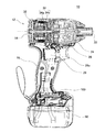
本発明を実施した電動ドライバ10について図面を参照しながら説明する。電動ドライバ10は、電動工具の一種であり、ネジ類の締付作業に用いられる。本実施例の電動ドライバ10は、インパクト方式の電動ドライバ(電動インパクトドライバ)である。
図1は、電動ドライバ10の構成を示す側方断面図である。図1に示すように、電動ドライバ10は、本体12と、本体12に着脱可能に取付けられている電池パック50を備えている。本体12は、概して、略円柱形状の胴体部14と、胴体部14の側方に伸びるグリップ部16を備えている。電池パック50は、グリップ部16の先端に取付けられている。
An
FIG. 1 is a side sectional view showing the configuration of the
本体12の胴体部14には、回転可能に支持されている工具チャック22と、工具チャック22に接続されているインパクト機構24と、インパクト機構24に接続されている減速機26と、減速機26に接続されているモータ32が内蔵されている。工具チャック22は、胴体部14の一端(図1中の右側)から突出しており、ドライバビット(図示省略)を着脱することができるようになっている。モータ32は、減速機26とインパクト機構24を介して工具チャック22に接続されており、ドライバビットが装着された工具チャック22を回転させる。このとき、モータ32の回転トルクは、減速機26によって増幅される。モータ32は、DC三相ブラシレスモータである。
The
本体12の胴体部14には、モータ32の回転位置を検出する位置検出センサ34が設けられている。位置検出センサ34は、モータ32に固定された複数のマグネット34aと、本体12側に固定されたセンサ基板34bを備えている。センサ基板34bには、マグネット34aの接近/離反を検出する複数のホール素子が設けられている。センサ基板34bのホール素子のそれぞれには、モータ32が回転するのに伴ってマグネット34aが接近/離反を繰り返す。位置検出センサ34は、モータ32が所定の回転角だけ回転する度に、モータ32の回転位置を示す検出信号(以下、ホール信号HSという)を更新して出力する。
The
本体12のグリップ部16には、利用者が操作するためのトリガスイッチ28と、トリガスイッチ28に加えられた操作に応じてモータ32の動作を制御する制御装置100が設けられている。トリガスイッチ28は、モータ32を起動/停止させるための操作部であるとともに、モータ32の回転速度を調節するための操作部でもある。利用者がトリガスイッチ28のトリガ部材28aを操作するとモータ32が回転を開始し、利用者がトリガ部材28aを戻すとモータ32の回転が中止されるようになっている。また、利用者がトリガ部材28aを大きく操作するとモータ32は高速で回転し、利用者がトリガ部材28aを小さく操作するとモータ32は低速で回転するようになっている。
The
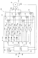
図2は、電動ドライバ10の電気的な構成を示している。図2に示すように、電動ドライバ10では、モータ32と電池パック50が制御装置100を介して接続されている。
制御装置100は、モータ32と電池パック50を電気的に接続するモータ駆動回路110を備えている。モータ駆動回路110は、モータ32のU相端子32uと電池パック50の正極50aを導通/遮断する第1スイッチング素子111と、モータ32のV相端子32vと電池パック50の正極50aを導通/遮断する第2スイッチング素子112と、モータ32のW相端子32wと電池パック50の正極50aを導通/遮断する第3スイッチング素子113と、モータ32のU相端子32uと電池パック50の負極50bを導通/遮断する第4スイッチング素子114と、モータ32のV相端子32vと電池パック50の負極50bを導通/遮断する第5スイッチング素子115と、モータ32のW相端子32wと電池パック50の負極50bを導通/遮断する第6スイッチング素子116を備えている。これらのスイッチング素子111−116は、nチャネルタイプの絶縁ゲート型電界効果トランジスタ(MOSFET)である。なお、スイッチング素子111−116には、例えば絶縁ゲート型バイポーラトランジスタ(IGBT)等の他のゲート駆動型の半導体スイッチング素子を用いることもできる。
本明細書では、モータ32の各端子32u、32v、32wと電池パック50の正極を導通/遮断する第1スイッチング素子111、第2スイッチング素子112、及び第3スイッチング素子113を、上アーム側スイッチング素子111−113と総称し、モータ32の各端子32u、32v、32wと電池パック50の負極を導通/遮断する第4スイッチング素子114、第5スイッチング素子115、第6スイッチング素子116を、下アーム側スイッチング素子114−116と総称することがある。
FIG. 2 shows an electrical configuration of the
The
In this specification, the
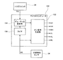
制御装置100は、マイクロコンピュータ150を備えている。マイクロコンピュータ150には、トリガスイッチ28と位置検出センサ34が接続されており、トリガスイッチ28からトリガ信号TGが入力され、位置検出センサ34からホール信号HSが入力されるようになっている。ここで、トリガ信号TGとは、トリガスイッチ28から出力される電圧信号であり、トリガ部材28aの操作量に応じて変動する。即ち、トリガ信号TGは、利用者が所望するモータ32の目標回転速度を示す。マイクロコンピュータ150は、トリガ信号TG及びホール信号HSに基づいて、スイッチング素子111−116へのオン信号UH、VH、WH、UL、VL、WLを選択的に出力する。マイクロコンピュータ150については後段において詳細に説明する。
The
制御装置100は、モータ駆動回路110のスイッチング素子111−116をそれぞれ駆動する6つのゲート駆動回路121−126を備えている。ゲート駆動回路121−126は、それぞれ、マイクロコンピュータ150が出力するスイッチング素子111−116へのオン信号UH、VH、WH、UL、VL、WLをレベルシフトし、スイッチング素子111−116のゲートに駆動電圧を印加する。これら6つのゲート駆動回路121−126は、同じ構造を有するレベルシフト回路である。例えば、第1スイッチング素子111用のゲート駆動回路121は、信号入力端子121cから二値の電圧信号を入力し、第1電圧入力端子121aと第2電圧入力端子121bの間の電圧で変動する二値の電圧信号を信号出力端子121dから出力する。図2に示すように、第1電圧入力端子121aは、電池パック50の正極50aに接続されており、第2電圧入力端子121bは、第1スイッチング素子111のソースに接続されている。他のゲート駆動回路122−126も同様の構成、機能を有し、各スイッチング素子112−116に対して同様に設けられている。
The
図2に示すように、上アーム側スイッチング素子111−113用のゲート駆動回路121−123には、ブートストラップ回路131−133がそれぞれ設けられている。ブートストラップ回路131−133は、ブートストラップコンデンサ131a−133aとダイオード131b−133bをそれぞれ有している。ブートストラップコンデンサ131a−133aは、それぞれ、ゲート駆動回路121−123の第1電圧入力端子121a−123aと第2電圧入力端子121b−123bの間に接続されている。また、ダイオード131b−133bは、それぞれ、ブートストラップコンデンサ131a−133aと電池パック50の正極50aの間に介装されている。なお、ダイオード131b−133bは、ブートストラップコンデンサ131a−133aとゲート駆動回路121−123の第1電圧入力端子121a−123aの間には介在しない位置に設けられている。各ブートストラップコンデンサ131a−133aは、対応する上アーム側スイッチング素子111−113がオフのときに充電され、対応する上アーム側スイッチング素子111−113がオンのときにそのゲート駆動回路121−123の電圧源として機能する。即ち、上アーム側スイッチング素子111−113がオンのときは、そのゲート駆動回路121−123の第1電圧入力端子121a−123aの電圧が、電池パック50の正極50aよりも高くなるように昇圧される。それにより、上アーム側スイッチング素子111−113がオンのときにも、上アーム側スイッチング素子111−113のゲートには十分な駆動電圧が印加される。
As shown in FIG. 2, bootstrap circuits 131-133 are provided in the gate drive circuits 121-123 for the upper arm side switching elements 111-113, respectively. The bootstrap circuit 131-133 includes a
次に、マイクロコンピュータ150について説明を加える。図3は、マイクロコンピュータ150の機能的な構成を示すブロック図である。図3に示すように、マイクロコンピュータ150は、機能的に、オン信号生成部152と、デューティ比設定部154と、タイマ156を備えている。
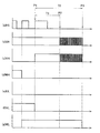
オン信号生成部152は、位置検出センサ34からのホール信号HSに基づいて、スイッチング素子111−116へ出力するオン信号UH、VH、WH、UL、VL、WLを生成する。図4に、位置検出センサ34がホール信号HSを更新するタイミングと、オン信号生成部152が生成するオン信号UH、VH、WH、UL、VL、WLの関係を例示する。また、図5に示すように、オン信号生成部152は、デューティ比設定部154によって設定されたデューティ比に基づいて、上アーム側スイッチング素子111−113へ出力するオン信号UH、VH、WHをパルス幅変調することができる。それにより、モータ32の回転速度が調節される。
Next, the
The on
デューティ比設定部154は、トリガスイッチ28からのトリガ信号TGに基づいて、前記したデューティ比を設定する。また、タイマ156による計時時間に基づいて、設定したデューティ比を増減調整する。ここで、タイマ156は、位置検出センサ34から出力されるホール信号HSを入力し、ホール信号HSが更新される時間間隔を計時する。タイマ156による計時時間は、モータ32の回転速度が遅いほど長くなる。そして、タイマ156による計時時間が非常に長い場合には、機械的ロックや過負荷等によってモータ32がロックしていると推定することができる。
図6は、デューティ比設定部154がデューティ比を設定する処理の流れを示すフローチャートである。デューティ比設定部154は、利用者によってトリガスイッチ28が操作されている間、図6に示す処理フローを実行する。
The duty
FIG. 6 is a flowchart showing a flow of processing in which the duty
先ず、ステップS10において、デューティ比設定部154は、トリガスイッチ28からトリガ信号TGを入力する。
次に、ステップS20において、デューティ比設定部154は、入力したトリガ信号TGに基づいてデューティ比を設定する。
次に、ステップS30において、デューティ比設定部154は、設定したデューティ比が80パーセント以上であればステップS40の処理に進み、設定したデューティ比が80パーセント以上でなければステップS10の処理に戻る。即ち、設定したデューティ比が80パーセント以上でなければ、トリガスイッチ28から入力されるトリガ信号TGに応じて、デューティ比の設定を繰り返し実行する。
一方、ステップS40の処理に進んだ場合、デューティ比設定部154は、タイマ156による計時時間を確認する。そして、タイマ156による計時時間が第1所定時間T1以上であればステップS50の処理に進み、第1所定時間T1を超えていなければステップS10の処理に戻る。ここで、第1所定時間T1は、モータ32が停止していると推定される時間に設定され、例えば数十ミリ秒程度に設定することができる。即ち、このステップS40において、デューティ比設定部154は、モータ32が停止しているのか否かを判断する。そして、モータ32が停止していると判断した場合、ステップS50の処理に進む。
First, in step S <b> 10, the duty
Next, in step S20, the duty
Next, in step S30, the duty
On the other hand, when the process proceeds to step S <b> 40, the duty
ステップS50の処理に進んだ場合、デューティ比設定部154は、80パーセント以上に設定しているデューティ比を70パーセントまで低下させる。それにより、図7に示すように、上アーム側スイッチング素子111−113へのオン信号UH、VH、WHは、パルス幅変調によってパルス信号列に変更される。ここで、図7中の時点P1はホール信号HSが最後に更新された時点を示し、時点P2は時点P1から第1所定時間T1だけ経過した時点を示す。
ここで、ステップS50の処理でデューティ比を低下させる幅は、10パーセントに限定されない。モータの出力を無用に低下させ過ぎることなく、ブートストラップコンデンサの放電による電圧低下を防止することができる範囲であればよく、具体的には10パーセントから50パーセントの範囲で設定するとよい。
また、電動ドライバ10のような電動工具では、モータの出力が低下したことが、利用者によって直ちに感受される。そのことから、ステップS50の処理でデューティ比を低下させることによって、モータ32への負荷が過大であることを利用者に報知することが可能となる。ただし、デューティ比を大きく低下させすぎると、電動ドライバ10からの反力が急激に低下することから、利用者がバランスを崩すといったことも起こりえる。これらの観点からも、デューティ比を低下させる幅は、10パーセントから50パーセントの範囲とすることが好ましい。
When the process proceeds to step S50, the duty
Here, the width for reducing the duty ratio in the process of step S50 is not limited to 10%. A range that can prevent a voltage drop due to the discharge of the bootstrap capacitor without unnecessarily reducing the output of the motor is sufficient, and specifically, a range of 10% to 50% may be set.
In addition, in an electric tool such as the
図7に示すように、例えば100パーセントのデューティ比による運転中に機械的ロック等によってモータ32がロックすると、上アーム側スイッチング素子111−113(図7の場合では2つの上アーム側スイッチング素子111、112)が長時間に亘ってオンし続けることになる。この状態が持続すれば、ブートストラップコンデンサ131a−133aは放電し続けることとなり、ブートストラップコンデンサ131a−133aの電圧が低下する。このような放電によるブートストラップコンデンサ131a−133aの電圧低下は、デューティ比が100パーセントに設定されている場合に限られず、80パーセント以上の比較的に高い値に設定されている場合に起こり得る。ブートストラップコンデンサ131a−133aの電圧が低下すると、上アーム側スイッチング素子111−113へ十分な駆動電圧を印加することができなくなる。この場合、上アーム側スイッチング素子111−113のオン抵抗が急激に上昇し、上アーム側スイッチング素子111−113が自身の発熱によって焼損してしまうことがある。それに対して、モータ32が停止していると判断した時点(P2)でデューティ比を低下させ、アーム側スイッチング素子111−113を断続的にオフさせると、ブートストラップコンデンサ131a−133aが充電され、その電圧が維持されることとなる。それにより、上アーム側スイッチング素子111−113の焼損を防止することができる。
As shown in FIG. 7, when the
次に、ステップS60において、デューティ比設定部154は、タイマ156による計時時間を確認する。そして、タイマ156による計時時間が第1所定時間T1以上であればステップS70の処理に進み、第1所定時間T1を超えていなければステップS10の処理に戻る。また、ステップS70においても、デューティ比設定部154は、タイマ156による計時時間を確認する。そして、タイマ156による計時時間が第2所定時間T2以上であればステップS80の処理に進み、第2所定時間T2を超えていなければステップS60の処理に戻る。このステップS60、S70の処理により、デューティ比設定部154は、モータ32がまだ停止し続けているのか、モータ32が再び回転し始めたのかを判断する。
タイマ156による計時時間が第2所定時間T2以上となった場合(ステップS70の処理でイエス)、モータ32は依然として停止していると判断される。この場合、デューティ比設定部154はステップS80の処理に進み、デューティ比をゼロパーセントに設定する。それにより、図7に示すように、時点P1から第2所定時間T2が経過した時点P3において、モータ32の運転を強制的に終了する。
Next, in step S <b> 60, the duty
When the time measured by the
一方、タイマ156による計時時間が第1所定時間T1未満となった場合(ステップS60の処理でイエス)、モータ32は再び回転を始めたと判断される。この場合、デューティ比設定部154はステップS10の処理に戻る。それにより、図8に示すように、時点P3以前の時点P4において、トリガ信号TGに応じたデューティ比が再び設定される。例えば、利用者がトリガスイッチ28を最大に操作し続けていれば、デューティ比は100パーセントに再設定される。過負荷等によってモータ32を一時的にロックさせただけであれば、利用者はトリガスイッチ28を操作し直すことなく作業を継続することができる。
On the other hand, when the time measured by the
以上のように、本実施例の電動ドライバ10によると、例えば機械的ロックや過負荷等によってモータ32がロックした場合には、トリガスイッチ28が最大に操作されている場合でも、上アーム側スイッチング素子111−113が断続的にオフさせられる。上アーム側スイッチング素子111−113が断続的にオフすることによって、ブートストラップコンデンサ131a−133aの放電による電圧低下が防止され、上アーム側スイッチング素子111−113には十分な駆動電圧が印加され続ける。それにより、上アーム側スイッチング素子111−113の焼損が防止される。
As described above, according to the
以上、本発明の実施形態について詳細に説明したが、これらは例示に過ぎず、特許請求の範囲を限定するものではない。特許請求の範囲に記載の技術には、以上に例示した具体例を様々に変形、変更したものが含まれる。
本明細書または図面に説明した技術要素は、単独であるいは各種の組合せによって技術的有用性を発揮するものであり、出願時の請求項に記載の組合せに限定されるものではない。本明細書または図面に例示した技術は複数の目的を同時に達成するものであり、そのうちの一つの目的を達成すること自体で技術的有用性を持つものである。
As mentioned above, although embodiment of this invention was described in detail, these are only illustrations and do not limit a claim. The technology described in the claims includes various modifications and changes of the specific examples illustrated above.
The technical elements described in this specification or the drawings exhibit technical usefulness alone or in various combinations, and are not limited to the combinations described in the claims at the time of filing. The technology illustrated in this specification or the drawings achieves a plurality of objects at the same time, and achieving one of the objects itself has technical utility.
10:電動ドライバ
28:トリガスイッチ
32:モータ
34:位置検出センサ
50:電池パック
100:制御装置
111−116:スイッチング素子
121−126:ゲート駆動回路
131−133:ブートストラップ回路
131a−133a:ブートストラップコンデンサ
131b−133b:ダイオード
150:マイクロコンピュータ
152:オン信号生成部
154:デューティ比設定部
156:タイマ
10: Electric driver 28: Trigger switch 32: Motor 34: Position detection sensor 50: Battery pack 100: Controller 111-116: Switching element 121-126: Gate drive circuit 131-133:
Claims (5)
モータの回転位置を検出する位置検出センサと、
モータの各端子を直流電源の正極に導通/遮断するゲート駆動型の上アーム側スイッチング素子と、
モータの各端子を直流電源の負極に導通/遮断するゲート駆動型の下アーム側スイッチング素子と、
前記位置検出センサによって検出されたモータの回転位置に基づいて、前記上アーム側スイッチング素子及び前記下アーム側スイッチング素子にオン信号を選択的に出力する処理回路と、
前記処理回路が出力する上アーム側スイッチング素子へのオン信号をレベルシフトし、前記上アーム側スイッチング素子のゲートへ駆動電圧を印加する上アーム側ゲート駆動回路と、
前記処理回路が出力する下アーム側スイッチング素子へのオン信号をレベルシフトし、前記下アーム側スイッチング素子のゲートへ駆動電圧を印加する下アーム側ゲート駆動回路と、
前記上アーム側スイッチング素子がオフのときに充電され、前記上アーム側スイッチング素子がオンのときに前記上アーム側ゲート駆動回路の電圧源として機能するブートストラップコンデンサを備え、
前記処理回路は、指示されたモータの目標回転速度に基づいてデューティ比を設定する設定処理、そのデューティ比の設定値に基づいて前記オン信号をパルス幅変調するPWM処理、前記位置検出センサによる検出位置が更新される時間間隔を計時する計時処理、前記設定処理によるデューティ比の設定値が80パーセント以上であって前記計時処理による計時間隔が第1所定時間を超えたときにそのデューティ比の設定値を低下させる設定値低下処理、を実行可能であり、
前記第1所定時間は、前記モータが停止していると推定される時間に設定されていることを特徴とするモータ制御装置。 A motor control device for an electric tool used for screw tightening work,
A position detection sensor for detecting the rotational position of the motor;
A gate drive type upper arm side switching element that electrically connects / disconnects each terminal of the motor to the positive electrode of the DC power supply
A gate drive type lower arm side switching element that conducts / cuts off each terminal of the motor to the negative electrode of the DC power supply
A processing circuit that selectively outputs an ON signal to the upper arm side switching element and the lower arm side switching element based on the rotational position of the motor detected by the position detection sensor;
An upper arm side gate drive circuit for level-shifting an ON signal to the upper arm side switching element output by the processing circuit and applying a drive voltage to the gate of the upper arm side switching element;
A lower arm side gate drive circuit for level-shifting an ON signal to the lower arm side switching element output by the processing circuit and applying a drive voltage to the gate of the lower arm side switching element;
A bootstrap capacitor that is charged when the upper arm side switching element is off and functions as a voltage source of the upper arm side gate drive circuit when the upper arm side switching element is on,
The processing circuit is configured to set a duty ratio based on an instructed target rotational speed of the motor, a PWM process for pulse width modulating the ON signal based on a set value of the duty ratio, and detection by the position detection sensor Timekeeping process for measuring the time interval at which the position is updated, and setting of the duty ratio when the set value of the duty ratio by the setting process is 80% or more and the time interval by the timekeeping process exceeds the first predetermined time set value lowering process of lowering the value, Ri executable der and
Wherein the first predetermined time, the motor control device according to claim Rukoto the motor is set to a time that is estimated to have stopped.
工具を回転させるモータと、
そのモータを制御する請求項1から4のいずれか一項に記載のモータ制御装置と、
を備える電動工具。 A power tool used for tightening screws,
A motor that rotates the tool;
The motor control device according to any one of claims 1 to 4, which controls the motor;
A power tool comprising:
Priority Applications (6)
| Application Number | Priority Date | Filing Date | Title |
|---|---|---|---|
| JP2008000977A JP5116490B2 (en) | 2008-01-08 | 2008-01-08 | Motor control device and electric tool using the same |
| RU2010133155/07A RU2478256C2 (en) | 2008-01-08 | 2008-12-01 | Motor controller, and electric tool having above described controller |
| EP08870429A EP2219288A4 (en) | 2008-01-08 | 2008-12-01 | Motor controller and electric tool employing the controller |
| PCT/JP2008/071779 WO2009087834A1 (en) | 2008-01-08 | 2008-12-01 | Motor controller and electric tool employing the controller |
| CN2008801234023A CN101911468B (en) | 2008-01-08 | 2008-12-01 | Motor controller and electric tool employing the controller |
| US12/734,645 US8294399B2 (en) | 2008-01-08 | 2008-12-01 | Motor controller and electric tool having the same |
Applications Claiming Priority (1)
| Application Number | Priority Date | Filing Date | Title |
|---|---|---|---|
| JP2008000977A JP5116490B2 (en) | 2008-01-08 | 2008-01-08 | Motor control device and electric tool using the same |
Publications (2)
| Publication Number | Publication Date |
|---|---|
| JP2009165280A JP2009165280A (en) | 2009-07-23 |
| JP5116490B2 true JP5116490B2 (en) | 2013-01-09 |
Family
ID=40852961
Family Applications (1)
| Application Number | Title | Priority Date | Filing Date |
|---|---|---|---|
| JP2008000977A Expired - Fee Related JP5116490B2 (en) | 2008-01-08 | 2008-01-08 | Motor control device and electric tool using the same |
Country Status (6)
| Country | Link |
|---|---|
| US (1) | US8294399B2 (en) |
| EP (1) | EP2219288A4 (en) |
| JP (1) | JP5116490B2 (en) |
| CN (1) | CN101911468B (en) |
| RU (1) | RU2478256C2 (en) |
| WO (1) | WO2009087834A1 (en) |
Families Citing this family (422)
| Publication number | Priority date | Publication date | Assignee | Title |
|---|---|---|---|---|
| US20070084897A1 (en) | 2003-05-20 | 2007-04-19 | Shelton Frederick E Iv | Articulating surgical stapling instrument incorporating a two-piece e-beam firing mechanism |
| US9060770B2 (en) | 2003-05-20 | 2015-06-23 | Ethicon Endo-Surgery, Inc. | Robotically-driven surgical instrument with E-beam driver |
| US8215531B2 (en) | 2004-07-28 | 2012-07-10 | Ethicon Endo-Surgery, Inc. | Surgical stapling instrument having a medical substance dispenser |
| US11998198B2 (en) | 2004-07-28 | 2024-06-04 | Cilag Gmbh International | Surgical stapling instrument incorporating a two-piece E-beam firing mechanism |
| US9072535B2 (en) | 2011-05-27 | 2015-07-07 | Ethicon Endo-Surgery, Inc. | Surgical stapling instruments with rotatable staple deployment arrangements |
| US11890012B2 (en) | 2004-07-28 | 2024-02-06 | Cilag Gmbh International | Staple cartridge comprising cartridge body and attached support |
| US9237891B2 (en) | 2005-08-31 | 2016-01-19 | Ethicon Endo-Surgery, Inc. | Robotically-controlled surgical stapling devices that produce formed staples having different lengths |
| US10159482B2 (en) | 2005-08-31 | 2018-12-25 | Ethicon Llc | Fastener cartridge assembly comprising a fixed anvil and different staple heights |
| US7669746B2 (en) | 2005-08-31 | 2010-03-02 | Ethicon Endo-Surgery, Inc. | Staple cartridges for forming staples having differing formed staple heights |
| US7934630B2 (en) | 2005-08-31 | 2011-05-03 | Ethicon Endo-Surgery, Inc. | Staple cartridges for forming staples having differing formed staple heights |
| US11246590B2 (en) | 2005-08-31 | 2022-02-15 | Cilag Gmbh International | Staple cartridge including staple drivers having different unfired heights |
| US11484312B2 (en) | 2005-08-31 | 2022-11-01 | Cilag Gmbh International | Staple cartridge comprising a staple driver arrangement |
| US20070106317A1 (en) | 2005-11-09 | 2007-05-10 | Shelton Frederick E Iv | Hydraulically and electrically actuated articulation joints for surgical instruments |
| US11793518B2 (en) | 2006-01-31 | 2023-10-24 | Cilag Gmbh International | Powered surgical instruments with firing system lockout arrangements |
| US8820603B2 (en) | 2006-01-31 | 2014-09-02 | Ethicon Endo-Surgery, Inc. | Accessing data stored in a memory of a surgical instrument |
| US20110024477A1 (en) | 2009-02-06 | 2011-02-03 | Hall Steven G | Driven Surgical Stapler Improvements |
| US8186555B2 (en) | 2006-01-31 | 2012-05-29 | Ethicon Endo-Surgery, Inc. | Motor-driven surgical cutting and fastening instrument with mechanical closure system |
| US7753904B2 (en) | 2006-01-31 | 2010-07-13 | Ethicon Endo-Surgery, Inc. | Endoscopic surgical instrument with a handle that can articulate with respect to the shaft |
| US11278279B2 (en) | 2006-01-31 | 2022-03-22 | Cilag Gmbh International | Surgical instrument assembly |
| US11224427B2 (en) | 2006-01-31 | 2022-01-18 | Cilag Gmbh International | Surgical stapling system including a console and retraction assembly |
| US20120292367A1 (en) | 2006-01-31 | 2012-11-22 | Ethicon Endo-Surgery, Inc. | Robotically-controlled end effector |
| US8708213B2 (en) | 2006-01-31 | 2014-04-29 | Ethicon Endo-Surgery, Inc. | Surgical instrument having a feedback system |
| US7845537B2 (en) | 2006-01-31 | 2010-12-07 | Ethicon Endo-Surgery, Inc. | Surgical instrument having recording capabilities |
| US20110290856A1 (en) | 2006-01-31 | 2011-12-01 | Ethicon Endo-Surgery, Inc. | Robotically-controlled surgical instrument with force-feedback capabilities |
| US8992422B2 (en) | 2006-03-23 | 2015-03-31 | Ethicon Endo-Surgery, Inc. | Robotically-controlled endoscopic accessory channel |
| US8322455B2 (en) | 2006-06-27 | 2012-12-04 | Ethicon Endo-Surgery, Inc. | Manually driven surgical cutting and fastening instrument |
| US10568652B2 (en) | 2006-09-29 | 2020-02-25 | Ethicon Llc | Surgical staples having attached drivers of different heights and stapling instruments for deploying the same |
| US11980366B2 (en) | 2006-10-03 | 2024-05-14 | Cilag Gmbh International | Surgical instrument |
| US11291441B2 (en) | 2007-01-10 | 2022-04-05 | Cilag Gmbh International | Surgical instrument with wireless communication between control unit and remote sensor |
| US8684253B2 (en) | 2007-01-10 | 2014-04-01 | Ethicon Endo-Surgery, Inc. | Surgical instrument with wireless communication between a control unit of a robotic system and remote sensor |
| US8632535B2 (en) | 2007-01-10 | 2014-01-21 | Ethicon Endo-Surgery, Inc. | Interlock and surgical instrument including same |
| US8827133B2 (en) | 2007-01-11 | 2014-09-09 | Ethicon Endo-Surgery, Inc. | Surgical stapling device having supports for a flexible drive mechanism |
| US11039836B2 (en) | 2007-01-11 | 2021-06-22 | Cilag Gmbh International | Staple cartridge for use with a surgical stapling instrument |
| US7673782B2 (en) | 2007-03-15 | 2010-03-09 | Ethicon Endo-Surgery, Inc. | Surgical stapling instrument having a releasable buttress material |
| US8931682B2 (en) | 2007-06-04 | 2015-01-13 | Ethicon Endo-Surgery, Inc. | Robotically-controlled shaft based rotary drive systems for surgical instruments |
| US11564682B2 (en) | 2007-06-04 | 2023-01-31 | Cilag Gmbh International | Surgical stapler device |
| US7753245B2 (en) | 2007-06-22 | 2010-07-13 | Ethicon Endo-Surgery, Inc. | Surgical stapling instruments |
| US11849941B2 (en) | 2007-06-29 | 2023-12-26 | Cilag Gmbh International | Staple cartridge having staple cavities extending at a transverse angle relative to a longitudinal cartridge axis |
| US8758391B2 (en) | 2008-02-14 | 2014-06-24 | Ethicon Endo-Surgery, Inc. | Interchangeable tools for surgical instruments |
| US11986183B2 (en) | 2008-02-14 | 2024-05-21 | Cilag Gmbh International | Surgical cutting and fastening instrument comprising a plurality of sensors to measure an electrical parameter |
| US7866527B2 (en) | 2008-02-14 | 2011-01-11 | Ethicon Endo-Surgery, Inc. | Surgical stapling apparatus with interlockable firing system |
| US8636736B2 (en) | 2008-02-14 | 2014-01-28 | Ethicon Endo-Surgery, Inc. | Motorized surgical cutting and fastening instrument |
| RU2493788C2 (en) | 2008-02-14 | 2013-09-27 | Этикон Эндо-Серджери, Инк. | Surgical cutting and fixing instrument, which has radio-frequency electrodes |
| US9179912B2 (en) | 2008-02-14 | 2015-11-10 | Ethicon Endo-Surgery, Inc. | Robotically-controlled motorized surgical cutting and fastening instrument |
| US7819298B2 (en) | 2008-02-14 | 2010-10-26 | Ethicon Endo-Surgery, Inc. | Surgical stapling apparatus with control features operable with one hand |
| US8573465B2 (en) | 2008-02-14 | 2013-11-05 | Ethicon Endo-Surgery, Inc. | Robotically-controlled surgical end effector system with rotary actuated closure systems |
| US9585657B2 (en) | 2008-02-15 | 2017-03-07 | Ethicon Endo-Surgery, Llc | Actuator for releasing a layer of material from a surgical end effector |
| US11648005B2 (en) | 2008-09-23 | 2023-05-16 | Cilag Gmbh International | Robotically-controlled motorized surgical instrument with an end effector |
| US8210411B2 (en) | 2008-09-23 | 2012-07-03 | Ethicon Endo-Surgery, Inc. | Motor-driven surgical cutting instrument |
| US9386983B2 (en) | 2008-09-23 | 2016-07-12 | Ethicon Endo-Surgery, Llc | Robotically-controlled motorized surgical instrument |
| US9005230B2 (en) | 2008-09-23 | 2015-04-14 | Ethicon Endo-Surgery, Inc. | Motorized surgical instrument |
| US8608045B2 (en) | 2008-10-10 | 2013-12-17 | Ethicon Endo-Sugery, Inc. | Powered surgical cutting and stapling apparatus with manually retractable firing system |
| US8517239B2 (en) | 2009-02-05 | 2013-08-27 | Ethicon Endo-Surgery, Inc. | Surgical stapling instrument comprising a magnetic element driver |
| EP2393430A1 (en) | 2009-02-06 | 2011-12-14 | Ethicon Endo-Surgery, Inc. | Driven surgical stapler improvements |
| US8851354B2 (en) | 2009-12-24 | 2014-10-07 | Ethicon Endo-Surgery, Inc. | Surgical cutting instrument that analyzes tissue thickness |
| US8220688B2 (en) | 2009-12-24 | 2012-07-17 | Ethicon Endo-Surgery, Inc. | Motor-driven surgical cutting instrument with electric actuator directional control assembly |
| US9819241B2 (en) | 2010-06-14 | 2017-11-14 | Black & Decker Inc. | Stator assembly for a brushless motor in a power tool |
| JP5469000B2 (en) | 2010-06-17 | 2014-04-09 | 株式会社マキタ | Electric tool, lock state occurrence determination device, and program |
| US8783543B2 (en) | 2010-07-30 | 2014-07-22 | Ethicon Endo-Surgery, Inc. | Tissue acquisition arrangements and methods for surgical stapling devices |
| JP5314652B2 (en) * | 2010-09-27 | 2013-10-16 | パナソニック株式会社 | Brushless motor drive circuit |
| US11812965B2 (en) | 2010-09-30 | 2023-11-14 | Cilag Gmbh International | Layer of material for a surgical end effector |
| US9839420B2 (en) | 2010-09-30 | 2017-12-12 | Ethicon Llc | Tissue thickness compensator comprising at least one medicament |
| US9320523B2 (en) | 2012-03-28 | 2016-04-26 | Ethicon Endo-Surgery, Llc | Tissue thickness compensator comprising tissue ingrowth features |
| US9295464B2 (en) | 2010-09-30 | 2016-03-29 | Ethicon Endo-Surgery, Inc. | Surgical stapler anvil comprising a plurality of forming pockets |
| US11298125B2 (en) | 2010-09-30 | 2022-04-12 | Cilag Gmbh International | Tissue stapler having a thickness compensator |
| US9629814B2 (en) | 2010-09-30 | 2017-04-25 | Ethicon Endo-Surgery, Llc | Tissue thickness compensator configured to redistribute compressive forces |
| US11849952B2 (en) | 2010-09-30 | 2023-12-26 | Cilag Gmbh International | Staple cartridge comprising staples positioned within a compressible portion thereof |
| US10945731B2 (en) | 2010-09-30 | 2021-03-16 | Ethicon Llc | Tissue thickness compensator comprising controlled release and expansion |
| US9788834B2 (en) | 2010-09-30 | 2017-10-17 | Ethicon Llc | Layer comprising deployable attachment members |
| US12213666B2 (en) | 2010-09-30 | 2025-02-04 | Cilag Gmbh International | Tissue thickness compensator comprising layers |
| US8695866B2 (en) | 2010-10-01 | 2014-04-15 | Ethicon Endo-Surgery, Inc. | Surgical instrument having a power control circuit |
| JP5491346B2 (en) * | 2010-10-13 | 2014-05-14 | 株式会社マキタ | Power tools and programs |
| JP6026509B2 (en) | 2011-04-29 | 2016-11-16 | エシコン・エンド−サージェリィ・インコーポレイテッドEthicon Endo−Surgery,Inc. | Staple cartridge including staples disposed within a compressible portion of the staple cartridge itself |
| EP3090838B1 (en) | 2011-05-19 | 2020-06-17 | Black & Decker Inc. | Power tool with force sensing electronic clutch |
| US11207064B2 (en) | 2011-05-27 | 2021-12-28 | Cilag Gmbh International | Automated end effector component reloading system for use with a robotic system |
| EP3150335B1 (en) * | 2011-06-02 | 2023-10-11 | Black & Decker, Inc. | Power tool with a control unit |
| JP5865715B2 (en) * | 2012-01-25 | 2016-02-17 | 三菱電機株式会社 | Motor control device |
| US9044230B2 (en) | 2012-02-13 | 2015-06-02 | Ethicon Endo-Surgery, Inc. | Surgical cutting and fastening instrument with apparatus for determining cartridge and firing motion status |
| JP5891410B2 (en) * | 2012-03-13 | 2016-03-23 | パナソニックIpマネジメント株式会社 | Electric tool |
| JP2013188825A (en) * | 2012-03-13 | 2013-09-26 | Panasonic Corp | Electric tool |
| CN104379068B (en) | 2012-03-28 | 2017-09-22 | 伊西康内外科公司 | Holding device assembly including tissue thickness compensation part |
| JP6305979B2 (en) | 2012-03-28 | 2018-04-04 | エシコン・エンド−サージェリィ・インコーポレイテッドEthicon Endo−Surgery,Inc. | Tissue thickness compensator with multiple layers |
| BR112014024098B1 (en) | 2012-03-28 | 2021-05-25 | Ethicon Endo-Surgery, Inc. | staple cartridge |
| US9101358B2 (en) | 2012-06-15 | 2015-08-11 | Ethicon Endo-Surgery, Inc. | Articulatable surgical instrument comprising a firing drive |
| EP2675041B1 (en) * | 2012-06-15 | 2020-05-13 | Black & Decker Inc. | Stator assembly for a brushless motor in a power tool |
| US11278284B2 (en) | 2012-06-28 | 2022-03-22 | Cilag Gmbh International | Rotary drive arrangements for surgical instruments |
| US20140001234A1 (en) | 2012-06-28 | 2014-01-02 | Ethicon Endo-Surgery, Inc. | Coupling arrangements for attaching surgical end effectors to drive systems therefor |
| US20140001231A1 (en) | 2012-06-28 | 2014-01-02 | Ethicon Endo-Surgery, Inc. | Firing system lockout arrangements for surgical instruments |
| US9289256B2 (en) | 2012-06-28 | 2016-03-22 | Ethicon Endo-Surgery, Llc | Surgical end effectors having angled tissue-contacting surfaces |
| BR112014032776B1 (en) | 2012-06-28 | 2021-09-08 | Ethicon Endo-Surgery, Inc | SURGICAL INSTRUMENT SYSTEM AND SURGICAL KIT FOR USE WITH A SURGICAL INSTRUMENT SYSTEM |
| US12383267B2 (en) | 2012-06-28 | 2025-08-12 | Cilag Gmbh International | Robotically powered surgical device with manually-actuatable reversing system |
| EP2866686A1 (en) | 2012-06-28 | 2015-05-06 | Ethicon Endo-Surgery, Inc. | Empty clip cartridge lockout |
| US9649111B2 (en) | 2012-06-28 | 2017-05-16 | Ethicon Endo-Surgery, Llc | Replaceable clip cartridge for a clip applier |
| BR112015021098B1 (en) | 2013-03-01 | 2022-02-15 | Ethicon Endo-Surgery, Inc | COVERAGE FOR A JOINT JOINT AND SURGICAL INSTRUMENT |
| JP6345707B2 (en) | 2013-03-01 | 2018-06-20 | エシコン・エンド−サージェリィ・インコーポレイテッドEthicon Endo−Surgery,Inc. | Surgical instrument with soft stop |
| US9883860B2 (en) | 2013-03-14 | 2018-02-06 | Ethicon Llc | Interchangeable shaft assemblies for use with a surgical instrument |
| US9629629B2 (en) | 2013-03-14 | 2017-04-25 | Ethicon Endo-Surgey, LLC | Control systems for surgical instruments |
| CN104981325B (en) * | 2013-03-30 | 2018-08-31 | 日立工机株式会社 | Electric tool |
| BR112015026109B1 (en) | 2013-04-16 | 2022-02-22 | Ethicon Endo-Surgery, Inc | surgical instrument |
| US9867612B2 (en) | 2013-04-16 | 2018-01-16 | Ethicon Llc | Powered surgical stapler |
| JP6107385B2 (en) * | 2013-04-26 | 2017-04-05 | 日立工機株式会社 | Electric tool |
| RU2678363C2 (en) | 2013-08-23 | 2019-01-28 | ЭТИКОН ЭНДО-СЕРДЖЕРИ, ЭлЭлСи | Firing member retraction devices for powered surgical instruments |
| US9445813B2 (en) | 2013-08-23 | 2016-09-20 | Ethicon Endo-Surgery, Llc | Closure indicator systems for surgical instruments |
| US9962161B2 (en) | 2014-02-12 | 2018-05-08 | Ethicon Llc | Deliverable surgical instrument |
| BR112016021943B1 (en) | 2014-03-26 | 2022-06-14 | Ethicon Endo-Surgery, Llc | SURGICAL INSTRUMENT FOR USE BY AN OPERATOR IN A SURGICAL PROCEDURE |
| US10028761B2 (en) | 2014-03-26 | 2018-07-24 | Ethicon Llc | Feedback algorithms for manual bailout systems for surgical instruments |
| US12232723B2 (en) | 2014-03-26 | 2025-02-25 | Cilag Gmbh International | Systems and methods for controlling a segmented circuit |
| US20150272557A1 (en) | 2014-03-26 | 2015-10-01 | Ethicon Endo-Surgery, Inc. | Modular surgical instrument system |
| US9733663B2 (en) | 2014-03-26 | 2017-08-15 | Ethicon Llc | Power management through segmented circuit and variable voltage protection |
| JP6128037B2 (en) | 2014-03-28 | 2017-05-17 | 日立工機株式会社 | Electric tool |
| BR112016023698B1 (en) | 2014-04-16 | 2022-07-26 | Ethicon Endo-Surgery, Llc | FASTENER CARTRIDGE FOR USE WITH A SURGICAL INSTRUMENT |
| JP6532889B2 (en) | 2014-04-16 | 2019-06-19 | エシコン エルエルシーEthicon LLC | Fastener cartridge assembly and staple holder cover arrangement |
| JP6612256B2 (en) | 2014-04-16 | 2019-11-27 | エシコン エルエルシー | Fastener cartridge with non-uniform fastener |
| US10470768B2 (en) | 2014-04-16 | 2019-11-12 | Ethicon Llc | Fastener cartridge including a layer attached thereto |
| US9801627B2 (en) | 2014-09-26 | 2017-10-31 | Ethicon Llc | Fastener cartridge for creating a flexible staple line |
| US20150297225A1 (en) | 2014-04-16 | 2015-10-22 | Ethicon Endo-Surgery, Inc. | Fastener cartridges including extensions having different configurations |
| BR112017004361B1 (en) | 2014-09-05 | 2023-04-11 | Ethicon Llc | ELECTRONIC SYSTEM FOR A SURGICAL INSTRUMENT |
| US9737301B2 (en) | 2014-09-05 | 2017-08-22 | Ethicon Llc | Monitoring device degradation based on component evaluation |
| US11311294B2 (en) | 2014-09-05 | 2022-04-26 | Cilag Gmbh International | Powered medical device including measurement of closure state of jaws |
| US10105142B2 (en) | 2014-09-18 | 2018-10-23 | Ethicon Llc | Surgical stapler with plurality of cutting elements |
| US11523821B2 (en) | 2014-09-26 | 2022-12-13 | Cilag Gmbh International | Method for creating a flexible staple line |
| MX380639B (en) | 2014-09-26 | 2025-03-12 | Ethicon Llc | SURGICAL STAPLE REINFORCEMENTS AND AUXILIARY MATERIALS. |
| US10076325B2 (en) | 2014-10-13 | 2018-09-18 | Ethicon Llc | Surgical stapling apparatus comprising a tissue stop |
| US9924944B2 (en) | 2014-10-16 | 2018-03-27 | Ethicon Llc | Staple cartridge comprising an adjunct material |
| US10517594B2 (en) | 2014-10-29 | 2019-12-31 | Ethicon Llc | Cartridge assemblies for surgical staplers |
| US11141153B2 (en) | 2014-10-29 | 2021-10-12 | Cilag Gmbh International | Staple cartridges comprising driver arrangements |
| US9844376B2 (en) | 2014-11-06 | 2017-12-19 | Ethicon Llc | Staple cartridge comprising a releasable adjunct material |
| US10736636B2 (en) | 2014-12-10 | 2020-08-11 | Ethicon Llc | Articulatable surgical instrument system |
| US9844375B2 (en) | 2014-12-18 | 2017-12-19 | Ethicon Llc | Drive arrangements for articulatable surgical instruments |
| US10085748B2 (en) | 2014-12-18 | 2018-10-02 | Ethicon Llc | Locking arrangements for detachable shaft assemblies with articulatable surgical end effectors |
| US9987000B2 (en) | 2014-12-18 | 2018-06-05 | Ethicon Llc | Surgical instrument assembly comprising a flexible articulation system |
| RU2703684C2 (en) | 2014-12-18 | 2019-10-21 | ЭТИКОН ЭНДО-СЕРДЖЕРИ, ЭлЭлСи | Surgical instrument with anvil which is selectively movable relative to staple cartridge around discrete fixed axis |
| US9943309B2 (en) | 2014-12-18 | 2018-04-17 | Ethicon Llc | Surgical instruments with articulatable end effectors and movable firing beam support arrangements |
| US9844374B2 (en) | 2014-12-18 | 2017-12-19 | Ethicon Llc | Surgical instrument systems comprising an articulatable end effector and means for adjusting the firing stroke of a firing member |
| US11154301B2 (en) | 2015-02-27 | 2021-10-26 | Cilag Gmbh International | Modular stapling assembly |
| US10617412B2 (en) | 2015-03-06 | 2020-04-14 | Ethicon Llc | System for detecting the mis-insertion of a staple cartridge into a surgical stapler |
| US10548504B2 (en) | 2015-03-06 | 2020-02-04 | Ethicon Llc | Overlaid multi sensor radio frequency (RF) electrode system to measure tissue compression |
| US9901342B2 (en) | 2015-03-06 | 2018-02-27 | Ethicon Endo-Surgery, Llc | Signal and power communication system positioned on a rotatable shaft |
| US9808246B2 (en) | 2015-03-06 | 2017-11-07 | Ethicon Endo-Surgery, Llc | Method of operating a powered surgical instrument |
| US10245033B2 (en) | 2015-03-06 | 2019-04-02 | Ethicon Llc | Surgical instrument comprising a lockable battery housing |
| US10441279B2 (en) | 2015-03-06 | 2019-10-15 | Ethicon Llc | Multiple level thresholds to modify operation of powered surgical instruments |
| JP2020121162A (en) | 2015-03-06 | 2020-08-13 | エシコン エルエルシーEthicon LLC | Time dependent evaluation of sensor data to determine stability element, creep element and viscoelastic element of measurement |
| US9993248B2 (en) | 2015-03-06 | 2018-06-12 | Ethicon Endo-Surgery, Llc | Smart sensors with local signal processing |
| US10687806B2 (en) | 2015-03-06 | 2020-06-23 | Ethicon Llc | Adaptive tissue compression techniques to adjust closure rates for multiple tissue types |
| US10213201B2 (en) | 2015-03-31 | 2019-02-26 | Ethicon Llc | Stapling end effector configured to compensate for an uneven gap between a first jaw and a second jaw |
| US10637379B2 (en) * | 2015-04-07 | 2020-04-28 | Black & Decker Inc. | Power tool with automatic feathering mode |
| WO2016196984A1 (en) * | 2015-06-05 | 2016-12-08 | Ingersoll-Rand Company | Power tools with user-selectable operational modes |
| WO2016196979A1 (en) | 2015-06-05 | 2016-12-08 | Ingersoll-Rand Company | Impact tools with ring gear alignment features |
| US11260517B2 (en) | 2015-06-05 | 2022-03-01 | Ingersoll-Rand Industrial U.S., Inc. | Power tool housings |
| US10615670B2 (en) | 2015-06-05 | 2020-04-07 | Ingersoll-Rand Industrial U.S., Inc. | Power tool user interfaces |
| CN104993750A (en) * | 2015-07-10 | 2015-10-21 | 常州格力博有限公司 | Inversion control system of electric tool and control method thereof |
| US10835249B2 (en) | 2015-08-17 | 2020-11-17 | Ethicon Llc | Implantable layers for a surgical instrument |
| US10105139B2 (en) | 2015-09-23 | 2018-10-23 | Ethicon Llc | Surgical stapler having downstream current-based motor control |
| US10238386B2 (en) | 2015-09-23 | 2019-03-26 | Ethicon Llc | Surgical stapler having motor control based on an electrical parameter related to a motor current |
| US10299878B2 (en) | 2015-09-25 | 2019-05-28 | Ethicon Llc | Implantable adjunct systems for determining adjunct skew |
| US10271849B2 (en) | 2015-09-30 | 2019-04-30 | Ethicon Llc | Woven constructs with interlocked standing fibers |
| US10980539B2 (en) | 2015-09-30 | 2021-04-20 | Ethicon Llc | Implantable adjunct comprising bonded layers |
| US10524788B2 (en) | 2015-09-30 | 2020-01-07 | Ethicon Llc | Compressible adjunct with attachment regions |
| US11890015B2 (en) | 2015-09-30 | 2024-02-06 | Cilag Gmbh International | Compressible adjunct with crossing spacer fibers |
| FR3042927B1 (en) * | 2015-10-26 | 2018-11-16 | Valeo Equipements Electriques Moteur | METHOD AND DEVICE FOR CONTROLLING AN EXCITATION SYNCHRONOUS SYNCHRONOUS ROTARY ELECTRIC MACHINE AND ALTERNATOR MOTOR VEHICLE CORRESPONDING THEREOF |
| US10292704B2 (en) | 2015-12-30 | 2019-05-21 | Ethicon Llc | Mechanisms for compensating for battery pack failure in powered surgical instruments |
| US10368865B2 (en) | 2015-12-30 | 2019-08-06 | Ethicon Llc | Mechanisms for compensating for drivetrain failure in powered surgical instruments |
| US10265068B2 (en) | 2015-12-30 | 2019-04-23 | Ethicon Llc | Surgical instruments with separable motors and motor control circuits |
| BR112018016098B1 (en) | 2016-02-09 | 2023-02-23 | Ethicon Llc | SURGICAL INSTRUMENT |
| US11213293B2 (en) | 2016-02-09 | 2022-01-04 | Cilag Gmbh International | Articulatable surgical instruments with single articulation link arrangements |
| US10448948B2 (en) | 2016-02-12 | 2019-10-22 | Ethicon Llc | Mechanisms for compensating for drivetrain failure in powered surgical instruments |
| US11224426B2 (en) | 2016-02-12 | 2022-01-18 | Cilag Gmbh International | Mechanisms for compensating for drivetrain failure in powered surgical instruments |
| US10617413B2 (en) | 2016-04-01 | 2020-04-14 | Ethicon Llc | Closure system arrangements for surgical cutting and stapling devices with separate and distinct firing shafts |
| US10828028B2 (en) | 2016-04-15 | 2020-11-10 | Ethicon Llc | Surgical instrument with multiple program responses during a firing motion |
| US10492783B2 (en) | 2016-04-15 | 2019-12-03 | Ethicon, Llc | Surgical instrument with improved stop/start control during a firing motion |
| US10456137B2 (en) | 2016-04-15 | 2019-10-29 | Ethicon Llc | Staple formation detection mechanisms |
| US11607239B2 (en) | 2016-04-15 | 2023-03-21 | Cilag Gmbh International | Systems and methods for controlling a surgical stapling and cutting instrument |
| US10426467B2 (en) | 2016-04-15 | 2019-10-01 | Ethicon Llc | Surgical instrument with detection sensors |
| US11179150B2 (en) | 2016-04-15 | 2021-11-23 | Cilag Gmbh International | Systems and methods for controlling a surgical stapling and cutting instrument |
| US10335145B2 (en) | 2016-04-15 | 2019-07-02 | Ethicon Llc | Modular surgical instrument with configurable operating mode |
| US10357247B2 (en) | 2016-04-15 | 2019-07-23 | Ethicon Llc | Surgical instrument with multiple program responses during a firing motion |
| US10433840B2 (en) | 2016-04-18 | 2019-10-08 | Ethicon Llc | Surgical instrument comprising a replaceable cartridge jaw |
| US20170296173A1 (en) | 2016-04-18 | 2017-10-19 | Ethicon Endo-Surgery, Llc | Method for operating a surgical instrument |
| US11317917B2 (en) | 2016-04-18 | 2022-05-03 | Cilag Gmbh International | Surgical stapling system comprising a lockable firing assembly |
| GB2549740B (en) * | 2016-04-26 | 2019-04-17 | Dyson Technology Ltd | A method for controlling an electric motor |
| US10548673B2 (en) | 2016-08-16 | 2020-02-04 | Ethicon Llc | Surgical tool with a display |
| US10610224B2 (en) | 2016-12-21 | 2020-04-07 | Ethicon Llc | Lockout arrangements for surgical end effectors and replaceable tool assemblies |
| CN110114014B (en) | 2016-12-21 | 2022-08-09 | 爱惜康有限责任公司 | Surgical instrument system including end effector and firing assembly lockout |
| US10537325B2 (en) | 2016-12-21 | 2020-01-21 | Ethicon Llc | Staple forming pocket arrangement to accommodate different types of staples |
| US10888322B2 (en) | 2016-12-21 | 2021-01-12 | Ethicon Llc | Surgical instrument comprising a cutting member |
| US10485543B2 (en) | 2016-12-21 | 2019-11-26 | Ethicon Llc | Anvil having a knife slot width |
| US20180168615A1 (en) | 2016-12-21 | 2018-06-21 | Ethicon Endo-Surgery, Llc | Method of deforming staples from two different types of staple cartridges with the same surgical stapling instrument |
| JP7010957B2 (en) | 2016-12-21 | 2022-01-26 | エシコン エルエルシー | Shaft assembly with lockout |
| US11134942B2 (en) | 2016-12-21 | 2021-10-05 | Cilag Gmbh International | Surgical stapling instruments and staple-forming anvils |
| US10568625B2 (en) | 2016-12-21 | 2020-02-25 | Ethicon Llc | Staple cartridges and arrangements of staples and staple cavities therein |
| JP7010956B2 (en) | 2016-12-21 | 2022-01-26 | エシコン エルエルシー | How to staple tissue |
| US11191539B2 (en) | 2016-12-21 | 2021-12-07 | Cilag Gmbh International | Shaft assembly comprising a manually-operable retraction system for use with a motorized surgical instrument system |
| US10898186B2 (en) | 2016-12-21 | 2021-01-26 | Ethicon Llc | Staple forming pocket arrangements comprising primary sidewalls and pocket sidewalls |
| US20180168619A1 (en) | 2016-12-21 | 2018-06-21 | Ethicon Endo-Surgery, Llc | Surgical stapling systems |
| MX2019007310A (en) | 2016-12-21 | 2019-11-18 | Ethicon Llc | Surgical stapling systems. |
| US20180168625A1 (en) | 2016-12-21 | 2018-06-21 | Ethicon Endo-Surgery, Llc | Surgical stapling instruments with smart staple cartridges |
| JP2020501779A (en) | 2016-12-21 | 2020-01-23 | エシコン エルエルシーEthicon LLC | Surgical stapling system |
| US11179155B2 (en) | 2016-12-21 | 2021-11-23 | Cilag Gmbh International | Anvil arrangements for surgical staplers |
| US11419606B2 (en) | 2016-12-21 | 2022-08-23 | Cilag Gmbh International | Shaft assembly comprising a clutch configured to adapt the output of a rotary firing member to two different systems |
| US10568626B2 (en) | 2016-12-21 | 2020-02-25 | Ethicon Llc | Surgical instruments with jaw opening features for increasing a jaw opening distance |
| US20180168608A1 (en) | 2016-12-21 | 2018-06-21 | Ethicon Endo-Surgery, Llc | Surgical instrument system comprising an end effector lockout and a firing assembly lockout |
| JP6983893B2 (en) | 2016-12-21 | 2021-12-17 | エシコン エルエルシーEthicon LLC | Lockout configuration for surgical end effectors and replaceable tool assemblies |
| US10608501B2 (en) | 2017-05-24 | 2020-03-31 | Black & Decker Inc. | Variable-speed input unit having segmented pads for a power tool |
| US11071554B2 (en) | 2017-06-20 | 2021-07-27 | Cilag Gmbh International | Closed loop feedback control of motor velocity of a surgical stapling and cutting instrument based on magnitude of velocity error measurements |
| US10779820B2 (en) | 2017-06-20 | 2020-09-22 | Ethicon Llc | Systems and methods for controlling motor speed according to user input for a surgical instrument |
| USD890784S1 (en) | 2017-06-20 | 2020-07-21 | Ethicon Llc | Display panel with changeable graphical user interface |
| US10813639B2 (en) | 2017-06-20 | 2020-10-27 | Ethicon Llc | Closed loop feedback control of motor velocity of a surgical stapling and cutting instrument based on system conditions |
| US11382638B2 (en) | 2017-06-20 | 2022-07-12 | Cilag Gmbh International | Closed loop feedback control of motor velocity of a surgical stapling and cutting instrument based on measured time over a specified displacement distance |
| US10888321B2 (en) | 2017-06-20 | 2021-01-12 | Ethicon Llc | Systems and methods for controlling velocity of a displacement member of a surgical stapling and cutting instrument |
| US11517325B2 (en) | 2017-06-20 | 2022-12-06 | Cilag Gmbh International | Closed loop feedback control of motor velocity of a surgical stapling and cutting instrument based on measured displacement distance traveled over a specified time interval |
| US10307170B2 (en) | 2017-06-20 | 2019-06-04 | Ethicon Llc | Method for closed loop control of motor velocity of a surgical stapling and cutting instrument |
| US10624633B2 (en) | 2017-06-20 | 2020-04-21 | Ethicon Llc | Systems and methods for controlling motor velocity of a surgical stapling and cutting instrument |
| US10881396B2 (en) | 2017-06-20 | 2021-01-05 | Ethicon Llc | Surgical instrument with variable duration trigger arrangement |
| US11653914B2 (en) | 2017-06-20 | 2023-05-23 | Cilag Gmbh International | Systems and methods for controlling motor velocity of a surgical stapling and cutting instrument according to articulation angle of end effector |
| USD879809S1 (en) | 2017-06-20 | 2020-03-31 | Ethicon Llc | Display panel with changeable graphical user interface |
| US10646220B2 (en) | 2017-06-20 | 2020-05-12 | Ethicon Llc | Systems and methods for controlling displacement member velocity for a surgical instrument |
| US11090046B2 (en) | 2017-06-20 | 2021-08-17 | Cilag Gmbh International | Systems and methods for controlling displacement member motion of a surgical stapling and cutting instrument |
| US10980537B2 (en) | 2017-06-20 | 2021-04-20 | Ethicon Llc | Closed loop feedback control of motor velocity of a surgical stapling and cutting instrument based on measured time over a specified number of shaft rotations |
| US12490980B2 (en) | 2017-06-20 | 2025-12-09 | Cilag Gmbh International | Surgical instrument having controllable articulation velocity |
| US10881399B2 (en) | 2017-06-20 | 2021-01-05 | Ethicon Llc | Techniques for adaptive control of motor velocity of a surgical stapling and cutting instrument |
| USD879808S1 (en) | 2017-06-20 | 2020-03-31 | Ethicon Llc | Display panel with graphical user interface |
| US10772629B2 (en) | 2017-06-27 | 2020-09-15 | Ethicon Llc | Surgical anvil arrangements |
| US10993716B2 (en) | 2017-06-27 | 2021-05-04 | Ethicon Llc | Surgical anvil arrangements |
| US11266405B2 (en) | 2017-06-27 | 2022-03-08 | Cilag Gmbh International | Surgical anvil manufacturing methods |
| US11324503B2 (en) | 2017-06-27 | 2022-05-10 | Cilag Gmbh International | Surgical firing member arrangements |
| US10856869B2 (en) | 2017-06-27 | 2020-12-08 | Ethicon Llc | Surgical anvil arrangements |
| US10631859B2 (en) | 2017-06-27 | 2020-04-28 | Ethicon Llc | Articulation systems for surgical instruments |
| US10765427B2 (en) | 2017-06-28 | 2020-09-08 | Ethicon Llc | Method for articulating a surgical instrument |
| USD906355S1 (en) | 2017-06-28 | 2020-12-29 | Ethicon Llc | Display screen or portion thereof with a graphical user interface for a surgical instrument |
| US10758232B2 (en) | 2017-06-28 | 2020-09-01 | Ethicon Llc | Surgical instrument with positive jaw opening features |
| EP3420947B1 (en) | 2017-06-28 | 2022-05-25 | Cilag GmbH International | Surgical instrument comprising selectively actuatable rotatable couplers |
| US11564686B2 (en) | 2017-06-28 | 2023-01-31 | Cilag Gmbh International | Surgical shaft assemblies with flexible interfaces |
| JP7210488B2 (en) | 2017-06-28 | 2023-01-23 | エシコン エルエルシー | A jaw retaining mechanism for retaining a pivotable surgical instrument jaw in pivotable retaining engagement with a second surgical instrument jaw. |
| US11058424B2 (en) | 2017-06-28 | 2021-07-13 | Cilag Gmbh International | Surgical instrument comprising an offset articulation joint |
| US10903685B2 (en) | 2017-06-28 | 2021-01-26 | Ethicon Llc | Surgical shaft assemblies with slip ring assemblies forming capacitive channels |
| US11259805B2 (en) | 2017-06-28 | 2022-03-01 | Cilag Gmbh International | Surgical instrument comprising firing member supports |
| US11246592B2 (en) | 2017-06-28 | 2022-02-15 | Cilag Gmbh International | Surgical instrument comprising an articulation system lockable to a frame |
| US10716614B2 (en) | 2017-06-28 | 2020-07-21 | Ethicon Llc | Surgical shaft assemblies with slip ring assemblies with increased contact pressure |
| US10932772B2 (en) | 2017-06-29 | 2021-03-02 | Ethicon Llc | Methods for closed loop velocity control for robotic surgical instrument |
| US11007022B2 (en) | 2017-06-29 | 2021-05-18 | Ethicon Llc | Closed loop velocity control techniques based on sensed tissue parameters for robotic surgical instrument |
| US10898183B2 (en) | 2017-06-29 | 2021-01-26 | Ethicon Llc | Robotic surgical instrument with closed loop feedback techniques for advancement of closure member during firing |
| JP6622263B2 (en) * | 2017-07-28 | 2019-12-18 | ミネベアミツミ株式会社 | Motor drive control device and motor drive control method |
| US11304695B2 (en) | 2017-08-03 | 2022-04-19 | Cilag Gmbh International | Surgical system shaft interconnection |
| US11974742B2 (en) | 2017-08-03 | 2024-05-07 | Cilag Gmbh International | Surgical system comprising an articulation bailout |
| US11944300B2 (en) | 2017-08-03 | 2024-04-02 | Cilag Gmbh International | Method for operating a surgical system bailout |
| US11471155B2 (en) | 2017-08-03 | 2022-10-18 | Cilag Gmbh International | Surgical system bailout |
| USD917500S1 (en) | 2017-09-29 | 2021-04-27 | Ethicon Llc | Display screen or portion thereof with graphical user interface |
| USD907647S1 (en) | 2017-09-29 | 2021-01-12 | Ethicon Llc | Display screen or portion thereof with animated graphical user interface |
| US10743872B2 (en) | 2017-09-29 | 2020-08-18 | Ethicon Llc | System and methods for controlling a display of a surgical instrument |
| US11399829B2 (en) | 2017-09-29 | 2022-08-02 | Cilag Gmbh International | Systems and methods of initiating a power shutdown mode for a surgical instrument |
| USD907648S1 (en) | 2017-09-29 | 2021-01-12 | Ethicon Llc | Display screen or portion thereof with animated graphical user interface |
| US10729501B2 (en) | 2017-09-29 | 2020-08-04 | Ethicon Llc | Systems and methods for language selection of a surgical instrument |
| US10765429B2 (en) | 2017-09-29 | 2020-09-08 | Ethicon Llc | Systems and methods for providing alerts according to the operational state of a surgical instrument |
| US11090075B2 (en) | 2017-10-30 | 2021-08-17 | Cilag Gmbh International | Articulation features for surgical end effector |
| US11134944B2 (en) | 2017-10-30 | 2021-10-05 | Cilag Gmbh International | Surgical stapler knife motion controls |
| US10842490B2 (en) | 2017-10-31 | 2020-11-24 | Ethicon Llc | Cartridge body design with force reduction based on firing completion |
| US10779903B2 (en) | 2017-10-31 | 2020-09-22 | Ethicon Llc | Positive shaft rotation lock activated by jaw closure |
| US10779826B2 (en) | 2017-12-15 | 2020-09-22 | Ethicon Llc | Methods of operating surgical end effectors |
| US11197670B2 (en) | 2017-12-15 | 2021-12-14 | Cilag Gmbh International | Surgical end effectors with pivotal jaws configured to touch at their respective distal ends when fully closed |
| US11033267B2 (en) | 2017-12-15 | 2021-06-15 | Ethicon Llc | Systems and methods of controlling a clamping member firing rate of a surgical instrument |
| US11006955B2 (en) | 2017-12-15 | 2021-05-18 | Ethicon Llc | End effectors with positive jaw opening features for use with adapters for electromechanical surgical instruments |
| US10687813B2 (en) | 2017-12-15 | 2020-06-23 | Ethicon Llc | Adapters with firing stroke sensing arrangements for use in connection with electromechanical surgical instruments |
| US10869666B2 (en) | 2017-12-15 | 2020-12-22 | Ethicon Llc | Adapters with control systems for controlling multiple motors of an electromechanical surgical instrument |
| US10828033B2 (en) | 2017-12-15 | 2020-11-10 | Ethicon Llc | Handheld electromechanical surgical instruments with improved motor control arrangements for positioning components of an adapter coupled thereto |
| US10743874B2 (en) | 2017-12-15 | 2020-08-18 | Ethicon Llc | Sealed adapters for use with electromechanical surgical instruments |
| US10966718B2 (en) | 2017-12-15 | 2021-04-06 | Ethicon Llc | Dynamic clamping assemblies with improved wear characteristics for use in connection with electromechanical surgical instruments |
| US11071543B2 (en) | 2017-12-15 | 2021-07-27 | Cilag Gmbh International | Surgical end effectors with clamping assemblies configured to increase jaw aperture ranges |
| US10779825B2 (en) | 2017-12-15 | 2020-09-22 | Ethicon Llc | Adapters with end effector position sensing and control arrangements for use in connection with electromechanical surgical instruments |
| US10743875B2 (en) | 2017-12-15 | 2020-08-18 | Ethicon Llc | Surgical end effectors with jaw stiffener arrangements configured to permit monitoring of firing member |
| US11020112B2 (en) | 2017-12-19 | 2021-06-01 | Ethicon Llc | Surgical tools configured for interchangeable use with different controller interfaces |
| USD910847S1 (en) | 2017-12-19 | 2021-02-16 | Ethicon Llc | Surgical instrument assembly |
| US10729509B2 (en) | 2017-12-19 | 2020-08-04 | Ethicon Llc | Surgical instrument comprising closure and firing locking mechanism |
| US10716565B2 (en) | 2017-12-19 | 2020-07-21 | Ethicon Llc | Surgical instruments with dual articulation drivers |
| US11045270B2 (en) | 2017-12-19 | 2021-06-29 | Cilag Gmbh International | Robotic attachment comprising exterior drive actuator |
| US10835330B2 (en) | 2017-12-19 | 2020-11-17 | Ethicon Llc | Method for determining the position of a rotatable jaw of a surgical instrument attachment assembly |
| US11311290B2 (en) | 2017-12-21 | 2022-04-26 | Cilag Gmbh International | Surgical instrument comprising an end effector dampener |
| US11129680B2 (en) | 2017-12-21 | 2021-09-28 | Cilag Gmbh International | Surgical instrument comprising a projector |
| US11076853B2 (en) | 2017-12-21 | 2021-08-03 | Cilag Gmbh International | Systems and methods of displaying a knife position during transection for a surgical instrument |
| US12336705B2 (en) | 2017-12-21 | 2025-06-24 | Cilag Gmbh International | Continuous use self-propelled stapling instrument |
| US11883019B2 (en) | 2017-12-21 | 2024-01-30 | Cilag Gmbh International | Stapling instrument comprising a staple feeding system |
| US10779821B2 (en) | 2018-08-20 | 2020-09-22 | Ethicon Llc | Surgical stapler anvils with tissue stop features configured to avoid tissue pinch |
| US11045192B2 (en) | 2018-08-20 | 2021-06-29 | Cilag Gmbh International | Fabricating techniques for surgical stapler anvils |
| US20200054321A1 (en) | 2018-08-20 | 2020-02-20 | Ethicon Llc | Surgical instruments with progressive jaw closure arrangements |
| US10912559B2 (en) | 2018-08-20 | 2021-02-09 | Ethicon Llc | Reinforced deformable anvil tip for surgical stapler anvil |
| US11324501B2 (en) | 2018-08-20 | 2022-05-10 | Cilag Gmbh International | Surgical stapling devices with improved closure members |
| USD914878S1 (en) | 2018-08-20 | 2021-03-30 | Ethicon Llc | Surgical instrument anvil |
| US10856870B2 (en) | 2018-08-20 | 2020-12-08 | Ethicon Llc | Switching arrangements for motor powered articulatable surgical instruments |
| US10842492B2 (en) | 2018-08-20 | 2020-11-24 | Ethicon Llc | Powered articulatable surgical instruments with clutching and locking arrangements for linking an articulation drive system to a firing drive system |
| US11083458B2 (en) | 2018-08-20 | 2021-08-10 | Cilag Gmbh International | Powered surgical instruments with clutching arrangements to convert linear drive motions to rotary drive motions |
| US11253256B2 (en) | 2018-08-20 | 2022-02-22 | Cilag Gmbh International | Articulatable motor powered surgical instruments with dedicated articulation motor arrangements |
| US11291440B2 (en) | 2018-08-20 | 2022-04-05 | Cilag Gmbh International | Method for operating a powered articulatable surgical instrument |
| US11207065B2 (en) | 2018-08-20 | 2021-12-28 | Cilag Gmbh International | Method for fabricating surgical stapler anvils |
| US11039834B2 (en) | 2018-08-20 | 2021-06-22 | Cilag Gmbh International | Surgical stapler anvils with staple directing protrusions and tissue stability features |
| US11147553B2 (en) | 2019-03-25 | 2021-10-19 | Cilag Gmbh International | Firing drive arrangements for surgical systems |
| US11172929B2 (en) | 2019-03-25 | 2021-11-16 | Cilag Gmbh International | Articulation drive arrangements for surgical systems |
| US11696761B2 (en) | 2019-03-25 | 2023-07-11 | Cilag Gmbh International | Firing drive arrangements for surgical systems |
| US11147551B2 (en) | 2019-03-25 | 2021-10-19 | Cilag Gmbh International | Firing drive arrangements for surgical systems |
| US11253254B2 (en) | 2019-04-30 | 2022-02-22 | Cilag Gmbh International | Shaft rotation actuator on a surgical instrument |
| US11452528B2 (en) | 2019-04-30 | 2022-09-27 | Cilag Gmbh International | Articulation actuators for a surgical instrument |
| US11471157B2 (en) | 2019-04-30 | 2022-10-18 | Cilag Gmbh International | Articulation control mapping for a surgical instrument |
| US11432816B2 (en) | 2019-04-30 | 2022-09-06 | Cilag Gmbh International | Articulation pin for a surgical instrument |
| US11903581B2 (en) | 2019-04-30 | 2024-02-20 | Cilag Gmbh International | Methods for stapling tissue using a surgical instrument |
| US11426251B2 (en) | 2019-04-30 | 2022-08-30 | Cilag Gmbh International | Articulation directional lights on a surgical instrument |
| US11648009B2 (en) | 2019-04-30 | 2023-05-16 | Cilag Gmbh International | Rotatable jaw tip for a surgical instrument |
| US11571803B2 (en) | 2019-05-30 | 2023-02-07 | Milwaukee Electric Tool Corporation | Power tool with combined chip for wireless communications and power tool control |
| CN112140066B (en) * | 2019-06-11 | 2024-04-09 | 苏州宝时得电动工具有限公司 | Electric tool |
| US12004740B2 (en) | 2019-06-28 | 2024-06-11 | Cilag Gmbh International | Surgical stapling system having an information decryption protocol |
| US11298127B2 (en) | 2019-06-28 | 2022-04-12 | Cilag GmbH Interational | Surgical stapling system having a lockout mechanism for an incompatible cartridge |
| US11553971B2 (en) | 2019-06-28 | 2023-01-17 | Cilag Gmbh International | Surgical RFID assemblies for display and communication |
| US11224497B2 (en) | 2019-06-28 | 2022-01-18 | Cilag Gmbh International | Surgical systems with multiple RFID tags |
| US11684434B2 (en) | 2019-06-28 | 2023-06-27 | Cilag Gmbh International | Surgical RFID assemblies for instrument operational setting control |
| US11638587B2 (en) | 2019-06-28 | 2023-05-02 | Cilag Gmbh International | RFID identification systems for surgical instruments |
| US11259803B2 (en) | 2019-06-28 | 2022-03-01 | Cilag Gmbh International | Surgical stapling system having an information encryption protocol |
| US11660163B2 (en) | 2019-06-28 | 2023-05-30 | Cilag Gmbh International | Surgical system with RFID tags for updating motor assembly parameters |
| US11497492B2 (en) | 2019-06-28 | 2022-11-15 | Cilag Gmbh International | Surgical instrument including an articulation lock |
| US11523822B2 (en) | 2019-06-28 | 2022-12-13 | Cilag Gmbh International | Battery pack including a circuit interrupter |
| US11291451B2 (en) | 2019-06-28 | 2022-04-05 | Cilag Gmbh International | Surgical instrument with battery compatibility verification functionality |
| US11627959B2 (en) | 2019-06-28 | 2023-04-18 | Cilag Gmbh International | Surgical instruments including manual and powered system lockouts |
| US11399837B2 (en) | 2019-06-28 | 2022-08-02 | Cilag Gmbh International | Mechanisms for motor control adjustments of a motorized surgical instrument |
| US11464601B2 (en) | 2019-06-28 | 2022-10-11 | Cilag Gmbh International | Surgical instrument comprising an RFID system for tracking a movable component |
| US11426167B2 (en) | 2019-06-28 | 2022-08-30 | Cilag Gmbh International | Mechanisms for proper anvil attachment surgical stapling head assembly |
| US11219455B2 (en) | 2019-06-28 | 2022-01-11 | Cilag Gmbh International | Surgical instrument including a lockout key |
| US11376098B2 (en) | 2019-06-28 | 2022-07-05 | Cilag Gmbh International | Surgical instrument system comprising an RFID system |
| US11350938B2 (en) | 2019-06-28 | 2022-06-07 | Cilag Gmbh International | Surgical instrument comprising an aligned rfid sensor |
| US11298132B2 (en) | 2019-06-28 | 2022-04-12 | Cilag GmbH Inlernational | Staple cartridge including a honeycomb extension |
| US11246678B2 (en) | 2019-06-28 | 2022-02-15 | Cilag Gmbh International | Surgical stapling system having a frangible RFID tag |
| US11051807B2 (en) | 2019-06-28 | 2021-07-06 | Cilag Gmbh International | Packaging assembly including a particulate trap |
| US11771419B2 (en) | 2019-06-28 | 2023-10-03 | Cilag Gmbh International | Packaging for a replaceable component of a surgical stapling system |
| US11478241B2 (en) | 2019-06-28 | 2022-10-25 | Cilag Gmbh International | Staple cartridge including projections |
| JP7341817B2 (en) * | 2019-09-20 | 2023-09-11 | 株式会社マキタ | electric work equipment |
| JP7385457B2 (en) * | 2019-12-17 | 2023-11-22 | 株式会社マキタ | Rebar binding machine |
| US11529137B2 (en) | 2019-12-19 | 2022-12-20 | Cilag Gmbh International | Staple cartridge comprising driver retention members |
| US11464512B2 (en) | 2019-12-19 | 2022-10-11 | Cilag Gmbh International | Staple cartridge comprising a curved deck surface |
| US11446029B2 (en) | 2019-12-19 | 2022-09-20 | Cilag Gmbh International | Staple cartridge comprising projections extending from a curved deck surface |
| US11529139B2 (en) | 2019-12-19 | 2022-12-20 | Cilag Gmbh International | Motor driven surgical instrument |
| US11701111B2 (en) | 2019-12-19 | 2023-07-18 | Cilag Gmbh International | Method for operating a surgical stapling instrument |
| US11607219B2 (en) | 2019-12-19 | 2023-03-21 | Cilag Gmbh International | Staple cartridge comprising a detachable tissue cutting knife |
| US11576672B2 (en) | 2019-12-19 | 2023-02-14 | Cilag Gmbh International | Surgical instrument comprising a closure system including a closure member and an opening member driven by a drive screw |
| US11504122B2 (en) | 2019-12-19 | 2022-11-22 | Cilag Gmbh International | Surgical instrument comprising a nested firing member |
| US11559304B2 (en) | 2019-12-19 | 2023-01-24 | Cilag Gmbh International | Surgical instrument comprising a rapid closure mechanism |
| US11304696B2 (en) | 2019-12-19 | 2022-04-19 | Cilag Gmbh International | Surgical instrument comprising a powered articulation system |
| US11234698B2 (en) | 2019-12-19 | 2022-02-01 | Cilag Gmbh International | Stapling system comprising a clamp lockout and a firing lockout |
| US12035913B2 (en) | 2019-12-19 | 2024-07-16 | Cilag Gmbh International | Staple cartridge comprising a deployable knife |
| US11291447B2 (en) | 2019-12-19 | 2022-04-05 | Cilag Gmbh International | Stapling instrument comprising independent jaw closing and staple firing systems |
| US11911032B2 (en) | 2019-12-19 | 2024-02-27 | Cilag Gmbh International | Staple cartridge comprising a seating cam |
| US11931033B2 (en) | 2019-12-19 | 2024-03-19 | Cilag Gmbh International | Staple cartridge comprising a latch lockout |
| US11844520B2 (en) | 2019-12-19 | 2023-12-19 | Cilag Gmbh International | Staple cartridge comprising driver retention members |
| USD966512S1 (en) | 2020-06-02 | 2022-10-11 | Cilag Gmbh International | Staple cartridge |
| USD967421S1 (en) | 2020-06-02 | 2022-10-18 | Cilag Gmbh International | Staple cartridge |
| USD974560S1 (en) | 2020-06-02 | 2023-01-03 | Cilag Gmbh International | Staple cartridge |
| USD976401S1 (en) | 2020-06-02 | 2023-01-24 | Cilag Gmbh International | Staple cartridge |
| USD975278S1 (en) | 2020-06-02 | 2023-01-10 | Cilag Gmbh International | Staple cartridge |
| USD975850S1 (en) | 2020-06-02 | 2023-01-17 | Cilag Gmbh International | Staple cartridge |
| USD975851S1 (en) | 2020-06-02 | 2023-01-17 | Cilag Gmbh International | Staple cartridge |
| US12064107B2 (en) | 2020-07-28 | 2024-08-20 | Cilag Gmbh International | Articulatable surgical instruments with articulation joints comprising flexible exoskeleton arrangements |
| US11779330B2 (en) | 2020-10-29 | 2023-10-10 | Cilag Gmbh International | Surgical instrument comprising a jaw alignment system |
| US11452526B2 (en) | 2020-10-29 | 2022-09-27 | Cilag Gmbh International | Surgical instrument comprising a staged voltage regulation start-up system |
| USD1013170S1 (en) | 2020-10-29 | 2024-01-30 | Cilag Gmbh International | Surgical instrument assembly |
| US11717289B2 (en) | 2020-10-29 | 2023-08-08 | Cilag Gmbh International | Surgical instrument comprising an indicator which indicates that an articulation drive is actuatable |
| US11844518B2 (en) | 2020-10-29 | 2023-12-19 | Cilag Gmbh International | Method for operating a surgical instrument |
| US11534259B2 (en) | 2020-10-29 | 2022-12-27 | Cilag Gmbh International | Surgical instrument comprising an articulation indicator |
| US11517390B2 (en) | 2020-10-29 | 2022-12-06 | Cilag Gmbh International | Surgical instrument comprising a limited travel switch |
| US11896217B2 (en) | 2020-10-29 | 2024-02-13 | Cilag Gmbh International | Surgical instrument comprising an articulation lock |
| US11617577B2 (en) | 2020-10-29 | 2023-04-04 | Cilag Gmbh International | Surgical instrument comprising a sensor configured to sense whether an articulation drive of the surgical instrument is actuatable |
| US11931025B2 (en) | 2020-10-29 | 2024-03-19 | Cilag Gmbh International | Surgical instrument comprising a releasable closure drive lock |
| USD980425S1 (en) | 2020-10-29 | 2023-03-07 | Cilag Gmbh International | Surgical instrument assembly |
| US12053175B2 (en) | 2020-10-29 | 2024-08-06 | Cilag Gmbh International | Surgical instrument comprising a stowed closure actuator stop |
| US11737751B2 (en) | 2020-12-02 | 2023-08-29 | Cilag Gmbh International | Devices and methods of managing energy dissipated within sterile barriers of surgical instrument housings |
| US11890010B2 (en) | 2020-12-02 | 2024-02-06 | Cllag GmbH International | Dual-sided reinforced reload for surgical instruments |
| US11627960B2 (en) | 2020-12-02 | 2023-04-18 | Cilag Gmbh International | Powered surgical instruments with smart reload with separately attachable exteriorly mounted wiring connections |
| US11849943B2 (en) | 2020-12-02 | 2023-12-26 | Cilag Gmbh International | Surgical instrument with cartridge release mechanisms |
| US11653920B2 (en) | 2020-12-02 | 2023-05-23 | Cilag Gmbh International | Powered surgical instruments with communication interfaces through sterile barrier |
| US11653915B2 (en) | 2020-12-02 | 2023-05-23 | Cilag Gmbh International | Surgical instruments with sled location detection and adjustment features |
| US11744581B2 (en) | 2020-12-02 | 2023-09-05 | Cilag Gmbh International | Powered surgical instruments with multi-phase tissue treatment |
| US12471982B2 (en) | 2020-12-02 | 2025-11-18 | Cilag Gmbh International | Method for tissue treatment by surgical instrument |
| US11944296B2 (en) | 2020-12-02 | 2024-04-02 | Cilag Gmbh International | Powered surgical instruments with external connectors |
| US11678882B2 (en) | 2020-12-02 | 2023-06-20 | Cilag Gmbh International | Surgical instruments with interactive features to remedy incidental sled movements |
| US11751869B2 (en) | 2021-02-26 | 2023-09-12 | Cilag Gmbh International | Monitoring of multiple sensors over time to detect moving characteristics of tissue |
| US11925349B2 (en) | 2021-02-26 | 2024-03-12 | Cilag Gmbh International | Adjustment to transfer parameters to improve available power |
| US12324580B2 (en) | 2021-02-26 | 2025-06-10 | Cilag Gmbh International | Method of powering and communicating with a staple cartridge |
| US11980362B2 (en) | 2021-02-26 | 2024-05-14 | Cilag Gmbh International | Surgical instrument system comprising a power transfer coil |
| US11696757B2 (en) | 2021-02-26 | 2023-07-11 | Cilag Gmbh International | Monitoring of internal systems to detect and track cartridge motion status |
| US11749877B2 (en) | 2021-02-26 | 2023-09-05 | Cilag Gmbh International | Stapling instrument comprising a signal antenna |
| US11812964B2 (en) | 2021-02-26 | 2023-11-14 | Cilag Gmbh International | Staple cartridge comprising a power management circuit |
| US11793514B2 (en) | 2021-02-26 | 2023-10-24 | Cilag Gmbh International | Staple cartridge comprising sensor array which may be embedded in cartridge body |
| US11730473B2 (en) | 2021-02-26 | 2023-08-22 | Cilag Gmbh International | Monitoring of manufacturing life-cycle |
| US11950777B2 (en) | 2021-02-26 | 2024-04-09 | Cilag Gmbh International | Staple cartridge comprising an information access control system |
| US11744583B2 (en) | 2021-02-26 | 2023-09-05 | Cilag Gmbh International | Distal communication array to tune frequency of RF systems |
| US11950779B2 (en) | 2021-02-26 | 2024-04-09 | Cilag Gmbh International | Method of powering and communicating with a staple cartridge |
| US12108951B2 (en) | 2021-02-26 | 2024-10-08 | Cilag Gmbh International | Staple cartridge comprising a sensing array and a temperature control system |
| US11723657B2 (en) | 2021-02-26 | 2023-08-15 | Cilag Gmbh International | Adjustable communication based on available bandwidth and power capacity |
| US11701113B2 (en) | 2021-02-26 | 2023-07-18 | Cilag Gmbh International | Stapling instrument comprising a separate power antenna and a data transfer antenna |
| US11759202B2 (en) | 2021-03-22 | 2023-09-19 | Cilag Gmbh International | Staple cartridge comprising an implantable layer |
| US11826042B2 (en) | 2021-03-22 | 2023-11-28 | Cilag Gmbh International | Surgical instrument comprising a firing drive including a selectable leverage mechanism |
| US11737749B2 (en) | 2021-03-22 | 2023-08-29 | Cilag Gmbh International | Surgical stapling instrument comprising a retraction system |
| US11723658B2 (en) | 2021-03-22 | 2023-08-15 | Cilag Gmbh International | Staple cartridge comprising a firing lockout |
| US11717291B2 (en) | 2021-03-22 | 2023-08-08 | Cilag Gmbh International | Staple cartridge comprising staples configured to apply different tissue compression |
| US11826012B2 (en) | 2021-03-22 | 2023-11-28 | Cilag Gmbh International | Stapling instrument comprising a pulsed motor-driven firing rack |
| US11806011B2 (en) | 2021-03-22 | 2023-11-07 | Cilag Gmbh International | Stapling instrument comprising tissue compression systems |
| US11944336B2 (en) | 2021-03-24 | 2024-04-02 | Cilag Gmbh International | Joint arrangements for multi-planar alignment and support of operational drive shafts in articulatable surgical instruments |
| US11786239B2 (en) | 2021-03-24 | 2023-10-17 | Cilag Gmbh International | Surgical instrument articulation joint arrangements comprising multiple moving linkage features |
| US11896219B2 (en) | 2021-03-24 | 2024-02-13 | Cilag Gmbh International | Mating features between drivers and underside of a cartridge deck |
| US11786243B2 (en) | 2021-03-24 | 2023-10-17 | Cilag Gmbh International | Firing members having flexible portions for adapting to a load during a surgical firing stroke |
| US11793516B2 (en) | 2021-03-24 | 2023-10-24 | Cilag Gmbh International | Surgical staple cartridge comprising longitudinal support beam |
| US11896218B2 (en) | 2021-03-24 | 2024-02-13 | Cilag Gmbh International | Method of using a powered stapling device |
| US11857183B2 (en) | 2021-03-24 | 2024-01-02 | Cilag Gmbh International | Stapling assembly components having metal substrates and plastic bodies |
| US11849945B2 (en) | 2021-03-24 | 2023-12-26 | Cilag Gmbh International | Rotary-driven surgical stapling assembly comprising eccentrically driven firing member |
| US11832816B2 (en) | 2021-03-24 | 2023-12-05 | Cilag Gmbh International | Surgical stapling assembly comprising nonplanar staples and planar staples |
| US12102323B2 (en) | 2021-03-24 | 2024-10-01 | Cilag Gmbh International | Rotary-driven surgical stapling assembly comprising a floatable component |
| US11744603B2 (en) | 2021-03-24 | 2023-09-05 | Cilag Gmbh International | Multi-axis pivot joints for surgical instruments and methods for manufacturing same |
| US11903582B2 (en) | 2021-03-24 | 2024-02-20 | Cilag Gmbh International | Leveraging surfaces for cartridge installation |
| US11849944B2 (en) | 2021-03-24 | 2023-12-26 | Cilag Gmbh International | Drivers for fastener cartridge assemblies having rotary drive screws |
| EP4101596B1 (en) | 2021-05-11 | 2023-11-08 | Black & Decker, Inc. | Under-speed and closed-loop speed control in a variable-speed power tool |
| US11723662B2 (en) | 2021-05-28 | 2023-08-15 | Cilag Gmbh International | Stapling instrument comprising an articulation control display |
| US11957337B2 (en) | 2021-10-18 | 2024-04-16 | Cilag Gmbh International | Surgical stapling assembly with offset ramped drive surfaces |
| US12239317B2 (en) | 2021-10-18 | 2025-03-04 | Cilag Gmbh International | Anvil comprising an arrangement of forming pockets proximal to tissue stop |
| US11980363B2 (en) | 2021-10-18 | 2024-05-14 | Cilag Gmbh International | Row-to-row staple array variations |
| US11877745B2 (en) | 2021-10-18 | 2024-01-23 | Cilag Gmbh International | Surgical stapling assembly having longitudinally-repeating staple leg clusters |
| US12089841B2 (en) | 2021-10-28 | 2024-09-17 | Cilag CmbH International | Staple cartridge identification systems |
| US11937816B2 (en) | 2021-10-28 | 2024-03-26 | Cilag Gmbh International | Electrical lead arrangements for surgical instruments |
| US12432790B2 (en) | 2021-10-28 | 2025-09-30 | Cilag Gmbh International | Method and device for transmitting UART communications over a security short range wireless communication |
| TWI832658B (en) * | 2023-01-05 | 2024-02-11 | 車王電子股份有限公司 | Electric tools and control methods |
Family Cites Families (21)
| Publication number | Priority date | Publication date | Assignee | Title |
|---|---|---|---|---|
| US4550277A (en) * | 1984-09-24 | 1985-10-29 | Black & Decker Inc. | Overload detection and warning system for electric motors in power tools and the like |
| JPH08149878A (en) * | 1994-11-22 | 1996-06-07 | Canon Inc | Motor control driver circuit |
| JPH11122703A (en) * | 1997-10-07 | 1999-04-30 | Hitachi Ltd | Electric vehicle overload prevention device |
| JP3577934B2 (en) * | 1998-03-04 | 2004-10-20 | 松下電器産業株式会社 | Electric washing machine |
| JP3661395B2 (en) * | 1998-03-04 | 2005-06-15 | 松下電器産業株式会社 | Power generator and electric washing machine using the same |
| US6771043B2 (en) * | 2001-05-09 | 2004-08-03 | Makita Corporation | Power tools |
| JP2003009573A (en) * | 2001-06-20 | 2003-01-10 | Denso Corp | Device for controlling synchronous machine for vehicle |
| JP2003305667A (en) * | 2002-04-12 | 2003-10-28 | Nidec Shibaura Corp | Power tool |
| JP2003326086A (en) * | 2002-05-14 | 2003-11-18 | Matsushita Electric Ind Co Ltd | Washing machine |
| JP2004201453A (en) * | 2002-12-20 | 2004-07-15 | Nissan Motor Co Ltd | Driving device for DC three-phase brushless motor |
| JP2005245075A (en) * | 2004-02-25 | 2005-09-08 | Minebea Co Ltd | Device for detecting lock state of brushless dc motor |
| JP4491557B2 (en) * | 2005-08-01 | 2010-06-30 | 伊東電機株式会社 | Motor built-in roller driven by a drive motor equipped with a motor drive circuit, control device for the motor built-in roller, control method for the drive motor, conveyor provided with the drive motor, and control method for the conveyor |
| DE102006033821B4 (en) | 2005-08-01 | 2019-06-19 | Itho Denki Co., Ltd. | Motorized pulley, motorized pulley control, method of controlling a drive motor, conveyors and methods of controlling a conveyor |
| JP4986258B2 (en) * | 2005-12-27 | 2012-07-25 | 日立工機株式会社 | Electric tool |
| DE102006016448A1 (en) * | 2006-04-07 | 2007-10-11 | Robert Bosch Gmbh | Electric machine tool and method of operating the same |
| JP2008104481A (en) * | 2006-10-23 | 2008-05-08 | Matsushita Electric Ind Co Ltd | Motor drive device for washing and drying machine |
| JP5360344B2 (en) * | 2007-09-21 | 2013-12-04 | 日立工機株式会社 | Electric tool |
| JP4978429B2 (en) * | 2007-11-01 | 2012-07-18 | アイシン・エィ・ダブリュ株式会社 | Electric motor control device, electric vehicle and hybrid electric vehicle |
| JP5018516B2 (en) * | 2008-01-31 | 2012-09-05 | アイシン・エィ・ダブリュ株式会社 | Rotating electrical machine control device |
| JP4793426B2 (en) * | 2008-11-10 | 2011-10-12 | パナソニック電工株式会社 | Rechargeable power tool |
| EP2305430A1 (en) * | 2009-09-30 | 2011-04-06 | Hitachi Koki CO., LTD. | Rotary striking tool |
-
2008
- 2008-01-08 JP JP2008000977A patent/JP5116490B2/en not_active Expired - Fee Related
- 2008-12-01 EP EP08870429A patent/EP2219288A4/en not_active Withdrawn
- 2008-12-01 RU RU2010133155/07A patent/RU2478256C2/en active
- 2008-12-01 WO PCT/JP2008/071779 patent/WO2009087834A1/en not_active Ceased
- 2008-12-01 US US12/734,645 patent/US8294399B2/en not_active Expired - Fee Related
- 2008-12-01 CN CN2008801234023A patent/CN101911468B/en not_active Expired - Fee Related
Also Published As
| Publication number | Publication date |
|---|---|
| US8294399B2 (en) | 2012-10-23 |
| WO2009087834A1 (en) | 2009-07-16 |
| EP2219288A1 (en) | 2010-08-18 |
| CN101911468A (en) | 2010-12-08 |
| RU2478256C2 (en) | 2013-03-27 |
| US20100308764A1 (en) | 2010-12-09 |
| JP2009165280A (en) | 2009-07-23 |
| CN101911468B (en) | 2013-03-27 |
| RU2010133155A (en) | 2012-02-20 |
| EP2219288A4 (en) | 2012-09-12 |
Similar Documents
| Publication | Publication Date | Title |
|---|---|---|
| JP5116490B2 (en) | Motor control device and electric tool using the same | |
| US11161227B2 (en) | Electric working machine and method for controlling motor of electric working machine | |
| EP2853353B1 (en) | Electric power tool | |
| CN102770243B (en) | Power tool | |
| JP4496988B2 (en) | Gate drive circuit | |
| US20050194925A1 (en) | Apparatus for controlling three-phase AC motor on two-phase modulation technique | |
| JP2020048328A (en) | Inverter control method | |
| JP5786629B2 (en) | Power converter | |
| CN104169050B (en) | Electric tool | |
| US12011810B2 (en) | Technique for controlling motor in electric power tool | |
| JP2016208633A (en) | Motor drive device | |
| WO2013136673A1 (en) | Electric tool | |
| EP2818281B1 (en) | Electric power tool | |
| TWI342103B (en) | ||
| JP4203268B2 (en) | Motor control device | |
| JP6953113B2 (en) | tool | |
| JP2005217774A5 (en) | ||
| JP6343247B2 (en) | Motor drive control device and motor drive control method | |
| JP7722892B2 (en) | power tools | |
| JP2014069253A (en) | Power tool | |
| JP2015046710A (en) | Load drive circuit | |
| JP7777095B2 (en) | Motor drive control device and motor unit | |
| JP2006280091A5 (en) | ||
| US20240123594A1 (en) | Electric power tool, and method for controlling motor in electric power tool | |
| CN103633906B (en) | Motor control assembly |
Legal Events
| Date | Code | Title | Description |
|---|---|---|---|
| A621 | Written request for application examination |
Free format text: JAPANESE INTERMEDIATE CODE: A621 Effective date: 20100715 |
|
| A131 | Notification of reasons for refusal |
Free format text: JAPANESE INTERMEDIATE CODE: A131 Effective date: 20120612 |
|
| A521 | Written amendment |
Free format text: JAPANESE INTERMEDIATE CODE: A523 Effective date: 20120810 |
|
| TRDD | Decision of grant or rejection written | ||
| A01 | Written decision to grant a patent or to grant a registration (utility model) |
Free format text: JAPANESE INTERMEDIATE CODE: A01 Effective date: 20120925 |
|
| A01 | Written decision to grant a patent or to grant a registration (utility model) |
Free format text: JAPANESE INTERMEDIATE CODE: A01 |
|
| A61 | First payment of annual fees (during grant procedure) |
Free format text: JAPANESE INTERMEDIATE CODE: A61 Effective date: 20121016 |
|
| R150 | Certificate of patent or registration of utility model |
Free format text: JAPANESE INTERMEDIATE CODE: R150 |
|
| FPAY | Renewal fee payment (event date is renewal date of database) |
Free format text: PAYMENT UNTIL: 20151026 Year of fee payment: 3 |
|
| R250 | Receipt of annual fees |
Free format text: JAPANESE INTERMEDIATE CODE: R250 |
|
| LAPS | Cancellation because of no payment of annual fees |