JP4716594B2 - Endoscope - Google Patents
Endoscope Download PDFInfo
- Publication number
- JP4716594B2 JP4716594B2 JP2001104390A JP2001104390A JP4716594B2 JP 4716594 B2 JP4716594 B2 JP 4716594B2 JP 2001104390 A JP2001104390 A JP 2001104390A JP 2001104390 A JP2001104390 A JP 2001104390A JP 4716594 B2 JP4716594 B2 JP 4716594B2
- Authority
- JP
- Japan
- Prior art keywords
- guide wire
- treatment instrument
- guide
- distal end
- endoscope
- Prior art date
- Legal status (The legal status is an assumption and is not a legal conclusion. Google has not performed a legal analysis and makes no representation as to the accuracy of the status listed.)
- Expired - Lifetime
Links
- 238000011282 treatment Methods 0.000 claims description 911
- 238000003780 insertion Methods 0.000 claims description 417
- 230000037431 insertion Effects 0.000 claims description 417
- 238000003860 storage Methods 0.000 claims description 60
- 238000003825 pressing Methods 0.000 claims description 16
- 230000007246 mechanism Effects 0.000 description 142
- 230000000694 effects Effects 0.000 description 110
- 238000012986 modification Methods 0.000 description 41
- 230000004048 modification Effects 0.000 description 41
- 210000000013 bile duct Anatomy 0.000 description 24
- 239000000463 material Substances 0.000 description 22
- 230000005540 biological transmission Effects 0.000 description 21
- 238000000034 method Methods 0.000 description 19
- 210000000496 pancreas Anatomy 0.000 description 18
- 230000001965 increasing effect Effects 0.000 description 16
- 229920005989 resin Polymers 0.000 description 15
- 239000011347 resin Substances 0.000 description 15
- 230000003287 optical effect Effects 0.000 description 13
- 230000002093 peripheral effect Effects 0.000 description 13
- 239000010935 stainless steel Substances 0.000 description 13
- 229910001220 stainless steel Inorganic materials 0.000 description 13
- 238000005452 bending Methods 0.000 description 12
- 229920001971 elastomer Polymers 0.000 description 12
- 230000001629 suppression Effects 0.000 description 12
- 230000002829 reductive effect Effects 0.000 description 11
- 239000005060 rubber Substances 0.000 description 11
- 210000002445 nipple Anatomy 0.000 description 9
- 229910052751 metal Inorganic materials 0.000 description 8
- 239000002184 metal Substances 0.000 description 8
- 230000000630 rising effect Effects 0.000 description 8
- 230000007423 decrease Effects 0.000 description 7
- 230000002708 enhancing effect Effects 0.000 description 7
- 238000005286 illumination Methods 0.000 description 7
- 238000012545 processing Methods 0.000 description 7
- 230000001105 regulatory effect Effects 0.000 description 7
- XLYOFNOQVPJJNP-UHFFFAOYSA-N water Substances O XLYOFNOQVPJJNP-UHFFFAOYSA-N 0.000 description 7
- 238000006243 chemical reaction Methods 0.000 description 6
- 238000010586 diagram Methods 0.000 description 6
- 210000004400 mucous membrane Anatomy 0.000 description 6
- 230000000007 visual effect Effects 0.000 description 6
- 210000000277 pancreatic duct Anatomy 0.000 description 5
- 239000004417 polycarbonate Substances 0.000 description 5
- 230000000452 restraining effect Effects 0.000 description 5
- 230000004308 accommodation Effects 0.000 description 4
- NIXOWILDQLNWCW-UHFFFAOYSA-N acrylic acid group Chemical group C(C=C)(=O)O NIXOWILDQLNWCW-UHFFFAOYSA-N 0.000 description 4
- 229910045601 alloy Inorganic materials 0.000 description 4
- 239000000956 alloy Substances 0.000 description 4
- 238000003745 diagnosis Methods 0.000 description 4
- 229910001000 nickel titanium Inorganic materials 0.000 description 4
- 229920000515 polycarbonate Polymers 0.000 description 4
- 230000003405 preventing effect Effects 0.000 description 4
- 230000004044 response Effects 0.000 description 4
- 230000002441 reversible effect Effects 0.000 description 4
- 238000010008 shearing Methods 0.000 description 4
- 238000004381 surface treatment Methods 0.000 description 4
- BZHJMEDXRYGGRV-UHFFFAOYSA-N Vinyl chloride Chemical compound ClC=C BZHJMEDXRYGGRV-UHFFFAOYSA-N 0.000 description 3
- 230000006378 damage Effects 0.000 description 3
- 238000009434 installation Methods 0.000 description 3
- 229920005668 polycarbonate resin Polymers 0.000 description 3
- 239000004810 polytetrafluoroethylene Substances 0.000 description 3
- 229920001343 polytetrafluoroethylene Polymers 0.000 description 3
- 230000002787 reinforcement Effects 0.000 description 3
- 229910000679 solder Inorganic materials 0.000 description 3
- 229920000178 Acrylic resin Polymers 0.000 description 2
- 208000027418 Wounds and injury Diseases 0.000 description 2
- 229920000122 acrylonitrile butadiene styrene Polymers 0.000 description 2
- 229910052782 aluminium Inorganic materials 0.000 description 2
- XAGFODPZIPBFFR-UHFFFAOYSA-N aluminium Chemical compound [Al] XAGFODPZIPBFFR-UHFFFAOYSA-N 0.000 description 2
- 230000008859 change Effects 0.000 description 2
- 238000004140 cleaning Methods 0.000 description 2
- 238000007796 conventional method Methods 0.000 description 2
- 238000005520 cutting process Methods 0.000 description 2
- 230000002183 duodenal effect Effects 0.000 description 2
- 230000005489 elastic deformation Effects 0.000 description 2
- 238000012277 endoscopic treatment Methods 0.000 description 2
- 239000007788 liquid Substances 0.000 description 2
- 239000007769 metal material Substances 0.000 description 2
- 239000004431 polycarbonate resin Substances 0.000 description 2
- -1 polyethylene Polymers 0.000 description 2
- 238000004659 sterilization and disinfection Methods 0.000 description 2
- 239000004925 Acrylic resin Substances 0.000 description 1
- 0 CC1=CCC=*1C Chemical compound CC1=CCC=*1C 0.000 description 1
- RYGMFSIKBFXOCR-UHFFFAOYSA-N Copper Chemical compound [Cu] RYGMFSIKBFXOCR-UHFFFAOYSA-N 0.000 description 1
- 238000012327 Endoscopic diagnosis Methods 0.000 description 1
- JOYRKODLDBILNP-UHFFFAOYSA-N Ethyl urethane Chemical compound CCOC(N)=O JOYRKODLDBILNP-UHFFFAOYSA-N 0.000 description 1
- PXGOKWXKJXAPGV-UHFFFAOYSA-N Fluorine Chemical compound FF PXGOKWXKJXAPGV-UHFFFAOYSA-N 0.000 description 1
- 244000043261 Hevea brasiliensis Species 0.000 description 1
- 239000004677 Nylon Substances 0.000 description 1
- 239000004698 Polyethylene Substances 0.000 description 1
- 239000004743 Polypropylene Substances 0.000 description 1
- 239000004793 Polystyrene Substances 0.000 description 1
- 230000004913 activation Effects 0.000 description 1
- 238000013459 approach Methods 0.000 description 1
- 201000001883 cholelithiasis Diseases 0.000 description 1
- 210000001953 common bile duct Anatomy 0.000 description 1
- 210000003459 common hepatic duct Anatomy 0.000 description 1
- 238000004891 communication Methods 0.000 description 1
- 239000000470 constituent Substances 0.000 description 1
- 229910052802 copper Inorganic materials 0.000 description 1
- 239000010949 copper Substances 0.000 description 1
- 230000007797 corrosion Effects 0.000 description 1
- 238000005260 corrosion Methods 0.000 description 1
- 230000003247 decreasing effect Effects 0.000 description 1
- 230000001079 digestive effect Effects 0.000 description 1
- 201000010099 disease Diseases 0.000 description 1
- 208000037265 diseases, disorders, signs and symptoms Diseases 0.000 description 1
- 239000000806 elastomer Substances 0.000 description 1
- 238000002674 endoscopic surgery Methods 0.000 description 1
- 238000001125 extrusion Methods 0.000 description 1
- 230000004438 eyesight Effects 0.000 description 1
- 239000012530 fluid Substances 0.000 description 1
- 229910052731 fluorine Inorganic materials 0.000 description 1
- 239000011737 fluorine Substances 0.000 description 1
- 238000002594 fluoroscopy Methods 0.000 description 1
- 208000001130 gallstones Diseases 0.000 description 1
- 238000009499 grossing Methods 0.000 description 1
- 238000003384 imaging method Methods 0.000 description 1
- 208000014674 injury Diseases 0.000 description 1
- 230000002452 interceptive effect Effects 0.000 description 1
- 238000004519 manufacturing process Methods 0.000 description 1
- 230000013011 mating Effects 0.000 description 1
- 235000013372 meat Nutrition 0.000 description 1
- 150000002739 metals Chemical class 0.000 description 1
- 239000000203 mixture Substances 0.000 description 1
- 210000004877 mucosa Anatomy 0.000 description 1
- 210000003097 mucus Anatomy 0.000 description 1
- 229920003052 natural elastomer Polymers 0.000 description 1
- 229920001194 natural rubber Polymers 0.000 description 1
- 239000012811 non-conductive material Substances 0.000 description 1
- 229920001778 nylon Polymers 0.000 description 1
- 230000000149 penetrating effect Effects 0.000 description 1
- 229920003023 plastic Polymers 0.000 description 1
- 239000004033 plastic Substances 0.000 description 1
- 229920000573 polyethylene Polymers 0.000 description 1
- 229920013716 polyethylene resin Polymers 0.000 description 1
- 229920001155 polypropylene Polymers 0.000 description 1
- 229920001296 polysiloxane Polymers 0.000 description 1
- 229920002223 polystyrene Polymers 0.000 description 1
- 229920005990 polystyrene resin Polymers 0.000 description 1
- 229920002635 polyurethane Polymers 0.000 description 1
- 239000004814 polyurethane Substances 0.000 description 1
- 230000001681 protective effect Effects 0.000 description 1
- 230000003014 reinforcing effect Effects 0.000 description 1
- 239000011435 rock Substances 0.000 description 1
- 238000007789 sealing Methods 0.000 description 1
- 229910052710 silicon Inorganic materials 0.000 description 1
- 239000010703 silicon Substances 0.000 description 1
- 229920003051 synthetic elastomer Polymers 0.000 description 1
- 239000005061 synthetic rubber Substances 0.000 description 1
- 230000001225 therapeutic effect Effects 0.000 description 1
- 238000005406 washing Methods 0.000 description 1
Images


Classifications
-
- A—HUMAN NECESSITIES
- A61—MEDICAL OR VETERINARY SCIENCE; HYGIENE
- A61B—DIAGNOSIS; SURGERY; IDENTIFICATION
- A61B1/00—Instruments for performing medical examinations of the interior of cavities or tubes of the body by visual or photographical inspection, e.g. endoscopes; Illuminating arrangements therefor
- A61B1/00064—Constructional details of the endoscope body
- A61B1/00071—Insertion part of the endoscope body
- A61B1/0008—Insertion part of the endoscope body characterised by distal tip features
- A61B1/00098—Deflecting means for inserted tools
-
- A—HUMAN NECESSITIES
- A61—MEDICAL OR VETERINARY SCIENCE; HYGIENE
- A61B—DIAGNOSIS; SURGERY; IDENTIFICATION
- A61B1/00—Instruments for performing medical examinations of the interior of cavities or tubes of the body by visual or photographical inspection, e.g. endoscopes; Illuminating arrangements therefor
- A61B1/005—Flexible endoscopes
- A61B1/0051—Flexible endoscopes with controlled bending of insertion part
- A61B1/0052—Constructional details of control elements, e.g. handles
-
- A—HUMAN NECESSITIES
- A61—MEDICAL OR VETERINARY SCIENCE; HYGIENE
- A61B—DIAGNOSIS; SURGERY; IDENTIFICATION
- A61B1/00—Instruments for performing medical examinations of the interior of cavities or tubes of the body by visual or photographical inspection, e.g. endoscopes; Illuminating arrangements therefor
- A61B1/005—Flexible endoscopes
- A61B1/01—Guiding arrangements therefore
-
- A—HUMAN NECESSITIES
- A61—MEDICAL OR VETERINARY SCIENCE; HYGIENE
- A61B—DIAGNOSIS; SURGERY; IDENTIFICATION
- A61B17/00—Surgical instruments, devices or methods, e.g. tourniquets
- A61B17/22—Implements for squeezing-off ulcers or the like on the inside of inner organs of the body; Implements for scraping-out cavities of body organs, e.g. bones; Calculus removers; Calculus smashing apparatus; Apparatus for removing obstructions in blood vessels, not otherwise provided for
- A61B2017/22038—Implements for squeezing-off ulcers or the like on the inside of inner organs of the body; Implements for scraping-out cavities of body organs, e.g. bones; Calculus removers; Calculus smashing apparatus; Apparatus for removing obstructions in blood vessels, not otherwise provided for with a guide wire
- A61B2017/22045—Implements for squeezing-off ulcers or the like on the inside of inner organs of the body; Implements for scraping-out cavities of body organs, e.g. bones; Calculus removers; Calculus smashing apparatus; Apparatus for removing obstructions in blood vessels, not otherwise provided for with a guide wire fixed to the catheter; guiding tip
Description
【0001】
【発明の属する技術分野】
本発明は、特に膵胆管系の内視鏡検査や内視鏡下手術において、ガイドワイヤを用いて処置具を交換する作業が行なわれる内視鏡に関する。
【0002】
【従来の技術】
近年、消化管系及び膵胆管系内にある疾患の処置に内視鏡的処置を用いることが増えてきている。現在の内視鏡を用いた膵胆管系の処置には、内視鏡的に胆管や、膵管を造影する診断的処置の他に、総胆管等に存在する胆石を、バルーンや把持処置具により回収する治療的処置等もある。
【0004】
そして、内視鏡を用いて膵管や、胆管や、肝管等の内視鏡的処置を行なうに際しては、通常、内視鏡の挿入部の先端部を十二指腸乳頭付近まで挿入し、そこからX線透視下でガイドワイヤをガイドにしてカテーテル等の処置具を膵管や胆管に選択的に挿入することが一般に行なわれている。
【0005】
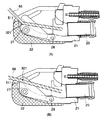
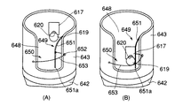
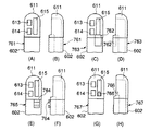
具体的には、次のような作業が行なわれる。まず、予め、図114(A),(B)に示す内視鏡901の挿入部902の先端部903を十二指腸乳頭付近まで挿入した後、この内視鏡901の処置具挿通用チャンネルにカテーテル904を挿入し、カテーテル904の先端部904aを経内視鏡的に膵管もしくは胆管内に挿入する。次に、挿入されたカテーテル904の基端側の口金904bからガイドワイヤ905を挿入する。
【0006】
その後、X線下で、ガイドワイヤ905が膵管もしくは胆管内まで正しく挿入されていることを確認し、図114(A)に示すようにガイドワイヤ905の基端側を手で把持しつつカテーテル904を内視鏡901の処置具挿通用チャンネルから引き抜く操作を行なう。この操作中、図114(B)に示すようにカテーテル904の先端部904aが内視鏡901の操作部906側のチャンネル開口部907より出てきたら、内視鏡901のチャンネル開口部907付近のガイドワイヤ905を把持してカテーテル904を完全に内視鏡901から引き抜く。
【0007】
次に、ガイドワイヤ905の基端側を別の処置具の挿通孔内に挿入し、このガイドワイヤ905に案内させる状態で、別の処置具を内視鏡901の処置具挿通用チャンネルに挿入する。以後、処置具の交換回数だけ上述の内容の作業を繰り返す。
【0008】
これらの処置に用いる処置具は、一般的に内視鏡901の長さを考慮して190cm以上の長さに設定されている。
【0009】
また、ガイドワイヤ905は、内視鏡901の長さと処置具の長さとを合わせた以上の長さが必要となるので、少なくとも400cm程度、必要であった。
【0010】
また、例えば、USP5,921,971号には、カテーテルシャフトにおけるガイドワイヤルーメンの先端部と基端部との間に長手方向の開口部を延在させることにより、迅速交換が可能な胆管用カテーテルが開示されている。
【0011】
【発明が解決しようとする課題】
ところで、内視鏡901を用いて膵胆管系を観察/処置する際に、内視鏡901の処置具挿通用チャンネルにカテーテル904等の処置具を挿通して使用する場合には、ガイドワイヤ905は処置具の内部に挿入されている。そのため、内視鏡901に対して処置具を移動すると、ガイドワイヤ905も同時に移動してしまうので、例えばガイドワイヤ905の先端が乳頭に挿入された状態で、ガイドワイヤ905をガイドに処置具を交換する場合には、ガイドワイヤ905の先端が乳頭に挿入された状態を保つために内視鏡901の操作部906側で常にガイドワイヤ905を把持している必要がある。
【0012】
さらに、従来の内視鏡901の使用中に、処置具を交換する作業時には内視鏡901の処置具挿通用チャンネルに対して処置具を引き抜きながら、同じ移動量だけガイドワイヤ905を挿入する、或いは同様に処置具挿通用チャンネルに処置具を挿入しながら、同じ移動量だけガイドワイヤ905を引き抜くという二つの動作を同時に行なう必要が有るので、その操作が複雑かつ面倒である。
【0013】
加えて、ガイドワイヤ905は400cm程度の長さを有しているため、狭い内視鏡室内でガイドワイヤ905が床等の不潔領域に接しないように取り回すことは難しい作業になっている。
【0014】
また、処置具はガイドワイヤ905の全長分移動させなければ交換作業を行なうことができないので、処置具の交換自体にかかる時間も長くなる可能性がある。従って、処置具を交換する作業時には、多くの時間がかかってしまう難点がある。
【0015】
さらに、処置具を交換する作業を行なう際には術者一人での交換作業も困難であり、手術室に少なくとも二人の補助者が必要である。そのため、人的コストが多く、病院や、患者への金銭的負担が大きくなるという問題も発生する。
【0016】
また、USP5,921,971号のようにカテーテルシャフトにおけるガイドワイヤルーメンの先端部と基端部との間に長手方向の開口部を延在させるカテーテルの場合には、従来の造影カテーテルに長手方向の開口部を設けるための作業が必要となる。そのため、従来の造影カテーテルに比べて製造コストが高いという欠点がある。
【0017】
さらにはスリットを設けたことによるカテーテルシャフトの剛性低下を補うためにシャフトの外径を太くしたり、シャフトの材質を硬質化する等の処置を施さなければならない。そのため、シャフトの大径化により、内視鏡のチャンネル内の挿入性が悪くなるために術者の作業性が劣る可能性がある。
【0018】
また、膵胆管系の処置は熟練を要し、多数の手技が確立されているため、術者の処置具に対する好みが特に別れるところである。さらに、患者の状況によっても処置具を使い分けることが頻繁に行なわれている。しかしながら、本従来技術では自ずと使用できる処置具が限定されてしまい、術者の選択の幅がなくなってしまうという欠点がある。
【0019】
本発明は上記事情に着目してなされたもので、その目的は、処置具の従来の操作方法や、操作感覚を損なうことなく、より短時間で容易に処置具が交換でき、かつ交換処置が術者と一人の補助者で行なうことができる内視鏡を提供することにある。
【0020】
【課題を解決するための手段】
請求項1の発明は、体腔内に挿入される挿入部内に処置具挿通用チャンネルが配設され、上記挿入部の先端付近に上記処置具挿通用チャンネルの先端開口部が配設された内視鏡において、上記処置具挿通用チャンネルを介して挿通されたガイドワイヤの先端部が上記処置具挿通用チャンネルの先端開口部から導出された状態で上記ガイドワイヤの上を走行する処置具を挿脱する際に、上記ガイドワイヤの軸方向の動きを規制する状態で上記ガイドワイヤを係脱可能に係止するガイドワイヤ固定手段を上記挿入部に設け、上記ガイドワイヤ固定手段は、上記処置具挿通用チャンネルの先端開口部近傍に設けられ、誘導面頂上部にガイドワイヤのみを挿入可能な大きさのほぼV字状のスリットを有する処置具起上台と、上記処置具挿通用チャンネルの開口部の上部に設けられたワイヤ当接面を有し、この処置具起上台の起上動作と組み合わせ、上記処置具起上台を操作して上記処置具起上台を起上させることで上記スリットと上記ワイヤ当接面との間に上記ガイドワイヤを挟持し、上記スリット内に上記ガイドワイヤを押圧することで上記ガイドワイヤのみを係合させたことで上記ガイドワイヤの軸方向の動きを規制することを特徴とする内視鏡である。
【0021】
請求項2の発明は、上記起上台が回動起上され上記スリットと上記ワイヤ当接面との間に上記ガイドワイヤを挟持・固定した際に上記ワイヤ当接面と上記ガイドワイヤとの最も先端側の接触部が上記起上台の回動軸よりも基端側に位置することを特徴とする請求項1に記載の内視鏡である。
【0022】
請求項3の発明は、上記処置具起上台の誘導面頂上部に対向する二つの壁面を持つスリットを設け、上記壁面は上記ガイドワイヤの外周のみと当接することで上記ガイドワイヤのみを固定することを特徴とする請求項1に記載の内視鏡である。
請求項4の発明は、上記スリットの開口部の幅は、上記ガイドワイヤの外径より広く、上記ガイドワイヤに外装される上記処置具の外径よりも狭いことを特徴とする請求項1に記載の内視鏡である。
請求項5の発明は、上記スリットの挿入部軸方向に対する中心軸を、上記誘導面の中心軸に対して傾斜させたことを特徴とする請求項1に記載の内視鏡である。
請求項6の発明は、上記起上台が回動倒置された際に、上記起上台の上記スリットの位置を上記処置具起上台の収容室の壁面の高さよりも低くなるように設定したことを特徴とする請求項1に記載の内視鏡である。
【0023】
【発明の実施の形態】
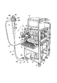
図1乃至図6(A),(B)は本発明の第1実施形態を示すものである。図1は本実施形態の内視鏡1と各種の外部装置とを組込んだ内視鏡装置のシステム全体の概略構成を示すものである。外部装置としては、光源装置2、画像処理装置3、モニタ4、入力用キーボード5、吸引ポンプ装置6、送水瓶7等の機器があり、これらの機器はキャリア8付きの棚9に設置されている。
【0024】
また、内視鏡1には体腔内に挿入される細長い挿入部12と、この挿入部12の基端部に連結された手元側の操作部13と、この操作部13に基端部が連結されたユニバーサルコード14とが設けられている。さらに、挿入部12には可撓性を備えた細長い可撓管部15と、この可撓管部15の先端に連結された湾曲部16と、挿入部12の最先端位置に配置された先端部17とからなる各構成部分が設けられている。
【0025】
また、操作部13に連結されたユニバーサルコード14の先端部にはコネクタ18が設けられている。このコネクタ18にはライトガイド管や電気接点部が設けられている。そしてこのコネクタ18は、外部装置である光源装置2及び画像処理装置3にそれぞれ接続されている。
【0026】
また、内視鏡1の先端部17の外周面には図7に示すように一側面側が切り欠かれた凹陥状の切欠部17aが形成されている。そして、この切欠部17aの一側部側にチャンネル開口部26が配置されている。さらに、このチャンネル開口部26の横には観察光学系の対物レンズ(不図示)と、照明光学系の照明レンズ(不図示)とが並べて配設されている。
【0027】
また、先端部17の切欠部17aの後端壁面17bには送気送水用のノズル(不図示)が突設されている。そして、このノズルから対物レンズの外表面に水や空気等の流体を噴き付けてそのレンズ面の清掃を行なうように構成されている。
【0028】
また、内視鏡1の操作部13には挿入部12の湾曲部16を上下/左右方向に湾曲させるための湾曲操作部56と、送気送水ボタン59と、吸引操作ボタン60とがそれぞれ設けられていると共に、処置具挿通用チャンネル23に通じる挿入口部61が配設されている。そして、送気送水ボタン59の操作によって先端部17のノズルに選択的に気体と液体とを噴出させるように構成されている。さらに、吸引操作ボタン60の操作によって処置具挿通用チャンネル23を通じて先端部17のチャンネル開口部26に選択的に吸引力を作用させ、体腔内の粘液等を回収するように構成されている。
【0029】
また、操作部13の内部には図3及び図4に示すように、起上ワイヤ30を操作するための起上台作動機構41が内蔵されている。起上ワイヤ30の基端部には金属等の硬質の棒状材質よりなるワイヤ固定部材42が半田等にて一体的に固着されている。このワイヤ固定部材42の基端部分には図4に示すように凹部よりなる係止溝43が形成されている。
【0030】
さらに、ワイヤ固定部材42の基端部分には金属等の硬質のブロック体よりなるリンク部材44が固定されている。このリンク部材44にはワイヤ固定部材42の挿入孔44aが形成されている。そして、このリンク部材44の挿入孔44a内にワイヤ固定部材42の基端部分が嵌挿されている。ワイヤ固定部材42の基端部分は係止溝43が形成された範囲が全てリンク部材44の挿入孔44a内に嵌挿されている。
【0031】
また、リンク部材44にはワイヤ固定部材42の固定ネジ46が螺挿される雌ネジ部45が設けられている。そして、リンク部材44の雌ネジ部45に螺合された固定ネジ46の先端部はワイヤ固定部材42の係止溝43に挿入された状態で係止されている。これにより、ワイヤ固定部材42はリンク部材44に固定された状態で連結されている。
【0032】
さらに、操作部13の内部には、その操作部13の基盤となるベース47が配設されている。そして、リンク部材44はこのベース47の長手方向に進退自在に配されている。
【0033】
また、リンク部材44には、アーム49の一端部が棒状の軸部材であるリンク軸50により回動自在に連結されている。リンク軸50におけるベース47側の端部と反対側の端部には、C型またはE型の止め輪等よりなる係止部材51が係合されている。
【0034】
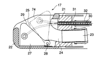
さらに、アーム49の他端部は湾曲操作部56に隣接して設けられた起上操作ノブ48に連接されている。そして、操作部13内の起上操作ノブ48の操作によってアーム49、リンク部材44、ワイヤ固定部材42を順次介して起上ワイヤ30が牽引操作され、処置具起上台27が起上台回動支点28を中心に起伏動作されるように構成されている。これにより、処置具挿通チャンネル23に挿通されてチャンネル開口部26から外部側に導出されるガイドカテーテル及びガイドワイヤ68が処置具起上台27を起上させることで起上されるように構成されている。
【0035】
次に、挿入部12の先端部17の構成について、図2を用いて詳細に説明する。この先端部17には先端部本体としての先端硬質部21と、これの周囲を覆うように樹脂等の非導電性材質より形成された先端カバー22とが設けられている。先端カバー22は先端硬質部21に接着等にて固定されている。
【0036】
さらに、先端硬質部21には処置具等の導入を先端側へ案内する導入案内路24が形成されている。この導入案内路24は内視鏡1の挿入部12内に配設された処置具挿通用案内路としての処置具挿通用チャンネル(挿通孔)23と連続して形成されている。
【0037】
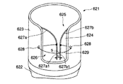
また、導入案内路24の先端側には先端硬質部21と先端カバー22とにて形成される空間部である収容室25が設けられている。そして、この収容室25の開口部によって処置具挿通用チャンネル23の先端開口部を構成するチャンネル開口部26が形成されている。
【0038】
また、収容室25内にはチャンネル23内を通じて導入される処置具やガイドカテーテル等の処置具を所望の位置へ起上させるための処置具起上台27が配設されている。この処置具起上台27はその一端が先端硬質部21に設けられた起上台回動支点28により枢着されている。
【0039】
この起上台回動支点28は、導入案内路24の先端開口部分の下側部位に配置されている。そして、処置具起上台27はこの起上台回動支点28を中心に収容室25内において図2中に実線で示す待機位置から同図中に仮想線で示す処置具起上位置まで回動するように起伏動作自在に取り付けられている。
【0040】
また、処置具起上台27には処置具やガイドカテーテル等の処置具を誘導するための誘導面29が形成されている。この誘導面29は導入案内路24より連続する断面形状が略V字状の溝によって形成されている。
【0041】
さらに、処置具起上台27には起上ワイヤ30の先端部が固定されている。この起上ワイヤ30は挿入部12内に挿通されるガイドパイプ31、ガイドチューブ32を通じて操作部13側に導かれ、後述する起上台操作機構41に接続されている。そして、この起上ワイヤ30の牽引操作に伴い処置具起上台27が起上台回動支点28を中心に起伏動作されるように構成されている。
【0042】
また、図6(B)に示すように処置具起上台27の誘導面29における略V字状溝の底部に、ガイドワイヤ固定手段としてガイドワイヤ68を係脱可能に係止するスリット状のワイヤ係止溝321が設けられている。ワイヤ係止溝321は対向する二つの壁面を持ち、ガイドワイヤ68の外周のみが当接するような幅を有している。
【0043】
なお、ワイヤ係止溝321は底部に向かうに従ってテーパ状に幅が狭くなる断面が略V字型の溝が好ましい。また、ワイヤ係止溝321の開口部スリット幅(溝幅)T1と、ガイドワイヤ68のワイヤ径D1と、処置具やガイドカテーテル等の、その他の処置具の外径D2との関係は、「D1≦T1<D2」に設定されているとなお良い。
【0044】
次に、本実施形態の作用について説明する。本実施形態の内視鏡1の使用時には、内視鏡1の操作部13の挿入口部61から処置具挿通用チャンネル23にガイドカテーテルを挿入する。そして、このガイドカテーテルを、チャンネル開口部26から外部側に突出させ、経乳頭的に膵/胆管(図示せず)内に挿入する。その後、現在使用中のガイドカテーテルを次に使用する処置具に交換する。まず、ガイドカテーテルの基端側の口金より、ガイドワイヤ68を挿入する。そして、このガイドワイヤ68の先端部が、膵/胆管内部まで挿入されたことを、内視鏡1の観察像(内視鏡像)で確認し、ガイドワイヤ68の基端側を手で把持する。続いてこの状態でガイドカテーテルを引き出す操作を行い、観察像にてガイドカテーテルが乳頭から引き抜かれたことを確認した後、さらにガイドカテーテルを手元側に引き抜く。そして、ガイドカテーテルの先端がチャンネル開口部26に収まった状態で、処置具起上台27の起上操作ノブ48を操作する。この起上操作ノブ48の操作に伴い起上ワイヤ30が牽引操作され、処置具起上台27が起上台回動支点28を中心に回動されて図5中に仮想線で示すように起上される。
【0045】
さらに、処置具起上台27の起上時には図6(A)に示すようにこの処置具起上台27の誘導面29における略V字状の溝に沿ってガイドワイヤ68がワイヤ係止溝321内に導かれ、図6(B)に示すようにこのワイヤ係止溝321内にガイドワイヤ68が係脱可能に係止される。そして、この処置具起上台27によってガイドワイヤ68が図6(A)中に矢印Pで示すように先端硬質部21の導入案内路24の上面273側に押し付けられる。この際、硬質のガイドワイヤ68からは直線を保とうとする図6(A)中に矢印Frで示す反力が作用するので、この反力によってガイドワイヤ68がワイヤ係止溝321内に押圧されることで強く係止され、この状態でガイドワイヤ68が機械的に固定される。
【0046】
さらに、ガイドワイヤ68が固定されたことを確認後、内視鏡1の操作部13側から処置具挿通用チャンネル23の外部にガイドカテーテルを完全に引き抜く。
【0047】
その後、次に使用する処置具を、ガイドワイヤ68の基端部側から挿入する。この際、ガイドワイヤ68をガイドにした状態で、処置具を処置具挿通用チャンネル23に挿通する。そして、処置具先端が処置具起上台27に突き当たった時点で起上操作ノブ48の操作により処置具起上台27を倒置することで、処置具が処置具起上台27を通過する際に、この際の処置具の押込力でワイヤ係止溝321からガイドワイヤ68が押し出され、ガイドワイヤ68の固定が解除される。さらに、膵/胆管内に処置具を挿入する。
【0048】
本実施形態にあっては次の効果を奏する。即ち、本実施形態では内視鏡1の手元操作部13の起上操作ノブ48を操作するという、通常行なわれる処置具起上台27の起上操作のみで容易にガイドワイヤ68の固定が可能となる。
【0049】
さらに、本実施形態では従来の処置具がそのまま使用できるため、術者の使い慣れた処置具の使用により、操作性が良いままの状態を維持できる。そのため、処置具の従来の操作方法や、操作感覚を損なうことなく、より短時間で容易に処置具が交換できる。
【0050】
また、内視鏡1の挿入部12の先端部17でガイドワイヤ68の固定ができるので、ガイドワイヤ68の長さを短くできる。そのため、ガイドワイヤ68の取り回しが容易となり、広い作業スペースが不要となる効果がある。加えて、処置具交換が容易になり、補助者の数も減らせ、かつ作業時の時間短縮にも繋がる効果がある。
【0051】
また、ワイヤ係止溝321を略V字状に形成することで、外径が微妙に異なるガイドワイヤ68に対しても安定してワイヤ係止溝321に強く係止することが可能である。加えて、ワイヤ係止溝321を設けることで、誘導面29に誘導されたガイドワイヤ68が常に同じワイヤ係止溝321のところに位置するため、固定状態が常に安定し、ガイドワイヤ68の位置による固定強度のばらつきをなくすことができる。
【0052】
さらに、本実施形態では、ワイヤ係止溝321のスリット幅(溝幅)T1と、ガイドワイヤ68のワイヤ径D1と、処置具やガイドカテーテル等の、その他の処置具の外径D2との関係を、「D1≦T1<D2」に設定したので、通常使用する処置具は、例えばガイドワイヤ68に外挿されるチューブ状の処置具は、ワイヤ係止溝321に引っかかることがなく、問題なく使用可能である。
【0053】
また、図7(A)〜(D)は本発明の第2実施形態を示すものである。本実施形態は第1実施形態における内視鏡1の、挿入部12の先端部17の構成を次の通り変更したものである。
【0054】
即ち、本実施形態では第1実施形態のガイドワイヤ68を固定するための処置具起上台27のワイヤ係止溝321に相当するスリット状のワイヤ係止溝331を先端硬質部21の導入案内路24の上面273側に設けたものである。このワイヤ係止溝331の開口部スリット幅(溝幅)T1と、ガイドワイヤ68のワイヤ径D1と、処置具やガイドカテーテル等の、その他の処置具の外径D2との関係は、第1実施形態と同様に「D1≦T1<D2」に設定されている。
【0055】
次に、本実施形態の作用について説明する。本実施形態の内視鏡1の使用時には、第1実施形態と同様に、チャンネル23内を通してガイドカテーテル及びガイドワイヤ68を体内に挿入後、ガイドカテーテルを導入案内路24或いはチャンネル23内に引き込んだ状態で、処置具起上台27の起上操作ノブ48が操作される。この起上操作ノブ48の操作に伴い起上ワイヤ30が牽引操作され、処置具起上台27が起上台回動支点28を中心に回動されて図7中に仮想線で示すように起上される。
【0056】
さらに、処置具起上台27の起上時にはこの処置具起上台27によってガイドワイヤ68が図7(C)に示すように先端硬質部21の導入案内路24の上面273側に押し付けられる。この際、硬質のガイドワイヤ68からは直線を保とうとする反力が作用するので、この反力によってガイドワイヤ68が先端硬質部21のワイヤ係止溝331内に強く係止され、図7(A)に示すようにこの状態でガイドワイヤ68が機械的に固定される。
【0057】
さらに、ガイドワイヤ68が固定されたことを確認後、内視鏡1の操作部13側から処置具挿通用チャンネル23の外部にガイドカテーテルを完全に引き抜く。
【0058】
その後、次に使用する処置具を、ガイドワイヤ68の基端部側から挿入する。この際、ガイドワイヤ68をガイドにした状態で、処置具を処置具挿通用チャンネル23に挿通する。そして、処置具先端が処置具起上台27に突き当たった時点で起上操作ノブ48の操作により処置具起上台27を倒置することで、処置具が処置具起上台27を通過する際に、この際の処置具の押込力でワイヤ係止溝331からガイドワイヤ68が押し出され、ガイドワイヤ68の固定が解除される。
【0059】
本実施形態にあっては次の効果を奏する。即ち、本実施形態では内視鏡1の手元操作部13側で通常行なわれる処置具起上台27の起上操作のみで容易にガイドワイヤ68の固定が可能となる。そのため、本実施形態でも第1実施形態と同様の効果が得られる。
【0060】
さらに、本実施形態では、ワイヤ係止溝331の開口部スリット幅(溝幅)T1と、ガイドワイヤ68のワイヤ径D1と、処置具やガイドカテーテル等の、その他の処置具の外径D2との関係を「D1≦T1<D2」に設定したので、通常使用する処置具はワイヤ係止溝331に引っかかることがなく、問題なく使用可能である。
【0061】
第1,第2実施形態の変形例として、図7(D)に示すように、第2実施形態にて示した先端硬質部21の導入案内路24の上面273側に設けたワイヤ係止溝331と、第1実施形態にて示した処置具起上台27の誘導面29に設けたワイヤ係止溝321の両方に設けても良い。
【0062】
これにより作用は、第1,第2実施形態と同様に処置具起上台27を起上することで、各ワイヤ係止溝321及び331にガイドワイヤ68が入り込んで、2点で係止される。
【0063】
これによる効果は、上述した第1,第2実施形態と同様の効果に加えて、2点で係止されることでさらに固定強度が増す点にある。
【0064】
また、図8は本発明の第3実施形態を示すものである。本実施形態は第1実施形態の内視鏡1における挿入部12の先端部17の構成を、以下の通り変更したものである。
【0065】
即ち、本実施形態では、図8(A),(B),(C)に示すように、処置具起上台27の誘導面29における略V字状溝の底部にガイドワイヤ68を係脱可能に係止するスリット状のワイヤ係止溝321が設けられている。該ワイヤ係止溝321の挿入部軸方向に対する中心軸をM1とし、誘導面29の挿入部軸方向に対する中心軸をM2とすると、ワイヤ係止溝321の角度をθ分傾けることでM1とM2がθだけ傾いている。
【0066】
なお、この傾きθはM1に対して、対物レンズ側もしくは対物レンズのM1を挟んだ反対側のどちらに傾いていても良い。
【0067】
また、必ずしもワイヤ係止溝321の中心軸M1と誘導面29の中心軸M2の交点にワイヤ係止溝321を設ける必要はなく、例えば図8(C)に示すように、誘導面29の中心よりずらした位置に設けても良い。
【0068】
本実施形態では、処置具起上台27の起上時にはこの処置具起上台27によってガイドワイヤ68が誘導面29に沿って挿入部軸方向に対して斜めに設けられたワイヤ係止溝321内に導かれ、図8(B)に示すようにワイヤ係止溝321内に嵌まり込むことで係脱可能に係止される。その後の作用は上述した第1実施形態と同様である。
【0069】
また、図9は本発明の第4実施形態を示すものである。本実施形態は第1実施形態の処置具起上台27の構成を次の通り変更したものである。
【0070】
即ち、本実施形態では第1実施形態の処置具起上台27におけるワイヤ係止溝321の内面に微小な凹凸を形成してざらつかせる表面処理を施した摩擦抵抗の大きい表面処理面541が形成されている。この表面処理面541は例えば、ワイヤ係止溝321の内面に腐食等の化学反応をさせる表面処理、或いは摩擦抵抗の大きい部材、例えばゴム,シリコーン,その他のエラストマー等を埋設もしくは貼り付ける等の処理によって形成されている。
【0071】
本実施形態にあっては次の効果を奏する。即ち、本実施形態では第1実施形態と同様の効果が得られる上、これに加えて、処置具起上台27におけるワイヤ係止溝321の内面の表面処理面541によってガイドワイヤ68とワイヤ係止溝321との間の摩擦抵抗が増えることで、ガイドワイヤ68の固定力量を増すことができる効果がある。
【0072】
また、図10(A),(B)は本発明の第5実施形態を示すものである。本実施形態は第1実施形態における内視鏡1の処置具起上台27の構成を次の通り変更したものである。
【0073】
即ち、本実施形態の処置具起上台27では、ワイヤ係止溝321と誘導面521との間における稜線の全周にわたって面取り加工を施した面取り加工部551が設けられている。
【0074】
本実施形態にあっては次の効果を奏する。即ち、本実施形態では第1実施形態と同様の効果が得られる上、これに加えて、処置具起上台27を起上した際にガイドワイヤ68が面取り加工部551に沿ってガイドされてワイヤ係止溝321に入り込み易くなる。さらに、ガイドワイヤ68や、他の処置具の挿通時にワイヤ係止溝321の端縁部にガイドワイヤ68や、他の処置具が引っかかることによる損傷がなくなる効果がある。
【0075】
また、図11(A),(B)は本発明の第6実施形態を示すものである。本実施形態は第1実施形態における内視鏡1の処置具起上台27の構成を次の通り変更したものである。
【0076】
即ち、本実施形態では処置具起上台27のワイヤ係止溝321における両側の壁面501の上部にワイヤ係止溝321の開口端部の幅を狭める係合突起502を設けたものである。ワイヤ係止溝321の開口端部における両側の係合突起502間の間隔はガイドワイヤ68の外径寸法よりもわずかに細い隙間になるように設定されている。
【0077】
次に、本実施形態の作用について説明する。本実施形態では第1実施形態の内視鏡1の処置具起上台27と同様に、ガイドカテーテルを処置具挿通チャンネル23内に引き込んだ状態で、処置具起上台27を起上させることで、ガイドワイヤ68は処置具起上台27の誘導面29によりワイヤ係止溝321に誘導される。
【0078】
この際、処置具起上台27の回動操作に伴い処置具起上台27の回動角度が大きくなるに従ってガイドワイヤ68が突起502に外側から強く押圧され、ガイドワイヤ68が弾性変形し始める。そして、処置具起上台27の回動角度が最大起上角度に達する前の適宜の角度で突起502をガイドワイヤ68が乗り越え、図11(B)に示すようにワイヤ係止溝321にガイドワイヤ68が嵌まり込む。これにより、処置具起上台27のワイヤ係止溝321における両側の壁面501と両側の係合突起502の4点で接触された状態でガイドワイヤ68が固定される。
【0079】
その後、ガイドカテーテルを一気に引き抜き、他の処置具を、ガイドワイヤ68をガイドとして挿入する。この際、挿入された処置具がワイヤ係止溝321を通過する際に、処置具の押圧力でガイドワイヤ68がワイヤ係止溝321から押し出され、ガイドワイヤ68の固定が解除される。
【0080】
本実施形態にあっては次の効果を奏する。即ち、本実施形態では第1実施形態の内視鏡1と同様に、内視鏡1の手元操作部13の起上操作ノブ48を操作する通常行なわれる処置具起上台27の起上操作のみで容易にガイドワイヤ68の固定が可能となる。
【0081】
また、本実施形態では第1実施形態の内視鏡1と同様の効果に加えて、ガイドワイヤ68の固定時には外側からワイヤ係止溝321における開口端部の両側の係合突起502を乗り越えた時点で、ワイヤ係止溝321と両側の係合突起502とでガイドワイヤ68を挟み込むことでガイドワイヤ68を一層、強固に固定することができる。
【0082】
さらに、ガイドワイヤ68の固定時には両側の係合突起502によってガイドワイヤ68が処置具起上台27の上面方向に逃げる力を押さえることができる。
【0083】
また、図12(A)に示す第6実施形態における処置具起上台27の第1変形例のように、処置具起上台27のワイヤ係止溝321における開口端部の両側の係合突起502は、挿入部軸方向に沿ってワイヤ係止溝321の全ての範囲、或いはワイヤ係止溝321の一部分に設けても良い。さらに、図12(B)に示す第6実施形態における処置具起上台27の第2変形例のように、処置具起上台27のワイヤ係止溝321における開口端部の両側にそれぞれ複数の係合突起502を設けても良い。
【0084】
また、図12(C)に示す第6実施形態における処置具起上台27の第3変形例のように、ガイドワイヤ68の固定能力を極端に下げない範囲で処置具起上台27のワイヤ係止溝321における開口端部の片側のみに係合突起502を設けても良い。このように係合突起502を処置具起上台27のワイヤ係止溝321における開口端部の片面のみに設けた場合には、ガイドワイヤ68のワイヤ係止溝321への出し入れ時の操作力量が軽くなるため、ガイドワイヤ68の固定操作が比較的容易になる効果がある。
【0085】
また、図13乃至図15(A),(B)は本発明の第7実施形態を示すものである。本実施形態は第1実施形態における内視鏡1の処置具起上台27の構成を次の通り変更したものである。
【0086】
即ち、本実施形態では図13に示すように処置具起上台27の倒置状態において処置具起上台27のワイヤ係止溝321が、他の処置具の進退時にワイヤ係止溝321に処置具が触れない位置に設けられている。図13はガイドカテーテル67を挿通状態での処置具起上台27の倒置時における断面図、図14は処置具起上台27の起上時の断面図である。そして、処置具起上台27のワイヤ係止溝321は、誘導面521と先端面522及びそれら2面をつなぐ連結面523とからなる。
【0087】
また、図15(A)は処置具起上台27の正面図、図15(B)は処置具起上台27の背面図を示す。本実施形態では処置具起上台27のワイヤ係止溝321は、図15(A),(B)に示すように手元側からでは見えない位置に配置されている。そして、処置具起上台27のワイヤ係止溝321は連結面523から先端面522に向けて徐々に深くなるように形成されている。これにより、処置具起上台27を起上させるに従ってワイヤ係止溝321がガイドワイヤ68の走行位置に露出してくるように設定されている。
【0088】
次に、本実施形態の作用について説明する。本実施形態では第1実施形態と同様に、ガイドカテーテル67を処置具挿通チャンネル23内に引き込んだ状態で、処置具起上台27を起上させることで、ワイヤ係止溝321が現れ、ガイドワイヤ68を挟み込んで固定する。その他は第1実施形態と同様である。
【0089】
本実施形態にあっては次の効果を奏する。即ち、本実施形態では第1実施形態と同様に、内視鏡1の手元操作部13の起上操作ノブ48を操作する通常行なわれる処置具起上台27の起上操作のみで容易にガイドワイヤ68の固定が可能となる。
【0090】
また、本実施形態では第1実施形態の内視鏡1と同様の効果に加えて、処置具起上台27が倒置時に、ワイヤ係止溝321が誘導面521に現れないことで、処置具を傷める虞がなく、処置具の進退が滑らかになる効果がある。
【0091】
また、図16乃至図18は本発明の第8実施形態を示すものである。本実施形態は第1実施形態における内視鏡1の処置具起上台27の構成を次の通り変更したものである。
【0092】
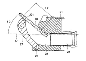
即ち、処置具起上台27のワイヤ係止溝321は、ガイドワイヤ68を起上した際に図17に示すようにワイヤ係止溝321全面でガイドワイヤ68を捕らえるような設計が望ましいが、実際には加工精度の関係からワイヤ係止溝321とガイドワイヤ68との接触面には図18に示すように若干のずれが生じるのが一般的である。処置具起上台27によってガイドワイヤ68を起上した際に図17に示す理想的な状態での挿入部軸Oとワイヤ係止溝321との間の角度をθとした場合に、図18に示すように加工精度の関係からワイヤ係止溝321とガイドワイヤ68との接触面にずれが生じた際の挿入部軸Oとワイヤ係止溝321との間の角度をθ2とすると「θ<θ2」の関係になることがある。この場合には、ワイヤ係止溝321の先端部でガイドワイヤ68の先端部を押さえることになるので、ガイドワイヤ68を押さえている処置具起上台27のガイドワイヤ接触点と先端硬質部21における導入案内路24のガイドワイヤ接触点との2点間の距離L2が比較的長くなる。そのため、この状態ではガイドワイヤ68の固定強度が落ちる問題がある。
【0093】
本実施形態では処置具起上台27のワイヤ係止溝321の加工による公差を考慮して、図16に示すように処置具起上台27によってガイドワイヤ68を起上した際に挿入部軸Oと処置具起上台27のワイヤ係止溝321との間の角度θ1を予め図17に示す理想的な状態での挿入部軸Oとワイヤ係止溝321との間の角度θに対して、「θ>θ1」に設定したものである。これにより、処置具起上台27によってガイドワイヤ68を起上した際に処置具起上台27のワイヤ係止溝321の手元側を図17に示す理想的なワイヤ係止溝321の手元側端部の位置よりも高くし、ワイヤ係止溝321の手元側にガイドワイヤ68との接触点が配置されるように設定したものである。そして、この場合にはガイドワイヤ68を押さえている処置具起上台27のガイドワイヤ接触点と先端硬質部21における導入案内路24のガイドワイヤ接触点との2点間の距離L1が図18のL2よりも小さく(L1<L2)なるので、ガイドワイヤ68の固定強度を図18の場合に比べて高くすることができる。
【0094】
従って、本実施形態では処置具起上台27によってガイドワイヤ68を起上した際に処置具起上台27のワイヤ係止溝321と先端硬質部21における導入案内路24のガイドワイヤ接触点との2点間の距離が、加工のばらつきによって長くなることがないので、処置具起上台27のワイヤ係止溝321の加工ばらつきでガイドワイヤ68の固定強度が下がることがなく、ガイドワイヤ68の固定強度を安定に保てる効果がある。
【0095】
また、図19及び図20は本発明の第9実施形態を示すものである。本実施形態は第1実施形態の処置具起上台27の構成を次の通り変更したものである。
【0096】
即ち、本実施形態では図19に示すように処置具起上台27の先端部にこの処置具起上台27の最大起上時にこの処置具起上台27によって起上されるガイドワイヤ68の起上位置を起上台回動支点28の位置よりも手元側に向けて強く屈曲させるワイヤ係止溝321が設けられている。このワイヤ係止溝321は処置具起上台27のガイドワイヤ68の誘導面29における先端近傍部位に配置されている。そして、処置具起上台27の最大起上時には、このワイヤ係止溝321は起上台回動支点28の位置よりも手元側に向けて適宜の距離L1程度突出する位置に配置されている。
【0097】
なお、処置具起上台27に設けたワイヤ係止溝321と、導入案内路24の上面273との処置具起上台27が起上時のクリアランスはガイドカテーテルや、他の処置具の挿脱を妨げないように、従来並みに確保した状態で保持されている。
【0098】
さらに、処置具起上台27の誘導面側側壁面27aにはこの処置具起上台27の最大起上時に先端硬質部21の先端の起上角ストッパ462と対向する部分に処置具の挿脱性を妨げない範囲で、この起上角ストッパ462との当接を逃げる状態に削り落とした切欠部463が形成されている。
【0099】
なお、上記ワイヤ係止溝321と起上台回動支点28との位置関係を保つ構成であれば、この限りでない。
【0100】
これに対し、図20は従来のガイドワイヤ68の固定時における内視鏡先端部の断面図を示す。図20に示す通り、従来は処置具起上台27を最大起上位置まで起上させた際のワイヤ係止溝321でのガイドワイヤ68の固定位置が、起上台回動支点28よりも適宜の距離L2程度先端側に配置されている。
【0101】
次に、本実施形態の作用について説明する。本実施形態では第1実施形態と同様にガイドカテーテルを処置具挿通チャンネル23内に引き込んだ状態で、処置具起上台27を起上させる。この際、本実施形態では処置具起上台27が従来の最大起上角度位置に対してさらに大きく起上されるので、ガイドワイヤ68もさらに曲げられることになる。そのため、ワイヤ係止溝321と導入案内路24の上面273との間のせん断力及びガイドワイヤ68の反力はさらに強く働くので、この状態でガイドワイヤ68を強く固定することができる。
【0102】
このようにガイドワイヤ68がしっかりと固定されていることを確認した後、ガイドカテーテルを引き抜き、別の処置具をガイドワイヤ68越しに挿入することで、この際に挿入される処置具がワイヤ係止溝321を通過する際に処置具起上台27を倒置し、さらにこの処置具の押込力によってワイヤ係止溝321からガイドワイヤ68が押し出され、ガイドワイヤ68とワイヤ係止溝321との固定が解除される。
【0103】
本実施形態にあっては次の効果を奏する。即ち、本実施形態では第1実施形態と同様の効果が得られると共に、これに加えて、ガイドワイヤ68を一層強固に固定することができる効果がある。
【0104】
なお、上述したガイドワイヤ固定手段は、ワイヤ係止溝321を有するものに限らず、起上角度を稼ぐために処置具起上台27のみで代用しても良い。
【0105】
また、図21及び図22(A)〜(D)は本発明の第10実施形態を示すものである。本実施形態は第1実施形態における内視鏡1の操作部13の内部に配設された起上台作動機構41に代えて図21及び図22(A)に示すように構成された起上台作動機構401を設けたものである。
【0106】
内視鏡1の操作部13の端縁部には起上台操作ノブ402が配設されている。この起上台操作ノブ402には操作レバー403と、図22(A)に示すようにこの操作レバー403の外端部に固定ネジ404によって固定された指当て部405とが設けられている。
【0107】
また、内視鏡1の操作部13には起上台操作ノブ402の取付用の固定筒体406が突設されている。この固定筒体406の基端部は操作部13の操作部ケーシング13a内に配設された図示しない固定フレームに固定されている。
【0108】
さらに、この固定筒体406には回転リング407が回転自在に嵌入されている。
【0109】
なお、操作部ケーシング13aにはこの回転リング407を回転自在に軸支する軸受部13bが設けられている。
【0110】
また、操作レバー403の内端部には図21に示すようにリング状の連結リング403aが設けられている。この連結リング403aは回転リング407の外面に複数の固定ネジ408によってネジ止め固定されている。そして、この起上台操作ノブ402は操作レバー403が固定筒体406の中心軸に沿って回転可能に軸支されている。
【0111】
また、回転リング407の内面には第2リンク部材409の基端部が固定されている。この第2リンク部材409には略L字状のリンクアーム409aが突設されている。このリンクアーム409aの先端部には棒状の軸部材である第2リンク軸410を介して第1実施形態の起上台作動機構41におけるアーム49の他端部が回動自在に連結されている。第2リンク軸410におけるアーム49側の端部と反対側の端部には、C型またはE型の止め輪等よりなる係止部材411が係合されている。
【0112】
そして、操作部13内の起上台操作ノブ402の回動操作時には指当て部405を支点に、操作レバー403を回転操作することによって、回転リング407を介して第2リンク部材409が回動操作され、この第2リンク部材409の回動動作に伴いアーム49を介してリンク部材44が起上ワイヤ30の軸方向に進退駆動されることにより、起上ワイヤ30が牽引操作され、処置具起上台27が起上台回動支点28を中心に起伏動作されるように構成されている。これにより、処置具挿通チャンネル23に挿通されてチャンネル開口部26から外部側に導出されるガイドカテーテル等の処置具が処置具起上台27を起上させることで起上されるように構成されている。
【0113】
また、本実施形態の起上台作動機構401には起上台操作ノブ402の操作レバー403の回動操作力を制動するブレーキ機構412が組込まれている。このブレーキ機構412には図22(B)に示すように起上台操作ノブ402の操作レバー403の中途部に突設されたピン等の抑止体413と、この抑止体413と係合する位置に配置された図22(C)に示す抑止増強部材414とが設けられている。
【0114】
さらに、抑止増強部材414には、操作レバー403の抑止体413が挿入される図22(C),(D)に示すように略U字状の断面形状のガイド溝414aが形成されている。このガイド溝414aは操作レバー403の回動動作時における抑止体413の回動軌道に沿って延設されている。そして、この抑止増強部材414のガイド溝414aの内部を抑止体413が通過するように構成されている。
【0115】
また、抑止増強部材414のガイド溝414aの内部にはこのガイド溝414aの一端部側に摩擦抵抗が大きい摩擦抵抗部材415が埋設されている。この摩擦抵抗部材415は操作レバー403の回動動作時に操作レバー403の回動を抑止させたい範囲Lにおいて、同範囲を回転する際に抑止体413が通過する領域に配置されている。
【0116】
次に、本実施形態の作用について説明する。本実施形態では処置具起上台27を起上させる操作時には第29実施形態の内視鏡1と同様に、操作部13の起上台操作ノブ402の操作レバー403を回転させる。この際、操作レバー403を抑止範囲Lまで回転させると、抑止体413が抑止増強部材414のガイド溝414a内の摩擦抵抗部材415に接触する。これにより、操作レバー403の回動動作に負荷がかかり、操作レバー403の回動動作が制動されて固定される。そのため、処置具起上台27を図57(A)中に仮想線で示す起上位置まで回動させた状態で、処置具起上台27を固定させることができるので、チャンネル開口部26から外部側に導出されているガイドワイヤ68が先端硬質部21の導入案内路24の先端面と処置具起上台27との間で挟み込まれて機械的に固定される。
【0117】
このように、ガイドワイヤ68が固定されたことを確認後、内視鏡1の操作部13側から処置具挿通用チャンネル23の外部にガイドカテーテルを完全に引き抜く。
【0118】
その後、次に使用する処置具を、ガイドワイヤ68の基端部側から挿入する。この際、ガイドワイヤ68をガイドにした状態で、処置具を処置具挿通用チャンネル23に挿通する。そして、処置具が処置具起上台27に突き当たった時点で、起上台操作ノブ402の操作レバー403を元に戻す。この際、操作レバー403が抑止範囲Lを越え、抑止体413が抑止増強部材414のガイド溝414a内の摩擦抵抗部材415から外れることで、操作レバー403の固定を解除することができる。これにより、処置具起上台27によるガイドワイヤ68の固定が解除される。
【0119】
本実施形態にあっては次の効果を奏する。即ち、本実施形態では起上台作動機構401に起上台操作ノブ402の操作レバー403の回動操作力を制動するブレーキ機構412を組込んだので、処置具起上台27を図5中に仮想線で示す起上位置まで回動させた状態で、処置具起上台27を固定させることにより、ガイドワイヤ68を固定した状態を維持できるため、ガイドワイヤ68を固定している間、操作レバー403を把持しておく必要がなくなり、術者の作業性が向上する効果がある。
【0120】
なお、後述するガイドワイヤ固定用起上台267の操作レバー72に本実施形態のブレーキ機構412を組込む構成にしても良い。この場合にはガイドワイヤ固定用起上台267を図57(C)に示す起上位置まで回動させた状態で、ガイドワイヤ固定用起上台267を固定させることにより、ガイドワイヤ68を固定した状態を維持できるため、ガイドワイヤ68を固定している間、ガイドワイヤ固定用起上台267の操作レバー72を把持しておく必要がなくなり、術者の作業性が向上する効果がある。
【0121】
また、図23は第10実施形態の第1の変形例を示すものである。本変形例はブレーキ機構412の抑止増強部材414のガイド溝414a内に摩擦抵抗部材415に代えて2枚の板バネ416a,416b等の弾性部材416を配設したものである。この弾性部材416は2枚の板バネ416a,416b間に抑止体413が挿入され、抑止体413が挿入されるに従って負荷が増えるような形状に形成されている。そして、本変形例の弾性部材416でも第11実施形態のブレーキ機構412と同様の効果が得られる。
【0122】
また、図51は第10実施形態の第2の変形例を示すものである。本変形例は第10実施形態のブレーキ機構412に代えて第33実施形態のように操作部13の周方向に沿って軸回り方向に回転する牽引ノブ264に切欠417を設け、図示しない弾性部材を介して突出する突起418をこの切欠417に係脱可能に係合させることにより、牽引ノブ264の回転を固定させるタイプのブレーキ機構を設けたものである。そして、本変形例でも第11実施形態のブレーキ機構412と同様の効果が得られる。
【0123】
また、図24乃至図27は本発明の第11実施形態を示すものである。本実施形態は第9実施形態の処置具起上台27の起上範囲を適宜、選択的に複数段に変化させることができる起上範囲選択型構造の起上操作手段471を設けたものである。
【0124】
即ち、本実施形態の起上操作手段471には第10実施形態における内視鏡1と略同構成の操作部13の内部に図24及び図25(A)に示す構成の起上台作動機構472が設けられている。
【0125】
この起上台作動機構472には固定筒体406の中心軸を中心とした弓形状のストッパ部材473が設けられている。このストッパ部材473の一端部側には図26に示すように平面状のベース面474に対して鉛直上向き方向に階段状に突設された2段式の突設部475が形成されている。この2段式の突設部475には低段の第1ストッパ475aと高段の第2ストッパ475bとが設けられている。高段の第2ストッパ475bは低段の第1ストッパ475aよりも後方のストッパ部材473の端部側に配置されている。そして、このストッパ部材473は操作部13のケーシング13aに固定ネジ476で固定されている。
【0126】
また、第1ストッパ475aの高さは、起上台操作ノブ402の操作レバー403が第1ストッパ475aを乗り越えられる程度に、操作レバー403の弾性変形が可能な範囲で設定されている。さらに、第2ストッパ475bは、操作レバー403の弾性変形ではこの操作レバー403が第2ストッパ475bを乗り越えることができない高さに設定されている。そして、起上台操作ノブ402の回動操作時にはこの起上台操作ノブ402の操作レバー403が第1ストッパ475aに突き当たる図24中のB位置で第1段の起上動作範囲の規制が行なわれるように構成されている。この際、図24中のA位置からB位置までの第1段の起上動作範囲で操作レバー403を回動することで、従来と同様に処置具等を所望の位置へ誘導させる通常の処置具の起上操作を行なうことができる。
【0127】
また、B位置で起上台操作ノブ402の指当て部405を図25(B)中の矢印方向に引き上げて操作レバー403を弾性変形させることにより、図25(B)に示すようにこの操作レバー403は、第1ストッパ475aを乗り越えることができる。さらに、第1ストッパ475aを乗り越えさせた後、この操作レバー403を第2ストッパ475bに突き当たる図24中のC位置まで回動させることで第2段の起上動作範囲の規制が行なわれるように構成されている。従って、本実施形態では起上操作手段471のストッパ部材473における低段の第1ストッパ475aと高段の第2ストッパ475bとによって処置具起上台27の起上範囲を2段に変化させることができる。そして、このC位置ではチャンネル開口部26から外部側に導出されているガイドワイヤ68が先端硬質部21の導入案内路24の先端面と処置具起上台27との間で挟み込まれて機械的に固定されるように構成されている。
【0128】
次に、本実施形態の作用について説明する。本実施形態では起上台操作ノブ402の回動操作時にはこの起上台操作ノブ402の操作レバー403が起上操作手段471のストッパ部材473における低段の第1ストッパ475aに突き当たる図24中のB位置で第1段の起上動作範囲の規制が行なわれる。この際、図24中のA位置からB位置までの第1段の起上動作範囲で操作レバー403を回動することで、従来と同様に処置具等を所望の位置へ誘導させる通常の処置具の起上操作を行なうことができる。
【0129】
また、ガイドワイヤ68の固定時には、第1実施形態と同様にガイドカテーテルを処置具挿通チャンネル23内に引き込んだ状態で、操作レバー403を回動操作して処置具起上台27を起上させる。
【0130】
この際、操作レバー403が第1ストッパ475aに突き当たったB位置の時点で、図25(B)に矢印で示すように、指当て部405を外側上方に押し上げることにより、第1ストッパ475aに突き当たっていた操作レバー403が撓む状態に弾性変形される。これにより、図27に仮想線で示すようにこの操作レバー403は、第1ストッパ475aを乗り越えることができる。
【0131】
さらに、第1ストッパ475aを乗り越えさせた後、この操作レバー403を第2ストッパ475bに突き当たる図24中のC位置までさらに回動させることでさらに処置具起上台27の起上が可能となり、第2段の起上動作範囲の規制が行なわれる。そして、このC位置ではチャンネル開口部26から外部側に導出されているガイドワイヤ68が先端硬質部21の導入案内路24の先端面と処置具起上台27との間で挟み込まれて機械的に強固に固定される。
【0132】
従って、本実施形態では起上操作手段471のストッパ部材473に低段の第1ストッパ475aと高段の第2ストッパ475bとを設け、通常使用する操作レバー403を第1ストッパ475aに突き当てた状態と、高段の第2ストッパ475bに突き当てた状態とに変化させるように通常使用する操作レバー403の動作を変えることのみで処置具起上台27の起上範囲を2段に変化させることができる。そのため、処置具起上台27の起上範囲を変化させるために新たに複雑な操作手段を設ける必要がないので、術者の混乱を招くことがなく、内視鏡を安定に操作することができる効果がある。
【0133】
加えて、処置具を起上させる場合と、ガイドワイヤ68を固定する場合とで、操作レバー403の回動位置の微調整をすることがなく、簡単に処置具を起上させる場合と、ガイドワイヤ68を固定する場合とに使い分けることができるので、検査時の術者の負担が減る効果が得られる。
【0134】
また、ガイドワイヤ68の固定位置まで起上台操作ノブ402の操作レバー403を回転した後、この操作レバー403をC位置からB位置を経てA位置方向に回動させるガイドワイヤ68の固定解除の操作時には操作レバー403が起上操作手段471のストッパ部材473に突き当たることがないので、処置具起上台27を倒置位置まで戻す操作を容易に行なうことができる。
【0135】
以上に加えて、第9実施形態における処置具起上台27とワイヤ係止溝321とのクリアランスも、B位置において、処置具の挿脱を妨げないように従来並みに確保されていれば良く、B位置からC位置に移行する際の処置具起上台27とワイヤ係止溝321とのクリアランスを狭くすることができ、ガイドワイヤ68の固定強度が増す。
【0136】
なお、ストッパ部材473と操作部13の操作部ケーシング13aとを一体に成形することにより、部品点数を減らす構成にしても良い。さらに、本実施形態のストッパ部材473では、低段の第1ストッパ475aと高段の第2ストッパ475bとの二つのストッパを設けた構成を示したが、必要に応じて3以上のストッパを設けても良い。
【0137】
また、本実施形態ではストッパ部材473を操作部13のケーシング13aに設けた構成を示したが、これに限らず、処置具起上台27の起上操作性を損なわない範囲で、操作レバー403と、固定筒体406と、第2リンク部材409と、リンク部材44とそれぞれ接触する部分に設けても良い。
【0138】
さらに、ストッパ部材473の形状も、先に示した板状部材に限らず、図28に示す第11実施形態の変形例のように板バネ等の弾性部材476で代用しても良い。この弾性部材476には操作レバー403の軌道上に突設された一対の突部477a,477aによって第1段の起上動作範囲を規制する第1ストッパ475aが形成され、さらにこの第1ストッパ475aから離れた位置に突設された一対の突部477b,477bによって第2段の起上動作範囲を規制する第2ストッパ475bが形成されている。
【0139】
また、図29(A),(B)及び図30は本発明の第12実施形態を示すものである。本実施形態は第1実施形態の内視鏡1の処置具起上台27を起上させた際に、図30に示すように処置具起上台27の一部を内視鏡1の対物光学系の対物レンズ481による観察視野482内に挿入させる状態に配置したものである。
【0140】
なお、図29(B)は内視鏡1の対物レンズ481による観察画像483を示すものである。そして、内視鏡1の対物光学系はこの観察画像483に表示される処置具起上台27のワイヤ係止溝321により固定されたガイドワイヤ68の一部が合焦する位置に配置されている。
【0141】
次に、本実施形態の作用について説明する。本実施形態では第1実施形態の内視鏡1と同様に、ガイドカテーテルを処置具挿通用チャンネル23内に引き込んだ状態で、処置具起上台27を起上させることで、対物光学系の対物レンズ481の視野482内に処置具起上台27及びそれに固定されたガイドワイヤ68が挿入される。そして、処置具起上台27の最大起上時には、図29(B)に示すように内視鏡1の対物レンズ481による観察画像483の隅に処置具起上台27が確認できる状態で配置される。この際、ガイドワイヤ68に対物レンズ481の焦点が合っている。この状態で、ガイドカテーテルを一気に引き抜き、他の処置具を、ガイドワイヤ68をガイドにして挿入する。処置具先端が処置具起上台27に突き当たったところで処置具起上台27を倒置し、処置具がワイヤ係止溝321を通過する際に、この処置具からの押圧力でガイドワイヤ68がワイヤ係止溝321から押し出され、ガイドワイヤ68の固定が解除される。
【0142】
本実施形態にあっては次の効果を奏する。即ち、本実施形態では第1実施形態の内視鏡1と同様に、内視鏡1の手元操作部13の起上操作ノブ48を操作する通常行なわれる処置具起上台27の起上操作のみで容易にガイドワイヤ68の固定が可能となる。
【0143】
さらに、本実施形態では第1実施形態の内視鏡1と同様の効果に加えて、内視鏡1の対物レンズ481による観察画像483を目視することにより、ガイドワイヤ68が確実に固定されているかどうかを視覚的に確認することができる。そのため、誤って固定されていないガイドワイヤ68を引き抜いてしまうような誤操作即ちの発生を未然に防止できる効果がある。
【0144】
また、処置具起上台27が内視鏡1の対物光学系の対物レンズ481による観察視野482内に挿入されることで、処置具起上台27がガイドワイヤ68の固定位置に移動している状態が視認できる効果がある。
【0145】
なお、本実施形態は必ずしも第1実施形態の内視鏡1に限定されるものではなく、ガイドワイヤ固定部材を用いてガイドワイヤ68を固定する機構を有するものには全て適用できるものである。
【0146】
また、図31(A)は本発明の第13実施形態を示すものである。本実施形態は第12実施形態における内視鏡1の処置具起上台27等のガイドワイヤ固定手段により固定され、内視鏡1の対物光学系の対物レンズ481による観察視野482内に挿入されるガイドワイヤ68に、ストライプ状のマーキングからなる指標491を設けたものである。
【0147】
なお、この指標491は、図31(B)に示す第1の変形例の目盛り492、或いは図31(C)に示す第2変形例の数字493等のようにガイドワイヤ68の位置がずれたことが分かる表示であれば良い。
【0148】
本実施形態にあっては次の効果を奏する。即ち、本実施形態では第12実施形態と同様の効果が得られる上、第12実施形態と同様の効果に加えて、ガイドワイヤ68のずれがさらに容易に視認できる効果がある。
【0149】
また、図32(A)は本発明の第14実施形態を示すものである。本実施形態は第1実施形態における内視鏡1の処置具起上台27におけるワイヤ係止溝321の位置を、内視鏡1の挿入部12の先端部17に設けた先端カバー22の処置具誘導面511よりも低くなるように設定したものである。
【0150】
なお、図32(B)はガイドワイヤ68の固定時における従来の処置具起上台27の倒置状態を示す。この図32(B)に示す通り、従来の処置具起上台27では処置具起上台27のワイヤ係止溝321の位置が挿入部12の先端カバー22の処置具誘導面511よりも高い位置に配置されている。
【0151】
次に、本実施形態の作用について説明する。本実施形態の処置具起上台27では第1実施形態の内視鏡1の処置具起上台27と同様に、ガイドワイヤ68を固定してガイドカテーテルを抜去した後、他の処置具を、ガイドワイヤ68をガイドとして挿入する。この際、本実施形態の処置具起上台27では処置具起上台27を完全に倒置することで、ワイヤ係止溝321に挟まれて固定されていたガイドワイヤ68が先端カバー22の処置具誘導面511により、上方に押し上げられる。そのため、この押し上げ力によってガイドワイヤ68がワイヤ係止溝321から押し出され、ガイドワイヤ68の固定が解除される。
【0152】
本実施形態にあっては次の効果を奏する。即ち、本実施形態では処置具起上台27の操作のみでガイドワイヤ68がワイヤ係止溝321から押し出され、ガイドワイヤ68の固定解除ができるので、挿入された処置具がワイヤ係止溝321を通過する際に、処置具の押圧力でガイドワイヤ68の固定を解除する方法に比べて作業性がさらに向上する効果がある。
【0153】
また、図33(A),(B)は本発明の第15実施形態を示すものである。本実施形態は第1実施形態のワイヤ係止溝321に代えて図33(A),(B)に示すようにチャンネル開口部26の手元側壁面26aに摩擦抵抗の大きい材質、例えばゴム等の弾性部材101を埋設し、処置具起上台27を起上操作してこの処置具起上台27によってガイドワイヤ68を弾性部材101に圧接させることにより、ガイドワイヤ68を固定するガイドワイヤ固定機構102を構成したものである。
【0154】
次に、本実施形態の作用について説明する。本実施形態では第1実施形態と同様に、ガイドワイヤ68とガイドカテーテルとを処置具挿通用チャンネル23に挿通後、ガイドワイヤ68の固定時には、ガイドカテーテルを導入案内路24或いはチャンネル23内に引き込んだ状態で、起上操作ノブ48を操作して牽引手段である起上ワイヤ30で処置具起上台27を起上させる。この際、図33(B)中に仮想線で示すように処置具起上台27によってガイドワイヤ68を弾性部材101に圧接させる位置まで処置具起上台27を起上させる。このように処置具起上台27と弾性部材101との間にガイドワイヤ68が挟まれることで、弾性部材101の摩擦抵抗によりガイドワイヤ68が滑らず、固定される。
【0155】
本実施形態では内視鏡1の手元操作部13側の起上操作ノブ48による操作で処置具起上台27を起上させ、処置具起上台27と弾性部材101との間にガイドワイヤ68を挟むことにより、ガイドワイヤ68の固定が可能であり、第1実施形態と同様の効果が得られる。
【0156】
さらに、本実施形態では特に、チャンネル開口部26の手元側壁面26aに弾性部材101を埋設するのみでよく、新たな付勢機構等の追加部品を設ける必要がない。そのため、内視鏡1の先端部17の構成が複雑にならず従来と同等である。
【0157】
なお、弾性部材で構成された先端カバー22が着脱可能なタイプの内視鏡1では、図34に示す変形例のように先端カバー22におけるチャンネル開口部26と対応する部位にチャンネル開口部26の手元側壁面26aまで延長されるガイドワイヤ固定部103を先端カバー22に一体的に設けても良い。この場合には、先端カバー22が着脱可能なタイプの内視鏡1で、従来の先端カバーと本実施形態の先端カバー22とを交換することで、現在のスコープにも容易にガイドワイヤ固定機構102を設けることが可能となる。
【0158】
また、第15実施形態の弾性部材101は、磁石に代えても良い。この場合には第1実施形態と同様に、ガイドカテーテル及び金属製のガイドワイヤ68を処置具挿通用チャンネル23に挿通後、ガイドカテーテルがチャンネル開口部26内まで引き込んだところで操作部13内の起上操作ノブ48にて処置具起上台27を起上させることで、起上されたガイドワイヤ68が磁力によりチャンネル開口部26の手元側壁面26aの磁石に吸着される。
【0159】
その後、ガイドカテーテルを完全に引き抜き、次に使用する処置具をガイドワイヤ68の基端側から挿入する。そして、ガイドワイヤ68をガイドに次に使用する処置具を処置具挿通用チャンネル23に挿入する。この際、磁石によりガイドワイヤ68が固定された位置を処置具が通過することで、吸着力が弱まり、磁石からガイドワイヤ68が離れ、さらに膵/胆管内(図示せず)まで挿入される。従って、この場合も第15実施形態と同じ効果が得られる。
【0160】
さらに、先端カバー22が着脱可能な内視鏡1において、先端カバー22におけるチャンネル開口部26の手前側壁面26aと対応する部位に磁石を埋設しても良い。
【0161】
また、図35(A),(B)は本発明の第16実施形態を示すものである。本実施形態は第1実施形態の内視鏡1の先端部17に配設された先端カバー22における処置具起上台27の収容室25の内壁面25aにガイドワイヤ係止溝441を設けたものである。このガイドワイヤ係止溝441の溝幅M1と、ガイドワイヤ68のワイヤ径D1との関係は、例えば「M1≦D1」に設定されている。ガイドワイヤ係止溝441の溝幅M1はガイドワイヤ68がガイドワイヤ係止溝441の方向に押圧された際に、先端カバー22におけるガイドワイヤ係止溝441の周辺部位が弾性変形することで、ガイドワイヤ係止溝441に嵌まり込む大きさに設定されている。
【0162】
また、処置具起上台27にはガイドワイヤ68をガイドワイヤ係止溝441の方向に誘導する誘導面442が形成されている。この誘導面442は図35(A)に示すように処置具起上台27が倒置されて収容室25内に収容されている状態(待機位置)で、収容室25のガイドワイヤ係止溝441と対向する側面に切欠された傾斜面によって形成されている。
【0163】
そして、処置具起上台27を起上させる操作時にはこの処置具起上台27が起上台回動支点28を中心に収容室25内において待機位置から処置具起上位置まで回動する動作に伴いガイドワイヤ68は処置具起上台27の誘導面442により、ガイドワイヤ係止溝441の方向に誘導され、ガイドワイヤ係止溝441に一部が嵌まり込むように構成されている。この状態で、さらに処置具起上台27の起上をかけることで図35(B)に示すように処置具起上台27の側面がガイドワイヤ68を押圧し、ガイドワイヤ係止溝441と、処置具起上台27の側面との間でガイドワイヤ68を押圧して固定するように構成されている。
【0164】
次に、本実施形態の作用について説明する。本実施形態では第1実施形態と同様に、ガイドカテーテルが処置具挿通チャンネル23に収まった状態で、処置具起上台27を起上させるとガイドワイヤ68は処置具起上台27の誘導面442により、ガイドワイヤ係止溝441に誘導され、ガイドワイヤ68はガイドワイヤ係止溝441に一部がはまり込む。
【0165】
この状態で、処置具起上台27をさらに起上させることで処置具起上台27の側面がガイドワイヤ68を押圧し、ガイドワイヤ係止溝441と、処置具起上台27の側面との間でガイドワイヤ68を押圧して固定することとなる。この際、処置具起上台27に起上をかけた状態で維持することで、ガイドワイヤ68がガイドワイヤ係止溝441から出ようとする動きを規制することができる。
【0166】
その後、ガイドカテーテルを処置具挿通チャンネル23から一気に引き抜く。続いて別の処置具を、ガイドワイヤ68をガイドにして挿入する。この際、処置具先端が処置具起上台27に突き当たった時点で、起上操作ノブ48の操作により処置具起上台27を倒置し、別の処置具がガイドワイヤ係止溝441を通過する際に、この処置具からの押圧力でガイドワイヤ68がガイドワイヤ係止溝441から押し出され、ガイドワイヤ68の固定が解除される。
【0167】
本実施形態にあっては次の効果を奏する。即ち、本実施形態では第1実施形態の内視鏡1と同様の効果があると共に、これに加えて、ガイドワイヤ係止溝441に挿入されたガイドワイヤ68を処置具起上台27とガイドワイヤ係止溝441との間で挟み込んで固定することで、より強固な固定が可能となる効果がある。
【0168】
また、図36(A),(B)は本発明の第17実施形態を示すものである。本実施形態は処置具起上台27の収容室25における対物光学系の対物レンズ445を有する先端硬質部21側の内壁面25bに第16実施形態のガイドワイヤ係止溝441を設けたものである。
【0169】
なお、ガイドワイヤ係止溝441の溝幅は、第16実施形態と同様に設定されている。
【0170】
さらに、処置具起上台27の先端部には先端硬質部21側の内壁面25bとは反対側の端部に処置具の突出方向を規制する誘導壁443が設けられている。この誘導壁443の側方にはガイドワイヤ68をガイドワイヤ係止溝441の方向に誘導する誘導面444が形成されている。
【0171】
本実施形態にあっては次の効果を奏する。即ち、本実施形態では第16実施形態と同様の効果があると共に、これに加えて、処置具起上台27の先端部に先端硬質部21側の内壁面25bとは反対側の端部に処置具の突出方向を規制する誘導壁443を設けたので、処置具起上台27を起上させる際に、ガイドワイヤ68は処置具起上台27の誘導壁443により、先端硬質部21の対物レンズ445側に向けて処置具を突出させることができ、処置具の操作性を向上させることができる。
【0172】
また、図37(A)〜(D)は本発明の第18実施形態を示すものである。本実施形態は第1実施形態のワイヤ係止溝321に代えて異なる構成のガイドワイヤ固定機構381を設けたものである。
【0173】
即ち、本実施形態のガイドワイヤ固定機構381にはガイドワイヤ68を挟み付けた状態で係脱可能に固定する第1付勢部材382と第2付勢部材383とが設けられている。図37(A)に示すように第1付勢部材382は、内視鏡1における挿入部12の先端部17に設けられた先端硬質部21のチャンネル開口部26の手元側端部に固定されている。さらに、第2付勢部材383は第1付勢部材382の横に第1付勢部材382に対して接離可能に配設されている。
【0174】
また、両付勢部材382,383の処置具誘導面384は、処置具形状に合わせて肉を落として形成されている。さらに、第2付勢部材383には図37(B)に示すように処置具誘導面384とは反対側の位置に誘導用突起385が設けられている。
【0175】
また、先端硬質部21の手元側の壁面には、第2付勢部材383の誘導溝386が設けられている。この誘導溝386には第2付勢部材383の誘導用突起385が移動可能に係合されている。そして、第2付勢部材383はこの誘導溝386に沿って導入案内路24に対して略垂直に移動可能に支持されている。
【0176】
さらに、第2付勢部材383における第1付勢部材382とは反対側の側方には、牽引ワイヤ387が配設されている。この牽引ワイヤ387の先端部には回転可能なローラ388が連結されている。
【0177】
また、この牽引ワイヤ387の基端部は牽引ワイヤチャンネル389を通じて操作部13に導かれ、図示しないリンク機構に連結されている。そして、第1実施形態と同様に手元側の操作レバー72の操作で牽引ワイヤ387を牽引操作が可能となっている。
【0178】
さらに、第1付勢部材382と第2付勢部材383には処置具誘導面384とは反対側に収容室390が設けられている。この収容室390には第2付勢部材383を第1付勢部材382から引き離す方向に付勢するコイル状のバネ部材391が配設されている。このバネ部材391は導入案内路24に対して略垂直に配している。
【0179】
また、本実施形態では図37(C)に示すように通常時の第1付勢部材382と第2付勢部材383との間の距離L1は、ガイドワイヤ68のワイヤ径D1と、処置具やガイドカテーテル等の、他の処置具の外径D2との関係が、「D1<L1<D2」に設定されている。
【0180】
さらに、操作レバー72の牽引時に図37(D)に示すように第2付勢部材383が移動した際の第1付勢部材382と第2付勢部材383との間の距離L2は、「L2≦D1<D2」に設定されている。
【0181】
また、第2付勢部材383における牽引ワイヤ387側のローラ388と最初に接する場所には角部を斜めに切欠させた面取り部392が設けられている。
【0182】
次に、本実施形態の作用について説明する。本実施形態の内視鏡1の使用時には、第29実施形態と同様に、チャンネル23内を通してガイドカテーテル及びガイドワイヤ68を体内に挿入後、ガイドカテーテルを導入案内路24或いはチャンネル23内に引き込んだ状態で、処置具起上台27の起上操作ノブ48が操作される。この起上操作ノブ48の操作に伴い起上ワイヤ30が牽引操作され、処置具起上台27が起上台回動支点28を中心に回動されて図37(B)中に仮想線で示すように起上される。
【0183】
この際、処置具起上台27の起上によって、ガイドワイヤ68を起上させることで、図37(C)に示すように第1付勢部材382と第2付勢部材383との間にガイドワイヤ68が誘導されて嵌まり込む。その状態で、操作レバー72により牽引ワイヤ387を介してローラ388を第2付勢部材383の横まで引き込む。これにより、図37(D)に示すように第2付勢部材383が誘導溝386に沿って押し出され、第1付勢部材382に近接するので、第1付勢部材382と第2付勢部材383との間の幅が狭くなり、ガイドワイヤ68を挟み込んで機械的に固定する。
【0184】
さらに、ガイドワイヤ68が固定されたことを確認後、内視鏡1の操作部13側から処置具挿通用チャンネル23の外部にガイドカテーテルを完全に引き抜く。
【0185】
その後、次に使用する処置具を、ガイドワイヤ68の基端部側から挿入する。この際、ガイドワイヤ68をガイドにした状態で、処置具を処置具挿通用チャンネル23に挿通する。そして、処置具が両付勢部材382,383に突き当たった時点で操作レバー72を操作することで牽引ワイヤ387を緩め、バネ部材391の力により第2付勢部材383が押し戻されることで、ガイドワイヤ68の固定が解除され、さらに膵/胆管内(図示せず)にまで処置具を挿入する。
【0186】
本実施形態では第1実施形態と同様に、内視鏡1の手元操作部13の操作レバー72による操作で容易にガイドワイヤ68の固定が可能であり、第1実施形態と同様の効果が得られる。
【0187】
また、図38及び図39は本発明の第19実施形態を示すものである。本実施形態は第1実施形態のワイヤ係止溝321に代えて図38及び図39に示すように処置具起上台27の誘導面29に略U字状のガイドワイヤ固定具121を設けたものである。
【0188】
図39に示すようにガイドワイヤ固定具121の寸法La,Lbは処置具挿通用チャンネル23の外径寸法dに対して、「La,Lb>d」の関係に設定されている。
【0189】
次に、本実施形態の作用について説明する。本実施形態では第1実施形態と同様に、ガイドワイヤ68とガイドカテーテルとを処置具挿通用チャンネル23に挿通後、ガイドワイヤ68の固定時には、ガイドカテーテルを導入案内路24或いはチャンネル23内に引き込み操作する。このガイドカテーテルの抜去時にガイドカテーテルがチャンネル23に入った時点で、処置具起上台27を起上操作して処置具起上台27を起上することで、ガイドワイヤ固定具121と先端硬質部21の導入案内路下面24aとの間にガイドワイヤ68が挟まれることにより、ガイドワイヤ68が固定される。
【0190】
本実施形態では内視鏡1の手元操作部13側の起上操作ノブ48による操作で処置具起上台27を起上させ、処置具起上台27のガイドワイヤ固定具121と先端硬質部21の導入案内路下面24aとの間にガイドワイヤ68を挟むことにより、ガイドワイヤ68の固定が可能であり、第1実施形態と同様の効果が得られる。
【0191】
さらに、本実施形態では特に、ガイドワイヤ固定具121の開口部を処置具挿通用チャンネル23よりも広く取ることで、処置具起上台27のガイドワイヤ固定具121によって通常の症例時における処置具の挿通が妨げられることがなく、処置具起上台27を起上することでガイドワイヤ68の固定が可能となる。
【0192】
また、図40は本発明の第20実施形態を示すものである。本実施形態は第1実施形態における内視鏡1の、挿入部12の先端部17の構成を次の通り変更したものである。
【0193】
即ち、本実施形態では第2実施形態のワイヤ係止溝331の代わりに、先端カバー22のチャンネル開口部26の周縁部位にガイドワイヤ68を固定するための係止凸部341を突設したものである。この係止凸部341は、処置具起上台27の起上時に図40中に仮想線で示すように処置具起上台27の誘導面29に圧接し、この係止凸部341と処置具起上台27との間でガイドワイヤ68を挟み込んでガイドワイヤ68を係脱可能に係止するように構成されている。
【0194】
次に、本実施形態の作用について説明する。本実施形態の内視鏡1の使用時には、第1実施形態と同様に、チャンネル23内を通してガイドカテーテル及びガイドワイヤ68を体内に挿入後、ガイドカテーテルを導入案内路24或いはチャンネル23内に引き込んだ状態で、処置具起上台27の起上操作ノブ48が操作される。この起上操作ノブ48の操作に伴い起上ワイヤ30が牽引操作され、処置具起上台27が起上台回動支点28を中心に回動されて図40中に仮想線で示すように起上される。
【0195】
さらに、処置具起上台27の起上時には処置具起上台27の誘導面29が先端カバー22のチャンネル開口部26の周縁部位に設けられた係止凸部341に圧接し、この係止凸部341と処置具起上台27との間でガイドワイヤ68を挟み込んでガイドワイヤ68が係脱可能に係止され、この状態でガイドワイヤ68が機械的に固定される。
【0196】
本実施形態にあっては次の効果を奏する。即ち、本実施形態では内視鏡1の手元操作部13側で通常行なわれる処置具起上台27の起上操作のみで容易にガイドワイヤ68の固定が可能となる。そのため、本実施形態でも第1実施形態と同様の効果が得られる。
【0197】
さらに、本実施形態では、第1実施形態の効果に加えて、内視鏡1の挿入部12の先端部17に新たに可動型の構成要素を設ける必要がないので、挿入部12の先端部17の構成を簡略化することができる。
【0198】
また、本実施形態では、処置具起上台27の起上角の関係で従来の起上台27ではガイドワイヤ68が挟み込めなかった場合でも、先端カバー22が着脱式の内視鏡1であれば、先端カバー22のチャンネル開口部26の周縁部位にガイドワイヤ68を固定するための係止凸部341を突設させた先端カバー22に交換することでガイドワイヤ68の固定が可能となる。
【0199】
また、図41(A),(B)は本発明の第21実施形態を示すものである。本実施形態は第1実施形態のワイヤ係止溝321に代えて異なる構成のガイドワイヤ固定手段351を設けたものである。
【0200】
即ち、本実施形態のガイドワイヤ固定手段351には先端硬質部21のチャンネル開口部26の周縁部位にガイドワイヤ68を係止するためのガイドワイヤ固定部材352が設けられている。このガイドワイヤ固定部材352には図41(B)に示すように先端硬質部21のチャンネル開口部26の両脇から開口部26の内部側に張り出したステンレス製の2本の針金からなるガイドワイヤ識別部材353a,353bが設けられている。これらのガイドワイヤ識別部材353a,353bの基端部は先端硬質部21のチャンネル開口部26の両脇部に埋設されている。さらに、チャンネル開口部26の側面の両脇には少なくとも二つのガイドワイヤ固定部材挿通孔354a,354bが設けられている。
【0201】
また、2本のガイドワイヤ識別部材353a,353bの内の一方である、第1ガイドワイヤ識別部材353aは図41(B)中で、チャンネル開口部26の上縁部側から内部側に延出され、左向きに湾曲されている。さらに、他方の第2のガイドワイヤ識別部材353bは図41(B)中で、チャンネル開口部26の下縁部側から内部側に延出され、右向きに湾曲されている。2本のガイドワイヤ識別部材353a,353bの各延出部分353a1,353b1は略平行に離間対向配置されている。そして、これらのガイドワイヤ識別部材353a,353bの各延出部分353a1,353b1間には適宜の幅寸法Lの間隔Sが形成されている。この間隔Sは例えばガイドワイヤ68の外径寸法よりも大きい状態に設定されている。
【0202】
さらに、ガイドワイヤ固定手段351には伸縮性のない糸状部材、例えば外科用縫合糸によって形成されたガイドワイヤ固定具355が設けられている。このガイドワイヤ固定具355の一端部は図41(B)中で、上側の第1のガイドワイヤ識別部材353aに固定されている。そして、このガイドワイヤ固定具355はチャンネル開口部26の図41(B)中で、上側(第1のガイドワイヤ識別部材353a側)のガイドワイヤ固定部材挿通孔354aを通った後、開口部26上を横断し、さらに図41(B)中で、下側(第2のガイドワイヤ識別部材353b側)のガイドワイヤ固定部材挿通孔354bを通ってこのガイドワイヤ固定具355の他端部側が第2のガイドワイヤ識別部材353bに固定されている。これにより、ガイドワイヤ固定具355は開口部26上の両側部間に架設された状態で取り付けられている。
【0203】
次に、本実施形態の作用について説明する。本実施形態の内視鏡1の使用時には、第1実施形態と同様に、チャンネル23内を通してガイドカテーテル及びガイドワイヤ68を体内に挿入し、内視鏡1の先端部17のチャンネル開口部26から突出させた状態にセットされる。この状態で、内視鏡1の操作部13の起上操作ノブ48を操作することにより処置具起上台27を起上すると、ガイドカテーテルはガイドワイヤ識別部材353a,353bの各延出部分353a1,353b1間に入ってくる。
【0204】
この際、ガイドカテーテル等のようにガイドワイヤ68よりも径の太いものはガイドワイヤ識別部材353a,353bの各延出部分353a1,353b1間を押し広げることで、ガイドワイヤ固定具355の張力が緩み、ガイドカテーテルはガイドワイヤ固定具355と干渉せず、起上される。
【0205】
また、ガイドワイヤ68を起上する場合には、2本のガイドワイヤ識別部材353a,353bの各延出部分353a1,353b1の間をガイドワイヤ68が通過するために、ガイドワイヤ識別部材353a,353bに固定されたガイドワイヤ固定具355の張力が弛緩されることはない。そのため、この場合には処置具起上台27を起上することにより、ガイドワイヤ68は処置具起上台27とガイドワイヤ固定具355とによってせん断的に互い違いに反対方向に力を受けるため、略L字状に折り曲げられて固定される。
【0206】
本実施形態にあっては次の効果を奏する。即ち、本実施形態では先端硬質部21のチャンネル開口部26の周縁部位にガイドワイヤ68を係止するためのガイドワイヤ固定部材352を設けたので、内視鏡1の手元操作部13の起上操作ノブ48を操作する通常行なわれる処置具起上台27の起上操作のみで容易にガイドワイヤ68の固定が可能となる。そのため、本実施形態でも第1実施形態と同様の効果が得られる。
【0207】
また、図42乃至図44は本発明の第22実施形態を示すものである。本実施形態は、第1実施形態の内視鏡1における挿入部12の先端部17の内部構成を次の通り変更したものである。
【0208】
即ち、本実施形態では内視鏡1における挿入部12の先端部17の先端硬質部21にガイドワイヤ固定部材収納室531が形成されている。この収納室531には絶縁部材によって形成されたガイドワイヤ固定具532がチャンネル開口部26に連通する導入案内路24内に突没可能に収納されている。このガイドワイヤ固定具532の絶縁部材はパピロトミーナイフ等を処置具挿通チャンネル23に挿通した状態で高周波を流した際に、誤って内視鏡先端部17に接触した際の火花防止に使用されているものである。
【0209】
さらに、図44に示すようにガイドワイヤ固定具532の上部には略T字状の誘導用突起533が突設されている。先端硬質部21にはこの誘導用突起533と対応する形状の誘導溝534が形成されている。この誘導溝534はガイドワイヤ固定部材収納室531に連接されている。そして、ガイドワイヤ固定具532の誘導用突起533は先端硬質部21の誘導溝534と係合されている。
【0210】
また、ガイドワイヤ固定部材収納室531の中にはガイドワイヤ固定具532をこの収納室531の外方向(内視鏡1の先端方向)に付勢するコイル状のバネ部材535が配設されている。
【0211】
さらに、ガイドワイヤ固定具532には牽引ワイヤ536の先端部が固定されている。この牽引ワイヤ536は牽引ワイヤチャンネル537を通じて操作部13に導かれ、図示しないリンク機構に連結されている。これにより、第1実施形態と同様に手元側の操作レバー72の操作で牽引ワイヤ536を介してガイドワイヤ固定具532の牽引操作が可能となっている。
【0212】
次に、本実施形態の作用について説明する。本実施形態ではガイドワイヤ68を介して体内に挿入されたガイドカテーテルを他の処置具と交換する交換作業時にガイドワイヤ68を内視鏡1における挿入部12の先端部17に固定する作業を行なう場合には第1実施形態と同様に、ガイドカテーテルを処置具挿通チャンネル23内に引き込んだ状態で、操作レバー72の操作により牽引ワイヤ536を緩める操作を行なう。この際、バネ部材535のバネ力によりガイドワイヤ固定具532が収納室531の外の挿入部先端方向に押し出され、図43に示すように導入案内路24内に突出される。これにより、処置具起上台27によって起上されたガイドワイヤ68がガイドワイヤ固定具532と、処置具起上台27との間に挟み込まれて機械的に固定される。
【0213】
本実施形態にあっては次の効果を奏する。即ち、本実施形態では第1実施形態と同様の効果が得られる上、これに加えて、ガイドワイヤ68を内視鏡1における挿入部12の先端部17に固定する作業を行なう場合にはガイドワイヤ固定具532と処置具起上台27との間での面接触状態でガイドワイヤ68を固定することができるので、従来に比べさらに強固にガイドワイヤ68を固定することができる効果がある。
【0214】
また、図45は本発明の第23実施形態を示すものである。本実施形態は第7実施形態のガイドカテーテル67の基端部にこのガイドカテーテルの挿入位置を示す指標451を設けたものである。本実施形態ではガイドカテーテル67の指標451は内視鏡1の処置具挿通用チャンネル23内にガイドカテーテル67或いは処置具を挿入させた際に、ガイドカテーテル67或いは処置具をガイドワイヤ68の固定が可能な位置まで引き込んだ時点で、操作部13の挿入口部61と対応する位置に配置されている。さらに、ガイドカテーテル67の指標451は、色等の着いた視覚的な表示物でも良く、或いは凹凸を付けた手感で分かる表示物でも良い。
【0215】
次に、本実施形態の作用について説明する。本実施形態では第1実施形態と同様に、内視鏡1の操作部13の挿入口部61から処置具挿通用チャンネル23にガイドカテーテル67を挿入させた後、このガイドカテーテル67をチャンネル開口部26から外部側に突出させ、経乳頭的に膵/胆管内(図示せず)に挿入させる。
【0216】
その後、現在使用中のガイドカテーテル67を次に使用する処置具に交換する作業時には、まず、ガイドカテーテル67の基端側の口金よりガイドワイヤ68を挿入する。そして、このガイドワイヤ68の先端部が膵/胆管内部(図示せず)まで入ったことを内視鏡1の観察像(内視鏡像)で確認し、ガイドワイヤ68が動かないようにガイドワイヤ68の基端側を手で把持する。続いて、このままの状態で、ガイドカテーテル67を引き出す操作が行なわれる。
【0217】
この際、内視鏡像にて、ガイドカテーテル67が乳頭(図示せず)から引き抜かれたことを確認後、さらにガイドカテーテル67を引き抜く。そして、ガイドカテーテル67の先端が内視鏡1の先端のチャンネル開口部26内に収まった状態で、操作部13の挿入口部61より露出しているガイドカテーテル67の部分に指標451が現れる。そのため、この指標451を術者或いは作業者が目視することにより、ガイドカテーテル67の先端の位置を確実に確認することができる。
【0218】
そして、ガイドカテーテル67の先端が内視鏡1の先端のチャンネル開口部26内に収まった状態を確認した時点で、後述するガイドワイヤ固定具69等を作動することでガイドワイヤ68の固定が可能となる。
【0219】
本実施形態にあっては次の効果を奏する。即ち、本実施形態ではガイドカテーテル67の基端部にこのガイドカテーテル67の挿入位置を示す指標451を設け、この指標451を内視鏡1の処置具挿通用チャンネル23内にガイドカテーテル67或いは処置具を挿入させた際に、ガイドカテーテル67或いは処置具をガイドワイヤ68の固定が可能な位置まで引き込んだ時点で、操作部13の挿入口部61と対応する位置に配置したので、この指標451を術者或いは作業者が目視することにより、ガイドカテーテル67の先端の位置を確実に確認することができ、ガイドワイヤ固定具69の操作するタイミングが、容易に分かる効果がある。
【0220】
また、図46(A),(B)は本発明の第24実施形態を示すものである。内視鏡1の先端部17の切欠部17aにはループ状に開いたスネア形状のワイヤによって形成されたガイドワイヤ固定具69が配設されている。先端部17の切欠部17aの後端壁面17bには挿入部12内に挿通される牽引ワイヤチャンネル71の先端開口部71aが配設されている。この牽引ワイヤチャンネル71の内部にはガイドワイヤ固定具69を牽引操作する牽引ワイヤ75が挿通されている。そして、この牽引ワイヤ75の先端部にはガイドワイヤ固定具69の基端部が接続されている。
【0221】
また、この牽引ワイヤ75は牽引ワイヤチャンネル71を通じて操作部13側に導かれている。さらに、この牽引ワイヤ75の基端部には、前述した起上台作動機構41と同構造のリンク機構を介して操作部13の操作レバー(操作伝達手段)72(図1参照)に連結されている。
【0222】
なお、このリンク機構については前述した起上台作動機構41と同構造であるため、説明は省略する。そして、操作レバー72の操作によって図46(A)に示すようにガイドワイヤ固定具69を牽引ワイヤチャンネル71の先端開口部71aからチャンネル開口部26の上面位置に突出させた突出位置と、図46(B)に示すように牽引ワイヤチャンネル71の先端開口部71a側に収納された収納位置とに移動可能に構成されている。
【0223】
また、ガイドワイヤ固定具69は牽引ワイヤチャンネル71の先端開口部71aからチャンネル開口部26の上面位置に突出させた突出時にはワイヤをループ状に開いた状態に開口されるように構成されている。
【0224】
なお、ガイドワイヤ固定具69は、開口時には図46(A)に示すようにチャンネル開口部26全体を覆える大きさで略楕円状に内視鏡1の挿入部12の軸方向に対して縦長になるように設定され、ループ状に開いた開口部の縦方向の長さが20mm前後程度に開口可能に構成されている。
【0225】
また、内視鏡1の先端部17の切欠部17aにはチャンネル開口部26よりも先端側にガイドワイヤ固定具69を仮固定できる突起70が設けられている。そして、ガイドワイヤ固定具69の先端部をこの突起70に引っ掛けた状態で係止することにより、ガイドワイヤ固定具69が待機位置で保持されるように構成されている。
【0226】
また、操作部13内の操作レバー72の操作時には起上台作動機構41と同構造のリンク機構によって牽引ワイヤ75が牽引操作され、ガイドワイヤ固定具69が図46(B)に示すように牽引ワイヤチャンネル71の先端開口部71a側に収納された収納位置に移動されるように構成されている。この際、ガイドワイヤ固定具69が牽引ワイヤチャンネル71の先端開口部71a側に引き込まれる動作に伴いガイドワイヤ固定具69のワイヤによるループ状の開口部の開口面積が徐々に縮小される。そして、ガイドワイヤ固定具69の大部分が牽引ワイヤチャンネル71の先端開口部71a側に収納されることにより、図46(B)に示すように処置具挿通チャンネル23に挿通されてチャンネル開口部26から外部側に導出されるガイドワイヤ68をチャンネル開口部26の後端部側の端縁部位に押し付けて固定するように構成されている。
【0227】
次に、本実施形態の作用について説明する。本実施形態の内視鏡1の使用時には予め図46(A)に示すようにガイドワイヤ固定具69を牽引ワイヤチャンネル71の先端開口部71aからチャンネル開口部26の上面位置に突出させた突出位置に移動させる。この際、ガイドワイヤ固定具69のワイヤによるループ状の開口部をチャンネル開口部26の周囲に広げた状態で、ガイドワイヤ固定具69の先端部を内視鏡1の先端部17の突起70に引っ掛けて係止することにより、ガイドワイヤ固定具69が待機位置で保持される。
【0228】
この状態で、内視鏡1の操作部13の挿入口部61から処置具挿通用チャンネル23にガイドカテーテル67を挿入させる。そして、このガイドカテーテル67をチャンネル開口部26から外部側に突出させ、経乳頭的に膵/胆管内(図示せず)に挿入させる。
【0229】
その後、現在使用中のガイドカテーテル67を次に使用する処置具に交換する作業時には、まず、ガイドカテーテル67の基端側の口金よりガイドワイヤ68を挿入する。そして、このガイドワイヤ68の先端部が膵/胆管内部(図示せず)まで入ったことを内視鏡1の観察像(内視鏡像)で確認し、ガイドワイヤ68が動かないようにガイドワイヤ68の基端側を手で把持する。続いて、このままの状態で、ガイドカテーテル67を引き出す操作が行なわれる。
【0230】
この際、内視鏡像にて、ガイドカテーテル67が乳頭(図示せず)から引き抜かれたことを確認後、さらにガイドカテーテル67を引き抜く。そして、ガイドカテーテル67の先端が内視鏡1の先端のチャンネル開口部26内に収まった状態で、操作レバー72でガイドワイヤ固定具73を牽引することにより図46(B)に示すように牽引ワイヤチャンネル71の先端開口部71aが絞られ、チャンネル開口部26から外部側に導出されるガイドワイヤ68がチャンネル開口部26の後端部側の端縁部位に押し付けられて機械的に固定される。
【0231】
さらに、ガイドワイヤ68が固定されたことを確認後、内視鏡1の操作部13側から処置具挿通用チャンネル23の外部にガイドカテーテル67を完全に引き抜く。
【0232】
その後、次に使用する処置具を、ガイドワイヤ68の基端側から挿入する。この際、ガイドワイヤ68をガイドにした状態で、処置具を処置具挿通用チャンネル23に挿通する。そして、処置具がガイドワイヤ固定具69に突き当たった時点で、操作レバー72を操作することでガイドワイヤ固定具69によるガイドワイヤ68の固定を解除し、さらに膵/胆管内(図示せず)にまで処置具を挿入する。以後、必要な回数だけ同様の方法で処置具の交換が可能である。
【0233】
本実施形態にあっては次の効果を奏する。即ち、本実施形態では内視鏡1の手元操作部13側の操作レバー72による操作で容易にガイドワイヤ固定具69によるガイドワイヤ68の固定が可能である。
【0234】
さらに、本実施形態のガイドワイヤ固定具69はループ状に開いたスネア形状のワイヤによって形成されているので、操作レバー72による操作時にはガイドワイヤ固定具69のスネア形状ワイヤをスネアリングすることで強固な固定が可能となる。
【0235】
また、通常症例時は、ガイドワイヤ固定具69を牽引ワイヤチャンネル71の先端開口部71a内に収納しておくことで、ガイドワイヤ固定具69が内視鏡1の観察視野内に挿入されることを防止することができる。そのため、問題なく症例が行なえる。
【0236】
また、本実施形態では内視鏡1の先端部17のチャンネル開口部26よりも先端側に突起70を設け、この突起70にガイドワイヤ固定具69を仮固定できるようにしたので、図46(A)に示すようにガイドワイヤ固定具69を牽引ワイヤチャンネル71の先端開口部71aからチャンネル開口部26の上面位置に突出させた突出位置で、ガイドワイヤ固定具69のワイヤをループ状に開いた状態に開口する際に安定して開口することができる。
【0237】
なお、本実施形態ではガイドワイヤ固定具69の操作の一例として操作部13の操作レバー72によってリンク機構を介して牽引ワイヤ75を牽引操作する構成を示したが、これに限定されるものではない。例えば、ガイドワイヤ固定具69の牽引ワイヤ75が操作部13から外部側に出た部分を作業者が手で牽引して作動させる等、ガイドワイヤ固定具69を内視鏡1の挿入部12の軸方向に誘導できれば他の手段を用いても良い。
【0238】
また、図47(A),(B)は本発明の第25実施形態を示すものである。本実施形態は第24実施形態のガイドワイヤ固定具69のようにループ状に開いたスネア形状のワイヤに代えて図47(A),(B)に示すようにフック形状のガイドワイヤ係止部73aを備えたガイドワイヤ固定具73を設ける構成に変更したものである。
【0239】
このガイドワイヤ固定具73の基端部には第24実施形態の牽引ワイヤ75の先端部が固定されている。そして、このガイドワイヤ固定具73の先端部にガイドワイヤ係止部73aが形成されている。
【0240】
次に、本実施形態の作用について説明する。本実施形態の内視鏡1の使用時における通常症例時は、操作レバー72によりガイドワイヤ固定具73を手元側に牽引し、牽引ワイヤチャンネル71の先端開口部71a内に収納させておく。
【0241】
また、ガイドワイヤ68の固定時には操作レバー72を用いて図47(A)に示すように牽引ワイヤチャンネル71の先端開口部71aからガイドワイヤ固定具73を突出させる。そして、このガイドワイヤ固定具73のガイドワイヤ係止部73aをガイドワイヤ68に引っ掛ける。続いて、この状態でさらに、操作レバー72によりガイドワイヤ固定具73を手元側に牽引する。これにより、図47(B)に示すようにガイドワイヤ固定具73のガイドワイヤ係止部73aによってチャンネル開口部26から外部側に導出されるガイドワイヤ68がチャンネル開口部26の後端部側の端縁部位に押し付けられて機械的に固定される。
【0242】
本実施形態にあっては次の効果を奏する。即ち、本実施形態でも第24実施形態と同様に内視鏡1の手元操作部13側の操作レバー72による操作で容易にガイドワイヤ固定具73によるガイドワイヤ68の固定が可能であり、第24実施形態と同様の効果が得られる。
【0243】
また、本実施形態では特に、フック形状のガイドワイヤ係止部73aを備えたガイドワイヤ固定具73を設けたので、内視鏡1の操作部13の挿入口部61から処置具挿通用チャンネル23にガイドカテーテル67を挿入させる際に、第24実施形態のようにガイドワイヤ固定具69のワイヤによるループ状の開口部を開口する状態にセットしておく必要がない。そのため、ガイドワイヤ68の固定時のみ手元の操作レバー72の操作で容易にガイドワイヤ68の固定が可能となるので、内視鏡1の操作性をさらに一層、高めることができる効果がある。
【0244】
また、図48乃至図50は本発明の第26実施形態を示すものである。本実施形態は第25実施形態における内視鏡1の先端部17の構成を次の通り変更したものである。
【0245】
即ち、本実施形態では図48に示すように内視鏡1の先端部17の切欠部17aにおけるチャンネル開口部26よりも先端部側に牽引ワイヤチャンネル71の先端開口部71aを配設し、第25実施形態のガイドワイヤ固定具73をチャンネル開口部26よりも先端部側の先端開口部71aから突出させる構成にしたものである。
【0246】
また、先端硬質部21には図49及び図50中で処置具起上台27の収容室25における下面側及び左端部(先端部)側に沿って略L字状に屈曲する牽引ワイヤチャンネル71が形成されている。そして、先端部17の切欠部17aの切欠面に牽引ワイヤチャンネル71の先端開口部71aが配置されている。
【0247】
さらに、この牽引ワイヤチャンネル71内には第25実施形態のフック形状のガイドワイヤ固定具73が挿通されている。このガイドワイヤ固定具73の基端部は第24実施形態と同様に操作部13側に導かれており、リンク機構を介して操作レバー72に連結されている。このリンク機構については前述した起上台作動機構41と同構造であるため、説明は省略する。
【0248】
次に、本実施形態の作用について説明する。本実施形態の内視鏡1では操作レバー72の操作時には内視鏡1の先端部17の切欠部17aにおけるチャンネル開口部26よりも先端部側の先端開口部71aからフック形状のガイドワイヤ固定具73が突出される。
【0249】
そして、このガイドワイヤ固定具73のガイドワイヤ係止部73aをガイドワイヤ68に引っ掛けた状態で、さらに、操作レバー72によりガイドワイヤ固定具73を手元側に牽引することにより、図50に示すようにチャンネル開口部26から外部側に導出されるガイドワイヤ68をこのガイドワイヤ固定具73のガイドワイヤ係止部73aによってチャンネル開口部26よりも先端部側の先端開口部71aの端縁部側に押し付けて機械的に固定することができる。
【0250】
さらに、本実施形態では図50に示すようにガイドワイヤ68をガイドワイヤ固定具73のガイドワイヤ係止部73aによってフッキングした状態で、処置具起上台27を起上することにより、ガイドワイヤ68にはガイドワイヤ固定具73からの引っ張り力と、処置具起上台27からの押圧力とが反対方向に互い違いにせん断的に作用する。そのため、これらの反対方向の力を受けてガイドワイヤ68が略L字状に折り曲げられるので、内視鏡1の先端部17にガイドワイヤ68を強固に固定することができる。
【0251】
本実施形態でも第1、第25実施形態と同様に内視鏡1の手元操作部13側の操作レバー72による操作で容易にガイドワイヤ固定具73によるガイドワイヤ68の固定が可能であり、第24実施形態と同様の効果が得られる。
【0252】
また、本実施形態では特に、内視鏡1の先端部17の切欠部17aにおけるチャンネル開口部26よりも先端部側に牽引ワイヤチャンネル71の先端開口部71aを配設したので、ガイドワイヤ68をガイドワイヤ固定具73のガイドワイヤ係止部73aによってフッキングした状態で、処置具起上台27を起上することにより、ガイドワイヤ68にガイドワイヤ固定具73からの引っ張り力と、処置具起上台27からの押圧力とを反対方向に互い違いにせん断的に作用させることができる。そのため、これらの反対方向の力を受けてガイドワイヤ68を略L字状に折り曲げる状態で強固に固定することができるので、第25実施形態のようにチャンネル開口部26の手元側からフック形状のガイドワイヤ固定具73を突出させる場合に比べて一層、確実にガイドワイヤ68を内視鏡1の先端部17に強固に固定することができる効果がある。
【0253】
また、図52乃至図54(A),(B)は本発明の第27実施形態を示すものである。本実施形態は第25実施形態のように牽引ワイヤ75の牽引方向に進退駆動されるガイドワイヤ固定具73におけるフック形状のガイドワイヤ係止部73aに代えてラック&ピニオンギヤによる回転動作機構421によって回転駆動されるフック形状のガイドワイヤ係止部材422を設けたものである。
【0254】
このガイドワイヤ係止部材422には図54(A)に示すように細長い腕部423の先端部にフック形状のガイドワイヤ係止部424が設けられている。さらに、腕部423の基端部にはピニオンギヤ425が設けられている。
【0255】
また、図54(B)に示すように第25実施形態の牽引ワイヤ75の先端部にはラックギヤ426が固定されている。この牽引ワイヤ75のラックギヤ426は図52に示すようにガイドワイヤ係止部材422のピニオンギヤ425に噛合されている。そして、ガイドワイヤ係止部材422のピニオンギヤ425とラックギヤ426とによってラック&ピニオンギヤによる回転動作機構421が形成されている。
【0256】
さらに、図53に示すように、内視鏡1の先端硬質部21における牽引ワイヤチャンネル71の先端開口部71aにはガイドワイヤ係止部材422を収納する係止部材収納室428が形成されている。
【0257】
なお、牽引ワイヤチャンネル71の先端部は先端硬質部21に穿設されたチャンネル孔に嵌着された接続管71bに連結されている。
【0258】
また、係止部材収納室428にはガイドワイヤ係止部材422のピニオンギヤ425を回転自在に軸支する軸受部427が設けられている。そして、ガイドワイヤ係止部材422のピニオンギヤ425はこの軸受部427の支軸427a(図52に示す)によって回転自在に軸支されている。
【0259】
ガイドワイヤ係止部材422のピニオンギヤ425の固定位置は内視鏡1の先端部17のチャンネル開口部26から突出されたガイドワイヤ68をフック形状のガイドワイヤ係止部424によって掴めるように、係止部材収納室428の側端に配置されている。
【0260】
次に、本実施形態の作用について説明する。本実施形態においては、ガイドワイヤ係止部材422は、通常時は図52中に実線で示すようにフック形状のガイドワイヤ係止部424がチャンネル開口部26の後端位置に移動された待機位置で保持されている。そして、操作部13の操作レバー72の操作によって牽引ワイヤ75を手元側に引き込むことで、ラック&ピニオンによる回転動作機構421によってガイドワイヤ係止部材422が回転駆動される。この際、フック形状のガイドワイヤ係止部424がチャンネル開口部26を横断することでガイドワイヤ68をフック形状のガイドワイヤ係止部424によってつかみ、ガイドワイヤ68を先端硬質部21の側壁方向に誘導する。この状態で、ガイドワイヤ係止部材422がさらに回転することで先端硬質部21の側壁とフック形状のガイドワイヤ係止部424との間でガイドワイヤ68を挟んでこのガイドワイヤ68を固定する。
【0261】
また、ガイドワイヤ68の固定を解除する場合には、操作部13の操作レバー72を元の位置に戻すことでガイドワイヤ係止部材422が逆回転し、図52中に実線で示すようにフック形状のガイドワイヤ係止部424がチャンネル開口部26の後端位置に移動された待機位置に戻されることにより、ガイドワイヤ68がフック形状のガイドワイヤ係止部424から外れてガイドワイヤ68の固定が解除される。
【0262】
本実施形態にあっては次の効果を奏する。即ち、本実施形態では第25実施形態と同様に内視鏡1の手元操作部13側の操作レバー72による操作で容易にガイドワイヤ係止部材422によるガイドワイヤ68の固定が可能であり、従来のように内視鏡1の操作部13側でガイドワイヤ68を把持する必要をなくすことができる。従って、処置具の交換作業が容易になるので、処置具の交換作業に要する作業時間を短縮することができる効果がある。
【0263】
また、本実施形態では、フック形状のガイドワイヤ係止部424を備えたガイドワイヤ係止部材422を設けたので、ガイドワイヤ68の固定時のみ手元の操作レバー72の操作で容易にガイドワイヤ68の固定が可能となる。そのため、内視鏡1の操作性をさらに一層、高めることができる効果がある。
【0264】
さらに、本実施形態では特に、ガイドワイヤ係止部材422の細長い腕部423が先端硬質部21の奥深くまで引き込まれることがないので、係止部材収納室428の奥行きが浅くなる。そのため、内視鏡1の洗滌時にブラシ・洗滌液等が係止部材収納室428の内部に容易に行き渡り易く、洗滌・消毒時の作業性が向上する。
【0265】
また、フック形状のガイドワイヤ係止部424によってガイドワイヤ68を先端硬質部21の側壁方向に誘導する際に、視野内にガイドワイヤ68が入り込むことで、ガイドワイヤ68が固定されていることが容易に確認できる効果がある。
【0266】
なお、図55に示す第27実施形態の変形例のようにガイドワイヤ係止部材422の腕部423と、この腕部423の先端部のフック形状を有するガイドワイヤ係止部424とを別部材によって形成し、フック形状のガイドワイヤ係止部424のみ摩擦抵抗の大きい摩擦増強部材429を使用しても良い。
【0267】
また、図56(A),(B)は本発明の第28実施形態を示すものである。本実施形態は第27実施形態のガイドワイヤ係止部材422を次の通り変更したものである。
【0268】
即ち、本実施形態のガイドワイヤ係止部材431では図56(B)に示すように第27実施形態のガイドワイヤ係止部材422と同様の腕部423の基端部にリング状の軸固定部432が設けられている。この軸固定部432には支軸433の一端部が固定されている。この支軸433の他端部にはピニオンギヤ434が固定されている。さらに、ガイドワイヤ係止部材431の軸固定部432とピニオンギヤ434との間には支軸433の外周面にシール用のOリング435が嵌着されている。
【0269】
また、図56(A)に示すように内視鏡1の先端硬質部21には係止部材収納室428の下方にギヤ部収納室436が別に設けられている。そして、先端硬質部21の係止部材収納室428にはガイドワイヤ係止部材431の軸固定部432、ギヤ部収納室436にはピニオンギヤ434がそれぞれ収納されている。さらに、係止部材収納室428とギヤ部収納室436との間の連通路にはOリング435と接する摺動面637が形成されている。そして、このOリング435によって係止部材収納室428とギヤ部収納室436との間の水密が確保されている。
【0270】
また、ギヤ部収納室436には先端硬質部21に穿設された牽引ワイヤチャンネル71のチャンネル孔の先端部が連通されている。そして、牽引ワイヤ75の先端部のラックギヤ426がギヤ部収納室436内のピニオンギヤ434と噛合されている。
【0271】
そして、本実施形態のガイドワイヤ係止部材431は牽引ワイヤ75の先端部のラックギヤ426とギヤ部収納室436内のピニオンギヤ434との噛合部を介して第27実施形態と同様の操作によって回転駆動される。
【0272】
本実施形態にあっては次の効果を奏する。即ち、本実施形態では第27実施形態と同様に内視鏡1の手元操作部13側の操作レバー72による操作で容易にガイドワイヤ係止部材431によるガイドワイヤ68の固定が可能であり、従来のように内視鏡1の操作部13側でガイドワイヤ68を把持する必要をなくすことができる。従って、処置具の交換作業が容易になるので、処置具の交換作業に要する作業時間を短縮することができる効果がある。
【0273】
また、本実施形態では、内視鏡1の先端硬質部21に係止部材収納室428の下方にギヤ部収納室436を別に設け、係止部材収納室428とギヤ部収納室436との間の水密をOリング435によって確保するようにしたので、複雑な形状に構成されているギヤ部収納室436、及び牽引ワイヤチャンネル71内に汚物等が入り込まない。そのため、第27実施形態の効果に加えて、洗滌・消毒性がさらに向上する効果がある。
【0274】
また、図57(A),(B),(C)は本発明の第29実施形態を示すものである。本実施形態は第1実施形態における内視鏡1の先端部17を次の通り変更したものである。
【0275】
内視鏡1の先端部17の構成について、図57(A)を用いて説明する。内視鏡1の先端部17における先端硬質部21内の導入案内路24の下面にはガイドワイヤ固定用起上台267が設けられている。このガイドワイヤ固定用起上台267の一端部は起上台回動支点268により先端硬質部21に枢着されている。この起上台回動支点268は、導入案内路24の先端開口部分の下側部位に配置されている。そして、ガイドワイヤ固定用起上台267はこの起上台回動支点268を中心に導入案内路24内において図57(A)中に実線で示す待機位置から同図中に仮想線で示す起上位置まで回動するように起伏動作自在に取り付けられている。
【0276】
さらに、ガイドワイヤ固定用起上台267の他端部には図57(B)に示すように牽引ワイヤ269の先端部が固定されている。この牽引ワイヤ269は牽引ワイヤチャンネル274を通じて操作部13に導かれている。
【0277】
また、操作部13の内部にはガイドワイヤ固定用起上台267の牽引ワイヤ269を操作するための図示しないリンク機構が内蔵されている。このリンク機構は起上台作動機構41と同構造であるため、ここではその説明を省略する。そして、操作部13内の操作レバー72の操作によって処置具起上台27と同様に起上台作動機構41と同様のリンク機構のアーム49、リンク部材44、ワイヤ固定部材42を順次介して牽引ワイヤ269が牽引操作され、ガイドワイヤ固定用起上台267が起上台回動支点268を中心に起伏動作されるように構成されている。これにより、図57(C)に示すように処置具挿通チャンネル23に挿通されてチャンネル開口部26から外部側に導出されるガイドワイヤ68がガイドワイヤ固定用起上台267を起上させることで固定されるように構成されている。
【0278】
なお、ガイドワイヤ固定用起上台267の作動手段についてはガイドワイヤ固定用起上台267の牽引が可能であれば、本実施形態に限定されるものではない。
【0279】
さらに、ガイドワイヤ固定用起上台267の誘導面275は、このガイドワイヤ固定用起上台267を倒置した際にチャンネル23と処置具起上台27の誘導面29との間を滑らかにつなぐように段差は極力少なくしている。
【0280】
なお、ガイドワイヤ固定用起上台267の寸法関係は、図57(B)に示すようにこのガイドワイヤ固定用起上台267の長さをL、導入案内路24の径をDとした場合に、「D≦L」の関係に設定されている。
【0281】
次に、本実施形態の作用について説明する。本実施形態の内視鏡1の使用時には予めガイドワイヤ固定用起上台267が図57(B)に示す待機位置で保持される。
【0282】
この状態で、内視鏡1の操作部13の挿入口部61から処置具挿通用チャンネル23にガイドカテーテル67を挿入させる。そして、このガイドカテーテル67をチャンネル開口部26から外部側に突出させ、経乳頭的に膵/胆管内(図示せず)に挿入させる。この際、ガイドワイヤ固定用起上台267の誘導面275とチャンネル23、処置具起上台27は滑らかにつなげられているため、ガイドカテーテル67を引っかかりなく挿入できる。
【0283】
その後、現在使用中のガイドカテーテル67を次に使用する処置具に交換する作業時には、まず、ガイドカテーテル67の基端側の口金よりガイドワイヤ68を挿入する。そして、このガイドワイヤ68の先端部が膵/胆管内部(図示せず)まで入ったことを内視鏡1の観察像(内視鏡像)で確認し、ガイドワイヤ68が動かないようにガイドワイヤ68の基端側を手で把持する。続いて、このままの状態で、ガイドカテーテル67を引き出す操作が行なわれる。
【0284】
この際、内視鏡像にて、ガイドカテーテル67が乳頭(図示せず)から引き抜かれたことを確認後、さらにガイドカテーテル67を引き抜く。そして、ガイドカテーテル67の先端が処置具挿通用チャンネル23内に収まった状態で、操作レバー72で牽引ワイヤ269を牽引することにより、ガイドワイヤ固定用起上台267が図57(A)中に仮想線で示す起上位置まで回動される。これにより、図57(C)に示すようにチャンネル開口部26から外部側に導出されているガイドワイヤ68が先端硬質部21の導入案内路24の上面273とガイドワイヤ固定用起上台267との間で挟み込まれて機械的に固定される。
【0285】
さらに、ガイドワイヤ68が固定されたことを確認後、内視鏡1の操作部13側から処置具挿通用チャンネル23の外部にガイドカテーテル67を完全に引き抜く。
【0286】
その後、次に使用する処置具を、ガイドワイヤ68の基端部側から挿入する。この際、ガイドワイヤ68をガイドにした状態で、処置具を処置具挿通用チャンネル23に挿通する。そして、処置具がガイドワイヤ固定用起上台267に突き当たった時点で、操作レバー72を操作することでガイドワイヤ固定用起上台267による固定を解除し、さらに膵/胆管内(図示せず)にまで処置具を挿入する。
【0287】
本実施形態にあっては次の効果を奏する。即ち、本実施形態では内視鏡1の手元操作部13側の操作レバー72によるガイドワイヤ固定用起上台267の操作で容易にガイドワイヤ68の固定が可能である。さらに、ガイドワイヤ68の固定時には操作レバー72を操作位置で保持しておくことで強固な固定が可能となる。
【0288】
また、通常症例時は、ガイドワイヤ固定用起上台267を図57(B)に示す待機位置に倒置しておくことで、先端硬質部21の導入案内路24は開口されているため、問題なく処置具の挿通が行なえる。
【0289】
さらに、本実施形態では従来の処置具がそのまま使用できるため、術者の使い慣れた処置具の使用により、操作性が良いままの状態を維持できる。そのため、処置具の従来の操作方法や、操作感覚を損なうことなく、より短時間で容易に処置具が交換できる。
【0290】
また、挿入部12の先端部17のガイドワイヤ固定用起上台267でガイドワイヤ68の固定ができるので、ガイドワイヤ68の長さを短くできる。そのため、ガイドワイヤ68の取り回しが容易となり、広い作業スペースが不要となる効果がある。加えて、処置具交換が容易になり、補助者の数も減らせ、かつ作業時の時間短縮にも繋がる効果がある。
【0291】
また、第29実施形態の内視鏡1におけるガイドワイヤ固定用起上台267のガイドワイヤ接触面には摩擦低抗により固定強度を増すために処置具挿通の支障をきたさない範囲で、図59(A)に示す第1の変形例のようにガイドワイヤ固定用起上台267に弾性部材276を設けたり、或いは図59(B)に示す第2の変形例のようにガイドワイヤ固定用起上台267のガイドワイヤ接触面に突起277を設けても良い。
【0292】
また、図58(A)〜(C)は本発明の第30実施形態を示すものである。本実施形態は第29実施形態における内視鏡1の処置具起上台27及びガイドワイヤ固定用起上台267の構成を次の通り変更したものである。
【0293】
即ち、本実施形態では図58(A)に示すように処置具起上台281の上に板状のガイドワイヤ固定用起上台282を重ねて設けたものである。処置具起上台281には図58(B)に示すように起上台回動支点283の近傍の回動部にガイドワイヤ固定用起上台282の取付用凹部284が設けられている。
【0294】
また、図58(C)に示すようにガイドワイヤ固定用起上台282の一端部側には軸受部285が形成されている。この軸受部285は処置具起上台281の凹部284内に回動自在に挿入されている。そして、このガイドワイヤ固定用起上台282の回動支点286は処置具起上台281の回動支点283と同軸に設けられている。
【0295】
なお、ガイドワイヤ固定用起上台282の回動支点286と、処置具起上台281の回動支点283とは軸を別々にしても良い。
【0296】
また、ガイドワイヤ固定用起上台282の側面には第29実施形態の牽引ワイヤ269の先端部が固定されている。この牽引ワイヤ269は牽引ワイヤチャンネル274を通じて操作部13に導かれ、図示しないリンク機構に連結されている。そして、第29実施形態と同様に手元側の操作レバー72の操作で牽引ワイヤ269を介してガイドワイヤ固定用起上台282の牽引操作が可能となっている。
【0297】
なお、第29実施形態と同様にガイドワイヤ固定用起上台282の頂上面に図59(A)に示す弾性部材276、或いは図59(B)に示す突起277を設けても良い。
【0298】
そして、本実施形態では、操作レバー72で牽引ワイヤ269を牽引することにより、ガイドワイヤ固定用起上台282が起上位置まで回動される。これにより、第29実施形態と同様にチャンネル開口部26から外部側に導出されているガイドワイヤ68が先端硬質部21の導入案内路24の上面273とガイドワイヤ固定用起上台282との間で挟み込まれて機械的に固定される。
【0299】
本実施形態にあっては次の効果を奏する。即ち、本実施形態でも操作レバー72で牽引ワイヤ269を牽引することにより、ガイドワイヤ固定用起上台282によって内視鏡1の挿入部12の先端部17でガイドワイヤ68を係脱可能に固定することができるので、第29実施形態と同様の効果が得られる。さらに、本実施形態では特に、処置具起上台281の上に板状のガイドワイヤ固定用起上台282を重ねて設けたので、ガイドワイヤ固定用起上台282の設置スペースを単独で設ける必要がなく、一層の省スペース化が図れる効果がある。
【0300】
また、図60(A),(B)乃至図62は本発明の第31実施形態を示すものである。本実施形態は第29実施形態のガイドワイヤ固定用起上台267を処置具起上台27の内部に組込む構成に変更したものである。
【0301】
即ち、図61(A),(B)に示すように本実施形態の処置具起上台291の誘導面291aには組込み部品を収容する開口部293が設けられている。この開口部293の中には本実施形態のガイドワイヤ固定用起上台292及び起上台移動部材295が収容されている。
【0302】
ガイドワイヤ固定用起上台292の起上台回動支点294は、処置具起上台291の回動支点294と一緒に同軸で枢着されている。
【0303】
なお、ガイドワイヤ固定用起上台292の起上台回動支点294は、処置具起上台291の回動支点294と別の軸を設けても良い。
【0304】
また、起上台移動部材295は、ガイドワイヤ固定用起上台292よりも内視鏡1の先端側の位置に配設されている。この起上台移動部材295には、第29実施形態の牽引ワイヤ269の先端部が固定されている。この牽引ワイヤ269は牽引ワイヤチャンネル274を通じて操作部13に導かれ、図示しないリンク機構に連結されている。そして、第29実施形態と同様に手元側の操作レバー72の操作で牽引ワイヤ269の牽引操作が可能となっている。
【0305】
なお、起上台移動部材295は、常時は図60(A)に示すようにガイドワイヤ固定用起上台292よりも前方に配置された待機位置で保持されている。この状態では、ガイドワイヤ固定用起上台292は倒置された待機位置で保持されている。
【0306】
そして、起上台移動部材295の牽引時には図60(B)に示すようにこの起上台移動部材295が手元側に移動してガイドワイヤ固定用起上台292を押圧するように構成されている。これにより、ガイドワイヤ固定用起上台292は起上台回動支点294を中心に回動し、図60(B)に示す起上位置まで回動するように構成されている。この際、ガイドワイヤ固定用起上台292は先端硬質部21の導入案内路24の上面297に当たる高さに設定されている。
【0307】
なお、処置具起上台291及びガイドワイヤ固定用起上台292の倒置時の誘導面291a、298は凹凸がないように滑らかに繋がっている。
【0308】
また、ガイドワイヤ固定用起上台292の裏面部のエッジを落としてR曲面部300を形成し、起上台移動部材295がガイドワイヤ固定用起上台292の裏面側に入り易くしている。さらに、ガイドワイヤ固定用起上台292の誘導面298の摩擦抵抗を減らすために、起上台移動部材295の材質を金属からプラスチックに代えても良い。
【0309】
また、本実施形態では図62に示すように処置具起上台291の起上角度θ1と、ガイドワイヤ固定用起上台292の起上角度θ2との関係は、「θ1<θ2」に設定されている。
【0310】
次に、本実施形態の作用について説明する。本実施形態の内視鏡1の使用時には、第29実施形態と同様に、ガイドカテーテル67を導入案内路24或いはチャンネル23内に引き込んだ状態で、ガイドワイヤ固定用起上台292を起上する操作を行なう。この場合、本実施形態では操作レバー72で起上台移動部材295を牽引することで、起上台移動部材295がガイドワイヤ固定用起上台292の下に入り込み、ガイドワイヤ固定用起上台292を起上させる。そして、ガイドワイヤ固定用起上台292と、先端硬質部21の導入案内路24の上面297との間でガイドワイヤ68を挟み込み、ガイドワイヤ68の固定を行なう。
【0311】
本実施形態にあっては処置具起上台291の開口部293の中にガイドワイヤ固定用起上台292及び起上台移動部材295が収容されているので、第30実施形態と同様の効果が得られる上、第30実施形態の効果に加えて、本実施形態では特に、処置具起上台291の起上角度θ1と、ガイドワイヤ固定用起上台292の起上角度θ2との関係を、「θ1<θ2」に設定したので、処置具起上台291よりも小さいサイズのガイドワイヤ固定用起上台292でガイドワイヤ68の固定が可能となる。
【0312】
また、図63に示す第31実施形態の内視鏡1におけるガイドワイヤ固定用起上台292の変形例のように、ガイドワイヤ固定用起上台292の裏面、或いは起上台移動部材295の誘導面298にローラ299を設け、ガイドワイヤ固定用起上台292の裏面と、起上台移動部材295の誘導面298との間の摩擦抵抗を減らしても良い。
【0313】
また、図64及び図65は本発明の第32実施形態を示すものである。本実施形態は第29実施形態の内視鏡1のガイドワイヤ固定用起上台267に代えて異なる構成のガイドワイヤ固定用起上台301を設けたものである。
【0314】
即ち、本実施形態の内視鏡1における挿入部12の先端部17には図64に示すように切欠部17aの後端壁面17bにガイドワイヤ固定用起上台301が配設されている。このガイドワイヤ固定用起上台301は、チャンネル開口部26内の処置具起上台27と対向する部分に配置されている。
【0315】
また、先端部17の先端硬質部21にはガイドワイヤ固定用起上台301の一端部が回動支点302を介して回動自在に枢着されている。さらに、ガイドワイヤ固定用起上台301の他端部側には牽引ワイヤ303の先端部が固定されている。この牽引ワイヤ303の基端部は操作部13に導かれ、図示しないリンク機構に連結されている。そして、第29実施形態と同様に手元側の操作レバー72の操作で牽引ワイヤ303を介してガイドワイヤ固定用起上台301の牽引操作が可能となっている。
【0316】
なお、第29実施形態と同様にガイドワイヤ固定用起上台301の頂上面301aに図59(A)に示す弾性部材276、或いは図59(B)に示す突起277を設けても良い。
【0317】
次に、本実施形態の作用について説明する。通常症例時は、操作レバー72によりガイドワイヤ固定用起上台301を押し出すことで、図65中に点線で示すようにガイドワイヤ固定用起上台回動支点302を基点として回動自在となり、症例時の処置具の挿通は問題なく行なえる。
【0318】
また、本実施形態では、操作レバー72で牽引ワイヤ303を牽引することにより、ガイドワイヤ固定用起上台301が図65中に実線で示すように処置具起上台27側に当接させる方向に回動される。これにより、チャンネル開口部26から外部側に導出されているガイドワイヤ68がガイドワイヤ固定用起上台301と処置具起上台27との間に挟み込まれて機械的に固定され、第29実施形態と同様にガイドワイヤ68の固定が可能である。
【0319】
本実施形態にあってもガイドワイヤ固定用起上台301によって第29実施形態と同様にガイドワイヤ68を固定することができるので、本実施形態でも第29実施形態と同様の効果が得られる。
【0320】
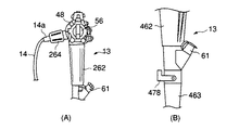
また、図66(A)〜(D)は本発明の第33実施形態を示すものである。本実施形態は第29実施形態の内視鏡1の操作部13におけるガイドワイヤ固定用起上台267の操作レバー72に代えて異なる構成のガイドワイヤ固定用起上台267の操作機構を設けたものである。
【0321】
即ち、本実施形態の内視鏡1の操作部13には図66(A)に示すように操作部13を保持するためのグリップ262と、挿入口部61の下のオレドメ部263との間にガイドワイヤ固定用起上台267の操作用の略円筒状に形成された牽引ノブ264が配設されている。この牽引ノブ264は図66(C)に示すように操作部13の基盤となるベース47に回転自在に装着されている。この牽引ノブ264の回転軸O1は挿入部12の中心軸O2と同軸である。
【0322】
なお、処置具起上台27の起上操作ノブ48の回転軸は湾曲操作部56と同軸であるため、挿入部12の中心軸O2と直交して存在している。そして、この起上操作ノブ48の回転軸と直交する位置に牽引ノブ264の回転軸O1が存在する。
【0323】
さらに、図66(C)に示すように牽引ノブ264の内部には円筒状のカム部材265が埋設されている。このカム部材265には図66(D)に示すようにカム溝265aが斜めに設けられている。このカム部材265のカム溝265aには移動ピン266がこのカム溝265aに沿って移動可能に係合されている。
【0324】
また、移動ピン266には牽引ワイヤチャンネル274内に挿通された牽引ワイヤ269の基端部が固定されている。そして、牽引ノブ264の回転操作に伴い移動ピン266がカム部材265のカム溝265aに沿って移動することにより、この移動ピン266を介して牽引ワイヤ269が挿入部12の中心軸O2の方向に沿って進退駆動されるように構成されている。
【0325】
次に、本実施形態の作用について説明する。本実施形態の内視鏡1の使用時に、ガイドワイヤ固定用起上台267を牽引する場合には、牽引ノブ264を回転させる。この際、牽引ノブ264と一体的にカム部材265も回転するので、このカム部材265の回転に伴い移動ピン266がカム溝265a内を移動し、牽引ワイヤ269を牽引することで、ガイドワイヤ固定用起上台267が牽引操作される。
【0326】
本実施形態にあっては次の効果を奏する。即ち、本実施形態では内視鏡1の手元操作部13側の牽引ノブ264による操作で容易に第29実施形態と同様に内視鏡1の挿入部12の先端部17でガイドワイヤ68の固定が可能であり、第29実施形態と同様の効果が得られる。
【0327】
また、本実施形態では特に、処置具起上台27の起上操作ノブ48の回転軸と直交する位置にガイドワイヤ固定用起上台267の牽引ノブ264の回転軸O1が存在しているので、処置具起上台27の起上操作ノブ48の操作方向と、ガイドワイヤ固定用起上台267の牽引ノブ264の操作方向とは異なる。そのため、処置具起上台27の起上操作ノブ48と、ガイドワイヤ固定用起上台267の牽引ノブ264とを誤って作動させる誤操作が起きることを防止することができる。
【0328】
さらに、挿入口部61の近傍位置にガイドワイヤ固定用起上台267の牽引ノブ264を設けることで、ガイドワイヤ68の挿入口とガイドワイヤ固定用起上台267の牽引ノブ264とを接近させることができるので、作業性がさらに向上する。
【0329】
なお、牽引ノブ264の位置は、挿入口部61の下のオレドメ部263とグリップ262との間に限定されるものではない。例えば、図67(A)に示す第33実施形態における内視鏡1の、操作部13の第1変形例のように操作部13におけるユニバーサルコード14との連結部に配置されたコネクタ側オレドメ部14a、或いはコネクタ18や、グリップ262に設けても良い。
【0330】
また、ガイドワイヤ固定用起上台267の操作手段はノブ型ではなく、図67(B)に示す内視鏡1における操作部13の第2変形例のように操作レバー278を使用するレバー型であっても良い。その際の操作レバー278の操作力伝達機構は第29実施形態で示したリンク機構を基本とするが、牽引操作が可能であればこの限りではない。
【0331】
また、図68(A),(B)は本発明の第34実施形態を示すものである。本実施形態は第29実施形態のガイドワイヤ固定用起上台267に代えて異なる構成のガイドワイヤ固定機構361を設けたものである。
【0332】
即ち、本実施形態のガイドワイヤ固定機構361には略ブロック状のガイドワイヤ固定具362が設けられている。内視鏡1における挿入部12の先端部17の先端硬質部21にはチャンネル開口部26に連通する導入案内路24の上面にガイドワイヤ固定具362の収納室363が設けられている。この収納室363の中にはガイドワイヤ固定具362を収納室363の外に略垂直に引き出す方向に付勢するコイル状のバネ部材364が配設されている。
【0333】
さらに、ガイドワイヤ固定具362には牽引ワイヤ365の先端部が固定されている。この牽引ワイヤ365は牽引ワイヤチャンネル366を通じて操作部13に導かれ、図示しないリンク機構に連結されている。これにより、第29実施形態と同様に手元側の操作レバー72の操作で牽引ワイヤ365を介してガイドワイヤ固定具362の牽引操作が可能となっている。
【0334】
なお、第29実施形態と同様にガイドワイヤ固定具362におけるガイドワイヤ68との接触面に図59(A)に示す弾性部材276、或いは図59(B)に示す突起277を設けても良い。
【0335】
次に、本実施形態の作用について説明する。本実施形態の内視鏡1の使用時には、予め初期の状態で、操作レバー72により牽引ワイヤ365を引き、図68(A)に示すように収納室363内にガイドワイヤ固定具362を引き込んでおく。
【0336】
そして、第29実施形態と同様に、チャンネル23内を通してガイドカテーテル67及びガイドワイヤ68を体内に挿入後、ガイドカテーテル67をチャンネル23内に引き込んだ状態で、操作レバー72の操作により牽引ワイヤ365を緩める操作を行なう。この際、バネ部材364の弾性力によりガイドワイヤ固定具362が収納室363の外に略垂直に引き出され、図68(B)に示すように導入案内路24内に突出される。これにより、ガイドワイヤ68が先端硬質部21とガイドワイヤ固定具362との間に挟み込まれて機械的に固定される。
【0337】
さらに、ガイドワイヤ68が固定されたことを確認後、内視鏡1の操作部13側から処置具挿通用チャンネル23の外部にガイドカテーテル67を完全に引き抜く。
【0338】
その後、次に使用する処置具を、ガイドワイヤ68の基端部側から挿入する。この際、ガイドワイヤ68をガイドにした状態で、処置具を処置具挿通用チャンネル23に挿通する。そして、処置具がガイドワイヤ固定具362に突き当たった時点で、操作レバー72を操作してガイドワイヤ固定具362による固定を解除し、さらに膵/胆管内(図示せず)にまで挿入する。
【0339】
本実施形態にあっては次の効果を奏する。即ち、本実施形態では内視鏡1の手元操作部13の操作レバー72による操作で容易にガイドワイヤ68の固定が可能であり、通常症例時はガイドワイヤ固定具362を収納室363に収めておくことで導入案内路24は開口されているため、問題なく処置具の挿通が行なえる。
【0340】
また、本実施形態では従来の処置具が使用できるため、術者の使い慣れた処置具の使用により操作性が良いままを維持できる。さらに、内視鏡1の挿入部12の先端部17でガイドワイヤ68の固定ができるので、ガイドワイヤ68の長さを従来に比べて短くできるため、作業性が向上する。
【0341】
また、図69(A)〜(C)は本発明の第35実施形態を示すものである。本実施形態は第34実施形態のガイドワイヤ固定具362と牽引ワイヤ365との間に、トルク伝達部材371を設ける構成に変更したものである。このトルク伝達部材371は先端部17に設けられた先端硬質部21の収納室363内の上部に配設されている。
【0342】
さらに、図69(C)に示すようにトルク伝達部材371の中央付近には回転軸372が設けられている。そして、このトルク伝達部材371の一端部に牽引ワイヤ365の先端部が固定されている。
【0343】
また、トルク伝達部材371における牽引ワイヤ365の固定端373と反対側にはバネ部材364が挿通されるスリット状の開口部374が設けられている。
【0344】
さらに、先端硬質部21には回転軸372の下部分を削ってトルク伝達部材371の回転時にトルク伝達部材371との干渉を防止する凹陥部375が形成されている。
【0345】
次に、本実施形態の作用について説明する。本実施形態の内視鏡1の使用時には、予め初期の状態で、図69(A)に示すようにトルク伝達部材371が導入案内路24に対して略平行に配置されている。これにより、バネ部材364は自然長にあるため、ガイドワイヤ固定具362は収納室363内に収納されている。
【0346】
そして、第29実施形態と同様に、チャンネル23内を通してガイドカテーテル67及びガイドワイヤ68を体内に挿入後、ガイドカテーテル67をチャンネル23内に引き込んだ状態で、操作レバー72の操作により牽引ワイヤ365を牽引する操作を行なう。この際、牽引ワイヤ365によってトルク伝達部材371の一端が引っ張られて上方に上がると同時に他端は下方に下がる。
【0347】
これにより、ガイドワイヤ固定具362が収納室363の外に略垂直に引き出され、図69(B)に示すように導入案内路24内に突出される。これにより、ガイドワイヤ68が先端硬質部21とガイドワイヤ固定具362との間に挟み込まれて機械的に固定される。
【0348】
また、ガイドワイヤ68の固定解除時には、操作レバー72を元に戻すことで、トルク伝達部材371が元の位置に戻り、バネ部材364の復元力によりガイドワイヤ固定具362も収納室363に戻り、ガイドワイヤ68の固定が解除される。
【0349】
本実施形態にあっては次の効果を奏する。即ち、本実施形態では第34実施形態と同様に内視鏡1の手元操作部13の操作レバー72による操作で容易にガイドワイヤ68の固定が可能であり、通常症例時はガイドワイヤ固定具362を収納室363に収めておくことで導入案内路24は開口されているため、問題なく処置具の挿通が行なえる。
【0350】
さらに、本実施形態では、第34実施形態と同様の効果に加えて、ガイドワイヤ68の固定時に操作レバー72で牽引した状態を保つことができるので、トルク伝達部材371を通じてガイドワイヤ固定具362に強い力をかけることが可能である。
【0351】
また、図70(A)〜(C)は本発明の第36実施形態を示すものである。本実施形態は第29実施形態のガイドワイヤ固定用起上台267に代えて異なる構成のガイドワイヤ固定機構311を設けたものである。
【0352】
即ち、本実施形態のガイドワイヤ固定機構311には図70(A)に示すように弾性変形可能な板状のガイドワイヤ固定部材312が設けられている。内視鏡1における挿入部12の先端部17の先端硬質部21にはチャンネル開口部26に連通する導入案内路24の上面にガイドワイヤ固定部材312の収納室313が設けられている。この収納室313の中にはガイドワイヤ固定部材312を収納室313の中に引き込む方向に付勢するコイル状のバネ部材314が配設されている。
【0353】
さらに、ガイドワイヤ固定部材312には牽引ワイヤ315の先端部が固定されている。
【0354】
また、先端硬質部21には導入案内路24の下面における収納室313の下方部分に回転自在なガイドローラ316が配設されている。そして、収納室313の下方に延出された牽引ワイヤ315はガイドローラ316によって操作部13側に向けて屈曲された状態で、操作部13側に導かれ、図示しないリンク機構に連結されている。これにより、第29実施形態と同様に手元側の操作レバー72の操作で牽引ワイヤ315を介してガイドワイヤ固定部材312の牽引操作が可能となっている。
【0355】
なお、ガイドワイヤ固定部材312の牽引機構は前述したリンク機構を基本とするが、ガイドワイヤ固定部材312の牽引が可能であれば、この限りではない。
【0356】
次に、本実施形態の作用について説明する。本実施形態の内視鏡1の使用時には、第29実施形態と同様に、チャンネル23内を通してガイドカテーテル67及びガイドワイヤ68を体内に挿入後、ガイドカテーテル67を導入案内路24或いはチャンネル23内に引き込んだ状態で、操作レバー72の操作により牽引ワイヤ315を介してガイドワイヤ固定部材312の牽引操作が行なわれる。この際、ガイドワイヤ固定部材312は収納室313の中から引き出され、図70(C)に示すように、ガイドワイヤ固定部材312の下端部が先端硬質部21の導入案内路24の下面に当接される。これにより、先端硬質部21の導入案内路24の下面とガイドワイヤ固定部材312との間でガイドワイヤ68を挟み込むことでガイドワイヤ68が固定される。
【0357】
また、操作レバー72を戻した場合には、バネ部材314の復元力により、ガイドワイヤ固定部材312は収納室313の中に引き込まれた状態に戻される。これにより、ガイドワイヤ固定部材312の下端部がガイドワイヤ68から離れるので、ガイドワイヤ68の固定が解除される。
【0358】
本実施形態にあっては操作レバー72の操作により牽引ワイヤ315を介してガイドワイヤ固定部材312を牽引操作し、このガイドワイヤ固定部材312によって内視鏡1の挿入部12の先端部17でガイドワイヤ68を係脱可能に固定することができるので、第29実施形態と同様の効果が得られる上、第29実施形態の効果に加えて、本実施形態では特に、ガイドワイヤ68の固定解除時にはガイドワイヤ固定部材312が先端部17の収納室313内に収納されることで、ガイドワイヤ固定部材312が症例の邪魔にならない効果がある。
【0359】
また、図71及び図72は本発明の第37実施形態を示すものである。本実施形態は第24実施形態における内視鏡1の先端部17の構成を次の通り変更したものである。
【0360】
即ち、本実施形態では第24実施形態の牽引ワイヤ75の先端部に図71に示すように略U字状に湾曲させたワイヤ状のガイドワイヤ固定具81を設け、このガイドワイヤ固定具81の先端部を内視鏡1の先端部17の切欠部17aにおけるチャンネル開口部26の側面に固定したものである。このガイドワイヤ固定具81の先端部17への固定方法は、接着、半田、ネジ固定等である。
【0361】
次に、本実施形態の作用について説明する。本実施形態の内視鏡1の使用時には、予め図71に示すようにガイドワイヤ固定具81を、チャンネル開口部26を囲むように広げた状態にセットする。
【0362】
そして、第24実施形態と同様に、ガイドワイヤ68とガイドカテーテル67とを処置具挿通用チャンネル23に挿通後、ガイドワイヤ68の固定時には、ガイドカテーテル67をチャンネル23内まで引き抜き、ガイドワイヤ68のみをチャンネル開口部26の外部に突出させた状態で、手元側の操作レバー72の操作でガイドワイヤ固定具81を手元側に引き込む操作を行なう。これにより、図72に示すようにチャンネル開口部26の手元側壁面26aとガイドワイヤ固定具81との間でガイドワイヤ68を挟み込み、ガイドワイヤ68が固定される。
【0363】
本実施形態でも第24実施形態と同様に内視鏡1の手元操作部13側の操作レバー72による操作で容易に牽引ワイヤ75の先端部のガイドワイヤ固定具81によるガイドワイヤ68の固定が可能であり、第24実施形態と同様の効果が得られる。
【0364】
また、本実施形態では特に、第24実施形態の効果に加えて、操作手段としての牽引ワイヤ75の先端部を内視鏡1の先端部17の切欠部17aにおけるチャンネル開口部26の側面に固定するのみで、ガイドワイヤ固定具81が形成されるため、安価である。
【0365】
また、図73は第37実施形態の内視鏡1における牽引ワイヤ75のガイドワイヤ固定具81の先端部における固定状態の変形例を示すものである。
【0366】
本変形例では図73に示すようにガイドワイヤ固定具81の先端部に板材82を半田等で固定し、この板材82をピン83等で内視鏡1の先端部17に回動自在に連結する構成にしたものである。
【0367】
さらに、内視鏡1の先端部17の切欠部17aにはチャンネル開口部26よりも先端側に第24実施形態と同様にガイドワイヤ固定具81を広げた状態で仮固定できる突起70を設けても良い。
【0368】
そこで、本変形例ではガイドワイヤ固定具81に板材82を固定し、この板材82をピン83等で内視鏡1の先端部17に回動自在に連結したので、ガイドワイヤ固定具81の操作時にガイドワイヤ固定具81に作用する負荷が軽減される効果がある。
【0369】
また、図74(A)〜(C)は本発明の第38実施形態を示すものである。本実施形態は第24実施形態における内視鏡1の先端部17の構成を次の通り変更したものである。
【0370】
即ち、本実施形態では図74(A),(B)に示すように第24実施形態の牽引ワイヤ75の先端部にこの牽引ワイヤ75とは別体のガイドワイヤ固定具91を連結したものである。
【0371】
このガイドワイヤ固定具91のガイドワイヤ固定面の形状は、円弧形状、或いは平面状、またはガイドワイヤ68のワイヤ径に合わせた凹凸形状でも良い。そして、このガイドワイヤ固定具91の一端部に牽引ワイヤ75の先端部が固定されている。さらに、ガイドワイヤ固定具91の他端部には誘導用突起92が突設されている。
【0372】
また、図74(C)に示すように先端硬質部21の収容室25の側面部にはガイドワイヤ固定具91の移動をガイドする誘導溝93が内視鏡1の挿入部12の軸方向に沿って延設されている。この誘導溝93にはガイドワイヤ固定具91の誘導用突起92が係合されている。そして、牽引ワイヤ75の操作に伴い誘導用突起92が誘導溝93に沿って摺動する状態で、ガイドワイヤ固定具91が内視鏡1の挿入部12の軸方向に沿って移動されるように構成されている。
【0373】
また、牽引ワイヤ75の操作によるガイドワイヤ固定具91の移動範囲は、チャンネル開口部26の手元側壁面26aから処置具起上台27よりも先端側までに設定されている。
【0374】
次に、本実施形態の作用について説明する。本実施形態ではガイドカテーテル67の挿入前に、予めガイドワイヤ固定具91を内視鏡1の先端部17の先端側に押し出した状態にセットする。
【0375】
そして、第24実施形態と同様に、ガイドワイヤ68とガイドカテーテル67とを処置具挿通用チャンネル23に挿通後、ガイドワイヤ68の固定時には、ガイドカテーテル67をチャンネル23内まで引き抜き、ガイドワイヤ68のみをチャンネル開口部26の外部に突出させた状態で、手元側の操作レバー72の操作で牽引ワイヤ75を介してガイドワイヤ固定具91を手元側に引き込む操作を行なう。これにより、チャンネル開口部26の手元側壁面26aとガイドワイヤ固定具91との間でガイドワイヤ68を挟み込み、ガイドワイヤ68が固定される。
【0376】
本実施形態でも第24実施形態と同様に内視鏡1の手元操作部13側の操作レバー72による操作で容易に牽引ワイヤ75の先端部のガイドワイヤ固定具91によるガイドワイヤ68の固定が可能であり、第24実施形態と同様の効果が得られる。
【0377】
また、本実施形態では特に、先端硬質部21の収容室25の側面部に誘導溝93を設け、この誘導溝93にガイドワイヤ固定具91の誘導用突起92を係合させたので、ガイドワイヤ固定具91がチャンネル開口部26より外に出ず、安定したガイドワイヤ68の固定動作が可能となる。
【0378】
また、図75に示す第38実施形態における内視鏡1の変形例のようにガイドワイヤ固定具91の牽引ワイヤ75を対物レンズ57から広がる観察視野内に入り込まない範囲で先端硬質部21上面部に配設する構成にしても良い。
【0379】
また、図76乃至図80は本発明の第39実施形態を示すものである。本実施形態は第24実施形態の内視鏡1における挿入部12の先端部17の内部構成を次の通り変更したものである。
【0380】
即ち、本実施形態では図78に示すように先端硬質部21におけるチャンネル開口部26の上面部に、第2開口部561が形成されている。この第2開口部561の基端部は先端硬質部21のチャンネル孔に固定された接続管562を介してガイドワイヤ固定具挿通用チャンネル563の先端部に連結されている。このガイドワイヤ固定具挿通用チャンネル563の基端部は図76に示すように内視鏡1の操作部13に設けられた第2挿入口金部564に連結されている。
【0381】
なお、ガイドワイヤ固定具挿通用チャンネル563の手元側の開口位置は、図76に示す操作部13の第2挿入口金部564の位置に限定されるものではなく、固定操作を行ない易い位置であればどこでも良い。
【0382】
また、このガイドワイヤ固定具挿通用チャンネル563にはガイドワイヤ68の固定操作を行なうガイドワイヤ固定具565が挿脱可能に挿入されるように構成されている。このガイドワイヤ固定具565は、図80に示すようにスネアユニット566と、コイルバネ等の弾性部材567と、外装ユニット568との3部品が組み付けられて構成されている。
【0383】
スネアユニット566には、細長い牽引ワイヤ569の基端部に手元側の端末部材570が連結されている。この端末部材570は大径な円柱状の把持部571と、小径な第2円柱部572とが連結された2段の円柱部材によって形成されている。
【0384】
さらに、端末部材570の第2円柱部572には係合突起573、段差部には弾性部材ストッパ574がそれぞれ設けられている。
【0385】
また、端末部材570の把持部571の一側部には回転位置が確認できる指標575が設けられている。
【0386】
さらに、牽引ワイヤ569の先端部にはループ形状のスネア576が設けられている。
【0387】
なお、この牽引ワイヤ569の先端部はスネア576に限らず、ガイドワイヤ68を引っ掛けてつかむことが可能なフック形状のもので良い。
【0388】
また、外装ユニット568には、スネアユニット566の牽引ワイヤ569を誘導する軟性チューブ578が設けられている。この軟性チューブ578の基端部にはスネアユニット566の端末部材570と係脱可能に係合される固定部材579が設けられている。
【0389】
この固定部材579には内視鏡1の操作部13の第2挿入口金部564に装着可能な口金押え部材580と、この口金押え部材580の上面に突設された円筒部材581とが設けられている。そして、円筒部材581にはL字状の係合溝582が形成されている。この係合溝582にはスネアユニット566の係合突起573が係合可能になっている。
【0390】
また、円筒部材581の下部には第2ストッパ583が設けられている。
【0391】
そして、ガイドワイヤ固定具565は、外装ユニット568の円筒部材581の内部にコイルバネ等の弾性部材567を介してスネアユニット566が挿入されることで一体に組み付けられている。この際、弾性部材567はスネアユニット566の弾性部材ストッパ574と、外装ユニット568の第2ストッパ583との間に配置されると共に、円筒部材581の係合溝582内にスネアユニット566の係合突起573が挿入された状態にセットされている。
【0392】
なお、本実施形態のガイドワイヤ固定具565は通常処置具として使われているスネアや把持処置具で代用しても良い。
【0393】
次に、本実施形態の作用について説明する。本実施形態のガイドワイヤ固定具565は、通常は、弾性部材567の弾性力により図79(B)に示すようにスネアユニット566の係合突起573が係合溝582の開口端側の端部(始端部582a)に突き当てられる方向の付勢力が働き、この状態でスネアユニット566の位置が規制されている。この状態ではスネアユニット566の把持部571が外装ユニット568の円筒部材581の外側に突出された状態で保持されると共に、スネア576は閉じられた状態で保持されている。
【0394】
また、スネア576を開く際には、弾性部材567の弾性力に抗してスネアユニット566の把持部571を外装ユニット568の円筒部材581の内部側に押込操作する。この操作に伴いスネアユニット566の係合突起573が係合溝582に沿って軸方向に摺動し、係合溝582の口金押え部材580側の端部と突き当たる位置まで移動する。この状態で、図79(A)に示すようにスネア576が軟性チューブ578から突出し、スネア576が開かれる。
【0395】
続いて、この位置で、把持部571を反時計回り方向に回動させ、図79(A)に示すようにスネアユニット566の係合突起573を係合溝582の終端の係合端部582bに突き当てることにより、係合突起573を係合させ、スネア576を開いた状態で保持させることができる。
【0396】
また、スネア576を閉じる際には、把持部571を時計回り方向に回転させることで、係合突起573が係合溝582の終端の係合端部582bから外れ、弾性部材567の弾性力によりスネアユニット566が図79(B)に示す元の位置に戻る。
【0397】
次に、本実施形態のガイドワイヤ固定具565を使用してガイドワイヤ68を挿入部12の先端部17に固定する方法について説明する。まず、内視鏡1を体内に挿入し、挿入部12の先端部17によって乳頭を捕らえたところで、第2挿入口金部564よりガイドワイヤ固定具565を、スネア576を閉じた状態で挿通する。そして、ガイドワイヤ固定具565の先端が第2開口部561から突出した時点で、把持部571を押込操作することで図77(B)に示すようにスネア576を突出させる。その後は、第24実施形態のガイドワイヤ固定具69の操作と同様である。
【0398】
本実施形態にあっては次の効果を奏する。即ち、本実施形態では第24実施形態と同様の効果が得られる上、これに加えて、ガイドワイヤ固定具565を内視鏡1から取り外すことが容易なため、内視鏡1の先端部17、ガイドワイヤ固定具用挿通チャンネル563内及びガイドワイヤ固定具565を容易に洗滌・消毒等を行なうことができる。
【0399】
さらに、内視鏡1における挿入部12の先端部17の内部構造が簡略化される効果がある。
【0400】
また、ガイドワイヤ固定具565として、既にあるスネア,把持用の処置具等でも代用することができ、かつガイドワイヤ固定具565を使用しない際は、ガイドワイヤ固定具用挿通チャンネル563を処置用チャンネル或いは前方送水管路として使用することが可能である。
【0401】
本発明の第40実施形態を図81乃至図85を参照して説明する。図81は本実施形態の内視鏡装置における内視鏡601の挿入部602の先端部603における概略構成を示すものである。本実施形態の内視鏡装置では挿入部602の軸方向に対して略直交する方向を観察する側視型の内視鏡601が使用されている。
【0402】
この側視型の内視鏡601には挿入部602の先端部603の外周面を切欠させて形成された略平面状の側視用基準面612が形成されている。この側視用基準面612には照明光学系の照明窓613と観察光学系の観察窓614とが前後方向に並設されている。さらに、側視用基準面612における照明窓613と観察窓614との並設部の横にはチャンネル開口部615が配設されている。このチャンネル開口部615は内視鏡601の挿入部602の内部に配設された処置具挿通用チャンネル616の先端開口部を構成するものである。
【0403】
また、チャンネル開口部615には処置具起上台617が配設されている。図85に示すようにこの処置具起上台617の一端部は回動軸618を介して先端部603の本体611aに回動自在に連結されている。
【0404】
さらに、処置具起上台617の他端部には図示しない可撓性の操作ワイヤの一端部が固定されている。この操作ワイヤの他端部は操作部606側に延出されている。そして、操作部606に配設された図示しない処置具起上台操作レバーの操作に連動して操作ワイヤが牽引操作され、この操作ワイヤの動作によって処置具起上台617が回動軸618を中心に回動駆動されるように構成されている。この際、処置具起上台617は図85中に仮想線で示す待機位置(倒置位置)から図85中に実線で示す最大回動位置(起上位置)まで回動され、この処置具起上台617の回動動作により、チャンネル開口部615から外部に延出されている図83(A),(B)に示す例えば造影チューブ等の処置具619における起上及び倒置の各動作を観察窓614の視野内で行なうように構成されている。
【0405】
また、本実施形態における内視鏡601の処置具挿通用チャンネル616の内部に挿入される処置具619は、後述するガイドワイヤ630を挿通可能なガイドワイヤルーメンを備えた既存の造影チューブ等の処置具がそのまま使用できる。
【0406】
なお、処置具619としてはガイドワイヤルーメンにコーティングを施すことにより、ガイドワイヤ630との摩擦力を低減する構成にしたものや、ガイドワイヤルーメンの内面を平滑にしたもの等は本実施形態においてさらに好適である。
【0407】
また、処置具起上台617における処置具619との対向面には略V字状の受け溝部20が形成されている。そして、処置具619の起上時にはこの受け溝部20内に処置具619が挿入されて位置決めされる状態で処置具619が処置具起上台617に接触され、この状態で処置具619を上下に誘導するように構成されている。
【0408】
さらに、本実施形態の側視型の内視鏡601には挿入部602の先端部603の近傍に、ガイドワイヤ固定手段としてガイドワイヤ固定部材621が装着されている。このガイドワイヤ固定部材621には略円筒形で、かつ例えば塩化ビニル等の材料で形成された軟性の取付部622と、この取付部622の先端側に連結された略円筒形のキャップ部623とが設けられている。
【0409】
また、取付部622の材質は、必ずしも、塩化ビニルである必要はなく、軟性樹脂であれば、ポリエチレンやポリスチレンもしくはポリウレタン製等でも良い。そして、キャップ部623が挿入部602の先端部603の周囲に配置された状態で、取付部622が内視鏡601における挿入部602の先端部603の近傍に取り付けられている。これにより、ガイドワイヤ固定部材621は、内視鏡601における挿入部602の先端部603の付近でチャンネル開口部615上もしくはチャンネル開口部615よりも基端側の挿入部602上に着脱自在に取り付けられている。
【0410】
さらに、キャップ部623は透明性を有したポリカーボネイト樹脂で作成されている。このキャップ部623の色調に関しては透明度が高いものが好ましいが、必ずしも透明でなくても良い。
【0411】
なお、キャップ部623の材料の組成に関してはポリカーボネイト樹脂が最も好ましいが、アクリル樹脂、ポリエチレン樹脂、ポリプロピレン樹脂、ポリスチレン樹脂等も使用できる。
【0412】
また、キャップ部623の先端側には先端部603の側視用基準面612における照明窓613、観察窓614及びチャンネル開口部615と対応する部位に処置具挿通用開口窓624が形成されている。このキャップ部623の処置具挿通用開口窓624は、内視鏡601の挿入部602の基準面612側が開口し、かつその開口窓624の幅がキャップ部623の円周の約1/4、長さが約10mm程度の略長方形状に形成されている。これにより、内視鏡601の観察窓614の視野や、チャンネル開口部615から外部側に延出される造影チューブ等の処置具619の進退動作を妨げず、かつ後述するガイドワイヤ識別部材627a,627bが作動し易く、さらに後述するガイドワイヤ固定具挿通孔628が効果的な位置に配置できるように設定されている。
【0413】
さらに、キャップ部623の処置具挿通用開口窓624にはガイドワイヤ識別機構部625と、ガイドワイヤ固定機構部626とが設けられている。ガイドワイヤ識別機構部625には開口窓624の両脇から開口窓624の内部側に張り出したステンレス製の2本の針金からなるガイドワイヤ識別部材627a,627bが設けられている。
【0414】
また、2本のガイドワイヤ識別部材627a,627bの一方の、第1のガイドワイヤ識別部材627aは、図82中で、キャップ部623の上端縁部に沿って処置具挿通用開口窓624の左側から内部側に延出され、下向きに湾曲されている。さらに、他方の第2のガイドワイヤ識別部材627bは図82中で、キャップ部623の上端縁部に沿って処置具挿通用開口窓624の右側から内部側に延出され、下向きに湾曲されている。2本のガイドワイヤ識別部材627a,627bの各下側延出部分627a1,627b1はガイドワイヤ固定部材621の中心線方向に沿って略平行に離間対向配置されている。そして、これらのガイドワイヤ識別部材627a,627bの各下側延出部分627a1,627b1間には適宜の幅寸法Lの間隔Sが形成されている。この間隔Sは例えばガイドワイヤ630の外径寸法よりも大きい状態に設定されている。
【0415】
また、キャップ部623には処置具挿通用開口窓624の両側部にガイドワイヤ固定具挿通孔628がそれぞれ形成されている。これらのガイドワイヤ固定具挿通孔628はガイドワイヤ固定部材621の中心線方向に沿って処置具挿通用開口窓624の略中央位置に配置されている。
【0416】
さらに、ガイドワイヤ固定機構部626には伸縮性のない糸状部材、例えば外径寸法が0.2mm程度の外科用縫合糸によって形成されたガイドワイヤ固定具629が設けられている。このガイドワイヤ固定具629の一端部は図82中で、左側の第1のガイドワイヤ識別部材627aに固定されている。そして、このガイドワイヤ固定具629は処置具挿通用開口窓624の図82中で、左側(第1のガイドワイヤ識別部材627a側)のガイドワイヤ固定具挿通孔628を通った後、開口窓624上を横断し、さらに図82中で、右側(第2のガイドワイヤ識別部材627b側)のガイドワイヤ固定具挿通孔628を通ってこのガイドワイヤ固定具629の他端部側が第2のガイドワイヤ識別部材627bに固定されている。これにより、ガイドワイヤ固定具629は開口窓624上の両側部間に架設された状態で取り付けられている。
【0417】
なお、本実施形態では、ガイドワイヤ固定具629は外径寸法0.2mm程度の外科用縫合糸が使用されているが、伸縮性がなく、引っ張り強度の強いしなやかな糸状部材であれば、ナイロン等、他の樹脂製の糸でも良い。
【0418】
また、ガイドワイヤ識別部材627a,627bはステンレス製の針金に限定されるものではなく、弾性部材であれば、銅線や、NiTi製超弾性合金等の他の金属や、樹脂等でも良い。
【0419】
これにより、ガイドワイヤ固定機構部626は、内視鏡601における挿入部602の先端部603側のチャンネル開口部615から処置具619が出ている状態では、処置具619の操作を妨げず、また、チャンネル開口部615からガイドワイヤ630のみが出ている状態では、処置具起上台617からの押圧力によってガイドワイヤ630をガイドワイヤ固定部材621の開口窓624上における両側部間のガイドワイヤ固定具629に圧接させて係止させるように構成されている。
【0420】
処置具619は、処置具挿通用チャンネル616に挿通後ガイドワイヤ固定機構部626より操作部手元側に引き込んだ状態において、処置具挿通用チャンネル616の操作部手元側開口であるチャンネル開口部615から作業上必要な突出長が確保されている。
【0421】
また、ガイドワイヤ630は、上記処置具619のガイドワイヤルーメン内に挿入される際に、処置具619先端から目的部位に合わせて必要分の突出長を有し、かつ処置具619の後端より作業上必要な突出長が確保されている。
【0422】
処置具619の先端からの突出長は40cm以下程度であり、処置具619の基端側にある口金604aからは10cm程度の突出量が最も作業性が良く理想的である。
【0423】
次に、本実施形態の作用について説明する。本実施形態の内視鏡装置の使用時に、造影チューブ等の処置具619を内視鏡601の操作部606側の処置具挿通用チャンネル616に挿入して使用する場合には、処置具619の先端部を内視鏡601における挿入部602の先端部603のチャンネル開口部615から突出させる。この際、処置具起上台617が図85中に仮想線で示す待機位置(倒置位置)で保持されている場合には図83(A)に示すように処置具619の先端部はガイドワイヤ識別機構部625のガイドワイヤ識別部材627a,627bから離れ、自由に移動可能な位置で保持される。
【0424】
この状態で、内視鏡601の操作部606の図示しない処置具起上台操作レバーを操作することにより、挿入部602の先端部603の処置具起上台617が起上操作される。そして、この操作に伴い処置具起上台617によって処置具619の先端部がキャップ部623の処置具挿通用開口窓624内に挿入される方向に押し出される。
【0425】
この際、処置具619はキャップ部623の処置具挿通用開口窓624の両脇から張り出した2本のガイドワイヤ識別部材627a,627bの各下側延出部分627a1,627b1間に挿入される。そのため、2本のガイドワイヤ識別部材627a,627bの各下側延出部分627a1,627b1間が処置具619によって押し広げられ、各下側延出部分627a1,627b1間の間隔が広げられる。こにより、各ガイドワイヤ識別部材627a,627bは、処置具挿通用開口窓624の両脇のガイドワイヤ固定具挿通孔628に近づくことで、各ガイドワイヤ識別部材627a,627bにそれぞれ固定されたガイドワイヤ固定具629の張力が弛緩される。このようにガイドワイヤ固定具629の張力が緩むことにより、処置具起上台617によって処置具619の先端部がキャップ部623の処置具挿通用開口窓624内に挿入される方向に押し出された際に、処置具619はガイドワイヤ固定具629によって係止されず、処置具619の起上動作が通常の通り、行なわれる。
【0426】
また、内視鏡601のチャンネル開口部615からガイドワイヤ630の先端部が導出された際に、処置具起上台617が図85中に仮想線で示す待機位置(倒置位置)で保持されている場合には、ガイドワイヤ630は図84(A)に示すようにガイドワイヤ固定具629から離れ、自由に移動可能な係合解除位置で保持されるように構成されている。
【0427】
この状態で、処置具起上台617が図85中に実線で示す最大回動位置(起上位置)まで回動された場合には、図84(B)に示すように処置具起上台617によってガイドワイヤ630がガイドワイヤ識別機構部625のガイドワイヤ識別部材627a,627b間に挿入される方向に押し出される。この際、ガイドワイヤ識別部材627a,627bの各下側延出部分627a1,627b1間の間隔Sは例えばガイドワイヤ630の外径寸法よりも大きいので、ガイドワイヤ識別部材627a,627bの各下側延出部分627a1,627b1間に挿入されるガイドワイヤ630によって二つの下側延出部分627a1,627b1間の間隔Sが広げられことはなく、ガイドワイヤ固定部材621の開口窓624上の両側部間に架設されたガイドワイヤ固定具629の張力が緩められることはない。
【0428】
この場合には図示しない処置具起上台操作レバーの操作により、挿入部602の先端部603の処置具起上台617が起上操作される動作に伴い、処置具起上台617からの押圧力によってガイドワイヤ630がガイドワイヤ固定部材621における開口窓624上の両側部間のガイドワイヤ固定具629に圧接される。この際、ガイドワイヤ630は処置具起上台617とガイドワイヤ固定具629との間でせん断的に互い違いに反対方向に力を受けるため、係脱可能に係止される。
【0429】
また、本実施形態の内視鏡装置の使用時には、造影チューブ等の処置具619を経乳頭的に膵/胆管(図示せず)へ挿入した後、上記処置具619の交換作業は次の通り行なわれる。まず、処置具619の基端側にある口金4bよりガイドワイヤ630を挿入し、膵/胆管内部(図示せず)まで導入する。
【0430】
ガイドワイヤ630が膵/胆管内(図示せず)まで入ったことを確認し、ガイドワイヤ630が動かないようにガイドワイヤ630の基端側を手で把持しつつ、処置具619を引き出す。この際、内視鏡像にて、処置具619の先端部が乳頭(図示せず)から引き抜かれたことを確認後、さらに処置具619を引き抜く。
【0431】
続いて、処置具619の先端が挿入部602の先端部603側のチャンネル開口部615内に収まったところで、処置具起上台617を起上することでガイドワイヤ630が処置具起上台617に沿って同様に起上され、ガイドワイヤ固定機構部626により内視鏡601の挿入部602の先端部603付近でガイドワイヤ630を機械的に固定する。
【0432】
さらに、ガイドワイヤ630が固定されたことを確認後、内視鏡601の操作部606側から処置具619を完全に引き抜く。その後、次に使用する処置具619を、ガイドワイヤ630の基端側から挿入し、処置具起上台617に突き当てる。その後処置具起上台617を倒置し、ガイドワイヤ630の基端部を手で把持して処置具619のみを、ガイドワイヤ630をガイドに膵/胆管内(図示せず)にまで挿入する。
【0433】
従って、上記処置具619の交換の際に、操作者はガイドワイヤ630を常に把持する必要はない。そして、以後、必要な回数だけ同様な方法で処置具619の交換を行なうことができる。
【0434】
本実施形態にあっては次の効果を奏する。即ち、本実施形態ではガイドワイヤ630以外の処置具619は、処置具起上台617の操作によって従来通り、起上や、進退等の操作が可能であり、ガイドワイヤ630のみが処置具起上台617の操作によって処置具起上台617とガイドワイヤ固定具629との間で挟まれて係止される状態で固定される。そのため、処置具619の交換作業時には処置具起上台617の操作によって処置具起上台617とガイドワイヤ固定具629との間でガイドワイヤ630のみを係止させることにより、従来のように内視鏡601の操作部606側でガイドワイヤ630を把持する必要をなくすことができる。従って、処置具619を交換する作業が容易になる効果があるので、処置具619の交換作業に要する作業時間を短縮することができる。
【0435】
さらに、処置具619にガイドワイヤ630を挿入する場合、従来は例えば4m分挿入する必要があったが、本発明では、例えば2.5m程挿入するだけで済む。そのため、従来、ガイドワイヤ630の全長は約4mあり、内視鏡601への挿入時であっても、半分以上が内視鏡601から外へ出ているため、取り扱いの際にガイドワイヤ630が床等不潔領域に触れる可能性が高く、注意が必要であったが、本発明においてはガイドワイヤ630の内視鏡601から出ている部分の長さが短く、ガイドワイヤ630が不潔領域に触れる可能性が低くなり、取り扱いが容易になる。
【0436】
さらに、ガイドワイヤ630を乳頭に残し、処置具619のみを抜去する際、従来は処置具619を引き抜きながら、処置具619を引き抜いた分だけガイドワイヤ630を押し込むという二つの動作を同時に行なう必要があったが、本発明では操作部606側でガイドワイヤ630を把持する必要がなく、処置具619だけをそのまま引き抜くという一つの動作だけで良い。そのため、処置具619の交換時間の短縮、補助者の人数の低減、手技の簡略化が可能となる。
【0437】
また、図86(A),(B)〜図89(A),(B)は本発明の第41実施形態を示すものである。本実施形態は第40実施形態における内視鏡601の挿入部602の先端部603に、第40実施形態のガイドワイヤ固定部材621とは異なる図86(A),(B)に示す構成のガイドワイヤ固定部材641を装着したものである。
【0438】
即ち、本実施形態のガイドワイヤ固定部材641には略漏斗形状の取付部642と、この取付部642の先端側に連結された略円筒形のキャップ部643とが設けられている。
【0439】
また、取付部642には図87(A)に示すように内視鏡601の挿入部602の基端部側(図87(A)中で下側)に向かって徐々に肉厚が大きくなる状態で外径寸法が大きくなる略円筒形で、テーパ状の取付部本体644が設けられている。この取付部本体644の筒壁部には複数、本実施形態では図86(B)に示すように4つのスリット645が形成されている。これらのスリット645は取付部本体644の基端部側が開口されている。そして、各スリット645間の部分によって弾性変形可能な4つの舌片646が形成されている。
【0440】
また、ガイドワイヤ固定部材641の外側には内視鏡601における挿入部602の先端部603にこのガイドワイヤ固定部材641の取付部642を係脱可能に固定する固定リング647が配設されている。この固定リング647の内径寸法は、ガイドワイヤ固定部材641における取付部本体644の舌片646の外径寸法が最も小さい最小外径部646aよりも大きく、ガイドワイヤ固定部材641における取付部本体644の舌片646の外径寸法が最も大きい最大外径部646bよりも小さい状態に設定されている。
【0441】
そして、図87(A)に示すように固定リング647が取付部本体644の舌片646と係合されていない係合解除位置で保持されている状態では内視鏡601の挿入部602に対してガイドワイヤ固定部材641が移動自在な状態で保持されるように構成されている。
【0442】
また、固定リング647が図87(B)に示すように取付部本体644の舌片646と係合する係合位置方向に移動された場合には固定リング647によって取付部本体644の舌片646が内向きに押圧されて4つの舌片646の内端部側が内向きに弾性変形されるように構成されている。
【0443】
なお、本実施形態では、内視鏡601における挿入部602の先端部603の寸法を考慮してガイドワイヤ固定部材641の取付部642の内径寸法が例えば14mm、長さが10mmで、取付部本体644の舌片646のテーパ面が5°のテーパ角度にそれぞれ設定されている。さらに、取付部本体644の4つのスリット645は取付部642の円周上に略90°間隔で等間隔に配置されている。
【0444】
また、各スリット645の長さは取付部642の基端側から先端側へ向かって内視鏡601の軸方向と平行で、約9mm程度に設定されている。さらに、取付部本体644のスリット645の数に関しては、成形性や内視鏡601への装着性の容易化を考慮すれば2本から6本程度が好ましい。
【0445】
また、取付部642上に移動自在に取り付けられた固定リング647は例えば内径寸法が16mm、外径寸法が18mm、幅が2mm程度に設定されている。
【0446】
なお、固定リング647はこれに限定されるものではなく、取付部642のスリット645を締め付ける機能を有していれば良いので、固定リング647の形状についてはベルト状部材でも、糸状部材でも良い。
【0447】
また、取付部642及び固定リング647の材質については、キャップ部643と同質のポリカーボネイトにより一体で作成されていることがコストの面からも望ましい。しかし、アクリル等の他の硬質樹脂でも、天然ゴム、合成ゴム、もしくはシリコンや、ウレタン等の軟性樹脂でも、ステンレス等の金属であっても良く、若干の弾性と内視鏡601の挿入部602の先端部603を傷付けない程度に滑らかな内表面を有していれば、特に透明である必要はない。
【0448】
また、ガイドワイヤ固定部材641のキャップ部643の先端側には、図86(A)に示すように第40実施形態のガイドワイヤ固定部材621と同様に開口窓648が形成されている。この開口窓648は、内視鏡601の挿入部602の先端部603側が開口する状態で、内視鏡601の先端部603の側視用基準面612における照明窓613、観察窓614及びチャンネル開口部615と対応する部位に形成されている。
【0449】
さらに、キャップ部643の開口窓648にはガイドワイヤ識別機構部649と、ガイドワイヤ固定機構部650とが設けられている。ガイドワイヤ識別機構部649には開口窓648に対してこの開口窓648の片側端部(内視鏡601における観察窓614の反対側)から開口窓648の内部側に張り出したステンレス製の1本の針金からなるガイドワイヤ識別部材651が設けられている。このガイドワイヤ識別部材651は図86中で、キャップ部643の上端縁部に沿って開口窓648の右側から内部側に延出され、下向きに湾曲されている。
【0450】
また、キャップ部643には開口窓648の両側部にガイドワイヤ固定部材挿通孔652がそれぞれ形成されている。これらのガイドワイヤ固定部材挿通孔652はガイドワイヤ固定部材641の中心線方向に沿って開口窓648の略中央位置に配置されている。
【0451】
さらに、ガイドワイヤ固定機構部650には、例えば外科用縫合糸によって形成された伸縮性のない糸状部材によって形成されたガイドワイヤ固定具653が設けられている。このガイドワイヤ固定具653の一端部は図86(A)中で、開口窓648の左側のガイドワイヤ固定部材挿通孔652に固定されている。そして、このガイドワイヤ固定具653は開口窓648上を横断し、図86(A)中で、開口窓648の右側のガイドワイヤ固定部材挿通孔652を通ってこのガイドワイヤ固定具653の他端部側がガイドワイヤ識別部材651に固定されている。これにより、ガイドワイヤ固定具653は開口窓648上の両側部間に架設された状態で取り付けられている。
【0452】
次に、本実施形態の作用について説明する。まず、本実施形態における内視鏡装置の内視鏡601の挿入部602に対してガイドワイヤ固定部材641を取り付ける場合には次の操作が行なわれる。まず、図87(A)に示すように固定リング647をガイドワイヤ固定部材641の先端部側へ移動した係合解除状態で、ガイドワイヤ固定部材641のスリット645側から内視鏡601における挿入部602の先端部603をガイドワイヤ固定部材641の取付部642内に挿入する。
【0453】
さらに、内視鏡601における挿入部602の先端部603を取付部642に挿入した後、キャップ部643上の開口窓648と、内視鏡601のチャンネル開口部615の位置を合わせた状態で、固定リング647を再びガイドワイヤ固定部材641の基端部側へ移動する。この際、固定リング647を基端部側へ移動させる動作に伴い、図87(B)に示すように取付部642の各スリット645間の、舌片646の部分が半径方向内側へ押し込まれる。そのため、この際、内向きに弾性変形した4つの舌片646の内端部側が内視鏡601の挿入部602の外周面に強く圧接された状態で係合され、ガイドワイヤ固定部材641が内視鏡601の挿入部602に対して移動不能な状態に固定される。
【0454】
また、本実施形態の内視鏡装置の使用時に、造影チューブ等の処置具619を内視鏡601の操作部606側の処置具挿通用チャンネル616に挿入して使用する場合には、処置具619の先端部を内視鏡601における挿入部602の先端部603のチャンネル開口部615から突出させる。この際、処置具起上台617が図85中に仮想線で示す待機位置(倒置位置)で保持されている場合には図88(A)に示すように処置具619の先端部はガイドワイヤ識別機構部649のガイドワイヤ識別部材651から離れ、自由に移動可能な位置で保持される。
【0455】
この状態で、内視鏡601の操作部606の図示しない処置具起上台操作レバーを操作することにより、挿入部602の先端部603の処置具起上台617が起上操作される。そして、この操作に伴い処置具起上台617によって処置具619の先端部がキャップ部643の開口窓648内に挿入される方向に押し出される。
【0456】
この際の処置具619の移動動作によってキャップ部643の開口窓648内の、ガイドワイヤ識別部材651の下側延出部分651aが横方向に押し出される。そして、このガイドワイヤ識別部材651の移動動作によってガイドワイヤ識別部材651に固定されたガイドワイヤ固定具653の張力が弛緩される。このようにガイドワイヤ固定具653の張力が緩むことにより、処置具起上台617によって処置具619の先端部がキャップ部643の開口窓648内に挿入される方向に押し出された際に、処置具619はガイドワイヤ固定具653と干渉せず、処置具619の起上動作が通常の通り、行なわれる。
【0457】
また、内視鏡601のチャンネル開口部615からガイドワイヤ630の先端部が導出された状態で、内視鏡601の操作部606の図示しない処置具起上台操作レバーが操作され、挿入部602の先端部603の処置具起上台617が起上操作される場合には、図89(B)に示すように処置具起上台617によってガイドワイヤ630が開口窓648内に挿入される方向に押し出される。この際、ガイドワイヤ識別部材651の下側延出部分651aはガイドワイヤ630によって横方向に押し出されることはなく、ガイドワイヤ固定部材641の開口窓648上の両側部間に架設されたガイドワイヤ固定具653の張力が緩められることはない。そのため、この場合には図示しない処置具起上台操作レバーの操作により、挿入部602の先端部603の処置具起上台617が起上操作される動作に伴い、処置具起上台617からの押圧力によってガイドワイヤ630がガイドワイヤ固定部材641の開口窓648上の、両側部間のガイドワイヤ固定具653に圧接される。この際、ガイドワイヤ630は処置具起上台617とガイドワイヤ固定具653との間でせん断的に互い違いに反対方向に力を受けるため、係脱可能に係止される。
【0458】
これにより、ガイドワイヤ固定機構部650は、挿入部602の先端部603側のチャンネル開口部615から処置具619が出ている状態では、処置具619の操作を妨げず、また、チャンネル開口部615からガイドワイヤ630のみが出ている状態では、処置具起上台617からの押圧力によってガイドワイヤ630をガイドワイヤ固定部材641の開口窓648上の、両側部間のガイドワイヤ固定具653に圧接させて係止させるように構成されている。
【0459】
本実施形態にあっては次の効果を奏する。即ち、本実施形態ではガイドワイヤ630以外の処置具619は、処置具起上台617の操作によって従来通り、起上や、進退等の操作が可能であり、ガイドワイヤ630のみが処置具起上台617の操作によって処置具起上台617とガイドワイヤ固定具653との間で挟まれて係止される状態で固定される。そのため、処置具619の交換作業時には処置具起上台617の操作によって処置具起上台617とガイドワイヤ固定具653との間でガイドワイヤ630のみを係止させることにより、従来のように内視鏡601の操作部606側でガイドワイヤ630を把持する必要をなくすことができる。従って、本実施形態でも第40実施形態と同様に処置具619を交換する作業が容易になる効果があるので、処置具619の交換作業に要する作業時間を短縮することができる。
【0460】
さらに、本実施形態では上記第40実施形態と同様の効果に加えて、特に、一つのガイドワイヤ識別部材651によってガイドワイヤ固定具653の張力を調整することができるので、第40実施形態で使用した2本のガイドワイヤ識別部材627a,627bの内、内視鏡601の観察窓614側のガイドワイヤ識別部材627aを省略することができる。そのため、内視鏡601の観察窓614の視野が確保される効果がある。
【0461】
また、ガイドワイヤ固定部材641を内視鏡601における挿入部602の先端部603に取り付ける固定部の原理が、ゴム弾性を利用しない固定リング647の機械的な係脱操作によるものであるため、1種類のサイズのガイドワイヤ固定部材641における取付部642で太さが異なる複数種類の内視鏡601に対応できる効果がある。
【0462】
さらに、ガイドワイヤ固定部材641の装着時に内視鏡601の挿入部602のゴム製部品を擦ることがないため、内視鏡601の挿入部602を傷付けにくく、ガイドワイヤ固定部材641の装着作業が一層容易になる効果がある。
【0463】
また、図90乃至図102(A)〜(D)は本発明の第42実施形態を示すものである。本実施形態は第40実施形態の内視鏡装置における側視型内視鏡601の挿入部602の先端部603に第40実施形態のガイドワイヤ固定部材621とは異なる図91に示す構成のガイドワイヤ固定部材661を装着したものである。
【0464】
即ち、本実施形態のガイドワイヤ固定部材661にはガイドワイヤ固定部材本体662と、このガイドワイヤ固定部材本体662を内視鏡601側に取り付ける取付部材663とが設けられている。
【0465】
まず、ガイドワイヤ固定部材本体662について説明する。このガイドワイヤ固定部材本体662には図94(A)〜(C)に示すベース部材664と、図95(A)に示すガイドワイヤ固定具665と、図95(B),(C)に示すガイドワイヤ識別部材666と、図96に示す上蓋667とが設けられている。そして、ガイドワイヤ固定具665とガイドワイヤ識別部材666とはこのベース部材664に対して突没可能に支持されている。
【0466】
また、ベース部材664の表面側にはガイドワイヤ固定具665及びガイドワイヤ識別部材666の突没動作をガイドするガイド溝668が設けられている。さらに、このベース部材664にはガイド溝668の先端部側に図99(A),(B)に示すようにガイド溝668に沿ってガイドワイヤ固定具665及びガイドワイヤ識別部材666をベース部材664の外部側に突出させた突出位置でこれらのガイドワイヤ固定具665及びガイドワイヤ識別部材666の移動を規制するための移動規制部669が設けられている。
【0467】
また、ベース部材664のガイド溝668の基端部側にはガイドワイヤ識別部材666を一時的に固定する後述するクリック機構670のクリックピン671をガイドするクリック溝672が設けられている。さらに、ベース部材664の先端部側にはガイド溝668の移動規制部669の近傍部位に裏面側から表面側へ貫通するストッパ挿通孔673がガイド溝668の両側にそれぞれ形成されている。
【0468】
なお、ベース部材664の裏面側には、図94(B)に示すように、取付部材663との係合用の係合溝674と、後述するストッパ部材675を固定するストッパ固定溝76とが設けられている。
【0469】
また、ガイドワイヤ固定具665は、例えば、縦約10mm、横約4mm、厚さ約0.2mm程度の大きさを有する略平板状の部材で、材質はステンレスである。
【0470】
なお、このガイドワイヤ固定具665は十分な板厚があり、剛性を維持できればステンレスに限らず、アルミ等の他の金属材料でも良く、或いはアクリルや、ポリカーボネイト、ABS樹脂等の硬質樹脂でも良い。
【0471】
このガイドワイヤ固定具665には図95(A)に示すように基端部中央にガイドワイヤ識別部材666と係合する凹陥状の突き当て部677が形成されている。さらに、このガイドワイヤ固定具665の先端側の端部にはガイドワイヤ630を受け止めるガイドワイヤ固定部678が形成されている。
【0472】
なお、このガイドワイヤ固定部678はガイドワイヤ630との摩擦を大きし、ガイドワイヤ630を傷付けにくくするためにゴム等の弾性部材を取り付けるとさらに良い。
【0473】
また、ガイドワイヤ固定具665の中途部には両側にガイドワイヤ固定部材本体662のベース部材664の移動規制部669に突き当たる肩部679と、ストッパ部材675を受けるためのスリット状のストッパ突き当て部680とがそれぞれ形成されている。
【0474】
また、ガイドワイヤ識別部材666は、図95(B),(C)に示すように例えば縦約10mm、横約4mm、厚さ約0.4mm程度の大きさの略平板状に形成された部材で、材質はステンレスである。
【0475】
なお、このガイドワイヤ識別部材666は十分な板厚があり、剛性を維持できればステンレスに限らず、アルミ等の他の金属材料でも良く、或いはアクリルや、ポリカーボネイト、ABS樹脂等の硬質樹脂でも良い。
【0476】
このガイドワイヤ識別部材666の先端部には、処置具受部681が形成されている。この処置具受部681の中央部位には先端側が開口した幅約1mmのガイドワイヤ挿通溝682が形成されている。そして、この処置具受部681によってガイドワイヤ630以外の処置具619を受け止めるように構成されている。
【0477】
なお、処置具受部681は処置具619との摩擦を小さくするためにフッ素コーティング等をしても良く、先端をR面取りしていても良い。
【0478】
また、ガイドワイヤ識別部材666の基端部には、図95(C)に示すように略L字状に屈曲された押し出し部683が形成されている。さらに、ガイドワイヤ識別部材666の中途部の略中央部位には横幅が大きい太幅部684が形成されている。そして、この太幅部684の先端部側の両側にはガイドワイヤ固定部材本体662におけるベース部材664の移動規制部669に突き当たる肩部85、基端部側の両側には滑らかな曲面状のストッパ解除部686がそれぞれ形成されている。
【0479】
また、ガイドワイヤ識別部材666の太幅部684には深さ0.2mm程度の凹部687が形成されている。この凹部687内にはクリックピン671を挿通するスリット688が形成されている。
【0480】
そして、図93(B)に示すようにガイドワイヤ固定部材本体662のベース部材664の、表面側のガイド溝668の上にガイドワイヤ識別部材666が配置されると共に、このガイドワイヤ識別部材666の上にガイドワイヤ固定具665が配置されている。従って、ガイドワイヤ識別部材666は、ガイドワイヤ固定部材本体662のベース部材664とガイドワイヤ固定具665との間に挟まれた状態で配置されている。
【0481】
ガイドワイヤ固定具665の先端側はガイドワイヤ固定部材本体662のベース部材664より進退自在に突出されている。そして、ガイドワイヤ固定具665の先端側は内視鏡601における挿入部602の先端部603側のチャンネル開口部615上にまで達している。
【0482】
なお、ガイドワイヤ識別部材666の先端側はガイドワイヤ固定具665よりもさらに先端側に進退自在に突出された状態で取り付けられている。
【0483】
また、ガイドワイヤ識別部材666がベース部材664のガイド溝668から外部側に突出する方向に移動する際に、ガイドワイヤ固定具665の突き当て部677にはガイドワイヤ識別部材666の押し出し部683が引っかかる状態で係合するように構成されている。
【0484】
さらに、ガイドワイヤ固定部材本体662のベース部材664の裏面側に設けられたストッパ固定溝76にはガイドワイヤ識別部材666とガイドワイヤ固定具665とを連動させるストッパ部材675が固定されている。このストッパ部材675は図95(D),(E)に示すように、線径が0.2mm程度の2本の細線材であり、材質はNiTi製の超弾性合金が望ましいが、弾性を有する線材であればステンレス等の金属でも、アクリルや、ポリカーボネイト等の硬質樹脂でも良い。
【0485】
また、このストッパ部材675の細線材におけるガイドワイヤ固定部材本体662のベース部材664の裏面側に配置される部分には略直線状の形状の直線部675aが形成されている。そして、このストッパ部材675の一端部側はガイドワイヤ固定部材本体662のベース部材664の先端側に開いたストッパ挿通孔673を通ってベース部材664の表面側に延出されている。さらに、ベース部材664の表面側に延出された部分には略L字状に折り曲げられた折り曲げ部675bが形成されている。そして、このストッパ部材675の折り曲げ部675bの先端部分はガイドワイヤ識別部材666を越えてガイドワイヤ固定具665まで届く程度にガイドワイヤ固定部材本体662のベース部材664から遠ざかる方向に曲げられている。
【0486】
また、このストッパ部材675の折り曲げ部675bはガイドワイヤ識別部材666のストッパ解除部686に当接し、上記ガイドワイヤ識別部材666は、このストッパ解除部686によってストッパ部材675の折り曲げ部675b間を左右に押し広げるように構成されている。
【0487】
さらに、図93(A),(B)に示すようにガイドワイヤ固定部材本体662の表面側には上蓋667が配設されている。この上蓋667の先端側にはバネ固定ピン89が突設されていると共に、この上蓋667の基端部側にはガイドワイヤ識別部材666の押し出し部683が突出される窓部90が形成されている。
【0488】
また、上蓋667にはガイドワイヤ識別部材666をベース部材664の先端部側に押圧する方向に付勢するトーションバーであるバネ部材691が設けられている。このバネ部材691の一端部はバネ固定ピン89に固定され、他端部はガイドワイヤ識別部材666の押し出し部683に係止されている。
【0489】
なお、このバネ部材691のワイヤ素線の線径は例えば約0.2mm程度で、材質はNiTi製の超弾性合金が望ましい。
【0490】
また、本実施形態のガイドワイヤ固定部材本体662にはガイドワイヤ識別部材666を一時的に固定するクリック機構670が設けられている。このクリック機構670には図98(A)に示すクリックピン671と、ガイドワイヤ固定部材本体662のベース部材664に設置されたクリック溝672とが設けられている。
【0491】
このクリックピン671の材質はステンレスであるが、ある程度の強度があれば特に弾性は必要ではなく、硬質樹脂でも良い。
【0492】
なお、クリックピン671の断面形状は円形状でも良いが、望ましくは長方形等クリック溝672に対して傾きにくい形状が良い。
【0493】
また、クリックピン671の一端部には、略U字状に折り曲げられたU字状折り曲げ部671aが形成されている。さらに、このクリックピン671の他端部には略直角にL字状に曲げられているL字状折り曲げ部671bが形成されている。そして、このクリックピン671のU字状折り曲げ部671aはガイドワイヤ識別部材666のスリット688に回転可能に取り付けられている。さらに、クリックピン671のL字状折り曲げ部671bはベース部材664のクリック溝672内に移動自在に挿入されている。
【0494】
なお、クリックピン671のL字状折り曲げ部671b側のピン端部にはピンをガイドするクリック溝672の中をスムースに動くように滑らかに丸められた端縁部671cが形成されている。
【0495】
また、ベース部材664のクリック溝672の形状は図98(B)に示すように設定されている。即ち、ベース部材664の先端側に配置される略軸方向に伸びる1本の直線状部分672aを備えた先端側凸部672bと、ベース部材664の後端側に横に並べて配置される二つの後端側凸部672c,672dと、これらの二つの後端側凸部672c,672d間に配置された凹部672eとを結んだ歪んだ輪状に形成されている。そして、ガイドワイヤ固定具665がガイドワイヤ固定部材本体662のベース部材664のガイド溝668から突出している際にクリックピン671は先端側凸部672b側に配置され、ガイドワイヤ固定具665がガイドワイヤ固定部材本体662のベース部材664のガイド溝668内に埋没している際にクリックピン671は二つの後端側凸部672c,672d側に配置されるように構成されている。
【0496】
さらに、クリック溝672は、全長にわたって内壁が滑らかであり、クリックピン671の遊びを考慮すると、このクリック溝672の溝幅は約0.25mm程度が望ましく、深さは0.4mmから0.2mm程度の間で変化する状態に次の通り設定されている。即ち、クリック溝672の先端側の直線状部分672aは深さ0.4mm程度に設定されている。この直線状部分672aの終端部には二股に分岐する左側溝672fと、右側溝672gとが連結されている。この分岐部では左側溝672fの深さに変化はなく、深さ0.4mm程度に設定されている。
【0497】
また、右側溝672gは不連続点672hにおいて、深さが不連続に変化し、0.2mm程度に設定されている。
【0498】
また、左側溝672fは分岐後、連続的に深さが0.2mmまで浅くなり、左側の後端側凸部672cへ到達する。この左側の後端側凸部672cは、不連続点672iにおいて、不連続に深さが0.4mm程度まで深くなっている。
【0499】
さらに、クリック溝672は、この左側の後端側凸部672cから連続的に溝の深さを0.2mmまで浅くし、凹部672eへと到達する。この凹部672eの不連続点672jにおいて深さが不連続に変化し、0.4mmとなる。続いて、クリック溝672は連続的に溝深さを0.2mmまで浅くし、右側の後端側凸部672dへと到達する。この右側の後端側凸部672dの不連続点672kにおいて深さが不連続に変化し、0.4mmとなる。
【0500】
また、クリック溝672はこの右側の後端側凸部672dから先端側へ伸び、右側溝672gとなり、連続的に深さを0.2mmまで浅くし、直線状部分672aの終端部の分岐部に合流する。
【0501】
また、取付部材663には図92(A)及び図97(A),(B)に示すようにリングの一部に不連続な切欠部分692を有する略C字状のベルト状取付部693が設けられている。このべルト状取付部693のベルト形状は幅が約10mm程度、厚さが約0.5mm程度の帯状部材である。
【0502】
さらに、このべルト状取付部693にはガイドワイヤ固定部材661が粘膜に引っかかることを防止するための粘膜保護部694が突設されている。この粘膜保護部694は内視鏡601の観察窓614の反対側に配置されている。
【0503】
また、取付部材663には内視鏡601への取り付け時に先端部603のチャンネル開口部615に嵌合する位置合わせ用の凸部95が突設されている。さらに、図92(A)に示すようにべルト状取付部693における不連続な切欠部分692の両端には、ガイドワイヤ固定部材本体662のベース部材664の裏面側に設けられた係合溝674に嵌合する略L字状の係合凸部696が突設されている。
【0504】
なお、取付部材663の材質は、ポリカーボネイトが望ましいが、強度があり、内視鏡601を傷付けないように表面が滑らかになっていれば、ゴム等の他の樹脂や、もしくはステンレス等の金属でも良い。
【0505】
次に、本実施形態の作用について説明する。まず、内視鏡601の挿入部602の先端部603に本実施形態のガイドワイヤ固定部材661を装着する作業について述べる。このガイドワイヤ固定部材661の装着作業時には取付部材663の位置合わせ用の凸部95を内視鏡601のチャンネル開口部615に嵌め込む。続いて、取付部材663のべルト状取付部693の不連続な切欠部分692を突き合わせた状態で、ガイドワイヤ固定部材本体662の係合溝674に取付部材663の係合凸部696を嵌合させる。この際、図91に示すように、べルト状取付部693の先端側からガイドワイヤ固定部材661をスライドさせ、ガイドワイヤ固定部材661を内視鏡601における挿入部602の先端部603に固定する。
【0506】
また、ガイドワイヤ固定部材661を装着した内視鏡601の先端部603を体腔内に挿入する場合には、図92(B)に示すように、ガイドワイヤ固定部材661の粘膜保護部694が体腔内の粘膜697を押し退けるため、ガイドワイヤ固定部材本体662が粘膜697を引っ掛けることがない。
【0507】
さらに、内視鏡601の先端部603を体腔内に挿入した状態で、ガイドワイヤ630以外の造影チューブ等の処置具619を内視鏡601の操作部606側の処置具挿通用チャンネル616に挿入して使用する場合には、処置具619の先端部を内視鏡601における挿入部602の先端部603のチャンネル開口部615から突出させる。初期状態では、処置具起上台617は図101(A),(B)に示す待機位置(倒置位置)で保持されると共に、ガイドワイヤ固定部材本体662は図99(A),(B)に示す状態で保持される。
【0508】
この際、ガイドワイヤ固定部材661のガイドワイヤ識別部材666はバネ部材691のバネ力によってベース部材664の先端部側に押圧する方向に付勢され、ガイドワイヤ識別部材666の押し出し部683がガイドワイヤ固定具665の突き当て部677に突き当てられた状態で保持される。そして、クリックピン671はクリック溝672の先端側の直線状部分672aに挿入された状態で保持される。
【0509】
また、上記初期状態から処置具619を起上する場合には次のような動作が行なわれる。まず、内視鏡601の操作部606の図示しない処置具起上台操作レバーを操作することにより、挿入部602の先端部603の処置具起上台617が起上操作方向に回動される。そして、この処置具起上台617の回動動作に伴い処置具起上台617によって処置具619の先端部が挿入部602の軸方向と直交する処置具起上方向に向けて押し出される。
【0510】
この際、処置具起上台617の回動動作の途中で、処置具起上台617によって押し出される処置具619の先端部がガイドワイヤ識別部材666の処置具受部681に当接する。そのため、それ以後の処置具起上台617の回動動作によってガイドワイヤ識別部材666が内視鏡601の基端側に押し込まれる。
【0511】
さらに、ガイドワイヤ識別部材666が内視鏡601の基端側に押し込まれる動作に伴いこのガイドワイヤ識別部材666のストッパ解除部686に沿ってストッパ部材675が左右に押し広げられる。この際、ストッパ部材675がガイドワイヤ識別部材666のストッパ解除部686に沿って終端位置まで移動すると図99(C)に示すように、ガイドワイヤ固定具665のストッパ突き当て部680からストッパ部材675が抜け落ちる。そのため、この状態ではガイドワイヤ固定具665のストッパが解除されるので、ガイドワイヤ固定具665もガイドワイヤ識別部材666と共に内視鏡601の基端側に押し込まれる。
【0512】
そして、処置具起上台617によって処置具619の先端部が図101(C),(D)に示すように挿入部602の軸方向と直交する処置具起上方向に向けて押し出された時点で、図99(D)に示すように、ガイドワイヤ識別部材666がベース部材664のガイド溝668内の最大押込位置まで押し込まれる。この際、ガイドワイヤ識別部材666に連動して、クリックピン671はクリック溝672の左側溝672fに沿って動き、左側の後端側凸部672cに到達する。
【0513】
その後、処置具起上台617を図101(A)に示す待機位置(倒置位置)の方向に戻す操作を行なうと、バネ部材691のバネ力によって図101(E),(F)に示すように、ガイドワイヤ識別部材666が挿入部602の先端方向に押し戻され、同時に図100(A)に示すように、ガイドワイヤ識別部材666に連結されているクリックピン671はクリック溝672に沿って凹部672eの位置に移動し、ガイドワイヤ固定具665及びガイドワイヤ識別部材666は、押し込まれた状態で保持される。
【0514】
この際、クリックピン671は、左側の後端側凸部672cで不連続点672iを通過しているため、逆回りすることはない。
【0515】
なお、以下のクリック溝672における全ての不連続点で同様な逆回り防止作用がある。
【0516】
この状態では、ガイドワイヤ固定具665及びガイドワイヤ識別部材666は処置具619と干渉せず、内視鏡601の観察窓614の視野内でもガイドワイヤ固定具665及びガイドワイヤ識別部材666が邪魔にならない。
【0517】
また、もう一度、処置具619を起上すると、図101(C),(D)に示すように、ガイドワイヤ固定具665及びガイドワイヤ識別部材666が再びベース部材664のガイド溝668内の最大押込位置まで押し込まれる。この際、図100(B)に示すように、クリックピン671がクリック溝672に沿って右側の後端側凸部672dに到達してロックが解除される。
【0518】
その後、処置具起上台617を図101(A)に示す待機位置(倒置位置)の方向に戻す操作を行なうと、バネ部材691のバネ力によってガイドワイヤ識別部材666が挿入部602の先端方向に押し戻され、同時にこの際のガイドワイヤ識別部材666の移動動作に伴い図100(C)に示すようにガイドワイヤ識別部材666の押し出し部683がガイドワイヤ固定具665の突き当て部677に突き当てられる。これにより、ガイドワイヤ固定具665もガイドワイヤ識別部材666と共に内視鏡601の先端側へ押し出され、図99(A),(B)に示す初期状態に戻る。
【0519】
また、図102(A),(B)に示すように内視鏡601のチャンネル開口部615からガイドワイヤ630の先端部が導出された状態(初期状態)で、処置具起上台617を起上した場合には次の動作が行なわれる。
【0520】
即ち、上記初期状態から挿入部602の先端部603の処置具起上台617が回動動作された場合には、この際の処置具起上台617の回動動作に伴い、処置具起上台617によってガイドワイヤ630がガイドワイヤ識別部材666の先端の処置具受部681に設けられたガイドワイヤ挿通溝682内に挿入される。そのため、この場合にはガイドワイヤ630によってガイドワイヤ識別部材666が押し込まれることはない。
【0521】
さらに、処置具起上台617の回動によって処置具受部681のガイドワイヤ挿通溝682に挿入されたガイドワイヤ630は図102(C),(D)に示すように、ガイドワイヤ固定具665のガイドワイヤ固定部678に直接突き当たる。
【0522】
この際、ガイドワイヤ固定具665は、図99(A)に示すようにストッパ突き当て部680においてストッパ部材675により規制されているため、押し込まれず、ガイドワイヤ630は処置具起上台617とガイドワイヤ固定具665との間に押し付けられて係止された状態で固定される。
【0523】
なお、ガイドワイヤ630の係止を解除する場合には、処置具起上台617を図102(A),(B)に示す待機位置(倒置位置)の方向に戻す操作を行なえば良い。
【0524】
本実施形態にあっては次の効果を奏する。即ち、本実施形態ではガイドワイヤ630以外の処置具619は、処置具起上台617の操作によって従来通り、起上や、進退等の操作が可能であり、ガイドワイヤ630のみが処置具起上台617の操作によって処置具起上台617とガイドワイヤ固定具665との間で挟まれて係止される状態で固定される。そのため、処置具619の交換作業時には処置具起上台617の操作によって処置具起上台617とガイドワイヤ固定具665との間でガイドワイヤ630のみを係止させることにより、従来のように内視鏡601の操作部606側でガイドワイヤ630を把持する必要をなくすことができる。従って、本実施形態でも第40実施形態と同様に処置具619を交換する作業が容易になる効果があるので、処置具619の交換作業に要する作業時間を短縮することができる。
【0525】
さらに、本実施形態では上記第40実施形態と同様の効果に加えて、ガイドワイヤ識別部材666の作動が確実であり、内視鏡601の観察窓614の視野をより広く確保できる効果がある。
【0526】
また、図103(A)〜(J)乃至図107(A)〜(D)は本発明の第43実施形態を示すものである。本実施形態は第42実施形態のガイドワイヤ固定部材661におけるガイドワイヤ固定部材本体662の構成を次の通り変更したものである。
【0527】
なお、これ以外の部分は第42実施形態と同一構成になっており、第42実施形態と同一部分には同一の符号を付してここではその説明を省略する。
【0528】
即ち、本実施形態のガイドワイヤ固定部材本体662には第42実施形態のガイドワイヤ固定具665及びガイドワイヤ識別部材666とは異なる構成の図103(D)に示すガイドワイヤ固定具701及び図103(E),(F)に示すガイドワイヤ識別部材702が設けられている。
【0529】
本実施形態のガイドワイヤ固定具701の先端部分にはガイドワイヤ630の外径寸法よりも小さい幅の略V字状のガイドワイヤ係止溝703が形成されている。さらに、このガイドワイヤ固定具701の基端部側の中央部分には後述するストッパ部材を受けるストッパ突き当て部704が設けられている。
【0530】
また、ガイドワイヤ固定具701の中途部には横幅が大きい太幅部705が形成されている。そして、この太幅部705の先端部側の両側にはベース部材664の移動規制部669に突き当たる肩部106が形成され、この太幅部705の基端部側の両側にはガイドワイヤ識別部材突き当て部707が形成されている。
【0531】
また、本実施形態のガイドワイヤ識別部材702は図103(E),(F)に示すように構成されている。ガイドワイヤ識別部材702の先端部には、処置具受部708が形成されている。この処置具受部708の中央部位には先端側が開口したガイドワイヤ挿通溝709が形成されている。そして、この処置具受部708によってガイドワイヤ630以外の処置具619を受け止めるように構成されている。
【0532】
さらに、ガイドワイヤ識別部材702の基端部側には、横幅が大きい太幅部710が形成されている。そして、この太幅部710の先端部側の両側にはガイドワイヤ固定部材本体662におけるベース部材664の移動規制部669に突き当たる肩部711が形成されている。
【0533】
また、この太幅部710の基端部側には図103(E)に示すように二股状に分岐された二股状の端縁部712が形成されている。この二股状の端縁部712には図103(F)に示すように基端部側から先端部側に向かって板厚が滑らかに肉厚に変化するストッパ解除部713が形成されている。さらに、各ストッパ解除部713の先端の段差部にはガイドワイヤ固定具701の押し出し部714が形成されている。そして、ガイドワイヤ識別部材702が突出する際に、ガイドワイヤ固定具701のガイドワイヤ識別部材突き当て部707でガイドワイヤ識別部材702の押し出し部714を受けるように構成されている。
【0534】
なお、ガイドワイヤ識別部材702の太幅部710には第42実施形態のガイドワイヤ識別部材666の凹部687及びスリット688と同様の凹部715及びスリット716が形成されている。
【0535】
また、図103(A)〜(C)は本実施形態のガイドワイヤ固定部材本体662のベース部材664を示すものである。このベース部材664の表面側の先端部にはガイドワイヤ固定具701の上に被さる上蓋機能を備え、ガイドワイヤ識別部材702とガイドワイヤ固定具701とを連動させる図103(G)に示すように略T字状のストッパ部材717が取り付けられている。
【0536】
このストッパ部材717は板厚が約0.2mm程度の板状部材であり、材質はNiTi製超弾性合金が望ましいが、ステンレス等の弾性を有する部材であれば良い。
【0537】
このストッパ部材717の先端側にはガイドワイヤ固定部材本体662のベース部材664の表面側における先端部上に固定される固定部717aが設けられている。さらに、このストッパ部材717の基端部には図103(H)に示すように略90度に折り曲げられた折り曲げ部分717bが設けられている。この折り曲げ部分717bはガイドワイヤ固定具701のストッパ突き当て部704に接している。
【0538】
また、ベース部材664のガイド溝668の基端部側には第42実施形態のクリック機構670とは異なる構成のクリック機構718が設けられている。クリック機構718には第42実施形態のクリックピン671と同じ構成の図103(I)に示すクリックピン719と、ガイドワイヤ固定部材本体662のベース部材664におけるガイド溝668の基端部側に配置された図103(J)に示すクリック溝720とが設けられている。
【0539】
そして、クリックピン719の一端部には、略U字状に折り曲げられたU字状折り曲げ部719aが形成されている。さらに、このクリックピン719の他端部には略直角にL字状に曲げられているL字状折り曲げ部719bが形成されている。そして、このクリックピン719のU字状折り曲げ部719aはガイドワイヤ識別部材702のスリット716に回転可能に取り付けられている。さらに、クリックピン719のL字状折り曲げ部719bはベース部材664のクリック溝720内に移動自在に挿入されている。
【0540】
なお、クリックピン719のL字状折り曲げ部719b側のピン端部にはピンをガイドするクリック溝720の中をスムースに動くように滑らかに丸められた端縁部719cが形成されている。
【0541】
また、ベース部材664のクリック溝720の形状は図103(J)に示すように設定されている。即ち、ベース部材664の先端側に配置される溝先端部720aと、ベース部材664の後端側に配置される溝後端部720bと、これらの溝先端部720aと溝後端部720bとの間を結ぶ直線状溝部720cと、この直線状溝部720cの側方に配置された孔部720dと、この孔部720dと溝先端部720aとの間を結ぶ直線状溝部720eと、孔部720dと溝後端部720bとの間を結ぶ直線状溝部720fとを備えた略三角形状の歪んだ輪状に形成されている。そして、ガイドワイヤ固定具701がガイドワイヤ固定部材本体662のベース部材664のガイド溝668から突出している際にクリックピン719は溝先端部720a側に配置され、ガイドワイヤ固定具701がガイドワイヤ固定部材本体662のベース部材664のガイド溝668内に埋没している際にクリックピン719は溝後端部720b側に配置されるように構成されている。
【0542】
さらに、このベース部材664のクリック溝720の形状について詳細な構造を説明する。即ち、クリック溝720の溝先端部720aと孔部720dとの間を結ぶ直線状溝部720eは深さ0.4mm程度に設定されている。孔部720dは深さ0.6mm程度に設定されている。さらに、孔部720dと溝後端部720bとの間は0.5mm程度に設定されている。さらに、孔部720dと溝後端部720bとの間では、深さは連続的に浅くなり、0.2mmになる。クリック溝720は、この溝後端部720bの不連続点720gで、不連続に0.4mmまで深くなっている。その後、溝後端部720bから直線状溝部720cに沿って先端側へ伸び、連続的に深さを0.2mmまで浅くし、不連続点720hを経て先端側の溝先端部720aに合流する。
【0543】
次に、本実施形態におけるガイドワイヤ固定部材本体662の作用について説明する。図106(A)〜(F)はガイドワイヤ固定部材661を用いてガイドワイヤ630以外の処置具619を起上した場合の動作状態を示した図であり、図107(A)〜(D)はガイドワイヤ固定部材661を用いてガイドワイヤ630を起上した場合の動作状態を示した図である。
【0544】
まず、ガイドワイヤ630以外の処置具619を起上した場合について述べる。内視鏡601の先端部603を体腔内に挿入した状態で、ガイドワイヤ630以外の造影チューブ等の処置具619を内視鏡601の操作部606側の処置具挿通用チャンネル616に挿入して使用する場合には、処置具619の先端部を内視鏡601における挿入部602の先端部603のチャンネル開口部615から突出させる。初期状態では、処置具起上台617は図106(A),(B)に示す待機位置(倒置位置)で保持されると共に、ガイドワイヤ固定部材661は図104(A),(B)に示す状態で保持される。
【0545】
この際、ガイドワイヤ固定部材661のガイドワイヤ識別部材702はバネ部材691のバネ力によってベース部材664の先端部側に押圧する方向に付勢され、ガイドワイヤ識別部材702の押し出し部714がガイドワイヤ固定具701のガイドワイヤ識別部材突き当て部707に突き当てられた状態で保持される。そして、クリックピン719はクリック溝720の先端側の溝先端部720aに挿入された状態で保持される。
【0546】
また、上記初期状態から処置具619を起上する場合には次のような動作が行なわれる。まず、内視鏡601の操作部606の図示しない処置具起上台操作レバーを操作することにより、挿入部602の先端部603の処置具起上台617が起上操作方向に回動される。そして、この処置具起上台617の回動動作に伴い処置具起上台617によって処置具619の先端部が挿入部602の軸方向と直交する処置具起上方向に向けて押し出される。
【0547】
この際、処置具起上台617の回動動作の途中で、処置具起上台617によって押し出される処置具619の先端部がガイドワイヤ識別部材702の処置具受部708に当接する。そのため、それ以後の処置具起上台617の回動動作によってガイドワイヤ識別部材702が内視鏡601の基端側に押し込まれる。
【0548】
さらに、ガイドワイヤ識別部材702が内視鏡601の基端側に押し込まれる動作に伴いこのガイドワイヤ識別部材702のストッパ解除部713によってストッパ部材717の折り曲げ部分717bがガイドワイヤ固定具701のストッパ突き当て部704から離れる方向に押し上げられる。この際、ストッパ部材717がガイドワイヤ識別部材702のストッパ解除部713に沿って終端位置まで移動すると図104(D)に示すように、ガイドワイヤ固定具701のストッパ突き当て部704からストッパ部材717が抜け落ちる。そのため、この状態ではガイドワイヤ固定具701のストッパが解除されるので、ガイドワイヤ固定具701もガイドワイヤ識別部材702と共に内視鏡601の基端側に押し込まれる。この際、ガイドワイヤ識別部材702に連動して、クリックピン719はクリック溝720の図103(J)中で左側の直線状溝部720eに沿って動く。
【0549】
そして、処置具起上台617によって処置具619の先端部が図106(C),(D)に示すように挿入部602の軸方向と直交する処置具起上方向に向けて押し出された時点で、図104(E),(F)に示す押込位置までガイドワイヤ識別部材702がベース部材664のガイド溝668内に押し込まれる。この際、クリックピン719は孔部720dに到達する。クリックピン719は孔部720dに引っかかり、係止された状態で固定される。そのため、ガイドワイヤ固定具701及びガイドワイヤ識別部材702は、図104(E),(F)に示すように押し込まれた状態で保持される。
【0550】
この状態から処置具起上台617を少し寝かせると、ガイドワイヤ固定具701及びガイドワイヤ識別部材702は処置具619と干渉せず、内視鏡601の観察窓614の視野内でもガイドワイヤ固定具701及びガイドワイヤ識別部材702が邪魔にならない。
【0551】
また、もう一度、処置具619を起上すると、図105(A),(B)に示すように、ガイドワイヤ固定具701及びガイドワイヤ識別部材702がベース部材664のガイド溝668内の最大押込位置まで押し込まれる。この際、クリックピン719はクリック溝720の孔部720dから脱出し、直線状溝部720fに沿って溝後端部720bに到達してロックが解除される。
【0552】
その後、処置具起上台617を図106(A),(B)に示す待機位置(倒置位置)の方向に戻す操作を行なうと、バネ部材691のバネ力によってガイドワイヤ識別部材702が挿入部602の先端方向に押し戻され、同時にこの際のガイドワイヤ識別部材702の移動動作に伴い図105(C),(D)に示すようにガイドワイヤ識別部材702の押し出し部714がガイドワイヤ固定具701の突き当て部707に突き当てられる。これにより、ガイドワイヤ固定具701もガイドワイヤ識別部材702と共に内視鏡601の先端側へ押し出され、図104(A),(B)に示す初期状態に戻る。
【0553】
また、図107(A),(B)に示すように内視鏡601のチャンネル開口部615からガイドワイヤ630の先端部が導出された状態(初期状態)で、処置具起上台617を起上した場合には次の動作が行なわれる。
【0554】
即ち、上記初期状態から挿入部602の先端部603の処置具起上台617が回動動作された場合には、この際の処置具起上台617の回動動作に伴い、処置具起上台617によってガイドワイヤ630がガイドワイヤ識別部材702の先端に設けられた処置具受部708のガイドワイヤ挿通溝709内に挿入される。そのため、この場合にはガイドワイヤ630によってガイドワイヤ識別部材702が押し込まれることはない。
【0555】
さらに、処置具起上台617の回動によって処置具受部708のガイドワイヤ挿通溝709内にあるガイドワイヤ630はガイドワイヤ固定具701の先端部701aの位置まで到達する。この際、ガイドワイヤ固定具701は、ガイドワイヤ識別部材702が押し込まれないため、ストッパ突き当て部704にストッパ部材717が係止された状態で規制され、押し込まれない。
【0556】
さらに、処置具起上台617を起上操作すると、図107(C),(D)に示すように、ガイドワイヤ630は処置具起上台617によって、ガイドワイヤ固定具701の先端部701aのガイドワイヤ係止溝703に押し付けられ、このガイドワイヤ係止溝703に狭まれて係止された状態で固定される。
【0557】
なお、ガイドワイヤ630の係止を解除する場合には、ガイドワイヤ630をガイドに処置具619を挿入し、内視鏡601における挿入部602の先端部603のチャンネル開口部615から突出させることで、処置具619がガイドワイヤ630をガイドワイヤ係止溝703から外れる方向に押し出すことにより、解除される。
【0558】
本実施形態にあっては次の効果を奏する。即ち、本実施形態ではガイドワイヤ630以外の処置具619は、処置具起上台617の操作によって従来通り、起上や、進退等の操作が可能であり、ガイドワイヤ630のみが処置具起上台617によって、ガイドワイヤ固定具701の先端部701aのガイドワイヤ係止溝703に押し付けられ、このガイドワイヤ係止溝703に狭まれて係止される状態で固定される。そのため、処置具619の交換作業時には処置具起上台617の操作によってガイドワイヤ固定具701の先端部701aのガイドワイヤ係止溝703にガイドワイヤ630のみを係止させることにより、従来のように内視鏡601の操作部606側でガイドワイヤ630を把持する必要をなくすことができる。従って、本実施形態でも第40実施形態と同様に処置具619を交換する作業が容易になる効果があるので、処置具619の交換作業に要する作業時間を短縮することができる。
【0559】
さらに、本実施形態では上記第40実施形態と同様の効果に加えて、ガイドワイヤ固定部材本体662の構成部品の数が減り、ガイドワイヤ固定部材本体662の組立作業が容易になる効果がある。
【0560】
また、図108(A)〜(E)は本発明の第44実施形態を示すものである。本実施形態は第40実施形態の内視鏡装置における側視型内視鏡601の挿入部602の先端部603に第40実施形態のガイドワイヤ固定部材621とは異なる構成のガイドワイヤ固定部材731を設けたものである。
【0561】
即ち、本実施形態では内視鏡601の挿入部602の側面に沿って外付チャンネル732が内視鏡601の挿入部602のほぼ全長にわたって配設されている。この外付チャンネル732の先端部は挿入部602の先端部603に設けられたチャンネル開口部615の近傍部位に配置されている。さらに、この外付チャンネル732の基端部は内視鏡601の操作部606(図114(A),(B)参照)の近傍部位に配置されている。
【0562】
また、この外付チャンネル732の内部には本実施形態のガイドワイヤ固定部材731が進退自在に移動可能に挿入されている。図108(A)はガイドワイヤ固定部材731として把持処置具733を使用した例を示している。さらに、図108(B)はガイドワイヤ固定部材731としてスネア734を使用した例であり、図108(C)はガイドワイヤ固定部材731としてガイドワイヤ押込具735を使用した例をそれぞれ示している。
【0563】
また、外付チャンネル732の材質は多孔質PTFEが望ましいが、同程度の硬度及び耐座屈性のある材質であれば、多孔質PTFEに限定するものではない。外付チャンネル732の材質が硬いと内視鏡601の挿入形状によっては外付チャンネル732が座屈したり、挿入部602の腰の強さを高めてしまうために挿入性を低下させることになる。
【0564】
また、逆に外付チャンネル732の材質が柔らかいとガイドワイヤ固定部材731を進退操作する際の進退力量を増大させてしまうことになる。従って、外付チャンネル732を多孔質PTFEによって形成することにより、外付チャンネル732の硬さを適正な状態に設定することができる。
【0565】
さらに、外付チャンネル732の内外径の寸法については、体腔内への挿入性を考慮すると外径寸法は小さい方が良いが、一方で、外付チャンネル732内に挿入するガイドワイヤ固定部材731の外径寸法を考慮すると少なくとも直径が3mm程度は必要であり、例えば内径が3mm程度、外径が4mm程度に設定することが望ましい。
【0566】
なお、ガイドワイヤ固定部材731の把持処置具733には、操作ワイヤ736aの先端部に把持部である開閉可能な腕部737が配設されている。そして、この腕部737間でガイドワイヤ630を把持するよう構成されている。さらに、図108(D)に示すように、腕部737におけるガイドワイヤ630との接触面にはガイドワイヤ630の軸方向と略直交する滑り止め用のジグザグ溝737a或いは凹凸溝737bが切ってある。この腕部737におけるガイドワイヤ630との接触面の溝は向かい合った溝同士が互いに嵌合し合うように段違いに形成されていても良い。
【0567】
また、図108(E)に示すようにガイドワイヤ630が接する接触面がゴム737c等の樹脂で覆われていても良い。
【0568】
なお、図108(B)のスネア734には、操作ワイヤ736bの先端部にループ状のスネアワイヤ738が配設されている。そして、このスネアワイヤ738間でガイドワイヤ630を把持するように構成されている。さらに、図108(C)のガイドワイヤ押込具735には、操作ワイヤ736cの先端部に平板状の押込板739が配設されている。そして、この押込板739と処置具起上台617との間でガイドワイヤ630を把持するように構成されている。
【0569】
次に、本実施形態の作用について説明する。まず、ガイドワイヤ630以外の処置具619を起上する場合は、ガイドワイヤ固定部材731である把持処置具733を外付チャンネル732内に収め、処置具619の操作に影響しないようにする。
【0570】
また、ガイドワイヤ630を起上する場合には、把持処置具733を外付チャンネル732より突き出させ、内視鏡像で確認しながら内視鏡601の操作部606側にある把持処置具733の操作部(図示せず)を操作し、ガイドワイヤ630を把持する。
【0571】
さらに、把持処置具733の腕部737におけるガイドワイヤ630との接触面にガイドワイヤ630と略直交する滑り止め用の溝が切ってあり、この溝が向かい合った溝同士が互いに嵌合し合うように段違いになっている場合には、ガイドワイヤ630が腕部737の溝に沿ってせん断的に力を受ける状態で係止される。
【0572】
また、ガイドワイヤ固定部材731がスネア734である場合は、スネア734の先端のスネアワイヤ738を外付チャンネル732より突出させて開き、スネアワイヤ738内にガイドワイヤ630を通す。この状態で、内視鏡601の操作部606側にあるスネアの操作部(図示せず)を操作し、スネアワイヤ738のループを縮小することにより、ガイドワイヤ630が係止される。
【0573】
また、ガイドワイヤ固定部材731がガイドワイヤ押込具735である場合は、ガイドワイヤ630を起上し、内視鏡601の操作部606側からガイドワイヤ押込具735を押し込み、処置具起上台617とガイドワイヤ押込具735との間でガイドワイヤ630を挟むことで、ガイドワイヤ630が係止される。
【0574】
本実施形態にあっては次の効果を奏する。即ち、本実施形態のガイドワイヤ固定部材731では第40実施形態と同様の効果に加えて、ガイドワイヤ630の固定と、解除とが操作者の意志により行なえ、既存の把持処置具等も使用できるため、容易に準備ができる。
【0575】
また、ガイドワイヤ630が接する面に溝がある場合は、ガイドワイヤ630の固定力がより大きくなる。さらに、ガイドワイヤ630が接する面がゴム等樹脂で覆われている場合、ガイドワイヤ630の固定力が大きくなり、さらにガイドワイヤ630を傷付けなくなる。
【0576】
また、ガイドワイヤ固定部材731がスネア734である場合は、1回目の操作でガイドワイヤ630をスネアワイヤ738のループに通してしまえば、2回目以降の操作時にはガイドワイヤ630を固定する際に、ガイドワイヤ630を確保する作業が容易になる。
【0577】
また、ガイドワイヤ固定部材731がガイドワイヤ押込具735である場合は、外付チャンネル732内にはガイドワイヤ押込具735を操作する操作ワイヤ736cしか入らないので、外付チャンネル732の内外径を小さくでき、体腔内への挿入性が良くなる。
【0578】
また、図109は本発明の第45実施形態を示すものである。本実施形態は第40実施形態のガイドワイヤ固定部材621の構成を次の通り変更したものである。
【0579】
なお、これ以外の部分は第40実施形態と同一構成になっており、第40実施形態と同一部分には同一の符号を付してここではその説明を省略する。
【0580】
即ち、本実施形態のガイドワイヤ固定部材621ではキャップ部623の処置具挿通用開口窓624の片側に配置されたガイドワイヤ固定具挿通孔628にガイドワイヤ固定具629の一端部が固定されている。このガイドワイヤ固定具629は処置具挿通用開口窓624上を横断し、処置具挿通用開口窓624の他方のガイドワイヤ固定具挿通孔628を通した後、内視鏡601の挿入部602の内部に配設された処置具挿通用チャンネル616内を通して内視鏡601の操作部606側に延出されている。さらに、このガイドワイヤ固定具629の延出端部は内視鏡601の操作部606側に配設されたガイドワイヤ固定具629の操作部(図示せず)に連結されるように構成されている。
【0581】
次に、本実施形態の作用について説明する。本実施形態ではガイドワイヤ630以外の処置具619を起上した場合は、内視鏡601の操作部606側でガイドワイヤ固定具629を弛緩させ、処置具619の起上を妨げない。
【0582】
また、ガイドワイヤ630を起上した場合は、内視鏡601の操作部606側からガイドワイヤ固定具629を引っ張り、キャップ部623の処置具挿通用開口窓624を横断しているガイドワイヤ固定具629に張力を発生させる。この状態で、処置具起上台617によってガイドワイヤ630を起上し、このガイドワイヤ630を処置具起上台617と、処置具挿通用開口窓624を横断しているガイドワイヤ固定具629との間で挟み、係止する。
【0583】
本実施形態にあっては次の効果を奏する。即ち、本実施形態では第40実施形態と同様の効果に加えて、ガイドワイヤ630の固定と解除とが操作者の意思で行なえ、かつ第44実施形態の外付チャンネル732がないため、体腔内への挿入性が良い効果がある。
【0584】
また、図110(A)〜(C)は本発明の第46実施形態を示すものである。本実施形態は第44実施形態のガイドワイヤ固定部材731の構成を次の通り変更したものである。
【0585】
即ち、本実施形態では内視鏡601における挿入部602の先端部603に把持処置具733が装着されている。さらに、挿入部602の先端部603の後端部には湾曲部741が連結されている。この湾曲部741の基端側にはワイヤ固定リング742が固定されている。そして、把持処置具733の操作ワイヤ736aの基端部はこのワイヤ固定リング742に固定されている。
【0586】
次に、本実施形態の作用について説明する。本実施形態では図110(B)に示すようにガイドワイヤ630を起上した場合は、一度、内視鏡601の湾曲部741を湾曲させ、操作ワイヤ736aを弛緩させる。この状態で、内視鏡像を確認して、ガイドワイヤ630が把持処置具733の腕部737で挟める位置まで起上した状態であることを確認する。
【0587】
その後、内視鏡601の湾曲部741の湾曲を解除する。これにより、図110(C)に示すように操作ワイヤ736aが緊張し、把持処置具733の腕部737が閉じ、この腕部737間にガイドワイヤ630を把持する状態で係止される。
【0588】
本実施形態にあっては次の効果を奏する。即ち、本実施形態では第44実施形態の効果に加えて、外付チャンネル732を取り付ける必要がなく、また、第45実施形態のように処置具挿通用チャンネル616内に操作ワイヤを挿通する手間もかからない。
【0589】
なお、本発明は上記各実施形態に限定されるものではない。例えば、図111(A),(B)に示すように処置具起上台617を有した内視鏡601の挿入部602の先端部603にガイドワイヤ固定機構部751と取付部材752とからなるガイドワイヤ固定部材753を取り付ける構成にしても良く、また、図111(C),(D)に示すように内視鏡601の挿入部602の先端部603に内蔵されたガイドワイヤ固定機構部751のみからなるガイドワイヤ固定部材754を設ける構成にしても良い。ガイドワイヤ固定機構部751にはガイドワイヤ固定具755が内蔵されている。
【0590】
なお、図111(A),(C)は内視鏡601のチャンネル開口部615からガイドワイヤ630以外の処置具619の先端部が導出された状態で、処置具起上台617を起上した状態、図111(B),(D)は内視鏡601のチャンネル開口部615からガイドワイヤ630の先端部が導出された状態で、処置具起上台617を起上した状態をそれぞれ示している。
【0591】
また、本発明に使用する内視鏡601は、図112(A),(B)に示すように、既存の内視鏡761でも良い。さらに、図112(C),(D)に示すように、予め内視鏡601の挿入部602の先端部603にガイドワイヤ固定機構部751が組込まれるガイドワイヤ固定部材設置空間762を有している内視鏡763でも良い。
【0592】
また、図112(E),(F)に示すように、ガイドワイヤ固定機構部751の取付部材764を有した内視鏡765でも良く、さらに図112(G),(H)に示すように、ガイドワイヤ固定機構部751を有したガイドワイヤ固定部材766が着脱不可能に内蔵された内視鏡767でも良い。
【0593】
また、従来はガイドワイヤの上を走行する処置具の挿脱を行なう際には、ガイドワイヤは処置具の2倍以上の長さが必要であったが、内視鏡先端の近傍部にてガイドワイヤ630aの固定が可能であるため、本実施形態におけるガイドワイヤ630aは処置具の2倍以下の長さで良い。さらに言及すると、本発明に使用する内視鏡601においては、ガイドワイヤ630aは、内視鏡601のチャンネル開口部615より体内に向けて40cm以下程度に突出し、かつ処置具619の基端側にある口金4a(図114(A),(B)参照)から10cm程度突出する長さを有していれば良い。
【0594】
即ち、長さが400cm程度もある既存のガイドワイヤ5(図114(A),(B)参照)も使用できるが、本実施形態では図113(A)に示すように、全長が250cm以下程度の長さを有するガイドワイヤ630Aを使用することができる。
【0595】
また、ガイドワイヤ630Aの外径寸法は1mm以下程度のものが望ましいが、特に限定する必要はない。
【0596】
さらに、図113(B)に示すように、必要に応じてガイドワイヤ630Bの基端部側に延長ガイドワイヤ630aを接続できる接続部630b、630cを備えた延長可能なガイドワイヤ630bでも良く、図113(C)に示すように、先端に円弧状に湾曲された円弧部630dを備えたガイドワイヤ630Cでも良い。
【0597】
また、処置具619は、既存の処置具がそのまま使用できる。ガイドワイヤ630との摩擦力を低減するために処置具のガイドワイヤルーメンにコーティングを施したものや、内面を平滑にしたものは本実施形態においてさらに好適である。
【0598】
また、ガイドワイヤ固定機構部751は、挿入部602の先端部603側のチャンネル開口部615から処置具619が出ている際は、処置具619の操作を妨げず、ガイドワイヤ630のみが出ている際は、ガイドワイヤ630を固定できる構造を有している。
【0599】
例えば、第44実施形態から第45実施形態に示すように、ガイドワイヤ固定機構部の操作は、処置具挿通用チャンネル616もしくは内視鏡挿入部602の脇にある外付チャンネル732内を進退自在に移動可能に配置されている操作ワイヤ736b、736c等によって内視鏡601の操作部606付近で行なっても良く、第40実施形態から第43実施形態に示すように、ガイドワイヤ識別機構部によって自動的に操作しても良い。
【0600】
さらに、本発明は上記実施形態に限定されるものではなく、本発明の要旨を逸脱しない範囲で種々変形実施できることは勿論である。
次に、本出願の他の特徴的な技術事項を下記の通り付記する。
記
(付記項1) 体腔内に挿入される挿入部内に処置具挿通用チャンネルが配設され、上記挿入部の先端付近に上記処置具挿通用チャンネルの先端開口部が配設された内視鏡において、
上記処置具挿通用チャンネルを介して挿通されたガイドワイヤの先端部が上記処置具挿通用チャンネルの先端開口部から導出された状態で上記ガイドワイヤの上を走行する処置具を挿脱する際に、上記ガイドワイヤを係脱可能に係止するガイドワイヤ固定手段を上記挿入部に設けたことを特徴とする内視鏡。
【0601】
(付記項2) 上記ガイドワイヤ固定手段は、上記挿入部の先端部近傍に設けられていることを特徴とする付記項1に記載の内視鏡。
【0602】
(付記項3) 上記処置具挿通用チャンネルの先端開口部近傍に設けられた処置具起上台と、この処置具起上台を起上した際に対向する位置に設けた構成部材によってガイドワイヤ固定手段を構成したことを特徴とする付記項1に記載の内視鏡。
【0603】
(付記項4) 上記処置具起上台を操作してガイドワイヤを起上させることでガイドワイヤのみを係合可能にするスリットを、上記処置具起上台の誘導面頂上部に設けたことを特徴とする付記項3に記載の内視鏡。
【0604】
(付記項5) 上記スリットを、先端硬質部の処置具挿通チャンネル開口部上面に設けたことを特徴とする付記項4に記載の内視鏡。
【0605】
(付記項6) 上記処置具挿通チャンネルの開口部の上部に設けられたワイヤ当接面を有し、上記起上台が回動起上され上記スリットと上記ワイヤ当接面との間に上記ガイドワイヤを挟持・固定した際に上記ワイヤ当接面と上記ガイドワイヤとの最も先端側の接触部が上記起上台の回動軸よりも基端側に位置することを特徴とする付記項4に記載の内視鏡。
【0606】
(付記項7) 上記スリットの開口部には上記起上台が回動起上された際に上記ガイドワイヤの外径が弾性変形して通過する突起部を設け、上記スリットの内部には上記突起部と協働して上記ガイドワイヤの外径が保持される空間を形成することを特徴とする付記項4に記載の内視鏡。
【0607】
(付記項8) 上記突起部は、上記スリットの開口部の両側に設けたことを特徴とする付記項7に記載の内視鏡。
【0608】
(付記項9) 上記突起部は、上記スリットの開口部の挿入部軸方向に対して全長にわたって設けられていることを特徴とする付記項7に記載の内視鏡。
【0609】
(付記項10) 上記処置具起上台の誘導面頂上部に対向する二つの壁面を持つスリットを設け、上記壁面はガイドワイヤの外周のみと当接することでガイドワイヤのみを固定することを特徴とする付記項4に記載の内視鏡。
【0610】
(付記項11) 上記スリットの開口部の幅は、ガイドワイヤの外径より広く、上記ガイドワイヤに外装される処置具の外径よりも狭いことを特徴とする、付記項4に記載の内視鏡。
【0611】
(付記項12) 上記スリットの挿入部軸方向に対する中心軸を、上記誘導面の中心軸に対して傾斜させたことを特徴とする、付記項4に記載の内視鏡。
【0612】
(付記項13) 上記処置具起上台の起上開始から所定の操作範囲の位置で上記操作部材の操作を中間停止させる中間ストッパを設け、この中間ストッパを解除して上記処置具起上台の操作全範囲までさらに操作可能とする操作手段を有することを特徴とする付記項4に記載の内視鏡。
【0613】
(付記項14) 上記中間ストッパを複数設けたことを特徴とする付記項13に記載の内視鏡。
【0614】
(付記項15) 上記操作手段は、操作部材に設けた突起部と上記突起部に係合する弾性部材よりなることを特徴とする付記項13に記載の内視鏡。
【0615】
(付記項16) 上記起上台が回動倒置された際に、上記スリットに対向する処置具起上台の収容室の壁面の高さを上記スリットの底面より高くしたことを特徴とする付記項4に記載の内視鏡。
【0616】
(付記項17) 上記処置具挿通チャンネルの開口部の上部に設けられたワイヤ当接面を有し、上記起上台が回動起上され該起上台と上記ワイヤ当接面との間に上記ガイドワイヤを挟持・固定した際に上記処置具起上台と上記ガイドワイヤとの最も先端側の接触部が上記起上台の回動軸よりも基端側に位置することを特徴とする付記項3に記載の内視鏡。
【0617】
(付記項18) 上記処置具起上台の起上開始から所定の操作範囲の位置で上記操作部材の操作を中間停止させる中間ストッパを設け、この中間ストッパを解除して上記処置具起上台の操作全範囲までさらに操作可能とする操作手段を有することを特徴とする付記項3に記載の内視鏡。
【0618】
(付記項19) 上記中間ストッパを複数設けたことを特徴とする付記項18に記載の内視鏡。
【0619】
(付記項20) 上記操作手段は、操作部材に設けた突起部と上記突起部に係合する弾性部材よりなることを特徴とする付記項18に記載の内視鏡。
【0620】
(付記項21) 体腔内に挿入される挿入部の手元側端部に操作部が連結されると共に、上記挿入部内に配設された処置具挿通チャンネルの先端開口部が上記挿入部の先端部に配置され、内視鏡の先端側下部に設けられた回動軸を中心として回動して処置具を起上・倒置する起上台と、該起上台を操作可能な操作レバーと、一端を起上台に、他端を操作レバーと同軸で一体的に回動する回転体に固定した牽引部材を設け、
上記回転体と対向して設けられ回転体の回動を抑止する回動抑止体と、回転体が所定量回転した際に抑止体による抑止力を増加させる抑止力増強機構を、上記回転体と抑止体との間に設けたことを特徴とする付記項3に記載の内視鏡。
【0621】
(付記項22) 上記構成部材は高摩擦抵抗部で形成されていることを特徴とする付記項3に記載の内視鏡。
【0622】
(付記項23) 摩擦抵抗が大きいゴム、弾性部材等を埋設することで高摩擦抵抗部を形成したことを特徴とする付記項22に記載の内視鏡。
【0623】
(付記項24) 磁石を埋設することで高摩擦抵抗部を形成したことを特徴とする付記項22に記載の内視鏡。
【0624】
(付記項25) 内視鏡における着脱可能な先端カバーを、弾性部材より形成し、該先端カバーを処置具起上台に対向する位置まで弾性部材を延出して上記高摩擦抵抗部を形成したことを特徴とする付記項22に記載の内視鏡。
【0625】
(付記項26) 上記処置具起上台の収容室の側壁にガイドワイヤがはまり込むガイドワイヤ係止溝を設けたことを特徴とする付記項3に記載の内視鏡。
【0626】
(付記項27) 上記ガイドワイヤ係止溝の幅を、処置具起上台の側面と上記ガイドワイヤ係止溝の間でガイドワイヤを押圧することでガイドワイヤの弾性変形により上記ガイドワイヤ係止溝に挟持可能な幅としたことを特徴とする付記項26に記載の内視鏡。
【0627】
(付記項28) 上記処置具起上台の誘導面に、上記処置具起上台を起上した際にガイドワイヤを上記ガイドワイヤ係止溝に導く誘導壁を設けたことを特徴とする付記項26に記載の内視鏡。
【0628】
(付記項29) 上記ガイドワイヤ係止溝を、ガイドワイヤが対物光学系の配された方向に傾いた状態で固定される位置に設けたことを特徴とする付記項26に記載の内視鏡。
【0629】
(付記項30) さらに、
内視鏡先端の処置具チャンネル開口部の手元側操作部側に固定された第1付勢部材と、
この第1付勢部材の横に配して内視鏡挿入部軸に対して略垂直に移動可能な第2付勢部材と、
この第2付勢部材を上記第1付勢部材側に押し出すローラと、
上記第1付勢部材と第2付勢部材の間に配した弾性部材より構成されたガイドワイヤ固定手段と、
上記ローラを牽引する操作手段と、
を有することを持徴とする付記項3に記載の内視鏡。
【0630】
(付記項31) 上記ガイドワイヤ固定手段は、挿入部先端に設けられた処置具起上台の近傍に配置されていることを特徴とする付記項1に記載の内視鏡。
【0631】
(付記項32) さらに、上記操作部に設けた操作レバーと、一端が操作レバーに連結され他端がガイドワイヤ固定手段に連結された操作ワイヤとからなる操作伝達手段を有することを特徴とする付記項31に記載の内視鏡。
【0632】
(付記項33) 上記操作レバーの回転軸を、処置具起上台を操作する処置具起上レバーの回転軸と異なる位置に設けたことを特徴とする付記項32に記載の内視鏡。
【0633】
(付記項34) 上記操作レバーの回転軸を、処置具起上レバーの回転軸と略直交する位置に設けたことを特徴とする付記項33に記載の内視鏡。
【0634】
(付記項35) 上記処置具起上レバーの回転軸を、挿入部の中心軸と略直交する軸上に設けると共に、操作レバーの回転軸を挿入部の中心軸と略平行な軸上に設けたことを特徴とする付記項33に記載の内視鏡。
【0635】
(付記項36) 上記処置具を処置具挿通チャンネルに導くための処置具挿入口を上記グリップに設けると共に、操作レバーを上記グリップの挿入部側端部に設けたことを特徴とする付記項33に記載の内視鏡。
【0636】
(付記項37) 上記処置具起上レバーを、操作部を保持するためのグリップより手元側に設けると共に、操作レバーをグリップより挿入部側に設けたことを特徴とする付記項33に記載の内視鏡。
【0637】
(付記項38) 上記ガイドワイヤ固定手段はスネア形状であることを特徴とする付記項31に記載の内視鏡。
【0638】
(付記項39) 上記内視鏡の処置具挿通チャンネル開口部近傍側に、上記ガイドワイヤ固定手段を一時的に固定可能にする固定部材を設けたことを特徴とする付記項38に記載の内視鏡。
【0639】
(付記項40) 上記ガイドワイヤ固定手段の形状をフック状にしたことを特徴とする付記項31に記載の内視鏡。
【0640】
(付記項41) さらに、
ガイドワイヤを固定するための固定部と、
この固定部の基端側に設けられた腕部と、該腕部に直交して腕部を回動支持する支軸よりなるガイドワイヤ固定部材と、
このガイドワイヤ固定部材の支軸を回動させる回動機構と、
上記回動機構を遠隔的に操作するために内視鏡の挿入部に挿通される牽引ワイヤと、
を有し、上記腕部を回動させることによって上記固定部材を上記ガイドワイヤの外径部に当接させて上記挿入部の先端の本体部分との間にて挟持固定することを特徴とする付記項40に記載の内視鏡。
【0641】
(付記項42) 少なくとも上記支軸と回動機構を、上記内視鏡の先端硬質部の内部に水密的に配したことを特徴とする付記項41に記載の内視鏡。
【0642】
(付記項43) 上記処置具挿通用チャンネル内に挿通され、上記処置具を誘導するガイドワイヤを係脱可能に係止する係止位置と、上記ガイドワイヤの係止を解除する係止解除位置とに移動可能なガイドワイヤ固定用起上台を上記ガイドワイヤ固定手段として上記挿入部の先端部に配設したことを特徴とする付記項31に記載の内視鏡。
【0643】
(付記項44) このガイドワイヤ固定用起上台によって上記ガイドワイヤの係止または解除を操作する操作手段を上記内視鏡の操作部に設けたことを特徴とする付記項43に記載の内視鏡。
【0644】
(付記項45) 上記内視鏡先端に配置された処置具挿通路の壁面部と、ガイドワイヤ固定用起上台で、ガイドワイヤを挟持して固定したことを特徴とする付記項43に記載の内視鏡。
【0645】
(付記項46) 上記ガイドワイヤ固定用起上台は、処置具を視野方向に起上するための処置具起上台の上に設けたことを持徴とする付記項43に記載の内視鏡。
【0646】
(付記項47) 上記処置具起上台の処置具が配される誘導面上に開口部を設け、その開口部に上記ガイドワイヤ固定用起上台を設けたことを特徴とする付記項43に記載の内視鏡。
【0647】
(付記項48) 上記ガイドワイヤ固定用起上台は、ガイドワイヤ固定用起上台を倒置した際に、ガイドワイヤ固定用起上台の誘導面と、処置具起上台のそれを滑らかに繋がるように配したことを特徴とする付記項43に記載の内視鏡。
【0648】
(付記項49) 上記ガイドワイヤ固定用起上台の起上角度が、処置具起上台のそれを上回ることを特徴とする付記項43に記載の内視鏡。
【0649】
(付記項50) 上記ガイドワイヤ固定用起上台によりガイドワイヤを固定した際のガイドワイヤ接触位置に弾性部材を設けたことを特徴とする付記項43に記載の内視鏡。
【0650】
(付記項51) 上記ガイドワイヤ固定用起上台によりガイドワイヤを固定した際の上記起上台のガイドワイヤ接触位置に突起を設けたことを特徴とする付記項43に記載の内視鏡。
【0651】
(付記項52) さらに、
内視鏡先端部に処置具挿通路に対して略垂直の向きに移動可能な付勢部材と、この付勢部材の移動を補助するバネ材より構成されたガイドワイヤ固定手段と、
このガイドワイヤ固定手段によるガイドワイヤの固定、解除を操作可能にする操作伝達手段を設けたことを特徴とする付記項31に記載の内視鏡。
【0652】
(付記項53) 上記付勢部材と操作伝達手段の間に、トルク伝達部材を設けてガイドワイヤ固定手段を構成したことを特徴とする付記項52に記載の内視鏡。
【0653】
(付記項54) 内視鏡に設けられたガイド管路から突出した固定操作用ワイヤの端部を処置具挿通チャンネルの先端側開口部近傍に固定することでガイドワイヤ固定手段を構成したことを特徴とする付記項31に記載の内視鏡。
【0654】
(付記項55) 上記ガイドワイヤ固定手段の端部を回動可能に固定したことを特徴とする付記項54に記載の内視鏡。
【0655】
(付記項56) 上記ガイドワイヤ固定手段は、上記挿入部の先端近傍に内蔵されることを特徴とする付記項1に記載の内視鏡。
【0656】
(付記項57) 上記ガイドワイヤ固定手段は、上記開口の近傍に配置されることを特徴とする付記項1に記載の内視鏡。
【0657】
(付記項58) 上記ガイドワイヤ固定手段は、上記挿入部の表面近傍に接する位置もしくは表面近傍の位置で、かつ、挿入部先端に配置された観察窓から離間した位置に配置されていることを特徴とする付記項57に記載の内視鏡。
【0658】
(付記項59) 上記ガイドワイヤ固定手段は、上記挿入部に対して着脱自在に構成されることを特徴とする付記項1に記載の内視鏡。
【0659】
(付記項60) 上記ガイドワイヤ固定手段は、上記挿入部の先端に対して着脱自在に構成されることを特徴とする付記項59に記載の内視鏡。
【0660】
(付記項61) 上記ガイドワイヤ固定手段を上記挿入部に取り付けるための取付機構を有することを特徴とする付記項59に記載の内視鏡。
【0661】
(付記項62) 上記取付機構は、塩化ビニルやゴム等の軟性樹脂からなることを特徴とする付記項61に記載の内視鏡。
【0662】
(付記項63) 上記取付機構は、上記処置具挿通チャンネルの開口に嵌まり込む凸部からなる位置決め部材を有することを特徴とする付記項61に記載の内視鏡。
【0663】
(付記項64) 上記取付機構は、ガイドワイヤ固定手段に設けられた突起部を覆うための、少なくとも挿入部先端からガイドワイヤ固定手段に至るまでの長さを有し、全体に角を排除した粘膜保護部を有することを特徴とする付記項61に記載の内視鏡。
【0664】
(付記項65) 上記取付機構は、略円筒形状に形成された装着部と、この装着部における軸方向の一端に向かって徐々に肉厚になるように形成された肉厚変化部と、この肉厚変化部に設けられ、上記一端側に開口を有する少なくとも一つのスリットと、上記装着部における、少なくとも肉厚変化部の外周部分を軸方向に移動可能にされたリング部材と、を具備しており、上記肉厚変化部を内視鏡における挿入部の先端に嵌合させることを特徴とする付記項61に記載の内視鏡。
【0665】
(付記項66) さらに、上記処置具挿通チャンネルの先端に開口する第1の開口部とこの第1の開口部の近傍に開口する第2の開口部を先端に有するガイドワイヤ固定部材挿通用チャンネルを設けると共に、上記処置具を上記処置対象部位へ案内するために上記第1の開口より延出したガイドワイヤを保持・固定するガイドワイヤ固定手段を上記第2の開口部より延出することを特徴とする付記項59に記載の内視鏡。
【0666】
(付記項67) 上記ガイドワイヤ固定手段は、先端部がスネア形状であることを特徴とする付記項66に記載の内視鏡。
【0667】
(付記項68) 上記ガイドワイヤ固定手段は、先端部が軟性部材よりなるフック形状であることを特徴とする付記項66に記載の内視鏡。
【0668】
(付記項69) 上記ガイドワイヤ固定手段は、少なくとも二つの略平行に配置された移動可能な部材であって、互いに近づく方向及び離間する方向に移動可能であるガイドワイヤ固定部を有することを特徴とする付記項1に記載の内視鏡。
【0669】
(付記項70) 上記二つのガイドワイヤ固定部は、互いに近づいた際に上記ガイドワイヤを挟み込んで固定することを特徴とする付記項69に記載の内視鏡。
【0670】
(付記項71) 上記ガイドワイヤ固定手段は、上記処置具挿通用チャンネルの開口近傍で、該開口を横断するように配置され、挿入部の長手方向に、内視鏡の先端部に設けられた処置具起上台に対して近づく方向及び離間する方向に移動可能に取り付けられ、処置具起上台と対向する面にガイドワイヤが接する部分を有するガイドワイヤ固定部を有することを特徴とする付記項1に記載の内視鏡。
【0671】
(付記項72) 上記ガイドワイヤ固定手段は、少なくとも一つのループ状部材からなり、該ループ状部材のループ径が拡大及び縮小自在であることを特徴とする付記項1に記載の内視鏡。
【0672】
(付記項73) 上記ガイドワイヤ固定手段は、上記挿入部先端に配置された処置具起上台と対向する面に、ガイドワイヤの外径より若干小さい幅の溝を有することを特徴とする付記項1に記載の内視鏡。
【0673】
(付記項74) 上記ガイドワイヤ固定手段は、ガイドワイヤと接する面に凹凸が設けられたガイドワイヤ固定部を有していることを特徴とする付記項1に記載の内視鏡。
【0674】
(付記項75) 上記ガイドワイヤ固定部は、上記ガイドワイヤを挟み込む一対のガイドワイヤ固定部材からなることを特徴とする付記項74に記載の内視鏡。
【0675】
(付記項76) 上記凹凸は、一方のガイドワイヤ固定部材における凹部に他方のガイドワイヤ固定部材における凸部が嵌合することを特徴とする付記項75に記載の内視鏡。
【0676】
(付記項77) 上記凹凸は、上記ガイドワイヤと略直交する段差からなることを特徴とする付記項74に記載の内視鏡。
【0677】
(付記項78) 上記ガイドワイヤ固定手段のガイドワイヤと接する面には、ゴム等の弾性部材からなる摩擦抵抗の大きな材質が配置されていることを特徴とする付記項1に記載の内視鏡。
【0678】
(付記項79) 上記ガイドワイヤ固定手段は、上記処置具挿通用チャンネルの開口より突出した処置具が通過可能な、処置具挿通用開口部を有した透明な略円筒形部材に設置されていることを特徴とする付記項1に記載の内視鏡。
【0679】
(付記項80) 上記ガイドワイヤ固定手段は、ガイドワイヤとガイドワイヤ以外の処置具とを識別するガイドワイヤ識別機構を有することを特徴とする付記項1に記載の内視鏡。
【0680】
(付記項81) 上記ガイドワイヤ識別機構は、少なくとも一部が進退自在に上記処置具挿通チャンネルの開口上に突出する突出部を有することを特徴とする付記項80に記載の内視鏡。
【0681】
(付記項82) 上記ガイドワイヤ識別機構は、挿入部の長手方向における基端側から処置具挿通用チャンネルの開口上に進退自在に突出する突出部を有し、該突出部は、ガイドワイヤと対向する側に該ガイドワイヤの径よりも大きな幅の隙間を有していることを特徴とする付記項81に記載の内視鏡。
【0682】
(付記項83) さらに、上記ガイドワイヤ固定手段に対して移動可能であり、弾性部材によりガイドワイヤを固定する第1の位置もしくはガイドワイヤ以外の処置具を挿通できる第2の位置に付勢されたガイドワイヤ固定部材もしくはガイドワイヤ識別部材を設けたことを特徴とする付記項80に記載の内視鏡。
【0683】
(付記項84) 上記ガイドワイヤ固定手段が、ガイドワイヤ固定部材とガイドワイヤ識別部材の少なくとも一方を第1の位置もしくは第2の位置に係止可能なクリック機構を有することを特徴とする付記項83に記載の内視鏡。
【0684】
(付記項85) 上記クリック機構は、クリックピンと該クリックピンをガイドするクリック溝からなることを特徴とする付記項84に記載の内視鏡。
【0685】
(付記項86) 上記クリック溝は、クリックピンの逆周りを防止する段差を有していることを特徴とする付記項85に記載の内視鏡。
【0686】
(付記項87) 上記クリックピンは上記ガイドワイヤ固定部材とガイドワイヤ識別部材の少なくともどちらか一方からなる移動部材に回転可能に取り付けられており、さらに、移動部材が付勢された側の反対側付近に到達した際に上記クリックピンがはまり込む孔と、上記移動部材が第1の位置と第2の位置との間を往復する際に上記クリックピンの往路と復路が異なるように、上記クリック溝における折り返し地点に逆周り防止のための段差と、を設けたことを特徴とする付記項86に記載の内視鏡。
【0687】
(付記項88) 上記クリックピンは上記ガイドワイヤ固定部材とガイドワイヤ識別部材の少なくともどちらか一方からなる移動部材に回転可能に取り付けられており、さらに、ガイドワイヤ固定部が付勢された側に設けられた一つの凸部と、付勢された側の反対側に設けられた第1の凸部及び第2の凸部と、これら二つの凸部の間に設けられた凹部と、を有しており、上記ガイドワイヤ固定部が第1の位置と第2の位置との間を往復する際に、上記クリックピンの往路と復路が異なるように、全ての折り返し地点に逆周り防止のための段差を設けたことを特徴とする付記項85に記載の内視鏡。
【0688】
(付記項89) 上記ガイドワイヤ固定手段が上記ガイドワイヤ識別機構と連動することを特徴とする付記項80に記載の内視鏡。
【0689】
(付記項90) 上記ガイドワイヤ固定手段が、上記ガイドワイヤ識別機構部に引っかかる部分を有することを特徴とする付記項89に記載の内視鏡。
【0690】
(付記項91) 上記ガイドワイヤ固定手段を操作する操作手段を有することを特徴とする付記項1に記載の内視鏡。
【0691】
(付記項92) 上記操作手段は内視鏡の操作部に設けられていることを特徴とする付記項91に記載の内視鏡。
【0692】
(付記項93) 上記操作手段とガイドワイヤ固定手段との間には操作手段の操作を伝達する伝達機構が設けられていることを特徴とする付記項91に記載の内視鏡。
【0693】
(付記項94) 上記伝達機構は処置具挿通用チャンネル内に配置された操作ワイヤであることを特徴とする付記項93に記載の内視鏡。
【0694】
(付記項95) 上記伝達機構は、内視鏡の側面に沿って挿入部の先端近傍から手元側までの間に設けられた外付チャンネル内に配置されていることを特徴とする付記項93に記載の内視鏡。
【0695】
(付記項96) 上記伝達機構は外付チャンネル内に配置された操作ワイヤであることを特徴とする付記項95に記載の内視鏡。
【0696】
(付記項97) 上記内視鏡における湾曲部の基端近傍に上記操作ワイヤを固定する部材を設けたことを特徴とする付記項91に記載の内視鏡。
【0697】
(付記項98) 上記操作手段と内視鏡操作部とは離間されて配置されていることを特徴とする付記項91に記載の内視鏡。
【0698】
(付記項99) 体腔内に挿入される挿入部と、
この挿入部の手元側端部に連結された操作部と、
上記挿入部の先端部に配置され、上記操作部にて操作可能な処置具起上台と、
を有する内視鏡において、
上記処置具起上台を操作してガイドワイヤを起上させることでガイドワイヤのみを係合可能にするスリットを、上記処置具起上台の誘導面頂上部に設けたことを特徴とする内視鏡。
【0699】
(付記項100) 上記処置具起上台の誘導面頂上部に対向する二つの壁面を持つスリットを設け、上記壁面はガイドワイヤの外周のみと当接することでガイドワイヤのみを固定することを特徴とする付記項99に記載の内視鏡。
【0700】
(付記項101) 上記スリットの開口部の幅は、ガイドワイヤの外径より広く、上記ガイドワイヤに外装される処置具の外径よりも狭いことを特徴とする、付記項99に記載の内視鏡。
【0701】
(付記項102) 上記スリットを、内視鏡における先端硬質部の処置具挿通チャンネル開口部上面に設けたことを特徴とする付記項99に記載の内視鏡。
【0702】
(付記項103) 上記内視鏡の先端に設けられた処置具挿通チャンネルの開口部の上部にワイヤ当接面を有し、上記起上台が回動起上され上記スリットと上記ワイヤ当接面との間に上記ガイドワイヤを挟持・固定した際に上記スリットと上記ガイドワイヤとの最も先端側の接触部が上記起上台の回動軸よりも基端側に位置することを特徴とする付記項99に記載の内視鏡。
【0703】
(付記項104) 内視鏡の先端部に対物光学系を有し、ガイドワイヤを固定した際に処置具起上台の一部が観察視野内にあり、かつ固定され観察視野内に入り込むガイドワイヤの一部に合焦するように上記対物光学系を設定したことを特徴とする付記項99に記載の内視鏡。
【0704】
(付記項105) 上記スリットの開口部には上記起上台が回動起上された際に上記ガイドワイヤの外径が弾性変形して通過する突起部を設け、上記スリットの内部には上記突起部と協働して上記ガイドワイヤの外径が保持される空間を形成することを特徴とする付記項99に記載の内視鏡。
【0705】
(付記項106) 上記突起部は、上記スリットの開口部の両側に設けたことを特徴とする付記項105に記載の内視鏡。
【0706】
(付記項107) 上記突起部は、上記スリットの開口部の挿入部軸方向に対して全長にわたって設けられていることを特徴とする付記項105に記載の内視鏡。
【0707】
(付記項108) 上記処置具起上台の起上開始から所定の操作範囲の位置で上記処置具起上台の操作部材の操作を中間停止させる中間ストッパを設け、この中間ストッパを解除して上記操作部材の操作全範囲までさらに操作可能とする操作手段を有することを特徴とする付記項99に記載の内視鏡。
【0708】
(付記項109) 上記中間ストッパを複数設けたことを特徴とする付記項108に記載の内視鏡。
【0709】
(付記項110) 上記操作手段は、操作部材に設けた突起部と上記突起部に係合する弾性部材よりなることを特徴とする付記項108に記載の内視鏡。
【0710】
(付記項111) 上記起上台が回動倒置された際に、上記スリットに対向する上記処置具起上台収容室の壁面の高さを上記スリット底面より高くしたことを特徴とする付記項99に記載の内視鏡。
【0711】
(付記項112) 上記処置具起上台は、処置具挿通用チャンネルの開口部と対向し処置具を誘導するための誘導面と、内視鏡の先端に向いた他の面と、上記誘導面と他の面を滑らかに連結する連結面とを有しており、連結面もしくは連結面から他の面にかけて上記スリットを設けたことを特徴とする付記項99に記載の内視鏡。
【0712】
(付記項113) 上記スリットの挿入部軸方向に対する中心軸を、上記誘導面の中心軸に対して傾斜させたことを特徴とする、付記項99に記載の内視鏡。
【0713】
(付記項114) 体腔内に挿入される挿入部内に処置具挿通用チャンネルが配設され、上記挿入部の先端付近に上記処置具挿通用チャンネルの先端開口部が、そして操作部手元側に上記処置具挿通用チャンネルの開口部である処置具挿入口が配設された内視鏡と、
上記処置具挿通用チャンネルを通過可能なガイドワイヤと、
このガイドワイヤを挿通可能な管路を有し、かつ上記処置具挿通用チャンネルに挿通可能な処置具と、
を有する内視鏡システムにおいて、
上記処置具は上記処置具挿通用チャンネル内に挿通した状態で処置に必要な上記先端開口部からの突出長と、手元側の作業上必要な上記処置具挿入口からの突出長を有しており、上記処置具挿通用チャンネルを介して挿通された上記ガイドワイヤの先端部が上記先端開口部から導出された状態で上記ガイドワイヤ上を走行する処置具を挿脱する際に、上記ガイドワイヤを係脱可能に係止するガイドワイヤ固定手段を上記挿入部の先端部近傍に設けると共に、上記ガイドワイヤは上記処置具先端部を上記係止位置より操作部手元側に引き込み、上記ガイドワイヤ固定手段にて係止された状態で処置具の手元側端部より突出する長さを有することを特徴とする内視鏡システム。
【0714】
(付記項115) さらに、上記処置具挿通用チャンネルの先端開口部近傍に設けられた処置具起上台を操作してガイドワイヤを起上させることでガイドワイヤのみを係合可能にするスリットを、上記処置具起上台の誘導面頂上部に設けたことを特徴とする付記項114に記載の内視鏡システム。
【0715】
(付記項116) 上記処置具挿通チャンネルの開口部の上部に設けられた突起部を有し、上記起上台が回動起上され上記スリットと上記突起部との間に上記ガイドワイヤを挟持・固定した際に上記突起部と上記ガイドワイヤとの最も先端側の接触部が上記起上台の回動軸よりも基端側に位置することを特徴とする付記項115に記載の内視鏡システム。
【0716】
(付記項117) 上記処置具起上台の起上開始から所定の操作範囲の位置で上記操作部材の操作を中間停止させる中間ストッパを設け、この中間ストッパを解除して上記操作部材の操作全範囲までさらに操作可能とする操作手段を有することを特徴とする付記項115に記載の内視鏡システム。
【0717】
(付記項118) 上記操作手段は、操作部材に設けた突起部と上記突起部に係合する弾性部材よりなることを特徴とする付記項117に記載の内視鏡システム。
【0718】
(付記項119) 上記スリットは対向する二つの壁面を有し、該壁面は上記ガイドワイヤの外周面のみを係止するように設定されていることを特徴とする付記項115に記載の内視鏡システム。
【0719】
(付記項120) 上記スリットの幅は、上記ガイドワイヤの外径より広く、該ガイドワイヤに外装される処置具の外径より狭く設定されている付記項115に記載の内視鏡システム。
【0720】
(付記項121) 上記スリットの挿入部中心軸方向に対する中心軸を、上記誘導面の中心軸に対して傾斜させたことを特徴とする付記項115に記載の内視鏡システム。
【0721】
(付記項122) 上記ガイドワイヤの全長は、処置具の全長の2倍以下に設定されていることを特徴とする付記項114に記載の内視鏡システム。
【0722】
(付記項123) 上記ガイドワイヤの全長は、上記処置具の先端部を上記係止位置より手元側操作部側に引き込み該ガイドワイヤを上記ガイドワイヤ固定手段に固定した状態において、処置具挿通用チャンネルの開口部より突出し、かつ処置具の手元側端部より突出することが可能に設定されていることを特徴とする付記項114に記載の内視鏡システム。
【0723】
(付記項124) 上記処置具先端部を上記係止位置より手元側操作部側に引き込み上記ガイドワイヤを上記ガイドワイヤ固定手段にて係止した状態における上記処置具の上記処置具挿入口からの突出長を30乃至60cmと設定し、さらに同状態における処置具の手元側から突出するガイドワイヤの長さを20cm以下と設定したことを特徴とする付記項114に記載の内視鏡システム。
【0724】
(付記項125) 挿入部に巻き付けるベルト状部材からなる内視鏡用補助具取付機構を有したことを特徴とする内視鏡。
【0725】
(付記項126) 第1の略円筒形部材の内側に移動可能に第2の略円筒形部材を配置した、少なくとも二つの略円筒形部材からなる内視鏡用補助具取付機構を有したことを特徴とする内視鏡。
【0726】
(付記項127) 上記二つの略円筒形部材のそれぞれにおける内径,外径,肉厚の少なくとも一つは、不均一に形成されていることを特徴とする付記項126に記載の内視鏡。
【0727】
(付記項128) 上記第1の略円筒形部材における一端の内径は、開口部に向かって徐々に大きくなるテーパ状に広がっており、第2の略円筒形部材における一端の外径は、開口部に向かって徐々に小さくなるテーパ状に狭く形成されていることを特徴とする付記項126に記載の内視鏡。
【0728】
(付記項129) 上記第2の略円筒形部材には少なくとも一つのスリットが設けられていることを特徴とする付記項126に記載の内視鏡。
【0729】
(付記項130) 第1の略円筒形部材に第2の略円筒形部材が押し込められた状態で仮止め可能なように、クリックやネジ、もしくは嵌合する溝等の係止機構が設けられていることを特徴とする付記項126に記載の内視鏡。
【0730】
(付記項131) 略円筒形状に形成された装着部と、この装着部における軸方向の一端に向かって徐々に肉厚になるように形成された肉厚変化部と、
この肉厚変化部に設けられ、上記一端側に開口を有する少なくとも一つのスリットと、
上記装着部における、少なくとも肉厚変化部の外周部分を軸方向に移動可能にされたリング部材と、
を具備しており、上記肉厚変化部を内視鏡における挿入部の先端に嵌合させることを特徴とする内視鏡用補助具装着部材。
【0731】
(付記項132) ガイドワイヤを用いて、経内視鏡的に診断もしくは処置をする方法において、
内視鏡に挿通された処置具のガイドワイヤ挿通ルーメン内にガイドワイヤを挿通するステップと、
上記ガイドワイヤが管腔を確保したことを確認後、内視鏡操作部側のガイドワイヤを把持して固定し、上記処置具を引き戻すステップと、
上記処置具の先端が内視鏡挿入部の内部まで引き戻された後、ガイドワイヤ固定部材を用いて内視鏡挿入部先端でガイドワイヤを固定するステップと、
ガイドワイヤが固定されたことを確認した後に、上記処置具を内視鏡から完全に引き抜くステップと、
を具備することを特徴とする診断もしくは処置をする方法。
【0732】
(付記項133) 上記ガイドワイヤの固定もしくは固定解除の動作は、内視鏡の操作部に配置された操作手段によって行なわれることを特徴とする付記項132に記載の診断もしくは処置をする方法。
【0733】
(付記項134) ガイドワイヤを用いて、経内視鏡的に診断もしくは処置をする方法において、
内視鏡挿入部の先端においてガイドワイヤ固定部材によってガイドワイヤが固定されていることを確認するステップと、
上記ガイドワイヤの基端側を処置具のガイドワイヤ挿通ルーメンに挿入するステップと、
上記処置具を内視鏡に挿通するステップと、
上記処置具の先端が内視鏡の挿入部先端付近まで挿入されたことを確認後、ガイドワイヤ固定部材による固定を解除するステップと、
上記ガイドワイヤの内視鏡操作部側を把持し固定するステップと、
上記ガイドワイヤに沿って上記処置具をさらに挿入するステップと、
を具備することを特徴とする診断もしくは処置をする方法。
【0734】
(付記項135) 上記ガイドワイヤの固定もしくは固定解除の動作は、内視鏡の操作部に配置された操作手段によって行なわれることを特徴とする、付記項134に記載の診断もしくは処置をする方法。
【0735】
【発明の効果】
本発明によれば、処置具挿通用チャンネル内に挿通されたガイドワイヤの先端部が処置具挿通用チャンネルの先端開口部から導出された際に、挿入部の先端部近傍のガイドワイヤ固定手段によってガイドワイヤを係脱可能に係止するようにしたので、処置具交換時に、内視鏡操作部側でガイドワイヤを把持する必要がなくなる。このため、処置具の従来の操作方法や、操作感覚を損なうことなく、より短時間で容易に処置具が交換でき、かつ交換処置が一人の術者で行なうことができる。
【図面の簡単な説明】
【図1】 本発明の第1実施形態の内視鏡と各種の外部装置とを組込んだ内視鏡装置のシステム全体の概略構成を示す斜視図。
【図2】 第1実施形態の内視鏡における挿入部の先端部の内部構成を示す要部の縦断面図。
【図3】 第1実施形態の内視鏡における操作部に内蔵されている起上台作動機構を示す要部の平面図。
【図4】 第1実施形態の内視鏡における操作部に内蔵されている起上台作動機構を示す要部の縦断面図。
【図5】 本発明の第1実施形態の内視鏡における挿入部の先端部の内部構成を示す要部の縦断面図。
【図6】 (A)は第1実施形態の内視鏡におけるガイドワイヤの係止状態を示す要部の縦断面図、(B)は処置具起上台の正面図。
【図7】 本発明の第2実施形態を示すもので、(A)は内視鏡における挿入部の先端部の概略構成を示す要部の斜視図、(B)は挿入部の先端部の平面図、(C)はガイドワイヤが係止位置に移動された状態を示す要部の縦断面図、(D)は第1,第2実施形態の変形例を示す要部の縦断面図。
【図8】 本発明の第3実施形態を示すもので、(A)は内視鏡における挿入部の先端部の概略構成を示す要部の断面図、(B)は挿入部の先端部の平面図、(C)はガイドワイヤが係止位置に移動された状態を示す挿入部の先端の平面図、(D)は変形例を示す挿入部の先端部の平面図。
【図9】 本発明の第4実施形態の処置具起上台を示す正面図。
【図10】 本発明の第5実施形態を示すもので、(A)は処置具起上台の正面図、(B)は処置具起上台の縦断面図。
【図11】 本発明の第6実施形態を示すもので、(A)は処置具起上台の背面図、(B)は処置具起上台のワイヤ係止溝の部分を拡大した縦断面図。
【図12】 (A)は第6実施形態の処置具起上台の第1変形例を示す正面図、(B)は第6実施形態の処置具起上台の第2変形例を示す正面図、(C)は第6実施形態の処置具起上台の第3変形例を示す要部の縦断面図。
【図13】 本発明の第7実施形態におけるガイドカテーテルを挿通した状態での処置具起上台の倒置状態を示す要部の縦断面図。
【図14】 第7実施形態の処置具起上台の起上状態を示す要部の縦断面図。
【図15】 (A)は第7実施形態の処置具起上台の正面図、(B)は処置具起上台の背面図。
【図16】 本発明の第8実施形態における内視鏡の処置具起上台の構成を示す要部の縦断面図。
【図17】 第8実施形態の内視鏡の処置具起上台における理想的なガイドワイヤ固定状態を示す要部の縦断面図。
【図18】 第8実施形態の内視鏡の処置具起上台における加工によるばらつきが起きた際のガイドワイヤ固定状態を示す縦断面図。
【図19】 本発明の第9実施形態におけるガイドワイヤ固定時の状態を示す要部の縦断面図。
【図20】 従来の内視鏡先端部におけるガイドワイヤ固定時の状態を示す要部の縦断面図。
【図21】 本発明の第11実施形態を示す起上台作動機構の要部の平面図。
【図22】 (A)は第11実施形態の起上台作動機構の縦断面図、(B)は起上台操作ノブを示す要部の斜視図、(C)はブレーキ機構の抑止増強部材を示す斜視図、(D)は摩擦抵抗部材の埋設状態を示す抑止増強部材の平面図。
【図23】 第11実施形態の第1の変形例におけるブレーキ機構の抑止増強部材を示す平面図。
【図24】 本発明の第10実施形態を示す起上台作動機構の要部の平面図。
【図25】 (A)は第10実施形態を示す起上台作動機構の縦断面図、(B)は起上台作動機構の操作レバーを弾性変形させた状態を示す要部の縦断面図。
【図26】 第10実施形態の起上台作動機構のストッパ部材を示す斜視図。
【図27】 第10実施形態の起上台作動機構の動作を説明するための説明図。
【図28】 第10実施形態の変形例を示す要部の縦断面図。
【図29】 本発明の第12実施形態を示すもので、(A)は内視鏡の挿入部の先端部分を示す斜視図、(B)はガイドワイヤ固定時の実際の内視鏡画面を示す平面図。
【図30】 第12実施形態の内視鏡の挿入部における先端部分の内部構成を示す縦断面図。
【図31】 (A)は本発明の第13実施形態のガイドワイヤを示す平面図、(B)は第13実施形態のガイドワイヤの第1変形例を示す平面図、(C)は第13実施形態のガイドワイヤの第2変形例を示す平面図。
【図32】 (A)は本発明の第14実施形態におけるガイドワイヤ固定時の処置具起上台の倒置状態を示す要部の縦断面図、(B)は従来のガイドワイヤ固定時における処置具起上台の倒置状態を示す要部の縦断面図。
。
【図33】 本発明の第15実施形態を示すもので、(A)は内視鏡における挿入部の先端部の概略構成を示す要部の斜視図、(B)は挿入部の先端部の内部構成を示す要部の縦断面図。
【図34】 第15実施形態の内視鏡における挿入部の先端カバーの変形例を示す要部の斜視図。
【図35】 本発明の第16実施形態を示すもので、(A)は内視鏡先端部より見た処置具起上台の倒置状態を示す横断面図、(B)は処置具起上台の起上時の状態を示す横断面図。
【図36】 本発明の第17実施形態を示すもので、(A)は内視鏡先端部より見た処置具起上台の倒置状態を示す横断面図、(B)は処置具起上台の起上時の状態を示す横断面図。
【図37】 本発明の第18実施形態を示すもので、(A)は内視鏡における挿入部の先端部を示す平面図、(B)は挿入部の先端部の内部構成を示す要部の縦断面図、(C)はガイドワイヤの固定前の状態を示す要部の縦断面図、(D)はガイドワイヤの固定状態を示す要部の縦断面図。
【図38】 本発明の第19実施形態の内視鏡における挿入部の先端部の内部構成を示す要部の縦断面図。
【図39】 第19実施形態の内視鏡における処置具起上台を示す斜視図。
【図40】 本発明の第20実施形態の内視鏡におけるガイドワイヤの係止状態を示す要部の縦断面図。
【図41】 本発明の第21実施形態を示すもので、(A)は内視鏡における挿入部の先端部の概略構成を示す斜視図、(B)はガイドワイヤ固定具を示す斜視図。
【図42】 本発明の第22実施形態における処置具起上台の倒置状態を示す縦断面図。
【図43】 第22実施形態の処置具起上台の起上状態を示す縦断面図。
【図44】 第22実施形態の内視鏡の挿入部における先端部分の内部構成を示す要部の横断面図。
【図45】 本発明の第23実施形態を示す内視鏡の概略構成図。
【図46】 第24実施形態の内視鏡におけるガイドワイヤ固定具の動作を説明するもので、(A)はガイドワイヤ固定具が待機位置で保持されている状態を示す要部の斜視図、(B)はガイドワイヤの固定状態を示す要部の斜視図。
【図47】 本発明の第25実施形態を示すもので、(A)は内視鏡におけるガイドワイヤ固定具が待機位置で保持されている状態を示す要部の斜視図、(B)はガイドワイヤの固定状態を示す要部の斜視図。
【図48】 本発明の第26実施形態の内視鏡における挿入部の先端部の平面図。
【図49】 第26実施形態の内視鏡におけるガイドワイヤ固定具が待機位置で保持されている状態を示す要部の縦断面図。
【図50】 第26実施形態の内視鏡におけるガイドワイヤ固定具によるガイドワイヤの固定状態を示す要部の縦断面図。
【図51】 第11実施形態の第2の変形例を示す要部の斜視図。
【図52】 本発明の第27実施形態を示す要部の概略構成図。
【図53】 第27実施形態の内視鏡における先端部の内部構成を示す縦断面図。
【図54】 (A)は第27実施形態のガイドワイヤ係止部材を示す斜視図、(B)は牽引ワイヤの先端のラックギヤを示す斜視図。
【図55】 第27実施形態におけるガイドワイヤ係止部材の変形例を示す斜視図。
【図56】 本発明の第28実施形態を示すもので、(A)は内視鏡における挿入部の先端部の内部構成を示す要部の縦断面図、(B)はガイドワイヤ係止部材を示す斜視図。
【図57】 (A)は第29実施形態の内視鏡における挿入部の先端部の内部構成を示す要部の縦断面図、(B)は起上台作動機構のガイドワイヤ固定用起上台が待機位置で保持されている状態を示す要部の縦断面図、(C)は起上台作動機構のガイドワイヤ固定用起上台がガイドワイヤの係止位置に移動された状態を示す要部の縦断面図。
【図58】 本発明の第30実施形態を示すもので、(A)は処置具起上台の上のガイドワイヤ固定用起上台を示す斜視図、(B)は処置具起上台の受部を示す斜視図、(C)はガイドワイヤ固定用起上台を示す斜視図。
【図59】 (A)は第29実施形態の内視鏡におけるガイドワイヤ固定用起上台の第1の変形例を示す斜視図、(B)はガイドワイヤ固定用起上台の第2の変形例を示す斜視図。
【図60】 本発明の第31実施形態を示すもので、(A)は起上台作動機構のガイドワイヤ固定用起上台が待機位置で保持されている状態を示す要部の縦断面図、(B)は起上台作動機構のガイドワイヤ固定用起上台がガイドワイヤの係止位置に移動された状態を示す要部の縦断面図。
【図61】 (A)は第31実施形態の内視鏡における処置具起上台の上のガイドワイヤ固定用起上台を示す斜視図、(B)は起上台作動機構のガイドワイヤ固定用起上台の動作状態を示す斜視図。
【図62】 第31実施形態の内視鏡における処置具起上台の起上角度とガイドワイヤ固定用起上台の起上角度との関係を示す関係図。
【図63】 第31実施形態の内視鏡におけるガイドワイヤ固定用起上台の変形例を示す斜視図。
【図64】 本発明の第32実施形態の内視鏡における挿入部の先端部の斜視図。
【図65】 第32実施形態の起上台作動機構のガイドワイヤ固定用起上台がガイドワイヤの係止位置に移動された状態を示す要部の縦断面図。
【図66】 本発明の第33実施形態を示すもので、(A)は内視鏡の操作部を示す平面図、(B)は内視鏡の挿入部を示す平面図、(C)は内視鏡の挿入部の内部構造を示す要部の縦断面図、(D)はカム部材を示す斜視図。
【図67】 (A)は第33実施形態における内視鏡の操作部の第1変形例を示す平面図、(B)は内視鏡の操作部の第2変形例を示す平面図。
【図68】 本発明の第34実施形態を示すもので、(A)は内視鏡における挿入部の先端部の内部構成を示す要部の縦断面図、(B)はガイドワイヤ固定具の動作状態を示す要部の縦断面図。
【図69】 本発明の第35実施形態を示すもので、(A)は内視鏡における挿入部の先端部の内部構成を示す要部の縦断面図、(B)はガイドワイヤ固定具の動作状態を示す要部の縦断面図、(C)はトルク伝達部材を示す斜視図。
【図70】 本発明の第36実施形態を示すもので、(A)は内視鏡における挿入部の先端部の概略構成を示す要部の斜視図、(B)は挿入部の先端部の内部構成を示す要部の縦断面図、(C)はガイドワイヤ固定用起上台がガイドワイヤの係止位置に移動された状態を示す要部の縦断面図。
【図71】 本発明の第37実施形態の内視鏡におけるガイドワイヤ固定部が待機位置で保持されている状態を示す要部の平面図。
【図72】 第37実施形態の内視鏡におけるガイドワイヤの固定状態を示す要部の平面図。
【図73】 第37実施形態の内視鏡におけるガイドワイヤ固定部の、端部の固定状態の変形例を示す平面図。
【図74】 本発明の第38実施形態を示すもので、(A)は内視鏡における挿入部の先端部の概略構成を示す要部の斜視図、(B)はガイドワイヤ固定具の構成を示す要部の斜視図、(C)はガイドワイヤ固定具の構成を示す要部の縦断面図。
【図75】 第38実施形態の内視鏡の変形例を示す要部の縦断面図。
【図76】 本発明の第39実施形態における内視鏡の手元側操作部を示す斜視図。
【図77】 (A)は第39実施形態のガイドワイヤ固定前の状態を示す斜視図、(B)はガイドワイヤ固定後の状態を示す斜視図。
【図78】 第39実施形態の内視鏡の挿入部における先端部分の内部構成を示す縦断面図。
【図79】 (A)は第39実施形態のスネアが閉じられた状態を示す斜視図、(B)はスネアが開かれた状態を示す斜視図。
【図80】 第39実施形態のガイドワイヤ固定部材を示す分解斜視図。
【図81】 本発明の第40実施形態の内視鏡装置における内視鏡の挿入部の先端部にガイドワイヤ固定部材を装着した状態を示す斜視図。
【図82】 第40実施形態の内視鏡装置におけるガイドワイヤ固定部材の構成を示した斜視図。
【図83】 第40実施形態の内視鏡装置におけるガイドワイヤ固定部材を用いてガイドワイヤ以外の処置具を起上する場合の動作を示すもので、(A)は処置具起上台を起上する前の状態を示す斜視図、(B)は処置具起上台を起上させた状態を示す斜視図。
【図84】 第40実施形態の内視鏡装置におけるガイドワイヤ固定部材を用いてガイドワイヤを起上する場合の操作を示すもので、(A)は処置具起上台を起上する前の状態を示す斜視図、(B)は処置具起上台を起上させた状態を示す斜視図。
【図85】 第40実施形態の内視鏡装置におけるガイドワイヤ固定部材を用いてガイドワイヤを係止させた状態を示す要部の縦断面図。
【図86】 本発明の第41実施形態を示すもので、(A)はガイドワイヤ固定部材の構成を示す要部の斜視図、(B)はガイドワイヤ固定部材の取付部を示す平面図。
【図87】 第41実施形態の内視鏡装置におけるガイドワイヤ固定部材の取付機構を示すもので、(A)は内視鏡の挿入部の先端部にガイドワイヤ固定部材を取り付ける前の状態を示す要部の縦断面図、(B)は内視鏡の挿入部の先端部にガイドワイヤ固定部材を取り付けた状態を示す要部の縦断面図。
【図88】 第41実施形態の内視鏡装置におけるガイドワイヤ固定部材を用いてガイドワイヤ以外の処置具を起上する場合の操作を示すもので、(A)は処置具起上台を起上する前の状態を示す斜視図、(B)は処置具起上台を起上させた状態を示す斜視図。
【図89】 第41実施形態の内視鏡装置におけるガイドワイヤ固定部材を用いてガイドワイヤを起上する場合の操作を示すもので、(A)は処置具起上台を起上する前の状態を示す斜視図、(B)は処置具起上台を起上させた状態を示す斜視図。
【図90】 本発明の第42実施形態の内視鏡装置における内視鏡の挿入部の先端部にガイドワイヤ固定部材を取り付けた状態を示す要部の平面図。
【図91】 第42実施形態の内視鏡装置におけるガイドワイヤ固定部材の取付機構を示す要部の平面図。
【図92】 第42実施形態の内視鏡装置におけるガイドワイヤ固定部材の取付機構を示すもので、(A)は要部の平面図、(B)は内視鏡装置を体腔内に挿入した状態を説明するための説明図。
【図93】 第42実施形態の内視鏡装置におけるガイドワイヤ識別機構部及びクリック機構を有するガイドワイヤ固定部材本体を示すもので、(A)はガイドワイヤ固定機構部の要部の平面図、(B)は同側面図、(C)はガイドワイヤ固定機構部の背面を示す平面図、(D)はガイドワイヤ固定機構部の側面図。
【図94】 第42実施形態の内視鏡装置におけるガイドワイヤ固定部材本体のベース部材を示すもので、(A)はベース部材の表面側の平面図、(B)はベース部材の裏面側の平面図、(C)はベース部材の側面図。
【図95】 第42実施形態の内視鏡装置における各部材を示すもので、(A)はガイドワイヤ固定具の平面図、(B)はガイドワイヤ識別部材の平面図、(C)はガイドワイヤ識別部材の側面図、(D)はストッパの側面図、(E)はストッパの平面図。
【図96】 第42実施形態の内視鏡装置におけるガイドワイヤ固定部材本体のベース部材の表側に配置された上蓋の平面図。
【図97】 第42実施形態の内視鏡装置におけるガイドワイヤ固定部材の取付部材を示すもので、(A)は側面図、(B)は平面図。
【図98】 第42実施形態の内視鏡装置におけるガイドワイヤ固定部材のクリック機構を示すもので、(A)はクリックピンを示す図、(B)はクリック溝を示す図。
【図99】 (A)は第42実施形態の内視鏡装置におけるガイドワイヤ固定部材の初期状態を示す平面図、(B)は同側面図、(C)はガイドワイヤ識別部材のストッパ解除部がストッパ部材を左右に押し広げた状態を示す平面図、(D)はストッパが解除されてガイドワイヤ固定具が押し込まれた状態を示す平面図。
【図100】 (A)は第42実施形態の内視鏡装置におけるガイドワイヤ固定具及びガイドワイヤ識別部材が押し込まれた状態で保持される状態を示す平面図、(B)はクリックピンが第2の凸部に到達してロックが解除された状態を示す平面図、(C)はガイドワイヤ固定具が初期状態に戻る途中の状態を示す平面図。
【図101】 第42実施形態の内視鏡装置における処置具を起上する場合の動作を示すもので、(A)は処置具起上台を起上する前の状態を示す挿入部の先端部の平面図、(B)は同縦断面図、(C)は処置具起上台が起上されてストッパが解除された状態を示す挿入部の先端部の平面図、(D)は同縦断面図、(E)はガイドワイヤ固定具及びガイドワイヤ識別部材が押し込まれた状態を示す挿入部の先端部の平面図、(F)は同縦断面図。
【図102】 第42実施形態の内視鏡装置におけるガイドワイヤを起上した場合の動作を示すもので、(A)は処置具起上台を起上する前の状態を示す挿入部の先端部の平面図、(B)は同縦断面図、(C)はガイドワイヤが処置具起上台とガイドワイヤ固定具とに押し付けられて固定された状態を示す挿入部の先端部の平面図、(D)は同縦断面図。
【図103】 本発明の第43実施形態を示すもので、(A)はガイドワイヤ固定部材本体におけるベース部材の表側の平面図、(B)はガイドワイヤ固定部材本体におけるベース部材の裏側の平面図、(C)はガイドワイヤ固定部材本体のベース部材の側面図、(D)はガイドワイヤ固定具の平面図、(E)はガイドワイヤ識別部材の平面図、(F)は同側面図、(G)はストッパ部材の平面図、(H)は同側面図、(I)はクリック機構のクリックピンの平面図、(J)はクリック機構のクリック溝を示す図。
【図104】 第43実施形態の内視鏡装置における処置具を起上する場合のガイドワイヤ固定部材本体の動作を示すもので、(A)は処置具起上台を起上する前の初期状態を示す平面図、(B)は同縦断面図、(C)は処置具起上台が起上されてストッパが解除された状態を示す平面図、(D)は同縦断面図、(E)はガイドワイヤ固定具及びガイドワイヤ識別部材が押し込まれた状態を示す平面図、(F)は同縦断面図。
【図105】 (A)は第43実施形態の内視鏡装置におけるガイドワイヤ固定具及びガイドワイヤ識別部材のクリック解除状態を示す平面図、(B)は同縦断面図、(C)はガイドワイヤ固定具及びガイドワイヤ識別部材が初期位置に戻る状態を示す平面図、(D)は同縦断面図。
【図106】 第43実施形態の内視鏡装置における処置具を起上する場合の動作を示すもので、(A)は処置具起上台を起上する前の状態を示す挿入部の先端部の平面図、(B)は同縦断面図、(C)は処置具起上台が起上されてストッパが解除された状態を示す挿入部の先端部の平面図、(D)は同縦断面図、(E)はガイドワイヤ固定具及びガイドワイヤ識別部材が押し込まれた状態を示す挿入部の先端部の平面図、(F)は同縦断面図。
【図107】 第43実施形態の内視鏡装置におけるガイドワイヤを起上した場合の動作を示すもので、(A)は処置具起上台を起上する前の状態を示す挿入部の先端部の平面図、(B)は同縦断面図、(C)はガイドワイヤが処置具起上台とガイドワイヤ固定具とに押し付けられて固定された状態を示す挿入部の先端部の平面図、(D)は同縦断面図。
【図108】 本発明の第44実施形態を示すもので、(A)は把持処置具が外付チャンネル内に挿入された状態を示す要部の斜視図、(B)はスネアが外付チャンネル内に挿入された状態を示す要部の斜視図、(C)はガイドワイヤ押込板が外付チャンネル内に挿入された状態を示す要部の斜視図。
【図109】 本発明の第45実施形態の内視鏡装置におけるガイドワイヤ固定部材の取り付け状態を示す要部の斜視図。
【図110】 本発明の第46実施形態を示すもので、(A)は内視鏡における挿入部の先端部に把持処置具が装着された状態を示す要部の斜視図、(B)は内視鏡の湾曲部を湾曲させて操作ワイヤを弛緩させた状態を示す要部の斜視図、(C)はガイドワイヤが把持処置具で挟める位置までを起上させた状態を示す要部の斜視図。
【図111】 本発明の概念図を示すもので、(A)は内視鏡の挿入部の先端部付近にガイドワイヤ固定部材が着脱自在に取り付けられた場合の処置具の起上状態を示す要部の縦断面図、(B)は(A)の処置具の代わりにガイドワイヤが起上されている状態を示す要部の縦断面図、(C)は内視鏡の挿入部の先端部付近にガイドワイヤ固定部材が埋め込まれている場合の処置具の起上状態を示す要部の縦断面図、(B)は(A)の処置具の代わりにガイドワイヤが起上されている状態を示す要部の縦断面図。
【図112】 (A)は既存の内視鏡における挿入部の先端部を示す要部の平面図、(B)は(A)の側面図、(C)は内視鏡の挿入部の先端部にガイドワイヤ固定部材設置空間を有している内視鏡を示す要部の平面図、(D)は(C)の側面図、(E)はガイドワイヤ固定機構部の取付部材を有した内視鏡を示す要部の平面図、(F)は(E)の側面図、(G)はガイドワイヤ固定機構部を有したガイドワイヤ固定部材が着脱不可能に内蔵された内視鏡を示す要部の平面図、(H)は(G)の側面図。
【図113】 (A)はガイドワイヤの変形例を示す要部の平面図、(B)はガイドワイヤの他の変形例を示す要部の平面図、(C)はガイドワイヤのさらに別の変形例を示す要部の平面図。
【図114】 従来の方法で内視鏡を用いて内視鏡的処置を行なうに際のガイドワイヤの使用状態を示すもので、(A)はカテーテルを内視鏡の処置具挿通用チャンネルから引き抜く操作状態を説明するための説明図、(B)はカテーテルを完全に内視鏡から引き抜く操作状態を説明するための説明図。
【符号の説明】
12 挿入部
17 先端部
21 先端硬質部
23 処置具挿通用チャンネル
24 導入案内路
26 チャンネル開口部
27 処置具起上台(ガイドワイヤ固定手段)
68 ガイドワイヤ
273 導入案内路上面(ガイドワイヤ固定手段)
321 ワイヤ係止溝(ガイドワイヤ固定手段) [0001]
BACKGROUND OF THE INVENTION
The present invention relates to an endoscope in which an operation for exchanging a treatment tool using a guide wire is performed particularly in endoscopic examination or endoscopic surgery of the pancreaticobiliary system.In the mirrorRelated.
[0002]
[Prior art]
In recent years, endoscopic procedures have been increasingly used to treat diseases in the digestive and pancreaticobiliary systems. In the current treatment of pancreaticobiliary system using endoscopes, in addition to the diagnostic treatment of endoscopically imaging the bile duct and pancreatic duct, gallstones present in the common bile duct, etc. can be removed using a balloon or grasping instrument. There are also therapeutic treatments to be recovered.
[0004]
When performing endoscopic procedures such as pancreatic duct, bile duct, and hepatic duct using an endoscope, the distal end portion of the insertion portion of the endoscope is usually inserted to the vicinity of the duodenal papilla, and then X In general, a treatment tool such as a catheter is selectively inserted into a pancreatic duct or bile duct using a guide wire as a guide under fluoroscopy.
[0005]
Specifically, the following work is performed. First, after inserting the
[0006]
Thereafter, under X-ray, it is confirmed that the
[0007]
Next, the proximal end side of the
[0008]
A treatment instrument used for these treatments is generally set to a length of 190 cm or more in consideration of the length of the
[0009]
Further, the
[0010]
Further, for example, USP 5,921,971 discloses a catheter for bile duct that can be quickly replaced by extending a longitudinal opening between a distal end portion and a proximal end portion of a guide wire lumen in a catheter shaft. Is disclosed.
[0011]
[Problems to be solved by the invention]
By the way, when observing / treating the pancreaticobiliary system using the
[0012]
Furthermore, while the
[0013]
In addition, since the
[0014]
Further, since the replacement cannot be performed unless the treatment tool is moved by the entire length of the
[0015]
Furthermore, when performing an operation for exchanging the treatment tool, it is difficult for the operator to perform an exchanging operation alone, and at least two assistants are required in the operating room. For this reason, there is a problem that the human cost is high and the financial burden on the hospital and the patient is increased.
[0016]
Further, in the case of a catheter in which a longitudinal opening is extended between the distal end portion and the proximal end portion of the guide wire lumen in the catheter shaft as in US Pat. No. 5,921,971, the longitudinal direction of the conventional contrast catheter is increased. The operation | work for providing this opening part is needed. Therefore, there is a drawback that the manufacturing cost is higher than that of a conventional contrast catheter.
[0017]
Furthermore, in order to compensate for the decrease in rigidity of the catheter shaft due to the provision of the slit, it is necessary to take measures such as increasing the outer diameter of the shaft or making the material of the shaft harder. Therefore, since the diameter of the shaft is increased, insertability in the channel of the endoscope is deteriorated, so that the operator's workability may be deteriorated.
[0018]
In addition, the treatment of the pancreaticobiliary system requires skill, and a number of techniques have been established, so that the operator's preference for the treatment tool is particularly different. Further, depending on the patient's situation, it is frequently performed to use different treatment tools. However, this conventional technique has a drawback that treatment tools that can be used by itself are limited, and the range of selection by the operator is lost.
[0019]
The present invention has been made paying attention to the above circumstances, and its purpose is to easily replace the treatment tool in a shorter time without impairing the conventional operation method and operation feeling of the treatment tool, and to perform replacement treatment. Internal vision that can be performed by the surgeon and one assistantMirrorIt is to provide.
[0020]
[Means for Solving the Problems]
According to the first aspect of the present invention, the treatment instrument insertion channel is disposed in the insertion portion to be inserted into the body cavity, and the distal end opening of the treatment instrument insertion channel is disposed in the vicinity of the distal end of the insertion portion. In the mirror, the treatment tool that runs on the guide wire is inserted and removed while the distal end portion of the guide wire inserted through the treatment instrument insertion channel is led out from the distal end opening of the treatment instrument insertion channel. A guide wire fixing means for releasably locking the guide wire in a state in which the movement of the guide wire in the axial direction is restricted, and the guide wire fixing means is inserted into the treatment instrument. A treatment instrument raising base provided in the vicinity of the distal end opening of the common channel and having a substantially V-shaped slit of a size capable of inserting only a guide wire at the top of the guide surface;Having a wire contact surface provided at the upper part of the opening of the treatment instrument insertion channel;In combination with the raising operation of the treatment instrument raising stand, the treatment instrument raising stand is operated by operating the treatment instrument raising stand.The guide wire is sandwiched between the slit and the wire contact surface,The endoscope is characterized by restricting the movement of the guide wire in the axial direction by engaging only the guide wire by pressing the guide wire into the slit.
[0021]
Invention of Claim 2OnWhen the guide base is pivoted up and the guide wire is sandwiched and fixed between the slit and the wire contact surface, the most distal contact portion between the wire contact surface and the guide wire is The endoscope according to
[0022]
ContractClaim3The invention is characterized in that a slit having two wall surfaces facing the top of the guide surface of the treatment instrument raising base is provided, and the wall surface is in contact with only the outer periphery of the guide wire to fix only the guide wire. Claim1The endoscope according to 1.
Claim4The invention according to
Claim5The present invention is characterized in that the central axis with respect to the insertion portion axial direction of the slit is inclined with respect to the central axis of the guide surface.1The endoscope according to 1.
Claim6The invention is characterized in that when the raising base is turned upside down, the position of the slit of the raising base is set to be lower than the height of the wall surface of the storage chamber of the treatment instrument raising base. Claim1The endoscope according to 1.
[0023]
DETAILED DESCRIPTION OF THE INVENTION
1 to 6 (A) and 6 (B) show a first embodiment of the present invention. FIG. 1 shows a schematic configuration of an entire system of an endoscope apparatus in which an
[0024]
The
[0025]
A
[0026]
Further, as shown in FIG. 7, a
[0027]
Further, a nozzle (not shown) for air / water supply projects from the rear
[0028]
Further, the
[0029]
Further, as shown in FIG. 3 and FIG. 4, an elevator
[0030]
Further, a
[0031]
The
[0032]
Further, a
[0033]
In addition, one end of an
[0034]
Further, the other end of the
[0035]
Next, the structure of the front-end | tip
[0036]
Furthermore, an
[0037]
In addition, a
[0038]
Further, a treatment
[0039]
The elevator fulcrum 28 is disposed at a lower portion of the leading opening portion of the
[0040]
The treatment
[0041]
Further, the distal end portion of the raising
[0042]
Further, as shown in FIG. 6B, a slit-like wire that removably engages a
[0043]
Note that the
[0044]
Next, the operation of this embodiment will be described. When the
[0045]
Further, when the treatment
[0046]
Further, after confirming that the
[0047]
Thereafter, the treatment tool to be used next is inserted from the proximal end side of the
[0048]
The present embodiment has the following effects. That is, in the present embodiment, the
[0049]
Furthermore, in this embodiment, since the conventional treatment tool can be used as it is, the use of the treatment tool familiar to the surgeon can maintain a state in which operability remains good. Therefore, the treatment instrument can be easily replaced in a shorter time without impairing the conventional operation method of the treatment instrument and the operation feeling.
[0050]
Further, since the
[0051]
Also, by forming the
[0052]
Furthermore, in this embodiment, the relationship between the slit width (groove width) T1 of the
[0053]
FIGS. 7A to 7D show a second embodiment of the present invention. In the present embodiment, the configuration of the
[0054]
That is, in this embodiment, a slit-like
[0055]
Next, the operation of this embodiment will be described. When using the
[0056]
Further, when the treatment
[0057]
Further, after confirming that the
[0058]
Thereafter, the treatment tool to be used next is inserted from the proximal end side of the
[0059]
The present embodiment has the following effects. That is, in this embodiment, the
[0060]
Furthermore, in the present embodiment, the opening slit width (groove width) T1 of the
[0061]
As a modification of the first and second embodiments, as shown in FIG. 7D, a wire locking groove provided on the
[0062]
As a result, as in the first and second embodiments, the
[0063]
In addition to the same effects as those of the first and second embodiments described above, the effect of this is that the fixing strength is further increased by being locked at two points.
[0064]
FIG. 8 shows a third embodiment of the present invention. In the present embodiment, the configuration of the
[0065]
That is, in this embodiment, as shown in FIGS. 8A, 8B, and 8C, the
[0066]
Note that the inclination θ may be inclined to either the objective lens side or the opposite side of M1 of the objective lens with respect to M1.
[0067]
Further, it is not always necessary to provide the
[0068]
In the present embodiment, when the treatment
[0069]
FIG. 9 shows a fourth embodiment of the present invention. In this embodiment, the configuration of the treatment
[0070]
That is, in this embodiment, a surface-treated
[0071]
The present embodiment has the following effects. That is, in this embodiment, the same effect as that of the first embodiment can be obtained, and in addition to this, the
[0072]
FIGS. 10A and 10B show a fifth embodiment of the present invention. In this embodiment, the configuration of the treatment
[0073]
That is, the treatment
[0074]
The present embodiment has the following effects. That is, in this embodiment, the same effect as that of the first embodiment can be obtained, and in addition, when the treatment
[0075]
FIGS. 11A and 11B show a sixth embodiment of the present invention. In this embodiment, the configuration of the treatment
[0076]
That is, in this embodiment, the
[0077]
Next, the operation of this embodiment will be described. In the present embodiment, similarly to the treatment
[0078]
At this time, the
[0079]
Thereafter, the guide catheter is pulled out at once, and another treatment tool is inserted using the
[0080]
The present embodiment has the following effects. That is, in the present embodiment, only the raising operation of the treatment
[0081]
Further, in this embodiment, in addition to the same effect as the
[0082]
Furthermore, when the
[0083]
In addition, as in the first modification of the treatment
[0084]
Further, as in the third modified example of the treatment
[0085]
FIGS. 13 to 15 (A) and 15 (B) show a seventh embodiment of the present invention. In this embodiment, the configuration of the treatment
[0086]
That is, in this embodiment, as shown in FIG. 13, the
[0087]
FIG. 15A is a front view of the treatment
[0088]
Next, the operation of this embodiment will be described. In the present embodiment, as in the first embodiment, the
[0089]
The present embodiment has the following effects. That is, in the present embodiment, similarly to the first embodiment, the guide wire can be easily operated only by the raising operation of the treatment
[0090]
Further, in this embodiment, in addition to the same effect as the
[0091]
FIGS. 16 to 18 show an eighth embodiment of the present invention. In this embodiment, the configuration of the treatment
[0092]
That is, the
[0093]
In this embodiment, considering the tolerance due to the processing of the
[0094]
Therefore, in this embodiment, when the
[0095]
19 and 20 show a ninth embodiment of the present invention. In this embodiment, the configuration of the treatment
[0096]
That is, in the present embodiment, as shown in FIG. 19, the rising position of the
[0097]
It should be noted that the clearance between the
[0098]
Further, on the guide surface
[0099]
Note that the configuration is not limited as long as the positional relationship between the
[0100]
On the other hand, FIG. 20 shows a sectional view of the distal end portion of the endoscope when the
[0101]
Next, the operation of this embodiment will be described. In the present embodiment, the treatment
[0102]
After confirming that the
[0103]
The present embodiment has the following effects. That is, in this embodiment, the same effect as that of the first embodiment can be obtained, and in addition to this, there is an effect that the
[0104]
Note that the above-described guide wire fixing means is not limited to the one having the
[0105]
FIG. 21 and FIGS. 22A to 22D show a tenth embodiment of the present invention. In this embodiment, the elevator operation configured as shown in FIGS. 21 and 22A instead of the
[0106]
An
[0107]
Further, a fixed
[0108]
Further, a
[0109]
The
[0110]
Further, a ring-shaped
[0111]
Further, the base end portion of the
[0112]
When the raising
[0113]
In addition, a
[0114]
Further, the
[0115]
Further, a
[0116]
Next, the operation of this embodiment will be described. In the present embodiment, during the operation of raising the treatment
[0117]
In this way, after confirming that the
[0118]
Thereafter, the treatment tool to be used next is inserted from the proximal end side of the
[0119]
The present embodiment has the following effects. That is, in this embodiment, since the
[0120]
It should be noted that the
[0121]
FIG. 23 shows a first modification of the tenth embodiment. In this modified example, two
[0122]
FIG. 51 shows a second modification of the tenth embodiment. In this modification, instead of the
[0123]
24 to 27 show an eleventh embodiment of the present invention. This embodiment is provided with a raising operation means 471 having a raising range selection type structure capable of selectively changing the raising range of the treatment
[0124]
That is, the raising operation means 471 of the present embodiment includes the raising stand operating mechanism 472 having the configuration shown in FIGS. 24 and 25A inside the
[0125]
The elevator operating mechanism 472 is provided with an
[0126]
The height of the
[0127]
Further, the
[0128]
Next, the operation of this embodiment will be described. In this embodiment, when the raising
[0129]
Further, when the
[0130]
At this time, when the
[0131]
Furthermore, after overcoming the
[0132]
Accordingly, in this embodiment, the
[0133]
In addition, when the treatment instrument is raised and when the
[0134]
Further, after the
[0135]
In addition to the above, the clearance between the treatment
[0136]
The
[0137]
In the present embodiment, the
[0138]
Further, the shape of the
[0139]
FIGS. 29A, 29B, and 30 show a twelfth embodiment of the present invention. In the present embodiment, when the treatment
[0140]
Note that FIG. 29B shows an
[0141]
Next, the operation of this embodiment will be described. In the present embodiment, similarly to the
[0142]
The present embodiment has the following effects. That is, in the present embodiment, only the raising operation of the treatment
[0143]
Furthermore, in this embodiment, in addition to the same effect as the
[0144]
The
[0145]
The present embodiment is not necessarily limited to the
[0146]
FIG. 31 (A) shows a thirteenth embodiment of the present invention. This embodiment is fixed by guide wire fixing means such as the treatment
[0147]
The indicator 491 is shifted in the position of the
[0148]
The present embodiment has the following effects. That is, in this embodiment, the same effect as that of the twelfth embodiment is obtained, and in addition to the same effect as that of the twelfth embodiment, the shift of the
[0149]
FIG. 32A shows a fourteenth embodiment of the present invention. In this embodiment, the treatment tool of the
[0150]
FIG. 32B shows a state in which the conventional treatment
[0151]
Next, the operation of this embodiment will be described. In the
[0152]
The present embodiment has the following effects. That is, in this embodiment, the
[0153]
FIGS. 33A and 33B show a fifteenth embodiment of the present invention. In this embodiment, instead of the
[0154]
Next, the operation of this embodiment will be described. In the present embodiment, as in the first embodiment, after the
[0155]
In the present embodiment, the treatment
[0156]
Furthermore, in this embodiment, in particular, it is only necessary to embed the
[0157]
Note that, in the
[0158]
The
[0159]
Thereafter, the guide catheter is completely withdrawn, and the treatment instrument to be used next is inserted from the proximal end side of the
[0160]
Furthermore, in the
[0161]
FIGS. 35A and 35B show a sixteenth embodiment of the present invention. In the present embodiment, a guide
[0162]
In addition, a
[0163]
During the operation of raising the treatment
[0164]
Next, the operation of this embodiment will be described. In the present embodiment, as in the first embodiment, when the
[0165]
In this state, when the treatment
[0166]
Thereafter, the guide catheter is pulled out from the treatment
[0167]
The present embodiment has the following effects. That is, this embodiment has the same effect as the
[0168]
FIGS. 36A and 36B show a seventeenth embodiment of the present invention. In the present embodiment, the guide
[0169]
Note that the groove width of the guide
[0170]
Further, a
[0171]
The present embodiment has the following effects. In other words, the present embodiment has the same effect as that of the sixteenth embodiment, and in addition to this, a treatment is applied to the distal end portion of the treatment
[0172]
FIGS. 37A to 37D show an eighteenth embodiment of the present invention. In this embodiment, a guide
[0173]
That is, the first urging
[0174]
Further, the treatment instrument guide surfaces 384 of the urging
[0175]
Further, a
[0176]
Further, a pulling
[0177]
Further, the proximal end portion of the pulling
[0178]
Further, the first urging
[0179]
In the present embodiment, as shown in FIG. 37C, the distance L1 between the first urging
[0180]
Furthermore, when the
[0181]
Further, a chamfered
[0182]
Next, the operation of this embodiment will be described. When the
[0183]
At this time, the
[0184]
Further, after confirming that the
[0185]
Thereafter, the treatment tool to be used next is inserted from the proximal end side of the
[0186]
In the present embodiment, as in the first embodiment, the
[0187]
FIGS. 38 and 39 show a nineteenth embodiment of the present invention. In this embodiment, a substantially U-shaped
[0188]
As shown in FIG. 39, the dimensions La and Lb of the guide
[0189]
Next, the operation of this embodiment will be described. In this embodiment, as in the first embodiment, after the
[0190]
In the present embodiment, the treatment
[0191]
Furthermore, in this embodiment, in particular, the opening of the guide
[0192]
FIG. 40 shows a twentieth embodiment of the present invention. In the present embodiment, the configuration of the
[0193]
That is, in this embodiment, instead of the
[0194]
Next, the operation of this embodiment will be described. When using the
[0195]
Further, when the treatment
[0196]
The present embodiment has the following effects. That is, in this embodiment, the
[0197]
Furthermore, in this embodiment, in addition to the effects of the first embodiment, there is no need to newly provide a movable component at the
[0198]
Further, in the present embodiment, even if the
[0199]
FIGS. 41A and 41B show a twenty-first embodiment of the present invention. In this embodiment, a guide wire fixing means 351 having a different configuration is provided instead of the
[0200]
That is, the guide wire fixing means 351 of the present embodiment is provided with a guide
[0201]
The first guide
[0202]
Further, the guide wire fixing means 351 is provided with a guide
[0203]
Next, the operation of this embodiment will be described. When the
[0204]
At this time, a guide catheter or the like having a diameter larger than that of the
[0205]
When the
[0206]
The present embodiment has the following effects. That is, in the present embodiment, the guide
[0207]
FIGS. 42 to 44 show a twenty-second embodiment of the present invention. In the present embodiment, the internal configuration of the
[0208]
In other words, in this embodiment, the guide wire fixing
[0209]
Furthermore, as shown in FIG. 44, a substantially T-shaped
[0210]
In addition, a
[0211]
Further, the distal end portion of the pulling
[0212]
Next, the operation of this embodiment will be described. In the present embodiment, the
[0213]
The present embodiment has the following effects. That is, in this embodiment, the same effect as that of the first embodiment can be obtained, and in addition to this, a
[0214]
FIG. 45 shows a twenty-third embodiment of the present invention. In this embodiment, an
[0215]
Next, the operation of this embodiment will be described. In the present embodiment, as in the first embodiment, the
[0216]
Thereafter, when exchanging the currently used
[0217]
At this time, after confirming that the
[0218]
Then, when it is confirmed that the distal end of the
[0219]
The present embodiment has the following effects. That is, in this embodiment, an
[0220]
46A and 46B show a twenty-fourth embodiment of the present invention. A
[0221]
The pulling
[0222]
Since this link mechanism has the same structure as the above-described
[0223]
Further, the
[0224]
In addition, the guide
[0225]
In addition, a
[0226]
Further, when operating the
[0227]
Next, the operation of this embodiment will be described. When the
[0228]
In this state, the
[0229]
Thereafter, when exchanging the currently used
[0230]
At this time, after confirming that the
[0231]
Further, after confirming that the
[0232]
Thereafter, the treatment tool to be used next is inserted from the proximal end side of the
[0233]
The present embodiment has the following effects. That is, in the present embodiment, the
[0234]
Furthermore, since the guide
[0235]
In a normal case, the guide
[0236]
In the present embodiment, a
[0237]
In the present embodiment, as an example of the operation of the guide
[0238]
FIGS. 47A and 47B show a twenty-fifth embodiment of the present invention. In the present embodiment, instead of a snare-shaped wire opened like a loop like the guide
[0239]
The distal end portion of the pulling
[0240]
Next, the operation of this embodiment will be described. In the normal case when the
[0241]
Further, when the
[0242]
The present embodiment has the following effects. That is, in this embodiment as well as the twenty-fourth embodiment, the
[0243]
Further, in this embodiment, since the guide
[0244]
48 to 50 show a twenty-sixth embodiment of the present invention. In this embodiment, the configuration of the
[0245]
That is, in the present embodiment, as shown in FIG. 48, the distal end opening 71a of the pulling
[0246]
49 and 50, a pulling
[0247]
Further, the hook-shaped
[0248]
Next, the operation of this embodiment will be described. In the
[0249]
Then, in the state where the guide
[0250]
Further, in the present embodiment, as shown in FIG. 50, the
[0251]
Also in this embodiment, the
[0252]
In the present embodiment, in particular, since the distal end opening 71a of the pulling
[0253]
FIGS. 52 to 54 (A) and (B) show a twenty-seventh embodiment of the present invention. In this embodiment, as in the twenty-fifth embodiment, instead of the hook-shaped guide
[0254]
As shown in FIG. 54A, the guide
[0255]
As shown in FIG. 54 (B), a
[0256]
Further, as shown in FIG. 53, a locking
[0257]
Note that the distal end portion of the pulling
[0258]
The locking
[0259]
The
[0260]
Next, the operation of this embodiment will be described. In this embodiment, the guide
[0261]
Further, when releasing the fixation of the
[0262]
The present embodiment has the following effects. That is, in the present embodiment, the
[0263]
In this embodiment, since the guide
[0264]
Further, in the present embodiment, in particular, since the
[0265]
In addition, when the
[0266]
As in the modification of the twenty-seventh embodiment shown in FIG. 55, the
[0267]
FIGS. 56A and 56B show a twenty-eighth embodiment of the present invention. In this embodiment, the guide
[0268]
That is, in the guide
[0269]
As shown in FIG. 56A, the distal end
[0270]
Further, the tip of the channel hole of the pulling
[0271]
The guide
[0272]
The present embodiment has the following effects. That is, in the present embodiment, the
[0273]
In the present embodiment, a separate gear
[0274]
FIGS. 57A, 57B, and 57C show a twenty-ninth embodiment of the present invention. In the present embodiment, the
[0275]
A configuration of the
[0276]
Further, as shown in FIG. 57 (B), the tip end portion of the pulling
[0277]
In addition, a link mechanism (not shown) for operating the pulling
[0278]
The operating means of the guide wire fixing
[0279]
Further, the
[0280]
The dimensional relationship of the guide wire fixing
[0281]
Next, the operation of this embodiment will be described. When the
[0282]
In this state, the
[0283]
Thereafter, when exchanging the currently used
[0284]
At this time, after confirming that the
[0285]
Further, after confirming that the
[0286]
Thereafter, the treatment tool to be used next is inserted from the proximal end side of the
[0287]
The present embodiment has the following effects. That is, in the present embodiment, the
[0288]
Further, in the normal case, the guide
[0289]
Furthermore, in this embodiment, since the conventional treatment tool can be used as it is, the use of the treatment tool familiar to the surgeon can maintain a state in which operability remains good. Therefore, the treatment instrument can be easily replaced in a shorter time without impairing the conventional operation method of the treatment instrument and the operation feeling.
[0290]
Further, since the
[0291]
In addition, the guide wire contact surface of the guide wire fixing
[0292]
FIGS. 58A to 58C show a thirtieth embodiment of the present invention. In the present embodiment, the configuration of the treatment
[0293]
That is, in this embodiment, as shown in FIG. 58 (A), a plate-shaped guide wire fixing
[0294]
As shown in FIG. 58C, a bearing
[0295]
The
[0296]
Further, the tip end portion of the pulling
[0297]
Similar to the twenty-ninth embodiment, an
[0298]
In this embodiment, by pulling the pulling
[0299]
The present embodiment has the following effects. That is, also in this embodiment, by pulling the pulling
[0300]
FIGS. 60A, 60B to 62 show a thirty-first embodiment of the present invention. In the present embodiment, the guide wire fixing
[0301]
That is, as shown in FIGS. 61 (A) and 61 (B), the
[0302]
The raising
[0303]
Note that the
[0304]
The
[0305]
Note that the
[0306]
When the raising
[0307]
In addition, the
[0308]
Further, the R curved
[0309]
In this embodiment, as shown in FIG. 62, the relationship between the rising angle θ1 of the treatment
[0310]
Next, the operation of this embodiment will be described. When using the
[0311]
In this embodiment, since the guide
[0312]
Further, like the modified example of the guide wire fixing
[0313]
FIGS. 64 and 65 show a thirty-second embodiment of the present invention. In this embodiment, instead of the guide wire fixing
[0314]
That is, as shown in FIG. 64, the guide
[0315]
Further, one end portion of a guide wire fixing
[0316]
Similarly to the twenty-ninth embodiment, an
[0317]
Next, the operation of this embodiment will be described. In the normal case, the guide wire fixing
[0318]
Further, in the present embodiment, by pulling the pulling
[0319]
Even in this embodiment, the
[0320]
66A to 66D show a thirty-third embodiment of the present invention. In this embodiment, instead of the
[0321]
That is, the
[0322]
In addition, since the rotation axis of the raising
[0323]
Furthermore, as shown in FIG. 66C, a
[0324]
Further, the proximal end portion of the pulling
[0325]
Next, the operation of this embodiment will be described. When pulling up the guide wire fixing
[0326]
The present embodiment has the following effects. That is, in the present embodiment, the
[0327]
In the present embodiment, in particular, the rotation axis O1 of the pulling
[0328]
Furthermore, by providing the pulling
[0329]
Note that the position of the pulling
[0330]
Further, the operating means of the guide wire fixing
[0331]
FIGS. 68A and 68B show a thirty-fourth embodiment of the present invention. In this embodiment, a guide
[0332]
That is, the guide
[0333]
Further, the distal end portion of the
[0334]
Similarly to the twenty-ninth embodiment, an
[0335]
Next, the operation of this embodiment will be described. When the
[0336]
Similarly to the twenty-ninth embodiment, after the
[0337]
Further, after confirming that the
[0338]
Thereafter, the treatment tool to be used next is inserted from the proximal end side of the
[0339]
The present embodiment has the following effects. That is, in this embodiment, the
[0340]
In addition, since the conventional treatment tool can be used in the present embodiment, the operability can be kept good by using the treatment tool familiar to the surgeon. Furthermore, since the
[0341]
FIGS. 69A to 69C show a thirty-fifth embodiment of the present invention. In the present embodiment, the configuration is such that a
[0342]
Furthermore, a
[0343]
A slit-
[0344]
Further, a
[0345]
Next, the operation of this embodiment will be described. When the
[0346]
Similarly to the twenty-ninth embodiment, after the
[0347]
As a result, the
[0348]
Further, when the
[0349]
The present embodiment has the following effects. That is, in the present embodiment, the
[0350]
Further, in the present embodiment, in addition to the same effects as those in the 34th embodiment, the
[0351]
FIGS. 70A to 70C show a thirty-sixth embodiment of the present invention. In this embodiment, a guide
[0352]
That is, the guide
[0353]
Further, the distal end portion of the pulling
[0354]
In addition, a
[0355]
Note that the pulling mechanism of the guide
[0356]
Next, the operation of this embodiment will be described. When using the
[0357]
Further, when the
[0358]
In the present embodiment, the guide
[0359]
71 and 72 show a thirty-seventh embodiment of the present invention. In the present embodiment, the configuration of the
[0360]
That is, in this embodiment, a wire-shaped guide
[0361]
Next, the operation of this embodiment will be described. When the
[0362]
Similarly to the twenty-fourth embodiment, after the
[0363]
In this embodiment as well as the twenty-fourth embodiment, the
[0364]
In the present embodiment, in particular, in addition to the effects of the twenty-fourth embodiment, the distal end portion of the pulling
[0365]
FIG. 73 shows a modified example of the fixed state of the distal end portion of the
[0366]
In this modification, as shown in FIG. 73, a
[0367]
Further, the
[0368]
Therefore, in the present modification, the
[0369]
74A to 74C show a thirty-eighth embodiment of the present invention. In this embodiment, the configuration of the
[0370]
That is, in this embodiment, as shown in FIGS. 74A and 74B, a
[0371]
The shape of the guide wire fixing surface of the guide
[0372]
As shown in FIG. 74C, a
[0373]
Further, the movement range of the guide
[0374]
Next, the operation of this embodiment will be described. In this embodiment, before the
[0375]
Similarly to the twenty-fourth embodiment, after the
[0376]
In this embodiment as well as the twenty-fourth embodiment, the
[0377]
Further, in this embodiment, in particular, the
[0378]
Further, the upper surface portion of the distal end
[0379]
FIGS. 76 to 80 show a thirty-ninth embodiment of the present invention. In the present embodiment, the internal configuration of the
[0380]
That is, in the present embodiment, as shown in FIG. 78, the
[0381]
Note that the opening position on the proximal side of the guide wire fixing
[0382]
The guide wire fixing
[0383]
The
[0384]
Further, the second
[0385]
In addition, an
[0386]
Further, a loop-shaped
[0387]
Note that the tip of the
[0388]
The
[0389]
The fixing member 579 is provided with a
[0390]
A
[0390]
The
[0392]
Note that the guide
[0393]
Next, the operation of this embodiment will be described. In the guide
[0394]
When the
[0395]
Subsequently, at this position, the
[0396]
Further, when the
[0397]
Next, a method for fixing the
[0398]
The present embodiment has the following effects. That is, in this embodiment, the same effect as that in the 24th embodiment is obtained, and in addition to this, the guide
[0399]
Furthermore, there is an effect that the internal structure of the
[0400]
In addition, an existing snare, a grasping treatment tool, or the like can be substituted for the guide
[0401]
A 40th embodiment of the present invention will be described with reference to FIGS. FIG. 81 shows a schematic configuration of the distal end portion 603 of the
[0402]
The side-
[0403]
Further, a treatment
[0404]
Furthermore, one end of a flexible operation wire (not shown) is fixed to the other end of the treatment
[0405]
Further, the
[0406]
Note that the
[0407]
Further, a substantially V-shaped receiving groove 20 is formed on the surface of the treatment
[0408]
Furthermore, a guide
[0409]
The material of the
[0410]
Further, the
[0411]
In addition, regarding the composition of the material of the
[0412]
In addition, a treatment instrument
[0413]
Further, the treatment instrument
[0414]
One of the two guide
[0415]
Further, guide wire fixing tool insertion holes 628 are formed in the
[0416]
Further, the guide
[0417]
In this embodiment, the
[0418]
The guide
[0419]
As a result, the guide
[0420]
The
[0421]
Further, when the
[0422]
The length of protrusion from the distal end of the
[0423]
Next, the operation of this embodiment will be described. When the
[0424]
In this state, by operating a treatment instrument raising base operation lever (not shown) of the operation section 606 of the
[0425]
At this time, the
[0426]
Further, when the distal end portion of the
[0427]
In this state, when the treatment
[0428]
In this case, as the treatment
[0429]
When the endoscope apparatus of the present embodiment is used, after the
[0430]
After confirming that the
[0431]
Subsequently, when the distal end of the
[0432]
Further, after confirming that the
[0433]
Therefore, the operator need not always grasp the
[0434]
The present embodiment has the following effects. In other words, in the present embodiment, the
[0435]
Further, when the
[0436]
Furthermore, when the
[0437]
86 (A), (B) to FIGS. 89 (A), (B) show a forty-first embodiment of the present invention. In this embodiment, a guide having a structure shown in FIGS. 86A and 86B, which is different from the guide
[0438]
That is, the guide
[0439]
In addition, as shown in FIG. 87A, the
[0440]
In addition, a fixing
[0441]
In the state where the fixing
[0442]
In addition, when the fixing
[0443]
In the present embodiment, the inner diameter dimension of the mounting
[0444]
The length of each slit 645 is set to about 9 mm parallel to the axial direction of the
[0445]
The fixing
[0446]
The fixing
[0447]
In addition, the material of the mounting
[0448]
Further, an
[0449]
Further, a guide
[0450]
Further, guide wire fixing member insertion holes 652 are formed in the
[0451]
Furthermore, the guide
[0452]
Next, the operation of this embodiment will be described. First, when the guide
[0453]
Further, after inserting the distal end portion 603 of the
[0454]
Further, when the endoscope apparatus of the present embodiment is used, when a
[0455]
In this state, by operating a treatment instrument raising base operation lever (not shown) of the operation section 606 of the
[0456]
By the movement operation of the
[0457]
In addition, in a state where the distal end portion of the
[0458]
As a result, the guide
[0459]
The present embodiment has the following effects. In other words, in the present embodiment, the
[0460]
Further, in the present embodiment, in addition to the same effects as those of the 40th embodiment, in particular, the tension of the guide
[0461]
Further, since the principle of the fixing portion for attaching the guide
[0462]
Further, since the rubber part of the
[0463]
FIGS. 90 to 102 (A) to (D) show a forty-second embodiment of the present invention. In this embodiment, the guide having the configuration shown in FIG. 91 is different from the guide
[0464]
That is, the guide
[0465]
First, the guide wire fixing member
[0466]
In addition, a
[0467]
A
[0468]
As shown in FIG. 94B, an
[0469]
The
[0470]
The
[0471]
As shown in FIG. 95A, the
[0472]
The guide
[0473]
Further, in the middle portion of the guide
[0474]
Further, as shown in FIGS. 95 (B) and 95 (C), the guide
[0475]
The guide
[0476]
A treatment
[0477]
The treatment
[0478]
Further, as shown in FIG. 95C, an
[0479]
A
[0480]
As shown in FIG. 93 (B), a guide
[0481]
The distal end side of the guide
[0482]
Note that the distal end side of the guide
[0483]
Further, when the guide
[0484]
Further, a
[0485]
In addition, a
[0486]
The
[0487]
Further, as shown in FIGS. 93A and 93B, an
[0488]
The
[0489]
The wire diameter of the
[0490]
Further, the guide wire fixing member
[0491]
The
[0492]
Note that the cross-sectional shape of the
[0493]
In addition, a U-shaped
[0494]
An
[0495]
The shape of the
[0496]
Further, the
[0497]
The
[0498]
Further, the left groove 672f continuously decreases in depth to 0.2 mm after branching, and reaches the left rear end
[0499]
Further, the
[0500]
Further, the
[0501]
Further, the
[0502]
Further, a mucous
[0503]
In addition, the
[0504]
The
[0505]
Next, the operation of this embodiment will be described. First, an operation of mounting the guide
[0506]
When the distal end portion 603 of the
[0507]
Further, with the distal end portion 603 of the
[0508]
At this time, the guide
[0509]
When the
[0510]
At this time, the distal end portion of the
[0511]
Further, as the guide
[0512]
Then, when the distal end portion of the
[0513]
Thereafter, when an operation for returning the treatment
[0514]
At this time, the
[0515]
It should be noted that the same reverse rotation preventing effect is obtained at all discontinuous points in the
[0516]
In this state, the guide
[0517]
When the
[0518]
Thereafter, when the operation
[0519]
Further, as shown in FIGS. 102A and 102B, the treatment
[0520]
In other words, when the treatment
[0521]
Further, the
[0522]
At this time, the guide
[0523]
In order to release the locking of the
[0524]
The present embodiment has the following effects. In other words, in the present embodiment, the
[0525]
Furthermore, in this embodiment, in addition to the same effects as those in the fortieth embodiment, the operation of the guide
[0526]
FIGS. 103 (A) to (J) to FIGS. 107 (A) to (D) show a forty-third embodiment of the present invention. In this embodiment, the configuration of the guide wire fixing member
[0527]
The other parts are the same as those in the forty-second embodiment, and the same parts as those in the forty-second embodiment are denoted by the same reference numerals and the description thereof is omitted here.
[0528]
That is, the guide wire fixing member
[0529]
A substantially V-shaped guide
[0530]
In addition, a
[0531]
Further, the guide
[0532]
Further, a
[0533]
Further, as shown in FIG. 103 (E), a bifurcated
[0534]
The
[0535]
FIGS. 103A to 103C show the
[0536]
The
[0537]
On the distal end side of the
[0538]
Further, a
[0539]
A U-shaped
[0540]
An
[0541]
The shape of the
[0542]
Further, a detailed structure of the shape of the
[0543]
Next, the operation of the guide wire fixing member
[0544]
First, the case where the
[0545]
At this time, the guide
[0546]
When the
[0547]
At this time, the distal end portion of the
[0548]
Further, as the guide
[0549]
When the distal end portion of the
[0550]
If the treatment
[0551]
When the
[0552]
Thereafter, when the operation
[0553]
Further, as shown in FIGS. 107A and 107B, the treatment
[0554]
In other words, when the treatment
[0555]
Further, the
[0556]
Further, when the treatment
[0557]
When releasing the locking of the
[0558]
The present embodiment has the following effects. In other words, in the present embodiment, the
[0559]
Furthermore, in this embodiment, in addition to the same effects as those in the fortieth embodiment, the number of components of the guide wire fixing member
[0560]
108 (A) to (E) show a forty-fourth embodiment of the present invention. In this embodiment, a guide
[0561]
That is, in this embodiment, the
[0562]
Further, the guide
[0563]
The material of the
[0564]
Conversely, if the material of the
[0565]
Further, regarding the size of the inner and outer diameters of the
[0566]
Note that the grasping
[0567]
In addition, as illustrated in FIG. 108E, the contact surface with which the
[0568]
In the
[0569]
Next, the operation of this embodiment will be described. First, when the
[0570]
When raising the
[0571]
Further, an anti-slip groove substantially perpendicular to the
[0572]
When the guide
[0573]
When the guide
[0574]
The present embodiment has the following effects. That is, in the guide
[0575]
In addition, when there is a groove on the surface with which the
[0576]
When the guide
[0577]
When the guide
[0578]
FIG. 109 shows a 45th embodiment of the present invention. In this embodiment, the configuration of the guide
[0579]
The other parts are the same as those in the 40th embodiment, and the same parts as those in the 40th embodiment are denoted by the same reference numerals and the description thereof is omitted here.
[0580]
That is, in the guide
[0581]
Next, the operation of this embodiment will be described. In this embodiment, when the
[0582]
Further, when the
[0583]
The present embodiment has the following effects. That is, in this embodiment, in addition to the same effects as those in the 40th embodiment, the
[0584]
FIGS. 110A to 110C show a 46th embodiment of the present invention. In this embodiment, the configuration of the guide
[0585]
That is, in the present embodiment, the grasping
[0586]
Next, the operation of this embodiment will be described. In this embodiment, as shown in FIG. 110B, when the
[0587]
Thereafter, the bending of the bending
[0588]
The present embodiment has the following effects. That is, in this embodiment, in addition to the effects of the 44th embodiment, there is no need to attach the
[0589]
The present invention is not limited to the above embodiments. For example, as shown in FIGS. 111 (A) and 111 (B), a guide comprising a guide
[0590]
111A and 111C show a state in which the treatment
[0591]
Further, the
[0592]
Further, as shown in FIGS. 112 (E) and 112 (F), an
[0593]
Conventionally, when inserting / removing a treatment tool traveling on a guide wire, the guide wire has to be twice as long as the treatment tool. Since the
[0594]
That is, an existing
[0595]
In addition, the outer diameter of the
[0596]
Furthermore, as shown in FIG. 113 (B), an
[0597]
In addition, as the
[0598]
In addition, when the
[0599]
For example, as shown in the forty-fourth to forty-fifth embodiments, the operation of the guide wire fixing mechanism can freely advance and retreat in the
[0600]
Furthermore, the present invention is not limited to the above-described embodiment, and various modifications can be made without departing from the scope of the present invention.
Next, other characteristic technical matters of the present application are appended as follows.
Record
(Additional Item 1) In an endoscope in which a treatment instrument insertion channel is disposed in an insertion portion to be inserted into a body cavity, and a distal end opening of the treatment instrument insertion channel is disposed in the vicinity of the distal end of the insertion portion. ,
When inserting / removing a treatment instrument that travels on the guide wire in a state where the distal end portion of the guide wire inserted through the treatment instrument insertion channel is led out from the distal end opening of the treatment instrument insertion channel An endoscope, characterized in that guide wire fixing means for detachably locking the guide wire is provided in the insertion portion.
[0601]
(Additional Item 2) The endoscope according to
[0602]
(Additional Item 3) A guide wire fixing means by a treatment instrument raising base provided in the vicinity of the distal end opening of the treatment instrument insertion channel and a component provided at a position facing when the treatment instrument raising base is raised. The endoscope according to
[0603]
(Additional Item 4) A slit that enables only the guide wire to be engaged by operating the treatment instrument raising base to raise the guide wire is provided at the top of the guide surface of the treatment instrument raising base. The endoscope according to additional item 3.
[0604]
(Additional Item 5) The endoscope according to Additional Item 4, wherein the slit is provided on the upper surface of the treatment instrument insertion channel opening of the distal end hard portion.
[0605]
(Additional Item 6) A wire contact surface provided at an upper portion of the opening of the treatment instrument insertion channel, wherein the raising base is turned up and the guide is interposed between the slit and the wire contact surface. The additional item 4 is characterized in that when the wire is clamped / fixed, the most distal contact portion between the wire contact surface and the guide wire is located on the proximal side with respect to the rotation shaft of the elevator. The endoscope described.
[0606]
(Additional Item 7) An opening of the slit is provided with a protrusion through which the outer diameter of the guide wire is elastically deformed when the raising base is turned up, and the protrusion is provided inside the slit. The endoscope according to appendix 4, wherein a space in which the outer diameter of the guide wire is held is formed in cooperation with a portion.
[0607]
(Additional Item 8) The endoscope according to
[0608]
(Additional Item 9) The endoscope according to
[0609]
(Additional Item 10) A slit having two wall surfaces opposed to the top of the guide surface of the treatment instrument raising base is provided, and the wall surface fixes only the guide wire by contacting only the outer periphery of the guide wire. The endoscope according to appendix 4, wherein:
[0610]
(Additional Item 11) The inner width according to Additional Item 4, wherein the width of the opening of the slit is wider than the outer diameter of the guide wire and smaller than the outer diameter of the treatment instrument sheathed on the guide wire. Endoscope.
[0611]
(Additional Item 12) The endoscope according to Additional Item 4, wherein a central axis with respect to the insertion portion axial direction of the slit is inclined with respect to the central axis of the guide surface.
[0612]
(Additional Item 13) An intermediate stopper for intermediately stopping the operation of the operation member at a position within a predetermined operation range from the start of raising the treatment instrument raising base is provided, and the intermediate stopper is released to operate the treatment instrument raising base. The endoscope according to appendix 4, wherein the endoscope has an operation means that allows further operation to the entire range.
[0613]
(Additional Item 14) The endoscope according to
[0614]
(Additional Item 15) The endoscope according to
[0615]
(Additional Item 16) The additional item 4 is characterized in that, when the raising table is turned upside down, the height of the wall surface of the accommodation chamber of the treatment instrument raising table facing the slit is made higher than the bottom surface of the slit. The endoscope according to 1.
[0616]
(Additional Item 17) A wire contact surface provided at an upper portion of the opening of the treatment instrument insertion channel, wherein the raising base is turned up and the raising base is interposed between the raising base and the wire contact surface. Item 3 is characterized in that when the guide wire is clamped and fixed, the most distal contact portion between the treatment instrument raising base and the guide wire is located on the proximal side with respect to the rotation axis of the raising base. The endoscope according to 1.
[0617]
(Additional Item 18) An intermediate stopper is provided for intermediately stopping the operation of the operation member at a position within a predetermined operation range from the start of raising the treatment instrument raising base, and the intermediate stopper is released to operate the treatment instrument raising base. The endoscope according to Additional Item 3, further comprising an operation unit that allows further operation to the entire range.
[0618]
(Additional Item 19) The endoscope according to
[0619]
(Additional Item 20) The endoscope according to
[0620]
(Additional Item 21) The operation unit is connected to the proximal end portion of the insertion portion to be inserted into the body cavity, and the distal end opening portion of the treatment instrument insertion channel disposed in the insertion portion is the distal end portion of the insertion portion. An elevator that is pivoted about a pivot shaft provided at the lower end on the distal end side of the endoscope to raise and lower the treatment instrument, an operation lever that can operate the elevator, and one end On the elevator, a traction member fixed at the other end to a rotating body that rotates coaxially with the operation lever is provided.
A rotation restraining body that is provided opposite to the rotating body and deters rotation of the rotating body, and a deterring force increasing mechanism that increases a deterring force by the deterring body when the rotating body rotates a predetermined amount. The endoscope according to additional item 3, wherein the endoscope is provided between the suppressor and the body.
[0621]
(Additional Item 22) The endoscope according to Additional Item 3, wherein the constituent member is formed of a high frictional resistance portion.
[0622]
(Additional Item 23) The endoscope according to
[0623]
(Additional Item 24) The endoscope according to
[0624]
(Additional Item 25) A removable tip cover in the endoscope is formed of an elastic member, and the elastic member is extended to a position facing the treatment instrument raising base to form the high friction resistance portion. The endoscope according to
[0625]
(Additional Item 26) The endoscope according to Additional Item 3, wherein a guide wire locking groove into which the guide wire is fitted is provided in a side wall of the storage chamber of the treatment instrument raising base.
[0626]
(Additional Item 27) The width of the guide wire locking groove is set such that the guide wire is pressed by elastic deformation of the guide wire by pressing the guide wire between the side surface of the treatment instrument raising base and the guide wire locking groove. The endoscope according to
[0627]
(Additional Item 28)
[0628]
(Additional Item 29) The endoscope according to
[0629]
(Additional Item 30)
A first biasing member fixed to the proximal-side operation unit side of the treatment instrument channel opening at the distal end of the endoscope;
A second urging member disposed beside the first urging member and movable substantially perpendicularly to the endoscope insertion portion axis;
A roller for pushing out the second urging member toward the first urging member;
A guide wire fixing means composed of an elastic member disposed between the first urging member and the second urging member;
Operating means for pulling the roller;
The endoscope according to additional item 3, wherein the endoscope is characterized by having
[0630]
(Additional Item 31) The endoscope according to
[0631]
(Additional Item 32) Further, there is provided an operation transmission means including an operation lever provided in the operation section, and an operation wire having one end connected to the operation lever and the other end connected to the guide wire fixing means. The endoscope according to
[0632]
(Additional Item 33) The endoscope according to
[0633]
(Additional Item 34) The endoscope according to Additional Item 33, wherein the rotation axis of the operation lever is provided at a position substantially orthogonal to the rotation axis of the treatment instrument raising lever.
[0634]
(Additional Item 35) The rotation axis of the treatment instrument raising lever is provided on an axis substantially orthogonal to the central axis of the insertion portion, and the rotation axis of the operation lever is provided on an axis substantially parallel to the central axis of the insertion portion 34. The endoscope according to additional item 33, wherein
[0635]
(Additional Item 36) The additional item 33 is characterized in that a treatment instrument insertion port for guiding the treatment instrument to the treatment instrument insertion channel is provided in the grip, and an operation lever is provided at the insertion portion side end of the grip. The endoscope according to 1.
[0636]
(Supplementary Item 37) The supplementary item 33, wherein the treatment instrument raising lever is provided closer to the hand than the grip for holding the operation portion, and the operation lever is provided closer to the insertion portion than the grip. Endoscope.
[0637]
(Additional Item 38) The endoscope according to
[0638]
(Additional Item 39) The inner portion according to Additional Item 38, wherein a fixing member that temporarily fixes the guide wire fixing means is provided near the treatment instrument insertion channel opening of the endoscope. Endoscope.
[0639]
(Additional Item 40) The endoscope according to
[0640]
(Appendix 41) Further,
A fixing part for fixing the guide wire;
An arm portion provided on the base end side of the fixing portion, and a guide wire fixing member including a support shaft that rotates and supports the arm portion orthogonal to the arm portion;
A rotation mechanism for rotating the support shaft of the guide wire fixing member;
A puller wire inserted through the insertion portion of the endoscope to remotely operate the rotating mechanism;
The fixing member is brought into contact with the outer diameter portion of the guide wire by rotating the arm portion, and is clamped and fixed with the main body portion at the distal end of the insertion portion. The endoscope according to appendix 40.
[0641]
(Additional Item 42) The endoscope according to
[0642]
(Additional Item 43) A locking position for releasably locking a guide wire that is inserted into the treatment instrument insertion channel and guides the treatment instrument, and an unlocking position for releasing the locking of the
[0643]
(Additional Item 44) The endoscope according to
[0644]
(Supplementary Item 45) The
[0645]
(Additional Item 46) The endoscope according to
[0646]
(Additional Item 47) The
[0647]
(Supplementary Item 48) The guide wire fixing elevator is arranged so that when the guide wire fixing elevator is turned upside down, the guide surface of the guide wire fixing elevator and the treatment instrument elevator are smoothly connected to each other. The endoscope according to
[0648]
(Additional Item 49) The endoscope according to
[0649]
(Additional Item 50) The endoscope according to
[0650]
(Additional Item 51) The endoscope according to
[0651]
(Additional Item 52)
An urging member that can move in a direction substantially perpendicular to the treatment instrument insertion path at the distal end of the endoscope, and a guide wire fixing means that includes a spring material that assists in the movement of the urging member;
32. The endoscope according to
[0652]
(Additional Item 53) The endoscope according to
[0653]
(Additional Item 54) The guide wire fixing means is configured by fixing the end portion of the fixing operation wire protruding from the guide conduit provided in the endoscope near the distal end side opening portion of the treatment instrument insertion channel. The endoscope according to
[0654]
(Additional Item 55) The endoscope according to Additional Item 54, wherein an end portion of the guide wire fixing means is rotatably fixed.
[0655]
(Additional Item 56) The endoscope according to
[0656]
(Additional Item 57) The endoscope according to
[0657]
(Additional Item 58) The guide wire fixing means is disposed at a position in contact with or near the surface of the insertion portion and at a position away from an observation window disposed at the distal end of the insertion portion. 58. The endoscope according to
[0658]
(Additional Item 59) The endoscope according to
[0659]
(Additional Item 60) The endoscope according to
[0660]
(Additional Item 61) The endoscope according to
[0661]
(Additional Item 62) The endoscope according to
[0662]
(Additional Item 63) The endoscope according to
[0663]
(Additional Item 64) The attachment mechanism has at least a length from the distal end of the insertion portion to the guide wire fixing means for covering the protrusion provided on the guide wire fixing means, and excludes the corners as a whole. 62. The endoscope according to
[0664]
(Additional Item 65) The attachment mechanism includes a mounting portion formed in a substantially cylindrical shape, a thickness changing portion formed so as to gradually increase in thickness toward one end in the axial direction of the mounting portion, At least one slit provided in the wall thickness changing portion and having an opening on the one end side, and a ring member that is movable in the axial direction at least the outer peripheral portion of the wall thickness changing portion in the mounting portion. 62. The endoscope according to
[0665]
(Additional Item 66) Further, a guide wire fixing member insertion channel having a first opening opened at the distal end of the treatment instrument insertion channel and a second opening opened near the first opening at the distal end. And a guide wire fixing means for holding and fixing the guide wire extending from the first opening for guiding the treatment instrument to the treatment target site is extended from the second opening.
[0666]
(Additional Item 67) The endoscope according to Additional Item 66, wherein the guide wire fixing means has a snare tip.
[0667]
(Additional Item 68) The endoscope according to Additional Item 66, wherein the guide wire fixing means has a hook shape having a distal end portion made of a soft member.
[0668]
(Additional Item 69) The guide wire fixing means includes at least two movable members arranged substantially in parallel, and has a guide wire fixing portion that is movable in a direction toward and away from each other. The endoscope according to
[0669]
(Additional Item 70) The endoscope according to
[0670]
(Additional Item 71) The guide wire fixing means is disposed in the vicinity of the opening of the treatment instrument insertion channel so as to cross the opening, and is provided at the distal end portion of the endoscope in the longitudinal direction of the insertion portion.
[0671]
(Additional Item 72) The endoscope according to
[0672]
(Additional Item 73) The above-mentioned guidewire fixing means has a groove having a width slightly smaller than the outer diameter of the guidewire on the surface facing the treatment instrument raising base disposed at the distal end of the insertion portion. 1. The endoscope according to 1.
[0673]
(Additional Item 74) The endoscope according to
[0674]
(Additional Item 75) The endoscope according to
[0675]
(Additional Item 76) The endoscope according to
[0676]
(Additional Item 77) The endoscope according to
[0677]
(Additional Item 78) The endoscope according to
[0678]
(Additional Item 79) The guide wire fixing means is installed on a transparent substantially cylindrical member having a treatment instrument insertion opening through which a treatment instrument protruding from the opening of the treatment instrument insertion channel can pass. The endoscope according to
[0679]
(Additional Item 80) The endoscope according to
[0680]
(Additional Item 81) The endoscope according to Additional Item 80, wherein the guide wire identifying mechanism has a protruding portion that protrudes at least partially over the opening of the treatment instrument insertion channel so as to be movable forward and backward.
[0681]
(Additional Item 82) The guide wire identification mechanism includes a protrusion that protrudes forward and backward from the proximal end side in the longitudinal direction of the insertion portion onto the opening of the treatment instrument insertion channel. 82. The endoscope according to
[0682]
(Additional Item 83) Further, the elastic member is movable to the guide wire fixing means and is biased to a first position where the guide wire is fixed or a second position where a treatment instrument other than the guide wire can be inserted. The endoscope according to additional item 80, further comprising a guide wire fixing member or a guide wire identification member.
[0683]
(Additional Item 84) The additional item, wherein the guide wire fixing means has a click mechanism that can lock at least one of the guide wire fixing member and the guide wire identification member at the first position or the second position. 83. The endoscope according to 83.
[0684]
(Additional Item 85) The endoscope according to Additional Item 84, wherein the click mechanism includes a click pin and a click groove that guides the click pin.
[0685]
(Additional Item 86) The endoscope according to Additional Item 85, wherein the click groove has a step that prevents reverse rotation of the click pin.
[0686]
(Additional Item 87) The click pin is rotatably attached to a moving member including at least one of the guide wire fixing member and the guide wire identifying member, and is further opposite to the side on which the moving member is urged. The click pin so that the forward and return paths of the click pin are different when the moving member reciprocates between the first position and the second position. 87. The endoscope according to additional item 86, wherein a step for preventing reverse rotation is provided at a turning point in the groove.
[0687]
(Additional Item 88) The click pin is rotatably attached to a moving member composed of at least one of the guide wire fixing member and the guide wire identification member, and further on the side where the guide wire fixing portion is urged. One provided convex portion, a first convex portion and a second convex portion provided on the opposite side of the biased side, and a concave portion provided between the two convex portions. When the guide wire fixing portion reciprocates between the first position and the second position, all the turning points are prevented from being reversely rotated so that the forward path and the return path of the click pin are different. The endoscope according to additional item 85, wherein a step is provided.
[0688]
(Additional Item 89) The endoscope according to Additional Item 80, wherein the guide wire fixing means is interlocked with the guide wire identification mechanism.
[0689]
(Additional Item 90) The endoscope according to
[0690]
(Additional Item 91) The endoscope according to
[0691]
(Additional Item 92) The endoscope according to
[0692]
(Additional Item 93) The endoscope according to
[0693]
(Additional Item 94) The endoscope according to
[0694]
(Additional Item 95) The above transmission mechanism is disposed in an external channel provided between the vicinity of the distal end of the insertion portion and the proximal side along the side surface of the endoscope. The endoscope according to 1.
[0695]
(Additional Item 96) The endoscope according to
[0696]
(Additional Item 97) The endoscope according to
[0697]
(Additional Item 98) The endoscope according to
[0698]
(Additional Item 99) An insertion portion to be inserted into a body cavity;
An operation unit connected to the proximal end of the insertion unit;
A treatment instrument elevator that is disposed at the distal end of the insertion section and can be operated by the operation section;
In an endoscope having
An endoscope characterized in that a slit that allows only the guide wire to be engaged by operating the treatment instrument raising base to raise the guide wire is provided at the top of the guide surface of the treatment instrument raising base. .
[0699]
(Additional Item 100) A slit having two wall surfaces facing the top of the guide surface of the treatment instrument raising base is provided, and the wall surface is fixed only to the guide wire by contacting only the outer periphery of the guide wire. The endoscope according to additional item 99.
[0700]
(Additional Item 101) The inner width according to Additional Item 99, wherein the width of the opening of the slit is wider than the outer diameter of the guide wire and smaller than the outer diameter of the treatment instrument sheathed on the guide wire. Endoscope.
[0701]
(Additional Item 102) The endoscope according to Additional Item 99, wherein the slit is provided on the upper surface of the treatment instrument insertion channel opening of the distal end hard portion of the endoscope.
[0702]
(Additional Item 103) A wire contact surface is provided above the opening of the treatment instrument insertion channel provided at the distal end of the endoscope, and the raising base is turned up so that the slit and the wire contact surface When the guide wire is sandwiched and fixed between the slit and the guide wire, the most distal contact portion between the slit and the guide wire is located on the proximal side with respect to the pivot shaft of the elevator. Item 99. The endoscope according to Item 99.
[0703]
(Additional Item 104) A guide wire having an objective optical system at the distal end portion of the endoscope, and a part of the treatment instrument raising base is in the observation field when the guide wire is fixed, and is fixed and enters the observation field The endoscope according to appendix 99, wherein the objective optical system is set so as to focus on a part of the endoscope.
[0704]
(Additional Item 105) The opening of the slit is provided with a protrusion through which the outer diameter of the guide wire is elastically deformed and passed when the raising base is turned up. 99. The endoscope according to additional item 99, wherein the endoscope forms a space in which the outer diameter of the guide wire is maintained in cooperation with a portion.
[0705]
(Additional Item 106) The endoscope according to Additional Item 105, wherein the protrusion is provided on both sides of the opening of the slit.
[0706]
(Additional Item 107) The endoscope according to Additional Item 105, wherein the protruding portion is provided over the entire length with respect to the insertion portion axial direction of the opening of the slit.
[0707]
(Additional Item 108) An intermediate stopper is provided for intermediately stopping the operation of the operating member of the treatment instrument raising base at a position within a predetermined operation range from the start of raising the treatment instrument raising base, and the intermediate stopper is released to perform the above operation. The endoscope according to additional item 99, further comprising operation means that allows further operation to a full operation range of the member.
[0708]
(Additional Item 109) The endoscope according to
[0709]
(Additional Item 110) The endoscope according to
[0710]
(Additional Item 111) In the additional item 99, the height of the wall surface of the treatment instrument elevator base accommodation chamber facing the slit is set higher than the bottom surface of the slit when the elevator base is turned upside down. The endoscope described.
[0711]
(Additional Item 112) The treatment instrument elevator includes a guide surface for guiding the treatment tool facing the opening of the treatment instrument insertion channel, another surface facing the distal end of the endoscope, and the
[0712]
(Additional Item 113) The endoscope according to Additional Item 99, wherein a central axis of the slit with respect to the axial direction of the insertion portion is inclined with respect to a central axis of the guide surface.
[0713]
(Additional Item 114) A treatment instrument insertion channel is disposed in an insertion portion to be inserted into a body cavity, the distal end opening of the treatment instrument insertion channel is located near the distal end of the insertion portion, and the operation portion is near the operation portion. An endoscope provided with a treatment instrument insertion port which is an opening of a treatment instrument insertion channel;
A guide wire capable of passing through the treatment instrument insertion channel;
A treatment instrument having a conduit through which the guide wire can be inserted, and capable of being inserted into the treatment instrument insertion channel;
In an endoscope system having
The treatment instrument has a projection length from the distal end opening necessary for treatment in a state of being inserted into the treatment instrument insertion channel and a projection length from the treatment instrument insertion port necessary for work on the hand side. When the treatment tool that travels on the guide wire is inserted and removed while the distal end portion of the guide wire inserted through the treatment instrument insertion channel is led out from the distal end opening, Guide wire fixing means for detachably locking the guide wire is provided in the vicinity of the distal end portion of the insertion portion, and the guide wire pulls the distal end portion of the treatment instrument from the locking position toward the operation portion hand side to fix the guide wire. An endoscope system characterized by having a length protruding from the proximal end of the treatment instrument in a state of being locked by the means.
[0714]
(Additional Item 115) Further, a slit that allows only the guide wire to be engaged by operating the treatment instrument raising base provided near the distal end opening of the treatment instrument insertion channel to raise the guide wire, 115. The endoscope system according to additional item 114, wherein the endoscope system is provided at the top of the guide surface of the treatment instrument raising base.
[0715]
(Additional Item 116) A projection provided at the upper part of the opening of the treatment instrument insertion channel, wherein the raising base is rotated up and the guide wire is sandwiched between the slit and the projection. 116. The endoscope system according to additional item 115, wherein when being fixed, the most distal contact portion between the protrusion and the guide wire is located on the proximal side with respect to the rotation shaft of the elevator. .
[0716]
(Additional Item 117) An intermediate stopper is provided for intermediately stopping the operation of the operation member at a position within a predetermined operation range from the start of raising the treatment instrument raising base, and the intermediate stopper is released to fully operate the operation member. 116. The endoscope system according to additional item 115, further comprising operation means that enables further operation.
[0717]
(Additional Item 118) The endoscope system according to Additional Item 117, wherein the operation means includes a protrusion provided on the operation member and an elastic member engaged with the protrusion.
[0718]
(Additional Item 119) The internal view according to Additional Item 115, wherein the slit has two opposing wall surfaces, and the wall surfaces are set so as to lock only the outer peripheral surface of the guide wire. Mirror system.
[0719]
(Additional Item 120) The endoscope system according to Additional Item 115, wherein a width of the slit is set to be wider than an outer diameter of the guide wire and smaller than an outer diameter of a treatment instrument to be sheathed on the guide wire.
[0720]
(Additional Item 121) The endoscope system according to Additional Item 115, wherein a central axis with respect to a central axis direction of the insertion portion of the slit is inclined with respect to a central axis of the guide surface.
[0721]
(Additional Item 122) The endoscope system according to Additional Item 114, wherein the total length of the guide wire is set to be equal to or less than twice the total length of the treatment instrument.
[0722]
(Additional Item 123) The total length of the guide wire is such that the distal end portion of the treatment instrument is retracted from the locking position toward the proximal side operation portion and the guide wire is fixed to the guide wire fixing means. 115. The endoscope system according to additional item 114, wherein the endoscope system is set so as to protrude from the opening of the channel and to protrude from the proximal end of the treatment instrument.
[0723]
(Additional Item 124) The distal end portion of the treatment instrument is retracted from the locking position to the hand side operation unit side, and the guide wire is locked by the guide wire fixing means from the treatment instrument insertion port of the treatment instrument. 115. The endoscope system according to additional item 114, wherein the protruding length is set to 30 to 60 cm, and the length of the guide wire protruding from the proximal side of the treatment instrument in the same state is set to 20 cm or less.
[0724]
(Additional Item 125) An endoscope having an endoscope auxiliary tool mounting mechanism including a belt-like member wound around the insertion portion.
[0725]
(Additional Item 126) Having an endoscope auxiliary tool mounting mechanism composed of at least two substantially cylindrical members in which a second substantially cylindrical member is disposed inside the first substantially cylindrical member so as to be movable. Endoscope characterized by.
[0726]
(Additional Item 127) The endoscope according to Additional Item 126, wherein at least one of the inner diameter, the outer diameter, and the thickness of each of the two substantially cylindrical members is formed non-uniformly.
[0727]
(Additional Item 128) The inner diameter of one end of the first substantially cylindrical member extends in a tapered shape that gradually increases toward the opening, and the outer diameter of one end of the second substantially cylindrical member is an opening. 131. The endoscope according to additional item 126, wherein the endoscope is narrowly formed in a tapered shape that gradually decreases toward the portion.
[0728]
(Additional Item 129) The endoscope according to Additional Item 126, wherein the second substantially cylindrical member is provided with at least one slit.
[0729]
(Additional Item 130) A locking mechanism such as a click, a screw, or a fitting groove is provided so that the first substantially cylindrical member can be temporarily fixed in a state where the second substantially cylindrical member is pushed into the first substantially cylindrical member. 131. The endoscope according to additional item 126, wherein
[0730]
(Additional Item 131) A mounting portion formed in a substantially cylindrical shape, and a thickness changing portion formed so as to gradually increase in thickness toward one end in the axial direction of the mounting portion,
At least one slit provided in the thickness changing portion and having an opening on the one end side;
A ring member capable of moving in the axial direction at least the outer peripheral portion of the thickness changing portion in the mounting portion;
An endoscope auxiliary tool mounting member, wherein the thickness changing portion is fitted to the distal end of the insertion portion of the endoscope.
[0731]
(Additional Item 132) In a method of performing endoscopic diagnosis or treatment using a guide wire,
Inserting a guide wire into the guide wire insertion lumen of the treatment instrument inserted through the endoscope; and
After confirming that the guide wire has secured the lumen, gripping and fixing the guide wire on the endoscope operation unit side, and pulling back the treatment instrument;
After the distal end of the treatment instrument is pulled back to the inside of the endoscope insertion portion, a step of fixing the guide wire at the distal end of the endoscope insertion portion using a guide wire fixing member;
After confirming that the guide wire is fixed, withdrawing the treatment tool completely from the endoscope;
A method for diagnosis or treatment comprising the steps of:
[0732]
(Additional Item 133) The method of performing diagnosis or treatment according to Additional Item 132, wherein the operation of fixing or releasing the guide wire is performed by an operation unit disposed in an operation unit of an endoscope.
[0733]
(Additional Item 134) In a method of diagnosing or treating endoscopically using a guide wire,
Confirming that the guide wire is fixed by the guide wire fixing member at the distal end of the endoscope insertion portion;
Inserting the proximal end side of the guide wire into the guide wire insertion lumen of the treatment instrument;
Inserting the treatment instrument through an endoscope;
After confirming that the distal end of the treatment instrument has been inserted to the vicinity of the distal end of the insertion portion of the endoscope, releasing the fixation by the guide wire fixing member;
Gripping and fixing the endoscope operation section side of the guide wire;
Further inserting the treatment tool along the guide wire;
A method for diagnosis or treatment comprising the steps of:
[0734]
(Additional Item 135) The method of performing diagnosis or treatment according to Additional Item 134, wherein the operation of fixing or releasing the guide wire is performed by an operation unit disposed in an operation unit of an endoscope. .
[0735]
【The invention's effect】
According to the present invention, when the distal end portion of the guide wire inserted into the treatment instrument insertion channel is led out from the distal end opening portion of the treatment instrument insertion channel, the guide wire fixing means near the distal end portion of the insertion section is used. Since the guide wire is detachably locked, it is not necessary to grasp the guide wire on the endoscope operation unit side when replacing the treatment instrument. For this reason, the treatment tool can be easily replaced in a shorter time without impairing the conventional operation method of the treatment tool and the operation feeling, and the replacement procedure can be performed by a single operator.
[Brief description of the drawings]
FIG. 1 is a perspective view showing a schematic configuration of an entire system of an endoscope apparatus in which an endoscope according to a first embodiment of the present invention and various external devices are incorporated.
FIG. 2 is a longitudinal sectional view of a main part showing an internal configuration of a distal end portion of an insertion portion in the endoscope of the first embodiment.
FIG. 3 is a plan view of a main part showing an elevator operating mechanism built in an operation unit in the endoscope of the first embodiment.
FIG. 4 is a longitudinal cross-sectional view of a main part showing an elevator operating mechanism built in an operation unit in the endoscope of the first embodiment.
FIG. 5 is a longitudinal sectional view of a main part showing an internal configuration of a distal end portion of an insertion portion in the endoscope according to the first embodiment of the present invention.
6A is a longitudinal sectional view of a main part showing a guide wire locking state in the endoscope of the first embodiment, and FIG. 6B is a front view of a treatment instrument raising base.
7A and 7B show a second embodiment of the present invention, in which FIG. 7A is a perspective view of a main part showing a schematic configuration of a distal end portion of an insertion portion in an endoscope, and FIG. 7B is a perspective view of a distal end portion of the insertion portion; The top view, (C) is a longitudinal cross-sectional view of the principal part which shows the state by which the guide wire was moved to the latching position, (D) is a longitudinal cross-sectional view of the principal part which shows the modification of 1st, 2nd embodiment.
8A and 8B show a third embodiment of the present invention, in which FIG. 8A is a cross-sectional view of a main part showing a schematic configuration of a distal end portion of an insertion portion in an endoscope, and FIG. 8B is a view of a distal end portion of the insertion portion; FIG. 4C is a plan view of the distal end of the insertion portion showing a state where the guide wire has been moved to the locking position, and FIG. 4D is a plan view of the distal end portion of the insertion portion showing a modification.
FIG. 9 is a front view showing a treatment instrument elevator according to a fourth embodiment of the present invention.
10A and 10B show a fifth embodiment of the present invention, in which FIG. 10A is a front view of a treatment instrument raising base, and FIG. 10B is a longitudinal sectional view of the treatment instrument raising base.
11A and 11B show a sixth embodiment of the present invention, in which FIG. 11A is a rear view of a treatment instrument elevator base, and FIG. 11B is an enlarged longitudinal sectional view of a wire locking groove portion of the treatment instrument elevator base;
12A is a front view showing a first modification of the treatment instrument elevator according to the sixth embodiment. FIG. 12B is a front view showing a second modification of the treatment instrument elevator according to the sixth embodiment. (C) is a longitudinal cross-sectional view of the main part showing a third modification of the treatment instrument elevator base of the sixth embodiment.
FIG. 13 is a longitudinal sectional view of an essential part showing an inverted state of a treatment instrument raising base in a state where a guide catheter is inserted in a seventh embodiment of the present invention.
FIG. 14 is a longitudinal sectional view of a main part showing a rising state of a treatment instrument raising base according to a seventh embodiment.
15A is a front view of a treatment instrument elevator according to a seventh embodiment, and FIG. 15B is a rear view of the treatment instrument elevator.
FIG. 16 is a longitudinal sectional view of a main part showing a configuration of a treatment instrument elevator base of an endoscope according to an eighth embodiment of the present invention.
FIG. 17 is a longitudinal sectional view of a main part showing an ideal guide wire fixing state in a treatment instrument raising base of an endoscope according to an eighth embodiment.
FIG. 18 is a longitudinal sectional view showing a guide wire fixed state when variation due to processing occurs in the treatment instrument raising base of the endoscope of the eighth embodiment.
FIG. 19 is a longitudinal sectional view of an essential part showing a state when a guide wire is fixed in a ninth embodiment of the present invention.
FIG. 20 is a longitudinal sectional view of a main part showing a state when a guide wire is fixed at a distal end portion of a conventional endoscope.
FIG. 21 is a plan view of a main part of an elevator base actuation mechanism showing an eleventh embodiment of the present invention.
22A is a longitudinal sectional view of an elevator operating mechanism according to an eleventh embodiment, FIG. 22B is a perspective view of the main part showing the elevator operating knob, and FIG. 22C shows a restraining enhancing member of the brake mechanism. A perspective view and (D) are top views of a deterrent reinforcement member which shows an embedding state of a friction resistance member.
FIG. 23 is a plan view showing a suppression enhancing member for a brake mechanism in a first modification of the eleventh embodiment.
FIG. 24 is a plan view of the main part of the elevator operating mechanism showing the tenth embodiment of the present invention.
FIG. 25A is a longitudinal sectional view of an elevator operating mechanism showing a tenth embodiment, and FIG. 25B is a longitudinal sectional view of a main part showing a state where an operation lever of the elevator operating mechanism is elastically deformed.
FIG. 26 is a perspective view showing a stopper member of the elevator operating mechanism according to the tenth embodiment.
FIG. 27 is an explanatory diagram for explaining the operation of the elevator base operating mechanism according to the tenth embodiment.
FIG. 28 is a longitudinal sectional view of an essential part showing a modification of the tenth embodiment.
29A and 29B show a twelfth embodiment of the present invention, in which FIG. 29A is a perspective view showing a distal end portion of an insertion portion of an endoscope, and FIG. 29B is an actual endoscope screen when a guide wire is fixed; FIG.
FIG. 30 is a longitudinal sectional view showing an internal configuration of a distal end portion in an insertion portion of an endoscope according to a twelfth embodiment.
31A is a plan view showing a guide wire according to a thirteenth embodiment of the present invention, FIG. 31B is a plan view showing a first modification of the guide wire according to the thirteenth embodiment, and FIG. The top view which shows the 2nd modification of the guide wire of embodiment.
FIG. 32A is a longitudinal sectional view of a main part showing an inverted state of a treatment instrument raising base when a guide wire is fixed in a fourteenth embodiment of the present invention, and FIG. 32B is a treatment instrument when fixing a conventional guide wire. The longitudinal cross-sectional view of the principal part which shows the raising state of the raising stand.
.
FIG. 33 shows a fifteenth embodiment of the present invention, in which (A) is a perspective view of an essential part showing a schematic configuration of a distal end portion of an insertion portion in an endoscope, and (B) is a perspective view of the distal end portion of the insertion portion. The longitudinal cross-sectional view of the principal part which shows an internal structure.
FIG. 34 is a perspective view of the main part showing a modification of the distal end cover of the insertion part in the endoscope of the fifteenth embodiment.
35A and 35B show a sixteenth embodiment of the present invention, in which FIG. 35A is a cross-sectional view showing an inverted state of a treatment instrument elevator viewed from the distal end of an endoscope, and FIG. The cross-sectional view which shows the state at the time of starting.
36A and 36B show a seventeenth embodiment of the present invention, in which FIG. 36A is a cross-sectional view showing the treatment instrument raising base in an inverted state as viewed from the endoscope distal end, and FIG. 36B is a treatment instrument raising base; The cross-sectional view which shows the state at the time of starting.
FIG. 37 shows an eighteenth embodiment of the present invention, in which (A) is a plan view showing a distal end portion of an insertion portion in an endoscope, and (B) is a main portion showing an internal configuration of the distal end portion of the insertion portion. (C) is a longitudinal cross-sectional view of the principal part which shows the state before fixation of a guide wire, (D) is a longitudinal cross-sectional view of the principal part which shows the fixation state of a guide wire.
FIG. 38 is a longitudinal sectional view of a main part showing an internal configuration of a distal end portion of an insertion portion in an endoscope according to a nineteenth embodiment of the present invention.
FIG. 39 is a perspective view showing a treatment instrument raising base in the endoscope of the nineteenth embodiment.
FIG. 40 is a longitudinal sectional view of main parts showing a guide wire locking state in an endoscope according to a twentieth embodiment of the present invention.
41A and 41B show a twenty-first embodiment of the present invention, in which FIG. 41A is a perspective view showing a schematic configuration of a distal end portion of an insertion portion in an endoscope, and FIG. 41B is a perspective view showing a guide wire fixing tool.
FIG. 42 is a longitudinal sectional view showing an inverted state of a treatment instrument elevator base according to a twenty-second embodiment of the present invention.
FIG. 43 is a longitudinal sectional view showing a rising state of a treatment instrument elevator according to a twenty-second embodiment.
FIG. 44 is a cross-sectional view of the main part showing the internal configuration of the distal end portion in the insertion portion of the endoscope of the twenty-second embodiment.
FIG. 45 is a schematic configuration diagram of an endoscope showing a twenty-third embodiment of the present invention.
FIG. 46 is a view for explaining the operation of the guide wire fixing tool in the endoscope of the twenty-fourth embodiment, wherein (A) is a perspective view of a main part showing a state in which the guide wire fixing tool is held at a standby position; (B) is a perspective view of the principal part which shows the fixed state of a guide wire.
47A and 47B show a twenty-fifth embodiment of the present invention, in which FIG. 47A is a perspective view of a main part showing a state where a guide wire fixing tool in an endoscope is held at a standby position, and FIG. The perspective view of the principal part which shows the fixed state of a wire.
48 is a plan view of a distal end portion of an insertion portion in an endoscope according to a twenty-sixth embodiment of the present invention. FIG.
FIG. 49 is a longitudinal sectional view of main parts showing a state in which the guide wire fixture in the endoscope of the twenty-sixth embodiment is held at a standby position.
FIG. 50 is a longitudinal sectional view of a main part showing a guide wire fixed state by a guide wire fixing tool in an endoscope according to a twenty-sixth embodiment.
FIG. 51 is a perspective view of an essential part showing a second modification of the eleventh embodiment.
FIG. 52 is a schematic configuration diagram of a main part showing a twenty-seventh embodiment of the present invention.
FIG. 53 is a longitudinal sectional view showing an internal configuration of a distal end portion in an endoscope according to a 27th embodiment.
54A is a perspective view showing a guide wire locking member according to a 27th embodiment, and FIG. 54B is a perspective view showing a rack gear at the tip of a pulling wire.
FIG. 55 is a perspective view showing a modification of the guide wire locking member according to the twenty-seventh embodiment.
56A and 56B show a twenty-eighth embodiment of the present invention, in which FIG. 56A is a longitudinal sectional view of an essential part showing an internal configuration of a distal end portion of an insertion portion in an endoscope, and FIG. 56B is a guide wire locking member; FIG.
FIG. 57 (A) is a longitudinal sectional view of an essential part showing the internal configuration of the distal end portion of the insertion portion in the endoscope of the twenty-ninth embodiment, and FIG. 57 (B) is a guide wire fixing elevator for the elevator operating mechanism. The longitudinal section of the principal part which shows the state currently hold | maintained in the stand-by position, (C) is a longitudinal section of the principal part showing the state where the guide wire fixing elevator of the elevator operating mechanism has been moved to the guide wire locking position Plan view.
58A and 58B show a thirtieth embodiment of the present invention, in which FIG. 58A is a perspective view showing a guide wire fixing elevator on the treatment instrument raising base, and FIG. 58B shows a receiving portion of the treatment instrument raising base. The perspective view shown, (C) is a perspective view which shows the raising base for guide wire fixation.
59A is a perspective view showing a first modification of the guide wire fixing elevator in the endoscope of the twenty-ninth embodiment, and FIG. 59B is a second modification of the guide wire fixing elevator. FIG. FIG.
FIG. 60 shows a thirty-first embodiment of the present invention, in which (A) is a longitudinal sectional view of the main part showing a state where the guide wire fixing elevator of the elevator operating mechanism is held at the standby position; B is a longitudinal cross-sectional view of the main part showing a state in which the guide wire fixing elevator of the elevator operating mechanism has been moved to the locking position of the guide wire.
FIG. 61A is a perspective view showing a guide wire fixing elevator on the treatment instrument elevator in the endoscope of the thirty-first embodiment, and FIG. 61B is a guide wire fixing elevator for the elevator operating mechanism. The perspective view which shows the operation state of.
62 is a relational diagram showing the relationship between the raising angle of the treatment instrument raising base and the raising angle of the guide wire fixing raising base in the endoscope of the thirty-first embodiment; FIG.
FIG. 63 is a perspective view showing a modification of the guide wire fixing elevator in the endoscope of the thirty-first embodiment.
FIG. 64 is a perspective view of the distal end portion of the insertion portion in the endoscope according to the thirty-second embodiment of the present invention.
FIG. 65 is a longitudinal sectional view of an essential part showing a state where a guide wire fixing elevator of the elevator operating mechanism of the thirty-second embodiment has been moved to a guide wire locking position;
66 shows a thirty-third embodiment of the present invention, in which (A) is a plan view showing an operation portion of the endoscope, (B) is a plan view showing an insertion portion of the endoscope, and (C) is FIG. The longitudinal cross-sectional view of the principal part which shows the internal structure of the insertion part of an endoscope, (D) is a perspective view which shows a cam member.
67A is a plan view showing a first modification of the operation section of the endoscope in the thirty-third embodiment, and FIG. 67B is a plan view showing a second modification of the operation section of the endoscope.
68A and 68B show a thirty-fourth embodiment of the present invention, in which FIG. 68A is a longitudinal sectional view of an essential part showing an internal configuration of a distal end portion of an insertion portion in an endoscope, and FIG. The longitudinal cross-sectional view of the principal part which shows an operation state.
FIG. 69 shows a thirty-fifth embodiment of the present invention, in which (A) is a longitudinal sectional view of the main part showing the internal configuration of the distal end portion of the insertion portion in the endoscope, and (B) is a guidewire fixing tool. The longitudinal cross-sectional view of the principal part which shows an operation state, (C) is a perspective view which shows a torque transmission member.
70A and 70B show a thirty-sixth embodiment of the present invention, in which FIG. 70A is a perspective view of a main part showing a schematic configuration of a distal end portion of an insertion portion in an endoscope, and FIG. The longitudinal cross-sectional view of the principal part which shows an internal structure, (C) is the longitudinal cross-sectional view of the principal part which shows the state which the raising base for guide wire fixation was moved to the latching position of a guide wire.
FIG. 71 is a plan view of a main part showing a state where a guide wire fixing part is held at a standby position in an endoscope according to a thirty-seventh embodiment of the present invention.
FIG. 72 is a plan view of a main part showing a fixed state of a guide wire in the endoscope of the thirty-seventh embodiment.
FIG. 73 is a plan view showing a modified example of the fixed state of the end portion of the guide wire fixing portion in the endoscope of the thirty-seventh embodiment.
74A and 74B show a thirty-eighth embodiment of the present invention, in which FIG. 74A is a perspective view of an essential part showing a schematic configuration of a distal end portion of an insertion portion in an endoscope, and FIG. 74B is a configuration of a guide wire fixture; The perspective view of the principal part which shows this, (C) is a longitudinal cross-sectional view of the principal part which shows the structure of a guide wire fixing tool.
75 is a longitudinal sectional view of an essential part showing a modification of the endoscope of the thirty-eighth embodiment. FIG.
FIG. 76 is a perspective view showing a proximal side operation unit of an endoscope according to a thirty-ninth embodiment of the present invention.
77A is a perspective view showing a state before fixing a guide wire according to a thirty-ninth embodiment, and FIG. 77B is a perspective view showing a state after fixing the guide wire.
78 is a longitudinal sectional view showing an internal configuration of a distal end portion in an insertion portion of an endoscope according to a 39th embodiment. FIG.
79A is a perspective view showing a state in which the snare according to the thirty-ninth embodiment is closed, and FIG. 79B is a perspective view showing a state in which the snare is opened.
80 is an exploded perspective view showing a guide wire fixing member according to a 39th embodiment. FIG.
FIG. 81 is a perspective view showing a state in which a guide wire fixing member is attached to the distal end portion of the insertion portion of the endoscope in the endoscope apparatus according to the 40th embodiment of the present invention.
FIG. 82 is a perspective view showing a configuration of a guide wire fixing member in the endoscope apparatus according to the fortieth embodiment.
FIG. 83 shows an operation when a treatment instrument other than a guide wire is raised using the guide wire fixing member in the endoscope apparatus of the forty-fourth embodiment. FIG. 83 (A) shows the treatment instrument raising base. The perspective view which shows the state before performing, (B) is a perspective view which shows the state which raised the treatment tool raising base.
FIG. 84 shows an operation of raising the guide wire using the guide wire fixing member in the endoscope apparatus according to the 40th embodiment. FIG. 84 (A) shows a state before the treatment instrument raising base is raised. FIG. 5B is a perspective view showing a state where the treatment instrument raising base is raised.
FIG. 85 is a longitudinal sectional view of a main part showing a state where a guide wire is locked using a guide wire fixing member in an endoscope apparatus according to a 40th embodiment.
86A and 86B show a forty-first embodiment of the present invention, in which FIG. 86A is a perspective view of a main part showing a configuration of a guide wire fixing member, and FIG. 86B is a plan view showing a mounting part of the guide wire fixing member.
87 shows a guide wire fixing member attachment mechanism in an endoscope apparatus according to a forty-first embodiment. FIG. 87 (A) shows a state before the guide wire fixing member is attached to the distal end portion of the insertion portion of the endoscope. The longitudinal cross-sectional view of the principal part shown, (B) is the longitudinal cross-sectional view of the principal part which shows the state which attached the guide wire fixing member to the front-end | tip part of the insertion part of an endoscope.
88A and 88B show operations when a treatment tool other than a guide wire is raised using a guide wire fixing member in the endoscope apparatus of the forty-first embodiment, wherein FIG. 88A raises the treatment tool raising base. The perspective view which shows the state before performing, (B) is a perspective view which shows the state which raised the treatment tool raising base.
FIG. 89 shows an operation of raising the guide wire using the guide wire fixing member in the endoscope apparatus of the forty-first embodiment, and FIG. 89 (A) shows a state before the treatment instrument raising base is raised. FIG. 5B is a perspective view showing a state where the treatment instrument raising base is raised.
90 is a plan view of a main part showing a state where a guide wire fixing member is attached to a distal end portion of an insertion portion of an endoscope in an endoscope apparatus according to a forty-second embodiment of the present invention. FIG.
FIG. 91 is a plan view of a main part showing a guide wire fixing member attachment mechanism in an endoscope apparatus according to a forty-second embodiment;
FIG. 92 shows a guide wire fixing member attachment mechanism in an endoscope apparatus according to a forty-second embodiment. FIG. 92 (A) is a plan view of the main part, and FIG. 92 (B) shows the endoscope apparatus inserted into a body cavity. Explanatory drawing for demonstrating a state.
FIG. 93 shows a guide wire fixing member main body having a guide wire identifying mechanism portion and a click mechanism in an endoscope apparatus according to a forty-second embodiment, wherein FIG. 93 (A) is a plan view of the main part of the guide wire fixing mechanism portion; (B) is the side view, (C) is a plan view showing the back of the guide wire fixing mechanism, and (D) is a side view of the guide wire fixing mechanism.
94 shows a base member of a guide wire fixing member main body in an endoscope apparatus according to a forty-second embodiment, in which (A) is a plan view of the front surface side of the base member, and (B) is a back surface side of the base member. A top view and (C) are side views of a base member.
95 shows each member in the endoscope apparatus according to the forty-second embodiment, in which (A) is a plan view of a guide wire fixing tool, (B) is a plan view of a guide wire identifying member, and (C) is a guide. FIG. The side view of a wire identification member, (D) is a side view of a stopper, (E) is a top view of a stopper.
96 is a plan view of an upper lid disposed on the front side of a base member of a guide wire fixing member main body in an endoscope apparatus according to a forty-second embodiment. FIG.
FIGS. 97A and 97B show a guide wire fixing member attachment member in an endoscope apparatus according to a forty-second embodiment, in which FIG. 97A is a side view and FIG.
FIGS. 98A and 98B show a click mechanism of a guide wire fixing member in an endoscope apparatus according to a forty-second embodiment, wherein FIG. 98A shows a click pin, and FIG. 98B shows a click groove.
99A is a plan view showing an initial state of a guide wire fixing member in an endoscope apparatus according to a forty-second embodiment, FIG. 99B is a side view thereof, and FIG. 99C is a stopper releasing portion of the guide wire identifying member; The top view which shows the state which expanded the stopper member right and left, (D) is a top view which shows the state by which the stopper was cancelled | released and the guide wire fixing tool was pushed in.
FIG. 100A is a plan view showing a state in which a guide wire fixing tool and a guide wire identification member are held in a state where they are pushed in an endoscope apparatus according to a forty-second embodiment; FIG. The top view which shows the state which reached | attained the convex part of 2 and the lock | rock was cancelled | released, (C) is a top view which shows the state in the middle of the guide wire fixing tool returning to an initial state.
FIG. 101 shows an operation when the treatment instrument is raised in the endoscope apparatus according to the forty-second embodiment. FIG. 101 (A) shows the distal end portion of the insertion portion showing a state before raising the treatment instrument raising base. (B) is the longitudinal sectional view, (C) is a plan view of the distal end portion of the insertion portion showing the state where the treatment instrument raising base is raised and the stopper is released, and (D) is the longitudinal sectional view. FIG. 5E is a plan view of the distal end portion of the insertion portion showing a state in which the guide wire fixing tool and the guide wire identification member are pushed in, and FIG.
FIG. 102 shows an operation when the guide wire is raised in the endoscope apparatus according to the forty-second embodiment. FIG. 102 (A) shows the distal end portion of the insertion portion showing a state before raising the treatment instrument raising base. (B) is a longitudinal sectional view of the same, (C) is a plan view of the distal end portion of the insertion portion showing a state in which the guide wire is pressed and fixed to the treatment instrument raising base and the guide wire fixing tool, ( D) is a longitudinal sectional view of the same.
FIG. 103 shows a forty-third embodiment of the present invention, in which (A) is a plan view of the front side of the base member in the guide wire fixing member main body, and (B) is a plane of the back side of the base member in the guide wire fixing member main body. (C) is a side view of the base member of the guide wire fixing member main body, (D) is a plan view of the guide wire fixing tool, (E) is a plan view of the guide wire identifying member, (F) is the side view, (G) is a plan view of a stopper member, (H) is a side view thereof, (I) is a plan view of a click pin of the click mechanism, and (J) is a diagram showing a click groove of the click mechanism.
FIG. 104 shows the operation of the guide wire fixing member main body when raising the treatment tool in the endoscope apparatus according to the 43rd embodiment. FIG. 104 (A) shows an initial state before raising the treatment tool raising base. (B) is a longitudinal sectional view, (C) is a plan view showing a state in which the treatment instrument raising base is raised and the stopper is released, (D) is the longitudinal sectional view, and (E). FIG. 4A is a plan view showing a state where a guide wire fixing tool and a guide wire identification member are pushed in, and FIG.
105 (A) is a plan view showing a click release state of a guide wire fixture and a guide wire identification member in an endoscope apparatus according to a 43rd embodiment, FIG. 105 (B) is a longitudinal sectional view thereof, and FIG. The top view which shows the state which a wire fixing tool and a guide wire identification member return to an initial position, (D) is the longitudinal cross-sectional view.
FIG. 106 shows an operation when the treatment instrument is raised in the endoscope apparatus according to the 43rd embodiment. FIG. 106 (A) shows the distal end portion of the insertion portion showing a state before raising the treatment instrument raising base. (B) is the longitudinal sectional view, (C) is a plan view of the distal end portion of the insertion portion showing the state where the treatment instrument raising base is raised and the stopper is released, and (D) is the longitudinal sectional view. FIG. 5E is a plan view of the distal end portion of the insertion portion showing a state in which the guide wire fixing tool and the guide wire identification member are pushed in, and FIG.
107 shows an operation when a guide wire is raised in an endoscope apparatus according to a 43rd embodiment, and FIG. 107 (A) shows a distal end portion of an insertion portion showing a state before raising a treatment instrument raising base. (B) is a longitudinal sectional view of the same, (C) is a plan view of the distal end portion of the insertion portion showing a state in which the guide wire is pressed and fixed to the treatment instrument raising base and the guide wire fixing tool, ( D) is a longitudinal sectional view of the same.
FIG. 108 shows a forty-fourth embodiment of the present invention, in which (A) is a perspective view of essential parts showing a state where a grasping treatment instrument is inserted into an external channel, and (B) is a snare of external channels. The perspective view of the principal part which shows the state inserted in the inside, (C) is the perspective view of the principal part which shows the state in which the guide wire pushing board was inserted in the external channel.
FIG. 109 is a perspective view of the main part showing a state in which the guide wire fixing member is attached in the endoscope apparatus according to the forty-fifth embodiment of the present invention.
FIG. 110 shows a forty-sixth embodiment of the present invention, in which (A) is a perspective view of the main part showing a state in which a grasping treatment instrument is attached to the distal end of the insertion part in the endoscope, and (B). The perspective view of the principal part which shows the state which bent the bending part of the endoscope, and relaxed the operation wire, (C) is the principal part which shows the state which raised the guide wire to the position pinched | interposed with a grasping treatment tool Perspective view.
FIG. 111 is a conceptual diagram of the present invention, in which (A) shows a rising state of the treatment instrument when a guide wire fixing member is detachably attached in the vicinity of the distal end portion of the insertion portion of the endoscope. (B) is a vertical cross-sectional view of the main part showing a state in which the guide wire is raised instead of the treatment instrument of (A), (C) is the distal end of the insertion part of the endoscope The longitudinal cross-sectional view of the principal part which shows the raising state of a treatment tool when the guide wire fixing member is embedded near the part, (B) is a guide wire raised instead of the treatment tool of (A) The longitudinal cross-sectional view of the principal part which shows a state.
112A is a plan view of the main part showing the distal end portion of the insertion portion in an existing endoscope, FIG. 112B is a side view of FIG. 112A, and FIG. 112C is the distal end of the insertion portion of the endoscope; The plan view of the principal part which shows the endoscope which has a guide wire fixing member installation space in a part, (D) is a side view of (C), (E) has the attachment member of the guide wire fixing mechanism part The top view of the principal part which shows an endoscope, (F) is a side view of (E), (G) is the endoscope which the guide wire fixing member which has the guide wire fixing mechanism part was incorporated detachably. The top view of the principal part shown, (H) is a side view of (G).
113A is a plan view of a main part showing a modification of the guide wire, FIG. 113B is a plan view of the main part showing another modification of the guide wire, and FIG. The top view of the principal part which shows a modification.
FIG. 114 shows a use state of a guide wire when performing an endoscopic treatment using an endoscope by a conventional method. FIG. 114 (A) shows a catheter from a treatment instrument insertion channel of the endoscope. Explanatory drawing for demonstrating the operation state which pulls out, (B) is explanatory drawing for demonstrating the operation state which pulls out a catheter completely from an endoscope.
[Explanation of symbols]
12 Insertion section
17 Tip
21 Hard tip
23 Treatment tool insertion channel
24 Introduction guide
26 Channel opening
27 Treatment tool elevator (guide wire fixing means)
68 Guidewire
273 Upper surface of guideway (guide wire fixing means)
321 Wire locking groove (guide wire fixing means)
Claims (6)
上記処置具挿通用チャンネルを介して挿通されたガイドワイヤの先端部が上記処置具挿通用チャンネルの先端開口部から導出された状態で上記ガイドワイヤの上を走行する処置具を挿脱する際に、上記ガイドワイヤの軸方向の動きを規制する状態で上記ガイドワイヤを係脱可能に係止するガイドワイヤ固定手段を上記挿入部に設け、
上記ガイドワイヤ固定手段は、上記処置具挿通用チャンネルの先端開口部近傍に設けられ、誘導面頂上部にガイドワイヤのみを挿入可能な大きさのほぼV字状のスリットを有する処置具起上台と、上記処置具挿通用チャンネルの開口部の上部に設けられたワイヤ当接面を有し、この処置具起上台の起上動作と組み合わせ、上記処置具起上台を操作して上記処置具起上台を起上させることで上記スリットと上記ワイヤ当接面との間に上記ガイドワイヤを挟持し、上記スリット内に上記ガイドワイヤを押圧することで上記ガイドワイヤのみを係合させたことで上記ガイドワイヤの軸方向の動きを規制する
ことを特徴とする内視鏡。In an endoscope in which a treatment instrument insertion channel is disposed in an insertion portion to be inserted into a body cavity, and a distal end opening of the treatment instrument insertion channel is disposed in the vicinity of the distal end of the insertion portion.
When inserting / removing a treatment instrument that travels on the guide wire in a state where the distal end portion of the guide wire inserted through the treatment instrument insertion channel is led out from the distal end opening of the treatment instrument insertion channel In the state where the axial movement of the guide wire is restricted, a guide wire fixing means for detachably locking the guide wire is provided in the insertion portion,
The guide wire fixing means is provided in the vicinity of the distal end opening of the treatment instrument insertion channel, and a treatment instrument raising base having a substantially V-shaped slit of a size capable of inserting only the guide wire at the top of the guide surface; The treatment tool insertion base has a wire abutting surface provided at the upper part of the opening of the treatment instrument insertion channel, and is combined with the raising operation of the treatment instrument raising base to operate the treatment instrument raising base. The guide wire is held between the slit and the wire contact surface by raising the guide wire, and only the guide wire is engaged by pressing the guide wire into the slit. An endoscope that restricts the movement of the wire in the axial direction.
Priority Applications (5)
| Application Number | Priority Date | Filing Date | Title |
|---|---|---|---|
| JP2001104390A JP4716594B2 (en) | 2000-04-17 | 2001-04-03 | Endoscope |
| DE10191636.1T DE10191636B3 (en) | 2000-04-17 | 2001-04-17 | endoscope |
| PCT/JP2001/003286 WO2001078581A1 (en) | 2000-04-17 | 2001-04-17 | Endoscope and endoscope system of the endoscope |
| US10/017,743 US7087010B2 (en) | 2000-04-17 | 2001-12-14 | Endoscope and endoscope system thereof |
| US10/951,142 US7341555B2 (en) | 2000-04-17 | 2004-09-27 | Method of using a guide wire, therapeutic instrument and endoscope |
Applications Claiming Priority (10)
| Application Number | Priority Date | Filing Date | Title |
|---|---|---|---|
| JP2000115355 | 2000-04-17 | ||
| JP2000-115355 | 2000-04-17 | ||
| JP2000115355 | 2000-04-17 | ||
| JP2000128262 | 2000-04-27 | ||
| JP2000-128262 | 2000-04-27 | ||
| JP2000128262 | 2000-04-27 | ||
| JP2000145530 | 2000-05-17 | ||
| JP2000145530 | 2000-05-17 | ||
| JP2000-145530 | 2000-05-17 | ||
| JP2001104390A JP4716594B2 (en) | 2000-04-17 | 2001-04-03 | Endoscope |
Related Child Applications (1)
| Application Number | Title | Priority Date | Filing Date |
|---|---|---|---|
| JP2011044891A Division JP4875774B2 (en) | 2000-04-17 | 2011-03-02 | Endoscope |
Publications (3)
| Publication Number | Publication Date |
|---|---|
| JP2002034905A JP2002034905A (en) | 2002-02-05 |
| JP2002034905A5 JP2002034905A5 (en) | 2007-08-23 |
| JP4716594B2 true JP4716594B2 (en) | 2011-07-06 |
Family
ID=27481226
Family Applications (1)
| Application Number | Title | Priority Date | Filing Date |
|---|---|---|---|
| JP2001104390A Expired - Lifetime JP4716594B2 (en) | 2000-04-17 | 2001-04-03 | Endoscope |
Country Status (4)
| Country | Link |
|---|---|
| US (2) | US7087010B2 (en) |
| JP (1) | JP4716594B2 (en) |
| DE (1) | DE10191636B3 (en) |
| WO (1) | WO2001078581A1 (en) |
Cited By (2)
| Publication number | Priority date | Publication date | Assignee | Title |
|---|---|---|---|---|
| US10492663B2 (en) | 2014-05-26 | 2019-12-03 | Hoya Corporation | Endoscope provided with raising base |
| US11330965B2 (en) | 2017-03-03 | 2022-05-17 | Boston Scientific Scimed, Inc. | Device tip |
Families Citing this family (529)
| Publication number | Priority date | Publication date | Assignee | Title |
|---|---|---|---|---|
| US6679264B1 (en) | 2000-03-04 | 2004-01-20 | Emphasys Medical, Inc. | Methods and devices for use in performing pulmonary procedures |
| US20030070683A1 (en) * | 2000-03-04 | 2003-04-17 | Deem Mark E. | Methods and devices for use in performing pulmonary procedures |
| JP3772107B2 (en) | 2001-10-12 | 2006-05-10 | オリンパス株式会社 | Endoscope system |
| JP2004057815A (en) * | 2002-06-07 | 2004-02-26 | Olympus Corp | Treatment instrument for endoscope |
| JP4488280B2 (en) | 2002-06-07 | 2010-06-23 | オリンパス株式会社 | Endoscopic treatment tool and endoscope apparatus |
| US9060770B2 (en) | 2003-05-20 | 2015-06-23 | Ethicon Endo-Surgery, Inc. | Robotically-driven surgical instrument with E-beam driver |
| US20070084897A1 (en) | 2003-05-20 | 2007-04-19 | Shelton Frederick E Iv | Articulating surgical stapling instrument incorporating a two-piece e-beam firing mechanism |
| JP4547184B2 (en) * | 2003-07-29 | 2010-09-22 | オリンパス株式会社 | Endoscope adapter and endoscope |
| JP3993550B2 (en) * | 2003-09-30 | 2007-10-17 | オリンパス株式会社 | Gastrointestinal inspection device |
| US20060068428A1 (en) * | 2003-11-03 | 2006-03-30 | Duke University | Identification of genetic markers associated with parkinson disease |
| US7347863B2 (en) | 2004-05-07 | 2008-03-25 | Usgi Medical, Inc. | Apparatus and methods for manipulating and securing tissue |
| US7351201B2 (en) * | 2003-12-19 | 2008-04-01 | Pentax Corporation | Treatment instrument for endoscope |
| JP4473027B2 (en) | 2004-03-31 | 2010-06-02 | 富士フイルム株式会社 | Endoscope |
| JP4652713B2 (en) * | 2004-04-02 | 2011-03-16 | オリンパス株式会社 | Endoscopic treatment device |
| US8992420B2 (en) * | 2004-04-14 | 2015-03-31 | Usgi Medical, Inc. | Methods and apparatus for off-axis visualization |
| US8257394B2 (en) | 2004-05-07 | 2012-09-04 | Usgi Medical, Inc. | Apparatus and methods for positioning and securing anchors |
| US8444657B2 (en) | 2004-05-07 | 2013-05-21 | Usgi Medical, Inc. | Apparatus and methods for rapid deployment of tissue anchors |
| JP4009621B2 (en) * | 2004-07-02 | 2007-11-21 | オリンパス株式会社 | Endoscope |
| JP4025755B2 (en) | 2004-07-02 | 2007-12-26 | オリンパス株式会社 | Endoscope |
| KR100893243B1 (en) * | 2004-07-02 | 2009-04-17 | 올림푸스 가부시키가이샤 | Endoscope |
| US8215531B2 (en) | 2004-07-28 | 2012-07-10 | Ethicon Endo-Surgery, Inc. | Surgical stapling instrument having a medical substance dispenser |
| US11896225B2 (en) | 2004-07-28 | 2024-02-13 | Cilag Gmbh International | Staple cartridge comprising a pan |
| US8182422B2 (en) | 2005-12-13 | 2012-05-22 | Avantis Medical Systems, Inc. | Endoscope having detachable imaging device and method of using |
| US8289381B2 (en) * | 2005-01-05 | 2012-10-16 | Avantis Medical Systems, Inc. | Endoscope with an imaging catheter assembly and method of configuring an endoscope |
| US20080021274A1 (en) * | 2005-01-05 | 2008-01-24 | Avantis Medical Systems, Inc. | Endoscopic medical device with locking mechanism and method |
| US8235887B2 (en) * | 2006-01-23 | 2012-08-07 | Avantis Medical Systems, Inc. | Endoscope assembly with retroscope |
| US20070293720A1 (en) * | 2005-01-05 | 2007-12-20 | Avantis Medical Systems, Inc. | Endoscope assembly and method of viewing an area inside a cavity |
| US8797392B2 (en) * | 2005-01-05 | 2014-08-05 | Avantis Medical Sytems, Inc. | Endoscope assembly with a polarizing filter |
| US8872906B2 (en) * | 2005-01-05 | 2014-10-28 | Avantis Medical Systems, Inc. | Endoscope assembly with a polarizing filter |
| JP4895509B2 (en) * | 2005-02-09 | 2012-03-14 | Hoya株式会社 | Endoscopic treatment tool |
| US20060178656A1 (en) * | 2005-02-09 | 2006-08-10 | Pentax Corporation | Treatment tool for endoscope |
| JP4763307B2 (en) * | 2005-02-18 | 2011-08-31 | オリンパス株式会社 | Endoscopic treatment tool |
| JP2006239184A (en) * | 2005-03-04 | 2006-09-14 | Pentax Corp | Distal end of side-viewing type endoscope |
| JP2006246933A (en) * | 2005-03-08 | 2006-09-21 | Pentax Corp | Distal end part of side-viewing endoscope |
| JP2006246984A (en) * | 2005-03-09 | 2006-09-21 | Pentax Corp | Distal end part of endoscope |
| JP2006246983A (en) * | 2005-03-09 | 2006-09-21 | Pentax Corp | Guide wire for endoscope |
| JP2006280602A (en) * | 2005-03-31 | 2006-10-19 | Olympus Medical Systems Corp | Endoscope |
| DE102005017204B4 (en) * | 2005-04-14 | 2012-03-22 | Lisa Laser Products Ohg Fuhrberg & Teichmann | Endoscope and method for introducing an optical fiber into a working channel of an endoscope |
| DE602006013294D1 (en) * | 2005-04-15 | 2010-05-12 | Wilson Cook Medical Inc | Endoscopic device with lifter |
| US20060270905A1 (en) * | 2005-05-05 | 2006-11-30 | Manoj Monga | Guide wire engaging ureteroscope |
| US8906040B2 (en) * | 2005-07-13 | 2014-12-09 | Creighton University | Systems and techniques for minimally invasive gastrointestinal procedures |
| US8641729B2 (en) * | 2005-07-13 | 2014-02-04 | Creighton University | Systems and techniques for minimally invasive gastrointestinal procedures |
| US11246590B2 (en) | 2005-08-31 | 2022-02-15 | Cilag Gmbh International | Staple cartridge including staple drivers having different unfired heights |
| US7934630B2 (en) | 2005-08-31 | 2011-05-03 | Ethicon Endo-Surgery, Inc. | Staple cartridges for forming staples having differing formed staple heights |
| US7669746B2 (en) | 2005-08-31 | 2010-03-02 | Ethicon Endo-Surgery, Inc. | Staple cartridges for forming staples having differing formed staple heights |
| US11484312B2 (en) | 2005-08-31 | 2022-11-01 | Cilag Gmbh International | Staple cartridge comprising a staple driver arrangement |
| US10159482B2 (en) | 2005-08-31 | 2018-12-25 | Ethicon Llc | Fastener cartridge assembly comprising a fixed anvil and different staple heights |
| US9237891B2 (en) | 2005-08-31 | 2016-01-19 | Ethicon Endo-Surgery, Inc. | Robotically-controlled surgical stapling devices that produce formed staples having different lengths |
| US20070106317A1 (en) | 2005-11-09 | 2007-05-10 | Shelton Frederick E Iv | Hydraulically and electrically actuated articulation joints for surgical instruments |
| US20120292367A1 (en) | 2006-01-31 | 2012-11-22 | Ethicon Endo-Surgery, Inc. | Robotically-controlled end effector |
| US11793518B2 (en) | 2006-01-31 | 2023-10-24 | Cilag Gmbh International | Powered surgical instruments with firing system lockout arrangements |
| US11224427B2 (en) | 2006-01-31 | 2022-01-18 | Cilag Gmbh International | Surgical stapling system including a console and retraction assembly |
| US7845537B2 (en) | 2006-01-31 | 2010-12-07 | Ethicon Endo-Surgery, Inc. | Surgical instrument having recording capabilities |
| US7753904B2 (en) | 2006-01-31 | 2010-07-13 | Ethicon Endo-Surgery, Inc. | Endoscopic surgical instrument with a handle that can articulate with respect to the shaft |
| US11278279B2 (en) | 2006-01-31 | 2022-03-22 | Cilag Gmbh International | Surgical instrument assembly |
| US8820603B2 (en) | 2006-01-31 | 2014-09-02 | Ethicon Endo-Surgery, Inc. | Accessing data stored in a memory of a surgical instrument |
| US8186555B2 (en) | 2006-01-31 | 2012-05-29 | Ethicon Endo-Surgery, Inc. | Motor-driven surgical cutting and fastening instrument with mechanical closure system |
| US20110024477A1 (en) | 2009-02-06 | 2011-02-03 | Hall Steven G | Driven Surgical Stapler Improvements |
| US8708213B2 (en) | 2006-01-31 | 2014-04-29 | Ethicon Endo-Surgery, Inc. | Surgical instrument having a feedback system |
| US20110290856A1 (en) | 2006-01-31 | 2011-12-01 | Ethicon Endo-Surgery, Inc. | Robotically-controlled surgical instrument with force-feedback capabilities |
| US7815564B2 (en) * | 2006-02-21 | 2010-10-19 | Boston Scientific Scimed, Inc. | Positioning system for manipulating a channel within a medical device |
| AU2007223970B2 (en) * | 2006-03-03 | 2013-08-29 | Cook Medical Technologies Llc | Endoscopic elevator apparatus |
| US7993287B2 (en) * | 2006-03-03 | 2011-08-09 | Cook Medical Technologies Llc | Endoscopic wire guide |
| JP2009528899A (en) * | 2006-03-03 | 2009-08-13 | ウィルソン−クック・メディカル・インコーポレーテッド | Endoscopic catheter device having radial grooves |
| AU2007224008B2 (en) * | 2006-03-03 | 2013-04-18 | Cook Medical Technologies Llc | Endoscopic apparatus having an improved catheter |
| US8992422B2 (en) | 2006-03-23 | 2015-03-31 | Ethicon Endo-Surgery, Inc. | Robotically-controlled endoscopic accessory channel |
| US20070244356A1 (en) * | 2006-04-17 | 2007-10-18 | Boston Scientific Scimed, Inc. | Elongate medical devices having an improved distal profile for use with an endoscope |
| US8287446B2 (en) * | 2006-04-18 | 2012-10-16 | Avantis Medical Systems, Inc. | Vibratory device, endoscope having such a device, method for configuring an endoscope, and method of reducing looping of an endoscope |
| US8197396B2 (en) | 2006-04-26 | 2012-06-12 | Olympus Medical Systems Corp. | Treatment tool for endoscope and medical procedure |
| US7753843B2 (en) * | 2006-05-09 | 2010-07-13 | Boston Scientific Scimed, Inc. | Medical device positioning system |
| JP4970877B2 (en) | 2006-05-17 | 2012-07-11 | オリンパスメディカルシステムズ株式会社 | Endoscope |
| JP5078279B2 (en) * | 2006-05-17 | 2012-11-21 | オリンパスメディカルシステムズ株式会社 | Endoscope |
| EP2023794A2 (en) | 2006-05-19 | 2009-02-18 | Avantis Medical Systems, Inc. | System and method for producing and improving images |
| JP5345525B2 (en) * | 2006-06-01 | 2013-11-20 | クック メディカル テクノロジーズ エルエルシー | Endoscope sleeve seal |
| US8475360B2 (en) * | 2006-06-09 | 2013-07-02 | Cook Medical Technologies Llc | Endoscopic apparatus having an expandable balloon delivery system |
| WO2007146881A1 (en) * | 2006-06-09 | 2007-12-21 | Wilson-Cook Medical, Inc. | Endoscopic apparatus having an expandable balloon delivery system |
| US8551076B2 (en) * | 2006-06-13 | 2013-10-08 | Intuitive Surgical Operations, Inc. | Retrograde instrument |
| US7942868B2 (en) | 2006-06-13 | 2011-05-17 | Intuitive Surgical Operations, Inc. | Surgical instrument with parallel motion mechanism |
| US9149173B2 (en) * | 2006-06-20 | 2015-10-06 | Boston Scientific Scimed, Inc. | Medical device for use in endoscopic procedure |
| US8322455B2 (en) | 2006-06-27 | 2012-12-04 | Ethicon Endo-Surgery, Inc. | Manually driven surgical cutting and fastening instrument |
| US8109957B2 (en) | 2006-06-30 | 2012-02-07 | Depuy Spine, Inc. | Disc nucleus removal devices and methods |
| JP5286263B2 (en) * | 2006-07-24 | 2013-09-11 | ボストン サイエンティフィック リミテッド | Placement system for operating a treatment instrument at the end of a medical device |
| US20080045859A1 (en) * | 2006-08-19 | 2008-02-21 | Fritsch Michael H | Devices and Methods for In-Vivo Pathology Diagnosis |
| US10568652B2 (en) | 2006-09-29 | 2020-02-25 | Ethicon Llc | Surgical staples having attached drivers of different heights and stapling instruments for deploying the same |
| US7506791B2 (en) | 2006-09-29 | 2009-03-24 | Ethicon Endo-Surgery, Inc. | Surgical stapling instrument with mechanical mechanism for limiting maximum tissue compression |
| US7976458B2 (en) * | 2006-12-05 | 2011-07-12 | Ethicon Endo-Surgery, Inc. | Independent articulating accessory channel |
| US8684253B2 (en) | 2007-01-10 | 2014-04-01 | Ethicon Endo-Surgery, Inc. | Surgical instrument with wireless communication between a control unit of a robotic system and remote sensor |
| US11291441B2 (en) | 2007-01-10 | 2022-04-05 | Cilag Gmbh International | Surgical instrument with wireless communication between control unit and remote sensor |
| US8652120B2 (en) | 2007-01-10 | 2014-02-18 | Ethicon Endo-Surgery, Inc. | Surgical instrument with wireless communication between control unit and sensor transponders |
| US11039836B2 (en) | 2007-01-11 | 2021-06-22 | Cilag Gmbh International | Staple cartridge for use with a surgical stapling instrument |
| US8701958B2 (en) | 2007-01-11 | 2014-04-22 | Ethicon Endo-Surgery, Inc. | Curved end effector for a surgical stapling device |
| JP4847354B2 (en) | 2007-01-22 | 2011-12-28 | オリンパスメディカルシステムズ株式会社 | Endoscopic treatment tool |
| US8007432B2 (en) * | 2007-01-26 | 2011-08-30 | Ethicon Endo-Surgery, Inc. | Endoscopic accessory control mechanism |
| US20080188862A1 (en) * | 2007-02-01 | 2008-08-07 | Olymous Medical Systems Corp. | Method of treatment with endoscope |
| US20090231419A1 (en) * | 2007-02-06 | 2009-09-17 | Avantis Medical Systems, Inc. | Endoscope Assembly and Method of Performing a Medical Procedure |
| US7655004B2 (en) | 2007-02-15 | 2010-02-02 | Ethicon Endo-Surgery, Inc. | Electroporation ablation apparatus, system, and method |
| US20080214890A1 (en) * | 2007-03-01 | 2008-09-04 | Olympus Medical Systems Corporation | Therapeutic method and therapeutic system used with steps for approaching to lesion using overtube |
| US20090001130A1 (en) | 2007-03-15 | 2009-01-01 | Hess Christopher J | Surgical procedure using a cutting and stapling instrument having releasable staple-forming pockets |
| US8893946B2 (en) | 2007-03-28 | 2014-11-25 | Ethicon Endo-Surgery, Inc. | Laparoscopic tissue thickness and clamp load measuring devices |
| EP2136718A2 (en) * | 2007-03-29 | 2009-12-30 | Wilson-Cook Medical INC. | Endoscopic suction device for mucosectomy |
| US8064666B2 (en) | 2007-04-10 | 2011-11-22 | Avantis Medical Systems, Inc. | Method and device for examining or imaging an interior surface of a cavity |
| US8931682B2 (en) | 2007-06-04 | 2015-01-13 | Ethicon Endo-Surgery, Inc. | Robotically-controlled shaft based rotary drive systems for surgical instruments |
| US11857181B2 (en) | 2007-06-04 | 2024-01-02 | Cilag Gmbh International | Robotically-controlled shaft based rotary drive systems for surgical instruments |
| US7753245B2 (en) | 2007-06-22 | 2010-07-13 | Ethicon Endo-Surgery, Inc. | Surgical stapling instruments |
| US11849941B2 (en) | 2007-06-29 | 2023-12-26 | Cilag Gmbh International | Staple cartridge having staple cavities extending at a transverse angle relative to a longitudinal cartridge axis |
| JP2009056105A (en) * | 2007-08-31 | 2009-03-19 | Olympus Medical Systems Corp | Focal distance variable endoscope |
| US10244928B2 (en) | 2007-09-05 | 2019-04-02 | Cogentix Medical, Inc. | Compact endoscope tip and method for constructing same |
| WO2009049324A1 (en) * | 2007-10-11 | 2009-04-16 | Avantis Medical Systems, Inc. | Method and device for reducing the fixed pattern noise of a digital image |
| US8435170B2 (en) * | 2008-01-11 | 2013-05-07 | Boston Scientific Scimed, Inc. | Positioning system for securing a treatment instrument at the end of a medical device |
| US8573465B2 (en) | 2008-02-14 | 2013-11-05 | Ethicon Endo-Surgery, Inc. | Robotically-controlled surgical end effector system with rotary actuated closure systems |
| US8758391B2 (en) | 2008-02-14 | 2014-06-24 | Ethicon Endo-Surgery, Inc. | Interchangeable tools for surgical instruments |
| US7866527B2 (en) | 2008-02-14 | 2011-01-11 | Ethicon Endo-Surgery, Inc. | Surgical stapling apparatus with interlockable firing system |
| US8636736B2 (en) | 2008-02-14 | 2014-01-28 | Ethicon Endo-Surgery, Inc. | Motorized surgical cutting and fastening instrument |
| US7819298B2 (en) | 2008-02-14 | 2010-10-26 | Ethicon Endo-Surgery, Inc. | Surgical stapling apparatus with control features operable with one hand |
| BRPI0901282A2 (en) | 2008-02-14 | 2009-11-17 | Ethicon Endo Surgery Inc | surgical cutting and fixation instrument with rf electrodes |
| US9179912B2 (en) | 2008-02-14 | 2015-11-10 | Ethicon Endo-Surgery, Inc. | Robotically-controlled motorized surgical cutting and fastening instrument |
| US9615826B2 (en) | 2010-09-30 | 2017-04-11 | Ethicon Endo-Surgery, Llc | Multiple thickness implantable layers for surgical stapling devices |
| US11272927B2 (en) | 2008-02-15 | 2022-03-15 | Cilag Gmbh International | Layer arrangements for surgical staple cartridges |
| JP2009291237A (en) * | 2008-06-02 | 2009-12-17 | Fujifilm Corp | Repeating clip treatment instrument |
| JP2010012222A (en) * | 2008-06-06 | 2010-01-21 | Olympus Medical Systems Corp | Medical apparatus |
| US20090318797A1 (en) * | 2008-06-19 | 2009-12-24 | Vision-Sciences Inc. | System and method for deflecting endoscopic tools |
| US9820719B2 (en) | 2008-06-19 | 2017-11-21 | Cogentix Medical, Inc. | Method and system for intrabody imaging |
| US8888792B2 (en) | 2008-07-14 | 2014-11-18 | Ethicon Endo-Surgery, Inc. | Tissue apposition clip application devices and methods |
| US8863748B2 (en) * | 2008-07-31 | 2014-10-21 | Olympus Medical Systems Corp. | Endoscopic surgical operation method |
| CH699338B1 (en) * | 2008-08-06 | 2012-01-13 | Carag Ag | Device for measuring the blood flow in a body tissue. |
| US8267873B2 (en) * | 2008-09-02 | 2012-09-18 | Olympus Medical Systems Corp. | Guidewire catheter |
| US8210411B2 (en) | 2008-09-23 | 2012-07-03 | Ethicon Endo-Surgery, Inc. | Motor-driven surgical cutting instrument |
| US9005230B2 (en) | 2008-09-23 | 2015-04-14 | Ethicon Endo-Surgery, Inc. | Motorized surgical instrument |
| US9386983B2 (en) | 2008-09-23 | 2016-07-12 | Ethicon Endo-Surgery, Llc | Robotically-controlled motorized surgical instrument |
| US11648005B2 (en) | 2008-09-23 | 2023-05-16 | Cilag Gmbh International | Robotically-controlled motorized surgical instrument with an end effector |
| WO2010035581A1 (en) * | 2008-09-29 | 2010-04-01 | テルモ株式会社 | Protective device |
| US8608045B2 (en) | 2008-10-10 | 2013-12-17 | Ethicon Endo-Sugery, Inc. | Powered surgical cutting and stapling apparatus with manually retractable firing system |
| US8157834B2 (en) | 2008-11-25 | 2012-04-17 | Ethicon Endo-Surgery, Inc. | Rotational coupling device for surgical instrument with flexible actuators |
| JP4585049B2 (en) * | 2008-12-17 | 2010-11-24 | オリンパスメディカルシステムズ株式会社 | Hood mounting jig |
| US8361066B2 (en) | 2009-01-12 | 2013-01-29 | Ethicon Endo-Surgery, Inc. | Electrical ablation devices |
| US8517239B2 (en) | 2009-02-05 | 2013-08-27 | Ethicon Endo-Surgery, Inc. | Surgical stapling instrument comprising a magnetic element driver |
| US8444036B2 (en) | 2009-02-06 | 2013-05-21 | Ethicon Endo-Surgery, Inc. | Motor driven surgical fastener device with mechanisms for adjusting a tissue gap within the end effector |
| EP2393430A1 (en) | 2009-02-06 | 2011-12-14 | Ethicon Endo-Surgery, Inc. | Driven surgical stapler improvements |
| BRPI1014285B1 (en) * | 2009-04-24 | 2019-12-17 | Imds R&D Bv | guide wire support system and guide wire system |
| JP5393383B2 (en) | 2009-09-30 | 2014-01-22 | Hoya株式会社 | Endoscope treatment tool raising operation device |
| EP2491283B1 (en) * | 2009-10-22 | 2020-09-23 | Cook Medical Technologies LLC | Locking assembly for a drainage catheter |
| US20110098704A1 (en) | 2009-10-28 | 2011-04-28 | Ethicon Endo-Surgery, Inc. | Electrical ablation devices |
| WO2011066113A1 (en) * | 2009-11-24 | 2011-06-03 | Vance Products Incorporated, D/B/A Cook Urological Incorporated | Locking assembly for a drainage catheter |
| US9028483B2 (en) | 2009-12-18 | 2015-05-12 | Ethicon Endo-Surgery, Inc. | Surgical instrument comprising an electrode |
| US8851354B2 (en) | 2009-12-24 | 2014-10-07 | Ethicon Endo-Surgery, Inc. | Surgical cutting instrument that analyzes tissue thickness |
| US8220688B2 (en) | 2009-12-24 | 2012-07-17 | Ethicon Endo-Surgery, Inc. | Motor-driven surgical cutting instrument with electric actuator directional control assembly |
| JP5389721B2 (en) * | 2010-03-31 | 2014-01-15 | 富士フイルム株式会社 | Endoscope hood |
| EP2446805A4 (en) | 2010-05-28 | 2012-05-30 | Olympus Medical Systems Corp | Endoscope |
| US8783543B2 (en) | 2010-07-30 | 2014-07-22 | Ethicon Endo-Surgery, Inc. | Tissue acquisition arrangements and methods for surgical stapling devices |
| US9211120B2 (en) | 2011-04-29 | 2015-12-15 | Ethicon Endo-Surgery, Inc. | Tissue thickness compensator comprising a plurality of medicaments |
| US11925354B2 (en) | 2010-09-30 | 2024-03-12 | Cilag Gmbh International | Staple cartridge comprising staples positioned within a compressible portion thereof |
| US10945731B2 (en) | 2010-09-30 | 2021-03-16 | Ethicon Llc | Tissue thickness compensator comprising controlled release and expansion |
| US11812965B2 (en) | 2010-09-30 | 2023-11-14 | Cilag Gmbh International | Layer of material for a surgical end effector |
| US20120080336A1 (en) | 2010-09-30 | 2012-04-05 | Ethicon Endo-Surgery, Inc. | Staple cartridge comprising staples positioned within a compressible portion thereof |
| US9364233B2 (en) | 2010-09-30 | 2016-06-14 | Ethicon Endo-Surgery, Llc | Tissue thickness compensators for circular surgical staplers |
| US9386988B2 (en) | 2010-09-30 | 2016-07-12 | Ethicon End-Surgery, LLC | Retainer assembly including a tissue thickness compensator |
| US11298125B2 (en) | 2010-09-30 | 2022-04-12 | Cilag Gmbh International | Tissue stapler having a thickness compensator |
| US10405854B2 (en) | 2010-09-30 | 2019-09-10 | Ethicon Llc | Surgical stapling cartridge with layer retention features |
| US9629814B2 (en) | 2010-09-30 | 2017-04-25 | Ethicon Endo-Surgery, Llc | Tissue thickness compensator configured to redistribute compressive forces |
| US8695866B2 (en) | 2010-10-01 | 2014-04-15 | Ethicon Endo-Surgery, Inc. | Surgical instrument having a power control circuit |
| US9233241B2 (en) | 2011-02-28 | 2016-01-12 | Ethicon Endo-Surgery, Inc. | Electrical ablation devices and methods |
| US9254169B2 (en) | 2011-02-28 | 2016-02-09 | Ethicon Endo-Surgery, Inc. | Electrical ablation devices and methods |
| US9049987B2 (en) | 2011-03-17 | 2015-06-09 | Ethicon Endo-Surgery, Inc. | Hand held surgical device for manipulating an internal magnet assembly within a patient |
| JP2012192080A (en) * | 2011-03-17 | 2012-10-11 | Fujifilm Corp | Endoscopic device |
| JP5437300B2 (en) * | 2011-03-17 | 2014-03-12 | 富士フイルム株式会社 | Endoscope insertion aid |
| BRDI7104784S (en) * | 2011-03-31 | 2013-10-22 | CONFIGURATION APPLIED IN MEDICAL INSTRUMENT | |
| USD668762S1 (en) * | 2011-03-31 | 2012-10-09 | Karl Storz Gmbh & Co. Kg | Handle for medical device |
| CA2834649C (en) | 2011-04-29 | 2021-02-16 | Ethicon Endo-Surgery, Inc. | Staple cartridge comprising staples positioned within a compressible portion thereof |
| US9603510B2 (en) * | 2011-05-17 | 2017-03-28 | Mario Ammirati | Method and apparatus for delivering an endoscope via microsurgical instruments while performing microscopic surgery |
| US11207064B2 (en) | 2011-05-27 | 2021-12-28 | Cilag Gmbh International | Automated end effector component reloading system for use with a robotic system |
| US9072535B2 (en) | 2011-05-27 | 2015-07-07 | Ethicon Endo-Surgery, Inc. | Surgical stapling instruments with rotatable staple deployment arrangements |
| EP2628435B1 (en) * | 2011-07-15 | 2014-11-26 | Olympus Medical Systems Corp. | Insertion apparatus |
| JP5425149B2 (en) * | 2011-09-15 | 2014-02-26 | オリンパスメディカルシステムズ株式会社 | Endoscopic treatment tool |
| US9044230B2 (en) | 2012-02-13 | 2015-06-02 | Ethicon Endo-Surgery, Inc. | Surgical cutting and fastening instrument with apparatus for determining cartridge and firing motion status |
| JP5932407B2 (en) * | 2012-03-09 | 2016-06-08 | Hoya株式会社 | Endoscope equipped with a treatment tool elevator |
| MX350846B (en) | 2012-03-28 | 2017-09-22 | Ethicon Endo Surgery Inc | Tissue thickness compensator comprising capsules defining a low pressure environment. |
| CN104321024B (en) | 2012-03-28 | 2017-05-24 | 伊西康内外科公司 | Tissue thickness compensator comprising a plurality of layers |
| RU2644272C2 (en) | 2012-03-28 | 2018-02-08 | Этикон Эндо-Серджери, Инк. | Limitation node with tissue thickness compensator |
| US9427255B2 (en) | 2012-05-14 | 2016-08-30 | Ethicon Endo-Surgery, Inc. | Apparatus for introducing a steerable camera assembly into a patient |
| US9101358B2 (en) | 2012-06-15 | 2015-08-11 | Ethicon Endo-Surgery, Inc. | Articulatable surgical instrument comprising a firing drive |
| US20140001231A1 (en) | 2012-06-28 | 2014-01-02 | Ethicon Endo-Surgery, Inc. | Firing system lockout arrangements for surgical instruments |
| US9289256B2 (en) | 2012-06-28 | 2016-03-22 | Ethicon Endo-Surgery, Llc | Surgical end effectors having angled tissue-contacting surfaces |
| BR112014032776B1 (en) | 2012-06-28 | 2021-09-08 | Ethicon Endo-Surgery, Inc | SURGICAL INSTRUMENT SYSTEM AND SURGICAL KIT FOR USE WITH A SURGICAL INSTRUMENT SYSTEM |
| US9649111B2 (en) | 2012-06-28 | 2017-05-16 | Ethicon Endo-Surgery, Llc | Replaceable clip cartridge for a clip applier |
| US9226751B2 (en) | 2012-06-28 | 2016-01-05 | Ethicon Endo-Surgery, Inc. | Surgical instrument system including replaceable end effectors |
| US9204879B2 (en) | 2012-06-28 | 2015-12-08 | Ethicon Endo-Surgery, Inc. | Flexible drive member |
| US11278284B2 (en) | 2012-06-28 | 2022-03-22 | Cilag Gmbh International | Rotary drive arrangements for surgical instruments |
| RU2636861C2 (en) | 2012-06-28 | 2017-11-28 | Этикон Эндо-Серджери, Инк. | Blocking of empty cassette with clips |
| US9078662B2 (en) | 2012-07-03 | 2015-07-14 | Ethicon Endo-Surgery, Inc. | Endoscopic cap electrode and method for using the same |
| US9545290B2 (en) | 2012-07-30 | 2017-01-17 | Ethicon Endo-Surgery, Inc. | Needle probe guide |
| US10314649B2 (en) | 2012-08-02 | 2019-06-11 | Ethicon Endo-Surgery, Inc. | Flexible expandable electrode and method of intraluminal delivery of pulsed power |
| US9277957B2 (en) | 2012-08-15 | 2016-03-08 | Ethicon Endo-Surgery, Inc. | Electrosurgical devices and methods |
| US9179826B2 (en) * | 2012-10-12 | 2015-11-10 | Karl Storz Gmbh & Co. Kg | Distal tip channel ramp |
| WO2014115336A1 (en) * | 2013-01-28 | 2014-07-31 | テルモ株式会社 | Replacement assist device, guiding catheter assembly, and guiding catheter |
| US10098527B2 (en) | 2013-02-27 | 2018-10-16 | Ethidcon Endo-Surgery, Inc. | System for performing a minimally invasive surgical procedure |
| BR112015021098B1 (en) | 2013-03-01 | 2022-02-15 | Ethicon Endo-Surgery, Inc | COVERAGE FOR A JOINT JOINT AND SURGICAL INSTRUMENT |
| RU2669463C2 (en) | 2013-03-01 | 2018-10-11 | Этикон Эндо-Серджери, Инк. | Surgical instrument with soft stop |
| US9629629B2 (en) | 2013-03-14 | 2017-04-25 | Ethicon Endo-Surgey, LLC | Control systems for surgical instruments |
| US9332987B2 (en) | 2013-03-14 | 2016-05-10 | Ethicon Endo-Surgery, Llc | Control arrangements for a drive member of a surgical instrument |
| US9826976B2 (en) | 2013-04-16 | 2017-11-28 | Ethicon Llc | Motor driven surgical instruments with lockable dual drive shafts |
| BR112015026109B1 (en) | 2013-04-16 | 2022-02-22 | Ethicon Endo-Surgery, Inc | surgical instrument |
| US9924942B2 (en) | 2013-08-23 | 2018-03-27 | Ethicon Llc | Motor-powered articulatable surgical instruments |
| MX369362B (en) | 2013-08-23 | 2019-11-06 | Ethicon Endo Surgery Llc | Firing member retraction devices for powered surgical instruments. |
| JP2015107226A (en) * | 2013-12-04 | 2015-06-11 | オリンパス株式会社 | Coil pipe position fixing member, manipulator, and coil pipe position fixing method |
| US9962161B2 (en) | 2014-02-12 | 2018-05-08 | Ethicon Llc | Deliverable surgical instrument |
| US9804618B2 (en) | 2014-03-26 | 2017-10-31 | Ethicon Llc | Systems and methods for controlling a segmented circuit |
| BR112016021943B1 (en) | 2014-03-26 | 2022-06-14 | Ethicon Endo-Surgery, Llc | SURGICAL INSTRUMENT FOR USE BY AN OPERATOR IN A SURGICAL PROCEDURE |
| US10004497B2 (en) | 2014-03-26 | 2018-06-26 | Ethicon Llc | Interface systems for use with surgical instruments |
| JP6636452B2 (en) | 2014-04-16 | 2020-01-29 | エシコン エルエルシーEthicon LLC | Fastener cartridge including extension having different configurations |
| CN106456158B (en) | 2014-04-16 | 2019-02-05 | 伊西康内外科有限责任公司 | Fastener cartridge including non-uniform fastener |
| CN106456159B (en) | 2014-04-16 | 2019-03-08 | 伊西康内外科有限责任公司 | Fastener cartridge assembly and nail retainer lid arragement construction |
| US20150297225A1 (en) | 2014-04-16 | 2015-10-22 | Ethicon Endo-Surgery, Inc. | Fastener cartridges including extensions having different configurations |
| US10561422B2 (en) | 2014-04-16 | 2020-02-18 | Ethicon Llc | Fastener cartridge comprising deployable tissue engaging members |
| US10206677B2 (en) | 2014-09-26 | 2019-02-19 | Ethicon Llc | Surgical staple and driver arrangements for staple cartridges |
| US11234581B2 (en) * | 2014-05-02 | 2022-02-01 | Endochoice, Inc. | Elevator for directing medical tool |
| EP3187092A4 (en) * | 2014-08-25 | 2018-07-11 | Olympus Corporation | Transmission mechanism, raising device, and inserted instrument |
| JP5989277B2 (en) | 2014-09-04 | 2016-09-07 | オリンパス株式会社 | Endoscope tip structure |
| US10016199B2 (en) | 2014-09-05 | 2018-07-10 | Ethicon Llc | Polarity of hall magnet to identify cartridge type |
| US11311294B2 (en) | 2014-09-05 | 2022-04-26 | Cilag Gmbh International | Powered medical device including measurement of closure state of jaws |
| BR112017004361B1 (en) | 2014-09-05 | 2023-04-11 | Ethicon Llc | ELECTRONIC SYSTEM FOR A SURGICAL INSTRUMENT |
| US10105142B2 (en) | 2014-09-18 | 2018-10-23 | Ethicon Llc | Surgical stapler with plurality of cutting elements |
| US11523821B2 (en) | 2014-09-26 | 2022-12-13 | Cilag Gmbh International | Method for creating a flexible staple line |
| JP6648119B2 (en) | 2014-09-26 | 2020-02-14 | エシコン エルエルシーEthicon LLC | Surgical stapling buttress and accessory materials |
| JP6148219B2 (en) * | 2014-09-30 | 2017-06-14 | 富士フイルム株式会社 | Endoscope device |
| JP6110829B2 (en) | 2014-09-30 | 2017-04-05 | 富士フイルム株式会社 | Endoscope device |
| JP6173287B2 (en) | 2014-09-30 | 2017-08-02 | 富士フイルム株式会社 | Endoscope device |
| JP6110828B2 (en) | 2014-09-30 | 2017-04-05 | 富士フイルム株式会社 | Endoscope device |
| US10076325B2 (en) | 2014-10-13 | 2018-09-18 | Ethicon Llc | Surgical stapling apparatus comprising a tissue stop |
| US9924944B2 (en) | 2014-10-16 | 2018-03-27 | Ethicon Llc | Staple cartridge comprising an adjunct material |
| US10517594B2 (en) | 2014-10-29 | 2019-12-31 | Ethicon Llc | Cartridge assemblies for surgical staplers |
| US11141153B2 (en) | 2014-10-29 | 2021-10-12 | Cilag Gmbh International | Staple cartridges comprising driver arrangements |
| US9844376B2 (en) | 2014-11-06 | 2017-12-19 | Ethicon Llc | Staple cartridge comprising a releasable adjunct material |
| US10736636B2 (en) | 2014-12-10 | 2020-08-11 | Ethicon Llc | Articulatable surgical instrument system |
| US9844374B2 (en) | 2014-12-18 | 2017-12-19 | Ethicon Llc | Surgical instrument systems comprising an articulatable end effector and means for adjusting the firing stroke of a firing member |
| US9987000B2 (en) | 2014-12-18 | 2018-06-05 | Ethicon Llc | Surgical instrument assembly comprising a flexible articulation system |
| US9844375B2 (en) | 2014-12-18 | 2017-12-19 | Ethicon Llc | Drive arrangements for articulatable surgical instruments |
| MX2017008108A (en) | 2014-12-18 | 2018-03-06 | Ethicon Llc | Surgical instrument with an anvil that is selectively movable about a discrete non-movable axis relative to a staple cartridge. |
| US9968355B2 (en) | 2014-12-18 | 2018-05-15 | Ethicon Llc | Surgical instruments with articulatable end effectors and improved firing beam support arrangements |
| US10085748B2 (en) | 2014-12-18 | 2018-10-02 | Ethicon Llc | Locking arrangements for detachable shaft assemblies with articulatable surgical end effectors |
| US11154301B2 (en) | 2015-02-27 | 2021-10-26 | Cilag Gmbh International | Modular stapling assembly |
| US10441279B2 (en) | 2015-03-06 | 2019-10-15 | Ethicon Llc | Multiple level thresholds to modify operation of powered surgical instruments |
| US10245033B2 (en) | 2015-03-06 | 2019-04-02 | Ethicon Llc | Surgical instrument comprising a lockable battery housing |
| US9993248B2 (en) | 2015-03-06 | 2018-06-12 | Ethicon Endo-Surgery, Llc | Smart sensors with local signal processing |
| US10617412B2 (en) | 2015-03-06 | 2020-04-14 | Ethicon Llc | System for detecting the mis-insertion of a staple cartridge into a surgical stapler |
| US9924961B2 (en) | 2015-03-06 | 2018-03-27 | Ethicon Endo-Surgery, Llc | Interactive feedback system for powered surgical instruments |
| US9808246B2 (en) | 2015-03-06 | 2017-11-07 | Ethicon Endo-Surgery, Llc | Method of operating a powered surgical instrument |
| US9901342B2 (en) | 2015-03-06 | 2018-02-27 | Ethicon Endo-Surgery, Llc | Signal and power communication system positioned on a rotatable shaft |
| US10687806B2 (en) | 2015-03-06 | 2020-06-23 | Ethicon Llc | Adaptive tissue compression techniques to adjust closure rates for multiple tissue types |
| JP2020121162A (en) | 2015-03-06 | 2020-08-13 | エシコン エルエルシーEthicon LLC | Time dependent evaluation of sensor data to determine stability element, creep element and viscoelastic element of measurement |
| US10052044B2 (en) | 2015-03-06 | 2018-08-21 | Ethicon Llc | Time dependent evaluation of sensor data to determine stability, creep, and viscoelastic elements of measures |
| JP6307464B2 (en) * | 2015-03-20 | 2018-04-04 | 富士フイルム株式会社 | Endoscope |
| US10213201B2 (en) | 2015-03-31 | 2019-02-26 | Ethicon Llc | Stapling end effector configured to compensate for an uneven gap between a first jaw and a second jaw |
| GR1008783B (en) | 2015-06-17 | 2016-06-09 | Γιαννης Χρηστου Στεφανιδης | Intravascular support catheter with movable balloon |
| CN105455772B (en) * | 2015-07-31 | 2017-06-27 | 沈阳沈大内窥镜有限公司 | The ERCP protected with medical disposable material |
| US10835249B2 (en) | 2015-08-17 | 2020-11-17 | Ethicon Llc | Implantable layers for a surgical instrument |
| US10327769B2 (en) | 2015-09-23 | 2019-06-25 | Ethicon Llc | Surgical stapler having motor control based on a drive system component |
| US10105139B2 (en) | 2015-09-23 | 2018-10-23 | Ethicon Llc | Surgical stapler having downstream current-based motor control |
| US10238386B2 (en) | 2015-09-23 | 2019-03-26 | Ethicon Llc | Surgical stapler having motor control based on an electrical parameter related to a motor current |
| US10299878B2 (en) | 2015-09-25 | 2019-05-28 | Ethicon Llc | Implantable adjunct systems for determining adjunct skew |
| US10980539B2 (en) | 2015-09-30 | 2021-04-20 | Ethicon Llc | Implantable adjunct comprising bonded layers |
| US11890015B2 (en) | 2015-09-30 | 2024-02-06 | Cilag Gmbh International | Compressible adjunct with crossing spacer fibers |
| US11690623B2 (en) | 2015-09-30 | 2023-07-04 | Cilag Gmbh International | Method for applying an implantable layer to a fastener cartridge |
| US10271849B2 (en) | 2015-09-30 | 2019-04-30 | Ethicon Llc | Woven constructs with interlocked standing fibers |
| JP6514087B2 (en) * | 2015-10-23 | 2019-05-15 | 富士フイルム株式会社 | Endoscope |
| US10292704B2 (en) | 2015-12-30 | 2019-05-21 | Ethicon Llc | Mechanisms for compensating for battery pack failure in powered surgical instruments |
| US10368865B2 (en) | 2015-12-30 | 2019-08-06 | Ethicon Llc | Mechanisms for compensating for drivetrain failure in powered surgical instruments |
| US10265068B2 (en) | 2015-12-30 | 2019-04-23 | Ethicon Llc | Surgical instruments with separable motors and motor control circuits |
| US11213293B2 (en) | 2016-02-09 | 2022-01-04 | Cilag Gmbh International | Articulatable surgical instruments with single articulation link arrangements |
| US10245029B2 (en) | 2016-02-09 | 2019-04-02 | Ethicon Llc | Surgical instrument with articulating and axially translatable end effector |
| CN108882932B (en) | 2016-02-09 | 2021-07-23 | 伊西康有限责任公司 | Surgical instrument with asymmetric articulation configuration |
| US11224426B2 (en) | 2016-02-12 | 2022-01-18 | Cilag Gmbh International | Mechanisms for compensating for drivetrain failure in powered surgical instruments |
| US10448948B2 (en) | 2016-02-12 | 2019-10-22 | Ethicon Llc | Mechanisms for compensating for drivetrain failure in powered surgical instruments |
| US10376263B2 (en) | 2016-04-01 | 2019-08-13 | Ethicon Llc | Anvil modification members for surgical staplers |
| US10617413B2 (en) | 2016-04-01 | 2020-04-14 | Ethicon Llc | Closure system arrangements for surgical cutting and stapling devices with separate and distinct firing shafts |
| US11607239B2 (en) | 2016-04-15 | 2023-03-21 | Cilag Gmbh International | Systems and methods for controlling a surgical stapling and cutting instrument |
| US10426467B2 (en) | 2016-04-15 | 2019-10-01 | Ethicon Llc | Surgical instrument with detection sensors |
| US11179150B2 (en) | 2016-04-15 | 2021-11-23 | Cilag Gmbh International | Systems and methods for controlling a surgical stapling and cutting instrument |
| US10492783B2 (en) | 2016-04-15 | 2019-12-03 | Ethicon, Llc | Surgical instrument with improved stop/start control during a firing motion |
| US10357247B2 (en) | 2016-04-15 | 2019-07-23 | Ethicon Llc | Surgical instrument with multiple program responses during a firing motion |
| US10405859B2 (en) | 2016-04-15 | 2019-09-10 | Ethicon Llc | Surgical instrument with adjustable stop/start control during a firing motion |
| US10456137B2 (en) | 2016-04-15 | 2019-10-29 | Ethicon Llc | Staple formation detection mechanisms |
| US10828028B2 (en) | 2016-04-15 | 2020-11-10 | Ethicon Llc | Surgical instrument with multiple program responses during a firing motion |
| US10335145B2 (en) | 2016-04-15 | 2019-07-02 | Ethicon Llc | Modular surgical instrument with configurable operating mode |
| US11317917B2 (en) | 2016-04-18 | 2022-05-03 | Cilag Gmbh International | Surgical stapling system comprising a lockable firing assembly |
| US10363037B2 (en) | 2016-04-18 | 2019-07-30 | Ethicon Llc | Surgical instrument system comprising a magnetic lockout |
| US20170296173A1 (en) | 2016-04-18 | 2017-10-19 | Ethicon Endo-Surgery, Llc | Method for operating a surgical instrument |
| JP6461852B2 (en) * | 2016-04-28 | 2019-01-30 | スマート・メディカル・システムズ・リミテッド | Endoscopy tools |
| EP3442396B1 (en) * | 2016-07-01 | 2020-03-11 | Boston Scientific Scimed Inc. | Device for engaging of medical tools |
| WO2018037249A1 (en) * | 2016-08-23 | 2018-03-01 | Stefanidis Giannis | Endovascular remotely steerable guidewire catheter |
| WO2018058007A1 (en) * | 2016-09-23 | 2018-03-29 | Safeview Medical, Llc | Devices and methods for internal imaging |
| CN109788887B (en) * | 2016-10-14 | 2022-02-18 | Hoya株式会社 | Endoscope and lens cap for endoscope |
| JP6758400B2 (en) * | 2016-10-28 | 2020-09-23 | オリンパス株式会社 | Endoscope |
| US10610224B2 (en) | 2016-12-21 | 2020-04-07 | Ethicon Llc | Lockout arrangements for surgical end effectors and replaceable tool assemblies |
| US10667810B2 (en) | 2016-12-21 | 2020-06-02 | Ethicon Llc | Closure members with cam surface arrangements for surgical instruments with separate and distinct closure and firing systems |
| JP7010956B2 (en) | 2016-12-21 | 2022-01-26 | エシコン エルエルシー | How to staple tissue |
| US20180168633A1 (en) | 2016-12-21 | 2018-06-21 | Ethicon Endo-Surgery, Llc | Surgical stapling instruments and staple-forming anvils |
| US20180168615A1 (en) | 2016-12-21 | 2018-06-21 | Ethicon Endo-Surgery, Llc | Method of deforming staples from two different types of staple cartridges with the same surgical stapling instrument |
| US10682138B2 (en) | 2016-12-21 | 2020-06-16 | Ethicon Llc | Bilaterally asymmetric staple forming pocket pairs |
| US10426471B2 (en) | 2016-12-21 | 2019-10-01 | Ethicon Llc | Surgical instrument with multiple failure response modes |
| US20180168623A1 (en) | 2016-12-21 | 2018-06-21 | Ethicon Endo-Surgery, Llc | Surgical stapling systems |
| US10675025B2 (en) | 2016-12-21 | 2020-06-09 | Ethicon Llc | Shaft assembly comprising separately actuatable and retractable systems |
| US10568626B2 (en) | 2016-12-21 | 2020-02-25 | Ethicon Llc | Surgical instruments with jaw opening features for increasing a jaw opening distance |
| US10695055B2 (en) | 2016-12-21 | 2020-06-30 | Ethicon Llc | Firing assembly comprising a lockout |
| US10485543B2 (en) | 2016-12-21 | 2019-11-26 | Ethicon Llc | Anvil having a knife slot width |
| US10758230B2 (en) | 2016-12-21 | 2020-09-01 | Ethicon Llc | Surgical instrument with primary and safety processors |
| US11419606B2 (en) | 2016-12-21 | 2022-08-23 | Cilag Gmbh International | Shaft assembly comprising a clutch configured to adapt the output of a rotary firing member to two different systems |
| US10675026B2 (en) | 2016-12-21 | 2020-06-09 | Ethicon Llc | Methods of stapling tissue |
| MX2019007311A (en) | 2016-12-21 | 2019-11-18 | Ethicon Llc | Surgical stapling systems. |
| US11134942B2 (en) | 2016-12-21 | 2021-10-05 | Cilag Gmbh International | Surgical stapling instruments and staple-forming anvils |
| US10888322B2 (en) | 2016-12-21 | 2021-01-12 | Ethicon Llc | Surgical instrument comprising a cutting member |
| JP6983893B2 (en) | 2016-12-21 | 2021-12-17 | エシコン エルエルシーEthicon LLC | Lockout configuration for surgical end effectors and replaceable tool assemblies |
| EP4223207A1 (en) * | 2017-02-01 | 2023-08-09 | Boston Scientific Scimed, Inc. | Endoscope having multiple viewing directions |
| EP3593699A1 (en) * | 2017-03-10 | 2020-01-15 | Olympus Corporation | Guide wire gripping unit |
| US10779820B2 (en) | 2017-06-20 | 2020-09-22 | Ethicon Llc | Systems and methods for controlling motor speed according to user input for a surgical instrument |
| US10888321B2 (en) | 2017-06-20 | 2021-01-12 | Ethicon Llc | Systems and methods for controlling velocity of a displacement member of a surgical stapling and cutting instrument |
| US10624633B2 (en) | 2017-06-20 | 2020-04-21 | Ethicon Llc | Systems and methods for controlling motor velocity of a surgical stapling and cutting instrument |
| US10813639B2 (en) | 2017-06-20 | 2020-10-27 | Ethicon Llc | Closed loop feedback control of motor velocity of a surgical stapling and cutting instrument based on system conditions |
| USD879809S1 (en) | 2017-06-20 | 2020-03-31 | Ethicon Llc | Display panel with changeable graphical user interface |
| US10327767B2 (en) | 2017-06-20 | 2019-06-25 | Ethicon Llc | Control of motor velocity of a surgical stapling and cutting instrument based on angle of articulation |
| US11090046B2 (en) | 2017-06-20 | 2021-08-17 | Cilag Gmbh International | Systems and methods for controlling displacement member motion of a surgical stapling and cutting instrument |
| US11071554B2 (en) | 2017-06-20 | 2021-07-27 | Cilag Gmbh International | Closed loop feedback control of motor velocity of a surgical stapling and cutting instrument based on magnitude of velocity error measurements |
| US10646220B2 (en) | 2017-06-20 | 2020-05-12 | Ethicon Llc | Systems and methods for controlling displacement member velocity for a surgical instrument |
| US10307170B2 (en) | 2017-06-20 | 2019-06-04 | Ethicon Llc | Method for closed loop control of motor velocity of a surgical stapling and cutting instrument |
| US11517325B2 (en) | 2017-06-20 | 2022-12-06 | Cilag Gmbh International | Closed loop feedback control of motor velocity of a surgical stapling and cutting instrument based on measured displacement distance traveled over a specified time interval |
| USD890784S1 (en) | 2017-06-20 | 2020-07-21 | Ethicon Llc | Display panel with changeable graphical user interface |
| US10980537B2 (en) | 2017-06-20 | 2021-04-20 | Ethicon Llc | Closed loop feedback control of motor velocity of a surgical stapling and cutting instrument based on measured time over a specified number of shaft rotations |
| US11382638B2 (en) | 2017-06-20 | 2022-07-12 | Cilag Gmbh International | Closed loop feedback control of motor velocity of a surgical stapling and cutting instrument based on measured time over a specified displacement distance |
| US10881396B2 (en) | 2017-06-20 | 2021-01-05 | Ethicon Llc | Surgical instrument with variable duration trigger arrangement |
| US10881399B2 (en) | 2017-06-20 | 2021-01-05 | Ethicon Llc | Techniques for adaptive control of motor velocity of a surgical stapling and cutting instrument |
| USD879808S1 (en) | 2017-06-20 | 2020-03-31 | Ethicon Llc | Display panel with graphical user interface |
| US10368864B2 (en) | 2017-06-20 | 2019-08-06 | Ethicon Llc | Systems and methods for controlling displaying motor velocity for a surgical instrument |
| US11653914B2 (en) | 2017-06-20 | 2023-05-23 | Cilag Gmbh International | Systems and methods for controlling motor velocity of a surgical stapling and cutting instrument according to articulation angle of end effector |
| US11266405B2 (en) | 2017-06-27 | 2022-03-08 | Cilag Gmbh International | Surgical anvil manufacturing methods |
| US11324503B2 (en) | 2017-06-27 | 2022-05-10 | Cilag Gmbh International | Surgical firing member arrangements |
| US10993716B2 (en) | 2017-06-27 | 2021-05-04 | Ethicon Llc | Surgical anvil arrangements |
| US11141154B2 (en) | 2017-06-27 | 2021-10-12 | Cilag Gmbh International | Surgical end effectors and anvils |
| US10772629B2 (en) | 2017-06-27 | 2020-09-15 | Ethicon Llc | Surgical anvil arrangements |
| US10856869B2 (en) | 2017-06-27 | 2020-12-08 | Ethicon Llc | Surgical anvil arrangements |
| US10903685B2 (en) | 2017-06-28 | 2021-01-26 | Ethicon Llc | Surgical shaft assemblies with slip ring assemblies forming capacitive channels |
| US10786253B2 (en) | 2017-06-28 | 2020-09-29 | Ethicon Llc | Surgical end effectors with improved jaw aperture arrangements |
| USD906355S1 (en) | 2017-06-28 | 2020-12-29 | Ethicon Llc | Display screen or portion thereof with a graphical user interface for a surgical instrument |
| US10716614B2 (en) | 2017-06-28 | 2020-07-21 | Ethicon Llc | Surgical shaft assemblies with slip ring assemblies with increased contact pressure |
| USD854151S1 (en) | 2017-06-28 | 2019-07-16 | Ethicon Llc | Surgical instrument shaft |
| US11564686B2 (en) | 2017-06-28 | 2023-01-31 | Cilag Gmbh International | Surgical shaft assemblies with flexible interfaces |
| US11246592B2 (en) | 2017-06-28 | 2022-02-15 | Cilag Gmbh International | Surgical instrument comprising an articulation system lockable to a frame |
| US11389161B2 (en) | 2017-06-28 | 2022-07-19 | Cilag Gmbh International | Surgical instrument comprising selectively actuatable rotatable couplers |
| US10765427B2 (en) | 2017-06-28 | 2020-09-08 | Ethicon Llc | Method for articulating a surgical instrument |
| US11259805B2 (en) | 2017-06-28 | 2022-03-01 | Cilag Gmbh International | Surgical instrument comprising firing member supports |
| EP3420947B1 (en) | 2017-06-28 | 2022-05-25 | Cilag GmbH International | Surgical instrument comprising selectively actuatable rotatable couplers |
| USD869655S1 (en) | 2017-06-28 | 2019-12-10 | Ethicon Llc | Surgical fastener cartridge |
| US10398434B2 (en) | 2017-06-29 | 2019-09-03 | Ethicon Llc | Closed loop velocity control of closure member for robotic surgical instrument |
| US10932772B2 (en) | 2017-06-29 | 2021-03-02 | Ethicon Llc | Methods for closed loop velocity control for robotic surgical instrument |
| US10898183B2 (en) | 2017-06-29 | 2021-01-26 | Ethicon Llc | Robotic surgical instrument with closed loop feedback techniques for advancement of closure member during firing |
| US11007022B2 (en) | 2017-06-29 | 2021-05-18 | Ethicon Llc | Closed loop velocity control techniques based on sensed tissue parameters for robotic surgical instrument |
| WO2019008709A1 (en) * | 2017-07-05 | 2019-01-10 | オリンパス株式会社 | Insertion assisting system |
| WO2019017113A1 (en) | 2017-07-18 | 2019-01-24 | 富士フイルム株式会社 | Endoscope |
| CN110809427B (en) * | 2017-07-18 | 2022-03-18 | 富士胶片株式会社 | Endoscope with a detachable handle |
| WO2019017117A1 (en) | 2017-07-18 | 2019-01-24 | 富士フイルム株式会社 | Endoscope |
| WO2019017116A1 (en) | 2017-07-18 | 2019-01-24 | 富士フイルム株式会社 | Endoscope |
| US11304695B2 (en) | 2017-08-03 | 2022-04-19 | Cilag Gmbh International | Surgical system shaft interconnection |
| US11471155B2 (en) | 2017-08-03 | 2022-10-18 | Cilag Gmbh International | Surgical system bailout |
| US11944300B2 (en) | 2017-08-03 | 2024-04-02 | Cilag Gmbh International | Method for operating a surgical system bailout |
| USD907647S1 (en) | 2017-09-29 | 2021-01-12 | Ethicon Llc | Display screen or portion thereof with animated graphical user interface |
| US10729501B2 (en) | 2017-09-29 | 2020-08-04 | Ethicon Llc | Systems and methods for language selection of a surgical instrument |
| US10765429B2 (en) | 2017-09-29 | 2020-09-08 | Ethicon Llc | Systems and methods for providing alerts according to the operational state of a surgical instrument |
| US11399829B2 (en) | 2017-09-29 | 2022-08-02 | Cilag Gmbh International | Systems and methods of initiating a power shutdown mode for a surgical instrument |
| US10796471B2 (en) * | 2017-09-29 | 2020-10-06 | Ethicon Llc | Systems and methods of displaying a knife position for a surgical instrument |
| USD907648S1 (en) | 2017-09-29 | 2021-01-12 | Ethicon Llc | Display screen or portion thereof with animated graphical user interface |
| USD917500S1 (en) | 2017-09-29 | 2021-04-27 | Ethicon Llc | Display screen or portion thereof with graphical user interface |
| US10743872B2 (en) | 2017-09-29 | 2020-08-18 | Ethicon Llc | System and methods for controlling a display of a surgical instrument |
| US11134944B2 (en) | 2017-10-30 | 2021-10-05 | Cilag Gmbh International | Surgical stapler knife motion controls |
| US11090075B2 (en) | 2017-10-30 | 2021-08-17 | Cilag Gmbh International | Articulation features for surgical end effector |
| US10779903B2 (en) | 2017-10-31 | 2020-09-22 | Ethicon Llc | Positive shaft rotation lock activated by jaw closure |
| US10842490B2 (en) | 2017-10-31 | 2020-11-24 | Ethicon Llc | Cartridge body design with force reduction based on firing completion |
| US11006955B2 (en) | 2017-12-15 | 2021-05-18 | Ethicon Llc | End effectors with positive jaw opening features for use with adapters for electromechanical surgical instruments |
| US11071543B2 (en) | 2017-12-15 | 2021-07-27 | Cilag Gmbh International | Surgical end effectors with clamping assemblies configured to increase jaw aperture ranges |
| US11197670B2 (en) | 2017-12-15 | 2021-12-14 | Cilag Gmbh International | Surgical end effectors with pivotal jaws configured to touch at their respective distal ends when fully closed |
| US10966718B2 (en) | 2017-12-15 | 2021-04-06 | Ethicon Llc | Dynamic clamping assemblies with improved wear characteristics for use in connection with electromechanical surgical instruments |
| US10779826B2 (en) | 2017-12-15 | 2020-09-22 | Ethicon Llc | Methods of operating surgical end effectors |
| US10687813B2 (en) | 2017-12-15 | 2020-06-23 | Ethicon Llc | Adapters with firing stroke sensing arrangements for use in connection with electromechanical surgical instruments |
| US10779825B2 (en) | 2017-12-15 | 2020-09-22 | Ethicon Llc | Adapters with end effector position sensing and control arrangements for use in connection with electromechanical surgical instruments |
| US10743875B2 (en) | 2017-12-15 | 2020-08-18 | Ethicon Llc | Surgical end effectors with jaw stiffener arrangements configured to permit monitoring of firing member |
| US10828033B2 (en) | 2017-12-15 | 2020-11-10 | Ethicon Llc | Handheld electromechanical surgical instruments with improved motor control arrangements for positioning components of an adapter coupled thereto |
| US10869666B2 (en) | 2017-12-15 | 2020-12-22 | Ethicon Llc | Adapters with control systems for controlling multiple motors of an electromechanical surgical instrument |
| US11033267B2 (en) | 2017-12-15 | 2021-06-15 | Ethicon Llc | Systems and methods of controlling a clamping member firing rate of a surgical instrument |
| US10743874B2 (en) | 2017-12-15 | 2020-08-18 | Ethicon Llc | Sealed adapters for use with electromechanical surgical instruments |
| US10729509B2 (en) | 2017-12-19 | 2020-08-04 | Ethicon Llc | Surgical instrument comprising closure and firing locking mechanism |
| USD910847S1 (en) | 2017-12-19 | 2021-02-16 | Ethicon Llc | Surgical instrument assembly |
| US11045270B2 (en) | 2017-12-19 | 2021-06-29 | Cilag Gmbh International | Robotic attachment comprising exterior drive actuator |
| US10835330B2 (en) | 2017-12-19 | 2020-11-17 | Ethicon Llc | Method for determining the position of a rotatable jaw of a surgical instrument attachment assembly |
| US11020112B2 (en) | 2017-12-19 | 2021-06-01 | Ethicon Llc | Surgical tools configured for interchangeable use with different controller interfaces |
| US10716565B2 (en) | 2017-12-19 | 2020-07-21 | Ethicon Llc | Surgical instruments with dual articulation drivers |
| US11129680B2 (en) | 2017-12-21 | 2021-09-28 | Cilag Gmbh International | Surgical instrument comprising a projector |
| US11311290B2 (en) | 2017-12-21 | 2022-04-26 | Cilag Gmbh International | Surgical instrument comprising an end effector dampener |
| US11076853B2 (en) | 2017-12-21 | 2021-08-03 | Cilag Gmbh International | Systems and methods of displaying a knife position during transection for a surgical instrument |
| US11147547B2 (en) | 2017-12-21 | 2021-10-19 | Cilag Gmbh International | Surgical stapler comprising storable cartridges having different staple sizes |
| JP6837426B2 (en) * | 2017-12-27 | 2021-03-03 | Hoya株式会社 | How to attach the endoscope, riser, endoscope cap, endoscope cap, and how to remove the endoscope cap |
| US20190313887A1 (en) * | 2018-04-11 | 2019-10-17 | Boston Scientific Scimed, Inc. | Devices and methods for extending a working channel |
| JP7244232B2 (en) * | 2018-08-06 | 2023-03-22 | 周 中村 | Endo-retractor instrument for percutaneous endoscopic surgery of the spine |
| US11291440B2 (en) | 2018-08-20 | 2022-04-05 | Cilag Gmbh International | Method for operating a powered articulatable surgical instrument |
| US10842492B2 (en) | 2018-08-20 | 2020-11-24 | Ethicon Llc | Powered articulatable surgical instruments with clutching and locking arrangements for linking an articulation drive system to a firing drive system |
| US11324501B2 (en) | 2018-08-20 | 2022-05-10 | Cilag Gmbh International | Surgical stapling devices with improved closure members |
| US11045192B2 (en) | 2018-08-20 | 2021-06-29 | Cilag Gmbh International | Fabricating techniques for surgical stapler anvils |
| US10912559B2 (en) | 2018-08-20 | 2021-02-09 | Ethicon Llc | Reinforced deformable anvil tip for surgical stapler anvil |
| US11253256B2 (en) | 2018-08-20 | 2022-02-22 | Cilag Gmbh International | Articulatable motor powered surgical instruments with dedicated articulation motor arrangements |
| US10856870B2 (en) | 2018-08-20 | 2020-12-08 | Ethicon Llc | Switching arrangements for motor powered articulatable surgical instruments |
| US11039834B2 (en) | 2018-08-20 | 2021-06-22 | Cilag Gmbh International | Surgical stapler anvils with staple directing protrusions and tissue stability features |
| US10779821B2 (en) | 2018-08-20 | 2020-09-22 | Ethicon Llc | Surgical stapler anvils with tissue stop features configured to avoid tissue pinch |
| US11083458B2 (en) | 2018-08-20 | 2021-08-10 | Cilag Gmbh International | Powered surgical instruments with clutching arrangements to convert linear drive motions to rotary drive motions |
| US11207065B2 (en) | 2018-08-20 | 2021-12-28 | Cilag Gmbh International | Method for fabricating surgical stapler anvils |
| USD914878S1 (en) | 2018-08-20 | 2021-03-30 | Ethicon Llc | Surgical instrument anvil |
| CN112672674B (en) * | 2018-09-10 | 2023-11-14 | 富士胶片株式会社 | Endoscope with a lens |
| US11607122B2 (en) | 2018-10-01 | 2023-03-21 | Medivators Inc. | Hands-free mechanical manipulation of duodenoscope elevator during cleaning |
| JP7086015B2 (en) * | 2019-03-07 | 2022-06-17 | 富士フイルム株式会社 | Endoscopic ultrasound |
| US11147553B2 (en) | 2019-03-25 | 2021-10-19 | Cilag Gmbh International | Firing drive arrangements for surgical systems |
| US11172929B2 (en) | 2019-03-25 | 2021-11-16 | Cilag Gmbh International | Articulation drive arrangements for surgical systems |
| US11147551B2 (en) | 2019-03-25 | 2021-10-19 | Cilag Gmbh International | Firing drive arrangements for surgical systems |
| US11696761B2 (en) | 2019-03-25 | 2023-07-11 | Cilag Gmbh International | Firing drive arrangements for surgical systems |
| US11903581B2 (en) | 2019-04-30 | 2024-02-20 | Cilag Gmbh International | Methods for stapling tissue using a surgical instrument |
| US11452528B2 (en) | 2019-04-30 | 2022-09-27 | Cilag Gmbh International | Articulation actuators for a surgical instrument |
| US11426251B2 (en) | 2019-04-30 | 2022-08-30 | Cilag Gmbh International | Articulation directional lights on a surgical instrument |
| US11432816B2 (en) | 2019-04-30 | 2022-09-06 | Cilag Gmbh International | Articulation pin for a surgical instrument |
| US11648009B2 (en) | 2019-04-30 | 2023-05-16 | Cilag Gmbh International | Rotatable jaw tip for a surgical instrument |
| US11471157B2 (en) | 2019-04-30 | 2022-10-18 | Cilag Gmbh International | Articulation control mapping for a surgical instrument |
| US11253254B2 (en) | 2019-04-30 | 2022-02-22 | Cilag Gmbh International | Shaft rotation actuator on a surgical instrument |
| US11051807B2 (en) | 2019-06-28 | 2021-07-06 | Cilag Gmbh International | Packaging assembly including a particulate trap |
| US11291451B2 (en) | 2019-06-28 | 2022-04-05 | Cilag Gmbh International | Surgical instrument with battery compatibility verification functionality |
| US11219455B2 (en) | 2019-06-28 | 2022-01-11 | Cilag Gmbh International | Surgical instrument including a lockout key |
| US11627959B2 (en) | 2019-06-28 | 2023-04-18 | Cilag Gmbh International | Surgical instruments including manual and powered system lockouts |
| US11426167B2 (en) | 2019-06-28 | 2022-08-30 | Cilag Gmbh International | Mechanisms for proper anvil attachment surgical stapling head assembly |
| US11497492B2 (en) | 2019-06-28 | 2022-11-15 | Cilag Gmbh International | Surgical instrument including an articulation lock |
| US11298127B2 (en) | 2019-06-28 | 2022-04-12 | Cilag GmbH Interational | Surgical stapling system having a lockout mechanism for an incompatible cartridge |
| US11478241B2 (en) | 2019-06-28 | 2022-10-25 | Cilag Gmbh International | Staple cartridge including projections |
| US11399837B2 (en) | 2019-06-28 | 2022-08-02 | Cilag Gmbh International | Mechanisms for motor control adjustments of a motorized surgical instrument |
| US11246678B2 (en) | 2019-06-28 | 2022-02-15 | Cilag Gmbh International | Surgical stapling system having a frangible RFID tag |
| US11684434B2 (en) | 2019-06-28 | 2023-06-27 | Cilag Gmbh International | Surgical RFID assemblies for instrument operational setting control |
| US11638587B2 (en) | 2019-06-28 | 2023-05-02 | Cilag Gmbh International | RFID identification systems for surgical instruments |
| US11771419B2 (en) | 2019-06-28 | 2023-10-03 | Cilag Gmbh International | Packaging for a replaceable component of a surgical stapling system |
| US11224497B2 (en) | 2019-06-28 | 2022-01-18 | Cilag Gmbh International | Surgical systems with multiple RFID tags |
| US11229437B2 (en) | 2019-06-28 | 2022-01-25 | Cilag Gmbh International | Method for authenticating the compatibility of a staple cartridge with a surgical instrument |
| US11660163B2 (en) | 2019-06-28 | 2023-05-30 | Cilag Gmbh International | Surgical system with RFID tags for updating motor assembly parameters |
| US11259803B2 (en) | 2019-06-28 | 2022-03-01 | Cilag Gmbh International | Surgical stapling system having an information encryption protocol |
| US11464601B2 (en) | 2019-06-28 | 2022-10-11 | Cilag Gmbh International | Surgical instrument comprising an RFID system for tracking a movable component |
| US11523822B2 (en) | 2019-06-28 | 2022-12-13 | Cilag Gmbh International | Battery pack including a circuit interrupter |
| US11553971B2 (en) | 2019-06-28 | 2023-01-17 | Cilag Gmbh International | Surgical RFID assemblies for display and communication |
| US11376098B2 (en) | 2019-06-28 | 2022-07-05 | Cilag Gmbh International | Surgical instrument system comprising an RFID system |
| US11298132B2 (en) | 2019-06-28 | 2022-04-12 | Cilag GmbH Inlernational | Staple cartridge including a honeycomb extension |
| CN110522398A (en) * | 2019-09-24 | 2019-12-03 | 重庆金山医疗技术研究院有限公司 | A kind of endoscope mirror body fixation with steel wire structure and endoscope |
| US11304696B2 (en) | 2019-12-19 | 2022-04-19 | Cilag Gmbh International | Surgical instrument comprising a powered articulation system |
| US11931033B2 (en) | 2019-12-19 | 2024-03-19 | Cilag Gmbh International | Staple cartridge comprising a latch lockout |
| US11607219B2 (en) | 2019-12-19 | 2023-03-21 | Cilag Gmbh International | Staple cartridge comprising a detachable tissue cutting knife |
| US11576672B2 (en) | 2019-12-19 | 2023-02-14 | Cilag Gmbh International | Surgical instrument comprising a closure system including a closure member and an opening member driven by a drive screw |
| US11529137B2 (en) | 2019-12-19 | 2022-12-20 | Cilag Gmbh International | Staple cartridge comprising driver retention members |
| US11701111B2 (en) | 2019-12-19 | 2023-07-18 | Cilag Gmbh International | Method for operating a surgical stapling instrument |
| US11464512B2 (en) | 2019-12-19 | 2022-10-11 | Cilag Gmbh International | Staple cartridge comprising a curved deck surface |
| US11234698B2 (en) | 2019-12-19 | 2022-02-01 | Cilag Gmbh International | Stapling system comprising a clamp lockout and a firing lockout |
| US11911032B2 (en) | 2019-12-19 | 2024-02-27 | Cilag Gmbh International | Staple cartridge comprising a seating cam |
| US11529139B2 (en) | 2019-12-19 | 2022-12-20 | Cilag Gmbh International | Motor driven surgical instrument |
| US11446029B2 (en) | 2019-12-19 | 2022-09-20 | Cilag Gmbh International | Staple cartridge comprising projections extending from a curved deck surface |
| US11559304B2 (en) | 2019-12-19 | 2023-01-24 | Cilag Gmbh International | Surgical instrument comprising a rapid closure mechanism |
| US11291447B2 (en) | 2019-12-19 | 2022-04-05 | Cilag Gmbh International | Stapling instrument comprising independent jaw closing and staple firing systems |
| US11844520B2 (en) | 2019-12-19 | 2023-12-19 | Cilag Gmbh International | Staple cartridge comprising driver retention members |
| US11504122B2 (en) | 2019-12-19 | 2022-11-22 | Cilag Gmbh International | Surgical instrument comprising a nested firing member |
| WO2021166085A1 (en) * | 2020-02-18 | 2021-08-26 | オリンパス株式会社 | Endoscope |
| KR20220166301A (en) * | 2020-04-08 | 2022-12-16 | 보스톤 싸이엔티픽 싸이메드 인코포레이티드 | Locking Mechanism for Endoscopic Devices |
| USD967421S1 (en) | 2020-06-02 | 2022-10-18 | Cilag Gmbh International | Staple cartridge |
| USD976401S1 (en) | 2020-06-02 | 2023-01-24 | Cilag Gmbh International | Staple cartridge |
| USD975851S1 (en) | 2020-06-02 | 2023-01-17 | Cilag Gmbh International | Staple cartridge |
| USD974560S1 (en) | 2020-06-02 | 2023-01-03 | Cilag Gmbh International | Staple cartridge |
| USD966512S1 (en) | 2020-06-02 | 2022-10-11 | Cilag Gmbh International | Staple cartridge |
| USD975278S1 (en) | 2020-06-02 | 2023-01-10 | Cilag Gmbh International | Staple cartridge |
| USD975850S1 (en) | 2020-06-02 | 2023-01-17 | Cilag Gmbh International | Staple cartridge |
| US20220031320A1 (en) | 2020-07-28 | 2022-02-03 | Cilag Gmbh International | Surgical instruments with flexible firing member actuator constraint arrangements |
| US11452526B2 (en) | 2020-10-29 | 2022-09-27 | Cilag Gmbh International | Surgical instrument comprising a staged voltage regulation start-up system |
| US11617577B2 (en) | 2020-10-29 | 2023-04-04 | Cilag Gmbh International | Surgical instrument comprising a sensor configured to sense whether an articulation drive of the surgical instrument is actuatable |
| USD980425S1 (en) | 2020-10-29 | 2023-03-07 | Cilag Gmbh International | Surgical instrument assembly |
| US11717289B2 (en) | 2020-10-29 | 2023-08-08 | Cilag Gmbh International | Surgical instrument comprising an indicator which indicates that an articulation drive is actuatable |
| US11931025B2 (en) | 2020-10-29 | 2024-03-19 | Cilag Gmbh International | Surgical instrument comprising a releasable closure drive lock |
| USD1013170S1 (en) | 2020-10-29 | 2024-01-30 | Cilag Gmbh International | Surgical instrument assembly |
| US11844518B2 (en) | 2020-10-29 | 2023-12-19 | Cilag Gmbh International | Method for operating a surgical instrument |
| US11517390B2 (en) | 2020-10-29 | 2022-12-06 | Cilag Gmbh International | Surgical instrument comprising a limited travel switch |
| US11534259B2 (en) | 2020-10-29 | 2022-12-27 | Cilag Gmbh International | Surgical instrument comprising an articulation indicator |
| US11896217B2 (en) | 2020-10-29 | 2024-02-13 | Cilag Gmbh International | Surgical instrument comprising an articulation lock |
| US11779330B2 (en) | 2020-10-29 | 2023-10-10 | Cilag Gmbh International | Surgical instrument comprising a jaw alignment system |
| US11849943B2 (en) | 2020-12-02 | 2023-12-26 | Cilag Gmbh International | Surgical instrument with cartridge release mechanisms |
| US11627960B2 (en) | 2020-12-02 | 2023-04-18 | Cilag Gmbh International | Powered surgical instruments with smart reload with separately attachable exteriorly mounted wiring connections |
| US11737751B2 (en) | 2020-12-02 | 2023-08-29 | Cilag Gmbh International | Devices and methods of managing energy dissipated within sterile barriers of surgical instrument housings |
| US11653915B2 (en) | 2020-12-02 | 2023-05-23 | Cilag Gmbh International | Surgical instruments with sled location detection and adjustment features |
| US11653920B2 (en) | 2020-12-02 | 2023-05-23 | Cilag Gmbh International | Powered surgical instruments with communication interfaces through sterile barrier |
| US11744581B2 (en) | 2020-12-02 | 2023-09-05 | Cilag Gmbh International | Powered surgical instruments with multi-phase tissue treatment |
| US11944296B2 (en) | 2020-12-02 | 2024-04-02 | Cilag Gmbh International | Powered surgical instruments with external connectors |
| US11890010B2 (en) | 2020-12-02 | 2024-02-06 | Cllag GmbH International | Dual-sided reinforced reload for surgical instruments |
| US11678882B2 (en) | 2020-12-02 | 2023-06-20 | Cilag Gmbh International | Surgical instruments with interactive features to remedy incidental sled movements |
| JP2024501970A (en) * | 2020-12-31 | 2024-01-17 | ボストン サイエンティフィック サイムド,インコーポレイテッド | medical device actuator |
| JPWO2022163169A1 (en) * | 2021-01-26 | 2022-08-04 | ||
| US11744583B2 (en) | 2021-02-26 | 2023-09-05 | Cilag Gmbh International | Distal communication array to tune frequency of RF systems |
| US11793514B2 (en) | 2021-02-26 | 2023-10-24 | Cilag Gmbh International | Staple cartridge comprising sensor array which may be embedded in cartridge body |
| US11696757B2 (en) | 2021-02-26 | 2023-07-11 | Cilag Gmbh International | Monitoring of internal systems to detect and track cartridge motion status |
| US11701113B2 (en) | 2021-02-26 | 2023-07-18 | Cilag Gmbh International | Stapling instrument comprising a separate power antenna and a data transfer antenna |
| US11723657B2 (en) | 2021-02-26 | 2023-08-15 | Cilag Gmbh International | Adjustable communication based on available bandwidth and power capacity |
| US11812964B2 (en) | 2021-02-26 | 2023-11-14 | Cilag Gmbh International | Staple cartridge comprising a power management circuit |
| US11749877B2 (en) | 2021-02-26 | 2023-09-05 | Cilag Gmbh International | Stapling instrument comprising a signal antenna |
| US11950779B2 (en) | 2021-02-26 | 2024-04-09 | Cilag Gmbh International | Method of powering and communicating with a staple cartridge |
| US11925349B2 (en) | 2021-02-26 | 2024-03-12 | Cilag Gmbh International | Adjustment to transfer parameters to improve available power |
| US11751869B2 (en) | 2021-02-26 | 2023-09-12 | Cilag Gmbh International | Monitoring of multiple sensors over time to detect moving characteristics of tissue |
| US11950777B2 (en) | 2021-02-26 | 2024-04-09 | Cilag Gmbh International | Staple cartridge comprising an information access control system |
| US11730473B2 (en) | 2021-02-26 | 2023-08-22 | Cilag Gmbh International | Monitoring of manufacturing life-cycle |
| US11717291B2 (en) | 2021-03-22 | 2023-08-08 | Cilag Gmbh International | Staple cartridge comprising staples configured to apply different tissue compression |
| US11723658B2 (en) | 2021-03-22 | 2023-08-15 | Cilag Gmbh International | Staple cartridge comprising a firing lockout |
| US11759202B2 (en) | 2021-03-22 | 2023-09-19 | Cilag Gmbh International | Staple cartridge comprising an implantable layer |
| US11806011B2 (en) | 2021-03-22 | 2023-11-07 | Cilag Gmbh International | Stapling instrument comprising tissue compression systems |
| US11826042B2 (en) | 2021-03-22 | 2023-11-28 | Cilag Gmbh International | Surgical instrument comprising a firing drive including a selectable leverage mechanism |
| US11737749B2 (en) | 2021-03-22 | 2023-08-29 | Cilag Gmbh International | Surgical stapling instrument comprising a retraction system |
| US11826012B2 (en) | 2021-03-22 | 2023-11-28 | Cilag Gmbh International | Stapling instrument comprising a pulsed motor-driven firing rack |
| US11744603B2 (en) | 2021-03-24 | 2023-09-05 | Cilag Gmbh International | Multi-axis pivot joints for surgical instruments and methods for manufacturing same |
| US11849944B2 (en) | 2021-03-24 | 2023-12-26 | Cilag Gmbh International | Drivers for fastener cartridge assemblies having rotary drive screws |
| US11903582B2 (en) | 2021-03-24 | 2024-02-20 | Cilag Gmbh International | Leveraging surfaces for cartridge installation |
| US11896219B2 (en) | 2021-03-24 | 2024-02-13 | Cilag Gmbh International | Mating features between drivers and underside of a cartridge deck |
| US11793516B2 (en) | 2021-03-24 | 2023-10-24 | Cilag Gmbh International | Surgical staple cartridge comprising longitudinal support beam |
| US11896218B2 (en) | 2021-03-24 | 2024-02-13 | Cilag Gmbh International | Method of using a powered stapling device |
| US11857183B2 (en) | 2021-03-24 | 2024-01-02 | Cilag Gmbh International | Stapling assembly components having metal substrates and plastic bodies |
| US11944336B2 (en) | 2021-03-24 | 2024-04-02 | Cilag Gmbh International | Joint arrangements for multi-planar alignment and support of operational drive shafts in articulatable surgical instruments |
| US11849945B2 (en) | 2021-03-24 | 2023-12-26 | Cilag Gmbh International | Rotary-driven surgical stapling assembly comprising eccentrically driven firing member |
| US11786243B2 (en) | 2021-03-24 | 2023-10-17 | Cilag Gmbh International | Firing members having flexible portions for adapting to a load during a surgical firing stroke |
| US11832816B2 (en) | 2021-03-24 | 2023-12-05 | Cilag Gmbh International | Surgical stapling assembly comprising nonplanar staples and planar staples |
| US11786239B2 (en) | 2021-03-24 | 2023-10-17 | Cilag Gmbh International | Surgical instrument articulation joint arrangements comprising multiple moving linkage features |
| US11918217B2 (en) | 2021-05-28 | 2024-03-05 | Cilag Gmbh International | Stapling instrument comprising a staple cartridge insertion stop |
| US11877745B2 (en) | 2021-10-18 | 2024-01-23 | Cilag Gmbh International | Surgical stapling assembly having longitudinally-repeating staple leg clusters |
| US11937816B2 (en) | 2021-10-28 | 2024-03-26 | Cilag Gmbh International | Electrical lead arrangements for surgical instruments |
Citations (5)
| Publication number | Priority date | Publication date | Assignee | Title |
|---|---|---|---|---|
| JPH0664609U (en) * | 1993-02-23 | 1994-09-13 | オリンパス光学工業株式会社 | Endoscope with channel cover endoscope |
| JPH0666609U (en) * | 1993-03-04 | 1994-09-20 | オリンパス光学工業株式会社 | Endoscope cover with channel |
| JPH07303U (en) * | 1993-06-14 | 1995-01-06 | オリンパス光学工業株式会社 | Endoscopic treatment tool |
| JP2000023904A (en) * | 1998-07-08 | 2000-01-25 | Olympus Optical Co Ltd | Endoscope |
| JP2001037710A (en) * | 1999-07-30 | 2001-02-13 | Olympus Optical Co Ltd | Side-viewing endoscope |
Family Cites Families (45)
| Publication number | Priority date | Publication date | Assignee | Title |
|---|---|---|---|---|
| JPS5623501U (en) * | 1979-08-02 | 1981-03-03 | ||
| JPS5623501A (en) * | 1979-08-04 | 1981-03-05 | Susumu Mitoya | Internal motive engine |
| US4407273A (en) * | 1981-02-25 | 1983-10-04 | Kabushiki Kaisha Medos Kenkyusho | Raising means for guiding an implement of an endoscope |
| JPS5937923A (en) * | 1982-08-25 | 1984-03-01 | オリンパス光学工業株式会社 | Endoscope |
| JPS5993502A (en) * | 1982-11-16 | 1984-05-30 | Fujikura Rubber Ltd | Piston type fluid operating device |
| JPS5993502U (en) * | 1982-12-15 | 1984-06-25 | 旭光学工業株式会社 | Endoscope prosthesis insertion tool |
| JPS60184506A (en) * | 1984-03-01 | 1985-09-20 | Toho Titanium Co Ltd | Catalyst component and catalyst for polymerization of olefin |
| JPS60184506U (en) * | 1984-05-21 | 1985-12-07 | オリンパス光学工業株式会社 | Endoscope |
| JPS6287604A (en) * | 1985-10-11 | 1987-04-22 | Yamaha Motor Co Ltd | Muffler of internal combustion engine |
| JPH045134Y2 (en) * | 1985-11-22 | 1992-02-14 | ||
| JPS6346107A (en) * | 1986-08-13 | 1988-02-27 | 松下電工株式会社 | Wagon |
| JP2524600B2 (en) * | 1986-09-16 | 1996-08-14 | オリンパス光学工業株式会社 | Endoscope device |
| US4841949A (en) * | 1986-12-10 | 1989-06-27 | Olympus Optical Co., Ltd. | Endoscope with a device for raising a medical instrument |
| JPH0412745Y2 (en) * | 1987-08-04 | 1992-03-26 | ||
| JP2835054B2 (en) * | 1988-10-12 | 1998-12-14 | 旭光学工業株式会社 | Endoscope tip |
| US5323768A (en) * | 1991-04-22 | 1994-06-28 | Olympus Optical Co., Ltd. | Diathermic dissector with a bifurcation having substantially the same cross-sectional area as a lumen for guiding a wire |
| JP3048441B2 (en) * | 1991-09-03 | 2000-06-05 | 富士写真光機株式会社 | Treatment instrument insertion type endoscope |
| JP3110819B2 (en) * | 1991-09-20 | 2000-11-20 | 富士写真光機株式会社 | Endoscope operation section structure |
| US5343853A (en) * | 1991-09-20 | 1994-09-06 | Fuji Photo Optical Co., Ltd. | Side-looking type electronic endoscope which allows manipulating tool to be inserted thereinto |
| JP3045586B2 (en) * | 1991-11-29 | 2000-05-29 | 富士写真光機株式会社 | Endoscope treatment instrument insertion channel |
| US5307667A (en) | 1992-07-13 | 1994-05-03 | Ford Motor Company | Response time test apparatus for a mass air flow sensor |
| JPH0664609A (en) | 1992-08-06 | 1994-03-08 | Daido Hoxan Inc | Boxing apparatus for carrot or the like by belt with ledge |
| JPH06285014A (en) * | 1993-02-05 | 1994-10-11 | Olympus Optical Co Ltd | Side view type endoscope |
| JP3353952B2 (en) | 1993-06-18 | 2002-12-09 | 大和ハウス工業株式会社 | Support structure for sinking tub |
| JP3228618B2 (en) * | 1993-11-26 | 2001-11-12 | オリンパス光学工業株式会社 | Endoscope |
| JP3300146B2 (en) * | 1993-12-29 | 2002-07-08 | オリンパス光学工業株式会社 | Endoscope treatment instrument raising device |
| JP3306223B2 (en) * | 1994-05-26 | 2002-07-24 | 旭光学工業株式会社 | Tip of side-viewing type endoscope |
| JP3435214B2 (en) * | 1994-06-14 | 2003-08-11 | ペンタックス株式会社 | Endoscope |
| JPH0838612A (en) * | 1994-07-28 | 1996-02-13 | Nippon Zeon Co Ltd | Medical tube and its use method |
| JP3418270B2 (en) * | 1995-03-10 | 2003-06-16 | オリンパス光学工業株式会社 | Endoscope |
| JP4236290B2 (en) * | 1995-04-28 | 2009-03-11 | オリンパス株式会社 | Endoscopic treatment tool |
| JPH0966109A (en) * | 1995-09-04 | 1997-03-11 | Olympus Optical Co Ltd | Medical tube |
| JP3776484B2 (en) * | 1995-09-13 | 2006-05-17 | オリンパス株式会社 | Endoscope |
| JPH09234182A (en) * | 1996-02-29 | 1997-09-09 | Olympus Optical Co Ltd | Endoscope |
| JP3626550B2 (en) * | 1996-03-26 | 2005-03-09 | ペンタックス株式会社 | The tip of a side-viewing endoscope |
| US5868663A (en) * | 1996-03-26 | 1999-02-09 | Asahi Kogaku Kogyo Kabushiki Kaisha | Front end structure of side-view type endoscope |
| US5921971A (en) * | 1996-09-13 | 1999-07-13 | Boston Scientific Corporation | Single operator exchange biliary catheter |
| JP3756589B2 (en) * | 1996-10-16 | 2006-03-15 | オリンパス株式会社 | Endoscope |
| JPH114804A (en) * | 1997-06-17 | 1999-01-12 | Olympus Optical Co Ltd | Endoscope |
| JP4037488B2 (en) * | 1997-07-29 | 2008-01-23 | オリンパス株式会社 | Endoscope device |
| JP3315931B2 (en) * | 1998-01-05 | 2002-08-19 | 旭光学工業株式会社 | Drainage tube indwelling device for endoscope |
| JP3634671B2 (en) * | 1999-06-21 | 2005-03-30 | ペンタックス株式会社 | Endoscope |
| WO2001058360A2 (en) | 2000-02-08 | 2001-08-16 | Medsource Technologies, Llc | Endoscopic tool restraint |
| US6582357B2 (en) * | 2000-05-24 | 2003-06-24 | Pentax Corporation | Treating instrument erecting device for use in endoscope |
| US6824509B2 (en) * | 2001-07-23 | 2004-11-30 | Olympus Corporation | Endoscope |
-
2001
- 2001-04-03 JP JP2001104390A patent/JP4716594B2/en not_active Expired - Lifetime
- 2001-04-17 DE DE10191636.1T patent/DE10191636B3/en not_active Expired - Fee Related
- 2001-04-17 WO PCT/JP2001/003286 patent/WO2001078581A1/en active Application Filing
- 2001-12-14 US US10/017,743 patent/US7087010B2/en not_active Expired - Lifetime
-
2004
- 2004-09-27 US US10/951,142 patent/US7341555B2/en not_active Expired - Lifetime
Patent Citations (5)
| Publication number | Priority date | Publication date | Assignee | Title |
|---|---|---|---|---|
| JPH0664609U (en) * | 1993-02-23 | 1994-09-13 | オリンパス光学工業株式会社 | Endoscope with channel cover endoscope |
| JPH0666609U (en) * | 1993-03-04 | 1994-09-20 | オリンパス光学工業株式会社 | Endoscope cover with channel |
| JPH07303U (en) * | 1993-06-14 | 1995-01-06 | オリンパス光学工業株式会社 | Endoscopic treatment tool |
| JP2000023904A (en) * | 1998-07-08 | 2000-01-25 | Olympus Optical Co Ltd | Endoscope |
| JP2001037710A (en) * | 1999-07-30 | 2001-02-13 | Olympus Optical Co Ltd | Side-viewing endoscope |
Cited By (3)
| Publication number | Priority date | Publication date | Assignee | Title |
|---|---|---|---|---|
| US10492663B2 (en) | 2014-05-26 | 2019-12-03 | Hoya Corporation | Endoscope provided with raising base |
| US11330965B2 (en) | 2017-03-03 | 2022-05-17 | Boston Scientific Scimed, Inc. | Device tip |
| US11751751B2 (en) | 2017-03-03 | 2023-09-12 | Boston Scientific Scimed, Inc. | Device tip |
Also Published As
| Publication number | Publication date |
|---|---|
| US7087010B2 (en) | 2006-08-08 |
| US20020091303A1 (en) | 2002-07-11 |
| US20050049455A1 (en) | 2005-03-03 |
| US7341555B2 (en) | 2008-03-11 |
| DE10191636T1 (en) | 2002-08-01 |
| DE10191636B3 (en) | 2016-11-03 |
| JP2002034905A (en) | 2002-02-05 |
| WO2001078581A1 (en) | 2001-10-25 |
Similar Documents
| Publication | Publication Date | Title |
|---|---|---|
| JP4716594B2 (en) | Endoscope | |
| JP4875774B2 (en) | Endoscope | |
| JP3772107B2 (en) | Endoscope system | |
| JP5164553B2 (en) | Surgical treatment device | |
| JP5155499B2 (en) | Medical equipment system | |
| JP3922284B2 (en) | Holding device | |
| EP1854500B1 (en) | Treatment tool inserting/withdrawing auxiliary device | |
| EP2116175B1 (en) | Medical system | |
| CN106659375A (en) | Guidance system mounts for surgical introducers | |
| JP2007111541A (en) | Endoscope apparatus and connecting device for endoscope | |
| JP4163438B2 (en) | Endoscope | |
| JP2004049891A (en) | Endoscope apparatus | |
| JP2004057814A (en) | Treatment instrument for endoscope and endoscope unit | |
| WO2015033904A1 (en) | Endoscopic surgical device and outer sleeve | |
| JP4554034B2 (en) | Medical guidewire | |
| JP7298927B2 (en) | A device that aids in positioning and securing an endoscope in gastrointestinal procedures | |
| JP4481029B2 (en) | Endoscopic treatment tool | |
| JP2023515784A (en) | vessel caliper | |
| JP4414827B2 (en) | Endoscope | |
| EP3750485B1 (en) | Control assemblies for medical devices | |
| EP1676541A2 (en) | Surgical arm assembly including quick connect mechanism | |
| US20220322916A1 (en) | Device for Aiding in the Positioning and Anchoring of an Endoscope During Gastrointestinal Procedures | |
| US20170035456A1 (en) | Holding mechanism and insertion device | |
| JP2006068550A (en) | Endoscope apparatus and connecting device for endoscope | |
| WO2023101755A1 (en) | Device for aiding in the positioning and anchoring of an endoscope during gastrointestinal procedures |
Legal Events
| Date | Code | Title | Description |
|---|---|---|---|
| A521 | Request for written amendment filed |
Free format text: JAPANESE INTERMEDIATE CODE: A523 Effective date: 20070709 |
|
| A621 | Written request for application examination |
Free format text: JAPANESE INTERMEDIATE CODE: A621 Effective date: 20070709 |
|
| A131 | Notification of reasons for refusal |
Free format text: JAPANESE INTERMEDIATE CODE: A131 Effective date: 20100720 |
|
| A521 | Request for written amendment filed |
Free format text: JAPANESE INTERMEDIATE CODE: A523 Effective date: 20100921 |
|
| A131 | Notification of reasons for refusal |
Free format text: JAPANESE INTERMEDIATE CODE: A131 Effective date: 20101026 |
|
| A521 | Request for written amendment filed |
Free format text: JAPANESE INTERMEDIATE CODE: A523 Effective date: 20101213 |
|
| A131 | Notification of reasons for refusal |
Free format text: JAPANESE INTERMEDIATE CODE: A131 Effective date: 20110104 |
|
| A521 | Request for written amendment filed |
Free format text: JAPANESE INTERMEDIATE CODE: A523 Effective date: 20110302 |
|
| A01 | Written decision to grant a patent or to grant a registration (utility model) |
Free format text: JAPANESE INTERMEDIATE CODE: A01 Effective date: 20110322 |
|
| A01 | Written decision to grant a patent or to grant a registration (utility model) |
Free format text: JAPANESE INTERMEDIATE CODE: A01 |
|
| A61 | First payment of annual fees (during grant procedure) |
Free format text: JAPANESE INTERMEDIATE CODE: A61 Effective date: 20110329 |
|
| FPAY | Renewal fee payment (event date is renewal date of database) |
Free format text: PAYMENT UNTIL: 20140408 Year of fee payment: 3 |
|
| S531 | Written request for registration of change of domicile |
Free format text: JAPANESE INTERMEDIATE CODE: R313531 |
|
| R350 | Written notification of registration of transfer |
Free format text: JAPANESE INTERMEDIATE CODE: R350 |
|
| R250 | Receipt of annual fees |
Free format text: JAPANESE INTERMEDIATE CODE: R250 |