JP3922284B2 - Holding device - Google Patents

Holding device Download PDF

Info

Publication number
JP3922284B2
JP3922284B2 JP2005015711A JP2005015711A JP3922284B2 JP 3922284 B2 JP3922284 B2 JP 3922284B2 JP 2005015711 A JP2005015711 A JP 2005015711A JP 2005015711 A JP2005015711 A JP 2005015711A JP 3922284 B2 JP3922284 B2 JP 3922284B2
Authority
JP
Japan
Prior art keywords
holding
endoscope
auxiliary tool
holding device
assisting tool
Prior art date
Legal status (The legal status is an assumption and is not a legal conclusion. Google has not performed a legal analysis and makes no representation as to the accuracy of the status listed.)
Active
Application number
JP2005015711A
Other languages
Japanese (ja)
Other versions
JP2006141976A (en
Inventor
博徳 山本
光則 町田
美紀 上遠野
政由紀 高野
利男 坂本
正 関口
哲也 藤倉
Current Assignee (The listed assignees may be inaccurate. Google has not performed a legal analysis and makes no representation or warranty as to the accuracy of the list.)
Fujinon Corp
SRJ Corp
Original Assignee
Fujinon Corp
SRJ Corp
Priority date (The priority date is an assumption and is not a legal conclusion. Google has not performed a legal analysis and makes no representation as to the accuracy of the date listed.)
Filing date
Publication date
Application filed by Fujinon Corp, SRJ Corp filed Critical Fujinon Corp
Priority to JP2005015711A priority Critical patent/JP3922284B2/en
Priority to US11/094,568 priority patent/US7833150B2/en
Priority to EP05252008A priority patent/EP1582139A3/en
Priority to CNB2005100629495A priority patent/CN100355389C/en
Publication of JP2006141976A publication Critical patent/JP2006141976A/en
Application granted granted Critical
Publication of JP3922284B2 publication Critical patent/JP3922284B2/en
Active legal-status Critical Current
Anticipated expiration legal-status Critical

Links

Images

Classifications

    • AHUMAN NECESSITIES
    • A61MEDICAL OR VETERINARY SCIENCE; HYGIENE
    • A61BDIAGNOSIS; SURGERY; IDENTIFICATION
    • A61B1/00Instruments for performing medical examinations of the interior of cavities or tubes of the body by visual or photographical inspection, e.g. endoscopes; Illuminating arrangements therefor
    • A61B1/04Instruments for performing medical examinations of the interior of cavities or tubes of the body by visual or photographical inspection, e.g. endoscopes; Illuminating arrangements therefor combined with photographic or television appliances
    • A61B1/042Instruments for performing medical examinations of the interior of cavities or tubes of the body by visual or photographical inspection, e.g. endoscopes; Illuminating arrangements therefor combined with photographic or television appliances characterised by a proximal camera, e.g. a CCD camera
    • AHUMAN NECESSITIES
    • A61MEDICAL OR VETERINARY SCIENCE; HYGIENE
    • A61BDIAGNOSIS; SURGERY; IDENTIFICATION
    • A61B1/00Instruments for performing medical examinations of the interior of cavities or tubes of the body by visual or photographical inspection, e.g. endoscopes; Illuminating arrangements therefor
    • A61B1/00064Constructional details of the endoscope body
    • A61B1/00071Insertion part of the endoscope body
    • A61B1/0008Insertion part of the endoscope body characterised by distal tip features
    • A61B1/00082Balloons
    • AHUMAN NECESSITIES
    • A61MEDICAL OR VETERINARY SCIENCE; HYGIENE
    • A61BDIAGNOSIS; SURGERY; IDENTIFICATION
    • A61B1/00Instruments for performing medical examinations of the interior of cavities or tubes of the body by visual or photographical inspection, e.g. endoscopes; Illuminating arrangements therefor
    • A61B1/00131Accessories for endoscopes
    • A61B1/00135Oversleeves mounted on the endoscope prior to insertion
    • AHUMAN NECESSITIES
    • A61MEDICAL OR VETERINARY SCIENCE; HYGIENE
    • A61BDIAGNOSIS; SURGERY; IDENTIFICATION
    • A61B1/00Instruments for performing medical examinations of the interior of cavities or tubes of the body by visual or photographical inspection, e.g. endoscopes; Illuminating arrangements therefor
    • A61B1/00147Holding or positioning arrangements
    • A61B1/00148Holding or positioning arrangements using anchoring means
    • AHUMAN NECESSITIES
    • A61MEDICAL OR VETERINARY SCIENCE; HYGIENE
    • A61BDIAGNOSIS; SURGERY; IDENTIFICATION
    • A61B1/00Instruments for performing medical examinations of the interior of cavities or tubes of the body by visual or photographical inspection, e.g. endoscopes; Illuminating arrangements therefor
    • A61B1/00147Holding or positioning arrangements
    • A61B1/00149Holding or positioning arrangements using articulated arms
    • AHUMAN NECESSITIES
    • A61MEDICAL OR VETERINARY SCIENCE; HYGIENE
    • A61BDIAGNOSIS; SURGERY; IDENTIFICATION
    • A61B34/00Computer-aided surgery; Manipulators or robots specially adapted for use in surgery
    • A61B34/30Surgical robots
    • A61B34/37Master-slave robots
    • AHUMAN NECESSITIES
    • A61MEDICAL OR VETERINARY SCIENCE; HYGIENE
    • A61BDIAGNOSIS; SURGERY; IDENTIFICATION
    • A61B34/00Computer-aided surgery; Manipulators or robots specially adapted for use in surgery
    • A61B34/70Manipulators specially adapted for use in surgery
    • AHUMAN NECESSITIES
    • A61MEDICAL OR VETERINARY SCIENCE; HYGIENE
    • A61BDIAGNOSIS; SURGERY; IDENTIFICATION
    • A61B90/00Instruments, implements or accessories specially adapted for surgery or diagnosis and not covered by any of the groups A61B1/00 - A61B50/00, e.g. for luxation treatment or for protecting wound edges
    • A61B90/50Supports for surgical instruments, e.g. articulated arms
    • A61B90/57Accessory clamps
    • AHUMAN NECESSITIES
    • A61MEDICAL OR VETERINARY SCIENCE; HYGIENE
    • A61BDIAGNOSIS; SURGERY; IDENTIFICATION
    • A61B17/00Surgical instruments, devices or methods, e.g. tourniquets
    • A61B2017/00367Details of actuation of instruments, e.g. relations between pushing buttons, or the like, and activation of the tool, working tip, or the like
    • A61B2017/00398Details of actuation of instruments, e.g. relations between pushing buttons, or the like, and activation of the tool, working tip, or the like using powered actuators, e.g. stepper motors, solenoids
    • AHUMAN NECESSITIES
    • A61MEDICAL OR VETERINARY SCIENCE; HYGIENE
    • A61BDIAGNOSIS; SURGERY; IDENTIFICATION
    • A61B34/00Computer-aided surgery; Manipulators or robots specially adapted for use in surgery
    • A61B34/30Surgical robots
    • A61B2034/301Surgical robots for introducing or steering flexible instruments inserted into the body, e.g. catheters or endoscopes
    • AHUMAN NECESSITIES
    • A61MEDICAL OR VETERINARY SCIENCE; HYGIENE
    • A61BDIAGNOSIS; SURGERY; IDENTIFICATION
    • A61B34/00Computer-aided surgery; Manipulators or robots specially adapted for use in surgery
    • A61B34/30Surgical robots
    • A61B2034/303Surgical robots specifically adapted for manipulations within body lumens, e.g. within lumen of gut, spine, or blood vessels

Landscapes

  • Health & Medical Sciences (AREA)
  • Life Sciences & Earth Sciences (AREA)
  • Surgery (AREA)
  • Engineering & Computer Science (AREA)
  • General Health & Medical Sciences (AREA)
  • Veterinary Medicine (AREA)
  • Public Health (AREA)
  • Animal Behavior & Ethology (AREA)
  • Nuclear Medicine, Radiotherapy & Molecular Imaging (AREA)
  • Molecular Biology (AREA)
  • Biomedical Technology (AREA)
  • Heart & Thoracic Surgery (AREA)
  • Medical Informatics (AREA)
  • Pathology (AREA)
  • Biophysics (AREA)
  • Radiology & Medical Imaging (AREA)
  • Physics & Mathematics (AREA)
  • Optics & Photonics (AREA)
  • Robotics (AREA)
  • Oral & Maxillofacial Surgery (AREA)
  • Endoscopes (AREA)

Description

本発明は保持装置に係り、特に小腸や大腸等の深部消化管を観察する医療用の内視鏡装置に関する。 The present invention relates to a holding apparatus , and more particularly to a medical endoscope apparatus for observing a deep digestive tract such as a small intestine or a large intestine.

医療用の内視鏡は、患者に挿入する挿入部を有し、この挿入部を患者の口或いは肛門から挿入することによって、胃、十二指腸、大腸等を観察することができる。しかし、小腸を観察する場合は、小腸が口や肛門から遠い上、そこに至るまでの消化管が複雑に屈曲しているため、挿入部を単に押し入れていくだけでは挿入部の先端を小腸の深部に挿入することが難しいという問題がある。そこで、内視鏡の挿入部に挿入補助具を被せて体腔内に挿入し、この挿入補助具で挿入部をガイドすることによって、挿入部の余分な屈曲や撓みを防止する方法が提案されている。   A medical endoscope has an insertion portion that is inserted into a patient, and the stomach, duodenum, large intestine, and the like can be observed by inserting the insertion portion from the patient's mouth or anus. However, when observing the small intestine, the small intestine is far from the mouth and anus, and the gastrointestinal tract leading to it is complicatedly bent. There is a problem that it is difficult to insert into. Therefore, a method has been proposed in which an insertion aid is put on the insertion portion of the endoscope and inserted into the body cavity, and the insertion portion is guided by this insertion aid to prevent excessive bending or bending of the insertion portion. Yes.

例えば、特許文献1には、内視鏡と、この内視鏡の挿入部に被せて挿入を補助する挿入補助具(オーバーチューブ又はスライディングチューブともいう)を備えた内視鏡装置が開示されている。この内視鏡装置は、挿入部の先端に第1バルーンが設けられ、挿入補助具の先端に第2バルーンが設けられており、第1バルーンや第2バルーンの膨張、収縮を繰り返しながら、挿入部と挿入補助具を交互に挿入することによって、挿入部を小腸等の複雑に屈曲した腸管の深部に挿入することができる。
特開昭51−11689号公報
For example, Patent Document 1 discloses an endoscope apparatus including an endoscope and an insertion assisting tool (also referred to as an overtube or a sliding tube) that covers the insertion portion of the endoscope and assists the insertion. Yes. In this endoscope apparatus, a first balloon is provided at the distal end of the insertion portion, and a second balloon is provided at the distal end of the insertion assisting tool. The endoscope apparatus is inserted while repeatedly expanding and contracting the first balloon and the second balloon. By alternately inserting the portion and the insertion aid, the insertion portion can be inserted into a deep portion of the intestinal tract that is bent in a complicated manner, such as the small intestine.
Japanese Patent Laid-Open No. 51-11689

ところで、従来の内視鏡装置は、術者が内視鏡の手元操作部を把持して操作する一方で、助手が挿入案内具を把持して操作する必要があった。このため、従来の内視鏡装置は、助手がいなければ操作できないという問題があった。さらに、従来の内視鏡装置は、術者と助手がタイミングを合わせて操作しなければならないため、術者のみならず、助手にも熟練が必要になるという問題があった。   By the way, in the conventional endoscope apparatus, while an operator grasps and operates the hand operation part of the endoscope, an assistant needs to grasp and operate the insertion guide. For this reason, the conventional endoscope apparatus has a problem that it cannot be operated without an assistant. Furthermore, the conventional endoscope apparatus has a problem that not only the operator but also the assistant needs skill because the operator and the assistant have to operate in time.

また、従来の内視鏡装置は、内視鏡の挿入部や挿入案内具を押し引き操作した際に、挿入部や挿入補助具を患者にスムーズに挿脱することができず、患者に余計な負担を与えるおそれがあった。   In addition, when a conventional endoscope apparatus pushes and pulls an insertion portion or insertion guide of an endoscope, the insertion portion or insertion assisting tool cannot be smoothly inserted into and removed from the patient. There was a risk of giving a heavy burden.

本発明はこのような事情に鑑みてなされたもので、内視鏡や挿入補助具の操作性を向上させることができる内視鏡装置用の保持装置を提供することを目的とする。 The present invention has been made in view of such circumstances, and an object thereof is to provide a holding device for an endoscope apparatus which can improve the operability of the endoscope and the insertion auxiliary member.

請求項1に記載の発明は前記目的を達成するために、内視鏡の挿入部に被せられて前記挿入部の挿入を補助するとともに、可撓性を有し、且つ、基端側に硬質の把持部を有する挿入補助具を保持する保持装置であって、前記把持部を保持する補助具保持部と、前記把持部よりも先端側を前記挿入補助具の挿入方向にガイドするガイド部材と、を備えたことを特徴とする。 In order to achieve the above object, the invention according to claim 1 covers the insertion portion of the endoscope to assist the insertion of the insertion portion, has flexibility, and is rigid on the proximal end side. A holding device for holding an insertion assisting tool having a gripping part, an auxiliary tool holding part for holding the gripping part, and a guide member for guiding the distal end side of the gripping part in the insertion direction of the insertion assisting tool. , Provided.

請求項1の発明によれば、保持手段で挿入補助具を保持するようにしたので、操作性が向上する。即ち、挿入補助具を保持手段で保持することによって、術者は一人で内視鏡を押し引き操作することができる According to the present invention, since so as to hold the insertion auxiliary member by the holding means, operability is improved. That is, by holding the insertion assisting tool with the holding means, the operator can push and pull the endoscope alone .

請求項2に記載の発明は請求項1の発明において、前記補助具保持部は前記挿入方向に移動自在に支持されることを特徴とする。 According to a second aspect of the present invention, in the first aspect of the invention, the auxiliary tool holding portion is supported so as to be movable in the insertion direction.

請求項3に記載の発明は請求項2の発明において、前記補助具保持部を前記挿入方向にのみ移動可能に支持するガイドを備えたことを特徴とする。The invention according to claim 3 is the invention according to claim 2, further comprising a guide for supporting the auxiliary tool holding portion so as to be movable only in the insertion direction.

請求項4に記載の発明は請求項1〜3のいずれか1に記載の発明において、前記内視鏡の手元操作部を保持する内視鏡保持部を備えることを特徴とする。According to a fourth aspect of the present invention, there is provided the endoscope according to any one of the first to third aspects, further comprising an endoscope holding portion that holds a hand operation portion of the endoscope.

請求項5に記載の発明は請求項4に記載の発明において、前記補助具保持部と前記内視鏡保持部が前記挿入方向に並んで配置されるとともに、前記補助具保持部及び前記内視鏡保持部が前記挿入方向に移動自在に支持されることを特徴とする。The invention according to claim 5 is the invention according to claim 4, wherein the auxiliary tool holding portion and the endoscope holding portion are arranged side by side in the insertion direction, and the auxiliary tool holding portion and the endoscope. The mirror holding part is supported movably in the insertion direction.

請求項6に記載の発明は請求項1〜5のいずれか1に記載の発明において、前記補助具保持部には把手が設けられたことを特徴とする。The invention according to claim 6 is the invention according to any one of claims 1 to 5, characterized in that a handle is provided in the auxiliary tool holding portion.

請求項7に記載の発明は請求項1〜6のいずれか1に記載の発明において、前記ガイド部材と前記補助具保持部との間には、前記挿入補助具を覆う筒状のカバーが設けられることを特徴とする。According to a seventh aspect of the present invention, in the first aspect of the present invention, a cylindrical cover that covers the insertion assisting tool is provided between the guide member and the assisting tool holding portion. It is characterized by being able to.

請求項8に記載の発明は請求項3又は4に記載の発明において、前記補助具保持部と前記内視鏡保持部との間には、前記挿入部を覆う筒状のカバーが設けられることを特徴とする。The invention according to claim 8 is the invention according to claim 3 or 4, wherein a cylindrical cover for covering the insertion portion is provided between the auxiliary tool holding portion and the endoscope holding portion. It is characterized by.

請求項9に記載の発明は請求項1〜8のいずれか1に記載の発明において、前記補助具保持部は、前記把持部が差し込まれる開口を有する形状であることを特徴とする。The invention according to claim 9 is the invention according to any one of claims 1 to 8, wherein the auxiliary tool holding part has a shape having an opening into which the grip part is inserted.

請求項10に記載の発明は請求項9に記載の発明において、前記補助具保持部は、断面円弧状の溝を形成することによって前記開口が形成され、該溝の両側に弾性変形可能な一対の挟持部が形成されるとともに、前記溝に前記把持部が嵌め込まれた際に前記一対の挟持部によって前記把持部が挟持されることを特徴とする。According to a tenth aspect of the present invention, in the invention according to the ninth aspect, the auxiliary tool holding portion is formed with a groove having a circular arc cross section so that the opening is formed, and a pair of elastically deformable parts on both sides of the groove. The gripping portion is formed by the pair of clamping portions when the gripping portion is fitted into the groove.

請求項11に記載の発明は請求項9に記載の発明において、前記補助具保持部は、略コ字状に形成されることによって前記開口が形成されることを特徴とする。According to an eleventh aspect of the present invention, in the invention according to the ninth aspect, the auxiliary tool holding portion is formed in a substantially U shape to form the opening.

請求項12に記載の発明は請求項11に記載の発明において、前記略コ字状の内側に弾性部材が設けられることを特徴とする。According to a twelfth aspect of the present invention, in the invention of the eleventh aspect, an elastic member is provided on the inner side of the substantially U-shape.

請求項13に記載の発明は請求項1〜12のいずれか1に記載の発明において、前記補助具保持部は、複数の筒部材が入れ子式に構成されるとともに前記挿入方向に伸縮自在に構成されたアーム機構によって支持されることを特徴とする。The invention according to claim 13 is the invention according to any one of claims 1 to 12, wherein the auxiliary tool holding portion is configured to be telescopic in the insertion direction while a plurality of cylindrical members are configured to be nested. It is supported by the arm mechanism made.

請求項14に記載の発明は請求項1〜12のいずれか1に記載の発明において、前記補助具保持部は、複数のアームが回動自在に連結されたアーム機構を介して支持されることを特徴とする。The invention according to claim 14 is the invention according to any one of claims 1 to 12, wherein the auxiliary tool holding portion is supported via an arm mechanism in which a plurality of arms are rotatably connected. It is characterized by.

請求項15に記載の発明は請求項1〜12のいずれか1に記載の発明において、前記補助具保持部は、検査台に移動自在に支持されたアーム機構を介して支持されることを特徴とする。A fifteenth aspect of the present invention is the invention according to any one of the first to twelfth aspects, wherein the auxiliary tool holding part is supported via an arm mechanism that is movably supported by an examination table. And

請求項16に記載の発明は請求項1〜12のいずれか1に記載の発明において、前記補助具保持部は、移動自在なカートに取り付けられることを特徴とする。The invention according to claim 16 is the invention according to any one of claims 1 to 12, wherein the auxiliary tool holding portion is attached to a movable cart.

請求項17に記載の発明は請求項1〜16のいずれか1に記載の発明において、前記補助具保持部を前記挿入方向に移動させる駆動装置を備えたことを特徴とする。The invention according to claim 17 is the invention according to any one of claims 1 to 16, further comprising a drive device that moves the auxiliary tool holding portion in the insertion direction.

請求項18に記載の発明は請求項17に記載の発明において、前記駆動装置は、送りネジにより前記補助具保持部を移動させることを特徴とする。The invention described in claim 18 is the invention described in claim 17, characterized in that the driving device moves the auxiliary tool holding portion by a feed screw.

請求項19に記載の発明は請求項5に記載の発明において、前記補助具保持部に螺合される第1の送りネジを備え、該第1の送りネジを回転させることによって前記補助具保持部を前記挿入方向に移動させる第1の駆動装置と、前記内視鏡保持部に螺合される第2の送りネジを備え、該第2の送りネジを回転させることによって前記内視鏡保持部を前記挿入方向に移動させる第2の駆動装置と、を備えるとともに、前記補助具保持部には、前記第2の送りネジよりも大きい孔が形成され、該孔に前記第2の送りネジが挿通され、前記内視鏡保持部には、前記第1の送りネジよりも大きい孔が形成され、該孔に前記第1の送りネジが挿通されることを特徴とする。The invention according to claim 19 is the invention according to claim 5, further comprising a first feed screw screwed into the assisting tool holding portion, and holding the assisting tool by rotating the first feed screw. A first drive device that moves the portion in the insertion direction and a second feed screw that is screwed into the endoscope holding portion, and the endoscope is held by rotating the second feed screw. A second driving device that moves the portion in the insertion direction, and the auxiliary tool holding portion is formed with a hole larger than the second feed screw, and the second feed screw is formed in the hole. Is inserted, and the endoscope holding part is formed with a hole larger than the first feed screw, and the first feed screw is inserted into the hole.

請求項20に記載の発明は請求項1〜19のいずれか1に記載の発明において、前記補助具保持部の移動量を測定することによって、該挿入補助具の挿入量の総和を求める挿入量測定手段を備えたことを特徴とする。An invention according to claim 20 is the insertion amount for obtaining the sum of the insertion amounts of the insertion assisting tool by measuring the movement amount of the assisting tool holding portion in the invention according to any one of claims 1 to 19. A measuring means is provided.

請求項21に記載の発明は請求項1〜20のいずれか1に記載の発明において、前記挿入補助具には歪みゲージが設けられることを特徴とする。The invention according to claim 21 is the invention according to any one of claims 1 to 20, wherein the insertion assisting tool is provided with a strain gauge.

本発明に係る保持装置によれば、保持装置で挿入補助具を保持するようにしたので、操作性が向上し、術者一人で操作することが可能になり、また自動化も容易となる。 According to the holding device according to the present invention, since so as to hold the insertion auxiliary member by the holding device to improve operability, it is possible to operate at operator alone, also the automation easy.

以下、添付図面に従って本発明に係る保持装置の好ましい実施形態について説明する。図1は、本発明に係る保持装置を適用した検査室の内部を示す斜視図である。同図に示すように、検査室の内部には、患者1が横たわる検査台2が設けられる。術者(不図示)は、この検査台2の手前に立って作業を行う。検査台2の奥側には、後述するモニタ60やバルーン専用モニタ106が設けられる。 Hereinafter, preferred embodiments of a holding device according to the present invention will be described with reference to the accompanying drawings. FIG. 1 is a perspective view showing the inside of an examination room to which a holding device according to the present invention is applied. As shown in the figure, an examination table 2 on which a patient 1 lies is provided inside the examination room. An operator (not shown) performs work while standing in front of the examination table 2. On the back side of the examination table 2, a monitor 60 and a balloon dedicated monitor 106 described later are provided.

検査台2の手前側には、補助台3が検査台2に隣接して配置される。補助台3には、後述する保持装置200が搭載され、この保持装置200に内視鏡10及び挿入補助具70が保持される。なお、補助台3に、後述する光源装置20、プロセッサ30、バルーン制御装置100等を搭載するようにしてもよい。また、補助台3を設ける代わりに、補助台3のスペースを含む検査台2を用いて保持装置200を搭載するようにしてもよい。   On the front side of the inspection table 2, an auxiliary table 3 is disposed adjacent to the inspection table 2. A holding device 200 described later is mounted on the auxiliary base 3, and the endoscope 10 and the insertion assisting tool 70 are held by the holding device 200. In addition, you may make it mount the light source device 20, the processor 30, the balloon control apparatus 100, etc. which are mentioned later on the auxiliary stand 3. FIG. Further, instead of providing the auxiliary table 3, the holding device 200 may be mounted using the inspection table 2 including the space of the auxiliary table 3.

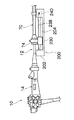
図2は本発明に係る内視鏡装置の実施形態を示すシステム構成図である。本実施形態の内視鏡装置は主として、内視鏡10、光源装置20、プロセッサ30、挿入補助具70、及びバルーン制御装置100と、後述する図4の保持装置200で構成される。   FIG. 2 is a system configuration diagram showing an embodiment of an endoscope apparatus according to the present invention. The endoscope apparatus according to the present embodiment mainly includes an endoscope 10, a light source device 20, a processor 30, an insertion assisting tool 70, a balloon control device 100, and a holding device 200 shown in FIG.

図2に示すように内視鏡10は、体腔内に挿入される挿入部12と、この挿入部12に連設される手元操作部14を備える。手元操作部14には、ユニバーサルケーブル16が接続され、ユニバーサルケーブル16の先端にはLGコネクタ18が設けられる。このLGコネクタ18は光源装置20に着脱自在に連結され、これによって後述する挿入部12の先端の照明光学系54(図3参照)に照明光を伝送することができる。また、LGコネクタ18には、ケーブル22を介して電気コネクタ24が接続され、この電気コネクタ24がプロセッサ30に着脱自在に連結される。なお、LGコネクタ18は送気・送水用のチューブ26を介して貯水タンク27に接続され、貯水タンク27の水がチューブ26を介して送水されるようになっている。また、LGコネクタ18は、吸引用のチューブ28を介して不図示の吸引装置に接続され、吸引チューブ28を介して挿入部12の先端からエアを吸引できるようになっている。   As shown in FIG. 2, the endoscope 10 includes an insertion portion 12 that is inserted into a body cavity, and a hand operation portion 14 that is connected to the insertion portion 12. A universal cable 16 is connected to the hand operation unit 14, and an LG connector 18 is provided at the tip of the universal cable 16. The LG connector 18 is detachably connected to the light source device 20, thereby transmitting illumination light to an illumination optical system 54 (see FIG. 3) at the distal end of the insertion portion 12 described later. In addition, an electrical connector 24 is connected to the LG connector 18 via a cable 22, and the electrical connector 24 is detachably coupled to the processor 30. The LG connector 18 is connected to a water storage tank 27 via an air / water supply tube 26 so that the water in the water storage tank 27 is supplied via the tube 26. The LG connector 18 is connected to a suction device (not shown) via a suction tube 28 and can suck air from the distal end of the insertion portion 12 via the suction tube 28.

挿入部12は、先端部46、湾曲部48、及び軟性部50で構成され、湾曲部48は、手元操作部14に設けられた一対のアングルノブ38、38を回動することによって遠隔的に湾曲操作される。これにより、先端部46の先端面47を所望の方向に向けることができる。   The insertion portion 12 includes a distal end portion 46, a bending portion 48, and a flexible portion 50. The bending portion 48 is remotely operated by rotating a pair of angle knobs 38, 38 provided on the hand operating portion 14. Curved operation. Thereby, the front end surface 47 of the front end portion 46 can be directed in a desired direction.

図3に示すように、先端部46の先端面47には、観察光学系52、照明光学系54、54、送気・送水ノズル56、鉗子口58が設けられる。観察光学系52の後方にはCCD(不図示)が配設され、このCCDを支持する基板には信号ケーブルが接続される。信号ケーブルは図2の挿入部12、手元操作部14、ユニバーサルケーブル16に挿通されて電気コネクタ24まで延設され、プロセッサ30に接続される。よって、観察光学系52で取り込まれた観察像は、CCDの受光面に結像されて電気信号に変換され、そして、この電気信号が信号ケーブルを介してプロセッサ30に出力され、映像信号に変換される。これにより、プロセッサ30に接続されたモニタ60に観察画像が表示される。   As shown in FIG. 3, an observation optical system 52, illumination optical systems 54 and 54, an air / water supply nozzle 56, and a forceps port 58 are provided on the distal end surface 47 of the distal end portion 46. A CCD (not shown) is disposed behind the observation optical system 52, and a signal cable is connected to a substrate that supports the CCD. The signal cable is inserted into the insertion section 12, the hand operating section 14, and the universal cable 16 of FIG. 2, extends to the electrical connector 24, and is connected to the processor 30. Therefore, the observation image captured by the observation optical system 52 is formed on the light receiving surface of the CCD and converted into an electric signal, and this electric signal is output to the processor 30 via the signal cable and converted into a video signal. Is done. As a result, the observation image is displayed on the monitor 60 connected to the processor 30.

図3の照明光学系54、54の後方にはライトガイド(不図示)の出射端が配設されている。このライトガイドは、図2の挿入部12、手元操作部14、ユニバーサルケーブル16に挿通され、入射端側がLGコネクタ18内に配設される。したがって、LGコネクタ18を光源装置20に連結することによって、光源装置20から照射された照明光がライトガイドを介して照明光学系54、54に伝送され、照明光学系54、54から前方に照射される。   An exit end of a light guide (not shown) is disposed behind the illumination optical systems 54 and 54 in FIG. This light guide is inserted through the insertion portion 12, the hand operating portion 14, and the universal cable 16 of FIG. 2, and the incident end side is disposed in the LG connector 18. Therefore, by connecting the LG connector 18 to the light source device 20, the illumination light emitted from the light source device 20 is transmitted to the illumination optical systems 54 and 54 via the light guide, and irradiated forward from the illumination optical systems 54 and 54. Is done.

図3の送気・送水ノズル56は、図2の送気・送水ボタン32によって操作されるバルブ(不図示)に連通される。このバルブは、前記送気・送水チューブ26を介してタンク27に接続されるとともに、光源装置20内のエアポンプ(不図示)に接続される。そして、送気・送水ボタン32を操作することによって、エアポンプから送気したエア、又は、タンク27から送液された水が、送気・送水ノズル56に送られるようになっている。これにより、送気・送水ノズル56からエア又は水を挿入部12の先端の観察光学系52に向けて噴射することができる。   The air / water supply nozzle 56 of FIG. 3 is communicated with a valve (not shown) operated by the air / water supply button 32 of FIG. This bulb is connected to the tank 27 via the air / water supply tube 26 and to an air pump (not shown) in the light source device 20. By operating the air / water supply button 32, the air supplied from the air pump or the water supplied from the tank 27 is sent to the air / water supply nozzle 56. Thereby, air or water can be injected from the air / water supply nozzle 56 toward the observation optical system 52 at the tip of the insertion portion 12.

図3の鉗子口58は、図2の鉗子挿入部40に連通されている。よって、鉗子挿入部40から処置具を挿入することによって、この処置具を鉗子口58から導出することができる。また、鉗子口58は、吸引ボタン34によって操作されるバルブ(不図示)に連通され、このバルブがさらに吸引チューブ28に連通される。したがって、吸引チューブ28の先端に接続された吸引装置を駆動することによって、鉗子口58から病変部等を吸引することができる。   The forceps port 58 in FIG. 3 communicates with the forceps insertion portion 40 in FIG. Therefore, the treatment tool can be led out from the forceps opening 58 by inserting the treatment tool from the forceps insertion portion 40. The forceps port 58 is communicated with a valve (not shown) operated by the suction button 34, and this valve is further communicated with the suction tube 28. Therefore, a lesioned part or the like can be sucked from the forceps opening 58 by driving a suction device connected to the tip of the suction tube 28.

図3に示すように、挿入部12の先端の外周面には、ゴム等の弾性体から成る第1バルーン42が装着される。第1バルーン42は、両端部が絞られた略筒状に形成されており、挿入部12を挿通させて所望の位置に配置した後に、第1バルーン42の両端部を挿入部12に固定することによって装着される。   As shown in FIG. 3, a first balloon 42 made of an elastic body such as rubber is attached to the outer peripheral surface of the distal end of the insertion portion 12. The first balloon 42 is formed in a substantially cylindrical shape with both ends narrowed. After the insertion portion 12 is inserted and disposed at a desired position, the both ends of the first balloon 42 are fixed to the insertion portion 12. It is installed by.

第1バルーン42の装着位置となる挿入部12の外周面には、通気孔62が形成されている。通気孔62は、不図示のチューブを介して図2の供給・吸引口44に連通される。供給・吸引口44にはチューブ64が接続され、このチューブ64がバルーン制御装置100に接続される。バルーン制御装置100は、チューブ64を介して第1バルーン42にエアを供給したり、エアを吸引したりするとともに、その際のエア圧を制御する装置である。なお、第1バルーン42はエアを供給することによって略球状に膨張し、エアを吸引することによって挿入部12の外表面に張り付くようになっている。   A vent hole 62 is formed on the outer peripheral surface of the insertion portion 12 where the first balloon 42 is attached. The vent hole 62 communicates with the supply / suction port 44 of FIG. 2 via a tube (not shown). A tube 64 is connected to the supply / suction port 44, and this tube 64 is connected to the balloon control device 100. The balloon control device 100 is a device that supplies air to the first balloon 42 via the tube 64 or sucks air and controls the air pressure at that time. The first balloon 42 is inflated into a substantially spherical shape by supplying air, and sticks to the outer surface of the insertion portion 12 by sucking air.

一方、図2に示す挿入補助具70は筒状に形成されており、挿入部12の外径よりも僅かに大きい内径を有するとともに、十分な可撓性を備えている。挿入補助具70の基端には硬質の把持部74が設けられ、この把持部74から挿入部12を挿入するようになっている。挿入補助具70の先端には、ラテックス製の第2バルーン72が装着される。第2バルーン72は、両端が窄まった略筒状に形成されており、挿入補助具70を貫通させた状態で装着される。第2バルーン72には、挿入補助具70の外周面に貼り付けたチューブ76が連通されている。このチューブ76の端部にはコネクタ78が設けられ、このコネクタ78にチューブ80が着脱自在に連結される。チューブ80は、バルーン制御装置100に連結されており、このバルーン制御装置100によって、チューブ80にエアが供給、吸引されるとともに、その際のエア圧が制御される。したがって、バルーン制御装置100を駆動することによって、第2バルーン72にエアを供給、吸引することができる。なお、第2バルーン72は、エアを供給することによって略球状に膨張し、エアを吸引することによって挿入補助具70の外周面に貼りつくようになっている。   On the other hand, the insertion assisting tool 70 shown in FIG. 2 is formed in a cylindrical shape, has an inner diameter slightly larger than the outer diameter of the insertion portion 12, and has sufficient flexibility. A rigid gripping portion 74 is provided at the proximal end of the insertion assisting tool 70, and the insertion portion 12 is inserted from the gripping portion 74. A latex second balloon 72 is attached to the distal end of the insertion assisting tool 70. The second balloon 72 is formed in a substantially cylindrical shape whose both ends are narrowed, and is attached in a state where the insertion assisting tool 70 is penetrated. A tube 76 attached to the outer peripheral surface of the insertion assisting tool 70 is communicated with the second balloon 72. A connector 78 is provided at the end of the tube 76, and the tube 80 is detachably connected to the connector 78. The tube 80 is connected to the balloon control device 100, and air is supplied to and sucked from the tube 80 by the balloon control device 100, and the air pressure at that time is controlled. Therefore, by driving the balloon control device 100, it is possible to supply and suck air to the second balloon 72. The second balloon 72 is expanded into a substantially spherical shape by supplying air, and is attached to the outer peripheral surface of the insertion assisting tool 70 by sucking air.

図2に示したように、挿入部12の所定の位置には、挿入部12の軟性部50の伸縮量を測定する歪みゲージ82が設けられており、この歪みゲージ82によって、挿入部12を挿入する際、或いは挿入部12を引き抜く際の軟性部50の伸縮量が測定される。歪みゲージ82には信号線84が接続されており、この信号線84は、挿入部12に挿通され、手元操作部14から外部に延設された後、バルーン制御装置100に接続される。バルーン制御装置100は、歪みゲージ82の電気抵抗値がしきい値を超えた際に、軟性部50の伸縮量が減少するように制御する。例えば後述の保持装置200を制御することによって、内視鏡10の移動(即ち挿入、或いは引抜)を停止したり、内視鏡10を逆方向に移動させたりする。また、挿入補助具70の内周面と挿入部12の外周面との間に潤滑剤を自動的に注入する自動注入手段を設けておき、歪みゲージ82の測定値に応じて潤滑剤の供給を行うようにしてもよい。これにより、挿入補助具70と挿入部12との摩擦抵抗を減少させ、負荷を軽減させることができる。なお、挿入部12を引き抜く際に歪みゲージ82の電気抵抗値がしきい値を超えた場合は、第1バルーン42に連通する電磁弁ユニット144(図8参照)を外部に連通させ、第1バルーン42のエアをリークしてもよい。これにより、挿入部12がスムーズに引き抜けるので、軟性部50の伸び量を減少させることができ、患者の負担を軽減することができる。   As shown in FIG. 2, a strain gauge 82 for measuring the amount of expansion / contraction of the soft portion 50 of the insertion portion 12 is provided at a predetermined position of the insertion portion 12. The amount of expansion / contraction of the soft part 50 when inserting or pulling out the insertion part 12 is measured. A signal line 84 is connected to the strain gauge 82, and the signal line 84 is inserted into the insertion unit 12, extended from the hand operation unit 14 to the outside, and then connected to the balloon control device 100. The balloon control device 100 controls the amount of expansion / contraction of the flexible portion 50 to decrease when the electrical resistance value of the strain gauge 82 exceeds the threshold value. For example, by controlling a holding device 200 described later, the movement (that is, insertion or withdrawal) of the endoscope 10 is stopped, or the endoscope 10 is moved in the reverse direction. Further, automatic injection means for automatically injecting a lubricant is provided between the inner peripheral surface of the insertion assisting tool 70 and the outer peripheral surface of the insertion portion 12, and supply of the lubricant according to the measured value of the strain gauge 82. May be performed. Thereby, the frictional resistance between the insertion assisting tool 70 and the insertion portion 12 can be reduced, and the load can be reduced. If the electrical resistance value of the strain gauge 82 exceeds the threshold value when the insertion portion 12 is pulled out, the electromagnetic valve unit 144 (see FIG. 8) communicating with the first balloon 42 is communicated with the outside, and the first Air in the balloon 42 may leak. Thereby, since the insertion part 12 is pulled out smoothly, the amount of elongation of the soft part 50 can be reduced, and a patient's burden can be eased.

一方、挿入補助具70の所定の位置には、挿入補助具70の伸縮量を測定する歪みゲージ86が設けられており、この歪みゲージ86によって、挿入補助具70を挿入する際、或いは挿入補助具70を引き抜く際の挿入補助具70の伸縮量が測定される。歪みゲージ86には信号線88が接続されており、この信号線88は、挿入補助具70に挿通され、把持部74から外部に延設された後、バルーン制御装置100に接続される。バルーン制御装置100は、歪みゲージ86の電気抵抗値がしきい値を超えた際に、挿入補助具70の伸縮量が減少するように制御する。例えば後述の保持装置200を制御することによって、挿入補助具70の移動(即ち挿入、或いは引抜)を停止したり、挿入補助具70を逆方向に移動させたりする。また、潤滑剤の自動注入手段を設けておき、歪みゲージ82の測定値に応じて潤滑剤の供給を行うようにしてもよい。なお、挿入補助具70を引き抜く際に歪みゲージ86の電気抵抗値がしきい値を超えた場合は、第2バルーン72に連通する電磁弁ユニット148(図8参照)を外部に連通させ、第2バルーン72のエアをリークしてもよい。これにより、挿入補助具70がスムーズに引き抜けるので、挿入補助具70の伸び量を減少させることができ、患者の負担を軽減することができる。   On the other hand, a strain gauge 86 for measuring the amount of expansion / contraction of the insertion assisting tool 70 is provided at a predetermined position of the insertion assisting tool 70. The amount of expansion / contraction of the insertion assisting tool 70 when the tool 70 is pulled out is measured. A signal line 88 is connected to the strain gauge 86, and the signal line 88 is inserted into the insertion assisting tool 70, extends outward from the grip portion 74, and then connected to the balloon control device 100. The balloon control device 100 controls the amount of expansion / contraction of the insertion assisting tool 70 to decrease when the electrical resistance value of the strain gauge 86 exceeds the threshold value. For example, by controlling a holding device 200 described later, the movement (that is, insertion or withdrawal) of the insertion assisting tool 70 is stopped, or the insertion assisting tool 70 is moved in the reverse direction. Further, an automatic lubricant injection unit may be provided, and the lubricant may be supplied according to the measured value of the strain gauge 82. When the electrical resistance value of the strain gauge 86 exceeds the threshold when the insertion assisting tool 70 is pulled out, the electromagnetic valve unit 148 (see FIG. 8) communicating with the second balloon 72 is communicated with the outside. 2 Air in the balloon 72 may be leaked. Thereby, since the insertion assistance tool 70 is pulled out smoothly, the amount of extension of the insertion assistance tool 70 can be reduced, and a patient's burden can be eased.

上記の如く構成された内視鏡10及び挿入補助具70は、図4に示す保持装置200によって保持される。保持装置200は、ステージ202を有し、このステージ202にガイドレール204が敷設されている。ガイドレール204は患者1の口部4に向けて直線的に配置されており、このガイドレール204に沿って内視鏡保持具210と補助具保持具230がスライド自在に支持されている。またガイドレール204は、図5及び図6に示すようにアリ型に形成されており、内視鏡保持具210及び補助具保持具230にはアリ溝が形成されており、係合するようになっている。よって、内視鏡保持具210と補助具保持具230は、脱落することなく、ガイドレール204に沿ってスライドすることができる。なお、ガイドレール204と内視鏡保持具210或いは補助具保持具230との係合形状は、特に限定するものではなく、スライド自在に支持されていればよい。   The endoscope 10 and the insertion assisting tool 70 configured as described above are held by the holding device 200 shown in FIG. The holding device 200 includes a stage 202, and a guide rail 204 is laid on the stage 202. The guide rail 204 is linearly arranged toward the mouth 4 of the patient 1, and the endoscope holder 210 and the auxiliary tool holder 230 are slidably supported along the guide rail 204. The guide rail 204 is formed in an ant shape as shown in FIGS. 5 and 6, and the dovetail groove is formed in the endoscope holder 210 and the auxiliary tool holder 230 so as to engage with each other. It has become. Therefore, the endoscope holder 210 and the auxiliary tool holder 230 can slide along the guide rail 204 without dropping off. The engagement shape between the guide rail 204 and the endoscope holding tool 210 or the auxiliary tool holding tool 230 is not particularly limited as long as it is slidably supported.

図5に示すように、補助具保持具230は、リング部232を有し、このリング部232には、挿入補助具70の把持部74の外径よりも若干大きい内径の貫通孔232Aが形成されている。また、リング部232には、外周面側から固定ネジ234が螺合されており、この固定ネジ234を締め込むことによって固定ネジ234の先端がリング部232の内周面から突出するようになっている。したがって、リング部232の貫通孔232Aに挿入補助具70の把持部74を挿入して配置した後、固定ネジ234を締め込むことによって、固定ネジ234の先端が把持部74に係合され、挿入補助具70が補助具保持具230に保持される。   As shown in FIG. 5, the auxiliary tool holder 230 has a ring part 232, and a through hole 232 </ b> A having an inner diameter slightly larger than the outer diameter of the grip part 74 of the insertion auxiliary tool 70 is formed in the ring part 232. Has been. Further, a fixing screw 234 is screwed onto the ring portion 232 from the outer peripheral surface side, and by tightening the fixing screw 234, the tip of the fixing screw 234 protrudes from the inner peripheral surface of the ring portion 232. ing. Therefore, after the gripping portion 74 of the insertion assisting tool 70 is inserted and arranged in the through hole 232A of the ring portion 232, the fixing screw 234 is tightened so that the tip of the fixing screw 234 is engaged with the gripping portion 74 and inserted. The auxiliary tool 70 is held by the auxiliary tool holder 230.

補助具保持具230には、ネジ孔236が形成されており、このネジ孔236に送りネジ238が螺合されている。送りネジ238は、図4に示すようにガイドレール204に沿って配置され、ステージ202に回動自在に支持されている。ステージ202の端部には、送りネジ238を回動させるモータ240が設けられており、このモータ240で送りネジ238を回転させることによって、補助具保持具230がガイドレール204に沿ってスライド移動する。すなわち、補助具保持具230が、患者1の口部4に対して直線的に移動する。よって、補助具保持具230で保持した挿入補助具70を患者1の口部4に対して直線的にガイドすることができる。   A screw hole 236 is formed in the auxiliary tool holder 230, and a feed screw 238 is screwed into the screw hole 236. As shown in FIG. 4, the feed screw 238 is disposed along the guide rail 204 and is rotatably supported by the stage 202. A motor 240 that rotates the feed screw 238 is provided at the end of the stage 202, and the auxiliary tool holder 230 slides along the guide rail 204 by rotating the feed screw 238 by the motor 240. To do. That is, the auxiliary tool holder 230 moves linearly with respect to the mouth 4 of the patient 1. Therefore, the insertion assisting tool 70 held by the assisting instrument holder 230 can be linearly guided with respect to the mouth 4 of the patient 1.

さらに図5の補助具保持具230には、後述する送りネジ218が挿通される孔242が形成されている。この孔242は、送りネジ218の外径よりも大きく形成されている。   Furthermore, a hole 242 through which a feed screw 218 described later is inserted is formed in the auxiliary tool holder 230 of FIG. The hole 242 is formed larger than the outer diameter of the feed screw 218.

一方、内視鏡保持具210は、図6に示すように、リング部212を有し、このリング部212には、手元操作部14が挿入可能な貫通孔212Aが形成されている。また、リング部212には、外周面側から固定ネジ214が螺合されており、この固定ネジ214を締め込むことによって固定ネジ214の先端がリング部212の内周面から突出するようになっている。したがって、貫通孔212Aに手元操作部14を挿入して固定ネジ214を締め込むことによって固定ネジ214の先端が手元操作部14に係合し、手元操作部14が内視鏡保持具210に固定される。   On the other hand, as shown in FIG. 6, the endoscope holder 210 has a ring portion 212, and a through-hole 212 </ b> A into which the hand operation portion 14 can be inserted is formed in the ring portion 212. Further, a fixing screw 214 is screwed into the ring portion 212 from the outer peripheral surface side, and by tightening the fixing screw 214, the tip of the fixing screw 214 projects from the inner peripheral surface of the ring portion 212. ing. Therefore, by inserting the hand operation part 14 into the through hole 212A and tightening the fixing screw 214, the tip of the fixing screw 214 is engaged with the hand operation part 14, and the hand operation part 14 is fixed to the endoscope holder 210. Is done.

また、内視鏡保持具210には、ネジ孔216が形成されており、このネジ孔216に送りネジ218が螺合されている。送りネジ218は、図4に示すようにガイドレール204に沿って配置されており、ステージ202に回動自在に支持されている。ステージ202の端部には、送りネジ218を回動させるモータ220が設けられており、このモータ220で送りネジ218を回転させることによって、内視鏡保持具210がガイドレール204に沿ってスライド移動する。すなわち、内視鏡保持具210が、患者1の口部4に対して直線的に移動する。よって、内視鏡保持具210で保持した内視鏡10の挿入部12を患者1の口部4に対して直線的にガイドすることができる。   The endoscope holder 210 has a screw hole 216, and a feed screw 218 is screwed into the screw hole 216. As shown in FIG. 4, the feed screw 218 is disposed along the guide rail 204 and is rotatably supported by the stage 202. A motor 220 for rotating the feed screw 218 is provided at the end of the stage 202, and the endoscope holder 210 slides along the guide rail 204 by rotating the feed screw 218 by the motor 220. Moving. That is, the endoscope holder 210 moves linearly with respect to the mouth 4 of the patient 1. Therefore, the insertion portion 12 of the endoscope 10 held by the endoscope holder 210 can be linearly guided with respect to the mouth 4 of the patient 1.

また、図6の内視鏡保持具210には、前述した補助具保持具230側の送りネジ238が挿通される孔222が形成されている。この孔222は、送りネジ238の外径よりも大きく形成されている。   In addition, the endoscope holder 210 in FIG. 6 is formed with a hole 222 through which the feed screw 238 on the auxiliary tool holder 230 side described above is inserted. The hole 222 is formed larger than the outer diameter of the feed screw 238.

さらに、内視鏡保持具210には、挿入量測定手段として、ローラ224が回動自在に支持されている。ローラ224は、ガイドレール204側に突出して配置されており、内視鏡保持具210をガイドレール204に沿ってスライド移動させた際に、ガイドレール204に当接して連れ回りするようになっている。   Furthermore, a roller 224 is rotatably supported by the endoscope holder 210 as insertion amount measuring means. The roller 224 is disposed so as to protrude toward the guide rail 204, and comes into contact with the guide rail 204 when the endoscope holder 210 is slid along the guide rail 204. Yes.

ローラ224の回転軸225には、ギア226が連結されており、ローラ224の回転力がギア226に伝達されるようになっている。ギア226は不図示のワンウェイクラッチを介してセンサ227に接続されており、ギア226の一方向の回転数のみがセンサ227によって検出される。検出される回転方向は、内視鏡保持具210を患者1の口4に向けて前進させた際にギア226が回転する方向である。   A gear 226 is connected to the rotation shaft 225 of the roller 224 so that the rotational force of the roller 224 is transmitted to the gear 226. The gear 226 is connected to the sensor 227 via a not-shown one-way clutch, and only the rotational speed in one direction of the gear 226 is detected by the sensor 227. The detected rotation direction is a direction in which the gear 226 rotates when the endoscope holder 210 is advanced toward the mouth 4 of the patient 1.

センサ227には演算装置228が接続されており、この演算装置228によって、センサ227で検出したギア226の回転数が挿入部12の挿入量(長さ)に換算される。そして、その換算値が積算され、挿入量の総和が求められる。演算装置228は、バルーン制御装置100に接続されており、演算装置228で求めた挿入量の総和が、バルーン制御装置100のバルーン専用モニタ106等に表示されるようになっている。これにより、挿入部12の先端が体腔内のどの位置まで到達したかを把握することができる。   An arithmetic device 228 is connected to the sensor 227, and the arithmetic device 228 converts the rotational speed of the gear 226 detected by the sensor 227 into an insertion amount (length) of the insertion portion 12. Then, the converted values are integrated to obtain the total amount of insertion. The arithmetic device 228 is connected to the balloon control device 100, and the total amount of insertion determined by the arithmetic device 228 is displayed on the balloon dedicated monitor 106 of the balloon control device 100. Thereby, it can be grasped to which position in the body cavity the distal end of the insertion portion 12 has reached.

図4に示すように、ステージ202の先端側の端部には、ガイドリング250が設けられる。ガイドリング250は、挿入補助具70の外径よりも若干大きな内径を有し、挿入補助具70をガイドリング250に挿入してガイドできるようになっている。   As shown in FIG. 4, a guide ring 250 is provided at the end of the stage 202 on the front end side. The guide ring 250 has an inner diameter slightly larger than the outer diameter of the insertion assisting tool 70, and can be guided by being inserted into the guide ring 250.

ガイドリング250と補助具保持具230との間には、二点鎖線で示す如くカバー252が設けられている。カバー252は、伸縮自在な筒状(例えば蛇腹状)に形成されており、挿入補助具70を覆うようにして取り付けられている。カバー252の両端部はガイドリング250と補助具保持具230に着脱自在に連結されており、必要に応じてカバー252を取り外して洗浄できるようになっている。上記の如く構成されたカバー252で挿入補助具70を覆うことによって、挿入補助具70の外表面に付着した体液等が飛散することを防止できる。よって、術者が手を汚すことなく操作することができる。   A cover 252 is provided between the guide ring 250 and the auxiliary tool holder 230 as shown by a two-dot chain line. The cover 252 is formed in a telescopic cylinder shape (for example, a bellows shape), and is attached so as to cover the insertion assisting tool 70. Both ends of the cover 252 are detachably connected to the guide ring 250 and the auxiliary tool holder 230 so that the cover 252 can be removed and cleaned as necessary. By covering the insertion assisting tool 70 with the cover 252 configured as described above, it is possible to prevent body fluid and the like attached to the outer surface of the insertion assisting tool 70 from being scattered. Therefore, the surgeon can operate without getting his hands dirty.

また、補助具保持具230と内視鏡保持具210との間には、二点鎖線で示す如くカバー254が設けられている。カバー254は、カバー252と同様に、伸縮自在な筒状(例えば蛇腹状)に形成されており、挿入部12を覆うようにして取り付けられている。カバー254の両端部は、補助具保持具230と内視鏡保持具210に着脱自在に連結されており、必要に応じてカバー254を取り外して洗浄できるようになっている。上記の如く構成されたカバー254で挿入部12を覆うことによって、挿入部12の外表面に付着した体液等が飛散することを防止できる。よって、術者が手を汚すことなく操作することができる。   Further, a cover 254 is provided between the auxiliary tool holder 230 and the endoscope holder 210 as shown by a two-dot chain line. Similar to the cover 252, the cover 254 is formed in a telescopic cylinder shape (for example, a bellows shape), and is attached so as to cover the insertion portion 12. Both ends of the cover 254 are detachably connected to the auxiliary tool holder 230 and the endoscope holder 210 so that the cover 254 can be removed and cleaned as necessary. By covering the insertion portion 12 with the cover 254 configured as described above, it is possible to prevent body fluid or the like attached to the outer surface of the insertion portion 12 from scattering. Therefore, the surgeon can operate without getting his hands dirty.

図7はバルーン制御装置100を示す斜視図である。図7に示すように、バルーン制御装置100は主として、装置本体102、リモートコントローラ104、バルーン専用モニタ106、及びフットスイッチ108で構成される。装置本体102の前面パネルには、電源スイッチ110、エラー表示部112、状態表示部114、圧力値表示部116、気液分離フィルタ118、119が設けられ、この気液分離フィルタ118、119には前述したチューブ64、80が連結される。チューブ64、80を介して吸引された液体は、この気液分離フィルタ118、119によって気液分離されて取り除かれる。よって、装置本体102内に液体が吸引されることを防止することができる。   FIG. 7 is a perspective view showing the balloon control device 100. As shown in FIG. 7, the balloon control device 100 mainly includes a device main body 102, a remote controller 104, a balloon dedicated monitor 106, and a foot switch 108. On the front panel of the apparatus main body 102, a power switch 110, an error display unit 112, a status display unit 114, a pressure value display unit 116, and gas-liquid separation filters 118 and 119 are provided. The tubes 64 and 80 described above are connected. The liquid sucked through the tubes 64 and 80 is gas-liquid separated and removed by the gas-liquid separation filters 118 and 119. Therefore, it is possible to prevent the liquid from being sucked into the apparatus main body 102.

エラー表示部112には、第1バルーン42や第2バルーン72が破れたりした際に、その旨を示す文字や数字等が表示される。状態表示部114には、第1バルーン42や第2バルーン72の膨縮状態が表示される。圧力値表示部116には、後述する圧力センサ146、150(図8参照)によって測定された第1バルーン42の内圧や第2バルーン72の内圧が表示される。   When the first balloon 42 or the second balloon 72 is torn, the error display unit 112 displays characters, numbers, or the like indicating that. The state display unit 114 displays the expansion / contraction state of the first balloon 42 and the second balloon 72. The pressure value display unit 116 displays the internal pressure of the first balloon 42 and the internal pressure of the second balloon 72 measured by pressure sensors 146 and 150 (see FIG. 8) described later.

バルーン専用モニタ106は、図1に示す如くモニタ60に取り付けられ、術者がモニタ60の画面と一緒に観察できるようになっている。また、図7のバルーン専用モニタ106には、上述したエラー表示部112や状態表示部114と同様の表示を行う、エラー表示部122、状態表示部124が設けられる。よって、バルーン専用モニタ106を観察することによっても、第1バルーン42や第2バルーン72の膨縮状態やエラーの発生を把握することができる。また、バルーン専用モニタ106には、総挿入量表示部120が設けられている。総挿入量表示部120は、腸管の全長を示すL1に対して、挿入量の総和を示すL2が点灯するようになっており、腸管の残量を示すL3が一目で分かるようになっている。なお、総挿入量表示部120と同様の表示部を、装置本体102の前面パネルやリモートコントローラ104に設けてもよい。   The balloon dedicated monitor 106 is attached to the monitor 60 as shown in FIG. 1 so that the surgeon can observe it together with the screen of the monitor 60. In addition, the balloon dedicated monitor 106 of FIG. 7 is provided with an error display unit 122 and a state display unit 124 that perform the same display as the error display unit 112 and the state display unit 114 described above. Therefore, by observing the balloon dedicated monitor 106, it is possible to grasp the expansion / contraction state of the first balloon 42 and the second balloon 72 and the occurrence of an error. The balloon dedicated monitor 106 is provided with a total insertion amount display unit 120. In the total insertion amount display section 120, L2 indicating the total amount of insertion is turned on with respect to L1 indicating the entire length of the intestinal tract, and L3 indicating the remaining amount of the intestinal tract can be seen at a glance. . A display unit similar to the total insertion amount display unit 120 may be provided on the front panel of the apparatus main body 102 or the remote controller 104.

リモートコントローラ104には、上述した状態表示部114と同様の表示を行う状態表示部126が設けられる。また、リモートコントローラ104には、手動モードと自動モードとでモードを切り替えるモード切替スイッチ128と、手動モード時に操作が有効となる操作ボタン130a〜130gと、自動モード時に操作が有効となる操作ボタン132a、132bと、各モードで共通となる停止ボタン134が設けられている。   The remote controller 104 is provided with a status display unit 126 that performs the same display as the status display unit 114 described above. In addition, the remote controller 104 includes a mode switch 128 that switches between the manual mode and the automatic mode, operation buttons 130a to 130g that enable operations in the manual mode, and operation buttons 132a that enable operations in the automatic mode. , 132b, and a stop button 134 that is common to the respective modes.

手動モード用の操作ボタン130aを押下操作すると、図4のモータ220が駆動し、内視鏡保持具210が所定量、前進移動する。同様に、図7の操作ボタン130bを押下操作すると、図4の補助具保持具230が所定量、前進移動する。そして、図7の操作ボタン130cを押下操作すると、図4の内視鏡保持具210と補助具保持具230が同時に後退移動する。   When the manual mode operation button 130a is pressed, the motor 220 in FIG. 4 is driven, and the endoscope holder 210 moves forward by a predetermined amount. Similarly, when the operation button 130b in FIG. 7 is pressed, the auxiliary tool holder 230 in FIG. 4 moves forward by a predetermined amount. When the operation button 130c shown in FIG. 7 is pressed, the endoscope holder 210 and the auxiliary tool holder 230 shown in FIG.

また、図7の操作ボタン130dを押下操作すると、図2の第1バルーン42にエアが送気され、図7の操作ボタン130eを押下操作すると、図2の第1バルーン42からエアが吸引される。同様に、図7の操作ボタン130fを押下操作すると、図2の第2バルーン72にエアが送気され、図7の操作ボタン130gを押下操作すると、図2の第2バルーン72からエアが吸引される。   When the operation button 130d in FIG. 7 is pressed, air is supplied to the first balloon 42 in FIG. 2, and when the operation button 130e in FIG. 7 is pressed, air is sucked from the first balloon 42 in FIG. The Similarly, when the operation button 130f in FIG. 7 is pressed, air is supplied to the second balloon 72 in FIG. 2, and when the operation button 130g in FIG. 7 is pressed, air is sucked from the second balloon 72 in FIG. Is done.

一方、自動モード用の操作ボタン132aは、一回押下するごとに、次の操作(ステップ)に移行するようになっている。そして、操作ボタン132bを押下操作すると、前段の操作に戻るようになっている。   On the other hand, every time the operation button 132a for automatic mode is pressed, the operation is shifted to the next operation (step). When the operation button 132b is pressed, the operation returns to the previous operation.

なお、上述したリモートコントローラ104には、状態表示部126のみを設けたが、エラー表示部、総挿入量表示部、圧力値表示部等を設けてもよい。また、現在のモードを表示するモード表示部を設けてもよい。   In addition, although only the status display unit 126 is provided in the remote controller 104 described above, an error display unit, a total insertion amount display unit, a pressure value display unit, and the like may be provided. Moreover, you may provide the mode display part which displays the present mode.

図7のフットスイッチ108には、自動モード用の操作ボタン136a、136bと、停止ボタン138が設けられる。操作ボタン136a、136bは、リモートコントローラ104の操作ボタン132a、132bと同様の機能を有する。このフットスイッチ108は、図1に示す如く補助台2の下方に配置される。よって、自動モードの際に術者は足で操作を進行させることができる。なお、手動モードの際に、フットスイッチ108を押下操作することによって、第1バルーン42や第2バルーン72に供給、吸引するエアの流量を調節するようにしてもよい。   The foot switch 108 in FIG. 7 is provided with operation buttons 136a and 136b for an automatic mode and a stop button 138. The operation buttons 136a and 136b have the same functions as the operation buttons 132a and 132b of the remote controller 104. The foot switch 108 is disposed below the auxiliary base 2 as shown in FIG. Therefore, the operator can advance the operation with his / her foot during the automatic mode. In the manual mode, the flow rate of air supplied to and sucked from the first balloon 42 and the second balloon 72 may be adjusted by pressing the foot switch 108.

図8はバルーン制御装置100の内部構成を示すブロック図である。図8に示すように、装置本体102の内部には、ポンプユニット140、142が設けられる。ポンプユニット140は、電磁弁ユニット144を介して第1バルーン42と圧力センサ146に連通されており、ポンプユニット142は電磁弁ユニット148を介して第2バルーン72と圧力センサ150に連通されている。ポンプユニット140、142はそれぞれ、不図示の加圧ポンプと減圧ポンプを備え、この加圧ポンプと減圧ポンプの一方がバルーンに連通するように電磁弁ユニット144、148で切替操作が行われる。ポンプユニット140、142及び電磁弁ユニット144、148は、CPU152に接続され、CPU152によって第1バルーン42の膨縮操作と第2バルーン72の膨縮操作が制御される。すなわち、ポンプユニット140からエアを供給して第1バルーン42を膨張したり、ポンプユニット140でエアを吸引して第1バルーン42を収縮したり、或いは、ポンプユニット142からエアを供給して第2バルーン72を膨張したり、ポンプユニット142でエアを吸引して第2バルーン72を収縮する操作が行われる。その操作の際、圧力センサ146、150の測定値に応じて、ポンプユニット140、142や電磁弁ユニット144、148が制御される。これにより、第1バルーン42や第2バルーン72を所定の内圧に制御することができる。また、エラー(例えば第1バルーン42や第2バルーン72の破れ等)が発生した場合に、圧力センサ146、150の測定値によってエラーを検出することができ、エアの送気や吸引を停止することができる。   FIG. 8 is a block diagram showing an internal configuration of the balloon control device 100. As shown in FIG. 8, pump units 140 and 142 are provided inside the apparatus main body 102. The pump unit 140 is in communication with the first balloon 42 and the pressure sensor 146 through the electromagnetic valve unit 144, and the pump unit 142 is in communication with the second balloon 72 and the pressure sensor 150 through the electromagnetic valve unit 148. . Each of the pump units 140 and 142 includes a pressurization pump and a decompression pump (not shown), and the switching operation is performed by the electromagnetic valve units 144 and 148 so that one of the pressurization pump and the decompression pump communicates with the balloon. The pump units 140 and 142 and the solenoid valve units 144 and 148 are connected to the CPU 152, and the expansion / contraction operation of the first balloon 42 and the expansion / contraction operation of the second balloon 72 are controlled by the CPU 152. That is, the first balloon 42 is inflated by supplying air from the pump unit 140, the first balloon 42 is contracted by sucking air by the pump unit 140, or the first balloon 42 is supplied by supplying air from the pump unit 142. The operation of inflating the second balloon 72 or contracting the second balloon 72 by sucking air with the pump unit 142 is performed. During the operation, the pump units 140 and 142 and the electromagnetic valve units 144 and 148 are controlled according to the measured values of the pressure sensors 146 and 150. Thereby, the first balloon 42 and the second balloon 72 can be controlled to a predetermined internal pressure. In addition, when an error (for example, the first balloon 42 or the second balloon 72 is broken), the error can be detected based on the measured values of the pressure sensors 146 and 150, and air supply and suction are stopped. be able to.

前記CPU152は、歪みゲージ82、86が接続されており、この歪みゲージ82、86の測定値がしきい値を超えた際に、電磁弁ユニット144、148が制御される。そして、第1バルーン42や第2バルーン72のエアがリークされ、第1バルーン42や第2バルーン72が収縮される。   The CPU 152 is connected to strain gauges 82 and 86, and when the measured values of the strain gauges 82 and 86 exceed a threshold value, the solenoid valve units 144 and 148 are controlled. Then, the air in the first balloon 42 and the second balloon 72 is leaked, and the first balloon 42 and the second balloon 72 are deflated.

また、CPU152には、保持装置200用のコントロールユニット154が接続されており、このコントロールユニット154を介して保持装置200のモータ220、240の駆動制御が行われる。さらに、CPU152は、保持装置200の演算装置228に接続されており、演算装置228で求めた挿入量の総和に基づいて、挿入部12の挿入を続けるか否か(すなわちモータ220、240の駆動を行うか否か)を判断するようになっている。   Further, a control unit 154 for the holding device 200 is connected to the CPU 152, and drive control of the motors 220 and 240 of the holding device 200 is performed via the control unit 154. Further, the CPU 152 is connected to the arithmetic device 228 of the holding device 200, and based on the total amount of insertion obtained by the arithmetic device 228, whether or not to continue the insertion of the insertion portion 12 (that is, driving of the motors 220 and 240). Or not).

CPU152には、プログラム入力ユニット156が接続されており、キーボード等の外部入力手段158からプログラムを入力できるようになっている。入力されたプログラムは、プログラムメモリー160に記憶される。ここで、プログラムとは、自動モードで行われる操作手順のプログラムであり、第1バルーン42や第2バルーン72に対するエアの供給圧力、吸引圧力等も設定される。   A program input unit 156 is connected to the CPU 152 so that a program can be input from an external input means 158 such as a keyboard. The input program is stored in the program memory 160. Here, the program is a program of an operation procedure performed in the automatic mode, and air supply pressure, suction pressure, and the like for the first balloon 42 and the second balloon 72 are also set.

CPU152には、操作信号入力I/F162が接続されており、フットスイッチ108やリモートコントローラ104の操作部(すなわちモード切替スイッチ128、操作ボタン130a〜130g、操作ボタン132a、132b、及び停止ボタン134)から操作信号が入力されるようになっている。CPU152は、この操作信号に応じて、前記ポンプユニット140、142、電磁弁ユニット144、148、コントロールユニット154に制御信号を出力する。   An operation signal input I / F 162 is connected to the CPU 152, and the operation unit of the foot switch 108 and the remote controller 104 (that is, the mode switch 128, the operation buttons 130a to 130g, the operation buttons 132a and 132b, and the stop button 134). An operation signal is input from. The CPU 152 outputs a control signal to the pump units 140 and 142, the electromagnetic valve units 144 and 148, and the control unit 154 according to the operation signal.

また、CPU152には、プログラム表示ユニット164と状態表示ユニット166が接続される。プログラム表示ユニット164と状態表示ユニット166は表示切替ユニット168を介してバルーン専用モニタ106やリモートコントローラ104の状態表示部126に接続される。よって、バルーン専用モニタ106やリモートコントローラ104に、第1バルーン42や第2バルーン72の膨縮状態だけでなく、プログラムを表示することもできる。   In addition, a program display unit 164 and a status display unit 166 are connected to the CPU 152. The program display unit 164 and the status display unit 166 are connected to the balloon dedicated monitor 106 and the status display unit 126 of the remote controller 104 via the display switching unit 168. Therefore, not only the inflated / deflated state of the first balloon 42 and the second balloon 72 but also the program can be displayed on the balloon dedicated monitor 106 and the remote controller 104.

次に上記の如く構成された内視鏡装置の操作方法について図9及び図10(a)〜図10(h)を用いて説明する。図9は、上述した内視鏡装置の操作手順を示すフローチャートであり、図10(a)〜図10(h)は内視鏡装置の操作手順を説明する説明図である。   Next, an operation method of the endoscope apparatus configured as described above will be described with reference to FIGS. 9 and 10A to 10H. FIG. 9 is a flowchart illustrating an operation procedure of the endoscope apparatus described above, and FIGS. 10A to 10H are explanatory diagrams illustrating the operation procedure of the endoscope apparatus.

まず、挿入操作の準備作業として、挿入補助具70を挿入部12に被せるとともに、内視鏡10の手元操作部14を内視鏡保持具210に固定し、挿入補助具70を補助具保持具230に固定する(ステップS1)。このとき、第1バルーン42及び第2バルーン72は収縮させておく。   First, as a preparatory work for the insertion operation, the insertion assisting tool 70 is put on the insertion portion 12, the hand operation portion 14 of the endoscope 10 is fixed to the endoscope holder 210, and the insertion assisting tool 70 is fixed to the assisting tool holder 230 (step S1). At this time, the first balloon 42 and the second balloon 72 are deflated.

以降の操作は、図7のリモートコントローラ104のモード切替スイッチ128で自動モードと手動モードの一方を選択して行われる。まず、自動モードを選択した場合について説明する。自動モードを選択した場合には、リモートコントローラ104の操作ボタン132a、或いは、フットスイッチ108の操作ボタン136a(以下、まとめて進行ボタンという)を押下操作することによって、各操作ステップが自動的に進行するようになっている。   The subsequent operation is performed by selecting either the automatic mode or the manual mode with the mode changeover switch 128 of the remote controller 104 in FIG. First, the case where the automatic mode is selected will be described. When the automatic mode is selected, each operation step automatically proceeds by pressing the operation button 132a of the remote controller 104 or the operation button 136a of the foot switch 108 (hereinafter collectively referred to as a progress button). It is supposed to be.

例えば前述の準備作業の後に進行ボタンを押下すると、図4のモータ220、240が駆動され、内視鏡保持具210と補助具保持具230が患者1の口部4に向けて所定量前進して停止する。これにより、挿入部12と挿入補助具70が体腔内に挿入され(ステップ2)、図10(a)に示す如く、挿入補助具70の先端が腸管90の屈曲部に到達する。   For example, when the progress button is pressed after the above-described preparatory work, the motors 220 and 240 in FIG. 4 are driven, and the endoscope holder 210 and the auxiliary tool holder 230 move forward by a predetermined amount toward the mouth 4 of the patient 1. Stop. As a result, the insertion portion 12 and the insertion aid 70 are inserted into the body cavity (step 2), and the distal end of the insertion aid 70 reaches the bent portion of the intestinal tract 90 as shown in FIG.

次に進行ボタンを押下すると、図8のポンプユニット142と電磁弁ユニット148が制御され、第2バルーン72にエアが送気される。そして、圧力センサ150の測定値が所定の範囲になるまで、第2バルーン72にエアが送気される。これにより、第2バルーン72が膨張され(ステップS3)、図10(b)に示す如く挿入補助具70が第2バルーン72を介して腸管90に固定される。   Next, when the progress button is pressed, the pump unit 142 and the electromagnetic valve unit 148 in FIG. 8 are controlled, and air is supplied to the second balloon 72. Then, air is supplied to the second balloon 72 until the measurement value of the pressure sensor 150 falls within a predetermined range. As a result, the second balloon 72 is inflated (step S3), and the insertion assisting tool 70 is fixed to the intestinal tract 90 via the second balloon 72 as shown in FIG.

そしてこの状態で進行ボタンを押下操作すると、図4のモータ220が駆動され、内視鏡保持具210が患者1の口部4に向けて前進し、所定量前進したところで停止する。その際、術者は手元操作部14のアングルノブ38、38を操作し、挿入部12の湾曲部48(図2参照)を湾曲させて腸管90の屈曲形状に追従させる。これにより、挿入部12が腸管90に挿入され(ステップS4)、図10(c)に示すように、挿入部12の先端が腸管90の深部に挿入された状態になる。挿入部12の挿入操作の際、挿入部12の挿入量は、ローラ224、ギア226、及びセンサ227から成る挿入量測定手段によって測定され、その測定値が演算装置228によって積算され、挿入量の総和が求められる。   When the progress button is pressed in this state, the motor 220 in FIG. 4 is driven, and the endoscope holder 210 advances toward the mouth 4 of the patient 1 and stops when it advances a predetermined amount. At that time, the surgeon operates the angle knobs 38 of the hand operation unit 14 to bend the bending portion 48 (see FIG. 2) of the insertion portion 12 to follow the bent shape of the intestinal tract 90. As a result, the insertion portion 12 is inserted into the intestinal tract 90 (step S4), and the distal end of the insertion portion 12 is inserted into the deep portion of the intestinal tract 90 as shown in FIG. During the insertion operation of the insertion portion 12, the insertion amount of the insertion portion 12 is measured by an insertion amount measuring means comprising a roller 224, a gear 226, and a sensor 227, and the measured value is integrated by the arithmetic unit 228 to determine the insertion amount. Sum is required.

次いで進行ボタンを押下操作すると、図8のポンプユニット140と電磁弁ユニット144が制御され、第1バルーン42にエアが送気される。そして、圧力センサ146の測定値が所定の範囲になるまで、第1バルーン42にエアが送気される。これにより、第1バルーン42が膨張され(ステップS5)、図10(d)に示す如く挿入部12が第1バルーン42を介して腸管90に固定される。   Next, when the advance button is pressed, the pump unit 140 and the electromagnetic valve unit 144 shown in FIG. 8 are controlled, and air is supplied to the first balloon 42. Then, air is supplied to the first balloon 42 until the measurement value of the pressure sensor 146 falls within a predetermined range. As a result, the first balloon 42 is inflated (step S5), and the insertion portion 12 is fixed to the intestinal tract 90 via the first balloon 42 as shown in FIG.

この状態で進行ボタンを押下すると、図8のポンプユニット142と電磁弁ユニット148が制御され、第2バルーン72からエアが吸引される。そして、圧力センサ150の測定値が所定の範囲になるまで第2バルーン72がエアが吸引される。これにより、第2バルーン72は収縮し(ステップS6)、図10(d)に示すように第2バルーン72が挿入補助具70の表面に貼りついた状態になる。   When the progress button is pressed in this state, the pump unit 142 and the electromagnetic valve unit 148 in FIG. 8 are controlled, and air is sucked from the second balloon 72. Then, air is sucked into the second balloon 72 until the measurement value of the pressure sensor 150 falls within a predetermined range. As a result, the second balloon 72 is deflated (step S6), and the second balloon 72 is stuck to the surface of the insertion assisting tool 70 as shown in FIG.

次に進行ボタンを押下すると、図4のモータ240が駆動し、補助具保持具230が患者1の口部4に向かって移動する。したがって、挿入補助具70が直線的にガイドされた状態で患者1に挿入され、挿入補助具70が内視鏡10の挿入部12にガイドされて押し込まれる。補助具保持具230は所定量移動したところで停止する。これにより、挿入補助具70が所定量挿入され(ステップS7)、図10(e)示すように第2バルーン72が第1バルーン42の手前近傍に配置された状態になる。このとき、本実施の形態では、モータ24の駆動制御によって挿入補助具70の挿入量を制御することができるので、挿入補助具70の先端が挿入部12の第1バルーン42に接触することを防止することができ、第1バルーン42の損傷を防止できる。   Next, when the progress button is pressed, the motor 240 in FIG. 4 is driven, and the auxiliary tool holder 230 moves toward the mouth 4 of the patient 1. Therefore, the insertion assisting tool 70 is inserted into the patient 1 while being linearly guided, and the insertion assisting tool 70 is guided and pushed into the insertion portion 12 of the endoscope 10. The auxiliary tool holder 230 stops when it moves a predetermined amount. As a result, a predetermined amount of the insertion assisting tool 70 is inserted (step S7), and the second balloon 72 is placed in the vicinity of the front side of the first balloon 42 as shown in FIG. 10 (e). At this time, in the present embodiment, since the insertion amount of the insertion assisting tool 70 can be controlled by the drive control of the motor 24, the tip of the insertion assisting tool 70 is in contact with the first balloon 42 of the insertion portion 12. This can prevent the first balloon 42 from being damaged.

挿入補助具70を挿入した状態で進行ボタンを押下すると、図8のポンプユニット142と電磁弁ユニット148が制御され、第2バルーン72にエアが送気される。そして、圧力センサ150の測定値が所定の範囲になるまで、エアが送気される。これにより、第2バルーン72が膨張し(ステップS8)、図10(f)に示すように挿入補助具70が腸管90に固定される。すなわち、腸管90が第2バルーン72によって把持される。   When the progress button is pressed with the insertion assisting tool 70 inserted, the pump unit 142 and the electromagnetic valve unit 148 in FIG. 8 are controlled, and air is supplied to the second balloon 72. Then, air is supplied until the measurement value of the pressure sensor 150 falls within a predetermined range. Thereby, the second balloon 72 is inflated (step S8), and the insertion assisting tool 70 is fixed to the intestinal tract 90 as shown in FIG. That is, the intestinal tract 90 is grasped by the second balloon 72.

この状態で進行ボタンを操作すると、図4のモータ220とモータ240が駆動され、内視鏡保持具210と補助具保持具230が同時に、患者1の口部4から退避する方向に所定量、移動する。これにより、挿入部12と挿入補助具70が同時に患者1の口部4から引き抜かれ、腸管90が手繰り寄せられる(ステップS9)。これにより図10(g)に示す如ように、腸管90は収縮した状態になり、挿入補助具70の余分な撓みや屈曲が取り除かれる。なお、手繰り寄せる際、歪みゲージ82、86(図2参照)の測定値がしきい値を超えた場合には、バルーン制御装置100によって第1バルーン42や第2バルーン72のエアをリークして第1バルーン42や第2バルーン72を収縮させる。これにより、腸管90に大きな負荷がかかることを防止できる。   When the advance button is operated in this state, the motor 220 and the motor 240 in FIG. 4 are driven, and the endoscope holder 210 and the auxiliary tool holder 230 are simultaneously retracted from the mouth 4 of the patient 1 by a predetermined amount, Moving. Thereby, the insertion part 12 and the insertion assistance tool 70 are simultaneously withdrawn from the mouth part 4 of the patient 1, and the intestinal tract 90 is drawn by hand (step S9). As a result, as shown in FIG. 10G, the intestinal tract 90 is in a contracted state, and excess bending and bending of the insertion assisting tool 70 are removed. When the measured values of the strain gauges 82 and 86 (see FIG. 2) exceed the threshold value, the balloon control device 100 leaks air from the first balloon 42 and the second balloon 72. The first balloon 42 and the second balloon 72 are deflated. Thereby, it can prevent that a big load is applied to the intestinal tract 90.

挿入部12と挿入補助具70を手繰り寄せた状態で進行ボタンを押下すると、図8のポンプユニット140と電磁弁ユニット144が制御され、第1バルーン42からエアが吸引される。そして、圧力センサ146の測定値が所定の範囲になるまで、第1バルーン42からエアが吸引される。これにより、第1バルーン42が収縮するので(ステップS10)、第1バルーン42は図10(h)に示す如く挿入部12の表面に貼りついた状態になる。   When the advance button is pressed while the insertion portion 12 and the insertion assisting tool 70 are pulled together, the pump unit 140 and the electromagnetic valve unit 144 in FIG. 8 are controlled, and air is sucked from the first balloon 42. Then, air is sucked from the first balloon 42 until the measurement value of the pressure sensor 146 falls within a predetermined range. As a result, the first balloon 42 is deflated (step S10), and the first balloon 42 is stuck to the surface of the insertion portion 12 as shown in FIG. 10 (h).

次いで進行ボタンを押下すると、図4のモータ220が駆動され、内視鏡保持具210が患者1の口部4に向けて所定量移動し、停止する。これにより、挿入部12が腸管90の深部に挿入される(ステップS11)。このとき、挿入補助具70の余分な屈曲や撓みが取り除かれているので、挿入部12をスムーズに挿入することができる。   Next, when the progress button is pressed, the motor 220 in FIG. 4 is driven, and the endoscope holder 210 moves a predetermined amount toward the mouth 4 of the patient 1 and stops. Thereby, the insertion part 12 is inserted in the deep part of the intestinal tract 90 (step S11). At this time, since the excessive bending and bending of the insertion assisting tool 70 are removed, the insertion portion 12 can be inserted smoothly.

挿入部12を腸管90の深部に挿入した際、バルーン制御装置100は、挿入部12の先端が所定位置まで到達したか、すなわち、図6の演算装置228で求めた挿入量の総和が設定値に達したかを判断し(ステップS12)、設定値に達してない場合には、上述した操作(ステップS5〜ステップS11)を繰り返す。すなわち、図10(d)の固定操作を行った後、図10(e)の押し込み操作を行い、さらに図10(f)の把持操作、図10(g)の手繰り寄せ操作、さらには図10(h)の挿入操作を順に繰り返し行う。これにより、挿入部12をさらに腸管90の深部に挿入することができる。そして、挿入量の総和が所望する値に達した後に、内視鏡10による観察、又は処置を行う。   When the insertion unit 12 is inserted into the deep part of the intestinal tract 90, the balloon control device 100 determines whether the distal end of the insertion unit 12 has reached a predetermined position, that is, the sum of the insertion amounts obtained by the arithmetic unit 228 in FIG. Is reached (step S12). If the set value has not been reached, the above-described operations (steps S5 to S11) are repeated. That is, after performing the fixing operation of FIG. 10D, the pushing operation of FIG. 10E is performed, and the gripping operation of FIG. 10F, the hand-feeding operation of FIG. 10G, and further FIG. The insertion operation (h) is repeated in order. Thereby, the insertion part 12 can be further inserted into the deep part of the intestinal tract 90. Then, after the total amount of insertion reaches a desired value, observation or treatment with the endoscope 10 is performed.

このように本実施の形態では、進行ボタンを押下操作するだけで、上述した複雑な操作(ステップS2〜ステップS12)を自動で行うことができる。よって、術者が操作手順を考える必要がなく、操作を簡単に行うことができる。   As described above, in the present embodiment, the above-described complicated operations (steps S2 to S12) can be automatically performed only by pressing the progress button. Therefore, it is not necessary for the operator to consider the operation procedure, and the operation can be performed easily.

なお、上述した自動モードの際にリモートコントローラ104の操作ボタン132b、或いは操作ボタン136bを操作することによって、一つ前の操作に戻ることができる。また、停止ボタン134、138を押下操作することによって、各操作を停止することができる。   Note that the operation can be returned to the previous operation by operating the operation button 132b or the operation button 136b of the remote controller 104 in the automatic mode described above. Each operation can be stopped by pressing the stop buttons 134 and 138.

また、本実施の形態は、リモートコントローラ104のモード切替スイッチ128で手動モードを選択することもできる。手動モードを選択した場合には、各操作が終了するごとに、操作ボタン130a〜130gのいずれかを押下し、次の操作を行う。例えば、上記したステップS2〜S11の場合には、まず、操作ボタン130a、130bを同時に押下し(ステップS2)、次いで操作ボタン130f(ステップS3)を押下し、さらに操作ボタン130a(ステップS4)、操作ボタン130d(ステップS5)、操作ボタン130g(ステップS6)、操作ボタン130b(ステップS7)、操作ボタン130f(ステップS8)、操作ボタン130c(ステップS9)、操作ボタン130e(ステップS10)、操作ボタン130a(ステップS11)を順に押下操作する。このように操作ボタン130a〜130gを選択して順に押下操作するようにしてもよい。   In the present embodiment, the manual mode can also be selected by the mode changeover switch 128 of the remote controller 104. When the manual mode is selected, every time each operation is completed, one of the operation buttons 130a to 130g is pressed to perform the next operation. For example, in the case of steps S2 to S11 described above, first, the operation buttons 130a and 130b are simultaneously pressed (step S2), then the operation button 130f (step S3) is pressed, and further the operation button 130a (step S4), Operation button 130d (step S5), operation button 130g (step S6), operation button 130b (step S7), operation button 130f (step S8), operation button 130c (step S9), operation button 130e (step S10), operation button Press 130a (step S11) in order. As described above, the operation buttons 130a to 130g may be selected and sequentially pressed.

なお、手動モード用の各操作ボタン130a〜130gの内部にLED等のライトを配設し、このライトの点灯が分かるように各操作ボタン130a〜130gを構成するとともに、操作中の操作ボタン130a〜130gを点灯させるようにするとよい。これにより、どの操作が行われているかを常に把握することができる。また、次に操作する操作ボタン130a〜130gを別の色で点灯させることによって、次の操作を誘導するようにしてもよい。さらに、自動モードの際にも、手動モード用の操作ボタン130a〜130gを点灯させることによって、操作状況を把握することができる。   It should be noted that a light such as an LED is arranged inside each operation button 130a to 130g for manual mode, and each operation button 130a to 130g is configured so that the lighting of this light can be seen, and the operation buttons 130a to 130a being operated are operated. 130g should be lit. Thereby, it can always grasp | ascertain which operation is performed. Further, the next operation may be guided by lighting the operation buttons 130a to 130g to be operated next with different colors. Further, even in the automatic mode, the operation status can be grasped by turning on the operation buttons 130a to 130g for the manual mode.

次に本発明に係る内視鏡装置の作用について説明する。   Next, the operation of the endoscope apparatus according to the present invention will be described.

本実施の形態の内視鏡装置では、図4に示したように、内視鏡10と挿入補助具70が保持装置200によって保持され、患者1の口部4に対して直線的にガイドされるようになっている。すなわち、内視鏡10が内視鏡保持具210によって保持され、挿入補助具70が補助具保持具230によって保持されるとともに、内視鏡保持具210と補助具保持具230がステージ202のガイドレール204に沿ってスライド自在に支持されている。したがって、内視鏡10や挿入補助具70を把持する必要がないので、術者は、手元操作部14の操作やバルーン制御装置100の操作に集中することができる。また、従来のように挿入補助具70を操作する助手が不要になるので、術者が単独で内視鏡装置を操作することができる。   In the endoscope apparatus according to the present embodiment, as shown in FIG. 4, the endoscope 10 and the insertion assisting tool 70 are held by the holding device 200 and linearly guided with respect to the mouth 4 of the patient 1. It has become so. That is, the endoscope 10 is held by the endoscope holding tool 210, the insertion assisting tool 70 is held by the assisting tool holding tool 230, and the endoscope holding tool 210 and the assisting tool holding tool 230 are guided by the stage 202. It is slidably supported along the rail 204. Therefore, since it is not necessary to hold the endoscope 10 or the insertion assisting tool 70, the operator can concentrate on the operation of the hand operation unit 14 and the operation of the balloon control device 100. Further, since an assistant for operating the insertion assisting tool 70 is not required as in the prior art, the surgeon can operate the endoscope apparatus alone.

また、本実施の形態によれば、内視鏡10の挿入部12と挿入補助具70がそれぞれ、患者1の口部4に対して直線的にガイドされて挿入されるので、余分な力を加えることなく挿入することができる。よって、挿入部12や挿入補助具70を患者1にスムーズに挿入することができ、患者1の負担を軽減することができる。   In addition, according to the present embodiment, since the insertion portion 12 and the insertion assisting tool 70 of the endoscope 10 are each linearly guided and inserted into the mouth portion 4 of the patient 1, extra force is applied. Can be inserted without adding. Therefore, the insertion part 12 and the insertion assistance tool 70 can be smoothly inserted into the patient 1, and the burden on the patient 1 can be reduced.

さらに、本実施の形態によれば、内視鏡保持具210や補助具保持具230をモータ220、240の駆動によってスライドさせるようにしたので、挿入部12の挿脱操作や挿入補助具70の挿脱操作を自動的に行うことができる。   Furthermore, according to the present embodiment, since the endoscope holder 210 and the auxiliary tool holder 230 are slid by driving the motors 220 and 240, the insertion / removal operation of the insertion portion 12 and the insertion auxiliary tool 70 are performed. The insertion / removal operation can be performed automatically.

また、本実施の形態によれば、引抜力を測定する歪みゲージ82、86を設け、過大な負荷が加わらないようにしたので、腸管90に大きな負荷がかかることがなく、安全面で優れている。   In addition, according to the present embodiment, the strain gauges 82 and 86 for measuring the pulling force are provided so that an excessive load is not applied, so that a large load is not applied to the intestinal tract 90, which is excellent in terms of safety. Yes.

なお、上述した実施の形態は、図6のローラ224、ギア226、センサ227から成る挿入量測定手段によって、挿入部12の挿入量を測定したが、挿入量測定手段の構成は上述した実施の形態に限定されるものではない。例えばモータ220として回転量を制御できるモータ(例えばステッピングモータ)を用い、内視鏡保持具210の移動量を正確に管理して、挿入量の総和を求めるようにしてもよい。   In the above-described embodiment, the insertion amount of the insertion portion 12 is measured by the insertion amount measuring unit including the roller 224, the gear 226, and the sensor 227 in FIG. The form is not limited. For example, a motor (for example, a stepping motor) that can control the rotation amount may be used as the motor 220, and the movement amount of the endoscope holder 210 may be accurately managed to obtain the sum of the insertion amounts.

また、図11に示すように、紐状部材300、巻取ローラ302、及び回転量センサ304から成る挿入量測定手段によって挿入量を測定してもよい。図11の紐状部材300は、その先端部が内視鏡保持具210に連結され、基端部が巻取ローラ302によって巻き取られている。巻取ローラ302は、ステージ202の基端部(すなわち患者1の口部4と反対側の端部)に取り付けられ、不図示の付勢手段によって矢印方向(紐状部材300を巻き取る方法)に付勢されている。これにより、紐状部材300の余分な撓みを無くすことができる。巻取ローラ302には、回転量センサ304が接続されており、この回転量センサ304によって紐状部材300を繰り出す際の回転量が検出される。したがって、演算装置306によって、巻取ローラ302の回転量を紐状部材300の繰り出し量に換算することによって、挿入部12の挿入量が求められる。そして、この挿入量を積算することによって、挿入量の総和が求められる。   Further, as shown in FIG. 11, the insertion amount may be measured by an insertion amount measuring unit including a string-like member 300, a winding roller 302, and a rotation amount sensor 304. The string-like member 300 of FIG. 11 has a distal end portion connected to the endoscope holder 210 and a proximal end portion wound by a winding roller 302. The winding roller 302 is attached to the base end of the stage 202 (that is, the end opposite to the mouth 4 of the patient 1), and the direction of the arrow (method of winding the string-like member 300) by an unillustrated biasing means. Is being energized. Thereby, the excess bending of the string-like member 300 can be eliminated. A rotation amount sensor 304 is connected to the winding roller 302, and the rotation amount when the string-like member 300 is fed out is detected by the rotation amount sensor 304. Therefore, the amount of insertion of the insertion portion 12 is obtained by converting the amount of rotation of the winding roller 302 into the amount of feeding of the string-like member 300 by the arithmetic device 306. Then, by adding up the insertion amounts, the total sum of the insertion amounts is obtained.

図12には、挿入量測定手段の別の構成例が示されている。図12に示す内視鏡保持具210には光センサ310が設けられている。光センサ310は、不図示の投光素子と受光素子を備え、投光素子からガイドレール204に向かって光を照射するとともに、その反射光を受光素子で受光し、さらに受光量の変化を検出する。ガイドレール204には、周囲と反射率の異なる被検査線312、312…が一定間隔で形成されている。よって、内視鏡保持具210をガイドレール204に沿ってスライドさせると、光センサ310が被検査線312を検出するので、検出した被検査線312の本数によって移動量を測定することができる。よって、演算装置314によって、挿入部12の挿入量の総和を求めることができる。   FIG. 12 shows another configuration example of the insertion amount measuring means. The endoscope holder 210 shown in FIG. 12 is provided with an optical sensor 310. The optical sensor 310 includes a light projecting element and a light receiving element (not shown), irradiates light from the light projecting element toward the guide rail 204, receives the reflected light by the light receiving element, and detects a change in the amount of received light. To do. In the guide rail 204, inspected lines 312, 312,... Having different reflectances from the surroundings are formed at regular intervals. Therefore, when the endoscope holder 210 is slid along the guide rail 204, the optical sensor 310 detects the inspected line 312. Therefore, the movement amount can be measured based on the number of detected inspected lines 312. Therefore, the arithmetic device 314 can determine the sum of the insertion amounts of the insertion unit 12.

なお、図12に示した例では、光センサ310を用いたが、光センサ310の代わりに磁気センサを設けるとともに、被検査線312の代わりに磁性体を設けてもよい。この場合には、磁気センサで磁性体を検出することによって、挿入部12の挿入量を測定することができる。   In the example shown in FIG. 12, the optical sensor 310 is used. However, a magnetic sensor may be provided instead of the optical sensor 310, and a magnetic material may be provided instead of the inspection line 312. In this case, the insertion amount of the insertion portion 12 can be measured by detecting the magnetic material with the magnetic sensor.

挿入部12の挿入量を測定する代わりに、挿入部12の挿入回数を測定し、その測定値に基づいて挿入部12の挿入量を求めるようにしてもよい。例えば、図13に示す内視鏡保持具210とステージ202には、接触したことを検知する一対の接触センサ320、320が設けられ、接触センサ320、320の一方には演算装置322が接続されている。演算装置322は、一対の接触センサ320、320が接触した回数をカウントするとともに、そのカウントした回数に、一回の挿入におけるストロークをかけることによって挿入量の総和を求めるようになっている。このようにして挿入量の総和を求めるようにしてもよい。   Instead of measuring the insertion amount of the insertion unit 12, the number of insertions of the insertion unit 12 may be measured, and the insertion amount of the insertion unit 12 may be obtained based on the measured value. For example, the endoscope holder 210 and the stage 202 shown in FIG. 13 are provided with a pair of contact sensors 320 and 320 for detecting contact, and an arithmetic device 322 is connected to one of the contact sensors 320 and 320. ing. The arithmetic device 322 counts the number of times the pair of contact sensors 320 and 320 are in contact with each other, and calculates the total amount of insertion by multiplying the counted number of times by a stroke in one insertion. In this way, the total sum of the insertion amounts may be obtained.

なお、上述した実施の形態では、内視鏡保持具210の移動量を測定することによって、挿入部12の挿入量を求めるようにしたが、これに限定するものではなく、補助具保持具230の移動量を測定し、挿入補助具70の挿入量を求めるようにしてもよい。挿入補助具70の挿入量は、挿入部12の挿入量と略一致するので、挿入量の総和を求めることができる。   In the above-described embodiment, the amount of insertion of the insertion unit 12 is obtained by measuring the amount of movement of the endoscope holder 210. However, the present invention is not limited to this, and the auxiliary tool holder 230 is not limited thereto. The amount of movement of the insertion assisting tool 70 may be obtained by measuring the amount of movement. Since the insertion amount of the insertion assisting tool 70 substantially coincides with the insertion amount of the insertion portion 12, the total sum of the insertion amounts can be obtained.

また、上述した実施の形態では、内視鏡保持具210と補助具保持具230を送りネジ機構を用いてスライド移動させるようにしたが、内視鏡保持具210や補助具保持具230の駆動手段はこれに限定するものではなく、他の駆動手段、例えばエアシリンダや、ラックとピニオンの機構を利用して内視鏡保持具210や補助具保持具230をスライドさせてもよい。   In the above-described embodiment, the endoscope holder 210 and the auxiliary tool holder 230 are slid using the feed screw mechanism. However, the endoscope holder 210 and the auxiliary tool holder 230 are driven. The means is not limited to this, and the endoscope holder 210 and the auxiliary tool holder 230 may be slid using other driving means such as an air cylinder or a rack and pinion mechanism.

さらに、上述した実施の形態では、挿入部12の挿脱操作と、挿入補助具70の挿脱操作と、第1バルーン42及び第2バルーン72の膨縮操作を全て自動化したが、これに限定するものではなく部分的に手動化してもよい。例えば、挿入部12の挿入動作のみ(すなわち、内視鏡保持具210の前進方向のスライド操作のみ)を手動で行うようにしてもよい。この場合には、術者が内視鏡10の挿入部12を手動で挿入していくので、腸管90の内部を観察しながら挿入することができる。   Furthermore, in the above-described embodiment, the insertion / removal operation of the insertion portion 12, the insertion / removal operation of the insertion assisting tool 70, and the expansion / contraction operation of the first balloon 42 and the second balloon 72 are all automated. However, it may be partially manualized. For example, only the insertion operation of the insertion unit 12 (that is, only the sliding operation in the forward direction of the endoscope holder 210) may be performed manually. In this case, since the operator manually inserts the insertion portion 12 of the endoscope 10, it can be inserted while observing the inside of the intestinal tract 90.

また、挿入部12の挿脱操作と、挿入補助具70の挿脱操作の両方を術者が手動で行うようにしてもよい。すなわち、内視鏡保持具210と補助具保持具230をステージ202のガイドレール204にスライド自在に支持しておき、術者が必要に応じて内視鏡保持具210や補助具保持具230をスライドさせるようにしてもよい。この場合にも、術者が内視鏡10や挿入補助具70を保持する必要がないので、術者の負担を軽減することができ、術者が単独で内視鏡装置を操作することができる。また、挿入部12や挿入補助具70を直線的にガイドしながら患者1に挿入できるので、挿入部12や挿入補助具70をスムーズに挿入することができ、患者1の負担を軽減することができる。   Further, the operator may perform both the insertion / removal operation of the insertion portion 12 and the insertion / removal operation of the insertion assisting tool 70 manually. That is, the endoscope holding tool 210 and the auxiliary tool holding tool 230 are slidably supported on the guide rail 204 of the stage 202, and the endoscope holding tool 210 and the auxiliary tool holding tool 230 are attached as necessary by the operator. You may make it slide. Also in this case, since it is not necessary for the operator to hold the endoscope 10 or the insertion assisting tool 70, the burden on the operator can be reduced, and the operator can operate the endoscope apparatus alone. it can. Further, since the insertion portion 12 and the insertion assisting tool 70 can be inserted into the patient 1 while being linearly guided, the insertion portion 12 and the insertion assisting tool 70 can be smoothly inserted, and the burden on the patient 1 can be reduced. it can.

術者が手動で移動させる場合には、内視鏡保持具210や補助具保持具230に、把手を設けることが好ましい。例えば図14(a)に示す内視鏡保持具210にはリング状の把手330が取り付けられる。この把手330は、リング部212よりも大きく形成されており、術者が把手330をどの方向からでも把持できるようになっている。また、図14(b)に示す内視鏡保持具210には、棒状の把手332が側方に設けられている。このような把手332を設けても、内視鏡保持具210のスライド操作を容易に行うことができる。   When the surgeon manually moves, it is preferable to provide a handle on the endoscope holder 210 or the auxiliary tool holder 230. For example, a ring-shaped handle 330 is attached to the endoscope holder 210 shown in FIG. The handle 330 is formed larger than the ring portion 212 so that the operator can grip the handle 330 from any direction. Further, the endoscope holder 210 shown in FIG. 14B is provided with a rod-shaped handle 332 on the side. Even if such a handle 332 is provided, the slide operation of the endoscope holder 210 can be easily performed.

なお、上述した実施形態の保持装置200は、内視鏡10と挿入補助具70を直線的にガイドするようにしたが、直線的なガイドに限定されるものではなく、内視鏡10、挿入補助具70を移動自在に保持しているのであればよい。   In the above-described embodiment, the holding device 200 linearly guides the endoscope 10 and the insertion assisting tool 70, but is not limited to a linear guide. What is necessary is just to hold | maintain the auxiliary tool 70 movably.

また、上述した実施の形態は、内視鏡10と挿入補助具70の両方を保持装置200で保持するようにしたが、内視鏡10又は挿入補助具70の一方のみを保持するようにしてもよい。例えば図15に示す保持装置は、ステージ202のガイドレール204に補助具保持具230のみがスライド自在に支持されており、挿入補助具70のみを保持できるようになっている。このような保持装置を用いた場合、術者は、内視鏡10の手元操作部14のみを把持すればよく、挿入補助具70を把持する必要がない。したがって、術者が単独で内視鏡装置を操作することができる。また、図15の保持装置で保持された挿入補助具70を直線的に挿入することができるので、挿入補助具70をスムーズに挿入することができ、患者1の苦痛を和らげることができる。さらに、直線的にガイドされた挿入補助具70に挿入部12を挿入するので、挿入部12をスムーズに挿入することができる。   In the embodiment described above, both the endoscope 10 and the insertion assisting tool 70 are held by the holding device 200. However, only one of the endoscope 10 or the insertion assisting tool 70 is held. Also good. For example, in the holding device shown in FIG. 15, only the auxiliary tool holder 230 is slidably supported on the guide rail 204 of the stage 202, and only the insertion auxiliary tool 70 can be held. When such a holding device is used, the operator need only hold the hand operation unit 14 of the endoscope 10, and does not need to hold the insertion assisting tool 70. Therefore, the surgeon can operate the endoscope apparatus alone. Further, since the insertion assisting tool 70 held by the holding device of FIG. 15 can be linearly inserted, the insertion assisting tool 70 can be smoothly inserted and the pain of the patient 1 can be eased. Furthermore, since the insertion part 12 is inserted into the insertion assisting tool 70 guided linearly, the insertion part 12 can be smoothly inserted.

次に本発明に係る保持装置の第2の実施形態について説明する。図16に示すように、第2の実施形態の保持装置400は、固定基部402と、支柱404と、支柱404に直角方向に設けられたアーム410、420と、アーム410、420の先端に設けられた保持具412、422で構成される。固定基部406はクランプ406を有し、このクランプ406で検査台2を挟持することによって検査台2に固定される。なお、固定基部402の固定手段は、クランプ406に限定させるものではなく、磁力やねじ等の他の固定方法であってもよい。   Next, a second embodiment of the holding device according to the present invention will be described. As shown in FIG. 16, the holding device 400 according to the second embodiment includes a fixed base 402, a support column 404, arms 410 and 420 provided in a direction perpendicular to the support column 404, and the tips of the arms 410 and 420. The holders 412 and 422 are provided. The fixed base 406 has a clamp 406, and the inspection table 2 is clamped by the clamp 406 and is fixed to the inspection table 2. Note that the fixing means of the fixing base 402 is not limited to the clamp 406, and other fixing methods such as magnetic force and screws may be used.

支柱404は上下方向に配設され、固定基部402に形成された貫通孔407に挿通されており、固定ネジ414を締めることによって固定基部402に固定される。また、固定ネジ414を緩めることによって支柱404を昇降させることができる。   The support column 404 is arranged in the vertical direction, is inserted through a through-hole 407 formed in the fixed base 402, and is fixed to the fixed base 402 by tightening a fixing screw 414. Further, the support post 404 can be moved up and down by loosening the fixing screw 414.

支柱404の上端には、横方向に配置されたアーム410が固定されている。このアーム410は支柱404を固定基部402に昇降させることによって高さ位置を調節することができる。   An arm 410 arranged in the lateral direction is fixed to the upper end of the column 404. The height of the arm 410 can be adjusted by moving the column 404 up and down on the fixed base 402.

また、支柱404には、横方向のアーム420が支柱404に昇降自在に取り付けられており、調整ネジ424を締めることによって任意の高さ位置で固定されるようになっている。   In addition, a lateral arm 420 is attached to the support column 404 so as to be movable up and down, and is fixed at an arbitrary height position by tightening an adjustment screw 424.

アーム410、420はそれぞれ、複数の筒部材が入れ子式に構成されており、横方向に伸縮自在になっている。アーム410、420の先端には、棒状の連結具416、426が上下方向に取り付けられる。連結具416、426は上下方向の軸を中心として回動自在に支持されており、この連結具426、426の上に保持具412、422が傾動自在に取り付けられている。なお、アーム410、420の伸縮動作、連結具416、426の回動動作、保持具412、422の傾動動作には適度な摩擦力が働くようになっており、任意の位置で固定できるようになっている。   Each of the arms 410 and 420 includes a plurality of cylindrical members that are nested, and can extend and contract in the lateral direction. Bar-shaped connectors 416 and 426 are attached to the tips of the arms 410 and 420 in the vertical direction. The coupling tools 416 and 426 are supported so as to be rotatable about an axis in the vertical direction, and holding tools 412 and 422 are attached to the coupling tools 426 and 426 so as to be tiltable. Appropriate frictional force is applied to the expansion and contraction operations of the arms 410 and 420, the rotation operations of the coupling tools 416 and 426, and the tilting operations of the holding tools 412 and 422 so that they can be fixed at any position. It has become.

保持具412、422はそれぞれ、略コ字状に形成された金属製の支持体417、427と、その内側に取り付けられたゴムやスポンジ等の弾性体418、428とで構成される。弾性体418、428は、その弾性力によって内視鏡10の手元操作部14や挿入補助具70の把持部74を保持できるように、下記の条件を満たすように設定される。すなわち、弾性体418、428の自然状態での間隔をα(図17参照)、最大変形時の隙間をβ、手元操作部14の幅寸法A(図18参照)、挿入補助具70の把持部74の幅寸法B(図19参照)とした際に、α<A<β、α<B<βの関係を満たすように設定される。このような弾性体418、428を取り付けることによって、手元操作部14や把持部74を保持具412、422の上方から差し込むだけで保持させることができる。また、手元操作部14や把持部74は上方に引き抜くだけで、保持具412、422から取り外すことができる。さらに、保持具412、422が略コ字状に形成されているので、保持具412、422に手元操作部14や把持部74を保持したまま動かすと、その移動方向は保持具412、422によって一方向に(例えば挿入方向に)規制される。なお、保持具412、422の構成はこれに限定されるものではなく、内視鏡10や挿入補助具70を保持できる形状であればよい。 The holders 412 and 422 are respectively composed of metal supports 417 and 427 formed in a substantially U shape, and elastic bodies 418 and 428 such as rubber and sponge attached inside thereof. The elastic bodies 418 and 428 are set so as to satisfy the following condition so that the hand operating part 14 of the endoscope 10 and the gripping part 74 of the insertion assisting tool 70 can be held by the elastic force. That is, (see FIG. 17) alpha spacing in the natural state of the elastic body 418 and 428, the gap at the time of maximum deformation beta, (see FIG. 18) the width dimension A of the operation portion 14, the grip portion of the insertion assisting tool 70 When the width dimension B is 74 (see FIG. 19), it is set so as to satisfy the relationship of α <A <β and α <B <β. By attaching such elastic bodies 418 and 428, the hand operating section 14 and the gripping section 74 can be held simply by being inserted from above the holders 412 and 422. Moreover, the hand operation part 14 and the holding | grip part 74 can be removed from the holders 412 and 422 only by pulling upwards. Furthermore, since the holders 412 and 422 are formed in a substantially U-shape, when the holders 412 and 422 are moved while holding the hand operation unit 14 or the gripping part 74, the movement direction is determined by the holders 412 and 422. It is restricted in one direction (for example, in the insertion direction). Note that the configuration of the holders 412 and 422 is not limited to this, and may be any shape that can hold the endoscope 10 and the insertion assisting tool 70.

上記の如く構成された保持装置400は、内視鏡10の挿入部12と挿入補助具70を患者1に挿入した後、内視鏡10の手元操作部14と挿入補助具70の把持部74をそれぞれ保持具412、422に差し込んで保持させる。そして、アーム410或いはアーム420を伸縮させることによって、挿入部12或いは挿入補助具70を移動させ、挿入部12と挿入補助具70を患者1の体腔内に押し込んでいく。したがって、本実施の形態によれば、内視鏡10と挿入補助具70の両方を把持して操作する必要がなくなり、術者一人での操作が可能となる。 The holding device 400 configured as described above inserts the insertion portion 12 of the endoscope 10 and the insertion assisting tool 70 into the patient 1, and then the hand operating portion 14 of the endoscope 10 and the gripping portion 74 of the insertion assisting tool 70. Are inserted and held in the holders 412 and 422, respectively. Then, by extending or contracting the arm 410 or the arm 420, the insertion part 12 or the insertion assisting tool 70 is moved, and the insertion part 12 and the insertion assisting tool 70 are pushed into the body cavity of the patient 1. Therefore, according to this embodiment, it is not necessary to grasp and operate both the endoscope 10 and the insertion assisting tool 70, and an operation by a single operator is possible.

また、本実施の形態によれば、保持具412、422を連結具416、426に対して傾動させたり、連結具416、426を回動させたりすることによって、保持具412、422に保持した手元操作部14、把持部74の挿入方向の角度を自在に変えることができる。また、アーム410、420の高さ位置を調節したり、アーム410、420を伸縮させることによって、保持具412、422の位置を自在に調節することができ、患者1への挿入位置を自在に調節することができる。したがって、本実施形態によれば、内視鏡10、挿入補助具70の挿入方向や挿入位置を自在に調節することができるので、内視鏡10や挿入補助具70を患者1に挿入しやすいように設定することができ、患者1にかかる負担を大幅に軽減することができる。 Further, according to the present embodiment, the holders 412 and 422 are held by the holders 412 and 422 by tilting the holders 412 and 422 with respect to the couplers 416 and 426 or rotating the couplers 416 and 426. The angle of the insertion direction of the hand operation part 14 and the holding part 74 can be changed freely. In addition, by adjusting the height positions of the arms 410 and 420, or by extending and contracting the arms 410 and 420, the positions of the holders 412 and 422 can be freely adjusted, and the insertion position into the patient 1 can be freely set. Can be adjusted. Therefore, according to this embodiment, since the insertion direction and insertion position of the endoscope 10 and the insertion assisting tool 70 can be freely adjusted, it is easy to insert the endoscope 10 and the insertion assisting tool 70 into the patient 1. Thus, the burden on the patient 1 can be greatly reduced.

なお、上述した実施の形態では、アーム410、420の伸縮操作や高さ位置の調整操作、さらには、連結具416、426の回動操作や保持具412、422の傾動操作を手動で行うようにしたが、各操作をモータやシリンダ等の駆動手段を用いて自動で行うようにしてもよい。その場合、駆動手段による各操作量を制御することによって、保持具412、422を所望の位置や姿勢を調節することができる。   In the above-described embodiment, the arms 410 and 420 are expanded and contracted, the height position is adjusted, and the connecting tools 416 and 426 are rotated and the holding tools 412 and 422 are tilted manually. However, each operation may be automatically performed using driving means such as a motor or a cylinder. In that case, a desired position and posture of the holders 412 and 422 can be adjusted by controlling each operation amount by the driving unit.

また、上述した実施の形態では、内視鏡10、挿入補助具70を保持具412、422に保持したまま移動させたが、操作方法はこれに限定するものではなく、内視鏡10、挿入補助具70を必要な時だけ保持具412、422に装着して保持させ、内視鏡10、挿入補助具70を移動させる際に保持具412、422から脱着するようにしてもよい。   In the above-described embodiment, the endoscope 10 and the insertion assisting tool 70 are moved while being held by the holders 412 and 422. However, the operation method is not limited to this, and the endoscope 10 and the insertion tool are inserted. The auxiliary tool 70 may be attached to and held by the holding tools 412 and 422 only when necessary, and may be detached from the holding tools 412 and 422 when the endoscope 10 and the insertion auxiliary tool 70 are moved.

図20は、図16と異なるアーム機構で保持具を支持した保持装置の例である。図20に示す保持装置450は、固定部452、回動台454、アーム456、458、連結具460、保持具462によって構成される。固定部452は検査台2を挟持することによって検査台2に固定され、この固定部452の上に回動台454が上下方向の軸X1 を中心として回動自在に支持される。回動台454にはアーム456の下端が横方向の軸X2 を中心として回動自在に支持されており、このアーム456の上端にアーム458が横方向の軸X3 を中心として回動自在に支持される。アーム458の先端には、横方向の軸X4 を中心として連結具460が回動自在に支持されており、この連結具460に保持具462が横方向の軸X5 を中心として回動自在に支持される。   FIG. 20 is an example of a holding device in which a holding tool is supported by an arm mechanism different from that in FIG. A holding device 450 illustrated in FIG. 20 includes a fixed portion 452, a rotating table 454, arms 456 and 458, a connecting tool 460, and a holding tool 462. The fixing portion 452 is fixed to the inspection table 2 by sandwiching the inspection table 2, and the rotating table 454 is supported on the fixing portion 452 so as to be rotatable about the vertical axis X 1. The lower end of the arm 456 is supported on the turntable 454 so as to be rotatable about the horizontal axis X2, and the arm 458 is supported on the upper end of the arm 456 so as to be rotatable about the horizontal axis X3. Is done. A connecting tool 460 is supported at the tip of the arm 458 so as to be rotatable about a horizontal axis X4. A holding tool 462 is supported by the connecting tool 460 so as to be rotatable about a horizontal axis X5. Is done.

保持具462は、図16の保持具412、422と同様に構成されており、略コ字状に形成された金属製の支持体464とその内側の弾性体466とで構成される。なお、弾性体466は、上述した図17〜図19の弾性体418、428と同様に、α<A<β、α<B<βを満たすように構成されており、手元操作部14と基端部72の両方を把持できるようになっている。   The holder 462 is configured in the same manner as the holders 412 and 422 in FIG. 16, and includes a metal support body 464 formed in a substantially U shape and an elastic body 466 inside the metal support body 464. The elastic body 466 is configured so as to satisfy α <A <β and α <B <β similarly to the elastic bodies 418 and 428 of FIGS. Both ends 72 can be gripped.

上記の如く構成された保持装置450は、保持具462を支持するアーム機構が多数の回動軸X1 〜X5 を有しているので、保持具462の位置と角度を自在に調節することができる。よって、保持具462を、患者1への挿入口(口や肛門)に合わせて配置し、且つ、患者1に適した挿入方向に向けて配置することができる。したがって、この保持具462に内視鏡10又は挿入補助具70を保持させることによって、スムーズな挿入を行うことができる。   In the holding device 450 configured as described above, since the arm mechanism that supports the holding tool 462 has a large number of rotation axes X1 to X5, the position and angle of the holding tool 462 can be freely adjusted. . Therefore, the holder 462 can be arranged according to the insertion port (mouth or anus) to the patient 1 and can be arranged in the insertion direction suitable for the patient 1. Therefore, smooth insertion can be performed by holding the endoscope 10 or the insertion assisting tool 70 on the holder 462.

なお、保持装置450の場合には、内視鏡10と挿入補助具70の一方を保持具462に差し込んで保持させる。例えば、内視鏡10を移動する場合には、挿入補助具70を保持具462に保持させ、挿入補助具70を移動させる場合には、内視鏡10を保持具462に保持させる。このように、内視鏡10と挿入補助具70で共通の保持具462を使用するようにしてもよい。   In the case of the holding device 450, one of the endoscope 10 and the insertion assisting tool 70 is inserted into the holding tool 462 and held. For example, when the endoscope 10 is moved, the insertion assisting tool 70 is held by the holding tool 462, and when the insertion assisting tool 70 is moved, the endoscope 10 is held by the holding tool 462. As described above, the holding tool 462 common to the endoscope 10 and the insertion assisting tool 70 may be used.

なお、上述した実施形態では、保持装置450を検査台2に固定するようにしたが、これに限定するものではなく、保持装置450が移動自在となるように構成してもよい。例えば、図21に示す保持装置470は、検査台2に形成されたガイドレール472に沿って移動自在になるように構成されている。ガイドレール472は、検査台2の縁2Aに沿って直線状に形成されており、このガイドレール472に沿って移動台474が移動自在に取り付けられ、さらにこの移動台474に保持装置470の回動台454が固定される。なお、回動台454の上側の構成(アーム456、458、連結具460、保持具462)は図20の保持装置450と同様に構成されるので、その説明を省略する。   In the above-described embodiment, the holding device 450 is fixed to the examination table 2. However, the present invention is not limited to this, and the holding device 450 may be configured to be movable. For example, the holding device 470 shown in FIG. 21 is configured to be movable along a guide rail 472 formed on the inspection table 2. The guide rail 472 is formed in a straight line along the edge 2A of the inspection table 2, and a movable table 474 is movably attached along the guide rail 472. Further, the guide rail 472 rotates the holding device 470 on the movable table 474. A moving base 454 is fixed. In addition, since the structure (arms 456 and 458, the connection tool 460, the holder 462) of the upper side of the turntable 454 is comprised similarly to the holding | maintenance apparatus 450 of FIG. 20, the description is abbreviate | omitted.

上記の如く構成された保持装置470は、保持装置470全体をガイドレール472に沿って移動させることができるので、保持具462をより広い範囲に移動させることができる。また、保持具462に内視鏡10や挿入補助具70を保持したまま、保持装置470をガイドレール472に沿って移動させることによって、ガイドレール472の方向に内視鏡10や挿入補助具70を移動させることができる。よって、内視鏡10や挿入補助具70の押し引き操作を行うことができる。   Since the holding device 470 configured as described above can move the entire holding device 470 along the guide rail 472, the holding tool 462 can be moved to a wider range. Further, the endoscope 10 and the insertion assisting tool 70 are moved in the direction of the guide rail 472 by moving the holding device 470 along the guide rail 472 while holding the endoscope 10 and the insertion assisting tool 70 on the holder 462. Can be moved. Therefore, the push-pull operation of the endoscope 10 and the insertion assisting tool 70 can be performed.

なお、保持装置470の移動は、手動で行っても、自動で行ってもよい。また、上述した、ガイドレール472の形状は、直線状に限定されるものではなく、内視鏡10や挿入補助具70の挿入に適した形状に形成されていればよい。例えば、検査台2の全ての縁に沿って四角くなるにようにガイドレール472を形成してもよい。これにより、検査台2の全域に保持具462を配置することができる。   Note that the holding device 470 may be moved manually or automatically. Further, the shape of the guide rail 472 described above is not limited to a linear shape, and may be any shape that is suitable for insertion of the endoscope 10 and the insertion assisting tool 70. For example, the guide rail 472 may be formed so as to be square along all edges of the inspection table 2. Thereby, the holder 462 can be arranged in the entire area of the inspection table 2.

また、上述した実施の形態は、ガイドレール472を検査台2に形成したが、これに限定するものではなく、図1の補助台3やその他の周辺機器に形成してもよい。さらに、図22に示すように、検査台2の上方の天井面にガイドレール478を配置してもよい。図22に示す場合、保持装置480は、ガイドレール478に沿って移動する移動部482を有し、この移動部482にアーム484が自在継手を介して連結されている。アーム484は入れ子式で伸縮自在に構成されており、アーム484の先端には、アーム486が自在継手488を介して連結されている。アーム486の下端には、間隔調整装置490を介して二つの保持具492、494が取り付けられている。二つの保持具492、494は、間隔調整装置490によってその間隔を調整可能に支持されている。また、保持具492、494は略C状に形成され、保持具492には内視鏡10の挿入部12を、保持具494には挿入補助具70を嵌め込んで保持できるようになっている。なお、間隔調整装置490は、アーム486に回動自在に取り付けられている。   In the above-described embodiment, the guide rail 472 is formed on the inspection table 2. However, the guide rail 472 is not limited to this and may be formed on the auxiliary table 3 in FIG. 1 or other peripheral devices. Furthermore, as shown in FIG. 22, a guide rail 478 may be disposed on the ceiling surface above the inspection table 2. In the case shown in FIG. 22, the holding device 480 has a moving part 482 that moves along the guide rail 478, and an arm 484 is connected to the moving part 482 via a universal joint. The arm 484 is configured to be telescopic and telescopic, and an arm 486 is connected to the tip of the arm 484 via a universal joint 488. Two holders 492 and 494 are attached to the lower end of the arm 486 via a gap adjusting device 490. The two holders 492 and 494 are supported by the interval adjusting device 490 so that the interval can be adjusted. The holders 492 and 494 are formed in a substantially C shape, and the insertion portion 12 of the endoscope 10 can be fitted into the holder 492 and the insertion assisting tool 70 can be fitted into the holder 494 and held therein. . The interval adjusting device 490 is rotatably attached to the arm 486.

上記の如く構成された保持装置480は、天井面に設けられたガイドレール478に沿って移動させることができるので、保持具492、494をより広い範囲で移動させることができ、検査台2上の任意の位置に保持具492、494を配置することができる。また、保持装置480は、不使用時に、保持具492、494を上方に退避させておくことができる。さらに、保持装置480は、間隔調整装置490によって保持具492、494の間隔を調整することによって、内視鏡10や挿入補助具70を押し引き操作することができ、内視鏡10や挿入補助具70を患者1にスムーズに挿入することができる。   Since the holding device 480 configured as described above can be moved along the guide rails 478 provided on the ceiling surface, the holding tools 492 and 494 can be moved in a wider range, and the upper side of the inspection table 2 can be moved. The holders 492 and 494 can be arranged at arbitrary positions. Further, the holding device 480 can retract the holders 492 and 494 upward when not in use. Furthermore, the holding device 480 can push and pull the endoscope 10 and the insertion assisting tool 70 by adjusting the distance between the holding tools 492 and 494 by the interval adjusting device 490, and the endoscope 10 and the insertion assisting device can be operated. The tool 70 can be smoothly inserted into the patient 1.

なお、上述した保持装置480において、移動部482の移動操作、アーム484の伸縮操作、アーム484、486の両端部の回動操作、保持具492、494の間隔調整操作は、モータやシリンダ等の駆動手段を用いて自動的に行うようにしてもよい。   In the holding device 480 described above, the moving operation of the moving unit 482, the expansion and contraction operation of the arm 484, the rotation operation of both ends of the arms 484 and 486, and the interval adjustment operation of the holding tools 492 and 494 are performed by a motor, a cylinder, or the like. You may make it perform automatically using a drive means.

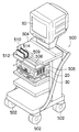
図23は、保持装置の第3の実施形態を示す斜視図である。同図に示す第3の実施形態の保持装置は、カート500に一体的に形成されている。カート500は、光源装置20、プロセッサ30、モニタ60を搭載する台車であり、車輪502、502…を備え、移動自在に構成される。車輪502には不図示のロック機構が取り付けられており、カート500を固定させることができる。また、カート500は、固定テーブル504と、手前に引き出せる移動テーブル506を備え、移動テーブル506には、ガイドレール508が横方向(すなわち、移動テーブル506の移動方向と直交する方向)に形成される。ガイドレール508には、走行体509がガイドレール509に沿って移動自在に取り付けられ、この走行体509に保持具510が取り付けられる。走行体509は、不図示の駆動手段によってガイドレール508に沿って自動で移動するようになっている。また、前記移動テーブル506は、不図示の駆動手段によって自動で固定テーブル504に対して移動するようになっている。なお、走行体509の移動と、移動テーブル506の移動は手動で行うようにしてもよい。   FIG. 23 is a perspective view showing a third embodiment of the holding device. The holding device of the third embodiment shown in the figure is formed integrally with the cart 500. The cart 500 is a carriage on which the light source device 20, the processor 30, and the monitor 60 are mounted, and includes wheels 502, 502, and is configured to be movable. A lock mechanism (not shown) is attached to the wheel 502, and the cart 500 can be fixed. Further, the cart 500 includes a fixed table 504 and a moving table 506 that can be pulled out to the front, and a guide rail 508 is formed on the moving table 506 in the lateral direction (that is, a direction orthogonal to the moving direction of the moving table 506). . A traveling body 509 is attached to the guide rail 508 movably along the guide rail 509, and a holder 510 is attached to the traveling body 509. The traveling body 509 is automatically moved along the guide rail 508 by driving means (not shown). The moving table 506 is automatically moved relative to the fixed table 504 by a driving means (not shown). Note that the movement of the traveling body 509 and the movement of the moving table 506 may be performed manually.

保持具510は、図21の保持具462と同様に、略コ字状に形成された支持体512と、その内側に取り付けられた弾性体514によって構成され、内視鏡10の手元操作部14、或いは挿入補助具70の把持部74を差し込んで保持できるようになっている。 Similar to the holder 462 in FIG. 21, the holder 510 includes a support body 512 formed in a substantially U-shape and an elastic body 514 attached to the inside thereof, and the hand operation unit 14 of the endoscope 10. or so as to be capable of retaining insert the grip portion 74 of the insertion assisting tool 70.

上記の如く構成されたカート500は、保持具510が患者1の挿入口(口又は肛門)の近傍に配置されるように車輪502を移動して車輪502をロックする。そして、患者1に挿入した内視鏡10又は挿入補助具70を必要に応じて保持具512に差し込んで保持させる。これにより、内視鏡10や挿入補助具70を把持する必要がなくなり、術者が一人で操作することが可能となる。なお、内視鏡10や挿入補助具70の挿入方向の調節は、移動テーブル506を移動させることによって行うことができる。また、走行体509をガイドレール508に沿って移動させることによって、保持具510で保持した内視鏡10又は挿入補助具70を挿入方向に移動させることができる。よって、内視鏡10又は挿入補助具70を患者1に自動挿入することができる。   The cart 500 configured as described above moves the wheels 502 to lock the wheels 502 so that the holder 510 is disposed in the vicinity of the insertion opening (mouth or anus) of the patient 1. Then, the endoscope 10 or the insertion assisting tool 70 inserted into the patient 1 is inserted into the holding tool 512 and held as necessary. Thereby, it is not necessary to hold the endoscope 10 or the insertion assisting tool 70, and the operator can operate alone. The insertion direction of the endoscope 10 and the insertion assisting tool 70 can be adjusted by moving the moving table 506. Further, by moving the traveling body 509 along the guide rail 508, the endoscope 10 or the insertion assisting tool 70 held by the holding tool 510 can be moved in the insertion direction. Therefore, the endoscope 10 or the insertion assisting tool 70 can be automatically inserted into the patient 1.

なお、上述した装置において、保持具510を二つ設け、両方の保持具510がガイドレール508に沿って移動するように構成してもよい。これにより、内視鏡10と挿入補助具70を二つの保持具510に保持させ、内視鏡10の移動と挿入補助具70の移動の両方を自動で行うことができる。   In the above-described apparatus, two holders 510 may be provided, and both holders 510 may be configured to move along the guide rail 508. Thereby, the endoscope 10 and the insertion assisting tool 70 are held by the two holders 510, and both the movement of the endoscope 10 and the movement of the insertion assisting tool 70 can be performed automatically.

また、上述した実施形態では、保持具510をガイドレール508に沿って移動できるように構成したが、これに限定するものではなく、移動テーブル506や固定テーブル508等に固定してもよい。この場合にも、カート500を移動させることによって、保持具510の位置を調節することができる。さらに、保持具510を嵌合や磁着等によって着脱自在となるように移動テーブル506等に取り付けてもよい。このように保持具510を着脱自在に構成すると、保持具510で内視鏡10や挿入補助具70を保持したまま、任意の位置に移動させることができる。よって、保持具510を患者1への挿入に適した位置に配置したり、或いは、検査の邪魔にならない位置に一旦、退避させたりすることができる。なお、図4に示した保持具210、230、又は図16や図20に示した保持具412、422、或いは図20の保持具462を着脱自在に構成し、その保持具210、230、412、422、462を取り外してカート500や検査台2に装着するようにしてもよい。   In the above-described embodiment, the holder 510 is configured to be movable along the guide rail 508. However, the present invention is not limited to this, and the holder 510 may be fixed to the moving table 506, the fixed table 508, or the like. Also in this case, the position of the holder 510 can be adjusted by moving the cart 500. Further, the holder 510 may be attached to the moving table 506 or the like so as to be detachable by fitting or magnetic attachment. When the holder 510 is configured to be detachable as described above, the endoscope 10 and the insertion assisting tool 70 can be moved to an arbitrary position while the holder 510 is held. Therefore, the holder 510 can be disposed at a position suitable for insertion into the patient 1 or can be temporarily retracted to a position that does not interfere with the examination. Note that the holders 210 and 230 shown in FIG. 4, the holders 412 and 422 shown in FIG. 16 and FIG. 20, or the holder 462 of FIG. 422 and 462 may be removed and attached to the cart 500 or the inspection table 2.

図24は保持装置の第4の実施形態を示す斜視図である。図24に示す保持具550は、対向する一対の挟持板552、552を有し、この一対の挟持板552、552が所定の間隔で固定具554に取り付けられている。一対の挟持板552、552は外側に弾性変形させることができ、この一対の挟持板552、552の間に内視鏡10又は挿入補助具70を差し込むことによって、内視鏡10又は挿入補助具70が一対の挟持板552、552に挟持される。各挟持板552、552は、外側に円弧状に湾曲しており、この円弧部分に内視鏡10又は挿入補助具70が挟持され、保持される。   FIG. 24 is a perspective view showing a fourth embodiment of the holding device. The holding tool 550 shown in FIG. 24 has a pair of opposing clamping plates 552 and 552, and the pair of clamping plates 552 and 552 are attached to the fixture 554 at a predetermined interval. The pair of sandwiching plates 552 and 552 can be elastically deformed outward. By inserting the endoscope 10 or the insertion assisting tool 70 between the pair of sandwiching plates 552 and 552, the endoscope 10 or the insertion assisting tool. 70 is sandwiched between a pair of sandwiching plates 552 and 552. Each of the clamping plates 552 and 552 is curved outward in an arc shape, and the endoscope 10 or the insertion assisting tool 70 is clamped and held in the arc portion.

保持具550は、光源装置20の側面に着脱自在に取り付けられ、移動自在に支持される。すなわち、保持具550の固定部554には、略半球状の突起部556が設けられ、この突起部556が光源装置20の側面の開口558に挿入される。開口558は、矢印方向に細長く形成されたスリット開口部558Aと、このスリット開口部558Aの端部に大きく開口された取付開口部558Bとから成り、保持具550は、突起部556を取付開口部558Bに挿入し、スリット開口558Aに沿って移動させることによって、矢印方向に移動自在に支持される。光源装置20の内部には、突起部556が嵌合される嵌合部材(不図示)が設けられるとともに、この嵌合部材を矢印方向に駆動させる駆動手段(不図示)が設けられる。したがって、保持具550の矢印方向への移動を自動で行うことができる。なお、保持具550の移動は手動であってもよい。   The holder 550 is detachably attached to the side surface of the light source device 20, and is supported movably. That is, the fixing portion 554 of the holder 550 is provided with a substantially hemispherical protrusion 556, and the protrusion 556 is inserted into the opening 558 on the side surface of the light source device 20. The opening 558 includes a slit opening 558A that is elongated in the direction of the arrow, and a mounting opening 558B that is greatly opened at the end of the slit opening 558A. The holder 550 includes the protrusion 556 as a mounting opening. By being inserted into 558B and moved along the slit opening 558A, it is supported so as to be movable in the direction of the arrow. Inside the light source device 20, a fitting member (not shown) to which the protrusion 556 is fitted is provided, and driving means (not shown) for driving the fitting member in the arrow direction is provided. Therefore, the holder 550 can be automatically moved in the arrow direction. Note that the movement of the holder 550 may be manual.

上記の如く構成された保持具550に内視鏡10や挿入補助具70を保持させた場合にも、保持具550に保持した内視鏡10や挿入補助具70を移動させることができる。よって、内視鏡10や挿入補助具70のスムーズな挿入が可能となる。   Even when the endoscope 10 and the insertion assisting tool 70 are held by the holding tool 550 configured as described above, the endoscope 10 and the insertion assisting tool 70 held by the holding tool 550 can be moved. Therefore, the endoscope 10 and the insertion assisting tool 70 can be smoothly inserted.

なお、図24には、保持具550を光源装置20の側面に取り付ける例を示したが、これに限定するものではなく、光源装置20の前面や上面に取り付けるようにしてもよい。また、プロセッサ30やバルーン制御装置100等の周辺機器に保持具550を取り付けてもよく、さらには、検査台2等に取り付けてもよい。   In addition, although the example which attaches the holder 550 to the side surface of the light source device 20 was shown in FIG. 24, you may make it attach to the front surface or upper surface of the light source device 20 which is not limited to this. Further, the holder 550 may be attached to peripheral devices such as the processor 30 and the balloon control device 100, and may be attached to the examination table 2 or the like.

また、図24には、保持具550を矢印方向にスライド自在に取り付けた例を示したが、これに限定するものではなく、光源装置20等に固定されるようにしてもよい。   24 shows an example in which the holder 550 is slidably attached in the direction of the arrow. However, the present invention is not limited to this, and the holder 550 may be fixed to the light source device 20 or the like.

図25乃至図27は、図5に示した補助具保持具230の変形例である。図25の保持具600の上面には、挿入補助具70が嵌め込まれる断面円弧状の溝602が形成され、この溝602の両側には一対の挟持部504、504が形成されている。また、保持具600はプラスチック等の弾性変形しやすい材質から成り、挟持部504、504が外側に弾性変形するようになっている。したがって、挿入補助具70を上方から保持具600の溝602に差し込むと、一対の挟持部504、504が外側に弾性変形し、挿入補助具70が溝602に嵌め込まれる。そして、一対の挟持部504、504が弾性力によって元の形状に復帰することによって、挿入補助具70が一対の挟持部504、504によって挟持され、保持される。   25 to 27 are modifications of the auxiliary tool holder 230 shown in FIG. On the upper surface of the holder 600 in FIG. 25, a groove 602 having an arcuate cross section into which the insertion assisting tool 70 is fitted is formed. The holder 600 is made of a material that is easily elastically deformed, such as plastic, and the holding portions 504 and 504 are elastically deformed outward. Therefore, when the insertion assisting tool 70 is inserted into the groove 602 of the holding tool 600 from above, the pair of holding portions 504 and 504 are elastically deformed outward, and the insertion assisting tool 70 is fitted into the groove 602. Then, when the pair of sandwiching portions 504 and 504 are restored to the original shape by elastic force, the insertion assisting tool 70 is sandwiched and held by the pair of sandwiching portions 504 and 504.

図26に示す保持具610は、ガイドレール204に沿ってスライド自在に支持されたスライド部材612と、このスライド部材612の上端に固定された略半円状の固定挟持部材614と、この固定挟持部材614にピン616を介して回動自在に連結された略半円状の移動挟持部材618と、から構成されている。固定挟持部材614、移動挟持部材618にはそれぞれ、摘まみ部615、619が一体的に形成されている。この摘まみ部615、619の間には、ばね617が取り付けられ、摘まみ部615、619の間隔を拡げる方向に(すなわち、固定挟持部材614、移動挟持部材618の間隔を狭める方向に)付勢するようになっている。上記の如く構成された保持具610は、まず、ばね617の付勢力に抗して、摘まみ部615、619の間隔を狭めることによって、固定挟持部材614、移動挟持部材618の間隔を拡げる。そして、固定挟持部材614、移動挟持部材618の間に挿入補助具70を配置する。次いで、摘まみ部615、619から手を離し、ばね617の付勢力を利用して固定挟持部材614と移動挟持部材618で挿入補助具70を挟持させる。これにより、挿入補助具70が保持具610に保持される。   26 includes a slide member 612 slidably supported along the guide rail 204, a substantially semicircular fixed clamping member 614 fixed to the upper end of the sliding member 612, and the fixed clamping. The movable pinching member 618 has a substantially semicircular shape that is rotatably connected to the member 614 via a pin 616. Knob portions 615 and 619 are integrally formed with the fixed clamping member 614 and the movable clamping member 618, respectively. A spring 617 is attached between the knobs 615 and 619, and is attached in a direction to widen the gap between the knobs 615 and 619 (that is, in a direction to narrow the gap between the fixed clamping member 614 and the movable clamping member 618). It has come to force. The holder 610 configured as described above first widens the interval between the fixed clamping member 614 and the movable clamping member 618 by narrowing the interval between the knob portions 615 and 619 against the urging force of the spring 617. Then, the insertion assisting tool 70 is disposed between the fixed clamping member 614 and the movable clamping member 618. Next, the hand is released from the knobs 615 and 619, and the insertion assisting tool 70 is held between the fixed holding member 614 and the moving holding member 618 using the biasing force of the spring 617. Thereby, the insertion assisting tool 70 is held by the holding tool 610.

図27に示す保持具620は、固定挟持部材614の先端と移動挟持部材618の先端がそれぞれ屈曲され、嵌合部614A、618Aが形成されており、両者が嵌合するようになっている。したがって、保持具620によれば、固定挟持部材614と移動挟持部材618で挿入補助具70を挟持した際に嵌合部614A、618Aを嵌合させることができ、挿入補助具70を強固に保持することができる。   In the holder 620 shown in FIG. 27, the distal end of the fixed clamping member 614 and the distal end of the movable clamping member 618 are bent to form fitting portions 614A and 618A, respectively, so that both can be fitted. Therefore, according to the holding tool 620, when the insertion assisting tool 70 is clamped by the fixed clamping member 614 and the movable clamping member 618, the fitting portions 614A and 618A can be fitted, and the insertion assisting tool 70 is firmly held. can do.

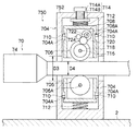
図28は本発明に係る保持装置の第5の実施形態が用いられた内視鏡装置の構成を示す斜視図であり、図29は保持装置の断面図である。これらの図に示す保持装置700は挿入補助具70に取り付けられ、内視鏡10の挿入部12を保持する装置である。   FIG. 28 is a perspective view showing a configuration of an endoscope apparatus in which the fifth embodiment of the holding apparatus according to the present invention is used, and FIG. 29 is a sectional view of the holding apparatus. The holding device 700 shown in these drawings is a device that is attached to the insertion assisting tool 70 and holds the insertion portion 12 of the endoscope 10.

これらの図に示すように、保持装置700は主としてケース702、スライダー704、ローラ706、及びモータ708によって構成される。   As shown in these drawings, the holding device 700 mainly includes a case 702, a slider 704, a roller 706, and a motor 708.

ケース702は、略円筒状に形成されており、その内径D1は、挿入部12の外径D2よりも大きく形成され、挿入部12を挿通できるようになっている。また、ケース702は、雌ねじ部702Aを有し、この雌ねじ部702Aが挿入補助具70の把持部74に螺合される。なお、ケース702は、挿入補助具70の把持部74に着脱自在に装着される構成であればよく、例えば嵌合や磁着によって装着されるようにしてもよい。 The case 702 is formed in a substantially cylindrical shape, and its inner diameter D1 is formed larger than the outer diameter D2 of the insertion portion 12, so that the insertion portion 12 can be inserted. The case 702 has a female screw portion 702A, and this female screw portion 702A is screwed into the gripping portion 74 of the insertion assisting tool 70. Note that the case 702 may be configured to be detachably attached to the grip portion 74 of the insertion assisting tool 70, and may be attached by fitting or magnetic attachment, for example.

ケース702の内部には、一対のスライダー704、704が設けられる。各スライダー704には、溝704A、704Aがケース702の径方向に形成されており、この溝704Aに、ケース702に突設したピン710が係合される。これにより、各スライダー704はケース702の径方向にスライド自在に支持される。   A pair of sliders 704 and 704 are provided inside the case 702. Each slider 704 has grooves 704A and 704A formed in the radial direction of the case 702, and a pin 710 protruding from the case 702 is engaged with the groove 704A. Accordingly, each slider 704 is supported to be slidable in the radial direction of the case 702.

各スライダー704の外側にはスプリング712が設けられ、このスプリング712によって各スライダー704が内側に向けて付勢される。各スプリング712の外側には、付勢力調整部材714が設けられる。付勢力調整部材712は、ケース702の外周面から径方向に螺入された調整ネジ714Aと、この調整ネジ714Aの先端に取り付けられた抑え板714Bとから成り、抑え板714Bとスライダー704との間にスプリング712が配設される。この付勢力調整部材714によれば、調整ネジ714Aを回転させて抑え板714Bを径方向に移動させることによって、抑え板714Bとスライダー704との間隔が変化し、スプリング712の付勢力が調整される。これにより、後述のローラ706によって挿入部12を押圧する押圧力を調整することができる。なお、付勢手段はスプリング712に限定されるものではなく、ゴム等の弾性体を用いてもよい。   A spring 712 is provided on the outside of each slider 704, and each slider 704 is urged inward by the spring 712. An urging force adjusting member 714 is provided outside each spring 712. The biasing force adjusting member 712 includes an adjusting screw 714A screwed in the radial direction from the outer peripheral surface of the case 702, and a holding plate 714B attached to the tip of the adjusting screw 714A. A spring 712 is disposed therebetween. According to the biasing force adjusting member 714, by rotating the adjusting screw 714A and moving the restraining plate 714B in the radial direction, the distance between the restraining plate 714B and the slider 704 changes, and the biasing force of the spring 712 is adjusted. The Thereby, the pressing force which presses the insertion part 12 with the below-mentioned roller 706 can be adjusted. The biasing means is not limited to the spring 712, and an elastic body such as rubber may be used.

また、各スライダー704にはローラ706が支持される。ローラ706は、各スライダー704の径方向の内側面から突出した状態に設けられ、ケース702に挿通させた挿入部12に当接される。また、ローラ706は、挿入部12を挿脱する方向に回転自在に支持されている。したがって、ローラ706を挿入部12に当接させて回転させることによって、挿入部12を挿脱させることができる。なお、ローラ706の外周面はゴム等の柔らかい材質で構成することが好ましく、これによって、挿入部12の表面に対して十分な摩擦力を得ることができ、且つ挿入部12の表面を傷つけることを防止できる。   Each slider 704 supports a roller 706. The roller 706 is provided in a state of protruding from the inner surface in the radial direction of each slider 704, and comes into contact with the insertion portion 12 inserted through the case 702. The roller 706 is supported so as to be rotatable in a direction in which the insertion portion 12 is inserted and removed. Therefore, the insertion portion 12 can be inserted and removed by rotating the roller 706 in contact with the insertion portion 12. The outer peripheral surface of the roller 706 is preferably made of a soft material such as rubber, whereby a sufficient frictional force can be obtained against the surface of the insertion portion 12 and the surface of the insertion portion 12 can be damaged. Can be prevented.

スライダー704、704の一方(図29の上側のスライダー704)には、ローラ706の回転軸716にギア718が取り付けられている。ギア718は、ギア720を介してギア722に噛み合っており、このギア722は、モータ708の回転軸708Aに取り付られている。モータ708は、スライダー704に固定されており、スライダー704とともにケース702の径方向にスライド自在に支持される。モータ708としては例えばステッピングモータが用いられ、回転軸708Aを所望の速度で正回転、或いは逆回転させることができる。したがって、モータ708を駆動することによって、ローラ706を正回転、或いは逆回転させることができる。よって、ローラ706に当接した挿入部12を挿入方向、或いは引き抜き方向に移動させることができる。ここで、正回転とは、挿入部12を挿入する方向の回転をいい、逆回転とは、挿入部12を引き抜く方向の回転をいう。なお、モータ708には、しきい値以上の負荷がかかった際に自動的に停止する安全機能と、回転駆動を停止した際に回転軸708Aの回転をロックするロック機能が設けられる。   A gear 718 is attached to the rotation shaft 716 of the roller 706 on one of the sliders 704 and 704 (the upper slider 704 in FIG. 29). The gear 718 meshes with the gear 722 via the gear 720, and the gear 722 is attached to the rotation shaft 708 </ b> A of the motor 708. The motor 708 is fixed to the slider 704 and is supported so as to be slidable in the radial direction of the case 702 together with the slider 704. For example, a stepping motor is used as the motor 708, and the rotating shaft 708A can be rotated forward or reverse at a desired speed. Therefore, by driving the motor 708, the roller 706 can be rotated forward or backward. Therefore, the insertion portion 12 that is in contact with the roller 706 can be moved in the insertion direction or the extraction direction. Here, forward rotation refers to rotation in a direction in which the insertion portion 12 is inserted, and reverse rotation refers to rotation in a direction in which the insertion portion 12 is pulled out. The motor 708 is provided with a safety function that automatically stops when a load equal to or greater than a threshold is applied, and a lock function that locks the rotation of the rotary shaft 708A when rotation driving is stopped.

モータ708の駆動制御は、バルーン制御装置100(図7)によって行われる。すなわち、バルーン制御装置100によって手動モードを選択し、操作ボタン130aを押下した際に、モータ708が駆動してローラ706を正回転し、操作ボタン130bを押下した際に、モータ708が駆動してローラ706が逆回転する。また、自動モードを選択し、操作ボタン132a、132b、136a、136bを押下した際に、予め記憶された操作手順に従ってモータ708が駆動してローラ706が正回転或いは逆回転するようになっている。なお、モータ708を駆動させるための操作ボタンを保持装置700のケース702に設けてもよい。すなわち、ケース702の外表面に、モータ708を駆動させるための操作ボタン、モータ708を停止させるための操作ボタン、及び、モータ708の正逆回転を切り替えるための操作ボタンを設けておき、これらの操作ボタンによってモータ708の駆動制御を行うようにしてもよい。   The drive control of the motor 708 is performed by the balloon control device 100 (FIG. 7). That is, when the manual mode is selected by the balloon control device 100 and the operation button 130a is pressed, the motor 708 is driven to rotate the roller 706 forward, and when the operation button 130b is pressed, the motor 708 is driven. The roller 706 rotates in the reverse direction. In addition, when the automatic mode is selected and the operation buttons 132a, 132b, 136a, and 136b are pressed, the motor 708 is driven according to the operation procedure stored in advance, and the roller 706 is rotated forward or backward. . Note that an operation button for driving the motor 708 may be provided on the case 702 of the holding device 700. That is, an operation button for driving the motor 708, an operation button for stopping the motor 708, and an operation button for switching forward / reverse rotation of the motor 708 are provided on the outer surface of the case 702. You may make it perform drive control of the motor 708 with an operation button.

前述したギア720には、エンコーダ724が接続されている。したがって、ギア720の回転数、すなわち、ローラ706の回転数をエンコーダ724によって測定することができる。エンコーダ724は、スライダー704又はケース702に搭載された不図示の演算装置に接続されており、この演算装置によってエンコーダ724の測定値が、挿入部12の挿入補助具70に対する相対的な移動量に換算される。そして、その換算値が積算されて、挿入量の総和が求められる。求めた挿入量の総和は、例えばバルーン専用モニタ106(図7参照)の総挿入量表示部120に表示される。これにより、挿入部12の先端が体腔内のどの位置まで到達したかを把握することができる。なお、ケース702の外表面に表示部を設け、この表示部に挿入量或いは挿入量の総和を表示するようにしてもよい。   An encoder 724 is connected to the gear 720 described above. Therefore, the rotation speed of the gear 720, that is, the rotation speed of the roller 706 can be measured by the encoder 724. The encoder 724 is connected to a calculation device (not shown) mounted on the slider 704 or the case 702, and the measurement value of the encoder 724 is converted to a relative movement amount of the insertion unit 12 with respect to the insertion assisting tool 70 by this calculation device. Converted. Then, the converted values are integrated to obtain the total amount of insertion. The total sum of the obtained insertion amounts is displayed, for example, on the total insertion amount display unit 120 of the balloon dedicated monitor 106 (see FIG. 7). Thereby, it can be grasped to which position in the body cavity the distal end of the insertion portion 12 has reached. Note that a display unit may be provided on the outer surface of the case 702, and the amount of insertion or the total amount of insertion may be displayed on this display unit.

上述した実施形態では、一つのスライダー704のみに駆動手段を設けたが、各スライダー704、704に駆動手段を搭載し、各ローラ706、706を同期して回転させるようにしてもよい。   In the above-described embodiment, the driving unit is provided only for one slider 704. However, the driving unit may be mounted on each slider 704 and 704, and the rollers 706 and 706 may be rotated in synchronization.

また、スライダー704及びローラ706の個数は特に限定するものではないが、挿入部12を安定して保持するために三個以上設けることが好ましい。この場合、周方向に等しい角度間隔で配置することが好ましい。   The number of sliders 704 and rollers 706 is not particularly limited, but it is preferable to provide three or more in order to stably hold the insertion portion 12. In this case, it is preferable to arrange them at equal angular intervals in the circumferential direction.

また、上述した実施形態では各ローラ706をスライダー704で支持し、径方向にスライドするようにしたが、一方のローラ706を固定するようにしてもよい。   In the above-described embodiment, each roller 706 is supported by the slider 704 and slid in the radial direction. However, one roller 706 may be fixed.

さらに、上述した実施形態では、モータ708を停止した際に回転軸708Aの回転をロックしたが、モータ708の停止時に内視鏡10の挿入部12と挿入補助具70との相対的な移動を防止する手段であればよく、例えば、ギア720や回転軸716の回転をロックするロック手段を設けたり、或いは、挿入部12にブレーキ部材を当接させてロックするロック手段を設けたりしても良い。   Further, in the above-described embodiment, the rotation of the rotary shaft 708A is locked when the motor 708 is stopped. However, when the motor 708 is stopped, the insertion portion 12 of the endoscope 10 and the insertion assisting tool 70 are relatively moved. For example, a locking unit that locks the rotation of the gear 720 and the rotating shaft 716 may be provided, or a locking unit that locks the insertion member 12 by contacting the brake member may be provided. good.

上記の如く構成された保持部材700の操作方法について説明する。   A method of operating the holding member 700 configured as described above will be described.

まず、準備作業として、挿入補助具70の把持部74に保持装置700のケース702を装着する。次いで、内視鏡10の挿入部12を保持部材700のケース702側から挿入補助具70内に挿入することによって、挿入補助具70を挿入部12に被せる。そして、保持部材700の付勢力調整部材714の調整ネジ714Aを回動することによって付勢力を調整し、ローラ706を挿入部12に当接させる。 First, as preparation work, mounting the case 702 of the holding device 700 to the grip portion 74 of the insertion assisting tool 70. Next, by inserting the insertion portion 12 of the endoscope 10 into the insertion assisting tool 70 from the case 702 side of the holding member 700, the insertion assisting tool 70 is put on the insertion portion 12. Then, the biasing force is adjusted by rotating the adjustment screw 714 </ b> A of the biasing force adjusting member 714 of the holding member 700, and the roller 706 is brought into contact with the insertion portion 12.

準備作業の終了後、図9に示した操作手順(ステップS2〜ステップS12)に従って各操作を行う。各操作は、バルーン制御装置100(図7参照)のリモートコントローラ104やフットスイッチ108を操作することによって行われる。   After completion of the preparation work, each operation is performed according to the operation procedure (steps S2 to S12) shown in FIG. Each operation is performed by operating the remote controller 104 or the foot switch 108 of the balloon control device 100 (see FIG. 7).

一連の操作手順のうち、内視鏡10(すなわち挿入部12)の挿入操作(ステップS4、ステップS11)は、挿入補助具70を把持して内視鏡10から手を離した状態で、モータ708を駆動させ、ローラ706を正回転させる。これにより、内視鏡10の挿入部12が挿入補助具70に対して挿入方向に移動し、挿入部12が自動的に体腔内に挿入される。挿入部12の挿入量はエンコーダ724によって測定され、この測定値が設定値になった際にモータ708が停止し、挿入操作が終了する。   Of the series of operation procedures, the insertion operation (step S4, step S11) of the endoscope 10 (that is, the insertion portion 12) is performed by holding the insertion assisting tool 70 and releasing the hand from the endoscope 10. 708 is driven to rotate the roller 706 forward. Thereby, the insertion part 12 of the endoscope 10 moves in the insertion direction with respect to the insertion assisting tool 70, and the insertion part 12 is automatically inserted into the body cavity. The amount of insertion of the insertion unit 12 is measured by the encoder 724, and when the measured value becomes a set value, the motor 708 is stopped and the insertion operation is completed.

挿入補助具70の押し込み操作(ステップS7)は、内視鏡10の手元操作部14を把持して挿入補助具70から手を離した状態で、モータ708を駆動させ、ローラ706を逆回転させる。これにより、挿入部12は挿入補助具70に対して引き抜き方向に移動するが、内視鏡12が保持されているため、保持装置700が挿入部12に沿って挿入方向に自走し、挿入補助具70が体腔内に自動的に押し込まれる。その際、挿入補助具70の押し込み量がエンコーダ724によって測定され、この測定値が設定値になった際にモータ708が停止し、押し込み操作が終了する。   In the pushing operation of the insertion assisting tool 70 (step S7), the motor 708 is driven and the roller 706 is rotated in the reverse direction while holding the hand operating part 14 of the endoscope 10 and releasing the hand from the insertion assisting tool 70. . As a result, the insertion unit 12 moves in the pulling direction with respect to the insertion assisting tool 70. However, since the endoscope 12 is held, the holding device 700 is self-propelled along the insertion unit 12 in the insertion direction. The auxiliary tool 70 is automatically pushed into the body cavity. At that time, the pushing amount of the insertion assisting tool 70 is measured by the encoder 724, and when the measured value becomes a set value, the motor 708 is stopped and the pushing operation is finished.

内視鏡10と挿入補助具70の手繰り寄せ操作(ステップS9)では、モータ708を停止し、ローラ706の回転を防止する。これによって、内視鏡10の挿入部12と挿入補助具70が固定されるので、内視鏡10或いは挿入補助具70の一方を把持して手繰り寄せるだけで、内視鏡10と挿入補助具70の両方を同時に手繰り寄せることができる。その際、モータ708の停止によってローラ706の回転がロックされるので、内視鏡10と挿入補助具70が確実に固定され、同時に手繰り寄せられる。   In the hand pulling operation (step S9) between the endoscope 10 and the insertion assisting tool 70, the motor 708 is stopped and the rotation of the roller 706 is prevented. As a result, the insertion portion 12 and the insertion assisting tool 70 of the endoscope 10 are fixed, so that the endoscope 10 and the insertion assisting tool can be simply held by gripping and pulling one of the endoscope 10 or the insertion assisting tool 70. Both 70s can be dragged at the same time. At this time, since the rotation of the roller 706 is locked by the stop of the motor 708, the endoscope 10 and the insertion assisting tool 70 are securely fixed, and are simultaneously pulled together.

このように本実施の形態によれば、挿入補助具70の把持部74に保持部材700を装着し、この保持部材700で内視鏡10の挿入部12を保持するようにしたので、内視鏡10の挿入操作、又は挿入補助具70の押し込み操作、或いは内視鏡10と挿入補助具70の手繰り寄せ操作を行う際に、内視鏡10と挿入補助具70の一方のみを把持して操作すればよく、操作性を向上させることができる。 As described above, according to the present embodiment, the holding member 700 is attached to the grip portion 74 of the insertion assisting tool 70, and the insertion member 12 of the endoscope 10 is held by the holding member 700. When performing the insertion operation of the mirror 10, the pushing operation of the insertion assisting tool 70, or the hand pulling operation of the endoscope 10 and the insertion assisting tool 70, only one of the endoscope 10 and the insertion assisting tool 70 is grasped. It is sufficient to operate, and the operability can be improved.

また、本実施形態によれば、ローラ706及びモータ708から成る移動手段を保持装置700に設けたので、内視鏡10の挿入操作、及び挿入補助具70の押し込み操作を自動で行うことができる。   Further, according to the present embodiment, since the moving device including the roller 706 and the motor 708 is provided in the holding device 700, the insertion operation of the endoscope 10 and the push-in operation of the insertion assisting tool 70 can be automatically performed. .

また、本実施形態によれば、スライダー704を径方向にスライド自在に設け、このスライダー704にローラ706を支持するとともに、スライダー704をスプリング712によって内側に付勢するようにしたので、ローラ706で挿入部12に確実に押圧することができる。また、ローラ706をスプリング712で付勢しながら内視鏡10の挿入部12に押し付けて回転させるようにしたので、挿入部12とローラ706の挿入抵抗を減少させることができる。   Further, according to the present embodiment, the slider 704 is provided so as to be slidable in the radial direction, the roller 706 is supported on the slider 704, and the slider 704 is biased inward by the spring 712. The insertion portion 12 can be surely pressed. Further, since the roller 706 is pressed against the insertion portion 12 of the endoscope 10 while being urged by the spring 712, the insertion resistance between the insertion portion 12 and the roller 706 can be reduced.

さらに、本実施形態によれば、付勢力調整部材714を設けることによって、ローラ706を挿入部12に付勢する付勢力を調整できるようにしたので、常に適切な付勢力をローラ706に与えることができる。また、挿入部12の外径が異なる様々な内視鏡10に対応することができる。   Furthermore, according to the present embodiment, by providing the biasing force adjusting member 714, the biasing force for biasing the roller 706 to the insertion portion 12 can be adjusted, so that an appropriate biasing force is always given to the roller 706. Can do. Moreover, it can respond to the various endoscope 10 from which the outer diameter of the insertion part 12 differs.

なお、上述した実施形態において、保持装置700のケース702を図1の検査台2や補助台3、或いは図23のカート500等に固定してもよい。また、ケース702を図16や図21に示したアーム機構を介して他の装置に固定するようにしてもよい。   In the above-described embodiment, the case 702 of the holding device 700 may be fixed to the inspection table 2 or the auxiliary table 3 in FIG. 1, the cart 500 in FIG. Further, the case 702 may be fixed to another device via the arm mechanism shown in FIGS.

また、ケース702を挿入補助具70に一体化して形成したり、或いは挿入補助具70内に組み込むようにしてもよい。   Further, the case 702 may be formed integrally with the insertion assisting tool 70 or may be incorporated into the insertion assisting tool 70.

また、上述した実施形態は、内視鏡10を保持する保持装置700の例であるが、挿入補助具70を保持する保持装置にも適用することができる。図30は、挿入補助具70を保持する保持装置750を示す断面図である。同図に示す保持装置750は、ケース752が検査台2に固定される。また、ケース752は略円筒状に形成されており、その内径D3が挿入補助具70のチューブ部分の外径D4よりも大きく形成されている。したがって、挿入補助具70のチューブ部分をケース752に挿通させることができる。なお、保持装置750は、ケース752以外の構成が図29の保持装置700と同様に構成される。すなわち、スライダー704、704はケース702に径方向にスライド自在に支持され、このスライダー704、704にローラ706、706が回動自在に支持される。スライダー704、704はスプリング712、712によって内側方向に付勢されており、これによってローラ706、706が挿入補助具70の外周面に当接される。ローラ706にはモータ708が接続されており、モータ708を駆動することによってローラ706が正回転或いは逆回転するようになっている。   The above-described embodiment is an example of the holding device 700 that holds the endoscope 10, but can also be applied to a holding device that holds the insertion assisting tool 70. FIG. 30 is a cross-sectional view showing a holding device 750 that holds the insertion assisting tool 70. In the holding device 750 shown in the figure, the case 752 is fixed to the inspection table 2. The case 752 is formed in a substantially cylindrical shape, and its inner diameter D3 is formed larger than the outer diameter D4 of the tube portion of the insertion assisting tool 70. Therefore, the tube portion of the insertion assisting tool 70 can be inserted into the case 752. The holding device 750 is configured in the same manner as the holding device 700 in FIG. 29 except for the case 752. That is, the sliders 704 and 704 are supported by the case 702 so as to be slidable in the radial direction, and the rollers 706 and 706 are rotatably supported by the sliders 704 and 704. The sliders 704 and 704 are urged inward by springs 712 and 712, whereby the rollers 706 and 706 are brought into contact with the outer peripheral surface of the insertion assisting tool 70. A motor 708 is connected to the roller 706, and the roller 706 rotates forward or backward by driving the motor 708.

上記の如く構成された保持装置750によれば、モータ708を駆動することによってローラ706が回転するので、挿入補助具70を体腔内に挿入したり、或いは体腔内から引き抜くことができる。したがって、挿入補助具70の押し込み操作と手繰り寄せ操作を自動で行うことができる。   According to the holding device 750 configured as described above, since the roller 706 rotates by driving the motor 708, the insertion assisting tool 70 can be inserted into or extracted from the body cavity. Therefore, the pushing-in operation and the hand-drawing operation of the insertion assisting tool 70 can be automatically performed.

なお、図30の保持装置750を、図29の保持装置700と組み合わせて使用してもよい。これにより、内視鏡10の挿入操作、挿入補助具70の押し込み操作、及び、内視鏡10と挿入補助具70の手繰り寄せ操作を全て自動で行うことができる。   Note that the holding device 750 in FIG. 30 may be used in combination with the holding device 700 in FIG. 29. Thereby, the insertion operation of the endoscope 10, the pushing operation of the insertion assisting tool 70, and the hand feeding operation of the endoscope 10 and the insertion assisting tool 70 can all be performed automatically.

また、図30の保持装置750はケース752を検査台2に固定したが、他の装置や機器等に固定してもよい。例えば、保持装置750のケース752を、補助台3(図1参照)やカート500(図23参照)等に固定してもよい。また、図16や図21に示したアーム機構を介して保持装置750を他の装置に固定するようにしてもよい。   In addition, although the holding device 750 of FIG. 30 fixes the case 752 to the inspection table 2, it may be fixed to other devices or devices. For example, the case 752 of the holding device 750 may be fixed to the auxiliary table 3 (see FIG. 1), the cart 500 (see FIG. 23), or the like. Further, the holding device 750 may be fixed to another device via the arm mechanism shown in FIG. 16 or FIG.

さらに、挿入補助具70を保持する保持装置を、内視鏡10に取り付けるようにしてもよい。例えば、内視鏡10の挿入部12において、挿入補助具70が常に被せられる部分に保持装置を設ける。保持装置としては、挿入部12の外表面から突出したローラを設け、このローラを挿入補助具70の内周面に当接させて回転させるとよい。これにより、挿入補助具70を内視鏡10に保持させることができるので、内視鏡10、挿入補助具70の一方を把持することによって両方を保持することができる。   Furthermore, a holding device that holds the insertion assisting tool 70 may be attached to the endoscope 10. For example, in the insertion portion 12 of the endoscope 10, a holding device is provided in a portion where the insertion assisting tool 70 is always covered. As the holding device, a roller protruding from the outer surface of the insertion portion 12 may be provided, and this roller may be brought into contact with the inner peripheral surface of the insertion assisting tool 70 and rotated. As a result, the insertion assisting tool 70 can be held by the endoscope 10, so that both can be held by gripping one of the endoscope 10 and the insertion assisting tool 70.

図31は、保護チューブ760を用いてチューブ64、80を保護した内視鏡装置を示す構成図である。同図に示す保護チューブ760はチューブ64、80を結束し、且つ被覆する硬質のチューブであり、例えば、シリコンゴムから成る螺旋チューブやフッ素樹脂から成る筒状チューブが用いられる。このような保護チューブ760を用いることによって、チューブ64、80が潰れることを防止できる。よって、チューブ64、80が潰れてエアの送気不良や排気不良が発生することを防止できる。また、保護チューブ760を用いることによって、チューブ64、80がバラバラになってチューブ64、80同士が絡んだり、他の機器等に引っ掛かることを防止できる。なお、保護チューブ760の先端760Aから露出する部分は、チューブ64よりもチューブ80が短くなるように設定することが好ましい。このように挿入補助具70側のチューブ80の露出部分を短くし、弛みを無くすことによって、操作性を向上させることができる。すなわち、挿入補助具70の把持部74近辺でチューブ80が弛んでいると、挿入補助具70を移動させた際に絡みやすく操作性が悪いという問題があるが、チューブ80の露出部分を短くすることによってチューブ80の弛みを防止でき、操作性を向上させることができる。 FIG. 31 is a configuration diagram showing an endoscope apparatus in which the tubes 64 and 80 are protected by using the protection tube 760. The protective tube 760 shown in the figure is a hard tube that binds and covers the tubes 64 and 80. For example, a spiral tube made of silicon rubber or a cylindrical tube made of fluororesin is used. By using such a protective tube 760, the tubes 64 and 80 can be prevented from being crushed. Therefore, it is possible to prevent the tubes 64 and 80 from being crushed and causing poor air supply and exhaust. Further, by using the protective tube 760, it is possible to prevent the tubes 64 and 80 from falling apart and being entangled with each other or being caught by other devices. The portion exposed from the tip 760 </ b> A of the protective tube 760 is preferably set so that the tube 80 is shorter than the tube 64. Thus, the operability can be improved by shortening the exposed portion of the tube 80 on the insertion assisting tool 70 side and eliminating the slack. That is, if the tube 80 is loose in the vicinity of the gripping portion 74 of the insertion assisting tool 70, there is a problem that it is easily entangled when the insertion assisting tool 70 is moved, but the operability is poor, but the exposed portion of the tube 80 is shortened. As a result, loosening of the tube 80 can be prevented and operability can be improved.

本発明に係る内視鏡装置が適用された検査室の内部を示す斜視図The perspective view which shows the inside of the examination room to which the endoscope apparatus according to the present invention is applied. 本発明に係る内視鏡装置の実施形態を示すシステム構成図System configuration diagram showing an embodiment of an endoscope apparatus according to the present invention 図2の挿入部の先端を示す斜視図The perspective view which shows the front-end | tip of the insertion part of FIG. 図1の保持装置の構成を示す側面図The side view which shows the structure of the holding | maintenance apparatus of FIG. 図4の5−5線に沿う断面図Sectional view along line 5-5 in FIG. 図4の6−6線に沿う断面図Sectional drawing which follows the 6-6 line of FIG. バルーン制御装置の構成を示す斜視図The perspective view which shows the structure of a balloon control apparatus バルーン制御装置の内部構成を示すブロック図Block diagram showing the internal configuration of the balloon control device 本発明に係る内視鏡装置の操作手順を示すフローチャートThe flowchart which shows the operation procedure of the endoscope apparatus which concerns on this invention. 本発明に係る内視鏡装置の操作手順を示す説明図Explanatory drawing which shows the operation procedure of the endoscope apparatus which concerns on this invention 図6と異なる構成の挿入量測定手段を示す側面図FIG. 6 is a side view showing an insertion amount measuring means having a configuration different from that of FIG. 図6と異なる構成の挿入量測定手段を示す側面図FIG. 6 is a side view showing an insertion amount measuring means having a configuration different from that of FIG. 図6と異なる構成の挿入量測定手段を示す側面図FIG. 6 is a side view showing an insertion amount measuring means having a configuration different from that of FIG. 把手を備えた保持装置の断面図Cross section of holding device with handle 挿入補助具用の保持装置を示す側面図Side view showing a holding device for an insertion aid 保持装置の第2の実施形態を示す斜視図The perspective view which shows 2nd Embodiment of a holding device. 図16の保持具の平面図The top view of the holder of FIG. 内視鏡の手元操作部を保持した保持具の平面図Top view of the holder holding the hand operation part of the endoscope 挿入補助具の基端部を保持した保持具の平面図Top view of the holder holding the proximal end of the insertion aid 図16と異なる構造の保持装置を示す斜視図The perspective view which shows the holding | maintenance apparatus of a structure different from FIG. 図20の保持装置の変形例を示す斜視図The perspective view which shows the modification of the holding | maintenance apparatus of FIG. 図16と異なる構造の保持装置を示す斜視図The perspective view which shows the holding | maintenance apparatus of a structure different from FIG. 保持装置の第3の実施形態を示す斜視図The perspective view which shows 3rd Embodiment of a holding device. 保持装置の第4の実施形態を示す斜視図The perspective view which shows 4th Embodiment of a holding device. 図5と異なる構造の保持具を示す正面図The front view which shows the holder of a structure different from FIG. 図5と異なる構造の保持具を示す正面図The front view which shows the holder of a structure different from FIG. 図5と異なる構造の保持具を示す正面図The front view which shows the holder of a structure different from FIG. 保持装置の第4の実施形態を示すシステム構成図System configuration diagram showing a fourth embodiment of the holding device 図28の保持装置の構成を示す断面図Sectional drawing which shows the structure of the holding | maintenance apparatus of FIG. 挿入補助具を保持する保持装置を示す断面図Sectional drawing which shows the holding | maintenance apparatus holding an insertion auxiliary tool 保護チューブを用いた内視鏡装置を示す構成図Configuration diagram showing an endoscope apparatus using a protective tube

符号の説明Explanation of symbols

10…内視鏡、12…挿入部、14…手元操作部、42…第1バルーン、70…挿入補助具、72…第2バルーン、100…バルーン制御装置、200…保持装置、202…ステージ、204…ガイドレール、210…内視鏡保持具、230…補助具保持具、400…保持装置、410、420…アーム、412、422…保持具、450…保持装置、456、458…アーム、462…保持具、472、478…ガイドレール、480…保持装置、492、494…保持具、500…カート、700…保持装置、702…ケース、704…スライダ、706…ローラ、708…モータ   DESCRIPTION OF SYMBOLS 10 ... Endoscope, 12 ... Insertion part, 14 ... Hand operation part, 42 ... 1st balloon, 70 ... Insertion aid, 72 ... 2nd balloon, 100 ... Balloon control apparatus, 200 ... Holding apparatus, 202 ... Stage, 204 ... Guide rail, 210 ... Endoscope holder, 230 ... Auxiliary tool holder, 400 ... Holding device, 410, 420 ... Arm 412, 422 ... Holding tool, 450 ... Holding device, 456, 458 ... Arm, 462 ... retainer, 472, 478 ... guide rail, 480 ... retainer, 492, 494 ... retainer, 500 ... cart, 700 ... retainer, 702 ... case, 704 ... slider, 706 ... roller, 708 ... motor

Claims (21)

内視鏡の挿入部に被せられて前記挿入部の挿入を補助するとともに、可撓性を有し、且つ、基端側に硬質の把持部を有する挿入補助具を保持する保持装置であって、A holding device that covers an insertion portion of an endoscope and assists insertion of the insertion portion, and holds an insertion assisting tool having flexibility and a rigid gripping portion on a proximal end side. ,
前記把持部を保持する補助具保持部と、An auxiliary tool holding part for holding the grip part;
前記把持部よりも先端側を前記挿入補助具の挿入方向にガイドするガイド部材と、A guide member that guides the distal end side of the grip portion in the insertion direction of the insertion assisting tool;
を備えたことを特徴とする保持装置。A holding device comprising:
前記補助具保持部は前記挿入方向に移動自在に支持されることを特徴とする請求項1に記載の保持装置。The holding device according to claim 1, wherein the auxiliary tool holding portion is supported movably in the insertion direction. 前記補助具保持部を前記挿入方向にのみ移動可能に支持するガイドを備えたことを特徴とする請求項2に記載の保持装置。The holding device according to claim 2, further comprising a guide that supports the auxiliary tool holding portion so as to be movable only in the insertion direction. 前記内視鏡の手元操作部を保持する内視鏡保持部を備えることを特徴とする請求項1〜3のいずれか1に記載の保持装置。The holding apparatus according to any one of claims 1 to 3, further comprising an endoscope holding unit that holds a hand operation unit of the endoscope. 前記補助具保持部と前記内視鏡保持部が前記挿入方向に並んで配置されるとともに、前記補助具保持部及び前記内視鏡保持部が前記挿入方向に移動自在に支持されることを特徴とする請求項4に記載の保持装置。The auxiliary tool holding part and the endoscope holding part are arranged side by side in the insertion direction, and the auxiliary tool holding part and the endoscope holding part are supported movably in the insertion direction. The holding device according to claim 4. 前記補助具保持部には把手が設けられたことを特徴とする請求項1〜5のいずれか1に記載の保持装置。The holding device according to claim 1, wherein a handle is provided in the auxiliary tool holding portion. 前記ガイド部材と前記補助具保持部との間には、前記挿入補助具を覆う筒状のカバーが設けられることを特徴とする請求項1〜6のいずれか1に記載の保持装置。The holding device according to claim 1, wherein a cylindrical cover that covers the insertion assisting tool is provided between the guide member and the assisting tool holding part. 前記補助具保持部と前記内視鏡保持部との間には、前記挿入部を覆う筒状のカバーが設けられることを特徴とする請求項3又は4に記載の保持装置。The holding device according to claim 3 or 4, wherein a cylindrical cover that covers the insertion portion is provided between the auxiliary tool holding portion and the endoscope holding portion. 前記補助具保持部は、前記把持部が差し込まれる開口を有する形状であることを特徴とする請求項1〜8のいずれか1に記載の保持装置。The holding device according to claim 1, wherein the auxiliary tool holding portion has a shape having an opening into which the grip portion is inserted. 前記補助具保持部は、断面円弧状の溝を形成することによって前記開口が形成され、該溝の両側に弾性変形可能な一対の挟持部が形成されるとともに、The auxiliary tool holding part is formed with the opening by forming a groove having an arc-shaped cross section, and a pair of holding parts that can be elastically deformed are formed on both sides of the groove,
前記溝に前記把持部が嵌め込まれた際に前記一対の挟持部によって前記把持部が挟持されることを特徴とする請求項9に記載の保持装置。The holding device according to claim 9, wherein when the grip portion is fitted into the groove, the grip portion is clamped by the pair of clamp portions.
前記補助具保持部は、略コ字状に形成されることによって前記開口が形成されることを特徴とする請求項9に記載の保持装置。The holding device according to claim 9, wherein the opening is formed by forming the auxiliary tool holding portion in a substantially U shape. 前記略コ字状の内側に弾性部材が設けられることを特徴とする請求項11に記載の保持装置。The holding device according to claim 11, wherein an elastic member is provided inside the substantially U-shape. 前記補助具保持部は、複数の筒部材が入れ子式に構成されるとともに前記挿入方向に伸縮自在に構成されたアーム機構によって支持されることを特徴とする請求項1〜12のいずれか1に記載の保持装置。The said auxiliary tool holding | maintenance part is supported by the arm mechanism comprised so that the some cylindrical member was nested, and was able to expand-contract in the said insertion direction, It is any one of Claims 1-12 characterized by the above-mentioned. The holding device as described. 前記補助具保持部は、複数のアームが回動自在に連結されたアーム機構を介して支持されることを特徴とする請求項1〜12のいずれか1に記載の保持装置。The holding device according to claim 1, wherein the auxiliary tool holding portion is supported via an arm mechanism in which a plurality of arms are rotatably connected. 前記補助具保持部は、検査台に移動自在に支持されたアーム機構を介して支持されることを特徴とする請求項1〜12のいずれか1に記載の保持装置。The holding device according to claim 1, wherein the auxiliary tool holding unit is supported via an arm mechanism that is movably supported by an examination table. 前記補助具保持部は、移動自在なカートに取り付けられることを特徴とする請求項1〜12のいずれか1に記載の保持装置。The holding device according to claim 1, wherein the auxiliary tool holding unit is attached to a movable cart. 前記補助具保持部を前記挿入方向に移動させる駆動装置を備えたことを特徴とする請求項1〜16のいずれか1に記載の保持装置。The holding device according to claim 1, further comprising a drive device that moves the auxiliary tool holding portion in the insertion direction. 前記駆動装置は、送りネジにより前記補助具保持部を移動させることを特徴とする請求項17に記載の保持装置。The holding device according to claim 17, wherein the driving device moves the auxiliary tool holding portion with a feed screw. 前記補助具保持部に螺合される第1の送りネジを備え、該第1の送りネジを回転させることによって前記補助具保持部を前記挿入方向に移動させる第1の駆動装置と、A first drive device that includes a first feed screw that is screwed into the auxiliary tool holding portion, and moves the auxiliary tool holding portion in the insertion direction by rotating the first feed screw;
前記内視鏡保持部に螺合される第2の送りネジを備え、該第2の送りネジを回転させることによって前記内視鏡保持部を前記挿入方向に移動させる第2の駆動装置と、を備えるとともに、A second drive device comprising a second feed screw threadedly engaged with the endoscope holding portion, and moving the endoscope holding portion in the insertion direction by rotating the second feed screw; With
前記補助具保持部には、前記第2の送りネジよりも大きい孔が形成され、該孔に前記第2の送りネジが挿通され、A hole larger than the second feed screw is formed in the auxiliary tool holding portion, and the second feed screw is inserted into the hole,
前記内視鏡保持部には、前記第1の送りネジよりも大きい孔が形成され、該孔に前記第1の送りネジが挿通されることを特徴とする請求項5に記載の保持装置。6. The holding apparatus according to claim 5, wherein a hole larger than the first feed screw is formed in the endoscope holding portion, and the first feed screw is inserted into the hole.
前記補助具保持部の移動量を測定することによって、該挿入補助具の挿入量の総和を求める挿入量測定手段を備えたことを特徴とする請求項1〜19のいずれか1に記載の保持装置。The holding device according to claim 1, further comprising an insertion amount measuring unit that calculates a total amount of insertion of the insertion assisting tool by measuring a moving amount of the assisting tool holding unit. apparatus. 前記挿入補助具には歪みゲージが設けられることを特徴とする請求項1〜20のいずれか1に記載の保持装置。The holding device according to claim 1, wherein the insertion assisting tool is provided with a strain gauge.
JP2005015711A 2004-03-31 2005-01-24 Holding device Active JP3922284B2 (en)

Priority Applications (4)

Application Number Priority Date Filing Date Title
JP2005015711A JP3922284B2 (en) 2004-03-31 2005-01-24 Holding device
US11/094,568 US7833150B2 (en) 2004-03-31 2005-03-31 Holding device, endoscopic device, and operating method of endoscopic device
EP05252008A EP1582139A3 (en) 2004-03-31 2005-03-31 Holding device, endoscopic device and operating method of endoscopic device
CNB2005100629495A CN100355389C (en) 2004-03-31 2005-03-31 Holding device, endoscopic device, and operating method of endoscopic device

Applications Claiming Priority (3)

Application Number Priority Date Filing Date Title
JP2004107179 2004-03-31
JP2004308690 2004-10-22
JP2005015711A JP3922284B2 (en) 2004-03-31 2005-01-24 Holding device

Publications (2)

Publication Number Publication Date
JP2006141976A JP2006141976A (en) 2006-06-08
JP3922284B2 true JP3922284B2 (en) 2007-05-30

Family

ID=34890908

Family Applications (1)

Application Number Title Priority Date Filing Date
JP2005015711A Active JP3922284B2 (en) 2004-03-31 2005-01-24 Holding device

Country Status (4)

Country Link
US (1) US7833150B2 (en)
EP (1) EP1582139A3 (en)
JP (1) JP3922284B2 (en)
CN (1) CN100355389C (en)

Families Citing this family (120)

* Cited by examiner, † Cited by third party
Publication number Priority date Publication date Assignee Title
US7635342B2 (en) * 2001-05-06 2009-12-22 Stereotaxis, Inc. System and methods for medical device advancement and rotation
DE102004052036A1 (en) * 2004-10-26 2006-04-27 Stm Medizintechnik Starnberg Gmbh Endoscope for examining channel-like cavity e.g. duodenum, has alternating propulsion system to propel endoscope shaft into cavity using auxiliary unit e.g. flexible tube with fluid pad, or guided wire
JP3859081B2 (en) * 2004-11-04 2006-12-20 フジノン株式会社 Balloon control device for endoscope apparatus
JP3874298B2 (en) * 2004-11-05 2007-01-31 フジノン株式会社 Balloon control device for endoscope apparatus
US20080091062A1 (en) * 2005-02-07 2008-04-17 Smart Medical Systems, Ltd. Endoscope assembly
JP2006288751A (en) * 2005-04-11 2006-10-26 Olympus Corp Electric bending endoscopy instrument
JP4868784B2 (en) * 2005-07-14 2012-02-01 オリンパスメディカルシステムズ株式会社 Endoscope device
US7930065B2 (en) 2005-12-30 2011-04-19 Intuitive Surgical Operations, Inc. Robotic surgery system including position sensors using fiber bragg gratings
US9962066B2 (en) * 2005-12-30 2018-05-08 Intuitive Surgical Operations, Inc. Methods and apparatus to shape flexible entry guides for minimally invasive surgery
CA2651081A1 (en) * 2006-05-03 2007-11-15 Wilson-Cook Medical Inc. Endoscope rotational and positioning apparatus and method
KR101477121B1 (en) 2006-06-13 2014-12-29 인튜어티브 서지컬 인코포레이티드 Minimally invasive surgical system
JP4709708B2 (en) * 2006-07-31 2011-06-22 オリンパスメディカルシステムズ株式会社 Endoscope device, endoscope light source device, and suction tube holding member
US7946546B2 (en) 2006-10-20 2011-05-24 Carnegie Mellon University Apparatus for positioning a device
US9289266B2 (en) 2006-12-01 2016-03-22 Boston Scientific Scimed, Inc. On-axis drive systems and methods
JP4914736B2 (en) 2007-02-14 2012-04-11 オリンパスメディカルシステムズ株式会社 Endoscope system
WO2008131093A2 (en) * 2007-04-17 2008-10-30 Fox Chase Cancer Center Method and apparatus for endoscopic examination of lesions
US9096033B2 (en) 2007-06-13 2015-08-04 Intuitive Surgical Operations, Inc. Surgical system instrument sterile adapter
GB0804633D0 (en) * 2008-03-12 2008-04-16 Prosurgics Ltd a telescopic support
US8641663B2 (en) 2008-03-27 2014-02-04 St. Jude Medical, Atrial Fibrillation Division, Inc. Robotic catheter system input device
US9161817B2 (en) 2008-03-27 2015-10-20 St. Jude Medical, Atrial Fibrillation Division, Inc. Robotic catheter system
US8317744B2 (en) 2008-03-27 2012-11-27 St. Jude Medical, Atrial Fibrillation Division, Inc. Robotic catheter manipulator assembly
US8343096B2 (en) 2008-03-27 2013-01-01 St. Jude Medical, Atrial Fibrillation Division, Inc. Robotic catheter system
WO2009120982A2 (en) 2008-03-27 2009-10-01 St. Jude Medical, Atrial Fibrillation Division, Inc. Robotic catheter system with dynamic response
US8684962B2 (en) 2008-03-27 2014-04-01 St. Jude Medical, Atrial Fibrillation Division, Inc. Robotic catheter device cartridge
US9241768B2 (en) 2008-03-27 2016-01-26 St. Jude Medical, Atrial Fibrillation Division, Inc. Intelligent input device controller for a robotic catheter system
JP2009273827A (en) * 2008-05-19 2009-11-26 Ntn Corp Linear object operation controller
WO2009125744A1 (en) * 2008-04-10 2009-10-15 Ntn株式会社 Linear object operation controller which controls operation of linear object by operator
JP2011520480A (en) 2008-04-29 2011-07-21 ウィルソン−クック・メディカル・インコーポレーテッド Equipment table for medical procedures
US8333689B2 (en) 2008-05-13 2012-12-18 Olympus Medical Systems Corp. Medical operation device
US8758223B1 (en) * 2008-10-02 2014-06-24 Integrated Medical Systems International, Inc. Test equipment for endoscopes
JP5403785B2 (en) 2008-10-15 2014-01-29 国立大学法人 名古屋工業大学 Insertion device
WO2010100777A1 (en) * 2009-03-05 2010-09-10 オリンパスメディカルシステムズ株式会社 Medical device
EP2413775A4 (en) * 2009-04-01 2014-01-15 Univ Florida Apparatuses for advancing an endoscope through a passage
US9254123B2 (en) 2009-04-29 2016-02-09 Hansen Medical, Inc. Flexible and steerable elongate instruments with shape control and support elements
US9330497B2 (en) 2011-08-12 2016-05-03 St. Jude Medical, Atrial Fibrillation Division, Inc. User interface devices for electrophysiology lab diagnostic and therapeutic equipment
US9439736B2 (en) 2009-07-22 2016-09-13 St. Jude Medical, Atrial Fibrillation Division, Inc. System and method for controlling a remote medical device guidance system in three-dimensions using gestures
US20120203168A1 (en) * 2009-10-14 2012-08-09 Hideo Fujimoto Insertion device, training device, and recording system
US11877722B2 (en) 2009-12-15 2024-01-23 Cornell University Method and apparatus for manipulating the side wall of a body lumen or body cavity
US10485401B2 (en) 2009-12-15 2019-11-26 Lumendi Ltd. Method and apparatus for manipulating the side wall of a body lumen or body cavity so as to provide increased visualization of the same and/or increased access to the same, and/or for stabilizing instruments relative to the same
US8979884B2 (en) 2009-12-15 2015-03-17 Cornell University Method and apparatus for stabilizing, straightening, expanding and/or flattening the side wall of a body lumen and/or body cavity so as to provide increased visualization of the same and/or increased access to the same, and/or for stabilizing instruments relative to the same
US9986893B2 (en) 2009-12-15 2018-06-05 Cornell University Method and apparatus for manipulating the side wall of a body lumen or body cavity so as to provide increased visualization of the same and/or increased access to the same, and/or for stabilizing instruments relative to the same
US10149601B2 (en) 2009-12-15 2018-12-11 Lumendi Ltd. Method and apparatus for manipulating the side wall of a body lumen or body cavity so as to provide increased visualization of the same and/or increased access to the same, and/or for stabilizing instruments relative to the same
US9888973B2 (en) 2010-03-31 2018-02-13 St. Jude Medical, Atrial Fibrillation Division, Inc. Intuitive user interface control for remote catheter navigation and 3D mapping and visualization systems
US20120035596A1 (en) * 2010-08-04 2012-02-09 Tegg Troy T Disposable Drive Interface for Longitudinal Movement of an Elongate Medical Device
US9498107B2 (en) * 2010-08-06 2016-11-22 Carefusion 2200, Inc. Clamping system
US20120071752A1 (en) 2010-09-17 2012-03-22 Sewell Christopher M User interface and method for operating a robotic medical system
JP5409570B2 (en) * 2010-09-22 2014-02-05 富士フイルム株式会社 Endoscope suction button
US20130310645A1 (en) * 2011-01-28 2013-11-21 Koninklijke Philips N.V. Optical sensing for relative tracking of endoscopes
IL286546B (en) * 2011-03-07 2022-09-01 Smart Medical Systems Ltd Balloon-equipped endoscopic devices and methods thereof
WO2013011771A1 (en) * 2011-07-15 2013-01-24 オリンパスメディカルシステムズ株式会社 Insertion instrument
CA2843647A1 (en) 2011-07-29 2013-02-07 Contour Fabricators, Inc. Fluoroscopy c-arm drape clip, drape clip assembly and method of clipping a sterile drape to a fluoroscopy c-arm
WO2013029045A1 (en) * 2011-08-25 2013-02-28 The Johns Hopkins University Endoscope manipulation adapter
US20140148673A1 (en) 2012-11-28 2014-05-29 Hansen Medical, Inc. Method of anchoring pullwire directly articulatable region in catheter
EA033708B1 (en) * 2013-02-26 2019-11-19 Ahmet Sinan Kabakci Robotic manipulator system
US10149720B2 (en) 2013-03-08 2018-12-11 Auris Health, Inc. Method, apparatus, and a system for facilitating bending of an instrument in a surgical or medical robotic environment
US9827056B2 (en) * 2013-03-08 2017-11-28 St. Jude Medical, Atrial Fibrillation Division, Inc. Medical device positioner for remote catheter guidance systems
US10376672B2 (en) 2013-03-15 2019-08-13 Auris Health, Inc. Catheter insertion system and method of fabrication
DE102013110227A1 (en) * 2013-09-17 2015-03-19 Karl Storz Gmbh & Co. Kg Endoscopic system
CN104757929B (en) * 2014-01-02 2017-04-12 中国科学院沈阳自动化研究所 Digestive endoscopy conveying mechanism
WO2015125358A1 (en) * 2014-02-18 2015-08-27 シャープ株式会社 Medical device
US9381069B2 (en) * 2014-02-20 2016-07-05 Hiwin Technologies Corp. Medical instrument holding apparatus
EP2923669B1 (en) 2014-03-24 2017-06-28 Hansen Medical, Inc. Systems and devices for catheter driving instinctiveness
US9744335B2 (en) 2014-07-01 2017-08-29 Auris Surgical Robotics, Inc. Apparatuses and methods for monitoring tendons of steerable catheters
US10792464B2 (en) 2014-07-01 2020-10-06 Auris Health, Inc. Tool and method for using surgical endoscope with spiral lumens
US9561083B2 (en) 2014-07-01 2017-02-07 Auris Surgical Robotics, Inc. Articulating flexible endoscopic tool with roll capabilities
CN106794045B (en) 2014-09-09 2021-02-19 直观外科手术操作公司 Flexible medical instrument
EP3200718A4 (en) 2014-09-30 2018-04-25 Auris Surgical Robotics, Inc Configurable robotic surgical system with virtual rail and flexible endoscope
US10314463B2 (en) 2014-10-24 2019-06-11 Auris Health, Inc. Automated endoscope calibration
DE102015101018A1 (en) * 2015-01-23 2016-07-28 MAQUET GmbH Device for holding and moving a laparoscope during an operation
JP6368256B2 (en) * 2015-02-05 2018-08-01 富士フイルム株式会社 Endoscope system
US11819636B2 (en) 2015-03-30 2023-11-21 Auris Health, Inc. Endoscope pull wire electrical circuit
US11553832B2 (en) * 2015-06-05 2023-01-17 Fujifilm Corporation Endoscope system
EP3909517A1 (en) * 2015-09-01 2021-11-17 Boston Scientific Scimed, Inc. Scope-mounted inod handle
US10765304B2 (en) * 2015-09-28 2020-09-08 Bio-Medical Engineering (HK) Limited Endoscopic systems, devices, and methods for performing in vivo procedures
CN114209420A (en) * 2015-10-07 2022-03-22 梅约医学教育与研究基金会 Electroporation for the treatment of obesity or diabetes
US10143526B2 (en) 2015-11-30 2018-12-04 Auris Health, Inc. Robot-assisted driving systems and methods
WO2017132375A1 (en) * 2016-01-29 2017-08-03 Boston Scientific Scimed, Inc. Medical instrument system
EP3421195A4 (en) * 2016-02-25 2020-01-08 Olympus Corporation Manipulator system and operating method therefor
EP3424435A4 (en) * 2016-03-03 2019-11-27 Olympus Corporation Ultrasonic endoscope
CN105751210B (en) * 2016-04-13 2018-06-26 上海交通大学 A kind of modularization highly redundant multiple degrees of freedom flexible mechanical arm system
CN105856213B (en) * 2016-04-13 2017-10-10 上海交通大学 A kind of modularization highly redundant multiple degrees of freedom flexible mechanical arm system
CN105962877B (en) * 2016-06-24 2017-11-10 武汉佑康科技有限公司 A kind of soft endoscope motion compensator
US10463439B2 (en) 2016-08-26 2019-11-05 Auris Health, Inc. Steerable catheter with shaft load distributions
US9931025B1 (en) 2016-09-30 2018-04-03 Auris Surgical Robotics, Inc. Automated calibration of endoscopes with pull wires
US10244926B2 (en) 2016-12-28 2019-04-02 Auris Health, Inc. Detecting endolumenal buckling of flexible instruments
CA3050410A1 (en) * 2017-01-23 2018-07-26 Human Xtensions Ltd. Minimally invasive device and system
WO2018145100A1 (en) * 2017-02-06 2018-08-09 Intuitive Surgical Operations, Inc. Systems and methods for coupling components of a medical system
CN110831498B (en) 2017-05-12 2022-08-12 奥瑞斯健康公司 Biopsy device and system
WO2018235185A1 (en) * 2017-06-21 2018-12-27 オリンパス株式会社 Insertion assistance device, insertion assistance method, and endoscope apparatus including insertion assistance device
WO2019005872A1 (en) 2017-06-28 2019-01-03 Auris Health, Inc. Instrument insertion compensation
US10426559B2 (en) 2017-06-30 2019-10-01 Auris Health, Inc. Systems and methods for medical instrument compression compensation
WO2019071145A1 (en) * 2017-10-06 2019-04-11 Beaver-Visitec International, Inc. Disposable endoscope cover, reusable endoscope, and system
US10145747B1 (en) 2017-10-10 2018-12-04 Auris Health, Inc. Detection of undesirable forces on a surgical robotic arm
WO2019077605A1 (en) * 2017-10-19 2019-04-25 270 Surgical Ltd. Medical imaging device with a telescopic scope
JP7362610B2 (en) 2017-12-06 2023-10-17 オーリス ヘルス インコーポレイテッド System and method for correcting uncommanded instrument rotation
AU2018384820A1 (en) 2017-12-14 2020-05-21 Auris Health, Inc. System and method for estimating instrument location
EP3752085A4 (en) * 2018-02-13 2021-11-24 Auris Health, Inc. System and method for driving medical instrument
WO2019190657A1 (en) * 2018-03-28 2019-10-03 Auris Health, Inc. Medical instruments with variable bending stiffness profiles
JP7085401B2 (en) * 2018-04-27 2022-06-16 川崎重工業株式会社 Surgical system
CN112804946A (en) 2018-08-07 2021-05-14 奥瑞斯健康公司 Combining strain-based shape sensing with catheter control
EP3813634A4 (en) 2018-09-26 2022-04-06 Auris Health, Inc. Articulating medical instruments
EP3856064A4 (en) 2018-09-28 2022-06-29 Auris Health, Inc. Systems and methods for docking medical instruments
CN109771795B (en) * 2019-03-19 2021-08-13 韩燕臣 Emergency department inserts with stomach and puts supplementary device of inserting of pipe
US11617627B2 (en) 2019-03-29 2023-04-04 Auris Health, Inc. Systems and methods for optical strain sensing in medical instruments
CN111839977A (en) * 2019-04-30 2020-10-30 李乾坤 Endoscope clamping assembly and clamp thereof
KR20220050151A (en) 2019-08-15 2022-04-22 아우리스 헬스, 인코포레이티드 Medical device having multiple bend sections
CN111067467A (en) * 2019-12-25 2020-04-28 吉林大学 Digestive endoscopy diagnosis and treatment auxiliary device
KR20220123087A (en) 2019-12-31 2022-09-05 아우리스 헬스, 인코포레이티드 Alignment interface for transdermal access
KR20220123076A (en) 2019-12-31 2022-09-05 아우리스 헬스, 인코포레이티드 Alignment Techniques for Transdermal Access
US11950872B2 (en) 2019-12-31 2024-04-09 Auris Health, Inc. Dynamic pulley system
EP4084721A4 (en) 2019-12-31 2024-01-03 Auris Health Inc Anatomical feature identification and targeting
US11193897B2 (en) * 2020-01-29 2021-12-07 Honda Motor Company, Ltd. Methods and systems for mounting inspection devices
WO2021183495A1 (en) * 2020-03-10 2021-09-16 Boston Scientific Scimed, Inc. Devices, systems, and methods for an instrument accessory
WO2021188602A2 (en) * 2020-03-16 2021-09-23 Certus Critical Care, Inc. Blood flow control devices, systems, and methods and error detection thereof
CN112022061A (en) * 2020-08-26 2020-12-04 苏州新光维医疗科技有限公司 Endoscope catheter propulsion device
CN112704569B (en) * 2020-12-23 2022-03-01 华中科技大学同济医学院附属协和医院 Simulation hand for endoscope operation
TWI751942B (en) * 2021-04-20 2022-01-01 醫電鼎眾股份有限公司 Hand-held endoscope tripod for convenient retractable pipeline
WO2023201116A1 (en) * 2022-04-15 2023-10-19 Triton Endoscopy Technologies, Llc Robotic endoscope devices, systems, and methods
WO2023212277A1 (en) * 2022-04-29 2023-11-02 Intuitive Surgical Operations, Inc. Nesting proximal links for table mounted manipulator system, and related devices, systems and methods
JP2024000193A (en) * 2022-06-20 2024-01-05 学校法人東京理科大学 Double balloon type endoscope

Family Cites Families (16)

* Cited by examiner, † Cited by third party
Publication number Priority date Publication date Assignee Title
US4040413A (en) * 1974-07-18 1977-08-09 Fuji Photo Optical Co. Ltd. Endoscope
JPS5111689A (en) 1974-07-18 1976-01-29 Fuji Photo Optical Co Ltd
US4461182A (en) * 1982-07-23 1984-07-24 Niagara Machine & Tool Works Load measuring apparatus
US4573452A (en) * 1984-07-12 1986-03-04 Greenberg I Melvin Surgical holder for a laparoscope or the like
US4690131A (en) * 1985-05-31 1987-09-01 The United States Of America As Represented By The Department Of Health And Human Services Medical apparatus
CN86207419U (en) * 1986-10-06 1987-07-01 徐正斌 Fixing stand for endoscope
JP3063784B2 (en) * 1991-03-26 2000-07-12 オリンパス光学工業株式会社 Endoscope device
IL105306A (en) * 1993-04-04 2000-02-17 Fms Future Medical Systems S A Automatic tourniqueting system
US5540649A (en) * 1993-10-08 1996-07-30 Leonard Medical, Inc. Positioner for medical instruments
US5679110A (en) * 1994-05-26 1997-10-21 Olympus Optical Co., Ltd. Endoscope cover attaching apparatus
WO1996028107A1 (en) * 1995-03-10 1996-09-19 Forschungszentrum Karlsruhe Gmbh Device for guiding surgical instruments for endoscopic surgery
US6132368A (en) * 1996-12-12 2000-10-17 Intuitive Surgical, Inc. Multi-component telepresence system and method
US6007482A (en) * 1996-12-20 1999-12-28 Madni; Asad M. Endoscope with stretchable flexible sheath covering
US6451027B1 (en) * 1998-12-16 2002-09-17 Intuitive Surgical, Inc. Devices and methods for moving an image capture device in telesurgical systems
US6833912B2 (en) * 2000-09-06 2004-12-21 Karl Storz Gmbh & Co. Kg Apparatus for testing the state of an endoscope
ATE412372T1 (en) * 2001-05-06 2008-11-15 Stereotaxis Inc CATHETER ADVANCEMENT SYSTEM

Also Published As

Publication number Publication date
US7833150B2 (en) 2010-11-16
CN100355389C (en) 2007-12-19
US20050234293A1 (en) 2005-10-20
CN1676092A (en) 2005-10-05
EP1582139A2 (en) 2005-10-05
JP2006141976A (en) 2006-06-08
EP1582139A3 (en) 2005-12-07

Similar Documents

Publication Publication Date Title
JP3922284B2 (en) Holding device
JP3874296B2 (en) Balloon control device
US20200315720A1 (en) Flexible robotic endoscopy system
US8409079B2 (en) Electric bending operation device and medical treatment system including electric bending operation device
US8512227B2 (en) Apparatus for assisting operations of medical instrument attached to endoscope
US6554766B2 (en) Endoscope device
EP2052671B1 (en) Medical apparatus e.g. for bile or pancreatic duct
JP4197877B2 (en) Electric bending endoscope apparatus and calibration method
JP4435153B2 (en) Insertion device
US20070078301A1 (en) Endoscope system comprising endoscope to which medical instrument is attached
JP2010029382A (en) Endoscope insertion aid and endoscope apparatus
JP4870147B2 (en) Endoscope system and medical instrument
EP2022433A1 (en) Endoscope treatment system
US20040097789A1 (en) Colonoscope apparatus and method
EP2820999A1 (en) Endoscope
JP2003010099A (en) Endoscope
US20070299305A1 (en) Endoscope treatment system
JP5025319B2 (en) Rotating self-propelled endoscope system
JP2007268137A (en) Endoscopic equipment for large intestine
US10070775B2 (en) Endoscopic system
JP2007075283A (en) Endoscope and method for operating the same
EP3967210A1 (en) Endoscope
WO2023201116A1 (en) Robotic endoscope devices, systems, and methods
JP4515237B2 (en) Endoscope

Legal Events

Date Code Title Description
A975 Report on accelerated examination

Free format text: JAPANESE INTERMEDIATE CODE: A971005

Effective date: 20060516

A131 Notification of reasons for refusal

Free format text: JAPANESE INTERMEDIATE CODE: A131

Effective date: 20060518

A521 Request for written amendment filed

Free format text: JAPANESE INTERMEDIATE CODE: A523

Effective date: 20060714

TRDD Decision of grant or rejection written
A01 Written decision to grant a patent or to grant a registration (utility model)

Free format text: JAPANESE INTERMEDIATE CODE: A01

Effective date: 20070130

A61 First payment of annual fees (during grant procedure)

Free format text: JAPANESE INTERMEDIATE CODE: A61

Effective date: 20070212

R150 Certificate of patent or registration of utility model

Ref document number: 3922284

Country of ref document: JP

Free format text: JAPANESE INTERMEDIATE CODE: R150

Free format text: JAPANESE INTERMEDIATE CODE: R150

FPAY Renewal fee payment (event date is renewal date of database)

Free format text: PAYMENT UNTIL: 20100302

Year of fee payment: 3

S111 Request for change of ownership or part of ownership

Free format text: JAPANESE INTERMEDIATE CODE: R313117

FPAY Renewal fee payment (event date is renewal date of database)

Free format text: PAYMENT UNTIL: 20100302

Year of fee payment: 3

R350 Written notification of registration of transfer

Free format text: JAPANESE INTERMEDIATE CODE: R350

FPAY Renewal fee payment (event date is renewal date of database)

Free format text: PAYMENT UNTIL: 20100302

Year of fee payment: 3

FPAY Renewal fee payment (event date is renewal date of database)

Free format text: PAYMENT UNTIL: 20110302

Year of fee payment: 4

R250 Receipt of annual fees

Free format text: JAPANESE INTERMEDIATE CODE: R250

FPAY Renewal fee payment (event date is renewal date of database)

Free format text: PAYMENT UNTIL: 20110302

Year of fee payment: 4

FPAY Renewal fee payment (event date is renewal date of database)

Free format text: PAYMENT UNTIL: 20120302

Year of fee payment: 5

R250 Receipt of annual fees

Free format text: JAPANESE INTERMEDIATE CODE: R250

FPAY Renewal fee payment (event date is renewal date of database)

Free format text: PAYMENT UNTIL: 20120302

Year of fee payment: 5

FPAY Renewal fee payment (event date is renewal date of database)

Free format text: PAYMENT UNTIL: 20130302

Year of fee payment: 6

R250 Receipt of annual fees

Free format text: JAPANESE INTERMEDIATE CODE: R250

FPAY Renewal fee payment (event date is renewal date of database)

Free format text: PAYMENT UNTIL: 20130302

Year of fee payment: 6

FPAY Renewal fee payment (event date is renewal date of database)

Free format text: PAYMENT UNTIL: 20140302

Year of fee payment: 7

R250 Receipt of annual fees

Free format text: JAPANESE INTERMEDIATE CODE: R250

R250 Receipt of annual fees

Free format text: JAPANESE INTERMEDIATE CODE: R250

R250 Receipt of annual fees

Free format text: JAPANESE INTERMEDIATE CODE: R250

R250 Receipt of annual fees

Free format text: JAPANESE INTERMEDIATE CODE: R250

R250 Receipt of annual fees

Free format text: JAPANESE INTERMEDIATE CODE: R250

R250 Receipt of annual fees

Free format text: JAPANESE INTERMEDIATE CODE: R250

R250 Receipt of annual fees

Free format text: JAPANESE INTERMEDIATE CODE: R250

R250 Receipt of annual fees

Free format text: JAPANESE INTERMEDIATE CODE: R250

R250 Receipt of annual fees

Free format text: JAPANESE INTERMEDIATE CODE: R250

R250 Receipt of annual fees

Free format text: JAPANESE INTERMEDIATE CODE: R250

R250 Receipt of annual fees

Free format text: JAPANESE INTERMEDIATE CODE: R250

R250 Receipt of annual fees

Free format text: JAPANESE INTERMEDIATE CODE: R250