JP7362610B2 - System and method for correcting uncommanded instrument rotation - Google Patents
System and method for correcting uncommanded instrument rotation Download PDFInfo
- Publication number
- JP7362610B2 JP7362610B2 JP2020530977A JP2020530977A JP7362610B2 JP 7362610 B2 JP7362610 B2 JP 7362610B2 JP 2020530977 A JP2020530977 A JP 2020530977A JP 2020530977 A JP2020530977 A JP 2020530977A JP 7362610 B2 JP7362610 B2 JP 7362610B2
- Authority
- JP
- Japan
- Prior art keywords
- coordinate system
- reference frame
- instrument
- patient
- control
- Prior art date
- Legal status (The legal status is an assumption and is not a legal conclusion. Google has not performed a legal analysis and makes no representation as to the accuracy of the status listed.)
- Active
Links
Images


Classifications
-
- A—HUMAN NECESSITIES
- A61—MEDICAL OR VETERINARY SCIENCE; HYGIENE
- A61B—DIAGNOSIS; SURGERY; IDENTIFICATION
- A61B34/00—Computer-aided surgery; Manipulators or robots specially adapted for use in surgery
- A61B34/30—Surgical robots
- A61B34/37—Master-slave robots
-
- A—HUMAN NECESSITIES
- A61—MEDICAL OR VETERINARY SCIENCE; HYGIENE
- A61B—DIAGNOSIS; SURGERY; IDENTIFICATION
- A61B34/00—Computer-aided surgery; Manipulators or robots specially adapted for use in surgery
- A61B34/20—Surgical navigation systems; Devices for tracking or guiding surgical instruments, e.g. for frameless stereotaxis
-
- A—HUMAN NECESSITIES
- A61—MEDICAL OR VETERINARY SCIENCE; HYGIENE
- A61B—DIAGNOSIS; SURGERY; IDENTIFICATION
- A61B34/00—Computer-aided surgery; Manipulators or robots specially adapted for use in surgery
- A61B34/70—Manipulators specially adapted for use in surgery
- A61B34/74—Manipulators with manual electric input means
-
- A—HUMAN NECESSITIES
- A61—MEDICAL OR VETERINARY SCIENCE; HYGIENE
- A61B—DIAGNOSIS; SURGERY; IDENTIFICATION
- A61B90/00—Instruments, implements or accessories specially adapted for surgery or diagnosis and not covered by any of the groups A61B1/00 - A61B50/00, e.g. for luxation treatment or for protecting wound edges
- A61B90/36—Image-producing devices or illumination devices not otherwise provided for
- A61B90/37—Surgical systems with images on a monitor during operation
-
- G—PHYSICS
- G06—COMPUTING; CALCULATING OR COUNTING
- G06T—IMAGE DATA PROCESSING OR GENERATION, IN GENERAL
- G06T7/00—Image analysis
- G06T7/20—Analysis of motion
- G06T7/246—Analysis of motion using feature-based methods, e.g. the tracking of corners or segments
- G06T7/248—Analysis of motion using feature-based methods, e.g. the tracking of corners or segments involving reference images or patches
-
- G—PHYSICS
- G06—COMPUTING; CALCULATING OR COUNTING
- G06T—IMAGE DATA PROCESSING OR GENERATION, IN GENERAL
- G06T7/00—Image analysis
- G06T7/70—Determining position or orientation of objects or cameras
- G06T7/73—Determining position or orientation of objects or cameras using feature-based methods
- G06T7/74—Determining position or orientation of objects or cameras using feature-based methods involving reference images or patches
-
- A—HUMAN NECESSITIES
- A61—MEDICAL OR VETERINARY SCIENCE; HYGIENE
- A61B—DIAGNOSIS; SURGERY; IDENTIFICATION
- A61B34/00—Computer-aided surgery; Manipulators or robots specially adapted for use in surgery
- A61B34/20—Surgical navigation systems; Devices for tracking or guiding surgical instruments, e.g. for frameless stereotaxis
- A61B2034/2046—Tracking techniques
- A61B2034/2048—Tracking techniques using an accelerometer or inertia sensor
-
- A—HUMAN NECESSITIES
- A61—MEDICAL OR VETERINARY SCIENCE; HYGIENE
- A61B—DIAGNOSIS; SURGERY; IDENTIFICATION
- A61B34/00—Computer-aided surgery; Manipulators or robots specially adapted for use in surgery
- A61B34/20—Surgical navigation systems; Devices for tracking or guiding surgical instruments, e.g. for frameless stereotaxis
- A61B2034/2046—Tracking techniques
- A61B2034/2051—Electromagnetic tracking systems
-
- A—HUMAN NECESSITIES
- A61—MEDICAL OR VETERINARY SCIENCE; HYGIENE
- A61B—DIAGNOSIS; SURGERY; IDENTIFICATION
- A61B34/00—Computer-aided surgery; Manipulators or robots specially adapted for use in surgery
- A61B34/20—Surgical navigation systems; Devices for tracking or guiding surgical instruments, e.g. for frameless stereotaxis
- A61B2034/2046—Tracking techniques
- A61B2034/2065—Tracking using image or pattern recognition
-
- A—HUMAN NECESSITIES
- A61—MEDICAL OR VETERINARY SCIENCE; HYGIENE
- A61B—DIAGNOSIS; SURGERY; IDENTIFICATION
- A61B34/00—Computer-aided surgery; Manipulators or robots specially adapted for use in surgery
- A61B34/30—Surgical robots
- A61B2034/302—Surgical robots specifically adapted for manipulations within body cavities, e.g. within abdominal or thoracic cavities
-
- G—PHYSICS
- G06—COMPUTING; CALCULATING OR COUNTING
- G06T—IMAGE DATA PROCESSING OR GENERATION, IN GENERAL
- G06T2207/00—Indexing scheme for image analysis or image enhancement
- G06T2207/10—Image acquisition modality
- G06T2207/10016—Video; Image sequence
-
- G—PHYSICS
- G06—COMPUTING; CALCULATING OR COUNTING
- G06T—IMAGE DATA PROCESSING OR GENERATION, IN GENERAL
- G06T2207/00—Indexing scheme for image analysis or image enhancement
- G06T2207/10—Image acquisition modality
- G06T2207/10068—Endoscopic image
-
- G—PHYSICS
- G06—COMPUTING; CALCULATING OR COUNTING
- G06T—IMAGE DATA PROCESSING OR GENERATION, IN GENERAL
- G06T2207/00—Indexing scheme for image analysis or image enhancement
- G06T2207/30—Subject of image; Context of image processing
- G06T2207/30004—Biomedical image processing
-
- G—PHYSICS
- G06—COMPUTING; CALCULATING OR COUNTING
- G06T—IMAGE DATA PROCESSING OR GENERATION, IN GENERAL
- G06T2207/00—Indexing scheme for image analysis or image enhancement
- G06T2207/30—Subject of image; Context of image processing
- G06T2207/30196—Human being; Person
Description
本願は、2017年12月6日出願の米国仮出願第62/595,455号の利益を主張し、それを参照により本願に援用する。また、本願と共に提出されたApplication Data
Sheetにおいて特定される外国および国内の優先権主張を伴うすべての出願は、37 CFR 1.56の下、参照により本願に援用する。
This application claims the benefit of U.S. Provisional Application No. 62/595,455, filed December 6, 2017, which is incorporated herein by reference. In addition, the Application Data submitted with this application
All applications with foreign and domestic priority claims identified in Sheet are incorporated herein by reference under 37 CFR 1.56.
本開示は、医療手技に関し、より具体的には、コマンド指示されていない器具の回動を修正するシステムおよび方法に関する。 TECHNICAL FIELD The present disclosure relates to medical procedures and, more particularly, to systems and methods for correcting uncommanded instrument rotation.
内視鏡検査(例えば、気管支鏡検査)などの医療手技には、診断目的または治療目的で患者の管腔(例えば、気道、気管支、細気管支)内にアクセスおよび視覚化することが含まれる。特定の手技では、軟性の管状の器具(例えば、内視鏡、カテーテル)が患者の体内に挿入されたり、診断および/または治療目的で識別された組織部位に対して、道具(例えば、把持鉗子、生検鉗子、細胞診ブラシ、バルーン拡張器、スネア、ニードル、バスケット)が軟性の管状の器具に通されたりする。 Medical procedures such as endoscopy (eg, bronchoscopy) involve accessing and visualizing within a patient's lumens (eg, airways, bronchi, bronchioles) for diagnostic or therapeutic purposes. In certain procedures, flexible tubular instruments (e.g., endoscopes, catheters) are inserted into the patient's body, or tools (e.g., grasping forceps) are inserted into the patient's body to identify tissue sites for diagnostic and/or therapeutic purposes. , biopsy forceps, cytology brushes, balloon dilators, snares, needles, baskets) are passed through soft tubular instruments.
本件開示のシステム、方法および装置には、それぞれいくつかの革新的な側面があり、いずれも本明細書に開示する所望の特徴を単独で担うものではない。 The systems, methods, and devices of the present disclosure each have several innovative aspects, none of which are solely responsible for the desired features disclosed herein.
一側面では、患者に挿入されるロボット制御された医療器具においてコントローラフィードバックシステムを調整する方法であって、前記器具の遠位端にある少なくとも1つの画像処理装置または位置センサからデータを受信することと、前記少なくとも1つの画像処理装置または位置センサからの前記データに基づいて、先端基準系を特定することであって、前記先端基準系は、前記器具の前記遠位端の現在の向きを表す、ことと、解剖学的基準系またはグローバル基準系に関連する基準系を表す目標基準系を取得することと、前記先端基準系および前記目標基準系に基づいて視覚基準系または制御基準系に対する調整を特定することと、前記特定された調整に基づいて前記視覚基準系または前記制御基準系を変換することと、を含むことを特徴とする方法を提供する。 In one aspect, a method of adjusting a controller feedback system in a robotically controlled medical device inserted into a patient, the method comprising: receiving data from at least one image processing device or position sensor at a distal end of the device; and identifying a tip reference frame based on the data from the at least one image processing device or position sensor, the tip reference frame representing a current orientation of the distal end of the instrument. , obtaining a target reference frame representing a reference frame relative to an anatomical reference frame or a global reference frame; and adjusting to a visual reference frame or a control reference frame based on the tip reference frame and the target reference frame. and transforming the visual reference frame or the control reference frame based on the identified adjustment.
また、上記方法は、以下の1つまたは複数の特徴を任意に組み合わせてもよい。(a)前記少なくとも1つの位置センサは電磁センサを含む。(b)前記視覚基準系は、前記器具の前記遠位端にある前記画像処理装置からの画像を表す。(c)前記制御基準系は、前記器具の制御システムの向きを表す。(d)前記目標基準系を取得することは、前記患者の1つまたは複数の解剖学的特徴に基づく。(e)前記目標基準系を取得することは、前記患者の前記1つまたは複数の解剖学的特徴を表す画像の1つまたは複数の画素値に基づく。(f)前記目標基準系を取得することは、前記患者の主竜骨(main carina)の1つ
または複数の解剖学的特徴に基づく。(g)前記目標基準系を取得することは、前記患者上に配置された1つまたは複数の電磁パッチからのデータに基づく。(h)前記目標基準系を取得することは、前記先端基準系に基づく。(i)前記調整を特定することは、解剖学的特徴の少なくとも1つの画像から導出される1つまたは複数の特徴と、前記解剖学的特徴の少なくとも1つのモデルから導出される1つまたは複数の特徴との比較に基づく。(j)解剖学的特徴の前記少なくとも1つの画像は、前記器具の前記遠位端にある前記画像処理装置から取得される。(k)前記調整を特定することは、前記器具の前記遠位端の1つまたは複数の電磁センサからのデータと、前記患者上に配置された1つまたは複数の
電磁パッチからのデータとの比較に基づく。(l)前記調整を特定することは、重力を計測する加速度計からのデータに基づく。(m)前記視覚基準系または前記制御基準系を変換することは、前記視覚基準系または前記制御基準系を前記器具の長手方向軸に対して回動することを含む。(n)前記視覚基準系または前記制御基準系を変換することは、前記視覚基準系または前記制御基準系を前記先端基準系または前記目標基準系に一致するように回動することを含む。(o)前記視覚基準系または前記制御基準系を変換することは、ユーザ入力に基づく。(p)前記変換された視覚基準系または前記変換された制御基準系を検証する。(q)前記変換された視覚基準系または前記変換された制御基準系を検証することは、前記器具を一方向に移動させることと、前記視覚基準系または前記制御基準系において、前記器具の前記移動に応じて予測される変化を計算することと、前記視覚基準系または前記制御基準系における実際の変化と前記予測される変化とを比較することと、を含む。
Additionally, the above method may optionally combine one or more of the following features. (a) the at least one position sensor includes an electromagnetic sensor; (b) the visual reference frame represents an image from the image processing device at the distal end of the instrument; (c) the control reference frame represents an orientation of a control system of the instrument; (d) obtaining the target reference frame is based on one or more anatomical characteristics of the patient; (e) obtaining the target reference frame is based on one or more pixel values of an image representative of the one or more anatomical features of the patient; (f) obtaining the target reference frame is based on one or more anatomical features of the patient's main carina; (g) obtaining the target reference frame is based on data from one or more electromagnetic patches placed on the patient; (h) obtaining the target reference frame is based on the tip reference frame; (i) identifying said adjustment includes one or more features derived from at least one image of an anatomical feature and one or more features derived from at least one model of said anatomical feature; Based on comparison with the characteristics of (j) the at least one image of an anatomical feature is obtained from the image processing device at the distal end of the instrument; (k) identifying the adjustment comprises combining data from one or more electromagnetic sensors on the distal end of the device and data from one or more electromagnetic patches placed on the patient; Based on comparison. (l) Identifying the adjustment is based on data from an accelerometer that measures gravity. (m) transforming the visual reference frame or the control reference frame includes rotating the visual reference frame or the control reference frame about a longitudinal axis of the instrument; (n) converting the visual reference frame or the control reference frame includes rotating the visual reference frame or the control reference frame to match the tip reference frame or the target reference frame; (o) transforming the visual reference frame or the control reference frame is based on user input; (p) verifying the transformed visual reference frame or the transformed control reference frame; (q) verifying the transformed visual reference frame or the transformed control reference frame includes moving the instrument in one direction; calculating an expected change in response to movement; and comparing the expected change with an actual change in the visual reference frame or the control reference frame.
[0005]別の側面では、患者に挿入される医療器具の制御基準系を変換するシステムであって、前記医療器具の移動を特定する制御システムと、実行可能な命令を記憶する少なくとも1つのコンピュータ可読メモリと、前記少なくとも1つのコンピュータ可読メモリと通信する1つまたは複数のプロセッサであって、前記命令を実行して前記システムに少なくとも前記医療器具のモータ制御コマンドとモータ出力との間の関係を表す制御基準系を取得することと、前記医療器具の遠位端にある少なくとも1つの画像処理装置または位置センサからのデータに基づいて、先端基準系を特定することであって、前記先端基準系は、前記医療器具の前記遠位端の現在の向きを表す、ことと、目標基準系を取得することと、前記先端基準系および前記目標基準系に基づいて、前記制御基準系を変換することと、を実行させる1つまたは複数のプロセッサと、を有することを特徴とするシステムを提供する。 [0005] In another aspect, a system for converting a control frame of reference for a medical device inserted into a patient, the system comprising: a control system for specifying movement of the medical device; and at least one computer storing executable instructions. a readable memory and one or more processors in communication with the at least one computer readable memory to execute the instructions to provide the system with at least a relationship between a motor control command and a motor output of the medical instrument; obtaining a control reference frame representing the tip reference frame, and identifying a tip reference frame based on data from at least one image processing device or position sensor at a distal end of the medical device; represents a current orientation of the distal end of the medical device; obtaining a target reference frame; and transforming the control reference frame based on the tip reference frame and the target reference frame. and one or more processors for executing the following.
また、上記システムは、以下の1つまたは複数の特徴を任意に組み合わせてもよい。(a)前記少なくとも1つの位置センサは電磁センサを含む。(b)前記少なくとも1つのコンピュータ可読メモリと通信する前記1つまたは複数のプロセッサは、前記命令を実行して前記システムに少なくとも前記医療器具から前記先端基準系を受信することを実行させる。(c)前記少なくとも1つのコンピュータ可読メモリと通信する前記1つまたは複数のプロセッサは、前記命令を実行して前記システムに少なくとも前記医療器具の前記遠位端にある第2のセンサからデータを受信することと、前記第2のセンサからの前記データに基づいて、前記先端基準系を特定することと、を実行させる。(d)前記器具の前記遠位端にある前記第2のセンサは、少なくとも1つの画像処理装置または位置センサを含む。(e)前記第2のセンサは電磁センサを含む。(f)前記少なくとも1つのコンピュータ可読メモリと通信する前記1つまたは複数のプロセッサは、前記命令を実行して前記システムに少なくとも前記制御システムから前記制御基準系を受信すること、を実行させる。(g)前記少なくとも1つのコンピュータ可読メモリと通信する前記1つまたは複数のプロセッサは、前記命令を実行して前記システムに少なくとも前記医療器具を一方向に移動させることと、前記医療器具の前記移動に基づいて、前記制御基準系を特定することと、を実行させる。(h)前記少なくとも1つのコンピュータ可読メモリと通信する前記1つまたは複数のプロセッサは、前記命令を実行して前記システムに少なくとも前記器具から視覚基準系を受信することと、前記先端基準系および前記目標基準系に基づいて、前記視覚基準系を変換することと、を実行させる。(i)前記少なくとも1つのコンピュータ可読メモリと通信する前記1つまたは複数のプロセッサは、前記命令を実行して前記システムに少なくとも前記医療器具の前記遠位端にある前記少なくとも1つのセンサからデータを受信することと、前記少なくとも1つのセンサからの前記データに基づいて、視覚基準系を特定することと、前記先端基準系および前記目標基準系に基づいて、前記視覚基準系を変換することと、を実行させる。(j)前記少なくとも1つのコンピュータ可読メモリと通信する前記1つまたは複数のプロセッサは、前記命令を実行して前記システムに
少なくとも前記患者の1つまたは複数の解剖学的特徴に基づいて、前記目標基準系を特定すること、を実行させる。(k)前記少なくとも1つのコンピュータ可読メモリと通信する前記1つまたは複数のプロセッサは、前記命令を実行して前記システムに少なくとも前記患者の前記1つまたは複数の解剖学的特徴を表す画像の1つまたは複数の画素値に基づいて、前記目標基準系を特定すること、を実行させる。(l)前記少なくとも1つのコンピュータ可読メモリと通信する前記1つまたは複数のプロセッサは、前記命令を実行して前記システムに少なくとも前記患者上に配置された1つまたは複数の電磁パッチからのデータに基づいて、前記目標基準系を特定すること、を実行させる。(m)前記少なくとも1つのコンピュータ可読メモリと通信する前記1つまたは複数のプロセッサは、前記命令を実行して前記システムに少なくとも解剖学的特徴の少なくとも1つの画像と前記解剖学的特徴の少なくとも1つのモデルとの間の1つまたは複数の違いを特定することと、前記少なくとも1つの画像と前記少なくとも1つのモデルとの間の前記違いに基づいて、前記制御基準系を変換すること、を実行させる。(n)前記少なくとも1つのコンピュータ可読メモリと通信する前記1つまたは複数のプロセッサは、前記命令を実行して前記システムに少なくとも前記制御基準系を前記目標基準系に一致するように前記医療器具の長手方向軸に対して回動すること、を実行させる。(o)前記少なくとも1つのコンピュータ可読メモリと通信する前記1つまたは複数のプロセッサは、前記命令を実行して前記システムに少なくともユーザ入力に基づいて前記制御基準系を変換すること、を実行させる。(p)前記少なくとも1つのコンピュータ可読メモリと通信する前記1つまたは複数のプロセッサは、前記命令を実行して前記システムに少なくとも前記変換された制御基準系を検証すること、を実行させる。(q)前記少なくとも1つのコンピュータ可読メモリと通信する前記1つまたは複数のプロセッサは、前記命令を実行して前記システムに少なくとも前記医療器具を一方向に移動させることと、前記制御基準系において、前記器具の前記移動に応じて予測される変化を特定することと、前記制御基準系における実際の変化と前記予測される変化とを比較することと、を実行させる。(r)前記少なくとも1つのコンピュータ可読メモリと通信する前記1つまたは複数のプロセッサは、前記命令を実行して前記システムに少なくとも前記医療器具を摺動可能に覆うシースの遠位端の向きを表すシース基準系を取得することと、前記制御基準系または前記目標基準系に基づいて、前記シース基準系を変換することと、を実行させる。
Additionally, the above system may optionally combine one or more of the following features. (a) the at least one position sensor includes an electromagnetic sensor; (b) the one or more processors in communication with the at least one computer readable memory execute the instructions to cause the system to receive the tip reference frame from at least the medical device; (c) the one or more processors in communication with the at least one computer readable memory execute the instructions to cause the system to receive data from at least a second sensor at the distal end of the medical device; and identifying the tip reference system based on the data from the second sensor. (d) the second sensor at the distal end of the instrument includes at least one image processing device or position sensor; (e) The second sensor includes an electromagnetic sensor. (f) the one or more processors in communication with the at least one computer readable memory execute the instructions to cause the system to receive at least the control reference frame from the control system; (g) the one or more processors in communication with the at least one computer readable memory execute the instructions to cause the system to move at least the medical device in one direction; and and specifying the control reference system based on the control reference system. (h) the one or more processors in communication with the at least one computer readable memory are configured to execute the instructions to cause the system to receive a visual reference frame from at least the instrument; and converting the visual reference system based on a target reference system. (i) the one or more processors in communication with the at least one computer readable memory execute the instructions to provide data to the system from the at least one sensor at the distal end of the medical device; determining a visual reference frame based on the data from the at least one sensor; and transforming the visual reference frame based on the tip reference frame and the target reference frame; Execute. (j) the one or more processors in communication with the at least one computer readable memory are configured to execute the instructions to cause the system to determine the target based on at least one or more anatomical characteristics of the patient; specifying a reference frame; (k) the one or more processors in communication with the at least one computer readable memory are configured to execute the instructions to provide the system with at least one image representative of the one or more anatomical features of the patient; specifying the target reference system based on one or more pixel values. (l) the one or more processors in communication with the at least one computer readable memory are configured to execute the instructions to input data from at least one or more electromagnetic patches disposed on the patient into the system; specifying the target reference system based on the target reference system. (m) the one or more processors in communication with the at least one computer readable memory are configured to execute the instructions to provide the system with at least one image of the anatomical feature and at least one image of the anatomical feature; identifying one or more differences between the at least one image and the at least one model; and transforming the control frame of reference based on the differences between the at least one image and the at least one model. let (n) the one or more processors in communication with the at least one computer readable memory are configured to execute the instructions to cause the system to match at least the control frame of reference with the target frame of reference of the medical device; rotation about a longitudinal axis. (o) the one or more processors in communication with the at least one computer readable memory execute the instructions to cause the system to transform the control frame of reference based at least on user input; (p) the one or more processors in communication with the at least one computer readable memory execute the instructions to cause the system to perform at least verifying the transformed control reference frame; (q) the one or more processors in communication with the at least one computer readable memory execute the instructions to cause the system to move at least the medical instrument in one direction; and in the control frame of reference; determining an expected change in response to the movement of the instrument; and comparing the actual change in the control reference frame with the expected change. (r) the one or more processors in communication with the at least one computer readable memory execute the instructions to instruct the system at least an orientation of a distal end of a sheath slidably enclosing the medical device; Obtaining a sheath reference system and converting the sheath reference system based on the control reference system or the target reference system.
さらに別の側面では、ロボット制御操縦可能器具システムであって、操縦可能な器具であって、近位端と、遠位端と、前記器具を通って延伸するチャネルと、前記遠位端にある少なくとも1つのセンサとを有し、患者に挿入される、器具と、前記操縦可能な器具を通って延伸し、前記操縦可能な器具の少なくとも1部と接続される1つまたは複数のプルワイヤと、ロボット器具ドライバと、前記器具ドライバに通信可能に接続され、前記1つまたは複数のプルワイヤを作動させる制御システムと、実行可能な命令を記憶する少なくとも1つのコンピュータ可読メモリと、前記少なくとも1つのコンピュータ可読メモリと通信する1つまたは複数のプロセッサであって、前記命令を実行して前記システムに少なくとも前記器具のモータ制御コマンドとモータ出力との間の関係を表す制御基準系を取得することと、前記器具の遠位端にある少なくとも1つの画像処理装置または位置センサからのデータに基づいて、先端基準系を特定することであって、前記先端基準系は、前記器具の前記遠位端の現在の向きを表す、ことと、目標基準系を取得することと、前記先端基準系および前記目標基準系に基づいて、前記制御基準系を変換することと、を実行させる1つまたは複数のプロセッサと、を有することを特徴とするシステムを提供する。 In yet another aspect, a robotically controlled steerable instrument system includes a steerable instrument having a proximal end, a distal end, a channel extending through the instrument, and a channel at the distal end. at least one sensor and inserted into a patient; one or more pull wires extending through the steerable instrument and connected to at least a portion of the steerable instrument; a robotic instrument driver; a control system communicatively connected to the instrument driver for actuating the one or more pull wires; at least one computer readable memory storing executable instructions; and at least one computer readable memory for storing executable instructions. one or more processors in communication with a memory for executing the instructions to obtain to the system at least a control reference frame representative of a relationship between a motor control command and a motor output of the appliance; identifying a tip reference frame based on data from at least one image processing device or position sensor at a distal end of the instrument, the tip reference frame being based on data from at least one image processing device or position sensor at a distal end of the instrument; one or more processors for representing an orientation, obtaining a target reference frame, and transforming the control reference frame based on the tip reference frame and the target reference frame; Provided is a system characterized by having the following.
また、上記システムは、以下の1つまたは複数の特徴を任意に組み合わせてもよい。(a)前記位置センサは電磁センサを含む。(b)前記少なくとも1つのコンピュータ可読メモリと通信する前記1つまたは複数のプロセッサは、前記命令を実行して前記システムに少なくとも前記少なくとも1つのセンサからデータを受信することと、前記少なくとも1つのセンサからの前記データに基づいて、前記先端基準系を特定することと、を実行さ
せる。(c)前記少なくとも1つのコンピュータ可読メモリと通信する前記1つまたは複数のプロセッサは、前記命令を実行して前記システムに少なくとも前記制御システムから前記制御基準系を受信すること、を実行させる。(d)前記少なくとも1つのコンピュータ可読メモリと通信する前記1つまたは複数のプロセッサは、前記命令を実行して前記システムに少なくとも前記1つまたは複数のプルワイヤを作動させて前記器具の前記部分を移動させることと、前記器具の前記部分の前記移動に基づいて、前記制御基準系を特定することと、を実行させる。(e)前記少なくとも1つのコンピュータ可読メモリと通信する前記1つまたは複数のプロセッサは、前記命令を実行して前記システムに少なくとも前記少なくとも1つのセンサからデータを受信することと、前記少なくとも1つのセンサからの前記データに基づいて、視覚基準系を特定することと、前記先端基準系および前記目標基準系に基づいて、前記視覚基準系を変換することと、を実行させる。(f)前記少なくとも1つのコンピュータ可読メモリと通信する前記1つまたは複数のプロセッサは、前記命令を実行して前記システムに少なくとも前記患者の1つまたは複数の解剖学的特徴に基づいて、前記目標基準系を特定すること、を実行させる。(g)前記少なくとも1つのコンピュータ可読メモリと通信する前記1つまたは複数のプロセッサは、前記命令を実行して前記システムに少なくとも前記患者上に配置された1つまたは複数の電磁パッチからのデータに基づいて、前記目標基準系を特定すること、を実行させる。(h)前記少なくとも1つのコンピュータ可読メモリと通信する前記1つまたは複数のプロセッサは、前記命令を実行して前記システムに少なくとも解剖学的特徴の少なくとも1つの画像と前記解剖学的特徴の少なくとも1つのモデルとの間の1つまたは複数の違いを特定することと、前記少なくとも1つの画像と前記少なくとも1つのモデルとの間の前記違いに基づいて、前記制御基準系を変換すること、を実行させる。(i)前記少なくとも1つのコンピュータ可読メモリと通信する前記1つまたは複数のプロセッサは、前記命令を実行して前記システムに少なくとも前記制御基準系を前記目標基準系に一致するように前記器具の長手方向軸に対して回動すること、を実行させる。(j)前記少なくとも1つのコンピュータ可読メモリと通信する前記1つまたは複数のプロセッサは、前記命令を実行して前記システムに少なくともユーザ入力に基づいて前記制御基準系を変換すること、を実行させる。(k)前記少なくとも1つのコンピュータ可読メモリと通信する前記1つまたは複数のプロセッサは、前記変換された制御基準系を検証すること、を実行させる。(l)前記少なくとも1つのコンピュータ可読メモリと通信する前記1つまたは複数のプロセッサは、前記命令を実行して前記システムに少なくとも前記1つまたは複数のプルワイヤを作動させて前記器具の前記一部を移動させることと、前記制御基準系において、前記器具の前記一部の前記移動に応じて予測される変化を特定することと、前記制御基準系における実際の変化と前記予測される変化とを比較することと、を実行させる。(m)前記操縦可能な器具は前記器具の少なくとも一部を摺動可能に覆うシースをさらに有し、前記少なくとも1つのコンピュータ可読メモリと通信する前記1つまたは複数のプロセッサは、前記命令を実行して前記システムに少なくとも前記シースの遠位端の向きを表すシース基準系を取得することと、前記制御基準系または前記目標基準系に基づいて、前記シース基準系を変換することと、を実行させる。
Additionally, the above system may optionally combine one or more of the following features. (a) The position sensor includes an electromagnetic sensor. (b) the one or more processors in communication with the at least one computer readable memory are configured to execute the instructions to cause the system to receive data from at least the at least one sensor; and identifying the tip reference frame based on the data from. (c) the one or more processors in communication with the at least one computer readable memory execute the instructions to cause the system to receive at least the control reference frame from the control system; (d) the one or more processors in communication with the at least one computer readable memory execute the instructions to cause the system to actuate the at least one or more pull wires to move the portion of the instrument; and determining the control reference frame based on the movement of the portion of the instrument. (e) the one or more processors in communication with the at least one computer readable memory are configured to execute the instructions to cause the system to receive data from at least the at least one sensor; identifying a visual reference frame based on the data from the , and transforming the visual reference frame based on the tip reference frame and the target reference frame. (f) the one or more processors in communication with the at least one computer readable memory are configured to execute the instructions to configure the system to target the patient based on at least one or more anatomical characteristics of the patient; specifying a reference frame; (g) the one or more processors in communication with the at least one computer readable memory are configured to execute the instructions to input data from at least one or more electromagnetic patches disposed on the patient into the system; specifying the target reference system based on the target reference system. (h) the one or more processors in communication with the at least one computer readable memory execute the instructions to provide the system with at least one image of the anatomical feature and at least one image of the anatomical feature; identifying one or more differences between the at least one image and the at least one model; and transforming the control frame of reference based on the differences between the at least one image and the at least one model. let (i) the one or more processors in communication with the at least one computer readable memory are configured to execute the instructions to cause the system to conform at least the control frame of reference to the target frame of reference; Rotate around the directional axis. (j) the one or more processors in communication with the at least one computer readable memory execute the instructions to cause the system to transform the control frame of reference based at least on user input; (k) the one or more processors in communication with the at least one computer-readable memory to verify the transformed control reference frame; (l) the one or more processors in communication with the at least one computer readable memory execute the instructions to cause the system to actuate the at least one or more pull wires to operate the portion of the instrument; determining an expected change in the control reference frame in response to the movement of the portion of the instrument; and comparing the actual change in the control reference frame with the predicted change. to do and to carry out. (m) the steerable instrument further comprises a sheath slidably covering at least a portion of the instrument, and the one or more processors in communication with the at least one computer readable memory execute the instructions. obtaining into the system a sheath reference frame representing at least an orientation of the distal end of the sheath; and transforming the sheath reference frame based on the control reference frame or the target reference frame. let
一側面では、命令が記憶された非一時的なコンピュータ可読記憶媒体であって、前記命令が実行されると、少なくとも1つのプロセッサに少なくとも、患者に挿入される医療器具のモータ制御コマンドとモータ出力との間の関係を表す制御基準系を取得することと、前記医療器具の遠位端にある少なくとも1つの画像処理装置または位置センサからのデータに基づいて、先端基準系を特定することであって、前記先端基準系は、前記医療器具の前記遠位端の現在の向きを表す、ことと、前記患者上に配置された前記少なくとも1つの画像処理装置または位置センサからのデータに基づいて、目標基準系を取得することと、(1)前記制御基準系と(2)前記目標基準系との間の1つまたは複数の違いを特定することと、を実行させる、ことを特徴とする非一時的なコンピュータ可読記憶媒体に関する。 In one aspect, a non-transitory computer readable storage medium having instructions stored thereon, the instructions being executed to cause at least one processor to control at least motor control commands and motor outputs of a medical device inserted into a patient. and identifying a tip reference frame based on data from at least one image processing device or position sensor at a distal end of the medical device. the tip reference system represents a current orientation of the distal end of the medical device, and based on data from the at least one image processing device or position sensor located on the patient; A non-computer system comprising: obtaining a target frame of reference; and determining one or more differences between (1) the control frame of reference and (2) the target frame of reference. Relating to temporary computer-readable storage media.
また、上記非一時的なコンピュータ可読記憶媒体は、以下の1つまたは複数の特徴を任意に組み合わせてもよい。(a)前記命令が実行されると、少なくとも1つのプロセッサに少なくとも、患者に挿入される医療器具のモータ制御コマンドとモータ出力との間の関係を表す制御基準系を取得することと、前記医療器具の遠位端にある少なくとも1つの画像処理装置または位置センサからのデータに基づいて、先端基準系を特定することであって、前記先端基準系は、前記医療器具の前記遠位端の現在の向きを表す、ことと、前記患者上に配置された前記少なくとも1つの画像処理装置または位置センサからのデータに基づいて、目標基準系を取得することと、前記制御基準系と記目標基準系との間の1つまたは複数の違いを特定することと、を実行させる(b)前記少なくとも1つの位置センサは電磁センサを含む。(c)前記命令が実行されると、前記少なくとも1つのプロセッサに少なくとも前記医療器具から先端基準系を受信すること、を実行させる。(d)前記命令が実行されると、前記少なくとも1つのプロセッサに少なくとも前記先端基準系に基づいて、前記目標基準系を特定すること、を実行させる。(e)前記命令が実行されると、前記少なくとも1つのプロセッサに少なくとも前記特定された違いに基づいて、視覚基準系または前記制御基準系を変換すること、を実行させる。(f)前記視覚基準系は、前記医療器具の前記遠位端にある前記少なくとも1つの画像処理装置の向きを表す。(g)前記命令が実行されると、前記少なくとも1つのプロセッサに少なくとも前記患者の1つまたは複数の解剖学的特徴に基づいて、前記目標基準系を特定すること、を実行させる。(h)前記命令が実行されると、前記少なくとも1つのプロセッサに少なくとも解剖学的特徴の少なくとも1つの画像から導出される1つまたは複数の特徴と前記解剖学的特徴の少なくとも1つのモデルから導出される1つまたは複数の特徴とを比較することによって、前記1つまたは複数の違いを特定すること、を実行させる。(i)前記命令が実行されると、前記少なくとも1つのプロセッサに少なくとも前記医療器具の前記遠位端にある前記少なくとも1つの位置センサからのデータと前記患者上に配置された1つまたは複数の電磁パッチからのデータとを比較することによって、前記1つまたは複数の違いを特定すること、を実行させる。(j)前記命令が実行されると、前記少なくとも1つのプロセッサに少なくとも前記制御基準系を前記目標基準系に一致するように前記医療器具の長手方向軸に対して回動すること、を実行させる。(k)前記命令が実行されると、前記少なくとも1つのプロセッサに少なくともユーザ入力に基づいて、前記制御基準系を変換すること、を実行させる。(l)前記命令が実行されると、前記少なくとも1つのプロセッサに少なくとも前記変換された制御基準系を検証すること、を実行させる。(m)前記命令が実行されると、前記少なくとも1つのプロセッサに少なくとも前記器具を一方向に移動させることと、前記制御基準系において、前記医療器具の前記移動に応じて予測される変化を特定することと、前記制御基準系における実際の変化と前記予測される変化とを比較することと、を実行させる。 Additionally, the non-transitory computer-readable storage medium may have any combination of one or more of the following features. (a) upon execution of the instructions, the at least one processor is configured to: obtain at least a control reference frame representative of a relationship between a motor control command and a motor output of a medical device inserted into a patient; identifying a tip reference frame based on data from at least one image processing device or position sensor at a distal end of the medical instrument, the tip reference frame being a current state of the distal end of the medical instrument; obtaining a target reference frame based on data from the at least one image processing device or position sensor disposed on the patient; and the control reference frame and the target reference frame. (b) the at least one position sensor includes an electromagnetic sensor. (c) execution of the instructions causes the at least one processor to receive at least a tip reference frame from the medical device; (d) execution of the instructions causes the at least one processor to identify the target frame of reference based at least on the tip frame of reference; (e) upon execution of the instructions, causing the at least one processor to transform the visual reference frame or the control reference frame based at least on the identified difference; (f) the visual reference system represents an orientation of the at least one image processing device at the distal end of the medical device; (g) upon execution of the instructions, cause the at least one processor to identify the target reference frame based on at least one or more anatomical characteristics of the patient; (h) execution of the instructions causes the at least one processor to generate one or more features derived from at least one image of at least an anatomical feature and at least one model of the anatomical feature; identifying the one or more differences by comparing the one or more features that are identified. (i) execution of the instructions causes the at least one processor to transmit data from the at least one position sensor on the distal end of the medical device and one or more position sensors located on the patient; identifying the one or more differences by comparing data from the electromagnetic patch. (j) upon execution of the instructions, causing the at least one processor to rotate at least the control frame of reference relative to a longitudinal axis of the medical device to match the target frame of reference; . (k) upon execution of the instructions, causing the at least one processor to transform the control frame of reference based at least on user input; (l) upon execution of the instructions, causing the at least one processor to verify at least the transformed control reference frame; (m) upon execution of the instructions, causing the at least one processor to move the instrument in at least one direction; and determining in the control frame of reference an expected change in response to the movement of the medical instrument; and comparing the actual change in the control reference system with the predicted change.
本件開示の側面について、添付の図面および表と共に以下に説明するが、例示であって開示の側面を限定するものではなく、同様の構成要素には同様の名称を付す。 Aspects of the present disclosure are described below in conjunction with the accompanying drawings and tables, which are illustrative and not limiting of aspects of the disclosure, and like components are similarly labeled.
(1.はじめに)
本件開示の側面は、腹腔鏡検査などの低侵襲の手技や内視鏡検査などの非侵襲の手技を含む種々の医療手技を実行可能なロボット対応医療システムに組み込むことができる。内視鏡検査の手技においては、本システムは、気管支鏡検査、尿管鏡検査、消化器病検査などを実行することができる。
(1. Introduction)
Aspects of the present disclosure can be incorporated into robot-enabled medical systems capable of performing a variety of medical procedures, including minimally invasive procedures such as laparoscopy and non-invasive procedures such as endoscopy. In endoscopy procedures, the system can perform bronchoscopy, ureteroscopy, gastrointestinal examinations, etc.
本システムは、さまざまな手技を実行できることに加えて、術者を支援する強化された画像取得や誘導など、追加の利点を提供することができる。また、本システムは、扱いにくいアームの動きや位置などに対応する必要なく、人工工学による位置から手技を行うことが可能な機能を術者に提供することができる。さらに、本システムは、システムの1つまたは複数の器具を1人のユーザで制御可能な使いやすさが向上した手技を行うことが可能な機能を術者に提供することができる。 In addition to being able to perform a variety of procedures, the system can provide additional benefits such as enhanced image acquisition and guidance to assist the surgeon. Additionally, the system can provide the surgeon with the ability to perform the procedure from an artificially engineered position without having to deal with awkward arm movements and positions. Additionally, the system may provide the operator with the ability to perform procedures with increased ease of use, allowing a single user to control one or more instruments of the system.
以下に、例示目的の図面とともに種々の実施形態について説明する。開示の技術的思想のその他多数の実装が可能であり、さまざまな利点が開示の実装と共に得られる。また、ここには、参照用および多数の節の位置がわかるように見出しが含まれている。これらの見出しは、見出しが示す技術思想の範囲を制限するものではない。それぞれの技術思想は本明細書全体にわたって適用されてよい。 Various embodiments are described below along with drawings for illustrative purposes. Many other implementations of the disclosed ideas are possible, and various advantages may be obtained with implementations of the disclosure. It also includes headings for reference and to help locate many sections. These headings do not limit the scope of the technical ideas they represent. Each technical idea may be applied throughout this specification.
本明細書で使用される場合、「遠位」は、使用時において患者に最も近いスコープ、器具、道具の端部を意味し、「近位」は、操作者(術者やロボット制御システムなど)に最も近いスコープ、器具、道具の端部を意味する。すなわち、ここでは、スコープ、器具、道具、および/またはロボットシステムの構成要素の相対位置が、操作者の視点から説明される。 As used herein, "distal" refers to the end of a scope, instrument, or tool closest to the patient in use, and "proximal" refers to the end of the scope, instrument, or tool closest to the patient in use; ) means the end of the scope, instrument, or tool closest to That is, the relative positions of scopes, instruments, tools, and/or robotic system components are described here from an operator's perspective.
本明細書で使用される場合、用語「約」は長さ、厚さ、数量、時間、その他の計測値の計測範囲を意味する。この計測範囲には、指定された値に対する+10%~-10%あるいはそれ以下の変動、好ましくは+5%~-5%あるいはそれ以下の変動、より好ましくは+1%~-1%あるいはそれ以下の変動、さらに好ましくは+0.1%~-0.1%あるいはそれ以下の変動を含み、本明細書に記載する装置、システム、手法が機能する適切な程度においてこれらの変動が許容される。 As used herein, the term "about" refers to a range of measurements of length, thickness, quantity, time, or other measurements. This measurement range includes a variation of +10% to -10% or less relative to the specified value, preferably a variation of +5% to -5% or less, and more preferably a variation of +1% to -1% or less. Variations, more preferably +0.1% to -0.1% or less, are tolerated to the extent that the devices, systems, and techniques described herein function properly.
以下に、例示目的の図面とともに種々の実施形態について説明する。開示の技術的思想のその他多数の実装が可能であり、さまざまな利点が開示の実装と共に得られる。また、ここには、参照用および多数の節の位置がわかるように見出しが含まれている。これらの見出しは、見出しが示す技術思想の範囲を制限するものではない。それぞれの技術思想は本明細書全体にわたって適用されてよい。 Various embodiments are described below in conjunction with drawings for illustrative purposes. Many other implementations of the disclosed ideas are possible, and various advantages may be obtained with implementations of the disclosure. It also includes headings for reference and to help locate many sections. These headings do not limit the scope of the technical ideas they represent. Each technical idea may be applied throughout this specification.
(A.ロボットシステム-カート)
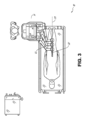
ロボット対応医療システムは、特定手技に応じてさまざまに構成することができる。図1は、気管支鏡検査の診断手技および/または治療樹技用に配置されたカートベースのロボット対応システム10の一実施形態を示す。気管支検査時に、システム10は、気管支鏡検査用の手技に特化した気管支鏡を自然開口のアクセスポイント(この例ではテーブルに配置された患者の口など)に操作可能な内視鏡13などの医療器具を搬送して診断用の
道具および/または治療用の道具を搬送するための、1つまたは複数のロボットアーム12を有するカート11を備える。図に示すように、カート11は、当該アクセスポイントにアクセスするために、患者の上半身に近い位置に配置されている。同様に、ロボットアーム12は、当該アクセスポイントに対して気管支鏡を配置するように作動可能である。図1に示す配置は、胃腸に関する(GI;gastro-intestinal)手技用の特別な内視鏡で
ある胃鏡を用いた胃腸に関する手技を行うときにも使用できる。図2は、カートの一例である実施形態をより詳細に示す。
(A. Robot System - Cart)
Robot-enabled medical systems can be configured in a variety of ways depending on the specific procedure. FIG. 1 depicts one embodiment of a cart-based robot-enabled
引き続き図1を参照すると、カート11が適切に位置決めされると、ロボットアーム12は操縦可能な内視鏡13を患者に、ロボットにより、手動により、またはそれらの組み合わせにより挿入することができる。図示のように、操縦可能な内視鏡13は内側リーダ部分および外部シース部分などの少なくとも2つの入れ子式部分を備えることができ、各部分は器具ドライバ28のセットから別個の器具ドライバに結合され、各器具ドライバは個々のロボットアームの遠位端に結合される。リーダ部分をシース部分と同軸に位置合わせすることを容易にする、器具ドライバ28のこの線形配置は、1つ以上のロボットアーム12を異なる角度および/または位置に操作することによって、空間内で再配置され得る「仮想レール」29を作成する。本明細書で説明する仮想レールは破線を使用して図示され、したがって、破線はシステムのいかなる物理的構造も示さない。仮想レール29に沿った器具ドライバ28の移動は外部シース部分に対して内側リーダ部分を入れ子式にし、または内視鏡13を患者から前進または後退させる。仮想レール29の角度は、臨床用途または医師の好みに基づいて、調整、移動、および旋回されてもよい。例えば、気管支鏡検査では、図示のような仮想レール29の角度および位置が内視鏡13を患者の口内に曲げることに起因する摩擦を最小限に抑えながら、内視鏡13への医師のアクセスを提供することの折衷案を表す。
With continued reference to FIG. 1, once the cart 11 is properly positioned, the
内視鏡13は、挿入後、ロボットシステムからの正確なコマンドを使用して、目標位置または手術部位に到達するまで、患者の気管および肺に向けられ得る。患者の肺ネットワークを通るナビゲーションを強化し、かつ/または所望の標的に到達するために、内視鏡13を操作して、外部シース部分から内側リーダ部分を入れ子式に延ばして、関節動作を強化し、曲げ半径を大きくすることができる。別個の器具ドライバ28の使用はまた、リーダ部分およびシース部分が、互いに独立して駆動されることを可能にする。
After insertion, the
例えば、内視鏡13は例えば、患者の肺内の病変または結節などの標的に生検針を送達するように指示されてもよい。針は病理学者によって解析されるべき組織サンプルを得るために、内視鏡の長さにわたるワーキングチャネルに沿って展開され得る。病理学的結果に応じて、追加のツールが追加の生検のために、内視鏡のワーキングチャネルの下方に配置されてもよい。悪性である結節を同定した後、内視鏡13は、潜在的に癌性の組織を切除するためのツールを内視鏡的に送達し得る。いくつかの例において、診断および治療手技は、別々の手続で送達される必要があり得る。これらの状況では、内視鏡13はまた、基準を送達して、対象結節の位置を「マーキング」するために使用され得る。他の例において、診断および治療手技は、同じ手順の間に送達され得る。
For example,
システム10はまた、可動タワー30を含むことができ、このタワー30は、支持ケーブルを介してカート11に接続されて、カート11に対する制御、電子機器、流体工学、光学系、センサ、および/または電力のためのサポートを提供することができる。このような機能をタワー30内に配置することにより、より小さなフォームファクタのカート11が可能になり、これは、手術医師およびそのスタッフによって、より容易に調整および/または再配置され得る。さらに、カート/テーブルと支持タワー30との間の機能の分割は手術室の混乱を低減し、臨床作業の流れを改善することを容易にする。カート11を患者の近くに配置することができるが、タワー30は手技中に邪魔にならないように離れ
た場所に収容することができる。
上述のロボットシステムのサポートにおいて、タワー30はコンピュータプログラム命令を、例えば、永続的磁気記憶ドライブ、ソリッドステートドライブなどの非一時的コンピュータ可読記憶媒体内に記憶するコンピュータベースの制御システムの構成要素を含むことができる。これらの命令の実行は、実行がタワー30またはカート11内で行われるかどうかにかかわらず、システム全体またはそのサブシステムを制御することができる。例えば、コンピュータシステムのプロセッサによって実行される場合、命令はロボットシステムの構成要素に、関連するキャリッジおよびアームマウントを作動させ、ロボットアームを作動させ、医療器具を制御させることができる。例えば、制御信号の受信に応じて、ロボットアームのジョイント内のモータは、アームを特定の姿勢に位置決めすることができる。
In support of the robotic system described above,
タワー30はまた、内視鏡13を通して展開され得るシステムに制御された潅注および吸引能力を提供するために、ポンプ、流量計、弁制御、および/または流体アクセスを含む。これらの構成要素は、タワー30のコンピュータシステムを使用して制御することもできる。いくつかの実施形態では、洗浄および吸引能力が別個のケーブルを介して内視鏡13に直接送達されてもよい。
タワー30はカート11にフィルタされ保護された電力を供給するように設計された電圧およびサージプロテクタを含むことができ、それによって、カート11内に電力変圧器および他の補助電力部品を配置することが回避され、その結果、より小さく、より可動性の高いカート11が得られる。
タワー30はまた、ロボットシステム10全体に展開されるセンサのための支持装置を含むことができる。例えば、タワー30はロボットシステム10全体にわたって光学センサまたはカメラから受信したデータを検出し、受信し、処理するための光電子機器を含むことができる。制御システムと組み合わせて、このような光電子機器を使用して、タワー30を含むシステム全体に配置された任意の数のコンソールに表示するためのリアルタイム画像を生成することができる。同様に、タワー30は配置された電磁(EM;Electromagnetic)センサから受信された信号を受信し、処理するための電子サブシステムも含む
ことができる。タワー30はまた、医療器具内または医療器具上の電磁センサによる検出のために電磁場発生器を収容し、位置決めするために使用されてもよい。
タワー30は、システムの残りの部分で利用可能な他のコンソール、例えばカートの頂部に取り付けられたコンソールに加えて、コンソール31を含むこともできる。コンソール31は、ユーザインタフェースと、医師の操作者のためのタッチスクリーンなどの表示画面とを含むことができる。システム10内のコンソールは一般に、ロボット制御と、内視鏡13のナビゲーションおよび位置決め情報などの手術前およびリアルタイム情報との両方を提供するように設計される。コンソール31が医師が利用できる唯一のコンソールではない場合、看護師のような第二の操作者によって、患者の健康状態や活動状態とシステムの動作を監視し、ナビゲーションおよび位置決め情報などの手続固有のデータを提供するために使用することができる。他の実施形態では、コンソール30は、タワー30とは別の筐体内に格納されている。
タワー30は、1つまたは複数のケーブルまたは接続部(図示せず)を介してカート11および内視鏡13に結合することができる。いくつかの実施形態では、タワー30からのサポート機能が単一のケーブルを介してカート11に提供されてもよく、手術室を単純化し、混乱を解消する。他の実施形態では、特定の機能が別個のケーブル配線および接続で結合されてもよい。例えば、単一の電力ケーブルを介してカートに電力を供給すること
ができるが、制御、光学、流体、および/またはナビゲーションのための支持体は別個のケーブルを介して提供することができる。
図2は、図1に示されたカートベースのロボット使用可能システムからのカートの実施形態の詳細図を提供する。カート11は全体として、細長い支持構造14(しばしば「カラム」と呼ばれる)、カート基部15、およびカラム14の上端部にコンソール16を含む。カラム14は、1つまたは複数のロボットアーム12(図2には3つが示されている)の展開を支持するためのキャリッジ17(あるいは「アーム支持体」)などの1つまたは複数のキャリッジを含むことができる。キャリッジ17は、患者に対してより良好に位置決めするためにロボットアーム12の基部を調整するために垂直軸に沿って回動する個別に構成可能なアームマウントを含むことができる。キャリッジ17はまた、キャリッジ17がカラム14に沿って垂直に移動することを可能にするキャリッジインタフェース19を含む。
FIG. 2 provides a detailed view of an embodiment of a cart from the cart-based robot-enabled system shown in FIG. Cart 11 generally includes an elongated support structure 14 (often referred to as a "column"), a
キャリッジインタフェース19は、キャリッジ17の垂直方向の移動を案内するためにカラム14の両側に配置されたスロット20のようなスロットを介してカラム14に接続されている。スロット20はキャリッジをカート基部15に対して種々の垂直高さに位置決めし、保持するための垂直移動インタフェースを含む。キャリッジ17の垂直移動は、カート11が様々なテーブル高さ、患者サイズ、および医師の好みに合うようにロボットアーム12の到達範囲を調整することを可能にする。同様に、キャリッジ17上の個々に構成可能なアームマウントは、ロボットアーム12のロボットアームベース21が様々な構成で角度付けされることを可能にする。
いくつかの実施形態では、スロット20がキャリッジ17が垂直に移動するときに、カラム14の内部チャンバおよび垂直移動インタフェース内への汚れおよび流体の進入を防止するために、スロット表面と面一であり、かつ平行であるスロットカバーで補足されてもよい。スロットカバーは、スロット20の縦上端部および底部の近くに配置されたバネスプールの対を通して展開されてもよい。カバーはキャリッジ17が垂直に上下に平行移動するときに、展開されてそれらのコイル状態から伸縮するまで、スプール内でコイル状に巻かれる。スプールのばね荷重はキャリッジ17がスプールに向かって移動するときにカバーをスプール内に引っ込める力を提供し、一方、キャリッジ17がスプールから離れるように移動するときにも緊密な捺印を維持する。カバーは例えば、キャリッジ17が移動するときにカバーの適切な伸縮を確実にするために、キャリッジインタフェース19内のブラケットを使用して、キャリッジ17に接続されてもよい。
In some embodiments, the
カラム14はユーザ入力、例えばコンソール16からの入力に応答して生成される制御信号に応答して機械的な方法でキャリッジ17を移動させるために、垂直に位置合わせされた親ねじを使用するように設計された、歯車およびモータなどの機構を内部に備えることができる。
ロボットアーム12は一般に、一連のジョイント24によって接続された一連のリンク機構23によって分離されたロボットアーム基部21およびエンドエフェクタ22を備えることができ、各ジョイントは独立したアクチュエータを備え、各アクチュエータは独立して制御可能なモータを備える。各独立して制御可能なジョイントは、ロボットアームに利用可能な独立した自由度を表す。アーム12のそれぞれは7つのジョイントを有し、したがって、7つの自由度を提供する。多数のジョイントは多数の自由度をもたらし、「冗長である」自由度を可能にする。冗長な自由度は、ロボットアーム12が異なる結合位置および関節角を使用して、空間内の特定の位置、向き、および軌道にそれぞれのエンドエフェクタ22を位置決めすることを可能にする。これにより、システムは医師が腕の関節を患者から離れた臨床的に有利な位置に移動させて、腕の衝突を回避して、より広いアク
セス範囲を実現しながら、空間内の所望の位置から医療器具を位置決めしたり方向付けたりすることが可能になる。
The
カート基部15は、床上のカラム14、キャリッジ17、およびアーム12の重量を釣り合わせる。したがって、カート基部15は、電子機器、モータ、電源などのより重い構成要素、ならびにカートの移動および/または固定のいずれかを可能にする構成要素を収容する。例えば、カート基部15は、手技の前にカートが部屋の周りを容易に移動することを可能にする、回動可能なホイール形状のキャスタ25を含む。適切な位置に到達した後、キャスタ25は、手続中にカート11を所定の位置に保持するためにホイールロックを使用して固定されてもよい。
コンソール16はカラム14の垂直端部に配置されているので、ユーザ入力を受け取るためのユーザインタフェースと、医師ユーザに手術前および手術中の両方のデータを提供するための表示画面(または、例えば、タッチスクリーン26などの二目的用装置)との両方を可能にする。タッチスクリーン26上の潜在的な術前データは、術前計画、術前コンピュータ断層撮影(CT)スキャンから導出されたナビゲーションおよびマッピングデータ、および/または術前患者インタビューからの注を含むことができる。ディスプレイ上の手術中データは、器具から提供される光学情報、センサおよびセンサからの座標情報、ならびに呼吸、心拍数、および/または脈拍などの患者の活動統計を含むことができる。コンソール16は医師がキャリッジ17の反対側のカラム14の側からコンソールにアクセスすることができるように、配置され、傾斜されてもよい。この位置から、医師はカート11の背後からコンソール16を操作しながら、コンソール16、ロボットアーム12、および患者を見ることができる。図示のように、コンソール16はまた、カート11の操縦および安定化を補助するためのハンドル27を含む。
図3は、尿管鏡検査のために配置されたロボット使用可能システム10の実施形態を示す。尿管鏡手技では、カート11が患者の尿道および尿管を横切るように設計された手技特有の内視鏡である尿管鏡32を患者の下腹部領域に送達するように配置されてもよい。尿管鏡検査では、尿管鏡32を患者の尿道と直接位置合わせして、領域内の繊細な解剖学的構造に対する摩擦および力を低減することが望ましい場合がある。図に示されるように、カート11はロボットアーム12が患者の尿道への直接的な線形アクセスのために尿管鏡32を位置決めすることを可能にするために、テーブルの足に位置合わせすることができる。テーブルの足から、ロボットアーム12は、尿管鏡32を仮想レール33に沿って尿道を通して患者の下腹部に直接挿入することができる。
FIG. 3 shows an embodiment of a robot-enabled
尿道への挿入後、気管支鏡検査におけるのと同様の制御手法を使用して、尿管鏡32は診断および/または治療用途のために、膀胱、尿管、および/または腎臓内にナビゲートされ得る。例えば、尿管鏡32は、尿管鏡32のワーキングチャネルの下に配置されたレーザまたは超音波砕石装置を用いて、尿管および腎臓に向けられて、腎結石の蓄積を破壊することができる。砕石術が完了した後、得られた結石断片は、尿管鏡32の下方に配置されたバスケットを用いて除去され得る。
After insertion into the urethra, using control techniques similar to those in bronchoscopy,
図4は、血管手技のために同様に配置されたロボット使用可能システムの実施形態を示す。血管手技では、システム10がカート11が操縦可能なカテーテルなどの医療器具34を患者の脚の大腿動脈内のアクセスポイントに送ることができるように構成することができる。大腿動脈はナビゲーションのためのより大きな直径と、患者の心臓への比較的遠回りで曲がりくねった経路との両方の特徴があり、このためナビゲーションを単純化できる。尿管鏡手技におけるように、カート11は、ロボットアーム12が患者の大腿/股関節領域における大腿動脈アクセスポイントへの直接的な線形アクセスを有する仮想レール35を提供することを可能にするように、患者の脚および下腹部に向かって配置され得る
。動脈内への挿入後、医療器具34は、器具ドライバ28を移動させることによって方向付けられ、挿入されてもよい。あるいは、カートが例えば、肩および手首の近くの頸動脈および上腕動脈などの代替の血管アクセスポイントに到達するために、患者の上腹部の周りに配置されてもよい。
FIG. 4 shows an embodiment of a robot-enabled system similarly arranged for vascular procedures. For vascular procedures,
(B.ロボットシステム-テーブル)
ロボット対応医療システムの実施形態はまた、患者のテーブルを組み込んでもよい。テーブルを組み込むことにより、カートを取り外すことによって手術室内の資本設備の量が減少し、患者へのアクセスがより大きくなる。図5は、気管支鏡検査手順のために配置されたそのようなロボット使用可能システムの実施形態を示す。システム36は、床の上にプラットフォーム38(「テーブル」または「ベッド」として示される)を支持するための支持構造または支柱37を含む。カートベースのシステムと同様に、システム36のロボットアーム39のエンドエフェクタは、図5の気管支鏡40などの細長い医療器具を、器具ドライバ42の直線的な位置合わせから形成された仮想レール41を通して、またはそれに沿って操作するように設計された器具ドライバ42を備える。実際には、X線透視画像を提供するためのCアームがテーブル38の周りにエミッタおよび検出器を配置することによって、患者の上腹部領域の上に配置され得る。
(B. Robot system - table)
Embodiments of the robot-enabled medical system may also incorporate a patient table. Incorporating the table reduces the amount of capital equipment in the operating room by removing the cart and provides greater access to the patient. FIG. 5 shows an embodiment of such a robot-enabled system configured for a bronchoscopy procedure.
図6は、説明のため患者および医療器具を除いたシステム36の代替図を示す。図示されているように、カラム37はシステム36内にリング形状として示されている1つ以上のキャリッジ43を含むことができ、このキャリッジを基に1つ以上のロボットアーム39を構成することができる。キャリッジ43はロボットアーム39が患者に到達するように配置され得る異なる視点を提供するために、カラム37の長さに沿って延びる垂直カラムインタフェース44に沿って移動してもよい。キャリッジ43は、カラム37内に配置された機械的モータを使用してカラム37の周りを回動して、ロボットアーム39がテーブル38の複数の側、例えば患者の両側にアクセスできるようにすることができる。複数のキャリッジを有する実施形態では、キャリッジがカラム上に個別に配置されてもよく、他のキャリッジとは独立して移動および/または回動してもよい。キャリッジ43はカラム37を取り囲む必要はなく、または円形である必要もないが、図示されるようなリング形状は構造的バランスを維持しながら、カラム37の周りのキャリッジ43の回動を容易にする。キャリッジ43の回動および移動により、システムは、内視鏡および腹腔鏡のような医療器具を患者の異なるアクセスポイントに位置合わせすることができる。他の実施形態(図示せず)では、システム36は、調節可能なアーム支持部を有する患者テーブルまたはベッドを備えてもよく、アーム支持部はテーブルまたはベッドに沿って延伸するバーやレールの形態として設けることができる。1つまたは複数のロボットアーム39(肘関節を有する肩部を介するなどによる)は、上記の調節可能なアーム支持部を垂直方向に調整して取り付けることができる。垂直方向の調整ができることで、ロボットアーム39は、患者テーブルまたは別途の下にコンパクトに収容でき、後で手技時に引き上げることができる。
FIG. 6 shows an alternative view of
アーム39は、ロボットアーム39に追加の構成要素を提供するために個別に回動および/または入れ子式に延在することができる一連のジョイントを備える一組のアームマウント45を介してキャリッジに取り付けることができる。さらに、アームマウント45は、キャリッジ43が適切に回動されたときに、アームマウント45がテーブル38の同じ側(図6に示す)、テーブル38の反対側(図9に示す)、またはテーブル38の隣接する側(図示せず)のいずれかに配置されるように、キャリッジ43上に配置されてもよい。
カラム37は構造的に、テーブル38を支持し、キャリッジを垂直方向に移動させるための経路を提供する。内部においては、カラム37がキャリッジの垂直移動を案内するた
めのリードスクリューと、リードスクリューに基づいて前記キャリッジの移動を機械化するためのモータとを備えることができる。カラム37はまた、キャリッジ43およびその上に取り付けられたロボットアーム39に電力および制御信号を伝達することができる。
テーブル基部46は図2に示すカート11のカート基部15と同様の機能を果たし、テーブル/ベッド38、カラム37、キャリッジ43、およびロボットアーム39をバランスさせるためのより重い構成要素を収容する。テーブル基部46はまた、手続中の安定性を提供するために、硬性キャスタを組み込んでもよい。キャスタはテーブル基部46の下端から展開されて、基部46の両側で反対方向に延在し、システム36を移動させる必要があるときに後退することができる。
引き続き図6を参照すると、システム36は、テーブルとタワーとの間でシステム36の機能を分割してテーブルのフォームファクタおよびバルクを低減するタワー(図示せず)を含むこともできる。上記の実施形態と同様に、タワーは、処理、計算、および制御能力、電力、流体工学、ならびに/または光学およびセンサ処理などの様々なサポート機能をテーブルに提供することができる。タワーはまた、医師のアクセスを改善し、手術室を煩雑にしないようにするために、患者から離れて配置されるように移動可能であってもよい。さらに、タワー内に部品を配置することにより、ロボットアームの潜在的な収納のためのテーブル基部内のより大きい収納スペースが実現する。タワーはまた、キーボードおよび/またはペンダントなどのユーザ入力のためのユーザインタフェースと、リアルタイム画像、ナビゲーション、および追跡情報などの術前および術中情報のための表示画面(またはタッチスクリーン)との両方を提供するコンソールを含むことができる。
With continued reference to FIG. 6,
いくつかの実施形態では、テーブル基部が使用されていないときにロボットアームを収納し、格納することができる。図7は、テーブルベースのシステムの一実施形態においてロボットアームを収容するシステム47を示す。システム47では、キャリッジ48がロボットアーム50、アームマウント51、およびキャリッジ48を基部49内に収容するために、基部49内に垂直に移動させることができる。基地カバー52は、キャリッジ48、アームマウント51、およびアーム50を列53の近辺に展開するために移動されて開閉され、使用されていないときにそれらを保護するために閉じられてもよい。基部カバー52は、その開口の縁部に沿って膜54で封止されて、閉鎖時の汚れおよび流体の進入を防止することができる。
In some embodiments, the robot arm can be stowed and retracted when the table base is not in use. FIG. 7 shows a
図8は、尿管鏡検査手順のために構成されたロボット使用可能なテーブルベースのシステムの実施形態を示す。尿管鏡検査では、テーブル38が患者をカラム37およびテーブル基部46から外れた角度に位置決めするための旋回部分55を含むことができる。旋回部分55は旋回部分55の下端を支柱37から離して位置決めするために、旋回点(例えば、患者の頭部の下に位置する)の周りで回動または旋回してもよい。例えば、旋回部分55の旋回は、Cアーム(図示せず)がテーブル38の下のカラム(図示せず)と空間を競合することなく、患者の下腹部の上に配置されることを可能にする。キャリッジ35(図示せず)を支柱37の周りに回動させることによって、ロボットアーム39は、尿管鏡56を仮想レール57に沿って患者の鼠径部に直接挿入して尿道に到達させることができる。尿管鏡検査では、手技中に患者の脚の位置を支持し、患者の鼠径部への明確なアクセスを可能にするために、スターラップ58をテーブル38の旋回部分55に固定することもできる。
FIG. 8 depicts an embodiment of a robot-enabled table-based system configured for a ureteroscopy procedure. For ureteroscopy, table 38 may include a pivot portion 55 for positioning the patient at an angle off
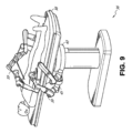
腹腔鏡手技では、患者の腹壁の小さな切開を通して、最小侵襲性器具(1つ以上の切開のサイズに適応するように細長い形状)が患者の解剖学的構造に挿入され得る。患者の腹腔を膨張させた後、しばしば腹腔鏡と呼ばれる器具は把持、切断、切除、縫合などの手術タスクを実行するように指示されてもよく、図9は腹腔鏡手技のために構成されたロボッ
ト使用可能なテーブルベースのシステムの実施形態を示す。図9に示されるように、システム36のキャリッジ43はテーブル38の両側にロボットアーム39の対を位置決めするように回動され、垂直に調整され、その結果、腹腔鏡59は患者の腹腔に到達するために患者の両側の最小切開部を通過するようにアームマウント45を使用して位置決めされ得る。
In laparoscopic procedures, minimally invasive instruments (elongated to accommodate the size of one or more incisions) may be inserted into the patient's anatomy through small incisions in the patient's abdominal wall. After inflating the patient's abdominal cavity, an instrument often referred to as a laparoscope may be instructed to perform surgical tasks such as grasping, cutting, resection, suturing, etc., and Figure 9 shows a diagram configured for laparoscopic procedures. 2 illustrates an embodiment of a robot-enabled table-based system. As shown in FIG. 9, the
腹腔鏡手技に適応するために、ロボット使用可能テーブルシステムは、プラットフォームを所望の角度に傾斜させることもできる。図10は、ピッチまたはチルト調整を有するロボット使用可能医療システムの実施形態を示す。図10に示すように、システム36は、テーブル38の傾斜に適応して、テーブルの一部分を床から他の部分よりも大きな距離に位置決めすることができる。さらに、アームマウント45はアーム39がテーブル38と同じ平面関係を維持するように、傾きに合わせて回動することができる。より急勾配の角度に適応するために、カラム37は、カラム37の垂直延長部がテーブル38が床に触れたり基部46と衝突したりしないようにする入れ子式部分60を含むこともできる。
To accommodate laparoscopic procedures, the robot-enabled table system can also tilt the platform to a desired angle. FIG. 10 illustrates an embodiment of a robot-enabled medical system with pitch or tilt adjustment. As shown in FIG. 10,
図11は、テーブル38とカラム37との間のインタフェースの詳細を示す。ピッチ回動機構61は、欄37に対するテーブル38のピッチ角を複数の自由度で変更するように構成されてもよい。ピッチ回動機構61はカラム・テーブル・インタフェースにおける直交軸1、2の位置決めによって可能にすることができ、各軸は、電気的なピッチ角コマンドに応答して各軸が別個のモータ3、4によって作動される。一方のねじ5に沿った回動は一方の軸1における傾斜調整を可能にし、他方のねじ6に沿った回動は、他方の軸2に沿った傾斜調整を可能にする。いくつかの実施形態では、ボールジョイントを用いて、複数の自由度でカラム37に対する相対的なテーブル38のピッチ角を変更することができる。
FIG. 11 shows details of the interface between table 38 and
例えば、ピッチ調整は下腹部手術のために、テーブルをトレンデレンブルグ位置に位置決めしようとするとき、すなわち、患者の下腹部を患者の下腹部よりも床から高い位置に位置決めしようとするとき、特に有用である。トレンデレンブルグ位置は患者の内部器官を重力によって患者の上腹部に向かってスライドさせ、腹腔鏡前立腺切除術などの下腹部手術手技を開始して実行するための最小侵襲性ツール(minimally invasive tool)のた
めに腹腔の空間を空ける。
For example, pitch adjustment is particularly important when attempting to position the table in the Trendelenburg position for lower abdominal surgery, i.e. when attempting to position the patient's lower abdomen higher off the floor than the patient's lower abdomen. Useful. The Trendelenburg position slides the patient's internal organs toward the patient's upper abdomen by gravity, making it a minimally invasive tool for initiating and performing lower abdominal surgical procedures such as laparoscopic prostatectomy. Free up space in the abdominal cavity for.
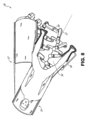
(C.器具ドライバとインタフェース)
システムのロボットアームのエンドエフェクタは、(1)医療器具を作動させるための電気機械的手段を組み込む器具ドライバ(あるいは「器具駆動機構」または「器具装置マニピュレータ(IDM;instrument device manipulator)」と呼ばれる)と、(2)モ
ータなどの任意の電気機械的構成要素を削除できる取り外し可能または取り外し可能な医療器具とを備える。この二分法は、医療手技に使用される医療器具を滅菌する必要性、およびそれらの複雑な機械的アセンブリおよび繊細な電子機器のために高価な資本設備を適切に滅菌することができないことが起因となりうる。したがって、医療器具は医師または医師のスタッフによる個々の滅菌または廃棄のために、器具ドライバ(したがってシステム)から取り外し、取り外し、および交換されるように設計されてもよい。対照的に、器具ドライバは、交換または滅菌される必要はなく、保護のためにドレープで覆われてもよい。
(C. Instrument driver and interface)
The end effectors of the system's robotic arm are: (1) an instrument driver (also referred to as an "instrument drive mechanism" or "instrument device manipulator" (IDM)) that incorporates electromechanical means for actuating a medical instrument; and (2) a removable or removable medical device in which any electromechanical components, such as a motor, can be removed. This dichotomy stems from the need to sterilize medical instruments used in medical procedures and the inability to adequately sterilize expensive capital equipment due to their complex mechanical assemblies and delicate electronics. It can be. Accordingly, medical instruments may be designed to be removed, removed, and replaced from the instrument driver (and thus the system) for individual sterilization or disposal by the physician or physician's staff. In contrast, instrument drivers do not need to be replaced or sterilized and may be draped for protection.
図12は、例示的な器具ドライバを示す。ロボットアームの遠位端に配置された器具ドライバ62は駆動シャフト64を介して医療器具に制御されたトルクを提供するために、平行軸に配置された1つ以上の駆動ユニット63を備える。各駆動ユニット63は器具と相互作用するための個々の駆動シャフト64と、モータシャフトの回動を所望のトルクに変換するためのギアヘッド65と、駆動トルクを生成するためのモータ66と、モータシ
ャフトの速度を測定し、制御回路にフィードバックを提供するためのエンコーダ67と、制御信号を受信し、駆動ユニットを作動させるための制御回路68とを備える。各駆動ユニット63は独立して制御され、電動化されており、器具ドライバ62は、医療器具に複数(図12に示すように4つ)の独立した駆動出力を提供することができる。動作中、制御回路68は制御信号を受信し、モータ信号をモータ66に送信し、エンコーダ67によって測定された結果のモータ速度を所望の速度と比較し、モータ信号を変調して所望のトルクを生成する。
FIG. 12 shows an exemplary instrument driver. An
無菌環境を必要とする手技では、ロボットシステムが器具ドライバと医療器具との間に位置する、無菌ドレープに接続された無菌アダプタなどの駆動インタフェースを組み込むことができる。無菌アダプタの主な目的は駆動シャフトと駆動入力との間の物理的分離、したがって無菌性を維持しながら、器具ドライバの駆動シャフトから器具の駆動入力に角運動を伝達することである。したがって、例示的な無菌アダプタは、器具ドライバの駆動シャフトおよび器具上の駆動入力と嵌合されることが意図される一連の回動入力および出力を備えてもよい。滅菌アダプタに接続された滅菌ドレープは透明または半透明プラスチックなどの薄い軟性材料からなり、器具ドライバ、ロボットアーム、およびカート(カートベースのシステム内)またはテーブル(テーブルベースのシステム内)などの資本設備を覆うように設計される。ドレープの使用は滅菌を必要としない領域(すなわち、非滅菌領域)に依然として配置されている間に、患者の近くに資本設備を配置することを可能にする。滅菌ドレープの反対側では、医療器具が滅菌を必要とする領域(すなわち、滅菌野)において患者と接触することができる。 For procedures requiring a sterile environment, the robotic system can incorporate a drive interface, such as a sterile adapter connected to a sterile drape, located between the instrument driver and the medical instrument. The primary purpose of the sterile adapter is to transfer angular motion from the instrument driver's drive shaft to the instrument's drive input while maintaining physical separation between the drive shaft and the drive input, and thus sterility. Accordingly, an exemplary sterile adapter may include a series of rotational inputs and outputs intended to be mated with the drive shaft of the instrument driver and the drive input on the instrument. The sterile drape connected to the sterile adapter is made of a thin, flexible material such as clear or translucent plastic and is attached to capital equipment such as instrument drivers, robotic arms, and carts (in cart-based systems) or tables (in table-based systems). designed to cover. The use of drapes allows capital equipment to be placed close to the patient while still being placed in areas that do not require sterilization (ie, non-sterile areas). On the other side of the sterile drape, medical instruments can come into contact with the patient in the area requiring sterilization (ie, the sterile field).
(D.医療器具)
図13は、組になった器具ドライバを有する例示的な医療器具を示す。ロボットシステムと共に使用するように設計された他の器具と同様に、医療器具70は、細長いシャフト71(または細長い本体)および器具基部72を備える。医師による手動操作向けの設計として「器具ハンドル」とも呼ばれる器具基部72は、全体として、ロボットアーム76の遠位端で器具ドライバ75上の駆動インタフェースを通って延びる駆動出力74と嵌合するように設計された、回動可能な駆動入力73、例えば、レセプタクル、プーリ、またはスプールを備えてもよい。物理的に接続され、ラッチされ、および/または結合されると、器具基部72の嵌合された駆動入力73は器具ドライバ75内の駆動出力74と回動軸を共有し、駆動出力74から駆動入力73へのトルクの伝達が可能になる。いくつかの実施形態では、駆動出力74が駆動入力73上のレセプタクルと嵌合するように設計されたスプラインを備えてもよい。
(D.Medical equipment)
FIG. 13 illustrates an exemplary medical instrument having a paired instrument driver. Like other instruments designed for use with robotic systems,
細長いシャフト71は例えば、内視鏡検査におけるように、解剖学的な開口またはルーメン、または、例えば、腹腔鏡検査におけるように、最小侵襲性切開のいずれかを介して送られるように設計される。細長いシャフト66は軟性(例えば、内視鏡と同様の特性を有する)または硬性(例えば、腹腔鏡と同様の特性を有する)のいずれかであり得るか、または軟性部分および硬性部分の両方のカスタマイズされた組み合わせを含む。腹腔鏡検査用に設計される場合、硬性の細長いシャフトの遠位端は回動軸を有するUリンクと、器具ドライバ75の駆動出力74から受け取ったトルクに応じて駆動入力が回動するときにテンドンからの力に基づいて作動され得る、例えば、1つまたは複数の把持器などの手術用道具とから形成される接合手首を備えるエンドエフェクタに接続されてもよい。内視鏡検査用に設計される場合、可撓性の細長いシャフトの遠位端は、器具ドライバ75の駆動出力74から受け取られるトルクに基づいて関節動作および屈曲され得る、操縦可能または制御可能な屈曲部を含む。
The
器具ドライバ75からのトルクは、シャフト71内のテンドンを使用して細長いシャフト71に伝達される。プルワイヤなどのこれらの個々のテンドンは、器具ハンドル72内
の個々の駆動入力73に個々に固定することができる。ハンドル72から、テンドンは、細長いシャフト71内の1つ以上のプルルーメンに向けられ、細長いシャフト71の遠位部分に固定される。腹腔鏡検査では、これらのテンドンが手首、把持器、またはさみなどの遠位に取り付けられたエンドエフェクタに結合されてもよい。このような構成の下では、駆動入力73に及ぼされるトルクがテンドンに表面張力を伝達し、それによってエンドエフェクタを何らかの方法で作動させる。腹腔鏡検査では、テンドンは関節を軸の周りに回動させ、それによってエンドエフェクタを一指示または別の指示に移動させることができる。あるいはテンドンは細長いシャフト71の遠位端において、把持器の1つ以上の顎に接続され得、ここで、テンドンからの張力によって把持器が閉じる。
Torque from
内視鏡検査では、テンドンは接着剤、制御リング、または他の機械的固定を介して、細長いシャフト71に沿って(例えば、遠位端で)配置された屈曲または関節動作部に結合されてもよい。屈曲部の遠位端に固定して取り付けられると、駆動入力73に及ぼされるトルクがテンドンに伝達され、より柔軟性のある屈曲部(関節部または関節動作領域と呼ばれることもある)を屈曲または関節動作させる。非屈曲部に沿って、個々のテンドンを内視鏡シャフトの壁に沿って(または内側に)向ける個々のプルルーメンを螺旋状または螺旋状にして、プルワイヤの表面張力から生じる半径方向の力を釣り合わせることが効果的であり得る。スパイラルの角度および/またはそれらの間の間隔は特定の目的のために変更または設計されてもよく、スパイラルを緊密にすると荷重力下でのシャフト圧縮が小さくなり、一方、スパイラルを少なくすると荷重力下でのシャフト圧縮が大きくなるが限界曲げとなる。スペクトルの他端では、プルルーメンが細長いシャフト71の長手方向軸に平行に向けられて、所望の屈曲または関節動作可能な部分における制御された関節動作が可能となる。
In endoscopy, the tendons are coupled via adhesive, control rings, or other mechanical fixation to a bending or articulating portion located along the elongate shaft 71 (e.g., at the distal end). Good too. When fixedly attached to the distal end of the flexure, the torque exerted on the
内視鏡検査では、細長いシャフト71がロボットシステム手続を補助するために、いくつかの構成要素を収容する。シャフトは、シャフト71の遠位端における手術領域に手術ツール、潅注、および/または吸引を展開するためのワーキングチャネルを備えてもよい。シャフト71はまた、ワイヤおよび/または光ファイバを収容して、光学カメラを含む遠位先端の光学アセンブリへ/から信号を伝達し得る。シャフト71はまた、光ファイバを収容して、発光ダイオードなどの近位に位置する光源からシャフトの遠位端に光を運ぶことができる。
In endoscopy, the
器具70の遠位端において、遠位先端はまた、診断および/または治療、潅注、および吸引のためのツールを手術部位に送達するためのワーキングチャネルの開口を備え得る。遠位先端はまた、内部解剖学的空間の画像を取得するために、ファイバスコープまたはデジタルカメラなどのカメラのためのポートを含んでもよい。関連して、遠位先端はまた、カメラを使用するときに解剖学的空間を照明するための光源のためのポートを含む。
At the distal end of
図13の例では駆動シャフト軸、したがって駆動入力軸は細長いシャフトの軸に直交する。しかしながら、この配置では、細長いシャフト71の回動機能が複雑になる。駆動入力73を静止状態に保ちながら、細長いシャフト71をその軸に沿って回動させると、テンドンが駆動入力73から延出して細長いシャフト71内のプルルーメンに入るときに、テンドンの望ましくない絡み合いが生じる。そのようなテンドンによって生じる絡み合いは、内視鏡手技時に可撓性の細長いシャフトの移動を予測することを目的とする任意の制御アルゴリズムの障害となり得る。
In the example of FIG. 13, the drive shaft axis, and thus the drive input axis, is perpendicular to the axis of the elongate shaft. However, this arrangement complicates the rotation function of the
図14は器具ドライバおよび器具の代替設計を示し、駆動ユニットの軸が器具の細長いシャフトの軸に平行である。図示のように、円形の器具ドライバ80は、ロボットアーム82の端部に平行に位置合わせされた駆動出力81を有する4つの駆動ユニットを備える。駆動ユニットおよびそれぞれの駆動出力81は、アセンブリ83内の駆動ユニットのう
ちの1つによって駆動される器具ドライバ80の回動アセンブリ83内に収容される。回動駆動ユニットによって提供されるトルクに応じて、回動アセンブリ83は、回動アセンブリ83を器具ドライバの非回動部分84に接続する円形ベアリングに沿って回動する。電気接点を介して器具ドライバ80の非回動部分84から回動アセンブリ83に電力および制御信号を伝達することができ、この信号は、ブラシ付きスリップリング接続(図示せず)による回動によって維持することができる。他の実施形態では、回動アセンブリ83が非回動部分84に一体化され、したがって他の駆動ユニットと平行ではない別個の駆動ユニットに応答することができる。回動機構83は、器具ドライバ80が器具ドライバ軸85の周りに単一のユニットとして、駆動ユニットおよびそれぞれの駆動出力81を回動させることができる。
Figure 14 shows an alternative design of the instrument driver and instrument, in which the axis of the drive unit is parallel to the axis of the elongated shaft of the instrument. As shown, the
上記に開示した実施形態と同様に、器具86は、細長いシャフト部分88と、器具ドライバ80内の駆動出力81を受けるように構成された複数の駆動入力89(レセプタクル、プーリ、およびスプールなど)を備える器具基部87(説明のために透明な外皮と共に示されている)とを備えることができる。先に開示された実施形態とは異なり、器具シャフト88は、図13の設計におけるように直交するのではなく、駆動入力89の軸に実質的に平行な軸を有する器具基部87の中心から延伸する。
Similar to the embodiments disclosed above, the
器具ドライバ80の回動アセンブリ83に結合されると、器具基部87および器具シャフト88を備える医療器具86は、器具ドライバ軸85の周りで回動アセンブリ83と組み合わせて回動する。器具シャフト88は器具基部87の中心に配置されているので、器具シャフト88は取り付けられたとき、器具ドライバ軸85と同軸である。したがって、回動アセンブリ83の回動は、器具シャフト88をそれ自体の前後軸の周りに回動させる。さらに、器具基部87が器具シャフト88と共に回動するとき、器具基部87の駆動入力89に接続されたテンドンは、回動中に絡み合わない。したがって、駆動出力81、駆動入力89、および器具シャフト88の軸の平行性は、任意の制御テンドンの絡み合いを発生させることなく、シャフトを回動させることができる。
When coupled to pivot
(E.ナビゲーションと制御)
従来の内視鏡検査には、X線透視法(例えば、Cアームを介して送達され得るよう)および他の形態の放射線ベースの画像化モダリティの使用が含まれ、操作者の医師に管腔内ガイダンスが提供される。一方、本件開示によって実現されるロボットシステムは、放射線に対する医師の曝露を低減し、手術室内の器具の数を減らすために、非放射線ベースのナビゲーションおよび位置決め手段を提供する。本明細書で使用されるように、用語「位置決め」は、基準系における物体の位置を特定および/または監視することを指すことができる。術前マッピング、コンピュータビジョン、リアルタイム電磁追跡、およびロボットコマンドデータなどの技術は放射線を用いない運用環境を達成するために、個別に、または組み合わせて使用されてもよい。放射線ベースの画像モダリティが依然として使用される他の場合には、術前マッピング、コンピュータビジョン、リアルタイム電磁追跡、およびロボットコマンドデータは放射線ベースの画像モダリティによってのみ得られる情報を改善するために、個別に、または組み合わせて使用されてもよい。
(E. Navigation and Control)
Traditional endoscopy involves the use of fluoroscopy (e.g., as may be delivered via a C-arm) and other forms of radiation-based imaging modalities, giving the operator physician an overview of the lumen. Internal guidance will be provided. On the other hand, the robotic system enabled by the present disclosure provides non-radiation-based navigation and positioning means to reduce physician exposure to radiation and reduce the number of instruments in the operating room. As used herein, the term "positioning" can refer to identifying and/or monitoring the position of an object in a frame of reference. Technologies such as preoperative mapping, computer vision, real-time electromagnetic tracking, and robotic command data may be used individually or in combination to achieve a radiation-free operating environment. In other cases where radiology-based imaging modalities are still used, preoperative mapping, computer vision, real-time electromagnetic tracking, and robotic command data can be used individually to improve the information obtained only by radiology-based imaging modalities. , or may be used in combination.
図15は、例示的な実施形態による、器具の位置など、ロボットシステムの1つまたは複数の要素の位置を推定する位置決めシステム90を示すブロック図である。位置決めシステム90は、1つまたは複数の命令を実行するように構成された1つまたは複数の計算装置のセットとすることができる。計算装置は、上述の1つまたは複数の構成要素内のプロセッサ(または複数のプロセッサ)およびコンピュータ可読メモリによって具現化され得る。限定ではなく例示として、計算装置は、図1に示すタワー30内や、図1~4に示すカート内や、図5~10に示すベッド内などに配置されてよい。
FIG. 15 is a block diagram illustrating a
図15に示すように、位置決めシステム90は、入力データ91~94を処理して医療器具の遠位先端の位置データ96を生成する位置決めモジュール95を含むことができる。位置データ96は、基準系に対する器具の遠位端の位置および/または向きを表すデータまたはロジックであってもよい。基準系は、患者の解剖学的構造、または電磁場発生器(電磁場発生器については以下の説明を参照)などの既知の物体に対する基準系とすることができる。
As shown in FIG. 15,
ここで、さまざまな入力データ91~94についてより詳細に説明する。術前マッピングは、低線量CTスキャンの収集を使用することによって達成することができる。術前CTスキャンは2次元画像を生成し、各画像は、患者の内部解剖学的構造の破断図の「スライス」を表す。集合体で解析される場合、患者の肺ネットワークなどの患者の解剖学的構造の解剖学的空洞、空間、および構造のための画像ベースのモデルが生成され得る。中心線ジオメトリのような手法は、CT画像から決定され、近似されて、術前モデルデータ91と呼ばれる患者の解剖学的構造の3次元ボリュームを展開することができる。中心線ジオメトリの使用については、米国特許第14/523,760号に記載されており、その内容の全体を本願に援用する。また、ネットワークトポロジーモデルは、CT画像から導出されてもよく、気管支鏡検査に特に適している。
Here, various input data 91-94 will be explained in more detail. Preoperative mapping can be accomplished by using acquisition of low-dose CT scans. Preoperative CT scans produce two-dimensional images, each image representing a cutaway "slice" of the patient's internal anatomy. When analyzed in an ensemble, image-based models may be generated for the anatomical cavities, spaces, and structures of the patient's anatomy, such as the patient's pulmonary network. Techniques such as centerline geometry can be determined and approximated from the CT images to develop a three-dimensional volume of the patient's anatomy, referred to as
いくつかの実施形態では、器具が視覚データ92を提供するためにカメラを装備することができる。位置決めモジュール95は1つまたは複数の視覚ベースの位置追跡を可能にするために、視覚データを処理することができる。例えば、手術前モデルデータは医療器具(例えば、内視鏡または内視鏡のワーキングチャネルを通る器具の前進)のコンピュータビジョンベースの追跡を可能にするために、ビジョンデータ92と共に使用されてもよい。例えば、手術前モデルデータ91を使用して、ロボットシステムは内視鏡の予測される移動経路に基づいてモデルから予測される内視鏡画像のライブラリを生成することができ、各画像はモデル内の位置にリンクされる。手術中に、このライブラリはカメラ(例えば、内視鏡の遠位端にあるカメラ)で取得されたリアルタイム画像を画像ライブラリ内の画像と比較して位置決めを補助するために、ロボットシステムによって参照されてもよい。
In some embodiments, the instrument can be equipped with a camera to provide
他のコンピュータビジョンベースの追跡技術は、カメラ、したがって内視鏡の動きを特定するために特徴追跡を使用する。位置決めモジュール95のいくつかの特徴は解剖学的な管腔に対応する手術前モデルデータ91内の円形の幾何学的形状を識別し、それらの幾何学的形状の変化を追跡して、どの解剖学的な管腔が選択されたかや、カメラの相対的な回動および/または移動運動を特定することができる。トポロジーマップの使用によって、視覚ベースのアルゴリズムまたは方法をさらに強化することができる。
Other computer vision-based tracking techniques use feature tracking to identify camera and therefore endoscope movement. Several features of the
別のコンピュータビジョンベースの技術であるオプティカルフローはカメラの動きを推測するために、ビジョンデータ92のビデオシーケンス内の画像画素の変位および移動を解析することができる。複数の反復にわたる複数のフレームの比較によって、カメラ(したがって、内視鏡)の移動および位置を特定することができる。
Optical flow, another computer vision-based technique, can analyze the displacement and movement of image pixels within a video sequence of
位置決めモジュール95は、リアルタイム電磁追跡を使用して、手術前モデルによって表される患者の解剖学的構造に位置合わせすることができるグローバル座標系における内視鏡のリアルタイム位置を生成し得る。電磁追跡では医療器具(例えば、内視鏡ツール)の1つ以上の位置および向きに埋め込まれた1つ以上のセンサコイルを備える電磁センサ(トラッカ)は既知の位置に配置された1つ以上の静的電磁場発生器によって生成された電磁場の変動を測定する。電磁センサによって検出された位置情報は、電磁データ記憶される。電磁場発生器(または送信機)は埋め込まれたセンサが検出し得る低強度磁場を生成するために、患者の近くに配置され得る。磁界は電磁センサコイルに小さな電流をガイ
ドし、この電流は、電磁センサと電磁界発生器との間の距離および角度を特定するために解析され得る。これらの距離および向きは、座標系内の単一の位置を患者の解剖学的構造の手術前モデル内の位置と位置合わせさせる幾何学的変換を特定するために、患者の解剖学的構造(例えば、手術前モデル)に対して手術中に「位置合わせ」されてもよい。一旦位置合わせされると、医療器具の1つ以上の位置(例えば、内視鏡の遠位先端)に埋め込まれた電磁追跡装置は、患者の解剖学的構造を通る医療器具の進歩のリアルタイムの指示を提供し得る。
ロボットコマンドおよび運動学データ94はまた、ロボットシステムのための位置決めデータ96を提供するために、位置決めモジュール95によって使用されてもよい、関節動作コマンドから生じる装置ピッチおよびヨーは、手術前較正中に特定され得る。手術中に、これらの較正計量値は器具の位置を推定するために、既知の挿入デプス情報と組み合わせて使用されてもよい。あるいは、これらの計算がネットワーク内の医療器具の位置を推定するために、電磁、視覚、および/またはトポロジーモデリングと組み合わせて解析されてもよい。
Robotic commands and
図15に示すように、多数の他の入力データを位置決めモジュール95によって使用することができる。例えば、図15には示されていないが、形状感知ファイバを用いる器具は、位置決めモジュール95が器具の位置および形状を特定するために使用する形状データを提供することができる。
A number of other input data may be used by positioning
位置決めモジュール95は、入力データ91~94を組み合わせて使用することができる。場合によっては、このような組み合わせは位置決めモジュール95が入力データ91~94のそれぞれから特定された位置に信頼性重みを割り当てる確率的アプローチを使用することができる。したがって、電磁データが信頼できない場合(電磁干渉がある場合のように)、電磁データによって特定される位置の信頼性は低下する可能性があり、位置決めモジュール95は、視覚データ92および/またはロボットコマンドおよび運動学データ94により依存する可能性がある。
上記の通り、本明細書で説明するロボットシステムは、上記の技術のうちの1つまたは複数の組合せを組み込むように設計することができる。タワー、ベッドおよび/またはカートに基づくロボットシステムのコンピュータベースの制御システムはコンピュータプログラム命令を、例えば、永続的磁気記憶ドライブ、ソリッドステートドライブなどの非一時的コンピュータ可読記憶媒体内に記憶することができ、これは、実行時に、システムにセンサデータおよびユーザコマンドを受信および解析させ、システム全体の制御信号を生成させ、グローバル座標系内の器具の位置、解剖学的マップなどのナビゲーションおよび位置決めデータを表示させる。 As noted above, the robotic systems described herein can be designed to incorporate a combination of one or more of the techniques described above. A computer-based control system for a tower, bed, and/or cart-based robotic system may store computer program instructions in a non-transitory computer-readable storage medium, such as, for example, a persistent magnetic storage drive, a solid state drive, etc. , which, at runtime, causes the system to receive and analyze sensor data and user commands, generate system-wide control signals, and display navigation and positioning data such as instrument positions in a global coordinate system, anatomical maps, etc. let
(2.コマンド指示されていない器具の回動の修正について)
本開示の実施形態は、コマンド指示されていない器具の移動を補正するために使用されるシステムおよび手法に関し、これは、特定の実施形態において、コマンド指示されていない器具の回動を修正することを含む。操作者(例えば、医師、手術医、気管支鏡医、またはロボット制御システム)が患者の体内の軟性の管状器具を制御する場合、器具は、器具の向きを変化させるように動作する。例えば、器具は、操作者によるコマンド指示とは無関係に(例えば、器具の長手方向軸に対して)回動することができる。このようなコマンド指示されていない動作は、例えば、軟性の管状器具が気管内チューブを介して挿入される場合、および/または器具が湾曲した解剖学的構造を通過し、その形状が構造に適合する場合のような種々の状況において発生しうる。このコマンド指示されていない回動は、軟性の管状器具の操作者にとって1つまたは複数の座標系に関する問題を引き起こす可能性がある。というのは、コマンド指示されていない回動は、操作者が望むまたは予測す
る基準系と矛盾する視覚基準系および/または制御基準系を表す可能性があるからである。本明細書に開示される特定の実施形態は、そのような意図しない器具の動きを修正するための方法およびシステムに関係する。
(2. Regarding correction of rotation of instruments that are not commanded)
Embodiments of the present disclosure relate to systems and techniques used to correct for uncommanded instrument movement, which in certain embodiments correct for uncommanded instrument rotation. including. When an operator (eg, a physician, surgeon, bronchoscopist, or robotic control system) controls a flexible tubular instrument within a patient, the instrument operates to change its orientation. For example, the instrument can rotate (eg, about a longitudinal axis of the instrument) independently of commands by an operator. Such uncommanded movement may occur, for example, when a soft tubular instrument is inserted via an endotracheal tube, and/or when the instrument passes through a curved anatomical structure and its shape conforms to the structure. This can occur in a variety of situations, such as when This uncommanded rotation can create problems with one or more coordinate systems for the operator of the flexible tubular instrument. This is because uncommanded rotations may represent a visual and/or control reference frame that is inconsistent with the operator's desired or expected reference frame. Certain embodiments disclosed herein relate to methods and systems for correcting such unintended instrument movement.
上述のように、電磁データは、本明細書で議論される実施形態によって、医療器具(例えば、操作可能な器具)のナビゲーションおよび位置特定のために使用されてもよい。電磁データ、医療器具内に配置された1つ以上の電磁センサおよび/または患者上に配置された1つ以上の電磁パッチセンサによって生成されてもよい。図16は、電磁データを使用して、コマンド指示されていない回動を検出および/または修正するために、開示されたシステムおよび技術の1つ以上の態様を実施する例示的な運用環境100を示す。運用環境100は、患者を支持するテーブル38と、電磁センサ105(後述するように、医療器具上に位置する電磁機器センサと区別されるように、「電磁パッチセンサ」とも呼ばれる)と、電磁場発生器110とを含む。追加のデバイス/要素も含まれてもよいが、図16には示されていない。例えば、環境100は、医療器具の移動をガイドするように構成されたロボットシステム、ロボットシステムの動作を制御するためのコマンドセンタまたはコンソール、および電磁コントローラを含むこともできる。電磁コントローラは、電磁パッチセンサ105に電気的に接続され、電磁センサ信号を受信することができる。電磁コントローラは、さらに、電磁場発生器110に接続されて、電磁場を生成するための制御信号を電磁場発生器に供給することができる。特定の実施形態では、電磁コントローラは、電磁場発生器110、カート11(図1参照)、および/またはタワー30(図1参照)を含む、システムの他の処理装置の1つまたは複数に部分的または完全に組み込まれてもよい。
As mentioned above, electromagnetic data may be used by embodiments discussed herein for navigation and location of medical instruments (eg, steerable instruments). The electromagnetic data may be generated by one or more electromagnetic sensors located within the medical device and/or one or more electromagnetic patch sensors located on the patient. FIG. 16 illustrates an example
電磁コントローラがシステムに含まれる場合、電磁コントローラは、電磁場発生器110を制御して、変化する電磁場を生成することができる。電磁場は、実施形態に応じて、経時的に変化および/または空間的に変化する。電磁場発生器110は、図2に示されるカート11と同様に、カート上に配置されてもよく、または1つ以上の支持カラムを介してテーブル38のレールに取り付けられてもよい。他の実施形態では、電磁場発生器110は、例えば、図1の手術ロボットシステム10に示されているものと同様のロボットアームに取り付けることができ、これにより患者の周囲に柔軟な設定オプションが提供される。電磁場発生器110は、使用時に電磁パッチセンサ105を配置することができる可動範囲を有する。
If an electromagnetic controller is included in the system, the electromagnetic controller can control the
電磁空間計測システムは、電磁センサコイル、例えば、電磁パッチセンサ105(図16に示されるように)または電磁器具センサ305(下の図18に示されるように)が埋め込まれるか、または設けられる電磁場内の物体の位置を決定することができる。電磁センサが、本明細書に記載されるように、制御され、変化する電磁場の内部に配置されると、電圧が電磁センサコイルに誘導される。この誘導電圧は、電磁空間計測システムによって、電磁センサ、さらには電磁センサを有する物体の位置および向きを計算するのに使用される。電磁場は弱く人体の組織を安全に通過することができるため、光学空間計測システムにおける照準線の制約なく、物体の位置測定が可能である。電磁場は、電磁場発生器110の座標系に対して定義することができ、管腔ネットワークの3次元モデルの座標系は、電磁場の座標系にマッピングまたは位置合わせすることができる。電磁空間計測システムは、ロボット制御システム(例えば、システム10、36または47)、器具ドライバ(例えば、器具ドライバ62)、コントローラ(例えば、制御回路68)、コンソール(例えば、コンソール16または31)、および/またはコンソールベース(例えば、カートベース15)、またはそれらのコンポーネントに実装することができる。
An electromagnetic spatial measurement system is an electromagnetic field in which an electromagnetic sensor coil, for example an electromagnetic patch sensor 105 (as shown in FIG. 16) or an electromagnetic instrument sensor 305 (as shown in FIG. 18 below) is embedded or provided. The position of objects within can be determined. When an electromagnetic sensor is placed within a controlled and changing electromagnetic field as described herein, a voltage is induced in the electromagnetic sensor coil. This induced voltage is used by the electromagnetic spatial measurement system to calculate the position and orientation of the electromagnetic sensor and also of the object containing the electromagnetic sensor. Since the electromagnetic field is weak and can safely pass through human tissue, it is possible to measure the position of objects without the line-of-sight constraints of optical spatial measurement systems. The electromagnetic field can be defined relative to the coordinate system of the
図16に示すように、多数の電磁パッチセンサ105を患者の身体上またはその付近に配置することができる(例えば、図17に示すように管腔ネットワーク140の領域内な
ど)。これらの位置における異なる変位を追跡するために、多数の異なる電磁パッチセンサ105を体表面上で離間させて配置することができる。例えば、肺の周辺部は、中央気道よりも呼吸による動きが大きく、図に示すように多数の電磁パッチセンサ105を配置することにより、これらの運動をより正確に分析することができる。これにより、管腔ネットワーク140の異なる領域を通って移動する内視鏡に対して、これらの異なる領域を通過する際の患者の呼吸に起因するさまざまな位置ずれが生じる、内視鏡の遠位端を正確に追跡することが可能となる。
As shown in FIG. 16, a number of
電磁パッチセンサ105から受信された電磁センサ信号は、電磁場発生器110に対する電磁パッチセンサ105の位置および向きを決定するために使用されてもよい。電磁パッチセンサ105は、各パッチセンサの5自由度(DoF;Degrees-of-Freedom)データ(例えば、3つの位置DoFおよび2つの角度DoF)または6DoFデータ(例えば、3つの位置DoFおよび3つの角度DoF)を提供する。
Electromagnetic sensor signals received from
図17は、例えば、図16の運用環境100内でナビゲートすることができる例示的な管腔ネットワーク140を示す。図示されるように、管腔ネットワーク140は、患者の気道150の分枝構造と、診断および/または治療のために本明細書に記載されるようにアクセスすることができる小結節155とを含む。この例では、小結節155は、気道150の周辺に位置する。内視鏡115は、シース120とリーダ145とを含む。一実施形態では、シース120およびリーダ145は、入れ子式に構成されてもよい。例えば、リーダ145は、シース120のワーキングチャネル内に摺動可能に配置されてもよい。場合によっては、シース120が第1の直径を有し、遠位端を結節155の周りの小さな直径の気道150を通って位置決めすることができないことがある。そこで、リーダ145は、シース120のワーキングチャネルから小結節155までの残りの距離を伸長するように構成することができる。リーダ145は、器具、例えば生検針、細胞診ブラシ、および/または組織サンプリング鉗子を小結節155の目標の組織部位に通すことができる管腔を有する。このような実施形態では、シース120の遠位端とリーダ145の遠位端の両方に、気道150内のそれらの位置を追跡するための電磁器具センサ(例えば、図18の電磁器具センサ305)を設けることができる。シース120およびリーダ145のこの入れ子式の構成は、いくつかの実施態様において、内視鏡115のより薄い設計が可能となり、シース120を介して構造的なサポートを提供しつつ内視鏡115の曲げ半径を改善することができる。
FIG. 17 illustrates an
他の実施形態では、内視鏡115の全体の直径は、入れ子式の構成を採用せず、外周に到達するのに十分に小さくてもよく、または、操縦可能でないカテーテルを介して医療器具を展開するために外周に到達するのに十分に小さくてもよい(例えば、2.5~3cm以内)。内視鏡115を介して配置される医療器具は、電磁器具センサ(例えば、図18の電磁器具センサ305)を備えることができ、以下に記載される位置フィルタリングおよび安全モードナビゲーション技術は、このような医療器具に適用することができる。いくつかの実施形態では、本明細書に記載されるような3次元管腔ネットワークモデルの2次元表示、または3次元モデルの断面を、図17と同様にすることができる。いくつかの実施形態では、ナビゲーションの安全領域および/またはナビゲーションの経路情報を、それらの表示に重畳することができる。
In other embodiments, the overall diameter of the
図18は、本明細書に説明する画像および電磁感知機能を有する例示的な器具(例えば、図17の内視鏡115、シース120、またはリーダ145、および/または図1の医療器具70または内視鏡13)の遠位端300を示す。しかしながら、本開示の態様は、図3の尿管鏡32、図9の腹腔鏡59などの他の操縦可能な器具の使用に関する。図18に示すように、器具の遠位端300は、画像処理装置315、照明光源310、および電磁センサコイルの端部を含むことができる。遠位端300は、器具のワーキングチャネル
320への開口をさらに有し、器具(例えば、生検針、細胞診ブラシ、鉗子)は器具シャフトに沿って挿入することができ、器具の遠位端300に近い領域へのアクセスが可能になる。
FIG. 18 illustrates an example instrument (e.g.,
照明光源310は、解剖学的空間の一部を照明する光を提供する。照明光源は、それぞれ、選択された波長または波長の範囲で光を放射するように構成された1つまたは複数の発光装置である。波長は、いくつかの例を挙げると、任意の適切な波長、例えば可視スペクトル光、赤外光、X線(例えば、透視法用)である。いくつかの実施形態では、照明光源310は、遠位端310またはその近傍に位置する発光ダイオード(LED)を含む。いくつかの実施形態では、照明光源310は、遠位端300を通って光を遠隔光源、例えばX線発生器から透過させるために、内視鏡の長さを通って延伸する1つ以上の光ファイバを有する。遠位端300が複数の照明光源310を有する場合、これらは、それぞれ、同じまたは異なる波長の光を放射するように構成することができる。
画像処理装置315は、受光を表すエネルギーを電気信号に変換するように構成された任意の感光性基板または構造、例えば、電荷結合素子(CCD)または相補型金属酸化膜半導体(CMOS)イメージセンサを含むことができる。画像処理装置315のいくつかの例は、内視鏡の遠位端300から内視鏡の近位端におけるアイピースおよび/またはイメージセンサへ画像を送信するように構成された、1つ以上の光ファイバ、例えば光ファイババンドルを含む。画像処理装置315は、さらに、種々の光学設計に必要とされるように、1つ以上のレンズおよび/または波長透過フィルタまたは波長遮断フィルタを含む。照明光源310から放射される光は、画像処理装置315が患者の管腔ネットワークの内部の画像を取得することを可能にする。これらの画像は、個々のフレームまたは連続した一連のフレーム(例えば、ビデオ)として、処理および/または表示のためのコマンドコンソールなどのコンピュータシステムに送信することができる。
遠位端300上に配置された電磁センサ追跡システムと共に使用して、解剖学的システム内にある内視鏡の遠位端300の位置および/または向きを検出することができる。いくつかの実施形態では、電磁センサ、異なる軸に沿った電磁場に対する感応性を与えるように角度付けることができ、開示のナビゲーションシステムに、完全な6DoF(3つの位置DoFおよび3つの角度DoF)を計測する機能を与える。他の実施形態では、単一のコイルまたはセンサのみが、内視鏡の内視鏡シャフトに沿って設けられた軸によって遠位端300上またはその内側に配置されてもよい。単一の電磁コイルまたはセンサのみが器具の遠位端300に配置され、その軸(例えば、長手方向軸)に対してシステムを対称となるようにすると、回動しても単一のコイルまたはセンサを横切る磁束または電束が変化しないため、システムはその軸に対する1つまたは複数の回動を検出することができない。そのようなシステムの回動対称性のため、当該軸周りの回動に対する感応性がない場合があるため、そのような実装においては5DoFのみが検出可能である。システムが平行でない対称軸(例えば、互いに垂直な対称軸)を有する2つ以上のコイルまたはセンサを備える場合、システムは当該軸に対する回動を感知することができる。当該軸に対する回動に感応性を有しない1つ以上の電磁コイルまたはセンサを有するシステムの場合、コマンド指示されていない回動は、電磁コイル以外の1つ以上のセンサまたは検出器を介して検出することができる。いくつかの実施形態では、コマンド指示されていない回動は、画像処理装置(例えば、画像処理装置315また器具の遠位端またはその近傍にある画像処理装置)からの1つ以上の画像を解析することによって特定されてもよい。
It can be used in conjunction with an electromagnetic sensor tracking system disposed on the
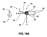
図19Aおよび図19Bは、例示的な医療器具(例えば、医療器具350、医療器具70または図1の内視鏡13)の先端基準系、視覚基準系、制御基準系、および目標基準系を示す。図19Aは、3次元(3D)空間における医療器具350の先端基準系360と目標基準系368を示す。医療器具350は、図18に示される医療器具の遠位端300
の構成要素に類似する1つ以上の構成要素(例えば、画像処理装置356および/または電磁センサコイル358)を含む遠位先端352を有する。医療器具350はまた、器具350の遠位先端352を操作または関節動作させるように構成された1つ以上のプルワイヤ354を含む。先端基準系360は、器具350の遠位端352の向きを表す。先端基準系360は、x軸362、y軸364、およびz軸366を含む。以下により詳細に説明されるように、先端基準系360は、1つ以上の画像処理装置(例えば、画像処理装置356)、位置センサ(例えば、電磁パッチセンサ105)、電磁コイル(例えば、電磁センサコイル358)、任意の他の適当なセンサ(例えば、器具350の重力または他の運動を測定する加速度計)、またはこれらの組み合わせによって特定されてもよい。
19A and 19B illustrate a tip reference frame, a visual reference frame, a control reference frame, and a target reference frame of an exemplary medical device (e.g.,
has a
目標基準系368は、視覚基準系および/または制御基準系に対する調整の基となる基準系であってもよい。いくつかの実施形態では、目標基準系368は、システムまたは操作者が視覚基準系および/または制御基準系を変換することを目的とする目標基準系であってもよい。システムは、リクエスト(ユーザ入力によって開始されたりユーザ入力から受信されたりする)などのトリガに基づいてこの変換が実行され、あるいはシステムが、医療手技中に一貫した表示と制御が維持されるように、この変換を継続的に実行される。目標基準系368は、解剖学的基準系(例えば、解剖学的特徴によって特定される基準系)またはグローバル基準系(例えば、重力方向によって特定される基準系)であってもよい。図19Aでは、目標基準系368は、頂部369が基準方向(例えば、上方向またはz方向)を指す三角錐によって表される。
The
図19Bは、医療器具350の遠位端352における画像装置356からの1つ以上の画像に示される目標基準系368、視覚基準系380、および医療器具350の制御基準系390を示す。視覚基準系380は、医療器具350の画像装置356から取得された画像から生成される出力画像の向きを表す。図19Bにおいて、視覚基準系380は、視覚基準系380に示される三角形のピラミッドによって表される目標基準系368に一致させられる。すなわち、上方向を表す三角錐の頂部369は、視覚基準系380の上方向に対応する。ここで、以下に説明するように、視覚基準系380は、コマンド指示されていない回動において生じうる先端基準系360に対する変更に関係なく出力画像が目標基準系368と一致するように、先端基準系360への変更に基づいて調整される。
FIG. 19B shows a
制御基準系390は、モータ制御コマンドと器具350のモータ出力との間の関係を表すデータである。図19Bにおいて、制御基準系390は、制御基準系の指標392、394、396、および398によって表される。制御基準系の指標392、394、396、398は、制御入力が医療器具350を作動させる移動の方向を示すだけであることを理解されたい。例えば、ユーザ入力装置の上方向を押すと、医療器具350の先端部が、制御基準系の指標392が示すように作動する。いくつかの実施形態では、制御基準系の指標392、394、396、および398が画面上に表示されてもよい。これらの実施形態では、制御基準系の指標392、394、396、および398は、操作者(例えば、医師、外科医、気管支鏡医、またはロボット制御システム)が医療器具350に移動(例えば、それぞれ、上下、左、および右)を指示するコマンドを表す1つ以上の形状(例えば、矢印、ドット、または三角形)を含む。視覚基準系380と同様に、制御基準系390は、コマンド指示されていない回動において生じうる先端基準系360に対する変更に関係なくモータ制御コマンドが目標基準系368と一致するように、先端基準系360への変更に基づいて調整される。
図20A~20Bは、例示的な医療器具(例えば、医療器具450)の先端基準系460、視覚基準系480、制御基準系490、および目標基準系468における変化を示す。図20Aは、コマンド指示されていない回動が生じて修正されていない状態における、3次元空間内の医療器具450の先端基準系460および目標基準系468を示す。図に
示す例では、医療器具450の遠位先端452は、遠位先端452が、コマンド指示されていない回動に起因して斜め方向を向いていることを示す。したがって、x軸462、y軸464、およびz軸466を含む先端基準系460もまた、斜め方向を向いている。目標基準系468は、頂点469が上方向を向く三角形のピラミッドによって表される。
20A-20B illustrate changes in
図20Bは、図20Aに示すコマンド指示されていない回動が修正されていない状態における、医療器具450の遠位端452にある画像処理装置456からの1つまたは複数の画像に示される、医療器具450の目標基準系468、視覚基準系480、および制御基準系490を示す。図20Bに示すように、医療器具450の視覚基準系480および制御基準系490(制御基準系の指標492、494、496、および498によって表される)は、目標基準系368と一致しない。この不一致は、エンドユーザにとって方向感覚を失うこととなる可能性がある。例えば、回動をコマンド指示しない場合に、医療器具によって表示される画像は、エンドユーザの予測と矛盾する向きになる可能性がある。この実施例に示すように、制御基準系の指標492(いくつかの実施形態では、操作者は、上方向であると予測する)は、医療器具450のコマンド指示されていない回動が原因で、目標基準系468(頂点469によって示される)の上方向と一致しない。
FIG. 20B shows the
図21Aおよび図21Bは、図20Aおよび図20Bと異なり、コマンド指示されていない回動が修正された後の状態における、例示的な医療器具(例えば、医療器具450)の先端基準系460’、視覚基準系480’、制御基準系490’、および目標基準系468’を図示する。図21Aは、先端基準系460(x軸462、y軸464、およびz軸466によって表される)および3次元空間における医療器具450の目標基準系468を示す。コマンド指示されていない回動の補正は、以下で説明する視覚基準系480および制御基準系468に対する1つまたは複数の調整を含み、いくつかの実施形態では、視覚基準系480および制御基準系490に対する調整は、先端基準系460を変更することなく行うことができる。図20Bは、医療器具450の遠位端452における画像装置456からの1つ以上の画像に示される、医療器具450の目標基準系468’、視覚基準系480’、および制御基準系490’(制御基準系の指標492’、494’、496’、および498’によって表される)を示す。調整において、医療器具450の視覚基準系480’および制御基準系490’は、目標基準系468’を表す三角錐の頂点469が表示されるように回動され、その結果、頂点469は上方向を指し、制御基準系の指標492’、494’、496’、および498’は、目標基準系468’に対して、それぞれ、上方向、下方向、左方向、右方向を表す。この調整は、例えば、視覚基準系480’および制御基準系490’を操作者が直感的に把握できる方向に向けることで、操作者による医療器具450の迅速かつ一貫した操作が支援される。視覚基準系および/または制御基準系を、先端基準系および/または目標基準系に基づいて調整または変換するための1つ以上の方法について、以下にさらに説明する。
21A and 21B, unlike FIGS. 20A and 20B, show a tip reference frame 460' of an exemplary medical instrument (e.g., medical instrument 450) after uncommanded rotation has been corrected; A visual reference frame 480', a control reference frame 490', and a target reference frame 468' are illustrated. FIG. 21A shows a tip reference frame 460 (represented by
本開示の1つまたは複数の態様によれば、図22は、本明細書に記載されるような、コマンド指示されていない器具の回動を修正するための例示的な方法または処理600のフローチャートを示す。本明細書に記載されるように、処理600は、装置の制御がより直感的であるように、視覚基準系および/または先端基準系および/または目標基準系に基づいた制御基準系を調整または変換するために使用されてもよい。例えば、処理600は、先端基準系の位置の器具のコマンド指示されていない回動に関わらず、ユーザが予測または希望する方向と視覚基準系および/または制御基準系を一致させることができる。処理600は、例えば、ロボット制御システム(例えば、システム10、36または47)、器具ドライバ(例えば、器具ドライバ62)、コントローラ(例えば、制御回路68)、コンソール(例えば、コンソール16または31)、および/またはコンソールベース(例えば、カートベース15)、またはそれらの構成要素に実装することができる。したがって、以下に説明する処理600を実装するシステムは、ロボット制御システムに限定
されるものではない。いくつかの場合において、例示的な処理600の1つ以上のブロックは、システムのユーザによって実行されてもよい。
In accordance with one or more aspects of the present disclosure, FIG. 22 is a flowchart of an example method or
処理600は、ブロック605から開始する。ブロック605において、システムは、医療器具(例えば、医療器具150、350、または450)の先端基準系(例えば、図19Aの先端基準系360、または図20Aおよび図21Aの先端基準系460)を取得または特定する。図19A~図21Bを参照しながら説明したように、先端基準系は、医療器具の遠位端の物理的な向きを表す。いくつかの側面において、システムは、例えば、医療器具上の1つ以上のセンサから、先端基準系を得るように構成されてもよい。例えば、システムは、1つまたは複数の画像処理装置、位置センサ、または電磁コイルまたはセンサからデータを取得し、そのデータに基づいて先端基準系を計算するように構成されてもよい。視覚に基づく例では、1つ以上の画像(例えば、画像処理装置からの1つ以上の画像)を分析することによって、先端基準系を特定することができる。画像の分析において、患者の1つ以上の解剖学的特徴を使用して、先端基準系を特定することができる。以下でさらに説明するように、解剖学的特徴は、手術中の画像データに示される特徴を識別する特徴であり得る。位置に基づく例では、先端基準系は、患者の近くに位置する、患者または装置(例えば、手術ベッド)に取り付けられた医療器具および電磁パッチセンサ上の位置センサからのデータに基づいて特定することができる。
ブロック610において、システムは、目標基準系(例えば、目標基準系368または468)を取得または特定することができる。先端基準系を取得するのと同様に、目標基準系は、解剖学的基準系(例えば、患者の解剖学に基づいて)、グローバル基準系(例えば、重力方向などのグローバルな特徴)などに基づいて特定することができる。他の実施形態は、他の基準系を使用することができる。目標基準系が解剖学的基準系から特定される場合には、目標基準系は、術前データ(例えば、1つ以上の解剖学的モデル)または解剖学的特徴に関する仮定から導出される患者の1つ以上の解剖学的特徴に基づいてもよい。例えば、手技前に、解剖学的特徴を特定して目標基準系を決定するために、患者の解剖学的構造のモデルを生成して処理することができる。このような特徴は、モデル内の所与の位置における気道の中心点の向きに基づいてもよい。これに加えてあるいはこの代わりに、患者の解剖学的構造のモデルに由来する特徴を使用するよりも、実施形態は、患者の解剖学的構造の仮定または既知の特徴に基づいて、目標基準系を特定することができる。そのような仮定または既知の特徴の1つは、主竜骨(main carina)の左気管支および右
気管支の中心線が横軸に実質的に一致していることである。患者の解剖学的特徴(例えば、術前データまたは仮定/既知から得られるもの)に基づいて目標基準系を決定するための例示的なプロセスは、図25を参照しながら以下に説明する。
At
上記の通り、いくつかの実施形態は、患者の近くに位置する(例えば、ベッド上に、または患者の胸部に取り付けられた)静的なパッチセンサから導出される基準系から目標基準系を導出することができる。これらの実施形態では、システムは、例えば、パッチセンサによって形成される平面に基づいて、重力方向を検出することができる。例えば、パッチが患者の胸部または手術台のベッド上に配置される場合、複数のパッチによって形成される平面におけるマイナスのz方向が重力方向であると仮定することができる。そして、システムは、目標基準系が重力方向に対して相対的(例えば、一致する)になるように動作することができる。目標基準系を特定するためにパッチセンサを使用するいくつかの実施形態について、図23を参照しながらより詳細に説明する。 As noted above, some embodiments derive the target reference frame from a reference frame derived from a static patch sensor located near the patient (e.g., on the bed or attached to the patient's chest). can do. In these embodiments, the system can detect the direction of gravity based on the plane formed by the patch sensor, for example. For example, if the patches are placed on the patient's chest or on the bed of an operating table, it can be assumed that the negative z direction in the plane formed by the patches is the direction of gravity. The system can then operate such that the target reference frame is relative to (eg, coincident with) the direction of gravity. Some embodiments of using patch sensors to identify a target reference frame are described in more detail with reference to FIG. 23.
ブロック615において、システムは、目標基準系に対する現在の先端基準系に基づいて、視覚基準系(例えば、視覚基準系380または480)および/または制御基準系(例えば、基準系390または490)に対する調整を特定することができる。調整は、先端基準系と目標基準系との間の違いに基づいて特定でき、そして視覚基準系および/また
は制御基準系に応じて調整できる。視覚基準系および制御基準系に対する調整が目標基準系に基づいて特定される調整プロセス例について、図19A~図21B、図24A~図24Dを参照しながら説明する。
At
ブロック620において、システムは、特定された調整に基づいて、視覚基準系および/または制御基準系を変換することができる。いくつかの実施形態では、システムは、医療器具の長手方向軸に対して視覚基準系および/または制御基準系を回動させることによって、視覚基準系および/または制御基準系を変換することができる。いくつかの実施形態では、システムは、目標基準系に位置合わせされるまで、視覚基準系および/または制御基準系を回動させることによって、視覚基準系および/または制御基準系を変換することができる。いくつかの実施形態では、システムは、ユーザ入力に基づいて、視覚基準系および/または制御基準系を変換することができる。いくつかの実施形態では、システムは、視覚基準系および/または制御基準系を回動することによって、視覚基準系および/または制御基準系を変換して、器具の遠位端の回動または先端基準系の累積的な回動の影響を低減することができる。
At
ブロック625において、システムはさらに、変換された視覚基準系および/または変換された制御基準系を検証することができる。いくつかの実施形態では、システムは、器具を1つ以上の方向に移動させること、器具の移動に応答して視覚基準系および/または制御基準系における予測される変化を計算または特定すること、および視覚基準系および/または制御基準系における実際の変化および予測される変化を比較することによって、変換された視覚基準系および/または変換された制御基準系を検証することができる。いくつかの実施形態では、器具を1つまたは複数の方向に移動させることは、器具を特定の一連の移動に従って移動させることを含む。いくつかの態様では、視覚的運動の検出方法(例えば、オプティカルフロー)を使用して、視覚基準系および/または制御基準系における実際の変更と予測される変更とを比較してもよい。いくつかの態様において、視覚的運動の検出方法は、器具の遠位端からの画像が器具と同じ向きに(または同じ態様で)移動したかどうかをチェックすることができる。いくつかの態様において、システムはさらに、比較に基づいて、視覚基準系および/または制御基準系を調整することができる。検証ステップは、例えば、器具の回動が180°を超える回動となる場合に特に有用である。
At
システムが入れ子式の医療器具を有する場合、複数の器具が関節動作可能であり、視覚基準系および/または制御基準系に対して同様の調整が可能である。例えば、一つの器具について特定された調整は、他の器具に適用してもよい。いくつかの実施形態では、それぞれの入れ子式の器具は、個別に調節されてもよい。 If the system has nested medical instruments, multiple instruments can be articulated and similar adjustments can be made with respect to the visual reference frame and/or the control reference frame. For example, adjustments specified for one instrument may be applied to other instruments. In some embodiments, each telescoping appliance may be individually adjusted.
関連する態様において、システムは、患者に挿入されるように構成された医療器具の制御基準系を変換するように構成されてもよい。このシステムは、医療器具の移動を決定するように構成された制御システムと、実行可能な命令を記憶する少なくとも1つのコンピュータ可読メモリと、少なくとも1つのコンピュータ可読メモリと通信する1つ以上のプロセッサとを備えることができ、プロセッサは命令を実行してシステムに少なくとも、医療器具のモータ制御コマンドとモータ出力との間の関係を表わす制御基準系を取得すること、医療器具の遠位端においてあるいはその近傍において、少なくとも1つの画像処理装置(例えば、画像処理装置315、356、もしくは456)または位置センサ(例えば、電磁コイル305、もしくは358、または電磁パッチセンサ105、670、672、もしくは674)からのデータに基づいて、医療器具の遠位端を表わす先端基準系を特定することであって、先端基準系は医療器具の遠位端の現在の向きを表わす、ことと、目標基準系を取得することと、先端基準系および/または目標基準系に基づいて制御基準系を変換することと、を実行させる。
In a related aspect, the system may be configured to transform a control frame of reference for a medical device configured to be inserted into a patient. The system includes a control system configured to determine movement of a medical instrument, at least one computer readable memory storing executable instructions, and one or more processors in communication with the at least one computer readable memory. and the processor executes instructions to cause the system to obtain at least a control reference frame representative of a relationship between a motor control command and a motor output at or at a distal end of the medical device. from at least one image processing device (e.g.,
図23は、一実施形態による、電磁パッチセンサに基づいて特定できる目標基準系680を示す。図23は、グローバル基準系から特定できる目標基準系を取得するためのアプローチを示す。図23に示すように、1つまたは複数の電磁パッチセンサ(例えば、電磁パッチセンサ670、672、および674)を、患者上またはその近傍(例えば、図16の電磁パッチセンサ105によって示されるような患者の上、あるいは患者が横たわっているベッドの上)に配置することができる。電磁パッチセンサ670、672、および674は、頂点が電磁パッチセンサ670、672、および674の位置にある三角形によって表される平面676を形成してもよい。目標基準系680は、平面676に基づいて特定することもできる。一実施形態では、x軸682およびy軸684は、平行であっても平面676内にあってもよく、z軸686は、平面676に対して垂直であってもよい。いくつかの態様において、目標基準系680は、基準系680のマイナスのz軸(すなわち、z軸686と反対の方向)が重力方向と一致してもよく、または少なくともほぼ一致してもよい(例えば、患者が仰向けであり、かつ電磁パッチセンサが患者の身体に配置される場合)。
FIG. 23 illustrates a
解剖学に基づくアプローチを用いて、視覚基準系および制御基準系を調整することについて以下に説明する。本開示の1つ以上の態様によれば、図24A~図24Dは、本明細書で説明するように、コマンド指示されていない器具の回動(例えば、図22の処理600)を修正するための処理においてユーザに提示される例示的なユーザインタフェース780、800、820、および840を示す。例えば、ユーザインタフェース780、800、820、または840は、いくつかの実施形態において、コンソール16または31の表示画面に提示される。
Adjusting the visual and control reference frames using an anatomical approach is described below. In accordance with one or more aspects of the present disclosure, FIGS. 24A-24D illustrate methods for modifying uncommanded instrument rotation (e.g.,
図24Aは、医療器具(例えば、医療器具350または450、医療器具70、または内視鏡13)が患者に挿入される前に、ユーザに提示される例示的なユーザインタフェース780を示す。例示的なユーザインタフェース780は、視覚表示782、および1つ以上の制御基準系の指標790、792、794、および796を含む。視覚表示782は、医療器具の遠位端またはその近傍で、画像処理装置(例えば、画像処理装置315、356、または456)から取得された1つ以上の画像を示す。医療器具が患者に挿入されていない場合は、視覚表示782には外界(例えば手術室)の画像が表示される。制御基準系の指標790、792、794、および796は、ここでは、ユーザ入力と器具との間の制御の対応を示すために表示され、実際には視覚的に表示されなくてもよい。しかしながら、視覚的指標を表示する実施形態では、任意の適切な形状(例えば、矢印、ドット、または三角形)として指標を表示することもできる。いくつかの実施形態では、例示的なユーザインタフェース780上に任意の数の制御基準系の指標が用いられてよい。例えば、上向きまたは下向きを表す1つの制御基準系の指標のみが表示される形態でもよい。別の例では、1)上方向および下方向のうちの1つ、および2)左方向および右方向のうちの1つを表す、制御基準系の2つの指標が表示されてもよい。さらに別の例では、上方向、下方向、左方向、および右方向以外の方向の指標も加わった、制御基準系の4つ以上の指標が表示されてもよい。
FIG. 24A shows an
いくつかの実施形態では、視覚基準系、制御基準系、および/または先端基準系は、器具が患者に挿入される前に、空中で較正されてもよい。例えば、制御基準系の指標790、792、794、および796(すなわち、制御基準系)の方向および/または位置は、本明細書で説明するように、画像処理装置(例えば、視覚表示782に示される画像)からの画像によって特定することができる。図24Aに示すように、いくつかの例では、制御基準系の指標790、792、794、および796は、少なくとも実質的に重力基準系と一致していてもよい。さらに、図24Aに示すように、いくつかの例において、制御基準系の指標790、792、794、および796は、視覚表示782の視覚基準系
と少なくとも実質的に一致していてもよい。例えば、視覚表示782内の上方向、下方向、左方向、および右方向は、制御基準系の指標790、792、794、および796の上方向、下方向、左方向、および右方向に少なくとも実質的に対応してもよい。
In some embodiments, the visual reference system, control reference system, and/or tip reference system may be calibrated in-air before the instrument is inserted into the patient. For example, the orientation and/or position of control
図24Bは、医療器具が患者内に挿入され、器具の遠位端が患者内の特定の領域(例えば、図24Bに示すような患者の主竜骨)に到達したときに、ユーザに提示され得る例示的なユーザインタフェース800を示す。例示的なユーザインタフェース800は、視覚表示802と、制御基準系(例えば、それぞれ、上方向、下方向、左方向、および右方向)を表す1つ以上の制御基準系の指標810、812、814、および816とを含む。この例では、医療器具が患者の主竜骨に到達し、視覚表示802は、左気管支804および右気管支806を有する主竜骨の画像を示す。図24Bに示されるユーザインタフェース800は、コマンド指示されていない回動が発生し、制御基準系または視覚基準系のいずれの修正も行われていない場合の表示例を示す。この場合、ユーザが左気管支804と右気管支806への気道の中心線が実質的に一致すると予測する場合があるため、システムのユーザが方向感覚を失う可能性がある。ただし、図24Bに示すように、右気管支806は、左気管支804の下方で実質的に回動される。この回動により、システムのユーザは、自らの解剖学の見識を医療器具によって提示される回動された視界に合わせて調整することが可能となる。このような方向の不一致は、上記のような(例えば、医療器具の気管内挿入による器具回動)コマンド指示されていない、ユーザが意図しない、および/または寄生的な器具の回動によるアーチファクトが原因となることがある。
FIG. 24B may be presented to a user when a medical device is inserted into a patient and the distal end of the device reaches a particular region within the patient (e.g., the patient's primary keel as shown in FIG. 24B). An
図24Cは、視覚基準系が変換された後にユーザに提示される例示的なユーザインタフェース820を示す。例示的なユーザインタフェース820は、視覚表示822と、制御基準系(例えば、それぞれ、上方向、下方向、左方向、および右方向)を表す1つ以上の制御基準系の指標830、832、834、および836とを含む。図24Bの視覚表示802の画像とは対照的に、視覚表示822の視覚基準系は、視覚基準系が解剖学的基準系(例えば、主竜骨)と一致するように変換される(例えば、回動される)。例えば、左気管支804は視覚表示822の左側に、右気管支806は視覚表示822の右側に配置される。視覚基準系を変換する方法は、本明細書で説明する(例えば、目標基準系、追跡された先端の回動、先端基準系、重力基準系、および/または1つ以上の電磁パッチセンサ、例えば、電磁パッチセンサ105、670、672、および/または674によって測定された基準系に基づく)。図24Cにおいて、視覚基準系のみが解剖学的基準系に対応するように変換され、制御基準系は依然として解剖学的基準系と一致していない。この不一致は、医療器具の操作者に制御上の問題を生じうる。例えば、医療器具を上方向に移動させるように指示したときに、ユーザインタフェース820に表示される画面に従うと、対角の右上方向に移動することになる場合がある。
FIG. 24C shows an
図24Dは、視覚基準系と制御基準系の両方が変換された後に、ユーザに提示され得る例示的なユーザインタフェース840を示す。例示的なユーザインタフェース840は、視覚表示842と、制御基準系(例えば、それぞれ上方向、下方向、左方向、および右方向)を表す1つ以上の制御基準系の指標850、852、854、および856とを含む。図24Cの視覚表示822とは対照的に、視覚表示842に示される視覚基準系および制御基準系の両方は、視覚基準系および制御基準系(制御基準系の指標850、852、854および856によって表される)が解剖学的基準系(例えば、主竜骨)と一致するように変換される(例えば、回動される)。例えば、左方向を示す制御基準系の指標854は、左気管支804の位置に対応し、右方向を示す制御基準系の指標856は、右気管支806の位置に対応する。制御基準系を変換する方法について、本明細書で説明する(例えば、目標基準系、追跡された先端の回動、先端基準系、重力基準系、および/または、例えば、電磁パッチセンサ105、670、672、および/または674のような1つ以上の電磁パッチセンサによって測定された基準系に基づく)。
FIG. 24D shows an
本開示の1つ以上の態様によれば、図25は、コマンド指示されていない回動を特定する例示的な処理を示す。いくつかの実施形態では、計算されたコマンド指示されていない回動を使用して、視覚基準系および/または制御基準系を調整することができる。医療器具(例えば、医療器具350または450、医療器具70、または内視鏡13)の遠位端またはその近くにある画像処理装置(例えば、画像処理装置315、356、または456)から導出される画像860は、患者の主竜骨を示し、左気管支804および右気管支806を有する。画像860は、視覚基準系が解剖学的基準系と一致していないことを示す。この例示的な処理では、解剖学的特徴(例えば、画像860に示す主竜骨)がランドマークとして使用される。肺の解剖学的特徴であることから、主竜骨の最深点は右気管支806である。最深点は、例えば、SFS(Shape From Shading)法などの種々の計算によって特定することができる。
In accordance with one or more aspects of the present disclosure, FIG. 25 illustrates an example process for identifying uncommanded rotations. In some embodiments, the calculated uncommanded rotation may be used to adjust the visual reference frame and/or the control reference frame. derived from an image processing device (e.g.,
SFS法では、まず、画像処理装置から導出される画像860をシェーディング画像865に変換し、シェーディング画像865の各画素は、元の画像860のシェーディングまたは輝度を表す。シェーディング画像865では、最も明るい画素がより暗い色で表現され、最も暗い画素がより明るい色で表現される。シェーディング画像865は、左気管支804および右気管支806のそれぞれデプスピーク867、869の位置を示す。システムは、左気管支804および右気管支806のそれぞれのデプスピーク867、869を、例えば、シェーディング画像865内の1つ以上の局所最大画素(local maximum pixel)を検索することによって位置決めするように構成することができる。
In the SFS method, first, an
SFS法では、次に、左気管支804および右気管支806のそれぞれのデプスピーク267、869の位置に基づいて、視覚基準系および/または制御基準系の回動調整を計算することができる。回動調整880は、元の画像860の水平線874と、左気管支867と右気管支869とを接続する線872との間の角度を計算することによって特定することができる。したがって、2つのデプスピーク867、869を接続する線872が水平になるように視覚基準系に対する回動調整880が行われ、これにより、左気管支804が変換画像における左側領域に位置し、右気管支806が変換画像における右側領域に位置する。制御基準系に対する回動調整は、視覚基準系に対する回動調整880とは同じ値であるが逆方向となるように計算される。制御基準系に対する回動調整により、上記の通り、制御基準系が解剖学的基準系に対応する。いくつかの実施形態では、コマンド指示されていない回動または視覚基準系および/または制御基準系への調整を特定するための処理は、自動化されてもよい。
The SFS method can then calculate rotational adjustments of the visual reference frame and/or control reference frame based on the positions of the depth peaks 267, 869 of the left 804 and
図26は、コマンド指示されていない器具回動を修正するように構成された制御システム900を示す。制御システム910は、1つ以上のデータ記憶装置および1つ以上のハードウェアプロセッサとして、例えば、ロボット制御システム(例えば、システム10、36または47)、器具ドライバ(例えば、器具ドライバ62)、コントローラ(例えば、制御回路68)、コンソール(例えば、コンソール16または31)、および/またはコンソールベース(例えば、カートベース15)、またはそれらの構成要素として、上記のように実装することができる。
FIG. 26 shows a
制御システム900は、視覚基準系のデータリポジトリ902、制御基準系のデータリポジトリ904、先端基準系のデータリポジトリ906、目標基準系のデータリポジトリ908、処理モジュール910、変換された視覚基準系のデータリポジトリ912、および/または変換された制御基準系のデータリポジトリ914を含む。入力リポジトリ902、904、906、および908の各々のデータは、ユーザ入力、1つ以上のプロセッサ、または別のデータリポジトリ(例えば、重力基準系のデータリポジトリ)からのデータであってもよい。いくつかの実施形態では、制御システム900は、入力データリポジ
トリ902、904、906、および908のすべてを有していてもよい。いくつかの実施形態では、制御システム900は、入力データリポジトリ902、904、906、および908のうちの2つ以上を有していてもよい。いくつかの実施形態では、制御システム900は、出力データリポジトリ912および914のすべてを有していなくてもよい。いくつかの実施形態では、制御システム900は、出力データリポジトリ912および914のうちの2つ以上を有していてもよい。以下の説明を明確化する目的で図24では別々に示されているが、データリポジトリの一部または全部が、単一のメモリまたは一連のメモリにまとめて記憶されてもよい。
The
処理モジュール910は、視覚基準系のデータリポジトリ902、制御基準系のデータリポジトリ904、先端基準系のデータリポジトリ906、および/または目標基準系のデータリポジトリ908から入力データを受け取り、変換された視覚基準系のデータリポジトリ912および/または変換された制御基準系のデータリポジトリ914に出力データを送信するように構成される。処理モジュール910は、1つ以上のプロセッサと、プロセッサに本明細書に説明する方法、処理、およびステップを実行させる命令を記憶する非一時的なコンピュータ可読記憶媒体とを有する。例えば、命令が実行されると、プロセッサに少なくとも、患者に挿入されるように構成された医療器具のモータ制御コマンドとモータ出力との関係を表す制御基準系を取得すること、医療器具の遠位端またはその近傍において、少なくとも1つの画像処理装置(例えば、画像処理装置315、356、もしくは456)または位置センサ(例えば、電磁コイル305、もしくは358、または電磁パッチセンサ105、670、672、もしくは674)からのデータに基づいて先端基準系を特定することと、患者上またはその近傍に配置された少なくとも1つの画像処理装置または位置センサからのデータに基づいて目標基準系を取得することと、(1)制御基準系と(2)目標基準系との間の1つまたは複数の違いを特定することと、を実行させることができる。一実施形態では、命令が実行されると、プロセッサに少なくとも、特定された違いに基づいて、視覚基準系および/または制御基準系を変換することを実行させることができる。一実施形態では、命令が実行されると、プロセッサに少なくとも、医療器具の遠位端にある少なくとも1つの画像処理装置または位置センサからのデータと、患者上またはその近くに配置された1つまたは複数の電磁パッチからのデータとを比較することによって、少なくとも1つまたは複数の違いを特定することを実行させることができる。
The
本開示の実施形態では、医療器具や患者に配置されたパッチセンサなど、外部に配置された他のセンサのセンサデータを介して先端基準系を特定するアプローチについて説明した。これに加えてあるいはこの代わりに、他の実施形態として、システム設定または器具形状に基づいて先端基準系を推定してもよい。例示目的で、いくつかの実施態様では、医療器具が所定の側から特許内に挿入されているかどうかに基づいて、医療器具が特定の方向に回動したことを特定することができる。例えば、医療器具が患者の右側から挿入される場合、システムは、医療器具が特定の方向に回動すると仮定することができる。同様の特定は、検出された内視鏡の形状に基づいてもよい。このように先端基準系が特定されると、システムは、これらの推定された先端基準系を目標基準系と比較したり、上記の方法に補足的に使用して先端基準系を検出したりすることができる。 Embodiments of the present disclosure have described approaches for identifying a tip reference frame via sensor data from other externally located sensors, such as patch sensors located on a medical device or patient. Additionally or alternatively, other embodiments may estimate the tip reference frame based on system settings or instrument geometry. For illustrative purposes, in some implementations, it may be determined that a medical device has been rotated in a particular direction based on whether the medical device is inserted into the patent from a predetermined side. For example, if the medical device is inserted from the right side of the patient, the system may assume that the medical device will rotate in a particular direction. Similar identification may be based on the shape of the detected endoscope. Once the tip reference frames are thus identified, the system compares these estimated tip reference frames to the target reference frame or uses them complementary to the methods described above to detect the tip reference frame. be able to.
(3.システムの実装および用語)
本明細書に開示される実施形態は、コマンド指示されていない器具の回動を修正するためのシステム、方法、および装置を提供する。
(3. System implementation and terminology)
Embodiments disclosed herein provide systems, methods, and apparatus for correcting uncommanded instrument rotation.
本明細書で使用される用語「結合する」、「結合する」、「結合される」、または単語対の他の変更は間接接続または直接接続のいずれかを示すことができ、例えば、第1の構成要素が第2の構成要素に「結合される」場合、第1の構成要素は、別の構成要素を介し
て第2の構成要素に間接的に接続されるか、または第2の構成要素に直接接続されることができることに留意されたい。
As used herein, the terms "couple,""coupling,""coupled," or other modifications of the word pair can indicate either an indirect or a direct connection, e.g., the first When a component of is "coupled" to a second component, the first component is indirectly connected to the second component through another component or Note that it can be connected directly to the element.
本明細書で説明する特徴類似度計算、位置推定、およびロボット動作作動機能は、プロセッサ可読媒体またはコンピュータ可読媒体上に1つまたは複数の命令として格納することができる。用語「コンピュータ可読媒体」は、コンピュータまたはプロセッサによってアクセスされ得る任意の利用可能な媒体を指す。限定ではなく例として、そのような媒体は、RAM(ランダムアクセスメモリ)、ROM(リードオンリメモリ)、EEPROM(電気的消去可能プログラマブルリードオンリメモリ)、フラッシュメモリ、CD-ROM(コンパクトディスクリードオンリ)または他の光ディスクストレージ、磁気ディスクストレージまたは他の磁気ストレージデバイス、あるいは命令またはデータ構造の様式で所望のプログラムコードを格納するために使用され得、コンピュータによってアクセスされ得る任意の他の媒体を備えることができる。コンピュータ可読媒体は、有形かつ非一時的であり得ることに留意されたい。本明細書で使用されるように、用語「コード」は、計算装置またはプロセッサによって実行可能なソフトウェア、命令、コード、またはデータを指すことができる。 The feature similarity computation, position estimation, and robot motion actuation functions described herein may be stored as one or more instructions on a processor-readable medium or a computer-readable medium. The term "computer-readable media" refers to any available media that can be accessed by a computer or processor. By way of example and not limitation, such media include RAM (Random Access Memory), ROM (Read Only Memory), EEPROM (Electrically Erasable Programmable Read Only Memory), Flash Memory, CD-ROM (Compact Disk Read Only). or other optical disk storage, magnetic disk storage or other magnetic storage device, or any other medium that may be used to store desired program code in the form of instructions or data structures and that may be accessed by a computer. I can do it. Note that computer-readable media can be tangible and non-transitory. As used herein, the term "code" can refer to software, instructions, code, or data executable by a computing device or processor.
本明細書で開示される方法は、説明される方法を達成するための1つまたは複数のステップまたはアクションを備える。方法のステップおよび/またはアクションは、代替形態の範囲から逸脱することなく、互いに交換することができる。言い換えれば、ステップまたはアクションの特定の命令が説明されている方法の適切な動作のために必要とされない限り、特定のステップおよび/またはアクションの命令および/または使用は、代替の範囲から逸脱することなく修正され得る。 The methods disclosed herein comprise one or more steps or actions to accomplish the described method. Method steps and/or actions may be interchanged with each other without departing from the scope of alternatives. In other words, the instruction and/or use of a particular step and/or action is outside the scope of alternatives unless that particular instruction of the step or action is required for the proper operation of the described method. It can be modified without any modification.
本明細書で使用される場合、用語「複数」は2つ以上を意味する。例えば、複数の構成要素は2つ以上の構成要素を示す。用語「特定すること」が多種多様なアクションを包含し、したがって、「特定すること」は計算すること、計算すること、処理すること、導出すること、調査すること、参照すること(例えば、テーブル、データベース、または別のデータ構造を参照すること)、確認することなどを含むことができ、「特定すること」は受信すること(例えば、情報を受信すること)、アクセスすること(例えば、メモリ内のデータにアクセスすること)などを含むことができる。また、「特定すること」は、解決すること、選択すること、選ぶこと、確立することなどを含むことができる。 As used herein, the term "plurality" means two or more. For example, plural components indicate two or more components. The term "identifying" encompasses a wide variety of actions; therefore, "identifying" includes calculating, calculating, processing, deriving, examining, referencing (e.g., , a database, or another data structure), verifying, etc., where "identifying" includes receiving (e.g., receiving information), accessing (e.g., memory (accessing data within). Moreover, "identifying" can include resolving, selecting, choosing, establishing, and the like.
「に基づく」という語句は特に断らない限り、「のみに基づく」という意味ではない。言い換えれば、「に基づく」という語句は、「のみに基づく」および「少なくともに基づく」の両方を表す。 The phrase "based on" does not mean "based solely on" unless specifically stated otherwise. In other words, the phrase "based on" refers to both "based only on" and "based on at least."
本明細書で使用される用語「通信可能に接続」とは、無線WAN(Wireless Wide Area
Network)(1つまたは複数のセルラーネットワーク)、無線LAN(Local Area Network)(IEEE 802.11(Wi-Fi(登録商標)など、1つまたは複数の規格用)、Bluetooth(
登録商標)、データ転送ケーブルなどを含み、これらに限定されない、任意の有線または無線データ転送媒体を表す。
As used herein, the term "communicatively connected" refers to a Wireless Wide Area Network (WAN).
Network) (for one or more cellular networks), Wireless LAN (Local Area Network) (for one or more standards, such as IEEE 802.11 (Wi-Fi®)), Bluetooth (
(Registered Trademark), data transfer cables, and the like.
開示された実施形態の上記の説明は、当業者が本件開示を実現または使用することを可能にするために提供される。これらの実装に対する様々な修正は当業者には容易に明らかであり、本明細書で定義される一般的な原理は、本件開示の範囲から逸脱することなく、他の実装に適用することができる。例えば、当業者は、工具構成要素を固定、取り付け、結合、または係合する等価な方法、特定の作動運動を生成するための等価な機構、および電気エネルギーを送達するための等価な機構などの、いくつかの対応する代替的および等価な構造的詳細を採用することができることが理解されるのであろう。したがって、本件
開示は、本明細書に示される実装に限定されることを意図するものではなく、本明細書に開示される原理および新規な特徴と一致する最も広い範囲を与えられるべきである。
The previous description of the disclosed embodiments is provided to enable any person skilled in the art to make or use the present disclosure. Various modifications to these implementations will be readily apparent to those skilled in the art, and the general principles defined herein may be applied to other implementations without departing from the scope of this disclosure. . For example, those skilled in the art will know of equivalent methods for securing, attaching, coupling, or engaging tool components, equivalent mechanisms for producing specific actuation motions, and equivalent mechanisms for delivering electrical energy, etc. , it will be understood that several corresponding alternative and equivalent structural details may be employed. Therefore, this disclosure is not intended to be limited to the implementations shown herein, but is to be accorded the widest scope consistent with the principles and novel features disclosed herein.
Claims (19)
前記ユーザ指示で指示されていない前記医療器具の前記医療器具の長手方向軸を中心とした回転を、下記(A)~(D)によって検出することと、
(A)前記医療器具の遠位端にある少なくとも1つの画像処理装置または位置センサからデータを受信することと、
(B)前記少なくとも1つの画像処理装置または位置センサからの前記データに基づいて、先端座標系を特定することであって、前記先端座標系は、前記医療器具の前記遠位端の現在の向きを表す、ことと、
(C)解剖学的座標系またはグローバル座標系を表す目標座標系を取得することと、
(D)前記画像処理装置によって取得される画像であって解剖学的特徴の少なくとも1つの画像から導出される1つまたは複数の特徴と、前記解剖学的特徴の少なくとも1つのモデルから導出される1つまたは複数の特徴と、の比較に基づいて、前記先端座標系と前記目標座標系との間の相違を検出すること、
(1)前記画像処理装置の表示出力の向きを表す視覚座標系または(2)前記ユーザ指示と前記医療器具の動きの向きを表す制御座標系の少なくとも一方に対する調整を、前記先端座標系および前記目標座標系の間の相違に基づいて特定することと、
前記視覚座標系または前記制御座標系が前記目標座標系に一致するように前記特定された調整に基づいて前記視覚座標系または前記制御座標系を変換することと、
を含むことを特徴とする方法。 A method of adjusting a controller feedback system in a robotically controlled medical device inserted into a patient and moved based on user instructions, the method comprising :
Detecting a rotation of the medical device about the longitudinal axis of the medical device that is not indicated by the user instruction by the following (A) to (D);
(A) receiving data from at least one image processing device or position sensor at a distal end of the medical device;
(B) determining a tip coordinate system based on the data from the at least one image processing device or position sensor, wherein the tip coordinate system is a current orientation of the distal end of the medical device; to represent, and
(C) obtaining a target coordinate system that represents an anatomical coordinate system or a global coordinate system ;
(D) an image obtained by the image processing device that includes one or more features derived from at least one image of an anatomical feature and at least one model of the anatomical feature; detecting a difference between the tip coordinate system and the target coordinate system based on a comparison of one or more features;
Adjustments to at least one of (1) a visual coordinate system representing the direction of display output of the image processing device or (2) a control coordinate system representing the direction of movement of the user instruction and the medical instrument are performed on the tip coordinate system and the identifying based on differences between target coordinate systems;
transforming the visual coordinate system or the control coordinate system based on the identified adjustment so that the visual coordinate system or the control coordinate system matches the target coordinate system;
A method characterized by comprising:
前記医療器具を一方向に移動させることと、
前記視覚座標系または前記制御座標系において、前記医療器具の一方向への移動に応じて予測される変化を計算することと、
(1)前記視覚座標系または前記制御座標系における実際の変化と、(2)前記予測される変化と、を比較することと、
によって検証することをさらに含むことを特徴とする請求項1に記載の方法。 The transformed visual coordinate system or the transformed control coordinate system ,
moving the medical device in one direction;
calculating an expected change in the visual coordinate system or the control coordinate system in response to movement of the medical instrument in one direction;
(1) comparing an actual change in the visual coordinate system or the control coordinate system; and (2) the predicted change;
The method of claim 1, further comprising verifying by .
前記ユーザ指示で指示されていない前記医療器具の前記医療器具の長手方向軸を中心とした回転を、下記(A)~(D)によって検出することと、Detecting a rotation of the medical device about the longitudinal axis of the medical device that is not indicated by the user instruction by the following (A) to (D);
(A)前記医療器具の遠位端にある少なくとも1つの画像処理装置または位置センサからデータを受信することと、(A) receiving data from at least one image processing device or position sensor at a distal end of the medical device;
(B)前記少なくとも1つの画像処理装置または位置センサからの前記データに基づいて、先端座標系を特定することであって、前記先端座標系は、前記医療器具の前記遠位端の現在の向きを表す、ことと、(B) determining a tip coordinate system based on the data from the at least one image processing device or position sensor, wherein the tip coordinate system is a current orientation of the distal end of the medical device; to represent, and
(C)前記患者上に配置された1つまたは複数の電磁パッチからのデータに基づいて目標座標系を取得することと、(C) obtaining a target coordinate system based on data from one or more electromagnetic patches placed on the patient;
(D)前記先端座標系と前記目標座標系の間の相違を検出すること、(D) detecting a difference between the tip coordinate system and the target coordinate system;
(1)前記画像処理装置の表示出力の向きを表す視覚座標系または(2)前記ユーザ指示と前記医療器具の動きの向きを表す制御座標系の少なくとも一方に対する調整を、前記先端座標系および前記目標座標系の間の相違に基づいて特定することと、Adjustments to at least one of (1) a visual coordinate system representing the direction of display output of the image processing device or (2) a control coordinate system representing the direction of movement of the user instruction and the medical instrument are performed on the tip coordinate system and the identifying based on differences between target coordinate systems;
前記視覚座標系または前記制御座標系が前記目標座標系に一致するように前記特定された調整に基づいて前記視覚座標系または前記制御座標系を変換することと、transforming the visual coordinate system or the control coordinate system based on the identified adjustment so that the visual coordinate system or the control coordinate system matches the target coordinate system;
を含むことを特徴とする方法。A method characterized by comprising:
前記医療器具を一方向に移動させることと、moving the medical device in one direction;
前記視覚座標系または前記制御座標系において、前記医療器具の一方向への移動に応じて予測される変化を計算することと、calculating an expected change in the visual coordinate system or the control coordinate system in response to movement of the medical instrument in one direction;
(1)前記視覚座標系または前記制御座標系における実際の変化と、(2)前記予測される変化と、を比較することと、(1) comparing an actual change in the visual coordinate system or the control coordinate system; and (2) the predicted change;
によって検証することをさらに含むことを特徴とする請求項11に記載の方法。12. The method of claim 11, further comprising verifying by.
Applications Claiming Priority (3)
| Application Number | Priority Date | Filing Date | Title |
|---|---|---|---|
| US201762595455P | 2017-12-06 | 2017-12-06 | |
| US62/595,455 | 2017-12-06 | ||
| PCT/US2018/064126 WO2019113249A1 (en) | 2017-12-06 | 2018-12-05 | Systems and methods to correct for uncommanded instrument roll |
Publications (2)
| Publication Number | Publication Date |
|---|---|
| JP2021505270A JP2021505270A (en) | 2021-02-18 |
| JP7362610B2 true JP7362610B2 (en) | 2023-10-17 |
Family
ID=66658356
Family Applications (1)
| Application Number | Title | Priority Date | Filing Date |
|---|---|---|---|
| JP2020530977A Active JP7362610B2 (en) | 2017-12-06 | 2018-12-05 | System and method for correcting uncommanded instrument rotation |
Country Status (7)
| Country | Link |
|---|---|
| US (2) | US10987179B2 (en) |
| EP (1) | EP3684282B1 (en) |
| JP (1) | JP7362610B2 (en) |
| KR (1) | KR102645922B1 (en) |
| CN (1) | CN110831536B (en) |
| AU (1) | AU2018380139B2 (en) |
| WO (1) | WO2019113249A1 (en) |
Families Citing this family (155)
| Publication number | Priority date | Publication date | Assignee | Title |
|---|---|---|---|---|
| US8414505B1 (en) | 2001-02-15 | 2013-04-09 | Hansen Medical, Inc. | Catheter driver system |
| WO2005087128A1 (en) | 2004-03-05 | 2005-09-22 | Hansen Medical, Inc. | Robotic catheter system |
| US9232959B2 (en) | 2007-01-02 | 2016-01-12 | Aquabeam, Llc | Multi fluid tissue resection methods and devices |
| WO2009111736A1 (en) | 2008-03-06 | 2009-09-11 | Aquabeam Llc | Tissue ablation and cautery with optical energy carried in fluid stream |
| US9254123B2 (en) | 2009-04-29 | 2016-02-09 | Hansen Medical, Inc. | Flexible and steerable elongate instruments with shape control and support elements |
| US8672837B2 (en) | 2010-06-24 | 2014-03-18 | Hansen Medical, Inc. | Methods and devices for controlling a shapeable medical device |
| US20120071752A1 (en) | 2010-09-17 | 2012-03-22 | Sewell Christopher M | User interface and method for operating a robotic medical system |
| US20130030363A1 (en) | 2011-07-29 | 2013-01-31 | Hansen Medical, Inc. | Systems and methods utilizing shape sensing fibers |
| CN104203078B (en) | 2012-02-29 | 2018-04-20 | 普罗赛普特生物机器人公司 | The cutting tissue of automated image guiding and processing |
| US20130317519A1 (en) | 2012-05-25 | 2013-11-28 | Hansen Medical, Inc. | Low friction instrument driver interface for robotic systems |
| US20140148673A1 (en) | 2012-11-28 | 2014-05-29 | Hansen Medical, Inc. | Method of anchoring pullwire directly articulatable region in catheter |
| US10231867B2 (en) | 2013-01-18 | 2019-03-19 | Auris Health, Inc. | Method, apparatus and system for a water jet |
| US9668814B2 (en) | 2013-03-07 | 2017-06-06 | Hansen Medical, Inc. | Infinitely rotatable tool with finite rotating drive shafts |
| US10149720B2 (en) | 2013-03-08 | 2018-12-11 | Auris Health, Inc. | Method, apparatus, and a system for facilitating bending of an instrument in a surgical or medical robotic environment |
| US9566414B2 (en) | 2013-03-13 | 2017-02-14 | Hansen Medical, Inc. | Integrated catheter and guide wire controller |
| US9057600B2 (en) | 2013-03-13 | 2015-06-16 | Hansen Medical, Inc. | Reducing incremental measurement sensor error |
| US11213363B2 (en) | 2013-03-14 | 2022-01-04 | Auris Health, Inc. | Catheter tension sensing |
| US9173713B2 (en) | 2013-03-14 | 2015-11-03 | Hansen Medical, Inc. | Torque-based catheter articulation |
| US20140277334A1 (en) | 2013-03-14 | 2014-09-18 | Hansen Medical, Inc. | Active drives for robotic catheter manipulators |
| US9326822B2 (en) | 2013-03-14 | 2016-05-03 | Hansen Medical, Inc. | Active drives for robotic catheter manipulators |
| US20140276936A1 (en) | 2013-03-15 | 2014-09-18 | Hansen Medical, Inc. | Active drive mechanism for simultaneous rotation and translation |
| US10376672B2 (en) | 2013-03-15 | 2019-08-13 | Auris Health, Inc. | Catheter insertion system and method of fabrication |
| US20140276647A1 (en) | 2013-03-15 | 2014-09-18 | Hansen Medical, Inc. | Vascular remote catheter manipulator |
| US9283046B2 (en) | 2013-03-15 | 2016-03-15 | Hansen Medical, Inc. | User interface for active drive apparatus with finite range of motion |
| US9271663B2 (en) | 2013-03-15 | 2016-03-01 | Hansen Medical, Inc. | Flexible instrument localization from both remote and elongation sensors |
| US9014851B2 (en) | 2013-03-15 | 2015-04-21 | Hansen Medical, Inc. | Systems and methods for tracking robotically controlled medical instruments |
| US10849702B2 (en) | 2013-03-15 | 2020-12-01 | Auris Health, Inc. | User input devices for controlling manipulation of guidewires and catheters |
| US9452018B2 (en) | 2013-03-15 | 2016-09-27 | Hansen Medical, Inc. | Rotational support for an elongate member |
| US9408669B2 (en) | 2013-03-15 | 2016-08-09 | Hansen Medical, Inc. | Active drive mechanism with finite range of motion |
| US9629595B2 (en) | 2013-03-15 | 2017-04-25 | Hansen Medical, Inc. | Systems and methods for localizing, tracking and/or controlling medical instruments |
| US11020016B2 (en) | 2013-05-30 | 2021-06-01 | Auris Health, Inc. | System and method for displaying anatomy and devices on a movable display |
| WO2014201165A1 (en) | 2013-06-11 | 2014-12-18 | Auris Surgical Robotics, Inc. | System for robotic assisted cataract surgery |
| US10426661B2 (en) | 2013-08-13 | 2019-10-01 | Auris Health, Inc. | Method and apparatus for laser assisted cataract surgery |
| EP2923669B1 (en) | 2014-03-24 | 2017-06-28 | Hansen Medical, Inc. | Systems and devices for catheter driving instinctiveness |
| US10046140B2 (en) | 2014-04-21 | 2018-08-14 | Hansen Medical, Inc. | Devices, systems, and methods for controlling active drive systems |
| US10569052B2 (en) | 2014-05-15 | 2020-02-25 | Auris Health, Inc. | Anti-buckling mechanisms for catheters |
| US9744335B2 (en) | 2014-07-01 | 2017-08-29 | Auris Surgical Robotics, Inc. | Apparatuses and methods for monitoring tendons of steerable catheters |
| US9561083B2 (en) | 2014-07-01 | 2017-02-07 | Auris Surgical Robotics, Inc. | Articulating flexible endoscopic tool with roll capabilities |
| US10792464B2 (en) | 2014-07-01 | 2020-10-06 | Auris Health, Inc. | Tool and method for using surgical endoscope with spiral lumens |
| EP3200718A4 (en) | 2014-09-30 | 2018-04-25 | Auris Surgical Robotics, Inc | Configurable robotic surgical system with virtual rail and flexible endoscope |
| US10499999B2 (en) | 2014-10-09 | 2019-12-10 | Auris Health, Inc. | Systems and methods for aligning an elongate member with an access site |
| US10314463B2 (en) | 2014-10-24 | 2019-06-11 | Auris Health, Inc. | Automated endoscope calibration |
| US11819636B2 (en) | 2015-03-30 | 2023-11-21 | Auris Health, Inc. | Endoscope pull wire electrical circuit |
| US20160287279A1 (en) | 2015-04-01 | 2016-10-06 | Auris Surgical Robotics, Inc. | Microsurgical tool for robotic applications |
| WO2016164824A1 (en) | 2015-04-09 | 2016-10-13 | Auris Surgical Robotics, Inc. | Surgical system with configurable rail-mounted mechanical arms |
| WO2016187054A1 (en) | 2015-05-15 | 2016-11-24 | Auris Surgical Robotics, Inc. | Surgical robotics system |
| CN113274140B (en) | 2015-09-09 | 2022-09-02 | 奥瑞斯健康公司 | Surgical covering |
| AU2016323982A1 (en) | 2015-09-18 | 2018-04-12 | Auris Health, Inc. | Navigation of tubular networks |
| US9949749B2 (en) | 2015-10-30 | 2018-04-24 | Auris Surgical Robotics, Inc. | Object capture with a basket |
| US9955986B2 (en) | 2015-10-30 | 2018-05-01 | Auris Surgical Robotics, Inc. | Basket apparatus |
| US10231793B2 (en) | 2015-10-30 | 2019-03-19 | Auris Health, Inc. | Object removal through a percutaneous suction tube |
| US10143526B2 (en) | 2015-11-30 | 2018-12-04 | Auris Health, Inc. | Robot-assisted driving systems and methods |
| US10932861B2 (en) | 2016-01-14 | 2021-03-02 | Auris Health, Inc. | Electromagnetic tracking surgical system and method of controlling the same |
| US10932691B2 (en) | 2016-01-26 | 2021-03-02 | Auris Health, Inc. | Surgical tools having electromagnetic tracking components |
| US11324554B2 (en) | 2016-04-08 | 2022-05-10 | Auris Health, Inc. | Floating electromagnetic field generator system and method of controlling the same |
| US10454347B2 (en) | 2016-04-29 | 2019-10-22 | Auris Health, Inc. | Compact height torque sensing articulation axis assembly |
| US11037464B2 (en) | 2016-07-21 | 2021-06-15 | Auris Health, Inc. | System with emulator movement tracking for controlling medical devices |
| US10463439B2 (en) | 2016-08-26 | 2019-11-05 | Auris Health, Inc. | Steerable catheter with shaft load distributions |
| US11241559B2 (en) | 2016-08-29 | 2022-02-08 | Auris Health, Inc. | Active drive for guidewire manipulation |
| AU2016422171B2 (en) | 2016-08-31 | 2022-01-20 | Auris Health, Inc. | Length conservative surgical instrument |
| US9931025B1 (en) | 2016-09-30 | 2018-04-03 | Auris Surgical Robotics, Inc. | Automated calibration of endoscopes with pull wires |
| US10543048B2 (en) | 2016-12-28 | 2020-01-28 | Auris Health, Inc. | Flexible instrument insertion using an adaptive insertion force threshold |
| US10244926B2 (en) | 2016-12-28 | 2019-04-02 | Auris Health, Inc. | Detecting endolumenal buckling of flexible instruments |
| US10136959B2 (en) | 2016-12-28 | 2018-11-27 | Auris Health, Inc. | Endolumenal object sizing |
| KR102545869B1 (en) | 2017-03-28 | 2023-06-23 | 아우리스 헬스, 인코포레이티드 | shaft operating handle |
| KR102558061B1 (en) | 2017-03-31 | 2023-07-25 | 아우리스 헬스, 인코포레이티드 | A robotic system for navigating the intraluminal tissue network that compensates for physiological noise |
| US10285574B2 (en) | 2017-04-07 | 2019-05-14 | Auris Health, Inc. | Superelastic medical instrument |
| EP3606400B1 (en) | 2017-04-07 | 2022-03-09 | Auris Health, Inc. | Patient introducer alignment |
| WO2018208823A1 (en) * | 2017-05-09 | 2018-11-15 | Boston Scientific Scimed, Inc. | Operating room devices, methods, and systems |
| CN110831498B (en) | 2017-05-12 | 2022-08-12 | 奥瑞斯健康公司 | Biopsy device and system |
| JP7301750B2 (en) | 2017-05-17 | 2023-07-03 | オーリス ヘルス インコーポレイテッド | Interchangeable working channel |
| US10022192B1 (en) | 2017-06-23 | 2018-07-17 | Auris Health, Inc. | Automatically-initialized robotic systems for navigation of luminal networks |
| EP3644885B1 (en) | 2017-06-28 | 2023-10-11 | Auris Health, Inc. | Electromagnetic field generator alignment |
| WO2019005872A1 (en) | 2017-06-28 | 2019-01-03 | Auris Health, Inc. | Instrument insertion compensation |
| WO2019005696A1 (en) | 2017-06-28 | 2019-01-03 | Auris Health, Inc. | Electromagnetic distortion detection |
| US11026758B2 (en) | 2017-06-28 | 2021-06-08 | Auris Health, Inc. | Medical robotics systems implementing axis constraints during actuation of one or more motorized joints |
| US10426559B2 (en) | 2017-06-30 | 2019-10-01 | Auris Health, Inc. | Systems and methods for medical instrument compression compensation |
| US10464209B2 (en) | 2017-10-05 | 2019-11-05 | Auris Health, Inc. | Robotic system with indication of boundary for robotic arm |
| US10016900B1 (en) | 2017-10-10 | 2018-07-10 | Auris Health, Inc. | Surgical robotic arm admittance control |
| US10145747B1 (en) | 2017-10-10 | 2018-12-04 | Auris Health, Inc. | Detection of undesirable forces on a surgical robotic arm |
| US10555778B2 (en) | 2017-10-13 | 2020-02-11 | Auris Health, Inc. | Image-based branch detection and mapping for navigation |
| US11058493B2 (en) | 2017-10-13 | 2021-07-13 | Auris Health, Inc. | Robotic system configured for navigation path tracing |
| JP7208237B2 (en) | 2017-12-08 | 2023-01-18 | オーリス ヘルス インコーポレイテッド | Systems and medical devices for performing medical procedures |
| KR20200099138A (en) | 2017-12-08 | 2020-08-21 | 아우리스 헬스, 인코포레이티드 | Systems and methods for navigation and target selection of medical devices |
| US10470830B2 (en) | 2017-12-11 | 2019-11-12 | Auris Health, Inc. | Systems and methods for instrument based insertion architectures |
| AU2018384820A1 (en) | 2017-12-14 | 2020-05-21 | Auris Health, Inc. | System and method for estimating instrument location |
| KR20200101334A (en) | 2017-12-18 | 2020-08-27 | 아우리스 헬스, 인코포레이티드 | Method and system for tracking and navigation of instruments in the luminal network |
| USD901018S1 (en) | 2018-01-17 | 2020-11-03 | Auris Health, Inc. | Controller |
| USD873878S1 (en) | 2018-01-17 | 2020-01-28 | Auris Health, Inc. | Robotic arm |
| USD932628S1 (en) | 2018-01-17 | 2021-10-05 | Auris Health, Inc. | Instrument cart |
| USD901694S1 (en) | 2018-01-17 | 2020-11-10 | Auris Health, Inc. | Instrument handle |
| JP6999824B2 (en) | 2018-01-17 | 2022-01-19 | オーリス ヘルス インコーポレイテッド | Surgical platform with adjustable arm support |
| USD924410S1 (en) | 2018-01-17 | 2021-07-06 | Auris Health, Inc. | Instrument tower |
| JP7463277B2 (en) | 2018-01-17 | 2024-04-08 | オーリス ヘルス インコーポレイテッド | Surgical robotic system having improved robotic arm |
| EP3752085A4 (en) | 2018-02-13 | 2021-11-24 | Auris Health, Inc. | System and method for driving medical instrument |
| JP7214747B2 (en) | 2018-03-28 | 2023-01-30 | オーリス ヘルス インコーポレイテッド | System and method for position sensor alignment |
| WO2019190657A1 (en) | 2018-03-28 | 2019-10-03 | Auris Health, Inc. | Medical instruments with variable bending stiffness profiles |
| KR102500422B1 (en) | 2018-03-28 | 2023-02-20 | 아우리스 헬스, 인코포레이티드 | System and method for displaying the estimated position of an instrument |
| US10872449B2 (en) | 2018-05-02 | 2020-12-22 | Covidien Lp | System and method for constructing virtual radial ultrasound images from CT data and performing a surgical navigation procedure using virtual ultrasound images |
| JP7314175B2 (en) | 2018-05-18 | 2023-07-25 | オーリス ヘルス インコーポレイテッド | Controller for robotic remote control system |
| EP3801190A4 (en) | 2018-05-30 | 2022-03-02 | Auris Health, Inc. | Systems and methods for location sensor-based branch prediction |
| EP3801280A4 (en) | 2018-05-31 | 2022-03-09 | Auris Health, Inc. | Robotic systems and methods for navigation of luminal network that detect physiological noise |
| KR102455671B1 (en) | 2018-05-31 | 2022-10-20 | 아우리스 헬스, 인코포레이티드 | Image-Based Airway Analysis and Mapping |
| MX2020012898A (en) | 2018-05-31 | 2021-02-26 | Auris Health Inc | Path-based navigation of tubular networks. |
| WO2019236450A1 (en) | 2018-06-07 | 2019-12-12 | Auris Health, Inc. | Robotic medical systems with high force instruments |
| WO2020005348A1 (en) | 2018-06-27 | 2020-01-02 | Auris Health, Inc. | Alignment and attachment systems for medical instruments |
| WO2020005370A1 (en) | 2018-06-27 | 2020-01-02 | Auris Health, Inc. | Systems and techniques for providing multiple perspectives during medical procedures |
| WO2020005854A1 (en) | 2018-06-28 | 2020-01-02 | Auris Health, Inc. | Medical systems incorporating pulley sharing |
| CN112804946A (en) | 2018-08-07 | 2021-05-14 | 奥瑞斯健康公司 | Combining strain-based shape sensing with catheter control |
| EP3806772A4 (en) | 2018-08-15 | 2022-03-30 | Auris Health, Inc. | Medical instruments for tissue cauterization |
| EP3806758A4 (en) | 2018-08-17 | 2022-04-06 | Auris Health, Inc. | Bipolar medical instrument |
| US10881280B2 (en) | 2018-08-24 | 2021-01-05 | Auris Health, Inc. | Manually and robotically controllable medical instruments |
| JP7427654B2 (en) | 2018-09-17 | 2024-02-05 | オーリス ヘルス インコーポレイテッド | Systems and methods for performing associated medical procedures |
| CN112770689A (en) | 2018-09-26 | 2021-05-07 | 奥瑞斯健康公司 | Systems and apparatus for suction and irrigation |
| EP3813634A4 (en) | 2018-09-26 | 2022-04-06 | Auris Health, Inc. | Articulating medical instruments |
| EP3856001A4 (en) | 2018-09-28 | 2022-06-22 | Auris Health, Inc. | Devices, systems, and methods for manually and robotically driving medical instruments |
| EP3856064A4 (en) | 2018-09-28 | 2022-06-29 | Auris Health, Inc. | Systems and methods for docking medical instruments |
| WO2020076447A1 (en) | 2018-10-08 | 2020-04-16 | Auris Health, Inc. | Systems and instruments for tissue sealing |
| EP3866718A4 (en) | 2018-12-20 | 2022-07-20 | Auris Health, Inc. | Systems and methods for robotic arm alignment and docking |
| US11950863B2 (en) | 2018-12-20 | 2024-04-09 | Auris Health, Inc | Shielding for wristed instruments |
| JP2022515835A (en) | 2018-12-28 | 2022-02-22 | オーリス ヘルス インコーポレイテッド | Percutaneous sheath for robotic medical systems and methods |
| WO2020154100A1 (en) | 2019-01-25 | 2020-07-30 | Auris Health, Inc. | Vessel sealer with heating and cooling capabilities |
| US11625825B2 (en) * | 2019-01-30 | 2023-04-11 | Covidien Lp | Method for displaying tumor location within endoscopic images |
| WO2020163076A1 (en) | 2019-02-08 | 2020-08-13 | Auris Health, Inc. | Robotically controlled clot manipulation and removal |
| EP3890645A4 (en) | 2019-02-22 | 2022-09-07 | Auris Health, Inc. | Surgical platform with motorized arms for adjustable arm supports |
| JP2022525037A (en) | 2019-03-08 | 2022-05-11 | オーリス ヘルス インコーポレイテッド | Tilt mechanism and applications for medical systems |
| EP3908224A4 (en) | 2019-03-22 | 2022-10-19 | Auris Health, Inc. | Systems and methods for aligning inputs on medical instruments |
| WO2020197625A1 (en) | 2019-03-25 | 2020-10-01 | Auris Health, Inc. | Systems and methods for medical stapling |
| US11617627B2 (en) | 2019-03-29 | 2023-04-04 | Auris Health, Inc. | Systems and methods for optical strain sensing in medical instruments |
| US11369448B2 (en) | 2019-04-08 | 2022-06-28 | Auris Health, Inc. | Systems, methods, and workflows for concomitant procedures |
| WO2020263629A1 (en) | 2019-06-27 | 2020-12-30 | Auris Health, Inc. | Systems and methods for a medical clip applier |
| WO2020263949A1 (en) | 2019-06-28 | 2020-12-30 | Auris Health, Inc. | Medical instruments including wrists with hybrid redirect surfaces |
| CN114025700A (en) | 2019-06-28 | 2022-02-08 | 奥瑞斯健康公司 | Console overlay and method of use |
| USD975275S1 (en) | 2019-08-15 | 2023-01-10 | Auris Health, Inc. | Handle for a medical instrument |
| KR20220050151A (en) | 2019-08-15 | 2022-04-22 | 아우리스 헬스, 인코포레이티드 | Medical device having multiple bend sections |
| USD978348S1 (en) | 2019-08-15 | 2023-02-14 | Auris Health, Inc. | Drive device for a medical instrument |
| US11896330B2 (en) | 2019-08-15 | 2024-02-13 | Auris Health, Inc. | Robotic medical system having multiple medical instruments |
| WO2021038469A1 (en) | 2019-08-30 | 2021-03-04 | Auris Health, Inc. | Systems and methods for weight-based registration of location sensors |
| WO2021038495A1 (en) | 2019-08-30 | 2021-03-04 | Auris Health, Inc. | Instrument image reliability systems and methods |
| CN114641252B (en) | 2019-09-03 | 2023-09-01 | 奥瑞斯健康公司 | Electromagnetic Distortion Detection and Compensation |
| CN114375182A (en) | 2019-09-10 | 2022-04-19 | 奥瑞斯健康公司 | System and method for kinematic optimization using shared robot degrees of freedom |
| EP4034349A1 (en) | 2019-09-26 | 2022-08-03 | Auris Health, Inc. | Systems and methods for collision detection and avoidance |
| WO2021064536A1 (en) | 2019-09-30 | 2021-04-08 | Auris Health, Inc. | Medical instrument with capstan |
| US11737835B2 (en) | 2019-10-29 | 2023-08-29 | Auris Health, Inc. | Braid-reinforced insulation sheath |
| KR20220123087A (en) | 2019-12-31 | 2022-09-05 | 아우리스 헬스, 인코포레이티드 | Alignment interface for transdermal access |
| US11950872B2 (en) | 2019-12-31 | 2024-04-09 | Auris Health, Inc. | Dynamic pulley system |
| KR20220123076A (en) | 2019-12-31 | 2022-09-05 | 아우리스 헬스, 인코포레이티드 | Alignment Techniques for Transdermal Access |
| EP4084721A4 (en) | 2019-12-31 | 2024-01-03 | Auris Health Inc | Anatomical feature identification and targeting |
| US11439419B2 (en) | 2019-12-31 | 2022-09-13 | Auris Health, Inc. | Advanced basket drive mode |
| CN111550480B (en) * | 2020-04-29 | 2021-03-23 | 四川大学 | Space precision pose alignment method |
| US11701492B2 (en) | 2020-06-04 | 2023-07-18 | Covidien Lp | Active distal tip drive |
| US11839969B2 (en) | 2020-06-29 | 2023-12-12 | Auris Health, Inc. | Systems and methods for detecting contact between a link and an external object |
| US11357586B2 (en) | 2020-06-30 | 2022-06-14 | Auris Health, Inc. | Systems and methods for saturated robotic movement |
| WO2022003493A1 (en) | 2020-06-30 | 2022-01-06 | Auris Health, Inc. | Robotic medical system with collision proximity indicators |
| US11730926B2 (en) | 2020-08-31 | 2023-08-22 | Avent, Inc. | System and method for detecting medical device location and orientation in relation to patient anatomy |
Citations (7)
| Publication number | Priority date | Publication date | Assignee | Title |
|---|---|---|---|---|
| JP2000079087A (en) | 1998-09-03 | 2000-03-21 | Olympus Optical Co Ltd | Endoscope form detection device |
| JP2003265500A (en) | 2002-03-15 | 2003-09-24 | Hitachi Ltd | Operation support device |
| JP2006116289A (en) | 2004-09-27 | 2006-05-11 | Olympus Corp | Curve control device |
| JP2006218027A (en) | 2005-02-09 | 2006-08-24 | Olympus Corp | Endoscope apparatus |
| JP2014023818A (en) | 2012-07-30 | 2014-02-06 | Mitsubishi Electric Engineering Co Ltd | Imaging system and function control method applied to the same |
| JP2014083156A (en) | 2012-10-22 | 2014-05-12 | Ge Medical Systems Global Technology Co Llc | Display device, medical device, display method and program |
| US20150265368A1 (en) | 2014-03-24 | 2015-09-24 | Intuitive Surgical Operations, Inc. | Systems and Methods for Anatomic Motion Compensation |
Family Cites Families (346)
| Publication number | Priority date | Publication date | Assignee | Title |
|---|---|---|---|---|
| US4644237A (en) | 1985-10-17 | 1987-02-17 | International Business Machines Corp. | Collision avoidance system |
| US4748969A (en) | 1987-05-07 | 1988-06-07 | Circon Corporation | Multi-lumen core deflecting endoscope |
| US4745908A (en) | 1987-05-08 | 1988-05-24 | Circon Corporation | Inspection instrument fexible shaft having deflection compensation means |
| US5194791A (en) | 1990-07-19 | 1993-03-16 | Mcdonnell Douglas Corporation | Compliant stereo vision target |
| US5251611A (en) | 1991-05-07 | 1993-10-12 | Zehel Wendell E | Method and apparatus for conducting exploratory procedures |
| JP3067346B2 (en) | 1991-10-30 | 2000-07-17 | 株式会社町田製作所 | Gravity direction indicator for endoscopes |
| US5408263A (en) | 1992-06-16 | 1995-04-18 | Olympus Optical Co., Ltd. | Electronic endoscope apparatus |
| NL9301210A (en) | 1993-07-09 | 1995-02-01 | Robert Philippe Koninckx | Image display system with image position correction. |
| JP3540362B2 (en) * | 1994-06-14 | 2004-07-07 | オリンパス株式会社 | Surgical manipulator control system and control method |
| US6690963B2 (en) | 1995-01-24 | 2004-02-10 | Biosense, Inc. | System for determining the location and orientation of an invasive medical instrument |
| US5769086A (en) | 1995-12-06 | 1998-06-23 | Biopsys Medical, Inc. | Control system and method for automated biopsy device |
| US5672877A (en) | 1996-03-27 | 1997-09-30 | Adac Laboratories | Coregistration of multi-modality data in a medical imaging system |
| US6004016A (en) | 1996-08-06 | 1999-12-21 | Trw Inc. | Motion planning and control for systems with multiple mobile objects |
| US8182469B2 (en) | 1997-11-21 | 2012-05-22 | Intuitive Surgical Operations, Inc. | Surgical accessory clamp and method |
| EP2362285B1 (en) | 1997-09-19 | 2015-03-25 | Massachusetts Institute of Technology | Robotic apparatus |
| AU5391999A (en) | 1998-08-04 | 2000-02-28 | Intuitive Surgical, Inc. | Manipulator positioning linkage for robotic surgery |
| US6198974B1 (en) | 1998-08-14 | 2001-03-06 | Cordis Webster, Inc. | Bi-directional steerable catheter |
| US6459926B1 (en) | 1998-11-20 | 2002-10-01 | Intuitive Surgical, Inc. | Repositioning and reorientation of master/slave relationship in minimally invasive telesurgery |
| US6179776B1 (en) | 1999-03-12 | 2001-01-30 | Scimed Life Systems, Inc. | Controllable endoscopic sheath apparatus and related method of use |
| US10820949B2 (en) | 1999-04-07 | 2020-11-03 | Intuitive Surgical Operations, Inc. | Medical robotic system with dynamically adjustable slave manipulator characteristics |
| US8442618B2 (en) | 1999-05-18 | 2013-05-14 | Mediguide Ltd. | Method and system for delivering a medical device to a selected position within a lumen |
| US8271130B2 (en) | 2009-03-09 | 2012-09-18 | Intuitive Surgical Operations, Inc. | Master controller having redundant degrees of freedom and added forces to create internal motion |
| US8004229B2 (en) | 2005-05-19 | 2011-08-23 | Intuitive Surgical Operations, Inc. | Software center and highly configurable robotic systems for surgery and other uses |
| US7037258B2 (en) | 1999-09-24 | 2006-05-02 | Karl Storz Imaging, Inc. | Image orientation for endoscopic video displays |
| US7366562B2 (en) | 2003-10-17 | 2008-04-29 | Medtronic Navigation, Inc. | Method and apparatus for surgical navigation |
| US6458076B1 (en) | 2000-02-01 | 2002-10-01 | 5 Star Medical | Multi-lumen medical device |
| DE10011790B4 (en) | 2000-03-13 | 2005-07-14 | Siemens Ag | Medical instrument for insertion into an examination subject, and medical examination or treatment device |
| US6837846B2 (en) | 2000-04-03 | 2005-01-04 | Neo Guide Systems, Inc. | Endoscope having a guide tube |
| US6858005B2 (en) | 2000-04-03 | 2005-02-22 | Neo Guide Systems, Inc. | Tendon-driven endoscope and methods of insertion |
| DE10033723C1 (en) | 2000-07-12 | 2002-02-21 | Siemens Ag | Surgical instrument position and orientation visualization device for surgical operation has data representing instrument position and orientation projected onto surface of patient's body |
| JP4133319B2 (en) | 2000-07-14 | 2008-08-13 | ノバダック テクノロジーズ インコーポレイテッド | Compact fluorescent endoscope imaging system |
| JP4153305B2 (en) | 2001-01-30 | 2008-09-24 | ゼット − キャット、インコーポレイテッド | Instrument calibrator and tracking system |
| JP3808321B2 (en) | 2001-04-16 | 2006-08-09 | ファナック株式会社 | Robot controller |
| US7607440B2 (en) | 2001-06-07 | 2009-10-27 | Intuitive Surgical, Inc. | Methods and apparatus for surgical planning |
| US6835173B2 (en) | 2001-10-05 | 2004-12-28 | Scimed Life Systems, Inc. | Robotic endoscope |
| US7277833B2 (en) | 2002-02-06 | 2007-10-02 | Siemens Corporate Research, Inc. | Modeling of the workspace and active pending behavior of an endscope using filter functions |
| DE10210646A1 (en) | 2002-03-11 | 2003-10-09 | Siemens Ag | Method for displaying a medical instrument brought into an examination area of a patient |
| US20050256398A1 (en) | 2004-05-12 | 2005-11-17 | Hastings Roger N | Systems and methods for interventional medicine |
| EP1581100A4 (en) | 2002-09-30 | 2009-01-21 | Stereotaxis Inc | A method and apparatus for improved surgical navigation employing electronic identification with automatically actuated flexible medical devices |
| KR100449765B1 (en) | 2002-10-12 | 2004-09-22 | 삼성에스디아이 주식회사 | Lithium metal anode for lithium battery |
| US7697972B2 (en) | 2002-11-19 | 2010-04-13 | Medtronic Navigation, Inc. | Navigation system for cardiac therapies |
| EP1442720A1 (en) | 2003-01-31 | 2004-08-04 | Tre Esse Progettazione Biomedica S.r.l | Apparatus for the maneuvering of flexible catheters in the human cardiovascular system |
| WO2004114037A2 (en) | 2003-06-20 | 2004-12-29 | Fanuc Robotics America, Inc. | Multiple robot arm tracking and mirror jog |
| US9002518B2 (en) | 2003-06-30 | 2015-04-07 | Intuitive Surgical Operations, Inc. | Maximum torque driving of robotic surgical tools in robotic surgical systems |
| US7280863B2 (en) | 2003-10-20 | 2007-10-09 | Magnetecs, Inc. | System and method for radar-assisted catheter guidance and control |
| US20050107917A1 (en) | 2003-11-14 | 2005-05-19 | Smith Paul E. | Robotic system for sequencing multiple specimens between a holding tray and a microscope |
| TW200523703A (en) | 2003-12-01 | 2005-07-16 | Unisearch Ltd | A method for controlling a system formed from interdependent units |
| EP1691666B1 (en) | 2003-12-12 | 2012-05-30 | University of Washington | Catheterscope 3d guidance and interface system |
| FI20040255A (en) | 2004-02-18 | 2005-08-19 | Jurilab Ltd Oy | A method for detecting the risk of pre-eclampsia |
| US8046049B2 (en) | 2004-02-23 | 2011-10-25 | Biosense Webster, Inc. | Robotically guided catheter |
| WO2005087128A1 (en) | 2004-03-05 | 2005-09-22 | Hansen Medical, Inc. | Robotic catheter system |
| EP1737335B1 (en) | 2004-03-23 | 2013-05-15 | Boston Scientific Limited | In-vivo visualization system |
| US9345456B2 (en) | 2004-03-24 | 2016-05-24 | Devicor Medical Products, Inc. | Biopsy device |
| JP3922284B2 (en) | 2004-03-31 | 2007-05-30 | 有限会社エスアールジェイ | Holding device |
| US7303528B2 (en) | 2004-05-18 | 2007-12-04 | Scimed Life Systems, Inc. | Serialization of single use endoscopes |
| US7632265B2 (en) | 2004-05-28 | 2009-12-15 | St. Jude Medical, Atrial Fibrillation Division, Inc. | Radio frequency ablation servo catheter and method |
| US7197354B2 (en) | 2004-06-21 | 2007-03-27 | Mediguide Ltd. | System for determining the position and orientation of a catheter |
| US7772541B2 (en) | 2004-07-16 | 2010-08-10 | Luna Innnovations Incorporated | Fiber optic position and/or shape sensing based on rayleigh scatter |
| US7395116B2 (en) | 2004-08-19 | 2008-07-01 | Medtronic, Inc. | Lead body-to-connector transition zone |
| JP4709513B2 (en) | 2004-08-19 | 2011-06-22 | オリンパス株式会社 | Electric bending control device |
| US7831294B2 (en) | 2004-10-07 | 2010-11-09 | Stereotaxis, Inc. | System and method of surgical imagining with anatomical overlay for navigation of surgical devices |
| US20060200026A1 (en) | 2005-01-13 | 2006-09-07 | Hansen Medical, Inc. | Robotic catheter system |
| US7763015B2 (en) | 2005-01-24 | 2010-07-27 | Intuitive Surgical Operations, Inc. | Modular manipulator support for robotic surgery |
| US8182433B2 (en) | 2005-03-04 | 2012-05-22 | Endosense Sa | Medical apparatus system having optical fiber load sensing capability |
| US8945095B2 (en) | 2005-03-30 | 2015-02-03 | Intuitive Surgical Operations, Inc. | Force and torque sensing for surgical instruments |
| WO2006119495A2 (en) * | 2005-05-03 | 2006-11-09 | Hansen Medical, Inc. | Robotic catheter system |
| WO2006122061A1 (en) | 2005-05-06 | 2006-11-16 | Acumen Medical, Inc. | Complexly shaped steerable catheters and methods for making and using them |
| US7860609B2 (en) | 2005-05-06 | 2010-12-28 | Fanuc Robotics America, Inc. | Robot multi-arm control system |
| US10555775B2 (en) | 2005-05-16 | 2020-02-11 | Intuitive Surgical Operations, Inc. | Methods and system for performing 3-D tool tracking by fusion of sensor and/or camera derived data during minimally invasive robotic surgery |
| US9789608B2 (en) | 2006-06-29 | 2017-10-17 | Intuitive Surgical Operations, Inc. | Synthetic representation of a surgical robot |
| US20070043455A1 (en) | 2005-07-26 | 2007-02-22 | Viswanathan Raju R | Apparatus and methods for automated sequential movement control for operation of a remote navigation system |
| US8079950B2 (en) | 2005-09-29 | 2011-12-20 | Intuitive Surgical Operations, Inc. | Autofocus and/or autoscaling in telesurgery |
| US7835785B2 (en) * | 2005-10-04 | 2010-11-16 | Ascension Technology Corporation | DC magnetic-based position and orientation monitoring system for tracking medical instruments |
| US8498691B2 (en) | 2005-12-09 | 2013-07-30 | Hansen Medical, Inc. | Robotic catheter system and methods |
| DE102005059271B4 (en) | 2005-12-12 | 2019-02-21 | Siemens Healthcare Gmbh | catheter device |
| US9586327B2 (en) | 2005-12-20 | 2017-03-07 | Intuitive Surgical Operations, Inc. | Hook and pivot electro-mechanical interface for robotic medical arms |
| US7819859B2 (en) | 2005-12-20 | 2010-10-26 | Intuitive Surgical Operations, Inc. | Control system for reducing internally generated frictional and inertial resistance to manual positioning of a surgical manipulator |
| US8672922B2 (en) | 2005-12-20 | 2014-03-18 | Intuitive Surgical Operations, Inc. | Wireless communication in a robotic surgical system |
| US9266239B2 (en) | 2005-12-27 | 2016-02-23 | Intuitive Surgical Operations, Inc. | Constraint based control in a minimally invasive surgical apparatus |
| US7930065B2 (en) | 2005-12-30 | 2011-04-19 | Intuitive Surgical Operations, Inc. | Robotic surgery system including position sensors using fiber bragg gratings |
| US8469945B2 (en) | 2006-01-25 | 2013-06-25 | Intuitive Surgical Operations, Inc. | Center robotic arm with five-bar spherical linkage for endoscopic camera |
| US8161977B2 (en) | 2006-01-31 | 2012-04-24 | Ethicon Endo-Surgery, Inc. | Accessing data stored in a memory of a surgical instrument |
| EP1815950A1 (en) | 2006-02-03 | 2007-08-08 | The European Atomic Energy Community (EURATOM), represented by the European Commission | Robotic surgical system for performing minimally invasive medical procedures |
| EP1815949A1 (en) | 2006-02-03 | 2007-08-08 | The European Atomic Energy Community (EURATOM), represented by the European Commission | Medical robotic system with manipulator arm of the cylindrical coordinate type |
| US8191359B2 (en) | 2006-04-13 | 2012-06-05 | The Regents Of The University Of California | Motion estimation using hidden markov model processing in MRI and other applications |
| US8112292B2 (en) | 2006-04-21 | 2012-02-07 | Medtronic Navigation, Inc. | Method and apparatus for optimizing a therapy |
| US8628520B2 (en) | 2006-05-02 | 2014-01-14 | Biosense Webster, Inc. | Catheter with omni-directional optical lesion evaluation |
| ATE472980T1 (en) | 2006-05-17 | 2010-07-15 | Hansen Medical Inc | ROBOTIC INSTRUMENT SYSTEM |
| KR101477121B1 (en) | 2006-06-13 | 2014-12-29 | 인튜어티브 서지컬 인코포레이티드 | Minimally invasive surgical system |
| US7505810B2 (en) | 2006-06-13 | 2009-03-17 | Rhythmia Medical, Inc. | Non-contact cardiac mapping, including preprocessing |
| WO2007146984A2 (en) | 2006-06-13 | 2007-12-21 | Intuitive Surgical, Inc. | Control system configured to compensate for non-ideal actuator-to-joint linkage characteristics in a medical robotic system |
| JP4878526B2 (en) | 2006-09-05 | 2012-02-15 | 国立大学法人 名古屋工業大学 | Apparatus for measuring compressive force of flexible linear body |
| US8150498B2 (en) | 2006-09-08 | 2012-04-03 | Medtronic, Inc. | System for identification of anatomical landmarks |
| US20080108870A1 (en) | 2006-11-06 | 2008-05-08 | Wiita Bruce E | Apparatus and method for stabilizing an image from an endoscopic camera |
| US20140163664A1 (en) | 2006-11-21 | 2014-06-12 | David S. Goldsmith | Integrated system for the ballistic and nonballistic infixion and retrieval of implants with or without drug targeting |
| DE102006061178A1 (en) | 2006-12-22 | 2008-06-26 | Siemens Ag | Medical system for carrying out and monitoring a minimal invasive intrusion, especially for treating electro-physiological diseases, has X-ray equipment and a control/evaluation unit |
| US7783133B2 (en) | 2006-12-28 | 2010-08-24 | Microvision, Inc. | Rotation compensation and image stabilization system |
| EP2124798B1 (en) | 2007-01-30 | 2019-04-10 | Auris Health, Inc. | Robotic instrument systems controlled using kinematics and mechanics models |
| JP4550849B2 (en) | 2007-03-22 | 2010-09-22 | 株式会社東芝 | Mobile robot with arm |
| EP1972416B1 (en) | 2007-03-23 | 2018-04-25 | Honda Research Institute Europe GmbH | Robots with occlusion avoidance functionality |
| US8391957B2 (en) | 2007-03-26 | 2013-03-05 | Hansen Medical, Inc. | Robotic catheter systems and methods |
| EP2142133B1 (en) | 2007-04-16 | 2012-10-10 | NeuroArm Surgical, Ltd. | Methods, devices, and systems for automated movements involving medical robots |
| WO2009034477A2 (en) | 2007-04-16 | 2009-03-19 | The Governors Of The University Of Calgary | Frame mapping and force feedback methods, devices and systems |
| US9089256B2 (en) | 2008-06-27 | 2015-07-28 | Intuitive Surgical Operations, Inc. | Medical robotic system providing an auxiliary view including range of motion limitations for articulatable instruments extending out of a distal end of an entry guide |
| WO2008155828A1 (en) | 2007-06-20 | 2008-12-24 | Olympus Medical Systems Corp. | Endoscope system, imaging system, and image processing device |
| US20130165945A9 (en) | 2007-08-14 | 2013-06-27 | Hansen Medical, Inc. | Methods and devices for controlling a shapeable instrument |
| EP2626030A3 (en) | 2007-08-14 | 2017-03-08 | Koninklijke Philips N.V. | Robotic instrument systems and methods utilizing optical fiber sensors |
| EP3281671A1 (en) | 2007-09-13 | 2018-02-14 | ProCure Treatment Centers, Inc. | Patient positioner system |
| US8180428B2 (en) | 2007-10-03 | 2012-05-15 | Medtronic, Inc. | Methods and systems for use in selecting cardiac pacing sites |
| US10498269B2 (en) | 2007-10-05 | 2019-12-03 | Covidien Lp | Powered surgical stapling device |
| US8396595B2 (en) | 2007-11-01 | 2013-03-12 | Honda Motor Co., Ltd. | Real-time self collision and obstacle avoidance using weighting matrix |
| US20090184825A1 (en) | 2008-01-23 | 2009-07-23 | General Electric Company | RFID Transponder Used for Instrument Identification in an Electromagnetic Tracking System |
| US8343096B2 (en) | 2008-03-27 | 2013-01-01 | St. Jude Medical, Atrial Fibrillation Division, Inc. | Robotic catheter system |
| US8155479B2 (en) | 2008-03-28 | 2012-04-10 | Intuitive Surgical Operations Inc. | Automated panning and digital zooming for robotic surgical systems |
| JP5424570B2 (en) | 2008-04-10 | 2014-02-26 | Hoya株式会社 | Electronic endoscope processor, videoscope, and electronic endoscope apparatus |
| US9125562B2 (en) | 2009-07-01 | 2015-09-08 | Avinger, Inc. | Catheter-based off-axis optical coherence tomography imaging system |
| KR101479233B1 (en) | 2008-05-13 | 2015-01-05 | 삼성전자 주식회사 | Robot and method for controlling cooperative task of the same |
| US7720322B2 (en) * | 2008-06-30 | 2010-05-18 | Intuitive Surgical, Inc. | Fiber optic shape sensor |
| US20100030061A1 (en) * | 2008-07-31 | 2010-02-04 | Canfield Monte R | Navigation system for cardiac therapies using gating |
| US20100256812A1 (en) | 2008-08-08 | 2010-10-07 | Yuko Tsusaka | Control device and control method for cleaner, cleaner, control program for cleaner, and integrated electronic circuit |
| US8126114B2 (en) | 2008-09-12 | 2012-02-28 | Accuray Incorporated | Seven or more degrees of freedom robotic manipulator having at least one redundant joint |
| US9610131B2 (en) | 2008-11-05 | 2017-04-04 | The Johns Hopkins University | Rotating needle driver and apparatuses and methods related thereto |
| US8720448B2 (en) | 2008-11-07 | 2014-05-13 | Hansen Medical, Inc. | Sterile interface apparatus |
| US8083691B2 (en) | 2008-11-12 | 2011-12-27 | Hansen Medical, Inc. | Apparatus and method for sensing force |
| US8374723B2 (en) | 2008-12-31 | 2013-02-12 | Intuitive Surgical Operations, Inc. | Obtaining force information in a minimally invasive surgical procedure |
| KR101038417B1 (en) * | 2009-02-11 | 2011-06-01 | 주식회사 이턴 | Surgical robot system and control method thereof |
| KR100961661B1 (en) | 2009-02-12 | 2010-06-09 | 주식회사 래보 | Apparatus and method of operating a medical navigation system |
| US8120301B2 (en) | 2009-03-09 | 2012-02-21 | Intuitive Surgical Operations, Inc. | Ergonomic surgeon control console in robotic surgical systems |
| EP2241179B1 (en) | 2009-04-16 | 2017-05-17 | DeLaval Holding AB | A milking parlour and method for operating the same |
| JP5836267B2 (en) | 2009-05-18 | 2015-12-24 | コーニンクレッカ フィリップス エヌ ヴェKoninklijke Philips N.V. | Method and system for markerless tracking registration and calibration for an electromagnetic tracking endoscope system |
| ES2388029B1 (en) | 2009-05-22 | 2013-08-13 | Universitat Politècnica De Catalunya | ROBOTIC SYSTEM FOR LAPAROSCOPIC SURGERY. |
| CN102368944B (en) | 2009-06-11 | 2015-07-08 | 奥林巴斯医疗株式会社 | Medical control device |
| CN102448683B (en) | 2009-07-02 | 2014-08-27 | 松下电器产业株式会社 | Robot, control device for robot arm, and control program for robot arm |
| US9492927B2 (en) | 2009-08-15 | 2016-11-15 | Intuitive Surgical Operations, Inc. | Application of force feedback on an input device to urge its operator to command an articulated instrument to a preferred pose |
| KR101609281B1 (en) | 2009-10-01 | 2016-04-05 | 마코 서지컬 코포레이션 | Tool, kit-of-parts for multi-functional tool, and robotic system for same |
| JP5077323B2 (en) | 2009-10-26 | 2012-11-21 | 株式会社安川電機 | Robot control system |
| EP2382939B1 (en) | 2009-11-10 | 2013-09-04 | Olympus Medical Systems Corp. | Multi-joint manipulator device and endoscope system having the same |
| BR112012011422B1 (en) | 2009-11-13 | 2020-09-29 | Intuitive Surgical Operations, Inc | MINIMUM INVASIVE SURGICAL SYSTEM |
| KR101948703B1 (en) | 2009-11-13 | 2019-02-15 | 인튜어티브 서지컬 오퍼레이션즈 인코포레이티드 | Curved cannula and robotic manipulator |
| US8374819B2 (en) | 2009-12-23 | 2013-02-12 | Biosense Webster (Israel), Ltd. | Actuator-based calibration system for a pressure-sensitive catheter |
| US9675302B2 (en) | 2009-12-31 | 2017-06-13 | Mediguide Ltd. | Prolapse detection and tool dislodgement detection |
| JP5750122B2 (en) | 2010-02-11 | 2015-07-15 | インテュイティブ サージカル オペレーションズ, インコーポレイテッド | Robot endoscope operation control method and system |
| JP5048158B2 (en) | 2010-03-17 | 2012-10-17 | オリンパスメディカルシステムズ株式会社 | Endoscope system |
| DE102010012621A1 (en) | 2010-03-24 | 2011-09-29 | Siemens Aktiengesellschaft | Method and device for automatically adapting a reference image |
| IT1401669B1 (en) | 2010-04-07 | 2013-08-02 | Sofar Spa | ROBOTIC SURGERY SYSTEM WITH PERFECT CONTROL. |
| JP4679668B1 (en) | 2010-04-21 | 2011-04-27 | 日本ライフライン株式会社 | catheter |
| DE102010029745A1 (en) | 2010-06-07 | 2011-12-08 | Kuka Laboratories Gmbh | Workpiece handling system and method for manipulating workpieces by means of cooperating manipulators |
| US20120130217A1 (en) | 2010-11-23 | 2012-05-24 | Kauphusman James V | Medical devices having electrodes mounted thereon and methods of manufacturing therefor |
| US10737398B2 (en) | 2010-07-08 | 2020-08-11 | Vanderbilt University | Continuum devices and control methods thereof |
| US20120071752A1 (en) | 2010-09-17 | 2012-03-22 | Sewell Christopher M | User interface and method for operating a robotic medical system |
| US9101379B2 (en) | 2010-11-12 | 2015-08-11 | Intuitive Surgical Operations, Inc. | Tension control in actuation of multi-joint medical instruments |
| EP2476455A1 (en) | 2011-01-13 | 2012-07-18 | BIOTRONIK SE & Co. KG | Implantable electrode lead |
| US10391277B2 (en) | 2011-02-18 | 2019-08-27 | Voxel Rad, Ltd. | Systems and methods for 3D stereoscopic angiovision, angionavigation and angiotherapeutics |
| FR2972915B1 (en) | 2011-03-24 | 2013-04-19 | Gen Electric | MULTIPLAN MEDICAL IMAGING SYSTEM |
| US10362963B2 (en) | 2011-04-14 | 2019-07-30 | St. Jude Medical, Atrial Fibrillation Division, Inc. | Correction of shift and drift in impedance-based medical device navigation using magnetic field information |
| US8900131B2 (en) | 2011-05-13 | 2014-12-02 | Intuitive Surgical Operations, Inc. | Medical system providing dynamic registration of a model of an anatomical structure for image-guided surgery |
| WO2013001388A1 (en) | 2011-06-27 | 2013-01-03 | Koninklijke Philips Electronics N.V. | Live 3d angiogram using registration of a surgical tool curve to an x-ray image |
| US20130018306A1 (en) | 2011-07-13 | 2013-01-17 | Doron Moshe Ludwin | System for indicating catheter deflection |
| CN102973317A (en) | 2011-09-05 | 2013-03-20 | 周宁新 | Arrangement structure for mechanical arm of minimally invasive surgery robot |
| WO2013038313A1 (en) | 2011-09-13 | 2013-03-21 | Koninklijke Philips Electronics N.V. | Vascular outlining with ostia visualization |
| WO2013040498A1 (en) | 2011-09-16 | 2013-03-21 | Translucent Medical, Inc. | System and method for virtually tracking a surgical tool on a movable display |
| US9452276B2 (en) | 2011-10-14 | 2016-09-27 | Intuitive Surgical Operations, Inc. | Catheter with removable vision probe |
| EP2768373B1 (en) | 2011-10-21 | 2018-06-13 | Viking Systems, Inc. | Steerable endoscope comprising a brake |
| CA2856519C (en) | 2011-11-22 | 2020-11-03 | Ascension Technology Corporation | Tracking a guidewire |
| US9504604B2 (en) | 2011-12-16 | 2016-11-29 | Auris Surgical Robotics, Inc. | Lithotripsy eye treatment |
| US8920368B2 (en) | 2011-12-22 | 2014-12-30 | St. Jude Medical, Atrial Fibrillation Division, Inc. | Multi-user touch-based control of a remote catheter guidance system (RCGS) |
| JP6290099B2 (en) | 2012-02-03 | 2018-03-07 | インテュイティブ サージカル オペレーションズ, インコーポレイテッド | Steerable flexible needle with implantable shape sensing function |
| US20130218005A1 (en) | 2012-02-08 | 2013-08-22 | University Of Maryland, Baltimore | Minimally invasive neurosurgical intracranial robot system and method |
| US9129417B2 (en) | 2012-02-21 | 2015-09-08 | Siemens Aktiengesellschaft | Method and system for coronary artery centerline extraction |
| US20140142591A1 (en) | 2012-04-24 | 2014-05-22 | Auris Surgical Robotics, Inc. | Method, apparatus and a system for robotic assisted surgery |
| US10383765B2 (en) | 2012-04-24 | 2019-08-20 | Auris Health, Inc. | Apparatus and method for a global coordinate system for use in robotic surgery |
| EP2849668B1 (en) * | 2012-05-14 | 2018-11-14 | Intuitive Surgical Operations Inc. | Systems and methods for registration of a medical device using rapid pose search |
| US10039473B2 (en) | 2012-05-14 | 2018-08-07 | Intuitive Surgical Operations, Inc. | Systems and methods for navigation based on ordered sensor records |
| CN104540548B (en) | 2012-05-15 | 2017-02-22 | 皇家飞利浦有限公司 | Brachytherapy apparatus |
| EP2854687B1 (en) | 2012-06-01 | 2022-08-24 | Intuitive Surgical Operations, Inc. | Systems for avoiding collisions between manipulator arms using a null-space |
| US9603666B2 (en) | 2012-08-02 | 2017-03-28 | Koninklijke Philips N.V. | Controller definition of a robotic remote center of motion |
| US9226796B2 (en) | 2012-08-03 | 2016-01-05 | Stryker Corporation | Method for detecting a disturbance as an energy applicator of a surgical instrument traverses a cutting path |
| US9008757B2 (en) | 2012-09-26 | 2015-04-14 | Stryker Corporation | Navigation system including optical and non-optical sensors |
| GB201220688D0 (en) | 2012-11-16 | 2013-01-02 | Trw Ltd | Improvements relating to electrical power assisted steering systems |
| US20140148673A1 (en) | 2012-11-28 | 2014-05-29 | Hansen Medical, Inc. | Method of anchoring pullwire directly articulatable region in catheter |
| US8894610B2 (en) | 2012-11-28 | 2014-11-25 | Hansen Medical, Inc. | Catheter having unirail pullwire architecture |
| US10231867B2 (en) | 2013-01-18 | 2019-03-19 | Auris Health, Inc. | Method, apparatus and system for a water jet |
| DE102013100605A1 (en) | 2013-01-22 | 2014-07-24 | Rg Mechatronics Gmbh | Robotic system and method for controlling a robotic system for minimally invasive surgery |
| US11172809B2 (en) | 2013-02-15 | 2021-11-16 | Intuitive Surgical Operations, Inc. | Vision probe with access port |
| US10431438B2 (en) | 2013-03-06 | 2019-10-01 | Jx Nippon Mining & Metals Corporation | Titanium target for sputtering and manufacturing method thereof |
| US10149720B2 (en) | 2013-03-08 | 2018-12-11 | Auris Health, Inc. | Method, apparatus, and a system for facilitating bending of an instrument in a surgical or medical robotic environment |
| US10080576B2 (en) | 2013-03-08 | 2018-09-25 | Auris Health, Inc. | Method, apparatus, and a system for facilitating bending of an instrument in a surgical or medical robotic environment |
| US9867635B2 (en) | 2013-03-08 | 2018-01-16 | Auris Surgical Robotics, Inc. | Method, apparatus and system for a water jet |
| US9057600B2 (en) | 2013-03-13 | 2015-06-16 | Hansen Medical, Inc. | Reducing incremental measurement sensor error |
| US9326822B2 (en) | 2013-03-14 | 2016-05-03 | Hansen Medical, Inc. | Active drives for robotic catheter manipulators |
| US9498601B2 (en) | 2013-03-14 | 2016-11-22 | Hansen Medical, Inc. | Catheter tension sensing |
| US9173713B2 (en) | 2013-03-14 | 2015-11-03 | Hansen Medical, Inc. | Torque-based catheter articulation |
| WO2014151952A1 (en) | 2013-03-14 | 2014-09-25 | Sri International | Compact robotic wrist |
| US9271663B2 (en) | 2013-03-15 | 2016-03-01 | Hansen Medical, Inc. | Flexible instrument localization from both remote and elongation sensors |
| US9014851B2 (en) | 2013-03-15 | 2015-04-21 | Hansen Medical, Inc. | Systems and methods for tracking robotically controlled medical instruments |
| US9629595B2 (en) | 2013-03-15 | 2017-04-25 | Hansen Medical, Inc. | Systems and methods for localizing, tracking and/or controlling medical instruments |
| US9782198B2 (en) | 2013-03-28 | 2017-10-10 | Koninklijke Philips N.V. | Localization of robotic remote center of motion point using custom trocar |
| CN105283119B (en) | 2013-04-12 | 2018-09-21 | 皇家飞利浦有限公司 | Shape senses ultrasonic probe |
| US9414859B2 (en) | 2013-04-19 | 2016-08-16 | Warsaw Orthopedic, Inc. | Surgical rod measuring system and method |
| US9387045B2 (en) | 2013-05-14 | 2016-07-12 | Intuitive Surgical Operations, Inc. | Grip force normalization for surgical instrument |
| US9592095B2 (en) | 2013-05-16 | 2017-03-14 | Intuitive Surgical Operations, Inc. | Systems and methods for robotic medical system integration with external imaging |
| US11020016B2 (en) | 2013-05-30 | 2021-06-01 | Auris Health, Inc. | System and method for displaying anatomy and devices on a movable display |
| WO2014201165A1 (en) | 2013-06-11 | 2014-12-18 | Auris Surgical Robotics, Inc. | System for robotic assisted cataract surgery |
| CN105377131B (en) | 2013-07-02 | 2018-05-25 | 奥林巴斯株式会社 | Medical Devices |
| JP6037964B2 (en) | 2013-07-26 | 2016-12-07 | オリンパス株式会社 | Manipulator system |
| US10426661B2 (en) | 2013-08-13 | 2019-10-01 | Auris Health, Inc. | Method and apparatus for laser assisted cataract surgery |
| CN109954196B (en) * | 2013-08-15 | 2021-11-09 | 直观外科手术操作公司 | Graphical user interface for catheter positioning and insertion |
| US10098565B2 (en) * | 2013-09-06 | 2018-10-16 | Covidien Lp | System and method for lung visualization using ultrasound |
| JP6506295B2 (en) | 2013-09-20 | 2019-04-24 | ザ ブリガム アンド ウィメンズ ホスピタル インコーポレイテッドThe Brigham and Women’s Hospital, Inc. | Control device and tendon drive device |
| DE102013220798A1 (en) | 2013-10-15 | 2015-04-16 | Kuka Laboratories Gmbh | Method for handling objects by means of at least two industrial robots, and associated industrial robots |
| WO2015061756A1 (en) | 2013-10-24 | 2015-04-30 | Auris Surgical Robotics, Inc. | System for robotic-assisted endolumenal surgery and related methods |
| US9737373B2 (en) | 2013-10-24 | 2017-08-22 | Auris Surgical Robotics, Inc. | Instrument device manipulator and surgical drape |
| CN103565529B (en) | 2013-11-11 | 2015-06-17 | 哈尔滨工程大学 | Robot-assisted multifunctional instrument arm for minimally invasive surgery |
| CN103735313B (en) | 2013-12-11 | 2016-08-17 | 中国科学院深圳先进技术研究院 | A kind of operating robot and state monitoring method thereof |
| JP6261612B2 (en) | 2013-12-20 | 2018-01-17 | オリンパス株式会社 | Guide member for soft manipulator and soft manipulator |
| CN103767659B (en) | 2014-01-02 | 2015-06-03 | 中国人民解放军总医院 | Digestion endoscope robot |
| WO2015110928A1 (en) | 2014-01-24 | 2015-07-30 | Koninklijke Philips N.V. | Virtual image with optical shape sensing device perspective |
| JP2017511707A (en) | 2014-01-24 | 2017-04-27 | コーニンクレッカ フィリップス エヌ ヴェKoninklijke Philips N.V. | Sensorless force control for transesophageal echocardiography probe |
| KR20160118295A (en) | 2014-02-04 | 2016-10-11 | 인튜어티브 서지컬 오퍼레이션즈 인코포레이티드 | Systems and methods for non-rigid deformation of tissue for virtual navigation of interventional tools |
| JP6246383B2 (en) | 2014-02-06 | 2017-12-13 | セント・ジュード・メディカル,カーディオロジー・ディヴィジョン,インコーポレイテッド | Elongated medical device with chamfered ring electrode and variable shaft |
| US20150223902A1 (en) | 2014-02-07 | 2015-08-13 | Hansen Medical, Inc. | Navigation with 3d localization using 2d images |
| CN106456269B (en) | 2014-02-18 | 2019-09-24 | 西门子保健有限责任公司 | To the system and method for the real-time simulation of the specific cardiac electrophysiology of patient including the influence of the electrical conduction system of heart |
| JP6353665B2 (en) | 2014-02-21 | 2018-07-04 | オリンパス株式会社 | Manipulator initialization method, manipulator, and manipulator system |
| JP6138071B2 (en) | 2014-02-26 | 2017-05-31 | オリンパス株式会社 | Loosening correction mechanism, manipulator and manipulator system |
| JP6270537B2 (en) | 2014-02-27 | 2018-01-31 | オリンパス株式会社 | Medical system |
| WO2015128218A1 (en) | 2014-02-27 | 2015-09-03 | Koninklijke Philips N.V. | System for performing a therapeutic procedure |
| KR20150103938A (en) | 2014-03-04 | 2015-09-14 | 현대자동차주식회사 | A separation membrane for lithium sulfur batteries |
| JP2017516507A (en) | 2014-03-17 | 2017-06-22 | インテュイティブ サージカル オペレーションズ, インコーポレイテッド | System and method for controlling the orientation of an imaging instrument |
| CN104931059B (en) | 2014-03-21 | 2018-09-11 | 比亚迪股份有限公司 | Vehicle-mounted rescue navigation system and method |
| EP2923669B1 (en) * | 2014-03-24 | 2017-06-28 | Hansen Medical, Inc. | Systems and devices for catheter driving instinctiveness |
| US10046140B2 (en) | 2014-04-21 | 2018-08-14 | Hansen Medical, Inc. | Devices, systems, and methods for controlling active drive systems |
| US20150305650A1 (en) | 2014-04-23 | 2015-10-29 | Mark Hunter | Apparatuses and methods for endobronchial navigation to and confirmation of the location of a target tissue and percutaneous interception of the target tissue |
| AU2015258819B2 (en) | 2014-05-16 | 2019-12-12 | Applied Medical Resources Corporation | Electrosurgical system |
| US9549781B2 (en) | 2014-05-30 | 2017-01-24 | The Johns Hopkins University | Multi-force sensing surgical instrument and method of use for robotic surgical systems |
| EP3166527B1 (en) | 2014-06-05 | 2020-08-05 | Medrobotics Corporation | Articulating robotic probes and systems |
| US20170007337A1 (en) | 2014-07-01 | 2017-01-12 | Auris Surgical Robotics, Inc. | Driver-mounted torque sensing mechanism |
| US10792464B2 (en) | 2014-07-01 | 2020-10-06 | Auris Health, Inc. | Tool and method for using surgical endoscope with spiral lumens |
| US10159533B2 (en) | 2014-07-01 | 2018-12-25 | Auris Health, Inc. | Surgical system with configurable rail-mounted mechanical arms |
| US9788910B2 (en) | 2014-07-01 | 2017-10-17 | Auris Surgical Robotics, Inc. | Instrument-mounted tension sensing mechanism for robotically-driven medical instruments |
| US9561083B2 (en) | 2014-07-01 | 2017-02-07 | Auris Surgical Robotics, Inc. | Articulating flexible endoscopic tool with roll capabilities |
| US20160270865A1 (en) | 2014-07-01 | 2016-09-22 | Auris Surgical Robotics, Inc. | Reusable catheter with disposable balloon attachment and tapered tip |
| US9744335B2 (en) | 2014-07-01 | 2017-08-29 | Auris Surgical Robotics, Inc. | Apparatuses and methods for monitoring tendons of steerable catheters |
| US20160000414A1 (en) | 2014-07-02 | 2016-01-07 | Covidien Lp | Methods for marking biopsy location |
| US9603668B2 (en) | 2014-07-02 | 2017-03-28 | Covidien Lp | Dynamic 3D lung map view for tool navigation inside the lung |
| US9633431B2 (en) | 2014-07-02 | 2017-04-25 | Covidien Lp | Fluoroscopic pose estimation |
| KR102628063B1 (en) | 2014-07-22 | 2024-01-23 | 엑시미스 서지컬 인코포레이티드 | Large volume tissue reduction and removal system and method |
| US20160051221A1 (en) | 2014-08-25 | 2016-02-25 | Covidien Lp | System and Method for Planning, Monitoring, and Confirming Treatment |
| JP6460690B2 (en) | 2014-09-16 | 2019-01-30 | キヤノン株式会社 | Robot apparatus, robot control method, program, and recording medium |
| EP3193727A1 (en) | 2014-09-18 | 2017-07-26 | Koninklijke Philips N.V. | Ultrasound imaging apparatus |
| EP3200718A4 (en) | 2014-09-30 | 2018-04-25 | Auris Surgical Robotics, Inc | Configurable robotic surgical system with virtual rail and flexible endoscope |
| US10441374B2 (en) | 2014-10-08 | 2019-10-15 | Mohammad Ali Tavallaei | System for catheter manipulation |
| US10314463B2 (en) | 2014-10-24 | 2019-06-11 | Auris Health, Inc. | Automated endoscope calibration |
| DE102014222293A1 (en) | 2014-10-31 | 2016-05-19 | Siemens Aktiengesellschaft | Method for automatically monitoring the penetration behavior of a trocar held by a robot arm and monitoring system |
| KR20170088883A (en) | 2014-11-11 | 2017-08-02 | 벤더르빌트 유니버시티 | Methods for limiting acute kidney injury |
| EP3226762B1 (en) | 2014-12-01 | 2021-05-19 | Koninklijke Philips N.V. | Virtually-oriented electromagnetic tracking coil for catheter based navigation |
| DE112014007269T5 (en) | 2014-12-19 | 2017-10-12 | Olympus Corporation | Insertion / removal support apparatus and insertion / removal support method |
| CN106572791B (en) * | 2014-12-19 | 2018-11-13 | 奥林巴斯株式会社 | Endoscopic system |
| DE112014007273T5 (en) | 2014-12-19 | 2017-11-02 | Olympus Corporation | Insertion / removal support apparatus and insertion / removal support method |
| AU2016229897B2 (en) | 2015-03-10 | 2020-07-16 | Covidien Lp | Measuring health of a connector member of a robotic surgical system |
| US10413377B2 (en) | 2015-03-19 | 2019-09-17 | Medtronic Navigation, Inc. | Flexible skin based patient tracker for optical navigation |
| US9302702B1 (en) | 2015-03-27 | 2016-04-05 | Proterra Inc. | Steering control mechanisms for an electric vehicle |
| JP6360455B2 (en) | 2015-03-30 | 2018-07-18 | 富士フイルム株式会社 | Inspection image browsing support device, operating method thereof and operating program |
| US10226193B2 (en) | 2015-03-31 | 2019-03-12 | Medtronic Ps Medical, Inc. | Wireless pressure measurement and monitoring for shunts |
| US20160287279A1 (en) | 2015-04-01 | 2016-10-06 | Auris Surgical Robotics, Inc. | Microsurgical tool for robotic applications |
| WO2016164824A1 (en) | 2015-04-09 | 2016-10-13 | Auris Surgical Robotics, Inc. | Surgical system with configurable rail-mounted mechanical arms |
| CN105030331A (en) * | 2015-04-24 | 2015-11-11 | 长春理工大学 | Position sensor and three-dimension laparoscope camera calibration device and method |
| WO2016187054A1 (en) | 2015-05-15 | 2016-11-24 | Auris Surgical Robotics, Inc. | Surgical robotics system |
| US20160354057A1 (en) | 2015-06-08 | 2016-12-08 | General Electric Company | Ultrasound imaging system and ultrasound-based method for guiding a catheter |
| US10347904B2 (en) | 2015-06-19 | 2019-07-09 | Solidenergy Systems, Llc | Multi-layer polymer coated Li anode for high density Li metal battery |
| US20170056215A1 (en) | 2015-09-01 | 2017-03-02 | Medtronic, Inc. | Stent assemblies including passages to provide blood flow to coronary arteries and methods of delivering and deploying such stent assemblies |
| CN113274140B (en) | 2015-09-09 | 2022-09-02 | 奥瑞斯健康公司 | Surgical covering |
| US11311343B2 (en) | 2015-09-17 | 2022-04-26 | Endomaster Pte Ltd | Flexible robotic endoscopy system |
| AU2016323982A1 (en) | 2015-09-18 | 2018-04-12 | Auris Health, Inc. | Navigation of tubular networks |
| ITUB20154977A1 (en) | 2015-10-16 | 2017-04-16 | Medical Microinstruments S R L | Medical instrument and method of manufacture of said medical instrument |
| US20170106904A1 (en) | 2015-10-16 | 2017-04-20 | Ford Global Technologies, Llc | Control Method For Vehicle With Electronic Steering Column Lock |
| US9949749B2 (en) | 2015-10-30 | 2018-04-24 | Auris Surgical Robotics, Inc. | Object capture with a basket |
| US9955986B2 (en) | 2015-10-30 | 2018-05-01 | Auris Surgical Robotics, Inc. | Basket apparatus |
| US10231793B2 (en) | 2015-10-30 | 2019-03-19 | Auris Health, Inc. | Object removal through a percutaneous suction tube |
| US10143526B2 (en) | 2015-11-30 | 2018-12-04 | Auris Health, Inc. | Robot-assisted driving systems and methods |
| CN105511881A (en) | 2015-12-10 | 2016-04-20 | 中国航空工业集团公司西安航空计算技术研究所 | General airborne interactive data management method |
| CN105559850B (en) | 2015-12-17 | 2017-08-25 | 天津工业大学 | It is a kind of to be used for the surgical drill apparatus that robot assisted surgery has power sensing function |
| US10932861B2 (en) | 2016-01-14 | 2021-03-02 | Auris Health, Inc. | Electromagnetic tracking surgical system and method of controlling the same |
| US10932691B2 (en) | 2016-01-26 | 2021-03-02 | Auris Health, Inc. | Surgical tools having electromagnetic tracking components |
| US10485579B2 (en) | 2016-02-25 | 2019-11-26 | Indian Wells Medical, Inc. | Steerable endoluminal punch |
| US11324554B2 (en) | 2016-04-08 | 2022-05-10 | Auris Health, Inc. | Floating electromagnetic field generator system and method of controlling the same |
| US10786224B2 (en) | 2016-04-21 | 2020-09-29 | Covidien Lp | Biopsy devices and methods of use thereof |
| US10454347B2 (en) | 2016-04-29 | 2019-10-22 | Auris Health, Inc. | Compact height torque sensing articulation axis assembly |
| US11037464B2 (en) | 2016-07-21 | 2021-06-15 | Auris Health, Inc. | System with emulator movement tracking for controlling medical devices |
| AU2016422171B2 (en) | 2016-08-31 | 2022-01-20 | Auris Health, Inc. | Length conservative surgical instrument |
| US9931025B1 (en) | 2016-09-30 | 2018-04-03 | Auris Surgical Robotics, Inc. | Automated calibration of endoscopes with pull wires |
| US10543048B2 (en) | 2016-12-28 | 2020-01-28 | Auris Health, Inc. | Flexible instrument insertion using an adaptive insertion force threshold |
| US10136959B2 (en) | 2016-12-28 | 2018-11-27 | Auris Health, Inc. | Endolumenal object sizing |
| US10244926B2 (en) | 2016-12-28 | 2019-04-02 | Auris Health, Inc. | Detecting endolumenal buckling of flexible instruments |
| CN107328016B (en) | 2017-05-31 | 2020-05-05 | 广东美的制冷设备有限公司 | Air conditioner and detection control device and method for moving part in air conditioner |
| CN107028659B (en) * | 2017-01-23 | 2023-11-28 | 新博医疗技术有限公司 | Surgical navigation system and navigation method under guidance of CT image |
| EP3600112A4 (en) | 2017-03-22 | 2020-10-28 | Intuitive Surgical Operations Inc. | Systems and methods for intelligently seeding registration |
| US11078945B2 (en) | 2017-03-26 | 2021-08-03 | Verb Surgical Inc. | Coupler to attach robotic arm to surgical table |
| KR102545869B1 (en) | 2017-03-28 | 2023-06-23 | 아우리스 헬스, 인코포레이티드 | shaft operating handle |
| KR102558061B1 (en) | 2017-03-31 | 2023-07-25 | 아우리스 헬스, 인코포레이티드 | A robotic system for navigating the intraluminal tissue network that compensates for physiological noise |
| US10285574B2 (en) | 2017-04-07 | 2019-05-14 | Auris Health, Inc. | Superelastic medical instrument |
| EP3606400B1 (en) | 2017-04-07 | 2022-03-09 | Auris Health, Inc. | Patient introducer alignment |
| CN110831498B (en) | 2017-05-12 | 2022-08-12 | 奥瑞斯健康公司 | Biopsy device and system |
| JP7301750B2 (en) | 2017-05-17 | 2023-07-03 | オーリス ヘルス インコーポレイテッド | Interchangeable working channel |
| US10022192B1 (en) | 2017-06-23 | 2018-07-17 | Auris Health, Inc. | Automatically-initialized robotic systems for navigation of luminal networks |
| WO2019005696A1 (en) | 2017-06-28 | 2019-01-03 | Auris Health, Inc. | Electromagnetic distortion detection |
| EP3644885B1 (en) | 2017-06-28 | 2023-10-11 | Auris Health, Inc. | Electromagnetic field generator alignment |
| WO2019005872A1 (en) | 2017-06-28 | 2019-01-03 | Auris Health, Inc. | Instrument insertion compensation |
| US11026758B2 (en) | 2017-06-28 | 2021-06-08 | Auris Health, Inc. | Medical robotics systems implementing axis constraints during actuation of one or more motorized joints |
| US10426559B2 (en) | 2017-06-30 | 2019-10-01 | Auris Health, Inc. | Systems and methods for medical instrument compression compensation |
| US10464209B2 (en) | 2017-10-05 | 2019-11-05 | Auris Health, Inc. | Robotic system with indication of boundary for robotic arm |
| US10016900B1 (en) | 2017-10-10 | 2018-07-10 | Auris Health, Inc. | Surgical robotic arm admittance control |
| US10145747B1 (en) | 2017-10-10 | 2018-12-04 | Auris Health, Inc. | Detection of undesirable forces on a surgical robotic arm |
| US10555778B2 (en) | 2017-10-13 | 2020-02-11 | Auris Health, Inc. | Image-based branch detection and mapping for navigation |
| US11058493B2 (en) | 2017-10-13 | 2021-07-13 | Auris Health, Inc. | Robotic system configured for navigation path tracing |
| KR20200099138A (en) | 2017-12-08 | 2020-08-21 | 아우리스 헬스, 인코포레이티드 | Systems and methods for navigation and target selection of medical devices |
| JP7208237B2 (en) | 2017-12-08 | 2023-01-18 | オーリス ヘルス インコーポレイテッド | Systems and medical devices for performing medical procedures |
| US10470830B2 (en) | 2017-12-11 | 2019-11-12 | Auris Health, Inc. | Systems and methods for instrument based insertion architectures |
| AU2018384820A1 (en) | 2017-12-14 | 2020-05-21 | Auris Health, Inc. | System and method for estimating instrument location |
| KR20200101334A (en) | 2017-12-18 | 2020-08-27 | 아우리스 헬스, 인코포레이티드 | Method and system for tracking and navigation of instruments in the luminal network |
| JP7463277B2 (en) | 2018-01-17 | 2024-04-08 | オーリス ヘルス インコーポレイテッド | Surgical robotic system having improved robotic arm |
| JP6999824B2 (en) | 2018-01-17 | 2022-01-19 | オーリス ヘルス インコーポレイテッド | Surgical platform with adjustable arm support |
| EP3752085A4 (en) | 2018-02-13 | 2021-11-24 | Auris Health, Inc. | System and method for driving medical instrument |
| CN112087981A (en) | 2018-03-01 | 2020-12-15 | 奥瑞斯健康公司 | Method and system for mapping and navigation |
| KR102500422B1 (en) | 2018-03-28 | 2023-02-20 | 아우리스 헬스, 인코포레이티드 | System and method for displaying the estimated position of an instrument |
| WO2019190657A1 (en) | 2018-03-28 | 2019-10-03 | Auris Health, Inc. | Medical instruments with variable bending stiffness profiles |
| JP7214747B2 (en) | 2018-03-28 | 2023-01-30 | オーリス ヘルス インコーポレイテッド | System and method for position sensor alignment |
| MX2020010220A (en) | 2018-03-29 | 2021-01-15 | Auris Health Inc | Robotically-enabled medical systems with multifunction end effectors having rotational offsets. |
| EP3801190A4 (en) | 2018-05-30 | 2022-03-02 | Auris Health, Inc. | Systems and methods for location sensor-based branch prediction |
| MX2020012898A (en) | 2018-05-31 | 2021-02-26 | Auris Health Inc | Path-based navigation of tubular networks. |
| EP3801280A4 (en) | 2018-05-31 | 2022-03-09 | Auris Health, Inc. | Robotic systems and methods for navigation of luminal network that detect physiological noise |
| KR102455671B1 (en) | 2018-05-31 | 2022-10-20 | 아우리스 헬스, 인코포레이티드 | Image-Based Airway Analysis and Mapping |
| US10744981B2 (en) | 2018-06-06 | 2020-08-18 | Sensata Technologies, Inc. | Electromechanical braking connector |
| WO2019236450A1 (en) | 2018-06-07 | 2019-12-12 | Auris Health, Inc. | Robotic medical systems with high force instruments |
| WO2020005370A1 (en) | 2018-06-27 | 2020-01-02 | Auris Health, Inc. | Systems and techniques for providing multiple perspectives during medical procedures |
| WO2020005854A1 (en) | 2018-06-28 | 2020-01-02 | Auris Health, Inc. | Medical systems incorporating pulley sharing |
| CN112804946A (en) | 2018-08-07 | 2021-05-14 | 奥瑞斯健康公司 | Combining strain-based shape sensing with catheter control |
| EP3806772A4 (en) | 2018-08-15 | 2022-03-30 | Auris Health, Inc. | Medical instruments for tissue cauterization |
| EP3806758A4 (en) | 2018-08-17 | 2022-04-06 | Auris Health, Inc. | Bipolar medical instrument |
| US10881280B2 (en) | 2018-08-24 | 2021-01-05 | Auris Health, Inc. | Manually and robotically controllable medical instruments |
| EP3813634A4 (en) | 2018-09-26 | 2022-04-06 | Auris Health, Inc. | Articulating medical instruments |
| CN112770689A (en) | 2018-09-26 | 2021-05-07 | 奥瑞斯健康公司 | Systems and apparatus for suction and irrigation |
| EP3856064A4 (en) | 2018-09-28 | 2022-06-29 | Auris Health, Inc. | Systems and methods for docking medical instruments |
| EP3856065A4 (en) | 2018-09-28 | 2022-06-29 | Auris Health, Inc. | Robotic systems and methods for concomitant endoscopic and percutaneous medical procedures |
| EP3856001A4 (en) | 2018-09-28 | 2022-06-22 | Auris Health, Inc. | Devices, systems, and methods for manually and robotically driving medical instruments |
| WO2020076447A1 (en) | 2018-10-08 | 2020-04-16 | Auris Health, Inc. | Systems and instruments for tissue sealing |
| JP2022515835A (en) | 2018-12-28 | 2022-02-22 | オーリス ヘルス インコーポレイテッド | Percutaneous sheath for robotic medical systems and methods |
-
2018
- 2018-12-05 JP JP2020530977A patent/JP7362610B2/en active Active
- 2018-12-05 US US16/210,971 patent/US10987179B2/en active Active
- 2018-12-05 WO PCT/US2018/064126 patent/WO2019113249A1/en unknown
- 2018-12-05 EP EP18886855.8A patent/EP3684282B1/en active Active
- 2018-12-05 AU AU2018380139A patent/AU2018380139B2/en active Active
- 2018-12-05 CN CN201880044511.XA patent/CN110831536B/en active Active
- 2018-12-05 KR KR1020207014158A patent/KR102645922B1/en active IP Right Grant
-
2021
- 2021-01-19 US US17/152,085 patent/US11801105B2/en active Active
Patent Citations (7)
| Publication number | Priority date | Publication date | Assignee | Title |
|---|---|---|---|---|
| JP2000079087A (en) | 1998-09-03 | 2000-03-21 | Olympus Optical Co Ltd | Endoscope form detection device |
| JP2003265500A (en) | 2002-03-15 | 2003-09-24 | Hitachi Ltd | Operation support device |
| JP2006116289A (en) | 2004-09-27 | 2006-05-11 | Olympus Corp | Curve control device |
| JP2006218027A (en) | 2005-02-09 | 2006-08-24 | Olympus Corp | Endoscope apparatus |
| JP2014023818A (en) | 2012-07-30 | 2014-02-06 | Mitsubishi Electric Engineering Co Ltd | Imaging system and function control method applied to the same |
| JP2014083156A (en) | 2012-10-22 | 2014-05-12 | Ge Medical Systems Global Technology Co Llc | Display device, medical device, display method and program |
| US20150265368A1 (en) | 2014-03-24 | 2015-09-24 | Intuitive Surgical Operations, Inc. | Systems and Methods for Anatomic Motion Compensation |
Also Published As
| Publication number | Publication date |
|---|---|
| AU2018380139B2 (en) | 2024-01-25 |
| US11801105B2 (en) | 2023-10-31 |
| US10987179B2 (en) | 2021-04-27 |
| US20190167366A1 (en) | 2019-06-06 |
| CN110831536B (en) | 2021-09-07 |
| AU2018380139A1 (en) | 2020-05-21 |
| KR102645922B1 (en) | 2024-03-13 |
| EP3684282A1 (en) | 2020-07-29 |
| WO2019113249A1 (en) | 2019-06-13 |
| CN110831536A (en) | 2020-02-21 |
| JP2021505270A (en) | 2021-02-18 |
| US20210137621A1 (en) | 2021-05-13 |
| KR20200096910A (en) | 2020-08-14 |
| EP3684282A4 (en) | 2021-06-09 |
| EP3684282B1 (en) | 2024-02-21 |
Similar Documents
| Publication | Publication Date | Title |
|---|---|---|
| JP7362610B2 (en) | System and method for correcting uncommanded instrument rotation | |
| JP7271774B2 (en) | Systems and methods for compensating compression of medical devices | |
| JP7322026B2 (en) | System and method for instrument localization | |
| JP7350726B2 (en) | Image-based branch detection and navigation mapping | |
| US11472030B2 (en) | Robotic system with indication of boundary for robotic arm | |
| CN110831480B (en) | Medical device with variable bending stiffness profile | |
| KR102582808B1 (en) | Robotic system for determining the pose of medical devices in a luminal network | |
| US20210282863A1 (en) | Robotic system configured for navigation path tracing |
Legal Events
| Date | Code | Title | Description |
|---|---|---|---|
| A521 | Request for written amendment filed |
Free format text: JAPANESE INTERMEDIATE CODE: A821 Effective date: 20210428 |
|
| RD02 | Notification of acceptance of power of attorney |
Free format text: JAPANESE INTERMEDIATE CODE: A7422 Effective date: 20210428 |
|
| RD04 | Notification of resignation of power of attorney |
Free format text: JAPANESE INTERMEDIATE CODE: A7424 Effective date: 20210511 |
|
| A621 | Written request for application examination |
Free format text: JAPANESE INTERMEDIATE CODE: A621 Effective date: 20211203 |
|
| A977 | Report on retrieval |
Free format text: JAPANESE INTERMEDIATE CODE: A971007 Effective date: 20221228 |
|
| A131 | Notification of reasons for refusal |
Free format text: JAPANESE INTERMEDIATE CODE: A131 Effective date: 20230124 |
|
| A601 | Written request for extension of time |
Free format text: JAPANESE INTERMEDIATE CODE: A601 Effective date: 20230424 |
|
| A521 | Request for written amendment filed |
Free format text: JAPANESE INTERMEDIATE CODE: A523 Effective date: 20230619 |
|
| TRDD | Decision of grant or rejection written | ||
| A01 | Written decision to grant a patent or to grant a registration (utility model) |
Free format text: JAPANESE INTERMEDIATE CODE: A01 Effective date: 20230912 |
|
| A61 | First payment of annual fees (during grant procedure) |
Free format text: JAPANESE INTERMEDIATE CODE: A61 Effective date: 20231004 |
|
| R150 | Certificate of patent or registration of utility model |
Ref document number: 7362610 Country of ref document: JP Free format text: JAPANESE INTERMEDIATE CODE: R150 |