EP2768373B1 - Steerable endoscope comprising a brake - Google Patents
Steerable endoscope comprising a brake Download PDFInfo
- Publication number
- EP2768373B1 EP2768373B1 EP12842363.9A EP12842363A EP2768373B1 EP 2768373 B1 EP2768373 B1 EP 2768373B1 EP 12842363 A EP12842363 A EP 12842363A EP 2768373 B1 EP2768373 B1 EP 2768373B1
- Authority
- EP
- European Patent Office
- Prior art keywords
- shaft
- brake
- distal end
- endoscope
- steerable
- Prior art date
- Legal status (The legal status is an assumption and is not a legal conclusion. Google has not performed a legal analysis and makes no representation as to the accuracy of the status listed.)
- Active
Links
- 125000006850 spacer group Chemical group 0.000 claims description 8
- 230000033001 locomotion Effects 0.000 claims description 5
- 238000005286 illumination Methods 0.000 description 33
- 239000000835 fiber Substances 0.000 description 31
- 238000000034 method Methods 0.000 description 30
- 229910052751 metal Inorganic materials 0.000 description 23
- 239000002184 metal Substances 0.000 description 23
- 230000000712 assembly Effects 0.000 description 16
- 238000000429 assembly Methods 0.000 description 16
- 229920001971 elastomer Polymers 0.000 description 11
- 239000000806 elastomer Substances 0.000 description 11
- 229910001000 nickel titanium Inorganic materials 0.000 description 10
- 230000003287 optical effect Effects 0.000 description 10
- HLXZNVUGXRDIFK-UHFFFAOYSA-N nickel titanium Chemical compound [Ti].[Ti].[Ti].[Ti].[Ti].[Ti].[Ti].[Ti].[Ti].[Ti].[Ti].[Ni].[Ni].[Ni].[Ni].[Ni].[Ni].[Ni].[Ni].[Ni].[Ni].[Ni].[Ni].[Ni].[Ni] HLXZNVUGXRDIFK-UHFFFAOYSA-N 0.000 description 9
- 210000003644 lens cell Anatomy 0.000 description 8
- 239000002775 capsule Substances 0.000 description 7
- 229910052594 sapphire Inorganic materials 0.000 description 6
- 239000010980 sapphire Substances 0.000 description 6
- 238000007789 sealing Methods 0.000 description 6
- 230000001954 sterilising effect Effects 0.000 description 5
- 238000004659 sterilization and disinfection Methods 0.000 description 5
- 239000000853 adhesive Substances 0.000 description 4
- 230000001070 adhesive effect Effects 0.000 description 4
- 239000010935 stainless steel Substances 0.000 description 4
- 229910001220 stainless steel Inorganic materials 0.000 description 4
- 239000013307 optical fiber Substances 0.000 description 3
- 238000005219 brazing Methods 0.000 description 2
- 230000015556 catabolic process Effects 0.000 description 2
- 238000006731 degradation reaction Methods 0.000 description 2
- 238000013461 design Methods 0.000 description 2
- 230000013011 mating Effects 0.000 description 2
- 238000012986 modification Methods 0.000 description 2
- 230000004048 modification Effects 0.000 description 2
- 238000012545 processing Methods 0.000 description 2
- 230000000452 restraining effect Effects 0.000 description 2
- 238000005476 soldering Methods 0.000 description 2
- 238000003466 welding Methods 0.000 description 2
- 208000003464 asthenopia Diseases 0.000 description 1
- 230000003190 augmentative effect Effects 0.000 description 1
- 230000004323 axial length Effects 0.000 description 1
- 230000005540 biological transmission Effects 0.000 description 1
- 230000001427 coherent effect Effects 0.000 description 1
- 238000004891 communication Methods 0.000 description 1
- 230000006835 compression Effects 0.000 description 1
- 238000007906 compression Methods 0.000 description 1
- 230000005494 condensation Effects 0.000 description 1
- 238000009833 condensation Methods 0.000 description 1
- 238000010276 construction Methods 0.000 description 1
- 230000000694 effects Effects 0.000 description 1
- 238000005516 engineering process Methods 0.000 description 1
- 239000011521 glass Substances 0.000 description 1
- 238000004519 manufacturing process Methods 0.000 description 1
- 239000000463 material Substances 0.000 description 1
- 230000002093 peripheral effect Effects 0.000 description 1
- 230000000717 retained effect Effects 0.000 description 1
- 239000000523 sample Substances 0.000 description 1
- 229910000679 solder Inorganic materials 0.000 description 1
- 210000003813 thumb Anatomy 0.000 description 1
- 238000012800 visualization Methods 0.000 description 1
Images


Classifications
-
- A—HUMAN NECESSITIES
- A61—MEDICAL OR VETERINARY SCIENCE; HYGIENE
- A61B—DIAGNOSIS; SURGERY; IDENTIFICATION
- A61B1/00—Instruments for performing medical examinations of the interior of cavities or tubes of the body by visual or photographical inspection, e.g. endoscopes; Illuminating arrangements therefor
- A61B1/005—Flexible endoscopes
- A61B1/0051—Flexible endoscopes with controlled bending of insertion part
- A61B1/0055—Constructional details of insertion parts, e.g. vertebral elements
-
- A—HUMAN NECESSITIES
- A61—MEDICAL OR VETERINARY SCIENCE; HYGIENE
- A61B—DIAGNOSIS; SURGERY; IDENTIFICATION
- A61B1/00—Instruments for performing medical examinations of the interior of cavities or tubes of the body by visual or photographical inspection, e.g. endoscopes; Illuminating arrangements therefor
- A61B1/00163—Optical arrangements
- A61B1/00193—Optical arrangements adapted for stereoscopic vision
-
- A—HUMAN NECESSITIES
- A61—MEDICAL OR VETERINARY SCIENCE; HYGIENE
- A61B—DIAGNOSIS; SURGERY; IDENTIFICATION
- A61B1/00—Instruments for performing medical examinations of the interior of cavities or tubes of the body by visual or photographical inspection, e.g. endoscopes; Illuminating arrangements therefor
- A61B1/005—Flexible endoscopes
- A61B1/0051—Flexible endoscopes with controlled bending of insertion part
- A61B1/0052—Constructional details of control elements, e.g. handles
-
- A—HUMAN NECESSITIES
- A61—MEDICAL OR VETERINARY SCIENCE; HYGIENE
- A61B—DIAGNOSIS; SURGERY; IDENTIFICATION
- A61B1/00—Instruments for performing medical examinations of the interior of cavities or tubes of the body by visual or photographical inspection, e.g. endoscopes; Illuminating arrangements therefor
- A61B1/005—Flexible endoscopes
- A61B1/0051—Flexible endoscopes with controlled bending of insertion part
- A61B1/0057—Constructional details of force transmission elements, e.g. control wires
-
- A—HUMAN NECESSITIES
- A61—MEDICAL OR VETERINARY SCIENCE; HYGIENE
- A61B—DIAGNOSIS; SURGERY; IDENTIFICATION
- A61B1/00—Instruments for performing medical examinations of the interior of cavities or tubes of the body by visual or photographical inspection, e.g. endoscopes; Illuminating arrangements therefor
- A61B1/005—Flexible endoscopes
- A61B1/008—Articulations
-
- A—HUMAN NECESSITIES
- A61—MEDICAL OR VETERINARY SCIENCE; HYGIENE
- A61B—DIAGNOSIS; SURGERY; IDENTIFICATION
- A61B1/00—Instruments for performing medical examinations of the interior of cavities or tubes of the body by visual or photographical inspection, e.g. endoscopes; Illuminating arrangements therefor
- A61B1/04—Instruments for performing medical examinations of the interior of cavities or tubes of the body by visual or photographical inspection, e.g. endoscopes; Illuminating arrangements therefor combined with photographic or television appliances
- A61B1/05—Instruments for performing medical examinations of the interior of cavities or tubes of the body by visual or photographical inspection, e.g. endoscopes; Illuminating arrangements therefor combined with photographic or television appliances characterised by the image sensor, e.g. camera, being in the distal end portion
-
- A—HUMAN NECESSITIES
- A61—MEDICAL OR VETERINARY SCIENCE; HYGIENE
- A61B—DIAGNOSIS; SURGERY; IDENTIFICATION
- A61B1/00—Instruments for performing medical examinations of the interior of cavities or tubes of the body by visual or photographical inspection, e.g. endoscopes; Illuminating arrangements therefor
- A61B1/06—Instruments for performing medical examinations of the interior of cavities or tubes of the body by visual or photographical inspection, e.g. endoscopes; Illuminating arrangements therefor with illuminating arrangements
- A61B1/07—Instruments for performing medical examinations of the interior of cavities or tubes of the body by visual or photographical inspection, e.g. endoscopes; Illuminating arrangements therefor with illuminating arrangements using light-conductive means, e.g. optical fibres
Landscapes
- Health & Medical Sciences (AREA)
- Life Sciences & Earth Sciences (AREA)
- Surgery (AREA)
- Biomedical Technology (AREA)
- Medical Informatics (AREA)
- Optics & Photonics (AREA)
- Pathology (AREA)
- Radiology & Medical Imaging (AREA)
- Biophysics (AREA)
- Engineering & Computer Science (AREA)
- Physics & Mathematics (AREA)
- Heart & Thoracic Surgery (AREA)
- Nuclear Medicine, Radiotherapy & Molecular Imaging (AREA)
- Molecular Biology (AREA)
- Animal Behavior & Ethology (AREA)
- General Health & Medical Sciences (AREA)
- Public Health (AREA)
- Veterinary Medicine (AREA)
- Rehabilitation Therapy (AREA)
- Endoscopes (AREA)
- Instruments For Viewing The Inside Of Hollow Bodies (AREA)
Description
- This patent application claims benefit of pending prior
U.S. Provisional Patent Application Serial No. 61/550,095, filed 10/21/2011 by Douglas D. Sjostrom et al. - This invention relates to visualization systems in general, and more particularly to stereoscopic endoscopes which may be articulated and directed by the user.
-
US 2009/0209820A1 discloses an endoscope device having a control unit and a bendable probe unit arranged at the distal end of a wire extending from the control unit. The control unit comprises a ball shaft and a control lever arranged on the ball shaft. The ball shaft includes a ball member and an outer case that encases the ball member and rotates along the outer peripheral surface of the ball member when the control lever is tilted. The wire is attached to the outer case. - Typically endoscopes that may be articulated are limited to single channel optical or electronic image transmission means.
- Optical endoscopes that are flexible currently rely upon coherent optical fiber bundles to transmit coarsely pixilated images, giving the user the impression of viewing a scene through a grid, not unlike viewing a scene through a window screen.
- Electronic endoscopes (also known as "chip-on-tip" or "chip-on-stick" endoscopes) that are flexible feature a single, highly miniaturized image sensor disposed at the distal end of the device.
- Both types of endoscopes (i.e., optical and electronic) typically include fiber optic illumination means for illuminating the operative field which is being directly visualized.
- Due to challenges in adequately sealing flexible and articulating endoscopes, these types of devices are limited to cold sterilization techniques. Typically such flexible and articulating endoscopes are hand-held and steered directly by the user.
- Stereoscopic (i.e., 3D) endoscopes differ from their non-stereo counterparts in that they are more sensitive to optical misalignments. Not only must each channel be optically aligned for the best image, but also key optical parameters for each channel (such as magnification, bore-sight, image rotation, image focus, etc.) must be identical between the two channels - otherwise, an unwanted parallax will be created in the system, causing depth distortions and user eye strain/fatigue in converging the two images.
- The present invention addresses the forgoing issues and provides a steerable electronic endoscope which is able to withstand the pressure and elevated temperatures of steam autoclave sterilization, so that the steerable electronic endoscope may be sterilized with both hot and cold sterilization techniques.
- According to the invention, there is provided a steerable endoscope with the features of claim 1. In one form there is provided a steerable stereoscopic endoscope comprising:
- a shaft having a distal end, a proximal end, and an articulating region therebetween;
- stereo image acquisition means disposed at the distal end of the shaft for acquiring stereo images of a remote site; and
- means for steering the portion of the shaft distal to the articulating region.
- In another preferred form of the invention, there is provided a steerable endoscope comprising:
- a shaft having a distal end, a proximal end, and an articulating region therebetween; and
- image acquisition means disposed at the distal end of the shaft for acquiring an image of a remote site;
- wherein the distal end of the shaft comprises at least two decks sealably connected by flexible metal bellows.
- In another preferred form of the invention, there is provided a steerable endoscope comprising:
- a shaft having a distal end, a proximal end, and an articulating region therebetween; and
- image acquisition means disposed at the distal end of the shaft for acquiring an image of a remote site;
- wherein the distal end of the shaft comprises a wire spine having a distal end and a proximal end, a first deck mounted to the distal end of the wire spine and a second deck mounted to the proximal end of the wire spine.
- In another preferred form of the invention, there is provided a steerable endoscope comprising:
- a shaft having a distal end, a proximal end, and an articulating region therebetween;
- image acquisition means disposed at the distal end of the shaft for acquiring an image of a remote site;
- a steering and brake assembly mounted to the proximal end of the shaft; and
- a plurality of actuating wires extending between the distal end of the shaft and the steering and brake assembly;
- wherein the steering and brake assembly comprises:
- a base having a spherical seat;
- a bearing ball rotatably mounted within the spherical seat of the base;
- a joystick core mounted to the ball;
- a swash plate mounted to the joystick core, wherein the plurality of actuating wires are attached to the swash plate;
- a brake for selectively locking the bearing ball in position within the spherical seat of the base; and
- means for actuating the brake.
- In another preferred form of the invention, there is provided a steerable endoscope comprising:
- a shaft having a distal end, a proximal end, and an articulating region therebetween;
- image acquisition means disposed at the distal end of the shaft for acquiring an image of a remote site; and
- a control joystick for steering the portion of the shaft distal to the articulating region.
- A method for acquiring an image of a remote site is described, the method comprising:
- providing a steerable stereoscopic endoscope comprising:
- a shaft having a distal end, a proximal end, and an articulating region therebetween;
- stereo image acquisition means disposed at the distal end of the shaft for acquiring stereo images of a remote site; and
- means for steering the portion of the shaft distal to the articulating region; and
- using the steerable stereoscopic endoscope to acquire an image of a remote site.
- In another form, a method for acquiring an image of a remote site is described, the method comprising:
- providing a steerable endoscope comprising:
- a shaft having a distal end, a proximal end, and an articulating region therebetween; and
- image acquisition means disposed at the distal end of the shaft for acquiring an image of a remote site;
- wherein the distal end of the shaft comprises at least two decks sealably connected by flexible metal bellows; and
- using the steerable endoscope to acquire an image of a remote site.
- In another form, a method for acquiring an image of a remote site is described, the method comprising:
- providing a steerable endoscope comprising:
- a shaft having a distal end, a proximal end, and an articulating region therebetween; and
- image acquisition means disposed at the distal end of the shaft for acquiring an image of a remote site;
- wherein the distal end of the shaft comprises a wire spine having a distal end and a proximal end, a first deck mounted to the distal end of the wire spine and a second deck mounted to the proximal end of the wire spine; and
- using the steerable endoscope to acquire an image of a remote site.
- In another form, a method for acquiring an image of a remote site is described, the method comprising:
- providing a steerable endoscope comprising:
- a shaft having a distal end, a proximal end, and an articulating region therebetween;
- image acquisition means disposed at the distal end of the shaft for acquiring an image of a remote site;
- a steering and brake assembly mounted to the proximal end of the shaft; and
- a plurality of actuating wires extending between the distal end of the shaft and the steering and brake assembly;
- wherein the steering and brake assembly comprises:
- a base having a spherical seat;
- a bearing ball rotatably mounted within the spherical seat of the base;
- a joystick core mounted to the ball;
- a swash plate mounted to the joystick core, wherein the plurality of actuating wires are attached to the swash plate;
- a brake for selectively locking the bearing ball in position within the spherical seat of the base; and
- means for actuating the brake; and
- using the steerable endoscope to acquire an image of a remote site.
- In another form, a method for acquiring an image of a remote site is described, the method comprising:
- providing a steerable endoscope comprising:
- a shaft having a distal end, a proximal end, and an articulating region therebetween;
- image acquisition means disposed at the distal end of the shaft for acquiring an image of a remote site; and
- a control joystick for steering the portion of the shaft distal to the articulating region; and
- using the steerable endoscope to acquire an image of a remote site.
- In another preferred form of the invention, there is provided a steerable endoscope comprising:
- a shaft having a distal end, a proximal end, and an articulating region therebetween;
- image acquisition means disposed at the distal end of the shaft for acquiring an image of a remote site; and
- means for steering the portion of the shaft distal to the articulating region;
- wherein the image acquisition means are isolated within a capsule configured to protect the image acquisition means against multiple steam autoclave cycles.
- In another form, a method for acquiring an image of a remote site is described, the method comprising:
- providing a steerable endoscope comprising:
- a shaft having a distal end, a proximal end, and an articulating region therebetween;
- image acquisition means disposed at the distal end of the shaft for acquiring an image of a remote site; and
- means for steering the portion of the shaft distal to the articulating region;
- wherein the image acquisition means are isolated within a capsule configured to protect the image acquisition means against multiple steam autoclave cycles; and
- using the steerable endoscope to acquire an image of a remote site.
- These and other objects and features of the present invention will be more fully disclosed or rendered obvious by the following detailed description of the preferred embodiments of the invention, which is to be considered together with the accompanying drawings wherein like numbers refer to like parts, and further wherein:
-
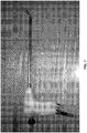
Fig. 1 is a schematic view showing a steerable electronic stereoscopic endoscope formed in accordance with the present disclosure -
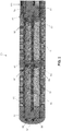
Figs. 2 and2A are schematic views showing the articulating region of the shaft of the endoscope; -
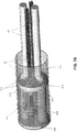
Figs. 3 ,3A ,3B and3C are schematic views showing the endoscope's sealed camera module and details thereof; -
Fig. 4 is a schematic view showing the distal end of the endoscope; -
Figs. 5 ,5A ,5B ,5C ,5D and5E are schematic views showing the endoscope's steering and brake assembly and details thereof, which is an embodiment of the invention defined by claim 1; -
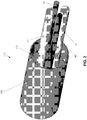
Figs. 6 and6A are schematic views showing the endoscope's handle and details thereof; and -
Figs. 7A and7B are schematic views showing an alternative configuration of the endoscope's camera head featuring improved resistance to degradation from steam autoclave sterilization. - Looking first at
Fig. 1 , there is shown a steerable electronic stereoscopic endoscope 5 formed in accordance with the present invention. Endoscope 5 generally comprises a shaft 10 having adistal end 15 and a proximal end 20. Shaft 10 is flexible in the articulatingregion 25 as will hereinafter be discussed in further detail. The proximal end 20 of shaft 10 is mounted to ahandle 30. -
Fig. 2 shows shaft 10 in the articulatingregion 25. Articulatingregion 25 generally comprises adistal joiner deck 35, at least oneintermediate deck 40 and abase joiner deck 45. Further elements in the articulatingregion 25 include a central supporting Nitinolsuper-elastic wire 50 captively supported withindistal joiner deck 35 andbase joiner deck 45.Intermediate deck 40 is slidably supported byNitinol superelastic wire 50. A plurality of stacked spacer elements (e.g., rings) 55 are coaxially mounted onNitinol superelastic wire 50 betweendistal joiner deck 35 and the at least oneintermediate deck 40, and between the at least oneintermediate deck 40 andbase joiner deck 45, so as to ensure a fixed spacing betweendistal joiner deck 35 and the at least oneintermediate deck 40, and between the at least oneintermediate deck 40 andbase joiner deck 45, regardless of endoscope articulation. - Four actuating wires 60 (only three of which are seen in
Fig. 2 ) are bonded securely withindistal joiner deck 35 and slidably pass through the at least oneintermediate deck 40 andbase joiner deck 45. Fourconduit tubes 65, joined tobase joiner deck 45 and extending proximally therefrom, maintain straightness and proper orientation of actuatingwires 60 as the actuating wires pass through the axial length of endoscope 5. - Looking now at
Figs. 2 and2A , two metal bellows 70 are hermetically joined (at joints 75) to theirrespective decks -
Holes 80 indecks Fig. 3 ) to slide freely withindecks decks Fig. 3 ) to slide freely withindecks -
Fig. 3 shows the sealed camera module 100 which is disposed in shaft 10 distal todistal joiner deck 35, withelectronic leads 85 and fiber optic illumination bundles 95 passing throughholes decks outer sleeve 105, anelastomer seal 110 and the aforementioned electronic leads 85 (from the camera module's image sensor assemblies, see below) and optical fiber illumination bundles 95. -
Figs. 3A ,3B and3C show interior construction details of sealed camera module 100. -
Fig. 3A shows themodule body 115 which is disposed coaxially withinouter sleeve 105 of sealed camera module 100, and animage sensor assembly 120, as well as the aforementioned electronic leads 85 and fiber optic illumination bundles 95. -
Fig. 3C illustrates the interior elements of sealed camera module 100 aligned and bonded withinmodule body 115. Shown are pairs of CCDimage sensor assemblies 120,camera lens cells 125 and optical fiber illumination bundles 95 bonded and polished withinferrules 130. -
Fig. 3B illustrates the foregoing elements bonded withinmodule body 115. The pair ofimage sensor assemblies 120 are carefully optically aligned and then bonded (e.g., at 116) tomodule body 115. Note thatcamera lens cells 125, and fiber optic illumination bundles 95 (mounted within ferrules 130), open on the distal end ofmodule body 115. Thus it will be seen that sealed camera module 100 comprises amodule body 115 which carriesimage sensor assemblies 120 andferrules 130 supporting fiber optic illumination bundles 95, and thismodule body 115 is secured withinouter sleeve 105 and sealed withelastomer seat 110, with the electronic leads 85 ofimage sensor assemblies 120 and fiber optic illumination bundles 95 extending throughelastomer seal 110. -
Fig. 4 illustrates the assembleddistal end 15 of endoscope 5, including articulatingregion 25. Note that the distal end ofdistal joiner deck 35 is received withinouter sleeve 105 of sealed camera module 100, with the distal end ofdistal joiner deck 35 abuttingelastomer seal 110 and with theouter sleeve 105 of sealed camera module 100 being hermetically bonded to the outside diameter ofdistal joiner deck 35. Note also that electronic leads 85 ofimage sensor assemblies 120 and fiber optic illumination bundles 95 extend throughdecks decks -
Fig. 5 shows the endoscope's steering andbrake assembly 135 which is contained within, and extends out of, handle 30. Using steering andbrake assembly 135, the user may direct the viewing angle of the endoscope by manipulating thecontrol joystick 140, which comprisesshaft members knob 155. The control joystick position also provides an external indication of the endoscope's viewing position, with the shaft (145, 150) ofcontrol joystick 140 representing the axis of a pointer andknob 155 representing the "tail" of the pointer. -
Control joystick 140 is secured by a captive ball joint 160 (Fig. 5A ) formed by abase 165, abearing ball 170 and a braking element 175. Viewing may be directed in a 360 degree conic arc of up to, but not limited to, an included angle of 140 degrees without altering the disposition of the main body of endoscope 5 itself.Fig. 1 shows the actual device with the viewing angle being held in place by the brake feature. - Manipulating
control joystick 140 deflects the distal end of the endoscope, whereby to appropriately direct its camera, by pulling one or more of the four actuating wires 60 (Fig. 5D ) held in position within aswash plate 180 by four ball-ended terminations 185 (Figs. 5D and5E ) bonded or swaged to their respective Nitinol pullwires 60. -
Figs. 5A and5E represent sectional views of the steering andbrake assembly 135. When the desired view position is achieved, the brake is applied by rotatingknob 155 clockwise. -
Knob 155 drives the brake cam 190 (Fig. 5B ) through adrive pin 195. A Nitinol brake pull wire 200 (Fig. 5A ) passes through a threaded tubularcontrol joystick core 205 and is fixed within the braking element 175 by two non-scoring set screws 210 (Fig. 5A ). Nitinol (a superelastic nickel titanium alloy) is used for its high strength inbrake pull wire 200 as well as in the aforementionedNitinol superelastic wire 50 disposed within the distal end of the endoscope (see above). Nitinol's unique elastic properties resist fatigue and contribute to maintaining straightness when the brake is not engaged. - Braking element 175 (
Fig. 5E ) features a partial precision hemispherical socket covering approximately one third of the control stick precision bearing ball 170 (Fig. 5A ). With the brake released, the braking element 175 serves as the distal element of the control stick bearing socket. The movable braking element 175 (Fig. 5A ) is constrained by the main tube sleeve 215 (Fig. 5E ). Proximally, the Nitinol brake pull wire 200 (Fig. 5A ) is attached to the cam follower body 220 (Fig. 5A ) by two non-scoring set screws 225 (only one of which is shown inFig. 5A ). Two cam follower pins 230 (Fig. 5A ) are inserted through slots in the cam 235 (Fig. 5A ) and restraininggrooves 240 in the knob body 245 (Fig. 5C ). -
Fig. 5A shows, at 250, the exit point of the hole through the threadedcore 205 ofcontrol joystick 140 located at the center point of thebearing ball 170. This is done to minimize any effective length change caused by the excursion made by the control joystick during use. Minimizing this length change effect removes unwanted friction and/or, conversely, sudden accidental brake release. - Referring to
Fig. 5A , it will be seen that rotating theknob 155 clockwise will place increasing tension on the braking element 175 viabrake pull wire 200, which in turn clamps upon the controlstick bearing ball 170 with sufficient friction to effectively holdswash plate 180, and hence the distal end of the endoscope's shaft, with the desired view orientation, yet light enough to allow overriding movement of the control joystick. - Undesirable rotation of the
swash plate 180 is prohibited by a restraining tab 255 (Figs. 5A and5B ) which is disposed within a parallel pair of dowel pins 260 joined tobase 165. - As shown in
Figs. 5D and5E , the effective leverage of theswash plate 180 when acting upon thepull wires 60 is maintained by the fourrounded grooves 265 inbase 165. -
Figs. 6 and6A show the proximal hand control end of endoscope 5.Handle 30 may be gripped by the user and thecontrol joystick 140 operated with the thumb of the gripping hand of the user, or thecontrol joystick 140 may be operated with the other hand of the user. - The fiber optic illumination bundles 95 are terminated and polished at 270 in an
input connector 275 to which an input light guide (not shown) from the accessory light source (not shown) is connected. The electronic leads (cable) 85 (Fig. 3 ) connect the image sensor assemblies 120 (Fig. 3C ) to the main 3D video control unit (not shown) and are routed through (at 280) asuitable strain relief 285. - Both the electronic
cable strain relief 285 and the fiberoptic input connector 275 are sealably bonded at 290, 295, respectively, to handle 30.Control joystick 140 is movably sealed to handle 30 by anelastomer seal 300 which is configured so as to minimize resistance to movement ofcontrol joystick 140.Area 305 ofelastomer seal 300 is preferably made slightly undersized so as to grasp and seal to handle 30, andarea 310 ofelastomer seal 300 is preferably made slightly undersized so as to grasp and seal to controljoystick 140. This sealing may be further augmented by adding compression collars and/or suitable adhesives toareas - A
stainless steel collar 315 provides additional support for themain tube 320 of shaft 10 wheremain tube 320 emerges fromhandle 30. Note thatmain tube 320 of shaft 10 is bonded and sealed to handle 30. -
Handle 30 may be formed from two halves which are united during manufacturing, e.g., by bonding at 325.Fig. 6A shows the proximal portion of endoscope 5 as it appears with the left side ofhandle 30 removed. The fiber optic illumination bundles 95 pass through theelongated hole 330 inouter tube 320 and then extend down toinput connector 275. The shieldedelectronic leads 85 from theimage sensor assemblies 120 also pass through theelongated hole 330 inouter tube 320 and then extend down tosuitable strain relief 285. The flange 332 (Figs. 5A and6A ) ofbase 165 is retained and supported within matching receiving features 335 within each handle half. Unwanted rotation of the steering mechanism is prevented by two opposingmachined slots 340 formed inflange 332 and fitting over mating tabs (not shown) formed in receiving features 335. The halves ofhandle 30 are sealed at all of the mating edge surfaces (e.g., at 325). - Thus it will be seen that shaft 10 of endoscope 5 comprises a sealed camera module 100 (
Fig. 3 ) which has its distal working components (e.g., the image-forming optics and electronics shown inFigs. 3A ,3B and3C ) disposed withinouter sleeve 105 so as to present itsobjective lens cells 125 and the distal ends of its fiber optic illumination bundles 95 to the region distal toouter sleeve 105, with fiber optic illumination bundles 95 andelectronic leads 85 extending proximally therefrom. Shaft 10 further comprises threedecks Figs. 2 and2A ) which are connected together by aninterior wire spine 50 and exterior metal bellows 70 so as to provide an articulating region to the shaft.Wire spine 50 further comprises a plurality of stacked spacer elements (e.g., rings) 55 coaxially mounted on thewire spine 50 so as to ensure consistent shaft length when the shaft is articulated.Distal deck 35 is received within and mated toouter sleeve 105 of sealed camera module 100, andmain tube 320 of shaft 10 extends proximally fromproximal deck 45. The proximal end ofmain tube 320 is secured to handle 30.Actuating wires 60 are provided to articulate the distal end of shaft 10 and, to this end, the distal end of articulatingwires 60 are secured todistal deck 35 and extend proximally along the shaft, terminating atswash plate 180 of the steering andbrake assembly 135. The disposition ofswash plate 180, and hence the disposition of the distal end of shaft 10, is adjusted by manipulatingknob 155 at the proximal end of steering andbrake assembly 135. The disposition ofswash plate 180, and hence the view position of the distal end of the shaft, is adjusted by movingcontrol joystick 140, and is locked in position by turningknob 155 ofcontrol joystick 140, which applies a proximal force to brakepull wire 200, which causes brake 175 to lockbearing ball 170 in position, whereby to lock swash plate 180 (and hence the distal end of the shaft) in position. - As shown, endoscope 5 is hand-operated. However, by linking at least two electromechanical, remotely-operated servos to at least two quadrants of the
swash plate 180 and replacinghandle 30 with a suitable adapter, steerable electronic stereoscopic endoscope 5 may be adapted for utilization with remotely-operated surgical robot systems. - It is well known in the art that endoscopes capable of withstanding multiple autoclave cycles must be sealed in such a way that all image-forming optics and electronics (e.g., the image sensor assemblies) are hermetically sealed by means of welding, high temperature soldering, brazing or other types of "hard" sealing methods, as opposed to elastomer seals or adhesives that are permeable to hot steam. Even very small amounts of moisture, if present in the optical path from the distal tip to the image sensor, will cause condensation and render the image unusable. The present invention lends itself to a complete hermetically-sealed autoclavable design. As seen in
Figs. 2 and2A , the steerable distal portion of the endoscope comprises metal bellows 70 soldered or welded to themetal decks Fig. 3C ,objective lens cells 125 may be designed in such a way that the distal optical lens or window is fabricated out of optical grade sapphire and soldered to the metal barrel of the lens cell. Note that this type of sapphire-to-metal sealing technology is well known in the art. The metal barrels of thecamera lens cells 125 may then be welded to the module body 115 (Fig. 3B ). Alternatively the front lens of eachobjective lens assembly 125 may be soldered directly to themodule body 115. Similarly, thin sapphire windows may be soldered to themodule body 115 at the distal ports ofillumination fibers 95, thereby providing for autoclavable hermetic seals at the distal surface ofmodule body 115. The outer sleeve 105 (Fig. 3 ) may be welded or brazed tomodule body 115 at its distal end. Referring toFig. 3 ,elastomer seal 110 may be replaced with a metal part welded or brazed toouter sleeve 105 and having hermetic feed-through connections forillumination fiber bundles 95 andimage sensor cables 85. Such hermetic feed-through connectors are known in the art. The modifications described above will encapsulate the most critical distal portion of the endoscope, which contains the optics and image sensors, into a fully hermetic assembly amenable to multiple autoclave cycles. The remaining portions of the endoscope are much less critical for small amounts of moisture and may be sealed by conventional sealing methods using elastomers and adhesives. - Thus, for example,
Figs. 7A and7B show an alternative configuration of the camera head featuring improved resistance to degradation from steam autoclave sterilization. More particularly, a distal stainless steel face (or deck) 345 features twoholes 350 closely fitted with theconduit tubes 355 ofillumination fibers 95.Conduit tubes 355 are sealably soldered about their distal perimeter to eachhole 350. Also shown are two sapphireoptical windows 360 with metalized edges which are also sealably soldered inholes 365 instainless steel face 345. Thesesapphire windows 360 are aligned with the optical axis of the twocamera lens cells 125. A second stainless steel face (or deck) 370 constrains the proximal ends of theconduit tubes 355 ofillumination fiber optics 95, i.e.,conduit tubes 355 are sealably soldered inholes 375 inmetal deck 370. The camera heads 120, and theircorresponding lens cells 125, are constrained and held in proper alignment within module body 115 (shown transparent inFigs. 7A and7B ). This assembled camera module is adhesively bonded within the inner diameter of theouter sleeve 105. In addition to having the illumination fiber optic conduits sealably soldered,deck 370 also has two glass-to-metal sealed headers 380 (Fig. 7B ) sealably soldered withinholes 385 formed indeck 370. The electronic leads 85 from the twoimage sensor assemblies 120 are conductively joined to the glass-sealed feed-through leads within the two glass-to-metal sealedheaders 380. The twoillumination fiber bundles 95 are seen exiting their corresponding sealedconduits 355 inFig. 7B . The twodecks inner diameter 385 ofouter sleeve 105, resulting in an assembly sealed by solder about the perimeters of thefiber optic conduits 355,sapphire windows 360 andglass headers 380. -
Figs. 6 and6A show two connections, i.e.,connection 275 for theillumination fibers 95 andconnection 285 forelectrical cable 85. In an alternative embodiment, these two connectors may be combined into one universal cable carrying both illumination fibers and electrical wires, and may be permanently affixed to handle 30. The proximal end of such a universal cable connects to a universal control unit (not shown) comprising a light source and the camera processor. Alternatively, such a universal cable may be detachably connected to handle 30. - In another embodiment of the present invention, rather than connecting the
illumination fiber bundles 95 to an external light source via connector 275 (Fig. 6 ), the proximal portion of the endoscope (e.g. handle 30) may contain an illumination engine based on white LEDs optically coupled to illumination fiber bundles 95 (Fig. 3 ). As a result, an external light source will be no longer needed. The electrical power and control signals for the LEDs may be supplied viaconnector 285. Alternatively, miniature white LEDs may be disposed at the distal end of the shaft of the endoscope, thereby eliminatingillumination fiber bundles 95 altogether, or coupled to very short segments of illumination fiber. - In yet another embodiment of the present invention, the proximal portion of the endoscope contains a portable electrical power supply (e.g., a battery) and a wireless transceiver for providing a wireless video link to a corresponding transceiver in the external camera control unit. Thus, electrical cable connector 285 (
Fig. 6 ) may be eliminated. This embodiment, combined with the one described above in which LEDs are used for illumination, will render the endoscope completely untethered, thereby significantly improving user interface and freedom of movement for the operator of the device. The portable power supply (i.e., battery) will provide electrical power for image sensor assemblies, the LED light engine and the wireless video link circuitry. - In another embodiment, the proximal portion of the endoscope contains the entire video processing circuitry using highly integrated SoC ("system-on-a-chip") or CoC ("camera-on-a-chip") electronics. This embodiment, if combined with the two embodiments previously described (i.e., on-board light source, portable power supply and wireless communications), will eliminate the need for an external light source, external camera processing unit, light guide and electrical cable. The wireless video link will be established directly with a wireless device built into a video display, or with a wireless device external to, and electrically coupled to, the video display.
- It should also be understood that many additional changes in the details, materials, steps and arrangements of parts, which have been herein described and illustrated in order to explain the nature of the present invention, may be made by those skilled in the art while still remaining within the principles and scope of the invention.
- Preferred features of the steerable stereoscopic endoscope, steerable endoscope and the method for a acquiring an image at a remote site are given in the following clauses:
- 1. A steerable stereoscopic endoscope comprising:
- a shaft having a distal end, a proximal end, and an articulating region therebetween;
- stereo image acquisition means disposed at the distal end of the shaft for acquiring stereo images of a remote site; and
- means for steering the portion of the shaft distal to the articulating region.
- 2. A steerable stereoscopic endoscope according to clause 1 wherein the stereo image acquisition means comprise a pair of electronic image sensor assemblies.
- 3. A steerable stereoscopic endoscope according to clause 1 wherein the articulating region of the shaft comprises a wire spine having a distal end and a proximal end, a distal deck mounted to the distal end of the wire spine and a proximal deck mounted to the proximal end of the wire spine.
- 4. A steerable stereoscopic endoscope according to clause 3 further comprising a plurality of stacked spacer elements coaxially mounted on the wire spine.
- 5. A steerable stereoscopic endoscope according to clause 1 further comprising fiber optic illumination bundles for delivering light to the distal end of the shaft.
- 6. A steerable stereoscopic endoscope according to clause 1 further comprising a steering and brake assembly mounted to the proximal end of the shaft for controlling the disposition of the portion of the shaft distal to the articulating region of the shaft.
- 7. A steerable endoscope comprising:
- a shaft having a distal end, a proximal end, and an articulating region therebetween; and
- image acquisition means disposed at the distal end of the shaft for acquiring an image of a remote site;
- wherein the distal end of the shaft comprises at least two decks sealably connected by flexible metal bellows.
- 8. A steerable endoscope according to clause 7 further comprising a wire spine having a distal end and a proximal end, the distal end of the wire spine being mounted to a deck and the proximal end of the wire spine being mounted to a deck.
- 9. A steerable endoscope according to clause 8 further comprising a plurality of stacked spacer elements coaxially mounted on the wire spine.
- 10. A steerable endoscope according to clause 7 wherein the image acquisition means comprise a pair of electronic image sensor assemblies.
- 11. A steerable endoscope according to clause 7 further comprising fiber optic illumination bundles for delivering light to the distal end of the shaft.
- 12. A steerable endoscope according to clause 7 further comprising a steering and brake assembly mounted to the proximal end of the shaft for controlling the disposition of the portion of the shaft distal to the articulating region of the shaft.
- 13. A steerable endoscope comprising:
- a shaft having a distal end, a proximal end, and an articulating region therebetween; and
- image acquisition means disposed at the distal end of the shaft for acquiring an image of a remote site;
- wherein the distal end of the shaft comprises a wire spine having a distal end and a proximal end, a first deck mounted to the distal end of the wire spine and a second deck mounted to the proximal end of the wire spine.
- 14. A steerable endoscope according to clause 13 further comprising a plurality of stacked spacer elements coaxially mounted on the wire spine.
- 15. A steerable endoscope according to clause 13 further comprising a third deck disposed intermediate the first deck and the second deck, and further wherein the third deck is slidably mounted on the wire spine.
- 16. A steerable endoscope according to
clause 15 wherein the first deck and the third deck are sealably connected by flexible metal bellows, and further wherein the second deck and the third deck are sealably connected by flexible metal bellows. - 17. A steerable endoscope according to clause 13 wherein the image acquisition means comprise a pair of electronic image sensor assemblies.
- 18. A steerable endoscope according to clause 13 further comprising fiber optic illumination bundles for delivering light to the distal end of the shaft.
- 19. A steerable endoscope according to clause 13 further comprising a steering and brake assembly mounted to the proximal end of the shaft for controlling the disposition of the portion of the shaft distal to the articulating region of the shaft.
- 20. A steerable endoscope comprising:
- a shaft having a distal end, a proximal end, and an articulating region therebetween;
- image acquisition means disposed at the distal end of the shaft for acquiring an image of a remote site;
- a steering and brake assembly mounted to the proximal end of the shaft; and
- a plurality of actuating wires extending between the distal end of the shaft and the steering and brake assembly;
- wherein the steering and brake assembly comprises:
- a base having a spherical seat;
- a bearing ball rotatably mounted within the spherical seat of the base;
- a joystick core mounted to the ball;
- a swash plate mounted to the joystick core, wherein the plurality of actuating wires are attached to the swash plate;
- a brake for selectively locking the bearing ball in position within the spherical seat of the base; and
- means for actuating the brake.
- 21. A steerable endoscope according to clause 20 wherein the means for actuating the brake comprise a brake pull wire connected to the brake.
- 22. A steerable endoscope according to clause 21 further comprising a knob rotatably mounted to the joystick core, with the brake pull wire being connected to the knob.
- 23. A steerable endoscope according to clause 22 further comprising a cam mechanism associated with the knob such that rotation of the knob results in longitudinal motion of the brake pull wire, whereby to actuate the brake.
- 24. A steerable endoscope according to clause 20 wherein the image acquisition means comprise a pair of electronic image sensor assemblies.
- 25. A steerable endoscope according to clause 20 wherein the articulating region of the shaft comprises a wire spine having a distal end and a proximal end, a distal deck mounted to the distal end of the wire spine and a proximal deck mounted to the proximal end of the wire spine.
- 26. A steerable endoscope according to clause 20 further comprising a plurality of stacked spacer elements coaxially mounted on the wire.
- 27. A steerable endoscope according to clause 20 further comprising fiber optic illumination bundles for delivering light to the distal end of the shaft.
- 28. A steerable endoscope comprising:
- a shaft having a distal end, a proximal end, and an articulating region therebetween;
- image acquisition means disposed at the distal end of the shaft for acquiring an image of a remote site; and
- a control joystick for steering the portion of the shaft distal to the articulating region.
- 29. A steerable endoscope according to clause 28 wherein the image acquisition means comprises a pair of electronic image sensor assemblies.
- 30. A steerable endoscope according to clause 28 wherein the articulating region of the shaft comprises a wire spine having a distal end and a proximal end, a distal deck mounted to the distal end of the wire spine and a proximal deck mounted to the proximal end of the wire spine.
- 31. A steerable endoscope according to
clause 30 further comprising a plurality of stacked spacer elements coaxially mounted on the wire spine. - 32. A steerable endoscope according to clause 28 further comprising fiber optic illumination bundles for delivering light to the distal end of the shaft.
- 33. A steerable endoscope according to clause 28 further comprising a brake for locking the disposition of the portion of the shaft distal to the articulating region of the shaft.
- 34. A method for acquiring an image of a remote site, the method comprising:
- providing a steerable stereoscopic endoscope comprising:
- a shaft having a distal end, a proximal end, and an articulating region therebetween;
- stereo image acquisition means disposed at the distal end of the shaft for acquiring stereo images of a remote site; and
- means for steering the portion of the shaft distal to the articulating region; and
- using the steerable stereoscopic endoscope to acquire an image of a remote site.
- providing a steerable stereoscopic endoscope comprising:
- 35. A method for acquiring an image of a remote site, the method comprising:
- providing a steerable endoscope comprising:
- a shaft having a distal end, a proximal end, and an articulating region therebetween; and
- image acquisition means disposed at the distal end of the shaft for acquiring an image of a remote site;
- wherein the distal end of the shaft comprises at least two decks sealably connected by flexible metal bellows; and
- using the steerable endoscope to acquire an image of a remote site.
- providing a steerable endoscope comprising:
- 36. A method for acquiring an image of a remote site, the method comprising:
- providing a steerable endoscope comprising:
- a shaft having a distal end, a proximal end, and an articulating region therebetween; and
- image acquisition means disposed at the distal end of the shaft for acquiring an image of a remote site;
- wherein the distal end of the shaft comprises a wire spine having a distal end and a proximal end, a first deck mounted to the distal end of the wire spine and a second deck mounted to the proximal end of the wire spine; and
- using the steerable endoscope to acquire an image of a remote site.
- providing a steerable endoscope comprising:
- 37. A method for acquiring an image of a remote site, the method comprising:
- providing a steerable endoscope comprising:
- a shaft having a distal end, a proximal end, and an articulating region therebetween;
- image acquisition means disposed at the distal end of the shaft for acquiring an image of a remote site;
- a steering and brake assembly mounted to the proximal end of the shaft; and
- a plurality of actuating wires extending between the distal end of the shaft and the steering and brake assembly;
- wherein the steering and brake assembly comprises:
- a base having a spherical seat;
- a bearing ball rotatably mounted within the spherical seat of the base;
- a joystick core mounted to the ball;
- a swash plate mounted to the joystick core, wherein the plurality of actuating wires are attached to the swash plate;
- a brake for selectively locking the bearing ball in position within the spherical seat of the base; and
- means for actuating the brake; and
- using the steerable endoscope to acquire an image of a remote site.
- providing a steerable endoscope comprising:
- 38. A method for acquiring an image of a remote site, the method comprising:
- providing a steerable endoscope comprising:
- a shaft having a distal end, a proximal end, and an articulating region therebetween;
- image acquisition means disposed at the distal end of the shaft for acquiring an image of a remote site; and
- a control joystick for steering the portion of the shaft distal to the articulating region; and
- using the steerable endoscope to acquire an image of a remote site.
- providing a steerable endoscope comprising:
- 39. A steerable endoscope comprising:
- a shaft having a distal end, a proximal end, and an articulating region therebetween;
- image acquisition means disposed at the distal end of the shaft for acquiring an image of a remote site; and
- means for steering the portion of the shaft distal to the articulating region;
- wherein the image acquisition means are isolated within a capsule configured to protect the image acquisition means against multiple steam autoclave cycles.
- 40. A steerable endoscope according to clause 39 wherein the image acquisition means comprises at least one electronic image sensor assembly.
- 41. A steerable endoscope according to clause 39 wherein the capsule is sealed by soldering, welding or brazing.
- 42. A steerable endoscope according to clause 39 wherein the capsule is sealed without the use of an adhesive or an elastomer.
- 43. A steerable endoscope according to clause 39 wherein the capsule comprises a metal cylinder closed off at its distal end by a distal metal deck and closed off at its proximal end by a proximal metal deck, the image acquisition means comprising at least one electronic image assembly terminating in electronic leads, with the at least one electronic image assembly being configured to image through a sapphire window sealed within the distal metal deck, and with the electrical wires from the at least one electronic image assembly passing through the proximal deck by means of a glass-to-metal sealed header.
- 44. A method for acquiring an image of a remote site, the method comprising:
- providing a steerable endoscope comprising:
- a shaft having a distal end, a proximal end, and an articulating region therebetween;
- image acquisition means disposed at the distal end of the shaft for acquiring an image of a remote site; and
- means for steering the portion of the shaft distal to the articulating region;
- wherein the image acquisition means are isolated within a capsule configured to protect the image acquisition means against multiple steam autoclave cycles; and
- using the steerable endoscope to acquire an image of a remote site.
- providing a steerable endoscope comprising:
- 45. A method according to clause 44 further comprising:
- subjecting the steerable endoscope to multiple steam autoclave cycles; and
- using the steerable endoscope to acquire an image of a remote site.
Claims (5)
- A steerable endoscope (5) comprising:a shaft (10) having a distal end (15), a proximal end (20), and an articulating region (25) therebetween;a steering and brake assembly (135) mounted to the proximal end (20) of the shaft (10); anda plurality of actuating wires (60) extending between the distal end (15) of the shaft (10) and the steering and brake assembly (135);wherein the steering and brake assembly (135) comprises:a brake (175); anda base (165) having a spherical seat;a bearing ball (170) rotatably mounted within the spherical seat of the base (165);
means for actuating the brake (175),
characterized in that the steerable endoscope further comprises image acquisition means disposed at the distal end (15) of the shaft (10) for acquiring an image of a remote site; and whereinthe steering and brake assembly (135) further comprises:
a joystick with a joystick core (205) mounted to the ball (170) and a rotatable knob (155);a swash plate (180) mounted to the joystick core (205), wherein the plurality of actuating wires (60) are attached to the swash plate (180);and wherein the brake (175) is a brake for selectively locking the bearing ball (170) in position within the spherical seat of the base (165);and wherein the means for actuating the brake (175) comprise:
a brake pull wire (200) passing through the joystick core (205) and the bearing ball (170) and being connected to the brake (175) such that when turning the rotatable knob (155) of joystick (140), proximal force is applied to brake pull wire (200), which causes brake (175) to lock bearing ball (170) in position, whereby to lock swash plate (180). - A steerable endoscope according to claim 1 with the steerable endoscope (5) having the knob (155) rotatably mounted to the joystick core (205), with the brake pull wire (200) being connected to the knob (155), and the steerable endoscope (5) further comprising a cam mechanism associated with the knob (155) such that rotation of the knob (155) results in longitudinal motion of the brake pull wire (200), whereby to actuate the brake (175).
- A steerable endoscope according to claim 1 wherein the articulating region (25) of the shaft (10) comprises a wire spine (50) having a distal end and a proximal end, a distal deck (35) mounted to the distal end of the wire spine and a proximal deck (45) mounted to the proximal end of the wire spine (50).
- A steerable endoscope according to claim 1 further comprising a plurality of stacked spacer elements (55) coaxially mounted on the wire.
- A steerable endoscope according to claim 1, characterized in that the endoscope is a stereoscopic endoscope comprising:a shaft having a distal end, a proximal end, and an articulating region therebetween;stereo image acquisition means disposed at the distal end of the shaft for acquiring stereo images of a remote site; andmeans for steering the portion of the shaft distal to the articulating region.
Priority Applications (2)
| Application Number | Priority Date | Filing Date | Title |
|---|---|---|---|
| EP18165022.7A EP3372143B1 (en) | 2011-10-21 | 2012-10-22 | Steerable electronic stereoscopic endoscope |
| EP20154227.1A EP3666162A1 (en) | 2011-10-21 | 2012-10-22 | Steerable electronic stereoscopic endoscope |
Applications Claiming Priority (2)
| Application Number | Priority Date | Filing Date | Title |
|---|---|---|---|
| US201161550095P | 2011-10-21 | 2011-10-21 | |
| PCT/US2012/061375 WO2013059821A2 (en) | 2011-10-21 | 2012-10-22 | Steerable electronic stereoscopic endoscope |
Related Child Applications (3)
| Application Number | Title | Priority Date | Filing Date |
|---|---|---|---|
| EP20154227.1A Division EP3666162A1 (en) | 2011-10-21 | 2012-10-22 | Steerable electronic stereoscopic endoscope |
| EP18165022.7A Division EP3372143B1 (en) | 2011-10-21 | 2012-10-22 | Steerable electronic stereoscopic endoscope |
| EP18165022.7A Division-Into EP3372143B1 (en) | 2011-10-21 | 2012-10-22 | Steerable electronic stereoscopic endoscope |
Publications (3)
| Publication Number | Publication Date |
|---|---|
| EP2768373A2 EP2768373A2 (en) | 2014-08-27 |
| EP2768373A4 EP2768373A4 (en) | 2016-02-17 |
| EP2768373B1 true EP2768373B1 (en) | 2018-06-13 |
Family
ID=48136511
Family Applications (3)
| Application Number | Title | Priority Date | Filing Date |
|---|---|---|---|
| EP12842363.9A Active EP2768373B1 (en) | 2011-10-21 | 2012-10-22 | Steerable endoscope comprising a brake |
| EP18165022.7A Active EP3372143B1 (en) | 2011-10-21 | 2012-10-22 | Steerable electronic stereoscopic endoscope |
| EP20154227.1A Pending EP3666162A1 (en) | 2011-10-21 | 2012-10-22 | Steerable electronic stereoscopic endoscope |
Family Applications After (2)
| Application Number | Title | Priority Date | Filing Date |
|---|---|---|---|
| EP18165022.7A Active EP3372143B1 (en) | 2011-10-21 | 2012-10-22 | Steerable electronic stereoscopic endoscope |
| EP20154227.1A Pending EP3666162A1 (en) | 2011-10-21 | 2012-10-22 | Steerable electronic stereoscopic endoscope |
Country Status (4)
| Country | Link |
|---|---|
| US (2) | US9044138B2 (en) |
| EP (3) | EP2768373B1 (en) |
| ES (1) | ES2836119T3 (en) |
| WO (1) | WO2013059821A2 (en) |
Cited By (1)
| Publication number | Priority date | Publication date | Assignee | Title |
|---|---|---|---|---|
| DE102020104563A1 (en) | 2020-02-20 | 2021-08-26 | Christoph Miethke Gmbh & Co Kg | Device for positioning a heart implant |
Families Citing this family (72)
| Publication number | Priority date | Publication date | Assignee | Title |
|---|---|---|---|---|
| US8556807B2 (en) | 2006-12-21 | 2013-10-15 | Intuitive Surgical Operations, Inc. | Hermetically sealed distal sensor endoscope |
| US8814779B2 (en) | 2006-12-21 | 2014-08-26 | Intuitive Surgical Operations, Inc. | Stereoscopic endoscope |
| US9452276B2 (en) | 2011-10-14 | 2016-09-27 | Intuitive Surgical Operations, Inc. | Catheter with removable vision probe |
| US20130303944A1 (en) | 2012-05-14 | 2013-11-14 | Intuitive Surgical Operations, Inc. | Off-axis electromagnetic sensor |
| US20140148673A1 (en) | 2012-11-28 | 2014-05-29 | Hansen Medical, Inc. | Method of anchoring pullwire directly articulatable region in catheter |
| US20140221740A1 (en) * | 2013-02-05 | 2014-08-07 | Paul John Kawula | Wireless endoscopic surgical device |
| US20160278615A1 (en) * | 2013-02-05 | 2016-09-29 | Scopernicus, LLC | Wireless endoscopic surgical device |
| US11382492B2 (en) | 2013-02-05 | 2022-07-12 | Scopernicus, LLC | Wireless endoscopic surgical device |
| US20140275779A1 (en) * | 2013-03-12 | 2014-09-18 | Covidien Lp | Flexible Shaft with Multiple Flexible Portions |
| US20140360308A1 (en) * | 2013-06-10 | 2014-12-11 | Donal Walker Lumsden | Mechanical maneuvering system |
| DE102013110543A1 (en) * | 2013-09-24 | 2015-03-26 | Karl Storz Gmbh & Co. Kg | Apparatus for capturing an image of an object field on a human or animal body |
| US9795279B2 (en) | 2013-10-21 | 2017-10-24 | Access Optics, LLC | Endoscope coupler |
| US9819926B2 (en) | 2013-11-26 | 2017-11-14 | Conmed Corporation | Stereoscopic (3D) camera system utilizing a monoscopic (2D) control unit |
| EP2923669B1 (en) | 2014-03-24 | 2017-06-28 | Hansen Medical, Inc. | Systems and devices for catheter driving instinctiveness |
| EP3131479B1 (en) | 2014-04-17 | 2019-04-10 | Stryker Corporation | Surgical tool with selectively bendable shaft that resists buckling |
| WO2016024414A1 (en) * | 2014-08-11 | 2016-02-18 | オリンパス株式会社 | Endoscope system |
| EP3200718A4 (en) | 2014-09-30 | 2018-04-25 | Auris Surgical Robotics, Inc | Configurable robotic surgical system with virtual rail and flexible endoscope |
| EP3209192A4 (en) * | 2014-10-20 | 2019-01-16 | Research Development International Corporation | Steerable micro-endoscope |
| US10314463B2 (en) | 2014-10-24 | 2019-06-11 | Auris Health, Inc. | Automated endoscope calibration |
| WO2017079434A1 (en) * | 2015-11-03 | 2017-05-11 | Nowlin John William | Guidable intubation stylet |
| US10143526B2 (en) | 2015-11-30 | 2018-12-04 | Auris Health, Inc. | Robot-assisted driving systems and methods |
| DE102015015993B4 (en) * | 2015-12-10 | 2019-05-29 | Schölly Fiberoptic GmbH | endoscope |
| WO2017122399A1 (en) * | 2016-01-13 | 2017-07-20 | オリンパス株式会社 | Endoscope |
| WO2017132265A1 (en) | 2016-01-29 | 2017-08-03 | Boston Scientific Scimed, Inc. | Endoscopy systems and related methods |
| US11363944B2 (en) | 2016-02-12 | 2022-06-21 | Stryker Corporation | Surgical instrument with steerable camera |
| US20170239091A1 (en) * | 2016-02-22 | 2017-08-24 | Altek Corporation | Eardrum incision device |
| WO2017181153A1 (en) | 2016-04-14 | 2017-10-19 | Transenterix Surgical, Inc. | Electromechanical surgical system inlcuding linearly driven instrument roll |
| WO2018013202A1 (en) * | 2016-07-14 | 2018-01-18 | Intuitive Surgical Operations, Inc. | A pressure test port contained within a body of surgical instrument |
| CN109310286A (en) * | 2016-07-14 | 2019-02-05 | 直观外科手术操作公司 | Endoscope including multiple sub-components that can individually test |
| JP6234649B1 (en) * | 2016-07-25 | 2017-11-22 | オリンパス株式会社 | Bending operation mechanism of medical equipment |
| JP6234650B1 (en) * | 2016-07-25 | 2017-11-22 | オリンパス株式会社 | Endoscope bending operation mechanism |
| WO2018020717A1 (en) * | 2016-07-25 | 2018-02-01 | オリンパス株式会社 | Bending operation mechanism for medical apparatus |
| WO2018020718A1 (en) * | 2016-07-25 | 2018-02-01 | オリンパス株式会社 | Bending operation mechanism for endoscope |
| US9931025B1 (en) * | 2016-09-30 | 2018-04-03 | Auris Surgical Robotics, Inc. | Automated calibration of endoscopes with pull wires |
| US10244926B2 (en) | 2016-12-28 | 2019-04-02 | Auris Health, Inc. | Detecting endolumenal buckling of flexible instruments |
| CN110831498B (en) | 2017-05-12 | 2022-08-12 | 奥瑞斯健康公司 | Biopsy device and system |
| WO2019005872A1 (en) | 2017-06-28 | 2019-01-03 | Auris Health, Inc. | Instrument insertion compensation |
| CN110831482B (en) * | 2017-06-30 | 2022-01-11 | 奥林巴斯株式会社 | Endoscope with a detachable handle |
| US10426559B2 (en) | 2017-06-30 | 2019-10-01 | Auris Health, Inc. | Systems and methods for medical instrument compression compensation |
| WO2019003587A1 (en) * | 2017-06-30 | 2019-01-03 | オリンパス株式会社 | Endoscope |
| US10016900B1 (en) | 2017-10-10 | 2018-07-10 | Auris Health, Inc. | Surgical robotic arm admittance control |
| US10145747B1 (en) | 2017-10-10 | 2018-12-04 | Auris Health, Inc. | Detection of undesirable forces on a surgical robotic arm |
| TWI659728B (en) * | 2017-11-02 | 2019-05-21 | 國立交通大學 | Minimally invasive surgical instruments with terminal steerable mechanism |
| JP7362610B2 (en) | 2017-12-06 | 2023-10-17 | オーリス ヘルス インコーポレイテッド | System and method for correcting uncommanded instrument rotation |
| AU2018384820A1 (en) | 2017-12-14 | 2020-05-21 | Auris Health, Inc. | System and method for estimating instrument location |
| EP3752085A4 (en) | 2018-02-13 | 2021-11-24 | Auris Health, Inc. | System and method for driving medical instrument |
| US11589736B2 (en) | 2018-03-13 | 2023-02-28 | Meditrina, Inc. | Deflectable endoscope and method of use |
| US10365554B1 (en) * | 2018-04-04 | 2019-07-30 | Intuitive Surgical Operations, Inc. | Dynamic aperture positioning for stereo endoscopic cameras |
| WO2019198350A1 (en) * | 2018-04-13 | 2019-10-17 | オリンパス株式会社 | Surgical endoscope |
| DE102018209087A1 (en) * | 2018-06-07 | 2019-12-12 | Epflex Feinwerktechnik Gmbh | Control handle device and catheter instrument |
| CN110393499B (en) * | 2018-08-31 | 2021-12-07 | 上海微创医疗机器人(集团)股份有限公司 | Electronic endoscope and electronic endoscope system |
| EP3856064A4 (en) | 2018-09-28 | 2022-06-29 | Auris Health, Inc. | Systems and methods for docking medical instruments |
| DE102018126938A1 (en) * | 2018-10-29 | 2020-04-30 | Hoya Corporation | Endoscope control device and endoscope with an endoscope control device |
| US11357593B2 (en) | 2019-01-10 | 2022-06-14 | Covidien Lp | Endoscopic imaging with augmented parallax |
| USD908161S1 (en) | 2019-01-15 | 2021-01-19 | Moleculight, Inc. | Handheld imaging device |
| USD908881S1 (en) | 2019-01-17 | 2021-01-26 | Sbi Alapharma Canada, Inc. | Handheld endoscopic imaging device |
| USD910182S1 (en) | 2019-01-17 | 2021-02-09 | Sbi Alapharma Canada, Inc. | Handheld multi-modal imaging device |
| WO2020148725A1 (en) * | 2019-01-17 | 2020-07-23 | Sbi Alapharma Canada, Inc. | Modular endoscopic system for visualization of disease |
| CN109924969A (en) * | 2019-04-19 | 2019-06-25 | 优谱激光科技(南京)有限公司 | A kind of laser imaging blood perfusion detection device with light probe |
| CN110151109A (en) * | 2019-05-23 | 2019-08-23 | 房博 | A kind of multichannel has the flexible endoscope of 3D three-dimensional imaging mechanism |
| EP3958941A4 (en) * | 2019-06-02 | 2023-09-06 | Wolf Technical Services, Inc. | Tube introducer intubation device |
| DE102019115147B4 (en) * | 2019-06-05 | 2021-01-14 | Schott Ag | Biocompatible composite element and method for producing a biocompatible composite element |
| KR20220123076A (en) | 2019-12-31 | 2022-09-05 | 아우리스 헬스, 인코포레이티드 | Alignment Techniques for Transdermal Access |
| KR20220123087A (en) | 2019-12-31 | 2022-09-05 | 아우리스 헬스, 인코포레이티드 | Alignment interface for transdermal access |
| EP4084721A4 (en) | 2019-12-31 | 2024-01-03 | Auris Health Inc | Anatomical feature identification and targeting |
| US20210338049A1 (en) | 2020-04-30 | 2021-11-04 | Ambu A/S | Method of assembly of an endoscope control system |
| US11259695B2 (en) | 2020-07-21 | 2022-03-01 | Meditrina, Inc. | Endoscope and method of use |
| EP4056100A1 (en) | 2021-03-12 | 2022-09-14 | Ambu A/S | A tip part for a medical insertion vision device |
| DE102021119517A1 (en) | 2021-07-28 | 2023-02-02 | Karl Storz Se & Co. Kg | Method for reshaping and/or for attaching steering wires to a spatially adjustable disk, steering wires for moving a distal-side joint mechanism, medical instrument and robot |
| DE102021119513A1 (en) | 2021-07-28 | 2023-02-02 | Karl Storz Se & Co. Kg | Method for assembling a joint mechanism for a medical instrument and joint mechanism for a medical instrument and medical instrument |
| DE102021119506A1 (en) | 2021-07-28 | 2023-02-02 | Karl Storz Se & Co. Kg | Method for attaching steering elements to a spatially adjustable disk, steering elements for moving a distal joint mechanism and medical instrument |
| CN114280767A (en) * | 2021-12-27 | 2022-04-05 | 青岛奥美克医疗科技有限公司 | Three-dimensional image adapter with double lenses focusing synchronously and endoscope system |
Family Cites Families (78)
| Publication number | Priority date | Publication date | Assignee | Title |
|---|---|---|---|---|
| US3788303A (en) * | 1972-01-24 | 1974-01-29 | American Cystoscope Makers Inc | Orthogonally deflectable endoscope |
| US4491865A (en) * | 1982-09-29 | 1985-01-01 | Welch Allyn, Inc. | Image sensor assembly |
| US4686963A (en) * | 1986-03-05 | 1987-08-18 | Circon Corporation | Torsion resistant vertebrated probe of simple construction |
| IT1235460B (en) * | 1987-07-31 | 1992-07-30 | Confida Spa | FLEXIBLE ENDOSCOPE. |
| US4924852A (en) * | 1987-09-11 | 1990-05-15 | Olympus Optical Co., Ltd. | Endoscope |
| US5007406A (en) * | 1988-11-04 | 1991-04-16 | Asahi Kogaku Kogyo Kabushiki Kaisha | Bending control device of endoscope |
| DE3921233A1 (en) * | 1989-06-28 | 1991-02-14 | Storz Karl Gmbh & Co | ENDOSCOPE WITH A VIDEO DEVICE AT THE DISTAL END |
| US5329887A (en) * | 1992-04-03 | 1994-07-19 | Vision Sciences, Incorporated | Endoscope control assembly with removable control knob/brake assembly |
| US5575755A (en) * | 1994-02-23 | 1996-11-19 | Welch Allyn, Inc. | Fluid insensitive braking for an endoscope |
| US5464007A (en) * | 1994-02-23 | 1995-11-07 | Welch Allyn, Inc. | Fluid insensitive braking for an endoscope |
| US5496260A (en) * | 1994-05-16 | 1996-03-05 | Welch Allyn, Inc. | Torque override knob for endoscopes, borescopes, or guide tubes |
| JPH0829701A (en) * | 1994-07-18 | 1996-02-02 | Olympus Optical Co Ltd | Stereoscopic viewing endoscope system |
| WO1996039917A1 (en) * | 1995-06-07 | 1996-12-19 | Chilcoat Robert T | Articulated endospcope with specific advantages for laryngoscopy |
| US5782752A (en) * | 1996-04-05 | 1998-07-21 | Vista Medical Technologies, Inc. | Device for carrying two units in end to end disposition and for moving one of the units alongside the other of the units |
| JP3526531B2 (en) * | 1998-06-19 | 2004-05-17 | 富士写真光機株式会社 | Advanced structure of stereoscopic endoscope |
| US6547721B1 (en) * | 1998-08-07 | 2003-04-15 | Olympus Optical Co., Ltd. | Endoscope capable of being autoclaved |
| US6080101A (en) * | 1998-08-26 | 2000-06-27 | Olympus Optical Co. Ltd. | Endoscope video camera head which can be autoclaved |
| US7744613B2 (en) * | 1999-06-25 | 2010-06-29 | Usgi Medical, Inc. | Apparatus and methods for forming and securing gastrointestinal tissue folds |
| US6858005B2 (en) * | 2000-04-03 | 2005-02-22 | Neo Guide Systems, Inc. | Tendon-driven endoscope and methods of insertion |
| US6837846B2 (en) * | 2000-04-03 | 2005-01-04 | Neo Guide Systems, Inc. | Endoscope having a guide tube |
| WO2002043569A2 (en) * | 2000-11-28 | 2002-06-06 | Intuitive Surgical, Inc. | Endoscopic beating-heart stabilizer and vessel occlusion fastener |
| JP2003153853A (en) * | 2001-11-22 | 2003-05-27 | Olympus Optical Co Ltd | Endoscope |
| US7041052B2 (en) * | 2002-06-13 | 2006-05-09 | Usgi Medical Inc. | Shape lockable apparatus and method for advancing an instrument through unsupported anatomy |
| US20040193016A1 (en) * | 2002-06-17 | 2004-09-30 | Thomas Root | Endoscopic delivery system for the non-destructive testing and evaluation of remote flaws |
| ES2382762T3 (en) * | 2002-09-30 | 2012-06-13 | Tyco Healthcare Group Lp | Self-contained sterilizable surgical system |
| US20040199052A1 (en) | 2003-04-01 | 2004-10-07 | Scimed Life Systems, Inc. | Endoscopic imaging system |
| US7090637B2 (en) * | 2003-05-23 | 2006-08-15 | Novare Surgical Systems, Inc. | Articulating mechanism for remote manipulation of a surgical or diagnostic tool |
| US8100824B2 (en) * | 2003-05-23 | 2012-01-24 | Intuitive Surgical Operations, Inc. | Tool with articulation lock |
| JP4460857B2 (en) * | 2003-06-23 | 2010-05-12 | オリンパス株式会社 | Surgical system |
| WO2005044124A1 (en) * | 2003-10-30 | 2005-05-19 | Medical Cv, Inc. | Apparatus and method for laser treatment |
| DE10351013A1 (en) * | 2003-10-31 | 2005-06-02 | Polydiagnost Gmbh | Endoscope with a flexible probe |
| NL1025274C2 (en) * | 2004-01-16 | 2005-07-19 | Univ Delft Tech | Instrument for fine-mechanical or fine-surgical applications. |
| JP4874259B2 (en) * | 2004-11-23 | 2012-02-15 | ヌームアールエックス・インコーポレーテッド | Steerable device for accessing the target site |
| US20060178562A1 (en) * | 2005-02-10 | 2006-08-10 | Usgi Medical Inc. | Apparatus and methods for obtaining endoluminal access with a steerable guide having a variable pivot |
| US20060252993A1 (en) * | 2005-03-23 | 2006-11-09 | Freed David I | Medical devices and systems |
| CN100579442C (en) * | 2005-05-26 | 2010-01-13 | 株式会社Ars | Endoscope device |
| US8409175B2 (en) * | 2005-07-20 | 2013-04-02 | Woojin Lee | Surgical instrument guide device |
| JP4772464B2 (en) * | 2005-11-11 | 2011-09-14 | オリンパスメディカルシステムズ株式会社 | Operating device |
| US20070112250A1 (en) * | 2005-11-16 | 2007-05-17 | Yasuhito Kura | Insertion support tool for medical instrument and insertion method for medical instrument |
| US9962066B2 (en) * | 2005-12-30 | 2018-05-08 | Intuitive Surgical Operations, Inc. | Methods and apparatus to shape flexible entry guides for minimally invasive surgery |
| US8556805B2 (en) * | 2006-01-13 | 2013-10-15 | Olympus Medical Systems Corp. | Rotational force transmission mechanism, force-attenuating apparatus, medical device, and medical instrument-operation mechanism |
| US8021293B2 (en) * | 2006-01-13 | 2011-09-20 | Olympus Medical Systems Corp. | Medical treatment endoscope |
| US8617054B2 (en) * | 2006-01-13 | 2013-12-31 | Olympus Medical Systems Corp. | Medical treatment endoscope |
| US8092371B2 (en) * | 2006-01-13 | 2012-01-10 | Olympus Medical Systems Corp. | Medical treatment endoscope |
| US20070225562A1 (en) * | 2006-03-23 | 2007-09-27 | Ethicon Endo-Surgery, Inc. | Articulating endoscopic accessory channel |
| US8721630B2 (en) * | 2006-03-23 | 2014-05-13 | Ethicon Endo-Surgery, Inc. | Methods and devices for controlling articulation |
| US20070225556A1 (en) * | 2006-03-23 | 2007-09-27 | Ethicon Endo-Surgery, Inc. | Disposable endoscope devices |
| US8518024B2 (en) * | 2006-04-24 | 2013-08-27 | Transenterix, Inc. | System and method for multi-instrument surgical access using a single access port |
| US9138250B2 (en) * | 2006-04-24 | 2015-09-22 | Ethicon Endo-Surgery, Inc. | Medical instrument handle and medical instrument having a handle |
| CA2650474A1 (en) * | 2006-04-24 | 2007-11-08 | Synecor, Llc | Natural orifice surgical system |
| US8105350B2 (en) * | 2006-05-23 | 2012-01-31 | Cambridge Endoscopic Devices, Inc. | Surgical instrument |
| US8029531B2 (en) * | 2006-07-11 | 2011-10-04 | Cambridge Endoscopic Devices, Inc. | Surgical instrument |
| US9289266B2 (en) * | 2006-12-01 | 2016-03-22 | Boston Scientific Scimed, Inc. | On-axis drive systems and methods |
| US8556807B2 (en) * | 2006-12-21 | 2013-10-15 | Intuitive Surgical Operations, Inc. | Hermetically sealed distal sensor endoscope |
| WO2009134686A1 (en) * | 2008-04-27 | 2009-11-05 | Loma Vista Medical, Inc. | Biological navigation device |
| WO2008095046A2 (en) * | 2007-01-30 | 2008-08-07 | Loma Vista Medical, Inc., | Biological navigation device |
| DE102007014739A1 (en) * | 2007-03-20 | 2008-09-25 | Karl Storz Gmbh & Co. Kg | Deflectable autoclavable endoscope |
| US20080255420A1 (en) * | 2007-04-10 | 2008-10-16 | Cambridge Endoscopic Devices, Inc. | Surgical instrument |
| US20080262294A1 (en) * | 2007-04-20 | 2008-10-23 | Usgi Medical, Inc. | Endoscopic system with disposable sheath |
| US20080262300A1 (en) * | 2007-04-20 | 2008-10-23 | Usgi Medical, Inc. | Endoscopic system with disposable sheath |
| EP2343024B1 (en) * | 2007-05-18 | 2018-05-02 | Boston Scientific Scimed, Inc. | Drive systems |
| US20080300462A1 (en) * | 2007-05-31 | 2008-12-04 | Boston Scientific Scimed, Inc. | Active controlled bending in medical devices |
| US20080308602A1 (en) * | 2007-06-18 | 2008-12-18 | Timm Richard W | Surgical stapling and cutting instruments |
| US8257386B2 (en) * | 2007-09-11 | 2012-09-04 | Cambridge Endoscopic Devices, Inc. | Surgical instrument |
| US20090076329A1 (en) | 2007-09-17 | 2009-03-19 | Wei Su | Disposable Stereoscopic Endoscope System |
| US20090171161A1 (en) * | 2007-12-10 | 2009-07-02 | Usgi Medical, Inc. | Steerable endoscopic instruments |
| US8460213B2 (en) * | 2008-01-03 | 2013-06-11 | Boston Scientific Scimed, Inc. | Cut tubular members for a medical device and methods for making and using the same |
| KR101707924B1 (en) * | 2008-02-06 | 2017-02-17 | 인튜어티브 서지컬 오퍼레이션즈 인코포레이티드 | A segmented instrument having braking capabilities |
| US9055864B2 (en) * | 2008-04-02 | 2015-06-16 | Usgi Medical, Inc. | Endoscopic system with torque transmitting sheath |
| US8801752B2 (en) * | 2008-08-04 | 2014-08-12 | Covidien Lp | Articulating surgical device |
| US20110009694A1 (en) * | 2009-07-10 | 2011-01-13 | Schultz Eric E | Hand-held minimally dimensioned diagnostic device having integrated distal end visualization |
| US20110230723A1 (en) * | 2008-12-29 | 2011-09-22 | Salvatore Castro | Active Instrument Port System for Minimally-Invasive Surgical Procedures |
| US20100249497A1 (en) * | 2009-03-30 | 2010-09-30 | Peine William J | Surgical instrument |
| US20100286480A1 (en) * | 2009-05-06 | 2010-11-11 | Peine William J | Surgical instrument |
| US8363097B2 (en) * | 2009-07-23 | 2013-01-29 | Smith & Nephew, Inc. | Endoscopic imaging system |
| JP5750122B2 (en) * | 2010-02-11 | 2015-07-15 | インテュイティブ サージカル オペレーションズ, インコーポレイテッド | Robot endoscope operation control method and system |
| JP2013528417A (en) * | 2010-04-28 | 2013-07-11 | ヴァイキング・システムズ・インコーポレーテッド | Stereo coupler for mechanically and optically coupling a stereo endoscope to a stereo endoscope camera |
| DE102010034378A1 (en) * | 2010-08-13 | 2012-02-16 | Karl Storz Gmbh & Co. Kg | Shank element for an endoscope |
-
2012
- 2012-10-22 EP EP12842363.9A patent/EP2768373B1/en active Active
- 2012-10-22 EP EP18165022.7A patent/EP3372143B1/en active Active
- 2012-10-22 ES ES18165022T patent/ES2836119T3/en active Active
- 2012-10-22 WO PCT/US2012/061375 patent/WO2013059821A2/en active Application Filing
- 2012-10-22 US US13/657,648 patent/US9044138B2/en active Active
- 2012-10-22 EP EP20154227.1A patent/EP3666162A1/en active Pending
-
2015
- 2015-06-02 US US14/727,975 patent/US20160081529A1/en active Pending
Non-Patent Citations (1)
| Title |
|---|
| None * |
Cited By (1)
| Publication number | Priority date | Publication date | Assignee | Title |
|---|---|---|---|---|
| DE102020104563A1 (en) | 2020-02-20 | 2021-08-26 | Christoph Miethke Gmbh & Co Kg | Device for positioning a heart implant |
Also Published As
| Publication number | Publication date |
|---|---|
| EP2768373A4 (en) | 2016-02-17 |
| EP2768373A2 (en) | 2014-08-27 |
| EP3372143B1 (en) | 2020-09-02 |
| US20130102846A1 (en) | 2013-04-25 |
| WO2013059821A2 (en) | 2013-04-25 |
| WO2013059821A3 (en) | 2014-08-21 |
| US20160081529A1 (en) | 2016-03-24 |
| ES2836119T3 (en) | 2021-06-24 |
| EP3372143A1 (en) | 2018-09-12 |
| EP3666162A1 (en) | 2020-06-17 |
| US9044138B2 (en) | 2015-06-02 |
Similar Documents
| Publication | Publication Date | Title |
|---|---|---|
| EP2768373B1 (en) | Steerable endoscope comprising a brake | |
| KR102569960B1 (en) | Instrument device manipulator for a surgical robotics system | |
| EP3753473B1 (en) | Video endoscope and handle, including driven rotation limitation, for video endoscope | |
| US8419623B2 (en) | Portable endoscope for diverse medical disciplines | |
| JP5562940B2 (en) | Articulated device with visualization system | |
| US9107573B2 (en) | Detachable shaft flexible endoscope | |
| EP3193694B1 (en) | Single-use, port deployable articulating endoscope | |
| US6398724B1 (en) | Focusable optical instrument with a sealed optical system having no internal optical moving parts | |
| EP1423042B1 (en) | Endoscopic system with a solid-state light source | |
| US10842357B2 (en) | Endoscopic surgical system | |
| US4611888A (en) | Coupler for surgical endoscope and video camera | |
| US11445890B2 (en) | Modular endoscope | |
| EP2412297A1 (en) | Cover type endoscope for treatment and cover for endoscope | |
| EP2883491B1 (en) | Endoscope | |
| JP2020513288A (en) | Endoscope with separable disposable shaft | |
| EP1509120A4 (en) | Endoscope and camera mount | |
| EP3484342B1 (en) | Compact binocular image capture device | |
| US20080058600A1 (en) | Method and system for stabilizing an optical imaging fiber in a diagnostic scope | |
| US7273450B2 (en) | Stereoscopic observation system | |
| JP5853159B2 (en) | Endoscope | |
| US20230148839A1 (en) | Disposable endoscope | |
| JP2015178045A (en) | endoscope | |
| US20230172433A1 (en) | Modular endoscope with a bayonet connection | |
| CN116195955A (en) | Endoscope with a lens | |
| JPS6323120A (en) | Endoscope |
Legal Events
| Date | Code | Title | Description |
|---|---|---|---|
| PUAI | Public reference made under article 153(3) epc to a published international application that has entered the european phase |
Free format text: ORIGINAL CODE: 0009012 |
|
| 17P | Request for examination filed |
Effective date: 20140521 |
|
| AK | Designated contracting states |
Kind code of ref document: A2 Designated state(s): AL AT BE BG CH CY CZ DE DK EE ES FI FR GB GR HR HU IE IS IT LI LT LU LV MC MK MT NL NO PL PT RO RS SE SI SK SM TR |
|
| R17D | Deferred search report published (corrected) |
Effective date: 20140821 |
|
| RIC1 | Information provided on ipc code assigned before grant |
Ipc: A61B 1/01 20060101AFI20140905BHEP |
|
| DAX | Request for extension of the european patent (deleted) | ||
| RIC1 | Information provided on ipc code assigned before grant |
Ipc: A61B 1/01 20060101AFI20150810BHEP |
|
| A4 | Supplementary search report drawn up and despatched |
Effective date: 20160115 |
|
| RIC1 | Information provided on ipc code assigned before grant |
Ipc: A61B 1/01 20060101AFI20160111BHEP |
|
| R17P | Request for examination filed (corrected) |
Effective date: 20140521 |
|
| 17Q | First examination report despatched |
Effective date: 20170105 |
|
| GRAP | Despatch of communication of intention to grant a patent |
Free format text: ORIGINAL CODE: EPIDOSNIGR1 |
|
| INTG | Intention to grant announced |
Effective date: 20180131 |
|
| GRAS | Grant fee paid |
Free format text: ORIGINAL CODE: EPIDOSNIGR3 |
|
| GRAA | (expected) grant |
Free format text: ORIGINAL CODE: 0009210 |
|
| AK | Designated contracting states |
Kind code of ref document: B1 Designated state(s): AL AT BE BG CH CY CZ DE DK EE ES FI FR GB GR HR HU IE IS IT LI LT LU LV MC MK MT NL NO PL PT RO RS SE SI SK SM TR |
|
| REG | Reference to a national code |
Ref country code: GB Ref legal event code: FG4D |
|
| REG | Reference to a national code |
Ref country code: CH Ref legal event code: EP Ref country code: AT Ref legal event code: REF Ref document number: 1007615 Country of ref document: AT Kind code of ref document: T Effective date: 20180615 |
|
| REG | Reference to a national code |
Ref country code: IE Ref legal event code: FG4D |
|
| REG | Reference to a national code |
Ref country code: DE Ref legal event code: R096 Ref document number: 602012047524 Country of ref document: DE |
|
| REG | Reference to a national code |
Ref country code: NL Ref legal event code: MP Effective date: 20180613 |
|
| REG | Reference to a national code |
Ref country code: LT Ref legal event code: MG4D Ref country code: FR Ref legal event code: PLFP Year of fee payment: 7 |
|
| PG25 | Lapsed in a contracting state [announced via postgrant information from national office to epo] |
Ref country code: BG Free format text: LAPSE BECAUSE OF FAILURE TO SUBMIT A TRANSLATION OF THE DESCRIPTION OR TO PAY THE FEE WITHIN THE PRESCRIBED TIME-LIMIT Effective date: 20180913 Ref country code: NO Free format text: LAPSE BECAUSE OF FAILURE TO SUBMIT A TRANSLATION OF THE DESCRIPTION OR TO PAY THE FEE WITHIN THE PRESCRIBED TIME-LIMIT Effective date: 20180913 Ref country code: FI Free format text: LAPSE BECAUSE OF FAILURE TO SUBMIT A TRANSLATION OF THE DESCRIPTION OR TO PAY THE FEE WITHIN THE PRESCRIBED TIME-LIMIT Effective date: 20180613 Ref country code: SE Free format text: LAPSE BECAUSE OF FAILURE TO SUBMIT A TRANSLATION OF THE DESCRIPTION OR TO PAY THE FEE WITHIN THE PRESCRIBED TIME-LIMIT Effective date: 20180613 Ref country code: CY Free format text: LAPSE BECAUSE OF FAILURE TO SUBMIT A TRANSLATION OF THE DESCRIPTION OR TO PAY THE FEE WITHIN THE PRESCRIBED TIME-LIMIT Effective date: 20180613 Ref country code: ES Free format text: LAPSE BECAUSE OF FAILURE TO SUBMIT A TRANSLATION OF THE DESCRIPTION OR TO PAY THE FEE WITHIN THE PRESCRIBED TIME-LIMIT Effective date: 20180613 Ref country code: LT Free format text: LAPSE BECAUSE OF FAILURE TO SUBMIT A TRANSLATION OF THE DESCRIPTION OR TO PAY THE FEE WITHIN THE PRESCRIBED TIME-LIMIT Effective date: 20180613 |
|
| PG25 | Lapsed in a contracting state [announced via postgrant information from national office to epo] |
Ref country code: HR Free format text: LAPSE BECAUSE OF FAILURE TO SUBMIT A TRANSLATION OF THE DESCRIPTION OR TO PAY THE FEE WITHIN THE PRESCRIBED TIME-LIMIT Effective date: 20180613 Ref country code: LV Free format text: LAPSE BECAUSE OF FAILURE TO SUBMIT A TRANSLATION OF THE DESCRIPTION OR TO PAY THE FEE WITHIN THE PRESCRIBED TIME-LIMIT Effective date: 20180613 Ref country code: GR Free format text: LAPSE BECAUSE OF FAILURE TO SUBMIT A TRANSLATION OF THE DESCRIPTION OR TO PAY THE FEE WITHIN THE PRESCRIBED TIME-LIMIT Effective date: 20180914 Ref country code: RS Free format text: LAPSE BECAUSE OF FAILURE TO SUBMIT A TRANSLATION OF THE DESCRIPTION OR TO PAY THE FEE WITHIN THE PRESCRIBED TIME-LIMIT Effective date: 20180613 |
|
| REG | Reference to a national code |
Ref country code: AT Ref legal event code: MK05 Ref document number: 1007615 Country of ref document: AT Kind code of ref document: T Effective date: 20180613 |
|
| PG25 | Lapsed in a contracting state [announced via postgrant information from national office to epo] |
Ref country code: NL Free format text: LAPSE BECAUSE OF FAILURE TO SUBMIT A TRANSLATION OF THE DESCRIPTION OR TO PAY THE FEE WITHIN THE PRESCRIBED TIME-LIMIT Effective date: 20180613 |
|
| PG25 | Lapsed in a contracting state [announced via postgrant information from national office to epo] |
Ref country code: EE Free format text: LAPSE BECAUSE OF FAILURE TO SUBMIT A TRANSLATION OF THE DESCRIPTION OR TO PAY THE FEE WITHIN THE PRESCRIBED TIME-LIMIT Effective date: 20180613 Ref country code: PL Free format text: LAPSE BECAUSE OF FAILURE TO SUBMIT A TRANSLATION OF THE DESCRIPTION OR TO PAY THE FEE WITHIN THE PRESCRIBED TIME-LIMIT Effective date: 20180613 Ref country code: IS Free format text: LAPSE BECAUSE OF FAILURE TO SUBMIT A TRANSLATION OF THE DESCRIPTION OR TO PAY THE FEE WITHIN THE PRESCRIBED TIME-LIMIT Effective date: 20181013 Ref country code: RO Free format text: LAPSE BECAUSE OF FAILURE TO SUBMIT A TRANSLATION OF THE DESCRIPTION OR TO PAY THE FEE WITHIN THE PRESCRIBED TIME-LIMIT Effective date: 20180613 Ref country code: AT Free format text: LAPSE BECAUSE OF FAILURE TO SUBMIT A TRANSLATION OF THE DESCRIPTION OR TO PAY THE FEE WITHIN THE PRESCRIBED TIME-LIMIT Effective date: 20180613 Ref country code: CZ Free format text: LAPSE BECAUSE OF FAILURE TO SUBMIT A TRANSLATION OF THE DESCRIPTION OR TO PAY THE FEE WITHIN THE PRESCRIBED TIME-LIMIT Effective date: 20180613 Ref country code: SK Free format text: LAPSE BECAUSE OF FAILURE TO SUBMIT A TRANSLATION OF THE DESCRIPTION OR TO PAY THE FEE WITHIN THE PRESCRIBED TIME-LIMIT Effective date: 20180613 |
|
| PG25 | Lapsed in a contracting state [announced via postgrant information from national office to epo] |
Ref country code: SM Free format text: LAPSE BECAUSE OF FAILURE TO SUBMIT A TRANSLATION OF THE DESCRIPTION OR TO PAY THE FEE WITHIN THE PRESCRIBED TIME-LIMIT Effective date: 20180613 |
|
| REG | Reference to a national code |
Ref country code: DE Ref legal event code: R097 Ref document number: 602012047524 Country of ref document: DE |
|
| PLBE | No opposition filed within time limit |
Free format text: ORIGINAL CODE: 0009261 |
|
| STAA | Information on the status of an ep patent application or granted ep patent |
Free format text: STATUS: NO OPPOSITION FILED WITHIN TIME LIMIT |
|
| 26N | No opposition filed |
Effective date: 20190314 |
|
| PG25 | Lapsed in a contracting state [announced via postgrant information from national office to epo] |
Ref country code: DK Free format text: LAPSE BECAUSE OF FAILURE TO SUBMIT A TRANSLATION OF THE DESCRIPTION OR TO PAY THE FEE WITHIN THE PRESCRIBED TIME-LIMIT Effective date: 20180613 Ref country code: SI Free format text: LAPSE BECAUSE OF FAILURE TO SUBMIT A TRANSLATION OF THE DESCRIPTION OR TO PAY THE FEE WITHIN THE PRESCRIBED TIME-LIMIT Effective date: 20180613 |
|
| REG | Reference to a national code |
Ref country code: CH Ref legal event code: PL |
|
| PG25 | Lapsed in a contracting state [announced via postgrant information from national office to epo] |
Ref country code: MC Free format text: LAPSE BECAUSE OF FAILURE TO SUBMIT A TRANSLATION OF THE DESCRIPTION OR TO PAY THE FEE WITHIN THE PRESCRIBED TIME-LIMIT Effective date: 20180613 Ref country code: LU Free format text: LAPSE BECAUSE OF NON-PAYMENT OF DUE FEES Effective date: 20181022 |
|
| REG | Reference to a national code |
Ref country code: IE Ref legal event code: MM4A |
|
| PG25 | Lapsed in a contracting state [announced via postgrant information from national office to epo] |
Ref country code: LI Free format text: LAPSE BECAUSE OF NON-PAYMENT OF DUE FEES Effective date: 20181031 Ref country code: CH Free format text: LAPSE BECAUSE OF NON-PAYMENT OF DUE FEES Effective date: 20181031 |
|
| PG25 | Lapsed in a contracting state [announced via postgrant information from national office to epo] |
Ref country code: IE Free format text: LAPSE BECAUSE OF NON-PAYMENT OF DUE FEES Effective date: 20181022 |
|
| PG25 | Lapsed in a contracting state [announced via postgrant information from national office to epo] |
Ref country code: AL Free format text: LAPSE BECAUSE OF FAILURE TO SUBMIT A TRANSLATION OF THE DESCRIPTION OR TO PAY THE FEE WITHIN THE PRESCRIBED TIME-LIMIT Effective date: 20180613 |
|
| PG25 | Lapsed in a contracting state [announced via postgrant information from national office to epo] |
Ref country code: MT Free format text: LAPSE BECAUSE OF NON-PAYMENT OF DUE FEES Effective date: 20181022 |
|
| PG25 | Lapsed in a contracting state [announced via postgrant information from national office to epo] |
Ref country code: TR Free format text: LAPSE BECAUSE OF FAILURE TO SUBMIT A TRANSLATION OF THE DESCRIPTION OR TO PAY THE FEE WITHIN THE PRESCRIBED TIME-LIMIT Effective date: 20180613 |
|
| PG25 | Lapsed in a contracting state [announced via postgrant information from national office to epo] |
Ref country code: PT Free format text: LAPSE BECAUSE OF FAILURE TO SUBMIT A TRANSLATION OF THE DESCRIPTION OR TO PAY THE FEE WITHIN THE PRESCRIBED TIME-LIMIT Effective date: 20180613 |
|
| PG25 | Lapsed in a contracting state [announced via postgrant information from national office to epo] |
Ref country code: HU Free format text: LAPSE BECAUSE OF FAILURE TO SUBMIT A TRANSLATION OF THE DESCRIPTION OR TO PAY THE FEE WITHIN THE PRESCRIBED TIME-LIMIT; INVALID AB INITIO Effective date: 20121022 Ref country code: MK Free format text: LAPSE BECAUSE OF NON-PAYMENT OF DUE FEES Effective date: 20180613 |
|
| PGFP | Annual fee paid to national office [announced via postgrant information from national office to epo] |
Ref country code: BE Payment date: 20221027 Year of fee payment: 11 |
|
| P01 | Opt-out of the competence of the unified patent court (upc) registered |
Effective date: 20230524 |
|
| PGFP | Annual fee paid to national office [announced via postgrant information from national office to epo] |
Ref country code: GB Payment date: 20231027 Year of fee payment: 12 |
|
| PGFP | Annual fee paid to national office [announced via postgrant information from national office to epo] |
Ref country code: IT Payment date: 20231023 Year of fee payment: 12 Ref country code: FR Payment date: 20231025 Year of fee payment: 12 Ref country code: DE Payment date: 20231027 Year of fee payment: 12 |
|
| PGFP | Annual fee paid to national office [announced via postgrant information from national office to epo] |
Ref country code: BE Payment date: 20231027 Year of fee payment: 12 |