KR20220050151A - Medical device having multiple bend sections - Google Patents
Medical device having multiple bend sections Download PDFInfo
- Publication number
- KR20220050151A KR20220050151A KR1020227008419A KR20227008419A KR20220050151A KR 20220050151 A KR20220050151 A KR 20220050151A KR 1020227008419 A KR1020227008419 A KR 1020227008419A KR 20227008419 A KR20227008419 A KR 20227008419A KR 20220050151 A KR20220050151 A KR 20220050151A
- Authority
- KR
- South Korea
- Prior art keywords
- section
- instrument
- distal
- plane
- proximal
- Prior art date
Links
Images


Classifications
-
- A—HUMAN NECESSITIES
- A61—MEDICAL OR VETERINARY SCIENCE; HYGIENE
- A61B—DIAGNOSIS; SURGERY; IDENTIFICATION
- A61B1/00—Instruments for performing medical examinations of the interior of cavities or tubes of the body by visual or photographical inspection, e.g. endoscopes; Illuminating arrangements therefor
- A61B1/005—Flexible endoscopes
- A61B1/0051—Flexible endoscopes with controlled bending of insertion part
- A61B1/0055—Constructional details of insertion parts, e.g. vertebral elements
-
- A—HUMAN NECESSITIES
- A61—MEDICAL OR VETERINARY SCIENCE; HYGIENE
- A61B—DIAGNOSIS; SURGERY; IDENTIFICATION
- A61B1/00—Instruments for performing medical examinations of the interior of cavities or tubes of the body by visual or photographical inspection, e.g. endoscopes; Illuminating arrangements therefor
- A61B1/00064—Constructional details of the endoscope body
- A61B1/00071—Insertion part of the endoscope body
- A61B1/0008—Insertion part of the endoscope body characterised by distal tip features
- A61B1/00085—Baskets
-
- A—HUMAN NECESSITIES
- A61—MEDICAL OR VETERINARY SCIENCE; HYGIENE
- A61B—DIAGNOSIS; SURGERY; IDENTIFICATION
- A61B1/00—Instruments for performing medical examinations of the interior of cavities or tubes of the body by visual or photographical inspection, e.g. endoscopes; Illuminating arrangements therefor
- A61B1/00064—Constructional details of the endoscope body
- A61B1/00071—Insertion part of the endoscope body
- A61B1/0008—Insertion part of the endoscope body characterised by distal tip features
- A61B1/00087—Tools
-
- A—HUMAN NECESSITIES
- A61—MEDICAL OR VETERINARY SCIENCE; HYGIENE
- A61B—DIAGNOSIS; SURGERY; IDENTIFICATION
- A61B1/00—Instruments for performing medical examinations of the interior of cavities or tubes of the body by visual or photographical inspection, e.g. endoscopes; Illuminating arrangements therefor
- A61B1/005—Flexible endoscopes
- A61B1/0051—Flexible endoscopes with controlled bending of insertion part
- A61B1/0052—Constructional details of control elements, e.g. handles
-
- A—HUMAN NECESSITIES
- A61—MEDICAL OR VETERINARY SCIENCE; HYGIENE
- A61B—DIAGNOSIS; SURGERY; IDENTIFICATION
- A61B1/00—Instruments for performing medical examinations of the interior of cavities or tubes of the body by visual or photographical inspection, e.g. endoscopes; Illuminating arrangements therefor
- A61B1/005—Flexible endoscopes
- A61B1/0051—Flexible endoscopes with controlled bending of insertion part
- A61B1/0057—Constructional details of force transmission elements, e.g. control wires
-
- A—HUMAN NECESSITIES
- A61—MEDICAL OR VETERINARY SCIENCE; HYGIENE
- A61B—DIAGNOSIS; SURGERY; IDENTIFICATION
- A61B1/00—Instruments for performing medical examinations of the interior of cavities or tubes of the body by visual or photographical inspection, e.g. endoscopes; Illuminating arrangements therefor
- A61B1/04—Instruments for performing medical examinations of the interior of cavities or tubes of the body by visual or photographical inspection, e.g. endoscopes; Illuminating arrangements therefor combined with photographic or television appliances
- A61B1/05—Instruments for performing medical examinations of the interior of cavities or tubes of the body by visual or photographical inspection, e.g. endoscopes; Illuminating arrangements therefor combined with photographic or television appliances characterised by the image sensor, e.g. camera, being in the distal end portion
-
- A—HUMAN NECESSITIES
- A61—MEDICAL OR VETERINARY SCIENCE; HYGIENE
- A61B—DIAGNOSIS; SURGERY; IDENTIFICATION
- A61B1/00—Instruments for performing medical examinations of the interior of cavities or tubes of the body by visual or photographical inspection, e.g. endoscopes; Illuminating arrangements therefor
- A61B1/307—Instruments for performing medical examinations of the interior of cavities or tubes of the body by visual or photographical inspection, e.g. endoscopes; Illuminating arrangements therefor for the urinary organs, e.g. urethroscopes, cystoscopes
-
- A—HUMAN NECESSITIES
- A61—MEDICAL OR VETERINARY SCIENCE; HYGIENE
- A61B—DIAGNOSIS; SURGERY; IDENTIFICATION
- A61B34/00—Computer-aided surgery; Manipulators or robots specially adapted for use in surgery
- A61B34/30—Surgical robots
-
- A—HUMAN NECESSITIES
- A61—MEDICAL OR VETERINARY SCIENCE; HYGIENE
- A61B—DIAGNOSIS; SURGERY; IDENTIFICATION
- A61B34/00—Computer-aided surgery; Manipulators or robots specially adapted for use in surgery
- A61B34/30—Surgical robots
- A61B34/37—Master-slave robots
-
- A—HUMAN NECESSITIES
- A61—MEDICAL OR VETERINARY SCIENCE; HYGIENE
- A61B—DIAGNOSIS; SURGERY; IDENTIFICATION
- A61B34/00—Computer-aided surgery; Manipulators or robots specially adapted for use in surgery
- A61B34/70—Manipulators specially adapted for use in surgery
- A61B34/71—Manipulators operated by drive cable mechanisms
-
- A—HUMAN NECESSITIES
- A61—MEDICAL OR VETERINARY SCIENCE; HYGIENE
- A61B—DIAGNOSIS; SURGERY; IDENTIFICATION
- A61B18/00—Surgical instruments, devices or methods for transferring non-mechanical forms of energy to or from the body
- A61B18/18—Surgical instruments, devices or methods for transferring non-mechanical forms of energy to or from the body by applying electromagnetic radiation, e.g. microwaves
- A61B18/20—Surgical instruments, devices or methods for transferring non-mechanical forms of energy to or from the body by applying electromagnetic radiation, e.g. microwaves using laser
-
- A—HUMAN NECESSITIES
- A61—MEDICAL OR VETERINARY SCIENCE; HYGIENE
- A61B—DIAGNOSIS; SURGERY; IDENTIFICATION
- A61B17/00—Surgical instruments, devices or methods, e.g. tourniquets
- A61B17/00234—Surgical instruments, devices or methods, e.g. tourniquets for minimally invasive surgery
- A61B2017/00292—Surgical instruments, devices or methods, e.g. tourniquets for minimally invasive surgery mounted on or guided by flexible, e.g. catheter-like, means
- A61B2017/003—Steerable
- A61B2017/00305—Constructional details of the flexible means
- A61B2017/00309—Cut-outs or slits
-
- A—HUMAN NECESSITIES
- A61—MEDICAL OR VETERINARY SCIENCE; HYGIENE
- A61B—DIAGNOSIS; SURGERY; IDENTIFICATION
- A61B17/00—Surgical instruments, devices or methods, e.g. tourniquets
- A61B17/00234—Surgical instruments, devices or methods, e.g. tourniquets for minimally invasive surgery
- A61B2017/00292—Surgical instruments, devices or methods, e.g. tourniquets for minimally invasive surgery mounted on or guided by flexible, e.g. catheter-like, means
- A61B2017/003—Steerable
- A61B2017/00305—Constructional details of the flexible means
- A61B2017/00314—Separate linked members
-
- A—HUMAN NECESSITIES
- A61—MEDICAL OR VETERINARY SCIENCE; HYGIENE
- A61B—DIAGNOSIS; SURGERY; IDENTIFICATION
- A61B17/00—Surgical instruments, devices or methods, e.g. tourniquets
- A61B2017/00477—Coupling
-
- A—HUMAN NECESSITIES
- A61—MEDICAL OR VETERINARY SCIENCE; HYGIENE
- A61B—DIAGNOSIS; SURGERY; IDENTIFICATION
- A61B34/00—Computer-aided surgery; Manipulators or robots specially adapted for use in surgery
- A61B34/30—Surgical robots
- A61B2034/301—Surgical robots for introducing or steering flexible instruments inserted into the body, e.g. catheters or endoscopes
-
- A—HUMAN NECESSITIES
- A61—MEDICAL OR VETERINARY SCIENCE; HYGIENE
- A61B—DIAGNOSIS; SURGERY; IDENTIFICATION
- A61B34/00—Computer-aided surgery; Manipulators or robots specially adapted for use in surgery
- A61B34/30—Surgical robots
- A61B2034/305—Details of wrist mechanisms at distal ends of robotic arms
- A61B2034/306—Wrists with multiple vertebrae
Landscapes
- Health & Medical Sciences (AREA)
- Life Sciences & Earth Sciences (AREA)
- Surgery (AREA)
- Engineering & Computer Science (AREA)
- Animal Behavior & Ethology (AREA)
- Veterinary Medicine (AREA)
- Biomedical Technology (AREA)
- Heart & Thoracic Surgery (AREA)
- Medical Informatics (AREA)
- Molecular Biology (AREA)
- Nuclear Medicine, Radiotherapy & Molecular Imaging (AREA)
- General Health & Medical Sciences (AREA)
- Public Health (AREA)
- Physics & Mathematics (AREA)
- Optics & Photonics (AREA)
- Biophysics (AREA)
- Pathology (AREA)
- Radiology & Medical Imaging (AREA)
- Robotics (AREA)
- Urology & Nephrology (AREA)
- Endoscopes (AREA)
- Electromagnetism (AREA)
- Otolaryngology (AREA)
Abstract
소정 태양은 다양한 장기의 자연 구멍 및 내강을 통해 다양한 장기의 질환에 접근하고, 시각화하고, 치료하기 위한 내시경 시스템을 위한 시스템 및 기법에 관한 것이다. 일 태양에서, 시스템은 환자의 요로 내로의 삽입을 위해 구성되는 세장형 샤프트를 포함한다. 세장형 샤프트는 근위 섹션, 원위 섹션, 팁 부분, 및 세장형 샤프트를 따라서 연장되고 세장형 샤프트의 팁 부분에서 종단되는 복수의 당김 와이어를 포함할 수 있다. 복수의 당김 와이어는 제1 및 제2 당김 와이어를 포함할 수 있다. 제1 당김 와이어는 근위 섹션 및 원위 섹션의 각각을 제1 방향으로 관절운동시키도록 구성될 수 있다. 제2 당김 와이어는 원위 섹션을 근위 섹션과 독립적으로, 제1 방향을 횡단하는 제2 방향으로 관절운동시키도록 구성될 수 있다.Certain aspects relate to systems and techniques for endoscopic systems for accessing, visualizing, and treating diseases of various organs through their natural orifices and lumens. In one aspect, the system includes an elongate shaft configured for insertion into a urinary tract of a patient. The elongate shaft may include a proximal section, a distal section, a tip portion, and a plurality of pull wires extending along the elongate shaft and terminating at a tip portion of the elongate shaft. The plurality of pull wires may include first and second pull wires. The first pull wire may be configured to articulate each of the proximal section and the distal section in a first direction. The second pull wire may be configured to articulate the distal section in a second direction transverse to the first direction, independently of the proximal section.
Description
관련 출원(들)의 상호 참조CROSS-REFERENCE TO RELATED APPLICATION(S)
본 출원은 전체적으로 본 명세서에 참고로 포함되는, 2019년 8월 15일자로 출원된 미국 가출원 제62/887,560호의 이익을 주장한다.This application claims the benefit of U.S. Provisional Application Serial No. 62/887,560, filed on August 15, 2019, which is incorporated herein by reference in its entirety.
기술분야technical field
본 명세서에 개시된 시스템 및 방법은 의료 시스템 및 절차에 관한 것으로, 더 상세하게는 다수의 굽힘 섹션(bending section)을 갖는 의료 장치에 관한 것이다.The systems and methods disclosed herein relate to medical systems and procedures, and more particularly to medical devices having a plurality of bending sections.
내시경술과 같은 의료 절차는 진단 및/또는 치료 목적을 위해 환자의 해부학적 구조의 내측에 접근하여 시각화하는 것을 수반할 수 있다. 예를 들어, 비뇨기과학(urology) 또는 요관경술(ureteroscopy)은 의사가 환자 내강, 예컨대 요관, 또는 장기, 예컨대 신장을 검사하는 것을 허용하는 의료 절차를 수반할 수 있다. 이들 절차 동안, 내시경으로 알려진 얇은 가요성 튜브형 도구 또는 기구가 (자연 구멍(natural orifice)과 같은) 구멍을 통해 환자 내로 삽입되고 후속 진단 및/또는 치료를 위해 식별되는 조직 부위를 향해 전진된다. 의료 기구는 해부학적 구조를 통한 내비게이션(navigation)을 용이하게 하도록 제어가능하고 관절운동가능할(articulable) 수 있다.Medical procedures, such as endoscopy, may involve accessing and visualizing the inside of a patient's anatomy for diagnostic and/or therapeutic purposes. For example, urology or ureteroscopy may involve a medical procedure that allows a physician to examine a patient's lumen, such as the ureter, or organs such as the kidneys. During these procedures, a thin flexible tubular instrument or instrument known as an endoscope is inserted into the patient through an orifice (such as a natural orifice) and advanced towards an identified tissue site for subsequent diagnosis and/or treatment. A medical instrument may be controllable and articulable to facilitate navigation through anatomy.
개시된 태양은, 개시된 태양을 제한하지 않고 예시하기 위해 제공되는 첨부 도면과 함께 본 명세서에 후술될 것이며, 여기에서 유사한 명칭은 유사한 요소를 나타낸다.
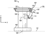
도 1은 진단 및/또는 치료 기관지경술을 위해 배열된 카트(cart)-기반 로봇 시스템의 일 실시예를 예시한 도면.
도 2는 도 1의 로봇 시스템의 추가의 태양을 도시한 도면.
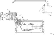
도 3은 요관경술을 위해 배열된 도 1의 로봇 시스템의 일 실시예를 예시한 도면.
도 4는 혈관 절차를 위해 배열된 도 1의 로봇 시스템의 일 실시예를 예시한 도면.
도 5는 기관지경술 절차를 위해 배열된 테이블(table)-기반 로봇 시스템의 일 실시예를 예시한 도면.
도 6은 도 5의 로봇 시스템의 대안적인 도면을 제공한 도면.
도 7은 로봇 아암(robotic arm)(들)을 적재하도록(stow) 구성된 예시적인 시스템을 예시한 도면.
도 8은 요관경술 절차를 위해 구성된 테이블-기반 로봇 시스템의 일 실시예를 예시한 도면.
도 9는 복강경술 절차를 위해 구성된 테이블-기반 로봇 시스템의 일 실시예를 예시한 도면.
도 10은 피치(pitch) 또는 틸트(tilt) 조절을 갖는 도 5 내지 도 9의 테이블-기반 로봇 시스템의 일 실시예를 예시한 도면.
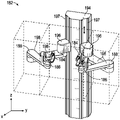
도 11은 도 5 내지 도 10의 테이블-기반 로봇 시스템의 테이블과 칼럼(column) 사이의 인터페이스(interface)의 상세한 예시를 제공한 도면.
도 12는 테이블-기반 로봇 시스템의 대안적인 실시예를 예시한 도면.
도 13은 도 12의 테이블-기반 로봇 시스템의 단부도를 예시한 도면.
도 14는 로봇 아암이 그에 부착된 테이블-기반 로봇 시스템의 단부도를 예시한 도면.
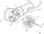
도 15는 예시적인 기구 드라이버(instrument driver)를 예시한 도면.
도 16은 페어링된(paired) 기구 드라이버를 갖는 예시적인 의료 기구를 예시한 도면.
도 17은 구동 유닛의 축이 기구의 세장형 샤프트(elongated shaft)의 축에 평행한 기구 드라이버 및 기구에 대한 대안적인 설계를 예시한 도면.
도 18은 기구-기반 삽입 아키텍처(insertion architecture)를 갖는 기구를 예시한 도면.
도 19는 예시적인 제어기를 예시한 도면.
도 20은 예시적인 실시예에 따른, 도 16 내지 도 18의 기구의 위치와 같은, 도 1 내지 도 10의 로봇 시스템의 하나 이상의 요소의 위치를 추정하는 위치결정 시스템(localization system)을 예시한 블록도를 도시한 도면.
도 21은 요관경의 예시적인 실시예를 예시한 도면.
도 22a는 요관경의 다른 예시적인 실시예를 예시한 도면.
도 22b는 신장의 자연 내강을 통해 내비게이팅된 요관경을 예시한 도면.
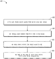
도 23은 요관경술 절차를 위해 요관경을 관절운동시키기 위한 예시적인 기법을 예시한 흐름도.
도 24a는 하나의 평면 내에서 편향가능한 요관경의 일부분의 예시적인 실시예를 예시한 도면.
도 24b는 2개의 평면 내에서 편향가능한 요관경의 일부분의 예시적인 실시예를 예시한 도면.
도 25는 요관경의 관절운동 섹션(articulation section)의 예시적인 실시예를 예시한 도면.
도 26a는 하나의 평면 내에서 편향된 도 25의 요관경을 예시한 도면.
도 26b는 2개의 평면 내에서 편향된 도 25 및 도 26a의 요관경을 예시한 도면.
도 27a는 하나의 평면 내에서 편향가능한 요관경의 일부분의 예시적인 실시예를 예시한 도면.
도 27b는 2개의 평면 내에서 편향가능한 요관경의 일부분의 예시적인 실시예를 예시한 도면.
도 28a는 예시적인 내시경을 예시한 도면.
도 28b는 도 28a의 예시적인 내시경의 내부 구성요소들 중 일부를 예시한 도면.BRIEF DESCRIPTION OF THE DRAWINGS The disclosed aspects will be described below in conjunction with the accompanying drawings, which are provided to illustrate, but not limit, the disclosed aspects, wherein like designations refer to like elements.
1 illustrates one embodiment of a cart-based robotic system arranged for diagnostic and/or therapeutic bronchoscopy;
Fig. 2 shows a further aspect of the robotic system of Fig. 1;
Fig. 3 illustrates one embodiment of the robotic system of Fig. 1 arranged for ureteroscopy;
Fig. 4 illustrates one embodiment of the robotic system of Fig. 1 arranged for a vascular procedure;
Figure 5 illustrates one embodiment of a table-based robotic system arranged for a bronchoscopy procedure.
Fig. 6 provides an alternative view of the robot system of Fig. 5;
7 illustrates an example system configured to stow robotic arm(s).
8 illustrates one embodiment of a table-based robotic system configured for a ureteroscopy procedure.
9 illustrates one embodiment of a table-based robotic system configured for a laparoscopic procedure.
Fig. 10 illustrates one embodiment of the table-based robotic system of Figs. 5-9 with pitch or tilt adjustment;
FIG. 11 provides a detailed illustration of the interface between tables and columns of the table-based robotic system of FIGS. 5 to 10 ;
12 illustrates an alternative embodiment of a table-based robotic system;
Fig. 13 illustrates an end view of the table-based robotic system of Fig. 12;
14 illustrates an end view of a table-based robotic system with a robotic arm attached thereto;
15 illustrates an exemplary instrument driver;
16 illustrates an exemplary medical instrument having a paired instrument driver.
Fig. 17 illustrates an alternative design for an instrument driver and instrument in which the axis of the drive unit is parallel to the axis of the instrument's elongated shaft;
18 illustrates an instrument with an instrument-based insertion architecture.
19 illustrates an exemplary controller;
20 is a block illustrating a localization system estimating the location of one or more elements of the robotic system of FIGS. 1-10 , such as the location of the instrument of FIGS. 16-18 , in accordance with an exemplary embodiment; A drawing showing a figure.
21 illustrates an exemplary embodiment of a ureteroscope.
22A illustrates another exemplary embodiment of a ureteroscope.
22B illustrates a ureteroscope navigating through the natural lumen of the kidney.
23 is a flow diagram illustrating an example technique for articulating a ureteroscope for a ureteroscopy procedure.
24A illustrates an exemplary embodiment of a portion of a ureteroscope deflectable in one plane;
24B illustrates an exemplary embodiment of a portion of a ureteroscope deflectable in two planes;
25 illustrates an exemplary embodiment of an articulation section of a ureteroscope;
Fig. 26a illustrates the ureteroscope of Fig. 25 deflected in one plane;
26B illustrates the ureteroscope of FIGS. 25 and 26A biased in two planes;
27A illustrates an exemplary embodiment of a portion of a ureteroscope deflectable in one plane;
27B illustrates an exemplary embodiment of a portion of a ureteroscope deflectable in two planes;
28A illustrates an exemplary endoscope.
28B illustrates some of the internal components of the exemplary endoscope of FIG. 28A;
1. 개요.1. Overview.
본 개시의 태양은 복강경술과 같은 최소 침습 절차 및 내시경술과 같은 비-침습 절차 둘 모두를 비롯하여 다양한 의료 절차를 수행할 수 있는 로봇식(robotically-enabled) 의료 시스템 내에 통합될 수 있다. 내시경술 절차 중에서, 시스템은 기관지경술, 요관경술, 위내시경술(gastroscopy) 등을 수행하는 것이 가능할 수 있다.Aspects of the present disclosure may be incorporated into robotically-enabled medical systems capable of performing a variety of medical procedures, including both minimally invasive procedures such as laparoscopy and non-invasive procedures such as endoscopy. Among the endoscopic procedures, the system may be capable of performing bronchoscopy, ureteroscopy, gastroscopy, and the like.
광범위한 절차를 수행하는 것에 더하여, 시스템은 의사를 보조하기 위한 향상된 이미징 및 안내와 같은 추가의 이점을 제공할 수 있다. 추가적으로, 시스템은 다루기 어려운 아암 운동 및 위치에 대한 필요 없이 인체공학적 위치로부터 절차를 수행하는 능력을 의사에게 제공할 수 있다. 더욱이, 시스템은, 시스템의 기구들 중 하나 이상이 단일 사용자에 의해 제어될 수 있도록, 개선된 사용 용이성을 갖고서 절차를 수행하는 능력을 의사에게 제공할 수 있다.In addition to performing a wide range of procedures, the system may provide additional benefits such as improved imaging and guidance to assist the physician. Additionally, the system may provide the surgeon with the ability to perform procedures from an ergonomic position without the need for cumbersome arm movements and positions. Moreover, the system may provide a physician with the ability to perform procedures with improved ease of use, such that one or more of the system's instruments may be controlled by a single user.
다양한 실시예가 예시의 목적으로 도면과 함께 후술될 것이다. 개시된 개념의 많은 다른 구현예가 가능하고, 개시된 구현예로 다양한 이점이 달성될 수 있다는 것이 인식되어야 한다. 참조를 위해, 그리고 다양한 섹션을 찾는 데 도움을 주기 위해 표제가 본 명세서에 포함된다. 이들 표제는 그와 관련하여 기술되는 개념의 범주를 제한하도록 의도되지 않는다. 그러한 개념은 전체 명세서 전반에 걸쳐 적용될 수 있다.Various embodiments will be described below in conjunction with drawings for purposes of illustration. It should be appreciated that many other implementations of the disclosed concepts are possible, and that various advantages may be achieved with the disclosed implementations. Headings are included herein for reference and to aid in locating the various sections. These headings are not intended to limit the scope of the concepts described in connection therewith. Such concepts may be applied throughout the entire specification.
A. 로봇 시스템 - 카트.A. Robot system - cart.
로봇식 의료 시스템은 특정 절차에 따라 다양한 방식으로 구성될 수 있다. 도 1은 진단 및/또는 치료 기관지경술을 위해 배열된 카트-기반 로봇식 시스템(10)의 일 실시예를 예시한다. 기관지경술 동안, 시스템(10)은 기관지경술을 위한 절차-특정적 기관지경일 수 있는, 조향가능 내시경(13)과 같은 의료 기구를 진단 및/또는 치료 도구를 전달하기 위한 자연 구멍 접근 지점(즉, 본 예에서 테이블 상에 위치된 환자의 입)으로 전달하기 위한 하나 이상의 로봇 아암(12)을 갖는 카트(11)를 포함할 수 있다. 도시된 바와 같이, 카트(11)는 접근 지점에 대한 접근을 제공하기 위해 환자의 상체에 근접하게 위치될 수 있다. 유사하게, 로봇 아암(12)은 접근 지점에 대해 기관지경을 위치시키도록 작동될 수 있다. 도 1의 배열은 또한, 위장(gastro-intestinal, GI) 절차를 위한 전문화된 내시경인 위내시경으로 GI 절차를 수행할 때 이용될 수 있다. 도 2는 카트의 예시적인 실시예를 더 상세히 도시한다.Robotic medical systems can be configured in a variety of ways, depending on specific procedures. 1 illustrates one embodiment of a cart-based
계속해서 도 1을 참조하면, 일단 카트(11)가 적절하게 위치되면, 로봇 아암(12)은 조향가능 내시경(13)을 로봇으로, 수동으로, 또는 이들의 조합으로 환자 내로 삽입할 수 있다. 도시된 바와 같이, 조향가능 내시경(13)은 적어도 2개의 삽통 부품(telescoping part), 예컨대 내부 리더(leader) 부분 및 외부 시스(sheath) 부분을 포함할 수 있으며, 각각의 부분은 기구 드라이버들(28)의 세트로부터의 별개의 기구 드라이버에 결합되고, 각각의 기구 드라이버는 개별 로봇 아암의 원위 단부에 결합된다. 리더 부분을 시스 부분과 동축으로 정렬시키는 것을 용이하게 하는, 기구 드라이버(28)의 이러한 선형 배열은 하나 이상의 로봇 아암(12)을 상이한 각도 및/또는 위치로 조작함으로써 공간에서 재위치될 수 있는 "가상 레일(virtual rail)"(29)을 생성한다. 본 명세서에 기술되는 가상 레일은 파선을 사용하여 도면에 도시되어 있으며, 따라서 파선은 시스템의 임의의 물리적 구조를 도시하지 않는다. 가상 레일(29)을 따른 기구 드라이버(28)의 병진은 외부 시스 부분에 대해 내부 리더 부분을 삽통식으로 이동시키거나, 환자로부터 내시경(13)을 전진 또는 후퇴시킨다. 가상 레일(29)의 각도는 임상 적용 또는 의사 선호도에 기초하여 조절, 병진, 및 피봇될(pivoted) 수 있다. 예를 들어, 기관지경술에서, 도시된 바와 같은 가상 레일(29)의 각도 및 위치는 내시경(13)을 환자의 입 안으로 구부림으로써 발생하는 마찰을 최소화하면서 내시경(13)에 대한 의사 접근을 제공하는 것 사이의 절충을 나타낸다.1 , once
내시경(13)은 표적 목적지 또는 수술 부위에 도달할 때까지 로봇 시스템으로부터의 정확한 명령을 사용하여 삽입 후 환자의 기관 및 폐를 따라 지향될 수 있다. 환자의 폐 네트워크(lung network)를 통한 내비게이션을 향상시키고/시키거나 원하는 표적에 도달하기 위해, 내시경(13)은 향상된 관절운동 및 더 큰 굽힘 반경을 얻기 위해 외부 시스 부분으로부터 내부 리더 부분을 삽통식으로 연장시키도록 조작될 수 있다. 별개의 기구 드라이버(28)의 사용은 또한 리더 부분과 시스 부분이 서로 독립적으로 구동되도록 허용한다.The
예를 들어, 내시경(13)은, 예를 들어 환자의 폐 내의 병변 또는 결절과 같은 표적에 생검 바늘을 전달하도록 지향될 수 있다. 바늘은 병리학자에 의해 분석될 조직 샘플을 얻기 위해 내시경의 길이를 따라 연장되는 작업 채널(working channel)을 따라 전개될 수 있다. 병리학 결과에 따라, 추가 도구가 추가 생검을 위해 내시경의 작업 채널을 따라 전개될 수 있다. 결절을 악성으로 확인한 후에, 내시경(13)은 잠재적인 암 조직을 절제하기 위한 도구를 내시경으로 전달할 수 있다. 일부 경우에, 진단 및 치료 처치제(treatment)가 별개의 절차로 전달될 수 있다. 그들 상황에서, 내시경(13)은 또한 표적 결절의 위치를 "표시"하기 위한 기준점을 전달하는 데에도 사용될 수 있다. 다른 경우에서, 진단 및 치료 처치제는 동일한 절차 동안 전달될 수 있다.For example, the
시스템(10)은 또한 이동가능 타워(tower)(30)를 포함할 수 있으며, 이는 카트(11)에 지원 케이블을 통해 연결되어 카트(11)에 제어부, 전자장치, 유체장치, 광학계, 센서, 및/또는 전력에 대한 지원을 제공할 수 있다. 그러한 기능을 타워(30) 내에 두는 것은 수술 의사 및 그/그녀의 스태프에 의해 더 용이하게 조절 및/또는 재위치될 수 있는 더 작은 형태 인자(form factor)의 카트(11)를 허용한다. 추가적으로, 카트/테이블과 지원 타워(30) 사이의 기능의 분할은 수술실의 어수선함을 감소시키고, 임상 작업흐름의 개선을 용이하게 한다. 카트(11)는 환자 가까이에 위치될 수 있지만, 타워(30)는 절차 동안 방해가 되지 않도록 원격 위치에 적재될 수 있다.The
전술된 로봇 시스템을 지원하기 위해, 타워(30)는, 예를 들어 영구 자기 저장 드라이브(persistent magnetic storage drive), 솔리드 스테이트 드라이브(solid state drive) 등과 같은 비-일시적 컴퓨터-판독가능 저장 매체 내에 컴퓨터 프로그램 명령어를 저장하는 컴퓨터-기반 제어 시스템의 구성요소(들)를 포함할 수 있다. 그들 명령어의 실행은, 실행이 타워(30)에서 발생하든 또는 카트(11)에서 발생하든 간에, 전체 시스템 또는 그의 서브-시스템(들)을 제어할 수 있다. 예를 들어, 컴퓨터 시스템의 프로세서에 의해 실행될 때, 명령어는 로봇 시스템의 구성요소로 하여금 관련 캐리지(carriage) 및 아암 마운트(arm mount)를 작동시키고, 로봇 아암을 작동시키고, 의료 기구를 제어하게 할 수 있다. 예를 들어, 제어 신호를 수신하는 것에 응답하여, 로봇 아암의 조인트(joint) 내의 모터는 아암을 소정 자세로 위치시킬 수 있다.To support the robotic system described above, the
타워(30)는 또한, 내시경(13)을 통해 전개될 수 있는 시스템에 제어된 관주 및 흡인 능력을 제공하기 위해 펌프, 유량계, 밸브 제어부, 및/또는 유체 접근부(fluid access)를 포함할 수 있다. 이들 구성요소는 또한 타워(30)의 컴퓨터 시스템을 사용하여 제어될 수 있다. 일부 실시예에서, 관주 및 흡인 능력은 별개의 케이블(들)을 통해 내시경(13)으로 직접 전달될 수 있다.
타워(30)는 카트(11)에 필터링되고 보호된 전력을 제공하도록 설계되는 전압 및 서지(surge) 보호기를 포함하여, 그에 의해 카트(11) 내에 전력 변압기 및 다른 보조 전력 구성요소를 배치하는 것을 회피하여, 더 작고 더 이동가능한 카트(11)를 생성할 수 있다.
타워(30)는 또한 로봇 시스템(10) 전체에 걸쳐 전개된 센서에 대한 지원 장비를 포함할 수 있다. 예를 들어, 타워(30)는 로봇 시스템(10) 전체에 걸쳐 광학 센서 또는 카메라로부터 수신된 데이터를 검출, 수신, 및 처리하기 위한 광전자 장비를 포함할 수 있다. 제어 시스템과 조합하여, 그러한 광전자 장비는 타워(30) 내를 비롯하여, 시스템 전체에 걸쳐 전개된 임의의 수의 콘솔(console)에 디스플레이하기 위한 실시간 이미지를 생성하는 데 사용될 수 있다. 유사하게, 타워(30)는 또한 전개된 전자기(electromagnetic, EM) 센서로부터 수신되는 신호를 수신하고 처리하기 위한 전자 서브시스템을 포함할 수 있다. 타워(30)는 또한 의료 기구 내의 또는 그 상의 EM 센서에 의한 검출을 위한 EM 필드 발생기(field generator)를 수용하고 위치시키는 데 사용될 수 있다.
타워(30)는 또한 시스템의 나머지 부분에서 이용가능한 다른 콘솔, 예컨대 카트의 상부에 장착된 콘솔에 더하여 콘솔(31)을 포함할 수 있다. 콘솔(31)은 의사 조작자를 위한 사용자 인터페이스 및 디스플레이 스크린, 예컨대 터치스크린을 포함할 수 있다. 시스템(10) 내의 콘솔은 일반적으로 로봇 제어뿐만 아니라 절차의 수술전 및 실시간 정보, 예컨대 내시경(13)의 내비게이션 및 위치결정 정보 둘 모두를 제공하도록 설계된다. 콘솔(31)이 의사가 이용가능한 유일한 콘솔이 아닐 때, 그것은 간호사와 같은 제2 조작자에 의해, 환자의 건강 또는 바이탈(vital) 및 시스템(10)의 작동을 모니터링할 뿐만 아니라, 내비게이션 및 위치결정 정보와 같은 절차-특정적 데이터를 제공하는 데 사용될 수 있다. 다른 실시예에서, 콘솔(30)은 타워(30)와 별개인 본체 내에 수용된다.
타워(30)는 하나 이상의 케이블 또는 연결부(도시되지 않음)를 통해 카트(11) 및 내시경(13)에 결합될 수 있다. 일부 실시예에서, 타워(30)로부터의 지원 기능은 단일 케이블을 통해 카트(11)에 제공되어, 수술실을 간소화하고 정리할 수 있다. 다른 실시예에서, 특정 기능은 별개의 케이블류(cabling) 및 연결부로 결합될 수 있다. 예를 들어, 전력은 단일 전력 케이블을 통해 카트(11)에 제공될 수 있지만, 제어부, 광학계, 유체장치, 및/또는 내비게이션에 대한 지원은 별개의 케이블을 통해 제공될 수 있다.
도 2는 도 1에 도시된 카트-기반 로봇식 시스템으로부터의 카트(11)의 일 실시예의 상세한 예시를 제공한다. 카트(11)는 일반적으로 세장형 지지 구조물(14)(흔히 "칼럼"으로 지칭됨), 카트 기부(15), 및 칼럼(14)의 상부에 있는 콘솔(16)을 포함한다. 칼럼(14)은 하나 이상의 로봇 아암(12)(3개가 도 2에 도시됨)의 전개를 지원하기 위한 캐리지(17)(대안적으로 "아암 지지부")와 같은 하나 이상의 캐리지를 포함할 수 있다. 캐리지(17)는 환자에 대한 더 양호한 위치설정을 위해 로봇 아암(12)의 기부를 조절하도록 수직 축을 따라 회전하는 개별적으로 구성가능한 아암 마운트를 포함할 수 있다. 캐리지(17)는 또한 캐리지(17)가 칼럼(14)을 따라 수직으로 병진하도록 허용하는 캐리지 인터페이스(19)를 포함한다.FIG. 2 provides a detailed illustration of one embodiment of a
캐리지 인터페이스(19)는 캐리지(17)의 수직 병진을 안내하기 위해 칼럼(14)의 서로 반대편에 있는 측부들 상에 위치되는, 슬롯(slot)(20)과 같은 슬롯을 통해 칼럼(14)에 연결된다. 슬롯(20)은 캐리지(17)를 카트 기부(15)에 대해 다양한 수직 높이에 위치시키고 유지시키기 위한 수직 병진 인터페이스를 포함한다. 캐리지(17)의 수직 병진은 카트(11)가 로봇 아암(12)의 도달범위를 조절하여 다양한 테이블 높이, 환자 크기, 및 의사 선호도를 충족시키도록 허용한다. 유사하게, 캐리지(17) 상의 개별적으로 구성가능한 아암 마운트는 로봇 아암(12)의 로봇 아암 기부(21)가 다양한 구성으로 경사지도록 허용한다.The
일부 실시예에서, 슬롯(20)은 캐리지(17)가 수직으로 병진함에 따라 수직 병진 인터페이스 및 칼럼(14)의 내부 챔버 내로 먼지 및 유체가 유입되는 것을 방지하기 위해 슬롯 표면과 동일 평면상에 있고 그에 평행한 슬롯 커버로 보완될 수 있다. 슬롯 커버는 슬롯(20)의 수직 상부 및 저부 부근에 위치된 스프링 스풀(spring spool)들의 쌍을 통해 전개될 수 있다. 커버는 캐리지(17)가 상향 및 하향으로 수직으로 병진함에 따라서 그들의 코일링된(coiled) 상태로부터 연장 및 후퇴되도록 전개될 때까지 스풀 내에 코일링된다. 스풀의 스프링-로딩(spring-loading)은 캐리지(17)가 스풀을 향해 병진할 때 커버를 스풀 내로 후퇴시키는 힘을 제공함과 동시에, 또한 캐리지(17)가 스풀로부터 멀어지게 병진할 때 밀폐 시일(tight seal)을 유지시킨다. 커버는 캐리지(17)가 병진함에 따라 커버의 적절한 연장 및 후퇴를 보장하기 위해, 예를 들어 캐리지 인터페이스(19) 내의 브래킷(bracket)을 사용하여 캐리지(17)에 연결될 수 있다.In some embodiments, the
칼럼(14)은 내부적으로, 사용자 입력, 예컨대 콘솔(16)로부터의 입력에 응답하여 생성된 제어 신호에 응답하여 기계화된 방식으로 캐리지(17)를 병진시키기 위해 수직으로 정렬된 리드 스크류(lead screw)를 사용하도록 설계되는, 기어 및 모터와 같은 메커니즘을 포함할 수 있다.
로봇 아암(12)은 일반적으로, 일련의 조인트(24)에 의해 연결되는 일련의 링크장치(linkage)(23)에 의해 분리되는 로봇 아암 기부(21) 및 엔드 이펙터(end effector)(22)를 포함할 수 있으며, 각각의 조인트는 독립적인 액추에이터(actuator)를 포함하고, 각각의 액추에이터는 독립적으로 제어가능한 모터를 포함한다. 각각의 독립적으로 제어가능한 조인트는 로봇 아암(12)이 이용가능한 독립적인 자유도(degree of freedom)를 나타낸다. 로봇 아암들(12) 각각은 7개의 조인트를 가질 수 있고, 따라서 7 자유도를 제공할 수 있다. 다수의 조인트는 다수의 자유도를 생성하여, "여분의(redundant)" 자유도를 허용한다. 여분의 자유도를 갖는 것은 로봇 아암(12)이 상이한 링크장치 위치 및 조인트 각도를 사용하여 공간에서 특정 위치, 배향, 및 궤적으로 그들 각각의 엔드 이펙터(22)를 위치시키도록 허용한다. 이는 시스템이 의료 기구를 공간에서 원하는 지점으로부터 위치시키고 지향시키도록 허용함과 동시에, 의사가 아암 충돌을 회피하면서 더 우수한 접근을 생성하기 위해 아암 조인트를 환자로부터 떨어진 임상적으로 유리한 위치로 이동시키도록 허용한다.The
카트 기부(15)는 바닥 위에서 칼럼(14), 캐리지(17), 및 로봇 아암(12)의 중량의 균형을 잡는다. 따라서, 카트 기부(15)는 전자장치, 모터, 전력 공급부와 같은 더 무거운 구성요소뿐만 아니라, 이동을 가능하게 하고/하거나 카트(11)를 움직이지 못하게 하는 구성요소를 수용한다. 예를 들어, 카트 기부(15)는 절차 전에 카트(11)가 수술실을 용이하게 돌아다니도록 허용하는 롤링가능 휠(rollable wheel)-형상의 캐스터(caster)(25)를 포함한다. 적절한 위치에 도달한 후에, 캐스터(25)는 절차 동안 카트(11)를 제위치로 유지시키기 위해 휠 로크(wheel lock)를 사용하여 움직이지 못하게 될 수 있다.
칼럼(14)의 수직 단부에 위치되어, 콘솔(16)은 사용자 입력을 수신하기 위한 사용자 인터페이스, 및 수술전 데이터 및 수술중 데이터 둘 모두를 의사 사용자에게 제공하기 위한 디스플레이 스크린 둘 모두(또는 예를 들어 터치스크린(26)과 같은 이중-목적 장치)를 허용한다. 터치스크린(26) 상의 잠재적인 수술전 데이터는 수술전 계획, 수술전 컴퓨터 단층촬영(computerized tomography, CT) 스캔으로부터 도출된 내비게이션 및 매핑 데이터(mapping data), 및/또는 수술전 환자 인터뷰로부터의 기록을 포함할 수 있다. 디스플레이 상의 수술중 데이터는 도구로부터 제공되는 광학 정보, 센서로부터의 센서 및 좌표 정보뿐만 아니라, 호흡, 심박수, 및/또는 맥박과 같은 바이탈 환자 통계치를 포함할 수 있다. 콘솔(16)은 의사가 캐리지(17) 반대편에 있는 칼럼(14)의 측부로부터 콘솔(16)에 접근하게 허용하도록 위치되고 틸팅될 수 있다. 이러한 위치로부터, 의사는 카트(11) 뒤로부터 콘솔(16)을 작동시키면서 콘솔(16), 로봇 아암(12), 및 환자를 관찰할 수 있다. 도시된 바와 같이, 콘솔(16)은 또한 카트(11)를 조작하고 안정시키는 것을 보조하기 위한 손잡이(27)를 포함한다.Located at the vertical end of
도 3은 요관경술을 위해 배열된 로봇식 시스템(10)의 일 실시예를 예시한다. 요관경술 절차에서, 카트(11)는 환자의 요도 및 요관을 통과하도록 설계된 절차-특정적 내시경인 요관경(32)을 환자의 하복부 영역으로 전달하도록 위치될 수 있다. 요관경술에서, 요관경(32)이 환자의 요도와 직접 정렬되어 그러한 영역 내의 민감한 해부학적 구조에 대한 마찰과 힘을 감소시키는 것이 바람직할 수 있다. 도시된 바와 같이, 카트(11)는 로봇 아암(12)이 환자의 요도에 대한 직접적인 선형 접근을 위해 요관경(32)을 위치시키게 허용하도록 테이블의 풋(foot)에 정렬될 수 있다. 테이블의 풋으로부터, 로봇 아암(12)은 요관경(32)을 가상 레일(33)을 따라 요도를 통해 환자의 하복부 내로 직접 삽입할 수 있다.3 illustrates one embodiment of a
요도 내로의 삽입 후에, 기관지경술에서와 유사한 제어 기법을 사용하여, 요관경(32)은 진단 및/또는 치료 응용을 위해 방광, 요관, 및/또는 신장 내로 내비게이팅될 수 있다. 예를 들어, 요관경(32)은 요관경(32)의 작업 채널을 따라 전개된 레이저 또는 초음파 쇄석술 장치를 사용하여 신장 결석 축적물을 부수기 위해 요관 및 신장 내로 지향될 수 있다. 쇄석술이 완료된 후에, 생성된 결석 파편은 요관경(32)을 따라 전개된 바스켓(basket)을 사용하여 제거될 수 있다.After insertion into the urethra, using control techniques similar to those in bronchoscopy, the
도 4는 혈관 절차를 위해 유사하게 배열된 로봇식 시스템(10)의 일 실시예를 예시한다. 혈관 절차에서, 시스템(10)은 카트(11)가 조향가능 카테터(steerable catheter)와 같은 의료 기구(34)를 환자의 다리 내의 대퇴 동맥 내의 접근 지점으로 전달할 수 있도록 구성될 수 있다. 대퇴 동맥은 내비게이션을 위한 더 큰 직경뿐만 아니라 환자의 심장으로의 상대적으로 덜 우회하고 사행형인 경로 둘 모두를 나타내며, 이는 내비게이션을 단순화한다. 요관경술 절차에서와 같이, 카트(11)는 로봇 아암(12)이 환자의 대퇴부/둔부 영역 내의 대퇴 동맥 접근 지점에 대한 직접적인 선형 접근을 갖는 가상 레일(35)을 제공하게 허용하도록 환자의 다리 및 하복부를 향해 위치될 수 있다. 동맥 내로의 삽입 후에, 의료 기구(34)는 기구 드라이버(28)를 병진시킴으로써 지향되고 삽입될 수 있다. 대안적으로, 카트는, 예를 들어 어깨 및 손목 부근의 경동맥 및 상완 동맥과 같은 대안적인 혈관 접근 지점에 도달하기 위해 환자의 상복부 주위에 위치될 수 있다.4 illustrates one embodiment of a
B. 로봇 시스템 - 테이블.B. Robot system - table.
로봇식 의료 시스템의 실시예는 또한 환자의 테이블을 통합할 수 있다. 테이블의 통합은 카트를 제거함으로써 수술실 내의 자본 장비의 양을 감소시키며, 이는 환자에 대한 더 우수한 접근을 허용한다. 도 5는 기관지경술 절차를 위해 배열된 그러한 로봇식 시스템의 일 실시예를 예시한다. 시스템(36)은 바닥 위에서 플랫폼(platform)(38)("테이블" 또는 "베드(bed)"로 도시됨)을 지지하기 위한 지지 구조물 또는 칼럼(37)을 포함한다. 카트-기반 시스템에서와 매우 유사하게, 시스템(36)의 로봇 아암(39)의 엔드 이펙터는 기구 드라이버(42)를 포함하며, 이는 도 5의 기관지경(40)과 같은 세장형 의료 기구를 기구 드라이버(42)의 선형 정렬로부터 형성된 가상 레일(41)을 통해 또는 그를 따라 조작하도록 설계된다. 실제로, 형광투시 이미징(fluoroscopic imaging)을 제공하기 위한 C-아암이 방출기(emitter) 및 검출기(detector)를 테이블(38) 주위에 배치함으로써 환자의 상복부 영역 위에 위치될 수 있다.Embodiments of the robotic medical system may also incorporate a patient's table. Integration of the table reduces the amount of capital equipment in the operating room by eliminating the cart, which allows for better access to the patient. 5 illustrates one embodiment of such a robotic system arranged for a bronchoscopy procedure.
도 6은 논의 목적을 위해 환자 및 의료 기구가 없는 시스템(36)의 대안적인 도면을 제공한다. 도시된 바와 같이, 칼럼(37)은 시스템(36) 내에 링(ring)-형상으로 도시된 하나 이상의 캐리지(43)를 포함할 수 있으며, 하나 이상의 로봇 아암(39)이 그로부터 기초할 수 있다. 캐리지(43)는 로봇 아암(39)이 그로부터 환자에게 도달하도록 위치될 수 있는 상이한 유리한 지점을 제공하기 위해 칼럼(37)의 길이를 따라 연장되는 수직 칼럼 인터페이스(44)를 따라 병진할 수 있다. 캐리지(들)(43)는, 로봇 아암(39)이 예를 들어 환자의 양쪽 측부와 같은 테이블(38)의 다수의 측부에 접근할 수 있도록 허용하기 위해, 칼럼(37) 내에 위치된 기계식 모터를 사용하여 칼럼(37)을 중심으로 회전할 수 있다. 다수의 캐리지를 갖는 실시예에서, 캐리지는 칼럼 상에 개별적으로 위치될 수 있고, 다른 캐리지와 독립적으로 병진 및/또는 회전할 수 있다. 캐리지(43)가 칼럼(37)을 둘러싸거나 심지어 원형일 필요는 없지만, 도시된 바와 같은 링-형상은 구조적 균형을 유지시키면서 칼럼(37)을 중심으로 하는 캐리지(43)의 회전을 용이하게 한다. 캐리지(43)의 회전 및 병진은 시스템(36)이 내시경 및 복강경과 같은 의료 기구를 환자 상의 상이한 접근 지점으로 정렬시키도록 허용한다. (도시되지 않은) 다른 실시예에서, 시스템(36)은 그 옆으로 연장되는 바아(bar) 또는 레일 형태의 조절가능 아암 지지부(adjustable arm support)를 갖는 환자 테이블 또는 베드를 포함할 수 있다. 하나 이상의 로봇 아암(39)은 (예컨대, 엘보우 조인트(elbow joint)를 갖는 쇼울더(shoulder)를 통해) 조절가능 아암 지지부에 부착될 수 있고, 이는 수직으로 조절될 수 있다. 수직 조절을 제공함으로써, 로봇 아암(39)은 유리하게는 환자 테이블 또는 베드 아래에 콤팩트하게 적재되고, 후속하여 절차 동안 상승될 수 있다.6 provides an alternative view of
로봇 아암(39)은 로봇 아암(39)에 추가의 구성가능성(configurability)을 제공하기 위해 개별적으로 회전하고/하거나 삽통식으로 연장될 수 있는 일련의 조인트를 포함하는 아암 마운트들(45)의 세트를 통해 캐리지(43) 상에 장착될 수 있다. 추가적으로, 아암 마운트(45)는, 캐리지(43)가 적절하게 회전될 때, 아암 마운트(45)가 (도 6에 도시된 바와 같이) 테이블(38)의 동일한 측부 상에, (도 9에 도시된 바와 같이) 테이블(38)의 서로 반대편에 있는 측부들 상에, 또는 테이블(38)의 인접한 측부들 상에(도시되지 않음) 위치될 수 있도록 캐리지(43) 상에 위치될 수 있다.The
칼럼(37)은 테이블(38)에 대한 지지, 및 캐리지(43)의 수직 병진을 위한 경로를 구조적으로 제공한다. 내부적으로, 칼럼(37)은 캐리지의 수직 병진을 안내하기 위한 리드 스크류, 및 리드 스크류에 기초하여 캐리지(43)의 병진을 기계화하기 위한 모터를 구비할 수 있다. 칼럼(37)은 또한 캐리지(43) 및 그 상에 장착된 로봇 아암(39)에 전력 및 제어 신호를 전달할 수 있다.
테이블 기부(46)는 도 2에 도시된 카트(11) 내의 카트 기부(15)와 유사한 기능을 하여, 테이블/베드(38), 칼럼(37), 캐리지(43), 및 로봇 아암(39)의 균형을 잡기 위해 더 무거운 구성요소를 수용한다. 테이블 기부(46)는 또한 절차 동안 안정성을 제공하기 위해 강성 캐스터를 통합할 수 있다. 테이블 기부(46)의 저부로부터 전개되어, 캐스터는 기부(46)의 양쪽 측부 상에서 반대 방향에서 연장될 수 있고, 시스템(36)이 이동될 필요가 있을 때 후퇴될 수 있다.
계속해서 도 6을 참조하면, 시스템(36)은 또한 타워(도시되지 않음)를 포함할 수 있으며, 이는 테이블의 형태 인자 및 부피(bulk)를 감소시키기 위해 시스템(36)의 기능을 테이블과 타워 사이에서 분할한다. 이전에 개시된 실시예에서와 같이, 타워는 처리, 컴퓨팅, 및 제어 능력, 전력, 유체장치, 및/또는 광학 및 센서 처리와 같은 다양한 지원 기능을 테이블에 제공할 수 있다. 타워는 또한, 의사 접근을 개선하고 수술실을 정리하기 위해 환자로부터 멀리 위치되도록 이동가능할 수 있다. 추가적으로, 타워 내에 구성요소를 배치하는 것은 로봇 아암(39)의 잠재적인 적재를 위한, 테이블 기부(46) 내의 더 많은 보관 공간을 허용한다. 타워는 또한, 키보드 및/또는 펜던트(pendant)와 같은, 사용자 입력을 위한 사용자 인터페이스뿐만 아니라, 실시간 이미징, 내비게이션, 및 추적 정보와 같은 수술전 및 수술중 정보를 위한 디스플레이 스크린(또는 터치스크린) 둘 모두를 제공하는 마스터 제어기(master controller) 또는 콘솔을 포함할 수 있다. 일부 실시예에서, 타워는 또한 흡입법(insufflation)을 위해 사용될 가스 탱크를 위한 홀더를 포함할 수 있다.With continued reference to FIG. 6 ,
일부 실시예에서, 테이블 기부는 사용하지 않을 때 로봇 아암을 적재 및 보관할 수 있다. 도 7은 테이블-기반 시스템의 일 실시예에서 로봇 아암을 적재하는 시스템(47)을 예시한다. 시스템(47)에서, 캐리지(48)는 로봇 아암(50), 아암 마운트(51), 및 캐리지(48)를 기부(49) 내에 적재하기 위해 기부(49) 내로 수직으로 병진될 수 있다. 기부 커버(52)는 병진 및 후퇴되어 개방되어 캐리지(48), 아암 마운트(51), 및 로봇 아암(50)을 칼럼(53) 주위로 전개시킬 수 있고, 사용하지 않을 때 그들을 적재하여 보호하기 위해 폐쇄될 수 있다. 기부 커버(52)는 그의 개구의 에지를 따라 멤브레인(membrane)(54)으로 밀봉되어, 폐쇄될 때 먼지 및 유체 유입을 방지할 수 있다.In some embodiments, the table base can load and store the robotic arm when not in use. 7 illustrates a
도 8은 요관경술 절차를 위해 구성된 로봇식 테이블-기반 시스템의 일 실시예를 예시한다. 요관경술에서, 테이블(38)은 환자를 칼럼(37) 및 테이블 기부(46)로부터 벗어난 각도로 위치시키기 위한 스위블 부분(swivel portion)(55)을 포함할 수 있다. 스위블 부분(55)은 스위블 부분(55)의 저부 부분을 칼럼(37)으로부터 멀리 위치시키기 위해 피봇 지점(예컨대, 환자의 머리 아래에 위치됨)을 중심으로 회전 또는 피봇할 수 있다. 예를 들어, 스위블 부분(55)의 피봇팅(pivoting)은 C-아암(도시되지 않음)이 테이블(38) 아래의 칼럼(도시되지 않음)과 공간을 경합함이 없이 환자의 하복부 위에 위치되도록 허용한다. 캐리지(35)(도시되지 않음)를 칼럼(37)을 중심으로 회전시킴으로써, 로봇 아암(39)은 요관경(56)을 가상 레일(57)을 따라 환자의 서혜부 영역 내로 직접 삽입하여 요도에 도달하게 할 수 있다. 요관경술에서, 스터럽(stirrup)(58)이 또한 테이블(38)의 스위블 부분(55)에 고정되어, 절차 동안 환자의 다리의 위치를 지지하고 환자의 서혜부 영역에 대한 명확한 접근을 허용할 수 있다.8 illustrates one embodiment of a robotic table-based system configured for a ureteroscopy procedure. In ureteroscopy, table 38 may include a
복강경술 절차에서, 환자의 복벽 내의 작은 절개부(들)를 통해, 최소 침습 기구가 환자의 해부학적 구조 내로 삽입될 수 있다. 일부 실시예에서, 최소 침습 기구는 환자 내의 해부학적 구조에 접근하는 데 사용되는, 샤프트와 같은 세장형 강성 부재를 포함한다. 환자의 복강의 팽창 후에, 기구는 파지, 절단, 절제, 봉합 등과 같은 수술 또는 의료 작업을 수행하도록 지향될 수 있다. 일부 실시예에서, 기구는 복강경과 같은 스코프(scope)를 포함할 수 있다. 도 9는 복강경술 절차를 위해 구성된 로봇식 테이블-기반 시스템의 일 실시예를 예시한다. 도 9에 도시된 바와 같이, 시스템(36)의 캐리지(43)는 로봇 아암들(39)의 쌍을 테이블(38)의 서로 반대편에 있는 측부들 상에 위치시키도록 회전되고 수직으로 조절될 수 있어서, 기구(59)가 환자의 양쪽 측부 상의 최소 절개부로 통과되어 그/그녀의 복강에 도달하도록 아암 마운트(45)를 사용하여 위치될 수 있게 한다.In a laparoscopic procedure, a minimally invasive instrument may be inserted into the patient's anatomy through small incision(s) in the patient's abdominal wall. In some embodiments, the minimally invasive instrument includes an elongate rigid member, such as a shaft, used to access anatomy within the patient. After inflation of the patient's abdominal cavity, the instrument may be directed to perform a surgical or medical operation such as gripping, cutting, excising, suturing, and the like. In some embodiments, the instrument may include a scope, such as a laparoscope. 9 illustrates one embodiment of a robotic table-based system configured for a laparoscopic procedure. 9 , the
복강경술 절차를 수용하기 위해, 로봇식 테이블 시스템은 또한 플랫폼을 원하는 각도로 틸팅되게 할 수 있다. 도 10은 피치 또는 틸트 조절을 갖는 로봇식 의료 시스템의 일 실시예를 예시한다. 도 10에 도시된 바와 같이, 시스템(36)은 테이블(38)의 틸트를 수용하여, 테이블의 하나의 부분을 다른 부분보다 바닥으로부터 더 큰 거리를 두고 위치시킬 수 있다. 추가적으로, 아암 마운트(45)는 틸트와 일치하도록 회전할 수 있어서, 로봇 아암(39)이 테이블(38)과 동일한 평면 관계를 유지시키게 한다. 더 급격한 각도를 수용하기 위해, 칼럼(37)은 또한, 칼럼(37)의 수직 연장이 테이블(38)이 바닥에 닿거나 테이블 기부(46)와 충돌하지 않게 하도록 허용하는 삽통 부분(60)을 포함할 수 있다.To accommodate laparoscopic procedures, the robotic table system may also allow the platform to be tilted to a desired angle. 10 illustrates one embodiment of a robotic medical system with pitch or tilt adjustment. As shown in FIG. 10 , the
도 11은 테이블(38)과 칼럼(37) 사이의 인터페이스의 상세한 예시를 제공한다. 피치 회전 메커니즘(61)은 다중 자유도로 칼럼(37)에 대한 테이블(38)의 피치 각도를 변경하도록 구성될 수 있다. 피치 회전 메커니즘(61)은 칼럼-테이블 인터페이스에서의 직교 축(1, 2)의 위치설정에 의해 가능해질 수 있으며, 각각의 축은 전기 피치 각도 명령에 응답하여 별개의 모터(3, 4)에 의해 작동된다. 하나의 스크류(5)를 따른 회전은 하나의 축(1)에서의 틸트 조절을 가능하게 할 것인 한편, 다른 하나의 스크류(6)를 따른 회전은 다른 하나의 축(2)을 따른 틸트 조절을 가능하게 할 것이다. 일부 실시예에서, 볼 조인트(ball joint)가 다중 자유도로 칼럼(37)에 대한 테이블(38)의 피치 각도를 변경하도록 사용될 수 있다.11 provides a detailed illustration of the interface between table 38 and
예를 들어, 피치 조절은, 하복부 수술을 위해, 테이블을 트렌델렌부르크 자세(Trendelenburg position)로 위치시키려고 할 때, 즉 환자의 하복부를 환자의 상복부보다 바닥으로부터 더 높은 위치에 위치시키려고 할 때 특히 유용하다. 트렌델렌부르크 자세는 환자의 내부 장기가 중력을 통해 그/그녀의 상복부를 향해 미끄러지게 하여, 최소 침습 도구가 들어가서 복강경 전립선절제술과 같은 하복부 수술 또는 의료 절차를 수행할 복강을 비운다.For example, pitch adjustment is particularly useful when attempting to position the table in the Trendelenburg position for lower abdominal surgery, i.e. placing the patient's lower abdomen higher from the floor than the patient's upper abdomen. Do. The Trendelenburg posture causes the patient's internal organs to slide through gravity towards his/her upper abdomen, leaving the abdominal cavity for a minimally invasive instrument to enter and perform lower abdominal surgery or medical procedures, such as laparoscopic prostatectomy.
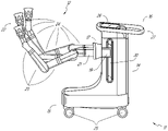
도 12 및 도 13은 테이블-기반 수술 로봇 시스템(100)의 대안적인 실시예의 등각도 및 단부도를 예시한다. 수술 로봇 시스템(100)은 테이블(101)에 대해 하나 이상의 로봇 아암(예를 들어, 도 14 참조)을 지지하도록 구성될 수 있는 하나 이상의 조절가능 아암 지지부(105)를 포함한다. 예시된 실시예에서, 단일 조절가능 아암 지지부(105)가 도시되어 있지만, 추가 아암 지지부가 테이블(101)의 반대편 측부 상에 제공될 수 있다. 조절가능 아암 지지부(105)는 그것이 테이블(101)에 대한 조절가능 아암 지지부(105) 및/또는 그에 장착된 임의의 로봇 아암의 위치를 조절 및/또는 변경하기 위해 테이블(101)에 대해 이동할 수 있도록 구성될 수 있다. 예를 들어, 조절가능 아암 지지부(105)는 1 이상의 자유도로 테이블(101)에 대해 조절될 수 있다. 조절가능 아암 지지부(105)는, 하나 이상의 조절가능 아암 지지부(105) 및 그에 부착된 임의의 로봇 아암을 테이블(101) 아래에 용이하게 적재하는 능력을 포함하는, 시스템(100)에 대한 높은 다용도성을 제공한다. 조절가능 아암 지지부(105)는 적재된 위치로부터 테이블(101)의 상부 표면 아래의 위치로 상승될 수 있다. 다른 실시예에서, 조절가능 아암 지지부(105)는 적재된 위치로부터 테이블(101)의 상부 표면 위의 위치로 상승될 수 있다.12 and 13 illustrate isometric and end views of an alternative embodiment of a table-based surgical
조절가능 아암 지지부(105)는 리프트(lift), 측방향 병진, 틸트 등을 포함하는 여러 자유도를 제공할 수 있다. 도 12 및 도 13의 예시된 실시예에서, 아암 지지부(105)는 도 12에 화살표로 예시된 4 자유도로 구성된다. 제1 자유도는 z-방향으로의 조절가능 아암 지지부(105)의 조절("Z-리프트")을 허용한다. 예를 들어, 조절가능 아암 지지부(105)는 테이블(101)을 지지하는 칼럼(102)을 따라 또는 그에 대해 상향 또는 하향으로 이동하도록 구성되는 캐리지(109)를 포함할 수 있다. 제2 자유도는 조절가능 아암 지지부(105)가 틸팅하도록 허용할 수 있다. 예를 들어, 조절가능 아암 지지부(105)는 조절가능 아암 지지부(105)가 트렌델렌부르크 자세에서 베드와 정렬되도록 허용할 수 있는 회전 조인트를 포함할 수 있다. 제3 자유도는 조절가능 아암 지지부(105)가 "상향 피봇(pivot up)"하도록 허용할 수 있으며, 이는 테이블(101)의 측부와 조절가능 아암 지지부(105) 사이의 거리를 조절하는 데 사용될 수 있다. 제4 자유도는 테이블의 길이방향 길이를 따른 조절가능 아암 지지부(105)의 병진을 허용할 수 있다.The
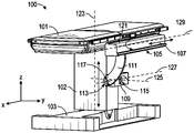
도 12 및 도 13의 수술 로봇 시스템(100)은 기부(103)에 장착된 칼럼(102)에 의해 지지되는 테이블을 포함할 수 있다. 기부(103) 및 칼럼(102)은 지지 표면에 대해 테이블(101)을 지지한다. 바닥 축(131) 및 지지 축(133)이 도 13에 도시되어 있다.The surgical
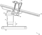
조절가능 아암 지지부(105)는 칼럼(102)에 장착될 수 있다. 다른 실시예에서, 아암 지지부(105)는 테이블(101) 또는 기부(103)에 장착될 수 있다. 조절가능 아암 지지부(105)는 캐리지(109), 바아 또는 레일 커넥터(111), 및 바아 또는 레일(107)을 포함할 수 있다. 일부 실시예에서, 레일(107)에 장착된 하나 이상의 로봇 아암은 서로에 대해 병진 및 이동할 수 있다.The
캐리지(109)는 제1 조인트(113)에 의해 칼럼(102)에 부착될 수 있으며, 이는 캐리지(109)가 (예컨대, 제1 또는 수직 축(123)의 상향 및 하향으로와 같이) 칼럼(102)에 대해 이동하도록 허용한다. 제1 조인트(113)는 조절가능 아암 지지부(105)에 제1 자유도("Z-리프트")를 제공할 수 있다. 조절가능 아암 지지부(105)는 조절가능 아암 지지부(105)에 대한 제2 자유도(틸트)를 제공하는 제2 조인트(115)를 포함할 수 있다. 조절가능 아암 지지부(105)는 조절가능 아암 지지부(105)에 대한 제3 자유도("상향 피봇")를 제공할 수 있는 제3 조인트(117)를 포함할 수 있다. 레일 커넥터(111)가 제3 축(127)을 중심으로 회전됨에 따라 레일(107)의 배향을 유지시키기 위해 제3 조인트(117)를 기계적으로 구속하는 (도 13에 도시된) 추가 조인트(119)가 제공될 수 있다. 조절가능 아암 지지부(105)는 제4 축(129)을 따라 조절가능 아암 지지부(105)에 대한 제4 자유도(병진)를 제공할 수 있는 제4 조인트(121)를 포함할 수 있다.The
도 14는 테이블(101)의 서로 반대편에 있는 측부들 상에 장착된 2개의 조절가능 아암 지지부(105A, 105B)를 갖는 수술 로봇 시스템(140A)의 단부도를 예시한다. 제1 로봇 아암(142A)이 제1 조절가능 아암 지지부(105B)의 바아 또는 레일(107A)에 부착된다. 제1 로봇 아암(142A)은 레일(107A)에 부착되는 기부(144A)를 포함한다. 제1 로봇 아암(142A)의 원위 단부는 하나 이상의 로봇 의료 기구 또는 도구에 부착될 수 있는 기구 구동 메커니즘(146A)을 포함한다. 유사하게, 제2 로봇 아암(142B)은 레일(107B)에 부착되는 기부(144B)를 포함한다. 제2 로봇 아암(142B)의 원위 단부는 기구 구동 메커니즘(146B)을 포함한다. 기구 구동 메커니즘(146B)은 하나 이상의 로봇 의료 기구 또는 도구에 부착되도록 구성될 수 있다.14 illustrates an end view of a surgical
일부 실시예에서, 로봇 아암들(142A, 142B) 중 하나 이상은 7 이상의 자유도를 갖는 아암을 포함한다. 일부 실시예에서, 로봇 아암들(142A, 142B) 중 하나 이상은, 삽입 축(삽입을 포함하는 1-자유도), 리스트(wrist)(리스트 피치, 요(yaw) 및 롤(roll)을 포함하는 3-자유도), 엘보우(엘보우 피치를 포함하는 1-자유도), 쇼울더(쇼울더 피치 및 요를 포함하는 2-자유도), 및 기부(144A, 144B)(병진을 포함하는 1-자유도)를 포함하는, 8 자유도를 포함할 수 있다. 일부 실시예에서, 삽입 자유도는 로봇 아암(142A, 142B)에 의해 제공될 수 있는 한편, 다른 실시예에서는, 기구 자체가 기구-기반 삽입 아키텍처를 통한 삽입을 제공한다.In some embodiments, one or more of
C. 기구 드라이버 및 인터페이스.C. Instrument Drivers and Interfaces.
시스템의 로봇 아암의 엔드 이펙터는 (i) 의료 기구를 작동시키기 위한 전기-기계 수단을 통합하는 기구 드라이버(대안적으로 "기구 구동 메커니즘" 또는 "기구 장치 조작기"로 지칭됨), 및 (ii) 모터와 같은 임의의 전기-기계 구성요소가 없을 수 있는 제거가능 또는 탈착가능 의료 기구를 포함할 수 있다. 이러한 이분법은 의료 절차에 사용되는 의료 기구를 멸균할 필요성, 및 그들의 복잡한 기계 조립체 및 민감한 전자장치로 인해 고가의 자본 장비를 적절하게 멸균할 수 없음에 의해 주도될 수 있다. 따라서, 의료 기구는 의사 또는 의사의 스태프에 의한 개별적인 멸균 또는 폐기를 위해 기구 드라이버(및 그에 따라 시스템)로부터 탈착, 제거, 및 교환되도록 설계될 수 있다. 대조적으로, 기구 드라이버는 변경 또는 멸균될 필요가 없고, 보호를 위해 드레이핑될(draped) 수 있다.The end effector of the robotic arm of the system comprises (i) an instrument driver incorporating electro-mechanical means for actuating a medical instrument (alternatively referred to as an “instrument drive mechanism” or “instrument device manipulator”), and (ii) may include a removable or removable medical instrument that may be devoid of any electro-mechanical component such as a motor. This dichotomy may be driven by the need to sterilize medical instruments used in medical procedures, and the inability to adequately sterilize expensive capital equipment due to their complex mechanical assemblies and sensitive electronics. Accordingly, a medical instrument may be designed to be detached, removed, and exchanged from the instrument driver (and thus the system) for individual sterilization or disposal by a physician or staff of a physician. In contrast, instrument drivers need not be altered or sterilized and may be draped for protection.
도 15는 예시적인 기구 드라이버를 예시한다. 로봇 아암의 원위 단부에 위치되어, 기구 드라이버(62)는 구동 샤프트(64)를 통해 의료 기구에 제어된 토크를 제공하기 위해 평행 축으로 배열되는 하나 이상의 구동 유닛(63)을 포함한다. 각각의 구동 유닛(63)은 기구와 상호작용하기 위한 개별 구동 샤프트(64), 모터 샤프트 회전을 원하는 토크로 변환시키기 위한 기어 헤드(65), 구동 토크를 생성하기 위한 모터(66), 모터 샤프트의 속도를 측정하고 제어 회로부에 피드백을 제공하기 위한 인코더(encoder)(67), 및 제어 신호를 수신하고 구동 유닛을 작동시키기 위한 제어 회로부(68)를 포함한다. 각각의 구동 유닛(63)이 독립적으로 제어되고 동력화되기 때문에, 기구 드라이버(62)는 의료 기구에 다수의(예컨대, 도 15에 도시된 바와 같이 4개의) 독립적인 구동 출력부(drive output)를 제공할 수 있다. 작동 시에, 제어 회로부(68)는 제어 신호를 수신할 것이고, 모터(66)에 모터 신호를 전송할 것이며, 인코더(67)에 의해 측정된 바와 같은 생성된 모터 속도를 원하는 속도와 비교할 것이고, 모터 신호를 변조하여 원하는 토크를 생성할 것이다.15 illustrates an exemplary instrument driver. Located at the distal end of the robotic arm, the
멸균 환경을 필요로 하는 절차의 경우, 로봇 시스템은 기구 드라이버와 의료 기구 사이에 있는, 멸균 드레이프(sterile drape)에 연결된 멸균 어댑터(sterile adapter)와 같은 구동 인터페이스를 통합할 수 있다. 멸균 어댑터의 주된 목적은 기구 드라이버의 구동 샤프트로부터 기구의 구동 입력부(drive input)로 각도 운동을, 구동 샤프트와 구동 입력부 사이의 물리적 분리, 및 그에 따라 멸균을 유지시키면서, 전달하는 것이다. 따라서, 예시적인 멸균 어댑터는 기구 드라이버의 구동 샤프트 및 기구 상의 구동 입력부와 정합되도록 의도되는 일련의 회전 입력부 및 출력부를 포함할 수 있다. 멸균 어댑터에 연결되어, 투명 또는 반투명 플라스틱과 같은 얇은 가요성 재료로 구성된 멸균 드레이프는 기구 드라이버, 로봇 아암, (카트-기반 시스템 내의) 카트 또는 (테이블-기반 시스템 내의) 테이블과 같은 자본 장비를 덮도록 설계된다. 드레이프의 사용은 자본 장비가 멸균을 필요로 하지 않는 영역(즉, 비-멸균 영역) 내에 여전히 위치되면서 환자에게 근접하게 위치되도록 허용할 것이다. 멸균 드레이프의 다른 하나의 측부 상에서, 의료 기구는 멸균을 필요로 하는 영역(즉, 멸균 영역)에서 환자와 인터페이싱할 수 있다.For procedures requiring a sterile environment, the robotic system may incorporate a drive interface, such as a sterile adapter connected to a sterile drape, between the instrument driver and the medical instrument. The primary purpose of the sterile adapter is to transfer angular motion from the drive shaft of the instrument driver to the drive input of the instrument while maintaining a physical separation between the drive shaft and the drive input, and thus sterility. Accordingly, an exemplary sterile adapter may include a drive shaft of an instrument driver and a series of rotational inputs and outputs intended to mate with drive inputs on the instrument. Connected to a sterile adapter, a sterile drape made of a thin flexible material such as transparent or translucent plastic covers capital equipment such as instrument drivers, robotic arms, carts (in cart-based systems) or tables (in table-based systems). is designed to The use of a drape will allow capital equipment to be positioned proximate to the patient while still being positioned within an area that does not require sterilization (ie, a non-sterile area). On the other side of the sterile drape, the medical instrument may interface with the patient in an area requiring sterilization (ie, a sterile area).
D. 의료 기구.D. Medical Devices.
도 16은 페어링된 기구 드라이버를 갖는 예시적인 의료 기구를 예시한다. 로봇 시스템과 함께 사용하도록 설계된 다른 기구와 마찬가지로, 의료 기구(70)는 세장형 샤프트(71)(또는 세장형 본체) 및 기구 기부(instrument base)(72)를 포함한다. 의사에 의한 수동 상호작용을 위한 그의 의도된 설계로 인해 "기구 손잡이"로 또한 지칭되는 기구 기부(72)는 일반적으로, 로봇 아암(76)의 원위 단부에서 기구 드라이버(75) 상의 구동 인터페이스를 통해 연장되는 구동 출력부(74)와 정합되도록 설계되는 회전가능 구동 입력부(73), 예컨대 리셉터클(receptacle), 풀리(pulley) 또는 스풀을 포함할 수 있다. 물리적으로 연결, 래칭(latched), 및/또는 결합될 때, 기구 기부(72)의 정합된 구동 입력부(73)는 기구 드라이버(75) 내의 구동 출력부(74)와 회전 축을 공유하여, 구동 출력부(74)로부터 구동 입력부(73)로의 토크의 전달을 허용할 수 있다. 일부 실시예에서, 구동 출력부(74)는 구동 입력부(73) 상의 리셉터클과 정합하도록 설계되는 스플라인(spline)을 포함할 수 있다.16 illustrates an example medical instrument having a paired instrument driver. Like other instruments designed for use with robotic systems,
세장형 샤프트(71)는, 예컨대 내시경술에서와 같이, 해부학적 개구 또는 내강, 또는 예컨대 복강경술에서와 같이, 최소 침습 절개부를 통해 전달되도록 설계된다. 세장형 샤프트(71)는 가요성(예컨대, 내시경과 유사한 특성을 가짐) 또는 강성(예컨대, 복강경과 유사한 특성을 가짐)이거나 가요성 부분 및 강성 부분 둘 모두의 맞춤형 조합을 포함할 수 있다. 복강경술을 위해 설계될 때, 강성의 세장형 샤프트의 원위 단부는, 적어도 1의 자유도를 갖는 클레비스(clevis)로부터 형성되는 조인트식 리스트(jointed wrist)로부터 연장되는 엔드 이펙터, 및 구동 입력부가 기구 드라이버(75)의 구동 출력부(74)로부터 수신된 토크에 응답하여 회전함에 따라 텐돈(tendon)으로부터의 힘에 기초하여 작동될 수 있는, 예를 들어 파지기 또는 가위와 같은 수술 도구 또는 의료 기구에 연결될 수 있다. 내시경술을 위해 설계될 때, 가요성의 세장형 샤프트의 원위 단부는 기구 드라이버(75)의 구동 출력부(74)로부터 수신된 토크에 기초하여 관절운동되고 구부러질 수 있는 조향가능 또는 제어가능 굽힘 섹션을 포함할 수 있다.The
기구 드라이버(75)로부터의 토크는 세장형 샤프트(71)를 따른 텐돈을 사용하여 세장형 샤프트(71)를 따라 전달된다. 당김 와이어(pull wire)와 같은 이들 개별 텐돈은 기구 손잡이(72) 내의 개별 구동 입력부(73)에 개별적으로 고정될 수 있다. 손잡이(72)로부터, 텐돈은 세장형 샤프트(71)를 따른 하나 이상의 당김 루멘(pull lumen)을 따라 지향되고, 세장형 샤프트(71)의 원위 부분에, 또는 세장형 샤프트의 원위 부분에 있는 리스트 내에 고정된다. 복강경술, 내시경술 또는 하이브리드 절차와 같은 수술 절차 동안, 이들 텐돈은 리스트, 파지기, 또는 가위와 같은 원위에 장착된 엔드 이펙터에 결합될 수 있다. 그러한 배열 하에서, 구동 입력부(73)에 가해진 토크는 텐돈에 장력을 전달하여, 그에 의해 엔드 이펙터가 일정 방식으로 작동하게 할 것이다. 일부 실시예에서, 수술 절차 동안, 텐돈은 조인트가 축을 중심으로 회전하게 하여, 그에 의해 엔드 이펙터가 하나의 방향 또는 다른 방향으로 이동하게 할 수 있다. 대안적으로, 텐돈은 세장형 샤프트(71)의 원위 단부에서 파지기의 하나 이상의 조오(jaw)에 연결될 수 있으며, 여기에서 텐돈으로부터의 장력은 파지기가 폐쇄되게 한다.Torque from the
내시경술에서, 텐돈은 접착제, 제어 링, 또는 다른 기계적 고정을 통해 (예컨대, 원위 단부에서) 세장형 샤프트(71)를 따라 위치된 굽힘 또는 관절운동 섹션에 결합될 수 있다. 굽힘 섹션의 원위 단부에 고정식으로 부착될 때, 구동 입력부(73)에 가해진 토크는 텐돈을 따라 전달되어, 더 연질인 굽힘 섹션(때때로 관절운동가능 섹션 또는 영역으로 지칭됨)이 구부러지거나 관절운동하게 할 것이다. 비-굽힘 섹션을 따라, 내시경 샤프트의 벽을 따라(또는 그 내측에서) 개별 텐돈을 지향시키는 개별 당김 루멘을 나선형화 또는 나선화하여, 당김 와이어의 장력으로부터 발생하는 반경방향 힘의 균형을 잡는 것이 유리할 수 있다. 나선(spiraling)의 각도 및/또는 그들 사이의 간격은 특정 목적을 위해 변경 또는 조작될 수 있으며, 여기에서 더 조밀한 나선은 하중 힘 하에서의 더 작은 샤프트 압축을 나타내는 한편, 더 적은 양의 나선은 하중 힘 하에서의 더 큰 샤프트 압축을 가져오지만, 굽힘을 제한한다. 스펙트럼의 다른 단부 상에서, 당김 루멘은 원하는 굽힘 또는 관절운동가능 섹션에서의 제어된 관절운동을 허용하기 위해 세장형 샤프트(71)의 길이방향 축에 평행하게 지향될 수 있다.In endoscopy, the tendon may be coupled to a bending or articulating section positioned along the elongate shaft 71 (eg, at the distal end) via adhesive, control ring, or other mechanical fixation. When fixedly attached to the distal end of the bending section, the torque applied to the
내시경술에서, 세장형 샤프트(71)는 로봇 절차를 보조하기 위한 다수의 구성요소를 수용한다. 샤프트(71)는 샤프트(71)의 원위 단부에서 수술 영역에 수술 도구(또는 의료 기구), 관주, 및/또는 흡인을 전개시키기 위한 작업 채널을 포함할 수 있다. 샤프트(71)는 또한, 광학 카메라를 포함할 수 있는, 원위 팁(distal tip)에 있는 광학 조립체로/그로부터 신호를 전달하기 위한 와이어 및/또는 광섬유를 수용할 수 있다. 샤프트(71)는 또한, 발광 다이오드와 같은 근위에 위치된 광원으로부터 샤프트(71)의 원위 단부로 광을 전달하기 위한 광섬유를 수용할 수 있다.In endoscopy, the
기구(70)의 원위 단부에서, 원위 팁은 또한, 진단 및/또는 치료, 관주, 및 흡인을 위한 도구를 수술 부위로 전달하기 위한 작업 채널의 개구를 포함할 수 있다. 원위 팁은 또한, 내부 해부학적 공간의 이미지를 캡처하기 위한, 섬유경 또는 디지털 카메라와 같은 카메라를 위한 포트를 포함할 수 있다. 이와 관련하여, 원위 팁은 또한, 카메라를 사용할 때 해부학적 공간을 조명하기 위한 광원을 위한 포트를 포함할 수 있다.At the distal end of
도 16의 예에서, 구동 샤프트 축, 및 그에 따라 구동 입력부 축은 세장형 샤프트(71)의 축에 직교한다. 그러나, 이러한 배열은 세장형 샤프트(71)에 대한 롤 능력을 복잡하게 한다. 구동 입력부(73)를 정적으로 유지시키면서 세장형 샤프트(71)를 그의 축을 따라 롤링시키는 것은 텐돈이 구동 입력부(73)로부터 연장되고 세장형 샤프트(71) 내의 당김 루멘에 들어감에 따라 텐돈의 바람직하지 않은 엉킴을 야기한다. 그러한 텐돈의 결과적인 엉킴은 내시경술 절차 동안 가요성의 세장형 샤프트(71)의 이동을 예측하도록 의도된 임의의 제어 알고리즘을 방해할 수 있다.In the example of FIG. 16 , the drive shaft axis, and thus the drive input axis, is orthogonal to the axis of the
도 17은 구동 유닛의 축이 기구의 세장형 샤프트의 축에 평행한 기구 드라이버 및 기구에 대한 대안적인 설계를 예시한다. 도시된 바와 같이, 원형 기구 드라이버(80)는 그들의 구동 출력부(81)가 로봇 아암(82)의 단부에서 평행하게 정렬되는 4개의 구동 유닛을 포함한다. 구동 유닛, 및 그들 각각의 구동 출력부(81)는 기구 드라이버(80)의 회전 조립체(83) 내에 수용되며, 이는 조립체(83) 내의 구동 유닛들 중 하나에 의해 구동된다. 회전 구동 유닛에 의해 제공되는 토크에 응답하여, 회전 조립체(83)는 회전 조립체(83)를 기구 드라이버(80)의 비-회전 부분(84)에 연결하는 원형 베어링을 따라 회전한다. 전력 및 제어 신호가 기구 드라이버(80)의 비-회전 부분(84)으로부터, 브러시형 슬립 링 연결부(brushed slip ring connection)(도시되지 않음)에 의해 회전을 통해 유지될 수 있는 전기 접촉부를 통해 회전 조립체(83)로 전달될 수 있다. 다른 실시예에서, 회전 조립체(83)는, 비-회전가능 부분(84) 내에 통합되어, 그에 따라 다른 구동 유닛에 평행하지 않은 별개의 구동 유닛에 응답할 수 있다. 회전 메커니즘(83)은 기구 드라이버(80)가 구동 유닛, 및 그들 각각의 구동 출력부(81)를 단일 유닛으로서 기구 드라이버 축(85)을 중심으로 회전시키도록 허용한다.17 illustrates an alternative design for an instrument driver and instrument in which the axis of the drive unit is parallel to the axis of the elongate shaft of the instrument. As shown, the
이전에 개시된 실시예와 마찬가지로, 기구(86)는 세장형 샤프트 부분(88), 및 기구 드라이버(80) 내의 구동 출력부(81)를 수용하도록 구성되는 (리셉터클, 풀리, 및 스풀과 같은) 복수의 구동 입력부(89)를 포함하는 기구 기부(87)(논의 목적을 위해 투명 외부 스킨으로 도시됨)를 포함할 수 있다. 이전에 개시된 실시예와 달리, 기구 샤프트(88)는 축이 도 16의 설계에서와 같이 직교하기보다는 구동 입력부(89)의 축에 실질적으로 평행한 상태로 기구 기부(87)의 중심으로부터 연장된다.As with the previously disclosed embodiments, the
기구 드라이버(80)의 회전 조립체(83)에 결합될 때, 기구 기부(87) 및 기구 샤프트(88)를 포함하는 의료 기구(86)는 회전 조립체(83)와 조합하여 기구 드라이버 축(85)을 중심으로 회전한다. 기구 샤프트(88)가 기구 기부(87)의 중심에 위치되기 때문에, 기구 샤프트(88)는 부착될 때 기구 드라이버 축(85)과 동축이다. 따라서, 회전 조립체(83)의 회전은 기구 샤프트(88)가 그 자체의 길이방향 축을 중심으로 회전하게 한다. 더욱이, 기구 기부(87)가 기구 샤프트(88)와 함께 회전함에 따라, 기구 기부(87) 내의 구동 입력부(89)에 연결된 임의의 텐돈은 회전 동안 엉키지 않는다. 따라서, 구동 출력부(81), 구동 입력부(89), 및 기구 샤프트(88)의 축의 평행성은 임의의 제어 텐돈을 엉키게 하지 않고서 샤프트 회전을 허용한다.When coupled to the rotating
도 18은 일부 실시예에 따른, 기구 기반 삽입 아키텍처를 갖는 기구를 예시한다. 기구(150)는 위에서 논의된 기구 드라이버들 중 임의의 것에 결합될 수 있다. 기구(150)는 세장형 샤프트(152), 샤프트(152)에 연결되는 엔드 이펙터(162), 및 샤프트(152)에 결합되는 손잡이(170)를 포함한다. 세장형 샤프트(152)는 근위 부분(154) 및 원위 부분(156)을 갖는 튜브형 부재를 포함한다. 세장형 샤프트(152)는 그의 외부 표면을 따라 하나 이상의 채널 또는 홈(158)을 포함한다. 홈(158)은 그를 통해 하나 이상의 와이어 또는 케이블(180)을 수용하도록 구성된다. 따라서, 하나 이상의 케이블(180)이 세장형 샤프트(152)의 외부 표면을 따라 이어진다. 다른 실시예에서, 케이블(180)은 또한 세장형 샤프트(152)를 통해 이어질 수 있다. (예컨대, 기구 드라이버를 통한) 하나 이상의 케이블(180)의 조작이 엔드 이펙터(162)의 작동을 유발한다.18 illustrates an instrument having an instrument-based insertion architecture, in accordance with some embodiments.
기구 기부로 또한 지칭될 수 있는 기구 손잡이(170)는 일반적으로, 기구 드라이버의 부착 표면 상의 하나 이상의 토크 커플러(torque coupler)와 상호 정합되도록 설계되는 하나 이상의 기계적 입력부(174), 예컨대 리셉터클, 풀리 또는 스풀을 갖는 부착 인터페이스(172)를 포함할 수 있다.
일부 실시예에서, 기구(150)는 세장형 샤프트(152)가 손잡이(170)에 대해 병진하는 것을 가능하게 하는 일련의 풀리 또는 케이블을 포함한다. 다시 말하면, 기구(150) 자체가 기구의 삽입을 수용하는 기구-기반 삽입 아키텍처를 포함하여, 그에 의해 기구(150)의 삽입을 제공하기 위한 로봇 아암에 대한 의존성을 최소화한다. 다른 실시예에서, 로봇 아암이 기구 삽입을 주로 담당할 수 있다.In some embodiments,
E. 제어기.E. Controller.
본 명세서에 기술된 로봇 시스템들 중 임의의 것은 로봇 아암에 부착된 기구를 조작하기 위한 입력 장치 또는 제어기를 포함할 수 있다. 일부 실시예에서, 제어기는 제어기의 조작이 예컨대 마스터 슬레이브 제어(master slave control)를 통해 기구의 대응하는 조작을 유발하도록 기구와 (예컨대, 통신가능하게, 전자적으로, 전기적으로, 무선으로, 그리고/또는 기계적으로) 결합될 수 있다.Any of the robotic systems described herein may include an input device or controller for manipulating an instrument attached to a robotic arm. In some embodiments, the controller is configured to communicate with (eg, communicatively, electronically, electrically, wirelessly, or mechanically).
도 19는 제어기(182)의 일 실시예의 사시도이다. 본 실시예에서, 제어기(182)는 임피던스 및 어드미턴스 제어(impedance and admittance control) 둘 모두를 가질 수 있는 하이브리드 제어기를 포함한다. 다른 실시예에서, 제어기(182)는 단지 임피던스 또는 수동 제어(passive control)를 이용할 수 있다. 다른 실시예에서, 제어기(182)는 단지 어드미턴스 제어를 이용할 수 있다. 하이브리드 제어기임으로 인해, 제어기(182)는 유리하게는 사용 중인 동안 더 낮은 인지 관성(perceived inertia)을 가질 수 있다.19 is a perspective view of one embodiment of a
예시된 실시예에서, 제어기(182)는 2개의 의료 기구의 조작을 허용하도록 구성되고, 2개의 손잡이(184)를 포함한다. 손잡이들(184) 각각은 짐벌(gimbal)(186)에 연결된다. 각각의 짐벌(186)은 위치설정 플랫폼(188)에 연결된다.In the illustrated embodiment, the
도 19에 도시된 바와 같이, 각각의 위치설정 플랫폼(188)은 직선형 조인트(prismatic joint)(196)에 의해 칼럼(194)에 결합되는 SCARA 아암(선택적 순응형 조립 로봇 아암(selective compliance assembly robot arm))(198)을 포함한다. 직선형 조인트(196)는 손잡이들(184) 각각이 z-방향으로 병진되는 것을 허용하여 제1 자유도를 제공하기 위해 칼럼(194)을 따라(예컨대, 레일(197)을 따라) 병진하도록 구성된다. SCARA 아암(198)은 x-y 평면 내에서의 손잡이(184)의 운동을 허용하여, 2의 추가 자유도를 제공하도록 구성된다.19 , each
일부 실시예에서, 하나 이상의 로드 셀(load cell)이 제어기 내에 위치된다. 예를 들어, 일부 실시예에서, 로드 셀(도시되지 않음)이 짐벌들(186) 각각의 본체에 위치된다. 로드 셀을 제공함으로써, 제어기(182)의 부분들은 어드미턴스 제어 하에서 작동할 수 있어서, 그에 의해 유리하게는 사용 중인 동안 제어기의 인지 관성을 감소시킨다. 일부 실시예에서, 위치설정 플랫폼(188)은 어드미턴스 제어를 위해 구성되는 한편, 짐벌(186)은 임피던스 제어를 위해 구성된다. 다른 실시예에서, 짐벌(186)은 어드미턴스 제어를 위해 구성되는 한편, 위치설정 플랫폼(188)은 임피던스 제어를 위해 구성된다. 따라서, 일부 실시예의 경우, 위치설정 플랫폼(188)의 병진 또는 위치 자유도는 어드미턴스 제어에 의존할 수 있는 한편, 짐벌(186)의 회전 자유도는 임피던스 제어에 의존할 수 있다.In some embodiments, one or more load cells are located within the controller. For example, in some embodiments, a load cell (not shown) is located in the body of each of the
F. 내비게이션 및 제어.F. Navigation and Control.
전통적인 내시경술은 (예컨대, C-아암을 통해 전달될 수 있는 바와 같은) 형광투시법 및 다른 형태의 방사선-기반 이미징 기법의 사용을 수반하여, 조작자 의사에게 관내 안내를 제공할 수 있다. 대조적으로, 본 개시에 의해 고려되는 로봇 시스템은 비-방사선-기반 내비게이션 및 위치결정 수단을 제공하여, 방사선에 대한 의사의 노출을 감소시키고 수술실 내의 장비의 양을 감소시킬 수 있다. 본 명세서에 사용되는 바와 같이, 용어 "위치결정"은 기준 좌표계에서 물체의 위치를 결정 및/또는 모니터링하는 것을 지칭할 수 있다. 수술전 매핑, 컴퓨터 비전(computer vision), 실시간 EM 추적, 및 로봇 명령 데이터와 같은 기법은 방사선이 없는 수술 환경을 달성하기 위해 개별적으로 또는 조합으로 사용될 수 있다. 방사선-기반 이미징 기법이 여전히 사용되는 다른 경우에, 수술전 매핑, 컴퓨터 비전, 실시간 EM 추적, 및 로봇 명령 데이터는 방사선-기반 이미징 기법만을 통해 획득된 정보를 개선하기 위해 개별적으로 또는 조합으로 사용될 수 있다.Traditional endoscopy may involve the use of fluoroscopy and other forms of radiation-based imaging techniques (eg, as may be delivered via a C-arm), providing an operator physician with intraluminal guidance. In contrast, the robotic system contemplated by this disclosure may provide a non-radiation-based means of navigation and positioning, reducing the surgeon's exposure to radiation and reducing the amount of equipment in the operating room. As used herein, the term “positioning” may refer to determining and/or monitoring the position of an object in a reference coordinate system. Techniques such as preoperative mapping, computer vision, real-time EM tracking, and robotic command data can be used individually or in combination to achieve a radiation-free surgical environment. In other cases where radiation-based imaging techniques are still used, preoperative mapping, computer vision, real-time EM tracking, and robotic command data can be used individually or in combination to improve information obtained through radiation-based imaging techniques alone. there is.
도 20은 예시적인 실시예에 따른, 기구의 위치와 같은, 로봇 시스템의 하나 이상의 요소의 위치를 추정하는 위치결정 시스템(90)을 예시한 블록도이다. 위치결정 시스템(90)은 하나 이상의 명령어를 실행하도록 구성되는 하나 이상의 컴퓨터 장치들의 세트일 수 있다. 컴퓨터 장치는 위에서 논의된 하나 이상의 구성요소 내의 프로세서(또는 프로세서들) 및 컴퓨터-판독가능 메모리에 의해 구현될 수 있다. 제한이 아닌 예로서, 컴퓨터 장치는 도 1에 도시된 타워(30), 도 1 내지 도 4에 도시된 카트(11), 도 5 내지 도 14에 도시된 베드 등 내에 있을 수 있다.20 is a block diagram illustrating a
도 20에 도시된 바와 같이, 위치결정 시스템(90)은 의료 기구의 원위 팁에 대한 위치 데이터(96)를 생성하도록 입력 데이터(91 내지 94)를 처리하는 위치결정 모듈(95)을 포함할 수 있다. 위치 데이터(96)는 기준 프레임(frame of reference)에 대한 기구의 원위 단부의 위치 및/또는 배향을 나타내는 데이터 또는 논리일 수 있다. 기준 프레임은 환자의 해부학적 구조 또는 알려진 물체, 예컨대 EM 필드 발생기(EM 필드 발생기에 대해서는 아래의 논의 참조)에 대한 기준 프레임일 수 있다.As shown in FIG. 20 , the
이제, 다양한 입력 데이터(91 내지 94)가 더 상세히 기술된다. 수술전 매핑은 저 선량 CT 스캔의 집합의 사용을 통해 달성될 수 있다. 수술전 CT 스캔은 3차원 이미지로 재구성되며, 이는, 예컨대 환자의 내부 해부학적 구조의 절결도의 "슬라이스(slice)"로서 시각화된다. 전체적으로 분석될 때, 환자 폐 네트워크와 같은 환자의 해부학적 구조의 해부학적 공동, 공간 및 구조에 대한 이미지-기반 모델이 생성될 수 있다. 중심선 기하학(center-line geometry)과 같은 기법이 CT 이미지로부터 결정되고 근사화되어, 모델 데이터(91)로 지칭되는(수술전 CT 스캔만을 사용하여 생성될 때 "수술전 모델 데이터"로 또한 지칭됨), 환자의 해부학적 구조의 3차원 볼륨(three-dimensional volume)을 개발할 수 있다. 중심선 기하학의 사용은 그 내용이 전체적으로 본 명세서에 포함되는 미국 특허 출원 제14/523,760호에서 논의된다. 네트워크 위상 모델(network topological model)이 또한 CT-이미지로부터 도출될 수 있으며, 기관지경술에 특히 적절하다.The
일부 실시예에서, 기구는 비전 데이터(또는 이미지 데이터)(92)를 제공하기 위한 카메라를 구비할 수 있다. 위치결정 모듈(95)은 하나 이상의 비전-기반(또는 이미지-기반) 위치 추적 모듈 또는 특징부를 가능하게 하도록 비전 데이터(92)를 처리할 수 있다. 예를 들어, 수술전 모델 데이터(91)는 비전 데이터(92)와 함께 사용되어 의료 기구의 컴퓨터 비전-기반 추적을 가능하게 할 수 있다(예컨대, 내시경 전진 또는 내시경의 작업 채널을 통한 기구 전진). 예를 들어, 수술전 모델 데이터(91)를 사용하여, 로봇 시스템은 내시경의 예상 이동 경로에 기초하여 모델로부터 예상 내시경 이미지의 라이브러리(library)를 생성할 수 있으며, 각각의 이미지는 모델 내의 일정 위치에 링크된다. 수술중에, 이러한 라이브러리는, 카메라(예컨대, 내시경의 원위 단부에 있는 카메라)에서 캡처된 실시간 이미지를 이미지 라이브러리 내의 이미지와 비교하여 위치결정을 보조하기 위해 로봇 시스템에 의해 참조될 수 있다.In some embodiments, the instrument may include a camera to provide vision data (or image data) 92 . The
다른 컴퓨터 비전-기반 추적 기법은 특징부 추적(feature tracking)을 사용하여 카메라, 및 그에 따라 내시경의 운동을 결정한다. 위치결정 모듈(95)의 일부 특징부는 해부학적 내강에 대응하는 수술전 모델 데이터(91) 내의 원형 기하학적 구조를 식별하고 그들 기하학적 구조의 변화를 추적하여, 어느 해부학적 내강이 선택되었는지뿐만 아니라 카메라의 상대 회전 및/또는 병진 운동을 결정할 수 있다. 위상 맵(topological map)의 사용은 비전-기반 알고리즘 또는 기법을 추가로 향상시킬 수 있다.Another computer vision-based tracking technique uses feature tracking to determine motion of the camera, and thus the endoscope. Some features of the
다른 컴퓨터 비전-기반 기법인 광학 흐름(optical flow)은 비전 데이터(92) 내의 비디오 시퀀스(video sequence)에서 이미지 픽셀의 변위 및 병진을 분석하여 카메라 이동을 추론할 수 있다. 광학 흐름 기법의 예는 모션 검출(motion detection), 객체 분할 계산(object segmentation calculation), 휘도(luminance), 모션 보상 인코딩(motion compensated encoding), 스테레오 디스패리티 측정(stereo disparity measurement) 등을 포함할 수 있다.다수의 반복에 걸친 다수의 프레임의 비교를 통해, 카메라(및 그에 따라 내시경)의 이동 및 위치가 결정될 수 있다.Another computer vision-based technique, optical flow, can infer camera movement by analyzing the displacement and translation of image pixels in a video sequence within
위치결정 모듈(95)은 수술전 모델에 의해 표현되는 환자의 해부학적 구조에 정합될 수 있는 전역 좌표계에서 내시경의 실시간 위치를 생성하기 위해 실시간 EM 추적을 사용할 수 있다. EM 추적에서, 의료 기구(예컨대, 내시경 도구) 내에 하나 이상의 위치 및 배향으로 내장된 하나 이상의 센서 코일을 포함하는 EM 센서(또는 추적기)가 알려진 위치에 위치된 하나 이상의 정적 EM 필드 발생기에 의해 생성되는 EM 필드의 변화를 측정한다. EM 센서에 의해 검출된 위치 정보는 EM 데이터(93)로서 저장된다. EM 필드 발생기(또는 전송기)는 내장된 센서가 검출할 수 있는 저 강도 자기장을 생성하기 위해 환자 가까이에 배치될 수 있다. 자기장은 EM 센서의 센서 코일에 소전류(small current)를 유도하며, 이는 EM 센서와 EM 필드 발생기 사이의 거리 및 각도를 결정하기 위해 분석될 수 있다. 이들 거리 및 배향은 좌표계 내의 단일 위치를 환자의 해부학적 구조의 수술전 모델 내의 위치와 정렬시키는 기하학적 변환을 결정하기 위해 수술중에 환자 해부학적 구조(예컨대, 수술전 모델)에 "정합될" 수 있다. 일단 정합되면, 의료 기구의 하나 이상의 위치(예컨대, 내시경의 원위 팁)에 있는 내장된 EM 추적기는 환자의 해부학적 구조를 통한 의료 기구의 진행의 실시간 표시(real-time indication)를 제공할 수 있다.The
로봇 명령 및 운동학(kinematics) 데이터(94)가 또한 위치결정 모듈(95)에 의해 사용되어, 로봇 시스템에 대한 위치결정 데이터(96)를 제공할 수 있다. 관절운동 명령으로부터 발생하는 장치 피치 및 요는 수술전 보정 동안 결정될 수 있다. 수술중에, 이들 보정 측정치는 알려진 삽입 깊이 정보와 조합하여 사용되어 기구의 위치를 추정할 수 있다. 대안적으로, 이들 계산치는 EM, 비전, 및/또는 위상 모델링과 조합하여 분석되어 네트워크 내의 의료 기구의 위치를 추정할 수 있다.Robot commands and
도 20이 도시하는 바와 같이, 다수의 다른 입력 데이터가 위치결정 모듈(95)에 의해 사용될 수 있다. 예를 들어, 도 20에 도시되어 있지 않지만, 형상-감지 섬유를 이용하는 기구가, 위치결정 모듈(95)이 기구의 위치 및 형상을 결정하는 데 사용할 수 있는 형상 데이터를 제공할 수 있다.As FIG. 20 shows, a number of different input data may be used by the
위치결정 모듈(95)은 입력 데이터(91 내지 94)를 조합(들)으로 사용할 수 있다. 일부 경우에, 그러한 조합은 위치결정 모듈(95)이 입력 데이터(91 내지 94) 각각으로부터 결정된 위치에 신뢰 가중치(confidence weight)를 할당하는 확률적 접근법(probabilistic approach)을 사용할 수 있다. 따라서, (EM 간섭이 있는 경우 그러할 수 있는 바와 같이) EM 데이터가 신뢰가능하지 않을 수 있는 경우, EM 데이터(93)에 의해 결정된 위치의 신뢰도가 감소될 수 있고, 위치결정 모듈(95)은 비전 데이터(92) 및/또는 로봇 명령 및 운동학 데이터(94)에 더 많이 의존할 수 있다.The
위에서 논의된 바와 같이, 본 명세서에서 논의되는 로봇 시스템은 위의 기법들 중 하나 이상의 조합을 통합하도록 설계될 수 있다. 타워, 베드 및/또는 카트에 기반한 로봇 시스템의 컴퓨터-기반 제어 시스템은 예를 들어 영구 자기 저장 드라이브, 솔리드 스테이트 드라이브 등과 같은 비-일시적 컴퓨터-판독가능 저장 매체 내에 컴퓨터 프로그램 명령어를 저장할 수 있으며, 이는, 실행 시에, 시스템으로 하여금 센서 데이터 및 사용자 명령을 수신 및 분석하고, 시스템 전체에 걸쳐 제어 신호를 생성하고, 전역 좌표계, 해부학적 맵 등 내에서의 기구의 위치와 같은 내비게이션 및 위치결정 데이터를 디스플레이하게 한다.As discussed above, the robotic systems discussed herein may be designed to incorporate a combination of one or more of the above techniques. A computer-based control system of a tower, bed and/or cart based robotic system may store computer program instructions in a non-transitory computer-readable storage medium such as, for example, a permanent magnetic storage drive, a solid state drive, etc. , which, when executed, causes the system to receive and analyze sensor data and user commands, generate control signals throughout the system, and store navigation and positioning data, such as the position of the instrument within the global coordinate system, anatomical maps, etc. to display
2. 편향가능 내시경.2. Deflectable endoscope.
본 개시의 실시예는 요관경술을 위해, 신장과 같은 다양한 장기의 구멍 및 내강을 통해 다양한 장기의 질환에 접근하고, 시각화하고, 진단하고/하거나 치료하기 위한 가요성 내시경을 위한 시스템 및 기법에 관한 것이다. 표적 위치가 흔히 내부이기 때문에, 의료 기구를 표적 위치로 정확하게 안내하는 것이 어려울 수 있다. 예를 들어, 요관경술은 신장 결석의 치료에 사용되는 의료 절차이다. 절차 동안, 요관경 또는 내시경과 같은 얇은 가요성 튜브형 도구 또는 의료 기구가 요도 내로, 방광 및 요관을 통해, 신장의 신우(renal pelvis) 내로, 그리고 신장의 원하는 신배(calyx) 내로 삽입될 수 있다.Embodiments of the present disclosure relate to systems and techniques for flexible endoscopes for accessing, visualizing, diagnosing and/or treating diseases of various organs through the orifices and lumens of various organs, such as the kidney, for ureteroscopy. will be. Because the target location is often internal, it can be difficult to accurately guide the medical instrument to the target location. For example, ureteroscopy is a medical procedure used to treat kidney stones. During the procedure, a thin flexible tubular instrument or medical instrument, such as a ureteroscope or endoscope, may be inserted into the urethra, through the bladder and ureters, into the renal pelvis of the kidney, and into the desired calyx of the kidney.
신장과 같은 다양한 장기의 구멍 및 내강을 통해 내비게이팅하기 위해, 내시경 또는 요관경은 하나 이상의 방향으로 편향가능하고 가요성이어야 한다. 요관경은 그것이 좁은 자연 구멍 및 내강(예컨대, 요도 또는 요관)을 통해 맞춰지도록 적절하게 크기설정되기에 충분히 좁아야 하고, 자연 내강의 비틀림부(twist) 및 선회부(turn)를 적절하게 내비게이팅하기에 또는 장기 내의 원하는 영역에 도달하기에 충분히 가요성이어야 하며, 지지를 제공하는 장기의 구조 없이 원하는 형상 및 편향을 유지하기에 충분히 안정적이어야 한다. 요관경은 상이한 직경, 형상, 및 구성의 해부학적 구조의 다양한 부분을 통해 이동하도록 구성될 수 있다. 요관경의 직경은 해부학적 구조의 다양한 부분을 통해 이동하기에 충분히 작아야 하는 반면, 요관경의 안정성 및 제어를 유지하기에 충분히 커야 한다. 요관경은 해부학적 제약부를 내비게이팅하면서 다양한 양의 관절운동을 수행하도록 구성될 수 있다.In order to navigate through the orifices and lumens of various organs, such as the kidney, the endoscope or ureteroscope must be deflectable and flexible in one or more directions. The ureteroscope must be narrow enough to be properly sized so that it fits through the narrow natural orifice and lumen (eg, the urethra or ureter), and to properly navigate the twists and turns of the natural lumen. It must be flexible enough to reach a desired area in the body or within an organ, and must be stable enough to maintain the desired shape and deflection without the structure of the organ providing support. The ureteroscope may be configured to move through various portions of anatomy of different diameters, shapes, and configurations. The diameter of the ureteroscope should be small enough to move through the various parts of the anatomy, while large enough to maintain stability and control of the ureteroscope. The ureteroscope may be configured to perform varying amounts of joint motion while navigating through anatomical constraints.
요관경술에서의 문제들 중 하나는, 특히 요관경이 (예컨대, 특정 신배 내와 같은) 신장 내의 원하는 표적에 도달하기 위해 이미 상당히 구부러지거나 편향된 후에, 요관경의 원위 팁 또는 단부 부근에서 정밀한 제어를 제공할 수 없는 것일 수 있다. 예를 들어, 신장의 중간 또는 하부 극 영역(polar region)에 도달하기 위해 상당한 편향 또는 굽힘 반경이 있을 때, 요관경을 관절운동시켜서, 예컨대 전방으로 또는 후방으로 지향되는 신배와 같은 특정 신배를 이어서 선택하는 것이 어려울 수 있다.One of the problems with ureteroscopy is that it will not provide precise control near the distal tip or end of the ureteroscope, especially after the ureteroscope has already been significantly bent or deflected to reach a desired target in the kidney (such as in a particular renal vessel). it may be impossible For example, when there is a significant radius of deflection or bending to reach the middle or lower polar region of the kidney, articulating the ureteroscope, eg, followed by a specific renal glia, such as an anteriorly or posteriorly directed renal glia Choosing can be difficult.
특히 근위 섹션이 이미 상당히 편향된 때, 요관경의 원위 섹션 또는 단부를 미세하고 정확하게 관절운동시키는 것이 어려울 수 있다. 또한, 가요성 요관경의 근위 또는 중간 영역의 예측가능하지 않은 거동을 유발하지 않고서 원위 단부를 적절하게 제어하는 것이 어려울 수 있다.It can be difficult to finely and precisely articulate the distal section or end of the ureteroscope, especially when the proximal section is already significantly deflected. In addition, it can be difficult to properly control the distal end without causing unpredictable behavior of the proximal or intermediate region of the flexible ureteroscope.
요관경은 제1 평면 내에서 1개 또는 2개의 방향으로 편향가능할 수 있다. 요관경은 또한 2개의 평면들 각각 내에서 1개 또는 2개의 방향으로 편향가능할 수 있다. 예를 들어, 요관경은 제1 평면 내에서 2개의 방향으로 편향될 수 있고, 또한 제2 평면 내에서 2개의 방향으로 편향될 수 있어서, 요관경(또는 적어도 그의 섹션)이 4개의 방향으로 편향가능하다. 추가적으로, 적어도 원위 섹션이 특정 전방으로 또는 후방으로 지향되는 신배와 같은 원하는 영역에 도달하기 위해 하나 초과의 평면 내에서 편향가능한 것이 바람직할 수 있다.The ureteroscope may be deflectable in one or two directions within the first plane. The ureteroscope may also be deflectable in one or two directions within each of the two planes. For example, the ureteroscope may be biased in two directions in a first plane and also biased in two directions in a second plane such that the ureteroscope (or at least a section thereof) is biasable in four directions. Do. Additionally, it may be desirable for at least the distal section to be deflectable in more than one plane to reach a desired area, such as a specific anteriorly or posteriorly oriented renal plexus.
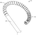
도 21은 본 개시의 태양에 따른 의료 기구 또는 요관경(200)의 예시적인 실시예를 예시한다. 도 21에 예시된 실시예에서, 요관경(200)은 기구 기부 또는 손잡이(210), 세장형 샤프트(220), 및 관절운동 섹션(230)을 포함할 수 있는 로봇-제어식 기구일 수 있다. 세장형 샤프트(220)는 기구 기부 또는 손잡이(210)로부터 연장될 수 있다. 관절운동 섹션(230)은 근위 섹션(240) 및 원위 섹션(250)을 포함할 수 있다. 원위 섹션(250)의 원위 단부 또는 팁은 팁 부분(272)을 포함할 수 있다. 근위 섹션(240)은 또한 제1 또는 근위 관절운동 섹션, 관절운동 섹션, 굽힘 섹션, 또는 편향 섹션뿐만 아니라, 2-방향 편향 섹션(two-way deflection section)으로 불릴 수 있다. 원위 섹션(250)은 또한 원위 또는 제2 관절운동 섹션, 관절운동 섹션, 굽힘 섹션, 또는 편향 섹션뿐만 아니라, 4-방향 편향 섹션(four-way deflection section)으로 불릴 수 있다. 관절운동 섹션(230)은 또한 샤프트(220)의 원위 단부로 고려될 수 있고, 또한 관절운동 섹션, 굽힘 섹션, 또는 편향 섹션으로 불릴 수 있다.21 illustrates an example embodiment of a medical instrument or
하나 이상의 케이블, 당김 와이어, 또는 당김 와이어 세그먼트가 샤프트(220)와 관절운동 섹션(230)의 외부 표면을 따라 연장될 수 있다. 추가적으로, 하나 이상의 케이블은 샤프트(220)의 중심 루멘을 따라 연장될 수 있다. 하나 이상의 당김 와이어 세그먼트는 1개, 2개, 3개, 4개, 5개, 6개 또는 그보다 많은 당김 와이어 또는 세그먼트를 포함할 수 있다.One or more cables, pull wires, or pull wire segments may extend along the
하나 이상의 케이블의 조작은 관절운동 섹션(230)의 작동 또는 편향을 유발한다. 하나 이상의 케이블의 조작은 기구 기부 또는 손잡이(210) 내에 위치되거나 그에 연결된 하나 이상의 기구 드라이버를 통해 제어될 수 있다. 기구 기부 또는 손잡이(210)는 일반적으로, 기구 드라이버의 부착 표면 상의 하나 이상의 토크 커플러와 상호 정합되도록 설계되는 하나 이상의 기계적 입력부, 예컨대 리셉터클, 풀리, 또는 스풀을 갖는 부착 인터페이스를 포함할 수 있다. 기구 기부(210)는 복수의 구동 입력부를 포함할 수 있다. 복수의 제어 케이블이 복수의 구동 입력부에 결합되고 가요성 샤프트(flexible shaft)(220)를 따라 연장될 수 있다. 복수의 구동 입력부는 도 1 내지 도 20에 기술된 것과 같은, 의료 로봇 시스템(medical robotic system)으로부터의 구동 출력부에 응답하여 복수의 당김 와이어 또는 제어 케이블에 장력을 인가하거나 그것을 제어하도록 구성된다. 또한, 의료 로봇 시스템의 로봇 아암이 요관경을 운반하도록 구성될 수 있다. 로봇 아암은 관절운동 섹션(230)을 구부리기 위해 복수의 제어 케이블에 장력을 인가하도록 구성될 수 있다.Manipulation of one or more cables causes actuation or deflection of
도 21에 예시된 실시예에서, 요관경(200)은 4개의 당김 와이어 또는 당김 와이어 세그먼트(260, 262, 264, 266)를 포함한다. 복수의 당김 와이어 또는 당김 와이어 세그먼트(260, 262, 264, 266)는 세장형 샤프트(220)를 따라 연장되고 세장형 샤프트(220)의 팁 부분(272)에서 종단될 수 있다. 일부 실시예에서, 기구(200)는 샤프트(220)가 손잡이(210)에 대해 병진하는 것을 가능하게 하는, 하나 이상의 케이블(260, 262, 264, 266)이 그에 작동식으로 결합될 수 있는 일련의 풀리를 포함한다. 특정 기구(200)의 구현예에 따라, 기구(200)는 하나 이상의 당김 와이어 또는 케이블(260, 262, 264, 266)을 인장시킴으로써 달성될 수 있는, 하나 이상의 상이한 의료 및/또는 수술 작업을 수행하도록 구현될 수 있는 엔드 이펙터(예시되지 않음)를 포함할 수 있다. 엔드 이펙터는 기구(200)의 원위 단부에 위치될 수 있다. 엔드 이펙터는 예컨대 바스켓 또는 에너지 방출 도구와 같은 하나 이상의 도구를 포함할 수 있다. 일부 예에서, 기구(200)는 세장형 샤프트(220)를 통해 연장되는 작업 채널(270)을 포함하여, 바스켓 또는 레이저 도구(laser tool)와 같은 적어도 하나의 도구(예시되지 않음)가 그것을 통해 삽입되어 환자의 요로(urinary tract) 내와 같은 표적 영역과 상호작용하도록 허용할 수 있다. 레이저 도구는, 예컨대 신장 결석의 크기를 감소시키기 위해, 환자의 요로 내에 위치된 신장 결석에 인가되도록 구성되는 에너지를 전달하도록 구성될 수 있다. 바스켓 도구는 환자의 요로 내에 위치된 신장 결석 또는 그의 부분을 포획하도록 구성될 수 있다.In the embodiment illustrated in FIG. 21 , the
도 22a는 근위 섹션(240) 및 원위 섹션(250) 둘 모두를 포함할 수 있는 관절운동 섹션(230) 및 세장형 샤프트(220)를 포함하는, 요관경(200)의 다양한 부분의 편향 방향을 예시한, 의료 기구 또는 요관경(200)의 예시적인 실시예를 예시한다. 도 22a에 예시된 바와 같은 이들 다양한 편향 방향은 도 21에 도시되고 기술된 복수의 당김 와이어(260, 262, 264, 266)에 의해 제어되거나 작동될 수 있다. 해부학적 구조를 통해 요관경(200)을 내비게이팅하기 위해, 근위 섹션(240) 및 원위 섹션(250) 둘 모두는 제1 평면 내에서 곡선형 축(232)을 따라 2개의 방향, 예컨대 제1 방향 및 제3 방향으로 편향가능할 수 있고, 여기서 제1 방향과 제3 방향은 곡선형 축(232)을 따라 서로 반대이다(예컨대, 좌측/우측 또는 하방/후방). 원위 섹션(250)은 제2 평면 내에서 곡선형 축(234)을 따라 2개의 방향, 예컨대 제2 평면 내에서 제2 방향 및 제4 방향으로 추가로 편향가능할 수 있고, 여기서 제2 방향과 제4 방향은 곡선형 축(234)을 따라 서로 반대이다(예컨대, 상향/하향 또는 전방/후방). 제1 평면은 제2 평면에 직교하거나 횡단할 수 있다. 제1 방향은 제2 방향에 직교하거나 횡단할 수 있다. 제3 방향은 제4 방향에 직교하거나 횡단할 수 있다. 따라서, 원위 섹션(250)은 2개의 평면 내에서 그리고 4개의 방향(예컨대, 좌측/우측 및 상향/하향)으로 편향가능할 수 있다.22A shows the direction of deflection of various portions of the
도 21에 예시된 4개의 당김 와이어(260, 262, 264, 266)는 관절운동 섹션(230)을 다양한 방향(예컨대, 상향, 하향, 좌측, 우측)으로 편향시키도록 구성될 수 있다. 도 21에 도시된 바와 같은 제1 당김 와이어(260)는 관절운동 섹션(230)을 제1 평면 내에서 제1 방향으로 편향시키도록 구성될 수 있다. 제2 당김 와이어(262)는 관절운동 섹션(230)을 제2 평면 내에서 제2 방향으로 편향시키도록 구성될 수 있고, 제2 평면은 제1 평면에 직교하거나 횡단한다. 제3 당김 와이어(264)는 관절운동 섹션(230)을 제1 평면 내에서 제1 방향과 반대인 제3 방향으로 관절운동시키도록 구성될 수 있다. 제4 당김 와이어(266)는 관절운동 섹션(230)을 제2 평면 내에서 제2 방향과 반대인 제4 방향으로 관절운동시키도록 구성될 수 있다.The four
일부 실시예에서, 요관경(200)은 팁 부분(272) 내의 이미지 센서 또는 카메라(650)(도 26b)를 포함할 수 있다. 제1 당김 와이어(260)는 관절운동 섹션(230)을 카메라의 기준 프레임에 대해 수평 축을 따라 제1 평면 내에서 제1 방향으로 관절운동시킬 수 있다. 제2 당김 와이어(262)는 관절운동 섹션(230)을 카메라의 기준 프레임에 대해 수직 축을 따라 제2 평면 내에서 제2 방향으로 관절운동시킬 수 있다. 일부 실시예에서, 팁 부분(272)은 하나 이상의 광원(예컨대, 발광 다이오드) 또는 (예컨대, 타워 내의) 원격 광원으로부터 광을 전달하도록 구성된 광섬유와 같은 조명기(illuminator)(750)(도 26b)를 포함할 수 있다. 조명기(750)는 카메라에 의해 획득된 이미지를 통한 시각화를 용이하게 하기 위해 표적 해부학적 구조를 조명하도록 구성될 수 있다.In some embodiments,
일부 실시예에서, 제1 당김 와이어(260)는 근위 섹션(240) 및 원위 섹션(250) 둘 모두를 제1 평면 내에서 제1 곡선형 축(232)을 따라 제1 방향으로 편향시키도록 구성된다. 일부 실시예에서, 제2 당김 와이어(262)는 근위 섹션(240) 및 원위 섹션(250) 둘 모두를 제2 평면 내에서 제2 곡선형 축(234)을 따라 제2 방향으로 편향시키도록 구성된다. 일부 실시예에서, 제2 당김 와이어(262)는 원위 섹션(250)을 근위 섹션(240)과 독립적으로 제2 방향으로 관절운동시키도록 구성되고, 제2 곡선형 축(234)을 따른 제2 방향은 예컨대 제1 곡선형 축(232)을 따른 제1 방향을 횡단한다.In some embodiments,
또한, 근위 섹션(240)과 원위 섹션(250)은 각각 상이한 굽힘 반경을 가질 수 있다. 일부 실시예에서, 제1 당김 와이어(260)에 대한 인장력의 인가 시에, 원위 섹션(250)의 원위 부분이 근위 섹션(240)의 근위 부분보다 작은 굽힘 반경으로 제1 평면 내에서 제1 방향으로 구부러지도록 구성된다. 일부 실시예에서, 제1 당김 와이어(260)에 대한 인장력의 인가 시에, 원위 섹션(250)의 근위 부분이 근위 섹션(240)의 원위 부분과 동일하거나 대략 동일한 굽힘 반경으로 제1 방향으로 구부러지도록 구성된다. 일부 실시예에서, 근위 섹션(240)은 제1 평면 내에서 제1 방향으로의 그의 굽힘을 허용하고, 제2 평면 내에서 제2 방향으로의 그의 굽힘을 억제한다. 일부 실시예에서, 원위 섹션(250)은 제1 및 제2 방향으로의(예컨대, 각각의 제1 및 제2 곡선형 축(232, 234)을 따른) 그의 굽힘을 허용한다.Also, the
도 21에 도시된 바와 같이, 기구 기부(210)는 세장형 샤프트(220)에 결합될 수 있다. 세장형 샤프트(220)는 길이방향 축을 한정할 수 있다. 세장형 샤프트(220)는 세장형 샤프트(220)의 길이방향 축을 중심으로 기구 기부(210)에 대해 회전하도록 구성될 수 있다. 또한 도 22a에 예시된 바와 같이, 세장형 샤프트(220)는 세장형 샤프트(220)의 길이방향 축을 중심으로 방향(222)으로 회전 또는 롤링할 수 있다. 기구 기부(210)에 대한 세장형 샤프트(220)의 회전은 환자의 하방-상방 평면(inferior-superior plane)일 수 있는 제1 평면 내에서의 제1 방향, 및 환자의 전방-후방 평면(anterior-posterior plane)일 수 있는 제2 평면 내에서의 제2 방향 둘 모두를 정렬시키도록 작동가능할 수 있다. 세장형 샤프트(220)의 롤 방향(222)은 관절운동 섹션(230)의 제1 방향을 원하는 제1 방향으로 지향 또는 정렬시키도록 구성될 수 있다. 예를 들어, 요관경(200)이 팁 부분(272)의 관점에서 우측 및 좌측 선회를 형성하도록 지향됨에 따라, 세장형 샤프트(220)는 상향 및 하향과 같은 상이한 방향으로 편향을 지향시키기 위해 길이방향 축을 중심으로 방향(222)으로 롤링될 수 있다.21 , the
도 22b는 신장(300)의 자연 내강을 통해 내비게이팅된 요관경의 예시적인 실시예를 예시한다. 신장(300)이 형상, 크기, 및 구성에서 폭넓게 가변적이지만, 그것은 상부, 중간, 및 하부 극을 갖는 평면형 구조로서 개략적으로 일반화될 수 있다. 이러한 극들 각각으로부터, 전방으로 또는 후방으로 지향되는 일련의 신배가 나온다. 요관경(200)은 환자의 요로 내로의 삽입을 위해 구성될 수 있다. 요관경(200)은 회전될 수 있고, 이에 의해 세장형 샤프트(220)는 관절운동 섹션(230)을 정확한 방향으로 지향 또는 정렬시키기 위해 세장형 샤프트(220)를 중심으로 롤링된다.22B illustrates an exemplary embodiment of a ureteroscope navigating through the natural lumen of the
근위 섹션(240) 및 원위 섹션(250) 둘 모두를 포함하는 관절운동 섹션(230)의 전체 길이가 2-방향 편향 내시경으로서 기능할 수 있는 요관경(200)의 조합된 편향이 있다. 관절운동 섹션(230)은 요관경이 요도를 통해, 방광 내로, 그리고 신우 내로 이동함에 따라 요관경(200)을 조향하기 위해 제1 평면 내에서 제1 방향으로(예컨대, 좌측 및/또는 우측) 하나의 유닛으로서 구부러질 수 있다. 2-방향 편향 섹션은 환자의 요관을 통과하도록 구성될 수 있다. 관절운동 섹션(230)의 2-방향 편향 섹션은 신장(300)의 다양한 극에 접근하기 위해 제1 방향으로 편향되도록 구성될 수 있다. 편향 섹션은 신장(300)의 특정 극에 접근하기 위해 제1 평면 내에서 제1 곡선형 축(232)을 따라 제1 방향으로 편향되도록 구성될 수 있고, 이는 편향 섹션(230)이 상당히 구부러질 수 있기 때문에, 요관경(200)의 1차 편향 또는 대략적 편향(coarse deflection)으로 고려될 수 있다. 일부 실시예에서, 2-방향 및 4-방향 관절운동 둘 모두가 신장의 다양한 극으로 내비게이팅하기 위해 사용될 수 있다.There is a combined deflection of the
원하는 극에 접근한 후에, 원위 섹션(250)의 4-방향 굽힘 섹션 또는 4 방향 편향은 전방으로 그리고 후방으로 지향되는 신배를 하위-선택(sub-select)하도록 구성될 수 있다. 원하는 신배를 하위-선택하는 것과 같이, 해부학적 구조를 통해 요관경(200)의 원위 단부를 내비게이팅하기 위해, 원위 섹션(250)은 제1 방향을 횡단하는 제2 방향으로 편향될 수 있다. 4-방향 굽힘 섹션의 편향은 더 작은 또는 정밀한 굽힘으로 고려될 수 있다. 근위 섹션(240)은 가요성 세장형 샤프트의 1차 또는 대략적 편향을 포함할 수 있다. 원위 굽힘 섹션은 가요성 세장형 샤프트의 2차 또는 미세 관절운동(fine articulation)을 포함할 수 있다. 정확한 제2 방향은 제2 평면 내에서 제2 곡선형 축(234)을 따를 수 있고, 요관경(200)이, 관절운동 섹션(230)의 1차 편향 곡선을 유지하면서, 전방으로 그리고 후방으로 지향되는 신배를 하위-선택하도록 허용할 수 있다. 신배의 누두(infundibulum)에 도달한 후에, 관절운동 섹션(230)의 원위 섹션(250)은 원하는 전방 지향 또는 후방 지향 신배를 선택하기 위해 제2 곡선형 축(234)을 따라 제2 방향으로 지향될 수 있다.After approaching the desired pole, the four-way bending section or four-way deflection of the
세장형 샤프트(220), 원위 섹션(250) 또는 근위 섹션(240)의 길이는 가변적이어서, 길이는 요관경(200)이 신장의 대부분의 신배 또는 다양한 극에 도달하는 것을 가능하게 하도록 조정될 수 있다.The length of the
도 23은 절차를 위해 의료 기구 또는 요관경을 편향시키는 것을 포함하는, 의료 절차를 수행하기 위한 방법(400)의 일 실시예를 예시한 흐름도이다. 방법(400)은 기구의 원위 섹션이 환자의 요관을 통해 환자의 신장 내로 삽입되는 블록(402)에서 시작한다. 본 명세서에 기술된 바와 같이, 기구는 원위 섹션 및 근위 섹션을 포함할 수 있다. 기구는 제1 평면 및 제2 평면 내에서 관절운동가능한 굽힘 섹션을 포함할 수 있고, 제2 평면은 제1 평면에 직교한다. 기구의 근위 섹션은 제1 평면 내에서 관절운동하도록 제한된 굽힘 섹션을 포함할 수 있다. 기구는 예를 들어 도 1 내지 도 22를 참조하여 전술된 로봇식 의료 시스템을 사용하여 로봇으로 제어될 수 있다. 기구는 수동으로 제어될 수 있다. 일부 실시예에서, 초기 접근은 경피적으로 또는 자연 환자 구멍을 통해, 예컨대 요도를 통해 삽입되어 얻어진다.23 is a flow diagram illustrating one embodiment of a
다음으로, 방법(400)은 기구가 굽힘 섹션의 제1 평면을 신장의 평면과 정렬시키기 위해 롤링되는 블록(404)으로 이동한다. 일부 실시예에서, 신장의 평면은 신장의 주 평면 또는 신장의 관상면일 수 있다.Next,
방법(400)은 이어서 기구의 관절운동 섹션이 제1 평면 내에서 관절운동되는 블록(406)으로 이동한다. 일부 실시예에서, 근위 섹션은 제1 평면 내에서만 관절운동하도록 제한되거나 제약될 수 있다.The
마지막으로, 방법(400)은 기구의 원위 섹션이 제1 평면 및 제2 평면 중 적어도 하나 내에서 관절운동되는 블록(408)으로 이동한다. 일부 실시예에서, 기구의 원위 섹션은 제2 평면 내에서 관절운동되거나 편향될 수 있는 굽힘 섹션의 유일한 부분일 수 있다. 일부 실시예에서, 제2 평면은 제1 평면에 직교하거나 횡단한다. 일부 실시예에서, 제1 평면은 하방-상방 평면일 수 있다. 일부 실시예에서, 제2 평면은 전방-후방 평면일 수 있다.Finally, the
일부 실시예에서, 방법(400)은 방광, 요관, 신우 및 원하는 신배의 누두를 통해 기구를 내비게이팅하도록 구성될 수 있다. 예를 들어, 일부 실시예에서, 블록(406)에서, 관절운동 섹션의 근위 부분을 관절운동시키는 것은 1차 편향 곡선을 달성하도록 구성될 수 있다. 또한, 블록(408)에서, 기구는 근위 부분의 1차 편향 곡선을 유지하면서 원위 부분을 관절운동시키도록 구성될 수 있다. 추가적으로, 일부 실시예에서, 블록(408)에서, 원위 부분을 관절운동시키는 것은 표적 영역에 도달하기 위해 누두를 통해 그리고 원하는 신배로 원위 부분을 통해 내비게이팅하도록 구성될 수 있다.In some embodiments,
도 24a는 단일 평면 내에서 편향가능한 요관경의 일부분의 예시적인 실시예를 예시한다. 이러한 부분은 제1 평면 내에서 하나 이상의 축(232)을 따라 편향가능한 요관경 내의 제1 굽힘 섹션(450)일 수 있다. 제1 굽힘 섹션(440)은 일련의 정렬된 힌지(aligned hinge)를 통해 연결된 일련의 링크(link)(442a 내지 442c)를 포함할 수 있다. 전술된 바와 같이, 제1 굽힘 섹션(440)은 요관경의 근위 부분일 수 있다. 제1 굽힘 섹션(440)은 일련의 정렬된 힌지를 통해 연결된 일련의 링크(442)를 포함할 수 있다. 제1 굽힘 섹션(440)은 복수의 링크(442)를 포함할 수 있고, 여기서 제1 굽힘 섹션(440)의 각각의 링크(442)는 링크(442b)를 근위 링크(442c)에 연결하기 위한 제1 힌지 부재 및 링크(442b)를 원위 링크(442a)에 연결하기 위한 제2 힌지 부재를 포함한다. 제1 굽힘 섹션(440)은 임의의 가변 수의 복수의 링크를 포함할 수 있다.24A illustrates an exemplary embodiment of a portion of a ureteroscope that is deflectable within a single plane. This portion may be a first
각각의 링크(442)는 각각의 링크(442)의 근위측 또는 저부 표면 상의 암형 힌지 부재를 제공하는 곡선형 표면, 리세스(recess) 또는 개구(446)를 포함할 수 있다. 각각의 링크(442)는 링크(442)의 원위측 또는 상부 표면 상의 수형 힌지 부재를 제공하는 돌출부(444)를 포함할 수 있다. 돌출부(444)는 링크(442)의 원위측 또는 상부 표면으로부터 원위로 연장될 수 있다. 리세스(446)는 인접한 링크(442)의 돌출부(444)를 수용하거나 그것과 맞물리도록 구성될 수 있다. 리세스(446)는 컵-형상 또는 u-형상일 수 있다. 힌지가 인접한 링크들(442)(예컨대, 442a와 442b) 사이에 형성될 수 있다. 힌지는 인접한 링크(442a 또는 442c)의 돌출부(444)를 수용하는 제1 링크(442b)의 리세스(446)에 의해 형성될 수 있다. 리세스(446)와 돌출부(444)의 대응하는 형상은 제1 평면 내에서 제1 곡선형 축(232)을 따라 제1 방향으로 다른 링크(442a 또는 442c)에 대한 하나의 링크(442b)의 회전을 허용할 수 있다. 근위 섹션(440)의 정렬된 힌지들의 각각은 한 쌍의 인접한 링크(442)를 인접한 힌지에 평행한 피봇 축을 중심으로 회전가능하게 연결할 수 있다. 각각의 링크(442)는 힌지가 정렬되도록 정렬될 수 있고, 여기서 돌출부(444)와 리세스(446)는 각각의 링크(442) 상에서 서로 반경방향으로 정렬된다. 제1 굽힘 섹션(440) 내의 링크들(442) 각각에 대해, 제1 힌지 부재와 제2 힌지 부재가 정렬된다.Each link 442 may include a curved surface, recess, or opening 446 that provides a female hinge member on a proximal or bottom surface of each link 442 . Each link 442 can include a
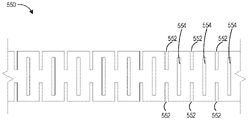
도 24b는 2개의 상이한 평면 내에서 편향가능한 요관경의 일부분의 예시적인 실시예를 예시한다. (예컨대, 곡선형 축(232, 234)을 따라) 2개의 평면 내에서 편향가능한 이러한 부분은 요관경의 제2 굽힘 섹션(450)일 수 있다. 제2 굽힘 섹션(450)은 일련의 엇갈린 힌지(staggered hinge)를 통해 연결된 일련의 링크(452)를 포함할 수 있다. 전술된 바와 같이, 제2 굽힘 섹션(450)은 요관경의 원위 부분일 수 있다. 제2 굽힘 섹션(450)은 복수의 링크(452)를 포함하고, 여기서 각각의 링크(452)는 링크(452)를 인접한 근위에 위치된 링크에 연결하도록(예컨대, 링크(452b)를 근위 링크(452c)에 연결함) 구성된 제1 힌지 부재 및 링크를 인접한 원위에 위치된 링크에 연결하도록(예컨대, 링크(452b)를 원위 링크(452a)에 연결함) 구성된 제2 힌지 부재를 포함한다. 관련 태양에서, 제2 힌지 부재는 예컨대 약 90도만큼 제1 힌지 부재로부터 회전 오프셋될 수 있다. 제2 굽힘 섹션(450)은 임의의 가변 수의 복수의 링크를 포함할 수 있다.24B illustrates an exemplary embodiment of a portion of a ureteroscope that is deflectable in two different planes. This portion that is deflectable in two planes (eg, along
근위 섹션(440)의 링크(442)와 유사하게, 제2 굽힘 섹션(450)의 각각의 링크(452)는 각각의 링크(452)의 근위측 또는 저부 표면 상의 곡선형 표면, 리세스 또는 개구(456)를 포함할 수 있다. 각각의 링크(452)는 링크(452)의 원위측 또는 상부 표면 상의 돌출부(454)를 포함할 수 있다. 하나의 링크(452b)의 리세스(456)는 이웃 또는 인접한 링크(452a 또는 452c)의 돌출부(454)를 수용하거나 그것과 맞물리도록 구성될 수 있다. 힌지가 인접한 링크들(452)(예컨대, 452a와 452b) 사이에 형성될 수 있다. 힌지는 인접한 링크(452a 또는 452c)의 돌출부(454)를 수용하는 제1 링크(452b)의 리세스(456)에 의해 형성될 수 있다. 다양한 실시예에서, 수형 및 암형 힌지 부재의 위치설정이 역전되거나 변경될 수 있음이 인식될 것이다. 예를 들어, 수형 힌지 부재는 각각의 링크의 근위측 상에 위치될 수 있고, 암형 힌지 부재는 각각의 링크의 원위측 상에 위치될 수 있다.Similar to the links 442 of the
제2 굽힘 섹션(450)에서, 각각의 쌍의 인접한 링크(452)를 연결하는 힌지는 엇갈려 있다. 힌지의 이러한 엇갈림은 원위 섹션(450)이 제1 평면(예컨대, 제1 곡선형 축(232)을 따름)뿐만 아니라 제2 평면(예컨대, 제2 곡선형 축(234)을 따름) 둘 모두에서 관절운동하도록 허용할 수 있다. 원위 섹션(450)의 엇갈린 힌지들의 각각은 한 쌍의 인접한 링크(452)를 인접한 힌지에 수직인 피봇 축을 중심으로 회전가능하게 연결할 수 있다. 제2 굽힘 섹션(450) 내의 링크들(452a 내지 452c) 각각에 대해, 모든 다른 힌지 부재는 서로 90도 오프셋되어 위치될 수 있다. 제1 힌지 부재와 제2 힌지 부재는 서로 90도 오프셋되어 위치될 수 있다.In the second
제2/원위 섹션(450) 내의 링크 힌지의 엇갈린 배열은 모든 다른 힌지 부재가 서로 오프셋되어 도 24b 및 도 25에 도시되어 있지만, 힌지 부재의 엇갈림은 모든 제3, 제4, 또는 제5 힌지 부재, 또는 임의의 다른 패턴 또는 수로 이루어질 수 있다. 예를 들어, 제2 굽힘 섹션(450)은 제1 쌍(A-A)이 서로 정렬되고, 제2 쌍(B-B)이 서로 정렬되고 제1 쌍(A-A)으로부터 90도 오프셋되어 위치되고, 제3 쌍(A-A)이 서로 정렬되고 제2 쌍(B-B)으로부터 90도 오프셋으로 위치되도록 할 수 있다. 제3 쌍(AA)은 제1 쌍(A-A)과 정렬될 것이다. 이러한 교번하는 쌍은 A-A-B-B 힌지 패턴으로 불릴 수 있다. 일부 실시예에서, 이러한 반복 패턴은, 쌍 대신에, 3개, 4개, 5개, 또는 임의의 수의 힌지의 교번하는 그룹일 수 있다.The staggering arrangement of the link hinges in the second/
교번하는 패턴은 힌지 수의 동일한 비를 갖거나, 힌지 부재의 비가 변할 수 있다. 예를 들어, 제1 힌지 부재(A)는 제2 힌지 부재(B)로부터 90도 오프셋될 수 있다. 제3 힌지 부재(B)는 제2 힌지 부재(B)와 정렬될 수 있다. 패턴은 이어서 반복될 것이며, 여기서 제4 힌지(A) 부재는 제1 힌지 부재(A) 등과 정렬될 수 있다. 이는 A-B-B 패턴으로 불릴 수 있다.The alternating pattern may have the same ratio of the number of hinges, or the ratio of the hinge members may vary. For example, the first hinge member (A) may be offset 90 degrees from the second hinge member (B). The third hinge member (B) may be aligned with the second hinge member (B). The pattern will then be repeated, where the fourth hinge (A) member may be aligned with the first hinge member (A) and the like. This may be referred to as an A-B-B pattern.
정렬되고 엇갈린 힌지의 패턴은 제2 굽힘 섹션(450) 전체에 걸쳐 일관될 수 있다. 정렬되고 엇갈린 힌지의 패턴은 또한 제2 굽힘 섹션(450)을 통해 변할 수 있다. 예를 들어, 제2 굽힘 섹션(450)의 근위 부분은 전술된 2개의 정렬된 교번하는 힌지를 가질 수 있고, 제2 굽힘 섹션(450)의 원위 부분은 전술된 바와 같은 모든 다른 엇갈린 힌지를 가질 수 있다(도 24b에 예시된 바와 같음).The pattern of aligned and staggered hinges may be consistent throughout the second
제2 굽힘 섹션(450) 내의 엇갈린 힌지 부재는 힌지 부재가 서로 90도 오프셋되도록 예시되어 있지만, 힌지 부재는 임의의 수의 각도, 예컨대 45 내지 90도, 50 내지 75도, 60 내지 80도, 80 내지 90도로 서로 오프셋될 수 있다.While the staggered hinge members in the
이러한 제2 굽힘 섹션(450) 내에 힌지의 엇갈린 패턴, 범위 또는 길이로 생성될 수 있는 다양한 패턴이 있다. 이는 제2 굽힘 섹션(250)이 내비게이팅될 특정 환자의 해부학적 구조 및 원하는 제어에 따라 맞춤화가능한 특정 굽힘 반경 또는 굽힘 프로파일을 갖도록 허용한다. 유사하게, (각각의 섹션 내의 링크의 수 또는 개별 링크의 길이에 의한) 길이의 상이한 변동은 특정 굽힘 반경 또는 굽힘 프로파일을 변경할 수 있고, 따라서 제2 굽힘 부분이 그를 따라 이동할 수 있는 제1 곡선형 축(232) 및/또는 제2 곡선형 축의 형상을 변경할 수 있다.There are various patterns that can be created with staggered patterns, ranges or lengths of hinges within this second
제1 굽힘 섹션(440)의 링크(442) 및 제2 굽힘 섹션의 링크(452)는 각각의 링크(442, 452)의 원위 표면으로부터 원위로 연장되는 일련의 포스트(472)를 포함할 수 있다. 일련의 포스트(472)는 돌출부(444)보다 길이가 짧고 각각의 링크(442, 452)의 반경 둘레에 위치될 수 있다. 포스트(472)는 원위의 인접한 링크의 저부 또는 근위 표면과 접촉하고 맞물리도록 구성될 수 있다. 이들 포스트(472)는 링크가 원하는 방향으로 편향됨에 따라 지지를 제공할 수 있다.Link 442 of first
도 25는 편향되지 않은 상태에서의 요관경의 관절운동 섹션(430)의 예시적인 실시예를 예시한다. 요관경은 도 24a에서 기술된 바와 같은 근위 섹션(440) 및 도 24b에서 기술된 바와 같은 원위 섹션(450)을 포함할 수 있다.25 illustrates an exemplary embodiment of an articulating
근위 섹션(440)의 길이와 원위 섹션(450)의 길이는 변할 수 있다. 일부 실시예에서, 근위 섹션(440)의 길이와 원위 섹션(450)의 길이는 동일할 수 있다. 다른 실시예에서, 근위 섹션(440)의 길이는 원위 섹션(450)의 길이보다 길 수 있다. 일부 실시예에서, 근위 섹션(440)의 길이 대 원위 섹션(550)의 길이의 비는 75:25, 70:30, 60:40, 50:50, 40:60, 30:70, 25:75, 또는 임의의 다른 적합한 비일 수 있다.The length of the
제1 굽힘 섹션(440)의 개별 링크(442)의 길이는 변할 수 있다. 예를 들어, 일련의 링크(442)는 원위 방향으로 단축되는 구배 길이를 가질 수 있다(여기서 원위 링크(442)는 제1 굽힘 섹션(440) 내의 근위 링크(442)보다 길이가 짧음). 다른 예에서, 제1 굽힘 섹션(440)의 근위 부분은 제1 굽힘 섹션(440)의 원위 부분의 링크(442)보다 긴 길이를 갖는 링크(442)를 가질 수 있다. 유사하게, 제2 굽힘 섹션(450)의 개별 링크(452)의 길이는 유사한 방식으로 변할 수 있다. 추가적으로 또는 대안적으로, 인접한 링크가 서로에 대해 구부러질 수 있는 각도는 굽힘 반경을 결정하도록 조정될 수 있다. 예를 들어, 인접한 링크들 사이의 힌지 부재 또는 정지부는 굽힘 섹션에 대한 최소 굽힘 반경을 제한하기 위해 사용될 수 있다.The length of the individual links 442 of the first
도 26a는 단일 평면 내에서 관절운동된 도 25의 관절운동 섹션(430)을 예시한다. 제1 굽힘 섹션(440) 및 제2 굽힘 섹션(450) 둘 모두는 동일한 평면 내에서 구부러진다. 도 26a에 예시된 바와 같이, 제2 굽힘 섹션(450) 내의 링크(452)의 길이는 제1 굽힘 섹션(440) 내의 링크(442)의 길이보다 짧고, 이는 제1 굽힘 섹션(440)의 굽힘 반경과 비교하여 제2 굽힘 섹션(450)의 더 작은 굽힘 반경을 생성한다.26A illustrates the articulating
도 26b는 2개의 평면 내에서 관절운동된 도 25 및 도 26a의 요관경을 예시한다. 제1 굽힘 섹션(440)은 제1 평면 내에서 제1 방향으로 편향된다. 제1 굽힘 섹션(404)은 제1 평면 내에서 구부러지도록 제한될 수 있다. 제2 굽힘 섹션(450)은 (제1 평면에 직교하는) 제2 평면 내에서 (제1 평면 외부로의 또는 제1 방향으로부터 횡방향으로의) 제2 방향으로 편향된다. 제2 굽힘 섹션은 제1 평면을 따라서, 그리고 제1 평면 외부로 구부러지는 것이 가능할 수 있다.26B illustrates the ureteroscope of FIGS. 25 and 26A articulated in two planes. The first
도 27a는 하나의 평면 내에서 편향가능한 요관경의 일부분의 다른 예시적인 실시예를 예시한다. 이러한 제1 부분은 하나의 평면 내에서만 편향가능한 요관경 내의 제1 굽힘 섹션(540)일 수 있다. 제1 굽힘 섹션(540)은 제1 평면보다 제2 평면 내에서 더 큰 굽힘 강성을 갖는 변형가능 굴곡부(deformable flexure)를 포함할 수 있다. 제1 굽힘 섹션(540)의 변형가능 굴곡부는 그의 길이방향 축을 중심으로 2차 회전 대칭을 갖는 제1 패턴의 공극(void)(542)을 가진 제1 튜브 섹션(tube section)을 포함할 수 있다. 가요성 샤프트는 제1 굽힘 섹션(540)이 180도 회전 대칭으로 튜브 둘레에 일련의 절결부(cutout)(542)를 포함하는 튜브일 수 있다. 일련의 절결부 또는 공극(542)은 제1 굽힘 섹션(540)의 길이를 따라 서로 정렬될 수 있어서, 일련의 절결부 또는 공극(542)이 제1 굽힘 섹션(540)의 길이를 따라 동일한 위치에서 반경방향으로 있게 된다. 일련의 절결부 또는 공극(542)은 길이방향 축의 서로 반대편에 있는 측부들 상에 위치될 수 있어서, 그들이 반경방향으로 서로 180도 떨어져 위치된다. 일련의 절결부 또는 공극(542)은 제1 굽힘 섹션(540)이 가요성을 증가시키도록 허용하고, 이는 제1 굽힘 섹션(540)이 제1 평면 내에서 구부러지도록 허용한다.27A illustrates another exemplary embodiment of a portion of a ureteroscope that is deflectable in one plane. This first portion may be a first
도 27b는 2개의 평면 내에서 편향가능한 요관경의 일부분의 예시적인 실시예를 예시한다. 이러한 제2 부분은 (예컨대, 제1 평면과 제2 평면이 직교하는) 2개의 평면 내에서 편향가능한 요관경 내의 제2 굽힘 섹션(550)일 수 있다. 제2 굽힘 섹션(550)은 제1 및 제2 평면 내에서 동일한 굽힘 강성을 갖는 변형가능 굴곡부를 포함할 수 있다. 제2 굽힘 섹션(550)의 변형가능 굴곡부는 제1 굽힘 섹션(540)과 유사한 제1 패턴을 가진 제2 튜브 섹션을 포함하고, 여기서 제2 튜브 섹션은 요관경이 하나의 평면 내에서 편향가능하도록 허용하는 제1 패턴의 공극(552)을 갖는다.27B illustrates an exemplary embodiment of a portion of a ureteroscope that is deflectable in two planes. This second portion may be a second
제1 굽힘 섹션(540) 내의 제1 패턴의 공극(542)과 유사하게, 제2 굽힘 섹션(550)의 변형가능 굴곡부는 그의 길이방향 축을 중심으로 2차 회전 대칭을 갖는 제1 패턴의 공극(552)을 가진 제2 튜브 섹션을 포함할 수 있다. 제2 굽힘 섹션(550)의 변형가능 굴곡부는 또한 그의 길이방향 축을 중심으로 n차 회전 대칭을 갖는 제2 패턴의 공극(554)을 포함할 수 있고, n은 4의 정수배이다.Similar to the
제1 굽힘 섹션(540) 내의 제1 일련의 절결부(542)와 유사하게, 제2 굽힘 섹션(550)은 180도 회전 대칭으로 튜브 둘레에 일련의 절결부(552)를 포함하는 튜브일 수 있다. 제2 굽힘 섹션(550)은 추가적으로 90도 회전 대칭으로 튜브 둘레에 반경방향으로 위치된 제2 일련의 절결부(554)를 가질 수 있다.Similar to the first series of cut-
제1 일련의 절결부 또는 공극(552)은 제2 굽힘 섹션(550)의 길이를 따라 서로 정렬될 수 있어서, 제1 일련의 절결부 또는 공극(552)이 제2 굽힘 섹션(550)의 길이를 따라 동일한 위치에서 반경방향으로 있게 된다. 유사하게, 제2 일련의 절결부 또는 공극(554)은 제2 굽힘 섹션(550)의 길이를 따라 서로 정렬될 수 있어서, 제2 일련의 절결부 또는 공극(554)이 제2 굽힘 섹션(550)의 길이를 따라 동일한 위치에서 반경방향으로 있게 된다. 제1 일련의 절결부 또는 공극(552)은 길이방향 축의 서로 반대편에 있는 측부들 상에 위치될 수 있어서, 그들이 반경방향으로 서로 180도 떨어져 위치된다. 유사하게, 제2 일련의 절결부 또는 공극(554)은 길이방향 축의 서로 반대편에 있는 측부들 상에 위치될 수 있어서, 그들이 반경방향으로 서로 180도 떨어져 위치된다.The first series of cutouts or
도 28a는 도 21과 도 22a 및 도 22b를 참조하여 전술된 실시예와 유사한 기구, 예컨대 기구(200)에 결합되고 그와 함께 사용될 수 있는, 하나의 구성에 따른 예시적인 내시경(1210)의 일부분의 저면도를 예시한다. 예시된 바와 같이, 내시경(1210)은 내시경 기부(1211)(또는 내시경 손잡이) 및 세장형 샤프트(도시되지 않음)를 포함한다. 세장형 샤프트(예컨대, 도 21과 도 22a 및 도 22b에 도시된 바와 같은 세장형 샤프트(220))는 내시경 출구(1242)로부터 원위로 연장될 수 있다. 세장형 샤프트는 의료 절차 동안 환자 내로 삽입되도록 구성된다. 세장형 샤프트는 관절운동가능하고 제어가능하도록 구성될 수 있어서, 세장형 샤프트가 환자의 해부학적 구조를 통해 내비게이팅되고 조향될 수 있다. 예를 들어, 일부 실시예에서, 세장형 샤프트는 요도, 요관, 위장관, 식도, 폐의 기도 등과 같은 환자 내강 내로 삽입되고 그를 통해 안내되도록 구성되는 얇은 가요성 본체를 포함한다. 전술된 바와 같이, 당김 와이어(예컨대, 당김 와어어(260, 262, 264, 266))는 세장형 샤프트의 관절운동을 제어하기 위해 세장형 샤프트 내에 또는 그 상에 포함될 수 있다. 세장형 샤프트는 원위 단부와 근위 단부 사이에서 연장될 수 있다. 원위 단부는 환자 내로 삽입되도록 구성될 수 있다. 근위 단부는 내시경 출구(1242)를 통해 내시경 기부(211)에 부착될 수 있다. 세장형 샤프트는 추가 기구 또는 도구가 원위 단부로의 전달을 위해 통과할 수 있는 (예시되지 않은) 작업 채널을 포함할 수 있다. 내시경(1210)은 작업 채널에 대한 접근을 허용하도록 구성된 (예시되지 않은) 작업 채널 진입 포트를 포함할 수 있다. 기구 샤프트 입구(1256)는 (후술되는) 기구 샤프트가 그 내부에 삽입되어 작업 채널 진입 포트 내로 그리고 작업 채널 내로 결합되도록 결합하는 것을 허용할 수 있다.28A is a portion of an
내시경 기부(1211)는 내시경(1210)의 수동 제어 및 로봇 제어 둘 모두를 허용하도록 구성된다. 예를 들어, 내시경 기부(1211)는 수동 제어를 제공하기 위해 물리적으로 보유되고 수동으로 조작되도록, 그리고 로봇 제어를 제공하기 위해 기구 구동 메커니즘에 결합하도록 구성된다. 일부 실시예에서, 멸균 어댑터가 의료 절차 동안 멸균 영역을 유지하기 위해 내시경 기부(1211)와 기구 구동 메커니즘 사이에 위치될 수 있다.
예시된 바와 같이, 내시경 기부(1211)는 하우징(1212)을 포함한다. 예시된 바와 같이, 하우징(1212)은 또한 그에 결합되는 기구를 포함하도록 형상화될 수 있다. 내시경 기부(1211)는 하나 이상의 내시경 수용 요소(1276)를 포함한다. 내시경 수용 요소(1276)는 다른 기구(예컨대, 전술된 기구(200))의 대응하는 요소와 결합하도록 구성된다. 예를 들어, 내시경 수용 요소(1276)는 도 21에 도시된 것과 같은 기구 기부 또는 손잡이(210)의 대응하는 요소(도시되지 않음)와 결합할 수 있다. 내시경 기부(1211)의 하우징(1212)은 의사의 손에서의 기구 손잡이를 위한 그리고/또는 다른 기구의 결합을 위한 인체공학적 맞춤을 제공하도록 형상화될 수 있다. 예를 들어, 하우징(1212) 형상은 내시경 기부(1211)가 수동 제어 동안 더욱 용이하게 또는 편안하게 보유되도록 허용할 수 있다. 대안적으로 또는 추가적으로, 하우징(1212) 형상은 후술될 바와 같이 기구 구동 메커니즘 상의 하나 이상의 미사용 로봇 구동 출력부에 대한 접근을 제공할(또는 차단하지 않을) 수 있다. 내시경 기부(1211)는 의료 기구 시스템의 하나 이상의 기구에 전력을 공급하기 위해 전력 유닛에 연결하기 위한 전력 접근부(1214)를 포함할 수 있다. 전력 접근부(1214)는 내시경(1210)에 대한 전기적 및/또는 시각적 연결부를 제공하도록 구성될 수 있다. 예시된 실시예에서, 전력 접근부(1214)는 타워에 있는 커넥터로 이어지는 엄빌리컬 케이블(umbilical cable)을 위한 변형 완화부(strain relief)로서 예시되어 있다.As illustrated, the
내시경 기부(1211)는 기구(예컨대, 전술된 기구(200))의 삽입을 허용하는 기구 샤프트 입구(1256)를 포함할 수 있다. 기구 입구는 기구 입구 액추에이터(1229)를 포함할 수 있다. 기구 입구 액추에이터(1229)는 기구의 샤프트의 수동 제어를 허용할 수 있다. 일부 실시예에서, 기구 입구 액추에이터(1229)는 기구 샤프트와 내시경(1210) 사이의 연결을 개선하기 위해 조여질 수 있다. 기구 입구 액추에이터(1229)는 루어 로크 조립체(Luer lock assembly)를 포함할 수 있다. 일부 실시예에서, 기구 입구 액추에이터(1229)는 기구 샤프트 입구(1256) 내에서의 기구 샤프트의 의도하지 않은 미끄러짐(예컨대, 병진, 회전)을 방지할 수 있다. 추가적으로 또는 대안적으로, 기구 입구 액추에이터(1229)는 의사가 기구 샤프트를 수동으로 회전시키는 것을 허용하도록 구성될 수 있다.The
내시경 기부(1211)는 수동 액추에이터(1236)를 포함할 수 있다. 예시된 실시예에서, 수동 액추에이터(1236)는 레버로서 구성되지만, 슬라이더 또는 휠과 같은 다른 기계적 구조물이 가능하다. 더 상세히 후술될 바와 같이, 수동 액추에이터(1236)는 내시경(1210)을 위한 수동 2-방향 편향 제어를 제공하도록 구성된다. 예시된 실시예에서, 수동 액추에이터(1236)는 전후로 조작되거나 회전되도록 구성된다. 수동 액추에이터(1236)를 제1 방향으로 이동시키는 것은 제1 평면 내에서 제1 관절운동 방향으로의 세장형 샤프트의 관절운동을 유발할 수 있고, 수동 액추에이터(236)를 (제1 방향과 반대인) 제2 방향으로 이동시키는 것은 제1 평면 내에서 (제1 관절운동 방향과 반대인) 제3 관절운동 방향으로의 세장형 샤프트의 관절운동을 유발할 수 있다. 제1 및 제3 관절운동 방향은 실질적으로 반대(예컨대, 상향 및 하향)일 수 있지만, 이는 모든 실시예에서 그러할 필요는 없다.The
내시경 기부(1211)는 또한 내시경 출구(1242)에 의해 제어가능한 수동 롤 입력부를 포함할 수 있다. 도시되지 않지만, 내시경(1210)의 세장형 샤프트의 원위 단부는 내시경 출구(1242)에 부착될 수 있다. 일부 실시예에서, 세장형 샤프트는 내시경 출구(1242)를 통해 그리고 내시경(1210)의 하우징(1212) 내로 연장된다. 내시경 출구(1242)는 세장형 샤프트가 내시경 기부(1211)에 대해 회전하는 것을 허용하도록 구성될 수 있다. 예시된 바와 같이, 내시경 출구(1242)는 하우징(1212)에 대해 회전할 수 있는 트위스터(twister) 또는 회전가능 손잡이 또는 그립(grip)일 수 있다. 예를 들어, 내시경 출구(1242)는 시계 방향 및/또는 반시계 방향 운동으로 회전할 수 있다. 일부 실시예에서, 내시경 출구(1242)는 시계 방향 및 반시계 방향 둘 모두로 회전한다. 세장형 샤프트는 내시경 출구(1242)에 대해 회전적으로 고정될 수 있어서, 내시경 출구(1242)의 회전이 세장형 샤프트의 회전을 유발한다. 세장형 샤프트의 회전은 내시경 출구(1242)의 대응하는 운동과 동등하고 동일한 방향일 수 있지만, 이는 모든 실시예에서 그러할 필요는 없다. 세장형 샤프트는 적어도 90, 적어도 100, 적어도 110, 적어도 120, 적어도 130, 적어도 140, 적어도 150, 적어도 160, 적어도 170, 적어도 180, 적어도 190, 적어도 200, 적어도 210, 적어도 220, 적어도 230, 적어도 240, 적어도 250, 적어도 260, 적어도 270, 적어도 280, 적어도 290, 적어도 300, 적어도 310, 적어도 320, 적어도 330, 적어도 340, 적어도 350, 또는 적어도 360도로 양쪽 회전 방향으로 회전(예컨대, 롤링)하도록 허용될 수 있다. 이러한 롤 제어는 선택적이고, 소정 실시예에서, 롤은 예를 들어 내시경(1210)을 회전시킴으로써 수동으로 제어될 수 있다.
계속해서 도 28a를 참조하면, 내시경(1210)은 복수의 로봇 내시경 구동 입력부(1262)를 포함한다. 예시된 실시예에서, 내시경(1210)은 3개의 로봇 내시경 구동 입력부(1262)를 포함하지만, 다른 실시예에서 다른 수의 로봇 내시경 구동 입력부(1262)가 사용될 수 있다. 로봇 내시경 구동 입력부(1262)는 내시경 기부(1211)가 기구 구동 메커니즘에 부착될 때 기구 구동 메커니즘 상의 대응하는 로봇 구동 출력부와 맞물리도록 구성된다. 예시적인 로봇 구동 출력부 및 기구 구동 메커니즘이 (전술된) 도 15 내지 도 17에 도시되어 있다. 기구 구동 메커니즘의 로봇 구동 출력부는 로봇 내시경 구동 입력부(1262)와 맞물려 로봇 내시경 구동 입력부로 토크를 전달하거나 로봇 내시경 구동 입력부를 회전시킨다. 일부 실시예에서, 로봇 내시경 구동 입력부들(1262) 각각은 시계 방향 및 반시계 방향 둘 모두로 회전가능하다. 예시된 실시예에서, 로봇 내시경 구동 입력부(1262)는 홈형(grooved) 또는 키이형(keyed) 리세스로서 구성되고, 돌출 스플라인으로서 구성되는 로봇 구동 출력부와 맞물리도록 구성된다. 로봇 구동 출력부는 시계 방향 및 반시계 방향으로 회전하도록 모터에 의해 구동될 수 있다. 로봇 구동 출력부가 로봇 내시경 구동 입력부(1262)와 맞물릴 때, 로봇 구동 입력부는 로봇 내시경 구동 입력부(1262)로 회전 운동을 전달한다. 일부 실시예에서, 로봇 구동 출력부는 로봇 내시경 구동 입력부(1262)를 구동한다. 일부 실시예에서, 이러한 배열은 역전될 수 있거나, 다른 유형 및 구성의 로봇 구동 입력부 및 출력부가 사용될 수 있다.With continued reference to FIG. 28A , the
내시경(1210)의 예시된 실시예는 적어도 로봇 4-방향 편향 제어 및 로봇 롤 제어를 위해 구성된다. 이러한 실시예에서, 로봇 구동 입력부들(1262) 중 2개는 편향 제어를 위해 구성되고, 로봇 구동 입력부들(1262) 중 다른 것은 롤 제어를 위해 구성된다. 편향 제어를 위해 구성된 로봇 구동 입력부들(1262) 중 2개 각각은 2-방향 편향 제어를 허용할 수 있어서, 함께 4-방향 편향 제어가 달성될 수 있다.The illustrated embodiment of
더 상세히 후술될 바와 같이, 일부 실시예에서, 로봇 내시경 구동 입력부들(1262) 중 하나의 제1 로봇 구동 입력부의 작동은 수동 구동 입력부의 작동과 동일한 세장형 샤프트의 관절운동을 유발하도록 구성될 수 있다. 예를 들어, 제1 로봇 구동 입력부 및 수동 액추에이터(1236) 둘 모두는 상향 및 하향 방향으로의 세장형 샤프트의 관절운동을 유발하도록 구성될 수 있다. 이는, 후술될 바와 같이, 제1 로봇 구동 입력부 및 수동 액추에이터(1236) 둘 모두가 내시경 기부(1211)의 하우징(1212) 내에서 동일한 관절운동 메커니즘(예컨대, 대응하는 풀리)에 연결될 수 있기 때문일 수 있다. 일부 실시예에서, 수동 액추에이터(1236)에 의해 제공되는 2-방향 편향 제어는 제1 로봇 구동 입력부에 의해 제공되는 2-방향 편향 제어와 동일하다.As will be described in greater detail below, in some embodiments, actuation of a first robot drive input of one of robotic
도 28b는 내시경 기부(211)의 내부 구성요소들 중 일부를 예시한다. 내부 구성요소들 중 일부를 보여주기 위해 하우징(1212)의 일부분이 제거된 내시경 기부(1211)의 제1 측면도가 도시되어 있다. 도시된 바와 같이, 2개의 풀리(또는 풀리 조립체), 즉 제1 풀리(1310a) 및 제2 풀리(1310b)가 하우징(1212) 내에 위치된다. 이러한 실시예에서, 제1 풀리(1310a) 및 제2 풀리(1310b) 각각은 세장형 샤프트의 4개의 관절운동 방향들 중 2개와 연관된다. 일부 실시예에서, 각각의 관절운동 평면(예컨대, 상향-하향 또는 좌측-우측)은 하나의 풀리 조립체에 링크될 수 있다. 예를 들어, 세장형 샤프트의 상향 및 하향 관절운동은 제1 풀리(1310a)와 연관될 수 있고, 세장형 샤프트의 좌측 및 우측 관절운동은 제2 풀리(1310b)와 연관될 수 있다.28B illustrates some of the internal components of the endoscope base 211 . A first side view of the
예시된 실시예에서, 제1 풀리(1310a)는 대응하는 제1 로봇 구동 입력부에 회전식으로 결합되고, 제2 풀리(1310b)는 대응하는 제2 로봇 구동 입력부에 회전식으로 결합된다. 따라서, 제1 로봇 구동 입력부의 회전은 제1 풀리(1310a)의 대응하는 회전을 유발할 수 있고, 제2 로봇 구동 입력부의 회전은 제2 풀리 조립체(1310b)의 대응하는 회전을 유발할 수 있다. 위에서 언급된 바와 같이, 제1 풀리(1310a)의 회전은 제1 및 제3 방향으로(예컨대, 상향 및 하향 방향으로) 제1 평면 내에서의 세장형 샤프트의 관절운동을 유발할 수 있고, 제2 풀리(1310b)의 회전은 제2 및 제4 방향으로(예컨대, 좌측 및 우측 방향으로) 제2 평면 내에서의 세장형 샤프트의 관절운동을 유발할 수 있다. 따라서, 일부 실시예에 대해, 로봇 4-방향 편향 제어는 제1 및 제2 로봇 구동 입력부 및 제1 및 제2 풀리 조립체(1310a, 1310b)로 달성될 수 있다. 대안적으로, 4개의 별개의 풀리가 4개의 대응하는 로봇 구동 입력부와 함께 사용될 수 있다.In the illustrated embodiment, a
위에서 언급된 바와 같이, 수동 액추에이터(1236)는 또한 제1 풀리(1310a)에 회전식으로 결합될 수 있어서, 수동 액추에이터(1236)가 제1 풀리(1310a)를 회전시키는 데 사용될 수 있다. 제1 풀리(1310a)의 회전은 제1 및 제3 방향으로(예컨대, 상향 및 하향 방향으로) 제1 평면 내에서의 세장형 샤프트의 관절운동을 유발할 수 있다. 따라서, 예시된 실시예에서, 수동 액추에이터(1236) 및 제1 로봇 구동 입력부 둘 모두는 각각 제1 풀리(1310a)에 회전식으로 결합되어, 둘 모두가 제1 및 제3 방향으로(예를 들어, 상향 및 하향 방향으로) 제1 평면 내에서의 세장형 샤프트의 관절운동을 유발할 수 있다. 예시된 실시예에서, 수동 액추에이터(1236)는 제1 풀리(1310a)에 고정식으로 부착되는 레버로서 구성된다. 예를 들어, 수동 액추에이터(1236)의 단부가 제1 풀리(1310a)의 샤프트에 부착될 수 있다. 따라서, 수동 액추에이터(1236)의 임의의 운동이 제1 풀리(1310a)로 직접 전달될 수 있다. 따라서, 내시경(1210)은 (수동 액추에이터(1236)에 의한) 수동 2-방향 편향 제어 및 (제1 및 제2 로봇 구동 입력부에 의한) 4-방향 편향 제어를 위해 구성된다.As noted above,
예시된 실시예에서, 제2 풀리(1310b)는 제2 로봇 구동 입력부에 의해서만 관절운동가능하다. 일부 실시예에서, (예시되지 않은) 제2 수동 액추에이터가 제2 풀리(1310b)에 회전식으로 결합되어, 제2 및 제4 방향으로(예를 들어, 좌측 및 우측 방향으로) 제2 평면 내에서의 세장형 샤프트의 수동 제어를 추가로 허용할 수 있다.In the illustrated embodiment, the second pulley 1310b is articulated only by the second robot drive input. In some embodiments, a second passive actuator (not illustrated) is rotationally coupled to the second pulley 1310b in a second plane in second and fourth directions (eg, in left and right directions). may additionally allow for manual control of the elongated shaft of
일부 예에서, 수동 액추에이터(1236)는 근위 섹션(240) 및/또는 원위 섹션(250)을 포함하는 관절운동 섹션(230)의 관절운동을 유발할 수 있다. 예를 들어, 수동 액추에이터(1236)는 (예컨대, 좌측/우측 또는 하방/후방으로) 근위 섹션(240) 및 원위 섹션(250) 둘 모두의 관절운동을 유발할 수 있어서, 관절운동 섹션(230)이 2 방향 편향으로 제어된다. 일부 예에서, 로봇 아암은, 제1 로봇 구동 입력부 또는 제2 로봇 구동 입력부를 통해, 근위 섹션(240) 및/또는 원위 섹션(250)과 같은, 관절운동 섹션(230)의 섹션들 중 하나 이상의 관절운동을 유발할 수 있다. 일부 예에서, 로봇 아암은 제1 평면(예컨대, 좌측/우측 또는 하방/후방) 내에서 그리고 제2 평면(예컨대, 상향/하향 또는 전방/후방) 내에서 관절운동을 유발할 수 있어서, 원위 섹션(250)이 4 방향 편향을 달성하도록 제어될 수 있다. 일부 예에서, 근위 섹션(240)은 예컨대 수동 액추에이터(1236)를 통해 사용자로부터의 수동 입력 또는 상호작용에 응답하여 구부러질 수 있는 반면, 원위 섹션(250)은 예컨대 제1 및 제2 로봇 구동 입력부를 통해 로봇 아암에 의한 제어에 응답하여 구부러질 수 있다. 다른 예에서, 원위 섹션(250)은 예컨대 수동 액추에이터(1236)를 통해 사용자와의 상호작용 또는 수동 입력에 기초하여 제1 평면 내에서 구부러질 수 있고; 이어서, 원위 섹션(250)은 예컨대 제1, 제2, 및/또는 제3 로봇 구동 입력부(들)를 통해 로봇 아암에 의한 제어에 기초하여 제1 평면 외부로 그리고 제2 평면 내에서 구부러질 수 있다.In some examples,
로봇 샤프트 롤은 제1 베벨 기어(bevel gear)(1320) 및 제2 베벨 기어(1330)에 의해 달성될 수 있다. 제1 베벨 기어(1320)는 제3 로봇 구동 입력부에 부착될 수 있어서, 제3 로봇 구동 입력부의 회전이 제1 베벨 기어(1320)의 회전을 유발할 수 있다. 제2 베벨 기어(1330)는 내시경(1210)의 세장형 샤프트의 근위 단부에 부착될 수 있어서, 제2 베벨 기어(1330)의 회전이 내시경 기부(1211)에 대한 세장형 샤프트의 회전을 유발할 수 있다. 제1 및 제2 베벨 기어(1320, 1330)는 제3 로봇 구동 입력부의 회전 이동을 내시경(1210)의 세장형 샤프트로 전달하도록 맞물릴 수 있다. 예를 들어, 도시된 바와 같이, 구동 벨트(1324)가 제1 베벨 기어(1320)를 제3 로봇 구동 입력부(도시되지 않음)에 멀리 떨어져 작동식으로 결합시키기 위해 사용될 수 있다. 제3 구동 입력부는 제1 베벨 기어(1320)의 근위에 있을 수 있다. 제3 구동 입력부는 내시경(1210)의 제1 및 제2 로봇 구동 입력부들 사이에 배치될 수 있다. 제3 로봇 구동 입력부의 회전 운동을 내시경(1210)의 세장형 샤프트로 전달하기 위한 다른 방법 및 메커니즘이 또한 가능하다. 일부 실시예에서, 세장형 샤프트가 롤링됨에 따라, (코일 파이프, 당김 와이어, 전기 와이어, 및 광섬유와 같은) 내부 구성요소는 그들이 내시경(1210)의 세장형 샤프트의 근위 및 원위 단부 둘 모두에 고정될 수 있으므로 비틀리도록 허용된다. 내부 구성요소의 비틀림은 세장형 샤프트의 길이의 대부분 전체에 걸쳐 달성되어, 근위 및 원위 종단부에 인가되는 결과적인 힘/토크를 최소화할 수 있다.The robot shaft roll may be achieved by a
내시경(1210)은 또한 전자 제어기(1328)를 포함할 수 있다. 전자 제어기(1328)는 전력 접근부(1214)를 통해 전력에 결합될 수 있다. 전자 제어기(1328)는 내시경(1210)의 세장형 채널의 작업 채널 내측에 배치되는 하나 이상의 요소에 대한 전자 제어를 제공하도록 구성될 수 있다. 예를 들어, 내시경(1210)은 카메라, 광원, 마이크, 다른 센서, 및/또는 의료 절차 동안 사용하기 위한 다른 도구를 포함할 수 있다. 전자 제어기(1328)는 이러한 도구들 중 하나 이상에 대한 전력 및/또는 신호를 제공할 수 있다. 추가적으로 또는 대안적으로, 전자 제어기(1328)는 이러한 도구들 중 하나 이상으로부터 신호를 수신하고 그러한 정보를 컴퓨터(도시되지 않음)로 전달할 수 있다. 예를 들어, 전자 제어기(1328)는 수술 동안 의사를 보조하기 위해 비디오 및/또는 오디오 신호를 원격 디스플레이로 전달할 수 있다.
내시경(1210)은 하나 이상의 안내 요소(1332)를 포함할 수 있다. 안내 요소(1332)는 그를 통해 하나 이상의 당김 와이어(예컨대, 당김 와이어(260, 262, 264, 266))를 수용하도록 그리고 내시경(1210)의 세장형 샤프트의 작업 채널을 통한 그들의 통과를 증진시키도록 위치되고 크기설정될 수 있다. 안내 요소(1332)는 유리하게는 당김 와이어가 세장형 샤프트를 관절운동시킴에 따라 당김 와이어(예컨대, 당김 와이어(260, 262, 264, 266))에 대한 마찰의 손상 효과를 감소시킬 수 있다. 안내 요소(1332)는 제1 및/또는 제2 풀리 조립체(1310a, 1310b)와 내시경 출구(1242) 사이에서 당김 와이어(예컨대, 당김 와이어(260, 262, 264, 266))를 안내할 수 있다. 제1 레벨의 안내 요소(1332)가 제1 풀리(1310a)로부터의 당김 와이어를 안내하도록 구성될 수 있고, 제2 레벨의 안내 요소(1332)가 제2 풀리(1310b)로부터의 당김 와이어를 안내하도록 구성될 수 있다. 제1 레벨과 제2 레벨은 (예컨대, 제1 및/또는 제2 풀리 조립체들(1310a, 1310b) 중 하나 이상의 회전 축에 대략 평행한 축을 따라) 서로 이격될 수 있다.
풀리들(1310a, 1310b) 중 하나 또는 각각은 도 28b에 도시된 것과 같은, 대응하는 풀리 래칫(pulley ratchet)(1314a, 1314b) 및/또는 풀리 로크 메커니즘(pulley lock mechanism)(1318a, 1318b)을 포함할 수 있다. 명료함을 위해, 제1 풀리(1310a)를 참조할 것이지만, 동일한 기능이 제2 풀리(1310b)에 적용될 수 있다. 풀리 래칫(1314a, 1314b)은 예컨대 제조 동안 대응하는 풀리(1310a, 1310b)에 초기 장력을 제공하기 위해 사용될 수 있다. 따라서, 일단 당김 와이어(예컨대, 당김 와이어(260, 262, 264, 266))가 풀리 래칫(1314a, 1314b)을 회전시킴으로써 적절하게 인장되면, 풀리 로크 메커니즘(1318a, 1318b)은 풀리 래칫(1314a, 1314b)이 반대 방향으로 회전하는 것을 방지한다.One or each of the pulleys 1310a, 1310b may have a corresponding
3. 구현 시스템 및 용어.3. Implementation system and terminology.
본 명세서에 개시된 구현예는 다양한 장기의 자연 구멍 및 내강을 통해 다양한 장기의 질환에 접근하고, 시각화하고, 치료하기 위한 내시경술을 위한 시스템, 방법 및 장치를 제공한다.Embodiments disclosed herein provide systems, methods, and devices for endoscopy to access, visualize, and treat diseases of various organs through the natural orifices and lumens of various organs.
본 명세서에 사용되는 바와 같은 용어 "결합하다", "결합하는", "결합된" 또는 단어 결합하다의 다른 변형은 간접적인 연결 또는 직접적인 연결을 나타낼 수 있다는 것에 유의하여야 한다. 예를 들어, 제1 구성요소가 제2 구성요소에 "결합된" 경우, 제1 구성요소는 다른 구성요소를 통해 제2 구성요소에 간접적으로 연결되거나 제2 구성요소에 직접적으로 연결될 수 있다.It should be noted that as used herein, the terms “couple”, “combining”, “coupled” or other variations of the word combine may refer to an indirect connection or a direct connection. For example, when a first component is "coupled" to a second component, the first component can be indirectly coupled to the second component through another component or directly coupled to the second component.
본 명세서에 기술된 내시경 시스템 기능의 제어 및 사용은 프로세서-판독가능 또는 컴퓨터-판독가능 매체 상에 하나 이상의 명령어로서 저장될 수 있다. 용어 "컴퓨터-판독가능 매체"는 컴퓨터 또는 프로세서에 의해 액세스될 수 있는 임의의 이용가능한 매체를 지칭한다. 제한이 아닌 예로서, 그러한 매체는 랜덤 액세스 메모리(RAM), 판독-전용 메모리(ROM), 전기적 소거가능 프로그램가능 판독-전용 메모리(EEPROM), 플래시 메모리, 콤팩트 디스크 판독-전용 메모리(CD-ROM) 또는 다른 광학 디스크 저장 장치, 자기 디스크 저장 장치 또는 다른 자기 저장 장치, 또는 명령어 또는 데이터 구조의 형태로 원하는 프로그램 코드를 저장하는 데 사용될 수 있고 컴퓨터에 의해 액세스될 수 있는 임의의 다른 매체를 포함할 수 있다. 컴퓨터-판독가능 매체는 유형적이고 비-일시적일 수 있음에 유의하여야 한다. 본 명세서에 사용되는 바와 같이, 용어 "코드"는 컴퓨팅 장치 또는 프로세서에 의해 실행가능한 소프트웨어, 명령어, 코드 또는 데이터를 지칭할 수 있다.Control and use of the endoscopic system functions described herein may be stored as one or more instructions on a processor-readable or computer-readable medium. The term “computer-readable medium” refers to any available medium that can be accessed by a computer or processor. By way of example, and not limitation, such media include random access memory (RAM), read-only memory (ROM), electrically erasable programmable read-only memory (EEPROM), flash memory, compact disk read-only memory (CD-ROM). ) or other optical disk storage device, magnetic disk storage device or other magnetic storage device, or any other medium that can be used to store the desired program code in the form of instructions or data structures and that can be accessed by a computer. can It should be noted that computer-readable media can be tangible and non-transitory. As used herein, the term “code” may refer to software, instructions, code, or data executable by a computing device or processor.
본 명세서에 개시된 방법은 기술된 방법을 달성하기 위한 하나 이상의 단계 또는 동작을 포함한다. 방법 단계 및/또는 동작은 청구범위의 범주로부터 벗어남이 없이 서로 교환될 수 있다. 다시 말하면, 기술되는 방법의 적절한 작동을 위해 특정 순서의 단계 또는 동작이 요구되지 않는 한, 특정 단계 및/또는 동작의 순서 및/또는 사용은 청구범위의 범주로부터 벗어남이 없이 수정될 수 있다.The methods disclosed herein include one or more steps or acts for achieving the described methods. Method steps and/or acts may be interchanged without departing from the scope of the claims. In other words, unless a specific order of steps or acts is required for proper operation of the described method, the order and/or use of specific steps and/or acts may be modified without departing from the scope of the claims.
본 명세서에 사용되는 바와 같이, 용어 "복수"는 2개 이상을 나타낸다. 예를 들어, 복수의 구성요소는 2개 이상의 구성요소를 나타낸다. 용어 "결정하는"은 매우 다양한 동작을 포함하며, 따라서 "결정하는"은 계산, 컴퓨팅, 처리, 도출, 조사, 검색(예컨대, 테이블, 데이터베이스 또는 다른 데이터 구조에서의 검색), 확인 등을 포함할 수 있다. 또한, "결정하는"은 수신(예컨대, 정보를 수신함), 액세스(예컨대, 메모리의 데이터에 액세스함) 등을 포함할 수 있다. 또한, "결정하는"은 해석, 선택, 선정, 설정 등을 포함할 수 있다.As used herein, the term “plurality” refers to two or more. For example, a plurality of components refers to two or more components. The term "determining" encompasses a wide variety of operations, and thus "determining" may include calculating, computing, processing, derivation, investigation, retrieval (eg, retrieval in a table, database or other data structure), ascertaining, and the like. can Also, “determining” may include receiving (eg, receiving information), accessing (eg, accessing data in a memory), and the like. Also, “determining” may include interpretation, selection, selection, setting, and the like.
어구 "~에 기초한"은, 달리 명백히 명시되지 않는 한, "단지 ~에 기초한"을 의미하지는 않는다. 다시 말하면, 어구 "~에 기초한"은 "단지 ~에 기초한" 및 "적어도 ~에 기초한" 둘 모두를 기술한다.The phrase “based on” does not mean “only based on” unless explicitly stated otherwise. In other words, the phrase “based on” describes both “based solely on” and “at least on the basis of”.
개시된 구현예의 이전의 설명은 당업자가 본 발명을 제조하거나 사용하는 것을 가능하게 하도록 제공된다. 이들 구현예에 대한 다양한 수정은 당업자에게 용이하게 명백해질 것이고, 본 명세서에서 정의된 일반적인 원리는 본 발명의 범주로부터 벗어남이 없이 다른 구현예에 적용될 수 있다. 예를 들어, 당업자가 다수의 대응하는 대안적인 그리고 동등한 구조적 상세사항, 예컨대 도구 구성요소를 체결, 장착, 결합, 또는 맞물리게 하는 동등한 방식, 특정 작동 운동을 생성하기 위한 동등한 메커니즘, 및 전기 에너지를 전달하기 위한 동등한 메커니즘을 채용할 수 있을 것임이 인식될 것이다. 따라서, 본 발명은 본 명세서에 도시된 구현예로 제한되도록 의도되는 것이 아니라, 본 명세서에 개시된 원리 및 신규한 특징과 일치하는 가장 넓은 범주에 따른다.The previous description of the disclosed embodiments is provided to enable any person skilled in the art to make or use the present invention. Various modifications to these embodiments will be readily apparent to those skilled in the art, and the generic principles defined herein may be applied to other embodiments without departing from the scope of the invention. For example, a number of corresponding alternative and equivalent structural details by those skilled in the art, such as equivalent ways of fastening, mounting, engaging, or engaging tool components, equivalent mechanisms for generating specific actuation motions, and transferring electrical energy It will be appreciated that equivalent mechanisms for doing so may be employed. Accordingly, the present invention is not intended to be limited to the embodiments shown herein, but is to be accorded the widest scope consistent with the principles and novel features disclosed herein.
Claims (30)
환자의 요로(urinary tract) 내로의 삽입을 위해 구성되고, 근위 섹션, 원위 섹션, 및 팁 부분(tip portion)을 포함하는 세장형 샤프트(elongate shaft); 및
상기 세장형 샤프트를 따라 연장되고 상기 세장형 샤프트의 상기 팁 부분에서 종단되고, 제1 당김 와이어(pull wire) 및 제2 당김 와이어를 포함하는 복수의 당김 와이어들을 포함하고,
상기 제1 당김 와이어는 상기 근위 섹션 및 상기 원위 섹션의 각각을 제1 방향으로 관절운동(articulate)시키도록 구성되고,
상기 제2 당김 와이어는 상기 원위 섹션을 상기 근위 섹션과 독립적으로, 상기 제1 방향을 횡단하는 제2 방향으로 관절운동시키도록 구성되는, 요관경.A ureteroscope comprising:
an elongate shaft configured for insertion into a patient's urinary tract and comprising a proximal section, a distal section, and a tip portion; and
a plurality of pull wires extending along the elongate shaft and terminating at the tip portion of the elongate shaft, the pull wires comprising a first pull wire and a second pull wire;
the first pull wire is configured to articulate each of the proximal section and the distal section in a first direction;
and the second pull wire is configured to articulate the distal section, independently of the proximal section, in a second direction transverse to the first direction.
상기 근위 섹션 및 상기 원위 섹션의 각각을 상기 제1 방향과 반대인 제3 방향으로 관절운동시키도록 구성되는 제3 당김 와이어; 및
상기 원위 섹션을 상기 근위 섹션과 독립적으로, 상기 제2 방향과 반대인 제4 방향으로 관절운동시키도록 구성되는 제4 당김 와이어를 추가로 포함하고,
상기 제1 방향은 상기 제2 방향에 직교하고,
상기 제3 방향은 상기 제4 방향에 직교하는, 요관경.According to claim 1, wherein the plurality of pulling wires,
a third pull wire configured to articulate each of the proximal section and the distal section in a third direction opposite the first direction; and
further comprising a fourth pull wire configured to articulate the distal section independently of the proximal section in a fourth direction opposite the second direction;
The first direction is orthogonal to the second direction,
and the third direction is orthogonal to the fourth direction.
상기 원위 섹션은 상기 제1 및 제2 방향에서 상기 원위 섹션의 굽힘을 허용하는, 요관경.The method of claim 1 , wherein the proximal section permits bending of the proximal section in the first direction and inhibits bending of the proximal section in the second direction;
wherein the distal section permits bending of the distal section in the first and second directions.
상기 원위 섹션은 일련의 엇갈린 힌지들(staggered hinges)을 통해 연결되는 일련의 링크들을 포함하는, 요관경.2. The method of claim 1 wherein: said proximal section comprises a series of links connected via a series of aligned hinges;
wherein the distal section comprises a series of links connected via a series of staggered hinges.
상기 원위 섹션의 상기 일련의 엇갈린 힌지들의 각각은 한 쌍의 인접한 링크들을 인접한 힌지에 수직인 피봇 축을 중심으로 회전가능하게 연결하는, 요관경.11. The method of claim 10, wherein: each of the series of aligned hinges of the proximal section rotatably connects a pair of adjacent links about a pivot axis parallel to the adjacent hinge;
and each of the series of staggered hinges of the distal section rotatably connects a pair of adjacent links about a pivot axis perpendicular to the adjacent hinges.
상기 원위 섹션은 상기 제1 및 제2 방향에서 동일한 굽힘 강성을 갖는 변형가능 굴곡부를 포함하는, 요관경.The method of claim 1 , wherein: the proximal section comprises a deformable flexure having a greater bending stiffness in the second direction than in the first direction;
wherein the distal section comprises a deformable flexure having the same bending stiffness in the first and second directions.
의료 로봇 시스템(medical robotic system)에 결합하도록 구성되는 기구 기부; 및
상기 기구 기부로부터 연장되고, 환자의 요관을 통과하도록 구성되는 제1 및 제2 관절운동 섹션들(articulating sections)을 포함하는 가요성 샤프트(flexible shaft)를 포함하고,
상기 제1 관절운동 섹션은 제1 평면을 따른 상기 제1 관절운동 섹션의 굽힘을 허용하고, 상기 제1 평면에 직교하는 제2 평면을 따른 상기 제1 관절운동 섹션의 굽힘을 억제하고,
상기 제2 관절운동 섹션은 상기 제1 및 제2 평면들을 따른 상기 제2 관절운동 섹션의 굽힘을 허용하는, 요관경.As a ureteroscope,
an instrument base configured to couple to a medical robotic system; and
a flexible shaft extending from the instrument base and comprising first and second articulating sections configured to pass through a ureter of a patient;
the first articulating section permits bending of the first articulating section along a first plane and inhibits bending of the first articulating section along a second plane orthogonal to the first plane;
and the second articulating section permits bending of the second articulating section along the first and second planes.
상기 제2 관절운동 섹션 내의 상기 복수의 링크들 각각에 대해, 상기 제1 힌지 부재와 제2 힌지 부재는 서로 90도 오프셋(offset)되어 위치되는, 요관경.15. The method of claim 14, wherein: for each of the plurality of links in the first articulating section, the first hinge member and the second hinge member are aligned;
For each of the plurality of links in the second articulating section, the first hinge member and the second hinge member are positioned 90 degrees offset from each other.
상기 제1 관절운동 섹션은 180도 회전 대칭으로 상기 튜브 둘레에 반경방향으로 위치되는 일련의 절결부들(cutouts)을 포함하고;
상기 제2 관절운동 섹션은 90도 회전 대칭으로 상기 튜브 둘레에 반경방향으로 위치되는 일련의 절결부들을 포함하는, 요관경.14. The method of claim 13, wherein: the flexible shaft comprises a tube;
the first articulating section includes a series of cutouts positioned radially around the tube in 180 degree rotational symmetry;
and the second articulating section comprises a series of cutouts positioned radially around the tube in 90 degree rotational symmetry.
상기 복수의 구동 입력부들에 결합되고 상기 가요성 샤프트를 따라 연장되는 복수의 제어 케이블들을 추가로 포함하고,
상기 의료 로봇 시스템으로부터의 구동 출력부들(drive outputs)에 응답하여, 상기 복수의 구동 입력부들은 상기 제1 평면을 따라 상기 제1 및 제2 관절운동 섹션들을 구부리기 위해, 그리고 상기 제1 및 제2 평면들을 따라 상기 제2 관절운동 섹션을 구부리기 위해 상기 복수의 제어 케이블들에 장력을 인가하도록 구성되는, 요관경.14. The apparatus of claim 13, further comprising: a plurality of drive inputs in the instrument base; and
further comprising a plurality of control cables coupled to the plurality of drive inputs and extending along the flexible shaft;
In response to drive outputs from the medical robotic system, the plurality of drive inputs are configured to flex the first and second articulation sections along the first plane, and the first and second and apply a tension to the plurality of control cables to flex the second articulating section along planes.
가요성 세장형 샤프트 및 상기 가요성 세장형 샤프트를 따라 연장되는 복수의 제어 케이블들을 포함하는 의료 기구로서, 상기 가요성 세장형 샤프트는 근위 굽힘 섹션(proximal bending section) 및 원위 굽힘 섹션(distal bending section)을 갖고, 상기 근위 굽힘 섹션은 제1 평면을 따라 구부러지도록 제한되고, 상기 원위 굽힘 섹션은 상기 제1 평면을 따라 그리고 상기 제1 평면 외부로 구부러질 수 있는, 상기 의료 기구; 및
상기 의료 기구를 운반하도록 구성되고, 상기 근위 및 원위 굽힘 섹션들 각각을 구부리기 위해 상기 복수의 제어 케이블들에 장력을 인가하도록 구성되는 로봇 아암(robotic arm)을 포함하는, 로봇 의료 시스템.A robotic medical system comprising:
A medical instrument comprising a flexible elongate shaft and a plurality of control cables extending along the flexible elongate shaft, the flexible elongate shaft having a proximal bending section and a distal bending section ), wherein the proximal bend section is limited to bend along a first plane, and wherein the distal bend section is bendable along and out of the first plane; and
and a robotic arm configured to carry the medical instrument and configured to tension the plurality of control cables to flex each of the proximal and distal bending sections.
환자의 요관을 통해 상기 환자의 신장 내로 상기 기구의 상기 원위 섹션을 삽입하는 단계로서, 상기 기구의 상기 원위 섹션은 제1 평면 및 제2 평면 내에서 관절운동가능한 굽힘 섹션을 포함하고, 상기 제2 평면은 상기 제1 평면에 직교하고, 상기 기구의 상기 근위 섹션은 상기 제1 평면 내에서 관절운동하도록 제한되는 굽힘 섹션을 포함하는, 상기 기구의 상기 원위 섹션을 삽입하는 단계;
상기 제1 평면 내에서 상기 기구의 상기 근위 섹션을 관절운동시키는 단계; 및
상기 제1 평면 및 상기 제2 평면 중 적어도 하나 내에서 상기 기구의 상기 원위 섹션을 관절운동시키는 단계를 포함하는, 방법.A method of using an instrument comprising a distal section and a proximal section for a ureteroscopy procedure, the method comprising:
inserting the distal section of the instrument through the ureter of the patient and into the kidney of the patient, the distal section of the instrument comprising a bent section articulated in a first plane and a second plane, the second inserting the distal section of the instrument wherein a plane is orthogonal to the first plane and the proximal section of the instrument comprises a flexed section that is limited to articulate within the first plane;
articulating the proximal section of the instrument in the first plane; and
articulating the distal section of the instrument within at least one of the first plane and the second plane.
Applications Claiming Priority (3)
| Application Number | Priority Date | Filing Date | Title |
|---|---|---|---|
| US201962887560P | 2019-08-15 | 2019-08-15 | |
| US62/887,560 | 2019-08-15 | ||
| PCT/IB2020/057688 WO2021028883A1 (en) | 2019-08-15 | 2020-08-14 | Medical device having multiple bending sections |
Publications (1)
| Publication Number | Publication Date |
|---|---|
| KR20220050151A true KR20220050151A (en) | 2022-04-22 |
Family
ID=74568545
Family Applications (1)
| Application Number | Title | Priority Date | Filing Date |
|---|---|---|---|
| KR1020227008419A KR20220050151A (en) | 2019-08-15 | 2020-08-14 | Medical device having multiple bend sections |
Country Status (6)
| Country | Link |
|---|---|
| US (1) | US11717147B2 (en) |
| EP (1) | EP4013285A4 (en) |
| JP (1) | JP2022544554A (en) |
| KR (1) | KR20220050151A (en) |
| CN (1) | CN114554930A (en) |
| WO (1) | WO2021028883A1 (en) |
Cited By (1)
| Publication number | Priority date | Publication date | Assignee | Title |
|---|---|---|---|---|
| CN115300006A (en) * | 2022-07-07 | 2022-11-08 | 天津大学 | Flexible continuum surgical instrument with structural decoupling function |
Families Citing this family (17)
| Publication number | Priority date | Publication date | Assignee | Title |
|---|---|---|---|---|
| US11793392B2 (en) | 2019-04-17 | 2023-10-24 | Neptune Medical Inc. | External working channels |
| US11246672B2 (en) | 2019-08-15 | 2022-02-15 | Auris Health, Inc. | Axial motion drive devices, systems, and methods for a robotic medical system |
| USD1039141S1 (en) * | 2020-04-27 | 2024-08-13 | Acclarent, Inc. | Flex section in shaft for ENT instrument |
| WO2021243397A1 (en) * | 2020-06-02 | 2021-12-09 | The Commonwealth Of Australia | Method and apparatus for moving a fibre tip |
| EP4167892A1 (en) | 2020-06-19 | 2023-04-26 | Remedy Robotics, Inc. | Systems and methods for guidance of intraluminal devices within the vasculature |
| US20220225859A1 (en) * | 2021-01-20 | 2022-07-21 | Covidien Lp | Steerable endoscope system and method |
| CN117561018A (en) * | 2021-05-13 | 2024-02-13 | 波士顿科学国际有限公司 | Motorized control for medical device |
| US20220401160A1 (en) * | 2021-06-18 | 2022-12-22 | Mazor Robotics Ltd. | Robotic surgical system with rigid bed mount |
| US11707332B2 (en) | 2021-07-01 | 2023-07-25 | Remedy Robotics, Inc. | Image space control for endovascular tools |
| WO2023278789A1 (en) | 2021-07-01 | 2023-01-05 | Remedy Robotics, Inc. | Vision-based position and orientation determination for endovascular tools |
| CN115590631A (en) * | 2021-07-14 | 2023-01-13 | 天津大学医疗机器人与智能系统研究院(Cn) | Front end execution device, surgical instrument, slave hand end and minimally invasive surgery system |
| CN113456231B (en) * | 2021-07-22 | 2022-08-12 | 上海交通大学 | Incision type continuum robot based on crossed bending beam structure |
| CN113576378B (en) * | 2021-08-11 | 2024-07-05 | 岱川医疗(深圳)有限责任公司 | Bending structure of endoscope |
| CN118510454A (en) * | 2021-12-22 | 2024-08-16 | 海王星医疗公司 | Method and apparatus for reducing bending of the colon |
| US11937778B2 (en) | 2022-04-27 | 2024-03-26 | Neptune Medical Inc. | Apparatuses and methods for determining if an endoscope is contaminated |
| CN115462737A (en) * | 2022-08-26 | 2022-12-13 | 上海市静安区闸北中心医院 | Distal end multidirectional control and adjustment device of endoscopic soft endoscope, tube placing kit and use method |
| CN115844321B (en) * | 2023-01-10 | 2024-03-12 | 浙江大学 | Medical active continuous endoscope robot |
Family Cites Families (418)
| Publication number | Priority date | Publication date | Assignee | Title |
|---|---|---|---|---|
| US3572325A (en) | 1968-10-25 | 1971-03-23 | Us Health Education & Welfare | Flexible endoscope having fluid conduits and control |
| JPS506192A (en) | 1973-05-18 | 1975-01-22 | ||
| US4294234A (en) | 1979-06-22 | 1981-10-13 | Olympus Optical Co., Ltd. | Endoscope |
| US4392485A (en) | 1981-02-17 | 1983-07-12 | Richard Wolf Gmbh | Endoscope |
| US4690175A (en) | 1981-11-17 | 1987-09-01 | Kabushiki Kaisha Medos Kenkyusho | Flexible tube for endoscope |
| JPS60179033A (en) | 1984-02-28 | 1985-09-12 | 雪印乳業株式会社 | Laparoscope |
| US5106387A (en) | 1985-03-22 | 1992-04-21 | Massachusetts Institute Of Technology | Method for spectroscopic diagnosis of tissue |
| JPS61259637A (en) | 1985-05-15 | 1986-11-17 | オリンパス光学工業株式会社 | Endoscope apparatus |
| JPS6233801U (en) | 1985-08-14 | 1987-02-27 | ||
| US4771766A (en) | 1986-07-08 | 1988-09-20 | Kabushiki Kaisha Machida Seisakusho | Guide tube assembly of endoscope |
| US4741326A (en) | 1986-10-01 | 1988-05-03 | Fujinon, Inc. | Endoscope disposable sheath |
| JPS6398413A (en) | 1986-10-15 | 1988-04-28 | Smc Corp | Double pipe and its continuous manufacture |
| US4748969A (en) | 1987-05-07 | 1988-06-07 | Circon Corporation | Multi-lumen core deflecting endoscope |
| US4745908A (en) | 1987-05-08 | 1988-05-24 | Circon Corporation | Inspection instrument fexible shaft having deflection compensation means |
| US4907168A (en) | 1988-01-11 | 1990-03-06 | Adolph Coors Company | Torque monitoring apparatus |
| JPH01244732A (en) | 1988-03-28 | 1989-09-29 | Asahi Optical Co Ltd | Endoscope with sheath |
| US4869238A (en) | 1988-04-22 | 1989-09-26 | Opielab, Inc. | Endoscope for use with a disposable sheath |
| US4846791A (en) | 1988-09-02 | 1989-07-11 | Advanced Medical Technology & Development Corp. | Multi-lumen catheter |
| US5083549A (en) | 1989-02-06 | 1992-01-28 | Candela Laser Corporation | Endoscope with tapered shaft |
| JPH0724086Y2 (en) | 1989-05-01 | 1995-06-05 | 株式会社町田製作所 | Channel tube for endoscope |
| DE3919441A1 (en) | 1989-06-14 | 1990-12-20 | Wolf Gmbh Richard | FLEXIBLE PROBE CHANNEL |
| US5257617A (en) | 1989-12-25 | 1993-11-02 | Asahi Kogaku Kogyo Kabushiki Kaisha | Sheathed endoscope and sheath therefor |
| US6413234B1 (en) | 1990-02-02 | 2002-07-02 | Ep Technologies, Inc. | Assemblies for creating compound curves in distal catheter regions |
| JP2926189B2 (en) | 1990-05-14 | 1999-07-28 | 旭光学工業株式会社 | Flexible tube for endoscope and method for manufacturing the same |
| GB2235378B (en) | 1990-05-17 | 1991-07-31 | United Chinese Plastics Prod | Artifical flowers |
| US5199417A (en) | 1990-12-21 | 1993-04-06 | Circon Corporation | Endoscope having a deflectable distal section and a semi-rigid proximal section |
| US5251611A (en) | 1991-05-07 | 1993-10-12 | Zehel Wendell E | Method and apparatus for conducting exploratory procedures |
| JPH0549593A (en) | 1991-08-23 | 1993-03-02 | Machida Endscope Co Ltd | Connection structure between tip structural part and channel tube for endoscope |
| US5741429A (en) | 1991-09-05 | 1998-04-21 | Cardia Catheter Company | Flexible tubular device for use in medical applications |
| US5168864A (en) | 1991-09-26 | 1992-12-08 | Clarus Medical Systems, Inc. | Deflectable endoscope |
| US5238005A (en) | 1991-11-18 | 1993-08-24 | Intelliwire, Inc. | Steerable catheter guidewire |
| WO1993013704A1 (en) * | 1992-01-09 | 1993-07-22 | Endomedix Corporation | Bi-directional miniscope |
| DE69332914T2 (en) | 1992-01-21 | 2004-02-26 | Sri International, Menlo Park | Surgical system |
| US5482029A (en) | 1992-06-26 | 1996-01-09 | Kabushiki Kaisha Toshiba | Variable flexibility endoscope system |
| US5313934A (en) | 1992-09-10 | 1994-05-24 | Deumed Group Inc. | Lens cleaning means for invasive viewing medical instruments |
| US5287861A (en) | 1992-10-30 | 1994-02-22 | Wilk Peter J | Coronary artery by-pass method and associated catheter |
| CA2109980A1 (en) | 1992-12-01 | 1994-06-02 | Mir A. Imran | Steerable catheter with adjustable bend location and/or radius and method |
| JPH06169887A (en) | 1992-12-02 | 1994-06-21 | Toshiba Corp | Endoscope |
| US5368564A (en) | 1992-12-23 | 1994-11-29 | Angeion Corporation | Steerable catheter |
| US5403276A (en) | 1993-02-16 | 1995-04-04 | Danek Medical, Inc. | Apparatus for minimally invasive tissue removal |
| US5378100A (en) | 1993-04-16 | 1995-01-03 | Fullerton; Robert L. | Method and apparatus for rapidly engaging and disengaging threaded coupling members |
| US5386818A (en) | 1993-05-10 | 1995-02-07 | Schneebaum; Cary W. | Laparoscopic and endoscopic instrument guiding method and apparatus |
| NL9301018A (en) | 1993-06-11 | 1995-01-02 | Cordis Europ | Controlled bendable catheter. |
| US5876325A (en) | 1993-11-02 | 1999-03-02 | Olympus Optical Co., Ltd. | Surgical manipulation system |
| US5533985A (en) | 1994-04-20 | 1996-07-09 | Wang; James C. | Tubing |
| JP3394327B2 (en) | 1994-07-11 | 2003-04-07 | テルモ株式会社 | Tube inner surface treatment method |
| US5704534A (en) | 1994-12-19 | 1998-01-06 | Ethicon Endo-Surgery, Inc. | Articulation assembly for surgical instruments |
| DE19509116C2 (en) | 1995-03-16 | 2000-01-05 | Deutsch Zentr Luft & Raumfahrt | Flexible structure |
| CA2182526C (en) | 1995-04-28 | 2002-01-01 | Gene Samson | High performance braided catheter |
| JP3468952B2 (en) | 1995-11-17 | 2003-11-25 | 株式会社町田製作所 | Medical endoscope |
| US5749889A (en) | 1996-02-13 | 1998-05-12 | Imagyn Medical, Inc. | Method and apparatus for performing biopsy |
| US6436107B1 (en) | 1996-02-20 | 2002-08-20 | Computer Motion, Inc. | Method and apparatus for performing minimally invasive surgical procedures |
| US5938587A (en) | 1996-04-25 | 1999-08-17 | Modified Polymer Components, Inc. | Flexible inner liner for the working channel of an endoscope |
| US5746694A (en) | 1996-05-16 | 1998-05-05 | Wilk; Peter J. | Endoscope biopsy channel liner and associated method |
| US5720775A (en) | 1996-07-31 | 1998-02-24 | Cordis Corporation | Percutaneous atrial line ablation catheter |
| NL1003984C2 (en) | 1996-09-09 | 1998-03-10 | Cordis Europ | Catheter with internal stiffening bridges. |
| US6827710B1 (en) | 1996-11-26 | 2004-12-07 | Edwards Lifesciences Corporation | Multiple lumen access device |
| US8206406B2 (en) | 1996-12-12 | 2012-06-26 | Intuitive Surgical Operations, Inc. | Disposable sterile surgical adaptor |
| US5910129A (en) | 1996-12-19 | 1999-06-08 | Ep Technologies, Inc. | Catheter distal assembly with pull wires |
| US6847490B1 (en) | 1997-01-13 | 2005-01-25 | Medispectra, Inc. | Optical probe accessory device for use in vivo diagnostic procedures |
| JP3658130B2 (en) | 1997-02-14 | 2005-06-08 | フジノン株式会社 | Pipe-line separation type endoscopic device |
| US6723063B1 (en) | 1998-06-29 | 2004-04-20 | Ekos Corporation | Sheath for use with an ultrasound element |
| US5873817A (en) | 1997-05-12 | 1999-02-23 | Circon Corporation | Endoscope with resilient deflectable section |
| US6231565B1 (en) | 1997-06-18 | 2001-05-15 | United States Surgical Corporation | Robotic arm DLUs for performing surgical tasks |
| US6123699A (en) | 1997-09-05 | 2000-09-26 | Cordis Webster, Inc. | Omni-directional steerable catheter |
| US6157853A (en) | 1997-11-12 | 2000-12-05 | Stereotaxis, Inc. | Method and apparatus using shaped field of repositionable magnet to guide implant |
| US20080177285A1 (en) | 1998-02-24 | 2008-07-24 | Hansen Medical, Inc. | Surgical instrument |
| US7371210B2 (en) | 1998-02-24 | 2008-05-13 | Hansen Medical, Inc. | Flexible instrument |
| US6746422B1 (en) | 2000-08-23 | 2004-06-08 | Norborn Medical, Inc. | Steerable support system with external ribs/slots that taper |
| DE19815598B4 (en) | 1998-04-07 | 2007-01-18 | Stm Medizintechnik Starnberg Gmbh | Flexible access tube with everting tube system |
| US6198974B1 (en) | 1998-08-14 | 2001-03-06 | Cordis Webster, Inc. | Bi-directional steerable catheter |
| US6174280B1 (en) | 1998-11-19 | 2001-01-16 | Vision Sciences, Inc. | Sheath for protecting and altering the bending characteristics of a flexible endoscope |
| US6234958B1 (en) | 1998-11-30 | 2001-05-22 | Medical Access Systems, Llc | Medical device introduction system including medical introducer having a plurality of access ports and methods of performing medical procedures with same |
| US6197015B1 (en) | 1998-12-09 | 2001-03-06 | Medi-Dyne Inc. | Angiography catheter with sections having different mechanical properties |
| US6404497B1 (en) | 1999-01-25 | 2002-06-11 | Massachusetts Institute Of Technology | Polarized light scattering spectroscopy of tissue |
| US6464632B1 (en) | 1999-02-13 | 2002-10-15 | James M. Taylor | Flexible inner liner for the working channel of an endoscope |
| US6594552B1 (en) | 1999-04-07 | 2003-07-15 | Intuitive Surgical, Inc. | Grip strength with tactile feedback for robotic surgery |
| US6491626B1 (en) | 1999-04-16 | 2002-12-10 | Nuvasive | Articulation systems for positioning minimally invasive surgical tools |
| ATE332108T1 (en) | 1999-05-10 | 2006-07-15 | Hansen Medical Inc | SURGICAL INSTRUMENT |
| US7637905B2 (en) | 2003-01-15 | 2009-12-29 | Usgi Medical, Inc. | Endoluminal tool deployment system |
| US7128708B2 (en) | 2002-06-13 | 2006-10-31 | Usgi Medical Inc. | Shape lockable apparatus and method for advancing an instrument through unsupported anatomy |
| US20050234437A1 (en) | 1999-07-14 | 2005-10-20 | Cardiofocus, Inc. | Deflectable sheath catheters with out-of-plane bent tip |
| US8271130B2 (en) | 2009-03-09 | 2012-09-18 | Intuitive Surgical Operations, Inc. | Master controller having redundant degrees of freedom and added forces to create internal motion |
| US6537205B1 (en) | 1999-10-14 | 2003-03-25 | Scimed Life Systems, Inc. | Endoscopic instrument system having reduced backlash control wire action |
| US6749560B1 (en) | 1999-10-26 | 2004-06-15 | Circon Corporation | Endoscope shaft with slotted tube |
| DK200001852A (en) | 1999-12-14 | 2001-06-15 | Asahi Optical Co Ltd | Manipulation section for an endoscopic treatment instrument |
| US20060025749A1 (en) | 2000-02-23 | 2006-02-02 | Moenning Stephen P | Trocar-cannula complex, cannula and method for delivering fluids during minimally invasive surgery |
| AU2001246520B2 (en) | 2000-03-31 | 2005-08-25 | Konigsee Implantate Und Instrumente Zur Osteosynthese Gmbh | Variable-height vertebral implant |
| US6837846B2 (en) | 2000-04-03 | 2005-01-04 | Neo Guide Systems, Inc. | Endoscope having a guide tube |
| US6858005B2 (en) | 2000-04-03 | 2005-02-22 | Neo Guide Systems, Inc. | Tendon-driven endoscope and methods of insertion |
| US6485411B1 (en) | 2000-04-12 | 2002-11-26 | Circon Corporation | Endoscope shaft with superelastic alloy spiral frame and braid |
| US6860849B2 (en) | 2000-05-08 | 2005-03-01 | Pentax Corporation | Flexible tube for an endoscope |
| US20030158545A1 (en) | 2000-09-28 | 2003-08-21 | Arthrocare Corporation | Methods and apparatus for treating back pain |
| JP2002177198A (en) | 2000-10-02 | 2002-06-25 | Olympus Optical Co Ltd | Endoscope |
| US7766894B2 (en) | 2001-02-15 | 2010-08-03 | Hansen Medical, Inc. | Coaxial catheter system |
| EP3097863A1 (en) | 2001-02-15 | 2016-11-30 | Hansen Medical, Inc. | Flexible instrument |
| JP2002336190A (en) | 2001-03-12 | 2002-11-26 | Olympus Optical Co Ltd | Endoscope |
| US6716178B1 (en) | 2001-05-31 | 2004-04-06 | Advanced Cardiovascular Systems, Inc. | Apparatus and method for performing thermal and laser doppler velocimetry measurements |
| US6817974B2 (en) * | 2001-06-29 | 2004-11-16 | Intuitive Surgical, Inc. | Surgical tool having positively positionable tendon-actuated multi-disk wrist joint |
| US6740030B2 (en) | 2002-01-04 | 2004-05-25 | Vision Sciences, Inc. | Endoscope assemblies having working channels with reduced bending and stretching resistance |
| DE10210646A1 (en) | 2002-03-11 | 2003-10-09 | Siemens Ag | Method for displaying a medical instrument brought into an examination area of a patient |
| WO2003088833A1 (en) | 2002-04-22 | 2003-10-30 | The Johns Hopkins University | Apparatus for insertion of a medical device during a medical imaging process |
| US8298161B2 (en) | 2002-09-12 | 2012-10-30 | Intuitive Surgical Operations, Inc. | Shape-transferring cannula system and method of use |
| US7594903B2 (en) | 2002-09-25 | 2009-09-29 | Abbott Cardiovascular Systems Inc. | Controlling shaft bending moment and whipping in a tendon deflection or other tendon system |
| JP4131012B2 (en) | 2002-10-10 | 2008-08-13 | Hoya株式会社 | Endoscope with sheath |
| KR100449765B1 (en) | 2002-10-12 | 2004-09-22 | 삼성에스디아이 주식회사 | Lithium metal anode for lithium battery |
| US6958035B2 (en) | 2002-10-15 | 2005-10-25 | Dusa Pharmaceuticals, Inc | Medical device sheath apparatus and method of making and using same |
| EP1565118B1 (en) | 2002-10-31 | 2016-03-09 | Boston Scientific Scimed, Inc. | Electrophysiology catheter with biased tip |
| US20050004515A1 (en) | 2002-11-15 | 2005-01-06 | Hart Charles C. | Steerable kink resistant sheath |
| US20050256452A1 (en) | 2002-11-15 | 2005-11-17 | Demarchi Thomas | Steerable vascular sheath |
| US20050165366A1 (en) | 2004-01-28 | 2005-07-28 | Brustad John R. | Medical tubing having variable characteristics and method of making same |
| US7130700B2 (en) | 2002-11-19 | 2006-10-31 | Medtronic, Inc. | Multilumen body for an implantable medical device |
| DE60333482D1 (en) | 2002-11-25 | 2010-09-02 | Edwards Lifesciences Ag | DEVICE FOR REMODELING AN EXTRAVASCULAR TISSUE STRUCTURE |
| EP1442720A1 (en) | 2003-01-31 | 2004-08-04 | Tre Esse Progettazione Biomedica S.r.l | Apparatus for the maneuvering of flexible catheters in the human cardiovascular system |
| JP4481247B2 (en) | 2003-02-11 | 2010-06-16 | オリンパス株式会社 | Overtube and method of manufacturing overtube |
| US20060041188A1 (en) | 2003-03-25 | 2006-02-23 | Dirusso Carlo A | Flexible endoscope |
| JP4139920B2 (en) | 2003-03-28 | 2008-08-27 | フジノン株式会社 | Endoscope pipe structure |
| US20040199052A1 (en) * | 2003-04-01 | 2004-10-07 | Scimed Life Systems, Inc. | Endoscopic imaging system |
| US20050154262A1 (en) | 2003-04-01 | 2005-07-14 | Banik Michael S. | Imaging system for video endoscope |
| US7591783B2 (en) | 2003-04-01 | 2009-09-22 | Boston Scientific Scimed, Inc. | Articulation joint for video endoscope |
| US7578786B2 (en) | 2003-04-01 | 2009-08-25 | Boston Scientific Scimed, Inc. | Video endoscope |
| US8075478B2 (en) | 2003-04-22 | 2011-12-13 | Campos Jorge A | System, apparatus, and method for viewing a visually obscured portion of a cavity |
| CA2523270A1 (en) | 2003-04-25 | 2004-11-11 | Applied Medical Resources Corporation | Steerable kink-resistant sheath |
| WO2004103430A2 (en) | 2003-05-19 | 2004-12-02 | Usgi Medical Inc. | Endoluminal tool deployment system |
| JP2004351005A (en) | 2003-05-29 | 2004-12-16 | Japan Science & Technology Agency | Flexible tube, and its production method |
| CN1846181A (en) | 2003-06-20 | 2006-10-11 | 美国发那科机器人有限公司 | Multiple robot arm tracking and mirror jog |
| US9002518B2 (en) | 2003-06-30 | 2015-04-07 | Intuitive Surgical Operations, Inc. | Maximum torque driving of robotic surgical tools in robotic surgical systems |
| JP2005040293A (en) * | 2003-07-28 | 2005-02-17 | Olympus Corp | Endoscope |
| WO2005009227A1 (en) | 2003-07-29 | 2005-02-03 | Pentax Corporation | Internal treatment apparatus for a patient and an internal treatment system for a patient |
| US6908428B2 (en) | 2003-09-04 | 2005-06-21 | Sightline Technologies Ltd. | Sleeve for endoscopic tools |
| US7998112B2 (en) | 2003-09-30 | 2011-08-16 | Abbott Cardiovascular Systems Inc. | Deflectable catheter assembly and method of making same |
| JP3791011B2 (en) | 2003-12-08 | 2006-06-28 | 有限会社エスアールジェイ | Balloon mounting jig |
| US8287584B2 (en) | 2005-11-14 | 2012-10-16 | Sadra Medical, Inc. | Medical implant deployment tool |
| US8046049B2 (en) | 2004-02-23 | 2011-10-25 | Biosense Webster, Inc. | Robotically guided catheter |
| US8052636B2 (en) | 2004-03-05 | 2011-11-08 | Hansen Medical, Inc. | Robotic catheter system and methods |
| DE102004011685A1 (en) | 2004-03-09 | 2005-09-29 | Biedermann Motech Gmbh | Spine supporting element, comprising spiraled grooves at outer surface and three plain areas |
| JP4764417B2 (en) | 2004-03-23 | 2011-09-07 | ボストン サイエンティフィック リミテッド | In vivo visualization system |
| AU2005231304A1 (en) | 2004-03-30 | 2005-10-20 | Cook Urological Incorporated | Multiple lumen access sheath |
| JP3922284B2 (en) | 2004-03-31 | 2007-05-30 | 有限会社エスアールジェイ | Holding device |
| US7678117B2 (en) * | 2004-06-07 | 2010-03-16 | Novare Surgical Systems, Inc. | Articulating mechanism with flex-hinged links |
| WO2005122870A2 (en) | 2004-06-14 | 2005-12-29 | Pneumrx, Inc. | Lung access device |
| US7781724B2 (en) | 2004-07-16 | 2010-08-24 | Luna Innovations Incorporated | Fiber optic position and shape sensing device and method relating thereto |
| US7772541B2 (en) | 2004-07-16 | 2010-08-10 | Luna Innnovations Incorporated | Fiber optic position and/or shape sensing based on rayleigh scatter |
| US8005537B2 (en) | 2004-07-19 | 2011-08-23 | Hansen Medical, Inc. | Robotically controlled intravascular tissue injection system |
| JP4674214B2 (en) | 2004-12-03 | 2011-04-20 | オリンパス株式会社 | Insertable / detachable electric bending endoscope device |
| US7918787B2 (en) | 2005-02-02 | 2011-04-05 | Voyage Medical, Inc. | Tissue visualization and manipulation systems |
| US7860609B2 (en) | 2005-05-06 | 2010-12-28 | Fanuc Robotics America, Inc. | Robot multi-arm control system |
| US9439555B2 (en) | 2005-05-20 | 2016-09-13 | Karl Storz Endovision, Inc. | Liner for endoscope working channel |
| US20060276826A1 (en) | 2005-06-02 | 2006-12-07 | Vladimir Mitelberg | Stretch resistant embolic coil delivery system with mechanical release mechanism |
| US20090306587A1 (en) | 2005-06-20 | 2009-12-10 | Zoran Milijasevic | Sleeve Steering and Reinforcement |
| US8409175B2 (en) | 2005-07-20 | 2013-04-02 | Woojin Lee | Surgical instrument guide device |
| EP1931237A2 (en) | 2005-09-14 | 2008-06-18 | Neoguide Systems, Inc. | Methods and apparatus for performing transluminal and other procedures |
| US7892186B2 (en) | 2005-12-09 | 2011-02-22 | Heraeus Materials S.A. | Handle and articulator system and method |
| US8498691B2 (en) | 2005-12-09 | 2013-07-30 | Hansen Medical, Inc. | Robotic catheter system and methods |
| US8292827B2 (en) | 2005-12-12 | 2012-10-23 | Boston Scientific Scimed, Inc. | Micromachined medical devices |
| US8672922B2 (en) | 2005-12-20 | 2014-03-18 | Intuitive Surgical Operations, Inc. | Wireless communication in a robotic surgical system |
| US7930065B2 (en) | 2005-12-30 | 2011-04-19 | Intuitive Surgical Operations, Inc. | Robotic surgery system including position sensors using fiber bragg gratings |
| EP1815949A1 (en) | 2006-02-03 | 2007-08-08 | The European Atomic Energy Community (EURATOM), represented by the European Commission | Medical robotic system with manipulator arm of the cylindrical coordinate type |
| EP1815950A1 (en) | 2006-02-03 | 2007-08-08 | The European Atomic Energy Community (EURATOM), represented by the European Commission | Robotic surgical system for performing minimally invasive medical procedures |
| US20070265503A1 (en) | 2006-03-22 | 2007-11-15 | Hansen Medical, Inc. | Fiber optic instrument sensing system |
| US9186046B2 (en) | 2007-08-14 | 2015-11-17 | Koninklijke Philips Electronics N.V. | Robotic instrument systems and methods utilizing optical fiber sensor |
| US8246536B2 (en) | 2006-04-26 | 2012-08-21 | Hoya Corporation | Treatment tool insertion channel of endoscope |
| DE602007007610D1 (en) | 2006-05-17 | 2010-08-19 | Hansen Medical Inc | Robotic Instrument System |
| US20070270679A1 (en) | 2006-05-17 | 2007-11-22 | Duy Nguyen | Deflectable variable radius catheters |
| JP5095124B2 (en) | 2006-05-17 | 2012-12-12 | 富士フイルム株式会社 | Endoscope |
| WO2007136754A2 (en) | 2006-05-19 | 2007-11-29 | Boston Scientific Limited | Control mechanism for steerable medical device |
| CN104688327B (en) | 2006-06-13 | 2017-06-09 | 直观外科手术操作公司 | Minimally invasive surgery system |
| JP4755047B2 (en) | 2006-08-08 | 2011-08-24 | テルモ株式会社 | Working mechanism and manipulator |
| US7789827B2 (en) | 2006-08-21 | 2010-09-07 | Karl Storz Endovision, Inc. | Variable shaft flexibility in endoscope |
| US8747350B2 (en) | 2006-09-11 | 2014-06-10 | Boston Scientific Scimed, Inc. | Steerable catheter with rapid exchange lumen |
| EP2086386A2 (en) | 2006-10-20 | 2009-08-12 | Femsuite LLC | Optical surgical device and methods of use |
| US20080139887A1 (en) | 2006-12-07 | 2008-06-12 | International Polymer Engineering, Inc. | Endoscopic working channel and method of making same |
| TW200824643A (en) | 2006-12-13 | 2008-06-16 | Chieh-Hsiao Chen | Guiding stylet apparatus |
| US8444637B2 (en) | 2006-12-29 | 2013-05-21 | St. Jude Medical, Atrial Filbrillation Division, Inc. | Steerable ablation device |
| US20080195081A1 (en) | 2007-02-02 | 2008-08-14 | Hansen Medical, Inc. | Spinal surgery methods using a robotic instrument system |
| US20080208001A1 (en) | 2007-02-26 | 2008-08-28 | Ron Hadani | Conforming endoscope |
| US9549689B2 (en) | 2007-03-09 | 2017-01-24 | St. Jude Medical, Atrial Fibrillation Division, Inc. | System and method for correction of inhomogeneous fields |
| WO2008131303A2 (en) | 2007-04-20 | 2008-10-30 | Hansen Medical, Inc. | Optical fiber shape sensing systems |
| US9089256B2 (en) | 2008-06-27 | 2015-07-28 | Intuitive Surgical Operations, Inc. | Medical robotic system providing an auxiliary view including range of motion limitations for articulatable instruments extending out of a distal end of an entry guide |
| US8613735B2 (en) | 2007-07-26 | 2013-12-24 | Kyoto University | Suction device, suction system, and suction method |
| JP2009055955A (en) | 2007-08-29 | 2009-03-19 | Olympus Medical Systems Corp | Endoscope apparatus |
| US10498269B2 (en) | 2007-10-05 | 2019-12-03 | Covidien Lp | Powered surgical stapling device |
| US9220398B2 (en) | 2007-10-11 | 2015-12-29 | Intuitive Surgical Operations, Inc. | System for managing Bowden cables in articulating instruments |
| US9314953B2 (en) | 2007-11-16 | 2016-04-19 | Nomacorc, Llc | Multi-component synthetic closure and method of manufacture |
| US20090163851A1 (en) | 2007-12-19 | 2009-06-25 | Holloway Kenneth A | Occlusive material removal device having selectively variable stiffness |
| JP5478511B2 (en) | 2008-01-16 | 2014-04-23 | カセター・ロボティクス・インコーポレーテッド | Remote control catheter insertion system |
| WO2009097461A1 (en) | 2008-01-29 | 2009-08-06 | Neoguide Systems Inc. | Apparatus and methods for automatically controlling an endoscope |
| US20090254083A1 (en) | 2008-03-10 | 2009-10-08 | Hansen Medical, Inc. | Robotic ablation catheter |
| JP2009254773A (en) | 2008-03-28 | 2009-11-05 | Fujinon Corp | Ultrasonic diagnosis system and pump apparatus |
| US20090259099A1 (en) | 2008-04-10 | 2009-10-15 | Georgia Tech Research Corporation | Image-based control systems |
| JP5334035B2 (en) | 2008-05-29 | 2013-11-06 | Ntn株式会社 | Coil insertion device |
| JP2010035768A (en) | 2008-08-04 | 2010-02-18 | Olympus Medical Systems Corp | Active drive type medical apparatus |
| JP2010046384A (en) | 2008-08-25 | 2010-03-04 | Terumo Corp | Medical manipulator and experimental device |
| US8390438B2 (en) | 2008-09-24 | 2013-03-05 | St. Jude Medical, Atrial Fibrillation Division, Inc. | Robotic catheter system including haptic feedback |
| US9259274B2 (en) | 2008-09-30 | 2016-02-16 | Intuitive Surgical Operations, Inc. | Passive preload and capstan drive for surgical instruments |
| WO2010050526A1 (en) | 2008-10-28 | 2010-05-06 | オリンパスメディカルシステムズ株式会社 | Medical device |
| JP5286049B2 (en) | 2008-11-25 | 2013-09-11 | 富士フイルム株式会社 | Endoscope |
| US8374723B2 (en) | 2008-12-31 | 2013-02-12 | Intuitive Surgical Operations, Inc. | Obtaining force information in a minimally invasive surgical procedure |
| AU2010205892A1 (en) | 2009-01-15 | 2011-07-21 | Cathrx Ltd | Steerable stylet |
| KR100961661B1 (en) | 2009-02-12 | 2010-06-09 | 주식회사 래보 | Apparatus and method of operating a medical navigation system |
| EP2398540B1 (en) | 2009-02-20 | 2018-04-25 | Boston Scientific Scimed, Inc. | Steerable catheter having intermediate stiffness transition zone |
| EP2405824B1 (en) | 2009-03-14 | 2018-08-08 | Vasostitch, Inc. | Vessel access and closure device |
| US10004387B2 (en) | 2009-03-26 | 2018-06-26 | Intuitive Surgical Operations, Inc. | Method and system for assisting an operator in endoscopic navigation |
| US20100249497A1 (en) * | 2009-03-30 | 2010-09-30 | Peine William J | Surgical instrument |
| US20100280320A1 (en) | 2009-04-29 | 2010-11-04 | Hansen Medical, Inc. | Flexible and steerable elongate instruments with shape control and support elements |
| US9254123B2 (en) | 2009-04-29 | 2016-02-09 | Hansen Medical, Inc. | Flexible and steerable elongate instruments with shape control and support elements |
| US8758231B2 (en) | 2009-05-14 | 2014-06-24 | Cook Medical Technologies Llc | Access sheath with active deflection |
| ES2388029B1 (en) | 2009-05-22 | 2013-08-13 | Universitat Politècnica De Catalunya | ROBOTIC SYSTEM FOR LAPAROSCOPIC SURGERY. |
| US10537713B2 (en) | 2009-05-25 | 2020-01-21 | Stereotaxis, Inc. | Remote manipulator device |
| KR101180665B1 (en) | 2009-07-03 | 2012-09-07 | 주식회사 이턴 | Hybrid surgical robot system and control method thereof |
| WO2011005335A1 (en) | 2009-07-10 | 2011-01-13 | Tyco Healthcare Group Lp | Shaft constructions for medical devices with an articulating tip |
| US20110015484A1 (en) | 2009-07-16 | 2011-01-20 | Alvarez Jeffrey B | Endoscopic robotic catheter system |
| WO2011014562A1 (en) | 2009-07-28 | 2011-02-03 | North Carolina State University | Methods and devices for targeted injection of microspheres |
| US8579801B2 (en) * | 2009-08-10 | 2013-11-12 | Gyrus Acmi, Inc. | Endoscope riveted deflection section frame |
| US9492927B2 (en) | 2009-08-15 | 2016-11-15 | Intuitive Surgical Operations, Inc. | Application of force feedback on an input device to urge its operator to command an articulated instrument to a preferred pose |
| US8888686B2 (en) | 2009-09-23 | 2014-11-18 | Entellus Medical, Inc. | Endoscope system for treatment of sinusitis |
| EP2501319A1 (en) | 2009-11-16 | 2012-09-26 | Koninklijke Philips Electronics N.V. | Human-robot shared control for endoscopic assistant robot |
| US8932211B2 (en) | 2012-06-22 | 2015-01-13 | Macroplata, Inc. | Floating, multi-lumen-catheter retractor system for a minimally-invasive, operative gastrointestinal treatment |
| CA2778870C (en) | 2009-12-21 | 2018-05-08 | Inventio Ag | Monitoring a supporting and propulsion means of an elevator system |
| US20110152880A1 (en) | 2009-12-23 | 2011-06-23 | Hansen Medical, Inc. | Flexible and steerable elongate instruments with torsion control |
| US8220688B2 (en) | 2009-12-24 | 2012-07-17 | Ethicon Endo-Surgery, Inc. | Motor-driven surgical cutting instrument with electric actuator directional control assembly |
| US20130109957A1 (en) | 2010-01-14 | 2013-05-02 | Koninklijke Philips Electronics N.V. | Flexible instrument channel insert for scope with real-time position tracking |
| WO2011100110A1 (en) | 2010-02-11 | 2011-08-18 | Intuitive Surgical Operations, Inc. | Method and system for automatically maintaining an operator selected roll orientation at a distal tip of a robotic endoscope |
| US9610133B2 (en) | 2010-03-16 | 2017-04-04 | Covidien Lp | Wireless laparoscopic camera |
| JP5571432B2 (en) | 2010-03-30 | 2014-08-13 | カール シュトルツ ゲゼルシャフト ミット ベシュレンクテル ハフツング ウント コンパニー コマンディートゲゼルシャフト | Medical robot system |
| WO2011136115A1 (en) * | 2010-04-26 | 2011-11-03 | オリンパスメディカルシステムズ株式会社 | Endoscope |
| US8746252B2 (en) * | 2010-05-14 | 2014-06-10 | Intuitive Surgical Operations, Inc. | Surgical system sterile drape |
| JP5080694B2 (en) | 2010-05-21 | 2012-11-21 | オリンパスメディカルシステムズ株式会社 | Two-stage curved endoscope |
| US8460236B2 (en) | 2010-06-24 | 2013-06-11 | Hansen Medical, Inc. | Fiber optic instrument sensing system |
| EP2412391A1 (en) | 2010-07-27 | 2012-02-01 | Koninklijke Philips Electronics N.V. | A breast pump |
| KR101146945B1 (en) | 2010-09-14 | 2012-05-23 | 주식회사 이턴 | Wrist device for surgical tool |
| US20120191107A1 (en) | 2010-09-17 | 2012-07-26 | Tanner Neal A | Systems and methods for positioning an elongate member inside a body |
| CN103282074B (en) | 2010-11-03 | 2016-08-10 | 比尔卡地亚股份有限公司 | Endoluminal and method can be handled |
| AU2011338931B2 (en) | 2010-11-11 | 2017-02-09 | Medrobotics Corporation | Introduction devices for highly articulated robotic probes and methods of production and use of such probes |
| US20130274783A1 (en) | 2010-11-15 | 2013-10-17 | Jason B. Wynberg | Percutaneous renal access system |
| JP2012105793A (en) | 2010-11-17 | 2012-06-07 | Hoya Corp | Treatment tool with one direction bending function for endoscope |
| US20120136419A1 (en) | 2010-11-29 | 2012-05-31 | Zarembo Paul E | Implantable medical leads with spiral lumens |
| US9186219B2 (en) | 2010-12-17 | 2015-11-17 | Ethicon Endo-Surgery, Inc. | Surgical system and methods for mimicked motion |
| EP2654583A2 (en) | 2010-12-20 | 2013-10-30 | Spine View, Inc. | Articulating tissue removal systems and methods |
| US20120259244A1 (en) | 2011-04-08 | 2012-10-11 | Salient Surgical Technologies, Inc. | Catheter Systems and Methods of Use |
| US10786432B2 (en) | 2011-04-12 | 2020-09-29 | Sartorius Stedim Biotech Gmbh | Use of a device and a method for preparing mixtures of pharmaceutical substances |
| US10362963B2 (en) | 2011-04-14 | 2019-07-30 | St. Jude Medical, Atrial Fibrillation Division, Inc. | Correction of shift and drift in impedance-based medical device navigation using magnetic field information |
| US8900131B2 (en) | 2011-05-13 | 2014-12-02 | Intuitive Surgical Operations, Inc. | Medical system providing dynamic registration of a model of an anatomical structure for image-guided surgery |
| WO2013009252A2 (en) | 2011-07-11 | 2013-01-17 | Medical Vision Research & Development Ab | Status control for electrically powered surgical tool systems |
| US9119716B2 (en) | 2011-07-27 | 2015-09-01 | Edwards Lifesciences Corporation | Delivery systems for prosthetic heart valve |
| US9138166B2 (en) | 2011-07-29 | 2015-09-22 | Hansen Medical, Inc. | Apparatus and methods for fiber integration and registration |
| US20130035537A1 (en) | 2011-08-05 | 2013-02-07 | Wallace Daniel T | Robotic systems and methods for treating tissue |
| CN102973317A (en) | 2011-09-05 | 2013-03-20 | 周宁新 | Arrangement structure for mechanical arm of minimally invasive surgery robot |
| US9173551B2 (en) | 2011-09-09 | 2015-11-03 | Children's National Medical Center | Enhanced control of flexible endoscopes through human-machine interface |
| US9918681B2 (en) | 2011-09-16 | 2018-03-20 | Auris Surgical Robotics, Inc. | System and method for virtually tracking a surgical tool on a movable display |
| US20130165908A1 (en) | 2011-12-02 | 2013-06-27 | Barosense, Inc. | Positioning device and articulation assembly for remote positioning of a tool |
| US9504604B2 (en) | 2011-12-16 | 2016-11-29 | Auris Surgical Robotics, Inc. | Lithotripsy eye treatment |
| US8920368B2 (en) | 2011-12-22 | 2014-12-30 | St. Jude Medical, Atrial Fibrillation Division, Inc. | Multi-user touch-based control of a remote catheter guidance system (RCGS) |
| JP5826862B2 (en) | 2012-01-16 | 2015-12-02 | オリンパス株式会社 | Insertion device |
| CA2861139C (en) | 2012-01-18 | 2017-07-11 | Wavelight Gmbh | Adjusting laser energy in accordance with optical density |
| CN104203348A (en) | 2012-01-30 | 2014-12-10 | 维特罗纳斯有限公司 | Tissue necrosis methods and apparatus |
| EP2809249B1 (en) | 2012-02-03 | 2018-12-26 | Intuitive Surgical Operations, Inc. | Steerable flexible needle with embedded shape sensing |
| US20130218005A1 (en) | 2012-02-08 | 2013-08-22 | University Of Maryland, Baltimore | Minimally invasive neurosurgical intracranial robot system and method |
| US9314926B2 (en) | 2012-02-15 | 2016-04-19 | Intuitive Surgical Operations, Inc. | Compact needle manipulator for targeted interventions |
| JP6034573B2 (en) | 2012-02-28 | 2016-11-30 | テルモ株式会社 | Flexible tube for medical device and medical device |
| US10383765B2 (en) | 2012-04-24 | 2019-08-20 | Auris Health, Inc. | Apparatus and method for a global coordinate system for use in robotic surgery |
| US20140142591A1 (en) | 2012-04-24 | 2014-05-22 | Auris Surgical Robotics, Inc. | Method, apparatus and a system for robotic assisted surgery |
| DE102012207707A1 (en) | 2012-05-09 | 2013-11-28 | Deutsches Zentrum für Luft- und Raumfahrt e.V. | Minimally invasive instrument for robotic surgery |
| US9364228B2 (en) | 2012-05-11 | 2016-06-14 | Ethicon, Llc | Applicator instruments having distal end caps for facilitating the accurate placement of surgical fasteners during open repair procedures |
| US10039473B2 (en) | 2012-05-14 | 2018-08-07 | Intuitive Surgical Operations, Inc. | Systems and methods for navigation based on ordered sensor records |
| US8979725B2 (en) | 2012-05-23 | 2015-03-17 | Mark A. D'Andrea | Brachytherapy tandem and ovoid implantation devices and methods |
| US20130317519A1 (en) | 2012-05-25 | 2013-11-28 | Hansen Medical, Inc. | Low friction instrument driver interface for robotic systems |
| US20140001234A1 (en) | 2012-06-28 | 2014-01-02 | Ethicon Endo-Surgery, Inc. | Coupling arrangements for attaching surgical end effectors to drive systems therefor |
| GB201220688D0 (en) | 2012-11-16 | 2013-01-02 | Trw Ltd | Improvements relating to electrical power assisted steering systems |
| US20140200402A1 (en) | 2013-01-16 | 2014-07-17 | Phillip Jack Snoke | Medical Device Introduction Systems and Methods |
| US10231867B2 (en) | 2013-01-18 | 2019-03-19 | Auris Health, Inc. | Method, apparatus and system for a water jet |
| JP5702031B2 (en) * | 2013-02-05 | 2015-04-15 | オリンパスメディカルシステムズ株式会社 | Insertion device |
| US11172809B2 (en) | 2013-02-15 | 2021-11-16 | Intuitive Surgical Operations, Inc. | Vision probe with access port |
| US9839481B2 (en) | 2013-03-07 | 2017-12-12 | Intuitive Surgical Operations, Inc. | Hybrid manual and robotic interventional instruments and methods of use |
| US10080576B2 (en) | 2013-03-08 | 2018-09-25 | Auris Health, Inc. | Method, apparatus, and a system for facilitating bending of an instrument in a surgical or medical robotic environment |
| US9867635B2 (en) | 2013-03-08 | 2018-01-16 | Auris Surgical Robotics, Inc. | Method, apparatus and system for a water jet |
| US10149720B2 (en) | 2013-03-08 | 2018-12-11 | Auris Health, Inc. | Method, apparatus, and a system for facilitating bending of an instrument in a surgical or medical robotic environment |
| US9057600B2 (en) | 2013-03-13 | 2015-06-16 | Hansen Medical, Inc. | Reducing incremental measurement sensor error |
| US9173713B2 (en) | 2013-03-14 | 2015-11-03 | Hansen Medical, Inc. | Torque-based catheter articulation |
| US9498601B2 (en) | 2013-03-14 | 2016-11-22 | Hansen Medical, Inc. | Catheter tension sensing |
| US20140316397A1 (en) | 2013-03-15 | 2014-10-23 | Joe Denton Brown | Protective Sheath for Surgical Laser Fiber |
| US10376672B2 (en) | 2013-03-15 | 2019-08-13 | Auris Health, Inc. | Catheter insertion system and method of fabrication |
| WO2014150509A1 (en) | 2013-03-15 | 2014-09-25 | Intuitive Surgical Operations, Inc. | Shape sensor systems for tracking interventional instruments and methods of use |
| US9174024B1 (en) | 2013-03-15 | 2015-11-03 | St. Jude Medical Luxembourg Holdings S.À.R.L. | Steering control mechanisms for catheters |
| WO2014153275A1 (en) | 2013-03-16 | 2014-09-25 | Clph, Llc | Steerable catheters and methods for making them |
| CN105142709B (en) * | 2013-04-26 | 2018-04-03 | 泰尔茂株式会社 | Medical long size element |
| US9592095B2 (en) | 2013-05-16 | 2017-03-14 | Intuitive Surgical Operations, Inc. | Systems and methods for robotic medical system integration with external imaging |
| US11020016B2 (en) | 2013-05-30 | 2021-06-01 | Auris Health, Inc. | System and method for displaying anatomy and devices on a movable display |
| WO2014201165A1 (en) | 2013-06-11 | 2014-12-18 | Auris Surgical Robotics, Inc. | System for robotic assisted cataract surgery |
| US10426661B2 (en) | 2013-08-13 | 2019-10-01 | Auris Health, Inc. | Method and apparatus for laser assisted cataract surgery |
| WO2015023665A1 (en) | 2013-08-15 | 2015-02-19 | Intuitive Surgical Operations, Inc. | Graphical user interface for catheter positioning and insertion |
| US9737373B2 (en) | 2013-10-24 | 2017-08-22 | Auris Surgical Robotics, Inc. | Instrument device manipulator and surgical drape |
| KR102332023B1 (en) | 2013-10-24 | 2021-12-01 | 아우리스 헬스, 인크. | System for Robotic-Assisted Endolumenal Surgery and Related Methods |
| WO2015066294A1 (en) | 2013-10-30 | 2015-05-07 | Faculty Physicians And Surgeons Of Loma Linda University School Of Medicine | Controlled pressure endoscopic and percutaneous surgery |
| EP3085324B1 (en) | 2013-12-20 | 2019-02-20 | Olympus Corporation | Guide member for flexible manipulator, and flexible manipulator |
| CN103767659B (en) | 2014-01-02 | 2015-06-03 | 中国人民解放军总医院 | Digestion endoscope robot |
| KR20160118295A (en) | 2014-02-04 | 2016-10-11 | 인튜어티브 서지컬 오퍼레이션즈 인코포레이티드 | Systems and methods for non-rigid deformation of tissue for virtual navigation of interventional tools |
| CN105979882B (en) | 2014-02-07 | 2019-03-26 | 柯惠Lp公司 | Input device assembly for robotic surgical system |
| KR20150103938A (en) | 2014-03-04 | 2015-09-14 | 현대자동차주식회사 | A separation membrane for lithium sulfur batteries |
| CN105828690B (en) * | 2014-04-08 | 2017-12-12 | 奥林巴斯株式会社 | Endoscope |
| US20150305650A1 (en) | 2014-04-23 | 2015-10-29 | Mark Hunter | Apparatuses and methods for endobronchial navigation to and confirmation of the location of a target tissue and percutaneous interception of the target tissue |
| KR101488786B1 (en) | 2014-06-30 | 2015-02-04 | 최대명 | endoscope managing system and method therefor |
| US9561083B2 (en) | 2014-07-01 | 2017-02-07 | Auris Surgical Robotics, Inc. | Articulating flexible endoscopic tool with roll capabilities |
| US10792464B2 (en) | 2014-07-01 | 2020-10-06 | Auris Health, Inc. | Tool and method for using surgical endoscope with spiral lumens |
| US10159533B2 (en) | 2014-07-01 | 2018-12-25 | Auris Health, Inc. | Surgical system with configurable rail-mounted mechanical arms |
| US20160270865A1 (en) | 2014-07-01 | 2016-09-22 | Auris Surgical Robotics, Inc. | Reusable catheter with disposable balloon attachment and tapered tip |
| US20170007337A1 (en) | 2014-07-01 | 2017-01-12 | Auris Surgical Robotics, Inc. | Driver-mounted torque sensing mechanism |
| US9788910B2 (en) | 2014-07-01 | 2017-10-17 | Auris Surgical Robotics, Inc. | Instrument-mounted tension sensing mechanism for robotically-driven medical instruments |
| US9744335B2 (en) | 2014-07-01 | 2017-08-29 | Auris Surgical Robotics, Inc. | Apparatuses and methods for monitoring tendons of steerable catheters |
| US20160000414A1 (en) | 2014-07-02 | 2016-01-07 | Covidien Lp | Methods for marking biopsy location |
| US9931651B2 (en) | 2014-08-28 | 2018-04-03 | Nebia Inc. | Immersive showerhead |
| US11273290B2 (en) | 2014-09-10 | 2022-03-15 | Intuitive Surgical Operations, Inc. | Flexible instrument with nested conduits |
| JP5993535B2 (en) * | 2014-09-22 | 2016-09-14 | オリンパス株式会社 | Endoscope bending portion and endoscope provided with the endoscope bending portion |
| WO2016054256A1 (en) | 2014-09-30 | 2016-04-07 | Auris Surgical Robotics, Inc | Configurable robotic surgical system with virtual rail and flexible endoscope |
| WO2016051421A1 (en) | 2014-09-30 | 2016-04-07 | Shah Kaushikkumar Vallabhadas | A sheath assembly and mutihole catheter for different fields of endoscopic surgery involving suction, irrigation and material removal. |
| GB201418368D0 (en) | 2014-10-16 | 2014-12-03 | Creo Medical Ltd | Surgical snare |
| US10314463B2 (en) | 2014-10-24 | 2019-06-11 | Auris Health, Inc. | Automated endoscope calibration |
| EP3229719B1 (en) | 2014-12-11 | 2019-07-17 | Boston Scientific Scimed, Inc. | Medical device |
| US10405908B2 (en) | 2014-12-18 | 2019-09-10 | Warsaw Orthopedic, Inc. | Apparatus and method for forming support device for effecting orthopedic stabilization |
| JP6368256B2 (en) | 2015-02-05 | 2018-08-01 | 富士フイルム株式会社 | Endoscope system |
| US9302702B1 (en) | 2015-03-27 | 2016-04-05 | Proterra Inc. | Steering control mechanisms for an electric vehicle |
| US20160287279A1 (en) | 2015-04-01 | 2016-10-06 | Auris Surgical Robotics, Inc. | Microsurgical tool for robotic applications |
| WO2016164824A1 (en) | 2015-04-09 | 2016-10-13 | Auris Surgical Robotics, Inc. | Surgical system with configurable rail-mounted mechanical arms |
| WO2016187054A1 (en) | 2015-05-15 | 2016-11-24 | Auris Surgical Robotics, Inc. | Surgical robotics system |
| CN107072490A (en) * | 2015-05-28 | 2017-08-18 | 奥林巴斯株式会社 | Curved part of endoscope |
| WO2016205653A1 (en) | 2015-06-19 | 2016-12-22 | SolidEnergy Systems | Multi-layer polymer coated li anode for high density li metal battery |
| KR102569960B1 (en) | 2015-09-09 | 2023-08-24 | 아우리스 헬스, 인크. | Instrument device manipulator for a surgical robotics system |
| EP3735888B1 (en) | 2015-09-17 | 2022-11-23 | EndoMaster Pte Ltd | Improved flexible robotic endoscopy system |
| WO2017049163A1 (en) | 2015-09-18 | 2017-03-23 | Auris Surgical Robotics, Inc. | Navigation of tubular networks |
| JP6768061B2 (en) | 2015-09-25 | 2020-10-14 | コヴィディエン リミテッド パートナーシップ | Robot Surgical Assembly and its electromechanical instruments |
| US20170106904A1 (en) | 2015-10-16 | 2017-04-20 | Ford Global Technologies, Llc | Control Method For Vehicle With Electronic Steering Column Lock |
| US10639108B2 (en) | 2015-10-30 | 2020-05-05 | Auris Health, Inc. | Process for percutaneous operations |
| US9949749B2 (en) | 2015-10-30 | 2018-04-24 | Auris Surgical Robotics, Inc. | Object capture with a basket |
| CN109069136B (en) * | 2015-10-30 | 2021-07-20 | 奥瑞斯健康公司 | Procedure for percutaneous surgery |
| US9955986B2 (en) | 2015-10-30 | 2018-05-01 | Auris Surgical Robotics, Inc. | Basket apparatus |
| US10413316B2 (en) | 2015-11-17 | 2019-09-17 | Covidien Lp | Articulating ultrasonic surgical instruments and systems |
| US10932861B2 (en) | 2016-01-14 | 2021-03-02 | Auris Health, Inc. | Electromagnetic tracking surgical system and method of controlling the same |
| EP3405123B1 (en) | 2016-01-22 | 2020-09-23 | Boston Scientific Scimed, Inc. | Retrieval system |
| US10932691B2 (en) | 2016-01-26 | 2021-03-02 | Auris Health, Inc. | Surgical tools having electromagnetic tracking components |
| US10507034B2 (en) | 2016-04-04 | 2019-12-17 | Ethicon Llc | Surgical instrument with motorized articulation drive in shaft rotation knob |
| US11324554B2 (en) | 2016-04-08 | 2022-05-10 | Auris Health, Inc. | Floating electromagnetic field generator system and method of controlling the same |
| US11037464B2 (en) | 2016-07-21 | 2021-06-15 | Auris Health, Inc. | System with emulator movement tracking for controlling medical devices |
| US10463439B2 (en) | 2016-08-26 | 2019-11-05 | Auris Health, Inc. | Steerable catheter with shaft load distributions |
| KR20230096148A (en) | 2016-08-31 | 2023-06-29 | 아우리스 헬스, 인코포레이티드 | Length conservative surgical instrument |
| US9931025B1 (en) | 2016-09-30 | 2018-04-03 | Auris Surgical Robotics, Inc. | Automated calibration of endoscopes with pull wires |
| JP6407495B2 (en) * | 2016-10-25 | 2018-10-17 | オリンパス株式会社 | Endoscope |
| WO2018098477A1 (en) | 2016-11-28 | 2018-05-31 | University Of Florida Research Foundation, Incorporated | Urologic sheath with photodiode and coaxial grabber for suctioning of larger kidney stones |
| US10543048B2 (en) | 2016-12-28 | 2020-01-28 | Auris Health, Inc. | Flexible instrument insertion using an adaptive insertion force threshold |
| US10244926B2 (en) | 2016-12-28 | 2019-04-02 | Auris Health, Inc. | Detecting endolumenal buckling of flexible instruments |
| US10136959B2 (en) | 2016-12-28 | 2018-11-27 | Auris Health, Inc. | Endolumenal object sizing |
| JP7159192B2 (en) | 2017-03-28 | 2022-10-24 | オーリス ヘルス インコーポレイテッド | shaft actuation handle |
| KR102558061B1 (en) | 2017-03-31 | 2023-07-25 | 아우리스 헬스, 인코포레이티드 | A robotic system for navigating the intraluminal tissue network that compensates for physiological noise |
| US10285574B2 (en) | 2017-04-07 | 2019-05-14 | Auris Health, Inc. | Superelastic medical instrument |
| JP7314052B2 (en) | 2017-04-07 | 2023-07-25 | オーリス ヘルス インコーポレイテッド | Patient introducer alignment |
| KR102695556B1 (en) | 2017-05-12 | 2024-08-20 | 아우리스 헬스, 인코포레이티드 | Biopsy apparatus and system |
| CN110769736B (en) | 2017-05-17 | 2023-01-13 | 奥瑞斯健康公司 | Replaceable working channel |
| US10022192B1 (en) | 2017-06-23 | 2018-07-17 | Auris Health, Inc. | Automatically-initialized robotic systems for navigation of luminal networks |
| CN110809452B (en) | 2017-06-28 | 2023-05-23 | 奥瑞斯健康公司 | Electromagnetic field generator alignment |
| JP7130682B2 (en) | 2017-06-28 | 2022-09-05 | オーリス ヘルス インコーポレイテッド | instrument insertion compensation |
| US11026758B2 (en) | 2017-06-28 | 2021-06-08 | Auris Health, Inc. | Medical robotics systems implementing axis constraints during actuation of one or more motorized joints |
| JP7330902B2 (en) | 2017-06-28 | 2023-08-22 | オーリス ヘルス インコーポレイテッド | Electromagnetic distortion detection |
| US10426559B2 (en) | 2017-06-30 | 2019-10-01 | Auris Health, Inc. | Systems and methods for medical instrument compression compensation |
| US10464209B2 (en) | 2017-10-05 | 2019-11-05 | Auris Health, Inc. | Robotic system with indication of boundary for robotic arm |
| US10145747B1 (en) | 2017-10-10 | 2018-12-04 | Auris Health, Inc. | Detection of undesirable forces on a surgical robotic arm |
| US10016900B1 (en) | 2017-10-10 | 2018-07-10 | Auris Health, Inc. | Surgical robotic arm admittance control |
| US11058493B2 (en) | 2017-10-13 | 2021-07-13 | Auris Health, Inc. | Robotic system configured for navigation path tracing |
| US10555778B2 (en) | 2017-10-13 | 2020-02-11 | Auris Health, Inc. | Image-based branch detection and mapping for navigation |
| DE102017123975A1 (en) * | 2017-10-16 | 2019-04-18 | Hoya Corporation | Method of making an introducer tube of an endoscope and endoscope with an introducer tube |
| CN107595368B (en) | 2017-10-19 | 2024-04-30 | 以诺康医疗科技(苏州)有限公司 | Ultrasonic surgical tool bit, cutter bar and ultrasonic surgical knife |
| AU2018380139B2 (en) | 2017-12-06 | 2024-01-25 | Auris Health, Inc. | Systems and methods to correct for uncommanded instrument roll |
| AU2018378810B2 (en) | 2017-12-08 | 2024-02-22 | Auris Health, Inc. | System and method for medical instrument navigation and targeting |
| CN116059454A (en) | 2017-12-08 | 2023-05-05 | 奥瑞斯健康公司 | System for performing medical procedures and medical device for removing kidney stones |
| CN111770736A (en) | 2017-12-11 | 2020-10-13 | 奥瑞斯健康公司 | System and method for instrument-based insertion architecture |
| JP7322026B2 (en) | 2017-12-14 | 2023-08-07 | オーリス ヘルス インコーポレイテッド | System and method for instrument localization |
| WO2019125964A1 (en) | 2017-12-18 | 2019-06-27 | Auris Health, Inc. | Methods and systems for instrument tracking and navigation within luminal networks |
| US10517692B2 (en) | 2018-01-17 | 2019-12-31 | Auris Health, Inc. | Surgical platform with adjustable arm supports |
| KR102690164B1 (en) | 2018-02-13 | 2024-08-02 | 아우리스 헬스, 인코포레이티드 | Systems and methods for operating medical devices |
| KR20200136931A (en) | 2018-03-01 | 2020-12-08 | 아우리스 헬스, 인코포레이티드 | Methods and systems for mapping and navigation |
| WO2019191144A1 (en) | 2018-03-28 | 2019-10-03 | Auris Health, Inc. | Systems and methods for registration of location sensors |
| WO2019191143A1 (en) | 2018-03-28 | 2019-10-03 | Auris Health, Inc. | Systems and methods for displaying estimated location of instrument |
| JP7305668B2 (en) | 2018-03-28 | 2023-07-10 | オーリス ヘルス インコーポレイテッド | Medical device with variable bending stiffness profile |
| JP7322057B2 (en) | 2018-03-29 | 2023-08-07 | オーリス ヘルス インコーポレイテッド | Robotically controllable medical system with multi-function end effector with rotational offset |
| WO2019231895A1 (en) | 2018-05-30 | 2019-12-05 | Auris Health, Inc. | Systems and methods for location sensor-based branch prediction |
| CN110831481B (en) | 2018-05-31 | 2022-08-30 | 奥瑞斯健康公司 | Path-based navigation of tubular networks |
| EP3801348B1 (en) | 2018-05-31 | 2024-05-01 | Auris Health, Inc. | Image-based airway analysis and mapping |
| WO2019231990A1 (en) | 2018-05-31 | 2019-12-05 | Auris Health, Inc. | Robotic systems and methods for navigation of luminal network that detect physiological noise |
| US10744981B2 (en) | 2018-06-06 | 2020-08-18 | Sensata Technologies, Inc. | Electromechanical braking connector |
| JP7267309B2 (en) | 2018-06-07 | 2023-05-01 | オーリス ヘルス インコーポレイテッド | Robotic medical system with high-strength instruments |
| US10667875B2 (en) | 2018-06-27 | 2020-06-02 | Auris Health, Inc. | Systems and techniques for providing multiple perspectives during medical procedures |
| JP7366943B2 (en) | 2018-06-27 | 2023-10-23 | オーリス ヘルス インコーポレイテッド | Alignment and mounting system for medical devices |
| JP7391886B2 (en) | 2018-06-28 | 2023-12-05 | オーリス ヘルス インコーポレイテッド | Medical system incorporating pulley sharing |
| WO2020033318A1 (en) | 2018-08-07 | 2020-02-13 | Auris Health, Inc. | Combining strain-based shape sensing with catheter control |
| CN112566584A (en) | 2018-08-15 | 2021-03-26 | 奥瑞斯健康公司 | Medical instrument for tissue cauterization |
| CN112566567A (en) | 2018-08-17 | 2021-03-26 | 奥瑞斯健康公司 | Bipolar medical instrument |
| EP3820384A4 (en) | 2018-08-24 | 2022-06-08 | Auris Health, Inc. | Manually and robotically controllable medical instruments |
| KR20210062043A (en) | 2018-09-17 | 2021-05-28 | 아우리스 헬스, 인코포레이티드 | Systems and methods for concurrent medical procedures |
| CN112770689B (en) | 2018-09-26 | 2024-07-19 | 奥瑞斯健康公司 | Systems and devices for aspiration and irrigation |
| EP3813634A4 (en) | 2018-09-26 | 2022-04-06 | Auris Health, Inc. | Articulating medical instruments |
| KR20210073542A (en) | 2018-09-28 | 2021-06-18 | 아우리스 헬스, 인코포레이티드 | Systems and methods for docking medical instruments |
| US10820947B2 (en) | 2018-09-28 | 2020-11-03 | Auris Health, Inc. | Devices, systems, and methods for manually and robotically driving medical instruments |
| US12076100B2 (en) | 2018-09-28 | 2024-09-03 | Auris Health, Inc. | Robotic systems and methods for concomitant endoscopic and percutaneous medical procedures |
| US11576738B2 (en) | 2018-10-08 | 2023-02-14 | Auris Health, Inc. | Systems and instruments for tissue sealing |
| EP3870075A4 (en) | 2018-12-20 | 2022-08-03 | Auris Health, Inc. | Shielding for wristed instruments |
| AU2019414510A1 (en) | 2018-12-28 | 2021-06-03 | Auris Health, Inc. | Percutaneous sheath for robotic medical systems and methods |
| US11202683B2 (en) | 2019-02-22 | 2021-12-21 | Auris Health, Inc. | Surgical platform with motorized arms for adjustable arm supports |
| US10945904B2 (en) | 2019-03-08 | 2021-03-16 | Auris Health, Inc. | Tilt mechanisms for medical systems and applications |
| US20200297444A1 (en) | 2019-03-21 | 2020-09-24 | The Board Of Trustees Of The Leland Stanford Junior University | Systems and methods for localization based on machine learning |
| EP3908224A4 (en) | 2019-03-22 | 2022-10-19 | Auris Health, Inc. | Systems and methods for aligning inputs on medical instruments |
| US11534248B2 (en) | 2019-03-25 | 2022-12-27 | Auris Health, Inc. | Systems and methods for medical stapling |
| US11617627B2 (en) | 2019-03-29 | 2023-04-04 | Auris Health, Inc. | Systems and methods for optical strain sensing in medical instruments |
| JP2022527834A (en) | 2019-04-08 | 2022-06-06 | オーリス ヘルス インコーポレイテッド | Systems, methods, and workflows for accompanying procedures |
| EP3989862A4 (en) | 2019-06-25 | 2023-10-04 | Auris Health, Inc. | Medical instruments including wrists with hybrid redirect surfaces |
| CN114007521A (en) | 2019-06-26 | 2022-02-01 | 奥瑞斯健康公司 | System and method for robotic arm alignment and docking |
| US11369386B2 (en) | 2019-06-27 | 2022-06-28 | Auris Health, Inc. | Systems and methods for a medical clip applier |
| WO2020263949A1 (en) | 2019-06-28 | 2020-12-30 | Auris Health, Inc. | Medical instruments including wrists with hybrid redirect surfaces |
| EP3989794A4 (en) | 2019-06-28 | 2023-07-12 | Auris Health, Inc. | Patient introducer for a robotic system |
| CN114025700A (en) | 2019-06-28 | 2022-02-08 | 奥瑞斯健康公司 | Console overlay and method of use |
| WO2021024090A1 (en) | 2019-08-02 | 2021-02-11 | Auris Health, Inc. | Systems and methods for adjusting remote center distances in medical procedures |
-
2020
- 2020-08-14 KR KR1020227008419A patent/KR20220050151A/en not_active Application Discontinuation
- 2020-08-14 US US16/994,245 patent/US11717147B2/en active Active
- 2020-08-14 CN CN202080072189.9A patent/CN114554930A/en active Pending
- 2020-08-14 EP EP20852369.6A patent/EP4013285A4/en active Pending
- 2020-08-14 WO PCT/IB2020/057688 patent/WO2021028883A1/en unknown
- 2020-08-14 JP JP2022509088A patent/JP2022544554A/en not_active Abandoned
Cited By (1)
| Publication number | Priority date | Publication date | Assignee | Title |
|---|---|---|---|---|
| CN115300006A (en) * | 2022-07-07 | 2022-11-08 | 天津大学 | Flexible continuum surgical instrument with structural decoupling function |
Also Published As
| Publication number | Publication date |
|---|---|
| US20210045626A1 (en) | 2021-02-18 |
| JP2022544554A (en) | 2022-10-19 |
| WO2021028883A1 (en) | 2021-02-18 |
| EP4013285A1 (en) | 2022-06-22 |
| EP4013285A4 (en) | 2023-11-22 |
| CN114554930A (en) | 2022-05-27 |
| US11717147B2 (en) | 2023-08-08 |
Similar Documents
| Publication | Publication Date | Title |
|---|---|---|
| US20220370163A1 (en) | Medical systems incorporating pulley sharing | |
| US11638618B2 (en) | Systems and methods for aligning inputs on medical instruments | |
| US11717147B2 (en) | Medical device having multiple bending sections | |
| US20230146311A1 (en) | Systems and methods for docking medical instruments | |
| US20200405423A1 (en) | Medical instruments including wrists with hybrid redirect surfaces | |
| US11896330B2 (en) | Robotic medical system having multiple medical instruments | |
| WO2020068853A2 (en) | Articulating medical instruments | |
| EP3866718A1 (en) | Systems and methods for robotic arm alignment and docking | |
| US11771510B2 (en) | Systems and methods for kinematic optimization with shared robotic degrees-of-freedom | |
| CN115334993A (en) | System and method for constrained motion control of a medical instrument | |
| US20210093399A1 (en) | Robotically-actuated medical retractors | |
| WO2022003485A1 (en) | Systems and methods for detecting contact between a link and an external object | |
| WO2021137104A1 (en) | Dynamic pulley system | |
| EP4247287A1 (en) | Systems and methods for improving external workspace in robotic surgical systems | |
| WO2024184749A1 (en) | Tool driver axial displacement sensing |
Legal Events
| Date | Code | Title | Description |
|---|---|---|---|
| WITB | Written withdrawal of application |