JP4131012B2 - Endoscope with sheath - Google Patents
Endoscope with sheath Download PDFInfo
- Publication number
- JP4131012B2 JP4131012B2 JP2002296913A JP2002296913A JP4131012B2 JP 4131012 B2 JP4131012 B2 JP 4131012B2 JP 2002296913 A JP2002296913 A JP 2002296913A JP 2002296913 A JP2002296913 A JP 2002296913A JP 4131012 B2 JP4131012 B2 JP 4131012B2
- Authority
- JP
- Japan
- Prior art keywords
- distal end
- sheath
- outer sheath
- flexible insertion
- end portion
- Prior art date
- Legal status (The legal status is an assumption and is not a legal conclusion. Google has not performed a legal analysis and makes no representation as to the accuracy of the status listed.)
- Expired - Fee Related
Links
Images


Classifications
-
- A—HUMAN NECESSITIES
- A61—MEDICAL OR VETERINARY SCIENCE; HYGIENE
- A61B—DIAGNOSIS; SURGERY; IDENTIFICATION
- A61B1/00—Instruments for performing medical examinations of the interior of cavities or tubes of the body by visual or photographical inspection, e.g. endoscopes; Illuminating arrangements therefor
- A61B1/00142—Instruments for performing medical examinations of the interior of cavities or tubes of the body by visual or photographical inspection, e.g. endoscopes; Illuminating arrangements therefor with means for preventing contamination, e.g. by using a sanitary sheath
-
- A—HUMAN NECESSITIES
- A61—MEDICAL OR VETERINARY SCIENCE; HYGIENE
- A61B—DIAGNOSIS; SURGERY; IDENTIFICATION
- A61B1/00—Instruments for performing medical examinations of the interior of cavities or tubes of the body by visual or photographical inspection, e.g. endoscopes; Illuminating arrangements therefor
- A61B1/012—Instruments for performing medical examinations of the interior of cavities or tubes of the body by visual or photographical inspection, e.g. endoscopes; Illuminating arrangements therefor characterised by internal passages or accessories therefor
- A61B1/018—Instruments for performing medical examinations of the interior of cavities or tubes of the body by visual or photographical inspection, e.g. endoscopes; Illuminating arrangements therefor characterised by internal passages or accessories therefor for receiving instruments
Landscapes
- Health & Medical Sciences (AREA)
- Life Sciences & Earth Sciences (AREA)
- Surgery (AREA)
- Nuclear Medicine, Radiotherapy & Molecular Imaging (AREA)
- Biomedical Technology (AREA)
- Optics & Photonics (AREA)
- Pathology (AREA)
- Radiology & Medical Imaging (AREA)
- Biophysics (AREA)
- Engineering & Computer Science (AREA)
- Physics & Mathematics (AREA)
- Heart & Thoracic Surgery (AREA)
- Medical Informatics (AREA)
- Molecular Biology (AREA)
- Animal Behavior & Ethology (AREA)
- General Health & Medical Sciences (AREA)
- Public Health (AREA)
- Veterinary Medicine (AREA)
- Endoscopes (AREA)
Description
【0001】
【発明の属する技術分野】
この発明は、内視鏡の可撓性挿入部が汚染されるのを防止するための外套シースを有する外套シース付内視鏡に関する。
【0002】
【従来の技術】
内視鏡検査において内視鏡を介して患者間感染が発生しないようにするためには、内視鏡の可撓性挿入部に外套シースを被覆して、その外套シースを内視鏡検査一回毎に取り替えるようにすればよい。
【0003】
そして、内視鏡検査の際に処置具類を使用できるようにするためには、処置具類を通すためのチャンネルチューブを外套シースに設けて、可撓性挿入部側に設けたガイド溝にチャンネルチューブが通されるように構成される。
【0004】
そのような外套シース付内視鏡においては、内視鏡検査中に、観察窓等が配置されている可撓性挿入部の先端部分に対して、そこに被覆された外套シースの先端部分が移動してしまわないようにする必要がある。
【0005】
そこで従来は、可撓性挿入部の先端部分が外套シースの先端内から後方に抜け出すのを規制するための爪機構からなる抜け止め機構を設けて、内視鏡検査終了後に外套シースから可撓性挿入部を抜き出す際には、キャップ状に形成された外套シースの先端部材を外側から押しつぶして径方向に弾性変形させることにより爪機構の係合が外れるようにしていた(例えば、特許文献1、特許文献2)。
【0006】
【特許文献1】
特開平3−193023号公報
【特許文献2】
実開平7−33301号公報
【0007】
【発明が解決しようとする課題】
しかし、爪機構の係合を外す際に、キャップ状に形成された外套シースの先端部材を外側から押しつぶして弾性変形させると、力加減が分からなくて係合がうまく外れない場合があるだけでなく、力が入り過ぎて外套シースの先端部分を破損してしまう場合があった。
【0008】
そこで本発明は、可撓性挿入部の先端部分が外套シースの先端部分内から抜け出すのを規制するための抜け止め機構を、確実かつ部材を破損する恐れなく係脱させることができる外套シース付内視鏡を提供することを目的とする。
【0009】
【課題を解決するための手段】
上記の目的を達成するため、本発明の外套シース付内視鏡は、内視鏡の可撓性挿入部に着脱自在に被覆される外套シース内にチャンネルチューブが挿通配置されてチャンネルチューブの先端が外套シースの先端に固着され、外套シースが可撓性挿入部に被覆された状態においてチャンネルチューブが通されるガイド溝が可撓性挿入部に設けられると共に、可撓性挿入部の先端部分が外套シースの先端部分内から抜け出すのを規制するための抜け止め機構が設けられた外套シース付内視鏡において、外套シースの先端部分を可撓性挿入部の先端部分に対して軸線周りに所定の範囲で回転可能に構成すると共に、その回転動作に追従してチャンネルチューブの先端近傍部が弾性変形しながら回動するためのチャンネル変形空間を設け、外套シースの先端部分を可撓性挿入部の先端部分に対して軸線周りに所定の範囲で回転させることにより抜け止め機構が係脱されるようにしたものである。
【0010】
なお、外套シースが可撓性挿入部に被覆されて無荷重の状態ではチャンネルチューブの弾性により抜け止め機構が係合する状態を維持し、チャンネルチューブをチャンネル変形空間内で弾性変形させながら外套シースの先端部分を可撓性挿入部の先端部分に対して軸線周りに所定の範囲で回転させることにより、抜け止め機構の係合が外れて外套シースの先端部分内から可撓性挿入部の先端部分が抜け出せる状態になるようにしてもよい。
【0011】
そして、抜け止め機構が、可撓性挿入部の先端部分の外面に形成されたL字状の溝状部と、その溝状部に係脱自在に外套シースの先端部分の内面に形成された爪状部とを有していてもよい。
【0012】
【発明の実施の形態】
図面を参照して本発明の実施例を説明する。
図2は、内視鏡10と、その内視鏡10の可撓性挿入部11に着脱自在に被覆される外套シース20の一例を示している。なお、外套シース20は断面が図示され、内視鏡10は外観が図示されている。
【0013】
内視鏡10の可撓性挿入部11の先端には、観察窓14等が配置された先端部本体13が連結され、可撓性挿入部11の基端は操作部15の下端に連結されている。
【0014】
可撓性挿入部11の内部には、例えば可撓性のポリエチレン樹脂チューブ等からなるガイドチャンネル17が全長にわたって挿通配置されており、その先端開口17aが先端部本体13の先端面の中心から偏位した位置に形成され、ガイドチャンネル17の基端は、操作部15に突出形成された基端側開口17bに連通している。
【0015】
外套シース20は、内視鏡検査の際に内視鏡10が被験者の体液等によって汚染されないように可撓性挿入部11に被覆されるものであり、例えばシリコンゴムチューブ等のような伸縮性のある材料によって薄肉円筒状に形成された被覆チューブ21が、内視鏡10の可撓性挿入部11に着脱自在に被覆されるように設けられている。
【0016】
そして、被覆チューブ21の先端には、透明な部材により形成されて内視鏡10の先端部本体13部分に被嵌される先端キャップ22が水密に取り付けられている。
【0017】
被覆チューブ21の基端に固着された連結環24は内視鏡10の可撓性挿入部11と操作部15との連結部分に対して係脱自在になっていて、手動固定ネジ25を締め付けることにより連結部分に任意に固定することができる。
【0018】
被覆チューブ21内には、例えば可撓性の四フッ化エチレン樹脂チューブ等のように滑りのよい材料からなるチャンネルチューブ23が、軸線と平行方向に全長にわたって挿通配置されている。
【0019】
そして、チャンネルチューブ23の先端は先端キャップ22の先端面において外面に開口するように先端キャップ22に接続固着されており、チャンネルチューブ23の基端側部分23Aは連結環24内を通過して後方に長く延出している。
【0020】
チャンネルチューブ23は内視鏡10のガイドチャンネル17内に全長にわたって挿脱自在であり、チャンネルチューブ23の基端側部分23Aを、ガイドチャンネル17に先端開口17a側から差し込んで反対側の基端側開口17bから引き出すことができる。
【0021】
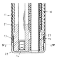
図3は、内視鏡10の可撓性挿入部11に外套シース20が被覆された状態の先端部分を示し、図1は、先端部本体13から先端キャップ22が外された状態を、被覆チューブ21を省略して示している。
【0022】
図3に示されるように、可撓性挿入部11に外套シース20が被覆された状態では、先端キャップ22の先端内面が先端部本体13の先端外面に密着し、外套シース20のチャンネルチューブ23が内視鏡10のガイドチャンネル17内に通されている。
【0023】
したがって、先端キャップ22は軸線周りに回転可能に先端部本体13に被嵌された状態になっているものの、その回転は、チャンネルチューブ23がガイドチャンネル17内に挿通されていることにより規制されている。
【0024】
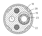
ただし、先端部本体13内においてチャンネルチューブ23が通過する部分には、IV−IV断面を図示する図4に示されるように、チャンネルチューブ23の先端近傍部が先端キャップ22の軸線周りに回動して変形(それは、ほぼ弾性変形である)可能なチャンネル変形空間19が形成されていて、チャンネルチューブ23がチャンネル変形空間19内で弾性変形する範囲で、先端キャップ22が先端部本体13の周りに回転することができる。
【0025】
また、図1等に示されるように、先端キャップ22と先端部本体13には、先端キャップ22内から先端部本体13が後方に抜け出すのを規制するための爪状部28と溝状部18からなる抜け止め機構が設けられている。
【0026】
この実施例においては、爪状部28は、先端キャップ22の内周面の4ヵ所にL字状に突出形成され、溝状部18は、爪状部28が係脱できるように先端部本体13の外周面の4ヵ所にL字状に窪んで形成されている。
【0027】
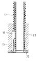
図5は、その爪状部28と溝状部18の係合状態を示しており、爪状部28の爪部分28aが溝状部18の段差部分18aに係合することにより、先端キャップ22と先端部本体13とが軸線方向に相対的に移動できない抜け止め状態になる。
【0028】
しかし、図4等にも示されるように、溝状部18が爪状部28より周方向に幅広に形成されているので、先端キャップ22を先端部本体13の周りに回転させることにより、図6に示されるように爪状部28の爪部分28aが溝状部18の段差部分18aから外れて、先端キャップ22内から後方に先端部本体13を抜き出すことができる抜け止め解除状態になる。
【0029】
このように構成された実施例の装置においては、外套シース20が可撓性挿入部11に被覆されて先端キャップ22に対して特別な荷重が加えられていない通常の状態では、図7に示されるように、チャンネルチューブ23がチャンネル変形空間19内において自己の弾性により先端キャップ22の軸線とほぼ平行に真っ直ぐになっていて、図5に示されるように、爪状部28が溝状部18に係合する抜け止め状態を維持している。
【0030】
そして、その状態から先端キャップ22を先端部本体13の周りに回転させると、それに追従して、図8に示されるようにチャンネル変形空間19内でチャンネルチューブ23が弾性変形しながら回動し、図6に示されるように爪状部28と溝状部18との係合が外れた抜け止め解除状態になって、可撓性挿入部11を外套シース20から後方に抜き出すことができる。
【0031】
なお、外套シース20を可撓性挿入部11に被覆する際には、爪状部28の先端の角部分が斜面状に形成されているので、爪状部28が溝状部18内にスムーズに導入される。
【0032】
また、その際には、チャンネルチューブ23がチャンネル変形空間19内において図8に示される弾性変形状態になるが、爪状部28と溝状部18との係合後は、チャンネルチューブ23が自己の弾性により図7に示される通常の真っ直ぐな状態に戻って、図5に示される抜け止め状態になる。
【0033】
なお、本発明は上記実施例に限定されるものではなく、例えばガイドチャンネル17が可撓性挿入部11内に挿通配置されずに、可撓性挿入部11の外表面から凹んだ溝状に形成されている装置等であっても、上述の実施例と同様に本発明を適用することができる。
【0034】
【発明の効果】
本発明によれば、可撓性挿入部の先端部分が外套シースの先端部分内から抜け出すのを規制するための抜け止め機構の係脱が、チャンネルチューブがチャンネル変形空間内において弾性変形する範囲で外套シースの先端部分を可撓性挿入部の先端部分に対して軸線周りに回転させることにより行われるので、部材を破損する恐れなく抜け止め機構を確実に係脱させることができる。
【図面の簡単な説明】
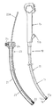
【図1】本発明の実施例の外套シース付内視鏡の可撓性挿入部から外套シースが外された状態を一部を省略して示す斜視図である。
【図2】本発明の実施例の外套シース付内視鏡の可撓性挿入部と外套シースとが分離された状態の側面一部断面図である。
【図3】本発明の実施例の外套シース付内視鏡の可撓性挿入部に外套シースが被覆された状態の先端部分の側面断面図である。
【図4】本発明の実施例の図3におけるIV−IV断面図である。
【図5】本発明の実施例の抜け止め機構の係合状態の側面断面図である。
【図6】本発明の実施例の抜け止め機構の解除状態の側面断面図である。
【図7】本発明の実施例の通常状態におけるチャンネル変形空間内のチャンネルチューブの状態を示す側面断面図である。
【図8】本発明の実施例の抜け止め機構を係脱させる際のチャンネル変形空間内のチャンネルチューブの状態を示す側面断面図である。
【符号の説明】
10 内視鏡
11 可撓性挿入部
13 先端部本体(先端部分)
17 ガイドチャンネル
18 溝状部(抜け止め機構)
18a 段差部分
19 チャンネル変形空間
20 外套シース
21 被覆チューブ
22 先端キャップ
23 チャンネルチューブ
28 爪状部(抜け止め機構)
28a 爪部分[0001]
BACKGROUND OF THE INVENTION
The present invention relates to an endoscope with a sheath sheath having a sheath sheath for preventing the flexible insertion portion of the endoscope from being contaminated.
[0002]
[Prior art]
In order to prevent infection between patients through an endoscope in an endoscopic examination, a flexible sheath of the endoscope is covered with a mantle sheath, and the mantle sheath is subjected to endoscopic examination. It should be replaced every time.
[0003]
In order to be able to use the treatment instrument during endoscopy, a channel tube for passing the treatment instrument is provided in the outer sheath, and the guide groove provided on the flexible insertion portion side is provided. A channel tube is configured to be threaded.
[0004]
In such an endoscope with a sheath, during the endoscopy, the distal end portion of the sheath sheath that is covered with the distal end portion of the flexible insertion portion where the observation window or the like is disposed is provided. It is necessary not to move.
[0005]
Therefore, conventionally, a retaining mechanism including a claw mechanism for restricting the distal end portion of the flexible insertion portion from being pulled backward from the distal end of the outer sheath is provided, and the flexible sheath is flexed from the outer sheath after the endoscopic examination is completed. When extracting the sexual insertion portion, the distal end member of the outer sheath formed in a cap shape is crushed from the outside and elastically deformed in the radial direction so as to disengage the claw mechanism (for example, Patent Document 1). Patent Document 2).
[0006]
[Patent Document 1]
Japanese Patent Laid-Open No. 3-1903023 [Patent Document 2]
Japanese Utility Model Publication No. 7-33301 [0007]
[Problems to be solved by the invention]
However, when the claw mechanism is disengaged, if the distal end member of the outer sheath formed in a cap shape is crushed from the outside and elastically deformed, the force may not be controlled and the engagement may not be disengaged. In other cases, the tip of the outer sheath may be damaged due to excessive force.
[0008]
Therefore, the present invention provides a sheath sheath with a sheath sheath that can securely and securely disengage a retaining mechanism for restricting the distal end portion of the flexible insertion portion from slipping out of the distal end portion of the sheath sheath. An object is to provide an endoscope.
[0009]
[Means for Solving the Problems]
In order to achieve the above object, an endoscope with a sheath sheath according to the present invention is configured such that a channel tube is inserted into a sheath sheath that is detachably covered by a flexible insertion portion of the endoscope so that the distal end of the channel tube is inserted. Is fixed to the distal end of the outer sheath, and a guide groove through which the channel tube is passed in the state where the outer sheath is covered by the flexible insertion portion is provided in the flexible insertion portion, and the distal end portion of the flexible insertion portion In an endoscope with a sheath sheath provided with a retaining mechanism for restricting the sheath from slipping out of the distal end portion of the outer sheath, the distal end portion of the outer sheath is arranged around the axis with respect to the distal end portion of the flexible insertion portion. The outer sheath is configured to be rotatable within a predetermined range, and is provided with a channel deformation space for rotating while elastically deforming the vicinity of the tip of the channel tube following the rotation operation. Retaining mechanism by rotating about the axis in a predetermined range is obtained so as to be disengaged with respect to the tip portion distal end portion of the flexible insertion portion.
[0010]
When the outer sheath is covered with the flexible insertion portion and no load is applied, the retaining mechanism is kept engaged by the elasticity of the channel tube, and the outer sheath is elastically deformed in the channel deformation space. The distal end portion of the flexible insertion portion is rotated within a predetermined range around the axis with respect to the distal end portion of the flexible insertion portion, whereby the engagement of the retaining mechanism is released and the distal end of the flexible insertion portion is inserted from within the distal end portion of the outer sheath. You may make it the state which can escape a part.
[0011]
A retaining mechanism is formed on the outer surface of the distal end portion of the flexible insertion portion, and on the inner surface of the distal end portion of the outer sheath so as to be detachable from the groove-shaped portion. You may have a nail | claw-shaped part.
[0012]
DETAILED DESCRIPTION OF THE INVENTION
Embodiments of the present invention will be described with reference to the drawings.
FIG. 2 shows an example of an
[0013]
A
[0014]
A
[0015]
The
[0016]
A
[0017]
The connecting
[0018]
A
[0019]
The distal end of the
[0020]
The
[0021]
FIG. 3 shows the distal end portion of the
[0022]
As shown in FIG. 3, in a state in which the
[0023]
Therefore, although the
[0024]
However, in the portion where the
[0025]
Further, as shown in FIG. 1 and the like, the
[0026]
In this embodiment, the claw-shaped
[0027]
FIG. 5 shows an engagement state between the claw-shaped
[0028]
However, as shown in FIG. 4 and the like, since the groove-shaped
[0029]
In the apparatus of the embodiment configured as described above, the
[0030]
Then, when the
[0031]
When the
[0032]
At this time, the
[0033]
In addition, this invention is not limited to the said Example, For example, the
[0034]
【The invention's effect】
According to the present invention, the engagement and disengagement of the retaining mechanism for restricting the distal end portion of the flexible insertion portion from slipping out of the distal end portion of the outer sheath is within the range where the channel tube is elastically deformed in the channel deformation space. Since the distal end portion of the sheath is rotated around the axis with respect to the distal end portion of the flexible insertion portion, the retaining mechanism can be reliably engaged and disengaged without fear of damaging the member.
[Brief description of the drawings]
FIG. 1 is a perspective view showing a state in which a mantle sheath has been removed from a flexible insertion portion of an endoscope with mantle sheath according to an embodiment of the present invention.
FIG. 2 is a partial cross-sectional side view of the endoscope with a sheath sheath according to the embodiment of the present invention in a state where the flexible insertion portion and the sheath are separated.
FIG. 3 is a side cross-sectional view of the distal end portion of the endoscope with a sheath sheath according to the embodiment of the present invention in a state where the sheath is covered on the flexible insertion portion.
4 is a cross-sectional view taken along the line IV-IV in FIG. 3 according to the embodiment of the present invention.
FIG. 5 is a side sectional view showing an engagement state of the retaining mechanism according to the embodiment of the present invention.
FIG. 6 is a side sectional view showing a released state of the retaining mechanism according to the embodiment of the present invention.
FIG. 7 is a side sectional view showing a state of the channel tube in the channel deformation space in the normal state according to the embodiment of the present invention.
FIG. 8 is a side sectional view showing a state of the channel tube in the channel deformation space when the retaining mechanism of the embodiment of the present invention is engaged and disengaged.
[Explanation of symbols]
DESCRIPTION OF
17
18a Stepped
28a Nail part
Claims (3)
上記外套シースの先端部分を上記可撓性挿入部の先端部分に対して軸線周りに所定の範囲で回転可能に構成すると共に、その回転動作に追従して上記チャンネルチューブの先端近傍部が弾性変形しながら回動するためのチャンネル変形空間を設け、上記外套シースの先端部分を上記可撓性挿入部の先端部分に対して軸線周りに上記所定の範囲で回転させることにより上記抜け止め機構が係脱されるようにしたことを特徴とする外套シース付内視鏡。A channel tube is inserted and disposed in an outer sheath that is detachably covered by the flexible insertion portion of the endoscope, and the distal end of the channel tube is fixed to the distal end of the outer sheath, and the outer sheath is the flexible sheath. A guide conduit through which the channel tube is passed in the state covered with the insertion portion is provided in the flexible insertion portion, and the distal end portion of the flexible insertion portion comes out of the distal end portion of the outer sheath. In an endoscope with a sheath sheath provided with a retaining mechanism for regulating
The distal end portion of the outer sheath is configured to be rotatable within a predetermined range around the axis with respect to the distal end portion of the flexible insertion portion, and the vicinity of the distal end of the channel tube is elastically deformed following the rotation operation. A channel deformation space is provided for rotation while rotating, and the distal end portion of the outer sheath is rotated within the predetermined range around the axis with respect to the distal end portion of the flexible insertion portion, whereby the retaining mechanism is engaged. An endoscope with a mantle sheath, characterized by being removed.
Priority Applications (2)
| Application Number | Priority Date | Filing Date | Title |
|---|---|---|---|
| JP2002296913A JP4131012B2 (en) | 2002-10-10 | 2002-10-10 | Endoscope with sheath |
| US10/681,155 US6921362B2 (en) | 2002-10-10 | 2003-10-09 | Outer sheathed endoscope |
Applications Claiming Priority (1)
| Application Number | Priority Date | Filing Date | Title |
|---|---|---|---|
| JP2002296913A JP4131012B2 (en) | 2002-10-10 | 2002-10-10 | Endoscope with sheath |
Publications (2)
| Publication Number | Publication Date |
|---|---|
| JP2004129813A JP2004129813A (en) | 2004-04-30 |
| JP4131012B2 true JP4131012B2 (en) | 2008-08-13 |
Family
ID=32089250
Family Applications (1)
| Application Number | Title | Priority Date | Filing Date |
|---|---|---|---|
| JP2002296913A Expired - Fee Related JP4131012B2 (en) | 2002-10-10 | 2002-10-10 | Endoscope with sheath |
Country Status (2)
| Country | Link |
|---|---|
| US (1) | US6921362B2 (en) |
| JP (1) | JP4131012B2 (en) |
Families Citing this family (127)
| Publication number | Priority date | Publication date | Assignee | Title |
|---|---|---|---|---|
| US6379334B1 (en) | 1997-02-10 | 2002-04-30 | Essex Technology, Inc. | Rotate advance catheterization system |
| WO2001023027A1 (en) | 1999-09-27 | 2001-04-05 | Essex Technology, Inc. | Rotate-to-advance catheterization system |
| US7478946B2 (en) | 2003-01-06 | 2009-01-20 | Covidien Ag | Probe cover cassette with improved probe cover support |
| US7686506B2 (en) | 2003-01-06 | 2010-03-30 | Covidien Ag | Stackable tympanic thermometer probe cover cassette |
| US7354194B2 (en) | 2003-01-06 | 2008-04-08 | Covidien Ag | Tympanic thermometer probe cover with film support mechanism |
| US7431694B2 (en) * | 2003-05-16 | 2008-10-07 | Ethicon Endo-Surgery, Inc. | Method of guiding medical devices |
| US7615003B2 (en) * | 2005-05-13 | 2009-11-10 | Ethicon Endo-Surgery, Inc. | Track for medical devices |
| JP2005334237A (en) * | 2004-05-26 | 2005-12-08 | Olympus Corp | Endoscope apparatus |
| WO2006063491A1 (en) * | 2004-12-14 | 2006-06-22 | Kerang Jiang | Endoscope system with a disposable sheath and method of use thereof |
| WO2006093976A1 (en) | 2005-02-28 | 2006-09-08 | Spirus Medical Inc. | Rotate-to-advance catheterization system |
| US8414477B2 (en) | 2005-05-04 | 2013-04-09 | Olympus Endo Technology America Inc. | Rotate-to-advance catheterization system |
| US7780650B2 (en) | 2005-05-04 | 2010-08-24 | Spirus Medical, Inc. | Rotate-to-advance catheterization system |
| US8235942B2 (en) | 2005-05-04 | 2012-08-07 | Olympus Endo Technology America Inc. | Rotate-to-advance catheterization system |
| US8343040B2 (en) | 2005-05-04 | 2013-01-01 | Olympus Endo Technology America Inc. | Rotate-to-advance catheterization system |
| US8317678B2 (en) | 2005-05-04 | 2012-11-27 | Olympus Endo Technology America Inc. | Rotate-to-advance catheterization system |
| US7905830B2 (en) | 2005-05-13 | 2011-03-15 | Ethicon Endo-Surgery, Inc. | Sheath for use with an endoscope |
| US7648457B2 (en) * | 2005-05-13 | 2010-01-19 | Ethicon Endo-Surgery, Inc. | Method of positioning a device on an endoscope |
| US20060258903A1 (en) * | 2005-05-13 | 2006-11-16 | David Stefanchik | Method of inserting a feeding tube |
| US20060258904A1 (en) * | 2005-05-13 | 2006-11-16 | David Stefanchik | Feeding tube and track |
| US7857754B2 (en) * | 2005-05-13 | 2010-12-28 | Ethicon Endo-Surgery, Inc. | Apparatus useful for positioning a device on an endoscope |
| US9439555B2 (en) * | 2005-05-20 | 2016-09-13 | Karl Storz Endovision, Inc. | Liner for endoscope working channel |
| NL1030539C2 (en) * | 2005-11-28 | 2007-05-30 | Intellectual Property Mvm B V | Shielding sleeve as well as an optical measuring device in which this shielding sleeve can be used. |
| US8574220B2 (en) | 2006-02-28 | 2013-11-05 | Olympus Endo Technology America Inc. | Rotate-to-advance catheterization system |
| US8435229B2 (en) | 2006-02-28 | 2013-05-07 | Olympus Endo Technology America Inc. | Rotate-to-advance catheterization system |
| US20070248141A1 (en) * | 2006-04-21 | 2007-10-25 | Sherwood Services Ag | Infrared thermometer and probe cover thereof |
| US7556424B2 (en) * | 2006-05-19 | 2009-07-07 | Covidien Ag | Tympanic thermometer prove cover cassette and holder |
| US8870755B2 (en) | 2007-05-18 | 2014-10-28 | Olympus Endo Technology America Inc. | Rotate-to-advance catheterization system |
| US9050036B2 (en) | 2007-06-19 | 2015-06-09 | Minimally Invasive Devices, Inc. | Device for maintaining visualization with surgical scopes |
| US20090048486A1 (en) * | 2007-08-08 | 2009-02-19 | Wilson-Cook Medical Inc. | Distal Tip for an Endoscope |
| AU2009325140A1 (en) | 2008-12-10 | 2011-06-30 | Minimally Invasive Devices, Inc | Systems and methods for optimizing and maintaining visualization of a surgical field during the use of surgical scopes |
| USD613403S1 (en) * | 2008-12-10 | 2010-04-06 | Minimally Invasive Devices, Llc | Sheath tip for maintaining surgical scope visualization |
| US9254123B2 (en) | 2009-04-29 | 2016-02-09 | Hansen Medical, Inc. | Flexible and steerable elongate instruments with shape control and support elements |
| US9492063B2 (en) | 2009-06-18 | 2016-11-15 | Endochoice Innovation Center Ltd. | Multi-viewing element endoscope |
| US9713417B2 (en) | 2009-06-18 | 2017-07-25 | Endochoice, Inc. | Image capture assembly for use in a multi-viewing elements endoscope |
| US10524645B2 (en) | 2009-06-18 | 2020-01-07 | Endochoice, Inc. | Method and system for eliminating image motion blur in a multiple viewing elements endoscope |
| US9402533B2 (en) | 2011-03-07 | 2016-08-02 | Endochoice Innovation Center Ltd. | Endoscope circuit board assembly |
| US10165929B2 (en) | 2009-06-18 | 2019-01-01 | Endochoice, Inc. | Compact multi-viewing element endoscope system |
| US9706903B2 (en) | 2009-06-18 | 2017-07-18 | Endochoice, Inc. | Multiple viewing elements endoscope system with modular imaging units |
| US11547275B2 (en) | 2009-06-18 | 2023-01-10 | Endochoice, Inc. | Compact multi-viewing element endoscope system |
| US8926502B2 (en) | 2011-03-07 | 2015-01-06 | Endochoice, Inc. | Multi camera endoscope having a side service channel |
| US9901244B2 (en) | 2009-06-18 | 2018-02-27 | Endochoice, Inc. | Circuit board assembly of a multiple viewing elements endoscope |
| US11278190B2 (en) | 2009-06-18 | 2022-03-22 | Endochoice, Inc. | Multi-viewing element endoscope |
| US9101268B2 (en) | 2009-06-18 | 2015-08-11 | Endochoice Innovation Center Ltd. | Multi-camera endoscope |
| EP2442706B1 (en) | 2009-06-18 | 2014-11-12 | EndoChoice Innovation Center Ltd. | Multi-camera endoscope |
| US20140296866A1 (en) * | 2009-06-18 | 2014-10-02 | Endochoice, Inc. | Multiple Viewing Elements Endoscope Having Two Front Service Channels |
| US9101287B2 (en) | 2011-03-07 | 2015-08-11 | Endochoice Innovation Center Ltd. | Multi camera endoscope assembly having multiple working channels |
| US9474440B2 (en) | 2009-06-18 | 2016-10-25 | Endochoice, Inc. | Endoscope tip position visual indicator and heat management system |
| US11864734B2 (en) | 2009-06-18 | 2024-01-09 | Endochoice, Inc. | Multi-camera endoscope |
| US9642513B2 (en) | 2009-06-18 | 2017-05-09 | Endochoice Inc. | Compact multi-viewing element endoscope system |
| US9872609B2 (en) | 2009-06-18 | 2018-01-23 | Endochoice Innovation Center Ltd. | Multi-camera endoscope |
| US12137873B2 (en) | 2009-06-18 | 2024-11-12 | Endochoice, Inc. | Compact multi-viewing element endoscope system |
| US20110061659A1 (en) * | 2009-09-17 | 2011-03-17 | Julian Cruzada | Minimally invasive delivery devices and methods |
| US9078562B2 (en) | 2010-01-11 | 2015-07-14 | Minimally Invasive Devices, Inc. | Systems and methods for optimizing and maintaining visualization of a surgical field during the use of surgical scopes |
| WO2011124149A1 (en) * | 2010-04-09 | 2011-10-13 | 姜守美 | Disposable protection assembly for endoscope |
| CN101810463B (en) * | 2010-04-12 | 2011-12-28 | 飞秒光电科技(西安)有限公司 | Disinfection-free portable ear examination endoscope |
| CN101810462B (en) * | 2010-04-12 | 2012-10-17 | 飞秒光电科技(西安)有限公司 | Disposable sleeves for ear examination endoscope and nose and throat examination endoscope |
| US12220105B2 (en) | 2010-06-16 | 2025-02-11 | Endochoice, Inc. | Circuit board assembly of a multiple viewing elements endoscope |
| WO2012019023A1 (en) | 2010-08-04 | 2012-02-09 | Minimally Invasive Devices, Llc | Systems and methods for optimizing and maintaining visualization of a surgical field during the use of surgical scopes |
| US20120191107A1 (en) | 2010-09-17 | 2012-07-26 | Tanner Neal A | Systems and methods for positioning an elongate member inside a body |
| US10080486B2 (en) | 2010-09-20 | 2018-09-25 | Endochoice Innovation Center Ltd. | Multi-camera endoscope having fluid channels |
| US9560953B2 (en) | 2010-09-20 | 2017-02-07 | Endochoice, Inc. | Operational interface in a multi-viewing element endoscope |
| US10663714B2 (en) | 2010-10-28 | 2020-05-26 | Endochoice, Inc. | Optical system for an endoscope |
| US12204087B2 (en) | 2010-10-28 | 2025-01-21 | Endochoice, Inc. | Optical systems for multi-sensor endoscopes |
| US9706908B2 (en) | 2010-10-28 | 2017-07-18 | Endochoice, Inc. | Image capture and video processing systems and methods for multiple viewing element endoscopes |
| JP5944912B2 (en) | 2010-10-28 | 2016-07-05 | エンドチョイス イノベーション センター リミテッド | Optical system for multi-sensor endoscope |
| WO2012075487A2 (en) | 2010-12-03 | 2012-06-07 | Minimally Invasive Devices, Llc | Devices, systems, and methods for performing endoscopic surgical procedures |
| EP2648602B1 (en) | 2010-12-09 | 2018-07-18 | EndoChoice Innovation Center Ltd. | Flexible electronic circuit board multi-camera endoscope |
| EP3522215A1 (en) | 2010-12-09 | 2019-08-07 | EndoChoice Innovation Center Ltd. | Flexible electronic circuit board for a multi-camera endoscope |
| US11889986B2 (en) | 2010-12-09 | 2024-02-06 | Endochoice, Inc. | Flexible electronic circuit board for a multi-camera endoscope |
| US10517464B2 (en) | 2011-02-07 | 2019-12-31 | Endochoice, Inc. | Multi-element cover for a multi-camera endoscope |
| CN103491854B (en) | 2011-02-07 | 2016-08-24 | 恩多卓斯创新中心有限公司 | Multicomponent cover for many cameras endoscope |
| US20130030363A1 (en) | 2011-07-29 | 2013-01-31 | Hansen Medical, Inc. | Systems and methods utilizing shape sensing fibers |
| CA2798729A1 (en) | 2011-12-13 | 2013-06-13 | Peermedical Ltd. | Rotatable connector for an endoscope |
| CA2798716A1 (en) | 2011-12-13 | 2013-06-13 | Peermedical Ltd. | Removable tip endoscope |
| US9560954B2 (en) | 2012-07-24 | 2017-02-07 | Endochoice, Inc. | Connector for use with endoscope |
| US10149720B2 (en) | 2013-03-08 | 2018-12-11 | Auris Health, Inc. | Method, apparatus, and a system for facilitating bending of an instrument in a surgical or medical robotic environment |
| WO2014151824A1 (en) | 2013-03-14 | 2014-09-25 | Minimally Invasive Devices, Inc. | Fluid dispensing control systems and methods |
| US10376672B2 (en) | 2013-03-15 | 2019-08-13 | Auris Health, Inc. | Catheter insertion system and method of fabrication |
| US10595714B2 (en) | 2013-03-28 | 2020-03-24 | Endochoice, Inc. | Multi-jet controller for an endoscope |
| US9636003B2 (en) | 2013-06-28 | 2017-05-02 | Endochoice, Inc. | Multi-jet distributor for an endoscope |
| US9986899B2 (en) | 2013-03-28 | 2018-06-05 | Endochoice, Inc. | Manifold for a multiple viewing elements endoscope |
| US9993142B2 (en) | 2013-03-28 | 2018-06-12 | Endochoice, Inc. | Fluid distribution device for a multiple viewing elements endoscope |
| US12207796B2 (en) | 2013-03-28 | 2025-01-28 | Endochoice Inc. | Multi-jet controller for an endoscope |
| US9667935B2 (en) | 2013-05-07 | 2017-05-30 | Endochoice, Inc. | White balance enclosure for use with a multi-viewing elements endoscope |
| US10499794B2 (en) | 2013-05-09 | 2019-12-10 | Endochoice, Inc. | Operational interface in a multi-viewing element endoscope |
| JP6466412B2 (en) * | 2013-05-17 | 2019-02-06 | エンドチョイス インコーポレイテッドEndochoice, Inc. | Multiple view element endoscope with two forward service channels |
| US10064541B2 (en) | 2013-08-12 | 2018-09-04 | Endochoice, Inc. | Endoscope connector cover detection and warning system |
| US9943218B2 (en) | 2013-10-01 | 2018-04-17 | Endochoice, Inc. | Endoscope having a supply cable attached thereto |
| WO2015061756A1 (en) | 2013-10-24 | 2015-04-30 | Auris Surgical Robotics, Inc. | System for robotic-assisted endolumenal surgery and related methods |
| US9968242B2 (en) | 2013-12-18 | 2018-05-15 | Endochoice, Inc. | Suction control unit for an endoscope having two working channels |
| WO2015112747A2 (en) | 2014-01-22 | 2015-07-30 | Endochoice, Inc. | Image capture and video processing systems and methods for multiple viewing element endoscopes |
| WO2015174445A1 (en) * | 2014-05-15 | 2015-11-19 | オリンパス株式会社 | Fixing mechanism and endoscope having fixing mechanism |
| US9744335B2 (en) | 2014-07-01 | 2017-08-29 | Auris Surgical Robotics, Inc. | Apparatuses and methods for monitoring tendons of steerable catheters |
| US10792464B2 (en) | 2014-07-01 | 2020-10-06 | Auris Health, Inc. | Tool and method for using surgical endoscope with spiral lumens |
| US9561083B2 (en) | 2014-07-01 | 2017-02-07 | Auris Surgical Robotics, Inc. | Articulating flexible endoscopic tool with roll capabilities |
| CN106659368B (en) | 2014-07-21 | 2020-04-17 | 恩多巧爱思股份有限公司 | Multi-focus and multi-camera endoscope system |
| JP6665164B2 (en) | 2014-08-29 | 2020-03-13 | エンドチョイス インコーポレイテッドEndochoice, Inc. | Endoscope assembly |
| WO2016100173A1 (en) | 2014-12-18 | 2016-06-23 | Endochoice, Inc. | System and method for processing video images generated by a multiple viewing elements endoscope |
| WO2016103876A1 (en) * | 2014-12-24 | 2016-06-30 | オリンパス株式会社 | Insertion device |
| US10376181B2 (en) | 2015-02-17 | 2019-08-13 | Endochoice, Inc. | System for detecting the location of an endoscopic device during a medical procedure |
| CN106659359B (en) | 2015-03-18 | 2018-07-13 | 奥林巴斯株式会社 | Endoscope |
| US10078207B2 (en) | 2015-03-18 | 2018-09-18 | Endochoice, Inc. | Systems and methods for image magnification using relative movement between an image sensor and a lens assembly |
| US11819636B2 (en) | 2015-03-30 | 2023-11-21 | Auris Health, Inc. | Endoscope pull wire electrical circuit |
| US10401611B2 (en) | 2015-04-27 | 2019-09-03 | Endochoice, Inc. | Endoscope with integrated measurement of distance to objects of interest |
| EP3539453A1 (en) * | 2015-07-21 | 2019-09-18 | GI Scientific LLC | Endoscope accessory with angularly adjustable exit portal |
| CN114795472B (en) | 2015-10-28 | 2024-11-08 | 安多卓思公司 | Apparatus and method for tracking the position of an endoscope within a patient's body |
| EP4579310A3 (en) | 2015-11-24 | 2025-09-10 | Endochoice, Inc. | Disposable air/water and suction valves for an endoscope |
| CN105662327A (en) * | 2016-01-29 | 2016-06-15 | 姜克让 | Jacketed endoscope |
| CN109068951A (en) | 2016-02-24 | 2018-12-21 | 安多卓思公司 | For using the circuit board assemblies of more observation element endoscopes of cmos sensor |
| US10292570B2 (en) | 2016-03-14 | 2019-05-21 | Endochoice, Inc. | System and method for guiding and tracking a region of interest using an endoscope |
| US10993605B2 (en) | 2016-06-21 | 2021-05-04 | Endochoice, Inc. | Endoscope system with multiple connection interfaces to interface with different video data signal sources |
| US10463439B2 (en) | 2016-08-26 | 2019-11-05 | Auris Health, Inc. | Steerable catheter with shaft load distributions |
| WO2018106787A1 (en) * | 2016-12-07 | 2018-06-14 | Boston Scientific Scimed, Inc. | Systems for eccentric nodule tissue acquisition |
| CN113812986B (en) * | 2016-12-07 | 2025-10-28 | 波士顿科学国际有限公司 | System for real-time visualization of biopsy needles and target tissue |
| EP3624668A4 (en) * | 2017-05-17 | 2021-05-26 | Auris Health, Inc. | EXCHANGEABLE WORK CHANNEL |
| EP4344723A3 (en) | 2018-03-28 | 2024-06-12 | Auris Health, Inc. | Medical instruments with variable bending stiffness profiles |
| KR102612146B1 (en) | 2018-08-07 | 2023-12-13 | 아우리스 헬스, 인코포레이티드 | Combination of strain-based shape detection with catheter control |
| EP4403117A3 (en) * | 2018-09-24 | 2024-09-25 | Boston Scientific Scimed, Inc. | Multiple channel flexible ureteroscope |
| CN112804933B (en) | 2018-09-26 | 2024-10-18 | 奥瑞斯健康公司 | Joint motion medical device |
| US10709317B2 (en) * | 2018-10-04 | 2020-07-14 | PraesidioDyne, LLC | Clamp assembly for disposable endoscopic sheaths |
| EP3870023A4 (en) | 2018-12-28 | 2022-07-27 | Auris Health, Inc. | Medical instrument with articulable segment |
| US12096915B2 (en) * | 2019-03-11 | 2024-09-24 | Gyrus Acmi, Inc. | Sheath location indicator and overextension preventer |
| US11617627B2 (en) | 2019-03-29 | 2023-04-04 | Auris Health, Inc. | Systems and methods for optical strain sensing in medical instruments |
| EP4013285A4 (en) | 2019-08-15 | 2023-11-22 | Auris Health, Inc. | Medical device having multiple bending sections |
| US12042128B2 (en) * | 2019-11-26 | 2024-07-23 | Karl Storz Se & Co. Kg | Endoscope device for a flexible endoscope, and method for producing an endoscope device |
| EP4084717A4 (en) | 2019-12-31 | 2024-02-14 | Auris Health, Inc. | Dynamic pulley system |
| JP2023522171A (en) * | 2020-04-10 | 2023-05-29 | ボストン サイエンティフィック サイムド,インコーポレイテッド | Distal tip of medical device |
Family Cites Families (17)
| Publication number | Priority date | Publication date | Assignee | Title |
|---|---|---|---|---|
| JPH01244732A (en) | 1988-03-28 | 1989-09-29 | Asahi Optical Co Ltd | Endoscope with sheath |
| US5193263A (en) | 1989-07-19 | 1993-03-16 | Asahi Kogaku Kogyo Kabushiki Kaisha | Method of securing skin tube to bendable tube portion of endoscope |
| JP2756706B2 (en) | 1989-07-19 | 1998-05-25 | 旭光学工業株式会社 | Method and fixture for fixing outer tube of curved tube section of endoscope |
| US5257617A (en) | 1989-12-25 | 1993-11-02 | Asahi Kogaku Kogyo Kabushiki Kaisha | Sheathed endoscope and sheath therefor |
| JP2802952B2 (en) | 1989-12-25 | 1998-09-24 | 旭光学工業株式会社 | Endoscope endoscope with sheath |
| JPH0713682Y2 (en) * | 1990-02-01 | 1995-04-05 | 株式会社町田製作所 | Endoscope cover locking structure |
| US5359991A (en) | 1991-04-24 | 1994-11-01 | Asahi Kogaku Kogyo Kabushiki Kaisha | Cover device for endoscope |
| JP2586297B2 (en) | 1993-07-22 | 1997-02-26 | 双葉電子工業株式会社 | Mandrel control device |
| US5725477A (en) * | 1993-11-18 | 1998-03-10 | Asahi Kogaku Kogyo Kabushiki Kaisha | Front end structure of endoscope |
| US5685823A (en) | 1994-03-30 | 1997-11-11 | Asahi Kogaku Kogyo Kabushiki Kaisha | End structure of endoscope |
| US5782751A (en) | 1994-05-26 | 1998-07-21 | Asahi Kogaku Kogyo Kabushiki Kaisha | Side view endoscope |
| US5788628A (en) | 1994-05-26 | 1998-08-04 | Asahi Kogaku Kogyo Kabushiki Kaisha | Endoscope |
| JP3379821B2 (en) * | 1994-05-31 | 2003-02-24 | オリンパス光学工業株式会社 | Endoscope |
| JPH08182648A (en) * | 1994-12-27 | 1996-07-16 | Olympus Optical Co Ltd | Endoscope with detachable front end cover |
| JP3490817B2 (en) | 1995-03-13 | 2004-01-26 | ペンタックス株式会社 | Endoscope tip |
| US5868663A (en) | 1996-03-26 | 1999-02-09 | Asahi Kogaku Kogyo Kabushiki Kaisha | Front end structure of side-view type endoscope |
| US5865726A (en) | 1996-03-27 | 1999-02-02 | Asahi Kogaku Kogyo Kabushiki Kaisha | Front end structure of side-view type endoscope |
-
2002
- 2002-10-10 JP JP2002296913A patent/JP4131012B2/en not_active Expired - Fee Related
-
2003
- 2003-10-09 US US10/681,155 patent/US6921362B2/en not_active Expired - Fee Related
Also Published As
| Publication number | Publication date |
|---|---|
| US6921362B2 (en) | 2005-07-26 |
| US20040077927A1 (en) | 2004-04-22 |
| JP2004129813A (en) | 2004-04-30 |
Similar Documents
| Publication | Publication Date | Title |
|---|---|---|
| JP4131012B2 (en) | Endoscope with sheath | |
| US6852078B2 (en) | Outer sheathed endoscope | |
| RU2738782C1 (en) | Device for fixing endoscope tip | |
| EP3329833B1 (en) | Duodenoscope protected with disposable consumables | |
| CA2324296A1 (en) | Anchoring and positioning device and method for an endoscope | |
| JP2003325431A (en) | Endoscope insertion tube flexible tube | |
| US20190246881A1 (en) | Disposable Protective Sheath for Endoscope | |
| JP4199560B2 (en) | Endoscope with sheath | |
| JP2024060094A (en) | Device sending tools and systems | |
| JP4338300B2 (en) | Endoscopic treatment tool | |
| JP4014847B2 (en) | Anti-contamination endoscope | |
| WO2001000080A3 (en) | Safety sheaths for endoscopes | |
| JP4311958B2 (en) | Endoscope with sheath | |
| KR102359218B1 (en) | needle shield remover | |
| JP4475719B2 (en) | Endoscope forceps plug | |
| JP3204367U (en) | Infection prevention sheath for endoscope | |
| JP2005230084A (en) | Balloon attaching tool | |
| JP3620574B2 (en) | Endoscope mouthpiece | |
| JP4135884B2 (en) | Endoscope with sheath | |
| JP3934408B2 (en) | Endoscope contamination prevention device | |
| JP3869700B2 (en) | Endoscope with sheath | |
| JP3989773B2 (en) | Endoscope with sheath | |
| JP3992820B2 (en) | Endoscope forceps plug | |
| JP4087156B2 (en) | Endoscope | |
| JP3911151B2 (en) | Endoscope contamination prevention device |
Legal Events
| Date | Code | Title | Description |
|---|---|---|---|
| A621 | Written request for application examination |
Free format text: JAPANESE INTERMEDIATE CODE: A621 Effective date: 20050802 |
|
| A977 | Report on retrieval |
Free format text: JAPANESE INTERMEDIATE CODE: A971007 Effective date: 20080122 |
|
| A131 | Notification of reasons for refusal |
Free format text: JAPANESE INTERMEDIATE CODE: A131 Effective date: 20080124 |
|
| A521 | Request for written amendment filed |
Free format text: JAPANESE INTERMEDIATE CODE: A523 Effective date: 20080312 |
|
| TRDD | Decision of grant or rejection written | ||
| A01 | Written decision to grant a patent or to grant a registration (utility model) |
Free format text: JAPANESE INTERMEDIATE CODE: A01 Effective date: 20080410 |
|
| A01 | Written decision to grant a patent or to grant a registration (utility model) |
Free format text: JAPANESE INTERMEDIATE CODE: A01 |
|
| A711 | Notification of change in applicant |
Free format text: JAPANESE INTERMEDIATE CODE: A712 Effective date: 20080430 |
|
| A61 | First payment of annual fees (during grant procedure) |
Free format text: JAPANESE INTERMEDIATE CODE: A61 Effective date: 20080509 |
|
| FPAY | Renewal fee payment (event date is renewal date of database) |
Free format text: PAYMENT UNTIL: 20110606 Year of fee payment: 3 |
|
| R150 | Certificate of patent or registration of utility model |
Free format text: JAPANESE INTERMEDIATE CODE: R150 |
|
| LAPS | Cancellation because of no payment of annual fees |