JP2017511707A - Sensorless force control for transesophageal echocardiography probe - Google Patents
Sensorless force control for transesophageal echocardiography probe Download PDFInfo
- Publication number
- JP2017511707A JP2017511707A JP2016547081A JP2016547081A JP2017511707A JP 2017511707 A JP2017511707 A JP 2017511707A JP 2016547081 A JP2016547081 A JP 2016547081A JP 2016547081 A JP2016547081 A JP 2016547081A JP 2017511707 A JP2017511707 A JP 2017511707A
- Authority
- JP
- Japan
- Prior art keywords
- motor
- robot
- actuation
- drive gear
- motor drive
- Prior art date
- Legal status (The legal status is an assumption and is not a legal conclusion. Google has not performed a legal analysis and makes no representation as to the accuracy of the status listed.)
- Pending
Links
Images


Classifications
-
- A—HUMAN NECESSITIES
- A61—MEDICAL OR VETERINARY SCIENCE; HYGIENE
- A61B—DIAGNOSIS; SURGERY; IDENTIFICATION
- A61B1/00—Instruments for performing medical examinations of the interior of cavities or tubes of the body by visual or photographical inspection, e.g. endoscopes; Illuminating arrangements therefor
- A61B1/00002—Operational features of endoscopes
- A61B1/00039—Operational features of endoscopes provided with input arrangements for the user
-
- A—HUMAN NECESSITIES
- A61—MEDICAL OR VETERINARY SCIENCE; HYGIENE
- A61B—DIAGNOSIS; SURGERY; IDENTIFICATION
- A61B1/00—Instruments for performing medical examinations of the interior of cavities or tubes of the body by visual or photographical inspection, e.g. endoscopes; Illuminating arrangements therefor
- A61B1/005—Flexible endoscopes
- A61B1/0051—Flexible endoscopes with controlled bending of insertion part
- A61B1/0052—Constructional details of control elements, e.g. handles
-
- A—HUMAN NECESSITIES
- A61—MEDICAL OR VETERINARY SCIENCE; HYGIENE
- A61B—DIAGNOSIS; SURGERY; IDENTIFICATION
- A61B1/00—Instruments for performing medical examinations of the interior of cavities or tubes of the body by visual or photographical inspection, e.g. endoscopes; Illuminating arrangements therefor
- A61B1/00002—Operational features of endoscopes
- A61B1/00039—Operational features of endoscopes provided with input arrangements for the user
- A61B1/00042—Operational features of endoscopes provided with input arrangements for the user for mechanical operation
-
- A—HUMAN NECESSITIES
- A61—MEDICAL OR VETERINARY SCIENCE; HYGIENE
- A61B—DIAGNOSIS; SURGERY; IDENTIFICATION
- A61B1/00—Instruments for performing medical examinations of the interior of cavities or tubes of the body by visual or photographical inspection, e.g. endoscopes; Illuminating arrangements therefor
- A61B1/00002—Operational features of endoscopes
- A61B1/00057—Operational features of endoscopes provided with means for testing or calibration
-
- A—HUMAN NECESSITIES
- A61—MEDICAL OR VETERINARY SCIENCE; HYGIENE
- A61B—DIAGNOSIS; SURGERY; IDENTIFICATION
- A61B1/00—Instruments for performing medical examinations of the interior of cavities or tubes of the body by visual or photographical inspection, e.g. endoscopes; Illuminating arrangements therefor
- A61B1/00147—Holding or positioning arrangements
- A61B1/0016—Holding or positioning arrangements using motor drive units
-
- A—HUMAN NECESSITIES
- A61—MEDICAL OR VETERINARY SCIENCE; HYGIENE
- A61B—DIAGNOSIS; SURGERY; IDENTIFICATION
- A61B1/00—Instruments for performing medical examinations of the interior of cavities or tubes of the body by visual or photographical inspection, e.g. endoscopes; Illuminating arrangements therefor
- A61B1/31—Instruments for performing medical examinations of the interior of cavities or tubes of the body by visual or photographical inspection, e.g. endoscopes; Illuminating arrangements therefor for the rectum, e.g. proctoscopes, sigmoidoscopes, colonoscopes
-
- A—HUMAN NECESSITIES
- A61—MEDICAL OR VETERINARY SCIENCE; HYGIENE
- A61B—DIAGNOSIS; SURGERY; IDENTIFICATION
- A61B34/00—Computer-aided surgery; Manipulators or robots specially adapted for use in surgery
- A61B34/30—Surgical robots
-
- A—HUMAN NECESSITIES
- A61—MEDICAL OR VETERINARY SCIENCE; HYGIENE
- A61B—DIAGNOSIS; SURGERY; IDENTIFICATION
- A61B34/00—Computer-aided surgery; Manipulators or robots specially adapted for use in surgery
- A61B34/30—Surgical robots
- A61B34/37—Master-slave robots
-
- A—HUMAN NECESSITIES
- A61—MEDICAL OR VETERINARY SCIENCE; HYGIENE
- A61B—DIAGNOSIS; SURGERY; IDENTIFICATION
- A61B8/00—Diagnosis using ultrasonic, sonic or infrasonic waves
- A61B8/08—Detecting organic movements or changes, e.g. tumours, cysts, swellings
- A61B8/0883—Detecting organic movements or changes, e.g. tumours, cysts, swellings for diagnosis of the heart
-
- A—HUMAN NECESSITIES
- A61—MEDICAL OR VETERINARY SCIENCE; HYGIENE
- A61B—DIAGNOSIS; SURGERY; IDENTIFICATION
- A61B8/00—Diagnosis using ultrasonic, sonic or infrasonic waves
- A61B8/12—Diagnosis using ultrasonic, sonic or infrasonic waves in body cavities or body tracts, e.g. by using catheters
-
- A—HUMAN NECESSITIES
- A61—MEDICAL OR VETERINARY SCIENCE; HYGIENE
- A61M—DEVICES FOR INTRODUCING MEDIA INTO, OR ONTO, THE BODY; DEVICES FOR TRANSDUCING BODY MEDIA OR FOR TAKING MEDIA FROM THE BODY; DEVICES FOR PRODUCING OR ENDING SLEEP OR STUPOR
- A61M25/00—Catheters; Hollow probes
- A61M25/01—Introducing, guiding, advancing, emplacing or holding catheters
- A61M25/0105—Steering means as part of the catheter or advancing means; Markers for positioning
- A61M25/0116—Steering means as part of the catheter or advancing means; Markers for positioning self-propelled, e.g. autonomous robots
-
- A—HUMAN NECESSITIES
- A61—MEDICAL OR VETERINARY SCIENCE; HYGIENE
- A61M—DEVICES FOR INTRODUCING MEDIA INTO, OR ONTO, THE BODY; DEVICES FOR TRANSDUCING BODY MEDIA OR FOR TAKING MEDIA FROM THE BODY; DEVICES FOR PRODUCING OR ENDING SLEEP OR STUPOR
- A61M25/00—Catheters; Hollow probes
- A61M25/01—Introducing, guiding, advancing, emplacing or holding catheters
- A61M25/09—Guide wires
- A61M25/09041—Mechanisms for insertion of guide wires
-
- B—PERFORMING OPERATIONS; TRANSPORTING
- B25—HAND TOOLS; PORTABLE POWER-DRIVEN TOOLS; MANIPULATORS
- B25J—MANIPULATORS; CHAMBERS PROVIDED WITH MANIPULATION DEVICES
- B25J9/00—Programme-controlled manipulators
- B25J9/16—Programme controls
- B25J9/1628—Programme controls characterised by the control loop
- B25J9/1633—Programme controls characterised by the control loop compliant, force, torque control, e.g. combined with position control
-
- B—PERFORMING OPERATIONS; TRANSPORTING
- B25—HAND TOOLS; PORTABLE POWER-DRIVEN TOOLS; MANIPULATORS
- B25J—MANIPULATORS; CHAMBERS PROVIDED WITH MANIPULATION DEVICES
- B25J9/00—Programme-controlled manipulators
- B25J9/16—Programme controls
- B25J9/1679—Programme controls characterised by the tasks executed
- B25J9/1692—Calibration of manipulator
-
- A—HUMAN NECESSITIES
- A61—MEDICAL OR VETERINARY SCIENCE; HYGIENE
- A61B—DIAGNOSIS; SURGERY; IDENTIFICATION
- A61B1/00—Instruments for performing medical examinations of the interior of cavities or tubes of the body by visual or photographical inspection, e.g. endoscopes; Illuminating arrangements therefor
- A61B1/00002—Operational features of endoscopes
- A61B1/00004—Operational features of endoscopes characterised by electronic signal processing
- A61B1/00006—Operational features of endoscopes characterised by electronic signal processing of control signals
-
- A—HUMAN NECESSITIES
- A61—MEDICAL OR VETERINARY SCIENCE; HYGIENE
- A61B—DIAGNOSIS; SURGERY; IDENTIFICATION
- A61B1/00—Instruments for performing medical examinations of the interior of cavities or tubes of the body by visual or photographical inspection, e.g. endoscopes; Illuminating arrangements therefor
- A61B1/00064—Constructional details of the endoscope body
- A61B1/00066—Proximal part of endoscope body, e.g. handles
-
- A—HUMAN NECESSITIES
- A61—MEDICAL OR VETERINARY SCIENCE; HYGIENE
- A61B—DIAGNOSIS; SURGERY; IDENTIFICATION
- A61B1/00—Instruments for performing medical examinations of the interior of cavities or tubes of the body by visual or photographical inspection, e.g. endoscopes; Illuminating arrangements therefor
- A61B1/005—Flexible endoscopes
- A61B1/0051—Flexible endoscopes with controlled bending of insertion part
-
- A—HUMAN NECESSITIES
- A61—MEDICAL OR VETERINARY SCIENCE; HYGIENE
- A61B—DIAGNOSIS; SURGERY; IDENTIFICATION
- A61B17/00—Surgical instruments, devices or methods, e.g. tourniquets
- A61B2017/00681—Aspects not otherwise provided for
- A61B2017/00725—Calibration or performance testing
-
- A—HUMAN NECESSITIES
- A61—MEDICAL OR VETERINARY SCIENCE; HYGIENE
- A61B—DIAGNOSIS; SURGERY; IDENTIFICATION
- A61B34/00—Computer-aided surgery; Manipulators or robots specially adapted for use in surgery
- A61B34/30—Surgical robots
- A61B2034/301—Surgical robots for introducing or steering flexible instruments inserted into the body, e.g. catheters or endoscopes
-
- A—HUMAN NECESSITIES
- A61—MEDICAL OR VETERINARY SCIENCE; HYGIENE
- A61B—DIAGNOSIS; SURGERY; IDENTIFICATION
- A61B90/00—Instruments, implements or accessories specially adapted for surgery or diagnosis and not covered by any of the groups A61B1/00 - A61B50/00, e.g. for luxation treatment or for protecting wound edges
- A61B90/06—Measuring instruments not otherwise provided for
- A61B2090/064—Measuring instruments not otherwise provided for for measuring force, pressure or mechanical tension
- A61B2090/065—Measuring instruments not otherwise provided for for measuring force, pressure or mechanical tension for measuring contact or contact pressure
Landscapes
- Health & Medical Sciences (AREA)
- Life Sciences & Earth Sciences (AREA)
- Surgery (AREA)
- Engineering & Computer Science (AREA)
- Public Health (AREA)
- Veterinary Medicine (AREA)
- Animal Behavior & Ethology (AREA)
- General Health & Medical Sciences (AREA)
- Biomedical Technology (AREA)
- Heart & Thoracic Surgery (AREA)
- Nuclear Medicine, Radiotherapy & Molecular Imaging (AREA)
- Medical Informatics (AREA)
- Molecular Biology (AREA)
- Biophysics (AREA)
- Pathology (AREA)
- Radiology & Medical Imaging (AREA)
- Physics & Mathematics (AREA)
- Optics & Photonics (AREA)
- Robotics (AREA)
- Mechanical Engineering (AREA)
- Pulmonology (AREA)
- Anesthesiology (AREA)
- Hematology (AREA)
- Cardiology (AREA)
- Manipulator (AREA)
- Ultra Sonic Daignosis Equipment (AREA)
- Endoscopes (AREA)
Abstract
ケーブル駆動される遠位端(例えば、プローブ、ステア可能なカテーテル、ガイドワイヤ及び結腸内視鏡)を有する介入ツール14のセンサレス力制御のためのロボットアクチュエーションシステムが提供される。システムは、1又は複数のモータ駆動ギアに、介入ツール14のケーブル駆動を操作させるロボットアクチュエータ30を用いる。システムは更に、介入ツール14のアクチュエーション位置及び接触力の同時制御のためのモータコマンドを生成するために、ロボットワークステーション20を用いる。モータコマンドは、アクチュエーション位置測定、及び介入ツール14の所望のアクチュエーション位置のための少なくとも1つのモータ駆動ギアのモータ電流測定の関数である。A robot actuation system is provided for sensorless force control of the interventional tool 14 having a cable driven distal end (eg, probe, steerable catheter, guidewire and colonoscope). The system uses a robot actuator 30 that causes one or more motor drive gears to operate the cable drive of the intervention tool 14. The system further uses the robot workstation 20 to generate motor commands for simultaneous control of the actuation position and contact force of the intervention tool 14. The motor command is a function of the actuation position measurement and the motor current measurement of at least one motor drive gear for the desired actuation position of the intervention tool 14.
Description
本発明は、概して、経食道心エコー(「TEE」)プローブに関する。本発明は、特に、介入プロシージャ中のTEEプローブのセンサレスな力制御に関する。 The present invention relates generally to transesophageal echocardiography (“TEE”) probes. The invention particularly relates to sensorless force control of a TEE probe during an interventional procedure.
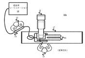
経食道心エコー法は、構造心臓疾患(「SHD」)の処置の間、心臓の解剖学的構造及び介入デバイスを視覚化するために一般に使用されている。図1は、超音波ワークステーション11及びX線スキャナを有する検査室10内の現場スタッフの典型的な配置を示しており、X線スキャナのCアーム12が図示されている。SHD手術の間、心エコー検査技師13は、TEEプローブ14を保持し、TEEプローブ14は、患者16の心臓を視覚化するために、患者16の口を通じて食道に通される。心臓専門医15は、X線Cアーム12及び手術テーブル17の向こう側に位置する。心臓専門医15は、さまざまな異なる診断又は治療プロシージャを実施するために、TEEプローブ14を介するX線ガイダンス及び超音波ガイダンス下、動脈切開部から心臓に介入デバイス(図示せず)(例えばカテーテル及びガイドワイヤ)をナビゲートする。例えば僧帽弁クリップ配置又は経カテーテル大動脈弁置換術(「TAVR」)のようなプロシージャは、時間がかかることがあり、複雑でありうる。更に、プロシージャの間、ターゲット解剖学的構造の適当な視覚化を確実にすることは、心エコー検査技師13の責任であり、心エコー検査技師は、プロシージャの持続中、TEEプローブ14の先端の位置に対する一定の小さい調整を行わなければならない。
Transesophageal echocardiography is commonly used to visualize the anatomy of the heart and interventional devices during the treatment of structural heart disease (“SHD”). FIG. 1 shows a typical arrangement of field staff in an
実際、図1の手術条件は、いくつかの課題を示す。第1の課題は、疲労及び貧弱な視覚化である。具体的には、適当な視覚化は、適切な解剖学的構造が視野内にあること、及び適切な音響結合を達成するためにトランスデューサヘッドと食道壁との間に必要な接触力が達成されること、の両方を確実にすることを含む。この目的で、TEEプローブ14のヘッドの位置及び向きは、ターゲット構造の適当な視覚化を維持するために、プロシージャの持続中一定の微小な調整を必要とする。これは、長いプロシージャの間の心エコー検査技師13による疲労及び貧弱な視覚化につながりうる。
In fact, the surgical conditions of FIG. 1 present several challenges. The first challenge is fatigue and poor visualization. Specifically, proper visualization ensures that the proper anatomy is in the field of view and the necessary contact force between the transducer head and the esophageal wall to achieve proper acoustic coupling. To ensure both. For this purpose, the position and orientation of the head of the
第2の課題は、X線曝露である。具体的には、長さをもつTEEプローブ14は、介入X線システムの線源のすぐ近くに心エコー検査技師13を位置させ、こうして、プロシージャの最中、心エコー検査技師13のX線曝露を最大にする。
The second problem is X-ray exposure. Specifically, the length of the
第3の課題は、コミュニケーション及び視覚化である。プロシージャの特定のフェーズの間、心臓専門医15は、どの構造を視覚化するべきかを心エコー検査技師13に指示するので、心臓専門医15及び心エコー検査技師13は、常にコミュニケーションをとらなければならない。3D超音波ボリュームを解釈する難しさと、X線システム及び超音波システムによって表示される異なる座標系が提供される場合、心エコー検査技師13は、心臓専門医15の意図を理解することは困難でありうる。
The third issue is communication and visualization. During a particular phase of the procedure, the
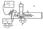
本発明は、これらの課題に対処するために、ロボットアクチュエーションシステムを提供する。概して、図2に示すように、ロボットアクチュエータシステムを用いるロボットアクチュエータシステムを有する検査室10b内の現場スタッフの新しい配置は、TEEプローブ14の超音波イメージングボリュームを調整するTEEプローブ14の2自由度と4自由度との間の遠隔制御のために、ロボットワークステーション20及びロボットアクチュエータ30を用いる。更に、ここに記述されるように、ロボットアクチュエータ30は、既存の及びさまざまなタイプのTEEプローブ14に組み込まれる能力を有することができるとともに、心エコー検査技師13が何らかの理由でTEEプローブ14の手動動作に戻ることを決める場合に、TEEプローブ14から迅速に取り外される能力を有することができる。
The present invention provides a robot actuation system to address these issues. In general, as shown in FIG. 2, the new placement of field staff in an examination room 10b having a robot actuator system that uses a robot actuator system allows two degrees of freedom for the
しかしながら、TEEプローブ14のロボット制御から生じる潜在的な問題は安全性である。特に、TEEプローブ14のダイヤルが、心エコー検査技師13の手ではなく、ロータアクチュエータ30によって移動されるので、触覚フィードバックがない(すなわち、プローブ14が患者16の食道上の過剰な力を及ぼしているかどうかを心エコー検査技師13が感じることができない)。
However, a potential problem arising from robot control of the TEE
ロボットの力制御は、例えば研摩又は組立てのようなアプリケーションの技術において知られている。これらの方法は、ロボットエンドエフェクタ上又はロボット関節における力又はトルクを検出するために、力センサを使用する。同様に、プローブ−組織接触力は、当技術分野において知られている力センサによって測定されることができる。しかしながら、力センサによりプローブ−組織接触力を測定することに関するいくつかの問題がある。 Robot force control is known in the art of applications such as polishing or assembly. These methods use force sensors to detect force or torque on a robot end effector or at a robot joint. Similarly, probe-tissue contact force can be measured by force sensors known in the art. However, there are several problems associated with measuring probe-tissue contact forces with force sensors.
第1に、TEEプローブ14は、複数の力センサを有するように変更される必要がある。患者16の安全性及び快適さのために、TEEプローブ14のサイズは、可能な限り小さくなければならない。逆に、ガイダンス及び診断目的のために、TEEプローブ14のイメージング素子は、視野を増大するために可能な限り大きくされるべきである。これらの制約に関して、TEEプローブ14のヘッドに新しいエレクトロニクスを加えることは、TEEプローブ14の主な機能、すなわち、超音波画像の取得に支障を来すことがある。
First, the TEE
第2に、センサは、TEEプローブ14の離散的なロケーションにのみ配置されることができ、他方、患者16に対する外傷が、全体のTEEプローブ14の長さに沿ったいかなるポイントでも発生しうる。
Second, the sensor can be placed only at discrete locations on the
第3に、直接的な力センシングが使われる場合、力センサベースの制御システムは、専ら新しく製造されるプローブとのみ使用されることができる。しかしながら、当分野ですでに展開されているTEEプローブ14と共に力制御システムを使用することが有利である。
Third, if direct force sensing is used, the force sensor based control system can only be used with newly manufactured probes. However, it is advantageous to use a force control system with a
センサレス力制御は、力が、システムの他のパラメータから導出される技術(最も一般にはモータの電流)においても知られている。従来のロボットアプリケーションにおいて、力及び位置は、切り離される。これらのアプリケーションにおいて、制御スキームは、経路制御及び力制御を組み合わせる。例えば、経路制御ループは、不適合モードにおいてプロセスを制御することができ、力制御ループは、適合モードにおいてシステムを制御することができる。これらのデュアルループは、同時に動作することができる。更に、従来のロボットアプリケーションにおいて、エンドエフェクタのモータの電流は、ロボット全体の位置に依存せず、これはセンサレス力制御を簡略化する。 Sensorless force control is also known in the art where force is derived from other parameters of the system (most commonly the motor current). In conventional robot applications, forces and positions are disconnected. In these applications, the control scheme combines path control and force control. For example, the path control loop can control the process in the non-conforming mode, and the force control loop can control the system in the conforming mode. These dual loops can operate simultaneously. Furthermore, in conventional robot applications, the current of the end effector motor is independent of the overall position of the robot, which simplifies sensorless force control.
TEEプローブ14の力制御の問題は、全体のアクチュエーションがTEEプローブ14の近位端部で行われるという理由で、ケーブル駆動される類の装置(例えばTEE超音波プローブ及びカテーテル)にユニークであり、結果的に幾つかの問題にいたる。まず、ロボットアクチュエータ30の各モータにおいてセンスされる又は測定される力は、TEEプローブ14が組織に及ぼしている力及びTEEプローブ14の全長の形状に依存する。第2に、ロボットアクチュエータ30のモータにおいてセンスされる又は測定される力は、ケーブルを引っ張るのに必要とされる力を含む。この力は、TEEプローブ14のヘッドの位置に依存して変わる。
The force control problem of the
本発明は、ロボットアクチュエータ30からのTEEプローブ14の先端位置/力の同時の算出を処理するロボットワークステーション20によって、TEEプローブ14のセンサレス力制御を提供する。これはTEEプローブ14の安全な遠隔操作を可能にし、それによって、患者16の食道に対する外傷のリスクを低減し、更に、ロボットワークステーション20及びロボットアクチュエータ30が、当分野においてすでに展開されているプローブと共に利用されることを可能にする。
The present invention provides sensorless force control of the
本発明の1つの形態は、ケーブル駆動される遠位端を有する介入ツール(例えば、プローブ、ステア可能なカテーテル、ガイドワイヤ及び結腸内視鏡)のセンサレス力制御のためのロボットアクチュエーションシステムである。システムは、1又は複数のモータ駆動ギアに介入ツールのケーブル駆動を操作させるロボットアクチュエータを用いる。システムは、介入ツールのアクチュエーション位置及び接触力を同時に制御するためのモータコマンドを生成するために、ロボットワークステーションを更に用いる。モータコマンドは、介入ツールの所望のアクチュエーション位置について、少なくとも1つのモータ駆動ギアのモータ電流測定及びアクチュエーション位置測定の関数である。 One form of the present invention is a robot actuation system for sensorless force control of interventional tools (eg, probes, steerable catheters, guidewires and colonoscopy) having a cable driven distal end. . The system uses a robot actuator that causes one or more motor drive gears to operate the cable drive of the intervention tool. The system further uses a robotic workstation to generate motor commands for simultaneously controlling the intervention tool actuation position and contact force. The motor command is a function of at least one motor drive gear motor current measurement and actuation position measurement for the desired actuation position of the intervention tool.
本発明の上述の形態及び他の形態並びに本発明のさまざまな特徴及び効果は、添付の図面に関連して読まれる本発明のさまざまな実施形態の以下の詳細な説明から一層明らかになる。詳細な説明及び図面は、本発明を単に説明するものであって、制限するものではなく、本発明の範囲は、添付の請求項及びそれらと等価のものによって規定される。 The foregoing and other aspects of the invention, as well as various features and advantages of the invention, will become more apparent from the following detailed description of various embodiments of the invention read in conjunction with the accompanying drawings. The detailed description and drawings are merely illustrative of the invention rather than limiting, the scope of the invention being defined by the appended claims and equivalents thereof.
本発明の理解を容易にするために、本発明のロボットアクチュエーションシステム及びさまざまなコンポーネントの例示の実施形態は、図3に示すようにTEEプローブの遠隔制御アクチュエーションの状況において記述される。これらの記述から、当業者は、任意のタイプのプロシージャのための適切な設計の超音波プローブ及び他の腱駆動可撓性デバイス(例えば結腸内視鏡、胃カメラ、その他)に、本発明のロボットアクチュエーションシステムの原理を適用する方法を理解する。 To facilitate understanding of the present invention, an exemplary embodiment of the robot actuation system and various components of the present invention will be described in the context of remote control actuation of a TEE probe as shown in FIG. From these descriptions, one of ordinary skill in the art can use the appropriately designed ultrasound probe and other tendon driven flexible devices for any type of procedure (eg, colonoscopy, gastrocamera, etc.) Understand how to apply the principles of robot actuation system.
図3を参照して、当分野において知られているTEEプローブ40は、ハンドル41と、ハンドル41に取り付けられる近位端部42p及び超音波トランスデューサ43を有する遠位ヘッド端部42dを有する細長いプローブと、を用いる。TEEプローブ40は、プローブヘッド42dのヨー自由度を調整するヨーアクチュエーションダイヤル43と、プローブヘッド42のピッチ自由度を調整するピッチアクチュエーションダイヤル44とを用いる。
Referring to FIG. 3, a
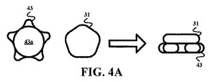
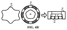
本発明は、ヨーアクチュエーションダイヤル43及びピッチアクチュエーションダイヤル44のアクチュエーションを制御するモータ駆動ギアを提供する。例えば、図4Aに示すように、本発明の摩擦ギア31は、ヨーアクチュエーションダイヤル43の回転を制御するための十分なトルクを伝達するためにヨーアクチュエーションダイヤル43と摩擦係合するように設計される。図4Bに示すように他の例によれば、本発明のクラウンギア32は、ピッチアクチュエーションダイヤル44の回転を制御するために、ヨーアクチュエーションダイヤル43と接触せずにピッチアクチュエーションダイヤル44と機械的に係合するように設計される。
The present invention provides a motor drive gear that controls the actuation of the
実際、ロボットアクチュエータ30(図2)のギアの設計は、係合されることが意図されるプローブの対応するアクチュエーションダイヤルの設計に依存するが、ロボットアクチュエータ30の実施形態は、ギア31及び32の状況においてここに記述される。
Indeed, although the gear design of the robot actuator 30 (FIG. 2) depends on the corresponding actuation dial design of the probe that is intended to be engaged, embodiments of the
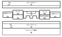
図5を参照して、ロボットアクチュエータ30の一実施形態は、1又は複数の磁気カップラ37を通じて磁気的に結合されるときにアクチュエーションチャンバを規定するために、凹形内側表面33aを有するプローブハンドルカバー33と、凹形内側表面33bを有するプローブハンドルベース34を用いる。動作中、チャンバはプローブのアクチュエーションダイヤルを収容し、特に手術環境がプローブの手動制御を指図する場合、磁気結合は、所望のプローブの容易な除去を容易にする利点を提供する。
Referring to FIG. 5, one embodiment of a
ロボットアクチュエータ30は、各々のギア31及び32用のモータ35及びモータコントローラ36(「MCONTROL」)を更に用い、ロボットワークステーション20のモータコントローラ36への電気結合を通じて、ロボットワークステーション20(図2)によって制御可能なモータ駆動ギアを与える。動作中、モータ駆動ギアは、プローブのアクチュエーションダイヤルを係合し回転させるのに十分であり、これは、プローブハンドルカバー33の軽量設計を容易にする。
The
更に、ロボットアクチュエータ30が作動される環境(例えば手術室)に依存して、当分野において知られているプローブハンドルベース34及び/又はアクチュエータプラットホーム38が、環境内の座標系にロボットアクチュエータ30を固定するために利用されることができる。例えば、プローブハンドルベース34及び/又はアクチュエータプラットホーム38は、手術室内の座標系にロボットアクチュエータ30を固定するために、固定具、手術テーブル、手術機器又は他のやり方で任意の対象に、取り付けられることができる。
Further, depending on the environment in which the
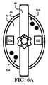
図6A及び図6Bを参照して、ロボットアクチュエータ30の概略的な実施形態は、プローブ(例えば表示されるプローブハンドル41)のアクチュエーションダイヤルを制御するために、プローブハンドルベース50及びプローブハンドルカバー60を用いる。具体的には、プローブハンドルカバー50は、凹形内側表面51を有し、プローブハンドルベース60は、凹形内側表面61を有し、これらは、プローブハンドルベース50の磁気手段52a及びプローブハンドルカバー60のスチールロケータピン62bを通じて磁気的に結合されるときにアクチュエーションチャンバを規定する。
With reference to FIGS. 6A and 6B, a schematic embodiment of the
プローブハンドルベース50は、ロボットワークステーション20(図2)に電気的に接続されるモータ制御盤53を用い、プローブハンドルカバー60は、モータ64(例えば2つのスパーギヤを介するブラシDCモータ)に電気的に接続されるモータ制御盤63を用いる。モータ制御盤53及び63は、モータコントローラを形成するために、プローブハンドルベース50及びプローブハンドルカバー60の磁気結合に応じて係合される電気接点(図示せず)(例えばバネ接触)を有する。モータコントローラ53a/63aは、クラウンギア65に対するモータ64aの電流制御を実現し、それによりクラウンギア65の回転を制御する。同様に、モータコントローラ53b/63bは、クラウンギア65と同心の摩擦ギア66に対するモータ64bの電流制御を実施し、それにより摩擦ギア66の回転を制御する。
The
図7は、プローブハンドル141のアクチュエーションダイヤル(図示せず)を収容し制御するために、プローブハンドルベース150及びプローブハンドルカバー160の磁気結合を有するロボットアクチュエータ130の審美的な実際のビューを示す。
FIG. 7 shows an aesthetic real view of the robot actuator 130 having a magnetic coupling of the
図8A及び図8Bは、一対のレール71、一対のスライダ72、一対の回転モータ73及びクランク軸75を用いるアクチュエータプラットホーム38(図5)の一実施形態70を示す。当技術分野において知られている技法によって、スライダ72は、レール71に摺動可能に結合されるとともに回転モータ73に固定され、クランク軸75は、回転モータ73に回転可能に結合される。動作中、プラットホームコントローラ76は、スライダ72の移動の従来の制御を通じて、矢印方向の一方においてレール71に沿ってクランクシャフト75を横方向に移動させるために、及び回転モータ73の制御を通じて回転軸RAを中心にクランク軸75を回転させるために(例えば、図8Bに示される180°の回転)、ハードウェア、ソフトウェア、ファームウェア及び/又は回路を用いる。実際、回転モータ73は、プローブハンドル、プローブ自体及び/又はプローブの配線の一部を支持するためのグローブ74を有することができる。
8A and 8B show an
クランクシャフト75の重要性は、クランクシャフト75が、図9A及び図9Bの矢印によって例示的に示されるように横方向に移動され、又は図9C及び図9Dに示されるように回転軸RAを中心にされるとき、プローブハンドルの回転軸RAとの回転アライメントを維持することである。具体的には、クランクシャフト75は、プローブハンドル(「PH」)ベース50を通って延び、プローブハンドルベース50とプローブハンドルカバー60との間に位置するプローブハンドル41は、回転方向において回転軸RAにアラインされる。
The importance of the
従って、レール71上を横方向に摺動するスライダ72の制御を介したクランクシャフト75の横方向の移動は、図9A及び図9Bに例示的に示されるように、回転方向における回転軸RAとのアライメントを保ちつつプローブハンドル40を横方向に移動させる。更に、回転モータ73の制御を介した回転軸RAを中心とするクランクシャフト75の回転運動は、図9C及び図9Dに示されるように、回転軸RAを中心にプローブハンドル40を回転させる。
Accordingly, the lateral movement of the
実際に、図7に示すアクチュエータプラットホーム70は、プローブ40の遠位ヘッド42dのピッチング及び/又はヨーイングを可能にするために、横方向運動及び回転運動の付加の2度の自由度を提供する。
Indeed, the
図1に戻って、ロボットワークステーション20は、ユーザ入力部を介してロボットアクチュエータ30のモータ駆動ギアに対するモータコマンドを生成するための技法を実行するための、当技術分野において知られているハードウェア、ソフトウェア、ファームウェア及び/又は回路によって構造的に構成される。実際、ロボットワークステーション20は、被検体プローブの特定のアクチュエーションスキームのためのモータコマンドを生成するために、任意の知られている技法を実現することができる。特にTEEプローブ14に関して、ロボットワークステーション20は、プローブ14の遠位ヘッドのピッチ自由度及びヨー自由度を制御するためにモータコマンドを生成する知られている技法を実行する。更に、アクチュエータプラットホーム70又は任意の他のアクチュエータプラットホームが、プローブ14の遠位ヘッドの横方向運動及び回転運動を容易にする場合、アクチュエータプラットホームのコントローラは、ロボットワークステーション20に結合される又はロボットワークステーション20内に組み込まれるスタンドアロンのコントローラでありうる。アクチュエータプラットホームのコントローラが、ロボットワークステーション20内に結合され又は組み込まれる場合、ロボットワークステーション20は、ユーザ入力部を介してアクチュエータプラットホームのコントローラに対する運動コマンドを生成する知られている技法を実行するための、当分野において知られているハードウェア、ソフトウェア、ファームウェア及び/又は回路によって構造的に構成される。
Returning to FIG. 1, the
更に実際に、ロボットワークステーション20は、ロボットアクチュエーションシステムの1又は複数のユーザとインタフェースするための知られているコンポーネント及びスキームを実現することができる。特に図1を参照して、直接制御スキームにおいて、ロボットワークステーション20は、心エコー検査技師13によるTEEプローブ14のヘッドの直接制御を容易にするために、適当なユーザインタフェース(図示せず)(例えばジョイスティック、マウス、タッチスクリーン、その他)を用いる。共同制御スキームにおいて、ロボットワークステーション20は、心エコー検査技師13及び心臓専門医15によるTEEプローブ14のヘッドの共有される制御を容易にするために適当なユーザインタフェース(図示せず)(例えばジョイスティック、マウス、タッチスクリーン、その他)を用いる。
In fact, the
図10を参照して、ロボットワークステーション20は、TEEプローブ14(図2)のアクチュエーションを制御するために、本発明に従ってロボットアクチュエータ30(図2)に対しモータコマンドを生成するハードウェア、ソフトウェア、ファームウェア及び/又は回路によって構造的に構成される。実際、ロボットワークステーション20は、このようなモータコマンドの生成に適した任意の技法を実行することができる。
Referring to FIG. 10, the
一実施形態において、ロボットワークステーション30は、(1)TEEプローブ14のヘッドの位置/形状とロボットアクチュエータ30のモータ電流との間の動作関係を確立するプローブ較正方法と、(2)TEEプローブ14のアクチュエーション位置及び接触力の同時制御と、を含む本発明のセンサレス力制御スキームを組み込むためにその中に搭載されるモジュール22−24のネットワーク21を用いる。図4A及び図4Bに示されるように個々のアクチュエーションダイヤル42及び43の角度位置に対するギア31及び32の角度位置の1対1の対応が重要である。
In one embodiment, the
図11を参照して、フローチャート80は、アクチュエーション位置較正器22(図10)によって実行される本発明のアクチュエーション位置較正方法を表す。フローチャート80のステージS82は、ロボットアクチュエータ30によるTEEプローブ14のプローブアクチュエーションサイクルを起動する較正器22を含み、フローチャート80のステージS84は、較正器22に通信されるロボットアクチュエータ30によるモータ電流の測定を含む。
Referring to FIG. 11, flow chart 80 represents the actuation position calibration method of the present invention performed by actuation position calibrator 22 (FIG. 10). Stage S82 of flowchart 80 includes a
具体的には、ステージS82について、TEEプローブ14は、複数の配置に位置付けられることができ、それらのうち2つの可能性がある形状配置90及び91が図示されている。具体的には、配置90は、TEEプローブ14が手術テーブル(図示せず)と平行に載置されることを必要とし、又は、配置91は、TEEプローブ14が手術テーブルに対し垂直に載置されることを必要とする。いずれの配置においても、TEEプローブ14は、自由に動かされることを可能にされ、それにより、TEEプローブ14のヘッドに及ぼされる付加の力がなく、TEEプローブ14はヘッドをまっすぐに保持したままにする。
Specifically, for stage S82, the
プローブ較正サイクルは、ロボットアクチュエータ30が、指定された程度のサンプルレートで、第2の自由度の複数の角度において第1の自由度の完全な角度レンジにわたってTEEプローブ14のヘッドを移動させることを含む。TEEプローブ14に関するように、ロボットアクチュエータ30は、ピッチアクチュエーションダイヤルの多数の角度位置について、ヨーアクチュエーションダイヤルをそのフルレンジの角度位置にわたって、指定されたサンプルレートで回転させる。例えば、5度ごと及び−90度から90度までのフルレンジのサンプリングレートで、ロボットアクチュエータ30は、ピッチアクチュエーションダイヤルの角度位置の5度ごとに、ヨーアクチュエーションダイヤルをフルレンジにわたって5度ずつ回転させる。
The probe calibration cycle allows the
各サンプリングは、ロボットアクチュエータ30の各モータのモータ電流の測定及び記憶を含む。センサレス力制御を容易にするために、ステージS84は、測定されたモータ電流のルックアップテーブルの生成を伴うことができる。以下の表は、(動きレンジ)^2/(サンプリングレート)^2 + 1エレメント数から導き出される649のエントリのための例示的なルックアップテーブルである(選択された10のエントリのみが示されていることを注意されたい):

較正器22は、プローブアクチュエーションサイクルの終了までステージS82/S84をループする。 The calibrator 22 loops through stages S82 / S84 until the end of the probe actuation cycle.
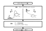
図12を参照して、フローチャート100は、接触力較正器23(図8)によって実行される本発明の接触力較正方法を表す。フローチャート100のステージS102は、フローチャート80(図11)のステージS82について上述したように、ロボットアクチュエータ30によるTEEプローブ14のプローブアクチュエーションサイクルを起動する較正器23を含み、フローチャート100のステージS104は、較正器23に通信される力センサによる力の測定を含み、これは、力/モータ電流比を生成する。
Referring to FIG. 12, a flowchart 100 represents the contact force calibration method of the present invention performed by the contact force calibrator 23 (FIG. 8). Stage S102 of flowchart 100 includes a
具体的には、ステージS102について、TEEプローブ14のヘッドは、知られている機械特性をもつ2つのばねにより2つの力センサに取り付けられる。1つの力センサは、プローブヘッドに対して垂直に取り付けられ、力センサ102は、例えば図10に示すようにTEEプローブ14のヘッドに対し垂直に取り付けられる。他方の力センサ(図示せず)は、プローブヘッドと同じ面に取り付けられる。プローブヘッドが直線的な配置110を有する場合には力がゼロであるように、及びプローブヘッドが曲がった配置(例えば曲がった配置111)を有する場合は力がゼロ以外であるように、バネが構成される。
Specifically, for stage S102, the head of
モータ電流及び力の値は、ステージS104の間に記録される。電流及び力の値は、各々の自由度についてヒステリシス曲線を形成することが期待され、これは、以下に説明されるように接触力制御を容易にするために正確な1つの力/モータ電流比があることを確実にするよう、ラインがこれらの値にフィットされることを可能にする。 Motor current and force values are recorded during stage S104. The current and force values are expected to form a hysteresis curve for each degree of freedom, which is an accurate single force / motor current ratio to facilitate contact force control as described below. Allows the line to be fitted to these values to ensure that there is.
較正器23は、プローブアクチュエーションサイクルの終了までステージS102/S104をループする。 The calibrator 23 loops through stages S102 / S104 until the end of the probe actuation cycle.
図13を参照して、アクチュエーションコントローラ24(図8)は、アクチュエーション位置及び接触力を同時に制御する制御スキーム120を実現する。基本的に、TEEプローブ14のヘッドの所望のアクチュエーション位置PDは、位置制御のためジョイスティック、キーボード又は任意の他の入力装置を介してロボットワークステーション20のユーザによってコントローラ24に通信され、それに応じて、コントローラ24は、位置制御ステージS122の間、ギア/アクチュエーションダイヤルの対応する角度位置によって達成されるTEEプローブ14のヘッドの特定のピッチ及びヨーに関してTEEプローブ14のアクチュエーション位置PAを生成する。更に、組織との接触を維持し音響結合を保証するように一般にゼロより大きい定数値であるTEEプローブ14の所望の力FDが、力制御ステージS124の間、コントローラ24に通信され、それにより、コントローラ24は、TEEプローブ14のアクチュエーション位置PAについて接触力補正FCを生成する。
Referring to FIG. 13, the actuation controller 24 (FIG. 8) implements a control scheme 120 that simultaneously controls the actuation position and the contact force. Basically, the desired actuation position PD of the head of the
モータコマンドMCの生成は、アクチュエーション位置PAと測定されたモータ位置PMとの間の位置誤差及び接触力補正FCと期待される接触力FEとの間で接触力誤差を最小限にするという観点で、アクチュエーション位置PAに対する接触力補正FCの適用を含む。 Generation of the motor command MC minimizes the contact force error between the position error and the contact force correction FC to an expected contact force FE between the motor position P M that has been determined actuation position P A In view of the above, the application of the contact force correction FC to the actuation position PA is included.
具体的には、ロボットアクチュエータ40のモータコントローラ36(図5)は、スキーム120の個々のステージS126及びS128の間、センスされたモータ位置PS及びセンスされたモータ電流ISをコントローラ24に連続的に通信する。それに応じて、コントローラ24は、センスされたモータ位置PSを周期的に測定し、測定されたモータ位置PMを、TEEプローブ14のヘッドの所望のアクチュエーション位置PDに関連付けられるモータ位置と比較し、結果的に得られる位置誤差は、位置誤差を最小限にするように設計される位置制御ステージS122への入力となる。実際に、コントローラ24は、位置誤差を最小限にするための当技術分野において知られている任意の制御技法(例えばPID制御)を実行することができる。
Continuous Specifically, the motor controller 36 of the robot actuators 40 (FIG. 5) during the individual stages S126 and S128 in Scheme 120, the sensed motor position P S and the sensed motor current I S to the controller 24 Communicate. In response, the controller 24, the sensed motor position P S periodically measures, the measured motor position P M, and the motor position associated with the desired actuation position P D of the head of the
コントローラ24は、センスされたモータ電流ISを周期的に同期して測定し、センスされ測定されたモータ電流ISを、期待されるモータ電流IEに組み合わせ、期待されるモータ電流IEは、較正器22(図11)によって生成されるステージS130のルックアップテーブルに、測定されたモータ位置PMを入力することによって計算される。ルックアップテーブルは、2つのダイヤルの位置の2つの入力を取得し、各々の自由度に2つの期待される電流値IEを返す。ステージS132の間、期待される電流値IE及び測定されたモータ電流値IMは、TEEプローブ14のヘッド上の期待される接触力FEを算出するために、較正器23(図12)によって計算される供給される電流対力曲線(C→F)に供給される。
Controller 24, the sensed motor current I S periodically measured synchronously, the motor current I S which is sensed measurement, combined with the motor current I E to be expected, the motor current I E to be expected , the look-up table of the stage S130, which is generated by the calibrator 22 (FIG. 11), is calculated by entering the measured motor position P M. The look-up table takes two inputs at two dial positions and returns two expected current values IE for each degree of freedom. During stage S132, the expected current value I E and the measured motor current value I M are used to calculate the expected contact force F E on the head of the
力制御ステージS124は、所望の接触力FD及び期待される接触力FEの比較から、接触力補正FCを受け取り、TEEプローブ14のヘッドによって及ぼされる力を制限するために、位置制御ステージS122によって生成される経路を調整する。1つの実施形態において、この運動をモデル化する直接的な方法は、接触表面が理想ばねとして振る舞うことを仮定する:
コントローラ24は、プロシージャの間、スキーム120のステージをループする。 The controller 24 loops through the stages of scheme 120 during the procedure.
図1−図11を参照して、当業者であれば、ケーブル駆動の介入ツール(例えば、TEEプローブ、ステア可能なカテーテル、ガイドワイヤ、結腸内視鏡、その他)を含む任意のプロシージャのためのセンサレス力制御を非限定的な例として含む本発明の多数の利点を理解する。 With reference to FIGS. 1-11, one of ordinary skill in the art would understand that any procedure involving a cable-driven interventional tool (eg, TEE probe, steerable catheter, guidewire, colonoscope, etc.) We will appreciate the many advantages of the present invention including sensorless force control as a non-limiting example.
本発明の各種実施形態が図示され記述されているが、当業者により、ここに記述される本発明の実施形態は説明的であり、さまざまな変形及び変更は実施されることができ、等価なものは、本発明の真の範囲を逸脱しない範囲でそれらの素子と置き換えられることができることが理解される。更に、多くの変更が、その中心の範囲を逸脱することなく本発明の教示を適応させるために行われることができる。従って、本発明は、本発明を実施するために企図される最良の形態として開示される特定の実施形態に制限されず、本発明は、添付の請求項の範囲内にあるすべての実施形態を含むことが意図される。 While various embodiments of the present invention have been illustrated and described, it will be understood by those skilled in the art that the embodiments of the present invention described herein are illustrative and that various modifications and changes can be made and equivalent. It will be understood that those can be substituted for those elements without departing from the true scope of the invention. In addition, many modifications may be made to adapt the teachings of the present invention without departing from its central scope. Accordingly, the invention is not limited to the specific embodiments disclosed as the best mode contemplated for carrying out the invention, but the invention encompasses all embodiments within the scope of the appended claims. It is intended to include.
Claims (15)
アクチュエーション位置のレンジにおいて前記介入ツールを制御するロボットアクチュエータであって、前記介入ツールのケーブル駆動を操作する少なくとも1つのモータ駆動ギアを有する、ロボットアクチュエータと、
前記少なくとも1つのモータ駆動ギアに接続され、前記介入ツールのアクチュエーション位置及び接触力を同時に制御するためのモータコマンドを生成するロボットワークステーションであって、アクチュエーション位置測定、及び前記介入ツールの所望のアクチュエーション位置についての前記少なくとも1つのモータ駆動ギアのモータ電流測定の関数として、前記モータコマンドを生成する、ロボットワークステーションと、
を有するロボットアクチュエーションシステム。 A robot actuation system for sensorless force control of an interventional tool having a cable driven distal end comprising:
A robot actuator for controlling the intervention tool in a range of actuation positions, the robot actuator having at least one motor drive gear for operating a cable drive of the intervention tool;
A robot workstation connected to the at least one motor drive gear and generating a motor command for simultaneously controlling an actuation position and contact force of the intervention tool, comprising actuating position measurement and a desired of the intervention tool A robot workstation that generates the motor command as a function of a motor current measurement of the at least one motor drive gear for a plurality of actuation positions;
Robot actuation system with
前記ロボットワークステーションは、前記モータ駆動ギアの所望のモータ電流に対する、前記モータ駆動ギアの期待されるモータ電流の比較の関数として、接触力誤差を生成し、
前記モータコマンドが、前記モータ位置誤差及び前記接触力誤差を最小限にするために前記ロボットワークステーションによって生成される、請求項1に記載のロボットアクチュエーションシステム。 The robot workstation is a function of a comparison of measured motor position of at least one motor drive to a desired motor position of at least one motor drive gear associated with a desired actuation position of the intervention tool, Generate motor position error,
The robot workstation generates a contact force error as a function of a comparison of an expected motor current of the motor drive gear to a desired motor current of the motor drive gear;
The robot actuation system of claim 1, wherein the motor command is generated by the robot workstation to minimize the motor position error and the contact force error.
前記ロボットワークステーションは、前記介入ツールの力対モータ電流曲線を含む較正曲線を有し、
前記ロボットワークステーションは、前記較正ルックアップテーブル及び前記較正曲線から、前記介入ツールの期待される接触力を導き出す、請求項3に記載のロボットアクチュエーションシステム。 The robot workstation has a calibration look-up table that includes the expected motor current for the measured motor position of at least one motor drive gear;
The robot workstation has a calibration curve including a force versus motor current curve of the intervention tool;
The robot actuation system of claim 3, wherein the robot workstation derives an expected contact force of the intervention tool from the calibration lookup table and the calibration curve.
前記介入ツールと係合する少なくとも1つの各モータ駆動ギアの測定されたモータ位置について期待されるモータ電流を含む較正ルックアップテーブルを生成するアクチュエーション位置較正器と、
前記介入ツールのための力対モータ電流曲線を含む較正曲線を生成する力制御較正器と、
前記アクチュエーション位置較正器及び前記力制御較正器に接続され、前記較正ルックアップテーブル及び前記較正曲線から導き出される前記介入ツールのアクチュエーション位置及び接触力の同時制御のためのモータコマンドを生成するアクチュエーションコントローラと、
を有し、前記ロボットワークステーションは、アクチュエーション位置測定及び前記介入ツールの所望のアクチュエーション位置のための少なくとも1つのモータ駆動ギアのモータ電流測定の関数として、前記モータコマンドを生成する、ロボットワークステーション。 A robotic workstation for sensorless force control of an interventional tool having a cable driven distal end,
An actuation position calibrator that generates a calibration look-up table that includes the expected motor current for the measured motor position of at least one motor drive gear that engages the intervention tool;
A force control calibrator that generates a calibration curve including a force versus motor current curve for the intervention tool;
An actuator connected to the actuation position calibrator and the force control calibrator to generate a motor command for simultaneous control of the actuation position and contact force of the intervention tool derived from the calibration look-up table and the calibration curve. A tuition controller,
The robot workstation generates the motor command as a function of actuation position measurement and motor current measurement of at least one motor drive gear for a desired actuation position of the intervention tool. station.
前記ロボットワークステーションは、前記モータ駆動ギアの所望のモータ電流に対する、前記モータ駆動ギアの期待されるモータ電流の比較の関数として、接触力誤差を生成し、
前記モータコマンドは、前記モータ位置誤差及び前記接触力誤差を最小限にするために前記アクチュエータコントローラによって生成される、請求項10に記載のロボットワークステーション。 The actuation controller as a function of a comparison of the measured motor position of at least one motor drive gear to a desired motor position of at least one motor drive gear associated with a desired actuation position of the intervention tool. Generate motor position error,
The robot workstation generates a contact force error as a function of a comparison of an expected motor current of the motor drive gear to a desired motor current of the motor drive gear;
The robotic workstation of claim 10, wherein the motor command is generated by the actuator controller to minimize the motor position error and the contact force error.
Applications Claiming Priority (3)
| Application Number | Priority Date | Filing Date | Title |
|---|---|---|---|
| US201461931203P | 2014-01-24 | 2014-01-24 | |
| US61/931,203 | 2014-01-24 | ||
| PCT/IB2015/050302 WO2015110937A2 (en) | 2014-01-24 | 2015-01-15 | Sensorless force control for transeopagel echocardiography probe |
Publications (2)
| Publication Number | Publication Date |
|---|---|
| JP2017511707A true JP2017511707A (en) | 2017-04-27 |
| JP2017511707A5 JP2017511707A5 (en) | 2018-01-25 |
Family
ID=52577879
Family Applications (1)
| Application Number | Title | Priority Date | Filing Date |
|---|---|---|---|
| JP2016547081A Pending JP2017511707A (en) | 2014-01-24 | 2015-01-15 | Sensorless force control for transesophageal echocardiography probe |
Country Status (5)
| Country | Link |
|---|---|
| US (2) | US10258417B2 (en) |
| EP (1) | EP3096672B1 (en) |
| JP (1) | JP2017511707A (en) |
| CN (1) | CN105939648B (en) |
| WO (1) | WO2015110937A2 (en) |
Families Citing this family (29)
| Publication number | Priority date | Publication date | Assignee | Title |
|---|---|---|---|---|
| US9452276B2 (en) | 2011-10-14 | 2016-09-27 | Intuitive Surgical Operations, Inc. | Catheter with removable vision probe |
| US20130303944A1 (en) | 2012-05-14 | 2013-11-14 | Intuitive Surgical Operations, Inc. | Off-axis electromagnetic sensor |
| US20140148673A1 (en) | 2012-11-28 | 2014-05-29 | Hansen Medical, Inc. | Method of anchoring pullwire directly articulatable region in catheter |
| EP2923669B1 (en) | 2014-03-24 | 2017-06-28 | Hansen Medical, Inc. | Systems and devices for catheter driving instinctiveness |
| US9737371B2 (en) | 2014-09-30 | 2017-08-22 | Auris Surgical Robotics, Inc. | Configurable robotic surgical system with virtual rail and flexible endoscope |
| US10314463B2 (en) * | 2014-10-24 | 2019-06-11 | Auris Health, Inc. | Automated endoscope calibration |
| US10143526B2 (en) | 2015-11-30 | 2018-12-04 | Auris Health, Inc. | Robot-assisted driving systems and methods |
| US9931025B1 (en) * | 2016-09-30 | 2018-04-03 | Auris Surgical Robotics, Inc. | Automated calibration of endoscopes with pull wires |
| CN110087548B (en) | 2016-12-19 | 2023-06-27 | 皇家飞利浦有限公司 | Control of anatomical image acquisition using physiological information |
| US10244926B2 (en) | 2016-12-28 | 2019-04-02 | Auris Health, Inc. | Detecting endolumenal buckling of flexible instruments |
| KR102643758B1 (en) | 2017-05-12 | 2024-03-08 | 아우리스 헬스, 인코포레이티드 | Biopsy devices and systems |
| US10299870B2 (en) | 2017-06-28 | 2019-05-28 | Auris Health, Inc. | Instrument insertion compensation |
| US10426559B2 (en) | 2017-06-30 | 2019-10-01 | Auris Health, Inc. | Systems and methods for medical instrument compression compensation |
| US10145747B1 (en) | 2017-10-10 | 2018-12-04 | Auris Health, Inc. | Detection of undesirable forces on a surgical robotic arm |
| US10016900B1 (en) | 2017-10-10 | 2018-07-10 | Auris Health, Inc. | Surgical robotic arm admittance control |
| CN110831536B (en) | 2017-12-06 | 2021-09-07 | 奥瑞斯健康公司 | System and method for correcting for a non-commanded instrument roll |
| KR20200100613A (en) | 2017-12-14 | 2020-08-26 | 아우리스 헬스, 인코포레이티드 | System and method for estimating instrument position |
| JP7301884B2 (en) | 2018-02-13 | 2023-07-03 | オーリス ヘルス インコーポレイテッド | Systems and methods for driving medical instruments |
| JP7536752B2 (en) | 2018-09-28 | 2024-08-20 | オーリス ヘルス インコーポレイテッド | Systems and methods for endoscope-assisted percutaneous medical procedures - Patents.com |
| WO2020069430A1 (en) | 2018-09-28 | 2020-04-02 | Auris Health, Inc. | Systems and methods for docking medical instruments |
| EP4084720A4 (en) | 2019-12-31 | 2024-01-17 | Auris Health, Inc. | Alignment techniques for percutaneous access |
| US11298195B2 (en) | 2019-12-31 | 2022-04-12 | Auris Health, Inc. | Anatomical feature identification and targeting |
| US11602372B2 (en) | 2019-12-31 | 2023-03-14 | Auris Health, Inc. | Alignment interfaces for percutaneous access |
| CN113827276A (en) * | 2020-06-24 | 2021-12-24 | 通用电气精准医疗有限责任公司 | Ultrasonic imaging system and imaging method thereof |
| US11701117B2 (en) * | 2020-09-29 | 2023-07-18 | Cilag Gmbh International | Manual drive functions for surgical tool |
| CN116322464A (en) * | 2020-09-29 | 2023-06-23 | 波士顿科学国际有限公司 | Medical device controller |
| KR20230146582A (en) * | 2021-02-17 | 2023-10-19 | 아우리스 헬스, 인코포레이티드 | Instrument roll control |
| CN113796963B (en) * | 2021-08-27 | 2023-07-21 | 中科尚易健康科技(北京)有限公司 | Mechanical arm control method with force sensing feedback adjustment and control terminal |
| CN117204955A (en) * | 2023-11-06 | 2023-12-12 | 华东交通大学 | Force control system of flexible surgical robot and device thereof |
Citations (4)
| Publication number | Priority date | Publication date | Assignee | Title |
|---|---|---|---|---|
| JPH03198828A (en) * | 1989-12-26 | 1991-08-30 | Olympus Optical Co Ltd | Endoscope apparatus |
| JPH04263830A (en) * | 1991-02-19 | 1992-09-18 | Olympus Optical Co Ltd | Endoscope device |
| JPH05161598A (en) * | 1991-12-12 | 1993-06-29 | Olympus Optical Co Ltd | Electrically bending type endoscope apparatus |
| JPH05300873A (en) * | 1992-04-28 | 1993-11-16 | Olympus Optical Co Ltd | Bending controller for endoscope |
Family Cites Families (31)
| Publication number | Priority date | Publication date | Assignee | Title |
|---|---|---|---|---|
| JPS53873A (en) | 1976-06-23 | 1978-01-07 | Mitsubishi Electric Corp | Fluid blowwout breaker |
| US5469840A (en) | 1991-12-10 | 1995-11-28 | Olympus Optical, Ltd. | Electromotive warping type endoscope with velocity control |
| US5609563A (en) | 1991-12-12 | 1997-03-11 | Olympus Optical Co., Ltd. | Endoscope apparatus provided with curvature and fluid flow control |
| US6803681B2 (en) * | 1998-02-26 | 2004-10-12 | Anorad Corporation | Path module for a linear motor, modular linear motor system and method to control same |
| JP4503985B2 (en) * | 2003-11-07 | 2010-07-14 | オリンパス株式会社 | Medical control device |
| US7152456B2 (en) * | 2004-01-14 | 2006-12-26 | Romer Incorporated | Automated robotic measuring system |
| GB0500530D0 (en) * | 2005-01-12 | 2005-02-16 | Zi Medical Plc | Position transducer |
| JP5097347B2 (en) * | 2005-12-26 | 2012-12-12 | オリンパスメディカルシステムズ株式会社 | Endoscope and endoscope system |
| JP4961475B2 (en) * | 2007-06-20 | 2012-06-27 | オリンパスメディカルシステムズ株式会社 | Endoscope system |
| US9050120B2 (en) * | 2007-09-30 | 2015-06-09 | Intuitive Surgical Operations, Inc. | Apparatus and method of user interface with alternate tool mode for robotic surgical tools |
| JP5153787B2 (en) * | 2007-11-29 | 2013-02-27 | オリンパスメディカルシステムズ株式会社 | Endoscope bending control device and endoscope system |
| JP5139194B2 (en) * | 2008-08-06 | 2013-02-06 | オリンパスメディカルシステムズ株式会社 | Active medical device system |
| WO2010047223A1 (en) | 2008-10-22 | 2010-04-29 | オリンパスメディカルシステムズ株式会社 | Electrically bendable endoscope |
| WO2010090059A1 (en) * | 2009-02-03 | 2010-08-12 | オリンパスメディカルシステムズ株式会社 | Manipulator |
| EP2305144B1 (en) * | 2009-03-24 | 2012-10-31 | Olympus Medical Systems Corp. | Robot system for endoscope treatment |
| US9393068B1 (en) * | 2009-05-08 | 2016-07-19 | St. Jude Medical International Holding S.À R.L. | Method for predicting the probability of steam pop in RF ablation therapy |
| CA2703347C (en) * | 2009-05-08 | 2016-10-04 | Endosense Sa | Method and apparatus for controlling lesion size in catheter-based ablation treatment |
| EP2471436B1 (en) * | 2009-08-26 | 2017-10-25 | Olympus Corporation | Endoscope apparatus |
| JP5052698B2 (en) * | 2009-11-18 | 2012-10-17 | オリンパスメディカルシステムズ株式会社 | Medical equipment |
| US8374819B2 (en) * | 2009-12-23 | 2013-02-12 | Biosense Webster (Israel), Ltd. | Actuator-based calibration system for a pressure-sensitive catheter |
| CN102573599B (en) * | 2010-03-02 | 2015-05-06 | 奥林巴斯医疗株式会社 | Medical system and control method |
| EP2634614B1 (en) * | 2011-08-10 | 2014-10-08 | Olympus Medical Systems Corp. | Endoscope device |
| US8766578B2 (en) * | 2012-02-27 | 2014-07-01 | Canadian Space Agency | Method and apparatus for high velocity ripple suppression of brushless DC motors having limited drive/amplifier bandwidth |
| US20140005718A1 (en) * | 2012-06-28 | 2014-01-02 | Ethicon Endo-Surgery, Inc. | Multi-functional powered surgical device with external dissection features |
| CN103917148B (en) * | 2012-07-02 | 2017-02-22 | 奥林巴斯株式会社 | Endoscope system |
| DE102012106755A1 (en) * | 2012-07-25 | 2014-01-30 | Karl Storz Gmbh & Co. Kg | endoscope |
| US9134261B2 (en) * | 2013-04-22 | 2015-09-15 | Ebara Corporation | Inspection apparatus |
| KR20150011779A (en) * | 2013-07-23 | 2015-02-02 | 한국해양과학기술원 | motor driver |
| US10564221B2 (en) * | 2013-11-13 | 2020-02-18 | Brooks Automation, Inc. | Method and apparatus for brushless electrical machine control |
| KR102086504B1 (en) * | 2015-05-15 | 2020-03-09 | 인튜어티브 서지컬 오퍼레이션즈 인코포레이티드 | System and method for compensating force or torque limits |
| US10238386B2 (en) * | 2015-09-23 | 2019-03-26 | Ethicon Llc | Surgical stapler having motor control based on an electrical parameter related to a motor current |
-
2015
- 2015-01-15 US US15/112,707 patent/US10258417B2/en active Active
- 2015-01-15 WO PCT/IB2015/050302 patent/WO2015110937A2/en active Application Filing
- 2015-01-15 JP JP2016547081A patent/JP2017511707A/en active Pending
- 2015-01-15 CN CN201580005301.6A patent/CN105939648B/en active Active
- 2015-01-15 EP EP15706294.4A patent/EP3096672B1/en active Active
-
2019
- 2019-03-19 US US16/357,792 patent/US11266473B2/en active Active
Patent Citations (4)
| Publication number | Priority date | Publication date | Assignee | Title |
|---|---|---|---|---|
| JPH03198828A (en) * | 1989-12-26 | 1991-08-30 | Olympus Optical Co Ltd | Endoscope apparatus |
| JPH04263830A (en) * | 1991-02-19 | 1992-09-18 | Olympus Optical Co Ltd | Endoscope device |
| JPH05161598A (en) * | 1991-12-12 | 1993-06-29 | Olympus Optical Co Ltd | Electrically bending type endoscope apparatus |
| JPH05300873A (en) * | 1992-04-28 | 1993-11-16 | Olympus Optical Co Ltd | Bending controller for endoscope |
Also Published As
| Publication number | Publication date |
|---|---|
| US20190209254A1 (en) | 2019-07-11 |
| CN105939648A (en) | 2016-09-14 |
| EP3096672A2 (en) | 2016-11-30 |
| US11266473B2 (en) | 2022-03-08 |
| EP3096672B1 (en) | 2022-07-20 |
| US10258417B2 (en) | 2019-04-16 |
| CN105939648B (en) | 2018-12-07 |
| US20160338787A1 (en) | 2016-11-24 |
| WO2015110937A3 (en) | 2015-12-03 |
| WO2015110937A2 (en) | 2015-07-30 |
Similar Documents
| Publication | Publication Date | Title |
|---|---|---|
| JP2017511707A (en) | Sensorless force control for transesophageal echocardiography probe | |
| JP7225259B2 (en) | Systems and methods for indicating probable location of instruments | |
| JP5303558B2 (en) | Robot control catheter and calibration method thereof | |
| JP6620104B2 (en) | Robotic actuator for transesophageal echocardiography probe | |
| US8740882B2 (en) | Medical robotic system and method of controlling the same | |
| RU2741469C1 (en) | Robotic surgical system | |
| CN111328306A (en) | Surgical robot arm admittance control | |
| JP2023022234A (en) | Tracking and guide device for surgical robot system and related method | |
| CN107753109B (en) | Concentric tube robot device and control method thereof | |
| US10813708B2 (en) | Remote robotic actuation of a transesophageal echocardiography probe | |
| CN107961078A (en) | Surgical robot system and its operating theater instruments | |
| US20200008879A1 (en) | Ultrasound guidance of actuatable medical tool | |
| WO2008038184A2 (en) | Haptic feedback medical scanning methods and systems | |
| CN115605157A (en) | Passive and active arm control schemes with sensor integration to support remote operation and direct manual interaction | |
| JP2020526271A (en) | Laparoscopic adapter, echocardiography probe, and method for connecting the adapter to the probe | |
| CN115297798A (en) | Trocar pose estimation for docking a surgical robotic arm to a trocar using machine learning | |
| JP2021151469A (en) | Method and apparatus for controlling continuum robot | |
| JP2022549347A (en) | Method and system for controlling flexible devices in the presence of abnormal sensor signals | |
| US20220125530A1 (en) | Feedback continuous positioning control of end-effectors |
Legal Events
| Date | Code | Title | Description |
|---|---|---|---|
| RD04 | Notification of resignation of power of attorney |
Free format text: JAPANESE INTERMEDIATE CODE: A7424 Effective date: 20170214 |
|
| A521 | Request for written amendment filed |
Free format text: JAPANESE INTERMEDIATE CODE: A523 Effective date: 20171205 |
|
| A621 | Written request for application examination |
Free format text: JAPANESE INTERMEDIATE CODE: A621 Effective date: 20171205 |
|
| A977 | Report on retrieval |
Free format text: JAPANESE INTERMEDIATE CODE: A971007 Effective date: 20180718 |
|
| A131 | Notification of reasons for refusal |
Free format text: JAPANESE INTERMEDIATE CODE: A131 Effective date: 20180807 |
|
| A601 | Written request for extension of time |
Free format text: JAPANESE INTERMEDIATE CODE: A601 Effective date: 20181102 |
|
| A521 | Request for written amendment filed |
Free format text: JAPANESE INTERMEDIATE CODE: A523 Effective date: 20190207 |
|
| A02 | Decision of refusal |
Free format text: JAPANESE INTERMEDIATE CODE: A02 Effective date: 20190723 |
|
| A521 | Request for written amendment filed |
Free format text: JAPANESE INTERMEDIATE CODE: A523 Effective date: 20191122 |
|
| C60 | Trial request (containing other claim documents, opposition documents) |
Free format text: JAPANESE INTERMEDIATE CODE: C60 Effective date: 20191122 |
|
| A911 | Transfer to examiner for re-examination before appeal (zenchi) |
Free format text: JAPANESE INTERMEDIATE CODE: A911 Effective date: 20191129 |
|
| C21 | Notice of transfer of a case for reconsideration by examiners before appeal proceedings |
Free format text: JAPANESE INTERMEDIATE CODE: C21 Effective date: 20191203 |
|
| A912 | Re-examination (zenchi) completed and case transferred to appeal board |
Free format text: JAPANESE INTERMEDIATE CODE: A912 Effective date: 20191227 |
|
| C211 | Notice of termination of reconsideration by examiners before appeal proceedings |
Free format text: JAPANESE INTERMEDIATE CODE: C211 Effective date: 20200107 |
|
| C22 | Notice of designation (change) of administrative judge |
Free format text: JAPANESE INTERMEDIATE CODE: C22 Effective date: 20200402 |
|
| C13 | Notice of reasons for refusal |
Free format text: JAPANESE INTERMEDIATE CODE: C13 Effective date: 20200630 |
|
| C23 | Notice of termination of proceedings |
Free format text: JAPANESE INTERMEDIATE CODE: C23 Effective date: 20201027 |
|
| C03 | Trial/appeal decision taken |
Free format text: JAPANESE INTERMEDIATE CODE: C03 Effective date: 20201126 |
|
| C30A | Notification sent |
Free format text: JAPANESE INTERMEDIATE CODE: C3012 Effective date: 20201126 |