JP7214747B2 - System and method for position sensor alignment - Google Patents
System and method for position sensor alignment Download PDFInfo
- Publication number
- JP7214747B2 JP7214747B2 JP2020551849A JP2020551849A JP7214747B2 JP 7214747 B2 JP7214747 B2 JP 7214747B2 JP 2020551849 A JP2020551849 A JP 2020551849A JP 2020551849 A JP2020551849 A JP 2020551849A JP 7214747 B2 JP7214747 B2 JP 7214747B2
- Authority
- JP
- Japan
- Prior art keywords
- instrument
- coordinate system
- branch
- model
- alignment
- Prior art date
- Legal status (The legal status is an assumption and is not a legal conclusion. Google has not performed a legal analysis and makes no representation as to the accuracy of the status listed.)
- Active
Links
Images


Classifications
-
- A—HUMAN NECESSITIES
- A61—MEDICAL OR VETERINARY SCIENCE; HYGIENE
- A61B—DIAGNOSIS; SURGERY; IDENTIFICATION
- A61B34/00—Computer-aided surgery; Manipulators or robots specially adapted for use in surgery
- A61B34/20—Surgical navigation systems; Devices for tracking or guiding surgical instruments, e.g. for frameless stereotaxis
-
- A—HUMAN NECESSITIES
- A61—MEDICAL OR VETERINARY SCIENCE; HYGIENE
- A61B—DIAGNOSIS; SURGERY; IDENTIFICATION
- A61B34/00—Computer-aided surgery; Manipulators or robots specially adapted for use in surgery
- A61B34/10—Computer-aided planning, simulation or modelling of surgical operations
-
- A—HUMAN NECESSITIES
- A61—MEDICAL OR VETERINARY SCIENCE; HYGIENE
- A61B—DIAGNOSIS; SURGERY; IDENTIFICATION
- A61B34/00—Computer-aided surgery; Manipulators or robots specially adapted for use in surgery
- A61B34/30—Surgical robots
-
- A—HUMAN NECESSITIES
- A61—MEDICAL OR VETERINARY SCIENCE; HYGIENE
- A61B—DIAGNOSIS; SURGERY; IDENTIFICATION
- A61B34/00—Computer-aided surgery; Manipulators or robots specially adapted for use in surgery
- A61B34/70—Manipulators specially adapted for use in surgery
- A61B34/74—Manipulators with manual electric input means
-
- A—HUMAN NECESSITIES
- A61—MEDICAL OR VETERINARY SCIENCE; HYGIENE
- A61B—DIAGNOSIS; SURGERY; IDENTIFICATION
- A61B90/00—Instruments, implements or accessories specially adapted for surgery or diagnosis and not covered by any of the groups A61B1/00 - A61B50/00, e.g. for luxation treatment or for protecting wound edges
- A61B90/36—Image-producing devices or illumination devices not otherwise provided for
- A61B90/361—Image-producing devices, e.g. surgical cameras
-
- A—HUMAN NECESSITIES
- A61—MEDICAL OR VETERINARY SCIENCE; HYGIENE
- A61B—DIAGNOSIS; SURGERY; IDENTIFICATION
- A61B90/00—Instruments, implements or accessories specially adapted for surgery or diagnosis and not covered by any of the groups A61B1/00 - A61B50/00, e.g. for luxation treatment or for protecting wound edges
- A61B90/39—Markers, e.g. radio-opaque or breast lesions markers
-
- A—HUMAN NECESSITIES
- A61—MEDICAL OR VETERINARY SCIENCE; HYGIENE
- A61G—TRANSPORT, PERSONAL CONVEYANCES, OR ACCOMMODATION SPECIALLY ADAPTED FOR PATIENTS OR DISABLED PERSONS; OPERATING TABLES OR CHAIRS; CHAIRS FOR DENTISTRY; FUNERAL DEVICES
- A61G13/00—Operating tables; Auxiliary appliances therefor
- A61G13/02—Adjustable operating tables; Controls therefor
- A61G13/04—Adjustable operating tables; Controls therefor tiltable around transverse or longitudinal axis
-
- A—HUMAN NECESSITIES
- A61—MEDICAL OR VETERINARY SCIENCE; HYGIENE
- A61B—DIAGNOSIS; SURGERY; IDENTIFICATION
- A61B17/00—Surgical instruments, devices or methods, e.g. tourniquets
- A61B2017/00477—Coupling
-
- A—HUMAN NECESSITIES
- A61—MEDICAL OR VETERINARY SCIENCE; HYGIENE
- A61B—DIAGNOSIS; SURGERY; IDENTIFICATION
- A61B17/00—Surgical instruments, devices or methods, e.g. tourniquets
- A61B2017/00743—Type of operation; Specification of treatment sites
- A61B2017/00809—Lung operations
-
- A—HUMAN NECESSITIES
- A61—MEDICAL OR VETERINARY SCIENCE; HYGIENE
- A61B—DIAGNOSIS; SURGERY; IDENTIFICATION
- A61B34/00—Computer-aided surgery; Manipulators or robots specially adapted for use in surgery
- A61B34/10—Computer-aided planning, simulation or modelling of surgical operations
- A61B2034/101—Computer-aided simulation of surgical operations
- A61B2034/105—Modelling of the patient, e.g. for ligaments or bones
-
- A—HUMAN NECESSITIES
- A61—MEDICAL OR VETERINARY SCIENCE; HYGIENE
- A61B—DIAGNOSIS; SURGERY; IDENTIFICATION
- A61B34/00—Computer-aided surgery; Manipulators or robots specially adapted for use in surgery
- A61B34/10—Computer-aided planning, simulation or modelling of surgical operations
- A61B2034/107—Visualisation of planned trajectories or target regions
-
- A—HUMAN NECESSITIES
- A61—MEDICAL OR VETERINARY SCIENCE; HYGIENE
- A61B—DIAGNOSIS; SURGERY; IDENTIFICATION
- A61B34/00—Computer-aided surgery; Manipulators or robots specially adapted for use in surgery
- A61B34/20—Surgical navigation systems; Devices for tracking or guiding surgical instruments, e.g. for frameless stereotaxis
- A61B2034/2046—Tracking techniques
- A61B2034/2051—Electromagnetic tracking systems
-
- A—HUMAN NECESSITIES
- A61—MEDICAL OR VETERINARY SCIENCE; HYGIENE
- A61B—DIAGNOSIS; SURGERY; IDENTIFICATION
- A61B34/00—Computer-aided surgery; Manipulators or robots specially adapted for use in surgery
- A61B34/20—Surgical navigation systems; Devices for tracking or guiding surgical instruments, e.g. for frameless stereotaxis
- A61B2034/2046—Tracking techniques
- A61B2034/2059—Mechanical position encoders
-
- A—HUMAN NECESSITIES
- A61—MEDICAL OR VETERINARY SCIENCE; HYGIENE
- A61B—DIAGNOSIS; SURGERY; IDENTIFICATION
- A61B34/00—Computer-aided surgery; Manipulators or robots specially adapted for use in surgery
- A61B34/20—Surgical navigation systems; Devices for tracking or guiding surgical instruments, e.g. for frameless stereotaxis
- A61B2034/2046—Tracking techniques
- A61B2034/2065—Tracking using image or pattern recognition
-
- A—HUMAN NECESSITIES
- A61—MEDICAL OR VETERINARY SCIENCE; HYGIENE
- A61B—DIAGNOSIS; SURGERY; IDENTIFICATION
- A61B34/00—Computer-aided surgery; Manipulators or robots specially adapted for use in surgery
- A61B34/20—Surgical navigation systems; Devices for tracking or guiding surgical instruments, e.g. for frameless stereotaxis
- A61B2034/2068—Surgical navigation systems; Devices for tracking or guiding surgical instruments, e.g. for frameless stereotaxis using pointers, e.g. pointers having reference marks for determining coordinates of body points
-
- A—HUMAN NECESSITIES
- A61—MEDICAL OR VETERINARY SCIENCE; HYGIENE
- A61B—DIAGNOSIS; SURGERY; IDENTIFICATION
- A61B34/00—Computer-aided surgery; Manipulators or robots specially adapted for use in surgery
- A61B34/20—Surgical navigation systems; Devices for tracking or guiding surgical instruments, e.g. for frameless stereotaxis
- A61B2034/2074—Interface software
-
- A—HUMAN NECESSITIES
- A61—MEDICAL OR VETERINARY SCIENCE; HYGIENE
- A61B—DIAGNOSIS; SURGERY; IDENTIFICATION
- A61B34/00—Computer-aided surgery; Manipulators or robots specially adapted for use in surgery
- A61B34/30—Surgical robots
- A61B2034/301—Surgical robots for introducing or steering flexible instruments inserted into the body, e.g. catheters or endoscopes
-
- A—HUMAN NECESSITIES
- A61—MEDICAL OR VETERINARY SCIENCE; HYGIENE
- A61B—DIAGNOSIS; SURGERY; IDENTIFICATION
- A61B90/00—Instruments, implements or accessories specially adapted for surgery or diagnosis and not covered by any of the groups A61B1/00 - A61B50/00, e.g. for luxation treatment or for protecting wound edges
- A61B90/30—Devices for illuminating a surgical field, the devices having an interrelation with other surgical devices or with a surgical procedure
- A61B2090/306—Devices for illuminating a surgical field, the devices having an interrelation with other surgical devices or with a surgical procedure using optical fibres
-
- A—HUMAN NECESSITIES
- A61—MEDICAL OR VETERINARY SCIENCE; HYGIENE
- A61B—DIAGNOSIS; SURGERY; IDENTIFICATION
- A61B90/00—Instruments, implements or accessories specially adapted for surgery or diagnosis and not covered by any of the groups A61B1/00 - A61B50/00, e.g. for luxation treatment or for protecting wound edges
- A61B90/30—Devices for illuminating a surgical field, the devices having an interrelation with other surgical devices or with a surgical procedure
- A61B2090/309—Devices for illuminating a surgical field, the devices having an interrelation with other surgical devices or with a surgical procedure using white LEDs
-
- A—HUMAN NECESSITIES
- A61—MEDICAL OR VETERINARY SCIENCE; HYGIENE
- A61B—DIAGNOSIS; SURGERY; IDENTIFICATION
- A61B90/00—Instruments, implements or accessories specially adapted for surgery or diagnosis and not covered by any of the groups A61B1/00 - A61B50/00, e.g. for luxation treatment or for protecting wound edges
- A61B90/36—Image-producing devices or illumination devices not otherwise provided for
- A61B90/361—Image-producing devices, e.g. surgical cameras
- A61B2090/3614—Image-producing devices, e.g. surgical cameras using optical fibre
-
- A—HUMAN NECESSITIES
- A61—MEDICAL OR VETERINARY SCIENCE; HYGIENE
- A61B—DIAGNOSIS; SURGERY; IDENTIFICATION
- A61B90/00—Instruments, implements or accessories specially adapted for surgery or diagnosis and not covered by any of the groups A61B1/00 - A61B50/00, e.g. for luxation treatment or for protecting wound edges
- A61B90/36—Image-producing devices or illumination devices not otherwise provided for
- A61B2090/364—Correlation of different images or relation of image positions in respect to the body
- A61B2090/365—Correlation of different images or relation of image positions in respect to the body augmented reality, i.e. correlating a live optical image with another image
-
- A—HUMAN NECESSITIES
- A61—MEDICAL OR VETERINARY SCIENCE; HYGIENE
- A61B—DIAGNOSIS; SURGERY; IDENTIFICATION
- A61B34/00—Computer-aided surgery; Manipulators or robots specially adapted for use in surgery
- A61B34/25—User interfaces for surgical systems
Description
(関連出願の相互参照)
本出願は、2018年3月28日に出願された米国特許仮出願第62/649,513号の利益を主張するものであり、これは参照によりその全体が本明細書に組み込まれる。
(Cross reference to related applications)
This application claims the benefit of US Provisional Patent Application No. 62/649,513, filed March 28, 2018, which is hereby incorporated by reference in its entirety.
(発明の分野)
本明細書に開示されるシステム及び方法は、位置センサの位置合わせのためのシステム及び方法に関し、より具体的には、位置センサ座標系を別の座標系に位置合わせすることを目的とする。
(Field of Invention)
The systems and methods disclosed herein relate to systems and methods for position sensor alignment and, more particularly, are intended to align a position sensor coordinate system to another coordinate system.
内視鏡検査(例えば気管支鏡検査)などの医療処置は、診断及び/又は治療目的で、患者の管腔網(例えば、気道)内への医療用具の挿入を伴うことがある。外科用ロボットシステムが、医療処置中の医療用具の挿入及び/又は操作を制御するために使用されることがある。外科用ロボットシステムは、医療処置前及び医療処置中に医療用具の位置決めを制御するために使用され得るマニピュレータアセンブリを含む少なくとも1つのロボットアームを備え得る。外科用ロボットシステムは、位置センサ座標系に対する医療用具の遠位端のポジションを示す位置データを生成するように構成された位置センサを更に備え得る。 A medical procedure such as an endoscopy (eg, bronchoscopy) may involve the insertion of a medical device into a patient's luminal network (eg, airway) for diagnostic and/or therapeutic purposes. Surgical robotic systems are sometimes used to control the insertion and/or manipulation of medical devices during medical procedures. A surgical robotic system can include at least one robotic arm that includes a manipulator assembly that can be used to control the positioning of a medical tool before and during a medical procedure. The surgical robotic system may further comprise a position sensor configured to generate position data indicative of the position of the distal end of the medical device relative to the position sensor coordinate system.
外科用ロボットシステムは、患者の管腔網のモデルを更に利用することができ、このモデルは、モデル座標系に対して定義され得る。位置センサ座標系は、モデル座標系に位置合わせされなくてもよく、したがって、システムは、位置センサ座標系とモデル座標系との間の位置合わせを達成するプロセスを実行し、それにより位置センサから受信した位置データを使用して、モデルに対する医療用具の遠位端のポジションを判定することができる。 The surgical robotic system may further utilize a model of the patient's luminal network, which may be defined with respect to the model coordinate system. The position sensor coordinate system may not be aligned to the model coordinate system, so the system performs a process to achieve alignment between the position sensor coordinate system and the model coordinate system, thereby obtaining The received position data can be used to determine the position of the distal end of the medical device relative to the model.
本開示のシステム、方法及び装置はそれぞれ、いくつかの革新的な態様を有し、そのうちの1つも、本明細書に開示される望ましい属性にのみ関与するものではない。 The system, method and apparatus of the present disclosure each have several innovative aspects, no single one of which is solely responsible for the desirable attributes disclosed herein.
一態様では、1つ又は2つ以上の位置センサのセットを備える器具であって、位置センサのセットが、位置センサ座標系内の位置センサのセットのポジションを示す位置データを生成するように構成されている、器具と、器具の遠位端の移動を制御するように構成された器具マニピュレータのセットと、プロセッサのセットと、プロセッサのセットと通信し、患者の管腔網のモデルを記憶した少なくとも1つのコンピュータ可読メモリと、を備え、モデルが、モデル座標系内のターゲット及びターゲットへの経路を含む、システムが提供される。メモリは、プロセッサのセットに、器具を管腔網の第1の分岐に沿って駆動するように、第1のコマンドセットを器具マニピュレータのセットに提供することであって、第1の分岐が、ターゲットへの経路の外側にある、提供することと、器具を第1の分岐に沿って駆動する間に、1つ又は2つ以上の位置合わせパラメータのセットを追跡することと、位置合わせパラメータのセットが位置合わせ基準を満たすことを判定することと、器具を経路に戻し、器具を第2の分岐に沿って駆動するように、第2のコマンドセットを器具マニピュレータのセットに提供することであって、第2の分岐が、ターゲットへの経路の一部である、提供することと、位置センサ座標系とモデル座標系との間の位置合わせを、器具を第1の分岐及び第2の分岐に沿って駆動する間に、位置センサのセットから受信した位置データに基づいて判定することと、を行わせるための、コンピュータ実行可能命令を更に記憶していてもよい。 In one aspect, an instrument comprising a set of one or more position sensors, the set of position sensors configured to generate position data indicative of the position of the set of position sensors within a position sensor coordinate system. a set of instruments, a set of instrument manipulators configured to control movement of a distal end of the instrument, a set of processors, and a set of processors storing a model of the patient's luminal network. and at least one computer readable memory, wherein the model includes a target and a path to the target in the model coordinate system. The memory is for providing the set of processors with a first set of commands to the set of instrument manipulators to drive the instrument along a first branch of the luminal network, the first branch comprising: outside the path to the target, providing; tracking one or more sets of alignment parameters while driving the instrument along the first branch; determining that the set satisfies the registration criteria; and providing a second set of commands to the set of instrument manipulators to return the instrument to the path and drive the instrument along the second branch. and providing an alignment between the position sensor coordinate system and the model coordinate system, the second branch being part of the path to the target. and determining based on position data received from the set of position sensors while driving along.
別の態様では、非一時的コンピュータ可読記憶媒体であって、実行されると、少なくとも1つのコンピューティングデバイスに、器具を管腔網の第1の分岐に沿って駆動するように、第1のコマンドセットを器具マニピュレータのセットに提供することであって、器具が、1つ又は2つ以上の位置センサのセットを含み、位置センサのセットが、位置センサ座標系内の位置センサのセットのポジションを示す位置データを生成するように構成されており、器具マニピュレータのセットが、器具の遠位端の移動を制御するように構成されており、メモリが、患者の管腔網のモデルを記憶しており、モデルが、モデル座標系内のターゲット及びターゲットへの経路を含み、第1の分岐は、ターゲットへの経路の外側にある、提供することと、器具を第1の分岐に沿って駆動する間に、1つ又は2つ以上の位置合わせパラメータのセットを追跡することと、位置合わせパラメータのセットが位置合わせ基準を満たすことを判定することと、器具を経路に戻し、器具を第2の分岐に沿って駆動するように、第2のコマンドセットを器具マニピュレータのセットに提供することであって、第2の分岐は、ターゲットへの経路の一部である、提供することと、器具を第1の分岐及び第2の分岐に沿って駆動する間に、位置センサのセットから、受信した位置データに基づいて、位置センサ座標系とモデル座標系との間の位置合わせを判定することと、を行わせるための、命令を記憶している、非一時的コンピュータ可読記憶媒体が提供される。 In another aspect, a non-transitory computer-readable storage medium that, when executed, instructs at least one computing device to drive an instrument along a first branch of a luminal network, a first Providing a set of commands to a set of instrument manipulators, the instrument including a set of one or more position sensors, the set of position sensors indicating the position of the set of position sensors in a position sensor coordinate system. a set of instrument manipulators configured to control movement of the distal end of the instrument; a memory storing a model of the patient's luminal network; wherein the model includes a target and a path to the target in the model coordinate system, the first branch being outside the path to the target, providing and driving the instrument along the first branch tracking one or more sets of registration parameters during the process; determining that the sets of registration parameters satisfy the registration criteria; returning the instrument to the path; providing a second set of commands to a set of instrument manipulators to drive along a branch of the instrument, the second branch being part of the path to the target; along the first branch and the second branch, determining an alignment between the position sensor coordinate system and the model coordinate system based on the position data received from the set of position sensors. A non-transitory computer-readable storage medium is provided that stores instructions for causing and.
更に別の態様では、1つ又は2つ以上の位置センサのセットを位置合わせする方法であって、器具を管腔網の第1の分岐に沿って駆動するように、第1のコマンドセットを器具マニピュレータのセットに提供することであって、器具が、位置センサのセットを含み、位置センサのセットが、位置センサ座標系内の位置センサのセットのポジションを示す位置データを生成するように構成されており、器具マニピュレータのセットが、器具の遠位端の移動を制御するように構成されており、メモリが、患者の管腔網のモデルを記憶しており、モデルが、モデル座標系内のターゲット及びターゲットへの経路を含み、第1の分岐がターゲットへの当該経路の外側にある、提供することと、器具を第1の分岐に沿って駆動する間に、1つ又は2つ以上の位置合わせパラメータのセットを追跡することと、位置合わせパラメータのセットが、位置合わせ基準を満たすことを判定することと、器具を経路に戻し、器具を第2の分岐に沿って駆動するように、第2のコマンドセットを器具マニピュレータのセットに提供することであって、第2の分岐が、ターゲットへの経路の一部である、提供することと、器具を第1の分岐及び第2の分岐に沿って駆動する間に、位置センサのセットから受信した位置データに基づいて、位置センサ座標系とモデル座標系との間の位置合わせを判定することと、を含む、方法が提供される。 In yet another aspect, a method of aligning a set of one or more position sensors, comprising issuing a first set of commands to drive an instrument along a first branch of a luminal network. providing a set of instrument manipulators, the instrument including a set of position sensors, the set of position sensors configured to generate position data indicative of the position of the set of position sensors within a position sensor coordinate system; a set of instrument manipulators configured to control movement of the distal end of the instrument; a memory storing a model of the patient's luminal network; a target and a path to the target, the first branch being outside the path to the target, between providing and driving the instrument along the first branch, one or more determining that the set of alignment parameters satisfies the alignment criteria; returning the instrument to the path and driving the instrument along the second branch; , providing a second set of commands to the set of instrument manipulators, the second branch being part of the path to the target; determining alignment between the position sensor coordinate system and the model coordinate system based on position data received from the set of position sensors while driving along the branch. .
なおも更なる別の態様では、1つ又は2つ以上のプロセッサのセットと、プロセッサのセットと通信し、患者の管腔網のモデルを記憶している少なくとも1つのコンピュータ可読メモリと、を備えるシステムが提供され、このモデルが、モデル座標系内のターゲットと、ターゲットへの経路とを含み、メモリが、プロセッサのセットに、ディスプレイデバイスを介して管腔網を表示する命令を提供することと、モデル座標系内のターゲットの位置の指標を受信することと、管腔網内の第1の分岐及び第2の分岐を識別することであって、第1の分岐は、ターゲットへの経路の外側にあり、第2の分岐は、ターゲットへの経路の一部である、識別することと、器具の遠位端を第1の分岐に沿って駆動し、第1の分岐から経路に戻し、第2の分岐に沿って駆動するための命令のセットを生成することであって、命令に従って器具を駆動する間に1つ又は2つ以上の位置センサのセットから受信した位置データが、位置データの位置座標系とモデル座標系との間の位置合わせを容易にする、生成することと、器具を第1の分岐に沿って駆動する間に追跡される1つ又は2つ以上の位置合わせパラメータの位置合わせ基準を判定することと、を行わせる、コンピュータ実行可能命令を更に記憶している。 In still yet another aspect, comprising a set of one or more processors and at least one computer readable memory in communication with the set of processors and storing a model of the patient's luminal network. a system is provided, the model including a target in a model coordinate system and a path to the target, and a memory providing instructions to a set of processors for displaying the luminal network via a display device; , receiving an indication of the position of the target in the model coordinate system; and identifying a first branch and a second branch in the luminal network, the first branch being the path to the target. outside, the second branch being part of the pathway to the target; identifying and driving the distal end of the instrument along the first branch and back into the pathway from the first branch; Generating a set of instructions for driving along the second branch, wherein position data received from the set of one or more position sensors while driving the implement according to the instructions is the position data One or more alignment parameters that are tracked while generating and driving the instrument along the first branch to facilitate alignment between the position coordinate system of and the model coordinate system It further stores computer-executable instructions for determining the alignment criteria for the .
更に別の態様では、非一時的コンピュータ可読記憶媒体であって、実行されると、少なくとも1つのコンピューティングデバイスに、ディスプレイデバイスを介して管腔網を表示する命令を提供することであって、管腔網が、非一時的コンピュータ可読記憶媒体に記憶され、モデルが、モデル座標系内のターゲット及びターゲットへの経路を含む、提供することと、モデル座標系内のターゲットの位置の指標を受信することと、管腔網内の第1の分岐及び第2の分岐を識別することであって、第1の分岐が、ターゲットへの経路の外側にあり、第2の分岐が、ターゲットへの経路の一部である、識別することと、器具の遠位端を第1の分岐に沿って駆動し、第1の分岐から経路に戻し、第2の分岐に沿って駆動するための命令のセットを生成させることであって、命令に従って器具を駆動する間に1つ又は2つ以上の位置センサのセットから受信した位置データが、位置データの位置座標系とモデル座標系との間の位置合わせを容易にする、生成することと、器具を第1の分岐に沿って駆動する間に追跡される1つ又は2つ以上の位置合わせパラメータの位置合わせ基準を判定することと、を行わせるための、命令を更に記憶している、非一時的コンピュータ可読記憶媒体が提供される。 In yet another aspect, a non-transitory computer-readable storage medium that, when executed, provides instructions to at least one computing device to display a luminal network via a display device, comprising: A lumen network is stored in a non-transitory computer-readable storage medium, and a model provides a target, including a target and a path to the target, in the model coordinate system and receives an indication of the position of the target in the model coordinate system. and identifying a first branch and a second branch in the luminal network, the first branch being outside the path to the target and the second branch being outside the path to the target. identifying and instructing the distal end of the instrument to be driven along the first branch, from the first branch back into the pathway, and along the second branch; generating a set, wherein position data received from the set of one or more position sensors while driving the instrument according to instructions is a position data between the position coordinate system of the position data and the model coordinate system; facilitating alignment, generating and determining alignment criteria for one or more alignment parameters tracked while driving the instrument along the first branch; A non-transitory computer-readable storage medium is provided that further stores instructions for.
別の態様では、術前計画の方法であって、ディスプレイデバイスを介して管腔網を表示するための命令を提供することであって、管腔網は、非一時的コンピュータ可読記憶媒体に記憶されており、モデルが、モデル座標系内のターゲット及びターゲットへの経路を含む、提供することと、モデル座標系内のターゲットの位置の指標を受信することと、管腔網内の第1の分岐及び第2の分岐を識別することであって、第1の分岐が、ターゲットへの経路の外側にあり、第2の分岐が、ターゲットへの経路の一部である、識別することと、器具の遠位端を第1の分岐に沿って駆動し、第1の分岐から経路に戻し、第2の分岐に沿って駆動するための命令のセットを生成することであて、命令に従って器具を駆動する間に1つ又は2つ以上の位置センサのセットから受信した位置データが、位置データの位置座標系とモデル座標系との間の位置合わせを容易にする、生成することと、器具を第1の分岐に沿って駆動する間に追跡される1つ又は2つ以上の位置合わせパラメータの位置合わせ基準を判定することと、を含む、術前計画の方法が提供される。 In another aspect, a method of preoperative planning comprises providing instructions for displaying a luminal network via a display device, the luminal network being stored on a non-transitory computer-readable storage medium. wherein the model provides a target and a path to the target in the model coordinate system; receives an indication of the position of the target in the model coordinate system; identifying a branch and a second branch, the first branch being outside the path to the target and the second branch being part of the path to the target; Generating a set of instructions for driving the distal end of the instrument along the first branch, back into the path from the first branch, and along the second branch to drive the instrument according to the instructions. generating position data received from a set of one or more position sensors while driving, facilitating registration between a position coordinate system of the position data and a model coordinate system; and determining alignment criteria for one or more alignment parameters tracked while driving along the first branch.
開示される態様は、以下、添付の図面と併せて説明され、開示された態様を例示するが、限定するものではなく、同様の指定は同様の要素を示す。
1.概論
本開示の態様は、腹腔鏡検査などの低侵襲性、及び内視鏡検査などの非侵襲性の両方の処置を含む、様々な医療処置を行うことができるロボット制御可能な医療システムに統合され得る。内視鏡検査処置のうち、システムは、気管支鏡検査、尿管鏡検査、胃鏡検査等を実行することができる。
1. Overview Aspects of the present disclosure are integrated into a robotically controllable medical system capable of performing a variety of medical procedures, including both minimally invasive procedures such as laparoscopy and non-invasive procedures such as endoscopy. can be Among the endoscopy procedures, the system can perform bronchoscopy, ureteroscopy, gastroscopy, and the like.
幅広い処置を実行することに加えて、システムは、医師を支援するための強調された撮像及び誘導などの追加の利益を提供することができる。加えて、システムは、厄介な腕の動作及び姿勢を必要とせずに、人間工学的な姿勢から処置を行う能力を医師に提供することができる。また更に、システムは、システムの器具のうちの1つ又は2つ以上が単一のユーザによって制御され得るように、改善された使いやすさで処置を行う能力を医師に提供することができる。 In addition to performing a wide range of procedures, the system can provide additional benefits such as enhanced imaging and guidance to assist physicians. Additionally, the system can provide the physician with the ability to perform procedures from an ergonomic position without the need for awkward arm movements and postures. Still further, the system can provide the physician with the ability to perform procedures with improved ease of use as one or more of the instruments of the system can be controlled by a single user.
以下、説明を目的として、図面と併せて、様々な実施形態が説明される。開示された概念の多くの他の実施態様が可能であり、開示された実施態様で様々な利点が達成され得ると理解されたい。見出しが、参照のために本明細書に含まれ、様々なセクションの位置を特定する支援となる。これらの見出しは、それに関して説明される概念の範囲を限定することを意図するものではない。そのような概念は、本明細書全体にわたって適用可能性を有し得る。 Various embodiments are described below, for purposes of illustration, in conjunction with the drawings. It is to be understood that many other implementations of the disclosed concepts are possible and various advantages may be achieved with the disclosed implementations. Headings are included herein for reference to aid in locating the various sections. These headings are not intended to limit the scope of the concepts described therewith. Such concepts may have applicability throughout the specification.
A.ロボットシステム-カート
ロボット制御可能な医療システムは、特定の処置に応じて様々な方法で構成され得る。図1は、診断及び/又は治療的気管支鏡検査処置のために配置された、カートベースのロボット制御可能なシステム10の実施形態を示す。気管支鏡検査の間、システム10は、気管支鏡検査のための処置特有の気管支鏡であり得る操縦可能な内視鏡13などの医療用器具を、診断及び/又は治療用具を送達するための自然オリフィスアクセスポイント(すなわち、本実施例ではテーブル上に位置決めされた患者の口)に送達するための1つ又は2つ以上のロボットアーム12を有するカート11を含み得る。図示のように、カート11は、アクセスポイントへのアクセスを提供するために、患者の上部胴体に近接して位置決めされ得る。同様に、ロボットアーム12は、アクセスポイントに対して気管支鏡を位置決めするために作動され得る。図1の配置はまた、胃腸管(gastro-intestinal、GI)処置を胃鏡、つまりGI処置のための特殊な内視鏡を用いて実行するときに利用され得る。図2は、カートの例示的な実施形態をより詳細に描写する。
A. Robotic System—Cart Robotically controllable medical systems can be configured in a variety of ways depending on the particular procedure. FIG. 1 illustrates an embodiment of a cart-based, robotically
図1を引き続き参照すると、一旦カート11が適切に位置決めされると、ロボットアーム12は、操縦可能な内視鏡13をロボットで、手動で、又はそれらの組み合わせで患者内に挿入することができる。図示のように、操縦可能な内視鏡13は、内側リーダー部分及び外側シース部分などの少なくとも2つの入れ子式部品を含んでもよく、各部分は、器具ドライバのセット28から別個の器具ドライバに結合され、各器具ドライバは、個々のロボットアームの遠位端に結合されている。リーダー部分をシース部分と同軸上に整列させるのを容易にする器具ドライバ28のこの直線配置は、1つ又は2つ以上のロボットアーム12を異なる角度及び/又はポジションに操作することによって空間内に再配置され得る「仮想レール」29を作成する。本明細書に記載される仮想レールは、破線を使用して図に示されており、したがって破線は、システムの任意の物理的構造を示さない。仮想レール29に沿った器具ドライバ28の並進は、外側シース部分に対して内側リーダー部分を入れ子にするか、又は内視鏡13を患者から前進若しくは後退させる。仮想レール29の角度は、臨床用途又は医師の好みに基づいて調整、並進、及び枢動されてもよい。例えば、気管支鏡検査では、示されるような仮想レール29の角度及びポジションは、内視鏡13を患者の口内に曲げ入れることによる摩擦を最小限に抑えながら内視鏡13への医師のアクセスを提供する妥協を表す。
With continued reference to FIG. 1, once the
内視鏡13は、ターゲット目的地又は手術部位に到達するまで、ロボットシステムからの正確なコマンドを使用して挿入後に患者の気管及び肺の下方に指向されてもよい。患者の肺網を通したナビゲーションを高め、及び/又は所望のターゲットに到達するために、内視鏡13を操作して、内側リーダー部分を外側シース部分から入れ子状に延在させて、高められた関節運動及びより大きな曲げ半径を得てもよい。別個の器具ドライバ28の使用により、リーダー部分及びシース部分が互いに独立して駆動されることも可能となる。
The
例えば、内視鏡13は、例えば、患者の肺内の病変又は小結節などのターゲットに生検針を送達するように指向されてもよい。針は、内視鏡の長さにわたる作業チャネルの下方に展開されて、病理医によって分析される組織試料を得てもよい。病理の結果に応じて、追加の生検のために追加のツールが内視鏡の作業チャネルの下方に展開されてもよい。小結節を悪性と特定した後、内視鏡13は、潜在的な癌組織を切除するために器具を内視鏡的に送達してもよい。場合によっては、診断及び治療的処置は、別個の処置で送達される必要があってもよい。これらの状況において、内視鏡13はまた、ターゲット小結節の位置を「マーク」するために基準を送達するために使用されてもよい。他の例では、診断及び治療的処置は、同じ処置中に送達されてもよい。
For example,
システム10はまた、カート11にサポートケーブルを介して接続されて、カート11への制御、電子機器、流体工学、光学系、センサ、及び/又は電力のためのサポートを提供し得る移動可能なタワー30を含んでもよい。タワー30内にこのような機能を置くことにより、操作を行う医師及びそのスタッフにより容易に調整及び/又は再配置され得るより小さいフォームファクタのカート11が可能となる。追加的に、カート/テーブルとサポートタワー30との間で機能を分けることで手術室の煩雑さが軽減され、臨床ワークフローの改善を促進する。カート11は患者に近接して配置されてもよいが、タワー30は、処置中に邪魔にならないように遠隔位置に収容されてもよい。
上述のロボットシステムのサポートにおいて、タワー30は、例えば、永続的な磁気記憶ドライブ、ソリッドステートドライブなどの非一時的コンピュータ可読記憶媒体内にコンピュータプログラム命令を記憶するコンピュータベースの制御システムの構成要素を含んでもよい。これらの命令の実行は、実行がタワー30内で行われてもカート11内で行われても、そのシステム又はサブシステム全体を制御してもよい。例えば、コンピュータシステムのプロセッサによって実行されるときに、命令は、ロボットシステムの構成要素に、関連するキャリッジ及びアームマウントを作動させ、ロボットアームを作動させ、医療用器具を制御させてもよい。例えば、制御信号を受信したことに応答して、ロボットアームの関節内のモータは、アームをある特定の姿勢に配置してもよい。
In support of the robotic system described above, the
タワー30はまた、内視鏡13を通して展開され得るシステムに制御された灌注及び吸引能力を提供するために、ポンプ、流量計、弁制御、及び/又は流体アクセスを含んでもよい。これらの構成要素はまた、タワー30のコンピュータシステムを使用して制御されてもよい。いくつかの実施形態では、灌注及び吸引能力は、別個のケーブルを通して内視鏡13に直接送達されてもよい。
タワー30は、フィルタリングされ、保護された電力をカート11に提供するように設計された電圧及びサージ保護具を含んでもよく、それによって、カート11内の電力変圧器及び他の補助電力構成要素の配置を回避して、より小さくより移動可能なカート11をもたらす。
タワー30はまた、ロボットシステム10全体に配置されたセンサのためのサポート機器を含んでもよい。例えば、タワー30は、ロボットシステム10全体の光センサ又はカメラから受信したデータを検出、受信、及び処理するためのオプトエレクトロニクス機器を含んでもよい。制御システムと組み合わせて、このようなオプトエレクトロニクス機器は、タワー30内を含むシステム全体に展開された任意の数のコンソール内に表示するためのリアルタイム画像を生成するために使用されてもよい。同様に、タワー30はまた、展開された電磁(electromagnetic、EM)センサから受信した信号を受信及び処理するための電子サブシステムを含んでもよい。タワー30はまた、医療用器具内又は医療用器具上のEMセンサによる検出のためにEM場発生器を収容し、配置するために使用されてもよい。
タワー30はまた、システムの残りの部分で利用可能な他のコンソール、例えば、カートの上部に装着されたコンソールに追加して、コンソール31を含んでもよい。コンソール31は、医師操作者のためのユーザインターフェース及びタッチスクリーンなどの表示画面を含んでもよい。システム10内のコンソールは、一般に、ロボット制御、並びに内視鏡13のナビゲーション情報及び位置特定情報などの処置の術前及びリアルタイム情報の両方を提供するように設計される。コンソール31が医師に利用可能な唯一のコンソールではないときに、コンソールは、看護師などの第2の操作者によって使用されて、患者の健康又はバイタル及びシステムの動作を監視し、かつナビゲーション及び位置特定情報などの処置固有のデータを提供してもよい。
タワー30は、1つ又は2つ以上のケーブル又は接続(図示せず)を介してカート11及び内視鏡13に結合されてもよい。いくつかの実施形態では、タワー30からのサポート機能は、単一ケーブルを通してカート11に提供され、手術室を簡略化し、整理整頓し得る。他の実施形態では、特定の機能は、別個のケーブリング及び接続で結合されてもよい。例えば、単一の電力ケーブルを通してカートに電力が供給されてもよいが、制御、光学、流体工学、及び/又はナビゲーションのためのサポートは、別個のケーブルを通して提供されてもよい。
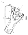
図2は、図1に示されるカートベースのロボット制御可能なシステムからのカートの実施形態の詳細な図を提供する。カート11は、概して、細長い支持構造14(「カラム」と呼ばれることが多い)、カート基部15、及びカラム14の頂部にあるコンソール16を含む。カラム14は、1つ又は2つ以上のロボットアーム12(図2には3つ示されている)の展開を支持するためのキャリッジ17(代替的に「アーム支持体」)などの1つ又は2つ以上のキャリッジを含んでもよい。キャリッジ17は、患者に対してより良好に位置決めするようロボットアーム12の基部を調整するために、垂直軸に沿って回転する個別に構成可能なアームマウントを含んでもよい。キャリッジ17はまた、キャリッジ17がカラム14に沿って垂直方向に並進することを可能にするキャリッジインターフェース19を含む。
FIG. 2 provides a detailed view of an embodiment of a cart from the cart-based robotic controllable system shown in FIG.
キャリッジインターフェース19は、キャリッジ17の垂直方向の並進を案内するためにカラム14の両側に配置されたスロット20などのスロットを通してカラム14に接続されている。スロット20は、カート基部15に対して様々な垂直方向の高さでキャリッジを配置及び保持するための垂直方向の並進インターフェースを含む。キャリッジ17の垂直方向の並進により、カート11が、様々なテーブルの高さ、患者のサイズ、及び医師の好みを満たすようにロボットアーム12の到達を調整することを可能にする。同様に、キャリッジ17上の個別に構成可能なアームマウントにより、ロボットアーム12のロボットアーム基部21が様々な構成で角度付けされることを可能にする。
いくつかの実施形態では、スロット20には、キャリッジ17が垂直方向に並進する際に、カラム14の内部チャンバ及び垂直方向の並進インターフェース内への汚れ及び流体の侵入を防止するためにスロット表面と同一平面及び平行であるスロットカバーが追加されてもよい。スロットカバーは、スロット20の垂直方向の頂部及び底部付近に配置されたばねスプールの対を通じて展開されてもよい。カバーはスプール内でコイル巻きにされており、キャリッジ17が垂直方向に上下に並進する際に、それらのコイル状から展開して延在し、後退する。スプールのばね荷重は、キャリッジ17がスプールに向かって並進するときにカバーをスプール内に後退させるための力を提供する一方で、キャリッジ17がスプールから離れるように並進するときに密封も維持する。カバーは、キャリッジ17が並進する際にカバーの適切な延在及び後退を確実にするために、例えば、キャリッジインターフェース19内のブラケットを使用してキャリッジ17に接続されてもよい。
In some embodiments, the
カラム14は、例えば、コンソール16からの入力などのユーザ入力に応答して生成された制御信号に応答してキャリッジ17を機械的に並進させるために垂直方向に整列した主ねじを使用するように設計された歯車及びモータなどの機構を内部的に含んでもよい。
Column 14 employs vertically aligned lead screws to mechanically translate carriage 17 in response to control signals generated in response to user input, such as input from
ロボットアーム12は、一般に一連の関節24によって接続されている一連の連結部23によって分離したロボットアーム基部21及びエンドエフェクタ22を含んでもよく、各関節は独立したアクチュエータを含み、各アクチュエータは、独立して制御可能なモータを含む。それぞれ独立して制御可能な関節は、ロボットアームに利用可能な独立した自由度を表す。アーム12の各々は、7つの関節を有し、したがって、7つの自由度を提供する。多数の関節は、多数の自由度をもたらし、「冗長」自由度を可能にする。冗長自由度は、ロボットアーム12が、異なる連結ポジション及び関節角度を使用して空間内の特定のポジション、向き、及び軌道で、それらのそれぞれのエンドエフェクタ22を配置することを可能にする。これにより、医師がアーム関節を患者から離れる臨床的に有利なポジションへと移動させて、アーム衝突を回避しつつ、より大きなアクセスを作り出すことを可能にしながら、システムが空間内の所望のポイントから医療用器具を配置及び指向させることを可能にする。
The
カート基部15は、床の上のカラム14、キャリッジ17及びアーム12の重量の釣り合いをとる。したがって、カート基部15は、電子機器、モータ、電源、及びカートの移動及び/又は固定化のいずれかを可能にする構成要素などの、より重い部品を収容する。例えば、カート基部15は、処置前にカートが部屋のあちこちを容易に移動することを可能にする、転動可能なホイール形状のキャスター25を含む。適切なポジションに到達した後、キャスター25は、処置中にカート11を定位置に保持するために、ホイールロックを使用して固定化されてもよい。
The
カラム14の垂直方向の端部に配置されたコンソール16は、ユーザ入力を受信するためのユーザインターフェース及び表示画面(又は、例えば、タッチスクリーン26などの二重目的デバイス)の両方を可能にして、術前データ及び術中データの両方を医師のユーザに提供する。タッチスクリーン26上の潜在的な術前データは、術前計画、術前コンピュータ断層撮影(computerized tomography、CT)スキャンから導出されたナビゲーション及びマッピングデータ、及び/又は患者との手術前問診からのメモを含んでもよい。ディスプレイ上の術中データは、ツールから提供される光学情報、センサからのセンサ及び座標情報、及び呼吸、心拍数、及び/又はパルスなどのバイタル患者統計を含んでもよい。コンソール16は、医師が、キャリッジ17の反対側でカラム14の側からコンソールにアクセスすることを可能にするように配置及び傾斜されてもよい。このポジションから、医師は、コンソール16をカート11の背後から操作しながらコンソール16、ロボットアーム12、及び患者を見ることができる。図示のように、コンソール16はまた、カート11の操作及び安定化を支援するハンドル27を含む。
図3は、尿管鏡検査のために構成されたロボット制御可能なシステム10の実施形態を示す。尿管鏡検査処置では、カート11は、患者の尿道及び尿管を横断するように設計された処置専用内視鏡である尿管鏡32を患者の下腹部領域に送達するように配置されてもよい。尿管鏡検査では、尿管鏡32が患者の尿道と直接整列して、領域内の敏感な解剖学的構造に対する摩擦及び力を低減することが望ましいことがある。図示のように、カート11は、ロボットアーム12が患者の尿道への直接的な線形アクセスのために、尿管鏡32を配置することを可能にするためにテーブルの脚部に整列されてもよい。テーブルの脚部から、ロボットアーム12は、尿道を通して患者の下腹部に直接、仮想レール33に沿って尿管鏡32を挿入してもよい。
FIG. 3 shows an embodiment of a robotically
気管支鏡検査のような同様の制御技法を使用して、尿道への挿入後、尿管鏡32は、診断及び/又は治療用途のために膀胱、尿管、及び/又は腎臓にナビゲートされてもよい。例えば、尿管鏡32は、尿管及び腎臓に指向されて、尿管鏡32の作業チャネルの下方に展開されたレーザー又は超音波砕石デバイスを使用して大きくなっている腎臓結石を破壊することができる。砕石術が完了した後、得られた結石片は、尿管鏡32の下方に展開されたバスケットを使用して除去されてもよい。
Using similar control techniques such as bronchoscopy, after insertion into the urethra, the
図4は、血管処置のために同様に構成されたロボット制御可能なシステムの実施形態を示す。血管処置において、システム10は、カート11が、操縦可能なカテーテルなどの医療用器具34を、患者の脚内の大腿動脈内のアクセスポイントに送達することができるように構成され得る。大腿動脈は、ナビゲーションのためのより大きな直径と、患者の心臓への、比較的迂回性でも蛇行性でもない経路との両方を呈し、これによりナビゲーションが単純化する。尿管鏡処置のように、カート11は、患者の脚及び下腹部に向かって配置されて、ロボットアーム12が患者の大腿/腰領域内の大腿動脈アクセスポイントへの直接的な線形アクセスで仮想レール35を提供することを可能にしてもよい。動脈内への挿入後、医療用器具34は、器具ドライバ28を並進させることによって指向され、挿入されてもよい。代替的には、カートは、例えば、肩付近の頚動脈及び手首付近の腕動脈などの代替的な血管アクセスポイントに到達するために、患者の上腹部の周囲に配置されてもよい。
FIG. 4 shows an embodiment of a robotically controllable system similarly configured for vascular procedures. In a vascular procedure, the
B.ロボットシステム-テーブル
ロボット制御可能な医療システムの実施形態はまた、患者のテーブルを組み込んでもよい。テーブルの組み込みは、カートを除去することによって手術室内の資本設備の量を低減し、患者へのより大きなアクセスを可能にする。図5は、気管支鏡検査処置のために構成されたこのようなロボット制御可能なシステムの実施形態を示す。システム36は、床の上にプラットフォーム38(「テーブル」又は「ベッド」として図示)を支持するための支持構造体又はカラム37を含む。カートベースのシステムと同様に、システム36のロボットアーム39のエンドエフェクタは、器具ドライバ42の線形整列から形成された仮想レール41を通して、又はそれに沿って、図5の気管支鏡40などの細長い医療用器具を操作するように設計された器具ドライバ42を含む。実際には、X線透視撮像を提供するためのCアームは、放射器及び検出器をテーブル38の周囲に置くことによって、患者の上部腹部領域の上方に配置されてもよい。
B. Robotic System—Table Embodiments of the robotic controllable medical system may also incorporate a patient table. Incorporating a table reduces the amount of capital equipment in the operating room by eliminating carts and allows greater access to the patient. FIG. 5 shows an embodiment of such a robotically controllable system configured for bronchoscopy procedures.
図6は、説明を目的として患者及び医療用器具なしのシステム36の代替図を提供する。図示のように、カラム37は、1つ又は2つ以上のロボットアーム39がベースとなり得るシステム36内でリング形状として図示される1つ又は2つ以上のキャリッジ43を含んでもよい。キャリッジ43は、カラム37の長さにわたる垂直方向のカラムインターフェース44に沿って並進して、ロボットアーム39が患者に到達するように配置され得る異なるバンテージポイントを提供してもよい。キャリッジ43は、カラム37内に配置された機械的モータを使用してカラム37の周りを回転して、ロボットアーム39が、例えば患者の両側などのテーブル38の複数の側面へのアクセスを有することを可能にしてもよい。複数のキャリッジを有する実施形態では、キャリッジはカラム上に個別に配置されてもよく、他のキャリッジとは独立して並進及び/又は回転してもよい。キャリッジ43はカラム37を取り囲む必要はなく、又は円形である必要すらないが、図示されるようなリング形状は、構造的バランスを維持しながらカラム37の周りでキャリッジ43の回転を容易にする。キャリッジ43の回転及び並進により、システムは、内視鏡及び腹腔鏡などの医療用器具を患者の異なるアクセスポイントに整列させることを可能にする。
FIG. 6 provides an alternative view of the
アーム39は、ロボットアーム39に追加の構成可能性を提供するために個別に回転及び/又は入れ子式に延在し得る一連の関節を含むアームマウント45のセットを通じてキャリッジに装着されてもよい。加えて、アームマウント45は、キャリッジ43が適切に回転されるとき、アームマウント45がテーブル38の同じ側(図6に示すように)、テーブル38の両側(図9に示すように)、又はテーブル38の隣接する側部(図示せず)のいずれかに配置され得るように、キャリッジ43に配置され得る。
The
カラム37は、テーブル38の支持及びキャリッジの垂直方向の並進のための経路を構造的に提供する。内部的に、カラム37には、キャリッジの垂直方向の並進を案内するための主ねじ、及び主ねじに基づくキャリッジの並進を機械化するためのモータが備えられ得る。カラム37はまた、キャリッジ43及びその上に装着されたロボットアーム39に電力及び制御信号を伝達してもよい。
テーブル基部46は、図2に示すカート11のカート基部15と同様の機能を果たし、テーブル/ベッド38、カラム37、キャリッジ43及びロボットアーム39の釣り合いをとるためにより重い構成要素を収容する。テーブル基部46はまた、処置中に安定性を提供するために剛性キャスターを組み込んでもよい。テーブル基部46の底部から展開されるキャスターは、基部46の両側で反対方向に延在し、システム36を移動させる必要があるときに後退させてもよい。
引き続き図6によれば、システム36はまた、テーブルとタワーとの間のシステム36の機能を分割して、テーブルのフォームファクタ及び大きさを低減するタワー(図示せず)を含んでもよい。先に開示された実施形態と同様に、タワーは、処理、計算、及び制御能力、電力、流体光学、及び/又は光学及びセンサ処理などの様々なサポート機能をテーブルに提供してもよい。タワーはまた、医師のアクセスを改善し、手術室を整理整頓するために、患者から離れて配置されるように移動可能であってもよい。加えて、タワー内に構成要素を置くことにより、ロボットアームの潜在的な収納のために、テーブル基部内により多くの保管空間を可能にする。タワーはまた、キーボード及び/又はペンダントなどのユーザ入力のためのユーザインターフェースと、リアルタイム撮像、ナビゲーション、及び追跡情報などの術前及び術中情報のための表示画面(又はタッチスクリーン)との両方を提供するコンソールを含んでもよい。
Continuing with FIG. 6,
いくつかの実施形態では、テーブル基部は、使用されていないときにロボットアームを収容して格納してもよい。図7は、テーブルベースのシステムの一実施形態におけるロボットアームを収容するシステム47を示す。システム47では、キャリッジ48は、ロボットアーム50、アームマウント51及びキャリッジ48を基部49内に収容するように基部49へと垂直方向に並進されてもよい。基部カバー52は、キャリッジ48、アームマウント51及びアーム50をカラム53の周りに展開させるように開放し、使用されていないときにそれらを保護するために収容するように閉鎖されるように、並進したり後退したりしてもよい。基部カバー52は、閉鎖したときに汚れ及び流体の侵入を防止するために、その開口の縁部に沿ってメンブレン54で封止されてもよい。
In some embodiments, the table base may house and store the robotic arm when not in use. FIG. 7 shows a system 47 housing a robotic arm in one embodiment of a table-based system. In system 47 ,
図8は、尿管鏡検査処置のために構成されたロボット制御可能なテーブルベースのシステムの一実施形態を示す。尿管鏡検査では、テーブル38は、患者をカラム37及びテーブル基部46からオフアングルに配置するためのスイベル部分55を含んでもよい。スイベル部分55は、スイベル部分55の底部をカラム37から離すように配置するために、旋回点(例えば、患者の頭部の下に位置する)の周りで回転又は旋回してもよい。例えば、スイベル部分55の旋回により、Cアーム(図示せず)が、テーブル38の下のカラム(図示せず)との空間を競合することなく、患者の下部腹部の上方に配置されることを可能にする。カラム37の周りにキャリッジ35(図示せず)を回転させることにより、ロボットアーム39は、仮想レール57に沿って、患者の鼠径部領域に直接尿管鏡56を挿入し尿道に到達させてもよい。尿管鏡検査では、あぶみ58はまた、処置中に患者の脚のポジションを支持し、患者の鼠径部領域への明確なアクセスを可能にするために、テーブル38のスイベル部分55に固定されてもよい。
FIG. 8 illustrates one embodiment of a robotically controllable table-based system configured for ureteroscopy procedures. For ureteroscopy, the table 38 may include a
腹腔鏡処置では、患者の腹壁内の小さな切開部を通して、低侵襲性器具(1つ又は2つ以上の切開部のサイズに適応するように形状が細長い)を患者の解剖学的構造に挿入してもよい。患者の腹腔の膨張後、腹腔鏡と呼ばれることが多い器具は、把持、切断、アブレーション、縫合などの外科的タスクを行うように指向されてもよい。図9は、腹腔鏡処置のために構成されたロボット制御可能なテーブルベースのシステムの実施形態を示す。図9に示されるように、システム36のキャリッジ43は回転され垂直方向に調整されて、腹腔鏡59が患者の両側の最小切開部を通過して患者の腹腔に到達するようにアームマウント45を使用し配置され得るように、ロボットアーム39の対をテーブル38の両側に配置してもよい。
In a laparoscopic procedure, a minimally invasive instrument (elongated in shape to accommodate the size of one or more incisions) is inserted into the patient's anatomy through a small incision in the patient's abdominal wall. may After inflation of the patient's abdominal cavity, instruments often referred to as laparoscopes may be directed to perform surgical tasks such as grasping, cutting, ablating, suturing, and the like. FIG. 9 shows an embodiment of a robotically controllable table-based system configured for laparoscopic procedures. As shown in FIG. 9,
腹腔鏡処置に対応するために、ロボット制御可能なテーブルシステムはまた、プラットフォームを所望の角度に傾斜させてもよい。図10は、ピッチ又は傾斜調整を有するロボット制御可能な医療システムの実施形態を示す。図10に示すように、システム36は、テーブル38の傾斜に適応して、テーブルの一方側の部分を他方側の部分よりも床から遠い距離に配置することができる。加えて、アームマウント45は、アーム39がテーブル38と同じ平面関係を維持するように、傾斜に一致するように回転してもよい。急角度に適応するように、カラム37はまた、テーブル38が床に接触するか、又は基部46と衝突するのを防ぐために、カラム37の垂直方向の延在を可能にする入れ子部分60を含んでもよい。
To accommodate laparoscopic procedures, the robotically controllable table system may also tilt the platform to a desired angle. FIG. 10 shows an embodiment of a robotically controllable medical system with pitch or tilt adjustment. As shown in FIG. 10, the
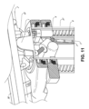
図11は、テーブル38とカラム37との間のインターフェースの詳細な図示を提供する。ピッチ回転機構61は、複数の自由度において、カラム37に対するテーブル38のピッチ角を変更するように構成されてもよい。ピッチ回転機構61は、カラム-テーブルインターフェースでの直交軸1、2の位置決めによって可能にされてもよく、各軸は、電気ピッチ角コマンドに応答して別個のモータ3、4によって作動される。一方のねじ5に沿った回転は、一方の軸1における傾斜調整を可能にし、他方のねじ6に沿った回転は、他方の軸2に沿った傾斜調整を可能にする。
FIG. 11 provides a detailed illustration of the interface between table 38 and
例えば、ピッチ調整は、トレンデレンブルグ体位にテーブルを配置、すなわち下腹部手術のために患者の下腹部よりも床からより高いポジションに患者の下腹部を位置させようとするときに、特に有用である。トレンデレンブルグ体位は、患者の内臓を重力によって自分の上腹部に向かってスライドさせ、低侵襲性ツールのために腹腔を空にして腹腔鏡前立腺切除術などの下腹部外科処置に移行し、これを行う。 For example, pitch adjustment is particularly useful when trying to place the table in the Trendelenburg position, i.e., position the patient's lower abdomen higher off the floor than the patient's lower abdomen for lower abdominal surgery. be. The Trendelenburg position allows the patient's internal organs to slide toward their upper abdomen by gravity, emptying the abdominal cavity for minimally invasive tools and transitioning to a lower abdominal surgical procedure such as laparoscopic prostatectomy. I do.
C.器具ドライバ及びインターフェース
システムのロボットアームのエンドエフェクタは、(i)医療用器具を作動させるための電気機械的手段を組み込む器具ドライバ(代替的には、「器具駆動機構」又は「器具デバイスマニピュレータ」と呼ばれる)と、(ii)モータなどの任意の電気機械的構成要素を欠いていてもよい除去可能な又は取り外し可能な医療用器具と、を含む。この二分法は、医療処置に使用される医療用器具を滅菌する必要性、それらの複雑な機械的アセンブリ及繊細な電子機器により、高価な資本設備を十分に滅菌することができないことにより推進され得る。したがって、医療用器具は、医師又は医師のスタッフによる個々の滅菌又は廃棄のために、器具ドライバ(したがってそのシステム)から取り外され、除去され、及び交換されるように設計され得る。対照的に、器具ドライバは交換又は滅菌される必要がなく、保護のために掛け布がされ得る。
C. The end effector of the robotic arm of the instrument driver and interface system includes: (i) an instrument driver (alternatively referred to as an "instrument drive mechanism" or "instrument device manipulator") that incorporates electromechanical means for actuating a medical instrument; (ii) removable or detachable medical devices, which may lack any electromechanical components, such as motors. This dichotomy is driven by the need to sterilize medical instruments used in medical procedures, their complex mechanical assemblies and delicate electronics, and the inability to adequately sterilize expensive capital equipment. obtain. Thus, medical instruments can be designed to be detached, removed, and replaced from the instrument driver (and thus the system) for individual sterilization or disposal by a physician or physician's staff. In contrast, instrument drivers do not need to be replaced or sterilized and can be draped for protection.
図12は、例示的な器具ドライバを示す。ロボットアームの遠位端に配置される器具ドライバ62は、駆動シャフト64を介して医療用器具に制御トルクを提供するために平行軸を伴って構成された1つ又は2つ以上の駆動ユニット63を含む。各駆動ユニット63は、器具と相互作用するための個々の駆動シャフト64と、モータシャフトの回転を所望のトルクに変換するためのギヤヘッド65と、駆動トルクを生成するためのモータ66と、モータシャフトの速度を測定し、制御回路にフィードバックを提供するエンコーダ67と、制御信号を受信し、駆動ユニットを作動させるための制御回路68と、を含む。各駆動ユニット63は独立して制御及び電動化され、器具ドライバ62は、複数(図12に示すように4つ)の独立した駆動出力を医療用器具に提供してもよい。動作中、制御回路68は、制御信号を受信し、モータ66にモータ信号を送信し、エンコーダ67によって測定された、得られたモータ速度を所望の速度と比較し、モータ信号を変調して所望のトルクを生成する。
FIG. 12 shows an exemplary instrument driver. An
無菌環境を必要とする処置のために、ロボットシステムは、器具ドライバと医療用器具との間に位置する無菌ドレープに接続された無菌アダプタなどの駆動インターフェースを組み込んでもよい。無菌アダプタの主な目的は、器具ドライバの駆動シャフトから器具の駆動入力に角度運動を伝達する一方で、物理的分離を維持し、したがって、駆動シャフトと駆動入力との間で無菌性を維持することである。したがって、例示的な無菌アダプタは、器具ドライバの駆動シャフトと嵌合されることを意図した一連の回転入力部及び出力部と器具に対する駆動入力部で構成され得る。無菌アダプタに接続される無菌ドレープは、透明又は半透明プラスチックなどの薄い可撓性材料で構成され、器具ドライバ、ロボットアーム、及び(カートベースのシステムにおける)カート又は(テーブルベースのシステムにおける)テーブルなどの資本設備を覆うように設計される。ドレープの使用は、滅菌を必要としない領域(すなわち、非滅菌野)に依然として位置している間に、資本設備が患者に近接して配置されることを可能にするであろう。滅菌ドレープの他方の側では、医療用器具は、滅菌を必要とする領域(すなわち、滅菌野)において患者とインターフェースしてもよい。 For procedures requiring a sterile environment, the robotic system may incorporate a drive interface such as a sterile adapter connected to a sterile drape positioned between the instrument driver and the medical instrument. The primary purpose of the sterile adapter is to transmit angular motion from the drive shaft of the instrument driver to the drive input of the instrument while maintaining physical separation and therefore sterility between the drive shaft and the drive input. That is. Thus, an exemplary sterile adapter can be configured with a series of rotary inputs and outputs intended to mate with the drive shaft of an instrument driver and a drive input to the instrument. A sterile drape, which is connected to a sterile adapter, is constructed of a thin, flexible material, such as transparent or translucent plastic, and is used to attach instrument drivers, robotic arms, and carts (in cart-based systems) or tables (in table-based systems). Designed to cover capital equipment such as The use of drapes would allow capital equipment to be placed in close proximity to the patient while still located in areas that do not require sterilization (ie, non-sterile fields). On the other side of the sterile drape, medical instruments may interface with the patient in areas requiring sterilization (ie, the sterile field).
D.医療用器具
図13は、ペアにされた器具ドライバを備えた例示的な医療用器具を示す。ロボットシステムと共に使用するために設計された他の器具と同様に、医療用器具70は、細長いシャフト71(又は細長い本体)及び器具基部72を含む。医師による手動相互作用のために意図された設計により「器具ハンドル」とも呼ばれる器具基部72は、概して、ロボットアーム76の遠位端で器具ドライバ75上の駆動インターフェースを通って延在する駆動出力部74と嵌合するように設計された、回転可能な駆動入力部73、例えば、レセプタクル、プーリ、又はスプールを含んでもよい。物理的に接続され、ラッチされ、かつ/又は結合されるときに、器具基部72の嵌合された駆動入力部73は、器具ドライバ75における駆動出力部74と回転軸を共有してもよく、駆動出力部74から駆動入力部73へのトルクの伝達を可能する。いくつかの実施形態では、駆動出力部74は、駆動入力部73上のレセプタクルと嵌合するように設計されたスプラインを含んでもよい。
D. Medical Instruments FIG. 13 shows an exemplary medical instrument with paired instrument drivers. As with other instruments designed for use with robotic systems,
細長いシャフト71は、例えば、内視鏡検査におけるような解剖学的開口部若しくは管腔、又は腹腔鏡検査におけるような低侵襲性切開部のいずれかを通して送達されるように設計されている。細長いシャフト66は、可撓性(例えば、内視鏡と同様の特性を有する)若しくは剛性(例えば、腹腔鏡と同様の特性を有する)、又は可撓性部分及び剛性部分の両方のカスタマイズされた組み合わせを含むこと、のいずれかであってもよい。腹腔鏡検査のために設計されるとき、剛性の細長いシャフトの遠位端は、回転軸を有するクレビスから形成される接合された手首部と、例えば、駆動入力部が器具ドライバ75の駆動出力部74から受け取ったトルクに応答して回転する際に、腱からの力に基づいて作動され得る把持具又ははさみである手術用ツールを含むエンドエフェクタに接続され得る。内視鏡検査のために設計されるときに、可撓性の細長いシャフトの遠位端は、器具ドライバ75の駆動出力部74から受信したトルクに基づいて関節運動及び屈曲され得る操縦可能又は制御可能な屈曲部を含んでもよい。
Elongated shaft 71 is designed to be delivered through either an anatomical opening or lumen, such as in endoscopy, or a minimally invasive incision, such as in laparoscopy, for example.
器具ドライバ75からのトルクは、シャフト71内の腱を使用して細長いシャフト71の下方に伝達される。プルワイヤなどのこれらの個々の腱は、器具ハンドル72内の個々の駆動入力部73に個別に固設されてもよい。ハンドル72から、腱は、細長いシャフト71内の1つ又は2つ以上のプルルーメン(pull lumen)を下方に指向され、細長いシャフト71の遠位部分に固設される。腹腔鏡検査では、これらの腱は、手首部、把持具、又ははさみなどの遠位に装着されたエンドエフェクタに結合されてもよい。このような構成の下で、駆動入力部73に及ぼされるトルクは、腱に張力を伝達し、それによってエンドエフェクタを何らかの方法で作動させる。腹腔鏡検査では、腱は、関節を軸周りに回転させることができ、それによってエンドエフェクタを一方向又は別の方向に移動させる。あるいは、腱は、細長いシャフト71の遠位端で把持具の1つ又は2つ以上のジョーに接続されてもよく、腱からの張力によって把持具が閉鎖される。
Torque from the
内視鏡検査では、腱は、接着剤、制御リング、又は他の機械的固定を介して、細長いシャフト71に沿って(例えば、遠位端に)配置された屈曲又は関節運動部に結合されてもよい。屈曲部の遠位端に固定的に取り付けられるときに、駆動入力部73に及ぼされるトルクは、腱の下方に伝達され、より軟質の屈曲部に(関節運動可能部又は領域と呼ばれることがある)を屈曲又は関節運動させる。非屈曲部分に沿って、個々の腱を内視鏡シャフトの壁に沿って(又は壁の内側に)指向する個々のプルルーメンを螺旋状又は渦巻状にして、プルワイヤにおける張力からもたらされる半径方向の力の釣り合いをとることが有利であり得る。これらの間の螺旋及び/又は間隔の角度は、特定の目的のために変更又は改変されてもよく、より狭い螺旋は負荷力下でより小さいシャフト圧縮を呈する一方で、より少ない量の螺旋は負荷力下でより大きなシャフト圧縮をもたらすが、屈曲制限も呈する。スペクトルのもう一方の端部では、プルルーメンは、細長いシャフト71の長手方向軸に平行に指向されてもよく、所望の屈曲又は関節運動可能部における制御された関節運動を可能にする。
During endoscopy, the tendon is coupled via adhesives, control rings, or other mechanical fixation to a flexure or articulation located along the elongated shaft 71 (eg, at the distal end). may When fixedly attached to the distal end of the flexure, torque exerted on the
内視鏡検査では、細長いシャフト71は、ロボット処置を支援する多数の構成要素を収容する。シャフトは、シャフト71の遠位端における手術領域への手術用ツールの展開、灌注、及び/又は吸引のための作業チャネルを含んでもよい。シャフト71はまた、光学カメラを含んでもよい遠位先端で光学アセンブリに/光学アセンブリから信号を伝達するために、ワイヤ及び/又は光ファイバを収容してもよい。シャフト71はまた、近位に位置する発光ダイオードなどの光源からシャフトの遠位端に光を搬送するための光ファイバを収容してもよい。 In endoscopy, elongated shaft 71 houses a number of components that assist in robotic procedures. The shaft may include a working channel for deploying, irrigating, and/or aspirating surgical tools to the surgical area at the distal end of shaft 71 . Shaft 71 may also accommodate wires and/or optical fibers to transmit signals to/from the optical assembly at the distal tip, which may include an optical camera. Shaft 71 may also contain an optical fiber for carrying light from a proximally located light source, such as a light emitting diode, to the distal end of the shaft.
器具70の遠位端では、遠位先端はまた、診断及び/又は治療、潅注、及び吸引のためのツールを手術部位に送達するための作業チャネルの開口部を含んでもよい。遠位先端はまた、内部解剖学的空間の画像をキャプチャするために、繊維スコープ又はデジタルカメラなどのカメラのためのポートを含んでもよい。関連して、遠位先端はまた、カメラを使用するときに解剖学的空間を照明するための光源のためのポートを含んでもよい。
At the distal end of
図13の例では、駆動シャフト軸、したがって駆動入力軸は、細長いシャフトの軸に直交する。しかしながら、この配置は、細長いシャフト71のロール能力を複雑にする。駆動入力部73を静止させながら、細長いシャフト71をその軸に沿ってロールさせることにより、駆動入力部73から延出し、細長いシャフト71内のプルルーメンに入る際に、腱の望ましくない絡まりをもたらす。もたらされたそのような腱のもつれは、内視鏡処置中の可撓性の細長いシャフトの移動を予測することを意図した何らかの制御アルゴリズムを中断させることがある。
In the example of Figure 13, the drive shaft axis, and thus the drive input axis, is orthogonal to the axis of the elongated shaft. However, this arrangement complicates the rolling ability of the elongated shaft 71 . Rolling the elongated shaft 71 along its axis while the
図14は、駆動ユニットの軸が器具の細長いシャフトの軸に平行である、器具ドライバ及び器具の代替的な設計を示す。図示のように、円形の器具ドライバ80は、ロボットアーム82の端部において平行に整列された駆動出力部81を備えた4つの駆動ユニットを含む。駆動ユニット及びそれらのそれぞれの駆動出力部81は、アセンブリ83内の駆動ユニットのうちの1つによって駆動される器具ドライバ80の回転アセンブリ83内に収容される。回転駆動ユニットによって提供されるトルクに応答して、回転アセンブリ83は、回転アセンブリ83を器具ドライバの非回転部分84に接続する円形ベアリングに沿って回転する。電力及び制御信号は、電気接点を通して器具ドライバ80の非回転部分84から回転アセンブリ83に伝達されてもよく、ブラシ付きスリップリング接続(図示せず)による回転を通して維持されてもよい。他の実施形態では、回転アセンブリ83は、非回転可能部分84に一体化され、したがって他の駆動ユニットと平行ではない別個の駆動ユニットに応答してもよい。回転機構83は、器具ドライバ80が、器具ドライバ軸85周りの単一ユニットとして、駆動ユニット及びそれらのそれぞれの駆動出力部81を回転させることを可能にする。
Figure 14 shows an alternative design of the instrument driver and instrument in which the axis of the drive unit is parallel to the axis of the elongated shaft of the instrument. As shown,
先に開示した実施形態と同様に、器具86は、細長いシャフト部分88と、器具ドライバ80内の駆動出力部81を受けるように構成された複数の駆動入力部89(レセプタクル、プーリ、及びスプールなど)を含む器具基部87(説明目的のために透明な外部スキンで示される)とを含んでもよい。以前に開示されている実施形態とは異なり、器具シャフト88は、図13の設計のように直交するのではなく、駆動入力部89の軸に実質的に平行な軸を有する器具基部87の中心から延在する。
As with the previously disclosed embodiments, the
器具ドライバ80の回転アセンブリ83に結合されるときに、器具基部87及び器具シャフト88を含む医療用器具86は、器具ドライバ軸85を中心に回転アセンブリ83との組み合わせで回転する。器具シャフト88は器具基部87の中心に配置されているため、器具シャフト88は、取り付けられたときに器具ドライバ軸85と同軸である。したがって、回転アセンブリ83の回転により、器具シャフト88は、それ自体の長手方向軸を中心に回転する。更に、器具基部87が器具シャフト88と共に回転すると、器具基部87内の駆動入力部89に接続されたいかなる腱も、回転中に絡まらない。したがって、駆動出力部81、駆動入力部89及び器具シャフト88の軸の平行性は、いかなる制御腱も絡ませることなくシャフト回転を可能にする。
When coupled to rotating
E.ナビゲーション及び制御
従来の内視鏡検査は、(例えば、Cアームを通して送達され得るような)蛍光透視法の使用、及び操作者の医師に腔内誘導を提供するための他の形態の放射線ベースの撮像モダリティの使用を伴うことがある。対照的に、本開示によって企図されるロボットシステムは、医師の放射線への曝露を低減し、手術室内の機器の量を低減するための非放射線ベースのナビゲーション及び位置特定手段を提供することができる。本明細書で使用するとき、用語「位置特定」は、基準座標系内のオブジェクトのポジションを判定及び/又は監視することを指すことがある。術前マッピング、コンピュータビジョン、リアルタイムEM追跡、及びロボットコマンドデータなどの技術は、放射線を含まない動作環境を達成するために個別に又は組み合わせて使用されてもよい。放射線ベースの撮像モダリティが依然として使用される場合、術前マッピング、コンピュータビジョン、リアルタイムEM追跡、及びロボットコマンドデータは、放射線ベースの撮像モダリティによってのみ取得される情報を改善するために、個別に又は組み合わせて使用されてもよい。
E. Navigation and Control Conventional endoscopy involves the use of fluoroscopy (for example, as it can be delivered through a C-arm) and other forms of radiation-based guidance to provide intraluminal guidance to the operator's physician. May involve the use of imaging modalities. In contrast, robotic systems contemplated by the present disclosure can provide non-radiation-based navigation and localization means for reducing the physician's exposure to radiation and reducing the amount of equipment in the operating room. . As used herein, the term "localization" may refer to determining and/or monitoring the position of an object within a reference coordinate system. Technologies such as preoperative mapping, computer vision, real-time EM tracking, and robotic command data may be used individually or in combination to achieve a radiation-free operating environment. If radiation-based imaging modalities are still used, preoperative mapping, computer vision, real-time EM tracking, and robotic command data may be used individually or in combination to improve the information obtained only by radiation-based imaging modalities. may be used as
図15は、例示的な実施形態による、器具の位置などのロボットシステムの1つ又は2つ以上の要素の位置を推定する位置特定システム90を示すブロック図である。位置特定システム90は、1つ又は2つ以上の命令を実行するように構成されている1つ又は2つ以上のコンピュータデバイスのセットであってもよい。コンピュータデバイスは、上述の1つ又は2つ以上の構成要素内のプロセッサ(又は複数のプロセッサ)及びコンピュータ可読メモリによって具現化されてもよい。例として、限定するものではないが、コンピュータデバイスは、図1に示されるタワー30、図1~図4に示されるカート、図5~図10に示されるベッド等の内部にあってもよい。
FIG. 15 is a block diagram illustrating a
図15に示すように、位置特定システム90は、入力データ91~94を処理して医療用器具の遠位先端のための位置データ96を生成する位置特定モジュール95を含んでもよい。位置データ96は、基準系に対する器具の遠位端の位置及び/又は配向を表すデータ又は論理であってもよい。基準系は、患者の解剖学的構造、又はEM場発生器(EM場発生器について以下の説明を参照)などの既知の物体に対する基準系とすることができる。位置データ96はまた、本明細書では、患者の解剖学的構造のモデル(例えば、骨格モデル)に対する医療用器具の遠位先端の現在の状態を説明する「状態データ」とも称され得る。状態データは、所与のサンプル期間に対する医療用器具の遠位先端のポジション及び配向などの情報を含んでもよい。例えば、患者の解剖学的構造が、管腔網の中点に基づいて骨格モデルを使用してモデル化されるとき、そのポジションは、セグメントID及びセグメントに沿った深さの形態を取ってもよい。
As shown in FIG. 15,
ここで、様々な入力データ91~94についてより詳細に説明する。術前マッピングは、低用量CTスキャンの収集を使用することを通して達成され得る。術前CTスキャンは、例えば、患者の内部解剖学的構造の切欠き図の「スライス」として可視化される3次元(3D)画像に再構成される。まとめて分析されるときに、患者の肺網などの患者の解剖学的構造の解剖学的空腔、空間、及び構造のための画像ベースのモデルが生成され得る。中心線幾何学形状などの技法を判定し、CT画像から概算して、術前モデルデータ91と称される患者の解剖学的構造の3Dボリュームを生成することができる。中心線幾何学形状の使用は、米国特許出願第14/523,760号において論じられており、その内容全体が本明細書に組み込まれる。ネットワークトポロジックモデルはまた、CT画像から導出されてもよく、気管支鏡検査に特に適している。
The various input data 91-94 will now be described in more detail. Preoperative mapping can be accomplished through the use of low-dose CT scan acquisitions. Pre-operative CT scans are reconstructed into three-dimensional (3D) images that are visualized, for example, as cutaway "slices" of the patient's internal anatomy. When analyzed together, an image-based model can be generated for the anatomical cavities, spaces, and structures of a patient's anatomy, such as the patient's pulmonary network. Techniques such as centerline geometry can be determined and approximated from CT images to generate a 3D volume of the patient's anatomy, referred to as
いくつかの実施形態では、器具にはカメラを装備して、ビジョンデータ92を提供してもよい。位置特定モジュール95は、ビジョンデータを処理して、1つ又は2つ以上のビジョンベースの位置追跡を可能にしてもよい。例えば、術前モデルデータは、医療用器具(例えば、内視鏡又は器具が内視鏡の作業チャネルを通って前進する)のコンピュータビジョンベースの追跡を可能にするために、ビジョンデータ92と共に使用されてもよい。例えば、術前モデルデータ91を使用して、ロボットシステムは、内視鏡の予想される移動経路に基づいてモデルから予測される内視鏡画像のライブラリを生成することができ、各画像はモデル内の位置にリンクされる。術中に、このライブラリは、カメラ(例えば、内視鏡の遠位端でのカメラ)でキャプチャされたリアルタイム画像を画像ライブラリ内のものと比較して、位置特定を支援するために、ロボットシステムによって参照され得る。
In some embodiments, the instrument may be equipped with cameras to provide
他のコンピュータビジョンベースの追跡技法は、カメラの、したがって内視鏡の動きを判定するための特徴追跡を使用する。位置特定モジュール95のいくつかの特徴は、解剖学的管腔に対応する術前モデルデータ91内の円形幾何学形状を特定し、どの解剖学的管腔が選択されたかと、カメラの相対的な回転及び/又は並進運動とを判定するためにそれらの幾何学的形状の変化を追跡してもよい。トポロジカルマップの使用は、ビジョンベースのアルゴリズム又は技法を更に向上させることがある。
Other computer vision-based tracking techniques use feature tracking to determine camera, and therefore endoscope, motion. Several features of the
光学フロー、別のコンピュータビジョンベースの技法は、カメラの動きを推測するために、ビジョンデータ92内のビデオシーケンス内の画像ピクセルの変位及び並進を分析してもよい。光学フロー技法の例としては、動き検出、オブジェクトセグメンテーション計算、輝度、動き補償符号化、立体視差測定等を挙げることができる。複数の反復にわたって複数のフレームを比較することにより、カメラ(及びしたがって内視鏡)の移動及び位置を判定することができる。
Optical flow, another computer vision-based technique, may analyze displacements and translations of image pixels within a video sequence within
位置特定モジュール95は、リアルタイムEM追跡を使用して、術前モデルによって表される患者の解剖学的構造に位置合わせされ得るグローバル座標系内で内視鏡のリアルタイム位置を生成し得る。EM追跡では、医療用器具(例えば、内視鏡器具)内の1つ又は2つ以上の位置及び配向に埋め込まれた1つ又は2つ以上のセンサコイルを含むEMセンサ(又はトラッカー)は、既知の位置に配置された1つ又は2つ以上の静的EM場発生器によって生成されるEM場の変動を測定する。EMセンサによって検出された位置情報は、EMデータ93として記憶される。EM場発生器(又は送信機)は、埋め込まれたセンサが検出し得る低強度磁場を生成するために、患者に近接して置かれ得る。磁場はEMセンサのセンサコイル内に小さな電流を誘導し、EMセンサとEM場発生器との間の距離及び角度を判定するために分析され得る。これらの距離及び配向は、患者の解剖学的構造の術前モデル内のポジションと座標系内の単一の位置を位置合わせする幾何学的変換を判定するために、患者の解剖学的構造(例えば、術前モデル)に術中「登録」され得る。一旦登録されると、医療用器具の1つ又は2つ以上のポジション(例えば、内視鏡の遠位先端)に埋め込まれたEMトラッカーは、患者の解剖学的構造を通じた医療用器具の進行のリアルタイム表示を提供し得る。
The
ロボットコマンド及び運動学データ94はまた、ロボットシステムのための位置特定データ96を提供するために、位置特定モジュール95によって使用されてもよい。関節運動コマンドから生じるデバイスピッチ及びヨーは、術前較正中に判定され得る。術中、これらの較正測定値は、既知の挿入深度情報と組み合わせて使用されて、器具のポジションを推定し得る。あるいは、これらの計算は、ネットワーク内の医療用器具のポジションを推定するために、EM、ビジョン、及び/又はトポロジカルモデリングと組み合わせて分析され得る。
Robot command and
図15が示すように、多数の他の入力データが位置特定モジュール95によって使用され得る。例えば、図15には示されていないが、形状検知繊維を利用する器具は、位置特定モジュール95が器具の位置及び形状を判定するために使用することができる形状データを提供することができる。
As FIG. 15 shows, numerous other input data may be used by the
位置特定モジュール95は、組み合わせた入力データ91~94を使用し得る。場合によっては、そのような組み合わせは、位置特定モジュール95が入力データ91~94の各々から判定された位置に信頼重みを割り当てる確率的アプローチを使用し得る。したがって、EMデータが信頼できるとはいえないことがある場合(EM干渉が存在する場合など)、EMデータ93によって判定された位置の信頼性を低下させることができ、位置特定モジュール95は、ビジョンデータ92並びに/又はロボットコマンド及び運動学データ94により重く依存してもよい。
上述のように、本明細書で論じられるロボットシステムは、上記の技術のうちの1つ又は2つ以上の組み合わせを組み込むように設計され得る。タワー、ベッド、及び/又はカートに基づいて、ロボットシステムのコンピュータベースの制御システムは、例えば、永続的な磁気記憶ドライブ、ソリッドステートドライブなどの非一時的コンピュータ可読記憶媒体内に、コンピュータプログラム命令を記憶してもよく、コンピュータプログラム命令は、実行されると、システムに、センサデータ及びユーザコマンドを受信及び分析させ、システム全体の制御信号を生成させ、グローバル座標系内の器具のポジション、解剖学的マップなどのナビゲーション及び位置特定データを表示させる。 As noted above, the robotic systems discussed herein may be designed to incorporate one or a combination of two or more of the above techniques. Based on a tower, bed, and/or cart, the robotic system's computer-based control system stores computer program instructions in non-transitory computer-readable storage media such as, for example, permanent magnetic storage drives, solid state drives, and the like. may be stored, and computer program instructions, when executed, cause the system to receive and analyze sensor data and user commands, generate system-wide control signals, determine instrument position within a global coordinate system, anatomy Display navigation and location data such as target maps.
2.位置センサの位置合わせへの導入
本開示の実施形態は、1つ又は2つ以上の位置センサによって使用される座標系を、解剖学的モデルによって使用される座標系などの別の座標系と位置合わせするためのシステム及び技法に関する。位置合わせは、位置センサデータに適用されて、位置センサデータを解剖学的モデルの座標系にマッピングすることができる変換を指し得る。したがって、位置合わせは、位置センサデータに基づいて解剖学的モデルに対する1つ又は2つ以上の位置センサの位置を判定するために、システムによって使用され得る。位置センサを使用して、医療処置中に器具の遠位端を解剖学的位置に位置特定することができる。位置センサは、器具の遠位端に若しくはその近くに位置決めされてもよく、又は器具の遠位端から離れて位置決めされてもよい。器具の遠位端に又はその近くに位置決めされ得る位置センサの例としては、EMセンサ、ビジョンベースの位置センサ(例えば、カメラ)、形状感知繊維等が挙げられる。器具の遠位端から離れて位置決めされ得る位置センサの例としては、X線透視撮像デバイス、1つ又は2つ以上の器具マニピュレータを介して器具のポジションを制御するために使用されるロボットデータ等が挙げられる。
2. Introduction to Position Sensor Alignment Embodiments of the present disclosure integrate the coordinate system used by one or more position sensors with another coordinate system, such as the coordinate system used by an anatomical model. Systems and techniques for matching. Registration may refer to a transformation that can be applied to the position sensor data to map the position sensor data to the coordinate system of the anatomical model. Registration can thus be used by the system to determine the position of one or more position sensors relative to the anatomical model based on the position sensor data. A position sensor can be used to localize the distal end of the instrument to an anatomical location during a medical procedure. The position sensor may be positioned at or near the distal end of the instrument, or may be positioned remote from the distal end of the instrument. Examples of position sensors that may be positioned at or near the distal end of the instrument include EM sensors, vision-based position sensors (eg, cameras), shape sensing fibers, and the like. Examples of position sensors that may be positioned remotely from the distal end of the instrument include fluoroscopic imaging devices, robotic data used to control instrument position via one or more instrument manipulators, and the like. is mentioned.
位置センサは、位置センサ座標系に対する器具の遠位端のポジションを示す位置データを生成するように構成されてもよい。位置センサが器具の遠位端と並置されるとき、位置データは、位置センサ自体の位置を表すことができ、これを使用して器具の遠位端の位置を判定することができる。ある特定の実施形態では、位置センサ座標系は、位置センサを実施するために使用される特定の技術に基づいて画定され得る、軸及び起点のセットを含んでもよい。 The position sensor may be configured to generate position data indicative of the position of the distal end of the instrument relative to the position sensor coordinate system. When the position sensor is juxtaposed with the distal end of the instrument, the position data can represent the position of the position sensor itself, which can be used to determine the position of the distal end of the instrument. In certain embodiments, the position sensor coordinate system may include a set of axes and origins that may be defined based on the particular technology used to implement the position sensor.
例えば、器具内又は器具上に位置するEMセンサは、EM場発生器によって生成されたEM場を測定するように構成され得る。EM場の特性、したがってEMセンサによって測定されるEM値は、EM場発生器の位置及び配向に関して定義され得る。したがって、EM場発生器の位置決めは、EMセンサによって測定された値に影響を及ぼすことができ、EM座標系の位置及び配向を定義することもできる。 For example, an EM sensor located in or on the instrument can be configured to measure the EM field produced by the EM field generator. The properties of the EM field, and thus the EM value measured by the EM sensor, can be defined with respect to the position and orientation of the EM field generator. Positioning of the EM field generator can therefore affect the values measured by the EM sensor and can also define the position and orientation of the EM coordinate system.
上述のように、患者の管腔網は、例えば、低用量CTスキャンを使用して術前にマッピングされて、管腔網のモデルを生成することができる。モデルは、器具の遠位端の位置を特定するために使用されるものとは異なる技法を介して生成され得るため、モデル座標系は、位置センサ座標系と整列されなくてもよい。したがって、位置センサ座標系を使用して、モデルに対する器具の位置を追跡するために、本開示のある特定の態様は、位置センサ座標系をモデル座標系に「位置合わせすること」に関する。この位置合わせは、例えば、位置データを位置センサ座標系からモデル座標系にマッピングするために位置データに適用することができる、並進及び/又は回転を含んでもよい。 As described above, the patient's luminal network can be mapped preoperatively using, for example, a low-dose CT scan to generate a model of the luminal network. The model coordinate system may not be aligned with the position sensor coordinate system, as the model may be generated via techniques different from those used to locate the distal end of the instrument. Accordingly, in order to use the position sensor coordinate system to track the position of the instrument relative to the model, certain aspects of this disclosure relate to "registering" the position sensor coordinate system to the model coordinate system. This alignment may include, for example, translations and/or rotations that may be applied to the position data to map the position data from the position sensor coordinate system to the model coordinate system.
管腔網のモデルは、患者の管腔網のマッピングを提供するため、モデル座標系は、患者に対して「固定」又は定義される。すなわち、モデル座標系に関する基準系は、処置中の患者の位置及び/又は配向に基づく。位置センサ座標系をモデル座標系に位置合わせする1つの課題は、位置センサ座標系に関する基準系が、患者に対して「固定」又は既定されていない場合があることである。例えば、位置センサがEMセンサとして具現化されるとき、EM座標系の基準系は、EM場発生器であってもよい。しかしながら、ある特定の実施態様では、EM場発生器は、EM場発生器がロボット外科用システム(例えば、ロボットアーム、Cアーム等)の他の要素の経路から外れて位置決めされ得るように、ある特定の領域内に自由に位置決めされてもよい。EM場発生器のポジション、したがってEM座標系の基準系は予め定義されていないため、EM座標系をモデル座標系に位置合わせするためのプロセスを実行するように構成され得る。 Since the model of the luminal network provides a mapping of the patient's luminal network, the model coordinate system is "fixed" or defined with respect to the patient. That is, the frame of reference for the model coordinate system is based on the position and/or orientation of the patient during treatment. One challenge with aligning the position sensor coordinate system to the model coordinate system is that the frame of reference for the position sensor coordinate system may not be "fixed" or predetermined with respect to the patient. For example, when the position sensor is embodied as an EM sensor, the reference frame of the EM coordinate system may be an EM field generator. However, in certain embodiments, the EM field generator is positioned such that the EM field generator can be positioned out of the path of other elements of the robotic surgical system (e.g., robotic arm, C-arm, etc.). It may be freely positioned within a specific area. Since the position of the EM field generator, and thus the frame of reference of the EM coordinate system, is not predefined, it can be configured to perform a process to align the EM coordinate system to the model coordinate system.
EM座標系をモデル座標系に位置合わせするための1つの技法は、術前モデル内の複数の位置を特定する術前工程と、器具をこれらの位置の各々に駆動するためにユーザに命令を提供する術中工程と、を含み得る。システムは、他の形態のナビゲーション(例えば、カメラフィードバック)に依存して、器具を位置の各々に駆動するようにユーザに指示することができ、システムは、器具が識別された位置の各々に位置するときを確認する、ユーザからの入力を受信するように更に構成されてもよい。ユーザから受信した確認、EMデータ、及びモデル内の特定された位置を使用して、システムは、EMデータを識別された位置にマッピングする位置合わせを判定することができる。次いで、この位置合わせを使用して、器具の遠位端の位置を表すEMデータを、処置の残りの部分についてモデルにマッピングすることができる。 One technique for registering the EM coordinate system to the model coordinate system is a preoperative process that identifies multiple locations within the preoperative model and instructs the user to drive the instrument to each of these locations. intraoperative steps to provide; The system can rely on other forms of navigation (e.g., camera feedback) to instruct the user to drive the instrument to each of the locations, and the system will locate the instrument to each of the identified locations. It may be further configured to receive input from a user confirming when to do so. Using the confirmation received from the user, the EM data, and the identified locations within the model, the system can determine a registration that maps the EM data to the identified locations. This registration can then be used to map the EM data representing the position of the distal end of the instrument to the model for the remainder of the procedure.
しかしながら、上記の位置合わせプロセスは、ユーザにとって複雑で時間がかかる場合がある。例えば、十分にロバストな位置合わせを提供するために、システムは、空間的に多様である比較的多数の位置(例えば、6つ以上の位置)を識別するために必要とされ得る(例えば、識別された位置は、互いに少なくとも一定の距離だけ離れている必要があり得る)。したがって、本開示のある特定の態様は、簡略化されたプロセスを介して位置センサ座標系とモデル座標系との間の位置合わせを提供し得るシステム及び技法に関する。 However, the alignment process described above can be complicated and time consuming for the user. For example, to provide sufficiently robust registration, the system may be required to identify a relatively large number of spatially diverse positions (e.g., 6 or more positions) (e.g., identification the positions may need to be at least a certain distance apart from each other). Accordingly, certain aspects of this disclosure relate to systems and techniques that may provide alignment between a position sensor coordinate system and a model coordinate system via a simplified process.
A.EMナビゲーション誘導気管支鏡検査
以下、EMナビゲーション誘導気管支鏡処置で使用するためのEMセンサの位置合わせの実施形態に関して、位置センサの位置合わせについて説明する。しかしながら、本開示の態様はまた、対応する位置センサ座標系内に位置データを生成することができる他の位置センサ、並びに他の医療処置の医療タイプにも適用することができる。
A. EM Navigation-Guided Bronchoscopy Position sensor alignment is described below with respect to embodiments of EM sensor alignment for use in EM navigation-guided bronchoscopy procedures. However, aspects of the present disclosure are also applicable to other position sensors capable of producing position data within a corresponding position sensor coordinate system, as well as other medical types of medical procedures.
気管支鏡は、医師が患者の気管及び気道を検査することを可能にする光源及び小型カメラを含むことができる。患者の気道内の気管支鏡の正確な位置が知られていない場合、患者の外傷が起こり得る。気管支鏡の位置を確認するために、画像ベースの気管支鏡誘導システムは、気管支鏡カメラからのデータを使用して、患者の気道の分岐において局所位置合わせ(例えば、管腔網内の特定の位置での位置合わせ)を実行することができ、したがって有利に、患者の呼吸運動による位置誤差の影響を受けにくい可能性がある。しかしながら、画像ベースの誘導法は気管支鏡ビデオに依存するため、患者の咳又は粘液閉塞等によって引き起こされる気管支鏡ビデオのアーチファクトによって影響を受ける可能性がある。 A bronchoscope can include a light source and miniature camera that allow a physician to examine a patient's trachea and airways. Patient trauma can occur if the exact position of the bronchoscope within the patient's airway is not known. To confirm the position of the bronchoscope, an image-based bronchoscope guidance system uses data from the bronchoscope camera to perform local registration at the bifurcation of the patient's airway (e.g., specific locations within the luminal network). alignment) can be performed, and thus may advantageously be less susceptible to position errors due to patient respiratory motion. However, because image-based guidance relies on bronchoscopic video, it can be affected by artifacts in the bronchoscopic video, such as those caused by patient coughing or mucus obstruction.
EMナビゲーション誘導気管支鏡検査は、EM技術を実施して、肺の気管支経路を通して内視鏡用具又はカテーテルを位置特定及び誘導するためにEM技術を実施する気管支鏡処置の種類である。EMナビゲーション誘導気管支鏡システムは、低強度の可変EM場を放出し、患者の管腔網の周囲の追跡ボリュームのポジションを確立するEM場発生器を使用することができる。EM場は、電界付近における荷電物体の挙動に影響を及ぼす、荷電物体によって生成される物理場である。生成された電界内に位置決めされたときに器具に取り付けられたEMセンサを使用して、EM場内の器具の位置及び配向を追跡することができる。小さな電流は、様々な電磁場によってEMセンサ内に誘導される。これらの電気信号の特性は、センサとEM場発生器との間の距離及び角度に依存する。したがって、EMナビゲーション誘導気管支鏡システムは、EM場発生器と、その遠位先端に又はその近くに1つ又は2つ以上のEMセンサを有する操縦可能な器具と、誘導コンピューティングシステムと、を含むことができる。EM場発生器は、ナビゲートされる患者の管腔網、例えば、気道、胃腸管、又は循環経路の周囲にEM場を生成する。操縦可能なチャネルは、気管支鏡の作業チャネルを通して挿入され、EMセンサを介してEM場内で追跡される。 EM navigation-guided bronchoscopy is a type of bronchoscopic procedure that performs EM techniques to locate and guide endoscopic instruments or catheters through the bronchial passages of the lungs. An EM navigation-guided bronchoscopy system can use an EM field generator that emits a variable low intensity EM field to establish the position of a tracking volume around the patient's luminal network. An EM field is a physical field produced by a charged object that affects its behavior in the vicinity of an electric field. An EM sensor attached to the instrument when positioned within the generated electric field can be used to track the position and orientation of the instrument within the EM field. Small currents are induced in EM sensors by various electromagnetic fields. The properties of these electrical signals depend on the distance and angle between the sensor and the EM field generator. Accordingly, an EM navigation guided bronchoscope system includes an EM field generator, a steerable instrument having one or more EM sensors at or near its distal tip, and a guidance computing system. be able to. The EM field generator produces an EM field around the patient's network of lumens to be navigated, eg, airways, gastrointestinal tracts, or circulatory pathways. A steerable channel is inserted through the working channel of the bronchoscope and tracked within the EM field via the EM sensor.
EMナビゲーション誘導気管支鏡検査処置の開始前に、例えば、術前CT胸部スキャンから、患者の特定の気道構造に対して仮想3D気管支モデルを得ることができる。モデル及びEMナビゲーション誘導気管支鏡システムを使用して、医師は、生検病変に対する肺内の所望の位置にナビゲートし、リンパ節をステージ分類し、放射線療法を誘導するか又は近接照射療法カテーテルを誘導するためのマーカーを挿入することができる。例えば、EM座標系とモデル座標系との間のマッピングを生成するために、処置の開始時に位置合わせを実行することができる。したがって、気管支鏡検査中に器具が追跡されると、モデル座標系内の器具のポジションは、EMセンサからのポジションデータに基づいて名目上既知になる。 Prior to initiation of an EM navigation-guided bronchoscopy procedure, a virtual 3D bronchial model can be obtained for a patient's specific airway structures, eg, from a preoperative CT chest scan. Using a model and an EM navigation guided bronchoscope system, the physician can navigate to the desired location in the lungs for biopsy lesions, stage lymph nodes, guide radiation therapy or place a brachytherapy catheter. Markers can be inserted for guidance. For example, registration can be performed at the beginning of treatment to generate a mapping between the EM coordinate system and the model coordinate system. Therefore, as the instrument is tracked during bronchoscopy, its position within the model coordinate system is nominally known based on the position data from the EM sensors.
図16Aは、開示されたナビゲーションシステム及び技法の1つ又は2つ以上の態様を実施する例示的な動作環境100を示す。動作環境100は、患者101、患者101を支持するプラットフォーム102、器具115の動きを誘導する外科用又は医療用ロボットシステム110、ロボットシステム110の動作を制御するためのコマンドセンター105、EMコントローラ135、EM場発生器120、及びEMセンサ125、130を含む。図16Aはまた、図16Bにより詳細に示される、患者101内の管腔網140の領域の輪郭を示す。
FIG. 16A illustrates an
システム110は、患者101の管腔網140を通る器具115を位置決めし、その移動を誘導するための1つ又は2つ以上のロボットアームを含むことができる。コマンドセンター105は、ポジションデータを受信する及び/又はユーザから制御信号を提供するために、ロボットシステム110に通信可能に結合され得る。本明細書で使用されるとき、「通信可能に結合された」とは、無線ワイドエリアネットワーク(wireless wide area network、WWAN)(例えば、1つ又は2つ以上のセルラーネットワーク)、無線ローカルエリアネットワーク(wireless local area network、WLAN)(例えば、IEEE 802.11(Wi-Fi)などの1つ又は2つ以上の規格用に構成された)、Bluetooth、データ転送ケーブル、及び/又は同様のものが挙げられるが、これらに限定されない、任意の有線及び/又は無線データ転送媒体を指す。ロボットシステム110は、図1~図15に関連して上述されるシステムのうちのいずれかであり得る。システム110の実施形態は、図16Cに関してより詳細に論じられ、コマンドセンター105は、図17に関してより詳細に論じられる。
器具115は、解剖学的構造(例えば、身体組織)の画像をキャプチャし、他の医療用器具をターゲット組織部位に挿入するための作業チャネルを提供するために、患者の解剖学的構造に挿入される管状及び可撓性外科用器具であってもよい。上述したように、器具115は、処置特異的な内視鏡、例えば気管支鏡、胃鏡、若しくは尿管鏡であってもよく、又は腹腔鏡若しくは血管操縦可能なカテーテルであってもよい。器具115は、その遠位端に1つ又は2つ以上の撮像デバイス(例えば、カメラ又は他の種類の光学センサ)を含むことができる。撮像デバイスは、光ファイバ、ファイバアレイ、感光基体、及び/又はレンズなどの1つ又は2つ以上の光学部品を含み得る。光学部品は、器具115の先端と共に移動することにより、器具115の先端の移動によって撮像デバイスによってキャプチャされた画像の視野に対応する変化をもたらす。器具115の遠位端は、管腔網140の周囲に生成されたEM場内の遠位端のポジションを追跡するための1つ又は2つ以上のEMセンサ125を備えることができる。器具115の遠位端は、以下の図18を参照して更に説明される。
EMコントローラ135は、EM場発生器120を制御して、様々なEM場を生成することができる。EM場は、実施形態に応じて、時間的に変化するもの及び/又は空間的に変化するものであり得る。EM場発生器120は、いくつかの実施形態では、EM場生成ボードであり得る。開示される患者ナビゲーションシステムのいくつかの実施形態は、患者と患者を支持するプラットフォーム102との間に位置決めされたEM場発生器ボードを使用することができ、EM場発生器ボードは、それより下に位置する導電性又は磁気性材料によって引き起こされる何らかの追跡歪みを最小限に抑える薄いバリアを組み込むことができる。他の実施形態では、EM場発生器ボードは、例えば、ロボットシステム110に示されるものと同様に、ロボットアーム上に装着することができ、これは患者の周囲にフレキシブルな設定オプションを提供することができる。
図16Bは、図16Aの動作環境100内でナビゲートすることができる例示的な管腔網140を示す。管腔網140は、患者101の気道150の分岐構造、主竜骨156につながる気管154(典型的には、気管支鏡ナビゲーション中に遭遇する第1の分岐点)、並びに診断及び/又は治療のために本明細書に記載されるようにアクセスされ得る小結節(若しくは病変)155を含む。図示されるように、小結節155は、気道150の周辺に位置する。器具115は、第1の直径を有するシース141を備えてもよく、したがってシース141の遠位端は、小結節155の周りの小径の気道を通して位置決めすることができない場合がある。したがって、スコープ145は、器具115の作業チャネルから、小結節155までの残りの距離にわたって延在する。スコープ145は、器具、例えば、生検針、細胞学的ブラシ、及び/又は組織サンプリング鉗子などの器具が、小結節155のターゲット組織部位に通され得る管腔を有してもよい。そのような実施態様では、シース141の遠位端及びスコープ145の遠位端の両方に、気道150内のそれらのそれぞれのポジションを追跡するためのEMセンサを設けることができる。
FIG. 16B shows an
いくつかの実施形態では、本明細書に記載される3D管腔網モデルの2Dディスプレイ、又は3Dモデルの断面は、図16Bに類似し得る。推定ポジション情報を、そのような表現に重ね合わせることができる。 In some embodiments, a 2D display of the 3D luminal network model described herein, or a cross-section of the 3D model, may resemble FIG. 16B. Estimated position information can be superimposed on such representations.
図16Cは、図16Bの管腔網140を通る器具の移動を誘導するためのロボットシステム110の例示的ロボットアーム175を示す。ロボットアーム175は、いくつかの実施形態で上述したロボットアーム12、39を含むことができ、様々な実施形態では、患者プラットフォーム38のカート基部15、カラム37又はシーリングベースのマウントを含むことができる基部180に結合される。上述のように、ロボットアーム175は、ロボットアーム175を複数の自由度で提供する連結部165に結合された複数のアームセグメント170を含む。
FIG. 16C shows an exemplary
ロボットアーム175は、例えば、機構交換インターフェース(mechanism changer interface、MCI)160を使用して、器具マニピュレータ190、例えば、上述の器具マニピュレータ62に結合されてもよい。器具マニピュレータ190は、除去され、異なるタイプの器具マニピュレータ、例えば、内視鏡を操作するように構成された第1のタイプの器具マニピュレータ、又は腹腔鏡を操作するように構成された第2のタイプの器具マニピュレータと交換することができる。MCI 160は、空気圧、電力、電気信号、及び光信号をロボットアーム175から器具ドライバ190に伝達するためのコネクタを含む。MCI 160は、止めねじ又はベースプレートコネクタであり得る。器具マニピュレータ190は、直接駆動、高調波駆動、ギヤ駆動、ベルト及びプーリ、磁気ドライブ等を含む技法を使用して、器具、例えば器具115を操作する。MCI 160は、器具マニピュレータ190のタイプに基づいて交換可能であり、ある特定のタイプの外科処置のためにカスタマイズされ得る。ロボット175アームは、関節レベルトルク感知器及び遠位端における手首部を含むことができる。
The
ロボットシステム110のロボットアーム175は、器具115の先端を偏向させるために、上述のように腱を使用して器具115を操作することができる。器具115は、細長い運動部材によって印加される力に応答して、非直線的挙動を呈し得る。非直線的挙動は、器具115の剛性及び圧縮性、並びに異なる細長い運動部材どうしの間の緩み又は剛性の変動性に基づくものであり得る。
The
基部180は、ロボットアーム175が患者に対して外科処置を実施又は支援するためのアクセスを有するように位置決めされ得るが、一方で医師などのユーザは、コマンドコンソールから快適に、ロボットシステム110を制御し得る。ベース180は、図16Aに示されるコマンドコンソール105に通信可能に結合することができる。
The base 180 can be positioned so that the
基部180は、電源182、空気圧源186、制御系及びセンサ電子機器184(中央処理ユニット、データバス、制御回路、及びメモリなどの構成要素を含む)、並びに関連するアクチュエータ(ロボットアーム175を動かすためのモータなど)を含み得る。電子機器184は、本明細書に記載されるナビゲーション制御技法を実施することができる。基部180内の電子機器184はまた、コマンドコンソールから伝達される制御信号を処理及び送信してもよい。いくつかの実施形態では、基部180は、ロボットシステム110を搬送するためのホイール188と、ホイール188用のホイールロック/ブレーキ(図示せず)と、を含む。ロボットシステム110の可動性は、外科手術室における空間制約に順応する助けとなり、かつ外科用装置の適切な位置決め及び移動を容易にする助けとなる。更に、この可動性により、ロボットアーム175が、患者、医師、麻酔科医、又はいかなる他の装置とも干渉しないように、ロボットアーム175を構成することが可能となる。手術中、ユーザは、制御デバイス、例えばコマンドコンソールを使用して、ロボットアーム175を制御し得る。
The
図17は、例えば、例示的な動作環境100内のコマンドコンソール105として使用することができる例示的なコマンドコンソール200を示す。コマンドコンソール200は、コンソールベース201、1つ又は2つ以上のディスプレイ202(例えば、モニタ)、及び1つ又は2つ以上の制御モジュール(例えば、キーボード203及びジョイスティック204)を含み得る。いくつかの実施形態では、コマンドコンソール200の機能のうちの1つ又は2つ以上は、ロボットシステム110の基部180、又はロボットシステム110に通信可能に結合された別のシステムに統合されてもよい。ユーザ205、例えば、医師は、コマンドコンソール200を使用して人間工学的な姿勢からロボットシステム110を遠隔制御する。
FIG. 17 illustrates an
コンソールベース201は、例えば、図16A~図16Cに示される器具115からのカメラ撮像データ及び追跡センサデータなどの信号の解釈及び処理に関与する、中央処理ユニット、メモリユニット、データバス、及び関連データ通信ポートを含んでもよい。いくつかの実施形態では、コンソールベース201及び基部180の両方は、負荷平衡化のための信号処理を実行する。コンソールベース201はまた、ユーザ205によって制御モジュール203及び204を通じて提供されるコマンド及び命令を処理してもよい。図17に示されるキーボード203及びジョイスティック204に加えて、制御モジュールは、他のデバイス、例えば、コンピュータマウス、トラックパッド、トラックボール、制御パッド、手持ち式リモートコントローラなどのコントローラ、並びにハンドジェスチャ及び指ジェスチャをキャプチャするセンサ(例えば、モーションセンサ又はカメラ)を含んでもよい。コントローラは、器具の動作(例えば、関節運動、駆動、水の灌注等)にマッピング又はリンクされたユーザ入力のセット(例えば、ボタン、ジョイスティック、指向性パッド等)を含むことができる。
ディスプレイ202は、電子モニタ(例えば、LCDディスプレイ、LEDディスプレイ、タッチ感応ディスプレイ)、仮想現実閲覧デバイス、例えば、ゴーグル若しくは眼鏡、及び/又は他のディスプレイデバイスを含んでもよい。一部の実施形態では、ディスプレイモジュール202は、例えば、タッチスクリーンを有するタブレットデバイスとして、制御モジュールに統合される。いくつかの実施形態では、ディスプレイ202のうちの1つは、患者の管腔網の3Dモデル、及び仮想ナビゲーション情報(例えば、EMセンサポジションに基づいてモデル内の内視鏡の端部の仮想表現)を表示することができ、一方でディスプレイ202の他方は、カメラ又は別の感知デバイスから受信した画像情報を器具115の端部に表示することができる。いくつかの実施態様では、ユーザ205は、統合ディスプレイモジュール202及び制御モジュールを使用して、データ及びシステム110への入力コマンドの両方を見ることができる。ディスプレイ202は、立体デバイス、例えば、バイザー又はゴーグルを使用して、3D画像の2Dレンダリング及び/又は3D画像を表示することができる。3D画像は、患者の解剖学的構造を示すコンピュータ3Dモデルである「エンドビュー(endo view)」(すなわち、内視鏡ビュー)を提供する。「エンドビュー」は、患者の内部の仮想環境、及び患者の内部における器具115の予想される位置を提供する。ユーザ205は、「エンドビュー」モデルを、カメラによってキャプチャされた実際の画像と比較して、器具115が患者の体内の正しい(又は概ね正しい)位置にあるように、頭の中において方向付けし確認する助けとする。「エンドビュー」は、器具115の遠位端の周囲の解剖学的構造、例えば、患者の気道、循環血管、又は腸若しくは結腸の形状に関する情報を提供する。ディスプレイモジュール202は、器具115の遠位端の周囲の解剖学的構造の3Dモデル及びCTスキャン画像を同時に表示することができる。更に、ディスプレイモジュール202は、器具115の所定のナビゲーション経路を、3Dモデル及びCTスキャン画像上に重ね合わせてもよい。
いくつかの実施形態では、器具115のモデルが3Dモデルと共に表示され、外科処置の状態を示す助けとなる。例えば、CTスキャンにより、生検が必要であり得る解剖学的構造にある病変が特定される。動作中、ディスプレイモジュール202は、器具115の現在の位置に対応する、器具115によってキャプチャされた基準画像を示すことができる。ディスプレイモジュール202は、ユーザ設定及び特定の外科処置に応じて、器具115のモデルの異なるビューを自動的に表示してもよい。例えば、ディスプレイモジュール202は、器具115が患者の手術領域に接近する際のナビゲーション工程中には、器具115の頭上からのX線透視図を示す。
In some embodiments, a model of
図18は、本明細書に記載されるような撮像及びEM検知能力を有する例示的な器具、例えば、図16A~図16Cの器具の115の遠位端300を示す。図18では、器具の遠位端300は、撮像デバイス315、照明源310、及びEMセンサコイル305の端部を含む。遠位端300は、内視鏡の作業チャネル320への開口部を更に含み、この開口部を通して、生検針、細胞学的ブラシ、及び鉗子などの外科用器具が内視鏡シャフトに沿って挿入され得、内視鏡先端付近の領域へのアクセスを可能にする。
FIG. 18 shows an exemplary instrument having imaging and EM sensing capabilities as described herein, eg, the
遠位端300上に位置するEMコイル305は、EM追跡システムと共に使用されて、解剖学的システム内に配置されている間に内視鏡の遠位端300のポジション及び配向を検出することができる。いくつかの実施形態では、コイル305は、異なる軸に沿ってEM場に感度を提供するように角度付けされてもよく、開示されたナビゲーションシステムに、完全な6つの自由度(3つの位置自由度及び3つの角度自由度)を測定する能力を与える。他の実施形態では、単一のコイルのみが遠位端300上又は内部に配置されてもよく、その軸は器具の内視鏡シャフトに沿って配向されてもよい。そのようなシステムの回転対称性に起因して、その軸を中心にロールすることは非感受性であり、そのような実施態様においては5つの自由度だけが検出され得る。
An
B.位置センサ位置合わせのための技法
上述のように、位置センサを使用して、医療処置中に器具が駆動される患者の解剖学的構造のモデルに対して器具の一部分(例えば、器具の遠位端)の位置を追跡することができる。モデルは、術前測定値に基づいて生成されてもよく、位置センサは、独立座標系に基づいて機能し得ることを理解されたい。位置センサを使用して器具の位置を正確に判定するために、位置センサ座標系は、モデル座標系に位置合わせされ、これは、位置センサからの測定に適用されて、モデル座標系内の対応するポジションに到達することができる変換を提供する。図17は、例えば、例示的な動作環境100内のコマンドコンソール105として使用することができる例示的なコマンドコンソール200を示す。コマンドコンソール200は、コンソールベース201、1つ又は2つ以上のディスプレイ202(例えば、モニタ)、及び1つ又は2つ以上の制御モジュール(例えば、キーボード203及びジョイスティック204)を含み得る。いくつかの実施形態では、コマンドコンソール200の機能のうちの1つ又は2つ以上は、ロボットシステム110の基部180、又はロボットシステム110に通信可能に結合された別のシステムに統合されてもよい。ユーザ205、例えば、医師は、コマンドコンソール200を使用して人間工学的な姿勢からロボットシステム110を遠隔制御する。
B. Techniques for Position Sensor Alignment As described above, a position sensor is used to position a portion of the instrument (e.g., distally of the instrument) relative to a model of the patient's anatomy against which the instrument is driven during a medical procedure. edge) can be tracked. It should be appreciated that the model may be generated based on pre-operative measurements and the position sensor may function based on an independent coordinate system. In order to accurately determine the position of the instrument using the position sensors, the position sensor coordinate system is aligned with the model coordinate system, which is applied to the measurements from the position sensors to give the corresponding in the model coordinate system. Provide a transform that can reach a position that FIG. 17 illustrates an
ある特定の実施態様では、位置センサ座標系は、器具が患者の解剖学的構造内で駆動されている間に取られた位置センサデータに基づいて、モデル座標系に位置合わせすることができる。位置センサ座標系を解剖学的構造のモデルの座標系に位置合わせするために必要とされるデータの量及び種類は、所与の解剖学的構造の形状に依存し得る。例えば、位置センサ座標系をモデル座標系に位置合わせするための1つの技法は、位置センサから受信したデータの履歴を維持することと、位置データ履歴によって形成された形状を、解剖学的構造のモデルに基づいて器具が移動することができる候補経路に一致させることとを伴う。この技法は、ある特定の量の非対称性を有する解剖学的構造のための位置センサ座標系とモデル座標系との間の位置合わせを見つけることにおいて、より成功し得る。 In certain implementations, the position sensor coordinate system can be registered to the model coordinate system based on position sensor data taken while the instrument is being driven within the patient's anatomy. The amount and type of data required to register the position sensor coordinate system to the coordinate system of the model of the anatomical structure may depend on the shape of the given anatomical structure. For example, one technique for registering the position sensor coordinate system to the model coordinate system is to maintain a history of the data received from the position sensors and to map the shape formed by the position data history to the anatomical structure. and matching candidate paths along which the instrument may travel based on the model. This technique may be more successful in finding registration between the position sensor coordinate system and the model coordinate system for anatomy with a certain amount of asymmetry.
図19は、本開示の態様に従って、位置センサの位置合わせを実行することができる、例示的な管腔網を示す。図19の実施形態では、図示された管腔網400は、患者の気道に対応しており、第1代気道405(例えば、気管)を含み、この気道は主竜骨410において2つの第2代気道415及び420(例えば、一次気管支)に分岐する。また、システムが医療処置中に器具を駆動することができるターゲット425(例えば、管腔網400内の病変又は小結節)も示されている。ターゲット経路430は、器具がターゲット425に到達するように駆動され得る計画された経路を提供する。実施形態に応じて、システムは、管腔網400の術前にスキャンされたモデル及びターゲット425の位置に基づいて、ターゲット経路425を自動的に生成してもよい。他の実施形態では、ターゲット経路425は、術前計画中にユーザによって選択されてもよい。システムは、ディスプレイ上のモデルに対するターゲット経路430の例示を表示して、器具を駆動しターゲット425に到達させる方向の指標をユーザに提供することができる。ある特定の実施形態では、ターゲット経路430は、管腔網の同じ部分を1回より多く横断しない(すなわち、ターゲット経路425を横断することは、管腔網のセグメントの下方に前進させ、器具を同じセグメントに沿って後退させることを伴わない)、ターゲット425への直接経路のみを含んでもよい。
FIG. 19 illustrates an exemplary lumen network in which position sensor alignment can be performed according to aspects of the present disclosure. In the embodiment of FIG. 19, the depicted
理解されるように、第2代分岐415及び420によって画定される気道は対称でなくてもよいが、代わりに、異なる長さを有し、第1代気道405と異なる角度を形成してもよい。本開示によるある特定の位置合わせ技法では、いわゆる対側位置合わせは、分岐415と420との間のこの非対称性を活用して器具の位置合わせを改善する。実施形態は、器具を対側経路435に沿って駆動することによって非対称性を活用することができ、これは、器具を、ターゲット経路430上の気道と対側である第2代気道415に駆動して、第1代気道405に引き戻し、次いで経路430上の第2代気道に駆動することを含み得る。以下に論じられるように、実施形態は、対側分岐415を自動的に検出し、対側分岐415に沿って器具によって横断される距離が十分であるときに自動的に判定することなどの、対側位置合わせを容易にする特徴を追加的に含んでもよい。
As will be appreciated, the airways defined by the
対側経路435の使用をより良く説明するために、位置合わせプロセス中に位置センサからのデータ出力によって画定される経路又はトレース(対側経路435を含む)を、管腔網400のモデルによって画定される様々な形状と比較することができる。管腔網400によって形成された非対称形状により、位置合わせプロセス中に位置センサデータによって画定される経路は、管腔網400のモデルの単一部分、すなわち、第1代気道405及び第2代気道415及び420の各々によって画定される形状に固有に対応し得る。したがって、位置センサ座標系とモデル座標系との間の位置合わせは、位置合わせプロセス中に位置センサデータ(例えば、対側経路435)によって画定される経路又はトレースと、第1代気道405及び第2代気道415及び420の各々によって画定される形状との間の変換に基づいて画定されてもよい。
To better illustrate the use of
図19は、管腔網の実施形態として患者の気道の例を提供するが、本開示の態様はまた、他の管腔網をナビゲートするために使用される位置センサ、特に、少なくとも部分的に非対称である管腔網の位置合わせにも適用され得る。例えば、本開示の態様は、胃腸管ネットワーク、尿路、血管網等に適用され得る。したがって、本開示の態様は、器具を管腔網内の非対称経路の少なくとも一部分に沿って駆動している間に受信された位置データに基づいた位置センサの位置合わせに関する。 Although FIG. 19 provides an example of a patient's airway as an embodiment of a luminal network, aspects of the present disclosure also include position sensors used to navigate other luminal networks, particularly at least in part It can also be applied to the registration of luminal networks that are asymmetrical to . For example, aspects of the present disclosure may be applied to gastrointestinal networks, urinary tracts, vascular networks, and the like. Accordingly, aspects of the present disclosure relate to alignment of position sensors based on position data received while driving an instrument along at least a portion of an asymmetric path within a luminal network.
図20Aは、本開示の態様による位置センサ座標系を対側に位置合わせするための、外科用ロボットシステム又はその構成要素によって動作可能な例示的方法を示すフローチャートである。図20Aに示される方法500の工程は、外科用ロボットシステムのプロセッサによって実行され得ることを理解されたい。便宜上、方法500は、システムのプロセッサによって実行されるものとして記載される。方法500の様々な工程の説明に関連する場合、以下の方法500の一実施形態を説明するために、図19に示される管腔網400を参照する。
FIG. 20A is a flowchart illustrating an exemplary method operable by a surgical robotic system or component thereof for contralaterally aligning a position sensor coordinate system according to aspects of the present disclosure; It should be appreciated that the steps of
プロセッサは、1つ又は2つ以上の位置センサのセットを有する器具を含むシステムの一部として含まれてもよい。位置センサのセットは、位置センサ座標系内の位置センサのセットのポジションを示す位置データを生成するように構成されてもよい。位置センサは、器具の遠位端に又はその近くに位置してもよく(例えば、図18を参照)、したがって位置データは、器具の遠位端の位置を示すことができる。システムは、器具の遠位端の移動を制御するように構成された器具マニピュレータのセットと、プロセッサと通信し、患者の管腔網のモデルを記憶した少なくとも1つのコンピュータ可読メモリと、を更に含んでもよい。モデルは、モデル座標系内のターゲット及びターゲットへの経路を含んでもよい。メモリは、プロセッサのセットに方法500を実行させるために、コンピュータ実行可能命令を更に記憶していてもよい。
A processor may be included as part of a system that includes an instrument having one or more sets of position sensors. The set of position sensors may be configured to generate position data indicative of the position of the set of position sensors within the position sensor coordinate system. A position sensor may be located at or near the distal end of the instrument (see, eg, FIG. 18), so position data can indicate the position of the distal end of the instrument. The system further includes a set of instrument manipulators configured to control movement of the distal end of the instrument, and at least one computer readable memory in communication with the processor and storing a model of the patient's luminal network. It's okay. A model may include a target and a path to the target in the model coordinate system. The memory may further store computer-executable instructions for causing the set of processors to perform the
方法500は、ブロック501において開始する。ブロック505において、プロセッサは、器具を管腔網の第1の分岐(例えば、対側分岐415)に沿って駆動するように、第1のコマンドセットを器具マニピュレータのセットに提供する。いくつかの実施形態では、第1のコマンドセットは、1つ又は2つ以上のユーザ入力デバイスのセットから受信したユーザ入力に基づいて生成されてもよい。したがって、プロセッサは、位置合わせプロセスに関連付けられた移動のセットに従うための(例えば、器具を対側位置合わせ経路435の第1の部分に沿って駆動するための)命令を含む、ユーザ命令をユーザに提供することができる。次いで、システムは、ユーザ命令に対応するユーザ入力を受信し、第1の分岐に沿った器具の移動のために第1のコマンドセットを生成することができる。図19に示されるように、第1の分岐415は、ターゲット経路430の外側でターゲット430に位置する。したがって、第1のコマンドセットは、器具マニピュレータに、器具を対側位置合わせ経路435の第1の部分に沿って対側分岐415の下方に駆動させることができる。
ブロック510において、プロセッサは、器具を第1の分岐に沿って駆動する間に、1つ又は2つ以上の位置合わせパラメータのセットを追跡する。位置合わせパラメータは、システムによって追跡され、位置センサ座標系とモデル座標系との間の位置合わせを実行するために、システムによって十分なデータが収集されたかどうかを判定するために使用され得る任意のデータであってもよい。ブロック515において、プロセッサは、位置合わせパラメータのセットが位置合わせ基準を満たすことを判定する。位置合わせ基準を満たす位置合わせパラメータは、対側分岐415に沿って十分な距離を移動する器具を示してもよく、位置合わせプロセスは、器具がターゲット経路430に後退して戻る状態で継続することができる。位置合わせパラメータを追跡し、位置合わせパラメータが位置合わせ基準を満たすかどうかを判定するためのより詳細な実施形態が、図20Bに関連して以下に提供される。
At
ブロック520において、プロセッサは、器具をターゲット経路430に戻し、器具を第2の分岐(例えば、側方分岐420)に沿って駆動するように、第2のコマンドセットを器具マニピュレータのセットに提供する。図19に示すように、分岐420は、ターゲット425へのターゲット経路430に沿って位置する。プロセッサは、器具を、側方分岐420を下り続ける対側位置合わせ経路435の残りの部分に沿って駆動してもよい。
At block 520, the processor provides a second set of commands to the set of instrument manipulators to return the instrument to the
ブロック525において、プロセッサは、器具を第1の分岐及び第2の分岐に沿って(例えば、対側位置合わせ経路435に沿って)駆動する間に、位置センサのセットから受信した位置データに基づいて、位置センサ座標系とモデル座標系との間の位置合わせを判定する。器具を側方分岐420に後退させるコマンドを提供する前に、ブロック515において位置合わせパラメータが位置合わせ基準を満たすことを確認することによって、プロセッサは、位置合わせを判定するために十分な位置データが収集されることを確実にすることができる。方法500は、ブロック530において終了する。
At block 525, the processor determines the position based on the position data received from the set of position sensors while driving the instrument along the first branch and the second branch (eg, along the contralateral registration path 435). to determine alignment between the position sensor coordinate system and the model coordinate system. By verifying that the alignment parameters meet the alignment criteria at
ある特定の実施形態では、位置センサ座標系とモデル座標系との間の位置合わせは、工程505で参照される第1のコマンドセット及び工程520からの第2のコマンドセットに更に基づいてもよい。すなわち、第1及び第2のコマンドセットは、器具の移動を制御するために器具マニピュレータに提供されるロボットデータであってもよい。第1及び第2のコマンドセットは、器具の移動を制御するために使用されるため、プロセッサは、第1及び第2のコマンドセットに基づいて移動されたときに器具の位置を判定することができる。したがって、プロセッサは、器具を駆動するために使用されるロボットデータに基づいて、モデルに対する器具の遠位端の位置を判定することができる。例として、器具の遠位端が竜骨(図19に示される竜骨410を参照)に、又はその近くに位置し、第1の分岐(例えば、対側分岐415)の下方に駆動するように位置決めされる場合、挿入コマンドを器具に提供した後、プロセッサは、器具の遠位端が挿入コマンドに指示された量だけ第1の分岐内に挿入されたことを判定することができる。
In one particular embodiment, the alignment between the position sensor coordinate system and the model coordinate system may be further based on the first set of commands referenced in
プロセッサは、1つ又は2つ以上のユーザ入力デバイスのセットから受信したユーザ入力に基づいて、器具マニピュレータに提供される第1及び第2のコマンドセットを生成するように更に構成されてもよい。したがって、器具の駆動は、システムによって受信されたユーザ入力に基づいて手動で実行されてもよい。 The processor may be further configured to generate first and second sets of commands to be provided to the instrument manipulator based on user input received from the set of one or more user input devices. Actuation of the instrument may therefore be performed manually based on user input received by the system.
上述のように、位置合わせは、位置センサ座標系からモデル座標系にデータをマッピングすることができる変換を含んでもよい。変換は、位置センサデータに適用され得る並進及び/又は回転を含み得る。位置センサ座標系からモデル座標系にデータを正確にマッピングする位置合わせを判定するのを支援するために、プロセッサは、位置センサ座標系とモデル座標系との間のアンカーとして使用することができる2つの座標系の各々における既知の位置を特定することができる。図19を参照すると、竜骨410は、管腔網のモデルから自動的に識別することができ、ユーザは、器具を竜骨410に容易にナビゲートし、竜骨410の位置を示すフィードバックをプロセッサに提供することができる。
As noted above, registration may include transformations that can map data from the position sensor coordinate system to the model coordinate system. Transformations may include translations and/or rotations that may be applied to the position sensor data. To help determine alignment that accurately maps data from the position sensor coordinate system to the model coordinate system, the processor can be used as an anchor between the position sensor coordinate system and the model coordinate system2. Known positions in each of the two coordinate systems can be identified. Referring to FIG. 19, the
ある特定の実施形態では、システムはまた、位置センサ座標系及びモデル座標系の各々において、既知の位置にあるアンカー点を判定するための誘導命令を生成してもよい。誘導命令は、ユーザに対し、器具の遠位端を駆動して、竜骨410に接触させ、次いで竜骨410に触れた後に器具を後退させる命令を含んでもよい。ユーザ入力に基づいて、プロセッサは、器具を竜骨410に駆動し、竜骨410に到達した後に器具を後退させるコマンドを提供してもよい。したがって、後退の直前に器具の位置を識別することによって、プロセッサは、位置センサ座標系内の識別された位置が、竜骨410の位置に対応することを判定することができる。次いで、2つの座標系の各々における竜骨410の位置は、位置センサ座標系をモデル座標系にマッピングする変換を判定するために、1つのデータとして使用することができる。
In certain embodiments, the system may also generate guidance instructions for determining anchor points at known positions in each of the position sensor coordinate system and the model coordinate system. Guiding instructions may include instructions to the user to drive the distal end of the instrument into contact with the
別の例示的な実施形態では、器具を後退させることによって、ユーザが竜骨410の位置を指示することを必要とするのではなく、プロセッサは、器具の遠位端に含まれるカメラを使用して、モデルに対する器具の位置を判定することができる。ユーザは、カメラによってキャプチャされた画像を使用し、ディスプレイに提供して、管腔網を通ってナビゲートすることができる。一実施形態では、カメラによって取得された画像は、リアルタイムでユーザに表示されてもよい。プロセッサは、カメラから受信した画像の分析に基づいて、器具の遠位端のポジションを判定するように構成されてもよい。管腔網の内部の特徴を判定することができる任意の画像処理技法を使用して、モデルに対する器具の遠位端のポジションを判定することができる。プロセッサは更に、器具の遠位端の遠位端が、器具の遠位端の判定されたポジションに基づいて、第1の位置(例えば、竜骨410)からの閾値距離内にあることを判定してもよい。
In another exemplary embodiment, rather than requiring the user to indicate the position of the
図20Bは、本開示の態様による、対側位置合わせを円滑にするために十分な位置データが受信されたかどうかを判定するための、外科用ロボットシステム又はその構成要素によって動作可能な例示的方法を示すフローチャートである。図20Aに示される方法550の工程は、外科用ロボットシステムのプロセッサによって実行され得ることを理解されたい。便宜上、方法550は、システムのプロセッサによって実行されるものとして記載される。方法550の工程は、図20Aのブロック510及び515の実施態様として実行されてもよい。
FIG. 20B illustrates an exemplary method operable by a surgical robotic system or component thereof for determining whether sufficient position data has been received to facilitate contralateral registration, according to aspects of the present disclosure; It is a flow chart showing. It should be appreciated that the steps of
方法550は、ブロック551において開始する。ブロック555において、プロセッサは、生の位置データ及び状態データを受信する。本明細書で使用するとき、「生の位置データ」は、位置センサ座標系内の位置を示す位置データを指し得る。したがって、「生の位置データ」は、モデル座標フレームではなく器具座標フレーム内の位置を表す位置データであってもよい。位置合わせプロセスを実行し、位置センサ座標系とモデル座標系との間の位置合わせを判定する前に、プロセッサは、位置センサデータをモデル座標系にマッピングすることができない。したがって、位置合わせプロセスの完了前に受信した位置データは、登録されていないか、又は生の位置データであることが理解されるであろう。
状態データは、モデル内の器具の位置を示すプロセッサによって生成されたデータを指し得る。例えば、図15に示される位置特定システム90は、方法500及び550で使用することができる位置データ96(状態データとも称される)を生成するために使用されてもよい。状態データは、所与のセグメント内の器具の現在の深さ、又は解剖学的モデル内の挿入深さなどの深さ情報を含んでもよい。状態データはまた、モデル座標フレーム内の器具の遠位端の配向を含んでもよい。ある特定の実施形態では、プロセッサは、図20Aに示される位置合わせプロセス500を通して生の位置データ及び状態データを受信してもよい。
State data may refer to data generated by the processor indicating the position of the instrument within the model. For example, the
ブロック560において、プロセッサは、方法500により実行される位置合わせプロセスなどの位置合わせプロセス中に収集された位置データ及び状態データを記憶してもよい。位置合わせプロセスは、管腔網の形状に関連し得る、器具の移動の、演出されたセットを含んでもよい。移動のセットはまた、モデル内のターゲット425への画定されたターゲット経路430に基づいてもよい。位置合わせプロセスは、器具を管腔網の第1の分岐に沿って駆動するように、第1のコマンドセットを器具マニピュレータのセットに提供することを含んでもよく、第1の分岐は対側分岐415上にあり、したがって、ターゲット425へのターゲット経路430の外側にある。位置合わせプロセスはまた、器具をターゲット部位425へのターゲット経路430に戻し、経路に沿って継続させるコマンドを提供することを伴ってもよい。演出された移動のセットは、器具の遠位端を、対側位置合わせ経路435によって画定される経路に沿って駆動するために必要とされるコマンドのセットを含んでもよい。プロセッサは、第1の分岐に沿って器具を駆動する間に、深さ情報などの1つ又は2つ以上の位置合わせパラメータのセットを追跡してもよい。
At
ブロック565において、プロセッサは、追跡されている位置合わせパラメータに基づいて、位置合わせプロセスの対側相の一部として、十分な位置センサデータが収集されたかどうかを判定してもよい。一実施形態では、プロセッサは、深さ情報(例えば、器具の挿入深さ)などの位置合わせパラメータを使用して、器具が対側経路435の対側分岐415に沿って十分な距離を駆動されたかどうかを判定することができる。ある特定の実施形態では、1つの位置合わせ基準が満たされた後、プロセッサは、器具をターゲット経路430に戻すため、及び器具をターゲット部位に向かって第2の分岐に沿って駆動するように、第2のコマンドセットを器具マニピュレータのセットに提供してもよい。器具がターゲット部位に沿って継続するとき、プロセッサは、位置合わせプロセスのために器具位置データ及び状態データを追跡し続けることができる。
At
器具が対側分岐415に沿って十分な距離だけ駆動されたかどうかを判定することによって、システムは、ユーザから要求される入力の量を低減することができ、それによってユーザエラーの機会を低減することができる。例えば、ある特定の位置合わせプロセスは、ユーザが複数の定義された位置に駆動することを必要とし、器具が定義された位置に駆動されたことを示す入力をシステムに提供することを必要とし得る。このタイプの必要なユーザ入力を排除することにより、本開示の態様は、位置合わせプロセスの容易性を改善し、ユーザエラーの潜在的なソースを低減することができる。
By determining whether the instrument has been driven a sufficient distance along the
ブロック570において、プロセッサは、位置合わせプロセス中に追跡された位置データ及び状態データ(例えば、対側経路435及びターゲット経路430に沿って追跡された位置データ及び状態データ)を使用して、位置座標系をモデル座標系に位置合わせしてもよい。上述したように、これは、位置センサを使用して追跡したときに器具によって取られた経路の形状を、モデルの骨格構造によって画定される管腔網の形状に一致させることを含んでもよい。ある特定の実施形態では、追跡された経路から最も低い差を有するモデルの形状が選択され、それを使用して位置センサ座標系とモデル座標系との間の位置合わせを判定する。追跡された経路が対側分岐415を含むため、実施形態は、追跡された経路がモデル内の他の候補経路に一致する可能性を低減し得ることを理解されたい。方法550は、ブロック575において終了する。
At
位置合わせを判定する際に、プロセッサは、位置センサデータ及びロボットデータの履歴によって画定される形状に一致するように更に構成されてもよい。したがって、ある特定の実施態様では、プロセッサは、器具を対側位置合わせ経路に沿って駆動しながら、位置座標系に対する器具の遠位端の位置を表す位置データ点のセットを生成するように構成されてもよい。プロセッサは、器具を対側位置合わせ経路に沿って駆動しながら、モデル座標系に対する器具の遠位端の位置を表すモデル点のセットを更に生成してもよい。プロセッサは、ロボットデータの履歴及びモデルに基づいてモデル点を生成してもよい。2つの点のセットは、位置座標系とモデル座標系との間の位置合わせを判定するためにプロセッサによって使用されてもよく、位置座標系内の位置データ点のセットをモデル座標系内の第2のモデル点のセットにマッピングする位置合わせを判定することに基づく。 In determining alignment, the processor may be further configured to conform to a shape defined by the history of the position sensor data and the robot data. Accordingly, in certain embodiments, the processor is configured to generate a set of position data points representing the position of the distal end of the instrument relative to the position coordinate system while driving the instrument along the contralateral registration path. may be The processor may further generate a set of model points representing the position of the distal end of the instrument relative to the model coordinate system while driving the instrument along the contralateral registration path. The processor may generate the model points based on the history of the robot data and the model. The two sets of points may be used by the processor to determine alignment between the position coordinate system and the model coordinate system; Based on determining registration that maps to a set of two model points.
図21は、本開示の態様による、管腔網のモデルに関する位置データを示す図である。図21の実施例では、図600は、管腔網の術前スキャンのモデル602を含み、これはまた、モデル602によって画定される気道の各々に沿った中点によって画定される骨格605を含んでもよい。具体的には、骨格605は、各々が管腔網内の対応する管腔の中点に位置する一連のセグメントを含む。また、解剖学的構造に対する対側位置合わせプロセス中の器具の遠位端の実際の位置又は真の位置を表すグラウンドトゥルースデータ610も示されている。図21に示されるグラウンドトゥルースデータ610は、対側位置合わせプロセスの精度を強調するために処置中に通常使用されない試験用具によって生成されていてもよい。図示した例では、ターゲット625は、図の左側に位置してもよい。したがって、位置合わせ処置の間、器具は、第1代気道630から対側第2代気道635内へと駆動されてもよい。その後、器具を第1代気道630内に後退させ、ターゲット625への経路に沿って位置する側方第2代気道640内に前進させてもよい。
FIG. 21 is a diagram illustrating position data for a model of a luminal network, according to aspects of the present disclosure; In the example of FIG. 21, diagram 600 includes
システムはまた、モデル605の骨格に沿った器具の位置を表す状態データ615を追跡してもよい。上述のように、プロセッサは、器具の遠位端の位置を示すデータの1つ又は2つ以上の異なるデータ源から受信したデータに基づいて(例えば、図15の位置特定モジュール95を介して)状態データを判定することができる。位置合わせプロセス中に十分なデータが受信されると、位置合わせされた位置データ620を生成するために位置合わせ変換を生の位置データに適用することができる。図21に示すように、位置合わせされた位置データ620は、グラウンドトゥルースデータ610を厳密に追跡してもよい。位置データが位置合わせされた後、プロセッサは、状態データ615を判定する際に、位置合わせされた位置データ620を入力として使用してもよい。
The system may also track
図22は、本開示の態様による、対側位置合わせプロセスを事前形成しない位置データの位置合わせの実施例を示す図である。この実施例では、対側位置合わせプロセスが実行されない(例えば、器具は対側分岐の下方に駆動されない)場合、生の位置データ705は、モデル内の2つの異なる候補経路710及び715と実質的に一致してもよい。すなわち、2つの候補経路710及び715の各々は、生の位置データ705の回転及び/又は並進が経路710及び715の両方と実質的に一致し得るような同様の形状を有してもよい。しかしながら、2つの経路710及び715が分岐しているため、位置合わせのために誤った経路715を選択することにより、位置データに、2つの経路710と715との間の分岐を通過して駆動されたときに器具の位置の不正確な指標を提供させることができる。対照的に、本開示の態様による対側位置合わせプロセスを実行することによって、誤った候補位置合わせ経路715に基づく位置合わせが、器具によって取られた対側経路に沿った形状に一致しないため、誤った候補位置合わせ経路715は、候補位置合わせのセットから除去され得る(例えば、図21を参照)。
FIG. 22 illustrates an example of registration of position data without preforming a contralateral registration process, in accordance with aspects of the present disclosure. In this example, if the contralateral registration process is not performed (e.g., the instrument is not driven down the contralateral branch), the
上述したように、対側位置合わせ処置は、第1の分岐及び第2の分岐が非対称であるとき(例えば、第2代セグメント)、より正確かつよりロバストな位置合わせを提供することができる。したがって、ある特定の実施形態では、プロセッサは、対側位置合わせ処置のために、管腔網の非対称な分岐を選択してもよい。管腔網内の位置のこの選択はまた、位置データとモデルとの間の一致に対する可能な解決策の数を低減し、よりロバストな位置合わせ処置をもたらすことができる。気管支鏡検査の例では、経路に沿ってターゲットへと進む前に器具を対側分岐に駆動することは、位置センサのモデル座標系への位置合わせを容易にするのに十分な生の位置データを提供することができる。したがって、ある特定の実施形態では、第1の分岐は、ターゲットに対する管腔網の対側に位置する。 As noted above, contralateral registration procedures can provide more accurate and robust registration when the first and second branches are asymmetric (eg, second generation segments). Thus, in certain embodiments, the processor may select asymmetric bifurcations of the luminal network for contralateral registration procedures. This selection of locations within the luminal network can also reduce the number of possible solutions for matching between the location data and the model, resulting in a more robust registration procedure. In the example of bronchoscopy, driving the instrument to the contralateral branch before proceeding along the path to the target provides sufficient raw position data to facilitate alignment of the position sensor to the model coordinate system. can be provided. Thus, in certain embodiments, the first branch is located on the contralateral side of the luminal network to the target.
C.位置センサ位置合わせ計画
本開示の態様はまた、位置センサ位置合わせ処置に関連する命令及び/又は基準を判定することを伴い得る術前計画にも関する。図23は、本開示の態様による、術前計画のための、外科用ロボットシステム又はその構成要素によって動作可能な例示的方法を示すフローチャートである。術前計画のための処置800は、本開示の態様による術前計画のために、外科用ロボットシステム又はその構成要素によって動作可能であり得る。例えば、術前計画のための方法800の態様は、図17に例示されるコマンドコンソール200などのコマンドコンソールによって実行され得るか、又はコマンドコンソールの一部として含まれ得る、外科用ロボットシステムのプロセッサ(若しくはプロセッサのセット)によって実行され得る。便宜上、術前計画のための方法は、システムのプロセッサによって実行されるものとして記載される。ある特定の実施形態では、システムはまた、プロセッサのセットと通信し、患者の管腔網のモデルを記憶した、少なくとも1つのコンピュータ可読メモリを含んでもよい。モデルは、モデル座標系内のターゲット及びターゲットへの経路を含む。メモリはまた、プロセッサのセットに方法800を実行させるコンピュータ実行可能命令を記憶してもよい。
C. Location Sensor Alignment Planning Aspects of the present disclosure also relate to pre-operative planning, which may involve determining commands and/or criteria associated with a location sensor alignment procedure. FIG. 23 is a flowchart illustrating an exemplary method operable by a surgical robotic system or components thereof for preoperative planning, according to aspects of the present disclosure;
方法800は、ブロック801において開始する。ブロック905において、プロセッサは、ディスプレイデバイスを介して管腔網を表示する命令を提供する。具体的には、プロセッサは、ディスプレイデバイスを介して管腔網を表示する命令を提供してもよい。これは、例えば、プロセッサが、メモリから管腔網のモデルを取得し、ユーザによって閲覧されるモデルを表示することを伴い得る。モデルのディスプレイは、例えば、管腔網の術前スキャン(図19、図21、及び図22に示される)に基づいて生成された骨格及び/又はより詳細にセグメント化された画像を表示することを伴い得る。
ブロック810において、プロセッサは、モデル座標系内のターゲットの位置の指標を受信する。例えば、プロセッサは、ユーザ入力デバイスを介して、医療処置の少なくとも一部分が実行されるモデルのターゲット部分の指標をユーザから受信してもよい。ターゲットは、例えば、病変を生検し、リンパ節をステージ分類し、放射線療法を誘導するか又は近接照射療法カテーテルを誘導するためにマーカーを挿入するための肺内の所望の位置であり得る。他の実施形態では、システムは、術前スキャンにおいて腫瘍を示す特徴を検出することに基づいて、ターゲット位置425を自動的に検出するか、又は別の方法で判定することができる。
At
ブロック815において、プロセッサは、管腔網内の第1の分岐(例えば、図19の対側分岐415などの、管腔網の対側に位置する分岐)と、管腔網内の第2の分岐(図19の側方分岐420などの、管腔網の側方に位置する分岐)を識別する。識別された第1及び第2の分岐は、ターゲットの位置に関して管腔網の対側及び側方にそれぞれ位置するため、第1の分岐は、ターゲットへの経路の外側に位置してもよく、第2の分岐は、ターゲットへの経路に沿って位置してもよい。
At
ある特定の実施形態では、モデル及び選択されたターゲットに基づいて、プロセッサは、位置センサの位置合わせを支援するために器具によって横断され得るモデルのある特定のセグメントを自動的に識別してもよい。これは、管腔網の対側に位置する分岐として第1の分岐を識別し、管腔網の側方に位置する分岐として第2の分岐を識別するプロセッサを含み得る。ある特定の実施形態では、第1及び第2の分岐は、図19に示される分岐415及び420などの、管腔網の第2代分岐であってもよい。プロセッサは、第1及び第2の分岐によって形成された形状が、管腔網内で十分に固有であることを判定するように更に構成されてもよく、器具が第2代分岐によって画定される対側位置合わせ経路に沿って駆動されるとき、モデル内の他の形状は、対側位置合わせプロセス中に器具によって取られた経路と一致することはない。この判定は、第1及び第2の分岐の形状をモデル内の他の可能な形状と比較して、形状に任意の可能な矛盾が存在するかどうかを判定することによって実行されてもよい。
In certain embodiments, based on the model and selected targets, the processor may automatically identify certain segments of the model that may be traversed by the instrument to assist in aligning the position sensor. . This may include a processor that identifies a first branch as a contralaterally located branch of the luminal network and a second branch as a laterally located branch of the luminal network. In certain embodiments, the first and second branches may be second generation branches of the lumen network, such as
上述したように、ある特定の位置合わせプロセスは、ユーザが器具を管腔網内の複数の画定された位置に駆動し、器具が画定された位置に位置するときにシステムに指標を提供することを必要とし得る。この技法はまた、ユーザが術前計画段階中に画定された位置を識別することを必要とし得る。しかしながら、プロセッサは、位置合わせプロセスに使用することができる対側経路を自動的に識別することができるため、術前計画段階中にユーザに必要な工程を低減することができる。 As mentioned above, one particular alignment process involves the user driving an instrument to a plurality of defined locations within the luminal network and providing indications to the system when the instrument is located at the defined locations. may require This technique may also require the user to identify the locations defined during the preoperative planning stage. However, the processor can automatically identify contralateral paths that can be used in the registration process, thus reducing the steps required of the user during the preoperative planning stage.
ブロック820において、プロセッサは、器具の遠位端を第1の分岐に沿って駆動し、第1の分岐から経路に戻り、第2の分岐に沿って駆動するための誘導命令のセットを生成する。したがって、命令のセットは、図19の対側位置合わせ経路435などの対側位置合わせ経路を画定し得る。誘導命令は、医療処置中にユーザに提供されるメモリに記憶されてもよい。医療処置中、命令に従って器具を駆動する間に、1つ又は2つ以上の位置センサのセットから受信した位置データは、位置データの位置座標系とモデル座標系との間の位置合わせを容易にし得る。位置合わせは、位置座標系とモデル座標系との間の並進及び回転のうちの少なくとも1つを含んでもよい。ブロック825において、プロセッサは、器具を第1の分岐に沿って駆動する間に追跡される1つ又は2つ以上の位置合わせパラメータに対する位置合わせ基準を判定する。方法800は、ブロック830において終了する。
At
位置合わせ基準は、位置センサ座標系の、モデル座標系への位置合わせに必要な位置データの量に関連し得る。例えば、基準は、器具を第1の分岐から経路に戻すことができる前に、対側分岐に沿った器具の必要な移動距離を指定してもよい。位置合わせ基準はまた、患者の解剖学的構造の特定の形状に依存し得る。例えば、いくつかの患者の気道は、他の患者よりも第1の分岐と第2の分岐との間に形成された形状と角度との間に、より大きな不一致を有し得る。第1の分岐と第2の分岐との間の差がより顕著である場合、位置合わせのために十分なデータを受信するために、器具が第1の分岐のはるか下方を移動する必要はない場合がある。他の実施形態では、位置合わせ基準は、実行される特定の処置のための患者の大部分に対する位置合わせ用の十分な位置データを提供するために判定された閾値に基づいて設定されてもよい。 Alignment criteria may relate to the amount of position data required to align the position sensor coordinate system to the model coordinate system. For example, the criteria may specify the required distance of travel of the instrument along the contralateral branch before the instrument can be returned to the pathway from the first branch. Registration criteria may also depend on the particular shape of the patient's anatomy. For example, some patients' airways may have a greater discrepancy between the shape and angle formed between the first and second branches than others. If the difference between the first branch and the second branch is more pronounced, the instrument does not need to travel far below the first branch to receive sufficient data for alignment. Sometimes. In other embodiments, the registration criteria may be set based on thresholds determined to provide sufficient position data for registration to the majority of patients for the particular procedure being performed. .
位置合わせパラメータは、対側分岐への器具の挿入深さを含んでもよい。この実施形態では、位置合わせパラメータのセットは、第1の分岐への挿入深さが閾値挿入深さよりも大きいことに応じて、位置合わせ基準を満たす。例えば、位置合わせ基準は、経路上の第1代分岐に戻る前に、器具を対側分岐の少なくとも50%に沿って駆動する命令を含んでもよい。特定の値は、医療処置に関与する特定の解剖学的構造に応じて、及び/又は一般集団における解剖学的構造の形状の変化の分析に基づいて異なっていてもよい。 Alignment parameters may include instrument insertion depth into the contralateral bifurcation. In this embodiment, the set of alignment parameters satisfies the alignment criteria responsive to the insertion depth into the first branch being greater than the threshold insertion depth. For example, the alignment criteria may include instructions to drive the instrument along at least 50% of the contralateral branch before returning to the first branch on the path. Specific values may vary depending on the particular anatomy involved in the medical procedure and/or based on an analysis of changes in the shape of anatomy in the general population.
特定の医療処置に応じて、プロセッサはまた、第1の分岐及び第2の分岐が非対称であるかどうかを判定してもよい。プロセッサは、第1及び第2の分岐が非対称であることを判定したことに応じて、第1及び第2の分岐を識別することができる。上述したように、位置合わせプロセスは、非対称経路及び/又は非対称形状の管腔網に対してより正確であり得る。したがって、プロセッサは、位置合わせプロセスが実行される場所に対して非対称な形状を有する、管腔網内の分岐点を選択してもよい。気道の場合などのある特定の実施形態では、位置合わせプロセスが実行され得る1つの分岐は、気管から主気管支内への分岐である。したがって、プロセッサは、第1の分岐が、ターゲットに対する管腔網の対側に位置することを判定することに更に応答して、第1の分岐を識別することができる。 Depending on the particular medical procedure, the processor may also determine whether the first branch and the second branch are asymmetric. The processor can identify the first and second branches in response to determining that the first and second branches are asymmetric. As noted above, the registration process may be more accurate for asymmetrical pathways and/or asymmetrically shaped luminal networks. Accordingly, the processor may select branch points within the luminal network that have an asymmetric shape relative to where the alignment process is performed. In certain embodiments, such as in the airway, one bifurcation on which the registration process may be performed is the bifurcation from the trachea into the main bronchi. Accordingly, the processor can identify the first branch further in response to determining that the first branch is located on the contralateral side of the luminal network relative to the target.
ある特定の実施形態では、命令のセットは、器具を管腔網内の第1の位置に駆動する命令を含む。第1の位置は、位置センサ座標系及びモデル座標系の各々の内部に既知の位置を提供することができる、医療処置中にユーザによって識別可能な位置であってもよい。例えば、気管支鏡検査処置中、第1の位置は、患者の竜骨に対応してもよい。竜骨は、主気管支間の分岐におけるその位置に基づいてモデル内で識別されてもよく、ユーザは、位置データの位置合わせの前に、竜骨に駆動することができる場合がある。この実施形態では、第1及び第2の分岐は、患者の主気管支に対応してもよい。器具の遠位端が第1の位置から閾値距離内にある間は、位置センサ座標系とモデル座標系との間の位置合わせは、位置センサのセットから受信した位置データに更に基づいてもよい。位置座標系とモデル座標系との間の既知の基準点として第1の位置を使用することによって、位置合わせのための並べ替えの数を制限することができる。加えて、ユーザ命令は、竜骨に触れた後に器具を後退させる命令を含んでもよい。この後退は、位置合わせ処置中に第1の位置として使用することができる、竜骨のポジションの指標として解釈され得る。 In certain embodiments, the set of instructions includes instructions to drive the instrument to a first position within the lumen network. The first position may be a user-identifiable position during the medical procedure that can provide a known position within each of the position sensor coordinate system and the model coordinate system. For example, during a bronchoscopic procedure, the first location may correspond to the patient's keel. The keel may be identified in the model based on its position at the bifurcation between the main bronchi, and the user may be able to drive to the keel prior to registration of the position data. In this embodiment, the first and second branches may correspond to the patient's main bronchi. Alignment between the position sensor coordinate system and the model coordinate system may be further based on position data received from the set of position sensors while the distal end of the instrument is within a threshold distance from the first position. . By using the first position as a known reference point between the position coordinate system and the model coordinate system, the number of permutations for registration can be limited. Additionally, the user instructions may include instructions to retract the instrument after touching the keel. This setback can be interpreted as an indicator of keel position, which can be used as the primary position during the alignment procedure.
3.システムの実施及び用語
本明細書に開示される実施態様は、位置センサをモデル座標系に位置合わせするためのシステム、方法、及び装置を提供する。
3. System Implementations and Terminology Embodiments disclosed herein provide systems, methods, and apparatus for aligning a position sensor to a model coordinate system.
本明細書で使用するとき、用語「結合する」、「結合している」、「結合された」、又は単語「結合」の他の変形は、間接的接続又は直接的接続のいずれかを示し得ることに留意されたい。例えば、第1の構成要素が第2の構成要素に「結合される」場合、第1の構成要素は、別の構成要素を介して第2の構成要素に間接的に接続されてもよく、又は第2の構成要素に直接的に接続されてもよい。 As used herein, the terms "couple," "couple," "coupled," or other variations of the word "couple" indicate either an indirect connection or a direct connection. Note that we get For example, when a first component is "coupled" to a second component, the first component may be indirectly connected to the second component through another component; or directly connected to the second component.
本明細書に記載される機能は、プロセッサ可読媒体又はコンピュータ可読媒体上の1つ又は2つ以上の命令として記憶されてもよい。用語「コンピュータ可読媒体」は、コンピュータ又はプロセッサによってアクセスすることができる任意の利用可能な媒体を指す。例として、限定するものではないが、このような媒体は、ランダムアクセスメモリ(RAM)、読み出し専用メモリ(ROM)、電気的消去可能プログラム可能読み出し専用メモリ(EEPROM)、フラッシュメモリ、コンパクトディスク読み出し専用メモリ(CD-ROM)、又は他の光ディスク記憶装置、磁気ディスク記憶装置若しくは他の磁気記憶デバイス、又は命令若しくはデータ構造の形態で所望のプログラムコードを記憶するために使用することができ、コンピュータによってアクセスすることができる任意の他の媒体を含んでもよい。コンピュータ可読媒体は、有形であり、非一時的であってもよいと留意されたい。本明細書で使用するとき、用語「コード」は、コンピューティングデバイス又はプロセッサによって実行可能であるソフトウェア、命令、コード、又はデータを指してもよい。 The functions described herein may be stored as one or more instructions on a processor-readable medium or computer-readable medium. The term "computer-readable medium" refers to any available medium that can be accessed by a computer or processor. By way of example, and not limitation, such media may include random access memory (RAM), read only memory (ROM), electrically erasable programmable read only memory (EEPROM), flash memory, compact disc read only. memory (CD-ROM), or other optical disk storage device, magnetic disk storage device or other magnetic storage device, or may be used to store desired program code in the form of instructions or data structures, which may be used by a computer to store Any other medium that can be accessed may also be included. Note that the computer-readable medium is tangible and may be non-transitory. As used herein, the term “code” may refer to software, instructions, code, or data executable by a computing device or processor.
本明細書に開示される方法は、記載される方法を達成するための1つ又は2つ以上の工程又は行為を含む。方法工程及び/又は行為は、特許請求の範囲から逸脱することなく互いに交換されてもよい。換言すれば、記載されている方法の適切な動作のために特定の順序の工程又は行為が必要とされない限り、請求項の範囲から逸脱することなく、特定の工程及び/又は行為の順序及び/又は使用を修正してもよい。 The methods disclosed herein comprise one or more steps or actions for achieving the described method. The method steps and/or actions may be interchanged with one another without departing from the scope of the claims. In other words, without departing from the scope of the claims, any specific order and/or order of steps and/or actions may be specified without departing from the scope of the claims, unless the specific order of steps or actions is required for proper operation of the method described. or modify the use.
本明細書で使用するとき、用語「複数」は、2つ又は3つ以上を示す。例えば、複数の構成要素は、2つ又は3つ以上の構成要素を示す。用語「判定する」は、多種多様な行為を包含し、したがって、「判定する」は、計算する、演算する、処理する、導出する、調査する、ルックアップする(例えば、テーブル、データベース又は別のデータ構造を調べること)、確認することなどを含むことができる。また、「判定する」は、受信すること(例えば、情報を受信すること)、アクセス(例えば、メモリ内のデータにアクセスすること)などを含むことができる。また、「判定する」は、解決する、選択する、選出する、確立するなどを含むことができる。 As used herein, the term "plurality" refers to two or more. For example, a plurality of components indicates two or more components. The term "determine" encompasses a wide variety of acts, and thus "determine" includes calculating, operating, processing, deriving, examining, looking up (e.g., in a table, database or other examining a data structure), checking, etc. Also, "determining" can include receiving (eg, receiving information), accessing (eg, accessing data in memory), and the like. Also, "determining" can include resolving, selecting, electing, establishing and the like.
語句「基づく」は、別途明示的に指定されない限り、「のみに基づく」ことを意味しない。換言すれば、語句「基づく」は、「のみに基づく」及び「少なくとも基づく」の両方を記載する。 The phrase "based on" does not mean "based only on," unless expressly specified otherwise. In other words, the phrase "based on" describes both "based only on" and "based at least on."
開示される実施態様の前述の説明は、任意の当業者が本発明を製造すること、又は使用することを可能にするために提供される。これらの実施態様に対する種々の修正は、当業者には容易に明らかになり、かつ、本明細書で規定される一般的な原理は、本発明の範囲から逸脱することなく、他の実施態様に適用され得る。例えば、当業者であれば、締結、装着、結合、又は係合ツール構成要素の均等の方法、特定の作動運動を生み出すための均等の機構、及び電気エネルギーを送達するための均等の機構など、多くの対応する代替的かつ均等の構造的詳細を使用することができると理解されるであろう。したがって、本発明は、本明細書に示される実施態様に限定されることを意図するものではなく、本明細書に開示される原則及び新規な特徴と一致する最も広い範囲が与えられるものである。 The previous description of the disclosed embodiments is provided to enable any person skilled in the art to make or use the present invention. Various modifications to these embodiments will be readily apparent to those skilled in the art, and the general principles defined herein can be adapted to other embodiments without departing from the scope of the invention. can be applied. For example, those skilled in the art will recognize equivalent methods of fastening, mounting, coupling, or engaging tool components, equivalent mechanisms for producing a particular actuation motion, equivalent mechanisms for delivering electrical energy, etc. It will be understood that many corresponding alternative and equivalent structural details can be used. Accordingly, this invention is not intended to be limited to the embodiments shown herein, but is to be accorded the broadest scope consistent with the principles and novel features disclosed herein. .
〔実施の態様〕
(1) システムであって、
1つ又は2つ以上の位置センサのセットを含む器具であって、前記位置センサのセットが、位置センサ座標系内の前記位置センサのセットのポジションを示す位置データを生成するように構成された、器具と、
前記器具の遠位端の移動を制御するように構成された器具マニピュレータのセットと、
プロセッサのセットと、
前記プロセッサのセットと通信し、患者の管腔網のモデルを記憶した少なくとも1つのコンピュータ可読メモリと、を備え、前記モデルが、モデル座標系内のターゲット及び前記ターゲットへの経路を含み、前記メモリは、前記プロセッサのセットに、
前記器具を前記管腔網の第1の分岐に沿って駆動するように、第1のコマンドセットを前記器具マニピュレータのセットに提供することであって、前記第1の分岐が、前記ターゲットへの前記経路の外側にある、提供することと、
前記器具を前記第1の分岐に沿って駆動する間に、1つ又は2つ以上の位置合わせパラメータのセットを追跡することと、
前記位置合わせパラメータのセットが位置合わせ基準を満たすことを判定することと、
前記器具を前記経路に戻し、前記器具を第2の分岐に沿って駆動するように、第2のコマンドセットを前記器具マニピュレータのセットに提供することであって、前記第2の分岐が、前記ターゲットへの前記経路の一部である、提供することと、
前記位置センサ座標系と前記モデル座標系との間の位置合わせを、前記器具を前記第1の分岐及び前記第2の分岐に沿って駆動する間に、前記位置センサのセットから受信した前記位置データに基づいて判定することと、を行わせるための、コンピュータ実行可能命令を更に記憶している、システム。
(2) 前記位置合わせが、前記位置座標系と前記モデル座標系との間の並進及び回転のうちの少なくとも1つを含む、実施態様1に記載のシステム。
(3) 前記第1の分岐及び前記第2の分岐が、非対称である、実施態様1に記載のシステム。
(4) 前記第1の分岐が、前記ターゲットに対して前記管腔網の対側に位置する、実施態様1に記載のシステム。
(5) 前記位置センサ座標系と前記モデル座標系との間の前記位置合わせが、前記第1のコマンドセット及び前記第2のコマンドセットに更に基づく、実施態様1に記載のシステム。
[Mode of implementation]
(1) A system comprising:
An instrument comprising a set of one or more position sensors, said set of position sensors configured to generate position data indicative of the position of said set of position sensors within a position sensor coordinate system , instruments and
a set of instrument manipulators configured to control movement of the distal end of the instrument;
a set of processors;
at least one computer readable memory in communication with said set of processors and storing a model of a patient's luminal network, said model comprising targets and paths to said targets in a model coordinate system, said memory; to the set of processors,
providing a first set of commands to the set of instrument manipulators to drive the instrument along a first branch of the lumen network, wherein the first branch is directed to the target; providing outside the path;
tracking one or more sets of alignment parameters while driving the instrument along the first branch;
determining that the set of alignment parameters satisfies alignment criteria;
providing a second set of commands to the set of instrument manipulators to return the instrument to the path and drive the instrument along a second branch, wherein the second branch comprises the being part of the route to a target, providing
alignment between the position sensor coordinate system and the model coordinate system for the position received from the set of position sensors while driving the instrument along the first branch and the second branch; The system further storing computer-executable instructions for causing the determining based on the data.
Aspect 2. The system of
(3) The system of
Aspect 4. The system of
Aspect 5. The system of
(6) 1つ又は2つ以上のユーザ入力デバイスのセットを更に備え、
前記メモリが、前記1つ又は2つ以上のユーザ入力デバイスから受信したユーザ入力に基づいて、前記プロセッサのセットに前記第1のコマンドセット及び前記第2のコマンドセットを生成させるための、コンピュータ実行可能命令を更に記憶している、実施態様1に記載のシステム。
(7) 前記メモリが、前記プロセッサのセットに、
前記器具を前記管腔網内の第1の位置に駆動するように、第3のコマンドセットを前記器具マニピュレータのセットに提供させるための、コンピュータ実行可能命令を更に記憶しており、
前記器具の前記遠位端が前記第1の位置から閾値距離内にある間は、前記位置センサ座標系と前記モデル座標系との間の前記位置合わせが、前記位置センサのセットから受信した前記位置データに更に基づく、実施態様1に記載のシステム。
(8) 前記メモリが、前記プロセッサのセットに、
前記第1の位置に到達した後に前記器具を後退させるように、第4のコマンドセットを前記器具マニピュレータのセットに提供させ、
前記第3のコマンドセット及び前記第4のコマンドに基づいて、前記モデル座標系内の前記第1の位置のポジションを判定させるための、コンピュータ実行可能命令を更に記憶しており、
前記位置センサ座標系と前記モデル座標系との間の前記位置合わせが、前記器具を前記第1の位置から後退させる前に受信された前記位置データに更に基づく、実施態様7に記載のシステム。
(9) 前記器具が、カメラを更に備え、
前記メモリは、前記プロセッサのセットに、
前記カメラから受信した画像の分析に基づいて、前記器具の前記遠位端のポジションを判定させ、
前記器具の前記遠位端の前記遠位端が、前記器具の前記遠位端の判定されたポジションに基づいて、前記第1の位置から閾値距離内にあることを判定させるための、コンピュータ実行可能命令を更に記憶している、実施態様7に記載のシステム。
(10) 前記メモリが、前記プロセッサのセットに、
前記器具を前記第1の分岐及び前記第2の分岐に沿って駆動する間に、前記位置座標系に対する前記器具の前記遠位端の前記位置を表す位置データ点のセットを生成させ、
前記第1のコマンドセット及び前記第2のコマンドセットに基づいて、前記モデル座標系に対する前記器具の前記遠位端の前記位置を表すモデル点のセットを生成させるための、コンピュータ実行可能命令を更に記憶しており、
前記位置座標系と前記モデル座標系との間の前記位置合わせが、前記位置座標系内の前記位置データ点のセットの、前記モデル座標系内の前記モデル点のセットへのマッピングに更に基づく、実施態様1に記載のシステム。
(6) further comprising a set of one or more user input devices;
computer-implemented, wherein the memory causes the set of processors to generate the first command set and the second command set based on user input received from the one or more user input devices 2. The system of
(7) the memory includes, in the set of processors,
further storing computer-executable instructions for causing the set of instrument manipulators to provide a third set of commands to drive the instrument to a first position within the lumen network;
While the distal end of the instrument is within a threshold distance from the first position, the alignment between the position sensor coordinate system and the model coordinate system is the alignment received from the set of position sensors. 2. The system of
(8) the memory includes, in the set of processors,
causing the set of instrument manipulators to provide a fourth set of commands to retract the instrument after reaching the first position;
further storing computer-executable instructions for determining the position of the first position within the model coordinate system based on the third set of commands and the fourth command;
8. The system of embodiment 7, wherein the alignment between the position sensor coordinate system and the model coordinate system is further based on the position data received prior to retracting the instrument from the first position.
(9) the instrument further comprises a camera;
The memory stores in the set of processors:
causing the position of the distal end of the instrument to be determined based on analysis of images received from the camera;
computer-implemented for determining that the distal end of the distal end of the instrument is within a threshold distance from the first position based on the determined position of the distal end of the instrument; 8. The system of embodiment 7, further storing possible instructions.
(10) the memory includes, in the set of processors,
generating a set of position data points representing the position of the distal end of the instrument relative to the position coordinate system while driving the instrument along the first branch and the second branch;
Further computer executable instructions for generating a set of model points representing the position of the distal end of the instrument relative to the model coordinate system based on the first set of commands and the second set of commands. I remember
the alignment between the position coordinate system and the model coordinate system is further based on mapping the set of position data points in the position coordinate system to the set of model points in the model coordinate system; 2. The system of
(11) 前記1つ又は2つ以上の位置合わせパラメータのセットが、前記第1の分岐への挿入深さを含み、
前記メモリは、前記プロセッサのセットに、
前記位置合わせパラメータのセットが、閾値挿入深さより大きい前記第1の分岐への前記挿入深さに応じて、前記位置合わせ基準を満たすことを判定させるための、コンピュータ実行可能命令を更に記憶している、実施態様1に記載のシステム。
(12) 非一時的コンピュータ可読記憶媒体であって、実行されると、少なくとも1つのコンピューティングデバイスに、
器具を管腔網の第1の分岐に沿って駆動するように、第1のコマンドセットを器具マニピュレータのセットに提供することであって、前記器具が、1つ又は2つ以上の位置センサのセットを含み、前記位置センサのセットが、位置センサ座標系内の前記位置センサのセットのポジションを示す位置データを生成するように構成されており、前記器具マニピュレータのセットが、前記器具の遠位端の移動を制御するように構成されており、メモリが、患者の管腔網のモデルを記憶しており、前記モデルが、モデル座標系内のターゲット及び前記ターゲットへの経路を含み、前記第1の分岐が、前記ターゲットへの前記経路の外側にある、提供することと、
前記器具を前記第1の分岐に沿って駆動する間に、1つ又は2つ以上の位置合わせパラメータのセットを追跡することと、
前記位置合わせパラメータのセットが、位置合わせ基準を満たすことを判定することと、
前記器具を前記経路に戻し、前記器具を第2の分岐に沿って駆動するように、第2のコマンドセットを前記器具マニピュレータのセットに提供することであって、前記第2の分岐が、前記ターゲットへの前記経路の一部である、提供することと、
前記器具を前記第1の分岐及び前記第2の分岐に沿って駆動する間に、前記位置センサのセットから受信した前記位置データに基づいて、前記位置センサ座標系と前記モデル座標系との間の位置合わせを判定することと、を行わせるための、命令を記憶している、非一時的コンピュータ可読記憶媒体。
(13) 前記位置合わせが、前記位置座標系と前記モデル座標系との間の並進及び回転のうちの少なくとも1つを含む、実施態様12に記載の非一時的コンピュータ可読記憶媒体。
(14) 前記第1の分岐及び前記第2の分岐が、非対称である、実施態様12に記載の非一時的コンピュータ可読記憶媒体。
(15) 前記第1の分岐が、前記ターゲットに対して前記管腔網の対側に位置する、実施態様12に記載の非一時的コンピュータ可読記憶媒体。
(11) the set of one or more alignment parameters includes an insertion depth into the first branch;
The memory stores in the set of processors:
further storing computer-executable instructions for determining that the set of alignment parameters satisfies the alignment criteria in response to the insertion depth into the first branch greater than a threshold insertion depth; 2. The system of
(12) A non-transitory computer-readable storage medium which, when executed, causes at least one computing device to:
providing a first set of commands to a set of instrument manipulators to drive the instrument along a first branch of the luminal network, the instrument being actuated by one or more position sensors; wherein the set of position sensors is configured to generate position data indicative of the position of the set of position sensors within a position sensor coordinate system, and the set of instrument manipulators is configured to be positioned distally of the instrument. configured to control movement of the end, a memory storing a model of the patient's luminal network, said model comprising a target in a model coordinate system and a path to said target; 1 branch is outside the path to the target;
tracking one or more sets of alignment parameters while driving the instrument along the first branch;
determining that the set of alignment parameters satisfies alignment criteria;
providing a second set of commands to the set of instrument manipulators to return the instrument to the path and drive the instrument along a second branch, wherein the second branch comprises the being part of the route to a target, providing
between the position sensor coordinate system and the model coordinate system based on the position data received from the set of position sensors while driving the instrument along the first branch and the second branch; A non-transitory computer-readable storage medium storing instructions for determining and causing alignment of the .
(13) The non-transitory computer-readable storage medium of
14. The non-transitory computer-readable storage medium of
15. The non-transitory computer-readable storage medium of
(16) 前記位置センサ座標系と前記モデル座標系との間の前記位置合わせが、前記第1のコマンドセット及び前記第2のコマンドセットに更に基づく、実施態様12に記載の非一時的コンピュータ可読記憶媒体。
(17) 実行されると、少なくとも1つのコンピューティングデバイスに、
1つ又は2つ以上のユーザ入力デバイスのセットから受信したユーザ入力に基づいて、前記プロセッサのセットに前記第1のコマンドセット及び前記第2のコマンドセットを生成させることを行わせる、命令を更に記憶している、実施態様12に記載の非一時的コンピュータ可読記憶媒体。
(18) 実行されると、少なくとも1つのコンピューティングデバイスに、
前記器具を前記管腔網内の第1の位置に駆動するように、第3のコマンドセットを前記器具マニピュレータのセットに提供させる、命令を更に記憶しており、
前記器具の前記遠位端が前記第1の位置から閾値距離内にある間は、前記位置センサ座標系と前記モデル座標系との間の前記位置合わせが、前記位置センサのセットから受信した前記位置データに更に基づく、実施態様12に記載の非一時的コンピュータ可読記憶媒体。
(19) 実行されると、少なくとも1つのコンピューティングデバイスに、
前記第1の位置に到達した後に前記器具を後退させるように、第4のコマンドセットを前記器具マニピュレータのセットに提供させ、
前記第3のコマンドセット及び前記第4のコマンドに基づいて、前記モデル座標系内の前記第1の位置のポジションを判定させる、命令を更に記憶しており、
前記位置センサ座標系と前記モデル座標系との間の前記位置合わせが、前記器具を前記第1の位置から後退させる前に受信された前記位置データに更に基づく、実施態様18に記載の非一時的コンピュータ可読記憶媒体。
(20) 前記器具が、カメラを更に備え、
前記非一時的コンピュータ可読記憶媒体は、実行されると、少なくとも1つのコンピューティングデバイスに、
前記カメラから受信した画像の分析に基づいて、前記器具の前記遠位端のポジションを判定することと、
前記器具の前記遠位端の前記遠位端が、前記器具の前記遠位端の判定されたポジションに基づいて、前記第1の位置から閾値距離内にあることを判定することと、を行わせる、命令を更に記憶している、実施態様18に記載の非一時的コンピュータ可読記憶媒体。
16. The non-transient computer readable of
(17) when executed, to at least one computing device;
Further instructions for causing the set of processors to generate the first command set and the second command set based on user input received from a set of one or more user input devices. 13. The non-transitory computer-readable storage medium according to
(18) when executed, to at least one computing device;
further storing instructions to cause the set of instrument manipulators to provide a third set of commands to drive the instrument to a first position within the lumen network;
While the distal end of the instrument is within a threshold distance from the first position, the alignment between the position sensor coordinate system and the model coordinate system is the alignment received from the set of position sensors. 13. The non-transitory computer-readable storage medium of
(19) when executed, to at least one computing device;
causing the set of instrument manipulators to provide a fourth set of commands to retract the instrument after reaching the first position;
further storing instructions for determining the position of the first position within the model coordinate system based on the third set of commands and the fourth command;
20. The non-temporal method of embodiment 18, wherein the alignment between the position sensor coordinate system and the model coordinate system is further based on the position data received prior to retracting the instrument from the first position. computer-readable storage medium.
(20) the instrument further comprises a camera;
The non-transitory computer-readable storage medium, when executed, causes at least one computing device to:
determining the position of the distal end of the instrument based on analysis of images received from the camera;
determining that the distal end of the distal end of the instrument is within a threshold distance from the first position based on the determined position of the distal end of the instrument. 19. The non-transitory computer-readable storage medium of embodiment 18, further storing instructions for causing the
(21) 実行されると、少なくとも1つのコンピューティングデバイスに、
前記器具を前記第1の分岐及び前記第2の分岐に沿って駆動する間に、前記位置座標系に対する前記器具の前記遠位端の前記位置を表す位置データ点のセットを生成させ、
前記第1のコマンドセット及び前記第2のコマンドセットに基づいて、前記モデル座標系に対する前記器具の前記遠位端の前記位置を表すモデル点のセットを生成させる、命令を更に記憶しており、
前記位置座標系と前記モデル座標系との間の前記位置合わせが、前記位置座標系内の前記位置データ点のセットの、前記モデル座標系内の前記モデル点のセットへのマッピングに更に基づく、実施態様12に記載の非一時的コンピュータ可読記憶媒体。
(22) 前記1つ又は2つ以上の位置合わせパラメータのセットが、前記第1の分岐への挿入深さを含み、
前記非一時的コンピュータ可読記憶媒体は、実行されると、少なくとも1つのコンピューティングデバイスに、
前記位置合わせパラメータのセットが、閾値挿入深さより大きい前記第1の分岐への前記挿入深さに応じて、前記位置合わせ基準を満たすことを判定させるための、命令を更に記憶している、実施態様12に記載の非一時的コンピュータ可読記憶媒体。
(23) 1つ又は2つ以上の位置センサのセットを位置合わせする方法であって、
器具を管腔網の第1の分岐に沿って駆動するように、第1のコマンドセットを器具マニピュレータのセットに提供することであって、前記器具が、前記位置センサのセットを含み、前記位置センサのセットが、位置センサ座標系内の前記位置センサのセットのポジションを示す位置データを生成するように構成されており、前記器具マニピュレータのセットが、前記器具の遠位端の移動を制御するように構成されており、メモリが、患者の管腔網のモデルを記憶しており、前記モデルが、モデル座標系内のターゲット及び前記ターゲットへの経路を含み、前記第1の分岐が前記ターゲットへの前記経路の外側にある、提供することと、
前記器具を前記第1の分岐に沿って駆動する間に、1つ又は2つ以上の位置合わせパラメータのセットを追跡することと、
前記位置合わせパラメータのセットが、位置合わせ基準を満たすことを判定することと、
前記器具を前記経路に戻し、前記器具を第2の分岐に沿って駆動するように、第2のコマンドセットを前記器具マニピュレータのセットに提供することであって、前記第2の分岐が、前記ターゲットへの前記経路の一部である、提供することと、
前記器具を前記第1の分岐及び前記第2の分岐に沿って駆動する間に、前記位置センサのセットから受信した前記位置データに基づいて、前記位置センサ座標系と前記モデル座標系との間の位置合わせを判定することと、を含む、方法。
(24) 前記位置合わせが、前記位置座標系と前記モデル座標系との間の並進及び回転のうちの少なくとも1つを含む、実施態様23に記載の方法。
(25) 前記第1の分岐及び前記第2の分岐が、非対称である、実施態様23に記載の方法。
(21) when executed, to at least one computing device;
generating a set of position data points representing the position of the distal end of the instrument relative to the position coordinate system while driving the instrument along the first branch and the second branch;
further storing instructions for generating a set of model points representing the position of the distal end of the instrument relative to the model coordinate system based on the first set of commands and the second set of commands;
the alignment between the position coordinate system and the model coordinate system is further based on mapping the set of position data points in the position coordinate system to the set of model points in the model coordinate system; The non-transitory computer-readable storage medium of
(22) the set of one or more alignment parameters includes an insertion depth into the first branch;
The non-transitory computer-readable storage medium, when executed, causes at least one computing device to:
further storing instructions for determining that the set of alignment parameters satisfies the alignment criteria in response to the insertion depth into the first branch being greater than a threshold insertion depth. 13. The non-transitory computer-readable storage medium of
(23) A method of aligning a set of one or more position sensors, comprising:
providing a first set of commands to a set of instrument manipulators to drive an instrument along a first branch of the luminal network, the instrument including the set of position sensors; A set of sensors is configured to generate position data indicative of the position of the set of position sensors within a position sensor coordinate system, and the set of instrument manipulators controls movement of the distal end of the instrument. wherein the memory stores a model of a patient's luminal network, said model comprising a target in a model coordinate system and a path to said target, said first branch being said target providing outside said path to
tracking one or more sets of alignment parameters while driving the instrument along the first branch;
determining that the set of alignment parameters satisfies alignment criteria;
providing a second set of commands to the set of instrument manipulators to return the instrument to the path and drive the instrument along a second branch, wherein the second branch comprises the being part of the route to a target, providing
between the position sensor coordinate system and the model coordinate system based on the position data received from the set of position sensors while driving the instrument along the first branch and the second branch; determining alignment of the .
(24) The method of
(25) The method of
(26) 前記第1の分岐が、前記ターゲットに対して前記管腔網の対側に位置する、実施態様23に記載の方法。
(27) 前記位置センサ座標系と前記モデル座標系との間の前記位置合わせが、前記第1のコマンドセット及び前記第2のコマンドセットに更に基づく、実施態様23に記載の方法。
(28) 1つ又は2つ以上のユーザ入力デバイスのセットから受信したユーザ入力に基づいて、前記プロセッサのセットに前記第1のコマンドセット及び前記第2のコマンドセットを生成させることを更に含む、実施態様23に記載の方法。
(29) 前記器具を前記管腔網内の第1の位置に駆動するように、第3のコマンドセットを前記器具マニピュレータのセットに提供することを更に含み、
前記器具の前記遠位端が前記第1の位置から閾値距離内にある間は、前記位置センサ座標系と前記モデル座標系との間の前記位置合わせが、前記位置センサのセットから受信した前記位置データに更に基づく、実施態様23に記載の方法。
(30) 前記第1の位置に到達した後に前記器具を後退させるように、第4のコマンドセットを前記器具マニピュレータのセットに提供することと、
前記第3のコマンドセット及び前記第4のコマンドに基づいて、前記モデル座標系内の前記第1の位置のポジションを判定することと、を更に含み、
前記位置センサ座標系と前記モデル座標系との間の前記位置合わせが、前記器具を前記第1の位置から後退させる前に受信された前記位置データに更に基づく、実施態様29に記載の方法。
(26) The method of
27. The method of
(28) further comprising causing said set of processors to generate said first set of commands and said second set of commands based on user input received from a set of one or more user input devices; 24. A method according to
(29) further comprising providing a third set of commands to the set of instrument manipulators to drive the instrument to a first position within the lumen network;
While the distal end of the instrument is within a threshold distance from the first position, the alignment between the position sensor coordinate system and the model coordinate system is the alignment received from the set of position sensors. 24. The method of
(30) providing a fourth set of commands to the set of instrument manipulators to retract the instrument after reaching the first position;
determining the position of the first position within the model coordinate system based on the third set of commands and the fourth command;
30. The method of
Claims (14)
1つ又は2つ以上の位置センサのセットを含む器具であって、前記1つ又は2つ以上の位置センサのセットが、位置センサ座標系内の前記1つ又は2つ以上の位置センサのセットのポジションを示す位置データを生成するように構成された、器具と、
前記器具の遠位端の移動を制御するように構成された器具マニピュレータのセットと、
コンピューターシステムのプロセッサのセットと、
前記プロセッサのセットと通信し、(i)患者の管腔網のモデルであって、前記モデルが、モデル座標系内のターゲット及び前記ターゲットへの経路を含む、モデルと、(ii)前記ターゲットへの前記経路の外側にある前記管腔網の第1の分岐、及び前記ターゲットへの前記経路の一部である前記管腔網の第2の分岐を含む、位置合わせ経路と、を記憶した、前記コンピューターシステムの少なくとも1つのコンピュータ可読メモリと、を備え、前記メモリは、前記プロセッサのセットに、
前記器具を前記位置合わせ経路に従って前記管腔網の前記第1の分岐に沿って駆動するように、第1のコマンドセットを前記器具マニピュレータのセットに提供することと、
前記器具を前記第1の分岐に沿って駆動する間に、1つ又は2つ以上の位置合わせパラメータのセットを追跡することと、
前記1つ又は2つ以上の位置合わせパラメータのセットが位置合わせ基準を満たすことを判定することと、
前記器具を前記ターゲットへの前記経路に戻し、前記器具を前記位置合わせ経路に従って前記第2の分岐に沿って駆動するように、第2のコマンドセットを前記器具マニピュレータのセットに提供することと、
前記位置センサ座標系と前記モデル座標系との間の位置合わせを、前記器具を前記第1の分岐及び前記第2の分岐に沿って駆動する間に、前記1つ又は2つ以上の位置センサのセットから受信した前記位置データに基づいて判定することと、を行わせるための、コンピュータ実行可能命令を更に記憶している、システム。 a system,
An instrument comprising a set of one or more position sensors, said set of one or more position sensors being aligned with said set of one or more position sensors in a position sensor coordinate system an instrument configured to generate position data indicative of the position of the
a set of instrument manipulators configured to control movement of the distal end of the instrument;
a set of computer system processors;
in communication with the set of processors and (i) a model of the patient's luminal network, the model comprising a target in a model coordinate system and a path to the target; an alignment path comprising a first branch of the luminal network outside the path of and a second branch of the luminal network that is part of the path to the target; at least one computer readable memory of said computer system, said memory having said set of processors:
providing a first set of commands to the set of instrument manipulators to drive the instrument along the first branch of the lumen network according to the alignment path;
tracking one or more sets of alignment parameters while driving the instrument along the first branch;
determining that the set of one or more alignment parameters satisfy alignment criteria;
providing a second set of commands to the set of instrument manipulators to return the instrument to the path to the target and drive the instrument along the second branch according to the alignment path;
Alignment between the position sensor coordinate system and the model coordinate system is performed by the one or more position sensors while driving the instrument along the first branch and the second branch. determining based on the position data received from the set of .
前記メモリが、前記1つ又は2つ以上のユーザ入力デバイスから受信したユーザ入力に基づいて、前記プロセッサのセットに前記第1のコマンドセット及び前記第2のコマンドセットを生成させるための、コンピュータ実行可能命令を更に記憶している、請求項1に記載のシステム。 further comprising a set of one or more user input devices;
computer-implemented, wherein the memory causes the set of processors to generate the first command set and the second command set based on user input received from the one or more user input devices 2. The system of claim 1, further storing possible instructions.
前記器具を前記管腔網内の第1の位置に駆動するように、第3のコマンドセットを前記器具マニピュレータのセットに提供させるための、コンピュータ実行可能命令を更に記憶しており、
前記器具の前記遠位端が前記第1の位置から閾値距離内にある間は、前記位置センサ座標系と前記モデル座標系との間の前記位置合わせが、前記1つ又は2つ以上の位置センサのセットから受信した前記位置データに更に基づく、請求項1に記載のシステム。 wherein the memory, in the set of processors,
further storing computer-executable instructions for causing the set of instrument manipulators to provide a third set of commands to drive the instrument to a first position within the lumen network;
While the distal end of the instrument is within a threshold distance from the first position, the alignment between the position sensor coordinate system and the model coordinate system is at the one or more positions. 2. The system of claim 1, further based on the position data received from a set of sensors.
前記第1の位置に到達した後に前記器具を後退させるように、第4のコマンドセットを前記器具マニピュレータのセットに提供させ、
前記第3のコマンドセット及び前記第4のコマンドセットに基づいて、前記モデル座標系内の前記第1の位置のポジションを判定させるための、コンピュータ実行可能命令を更に記憶しており、
前記位置センサ座標系と前記モデル座標系との間の前記位置合わせが、前記器具を前記第1の位置から後退させる前に受信された前記位置データに更に基づく、請求項4に記載のシステム。 wherein the memory, in the set of processors,
causing the set of instrument manipulators to provide a fourth set of commands to retract the instrument after reaching the first position;
further storing computer-executable instructions for determining the position of the first position within the model coordinate system based on the third set of commands and the fourth set of commands;
5. The system of claim 4, wherein the alignment between the position sensor coordinate system and the model coordinate system is further based on the position data received prior to retracting the instrument from the first position.
前記メモリは、前記プロセッサのセットに、
前記カメラから受信した画像の分析に基づいて、前記器具の前記遠位端のポジションを判定させ、
前記器具の前記遠位端が、前記器具の前記遠位端の判定されたポジションに基づいて、前記第1の位置から閾値距離内にあることを判定させるための、コンピュータ実行可能命令を更に記憶している、請求項4に記載のシステム。 the instrument further comprising a camera;
The memory stores in the set of processors:
causing the position of the distal end of the instrument to be determined based on analysis of images received from the camera;
Further storing computer executable instructions for determining that the distal end of the instrument is within a threshold distance from the first position based on the determined position of the distal end of the instrument. 5. The system of claim 4, wherein:
前記器具を前記第1の分岐及び前記第2の分岐に沿って駆動する間に、前記位置センサ座標系に対する前記器具の前記遠位端の前記位置を表す位置データ点のセットを生成させ、
前記第1のコマンドセット及び前記第2のコマンドセットに基づいて、前記モデル座標系に対する前記器具の前記遠位端の前記位置を表すモデル点のセットを生成させるための、コンピュータ実行可能命令を更に記憶しており、
前記位置センサ座標系と前記モデル座標系との間の前記位置合わせが、前記位置センサ座標系内の前記位置データ点のセットの、前記モデル座標系内の前記モデル点のセットへのマッピングに更に基づく、請求項1に記載のシステム。 wherein the memory, in the set of processors,
generating a set of position data points representing the position of the distal end of the instrument relative to the position sensor coordinate system while driving the instrument along the first branch and the second branch;
Further computer executable instructions for generating a set of model points representing the position of the distal end of the instrument relative to the model coordinate system based on the first set of commands and the second set of commands. I remember
The alignment between the position sensor coordinate system and the model coordinate system further comprises mapping the set of position data points in the position sensor coordinate system to the set of model points in the model coordinate system. 2. The system of claim 1, wherein the system is based on:
前記メモリは、前記プロセッサのセットに、
前記位置合わせパラメータのセットが、閾値挿入深さより大きい前記第1の分岐への前記挿入深さに応じて、前記位置合わせ基準を満たすことを判定させるための、コンピュータ実行可能命令を更に記憶している、請求項1に記載のシステム。 the set of one or more alignment parameters includes an insertion depth into the first branch;
The memory stores in the set of processors:
further storing computer-executable instructions for determining that the set of alignment parameters satisfies the alignment criteria in response to the insertion depth into the first branch greater than a threshold insertion depth; 2. The system of claim 1, wherein a
器具を管腔網の第1の分岐に沿って駆動するように、第1のコマンドセットを器具マニピュレータのセットに提供することであって、前記器具が、1つ又は2つ以上の位置センサのセットを含み、前記1つ又は2つ以上の位置センサのセットが、位置センサ座標系内の前記1つ又は2つ以上の位置センサのセットのポジションを示す位置データを生成するように構成されており、前記器具マニピュレータのセットが、前記器具の遠位端の移動を制御するように構成されており、メモリが、(i)患者の管腔網のモデルであって、前記モデルが、モデル座標系内のターゲット及び前記ターゲットへの経路を含む、モデルと、(ii)前記ターゲットへの前記経路の外側にある前記管腔網の前記第1の分岐、及び前記ターゲットへの前記経路の一部である前記管腔網の第2の分岐を含む、位置合わせ経路と、を記憶する、提供することと、
前記器具を前記位置合わせ経路に従って前記第1の分岐に沿って駆動する間に、1つ又は2つ以上の位置合わせパラメータのセットを追跡することと、
前記1つ又は2つ以上の位置合わせパラメータのセットが、位置合わせ基準を満たすことを判定することと、
前記器具を前記ターゲットへの前記経路に戻し、前記器具を前記位置合わせ経路に従って前記第2の分岐に沿って駆動するように、第2のコマンドセットを前記器具マニピュレータのセットに提供することと、
前記器具を前記第1の分岐及び前記第2の分岐に沿って駆動する間に、前記1つ又は2つ以上の位置センサのセットから受信した前記位置データに基づいて、前記位置センサ座標系と前記モデル座標系との間の位置合わせを判定することと、を行わせるための、命令を記憶している、非一時的コンピュータ可読記憶媒体。 A non-transitory computer-readable storage medium that, when executed, causes at least one computing device to:
providing a first set of commands to a set of instrument manipulators to drive the instrument along a first branch of the luminal network, the instrument being actuated by one or more position sensors; a set, wherein the set of one or more position sensors is configured to generate position data indicative of the position of the set of one or more position sensors within a position sensor coordinate system wherein the set of instrument manipulators is configured to control movement of the distal end of the instrument, and the memory is (i) a model of the patient's luminal network, the model comprising model coordinates; a model comprising a target in a system and a pathway to said target; and (ii) said first branch of said lumen network outside said pathway to said target and part of said pathway to said target. and storing and providing an alignment path that includes a second branch of the luminal network that is
tracking a set of one or more alignment parameters while driving the instrument along the first branch along the alignment path;
determining that the set of one or more alignment parameters satisfies alignment criteria;
providing a second set of commands to the set of instrument manipulators to return the instrument to the path to the target and drive the instrument along the second branch according to the alignment path;
a position sensor coordinate system based on the position data received from the set of one or more position sensors while driving the instrument along the first branch and the second branch; A non-transitory computer-readable storage medium storing instructions for determining alignment with the model coordinate system.
前記器具を前記管腔網内の第1の位置に駆動するように、第3のコマンドセットを前記器具マニピュレータのセットに提供させる、命令を更に記憶しており、
前記器具の前記遠位端が前記第1の位置から閾値距離内にある間は、前記位置センサ座標系と前記モデル座標系との間の前記位置合わせが、前記1つ又は2つ以上の位置センサのセットから受信した前記位置データに更に基づく、請求項9に記載の非一時的コンピュータ可読記憶媒体。 When executed, on at least one computing device,
further storing instructions to cause the set of instrument manipulators to provide a third set of commands to drive the instrument to a first position within the lumen network;
While the distal end of the instrument is within a threshold distance from the first position, the alignment between the position sensor coordinate system and the model coordinate system is at the one or more positions. 10. The non-transitory computer-readable storage medium of claim 9, further based on the position data received from a set of sensors.
前記第1の位置に到達した後に前記器具を後退させるように、第4のコマンドセットを前記器具マニピュレータのセットに提供させ、
前記第3のコマンドセット及び前記第4のコマンドセットに基づいて、前記モデル座標系内の前記第1の位置のポジションを判定させる、命令を更に記憶しており、
前記位置センサ座標系と前記モデル座標系との間の前記位置合わせが、前記器具を前記第1の位置から後退させる前に受信された前記位置データに更に基づく、請求項10に記載の非一時的コンピュータ可読記憶媒体。 When executed, on at least one computing device,
causing the set of instrument manipulators to provide a fourth set of commands to retract the instrument after reaching the first position;
further storing instructions to determine the position of the first position within the model coordinate system based on the third set of commands and the fourth set of commands;
11. The non-temporal system of claim 10, wherein the alignment between the position sensor coordinate system and the model coordinate system is further based on the position data received prior to retracting the instrument from the first position. computer-readable storage medium.
前記非一時的コンピュータ可読記憶媒体は、実行されると、少なくとも1つのコンピューティングデバイスに、
前記カメラから受信した画像の分析に基づいて、前記器具の前記遠位端のポジションを判定することと、
前記器具の前記遠位端が、前記器具の前記遠位端の判定されたポジションに基づいて、前記第1の位置から閾値距離内にあることを判定することと、を行わせる、命令を更に記憶している、請求項10に記載の非一時的コンピュータ可読記憶媒体。 the instrument further comprising a camera;
The non-transitory computer-readable storage medium, when executed, causes at least one computing device to:
determining the position of the distal end of the instrument based on analysis of images received from the camera;
determining that the distal end of the instrument is within a threshold distance from the first position based on the determined position of the distal end of the instrument; and 11. The non-transitory computer-readable storage medium of claim 10, storing.
前記器具を前記第1の分岐及び前記第2の分岐に沿って駆動する間に、前記位置センサ座標系に対する前記器具の前記遠位端の前記位置を表す位置データ点のセットを生成させ、
前記第1のコマンドセット及び前記第2のコマンドセットに基づいて、前記モデル座標系に対する前記器具の前記遠位端の前記位置を表すモデル点のセットを生成させる、命令を更に記憶しており、
前記位置センサ座標系と前記モデル座標系との間の前記位置合わせが、前記位置センサ座標系内の前記位置データ点のセットの、前記モデル座標系内の前記モデル点のセットへのマッピングに更に基づく、請求項9に記載の非一時的コンピュータ可読記憶媒体。 When executed, on at least one computing device,
generating a set of position data points representing the position of the distal end of the instrument relative to the position sensor coordinate system while driving the instrument along the first branch and the second branch;
further storing instructions for generating a set of model points representing the position of the distal end of the instrument relative to the model coordinate system based on the first set of commands and the second set of commands;
The alignment between the position sensor coordinate system and the model coordinate system further comprises mapping the set of position data points in the position sensor coordinate system to the set of model points in the model coordinate system. 10. The non-transitory computer-readable storage medium of claim 9, based on.
前記非一時的コンピュータ可読記憶媒体は、実行されると、少なくとも1つのコンピューティングデバイスに、
前記位置合わせパラメータのセットが、閾値挿入深さより大きい前記第1の分岐への前記挿入深さに応じて、前記位置合わせ基準を満たすことを判定させるための、命令を更に記憶している、請求項9に記載の非一時的コンピュータ可読記憶媒体。 the set of one or more alignment parameters includes an insertion depth into the first branch;
The non-transitory computer-readable storage medium, when executed, causes at least one computing device to:
further storing instructions for determining that the set of alignment parameters satisfies the alignment criteria in response to the insertion depth into the first branch being greater than a threshold insertion depth. 10. The non-transitory computer-readable storage medium of Item 9.
Applications Claiming Priority (3)
| Application Number | Priority Date | Filing Date | Title |
|---|---|---|---|
| US201862649513P | 2018-03-28 | 2018-03-28 | |
| US62/649,513 | 2018-03-28 | ||
| PCT/US2019/024147 WO2019191144A1 (en) | 2018-03-28 | 2019-03-26 | Systems and methods for registration of location sensors |
Publications (3)
| Publication Number | Publication Date |
|---|---|
| JP2021519142A JP2021519142A (en) | 2021-08-10 |
| JPWO2019191144A5 JPWO2019191144A5 (en) | 2022-04-28 |
| JP7214747B2 true JP7214747B2 (en) | 2023-01-30 |
Family
ID=68054618
Family Applications (1)
| Application Number | Title | Priority Date | Filing Date |
|---|---|---|---|
| JP2020551849A Active JP7214747B2 (en) | 2018-03-28 | 2019-03-26 | System and method for position sensor alignment |
Country Status (7)
| Country | Link |
|---|---|
| US (4) | US10524866B2 (en) |
| EP (1) | EP3773131A4 (en) |
| JP (1) | JP7214747B2 (en) |
| KR (1) | KR102489198B1 (en) |
| CN (1) | CN110891469B (en) |
| MX (1) | MX2020010112A (en) |
| WO (1) | WO2019191144A1 (en) |
Families Citing this family (189)
| Publication number | Priority date | Publication date | Assignee | Title |
|---|---|---|---|---|
| US8414505B1 (en) | 2001-02-15 | 2013-04-09 | Hansen Medical, Inc. | Catheter driver system |
| EP2359767B1 (en) | 2002-12-06 | 2017-08-30 | Intuitive Surgical Operations, Inc. | Flexible wrist for surgical tool |
| WO2005087128A1 (en) | 2004-03-05 | 2005-09-22 | Hansen Medical, Inc. | Robotic catheter system |
| US9232959B2 (en) | 2007-01-02 | 2016-01-12 | Aquabeam, Llc | Multi fluid tissue resection methods and devices |
| ES2769535T3 (en) | 2008-03-06 | 2020-06-26 | Aquabeam Llc | Tissue ablation and cauterization with optical energy carried in a fluid stream |
| US8218847B2 (en) | 2008-06-06 | 2012-07-10 | Superdimension, Ltd. | Hybrid registration method |
| US9254123B2 (en) | 2009-04-29 | 2016-02-09 | Hansen Medical, Inc. | Flexible and steerable elongate instruments with shape control and support elements |
| US8672837B2 (en) | 2010-06-24 | 2014-03-18 | Hansen Medical, Inc. | Methods and devices for controlling a shapeable medical device |
| US20120071752A1 (en) | 2010-09-17 | 2012-03-22 | Sewell Christopher M | User interface and method for operating a robotic medical system |
| US9138166B2 (en) | 2011-07-29 | 2015-09-22 | Hansen Medical, Inc. | Apparatus and methods for fiber integration and registration |
| ES2687817T3 (en) | 2012-02-29 | 2018-10-29 | Procept Biorobotics Corporation | Resection and treatment of automated image guided tissue |
| US20130317519A1 (en) | 2012-05-25 | 2013-11-28 | Hansen Medical, Inc. | Low friction instrument driver interface for robotic systems |
| US20140148673A1 (en) | 2012-11-28 | 2014-05-29 | Hansen Medical, Inc. | Method of anchoring pullwire directly articulatable region in catheter |
| US10231867B2 (en) | 2013-01-18 | 2019-03-19 | Auris Health, Inc. | Method, apparatus and system for a water jet |
| US10149720B2 (en) | 2013-03-08 | 2018-12-11 | Auris Health, Inc. | Method, apparatus, and a system for facilitating bending of an instrument in a surgical or medical robotic environment |
| US9566414B2 (en) | 2013-03-13 | 2017-02-14 | Hansen Medical, Inc. | Integrated catheter and guide wire controller |
| US9057600B2 (en) | 2013-03-13 | 2015-06-16 | Hansen Medical, Inc. | Reducing incremental measurement sensor error |
| US20140277334A1 (en) | 2013-03-14 | 2014-09-18 | Hansen Medical, Inc. | Active drives for robotic catheter manipulators |
| US9326822B2 (en) | 2013-03-14 | 2016-05-03 | Hansen Medical, Inc. | Active drives for robotic catheter manipulators |
| US11213363B2 (en) | 2013-03-14 | 2022-01-04 | Auris Health, Inc. | Catheter tension sensing |
| US9173713B2 (en) | 2013-03-14 | 2015-11-03 | Hansen Medical, Inc. | Torque-based catheter articulation |
| US10849702B2 (en) | 2013-03-15 | 2020-12-01 | Auris Health, Inc. | User input devices for controlling manipulation of guidewires and catheters |
| US9452018B2 (en) | 2013-03-15 | 2016-09-27 | Hansen Medical, Inc. | Rotational support for an elongate member |
| US9271663B2 (en) | 2013-03-15 | 2016-03-01 | Hansen Medical, Inc. | Flexible instrument localization from both remote and elongation sensors |
| US9283046B2 (en) | 2013-03-15 | 2016-03-15 | Hansen Medical, Inc. | User interface for active drive apparatus with finite range of motion |
| US20140276647A1 (en) | 2013-03-15 | 2014-09-18 | Hansen Medical, Inc. | Vascular remote catheter manipulator |
| US9408669B2 (en) | 2013-03-15 | 2016-08-09 | Hansen Medical, Inc. | Active drive mechanism with finite range of motion |
| US10376672B2 (en) | 2013-03-15 | 2019-08-13 | Auris Health, Inc. | Catheter insertion system and method of fabrication |
| US20140276936A1 (en) | 2013-03-15 | 2014-09-18 | Hansen Medical, Inc. | Active drive mechanism for simultaneous rotation and translation |
| US9629595B2 (en) | 2013-03-15 | 2017-04-25 | Hansen Medical, Inc. | Systems and methods for localizing, tracking and/or controlling medical instruments |
| US9014851B2 (en) | 2013-03-15 | 2015-04-21 | Hansen Medical, Inc. | Systems and methods for tracking robotically controlled medical instruments |
| US11020016B2 (en) | 2013-05-30 | 2021-06-01 | Auris Health, Inc. | System and method for displaying anatomy and devices on a movable display |
| WO2014201165A1 (en) | 2013-06-11 | 2014-12-18 | Auris Surgical Robotics, Inc. | System for robotic assisted cataract surgery |
| US10426661B2 (en) | 2013-08-13 | 2019-10-01 | Auris Health, Inc. | Method and apparatus for laser assisted cataract surgery |
| EP3243476B1 (en) | 2014-03-24 | 2019-11-06 | Auris Health, Inc. | Systems and devices for catheter driving instinctiveness |
| US10046140B2 (en) | 2014-04-21 | 2018-08-14 | Hansen Medical, Inc. | Devices, systems, and methods for controlling active drive systems |
| US10569052B2 (en) | 2014-05-15 | 2020-02-25 | Auris Health, Inc. | Anti-buckling mechanisms for catheters |
| US9744335B2 (en) | 2014-07-01 | 2017-08-29 | Auris Surgical Robotics, Inc. | Apparatuses and methods for monitoring tendons of steerable catheters |
| US10792464B2 (en) | 2014-07-01 | 2020-10-06 | Auris Health, Inc. | Tool and method for using surgical endoscope with spiral lumens |
| US9561083B2 (en) | 2014-07-01 | 2017-02-07 | Auris Surgical Robotics, Inc. | Articulating flexible endoscopic tool with roll capabilities |
| US9603668B2 (en) | 2014-07-02 | 2017-03-28 | Covidien Lp | Dynamic 3D lung map view for tool navigation inside the lung |
| US9633431B2 (en) | 2014-07-02 | 2017-04-25 | Covidien Lp | Fluoroscopic pose estimation |
| CN107427327A (en) | 2014-09-30 | 2017-12-01 | 奥瑞斯外科手术机器人公司 | Configurable robotic surgical system with virtual track and soft endoscope |
| US10499999B2 (en) | 2014-10-09 | 2019-12-10 | Auris Health, Inc. | Systems and methods for aligning an elongate member with an access site |
| US10314463B2 (en) | 2014-10-24 | 2019-06-11 | Auris Health, Inc. | Automated endoscope calibration |
| US9974525B2 (en) | 2014-10-31 | 2018-05-22 | Covidien Lp | Computed tomography enhanced fluoroscopic system, device, and method of utilizing the same |
| US11819636B2 (en) | 2015-03-30 | 2023-11-21 | Auris Health, Inc. | Endoscope pull wire electrical circuit |
| US20160287279A1 (en) | 2015-04-01 | 2016-10-06 | Auris Surgical Robotics, Inc. | Microsurgical tool for robotic applications |
| WO2016164824A1 (en) | 2015-04-09 | 2016-10-13 | Auris Surgical Robotics, Inc. | Surgical system with configurable rail-mounted mechanical arms |
| WO2016187054A1 (en) | 2015-05-15 | 2016-11-24 | Auris Surgical Robotics, Inc. | Surgical robotics system |
| US10716525B2 (en) | 2015-08-06 | 2020-07-21 | Covidien Lp | System and method for navigating to target and performing procedure on target utilizing fluoroscopic-based local three dimensional volume reconstruction |
| US10702226B2 (en) | 2015-08-06 | 2020-07-07 | Covidien Lp | System and method for local three dimensional volume reconstruction using a standard fluoroscope |
| US10674982B2 (en) | 2015-08-06 | 2020-06-09 | Covidien Lp | System and method for local three dimensional volume reconstruction using a standard fluoroscope |
| EP3346899B1 (en) | 2015-09-09 | 2022-11-09 | Auris Health, Inc. | Instrument device manipulator for a surgical robotics system |
| JP6824967B2 (en) | 2015-09-18 | 2021-02-03 | オーリス ヘルス インコーポレイテッド | Tubular net navigation |
| US10639108B2 (en) | 2015-10-30 | 2020-05-05 | Auris Health, Inc. | Process for percutaneous operations |
| US9955986B2 (en) | 2015-10-30 | 2018-05-01 | Auris Surgical Robotics, Inc. | Basket apparatus |
| US9949749B2 (en) | 2015-10-30 | 2018-04-24 | Auris Surgical Robotics, Inc. | Object capture with a basket |
| US10143526B2 (en) | 2015-11-30 | 2018-12-04 | Auris Health, Inc. | Robot-assisted driving systems and methods |
| US10932861B2 (en) | 2016-01-14 | 2021-03-02 | Auris Health, Inc. | Electromagnetic tracking surgical system and method of controlling the same |
| US10932691B2 (en) | 2016-01-26 | 2021-03-02 | Auris Health, Inc. | Surgical tools having electromagnetic tracking components |
| US11324554B2 (en) | 2016-04-08 | 2022-05-10 | Auris Health, Inc. | Floating electromagnetic field generator system and method of controlling the same |
| US10454347B2 (en) | 2016-04-29 | 2019-10-22 | Auris Health, Inc. | Compact height torque sensing articulation axis assembly |
| US11037464B2 (en) | 2016-07-21 | 2021-06-15 | Auris Health, Inc. | System with emulator movement tracking for controlling medical devices |
| US10463439B2 (en) | 2016-08-26 | 2019-11-05 | Auris Health, Inc. | Steerable catheter with shaft load distributions |
| US11241559B2 (en) | 2016-08-29 | 2022-02-08 | Auris Health, Inc. | Active drive for guidewire manipulation |
| KR20230096148A (en) | 2016-08-31 | 2023-06-29 | 아우리스 헬스, 인코포레이티드 | Length conservative surgical instrument |
| US9931025B1 (en) * | 2016-09-30 | 2018-04-03 | Auris Surgical Robotics, Inc. | Automated calibration of endoscopes with pull wires |
| US10244926B2 (en) | 2016-12-28 | 2019-04-02 | Auris Health, Inc. | Detecting endolumenal buckling of flexible instruments |
| US10136959B2 (en) | 2016-12-28 | 2018-11-27 | Auris Health, Inc. | Endolumenal object sizing |
| US11793579B2 (en) | 2017-02-22 | 2023-10-24 | Covidien Lp | Integration of multiple data sources for localization and navigation |
| JP7159192B2 (en) | 2017-03-28 | 2022-10-24 | オーリス ヘルス インコーポレイテッド | shaft actuation handle |
| KR102558061B1 (en) | 2017-03-31 | 2023-07-25 | 아우리스 헬스, 인코포레이티드 | A robotic system for navigating the intraluminal tissue network that compensates for physiological noise |
| US10285574B2 (en) | 2017-04-07 | 2019-05-14 | Auris Health, Inc. | Superelastic medical instrument |
| KR20230106716A (en) | 2017-04-07 | 2023-07-13 | 아우리스 헬스, 인코포레이티드 | Patient introducer alignment |
| KR20240035632A (en) | 2017-05-12 | 2024-03-15 | 아우리스 헬스, 인코포레이티드 | Biopsy apparatus and system |
| AU2018270785B2 (en) | 2017-05-17 | 2023-11-23 | Auris Health, Inc. | Exchangeable working channel |
| US10022192B1 (en) | 2017-06-23 | 2018-07-17 | Auris Health, Inc. | Automatically-initialized robotic systems for navigation of luminal networks |
| JP7330902B2 (en) | 2017-06-28 | 2023-08-22 | オーリス ヘルス インコーポレイテッド | Electromagnetic distortion detection |
| US11026758B2 (en) | 2017-06-28 | 2021-06-08 | Auris Health, Inc. | Medical robotics systems implementing axis constraints during actuation of one or more motorized joints |
| EP3645100A4 (en) | 2017-06-28 | 2021-03-17 | Auris Health, Inc. | Instrument insertion compensation |
| EP3644885B1 (en) | 2017-06-28 | 2023-10-11 | Auris Health, Inc. | Electromagnetic field generator alignment |
| US10699448B2 (en) | 2017-06-29 | 2020-06-30 | Covidien Lp | System and method for identifying, marking and navigating to a target using real time two dimensional fluoroscopic data |
| US10426559B2 (en) | 2017-06-30 | 2019-10-01 | Auris Health, Inc. | Systems and methods for medical instrument compression compensation |
| US10464209B2 (en) | 2017-10-05 | 2019-11-05 | Auris Health, Inc. | Robotic system with indication of boundary for robotic arm |
| CN111163697B (en) | 2017-10-10 | 2023-10-03 | 柯惠有限合伙公司 | System and method for identifying and marking targets in fluorescent three-dimensional reconstruction |
| US10016900B1 (en) | 2017-10-10 | 2018-07-10 | Auris Health, Inc. | Surgical robotic arm admittance control |
| US10145747B1 (en) | 2017-10-10 | 2018-12-04 | Auris Health, Inc. | Detection of undesirable forces on a surgical robotic arm |
| US10555778B2 (en) | 2017-10-13 | 2020-02-11 | Auris Health, Inc. | Image-based branch detection and mapping for navigation |
| US11058493B2 (en) | 2017-10-13 | 2021-07-13 | Auris Health, Inc. | Robotic system configured for navigation path tracing |
| KR102645922B1 (en) | 2017-12-06 | 2024-03-13 | 아우리스 헬스, 인코포레이티드 | Systems and methods for correcting non-directed instrument rolls |
| WO2019113391A1 (en) | 2017-12-08 | 2019-06-13 | Auris Health, Inc. | System and method for medical instrument navigation and targeting |
| CN116059454A (en) | 2017-12-08 | 2023-05-05 | 奥瑞斯健康公司 | System for performing medical procedures and medical device for removing kidney stones |
| EP3723655A4 (en) | 2017-12-11 | 2021-09-08 | Auris Health, Inc. | Systems and methods for instrument based insertion architectures |
| KR20200100613A (en) | 2017-12-14 | 2020-08-26 | 아우리스 헬스, 인코포레이티드 | System and method for estimating instrument position |
| KR20200101334A (en) | 2017-12-18 | 2020-08-27 | 아우리스 헬스, 인코포레이티드 | Method and system for tracking and navigation of instruments in the luminal network |
| USD932628S1 (en) | 2018-01-17 | 2021-10-05 | Auris Health, Inc. | Instrument cart |
| US10888386B2 (en) | 2018-01-17 | 2021-01-12 | Auris Health, Inc. | Surgical robotics systems with improved robotic arms |
| USD901018S1 (en) | 2018-01-17 | 2020-11-03 | Auris Health, Inc. | Controller |
| USD873878S1 (en) | 2018-01-17 | 2020-01-28 | Auris Health, Inc. | Robotic arm |
| CN111885980B (en) | 2018-01-17 | 2023-03-28 | 奥瑞斯健康公司 | Surgical platform with adjustable arm support |
| USD924410S1 (en) | 2018-01-17 | 2021-07-06 | Auris Health, Inc. | Instrument tower |
| USD901694S1 (en) | 2018-01-17 | 2020-11-10 | Auris Health, Inc. | Instrument handle |
| US10905498B2 (en) | 2018-02-08 | 2021-02-02 | Covidien Lp | System and method for catheter detection in fluoroscopic images and updating displayed position of catheter |
| US10930064B2 (en) | 2018-02-08 | 2021-02-23 | Covidien Lp | Imaging reconstruction system and method |
| US10893842B2 (en) | 2018-02-08 | 2021-01-19 | Covidien Lp | System and method for pose estimation of an imaging device and for determining the location of a medical device with respect to a target |
| JP7301884B2 (en) | 2018-02-13 | 2023-07-03 | オーリス ヘルス インコーポレイテッド | Systems and methods for driving medical instruments |
| JP7225259B2 (en) | 2018-03-28 | 2023-02-20 | オーリス ヘルス インコーポレイテッド | Systems and methods for indicating probable location of instruments |
| EP3773131A4 (en) | 2018-03-28 | 2021-12-15 | Auris Health, Inc. | Systems and methods for registration of location sensors |
| CN117017505A (en) | 2018-03-28 | 2023-11-10 | 奥瑞斯健康公司 | Composite instrument and robotic system |
| US10933526B2 (en) * | 2018-04-23 | 2021-03-02 | General Electric Company | Method and robotic system for manipulating instruments |
| KR20210010871A (en) | 2018-05-18 | 2021-01-28 | 아우리스 헬스, 인코포레이티드 | Controller for robotic remote operation system |
| CN110831486B (en) | 2018-05-30 | 2022-04-05 | 奥瑞斯健康公司 | System and method for location sensor based branch prediction |
| KR20210018858A (en) | 2018-05-31 | 2021-02-18 | 아우리스 헬스, 인코포레이티드 | Route-based navigation of coronary networks |
| CN112236083A (en) | 2018-05-31 | 2021-01-15 | 奥瑞斯健康公司 | Robotic system and method for navigating a luminal network detecting physiological noise |
| WO2019232236A1 (en) | 2018-05-31 | 2019-12-05 | Auris Health, Inc. | Image-based airway analysis and mapping |
| EP3813714A4 (en) | 2018-06-07 | 2022-02-09 | Auris Health, Inc. | Robotic medical systems with high force instruments |
| EP3813632A4 (en) | 2018-06-27 | 2022-03-09 | Auris Health, Inc. | Alignment and attachment systems for medical instruments |
| JP7391886B2 (en) | 2018-06-28 | 2023-12-05 | オーリス ヘルス インコーポレイテッド | Medical system incorporating pulley sharing |
| US11705238B2 (en) | 2018-07-26 | 2023-07-18 | Covidien Lp | Systems and methods for providing assistance during surgery |
| US11071591B2 (en) | 2018-07-26 | 2021-07-27 | Covidien Lp | Modeling a collapsed lung using CT data |
| KR20230169481A (en) | 2018-08-07 | 2023-12-15 | 아우리스 헬스, 인코포레이티드 | Combining strain-based shape sensing with catheter control |
| CN112566584A (en) | 2018-08-15 | 2021-03-26 | 奥瑞斯健康公司 | Medical instrument for tissue cauterization |
| US10639114B2 (en) | 2018-08-17 | 2020-05-05 | Auris Health, Inc. | Bipolar medical instrument |
| AU2019326548B2 (en) | 2018-08-24 | 2023-11-23 | Auris Health, Inc. | Manually and robotically controllable medical instruments |
| MX2021003099A (en) | 2018-09-17 | 2021-05-13 | Auris Health Inc | Systems and methods for concomitant medical procedures. |
| EP3813634A4 (en) | 2018-09-26 | 2022-04-06 | Auris Health, Inc. | Articulating medical instruments |
| CN112770689A (en) | 2018-09-26 | 2021-05-07 | 奥瑞斯健康公司 | Systems and apparatus for suction and irrigation |
| CN112752534A (en) | 2018-09-28 | 2021-05-04 | 奥瑞斯健康公司 | Apparatus, system and method for manual and robotic driving of medical instruments |
| AU2019347767A1 (en) | 2018-09-28 | 2021-04-08 | Auris Health, Inc. | Systems and methods for docking medical instruments |
| US11944388B2 (en) | 2018-09-28 | 2024-04-02 | Covidien Lp | Systems and methods for magnetic interference correction |
| US11576738B2 (en) | 2018-10-08 | 2023-02-14 | Auris Health, Inc. | Systems and instruments for tissue sealing |
| US11877806B2 (en) | 2018-12-06 | 2024-01-23 | Covidien Lp | Deformable registration of computer-generated airway models to airway trees |
| US11045075B2 (en) | 2018-12-10 | 2021-06-29 | Covidien Lp | System and method for generating a three-dimensional model of a surgical site |
| US11617493B2 (en) | 2018-12-13 | 2023-04-04 | Covidien Lp | Thoracic imaging, distance measuring, surgical awareness, and notification system and method |
| US11801113B2 (en) | 2018-12-13 | 2023-10-31 | Covidien Lp | Thoracic imaging, distance measuring, and notification system and method |
| WO2020131186A1 (en) | 2018-12-20 | 2020-06-25 | Auris Health, Inc. | Systems and methods for robotic arm alignment and docking |
| US11950863B2 (en) | 2018-12-20 | 2024-04-09 | Auris Health, Inc | Shielding for wristed instruments |
| WO2020140072A1 (en) | 2018-12-28 | 2020-07-02 | Auris Health, Inc. | Percutaneous sheath for robotic medical systems and methods |
| US11357593B2 (en) | 2019-01-10 | 2022-06-14 | Covidien Lp | Endoscopic imaging with augmented parallax |
| EP3883492A4 (en) | 2019-01-25 | 2022-11-30 | Auris Health, Inc. | Vessel sealer with heating and cooling capabilities |
| US11625825B2 (en) | 2019-01-30 | 2023-04-11 | Covidien Lp | Method for displaying tumor location within endoscopic images |
| US11925333B2 (en) | 2019-02-01 | 2024-03-12 | Covidien Lp | System for fluoroscopic tracking of a catheter to update the relative position of a target and the catheter in a 3D model of a luminal network |
| US11564751B2 (en) | 2019-02-01 | 2023-01-31 | Covidien Lp | Systems and methods for visualizing navigation of medical devices relative to targets |
| US11744643B2 (en) | 2019-02-04 | 2023-09-05 | Covidien Lp | Systems and methods facilitating pre-operative prediction of post-operative tissue function |
| EP3890644A4 (en) | 2019-02-08 | 2022-11-16 | Auris Health, Inc. | Robotically controlled clot manipulation and removal |
| CN113453642A (en) | 2019-02-22 | 2021-09-28 | 奥瑞斯健康公司 | Surgical platform having motorized arms for adjustable arm supports |
| US10945904B2 (en) | 2019-03-08 | 2021-03-16 | Auris Health, Inc. | Tilt mechanisms for medical systems and applications |
| WO2020197671A1 (en) | 2019-03-22 | 2020-10-01 | Auris Health, Inc. | Systems and methods for aligning inputs on medical instruments |
| WO2020197625A1 (en) | 2019-03-25 | 2020-10-01 | Auris Health, Inc. | Systems and methods for medical stapling |
| US11617627B2 (en) | 2019-03-29 | 2023-04-04 | Auris Health, Inc. | Systems and methods for optical strain sensing in medical instruments |
| US11819285B2 (en) | 2019-04-05 | 2023-11-21 | Covidien Lp | Magnetic interference detection systems and methods |
| CN114173698A (en) | 2019-04-08 | 2022-03-11 | 奥瑞斯健康公司 | Systems, methods, and workflows for companion procedures |
| US11369386B2 (en) | 2019-06-27 | 2022-06-28 | Auris Health, Inc. | Systems and methods for a medical clip applier |
| WO2020263949A1 (en) | 2019-06-28 | 2020-12-30 | Auris Health, Inc. | Medical instruments including wrists with hybrid redirect surfaces |
| EP3989793A4 (en) | 2019-06-28 | 2023-07-19 | Auris Health, Inc. | Console overlay and methods of using same |
| JP2022544554A (en) | 2019-08-15 | 2022-10-19 | オーリス ヘルス インコーポレイテッド | Medical device with multiple bends |
| USD978348S1 (en) | 2019-08-15 | 2023-02-14 | Auris Health, Inc. | Drive device for a medical instrument |
| USD975275S1 (en) | 2019-08-15 | 2023-01-10 | Auris Health, Inc. | Handle for a medical instrument |
| US11896330B2 (en) | 2019-08-15 | 2024-02-13 | Auris Health, Inc. | Robotic medical system having multiple medical instruments |
| US11269173B2 (en) | 2019-08-19 | 2022-03-08 | Covidien Lp | Systems and methods for displaying medical video images and/or medical 3D models |
| EP4021329A4 (en) | 2019-08-30 | 2023-05-03 | Auris Health, Inc. | Instrument image reliability systems and methods |
| CN114340542B (en) | 2019-08-30 | 2023-07-21 | 奥瑞斯健康公司 | Systems and methods for weight-based registration of position sensors |
| EP3808282A3 (en) | 2019-09-01 | 2021-06-30 | Bb Surgical Devices, S.L. | Universal surgical access system |
| US11324558B2 (en) | 2019-09-03 | 2022-05-10 | Auris Health, Inc. | Electromagnetic distortion detection and compensation |
| US11864935B2 (en) | 2019-09-09 | 2024-01-09 | Covidien Lp | Systems and methods for pose estimation of a fluoroscopic imaging device and for three-dimensional imaging of body structures |
| US11931111B2 (en) | 2019-09-09 | 2024-03-19 | Covidien Lp | Systems and methods for providing surgical guidance |
| US11234780B2 (en) | 2019-09-10 | 2022-02-01 | Auris Health, Inc. | Systems and methods for kinematic optimization with shared robotic degrees-of-freedom |
| US11627924B2 (en) | 2019-09-24 | 2023-04-18 | Covidien Lp | Systems and methods for image-guided navigation of percutaneously-inserted devices |
| US10959792B1 (en) | 2019-09-26 | 2021-03-30 | Auris Health, Inc. | Systems and methods for collision detection and avoidance |
| WO2021064536A1 (en) | 2019-09-30 | 2021-04-08 | Auris Health, Inc. | Medical instrument with capstan |
| US11737835B2 (en) | 2019-10-29 | 2023-08-29 | Auris Health, Inc. | Braid-reinforced insulation sheath |
| WO2021137071A1 (en) | 2019-12-31 | 2021-07-08 | Auris Health, Inc. | Advanced basket drive mode |
| US11660147B2 (en) | 2019-12-31 | 2023-05-30 | Auris Health, Inc. | Alignment techniques for percutaneous access |
| JP2023508719A (en) | 2019-12-31 | 2023-03-03 | オーリス ヘルス インコーポレイテッド | Alignment interface for percutaneous access |
| WO2021137104A1 (en) | 2019-12-31 | 2021-07-08 | Auris Health, Inc. | Dynamic pulley system |
| CN114901194A (en) | 2019-12-31 | 2022-08-12 | 奥瑞斯健康公司 | Anatomical feature identification and targeting |
| US11847730B2 (en) | 2020-01-24 | 2023-12-19 | Covidien Lp | Orientation detection in fluoroscopic images |
| US11380060B2 (en) | 2020-01-24 | 2022-07-05 | Covidien Lp | System and method for linking a segmentation graph to volumetric data |
| EP4171427A1 (en) | 2020-06-29 | 2023-05-03 | Auris Health, Inc. | Systems and methods for detecting contact between a link and an external object |
| US11357586B2 (en) | 2020-06-30 | 2022-06-14 | Auris Health, Inc. | Systems and methods for saturated robotic movement |
| CN115734765A (en) | 2020-06-30 | 2023-03-03 | 奥瑞斯健康公司 | Robotic medical system with collision proximity indicator |
| US11950950B2 (en) | 2020-07-24 | 2024-04-09 | Covidien Lp | Zoom detection and fluoroscope movement detection for target overlay |
| CN116507261A (en) * | 2020-11-17 | 2023-07-28 | 富士胶片株式会社 | Processor device, method for operating processor device, program for processor device, and endoscope system |
| DE102021103411A1 (en) | 2021-02-12 | 2022-08-18 | Aesculap Ag | Surgical assistance system and display method |
| CN113384347B (en) * | 2021-06-16 | 2022-07-08 | 瑞龙诺赋(上海)医疗科技有限公司 | Robot calibration method, device, equipment and storage medium |
| US20230077141A1 (en) | 2021-09-08 | 2023-03-09 | Cilag Gmbh International | Robotically controlled uterine manipulator |
| US11957382B2 (en) | 2021-09-08 | 2024-04-16 | Cilag Gmbh International | Robotically controlled uterine manipulator with articulation |
| US20230075930A1 (en) | 2021-09-08 | 2023-03-09 | Cilag Gmbh International | Uterine manipulator with robotically driven colpotomy cup |
Citations (5)
| Publication number | Priority date | Publication date | Assignee | Title |
|---|---|---|---|---|
| WO2014141968A1 (en) | 2013-03-12 | 2014-09-18 | オリンパスメディカルシステムズ株式会社 | Endoscopic system |
| WO2016191298A1 (en) | 2015-05-22 | 2016-12-01 | Intuitive Surgical Operations, Inc. | Systems and methods of registration for image guided surgery |
| WO2017030915A1 (en) | 2015-08-14 | 2017-02-23 | Intuitive Surgical Operations, Inc. | Systems and methods of registration for image-guided surgery |
| US20170084027A1 (en) | 2015-09-18 | 2017-03-23 | Auris Surgical Robotics, Inc. | Navigation of tubular networks |
| JP2018500054A (en) | 2014-09-30 | 2018-01-11 | オーリス サージカル ロボティクス, インコーポレイテッド | Configurable robotic surgical system with provisional trajectory and flexible endoscope |
Family Cites Families (360)
| Publication number | Priority date | Publication date | Assignee | Title |
|---|---|---|---|---|
| US4745908A (en) | 1987-05-08 | 1988-05-24 | Circon Corporation | Inspection instrument fexible shaft having deflection compensation means |
| JP2750201B2 (en) | 1990-04-13 | 1998-05-13 | オリンパス光学工業株式会社 | Endoscope insertion state detection device |
| US5550953A (en) | 1994-04-20 | 1996-08-27 | The United States Of America As Represented By The Administrator Of The National Aeronautics And Space Administration | On-line method and apparatus for coordinated mobility and manipulation of mobile robots |
| US5603318A (en) | 1992-04-21 | 1997-02-18 | University Of Utah Research Foundation | Apparatus and method for photogrammetric surgical localization |
| US5526812A (en) | 1993-06-21 | 1996-06-18 | General Electric Company | Display system for enhancing visualization of body structures during medical procedures |
| US6059718A (en) | 1993-10-18 | 2000-05-09 | Olympus Optical Co., Ltd. | Endoscope form detecting apparatus in which coil is fixedly mounted by insulating member so that form is not deformed within endoscope |
| DE69528998T2 (en) | 1994-10-07 | 2003-07-03 | St Louis University St Louis | SURGICAL NAVIGATION ARRANGEMENTS INCLUDING REFERENCE AND LOCATION SYSTEMS |
| US6690963B2 (en) | 1995-01-24 | 2004-02-10 | Biosense, Inc. | System for determining the location and orientation of an invasive medical instrument |
| US6246898B1 (en) | 1995-03-28 | 2001-06-12 | Sonometrics Corporation | Method for carrying out a medical procedure using a three-dimensional tracking and imaging system |
| CA2231425A1 (en) | 1995-09-20 | 1997-03-27 | Texas Heart Institute | Detecting thermal discrepancies in vessel walls |
| US6203493B1 (en) * | 1996-02-15 | 2001-03-20 | Biosense, Inc. | Attachment with one or more sensors for precise position determination of endoscopes |
| US6332089B1 (en) * | 1996-02-15 | 2001-12-18 | Biosense, Inc. | Medical procedures and apparatus using intrabody probes |
| US6063095A (en) | 1996-02-20 | 2000-05-16 | Computer Motion, Inc. | Method and apparatus for performing minimally invasive surgical procedures |
| US6047080A (en) | 1996-06-19 | 2000-04-04 | Arch Development Corporation | Method and apparatus for three-dimensional reconstruction of coronary vessels from angiographic images |
| US5831614A (en) | 1996-07-01 | 1998-11-03 | Sun Microsystems, Inc. | X-Y viewport scroll using location of display with respect to a point |
| DE69815260T2 (en) | 1997-01-24 | 2004-05-13 | Koninklijke Philips Electronics N.V. | IMAGE DISPLAY DEVICE |
| US6246784B1 (en) | 1997-08-19 | 2001-06-12 | The United States Of America As Represented By The Department Of Health And Human Services | Method for segmenting medical images and detecting surface anomalies in anatomical structures |
| US6810281B2 (en) | 2000-12-21 | 2004-10-26 | Endovia Medical, Inc. | Medical mapping system |
| FR2779339B1 (en) | 1998-06-09 | 2000-10-13 | Integrated Surgical Systems Sa | MATCHING METHOD AND APPARATUS FOR ROBOTIC SURGERY, AND MATCHING DEVICE COMPRISING APPLICATION |
| US6425865B1 (en) | 1998-06-12 | 2002-07-30 | The University Of British Columbia | Robotically assisted medical ultrasound |
| WO2000028882A2 (en) | 1998-11-18 | 2000-05-25 | Microdexterity Systems, Inc. | Medical manipulator for use with an imaging device |
| US6493608B1 (en) | 1999-04-07 | 2002-12-10 | Intuitive Surgical, Inc. | Aspects of a control system of a minimally invasive surgical apparatus |
| US6501981B1 (en) | 1999-03-16 | 2002-12-31 | Accuray, Inc. | Apparatus and method for compensating for respiratory and patient motions during treatment |
| US6594552B1 (en) | 1999-04-07 | 2003-07-15 | Intuitive Surgical, Inc. | Grip strength with tactile feedback for robotic surgery |
| US7386339B2 (en) | 1999-05-18 | 2008-06-10 | Mediguide Ltd. | Medical imaging and navigation system |
| US9272416B2 (en) | 1999-09-17 | 2016-03-01 | Intuitive Surgical Operations, Inc. | Phantom degrees of freedom for manipulating the movement of mechanical bodies |
| FI114282B (en) | 1999-11-05 | 2004-09-30 | Polar Electro Oy | Method, Arrangement and Heart Rate Monitor for Heartbeat Detection |
| US6466198B1 (en) | 1999-11-05 | 2002-10-15 | Innoventions, Inc. | View navigation and magnification of a hand-held device with a display |
| US7747312B2 (en) | 2000-01-04 | 2010-06-29 | George Mason Intellectual Properties, Inc. | System and method for automatic shape registration and instrument tracking |
| DE10011790B4 (en) | 2000-03-13 | 2005-07-14 | Siemens Ag | Medical instrument for insertion into an examination subject, and medical examination or treatment device |
| US7181289B2 (en) | 2000-03-20 | 2007-02-20 | Pflueger D Russell | Epidural nerve root access catheter and treatment methods |
| DE10025285A1 (en) | 2000-05-22 | 2001-12-06 | Siemens Ag | Fully automatic, robot-assisted camera guidance using position sensors for laparoscopic interventions |
| DE10033723C1 (en) | 2000-07-12 | 2002-02-21 | Siemens Ag | Surgical instrument position and orientation visualization device for surgical operation has data representing instrument position and orientation projected onto surface of patient's body |
| US6865498B2 (en) | 2001-11-30 | 2005-03-08 | Thermwood Corporation | System for calibrating the axes on a computer numeric controlled machining system and method thereof |
| US6812842B2 (en) | 2001-12-20 | 2004-11-02 | Calypso Medical Technologies, Inc. | System for excitation of a leadless miniature marker |
| US7747311B2 (en) | 2002-03-06 | 2010-06-29 | Mako Surgical Corp. | System and method for interactive haptic positioning of a medical device |
| DE10210646A1 (en) | 2002-03-11 | 2003-10-09 | Siemens Ag | Method for displaying a medical instrument brought into an examination area of a patient |
| US20050256398A1 (en) | 2004-05-12 | 2005-11-17 | Hastings Roger N | Systems and methods for interventional medicine |
| US7998062B2 (en) | 2004-03-29 | 2011-08-16 | Superdimension, Ltd. | Endoscope structures and techniques for navigating to a target in branched structure |
| CN1658789A (en) | 2002-04-17 | 2005-08-24 | 超级测量有限公司 | Endoscope structures and techniques for navigating to a target in branched structure |
| US7822466B2 (en) | 2002-04-25 | 2010-10-26 | The Johns Hopkins University | Robot for computed tomography interventions |
| WO2003101300A2 (en) | 2002-06-04 | 2003-12-11 | Koninklijke Philips Electronics N.V. | Rotational angiography based hybrid 3-d reconstruction of coronary arterial structure |
| CA2489584C (en) | 2002-06-17 | 2011-02-15 | Mazor Surgical Technologies Ltd. | Robot for use with orthopaedic inserts |
| WO2004000151A1 (en) | 2002-06-25 | 2003-12-31 | Michael Nicholas Dalton | Apparatus and method for superimposing images over an object |
| KR100449765B1 (en) | 2002-10-12 | 2004-09-22 | 삼성에스디아이 주식회사 | Lithium metal anode for lithium battery |
| US6899672B2 (en) | 2002-11-08 | 2005-05-31 | Scimed Life Systems, Inc. | Endoscopic imaging system including removable deflection device |
| WO2004044847A1 (en) | 2002-11-13 | 2004-05-27 | Koninklijke Philips Electronics N.V. | Medical viewing system and method for detecting boundary structures |
| US7599730B2 (en) | 2002-11-19 | 2009-10-06 | Medtronic Navigation, Inc. | Navigation system for cardiac therapies |
| US20040186349A1 (en) | 2002-12-24 | 2004-09-23 | Usgi Medical Corp. | Apparatus and methods for achieving endoluminal access |
| FR2852226B1 (en) | 2003-03-10 | 2005-07-15 | Univ Grenoble 1 | LOCALIZED MEDICAL INSTRUMENT WITH ORIENTABLE SCREEN |
| US7203277B2 (en) | 2003-04-25 | 2007-04-10 | Brainlab Ag | Visualization device and method for combined patient and object image data |
| US7822461B2 (en) | 2003-07-11 | 2010-10-26 | Siemens Medical Solutions Usa, Inc. | System and method for endoscopic path planning |
| EP2316328B1 (en) | 2003-09-15 | 2012-05-09 | Super Dimension Ltd. | Wrap-around holding device for use with bronchoscopes |
| US7835778B2 (en) | 2003-10-16 | 2010-11-16 | Medtronic Navigation, Inc. | Method and apparatus for surgical navigation of a multiple piece construct for implantation |
| US7901348B2 (en) | 2003-12-12 | 2011-03-08 | University Of Washington | Catheterscope 3D guidance and interface system |
| JP2005192632A (en) | 2003-12-26 | 2005-07-21 | Olympus Corp | Subject interior moving state detecting system |
| US8021301B2 (en) | 2003-12-26 | 2011-09-20 | Fujifilm Corporation | Ultrasonic image processing apparatus, ultrasonic image processing method and ultrasonic image processing program |
| US20050193451A1 (en) | 2003-12-30 | 2005-09-01 | Liposonix, Inc. | Articulating arm for medical procedures |
| WO2005087128A1 (en) | 2004-03-05 | 2005-09-22 | Hansen Medical, Inc. | Robotic catheter system |
| US7974681B2 (en) | 2004-03-05 | 2011-07-05 | Hansen Medical, Inc. | Robotic catheter system |
| AU2005228956B2 (en) | 2004-03-23 | 2011-08-18 | Boston Scientific Limited | In-vivo visualization system |
| WO2005092188A1 (en) | 2004-03-29 | 2005-10-06 | Olympus Corporation | System for detecting position in examinee |
| US7720521B2 (en) | 2004-04-21 | 2010-05-18 | Acclarent, Inc. | Methods and devices for performing procedures within the ear, nose, throat and paranasal sinuses |
| US20070208252A1 (en) | 2004-04-21 | 2007-09-06 | Acclarent, Inc. | Systems and methods for performing image guided procedures within the ear, nose, throat and paranasal sinuses |
| US7462175B2 (en) | 2004-04-21 | 2008-12-09 | Acclarent, Inc. | Devices, systems and methods for treating disorders of the ear, nose and throat |
| US8155403B2 (en) | 2004-05-05 | 2012-04-10 | University Of Iowa Research Foundation | Methods and devices for airway tree labeling and/or matching |
| US7632265B2 (en) | 2004-05-28 | 2009-12-15 | St. Jude Medical, Atrial Fibrillation Division, Inc. | Radio frequency ablation servo catheter and method |
| US20060209019A1 (en) | 2004-06-01 | 2006-09-21 | Energid Technologies Corporation | Magnetic haptic feedback systems and methods for virtual reality environments |
| US7772541B2 (en) | 2004-07-16 | 2010-08-10 | Luna Innnovations Incorporated | Fiber optic position and/or shape sensing based on rayleigh scatter |
| US20060025668A1 (en) | 2004-08-02 | 2006-02-02 | Peterson Thomas H | Operating table with embedded tracking technology |
| US8239002B2 (en) | 2004-08-12 | 2012-08-07 | Novatek Medical Ltd. | Guiding a tool for medical treatment by detecting a source of radioactivity |
| US7536216B2 (en) | 2004-10-18 | 2009-05-19 | Siemens Medical Solutions Usa, Inc. | Method and system for virtual endoscopy with guidance for biopsy |
| US9049954B2 (en) | 2004-11-03 | 2015-06-09 | Cambridge International, Inc. | Hanger bar assembly for architectural mesh and the like |
| JP4874259B2 (en) | 2004-11-23 | 2012-02-15 | ヌームアールエックス・インコーポレーテッド | Steerable device for accessing the target site |
| WO2006078678A2 (en) | 2005-01-18 | 2006-07-27 | Traxtal Inc. | Method and apparatus for guiding an instrument to a target in the lung |
| US8335357B2 (en) | 2005-03-04 | 2012-12-18 | Kabushiki Kaisha Toshiba | Image processing apparatus |
| US20060258935A1 (en) | 2005-05-12 | 2006-11-16 | John Pile-Spellman | System for autonomous robotic navigation |
| US10555775B2 (en) | 2005-05-16 | 2020-02-11 | Intuitive Surgical Operations, Inc. | Methods and system for performing 3-D tool tracking by fusion of sensor and/or camera derived data during minimally invasive robotic surgery |
| US7756563B2 (en) | 2005-05-23 | 2010-07-13 | The Penn State Research Foundation | Guidance method based on 3D-2D pose estimation and 3D-CT registration with application to live bronchoscopy |
| US7889905B2 (en) * | 2005-05-23 | 2011-02-15 | The Penn State Research Foundation | Fast 3D-2D image registration method with application to continuously guided endoscopy |
| JP4813190B2 (en) | 2005-05-26 | 2011-11-09 | オリンパスメディカルシステムズ株式会社 | Capsule medical device |
| GB2428110A (en) | 2005-07-06 | 2007-01-17 | Armstrong Healthcare Ltd | A robot and method of registering a robot. |
| US20070123748A1 (en) | 2005-07-14 | 2007-05-31 | Dwight Meglan | Robot for minimally invasive interventions |
| US8583220B2 (en) | 2005-08-02 | 2013-11-12 | Biosense Webster, Inc. | Standardization of catheter-based treatment for atrial fibrillation |
| US8657814B2 (en) | 2005-08-22 | 2014-02-25 | Medtronic Ablation Frontiers Llc | User interface for tissue ablation system |
| CA2620196A1 (en) | 2005-08-24 | 2007-03-01 | Traxtal Inc. | System, method and devices for navigated flexible endoscopy |
| US20070073136A1 (en) | 2005-09-15 | 2007-03-29 | Robert Metzger | Bone milling with image guided surgery |
| US8303505B2 (en) | 2005-12-02 | 2012-11-06 | Abbott Cardiovascular Systems Inc. | Methods and apparatuses for image guided medical procedures |
| US8190238B2 (en) | 2005-12-09 | 2012-05-29 | Hansen Medical, Inc. | Robotic catheter system and methods |
| DE102005059271B4 (en) | 2005-12-12 | 2019-02-21 | Siemens Healthcare Gmbh | catheter device |
| US8672922B2 (en) | 2005-12-20 | 2014-03-18 | Intuitive Surgical Operations, Inc. | Wireless communication in a robotic surgical system |
| US9266239B2 (en) | 2005-12-27 | 2016-02-23 | Intuitive Surgical Operations, Inc. | Constraint based control in a minimally invasive surgical apparatus |
| US9962066B2 (en) | 2005-12-30 | 2018-05-08 | Intuitive Surgical Operations, Inc. | Methods and apparatus to shape flexible entry guides for minimally invasive surgery |
| US7930065B2 (en) | 2005-12-30 | 2011-04-19 | Intuitive Surgical Operations, Inc. | Robotic surgery system including position sensors using fiber bragg gratings |
| US8191359B2 (en) | 2006-04-13 | 2012-06-05 | The Regents Of The University Of California | Motion estimation using hidden markov model processing in MRI and other applications |
| JP4822142B2 (en) | 2006-05-02 | 2011-11-24 | 国立大学法人名古屋大学 | Endoscope insertion support system and endoscope insertion support method |
| DE102006021373A1 (en) | 2006-05-08 | 2007-11-15 | Siemens Ag | X-ray diagnostic device |
| US8364245B2 (en) * | 2006-05-24 | 2013-01-29 | Koninklijke Philips Electronics N.V. | Coordinate system registration |
| CN101522134B (en) | 2006-06-05 | 2012-06-27 | 泰克尼恩研究和发展基金有限公司 | Controlled steering of a flexible needle |
| US9345387B2 (en) | 2006-06-13 | 2016-05-24 | Intuitive Surgical Operations, Inc. | Preventing instrument/tissue collisions |
| US7505810B2 (en) | 2006-06-13 | 2009-03-17 | Rhythmia Medical, Inc. | Non-contact cardiac mapping, including preprocessing |
| US8040127B2 (en) | 2006-08-15 | 2011-10-18 | General Electric Company | Multi-sensor distortion mapping method and system |
| US8150498B2 (en) | 2006-09-08 | 2012-04-03 | Medtronic, Inc. | System for identification of anatomical landmarks |
| US7824328B2 (en) | 2006-09-18 | 2010-11-02 | Stryker Corporation | Method and apparatus for tracking a surgical instrument during surgery |
| CN100546540C (en) | 2006-09-19 | 2009-10-07 | 上海宏桐实业有限公司 | Endocardium three-dimension navigation system |
| US7940977B2 (en) | 2006-10-25 | 2011-05-10 | Rcadia Medical Imaging Ltd. | Method and system for automatic analysis of blood vessel structures to identify calcium or soft plaque pathologies |
| US9129359B2 (en) | 2006-11-10 | 2015-09-08 | Covidien Lp | Adaptive navigation technique for navigating a catheter through a body channel or cavity |
| US7936922B2 (en) | 2006-11-22 | 2011-05-03 | Adobe Systems Incorporated | Method and apparatus for segmenting images |
| EP2087469A2 (en) | 2006-12-01 | 2009-08-12 | Thomson Licensing | Estimating a location of an object in an image |
| US9220439B2 (en) | 2006-12-29 | 2015-12-29 | St. Jude Medical, Atrial Fibrillation Division, Inc. | Navigational reference dislodgement detection method and system |
| US20080183188A1 (en) | 2007-01-25 | 2008-07-31 | Warsaw Orthopedic, Inc. | Integrated Surgical Navigational and Neuromonitoring System |
| US20080183068A1 (en) | 2007-01-25 | 2008-07-31 | Warsaw Orthopedic, Inc. | Integrated Visualization of Surgical Navigational and Neural Monitoring Information |
| US20080183064A1 (en) | 2007-01-30 | 2008-07-31 | General Electric Company | Multi-sensor distortion detection method and system |
| US8672836B2 (en) | 2007-01-31 | 2014-03-18 | The Penn State Research Foundation | Method and apparatus for continuous guidance of endoscopy |
| US9037215B2 (en) | 2007-01-31 | 2015-05-19 | The Penn State Research Foundation | Methods and apparatus for 3D route planning through hollow organs |
| US20080195081A1 (en) | 2007-02-02 | 2008-08-14 | Hansen Medical, Inc. | Spinal surgery methods using a robotic instrument system |
| JP4914735B2 (en) | 2007-02-14 | 2012-04-11 | オリンパスメディカルシステムズ株式会社 | Endoscope system for controlling the position of the treatment tool |
| EP2143038A4 (en) | 2007-02-20 | 2011-01-26 | Philip L Gildenberg | Videotactic and audiotactic assisted surgical methods and procedures |
| US8542900B2 (en) * | 2007-03-08 | 2013-09-24 | Sync-Rx Ltd. | Automatic reduction of interfering elements from an image stream of a moving organ |
| EP2117436A4 (en) * | 2007-03-12 | 2011-03-02 | David Tolkowsky | Devices and methods for performing medical procedures in tree-like luminal structures |
| EP2142095A1 (en) | 2007-05-02 | 2010-01-13 | Earlysense Ltd. | Monitoring, predicting and treating clinical episodes |
| US8934961B2 (en) | 2007-05-18 | 2015-01-13 | Biomet Manufacturing, Llc | Trackable diagnostic scope apparatus and methods of use |
| US20090030307A1 (en) | 2007-06-04 | 2009-01-29 | Assaf Govari | Intracorporeal location system with movement compensation |
| US9089256B2 (en) | 2008-06-27 | 2015-07-28 | Intuitive Surgical Operations, Inc. | Medical robotic system providing an auxiliary view including range of motion limitations for articulatable instruments extending out of a distal end of an entry guide |
| US9138129B2 (en) | 2007-06-13 | 2015-09-22 | Intuitive Surgical Operations, Inc. | Method and system for moving a plurality of articulated instruments in tandem back towards an entry guide |
| US20080319491A1 (en) | 2007-06-19 | 2008-12-25 | Ryan Schoenefeld | Patient-matched surgical component and methods of use |
| US20130165945A9 (en) | 2007-08-14 | 2013-06-27 | Hansen Medical, Inc. | Methods and devices for controlling a shapeable instrument |
| EP2626030A3 (en) | 2007-08-14 | 2017-03-08 | Koninklijke Philips N.V. | Robotic instrument systems and methods utilizing optical fiber sensors |
| US20090076476A1 (en) | 2007-08-15 | 2009-03-19 | Hansen Medical, Inc. | Systems and methods employing force sensing for mapping intra-body tissue |
| WO2009097461A1 (en) | 2008-01-29 | 2009-08-06 | Neoguide Systems Inc. | Apparatus and methods for automatically controlling an endoscope |
| KR100927096B1 (en) | 2008-02-27 | 2009-11-13 | 아주대학교산학협력단 | Method for object localization using visual images with reference coordinates |
| US8219179B2 (en) | 2008-03-06 | 2012-07-10 | Vida Diagnostics, Inc. | Systems and methods for navigation within a branched structure of a body |
| US8808164B2 (en) | 2008-03-28 | 2014-08-19 | Intuitive Surgical Operations, Inc. | Controlling a robotic surgical tool with a display monitor |
| US9002076B2 (en) | 2008-04-15 | 2015-04-07 | Medtronic, Inc. | Method and apparatus for optimal trajectory planning |
| US8532734B2 (en) | 2008-04-18 | 2013-09-10 | Regents Of The University Of Minnesota | Method and apparatus for mapping a structure |
| US8218846B2 (en) | 2008-05-15 | 2012-07-10 | Superdimension, Ltd. | Automatic pathway and waypoint generation and navigation method |
| JP5372407B2 (en) | 2008-05-23 | 2013-12-18 | オリンパスメディカルシステムズ株式会社 | Medical equipment |
| EP2153794B1 (en) | 2008-08-15 | 2016-11-09 | Stryker European Holdings I, LLC | System for and method of visualizing an interior of a body |
| WO2010044852A2 (en) | 2008-10-14 | 2010-04-22 | University Of Florida Research Foundation, Inc. | Imaging platform to provide integrated navigation capabilities for surgical guidance |
| BRPI0921731B1 (en) | 2008-10-31 | 2018-01-02 | Chevron Phillips Chemical Company Lp | "CATALYST SYSTEM, OLIGOMERIZATION PROCESS AND PROCESS FOR THE PREPARATION OF A CATALYST SYSTEM" |
| US20100121139A1 (en) | 2008-11-12 | 2010-05-13 | Ouyang Xiaolong | Minimally Invasive Imaging Systems |
| US20100125284A1 (en) * | 2008-11-20 | 2010-05-20 | Hansen Medical, Inc. | Registered instrument movement integration |
| WO2010068783A1 (en) | 2008-12-12 | 2010-06-17 | Corindus Inc. | Remote catheter procedure system |
| US8335590B2 (en) | 2008-12-23 | 2012-12-18 | Intuitive Surgical Operations, Inc. | System and method for adjusting an image capturing device attribute using an unused degree-of-freedom of a master control device |
| JP4585048B2 (en) | 2009-01-15 | 2010-11-24 | オリンパスメディカルシステムズ株式会社 | Endoscope system |
| KR100961661B1 (en) | 2009-02-12 | 2010-06-09 | 주식회사 래보 | Apparatus and method of operating a medical navigation system |
| US8120301B2 (en) | 2009-03-09 | 2012-02-21 | Intuitive Surgical Operations, Inc. | Ergonomic surgeon control console in robotic surgical systems |
| US8337397B2 (en) | 2009-03-26 | 2012-12-25 | Intuitive Surgical Operations, Inc. | Method and system for providing visual guidance to an operator for steering a tip of an endoscopic device toward one or more landmarks in a patient |
| US9002427B2 (en) | 2009-03-30 | 2015-04-07 | Lifewave Biomedical, Inc. | Apparatus and method for continuous noninvasive measurement of respiratory function and events |
| CN102413756B (en) | 2009-04-29 | 2015-04-01 | 皇家飞利浦电子股份有限公司 | Real-time depth estimation from monocular endoscope images |
| WO2010128411A1 (en) | 2009-05-08 | 2010-11-11 | Koninklijke Philips Electronics, N.V. | Real-time scope tracking and branch labeling without electro-magnetic tracking and pre-operative scan roadmaps |
| US8675736B2 (en) | 2009-05-14 | 2014-03-18 | Qualcomm Incorporated | Motion vector processing |
| US20110085720A1 (en) * | 2009-05-14 | 2011-04-14 | Superdimension, Ltd. | Automatic Registration Technique |
| CN102292991B (en) | 2009-05-15 | 2014-10-08 | 夏普株式会社 | Image processing device and image processing method |
| US20100292565A1 (en) | 2009-05-18 | 2010-11-18 | Andreas Meyer | Medical imaging medical device navigation from at least two 2d projections from different angles |
| JP5836267B2 (en) * | 2009-05-18 | 2015-12-24 | コーニンクレッカ フィリップス エヌ ヴェKoninklijke Philips N.V. | Method and system for markerless tracking registration and calibration for an electromagnetic tracking endoscope system |
| ES2388029B1 (en) | 2009-05-22 | 2013-08-13 | Universitat Politècnica De Catalunya | ROBOTIC SYSTEM FOR LAPAROSCOPIC SURGERY. |
| GB0915200D0 (en) | 2009-09-01 | 2009-10-07 | Ucl Business Plc | Method for re-localising sites in images |
| US20110092808A1 (en) | 2009-10-20 | 2011-04-21 | Magnetecs, Inc. | Method for acquiring high density mapping data with a catheter guidance system |
| WO2011055245A1 (en) | 2009-11-04 | 2011-05-12 | Koninklijke Philips Electronics N.V. | Collision avoidance and detection using distance sensors |
| CN102883651B (en) | 2010-01-28 | 2016-04-27 | 宾夕法尼亚州研究基金会 | Can be applicable to the global registration system and method based on image that bronchoscope guides |
| WO2011102012A1 (en) | 2010-02-22 | 2011-08-25 | オリンパスメディカルシステムズ株式会社 | Medical device |
| DE102010012621A1 (en) | 2010-03-24 | 2011-09-29 | Siemens Aktiengesellschaft | Method and device for automatically adapting a reference image |
| US8425455B2 (en) | 2010-03-30 | 2013-04-23 | Angiodynamics, Inc. | Bronchial catheter and method of use |
| IT1401669B1 (en) | 2010-04-07 | 2013-08-02 | Sofar Spa | ROBOTIC SURGERY SYSTEM WITH PERFECT CONTROL. |
| US8581905B2 (en) | 2010-04-08 | 2013-11-12 | Disney Enterprises, Inc. | Interactive three dimensional displays on handheld devices |
| WO2011134083A1 (en) | 2010-04-28 | 2011-11-03 | Ryerson University | System and methods for intraoperative guidance feedback |
| US20120101369A1 (en) | 2010-06-13 | 2012-04-26 | Angiometrix Corporation | Methods and systems for determining vascular bodily lumen information and guiding medical devices |
| US8672837B2 (en) | 2010-06-24 | 2014-03-18 | Hansen Medical, Inc. | Methods and devices for controlling a shapeable medical device |
| US8460236B2 (en) | 2010-06-24 | 2013-06-11 | Hansen Medical, Inc. | Fiber optic instrument sensing system |
| US20120071753A1 (en) | 2010-08-20 | 2012-03-22 | Mark Hunter | Apparatus and method for four dimensional soft tissue navigation including endoscopic mapping |
| US20120071752A1 (en) | 2010-09-17 | 2012-03-22 | Sewell Christopher M | User interface and method for operating a robotic medical system |
| JP5669529B2 (en) | 2010-11-17 | 2015-02-12 | オリンパス株式会社 | Imaging apparatus, program, and focus control method |
| US9066086B2 (en) | 2010-12-08 | 2015-06-23 | Industrial Technology Research Institute | Methods for generating stereoscopic views from monoscopic endoscope images and systems using the same |
| US8812079B2 (en) | 2010-12-22 | 2014-08-19 | Biosense Webster (Israel), Ltd. | Compensation for magnetic disturbance due to fluoroscope |
| US20120191083A1 (en) | 2011-01-20 | 2012-07-26 | Hansen Medical, Inc. | System and method for endoluminal and translumenal therapy |
| KR101964579B1 (en) | 2011-02-18 | 2019-04-03 | 디퍼이 신테스 프로덕츠, 인코포레이티드 | Tool with integrated navigation and guidance system and related apparatus and methods |
| US10391277B2 (en) | 2011-02-18 | 2019-08-27 | Voxel Rad, Ltd. | Systems and methods for 3D stereoscopic angiovision, angionavigation and angiotherapeutics |
| US10362963B2 (en) | 2011-04-14 | 2019-07-30 | St. Jude Medical, Atrial Fibrillation Division, Inc. | Correction of shift and drift in impedance-based medical device navigation using magnetic field information |
| US9572481B2 (en) | 2011-05-13 | 2017-02-21 | Intuitive Surgical Operations, Inc. | Medical system with multiple operating modes for steering a medical instrument through linked body passages |
| US8900131B2 (en) | 2011-05-13 | 2014-12-02 | Intuitive Surgical Operations, Inc. | Medical system providing dynamic registration of a model of an anatomical structure for image-guided surgery |
| JP6061926B2 (en) | 2011-06-27 | 2017-01-18 | コーニンクレッカ フィリップス エヌ ヴェKoninklijke Philips N.V. | System for providing live 3D image of body lumen, method of operation thereof and computer program |
| US9173683B2 (en) | 2011-08-31 | 2015-11-03 | DePuy Synthes Products, Inc. | Revisable orthopedic anchor and methods of use |
| CN102973317A (en) | 2011-09-05 | 2013-03-20 | 周宁新 | Arrangement structure for mechanical arm of minimally invasive surgery robot |
| AU2012304408B2 (en) | 2011-09-08 | 2017-03-30 | Apn Health, Llc | Automatically determining 3D catheter location and orientation using 2D fluoroscopy only |
| EP2755591B1 (en) | 2011-09-16 | 2020-11-18 | Auris Health, Inc. | System for displaying an image of a patient anatomy on a movable display |
| US9504604B2 (en) | 2011-12-16 | 2016-11-29 | Auris Surgical Robotics, Inc. | Lithotripsy eye treatment |
| US20130246334A1 (en) | 2011-12-27 | 2013-09-19 | Mcafee, Inc. | System and method for providing data protection workflows in a network environment |
| US9636040B2 (en) | 2012-02-03 | 2017-05-02 | Intuitive Surgical Operations, Inc. | Steerable flexible needle with embedded shape sensing |
| US20150051482A1 (en) | 2012-02-09 | 2015-02-19 | Koninklijke Philips N.V | Shaft tracker for real-time navigation tracking |
| WO2013126659A1 (en) | 2012-02-22 | 2013-08-29 | Veran Medical Technologies, Inc. | Systems, methods, and devices for four dimensional soft tissue navigation |
| US20140142591A1 (en) | 2012-04-24 | 2014-05-22 | Auris Surgical Robotics, Inc. | Method, apparatus and a system for robotic assisted surgery |
| US10383765B2 (en) | 2012-04-24 | 2019-08-20 | Auris Health, Inc. | Apparatus and method for a global coordinate system for use in robotic surgery |
| US10039473B2 (en) | 2012-05-14 | 2018-08-07 | Intuitive Surgical Operations, Inc. | Systems and methods for navigation based on ordered sensor records |
| WO2013192598A1 (en) | 2012-06-21 | 2013-12-27 | Excelsius Surgical, L.L.C. | Surgical robot platform |
| EP2866642B1 (en) | 2012-06-28 | 2017-09-13 | Koninklijke Philips N.V. | Fiber optic sensor guided navigation for vascular visualization and monitoring |
| DE102012220116A1 (en) | 2012-06-29 | 2014-01-02 | Fraunhofer-Gesellschaft zur Förderung der angewandten Forschung e.V. | Mobile device, in particular for processing or observation of a body, and method for handling, in particular calibration, of a device |
| US9183354B2 (en) | 2012-08-15 | 2015-11-10 | Musc Foundation For Research Development | Systems and methods for image guided surgery |
| CA2893369A1 (en) | 2012-08-24 | 2014-02-27 | University Of Houston | Robotic device and systems for image-guided and robot-assisted surgery |
| JP6219396B2 (en) | 2012-10-12 | 2017-10-25 | インテュイティブ サージカル オペレーションズ, インコーポレイテッド | Positioning of medical devices in bifurcated anatomical structures |
| US20140107390A1 (en) | 2012-10-12 | 2014-04-17 | Elekta Ab (Publ) | Implementation and experimental results of real-time 4d tumor tracking using multi-leaf collimator (mlc), and/or mlc-carriage (mlc-bank), and/or treatment table (couch) |
| WO2014074481A2 (en) | 2012-11-07 | 2014-05-15 | Dana Automotive Systems Group, Llc | A clutch management system |
| WO2014081725A2 (en) | 2012-11-20 | 2014-05-30 | University Of Washington Through Its Center For Commercialization | Electromagnetic sensor integration with ultrathin scanning fiber endoscope |
| LU92104B1 (en) | 2012-11-28 | 2014-05-30 | Iee Sarl | Method and system for determining a ventilatory threshold |
| JP6045417B2 (en) | 2012-12-20 | 2016-12-14 | オリンパス株式会社 | Image processing apparatus, electronic apparatus, endoscope apparatus, program, and operation method of image processing apparatus |
| US10231867B2 (en) | 2013-01-18 | 2019-03-19 | Auris Health, Inc. | Method, apparatus and system for a water jet |
| US11172809B2 (en) | 2013-02-15 | 2021-11-16 | Intuitive Surgical Operations, Inc. | Vision probe with access port |
| EA033708B1 (en) | 2013-02-26 | 2019-11-19 | Ahmet Sinan Kabakci | Robotic manipulator system |
| US9459087B2 (en) | 2013-03-05 | 2016-10-04 | Ezono Ag | Magnetic position detection system |
| WO2014136576A1 (en) | 2013-03-06 | 2014-09-12 | オリンパスメディカルシステムズ株式会社 | Endoscope system |
| US9867635B2 (en) | 2013-03-08 | 2018-01-16 | Auris Surgical Robotics, Inc. | Method, apparatus and system for a water jet |
| US10149720B2 (en) | 2013-03-08 | 2018-12-11 | Auris Health, Inc. | Method, apparatus, and a system for facilitating bending of an instrument in a surgical or medical robotic environment |
| US10080576B2 (en) | 2013-03-08 | 2018-09-25 | Auris Health, Inc. | Method, apparatus, and a system for facilitating bending of an instrument in a surgical or medical robotic environment |
| US20140296655A1 (en) | 2013-03-11 | 2014-10-02 | ROPAMedics LLC | Real-time tracking of cerebral hemodynamic response (rtchr) of a subject based on hemodynamic parameters |
| US9057600B2 (en) | 2013-03-13 | 2015-06-16 | Hansen Medical, Inc. | Reducing incremental measurement sensor error |
| US20170303941A1 (en) | 2013-03-14 | 2017-10-26 | The General Hospital Corporation | System and method for guided removal from an in vivo subject |
| US9271663B2 (en) | 2013-03-15 | 2016-03-01 | Hansen Medical, Inc. | Flexible instrument localization from both remote and elongation sensors |
| US20170238807A9 (en) | 2013-03-15 | 2017-08-24 | LX Medical, Inc. | Tissue imaging and image guidance in luminal anatomic structures and body cavities |
| US9301723B2 (en) | 2013-03-15 | 2016-04-05 | Covidien Lp | Microwave energy-delivery device and system |
| US9014851B2 (en) | 2013-03-15 | 2015-04-21 | Hansen Medical, Inc. | Systems and methods for tracking robotically controlled medical instruments |
| WO2014169103A2 (en) | 2013-04-12 | 2014-10-16 | Ninepoint Medical, Inc. | Multiple aperture, multiple modal optical systems and methods |
| US9592095B2 (en) | 2013-05-16 | 2017-03-14 | Intuitive Surgical Operations, Inc. | Systems and methods for robotic medical system integration with external imaging |
| US11020016B2 (en) | 2013-05-30 | 2021-06-01 | Auris Health, Inc. | System and method for displaying anatomy and devices on a movable display |
| US20140364739A1 (en) | 2013-06-06 | 2014-12-11 | General Electric Company | Systems and methods for analyzing a vascular structure |
| WO2014201165A1 (en) | 2013-06-11 | 2014-12-18 | Auris Surgical Robotics, Inc. | System for robotic assisted cataract surgery |
| JP6037964B2 (en) | 2013-07-26 | 2016-12-07 | オリンパス株式会社 | Manipulator system |
| US10426661B2 (en) | 2013-08-13 | 2019-10-01 | Auris Health, Inc. | Method and apparatus for laser assisted cataract surgery |
| CN105451802B (en) | 2013-08-15 | 2019-04-19 | 直观外科手术操作公司 | The graphic user interface for positioning and being inserted into for conduit |
| US10098565B2 (en) | 2013-09-06 | 2018-10-16 | Covidien Lp | System and method for lung visualization using ultrasound |
| WO2015049612A2 (en) | 2013-10-02 | 2015-04-09 | Koninklijke Philips N.V. | Hub design and methods for optical shape sensing registration |
| US9763741B2 (en) | 2013-10-24 | 2017-09-19 | Auris Surgical Robotics, Inc. | System for robotic-assisted endolumenal surgery and related methods |
| US9713509B2 (en) | 2013-10-24 | 2017-07-25 | Auris Surgical Robotics, Inc. | Instrument device manipulator with back-mounted tool attachment mechanism |
| US9314191B2 (en) | 2013-11-19 | 2016-04-19 | Pacesetter, Inc. | Method and system to measure cardiac motion using a cardiovascular navigation system |
| KR102337440B1 (en) | 2013-12-09 | 2021-12-10 | 인튜어티브 서지컬 오퍼레이션즈 인코포레이티드 | Systems and methods for device-aware flexible tool registration |
| CN103735313B (en) | 2013-12-11 | 2016-08-17 | 中国科学院深圳先进技术研究院 | A kind of operating robot and state monitoring method thereof |
| CN105828738B (en) | 2013-12-20 | 2018-10-09 | 奥林巴斯株式会社 | Flexible manipulator guide member and flexible manipulator |
| JP6659547B2 (en) | 2013-12-20 | 2020-03-04 | インテュイティブ サージカル オペレーションズ, インコーポレイテッド | Simulator system for medical procedure training |
| US11617623B2 (en) | 2014-01-24 | 2023-04-04 | Koninklijke Philips N.V. | Virtual image with optical shape sensing device perspective |
| EP3979210A1 (en) | 2014-02-04 | 2022-04-06 | Intuitive Surgical Operations, Inc. | Systems and methods for non-rigid deformation of tissue for virtual navigation of interventional tools |
| US20150223902A1 (en) | 2014-02-07 | 2015-08-13 | Hansen Medical, Inc. | Navigation with 3d localization using 2d images |
| EP3104803B1 (en) | 2014-02-11 | 2021-09-15 | KB Medical SA | Sterile handle for controlling a robotic surgical system from a sterile field |
| JP6270537B2 (en) | 2014-02-27 | 2018-01-31 | オリンパス株式会社 | Medical system |
| KR20150103938A (en) | 2014-03-04 | 2015-09-14 | 현대자동차주식회사 | A separation membrane for lithium sulfur batteries |
| US10952751B2 (en) | 2014-03-17 | 2021-03-23 | Marksman Targeting, Inc. | Surgical targeting systems and methods |
| CN104931059B (en) | 2014-03-21 | 2018-09-11 | 比亚迪股份有限公司 | Vehicle-mounted rescue navigation system and method |
| US10912523B2 (en) | 2014-03-24 | 2021-02-09 | Intuitive Surgical Operations, Inc. | Systems and methods for anatomic motion compensation |
| US10046140B2 (en) | 2014-04-21 | 2018-08-14 | Hansen Medical, Inc. | Devices, systems, and methods for controlling active drive systems |
| US20150305650A1 (en) | 2014-04-23 | 2015-10-29 | Mark Hunter | Apparatuses and methods for endobronchial navigation to and confirmation of the location of a target tissue and percutaneous interception of the target tissue |
| CN104055520B (en) | 2014-06-11 | 2016-02-24 | 清华大学 | Human organ motion monitoring method and operation guiding system |
| US10159533B2 (en) | 2014-07-01 | 2018-12-25 | Auris Health, Inc. | Surgical system with configurable rail-mounted mechanical arms |
| US20170007337A1 (en) | 2014-07-01 | 2017-01-12 | Auris Surgical Robotics, Inc. | Driver-mounted torque sensing mechanism |
| US10792464B2 (en) | 2014-07-01 | 2020-10-06 | Auris Health, Inc. | Tool and method for using surgical endoscope with spiral lumens |
| US9744335B2 (en) | 2014-07-01 | 2017-08-29 | Auris Surgical Robotics, Inc. | Apparatuses and methods for monitoring tendons of steerable catheters |
| US9788910B2 (en) | 2014-07-01 | 2017-10-17 | Auris Surgical Robotics, Inc. | Instrument-mounted tension sensing mechanism for robotically-driven medical instruments |
| US9561083B2 (en) | 2014-07-01 | 2017-02-07 | Auris Surgical Robotics, Inc. | Articulating flexible endoscopic tool with roll capabilities |
| US20160270865A1 (en) | 2014-07-01 | 2016-09-22 | Auris Surgical Robotics, Inc. | Reusable catheter with disposable balloon attachment and tapered tip |
| US9770216B2 (en) | 2014-07-02 | 2017-09-26 | Covidien Lp | System and method for navigating within the lung |
| CA2953133A1 (en) | 2014-07-02 | 2016-01-07 | Covidien Lp | System and method of providing distance and orientation feedback while navigating in 3d |
| US9603668B2 (en) | 2014-07-02 | 2017-03-28 | Covidien Lp | Dynamic 3D lung map view for tool navigation inside the lung |
| US20160000414A1 (en) | 2014-07-02 | 2016-01-07 | Covidien Lp | Methods for marking biopsy location |
| CA2964459A1 (en) | 2014-10-15 | 2016-04-21 | Vincent Suzara | Magnetic field structures, field generators, navigation and imaging for untethered robotic device enabled medical procedure |
| US10314463B2 (en) | 2014-10-24 | 2019-06-11 | Auris Health, Inc. | Automated endoscope calibration |
| DE102014222293A1 (en) | 2014-10-31 | 2016-05-19 | Siemens Aktiengesellschaft | Method for automatically monitoring the penetration behavior of a trocar held by a robot arm and monitoring system |
| JP2017537149A (en) | 2014-11-11 | 2017-12-14 | ヴァンダービルト ユニバーシティー | Methods for limiting acute kidney injury |
| KR102425170B1 (en) * | 2014-11-13 | 2022-07-26 | 인튜어티브 서지컬 오퍼레이션즈 인코포레이티드 | Systems and methods for filtering localization data |
| US9931168B2 (en) | 2015-01-12 | 2018-04-03 | Biomet Manufacuturing. LLC | Plan implementation |
| WO2016134297A1 (en) | 2015-02-20 | 2016-08-25 | Nostix, Llc | Medical device position location systems, devices and methods |
| JP6348078B2 (en) | 2015-03-06 | 2018-06-27 | 富士フイルム株式会社 | Branch structure determination apparatus, operation method of branch structure determination apparatus, and branch structure determination program |
| JP6371729B2 (en) | 2015-03-25 | 2018-08-08 | 富士フイルム株式会社 | Endoscopy support apparatus, operation method of endoscopy support apparatus, and endoscope support program |
| US20160287279A1 (en) | 2015-04-01 | 2016-10-06 | Auris Surgical Robotics, Inc. | Microsurgical tool for robotic applications |
| WO2016164824A1 (en) | 2015-04-09 | 2016-10-13 | Auris Surgical Robotics, Inc. | Surgical system with configurable rail-mounted mechanical arms |
| WO2016187054A1 (en) | 2015-05-15 | 2016-11-24 | Auris Surgical Robotics, Inc. | Surgical robotics system |
| JP6549711B2 (en) | 2015-06-11 | 2019-07-24 | オリンパス株式会社 | Endoscope apparatus and operating method of endoscope apparatus |
| WO2016205653A1 (en) | 2015-06-19 | 2016-12-22 | SolidEnergy Systems | Multi-layer polymer coated li anode for high density li metal battery |
| CN108024698B (en) | 2015-08-14 | 2020-09-15 | 直观外科手术操作公司 | Registration system and method for image guided surgery |
| US10736518B2 (en) | 2015-08-31 | 2020-08-11 | Masimo Corporation | Systems and methods to monitor repositioning of a patient |
| EP3346899B1 (en) | 2015-09-09 | 2022-11-09 | Auris Health, Inc. | Instrument device manipulator for a surgical robotics system |
| CN108348139B (en) | 2015-09-17 | 2021-11-09 | 恩达马斯特有限公司 | Improved flexible robotic endoscope system |
| ES2940439T3 (en) | 2015-10-13 | 2023-05-08 | Lightlab Imaging Inc | Intravascular Imaging System and Methods for Determining the Angle of View of the Side Branch Cut Plane |
| US10709352B2 (en) | 2015-10-27 | 2020-07-14 | Covidien Lp | Method of using lung airway carina locations to improve ENB registration |
| US10639108B2 (en) | 2015-10-30 | 2020-05-05 | Auris Health, Inc. | Process for percutaneous operations |
| US9955986B2 (en) | 2015-10-30 | 2018-05-01 | Auris Surgical Robotics, Inc. | Basket apparatus |
| US9949749B2 (en) * | 2015-10-30 | 2018-04-24 | Auris Surgical Robotics, Inc. | Object capture with a basket |
| US10143526B2 (en) | 2015-11-30 | 2018-12-04 | Auris Health, Inc. | Robot-assisted driving systems and methods |
| US11172895B2 (en) | 2015-12-07 | 2021-11-16 | Covidien Lp | Visualization, navigation, and planning with electromagnetic navigation bronchoscopy and cone beam computed tomography integrated |
| CN105559850B (en) | 2015-12-17 | 2017-08-25 | 天津工业大学 | It is a kind of to be used for the surgical drill apparatus that robot assisted surgery has power sensing function |
| US10932861B2 (en) | 2016-01-14 | 2021-03-02 | Auris Health, Inc. | Electromagnetic tracking surgical system and method of controlling the same |
| US10932691B2 (en) | 2016-01-26 | 2021-03-02 | Auris Health, Inc. | Surgical tools having electromagnetic tracking components |
| US10470719B2 (en) | 2016-02-01 | 2019-11-12 | Verily Life Sciences Llc | Machine learnt model to detect REM sleep periods using a spectral analysis of heart rate and motion |
| EP3432984B1 (en) | 2016-03-24 | 2019-07-31 | Koninklijke Philips N.V. | Treatment assessment device |
| EP3435904A1 (en) | 2016-03-31 | 2019-02-06 | Koninklijke Philips N.V. | Image guided robot for catheter placement |
| US11324554B2 (en) | 2016-04-08 | 2022-05-10 | Auris Health, Inc. | Floating electromagnetic field generator system and method of controlling the same |
| US10470839B2 (en) | 2016-06-02 | 2019-11-12 | Covidien Lp | Assessment of suture or staple line integrity and localization of potential tissue defects along the suture or staple line |
| US10806516B2 (en) | 2016-06-20 | 2020-10-20 | General Electric Company | Virtual 4D stent implantation path assessment |
| WO2018005842A1 (en) | 2016-06-30 | 2018-01-04 | Intuitive Surgical Operations, Inc. | Graphical user interface for displaying guidance information in a plurality of modes during an image-guided procedure |
| US11037464B2 (en) | 2016-07-21 | 2021-06-15 | Auris Health, Inc. | System with emulator movement tracking for controlling medical devices |
| US10238455B2 (en) | 2016-08-31 | 2019-03-26 | Covidien Lp | Pathway planning for use with a navigation planning and procedure system |
| KR20230096148A (en) | 2016-08-31 | 2023-06-29 | 아우리스 헬스, 인코포레이티드 | Length conservative surgical instrument |
| US9931025B1 (en) | 2016-09-30 | 2018-04-03 | Auris Surgical Robotics, Inc. | Automated calibration of endoscopes with pull wires |
| US10278778B2 (en) | 2016-10-27 | 2019-05-07 | Inneroptic Technology, Inc. | Medical device navigation using a virtual 3D space |
| US10136959B2 (en) | 2016-12-28 | 2018-11-27 | Auris Health, Inc. | Endolumenal object sizing |
| US10244926B2 (en) | 2016-12-28 | 2019-04-02 | Auris Health, Inc. | Detecting endolumenal buckling of flexible instruments |
| US10543048B2 (en) | 2016-12-28 | 2020-01-28 | Auris Health, Inc. | Flexible instrument insertion using an adaptive insertion force threshold |
| US11842030B2 (en) | 2017-01-31 | 2023-12-12 | Medtronic Navigation, Inc. | Method and apparatus for image-based navigation |
| JP7159192B2 (en) | 2017-03-28 | 2022-10-24 | オーリス ヘルス インコーポレイテッド | shaft actuation handle |
| US10475235B2 (en) | 2017-03-29 | 2019-11-12 | Fujifilm Corporation | Three-dimensional image processing apparatus, three-dimensional image processing method, and three-dimensional image processing program |
| KR102558061B1 (en) * | 2017-03-31 | 2023-07-25 | 아우리스 헬스, 인코포레이티드 | A robotic system for navigating the intraluminal tissue network that compensates for physiological noise |
| US10285574B2 (en) | 2017-04-07 | 2019-05-14 | Auris Health, Inc. | Superelastic medical instrument |
| KR20230106716A (en) | 2017-04-07 | 2023-07-13 | 아우리스 헬스, 인코포레이티드 | Patient introducer alignment |
| US20180308247A1 (en) | 2017-04-25 | 2018-10-25 | Best Medical International, Inc. | Tissue imaging system and method for tissue imaging |
| KR20240035632A (en) | 2017-05-12 | 2024-03-15 | 아우리스 헬스, 인코포레이티드 | Biopsy apparatus and system |
| AU2018270785B2 (en) | 2017-05-17 | 2023-11-23 | Auris Health, Inc. | Exchangeable working channel |
| US10022192B1 (en) | 2017-06-23 | 2018-07-17 | Auris Health, Inc. | Automatically-initialized robotic systems for navigation of luminal networks |
| EP3644885B1 (en) | 2017-06-28 | 2023-10-11 | Auris Health, Inc. | Electromagnetic field generator alignment |
| US11026758B2 (en) | 2017-06-28 | 2021-06-08 | Auris Health, Inc. | Medical robotics systems implementing axis constraints during actuation of one or more motorized joints |
| EP3645100A4 (en) | 2017-06-28 | 2021-03-17 | Auris Health, Inc. | Instrument insertion compensation |
| JP7330902B2 (en) | 2017-06-28 | 2023-08-22 | オーリス ヘルス インコーポレイテッド | Electromagnetic distortion detection |
| US10426559B2 (en) | 2017-06-30 | 2019-10-01 | Auris Health, Inc. | Systems and methods for medical instrument compression compensation |
| US10593052B2 (en) | 2017-08-23 | 2020-03-17 | Synaptive Medical (Barbados) Inc. | Methods and systems for updating an existing landmark registration |
| US10464209B2 (en) | 2017-10-05 | 2019-11-05 | Auris Health, Inc. | Robotic system with indication of boundary for robotic arm |
| US10145747B1 (en) | 2017-10-10 | 2018-12-04 | Auris Health, Inc. | Detection of undesirable forces on a surgical robotic arm |
| US10016900B1 (en) | 2017-10-10 | 2018-07-10 | Auris Health, Inc. | Surgical robotic arm admittance control |
| US11058493B2 (en) * | 2017-10-13 | 2021-07-13 | Auris Health, Inc. | Robotic system configured for navigation path tracing |
| US10555778B2 (en) | 2017-10-13 | 2020-02-11 | Auris Health, Inc. | Image-based branch detection and mapping for navigation |
| KR102645922B1 (en) | 2017-12-06 | 2024-03-13 | 아우리스 헬스, 인코포레이티드 | Systems and methods for correcting non-directed instrument rolls |
| CN116059454A (en) | 2017-12-08 | 2023-05-05 | 奥瑞斯健康公司 | System for performing medical procedures and medical device for removing kidney stones |
| WO2019113391A1 (en) | 2017-12-08 | 2019-06-13 | Auris Health, Inc. | System and method for medical instrument navigation and targeting |
| EP3723655A4 (en) | 2017-12-11 | 2021-09-08 | Auris Health, Inc. | Systems and methods for instrument based insertion architectures |
| KR20200100613A (en) | 2017-12-14 | 2020-08-26 | 아우리스 헬스, 인코포레이티드 | System and method for estimating instrument position |
| KR20200101334A (en) | 2017-12-18 | 2020-08-27 | 아우리스 헬스, 인코포레이티드 | Method and system for tracking and navigation of instruments in the luminal network |
| US10888386B2 (en) | 2018-01-17 | 2021-01-12 | Auris Health, Inc. | Surgical robotics systems with improved robotic arms |
| CN111885980B (en) | 2018-01-17 | 2023-03-28 | 奥瑞斯健康公司 | Surgical platform with adjustable arm support |
| JP7301884B2 (en) | 2018-02-13 | 2023-07-03 | オーリス ヘルス インコーポレイテッド | Systems and methods for driving medical instruments |
| JP2021514761A (en) | 2018-03-01 | 2021-06-17 | オーリス ヘルス インコーポレイテッド | Methods and systems for mapping and navigation |
| JP2019154816A (en) | 2018-03-13 | 2019-09-19 | ソニー・オリンパスメディカルソリューションズ株式会社 | Medical image processor, medical observation device and operation method of medical observation device |
| CN117017505A (en) | 2018-03-28 | 2023-11-10 | 奥瑞斯健康公司 | Composite instrument and robotic system |
| EP3773131A4 (en) * | 2018-03-28 | 2021-12-15 | Auris Health, Inc. | Systems and methods for registration of location sensors |
| JP7225259B2 (en) | 2018-03-28 | 2023-02-20 | オーリス ヘルス インコーポレイテッド | Systems and methods for indicating probable location of instruments |
| KR20200139200A (en) | 2018-03-29 | 2020-12-11 | 아우리스 헬스, 인코포레이티드 | Robotic medical system with multifunctional end effectors with rotational offset |
| CN110831486B (en) | 2018-05-30 | 2022-04-05 | 奥瑞斯健康公司 | System and method for location sensor based branch prediction |
| WO2019232236A1 (en) | 2018-05-31 | 2019-12-05 | Auris Health, Inc. | Image-based airway analysis and mapping |
| CN112236083A (en) * | 2018-05-31 | 2021-01-15 | 奥瑞斯健康公司 | Robotic system and method for navigating a luminal network detecting physiological noise |
| KR20210018858A (en) * | 2018-05-31 | 2021-02-18 | 아우리스 헬스, 인코포레이티드 | Route-based navigation of coronary networks |
| US10744981B2 (en) | 2018-06-06 | 2020-08-18 | Sensata Technologies, Inc. | Electromechanical braking connector |
| EP3813714A4 (en) | 2018-06-07 | 2022-02-09 | Auris Health, Inc. | Robotic medical systems with high force instruments |
| WO2020005370A1 (en) | 2018-06-27 | 2020-01-02 | Auris Health, Inc. | Systems and techniques for providing multiple perspectives during medical procedures |
| JP7391886B2 (en) | 2018-06-28 | 2023-12-05 | オーリス ヘルス インコーポレイテッド | Medical system incorporating pulley sharing |
| KR20230169481A (en) | 2018-08-07 | 2023-12-15 | 아우리스 헬스, 인코포레이티드 | Combining strain-based shape sensing with catheter control |
| CN112566584A (en) | 2018-08-15 | 2021-03-26 | 奥瑞斯健康公司 | Medical instrument for tissue cauterization |
| US10639114B2 (en) | 2018-08-17 | 2020-05-05 | Auris Health, Inc. | Bipolar medical instrument |
| AU2019326548B2 (en) | 2018-08-24 | 2023-11-23 | Auris Health, Inc. | Manually and robotically controllable medical instruments |
| EP3813634A4 (en) | 2018-09-26 | 2022-04-06 | Auris Health, Inc. | Articulating medical instruments |
| CN112770689A (en) | 2018-09-26 | 2021-05-07 | 奥瑞斯健康公司 | Systems and apparatus for suction and irrigation |
| CN112752534A (en) | 2018-09-28 | 2021-05-04 | 奥瑞斯健康公司 | Apparatus, system and method for manual and robotic driving of medical instruments |
| AU2019347767A1 (en) | 2018-09-28 | 2021-04-08 | Auris Health, Inc. | Systems and methods for docking medical instruments |
| KR20210069670A (en) | 2018-09-28 | 2021-06-11 | 아우리스 헬스, 인코포레이티드 | Robotic Systems and Methods for Simultaneous Endoscopy and Transdermal Medical Procedures |
| US11576738B2 (en) | 2018-10-08 | 2023-02-14 | Auris Health, Inc. | Systems and instruments for tissue sealing |
| US11950863B2 (en) | 2018-12-20 | 2024-04-09 | Auris Health, Inc | Shielding for wristed instruments |
| WO2020140072A1 (en) | 2018-12-28 | 2020-07-02 | Auris Health, Inc. | Percutaneous sheath for robotic medical systems and methods |
| CN113453642A (en) | 2019-02-22 | 2021-09-28 | 奥瑞斯健康公司 | Surgical platform having motorized arms for adjustable arm supports |
-
2019
- 2019-03-26 EP EP19777209.8A patent/EP3773131A4/en active Pending
- 2019-03-26 KR KR1020207030977A patent/KR102489198B1/en active IP Right Grant
- 2019-03-26 US US16/365,386 patent/US10524866B2/en active Active
- 2019-03-26 JP JP2020551849A patent/JP7214747B2/en active Active
- 2019-03-26 MX MX2020010112A patent/MX2020010112A/en unknown
- 2019-03-26 WO PCT/US2019/024147 patent/WO2019191144A1/en unknown
- 2019-03-26 CN CN201980003383.9A patent/CN110891469B/en active Active
-
2020
- 2020-01-06 US US16/735,218 patent/US10898277B2/en active Active
-
2021
- 2021-01-22 US US17/155,842 patent/US11576730B2/en active Active
-
2023
- 2023-02-13 US US18/108,744 patent/US20230270505A1/en active Pending
Patent Citations (5)
| Publication number | Priority date | Publication date | Assignee | Title |
|---|---|---|---|---|
| WO2014141968A1 (en) | 2013-03-12 | 2014-09-18 | オリンパスメディカルシステムズ株式会社 | Endoscopic system |
| JP2018500054A (en) | 2014-09-30 | 2018-01-11 | オーリス サージカル ロボティクス, インコーポレイテッド | Configurable robotic surgical system with provisional trajectory and flexible endoscope |
| WO2016191298A1 (en) | 2015-05-22 | 2016-12-01 | Intuitive Surgical Operations, Inc. | Systems and methods of registration for image guided surgery |
| WO2017030915A1 (en) | 2015-08-14 | 2017-02-23 | Intuitive Surgical Operations, Inc. | Systems and methods of registration for image-guided surgery |
| US20170084027A1 (en) | 2015-09-18 | 2017-03-23 | Auris Surgical Robotics, Inc. | Navigation of tubular networks |
Also Published As
| Publication number | Publication date |
|---|---|
| WO2019191144A1 (en) | 2019-10-03 |
| EP3773131A1 (en) | 2021-02-17 |
| US20190298458A1 (en) | 2019-10-03 |
| CN110891469B (en) | 2023-01-13 |
| KR102489198B1 (en) | 2023-01-18 |
| MX2020010112A (en) | 2020-11-06 |
| US10898277B2 (en) | 2021-01-26 |
| KR20200140299A (en) | 2020-12-15 |
| JP2021519142A (en) | 2021-08-10 |
| US10524866B2 (en) | 2020-01-07 |
| US20230270505A1 (en) | 2023-08-31 |
| US11576730B2 (en) | 2023-02-14 |
| CN110891469A (en) | 2020-03-17 |
| US20200205903A1 (en) | 2020-07-02 |
| US20210137609A1 (en) | 2021-05-13 |
| EP3773131A4 (en) | 2021-12-15 |
Similar Documents
| Publication | Publication Date | Title |
|---|---|---|
| JP7214747B2 (en) | System and method for position sensor alignment | |
| JP7250824B2 (en) | Systems and methods for location sensor-based branch prediction | |
| JP7225259B2 (en) | Systems and methods for indicating probable location of instruments | |
| JP7146949B2 (en) | Image-based airway analysis and mapping | |
| JP7314136B2 (en) | Systems and methods for navigation and targeting of medical instruments | |
| US11058493B2 (en) | Robotic system configured for navigation path tracing | |
| KR20200023639A (en) | Robotic system for determining pose of medical device in lumen network | |
| CN114340542B (en) | Systems and methods for weight-based registration of position sensors | |
| US11969217B2 (en) | Robotic system configured for navigation path tracing |
Legal Events
| Date | Code | Title | Description |
|---|---|---|---|
| A521 | Request for written amendment filed |
Free format text: JAPANESE INTERMEDIATE CODE: A523 Effective date: 20220328 |
|
| A621 | Written request for application examination |
Free format text: JAPANESE INTERMEDIATE CODE: A621 Effective date: 20220328 |
|
| A521 | Request for written amendment filed |
Free format text: JAPANESE INTERMEDIATE CODE: A523 Effective date: 20220420 |
|
| A871 | Explanation of circumstances concerning accelerated examination |
Free format text: JAPANESE INTERMEDIATE CODE: A871 Effective date: 20220420 |
|
| A131 | Notification of reasons for refusal |
Free format text: JAPANESE INTERMEDIATE CODE: A131 Effective date: 20220628 |
|
| A601 | Written request for extension of time |
Free format text: JAPANESE INTERMEDIATE CODE: A601 Effective date: 20220928 |
|
| A521 | Request for written amendment filed |
Free format text: JAPANESE INTERMEDIATE CODE: A523 Effective date: 20221125 |
|
| TRDD | Decision of grant or rejection written | ||
| A01 | Written decision to grant a patent or to grant a registration (utility model) |
Free format text: JAPANESE INTERMEDIATE CODE: A01 Effective date: 20221220 |
|
| A61 | First payment of annual fees (during grant procedure) |
Free format text: JAPANESE INTERMEDIATE CODE: A61 Effective date: 20230118 |
|
| R150 | Certificate of patent or registration of utility model |
Ref document number: 7214747 Country of ref document: JP Free format text: JAPANESE INTERMEDIATE CODE: R150 |