JP4585048B2 - Endoscope system - Google Patents
Endoscope system Download PDFInfo
- Publication number
- JP4585048B2 JP4585048B2 JP2010518448A JP2010518448A JP4585048B2 JP 4585048 B2 JP4585048 B2 JP 4585048B2 JP 2010518448 A JP2010518448 A JP 2010518448A JP 2010518448 A JP2010518448 A JP 2010518448A JP 4585048 B2 JP4585048 B2 JP 4585048B2
- Authority
- JP
- Japan
- Prior art keywords
- unit
- image
- subject
- probability
- endoscope system
- Prior art date
- Legal status (The legal status is an assumption and is not a legal conclusion. Google has not performed a legal analysis and makes no representation as to the accuracy of the status listed.)
- Active
Links
Images

Classifications
-
- A—HUMAN NECESSITIES
- A61—MEDICAL OR VETERINARY SCIENCE; HYGIENE
- A61B—DIAGNOSIS; SURGERY; IDENTIFICATION
- A61B1/00—Instruments for performing medical examinations of the interior of cavities or tubes of the body by visual or photographical inspection, e.g. endoscopes; Illuminating arrangements therefor
- A61B1/04—Instruments for performing medical examinations of the interior of cavities or tubes of the body by visual or photographical inspection, e.g. endoscopes; Illuminating arrangements therefor combined with photographic or television appliances
-
- A—HUMAN NECESSITIES
- A61—MEDICAL OR VETERINARY SCIENCE; HYGIENE
- A61B—DIAGNOSIS; SURGERY; IDENTIFICATION
- A61B1/00—Instruments for performing medical examinations of the interior of cavities or tubes of the body by visual or photographical inspection, e.g. endoscopes; Illuminating arrangements therefor
- A61B1/00147—Holding or positioning arrangements
- A61B1/00158—Holding or positioning arrangements using magnetic field
Landscapes
- Health & Medical Sciences (AREA)
- Life Sciences & Earth Sciences (AREA)
- Surgery (AREA)
- Biomedical Technology (AREA)
- Medical Informatics (AREA)
- Optics & Photonics (AREA)
- Pathology (AREA)
- Radiology & Medical Imaging (AREA)
- Biophysics (AREA)
- Engineering & Computer Science (AREA)
- Physics & Mathematics (AREA)
- Heart & Thoracic Surgery (AREA)
- Nuclear Medicine, Radiotherapy & Molecular Imaging (AREA)
- Molecular Biology (AREA)
- Animal Behavior & Ethology (AREA)
- General Health & Medical Sciences (AREA)
- Public Health (AREA)
- Veterinary Medicine (AREA)
- Endoscopes (AREA)
- Instruments For Viewing The Inside Of Hollow Bodies (AREA)
- Studio Devices (AREA)
Description
本発明は、内視鏡システムに関し、特に、体腔等の被検体内における内視鏡の挿入をサポートすることが可能な内視鏡システムに関するものである。 The present invention relates to an endoscope system, and more particularly to an endoscope system capable of supporting insertion of an endoscope in a subject such as a body cavity.
内視鏡は、医療分野及び工業分野等において従来広く用いられており、例えば医療分野においては、体腔内の生体組織等に対して観察及び種々の処置を行う際に用いられている。 Endoscopes have been widely used in the medical field, industrial field, and the like. For example, in the medical field, endoscopes are used for performing observations and various treatments on living tissue in a body cavity.
また、内視鏡により得られた観察画像内における暗部領域を抽出し、該暗部領域の中心位置が観察画像の中心位置となるように、該内視鏡を挿入してゆく際の目標位置(移動方向及び移動量)を適宜設定するための技術が日本国特開平7−155289号公報に開示されている。 In addition, a dark area in the observation image obtained by the endoscope is extracted, and the target position (when the endoscope is inserted so that the center position of the dark area becomes the center position of the observation image) A technique for appropriately setting the movement direction and the movement amount) is disclosed in Japanese Patent Laid-Open No. 7-155289.
一般的に、術者等は、内視鏡の挿入操作を自ら行う際に、該内視鏡により得られた観察画像から直接読み取ることが可能な各種の情報に加え、該観察画像からは直接読み取ることが不可能な他の様々な要素を統合しつつ考慮した結果として、該内視鏡の先端部を向かわせる目標位置を適宜決定している。具体的には、術者等は、例えば、内視鏡により得られた観察画像を見ながら該内視鏡の先端部の周辺の状況を確認し、さらに、該内視鏡の湾曲速度及び被検者の体位等の各要素を統合しつつ考慮することにより、該先端部を次にどこへ向かわせるべきかを適宜決定している。 In general, when performing the insertion operation of the endoscope, the surgeon or the like directly from the observation image in addition to various information that can be directly read from the observation image obtained by the endoscope. As a result of considering various other elements that cannot be read and integrated, a target position for directing the distal end portion of the endoscope is appropriately determined. Specifically, the operator, for example, confirms the situation around the distal end portion of the endoscope while viewing the observation image obtained by the endoscope, and further determines the bending speed and coverage of the endoscope. By considering each element such as the examiner's body in an integrated manner, it is determined as appropriate where the tip portion should be directed next.
これに対し、日本国特開平7−155289号公報に開示されている技術は、体腔内に配置された内視鏡の先端部の目標位置を設定する際に、該内視鏡により得られた観察画像内における暗部領域の抽出結果に依存した演算を行っているに過ぎず、すなわち、該暗部領域の抽出結果以外の様々な要素を略無視した演算を行っているといえる。 On the other hand, the technique disclosed in Japanese Patent Application Laid-Open No. 7-155289 is obtained by the endoscope when setting the target position of the distal end portion of the endoscope disposed in the body cavity. It can be said that the calculation is merely performed depending on the extraction result of the dark area in the observation image, that is, the calculation is performed while substantially ignoring various elements other than the extraction result of the dark area.
その結果、日本国特開平7−155289号公報に開示されている技術においては、内視鏡の先端部を向かわせる目標位置の設定結果の正確性が低下してしまうことにより、該内視鏡をスムーズに挿入することができない、という課題が生じている。 As a result, in the technique disclosed in Japanese Patent Application Laid-Open No. 7-155289, the accuracy of the result of setting the target position for directing the distal end portion of the endoscope is lowered, so that the endoscope There is a problem that it cannot be inserted smoothly.
本発明は、前述した事情に鑑みてなされたものであり、内視鏡の挿入を従来に比べてスムーズにすることが可能な内視鏡システムを提供することを目的としている。 The present invention has been made in view of the above-described circumstances, and an object of the present invention is to provide an endoscope system that can smoothly insert an endoscope as compared with the conventional art.
本発明における内視鏡システムは、被写体を撮像する撮像部と、前記撮像部により得られた前記被写体の画像において所定の対象を示す位置を検出する位置検出部と、前記撮像部で撮像した前記画像から得られる第1の情報と、前記撮像部が撮像する前記被写体の状態に関する第2の情報とを用い、前記位置が前記所定の対象であることについての正確さを示す度合いとしての確率値を算出する確率算出部と、を有することを特徴とする。 The endoscope system according to the present invention includes an imaging unit that images a subject, a position detection unit that detects a position indicating a predetermined target in the image of the subject obtained by the imaging unit, and the image captured by the imaging unit. A probability value as a degree indicating the accuracy of the position being the predetermined target using the first information obtained from the image and the second information regarding the state of the subject imaged by the imaging unit And a probability calculating unit for calculating.
本発明における内視鏡システムは、体腔内に挿入される挿入部、及び、該挿入部の先端部に設けられた撮像部を具備する内視鏡と、前記先端部を通過させる目標位置を、前記撮像部により得られた被写体の画像において設定する位置設定部と、前記撮像部で撮像した前記画像から得られる第1の情報と、前記撮像部が撮像する前記被写体の状態に関する第2の情報とを用い、前記位置が前記所定の対象であることについての正確さを示す度合いとしての確率値を算出する確率算出部と、を有することを特徴とする。 An endoscope system according to the present invention includes an insertion portion that is inserted into a body cavity, an endoscope that includes an imaging portion provided at a distal end portion of the insertion portion, and a target position through which the distal end portion passes. A position setting unit set in the image of the subject obtained by the imaging unit, first information obtained from the image captured by the imaging unit, and second information relating to the state of the subject captured by the imaging unit And a probability calculation unit that calculates a probability value as a degree indicating the accuracy of the position being the predetermined target.
本発明における内視鏡システムは、被写体を撮像する撮像部と、前記撮像部により得られた前記被写体の画像において所定の対象を示す位置を検出する位置検出部と、前記画像から複数の画素特徴量を取得する画素特徴量算出部と、前記複数の画素特徴量に基づき、前記位置が前記所定の対象であることについての正確さを示す度合いとしての確率値を算出する確率算出部と、を有することを特徴とする。 An endoscope system according to the present invention includes an imaging unit that images a subject, a position detection unit that detects a position indicating a predetermined target in the image of the subject obtained by the imaging unit, and a plurality of pixel features from the image A pixel feature amount calculation unit that acquires an amount; and a probability calculation unit that calculates a probability value as a degree indicating the accuracy of the position being the predetermined target based on the plurality of pixel feature amounts; It is characterized by having.
本発明における内視鏡システムは、被検体の内部を移動し、該被検体の内部の被写体の像を取得する撮像部と、前記被写体の像に応じた画像における暗部領域を抽出する抽出部と、前記抽出部による暗部領域の抽出結果とは異なる所定の情報を取得する情報取得部と、前記撮像部の通過目標位置としての正確さを示す確率値を、前記抽出部による暗部領域の抽出結果、及び、前記所定の情報を用いて算出する確率算出部と、を有することを特徴とする。 An endoscope system according to the present invention includes an imaging unit that moves inside a subject and acquires an image of a subject inside the subject, and an extraction unit that extracts a dark region in an image corresponding to the subject image. The information acquisition unit for acquiring predetermined information different from the extraction result of the dark area by the extraction unit, and the probability value indicating the accuracy as the passing target position of the imaging unit, the extraction result of the dark area by the extraction unit And a probability calculating unit that calculates using the predetermined information.
本発明における内視鏡システムは、被検体の体腔内に挿入される挿入部と、該挿入部の先端部に設けられ、該体腔内の被写体の像を取得する撮像部と、を具備する内視鏡と、前記被写体の像に応じた画像における暗部領域を抽出する抽出部と、前記抽出部による暗部領域の抽出結果とは異なる所定の情報を取得する情報取得部と、前記撮像部の通過目標位置としての正確さを示す確率値を、前記抽出部による暗部領域の抽出結果、及び、前記所定の情報を用いて算出する確率算出部と、を有することを特徴とする。 An endoscope system according to the present invention includes an insertion unit that is inserted into a body cavity of a subject, and an imaging unit that is provided at a distal end portion of the insertion unit and acquires an image of a subject in the body cavity. An endoscope, an extraction unit that extracts a dark area in an image corresponding to the image of the subject, an information acquisition unit that acquires predetermined information different from the extraction result of the dark area by the extraction unit, and a passage through the imaging unit And a probability calculation unit that calculates a probability value indicating accuracy as a target position using the extraction result of the dark region by the extraction unit and the predetermined information.
本発明における内視鏡システムは、被検体の内部を移動し、該被検体の内部の被写体の像を取得する撮像部と、前記撮像部の通過目標位置を、前記被写体の像に応じた画像の暗部領域内における一の画素位置として設定する位置設定部と、前記暗部領域の真偽の度合いを示す状態変数を算出する状態変数算出部と、前記状態変数に基づき、前記通過目標位置の正確さを示す確率値を算出する確率算出部と、を有することを特徴とする。 An endoscope system according to the present invention includes an imaging unit that moves inside a subject and obtains an image of a subject inside the subject, and an image corresponding to a passing target position of the imaging unit according to the image of the subject. A position setting unit that is set as one pixel position in the dark region, a state variable calculation unit that calculates a state variable indicating the authenticity of the dark region, and an accurate determination of the passing target position based on the state variable And a probability calculation unit for calculating a probability value indicating the length.
本発明における内視鏡システムは、被検体の体腔内に挿入される挿入部と、該挿入部の先端部に設けられ、該体腔内の被写体の像を取得する撮像部と、を具備する内視鏡と、前記先端部の通過目標位置を、前記被写体の像に応じた画像の暗部領域内における一の画素位置として設定する位置設定部と、前記暗部領域の真偽の度合いを示す状態変数を算出する状態変数算出部と、前記状態変数に基づき、前記通過目標位置の正確さを示す確率値を算出する確率算出部と、を有することを特徴とする。 An endoscope system according to the present invention includes an insertion unit that is inserted into a body cavity of a subject, and an imaging unit that is provided at a distal end portion of the insertion unit and acquires an image of a subject in the body cavity. A endoscope, a position setting unit that sets a target position of passage of the tip portion as one pixel position in a dark region of an image corresponding to the image of the subject, and a state variable that indicates a degree of authenticity of the dark region And a probability calculation unit for calculating a probability value indicating the accuracy of the passing target position based on the state variable.
以下、図面を参照して本発明の実施形態を説明する。 Hereinafter, embodiments of the present invention will be described with reference to the drawings.
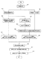
図1から図19は、本発明の実施形態に係るものである。図1は、本発明の実施形態に係る内視鏡システムの要部の構成の一例を示す図である。図2は、第1の確率マップを生成する際に行われる処理の一例を示す図である。図3は、暗部領域を近似的に表す楕円の一例を示す図である。図4は、第2の確率マップを生成する際に行われる処理の一例を示す図である。図5は、第3の確率マップを生成する際に行われる処理の一例を示す図である。図6は、移動速度v、回転速度θ及び湾曲速度ベクトルの相関を示した図である。図7は、第4の確率マップを生成する際に行われる処理の一例を示す図である。図8は、確率マップを用いて湾曲目標位置を設定する際に行われる処理の一例を示す図である。 1 to 19 relate to an embodiment of the present invention. FIG. 1 is a diagram illustrating an example of a configuration of a main part of an endoscope system according to an embodiment of the present invention. FIG. 2 is a diagram illustrating an example of processing performed when generating the first probability map. FIG. 3 is a diagram illustrating an example of an ellipse that approximately represents a dark area. FIG. 4 is a diagram illustrating an example of processing performed when the second probability map is generated. FIG. 5 is a diagram illustrating an example of processing performed when the third probability map is generated. FIG. 6 is a diagram showing the correlation among the moving speed v, the rotational speed θ, and the bending speed vector. FIG. 7 is a diagram illustrating an example of processing performed when the fourth probability map is generated. FIG. 8 is a diagram illustrating an example of processing performed when the bending target position is set using the probability map.
図9は、原画像に存在する暗部領域の信頼度を算出する際に行われる処理の一例を示す図である。図10は、図9の処理に用いられる原画像の一例を示す図である。図11は、図10の原画像を用いて生成される暗部領域マスク画像の一例を示す図である。図12は、図11の暗部領域マスク画像に対してモルフォロジー処理を適用することにより得られる膨張画像の一例を示す図である。図13は、図11の暗部領域マスク画像に対してモルフォロジー処理を適用することにより得られる収縮画像の一例を示す図である。図14は、図12の膨張画像及び図13の収縮画像を用いて生成される境界マスク画像の一例を示す図である。図15は、図10の原画像を用いて生成されるエッジ画像の一例を示す図である。図16は、第1の状態変数F1を取得する際に用いられる第1のメンバーシップ関数の一例を示す図である。図17は、第2の状態変数F2を取得する際に用いられる第2のメンバーシップ関数の一例を示す図である。図18は、第1の状態変数F1及び第2の状態変数F2を出力ファジィ集合に適用することにより、第3の状態変数G1を算出する様子を示した模式図である。図19は、図18とは異なる出力ファジィ集合の例を示す図である。 FIG. 9 is a diagram illustrating an example of processing performed when the reliability of the dark area existing in the original image is calculated. FIG. 10 is a diagram illustrating an example of an original image used in the process of FIG. FIG. 11 is a diagram illustrating an example of a dark area mask image generated using the original image of FIG. 12 is a diagram illustrating an example of an expanded image obtained by applying a morphological process to the dark area mask image of FIG. FIG. 13 is a diagram illustrating an example of a contracted image obtained by applying morphological processing to the dark area mask image of FIG. 11. FIG. 14 is a diagram illustrating an example of a boundary mask image generated using the dilated image of FIG. 12 and the contracted image of FIG. FIG. 15 is a diagram illustrating an example of an edge image generated using the original image of FIG. FIG. 16 is a diagram illustrating an example of a first membership function used when acquiring the first state variable F1. FIG. 17 is a diagram illustrating an example of the second membership function used when acquiring the second state variable F2. FIG. 18 is a schematic diagram showing how the third state variable G1 is calculated by applying the first state variable F1 and the second state variable F2 to the output fuzzy set. FIG. 19 is a diagram illustrating an example of an output fuzzy set different from that in FIG.
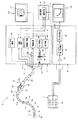
内視鏡システム1は、図1に示すように、被検体としての患者の体腔内に挿入されるとともに、該体腔内の被写体の像を撮像する内視鏡2と、内視鏡2に設けられたコネクタ14の着脱が可能なプロセッサ6と、該患者が横たわるベッドの周辺部に配置されるセンスコイルユニット7と、内視鏡挿入形状検出装置8と、端末装置9と、モニタ10a及び10bと、を有して構成されている。
As shown in FIG. 1, the
また、プロセッサ6は、撮像対象となる被写体を照明するための照明光を内視鏡2に供給する光源部3と、内視鏡2から出力される撮像信号に対して信号処理を行うことにより、映像信号を生成して出力する信号処理部4と、内視鏡2に対する湾曲制御を行う湾曲制御部5と、ソースコイル駆動部43と、を有している。
In addition, the
内視鏡2は、被検体の体腔内に挿入される細長の挿入部11と、挿入部11の後端に設けられた操作部12と、操作部12から延出されたユニバーサルコード13とを有している。そして、このユニバーサルコード13の後端には、プロセッサ6への着脱が可能なコネクタ14が設けられている。
The
挿入部11は、術者等の挿入操作に応じて被検体の体腔内を移動する。また、挿入部11は、先端側に設けられた硬質の先端部15と、先端部15の後端に接続された湾曲部16と、湾曲部16の後端と操作部12の前端との間に設けられた、可撓性を有する可撓管部17と、を有している。また、挿入部11の内部には、ソースコイル駆動部43により印加されるソースコイル駆動信号に応じた磁界を発生するn個のソースコイルC1、C2、・・・Cnが略等間隔に設けられている。
The
先端部15には、被写体の像を結像する対物光学系と、該対物光学系を経て結像された該被写体の像を撮像信号として出力する撮像素子等とを具備する撮像部15aが設けられている。
The
操作部12には、フリーズ画像(静止画像)取得等の指示を行うスコープスイッチ18と、湾曲部16の湾曲モードを手動モードまたは自動モードのいずれかに切り替えるための指示を行う湾曲モード切替スイッチ19と、該手動モードが選択された場合に、湾曲部16の湾曲方向及び湾曲角度の指示を行う湾曲用ジョイスティック20と、が設けられている。また、可撓管部17の後端側であって、操作部12の前端付近にあたる部分には、処置具等を挿通可能な図示しない処置具用チャンネルへ通ずる処置具挿入口39が設けられている。
The
内視鏡2の挿入部11等の内部には、光源部3から供給される照明光を先端部15へ伝送するライトガイド21が挿通されている。
A
ライトガイド21の一方の端面(入射端面)は、コネクタ14から突出した状態として配置されている。また、ライトガイド21の他方の端面(出射端面)は、先端部15に設けられた図示しない照明光学系の近傍に配置されている。このような構成により、光源部3から供給された照明光は、コネクタ14がプロセッサ6に接続された状態において、ライトガイド21及び図示しない照明光学系を経た後、撮像部15aの撮像対象となる被写体を照明する。
One end face (incident end face) of the
光源装置としての機能を具備する光源部3は、例えば白色光である照明光を発するランプ22と、ランプ22が駆動する際に要する電源を供給するランプ駆動部23と、絞り24と、信号処理部4から出力される映像信号に基づいて絞り24の絞り量(開口量)を増減させる絞り制御部25と、絞り24を通過した照明光を集光しつつライトガイド21の入射端面へ供給する集光光学系26と、を有している。
The
絞り制御部25は、例えば、入力される映像信号の輝度成分に基づいて平均の明るさを算出した後、該平均の明るさから適切な明るさに相当する基準値を減じた値である、差分値に基づいて絞り24の絞り量(開口量)を増減させることにより、絞り24を通過する照明光の光量を適宜変化させる。
The
信号処理部4は、撮像部15aに設けられた撮像素子を駆動するための撮像素子駆動信号を出力する撮像素子駆動部36と、撮像部15aから出力される撮像信号に対して信号処理を行うことにより、映像信号を生成して出力する映像処理部37と、を有している。これにより、モニタ10aには、前記映像信号に応じた内視鏡画像Iaが表示される。
The signal processing unit 4 performs signal processing on the image
湾曲制御部5は、湾曲モード切替スイッチ19においてなされた指示に基づき、湾曲部16の湾曲モードが手動モードに切り替えられた場合には、湾曲用ジョイスティック20の傾き方向及び傾き量に基づいて湾曲部16の湾曲方向及び湾曲角度を変更するための制御を行う。また、駆動制御部としての機能を具備する湾曲制御部5は、湾曲モード切替スイッチ19においてなされた指示に基づき、湾曲部16の湾曲モードが自動モードに切り替えられた場合には、端末装置9の演算結果に基づいて湾曲部16の湾曲方向及び湾曲角度を変更するための制御を行う。
When the bending mode of the bending
ソースコイル駆動部43は、挿入部11の内部に設けられたn個のソースコイルC1、C2、・・・Cnに接続されており、該ソースコイル各々に対して交流のソースコイル駆動信号を順次印加する。これにより、挿入部11の内部に設けられたソースコイル各々の周囲には、交流磁界が発生する。
The source
センスコイルユニット7には、挿入部11の内部に設けられたn個のソースコイルC1、C2、・・・Cnから発せられる磁界を各々検出し、磁界検出信号として出力するセンスコイル群44が設けられている。
The sense coil unit 7 is provided with a
内視鏡挿入形状検出装置8は、センスコイルユニット7から出力される磁界検出信号を増幅するアンプ45と、アンプ45から出力される磁界検出信号に基づいてn個のソースコイルC1、C2、・・・Cnの3次元座標位置及び向きを検出し、挿入形状情報として出力するソースコイル位置/向き検出部46と、ソースコイル位置/向き検出部46から出力される挿入形状情報に基づいて挿入部11の挿入形状を推定し、挿入形状画像信号として出力する挿入形状推定部47と、を有している。これにより、モニタ10bには、前記挿入形状画像信号に応じた挿入部11の挿入形状画像Ibが表示される。
The endoscope insertion shape detection device 8 includes an
端末装置9は、映像処理部37から出力される映像信号、及び、挿入形状推定部47から出力される挿入形状画像信号等に基づき、湾曲部16の湾曲モードが自動モードである場合に行われる湾曲制御に関する演算を行い、演算結果を湾曲制御部5へ出力する演算処理部91を有している。なお、演算処理部91において行われる前記演算の具体的な内容は、後程述べるものとする。
The terminal device 9 is performed when the bending mode of the bending
また、端末装置9には、演算処理部91における演算結果等を一時的に記憶可能な図示しないメモリが設けられている。
In addition, the terminal device 9 is provided with a memory (not shown) that can temporarily store the calculation results in the
次に、内視鏡システム1の作用について説明を行う。なお、以降においては、湾曲モード切替スイッチ19が手動湾曲モードに切り替えられた場合の制御についての説明を省略するとともに、湾曲モード切替スイッチ19が自動湾曲モードに切り替えられた場合の制御について主に説明を行うものとする。
Next, the operation of the
まず、術者は、内視鏡システム1の各部を接続及び起動した後、内視鏡2の挿入部11を患者の体腔内に挿入するとともに、湾曲モード切替スイッチ19を自動湾曲モードに切り替える。これに応じて、内視鏡2の撮像部15aにおける被写体の撮像が開始されるとともに、挿入部11に設けられた各ソースコイルにおいて磁界が発せられ始める。
First, after connecting and starting each part of the
被写体の撮像に伴って撮像部15aから出力される撮像信号は、ユニバーサルコード13及びコネクタ14を経てプロセッサ6へ出力され、映像処理部37において映像信号に変換された後、端末装置9の演算処理部91に入力される。また、挿入部11に設けられた各ソースコイルにおける磁界の発生に伴ってセンスコイルユニット7から出力される磁界検出信号は、アンプ45により増幅され、ソースコイル位置/向き検出部46により該各ソースコイルの3次元座標情報として変換され、挿入形状推定部47により挿入形状の推定がなされた後、挿入形状画像信号として端末装置9の演算処理部91に入力される。
An imaging signal output from the imaging unit 15a when the subject is imaged is output to the
端末装置9の演算処理部91は、入力される映像信号及び挿入形状画像信号等に基づく処理を行うことにより、先端部15の通過目標となる湾曲目標位置(通過目標位置)を設定し、設定した該湾曲目標位置の情報を湾曲制御部5へ出力する。
The
ここで、前述の湾曲目標位置を設定する際に演算処理部91が行う処理について述べる。
Here, a process performed by the
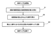
抽出部としての機能を具備する演算処理部91は、入力される映像信号に応じた画像(内視鏡画像)の暗部領域、及び、該暗部領域の重心を算出する(図2のステップS1)。
The
図2のステップS1において算出される暗部領域の重心は、該暗部領域の画素値のモーメントの中心と一致するものであり、すなわち、デジタル画像のモーメントの算出手法としての下記数式(1)を用いることにより、(μ10/μ00,μ01/μ00)の画素位置として算出される。 The center of gravity of the dark area calculated in step S1 in FIG. 2 coincides with the center of the moment of the pixel value of the dark area, that is, the following formula (1) is used as a method for calculating the moment of the digital image. Thus, the pixel position is calculated as (μ10 / μ00, μ01 / μ00).
![]()
その後、演算処理部91は、暗部領域の画素値の2次モーメントμ20、μ11及びμ02と、該暗部領域の画素値の0次モーメントμ00とに基づき、図2のステップS1において算出した該暗部領域の重心(μ10/μ00,μ01/μ00)を中心とする楕円を算出する(図2のステップS2)。
![]()
After that, the
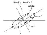
具体的には、演算処理部91は、暗部領域の画素値の2次モーメントμ20、μ11及びμ02と、該暗部領域の画素値の0次モーメントμ00とに基づき、例えば図3に示すような形状の暗部領域の算出結果に対し、中心座標(μ10/μ00,μ01/μ00)、長軸の長さa、短軸の長さb、及び、画像の水平方向に対する長軸の傾きφを具備する、該暗部領域を近似的に表す楕円を算出する。なお、長軸の長さa、短軸の長さb、及び、画像の水平方向に対する長軸の傾きφは、下記数式(2)〜(4)を用いてそれぞれ示される。
Specifically, the

そして、演算処理部91は、図2のステップS2において算出した楕円における2次元正規分布を確率マップに投影する(図2のステップS3)。
Then, the
すなわち、演算処理部91は、図2のステップS1〜ステップS3の処理を行うことにより、内視鏡2により得られた内視鏡画像の画素値に応じた第1の確率マップを生成する。
That is, the
なお、本実施形態において生成される各確率マップは、内視鏡画像の1画素に対して1つの確率値が付与されたものであるとする。 Note that each probability map generated in the present embodiment is obtained by assigning one probability value to one pixel of the endoscopic image.
また、前述の第1の確率マップは、図2のステップS1〜ステップS3の処理により生成されるものに限らず、例えば、明部領域の確率値を相対的に低くし、かつ、暗部領域の確率値を相対的に高くするような所定の関数を内視鏡画像の各画素値に対して適用することにより生成されるものであっても良い。具体的には、例えば、前述の第1の確率マップは、原画像の画素値C(x,y)に対応する確率値をP(x,y)とした場合、下記数式(5)を用いて生成されるものであっても良い。 In addition, the first probability map described above is not limited to the one generated by the processing of Steps S1 to S3 in FIG. 2. For example, the probability value of the bright area is relatively low, and the dark area is It may be generated by applying a predetermined function that makes the probability value relatively high to each pixel value of the endoscopic image. Specifically, for example, when the probability value corresponding to the pixel value C (x, y) of the original image is P (x, y), the first probability map described above uses the following formula (5). May be generated.
![]()
なお、上記数式(5)における画素値C(x,y)は、0以上255以下の値をとるものとする。
![]()
It should be noted that the pixel value C (x, y) in the above equation (5) takes a value between 0 and 255.
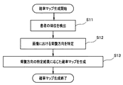
一方、情報取得部としての機能を有する演算処理部91は、少なくとも患者の背腹方向に関する情報が含まれる所定の入力信号に基づき、該患者が現在どのような体位であるかを検出する(図4のステップS11)。
On the other hand, the
なお、前記所定の入力信号は、患者に取り付けられた図示しないコイルの位置及び向きの検出結果に応じて出力される信号であっても良く、または、スコープスイッチ18等に設けられた体位選択スイッチにおける指示内容に応じて出力される信号であっても良い。 The predetermined input signal may be a signal output in accordance with a detection result of a position and orientation of a coil (not shown) attached to the patient, or a position selection switch provided in the scope switch 18 or the like It may be a signal that is output in accordance with the content of the instruction.
その後、演算処理部91は、図4のステップS11における検出結果と、挿入形状画像信号とに基づき、入力される映像信号に応じた画像(内視鏡画像)における背腹方向(背側及び腹側)を特定する(図4のステップS12)。
Thereafter, the
ところで、一般的な内視鏡の挿入操作を考慮した場合、該内視鏡の先端部を該患者の腹側または背中側へ向かって湾曲させることは比較的稀であると仮定できる。そして、演算処理部91は、このような仮定に則して構築された第1のアルゴリズムと、図4のステップS12における特定結果とに基づき、内視鏡画像の背側及び腹側に相当する領域の確率を相対的に低く設定した確率マップを生成する(図4のステップS13)。
By the way, when a general endoscope insertion operation is considered, it can be assumed that it is relatively rare to curve the distal end portion of the endoscope toward the abdomen or back of the patient. The
すなわち、演算処理部91は、図4のステップS11〜ステップS13の処理を行うことにより、内視鏡2が挿入されている患者の現在の体位に応じた第2の確率マップを生成する。
That is, the
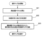
一方、情報取得部としての機能を有する演算処理部91は、例えば湾曲制御部5の制御内容を読み込むことにより、先端部15(撮像部15a)の移動速度に相当する湾曲速度ベクトルを算出する(図5のステップS21)。
On the other hand, the
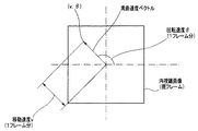
具体的には、演算処理部91は、湾曲制御部5の制御内容に基づき、内視鏡画像の画像平面上において、該内視鏡画像の中心を始点とし、先端部15が1フレームの間に移動した移動量を示す移動速度をvとし、さらに、該内視鏡画像の画像平面上において先端部15が1フレームの間に回転した回転量を示す回転速度をθとした湾曲速度ベクトルを算出する。なお、前述の移動速度v、回転速度θ及び湾曲速度ベクトルは、現フレームの内視鏡画像において、例えば図6に示すようなものとなる。
Specifically, based on the control content of the bending control unit 5, the
その後、演算処理部91は、図5のステップS21において得られた湾曲速度ベクトルの算出結果に基づき、先端部15が次に向かう方向を、該湾曲速度ベクトルの始点(内視鏡画像の中心)から終点に向かう方向として推定する(図5のステップS22)。
Thereafter, the
ところで、一般的な内視鏡の湾曲操作を考慮した場合、湾曲部が実際に湾曲駆動している方向及び速度を継続した場合の画像位置、すなわち、前述の湾曲速度ベクトルの終点に湾曲目標位置が存在する可能性が高いと仮定できる。 By the way, when considering a bending operation of a general endoscope, an image position when the bending portion is actually driven to bend and a speed, that is, an end position of the above-described bending speed vector, a bending target position. Can be assumed to exist.
そして、演算処理部91は、このような仮定に則して構築された第2のアルゴリズムと、図5のステップS22における推定結果とに基づき、現フレームの内視鏡画像における湾曲速度ベクトルの終点(v,θ)を中心とした、楕円状の2次元正規分布を確率マップに投影する(図5のステップS23)。
Then, based on the second algorithm constructed in accordance with such an assumption and the estimation result in step S22 of FIG. 5, the
すなわち、演算処理部91は、図5のステップS21〜ステップS23の処理を行うことにより、患者の体腔内に挿入されている内視鏡2の湾曲速度に応じた第3の確率マップを生成する。
That is, the
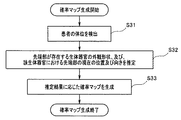
一方、演算処理部91は、図4のステップS11として述べた処理と同様の処理を行うことにより、患者が現在どのような体位であるかを検出する(図7のステップS31)。
On the other hand, the
その後、演算処理部91は、図7のステップS31における検出結果と、挿入形状画像信号とに基づき、先端部15が存在する生体器官の外観形状、及び、該生体器官における先端部15の現在の位置及び向きを推定する(図7のステップS32)。
Thereafter, the
そして、演算処理部91は、図7のステップS32における推定結果に応じた確率マップを生成する(図7のステップS33)。具体的には、演算処理部91は、例えば、先端部15の現在位置が下行結腸であり、かつ、先端部15の向きが患者の頭側を向いているという推定結果を得た場合、先端部15の正面及び略正面に相当する領域の確率を相対的に高く設定した確率マップを生成する。
And the
すなわち、演算処理部91は、図7のステップS31〜ステップS33の処理を行うことにより、先端部15の現在の位置及び向きに応じた第4の確率マップを生成する。
In other words, the
一方、演算処理部91は、過去に設定した一の湾曲目標位置(例えば前回設定した湾曲目標位置)に基づき、該一の湾曲目標位置を中心とした2次元正規分布を投影することにより、第5の確率マップを生成する。
On the other hand, the
そして、演算処理部91は、図8のステップS41に示す処理として、以上に述べた第1の確率マップ〜第5の確率マップを生成する処理を行う。
And the
次に、演算処理部91は、図8のステップS41の処理において生成した各確率マップを統合するための処理を行う(図8のステップS42)。
Next, the
具体的には、演算処理部91は、第1の確率マップにおける一の位置(画素位置)の確率値をP1、第2の確率マップにおける該一の位置の確率値をP2、第3の確率マップにおける該一の位置の確率値をP3、第4の確率マップにおける該一の位置の確率値をP4、及び、第5の確率マップにおける該一の位置の確率値をP5とした場合、該一の位置における統合値Cxを下記数式(6)により算出する。
Specifically, the
![]()
なお、上記数式(6)において、μaは第1の確率マップに対する重み付け値を示し、μbは第2の確率マップに対する重み付け値を示し、μcは第3の確率マップに対する重み付け値を示し、μdは第4の確率マップに対する重み付け値を示し、μeは第5の確率マップに対する重み付け値を示すものとする。
![]()
In the above equation (6), μa represents a weighting value for the first probability map, μb represents a weighting value for the second probability map, μc represents a weighting value for the third probability map, and μd is A weight value for the fourth probability map is indicated, and μe indicates a weight value for the fifth probability map.
また、前述の統合値Cxは、上記数式(6)に示したような重み付け演算により算出されるものに限らず、例えば、ファジィ論理演算または混合エキスパートモデル等の他の演算手法を用いて算出されるものであっても良い。 Further, the integrated value Cx is not limited to the one calculated by the weighting calculation as shown in the above formula (6), and is calculated by using another calculation method such as a fuzzy logic calculation or a mixed expert model, for example. It may be a thing.
その後、演算処理部91は、上記数式(6)を用いて統合値Cxを算出する処理を1画面内の全ての位置(画素位置)に対して行った後、算出した各統合値Cxが0以上1以下の値となるように正規化処理を施す。
Thereafter, the
そして、図8のステップS42の処理として以上に述べたような処理が行われることにより、第1の確率マップ〜第5の確率マップからなる5つの確率マップが統合された、新たな1つの確率マップが生成される。 Then, by performing the process as described above as the process of step S42 in FIG. 8, a new probability obtained by integrating the five probability maps including the first probability map to the fifth probability map. A map is generated.
すなわち、前述の正規化処理が施された後の統合値Cxは、湾曲目標位置(先端部15または撮像部15aの通過目標位置)としての正確さを示す確率値に相当する。
In other words, the integrated value Cx after the above-described normalization processing is performed corresponds to a probability value indicating the accuracy as the bending target position (the passing target position of the
演算処理部91は、図8のステップS42の処理により生成した統合後の確率マップにおいて、最も確率値が高い位置(画素位置)を抽出した(図8のステップS43)後、該位置(画素位置)が複数存在するか否かの判定を行う(図8のステップS44)。
The
演算処理部91は、図8のステップS43の処理により抽出した位置が複数存在する場合、統合後の確率マップにおける確率値の重心(モーメントの中心)を算出し(図8のステップS45)、該重心に相当する位置(画素位置)を湾曲目標位置として設定する(図8のステップS46)。
When there are a plurality of positions extracted by the process of step S43 in FIG. 8, the
また、演算処理部91は、図8のステップS43の処理により抽出した位置が1つのみ存在する場合、該位置(画素位置)を湾曲目標位置として設定する(図8のステップS46)。
In addition, when there is only one position extracted by the process of step S43 in FIG. 8, the
そして、演算処理部91は、図8のステップS46の処理において設定した湾曲目標位置の情報を湾曲制御部5へ出力した後、一連の処理を図8のステップS41から再度繰り返し行う。
Then, the
以上に述べたように、本実施形態の内視鏡システム1は、図2〜図8に関する一連の処理を自動湾曲モードにおいて行うことにより、内視鏡の先端部を向かわせる目標位置を正確に算出することができる。その結果、本実施形態の内視鏡システム1は、内視鏡の挿入を従来に比べてスムーズにすることができる。
As described above, the
なお、図2〜図8に示した一連の処理によれば、第1の確率マップ〜第5の確率マップを全て用いて統合後の確率マップを作成するものに限らず、例えば、第1の確率マップ及び第2の確率マップのみを用いて統合後の確率マップを作成するものであっても良い。 In addition, according to a series of processes shown in FIGS. 2-8, it is not restricted to creating the integrated probability map using all of the first probability map to the fifth probability map. An integrated probability map may be created using only the probability map and the second probability map.
また、図2〜図8に示した一連の処理において生成される第5の確率マップは、過去に設定した一の湾曲目標位置に基づいて生成されるものに限らず、例えば、前回作成された統合後の確率マップをそのまま用いるものであっても良い。 In addition, the fifth probability map generated in the series of processes shown in FIGS. 2 to 8 is not limited to the one generated based on the one curve target position set in the past, for example, created last time. The integrated probability map may be used as it is.
一方、本実施形態の内視鏡システム1によれば、内視鏡の挿入をスムーズにするために、図9〜図19に関する一連の処理が自動湾曲モードにおいて行われるものであっても良い。
On the other hand, according to the
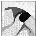
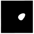
まず、演算処理部91は、入力される映像信号に応じた、例えば図10に示すような原画像を取得する(図9のステップS51)。
First, the
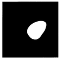
その後、演算処理部91は、図9のステップS51において得られた原画像に存在する暗部領域を抽出する(図9のステップS52)。具体的には、演算処理部91は、例えば、図9のステップS51において得られた原画像のうち、所定値未満の画素値を具備する孤立した領域を暗部領域として抽出する。そして、このような処理を行うことにより、演算処理部91は、図10に示した原画像から、暗部領域の画素値を一律に255とし、かつ、非暗部領域の画素値を一律に0とした、図11に示すような暗部領域マスク画像を生成する。
Thereafter, the
演算処理部91は、図10に示した原画像のうち、図11に示した暗部領域マスク画像によりマスクされた領域に存在する各画素を暗部領域内の画素とみなしつつ、該暗部領域内における全画素の画素値の平均値を算出する(図9のステップS53)。
The
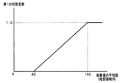
その後、演算処理部91は、図9のステップS53の処理により算出した、暗部領域内に存在する全画素の画素値の平均値を、図16に示す第1のメンバーシップ関数に適用することにより、ファジィ論理計算に用いる第1の状態変数F1を取得する(図9のステップS54)。
Thereafter, the
前述の第1のメンバーシップ関数は、図9のステップS52及びステップS53の処理により抽出した暗部領域の暗さの度合いを0≦F1≦1の値により示した関数であって、該暗部領域がより暗い場合にはF1=0に近い値をとり、かつ、該暗部領域がより明るい場合にはF1=1に近い値をとるように設定されている。具体的には、本実施形態における第1のメンバーシップ関数は、図16に示すように、暗部領域内の全画素の画素値の平均値が、40以下である場合にF1=0となり、140以上である場合にはF1=1となり、40を超過しかつ140未満である場合には0<F1<1において線形的に増加するように設定されている。 The first membership function described above is a function in which the darkness level of the dark area extracted by the processing of steps S52 and S53 in FIG. 9 is represented by a value of 0 ≦ F1 ≦ 1, and the dark area is It is set to take a value close to F1 = 0 when darker, and to take a value close to F1 = 1 when the dark area is brighter. Specifically, as shown in FIG. 16, the first membership function in the present embodiment is F1 = 0 when the average value of all the pixel values in the dark area is 40 or less, and 140 In the above case, F1 = 1 is set, and when it exceeds 40 and is less than 140, it is set to increase linearly in 0 <F1 <1.
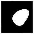
また、演算処理部91は、図9のステップS52において生成した暗部領域マスク画像に対してモルフォロジー処理を適用する(図9のステップS55)。そして、演算処理部91は、図9のステップS55の処理を行うことにより、図9のステップS52において抽出した暗部領域(画素値=255の領域)を膨張させた膨張画像と、該暗部領域を収縮させた収縮画像とを取得する。なお、図9のステップS55の処理を行うことにより得られる膨張画像及び収縮画像は、例えば、図12及び図13に示すようなものとなる。
Further, the
演算処理部91は、図9のステップS55の処理により得られた膨張画像及び収縮画像を用い、境界マスク画像を生成する(図9のステップS56)。具体的には、演算処理部91は、膨張画像の暗部領域(画素値=255の領域)のうち、収縮画像の暗部領域(画素値=255の領域)と重複する領域の画素値を0とした、例えば図14に示すような境界マスク画像として生成する。
The
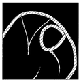
一方、演算処理部91は、図9のステップS51において得られた原画像に存在するエッジ部を抽出する(図9のステップS57)ことにより、エッジ画像を取得する。具体的には、演算処理部91は、図9のステップS51において得られた原画像に対してラプラシアンフィルタを適用することにより、該原画像におけるエッジ部が抽出された、例えば図15に示すようなエッジ画像を取得する。
On the other hand, the
そして、演算処理部91は、図9のステップS57において得られたエッジ画像のうち、図9のステップS56において得られた境界マスク画像によりマスクされた領域に存在する各画素を暗部領域の境界部に存在する画素とみなしつつ、該境界部における全画素の画素値の平均値を算出する(図9のステップS58)。
Then, the
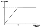
その後、演算処理部91は、図9のステップS58の処理により算出した、暗部領域の境界部に存在する全画素の画素値の平均値を、図17に示す第2のメンバーシップ関数に適用することにより、ファジィ論理計算に用いる第2の状態変数F2を取得する(図9のステップS59)。
After that, the
前述の第2のメンバーシップ関数は、図9のステップS55〜ステップS58の処理により抽出した(暗部領域の)境界部の明るさの度合いを0≦F2≦1の値により示した関数であって、該境界部がぼやけている場合にはF2=0に近い値をとり、かつ、該境界部がくっきりとしている場合にはF2=1に近い値をとるように設定されている。具体的には、本実施形態における第2のメンバーシップ関数は、図17に示すように、暗部領域の境界部におけるエッジ画像の全画素の画素値の平均値が、0である場合にF2=0となり、45以上である場合にはF2=1となり、0を超過しかつ45未満である場合には0<F2<1において線形的に増加するように設定されている。 The above-described second membership function is a function that indicates the degree of brightness of the boundary (of the dark area) extracted by the processing in steps S55 to S58 in FIG. 9 by a value of 0 ≦ F2 ≦ 1. When the boundary portion is blurred, a value close to F2 = 0 is set, and when the boundary portion is clear, a value close to F2 = 1 is set. Specifically, as shown in FIG. 17, the second membership function in the present embodiment is F2 = when the average value of all the pixel values of the edge image in the boundary portion of the dark area is zero. It is set to 0, and when it is 45 or more, F2 = 1, and when it exceeds 0 and less than 45, it is set to linearly increase in 0 <F2 <1.
演算処理部91は、所定のルールに則って作成された出力ファジィ集合と、図9のステップS54において得られた第1の状態変数F1と、図9のステップS59において得られた第2の状態変数F2とを用いることにより、暗部領域の真偽の度合いを示す値としての第3の状態変数G1を算出する(図9のステップS60)。
The
なお、本実施形態において、前述の所定のルールは、例えば、第1の状態変数F1の論理否定を*F1と表記した場合、「IF (*F1 and F2) THEN 暗部領域」という、ファジィ論理に基づく論理式として定義されている。 In the present embodiment, for example, when the logical negation of the first state variable F1 is expressed as * F1, the above-mentioned predetermined rule has a fuzzy logic of “IF (* F1 and F2) THEN dark area”. It is defined as a logical expression based on.
また、前述の所定のルールにおいては、暗部領域の内側の画素値が小さく(大きくなく)、かつ、該暗部領域の境界部がくっきりとしている場合、すなわち、真の暗部領域である場合にG1=1となるように定義されている。 Further, according to the above-described predetermined rule, when the pixel value inside the dark area is small (not large) and the boundary of the dark area is clear, that is, when the true dark area is G1 = It is defined to be 1.
さらに、前述の所定のルールにおいては、暗部領域の内側の画素値が大きく、かつ、該暗部領域の境界部がぼやけている場合、すなわち、偽の暗部領域である場合にG1=−1となるように定義されている。 Further, in the above-described predetermined rule, G1 = −1 when the pixel value inside the dark area is large and the boundary portion of the dark area is blurred, that is, when it is a false dark area. Is defined as
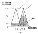
以上のように定義された各要素を用いて作成された出力ファジィ集合は、第1の状態変数F1及び第2の状態変数F2の値を縦軸とし、かつ、第3の状態変数G1の値を横軸とした座標軸において、第1の状態変数F1及び第2の状態変数F2にそれぞれ対応する三角形を配した、例えば図18に示すようなものとなる。 The output fuzzy set created using each element defined as described above has the values of the first state variable F1 and the second state variable F2 as the vertical axis, and the value of the third state variable G1. For example, as shown in FIG. 18, triangles corresponding to the first state variable F1 and the second state variable F2 are arranged on the coordinate axes with the horizontal axis as the horizontal axis.
第1の状態変数F1に対応する三角形は、偽の暗部領域を示す集合であって、図18に示すように、頂点がF1=1かつG1=−1となる座標位置に配置され、かつ、底辺がF1=0に配置された二等辺三角形T1として形成されている。また、第2の状態変数F2に対応する三角形は、真の暗部領域を示す集合であって、図18に示すように、頂点がF2=1かつG1=1となる座標位置に配置され、かつ、底辺がF2=0に配置された二等辺三角形T2として形成されている。 The triangle corresponding to the first state variable F1 is a set indicating a false dark area, and as shown in FIG. 18, the vertexes are arranged at coordinate positions where F1 = 1 and G1 = −1, and The base is formed as an isosceles triangle T1 arranged at F1 = 0. A triangle corresponding to the second state variable F2 is a set indicating a true dark area, and as shown in FIG. 18, the vertexes are arranged at coordinate positions where F2 = 1 and G1 = 1, and , The base is formed as an isosceles triangle T2 with F2 = 0.
ここで、第3の状態変数G1を算出する際に行われる処理の概要を、図18を用いつつ説明する。 Here, an outline of the processing performed when the third state variable G1 is calculated will be described with reference to FIG.
演算処理部91は、図9のステップS54において得られた第1の状態変数F1の値を、図18に例示する出力ファジィ集合に対して適用する。このような処理を視覚的に示した場合、図18の二等辺三角形T1の内部が第1の状態変数F1の値に相当する高さ(縦軸の値)まで塗りつぶされることに相当する。
The
また、演算処理部91は、図9のステップS59において得られた第2の状態変数F2の値を、図18に例示する出力ファジィ集合に対して適用する。このような処理を視覚的に示した場合、図18の二等辺三角形T2の内部が第2の状態変数F2の値に相当する高さ(縦軸の値)まで塗りつぶされることに相当する。
The
演算処理部91は、図18の二等辺三角形T1及びT2において塗りつぶされた部分全体からなる図形の重心を算出し、該重心の座標位置の横軸の値を第3の状態変数G1として算出する。
The
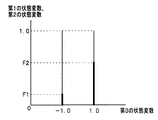
以上に述べた処理によれば、第3の状態変数G1の出力特性は、二等辺三角形T1及びT2の底辺の長さに依存しているといえる。そのため、例えば、二等辺三角形T1及びT2の底辺の長さを略0とした、図19の出力ファジィ集合に対して第1の状態変数F1及び第2の状態変数F2を適用することにより、図18の出力ファジィ集合を用いた場合とは異なる演算結果を得ることができる。 According to the processing described above, it can be said that the output characteristics of the third state variable G1 depend on the lengths of the bases of the isosceles triangles T1 and T2. Therefore, for example, by applying the first state variable F1 and the second state variable F2 to the output fuzzy set in FIG. 19 in which the lengths of the bases of the isosceles triangles T1 and T2 are substantially zero, An operation result different from the case of using 18 output fuzzy sets can be obtained.
なお、図19の出力ファジィ集合に対して第1の状態変数F1及び第2の状態変数F2を適用した場合の第3の状態変数G1は、下記数式(7)により求めることができる。 Note that the third state variable G1 when the first state variable F1 and the second state variable F2 are applied to the output fuzzy set of FIG. 19 can be obtained by the following equation (7).
但し、上記数式(7)においては、x1=−1及びx2=1とする。
However, in the above formula (7), x1 = −1 and x2 = 1.
その後、演算処理部91は、図9のステップS60において算出した第3の状態変数G1を、下記数式(8)を用いて正規化することにより、原画像に存在する暗部領域が先端部15を向かわせる方向として正確か否かを確率的に示す値としての、信頼度Rを算出する(図9のステップS61)。
Thereafter, the
![]()
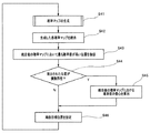
一方、演算処理部91は、図9のステップS51において取得した原画像に対して図2〜図8に関する一連の処理または公知の処理を施すことにより、湾曲部16の湾曲目標位置(先端部15の通過目標位置)を、該原画像の暗部領域内における一の画素位置として算出する。
![]()
On the other hand, the
ここで、原画像の中心から湾曲目標位置までの距離をdとし、画像内の距離を実際の距離に変換するための係数をkとした場合、単位時間あたりの湾曲部16(挿入部11)の湾曲量を表す湾曲ステップ量Saは、例えば下記数式(9)を用いることにより求められる。 Here, when the distance from the center of the original image to the bending target position is d and the coefficient for converting the distance in the image into the actual distance is k, the bending portion 16 (insertion portion 11) per unit time. The bending step amount Sa representing the amount of bending is obtained by using the following mathematical formula (9), for example.
![]()
一方、演算処理部91は、単位時間あたりの湾曲部16の湾曲量に対し、下記数式(10)を用いた線形変換を行うことにより、信頼度Rに応じた湾曲ステップ量Sbを算出する(図9のステップS62)。
![]()
On the other hand, the
![]()
なお、演算処理部91は、単位時間あたりの湾曲部16の湾曲量に対して線形変換を行うことにより湾曲ステップ量Sbを算出するものに限らない。具体的には、演算処理部91は、信頼度Rの値が大きくなるにつれて湾曲ステップ量Sbの値が大きくなり、かつ、信頼度Rの値が小さくなるにつれて湾曲ステップ量Sbの値が小さくなるような演算を行うものであれば、単位時間あたりの湾曲部16の湾曲量に対して非線形変換を行うことにより湾曲ステップ量Sbを算出するものであっても良い。
![]()
Note that the
その後、演算処理部91は、算出した湾曲ステップ量Sbを湾曲制御部5に対して出力する。これにより、湾曲部16は、原画像の取得タイミング毎に算出される湾曲ステップ量Sbに応じて湾曲する。
Thereafter, the
以上に述べたように、本実施形態の内視鏡システム1は、図9〜図19に関する一連の処理を自動湾曲モードにおいて行うことにより、原画像に存在する暗部領域の真偽の度合いに応じて湾曲部の単位時間当たりの湾曲量を設定することができる。
As described above, the
そのため、本実施形態の内視鏡システム1によれば、取得した原画像にノイズが混入し、内視鏡の先端部を向かわせる方向として適切とは考え難い目標位置が得られた場合には、単位時間当たりの湾曲量を少なくすることにより、該目標位置への湾曲動作を抑制することができる。また、本実施形態の内視鏡システム1によれば、内視鏡の先端部を向かわせる方向として適切な目標位置が得られた場合には、該目標位置への湾曲動作を素早く行わせることができる。
Therefore, according to the
なお、前述の信頼度Rの値は、図9〜図19に関する一連の処理として示したファジィ論理演算を用いて算出されるものに限らず、例えば、混合エキスパートモデル等の他の演算手法を用いて算出されるものであっても良い。 Note that the value of the reliability R described above is not limited to the value calculated using the fuzzy logic operation shown as a series of processes related to FIGS. 9 to 19, and other calculation methods such as a mixed expert model are used. May be calculated.
また、図9〜図19に関する一連の処理は、原画像から抽出した1つの暗部領域の信頼度を算出した後、該信頼度に応じたものとして単位時間あたりの湾曲部16の湾曲量を設定する、という場合に用いられるものに限らない。具体的には、図9〜図19に関する処理は、例えば、原画像から抽出した2つ以上の暗部領域における信頼度をそれぞれ算出した後、相対的に最も高い信頼度を具備する一の暗部領域へ先端部15が向かうように湾曲部16を湾曲させる、という制御に応用することができる。
Further, in the series of processes relating to FIGS. 9 to 19, after calculating the reliability of one dark area extracted from the original image, the bending amount of the bending
ところで、本実施形態によれば、図9〜図19に示した一連の処理において算出した信頼度Rを、図2〜図8に示した一連の処理において生成した第1の確率マップの修正に用いることにより、さらに正確な統合後の確率マップを生成することができる。具体的には、例えば、上記数式(5)に示す確率値P(x,y)に対して信頼度Rを乗算した、下記数式(11)を用いて確率値Pc(x,y)を算出することにより、第1の確率マップを修正する方法が挙げられる。 By the way, according to the present embodiment, the reliability R calculated in the series of processes shown in FIGS. 9 to 19 is used to correct the first probability map generated in the series of processes shown in FIGS. By using this, a more accurate probability map after integration can be generated. Specifically, for example, the probability value Pc (x, y) is calculated using the following equation (11) obtained by multiplying the probability value P (x, y) shown in the equation (5) by the reliability R. By doing so, a method of correcting the first probability map can be mentioned.
そして、上記数式(11)を用いて第1の確率マップが修正されることにより、統合後の確率マップにおける該第1の確率マップの寄与度が信頼度Rに応じたものとして適切に調整されるため、さらに正確な統合後の確率マップを生成することができる。
Then, by correcting the first probability map using the above formula (11), the contribution degree of the first probability map in the probability map after the integration is appropriately adjusted according to the reliability R. Therefore, a more accurate probability map after integration can be generated.
また、以上に述べた各処理は、湾曲可能な挿入部を具備する内視鏡の湾曲目標位置の設定に併せて用いられるものに限らず、例えば、生体の蠕動運動に応じて移動するカプセル型内視鏡の移動先の設定に併せて用いられるものであっても良い。 In addition, each processing described above is not limited to the one used in conjunction with the setting of the bending target position of the endoscope having a bendable insertion portion, but, for example, a capsule type that moves according to the peristaltic movement of a living body. It may be used in combination with the setting of the movement destination of the endoscope.
なお、本発明は、上述した実施形態に限定されるものではなく、発明の趣旨を逸脱しない範囲内において種々の変更や応用が可能であることは勿論である。 In addition, this invention is not limited to embodiment mentioned above, Of course, a various change and application are possible in the range which does not deviate from the meaning of invention.
本出願は、2009年1月15日に日本国に出願された特願2009−7024号を優先権主張の基礎として出願するものであり、上記の開示内容は、本願明細書、請求の範囲、図面に引用されたものとする。 This application is filed on the basis of the priority claim of Japanese Patent Application No. 2009-7024 filed in Japan on January 15, 2009, and the above disclosure is disclosed in the present specification, claims, It shall be cited in the drawing.
Claims (20)
前記撮像部により得られた前記被写体の画像において所定の対象を示す位置を検出する位置検出部と、
前記撮像部で撮像した前記画像から得られる第1の情報と、前記撮像部が撮像する前記被写体の状態に関する第2の情報とを用い、前記位置が前記所定の対象であることについての正確さを示す度合いとしての確率値を算出する確率算出部と、
を有することを特徴とする内視鏡システム。An imaging unit for imaging a subject;
A position detection unit for detecting a position indicating a predetermined target in the image of the subject obtained by the imaging unit;
Using the first information obtained from the image picked up by the image pickup unit and the second information related to the state of the subject picked up by the image pickup unit , the accuracy of the position being the predetermined target A probability calculation unit for calculating a probability value as a degree indicating
An endoscope system comprising:
前記先端部を通過させる目標位置を、前記撮像部により得られた被写体の画像において設定する位置設定部と、
前記撮像部で撮像した前記画像から得られる第1の情報と、前記撮像部が撮像する前記被写体の状態に関する第2の情報とを用い、前記位置が前記所定の対象であることについての正確さを示す度合いとしての確率値を算出する確率算出部と、
を有することを特徴とする内視鏡システム。An endoscope provided with an insertion portion to be inserted into a body cavity, and an imaging portion provided at a distal end portion of the insertion portion;
A position setting unit that sets a target position to pass the tip in the image of the subject obtained by the imaging unit;
Using the first information obtained from the image picked up by the image pickup unit and the second information related to the state of the subject picked up by the image pickup unit , the accuracy of the position being the predetermined target A probability calculation unit for calculating a probability value as a degree indicating
An endoscope system comprising:
前記撮像部により得られた前記被写体の画像において所定の対象を示す位置を検出する位置検出部と、
前記画像から複数の画素特徴量を取得する画素特徴量算出部と、
前記複数の画素特徴量に基づき、前記位置が前記所定の対象であることについての正確さを示す度合いとしての確率値を算出する確率算出部と、
を有することを特徴とする内視鏡システム。An imaging unit for imaging a subject;
A position detection unit for detecting a position indicating a predetermined target in the image of the subject obtained by the imaging unit;
A pixel feature amount calculation unit for acquiring a plurality of pixel feature amounts from the image;
A probability calculating unit that calculates a probability value as a degree indicating the accuracy of the position being the predetermined target based on the plurality of pixel feature amounts;
An endoscope system comprising:
前記被写体の像に応じた画像における暗部領域を抽出する抽出部と、An extraction unit for extracting a dark area in the image according to the image of the subject;
前記抽出部による暗部領域の抽出結果とは異なる所定の情報を取得する情報取得部と、An information acquisition unit for acquiring predetermined information different from the extraction result of the dark area by the extraction unit;
前記撮像部の通過目標位置としての正確さを示す確率値を、前記抽出部による暗部領域の抽出結果、及び、前記所定の情報を用いて算出する確率算出部と、A probability calculation unit that calculates a probability value indicating accuracy as a passing target position of the imaging unit using the extraction result of the dark part region by the extraction unit and the predetermined information;
を有することを特徴とする内視鏡システム。An endoscope system comprising:
前記撮像部の通過目標位置を、前記被写体の像に応じた画像の暗部領域内における一の画素位置として設定する位置設定部と、A position setting unit that sets a passing target position of the imaging unit as one pixel position in a dark region of an image corresponding to the image of the subject;
前記暗部領域の真偽の度合いを示す状態変数を算出する状態変数算出部と、A state variable calculation unit for calculating a state variable indicating the degree of authenticity of the dark area;
前記状態変数に基づき、前記通過目標位置の正確さを示す確率値を算出する確率算出部と、A probability calculating unit that calculates a probability value indicating the accuracy of the passing target position based on the state variable;
を有することを特徴とする内視鏡システム。An endoscope system comprising:
前記先端部の通過目標位置を、前記被写体の像に応じた画像の暗部領域内における一の画素位置として設定する位置設定部と、A position setting unit that sets a passing target position of the tip part as one pixel position in a dark part region of an image corresponding to the image of the subject;
前記暗部領域の真偽の度合いを示す状態変数を算出する状態変数算出部と、A state variable calculation unit for calculating a state variable indicating the degree of authenticity of the dark area;
前記状態変数に基づき、前記通過目標位置の正確さを示す確率値を算出する確率算出部と、A probability calculating unit that calculates a probability value indicating the accuracy of the passing target position based on the state variable;
を有することを特徴とする内視鏡システム。An endoscope system comprising:
Applications Claiming Priority (3)
| Application Number | Priority Date | Filing Date | Title |
|---|---|---|---|
| JP2009007024 | 2009-01-15 | ||
| JP2009007024 | 2009-01-15 | ||
| PCT/JP2009/067555 WO2010082383A1 (en) | 2009-01-15 | 2009-10-08 | Endoscope system |
Publications (2)
| Publication Number | Publication Date |
|---|---|
| JP4585048B2 true JP4585048B2 (en) | 2010-11-24 |
| JPWO2010082383A1 JPWO2010082383A1 (en) | 2012-06-28 |
Family
ID=42339646
Family Applications (1)
| Application Number | Title | Priority Date | Filing Date |
|---|---|---|---|
| JP2010518448A Active JP4585048B2 (en) | 2009-01-15 | 2009-10-08 | Endoscope system |
Country Status (5)
| Country | Link |
|---|---|
| US (1) | US8167791B2 (en) |
| EP (1) | EP2301411B1 (en) |
| JP (1) | JP4585048B2 (en) |
| CN (1) | CN102123651B (en) |
| WO (1) | WO2010082383A1 (en) |
Families Citing this family (67)
| Publication number | Priority date | Publication date | Assignee | Title |
|---|---|---|---|---|
| JP5295555B2 (en) * | 2007-12-10 | 2013-09-18 | オリンパスメディカルシステムズ株式会社 | Endoscope system |
| US11547275B2 (en) | 2009-06-18 | 2023-01-10 | Endochoice, Inc. | Compact multi-viewing element endoscope system |
| WO2012038958A2 (en) | 2010-09-20 | 2012-03-29 | Peermedical Ltd. | Multi-camera endoscope having fluid channels |
| US9101287B2 (en) | 2011-03-07 | 2015-08-11 | Endochoice Innovation Center Ltd. | Multi camera endoscope assembly having multiple working channels |
| US9713417B2 (en) | 2009-06-18 | 2017-07-25 | Endochoice, Inc. | Image capture assembly for use in a multi-viewing elements endoscope |
| US9101268B2 (en) | 2009-06-18 | 2015-08-11 | Endochoice Innovation Center Ltd. | Multi-camera endoscope |
| US9402533B2 (en) | 2011-03-07 | 2016-08-02 | Endochoice Innovation Center Ltd. | Endoscope circuit board assembly |
| WO2012056453A2 (en) | 2010-10-28 | 2012-05-03 | Peermedical Ltd. | Optical systems for multi-sensor endoscopes |
| CA2765559C (en) | 2009-06-18 | 2017-09-05 | Peer Medical Ltd. | Multi-camera endoscope |
| US9492063B2 (en) | 2009-06-18 | 2016-11-15 | Endochoice Innovation Center Ltd. | Multi-viewing element endoscope |
| US9901244B2 (en) | 2009-06-18 | 2018-02-27 | Endochoice, Inc. | Circuit board assembly of a multiple viewing elements endoscope |
| US11864734B2 (en) | 2009-06-18 | 2024-01-09 | Endochoice, Inc. | Multi-camera endoscope |
| US8926502B2 (en) | 2011-03-07 | 2015-01-06 | Endochoice, Inc. | Multi camera endoscope having a side service channel |
| US10165929B2 (en) | 2009-06-18 | 2019-01-01 | Endochoice, Inc. | Compact multi-viewing element endoscope system |
| US9706903B2 (en) | 2009-06-18 | 2017-07-18 | Endochoice, Inc. | Multiple viewing elements endoscope system with modular imaging units |
| US9872609B2 (en) | 2009-06-18 | 2018-01-23 | Endochoice Innovation Center Ltd. | Multi-camera endoscope |
| US11278190B2 (en) | 2009-06-18 | 2022-03-22 | Endochoice, Inc. | Multi-viewing element endoscope |
| US9642513B2 (en) | 2009-06-18 | 2017-05-09 | Endochoice Inc. | Compact multi-viewing element endoscope system |
| US8672837B2 (en) | 2010-06-24 | 2014-03-18 | Hansen Medical, Inc. | Methods and devices for controlling a shapeable medical device |
| US9560953B2 (en) | 2010-09-20 | 2017-02-07 | Endochoice, Inc. | Operational interface in a multi-viewing element endoscope |
| EP3522215A1 (en) | 2010-12-09 | 2019-08-07 | EndoChoice Innovation Center Ltd. | Flexible electronic circuit board for a multi-camera endoscope |
| US11889986B2 (en) | 2010-12-09 | 2024-02-06 | Endochoice, Inc. | Flexible electronic circuit board for a multi-camera endoscope |
| EP3747343A1 (en) | 2010-12-09 | 2020-12-09 | EndoChoice, Inc. | Flexible electronic circuit board multi-camera endoscope |
| EP3228236A1 (en) | 2011-02-07 | 2017-10-11 | Endochoice Innovation Center Ltd. | Multi-element cover for a multi-camera endoscope |
| EP2604175B1 (en) | 2011-12-13 | 2019-11-20 | EndoChoice Innovation Center Ltd. | Removable tip endoscope |
| CA2798729A1 (en) | 2011-12-13 | 2013-06-13 | Peermedical Ltd. | Rotatable connector for an endoscope |
| US9560954B2 (en) | 2012-07-24 | 2017-02-07 | Endochoice, Inc. | Connector for use with endoscope |
| US9057600B2 (en) | 2013-03-13 | 2015-06-16 | Hansen Medical, Inc. | Reducing incremental measurement sensor error |
| US9014851B2 (en) | 2013-03-15 | 2015-04-21 | Hansen Medical, Inc. | Systems and methods for tracking robotically controlled medical instruments |
| US9629595B2 (en) | 2013-03-15 | 2017-04-25 | Hansen Medical, Inc. | Systems and methods for localizing, tracking and/or controlling medical instruments |
| US9271663B2 (en) | 2013-03-15 | 2016-03-01 | Hansen Medical, Inc. | Flexible instrument localization from both remote and elongation sensors |
| US9986899B2 (en) | 2013-03-28 | 2018-06-05 | Endochoice, Inc. | Manifold for a multiple viewing elements endoscope |
| US9993142B2 (en) | 2013-03-28 | 2018-06-12 | Endochoice, Inc. | Fluid distribution device for a multiple viewing elements endoscope |
| WO2014156242A1 (en) * | 2013-03-29 | 2014-10-02 | オリンパス株式会社 | Manipulator, manipulator system, and manipulator control method |
| US10499794B2 (en) | 2013-05-09 | 2019-12-10 | Endochoice, Inc. | Operational interface in a multi-viewing element endoscope |
| US11020016B2 (en) | 2013-05-30 | 2021-06-01 | Auris Health, Inc. | System and method for displaying anatomy and devices on a movable display |
| JP2015156937A (en) * | 2014-02-24 | 2015-09-03 | ソニー株式会社 | Image processing device, image processing method, and program |
| CN104887230B (en) * | 2014-03-05 | 2017-08-25 | 上海理工大学 | Swallow the inclination angle type electromagnetic tracking system of formula electronic capsule |
| EP3150103A4 (en) * | 2014-09-25 | 2018-02-21 | Olympus Corporation | Endoscope system |
| CN105559735A (en) * | 2014-11-05 | 2016-05-11 | 深圳市古安泰自动化技术有限公司 | Endoscope |
| JP6519144B2 (en) * | 2014-11-06 | 2019-05-29 | ソニー株式会社 | Endoscope system, image processing apparatus, image processing method, and program |
| EP3349649B1 (en) | 2015-09-18 | 2022-03-09 | Auris Health, Inc. | Navigation of tubular networks |
| US10143526B2 (en) | 2015-11-30 | 2018-12-04 | Auris Health, Inc. | Robot-assisted driving systems and methods |
| US9931025B1 (en) | 2016-09-30 | 2018-04-03 | Auris Surgical Robotics, Inc. | Automated calibration of endoscopes with pull wires |
| US10244926B2 (en) | 2016-12-28 | 2019-04-02 | Auris Health, Inc. | Detecting endolumenal buckling of flexible instruments |
| WO2018183727A1 (en) | 2017-03-31 | 2018-10-04 | Auris Health, Inc. | Robotic systems for navigation of luminal networks that compensate for physiological noise |
| US10646288B2 (en) * | 2017-04-12 | 2020-05-12 | Bio-Medical Engineering (HK) Limited | Automated steering systems and methods for a robotic endoscope |
| US10022192B1 (en) | 2017-06-23 | 2018-07-17 | Auris Health, Inc. | Automatically-initialized robotic systems for navigation of luminal networks |
| KR102578978B1 (en) | 2017-06-28 | 2023-09-19 | 아우리스 헬스, 인코포레이티드 | Electromagnetic distortion detection |
| CN116725667A (en) | 2017-06-28 | 2023-09-12 | 奥瑞斯健康公司 | System for providing positioning information and method for positioning an instrument within an anatomical structure |
| US11058493B2 (en) | 2017-10-13 | 2021-07-13 | Auris Health, Inc. | Robotic system configured for navigation path tracing |
| US10555778B2 (en) | 2017-10-13 | 2020-02-11 | Auris Health, Inc. | Image-based branch detection and mapping for navigation |
| CN111278344B (en) * | 2017-11-01 | 2023-09-05 | 索尼公司 | Surgical Arm System and Surgical Arm Control System |
| KR20200100613A (en) | 2017-12-14 | 2020-08-26 | 아우리스 헬스, 인코포레이티드 | System and method for estimating instrument position |
| US11160615B2 (en) | 2017-12-18 | 2021-11-02 | Auris Health, Inc. | Methods and systems for instrument tracking and navigation within luminal networks |
| JP7214747B2 (en) | 2018-03-28 | 2023-01-30 | オーリス ヘルス インコーポレイテッド | System and method for position sensor alignment |
| US10827913B2 (en) | 2018-03-28 | 2020-11-10 | Auris Health, Inc. | Systems and methods for displaying estimated location of instrument |
| KR102499906B1 (en) | 2018-05-30 | 2023-02-16 | 아우리스 헬스, 인코포레이티드 | System and Method for Position Sensor-Based Branch Prediction |
| KR102567087B1 (en) | 2018-05-31 | 2023-08-17 | 아우리스 헬스, 인코포레이티드 | Robotic systems and methods for navigation of luminal networks detecting physiological noise |
| WO2019231891A1 (en) | 2018-05-31 | 2019-12-05 | Auris Health, Inc. | Path-based navigation of tubular networks |
| KR102455671B1 (en) | 2018-05-31 | 2022-10-20 | 아우리스 헬스, 인코포레이티드 | Image-Based Airway Analysis and Mapping |
| CN114340542B (en) | 2019-08-30 | 2023-07-21 | 奥瑞斯健康公司 | Systems and methods for weight-based registration of position sensors |
| US11147633B2 (en) | 2019-08-30 | 2021-10-19 | Auris Health, Inc. | Instrument image reliability systems and methods |
| WO2021044297A1 (en) | 2019-09-03 | 2021-03-11 | Auris Health, Inc. | Electromagnetic distortion detection and compensation |
| KR20220123273A (en) | 2019-12-31 | 2022-09-06 | 아우리스 헬스, 인코포레이티드 | Anatomical feature identification and targeting |
| KR20220123087A (en) | 2019-12-31 | 2022-09-05 | 아우리스 헬스, 인코포레이티드 | Alignment interface for transdermal access |
| CN114901192A (en) | 2019-12-31 | 2022-08-12 | 奥瑞斯健康公司 | Alignment technique for percutaneous access |
Citations (3)
| Publication number | Priority date | Publication date | Assignee | Title |
|---|---|---|---|---|
| JPH03165732A (en) * | 1989-11-24 | 1991-07-17 | Olympus Optical Co Ltd | Detecting method for insertion direction of endoscope |
| JPH05228102A (en) * | 1992-02-25 | 1993-09-07 | Olympus Optical Co Ltd | Endoscopic system |
| JP2005157902A (en) * | 2003-11-27 | 2005-06-16 | Olympus Corp | Image analyzing method |
Family Cites Families (10)
| Publication number | Priority date | Publication date | Assignee | Title |
|---|---|---|---|---|
| JP3012341B2 (en) * | 1990-12-25 | 2000-02-21 | オリンパス光学工業株式会社 | Endoscope device |
| US5347987A (en) * | 1991-04-08 | 1994-09-20 | Feldstein David A | Self-centering endoscope system |
| US5469840A (en) * | 1991-12-10 | 1995-11-28 | Olympus Optical, Ltd. | Electromotive warping type endoscope with velocity control |
| US5658238A (en) * | 1992-02-25 | 1997-08-19 | Olympus Optical Co., Ltd. | Endoscope apparatus capable of being switched to a mode in which a curvature operating lever is returned and to a mode in which the curvature operating lever is not returned |
| US5469254A (en) * | 1992-04-06 | 1995-11-21 | Olympus Optical Co., Ltd. | Method and apparatus for measuring three-dimensional position of a pipe from image of the pipe in an endoscopic observation system |
| JP3523672B2 (en) | 1993-12-02 | 2004-04-26 | オリンパス株式会社 | Endoscope device |
| WO2005110202A1 (en) * | 2004-05-14 | 2005-11-24 | Olympus Medical Systems Corp. | Electronic endoscope |
| JP4695420B2 (en) * | 2004-09-27 | 2011-06-08 | オリンパス株式会社 | Bending control device |
| JP5094036B2 (en) * | 2006-04-17 | 2012-12-12 | オリンパスメディカルシステムズ株式会社 | Endoscope insertion direction detection device |
| JP2009007024A (en) | 2007-06-27 | 2009-01-15 | Satoru Minamihata | Container for char bone flavored sake |
-
2009
- 2009-10-08 EP EP09838350A patent/EP2301411B1/en active Active
- 2009-10-08 CN CN200980131440.8A patent/CN102123651B/en active Active
- 2009-10-08 JP JP2010518448A patent/JP4585048B2/en active Active
- 2009-10-08 WO PCT/JP2009/067555 patent/WO2010082383A1/en active Application Filing
-
2010
- 2010-05-19 US US12/782,983 patent/US8167791B2/en active Active
Patent Citations (3)
| Publication number | Priority date | Publication date | Assignee | Title |
|---|---|---|---|---|
| JPH03165732A (en) * | 1989-11-24 | 1991-07-17 | Olympus Optical Co Ltd | Detecting method for insertion direction of endoscope |
| JPH05228102A (en) * | 1992-02-25 | 1993-09-07 | Olympus Optical Co Ltd | Endoscopic system |
| JP2005157902A (en) * | 2003-11-27 | 2005-06-16 | Olympus Corp | Image analyzing method |
Also Published As
| Publication number | Publication date |
|---|---|
| JPWO2010082383A1 (en) | 2012-06-28 |
| US8167791B2 (en) | 2012-05-01 |
| US20100298641A1 (en) | 2010-11-25 |
| EP2301411A1 (en) | 2011-03-30 |
| CN102123651A (en) | 2011-07-13 |
| WO2010082383A1 (en) | 2010-07-22 |
| EP2301411B1 (en) | 2012-12-12 |
| CN102123651B (en) | 2014-02-26 |
| EP2301411A4 (en) | 2011-07-20 |
Similar Documents
| Publication | Publication Date | Title |
|---|---|---|
| JP4585048B2 (en) | Endoscope system | |
| JP5855358B2 (en) | Endoscope apparatus and method for operating endoscope apparatus | |
| US9516993B2 (en) | Endoscope system | |
| JP4624486B2 (en) | Endoscope system | |
| JP4994737B2 (en) | Medical image processing apparatus and medical image processing method | |
| US8147402B2 (en) | Endoscope system | |
| JP5750669B2 (en) | Endoscope system | |
| JPWO2014156378A1 (en) | Endoscope system | |
| JP2003093328A (en) | Endoscope insertion direction detection method and endoscope insertion direction detection device | |
| CN107205626B (en) | The focusing control method of endoscope apparatus and endoscope apparatus | |
| US20170347989A1 (en) | Medical apparatus, medical-image generating method, and recording medium on which medical-image generating program is recorded | |
| JP5078486B2 (en) | Medical image processing apparatus and method of operating medical image processing apparatus | |
| WO2017212725A1 (en) | Medical observation system | |
| JP7385731B2 (en) | Endoscope system, image processing device operating method, and endoscope | |
| JPWO2015046152A1 (en) | Endoscope system | |
| US9345394B2 (en) | Medical apparatus | |
| KR102313319B1 (en) | AR colonoscopy system and method for monitoring by using the same | |
| JP4981335B2 (en) | Medical image processing apparatus and medical image processing method | |
| JP2008093213A (en) | Medical image processor and medical image processing method | |
| JP4776919B2 (en) | Medical image processing device |
Legal Events
| Date | Code | Title | Description |
|---|---|---|---|
| TRDD | Decision of grant or rejection written | ||
| A01 | Written decision to grant a patent or to grant a registration (utility model) |
Free format text: JAPANESE INTERMEDIATE CODE: A01 Effective date: 20100803 |
|
| A01 | Written decision to grant a patent or to grant a registration (utility model) |
Free format text: JAPANESE INTERMEDIATE CODE: A01 |
|
| A61 | First payment of annual fees (during grant procedure) |
Free format text: JAPANESE INTERMEDIATE CODE: A61 Effective date: 20100902 |
|
| R151 | Written notification of patent or utility model registration |
Ref document number: 4585048 Country of ref document: JP Free format text: JAPANESE INTERMEDIATE CODE: R151 |
|
| FPAY | Renewal fee payment (event date is renewal date of database) |
Free format text: PAYMENT UNTIL: 20130910 Year of fee payment: 3 |
|
| S111 | Request for change of ownership or part of ownership |
Free format text: JAPANESE INTERMEDIATE CODE: R313111 |
|
| R350 | Written notification of registration of transfer |
Free format text: JAPANESE INTERMEDIATE CODE: R350 |
|
| S531 | Written request for registration of change of domicile |
Free format text: JAPANESE INTERMEDIATE CODE: R313531 |
|
| R350 | Written notification of registration of transfer |
Free format text: JAPANESE INTERMEDIATE CODE: R350 |
|
| R250 | Receipt of annual fees |
Free format text: JAPANESE INTERMEDIATE CODE: R250 |
|
| R250 | Receipt of annual fees |
Free format text: JAPANESE INTERMEDIATE CODE: R250 |
|
| R250 | Receipt of annual fees |
Free format text: JAPANESE INTERMEDIATE CODE: R250 |
|
| R250 | Receipt of annual fees |
Free format text: JAPANESE INTERMEDIATE CODE: R250 |
|
| R250 | Receipt of annual fees |
Free format text: JAPANESE INTERMEDIATE CODE: R250 |
|
| R250 | Receipt of annual fees |
Free format text: JAPANESE INTERMEDIATE CODE: R250 |