CN110831486B - System and method for location sensor based branch prediction - Google Patents
System and method for location sensor based branch prediction Download PDFInfo
- Publication number
- CN110831486B CN110831486B CN201980003362.7A CN201980003362A CN110831486B CN 110831486 B CN110831486 B CN 110831486B CN 201980003362 A CN201980003362 A CN 201980003362A CN 110831486 B CN110831486 B CN 110831486B
- Authority
- CN
- China
- Prior art keywords
- instrument
- orientation
- data
- determining
- sub
- Prior art date
- Legal status (The legal status is an assumption and is not a legal conclusion. Google has not performed a legal analysis and makes no representation as to the accuracy of the status listed.)
- Active
Links
Images


Classifications
-
- A—HUMAN NECESSITIES
- A61—MEDICAL OR VETERINARY SCIENCE; HYGIENE
- A61B—DIAGNOSIS; SURGERY; IDENTIFICATION
- A61B34/00—Computer-aided surgery; Manipulators or robots specially adapted for use in surgery
- A61B34/20—Surgical navigation systems; Devices for tracking or guiding surgical instruments, e.g. for frameless stereotaxis
-
- A—HUMAN NECESSITIES
- A61—MEDICAL OR VETERINARY SCIENCE; HYGIENE
- A61B—DIAGNOSIS; SURGERY; IDENTIFICATION
- A61B1/00—Instruments for performing medical examinations of the interior of cavities or tubes of the body by visual or photographical inspection, e.g. endoscopes; Illuminating arrangements therefor
- A61B1/267—Instruments for performing medical examinations of the interior of cavities or tubes of the body by visual or photographical inspection, e.g. endoscopes; Illuminating arrangements therefor for the respiratory tract, e.g. laryngoscopes, bronchoscopes
- A61B1/2676—Bronchoscopes
-
- A—HUMAN NECESSITIES
- A61—MEDICAL OR VETERINARY SCIENCE; HYGIENE
- A61B—DIAGNOSIS; SURGERY; IDENTIFICATION
- A61B1/00—Instruments for performing medical examinations of the interior of cavities or tubes of the body by visual or photographical inspection, e.g. endoscopes; Illuminating arrangements therefor
- A61B1/273—Instruments for performing medical examinations of the interior of cavities or tubes of the body by visual or photographical inspection, e.g. endoscopes; Illuminating arrangements therefor for the upper alimentary canal, e.g. oesophagoscopes, gastroscopes
- A61B1/2736—Gastroscopes
-
- A—HUMAN NECESSITIES
- A61—MEDICAL OR VETERINARY SCIENCE; HYGIENE
- A61B—DIAGNOSIS; SURGERY; IDENTIFICATION
- A61B1/00—Instruments for performing medical examinations of the interior of cavities or tubes of the body by visual or photographical inspection, e.g. endoscopes; Illuminating arrangements therefor
- A61B1/307—Instruments for performing medical examinations of the interior of cavities or tubes of the body by visual or photographical inspection, e.g. endoscopes; Illuminating arrangements therefor for the urinary organs, e.g. urethroscopes, cystoscopes
-
- A—HUMAN NECESSITIES
- A61—MEDICAL OR VETERINARY SCIENCE; HYGIENE
- A61B—DIAGNOSIS; SURGERY; IDENTIFICATION
- A61B1/00—Instruments for performing medical examinations of the interior of cavities or tubes of the body by visual or photographical inspection, e.g. endoscopes; Illuminating arrangements therefor
- A61B1/313—Instruments for performing medical examinations of the interior of cavities or tubes of the body by visual or photographical inspection, e.g. endoscopes; Illuminating arrangements therefor for introducing through surgical openings, e.g. laparoscopes
- A61B1/3132—Instruments for performing medical examinations of the interior of cavities or tubes of the body by visual or photographical inspection, e.g. endoscopes; Illuminating arrangements therefor for introducing through surgical openings, e.g. laparoscopes for laparoscopy
-
- A—HUMAN NECESSITIES
- A61—MEDICAL OR VETERINARY SCIENCE; HYGIENE
- A61B—DIAGNOSIS; SURGERY; IDENTIFICATION
- A61B34/00—Computer-aided surgery; Manipulators or robots specially adapted for use in surgery
- A61B34/10—Computer-aided planning, simulation or modelling of surgical operations
-
- A—HUMAN NECESSITIES
- A61—MEDICAL OR VETERINARY SCIENCE; HYGIENE
- A61B—DIAGNOSIS; SURGERY; IDENTIFICATION
- A61B34/00—Computer-aided surgery; Manipulators or robots specially adapted for use in surgery
- A61B34/25—User interfaces for surgical systems
-
- A—HUMAN NECESSITIES
- A61—MEDICAL OR VETERINARY SCIENCE; HYGIENE
- A61B—DIAGNOSIS; SURGERY; IDENTIFICATION
- A61B34/00—Computer-aided surgery; Manipulators or robots specially adapted for use in surgery
- A61B34/30—Surgical robots
-
- A—HUMAN NECESSITIES
- A61—MEDICAL OR VETERINARY SCIENCE; HYGIENE
- A61B—DIAGNOSIS; SURGERY; IDENTIFICATION
- A61B34/00—Computer-aided surgery; Manipulators or robots specially adapted for use in surgery
- A61B34/30—Surgical robots
- A61B34/35—Surgical robots for telesurgery
-
- A—HUMAN NECESSITIES
- A61—MEDICAL OR VETERINARY SCIENCE; HYGIENE
- A61B—DIAGNOSIS; SURGERY; IDENTIFICATION
- A61B34/00—Computer-aided surgery; Manipulators or robots specially adapted for use in surgery
- A61B34/30—Surgical robots
- A61B34/37—Master-slave robots
-
- A—HUMAN NECESSITIES
- A61—MEDICAL OR VETERINARY SCIENCE; HYGIENE
- A61B—DIAGNOSIS; SURGERY; IDENTIFICATION
- A61B34/00—Computer-aided surgery; Manipulators or robots specially adapted for use in surgery
- A61B34/70—Manipulators specially adapted for use in surgery
- A61B34/76—Manipulators having means for providing feel, e.g. force or tactile feedback
-
- A—HUMAN NECESSITIES
- A61—MEDICAL OR VETERINARY SCIENCE; HYGIENE
- A61B—DIAGNOSIS; SURGERY; IDENTIFICATION
- A61B90/00—Instruments, implements or accessories specially adapted for surgery or diagnosis and not covered by any of the groups A61B1/00 - A61B50/00, e.g. for luxation treatment or for protecting wound edges
- A61B90/36—Image-producing devices or illumination devices not otherwise provided for
- A61B90/37—Surgical systems with images on a monitor during operation
-
- A—HUMAN NECESSITIES
- A61—MEDICAL OR VETERINARY SCIENCE; HYGIENE
- A61G—TRANSPORT, PERSONAL CONVEYANCES, OR ACCOMMODATION SPECIALLY ADAPTED FOR PATIENTS OR DISABLED PERSONS; OPERATING TABLES OR CHAIRS; CHAIRS FOR DENTISTRY; FUNERAL DEVICES
- A61G12/00—Accommodation for nursing, e.g. in hospitals, not covered by groups A61G1/00 - A61G11/00, e.g. trolleys for transport of medicaments or food; Prescription lists
- A61G12/001—Trolleys for transport of medicaments, food, linen, nursing supplies
-
- A—HUMAN NECESSITIES
- A61—MEDICAL OR VETERINARY SCIENCE; HYGIENE
- A61G—TRANSPORT, PERSONAL CONVEYANCES, OR ACCOMMODATION SPECIALLY ADAPTED FOR PATIENTS OR DISABLED PERSONS; OPERATING TABLES OR CHAIRS; CHAIRS FOR DENTISTRY; FUNERAL DEVICES
- A61G13/00—Operating tables; Auxiliary appliances therefor
- A61G13/02—Adjustable operating tables; Controls therefor
- A61G13/04—Adjustable operating tables; Controls therefor tiltable around transverse or longitudinal axis
-
- A—HUMAN NECESSITIES
- A61—MEDICAL OR VETERINARY SCIENCE; HYGIENE
- A61G—TRANSPORT, PERSONAL CONVEYANCES, OR ACCOMMODATION SPECIALLY ADAPTED FOR PATIENTS OR DISABLED PERSONS; OPERATING TABLES OR CHAIRS; CHAIRS FOR DENTISTRY; FUNERAL DEVICES
- A61G13/00—Operating tables; Auxiliary appliances therefor
- A61G13/10—Parts, details or accessories
- A61G13/12—Rests specially adapted therefor; Arrangements of patient-supporting surfaces
- A61G13/128—Rests specially adapted therefor; Arrangements of patient-supporting surfaces with mechanical surface adaptations
- A61G13/1295—Rests specially adapted therefor; Arrangements of patient-supporting surfaces with mechanical surface adaptations having alignment devices for the patient's body
-
- G—PHYSICS
- G06—COMPUTING; CALCULATING OR COUNTING
- G06T—IMAGE DATA PROCESSING OR GENERATION, IN GENERAL
- G06T17/00—Three dimensional [3D] modelling, e.g. data description of 3D objects
-
- G—PHYSICS
- G06—COMPUTING; CALCULATING OR COUNTING
- G06T—IMAGE DATA PROCESSING OR GENERATION, IN GENERAL
- G06T7/00—Image analysis
- G06T7/0002—Inspection of images, e.g. flaw detection
- G06T7/0012—Biomedical image inspection
-
- G—PHYSICS
- G16—INFORMATION AND COMMUNICATION TECHNOLOGY [ICT] SPECIALLY ADAPTED FOR SPECIFIC APPLICATION FIELDS
- G16H—HEALTHCARE INFORMATICS, i.e. INFORMATION AND COMMUNICATION TECHNOLOGY [ICT] SPECIALLY ADAPTED FOR THE HANDLING OR PROCESSING OF MEDICAL OR HEALTHCARE DATA
- G16H10/00—ICT specially adapted for the handling or processing of patient-related medical or healthcare data
- G16H10/60—ICT specially adapted for the handling or processing of patient-related medical or healthcare data for patient-specific data, e.g. for electronic patient records
-
- G—PHYSICS
- G16—INFORMATION AND COMMUNICATION TECHNOLOGY [ICT] SPECIALLY ADAPTED FOR SPECIFIC APPLICATION FIELDS
- G16H—HEALTHCARE INFORMATICS, i.e. INFORMATION AND COMMUNICATION TECHNOLOGY [ICT] SPECIALLY ADAPTED FOR THE HANDLING OR PROCESSING OF MEDICAL OR HEALTHCARE DATA
- G16H20/00—ICT specially adapted for therapies or health-improving plans, e.g. for handling prescriptions, for steering therapy or for monitoring patient compliance
- G16H20/40—ICT specially adapted for therapies or health-improving plans, e.g. for handling prescriptions, for steering therapy or for monitoring patient compliance relating to mechanical, radiation or invasive therapies, e.g. surgery, laser therapy, dialysis or acupuncture
-
- G—PHYSICS
- G16—INFORMATION AND COMMUNICATION TECHNOLOGY [ICT] SPECIALLY ADAPTED FOR SPECIFIC APPLICATION FIELDS
- G16H—HEALTHCARE INFORMATICS, i.e. INFORMATION AND COMMUNICATION TECHNOLOGY [ICT] SPECIALLY ADAPTED FOR THE HANDLING OR PROCESSING OF MEDICAL OR HEALTHCARE DATA
- G16H40/00—ICT specially adapted for the management or administration of healthcare resources or facilities; ICT specially adapted for the management or operation of medical equipment or devices
- G16H40/60—ICT specially adapted for the management or administration of healthcare resources or facilities; ICT specially adapted for the management or operation of medical equipment or devices for the operation of medical equipment or devices
- G16H40/63—ICT specially adapted for the management or administration of healthcare resources or facilities; ICT specially adapted for the management or operation of medical equipment or devices for the operation of medical equipment or devices for local operation
-
- A—HUMAN NECESSITIES
- A61—MEDICAL OR VETERINARY SCIENCE; HYGIENE
- A61B—DIAGNOSIS; SURGERY; IDENTIFICATION
- A61B17/00—Surgical instruments, devices or methods, e.g. tourniquets
- A61B2017/00743—Type of operation; Specification of treatment sites
- A61B2017/00809—Lung operations
-
- A—HUMAN NECESSITIES
- A61—MEDICAL OR VETERINARY SCIENCE; HYGIENE
- A61B—DIAGNOSIS; SURGERY; IDENTIFICATION
- A61B34/00—Computer-aided surgery; Manipulators or robots specially adapted for use in surgery
- A61B34/10—Computer-aided planning, simulation or modelling of surgical operations
- A61B2034/101—Computer-aided simulation of surgical operations
- A61B2034/105—Modelling of the patient, e.g. for ligaments or bones
-
- A—HUMAN NECESSITIES
- A61—MEDICAL OR VETERINARY SCIENCE; HYGIENE
- A61B—DIAGNOSIS; SURGERY; IDENTIFICATION
- A61B34/00—Computer-aided surgery; Manipulators or robots specially adapted for use in surgery
- A61B34/20—Surgical navigation systems; Devices for tracking or guiding surgical instruments, e.g. for frameless stereotaxis
- A61B2034/2046—Tracking techniques
- A61B2034/2051—Electromagnetic tracking systems
-
- A—HUMAN NECESSITIES
- A61—MEDICAL OR VETERINARY SCIENCE; HYGIENE
- A61B—DIAGNOSIS; SURGERY; IDENTIFICATION
- A61B34/00—Computer-aided surgery; Manipulators or robots specially adapted for use in surgery
- A61B34/20—Surgical navigation systems; Devices for tracking or guiding surgical instruments, e.g. for frameless stereotaxis
- A61B2034/2046—Tracking techniques
- A61B2034/2059—Mechanical position encoders
-
- A—HUMAN NECESSITIES
- A61—MEDICAL OR VETERINARY SCIENCE; HYGIENE
- A61B—DIAGNOSIS; SURGERY; IDENTIFICATION
- A61B34/00—Computer-aided surgery; Manipulators or robots specially adapted for use in surgery
- A61B34/20—Surgical navigation systems; Devices for tracking or guiding surgical instruments, e.g. for frameless stereotaxis
- A61B2034/2046—Tracking techniques
- A61B2034/2065—Tracking using image or pattern recognition
-
- A—HUMAN NECESSITIES
- A61—MEDICAL OR VETERINARY SCIENCE; HYGIENE
- A61B—DIAGNOSIS; SURGERY; IDENTIFICATION
- A61B34/00—Computer-aided surgery; Manipulators or robots specially adapted for use in surgery
- A61B34/30—Surgical robots
- A61B2034/301—Surgical robots for introducing or steering flexible instruments inserted into the body, e.g. catheters or endoscopes
-
- A—HUMAN NECESSITIES
- A61—MEDICAL OR VETERINARY SCIENCE; HYGIENE
- A61B—DIAGNOSIS; SURGERY; IDENTIFICATION
- A61B34/00—Computer-aided surgery; Manipulators or robots specially adapted for use in surgery
- A61B34/30—Surgical robots
- A61B2034/302—Surgical robots specifically adapted for manipulations within body cavities, e.g. within abdominal or thoracic cavities
-
- A—HUMAN NECESSITIES
- A61—MEDICAL OR VETERINARY SCIENCE; HYGIENE
- A61B—DIAGNOSIS; SURGERY; IDENTIFICATION
- A61B90/00—Instruments, implements or accessories specially adapted for surgery or diagnosis and not covered by any of the groups A61B1/00 - A61B50/00, e.g. for luxation treatment or for protecting wound edges
- A61B90/30—Devices for illuminating a surgical field, the devices having an interrelation with other surgical devices or with a surgical procedure
- A61B2090/306—Devices for illuminating a surgical field, the devices having an interrelation with other surgical devices or with a surgical procedure using optical fibres
-
- A—HUMAN NECESSITIES
- A61—MEDICAL OR VETERINARY SCIENCE; HYGIENE
- A61B—DIAGNOSIS; SURGERY; IDENTIFICATION
- A61B90/00—Instruments, implements or accessories specially adapted for surgery or diagnosis and not covered by any of the groups A61B1/00 - A61B50/00, e.g. for luxation treatment or for protecting wound edges
- A61B90/30—Devices for illuminating a surgical field, the devices having an interrelation with other surgical devices or with a surgical procedure
- A61B2090/309—Devices for illuminating a surgical field, the devices having an interrelation with other surgical devices or with a surgical procedure using white LEDs
-
- A—HUMAN NECESSITIES
- A61—MEDICAL OR VETERINARY SCIENCE; HYGIENE
- A61B—DIAGNOSIS; SURGERY; IDENTIFICATION
- A61B90/00—Instruments, implements or accessories specially adapted for surgery or diagnosis and not covered by any of the groups A61B1/00 - A61B50/00, e.g. for luxation treatment or for protecting wound edges
- A61B90/36—Image-producing devices or illumination devices not otherwise provided for
- A61B90/361—Image-producing devices, e.g. surgical cameras
- A61B2090/3612—Image-producing devices, e.g. surgical cameras with images taken automatically
-
- A—HUMAN NECESSITIES
- A61—MEDICAL OR VETERINARY SCIENCE; HYGIENE
- A61B—DIAGNOSIS; SURGERY; IDENTIFICATION
- A61B90/00—Instruments, implements or accessories specially adapted for surgery or diagnosis and not covered by any of the groups A61B1/00 - A61B50/00, e.g. for luxation treatment or for protecting wound edges
- A61B90/36—Image-producing devices or illumination devices not otherwise provided for
- A61B90/37—Surgical systems with images on a monitor during operation
- A61B2090/376—Surgical systems with images on a monitor during operation using X-rays, e.g. fluoroscopy
-
- A—HUMAN NECESSITIES
- A61—MEDICAL OR VETERINARY SCIENCE; HYGIENE
- A61G—TRANSPORT, PERSONAL CONVEYANCES, OR ACCOMMODATION SPECIALLY ADAPTED FOR PATIENTS OR DISABLED PERSONS; OPERATING TABLES OR CHAIRS; CHAIRS FOR DENTISTRY; FUNERAL DEVICES
- A61G13/00—Operating tables; Auxiliary appliances therefor
- A61G13/10—Parts, details or accessories
- A61G13/12—Rests specially adapted therefor; Arrangements of patient-supporting surfaces
- A61G13/1205—Rests specially adapted therefor; Arrangements of patient-supporting surfaces for specific parts of the body
- A61G13/125—Ankles or feet
-
- A—HUMAN NECESSITIES
- A61—MEDICAL OR VETERINARY SCIENCE; HYGIENE
- A61G—TRANSPORT, PERSONAL CONVEYANCES, OR ACCOMMODATION SPECIALLY ADAPTED FOR PATIENTS OR DISABLED PERSONS; OPERATING TABLES OR CHAIRS; CHAIRS FOR DENTISTRY; FUNERAL DEVICES
- A61G2203/00—General characteristics of devices
- A61G2203/10—General characteristics of devices characterised by specific control means, e.g. for adjustment or steering
- A61G2203/16—Touchpads
-
- A—HUMAN NECESSITIES
- A61—MEDICAL OR VETERINARY SCIENCE; HYGIENE
- A61G—TRANSPORT, PERSONAL CONVEYANCES, OR ACCOMMODATION SPECIALLY ADAPTED FOR PATIENTS OR DISABLED PERSONS; OPERATING TABLES OR CHAIRS; CHAIRS FOR DENTISTRY; FUNERAL DEVICES
- A61G2210/00—Devices for specific treatment or diagnosis
- A61G2210/50—Devices for specific treatment or diagnosis for radiography
-
- G—PHYSICS
- G16—INFORMATION AND COMMUNICATION TECHNOLOGY [ICT] SPECIALLY ADAPTED FOR SPECIFIC APPLICATION FIELDS
- G16H—HEALTHCARE INFORMATICS, i.e. INFORMATION AND COMMUNICATION TECHNOLOGY [ICT] SPECIALLY ADAPTED FOR THE HANDLING OR PROCESSING OF MEDICAL OR HEALTHCARE DATA
- G16H30/00—ICT specially adapted for the handling or processing of medical images
- G16H30/20—ICT specially adapted for the handling or processing of medical images for handling medical images, e.g. DICOM, HL7 or PACS
-
- G—PHYSICS
- G16—INFORMATION AND COMMUNICATION TECHNOLOGY [ICT] SPECIALLY ADAPTED FOR SPECIFIC APPLICATION FIELDS
- G16H—HEALTHCARE INFORMATICS, i.e. INFORMATION AND COMMUNICATION TECHNOLOGY [ICT] SPECIALLY ADAPTED FOR THE HANDLING OR PROCESSING OF MEDICAL OR HEALTHCARE DATA
- G16H50/00—ICT specially adapted for medical diagnosis, medical simulation or medical data mining; ICT specially adapted for detecting, monitoring or modelling epidemics or pandemics
- G16H50/50—ICT specially adapted for medical diagnosis, medical simulation or medical data mining; ICT specially adapted for detecting, monitoring or modelling epidemics or pandemics for simulation or modelling of medical disorders
Abstract
Systems and methods for location sensor based branch prediction are provided. In one aspect, the method comprises: the method further includes determining a first orientation of the instrument based on first positioning data generated by a set of one or more positioning sensors for the instrument, and determining a second orientation of the instrument at a second time based on second positioning data. The distal end of the instrument is located within a first segment of the model at a first time and a second time and the first segment branches into two or more sub-segments. The method further comprises the following steps: the method further includes determining data indicative of a difference between the first orientation and the second orientation, and determining a prediction that the instrument will advance into a first of the sub-segments based on the data indicative of the difference.
Description
Cross Reference to Related Applications
This application claims the benefit of U.S. provisional application No. 62/678,160 filed on 30.5.2018 and the benefit of U.S. provisional application No. 62/678,962 filed on 31.5.2018, each of which is hereby incorporated by reference in its entirety.
Technical Field
The systems and methods disclosed herein relate to branch prediction in luminal networks, and more particularly to techniques for predicting into which branch an instrument will advance based on positioning sensor data.
Background
Medical procedures such as endoscopy (e.g., bronchoscopy) may involve the insertion of medical tools into a luminal network (e.g., airway) of a patient for diagnostic and/or therapeutic purposes. Surgical robotic systems may be used to control insertion and/or manipulation of medical tools during medical procedures. The surgical robotic system may include at least one robotic arm including a manipulator assembly that may be used to control placement of a medical tool before and during a medical procedure. The surgical robotic system may also include positioning sensor(s) configured to generate positioning data indicative of a position of a distal end of the medical tool.
The surgical robotic system may also include one or more displays for providing an indication to the user of the location of the distal end of the instrument and thereby assisting the user in navigating the instrument through the patient's luminal network. The system may be configured to perform various techniques that support navigation of the instrument, including predicting which branch of the luminal network the instrument is most likely to proceed from the current branch.
Disclosure of Invention
The systems, methods, and devices of the present disclosure each have several innovative aspects, none of which are solely responsible for the desirable attributes disclosed herein.
In one aspect, a system is provided that includes a processor and at least one computer-readable memory in communication with the processor and having stored thereon a model of a luminal network of a patient, the memory further having stored thereon computer-executable instructions for causing the processor to: determining a first orientation of the instrument based on first positioning data generated by a set of one or more positioning sensors for the instrument, the first positioning data being indicative of a position of the instrument in a positioning sensor coordinate system at a first time; determining a second orientation of the instrument at a second time based on second positioning data generated by the set of positioning sensors, the distal end of the instrument being located within a first segment of the model at the first time and the second time and the first segment branching into two or more sub-segments; determining data indicative of a difference between the first orientation and the second orientation; and determining a prediction that the instrument will advance into a first of the sub-segments based on the data indicative of the difference.
In another aspect, a non-transitory computer-readable storage medium is provided having stored thereon instructions that, when executed, cause at least one computing device to: determining a first orientation of the instrument based on first positioning data generated by a set of one or more positioning sensors for the instrument, the first positioning data being indicative of a position of the instrument in a positioning sensor coordinate system at a first time; determining a second orientation of the instrument at a second time based on second positioning data generated by the set of positioning sensors, the distal end of the instrument being located within a first segment of a model at the first and second times and the first segment branching into two or more sub-segments, the model being stored in the memory and modeling a luminal network of the patient; determining data indicative of a difference between the first orientation and the second orientation; and determining a prediction that the instrument will advance into a first of the sub-segments based on the data indicative of the difference.
In yet another aspect, a method of predicting movement of an instrument is provided, comprising: determining a first orientation of the instrument based on first positioning data generated by a set of one or more positioning sensors for the instrument, the first positioning data being indicative of a position of the instrument in a positioning sensor coordinate system at a first time; determining a second orientation of the instrument at a second time based on second positioning data generated by the set of positioning sensors, the distal end of the instrument being located within a first segment of a model at the first and second times and the first segment branching into two or more sub-segments, the model being stored in the memory and modeling a luminal network of the patient; determining data indicative of a difference between the first orientation and the second orientation; and determining a prediction that the instrument will advance into a first of the sub-segments based on the data indicative of the difference.
In yet another aspect, a system is provided that includes a processor and at least one computer-readable memory in communication with the processor and having stored thereon a model of a luminal network of a patient, the memory further having stored thereon computer-executable instructions for causing the processor to: determining an orientation of the instrument relative to the model based on positioning data generated by a set of one or more positioning sensors for the instrument, a distal end of the instrument being located within a first segment of the model and the first segment branching into two or more sub-segments; determining an orientation of a first one of the subsections; and determining a prediction that the instrument will advance into the first sub-segment based on the orientation of the instrument and the orientation of the first sub-segment.
In another aspect, a non-transitory computer-readable storage medium is provided having stored thereon instructions that, when executed, cause at least one computing device to: determining an orientation of the instrument relative to a model stored in a memory and modeling a luminal network of the patient based on positioning data generated by a set of one or more positioning sensors for the instrument, a distal end of the instrument being located within a first segment of the model and the first segment branching into two or more sub-segments; determining an orientation of a first one of the subsections; and determining a prediction that the instrument will advance into the first sub-segment based on the orientation of the instrument and the orientation of the first sub-segment.
In yet another aspect, a method of predicting movement of an instrument is provided, comprising: determining an orientation of the instrument relative to a model stored in a memory and modeling a luminal network of the patient based on positioning data generated by a set of one or more positioning sensors for the instrument, a distal end of the instrument being located within a first segment of the model and the first segment branching into two or more sub-segments; determining an orientation of a first one of the subsections; and determining a prediction that the instrument will advance into the first sub-segment based on the orientation of the instrument and the orientation of the first sub-segment.
Drawings
The disclosed aspects will hereinafter be described in conjunction with the appended drawings, provided to illustrate and not to limit the disclosed aspects, wherein like numerals denote like elements.
Fig. 1 shows an embodiment of a cart-based robotic system arranged for use in diagnostic and/or therapeutic bronchoscopy procedures.
Fig. 2 depicts further aspects of the robotic system of fig. 1.
Fig. 3 shows an embodiment of the robotic system of fig. 1 arranged for ureteroscopy.
Fig. 4 shows an embodiment of the robotic system of fig. 1 arranged for vascular surgery.
Fig. 5 shows an embodiment of a table-based robotic system arranged for bronchoscopy procedures.
Fig. 6 provides an alternative view of the robotic system of fig. 5.
FIG. 7 illustrates an example system configured to stow a robotic arm(s).
Fig. 8 illustrates an embodiment of a table-based robotic system configured for a ureteroscopy procedure.
FIG. 9 illustrates an embodiment of a table-based robotic system configured for laparoscopic procedures.
Fig. 10 illustrates an embodiment of the table-based robotic system of fig. 5-9 with pitch or tilt adjustments.
Fig. 11 provides a detailed illustration of the interface between the stage and the column of the stage-based robotic system of fig. 5-10.
Fig. 12 illustrates an example instrument driver.
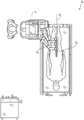
Fig. 13 illustrates an exemplary medical instrument having a mating instrument driver.
Fig. 14 shows an alternative design of the instrument driver and instrument, in which the axis of the drive unit is parallel to the axis of the elongate shaft of the instrument.
Fig. 15 depicts a block diagram illustrating a positioning system that estimates a position of one or more elements of the robotic system of fig. 1-10 (e.g., a position of an instrument of fig. 13 and 14), according to an example embodiment.
FIG. 16A illustrates an example operating environment implementing one or more aspects of the disclosed branch prediction systems and techniques.
FIG. 16B illustrates an example lumen network that may be navigated in the operating environment of FIG. 16A.
FIG. 16C illustrates an example command console that can be used, for example, as a command console in an example operating environment.
FIG. 17A provides an overview of an example block diagram of a navigation configuration system, according to one embodiment.
FIG. 17B illustrates an example block diagram of the navigation module shown in FIG. 17A in accordance with one embodiment.
FIG. 17C illustrates an example block diagram of an estimated state data store included in a state estimator in accordance with one embodiment.
FIG. 17D illustrates an example location sensor-based branch prediction system in accordance with aspects of the present disclosure.
Fig. 18A is a flow diagram illustrating an example method operable by a robotic system or component(s) thereof for unregistered positioning sensor-based branch prediction, in accordance with aspects of the present disclosure.
Fig. 18B illustrates an example set of localization data points that may be generated by one or more localization sensors as an instrument is driven through a luminal network in accordance with aspects of the present disclosure.
Fig. 19 shows an example lumen network that may perform location sensor-based branch prediction, in accordance with aspects of the present disclosure.
Fig. 20 is a flow diagram illustrating an example method operable by a robotic system or component(s) thereof for registration-based positioning sensor branch prediction, in accordance with aspects of the present disclosure.
Fig. 21 is a flow diagram illustrating an example method operable by a robotic system or component(s) thereof for positioning sensor-based branch prediction, in accordance with aspects of the present disclosure.
Detailed Description
1. Overview.
Aspects of the present disclosure may be integrated into a robotically enabled medical system capable of performing a variety of medical procedures, including both minimally invasive procedures, such as laparoscopy, and non-invasive procedures, such as endoscopy. During endoscopy, the system can perform bronchoscopy, ureteroscopy, gastroscopy, and the like.
In addition to performing a broad range of procedures, the system may provide additional benefits, such as enhanced imaging and guidance to assist the physician. In addition, the system may provide the physician with the ability to perform procedures from an ergonomic position without requiring awkward arm movements and positions. Still further, the system may provide a physician with the ability to perform a procedure with improved ease of use such that one or more instruments of the system may be controlled by a single user.
For purposes of illustration, various embodiments are described below in conjunction with the following figures. It should be understood that many other implementations of the disclosed concept are possible and that various advantages can be achieved with the disclosed implementations. Headings are included herein for reference and to aid in locating the various sections. These headings are not intended to limit the scope of the concepts described with respect to the headings. These concepts may have applicability throughout the present specification.
A. Robotic system-cart.
The robotically enabled medical system may be configured in various ways depending on the particular procedure. Fig. 1 shows an embodiment of a cart-based robot-enabled system 10 arranged for diagnostic and/or therapeutic bronchoscopy procedures. During bronchoscopy, the system 10 may include a cart 11 having one or more robotic arms 12 to deliver medical instruments (e.g., a steerable endoscope 13, which may be a procedure-specific bronchoscope for bronchoscopy) to a natural orifice entry point (i.e., the mouth of a patient on a table in this example) for delivery of diagnostic and/or therapeutic tools. As shown, the cart 11 may be positioned near the upper torso of the patient to provide access to the access point. Similarly, the robotic arm 12 may be actuated to position the bronchoscope relative to the entry point. The arrangement of fig. 1 may also be utilized when performing Gastrointestinal (GI) procedures with a gastroscope, a specialized endoscope for GI procedures. Fig. 2 depicts an example embodiment of a cart in more detail.
With continued reference to fig. 1, once the cart 11 is properly positioned, the robotic arm 12 may automatically, manually, or a combination thereof insert the steerable endoscope 13 into the patient. As shown, the steerable endoscope 13 may include at least two telescoping sections, such as an inner guide section and an outer sheath section, each coupled to a separate instrument driver from a set of instrument drivers 28, each coupled to the distal end of a separate robotic arm. This linear arrangement of the instrument driver 28, which facilitates coaxial alignment of the guide portion with the sheath portion, creates a "virtual track" 29, which "virtual track" 29 can be repositioned in space by manipulating one or more robotic arms 12 to different angles and/or positions. The virtual tracks described herein are depicted in the figures using dashed lines, and thus the dashed lines do not depict any physical structure of the system. Translation of the instrument driver 28 along the virtual track 29 causes the inner guide member portion to telescope relative to the outer sheath portion or the endoscope 13 to advance or retract relative to the patient. The angle of the virtual track 29 may be adjusted, translated, and pivoted based on clinical application or physician preference. For example, in bronchoscopy, the angle and position of virtual track 29 shown represents a compromise between providing physician access to endoscope 13 while minimizing friction resulting from bending endoscope 13 into the patient's mouth.
The endoscope 13 may be guided along the patient's trachea and lungs after insertion using precise commands from the robotic system until the target destination or surgical site is reached. To enhance navigation through the patient's pulmonary network and/or to a desired target, the endoscope 13 can be manipulated to telescopically extend the inner guide member portion from the outer sheath portion to achieve enhanced engagement and a larger bend radius. The use of a separate instrument driver 28 also allows the guide portion and sheath portion to be driven independently of each other.
For example, the endoscope 13 may be guided to deliver a biopsy needle to a target, e.g., a lesion or nodule within a patient's lung. A needle may be deployed along a working channel extending along the length of the endoscope to obtain a tissue sample to be analyzed by a pathologist. Depending on the pathology results, additional tools may be deployed along the working channel of the endoscope for additional biopsies. After identifying that the nodule is malignant, the endoscope 13 may endoscopically deliver a tool to resect the potentially cancerous tissue. In some cases, diagnostic and therapeutic treatments may need to be provided in separate processes. In those cases, endoscope 13 may also be used to deliver fiducials to also "mark" the location of the target nodule. In other cases, the diagnostic and therapeutic treatments may be provided during the same procedure.
The system 10 may also include a movable tower 30, which movable tower 30 may be connected to the cart 11 via support cables to provide control, electronic, fluid control, optical, sensor, and/or electrical support to the cart 11. Placing such functionality in the tower 30 allows for a smaller form factor cart 11 that can be more easily adjusted and/or relocated by the operating physician and his/her staff. Furthermore, the division of functionality between the cart/table and the support tower 30 reduces operating room clutter and facilitates improved clinical workflow. While the cart 11 may be positioned close to the patient, the tower 30 may be stowed at a remote location to not be in the way during the procedure.
To support the above-described robotic system, the tower 30 may include component(s) of a computer-based control system that stores computer program instructions, for example, within a non-transitory computer-readable storage medium such as a permanent magnetic storage drive, a solid state drive, or the like. Execution of these instructions, whether occurring in the tower 30 or in the cart 11, may control the entire system or its subsystem(s). For example, the instructions, when executed by a processor of the computer system, may cause components of the robotic system to actuate an associated carriage and arm mount, actuate a robotic arm, and control a medical instrument. For example, in response to receiving a control signal, a motor in a joint of the robotic arm may place the arm in a particular pose.
The tower 30 may also include pumps, flow meters, valve controllers, and/or fluid inlets to provide controlled irrigation and aspiration capabilities to the system that may be deployed through the endoscope 13. These components may also be controlled using the computer system of the tower 30. In some embodiments, irrigation and aspiration capabilities may be provided directly to endoscope 13 through separate cable(s).
The tower 30 may include a voltage and surge protector designed to provide filtered and protected power to the cart 11, thereby avoiding the placement of power transformers and other auxiliary power components in the cart 11, resulting in a smaller, more mobile cart 11.
The tower 30 may also include support equipment for sensors deployed throughout the robotic system 10. For example, the tower 30 may include optoelectronic devices for detecting, receiving, and processing data received from optical sensors or cameras throughout the robotic system 10. In conjunction with the control system, such optoelectronic devices may be used to generate real-time images for display in any number of consoles deployed throughout the system (including in the tower 30). Similarly, the tower 30 may also include an electronics subsystem for receiving and processing signals received from deployed Electromagnetic (EM) sensors. The tower 30 may also be used to house and position an EM field generator for detection by EM sensors in or on the medical instrument.
The tower 30 may include a console 31 in addition to other consoles available in the rest of the system (e.g., a console mounted on top of the cart). The console 31 may include a user interface and display screen, such as a touch screen, for the physician operator. The console in system 10 is typically designed to provide pre-operative and real-time information for robotic control and procedures, such as navigation and positioning information for endoscope 13. When the console 31 is not the only console available to the physician, the console 31 may be used by a second operator, such as a nurse, to monitor the patient's health or vital signs and operation of the system, as well as to provide process specific data, e.g., navigation and positioning information.
The tower 30 may be coupled to the cart 11 and the endoscope 13 by one or more cables or connections (not shown). In some embodiments, support functions from the tower 30 may be provided to the cart 11 by a single cable, thereby simplifying and clutter-free the operating room. In other embodiments, certain functions may be coupled in separate cables and connections. For example, while power may be provided to the cart through a single power cable, support for control, optics, fluidics, and/or navigation may also be provided through separate cables.
Fig. 2 provides a detailed illustration of an embodiment of a cart of the cart-based robot-enabled system shown in fig. 1. The cart 11 generally includes an elongated support structure 14 (commonly referred to as a "column"), a cart base 15, and a console 16 atop the column 14. The column 14 may include one or more carriages, such as carriage 17 (alternatively a "boom"), for supporting the deployment of one or more robotic arms 12 (three shown in fig. 2). The carriage 17 may include a separately configurable arm mount that rotates along a vertical axis to adjust the base of the robotic arm 12 for better positioning relative to the patient. The carriage 17 also includes a carriage interface 19 that allows the carriage 17 to translate vertically along the column 14.
The carriage interface 19 is connected to the column 14 by slots, such as slots 20, disposed on opposite sides of the column 14 to guide vertical translation of the carriage 17. The slots 20 contain vertical translation interfaces for positioning and retaining the carriage at various vertical heights relative to the cart base 15. Vertical translation of the carriage 17 allows the cart 11 to adjust the reach of the robotic arm 12 to meet various table heights, patient sizes, and physician preferences. Similarly, the individually configurable arm mounts on the carriage 17 allow the robotic arm base 21 of the robotic arm 12 to be angled in various configurations.
In some embodiments, the slot 20 may be supplemented with a slot cover that is flush and parallel with the slot surface to prevent dust and fluid from entering the vertical translation interface and the interior chamber of the column 14 as the carriage 17 translates vertically. The slot cover may be deployed by a pair of spring spools located near the vertical top and bottom of the slot 20. The lid is coiled within the reel until deployed to extend and retract from the coiled state of the lid as the carriage 17 translates vertically up and down. The spring loading of the spool provides a force to retract the cover into the spool as the carriage 17 translates toward the spool, while also maintaining a tight seal as the carriage 17 translates away from the spool. The cover may be connected to the carriage 17 using, for example, a bracket in the carriage interface 19 to ensure that the cover is properly extended and retracted as the carriage 17 translates.
The column 14 may internally include mechanisms such as gears and motors designed to use vertically aligned lead screws to mechanically translate the carriage 17 in response to control signals generated in response to user inputs (e.g., inputs from the console 16).
The robotic arm 12 may generally include a robotic arm base 21 and an end effector 22 separated by a series of links 23, the series of links 23 being connected by a series of joints 24, each joint including an independent actuator, each actuator including an independently controllable motor. Each independently controllable joint represents an independent degree of freedom available to the robotic arm. Each of the arms 12 has seven joints, thus providing seven degrees of freedom. Multiple joints bring multiple degrees of freedom, allowing "redundant" degrees of freedom. The redundant degrees of freedom allow the robotic arms 12 to use different link positions and joint angles to position their respective end effectors 22 at specific positions, orientations, and trajectories in space. This allows the system to position and guide the medical instrument from a desired point in space while allowing the physician to move the arm joint to a clinically advantageous position away from the patient to create better access while avoiding arm collisions.
The cart base 15 balances the weight of the column 14, carriage 17 and arm 12 on the floor. Thus, the cart base 15 houses heavier components such as electronics, motors, power supplies, and components that enable the cart to be moved and/or secured. For example, the cart base 15 includes rollable wheel casters 25 that allow the cart to be easily moved in the chamber prior to a procedure. After reaching the proper position, the caster 25 may be secured using a wheel lock to hold the cart 11 in place during the procedure.
The console 16, disposed at the vertical end of the column 14, allows both a user interface for receiving user inputs and a display screen (or dual-purpose device, such as a touch screen 26) to provide both pre-operative and intra-operative data to the physician user. The potential preoperative data on the touchscreen 26 may include navigation and mapping data derived from a preoperative Computerized Tomography (CT) scan, preoperative planning, and/or annotations from preoperative patient interviews. The intra-operative data on the display may include optical information provided from the tool, sensor and coordinate information from the sensors, and vital patient statistics such as respiration, heart rate, and/or pulse. The console 16 may be positioned and tilted to allow the physician access to the console from the side of the column 14 opposite the cradle 17. From this position, the physician can view the console 16, the robotic arm 12, and the patient while manipulating the console 16 from behind the cart 11. As shown, the console 16 also includes a handle 27 for assisting in maneuvering and stabilizing the cart 11.
Fig. 3 shows an embodiment of a robot-enabled system 10 arranged for ureteroscopy. During ureteroscopy, the cart 11 may be positioned to deliver a ureteroscope 32, i.e., a procedure-specific endoscope designed to traverse the patient's urethra and ureter, to the lower abdominal region of the patient. In ureteroscopy, it may be desirable for the ureteroscope 32 to be directly aligned with the patient's urethra to reduce friction and forces on sensitive anatomical structures in this region. As shown, the cart 11 may be aligned at the foot of the table to allow the robotic arm 12 to position the ureteroscope 32 to obtain direct linear access to the patient's urethra. From the foot of the table, the robotic arm 12 can insert the ureteroscope 32 directly into the patient's lower abdomen through the urethra along a virtual track 33.
After insertion into the urethra, ureteroscope 32 may be navigated to the bladder, ureter, and/or kidney for diagnostic and/or therapeutic applications using similar control techniques as in bronchoscopy. For example, the ureteroscope 32 may be guided into the ureter and kidney to break up accumulated kidney stones using a laser or ultrasonic lithotripsy device deployed along the working channel of the ureteroscope 32. After lithotripsy is complete, the resulting stone fragments may be removed using a basket deployed along the ureteroscope 32.
Fig. 4 shows an embodiment of a similarly arranged robot-enabled system for vascular surgery. In vascular procedures, the system 10 may be configured such that the cart 11 may deliver a medical device 34, such as a steerable catheter, to an entry point in the femoral artery of a patient's leg. The femoral artery provides both a larger diameter for navigation and relatively less tortuous and tortuous paths to the patient's heart, which simplifies navigation. As during ureteroscopy, the cart 11 may be positioned toward the patient's leg and lower abdomen to allow the robotic arm 12 to provide a virtual track 35 with direct linear access to the femoral artery access point in the thigh/hip region of the patient. After insertion into the artery, the medical instrument 34 may be guided and inserted by translating the instrument driver 28. Alternatively, the cart may be positioned around the patient's upper abdomen to reach alternative vascular access points, such as the carotid and brachial arteries near the shoulder and wrist.
B. Robotic system-station.
Embodiments of the robot-enabled medical system may also incorporate a patient table. The incorporation of a table reduces the amount of capital equipment in the operating room by removing the cart, which allows for better access to the patient. Fig. 5 shows an embodiment of such a robot-enabled system arranged for a bronchoscopy procedure. The system 36 includes a support structure or column 37 for supporting a platform 38 (shown as a "table" or "bed") on the floor. Much like in a cart-based system, the end effector of robotic arm 39 of system 36 includes an instrument driver 42 designed to manipulate an elongate medical instrument, such as bronchoscope 40 in fig. 5, through or along a virtual track 41 formed by the linear alignment of instrument driver 42. In practice, a C-arm for providing fluoroscopic imaging may be positioned over the upper abdominal region of the patient by placing the emitter and detector around table 38.
Fig. 6 provides an alternative view of the system 36 without the patient and medical instrument for discussion purposes. As shown, the column 37 may include one or more carriages 43, shown as rings in the system 36, upon which one or more robotic arms 39 may be based. The carriage 43 may translate along a vertical column interface 44 extending along the length of the column 37 to provide different vantage points from which the robotic arm 39 may be positioned to reach the patient. Carriage 43 may be rotated about column 37 using mechanical motors located within column 37 to allow robotic arm 39 access to multiple sides of table 38, such as both sides of a patient. In embodiments having multiple carriages, the carriages may be separately disposed on the column and may translate and/or rotate independently of the other carriages. Although the bracket 43 need not be circular about the post 37 or even circular, the illustrated annular shape facilitates rotation of the bracket 43 about the post 37 while maintaining structural balance. The rotation and translation of the carriage 43 allows the system to align medical instruments, such as endoscopes and laparoscopes, to different entry points on a patient.
The arm 39 may be mounted on the carriage by a set of arm mounts 45 that include a series of joints that may be individually rotated and/or telescopically extended to provide additional configurability for the robotic arm 39. Further, the arm mounts 45 may be disposed on the carriage 43 such that when the carriage 43 is rotated appropriately, the arm mounts 45 may be disposed on the same side of the table 38 (as shown in FIG. 6), on the opposite side of the table 38 (as shown in FIG. 9), or on the adjacent side of the table 38 (not shown).
The post 37 structurally provides support for the table 38 and provides a path for vertical translation of the carriage. Internally, the column 37 may be equipped with a lead screw for guiding the vertical translation of the carriage, and a motor for mechanizing the translation of said carriage on the basis of the lead screw. The post 37 may also transmit power and control signals to the carriage 43 and the robotic arm 39 mounted on the carriage.
The table base 46 functions similarly to the cart base 15 in the cart 11 shown in fig. 2, i.e., accommodates heavier components to balance the table/bed 38, the column 37, the carriage 43, and the robot arm 39. The table base 46 may also include rigid casters for providing stability during the procedure. In the case of deployment from the bottom of the table base 46, the casters may extend in opposite directions on either side of the base 46 and retract when the system 36 needs to be moved.
With continued reference to fig. 6, the system 36 may also include a tower (not shown) that divides the functions of the system 36 between the table and the tower to reduce the form factor and volume of the table. As in the earlier disclosed embodiments, the tower may provide various support functions for the station, such as processing, computing and control capabilities, power, flow control and/or optical and sensor processing. The tower may also be movable to be positioned away from the patient to improve access by the physician and to keep the operating room from clutter. Furthermore, placing the components in the tower may allow more storage space in the table base for potential stowing of the robotic arm. The tower may also include a console that provides a user interface (e.g., a keyboard and/or pendant) for user input and a display screen (or touch screen) for pre-operative and intra-operative information (e.g., real-time imaging, navigation, and tracking information).
In some embodiments, the table base may stow and store the robotic arm when not in use. FIG. 7 illustrates a system 47 for stowing a robotic arm in an embodiment of the table-based system. In the system 47, the carriage 48 may be vertically translated into the base 49 to stow the robotic arm 50, arm mount 51, and carriage 48 within the base 49. The base cover 52 may be translated and retracted to open to deploy the carriage 48, arm mount 51, and arm 50 around the post 53, and to close to stow to protect the carriage, arm mount, and arm when not in use. The base cover 52 may be sealed with a membrane 54 along the edges of the base cover opening to prevent the ingress of dust and fluids when closed.
Fig. 8 illustrates an embodiment of a robot-enabled table-based system configured for a ureteroscopy procedure. In ureteroscopy, table 38 may include a rotating portion 55 for positioning the patient at an angle off of column 37 and table base 46. The rotating portion 55 can rotate or pivot about a pivot point (e.g., located below the patient's head) to position a bottom portion of the rotating portion 55 away from the post 37. For example, the pivoting of rotating portion 55 allows a C-arm (not shown) to be positioned over the patient's lower abdomen without competing for space with a post (not shown) below table 38. By rotating the bracket 35 (not shown) about the post 37, the robotic arm 39 can insert the ureteroscope 56 directly into the groin area of the patient along the virtual track 57 to reach the urethra. In ureteroscopy, the stirrup 58 may also be secured to the rotating portion 55 of the table 38 to support the position of the patient's leg during the procedure and allow unobstructed access to the patient's groin area.
During laparoscopic procedures, minimally invasive instruments (elongated in shape to accommodate the size of one or more incisions) may be inserted into the patient's anatomy through a small incision(s) in the patient's abdominal wall. After the patient's abdominal cavity is inflated, instruments commonly referred to as laparoscopes may be guided to perform surgical tasks such as grasping, cutting, ablating, suturing, and the like. FIG. 9 illustrates an embodiment of a robot-enabled table-based system configured for laparoscopic procedures. As shown in fig. 9, the carriage 43 of the system 36 can be rotated and vertically adjusted to position the pair of robotic arms 39 on opposite sides of the table 38 so that a laparoscope 59 can be positioned through the smallest incisions on both sides of the patient to reach his/her abdominal cavity using the arm mounts 45.
To accommodate laparoscopic procedures, the robotic enabling table system may also tilt the platform to a desired angle. Fig. 10 illustrates an embodiment of a robot-enabled medical system with pitch or tilt adjustment. As shown in fig. 10, system 36 may accommodate the tilt of table 38 to position one portion of the table at a greater distance from the ground than another portion. In addition, arm mount 45 may be rotated to match the tilt so that arm 39 maintains the same planar relationship with table 38. To accommodate steeper angles, column 37 may also include a telescoping portion 60, which telescoping portion 60 allows vertical extension of column 37 to prevent table 38 from contacting the ground or colliding with base 46.
Fig. 11 provides a detailed illustration of the interface between table 38 and column 37. Pitch rotation mechanism 61 may be configured to change the pitch angle of table 38 relative to column 37 in multiple degrees of freedom. The pitch rotation mechanism 61 may be implemented by placing orthogonal axes 1, 2 at the spar interface, each axis being actuated by a separate motor 2, 4 in response to an electrical pitch angle command. Rotation along one screw 5 will enable tilt adjustment along one axis 1, while rotation along the other screw 6 will enable tilt adjustment along the other axis 2.
For example, pitch adjustment is particularly useful when attempting to position the table in a head-low-foot (Trendelenburg) position (i.e., the patient's lower abdomen is at a higher position from the ground than the patient's lower abdomen) for lower abdominal surgery. The low head and foot position allows the patient's internal organs to slide by gravity toward his/her upper abdomen, thereby emptying the abdominal cavity for access by minimally invasive tools and performing lower abdominal surgical procedures, such as laparoscopic prostatectomy.
C. An instrument driver and interface.
An end effector of a robotic arm of the system comprises: (i) an instrument driver (alternatively referred to as an "instrument drive mechanism" or "instrument device manipulator") that incorporates an electromechanical device for actuating a medical instrument; and (ii) a removable or detachable medical instrument that may be free of any electromechanical components such as a motor. This dichotomy may be driven by the need to sterilize medical instruments used in medical procedures and the inability to adequately sterilize expensive capital equipment due to the complex mechanical components and sensitive electronics of the expensive capital equipment. Thus, the medical instrument may be designed to be detached, removed, and interchanged from the instrument driver (and thus from the system) for individual sterilization or disposal by the physician or the physician's staff. In contrast, the instrument driver does not need to be changed or sterilized and may be covered with a drape for protection.
FIG. 12 illustrates an example instrument driver. The device driver 62 disposed at the distal end of the robotic arm includes one or more drive units 63 arranged in parallel axes to provide a controlled torque to the medical device via a drive shaft 64. Each drive unit 63 comprises a separate drive shaft 64 for interacting with the instrument, a gear head 65 for converting motor shaft rotation into a desired torque, a motor 66 for generating the drive torque, an encoder 67 for measuring the speed of the motor shaft and providing feedback to the control circuit, and a control circuit 68 for receiving control signals and actuating the drive unit. Each drive unit 63 is independently controlled and motorized, and the instrument driver 62 can provide a plurality (four as shown in fig. 12) of independent drive outputs to the medical instrument. In operation, the control circuit 68 will receive the control signal, transmit the motor signal to the motor 66, compare the resulting motor speed measured by the encoder 67 to a desired speed, and modulate the motor signal to generate a desired torque.
For procedures requiring a sterile environment, the robotic system may incorporate a drive interface between the instrument driver and the medical instrument, such as a sterile adapter connected to a sterile drape (drapee). The primary purpose of the sterile adapter is to transfer angular motion from the drive shaft of the instrument driver to the drive input of the instrument while maintaining a physical separation between the drive shaft and the drive input and thus maintaining sterility. Thus, an example sterile adapter may include a series of rotational inputs and outputs intended to mate with a drive shaft of a device driver and a drive input on a device. A sterile drape (e.g., transparent or translucent plastic) composed of a thin, flexible material connected to a sterile adaptor is designed to cover capital equipment such as instrument drivers, robotic arms and carts (in cart-based systems) or tables (in table-based systems). Use of the drape will allow capital equipment to be placed near the patient while still being located in areas that do not require sterilization (i.e., non-sterile areas). On the other side of the sterile drape, the medical device may be docked with the patient in the area requiring sterilization (i.e., the sterile field).
D. A medical device.
FIG. 13 illustrates an example medical instrument having a mating instrument driver. Similar to other instruments designed for use with robotic systems, the medical instrument 70 includes an elongate shaft 71 (or elongate body) and an instrument base 72. The instrument base 72, also referred to as an "instrument handle" due to its intended design for manual interaction by a physician, may generally include a rotatable drive input 73, such as a socket, pulley, or reel, designed to mate with a drive output 74 extending through a drive interface on an instrument driver 75 at the distal end of a robotic arm 76. When physically connected, latched, and/or coupled, the mated drive input 73 of the instrument base 72 may share an axis of rotation with the drive output 74 in the instrument driver 75 to allow torque to be transferred from the drive output 74 to the drive input 73. In some embodiments, drive output 74 may include splines designed to mate with sockets on drive input 73.
Elongate shaft 71 is designed to be delivered through an anatomical opening or lumen (e.g., in endoscopy) or through a minimally invasive incision (e.g., in laparoscopy). The elongate shaft 66 may be flexible (e.g., having endoscopic-like characteristics) or rigid (e.g., having laparoscopic-like characteristics), or comprise a customized combination of both flexible and rigid portions. When designed for laparoscopy, the distal end of the rigid elongate shaft may be connected to an end effector comprising an articulated wrist formed by a clevis having a rotational axis and a surgical tool (e.g., a grasper or scissors) that may be actuated based on forces from the tendons as the drive input rotates in response to torque received from the drive output 74 of the instrument driver 75. When designed for endoscopic examination, the distal end of the flexible elongate shaft may include a steerable or controllable bending portion that can be engaged and bent based on the torque received from the drive output 74 of the instrument driver 75.
Torque from instrument driver 75 is transmitted along elongate shaft 71 using tendons within shaft 71. These separate tendons (e.g., pull wires) may be individually anchored to separate drive inputs 73 within the instrument handle 72. Tendons are guided from handle 72 along one or more traction lumens within elongate shaft 71 and anchored at a distal portion of elongate shaft 71. In laparoscopy, these tendons may be coupled to a distally mounted end effector, such as a wrist, grasper, or scissors. With such an arrangement, torque applied to drive input 73 transfers tension to the tendons, causing the end effector to actuate in some manner. In laparoscopy, the tendon may rotate a joint about an axis, thereby moving an end effector in one direction or the other. Alternatively, the tendon may be connected to one or more jaws (jaw) of the grasper at the distal end of the elongate shaft 71, wherein tension from the tendon closes the grasper.
In endoscopy, the tendons can be coupled to bending or engaging sections disposed along (e.g., at the distal end of) elongate shaft 71 via adhesives, control rings, or other mechanical fasteners. When fixedly attached to the distal end of the bending section, the torque applied to the drive input 73 will be transmitted along the tendon, bending or engaging the softer bending section (sometimes referred to as the engageable section or region). Along the non-curved section, it may be advantageous to spiral or spiral the separate traction lumens guiding the separate tendons along (or inside) the wall of the endoscope shaft to balance the radial forces caused by the tension in the traction wires. The spacing therebetween and/or the angle of the spirals may be varied or designed for a particular purpose, wherein a tighter spiral exhibits less shaft compression under load forces, and a lesser amount of the spiral causes greater shaft compression under load forces, but also exhibits limited bending. In another aspect, the distraction lumen can be oriented parallel to the longitudinal axis of elongate shaft 71 to allow controlled engagement in a desired curved or engageable section.
In endoscopy, the elongate shaft 71 houses a number of components to assist in robotic procedures. The shaft may include a working channel for deploying surgical tools, irrigation and/or suction to a surgical field at the distal end of the shaft 71. The shaft 71 may also house wires and/or optical fibers to transmit signals to/from an optical assembly at the distal tip, which may include an optical camera. The shaft 71 may also house optical fibers to transmit light from a light source (e.g., a light emitting diode) located at the proximal end to the distal end of the shaft.
At the distal end of the instrument 70, the distal tip may also include openings for working channels for delivering tools for diagnosis and/or treatment, irrigation, and aspiration to the surgical site. The distal tip may also include a port for a camera device, such as a fiberscope or digital camera, to capture images of the internal anatomical space. Relatedly, the distal tip may also include a port for a light source to illuminate the anatomical space when the camera device is in use.
In the example of fig. 13, the drive shaft axis, and thus the drive input axis, is orthogonal to the axis of the elongate shaft. However, this arrangement complicates the rolling ability of elongate shaft 71. As the tendons extend away from drive input 73 and into a traction lumen within elongate shaft 71, rolling elongate shaft 71 along its axis while keeping drive input 73 stationary can cause undesirable tangling of the tendons. Such eventual entanglement of the tendons may disrupt any control algorithms intended to predict movement of the flexible elongate shaft during the endoscopic procedure.
Fig. 14 shows an alternative design of the instrument driver and instrument, in which the axis of the drive unit is parallel to the axis of the elongate shaft of the instrument. As shown, the circular instrument driver 80 includes four drive units whose drive outputs 81 are aligned in parallel at the end of a robotic arm 82. The drive units and their respective drive outputs 81 are housed in a rotation assembly 83 of the instrument driver 80 driven by one of the drive units within the assembly 83. In response to the torque provided by the rotational drive unit, the rotation assembly 83 rotates along a circular bearing that connects the rotation assembly 83 to the non-rotating portion 84 of the instrument driver. Power and control signals may be transmitted from the non-rotating portion 84 of the instrument driver 80 to the rotating assembly 83 through electrical contacts that may be maintained by rotation of a brush-slip ring connection (not shown). In other embodiments, the rotational assembly 83 may be responsive to a separate drive unit integrated into the non-rotating portion 84, and thus not parallel to the other drive units. Rotation mechanism 83 allows instrument driver 80 to rotate the drive unit and its corresponding drive output 81 as a single unit about instrument driver axis 85.
Similar to the earlier disclosed embodiments, the instrument 86 may include an elongated shaft portion 88 and an instrument base 87 (shown in transparent appearance for discussion purposes), the instrument base 87 including a plurality of drive inputs 89 (e.g., sockets, pulleys, and spools) configured to receive the drive outputs 81 in the instrument driver 80. Unlike the previously disclosed embodiment, the instrument shaft 88 extends from the center of the instrument base 87 with its central axis substantially parallel to the axis of the drive input 89, rather than orthogonal as in the design of fig. 13.
When coupled to the rotation assembly 83 of the instrument driver 80, a medical instrument 86 including an instrument base 87 and an instrument shaft 88 rotates in conjunction with the rotation assembly 83 about an instrument driver axis 85. Since the instrument shaft 88 is centered in the instrument base 87, the instrument shaft 88 is coaxial with the instrument driver axis 85 when attached. Thus, rotation of the rotation assembly 83 rotates the instrument shaft 88 about its own longitudinal axis. Furthermore, when instrument base 87 rotates with instrument shaft 88, any tendons connected to drive input 89 in instrument base 87 do not tangle during rotation. Thus, the parallelism of the axes of drive output 81, drive input 89, and instrument shaft 88 allows shaft rotation without tangling any control tendons.
E. Navigation and control.
Conventional endoscopy may include the use of fluoroscopy (e.g., as may be delivered through a C-arm) and other forms of radiation-based imaging modalities to provide intraluminal guidance to the operating physician. In contrast, robotic systems contemplated by the present disclosure may provide non-radiation based navigation and positioning means to reduce physician exposure to radiation and reduce the number of devices in the operating room. As used herein, the term "locating" may refer to determining and/or monitoring the position of an object in a reference coordinate system. Techniques such as pre-operative mapping, computer vision, real-time EM tracking, and robot command data may be used alone or in combination to achieve a radiation-free operating environment. In still other cases where a radiation-based imaging modality is used, preoperative mapping, computer vision, real-time EM tracking, and robot command data may be used, alone or in combination, to improve the information obtained only by the radiation-based imaging modality.
Fig. 15 is a block diagram illustrating a positioning system 90 that estimates a position of one or more elements of a robotic system (e.g., a position of an instrument), according to an example embodiment. The positioning system 90 may be a collection of one or more computer devices configured to execute one or more instructions. The computer apparatus may be implemented by one or more processors and computer readable memory in one or more of the components discussed above. By way of example and not limitation, the computer device may be located in the tower 30 shown in fig. 1, the cart shown in fig. 1-4, the bed shown in fig. 5-10, or the like.
As shown in fig. 15, the localization system 90 may include a localization module 95 that processes the input data 91-94 to generate localization data 96 for the distal tip of the medical instrument. The positioning data 96 may be data or logic representing the position and/or orientation of the distal end of the instrument relative to a frame of reference. The reference frame may be a reference frame relative to the anatomy of the patient or relative to a known object, such as an EM field generator (see discussion below regarding EM field generators). The positioning data 96, which may also be referred to herein as "state data," describes a current state of the distal tip of the medical instrument relative to a model (e.g., a model of a bone) of the patient's anatomy. The status data may include information such as the position and orientation of the distal tip of the medical instrument during a given sampling period. For example, when using a skeletal model to model a patient's anatomy based on the midpoints of the lumen network, the location may take the form of a segment ID and a depth along the segment.
The various input data 91 to 94 will now be described in more detail. The pre-operative mapping may be accomplished by using a set of low dose CT scans. The pre-operative CT scan is reconstructed into a three-dimensional (3D) image that is visualized, for example, as a "slice" of a cross-sectional view of the patient's internal anatomy. When analyzed in its entirety, an image-based model of the anatomical cavities, spaces, and structures for the patient's anatomy (e.g., the patient's lung network) may be generated. Techniques such as centerline geometry may be determined and approximated from the CT images to form a three-dimensional volume of the patient's anatomy referred to as pre-operative model data 91. The use of centerline geometry is discussed in U.S. patent application No. 14/523,760, which is incorporated herein in its entirety. The network topology model can also be derived from CT images and is particularly suitable for bronchoscopy.
In some embodiments, the instrument may be equipped with a camera to provide visual data 92. The positioning module 95 may process the visual data to enable one or more vision-based positioning tracks. For example, the pre-operative model data may be used in conjunction with the vision data 92 to enable computer vision-based tracking of a medical instrument (e.g., an endoscope or an instrument advanced through a working channel of an endoscope). For example, using the pre-operative model data 91, the robotic system may generate a library of expected endoscope images from the model based on the expected path of travel of the endoscope, each image linked to a location within the model. During surgery, the robotic system may reference the library to compare real-time images captured at a camera (e.g., at the distal end of the endoscope) with images in the image library to assist in positioning.
Other computer vision based tracking techniques use feature tracking to determine the motion of the camera, and thus the endoscope. Some features of the localization module 95 may identify circular geometries in the pre-operative model data 91 that correspond to anatomical lumens and track changes in those geometries to determine which anatomical lumen was selected, as well as relative rotational and/or translational motion of the camera. The use of a topological map may further enhance the vision-based algorithms or techniques.
Optical flow, another computer vision based technique, may analyze the displacement and translation of image pixels in a video sequence in the visual data 92 to infer camera motion. Examples of optical flow techniques may include motion detection, object segmentation computation, luminance, motion compensated coding, stereo disparity measurement, and so forth. By comparing multiple frames with multiple iterations, the movement and positioning of the camera (and hence the endoscope) can be determined.
The localization module 95 may use real-time EM tracking to generate a real-time localization of the endoscope in a global coordinate system, wherein the global coordinate system may be registered to the patient's anatomy represented by the pre-operative model. In EM tracking, an EM sensor (or tracker), which includes one or more sensor coils embedded in a medical instrument (e.g., an endoscopic tool) at one or more positions and orientations, measures changes in the EM field produced by one or more static EM field generators positioned at known locations. The positioning information detected by the EM sensor is stored as EM data 93. An EM field generator (or transmitter) may be placed close to the patient to produce a low-intensity magnetic field that the embedded sensors can detect. The magnetic field induces small currents in the sensor coils of the EM sensor, which may be analyzed to determine the distance and angle between the EM sensor and the EM field generator. These distances and orientations may be "registered" intra-operatively to the patient anatomy (e.g., a pre-operative model) to determine a geometric transformation that aligns individual locations in the coordinate system with locations in the pre-operative model of the patient's anatomy. Once registered, embedded EM trackers at one or more locations of the medical instrument (e.g., the distal tip of the endoscope) may provide real-time indications of the advancement of the medical instrument through the patient's anatomy.
The positioning module 95 may also use the robot commands and kinematic data 94 to provide positioning data 96 for the robotic system. Device pitch and yaw resulting from engagement commands may be determined during pre-operative calibration. During surgery, these calibration measurements may be used in conjunction with known insertion depth information to estimate the position of the instrument. Alternatively, these calculations may be analyzed in conjunction with EM, visual, and/or topological modeling to estimate the location of the medical instrument within the network.
As shown in fig. 15, the location module 95 may use several other input data. For example, although not shown in fig. 15, an instrument utilizing a shape sensing fiber may provide shape data that the localization module 95 may use to determine the position and shape of the instrument.
The positioning module 95 may use the input data 91 to 94 in combination. In some cases, such a combination may use a probabilistic approach, where the localization module 95 assigns confidence weights to the locations determined from each of the input data 91 to 94. Thus, in situations where the EM data may be unreliable (as is the case in the presence of EM interference), the confidence in the localization determined by EM data 93 may be reduced, and localization module 95 may rely to a greater extent on vision data 92 and/or robot commands and kinematic data 94.
As discussed above, the robotic systems discussed herein may be designed to incorporate a combination of one or more of the above techniques. A computer-based control system of a robotic system located in a tower, bed, and/or cart may store computer program instructions within a non-transitory computer-readable storage medium, such as a permanent magnetic storage drive, a solid state drive, or the like, wherein the computer program instructions, when executed, cause the system to receive and analyze sensor data and user commands, generate control signals for the entire system, and display navigation and positioning data, such as the position of an instrument within a global coordinate system, anatomical map, or the like.
2. Introduction of branch prediction based on positioning sensors.
Embodiments of the present disclosure relate to systems and techniques for location sensor based branch prediction. The system may employ a localization sensor(s) or localization sensing device(s) to localize, for example, the distal end of the instrument during a medical procedure. The positioning sensor(s) may be positioned at or near the distal end of the instrument, or may be positioned remote from the distal end of the instrument. Examples of a position sensor or position sensing device that may be positioned at or near the distal end of the instrument include an EM sensor, a vision-based position sensor (e.g., a camera device), a shape sensing fiber optic, and the like. Examples of a position sensor or position sensing device that may be disposed remote from the distal end of the instrument include a fluoroscopic imaging device, robotic system component(s) that generate or process robotic data for controlling the position of the instrument via one or more instrument manipulators, a remote vision-based position sensor, and the like.
The positioning sensor may be configured to generate positioning data indicative of a position of the distal end of the instrument (e.g., relative to a positioning sensor coordinate system). As used herein, a positioning sensor coordinate system may refer to any coordinate system that may be used to define or determine the location (e.g., on a manifold such as euclidean space) of positioning data generated by a positioning sensor. When the positioning sensor is juxtaposed to the distal end of the instrument, the positioning data may represent the position of the positioning sensor itself, which the processor may then use to determine the position of the distal end of the instrument. In some embodiments, the positioning sensor coordinate system may include a set of origins and axes, which may be defined based on the particular technology used to implement the positioning sensor.
For example, an EM sensor located in or on the instrument may be configured to measure the EM field generated by the EM field generator. The characteristics of the EM field, and thus the EM values measured by the EM sensors, may be defined with respect to the location and orientation of the EM field generator. Thus, the placement of the EM field generator may affect the values measured by the EM sensors, and may also define the location and orientation of the EM coordinate system.
As described above, the luminal network of the patient can be mapped preoperatively using, for example, a low dose CT scan to generate a model of the luminal network. Because the model may be generated via a different technique than that used to position the distal end of the instrument, the model coordinate system may not be aligned with the positioning sensor coordinate system. Accordingly, to track the position of the instrument relative to the model using the positioning sensor coordinate system, one technique may involve registering the coordinate system used by one or more positioning sensors with another coordinate system (e.g., the coordinate system used by the anatomical model) (e.g., by a separate system communicatively coupled to the robotic system or one or more components of the robotic system, including but not limited to a processor, a positioning system, a positioning module, etc.). The registration may include, for example, a translation and/or rotation applied to the positioning sensor data to map the positioning sensor data from the positioning sensor coordinate system to the model coordinate system.
The system or processor may perform registration of the localization sensor coordinate system to the model coordinate system, for example, during an initial stage of the procedure. According to implementations, the processor may automatically perform the registration process in the background as the instrument is initially advanced through the luminal network. In another implementation, the processor may provide a set of instructions to the user to drive the instrument to a particular location within the luminal network or along a set registration path to facilitate the registration process. Thus, the processor may perform a portion of the process when the position data received from the positioning sensor(s) is not registered to the model.
To provide feedback to the user regarding instrument navigation during a medical procedure, a "fused" localization algorithm may be run (e.g., by the localization system 90 of fig. 15). The fusion algorithm may combine data received from multiple sources indicative of the location of the distal end of the instrument to determine the location of the instrument. One function of the fusion algorithm may also include prediction of the next branch of the luminal network into which the instrument may advance. The prediction may be based on at least some of the data sources used in the fusion algorithm, including the positioning sensor data. In some embodiments, the prediction may also be used as an input in determining the position of the distal end of the instrument.
Since the localization sensor(s) may not be registered for at least a portion of the medical procedure, certain aspects of the present disclosure may relate to techniques for branch prediction, which may be employed based on either the registered localization sensor data or the unregistered localization sensor data (also commonly referred to as "raw" localization sensor data). Thus, the system may selectively apply different techniques or combinations thereof to location sensor-based branch prediction depending on whether the location sensor(s) have been registered.
Em navigation guides bronchoscopy.
In the following, an example system will be described that may employ techniques for location sensor-based branch prediction. For example, the system may be configured for EM navigation guided bronchoscopy procedures. However, aspects of the present disclosure may also be applied to systems using other positioning sensors capable of generating positioning data, as well as other types of medical procedures.
FIG. 16A illustrates an example operating environment 100 in which one or more aspects of the disclosed branch prediction systems and techniques may be implemented. The operating environment 100 includes a platform 102 supporting a patient 101, a surgical or medical robotic system 110 guiding movement of an instrument 115, a command center 105 for controlling operation of the robotic system 110, an EM controller 135, an EM field generator 120, and EM sensors 125, 130. Fig. 16A also shows an outline of a region of the luminal network 140 within the patient 101, the luminal network 140 being shown in more detail in fig. 16B.
The system 110 may include one or more robotic arms for positioning and guiding movement of the instrument 115 through the luminal network 140 of the patient 101. The command center 105 may be communicatively coupled to the robotic system 110 for receiving position data and/or providing control signals generated based on user commands received from a user. As used herein, "communicatively coupled" refers to any wired and/or wireless data transfer medium, including, but not limited to, a Wireless Wide Area Network (WWAN) (e.g., one or more cellular networks), a Wireless Local Area Network (WLAN) (e.g., configured for one or more standards, such as IEEE 802.11(Wi-Fi)), bluetooth, a data transfer cable, and the like. The robotic system 110 may be any of the systems described above with respect to fig. 1-15.
The instrument 115 may be a tubular and flexible surgical instrument that is inserted into a patient's anatomy to capture images of the anatomy (e.g., body tissue) and provide a working channel for inserting other medical instruments into the target tissue site. As noted above, the instrument 115 may be a procedure-specific endoscope, such as a bronchoscope, gastroscope, or ureteroscope, or may be a laparoscopic or vascular steerable catheter. The instrument 115 may include one or more imaging devices (e.g., cameras or other types of optical sensors) at the distal end of the instrument 115. The imaging device may include one or more optical components, such as an optical fiber, an optical fiber array, a photosensitive substrate, and/or a lens (es). The optical components move with the tip of the instrument 115 such that movement of the tip of the instrument 115 causes a corresponding change in the field of view of the image captured by the imaging device. The distal end of the instrument 115 may be provided with one or more EM sensors 125 for tracking the location of the distal end within the EM field generated around the luminal network 140.
Fig. 16B illustrates an example luminal network 140 that may be navigated in the operating environment 100 of fig. 16A. The luminal network 140 includes the branching structure of the airway 150 of the patient 101, the trachea 154 leading to a main carina 156 (typically the first bifurcation encountered during bronchoscopic navigation), and a nodule (or lesion) 155 that may be accessed for diagnosis and/or treatment as described herein. As shown, the nodule 155 is located at the periphery of the airway 150. The instrument 115 may include a sheath 141 having a first diameter, and thus the distal end of the sheath 141 cannot be positioned through the smaller diameter airway around the nodule 155. Thus, a scope (scope)145 extends from the working channel of the instrument 115 and spans the remaining distance to the nodule 155. The scope 145 can have a lumen through which instruments, such as a biopsy needle, a cytobrush, and/or a tissue-sampling forceps, can pass to reach the target tissue site of the nodule 155. In such implementations, both the distal end of the sheath 141 and the distal end of the scope 145 may be provided with EM sensors for tracking their respective positions within the airway 150.
In some embodiments, a two-dimensional (2D) display of a 3D luminal network model as described herein or a cross-section of the 3D model may be similar to fig. 16B. The estimated position of the distal end of the instrument may be overlaid onto such a representation. In some implementations, the estimated position can be displayed on a display of a command console, such as the command console 160 shown in FIG. 16C.
FIG. 16C illustrates an example command console 160 that can be used, for example, as the command console 105 in the example operating environment 100. Command console 160 may include a console base 161, one or more displays 162 (e.g., a monitor), and one or more control modules (e.g., a keyboard 163 and a joystick 164). In some embodiments, one or more of the command console 160 functions may be integrated into the base 180 of the robotic system 110 or another system communicatively coupled to the robotic system 110. A user 165, such as a physician, uses a command console 160 to remotely control the robotic system 110 from an ergonomic position.
The console base 161 may include a central processing unit, memory unit, data bus and associated data communication ports that are responsible for interpreting and processing signals such as camera images and tracking sensor data from the instrument 115 shown in fig. 16A and 16B, for example. In some embodiments, both console base 161 and base 180 perform signal processing to achieve load balancing. Console base 161 may also process commands and instructions provided by user 165 through control modules 163 and 164. In addition to the keyboard 163 and joystick 164 shown in fig. 16C, the control module may include other devices, such as a computer mouse, track pad, track ball, control pad, controller such as a handheld remote controller, and sensors (e.g., motion sensors or cameras) that capture hand and finger gestures. The controller may include a set of user inputs (e.g., buttons, joysticks, directional pads, etc.) that map or link to the operation of the instrument (e.g., engage, drive, flush, etc.).
In some embodiments, a model of the instrument 115 is displayed along with the 3D model to help indicate the status of the surgical procedure. For example, CT scans identify lesions in the anatomy that may require biopsy. During operation, the display module 162 may show a reference image captured by the instrument 115 that corresponds to the current position of the instrument 115. The display module 162 may automatically display different views of the model of the instrument 115 depending on user settings and the particular surgical procedure. For example, the display module 162 shows a top-down fluoroscopic view of the instrument 115 as the instrument 115 approaches the surgical area of the patient during the navigation step.
B. Location sensor based branch prediction using unregistered location data.
As described above, an initial phase of the medical procedure may be performed prior to registering the localization sensor(s) to the model of the luminal network. However, the localization sensor(s) may still generate localization data prior to registration. Although not registered to the model, the raw positioning sensor data may be used to provide certain positioning and navigation functions. For example, the processor may determine the relative orientation of the instrument at different times based on the raw, unregistered positioning data. Thus, in certain embodiments, the processor may facilitate predicting the next branch in the luminal network to which the instrument is likely to advance based on the shape and structure of the luminal network and the orientation of the instrument determined based on the unregistered data.
Branch prediction may be included as part of a navigation configuration system. 17A-17D illustrate example block diagrams of a navigation configuration system 200 according to one embodiment. More specifically, FIG. 17A provides an overview of an example block diagram of a navigation configuration system 200, according to one embodiment. In fig. 17A, the navigation configuration system 200 includes a plurality of input data storage devices, a navigation module 205 that receives various types of input data from the plurality of input data storage devices, and an output navigation data storage device 290 that receives output navigation data from the navigation module. The block diagram of the navigation configuration system 200 shown in fig. 17A is merely an example, and in an alternative embodiment not shown, the navigation configuration system 200 may include different and/or additional entities. Likewise, the functions performed by the various entities of system 200 may vary from implementation to implementation. The navigation configuration system 200 may be similar to the navigation system described in U.S. patent publication No. 2017/0084027, published 3-23-2017, which is incorporated by reference herein in its entirety.
Input data, as used herein, refers to raw data collected from and/or processed by an input device, e.g., command module(s), optical sensor(s), EM sensor(s), IDM(s), for generating estimated state information of an endoscope and outputting navigation data. The plurality of input data storage devices 210 to 240 include an image data storage device 210, an EM data storage device 220, a robot data storage device 230, and a 3D model data storage device 240. Each type of input data store 210-240 stores data of the type indicated by the name for access and use by the navigation module 205. The image data may include one or more image frames captured by an imaging device at the instrument tip and information such as a frame rate or timestamp that enables determination of the time elapsed between pairs of frames. Robot data includes data related to the physical movement of a medical instrument or portion of a medical instrument (e.g., an instrument tip or sheath) within a tubular network. Example robotic data includes command data indicating that the instrument tip reaches a particular anatomical site and/or changes its orientation within the tubular network (e.g., by a particular pitch, roll, yaw, insertion, and retraction for one or both of the guide and sheath), insertion data representing insertion movement of a portion of the medical instrument (e.g., the instrument tip or sheath), IDM data, and mechanical data representing mechanical movement of an elongate member of the medical instrument (e.g., movement of one or more pull wires, tendons, or shafts of an endoscope that drive actual movement of the medical instrument within the tubular network). The EM data may be collected by the EM sensors and/or EM tracking systems described above. The 3D model data may be obtained from a 2D CT scan as described above. The path data includes a planned navigation path, which may be generated by a topological search of a tubular network to one or more targets.
The output navigation data store 290 receives and stores the output navigation data provided by the navigation module 205. The output navigation data is indicative of information that assists in guiding the medical instrument through the tubular network to a particular destination within the tubular network, and the estimated state information includes a location and an orientation of the medical instrument within the tubular network based on the estimated state information of the medical instrument at each instant in time. In one embodiment, updated output navigation data indicative of movement and location/orientation information of the medical instrument is provided in real-time as the medical instrument moves within the tubular network, which better assists in navigation of the medical instrument through the tubular network.
To determine the output navigation data, the navigation module 205 finds (or determines) an estimated state of the medical instrument within the tubular network. As shown in fig. 17A, the navigation module 205 also includes various algorithm modules, such as an EM-based algorithm module 250, an image-based algorithm module 260, and a robot-based algorithm module 270, each of which may primarily use (consume) certain types of input data and contribute different types of data to a state estimator 280. As shown in fig. 17A, for illustration, the different types of data output by these modules, labeled EM-based data, image-based data, and robot-based data, may be collectively referred to as "intermediate data.
FIG. 17B illustrates an example block diagram of the navigation module 205 shown in FIG. 17A, according to one embodiment. As introduced above, the navigation module 205 also includes a state estimator 280 and a plurality of algorithm modules that employ different algorithms for navigating through the tubular network. For clarity of description, the state estimator 280 is described first, followed by a description of the various modules that exchange data with the state estimator 280.
A state estimator 280 included in the navigation module 205 receives the various intermediate data and provides an estimated state of the instrument tip as a function of time, wherein the estimated state is indicative of estimated position and orientation information of the instrument tip within the tubular network. The estimated state data is stored in an estimated data storage 285 included in the state estimator 280.
Fig. 17C illustrates an example block diagram of an estimated state data store 285 included in the state estimator 280 in accordance with one embodiment. The estimated state data store 285 may comprise a bifurcated (bifurcation) data store 286, a location data store 287, a depth data store 288 and an orientation data store 289, although this particular breakdown of data stores is merely an example and in alternative embodiments not shown, different and/or additional data stores may be included in the estimated state data store 285.
The respective storage devices described above represent the estimated state data in various ways. Specifically, bifurcation data refers to the positioning of a medical instrument relative to a set of branches (e.g., a bifurcation, a trifurcation, or a bifurcation (division) of more than three branches) within a tubular network. For example, the bifurcation data may be a set of branch choices selected by the instrument as it travels through the tubular network based on a larger set of available branches provided, for example, by a 3D model that maps the entire tubular network. The bifurcation data may also include information ahead of the location of the instrument tip, such as branches (bifurcations) that the instrument tip is approaching but has not yet traveled through, but that have been detected, e.g., based on current position information of the tip relative to a 3D model, or based on captured images of upcoming bifurcations.
The position data indicates a three-dimensional position of a certain part of the medical instrument within the tubular network or of a certain part of the tubular network itself. The position data may be in the form of absolute positioning or relative positioning with respect to the 3D model of the tubular network, for example. As one example, the position data may include an indication that the localized position of the instrument is within a particular branch. The identification of a particular branch may also be stored as a segment Identification (ID) that uniquely identifies the particular segment in the model in which the instrument tip is located.
The depth data is indicative of depth information of the instrument tip within the tubular network. Example depth data includes the total insertion (absolute) depth of the medical instrument within the patient and the (relative) depth within the identified branch (e.g., the segment identified by the location data store 287). The depth data may be determined based on position data about both the tubular network and the medical instrument.
The orientation data is indicative of orientation information of the instrument tip and may include overall roll, pitch, and yaw associated with the 3D model and pitch, roll, and yaw within the identified branches.
Returning to fig. 17B, the state estimator 280 provides the estimated state data back to the algorithm module for generating more accurate intermediate data that the state estimator uses to generate improved and/or updated estimated states, and so on to form a feedback loop. For example, as shown in FIG. 17B, EM-based algorithm module 250 receives previous EM-based estimated state data, also referred to as data associated with a timestamp "t-1". The state estimator 280 uses this data to generate "estimated state data (previous)" associated with the timestamp "t-1". The state estimator 280 then provides this data back to the EM-based algorithm module. The "estimated state data (previous)" may be based on a combination of different types of intermediate data (e.g., robot data, image data) associated with the timestamp "t-1" as generated and received from different algorithm modules. Next, EM-based algorithm module 250 runs its algorithm using the estimated state data (previous) to output improved and updated EM-based estimated state data, represented herein by "EM-based estimated state data (current)" and associated with a timestamp t, to state estimator 280. This process will continue to repeat for future timestamps as well.
Since the state estimator 280 may use several different types of intermediate data to derive its estimate of the state of the medical instrument within the tubular network, the state estimator 280 is configured to take into account each type of underlying data (robot, EM, image, path) and each type of algorithm module may generate or carry uncertainties in both measurement and analysis and various different types of errors in the intermediate data that are used for consideration in determining the estimated state. To address this, two concepts are discussed, a concept of a probability distribution and a concept of a confidence value.
As used herein, a "probability" in a "probability distribution" refers to the likelihood that an estimate of a possible location and/or orientation of a medical instrument is correct. For example, different probabilities may be calculated by one of the algorithm modules indicating the relative likelihood of the medical instrument being in one of several different possible branches within the tubular network. In one embodiment, the type of probability distribution (e.g., discrete distribution or continuous distribution) is selected to match the characteristics of the estimated states (e.g., the type of estimated state, such as continuous location information and discrete branch selection). As one example, the estimated state used to identify which segment of the trifurcation the medical instrument is in may be represented by a discrete probability distribution and may include three discrete values 20%, 30%, and 50% representing the likelihood of a location as being located within each of the three branches as determined by one of the algorithm modules. As another example, the estimated state may include a roll angle of the medical instrument of 40 + -5 degrees, and the segment depth of the instrument tip within the bifurcation may be 4 + -1 mm, each represented by a Gaussian distribution that is a type of continuous probability distribution. Different methods or modalities may be used to generate the probabilities, which will vary with the algorithm modules as described more fully below with reference to later figures.
In contrast, a "confidence value," as used herein, reflects a measure of confidence in an estimate of a state provided by one of the algorithms based on one or more factors. For EM-based algorithms, factors such as EM field distortion, EM registration inaccuracies, patient displacement or movement, and patient respiration may affect the confidence of the estimate of the state. In particular, the confidence value of the estimate of the state provided by the EM-based algorithm may depend on the particular respiratory cycle of the patient, the movement of the patient or the EM field generator, and the location within the anatomy in which the instrument tip is located. For image-based algorithms, example factors that may affect the confidence value when estimating the state include: a lighting condition of a location within the anatomy at which the image was captured; the presence of fluid, tissue or other obstructions against or in front of the optical sensor that captured the image; the patient's breathing; conditions of the patient's own tubular network (e.g., lungs), such as general fluid within the tubular network and occlusion of the tubular network; and specific operating techniques used in, for example, navigation or image capture.
For example, one factor may be that a particular algorithm has different levels of accuracy at different depths in the lungs of a patient, such that in the case of relatively close airway openings, the particular algorithm may have high confidence in its estimation of the position and orientation of the medical instrument, but the medical instrument travels further into the bottom of the lungs, the confidence value may drop. Generally, the confidence value is based on one or more system factors related to the process of determining the outcome, while the probability is a relative measure that occurs when attempting to determine the correct outcome from multiple probabilities using a single algorithm based on the underlying data.
As one example, the mathematical formula for calculating the result of the estimated states represented by a discrete probability distribution (e.g., branch/segment identification through three values of the estimated state involved for trifurcations) may be as follows:
S1=CEM*P1,EM+CImage*P1,Image+CRobot*P1,Robot;
S2=CEM*P2,EM+CImage*P2,Imtage+CRobot*P2,Robot;
S3=CEM*P3,EM+CImage*P3,Image+CRobot*P3,Robot。
in the above exemplary mathematical formula, Si(i=1,2,3) Possible example values representing the estimated states in case of identification or presence of 3 possible segments in the 3D model, CEM、CImageAnd CRobotRepresenting confidence values corresponding to EM-based, image-based, and robot-based algorithms, and Pi,EM、Pi,ImageAnd Pi,RobotRepresenting the probability of segment i.
To better illustrate the concepts of probability distributions and confidence values associated with estimated states, detailed examples are provided herein. In this example, the user is attempting to identify the segment in which the instrument tip is located in a particular trifurcation within the central airway (predicted region) of the tubular network, and uses three algorithm modules, including EM-based algorithms, image-based algorithms, and robot-based algorithms. In this example, the probability distribution corresponding to the EM-based algorithm may be 20% in the first branch, 30% in the second branch, and 50% in the third (last) branch, with a confidence value of 80% applied to the EM-based algorithm and the central airway. For the same example, for the first, second, and third branches, the probability distribution corresponding to the image-based algorithm may be 40%, 20%, 40%, and the confidence value applied to the image-based algorithm is 30%; while for the first, second and third branches, the probability distribution corresponding to the robot-based algorithm may be 10%, 60%, 30% and the confidence value applied to the image-based algorithm is 20%. The difference in confidence values applied to the EM-based algorithm and the image-based algorithm indicates: EM-based algorithms may be a better choice for segment identification in the central airway than image-based algorithms. An example mathematical calculation of the final estimated state may be:
for the first branch: 20% + 80% + 40% + 30% + 10% + 20% + 30%; for the second branch: 30% + 80% + 20% + 30% + 60% + 20% + 42%; and for the third branch: 50% + 80% + 40% + 30% + 20% + 58%.
In this example, the output estimated state of the instrument tip may be the resulting values (e.g., 30%, 42%, and 58% derived) or derived values from these resulting values, such as determining that the instrument tip is in the third branch. Although this example describes the use of algorithm modules including EM-based algorithms, image-based algorithms, and robot-based algorithms, the estimation of the state of the instrument tip may also be provided based on different combinations of various algorithm modules including path-based algorithms.
As described above, the estimated states may be represented in a number of different ways. For example, the estimated state may also include an absolute depth of localization from the airway to the instrument tip and a data set representing a set of branches traversed by the instrument within the tubular network, e.g., a set of branches is a subset of the entire set of branches provided by the 3D model of the patient's lungs. The application of the probability distribution and the confidence values on the estimated state allows to improve the accuracy of the estimation of the position and/or orientation of the instrument tip within the tubular network.
As shown in fig. 17B, the algorithm modules include an EM-based algorithm module 250, an image-based algorithm module 260, and a robot-based algorithm module 270. The algorithm module shown in fig. 17B is only one example, and in an alternative embodiment, different and/or additional algorithm modules involving different and/or additional navigation algorithms may also be included in the navigation module 205.
B.1. Branch prediction system
The EM-based algorithm module 250 also includes an EM registration module 252, an EM localization module 254, and an EM branch prediction module 256. The EM registration module 252 may perform registration of EM coordinates to 3D model coordinates. EM localization module 254 may determine an estimate of the position and orientation of the instrument. The EM branch prediction module 256 may determine a prediction as to which segment of the model the instrument will advance from the current segment in which the instrument is currently located.
FIG. 17D illustrates an example location sensor based location and branch prediction system in accordance with aspects of the present disclosure. In particular, fig. 17D illustrates a localized sensor-based localization and branch prediction system that includes EM data storage 220, registration transformation data storage 253, 3D model data storage 240, EM localization module 254, EM branch prediction module 256, and estimated state data storage 285. The block diagram of the location and branch prediction system is merely an example, and in other embodiments not shown, the location and branch prediction system may include different and/or additional components, for example, in some implementations, the branch prediction system 210 may include one or more of an image data store 220 and a robot data store 230 in place of or in addition to the EM data store 220.
The EM branch prediction module 256 may determine a prediction as to which segment of the model the instrument will advance. For example, based on the determined current segment of the model in which the instrument is located and/or orientation data received from orientation data store 289, EM branch prediction module 256 may determine a prediction that the instrument will advance into each sub-segment of the current segment. The EM branch prediction module 256 may employ a variety of different techniques to determine the prediction, which will be described in more detail below. In some embodiments, the particular technique used by the EM branch prediction module 256 may depend on whether the localization data has been registered to the model. The EM branch prediction module 256 may provide the determined prediction to the estimated state data storage 285. In some embodiments as discussed above, EM branch prediction module 256 may determine a prediction based on orientation data received from orientation data store 289. In other embodiments, the EM branch prediction module 256 may determine predictions based on location data from the location data store 287 or based on both orientation data and location data.
B.2. Example route taken by an Instrument
For illustrative purposes, various aspects of the present disclosure relating to location sensor-based branch prediction will be described in the context of bronchoscopy and the navigation portion of a bronchial lumen network. However, the present disclosure may also be applied to other luminal networks and other medical procedures.
Fig. 18A illustrates an example lumen network in which location sensor-based branch prediction may be performed in accordance with various aspects of the present disclosure. In the embodiment of fig. 18A, the illustrated network of lumens 300 corresponds to airways of a patient's lungs and includes a first-generation airway 305 (e.g., trachea) that branches into two second-generation airways 315 and 320 (e.g., a main bronchus) at a main carina 310. Assuming the patient lies supine, trachea 305 will branch into the patient's left bronchus 320 and the patient's right bronchus 315.
Fig. 18A also shows a route 325 along which the instrument may be driven as it is navigated through the airway during a medical procedure. Two example tracking positions 330 and 335 of the instrument as driven along the path 325 are shown and will be referenced in discussing various embodiments. The position sensor may generate position data (not shown) representing the tracking position 330 and the tracking position 335 within the position sensor coordinate system, as described in detail below in connection with fig. 18B. Various aspects of the present disclosure may relate to the prediction of which airway between the second generation airway 315 and one of the second generation airways 320 the instrument will advance to. As will be described in detail later, the processor may select an initial position 330 and a subsequent position 335 of the instrument for use in a branch prediction technique.
B.3. Example positioning data generated during a procedure
Fig. 18B illustrates an example set of localization data points that may be generated by one or more localization sensors as an instrument is driven through a luminal network in accordance with various aspects of the present disclosure. In fig. 18B, the navigation path 345 may be defined as the path along which the instrument is to be driven during the procedure. The navigation path 345 may be selected by a user prior to performing a procedure, generated by a path planning program, and so forth. For convenience, fig. 18B is shown in 2D, however, it should be understood that the present disclosure is also applicable to 3D navigation paths. The navigation path 345 may be defined relative to a model coordinate system 350 in which a model of a luminal network of the patient is defined (e.g., the skeleton-based model 500 of fig. 20).
During the procedure, the localization sensor may generate a plurality of unregistered data points 355 representing the tracked localization of the instrument as it is navigated through the airway. The unregistered data point 355 may be defined relative to the positioning sensor coordinate system 360. In the case of an embodiment utilizing EM sensors, the positioning sensor coordinate system 360 may be defined by or correspond to the EM field from the EM generator. A navigation system operated with a robotic system (e.g., the positioning system shown in fig. 15) may determine a registration between the positioning sensor coordinate system 360 and the model coordinate system 350, which may be used to map the unregistered data points 355 to the model coordinate system 350. This registration may be stored in memory, for example, in registration data store 225 of fig. 17. One technique for registering the localized sensor coordinate system 360 and the model coordinate system 350 may include selecting a transformation matrix that minimizes the sum of the distances between the data points and the path 345 when the transformation matrix is applied to the unregistered data points 355. Once registration is applied to the unregistered data points 355, the "registered" location data points may be substantially aligned with the path 345.
B.4. Example Branch prediction techniques
Fig. 19 is a flow diagram illustrating an example method operable by a robotic system or component(s) thereof for location sensor-based branch prediction in accordance with various aspects of the present disclosure. For example, the steps of method 400 shown in fig. 19 may be performed by the processor(s) and/or other component(s) of the robotic system or associated systems. For convenience, method 400 is described as being performed by a location sensor-based branch prediction system, where the description of the location sensor-based branch prediction system with respect to method 400 is also referred to simply as a "system".
At block 405, the positioning sensor-based branch prediction system determines a first orientation of the instrument based on first positioning data generated by a set of one or more positioning sensors for the instrument. The first positioning data may indicate a position of the instrument in a positioning sensor coordinate system at a first time. In some embodiments, the positioning sensor may be located at or near the distal end of the instrument, and thus, the positioning data generated by the positioning sensor may be indicative of the positioning of the distal end of the instrument. In one embodiment, the first orientation of the instrument may correspond to the orientation of the instrument in an initial position, such as initial position 330 of fig. 18.
At block 410, the positioning sensor-based branch prediction system determines a second orientation of the instrument at a second time based on second positioning data generated by the set of positioning sensors. The distal end of the instrument may be located within the first segment of the model at a first time and a second time. The first segment may branch into two or more subsegments. In the example embodiment shown in fig. 18, the distal end of the instrument may correspond to an initial position 330 and a subsequent position 335 at first and second times, respectively, each of the initial and subsequent positions 330, 335 being located within a first generation airway 305 that branches into two second generation airways 315, 320.
At block 415, the positioning sensor-based branch prediction system determines data indicative of a difference between the first orientation and the second orientation. This may include, for example, determining the orientation of the instrument at two successive points in time based on the unregistered positioning sensor data. Based on the difference between the orientation of the instrument when located in the current segment, the system can predict which of the two or more sub-segments the instrument is most likely to advance into. That is, since the system may branch from model access to the orientation of each of the first generation airway 305 of the two second generation airways 315 and 320, the system is able to predict into which sub-segment the instrument is most likely to advance based on changes in the orientation of the instrument.
In one implementation, the positioning sensor-based branch prediction system may determine the difference between the initial orientation and the subsequent orientation by calculating a relative transformation matrix between the initial orientation and the subsequent orientation. The system may decompose the transformation matrix into roll, pitch, and yaw angles to define the orientation of the instrument in the position sensor coordinate system. Certain localization sensor technologies (e.g., EM localization sensors) that may be used as localization sensors may be substantially aligned with a patient in at least one angular degree of freedom when the patient is supine to perform a given procedure (e.g., to perform a bronchoscopy procedure). In an EM implementation, the EM field generator may generate an EM field having an orientation defined relative to an orientation of the EM field generator. Thus, by arranging the orientation of the EM field generator to be aligned with the patient, the system is able to perform the branch prediction method 400 using only the yaw angle determined from the relative transformation matrix.
Since the EM field and the orientation of the patient may be known for the bronchoscopy procedure, the system is able to determine a yaw angle between the initial orientation and the subsequent orientation based on data generated by the EM sensor. Thus, the bifurcation of the trachea to the main bronchus may be defined relative to the yaw axis in the EM sensor coordinate system. Thus, when the instrument is positioned within trachea 305 (see fig. 18A), the yaw angle of the instrument determined based on the EM field may be substantially aligned with the difference in orientation between main bronchus 315 and main bronchus 320. Thus, the system may use the change in yaw angle between the initial orientation and the subsequent orientation as a basis for updating the prediction of the main bronchus 315 and the main bronchus 320 into which the instrument may be advanced.
In some embodiments, block 415 may further include: the system determines the angle formed between the orientations of the sub-segments. The amount of change in the orientation of the distal end of the instrument may correspond to the angle formed between the sub-segments in order to redirect the insertion direction of the instrument from one sub-segment to the other. As described below, the system may use the angle formed between the subsections as a factor in determining whether to update branch predictions and/or as a factor in assigning probabilities to subsections during branch prediction. It should be understood that embodiments in which the threshold is selected based on the angle formed between the sub-segments may be determined at design time (e.g., the threshold is a parameter selected by a designer of the system based on the angle) or during runtime (e.g., the system includes logic and data for dynamically determining the threshold before or during surgery). It should also be appreciated that the runtime method may affect the hardware and software of the system as well as the patient's anatomy to accurately distinguish the angles using the threshold.
At block 420, the location sensor-based branch prediction system determines a prediction that the instrument will advance to a first of the sub-segments based on the data indicative of the difference. According to an embodiment, the predicting may include: an identification of the sub-segment to which the instrument is most likely to advance, a probability that the instrument of each of the sub-segments will advance into the corresponding sub-segment, an ordered list of sub-segments from highest probability to lowest probability, and so forth. When the system has previously determined a prediction that the instrument is going to advance into a sub-segment, the system may update the prediction based on the difference in orientation determined in block 415.
In embodiments where the system determines angles between sub-segments, the system may use the angles formed between the orientations of the sub-segments in determining the predictions. In other embodiments, the system may determine the prediction based on a difference between an orientation of the distal end of the instrument and an orientation of each of the sub-segments. In one embodiment, the system may assign a higher probability to a sub-segment having a smaller orientation difference from the orientation of the instrument than the remaining sub-segments.
In certain embodiments, the system may avoid adjusting the probability of the instrument advancing into each of the sub-segments unless the orientation of the instrument has changed beyond a threshold level. In some embodiments, the system may adjust the threshold level based on the angle between the sub-segments. For example, the system may increase the threshold level when the angle between the sub-segments is greater than a first threshold angle, and may decrease the threshold level when the angle between the sub-segments is less than a second threshold angle. Once the system has determined a prediction that the instrument will advance to a given one of the sub-segments (e.g., based on a probability of advancing to the given sub-segment being greater than a probability of other sub-segments), the system may then determine an orientation of the instrument at a third time based on subsequent positioning data generated by the set of positioning sensors. The system may be configured to: calculating an angle between (i) an orientation at a third time (e.g., a time after the second time when the instrument is at a subsequent position) and (ii) the initial orientation; and comparing the calculated angle to a threshold angle value. The system may also be configured to update the probability of the instrument advancing into each of the sub-segments in response to the calculated angle being greater than the threshold angle value. Thus, in certain embodiments, the system does not update the probability of the instrument advancing into each of the sub-segments unless the orientation of the instrument makes an angle with the initial orientation that is greater than a threshold angle value. The method 400 ends at block 425.
The above-described method 400 may be particularly advantageous when performed using unregistered positioning data. That is, because the unregistered positioning data may not provide an accurate mapping of the position and/or orientation of the instrument to the model coordinate system, the system may use the relative orientation of the instrument at two or more successive times to determine whether a change in the measured orientation of the instrument is consistent with the instrument being engaged with one of the oriented sub-segments. The detected change in the measured orientation of the instrument (e.g., within the positioning sensor coordinate system) may coincide with a change in the physical orientation of the instrument to be pointed in a direction closer to the physical orientation of one of the sub-segments. In other words, when determined using the unregistered positioning data, a relative change in the orientation of the instrument from an initial orientation to a subsequent orientation in the positioning sensor coordinate system may still indicate a change in the direction of advancement of the instrument toward one of the sub-segments. Thus, since the localization sensor coordinate system may not be registered to the model coordinate system during an initial phase of certain processes, the method 400 may provide branch predictions that may be used by sensor fusion techniques (e.g., the localization system 90 of fig. 15) during the initial phase.
In one example, when the data indicative of the difference between the initial orientation and the subsequent orientation coincides with the instrument being advanced toward or pointed at the patient's left main bronchus (e.g., second-generation airway 320), the system may predict that the instrument will be advanced into the left main bronchus instead of the right main bronchus. The system may then update the prediction for each sub-branch based on whether the change in orientation indicates that the instrument is heading or heading away from the corresponding sub-branch or whether the change in orientation indicates that the instrument is pointing or heading away from the corresponding sub-branch.
B.5. Selection of initial positioning
As described above, the method 400 may include determining a first orientation of the instrument at block 405 when the instrument is in the initial position. The positioning sensor-based branch prediction system may select an initial position of the instrument in response to initialization of the state estimation module 240. In some embodiments, the location sensor-based branch prediction system may select the first indication of the location of the instrument generated by the state estimation module 240 after initialization as the initial location. However, in other embodiments, the system may select other positions (e.g., a second position, a third position, etc. of the instrument) produced by the state estimation module 240 as the initial position.
In some embodiments, the system may be configured to select the initial position of the instrument based on determining that the orientation of the instrument at the initial position is substantially aligned with the orientation of the current segment (e.g., aligned with a longitudinal axis of the current segment). As used herein, the system may consider the orientation of the instrument to be substantially aligned with the orientation of the current segment when the difference between the orientation of the instrument and the orientation of the current segment is less than a threshold difference. However, since the received positioning sensor data may not be registered to the model coordinate system, the system may not be able to directly compare the orientation of the instrument with the orientation of the current segment.
In one implementation, the system may be configured to receive an indication from a user that the instrument is aligned with the current segment. The user can confirm that the orientation of the instrument is currently aligned with the first segment based on other sensors of the system (e.g., a camera located at the distal end of the instrument). In one implementation, the system may provide instructions to the user to drive the instrument to a defined location (e.g., keel 310 of fig. 18) within the luminal network and retract the instrument at least a defined distance from the defined location. The system may determine the position of the distal end of the instrument at a location before or after retraction and set the orientation of the instrument at that point to an initial orientation that is substantially aligned with the orientation of the current segment.
In other implementations, the system may be configured or programmed to automatically select the initial position during driving of the instrument without receiving user input. In one embodiment, the system may track the orientation of the instrument as the instrument advances through the current segment over a period of time, and in response to the orientation of the instrument being substantially unchanged for a threshold period of time, the system may determine that the orientation of the instrument during the identified period is aligned with the orientation of the current segment. In some embodiments, the system may determine that the orientation of the instrument is substantially unchanged when the maximum difference between the orientations of the instrument measured over the period of time is less than a threshold difference.
B.6. Confirmation of registration process
In some embodiments, the system may be configured to perform a registration process in order to register the coordinate system of the localization sensor(s) to the coordinate system of the model of the luminal network. This registration may be stored in a registration data store 225 as shown in fig. 17. The registration process may include a process that facilitates determining a registration between the localized sensor coordinate system and the model coordinate system using the unregistered localization data. In some embodiments, the registration process may be performed based on: a history of data received from the positioning sensor(s) is maintained, and a shape formed from the positioning data history is matched to a candidate path along which an instrument based on the model of the anatomical structure can travel. During the registration process, the system may provide instructions to the user to drive the instrument along a predetermined registration path and track the position of the instrument based on the positioning sensor in response to the user driving the instrument along the registration path. For some procedures, the registration path may include a contralateral registration path that defines the shape of the path along which the instrument is to be driven for the registration process. The contralateral registration path may include: driving the instrument along a segment of the lumen network on an opposite side of its positioning relative to the target, retracting the instrument from the opposite side, and driving the instrument along a lateral side of the lumen network along a path to the target (also referred to as the target path). Thus, the contralateral registration path may include: driving the instrument along an opposite side branch of the luminal network that is outside of the target pathway (e.g., along a side branch of the luminal network that is opposite the target), returning the instrument to the target pathway, and driving the instrument along a side branch located along a portion of the target pathway.
In some procedures, the target may include a nodule (or lesion) to which the instrument may be driven to facilitate diagnosis and/or treatment. Thus, the memory can store the target path to the target in the model as well as the contralateral registration path. During the registration process, the system may be configured to confirm whether the user is currently driving the instrument to the correct branch of the luminal network defined by the contralateral registration path based on the prediction as to whether the instrument will advance along each of the sub-segments. Thus, the system may determine whether the instrument is positioned along the contralateral registration path based on the prediction. In one implementation, when approaching a bifurcation in the luminal network (e.g., a bifurcation near the main bronchus), the system can compare the probability that the instrument will advance into the bifurcation along the contralateral registration path to a threshold probability. When the probability is less than the threshold probability, the system may display an indication to the user that the user may not be driving toward the correct branch.
In another implementation, the system may determine that the instrument is advanced along the target path before being advanced along the contralateral registration path, which may indicate that the user inadvertently drives the instrument along a path that is not consistent with the contralateral registration path used in the registration process. Since the contralateral registration path may require the instrument to be driven along the contralateral path before being driven along the target path, the system may provide an indication that contralateral registration was unsuccessful in response to determining that the instrument was advanced along the target path before the instrument was advanced along the contralateral registration path.
The system may also be configured to display an indication of the positioning of the instrument relative to the model during a given procedure to provide feedback to the user. Accordingly, the system may determine the position of the distal end of the instrument relative to the model based on a plurality of data sources indicative of the location of the instrument. In certain implementations, the system may determine the position of the distal end of the instrument based on one or more of: positioning data received from a positioning sensor; a command set provided to control movement of the instrument, and prediction(s) regarding the instrument to advance into a sub-segment of the current segment. Thus, the prediction determined via the method 400 of fig. 19 may be one source of data that the system may use in the positioning and/or navigation of the instrument.
C. Branch prediction based on registered positioning sensors.
After the system has performed the registration process (registering the localization sensor coordinate system to the model coordinate system), the system can use the data generated by the localization sensor(s) to determine an indication of the location of the distal end of the instrument with reference to the model associated with the model coordinate system. Using the registered data positioning data, the system may generate predictions about sub-segments of the luminal network into which the instrument is most likely to advance. Depending on the implementation, once the instrument has been advanced beyond a certain distance into the luminal network, the use of unregistered localized sensor data may not provide sufficient accuracy for branch prediction in the luminal network. For example, once the instrument has been advanced into the main bronchus, the system may not be able to perform branch prediction without registered positioning sensor data. Accordingly, various aspects of the present disclosure are also relevant to using the registered positioning data for branch prediction.
FIG. 20 illustrates an example skeleton-based model of a portion of a luminal network. In particular, skeleton-based model 500 illustrates an implementation in which a lumen network is modeled as a "skeleton" 505 that may include a plurality of discrete segments, where each segment corresponds to an individual lumen of the lumen network. The model 500 shown in fig. 20 may be used by the positioning system 90 (see fig. 15) to calculate the position and orientation of the distal end of the instrument. Each segment of the skeleton 505 may be assigned a unique "segment ID," and each of the segments forming the skeleton 505 may be defined relative to a centerline of the corresponding lumen. During certain medical procedures, instruments may be navigated through a network of lumens for at least a portion of the procedure. In particular, at a given point in time, the distal end of the instrument 525 may be located within the current segment 510 of the model, and the current segment 510 may branch or diverge into two sub-segments 515 and 520. As will be discussed in detail below, various aspects of the present disclosure relate to branch prediction techniques that execute based on the orientation of an instrument when located within the current segment 510.
Fig. 21 is a flow diagram illustrating an example method operable by a robotic system or component(s) thereof for registration-based positioning sensor branch prediction, in accordance with various aspects of the present disclosure. For example, the steps of method 600 shown in fig. 21 may be performed by the processor(s) and/or other component(s) of the robotic system or associated systems. For convenience, method 600 is described as being performed by a location sensor-based branch prediction system, where the description of the location sensor-based branch prediction system with respect to method 600 is also referred to simply as a "system". The robotic system may include at least one computer readable memory having stored thereon a model of a luminal network of the patient.
At block 605, the positioning sensor-based branch prediction system determines an orientation of the instrument relative to the model based on positioning data generated by a set of one or more positioning sensors for the instrument. In certain implementations, the positioning data includes registered positioning data received from a set of positioning sensors. When the system receives the localization sensor data, the localization sensor may be registered to the model of the luminal network. Using the registered positioning data, the system can determine a position of the distal end of the instrument relative to the model based on the positioning data. In certain implementations, the system may employ a sensor fusion technique that determines the location of the distal end of the instrument using multiple data sources (e.g., by using the location system 90 of fig. 15). Since the received positioning data is registered to the model, the system may be able to make measurements of the positioning of the instrument relative to the model.
In some implementations, when the system determines the orientation of the instrument at block 605, the distal end of the instrument may be located within the first segment of the model. In one embodiment, the distal end of the instrument 525 is located within the current section 525 comprising the two sub-branches 515 and 520, as shown in fig. 20.
At block 610, a sensor-based branch prediction system determines an orientation of a first one of the subsections. In the example of fig. 20, the orientation of each of sub-segment 515 and sub-segment 520 may be determined based on the orientation of the respective segment of skeleton 505 relative to the model coordinate system. Depending on the implementation, the current segment may correspond to any of the segments of the skeleton 505 that include two or more sub-segments.
At block 615, a prediction that the instrument will advance into the first sub-segment is determined based on the orientation of the instrument and the orientation of the first sub-segment based on the branch prediction of the positioning sensor. This may include: for example, the system determines the difference between the orientation of the distal end of the instrument 525 and the orientation of each of the sub-segments 515 and 520 in the embodiment of fig. 20. The model may include data indicating an orientation of each of the segments. In some implementations, data indicating the orientation of the segments may be included in the data representing the skeleton 505, where the location, length, and orientation of each segment of the skeleton 505 may be defined in memory. Thus, the system may use the registered positioning sensor data to determine the orientation of the instrument in the model coordinate system and compare the orientation of the instrument to the orientation of each of the sub-segments. The method ends at block 620.
According to an embodiment, the predicting may include: the identification of the sub-segment to which the instrument is most likely to advance, the probability that the instrument of each field in the sub-segment will advance into the corresponding sub-segment, an ordered list of sub-segments from highest probability to lowest probability, and so on. Thus, in certain embodiments, the prediction may include data indicative of a probability that the instrument will advance to each of the sub-segments. In some implementations, the system may assign a higher probability to sub-segments that have a smaller difference in orientation from the orientation of the instrument. Accordingly, the system may determine data indicative of a difference between the orientation of the instrument and the orientation of each of the sub-segments to help determine the corresponding probabilities.
In certain implementations, the system may also determine an angle between the orientation of the instrument and the orientation of each of the sub-segments. The angle between the orientation of a given sub-segment and the instrument may indicate a difference between the orientations. Thus, the system may be configured to assign a probability to a given sub-segment that is inversely proportional to the angle between the given sub-segment and the instrument. In one implementation, the system may determine the angle based on a dot product between the orientation of the instrument and the orientation of a given sub-segment. Since smaller angles may indicate greater alignment between a given sub-segment and the orientation of the instrument, the system may also use the inverse of the determined angle (invert) to calculate the probability of the given sub-segment.
This prediction may be used by the system as a data source for a fusion technique (e.g., the localization system 90 of fig. 15) for determining the localization of the distal end of the instrument relative to the model. In certain implementations, the system may determine the position of the distal end of the instrument based on one or more of: positioning data received from the positioning sensor(s), a set of commands provided to control movement of the instrument, and prediction(s) about the instrument to advance into each of the sub-segments.
In some implementations, in addition to the orientation-based prediction described above, the system may also apply auxiliary techniques for branch prediction. In one implementation, the assistance technique may include a location-based prediction that compares the location of the distal end of the instrument with the location of the beginning of each of the sub-segments. The system may determine an auxiliary prediction that the instrument will advance into each of the sub-segments based on the location of the distal end of the instrument. The prediction may be based on a location of the distal end of the instrument relative to each of the sub-segments. Further details and examples of location-based prediction techniques that may be used as an assistance technique are described in the above-referenced U.S. patent publication No. 2017/0084027. In one implementation, when the positioning sensor data indicates that the distal end of the instrument is positioned closer to one sub-segment than another sub-segment, the system may assign a higher probability to the closer sub-segment than the more distant sub-segment. For example, referring back to fig. 20, the system may assign a higher probability to a first one of the sub-segments 515 when the distal end of the instrument 525 is closer to the first one of the sub-segments 515 than a second one of the sub-segments 520. In some implementations, the system can determine the location of the distal end of the instrument using a fusion technique based on both the orientation-based prediction technique and the assisted location-based prediction technique. The system may weight the outcome of each of the branch prediction techniques based on various factors, including the accuracy associated with each of the techniques, the error associated with a particular prediction, and so forth.
One advantage associated with orientation-based positioning sensor branch prediction over location-based branch prediction is that orientation-based prediction may be performed continuously during driving of the instrument through the luminal network. For example, location-based branch prediction techniques may not provide accurate predictions unless the distal end of the instrument is within a threshold distance of an entering sub-segment of the bifurcation of the current segment. Since the location-based prediction techniques rely on location sensor data, the location-based prediction techniques may be susceptible to errors in location sensor registration and jitter in the location sensor data. Thus, when the instruments are relatively far from the sub-segments, the distance between each of the sub-segments and the instrument may not indicate the sub-segment toward which the user is driving the instrument. In contrast, the orientation of the instrument may be more strongly correlated with the sub-segment into which the user is driving the instrument, even when the instrument is relatively far away from the bifurcation defined by the sub-segment. Thus, in some embodiments, the orientation-based branch prediction techniques described herein may be applied as the distal end of the instrument progresses from the beginning of the current segment to the end of the current segment. In other embodiments, the system may apply orientation-based branch prediction techniques regardless of the position of the distal end of the instrument within the current segment.
3. Implementation systems and terminology.
Implementations disclosed herein provide systems, methods, and apparatus for positioning sensor based branch prediction.
It should be noted that the terms "coupled," "coupled," or other variations of the word coupled as used herein may indicate either an indirect connection or a direct connection. For example, if a first element is "coupled" to a second element, the first element can be indirectly connected to the second element via another element or directly connected to the second element.
The functions described herein may be stored as one or more instructions on a processor-readable medium or a computer-readable medium. The term "computer-readable medium" refers to any available medium that can be accessed by a computer or processor. By way of example, and not limitation, such media can include Random Access Memory (RAM), Read Only Memory (ROM), Electrically Erasable Programmable Read Only Memory (EEPROM), flash memory, compact disc read only memory (CD-ROM) or other optical disk storage, magnetic disk storage or other magnetic storage devices, or any other medium that can be used to store desired program code in the form of instructions or data structures and that can be accessed by a computer. It should be noted that computer-readable media may be tangible and non-transitory. As used herein, the term "code" may refer to software, instructions, code or data capable of being executed by a computing device or processor.
The methods disclosed herein comprise one or more steps or actions for achieving the described method. The method steps and/or actions may be interchanged with one another without departing from the scope of the claims. In other words, unless a specific order of steps or actions is required for proper operation of the method being described, the order and/or use of specific steps and/or actions may be modified without departing from the scope of the claims.
As used herein, the term "plurality" means two or more. For example, a plurality of components indicates two or more components. The term "determining" encompasses a wide variety of actions and, thus, "determining" can include calculating, computing, processing, deriving, investigating, looking up (e.g., looking up in a table, a database or another data structure), ascertaining and the like. Further, "determining" may also include receiving (e.g., receiving information), accessing (e.g., accessing data in a memory), and the like. Further, "determining" may include resolving, selecting, choosing, establishing, and the like.
The phrase "based on" does not mean "based only on," unless expressly specified otherwise. In other words, the phrase "based on" describes both "based only on" and "based at least on".
The previous description of the disclosed implementations is provided to enable any person skilled in the art to make or use the present invention. Various modifications to these implementations will be readily apparent to those skilled in the art, and the generic principles defined herein may be applied to other implementations without departing from the scope of the invention. For example, it should be understood that one of ordinary skill in the art will be able to employ a number of corresponding alternative and equivalent structural details, such as equivalent ways of fastening, mounting, coupling, or engaging tool components, equivalent mechanisms for generating specific actuation motions, and equivalent mechanisms for delivering electrical energy. Thus, the present invention is not intended to be limited to the implementations shown herein but is to be accorded the widest scope consistent with the principles and novel features disclosed herein.
Claims (18)
1. A branch prediction system, comprising:
a processor; and
at least one computer-readable memory in communication with the processor and having stored thereon a model of a luminal network of a patient, the model being associated with a model coordinate system, the memory further having stored thereon computer-executable instructions for causing the processor to:
determining a first orientation of an instrument based on first EM positioning data generated by a set of one or more electromagnetic EM sensors for the instrument, the first EM positioning data indicative of a position of the instrument in an EM positioning sensor coordinate system at a first time;
determining a second orientation of the instrument at a second time based on second EM positioning data generated by a set of EM sensors, a distal end of the instrument being within a first segment of the model at the first and second times and the first segment branching into two or more sub-segments, at least one of the first EM positioning data and the second EM positioning data comprising EM data that is not registered to the model coordinate system;
determining data indicative of a difference between the first orientation and the second orientation; and
determining, from the data indicative of the difference, a prediction that the instrument will advance from a location of the instrument in the first segment at the second time into a first one of the sub-segments.
2. The branch prediction system according to claim 1, wherein the prediction includes data indicative of a probability that the instrument will advance into the first sub-segment.
3. The branch prediction system of claim 1, wherein the memory has further stored thereon computer-executable instructions for causing the processor to:
determining a prediction that the instrument will advance into a second of the sub-segments based on the data indicative of the difference.
4. The branch prediction system of claim 1, wherein the memory has further stored thereon computer-executable instructions for causing the processor to:
determining a third orientation of the instrument at a third time based on third EM positioning data generated by the set of EM sensors;
determining an angle between the third orientation and the first orientation;
comparing the angle to a threshold angle; and
in response to the angle being greater than the threshold angle, updating the prediction that the instrument will advance into the first sub-segment.
5. The branch prediction system of claim 1, wherein:
the EM sensor is configured to generate data indicative of an orientation of the EM sensor within an EM field,
the EM field is generated by an EM field generator,
the memory also has stored thereon computer-executable instructions for causing the processor to: determining a yaw angle between the first orientation and the second orientation based on data generated by the EM sensor.
6. The branch prediction system according to claim 5, wherein a yaw axis of the instrument determined based on the EM field is substantially aligned with a difference in orientation between a first and second of the subsections.
7. The branch prediction system of claim 1, wherein the memory has further stored thereon computer-executable instructions for causing the processor to:
determining a position of a distal end of the instrument relative to the model by analyzing the EM positioning data, a set of commands provided to control movement of the instrument, and a prediction that the instrument will advance into the first sub-segment.
8. The branch prediction system of claim 1, wherein the memory further has stored thereon:
a target path to a target within the model,
a contralateral registration path comprising: driving the instrument along a first branch of the luminal network outside the target path, returning the instrument to the target path, and driving the instrument along a second branch that is part of the target path, an
Computer-executable instructions for causing the processor to: determining whether the instrument is positioned along the contralateral registration path based on a prediction that the instrument will advance into the first sub-segment.
9. The branch prediction system of claim 8, wherein the memory has further stored thereon computer-executable instructions for causing the processor to:
determining that the instrument is advanced along the target path prior to being advanced along the contralateral registration path; and
providing an indication that contralateral registration is unsuccessful in response to determining that the instrument is advanced along the target path prior to being advanced along the contralateral registration path.
10. A non-transitory computer-readable storage medium having stored thereon instructions that, when executed, cause at least one computing device to:
determining a first orientation of an instrument based on first EM positioning data generated by a set of one or more electromagnetic EM sensors for the instrument, the first EM positioning data indicative of a position of the instrument in an EM positioning sensor coordinate system at a first time;
determining a second orientation of the instrument at a second time based on second EM positioning data generated by a set of EM sensors, a distal end of the instrument being within a first segment of a model at the first time and the second time and the first segment branching into two or more sub-segments, the model being stored in a memory and modeling a luminal network of a patient, and the model being associated with a model coordinate system, and at least one of the first EM positioning data and the second EM positioning data comprising EM data that is not registered to the model coordinate system;
determining data indicative of a difference between the first orientation and the second orientation; and
determining, from the data indicative of the difference, a prediction that the instrument will advance from a location of the instrument in the first segment at the second time into a first one of the sub-segments.
11. The non-transitory computer-readable storage medium of claim 10, wherein the prediction comprises data indicative of a probability that the instrument will advance into the first sub-segment.
12. The non-transitory computer-readable storage medium of claim 10, further having stored thereon instructions that, when executed, cause the at least one computing device to:
determining a prediction that the instrument will advance into a second of the sub-segments based on the data indicative of the difference.
13. The non-transitory computer-readable storage medium of claim 10, further having stored thereon instructions that, when executed, cause the at least one computing device to:
determining a third orientation of the instrument at a third time based on third EM positioning data generated by the set of EM sensors;
determining an angle between the third orientation and the first orientation;
comparing the angle to a threshold angle; and
in response to the angle being greater than the threshold angle, updating a prediction that the instrument will advance into the first sub-segment.
14. The non-transitory computer-readable storage medium of claim 10, wherein:
the EM sensor is configured to generate data indicative of an orientation of the EM sensor within an EM field,
the EM field is generated by an EM field generator,
the non-transitory computer-readable storage medium further has stored thereon computer-executable instructions that, when executed, cause the at least one computing device to: determining a yaw angle between the first orientation and the second orientation based on data generated by the EM sensor.
15. The non-transitory computer readable storage medium of claim 14, wherein a yaw axis of the instrument determined based on the EM field is substantially aligned with an orientation difference between a first and second of the subsections.
16. The non-transitory computer-readable storage medium of claim 10, further having stored thereon instructions that, when executed, cause the at least one computing device to:
determining a position of a distal end of the instrument relative to the model by analyzing the EM positioning data, a set of commands provided to control movement of the instrument, and a prediction that the instrument will advance into the first sub-segment.
17. The non-transitory computer readable storage medium of claim 10, wherein the memory further has stored thereon:
a target path to a target within the model, an
A contralateral registration path comprising: driving the instrument along a first branch of the luminal network outside the target path, returning the instrument to the target path, and driving the instrument along a second branch that is part of the target path,
wherein the non-transitory computer-readable storage medium further has stored thereon instructions that, when executed, cause the at least one computing device to: determining whether the instrument is positioned along the contralateral registration path based on a prediction that the instrument will advance into the first sub-segment.
18. The non-transitory computer-readable storage medium of claim 17, further having stored thereon instructions that, when executed, cause the at least one computing device to:
determining that the instrument is advanced along the target path prior to being advanced along the contralateral registration path; and
providing an indication that contralateral registration is unsuccessful in response to determining that the instrument is advanced along the target path prior to being advanced along the contralateral registration path.
Priority Applications (1)
| Application Number | Priority Date | Filing Date | Title |
|---|---|---|---|
| CN202210248177.8A CN114601559A (en) | 2018-05-30 | 2019-05-28 | System and medium for location sensor based branch prediction |
Applications Claiming Priority (5)
| Application Number | Priority Date | Filing Date | Title |
|---|---|---|---|
| US201862678160P | 2018-05-30 | 2018-05-30 | |
| US62/678,160 | 2018-05-30 | ||
| US201862678962P | 2018-05-31 | 2018-05-31 | |
| US62/678,962 | 2018-05-31 | ||
| PCT/US2019/034145 WO2019231895A1 (en) | 2018-05-30 | 2019-05-28 | Systems and methods for location sensor-based branch prediction |
Related Child Applications (1)
| Application Number | Title | Priority Date | Filing Date |
|---|---|---|---|
| CN202210248177.8A Division CN114601559A (en) | 2018-05-30 | 2019-05-28 | System and medium for location sensor based branch prediction |
Publications (2)
| Publication Number | Publication Date |
|---|---|
| CN110831486A CN110831486A (en) | 2020-02-21 |
| CN110831486B true CN110831486B (en) | 2022-04-05 |
Family
ID=68694866
Family Applications (2)
| Application Number | Title | Priority Date | Filing Date |
|---|---|---|---|
| CN202210248177.8A Pending CN114601559A (en) | 2018-05-30 | 2019-05-28 | System and medium for location sensor based branch prediction |
| CN201980003362.7A Active CN110831486B (en) | 2018-05-30 | 2019-05-28 | System and method for location sensor based branch prediction |
Family Applications Before (1)
| Application Number | Title | Priority Date | Filing Date |
|---|---|---|---|
| CN202210248177.8A Pending CN114601559A (en) | 2018-05-30 | 2019-05-28 | System and medium for location sensor based branch prediction |
Country Status (7)
| Country | Link |
|---|---|
| US (3) | US10905499B2 (en) |
| EP (1) | EP3801190A4 (en) |
| JP (1) | JP7250824B2 (en) |
| KR (1) | KR102499906B1 (en) |
| CN (2) | CN114601559A (en) |
| MX (1) | MX2020012902A (en) |
| WO (1) | WO2019231895A1 (en) |
Families Citing this family (182)
| Publication number | Priority date | Publication date | Assignee | Title |
|---|---|---|---|---|
| US8414505B1 (en) | 2001-02-15 | 2013-04-09 | Hansen Medical, Inc. | Catheter driver system |
| JP4755638B2 (en) | 2004-03-05 | 2011-08-24 | ハンセン メディカル,インク. | Robotic guide catheter system |
| US9232959B2 (en) | 2007-01-02 | 2016-01-12 | Aquabeam, Llc | Multi fluid tissue resection methods and devices |
| EP2259742B1 (en) | 2008-03-06 | 2020-01-01 | AquaBeam LLC | Tissue ablation and cautery with optical energy carried in fluid stream |
| US8218847B2 (en) | 2008-06-06 | 2012-07-10 | Superdimension, Ltd. | Hybrid registration method |
| WO2013130895A1 (en) | 2012-02-29 | 2013-09-06 | Aquabeam, Llc | Automated image-guided tissue resection and treatment |
| US9254123B2 (en) | 2009-04-29 | 2016-02-09 | Hansen Medical, Inc. | Flexible and steerable elongate instruments with shape control and support elements |
| US8672837B2 (en) | 2010-06-24 | 2014-03-18 | Hansen Medical, Inc. | Methods and devices for controlling a shapeable medical device |
| US20120071894A1 (en) | 2010-09-17 | 2012-03-22 | Tanner Neal A | Robotic medical systems and methods |
| US20130030363A1 (en) | 2011-07-29 | 2013-01-31 | Hansen Medical, Inc. | Systems and methods utilizing shape sensing fibers |
| US20130317519A1 (en) | 2012-05-25 | 2013-11-28 | Hansen Medical, Inc. | Low friction instrument driver interface for robotic systems |
| US20140148673A1 (en) | 2012-11-28 | 2014-05-29 | Hansen Medical, Inc. | Method of anchoring pullwire directly articulatable region in catheter |
| US10231867B2 (en) | 2013-01-18 | 2019-03-19 | Auris Health, Inc. | Method, apparatus and system for a water jet |
| US10149720B2 (en) | 2013-03-08 | 2018-12-11 | Auris Health, Inc. | Method, apparatus, and a system for facilitating bending of an instrument in a surgical or medical robotic environment |
| US9057600B2 (en) | 2013-03-13 | 2015-06-16 | Hansen Medical, Inc. | Reducing incremental measurement sensor error |
| US20140277334A1 (en) | 2013-03-14 | 2014-09-18 | Hansen Medical, Inc. | Active drives for robotic catheter manipulators |
| US9173713B2 (en) | 2013-03-14 | 2015-11-03 | Hansen Medical, Inc. | Torque-based catheter articulation |
| US11213363B2 (en) | 2013-03-14 | 2022-01-04 | Auris Health, Inc. | Catheter tension sensing |
| US9326822B2 (en) | 2013-03-14 | 2016-05-03 | Hansen Medical, Inc. | Active drives for robotic catheter manipulators |
| US9629595B2 (en) | 2013-03-15 | 2017-04-25 | Hansen Medical, Inc. | Systems and methods for localizing, tracking and/or controlling medical instruments |
| US10376672B2 (en) | 2013-03-15 | 2019-08-13 | Auris Health, Inc. | Catheter insertion system and method of fabrication |
| US9271663B2 (en) | 2013-03-15 | 2016-03-01 | Hansen Medical, Inc. | Flexible instrument localization from both remote and elongation sensors |
| US9408669B2 (en) | 2013-03-15 | 2016-08-09 | Hansen Medical, Inc. | Active drive mechanism with finite range of motion |
| US9283046B2 (en) | 2013-03-15 | 2016-03-15 | Hansen Medical, Inc. | User interface for active drive apparatus with finite range of motion |
| US9014851B2 (en) | 2013-03-15 | 2015-04-21 | Hansen Medical, Inc. | Systems and methods for tracking robotically controlled medical instruments |
| US10849702B2 (en) | 2013-03-15 | 2020-12-01 | Auris Health, Inc. | User input devices for controlling manipulation of guidewires and catheters |
| US20140276936A1 (en) | 2013-03-15 | 2014-09-18 | Hansen Medical, Inc. | Active drive mechanism for simultaneous rotation and translation |
| US9452018B2 (en) | 2013-03-15 | 2016-09-27 | Hansen Medical, Inc. | Rotational support for an elongate member |
| US20140276647A1 (en) | 2013-03-15 | 2014-09-18 | Hansen Medical, Inc. | Vascular remote catheter manipulator |
| US11020016B2 (en) | 2013-05-30 | 2021-06-01 | Auris Health, Inc. | System and method for displaying anatomy and devices on a movable display |
| WO2014201165A1 (en) | 2013-06-11 | 2014-12-18 | Auris Surgical Robotics, Inc. | System for robotic assisted cataract surgery |
| US10426661B2 (en) | 2013-08-13 | 2019-10-01 | Auris Health, Inc. | Method and apparatus for laser assisted cataract surgery |
| EP2923669B1 (en) | 2014-03-24 | 2017-06-28 | Hansen Medical, Inc. | Systems and devices for catheter driving instinctiveness |
| US10046140B2 (en) | 2014-04-21 | 2018-08-14 | Hansen Medical, Inc. | Devices, systems, and methods for controlling active drive systems |
| US10569052B2 (en) | 2014-05-15 | 2020-02-25 | Auris Health, Inc. | Anti-buckling mechanisms for catheters |
| US9744335B2 (en) | 2014-07-01 | 2017-08-29 | Auris Surgical Robotics, Inc. | Apparatuses and methods for monitoring tendons of steerable catheters |
| US9561083B2 (en) | 2014-07-01 | 2017-02-07 | Auris Surgical Robotics, Inc. | Articulating flexible endoscopic tool with roll capabilities |
| US10792464B2 (en) | 2014-07-01 | 2020-10-06 | Auris Health, Inc. | Tool and method for using surgical endoscope with spiral lumens |
| US9633431B2 (en) | 2014-07-02 | 2017-04-25 | Covidien Lp | Fluoroscopic pose estimation |
| US9603668B2 (en) | 2014-07-02 | 2017-03-28 | Covidien Lp | Dynamic 3D lung map view for tool navigation inside the lung |
| AU2015325052B2 (en) | 2014-09-30 | 2020-07-02 | Auris Health, Inc. | Configurable robotic surgical system with virtual rail and flexible endoscope |
| US10499999B2 (en) | 2014-10-09 | 2019-12-10 | Auris Health, Inc. | Systems and methods for aligning an elongate member with an access site |
| US10314463B2 (en) | 2014-10-24 | 2019-06-11 | Auris Health, Inc. | Automated endoscope calibration |
| US9974525B2 (en) | 2014-10-31 | 2018-05-22 | Covidien Lp | Computed tomography enhanced fluoroscopic system, device, and method of utilizing the same |
| US11819636B2 (en) | 2015-03-30 | 2023-11-21 | Auris Health, Inc. | Endoscope pull wire electrical circuit |
| US20160287279A1 (en) | 2015-04-01 | 2016-10-06 | Auris Surgical Robotics, Inc. | Microsurgical tool for robotic applications |
| WO2016164824A1 (en) | 2015-04-09 | 2016-10-13 | Auris Surgical Robotics, Inc. | Surgical system with configurable rail-mounted mechanical arms |
| WO2016187054A1 (en) | 2015-05-15 | 2016-11-24 | Auris Surgical Robotics, Inc. | Surgical robotics system |
| US10702226B2 (en) | 2015-08-06 | 2020-07-07 | Covidien Lp | System and method for local three dimensional volume reconstruction using a standard fluoroscope |
| US10674982B2 (en) | 2015-08-06 | 2020-06-09 | Covidien Lp | System and method for local three dimensional volume reconstruction using a standard fluoroscope |
| US10716525B2 (en) | 2015-08-06 | 2020-07-21 | Covidien Lp | System and method for navigating to target and performing procedure on target utilizing fluoroscopic-based local three dimensional volume reconstruction |
| AU2016321332B2 (en) | 2015-09-09 | 2020-10-08 | Auris Health, Inc. | Instrument device manipulator for a surgical robotics system |
| JP6824967B2 (en) | 2015-09-18 | 2021-02-03 | オーリス ヘルス インコーポレイテッド | Tubular net navigation |
| US9955986B2 (en) | 2015-10-30 | 2018-05-01 | Auris Surgical Robotics, Inc. | Basket apparatus |
| US9949749B2 (en) | 2015-10-30 | 2018-04-24 | Auris Surgical Robotics, Inc. | Object capture with a basket |
| US10231793B2 (en) | 2015-10-30 | 2019-03-19 | Auris Health, Inc. | Object removal through a percutaneous suction tube |
| US10143526B2 (en) | 2015-11-30 | 2018-12-04 | Auris Health, Inc. | Robot-assisted driving systems and methods |
| US10932861B2 (en) | 2016-01-14 | 2021-03-02 | Auris Health, Inc. | Electromagnetic tracking surgical system and method of controlling the same |
| US10932691B2 (en) | 2016-01-26 | 2021-03-02 | Auris Health, Inc. | Surgical tools having electromagnetic tracking components |
| US11324554B2 (en) | 2016-04-08 | 2022-05-10 | Auris Health, Inc. | Floating electromagnetic field generator system and method of controlling the same |
| US10454347B2 (en) | 2016-04-29 | 2019-10-22 | Auris Health, Inc. | Compact height torque sensing articulation axis assembly |
| US11037464B2 (en) | 2016-07-21 | 2021-06-15 | Auris Health, Inc. | System with emulator movement tracking for controlling medical devices |
| US10463439B2 (en) | 2016-08-26 | 2019-11-05 | Auris Health, Inc. | Steerable catheter with shaft load distributions |
| US11241559B2 (en) | 2016-08-29 | 2022-02-08 | Auris Health, Inc. | Active drive for guidewire manipulation |
| CN109069138B (en) | 2016-08-31 | 2021-07-20 | 奥瑞斯健康公司 | Length-conservative surgical instrument |
| US9931025B1 (en) * | 2016-09-30 | 2018-04-03 | Auris Surgical Robotics, Inc. | Automated calibration of endoscopes with pull wires |
| US10136959B2 (en) | 2016-12-28 | 2018-11-27 | Auris Health, Inc. | Endolumenal object sizing |
| US10244926B2 (en) | 2016-12-28 | 2019-04-02 | Auris Health, Inc. | Detecting endolumenal buckling of flexible instruments |
| US11793579B2 (en) | 2017-02-22 | 2023-10-24 | Covidien Lp | Integration of multiple data sources for localization and navigation |
| WO2018183393A1 (en) | 2017-03-28 | 2018-10-04 | Auris Health, Inc. | Shaft actuating handle |
| JP7282685B2 (en) | 2017-03-31 | 2023-05-29 | オーリス ヘルス インコーポレイテッド | A robotic system for navigation of luminal networks with compensation for physiological noise |
| KR102550962B1 (en) | 2017-04-07 | 2023-07-06 | 아우리스 헬스, 인코포레이티드 | Align the patient introducer |
| US10285574B2 (en) | 2017-04-07 | 2019-05-14 | Auris Health, Inc. | Superelastic medical instrument |
| AU2018265018B2 (en) | 2017-05-12 | 2024-03-07 | Auris Health, Inc. | Biopsy apparatus and system |
| AU2018270785B2 (en) | 2017-05-17 | 2023-11-23 | Auris Health, Inc. | Exchangeable working channel |
| US10022192B1 (en) | 2017-06-23 | 2018-07-17 | Auris Health, Inc. | Automatically-initialized robotic systems for navigation of luminal networks |
| US11026758B2 (en) | 2017-06-28 | 2021-06-08 | Auris Health, Inc. | Medical robotics systems implementing axis constraints during actuation of one or more motorized joints |
| CN110913788B (en) | 2017-06-28 | 2024-03-12 | 奥瑞斯健康公司 | Electromagnetic distortion detection |
| EP3645100A4 (en) | 2017-06-28 | 2021-03-17 | Auris Health, Inc. | Instrument insertion compensation |
| EP3644885B1 (en) | 2017-06-28 | 2023-10-11 | Auris Health, Inc. | Electromagnetic field generator alignment |
| US10699448B2 (en) | 2017-06-29 | 2020-06-30 | Covidien Lp | System and method for identifying, marking and navigating to a target using real time two dimensional fluoroscopic data |
| US10426559B2 (en) | 2017-06-30 | 2019-10-01 | Auris Health, Inc. | Systems and methods for medical instrument compression compensation |
| US10464209B2 (en) | 2017-10-05 | 2019-11-05 | Auris Health, Inc. | Robotic system with indication of boundary for robotic arm |
| US10145747B1 (en) | 2017-10-10 | 2018-12-04 | Auris Health, Inc. | Detection of undesirable forces on a surgical robotic arm |
| US10016900B1 (en) | 2017-10-10 | 2018-07-10 | Auris Health, Inc. | Surgical robotic arm admittance control |
| US10893843B2 (en) | 2017-10-10 | 2021-01-19 | Covidien Lp | System and method for identifying and marking a target in a fluoroscopic three-dimensional reconstruction |
| US10555778B2 (en) | 2017-10-13 | 2020-02-11 | Auris Health, Inc. | Image-based branch detection and mapping for navigation |
| US11058493B2 (en) | 2017-10-13 | 2021-07-13 | Auris Health, Inc. | Robotic system configured for navigation path tracing |
| WO2019113249A1 (en) | 2017-12-06 | 2019-06-13 | Auris Health, Inc. | Systems and methods to correct for uncommanded instrument roll |
| KR20200099138A (en) | 2017-12-08 | 2020-08-21 | 아우리스 헬스, 인코포레이티드 | Systems and methods for navigation and target selection of medical devices |
| WO2019113389A1 (en) | 2017-12-08 | 2019-06-13 | Auris Health, Inc. | Directed fluidics |
| US10470830B2 (en) | 2017-12-11 | 2019-11-12 | Auris Health, Inc. | Systems and methods for instrument based insertion architectures |
| KR20200100613A (en) | 2017-12-14 | 2020-08-26 | 아우리스 헬스, 인코포레이티드 | System and method for estimating instrument position |
| AU2018390476B2 (en) | 2017-12-18 | 2024-03-28 | Auris Health, Inc. | Methods and systems for instrument tracking and navigation within luminal networks |
| USD901018S1 (en) | 2018-01-17 | 2020-11-03 | Auris Health, Inc. | Controller |
| USD932628S1 (en) | 2018-01-17 | 2021-10-05 | Auris Health, Inc. | Instrument cart |
| USD901694S1 (en) | 2018-01-17 | 2020-11-10 | Auris Health, Inc. | Instrument handle |
| USD924410S1 (en) | 2018-01-17 | 2021-07-06 | Auris Health, Inc. | Instrument tower |
| USD873878S1 (en) | 2018-01-17 | 2020-01-28 | Auris Health, Inc. | Robotic arm |
| CN111867511A (en) | 2018-01-17 | 2020-10-30 | 奥瑞斯健康公司 | Surgical robotic system with improved robotic arm |
| BR112020014449B1 (en) | 2018-01-17 | 2023-12-12 | Auris Health, Inc | SURGICAL PLATFORM SYSTEM WITH ADJUSTABLE ARM BRACKETS |
| US10905498B2 (en) | 2018-02-08 | 2021-02-02 | Covidien Lp | System and method for catheter detection in fluoroscopic images and updating displayed position of catheter |
| US11364004B2 (en) | 2018-02-08 | 2022-06-21 | Covidien Lp | System and method for pose estimation of an imaging device and for determining the location of a medical device with respect to a target |
| US10930064B2 (en) | 2018-02-08 | 2021-02-23 | Covidien Lp | Imaging reconstruction system and method |
| WO2019160865A1 (en) | 2018-02-13 | 2019-08-22 | Auris Health, Inc. | System and method for driving medical instrument |
| CN110831480B (en) | 2018-03-28 | 2023-08-29 | 奥瑞斯健康公司 | Medical device with variable bending stiffness profile |
| EP3773131A4 (en) | 2018-03-28 | 2021-12-15 | Auris Health, Inc. | Systems and methods for registration of location sensors |
| KR102500422B1 (en) | 2018-03-28 | 2023-02-20 | 아우리스 헬스, 인코포레이티드 | System and method for displaying the estimated position of an instrument |
| WO2019222495A1 (en) | 2018-05-18 | 2019-11-21 | Auris Health, Inc. | Controllers for robotically-enabled teleoperated systems |
| WO2019231895A1 (en) | 2018-05-30 | 2019-12-05 | Auris Health, Inc. | Systems and methods for location sensor-based branch prediction |
| US10898275B2 (en) | 2018-05-31 | 2021-01-26 | Auris Health, Inc. | Image-based airway analysis and mapping |
| MX2020012898A (en) | 2018-05-31 | 2021-02-26 | Auris Health Inc | Path-based navigation of tubular networks. |
| JP7214757B2 (en) | 2018-05-31 | 2023-01-30 | オーリス ヘルス インコーポレイテッド | Robotic system and method for navigation of luminal networks that detect physiological noise |
| KR102579505B1 (en) | 2018-06-07 | 2023-09-20 | 아우리스 헬스, 인코포레이티드 | Robotic medical system with high-power instruments |
| KR20210024472A (en) | 2018-06-27 | 2021-03-05 | 아우리스 헬스, 인코포레이티드 | Alignment and attachment system for medical devices |
| JP7391886B2 (en) | 2018-06-28 | 2023-12-05 | オーリス ヘルス インコーポレイテッド | Medical system incorporating pulley sharing |
| US11705238B2 (en) | 2018-07-26 | 2023-07-18 | Covidien Lp | Systems and methods for providing assistance during surgery |
| US11071591B2 (en) | 2018-07-26 | 2021-07-27 | Covidien Lp | Modeling a collapsed lung using CT data |
| WO2020033318A1 (en) | 2018-08-07 | 2020-02-13 | Auris Health, Inc. | Combining strain-based shape sensing with catheter control |
| US10828118B2 (en) | 2018-08-15 | 2020-11-10 | Auris Health, Inc. | Medical instruments for tissue cauterization |
| CN112566567A (en) | 2018-08-17 | 2021-03-26 | 奥瑞斯健康公司 | Bipolar medical instrument |
| JP7404342B2 (en) | 2018-08-24 | 2023-12-25 | オーリス ヘルス インコーポレイテッド | Manually and robotically controllable medical instruments |
| KR20210062043A (en) | 2018-09-17 | 2021-05-28 | 아우리스 헬스, 인코포레이티드 | Systems and methods for concurrent medical procedures |
| US11179212B2 (en) | 2018-09-26 | 2021-11-23 | Auris Health, Inc. | Articulating medical instruments |
| WO2020068303A1 (en) | 2018-09-26 | 2020-04-02 | Auris Health, Inc. | Systems and instruments for suction and irrigation |
| EP3856064A4 (en) | 2018-09-28 | 2022-06-29 | Auris Health, Inc. | Systems and methods for docking medical instruments |
| US11944388B2 (en) | 2018-09-28 | 2024-04-02 | Covidien Lp | Systems and methods for magnetic interference correction |
| EP3856001A4 (en) | 2018-09-28 | 2022-06-22 | Auris Health, Inc. | Devices, systems, and methods for manually and robotically driving medical instruments |
| US11576738B2 (en) | 2018-10-08 | 2023-02-14 | Auris Health, Inc. | Systems and instruments for tissue sealing |
| US11877806B2 (en) | 2018-12-06 | 2024-01-23 | Covidien Lp | Deformable registration of computer-generated airway models to airway trees |
| US11045075B2 (en) | 2018-12-10 | 2021-06-29 | Covidien Lp | System and method for generating a three-dimensional model of a surgical site |
| US11801113B2 (en) | 2018-12-13 | 2023-10-31 | Covidien Lp | Thoracic imaging, distance measuring, and notification system and method |
| US11617493B2 (en) | 2018-12-13 | 2023-04-04 | Covidien Lp | Thoracic imaging, distance measuring, surgical awareness, and notification system and method |
| US11950863B2 (en) | 2018-12-20 | 2024-04-09 | Auris Health, Inc | Shielding for wristed instruments |
| WO2020131186A1 (en) | 2018-12-20 | 2020-06-25 | Auris Health, Inc. | Systems and methods for robotic arm alignment and docking |
| EP3866707A4 (en) | 2018-12-28 | 2022-07-20 | Auris Health, Inc. | Percutaneous sheath for robotic medical systems and methods |
| US11357593B2 (en) | 2019-01-10 | 2022-06-14 | Covidien Lp | Endoscopic imaging with augmented parallax |
| WO2020154100A1 (en) | 2019-01-25 | 2020-07-30 | Auris Health, Inc. | Vessel sealer with heating and cooling capabilities |
| US11625825B2 (en) | 2019-01-30 | 2023-04-11 | Covidien Lp | Method for displaying tumor location within endoscopic images |
| US11925333B2 (en) | 2019-02-01 | 2024-03-12 | Covidien Lp | System for fluoroscopic tracking of a catheter to update the relative position of a target and the catheter in a 3D model of a luminal network |
| US11564751B2 (en) | 2019-02-01 | 2023-01-31 | Covidien Lp | Systems and methods for visualizing navigation of medical devices relative to targets |
| US11744643B2 (en) | 2019-02-04 | 2023-09-05 | Covidien Lp | Systems and methods facilitating pre-operative prediction of post-operative tissue function |
| EP3890644A4 (en) | 2019-02-08 | 2022-11-16 | Auris Health, Inc. | Robotically controlled clot manipulation and removal |
| WO2020172394A1 (en) | 2019-02-22 | 2020-08-27 | Auris Health, Inc. | Surgical platform with motorized arms for adjustable arm supports |
| EP3965710A4 (en) | 2019-03-08 | 2023-04-05 | Auris Health, Inc. | Tilt mechanisms for medical systems and applications |
| EP3908224A4 (en) | 2019-03-22 | 2022-10-19 | Auris Health, Inc. | Systems and methods for aligning inputs on medical instruments |
| EP3908201B1 (en) | 2019-03-25 | 2024-04-24 | Auris Health, Inc. | Instruments for medical stapling |
| US11617627B2 (en) | 2019-03-29 | 2023-04-04 | Auris Health, Inc. | Systems and methods for optical strain sensing in medical instruments |
| US11819285B2 (en) | 2019-04-05 | 2023-11-21 | Covidien Lp | Magnetic interference detection systems and methods |
| CN114173698A (en) | 2019-04-08 | 2022-03-11 | 奥瑞斯健康公司 | Systems, methods, and workflows for companion procedures |
| US11856899B2 (en) | 2019-06-20 | 2024-01-02 | Reinke Manufacturing Co., Inc. | Monitoring and control of a movable tower in an irrigation system |
| US11369386B2 (en) | 2019-06-27 | 2022-06-28 | Auris Health, Inc. | Systems and methods for a medical clip applier |
| US11109928B2 (en) | 2019-06-28 | 2021-09-07 | Auris Health, Inc. | Medical instruments including wrists with hybrid redirect surfaces |
| WO2020264418A1 (en) | 2019-06-28 | 2020-12-30 | Auris Health, Inc. | Console overlay and methods of using same |
| KR20220050151A (en) | 2019-08-15 | 2022-04-22 | 아우리스 헬스, 인코포레이티드 | Medical device having multiple bend sections |
| US11896330B2 (en) | 2019-08-15 | 2024-02-13 | Auris Health, Inc. | Robotic medical system having multiple medical instruments |
| US11269173B2 (en) | 2019-08-19 | 2022-03-08 | Covidien Lp | Systems and methods for displaying medical video images and/or medical 3D models |
| KR20220058569A (en) | 2019-08-30 | 2022-05-09 | 아우리스 헬스, 인코포레이티드 | System and method for weight-based registration of position sensors |
| WO2021038495A1 (en) | 2019-08-30 | 2021-03-04 | Auris Health, Inc. | Instrument image reliability systems and methods |
| JP2022546136A (en) | 2019-09-03 | 2022-11-02 | オーリス ヘルス インコーポレイテッド | Electromagnetic distortion detection and compensation |
| US11864935B2 (en) | 2019-09-09 | 2024-01-09 | Covidien Lp | Systems and methods for pose estimation of a fluoroscopic imaging device and for three-dimensional imaging of body structures |
| US11931111B2 (en) | 2019-09-09 | 2024-03-19 | Covidien Lp | Systems and methods for providing surgical guidance |
| WO2021048707A1 (en) | 2019-09-10 | 2021-03-18 | Auris Health, Inc. | Systems and methods for kinematic optimization with shared robotic degrees-of-freedom |
| US11627924B2 (en) | 2019-09-24 | 2023-04-18 | Covidien Lp | Systems and methods for image-guided navigation of percutaneously-inserted devices |
| EP4034349A1 (en) | 2019-09-26 | 2022-08-03 | Auris Health, Inc. | Systems and methods for collision detection and avoidance |
| WO2021064536A1 (en) | 2019-09-30 | 2021-04-08 | Auris Health, Inc. | Medical instrument with capstan |
| US11737835B2 (en) | 2019-10-29 | 2023-08-29 | Auris Health, Inc. | Braid-reinforced insulation sheath |
| CN114901200A (en) | 2019-12-31 | 2022-08-12 | 奥瑞斯健康公司 | Advanced basket drive mode |
| EP4084721A4 (en) | 2019-12-31 | 2024-01-03 | Auris Health Inc | Anatomical feature identification and targeting |
| EP4084717A4 (en) | 2019-12-31 | 2024-02-14 | Auris Health Inc | Dynamic pulley system |
| JP2023508719A (en) | 2019-12-31 | 2023-03-03 | オーリス ヘルス インコーポレイテッド | Alignment interface for percutaneous access |
| US11660147B2 (en) | 2019-12-31 | 2023-05-30 | Auris Health, Inc. | Alignment techniques for percutaneous access |
| US11847730B2 (en) | 2020-01-24 | 2023-12-19 | Covidien Lp | Orientation detection in fluoroscopic images |
| US11380060B2 (en) | 2020-01-24 | 2022-07-05 | Covidien Lp | System and method for linking a segmentation graph to volumetric data |
| US20210393344A1 (en) * | 2020-06-22 | 2021-12-23 | Auris Health, Inc. | Control scheme calibration for medical instruments |
| CN115802975A (en) | 2020-06-29 | 2023-03-14 | 奥瑞斯健康公司 | System and method for detecting contact between a connecting rod and an external object |
| US11357586B2 (en) | 2020-06-30 | 2022-06-14 | Auris Health, Inc. | Systems and methods for saturated robotic movement |
| US11931901B2 (en) | 2020-06-30 | 2024-03-19 | Auris Health, Inc. | Robotic medical system with collision proximity indicators |
| US11950950B2 (en) | 2020-07-24 | 2024-04-09 | Covidien Lp | Zoom detection and fluoroscope movement detection for target overlay |
| CN113055598B (en) * | 2021-03-25 | 2022-08-05 | 浙江商汤科技开发有限公司 | Orientation data compensation method and device, electronic equipment and readable storage medium |
| WO2023154713A1 (en) * | 2022-02-11 | 2023-08-17 | Canon U.S.A., Inc. | Collision warning for medical device |
| WO2023192129A1 (en) * | 2022-03-29 | 2023-10-05 | Noah Medical Corporation | Systems and methods for responsive insertion and retraction of robotic endoscope |
Citations (2)
| Publication number | Priority date | Publication date | Assignee | Title |
|---|---|---|---|---|
| CN106170265A (en) * | 2014-02-04 | 2016-11-30 | 直观外科手术操作公司 | The system and method for non-rigid deformation of tissue for the virtual navigation of intervention tool |
| CN106455908A (en) * | 2014-02-05 | 2017-02-22 | 新加坡国立大学 | Systems and methods for tracking and displaying endoscope shape and distal end orientation |
Family Cites Families (360)
| Publication number | Priority date | Publication date | Assignee | Title |
|---|---|---|---|---|
| US4745908A (en) | 1987-05-08 | 1988-05-24 | Circon Corporation | Inspection instrument fexible shaft having deflection compensation means |
| JP2750201B2 (en) * | 1990-04-13 | 1998-05-13 | オリンパス光学工業株式会社 | Endoscope insertion state detection device |
| US5550953A (en) | 1994-04-20 | 1996-08-27 | The United States Of America As Represented By The Administrator Of The National Aeronautics And Space Administration | On-line method and apparatus for coordinated mobility and manipulation of mobile robots |
| US5603318A (en) | 1992-04-21 | 1997-02-18 | University Of Utah Research Foundation | Apparatus and method for photogrammetric surgical localization |
| US5526812A (en) | 1993-06-21 | 1996-06-18 | General Electric Company | Display system for enhancing visualization of body structures during medical procedures |
| US6059718A (en) | 1993-10-18 | 2000-05-09 | Olympus Optical Co., Ltd. | Endoscope form detecting apparatus in which coil is fixedly mounted by insulating member so that form is not deformed within endoscope |
| EP0869745B8 (en) | 1994-10-07 | 2003-04-16 | St. Louis University | Surgical navigation systems including reference and localization frames |
| US6690963B2 (en) * | 1995-01-24 | 2004-02-10 | Biosense, Inc. | System for determining the location and orientation of an invasive medical instrument |
| US6246898B1 (en) | 1995-03-28 | 2001-06-12 | Sonometrics Corporation | Method for carrying out a medical procedure using a three-dimensional tracking and imaging system |
| DE69622764T2 (en) | 1995-09-20 | 2003-04-24 | Texas Heart Inst Houston | y DISPLAY OF THERMAL DISCONTINUITY ON VESSEL WALLS |
| EP0883375B1 (en) | 1996-02-15 | 2005-05-11 | Biosense Webster, Inc. | Precise position determination of endoscopes |
| AU709081B2 (en) | 1996-02-15 | 1999-08-19 | Biosense, Inc. | Medical procedures and apparatus using intrabody probes |
| US6063095A (en) | 1996-02-20 | 2000-05-16 | Computer Motion, Inc. | Method and apparatus for performing minimally invasive surgical procedures |
| US6047080A (en) | 1996-06-19 | 2000-04-04 | Arch Development Corporation | Method and apparatus for three-dimensional reconstruction of coronary vessels from angiographic images |
| US5831614A (en) | 1996-07-01 | 1998-11-03 | Sun Microsystems, Inc. | X-Y viewport scroll using location of display with respect to a point |
| WO1998032388A2 (en) | 1997-01-24 | 1998-07-30 | Koninklijke Philips Electronics N.V. | Image display system |
| US6246784B1 (en) | 1997-08-19 | 2001-06-12 | The United States Of America As Represented By The Department Of Health And Human Services | Method for segmenting medical images and detecting surface anomalies in anatomical structures |
| US6810281B2 (en) | 2000-12-21 | 2004-10-26 | Endovia Medical, Inc. | Medical mapping system |
| FR2779339B1 (en) | 1998-06-09 | 2000-10-13 | Integrated Surgical Systems Sa | MATCHING METHOD AND APPARATUS FOR ROBOTIC SURGERY, AND MATCHING DEVICE COMPRISING APPLICATION |
| US6425865B1 (en) | 1998-06-12 | 2002-07-30 | The University Of British Columbia | Robotically assisted medical ultrasound |
| US6665554B1 (en) | 1998-11-18 | 2003-12-16 | Steve T. Charles | Medical manipulator for use with an imaging device |
| US6493608B1 (en) | 1999-04-07 | 2002-12-10 | Intuitive Surgical, Inc. | Aspects of a control system of a minimally invasive surgical apparatus |
| US6501981B1 (en) | 1999-03-16 | 2002-12-31 | Accuray, Inc. | Apparatus and method for compensating for respiratory and patient motions during treatment |
| US6594552B1 (en) | 1999-04-07 | 2003-07-15 | Intuitive Surgical, Inc. | Grip strength with tactile feedback for robotic surgery |
| US7386339B2 (en) | 1999-05-18 | 2008-06-10 | Mediguide Ltd. | Medical imaging and navigation system |
| US6466198B1 (en) | 1999-11-05 | 2002-10-15 | Innoventions, Inc. | View navigation and magnification of a hand-held device with a display |
| FI114282B (en) | 1999-11-05 | 2004-09-30 | Polar Electro Oy | Method, Arrangement and Heart Rate Monitor for Heartbeat Detection |
| US7747312B2 (en) | 2000-01-04 | 2010-06-29 | George Mason Intellectual Properties, Inc. | System and method for automatic shape registration and instrument tracking |
| DE10011790B4 (en) | 2000-03-13 | 2005-07-14 | Siemens Ag | Medical instrument for insertion into an examination subject, and medical examination or treatment device |
| US7181289B2 (en) | 2000-03-20 | 2007-02-20 | Pflueger D Russell | Epidural nerve root access catheter and treatment methods |
| DE10025285A1 (en) | 2000-05-22 | 2001-12-06 | Siemens Ag | Fully automatic, robot-assisted camera guidance using position sensors for laparoscopic interventions |
| DE10033723C1 (en) | 2000-07-12 | 2002-02-21 | Siemens Ag | Surgical instrument position and orientation visualization device for surgical operation has data representing instrument position and orientation projected onto surface of patient's body |
| US6865498B2 (en) | 2001-11-30 | 2005-03-08 | Thermwood Corporation | System for calibrating the axes on a computer numeric controlled machining system and method thereof |
| US6812842B2 (en) | 2001-12-20 | 2004-11-02 | Calypso Medical Technologies, Inc. | System for excitation of a leadless miniature marker |
| US7206627B2 (en) | 2002-03-06 | 2007-04-17 | Z-Kat, Inc. | System and method for intra-operative haptic planning of a medical procedure |
| DE10210646A1 (en) | 2002-03-11 | 2003-10-09 | Siemens Ag | Method for displaying a medical instrument brought into an examination area of a patient |
| US20050256398A1 (en) | 2004-05-12 | 2005-11-17 | Hastings Roger N | Systems and methods for interventional medicine |
| EP3189781A1 (en) | 2002-04-17 | 2017-07-12 | Covidien LP | Endoscope structures and techniques for navigating to a target in branched structure |
| US7998062B2 (en) | 2004-03-29 | 2011-08-16 | Superdimension, Ltd. | Endoscope structures and techniques for navigating to a target in branched structure |
| US7822466B2 (en) | 2002-04-25 | 2010-10-26 | The Johns Hopkins University | Robot for computed tomography interventions |
| WO2003101300A2 (en) | 2002-06-04 | 2003-12-11 | Koninklijke Philips Electronics N.V. | Rotational angiography based hybrid 3-d reconstruction of coronary arterial structure |
| JP4439393B2 (en) | 2002-06-17 | 2010-03-24 | メイザー サージカル テクノロジーズ リミテッド | Robots for use with orthopedic inserts |
| US20040047044A1 (en) | 2002-06-25 | 2004-03-11 | Dalton Michael Nicholas | Apparatus and method for combining three-dimensional spaces |
| KR100449765B1 (en) | 2002-10-12 | 2004-09-22 | 삼성에스디아이 주식회사 | Lithium metal anode for lithium battery |
| US6899672B2 (en) | 2002-11-08 | 2005-05-31 | Scimed Life Systems, Inc. | Endoscopic imaging system including removable deflection device |
| JP4804005B2 (en) | 2002-11-13 | 2011-10-26 | コーニンクレッカ フィリップス エレクトロニクス エヌ ヴィ | Medical viewing system and method for detecting boundary structures |
| US7599730B2 (en) | 2002-11-19 | 2009-10-06 | Medtronic Navigation, Inc. | Navigation system for cardiac therapies |
| US20040186349A1 (en) | 2002-12-24 | 2004-09-23 | Usgi Medical Corp. | Apparatus and methods for achieving endoluminal access |
| FR2852226B1 (en) | 2003-03-10 | 2005-07-15 | Univ Grenoble 1 | LOCALIZED MEDICAL INSTRUMENT WITH ORIENTABLE SCREEN |
| US7203277B2 (en) | 2003-04-25 | 2007-04-10 | Brainlab Ag | Visualization device and method for combined patient and object image data |
| US7822461B2 (en) | 2003-07-11 | 2010-10-26 | Siemens Medical Solutions Usa, Inc. | System and method for endoscopic path planning |
| EP2316328B1 (en) | 2003-09-15 | 2012-05-09 | Super Dimension Ltd. | Wrap-around holding device for use with bronchoscopes |
| US7835778B2 (en) | 2003-10-16 | 2010-11-16 | Medtronic Navigation, Inc. | Method and apparatus for surgical navigation of a multiple piece construct for implantation |
| EP1691666B1 (en) | 2003-12-12 | 2012-05-30 | University of Washington | Catheterscope 3d guidance and interface system |
| JP2005192632A (en) | 2003-12-26 | 2005-07-21 | Olympus Corp | Subject interior moving state detecting system |
| US8021301B2 (en) | 2003-12-26 | 2011-09-20 | Fujifilm Corporation | Ultrasonic image processing apparatus, ultrasonic image processing method and ultrasonic image processing program |
| US20050193451A1 (en) | 2003-12-30 | 2005-09-01 | Liposonix, Inc. | Articulating arm for medical procedures |
| US7974681B2 (en) | 2004-03-05 | 2011-07-05 | Hansen Medical, Inc. | Robotic catheter system |
| JP4755638B2 (en) | 2004-03-05 | 2011-08-24 | ハンセン メディカル,インク. | Robotic guide catheter system |
| US7811294B2 (en) * | 2004-03-08 | 2010-10-12 | Mediguide Ltd. | Automatic guidewire maneuvering system and method |
| AU2005228956B2 (en) | 2004-03-23 | 2011-08-18 | Boston Scientific Limited | In-vivo visualization system |
| WO2005092188A1 (en) | 2004-03-29 | 2005-10-06 | Olympus Corporation | System for detecting position in examinee |
| US20070208252A1 (en) | 2004-04-21 | 2007-09-06 | Acclarent, Inc. | Systems and methods for performing image guided procedures within the ear, nose, throat and paranasal sinuses |
| US7462175B2 (en) | 2004-04-21 | 2008-12-09 | Acclarent, Inc. | Devices, systems and methods for treating disorders of the ear, nose and throat |
| US7720521B2 (en) | 2004-04-21 | 2010-05-18 | Acclarent, Inc. | Methods and devices for performing procedures within the ear, nose, throat and paranasal sinuses |
| US8155403B2 (en) | 2004-05-05 | 2012-04-10 | University Of Iowa Research Foundation | Methods and devices for airway tree labeling and/or matching |
| US7632265B2 (en) | 2004-05-28 | 2009-12-15 | St. Jude Medical, Atrial Fibrillation Division, Inc. | Radio frequency ablation servo catheter and method |
| US20060209019A1 (en) | 2004-06-01 | 2006-09-21 | Energid Technologies Corporation | Magnetic haptic feedback systems and methods for virtual reality environments |
| US7772541B2 (en) | 2004-07-16 | 2010-08-10 | Luna Innnovations Incorporated | Fiber optic position and/or shape sensing based on rayleigh scatter |
| US20060025668A1 (en) | 2004-08-02 | 2006-02-02 | Peterson Thomas H | Operating table with embedded tracking technology |
| WO2007017847A1 (en) | 2005-08-11 | 2007-02-15 | Navotek Medical Ltd. | Medical treatment system and method using radioactivity based position sensor |
| US7536216B2 (en) | 2004-10-18 | 2009-05-19 | Siemens Medical Solutions Usa, Inc. | Method and system for virtual endoscopy with guidance for biopsy |
| US9049954B2 (en) | 2004-11-03 | 2015-06-09 | Cambridge International, Inc. | Hanger bar assembly for architectural mesh and the like |
| WO2006058195A2 (en) | 2004-11-23 | 2006-06-01 | Pneumrx, Inc. | Steerable device for accessing a target site and methods |
| CA2588002A1 (en) | 2005-01-18 | 2006-07-27 | Traxtal Inc. | Method and apparatus for guiding an instrument to a target in the lung |
| US8335357B2 (en) | 2005-03-04 | 2012-12-18 | Kabushiki Kaisha Toshiba | Image processing apparatus |
| US20060258935A1 (en) | 2005-05-12 | 2006-11-16 | John Pile-Spellman | System for autonomous robotic navigation |
| US10555775B2 (en) | 2005-05-16 | 2020-02-11 | Intuitive Surgical Operations, Inc. | Methods and system for performing 3-D tool tracking by fusion of sensor and/or camera derived data during minimally invasive robotic surgery |
| US7889905B2 (en) | 2005-05-23 | 2011-02-15 | The Penn State Research Foundation | Fast 3D-2D image registration method with application to continuously guided endoscopy |
| US7756563B2 (en) | 2005-05-23 | 2010-07-13 | The Penn State Research Foundation | Guidance method based on 3D-2D pose estimation and 3D-CT registration with application to live bronchoscopy |
| JP4813190B2 (en) | 2005-05-26 | 2011-11-09 | オリンパスメディカルシステムズ株式会社 | Capsule medical device |
| GB2428110A (en) | 2005-07-06 | 2007-01-17 | Armstrong Healthcare Ltd | A robot and method of registering a robot. |
| US20070123748A1 (en) | 2005-07-14 | 2007-05-31 | Dwight Meglan | Robot for minimally invasive interventions |
| US8583220B2 (en) | 2005-08-02 | 2013-11-12 | Biosense Webster, Inc. | Standardization of catheter-based treatment for atrial fibrillation |
| US8657814B2 (en) | 2005-08-22 | 2014-02-25 | Medtronic Ablation Frontiers Llc | User interface for tissue ablation system |
| CA2620196A1 (en) | 2005-08-24 | 2007-03-01 | Traxtal Inc. | System, method and devices for navigated flexible endoscopy |
| US20070073136A1 (en) | 2005-09-15 | 2007-03-29 | Robert Metzger | Bone milling with image guided surgery |
| US8303505B2 (en) | 2005-12-02 | 2012-11-06 | Abbott Cardiovascular Systems Inc. | Methods and apparatuses for image guided medical procedures |
| US8190238B2 (en) | 2005-12-09 | 2012-05-29 | Hansen Medical, Inc. | Robotic catheter system and methods |
| DE102005059271B4 (en) | 2005-12-12 | 2019-02-21 | Siemens Healthcare Gmbh | catheter device |
| US8672922B2 (en) | 2005-12-20 | 2014-03-18 | Intuitive Surgical Operations, Inc. | Wireless communication in a robotic surgical system |
| US9266239B2 (en) | 2005-12-27 | 2016-02-23 | Intuitive Surgical Operations, Inc. | Constraint based control in a minimally invasive surgical apparatus |
| US7930065B2 (en) | 2005-12-30 | 2011-04-19 | Intuitive Surgical Operations, Inc. | Robotic surgery system including position sensors using fiber bragg gratings |
| US9962066B2 (en) | 2005-12-30 | 2018-05-08 | Intuitive Surgical Operations, Inc. | Methods and apparatus to shape flexible entry guides for minimally invasive surgery |
| US8191359B2 (en) | 2006-04-13 | 2012-06-05 | The Regents Of The University Of California | Motion estimation using hidden markov model processing in MRI and other applications |
| JP4822142B2 (en) | 2006-05-02 | 2011-11-24 | 国立大学法人名古屋大学 | Endoscope insertion support system and endoscope insertion support method |
| DE102006021373A1 (en) | 2006-05-08 | 2007-11-15 | Siemens Ag | X-ray diagnostic device |
| EP2029035B1 (en) | 2006-06-05 | 2014-06-25 | Technion Research & Development Foundation LTD. | Controlled steering of a flexible needle |
| US7505810B2 (en) | 2006-06-13 | 2009-03-17 | Rhythmia Medical, Inc. | Non-contact cardiac mapping, including preprocessing |
| US8062211B2 (en) | 2006-06-13 | 2011-11-22 | Intuitive Surgical Operations, Inc. | Retrograde instrument |
| US8040127B2 (en) | 2006-08-15 | 2011-10-18 | General Electric Company | Multi-sensor distortion mapping method and system |
| US8150498B2 (en) | 2006-09-08 | 2012-04-03 | Medtronic, Inc. | System for identification of anatomical landmarks |
| US7824328B2 (en) | 2006-09-18 | 2010-11-02 | Stryker Corporation | Method and apparatus for tracking a surgical instrument during surgery |
| CN100546540C (en) | 2006-09-19 | 2009-10-07 | 上海宏桐实业有限公司 | Endocardium three-dimension navigation system |
| US7940977B2 (en) | 2006-10-25 | 2011-05-10 | Rcadia Medical Imaging Ltd. | Method and system for automatic analysis of blood vessel structures to identify calcium or soft plaque pathologies |
| EP2086399B1 (en) | 2006-11-10 | 2017-08-09 | Covidien LP | Adaptive navigation technique for navigating a catheter through a body channel or cavity |
| US7936922B2 (en) | 2006-11-22 | 2011-05-03 | Adobe Systems Incorporated | Method and apparatus for segmenting images |
| BRPI0719033A2 (en) | 2006-12-01 | 2013-11-05 | Thomson Licensing | ESTIMATION OF AN OBJECT LOCATION IN AN IMAGE |
| US9220439B2 (en) | 2006-12-29 | 2015-12-29 | St. Jude Medical, Atrial Fibrillation Division, Inc. | Navigational reference dislodgement detection method and system |
| US20080183188A1 (en) | 2007-01-25 | 2008-07-31 | Warsaw Orthopedic, Inc. | Integrated Surgical Navigational and Neuromonitoring System |
| US20080183068A1 (en) | 2007-01-25 | 2008-07-31 | Warsaw Orthopedic, Inc. | Integrated Visualization of Surgical Navigational and Neural Monitoring Information |
| US20080183064A1 (en) | 2007-01-30 | 2008-07-31 | General Electric Company | Multi-sensor distortion detection method and system |
| US9037215B2 (en) | 2007-01-31 | 2015-05-19 | The Penn State Research Foundation | Methods and apparatus for 3D route planning through hollow organs |
| US8672836B2 (en) | 2007-01-31 | 2014-03-18 | The Penn State Research Foundation | Method and apparatus for continuous guidance of endoscopy |
| WO2008097853A2 (en) | 2007-02-02 | 2008-08-14 | Hansen Medical, Inc. | Mounting support assembly for suspending a medical instrument driver above an operating table |
| JP4914735B2 (en) | 2007-02-14 | 2012-04-11 | オリンパスメディカルシステムズ株式会社 | Endoscope system for controlling the position of the treatment tool |
| WO2008103383A1 (en) | 2007-02-20 | 2008-08-28 | Gildenberg Philip L | Videotactic and audiotactic assisted surgical methods and procedures |
| EP2358269B1 (en) | 2007-03-08 | 2019-04-10 | Sync-RX, Ltd. | Image processing and tool actuation for medical procedures |
| EP2117436A4 (en) | 2007-03-12 | 2011-03-02 | David Tolkowsky | Devices and methods for performing medical procedures in tree-like luminal structures |
| EP2142095A1 (en) | 2007-05-02 | 2010-01-13 | Earlysense Ltd. | Monitoring, predicting and treating clinical episodes |
| US8934961B2 (en) | 2007-05-18 | 2015-01-13 | Biomet Manufacturing, Llc | Trackable diagnostic scope apparatus and methods of use |
| US20090030307A1 (en) | 2007-06-04 | 2009-01-29 | Assaf Govari | Intracorporeal location system with movement compensation |
| US9089256B2 (en) | 2008-06-27 | 2015-07-28 | Intuitive Surgical Operations, Inc. | Medical robotic system providing an auxiliary view including range of motion limitations for articulatable instruments extending out of a distal end of an entry guide |
| US9138129B2 (en) | 2007-06-13 | 2015-09-22 | Intuitive Surgical Operations, Inc. | Method and system for moving a plurality of articulated instruments in tandem back towards an entry guide |
| US20080319491A1 (en) | 2007-06-19 | 2008-12-25 | Ryan Schoenefeld | Patient-matched surgical component and methods of use |
| EP2626027B1 (en) | 2007-08-14 | 2020-04-29 | Koninklijke Philips N.V. | Robotic instrument systems utilizing optical fiber sensors |
| US20130165945A9 (en) | 2007-08-14 | 2013-06-27 | Hansen Medical, Inc. | Methods and devices for controlling a shapeable instrument |
| US20090076476A1 (en) | 2007-08-15 | 2009-03-19 | Hansen Medical, Inc. | Systems and methods employing force sensing for mapping intra-body tissue |
| WO2009097461A1 (en) | 2008-01-29 | 2009-08-06 | Neoguide Systems Inc. | Apparatus and methods for automatically controlling an endoscope |
| EP2247236B1 (en) * | 2008-02-12 | 2014-07-30 | Covidien LP | Controlled perspective guidance system |
| KR100927096B1 (en) | 2008-02-27 | 2009-11-13 | 아주대학교산학협력단 | Method for object localization using visual images with reference coordinates |
| US8219179B2 (en) | 2008-03-06 | 2012-07-10 | Vida Diagnostics, Inc. | Systems and methods for navigation within a branched structure of a body |
| US8808164B2 (en) | 2008-03-28 | 2014-08-19 | Intuitive Surgical Operations, Inc. | Controlling a robotic surgical tool with a display monitor |
| US9002076B2 (en) | 2008-04-15 | 2015-04-07 | Medtronic, Inc. | Method and apparatus for optimal trajectory planning |
| US8532734B2 (en) | 2008-04-18 | 2013-09-10 | Regents Of The University Of Minnesota | Method and apparatus for mapping a structure |
| US8218846B2 (en) | 2008-05-15 | 2012-07-10 | Superdimension, Ltd. | Automatic pathway and waypoint generation and navigation method |
| JP5372407B2 (en) | 2008-05-23 | 2013-12-18 | オリンパスメディカルシステムズ株式会社 | Medical equipment |
| EP2153794B1 (en) | 2008-08-15 | 2016-11-09 | Stryker European Holdings I, LLC | System for and method of visualizing an interior of a body |
| WO2010044852A2 (en) | 2008-10-14 | 2010-04-22 | University Of Florida Research Foundation, Inc. | Imaging platform to provide integrated navigation capabilities for surgical guidance |
| KR101642164B1 (en) | 2008-10-31 | 2016-07-22 | 셰브론 필립스 케미컬 컴퍼니 엘피 | Compositions and catalyst systems of metal precursors and olefinic diluents |
| US20100121139A1 (en) | 2008-11-12 | 2010-05-13 | Ouyang Xiaolong | Minimally Invasive Imaging Systems |
| US8317746B2 (en) | 2008-11-20 | 2012-11-27 | Hansen Medical, Inc. | Automated alignment |
| EP2376175B1 (en) | 2008-12-12 | 2019-01-30 | Corindus, Inc. | Remote catheter procedure system |
| US8335590B2 (en) | 2008-12-23 | 2012-12-18 | Intuitive Surgical Operations, Inc. | System and method for adjusting an image capturing device attribute using an unused degree-of-freedom of a master control device |
| WO2010082383A1 (en) | 2009-01-15 | 2010-07-22 | オリンパスメディカルシステムズ株式会社 | Endoscope system |
| KR100961661B1 (en) | 2009-02-12 | 2010-06-09 | 주식회사 래보 | Apparatus and method of operating a medical navigation system |
| US8120301B2 (en) | 2009-03-09 | 2012-02-21 | Intuitive Surgical Operations, Inc. | Ergonomic surgeon control console in robotic surgical systems |
| US8337397B2 (en) | 2009-03-26 | 2012-12-25 | Intuitive Surgical Operations, Inc. | Method and system for providing visual guidance to an operator for steering a tip of an endoscopic device toward one or more landmarks in a patient |
| US9002427B2 (en) | 2009-03-30 | 2015-04-07 | Lifewave Biomedical, Inc. | Apparatus and method for continuous noninvasive measurement of respiratory function and events |
| US9750399B2 (en) | 2009-04-29 | 2017-09-05 | Koninklijke Philips N.V. | Real-time depth estimation from monocular endoscope images |
| US8675736B2 (en) | 2009-05-14 | 2014-03-18 | Qualcomm Incorporated | Motion vector processing |
| US8817039B2 (en) | 2009-05-15 | 2014-08-26 | Sharp Kabushiki Kaisha | Image processing device and image processing method |
| US20100292565A1 (en) | 2009-05-18 | 2010-11-18 | Andreas Meyer | Medical imaging medical device navigation from at least two 2d projections from different angles |
| CN102428496B (en) | 2009-05-18 | 2015-08-26 | 皇家飞利浦电子股份有限公司 | Registration and the calibration of the marker free tracking of endoscopic system is followed the tracks of for EM |
| ES2388029B1 (en) | 2009-05-22 | 2013-08-13 | Universitat Politècnica De Catalunya | ROBOTIC SYSTEM FOR LAPAROSCOPIC SURGERY. |
| GB0915200D0 (en) | 2009-09-01 | 2009-10-07 | Ucl Business Plc | Method for re-localising sites in images |
| US20110092808A1 (en) | 2009-10-20 | 2011-04-21 | Magnetecs, Inc. | Method for acquiring high density mapping data with a catheter guidance system |
| JP2013509902A (en) | 2009-11-04 | 2013-03-21 | コーニンクレッカ フィリップス エレクトロニクス エヌ ヴィ | Collision avoidance and detection using distance sensors |
| WO2011094518A2 (en) | 2010-01-28 | 2011-08-04 | The Penn State Research Foundation | Image-based global registration system and method applicable to bronchoscopy guidance |
| WO2011102012A1 (en) | 2010-02-22 | 2011-08-25 | オリンパスメディカルシステムズ株式会社 | Medical device |
| DE102010012621A1 (en) | 2010-03-24 | 2011-09-29 | Siemens Aktiengesellschaft | Method and device for automatically adapting a reference image |
| US8425455B2 (en) | 2010-03-30 | 2013-04-23 | Angiodynamics, Inc. | Bronchial catheter and method of use |
| IT1401669B1 (en) | 2010-04-07 | 2013-08-02 | Sofar Spa | ROBOTIC SURGERY SYSTEM WITH PERFECT CONTROL. |
| US8581905B2 (en) | 2010-04-08 | 2013-11-12 | Disney Enterprises, Inc. | Interactive three dimensional displays on handheld devices |
| CA2797302C (en) | 2010-04-28 | 2019-01-15 | Ryerson University | System and methods for intraoperative guidance feedback |
| US8494794B2 (en) | 2010-06-13 | 2013-07-23 | Angiometrix Corporation | Methods and systems for determining vascular bodily lumen information and guiding medical devices |
| US8460236B2 (en) | 2010-06-24 | 2013-06-11 | Hansen Medical, Inc. | Fiber optic instrument sensing system |
| US8672837B2 (en) | 2010-06-24 | 2014-03-18 | Hansen Medical, Inc. | Methods and devices for controlling a shapeable medical device |
| EP3659490A1 (en) * | 2010-08-20 | 2020-06-03 | Veran Medical Technologies, Inc. | Apparatus and method for four dimensional soft tissue navigation |
| US20120071894A1 (en) | 2010-09-17 | 2012-03-22 | Tanner Neal A | Robotic medical systems and methods |
| JP5669529B2 (en) | 2010-11-17 | 2015-02-12 | オリンパス株式会社 | Imaging apparatus, program, and focus control method |
| US9066086B2 (en) | 2010-12-08 | 2015-06-23 | Industrial Technology Research Institute | Methods for generating stereoscopic views from monoscopic endoscope images and systems using the same |
| US8812079B2 (en) | 2010-12-22 | 2014-08-19 | Biosense Webster (Israel), Ltd. | Compensation for magnetic disturbance due to fluoroscope |
| US20120191079A1 (en) | 2011-01-20 | 2012-07-26 | Hansen Medical, Inc. | System and method for endoluminal and translumenal therapy |
| US10391277B2 (en) | 2011-02-18 | 2019-08-27 | Voxel Rad, Ltd. | Systems and methods for 3D stereoscopic angiovision, angionavigation and angiotherapeutics |
| CN103492833B (en) | 2011-02-18 | 2016-12-28 | 德普伊新特斯产品有限责任公司 | There is the instrument of integrated Navigation And Guidance system and relevant device and method |
| US10362963B2 (en) | 2011-04-14 | 2019-07-30 | St. Jude Medical, Atrial Fibrillation Division, Inc. | Correction of shift and drift in impedance-based medical device navigation using magnetic field information |
| US8900131B2 (en) | 2011-05-13 | 2014-12-02 | Intuitive Surgical Operations, Inc. | Medical system providing dynamic registration of a model of an anatomical structure for image-guided surgery |
| US9572481B2 (en) | 2011-05-13 | 2017-02-21 | Intuitive Surgical Operations, Inc. | Medical system with multiple operating modes for steering a medical instrument through linked body passages |
| WO2013001388A1 (en) | 2011-06-27 | 2013-01-03 | Koninklijke Philips Electronics N.V. | Live 3d angiogram using registration of a surgical tool curve to an x-ray image |
| US9173683B2 (en) | 2011-08-31 | 2015-11-03 | DePuy Synthes Products, Inc. | Revisable orthopedic anchor and methods of use |
| CN102973317A (en) | 2011-09-05 | 2013-03-20 | 周宁新 | Arrangement structure for mechanical arm of minimally invasive surgery robot |
| US8849388B2 (en) | 2011-09-08 | 2014-09-30 | Apn Health, Llc | R-wave detection method |
| WO2013040498A1 (en) | 2011-09-16 | 2013-03-21 | Translucent Medical, Inc. | System and method for virtually tracking a surgical tool on a movable display |
| US9504604B2 (en) | 2011-12-16 | 2016-11-29 | Auris Surgical Robotics, Inc. | Lithotripsy eye treatment |
| US20130246431A1 (en) | 2011-12-27 | 2013-09-19 | Mcafee, Inc. | System and method for providing data protection workflows in a network environment |
| JP6290099B2 (en) | 2012-02-03 | 2018-03-07 | インテュイティブ サージカル オペレーションズ, インコーポレイテッド | Steerable flexible needle with implantable shape sensing function |
| WO2013118090A2 (en) | 2012-02-09 | 2013-08-15 | Koninklijke Philips N.V. | Shaft tracker for real-time navigation tracking |
| EP4056111A3 (en) | 2012-02-22 | 2022-12-07 | Veran Medical Technologies, Inc. | Systems, methods, and devices for four dimensional soft tissue navigation |
| US20140142591A1 (en) | 2012-04-24 | 2014-05-22 | Auris Surgical Robotics, Inc. | Method, apparatus and a system for robotic assisted surgery |
| US10383765B2 (en) | 2012-04-24 | 2019-08-20 | Auris Health, Inc. | Apparatus and method for a global coordinate system for use in robotic surgery |
| US10039473B2 (en) | 2012-05-14 | 2018-08-07 | Intuitive Surgical Operations, Inc. | Systems and methods for navigation based on ordered sensor records |
| JP2015528713A (en) | 2012-06-21 | 2015-10-01 | グローバス メディカル インコーポレイティッド | Surgical robot platform |
| JP6633391B2 (en) | 2012-06-28 | 2020-01-22 | コーニンクレッカ フィリップス エヌ ヴェKoninklijke Philips N.V. | Fiber optic sensor guided navigation for blood vessel visualization and monitoring |
| DE102012220116A1 (en) | 2012-06-29 | 2014-01-02 | Fraunhofer-Gesellschaft zur Förderung der angewandten Forschung e.V. | Mobile device, in particular for processing or observation of a body, and method for handling, in particular calibration, of a device |
| EP2885114B1 (en) | 2012-08-15 | 2021-06-30 | Intuitive Surgical Operations, Inc. | Phantom degrees of freedom for manipulating the movement of mechanical bodies |
| US9183354B2 (en) | 2012-08-15 | 2015-11-10 | Musc Foundation For Research Development | Systems and methods for image guided surgery |
| KR20150058250A (en) | 2012-08-24 | 2015-05-28 | 유니버시티 오브 휴스턴 | Robotic device and systems for image-gruided and robot-assisted surgery |
| CN104736085B (en) | 2012-10-12 | 2018-01-30 | 直观外科手术操作公司 | Determine position of the medicine equipment in branch's anatomical structure |
| US20140107390A1 (en) | 2012-10-12 | 2014-04-17 | Elekta Ab (Publ) | Implementation and experimental results of real-time 4d tumor tracking using multi-leaf collimator (mlc), and/or mlc-carriage (mlc-bank), and/or treatment table (couch) |
| US9121455B2 (en) | 2012-11-07 | 2015-09-01 | Dana Automotive Systems Group, Llc | Clutch management system |
| US20150313503A1 (en) | 2012-11-20 | 2015-11-05 | University Of Washington Through Its Center For Commercialization | Electromagnetic sensor integration with ultrathin scanning fiber endoscope |
| LU92104B1 (en) | 2012-11-28 | 2014-05-30 | Iee Sarl | Method and system for determining a ventilatory threshold |
| JP6045417B2 (en) | 2012-12-20 | 2016-12-14 | オリンパス株式会社 | Image processing apparatus, electronic apparatus, endoscope apparatus, program, and operation method of image processing apparatus |
| US10231867B2 (en) | 2013-01-18 | 2019-03-19 | Auris Health, Inc. | Method, apparatus and system for a water jet |
| US11172809B2 (en) | 2013-02-15 | 2021-11-16 | Intuitive Surgical Operations, Inc. | Vision probe with access port |
| KR20150124446A (en) | 2013-02-26 | 2015-11-05 | 아메트 시난 카박시 | A robotic manipulator system |
| US9459087B2 (en) | 2013-03-05 | 2016-10-04 | Ezono Ag | Magnetic position detection system |
| CN104797186B (en) | 2013-03-06 | 2016-10-12 | 奥林巴斯株式会社 | Endoscopic system |
| US10149720B2 (en) | 2013-03-08 | 2018-12-11 | Auris Health, Inc. | Method, apparatus, and a system for facilitating bending of an instrument in a surgical or medical robotic environment |
| US10080576B2 (en) | 2013-03-08 | 2018-09-25 | Auris Health, Inc. | Method, apparatus, and a system for facilitating bending of an instrument in a surgical or medical robotic environment |
| US9867635B2 (en) | 2013-03-08 | 2018-01-16 | Auris Surgical Robotics, Inc. | Method, apparatus and system for a water jet |
| US20140296655A1 (en) | 2013-03-11 | 2014-10-02 | ROPAMedics LLC | Real-time tracking of cerebral hemodynamic response (rtchr) of a subject based on hemodynamic parameters |
| WO2014141968A1 (en) | 2013-03-12 | 2014-09-18 | オリンパスメディカルシステムズ株式会社 | Endoscopic system |
| US9057600B2 (en) | 2013-03-13 | 2015-06-16 | Hansen Medical, Inc. | Reducing incremental measurement sensor error |
| US9271663B2 (en) | 2013-03-15 | 2016-03-01 | Hansen Medical, Inc. | Flexible instrument localization from both remote and elongation sensors |
| US9014851B2 (en) | 2013-03-15 | 2015-04-21 | Hansen Medical, Inc. | Systems and methods for tracking robotically controlled medical instruments |
| US20170238807A9 (en) | 2013-03-15 | 2017-08-24 | LX Medical, Inc. | Tissue imaging and image guidance in luminal anatomic structures and body cavities |
| US9301723B2 (en) | 2013-03-15 | 2016-04-05 | Covidien Lp | Microwave energy-delivery device and system |
| WO2014169103A2 (en) | 2013-04-12 | 2014-10-16 | Ninepoint Medical, Inc. | Multiple aperture, multiple modal optical systems and methods |
| US9592095B2 (en) | 2013-05-16 | 2017-03-14 | Intuitive Surgical Operations, Inc. | Systems and methods for robotic medical system integration with external imaging |
| US11020016B2 (en) | 2013-05-30 | 2021-06-01 | Auris Health, Inc. | System and method for displaying anatomy and devices on a movable display |
| US20140364739A1 (en) | 2013-06-06 | 2014-12-11 | General Electric Company | Systems and methods for analyzing a vascular structure |
| WO2014201165A1 (en) | 2013-06-11 | 2014-12-18 | Auris Surgical Robotics, Inc. | System for robotic assisted cataract surgery |
| JP6037964B2 (en) | 2013-07-26 | 2016-12-07 | オリンパス株式会社 | Manipulator system |
| US10426661B2 (en) | 2013-08-13 | 2019-10-01 | Auris Health, Inc. | Method and apparatus for laser assisted cataract surgery |
| WO2015023665A1 (en) | 2013-08-15 | 2015-02-19 | Intuitive Surgical Operations, Inc. | Graphical user interface for catheter positioning and insertion |
| US10098566B2 (en) | 2013-09-06 | 2018-10-16 | Covidien Lp | System and method for lung visualization using ultrasound |
| WO2015049612A2 (en) | 2013-10-02 | 2015-04-09 | Koninklijke Philips N.V. | Hub design and methods for optical shape sensing registration |
| CN111166274A (en) | 2013-10-24 | 2020-05-19 | 奥瑞斯健康公司 | Robotically-assisted endoluminal surgical systems and related methods |
| US9713509B2 (en) | 2013-10-24 | 2017-07-25 | Auris Surgical Robotics, Inc. | Instrument device manipulator with back-mounted tool attachment mechanism |
| US9314191B2 (en) | 2013-11-19 | 2016-04-19 | Pacesetter, Inc. | Method and system to measure cardiac motion using a cardiovascular navigation system |
| CN105979899B (en) | 2013-12-09 | 2019-10-01 | 直观外科手术操作公司 | System and method for device-aware compliant tool registration |
| CN103735313B (en) | 2013-12-11 | 2016-08-17 | 中国科学院深圳先进技术研究院 | A kind of operating robot and state monitoring method thereof |
| EP3085324B1 (en) | 2013-12-20 | 2019-02-20 | Olympus Corporation | Guide member for flexible manipulator, and flexible manipulator |
| JP6659547B2 (en) | 2013-12-20 | 2020-03-04 | インテュイティブ サージカル オペレーションズ, インコーポレイテッド | Simulator system for medical procedure training |
| EP3096692B1 (en) | 2014-01-24 | 2023-06-14 | Koninklijke Philips N.V. | Virtual image with optical shape sensing device perspective |
| US20150223902A1 (en) | 2014-02-07 | 2015-08-13 | Hansen Medical, Inc. | Navigation with 3d localization using 2d images |
| WO2015121311A1 (en) | 2014-02-11 | 2015-08-20 | KB Medical SA | Sterile handle for controlling a robotic surgical system from a sterile field |
| JP6270537B2 (en) | 2014-02-27 | 2018-01-31 | オリンパス株式会社 | Medical system |
| KR20150103938A (en) | 2014-03-04 | 2015-09-14 | 현대자동차주식회사 | A separation membrane for lithium sulfur batteries |
| US10952751B2 (en) | 2014-03-17 | 2021-03-23 | Marksman Targeting, Inc. | Surgical targeting systems and methods |
| CN104931059B (en) | 2014-03-21 | 2018-09-11 | 比亚迪股份有限公司 | Vehicle-mounted rescue navigation system and method |
| US10912523B2 (en) | 2014-03-24 | 2021-02-09 | Intuitive Surgical Operations, Inc. | Systems and methods for anatomic motion compensation |
| US10046140B2 (en) | 2014-04-21 | 2018-08-14 | Hansen Medical, Inc. | Devices, systems, and methods for controlling active drive systems |
| US20150305650A1 (en) | 2014-04-23 | 2015-10-29 | Mark Hunter | Apparatuses and methods for endobronchial navigation to and confirmation of the location of a target tissue and percutaneous interception of the target tissue |
| CN104055520B (en) | 2014-06-11 | 2016-02-24 | 清华大学 | Human organ motion monitoring method and operation guiding system |
| US9744335B2 (en) | 2014-07-01 | 2017-08-29 | Auris Surgical Robotics, Inc. | Apparatuses and methods for monitoring tendons of steerable catheters |
| US10792464B2 (en) | 2014-07-01 | 2020-10-06 | Auris Health, Inc. | Tool and method for using surgical endoscope with spiral lumens |
| US20170007337A1 (en) | 2014-07-01 | 2017-01-12 | Auris Surgical Robotics, Inc. | Driver-mounted torque sensing mechanism |
| US10159533B2 (en) | 2014-07-01 | 2018-12-25 | Auris Health, Inc. | Surgical system with configurable rail-mounted mechanical arms |
| US9561083B2 (en) | 2014-07-01 | 2017-02-07 | Auris Surgical Robotics, Inc. | Articulating flexible endoscopic tool with roll capabilities |
| US9788910B2 (en) | 2014-07-01 | 2017-10-17 | Auris Surgical Robotics, Inc. | Instrument-mounted tension sensing mechanism for robotically-driven medical instruments |
| US20160270865A1 (en) | 2014-07-01 | 2016-09-22 | Auris Surgical Robotics, Inc. | Reusable catheter with disposable balloon attachment and tapered tip |
| US20160000414A1 (en) | 2014-07-02 | 2016-01-07 | Covidien Lp | Methods for marking biopsy location |
| CN106659374B (en) | 2014-07-02 | 2021-04-02 | 柯惠有限合伙公司 | System and method for providing distance and orientation feedback in 3D navigation |
| US9603668B2 (en) | 2014-07-02 | 2017-03-28 | Covidien Lp | Dynamic 3D lung map view for tool navigation inside the lung |
| US9770216B2 (en) | 2014-07-02 | 2017-09-26 | Covidien Lp | System and method for navigating within the lung |
| AU2015325052B2 (en) | 2014-09-30 | 2020-07-02 | Auris Health, Inc. | Configurable robotic surgical system with virtual rail and flexible endoscope |
| WO2016061418A1 (en) | 2014-10-15 | 2016-04-21 | Vincent Suzara | Magnetic field structures, field generators, navigation and imaging for untethered robotic device enabled medical procedure |
| US10314463B2 (en) | 2014-10-24 | 2019-06-11 | Auris Health, Inc. | Automated endoscope calibration |
| DE102014222293A1 (en) | 2014-10-31 | 2016-05-19 | Siemens Aktiengesellschaft | Method for automatically monitoring the penetration behavior of a trocar held by a robot arm and monitoring system |
| JP2017537149A (en) | 2014-11-11 | 2017-12-14 | ヴァンダービルト ユニバーシティー | Methods for limiting acute kidney injury |
| WO2016077419A1 (en) | 2014-11-13 | 2016-05-19 | Intuitive Surgical Operations, Inc. | Systems and methods for filtering localization data |
| US9931168B2 (en) | 2015-01-12 | 2018-04-03 | Biomet Manufacuturing. LLC | Plan implementation |
| EP3636149B1 (en) | 2015-02-20 | 2023-06-07 | Teleflex Life Sciences Limited | Medical device position location systems, devices and methods |
| JP6348078B2 (en) | 2015-03-06 | 2018-06-27 | 富士フイルム株式会社 | Branch structure determination apparatus, operation method of branch structure determination apparatus, and branch structure determination program |
| JP6371729B2 (en) | 2015-03-25 | 2018-08-08 | 富士フイルム株式会社 | Endoscopy support apparatus, operation method of endoscopy support apparatus, and endoscope support program |
| US20160287279A1 (en) | 2015-04-01 | 2016-10-06 | Auris Surgical Robotics, Inc. | Microsurgical tool for robotic applications |
| WO2016164824A1 (en) | 2015-04-09 | 2016-10-13 | Auris Surgical Robotics, Inc. | Surgical system with configurable rail-mounted mechanical arms |
| CN104758066B (en) * | 2015-05-06 | 2017-05-10 | 中国科学院深圳先进技术研究院 | Equipment for surgical navigation and surgical robot |
| WO2016187054A1 (en) | 2015-05-15 | 2016-11-24 | Auris Surgical Robotics, Inc. | Surgical robotics system |
| WO2016199273A1 (en) | 2015-06-11 | 2016-12-15 | オリンパス株式会社 | Endoscope device and operation method for endoscope device |
| WO2016205653A1 (en) | 2015-06-19 | 2016-12-22 | SolidEnergy Systems | Multi-layer polymer coated li anode for high density li metal battery |
| EP3334324B1 (en) | 2015-08-14 | 2021-01-06 | Intuitive Surgical Operations Inc. | Systems and methods of registration for image-guided surgery |
| JP6940483B2 (en) | 2015-08-31 | 2021-09-29 | マシモ・コーポレイション | Wireless patient monitoring system and method |
| AU2016321332B2 (en) | 2015-09-09 | 2020-10-08 | Auris Health, Inc. | Instrument device manipulator for a surgical robotics system |
| ES2884356T3 (en) | 2015-09-17 | 2021-12-10 | Endomaster Pte Ltd | Enhanced Flexible Robotic Endoscopy System |
| JP6824967B2 (en) | 2015-09-18 | 2021-02-03 | オーリス ヘルス インコーポレイテッド | Tubular net navigation |
| AU2016339822B9 (en) | 2015-10-13 | 2021-07-08 | Lightlab Imaging, Inc. | Intravascular imaging system and methods to determine cut plane view angle of side branch |
| US10709352B2 (en) * | 2015-10-27 | 2020-07-14 | Covidien Lp | Method of using lung airway carina locations to improve ENB registration |
| US9955986B2 (en) | 2015-10-30 | 2018-05-01 | Auris Surgical Robotics, Inc. | Basket apparatus |
| US10231793B2 (en) | 2015-10-30 | 2019-03-19 | Auris Health, Inc. | Object removal through a percutaneous suction tube |
| US9949749B2 (en) | 2015-10-30 | 2018-04-24 | Auris Surgical Robotics, Inc. | Object capture with a basket |
| US10143526B2 (en) | 2015-11-30 | 2018-12-04 | Auris Health, Inc. | Robot-assisted driving systems and methods |
| US11172895B2 (en) | 2015-12-07 | 2021-11-16 | Covidien Lp | Visualization, navigation, and planning with electromagnetic navigation bronchoscopy and cone beam computed tomography integrated |
| CN105511881A (en) | 2015-12-10 | 2016-04-20 | 中国航空工业集团公司西安航空计算技术研究所 | General airborne interactive data management method |
| CN105559850B (en) | 2015-12-17 | 2017-08-25 | 天津工业大学 | It is a kind of to be used for the surgical drill apparatus that robot assisted surgery has power sensing function |
| US10932861B2 (en) | 2016-01-14 | 2021-03-02 | Auris Health, Inc. | Electromagnetic tracking surgical system and method of controlling the same |
| US10932691B2 (en) | 2016-01-26 | 2021-03-02 | Auris Health, Inc. | Surgical tools having electromagnetic tracking components |
| US10470719B2 (en) | 2016-02-01 | 2019-11-12 | Verily Life Sciences Llc | Machine learnt model to detect REM sleep periods using a spectral analysis of heart rate and motion |
| US10729917B2 (en) | 2016-03-24 | 2020-08-04 | Koninklijke Philips N.V. | Treatment assessment device |
| CN108882967A (en) | 2016-03-31 | 2018-11-23 | 皇家飞利浦有限公司 | Robot for the image guidance that conduit is placed |
| US11324554B2 (en) | 2016-04-08 | 2022-05-10 | Auris Health, Inc. | Floating electromagnetic field generator system and method of controlling the same |
| US10470839B2 (en) | 2016-06-02 | 2019-11-12 | Covidien Lp | Assessment of suture or staple line integrity and localization of potential tissue defects along the suture or staple line |
| US10806516B2 (en) | 2016-06-20 | 2020-10-20 | General Electric Company | Virtual 4D stent implantation path assessment |
| US11612384B2 (en) | 2016-06-30 | 2023-03-28 | Intuitive Surgical Operations, Inc. | Graphical user interface for displaying guidance information in a plurality of modes during an image-guided procedure |
| US11037464B2 (en) | 2016-07-21 | 2021-06-15 | Auris Health, Inc. | System with emulator movement tracking for controlling medical devices |
| US10238455B2 (en) | 2016-08-31 | 2019-03-26 | Covidien Lp | Pathway planning for use with a navigation planning and procedure system |
| CN109069138B (en) | 2016-08-31 | 2021-07-20 | 奥瑞斯健康公司 | Length-conservative surgical instrument |
| US9931025B1 (en) | 2016-09-30 | 2018-04-03 | Auris Surgical Robotics, Inc. | Automated calibration of endoscopes with pull wires |
| US10278778B2 (en) | 2016-10-27 | 2019-05-07 | Inneroptic Technology, Inc. | Medical device navigation using a virtual 3D space |
| US10244926B2 (en) | 2016-12-28 | 2019-04-02 | Auris Health, Inc. | Detecting endolumenal buckling of flexible instruments |
| US10543048B2 (en) | 2016-12-28 | 2020-01-28 | Auris Health, Inc. | Flexible instrument insertion using an adaptive insertion force threshold |
| US10136959B2 (en) | 2016-12-28 | 2018-11-27 | Auris Health, Inc. | Endolumenal object sizing |
| US11842030B2 (en) | 2017-01-31 | 2023-12-12 | Medtronic Navigation, Inc. | Method and apparatus for image-based navigation |
| WO2018183393A1 (en) | 2017-03-28 | 2018-10-04 | Auris Health, Inc. | Shaft actuating handle |
| US10475235B2 (en) | 2017-03-29 | 2019-11-12 | Fujifilm Corporation | Three-dimensional image processing apparatus, three-dimensional image processing method, and three-dimensional image processing program |
| JP7282685B2 (en) | 2017-03-31 | 2023-05-29 | オーリス ヘルス インコーポレイテッド | A robotic system for navigation of luminal networks with compensation for physiological noise |
| US10285574B2 (en) | 2017-04-07 | 2019-05-14 | Auris Health, Inc. | Superelastic medical instrument |
| KR102550962B1 (en) | 2017-04-07 | 2023-07-06 | 아우리스 헬스, 인코포레이티드 | Align the patient introducer |
| US20180308247A1 (en) | 2017-04-25 | 2018-10-25 | Best Medical International, Inc. | Tissue imaging system and method for tissue imaging |
| AU2018265018B2 (en) | 2017-05-12 | 2024-03-07 | Auris Health, Inc. | Biopsy apparatus and system |
| AU2018270785B2 (en) | 2017-05-17 | 2023-11-23 | Auris Health, Inc. | Exchangeable working channel |
| US10022192B1 (en) | 2017-06-23 | 2018-07-17 | Auris Health, Inc. | Automatically-initialized robotic systems for navigation of luminal networks |
| EP3645100A4 (en) | 2017-06-28 | 2021-03-17 | Auris Health, Inc. | Instrument insertion compensation |
| CN110913788B (en) | 2017-06-28 | 2024-03-12 | 奥瑞斯健康公司 | Electromagnetic distortion detection |
| US11026758B2 (en) | 2017-06-28 | 2021-06-08 | Auris Health, Inc. | Medical robotics systems implementing axis constraints during actuation of one or more motorized joints |
| EP3644885B1 (en) | 2017-06-28 | 2023-10-11 | Auris Health, Inc. | Electromagnetic field generator alignment |
| US10426559B2 (en) | 2017-06-30 | 2019-10-01 | Auris Health, Inc. | Systems and methods for medical instrument compression compensation |
| US10593052B2 (en) | 2017-08-23 | 2020-03-17 | Synaptive Medical (Barbados) Inc. | Methods and systems for updating an existing landmark registration |
| US10464209B2 (en) | 2017-10-05 | 2019-11-05 | Auris Health, Inc. | Robotic system with indication of boundary for robotic arm |
| US10016900B1 (en) | 2017-10-10 | 2018-07-10 | Auris Health, Inc. | Surgical robotic arm admittance control |
| US10145747B1 (en) | 2017-10-10 | 2018-12-04 | Auris Health, Inc. | Detection of undesirable forces on a surgical robotic arm |
| US10555778B2 (en) | 2017-10-13 | 2020-02-11 | Auris Health, Inc. | Image-based branch detection and mapping for navigation |
| US11058493B2 (en) | 2017-10-13 | 2021-07-13 | Auris Health, Inc. | Robotic system configured for navigation path tracing |
| WO2019113249A1 (en) | 2017-12-06 | 2019-06-13 | Auris Health, Inc. | Systems and methods to correct for uncommanded instrument roll |
| WO2019113389A1 (en) | 2017-12-08 | 2019-06-13 | Auris Health, Inc. | Directed fluidics |
| KR20200099138A (en) | 2017-12-08 | 2020-08-21 | 아우리스 헬스, 인코포레이티드 | Systems and methods for navigation and target selection of medical devices |
| US10470830B2 (en) | 2017-12-11 | 2019-11-12 | Auris Health, Inc. | Systems and methods for instrument based insertion architectures |
| KR20200100613A (en) | 2017-12-14 | 2020-08-26 | 아우리스 헬스, 인코포레이티드 | System and method for estimating instrument position |
| AU2018390476B2 (en) | 2017-12-18 | 2024-03-28 | Auris Health, Inc. | Methods and systems for instrument tracking and navigation within luminal networks |
| CN111867511A (en) | 2018-01-17 | 2020-10-30 | 奥瑞斯健康公司 | Surgical robotic system with improved robotic arm |
| BR112020014449B1 (en) | 2018-01-17 | 2023-12-12 | Auris Health, Inc | SURGICAL PLATFORM SYSTEM WITH ADJUSTABLE ARM BRACKETS |
| WO2019160865A1 (en) | 2018-02-13 | 2019-08-22 | Auris Health, Inc. | System and method for driving medical instrument |
| EP3758641A4 (en) | 2018-03-01 | 2021-12-15 | Auris Health, Inc. | Methods and systems for mapping and navigation |
| JP2019154816A (en) | 2018-03-13 | 2019-09-19 | ソニー・オリンパスメディカルソリューションズ株式会社 | Medical image processor, medical observation device and operation method of medical observation device |
| KR102500422B1 (en) | 2018-03-28 | 2023-02-20 | 아우리스 헬스, 인코포레이티드 | System and method for displaying the estimated position of an instrument |
| CN110831480B (en) | 2018-03-28 | 2023-08-29 | 奥瑞斯健康公司 | Medical device with variable bending stiffness profile |
| EP3773131A4 (en) | 2018-03-28 | 2021-12-15 | Auris Health, Inc. | Systems and methods for registration of location sensors |
| JP7322057B2 (en) | 2018-03-29 | 2023-08-07 | オーリス ヘルス インコーポレイテッド | Robotically controllable medical system with multi-function end effector with rotational offset |
| WO2019231895A1 (en) | 2018-05-30 | 2019-12-05 | Auris Health, Inc. | Systems and methods for location sensor-based branch prediction |
| MX2020012898A (en) | 2018-05-31 | 2021-02-26 | Auris Health Inc | Path-based navigation of tubular networks. |
| US10898275B2 (en) | 2018-05-31 | 2021-01-26 | Auris Health, Inc. | Image-based airway analysis and mapping |
| JP7214757B2 (en) | 2018-05-31 | 2023-01-30 | オーリス ヘルス インコーポレイテッド | Robotic system and method for navigation of luminal networks that detect physiological noise |
| US10744981B2 (en) | 2018-06-06 | 2020-08-18 | Sensata Technologies, Inc. | Electromechanical braking connector |
| KR102579505B1 (en) | 2018-06-07 | 2023-09-20 | 아우리스 헬스, 인코포레이티드 | Robotic medical system with high-power instruments |
| WO2020005370A1 (en) | 2018-06-27 | 2020-01-02 | Auris Health, Inc. | Systems and techniques for providing multiple perspectives during medical procedures |
| JP7391886B2 (en) | 2018-06-28 | 2023-12-05 | オーリス ヘルス インコーポレイテッド | Medical system incorporating pulley sharing |
| WO2020033318A1 (en) | 2018-08-07 | 2020-02-13 | Auris Health, Inc. | Combining strain-based shape sensing with catheter control |
| US10828118B2 (en) | 2018-08-15 | 2020-11-10 | Auris Health, Inc. | Medical instruments for tissue cauterization |
| CN112566567A (en) | 2018-08-17 | 2021-03-26 | 奥瑞斯健康公司 | Bipolar medical instrument |
| JP7404342B2 (en) | 2018-08-24 | 2023-12-25 | オーリス ヘルス インコーポレイテッド | Manually and robotically controllable medical instruments |
| WO2020068303A1 (en) | 2018-09-26 | 2020-04-02 | Auris Health, Inc. | Systems and instruments for suction and irrigation |
| US11179212B2 (en) | 2018-09-26 | 2021-11-23 | Auris Health, Inc. | Articulating medical instruments |
| EP3856064A4 (en) | 2018-09-28 | 2022-06-29 | Auris Health, Inc. | Systems and methods for docking medical instruments |
| EP3856001A4 (en) | 2018-09-28 | 2022-06-22 | Auris Health, Inc. | Devices, systems, and methods for manually and robotically driving medical instruments |
| US20200100855A1 (en) | 2018-09-28 | 2020-04-02 | Auris Health, Inc. | Robotic systems and methods for concomitant endoscopic and percutaneous medical procedures |
| US11576738B2 (en) | 2018-10-08 | 2023-02-14 | Auris Health, Inc. | Systems and instruments for tissue sealing |
| EP3866707A4 (en) | 2018-12-28 | 2022-07-20 | Auris Health, Inc. | Percutaneous sheath for robotic medical systems and methods |
-
2019
- 2019-05-28 WO PCT/US2019/034145 patent/WO2019231895A1/en unknown
- 2019-05-28 CN CN202210248177.8A patent/CN114601559A/en active Pending
- 2019-05-28 KR KR1020207037970A patent/KR102499906B1/en active IP Right Grant
- 2019-05-28 CN CN201980003362.7A patent/CN110831486B/en active Active
- 2019-05-28 EP EP19810868.0A patent/EP3801190A4/en active Pending
- 2019-05-28 MX MX2020012902A patent/MX2020012902A/en unknown
- 2019-05-28 US US16/424,165 patent/US10905499B2/en active Active
- 2019-05-28 JP JP2020566601A patent/JP7250824B2/en active Active
-
2020
- 2020-12-30 US US17/137,952 patent/US11793580B2/en active Active
-
2023
- 2023-10-03 US US18/376,148 patent/US20240024040A1/en active Pending
Patent Citations (2)
| Publication number | Priority date | Publication date | Assignee | Title |
|---|---|---|---|---|
| CN106170265A (en) * | 2014-02-04 | 2016-11-30 | 直观外科手术操作公司 | The system and method for non-rigid deformation of tissue for the virtual navigation of intervention tool |
| CN106455908A (en) * | 2014-02-05 | 2017-02-22 | 新加坡国立大学 | Systems and methods for tracking and displaying endoscope shape and distal end orientation |
Also Published As
| Publication number | Publication date |
|---|---|
| US20240024040A1 (en) | 2024-01-25 |
| JP2021525572A (en) | 2021-09-27 |
| JP7250824B2 (en) | 2023-04-03 |
| MX2020012902A (en) | 2021-02-26 |
| EP3801190A1 (en) | 2021-04-14 |
| US10905499B2 (en) | 2021-02-02 |
| KR102499906B1 (en) | 2023-02-16 |
| KR20210016438A (en) | 2021-02-15 |
| EP3801190A4 (en) | 2022-03-02 |
| CN110831486A (en) | 2020-02-21 |
| CN114601559A (en) | 2022-06-10 |
| US20190365479A1 (en) | 2019-12-05 |
| US20210113279A1 (en) | 2021-04-22 |
| US11793580B2 (en) | 2023-10-24 |
| WO2019231895A1 (en) | 2019-12-05 |
Similar Documents
| Publication | Publication Date | Title |
|---|---|---|
| CN110831486B (en) | System and method for location sensor based branch prediction | |
| CN110913791B (en) | System and method for displaying estimated instrument positioning | |
| CN110891469B (en) | System and method for registration of positioning sensors | |
| US11759266B2 (en) | Robotic systems for determining a roll of a medical device in luminal networks | |
| CN110831535B (en) | Configuring a robotic system for navigation path tracking | |
| CN110831538B (en) | Image-based airway analysis and mapping | |
| CN110809453A (en) | Method and system for instrument tracking and navigation within a lumen network | |
| CN114340542B (en) | Systems and methods for weight-based registration of position sensors |
Legal Events
| Date | Code | Title | Description |
|---|---|---|---|
| PB01 | Publication | ||
| PB01 | Publication | ||
| SE01 | Entry into force of request for substantive examination | ||
| SE01 | Entry into force of request for substantive examination | ||
| GR01 | Patent grant | ||
| GR01 | Patent grant |