EP3908201B1 - Instruments for medical stapling - Google Patents
Instruments for medical stapling Download PDFInfo
- Publication number
- EP3908201B1 EP3908201B1 EP20776359.0A EP20776359A EP3908201B1 EP 3908201 B1 EP3908201 B1 EP 3908201B1 EP 20776359 A EP20776359 A EP 20776359A EP 3908201 B1 EP3908201 B1 EP 3908201B1
- Authority
- EP
- European Patent Office
- Prior art keywords
- instrument
- firing mechanism
- tab
- wrist
- cable
- Prior art date
- Legal status (The legal status is an assumption and is not a legal conclusion. Google has not performed a legal analysis and makes no representation as to the accuracy of the status listed.)
- Active
Links
- 230000007246 mechanism Effects 0.000 claims description 152
- 238000010304 firing Methods 0.000 claims description 136
- 210000000707 wrist Anatomy 0.000 claims description 68
- 239000012636 effector Substances 0.000 claims description 46
- 230000033001 locomotion Effects 0.000 claims description 35
- 238000000034 method Methods 0.000 description 63
- 230000004807 localization Effects 0.000 description 21
- 210000002435 tendon Anatomy 0.000 description 16
- 238000003780 insertion Methods 0.000 description 15
- 230000037431 insertion Effects 0.000 description 15
- 238000013519 translation Methods 0.000 description 15
- 210000003484 anatomy Anatomy 0.000 description 11
- 238000013276 bronchoscopy Methods 0.000 description 10
- 238000005452 bending Methods 0.000 description 8
- 210000001503 joint Anatomy 0.000 description 8
- 230000003287 optical effect Effects 0.000 description 8
- 238000003860 storage Methods 0.000 description 8
- 210000001015 abdomen Anatomy 0.000 description 7
- 238000013461 design Methods 0.000 description 7
- 238000001839 endoscopy Methods 0.000 description 7
- 238000003384 imaging method Methods 0.000 description 6
- 230000001225 therapeutic effect Effects 0.000 description 6
- 210000003708 urethra Anatomy 0.000 description 6
- 230000009471 action Effects 0.000 description 5
- 238000012545 processing Methods 0.000 description 5
- 230000004044 response Effects 0.000 description 5
- 230000006870 function Effects 0.000 description 4
- 230000002496 gastric effect Effects 0.000 description 4
- 230000002262 irrigation Effects 0.000 description 4
- 238000003973 irrigation Methods 0.000 description 4
- 210000004072 lung Anatomy 0.000 description 4
- 238000013507 mapping Methods 0.000 description 4
- 230000005855 radiation Effects 0.000 description 4
- 238000012546 transfer Methods 0.000 description 4
- 230000002792 vascular Effects 0.000 description 4
- 210000000683 abdominal cavity Anatomy 0.000 description 3
- 230000003187 abdominal effect Effects 0.000 description 3
- 238000002591 computed tomography Methods 0.000 description 3
- 210000001105 femoral artery Anatomy 0.000 description 3
- 239000012530 fluid Substances 0.000 description 3
- 238000002357 laparoscopic surgery Methods 0.000 description 3
- 210000002414 leg Anatomy 0.000 description 3
- 230000001954 sterilising effect Effects 0.000 description 3
- 238000004659 sterilization and disinfection Methods 0.000 description 3
- 210000000626 ureter Anatomy 0.000 description 3
- 230000008901 benefit Effects 0.000 description 2
- 238000001574 biopsy Methods 0.000 description 2
- 238000004364 calculation method Methods 0.000 description 2
- 230000006835 compression Effects 0.000 description 2
- 238000007906 compression Methods 0.000 description 2
- 238000004590 computer program Methods 0.000 description 2
- 230000008878 coupling Effects 0.000 description 2
- 238000010168 coupling process Methods 0.000 description 2
- 238000005859 coupling reaction Methods 0.000 description 2
- 230000007423 decrease Effects 0.000 description 2
- 238000001514 detection method Methods 0.000 description 2
- 238000010586 diagram Methods 0.000 description 2
- 238000005516 engineering process Methods 0.000 description 2
- 210000004013 groin Anatomy 0.000 description 2
- 210000003734 kidney Anatomy 0.000 description 2
- 238000005259 measurement Methods 0.000 description 2
- 239000013307 optical fiber Substances 0.000 description 2
- 230000005693 optoelectronics Effects 0.000 description 2
- 230000002085 persistent effect Effects 0.000 description 2
- 230000008569 process Effects 0.000 description 2
- 238000000926 separation method Methods 0.000 description 2
- 239000007787 solid Substances 0.000 description 2
- 230000003068 static effect Effects 0.000 description 2
- 238000001356 surgical procedure Methods 0.000 description 2
- 238000011282 treatment Methods 0.000 description 2
- 206010073306 Exposure to radiation Diseases 0.000 description 1
- 208000000913 Kidney Calculi Diseases 0.000 description 1
- 206010029148 Nephrolithiasis Diseases 0.000 description 1
- 238000012084 abdominal surgery Methods 0.000 description 1
- 210000003815 abdominal wall Anatomy 0.000 description 1
- 239000000853 adhesive Substances 0.000 description 1
- 230000001070 adhesive effect Effects 0.000 description 1
- 238000013459 approach Methods 0.000 description 1
- 210000001367 artery Anatomy 0.000 description 1
- 230000000712 assembly Effects 0.000 description 1
- 238000000429 assembly Methods 0.000 description 1
- 210000002302 brachial artery Anatomy 0.000 description 1
- 210000001715 carotid artery Anatomy 0.000 description 1
- 230000008859 change Effects 0.000 description 1
- 238000006073 displacement reaction Methods 0.000 description 1
- 210000002310 elbow joint Anatomy 0.000 description 1
- 239000000835 fiber Substances 0.000 description 1
- 238000002594 fluoroscopy Methods 0.000 description 1
- 239000012634 fragment Substances 0.000 description 1
- 238000002575 gastroscopy Methods 0.000 description 1
- 230000005484 gravity Effects 0.000 description 1
- 230000036541 health Effects 0.000 description 1
- 210000001624 hip Anatomy 0.000 description 1
- 238000010348 incorporation Methods 0.000 description 1
- 230000036512 infertility Effects 0.000 description 1
- 230000003993 interaction Effects 0.000 description 1
- 230000003902 lesion Effects 0.000 description 1
- 230000003211 malignant effect Effects 0.000 description 1
- 239000000463 material Substances 0.000 description 1
- 239000012528 membrane Substances 0.000 description 1
- 239000002184 metal Substances 0.000 description 1
- 238000012986 modification Methods 0.000 description 1
- 230000004048 modification Effects 0.000 description 1
- 238000012544 monitoring process Methods 0.000 description 1
- 230000007170 pathology Effects 0.000 description 1
- 238000011471 prostatectomy Methods 0.000 description 1
- 230000001012 protector Effects 0.000 description 1
- 238000002271 resection Methods 0.000 description 1
- 230000029058 respiratory gaseous exchange Effects 0.000 description 1
- 238000005096 rolling process Methods 0.000 description 1
- 230000011218 segmentation Effects 0.000 description 1
- 238000001228 spectrum Methods 0.000 description 1
- 230000000087 stabilizing effect Effects 0.000 description 1
- 210000002784 stomach Anatomy 0.000 description 1
- 239000004575 stone Substances 0.000 description 1
- 238000002560 therapeutic procedure Methods 0.000 description 1
- 238000003325 tomography Methods 0.000 description 1
- 210000003437 trachea Anatomy 0.000 description 1
- 230000009466 transformation Effects 0.000 description 1
- 238000009211 ultrasonic lithotripsy Methods 0.000 description 1
- 210000000689 upper leg Anatomy 0.000 description 1
- 210000001835 viscera Anatomy 0.000 description 1
Images


Classifications
-
- A—HUMAN NECESSITIES
- A61—MEDICAL OR VETERINARY SCIENCE; HYGIENE
- A61B—DIAGNOSIS; SURGERY; IDENTIFICATION
- A61B17/00—Surgical instruments, devices or methods, e.g. tourniquets
- A61B17/068—Surgical staplers, e.g. containing multiple staples or clamps
- A61B17/072—Surgical staplers, e.g. containing multiple staples or clamps for applying a row of staples in a single action, e.g. the staples being applied simultaneously
- A61B17/07207—Surgical staplers, e.g. containing multiple staples or clamps for applying a row of staples in a single action, e.g. the staples being applied simultaneously the staples being applied sequentially
-
- A—HUMAN NECESSITIES
- A61—MEDICAL OR VETERINARY SCIENCE; HYGIENE
- A61B—DIAGNOSIS; SURGERY; IDENTIFICATION
- A61B34/00—Computer-aided surgery; Manipulators or robots specially adapted for use in surgery
- A61B34/30—Surgical robots
-
- A—HUMAN NECESSITIES
- A61—MEDICAL OR VETERINARY SCIENCE; HYGIENE
- A61B—DIAGNOSIS; SURGERY; IDENTIFICATION
- A61B17/00—Surgical instruments, devices or methods, e.g. tourniquets
- A61B17/068—Surgical staplers, e.g. containing multiple staples or clamps
- A61B17/072—Surgical staplers, e.g. containing multiple staples or clamps for applying a row of staples in a single action, e.g. the staples being applied simultaneously
-
- A—HUMAN NECESSITIES
- A61—MEDICAL OR VETERINARY SCIENCE; HYGIENE
- A61B—DIAGNOSIS; SURGERY; IDENTIFICATION
- A61B34/00—Computer-aided surgery; Manipulators or robots specially adapted for use in surgery
- A61B34/20—Surgical navigation systems; Devices for tracking or guiding surgical instruments, e.g. for frameless stereotaxis
-
- A—HUMAN NECESSITIES
- A61—MEDICAL OR VETERINARY SCIENCE; HYGIENE
- A61B—DIAGNOSIS; SURGERY; IDENTIFICATION
- A61B34/00—Computer-aided surgery; Manipulators or robots specially adapted for use in surgery
- A61B34/30—Surgical robots
- A61B34/37—Master-slave robots
-
- A—HUMAN NECESSITIES
- A61—MEDICAL OR VETERINARY SCIENCE; HYGIENE
- A61G—TRANSPORT, PERSONAL CONVEYANCES, OR ACCOMMODATION SPECIALLY ADAPTED FOR PATIENTS OR DISABLED PERSONS; OPERATING TABLES OR CHAIRS; CHAIRS FOR DENTISTRY; FUNERAL DEVICES
- A61G13/00—Operating tables; Auxiliary appliances therefor
- A61G13/02—Adjustable operating tables; Controls therefor
- A61G13/08—Adjustable operating tables; Controls therefor the table being divided into different adjustable sections
-
- A—HUMAN NECESSITIES
- A61—MEDICAL OR VETERINARY SCIENCE; HYGIENE
- A61G—TRANSPORT, PERSONAL CONVEYANCES, OR ACCOMMODATION SPECIALLY ADAPTED FOR PATIENTS OR DISABLED PERSONS; OPERATING TABLES OR CHAIRS; CHAIRS FOR DENTISTRY; FUNERAL DEVICES
- A61G13/00—Operating tables; Auxiliary appliances therefor
- A61G13/10—Parts, details or accessories
- A61G13/101—Clamping means for connecting accessories to the operating table
-
- A—HUMAN NECESSITIES
- A61—MEDICAL OR VETERINARY SCIENCE; HYGIENE
- A61G—TRANSPORT, PERSONAL CONVEYANCES, OR ACCOMMODATION SPECIALLY ADAPTED FOR PATIENTS OR DISABLED PERSONS; OPERATING TABLES OR CHAIRS; CHAIRS FOR DENTISTRY; FUNERAL DEVICES
- A61G13/00—Operating tables; Auxiliary appliances therefor
- A61G13/10—Parts, details or accessories
- A61G13/12—Rests specially adapted therefor; Arrangements of patient-supporting surfaces
- A61G13/1205—Rests specially adapted therefor; Arrangements of patient-supporting surfaces for specific parts of the body
- A61G13/1235—Arms
-
- A—HUMAN NECESSITIES
- A61—MEDICAL OR VETERINARY SCIENCE; HYGIENE
- A61G—TRANSPORT, PERSONAL CONVEYANCES, OR ACCOMMODATION SPECIALLY ADAPTED FOR PATIENTS OR DISABLED PERSONS; OPERATING TABLES OR CHAIRS; CHAIRS FOR DENTISTRY; FUNERAL DEVICES
- A61G13/00—Operating tables; Auxiliary appliances therefor
- A61G13/10—Parts, details or accessories
- A61G13/12—Rests specially adapted therefor; Arrangements of patient-supporting surfaces
- A61G13/1205—Rests specially adapted therefor; Arrangements of patient-supporting surfaces for specific parts of the body
- A61G13/1245—Knees, upper or lower legs
-
- A—HUMAN NECESSITIES
- A61—MEDICAL OR VETERINARY SCIENCE; HYGIENE
- A61G—TRANSPORT, PERSONAL CONVEYANCES, OR ACCOMMODATION SPECIALLY ADAPTED FOR PATIENTS OR DISABLED PERSONS; OPERATING TABLES OR CHAIRS; CHAIRS FOR DENTISTRY; FUNERAL DEVICES
- A61G13/00—Operating tables; Auxiliary appliances therefor
- A61G13/10—Parts, details or accessories
- A61G13/12—Rests specially adapted therefor; Arrangements of patient-supporting surfaces
- A61G13/128—Rests specially adapted therefor; Arrangements of patient-supporting surfaces with mechanical surface adaptations
- A61G13/1285—Rests specially adapted therefor; Arrangements of patient-supporting surfaces with mechanical surface adaptations having modular surface parts, e.g. being replaceable or turnable
-
- A—HUMAN NECESSITIES
- A61—MEDICAL OR VETERINARY SCIENCE; HYGIENE
- A61G—TRANSPORT, PERSONAL CONVEYANCES, OR ACCOMMODATION SPECIALLY ADAPTED FOR PATIENTS OR DISABLED PERSONS; OPERATING TABLES OR CHAIRS; CHAIRS FOR DENTISTRY; FUNERAL DEVICES
- A61G13/00—Operating tables; Auxiliary appliances therefor
- A61G13/10—Parts, details or accessories
- A61G13/12—Rests specially adapted therefor; Arrangements of patient-supporting surfaces
- A61G13/128—Rests specially adapted therefor; Arrangements of patient-supporting surfaces with mechanical surface adaptations
- A61G13/1295—Rests specially adapted therefor; Arrangements of patient-supporting surfaces with mechanical surface adaptations having alignment devices for the patient's body
-
- A—HUMAN NECESSITIES
- A61—MEDICAL OR VETERINARY SCIENCE; HYGIENE
- A61B—DIAGNOSIS; SURGERY; IDENTIFICATION
- A61B17/00—Surgical instruments, devices or methods, e.g. tourniquets
- A61B2017/00017—Electrical control of surgical instruments
- A61B2017/00199—Electrical control of surgical instruments with a console, e.g. a control panel with a display
-
- A—HUMAN NECESSITIES
- A61—MEDICAL OR VETERINARY SCIENCE; HYGIENE
- A61B—DIAGNOSIS; SURGERY; IDENTIFICATION
- A61B17/00—Surgical instruments, devices or methods, e.g. tourniquets
- A61B17/00234—Surgical instruments, devices or methods, e.g. tourniquets for minimally invasive surgery
- A61B2017/00292—Surgical instruments, devices or methods, e.g. tourniquets for minimally invasive surgery mounted on or guided by flexible, e.g. catheter-like, means
- A61B2017/003—Steerable
- A61B2017/00305—Constructional details of the flexible means
- A61B2017/00314—Separate linked members
-
- A—HUMAN NECESSITIES
- A61—MEDICAL OR VETERINARY SCIENCE; HYGIENE
- A61B—DIAGNOSIS; SURGERY; IDENTIFICATION
- A61B17/00—Surgical instruments, devices or methods, e.g. tourniquets
- A61B17/00234—Surgical instruments, devices or methods, e.g. tourniquets for minimally invasive surgery
- A61B2017/00292—Surgical instruments, devices or methods, e.g. tourniquets for minimally invasive surgery mounted on or guided by flexible, e.g. catheter-like, means
- A61B2017/003—Steerable
- A61B2017/00318—Steering mechanisms
- A61B2017/00323—Cables or rods
- A61B2017/00327—Cables or rods with actuating members moving in opposite directions
-
- A—HUMAN NECESSITIES
- A61—MEDICAL OR VETERINARY SCIENCE; HYGIENE
- A61B—DIAGNOSIS; SURGERY; IDENTIFICATION
- A61B17/00—Surgical instruments, devices or methods, e.g. tourniquets
- A61B2017/00477—Coupling
-
- A—HUMAN NECESSITIES
- A61—MEDICAL OR VETERINARY SCIENCE; HYGIENE
- A61B—DIAGNOSIS; SURGERY; IDENTIFICATION
- A61B17/00—Surgical instruments, devices or methods, e.g. tourniquets
- A61B2017/00743—Type of operation; Specification of treatment sites
- A61B2017/00809—Lung operations
-
- A—HUMAN NECESSITIES
- A61—MEDICAL OR VETERINARY SCIENCE; HYGIENE
- A61B—DIAGNOSIS; SURGERY; IDENTIFICATION
- A61B17/00—Surgical instruments, devices or methods, e.g. tourniquets
- A61B17/068—Surgical staplers, e.g. containing multiple staples or clamps
- A61B17/072—Surgical staplers, e.g. containing multiple staples or clamps for applying a row of staples in a single action, e.g. the staples being applied simultaneously
- A61B2017/07214—Stapler heads
- A61B2017/07271—Stapler heads characterised by its cartridge
-
- A—HUMAN NECESSITIES
- A61—MEDICAL OR VETERINARY SCIENCE; HYGIENE
- A61B—DIAGNOSIS; SURGERY; IDENTIFICATION
- A61B17/00—Surgical instruments, devices or methods, e.g. tourniquets
- A61B17/068—Surgical staplers, e.g. containing multiple staples or clamps
- A61B17/072—Surgical staplers, e.g. containing multiple staples or clamps for applying a row of staples in a single action, e.g. the staples being applied simultaneously
- A61B2017/07214—Stapler heads
- A61B2017/07285—Stapler heads characterised by its cutter
-
- A—HUMAN NECESSITIES
- A61—MEDICAL OR VETERINARY SCIENCE; HYGIENE
- A61B—DIAGNOSIS; SURGERY; IDENTIFICATION
- A61B17/00—Surgical instruments, devices or methods, e.g. tourniquets
- A61B17/28—Surgical forceps
- A61B17/29—Forceps for use in minimally invasive surgery
- A61B2017/2926—Details of heads or jaws
- A61B2017/2927—Details of heads or jaws the angular position of the head being adjustable with respect to the shaft
-
- A—HUMAN NECESSITIES
- A61—MEDICAL OR VETERINARY SCIENCE; HYGIENE
- A61B—DIAGNOSIS; SURGERY; IDENTIFICATION
- A61B34/00—Computer-aided surgery; Manipulators or robots specially adapted for use in surgery
- A61B34/10—Computer-aided planning, simulation or modelling of surgical operations
- A61B2034/101—Computer-aided simulation of surgical operations
- A61B2034/105—Modelling of the patient, e.g. for ligaments or bones
-
- A—HUMAN NECESSITIES
- A61—MEDICAL OR VETERINARY SCIENCE; HYGIENE
- A61B—DIAGNOSIS; SURGERY; IDENTIFICATION
- A61B34/00—Computer-aided surgery; Manipulators or robots specially adapted for use in surgery
- A61B34/20—Surgical navigation systems; Devices for tracking or guiding surgical instruments, e.g. for frameless stereotaxis
- A61B2034/2046—Tracking techniques
- A61B2034/2051—Electromagnetic tracking systems
-
- A—HUMAN NECESSITIES
- A61—MEDICAL OR VETERINARY SCIENCE; HYGIENE
- A61B—DIAGNOSIS; SURGERY; IDENTIFICATION
- A61B34/00—Computer-aided surgery; Manipulators or robots specially adapted for use in surgery
- A61B34/20—Surgical navigation systems; Devices for tracking or guiding surgical instruments, e.g. for frameless stereotaxis
- A61B2034/2046—Tracking techniques
- A61B2034/2059—Mechanical position encoders
-
- A—HUMAN NECESSITIES
- A61—MEDICAL OR VETERINARY SCIENCE; HYGIENE
- A61B—DIAGNOSIS; SURGERY; IDENTIFICATION
- A61B34/00—Computer-aided surgery; Manipulators or robots specially adapted for use in surgery
- A61B34/20—Surgical navigation systems; Devices for tracking or guiding surgical instruments, e.g. for frameless stereotaxis
- A61B2034/2046—Tracking techniques
- A61B2034/2061—Tracking techniques using shape-sensors, e.g. fiber shape sensors with Bragg gratings
-
- A—HUMAN NECESSITIES
- A61—MEDICAL OR VETERINARY SCIENCE; HYGIENE
- A61B—DIAGNOSIS; SURGERY; IDENTIFICATION
- A61B34/00—Computer-aided surgery; Manipulators or robots specially adapted for use in surgery
- A61B34/20—Surgical navigation systems; Devices for tracking or guiding surgical instruments, e.g. for frameless stereotaxis
- A61B2034/2046—Tracking techniques
- A61B2034/2065—Tracking using image or pattern recognition
-
- A—HUMAN NECESSITIES
- A61—MEDICAL OR VETERINARY SCIENCE; HYGIENE
- A61B—DIAGNOSIS; SURGERY; IDENTIFICATION
- A61B34/00—Computer-aided surgery; Manipulators or robots specially adapted for use in surgery
- A61B34/30—Surgical robots
- A61B2034/301—Surgical robots for introducing or steering flexible instruments inserted into the body, e.g. catheters or endoscopes
-
- A—HUMAN NECESSITIES
- A61—MEDICAL OR VETERINARY SCIENCE; HYGIENE
- A61B—DIAGNOSIS; SURGERY; IDENTIFICATION
- A61B34/00—Computer-aided surgery; Manipulators or robots specially adapted for use in surgery
- A61B34/30—Surgical robots
- A61B2034/302—Surgical robots specifically adapted for manipulations within body cavities, e.g. within abdominal or thoracic cavities
-
- A—HUMAN NECESSITIES
- A61—MEDICAL OR VETERINARY SCIENCE; HYGIENE
- A61B—DIAGNOSIS; SURGERY; IDENTIFICATION
- A61B34/00—Computer-aided surgery; Manipulators or robots specially adapted for use in surgery
- A61B34/30—Surgical robots
- A61B2034/303—Surgical robots specifically adapted for manipulations within body lumens, e.g. within lumen of gut, spine, or blood vessels
-
- A—HUMAN NECESSITIES
- A61—MEDICAL OR VETERINARY SCIENCE; HYGIENE
- A61B—DIAGNOSIS; SURGERY; IDENTIFICATION
- A61B34/00—Computer-aided surgery; Manipulators or robots specially adapted for use in surgery
- A61B34/30—Surgical robots
- A61B2034/305—Details of wrist mechanisms at distal ends of robotic arms
-
- A—HUMAN NECESSITIES
- A61—MEDICAL OR VETERINARY SCIENCE; HYGIENE
- A61B—DIAGNOSIS; SURGERY; IDENTIFICATION
- A61B34/00—Computer-aided surgery; Manipulators or robots specially adapted for use in surgery
- A61B34/70—Manipulators specially adapted for use in surgery
- A61B34/74—Manipulators with manual electric input means
- A61B2034/743—Keyboards
-
- A—HUMAN NECESSITIES
- A61—MEDICAL OR VETERINARY SCIENCE; HYGIENE
- A61B—DIAGNOSIS; SURGERY; IDENTIFICATION
- A61B90/00—Instruments, implements or accessories specially adapted for surgery or diagnosis and not covered by any of the groups A61B1/00 - A61B50/00, e.g. for luxation treatment or for protecting wound edges
- A61B90/30—Devices for illuminating a surgical field, the devices having an interrelation with other surgical devices or with a surgical procedure
- A61B2090/306—Devices for illuminating a surgical field, the devices having an interrelation with other surgical devices or with a surgical procedure using optical fibres
-
- A—HUMAN NECESSITIES
- A61—MEDICAL OR VETERINARY SCIENCE; HYGIENE
- A61B—DIAGNOSIS; SURGERY; IDENTIFICATION
- A61B90/00—Instruments, implements or accessories specially adapted for surgery or diagnosis and not covered by any of the groups A61B1/00 - A61B50/00, e.g. for luxation treatment or for protecting wound edges
- A61B90/30—Devices for illuminating a surgical field, the devices having an interrelation with other surgical devices or with a surgical procedure
- A61B2090/309—Devices for illuminating a surgical field, the devices having an interrelation with other surgical devices or with a surgical procedure using white LEDs
-
- A—HUMAN NECESSITIES
- A61—MEDICAL OR VETERINARY SCIENCE; HYGIENE
- A61B—DIAGNOSIS; SURGERY; IDENTIFICATION
- A61B90/00—Instruments, implements or accessories specially adapted for surgery or diagnosis and not covered by any of the groups A61B1/00 - A61B50/00, e.g. for luxation treatment or for protecting wound edges
- A61B90/36—Image-producing devices or illumination devices not otherwise provided for
- A61B90/361—Image-producing devices, e.g. surgical cameras
- A61B2090/3614—Image-producing devices, e.g. surgical cameras using optical fibre
-
- A—HUMAN NECESSITIES
- A61—MEDICAL OR VETERINARY SCIENCE; HYGIENE
- A61B—DIAGNOSIS; SURGERY; IDENTIFICATION
- A61B90/00—Instruments, implements or accessories specially adapted for surgery or diagnosis and not covered by any of the groups A61B1/00 - A61B50/00, e.g. for luxation treatment or for protecting wound edges
- A61B90/36—Image-producing devices or illumination devices not otherwise provided for
- A61B90/37—Surgical systems with images on a monitor during operation
- A61B2090/373—Surgical systems with images on a monitor during operation using light, e.g. by using optical scanners
-
- A—HUMAN NECESSITIES
- A61—MEDICAL OR VETERINARY SCIENCE; HYGIENE
- A61B—DIAGNOSIS; SURGERY; IDENTIFICATION
- A61B90/00—Instruments, implements or accessories specially adapted for surgery or diagnosis and not covered by any of the groups A61B1/00 - A61B50/00, e.g. for luxation treatment or for protecting wound edges
- A61B90/36—Image-producing devices or illumination devices not otherwise provided for
- A61B90/37—Surgical systems with images on a monitor during operation
- A61B2090/376—Surgical systems with images on a monitor during operation using X-rays, e.g. fluoroscopy
- A61B2090/3762—Surgical systems with images on a monitor during operation using X-rays, e.g. fluoroscopy using computed tomography systems [CT]
- A61B2090/3764—Surgical systems with images on a monitor during operation using X-rays, e.g. fluoroscopy using computed tomography systems [CT] with a rotating C-arm having a cone beam emitting source
-
- A—HUMAN NECESSITIES
- A61—MEDICAL OR VETERINARY SCIENCE; HYGIENE
- A61B—DIAGNOSIS; SURGERY; IDENTIFICATION
- A61B2217/00—General characteristics of surgical instruments
- A61B2217/002—Auxiliary appliance
- A61B2217/005—Auxiliary appliance with suction drainage system
-
- A—HUMAN NECESSITIES
- A61—MEDICAL OR VETERINARY SCIENCE; HYGIENE
- A61B—DIAGNOSIS; SURGERY; IDENTIFICATION
- A61B2217/00—General characteristics of surgical instruments
- A61B2217/002—Auxiliary appliance
- A61B2217/007—Auxiliary appliance with irrigation system
-
- A—HUMAN NECESSITIES
- A61—MEDICAL OR VETERINARY SCIENCE; HYGIENE
- A61B—DIAGNOSIS; SURGERY; IDENTIFICATION
- A61B34/00—Computer-aided surgery; Manipulators or robots specially adapted for use in surgery
- A61B34/70—Manipulators specially adapted for use in surgery
- A61B34/71—Manipulators operated by drive cable mechanisms
-
- A—HUMAN NECESSITIES
- A61—MEDICAL OR VETERINARY SCIENCE; HYGIENE
- A61B—DIAGNOSIS; SURGERY; IDENTIFICATION
- A61B90/00—Instruments, implements or accessories specially adapted for surgery or diagnosis and not covered by any of the groups A61B1/00 - A61B50/00, e.g. for luxation treatment or for protecting wound edges
- A61B90/30—Devices for illuminating a surgical field, the devices having an interrelation with other surgical devices or with a surgical procedure
-
- A—HUMAN NECESSITIES
- A61—MEDICAL OR VETERINARY SCIENCE; HYGIENE
- A61B—DIAGNOSIS; SURGERY; IDENTIFICATION
- A61B90/00—Instruments, implements or accessories specially adapted for surgery or diagnosis and not covered by any of the groups A61B1/00 - A61B50/00, e.g. for luxation treatment or for protecting wound edges
- A61B90/36—Image-producing devices or illumination devices not otherwise provided for
- A61B90/361—Image-producing devices, e.g. surgical cameras
-
- A—HUMAN NECESSITIES
- A61—MEDICAL OR VETERINARY SCIENCE; HYGIENE
- A61G—TRANSPORT, PERSONAL CONVEYANCES, OR ACCOMMODATION SPECIALLY ADAPTED FOR PATIENTS OR DISABLED PERSONS; OPERATING TABLES OR CHAIRS; CHAIRS FOR DENTISTRY; FUNERAL DEVICES
- A61G12/00—Accommodation for nursing, e.g. in hospitals, not covered by groups A61G1/00 - A61G11/00, e.g. trolleys for transport of medicaments or food; Prescription lists
- A61G12/001—Trolleys for transport of medicaments, food, linen, nursing supplies
-
- A—HUMAN NECESSITIES
- A61—MEDICAL OR VETERINARY SCIENCE; HYGIENE
- A61G—TRANSPORT, PERSONAL CONVEYANCES, OR ACCOMMODATION SPECIALLY ADAPTED FOR PATIENTS OR DISABLED PERSONS; OPERATING TABLES OR CHAIRS; CHAIRS FOR DENTISTRY; FUNERAL DEVICES
- A61G2203/00—General characteristics of devices
- A61G2203/10—General characteristics of devices characterised by specific control means, e.g. for adjustment or steering
- A61G2203/16—Touchpads
-
- A—HUMAN NECESSITIES
- A61—MEDICAL OR VETERINARY SCIENCE; HYGIENE
- A61G—TRANSPORT, PERSONAL CONVEYANCES, OR ACCOMMODATION SPECIALLY ADAPTED FOR PATIENTS OR DISABLED PERSONS; OPERATING TABLES OR CHAIRS; CHAIRS FOR DENTISTRY; FUNERAL DEVICES
- A61G2203/00—General characteristics of devices
- A61G2203/10—General characteristics of devices characterised by specific control means, e.g. for adjustment or steering
- A61G2203/20—Displays or monitors
Landscapes
- Health & Medical Sciences (AREA)
- Life Sciences & Earth Sciences (AREA)
- Engineering & Computer Science (AREA)
- Surgery (AREA)
- Animal Behavior & Ethology (AREA)
- Biomedical Technology (AREA)
- General Health & Medical Sciences (AREA)
- Public Health (AREA)
- Veterinary Medicine (AREA)
- Heart & Thoracic Surgery (AREA)
- Medical Informatics (AREA)
- Molecular Biology (AREA)
- Nuclear Medicine, Radiotherapy & Molecular Imaging (AREA)
- Robotics (AREA)
- Manipulator (AREA)
Description
- The systems and methods disclosed herein are directed to medical instruments, and more particularly to medical staplers including an articulating wrist.
- Medical staplers can be used in a variety of different medical procedures, including, for example, laparoscopic procedures in which the medical stapler may be used to transect and/or seal tissue. Medical staplers can include two jaws configured to clamp tissue therebetween and then transect and seal the tissue clamped between the two jaws. When used as part of a robotic system, it can be desirable to provide one or more of degrees of freedom (DOF) of movement at an articulating wrist of the medical stapler.
-
US2016/192997A1 describes devices and systems for controlling movement of a working end of a surgical device by means of a robotic system. In one embodiment, systems and devices are provided for moving an end effector on a distal end of a surgical fastening device. Movement can include rotational movement of the end effector about an axis of the shaft, articulation of the end effector relative to the shaft, and actuation of an end effector, e.g., closing, firing, and/or cutting. - The invention is as defined in the independent claims.
- The disclosed aspects will hereinafter be described in conjunction with the appended drawings, provided to illustrate and not to limit the disclosed aspects, wherein like designations denote like elements.
-
FIG. 1 illustrates an embodiment of a cart-based robotic system arranged for diagnostic and/or therapeutic bronchoscopy procedure(s). -
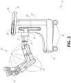
FIG. 2 depicts further aspects of the robotic system ofFIG. 1 . -
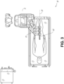
FIG. 3 illustrates an embodiment of the robotic system ofFIG. 1 arranged for ureteroscopy. -
FIG. 4 illustrates an embodiment of the robotic system ofFIG. 1 arranged for a vascular procedure. -
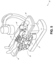
FIG. 5 illustrates an embodiment of a table-based robotic system arranged for a bronchoscopy procedure. -
FIG. 6 provides an alternative view of the robotic system ofFIG. 5 . -
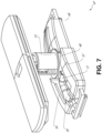
FIG. 7 illustrates an example system configured to stow robotic arm(s). -
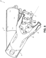
FIG. 8 illustrates an embodiment of a table-based robotic system configured for a ureteroscopy procedure. -
FIG. 9 illustrates an embodiment of a table-based robotic system configured for a laparoscopic procedure. -
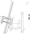
FIG. 10 illustrates an embodiment of the table-based robotic system ofFIGs. 5-9 with pitch or tilt adjustment. -
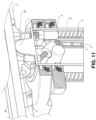
FIG. 11 provides a detailed illustration of the interface between the table and the column of the table-based robotic system ofFIGs. 5-10 . -
FIG. 12 illustrates an alternative embodiment of a table-based robotic system. -
FIG. 13 illustrates an end view of the table-based robotic system ofFIG. 12 . -
FIG. 14 illustrates an end view of a table-based robotic system with robotic arms attached thereto. -
FIG. 15 illustrates an exemplary instrument driver. -
FIG. 16 illustrates an exemplary medical instrument with a paired instrument driver. -
FIG. 17 illustrates an alternative design for an instrument driver and instrument where the axes of the drive units are parallel to the axis of the elongated shaft of the instrument. -
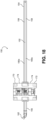
FIG. 18 illustrates an instrument having an instrument-based insertion architecture. -
FIG. 19 illustrates an exemplary controller. -
FIG. 20 depicts a block diagram illustrating a localization system that estimates a location of one or more elements of the robotic systems ofFIGs. 1-10 , such as the location of the instrument ofFIGs. 16-18 , in accordance to an example embodiment. -
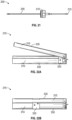
FIG. 21 illustrates an example embodiment of a medical instrument in accordance with aspects of this disclosure. -
FIGs. 22A and FIB. 22B illustrate an example embodiment wherein the end effector is configured to function as a medical stapler in accordance with aspects of this disclosure. -
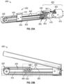
FIGs. 23A and 23B illustrates an example embodiment of a cable-driven medical instrument including an articulating wrist in accordance with aspects of this disclosure. -
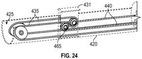
FIG. 24 illustrates a close up view of the lower jaw ofFIGs. 23A and 23B including a portion of the internal components of the tab in accordance with aspects of this disclosure. -
FIG. 25 illustrates another example embodiment of a cable-driven medical instrument including an articulating wrist in accordance with aspects of this disclosure. -
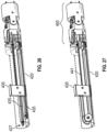
FIG. 26 illustrates yet another example embodiment of a cable-driven medical instrument including an articulating wrist in accordance with aspects of this disclosure. -
FIG. 27 illustrates still yet another example embodiment of a cable-driven medical instrument including an articulating wrist in accordance with aspects of this disclosure. -
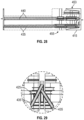
FIGs. 28 and 29 illustrate a top-down view and an endpoint view of yet another example embodiment of a cable-driven medical instrument including an articulating wrist in accordance with aspects of this disclosure. -
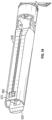
FIG. 30 illustrates an example embodiment of a push shaft-driven medical instrument including an articulating wrist in accordance with aspects of this disclosure. -
FIG. 31 provides a view of the cartridge ofFIG. 30 , separated from the instrument in accordance with aspects of this disclosure. -
FIG. 32 illustrates another view of the push shaft-driven medical instrument ofFIG. 30 in accordance with aspects of this disclosure. -
FIG. 33 illustrates yet another view of the push shaft-driven medical instrument ofFIG. 30 from the bottom in accordance with aspects of this disclosure. -
FIG. 34 illustrates yet another view of the push shaft-driven medical instrument ofFIG. 30 without the cartridge installed in accordance with aspects of this disclosure. -
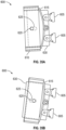
FIGs. 35A-35D provide a plurality of views of a tab which can be included in the firing mechanism of the push shaft-driven medical instrument in accordance with aspects of this disclosure. - Aspects of the present disclosure may be integrated into a robotically-enabled medical system capable of performing a variety of medical procedures, including both minimally invasive, such as laparoscopy, and non-invasive, such as endoscopy, procedures. Among endoscopy procedures, the system may be capable of performing bronchoscopy, ureteroscopy, gastroscopy, etc.
- In addition to performing the breadth of procedures, the system may provide additional benefits, such as enhanced imaging and guidance to assist the physician. Additionally, the system may provide the physician with the ability to perform the procedure from an ergonomic position without the need for awkward arm motions and positions. Still further, the system may provide the physician with the ability to perform the procedure with improved ease of use such that one or more of the instruments of the system can be controlled by a single user.
- Various embodiments will be described below in conjunction with the drawings for purposes of illustration. It should be appreciated that many other implementations of the disclosed concepts are possible, and various advantages can be achieved with the disclosed implementations. Headings are included herein for reference and to aid in locating various sections. These headings are not intended to limit the scope of the concepts described with respect thereto. Such concepts may have applicability throughout the entire specification.
- The robotically-enabled medical system may be configured in a variety of ways depending on the particular procedure.
FIG. 1 illustrates an embodiment of a cart-based robotically-enabledsystem 10 arranged for a diagnostic and/or therapeutic bronchoscopy procedure. During a bronchoscopy, thesystem 10 may comprise acart 11 having one or morerobotic arms 12 to deliver a medical instrument, such as asteerable endoscope 13, which may be a procedure-specific bronchoscope for bronchoscopy, to a natural orifice access point (i.e., the mouth of the patient positioned on a table in the present example) to deliver diagnostic and/or therapeutic tools. As shown, thecart 11 may be positioned proximate to the patient's upper torso in order to provide access to the access point. Similarly, therobotic arms 12 may be actuated to position the bronchoscope relative to the access point. The arrangement inFIG. 1 may also be utilized when performing a gastrointestinal (GI) procedure with a gastroscope, a specialized endoscope for GI procedures.FIG. 2 depicts an example embodiment of the cart in greater detail. - With continued reference to
FIG. 1 , once thecart 11 is properly positioned, therobotic arms 12 may insert thesteerable endoscope 13 into the patient robotically, manually, or a combination thereof. As shown, thesteerable endoscope 13 may comprise at least two telescoping parts, such as an inner leader portion and an outer sheath portion, each portion coupled to a separate instrument driver from the set ofinstrument drivers 28, each instrument driver coupled to the distal end of an individual robotic arm. This linear arrangement of theinstrument drivers 28, which facilitates coaxially aligning the leader portion with the sheath portion, creates a "virtual rail" 29 that may be repositioned in space by manipulating the one or morerobotic arms 12 into different angles and/or positions. The virtual rails described herein are depicted in the Figures using dashed lines, and accordingly the dashed lines do not depict any physical structure of the system. Translation of theinstrument drivers 28 along thevirtual rail 29 telescopes the inner leader portion relative to the outer sheath portion or advances or retracts theendoscope 13 from the patient. The angle of thevirtual rail 29 may be adjusted, translated, and pivoted based on clinical application or physician preference. For example, in bronchoscopy, the angle and position of thevirtual rail 29 as shown represents a compromise between providing physician access to theendoscope 13 while minimizing friction that results from bending theendoscope 13 into the patient's mouth. - The
endoscope 13 may be directed down the patient's trachea and lungs after insertion using precise commands from the robotic system until reaching the target destination or operative site. In order to enhance navigation through the patient's lung network and/or reach the desired target, theendoscope 13 may be manipulated to telescopically extend the inner leader portion from the outer sheath portion to obtain enhanced articulation and greater bend radius. The use ofseparate instrument drivers 28 also allows the leader portion and sheath portion to be driven independent of each other. - For example, the
endoscope 13 may be directed to deliver a biopsy needle to a target, such as, for example, a lesion or nodule within the lungs of a patient. The needle may be deployed down a working channel that runs the length of the endoscope to obtain a tissue sample to be analyzed by a pathologist. Depending on the pathology results, additional tools may be deployed down the working channel of the endoscope for additional biopsies. After identifying a nodule to be malignant, theendoscope 13 may endoscopically deliver tools to resect the potentially cancerous tissue. In some instances, diagnostic and therapeutic treatments can be delivered in separate procedures. In those circumstances, theendoscope 13 may also be used to deliver a fiducial to "mark" the location of the target nodule as well. In other instances, diagnostic and therapeutic treatments may be delivered during the same procedure. - The
system 10 may also include amovable tower 30, which may be connected via support cables to thecart 11 to provide support for controls, electronics, fluidics, optics, sensors, and/or power to thecart 11. Placing such functionality in thetower 30 allows for a smallerform factor cart 11 that may be more easily adjusted and/or repositioned by an operating physician and his/her staff. Additionally, the division of functionality between the cart / table and thesupport tower 30 reduces operating room clutter and facilitates improving clinical workflow. While thecart 11 may be positioned close to the patient, thetower 30 may be stowed in a remote location to stay out of the way during a procedure. - In support of the robotic systems described above, the
tower 30 may include component(s) of a computer-based control system that stores computer program instructions, for example, within a non-transitory computer-readable storage medium such as a persistent magnetic storage drive, solid state drive, etc. The execution of those instructions, whether the execution occurs in thetower 30 or thecart 11, may control the entire system or sub-system(s) thereof. For example, when executed by a processor of the computer system, the instructions may cause the components of the robotics system to actuate the relevant carriages and arm mounts, actuate the robotics arms, and control the medical instruments. For example, in response to receiving the control signal, the motors in the joints of the robotics arms may position the arms into a certain posture. - The
tower 30 may also include a pump, flow meter, valve control, and/or fluid access in order to provide controlled irrigation and aspiration capabilities to the system that may be deployed through theendoscope 13. These components may also be controlled using the computer system oftower 30. In some embodiments, irrigation and aspiration capabilities may be delivered directly to theendoscope 13 through separate cable(s). - The
tower 30 may include a voltage and surge protector designed to provide filtered and protected electrical power to thecart 11, thereby avoiding placement of a power transformer and other auxiliary power components in thecart 11, resulting in a smaller, moremoveable cart 11. - The
tower 30 may also include support equipment for the sensors deployed throughout therobotic system 10. For example, thetower 30 may include opto-electronics equipment for detecting, receiving, and processing data received from the optical sensors or cameras throughout therobotic system 10. In combination with the control system, such opto-electronics equipment may be used to generate real-time images for display in any number of consoles deployed throughout the system, including in thetower 30. Similarly, thetower 30 may also include an electronic subsystem for receiving and processing signals received from deployed electromagnetic (EM) sensors. Thetower 30 may also be used to house and position an EM field generator for detection by EM sensors in or on the medical instrument. - The
tower 30 may also include aconsole 31 in addition to other consoles available in the rest of the system, e.g., console mounted on top of the cart. Theconsole 31 may include a user interface and a display screen, such as a touchscreen, for the physician operator. Consoles insystem 10 are generally designed to provide both robotic controls as well as pre-operative and real-time information of the procedure, such as navigational and localization information of theendoscope 13. When theconsole 31 is not the only console available to the physician, it may be used by a second operator, such as a nurse, to monitor the health or vitals of the patient and the operation of system, as well as provide procedure-specific data, such as navigational and localization information. In other embodiments, theconsole 30 is housed in a body that is separate from thetower 30. - The
tower 30 may be coupled to thecart 11 andendoscope 13 through one or more cables or connections (not shown). In some embodiments, the support functionality from thetower 30 may be provided through a single cable to thecart 11, simplifying and de-cluttering the operating room. In other embodiments, specific functionality may be coupled in separate cabling and connections. For example, while power may be provided through a single power cable to the cart, the support for controls, optics, fluidics, and/or navigation may be provided through a separate cable. -
FIG. 2 provides a detailed illustration of an embodiment of the cart from the cart-based robotically-enabled system shown inFIG. 1 . Thecart 11 generally includes an elongated support structure 14 (often referred to as a "column"), acart base 15, and aconsole 16 at the top of thecolumn 14. Thecolumn 14 may include one or more carriages, such as a carriage 17 (alternatively "arm support") for supporting the deployment of one or more robotic arms 12 (three shown inFIG. 2 ). Thecarriage 17 may include individually configurable arm mounts that rotate along a perpendicular axis to adjust the base of therobotic arms 12 for better positioning relative to the patient. Thecarriage 17 also includes acarriage interface 19 that allows thecarriage 17 to vertically translate along thecolumn 14. - The
carriage interface 19 is connected to thecolumn 14 through slots, such asslot 20, that are positioned on opposite sides of thecolumn 14 to guide the vertical translation of thecarriage 17. Theslot 20 contains a vertical translation interface to position and hold the carriage at various vertical heights relative to thecart base 15. Vertical translation of thecarriage 17 allows thecart 11 to adjust the reach of therobotic arms 12 to meet a variety of table heights, patient sizes, and physician preferences. Similarly, the individually configurable arm mounts on thecarriage 17 allow therobotic arm base 21 ofrobotic arms 12 to be angled in a variety of configurations. - In some embodiments, the
slot 20 may be supplemented with slot covers that are flush and parallel to the slot surface to prevent dirt and fluid ingress into the internal chambers of thecolumn 14 and the vertical translation interface as thecarriage 17 vertically translates. The slot covers may be deployed through pairs of spring spools positioned near the vertical top and bottom of theslot 20. The covers are coiled within the spools until deployed to extend and retract from their coiled state as thecarriage 17 vertically translates up and down. The spring-loading of the spools provides force to retract the cover into a spool whencarriage 17 translates towards the spool, while also maintaining a tight seal when thecarriage 17 translates away from the spool. The covers may be connected to thecarriage 17 using, for example, brackets in thecarriage interface 19 to ensure proper extension and retraction of the cover as thecarriage 17 translates. - The
column 14 may internally comprise mechanisms, such as gears and motors, that are designed to use a vertically aligned lead screw to translate thecarriage 17 in a mechanized fashion in response to control signals generated in response to user inputs, e.g., inputs from theconsole 16. - The
robotic arms 12 may generally comprise robotic arm bases 21 andend effectors 22, separated by a series oflinkages 23 that are connected by a series ofjoints 24, each joint comprising an independent actuator, each actuator comprising an independently controllable motor. Each independently controllable joint represents an independent degree of freedom available to the robotic arm. Each of thearms 12 have seven joints, and thus provide seven degrees of freedom. A multitude of joints result in a multitude of degrees of freedom, allowing for "redundant" degrees of freedom. Redundant degrees of freedom allow therobotic arms 12 to position theirrespective end effectors 22 at a specific position, orientation, and trajectory in space using different linkage positions and joint angles. This allows for the system to position and direct a medical instrument from a desired point in space while allowing the physician to move the arm joints into a clinically advantageous position away from the patient to create greater access, while avoiding arm collisions. - The
cart base 15 balances the weight of thecolumn 14,carriage 17, andarms 12 over the floor. Accordingly, thecart base 15 houses heavier components, such as electronics, motors, power supply, as well as components that either enable movement and/or immobilize the cart. For example, thecart base 15 includes rollable wheel-shapedcasters 25 that allow for the cart to easily move around the room prior to a procedure. After reaching the appropriate position, thecasters 25 may be immobilized using wheel locks to hold thecart 11 in place during the procedure. - Positioned at the vertical end of
column 14, theconsole 16 allows for both a user interface for receiving user input and a display screen (or a dual-purpose device such as, for example, a touchscreen 26) to provide the physician user with both pre-operative and intra-operative data. Potential pre-operative data on thetouchscreen 26 may include pre-operative plans, navigation and mapping data derived from pre-operative computerized tomography (CT) scans, and/or notes from pre-operative patient interviews. Intra-operative data on display may include optical information provided from the tool, sensor and coordinate information from sensors, as well as vital patient statistics, such as respiration, heart rate, and/or pulse. Theconsole 16 may be positioned and tilted to allow a physician to access the console from the side of thecolumn 14 oppositecarriage 17. From this position, the physician may view theconsole 16,robotic arms 12, and patient while operating theconsole 16 from behind thecart 11. As shown, theconsole 16 also includes ahandle 27 to assist with maneuvering and stabilizingcart 11. -
FIG. 3 illustrates an embodiment of a robotically-enabledsystem 10 arranged for ureteroscopy. In a ureteroscopic procedure, thecart 11 may be positioned to deliver aureteroscope 32, a procedure-specific endoscope designed to traverse a patient's urethra and ureter, to the lower abdominal area of the patient. In a ureteroscopy, it may be desirable for theureteroscope 32 to be directly aligned with the patient's urethra to reduce friction and forces on the sensitive anatomy in the area. As shown, thecart 11 may be aligned at the foot of the table to allow therobotic arms 12 to position theureteroscope 32 for direct linear access to the patient's urethra. From the foot of the table, therobotic arms 12 may insert theureteroscope 32 along thevirtual rail 33 directly into the patient's lower abdomen through the urethra. - After insertion into the urethra, using similar control techniques as in bronchoscopy, the
ureteroscope 32 may be navigated into the bladder, ureters, and/or kidneys for diagnostic and/or therapeutic applications. For example, theureteroscope 32 may be directed into the ureter and kidneys to break up kidney stone build up using a laser or ultrasonic lithotripsy device deployed down the working channel of theureteroscope 32. After lithotripsy is complete, the resulting stone fragments may be removed using baskets deployed down theureteroscope 32. -
FIG. 4 illustrates an embodiment of a robotically-enabled system similarly arranged for a vascular procedure. In a vascular procedure, thesystem 10 may be configured such that thecart 11 may deliver amedical instrument 34, such as a steerable catheter, to an access point in the femoral artery in the patient's leg. The femoral artery presents both a larger diameter for navigation as well as a relatively less circuitous and tortuous path to the patient's heart, which simplifies navigation. As in a ureteroscopic procedure, thecart 11 may be positioned towards the patient's legs and lower abdomen to allow therobotic arms 12 to provide avirtual rail 35 with direct linear access to the femoral artery access point in the patient's thigh / hip region. After insertion into the artery, themedical instrument 34 may be directed and inserted by translating theinstrument drivers 28. Alternatively, the cart may be positioned around the patient's upper abdomen in order to reach alternative vascular access points, such as, for example, the carotid and brachial arteries near the shoulder and wrist. - Embodiments of the robotically-enabled medical system may also incorporate the patient's table. Incorporation of the table reduces the amount of capital equipment within the operating room by removing the cart, which allows greater access to the patient.
FIG. 5 illustrates an embodiment of such a robotically-enabled system arranged for a bronchoscopy procedure.System 36 includes a support structure orcolumn 37 for supporting platform 38 (shown as a "table" or "bed") over the floor. Much like in the cart-based systems, the end effectors of therobotic arms 39 of thesystem 36 compriseinstrument drivers 42 that are designed to manipulate an elongated medical instrument, such as abronchoscope 40 inFIG. 5 , through or along avirtual rail 41 formed from the linear alignment of theinstrument drivers 42. In practice, a C-arm for providing fluoroscopic imaging may be positioned over the patient's upper abdominal area by placing the emitter and detector around table 38. -
FIG. 6 provides an alternative view of thesystem 36 without the patient and medical instrument for discussion purposes. As shown, thecolumn 37 may include one ormore carriages 43 shown as ring-shaped in thesystem 36, from which the one or morerobotic arms 39 may be based. Thecarriages 43 may translate along avertical column interface 44 that runs the length of thecolumn 37 to provide different vantage points from which therobotic arms 39 may be positioned to reach the patient. The carriage(s) 43 may rotate around thecolumn 37 using a mechanical motor positioned within thecolumn 37 to allow therobotic arms 39 to have access to multiples sides of the table 38, such as, for example, both sides of the patient. In embodiments with multiple carriages, the carriages may be individually positioned on the column and may translate and/or rotate independent of the other carriages. Whilecarriages 43 need not surround thecolumn 37 or even be circular, the ring-shape as shown facilitates rotation of thecarriages 43 around thecolumn 37 while maintaining structural balance. Rotation and translation of thecarriages 43 allows the system to align the medical instruments, such as endoscopes and laparoscopes, into different access points on the patient. In other embodiments (not shown), thesystem 36 can include a patient table or bed with adjustable arm supports in the form of bars or rails extending alongside it. One or more robotic arms 39 (e.g., via a shoulder with an elbow joint) can be attached to the adjustable arm supports, which can be vertically adjusted. By providing vertical adjustment, therobotic arms 39 are advantageously capable of being stowed compactly beneath the patient table or bed, and subsequently raised during a procedure. - The
arms 39 may be mounted on the carriages through a set of arm mounts 45 comprising a series of joints that may individually rotate and/or telescopically extend to provide additional configurability to therobotic arms 39. Additionally, the arm mounts 45 may be positioned on thecarriages 43 such that, when thecarriages 43 are appropriately rotated, the arm mounts 45 may be positioned on either the same side of table 38 (as shown inFIG. 6 ), on opposite sides of table 38 (as shown inFIG. 9 ), or on adjacent sides of the table 38 (not shown). - The
column 37 structurally provides support for the table 38, and a path for vertical translation of the carriages. Internally, thecolumn 37 may be equipped with lead screws for guiding vertical translation of the carriages, and motors to mechanize the translation of said carriages based the lead screws. Thecolumn 37 may also convey power and control signals to thecarriage 43 androbotic arms 39 mounted thereon. - The
table base 46 serves a similar function as thecart base 15 incart 11 shown inFIG. 2 , housing heavier components to balance the table/bed 38, thecolumn 37, thecarriages 43, and therobotic arms 39. Thetable base 46 may also incorporate rigid casters to provide stability during procedures. Deployed from the bottom of thetable base 46, the casters may extend in opposite directions on both sides of thebase 46 and retract when thesystem 36 needs to be moved. - Continuing with
FIG. 6 , thesystem 36 may also include a tower (not shown) that divides the functionality ofsystem 36 between table and tower to reduce the form factor and bulk of the table. As in earlier disclosed embodiments, the tower may provide a variety of support functionalities to table, such as processing, computing, and control capabilities, power, fluidics, and/or optical and sensor processing. The tower may also be movable to be positioned away from the patient to improve physician access and de-clutter the operating room. Additionally, placing components in the tower allows for more storage space in the table base for potential stowage of the robotic arms. The tower may also include a master controller or console that provides both a user interface for user input, such as keyboard and/or pendant, as well as a display screen (or touchscreen) for pre-operative and intra-operative information, such as real-time imaging, navigation, and tracking information. In some embodiments, the tower may also contain holders for gas tanks to be used for insufflation. - In some embodiments, a table base may stow and store the robotic arms when not in use.
FIG. 7 illustrates asystem 47 that stows robotic arms in an embodiment of the table-based system. Insystem 47,carriages 48 may be vertically translated intobase 49 to stowrobotic arms 50, arm mounts 51, and thecarriages 48 within thebase 49. Base covers 52 may be translated and retracted open to deploy thecarriages 48, arm mounts 51, andarms 50 aroundcolumn 53, and closed to stow to protect them when not in use. The base covers 52 may be sealed with amembrane 54 along the edges of its opening to prevent dirt and fluid ingress when closed. -
FIG. 8 illustrates an embodiment of a robotically-enabled table-based system configured for a ureteroscopy procedure. In a ureteroscopy, the table 38 may include aswivel portion 55 for positioning a patient off-angle from thecolumn 37 andtable base 46. Theswivel portion 55 may rotate or pivot around a pivot point (e.g., located below the patient's head) in order to position the bottom portion of theswivel portion 55 away from thecolumn 37. For example, the pivoting of theswivel portion 55 allows a C-arm (not shown) to be positioned over the patient's lower abdomen without competing for space with the column (not shown) below table 38. By rotating the carriage 35 (not shown) around thecolumn 37, therobotic arms 39 may directly insert aureteroscope 56 along avirtual rail 57 into the patient's groin area to reach the urethra. In a ureteroscopy,stirrups 58 may also be fixed to theswivel portion 55 of the table 38 to support the position of the patient's legs during the procedure and allow clear access to the patient's groin area. - In a laparoscopic procedure, through small incision(s) in the patient's abdominal wall, minimally invasive instruments may be inserted into the patient's anatomy. In some embodiments, the minimally invasive instruments comprise an elongated rigid member, such as a shaft, which is used to access anatomy within the patient. After inflation of the patient's abdominal cavity, the instruments may be directed to perform surgical or medical tasks, such as grasping, cutting, ablating, suturing, etc. In some embodiments, the instruments can comprise a scope, such as a laparoscope.
FIG. 9 illustrates an embodiment of a robotically-enabled table-based system configured for a laparoscopic procedure. As shown inFIG. 9 , thecarriages 43 of thesystem 36 may be rotated and vertically adjusted to position pairs of therobotic arms 39 on opposite sides of the table 38, such thatinstrument 59 may be positioned using the arm mounts 45 to be passed through minimal incisions on both sides of the patient to reach his/her abdominal cavity. - To accommodate laparoscopic procedures, the robotically-enabled table system may also tilt the platform to a desired angle.
FIG. 10 illustrates an embodiment of the robotically-enabled medical system with pitch or tilt adjustment. As shown inFIG. 10 , thesystem 36 may accommodate tilt of the table 38 to position one portion of the table at a greater distance from the floor than the other. Additionally, the arm mounts 45 may rotate to match the tilt such that thearms 39 maintain the same planar relationship with table 38. To accommodate steeper angles, thecolumn 37 may also includetelescoping portions 60 that allow vertical extension ofcolumn 37 to keep the table 38 from touching the floor or colliding withbase 46. -
FIG. 11 provides a detailed illustration of the interface between the table 38 and thecolumn 37.Pitch rotation mechanism 61 may be configured to alter the pitch angle of the table 38 relative to thecolumn 37 in multiple degrees of freedom. Thepitch rotation mechanism 61 may be enabled by the positioning of orthogonal axes 1, 2 at the column-table interface, each axis actuated by a separate motor 3, 4 responsive to an electrical pitch angle command. Rotation along one screw 5 would enable tilt adjustments in one axis 1, while rotation along theother screw 6 would enable tilt adjustments along the other axis 2. In some embodiments, a ball joint can be used to alter the pitch angle of the table 38 relative to thecolumn 37 in multiple degrees of freedom. - For example, pitch adjustments are particularly useful when trying to position the table in a Trendelenburg position, i.e., position the patient's lower abdomen at a higher position from the floor than the patient's lower abdomen, for lower abdominal surgery. The Trendelenburg position causes the patient's internal organs to slide towards his/her upper abdomen through the force of gravity, clearing out the abdominal cavity for minimally invasive tools to enter and perform lower abdominal surgical or medical procedures, such as laparoscopic prostatectomy.
-
FIGs. 12 and 13 illustrate isometric and end views of an alternative embodiment of a table-basedsurgical robotics system 100. Thesurgical robotics system 100 includes one or more adjustable arm supports 105 that can be configured to support one or more robotic arms (see, for example,FIG. 14 ) relative to a table 101. In the illustrated embodiment, a singleadjustable arm support 105 is shown, though an additional arm support can be provided on an opposite side of the table 101. Theadjustable arm support 105 can be configured so that it can move relative to the table 101 to adjust and/or vary the position of theadjustable arm support 105 and/or any robotic arms mounted thereto relative to the table 101. For example, theadjustable arm support 105 may be adjusted one or more degrees of freedom relative to the table 101. Theadjustable arm support 105 provides high versatility to thesystem 100, including the ability to easily stow the one or more adjustable arm supports 105 and any robotics arms attached thereto beneath the table 101. Theadjustable arm support 105 can be elevated from the stowed position to a position below an upper surface of the table 101. In other embodiments, theadjustable arm support 105 can be elevated from the stowed position to a position above an upper surface of the table 101. - The
adjustable arm support 105 can provide several degrees of freedom, including lift, lateral translation, tilt, etc. In the illustrated embodiment ofFIGs. 12 and 13 , thearm support 105 is configured with four degrees of freedom, which are illustrated with arrows inFIG. 12 . A first degree of freedom allows for adjustment of theadjustable arm support 105 in the z-direction ("Z-lift"). For example, theadjustable arm support 105 can include acarriage 109 configured to move up or down along or relative to acolumn 102 supporting the table 101. A second degree of freedom can allow theadjustable arm support 105 to tilt. For example, theadjustable arm support 105 can include a rotary joint, which can allow theadjustable arm support 105 to be aligned with the bed in a Trendelenburg position. A third degree of freedom can allow theadjustable arm support 105 to "pivot up," which can be used to adjust a distance between a side of the table 101 and theadjustable arm support 105. A fourth degree of freedom can permit translation of theadjustable arm support 105 along a longitudinal length of the table. - The
surgical robotics system 100 inFIGs. 12 and 13 can comprise a table supported by acolumn 102 that is mounted to abase 103. Thebase 103 and thecolumn 102 support the table 101 relative to a support surface. Afloor axis 131 and asupport axis 133 are shown inFIG. 13 . - The
adjustable arm support 105 can be mounted to thecolumn 102. In other embodiments, thearm support 105 can be mounted to the table 101 orbase 103. Theadjustable arm support 105 can include acarriage 109, a bar orrail connector 111 and a bar orrail 107. In some embodiments, one or more robotic arms mounted to therail 107 can translate and move relative to one another. - The
carriage 109 can be attached to thecolumn 102 by a first joint 113, which allows thecarriage 109 to move relative to the column 102 (e.g., such as up and down a first or vertical axis 123). The first joint 113 can provide the first degree of freedom (Z-lift) to theadjustable arm support 105. Theadjustable arm support 105 can include a second joint 115, which provides the second degree of freedom (tilt) for theadjustable arm support 105. Theadjustable arm support 105 can include a third joint 117, which can provide the third degree of freedom ("pivot up") for theadjustable arm support 105. An additional joint 119 (shown inFIG. 13 ) can be provided that mechanically constrains the third joint 117 to maintain an orientation of therail 107 as therail connector 111 is rotated about athird axis 127. Theadjustable arm support 105 can include a fourth joint 121, which can provide a fourth degree of freedom (translation) for theadjustable arm support 105 along afourth axis 129. -
FIG. 14 illustrates an end view of thesurgical robotics system 140A with two adjustable arm supports 105A, 105B mounted on opposite sides of a table 101. A firstrobotic arm 142A is attached to the bar orrail 107A of the firstadjustable arm support 105B. The firstrobotic arm 142A includes abase 144A attached to therail 107A. The distal end of the firstrobotic arm 142A includes aninstrument drive mechanism 146A that can attach to one or more robotic medical instruments or tools. Similarly, the secondrobotic arm 142B includes abase 144B attached to therail 107B. The distal end of the secondrobotic arm 142B includes aninstrument drive mechanism 146B. Theinstrument drive mechanism 146B can be configured to attach to one or more robotic medical instruments or tools. - In some embodiments, one or more of the
robotic arms robotic arms base robotic arm - The end effectors of the system's robotic arms comprise (i) an instrument driver (alternatively referred to as "instrument drive mechanism" or "instrument device manipulator") that incorporate electro-mechanical means for actuating the medical instrument and (ii) a removable or detachable medical instrument, which may be devoid of any electro-mechanical components, such as motors. This dichotomy may be driven by the need to sterilize medical instruments used in medical procedures, and the inability to adequately sterilize expensive capital equipment due to their intricate mechanical assemblies and sensitive electronics. Accordingly, the medical instruments may be designed to be detached, removed, and interchanged from the instrument driver (and thus the system) for individual sterilization or disposal by the physician or the physician's staff. In contrast, the instrument drivers need not be changed or sterilized, and may be draped for protection.
-
FIG. 15 illustrates an example instrument driver. Positioned at the distal end of a robotic arm,instrument driver 62 comprises of one or more drive units 63 arranged with parallel axes to provide controlled torque to a medical instrument viadrive shafts 64. Each drive unit 63 comprises anindividual drive shaft 64 for interacting with the instrument, agear head 65 for converting the motor shaft rotation to a desired torque, amotor 66 for generating the drive torque, anencoder 67 to measure the speed of the motor shaft and provide feedback to the control circuitry, and controlcircuity 68 for receiving control signals and actuating the drive unit. Each drive unit 63 being independent controlled and motorized, theinstrument driver 62 may provide multiple (e.g., four as shown inFIG. 15 ) independent drive outputs to the medical instrument. In operation, thecontrol circuitry 68 would receive a control signal, transmit a motor signal to themotor 66, compare the resulting motor speed as measured by theencoder 67 with the desired speed, and modulate the motor signal to generate the desired torque. - For procedures that require a sterile environment, the robotic system may incorporate a drive interface, such as a sterile adapter connected to a sterile drape, that sits between the instrument driver and the medical instrument. The chief purpose of the sterile adapter is to transfer angular motion from the drive shafts of the instrument driver to the drive inputs of the instrument while maintaining physical separation, and thus sterility, between the drive shafts and drive inputs. Accordingly, an example sterile adapter may comprise of a series of rotational inputs and outputs intended to be mated with the drive shafts of the instrument driver and drive inputs on the instrument. Connected to the sterile adapter, the sterile drape, comprised of a thin, flexible material such as transparent or translucent plastic, is designed to cover the capital equipment, such as the instrument driver, robotic arm, and cart (in a cart-based system) or table (in a table-based system). Use of the drape would allow the capital equipment to be positioned proximate to the patient while still being located in an area not requiring sterilization (i.e., non-sterile field). On the other side of the sterile drape, the medical instrument may interface with the patient in an area requiring sterilization (i.e., sterile field).
-
FIG. 16 illustrates an example medical instrument with a paired instrument driver. Like other instruments designed for use with a robotic system,medical instrument 70 comprises an elongated shaft 71 (or elongate body) and aninstrument base 72. Theinstrument base 72, also referred to as an "instrument handle" due to its intended design for manual interaction by the physician, may generally compriserotatable drive inputs 73, e.g., receptacles, pulleys or spools, that are designed to be mated withdrive outputs 74 that extend through a drive interface oninstrument driver 75 at the distal end ofrobotic arm 76. When physically connected, latched, and/or coupled, the mateddrive inputs 73 ofinstrument base 72 may share axes of rotation with the drive outputs 74 in theinstrument driver 75 to allow the transfer of torque fromdrive outputs 74 to driveinputs 73. In some embodiments, the drive outputs 74 may comprise splines that are designed to mate with receptacles on thedrive inputs 73. - The
elongated shaft 71 is designed to be delivered through either an anatomical opening or lumen, e.g., as in endoscopy, or a minimally invasive incision, e.g., as in laparoscopy. Theelongated shaft 71 may be either flexible (e.g., having properties similar to an endoscope) or rigid (e.g., having properties similar to a laparoscope) or contain a customized combination of both flexible and rigid portions. When designed for laparoscopy, the distal end of a rigid elongated shaft may be connected to an end effector extending from a jointed wrist formed from a clevis with at least one degree of freedom and a surgical tool or medical instrument, such as, for example, a grasper or scissors, that may be actuated based on force from the tendons as the drive inputs rotate in response to torque received from the drive outputs 74 of theinstrument driver 75. When designed for endoscopy, the distal end of a flexible elongated shaft may include a steerable or controllable bending section that may be articulated and bent based on torque received from the drive outputs 74 of theinstrument driver 75. - Torque from the
instrument driver 75 is transmitted down theelongated shaft 71 using tendons along theshaft 71. These individual tendons, such as pull wires, may be individually anchored toindividual drive inputs 73 within theinstrument handle 72. From thehandle 72, the tendons are directed down one or more pull lumens along theelongated shaft 71 and anchored at the distal portion of theelongated shaft 71, or in the wrist at the distal portion of the elongated shaft. During a surgical procedure, such as a laparoscopic, endoscopic or hybrid procedure, these tendons may be coupled to a distally mounted end effector, such as a wrist, grasper, or scissor. Under such an arrangement, torque exerted ondrive inputs 73 would transfer tension to the tendon, thereby causing the end effector to actuate in some way. In some embodiments, during a surgical procedure, the tendon may cause a joint to rotate about an axis, thereby causing the end effector to move in one direction or another. Alternatively, the tendon may be connected to one or more jaws of a grasper at distal end of theelongated shaft 71, where tension from the tendon cause the grasper to close. - In endoscopy, the tendons may be coupled to a bending or articulating section positioned along the elongated shaft 71 (e.g., at the distal end) via adhesive, control ring, or other mechanical fixation. When fixedly attached to the distal end of a bending section, torque exerted on
drive inputs 73 would be transmitted down the tendons, causing the softer, bending section (sometimes referred to as the articulable section or region) to bend or articulate. Along the non-bending sections, it may be advantageous to spiral or helix the individual pull lumens that direct the individual tendons along (or inside) the walls of the endoscope shaft to balance the radial forces that result from tension in the pull wires. The angle of the spiraling and/or spacing there between may be altered or engineered for specific purposes, wherein tighter spiraling exhibits lesser shaft compression under load forces, while lower amounts of spiraling results in greater shaft compression under load forces, but also exhibits limits bending. On the other end of the spectrum, the pull lumens may be directed parallel to the longitudinal axis of theelongated shaft 71 to allow for controlled articulation in the desired bending or articulable sections. - In endoscopy, the
elongated shaft 71 houses a number of components to assist with the robotic procedure. The shaft may comprise of a working channel for deploying surgical tools (or medical instruments), irrigation, and/or aspiration to the operative region at the distal end of theshaft 71. Theshaft 71 may also accommodate wires and/or optical fibers to transfer signals to/from an optical assembly at the distal tip, which may include of an optical camera. Theshaft 71 may also accommodate optical fibers to carry light from proximally-located light sources, such as light emitting diodes, to the distal end of the shaft. - At the distal end of the
instrument 70, the distal tip may also comprise the opening of a working channel for delivering tools for diagnostic and/or therapy, irrigation, and aspiration to an operative site. The distal tip may also include a port for a camera, such as a fiberscope or a digital camera, to capture images of an internal anatomical space. Relatedly, the distal tip may also include ports for light sources for illuminating the anatomical space when using the camera. - In the example of
FIG. 16 , the drive shaft axes, and thus the drive input axes, are orthogonal to the axis of the elongated shaft. This arrangement, however, complicates roll capabilities for theelongated shaft 71. Rolling theelongated shaft 71 along its axis while keeping thedrive inputs 73 static results in undesirable tangling of the tendons as they extend off thedrive inputs 73 and enter pull lumens within theelongated shaft 71. The resulting entanglement of such tendons may disrupt any control algorithms intended to predict movement of the flexible elongated shaft during an endoscopic procedure. -
FIG. 17 illustrates an alternative design for an instrument driver and instrument where the axes of the drive units are parallel to the axis of the elongated shaft of the instrument. As shown, acircular instrument driver 80 comprises four drive units with theirdrive outputs 81 aligned in parallel at the end of arobotic arm 82. The drive units, and their respective drive outputs 81, are housed in arotational assembly 83 of theinstrument driver 80 that is driven by one of the drive units within theassembly 83. In response to torque provided by the rotational drive unit, therotational assembly 83 rotates along a circular bearing that connects therotational assembly 83 to thenon-rotational portion 84 of the instrument driver. Power and controls signals may be communicated from thenon-rotational portion 84 of theinstrument driver 80 to therotational assembly 83 through electrical contacts may be maintained through rotation by a brushed slip ring connection (not shown). In other embodiments, therotational assembly 83 may be responsive to a separate drive unit that is integrated into thenon-rotatable portion 84, and thus not in parallel to the other drive units. Therotational mechanism 83 allows theinstrument driver 80 to rotate the drive units, and their respective drive outputs 81, as a single unit around aninstrument driver axis 85. - Like earlier disclosed embodiments, an
instrument 86 may comprise anelongated shaft portion 88 and an instrument base 87 (shown with a transparent external skin for discussion purposes) comprising a plurality of drive inputs 89 (such as receptacles, pulleys, and spools) that are configured to receive the drive outputs 81 in theinstrument driver 80. Unlike prior disclosed embodiments,instrument shaft 88 extends from the center of instrument base 87 with an axis substantially parallel to the axes of thedrive inputs 89, rather than orthogonal as in the design ofFIG. 16 . - When coupled to the
rotational assembly 83 of theinstrument driver 80, themedical instrument 86, comprising instrument base 87 andinstrument shaft 88, rotates in combination with therotational assembly 83 about theinstrument driver axis 85. Since theinstrument shaft 88 is positioned at the center of instrument base 87, theinstrument shaft 88 is coaxial withinstrument driver axis 85 when attached. Thus, rotation of therotational assembly 83 causes theinstrument shaft 88 to rotate about its own longitudinal axis. Moreover, as the instrument base 87 rotates with theinstrument shaft 88, any tendons connected to thedrive inputs 89 in the instrument base 87 are not tangled during rotation. Accordingly, the parallelism of the axes of the drive outputs 81,drive inputs 89, andinstrument shaft 88 allows for the shaft rotation without tangling any control tendons. -
FIG. 18 illustrates an instrument having an instrument based insertion architecture in accordance with some embodiments. Theinstrument 150 can be coupled to any of the instrument drivers discussed above. Theinstrument 150 comprises anelongated shaft 152, anend effector 162 connected to theshaft 152, and ahandle 170 coupled to theshaft 152. Theelongated shaft 152 comprises a tubular member having aproximal portion 154 and adistal portion 156. Theelongated shaft 152 comprises one or more channels orgrooves 158 along its outer surface. Thegrooves 158 are configured to receive one or more wires or cables 180 therethrough. One or more cables 180 thus run along an outer surface of theelongated shaft 152. In other embodiments, cables 180 can also run through theelongated shaft 152. Manipulation of the one or more cables 180 (e.g., via an instrument driver) results in actuation of theend effector 162. - The instrument handle 170, which may also be referred to as an instrument base, may generally comprise an
attachment interface 172 having one or moremechanical inputs 174, e.g., receptacles, pulleys or spools, that are designed to be reciprocally mated with one or more torque couplers on an attachment surface of an instrument driver. - In some embodiments, the
instrument 150 comprises a series of pulleys or cables that enable theelongated shaft 152 to translate relative to thehandle 170. In other words, theinstrument 150 itself comprises an instrument-based insertion architecture that accommodates insertion of the instrument, thereby minimizing the reliance on a robot arm to provide insertion of theinstrument 150. In other embodiments, a robotic arm can be largely responsible for instrument insertion. - Any of the robotic systems described herein can include an input device or controller for manipulating an instrument attached to a robotic arm. In some embodiments, the controller can be coupled (e.g., communicatively, electronically, electrically, wirelessly and/or mechanically) with an instrument such that manipulation of the controller causes a corresponding manipulation of the instrument e.g., via master slave control.
-
FIG. 19 is a perspective view of an embodiment of acontroller 182. In the present embodiment, thecontroller 182 comprises a hybrid controller that can have both impedance and admittance control. In other embodiments, thecontroller 182 can utilize just impedance or passive control. In other embodiments, thecontroller 182 can utilize just admittance control. By being a hybrid controller, thecontroller 182 advantageously can have a lower perceived inertia while in use. - In the illustrated embodiment, the
controller 182 is configured to allow manipulation of two medical instruments, and includes two handles 184. Each of thehandles 184 is connected to agimbal 186. Eachgimbal 186 is connected to apositioning platform 188. - As shown in
FIG. 19 , eachpositioning platform 188 includes a SCARA arm (selective compliance assembly robot arm) 198 coupled to acolumn 194 by a prismatic joint 196. Theprismatic joints 196 are configured to translate along the column 194 (e.g., along rails 197) to allow each of thehandles 184 to be translated in the z-direction, providing a first degree of freedom. TheSCARA arm 198 is configured to allow motion of thehandle 184 in an x-y plane, providing two additional degrees of freedom. - In some embodiments, one or more load cells are positioned in the controller. For example, in some embodiments, a load cell (not shown) is positioned in the body of each of the
gimbals 186. By providing a load cell, portions of thecontroller 182 are capable of operating under admittance control, thereby advantageously reducing the perceived inertia of the controller while in use. In some embodiments, thepositioning platform 188 is configured for admittance control, while thegimbal 186 is configured for impedance control. In other embodiments, thegimbal 186 is configured for admittance control, while thepositioning platform 188 is configured for impedance control. Accordingly, for some embodiments, the translational or positional degrees of freedom of thepositioning platform 188 can rely on admittance control, while the rotational degrees of freedom of thegimbal 186 rely on impedance control. - Traditional endoscopy may involve the use of fluoroscopy (e.g., as may be delivered through a C-arm) and other forms of radiation-based imaging modalities to provide endoluminal guidance to an operator physician. In contrast, the robotic systems contemplated by this disclosure can provide for non-radiation-based navigational and localization means to reduce physician exposure to radiation and reduce the amount of equipment within the operating room. As used herein, the term "localization" may refer to determining and/or monitoring the position of objects in a reference coordinate system. Technologies such as pre-operative mapping, computer vision, real-time EM tracking, and robot command data may be used individually or in combination to achieve a radiation-free operating environment. In other cases, where radiation-based imaging modalities are still used, the pre-operative mapping, computer vision, real-time EM tracking, and robot command data may be used individually or in combination to improve upon the information obtained solely through radiation-based imaging modalities.
-
FIG. 20 is a block diagram illustrating alocalization system 90 that estimates a location of one or more elements of the robotic system, such as the location of the instrument, in accordance to an example embodiment. Thelocalization system 90 may be a set of one or more computer devices configured to execute one or more instructions. The computer devices may be embodied by a processor (or processors) and computer-readable memory in one or more components discussed above. By way of example and not limitation, the computer devices may be in thetower 30 shown inFIG. 1 , the cart shown inFIGs. 1-4 , the beds shown inFIGs. 5-14 , etc. - As shown in
FIG. 20 , thelocalization system 90 may include alocalization module 95 that processes input data 91-94 to generatelocation data 96 for the distal tip of a medical instrument. Thelocation data 96 may be data or logic that represents a location and/or orientation of the distal end of the instrument relative to a frame of reference. The frame of reference can be a frame of reference relative to the anatomy of the patient or to a known object, such as an EM field generator (see discussion below for the EM field generator). - The various input data 91-94 are now described in greater detail. Pre-operative mapping may be accomplished through the use of the collection of low dose CT scans. Pre-operative CT scans are reconstructed into three-dimensional images, which are visualized, e.g. as "slices" of a cutaway view of the patient's internal anatomy. When analyzed in the aggregate, image-based models for anatomical cavities, spaces and structures of the patient's anatomy, such as a patient lung network, may be generated. Techniques such as center-line geometry may be determined and approximated from the CT images to develop a three-dimensional volume of the patient's anatomy, referred to as model data 91 (also referred to as "preoperative model data" when generated using only preoperative CT scans). The use of center-line geometry is discussed in
U.S. Pat. App. No. 14/523,760 , the contents of which are herein incorporated in its entirety. Network topological models may also be derived from the CT-images, and are particularly appropriate for bronchoscopy. - In some embodiments, the instrument may be equipped with a camera to provide
vision data 92. Thelocalization module 95 may process the vision data to enable one or more vision-based location tracking. For example, the preoperative model data may be used in conjunction with thevision data 92 to enable computer vision-based tracking of the medical instrument (e.g., an endoscope or an instrument advance through a working channel of the endoscope). For example, using thepreoperative model data 91, the robotic system may generate a library of expected endoscopic images from the model based on the expected path of travel of the endoscope, each image linked to a location within the model. Intra-operatively, this library may be referenced by the robotic system in order to compare real-time images captured at the camera (e.g., a camera at a distal end of the endoscope) to those in the image library to assist localization. - Other computer vision-based tracking techniques use feature tracking to determine motion of the camera, and thus the endoscope. Some features of the
localization module 95 may identify circular geometries in thepreoperative model data 91 that correspond to anatomical lumens and track the change of those geometries to determine which anatomical lumen was selected, as well as the relative rotational and/or translational motion of the camera. Use of a topological map may further enhance vision-based algorithms or techniques. - Optical flow, another computer vision-based technique, may analyze the displacement and translation of image pixels in a video sequence in the
vision data 92 to infer camera movement. Examples of optical flow techniques may include motion detection, object segmentation calculations, luminance, motion compensated encoding, stereo disparity measurement, etc. Through the comparison of multiple frames over multiple iterations, movement and location of the camera (and thus the endoscope) may be determined. - The
localization module 95 may use real-time EM tracking to generate a real-time location of the endoscope in a global coordinate system that may be registered to the patient's anatomy, represented by the preoperative model. In EM tracking, an EM sensor (or tracker) comprising of one or more sensor coils embedded in one or more locations and orientations in a medical instrument (e.g., an endoscopic tool) measures the variation in the EM field created by one or more static EM field generators positioned at a known location. The location information detected by the EM sensors is stored asEM data 93. The EM field generator (or transmitter), may be placed close to the patient to create a low intensity magnetic field that the embedded sensor may detect. The magnetic field induces small currents in the sensor coils of the EM sensor, which may be analyzed to determine the distance and angle between the EM sensor and the EM field generator. These distances and orientations may be intra-operatively "registered" to the patient anatomy (e.g., the preoperative model) in order to determine the geometric transformation that aligns a single location in the coordinate system with a position in the pre-operative model of the patient's anatomy. Once registered, an embedded EM tracker in one or more positions of the medical instrument (e.g., the distal tip of an endoscope) may provide real-time indications of the progression of the medical instrument through the patient's anatomy. - Robotic command and
kinematics data 94 may also be used by thelocalization module 95 to providelocalization data 96 for the robotic system. Device pitch and yaw resulting from articulation commands may be determined during pre-operative calibration. Intra-operatively, these calibration measurements may be used in combination with known insertion depth information to estimate the position of the instrument. Alternatively, these calculations may be analyzed in combination with EM, vision, and/or topological modeling to estimate the position of the medical instrument within the network. - As
FIG. 20 shows, a number of other input data can be used by thelocalization module 95. For example, although not shown inFIG. 20 , an instrument utilizing shape-sensing fiber can provide shape data that thelocalization module 95 can use to determine the location and shape of the instrument. - The
localization module 95 may use the input data 91-94 in combination(s). In some cases, such a combination may use a probabilistic approach where thelocalization module 95 assigns a confidence weight to the location determined from each of the input data 91-94. Thus, where the EM data may not be reliable (as may be the case where there is EM interference) the confidence of the location determined by theEM data 93 can be decrease and thelocalization module 95 may rely more heavily on thevision data 92 and/or the robotic command andkinematics data 94. - As discussed above, the robotic systems discussed herein may be designed to incorporate a combination of one or more of the technologies above. The robotic system's computer-based control system, based in the tower, bed and/or cart, may store computer program instructions, for example, within a non-transitory computer-readable storage medium such as a persistent magnetic storage drive, solid state drive, or the like, that, upon execution, cause the system to receive and analyze sensor data and user commands, generate control signals throughout the system, and display the navigational and localization data, such as the position of the instrument within the global coordinate system, anatomical map, etc.
- Embodiments of the disclosure relate to systems and techniques for articulating medical instruments.
FIG. 21 illustrates an example embodiment of amedical instrument 200 in accordance with aspects of this disclosure. In the embodiment illustrated inFIG. 21 , themedical instrument 200 includes ashaft 205, ahandle 210, and anend effector 215. Theinstrument 200 can be coupled to any of the instrument drivers discussed above. One or more cables (not illustrated) can run along an outer surface of theshaft 205 and/or one or more cables can also run through theelongated shaft 205. Manipulation of the one or more cables (e.g., via an instrument driver) results in actuation of theend effector 215. - The
handle 210, which may also be referred to as an instrument base, may generally comprise an attachment interface having one or more mechanical inputs, e.g., receptacles, pulleys or spools, that are designed to be reciprocally mated with one or more torque couplers on an attachment surface of an instrument driver. - Depending on the implementation of the
particular instrument 200, theend effector 215 may be embodied to perform one or more different medical and/or surgical tasks, which can be effectuated via tensioning the one or more cables. In some embodiments, theinstrument 200 comprises a series of pulleys to which the one or more cables can be operatively coupled that enable theshaft 205 to translate relative to thehandle 210. - In some embodiments, the
instrument 200 may include anend effector 215 adapted to transect and/or seal tissue.FIGs. 22A and FIG. 22B illustrate an example embodiment wherein theend effector 215 is configured to function as a medical stapler in accordance with aspects of this disclosure. In particular,FIG. 22A illustrates theend effector 215 in an open position andFIG. 22B illustrates theend effector 215 in a closed position. As shown inFIGs. 22A and 22B , theend effector 215 in the illustrated embodiment includes alower jaw 310, andupper jaw 315, and afiring mechanism 320. One or more grooves (not illustrated) may be formed in theupper jaw 315. Further, the lower jaw 310 (also referred to as a cartridge jaw) may include alower jaw slot 330 and theupper jaw 315 may include anupper jaw slot 335. Thefiring mechanism 320 may include a tab and/or an I-beam in certain implementations as will be described in more detail below. In certain embodiments, thefiring mechanism 320 is configured to interact with a magazine (not illustrated) housing a plurality of staples (not illustrated) to drive the staples into tissue. In some embodiments, the firing mechanism can comprise a cantilevered member or push block. - With reference to
FIG. 22A , thefiring mechanism 320 may be located at a proximal end of theend effector 215 when theend effector 215 is in an open position. Thefiring mechanism 320 may be configured to engage with each of thelower jaw slot 330 and theupper jaw slot 335. In embodiments where thefiring mechanism 320 comprises an I-beam, thelower jaw slot 330 and theupper jaw slot 335 may be shaped to form tracks along which lower and upper flanges of the I-beam are configured to run. In addition, the tracks of thelower jaw slot 330 and theupper jaw slot 335 may be shaped such that as the I-beam of the firing mechanism is advanced a defined distance from the proximal end of theend effector 215, the I-beam closes theupper jaw 315 towards thelower jaw 310, which may be used to clamp tissue between the upper andlower jaws - As discussed above, the
end effector 215 may be embodied as a medical stapler which can be used to seal and/or transect tissue. As shown inFIG. 22B , once thefiring mechanism 320 has advanced transversely along theend effector 215 by more than the defined distance from the proximal end of theend effector 215, theend effector 215 will be clamped into the illustrated closed position. The medical instrument can operate by clamping tissue between the two jaws (e.g., thelower jaw 310 and the upper jaw 315) of the medical instrument and then pushing thefiring mechanism 320 transversely along thelower jaw 310 and theupper jaw 315 to both form the staples and transect the tissue. Medical staplers such as the medical instrument can be used, for example, in stomach stapling and/or roux-en-y gastric bypass procedures. - In the illustrated embodiment, the medical instrument can move the
upper jaw 315 towards the lower jaw 310 (or vice versa in other embodiments) by advancing the firing mechanism from the proximal end of the twojaws lower jaw slot 330 and theupper jaw slot 335 such that theupper jaw 315 is actuated towards thelower jaw 310 as the firing mechanism is advanced a defined distance from the proximal end of the twojaws FIGs. 22A and 22B , theupper jaw slot 335 may be shaped such that as the firing mechanism is advanced along theupper jaw slot 335, theupper jaw 315 is forced to actuate towards thelower jaw 310. In other embodiments, thelower jaw slot 330 may be shaped such that as the firing mechanism is advanced along thelower jaw slot 330, thelower jaw 310 is forced to actuate towards theupper jaw 315. - Once the firing mechanism has been advanced by the defined distance, thereby clamping the
upper jaw 315 to thelower jaw 310 with the tissue therebetween, the firing mechanism can be further advanced to perform resection of the tissue. For example, the firing mechanism comprises a tab. The tab may house a blade or other cutting surface configured to resect tissue as the firing mechanism is pushed towards the distal end of theupper jaw 315 and thelower jaw 310. In addition, the firing mechanism is further configured to interact with the magazine 323 to drive staples housed in the magazine 323 into the tissue. The staples may pierce the tissue and be forced into the one or more grooves 325 of theupper jaw 315, which may bend and redirect the staples back into the tissue. - In some embodiments, the medical instrument may have a wrist configured to be articulated in 1 degree-of-freedom (DOF). For certain medical procedures, for example, robotically controlled laparoscopic procedures, it is desirable to have a 2-DOF wrist. However, there may be design challenges associated with a 2-DOF wrist for a medical stapler which may not be present in a 1 DOF wrist. For example, it can be difficult to route the amount of force required to provide a sufficient clamping force to the jaws through the 2-DOF wrist. In addition, it can be difficult to provide control of the 2-DOF wrist (e.g., provide pitch and yaw DOF), while also independently controlling the stapler and firing mechanism separately from the 2-DOF movement of the wrist. Furthermore, staplers, whether manual or robotic, are often designed to be single-use (e.g., disposable), which can increase the costs associated with the staplers. Lastly, it can be difficult to design a medical stapler to have a low-profile, which can improve the maneuverability of the stapler in constricted spaces.
-
FIGs. 23A and 23B illustrate views of an example embodiment of a cable-drivenmedical instrument 400 including an articulatingwrist 405 in accordance with aspects of this disclosure. In particular, themedical instrument 400 includes thewrist 405 and a lower jaw 420 (e.g., a lower jaw as illustrated in the figure). Thewrist 405 includes aproximal clevis 410 and adistal clevis 415. Themedical instrument 400 further includes afiring mechanism 430 housed in thelower jaw 420. As will be explained below, thefiring mechanism 430 is configured to be advanced through thelower jaw 420 so as to drive certain components in the cartridge. In some embodiments, thefiring mechanism 430 may be in the form of a beam, such as an I-beam as illustrated inFIGs. 23A and 23B , configured to be driven along thelower jaw 420. The I-beam may comprise anupper flange 431 that can interact with the anvil of the upper jaw as described below and alower flange 433 that can interact with thelower jaw 420. - Although not illustrated, the
medical instrument 400 further comprises an upper jaw which can form an anvil (e.g., as shown in theupper jaw 315 illustrated inFIGs. 22A and 22B ), and may be configured to be actuated via movement of thefiring mechanism 430 to clamp tissue between the upper jaw and thelower jaw 420. Thus, theinstrument 400 includes an end effector comprising alower jaw 420 and an upper jaw (e.g., including the anvil) and afiring mechanism 430. Thefiring mechanism 430 can be configured to clamp the anvil to thelower jaw 420 and transect and seal tissue by forming staples in the tissue in a manner similar to that discussed above in connection withFIGS. 22A and 22B . Thus, thefiring mechanism 430 may further comprise a cutting mechanism (e.g., a blade or other cutting surface) configured to transect tissue as thefiring mechanism 430 is advanced towards the distal end of thelower jaw 420. In other embodiments, thefiring mechanism 430 is coupled to a separate cutting mechanism that is configured to be advanced by thefiring mechanism 430. Thefiring mechanism 430 is moveable along an axis of the end effector (e.g., the lower jaw 420) during actuation of thefiring mechanism 430. Thefiring mechanism 430 is configured to interact with a magazine housing the staples to drive the staples into the tissue. The magazine (not illustrated) may be housed in thelower jaw 420. - The
instrument 400 ofFIGs. 23A and 23B is configured to drive thefiring mechanism 430 via one or more cables. Specifically, to provide 2 DOF movement of thewrist 405 and control actuation of thefiring mechanism 430, theinstrument 400 further comprises one ormore cables 435 configured to pull thefiring mechanism 430 forward towards the distal end of thelower jaw 420, one ormore cables 440 configured to pull the firing mechanism backward towards the proximal end of thelower jaw 420, and a plurality ofpulleys cables instrument 400. In certain embodiments, theinstrument 400 may further include one or more cable redirect surfaces configured to aid in the routing of thecables instrument 400. Theinstrument 400 also includes one ormore cables 445 configured to control the actuation of thewrist 405 in 2 DOF, for example, in the yaw and pitch directions. Thus, thewrist 405 may have at least two degrees of freedom of movement. Specifically, the one ormore cables 445 may be configured to drive movement of theproximal clevis 410 and thedistal clevis 415. In certain embodiments, thewrist 405 may be configured to be actuated according an N+1 driving system, where N+1 cables are used to provide N DOF of actuation for thewrist 405. - The path traced by the
cables instrument 400 are configured such that actuation (e.g., movement) of thefiring mechanism 430 is decoupled from movement of thewrist 405 in the at least two degrees of freedom (e.g., rotation of thewrist 405 in the pitch and yaw directions). Thus, actuation of the firing mechanism (e.g., via movement of thefiring mechanism 430 along the end effector) can advantageously be independently controlled from the rotation of thewrist 405 without requiring adjustment to the lengths of thecables - The
medical instrument 400 is configured to use the one ormore cables 445 to articulate thewrist 405 in the pitch and/or yaw directions and thecables wrist 405 for driving thefiring mechanism 430 through a magazine (not illustrated) which houses the staples and is integrated into thelower jaw 420; however, in other embodiments, the cartridge may be a separate element which is removable from thelower jaw 420. - The
cable 435 can include two cable segments engaged with thefiring mechanism 430 via thepulleys 425 located near the distal end of thelower jaw 420 to pull thefiring mechanism 430 forward toward the distal end of thelower jaw 420. Similarly, thecable 440 can include two cable segments engaged with thefiring mechanism 430 configured to pull thefiring mechanism 430 back away from the distal end of thelower jaw 420 toward thewrist 405. Thecable 445 can include a set of two cable segments, which along with at least one additional cable segment, are configured to articulate thewrist 405 in the pitch direction (e.g., around an axis concentric withproximal pulleys 451 of the distal clevis 415) and in the yaw direction (e.g., around an axis concentric withdistal pulleys 453 of the distal clevis 415). - In some embodiments, the one or more cables or
cable segments 435 configured to pull thefiring mechanism 430 forward are larger than the one or more other cables orcable segments firing mechanism 430 during actuation of thefiring mechanism 430, which may be required for clamping tissue between the upper jaw and thelower jaw 420 as well as transecting tissue as thefiring mechanism 430 is advanced. In some embodiments, thecable 435 configured to pull thefiring mechanism 430 forward has a diameter of approximately 0.63 mm for strength, while theother cables cables - As mentioned above, the
lower jaw 420 houses a pair of distal redirect pulleys 425 (also referred to simply as distal pulleys) packaged in the front of thelower jaw 420. The cable segments ofcable 435 configured to pull thefiring mechanism 430 forward are routed around the two distal redirect pulleys 425. The cable segments ofcable 435 can share the pull load requirement and decouple movement of thefiring mechanism 430 from movement of thewrist 405 in the pitch and yaw directions. In some embodiments, the load of the cable segments of thecable 435 associated with pulling thefiring mechanism 430 forward may be about 250 N, which can be split across the two cable segments of thecable 435. -
FIG. 24 illustrates a close up view of thelower jaw 420 ofFIGs. 23A and 23B including a portion of the internal components of thefiring mechanism 430 in accordance with aspects of this disclosure. Referring toFIGs. 23A, 23B , and24 , the cable segments of thecable 435 are connected around a redirectidler pulley 460 housed in thefiring mechanism 430. Here, the term "idler pulley" may refer to a pulley that is not connected to an output drive (e.g., movement of a cable or cable segment around an idler pulley is decoupled from actuation of the end effector). - As the
wrist 405 is articulated, the total length of thecable 435 including the cable segments is conserved since as the length of one of the cable segments increases during articulation of thewrist 405, the length of the other cable segment decreases by substantially the same amount. The conservation of the total length of the cable segments of thecable 435 can provide the decoupling between the actuation of the firing mechanism (e.g., movement of thefiring mechanism 430 along the end effector) from the articulation of thewrist 405. - Similarly, the cable segments of the
cable 440 are connected around a redirectidler pulley 465 housed in thefiring mechanism 430. The total length of the cable segments of thecable 435 is also conserved during articulation of thewrist 405. By balancing out cable length changes in each of thecables wrist 405. -
FIG. 25 illustrates another example embodiment of a cable-driven medical instrument including an articulating wrist in accordance with aspects of this disclosure. In the embodiment illustrated inFIG. 25 , thefiring mechanism 431 does not include the pair ofidler pulleys FIG. 24 . Instead, the cable segments of thecables firing mechanism 430 and the cable segments of thecables idler pulleys shaft 480 of theinstrument 400 coupled to a proximal end thewrist 405. Each of theidler pulleys cable segments firing mechanism 430. Thus, in some embodiments, the cable segments of thecables 435 configured to pull thefiring mechanism 430 forward are coupled to theidler pulleys 470 within theshaft 480, which is in turn connected to aproximal cable 480. Similarly, in some embodiments, the cable segments of thecables 440 configured to pull the firing mechanism backward are coupled to theidler pulleys 475 within theshaft 480, which is in turn connected to aproximal cable 490. -
FIG. 26 illustrates yet another example embodiment of a cable-driven medical instrument including an articulating wrist in accordance with aspects of this disclosure. In the embodiment illustrated inFIG. 26 , the distal redirect pulleys 427 may have a reduced size and lower profile than the distal redirect pulleys in the embodiment illustrated inFIGs. 23 and 23B . In some embodiments, the distal redirect pulleys 427 ofFIG. 26 may have a diameter between 3.0 mm - 5.0 mm, while the distal redirect pulleys 425 ofFIGs. 23A and 23B may have a diameter between 5.0 mm - 7.0 mm. The use of smaller distal redirect pulleys 427 can allow for the entire run of thecable 435 to be located lower along thelower jaw 420 and to shorten the space taken by the distal redirect pulleys 427, thereby advantageously reducing the profile of the instrument. For certain situations, the larger distal redirect pulleys 425 ofFIGs. 23A and 23B may be advantageous, as the larger distal redirect pulleys 425 can introduce relatively less wear on larger cables coupled thereto when compared to the smaller distal redirect pulleys 427 ofFIG. 26 . -
FIG. 27 illustrates still yet another example embodiment of a cable-driven medical instrument including an articulating wrist in accordance with aspects of this disclosure. In the embodiment illustrated inFIG. 27 , the instrument may include a single retractcable segment 441 coupled to a spring return (not illustrated), which may be located proximal to thewrist 405. By incorporating the spring, the number of cable segments and pulleys required for the wrist and firing mechanism can be reduced, simplifying the design of the instrument. -
FIGs. 28 and 29 illustrate a top-down view and an endpoint view of yet another example embodiment of a cable-driven medical instrument including an articulating wrist in accordance with aspects of this disclosure. In this embodiment, the profile of the instrument can be reduced by reducing the distance which separates the cable segments of thecable 440 for pulling the firing mechanism backward from the cable segments of thecable 435 for pulling the firing mechanism forward. In some embodiments, the height of the firing mechanism can be changed in vertical height, thereby affecting the overall height of the end effector. In some embodiments, the cable segments of thecable 440 and/or the associated pulleys can be moved up approximately between .5-1.5 mm (e.g., 1.0 mm) and/or down approximately between 1.5-2.5 mm (e.g., 2 mm). In some embodiments, the cable segments of thecable 435 and/or their associated pulleys can be moved up approximately between .25-.75 mm (e.g., .5 mm) and/or down approximately between 1.5-2.5 mm (e.g., 2 mm). To move the cable segments of thecable 440 down, the associated pulleys can also be moved down. In some embodiments, the cable segments of thecable 435 can also be moved upward, though this may also be accommodated by an increase in the diameter of the distal redirect pulleys 425. - Advantageously, the above-described embodiments in which the firing mechanism is cable-driven can include a greater range of motion than other devices, which may utilize a single push shaft or lead screw to drive an I-beam. This is because the cables and pulleys provide more flexible driving mechanism and therefore, don't have as much loss in efficiency when transmitting forces as the range of motion in the wrist increases.
- In the present embodiment, a surgical stapler is provided with a push shaft-driven firing mechanism. Advantageously, the stapler is designed to provide a unique push shaft mechanism to drive a firing mechanism (e.g., I-beam) through a cartridge that is replaceable, thereby allowing the base or core instrument to be reused multiple times (e.g., 5, 10 or more times).
-
FIG. 30 illustrates an example embodiment of a push shaft-drivenmedical instrument 500 including an articulatingwrist 505 in accordance with aspects of this disclosure. As shown inFIG. 30 , theinstrument 500 includes thewrist 505 and an end effector including alower jaw 525, anupper jaw 530, and afiring mechanism 540 configured to form staples in tissue. Thewrist 505 includes aproximal clevis 510, adistal clevis 515, and alower jaw connector 520 configured to be coupled to thelower jaw 525. In theFIG. 30 embodiment, thelower jaw 525 may comprise an anvil and theupper jaw 530 may comprise a cartridge. - The
medical instrument 500 further includes areplaceable cartridge 545 housed in theupper jaw 530 and the firing mechanism includes afiring mechanism 540 housed in thereplaceable cartridge 545. In some embodiments, thefiring mechanism 540 may include a beam, such as an I-beam as illustrated inFIG. 22 , configured to be driven along thecartridge 545. Theupper jaw 530, which is reusable, is capable of receiving thecartridge 545 having afiring mechanism 540 and blade (not illustrated) that can be disposed of upon completion of a procedure. Thus, the end effector (e.g., including the upper jaw 530) is configured to be removably coupled with thecartridge 545. -
FIG. 31 provides a view of thecartridge 545 ofFIG. 30 , separated from theinstrument 500 in accordance with aspects of this disclosure. As shown inFIG. 31 , thecartridge 545 includes anupper slot 550 along which thefiring mechanism 540 is configured to be advanced during actuation of the firing mechanism. Thus, the upper slot may be configured to receive the firing mechanism. Referring toFIGs. 30 and 31 , thefiring mechanism 540 includes one ormore engagement surfaces 535 which are configured to be respectively coupled to one ormore push shafts 503. Thepush shafts 503 are configured to push thefiring mechanism 540 towards a distal end of theinstrument 500. In some embodiments, thepush shafts 503 may comprise tri-wound cables or laser cut metal. In some embodiments, thepush shafts 503 are formed to have compressive strength and lateral flexibility so as to bend along with articulation of thewrist 505 without buckling. - In some embodiments, the instrument comprises a pair of
engagement surfaces 535 and a pair ofpush shafts 503. In some embodiments, the firing mechanism may comprise a pair ofcup members 535 coupled to thefiring mechanism 540, and the engagement surfaces may be formed as part of thecup members 535. - In certain embodiments, the firing mechanism may be formed by the
lower jaw 525, thefiring mechanism 540, thecup member 535, theupper jaw 530, and thecartridge 545. The firing mechanism may be configured to transect and seal tissue by forming staples in the tissue in a manner similar to that discussed above in connection withFIG. 22 . Thus, thefiring mechanism 430 may further comprise tab housing a cutting mechanism (e.g., a blade or other cutting surface) configured to transect tissue as thefiring mechanism 540 is advanced towards the distal end of theinstrument 500. - Since the
cartridge 545 is replaceable, the remaining elements of theinstrument 500 can be reused. In some embodiments, the reusable portions of theinstrument 500 can be reused 3 or more times, 5 or more times, 8 or more times, or 10 or more times. - As previously mentioned, the
instrument 500 includes the pair ofpush shafts 503 that are capable of engagement with the pair ofcup members 535 coupled to thefiring mechanism 540 and blade of thedisposable cartridge 545. Thedisposable cartridge 545 includes anupper slot 550 and a lower slot (not shown) through which thefiring mechanism 540 and blade can be pushed through. In some embodiments, thedisposable cartridge 545 can be snap fitted into the instrument 500 (e.g., into the upper jaw 530). - When the
cartridge 545 is snapped into theinstrument 500, thepush shafts 503 can move forward and engage with thefiring mechanism 540. Thepush shafts 503 may be configured to snap into thefiring mechanism 540. In certain embodiments, the connection between thepush shafts 503 and thecup members 535 include ball-and-socket joint connections. In other embodiments, thepush shafts 503 may fit into an engagement surface formed in thefiring mechanism 540 without a snap-fit therebetween. In some embodiments, the engagement surface formed in thefiring mechanism 540 is tapered. - In some embodiments, rather than using a pair of
push shafts 503, a single push shaft can be used. However, using the twopush shafts 503 as shown inFIG. 30 advantageously distributes the pushing force evenly across thefiring mechanism 540 and provides a clearance zone in between the twopush shafts 503. The use of twopush shafts 503 can be used to translate thefiring mechanism 540 and blade through a slot formed in theupper jaw 530. -
FIG. 32 illustrates another view of the push shaft-drivenmedical instrument 500 ofFIG. 30 in accordance with aspects of this disclosure. Advantageously, theupper jaw 530 includes awider clearance slot 560 at the end of aslot 555 to allow for thefiring mechanism 540 to be removed through theupper jaw 530.FIG. 33 illustrates yet another view of the push shaft-drivenmedical instrument 500 ofFIG. 30 from the bottom in accordance with aspects of this disclosure. As shown inFIG. 33 , thelower jaw 525 includes aslot 565 with awider clearance slot 570 similar to theclearance slot 560 in theupper jaw 530. Thefiring mechanism 540 is configured to engage with theslot 555 of theupper jaw 530 and theslot 565 of thelower jaw 525 during actuation of thefiring mechanism 540. By having a pair ofclearance slots firing mechanism 540, one in theupper jaw 530 and the other in thelower jaw 525, thefiring mechanism 540 and thedisposable cartridge 545 can be easily removed without having to return thefiring mechanism 540 to its proximal position after actuation of the firing mechanism. That is, since thefiring mechanism 540 can pass through both theupper jaw 530 and thelower jaw 525, thefiring mechanism 540 can be removed from the distal end of the instrument without being returned to the proximal end of thecartridge 545. - As shown in
FIG. 33 , thewrist 505 may include one or moreanti-buckling constraints 575 through which thepush shafts 503 can be moved through thewrist 505. Theanti-buckling constraints 575 may be shaped to constrain each of thepush shafts 503 from buckling by providing lateral support to thepush shafts 503 as thepush shafts 503 are guided through thewrist 505. In some embodiments, theanti-buckling constraints 575 may comprise one or more channels (e.g., theanti-buckling constraints 575 may have a tubular shape) configured to guide and support thepush shafts 503 through thewrist 505. Thus, in some embodiments, theanti-buckling constraints 575 can prevent buckling of thepush shafts 503. -
FIG. 34 illustrates yet another view of the push shaft-drivenmedical instrument 500 ofFIG. 30 without the cartridge installed in accordance with aspects of this disclosure. In particular,FIG. 34 illustrates theclearance slot 560 of theupper jaw 530 and theclearance slot 570 of thelower jaw 525. As previously described, theclearance slots upper jaw 530 and thelower jaw 525 enables thecartridge 545 and the firing mechanism 540 (e.g., seeFIG. 30 ) to be removed from theinstrument 500 without returning thefiring mechanism 540 back to the proximal end of the upper jaw 530 (e.g., the initial proximal position of the firing mechanism 540). - In one embodiment, following the translation of the
firing mechanism 540 to the distal end of thecartridge 545, removal of thecartridge 545 can include thefiring mechanism 540 being pushed through theclearance slot 560 of theupper jaw 530 and falling through theclearance slot 570 of thelower jaw 525. Theupper jaw 530 can then be lifted upwards away from thelower jaw 525 to allow thecartridge 545 to be removed from theupper jaw 530. - In some embodiments, the
instrument 500 can include a unique firing mechanism including a housing that houses a cutting mechanism or blade that can be automatically retracted into a safe, covered position when the firing mechanism is not being pushed through tissue.FIGs. 35A-35D provide a plurality of views of afiring mechanism 600 which can be included in the push shaft-drivenmedical instrument 500 in accordance with aspects of this disclosure. In particular,FIG. 35A illustrates a hidden line view of thefiring mechanism 600 with aretractable blade 630,FIG. 35B illustrates a hidden line view of thefiring mechanism 600 with theretractable blade 630 exposed,FIG. 35C illustrates a perspective view of thefiring mechanism 600 with theretractable blade 630 retracted, andFIG. 35D illustrates a perspective view of thefiring mechanism 600 with theretractable blade 630 exposed. - The
firing mechanism 600 includes atab 610, a pair of engagement surfaces 605, theretractable blade 630, and aspring 615. Similar to the previously described embodiments, thefiring mechanism 600 can be configured to interact with a magazine housing the staples to drive the staples into the tissue. In some embodiments, thefiring mechanism 600 may comprise an I-beam. Theretractable blade 630 is connected to the engagement surfaces 605 (which may be formed as part of cup members as described above) such that a driving force applied to the engagement surfaces 605 via push shafts is transmitted to theretractable blade 630. In some embodiments, each of theengagement members 605 comprises a ball-and-socket joint and the push shafts are configured to engage the ball-and-socket joints. Theretractable blade 630 is further connected to thespring 615 and comprises aslot 625 that is coupled to apin 620 attached to thetab 610. - The
retractable blade 630 is configured to be retracted into thetab 610 as shown inFIGs. 35A and35C . Specifically, when no force is being exerted on the engagement surfaces 605, thespring 615 is configured to pull theretractable blade 630 into a retracted position in which no portion of theretractable blade 630 is exposed from thetab 610. Thepin 620 of thetab 610 together with theslot 625 in theretractable blade 630 may limit the distance thespring 615 is able to pull theretractable blade 630 into thetab 610, maintaining a certain amount of tension in thespring 615 when theretractable blade 630 is in the retracted position. - When force is exerted on the engagement surfaces 605 by the push shafts, the force due to the push shafts may overcome the retaining force of the
spring 615, moving theretractable blade 630 out of thetab 610 thereby exposing theretractable blade 630. Thus, as thefiring mechanism 600 is pushed through the cartridge via the push shafts, theretractable blade 630 can be exposed from thetab 610 to transect tissue. In other words, the push shafts can be configured to engage thespring 615 to push theretractable blade 630 forward, thereby exposing theretractable blade 630 while translating thefiring mechanism 600 along an axis of the end effector. - Although the
firing mechanism 600 has been described in connection with a push shaft-driven instrument (e.g., theinstrument 500 ofFIG. 30 ), thefiring mechanism 600 including theretractable blade 630 can also be modified to be used with a cable driven instrument (e.g., theinstrument 400 ofFIGs. 23A and 23B ). Thus, thefiring mechanism 600 can be configured to be advanced along an end effector by different types of driving mechanisms (e.g., a push shaft or cable). - Advantageously, certain embodiments of the push shaft-driven instrument provide a convenient way to integrate a retractable blade safely into the firing mechanism. In addition, push shaft-driven embodiments of the instrument provide a good and unique separation point for the cartridge, thereby allowing a greater portion of the instrument to be reused.
- Implementations disclosed herein provide systems, methods and apparatus for articulating medical instruments such as a medical stapler including an articulating wrist.
- It should be noted that the terms "couple," "coupling," "coupled" or other variations of the word couple as used herein may indicate either an indirect connection or a direct connection. For example, if a first component is "coupled" to a second component, the first component may be either indirectly connected to the second component via another component or directly connected to the second component.
- The functions for controlling the articulating medical instruments described herein may be stored as one or more instructions on a processor-readable or computer-readable medium. The term "computer-readable medium" refers to any available medium that can be accessed by a computer or processor. By way of example, and not limitation, such a medium may comprise random access memory (RAM), read-only memory (ROM), electrically erasable programmable read-only memory (EEPROM), flash memory, compact disc read-only memory (CD-ROM) or other optical disk storage, magnetic disk storage or other magnetic storage devices, or any other medium that can be used to store desired program code in the form of instructions or data structures and that can be accessed by a computer. It should be noted that a computer-readable medium may be tangible and non-transitory. As used herein, the term "code" may refer to software, instructions, code or data that is/are executable by a computing device or processor.
- The methods disclosed herein comprise one or more steps or actions for achieving the described method. The method steps and/or actions may be interchanged with one another without departing from the scope of the claims. In other words, unless a specific order of steps or actions is required for proper operation of the method that is being described, the order and/or use of specific steps and/or actions may be modified without departing from the scope of the claims.
- As used herein, the term "plurality" denotes two or more. For example, a plurality of components indicates two or more components. The term "determining" encompasses a wide variety of actions and, therefore, "determining" can include calculating, computing, processing, deriving, investigating, looking up (e.g., looking up in a table, a database or another data structure), ascertaining and the like. Also, "determining" can include receiving (e.g., receiving information), accessing (e.g., accessing data in a memory) and the like. Also, "determining" can include resolving, selecting, choosing, establishing and the like.
- The phrase "based on" does not mean "based only on," unless expressly specified otherwise. In other words, the phrase "based on" describes both "based only on" and "based at least on."
- The previous description of the disclosed implementations is provided to enable any person skilled in the art to make or use the present invention. Various modifications to these implementations will be readily apparent to those skilled in the art, and the generic principles defined herein may be applied to other implementations without departing from the scope of the invention. For example, it will be appreciated that one of ordinary skill in the art will be able to employ a number corresponding alternative and equivalent structural details, such as equivalent ways of fastening, mounting, coupling, or engaging tool components, equivalent mechanisms for producing particular actuation motions, and equivalent mechanisms for delivering electrical energy. Thus, the present invention is not intended to be limited to the implementations shown herein but is to be accorded the widest scope consistent with the independent claims.
Claims (9)
- An instrument (400), comprising:a wrist (405) having at least two degrees of freedom of movement; andan end effector coupled to the wrist, the end effector comprising an upper jaw, a lower jaw (420), and a firing mechanism (430) configured to form staples in tissue,wherein actuation of the firing mechanism is decoupled from the movement of the wrist in the at least two degrees of freedom, andcharacterized in that the firing mechanism comprises a tab moveable along an axis of the end effector, the tab configured to interact with a magazine housing the staples to drive the staples into the tissue,wherein the instrument further comprises:one or more cable segments (435) configured to pull the tab forward; andone or more cable segments (440) configured to pull the tab backward,wherein the one or more cable segments configured to pull the tab forward are coupled to one or more first idler pulleys (460) within the tab and/or the one or more cable segments configured to pull the tab backward are coupled to one or more second idler pulleys (465) within the tab.
- The instrument of Claim 1, wherein the wrist comprises a proximal clevis (410) and a distal clevis (415), optionally wherein the proximal clevis and distal clevis are cable driven.
- The instrument of Claim 1, wherein the tab comprises an I-beam.
- The instrument of Claim 1, wherein the one or more cable segments configured to pull the tab forward are coupled to a pair of distal pulleys (425).
- The instrument of Claim 1, wherein the one or more cable segments configured to pull the tab backward are coupled to one or more springs.
- An instrument (400), comprising:a wrist (405) having at least two degrees of freedom of movement;an end effector coupled to the wrist, the end effector comprising an upper jaw, a lower jaw (420), and a firing mechanism (430) configured to form staples in tissue; anda shaft (480) coupled to a proximal end of the wrist,wherein actuation of the firing mechanism is decoupled from the movement of the wrist in the at least two degrees of freedom, andcharacterized in that the firing mechanism comprises a tab moveable along an axis of the end effector, the tab configured to interact with a magazine housing the staples to drive the staples into the tissue,wherein the shaft comprises one or more first and second idler pulleys (470, 475),wherein the instrument further comprises:one or more cable segments (435) configured to pull the tab forward; andone or more cable segments (440) configured to pull the tab backward,wherein the one or more cable segments (435) configured to pull the tab forward are coupled to the one or more first idler pulleys (470) within the shaft and/or the one or more cable segments (440) configured to pull the tab backward are coupled to the one or more second idler pulleys (475) within the shaft.
- The instrument of Claim 6, wherein the one or more cable segments configured to pull the tab forward terminate at the tab.
- The instrument of Claim 6, wherein the one or more cable segments configured to pull the tab backward terminate at the tab.
- The instrument of Claim 1 or Claim 6, further comprising one or more cable segments (445) configured to articulate the wrist.
Applications Claiming Priority (2)
| Application Number | Priority Date | Filing Date | Title |
|---|---|---|---|
| US201962823285P | 2019-03-25 | 2019-03-25 | |
| PCT/US2020/015611 WO2020197625A1 (en) | 2019-03-25 | 2020-01-29 | Systems and methods for medical stapling |
Publications (3)
| Publication Number | Publication Date |
|---|---|
| EP3908201A1 EP3908201A1 (en) | 2021-11-17 |
| EP3908201A4 EP3908201A4 (en) | 2022-10-19 |
| EP3908201B1 true EP3908201B1 (en) | 2024-04-24 |
Family
ID=72606289
Family Applications (1)
| Application Number | Title | Priority Date | Filing Date |
|---|---|---|---|
| EP20776359.0A Active EP3908201B1 (en) | 2019-03-25 | 2020-01-29 | Instruments for medical stapling |
Country Status (4)
| Country | Link |
|---|---|
| US (2) | US11534248B2 (en) |
| EP (1) | EP3908201B1 (en) |
| CN (1) | CN113613566A (en) |
| WO (1) | WO2020197625A1 (en) |
Families Citing this family (62)
| Publication number | Priority date | Publication date | Assignee | Title |
|---|---|---|---|---|
| WO2005087128A1 (en) | 2004-03-05 | 2005-09-22 | Hansen Medical, Inc. | Robotic catheter system |
| US8672837B2 (en) | 2010-06-24 | 2014-03-18 | Hansen Medical, Inc. | Methods and devices for controlling a shapeable medical device |
| US9057600B2 (en) | 2013-03-13 | 2015-06-16 | Hansen Medical, Inc. | Reducing incremental measurement sensor error |
| US20140277334A1 (en) | 2013-03-14 | 2014-09-18 | Hansen Medical, Inc. | Active drives for robotic catheter manipulators |
| US9283046B2 (en) | 2013-03-15 | 2016-03-15 | Hansen Medical, Inc. | User interface for active drive apparatus with finite range of motion |
| US11020016B2 (en) | 2013-05-30 | 2021-06-01 | Auris Health, Inc. | System and method for displaying anatomy and devices on a movable display |
| ES2966760T3 (en) * | 2014-03-29 | 2024-04-24 | Standard Bariatrics Inc | End effectors for surgical stapling devices |
| US9744335B2 (en) | 2014-07-01 | 2017-08-29 | Auris Surgical Robotics, Inc. | Apparatuses and methods for monitoring tendons of steerable catheters |
| US11819636B2 (en) | 2015-03-30 | 2023-11-21 | Auris Health, Inc. | Endoscope pull wire electrical circuit |
| EP3346899B1 (en) | 2015-09-09 | 2022-11-09 | Auris Health, Inc. | Instrument device manipulator for a surgical robotics system |
| US10639108B2 (en) | 2015-10-30 | 2020-05-05 | Auris Health, Inc. | Process for percutaneous operations |
| US9949749B2 (en) | 2015-10-30 | 2018-04-24 | Auris Surgical Robotics, Inc. | Object capture with a basket |
| US9955986B2 (en) | 2015-10-30 | 2018-05-01 | Auris Surgical Robotics, Inc. | Basket apparatus |
| US10143526B2 (en) | 2015-11-30 | 2018-12-04 | Auris Health, Inc. | Robot-assisted driving systems and methods |
| US10932691B2 (en) | 2016-01-26 | 2021-03-02 | Auris Health, Inc. | Surgical tools having electromagnetic tracking components |
| US11324554B2 (en) | 2016-04-08 | 2022-05-10 | Auris Health, Inc. | Floating electromagnetic field generator system and method of controlling the same |
| US11037464B2 (en) | 2016-07-21 | 2021-06-15 | Auris Health, Inc. | System with emulator movement tracking for controlling medical devices |
| KR20230096148A (en) | 2016-08-31 | 2023-06-29 | 아우리스 헬스, 인코포레이티드 | Length conservative surgical instrument |
| US9931025B1 (en) | 2016-09-30 | 2018-04-03 | Auris Surgical Robotics, Inc. | Automated calibration of endoscopes with pull wires |
| KR102558061B1 (en) | 2017-03-31 | 2023-07-25 | 아우리스 헬스, 인코포레이티드 | A robotic system for navigating the intraluminal tissue network that compensates for physiological noise |
| US10022192B1 (en) | 2017-06-23 | 2018-07-17 | Auris Health, Inc. | Automatically-initialized robotic systems for navigation of luminal networks |
| US11026758B2 (en) | 2017-06-28 | 2021-06-08 | Auris Health, Inc. | Medical robotics systems implementing axis constraints during actuation of one or more motorized joints |
| WO2019113391A1 (en) | 2017-12-08 | 2019-06-13 | Auris Health, Inc. | System and method for medical instrument navigation and targeting |
| KR20200101334A (en) | 2017-12-18 | 2020-08-27 | 아우리스 헬스, 인코포레이티드 | Method and system for tracking and navigation of instruments in the luminal network |
| USD932628S1 (en) | 2018-01-17 | 2021-10-05 | Auris Health, Inc. | Instrument cart |
| CN111885980B (en) | 2018-01-17 | 2023-03-28 | 奥瑞斯健康公司 | Surgical platform with adjustable arm support |
| USD873878S1 (en) | 2018-01-17 | 2020-01-28 | Auris Health, Inc. | Robotic arm |
| USD901018S1 (en) | 2018-01-17 | 2020-11-03 | Auris Health, Inc. | Controller |
| USD924410S1 (en) | 2018-01-17 | 2021-07-06 | Auris Health, Inc. | Instrument tower |
| USD901694S1 (en) | 2018-01-17 | 2020-11-10 | Auris Health, Inc. | Instrument handle |
| JP7225259B2 (en) | 2018-03-28 | 2023-02-20 | オーリス ヘルス インコーポレイテッド | Systems and methods for indicating probable location of instruments |
| CN117017505A (en) | 2018-03-28 | 2023-11-10 | 奥瑞斯健康公司 | Composite instrument and robotic system |
| US10872449B2 (en) | 2018-05-02 | 2020-12-22 | Covidien Lp | System and method for constructing virtual radial ultrasound images from CT data and performing a surgical navigation procedure using virtual ultrasound images |
| KR20210010871A (en) | 2018-05-18 | 2021-01-28 | 아우리스 헬스, 인코포레이티드 | Controller for robotic remote operation system |
| WO2019232236A1 (en) | 2018-05-31 | 2019-12-05 | Auris Health, Inc. | Image-based airway analysis and mapping |
| CN112236083A (en) | 2018-05-31 | 2021-01-15 | 奥瑞斯健康公司 | Robotic system and method for navigating a luminal network detecting physiological noise |
| KR20230169481A (en) | 2018-08-07 | 2023-12-15 | 아우리스 헬스, 인코포레이티드 | Combining strain-based shape sensing with catheter control |
| CN112566584A (en) | 2018-08-15 | 2021-03-26 | 奥瑞斯健康公司 | Medical instrument for tissue cauterization |
| MX2021003099A (en) | 2018-09-17 | 2021-05-13 | Auris Health Inc | Systems and methods for concomitant medical procedures. |
| CN112752534A (en) | 2018-09-28 | 2021-05-04 | 奥瑞斯健康公司 | Apparatus, system and method for manual and robotic driving of medical instruments |
| US11369386B2 (en) | 2019-06-27 | 2022-06-28 | Auris Health, Inc. | Systems and methods for a medical clip applier |
| WO2020263949A1 (en) | 2019-06-28 | 2020-12-30 | Auris Health, Inc. | Medical instruments including wrists with hybrid redirect surfaces |
| EP3989793A4 (en) | 2019-06-28 | 2023-07-19 | Auris Health, Inc. | Console overlay and methods of using same |
| US11896330B2 (en) | 2019-08-15 | 2024-02-13 | Auris Health, Inc. | Robotic medical system having multiple medical instruments |
| JP2022544554A (en) | 2019-08-15 | 2022-10-19 | オーリス ヘルス インコーポレイテッド | Medical device with multiple bends |
| EP4021329A4 (en) | 2019-08-30 | 2023-05-03 | Auris Health, Inc. | Instrument image reliability systems and methods |
| CN114340542B (en) | 2019-08-30 | 2023-07-21 | 奥瑞斯健康公司 | Systems and methods for weight-based registration of position sensors |
| US11234780B2 (en) | 2019-09-10 | 2022-02-01 | Auris Health, Inc. | Systems and methods for kinematic optimization with shared robotic degrees-of-freedom |
| US10959792B1 (en) | 2019-09-26 | 2021-03-30 | Auris Health, Inc. | Systems and methods for collision detection and avoidance |
| WO2021064536A1 (en) | 2019-09-30 | 2021-04-08 | Auris Health, Inc. | Medical instrument with capstan |
| US11737835B2 (en) | 2019-10-29 | 2023-08-29 | Auris Health, Inc. | Braid-reinforced insulation sheath |
| JP2023508719A (en) | 2019-12-31 | 2023-03-03 | オーリス ヘルス インコーポレイテッド | Alignment interface for percutaneous access |
| WO2021137071A1 (en) | 2019-12-31 | 2021-07-08 | Auris Health, Inc. | Advanced basket drive mode |
| CN114901194A (en) | 2019-12-31 | 2022-08-12 | 奥瑞斯健康公司 | Anatomical feature identification and targeting |
| WO2021137104A1 (en) | 2019-12-31 | 2021-07-08 | Auris Health, Inc. | Dynamic pulley system |
| US11660147B2 (en) | 2019-12-31 | 2023-05-30 | Auris Health, Inc. | Alignment techniques for percutaneous access |
| US11701492B2 (en) | 2020-06-04 | 2023-07-18 | Covidien Lp | Active distal tip drive |
| EP4171427A1 (en) | 2020-06-29 | 2023-05-03 | Auris Health, Inc. | Systems and methods for detecting contact between a link and an external object |
| US11357586B2 (en) | 2020-06-30 | 2022-06-14 | Auris Health, Inc. | Systems and methods for saturated robotic movement |
| CN115734765A (en) | 2020-06-30 | 2023-03-03 | 奥瑞斯健康公司 | Robotic medical system with collision proximity indicator |
| CN115300006B (en) * | 2022-07-07 | 2024-04-16 | 天津大学 | Flexible continuum surgical instrument with structure decoupling function |
| WO2024054080A1 (en) * | 2022-09-07 | 2024-03-14 | 주식회사 리브스메드 | End tool of surgical instrument, cartridge, surgical instrument, and method for driving surgical instrument |
Family Cites Families (373)
| Publication number | Priority date | Publication date | Assignee | Title |
|---|---|---|---|---|
| US3763860A (en) | 1971-08-26 | 1973-10-09 | H Clarke | Laparoscopy instruments and method for suturing and ligation |
| US4040413A (en) | 1974-07-18 | 1977-08-09 | Fuji Photo Optical Co. Ltd. | Endoscope |
| JPS5394515A (en) | 1977-01-31 | 1978-08-18 | Kubota Ltd | Method of producing glass fiber reinforced cement plate |
| US4470407A (en) | 1982-03-11 | 1984-09-11 | Laserscope, Inc. | Endoscopic device |
| US4532935A (en) | 1982-11-01 | 1985-08-06 | Wang Ko P | Bronchoscopic needle assembly |
| US4747405A (en) | 1984-03-01 | 1988-05-31 | Vaser, Inc. | Angioplasty catheter |
| US4685458A (en) | 1984-03-01 | 1987-08-11 | Vaser, Inc. | Angioplasty catheter and method for use thereof |
| DE3715418A1 (en) | 1986-05-08 | 1987-11-12 | Olympus Optical Co | LITHOTOM |
| US4854301A (en) | 1986-11-13 | 1989-08-08 | Olympus Optical Co., Ltd. | Endoscope apparatus having a chair with a switch |
| US5029574A (en) | 1988-04-14 | 1991-07-09 | Okamoto Industries, Inc. | Endoscopic balloon with a protective film thereon |
| DE68917895T2 (en) | 1988-06-06 | 1995-02-02 | Sumitomo Electric Industries | CATHETER. |
| US5344395A (en) | 1989-11-13 | 1994-09-06 | Scimed Life Systems, Inc. | Apparatus for intravascular cavitation or delivery of low frequency mechanical energy |
| US4983165A (en) | 1990-01-23 | 1991-01-08 | Loiterman David A | Guidance system for vascular catheter or the like |
| DE9001262U1 (en) | 1990-02-05 | 1990-08-09 | Martin, Werner, 7207 Rietheim-Weilheim, De | |
| US5345927A (en) | 1990-03-02 | 1994-09-13 | Bonutti Peter M | Arthroscopic retractors |
| CA2048120A1 (en) | 1990-08-06 | 1992-02-07 | William J. Drasler | Thrombectomy method and device |
| US5496267A (en) | 1990-11-08 | 1996-03-05 | Possis Medical, Inc. | Asymmetric water jet atherectomy |
| US5085659A (en) | 1990-11-21 | 1992-02-04 | Everest Medical Corporation | Biopsy device with bipolar coagulation capability |
| JPH05208014A (en) | 1991-04-10 | 1993-08-20 | Olympus Optical Co Ltd | Treating tool |
| ATE168545T1 (en) | 1991-05-29 | 1998-08-15 | Origin Medsystems Inc | RETRACTOR DEVICE FOR ENDOSCOPIC SURGERY |
| US5417210A (en) | 1992-05-27 | 1995-05-23 | International Business Machines Corporation | System and method for augmentation of endoscopic surgery |
| US5279309A (en) | 1991-06-13 | 1994-01-18 | International Business Machines Corporation | Signaling device and method for monitoring positions in a surgical operation |
| US5269797A (en) | 1991-09-12 | 1993-12-14 | Meditron Devices, Inc. | Cervical discectomy instruments |
| US5449356A (en) | 1991-10-18 | 1995-09-12 | Birtcher Medical Systems, Inc. | Multifunctional probe for minimally invasive surgery |
| US5217001A (en) | 1991-12-09 | 1993-06-08 | Nakao Naomi L | Endoscope sheath and related method |
| US5217465A (en) | 1992-02-28 | 1993-06-08 | Alcon Surgical, Inc. | Flexible and steerable aspiration tip for microsurgery |
| US5318589A (en) | 1992-04-15 | 1994-06-07 | Microsurge, Inc. | Surgical instrument for endoscopic surgery |
| US5325848A (en) | 1992-09-10 | 1994-07-05 | Ethicon, Inc. | Endoscopic tissue manipulator with expandable frame |
| US5545170A (en) | 1992-10-09 | 1996-08-13 | Innovasive Devices, Inc. | Surgical instrument |
| US5342381A (en) | 1993-02-11 | 1994-08-30 | Everest Medical Corporation | Combination bipolar scissors and forceps instrument |
| CA2164860C (en) | 1993-06-10 | 2005-09-06 | Mir A. Imran | Transurethral radio frequency ablation apparatus |
| US5792165A (en) | 1993-07-21 | 1998-08-11 | Charles H. Klieman | Endoscopic instrument with detachable end effector |
| US5431649A (en) | 1993-08-27 | 1995-07-11 | Medtronic, Inc. | Method and apparatus for R-F ablation |
| US5645083A (en) | 1994-02-10 | 1997-07-08 | Essig; Mitchell N. | Peritoneal surgical method |
| US5411016A (en) | 1994-02-22 | 1995-05-02 | Scimed Life Systems, Inc. | Intravascular balloon catheter for use in combination with an angioscope |
| US5441485A (en) | 1994-02-24 | 1995-08-15 | Peters; Michael J. | Bladder catheter |
| US5501667A (en) | 1994-03-15 | 1996-03-26 | Cordis Corporation | Perfusion balloon and method of use and manufacture |
| US5529235A (en) * | 1994-04-28 | 1996-06-25 | Ethicon Endo-Surgery, Inc. | Identification device for surgical instrument |
| EP0699418A1 (en) | 1994-08-05 | 1996-03-06 | United States Surgical Corporation | Self-contained powered surgical apparatus |
| US5573535A (en) | 1994-09-23 | 1996-11-12 | United States Surgical Corporation | Bipolar surgical instrument for coagulation and cutting |
| US5613973A (en) | 1995-03-10 | 1997-03-25 | Wilson Greatbatch Ltd. | Laraposcopic surgical grasper having an attachable strap |
| US5562648A (en) | 1995-03-31 | 1996-10-08 | E. I. Du Pont De Nemours And Company | Adult incontinent absorbent undergarment |
| US5697949A (en) | 1995-05-18 | 1997-12-16 | Symbiosis Corporation | Small diameter endoscopic instruments |
| US5562678A (en) | 1995-06-02 | 1996-10-08 | Cook Pacemaker Corporation | Needle's eye snare |
| DE19532098A1 (en) | 1995-08-30 | 1997-03-06 | Stuemed Gmbh | Device for endoscopic operations, in particular an expandable support epi-hypopharyngo-laryngoscope according to Feyh-Kastenbauer |
| US5710870A (en) | 1995-09-07 | 1998-01-20 | California Institute Of Technology | Decoupled six degree-of-freedom robot manipulator |
| US5989230A (en) | 1996-01-11 | 1999-11-23 | Essex Technology, Inc. | Rotate to advance catheterization system |
| US5624398A (en) | 1996-02-08 | 1997-04-29 | Symbiosis Corporation | Endoscopic robotic surgical tools and methods |
| EP0848598B1 (en) | 1996-05-10 | 2005-02-23 | Emmanuil Giannadakis | System of laparoscopic-endoscopic surgery |
| US5797900A (en) | 1996-05-20 | 1998-08-25 | Intuitive Surgical, Inc. | Wrist mechanism for surgical instrument for performing minimally invasive surgery with enhanced dexterity and sensitivity |
| US5658311A (en) | 1996-07-05 | 1997-08-19 | Schneider (Usa) Inc. | High pressure expander bundle for large diameter stent deployment |
| US5788667A (en) | 1996-07-19 | 1998-08-04 | Stoller; Glenn | Fluid jet vitrectomy device and method for use |
| US6331181B1 (en) | 1998-12-08 | 2001-12-18 | Intuitive Surgical, Inc. | Surgical robotic tools, data architecture, and use |
| US5810770A (en) | 1996-12-13 | 1998-09-22 | Stryker Corporation | Fluid management pump system for surgical procedures |
| US5893869A (en) | 1997-02-19 | 1999-04-13 | University Of Iowa Research Foundation | Retrievable inferior vena cava filter system and method for use thereof |
| EP1014869B1 (en) | 1997-04-29 | 2005-02-09 | Raymond F. Lippitt | Annularly expanding and retracting gripping and releasing mechanism |
| US6156030A (en) | 1997-06-04 | 2000-12-05 | Y-Beam Technologies, Inc. | Method and apparatus for high precision variable rate material removal and modification |
| US6174318B1 (en) | 1998-04-23 | 2001-01-16 | Scimed Life Systems, Inc. | Basket with one or more moveable legs |
| US6071281A (en) | 1998-05-05 | 2000-06-06 | Ep Technologies, Inc. | Surgical method and apparatus for positioning a diagnostic or therapeutic element within the body and remote power control unit for use with same |
| US6093157A (en) | 1997-10-22 | 2000-07-25 | Scimed Life Systems, Inc. | Radiopaque guide wire |
| US6120476A (en) | 1997-12-01 | 2000-09-19 | Cordis Webster, Inc. | Irrigated tip catheter |
| RU2130762C1 (en) | 1997-12-10 | 1999-05-27 | Федоров Святослав Николаевич | Device for performing ophthalmosurgical operations |
| US6120498A (en) | 1998-03-05 | 2000-09-19 | Jani; Mahendra G. | Aspirating handpieces for laser surgical operations |
| FR2779934B1 (en) | 1998-06-17 | 2001-01-05 | Saphir Medical Sa | PNEUMATICALLY CONTROLLED HANDPIECE FOR SURGICAL AND MEDICAL APPLICATIONS |
| US6398726B1 (en) | 1998-11-20 | 2002-06-04 | Intuitive Surgical, Inc. | Stabilizer for robotic beating-heart surgery |
| US6522906B1 (en) | 1998-12-08 | 2003-02-18 | Intuitive Surgical, Inc. | Devices and methods for presenting and regulating auxiliary information on an image display of a telesurgical system to assist an operator in performing a surgical procedure |
| DE19859434C2 (en) | 1998-12-22 | 2001-03-08 | Bruker Optik Gmbh | IR spectroscopic endoscope with inflatable balloon |
| US6405078B1 (en) | 1999-01-15 | 2002-06-11 | Biosense Webster, Inc. | Porous irrigated tip electrode catheter |
| US6394998B1 (en) | 1999-01-22 | 2002-05-28 | Intuitive Surgical, Inc. | Surgical tools for use in minimally invasive telesurgical applications |
| US6110171A (en) | 1999-03-09 | 2000-08-29 | Everest Medical Corporation | Electrosurgical cutting and coagulating instrument for open surgery |
| WO2000053099A1 (en) | 1999-03-09 | 2000-09-14 | Advance Sentry Corporation | Biopsy apparatus and method of obtaining biopsy sample |
| US6183435B1 (en) | 1999-03-22 | 2001-02-06 | Cordis Webster, Inc. | Multi-directional steerable catheters and control handles |
| US6911026B1 (en) | 1999-07-12 | 2005-06-28 | Stereotaxis, Inc. | Magnetically guided atherectomy |
| US6375635B1 (en) | 1999-05-18 | 2002-04-23 | Hydrocision, Inc. | Fluid jet surgical instruments |
| US6491691B1 (en) | 1999-10-08 | 2002-12-10 | Intuitive Surgical, Inc. | Minimally invasive surgical hook apparatus and method for using same |
| US6206903B1 (en) | 1999-10-08 | 2001-03-27 | Intuitive Surgical, Inc. | Surgical tool with mechanical advantage |
| US6440061B1 (en) | 2000-03-24 | 2002-08-27 | Donald E. Wenner | Laparoscopic instrument system for real-time biliary exploration and stone removal |
| ES2365208T3 (en) | 2000-07-24 | 2011-09-26 | Jeffrey Grayzel | CATHETER WITH RIGIDIZED BALLOON FOR DILATATION AND IMPLEMENTATION OF ENDOVASCULAR PROSTHESIS. |
| US6746443B1 (en) | 2000-07-27 | 2004-06-08 | Intuitive Surgical Inc. | Roll-pitch-roll surgical tool |
| US20030158545A1 (en) | 2000-09-28 | 2003-08-21 | Arthrocare Corporation | Methods and apparatus for treating back pain |
| US6840938B1 (en) | 2000-12-29 | 2005-01-11 | Intuitive Surgical, Inc. | Bipolar cauterizing instrument |
| WO2002056805A2 (en) | 2001-01-18 | 2002-07-25 | The Regents Of The University Of California | Minimally invasive glaucoma surgical instrument and method |
| US7699835B2 (en) | 2001-02-15 | 2010-04-20 | Hansen Medical, Inc. | Robotically controlled surgical instruments |
| JP4588906B2 (en) | 2001-03-13 | 2010-12-01 | オリンパス株式会社 | Endoscope collection tool |
| US20030004455A1 (en) | 2001-06-28 | 2003-01-02 | Kadziauskas Kenneth E. | Bi-manual phaco needle |
| US6817974B2 (en) | 2001-06-29 | 2004-11-16 | Intuitive Surgical, Inc. | Surgical tool having positively positionable tendon-actuated multi-disk wrist joint |
| WO2003013374A1 (en) | 2001-08-06 | 2003-02-20 | Penn State Research Foundation | Multifunctional tool and method for minimally invasive surgery |
| US20030208189A1 (en) | 2001-10-19 | 2003-11-06 | Payman Gholam A. | Integrated system for correction of vision of the human eye |
| US6676668B2 (en) | 2001-12-12 | 2004-01-13 | C.R. Baed | Articulating stone basket |
| US6652537B2 (en) | 2001-12-12 | 2003-11-25 | C. R. Bard, Inc. | Articulating stone basket |
| DE10212154A1 (en) | 2002-03-19 | 2003-10-09 | Norbert F Heske | Handheld biopsy unit for the removal of tissue, comprises at least one tensioning and launching unit, and a needle unit with an outer hollow needle and a hollow biopsy needle |
| MXPA04008781A (en) | 2002-03-19 | 2005-12-15 | Bard Dublin Itc Ltd | Biopsy device and biopsy needle module that can be inserted into the biopsy device. |
| US20040158261A1 (en) | 2002-05-15 | 2004-08-12 | Vu Dinh Q. | Endoscopic device for spill-proof laparoscopic ovarian cystectomy |
| US8956280B2 (en) | 2002-05-30 | 2015-02-17 | Intuitive Surgical Operations, Inc. | Apparatus and methods for placing leads using direct visualization |
| US7155316B2 (en) | 2002-08-13 | 2006-12-26 | Microbotics Corporation | Microsurgical robot system |
| US20040176751A1 (en) | 2002-08-14 | 2004-09-09 | Endovia Medical, Inc. | Robotic medical instrument system |
| US20040186349A1 (en) | 2002-12-24 | 2004-09-23 | Usgi Medical Corp. | Apparatus and methods for achieving endoluminal access |
| US6984232B2 (en) | 2003-01-17 | 2006-01-10 | St. Jude Medical, Daig Division, Inc. | Ablation catheter assembly having a virtual electrode comprising portholes |
| US20040153093A1 (en) | 2003-01-31 | 2004-08-05 | Advanced Medical Optics, Inc. | Bi-manual phacoemulsification apparatus and method |
| US7559934B2 (en) | 2003-04-07 | 2009-07-14 | Scimed Life Systems, Inc. | Beaded basket retrieval device |
| US7122003B2 (en) | 2003-04-16 | 2006-10-17 | Granit Medical Innovations, Llc | Endoscopic retractor instrument and associated method |
| US7121781B2 (en) | 2003-06-11 | 2006-10-17 | Intuitive Surgical | Surgical instrument with a universal wrist |
| US9002518B2 (en) | 2003-06-30 | 2015-04-07 | Intuitive Surgical Operations, Inc. | Maximum torque driving of robotic surgical tools in robotic surgical systems |
| US8403828B2 (en) | 2003-07-21 | 2013-03-26 | Vanderbilt University | Ophthalmic orbital surgery apparatus and method and image-guide navigation system |
| US20050159645A1 (en) | 2003-11-12 | 2005-07-21 | Bertolero Arthur A. | Balloon catheter sheath |
| ITPI20030107A1 (en) | 2003-11-14 | 2005-05-15 | Massimo Bergamasco | DEVICE FOR PERFORMING OPERATIONS |
| WO2005074377A2 (en) | 2004-02-09 | 2005-08-18 | Smart Medical Systems Ltd. | Endoscope assembly |
| EP1734856A2 (en) | 2004-03-11 | 2006-12-27 | Medrad, Inc. | Energy assisted medical devices, systems and methods |
| US9345456B2 (en) | 2004-03-24 | 2016-05-24 | Devicor Medical Products, Inc. | Biopsy device |
| JP4638683B2 (en) | 2004-03-25 | 2011-02-23 | テルモ株式会社 | Intravascular foreign body removal aspiration catheter |
| US20050261705A1 (en) | 2004-05-21 | 2005-11-24 | Gist Christopher W | Device to remove kidney stones |
| DE102004040959B4 (en) | 2004-08-24 | 2008-12-24 | Erbe Elektromedizin Gmbh | Surgical instrument |
| WO2006031596A2 (en) | 2004-09-09 | 2006-03-23 | Onset Medical Corporation | Expandable gastrointestinal sheath |
| US7824415B2 (en) | 2004-09-15 | 2010-11-02 | Boston Scientific Scimed, Inc. | Atraumatic medical device |
| US10646292B2 (en) | 2004-09-30 | 2020-05-12 | Intuitive Surgical Operations, Inc. | Electro-mechanical strap stack in robotic arms |
| US20060116693A1 (en) | 2004-12-01 | 2006-06-01 | Weisenburgh William B Ii | Apparatus and method for stone capture and removal |
| JP4982637B2 (en) | 2004-12-15 | 2012-07-25 | クック メディカル テクノロジーズ エルエルシー | Flexible surgical needle device |
| US20060156875A1 (en) | 2005-01-19 | 2006-07-20 | Depuy Mitek, Inc. | Fluid cutting device and method of use |
| US8375808B2 (en) | 2005-12-30 | 2013-02-19 | Intuitive Surgical Operations, Inc. | Force sensing for surgical instruments |
| US7465288B2 (en) | 2005-06-28 | 2008-12-16 | St. Jude Medical, Atrial Fibrillation Division, Inc. | Actuation handle for a catheter |
| US20070027443A1 (en) | 2005-06-29 | 2007-02-01 | Ondine International, Ltd. | Hand piece for the delivery of light and system employing the hand piece |
| WO2007005976A1 (en) | 2005-07-01 | 2007-01-11 | Hansen Medical, Inc. | Robotic catheter system |
| US8790396B2 (en) | 2005-07-27 | 2014-07-29 | Medtronic 3F Therapeutics, Inc. | Methods and systems for cardiac valve delivery |
| US8800838B2 (en) * | 2005-08-31 | 2014-08-12 | Ethicon Endo-Surgery, Inc. | Robotically-controlled cable-based surgical end effectors |
| WO2007033379A2 (en) | 2005-09-14 | 2007-03-22 | Neoguide Systems, Inc. | Methods and apparatus for performing transluminal and other procedures |
| EP3111866B1 (en) | 2005-11-03 | 2019-04-24 | Cook Medical Technologies LLC | Articulating basket with simultaneous basket extension or basket retraction |
| JP4981680B2 (en) | 2005-11-04 | 2012-07-25 | オリンパスメディカルシステムズ株式会社 | Endoscope system, endoscope, support member |
| US8820603B2 (en) | 2006-01-31 | 2014-09-02 | Ethicon Endo-Surgery, Inc. | Accessing data stored in a memory of a surgical instrument |
| EP1986563B1 (en) | 2006-02-22 | 2012-12-26 | Hansen Medical, Inc. | System and apparatus for measuring distal forces on a working instrument |
| US20070208375A1 (en) | 2006-02-23 | 2007-09-06 | Kouji Nishizawa | Surgical device |
| US20070213668A1 (en) | 2006-03-07 | 2007-09-13 | Aaron Spitz | Foot Operated Irrigation Control Apparatus for Medical Procedures |
| US8992422B2 (en) * | 2006-03-23 | 2015-03-31 | Ethicon Endo-Surgery, Inc. | Robotically-controlled endoscopic accessory channel |
| US8211114B2 (en) | 2006-04-24 | 2012-07-03 | Ethicon Endo-Surgery, Inc. | Medical instrument having a medical snare |
| US7927327B2 (en) | 2006-04-25 | 2011-04-19 | Ethicon Endo-Surgery, Inc. | Medical instrument having an articulatable end effector |
| WO2007136591A1 (en) | 2006-05-15 | 2007-11-29 | Baystate Health, Inc. | Balloon endoscope device |
| CN101443069B (en) | 2006-05-17 | 2012-11-07 | 圣朱德医疗有限公司房颤分公司 | Auto lock for catheter handle |
| US8092470B2 (en) | 2006-06-08 | 2012-01-10 | Olympus Medical Systems Corp. | Calculus crushing apparatus and medical procedure using endoscope |
| EP2040635A1 (en) | 2006-06-14 | 2009-04-01 | MacDonald Dettwiler & Associates Inc. | Surgical manipulator with right-angle pulley drive mechanisms |
| CN101528146B (en) | 2006-07-13 | 2011-06-29 | 博维医药公司 | Surgical sealing and cutting apparatus |
| US8652086B2 (en) | 2006-09-08 | 2014-02-18 | Abbott Medical Optics Inc. | Systems and methods for power and flow rate control |
| WO2008036304A2 (en) | 2006-09-19 | 2008-03-27 | The Trustees Of Columbia University In The City Of New York | Systems, devices, and methods for surgery on a hollow anatomically suspended organ |
| US7496174B2 (en) | 2006-10-16 | 2009-02-24 | Oraya Therapeutics, Inc. | Portable orthovoltage radiotherapy |
| US20090131885A1 (en) | 2006-11-08 | 2009-05-21 | Takayuki Akahoshi | Curved Irrigation/Aspiration Needle |
| US7935130B2 (en) | 2006-11-16 | 2011-05-03 | Intuitive Surgical Operations, Inc. | Two-piece end-effectors for robotic surgical tools |
| US8480595B2 (en) | 2006-12-13 | 2013-07-09 | Devicor Medical Products, Inc. | Biopsy device with motorized needle cocking |
| US20080195081A1 (en) | 2007-02-02 | 2008-08-14 | Hansen Medical, Inc. | Spinal surgery methods using a robotic instrument system |
| US9254374B2 (en) | 2007-02-15 | 2016-02-09 | St. Jude Medical, Atrial Fibrillation Division, Inc. | Catheter and method of manufacture |
| CN101631522B (en) | 2007-03-13 | 2014-11-05 | 眼科医疗公司 | Apparatus for creating ocular surgical and relaxing incisions |
| US7987046B1 (en) | 2007-04-04 | 2011-07-26 | Garmin Switzerland Gmbh | Navigation device with improved user interface and mounting features |
| US20090030446A1 (en) | 2007-07-25 | 2009-01-29 | Measamer John P | Tissue Manipulator |
| JP5296351B2 (en) | 2007-08-28 | 2013-09-25 | オリンパスメディカルシステムズ株式会社 | Endoscope insertion device |
| US20090082634A1 (en) | 2007-09-25 | 2009-03-26 | Biten Kishore Kathrani | Surgical method |
| US9050120B2 (en) | 2007-09-30 | 2015-06-09 | Intuitive Surgical Operations, Inc. | Apparatus and method of user interface with alternate tool mode for robotic surgical tools |
| US8328819B2 (en) | 2007-10-22 | 2012-12-11 | Boston Scientific Scimed, Inc. | Steerable stone basket |
| US20140058365A1 (en) | 2007-12-17 | 2014-02-27 | Josef F. Bille | System and Method for Using Compensating Incisions in Intrastromal Refractive Surgery |
| US20090299352A1 (en) | 2007-12-21 | 2009-12-03 | Boston Scientific Scimed, Inc. | Steerable laser-energy delivery device |
| WO2009085204A2 (en) | 2007-12-23 | 2009-07-09 | Oraya Therapeutics, Inc. | Methods and devices for detecting, controlling, and predicting radiation delivery |
| WO2009097539A2 (en) | 2008-01-30 | 2009-08-06 | The Trustees Of Columbia University In The City Of New York | Systems, devices, and methods for robot-assisted micro-surgical stenting |
| ES2769535T3 (en) | 2008-03-06 | 2020-06-26 | Aquabeam Llc | Tissue ablation and cauterization with optical energy carried in a fluid stream |
| US20090254083A1 (en) | 2008-03-10 | 2009-10-08 | Hansen Medical, Inc. | Robotic ablation catheter |
| US8048024B2 (en) | 2008-03-17 | 2011-11-01 | Boston Scientific Scimed, Inc. | Steering mechanism |
| US10368838B2 (en) | 2008-03-31 | 2019-08-06 | Intuitive Surgical Operations, Inc. | Surgical tools for laser marking and laser cutting |
| US20090264878A1 (en) | 2008-04-21 | 2009-10-22 | Electro Medical Associates, Llc | Devices and methods for ablating and removing a tissue mass |
| US8864681B2 (en) | 2008-04-23 | 2014-10-21 | Devicor Medical Products, Inc. | Biopsy devices |
| US9539381B2 (en) | 2008-05-12 | 2017-01-10 | Humparkull, Llc | Hemostatic devices and methods for use thereof |
| CA2722507C (en) | 2008-05-13 | 2018-05-01 | Boston Scientific Scimed, Inc. | Steering system with locking mechanism |
| WO2009140688A2 (en) | 2008-05-16 | 2009-11-19 | The Johns Hopkins University | System and method for macro-micro distal dexterity enhancement in micro-surgery of the eye |
| KR101016102B1 (en) | 2008-05-30 | 2011-02-17 | 정창욱 | Tool for Minimally Invasive Surgery |
| US20100004642A1 (en) | 2008-07-02 | 2010-01-07 | Lumpkin Christopher F | Selectively bendable laser fiber for surgical laser probe |
| US8540748B2 (en) | 2008-07-07 | 2013-09-24 | Intuitive Surgical Operations, Inc. | Surgical instrument wrist |
| US9204923B2 (en) | 2008-07-16 | 2015-12-08 | Intuitive Surgical Operations, Inc. | Medical instrument electronically energized using drive cables |
| US9186221B2 (en) | 2008-07-16 | 2015-11-17 | Intuitive Surgical Operations Inc. | Backend mechanism for four-cable wrist |
| US8821480B2 (en) | 2008-07-16 | 2014-09-02 | Intuitive Surgical Operations, Inc. | Four-cable wrist with solid surface cable channels |
| US20100082017A1 (en) | 2008-09-26 | 2010-04-01 | Advanced Medical Optics, Inc. | Laser modification of intraocular lens |
| JP5913983B2 (en) | 2008-12-02 | 2016-05-11 | バイオリテック ファーマ マーケティング リミテッド | Laser induced vapor / plasma media medical treatment and apparatus |
| US20100179632A1 (en) | 2009-01-12 | 2010-07-15 | Medtronic Vascular, Inc. | Robotic Fenestration Device Having Impedance Measurement |
| ITBO20090004U1 (en) | 2009-02-11 | 2010-08-12 | Tre Esse Progettazione Biomedica S R L | ROBOTIC MANIPULATOR FOR DISTANCE MANEUVERING OF STEERABLE CATHETERS IN THE HUMAN CARDIOVASCULAR SYSTEM. |
| US20100204556A1 (en) | 2009-02-12 | 2010-08-12 | Keimar, Inc. | Physiological parameter sensors |
| US8418073B2 (en) | 2009-03-09 | 2013-04-09 | Intuitive Surgical Operations, Inc. | User interfaces for electrosurgical tools in robotic surgical systems |
| US8120301B2 (en) | 2009-03-09 | 2012-02-21 | Intuitive Surgical Operations, Inc. | Ergonomic surgeon control console in robotic surgical systems |
| US8945163B2 (en) | 2009-04-01 | 2015-02-03 | Ethicon Endo-Surgery, Inc. | Methods and devices for cutting and fastening tissue |
| US8506561B2 (en) | 2009-04-17 | 2013-08-13 | Domain Surgical, Inc. | Catheter with inductively heated regions |
| US8517955B2 (en) | 2009-05-08 | 2013-08-27 | Broncus Medical Inc. | Tissue sampling devices, systems and methods |
| JP5836267B2 (en) | 2009-05-18 | 2015-12-24 | コーニンクレッカ フィリップス エヌ ヴェKoninklijke Philips N.V. | Method and system for markerless tracking registration and calibration for an electromagnetic tracking endoscope system |
| SG176213A1 (en) | 2009-05-29 | 2011-12-29 | Univ Nanyang Tech | Robotic system for flexible endoscopy |
| US20110015483A1 (en) | 2009-07-16 | 2011-01-20 | Federico Barbagli | Endoscopic robotic catheter system |
| US8888789B2 (en) | 2009-09-23 | 2014-11-18 | Intuitive Surgical Operations, Inc. | Curved cannula surgical system control |
| US20110071541A1 (en) | 2009-09-23 | 2011-03-24 | Intuitive Surgical, Inc. | Curved cannula |
| US8721631B2 (en) | 2009-09-24 | 2014-05-13 | Biolite Pharma Marketing Ltd | Twister fiber optic systems and their use in medical applications |
| US20120232342A1 (en) | 2009-10-15 | 2012-09-13 | Boris Reydel | Disposable and reusable comlex shaped see-through endoscope |
| ES2388867B1 (en) | 2009-10-27 | 2013-09-18 | Universitat Politècnica De Catalunya | MINIMALLY INVASIVE LAPAROSCOPIC SURGERY CLAMPS. |
| US20110152880A1 (en) | 2009-12-23 | 2011-06-23 | Hansen Medical, Inc. | Flexible and steerable elongate instruments with torsion control |
| US20130053877A1 (en) | 2010-02-05 | 2013-02-28 | Imds Corporation | Multiple Function Surgical Instrument |
| WO2011100753A2 (en) | 2010-02-15 | 2011-08-18 | The Johns Hopkins University | Interventional photoacoustic imaging system |
| US8292889B2 (en) | 2010-02-26 | 2012-10-23 | Tyco Healthcare Group Lp | Drive mechanism for articulation of a surgical instrument |
| GB201006079D0 (en) | 2010-04-13 | 2010-05-26 | Central Manchester University | Surgical device and methods |
| US20110257641A1 (en) | 2010-04-14 | 2011-10-20 | Roger Hastings | Phototherapy for renal denervation |
| US8394120B2 (en) | 2010-05-04 | 2013-03-12 | Jacek Krzyzanowski | End effector assembly with increased clamping force for a surgical instrument |
| EP2579914B1 (en) | 2010-06-13 | 2019-05-01 | Motus Gi Medical Technologies Ltd. | Systems for cleaning body cavities |
| US20110313343A1 (en) | 2010-06-18 | 2011-12-22 | Alcon Research, Ltd. | Phacoemulsification Fluidics System Having a Single Pump Head |
| WO2011160686A1 (en) | 2010-06-23 | 2011-12-29 | Renzo Marco Giovanni Brun Del Re | Biopsy alignment guide |
| WO2017066518A1 (en) | 2010-06-29 | 2017-04-20 | Mighty Oak Medical, Inc. | Patient-matched apparatus and methods for performing surgical procedures |
| EP3552655B1 (en) | 2010-07-13 | 2020-12-23 | Loma Vista Medical, Inc. | Inflatable medical devices |
| US20120071752A1 (en) | 2010-09-17 | 2012-03-22 | Sewell Christopher M | User interface and method for operating a robotic medical system |
| US20120095504A1 (en) | 2010-09-20 | 2012-04-19 | Shanley John F | Method for providing surgical access |
| EP2619633B1 (en) | 2010-09-25 | 2023-12-06 | IPG Photonics (Canada) Inc. | Method of coherent imaging and feedback control for modification of materials |
| US9066741B2 (en) | 2010-11-01 | 2015-06-30 | Atricure, Inc. | Robotic toolkit |
| DE102011086032A1 (en) | 2010-11-16 | 2012-05-16 | Deutsches Zentrum für Luft- und Raumfahrt e.V. | Liquid jet scalpel for use with medical robot for performing minimally invasive surgery on thorax of patient in surgical site, has nozzle for outputting liquid jet, and functional end effector for manipulating tissue in surgical site |
| US20130066136A1 (en) | 2010-11-24 | 2013-03-14 | Mount Sinai School Of Medicine | Magnetic based device for retrieving a misplaced article |
| US9119655B2 (en) | 2012-08-03 | 2015-09-01 | Stryker Corporation | Surgical manipulator capable of controlling a surgical instrument in multiple modes |
| US20120191083A1 (en) | 2011-01-20 | 2012-07-26 | Hansen Medical, Inc. | System and method for endoluminal and translumenal therapy |
| DE102011011497A1 (en) | 2011-02-17 | 2012-08-23 | Kuka Roboter Gmbh | Surgical instrument |
| US10716706B2 (en) | 2011-04-07 | 2020-07-21 | Bausch & Lomb Incorporated | System and method for performing lens fragmentation |
| US9655615B2 (en) * | 2011-04-19 | 2017-05-23 | Dextera Surgical Inc. | Active wedge and I-beam for surgical stapler |
| EP2706968B1 (en) | 2011-05-12 | 2018-05-02 | Carl Zeiss Meditec AG | Laser instrument for eye therapy |
| US9301876B2 (en) | 2011-05-16 | 2016-04-05 | Wavelight Gmbh | System and process for surgical treatment of an eye as well as process for calibrating a system of such a type |
| WO2013003088A1 (en) | 2011-06-28 | 2013-01-03 | Cook Medical Technologies, LLC | Biopsy needle with flexible length |
| US20130035537A1 (en) | 2011-08-05 | 2013-02-07 | Wallace Daniel T | Robotic systems and methods for treating tissue |
| US8821377B2 (en) | 2011-09-07 | 2014-09-02 | Justin Collins | Laparoscopic surgery |
| US9597152B2 (en) | 2011-09-10 | 2017-03-21 | Cook Medical Technologies Llc | Control handles for medical devices |
| EP2755591B1 (en) | 2011-09-16 | 2020-11-18 | Auris Health, Inc. | System for displaying an image of a patient anatomy on a movable display |
| WO2013052531A1 (en) | 2011-10-03 | 2013-04-11 | Biolase, Inc. | Surgical laser cutting device |
| US9060794B2 (en) | 2011-10-18 | 2015-06-23 | Mako Surgical Corp. | System and method for robotic surgery |
| US9480492B2 (en) * | 2011-10-25 | 2016-11-01 | Covidien Lp | Apparatus for endoscopic procedures |
| JP6170931B2 (en) | 2011-10-31 | 2017-07-26 | ボストン サイエンティフィック サイムド,インコーポレイテッドBoston Scientific Scimed,Inc. | Endoscopic instrument with a deflectable distal tool |
| EP2773277B1 (en) | 2011-11-04 | 2016-03-02 | Titan Medical Inc. | Apparatus for controlling an end-effector assembly |
| US10213260B2 (en) | 2011-12-01 | 2019-02-26 | Joe Denton Brown | End fire fiber arrangements with improved erosion resistance |
| US9179927B2 (en) | 2011-12-02 | 2015-11-10 | Ethicon Endo-Surgery, Inc. | Surgical methods using a surgical device having a fixed angular orientation |
| US9131987B2 (en) | 2011-12-02 | 2015-09-15 | Ethicon Endo-Surgery, Inc. | Elbow assembly for surgical devices |
| WO2013090558A1 (en) | 2011-12-15 | 2013-06-20 | Imricor Medical Systems, Inc. | Mri compatible handle and steerable sheath |
| US9504604B2 (en) | 2011-12-16 | 2016-11-29 | Auris Surgical Robotics, Inc. | Lithotripsy eye treatment |
| KR101635971B1 (en) | 2012-01-18 | 2016-07-04 | 웨이브라이트 게엠베하 | Adjusting laser energy in accordance with optical density |
| ES2833281T3 (en) | 2012-02-25 | 2021-06-14 | Thrufocus Optics Inc | Devices to improve eyesight using laser photomyosis |
| US20130225997A1 (en) | 2012-02-28 | 2013-08-29 | Spiration, Inc. | Lung biopsy needle |
| US20130303876A1 (en) | 2012-03-28 | 2013-11-14 | Mark Gelfand | Carotid body modulation planning and assessment |
| US10383765B2 (en) | 2012-04-24 | 2019-08-20 | Auris Health, Inc. | Apparatus and method for a global coordinate system for use in robotic surgery |
| US20140142591A1 (en) | 2012-04-24 | 2014-05-22 | Auris Surgical Robotics, Inc. | Method, apparatus and a system for robotic assisted surgery |
| EP2841000B1 (en) | 2012-04-27 | 2019-02-27 | KUKA Deutschland GmbH | Robotic surgery system |
| US9820768B2 (en) | 2012-06-29 | 2017-11-21 | Ethicon Llc | Ultrasonic surgical instruments with control mechanisms |
| DE102012212510B4 (en) | 2012-07-17 | 2014-02-13 | Richard Wolf Gmbh | Endoscopic instrument |
| US20140051985A1 (en) | 2012-08-17 | 2014-02-20 | Tailin Fan | Percutaneous nephrolithotomy target finding system |
| US10105086B2 (en) | 2012-08-27 | 2018-10-23 | Facet Technologies, Llc | Twist-to-charge mechanism of lancing device |
| US9375235B2 (en) | 2012-12-12 | 2016-06-28 | Boston Scientific Scimed, Inc. | Method and system for transhiatal esophagectomy |
| US9510824B2 (en) | 2013-01-08 | 2016-12-06 | Boston Scientific Scimed, Inc. | Low profile medical device and related methods of use |
| US20140194859A1 (en) | 2013-01-10 | 2014-07-10 | Pravoslava IANCHULEV | System and method of performing femtosecond laser accomodative capsulotomy |
| US9522003B2 (en) | 2013-01-14 | 2016-12-20 | Intuitive Surgical Operations, Inc. | Clamping instrument |
| US10231867B2 (en) | 2013-01-18 | 2019-03-19 | Auris Health, Inc. | Method, apparatus and system for a water jet |
| EA033708B1 (en) | 2013-02-26 | 2019-11-19 | Ahmet Sinan Kabakci | Robotic manipulator system |
| US9554794B2 (en) * | 2013-03-01 | 2017-01-31 | Ethicon Endo-Surgery, Llc | Multiple processor motor control for modular surgical instruments |
| JP5676058B1 (en) | 2013-03-06 | 2015-02-25 | オリンパスメディカルシステムズ株式会社 | Endoscope system and method for operating endoscope system |
| US10149720B2 (en) | 2013-03-08 | 2018-12-11 | Auris Health, Inc. | Method, apparatus, and a system for facilitating bending of an instrument in a surgical or medical robotic environment |
| US9867635B2 (en) | 2013-03-08 | 2018-01-16 | Auris Surgical Robotics, Inc. | Method, apparatus and system for a water jet |
| US10080576B2 (en) | 2013-03-08 | 2018-09-25 | Auris Health, Inc. | Method, apparatus, and a system for facilitating bending of an instrument in a surgical or medical robotic environment |
| US9737300B2 (en) | 2013-03-13 | 2017-08-22 | Ethicon Llc | Electrosurgical device with disposable shaft having rack and pinion drive |
| US10258364B2 (en) | 2013-03-14 | 2019-04-16 | The Brigham And Women's Hospital | System and method for laparoscopic morcellator |
| WO2014143388A1 (en) | 2013-03-14 | 2014-09-18 | Gyrus Acmi, Inc. (D.B.A Olympus Surgical Technologies America) | Surgical positioning circuit |
| US9232956B2 (en) | 2013-04-16 | 2016-01-12 | Calcula Technologies, Inc. | Device for removing kidney stones |
| US10076231B2 (en) | 2013-04-22 | 2018-09-18 | Gyrus Acmi, Inc. | Surgeon controlled endoscope device and method |
| US11020016B2 (en) | 2013-05-30 | 2021-06-01 | Auris Health, Inc. | System and method for displaying anatomy and devices on a movable display |
| WO2014201165A1 (en) | 2013-06-11 | 2014-12-18 | Auris Surgical Robotics, Inc. | System for robotic assisted cataract surgery |
| US10426661B2 (en) | 2013-08-13 | 2019-10-01 | Auris Health, Inc. | Method and apparatus for laser assisted cataract surgery |
| CN105451802B (en) | 2013-08-15 | 2019-04-19 | 直观外科手术操作公司 | The graphic user interface for positioning and being inserted into for conduit |
| US9861428B2 (en) | 2013-09-16 | 2018-01-09 | Ethicon Llc | Integrated systems for electrosurgical steam or smoke control |
| US9713509B2 (en) | 2013-10-24 | 2017-07-25 | Auris Surgical Robotics, Inc. | Instrument device manipulator with back-mounted tool attachment mechanism |
| US9763741B2 (en) | 2013-10-24 | 2017-09-19 | Auris Surgical Robotics, Inc. | System for robotic-assisted endolumenal surgery and related methods |
| US10575851B2 (en) | 2013-10-26 | 2020-03-03 | The United States of America, as Represented by the the Secretary, Department of Health and Human Services | Atrial appendage ligation |
| EP3578119B1 (en) | 2013-12-11 | 2021-03-17 | Covidien LP | Wrist and jaw assemblies for robotic surgical systems |
| US9808269B2 (en) | 2013-12-12 | 2017-11-07 | Boston Scientific Scimed, Inc. | Adjustable medical retrieval devices and related methods of use |
| EP3079597B1 (en) | 2013-12-13 | 2023-07-26 | Intuitive Surgical Operations, Inc. | Telescoping biopsy needle |
| ES2746123T3 (en) | 2014-01-17 | 2020-03-04 | Merit Medical Systems Inc | Flush Cut Biopsy Needle Mount |
| JP6431678B2 (en) | 2014-03-20 | 2018-11-28 | オリンパス株式会社 | Insertion shape detection device |
| WO2015153174A1 (en) | 2014-04-02 | 2015-10-08 | Intuitive Surgical Operations, Inc. | Devices, systems, and methods using a steerable stylet and flexible needle |
| US20150314110A1 (en) | 2014-05-05 | 2015-11-05 | Hansen Medical, Inc. | Balloon visualization for traversing a vessel |
| CN106255451B (en) | 2014-05-06 | 2020-03-17 | 圣犹达医疗用品心脏病学部门有限公司 | Electrode support structure assembly |
| US20160270865A1 (en) | 2014-07-01 | 2016-09-22 | Auris Surgical Robotics, Inc. | Reusable catheter with disposable balloon attachment and tapered tip |
| US9561083B2 (en) | 2014-07-01 | 2017-02-07 | Auris Surgical Robotics, Inc. | Articulating flexible endoscopic tool with roll capabilities |
| US20170007337A1 (en) | 2014-07-01 | 2017-01-12 | Auris Surgical Robotics, Inc. | Driver-mounted torque sensing mechanism |
| US10792464B2 (en) | 2014-07-01 | 2020-10-06 | Auris Health, Inc. | Tool and method for using surgical endoscope with spiral lumens |
| US10159533B2 (en) | 2014-07-01 | 2018-12-25 | Auris Health, Inc. | Surgical system with configurable rail-mounted mechanical arms |
| US9788910B2 (en) | 2014-07-01 | 2017-10-17 | Auris Surgical Robotics, Inc. | Instrument-mounted tension sensing mechanism for robotically-driven medical instruments |
| US9744335B2 (en) | 2014-07-01 | 2017-08-29 | Auris Surgical Robotics, Inc. | Apparatuses and methods for monitoring tendons of steerable catheters |
| WO2016015011A1 (en) | 2014-07-24 | 2016-01-28 | Lim Innovations, Inc. | A sequential series of orthopedic devices that include incremental changes in form |
| US10828051B2 (en) | 2014-07-28 | 2020-11-10 | Shaw P. Wan | Suction evacuation device |
| US9877708B2 (en) | 2014-07-30 | 2018-01-30 | Covidien Lp | Exchangeable core biopsy needle |
| US10085759B2 (en) | 2014-08-14 | 2018-10-02 | Boston Scientific Scimed, Inc. | Kidney stone suction device |
| JP6682513B2 (en) | 2014-09-08 | 2020-04-15 | ボストン サイエンティフィック サイムド,インコーポレイテッドBoston Scientific Scimed,Inc. | Recovery device |
| CN107427327A (en) | 2014-09-30 | 2017-12-01 | 奥瑞斯外科手术机器人公司 | Configurable robotic surgical system with virtual track and soft endoscope |
| US10314463B2 (en) | 2014-10-24 | 2019-06-11 | Auris Health, Inc. | Automated endoscope calibration |
| EP4218882A3 (en) | 2014-11-05 | 2023-08-16 | Clph, Llc | Catheter devices and methods for making them |
| DE102014226240A1 (en) | 2014-12-17 | 2016-06-23 | Kuka Roboter Gmbh | System for robot-assisted medical treatment |
| DE102015200428B3 (en) | 2015-01-14 | 2016-03-17 | Kuka Roboter Gmbh | Method for aligning a multi-axis manipulator with an input device |
| US20160287279A1 (en) | 2015-04-01 | 2016-10-06 | Auris Surgical Robotics, Inc. | Microsurgical tool for robotic applications |
| WO2016164824A1 (en) | 2015-04-09 | 2016-10-13 | Auris Surgical Robotics, Inc. | Surgical system with configurable rail-mounted mechanical arms |
| WO2016187054A1 (en) | 2015-05-15 | 2016-11-24 | Auris Surgical Robotics, Inc. | Surgical robotics system |
| US10610254B2 (en) | 2015-08-20 | 2020-04-07 | Boston Scientific Scimed, Inc. | Medical device and related methods |
| EP3346899B1 (en) | 2015-09-09 | 2022-11-09 | Auris Health, Inc. | Instrument device manipulator for a surgical robotics system |
| JP6824967B2 (en) | 2015-09-18 | 2021-02-03 | オーリス ヘルス インコーポレイテッド | Tubular net navigation |
| US10052164B2 (en) | 2015-10-02 | 2018-08-21 | Ethicon Llc | System and method of converting user input into motion of a surgical instrument via a robotic surgical system |
| ITUB20155057A1 (en) | 2015-10-16 | 2017-04-16 | Medical Microinstruments S R L | Robotic surgery set |
| US9949749B2 (en) | 2015-10-30 | 2018-04-24 | Auris Surgical Robotics, Inc. | Object capture with a basket |
| US9955986B2 (en) | 2015-10-30 | 2018-05-01 | Auris Surgical Robotics, Inc. | Basket apparatus |
| US10639108B2 (en) | 2015-10-30 | 2020-05-05 | Auris Health, Inc. | Process for percutaneous operations |
| WO2017095753A1 (en) | 2015-12-01 | 2017-06-08 | Invivo Therapeutics Corporation | Compositions and methods for preparing an injectable medium for administration into the central nervous system |
| GB201521804D0 (en) | 2015-12-10 | 2016-01-27 | Cambridge Medical Robotics Ltd | Pulley arrangement for articulating a surgical instrument |
| WO2017114855A1 (en) | 2015-12-29 | 2017-07-06 | Koninklijke Philips N.V. | System, control unit and method for control of a surgical robot |
| US10932861B2 (en) | 2016-01-14 | 2021-03-02 | Auris Health, Inc. | Electromagnetic tracking surgical system and method of controlling the same |
| US10932691B2 (en) | 2016-01-26 | 2021-03-02 | Auris Health, Inc. | Surgical tools having electromagnetic tracking components |
| CN109219412B (en) | 2016-03-07 | 2022-02-08 | 伊西康有限责任公司 | Robot bipolar instrument |
| US10350016B2 (en) | 2016-03-17 | 2019-07-16 | Intuitive Surgical Operations, Inc. | Stapler with cable-driven advanceable clamping element and dual distal pulleys |
| US11324554B2 (en) | 2016-04-08 | 2022-05-10 | Auris Health, Inc. | Floating electromagnetic field generator system and method of controlling the same |
| WO2017218947A1 (en) | 2016-06-17 | 2017-12-21 | Align Technology, Inc. | Intraoral appliances with sensing |
| US11037464B2 (en) | 2016-07-21 | 2021-06-15 | Auris Health, Inc. | System with emulator movement tracking for controlling medical devices |
| US10687904B2 (en) | 2016-08-16 | 2020-06-23 | Ethicon Llc | Robotics tool exchange |
| KR20230096148A (en) | 2016-08-31 | 2023-06-29 | 아우리스 헬스, 인코포레이티드 | Length conservative surgical instrument |
| US9931025B1 (en) | 2016-09-30 | 2018-04-03 | Auris Surgical Robotics, Inc. | Automated calibration of endoscopes with pull wires |
| GB2554915B (en) | 2016-10-14 | 2022-03-02 | Cmr Surgical Ltd | Driving arrangement for articulating a surgical instrument |
| US10543048B2 (en) | 2016-12-28 | 2020-01-28 | Auris Health, Inc. | Flexible instrument insertion using an adaptive insertion force threshold |
| US10136959B2 (en) | 2016-12-28 | 2018-11-27 | Auris Health, Inc. | Endolumenal object sizing |
| US10244926B2 (en) | 2016-12-28 | 2019-04-02 | Auris Health, Inc. | Detecting endolumenal buckling of flexible instruments |
| US10987120B2 (en) | 2017-01-10 | 2021-04-27 | New Wave Endo-Surgery Inc. | Multifunction surgical instrument for use in laparoscopic surgery |
| JP7159192B2 (en) | 2017-03-28 | 2022-10-24 | オーリス ヘルス インコーポレイテッド | shaft actuation handle |
| KR102558061B1 (en) | 2017-03-31 | 2023-07-25 | 아우리스 헬스, 인코포레이티드 | A robotic system for navigating the intraluminal tissue network that compensates for physiological noise |
| KR20230106716A (en) | 2017-04-07 | 2023-07-13 | 아우리스 헬스, 인코포레이티드 | Patient introducer alignment |
| US10285574B2 (en) | 2017-04-07 | 2019-05-14 | Auris Health, Inc. | Superelastic medical instrument |
| KR20240035632A (en) | 2017-05-12 | 2024-03-15 | 아우리스 헬스, 인코포레이티드 | Biopsy apparatus and system |
| AU2018270785B2 (en) | 2017-05-17 | 2023-11-23 | Auris Health, Inc. | Exchangeable working channel |
| US10022192B1 (en) | 2017-06-23 | 2018-07-17 | Auris Health, Inc. | Automatically-initialized robotic systems for navigation of luminal networks |
| EP3645100A4 (en) | 2017-06-28 | 2021-03-17 | Auris Health, Inc. | Instrument insertion compensation |
| JP7330902B2 (en) | 2017-06-28 | 2023-08-22 | オーリス ヘルス インコーポレイテッド | Electromagnetic distortion detection |
| EP3644885B1 (en) | 2017-06-28 | 2023-10-11 | Auris Health, Inc. | Electromagnetic field generator alignment |
| US11026758B2 (en) | 2017-06-28 | 2021-06-08 | Auris Health, Inc. | Medical robotics systems implementing axis constraints during actuation of one or more motorized joints |
| US10426559B2 (en) | 2017-06-30 | 2019-10-01 | Auris Health, Inc. | Systems and methods for medical instrument compression compensation |
| US10973600B2 (en) | 2017-09-29 | 2021-04-13 | Ethicon Llc | Power axle wrist for robotic surgical tool |
| US10464209B2 (en) | 2017-10-05 | 2019-11-05 | Auris Health, Inc. | Robotic system with indication of boundary for robotic arm |
| US10016900B1 (en) | 2017-10-10 | 2018-07-10 | Auris Health, Inc. | Surgical robotic arm admittance control |
| US10145747B1 (en) | 2017-10-10 | 2018-12-04 | Auris Health, Inc. | Detection of undesirable forces on a surgical robotic arm |
| US11058493B2 (en) | 2017-10-13 | 2021-07-13 | Auris Health, Inc. | Robotic system configured for navigation path tracing |
| US10555778B2 (en) | 2017-10-13 | 2020-02-11 | Auris Health, Inc. | Image-based branch detection and mapping for navigation |
| KR102645922B1 (en) | 2017-12-06 | 2024-03-13 | 아우리스 헬스, 인코포레이티드 | Systems and methods for correcting non-directed instrument rolls |
| WO2019113391A1 (en) | 2017-12-08 | 2019-06-13 | Auris Health, Inc. | System and method for medical instrument navigation and targeting |
| CN116059454A (en) | 2017-12-08 | 2023-05-05 | 奥瑞斯健康公司 | System for performing medical procedures and medical device for removing kidney stones |
| EP3723655A4 (en) | 2017-12-11 | 2021-09-08 | Auris Health, Inc. | Systems and methods for instrument based insertion architectures |
| KR20200100613A (en) | 2017-12-14 | 2020-08-26 | 아우리스 헬스, 인코포레이티드 | System and method for estimating instrument position |
| KR20200101334A (en) | 2017-12-18 | 2020-08-27 | 아우리스 헬스, 인코포레이티드 | Method and system for tracking and navigation of instruments in the luminal network |
| CN111885980B (en) | 2018-01-17 | 2023-03-28 | 奥瑞斯健康公司 | Surgical platform with adjustable arm support |
| US10779839B2 (en) | 2018-02-08 | 2020-09-22 | Ethicon Llc | Surgical clip applier with parallel closure jaws |
| JP7301884B2 (en) | 2018-02-13 | 2023-07-03 | オーリス ヘルス インコーポレイテッド | Systems and methods for driving medical instruments |
| JP2021514761A (en) | 2018-03-01 | 2021-06-17 | オーリス ヘルス インコーポレイテッド | Methods and systems for mapping and navigation |
| EP3773131A4 (en) | 2018-03-28 | 2021-12-15 | Auris Health, Inc. | Systems and methods for registration of location sensors |
| CN117017505A (en) | 2018-03-28 | 2023-11-10 | 奥瑞斯健康公司 | Composite instrument and robotic system |
| JP7225259B2 (en) | 2018-03-28 | 2023-02-20 | オーリス ヘルス インコーポレイテッド | Systems and methods for indicating probable location of instruments |
| KR20200139200A (en) | 2018-03-29 | 2020-12-11 | 아우리스 헬스, 인코포레이티드 | Robotic medical system with multifunctional end effectors with rotational offset |
| CN110831486B (en) | 2018-05-30 | 2022-04-05 | 奥瑞斯健康公司 | System and method for location sensor based branch prediction |
| CN112236083A (en) | 2018-05-31 | 2021-01-15 | 奥瑞斯健康公司 | Robotic system and method for navigating a luminal network detecting physiological noise |
| WO2019232236A1 (en) | 2018-05-31 | 2019-12-05 | Auris Health, Inc. | Image-based airway analysis and mapping |
| KR20210018858A (en) | 2018-05-31 | 2021-02-18 | 아우리스 헬스, 인코포레이티드 | Route-based navigation of coronary networks |
| US10744981B2 (en) | 2018-06-06 | 2020-08-18 | Sensata Technologies, Inc. | Electromechanical braking connector |
| EP3813714A4 (en) | 2018-06-07 | 2022-02-09 | Auris Health, Inc. | Robotic medical systems with high force instruments |
| WO2020005370A1 (en) | 2018-06-27 | 2020-01-02 | Auris Health, Inc. | Systems and techniques for providing multiple perspectives during medical procedures |
| JP7391886B2 (en) | 2018-06-28 | 2023-12-05 | オーリス ヘルス インコーポレイテッド | Medical system incorporating pulley sharing |
| KR20230169481A (en) | 2018-08-07 | 2023-12-15 | 아우리스 헬스, 인코포레이티드 | Combining strain-based shape sensing with catheter control |
| CN112566584A (en) | 2018-08-15 | 2021-03-26 | 奥瑞斯健康公司 | Medical instrument for tissue cauterization |
| US10639114B2 (en) | 2018-08-17 | 2020-05-05 | Auris Health, Inc. | Bipolar medical instrument |
| AU2019326548B2 (en) | 2018-08-24 | 2023-11-23 | Auris Health, Inc. | Manually and robotically controllable medical instruments |
| EP3813634A4 (en) | 2018-09-26 | 2022-04-06 | Auris Health, Inc. | Articulating medical instruments |
| CN112770689A (en) | 2018-09-26 | 2021-05-07 | 奥瑞斯健康公司 | Systems and apparatus for suction and irrigation |
| CN112752534A (en) | 2018-09-28 | 2021-05-04 | 奥瑞斯健康公司 | Apparatus, system and method for manual and robotic driving of medical instruments |
| KR20210069670A (en) | 2018-09-28 | 2021-06-11 | 아우리스 헬스, 인코포레이티드 | Robotic Systems and Methods for Simultaneous Endoscopy and Transdermal Medical Procedures |
| AU2019347767A1 (en) | 2018-09-28 | 2021-04-08 | Auris Health, Inc. | Systems and methods for docking medical instruments |
| US11576738B2 (en) | 2018-10-08 | 2023-02-14 | Auris Health, Inc. | Systems and instruments for tissue sealing |
| WO2020140072A1 (en) | 2018-12-28 | 2020-07-02 | Auris Health, Inc. | Percutaneous sheath for robotic medical systems and methods |
| WO2020263949A1 (en) * | 2019-06-28 | 2020-12-30 | Auris Health, Inc. | Medical instruments including wrists with hybrid redirect surfaces |
| US10959792B1 (en) * | 2019-09-26 | 2021-03-30 | Auris Health, Inc. | Systems and methods for collision detection and avoidance |
-
2020
- 2020-01-29 WO PCT/US2020/015611 patent/WO2020197625A1/en unknown
- 2020-01-29 EP EP20776359.0A patent/EP3908201B1/en active Active
- 2020-01-29 US US16/776,239 patent/US11534248B2/en active Active
- 2020-01-29 CN CN202080024035.2A patent/CN113613566A/en active Pending
-
2022
- 2022-12-20 US US18/085,483 patent/US20230121364A1/en active Pending
Also Published As
| Publication number | Publication date |
|---|---|
| CN113613566A (en) | 2021-11-05 |
| EP3908201A1 (en) | 2021-11-17 |
| EP3908201A4 (en) | 2022-10-19 |
| US20230121364A1 (en) | 2023-04-20 |
| US20200305989A1 (en) | 2020-10-01 |
| WO2020197625A1 (en) | 2020-10-01 |
| US11534248B2 (en) | 2022-12-27 |
Similar Documents
| Publication | Publication Date | Title |
|---|---|---|
| EP3908201B1 (en) | Instruments for medical stapling | |
| US11638618B2 (en) | Systems and methods for aligning inputs on medical instruments | |
| US11399905B2 (en) | Medical systems incorporating pulley sharing | |
| US11957428B2 (en) | Medical instruments including wrists with hybrid redirect surfaces | |
| US11877754B2 (en) | Systems and methods for a medical clip applier | |
| US20200405423A1 (en) | Medical instruments including wrists with hybrid redirect surfaces | |
| US11254009B2 (en) | Systems and methods for robotic arm alignment and docking | |
| US20230390008A1 (en) | Systems and methods for kinematic optimization with shared robotic degrees-of-freedom | |
| US20210030501A1 (en) | Systems and methods for adjusting remote center distances in medical procedures | |
| US20200205908A1 (en) | Medical instrument with articulable segment | |
| WO2021198801A1 (en) | Workspace optimization for robotic surgery | |
| US20210299862A1 (en) | Systems and methods for constrained motion control of medical instruments | |
| US20230181269A1 (en) | System and method of controlling motion of kinematic chains | |
| US20210093399A1 (en) | Robotically-actuated medical retractors |
Legal Events
| Date | Code | Title | Description |
|---|---|---|---|
| STAA | Information on the status of an ep patent application or granted ep patent |
Free format text: STATUS: THE INTERNATIONAL PUBLICATION HAS BEEN MADE |
|
| PUAI | Public reference made under article 153(3) epc to a published international application that has entered the european phase |
Free format text: ORIGINAL CODE: 0009012 |
|
| STAA | Information on the status of an ep patent application or granted ep patent |
Free format text: STATUS: REQUEST FOR EXAMINATION WAS MADE |
|
| 17P | Request for examination filed |
Effective date: 20210810 |
|
| AK | Designated contracting states |
Kind code of ref document: A1 Designated state(s): AL AT BE BG CH CY CZ DE DK EE ES FI FR GB GR HR HU IE IS IT LI LT LU LV MC MK MT NL NO PL PT RO RS SE SI SK SM TR |
|
| DAV | Request for validation of the european patent (deleted) | ||
| DAX | Request for extension of the european patent (deleted) | ||
| A4 | Supplementary search report drawn up and despatched |
Effective date: 20220916 |
|
| RIC1 | Information provided on ipc code assigned before grant |
Ipc: A61B 17/28 20060101ALI20220912BHEP Ipc: A61B 17/068 20060101AFI20220912BHEP |
|
| STAA | Information on the status of an ep patent application or granted ep patent |
Free format text: STATUS: EXAMINATION IS IN PROGRESS |
|
| 17Q | First examination report despatched |
Effective date: 20230629 |
|
| REG | Reference to a national code |
Ref country code: DE Ref legal event code: R079 Ref document number: 602020029696 Country of ref document: DE Free format text: PREVIOUS MAIN CLASS: A61B0017068000 Ipc: A61B0017072000 Free format text: PREVIOUS MAIN CLASS: A61B0017068000 |
|
| GRAP | Despatch of communication of intention to grant a patent |
Free format text: ORIGINAL CODE: EPIDOSNIGR1 |
|
| STAA | Information on the status of an ep patent application or granted ep patent |
Free format text: STATUS: GRANT OF PATENT IS INTENDED |
|
| RIC1 | Information provided on ipc code assigned before grant |
Ipc: A61B 90/00 20160101ALN20240110BHEP Ipc: A61B 90/30 20160101ALN20240110BHEP Ipc: A61B 34/30 20160101ALN20240110BHEP Ipc: A61B 34/10 20160101ALN20240110BHEP Ipc: A61B 34/20 20160101ALN20240110BHEP Ipc: A61B 17/29 20060101ALN20240110BHEP Ipc: A61B 17/00 20060101ALN20240110BHEP Ipc: A61G 12/00 20060101ALI20240110BHEP Ipc: A61G 13/10 20060101ALI20240110BHEP Ipc: A61G 13/08 20060101ALI20240110BHEP Ipc: A61G 13/12 20060101ALI20240110BHEP Ipc: A61B 34/37 20160101ALI20240110BHEP Ipc: A61B 17/072 20060101AFI20240110BHEP |
|
| RIC1 | Information provided on ipc code assigned before grant |
Ipc: A61B 90/00 20160101ALN20240117BHEP Ipc: A61B 90/30 20160101ALN20240117BHEP Ipc: A61B 34/30 20160101ALN20240117BHEP Ipc: A61B 34/10 20160101ALN20240117BHEP Ipc: A61B 34/20 20160101ALN20240117BHEP Ipc: A61B 17/29 20060101ALN20240117BHEP Ipc: A61B 17/00 20060101ALN20240117BHEP Ipc: A61G 12/00 20060101ALI20240117BHEP Ipc: A61G 13/10 20060101ALI20240117BHEP Ipc: A61G 13/08 20060101ALI20240117BHEP Ipc: A61G 13/12 20060101ALI20240117BHEP Ipc: A61B 34/37 20160101ALI20240117BHEP Ipc: A61B 17/072 20060101AFI20240117BHEP |
|
| INTG | Intention to grant announced |
Effective date: 20240130 |
|
| GRAS | Grant fee paid |
Free format text: ORIGINAL CODE: EPIDOSNIGR3 |
|
| GRAA | (expected) grant |
Free format text: ORIGINAL CODE: 0009210 |
|
| STAA | Information on the status of an ep patent application or granted ep patent |
Free format text: STATUS: THE PATENT HAS BEEN GRANTED |
|
| AK | Designated contracting states |
Kind code of ref document: B1 Designated state(s): AL AT BE BG CH CY CZ DE DK EE ES FI FR GB GR HR HU IE IS IT LI LT LU LV MC MK MT NL NO PL PT RO RS SE SI SK SM TR |
|
| REG | Reference to a national code |
Ref country code: GB Ref legal event code: FG4D |