EP3552655B1 - Inflatable medical devices - Google Patents
Inflatable medical devices Download PDFInfo
- Publication number
- EP3552655B1 EP3552655B1 EP19175936.4A EP19175936A EP3552655B1 EP 3552655 B1 EP3552655 B1 EP 3552655B1 EP 19175936 A EP19175936 A EP 19175936A EP 3552655 B1 EP3552655 B1 EP 3552655B1
- Authority
- EP
- European Patent Office
- Prior art keywords
- balloon
- fiber
- panel
- wall
- narrowly
- Prior art date
- Legal status (The legal status is an assumption and is not a legal conclusion. Google has not performed a legal analysis and makes no representation as to the accuracy of the status listed.)
- Active
Links
- 239000000835 fiber Substances 0.000 claims description 447
- 230000002787 reinforcement Effects 0.000 claims description 145
- 239000010410 layer Substances 0.000 description 249
- 239000000853 adhesive Substances 0.000 description 73
- 230000001070 adhesive effect Effects 0.000 description 73
- 239000000463 material Substances 0.000 description 66
- 238000000034 method Methods 0.000 description 64
- 239000003550 marker Substances 0.000 description 47
- 238000000926 separation method Methods 0.000 description 46
- 239000011295 pitch Substances 0.000 description 37
- 239000012530 fluid Substances 0.000 description 36
- 239000010408 film Substances 0.000 description 32
- 238000004519 manufacturing process Methods 0.000 description 25
- 239000011159 matrix material Substances 0.000 description 25
- 238000010438 heat treatment Methods 0.000 description 23
- 210000001765 aortic valve Anatomy 0.000 description 20
- 229920000642 polymer Polymers 0.000 description 16
- 239000011888 foil Substances 0.000 description 15
- 229920006254 polymer film Polymers 0.000 description 15
- 229920000139 polyethylene terephthalate Polymers 0.000 description 14
- 239000005020 polyethylene terephthalate Substances 0.000 description 14
- 238000004804 winding Methods 0.000 description 13
- 210000003709 heart valve Anatomy 0.000 description 12
- 229910052751 metal Inorganic materials 0.000 description 12
- 239000002184 metal Substances 0.000 description 12
- 210000000569 greater omentum Anatomy 0.000 description 11
- 229920005989 resin Polymers 0.000 description 11
- 239000011347 resin Substances 0.000 description 11
- 239000002904 solvent Substances 0.000 description 11
- 229920001169 thermoplastic Polymers 0.000 description 11
- 239000004416 thermosoftening plastic Substances 0.000 description 11
- XLYOFNOQVPJJNP-UHFFFAOYSA-N water Substances O XLYOFNOQVPJJNP-UHFFFAOYSA-N 0.000 description 11
- 239000011248 coating agent Substances 0.000 description 10
- 238000000576 coating method Methods 0.000 description 10
- 239000002356 single layer Substances 0.000 description 10
- 238000002844 melting Methods 0.000 description 9
- 230000008018 melting Effects 0.000 description 9
- 230000008569 process Effects 0.000 description 8
- 230000005540 biological transmission Effects 0.000 description 7
- 238000007596 consolidation process Methods 0.000 description 7
- 238000012360 testing method Methods 0.000 description 7
- ZWEHNKRNPOVVGH-UHFFFAOYSA-N 2-Butanone Chemical compound CCC(C)=O ZWEHNKRNPOVVGH-UHFFFAOYSA-N 0.000 description 6
- IJGRMHOSHXDMSA-UHFFFAOYSA-N Atomic nitrogen Chemical compound N#N IJGRMHOSHXDMSA-UHFFFAOYSA-N 0.000 description 6
- 239000004677 Nylon Substances 0.000 description 6
- 229920001778 nylon Polymers 0.000 description 6
- 230000009467 reduction Effects 0.000 description 6
- JOYRKODLDBILNP-UHFFFAOYSA-N Ethyl urethane Chemical compound CCOC(N)=O JOYRKODLDBILNP-UHFFFAOYSA-N 0.000 description 5
- 210000000709 aorta Anatomy 0.000 description 5
- 238000004891 communication Methods 0.000 description 5
- 238000000151 deposition Methods 0.000 description 5
- 230000008021 deposition Effects 0.000 description 5
- 239000012453 solvate Substances 0.000 description 5
- 210000001519 tissue Anatomy 0.000 description 5
- 230000007704 transition Effects 0.000 description 5
- 238000009966 trimming Methods 0.000 description 5
- 239000004593 Epoxy Substances 0.000 description 4
- JHWNWJKBPDFINM-UHFFFAOYSA-N Laurolactam Chemical compound O=C1CCCCCCCCCCCN1 JHWNWJKBPDFINM-UHFFFAOYSA-N 0.000 description 4
- 229920000299 Nylon 12 Polymers 0.000 description 4
- WYURNTSHIVDZCO-UHFFFAOYSA-N Tetrahydrofuran Chemical compound C1CCOC1 WYURNTSHIVDZCO-UHFFFAOYSA-N 0.000 description 4
- 238000004873 anchoring Methods 0.000 description 4
- 238000002399 angioplasty Methods 0.000 description 4
- 210000004369 blood Anatomy 0.000 description 4
- 239000008280 blood Substances 0.000 description 4
- 230000008859 change Effects 0.000 description 4
- 238000005520 cutting process Methods 0.000 description 4
- 238000012856 packing Methods 0.000 description 4
- 229920002451 polyvinyl alcohol Polymers 0.000 description 4
- 238000003825 pressing Methods 0.000 description 4
- 230000002792 vascular Effects 0.000 description 4
- 238000012800 visualization Methods 0.000 description 4
- 229910001152 Bi alloy Inorganic materials 0.000 description 3
- 239000004372 Polyvinyl alcohol Substances 0.000 description 3
- 230000017531 blood circulation Effects 0.000 description 3
- 230000006835 compression Effects 0.000 description 3
- 238000007906 compression Methods 0.000 description 3
- 230000010339 dilation Effects 0.000 description 3
- PCHJSUWPFVWCPO-UHFFFAOYSA-N gold Chemical compound [Au] PCHJSUWPFVWCPO-UHFFFAOYSA-N 0.000 description 3
- 229910052737 gold Inorganic materials 0.000 description 3
- 239000010931 gold Substances 0.000 description 3
- 238000002513 implantation Methods 0.000 description 3
- WABPQHHGFIMREM-BJUDXGSMSA-N lead-206 Chemical compound [206Pb] WABPQHHGFIMREM-BJUDXGSMSA-N 0.000 description 3
- 210000005240 left ventricle Anatomy 0.000 description 3
- 210000004877 mucosa Anatomy 0.000 description 3
- 229910052757 nitrogen Inorganic materials 0.000 description 3
- -1 polyethylene terephthalate Polymers 0.000 description 3
- 235000019422 polyvinyl alcohol Nutrition 0.000 description 3
- 238000003892 spreading Methods 0.000 description 3
- 230000007480 spreading Effects 0.000 description 3
- 229920001187 thermosetting polymer Polymers 0.000 description 3
- 238000012546 transfer Methods 0.000 description 3
- 229920001651 Cyanoacrylate Polymers 0.000 description 2
- LFQSCWFLJHTTHZ-UHFFFAOYSA-N Ethanol Chemical compound CCO LFQSCWFLJHTTHZ-UHFFFAOYSA-N 0.000 description 2
- XEEYBQQBJWHFJM-UHFFFAOYSA-N Iron Chemical compound [Fe] XEEYBQQBJWHFJM-UHFFFAOYSA-N 0.000 description 2
- MWCLLHOVUTZFKS-UHFFFAOYSA-N Methyl cyanoacrylate Chemical compound COC(=O)C(=C)C#N MWCLLHOVUTZFKS-UHFFFAOYSA-N 0.000 description 2
- KDLHZDBZIXYQEI-UHFFFAOYSA-N Palladium Chemical compound [Pd] KDLHZDBZIXYQEI-UHFFFAOYSA-N 0.000 description 2
- FAPWRFPIFSIZLT-UHFFFAOYSA-M Sodium chloride Chemical compound [Na+].[Cl-] FAPWRFPIFSIZLT-UHFFFAOYSA-M 0.000 description 2
- 230000002159 abnormal effect Effects 0.000 description 2
- 239000000654 additive Substances 0.000 description 2
- 230000000996 additive effect Effects 0.000 description 2
- 230000003143 atherosclerotic effect Effects 0.000 description 2
- 238000013158 balloon valvuloplasty Methods 0.000 description 2
- 210000004204 blood vessel Anatomy 0.000 description 2
- 238000000071 blow moulding Methods 0.000 description 2
- 239000002639 bone cement Substances 0.000 description 2
- 230000000747 cardiac effect Effects 0.000 description 2
- 238000004040 coloring Methods 0.000 description 2
- 238000001723 curing Methods 0.000 description 2
- 230000003247 decreasing effect Effects 0.000 description 2
- 239000003989 dielectric material Substances 0.000 description 2
- 239000003814 drug Substances 0.000 description 2
- 229940079593 drug Drugs 0.000 description 2
- 239000000975 dye Substances 0.000 description 2
- 210000003238 esophagus Anatomy 0.000 description 2
- 230000005496 eutectics Effects 0.000 description 2
- 238000011049 filling Methods 0.000 description 2
- 239000007789 gas Substances 0.000 description 2
- 239000003292 glue Substances 0.000 description 2
- 238000002347 injection Methods 0.000 description 2
- 239000007924 injection Substances 0.000 description 2
- 239000000155 melt Substances 0.000 description 2
- 238000000465 moulding Methods 0.000 description 2
- 229920003023 plastic Polymers 0.000 description 2
- 239000004033 plastic Substances 0.000 description 2
- BASFCYQUMIYNBI-UHFFFAOYSA-N platinum Chemical compound [Pt] BASFCYQUMIYNBI-UHFFFAOYSA-N 0.000 description 2
- 229920000052 poly(p-xylylene) Polymers 0.000 description 2
- 239000011148 porous material Substances 0.000 description 2
- 238000002360 preparation method Methods 0.000 description 2
- 230000002784 sclerotic effect Effects 0.000 description 2
- 238000010008 shearing Methods 0.000 description 2
- 239000011780 sodium chloride Substances 0.000 description 2
- 239000003351 stiffener Substances 0.000 description 2
- 229910052715 tantalum Inorganic materials 0.000 description 2
- GUVRBAGPIYLISA-UHFFFAOYSA-N tantalum atom Chemical compound [Ta] GUVRBAGPIYLISA-UHFFFAOYSA-N 0.000 description 2
- 238000009864 tensile test Methods 0.000 description 2
- YLQBMQCUIZJEEH-UHFFFAOYSA-N tetrahydrofuran Natural products C=1C=COC=1 YLQBMQCUIZJEEH-UHFFFAOYSA-N 0.000 description 2
- 239000010409 thin film Substances 0.000 description 2
- 210000005166 vasculature Anatomy 0.000 description 2
- 244000144725 Amygdalus communis Species 0.000 description 1
- 235000011437 Amygdalus communis Nutrition 0.000 description 1
- 235000017060 Arachis glabrata Nutrition 0.000 description 1
- 244000105624 Arachis hypogaea Species 0.000 description 1
- 235000010777 Arachis hypogaea Nutrition 0.000 description 1
- 235000018262 Arachis monticola Nutrition 0.000 description 1
- 208000037260 Atherosclerotic Plaque Diseases 0.000 description 1
- 206010004552 Bicuspid aortic valve Diseases 0.000 description 1
- RYGMFSIKBFXOCR-UHFFFAOYSA-N Copper Chemical compound [Cu] RYGMFSIKBFXOCR-UHFFFAOYSA-N 0.000 description 1
- 108010010803 Gelatin Proteins 0.000 description 1
- 229920002153 Hydroxypropyl cellulose Polymers 0.000 description 1
- 241001504519 Papio ursinus Species 0.000 description 1
- 208000031481 Pathologic Constriction Diseases 0.000 description 1
- 229910000566 Platinum-iridium alloy Inorganic materials 0.000 description 1
- 229920002614 Polyether block amide Polymers 0.000 description 1
- 239000004698 Polyethylene Substances 0.000 description 1
- 229920000954 Polyglycolide Polymers 0.000 description 1
- 238000003848 UV Light-Curing Methods 0.000 description 1
- 240000008042 Zea mays Species 0.000 description 1
- 235000005824 Zea mays ssp. parviglumis Nutrition 0.000 description 1
- 235000002017 Zea mays subsp mays Nutrition 0.000 description 1
- 238000005299 abrasion Methods 0.000 description 1
- 230000002411 adverse Effects 0.000 description 1
- 235000020224 almond Nutrition 0.000 description 1
- 229910052782 aluminium Inorganic materials 0.000 description 1
- XAGFODPZIPBFFR-UHFFFAOYSA-N aluminium Chemical compound [Al] XAGFODPZIPBFFR-UHFFFAOYSA-N 0.000 description 1
- 210000001367 artery Anatomy 0.000 description 1
- 239000012298 atmosphere Substances 0.000 description 1
- 229910052788 barium Inorganic materials 0.000 description 1
- DSAJWYNOEDNPEQ-UHFFFAOYSA-N barium atom Chemical compound [Ba] DSAJWYNOEDNPEQ-UHFFFAOYSA-N 0.000 description 1
- 208000021654 bicuspid aortic valve disease Diseases 0.000 description 1
- 230000002051 biphasic effect Effects 0.000 description 1
- 229910052797 bismuth Inorganic materials 0.000 description 1
- JCXGWMGPZLAOME-UHFFFAOYSA-N bismuth atom Chemical compound [Bi] JCXGWMGPZLAOME-UHFFFAOYSA-N 0.000 description 1
- 238000002725 brachytherapy Methods 0.000 description 1
- 210000001715 carotid artery Anatomy 0.000 description 1
- 239000000919 ceramic Substances 0.000 description 1
- 239000003795 chemical substances by application Substances 0.000 description 1
- 239000003086 colorant Substances 0.000 description 1
- 239000002131 composite material Substances 0.000 description 1
- 238000010276 construction Methods 0.000 description 1
- 239000002872 contrast media Substances 0.000 description 1
- 229910052802 copper Inorganic materials 0.000 description 1
- 239000010949 copper Substances 0.000 description 1
- 235000005822 corn Nutrition 0.000 description 1
- 230000000593 degrading effect Effects 0.000 description 1
- 230000001419 dependent effect Effects 0.000 description 1
- 239000006185 dispersion Substances 0.000 description 1
- 229920001971 elastomer Polymers 0.000 description 1
- 239000000806 elastomer Substances 0.000 description 1
- 238000010894 electron beam technology Methods 0.000 description 1
- 210000000981 epithelium Anatomy 0.000 description 1
- 239000006260 foam Substances 0.000 description 1
- OCDAWJYGVOLXGZ-VPVMAENOSA-K gadobenate dimeglumine Chemical compound [Gd+3].CNC[C@H](O)[C@@H](O)[C@H](O)[C@H](O)CO.CNC[C@H](O)[C@@H](O)[C@H](O)[C@H](O)CO.OC(=O)CN(CC([O-])=O)CCN(CC([O-])=O)CCN(CC(O)=O)C(C([O-])=O)COCC1=CC=CC=C1 OCDAWJYGVOLXGZ-VPVMAENOSA-K 0.000 description 1
- HZHFFEYYPYZMNU-UHFFFAOYSA-K gadodiamide Chemical compound [Gd+3].CNC(=O)CN(CC([O-])=O)CCN(CC([O-])=O)CCN(CC([O-])=O)CC(=O)NC HZHFFEYYPYZMNU-UHFFFAOYSA-K 0.000 description 1
- LGMLJQFQKXPRGA-VPVMAENOSA-K gadopentetate dimeglumine Chemical compound [Gd+3].CNC[C@H](O)[C@@H](O)[C@H](O)[C@H](O)CO.CNC[C@H](O)[C@@H](O)[C@H](O)[C@H](O)CO.OC(=O)CN(CC([O-])=O)CCN(CC([O-])=O)CCN(CC(O)=O)CC([O-])=O LGMLJQFQKXPRGA-VPVMAENOSA-K 0.000 description 1
- DPNNNPAKRZOSMO-UHFFFAOYSA-K gadoteridol Chemical compound [Gd+3].CC(O)CN1CCN(CC([O-])=O)CCN(CC([O-])=O)CCN(CC([O-])=O)CC1 DPNNNPAKRZOSMO-UHFFFAOYSA-K 0.000 description 1
- 210000001035 gastrointestinal tract Anatomy 0.000 description 1
- 229920000159 gelatin Polymers 0.000 description 1
- 239000008273 gelatin Substances 0.000 description 1
- 235000019322 gelatine Nutrition 0.000 description 1
- 235000011852 gelatine desserts Nutrition 0.000 description 1
- 239000010437 gem Substances 0.000 description 1
- 229910001751 gemstone Inorganic materials 0.000 description 1
- 239000011521 glass Substances 0.000 description 1
- 235000010977 hydroxypropyl cellulose Nutrition 0.000 description 1
- 239000001863 hydroxypropyl cellulose Substances 0.000 description 1
- 239000007943 implant Substances 0.000 description 1
- 238000001746 injection moulding Methods 0.000 description 1
- 238000003780 insertion Methods 0.000 description 1
- 230000037431 insertion Effects 0.000 description 1
- 229910052742 iron Inorganic materials 0.000 description 1
- 238000002955 isolation Methods 0.000 description 1
- 238000005304 joining Methods 0.000 description 1
- 150000002576 ketones Chemical class 0.000 description 1
- 238000003698 laser cutting Methods 0.000 description 1
- 229920000126 latex Polymers 0.000 description 1
- 239000004816 latex Substances 0.000 description 1
- 230000003902 lesion Effects 0.000 description 1
- 238000012886 linear function Methods 0.000 description 1
- 238000011068 loading method Methods 0.000 description 1
- 238000002595 magnetic resonance imaging Methods 0.000 description 1
- 238000001465 metallisation Methods 0.000 description 1
- 238000002156 mixing Methods 0.000 description 1
- 230000001338 necrotic effect Effects 0.000 description 1
- 239000013307 optical fiber Substances 0.000 description 1
- DRKHJSDSSUXYTE-UHFFFAOYSA-L oxidanium;2-[bis[2-[carboxylatomethyl-[2-(2-methoxyethylamino)-2-oxoethyl]amino]ethyl]amino]acetate;gadolinium(3+) Chemical compound [OH3+].[Gd+3].COCCNC(=O)CN(CC([O-])=O)CCN(CC([O-])=O)CCN(CC([O-])=O)CC(=O)NCCOC DRKHJSDSSUXYTE-UHFFFAOYSA-L 0.000 description 1
- 239000003973 paint Substances 0.000 description 1
- 229910052763 palladium Inorganic materials 0.000 description 1
- 230000036961 partial effect Effects 0.000 description 1
- 235000020232 peanut Nutrition 0.000 description 1
- 210000005259 peripheral blood Anatomy 0.000 description 1
- 239000011886 peripheral blood Substances 0.000 description 1
- 230000002093 peripheral effect Effects 0.000 description 1
- 238000000206 photolithography Methods 0.000 description 1
- 238000005240 physical vapour deposition Methods 0.000 description 1
- 239000000049 pigment Substances 0.000 description 1
- 229910052697 platinum Inorganic materials 0.000 description 1
- HWLDNSXPUQTBOD-UHFFFAOYSA-N platinum-iridium alloy Chemical class [Ir].[Pt] HWLDNSXPUQTBOD-UHFFFAOYSA-N 0.000 description 1
- 229920000747 poly(lactic acid) Polymers 0.000 description 1
- 229920001610 polycaprolactone Polymers 0.000 description 1
- 239000004632 polycaprolactone Substances 0.000 description 1
- 239000004417 polycarbonate Substances 0.000 description 1
- 229920000515 polycarbonate Polymers 0.000 description 1
- 239000004633 polyglycolic acid Substances 0.000 description 1
- 239000004626 polylactic acid Substances 0.000 description 1
- 229920001296 polysiloxane Polymers 0.000 description 1
- 229920000915 polyvinyl chloride Polymers 0.000 description 1
- 239000000843 powder Substances 0.000 description 1
- 238000012545 processing Methods 0.000 description 1
- 238000003672 processing method Methods 0.000 description 1
- 230000002685 pulmonary effect Effects 0.000 description 1
- 230000002829 reductive effect Effects 0.000 description 1
- 239000012783 reinforcing fiber Substances 0.000 description 1
- 238000005096 rolling process Methods 0.000 description 1
- 150000003839 salts Chemical class 0.000 description 1
- 229920002379 silicone rubber Polymers 0.000 description 1
- 235000020374 simple syrup Nutrition 0.000 description 1
- 238000004513 sizing Methods 0.000 description 1
- 239000007787 solid Substances 0.000 description 1
- 230000003068 static effect Effects 0.000 description 1
- 230000036262 stenosis Effects 0.000 description 1
- 208000037804 stenosis Diseases 0.000 description 1
- 230000002966 stenotic effect Effects 0.000 description 1
- 239000000126 substance Substances 0.000 description 1
- 235000020357 syrup Nutrition 0.000 description 1
- 239000006188 syrup Substances 0.000 description 1
- 238000003856 thermoforming Methods 0.000 description 1
- 239000012815 thermoplastic material Substances 0.000 description 1
- 229920002803 thermoplastic polyurethane Polymers 0.000 description 1
- WFKWXMTUELFFGS-UHFFFAOYSA-N tungsten Chemical compound [W] WFKWXMTUELFFGS-UHFFFAOYSA-N 0.000 description 1
- 229910052721 tungsten Inorganic materials 0.000 description 1
- 239000010937 tungsten Substances 0.000 description 1
- 210000001635 urinary tract Anatomy 0.000 description 1
- 210000003462 vein Anatomy 0.000 description 1
- 230000002861 ventricular Effects 0.000 description 1
- 238000001429 visible spectrum Methods 0.000 description 1
- 230000000007 visual effect Effects 0.000 description 1
- 238000003466 welding Methods 0.000 description 1
Images


Classifications
-
- A—HUMAN NECESSITIES
- A61—MEDICAL OR VETERINARY SCIENCE; HYGIENE
- A61M—DEVICES FOR INTRODUCING MEDIA INTO, OR ONTO, THE BODY; DEVICES FOR TRANSDUCING BODY MEDIA OR FOR TAKING MEDIA FROM THE BODY; DEVICES FOR PRODUCING OR ENDING SLEEP OR STUPOR
- A61M25/00—Catheters; Hollow probes
- A61M25/10—Balloon catheters
- A61M25/1002—Balloon catheters characterised by balloon shape
-
- A—HUMAN NECESSITIES
- A61—MEDICAL OR VETERINARY SCIENCE; HYGIENE
- A61B—DIAGNOSIS; SURGERY; IDENTIFICATION
- A61B18/00—Surgical instruments, devices or methods for transferring non-mechanical forms of energy to or from the body
- A61B18/04—Surgical instruments, devices or methods for transferring non-mechanical forms of energy to or from the body by heating
- A61B18/08—Surgical instruments, devices or methods for transferring non-mechanical forms of energy to or from the body by heating by means of electrically-heated probes
- A61B18/082—Probes or electrodes therefor
-
- A—HUMAN NECESSITIES
- A61—MEDICAL OR VETERINARY SCIENCE; HYGIENE
- A61B—DIAGNOSIS; SURGERY; IDENTIFICATION
- A61B18/00—Surgical instruments, devices or methods for transferring non-mechanical forms of energy to or from the body
- A61B18/04—Surgical instruments, devices or methods for transferring non-mechanical forms of energy to or from the body by heating
- A61B18/12—Surgical instruments, devices or methods for transferring non-mechanical forms of energy to or from the body by heating by passing a current through the tissue to be heated, e.g. high-frequency current
- A61B18/14—Probes or electrodes therefor
- A61B18/1492—Probes or electrodes therefor having a flexible, catheter-like structure, e.g. for heart ablation
-
- A—HUMAN NECESSITIES
- A61—MEDICAL OR VETERINARY SCIENCE; HYGIENE
- A61F—FILTERS IMPLANTABLE INTO BLOOD VESSELS; PROSTHESES; DEVICES PROVIDING PATENCY TO, OR PREVENTING COLLAPSING OF, TUBULAR STRUCTURES OF THE BODY, e.g. STENTS; ORTHOPAEDIC, NURSING OR CONTRACEPTIVE DEVICES; FOMENTATION; TREATMENT OR PROTECTION OF EYES OR EARS; BANDAGES, DRESSINGS OR ABSORBENT PADS; FIRST-AID KITS
- A61F2/00—Filters implantable into blood vessels; Prostheses, i.e. artificial substitutes or replacements for parts of the body; Appliances for connecting them with the body; Devices providing patency to, or preventing collapsing of, tubular structures of the body, e.g. stents
- A61F2/02—Prostheses implantable into the body
- A61F2/24—Heart valves ; Vascular valves, e.g. venous valves; Heart implants, e.g. passive devices for improving the function of the native valve or the heart muscle; Transmyocardial revascularisation [TMR] devices; Valves implantable in the body
- A61F2/2427—Devices for manipulating or deploying heart valves during implantation
- A61F2/243—Deployment by mechanical expansion
- A61F2/2433—Deployment by mechanical expansion using balloon catheter
-
- A—HUMAN NECESSITIES
- A61—MEDICAL OR VETERINARY SCIENCE; HYGIENE
- A61F—FILTERS IMPLANTABLE INTO BLOOD VESSELS; PROSTHESES; DEVICES PROVIDING PATENCY TO, OR PREVENTING COLLAPSING OF, TUBULAR STRUCTURES OF THE BODY, e.g. STENTS; ORTHOPAEDIC, NURSING OR CONTRACEPTIVE DEVICES; FOMENTATION; TREATMENT OR PROTECTION OF EYES OR EARS; BANDAGES, DRESSINGS OR ABSORBENT PADS; FIRST-AID KITS
- A61F2/00—Filters implantable into blood vessels; Prostheses, i.e. artificial substitutes or replacements for parts of the body; Appliances for connecting them with the body; Devices providing patency to, or preventing collapsing of, tubular structures of the body, e.g. stents
- A61F2/95—Instruments specially adapted for placement or removal of stents or stent-grafts
- A61F2/958—Inflatable balloons for placing stents or stent-grafts
-
- A—HUMAN NECESSITIES
- A61—MEDICAL OR VETERINARY SCIENCE; HYGIENE
- A61M—DEVICES FOR INTRODUCING MEDIA INTO, OR ONTO, THE BODY; DEVICES FOR TRANSDUCING BODY MEDIA OR FOR TAKING MEDIA FROM THE BODY; DEVICES FOR PRODUCING OR ENDING SLEEP OR STUPOR
- A61M25/00—Catheters; Hollow probes
- A61M25/01—Introducing, guiding, advancing, emplacing or holding catheters
- A61M25/0105—Steering means as part of the catheter or advancing means; Markers for positioning
- A61M25/0127—Magnetic means; Magnetic markers
-
- A—HUMAN NECESSITIES
- A61—MEDICAL OR VETERINARY SCIENCE; HYGIENE
- A61M—DEVICES FOR INTRODUCING MEDIA INTO, OR ONTO, THE BODY; DEVICES FOR TRANSDUCING BODY MEDIA OR FOR TAKING MEDIA FROM THE BODY; DEVICES FOR PRODUCING OR ENDING SLEEP OR STUPOR
- A61M25/00—Catheters; Hollow probes
- A61M25/10—Balloon catheters
- A61M25/1027—Making of balloon catheters
- A61M25/1029—Production methods of the balloon members, e.g. blow-moulding, extruding, deposition or by wrapping a plurality of layers of balloon material around a mandril
-
- B—PERFORMING OPERATIONS; TRANSPORTING
- B29—WORKING OF PLASTICS; WORKING OF SUBSTANCES IN A PLASTIC STATE IN GENERAL
- B29C—SHAPING OR JOINING OF PLASTICS; SHAPING OF MATERIAL IN A PLASTIC STATE, NOT OTHERWISE PROVIDED FOR; AFTER-TREATMENT OF THE SHAPED PRODUCTS, e.g. REPAIRING
- B29C53/00—Shaping by bending, folding, twisting, straightening or flattening; Apparatus therefor
- B29C53/36—Bending and joining, e.g. for making hollow articles
- B29C53/38—Bending and joining, e.g. for making hollow articles by bending sheets or strips at right angles to the longitudinal axis of the article being formed and joining the edges
- B29C53/385—Bending and joining, e.g. for making hollow articles by bending sheets or strips at right angles to the longitudinal axis of the article being formed and joining the edges using several sheets to form the circumference
-
- B—PERFORMING OPERATIONS; TRANSPORTING
- B29—WORKING OF PLASTICS; WORKING OF SUBSTANCES IN A PLASTIC STATE IN GENERAL
- B29C—SHAPING OR JOINING OF PLASTICS; SHAPING OF MATERIAL IN A PLASTIC STATE, NOT OTHERWISE PROVIDED FOR; AFTER-TREATMENT OF THE SHAPED PRODUCTS, e.g. REPAIRING
- B29C53/00—Shaping by bending, folding, twisting, straightening or flattening; Apparatus therefor
- B29C53/56—Winding and joining, e.g. winding spirally
- B29C53/58—Winding and joining, e.g. winding spirally helically
- B29C53/60—Winding and joining, e.g. winding spirally helically using internal forming surfaces, e.g. mandrels
-
- B—PERFORMING OPERATIONS; TRANSPORTING
- B29—WORKING OF PLASTICS; WORKING OF SUBSTANCES IN A PLASTIC STATE IN GENERAL
- B29C—SHAPING OR JOINING OF PLASTICS; SHAPING OF MATERIAL IN A PLASTIC STATE, NOT OTHERWISE PROVIDED FOR; AFTER-TREATMENT OF THE SHAPED PRODUCTS, e.g. REPAIRING
- B29C70/00—Shaping composites, i.e. plastics material comprising reinforcements, fillers or preformed parts, e.g. inserts
- B29C70/04—Shaping composites, i.e. plastics material comprising reinforcements, fillers or preformed parts, e.g. inserts comprising reinforcements only, e.g. self-reinforcing plastics
- B29C70/28—Shaping operations therefor
- B29C70/30—Shaping by lay-up, i.e. applying fibres, tape or broadsheet on a mould, former or core; Shaping by spray-up, i.e. spraying of fibres on a mould, former or core
- B29C70/32—Shaping by lay-up, i.e. applying fibres, tape or broadsheet on a mould, former or core; Shaping by spray-up, i.e. spraying of fibres on a mould, former or core on a rotating mould, former or core
-
- B—PERFORMING OPERATIONS; TRANSPORTING
- B29—WORKING OF PLASTICS; WORKING OF SUBSTANCES IN A PLASTIC STATE IN GENERAL
- B29C—SHAPING OR JOINING OF PLASTICS; SHAPING OF MATERIAL IN A PLASTIC STATE, NOT OTHERWISE PROVIDED FOR; AFTER-TREATMENT OF THE SHAPED PRODUCTS, e.g. REPAIRING
- B29C70/00—Shaping composites, i.e. plastics material comprising reinforcements, fillers or preformed parts, e.g. inserts
- B29C70/04—Shaping composites, i.e. plastics material comprising reinforcements, fillers or preformed parts, e.g. inserts comprising reinforcements only, e.g. self-reinforcing plastics
- B29C70/28—Shaping operations therefor
- B29C70/30—Shaping by lay-up, i.e. applying fibres, tape or broadsheet on a mould, former or core; Shaping by spray-up, i.e. spraying of fibres on a mould, former or core
- B29C70/34—Shaping by lay-up, i.e. applying fibres, tape or broadsheet on a mould, former or core; Shaping by spray-up, i.e. spraying of fibres on a mould, former or core and shaping or impregnating by compression, i.e. combined with compressing after the lay-up operation
- B29C70/342—Shaping by lay-up, i.e. applying fibres, tape or broadsheet on a mould, former or core; Shaping by spray-up, i.e. spraying of fibres on a mould, former or core and shaping or impregnating by compression, i.e. combined with compressing after the lay-up operation using isostatic pressure
-
- B—PERFORMING OPERATIONS; TRANSPORTING
- B29—WORKING OF PLASTICS; WORKING OF SUBSTANCES IN A PLASTIC STATE IN GENERAL
- B29C—SHAPING OR JOINING OF PLASTICS; SHAPING OF MATERIAL IN A PLASTIC STATE, NOT OTHERWISE PROVIDED FOR; AFTER-TREATMENT OF THE SHAPED PRODUCTS, e.g. REPAIRING
- B29C70/00—Shaping composites, i.e. plastics material comprising reinforcements, fillers or preformed parts, e.g. inserts
- B29C70/04—Shaping composites, i.e. plastics material comprising reinforcements, fillers or preformed parts, e.g. inserts comprising reinforcements only, e.g. self-reinforcing plastics
- B29C70/28—Shaping operations therefor
- B29C70/54—Component parts, details or accessories; Auxiliary operations, e.g. feeding or storage of prepregs or SMC after impregnation or during ageing
- B29C70/549—Details of caul plates, e.g. materials or shape
-
- A—HUMAN NECESSITIES
- A61—MEDICAL OR VETERINARY SCIENCE; HYGIENE
- A61B—DIAGNOSIS; SURGERY; IDENTIFICATION
- A61B17/00—Surgical instruments, devices or methods, e.g. tourniquets
- A61B2017/00743—Type of operation; Specification of treatment sites
- A61B2017/00778—Operations on blood vessels
- A61B2017/00783—Valvuloplasty
-
- A—HUMAN NECESSITIES
- A61—MEDICAL OR VETERINARY SCIENCE; HYGIENE
- A61B—DIAGNOSIS; SURGERY; IDENTIFICATION
- A61B18/00—Surgical instruments, devices or methods for transferring non-mechanical forms of energy to or from the body
- A61B2018/00053—Mechanical features of the instrument of device
- A61B2018/00214—Expandable means emitting energy, e.g. by elements carried thereon
- A61B2018/0022—Balloons
-
- A—HUMAN NECESSITIES
- A61—MEDICAL OR VETERINARY SCIENCE; HYGIENE
- A61F—FILTERS IMPLANTABLE INTO BLOOD VESSELS; PROSTHESES; DEVICES PROVIDING PATENCY TO, OR PREVENTING COLLAPSING OF, TUBULAR STRUCTURES OF THE BODY, e.g. STENTS; ORTHOPAEDIC, NURSING OR CONTRACEPTIVE DEVICES; FOMENTATION; TREATMENT OR PROTECTION OF EYES OR EARS; BANDAGES, DRESSINGS OR ABSORBENT PADS; FIRST-AID KITS
- A61F2250/00—Special features of prostheses classified in groups A61F2/00 - A61F2/26 or A61F2/82 or A61F9/00 or A61F11/00 or subgroups thereof
- A61F2250/0058—Additional features; Implant or prostheses properties not otherwise provided for
- A61F2250/0096—Markers and sensors for detecting a position or changes of a position of an implant, e.g. RF sensors, ultrasound markers
- A61F2250/0098—Markers and sensors for detecting a position or changes of a position of an implant, e.g. RF sensors, ultrasound markers radio-opaque, e.g. radio-opaque markers
-
- A—HUMAN NECESSITIES
- A61—MEDICAL OR VETERINARY SCIENCE; HYGIENE
- A61M—DEVICES FOR INTRODUCING MEDIA INTO, OR ONTO, THE BODY; DEVICES FOR TRANSDUCING BODY MEDIA OR FOR TAKING MEDIA FROM THE BODY; DEVICES FOR PRODUCING OR ENDING SLEEP OR STUPOR
- A61M25/00—Catheters; Hollow probes
- A61M25/10—Balloon catheters
- A61M25/1002—Balloon catheters characterised by balloon shape
- A61M2025/1004—Balloons with folds, e.g. folded or multifolded
-
- A—HUMAN NECESSITIES
- A61—MEDICAL OR VETERINARY SCIENCE; HYGIENE
- A61M—DEVICES FOR INTRODUCING MEDIA INTO, OR ONTO, THE BODY; DEVICES FOR TRANSDUCING BODY MEDIA OR FOR TAKING MEDIA FROM THE BODY; DEVICES FOR PRODUCING OR ENDING SLEEP OR STUPOR
- A61M25/00—Catheters; Hollow probes
- A61M25/10—Balloon catheters
- A61M2025/1043—Balloon catheters with special features or adapted for special applications
- A61M2025/1072—Balloon catheters with special features or adapted for special applications having balloons with two or more compartments
-
- A—HUMAN NECESSITIES
- A61—MEDICAL OR VETERINARY SCIENCE; HYGIENE
- A61M—DEVICES FOR INTRODUCING MEDIA INTO, OR ONTO, THE BODY; DEVICES FOR TRANSDUCING BODY MEDIA OR FOR TAKING MEDIA FROM THE BODY; DEVICES FOR PRODUCING OR ENDING SLEEP OR STUPOR
- A61M25/00—Catheters; Hollow probes
- A61M25/10—Balloon catheters
- A61M2025/1043—Balloon catheters with special features or adapted for special applications
- A61M2025/1075—Balloon catheters with special features or adapted for special applications having a balloon composed of several layers, e.g. by coating or embedding
-
- A—HUMAN NECESSITIES
- A61—MEDICAL OR VETERINARY SCIENCE; HYGIENE
- A61M—DEVICES FOR INTRODUCING MEDIA INTO, OR ONTO, THE BODY; DEVICES FOR TRANSDUCING BODY MEDIA OR FOR TAKING MEDIA FROM THE BODY; DEVICES FOR PRODUCING OR ENDING SLEEP OR STUPOR
- A61M25/00—Catheters; Hollow probes
- A61M25/10—Balloon catheters
- A61M2025/1043—Balloon catheters with special features or adapted for special applications
- A61M2025/1079—Balloon catheters with special features or adapted for special applications having radio-opaque markers in the region of the balloon
-
- A—HUMAN NECESSITIES
- A61—MEDICAL OR VETERINARY SCIENCE; HYGIENE
- A61M—DEVICES FOR INTRODUCING MEDIA INTO, OR ONTO, THE BODY; DEVICES FOR TRANSDUCING BODY MEDIA OR FOR TAKING MEDIA FROM THE BODY; DEVICES FOR PRODUCING OR ENDING SLEEP OR STUPOR
- A61M25/00—Catheters; Hollow probes
- A61M25/10—Balloon catheters
- A61M2025/1043—Balloon catheters with special features or adapted for special applications
- A61M2025/1084—Balloon catheters with special features or adapted for special applications having features for increasing the shape stability, the reproducibility or for limiting expansion, e.g. containments, wrapped around fibres, yarns or strands
-
- A—HUMAN NECESSITIES
- A61—MEDICAL OR VETERINARY SCIENCE; HYGIENE
- A61M—DEVICES FOR INTRODUCING MEDIA INTO, OR ONTO, THE BODY; DEVICES FOR TRANSDUCING BODY MEDIA OR FOR TAKING MEDIA FROM THE BODY; DEVICES FOR PRODUCING OR ENDING SLEEP OR STUPOR
- A61M25/00—Catheters; Hollow probes
- A61M25/10—Balloon catheters
- A61M2025/1043—Balloon catheters with special features or adapted for special applications
- A61M2025/1097—Balloon catheters with special features or adapted for special applications with perfusion means for enabling blood circulation only while the balloon is in an inflated state, e.g. temporary by-pass within balloon
-
- B—PERFORMING OPERATIONS; TRANSPORTING
- B29—WORKING OF PLASTICS; WORKING OF SUBSTANCES IN A PLASTIC STATE IN GENERAL
- B29L—INDEXING SCHEME ASSOCIATED WITH SUBCLASS B29C, RELATING TO PARTICULAR ARTICLES
- B29L2031/00—Other particular articles
- B29L2031/753—Medical equipment; Accessories therefor
- B29L2031/7542—Catheters
- B29L2031/7543—Balloon catheters
Definitions
- Inflatable medical devices and methods for making and using the same are disclosed. More narrowly, medical invasive balloons, such as those used for transcutaneous heart valve implantation are disclosed. For example, those balloons used for transcatheter aortic-valve implantation.
- Inflatable structures such as balloons
- balloons are widely used in medical procedures.
- A. balloon is inserted, typically on the end of a catheter, until the balloon reaches the area of interest. Adding pressure to the balloon causes the balloon to inflate.
- the balloon creates a space inside the body when the balloon inflates.
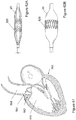
- Balloons may be used in the heart valves, including during Balloon Aortic Valvuloplasty (BAV) and Transcatheter Aortic Valve Implantation (TAVI).
- BAV Balloon Aortic Valvuloplasty
- TAVI Transcatheter Aortic Valve Implantation
- the balloons can be used to open a stenosed aortic valve.
- a stenosed valve may have hard calcific lesions which may tend to tear or puncture a balloon. Additionally, a precise inflated balloon diameter may be desired for increased safety and control.
- Balloons may be used to move plaque away from the center of a vascular lumen toward the vasculature walls, such as during an angioplasty or a peripheral vasculature procedure.
- a balloon tipped catheter is placed in a vascular obstruction.
- the vessel constriction is dilated, resulting in improved blood flow.
- Two basic types of balloons are utilized: One is a high pressure, low-compliance balloon. The other is a lower pressure, high-compliance balloon.
- High-compliance medical balloons are often composed of urethane, latex, silicone, PVC, Pebax, and other elastomers. As the pressure in a high-compliant balloon is increased, the balloon dimensions expand. Once the pressure is reduced, the high-compliance medical balloon may return to its original shape, or near its original shape. High-compliance medical balloons can easily expand several times in volume between zero inflation pressure and burst.
- High-compliance medical balloons can be inadequate for many reasons.
- High-compliance, or highly elastic medical balloons typically cannot reach high pressures because their walls have a low tensile strength and their walls thin out as the balloon expands.
- high-compliance medical balloons provide insufficient force to complete a procedure. Exceeding the rated pressure of a high-compliance medical balloon creates an excessive risk of balloon failure which can lead to serious complications for the patient.
- High-compliance medical balloons also have poor shape control. As a high-compliance medical balloon expands, it may assume a shape dictated mostly by the particulars of the environment inside the patient rather than the clinical goals. In some cases, this can be contrary to what the medical practitioner desires. Many medical procedures are predicated on forming a particular balloon shape reliably.
- PET polyethylene terephthalate
- PET polyethylene terephthalate
- PET is the most common material for use in high pressure low-compliance balloons. PET is commonly used for high-performance angioplasty balloons. PET is stronger than other polymers, can be molded into a variety of shapes and can be made very thin, (e.g., 5 ⁇ m to 50 ⁇ m (0.0002 in. to 0.002 in.)), thus giving these balloons a low profile.
- PET balloons made from PET walls are fragile and prone to tears. When pressed against a hard or sharp surface in the body, such as stenosis, PET balloons have poor puncture resistance. PET is very stiff so balloons made from PET may be difficult to pack or fold into a small diameter and may have poor trackability (i.e., the ability to slide and bend over a guidewire deployed through a tortuous vessel).
- Balloons made from PET while stronger than most other balloons made from homogenous polymers, may still not be strong enough to hold pressures sufficient to complete certain medical procedures. Additionally, with a large balloon diameter (For example, 20 mm or greater), a PET balloon still has excessive compliance for procedures such as BAY and TAVI.
- PET like most low compliance balloons, is usually blow-molded.
- the blow molding process makes it difficult or impossible to create certain shapes. Blow molding can result in wall thicknesses in the balloon that do not match the material thicknesses to the expected load.
- Nylon balloons are an alternative material for low-compliance, high pressure balloons. These balloons are typically weaker than PE I' balloons and so can contain less pressure. Nylon readily absorbs water, which can have an adverse affect on Nylon's material properties in some circumstances. Nylon has improved puncture resistance over PET and is more flexible than PET.
- a balloon is desired that can sustain high pressures, provide precise shape control and be highly resistant to tear and puncture.
- US 2009/0299327 A1 discloses inflatable medical devices and methods for making and using the same.
- the inflatable medical devices can be balloons.
- the balloons can be configured to have a through-lumen or no through-lumen and a wide varieties of geometries.
- the device can have a high-strength, non-compliant, fiber reinforced, multilayered wall.
- the inflatable medical device can be used for angioplasty, kyphoplasty, percutaneous aortic valve replacement, or other procedures.
- the present invention relates to an inflatable medical device according to Claim 1.
- the dependent claims refer to preferred embodiments.
- an inflatable medical device having a longitudinal axis has a balloon having a balloon length.
- the balloon has a wall and an inflatable volume defined by the wall; wherein the wall comprises reinforcement fibers; and wherein the reinforcement fibers are oriented substantially parallel with the longitudinal axis of the device; and wherein the reinforcement fibers have a reinforcement fiber length that is less than about 75% of the length of the balloon length. More narrowly, the length of the reinforcement fiber can be less than about 70%, yet more narrowly less than about 65%, yet more narrowly less than about 60% of the balloon length. All or substantially all of the reinforcement fibers in the balloon can have a reinforcement fiber length of less than 70% of the balloon length.
- the device can have a balloon having a balloon volume.
- the inflatable volume can be the balloon volume.
- the wall can have a first layer.
- the first layer can have at least two of the reinforcement fibers.
- the first layer can have a polymer layer.
- a composite fiber-reinforced medical balloon having a long axis is also disclosed.
- the balloon has an inner polymeric wall capable of sustaining pressure when inflated.
- the balloon also has a fiber and polymeric matrix outer wall.
- the outer wall has a layer of fibers and a polymer layer.
- the outer wall surrounds and reinforces the inner polymeric wall.
- the fibers are high-strength, inelastic fibers.
- the layer of fibers has at least a first fiber layer. All or substantially all of the fibers of the first fiber layer are less than about 75% of the length of the long axis of the balloon and run substantially longitudinally along the length of the long axis.
- the fiber and polymeric matrix outer wall can have a second fiber layer.
- the fibers of the first fiber layer can run substantially perpendicular to the fibers of the second fiber layer when the balloon is uninflated.
- the fibers of the first fiber layer can remain substantially perpendicular to the fibers of the second fiber layer when the balloon is inflated.
- the fibers of the second fiber layer can be wound radially around the long axis of the balloon substantially over the entire length of the long axis of the balloon.
- the balloon can have minimal radial distension.
- an inflatable medical device having a longitudinal axis.
- the device has a balloon that has a wall and an inflatable volume defined by the wall.
- the wall has a first layer having reinforcement fibers. About 50% or more of the reinforcement fibers have separations along the lengths of the reinforcement fibers. At least about 25% of the reinforcement fibers in the first layer are parallel with each other.
- the reinforcement fibers can be oriented parallel with the longitudinal axis of the device.
- the reinforcement fibers can extend in two opposite directions away from the separations.
- the separations can be intermediate along the length of the reinforcement fibers.
- the separations can be less than about 2 mm in length, more narrowly less than about 1 mm in length, yet more narrowly less than about 0.25 mm in length.
- the reinforcement fibers can have a first reinforcement fiber and a second reinforcement fiber.
- the first reinforcement fiber can have a first separation at a first length along the first reinforcement fiber.
- the second reinforcement fiber can have a second separation at a second length along the second reinforcement fiber.
- the first length can be unequal to the second length.
- the first reinforcement fiber can be the adjacent reinforcement fiber to the second reinforcement fiber.
- the first reinforcement fiber can be parallel with the second reinforcement fiber.
- Over about 90% of the reinforcement fibers can have separation along the lengths of the reinforcement fibers.
- An inflatable medical device having a longitudinal axis and a load path substantially parallel to the longitudinal axis.
- the inflatable medical device has a constant-diameter section disposed between taper walls and stem walls.
- the device has a balloon having a wall and an inflatable volume defined by the wall.
- the wall has a first layer having reinforcement fibers.
- the reinforcement fibers are substantially parallel to the longitudinal axis.
- the load path from the distal to the proximal end is interrupted in the constant-diameter section.
- an inflatable medical device having a longitudinal axis and a load path substantially parallel to the longitudinal axis.
- the device has a constant-diameter section between taper walls and stem walls.
- the device has a balloon having a wall and an inflatable volume defined by the wall.
- the wall has a first layer having reinforcement fibers.
- the first layer has a first fiber and a second fiber. The first and second fibers occupy the same load path.
- the load path can be substantially parallel to the longitudinal axis.
- the distal end of the first fiber and the proximal end of the second fiber can be located in the constant-diameter section.
- the first fiber and the second fiber can be located at the same angle as measured from the longitudinal axis, but at different lengths along the device.
- An inflatable medical device that has a longitudinal axis.
- the device has a constant-diameter section between taper walls and stem walls.
- the device can be inflated and deflated, and when inflated has a tensile load between the distal and proximal ends of the device.
- the device has a first layer having reinforcement fibers.
- the reinforcement fibers are substantially parallel to the longitudinal axis and carry all or a substantial portion (e.g., over about 50%, or more narrowly over about 75%) of the tensile load.
- a majority of the reinforcement fibers transmit their entire tensile load as a shearing load to other fibers at least at one point, along the reinforcement fiber.
- the first layer can have a single layer of filaments.
- the force load within a single layer of fibers from a proximal terminal end or proximal cone of the device to a distal terminal end or distal cone of the device is carried as shear force at least one point along the length. More narrowly, above about 70% of the force load within a single layer of fibers from a proximal terminal end or proximal cone of the device to a distal terminal end or distal cone of the device is carried as shear force at least one point along the length. Yet more narrowly, about 100% of the force load within a single layer of fibers from a proximal terminal end or proximal cone of the device to a distal terminal end or distal cone of the device is carried as shear force at least one point along the length.
- the fibers can be unidirectional fibers.
- the shear force can occur across load paths that are defined from a proximal terminal end of the balloon to a distal terminal end of the balloon.
- the shear force can occur in the fibers along the central length of the balloon (i.e., the length between a proximal cone and a distal cone, also referred to as the constant-diameter section).
- the device can have a first fiber at the side of a first tow that can shear against a second fiber at the side of a second tow.
- the first fiber can be immediately adjacent to the second fiber (i.e., with no other fibers between the first fiber and the second fiber).
- Adjacent fibers within a single tow can shear against the fibers next to them in the same tow.
- a method for making an inflatable device for use in a biological body includes forming a leak-proof member, such as a bladder, balloon or inflatable device, from first and second films positioned on a removable mandrel.
- the leak-proof member has a fiber.
- the first film has two panels.
- the first film is on the radially inner side of the fiber with respect to the inflatable device.
- the second film has two panels.
- the second film is on the radially outer side of the fiber with respect to the inflatable device.
- the forming includes perforating at least one of the panels.
- the method can also include evacuating a fluid from between a perforated panel and a non-perforated panel.
- the method includes forming a leak-proof member by joining films on a removable mandrel.
- the leak-proof member has a fiber.
- the method also includes perforating at least one of the films.
- the device has an inflatable balloon having a balloon wall having a reinforcement fiber.
- the balloon wall has perforations.
- the balloon wall can be leak-proof.
- the perforations can extend through the balloon wall.
- the perforations may or may not extend through the balloon wall.
- An inflatable medical device such as a balloon, having a longitudinal axis is disclosed that has an inner wall having a first seam oriented substantially parallel to the longitudinal axis of the balloon.
- the device has a first and second fiber reinforcement layer.
- the device also has an outer wall having a second seam oriented substantially parallel to the longitudinal axis of the balloon.
- the first and second fiber reinforcement layers can be radially outside the inner wall and radially inside the outer wall.
- the outer wall can be perforated.
- the first and second seams can lead from substantially the proximal to substantially the distal end of the balloon.
- the outer wall can be perforated.
- the first and second seams can lead from a proximal taper portion to a distal taper portion of the balloon.
- the device has an inner wall having a first and second seam oriented substantially parallel to the longitudinal axis of the balloon.
- the device has a first and second fiber reinforcement layer.
- the device also has an outer wall having a third seam and a fourth seam oriented substantially parallel to the longitudinal axis of the balloon.
- the first and second fiber reinforcement layers can be radially outside the inner wall and radially inside the outer wall.
- the first and third seams can lead from substantially the proximal to substantially the distal end of the balloon.
- the first and third seams can lead from the proximal taper portion to the distal taper portion of the balloon. Any of the seams can be an angled seam between two split halves of the respective layer.
- the device has a fiber layer having one or more high-strength substantially radiolucent filaments and one or more low-strength substantially radiopaque filaments.
- the fiber layer has a first filament layer.
- the radiopaque filaments are located between the radiolucent filaments in the first filament layer.
- the filaments can be substantially parallel to each other.
- the filaments can be oriented in a substantially circumferential pattern around the device.
- the filaments can be oriented substantially in the longitudinal direction.
- the device can have a film on the radial outside of the fiber layer.
- a method for making an inflatable device for use in a biological body includes applying a fiber layer by simultaneously applying a high-strength radiolucent filament and a low-strength radiopaque filament.
- the fiber layer has a single filament layer.
- the radiopaque filaments are urged (e.g., laid down accordingly, pressed) to lie between the radiolucent elements.
- An inflatable medical device that has a high-strength radiolucent fiber and a low-strength radiopaque fiber on separate layers are nested.
- the fiber tow has fibers and/or filaments.
- the method includes delivering the fiber tow to a length of the balloon wall.
- the length of the balloon wall has an angle relative to the longitudinal axis of the balloon equal to or greater than about 25°.
- the method also includes flattening the fiber tow.
- Flattening includes spreading the fiber tow so the fibers or filaments are side-by-side.
- the thickness of the tow after flattening can be equal to or less than about 25 microns.
- the flattened tow has a tow width of less than about 250 microns.
- the tow can have a circular cross-section before delivering the tow to the balloon wall.
- the tow can be wound in a circumferential pattern around the balloon.
- the fibers or filaments can be in a substantially single layer after the tow is applied to the balloon.
- Delivering the tow can include continually adding an adhesive to the fiber.
- Flattening can include increasing the adhesion of the tow to the wall.
- a method of applying a fiber tow to a balloon wall of a balloon having a longitudinal axis is also disclosed.
- the fiber tow has fibers.
- the method includes delivering the fiber tow to a length of the balloon wall.
- the length of the balloon wall has an angle at an angled section, where the angle of the angled section relative to the longitudinal axis of the balloon equal to or greater than about 25°.
- the strain between the topmost and bottommost fiber or filament in the fiber tow on the balloon wall angled section is less than or equal to about 2%.
- the fibers or filaments are in a substantially single layer after being applied to the balloon.
- the fibers or filaments can be applied to the layer by direct pressure by one or more direct pressure elements (e.g., a roller and/or jewel).
- the direct pressure element can be pressed against the fiber or filament with a spring loaded head.
- the fiber or filament can be spread normal to the surface of the balloon, for example following the contour of the balloon.
- the balloon can be mounted on a mandrel.
- the mandrel can be hard, solid, not hollow, or combinations thereof.
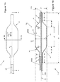
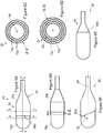
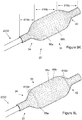
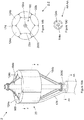
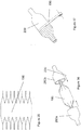
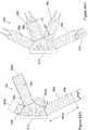
- Figures 1A and 1B illustrate that a medical inflatable device 2 can have a balloon 20 and a hollow shaft 2000.
- An inflation system (shown herein) can be attached to the hollow shaft to deliver a fluid pressure through the hollow shaft 2000 and to the balloon 20.
- the balloon 20 can be resilient (i.e., elastic) or non-compliant (i.e., inelastic).
- the balloon 20 can have a balloon longitudinal axis 26.
- the balloon 20 can have a balloon wall 22.
- the balloon wall 22 can define a cavity having a balloon volume 24.
- the balloon 20 can be a tube or a sheath.
- the tube or sheath can be a tubular structure that can be positioned over a medical device, such as an endoscope, vasculoscope, colonoscope, arthroscope, or combinations thereof.
- a tube can be a cylinder with a roughly equal inside and outside diameter.
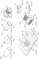
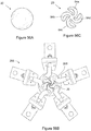
- the balloon 20 can have a closed end (as shown in Figure 2 ).
- the balloon 20 can have openings on either end (as shown in Figure 1 ).
- Figure 1B illustrates that the balloon 20 can have a. balloon length 28.
- the balloon length 28 can be from about 1.0 meter (39 in.) to about 5 mm(0.2 in.), more narrowly from about 200 mm (7.87 in.) to about 10mm (0.4 in.), yet more narrowly from about 120mm (4.72 in.) to about 50mm(1.97 in)
- the balloon 20 can have a balloon proximal stem 30 having a balloon proximal stem length 32.
- the proximal stem length 32 can be from about 3.0 mm (0.12 in.) to about 15 mm (0.60 in.), for example about 10 mm (0.40 in.).
- the balloon 20 can have a balloon proximal taper 34 having a balloon proximal taper length 36.
- the balloon proximal taper length 36 can be from about 0 mm (0 in.) to about 25 mm (0.98 in.), more narrowly from about 10 mm (0.40 in.) to about 22 mm (0.87 in.), yet more narrowly from about 16 mm (0.63 in.) to about 20 mm (0.79 in.).
- the balloon 20 can have a constant-diameter section 38 having a constant-diameter section length 40.
- the constant-diameter section 38 can be the length between the balloon proximal taper 34 and a balloon distal taper 42.
- the constant-diameter section length 40 can be from about 0 mm (0 in) to about 55 mm (2.17 in), more narrowly from about 30 mm (1.18 in) to about 50 mm (1.97 in).
- the constant-diameter section 38 is referred to herein as "constant-diameter" for illustrative purposes, and the constant-diameter section 38 can have a constant or variable diameter along the length of the constant-diameter section 38. In the case of a substantially variable diameter along the constant-diameter section, the constant-diameter section 38 is defined as the portion of the balloon between the cross sections of maximum balloon diameter.
- the balloon 20 can have a balloon distal taper 42 having a balloon distal taper length 44.
- the balloon distal taper length 44 can be from about 0 mm (0 in) to about 25 mm (0.98 in), more narrowly from about 10 mm (0.4 in) to about 22 mm(0.87mm), yet more narrowly from about 16 mm(0.63 in) to about 20 mm (0.79 in).
- the balloon 20 can have a balloon distal stem 43 having a balloon distal stem length 45.
- the distal stem length 45 can be from about 3 mm (0.12 in) to about 15 mm (0.6 in), more narrowly about 10 mm (0.4 in).
- the balloon 20 can have an inner lumen 154a and an outer lumen 154b.
- Inner lumen 154a may be formed by second hollow shaft 2000b.
- Inner lumen 154a may provide a lumen thru the entire balloon 20.
- Inner lumen 154a may allow a guidewire to pass thru the interior of the balloon.
- Outer lumen 154b may connect to balloon volume 24 and allow fluid into the balloon volume 24. Placing fluid into balloon volume 24 may cause the balloon to inflate.
- Outer lumen 154b may be formed between the inner wall of first hollow shaft 2000a and the outer wall of second hollow shaft 2000b.
- the proximal taper angle 90b and the distal taper angle 90a can be from about 0 to about 90°, more narrowly about 50° to about 20°, yet more narrowly about 45° to about 30°, for example about 40° or about 35° or about 30° or about 25° or about 20°.
- the proximal taper angle 90b and the distal taper angle 90a do not need to be substantially the same.
- the balloon 20 can have one or more balloon fluid ports 56.
- the first hollow shaft 2000a can have a hollow shaft distal port 54.
- One of the balloon fluid ports 56 can attach to the hollow shaft distal port 54.
- the balloon 20 can have a wall thickness 46.
- the wall thickness 46 can be less than about 25 ⁇ m (1 mil).
- the wall thickness 46 can be from about 25 ⁇ m (0.98 mil) to about 250 ⁇ m (9.8 mil), more narrowly from about 50 ⁇ m (2 mil) to about 150 ⁇ m (5.9 mil), more narrowly from about 35 ⁇ m(1.4mil) to about 75 ⁇ m(3mil), for example about 50 ⁇ m (2 mil), about 65 ⁇ m(2.6 mil), about 75 ⁇ m (3 mil), or about 100 ⁇ m (4 mil).
- the balloon 20 can have a balloon inner diameter 48 and a balloon outer diameter 50.
- the balloon outer diameter 50 can be measured perpendicular to the balloon longitudinal axis 26 at the widest point along the length of the balloon 20.
- the balloon outer diameter 50 can be from about 2 mm (0.08m) to about 50 mm (2in.) for example about 3 mm (0.12 in.), about 6 mm (0.24 in.), about 10 mm (0.4m), about 17 mm (0.67 in.), about 20 mm (0.79 in), about 22 mm (0.87 in), about 26 mm (1.02in), or about 30 mm (1.18in).
- the balloon proximal stem 30 may have a diameter of 2 mm (0.08 in) to about 50 mm (2 in.), more narrowly 2 mm (0,08 in) to about 5 mm (0.20 in), for example about 2mm (0.08 in), about 3 mm (0.12 in) or about 4 mm (0.16 in).
- the balloon 20 can have an unsupported burst pressure.
- the unsupported burst pressure is the pressure at which the balloon ruptures when inflated without any external constraint on the walls at about 1 atm external pressure and about 20 °C temperature.
- the unsupported burst pressure can be greater than about 150 psi (1,034 kPa).
- the unsupported burst pressure can be from about 200 psi(1,379kPa) to about 1,500 psi (10,343 kPa). More narrowly, the burst pressure can be from about 200 psi (1,379 kPa) to about 500 psi (3,448kPa).
- the burst pressure can be about 200 psi (1,379 kPa), 250 psi (1,724 kPa), about 300 psi (2,069 kPa), about 350 psi (2,413 kPa) about 400 psi (2,758 kPa), or about 500 psi (3,448 kPa).
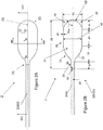
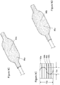
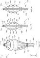
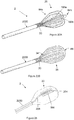
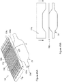
- Figures 2A and 2B illustrate that the balloon 20 can have balloon length 28.
- the balloon 20 can have a balloon proximal stem 30 having a balloon proximal stem length 32.
- the proximal stem length 32 can be from about 5 mm(0.20in) to about 15 mm (0.59 in).
- the balloon can have a balloon proximal taper 34 having a balloon proximal taper length 36.
- the balloon proximal taper length 36 can be from about 0 mm (0 in) to about 20 mm (0.79 in), more narrowly from about 0 mm (0 in) to about 15 mm (0.59 in), yet more narrowly from about 5 mm (0.20 in) to about 10 mm (0.39 in).
- the balloon 20 can have a constant-diameter section 38 having a constant-diameter section length 40.
- the constant-diameter section length 40 can be from about 0 mm (0 in) to about 15 mm (0.59 in), more narrowly from about 0 mm (0 in) to about 10 mm (0.39 in).
- the balloon 20 can have a balloon distal taper 42 at the terminal distal end 68 or tip of the balloon 20.
- the distal taper 42 can have a distal taper length 44.
- the distal taper length 44 can be from about 0 mm (0 in) to about 14 mm (0.55 in), more narrowly from about 2 mm (0.08 in) to about 9 mm (0.35 in).
- the proximal and/or distal tapers 34 and/or 42 can be concave, convex and/or s-curves.
- the proximal and/or distal tapers 34 and/or 42 can have continuously varying angles with respect to the balloon longitudinal axis 26.
- the balloon 20 can have one, two, three or more balloon fluid ports 56.
- the balloon 20 can have no through lumen.
- the balloon 20 can have no longitudinal through-lumen extending through the proximal terminal end 70 nor through the distal terminal end 68.
- the balloon 20 can have a balloon inner diameter 48 and a balloon outer diameter 50.
- the balloon outer diameter 50 can be measured perpendicular to the balloon longitudinal axis 26 at the widest point along the length of the balloon 20.
- the balloon 20 can have a radius (i.e., half the diameter), for example about 8.5 mm (0.33 in), and a distal taper length, for example about 8.5 mm (0.33 in).
- the ratio of the distal end length to the radius can be from about 2:1 to about 0:1, more narrowly about 1:1 to about 0.25:1.
- the balloon 20 can have an unsupported burst pressure.
- the unsupported burst pressure is the pressure at which the balloon ruptures when inflated without any external constraint on the walls at about 1 atm external pressure and about 20 °C temperature.
- the unsupported burst pressure can be greater than about 150 psi.
- the unsupported burst pressure can be from about 1,400 kPa (200 psi) to about 10,000 MPa (1,500 psi). More narrowly, the burst pressure can be from about 3,500 kPa (500 psi) to about 6,000 kPa (900 psi).
- the burst pressure can be about 3,500 kPa (500 psi), about 5,200 kPa (750 psi), about 7,000 (1,000 psi), about 10,000 kPa (1,500 psi), or higher than 10,000 kPa (1500 psi).
- the balloon 20 can be non-compliant or inelastic.
- the balloon 20 can have a failure strain of less than about 0.30, more narrowly less than about 0.20, more narrowly less than about 0.10, yet more narrowly less than about 0.05.
- a non-compliant balloon can have a failure strain of less than about 0.30.
- the failure strain of the balloon 20 is the difference between the balloon outer diameter 50 when the balloon 20 is inflated to 100% of the burst pressure and the balloon outer diameter 50 when the balloon 20 is inflated to 5% of the burst pressure (i.e., to expand from a deflated state without stretching the wall material) divided by the 100% pressure diameter.
- the burst pressure of the balloon 20 can be greater than about 3,500 kPa (500 psi) and have an outer diameter 50 of about 17 mm and a wall thickness 46 of less than about 100 ⁇ m with a failure strain of less than about 0.10, for example less than about 0.05.
- the burst pressure of the balloon 20 can be greater than about 200 psi (1,379 kPa) and have an outer diameter 50 of about 24 mm and a wall thickness 46 of less than about 75 ⁇ m with a failure strain of less than about 0.10, for example less than about 0.05.
- the reinforced balloon wall 22 may have a high tear strength as compared to traditional polymers. Tear strength can correlate to puncture strength and toughness.
- Tear strength can correlate to puncture strength and toughness.
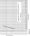
- a Mod MiI-C-21 189 10.2.4 tear test a specimen is created. That specimen has a width, a height, and thickness. A slit is made in the sample parallel to the width, mid-way along its height. The slit is then pulled to initiate tear at the corners of the slit.
- the Mod Mil-C-2U89 10.2.4 tear test gives resultant data in tensile pounds force (lbf). For the test to be meaningful as a comparison between two material samples, the tear test should be done on a thickness-comparable basis.
- a nylon 12 balloon material at about 0.0055 in (140 ⁇ m) thickness failed the tear test at a mean tensile load of 25 lbf (111 newtons).
- a variation of the balloon wall 22 of about 0005 in. (127 ⁇ m) wall thickness 46 can fail the same tear test performed on the nylon 12 balloon at a mean tensile value of 134 lbf (596 newtons).
- the balloon wall 22 can have a high puncture strength.
- a balloon 20 is inflated to about 60 psi (414 kPa) and a 1 mm (0.040 in) gauge pin is driven into the balloon 20 at about 1mm/sec (0.04 in/sec), the pin may need to exert more than 6 lbf (27 newtons) to puncture the balloon wall 22.
- a typical non-compliant polymer medical balloon may fail at about 3 lbf (13 newtons).
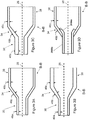
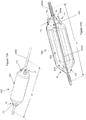
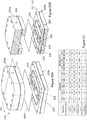
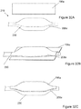
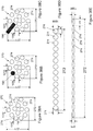
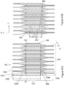
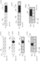
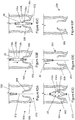
- Figure 3A illustrates that the balloon 20 can have a constant wall thicknesses 46 along the length of the balloon 20.
- a wall proximal stem thickness 46a can be substantially equal to a wall constant-diameter section thickness 46c and the wall proximal taper thickness 46b.
- Figure 3B illustrates that the balloon 20 can have a varying, such as increasing and/or decreasing, wall thicknesses 46 along the length of the balloon 20.
- Figure 3B illustrates that the wail constant-diameter section thickness 46c can be substantially greater than the wall proximal stem thickness 46a.
- the wall proximal taper thickness 46b can be less than the wall constant-diameter section thickness 46c and greater than the wall proximal stem thickness 46a.
- Figure 3C illustrates that the wall proximal stem thickness 46a can substantially greater than the wall constant-diameter section thickness 46c.
- the wall proximal taper thickness 46b can be less than the wall proximal stem thickness 46a and greater than the wall constant-diameter section thickness 46c.
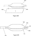
- Figure 3D illustrates that balloon 20 may terminate at the proximal end of the proximal taper 34.
- the balloon 20 may have no proximal stem 30.
- First hollow shaft 2000a may have a flare 2004 that attaches to inner wall of proximal taper 34,
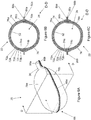
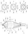
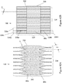
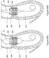
- Figure 4A illustrates that the balloon 20 can have a first balloon external seam 67a and a second balloon external seam 67b. Any or all seams 67 can extend partially, completely, not at all, or a combination thereof, through the depth of the wall thickness 46.
- the balloon external seams 67a and 67b can be longitudinal seams (i.e., oriented in a longitudinal direction with respect to the balloon 20, parallel or at an angle to the longitudinal axis 26 of the balloon 20).
- the balloon external seams 67a and 67b can extend from a first lateral side of the balloon 20 at the proximal terminal end 70 of the balloon 20, along the first lateral side of the balloon to the balloon distal stem 430.
- a balloon seam may be between 75% and 150% as long as the balloon length 28, more narrowly between 85% and 125% as long as the balloon length 28.
- a balloon seam my be between 180% and 300% as long as the balloon length 28, more narrowly between 190% and 260%.
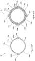
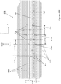
- FIGS 4B and 4C illustrate that the balloon wall 22 can have one or more layers 72.
- Each layer 72 can be a homogenous or heterogeneous discrete element distinguished from other layers by radial distance along the thickness of the balloon wall 22.
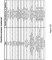
- a layer 72 may comprise film, reinforcement material or adhesive or combinations thereof, for example, the materials listed in Figures 27 , 28 and 29 .
- the balloon 20 can have a leak-proof bladder 52.
- the bladder 52 can be defined by one or more leak-proof layers within the balloon wall 22.
- the bladder 52 can be fluid-tight, such as air-tight or saline tight, or can be a fluid-porous bladder.
- the bladder 52 can be made of a urethane, a nylon, any material listed infra (eg.
- the bladder 52 can be made from the radial inner-most layer 72b (as shown in Figures 4B and 4C ) of the balloon wall 22.
- a bladder 52 may comprise film, reinforcement material or adhesive or combinations thereof (for example, the materials listed in Figures 27 , 28 and 29 ).
- the bladder 52 can be fixedly or removably attached to the hollow shaft 2000, for example at the inside and/or outside diameter of hollow shaft 2000.
- the hollow shaft 2000 can be a flexible or rigid catheter.
- the hollow shaft 2000 can deliver pressurized fluid to the balloon volume 24.
- the balloon wall 22 can be made from panels 76.
- the panels 76 can, for example, be cut or formed pieces of film and/or resin with or without other materials such as fibers.
- the layers 72 can each be made from one or more panels 76.
- the panels 76 can each contain one or more layers 72, or multiple panels 76 (e.g., of the same material) can be formed into a single layer 72, for example by melting panels 76 of the same material into an indiscrete, integral homogenous layer during the method of making the device.
- a panel 76 or a panel 74 or a panel 196 may comprise film, reinforcement material or adhesive or combinations thereof (for example, the materials listed in Figures 27 , 28 and 29 ).
- the outer layer 72a of the balloon wall 22 can have an outer layer first panel 76a and an outer layer second panel 76b.
- the outer layer first panel 76a can cover from about 90° to about 270° of the balloon, as measured in a transverse plane from the balloon longitudinal axis 26, for example about 185° of the balloon 20.
- the outer layer second panel 76b can cover from about 90° to about 270°, as measured along the balloon longitudinal axis 26, for example about 185°.
- the balloon wall 22 can have one or more seams 66 and or 67 and or 69 attaching panels 76 to other panels 76 in the same layers or to itself.
- the seams 66 and/or 67 and/or 69 can be an abutment or overlap of one or two panels 76 and/or panels 196 and/or panels 74.
- the seams 66 and or 67 and/or 69 can be linear, curved, circular, equatorial or combinations thereof.
- Figure 4B illustrates that the balloon external seams 67a and 67b can be overlayed seams, lap joints, or combinations thereof.
- the balloon external seams 67a and 67b can be flush against the side (i.e., having a substantially constant radius with respect to the balloon longitudinal axis 26) of the outer layer first panel 76a or outer layer second panel 76b.
- the outer layer first panel 76a can be radially outside of the outer layer second panel 76b where the outer layer first panel 76a overlaps the layer second panel 76b.
- the outer panels 76 may have an overlap length 59.
- the overlap length 59 can be from about 0 mm (0 in.) (e.g., an abutment seam) to about 3 ⁇ m (0.12 in.), more narrowly from about 1 mm (0.04 in.) to about 2 mm (0.08 in.).
- the outer layer first panel 76a can be bonded or adhered (e.g., with an adhesive) to the outer layer second panel 76b.
- the adhesive can be an epoxy or a thermally weldable material, such as a thermoplastic urethane.
- the inner layer 72b can have balloon internal seams 69a and 69b.
- the balloon inner seams 69a and 69b can join an inner layer first panel 74a and an inner layer second panel 74b.
- the inner seams 69a and 69b can have a similar structure to those described here for the balloon outer seams 67a and 67b.
- Figure 4C illustrates that the outer layer first panel 76a can be fused, solvated to, glued, adhered to, welded to, or a combination thereof, with the outer layer second panel 76b at the outer seams 67A and 67B.
- An adhesive 208 may be placed between the first panel 76a and the second panel 76b at the inner seams 69a and 69b and the outer seams 67a and 67b.
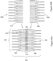
- Figure 5 illustrates that the balloon 20 can have a single balloon external seam 66a.
- the seam 66a can extend partially, completely, or not at all through the depth of the wall thickness 46.
- the balloon external seam 66a can be a longitudinal seam.
- the balloon external seam 66a can extend from a first lateral side of the balloon 20 at the proximal terminal end 70 of the balloon 20, along the first lateral side of the balloon to the balloon distal terminal end 68.
- the balloon external seam 66a can wrap around the balloon distal terminal end 68a, extending around the distal end of the balloon 20 and returning on the second lateral side of the balloon 20.
- the inner layer 72b can have a balloon inner seam 66b.
- the balloon inner seam 66b can join an inner layer first panel 74a and an inner layer second panel 74b.
- the inner seam 66b can have a similar structure to those described here for the balloon outer seam 66a.
- Sections C-C can be identical to variations of Sections H-H, except the outer seams 67 would be the single balloon external seam 66a and the inner seams 69 would be the inner seam 66b.
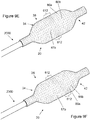
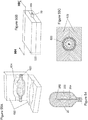
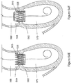
- FIG. 6A illustrates that the balloon external seam 66a can be a flange joint.
- the outer layer first panel 76a can have a seam first flange 80a around the perimeter of the outer layer first panel 76a.
- the outer layer second panel 76b can have a seam second flange 80b around the perimeter of the outer layer second panel 76b.
- the seam first flange 80a can attach to the seam second flange 80b at the balloon external seam 66a.
- the flange 80 can extend radially away from the balloon longitudinal axis 26.
- the balloon external seam 66a can be reinforced, for example with a metal foil, a wire or a polymer or combinations thereof.
- the balloon external seam 66a can be used to cut tissue during use in a biological target site or through tissue during delivery to the target site.
- Figure 6B illustrates that the seam first flange 80a can be bonded or adhered to the seam second flange 80b in the flange joint.
- Figure 6C illustrates that the layer first panel 76a can be fused, solvated to, glued, adhered to, welded to, or a combination thereof, with the layer second panel 76b in the flange joint.
- An adhesive 208 may be placed between the first panel 76a and the second panel 76b at the seams inner seam 66b and the outer seam 66a.
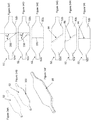
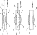
- Figure 7A illustrates that the balloon wall 22 can have a flange seam 66.
- the panels 76a and 76b can have seam areas 780.
- the seam areas 780 can be located at the terminal edges and/or areas near the terminal edges of panels 76a and 76b in a plane in which the panels 76a and 76b lie.
- the seams 66 and or 67 and/or 69 can join seam areas 780 of first panels 76 to seam areas of adjacent second panels 76 in the same layer or adjacent layers to the first panels 76a.
- Figure 7B illustrates that the balloon wall can have an abutment seam 66.
- the seam areas 780 can be perpendicular to the plane of the panels 76a and 76b.
- Figure 7C illustrates that the balloon wall can have a lap joint or overlap seam 66.
- the seam areas 780 can be parallel to the plane of the panels 76a and 76b.
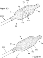
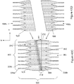
- Figure 8A illustrates that the balloon external seam 66a can be a lateral or latitudinal seam.
- the balloon external seam 66a can be in a plane perpendicular or substantially perpendicular to the balloon longitudinal axis 26,
- the balloon 20 can have one or more balloon external seams 66a and/or 67.
- the outer layer first panel 76a can be at the distal end of the balloon 20.
- the outer layer second panel 76b can be at the proximal end of the balloon 20.
- the outer layer second panel 76b can overlay the outer layer first panel 76a at the balloon external seam 66a.
- Figure 8B illustrates that the outer layer first panel 76a can overlay the outer layer second panel 76b at the balloon external seam 66a.
- Figure 8C illustrates that the balloon wall 22 at a first length along the balloon 20 can have a first layer and a second layer.
- the first layer can be a radially inner layer 72b, as measured from the balloon longitudinal axis 26.
- the second layer can be a radially outer layer 72a.
- Any of the layers 72 can have a laminate of fiber and resin (e.g., that can be elements of one or more panels 76 in the respective layers 72).
- the resin can be an adhesive.
- the fiber and resin laminate can be a matrix of the fiber in the resin.
- Figure 8D illustrates that the balloon wall 22 at a second length along the balloon 20 can have first, second and third layers.
- the second layer can be a first middle layer 72c between the inner and outer layers 72b and 72a, respectively. Any combination of the layers can be leak-proof, reinforced with one or more fibers, resistant and releasable from MMA, or combinations thereof.
- the first middle layer 72c can be reinforced with a fiber.
- the outer layer 72a can be MMA-resistant and/or MMA-releasing.
- An MMA-resistant material can substantially maintain material strength and thickness when exposed to MMA bone cement in any stage of the MMA bone cement from mixing to curing.
- An MMA-releasable material can form no substantial bond with MMA.
- Figure 8E illustrates that the balloon external seam 66A can be positioned at the proximal taper 34 of the balloon 20.
- the balloon external seams 66a and/or 67 can be in the constant-diameter section 38, the distal taper 42, the proximal, taper 34, the proximal stem 30, or combinations thereof.
- Figure 8F illustrates that balloon external seam 66a can lie in a plane at a non-perpendicular angle to the balloon longitudinal axis 26.
- the plane in which the balloon external seam 66a lies can form a seam angle 82 with the balloon longitudinal axis 26.
- the seam angle 82 can be from about 0° (i.e., a longitudinal seam) to about 90° (i.e., a latitudinal seam). More narrowly, the seam angle 82 can be from about 30° to about 60°.
- the seam angle 82 can be about 0°, about 30°, about 45°, about 60°, or about 90°.
- Figure 9A illustrates that the balloon 20 can be pleated to form flutes 84, for example four, five or six flutes 84, such as first flute 84a and second flute 84b.
- the flutes 84 can be made from accordion pleats, box pleats, cartridge pleats, fluted pleats, honeycomb pleats, knife pleats, rolled pleats, or combinations thereof.
- the pleating can be heat and/or pressure formed and/or the reinforcement fibers and/or panels can be oriented to form the flutes 84,
- the balloon 20 can be in a deflated configuration when the flutes 84 are shown.
- Figure 9B illustrates that the balloon 20 in an inflated configuration can push the pleated flutes 84 radially outward to form a substantially smooth outer surface of the balloon wall 22.
- the balloon 20 can have reinforcement fibers 86.
- Longitudinal reinforcement fibers 86b can be substantially parallel with the balloon longitudinal axis 26.
- Latitudinal reinforcement fibers 86a can be substantially perpendicular to the balloon longitudinal axis 26.
- Latitudinal reinforcement fibers 86a can be multiple fibers or a continuously wound single fiber.
- the balloon 20 may have a load path 750,
- the angle between fibers 86a and 86b may be approximately perpendicular and may not change between inflation and deflation.
- Figures 9C illustrates that latitudinal reinforcement fibers 86a can be applied in a wavy or curvy pattern (e.g., a sinusoidal configuration).
- Figure 9C' shows a dose-up of the latitudinal reinforcement fiber 86a.
- the wave pattern can have a first wave amplitude width 754 of less than about 10 mm (0.39 in), more narrowly less than about 5 mm (0.20 in), more narrowly less than about 2 mm (0.08 in).
- the wave pattern may have wave period width 758 of less than about 10 mm (0.39 in), more narrowly less than about 5 mm (0.20 in), more narrowly less than about 2 mm (0.08 in).
- the fibers 86a can straighten to resemble the configuration of the fibers 86a in Figure 9B .
- the fibers 86a may transform to a straighter configuration (e.g., the wave period width 758 may increase and the first wave amplitude width 754 may decrease).
- the balloon 20 can expand in the hoop direction without placing the fibers 86a in significant stress, for example, stress in excess of 10% of the yield stress.
- Figure 9D illustrates that longitudinal reinforcement fibers 86b can be applied to the balloon 20 in a wavy or curvy pattern similar to the pattern of fiber 86A shown in Figure 9C and 9C' .
- the fibers 86b may transform to a straighter configuration.
- the latitudinal and longitudinal reinforcement fibers 86a and 86b on a single balloon 20 can both have wavy configurations.
- the balloon 20 When inflated, the balloon 20 may have a biphasic compliance: a first compliance curve and a second compliance curve.
- the first compliance curve may be generated as the balloon 20 is first pressurized and be the result of the straightening of fibers 86a and/or 86b in the balloon wall 22.
- the second compliance curve may be generated by the straining under tension of fibers 86a and/or 86b which are then in a substantially straight (e.g., not curvy) configuration.
- the diametrical compliance of the balloon may average a first compliance of about 0.1% strain per psi (0.1 per 6.9 kPa). Therefore, when the balloon volume 24 is inflated to a transition pressure of 90 psi (610 kPa), the balloon outer diameter 50 may have grown 9%. At pressures beyond the transition pressure of 90 psi (610 kPa), the compliance of the balloon may average a second compliance of about 0.015% per psi (0.015% per 6.9kPa).
- the balloon outer diameter 50 may have grown 1.35% between about 90psi(610 kPa) and about 180psi psi (1220 kPa).
- the transition pressure can be from about 15 psi (101 kPa) to about 1000 psi (6890 kPa), more narrowly from about 15 psi (101 kPa) to about 250 psi (1723 kPa), still more narrowly from about 15 psi (101 kPa) to about 90 psi (610 kPa).
- the first compliance can be from about 0.025% per psi (0.025% per 6.9 kPa) to about 1% per psi (1% per 6.9kPa), more narrowly from about 0.05% per psi (0.05% per 6.9 kPa) to about 0.3% per psi (0.3% per 6.9 kPa).
- the second compliance can be from about 0.005% per psi (0.005% per 6.9 kPa) to about 0.05% (0.05% per 6.9 kPa), more narrowly from 0.01% per psi (0.01% per 6.9 kPa) to about 0.025%. per psi (0.025% per 6,9 kPa).
- the balloon 20 can have uniphasic compliance.
- the balloon 20 may have no first compliance.
- the balloon 20 may have no second compliance.
- the balloon 20 may have no transition pressure.
- Figure 9E illustrates that first and second longitudinal reinforcement fibers 86b and 87b, respectively, can be substantially parallel with the balloon longitudinal axis 26.
- the longitudinal reinforcement fibers 86b and 87b can longitudinally overlap (i.e., have concurrent longitudinal locations along the balloon 20 ) in reinforcement fiber overlap area 612.
- the reinforcement fiber overlap area 612 may form a hoop-shaped area that partially or completely encircles the constant-diameter section 38.
- the fibers 86B and 87B may have fiber lengths less than about 80% of the balloon length 28 more narrowly less than about75% as long, more narrowly less than about 70% as long, still more narrowly less than about 65% as long, still more narrowly less than about 60% as long as the balloon length 28.
- Second or latitudinal reinforcement fibers 86a can be substantially perpendicular to the balloon longitudinal axis 26.
- Figure 9F illustrates that the reinforcement fiber overlap area 612 may form a spiral or helical-shaped area that partially or completely encircles the constant-diameter section 38.
- Fiber separation areas 614 may be substantially rectangular and may have a fiber separation width 613 and fiber separation length 611.
- the fiber separation area 614 may separate fibers 86b and 87b by a fiber separation length 611 of about 2 mm (0.079 in.), more narrowly less than about 1 mm (0.039 in.), still more narrowly less than about 0.25 mm (0,01 in.).
- the fiber separation areas 614 may be distributed on the balloon surface such that no area 614 longitudinally substantially overlaps any other area on the balloon 20.
- the fiber separation areas 614 may be distributed such that latitudinally adjacent fiber separation areas 614 do not have any longitudinal overlap.
- the fiber separations 614 may be positioned along the length of the balloon 20 in a pattern sufficient to prevent any fiber from reaching from a first terminal longitudinal end of the balloon 20 to a second terminal longitudinal end of the balloon 20.
- the balloon 20 may have the panel 196 shown in figures 40B , 40C or 41B .
- Fibers 86b and 87b may have fiber lengths 88 less than about 80% as long as the balloon length 28, more narrowly less than about 75% as long, more narrowly less than about 70% as long, still more narrowly less than about 65% as long, still more narrowly less than about 60% as long as the balloon length 28.
- Figure 9H illustrates that the balloon 20 can have angled reinforcement fibers 85a and 85b.
- First angled reinforcement fiber 85a and/or second angled reinforcement fiber 85b can be at an angle with respect to the balloon longitudinal axis 26.
- first angled reinforcement fiber 85a and/or second angled reinforcement fiber 85b can be from about 10° to about 60°.
- the fiber 85a and/or 85b can be at about 10°, about 15°, about 20° or about 25° to the baboon longitudinal axis 26.
- the fiber 85a can be at about 50°, about 55° or about 60° with respect to the balloon longitudinal axis 26, Fiber 85b can have an equal but opposite angle to fiber 85a.
- fiber 85a can be at +20 degrees and fiber 85b can be at about -20° to the balloon longitudinal axis 26.
- the balloon 20 can have one or more latitudinal reinforcement fibers 85c and/or longitudinal reinforcement fibers (e.g., 86b and/or 87b, not shown in Figure 9H ) with one or more angled reinforcement fibers 85.
- the balloon 20 shown in Figure 9H may have a biphasie diametrical compliance: a first compliance curve and a second compliance curve.
- the balloon 20 may have a first angled reinforcement fiber 85a that forms an angle of about 20° with the balloon longitudinal axis 26 and a second angled reinforcement fiber 85b that forms an angle of about -20° with the balloon longitudinal axis 26.
- the first diametrical compliance curve may be generated as the balloon 20 is first pressurized and be the result of the absolute value of the angle that the fibers 85 make with the balloon longitudinal axis 26 increasing. For instance the angles may change from about 20° to about 39°, or from about -20° to about -39°.
- the balloon length 26 may decrease and the balloon outer diameter 50 may increase, both in proportion to the pressure contained in balloon volume 24.
- the second diametrical compliance curve may be generated by the straining under tension of fibers 85a and/or 85b as the pressure in balloon volume 24 is further increased.
- the first diametrical compliance curve may be more compliant than the second diametrical compliance curve.
- Figures 9I and 9J illustrate that the balloon wall 22 can have a first load path 750a, second load path 750b a third load path 750c, or combinations thereof.
- the load path 750 may be a portion of the balloon wall 22.
- the load path 750 can have a load path width 762 and a load path length 766.
- the load path 750 may be bounded by the thickness of a layer of longitudinal fiber 86b, have a load path length 766 about as long as the constant-diameter length 40 and have a load path width 762 that encompasses one or a plurality of filaments 274 or reinforcement fibers 86 or combinations thereof.
- the load path length 766 may be about parallel with the longitudinal axis 26 of the balloon 20.
- a load path 750 may have one or more continuous fibers, one or more cut or separated fibers, or combinations thereof.
- Load path width 762 may be about equal to fiber separation width 61 3
- Figure 9I shows that load paths 750a, 750b and 750c may each contain a continuous fiber 86b.
- the fibers 86b in the load paths 750 may carry a tensile load along the longitudinal axis 26.
- load paths 750a, 750b and 750c may each contain a first longitudinal reinforcement fiber 86b and a second longitudinal reinforcement 87b.
- the first longitudinal reinforcement fiber 86b can be separated by the fiber separation area 614 from the second longitudinal reinforcement 87b in the same load path 750.
- the tensile load in the respective load path 750 can be transferred by shear loading, as shown by arrows 770, from one load path to one or more adjacent load paths, for example, from the second load path 750b to the adjacent first and/or third load paths 750a and/or 750c, respectively; also for example from the first and/or third load paths 750a and/or 750c, respectively, to the second load path 750b.
- the reinforcement fibers 86b and 87b in the load paths may not carry a tensile load to between the two fibers 86b and 87b, for example, because the fiber separation area 614 is in the respective load path 750.
- the reinforcement fiber 86b or 87b may transfer the respective fiber's tensile load via one or more shear loads 770 to adjacent "receiving" reinforcement fibers 86b and 87b in adjacent load paths 750,
- the shear transferring of the tensile load can tension the adjacent receiving reinforcement fibers 86b and 87b,
- first shear load 770A may transfer tension from reinforcement fiber 87b" to reinforcement fiber 86b' over shear load length 772a.
- second shear load. 770b may transfer tension from reinforcement fiber 87b" to reinforcement fiber 86b''' over shear load length 772b.
- about 20% or more of the longitudinal reinforcement fibers 86b may transmit their tensile loads as shear loads 770, more narrowly about 40% or more, still, more narrowly about 60% or more, still more narrowly about 80% or more.
- Figure 9K illustrates that the reinforcement fiber 86 can be a single continuous fiber wound (e.g., in a hoop wind) around the balloon 20.
- the reinforcement fibers 86 can have a fiber density of about 100 winds per inch (i.e., the pitch of the wind).
- the pitch can vary across the length of the balloon 20.
- the balloon 20 can have a proximal pitch zone 618a, a middle pitch zone 618b, a distal pitch zone 618c, or combinations thereof.
- the reinforcement fiber(s) 86 in the pitch zones 618a, 618b, and 618c can have the same or different pitches. For instance, the pitch of the fiber 86 in zone 618b may be less than the pitches in zones 618a and 618c.
- the pitches in zones 618a and 618c may be substantially equivalent.
- the pitch in zones 618a and 618c may be about 128 winds per inch, while the pitch in zone 618b may be about 100 winds per inch
- a lower pitch in one zone, such as middle zone 618b with respect to the other zones, such as the proximal and distal zones 618a and 618b, may force the balloon wall 22 to fail (if failure of the balloon wall occurs 22 at all) in the respective zone 618b before failure of the balloon wall 22 were to occur in the other zones 618a and 618c.
- zone 618b may burst during failure of the balloon 20 before zones 618a and 618c burst.
- the pitch zones with a lower pitch may be more compliant than zones with a higher pitch, such as the proximal and distal pitch zones 618a and 618b.
- the balloon 20 can inflate more in the zone with the lower pitch, such as middle pitch zone 618b, relative to the zones with the higher pitch, such as the proximal and distal pitch zones 618a and 618b.
- One pitch zone e.g., pitch zone 618b
- Figure 9L illustrates that the balloon 20 can have a proximal latitudinal reinforcement band 616a and a distal latitudinal reinforcement band 616b.
- the pitch in the latitudinal reinforcement bands 616 may be higher or lower than the pitch of the latitudinal reinforcement fiber 86a in the remainder of the balloon.
- the pitch in the bands 616 may be at least 10% higher than the pitch in the remainder of the balloon, more narrowly 20% higher.
- Proximal latitudinal reinforcement band 616a may begin at the proximal end of the constant-diameter section 38 and end in the balloon proximal taper 34.
- band 616a may cover 50% or 25% or 10% of taper 34.
- distal latitudinal reinforcement band 616b may begin at the distal end of the constant-diameter section 38 and end in the balloon distal taper 42.
- band 616b may cover 50% or 25% or 10% of taper 42.
- the hoop strength of the balloon wall 22 in bands 616 may be increased over the hoop strength in the remainder of the balloon wall 22. The additional strength may minimize or stop balloon rupture propagation. For instance, if the balloon 20 were inflated and subsequently suffered a break in constant-diameter section 38 in latitudinal reinforcement fiber 86a, a rupture might form that was substantially parallel to the longitudinal axis. The resulting rupture may propagate into balloon proximal taper 34 or balloon distal taper 42. However, bands 616 may server to stop the propagation of the rupture because of their increased strength in the hoop or latitudinal direction.
- a balloon 20 may be designed to burst in a certain mode. For instance, hoop fiber pitch may be chosen such that as pressure in increased in balloon volume 24, the balloon 20 will break fibers 86a before breaking fibers 86b.
- Figure 10A illustrates that the balloon 10 can be pleated to form flutes 84, for example four, five or six flutes 84, such as first flute 84a, second flute 84b.
- the flutes 84 can be made from accordion pleats, box pleats, cartridge pleats, fluted pleats, honeycomb pleats, knife pleats, rolled pleats, or combinations thereof.
- the pleating can be heat and/or pressure formed and/or the reinforcement fibers and/or panels can be oriented to form the flutes 84.
- the balloon 20 can be in a deflated configuration when the flutes 84 are shown.
- Figure 10B illustrates that the balloon 20 in an inflated configuration can push the pleated flutes out to form a substantially smooth outer surface of the balloon wall 22.
- the balloon 20 can have reinforcement fibers 86.
- Longitudinal reinforcement fibers 86b can be parallel with the balloon longitudinal axis 26.
- Latitudinal reinforcement fibers 86a can be perpendicular to the balloon longitudinal axis 26.
- Figures 11A and 11B illustrates the distal end of the balloon outer wall 22b can folded around ("everted") and attached to the outside of the second hollow shaft 2000b.
- the proximal end of the balloon outer wall 22b can folded around ("everted") and attached to the outside of the first hollow shaft 2000a.
- Figures 12A and 12B illustrate that from the proximal end to the distal end, the balloon 20 can have a proximal taper 34, a first step 134a, a second step 134b, a third step 134c, and a distal taper 42, or combinations thereof.
- the first step 134a can have a first step outer radius 136a.
- the second step 134b can have a second step outer radius 136b.
- the third step 134c can have a third step outer radius 136c.
- the first step outer radius 136a can be greater than or less than (as shown) the second step outer radius 136b.
- the second step outer radius 136b can be greater than or less than (as shown) the third step outer radius 136c.
- the first step outer radius 136a can be greater than or less than (as shown) the third step outer radius 136c.
- the increasing radii steps 134 can be used to measure the target site.
- the steps 136 may also be used to dilate a target site in a patient.
- the dilation may be done in succession, first using a step 134 (for example, 134a), next using a step 134 with a larger radius (for example, 134b).
- the balloon can sequentially dilate a stenotic vessel or valve with increasing known radii (e.g., instead of purely by feel) of dilation.
- Figures 13A and 13B illustrate that the first step radius 136a and the third step radius 136c can be substantially equal.
- the second step radius 136b can be less than the first step radius and the third step radius.
- Figure 13C illustrates that a radially expandable implant 156 can be removably attached to the balloon wall 22.
- a stent, a percutaneous aortic heart valve, a replacement heart valve annulus, or combinations thereof can be balloon-expandable and deformed into the second step before insertion of the balloon into the target site.
- Figures 14A and 14B illustrate that the balloon 20 can have a peanut configuration with a smaller diameter step 134b between two larger steps 134a and 134c.
- Figure 15A illustrates that the balloon proximal stem 30, proximal taper 34, constant-diameter section 38, distal taper 42, or combinations thereof can be curved.
- the balloon longitudinal axis can be straight or have a balloon radius of curvature 102.
- the balloon radius of curvature 102 can be from about 2mm (0.08in) to about 50 mm(1.97in), for example about. 5 mm (0.20in), about 8 mm(0.31in), about 15mm(0.59in) or about 30 mm(1.18in).
- Figure 15B illustrates that the balloon can have a C-shaped configuration.
- the balloon 20 can trace out an arc (e.g., a portion of a circle).
- the arc can form an angle of 180 degrees or less, more narrowly 30-120 degrees.
- the arc can form an angle of 30 degrees, 45 degrees, 60 degrees, 90 degrees or 120 degrees.
- FIGS 16A and 16B illustrate that the balloon 20 can have a toroidal or annular shape.
- a fluid conduit 176 can extend from the hollow shaft 2000 to the balloon 20.
- the fluid conduit 176 can delivery fluid pressure to inflate and deflate the balloon 20.
- the balloon 20 can have an inner wall 22a and an outer wall 22b.
- the inner wall 22a can be radially inside the outer wall 22b.
- the inner wall 22a and/or the outer wall 22b can comprise a fiber 86 and/or a panel 196.
- the balloon 20 can have an annular lumen 160 passing through the radial center of the balloon 20.
- the annular lumen 160 can open to an annular lumen distal port 162a and an annular lumen proximal port 162b.
- the distal end of the annular lumen 160 can be attached to one or more distal tensioners 164a.
- the distal tensioners 164a can be elastic or inelastic wires, fibers or threads.
- the distal tensioners 164a can be fixed at distal tensioner first ends evenly or unevenly angularly distributed around the distal end of the balloon 20.
- the distal tensioners 164a can attach at distal tensioner second ends to a distal tension anchoring wrap 166a.
- the distal tension anchoring wrap 166a can be fixed to the hollow shaft 2000.
- the proximal end of the annular lumen 160 can be attached to one or more proximal tensioners 164b.
- the proximal tensioners 164b can be elastic or inelastic wires, fibers or threads.
- the proximal tensioners 164b can be fixed at proximal tensioner first ends evenly or unevenly angularly distributed around the proximal end of the balloon.
- the proximal tensioners 164b can attach at proximal tensioner second ends to a proximal tension anchoring wrap 166b.
- the proximal tension anchoring wrap 166b can be fixed to a tensioning collar 168.
- the second step can form a waist.
- the waist can have additional hoop wrapped fibers.
- the waist can be substantially non-compliant.
- the waist can be from about 0 mm (0 in) to about 12 mm in the balloon longitudinal direction, more narrowly from about 3 mm to about 9 mm.
- the waist diameter can be from about 2 mm (0.08in) to about 35 mm, for example about 3 mm, about 6 mm, about 20 mm, or about 23 mm.
- the tensioning collar 168 can be slidably attached to the hollow shaft 2000.
- the tensioning collar 168 can translate longitudinally, as shown by arrows in Figure 16B , along the shaft.
- the tensioning collar can be pulled and/or pushed by a control line 170 or rod.
- the balloon Before deployment of the inflatable device and after deployment but before removal of the inflatable device, the balloon can be deflated and contracted against the hollow shaft.
- the control line can be pulled to retract the proximal end of the balloon.
- the balloon can fold and contract against the hollow shaft.
- the balloon may be pleated such that, when the tensioning collar is pulled or when a vacuum is applied tot the inflatable device, the balloon contracts into a small, packed form (not shown).
- the balloon can have a distal segment 172a and a proximal segment 172b.
- the distal segment 172a and the proximal segment 172b can be annular or toroidal.
- the annular or toroidal planes can be perpendicular to the balloon longitudinal axis 26.
- the distal segment 172a can be longitudinally adjacent to the proximal segment 172b.
- the distal segment 172a can be directly bonded to the proximal segment 172b or joined to the proximal segment 172b by a segment joint 174.
- the segment joint 174 can be open and allow fluid communication between the proximal segment 172b and the distal segment 172a (not shown) or can be closed to isolate the fluid volume or the proximal segment 172b from the fluid volume of the distal segment 172a.
- the distal segment and/or the proximal segment may be inflated by a tube.
- the tube may be attached to the hollow shaft.
- the outer wall, the inner wall, or both walls, may contain a radiopaque material as described herein.
- the outer wall of the distal segment can form the first step.
- the segment joint can form the second step.
- the outer wall of the proximal segment can form the third step.
- the second step can be radially smaller than the first step and the second step.
- a device, such as a minimally invasive replacement heart valve can be attached to the outside of the balloon.
- FIG. 16C illustrates that the balloon 20 can have a valve 178.
- the valve 178 can have a first leaflet 180a, a second leaflet 180b, a third leaflet (not shown), or more.
- the leaflets 180 can be thin and flexible.
- the leaflets 180 can collapse inside the annular lumen 160 when the balloon is in a contracted configuration.
- the valve can allow flow through the annular lumen 160 in the distal direction and prevent flow through the annular lumen 160 in the proximal direction.
- the valve 178 can be fixed to the distal end of the distal segment of the balloon.
- the leaflets 180 can be oriented to allow flow distally through the annular lumen and impede or prevent flow proximally through the annular lumen.
- the leaflets 1 80 can be oriented to allow flow proximally through the annular lumen and impede or prevent flow distally through the annular lumen.
- Figure 17A illustrates that a shell 678 can have apertures 714.
- the apertures may be located in the proximal taper 34 and/or the distal taper 42. There may be an equal number of apertures on the each taper.
- the balloon could have 1, 2, 3, 4, 5, 6, 7, 8, 9, 10 or more apertures on each taper.
- the apertures may be aligned to fall between flutes or pleats.
- Apertures 714 may allow fluid, such as blood, to flow thru the inside of the shell. Apertures 714 may make the shell incapable of sustaining static pressure.
- Shell aperture flaps 718 may be made so that they will close apertures 714 when there is no flow through the balloon.
- flaps 718 When flow proceeds from left to right in Figure 17A with sufficient pressure, flaps 718 may open to allow flow through apertures 714. When the pressure relaxes, flaps 718 may shut to restrict flow from right to left in Figure 17A . In this way, flaps 718 may act as a one way valve.
- Figure 17B shows a cutaway of an inflated annular balloon structure 682.
- Balloon segments 656 are compressed by shell 678.
- the annular balloon structure has a central fluid passage 692 and apertures 714. Together, these features may allow fluids, such as blood, to pass through the annular balloon structure even when balloon segments 656 are fully inflated.
- Second hollow shaft 2000b may provide a lumen thru the center of the balloon. This lumen may be used with a guidewire to locate the balloon during a medical procedure. Second hollow shaft 2000b may have some elasticity or compressibility in the axial direction.
- First hollow shaft 2000a may allow the provision of pressurized fluid to hollow shaft distal port 54 and balloon inflation/deflation ports 654. Provision of pressurized fluid may cause balloon segments 656 to inflate. Removal of fluids may cause balloon segments 656 to collapse and for the shell to return to a pleated or fluted state.
- Figure 18A illustrates that the balloon can have segments that can be angularly adjacent to each other.
- the segments and the segment joints can be parallel with the longitudinal axis.
- the second step can have a larger radius than the first step or the third step.
- the proximal and distal tensioners can attach to the segments and/or segment joints.
- the segments may be inflated by a tube.
- the tube may be attached to the hollow shaft 2000.
- the distal and/or proximal tensioners can attach to the balloon at the segment joints and/or at the segments.
- the segment walls can have a radiopaque foil and/or a wire, such as a radiopaque marker wire.
- Figure 18B illustrates that the segments can be in fluid isolation from each other at cross section X-X.
- the segments can have a flattened circle longitudinal cross-sectional configuration.
- the segments can be almond or eye-shaped.
- Figure 18C illustrates that the segments can be in fluid communication with each other at a length along the balloon shown in Figure M1.
- Figure 18D illustrates that the segments can have a circular longitudinal cross-sectional configuration.
- the segments can be cylindrical.
- Figures 19A and 19B illustrate that the balloon can have a constant outer diameter when measured along the longitudinal axis.
- the balloon can have a single step.
- the balloon can have an inner wall 22a, an outer wall 22b and segment joints 174.
- the segment joints 174 can connect the inner wall to the outer wall.
- the segment joints 174 can minimize the inward radial collapse of the inner wall during inflation.
- Figure 19C illustrates that the hollow shaft can have an inner lumen 154a and an outer lumen 154b.
- the fluid conduit can be in fluid communication with the outer lumen and the balloon.
- the outer lumen can deliver pressure through the fluid conduit and to the balloon.
- the inner lumen can be a through lumen.
- the outer lumen can extend through the distal proximal tip.
- Figure 20 illustrates that the balloon can have a spiral or helical configuration.
- the spiral can have a first winding 182a, a second winding 182b, and more (e.g., five, as shown) windings.
- the first winding 182a can be joined to the second winding 182b at a winding joint 184.
- the winding joint 184 can have an adhesive or a weld joint.
- the winding joint 184 can have a strip of elastic or inelastic material attached to the adjacent windings.
- the balloon 20 can be formed from a single continuous lumen.
- Radiopaque foils, wires and any other radiopaque element or metal element herein can be made from gold, platinum, platinum-iridium alloy, tantalum, palladium, bismuth, barium, tungsten, or combinations thereof
- a radiopaque element may be a layer or a panel or a reinforcement element or a film or combinations thereof.
- a radiopaque element may be low strength.
- a low strength material can have a tensile yield strength less than about 100 ksi (690 MPa), more narrowly less than about 50 ksi (345 MPa), still more narrowly less than about 35 ksi (241 Mpa), still more narrowly less than about 25 ksi (172 MPa).
- the addition of the radiopaque element may increase the burst strength of the balloon no more than an insubstantial amount (e.g., by less than about 15%, more narrowly by less than about 10%, still more narrowly by less than about 5%).
- a radiopaque element may be ductile.
- Ductility can be measured by measuring the reduction in area of a test sample when pulled until the sample is fractured.
- Ductile materials can have about a 30% or more reduction in area, more narrowly, about a 40% or more reduction in area, still more narrowly about a 50% or more reduction in area, still more narrowly about a 70% or more reduction in area, still more narrowly about an 80% or more reduction in area.
- Ductile materials, as compared to brittle materials typically can be bent or folded with less chance of fracturing at the bend.
- balloon layers can have radiopaque dyes.
- Figures 21A and 22A illustrate that the first flute 84A can have a first vane 186a.
- the second flute can have a second vane 186b.
- the vanes 186 can be radiopaque elements.
- the vanes 186 can be panels.
- the vanes 186 can be embedded within or attached to the inside or outside of the balloon wall 22 . All, some, one, or none of the flutes can have vanes.
- the vanes 186 can be reinforcements.
- the vanes 186 can be a laminate, foil or wafer.
- the foil or wafer can be a plastic or metal listed herein, such as tantalum.
- the vane 186 can be strong enough to cut soft or hard tissue adjacent to the pleat.
- the vanes 186 can be rigid or flexible.
- Figures 21B and 22B illustrate that in an inflated or expanded configuration, the vanes 186 can lie flat along the wall.
- a single raqdiopaque layer can encompass substantially the entire area of the balloon (as shown in Figure 1 , but with a radiopaque layer congruent with the balloon 20).
- the radiopaque layer can be a single continuous layer, for example as a deposition or (e.g., radiopaque) foil lining with e.g. a deposition or foil of a metal such as listed herein.
- the foil can be less than about 30 ⁇ m (0.0012 in) thick, for example less than about 20 ⁇ m (0.0008 in) thick, for example about 15 ⁇ m (0.0006 in), about 12 ⁇ m (0.0005 in), about 10 ⁇ m (0.0004 in) or about 8 ⁇ m (0.0003 in) thick.
- Radiopaque foils can be cut or patterned by laser cutting, wire EDM, die cutting or deposition. The foils may be mounted to a removable backing before cutting such that a pattern of foils may be easily applied during the balloon construction process.
- the vanes 186 can cover the distal half of the balloon.
- the vanes 186 can cover the proximal half of the balloon.
- the vanes 186 can overlap in the longitudinal center of the balloon.
- a radiopaque foil can strengthen the balloon wall 22.
- the balloon 20 can have pleats or flutes between vanes or panels.
- the vanes or panels can form the pleats or flutes.
- a panel or vane, such as a radiopaque foil, can minimize leaks from forming between fibers in the balloon during use.
- FIG 23A illustrates that the vanes 186 can be spaced evenly around the balloon longitudinal axis.
- the vanes can be radiopaque and/or echogenic.
- the vanes can be rectangular, triangular, circular, oval, or combinations thereof.
- the vanes can be made of a metal foil.
- the vanes can be oblong having a major axis and a minor axis. The major axis can be parallel with the balloon longitudinal axis.
- Figure 23B illustrates that the balloon can have first vanes 186a spaced evenly around the balloon longitudinal axis.
- the balloon can have one or more second vanes 186b at the balloon distal terminal end.
- Figure 23C illustrates that the balloon can have a third vane 186c at the proximal taper.
- the second and/or third vanes can partially or completely circumferentially envelope the balloon around the balloon longitudinal axis.
- Figure 23D illustrates that the balloon can have marker spots 188 evenly or unevenly distributed around the balloon.
- the marker spots 188 can be radiopaque and/or echogenic.
- the marker spots 188 can be circular, oval, square, triangular, rectangular, pentagonal, hexagonal, or combinations thereof.
- the marker spots 188 can be in a layer of the balloon wall or attached to the inner or outer surface of the balloon
- the balloon can have a marker wire 190 in a helical configuration about the balloon longitudinal axis.
- the marker wire 190 can be radiopaque and/or echogenic.
- the wires 190 can be electrically conductive.
- the wires 190 can carry electrical current, for example for RF delivery, resistive heating, or combinations thereof.
- the marker wire 190 can be in a layer of the balloon wall or attached to the inner or outer surface of the balloon wall 22.
- Figure 24A shows a pattern for a marker wire 190.
- Marker wire 190 may be wound around the balloon such that it partially covers the distal and proximal ends of the constant-diameter section 38 of the balloon 20 .
- the constant-diameter section 38 may be the area of the balloon that is responsible for most or all of the expansion done by the balloon 20 in a patient.
- Figure 24B shows a pattern for a marker wire 190 .
- Marker wire 190 may be wound around the balloon on both the distal 42 and proximal tapers 34 of the balloon.
- the marker wire may be wound up to the distal and proximal borders of the constant-diameter section 38 without any substantial amount of the wire being placed in the constant-diameter section 38.
- the marker wire may be wound in a helical pattern in both directions on the balloon or be wound in a single direction.
- the angle 191 between two layers of marker wire may be less than 20 degrees, more narrowly less than 10 degrees, still more narrowly less than 6 degrees.
- Figure 24C illustrates that the balloon 20 can have a marker wire 190 wrapped over approximately the entire length of constant-diameter section 38.
- the marker wire 190 may be centered on the constant-diameter section 38 .
- the marker wire 190 may cover only a portion of the constant-diameter section 38. For instance, the marker wire 190 may cover more than 70% of the constant-diameter section 38, more narrowly more than 80%, still more narrowly more than 90%.
- the marker wire 190 may cover a portion of the distal tapers 42 and proximal tapers 34 . For example, the marker wire 190 may cover 100% of the distal tapers 42 and proximal tapers 34, more narrowly more than 50%, still more narrowly more than 25%.
- the marker wire 190 may be a latitudinal reinforcement fiber 86a .
- Figure 24D illustrates that the balloon can have a marker wire 190 wrapped over substantially the whole length of the balloon 20.
- the marker wire 190 can be made of any radiopaque material listed supra. The material may be chosen to be highly ductile so that it can form without fracturing as the balloon is folded.
- the marker wire 190 may be a round or flat wire.
- the marker wire 190 may be circular and about 6 ⁇ m (0.0002 in) to about 25 ⁇ m (0.001 in) in diameter.
- the marker wire 190 may be a flat (or rectangular) wire about 6 ⁇ m (0.0002 in) to about 18 ⁇ m (0.0007 in) thick and about 12 ⁇ m (0.0005 in) to 125 ⁇ m (0.005 in) wide. For example, it may be about 12 ⁇ m (0.0005 in) thick and 75 ⁇ m (0.0015 in) wide.
- the marker wire 190 can carry a tensile load.
- the wire 190 can have a 0,0254mm (0,001 in) diameter and maintain a tensile load of 0.3 N without yield or failure.
- the marker wire 190 can be low strength and/or ductile as defined herein.
- the vanes 186 , the marker spots 188 and the marker wires 190 can be on the inside of the balloon wall 22 , the outside of the balloon wall 22 , or within the balloon wall 22.
- Figure 25 illustrates that the balloon can have a resistive heating element 204 in a layer of the balloon wall or on the radial outside or radial inside of the balloon wall.
- the heating element 204 can have a resistive wire on a panel.
- the panel can be made from copper or another metal.
- the heating element 204, such as the resistive wire or panel, can be connected to a heating lead 206.
- the heating lead 206 can extend proximally along the hollow shaft 2000.
- the heating lead 206 can be proximally connected to a controller and power source.
- the system can have a heat control unit for controlling the level of energy delivery to the resistive heating element 204.
- the heating element 204 can be separated positive and negative electrodes on the balloon wall outer surface and contact the target site tissue directly, within the balloon wall, or on the radial inside of the inside surface of the balloon, or combinations thereof.
- the heating element 204 can have a dielectric material. Radiofrequency energy can be delivered across the dielectric material of the heating element 204 to create ohmic heating in the tissue.
- the balloon 20 can be used to heat, cool (e.g., when the panel is a Peltier junction), emit RF power, or combinations thereof.
- the heating element 204 can be substituted for or configured in combination with a UV-emitting element, visible light-emitting element, microwave-emitting element, ultrasonic-emitting element, or combinations thereof.
- the heating element 204 can be replaced or configured with a strain gauge, a peltier junction or a temperature measuring device, or combinations thereof
- the balloon can be used to treat abnormal mucosa in an esophagus, for example by positioning the heating element near or in contact with the abnormal mucosa and delivering heat.
- the mucosal layer of the esophageal wall for example the columnar epithelium, can be injured or ablated and made necrotic with the balloon to normalize mucosa in the esophagus.
- Figure 26A illustrates that the balloon 22 at section BB-BB or at other sections taken through a single wall of the balloon can have a layer 72 that can have a fiber matrix.
- the fiber matrix can have one or more monofilaments 274 and one or more resins.
- the resin can be a flexible adhesive 208.
- the flexible adhesive can remain flexible when cured or melted to form the medical inflatable device 2.
- monofilament 274 can be a. reinforcement fiber 85 a reinforcement fiber 86 or reinforcement fiber 87 .
- a reinforcement fiber can be a tow.
- a tow may contain one or more monofilaments.
- a fiber may contain one or more monofilaments.
- the fiber matrix may have one, two or more monofilaments 86 running substantially parallel to each other and embedded in a flexible adhesive 208.
- the substantially parallel monofilaments may be positioned within the flexible adhesive such that they are touching each other along their length.
- the substantially parallel monofilaments may be positioned such that there is flexible adhesive separating each fiber along its length.
- Figure 26A illustrates fiber array layer 72 having a layer width 210 in cross-section.
- the layer width 210 can include a number of monofilaments 274.
- the layer 72 can have a linear quantity fiber density measured, for example, as the number of monofilaments 274 per unit of layer width 210.
- the linear quantity fiber density can be equal to or greater than about 500 monofilaments 274 per 25,4mm (inch) more narrowly equal to or greater than about 1000 monofilaments 274 per inch, more narrowly equal to or greater than about 2000 monofilaments 274 per inch, yet more narrowly equal to or greater than about 4000 monofilaments 274 per inch.
- the liner quantity monofilaments 274 density can be from about 1,000 monofilaments 274 per inch to about 2,000 monofilaments 274 per inch.
- the fibers 86 or monofilaments 274 can be high strength and inelastic.
- the fibers may have a strain to failure of less than 10% more narrowly less than 5%.
- the fibers may have an ultimate tensile strength greater than 1.8 GPa (260 ksi), more narrowly greater than 2.4 GPa (350 ksi), still more narrowly greater than 2.9 GPa (420 ksi).
- the fibers can have a fiber or monofilament diameter 212 , for example, from about 1 ⁇ m (0.00004 in.) to about 50 ⁇ m (0.002 in.), for example less than about 25 ⁇ m (0.001 in.), more narrowly less than about 20 ⁇ m (0.0008 in.).
- the high strength fibers may be radiolucent or radiopaque.
- the unidirectional fiber-reinforced matrix can have the same or different sizes and materials of fibers within the same unidirectional fiber-reinforced matrix.
- the fiber matrix layer 72 can have a layer thickness 216 from about 1 ⁇ m (0.00004 in.) to about 50u ⁇ m (0.002 in.), more narrowly from about 8 ⁇ m (0.0003 in.) to about 25 ⁇ m (0.001 in.), yet more narrowly from about 10 ⁇ m (0.0004 in.) to about 20 ⁇ m (0.0008 in.)
- Figure 26B illustrates that the fiber density can be less than the fiber density shown in Figure 26A .
- the fiber density can be about 500 fibers per inch.
- Figures 26C and 26D illustrate that the monofilaments 274 or fibers may have a non-circular cross section. For instance, they may have a rectangular or oval cross-section.
- the cross section of monofilament 274 may have a fiber maximum height 1068 of, for instance about 5 ⁇ m to about 20 ⁇ m and a fiber maximum width 1072 of, for instance, about 20 ⁇ m to about 500 ⁇ m.
- the fiber or monofilament 274 can be about 8 ⁇ m high and 25 ⁇ m wide.
- the fiber or monofilament 274 can be about 12 ⁇ m high and 50 ⁇ m wide.
- Figure 26E illustrates that the inner layer 72b can have a fiber matrix having monofilament 274 in an adhesive 208.
- the outer layer 72a can have a polymer film, for example as shown in Figure 27 .
- the laminate shown can be a part of or the entire balloon wall 22 .
- Figure 26F illustrates that the outer layer 72a and the inner layer 72b can be polymer films, for example as shown in Figure 27 .
- the polymer films can be the same or different polymers, or any combination thereof.
- the first middle layer 72c can be a fiber matrix.
- Figure 26G illustrates the outer layer 72a , inner layer 72b, first middle layer 72c and third middle layer 72e can be polymer films, for example as shown in Figure 27 .
- the second middle layer 72d can be a fiber matrix.
- Part or all of the balloon wall 22 can have a volumetric quantitative density of monofilaments 274 measured, for example, as the number of monofilaments 274 per unit of area.
- the area quantity monofilaments 274 density can be equal to or greater than about 100,000 monofilaments 274 per square inch, more narrowly equal to or greater than about 250,000 monofilaments 274 per square inch, more narrowly equal to or greater than about 1,000,000 monofilaments 274 per square inch, yet more narrowly equal to or greater than about 4,000,000 monofilaments 274 per square inch.
- the area quantity of fiber can be about 25% of the area of a wall cross section, more narrowly about 50%, more narrowly about 75%.
- the ratio of the volume of the fiber matrix to the volume of the monofilaments 274 can be about equal to or greater than about 15%, more narrowly equal to or greater than about 30%, more narrowly equal to or greater than about 50%, yet more narrowly equal to or greater than about 75%.
- Figure 26H illustrates that the outer layer 72a , and inner layer 72b can be polymer
- the first middle layer 72c and the second middle layer 72d can be fiber matrices.
- the first middle layer 72c and the second middle layer 72d can be positioned with the monofilaments 274 substantially parallel to each other (as shown), substantially perpendicular to each other, or at an angle to each other.
- Figure 26I illustrates Figure 26H with the monofilaments 274 in second middle layer 72d substantially perpendicular the monofilaments 274 in first middle layer 72c .
- Figure 26J illustrates that the outer layer 72a , inner layer 72b , second middle layer 72d , and third middle layer 72e can be polymer films.
- the first middle layer 72c and the fourth middle layer 72f can be fiber matrices.
- Figure 26K illustrates that the outer layer 72a , inner layer 72b , second middle layer 72d, third middle layer 72e , fifth middle layer 72g , and sixth middle layer 72h can be polymer for example as shown in Figure 27 .
- the first middle layer 72c , fourth middle layer 72f and seventh middle layer 72i can be fiber matrices.
- Figure 26L illustrates that the outer layer 72a can be an MMA-resistant and MMA-releasing polymer film.
- the inner layer 72b can be a leak proof bladder made from a polymer film, for example as shown in Figure 27 .
- the first middle layer 72c can be a fiber matrix, for example with the fibers oriented as longitudinal fibers.
- the second middle layer 72d can be a fiber matrix, for example with the fibers oriented as latitudinal or hoop fibers.
- the third middle layer 72e can be a resin or adhesive.
- the fourth middle layer 72f can be a radiopaque layer, such as a metal foil.
- Figure 26M illustrates that the outer layer 72a can be a polymer film, for example as shown in Figure 27 .
- the inner layer 72b can be a leak proof bladder made from a polymer film, for example as shown in Figure 27 .
- the first middle layer 72c can be a fiber matrix, for example with the monofilaments 274 oriented as latitudinal or hoop fibers.
- the second middle layer 72d can be a fiber matrix, for example with the monofilaments 274 oriented as longitudinal fibers.
- the third middle layer 72e can be a resin or adhesive.
- the outer layer 72a may serve to isolate and protect the filaments 274.
- the filaments may be never get closer than 12 ⁇ m, or 10 ⁇ m, or 8 ⁇ m or 6 ⁇ m or 4 ⁇ m or 2 ⁇ m to the outside surface of the outer layer 72a.
- the outer layer 72a and/or the inner layer 72b may not melt when adhered to adhesive 208 using processing methods describe herein.
- Figure 26N illustrates that the outer layer 72a can be a polymer film, for example as shown in Figure 27 .
- Outer layer 72a may have perforations 782 as described infra.
- the inner layer 72b can be a leak proof bladder made from a polymer film, for example as shown in Figure 27 .
- the first middle layer 72c can be an adhesive 208.
- the second middle layer 72d can be a polymer film.
- the third middle layer 72e can be a fiber matrix, for example with the monofilaments 274 oriented as latitudinal or hoop fibers.
- the fourth middle layer 72f can be a fiber matrix, for example with the monofilaments 274 oriented as longitudinal fibers and with marker wire 190.
- the fifth middle layer 72g can be an adhesive 208.
- Figure 26O illustrates that the adhesive 208 in fifth middle layer 72g may fill in perforations 782 in outer layer 72a.
- Fourth middle layer 72f may contain a rectangular marker wire 190 .
- any of the polymer or fiber matrix layers can be leak proof, water tight, air tight, MMA-resistant, MMA-releasing, or combinations thereof.
- Magnetic resonance visualization enhancement materials such as magnetic contrast agents, can be added to the adhesive, the film or the fiber.
- the magnetic resonance visualization enhancement materials can enhance the visualization of the balloon during an magnetic resonance imaging (MRI) procedure.
- MRI magnetic resonance imaging
- the magnetic resonance visualization enhancement material can be gadolium, Omniscan, Optimark, ProHance, Magnevist, Multihance, or combinations thereof
- any of the layers can be tinted or dyed a visible spectrum color.
- a pigment, coloring additive, dispersions or other coloring agents such as an coloring additive from Plasticolors (Ashtabula, Ohio) can be added to the adhesive, laminate or fiber before consolidation.
- a paint or coating can be added to a layer surface or to the outer surface of the balloon wall.
- the color can be selected for branding, market, differentiating, as an indication of the type of device, the size of the device, or combinations thereof.
- devices having a selected diameter, length, pressure rating, clinical indication or efficacy, other common performance metric, or combinations thereof can be dyed a specific color (e.g., green for a first type of device, red for a second type of device),
- the layers can have one or more optical fibers.
- the fiber optic can be a strain sensor.
- the strain sensor can monitor the laminate's mechanical status in real time.
- the fiber optic can guide light delivery into the body.
- the fiber optic can visualize a target site (e.g., gather light from the body to produce a visual image).
- Figure 27 illustrates polymer films from which panels 196 and/or panels 74 and/or panels 76 and/or layers 72 can be made.
- the thickness of the polymer films can be from about 2 ⁇ m (0.00007 in.) to about 50 ⁇ m (0.002 in.), more narrowly from about 2 ⁇ m (0.00007 in.) to about 18 ⁇ m (0.0007 in.), yet more narrowly from about 4 ⁇ m (0.00016 in.) to about 12 ⁇ m (0.0005 in.).
- Films may be metalized or coated to change their surface properties. Metallization or coating may take place before or after a film is formed. Films may be treated chemically or via plasma or via corona treating or by combinations thereof in order to modify their bondability, for example to make them easier to bond too.
- Figure 28 illustrates materials from which the reinforcement fibers 86 or monofilaments 274 can be made.
- Reinforcement materials may be high strength as described supra.
- the reinforcement fibers 86 may be a wire or wires.
- the wire may have chosen with very low strain to failure (for instance, about 2%) or a high strain to failure (for instance, 10% or greater).
- the wire may be annealed or tempered to adjust its mechanical properties.
- the wire may have a breaking strength of greater than about 150 ksi, more narrowly greater than 250 ksi, still more narrowly greater than 400 ksi.
- the wire may be less than 25 ⁇ m in diameter.
- the wire may be substantially rectangular and less than about 25 ⁇ m in thickness 1068 , more narrowly less than about 15 ⁇ m in thickness 1068 when integrated into the wall of the balloon.
- the ratio of the width 1072 of the wire to the thickness 1069 of the wire may be greater than or equal to about 3, more narrowly greater than or equal to about 5, more narrowly greater than or equal to about 1 0.
- the density of the wire may be greater than about 24 g/cm ⁇ 3, more narrowly greater than about 6.9 g/cm ⁇ 3, more narrowly greater than about 15 g/cm ⁇ 3.
- the reinforcement fiber or wire 86 may be substantially radiopaque when used under a flourosocpe as part of a medical procedure in the human body.
- the physician may use an inflation medium, such as saline, which is not radiopaque when inflating a balloon 20.
- the reinforcement fibers or wires 86 may be coated.
- the coating may be an adhesive or otherwise increase adhesion of the fibers or wires 86.
- the coating may be a thermoplastic chosen from one of the materials (or combinations thereof) listed in figure 29 . The thermoplastic may be melted as part of the process of applying reinforcement fibers 86 to a balloon 20.
- Figure 29 illustrates that the adhesive 208 can be an elastomeric thermoset material, an elastomeric thermoplastic material, an epoxy, a coating or a combination thereof.
- the adhesive can be selected from any of the materials, or combinations thereof, listed in Figure 29 .
- the matrix can have a resin and a fiber.
- the resin can be an adhesive.
- Figures 30A and 30B illustrate that the device can be partially or completely manufactured in a pressure chamber 219.
- the pressure chamber 219 can be in a pressure chamber case 218.
- the pressure chamber case 218 can have a case top 220a separable from a case bottom 220b.
- the case top 220a can have a case top port 222.
- the case bottom 220b can have a case bottom port 224.
- the case top port 222 can be in fluid communication with the top of the pressure chamber 219.
- the case bottom port 224 can be in fluid communication with the bottom of the pressure chamber 219.
- the case top can screw or otherwise tightly join to the case bottom.
- the pressure chamber case can have one or more o-rings (not shown) in o-ring seats 226.
- the pressure chamber can have a mandrel seat 228.
- the mandrel seat 228 can be configured to receive a mandrel 230.
- the mandrel seat 228 can have holes or pores. The holes or pores in the mandrel seat 228 can allow pressure from the case bottom port and the bottom of the pressure chamber to reach the top surface of the mandrel seat around the mandrel and/or directly under the mandrel.
- the mandrel 230 can have the inner dimensions of the balloon 20.
- the mandrel 230 can be a water soluble mandrel
- the mandrel 230 may be made from a low melting point wax or metal, a foam, some collapsing structure or an inflatable bladder.
- the mandrel 230 can be made from a eutectic or non-eutectic bismuth alloy and removed by raising the temperature to the melt point of the metal.
- the mandrel 230 can be made from aluminum, glass, sugar, salt, corn syrup, hydroxypropylcellulose, ambergum, polyvinyl alcohol (PVA, PVAL or PVOH), hydroxypropyl methyl celluslose, polyglycolic acid, a ceramic powder, wax, ballistic gelatin, polylactic acid, polycaprolactone or combinations thereof
- Figure 31 illustrates characteristics of bismuth alloys from which the mandrel 230 can be made. The characteristics are characterized by melting temperature (as shown in the third row of Figure 31 ) of the bismuth alloy.
- the mandrel 230 can be transparent or translucent to light and/or an electron beam.
- the mandrel 230 can be hollow.
- the outside surface of the mandrel 230 can be coated in a release agent.
- the mandrel 230 may be molded, machined, cast, injection molded or combinations thereof
- the mandrel 230 can be in the mandrel seat 228 and a first panel 196a to be formed into about half of the inner layer of the balloon wall 22 can be placed between the case top 220a and the case bottom 220b. The case top can then be secured to the case bottom.
- Figure 32A illustrates that the outer surface of the mandrel 230 can have some glue or first adhesive 208a.
- the first adhesive 208a can be located around the perimeter of the first panel's 196a contact area with the mandrel.
- the first adhesive 208a can be water soluble.
- the first adhesive 208a can be a sugar syrup.
- a panel 196a may be positioned over the mandrel.
- the panel 196a may be a single layer or multiple layers.
- the panel could be a layer of film (for example, taken from Figure 27 ) and meltable adhesive (for example, taken from figure 29 ).
- the panel 196a can be positioned with film on the side that touches the mandrel and adhesive on the radially outer side.
- the panel 196A may be perforated as described infra. The panel may not be capable of sustaining pressure between the top and bottom of the panel.
- Figure 32B illustrates that a positive pressure can be applied to the top 220a of the pressure chamber (e.g., through the case top port 222) and/or a negative pressure or differential pressure or suction or vacuum applied to the bottom 220b of the pressure chamber (e.g., through the case bottom port 224).
- the panel 196A can get sucked and/or pressed down and/or formed onto the mandrel 230.
- the first panel can be smoothly fitted to the mandrel 230 and adhered to the mandrel at the first adhesive 208A.
- Heat may be applied to panel 196a before forming onto mandrel 230. Forming of one panel 196a may be done more than once on different sized mandrels before the panel 196a reaches the form shown in Figure 32B .
- Forming of panel 196a may also be accomplished with a mechanical die.
- the mechanical die may be heated and conform closely to the shape of the mandrel 230.
- the mechanical die may have a shape similar to the mandrel seat 228.
- the mandrel 230 and panel 196a can be mounted into a trimming jig. Any excess portion of the first panel 196a extending from the mandrel 230 can be trimmed with a blade, with a laser, with a water jet cutter, with a die cut tool or combinations thereof.
- the trimming jig can cover the mandrel 230 and the first panel 196a attached to the mandrel.
- Several panels 196a and/or layers 72 can be formed over the mandrel 230 and cut. The panels 196a and/or layers 72 may be trimmed at the same time or one at time.
- Figure 32C illustrates that the mandrel can have the excess area of the first panel. 196A removed in preparation for attachment of the second panel 196b.
- Figure 32D illustrates that a second adhesive 208b can be applied to the first panel 196a around the perimeter of the second panel's 196b contact area with the first panel 196a.
- the second adhesive 208b can be an epoxy, urethane, a thermoplastic, a cyanoacrylate, a UV curing adhesive, or combinations thereof.
- the mandrel 230 can be seated in the mandrel seat 228 with the first panel 196a in the mandrel seat.
- the second panel 196b can be placed on the mandrel 230 as shown (upside down relative to the Figures 30A and 30B for illustrative purposes).
- Figure 32E illustrates that after the case top 220a is secured to the case bottom 220b, the positive and/or negative pressures can be applied to the pressure chamber as described infra.
- the second pane! 196b can be smoothly fitted or pressure formed to or against the mandrel 230 and adhered to the first panel 196a at the second adhesive 208b. Adhesion can be accomplished by the application of heat.
- the first and second panels (196A and 196B) can form the inner layer 72b or bladder 52 of the balloon wall.
- the inner layer may be leaktight.
- the inner layer may be capable of sustaining pressure. Multiple layers can be made by repeating the method described infra.
- the pressure chamber can be heated, for example, to decrease the viscosity of and decrease the modulus of the panels.
- Figure 32F shows a cross section of 32E with the mandrel 230 omitted.
- the process in figures 32A thru 32E may be repeated on the part shown in Figures 32E and 32F to produce the bladder 52 cross section shown in Figure 32G .
- Panels 196c and 196d may be formed. Each panel may have an adhesive 208c and 208d facing radially in ward.
- Balloon third and fourth internal seams 69c and 69d may be oriented about midway between balloons first and second internal seams 69a and 69b.
- the bladder 52 may be leaktight
- Figure 33A illustrates that a first panel 196a can rest on top of the female mold half 378a.
- the first panel 196a can be a see-through polymer for illustrative purposes. For example, the contours of the mold may be seen.
- the first panel 196a can be a polymer, such as a nylon, PET, polycarbonate, urethane or those materials shown in Figure 27 or any other polymer that can be readily formed or combinations thereof.
- the first panel can be about 0.002 inches (50 ⁇ m) thick, more narrowly about 0.001 inches (25 ⁇ m), thick yet more narrowly about 0.0005 inches (12 ⁇ m) inches thick.
- Figure 33B illustrates that the first panel 196a can be formed to the contours of mold. Molding could be via heat or vacuum or pressure or combinations thereof.
- Figure 33C illustrates that the first panel 196a can be lifted free of the mold half 378a.
- the first panel 196a can have a panel flat 390 that did not enter the form of the female mold during forming.
- the panel 196a can be trimmed, for example in a trimming jig.
- Figure 33D illustrates that first and second panels (196a and 196b respectively) can have their flats 390 trimmed.
- the two panels can be closed tightly around a mandrel 230 and a mandrel shaft 392.
- the panels can then be bonded to each other at the seam 66b where they overlap.
- the seam 66b may connect all or some of the material that overlaps.
- the seam 66b may be leak tight to the passage or air and water.
- the bonding of the seam 66 and/or 67 and/or 69 may be caused by addition of an adhesive, by the application of heat, by the application of ultrasonic energy, by use of a laser, by the application of radio frequency energy, by the application of pressure or by combinations thereof.
- a material may be added to the seam, for example to bond the seam. The material may absorb laser light to generate heat in the seam.
- Figure 34A shows a bladder 52.
- the bladder 52 may be a thin-walled, blow-molded balloon.
- the bladder 52 may have a wall thickness of less than about 0.001 inches (0.025 mm), more narrowly less than about 0.0005 inches (0.0125 mm).
- the bladder 52 may have a constant of variable wall thickness along the length of the bladder 52 and/or around the circumference of the bladder 52.
- the bladder 52 may form the inner wall of a balloon 20 and be leak-tight.
- the inner volume of the bladder 52 may be filled with a mandrel material (types of mandrel material are described herein).
- the filling may be by injection or hy pouring or combinations thereof. The filling may occur after the bladder 52 has been formed.
- the mandrel material may be chose to match the thermal expansion properties of the fibers 86.
- Figure 34B shows a cut 350 that may be made though the wall of the bladder 52.
- the cut 350 may be a longitudinal cut running the entire length of the bladder 52,
- the cut 350 could be made mechanically (i.e., with a knife), with a laser, a water jet cutter, an ultrasonic blade a heated blade or combinations thereof.
- the cut 350 may allow one side of the bladder 52 to be opened.
- the cut 350 in figure 34F may leave the bladder 52 in one piece.
- the cut 350 can extend along a portion (e.g., from one terminal end to a mid-point, or from a first mid-point to a second mid-point), or the entire length of the bladder 52.
- Figure 34C shows a cut 350 through the bladder 52 at a cut angle 351.
- Cut angle 351 may be about 0° to about 70°, more narrowly about 0° to about 50°, still more narrowly about 25° to about 45°.
- Figure 34D shows a cut 350 through the bladder 52.
- the cut 350 is a spiral, with a maximum cut angle 351.
- Figure 34E shows a cut 350 through the bladder 52 at a cut angle 351 of 0°.
- the cut 350 may separate the bladder 52 into a first detached bladder portion 52a and a second detached bladder portion 52b.
- the first and second detached bladder portions 52a and 52b can each be half of the bladder 52 or can otherwise together comprise the complete bladder 52.
- the first bladder portion 52a can be symmetric or asymmetric with the second bladder portion 52b .
- Bladder portions 52 can also be formed separately and then joined as described infra.
- bladder portions 52 could be formed by thermoforming, injection molding, physical vapor deposition, dip molding or combinations thereof.
- Figure 34F shows the bladder 52 in Figure 34B after being fit over a mandrel 230 (mandrel 230 is inside bladder 52 and not directly shown in Figure 34F ).
- the bladder 52 may be made slightly larger in diameter and/or longer in length than the mandrel 230 onto which the bladder 52 is fit. This may allow the bladder 52 to be re-assembled on the mandrel 230 with an internal seam 66 that may be sealed.
- Figure 34F shows a longitudinal seam 66 running the length of the bladder 52.
- the seam 66 may be sealed with adhesive, by fusing, by heating, with a solvent or combinations thereof.
- the sealed bladder 52 may form the inner layer 72b of a balloon 20 and be leak-tight. Seam 66 may be an external seam 66a or internal seam 66b .
- Figure 34G through 34I illustrate the bladder 52 of Figures 34C, 34D, and 34E , respectively, after being fit over a mandrel 230 (mandrel not shown).
- the first bladder portion 52a can overlap at a lap joint or overlap (as shown), abut at an abutment, or flange with the second bladder portion 52b at the seam 66.
- Figure 34G shows that an angled seam 66 may be formed when the bladder 52 is reassembled on the mandrel 230.
- Figure 34H illustrates that a spiral seam 66 may be formed when the bladder is reassembled on the mandrel 230.
- Figure 34I shows that a 90 degree seam 66 may be formed when the bladder is reassembled on the mandrel 230. The seam 66 may be sealed as described supra.
- Figure 35 shows a panel 196.
- Panel 196 may be constructed of a thin film such as those shown in Figure 27 .
- the thin film may be a thermoplastic with a thickness less than about 20 ⁇ m, more narrowly less than about 15 ⁇ m, still more narrowly less than about 10 ⁇ m, still more narrowly less than about 6 ⁇ m.
- Panel 196 may have a similar outline to the panel described infra in Figures 40 .
- Figure 36 shows panel 196 applied to mandrel 230 (not shown).
- Distal caul 260a and proximal caul 260b may be applied over the panel 196.
- the assembled parts may be placed in a vacuum bag and heated until panel 196 fuses into a leak-tight bladder 52.
- the cauls 260 may be removed and the remainder of the balloon built on top of the bladder 52 and mandrel 230 as formed.
- the bladder 52 may be cut such that the bladder 52 can be removed from one mandrel 230 and placed on another mandrel. 230.
- a seam 66 may be formed.
- the bladder 52 may preferentially adhere to the cauls 260 allowing for easier handling and subsequent placement of bladder 52.
- Figure 37 shows a panel 196 being wrapped onto mandrel 230.
- the panel 196 may be wrapped onto the mandrel 230 such that each successive wrap slightly overlaps the previous wrap.
- Cauls 260 (not shown) may be placed over panel 196.
- the assembled parts may be placed in a vacuum bag, heated and processed into a bladder 52 as described herein.
- a bladder 52 may be formed by deposition.
- a metal such as gold (or other materials listed herein) may be deposited to form a bladder 52 .
- a material such as parylene may be deposited to form a bladder 52.
- a bladder 52 may be formed from a heat shrink tube.
- the tube may be formed in manufacture to fit the mandrel 230 , blown out to size, then placed over the mandrel 230 and shrunk to fit the mandrel.
- Shrinking may be accomplished by the application of heat.
- Figure 38A shows a cross section of a tow 270.
- a tow 270 may be or have one or more reinforcement fibers 86.
- a tow 270 may have one or more monofilaments 274 .
- the tow 270 may contain about 6, 25, 100, 500 or 1500 monofilaments.
- the tow 270 may have a tow height 271 and a tow width 272.
- the tow 270 may be approximately circular.
- the tow height 271 and tow width 272 may be about 0.025 mm (0.001 in) to about 0.150 mm (0.006 in), more narrowly 0.050 mm (0.020 in) to about 0.100 mm (0.040 in), more narrowly 0.075 mm (0.003 in).
- the tow 270 may be loosely held together by a polymer finish (not shown).
- tow 270 may contain a marker wire 190 .
- Marker wire 190 may be circular, as shown, and radiopaque.
- Figure 38C shows that the marker wire 190 in tow 270 may be rectangular with dimensions as described supra.
- Figure 38D shows the tow 270 after the tow 270 has been spread.
- the tow 270 may be flattened or spread by passing the tow 270 through a closely spaced set of rollers that form a narrow pinch gap.
- the tow 270 may be spread by pulling the tow 270 under tension over a set of rollers or pins. After spreading, the tow 270 may have a tow height 271 less than about twice the fiber height 1068 , for example about the same as fiber height 1068.
- the fiber height 1068 and fiber width 1072 may be substantially unchanged after spreading.
- the fiber width 1072 and fiber height 1068 may be about 15 ⁇ m (0.0006 in), tow width 272 may be about 210 ⁇ m (0.008 in) and tow height 271 may be about 15 ⁇ m (0.0006 in).
- the marker wire 1 90 is not shown in figure 38D but may be present after the tow 270 has been spread.
- Figure 38E shows the tow 270 from 38D after the tow 270 has had additional processing to flatten the monofilaments 274 .
- the monofilaments 274 may be flattened by, for example, running the flattened tow 270 as shown in figure 38D through a precision rolling mill.
- the fiber width 1072 may be about 25 ⁇ m (0.001 in).
- the fiber height 1068 may be about 9 ⁇ m (0.0004 in).
- the tow height 271 may be about 9 ⁇ m (0.0004 in).
- the tow width 272 may be about 350 ⁇ m (0.0014 in).
- the marker wire 190 is not shown in figure 38E but may be present after the tow 270 has been spread and the fibers flattened.
- Figure 39A illustrates that a layer of fiber matrix can be made on a roller 232.
- the roller 232 can be configured to rotate about a roller axle 234 .
- the roller 232 may have a diameter from about 100 mm (3.9 in) to about 1,000 mm (39.4 in).
- the roller 232 may be made or coated with an anti-stick material such as a flouropolymer.
- Figure 39B illustrates that a releaser 236, such as a release layer, can be placed around the circumference of the roller 232 .
- the release layer can be a low friction film or coating.
- the release layer may be a thin and/or flexible flouropolymer sheet.
- Figure 39C shows that an adhesive 208 can be placed on the releaser or directly onto the roller 232 (e.g., if no releaser 236 is used).
- the adhesive 208 may be a thermoplastic film.
- the adhesive 208 may be a thermoset adhesive.
- the adhesive 208 may be a solvated thermoplastic or thermoset.
- the adhesive 208 may have a backing film, such as paper.
- Figure 39D shows the application of the reinforcement fiber 86 to the roller 232.
- the fiber 86 may be unwound from a spool (not shown) and rolled onto the top surface of the adhesive 208.
- the fiber 86 may contain one or more monofilaments 274.
- the fiber 86 may be infused or coated with an adhesive 208 , a solvent, or both.
- the coating may be a thermoplastic.
- the fiber 86 may have been previously flattened as detailed supra.
- the fiber 86 may have a non-circular cross section, such as a rectangle or an ellispse. Any coating or sizing on the fiber may have been removed using a solvent.
- the fiber 86 may be placed with a gap between each successive fiber wrap.
- the gap may be less than 200 ⁇ m (0.008 in), more narrowly less than 5 ⁇ m (0.0002 in).
- a heat source or a solvent may be used to fix the fiber 86 to the adhesive 208 (i.e., tack the fiber 86 in place on the adhesive 208 ), to melt or solvate a material onto the release layer 236, to melt or solvate a material on the fiber 86 or combinations thereof.
- a separate resistive heater, a laser, a source of hot air, or an RF welder may be used.
- a solvent such as methyl ethyl ketone or tetrahydrofuran may be used.
- the fiber 86 can be wound with a pitch of 3000 to 30 turns per 1 inch (25.4 mm).
- the pitch can be chosen based on the total size of the fiber 86 or tow 270 being applied and the chosen gap between each subsequent fiber 86 or tow 270 on the roller 232.
- Applications of a single monofilament 274 which may be a wire, can have pitches from about 2000 to about 100 turns per 1 inch (25.4 mm).
- Figure 39E shows reinforcement fiber 86 on top of adhesive 208 on top of release layer 236.
- Figure 39E may show a cross section after the operation shown in Figure 39D is performed.
- Figure 39F illustrates that the roller can be placed between a vacuum top sheet 238a and a vacuum bottom sheet 238b , for example in a vacuum bag.
- a vacuum seal tape 240 can surround the roller 232 between the vacuum bottom and top sheets 238b and 238a , respectively. Air can be removed from between the vacuum top and bottom sheets 238a and 238b and within the vacuum seal tape, for example by suction from a suction tube 242 .
- the roller 232 can be heated, for example to melt or cure the adhesive 208.
- Roller 234 can be removed from the vacuum bag, for example after melting or curing of the adhesive is complete.
- Figure 39G shows the removal of the panel 196.
- a cut may be made substantially perpendicular to the fiber.
- the panel. 196 may be peeled away from the release layer.
- the panel 196 may be substantially foldable and/or flexible.
- Figure 39H illustrates that the panel 196 of fiber matrix can be removed from the roller 232.
- the panel 196 can be peeled off the releaser 236.
- the panel 196 can be repositioned on the roller 232 at about 90 degrees to the layer's previous angle and additional reinforcement fibers 86 can be applied as shown in figure 39D .
- This may result in a panel 196 with fibers 86 running perpendicular to each other (e.g., a "0-90" layer, so called for the angle the two layers of fiber make with respect to each other).
- the panel 196 can be cut into a smaller panel.
- the panel 196 can be cut with a trimming jig, a laser, a water jet cutter, a die cut tool, or a combination thereof.
- Figure 40A shows that a panel 196 may have reinforcement fibers 86b oriented substantially parallel to panel longitudinal edge 332 .
- the panel 196 can have a panel width 334.
- the panel width 334 can be about equal to the circumference of the balloon 20 in the constant-diameter section 38.
- the panel 196 can have a panel length 335.
- the panel length 335 can be greater than the balloon length 28.
- the panel 196 can have a panel rectangular section 336 and one or more panel serrations 338a , 338b and 338e .
- Each panel serration 338a , 338b and 338c can have a portion of the panel 186 that forms a portion of the stem 30 or 43 and taper 34 or 44.
- Each serration 338a, 338b and 338c can have a serration edge 339a, 339b and 339c , respectively.
- the angle between the serration edges 339 and a line parallel to the reinforcement fibers 86b can be a panel serration angle 340 .
- the panel serration angle 340 can be about 30°, about 20°, about 10°, or about 0°.
- a first panel serration 338a can be substantially in line with a second panel serration 338b .
- One or more fibers 86b may run from the terminal end of the first serration 338a to the terminal end of the second serration 338b.
- Figure 40B illustrates that longitudinal reinforcement fiber 86b can be parallel with longitudinal edge 332.
- Second longitudinal reinforcement fiber 87b can be parallel with the fiber 86b .
- Fibers 86b and 87b can be separated by fiber separation areas 614.
- the fiber separation areas 614 may separate fibers 86b and 87b by about 2 mm (0.079 in), more narrowly less than about 1 mm (0.039 in), still more narrowly less than about 0.25 mm (0.01 in).
- the fiber separation areas 614 may be distributed on the panel such that no area 614 substantially overlaps any other area in the X and/or Y direction.
- the fiber separation areas 614 may be positioned in the X and Y directions on the panel 196 in a pattern sufficient to prevent any fiber from reaching all the way across the panel rectangular section in the X direction.
- the balloon 20 in figure 9G may be built in part with the panel 196 shown in figures 40B or 41B , Fibers 86b and 87b may have fiber lengths 88 less than about 80% of the balloon length 28 more narrowly less than about 75% as long, more narrowly less than about 70% as long, still more narrowly less than about 65% as long, still more narrowly less than about 60% as long as the balloon length 28.
- Figure 40C illustrates a magnified view of panel area of separations 818 .
- Fiber separation areas 614 are located on fiber separation bands 617. Fiber separation bands are arranged parallel to the Y-axis and are separated by fiber separation spacing 615 . Each fiber separation areas 614 may be rectangular and have a fiber separation width 613 oriented in the Y-direction and a fiber separation length 611 oriented in the X-direction.
- Load path 750 may have a load path width 762.
- the load path 750 may be substantially aligned with fiber separation width 613 along the X axis.
- the load path width 762 may be about equal to the fiber separation width 613 .
- the upper edge of separation area 614a may be substantially inline with the lower edge of separation area 614b .
- the lower edge of separation area 614a may be substantially inline with the upper edge of separation area 614c.
- substantially inline it is meant that there may be an overlap between areas 614 of 0mm (0 in.) to about 0.2mm (0.008 in.).
- Fiber separation width 613 may be from about 0.10 mm (0.004 in.) to about 2mm (0.08 in.), more narrowly from about 0.2 mm (0.008 in.) to about 1.0 mm (0.04 in.), still more narrowly from about 0.3 mm (0.012 in.) to about 0.75 mm (0.03 in.).
- Fiber separation spacing 615 may be from about 0.50 mm (0.020 in.) to about 12.5mm (0.5 in.), more narrowly from about 1.0 mm (0.04 in.) to about 6 mm (0.24 in.), still more narrowly from about 2 mm (0.08 in.) to about 4 mm (0.16 in.).
- Shear load length 772 between load paths 750 will always be at least about 2 times separation spacing 615 .
- Separation areas 614 may allow the balloon 20 to expand in the longitudinal direction without placing the fibers 86b in significant stress, for example, stress in excess of 10% of the yield stress.
- Figure 41A shows that a panel 196 can have a panel rectangular section 336 and one or more panel serrations 338a, 338b and 338c.
- Panel serration 338b can be oriented in the Y direction substantially midway between panel serrations 338a and 338c.
- Panel serration 338b can be oriented in the Y direction substantially closer to either panel serrations 338a or 338c.
- the longest reinforcement fiber length 88 in panel 196 may be less than 75% of the length of the balloon, more narrowly less than 70% of the length of the balloon.
- Figure 41B illustrates that first longitudinal reinforcement fiber 86b can be parallel with longitudinal edge 332.
- the second longitudinal reinforcement fiber 87b can be parallel with first longitudinal fiber 86b.
- the first and second longitudinal fibers 86b and 87b can be separated by the fiber separation areas 614.
- the fiber separation areas 614 may be positioned in the X and Y directions on the panel 196 in a pattern so the first and second longitudinal reinforcement fibers 86b and/or fiber 87b have fiber lengths 88 less than about 80% of the balloon length 28, more narrowly less than about 75%, more narrowly less than about 70%, still more narrowly less than about 65%, still more narrowly less than about 60% of the balloon length 28.
- a continuous fiber 86 may connect from a first terminal end of the panel 196 to the second terminal end of the panel 196, where the first terminal end of the panel 196 is in the opposite X direction of the second terminal end of the panel 196.
- Figure 42A shows that a panel 196 may have reinforcement fibers 85a and 85b oriented at equal and opposite angles 341 to panel longitudinal edge 332.
- Angle 341 may be, for example, about 10°, about 15°, about 20° or about 25° to the panel longitudinal edge 332.
- Fibers 85a and 85b can be at about 50°, about 55° or about 60° to the balloon longitudinal axis.
- Figure 42B shows that the panel serration angle 340 can be about 0°
- Figures 43A and 43B show that a panel 196 can be made from two panels 196a and 196b. Panels 196a and 196b can be overlapped in reinforcement fiber overlap area 612. The long axis of overlap area 612 may be substantially perpendicular to the reinforcement fibers 86b and 87b. The panels can be joined with adhesive or by melting the adhesive in the fiber matrix.
- the panel 196 in Figure 43A may be used to make the balloon 20 shown in Figure 9E
- Figures 43C and 43D show that the long axis of reinforcement fiber overlap area 612 can be at an angle 341 to the Y axis.
- overlap area 612 can be at an angle 341 of from about 0° to about 50° to the Y-axis, more narrowly from about 5° to about 45°, still more narrowly from about 15° to about 40° to the Y-axis.
- the panel 196 in Figure 44A may be used to make the balloon 20 shown in Figure 9F .
- Figure 44A shows a panel 196 similar to the panel shown in figure 40A .
- reinforcement fiber 86b forms reinforcement fiber loop back 774.
- the reinforcement fiber 86b can make about a 180° turn at the loop back 774.
- Reinforcement fiber 86b may be continuous through loop back 774.
- Reinforcement fiber 86b may have a continuous length longer than panel length 335.
- Figure 44B shows that a panel 196 may have a panel width about from about 1 ⁇ 4 to about 1/10 the circumference of the balloon 20, more narrowly from about 1/6 to about 1/8 the circumference of the balloon 20.
- the circumference of the balloon 20 may be balloon outer diameter 50 multiplied by pi.
- a panel 196 may have a first panel serration 338a and second panel serration 338b.
- Figure 44C shows a variation of the panel 196 in Figure 44B .
- Panel 196 may have fibers 86b that are parallel to panel serration edge 339 within the panel serration 338. Fibers 86b may end on the centerline of the long axis of panel 196
- Figure 44D shows that panel 196 may contain reinforcement fibers 85a and 85b arranged in a woven pattern.
- a woven pattern can have fibers 85a and 85b that alternately pass over and under each other.
- Figure 44E shows that the panel 196 may contain reinforcement fibers 85 in a braided configuration.
- Figure 44F shows that the panel 196 may contain reinforcement fibers 85 of various lengths in random orientations, sometimes referred to as chopper fiber.
- Figure 44G shows that a panel 196 may contain a panel arc section 810 and panel legs 800.
- fibers 86b may travel on a radius of the arc section 810.
- fibers 86b may travel on a line parallel to the edge of the panel legs.
- First panel 800a may have a panel length 802a from about 50% to about 100% of the constant-diameter section length 40, more narrowly from about 60% to about 80%.
- Second panel 800b may have a panel length 802b from about 10% to about 50% of the constant-diameter section length 40, more narrowly from about 20% to about 40%.
- the panel leg width may be about 1/3 to about 1/6 of the balloon outer diameter multiplied by pi, more narrowly, about 1 ⁇ 4.
- the panel 196 shown in Figure 44G may be applied to a balloon 20.
- the panel arc section 810 may substantially cover the taper of the balloon.
- Panel legs 800 may cover a portion of the constant-diameter section 38.
- a second panel 196 as shown in Figure 44G may be applied similarly on the opposite taper.
- the two panels may interleave, substantially covering the balloon outer wall 22b.
- Figure 44H show that panel length 802 may be about 100% of the constant-diameter section length 40.
- Panel serrations 338 may be appended. Panel serrations may be applied to a balloon taper as described herein.
- the panel in figure 44H may substantially cover the balloon outer wall 22b when applied to a balloon 20.
- Panels 196 can be flattened.
- a panel 196 may be flattened in an industrial press by applying pressure and, optionally heat.
- a panel may be passed thru a precision pinch gap roller and flattened.
- Flattening may comprise changing the shape of monofilaments 274 (as shown in Figure 38E ) and/or redistributing with the panel some or all of adhesive 208.
- Figures 45A, 45B , 45C and 45D illustrate that a panel 196 may be applied to a mandrel with none, one or more layers 72 on the mandrel 230.
- the panel 196 may be joined to layers 72 by the application of adhesive or by heat or by combinations thereof.
- the panel 196 when folded onto the shape of the mandrel 230 may give a substantially complete coverage of the mandrel 230 with minimal or no overlap of the panel 196.
- Panel rectangular section 336 may cover the balloon constant-diameter section 38.
- Panel serrations 338 may cover proximal taper 34, distal taper 42, proximal stem 30 and distal stem 43.
- Figures 45B and 45C show that a die 778 may be used to press the panel 196 onto the balloon 20.
- the die 778 may be heated and the panel 196 may contain a thermoplastic.
- the die 778 may melt the thermoplastic and adhere the panel 196 to the balloon 20.
- the die may be shaped to match the mandrel 230 shape. After attaching two serrations 338 (one serration at each end of the mandrel 230. See figure 45C ), the mandrel 230 may be rotated about its longitudinal axis to advance the next set of serrations 338 into place under the die 778.
- the die 778 may again press two serrations 338 into place on the balloon 20. Subsequent use of the die in this manner may attach substantially the entire panel 196 to balloon 20.
- Figure 46 shows a method of attaching longitudinal reinforcement fiber 86b to balloon 20.
- a tool wheel 248 mounted to a tool arm 246 follows a longitudinal path on balloon 20. As the wheel 248 rolls, it presses into place tow 270. Adhesive (not shown) may be added to tow 270 before application so that tow 270 will stick to balloon 20. The tow may be cut when the tool wheel 248 reaches the end of the mandrel 230, the mandrel 230 may be rotated about its longitudinal axis, and a second track of reinforcement fiber 86B may be applied as shown in Figure 46 .
- Figure 47A illustrates that fiber 86 can be wound over the mandrel 230 or over balloon 20.
- the fiber 86 may be continuous or discontinuous.
- the mandrel can be rotated, as shown by arrow 252, about the mandrel longitudinal axis 250 or balloon longitudinal axis.
- the first spool 244a can be passively (e.g., freely) or actively rotated, as shown by arrow 254, deploying fiber 86 (shown) or tow 270.
- the fiber Before or during winding, the fiber may be infused or coated with an adhesive, a solvent, or both.
- the coating may be a thermoplastic.
- a fiber distal end can fix to the balloon 20 or directly to the mandrel 230.
- the fiber 86a may be wound with a gap between each successive fiber wind.
- the gap can be less than about 200 ⁇ m (0.008in), more narrowly less than about 5 ⁇ m (0.0002in).
- the fiber 86 can be wound with a pitch of about 3000 to about 30 winds per 1 inch (25.4mm).
- the pitch can be chosen based on the total size of the fiber 86 or tow 270 being applied to the part from first spool 244a and the chosen gap between each subsequent fiber 86 or tow 270 on the part.
- Applications of a single monofilament, which may be a wire, can have pitches from about 2000 to about 100 turns per inch.
- a tool arm 246 can be attached to a rotating tool wheel 248.
- the tool arm 246 can rotate and translate, as shown by arrows 256 and 258, to position the tool wheel 248 normal to and in contact with the balloon 20.
- a second tool wheel 248' (attached to tool arm 246') can have a range of motion sufficient to apply pressure normal to the surface of a balloon taper section.
- the tool wheel 248 can press the fiber 86 or tow 270 against the balloon 20 and spread the monofilaments 274 as shown in figure 47B .
- the tool wheel 248 may help to adhere the tow 270 to the balloon, for example by applying pressure and following closely the surface of the balloon.
- the tool wheel 248 can be heated to soften or melt the material on the surface of the balloon 20.
- Another heat source or a solvent may be used to tack the fiber in place, to melt or solvate a material on the balloon, to melt or solvate a material on the fiber or combinations thereof.
- a separate resistive heater, a laser, a UV light source, an infrared light source, a source of hot air, or an RF welder may be used with our without the tool wheel 248 to attach the fiber.
- a solvent such as methyl ethyl ketone or tetrahydrofuran or alcohol or combinations thereof may promote adhesion of the fiber 86 and may be used with our without the tool wheel 248.
- the tool wheel 248 can be made of or coated with a non-stick material. The tool wheel 248 may not rotate.
- the tool wheel 248 may comprise a hard surface, for example carbide.
- a second spool 244b may deploy marker wire 190 during a winding operation. Second spool 244b may also deploy a reinforcement fiber 85 (not shown). Marker wire 190 (or reinforcement fiber 85) may be applied simultaneously with fiber 86 and/or tow 270 to the balloon. Marker wire 190 may interleave with reinforcement fiber 86 to form a single fiber layer on balloon 20, for example as shown in Figure 47C . Marker wire 190 may be deposited on top (for example, as shown in Figures 47E and 47H ) or bellow another existing fiber layer.
- the resulting layer deposited in Figure 47 can have a layer thickness 216 of from about 1 ⁇ m (0.00004 in) to about 50 ⁇ m (0.002 in), more narrowly from about 8 ⁇ m (0.0003 in) to about 25 ⁇ m (0.001 in).
- Figure 47B illustrates that a hoop wind can deposit a layer 72 of monofilaments 274 side by side on the balloon 20.
- FIGS 47C and 47F illustrate that a hoop wind can deposit a layer 72 of monofilaments 274 side by side on the balloon 20 and that one of those monofilaments may be a marker wire 190
- FIG 47C shows that a radiopaque marker wire 190 or radiopaque filament may be located between first monofilament 274a and second monofilament 274b.
- Monofilaments 274a and 274b may be deposited on subsequent winds of one tow. That is, marker wire 190 may be between the successive winds of one tow and occupy the same layer 72 as the monofilaments 274a and 274b.
- Figures 47D and 47G illustrate that a hoop wind can deposit a layer 72 of monofilaments 274 side by side on the balloon 20 and that one of those monofilaments may be a marker wire 190 and that an adhesive 208 may surround those monfilaments in the layer 72.
- Figures 47E and 47H illustrate that a hoop wind can deposit a layer 72c of monofilaments 274 side by side on the balloon 20 and may deposit a second hoop wind layer 72d comprising a marker wire 190.
- Layers 72c and 72d may comprise an adhesive 208.
- Panels 196 may also be formed in the cross sectional configuration shown in figures 47B-H .
- Figure 48A shows a close-up cross-sectional view of the fiber application process in figure 47 .
- Tow 270 is herein shown to contain 6 monofilaments 274 spread flat and being wound on a balloon taper angle 90.
- the tow contains a lowest monofilament 608 and a highest monofilament 610.
- Monofilaments 608 and 610 can be monofilament 274.
- Figure 48B shows a further magnification of the wind cross-section in figure 48A .
- Monofilaments 608 and 610 spiral around the balloon taper.
- Single turn distance 602 gives the distance between each instance of the fiber in cross section.
- Lowest monofilament 608 has a lowest monofilament wind radius 604a to the balloon longitudinal axis at a first position and lowest monofilament wind radius 604b at a second position.
- the first and second groups of fibers shown in cross section may correspond to a single wind around the balloon.
- highest monofilament 610 can have a highest monofilament wind radius 606a at a first position and a highest monofilament wind radius 606b at a second position.
- the radius 604b is equal to radius 604a+sin(angle 90 ) ⁇ (distance 602 ).
- the " ⁇ " symbol denotes multiplication
- the "/” symbol denotes division
- the "sin” symbol denotes a sine operation.
- the average radius between the first position and the second position is therefore 604a+sin(angle 90 ) ⁇ (distance 602 /2).
- the monofilament length for lowest monofilament 608 for a radius 604a of about 2.000 mm a distance 602 of about 0.250 mm and angle 90 of about 35.000 degrees is about 13.017mm
- radius 606a can be shown to be equal to radius 604a +(sin(angle 90) ⁇ (fiber diameter 212 ⁇ (number of fibers-1))).
- the average radius between radius 606a and radius 606b is therefore about equal to (radius 604a +(sin(angle 90) ⁇ (fiber diameter 212 ⁇ (number of fibers-1))))+(sin(angle 90 ) ⁇ (distance 602 /2)). With the average radius we can calculate monofilament length.
- the monofilament length for highest monofilament 608 for a radius 604a of 2.00mm, a fiber diameter 212 of 25 ⁇ m , 6 fibers, a distance 602 of 0.250mm and an angle 90 of 35.00 degrees is about 13.47 mm
- monofilament length is calculated for the lowest and highest monofilaments in a given tow as 13.017 mm and 13.467 mm, respectively.
- the highest monofilament would need to be about 3.5% longer than the lowest monofilament. Over long distances, the monofilaments cannot significantly slide longitudinally with respect to one another, the uphill monofilament would need to strain (change its length) about 3.5%.
- High strength fibers typically have strains to failure of less than about 5%. The lowest fiber can experience no strain. The highest fiber can experience strain near the failure point of the highest fiber. Alternately, the highest fiber can relieve the strain by sliding down the curve.
- the fiber tow can transform from a flat 1x6 layer of fiber as shown in figure 48 to more of a bundle in which the tow 270 is significantly thicker than a single monofilament diameter (for example, the tow 270 shown in figure 38A ).
- the difference in strain may cause the tow 270 (or filaments in the tow) to pull away from the balloon and thus have poor adhesion.
- strain is a function of the sine of the angle, a linear function of the number of fibers, and that for larger R, the strain is far less than for a small R.
- the balloon stem 30 may have a small radius. Hoop winding may begin at the stem 30, progress up the proximal taper 34 and continue in the constant-diameter section 38. It maybe desirable to minimize balloon proximal taper length 36 while minimizing strain in the tow 270 .
- Figure 48C shows that a first angle 600a may be used initially as the wind begins, for instance, at the proximal taper 34.
- a second angle 600b may be used after the diameter of the balloon has grown larger than the balloon stem 30 diameter.
- Second angle 600b may be larger than first angle 600a.
- Additional angles may be used as the balloon diameter at the point, of application of the tow 270 increases. These angles may be chosen to keep the difference in strain between the highest and lowest monofilament at or below a certain value, for example less than 4%, or less than 3%, or less than 2% or less than 1%.
- a curve 601 with a continuously variable radius of curvature, as shown in 48D may be used that holds the difference in strain at or below a certain value, for example less than 4%, or less than 3%, or less than 2% or less than 1%.
- the flattened fiber tow width may be the fiber diameter 212 multiplied by the number of fibers. For instance, for a fiber diameter of about 17 ⁇ m and 8 fibers, the fiber tow width may be about 136 ⁇ m. For instance, for a fiber diameter of about 17 ⁇ m and 12 fibers, the fiber tow width may be about 204 ⁇ m. For instance, for a fiber diameter of about 23 ⁇ m and 5 fibers, the fiber tow width may be about 115 ⁇ m. The fiber tow width may be less than 300 ⁇ m, more narrowly less than 250 ⁇ m, still more narrowly less than 200 ⁇ m, still more narrowly less than 160 ⁇ m.
- Figure 49A illustrates that a fiber 86a can be helically wrapped around the balloon 20.
- Figure 49B illustrates that a fiber 85a can be wrapped at an angle 132 to the longitudinal axis.
- a second layer 85b may be wound at equal and opposite angle. Fibers substantially parallel to the longitudinal axis may be omitted.
- Angle 132 may be less than about 75°, more narrowly less than about 60°, for example about 51°. Angle 132 may be about 40°, about 35°, about 30°, about 25°, about 20°, or about 15°.
- FIGS 50A and 50B illustrate that a panel 196 may have perforations 782.
- a perforation 782 may be defined as a hole or absence in a panel 196 or gap between panels 196.
- a perforation 782 may be circular, elliptical, rectangular, substantially linear or combinations thereof.
- a perforation 782 may be formed mechanically (for example with a sharp tool or with a roller covered in spikes that extend radially outward), with a laser, a water jet cutter, via photolithography or combinations thereof.
- a perforation 782 may be formed by applying two or more panels with a gap.
- Figure 50A shows a panel 196 with substantially circular perforations 782.
- the perforations 782 may have a diameter of about 0.025mm (0.001 in.) to about 3.0mm (0.12 in.), more narrowly about 0.10mm (0.004 in.) to about 0.50 mm (0.02 in.), still more narrowly from about 0,10mm (0.004 in.) to about 0.25 mm (0.01 in.).
- the perforations may be placed on the panel 196 in a pattern.
- the perforations may separated from each other in the X direction by perforation X-axis gap 783 and perforation Y-axis gap 784.
- Gaps 783 and 784 may be about 0.10mm (0.004 in.) to about 12mm (0.47 in.), more narrowly about 0.5 mm (0.02 in.) to about 6.0 mm (0.24 in.), still more narrowly about 1.0mm (0.039 in.) to about 4.0 mm (0.16 in.). Gaps 783 and 784 may between columns (A column is line of holes in the Y direction) and rows (A row is a line of holes in the X direction).
- Figure 50B shows a panel 196 with rectangular perforations 782 having perforation width 786 and perforation length 790.
- Width 786 and length 790 can be from about 0.025mm (0.001 in.) to about 12mm (0.47 in.), more narrowly from about 0.025mm (0.001 in.) to about 6.0 mm (0.24 in.).
- Panel 196 may have a perforation density of about 10 to about 1000 perforations 782 per square inch (per 645 square millimeters), more narrowly about 25 to about 500, still more narrowly about 50 to about 250.
- Perforations 782 may pass thru one or more panels 196, one or more layers 72 or thru the entire balloon wall 22.
- Figure 51A illustrates that the outer surface of balloon 20 may have a glue or first adhesive 208A.
- a panel 196c may be positioned over the mandrel.
- the panel 196c may have a panel length 197 and a panel width 199.
- the panel length 197 may be equal to or less than twice the balloon length 28.
- the panel width 199 may be equal to or less than 4 times the balloon diameter 50.
- the panel 196c may be a single layer or multiple layers.
- the panel could be a layer of film and meltable adhesive 208.
- the panel 196c can be positioned with adhesive on the side that touches the reinforcing fibers with the film facing radially outwards.
- the panel 196c may be perforated as described supra.
- the panel 196c may not be capable of sustaining pressure between the top and bottom of the panel 196c.
- Figure 51B illustrates that a positive pressure can be applied to the top 220a of the pressure chamber (e.g., through the case top port 222 ) and/or a negative pressure or suction or vacuum applied to the bottom 220b of the pressure chamber (e.g., through the case bottom port).
- the panel 196c can get sucked and/or pressed down onto the balloon 20.
- the first panel can be smoothly fitted to the partially built balloon and adhered at the first adhesive 208A.
- Panel 196c and/or 196d may be adhered to balloon 20 by melting an adhesive in or on panel 196c and/or 196d. This melting can be accomplished with light (for example, infrared), with hot air, with a laser, with UV light, via an RF welding process or by using a hot metal part to iron the panel 196c and/or 196d into place.
- the panel 196c and/or 196d can be mounted into a trimming jig and trimmed as described supra.
- Figure 51C illustrates that the balloon can have the excess area or the first panel 196c removed in preparation for attachment to the second panel 196d.
- Figure 51D illustrates that a second adhesive 208b can be applied to the first panel around the perimeter of the second panel's contact area with the first panel.
- the second adhesive can be an epoxy, urethane, a thermoplastic, a cyanoacrylate, a UV cure, or combinations thereof.
- the mandrel call be seated in the mandrel seat with the first panel in the mandrel seat.
- the second panel 196d can be placed on the mandrel as shown (upside down relative to the Figures 30A and 30B for illustrative purposes).
- Figure 51E illustrates that after the case top 220a is secured to the case bottom 220b, the positive and/or negative pressures can be applied to the pressure chamber as described infra.
- the second panel 196d can be smoothly fitted or pressure formed to or against the balloon 20 and adhered to the first panel 196c at the second adhesive 208b.
- the first and second panels ( 196c and 196d ) can form the outer layer 72a of the balloon wall.
- the outer layer may be leak-tight.
- the outer layer may be capable of sustaining pressure.
- Figue 51F illustrates that a perforated panel 196 may be applied to the balloon 20.
- Perforations 782 may have been formed on the panel 196 before it was formed onto balloon 20 after it was formed onto balloon 20. Perforations 782 may have changed size during a forming operation.
- a perforated panel may have been formed with a second leaktight panel 196e to maintain differential pressure or suction or vacuum during forming. Panel 196e may be not become part of the balloon wall 22.
- Panels 196 may be made from films that are highly permeable. By “highly permeable” it is meant that the panel has a nitrogen transmission rate of greater than 60 and a CO2 transmission rate of greater than 1000. More narrowly. Panels 196 may be made from films in which the panel has a nitrogen transmission rate of greater than 200 and a CO2 transmission rate of greater than 2000. Still more narrowly. Panels 196 may be made from films in which the panel has a nitrogen transmission rate of greater than 500 and a CO2 transmission rate of greater than 5000. The units of transmission rate are cc (at STP)/sq. meter atm-day (for example, cubic centimeters at STP per square meter atmosphere-day). STP is 0 Centigrade and 1 atm. Normalized thickness is 0.5mm (0.02" in.).
- the outer layer may be substantially smooth and homogenous.
- the outer layer may completely encapsulate reinforcement fibers 85 and/or 86 and/or 87b and provide protection from catching or pulling or abrasion or damage of these fibers when in the body.
- the outer layer (for example, layer 72a ) may perfuse a chemical, such as a drug.
- Any methods of adding a layer to the mandrel or previous layer can be repeated to add additional layers, such as an outer layer of an MMA-resistant film.
- the mandrel and the layers can be adhered, heated and/or pressurized, for example, to melt solvate, or otherwise bond the layers, for example by creating molecular bonds and decreasing the viscosity and modulus of the layers.
- Figure 52 illustrates that a panel 196 may be applied to a balloon 20 to form an outer layer 72a.
- the panel 196 may be a film, such as those listed in Figure 27 .
- the panel 196 may applied in a manner similar to that shown in Figures 45A-45D .
- FIG. 33A-33D Figures 34A-34I , Figure 35, Figure 36 and Figure 37 disclose methods for applying a bladder 52 to a mandrel 230. These same methods may be used for applying an outer film 72a to a balloon 20.
- a outer layer 72a may be formed by deposition.
- a metal such as gold (or other materials listed herein) may be deposited to form outer layer 72a.
- a material such as parylene may be deposited to outer layer 72a.
- a outer layer 72a may be formed from a heat shrink tube.
- the tube may be formed in manufacture to fit the balloon 20, blown out to size, then placed over the balloon 20 and shrunk to fit the balloon.
- Shrinking may be accomplished by the application of heat.
- Figure 53A illustrates that after the layers 72 of the balloon have been assembled on the mandrel 230, a distal caul 260a can be placed over the distal end of the balloon.
- a proximal caul 260b can be slid over the mandrel and the proximal end of the balloon.
- the proximal caul 260b can be sealed to the distal caul 260a.
- the cauls 260 can be made from a flouro-polymer.
- the cauls 260 can have thermoformed FEP with a 0.005 in (127 ⁇ m) initial thickness.
- Figure 53B illustrates that the assembly in Figure 53A can be placed between top and bottom vacuum sheets 238a and 238b, Sheets 238 may be sealed to each other with vacuum seal tape 240 to form a vacuum bag.
- the interior of the vacuum bag can be heated.
- the vacuum bag can be inserted inside of an oven or autoclave.
- the layers of the balloon on the mandrel can be thermally cured or melted, for example under from about 15 psi (103 kPa) to about 450 psi (3100 kPa) of pressure.
- the suction tube 242 can suction the interior of the vacuum bag.
- the pressure in the vacuum bag can be less than about 1.5 psi (10 kPa).
- Figure 54 illustrates that a wash tube 264 can be inserted into a mandrel washout port 262.
- a dissolving or solvating fluid can be delivered through the wash tube and into the washout port 262.
- the mandrel can be removed by delivery of a fluid solvent such as water, alcohol or a ketone.
- the solvent may be applied during the consolidation process such that the solvent melts or partially softens the mandrel and concurrently pressurizes the bladder.
- the mandrel 230 can be removed by raising the mandrel to a melting temperature for the mandrel.
- the mandrel 230 can be removed by deflating the mandrel or by collapsing an internal structure.
- Figure 55A illustrates that the balloon before final consolidation 620 may be placed in a balloon mold 622 containing a balloon pocket 624.
- the balloon mold may be porous such that substantial amounts of gas may be drawn from balloon pocket 624 thru the wall of balloon mold 622 and out into the surrounding atmosphere.
- the balloon may have a tube placed in its inner volume that may extend out either end of the balloon 622 (not shown).
- the tube may be thin and very flexible,
- the tube may be a silicon rubber.
- a coating may be sprayed into mold 622 that bonds to the balloon during cure and forms an outer layer 72a on the balloon 20.
- Figure 55B illustrates that the balloon mold may be closed around the balloon 620. Pressure may be applied thru balloon second fluid port such that the balloon expands to contact the inside of balloon pocket 624. Alternately, the tube extending out either end of the balloon (not shown) may be pressurized to force the balloon into contact with pocket 624.
- Figure 55C shows Pressure P inside the balloon volume 24 pressing the balloon wall 22 outwards.
- Mold 622 may be placed in an oven and heated. Mold 622 may have built in heaters. The balloon mold may be placed under vacuum (as per Figure 53B ) or placed in a vacuum chamber during heating.
- Heating the balloon under pressure may cause one or more layers to melt and fuse with adjoining layers.
- the melting under pressure may remove voids in the balloon wall.
- the outer inner and outer film may not melt.
- Heating the balloon under pressure may cause the walls of balloon before final consolidation 620 to fuse or laminate into one continuous structure.
- the balloon outer wall 22b and or outer layer 72a may he substantially smoothed by this process.
- the balloon outer wall 22b and/or outer layer 72a may be permeable or perforated such that gas or other material trapped in the balloon wall 22 during manufacture may escape when the balloon is heated under pressure.
- the final balloon outer diameter 50 may be very accurate and repeatable. For instance, at a given pressure, the outer diameter of a group of parts may all fall within about 2% (+/- 1%) of each other. For instance, if the nominal dimension of the outer diameter 50 of the balloon is about 24 mm (0.945 in) at about 60 psi (414 kPa) all parts may have an outer diameter of about 23.76 mm (0.935 in) to about 24.24 mm (0.954 in).
- Figure 56A illustrates that a pleated balloon 20 in an expanded or inflated configuration can be substantially circular in cross-section.
- Figure 56B illustrates that a balloon can be clamped in a pleating tool 266 with two, three, four, five or more removable pleating blocks 268. Heating the pleating blocks 268 to about 80C and then pressing them against the balloon for about 1 minute causes the balloon to become pleated or fluted.
- Commercial pleating machines such as balloon folding machinery from Interface Associates (Laguna Niguel, CA) can also be used. A small amount of wax may be used to hold the pleated and folded balloon into its desired shape.
- Figure 56C illustrates that a pleated balloon in a deflated or contracted configuration can have one or more pleats or flutes 84.
- the balloon 20 may reform these pleat after inflation when vacuum is applied to balloon volume 24.
- a balloon may have different amounts of fiber, adhesive or polymer film in different portions of the balloon wall.
- a balloon may have different number of fiber layers in different portions of the balloon wall.
- the device 2 for example including the balloon 20, can be used for Kyphoplasty, angioplasty including CTO dilation, stem delivery, sinuplasty, valvuloplasty, drug or other fluid delivery through the balloon, radiopaque marking, incising the inside of a vessel (e.g., to open or expand a vessel), brachytherapy, intentionally obstruct a vessel, or combinations thereof.
- the device 2 can be used to deliver one or more stents and/valves and/or emboli filters to the coronary blood vessels (e.g., arteries or veins), carotid artery, peripheral blood vessels, the GI tract, the biliary ducts, the urinary tract, the gynecologic tract, and combinations thereof.
- the device 2 can be used to prepare a cardiac annulus and/or the leaflets of a natural heart valve for open or percutaneous (minimally invasive) valve replacement.
- the device 2 can expand and deploy a percutaenously delivered heart valve
- Figure 57A illustrates a cross section of a balloon 20 (layers 72 are not shown).
- the balloon 20 can be in a substantially inflated condition.
- the cross section area is shown.
- the balloon wall 22 can have a balloon wall area 432.
- Figure 57B illustrates a cross section of balloon 20 in a substantially deflated and folded configuration.
- the balloon 20 is shown in a delivery tube 428 or cannula with a delivery tube inside diameter 436 and a delivery tube inside diameter cross sectional area 434.
- the balloon 20 may be able to slide in the tube.
- the compression ratio of the balloon can be from about 3:1 to about 10:1, more narrowly from about 5:1 to about 8:1, still more narrowly about 6:1 to about 7:1.
- the compression ratio can be the ratio between the outside diameter 50 of the substantially inflated balloon (e.g., as shown in Figure 57a ) and the inside diameter of the delivery tube 436 (e.g., the tube as shown in Figure 57B ).
- a balloon 20 with balloon outer diameter 50 equal to 24mm (0.945in) may be folded to about 3.6mm (0.142in).
- the balloon can have a packing density equal to or greater than about 40%, more narrowly greater than or equal to about 55 %, yet more narrowly equal to or greater than about 70%.
- the packing density can be the percentage ratio between the cross sectional area 432 of the walls of the balloon and the delivery tube inside diameter cross sectional area 434 .
- the packing density and compression ratios for the balloon can remain substantially constant and the wall strength of the balloon can remain substantially constant with repeated packing and unpackings, and/or compressings and uncompressings.
- the balloon can be folded into the cannula and expanded about eight times or more while not significantly degrading the strength of the balloon wall.
- Figure 58 illustrates that the diametric elasticity of existing medical inflatable devices can be approximately 0.06 in/ATM and a typical burst pressure is about 3atm.
- the medical inflatable device 2 can have an exemplary diametric elasticity of 0.0004 in/ATM and a burst pressure above 20atm.
- Medical inflatable device 2 and balloon 20 can be substantially inelastic.
- Figure 59 illustrates that the inflation system 470 can be attachable to a syringe 472 or other source of flow and pressure.
- the inflation system 470 can include part or all of the hollow shaft 2000, an inner shaft 477a , a stiffening shaft 476 , a hollow shaft lumen 154 , a stiffening shaft lumen 478, an inflation port 482 and a stiffening rod control 480 .
- the distal end of the stiffening shaft 476 can have a stiffening rod tip 484 .
- the syringe 472 can be detachable or non-detachable from the remainder of the inflation system 470.
- the balloon 20 may be inflated by pushing inflation fluid, such as water or dye, from the syringe 472, into the inflation port 482, through the hollow shaft lumen 154 and into the balloon 20.
- inflation fluid such as water or dye
- the removable stiffening shaft 476 may be left in place to stiffen the inflation system 470 while positioning the balloon 20 in the body. Once the balloon 20 is in place, the removable shaft stiffener 476 can be removed to allow the hollow shaft 2000 additional freedom of motion outside the body.
- the stiffening shaft 476 can be integral with or removably attached to the stiffening rod 474.
- the stiffening rod tip 484 can have atraumatic geometry, or a soft plastic or elastomeric tip that will minimize puncture or damage the distal end of the balloon.
- the stiffener 476 can be withdrawn manually automatically.
- a flexible tether (not shown) may be attached near or at where balloon 20 bonds to hollow shaft 2000.
- the flexible tether may pass thru the inside of hollow shaft 2000 and be anchored to the proximal end of hollow shaft 2000.
- the flexible tether may act as a safety strap.
- the safety strap may act as an emergency retrieval tool in case the balloon becomes detached in the patient.
- the flexible tether may be made of one or more of the materials listed in Figure 28 .
- FIG. 60 shows that inflation fluid may be provided by detachable syringe 472 thru catheter Y-fitting 634 .
- inflation fluid may flow between in the inside wall of the outer catheter tube 2000a and the outside wall of the inner catheter tube 2000b.
- Inflation fluid may flow into balloon volume 24 to inflate the balloon.
- a guide wire may be inserted at guidewire port 632 and pass thru the inside of the inner catheter tube 630.
- FIG 61 shows a cross section of the heart 562 .
- the heart 562 has an aorta 568 , a left ventricle 570 and an aortic valve 564
- Figure 62A shows a folded balloon 20 with a prosthetic heart valve 626 crimped over it.
- expansion of balloon 20 from a deflated state to an inflated state may cause prosthetic heart valve 626 to deploy to a larger size.
- Balloon 20 may be substantially non-compliant as described herein. Non-compliance may allow the heart valve to deploy to a very precise inner diameter regardless of pressure applied.
- Figures 63A, 63B and 63C illustrate that a guidewire 572 can be inserted through the aorta 568 and positioned in the left ventricle 570 of the heart 562.
- the device 2 can be slidably inserted over the guidewire through the aorta 568.
- the device 2 may be in a deflated state when first placed in the aortic valve 564.
- the device 2 can be positioned to align along the guidewire the balloon 20 with the aortic valve leaflets 566.
- the device 2 can also be rotated about the balloon longitudinal axis to align with the aortic valve 564 , for example when cutting apart attached leaflets 566 in a bicuspid aortic valve with a flange, vane, blade, other cutting element described herein, or combinations thereof.
- Figure 63D shows the balloon 20 in an expanded configuration.
- the device 20 can be non-compliant and open the aortic valve 564 to a precise dimension (for example, about 20 mm (0.787in) or about 24 mm (0.945in)).
- the balloon 20 can fixedly reconfigure and press the aortic valve leaflets 566 against the outer wall or annulus 582 of the aortic valve 564.
- the balloon 20 can radially expand the aortic valve annulus 582.
- the balloon can have an annular lumen 160 , as shown in Figures 16 through 20 .
- Natural blood flow through the aortic valve can flow through the annular lumen 160 when the balloon 20 is in an inflated or expanded configuration in the aortic valve.
- the device can have a device valve 178 .
- the device valve 178 can open and close, for example depending on the ventricular pressure against the device valve.
- Figure 63E illustrates that the balloon 20 can be deflated, contracted and withdrawn from the aortic valve 564 .
- Figure 63F shows the aortic valve 564 in an opened configuration at a larger dimension than before the procedure.
- the method described supra can be performed on an aortic, mitral, pulmonary, tricuspid or vascular valve.
- the balloon 20 can be used to deploy a prosthetic valve 626 in, for instance, the aortic valve 564 near the coronary ostia 583.
- a guidewire 572 may first be introduced thru the aorta 568 into the left ventricle 570.
- a balloon catheter carrying prosthetic heart valve 626 and deflated balloon 20 may be introduced over guidewire 572 into aortic valve 564.
- balloon 20 is quickly inflated to expand the prosthetic heart valve into the aortic valve 564. The inflation is performed quickly as, when balloon 20 is fully inflated, cardiac output may be zero.
- FIG. 64D the balloon is quickly deflated, leaving the valve prosthesis 626 behind in the aortic valve.
- Figures 64E show the prosthetic valve closing (64E) and opening (64F) immediately after the balloon 20 is withdrawn
- Figure 65A illustrates that the balloon can be positioned in a narrowed, atherosclerotic length of a blood vessel 574 having atherosclerotic plaque 576 on the interior of the vessel wall 578.
- the vessel 574 can have a vessel lumen 580 through which blood can flow.
- Figure 65B illustrates that the balloon 20 can be inflated and expanded.
- the balloon 20 can remodel the vessel, pushing the sclerotic plaque 576 radially away from the balloon longitudinal axis.
- the balloon 20 can deploy a vascular stent to the sclerotic length of the vessel.
- Figure 65C illustrates that the balloon 20 can be deflated, contracted and removed from the narrowed length of the vessel 574.
- the vessel lumen 574 can remain patent after the balloon is removed, for example restoring blood flow past the treated atherosclerotic length.
- the balloon 20 can be implanted in the body semi-permanently or permanently.
- the balloon 20 can have one, two or more openings for fluid entry and/or exit.
Description
- The present application claims priority to
U.S. Provisional Application No. 61/363,793, filed 13 July 2010 61/486,720, filed 16 May 2011 - Inflatable medical devices and methods for making and using the same are disclosed. More narrowly, medical invasive balloons, such as those used for transcutaneous heart valve implantation are disclosed. For example, those balloons used for transcatheter aortic-valve implantation.
- Inflatable structures, such as balloons, are widely used in medical procedures. A. balloon is inserted, typically on the end of a catheter, until the balloon reaches the area of interest. Adding pressure to the balloon causes the balloon to inflate. In one variation of use, the balloon creates a space inside the body when the balloon inflates.
- Balloons may be used in the heart valves, including during Balloon Aortic Valvuloplasty (BAV) and Transcatheter Aortic Valve Implantation (TAVI). The balloons can be used to open a stenosed aortic valve. A stenosed valve may have hard calcific lesions which may tend to tear or puncture a balloon. Additionally, a precise inflated balloon diameter may be desired for increased safety and control.
- Balloons may be used to move plaque away from the center of a vascular lumen toward the vasculature walls, such as during an angioplasty or a peripheral vasculature procedure. During this procedure, a balloon tipped catheter is placed in a vascular obstruction. As the balloon is inflated, the vessel constriction is dilated, resulting in improved blood flow.
- Two basic types of balloons are utilized: One is a high pressure, low-compliance balloon. The other is a lower pressure, high-compliance balloon.
- High-compliance medical balloons are often composed of urethane, latex, silicone, PVC, Pebax, and other elastomers. As the pressure in a high-compliant balloon is increased, the balloon dimensions expand. Once the pressure is reduced, the high-compliance medical balloon may return to its original shape, or near its original shape. High-compliance medical balloons can easily expand several times in volume between zero inflation pressure and burst.
- Traditional high-compliance medical balloons can be inadequate for many reasons. High-compliance, or highly elastic medical balloons typically cannot reach high pressures because their walls have a low tensile strength and their walls thin out as the balloon expands. In some instances, high-compliance medical balloons provide insufficient force to complete a procedure. Exceeding the rated pressure of a high-compliance medical balloon creates an excessive risk of balloon failure which can lead to serious complications for the patient.
- High-compliance medical balloons also have poor shape control. As a high-compliance medical balloon expands, it may assume a shape dictated mostly by the particulars of the environment inside the patient rather than the clinical goals. In some cases, this can be contrary to what the medical practitioner desires. Many medical procedures are predicated on forming a particular balloon shape reliably.
- High-compliance medical balloons often suffer from poor puncture and tear resistance.
- Low-compliance, high pressure medical balloons substantially retain their shape under comparatively high pressures. PET (polyethylene terephthalate) is the most common material for use in high pressure low-compliance balloons. PET is commonly used for high-performance angioplasty balloons. PET is stronger than other polymers, can be molded into a variety of shapes and can be made very thin, (e.g., 5 µm to 50 µm (0.0002 in. to 0.002 in.)), thus giving these balloons a low profile.
- Balloons made from PET walls are fragile and prone to tears. When pressed against a hard or sharp surface in the body, such as stenosis, PET balloons have poor puncture resistance. PET is very stiff so balloons made from PET may be difficult to pack or fold into a small diameter and may have poor trackability (i.e., the ability to slide and bend over a guidewire deployed through a tortuous vessel).
- Balloons made from PET, while stronger than most other balloons made from homogenous polymers, may still not be strong enough to hold pressures sufficient to complete certain medical procedures. Additionally, with a large balloon diameter (For example, 20 mm or greater), a PET balloon still has excessive compliance for procedures such as BAY and TAVI.
- PET, like most low compliance balloons, is usually blow-molded. The blow molding process makes it difficult or impossible to create certain shapes. Blow molding can result in wall thicknesses in the balloon that do not match the material thicknesses to the expected load.
- Nylon balloons are an alternative material for low-compliance, high pressure balloons. These balloons are typically weaker than PE I' balloons and so can contain less pressure. Nylon readily absorbs water, which can have an adverse affect on Nylon's material properties in some circumstances. Nylon has improved puncture resistance over PET and is more flexible than PET.
- A balloon is desired that can sustain high pressures, provide precise shape control and be highly resistant to tear and puncture.
-
US 2009/0299327 A1 discloses inflatable medical devices and methods for making and using the same. The inflatable medical devices can be balloons. The balloons can be configured to have a through-lumen or no through-lumen and a wide varieties of geometries. The device can have a high-strength, non-compliant, fiber reinforced, multilayered wall. The inflatable medical device can be used for angioplasty, kyphoplasty, percutaneous aortic valve replacement, or other procedures. - The present invention relates to an inflatable medical device according to
Claim 1. The dependent claims refer to preferred embodiments. - Further, an inflatable medical device having a longitudinal axis is disclosed. The device has a balloon having a balloon length. The balloon has a wall and an inflatable volume defined by the wall; wherein the wall comprises reinforcement fibers; and wherein the reinforcement fibers are oriented substantially parallel with the longitudinal axis of the device; and wherein the reinforcement fibers have a reinforcement fiber length that is less than about 75% of the length of the balloon length. More narrowly, the length of the reinforcement fiber can be less than about 70%, yet more narrowly less than about 65%, yet more narrowly less than about 60% of the balloon length. All or substantially all of the reinforcement fibers in the balloon can have a reinforcement fiber length of less than 70% of the balloon length.
- The device can have a balloon having a balloon volume. The inflatable volume can be the balloon volume.
- The wall can have a first layer. The first layer can have at least two of the reinforcement fibers. The first layer can have a polymer layer.
- A composite fiber-reinforced medical balloon having a long axis is also disclosed. The balloon has an inner polymeric wall capable of sustaining pressure when inflated. The balloon also has a fiber and polymeric matrix outer wall. The outer wall has a layer of fibers and a polymer layer. The outer wall surrounds and reinforces the inner polymeric wall. The fibers are high-strength, inelastic fibers. The layer of fibers has at least a first fiber layer. All or substantially all of the fibers of the first fiber layer are less than about 75% of the length of the long axis of the balloon and run substantially longitudinally along the length of the long axis.
- The fiber and polymeric matrix outer wall can have a second fiber layer. The fibers of the first fiber layer can run substantially perpendicular to the fibers of the second fiber layer when the balloon is uninflated. The fibers of the first fiber layer can remain substantially perpendicular to the fibers of the second fiber layer when the balloon is inflated.
- The fibers of the second fiber layer can be wound radially around the long axis of the balloon substantially over the entire length of the long axis of the balloon.
- The balloon can have minimal radial distension.
- Also disclosed is an inflatable medical device having a longitudinal axis. The device has a balloon that has a wall and an inflatable volume defined by the wall. The wall has a first layer having reinforcement fibers. About 50% or more of the reinforcement fibers have separations along the lengths of the reinforcement fibers. At least about 25% of the reinforcement fibers in the first layer are parallel with each other.
- The reinforcement fibers can be oriented parallel with the longitudinal axis of the device. The reinforcement fibers can extend in two opposite directions away from the separations. The separations can be intermediate along the length of the reinforcement fibers. The separations can be less than about 2 mm in length, more narrowly less than about 1 mm in length, yet more narrowly less than about 0.25 mm in length.
- The reinforcement fibers can have a first reinforcement fiber and a second reinforcement fiber. The first reinforcement fiber can have a first separation at a first length along the first reinforcement fiber. The second reinforcement fiber can have a second separation at a second length along the second reinforcement fiber. The first length can be unequal to the second length. The first reinforcement fiber can be the adjacent reinforcement fiber to the second reinforcement fiber. The first reinforcement fiber can be parallel with the second reinforcement fiber.
- Over about 90% of the reinforcement fibers can have separation along the lengths of the reinforcement fibers.
- An inflatable medical device having a longitudinal axis and a load path substantially parallel to the longitudinal axis is disclosed. The inflatable medical device has a constant-diameter section disposed between taper walls and stem walls. The device has a balloon having a wall and an inflatable volume defined by the wall. The wall has a first layer having reinforcement fibers. The reinforcement fibers are substantially parallel to the longitudinal axis. The load path from the distal to the proximal end is interrupted in the constant-diameter section.
- Also disclosed is an inflatable medical device having a longitudinal axis and a load path substantially parallel to the longitudinal axis. The device has a constant-diameter section between taper walls and stem walls. The device has a balloon having a wall and an inflatable volume defined by the wall. The wall has a first layer having reinforcement fibers. The first layer has a first fiber and a second fiber. The first and second fibers occupy the same load path.
- The load path can be substantially parallel to the longitudinal axis. The distal end of the first fiber and the proximal end of the second fiber can be located in the constant-diameter section. The first fiber and the second fiber can be located at the same angle as measured from the longitudinal axis, but at different lengths along the device.
- An inflatable medical device is disclosed that has a longitudinal axis. The device has a constant-diameter section between taper walls and stem walls. The device can be inflated and deflated, and when inflated has a tensile load between the distal and proximal ends of the device. The device has a first layer having reinforcement fibers. The reinforcement fibers are substantially parallel to the longitudinal axis and carry all or a substantial portion (e.g., over about 50%, or more narrowly over about 75%) of the tensile load. A majority of the reinforcement fibers transmit their entire tensile load as a shearing load to other fibers at least at one point, along the reinforcement fiber.
- A majority of the reinforcement fibers can transmit their tensile load as a shearing load to other fibers within the constant diameter section. The first layer can have a single layer of filaments.
- Above about 66% of the force load within a single layer of fibers from a proximal terminal end or proximal cone of the device to a distal terminal end or distal cone of the device is carried as shear force at least one point along the length. More narrowly, above about 70% of the force load within a single layer of fibers from a proximal terminal end or proximal cone of the device to a distal terminal end or distal cone of the device is carried as shear force at least one point along the length. Yet more narrowly, about 100% of the force load within a single layer of fibers from a proximal terminal end or proximal cone of the device to a distal terminal end or distal cone of the device is carried as shear force at least one point along the length. The fibers can be unidirectional fibers.
- The shear force can occur across load paths that are defined from a proximal terminal end of the balloon to a distal terminal end of the balloon. The shear force can occur in the fibers along the central length of the balloon (i.e., the length between a proximal cone and a distal cone, also referred to as the constant-diameter section).
- The device can have a first fiber at the side of a first tow that can shear against a second fiber at the side of a second tow. The first fiber can be immediately adjacent to the second fiber (i.e., with no other fibers between the first fiber and the second fiber).
- Adjacent fibers within a single tow can shear against the fibers next to them in the same tow.
- A method is disclosed for making an inflatable device for use in a biological body. The method includes forming a leak-proof member, such as a bladder, balloon or inflatable device, from first and second films positioned on a removable mandrel. The leak-proof member has a fiber. The first film has two panels. The first film is on the radially inner side of the fiber with respect to the inflatable device. The second film has two panels. The second film is on the radially outer side of the fiber with respect to the inflatable device. The forming includes perforating at least one of the panels.
- The method can also include evacuating a fluid from between a perforated panel and a non-perforated panel.
- Also disclosed is a method for making an inflatable device for use in a biological body. The method includes forming a leak-proof member by joining films on a removable mandrel. The leak-proof member has a fiber. The method also includes perforating at least one of the films.
- Another inflatable medical device for use in a biological body is disclosed. The device has an inflatable balloon having a balloon wall having a reinforcement fiber. The balloon wall has perforations. The balloon wall can be leak-proof. The perforations can extend through the balloon wall. The perforations may or may not extend through the balloon wall.
- An inflatable medical device, such as a balloon, having a longitudinal axis is disclosed that has an inner wall having a first seam oriented substantially parallel to the longitudinal axis of the balloon. The device has a first and second fiber reinforcement layer. The device also has an outer wall having a second seam oriented substantially parallel to the longitudinal axis of the balloon.
- The first and second fiber reinforcement layers can be radially outside the inner wall and radially inside the outer wall. The outer wall can be perforated. The first and second seams can lead from substantially the proximal to substantially the distal end of the balloon. The outer wall can be perforated. The first and second seams can lead from a proximal taper portion to a distal taper portion of the balloon.
- Yet another inflatable medical device is disclosed. The device has an inner wall having a first and second seam oriented substantially parallel to the longitudinal axis of the balloon. The device has a first and second fiber reinforcement layer. The device also has an outer wall having a third seam and a fourth seam oriented substantially parallel to the longitudinal axis of the balloon.
- The first and second fiber reinforcement layers can be radially outside the inner wall and radially inside the outer wall. The first and third seams can lead from substantially the proximal to substantially the distal end of the balloon. The first and third seams can lead from the proximal taper portion to the distal taper portion of the balloon. Any of the seams can be an angled seam between two split halves of the respective layer.
- Another inflatable medical device for use in a biological body is disclosed. The device has a fiber layer having one or more high-strength substantially radiolucent filaments and one or more low-strength substantially radiopaque filaments. The fiber layer has a first filament layer. The radiopaque filaments are located between the radiolucent filaments in the first filament layer. The filaments can be substantially parallel to each other. The filaments can be oriented in a substantially circumferential pattern around the device. The filaments can be oriented substantially in the longitudinal direction. The device can have a film on the radial outside of the fiber layer.
- A method is disclosed for making an inflatable device for use in a biological body. The method includes applying a fiber layer by simultaneously applying a high-strength radiolucent filament and a low-strength radiopaque filament. The fiber layer has a single filament layer. The radiopaque filaments are urged (e.g., laid down accordingly, pressed) to lie between the radiolucent elements.
- An inflatable medical device is disclosed that has a high-strength radiolucent fiber and a low-strength radiopaque fiber on separate layers are nested.
- Also disclosed is a method of applying a fiber or filament tow to a balloon wall of a balloon having a longitudinal axis. The fiber tow has fibers and/or filaments. The method includes delivering the fiber tow to a length of the balloon wall. The length of the balloon wall has an angle relative to the longitudinal axis of the balloon equal to or greater than about 25°. The method also includes flattening the fiber tow. Flattening includes spreading the fiber tow so the fibers or filaments are side-by-side. The thickness of the tow after flattening can be equal to or less than about 25 microns. The flattened tow has a tow width of less than about 250 microns.
- The tow can have a circular cross-section before delivering the tow to the balloon wall. The tow can be wound in a circumferential pattern around the balloon. The fibers or filaments can be in a substantially single layer after the tow is applied to the balloon. Delivering the tow can include continually adding an adhesive to the fiber. Flattening can include increasing the adhesion of the tow to the wall.
- A method of applying a fiber tow to a balloon wall of a balloon having a longitudinal axis is also disclosed. The fiber tow has fibers. The method includes delivering the fiber tow to a length of the balloon wall. The length of the balloon wall has an angle at an angled section, where the angle of the angled section relative to the longitudinal axis of the balloon equal to or greater than about 25°. The strain between the topmost and bottommost fiber or filament in the fiber tow on the balloon wall angled section is less than or equal to about 2%. The fibers or filaments are in a substantially single layer after being applied to the balloon.
- The fibers or filaments can be applied to the layer by direct pressure by one or more direct pressure elements (e.g., a roller and/or jewel). The direct pressure element can be pressed against the fiber or filament with a spring loaded head. The fiber or filament can be spread normal to the surface of the balloon, for example following the contour of the balloon. The balloon can be mounted on a mandrel. The mandrel can be hard, solid, not hollow, or combinations thereof.
-
-
Figure 1A illustrates a variation of the device. -
Figure 1B illustrates a variation of cross section A-A ofFigure 1 . -
Figure 2A illustrates a variation of the device. -
Figure 2B illustrates a variation of cross section QQ-QQ ofFigure 2 . -
Figures 3A, 3B, 3C, and 3D are cross-sectional views of a length of variations of the device. -
Figure 4A illustrates a variation of the device. -
Figures 4B and 4C are variations of cross-section H-H ofFigure 4A . -
Figure 5 illustrates a variation of the device. -
Figure 6A illustrates a variation of the device. -
Figures 6B and 6C are variations of cross-section D-D ofFigure 5A . -
Figures 7A, 7B and 7C show close-up cross section views of variations of the seam. -
Figure 8A illustrates a variation of the device. -
Figure 8B is a variation of cross section E-E of the device offigure 8A . -
Figure 8C is a variation of cross section F-F of the device offigure 8A . -
Figure 8D is a variation of cross section G-G of the device offigure 8A . -
Figures 8E and 8F illustrate variations of the device. -
Figure 9A illustrates a variation of the device in a deflated state. -
Figure 9B illustrates a variation of the device in an inflated state. -
Figures 9C, 9C, 9D ,9E, 9F ,9G, and 9H illustrate variations of the device. -
Figures 9I and 9J are cross-sectional views of a portion of the wall of variations of the device. -
Figures 9K and 9L illustrate variations of the device. -
Figure 10A illustrates a variation of the device in a deflated state. -
Figure 10B illustrates a variation of the device in an inflated state. -
Figure 11A illustrates a variation of the device. -
Figure 11B is a variation of cross section R-R of the device offigure 11A . -
Figure 12A illustrates a variation of the device. -
Figure 12B is a variation of cross section S-S of the device offigure 12A . -
Figure 13A illustrates a variation of the device. -
Figures 13B and 13C are variations of cross section T-T of the device offigure 13A . -
Figure 14A illustrates a variation of the device. -
Figure 14B is a variation of cross section i-i of the device offigure 14A . -
Figures 15A and 15B are variations of the device -
Figure 16A illustrates a variation of the device. -
Figures 16B and 16C are variations of cross section V-V of the device offigure 16A . -
Figure 17A illustrates a variation of the device. -
Figure 17B is a variation of a cross section of the device offigure 17A -
Figure 18A illustrates a variation of the device. -
Figures 18B, 18C and 18D are variations of cross-section X-X and Y-Y ofFigure 18A . -
Figure 19A illustrates a variation of the device. -
Figures 19B, 19C are variations of cross-section Z-Z and AA-AA respectively ofFigure 19A . -
Figure 20 illustrates a variation of the device. -
Figures 21A and 21B illustrate a variation of the device in deflated and inflated configurations, respectively. -
Figures 22A and 22B illustrate a variation of the device in deflated and inflated configurations, respectively. -
Figures 23A-23E are partial see-through views of variations of the device. -
Figures 24A, 24B, 24C and 24D illustrate variations of the device. -
Figure 25 illustrates a variation of the device. -
Figures 26A through 26O are sectional views through variations of cross section BB-BB offigure 1 . -
Figures 27 through 29 are tables listing film materials, reinforcement materials, and adhesive and matrix materials, respectively. -
Figure 30A illustrates a variation of a tool for manufacturing a variation of the inflatable device. -
Figure 30B is a variation of cross-sectional view CC-CC ofFigure 30A . -
Figure 31 is a chart of material characteristics for variations of mandrel materials. -
Figures 32A through 32E illustrate a variation of a method for manufacturing the device. -
Figures 32F and 32G are transverse cross-sectional views of variations of a bladder. -
Figures 33A through 33D illustrate a method for manufacturing the device. -
Figures 34A through 34I illustrate a method for manufacturing the device. -
Figure 35 illustrates a variation of a panel. -
Figure 36 illustrates a variation of a method for manufacturing the device. -
Figure 37 illustrates a variation of a method for manufacturing the device. -
Figures 38A through 38E are transverse cross-sections of variations of fiber tows in various configurations during a method of manufacturing. -
Figures 39A through 39H illustrate a method of making a panel. -
Figures 40 through 44 illustrate variations of a panel. -
Figures 45A through 45D illustrate a method for manufacturing the device -
Figure 46 illustrates a method for manufacturing the device. -
Figure 47A illustrates a method for manufacturing the device. -
Figures 47B through 47G are cross-sectional views of variations of a layer. -
Figures 47E through 47H are cross-sectional views of variations of multiple layers. -
Figures 48A through 48D illustrate details of the manufacturing process inFigure 47A -
Figures 49A and 49B illustrate a method for manufacturing the device -
Figures 50A and 50B illustrate variations of a panel. -
Figures 51A through 51F illustrate a method for manufacturing the device -
Figure 52 illustrates a method for manufacturing the device. -
Figures 53A and 53B illustrate a method for manufacturing the device -
Figure 54 illustrates a variation of a method for removing the mandrel. -
Figures 55A through 55C illustrate a method for manufacturing the device -
Figure 56A illustrates a variation of the device in an inflated state before being pleated. -
Figure 56B illustrates a method of adding pleats or folds to a variation of the device. -
Figure 56C illustrates a variation of the device in a deflated, pleated state. -
Figure 57A illustrates a cross-section of a variation of the balloon wall. -
Figure 57B illustrates a cross-section of a variation of the balloon contracted inside of a delivery tube. -
Figure 58 is a graph of compliance of the variation of the balloon compared with a typical compliant balloon. -
Figures 59 and 60 illustrate variations of a deployment tool with the device. -
Figure 61 illustrates a cross section of a human heart. -
Figures 62A and 62B illustrate a variation of the device in deflated and inflated configurations, respectively. -
Figures 63A through 63F illustrate a variation of a method for using the device. -
Figures 64A through 64F illustrate a variation of a method for using the device. -
Figures 65A through 65C illustrate a variation of a method for using the device. -
Figures 1A and 1B illustrate that a medicalinflatable device 2 can have aballoon 20 and ahollow shaft 2000. An inflation system (shown herein) can be attached to the hollow shaft to deliver a fluid pressure through thehollow shaft 2000 and to theballoon 20. Theballoon 20 can be resilient (i.e., elastic) or non-compliant (i.e., inelastic). Theballoon 20 can have a balloonlongitudinal axis 26. Theballoon 20 can have aballoon wall 22. Theballoon wall 22 can define a cavity having aballoon volume 24. Theballoon 20 can be a tube or a sheath. The tube or sheath can be a tubular structure that can be positioned over a medical device, such as an endoscope, vasculoscope, colonoscope, arthroscope, or combinations thereof. A tube can be a cylinder with a roughly equal inside and outside diameter. Theballoon 20 can have a closed end (as shown inFigure 2 ). Theballoon 20 can have openings on either end (as shown inFigure 1 ). -
Figure 1B illustrates that theballoon 20 can have a.balloon length 28. Theballoon length 28 can be from about 1.0 meter (39 in.) to about 5 mm(0.2 in.), more narrowly from about 200 mm (7.87 in.) to about 10mm (0.4 in.), yet more narrowly from about 120mm (4.72 in.) to about 50mm(1.97 in) Theballoon 20 can have a balloonproximal stem 30 having a balloonproximal stem length 32. Theproximal stem length 32 can be from about 3.0 mm (0.12 in.) to about 15 mm (0.60 in.), for example about 10 mm (0.40 in.). Theballoon 20 can have a balloonproximal taper 34 having a balloonproximal taper length 36. The balloonproximal taper length 36 can be from about 0 mm (0 in.) to about 25 mm (0.98 in.), more narrowly from about 10 mm (0.40 in.) to about 22 mm (0.87 in.), yet more narrowly from about 16 mm (0.63 in.) to about 20 mm (0.79 in.). - The
balloon 20 can have a constant-diameter section 38 having a constant-diameter section length 40. The constant-diameter section 38 can be the length between the balloonproximal taper 34 and a balloondistal taper 42. The constant-diameter section length 40 can be from about 0 mm (0 in) to about 55 mm (2.17 in), more narrowly from about 30 mm (1.18 in) to about 50 mm (1.97 in). The constant-diameter section 38 is referred to herein as "constant-diameter" for illustrative purposes, and the constant-diameter section 38 can have a constant or variable diameter along the length of the constant-diameter section 38. In the case of a substantially variable diameter along the constant-diameter section, the constant-diameter section 38 is defined as the portion of the balloon between the cross sections of maximum balloon diameter. - The
balloon 20 can have a balloondistal taper 42 having a balloondistal taper length 44. The balloondistal taper length 44 can be from about 0 mm (0 in) to about 25 mm (0.98 in), more narrowly from about 10 mm (0.4 in) to about 22 mm(0.87mm), yet more narrowly from about 16 mm(0.63 in) to about 20 mm (0.79 in). Theballoon 20 can have a balloondistal stem 43 having a balloondistal stem length 45. Thedistal stem length 45 can be from about 3 mm (0.12 in) to about 15 mm (0.6 in), more narrowly about 10 mm (0.4 in). - The
balloon 20 can have aninner lumen 154a and anouter lumen 154b.Inner lumen 154a may be formed by secondhollow shaft 2000b.Inner lumen 154a may provide a lumen thru theentire balloon 20.Inner lumen 154a may allow a guidewire to pass thru the interior of the balloon.Outer lumen 154b may connect toballoon volume 24 and allow fluid into theballoon volume 24. Placing fluid intoballoon volume 24 may cause the balloon to inflate.Outer lumen 154b may be formed between the inner wall of firsthollow shaft 2000a and the outer wall of secondhollow shaft 2000b. - The
proximal taper angle 90b and thedistal taper angle 90a can be from about 0 to about 90°, more narrowly about 50° to about 20°, yet more narrowly about 45° to about 30°, for example about 40° or about 35° or about 30° or about 25° or about 20°. Theproximal taper angle 90b and thedistal taper angle 90a do not need to be substantially the same. - The
balloon 20 can have one or moreballoon fluid ports 56. The firsthollow shaft 2000a can have a hollow shaftdistal port 54. One of theballoon fluid ports 56 can attach to the hollow shaftdistal port 54. - The
balloon 20 can have awall thickness 46. Thewall thickness 46 can be less than about 25 µm (1 mil). Thewall thickness 46 can be from about 25 µm (0.98 mil) to about 250 µm (9.8 mil), more narrowly from about 50 µm (2 mil) to about 150 µm (5.9 mil), more narrowly from about 35 µm(1.4mil) to about 75 µm(3mil), for example about 50 µm (2 mil), about 65 µm(2.6 mil), about 75 µm (3 mil), or about 100 µm (4 mil). - The
balloon 20 can have a ballooninner diameter 48 and a balloonouter diameter 50. The balloonouter diameter 50 can be measured perpendicular to the balloonlongitudinal axis 26 at the widest point along the length of theballoon 20. The balloonouter diameter 50 can be from about 2 mm (0.08m) to about 50 mm (2in.) for example about 3 mm (0.12 in.), about 6 mm (0.24 in.), about 10 mm (0.4m), about 17 mm (0.67 in.), about 20 mm (0.79 in), about 22 mm (0.87 in), about 26 mm (1.02in), or about 30 mm (1.18in). - The balloon
proximal stem 30 may have a diameter of 2 mm (0.08 in) to about 50 mm (2 in.), more narrowly 2 mm (0,08 in) to about 5 mm (0.20 in), for example about 2mm (0.08 in), about 3 mm (0.12 in) or about 4 mm (0.16 in). - The
balloon 20 can have an unsupported burst pressure. The unsupported burst pressure is the pressure at which the balloon ruptures when inflated without any external constraint on the walls at about 1 atm external pressure and about 20 °C temperature. The unsupported burst pressure can be greater than about 150 psi (1,034 kPa). For example, the unsupported burst pressure can be from about 200 psi(1,379kPa) to about 1,500 psi (10,343 kPa). More narrowly, the burst pressure can be from about 200 psi (1,379 kPa) to about 500 psi (3,448kPa). For example, the burst pressure can be about 200 psi (1,379 kPa), 250 psi (1,724 kPa), about 300 psi (2,069 kPa), about 350 psi (2,413 kPa) about 400 psi (2,758 kPa), or about 500 psi (3,448 kPa). -
Figures 2A and 2B illustrate that theballoon 20 can haveballoon length 28. Theballoon 20 can have a balloonproximal stem 30 having a balloonproximal stem length 32. Theproximal stem length 32 can be from about 5 mm(0.20in) to about 15 mm (0.59 in). The balloon can have a balloonproximal taper 34 having a balloonproximal taper length 36. The balloonproximal taper length 36 can be from about 0 mm (0 in) to about 20 mm (0.79 in), more narrowly from about 0 mm (0 in) to about 15 mm (0.59 in), yet more narrowly from about 5 mm (0.20 in) to about 10 mm (0.39 in). Theballoon 20 can have a constant-diameter section 38 having a constant-diameter section length 40. The constant-diameter section length 40 can be from about 0 mm (0 in) to about 15 mm (0.59 in), more narrowly from about 0 mm (0 in) to about 10 mm (0.39 in). Theballoon 20 can have a balloondistal taper 42 at the terminaldistal end 68 or tip of theballoon 20. Thedistal taper 42 can have adistal taper length 44. Thedistal taper length 44 can be from about 0 mm (0 in) to about 14 mm (0.55 in), more narrowly from about 2 mm (0.08 in) to about 9 mm (0.35 in). - The proximal and/or
distal tapers 34 and/or 42 can be concave, convex and/or s-curves. For example, the proximal and/ordistal tapers 34 and/or 42 can have continuously varying angles with respect to the balloonlongitudinal axis 26. - The
balloon 20 can have one, two, three or moreballoon fluid ports 56. Theballoon 20 can have no through lumen. For example, theballoon 20 can have no longitudinal through-lumen extending through the proximalterminal end 70 nor through the distalterminal end 68. - The
balloon 20 can have a ballooninner diameter 48 and a balloonouter diameter 50. The balloonouter diameter 50 can be measured perpendicular to the balloonlongitudinal axis 26 at the widest point along the length of theballoon 20. - The
balloon 20 can have a radius (i.e., half the diameter), for example about 8.5 mm (0.33 in), and a distal taper length, for example about 8.5 mm (0.33 in). The ratio of the distal end length to the radius can be from about 2:1 to about 0:1, more narrowly about 1:1 to about 0.25:1. - The
balloon 20 can have an unsupported burst pressure. The unsupported burst pressure is the pressure at which the balloon ruptures when inflated without any external constraint on the walls at about 1 atm external pressure and about 20 °C temperature. The unsupported burst pressure can be greater than about 150 psi. For example, the unsupported burst pressure can be from about 1,400 kPa (200 psi) to about 10,000 MPa (1,500 psi). More narrowly, the burst pressure can be from about 3,500 kPa (500 psi) to about 6,000 kPa (900 psi). For example, the burst pressure can be about 3,500 kPa (500 psi), about 5,200 kPa (750 psi), about 7,000 (1,000 psi), about 10,000 kPa (1,500 psi), or higher than 10,000 kPa (1500 psi). - The
balloon 20 can be non-compliant or inelastic. Theballoon 20 can have a failure strain of less than about 0.30, more narrowly less than about 0.20, more narrowly less than about 0.10, yet more narrowly less than about 0.05. A non-compliant balloon can have a failure strain of less than about 0.30. - The failure strain of the
balloon 20 is the difference between the balloonouter diameter 50 when theballoon 20 is inflated to 100% of the burst pressure and the balloonouter diameter 50 when theballoon 20 is inflated to 5% of the burst pressure (i.e., to expand from a deflated state without stretching the wall material) divided by the 100% pressure diameter. - For example, the burst pressure of the
balloon 20 can be greater than about 3,500 kPa (500 psi) and have anouter diameter 50 of about 17 mm and awall thickness 46 of less than about 100µm with a failure strain of less than about 0.10, for example less than about 0.05. - Also for example, the burst pressure of the
balloon 20 can be greater than about 200 psi (1,379 kPa) and have anouter diameter 50 of about 24 mm and awall thickness 46 of less than about 75 µm with a failure strain of less than about 0.10, for example less than about 0.05. - The reinforced
balloon wall 22 may have a high tear strength as compared to traditional polymers. Tear strength can correlate to puncture strength and toughness. For example, in a Mod MiI-C-21 189 10.2.4 tear test, a specimen is created. That specimen has a width, a height, and thickness. A slit is made in the sample parallel to the width, mid-way along its height. The slit is then pulled to initiate tear at the corners of the slit. The Mod Mil-C-2U89 10.2.4 tear test gives resultant data in tensile pounds force (lbf). For the test to be meaningful as a comparison between two material samples, the tear test should be done on a thickness-comparable basis. Anylon 12 balloon material at about 0.0055 in (140 µm) thickness failed the tear test at a mean tensile load of 25 lbf (111 newtons). A variation of theballoon wall 22 of about 0005 in. (127 µm)wall thickness 46 can fail the same tear test performed on thenylon 12 balloon at a mean tensile value of 134 lbf (596 newtons). - In an ASTM D-3039 tensile test, a
nylon 12 material at 0.0055 in, (140 µm) thickness, failed at a mean tensile load of 22 lbf (98 newtons). Theballoon wall 22 of about 0.005 in. (127 µm)wall thickness 46 can fail the same tensile test performed on thenylon 12 material at a mean tensile value of 222 lbf (988 newtons). - The
balloon wall 22 can have a high puncture strength. For example, when aballoon 20 is inflated to about 60 psi (414 kPa) and a 1 mm (0.040 in) gauge pin is driven into theballoon 20 at about 1mm/sec (0.04 in/sec), the pin may need to exert more than 6 lbf (27 newtons) to puncture theballoon wall 22. A typical non-compliant polymer medical balloon may fail at about 3 lbf (13 newtons). -
Figure 3A illustrates that theballoon 20 can have a constant wall thicknesses 46 along the length of theballoon 20. A wallproximal stem thickness 46a can be substantially equal to a wall constant-diameter section thickness 46c and the wallproximal taper thickness 46b. -
Figure 3B illustrates that theballoon 20 can have a varying, such as increasing and/or decreasing, wall thicknesses 46 along the length of theballoon 20.Figure 3B illustrates that the wail constant-diameter section thickness 46c can be substantially greater than the wallproximal stem thickness 46a. The wallproximal taper thickness 46b can be less than the wall constant-diameter section thickness 46c and greater than the wallproximal stem thickness 46a. -
Figure 3C illustrates that the wallproximal stem thickness 46a can substantially greater than the wall constant-diameter section thickness 46c. The wallproximal taper thickness 46b can be less than the wallproximal stem thickness 46a and greater than the wall constant-diameter section thickness 46c. -
Figure 3D illustrates thatballoon 20 may terminate at the proximal end of theproximal taper 34. Theballoon 20 may have noproximal stem 30. Firsthollow shaft 2000a may have a flare 2004 that attaches to inner wall ofproximal taper 34, -
Figure 4A illustrates that theballoon 20 can have a first balloonexternal seam 67a and a second balloonexternal seam 67b. Any or all seams 67 can extend partially, completely, not at all, or a combination thereof, through the depth of thewall thickness 46. The balloonexternal seams balloon 20, parallel or at an angle to thelongitudinal axis 26 of the balloon 20). The balloonexternal seams balloon 20 at the proximalterminal end 70 of theballoon 20, along the first lateral side of the balloon to the balloon distal stem 430. A balloon seam may be between 75% and 150% as long as theballoon length 28, more narrowly between 85% and 125% as long as theballoon length 28. A balloon seam my be between 180% and 300% as long as theballoon length 28, more narrowly between 190% and 260%. -
Figures 4B and 4C illustrate that theballoon wall 22 can have one or more layers 72. Eachlayer 72 can be a homogenous or heterogeneous discrete element distinguished from other layers by radial distance along the thickness of theballoon wall 22. Alayer 72 may comprise film, reinforcement material or adhesive or combinations thereof, for example, the materials listed inFigures 27 ,28 and29 . Theballoon 20 can have a leak-proof bladder 52. Thebladder 52 can be defined by one or more leak-proof layers within theballoon wall 22. Thebladder 52 can be fluid-tight, such as air-tight or saline tight, or can be a fluid-porous bladder. Thebladder 52 can be made of a urethane, a nylon, any material listed infra (eg. the materials listed inFigure 29 ), or combinations thereof. Thebladder 52 can be made from the radialinner-most layer 72b (as shown inFigures 4B and 4C ) of theballoon wall 22. Abladder 52 may comprise film, reinforcement material or adhesive or combinations thereof (for example, the materials listed inFigures 27 ,28 and29 ). - The
bladder 52 can be fixedly or removably attached to thehollow shaft 2000, for example at the inside and/or outside diameter ofhollow shaft 2000. Thehollow shaft 2000 can be a flexible or rigid catheter. Thehollow shaft 2000 can deliver pressurized fluid to theballoon volume 24. - The
balloon wall 22 can be made frompanels 76. Thepanels 76 can, for example, be cut or formed pieces of film and/or resin with or without other materials such as fibers. Thelayers 72 can each be made from one ormore panels 76. Thepanels 76 can each contain one ormore layers 72, or multiple panels 76 (e.g., of the same material) can be formed into asingle layer 72, for example by meltingpanels 76 of the same material into an indiscrete, integral homogenous layer during the method of making the device. Apanel 76 or apanel 74 or apanel 196 may comprise film, reinforcement material or adhesive or combinations thereof (for example, the materials listed inFigures 27 ,28 and29 ). - The
outer layer 72a of theballoon wall 22 can have an outer layerfirst panel 76a and an outer layersecond panel 76b. The outer layerfirst panel 76a can cover from about 90° to about 270° of the balloon, as measured in a transverse plane from the balloonlongitudinal axis 26, for example about 185° of theballoon 20. The outer layersecond panel 76b can cover from about 90° to about 270°, as measured along the balloonlongitudinal axis 26, for example about 185°. - The
balloon wall 22 can have one ormore seams 66 and or 67 and or 69 attachingpanels 76 toother panels 76 in the same layers or to itself. Theseams 66 and/or 67 and/or 69 can be an abutment or overlap of one or twopanels 76 and/orpanels 196 and/orpanels 74. Theseams 66 and or 67 and/or 69 can be linear, curved, circular, equatorial or combinations thereof. -
Figure 4B illustrates that the balloonexternal seams external seams first panel 76a or outer layersecond panel 76b. The outer layerfirst panel 76a can be radially outside of the outer layersecond panel 76b where the outer layerfirst panel 76a overlaps the layersecond panel 76b. Theouter panels 76 may have anoverlap length 59. Theoverlap length 59 can be from about 0 mm (0 in.) (e.g., an abutment seam) to about 3 µm (0.12 in.), more narrowly from about 1 mm (0.04 in.) to about 2 mm (0.08 in.). The outer layerfirst panel 76a can be bonded or adhered (e.g., with an adhesive) to the outer layersecond panel 76b. The adhesive can be an epoxy or a thermally weldable material, such as a thermoplastic urethane. - The
inner layer 72b can have ballooninternal seams inner seams first panel 74a and an inner layersecond panel 74b. Theinner seams outer seams -
Figure 4C illustrates that the outer layerfirst panel 76a can be fused, solvated to, glued, adhered to, welded to, or a combination thereof, with the outer layersecond panel 76b at the outer seams 67A and 67B. An adhesive 208 may be placed between thefirst panel 76a and thesecond panel 76b at theinner seams outer seams -
Figure 5 illustrates that theballoon 20 can have a single balloonexternal seam 66a. Theseam 66a can extend partially, completely, or not at all through the depth of thewall thickness 46. The balloonexternal seam 66a can be a longitudinal seam. The balloonexternal seam 66a can extend from a first lateral side of theballoon 20 at the proximalterminal end 70 of theballoon 20, along the first lateral side of the balloon to the balloon distalterminal end 68. The balloonexternal seam 66a can wrap around the balloon distal terminal end 68a, extending around the distal end of theballoon 20 and returning on the second lateral side of theballoon 20. - The
inner layer 72b can have a ballooninner seam 66b. The ballooninner seam 66b can join an inner layerfirst panel 74a and an inner layersecond panel 74b. Theinner seam 66b can have a similar structure to those described here for the balloonouter seam 66a. - Sections C-C can be identical to variations of Sections H-H, except the outer seams 67 would be the single balloon
external seam 66a and the inner seams 69 would be theinner seam 66b. -
Figure 6A illustrates that the balloonexternal seam 66a can be a flange joint. The outer layerfirst panel 76a can have a seamfirst flange 80a around the perimeter of the outer layerfirst panel 76a. The outer layersecond panel 76b can have a seamsecond flange 80b around the perimeter of the outer layersecond panel 76b. The seamfirst flange 80a can attach to the seamsecond flange 80b at the balloonexternal seam 66a. The flange 80 can extend radially away from the balloonlongitudinal axis 26. The balloonexternal seam 66a can be reinforced, for example with a metal foil, a wire or a polymer or combinations thereof. The balloonexternal seam 66a can be used to cut tissue during use in a biological target site or through tissue during delivery to the target site. -
Figure 6B illustrates that the seamfirst flange 80a can be bonded or adhered to the seamsecond flange 80b in the flange joint.Figure 6C illustrates that the layerfirst panel 76a can be fused, solvated to, glued, adhered to, welded to, or a combination thereof, with the layersecond panel 76b in the flange joint. An adhesive 208 may be placed between thefirst panel 76a and thesecond panel 76b at the seamsinner seam 66b and theouter seam 66a. -
Figure 7A illustrates that theballoon wall 22 can have aflange seam 66. Thepanels seam areas 780. Theseam areas 780 can be located at the terminal edges and/or areas near the terminal edges ofpanels panels seams 66 and or 67 and/or 69 can joinseam areas 780 offirst panels 76 to seam areas of adjacentsecond panels 76 in the same layer or adjacent layers to thefirst panels 76a. -
Figure 7B illustrates that the balloon wall can have anabutment seam 66. Theseam areas 780 can be perpendicular to the plane of thepanels -
Figure 7C illustrates that the balloon wall can have a lap joint oroverlap seam 66. Theseam areas 780 can be parallel to the plane of thepanels -
Figure 8A illustrates that the balloonexternal seam 66a can be a lateral or latitudinal seam. The balloonexternal seam 66a can be in a plane perpendicular or substantially perpendicular to the balloonlongitudinal axis 26, Theballoon 20 can have one or more balloonexternal seams 66a and/or 67. - The outer layer
first panel 76a can be at the distal end of theballoon 20. The outer layersecond panel 76b can be at the proximal end of theballoon 20. The outer layersecond panel 76b can overlay the outer layerfirst panel 76a at the balloonexternal seam 66a. -
Figure 8B illustrates that the outer layerfirst panel 76a can overlay the outer layersecond panel 76b at the balloonexternal seam 66a. -
Figure 8C illustrates that theballoon wall 22 at a first length along theballoon 20 can have a first layer and a second layer. The first layer can be a radiallyinner layer 72b, as measured from the balloonlongitudinal axis 26. The second layer can be a radiallyouter layer 72a. Any of thelayers 72 can have a laminate of fiber and resin (e.g., that can be elements of one ormore panels 76 in the respective layers 72). The resin can be an adhesive. The fiber and resin laminate can be a matrix of the fiber in the resin. -
Figure 8D illustrates that theballoon wall 22 at a second length along theballoon 20 can have first, second and third layers. The second layer can be a firstmiddle layer 72c between the inner andouter layers middle layer 72c can be reinforced with a fiber. Theouter layer 72a can be MMA-resistant and/or MMA-releasing. - An MMA-resistant material can substantially maintain material strength and thickness when exposed to MMA bone cement in any stage of the MMA bone cement from mixing to curing. An MMA-releasable material can form no substantial bond with MMA.
-
Figure 8E illustrates that the balloon external seam 66A can be positioned at theproximal taper 34 of theballoon 20. The balloonexternal seams 66a and/or 67 can be in the constant-diameter section 38, thedistal taper 42, the proximal,taper 34, theproximal stem 30, or combinations thereof. -
Figure 8F illustrates that balloonexternal seam 66a can lie in a plane at a non-perpendicular angle to the balloonlongitudinal axis 26. The plane in which the balloonexternal seam 66a lies can form aseam angle 82 with the balloonlongitudinal axis 26. Theseam angle 82 can be from about 0° (i.e., a longitudinal seam) to about 90° (i.e., a latitudinal seam). More narrowly, theseam angle 82 can be from about 30° to about 60°. For example, theseam angle 82 can be about 0°, about 30°, about 45°, about 60°, or about 90°. -
Figure 9A illustrates that theballoon 20 can be pleated to formflutes 84, for example four, five or sixflutes 84, such asfirst flute 84a andsecond flute 84b. Theflutes 84 can be made from accordion pleats, box pleats, cartridge pleats, fluted pleats, honeycomb pleats, knife pleats, rolled pleats, or combinations thereof. The pleating can be heat and/or pressure formed and/or the reinforcement fibers and/or panels can be oriented to form theflutes 84, Theballoon 20 can be in a deflated configuration when theflutes 84 are shown. -
Figure 9B illustrates that theballoon 20 in an inflated configuration can push the pleated flutes 84 radially outward to form a substantially smooth outer surface of theballoon wall 22. Theballoon 20 can havereinforcement fibers 86.Longitudinal reinforcement fibers 86b can be substantially parallel with the balloonlongitudinal axis 26.Latitudinal reinforcement fibers 86a can be substantially perpendicular to the balloonlongitudinal axis 26.Latitudinal reinforcement fibers 86a can be multiple fibers or a continuously wound single fiber. Theballoon 20 may have aload path 750, - The angle between
fibers -
Figures 9C illustrates thatlatitudinal reinforcement fibers 86a can be applied in a wavy or curvy pattern (e.g., a sinusoidal configuration).Figure 9C' shows a dose-up of thelatitudinal reinforcement fiber 86a. The wave pattern can have a firstwave amplitude width 754 of less than about 10 mm (0.39 in), more narrowly less than about 5 mm (0.20 in), more narrowly less than about 2 mm (0.08 in). The wave pattern may havewave period width 758 of less than about 10 mm (0.39 in), more narrowly less than about 5 mm (0.20 in), more narrowly less than about 2 mm (0.08 in). When pressure is applied to theballoon 20 in 9C, thefibers 86a can straighten to resemble the configuration of thefibers 86a inFigure 9B . - During heating and consolidation of the
balloon 20 during manufacture (for example, the process shown inFigures 55A, 55B and 55C ), thefibers 86a may transform to a straighter configuration (e.g., thewave period width 758 may increase and the firstwave amplitude width 754 may decrease). Theballoon 20 can expand in the hoop direction without placing thefibers 86a in significant stress, for example, stress in excess of 10% of the yield stress. -
Figure 9D illustrates thatlongitudinal reinforcement fibers 86b can be applied to theballoon 20 in a wavy or curvy pattern similar to the pattern of fiber 86A shown inFigure 9C and 9C' . Similarly, as described supra, during heating and consolidation of theballoon 20 during manufacture, thefibers 86b may transform to a straighter configuration. - The latitudinal and
longitudinal reinforcement fibers single balloon 20 can both have wavy configurations. - When inflated, the
balloon 20 may have a biphasic compliance: a first compliance curve and a second compliance curve. The first compliance curve may be generated as theballoon 20 is first pressurized and be the result of the straightening offibers 86a and/or 86b in theballoon wall 22. The second compliance curve may be generated by the straining under tension offibers 86a and/or 86b which are then in a substantially straight (e.g., not curvy) configuration. - For example, when the
balloon volume 24 is initially inflated to a transition pressure of, for example, about 90 psi (610 kPa), the diametrical compliance of the balloon may average a first compliance of about 0.1% strain per psi (0.1 per 6.9 kPa). Therefore, when theballoon volume 24 is inflated to a transition pressure of 90 psi (610 kPa), the balloonouter diameter 50 may have grown 9%. At pressures beyond the transition pressure of 90 psi (610 kPa), the compliance of the balloon may average a second compliance of about 0.015% per psi (0.015% per 6.9kPa). Therefore, when theballoon volume 24 is inflated to, for example, about 180 psi (1220 kPa), the balloonouter diameter 50 may have grown 1.35% between about 90psi(610 kPa) and about 180psi psi (1220 kPa). - The transition pressure can be from about 15 psi (101 kPa) to about 1000 psi (6890 kPa), more narrowly from about 15 psi (101 kPa) to about 250 psi (1723 kPa), still more narrowly from about 15 psi (101 kPa) to about 90 psi (610 kPa). The first compliance can be from about 0.025% per psi (0.025% per 6.9 kPa) to about 1% per psi (1% per 6.9kPa), more narrowly from about 0.05% per psi (0.05% per 6.9 kPa) to about 0.3% per psi (0.3% per 6.9 kPa). The second compliance can be from about 0.005% per psi (0.005% per 6.9 kPa) to about 0.05% (0.05% per 6.9 kPa), more narrowly from 0.01% per psi (0.01% per 6.9 kPa) to about 0.025%. per psi (0.025% per 6,9 kPa).
- The
balloon 20 can have uniphasic compliance. For example, theballoon 20 may have no first compliance. Theballoon 20 may have no second compliance. Theballoon 20 may have no transition pressure. -
Figure 9E illustrates that first and secondlongitudinal reinforcement fibers longitudinal axis 26. Thelongitudinal reinforcement fibers fiber overlap area 612. The reinforcementfiber overlap area 612 may form a hoop-shaped area that partially or completely encircles the constant-diameter section 38. The fibers 86B and 87B may have fiber lengths less than about 80% of theballoon length 28 more narrowly less than about75% as long, more narrowly less than about 70% as long, still more narrowly less than about 65% as long, still more narrowly less than about 60% as long as theballoon length 28. Second orlatitudinal reinforcement fibers 86a can be substantially perpendicular to the balloonlongitudinal axis 26. -
Figure 9F illustrates that the reinforcementfiber overlap area 612 may form a spiral or helical-shaped area that partially or completely encircles the constant-diameter section 38. -
Figure 9G illustrates that thefibers fiber separation areas 614.Fiber separation areas 614 may be substantially rectangular and may have afiber separation width 613 andfiber separation length 611. Thefiber separation area 614 may separatefibers fiber separation length 611 of about 2 mm (0.079 in.), more narrowly less than about 1 mm (0.039 in.), still more narrowly less than about 0.25 mm (0,01 in.). Thefiber separation areas 614 may be distributed on the balloon surface such that noarea 614 longitudinally substantially overlaps any other area on theballoon 20. Thefiber separation areas 614 may be distributed such that latitudinally adjacentfiber separation areas 614 do not have any longitudinal overlap. The fiber separations 614 may be positioned along the length of theballoon 20 in a pattern sufficient to prevent any fiber from reaching from a first terminal longitudinal end of theballoon 20 to a second terminal longitudinal end of theballoon 20. As shown inFigure 9G , theballoon 20 may have thepanel 196 shown infigures 40B ,40C or41B .Fibers fiber lengths 88 less than about 80% as long as theballoon length 28, more narrowly less than about 75% as long, more narrowly less than about 70% as long, still more narrowly less than about 65% as long, still more narrowly less than about 60% as long as theballoon length 28. -
Figure 9H illustrates that theballoon 20 can have angledreinforcement fibers angled reinforcement fiber 85a and/or secondangled reinforcement fiber 85b can be at an angle with respect to the balloonlongitudinal axis 26. For instance, firstangled reinforcement fiber 85a and/or secondangled reinforcement fiber 85b can be from about 10° to about 60°. For instance, thefiber 85a and/or 85b can be at about 10°, about 15°, about 20° or about 25° to the baboonlongitudinal axis 26. Thefiber 85a can be at about 50°, about 55° or about 60° with respect to the balloonlongitudinal axis 26,Fiber 85b can have an equal but opposite angle tofiber 85a. For example,fiber 85a can be at +20 degrees andfiber 85b can be at about -20° to the balloonlongitudinal axis 26. Theballoon 20 can have one or morelatitudinal reinforcement fibers 85c and/or longitudinal reinforcement fibers (e.g., 86b and/or 87b, not shown inFigure 9H ) with one or moreangled reinforcement fibers 85. - When inflated, the
balloon 20 shown inFigure 9H may have a biphasie diametrical compliance: a first compliance curve and a second compliance curve. For example, theballoon 20 may have a firstangled reinforcement fiber 85a that forms an angle of about 20° with the balloonlongitudinal axis 26 and a secondangled reinforcement fiber 85b that forms an angle of about -20° with the balloonlongitudinal axis 26. The first diametrical compliance curve may be generated as theballoon 20 is first pressurized and be the result of the absolute value of the angle that thefibers 85 make with the balloonlongitudinal axis 26 increasing. For instance the angles may change from about 20° to about 39°, or from about -20° to about -39°. Theballoon length 26 may decrease and the balloonouter diameter 50 may increase, both in proportion to the pressure contained inballoon volume 24. The second diametrical compliance curve may be generated by the straining under tension offibers 85a and/or 85b as the pressure inballoon volume 24 is further increased. The first diametrical compliance curve may be more compliant than the second diametrical compliance curve. -
Figures 9I and 9J illustrate that theballoon wall 22 can have afirst load path 750a,second load path 750b athird load path 750c, or combinations thereof. Theload path 750 may be a portion of theballoon wall 22. Theload path 750 can have aload path width 762 and aload path length 766. For instance, theload path 750 may be bounded by the thickness of a layer oflongitudinal fiber 86b, have aload path length 766 about as long as the constant-diameter length 40 and have aload path width 762 that encompasses one or a plurality offilaments 274 orreinforcement fibers 86 or combinations thereof. Theload path length 766 may be about parallel with thelongitudinal axis 26 of theballoon 20. Aload path 750 may have one or more continuous fibers, one or more cut or separated fibers, or combinations thereof.Load path width 762 may be about equal tofiber separation width 613 -
Figure 9I shows thatload paths continuous fiber 86b. Whenballoon 20 is inflated, thefibers 86b in theload paths 750 may carry a tensile load along thelongitudinal axis 26. -
Figure 9J shows thatload paths longitudinal reinforcement fiber 86b and a secondlongitudinal reinforcement 87b. The firstlongitudinal reinforcement fiber 86b can be separated by thefiber separation area 614 from the secondlongitudinal reinforcement 87b in thesame load path 750. The tensile load in therespective load path 750 can be transferred by shear loading, as shown by arrows 770, from one load path to one or more adjacent load paths, for example, from thesecond load path 750b to the adjacent first and/orthird load paths 750a and/or 750c, respectively; also for example from the first and/orthird load paths 750a and/or 750c, respectively, to thesecond load path 750b. - When the
balloon 20 is inflated, thereinforcement fibers fibers fiber separation area 614 is in therespective load path 750. Thereinforcement fiber reinforcement fibers adjacent load paths 750, The shear transferring of the tensile load can tension the adjacentreceiving reinforcement fibers reinforcement fiber 87b" toreinforcement fiber 86b' overshear load length 772a. Similarly, second shear load. 770b may transfer tension fromreinforcement fiber 87b" toreinforcement fiber 86b''' overshear load length 772b. - About 20% or more of the
longitudinal reinforcement fibers 86b may transmit their tensile loads as shear loads 770, more narrowly about 40% or more, still, more narrowly about 60% or more, still more narrowly about 80% or more. -
Figure 9K illustrates that thereinforcement fiber 86 can be a single continuous fiber wound (e.g., in a hoop wind) around theballoon 20. Thereinforcement fibers 86 can have a fiber density of about 100 winds per inch (i.e., the pitch of the wind). The pitch can vary across the length of theballoon 20. Theballoon 20 can have aproximal pitch zone 618a, amiddle pitch zone 618b, adistal pitch zone 618c, or combinations thereof. The reinforcement fiber(s) 86 in thepitch zones fiber 86 inzone 618b may be less than the pitches inzones zones zones zone 618b may be about 100 winds per inch A lower pitch in one zone, such asmiddle zone 618b with respect to the other zones, such as the proximal anddistal zones balloon wall 22 to fail (if failure of the balloon wall occurs 22 at all) in therespective zone 618b before failure of theballoon wall 22 were to occur in theother zones zone 618b may burst during failure of theballoon 20 beforezones middle zone 618b, may be more compliant than zones with a higher pitch, such as the proximal anddistal pitch zones balloon 20 can inflate more in the zone with the lower pitch, such asmiddle pitch zone 618b, relative to the zones with the higher pitch, such as the proximal anddistal pitch zones pitch zone 618b) may have a 10% lower pitch than the remainder of the balloon wall 22 (e.g.,pitch zones -
Figure 9L illustrates that theballoon 20 can have a proximallatitudinal reinforcement band 616a and a distallatitudinal reinforcement band 616b. The pitch in the latitudinal reinforcement bands 616 may be higher or lower than the pitch of thelatitudinal reinforcement fiber 86a in the remainder of the balloon. For instance, the pitch in the bands 616 may be at least 10% higher than the pitch in the remainder of the balloon, more narrowly 20% higher. Proximallatitudinal reinforcement band 616a may begin at the proximal end of the constant-diameter section 38 and end in the balloonproximal taper 34. For instance,band 616a may cover 50% or 25% or 10% oftaper 34. Similarly, distallatitudinal reinforcement band 616b may begin at the distal end of the constant-diameter section 38 and end in the balloondistal taper 42. For instance,band 616b may cover 50% or 25% or 10% oftaper 42. The hoop strength of theballoon wall 22 in bands 616 may be increased over the hoop strength in the remainder of theballoon wall 22. The additional strength may minimize or stop balloon rupture propagation. For instance, if theballoon 20 were inflated and subsequently suffered a break in constant-diameter section 38 inlatitudinal reinforcement fiber 86a, a rupture might form that was substantially parallel to the longitudinal axis. The resulting rupture may propagate into balloonproximal taper 34 or balloondistal taper 42. However, bands 616 may server to stop the propagation of the rupture because of their increased strength in the hoop or latitudinal direction. - A
balloon 20 may be designed to burst in a certain mode. For instance, hoop fiber pitch may be chosen such that as pressure in increased inballoon volume 24, theballoon 20 will breakfibers 86a before breakingfibers 86b. -
Figure 10A illustrates that theballoon 10 can be pleated to formflutes 84, for example four, five or sixflutes 84, such asfirst flute 84a,second flute 84b. Theflutes 84 can be made from accordion pleats, box pleats, cartridge pleats, fluted pleats, honeycomb pleats, knife pleats, rolled pleats, or combinations thereof. The pleating can be heat and/or pressure formed and/or the reinforcement fibers and/or panels can be oriented to form theflutes 84. Theballoon 20 can be in a deflated configuration when theflutes 84 are shown. -
Figure 10B illustrates that theballoon 20 in an inflated configuration can push the pleated flutes out to form a substantially smooth outer surface of theballoon wall 22. Theballoon 20 can havereinforcement fibers 86.Longitudinal reinforcement fibers 86b can be parallel with the balloonlongitudinal axis 26.Latitudinal reinforcement fibers 86a can be perpendicular to the balloonlongitudinal axis 26. -
Figures 11A and 11B illustrates the distal end of the balloonouter wall 22b can folded around ("everted") and attached to the outside of the secondhollow shaft 2000b. The proximal end of the balloonouter wall 22b can folded around ("everted") and attached to the outside of the firsthollow shaft 2000a. -
Figures 12A and 12B illustrate that from the proximal end to the distal end, theballoon 20 can have aproximal taper 34, afirst step 134a, asecond step 134b, athird step 134c, and adistal taper 42, or combinations thereof. Thefirst step 134a can have a first stepouter radius 136a. Thesecond step 134b can have a second stepouter radius 136b. Thethird step 134c can have a third stepouter radius 136c. The first stepouter radius 136a can be greater than or less than (as shown) the second stepouter radius 136b. The second stepouter radius 136b can be greater than or less than (as shown) the third stepouter radius 136c. The first stepouter radius 136a can be greater than or less than (as shown) the third stepouter radius 136c. - During use, the increasing
radii steps 134 can be used to measure the target site. Thesteps 136 may also be used to dilate a target site in a patient. The dilation may be done in succession, first using a step 134 (for example, 134a), next using astep 134 with a larger radius (for example, 134b). For example, the balloon can sequentially dilate a stenotic vessel or valve with increasing known radii (e.g., instead of purely by feel) of dilation. -
Figures 13A and 13B illustrate that thefirst step radius 136a and thethird step radius 136c can be substantially equal. Thesecond step radius 136b can be less than the first step radius and the third step radius. -
Figure 13C illustrates that a radiallyexpandable implant 156 can be removably attached to theballoon wall 22. For example, a stent, a percutaneous aortic heart valve, a replacement heart valve annulus, or combinations thereof, can be balloon-expandable and deformed into the second step before insertion of the balloon into the target site. -
Figures 14A and 14B illustrate that theballoon 20 can have a peanut configuration with asmaller diameter step 134b between twolarger steps -
Figure 15A illustrates that the balloonproximal stem 30,proximal taper 34, constant-diameter section 38,distal taper 42, or combinations thereof can be curved. The balloon longitudinal axis can be straight or have a balloon radius ofcurvature 102. The balloon radius ofcurvature 102 can be from about 2mm (0.08in) to about 50 mm(1.97in), for example about. 5 mm (0.20in), about 8 mm(0.31in), about 15mm(0.59in) or about 30 mm(1.18in). -
Figure 15B illustrates that the balloon can have a C-shaped configuration. Theballoon 20 can trace out an arc (e.g., a portion of a circle). The arc can form an angle of 180 degrees or less, more narrowly 30-120 degrees. The arc can form an angle of 30 degrees, 45 degrees, 60 degrees, 90 degrees or 120 degrees. -
Figures 16A and 16B illustrate that theballoon 20 can have a toroidal or annular shape. Afluid conduit 176 can extend from thehollow shaft 2000 to theballoon 20. Thefluid conduit 176 can delivery fluid pressure to inflate and deflate theballoon 20. Theballoon 20 can have aninner wall 22a and anouter wall 22b. Theinner wall 22a can be radially inside theouter wall 22b. Theinner wall 22a and/or theouter wall 22b can comprise afiber 86 and/or apanel 196. Theballoon 20 can have anannular lumen 160 passing through the radial center of theballoon 20. Theannular lumen 160 can open to an annular lumendistal port 162a and an annular lumenproximal port 162b. - The distal end of the
annular lumen 160 can be attached to one or moredistal tensioners 164a. Thedistal tensioners 164a can be elastic or inelastic wires, fibers or threads. Thedistal tensioners 164a can be fixed at distal tensioner first ends evenly or unevenly angularly distributed around the distal end of theballoon 20. Thedistal tensioners 164a can attach at distal tensioner second ends to a distaltension anchoring wrap 166a. The distaltension anchoring wrap 166a can be fixed to thehollow shaft 2000. - The proximal end of the
annular lumen 160 can be attached to one or moreproximal tensioners 164b. Theproximal tensioners 164b can be elastic or inelastic wires, fibers or threads. Theproximal tensioners 164b can be fixed at proximal tensioner first ends evenly or unevenly angularly distributed around the proximal end of the balloon. Theproximal tensioners 164b can attach at proximal tensioner second ends to a proximaltension anchoring wrap 166b. The proximaltension anchoring wrap 166b can be fixed to atensioning collar 168. - The second step can form a waist. The waist can have additional hoop wrapped fibers. The waist can be substantially non-compliant. The waist can be from about 0 mm (0 in) to about 12 mm in the balloon longitudinal direction, more narrowly from about 3 mm to about 9 mm. The waist diameter can be from about 2 mm (0.08in) to about 35 mm, for example about 3 mm, about 6 mm, about 20 mm, or about 23 mm.
- The
tensioning collar 168 can be slidably attached to thehollow shaft 2000. Thetensioning collar 168 can translate longitudinally, as shown by arrows inFigure 16B , along the shaft. The tensioning collar can be pulled and/or pushed by acontrol line 170 or rod. Before deployment of the inflatable device and after deployment but before removal of the inflatable device, the balloon can be deflated and contracted against the hollow shaft. For example, the control line can be pulled to retract the proximal end of the balloon. For example, the balloon can fold and contract against the hollow shaft. The balloon may be pleated such that, when the tensioning collar is pulled or when a vacuum is applied tot the inflatable device, the balloon contracts into a small, packed form (not shown). - The balloon can have a
distal segment 172a and aproximal segment 172b. Thedistal segment 172a and theproximal segment 172b can be annular or toroidal. The annular or toroidal planes can be perpendicular to the balloonlongitudinal axis 26. Thedistal segment 172a can be longitudinally adjacent to theproximal segment 172b. Thedistal segment 172a can be directly bonded to theproximal segment 172b or joined to theproximal segment 172b by asegment joint 174. The segment joint 174 can be open and allow fluid communication between theproximal segment 172b and thedistal segment 172a (not shown) or can be closed to isolate the fluid volume or theproximal segment 172b from the fluid volume of thedistal segment 172a. - The distal segment and/or the proximal segment may be inflated by a tube. The tube may be attached to the hollow shaft.
- The outer wall, the inner wall, or both walls, may contain a radiopaque material as described herein.
- The outer wall of the distal segment can form the first step. The segment joint can form the second step. The outer wall of the proximal segment can form the third step. The second step can be radially smaller than the first step and the second step. A device, such as a minimally invasive replacement heart valve can be attached to the outside of the balloon.
-
Figures 16C illustrates that theballoon 20 can have avalve 178. Thevalve 178 can have afirst leaflet 180a, asecond leaflet 180b, a third leaflet (not shown), or more. The leaflets 180 can be thin and flexible. The leaflets 180 can collapse inside theannular lumen 160 when the balloon is in a contracted configuration. The valve can allow flow through theannular lumen 160 in the distal direction and prevent flow through theannular lumen 160 in the proximal direction. Thevalve 178 can be fixed to the distal end of the distal segment of the balloon. The leaflets 180 can be oriented to allow flow distally through the annular lumen and impede or prevent flow proximally through the annular lumen. The leaflets 180 can be oriented to allow flow proximally through the annular lumen and impede or prevent flow distally through the annular lumen. -
Figure 17A illustrates that ashell 678 can haveapertures 714. The apertures may be located in theproximal taper 34 and/or thedistal taper 42. There may be an equal number of apertures on the each taper. The balloon could have 1, 2, 3, 4, 5, 6, 7, 8, 9, 10 or more apertures on each taper. The apertures may be aligned to fall between flutes or pleats.Apertures 714 may allow fluid, such as blood, to flow thru the inside of the shell.Apertures 714 may make the shell incapable of sustaining static pressure. Shell aperture flaps 718 may be made so that they will closeapertures 714 when there is no flow through the balloon. When flow proceeds from left to right inFigure 17A with sufficient pressure, flaps 718 may open to allow flow throughapertures 714. When the pressure relaxes, flaps 718 may shut to restrict flow from right to left inFigure 17A . In this way, flaps 718 may act as a one way valve. -
Figure 17B shows a cutaway of an inflatedannular balloon structure 682.Balloon segments 656 are compressed byshell 678. The annular balloon structure has acentral fluid passage 692 andapertures 714. Together, these features may allow fluids, such as blood, to pass through the annular balloon structure even whenballoon segments 656 are fully inflated. Secondhollow shaft 2000b may provide a lumen thru the center of the balloon. This lumen may be used with a guidewire to locate the balloon during a medical procedure. Secondhollow shaft 2000b may have some elasticity or compressibility in the axial direction. Firsthollow shaft 2000a may allow the provision of pressurized fluid to hollow shaftdistal port 54 and balloon inflation/deflation ports 654. Provision of pressurized fluid may causeballoon segments 656 to inflate. Removal of fluids may causeballoon segments 656 to collapse and for the shell to return to a pleated or fluted state. -
Figure 18A illustrates that the balloon can have segments that can be angularly adjacent to each other. For example, the segments and the segment joints can be parallel with the longitudinal axis. The second step can have a larger radius than the first step or the third step. The proximal and distal tensioners can attach to the segments and/or segment joints. - The segments may be inflated by a tube. The tube may be attached to the
hollow shaft 2000. The distal and/or proximal tensioners can attach to the balloon at the segment joints and/or at the segments. - The segment walls can have a radiopaque foil and/or a wire, such as a radiopaque marker wire.
-
Figure 18B illustrates that the segments can be in fluid isolation from each other at cross section X-X. The segments can have a flattened circle longitudinal cross-sectional configuration. For example, the segments can be almond or eye-shaped. -
Figure 18C illustrates that the segments can be in fluid communication with each other at a length along the balloon shown in Figure M1. -
Figure 18D illustrates that the segments can have a circular longitudinal cross-sectional configuration. For example, the segments can be cylindrical. -
Figures 19A and 19B illustrate that the balloon can have a constant outer diameter when measured along the longitudinal axis. For example, the balloon can have a single step. The balloon can have aninner wall 22a, anouter wall 22b and segment joints 174. The segment joints 174 can connect the inner wall to the outer wall. The segment joints 174 can minimize the inward radial collapse of the inner wall during inflation. -
Figure 19C illustrates that the hollow shaft can have aninner lumen 154a and anouter lumen 154b. The fluid conduit can be in fluid communication with the outer lumen and the balloon. The outer lumen can deliver pressure through the fluid conduit and to the balloon. The inner lumen can be a through lumen. The outer lumen can extend through the distal proximal tip. -
Figure 20 illustrates that the balloon can have a spiral or helical configuration. The spiral can have a first winding 182a, a second winding 182b, and more (e.g., five, as shown) windings. The first winding 182a can be joined to the second winding 182b at a winding joint 184. The winding joint 184 can have an adhesive or a weld joint. The winding joint 184 can have a strip of elastic or inelastic material attached to the adjacent windings. Theballoon 20 can be formed from a single continuous lumen. - Radiopaque foils, wires and any other radiopaque element or metal element herein can be made from gold, platinum, platinum-iridium alloy, tantalum, palladium, bismuth, barium, tungsten, or combinations thereof A radiopaque element may be a layer or a panel or a reinforcement element or a film or combinations thereof.
- A radiopaque element may be low strength. A low strength material can have a tensile yield strength less than about 100 ksi (690 MPa), more narrowly less than about 50 ksi (345 MPa), still more narrowly less than about 35 ksi (241 Mpa), still more narrowly less than about 25 ksi (172 MPa). The addition of the radiopaque element may increase the burst strength of the balloon no more than an insubstantial amount (e.g., by less than about 15%, more narrowly by less than about 10%, still more narrowly by less than about 5%).
- A radiopaque element may be ductile. Ductility can be measured by measuring the reduction in area of a test sample when pulled until the sample is fractured. Ductile materials can have about a 30% or more reduction in area, more narrowly, about a 40% or more reduction in area, still more narrowly about a 50% or more reduction in area, still more narrowly about a 70% or more reduction in area, still more narrowly about an 80% or more reduction in area. Ductile materials, as compared to brittle materials, typically can be bent or folded with less chance of fracturing at the bend.
- Any of the balloon layers can have radiopaque dyes.
-
Figures 21A and22A illustrate that the first flute 84A can have afirst vane 186a. The second flute can have asecond vane 186b. Thevanes 186 can be radiopaque elements. Thevanes 186 can be panels. Thevanes 186 can be embedded within or attached to the inside or outside of theballoon wall 22. All, some, one, or none of the flutes can have vanes. Thevanes 186 can be reinforcements. For example, thevanes 186 can be a laminate, foil or wafer. The foil or wafer can be a plastic or metal listed herein, such as tantalum. Thevane 186 can be strong enough to cut soft or hard tissue adjacent to the pleat. Thevanes 186 can be rigid or flexible.Figures 21B and22B illustrate that in an inflated or expanded configuration, thevanes 186 can lie flat along the wall. - A single raqdiopaque layer can encompass substantially the entire area of the balloon (as shown in
Figure 1 , but with a radiopaque layer congruent with the balloon 20). The radiopaque layer can be a single continuous layer, for example as a deposition or (e.g., radiopaque) foil lining with e.g. a deposition or foil of a metal such as listed herein. - The foil can be less than about 30 µm (0.0012 in) thick, for example less than about 20 µm (0.0008 in) thick, for example about 15 µm (0.0006 in), about 12 µm (0.0005 in), about 10 µm (0.0004 in) or about 8 µm (0.0003 in) thick. Radiopaque foils can be cut or patterned by laser cutting, wire EDM, die cutting or deposition. The foils may be mounted to a removable backing before cutting such that a pattern of foils may be easily applied during the balloon construction process.
- The
vanes 186 can cover the distal half of the balloon. Thevanes 186 can cover the proximal half of the balloon. Thevanes 186 can overlap in the longitudinal center of the balloon. A radiopaque foil can strengthen theballoon wall 22. - The
balloon 20 can have pleats or flutes between vanes or panels. The vanes or panels can form the pleats or flutes. A panel or vane, such as a radiopaque foil, can minimize leaks from forming between fibers in the balloon during use. -
Figure 23A illustrates that thevanes 186 can be spaced evenly around the balloon longitudinal axis. The vanes can be radiopaque and/or echogenic. The vanes can be rectangular, triangular, circular, oval, or combinations thereof. The vanes can be made of a metal foil. The vanes can be oblong having a major axis and a minor axis. The major axis can be parallel with the balloon longitudinal axis. -
Figure 23B illustrates that the balloon can havefirst vanes 186a spaced evenly around the balloon longitudinal axis. The balloon can have one or moresecond vanes 186b at the balloon distal terminal end. -
Figure 23C illustrates that the balloon can have athird vane 186c at the proximal taper. The second and/or third vanes can partially or completely circumferentially envelope the balloon around the balloon longitudinal axis. -
Figure 23D illustrates that the balloon can havemarker spots 188 evenly or unevenly distributed around the balloon. The marker spots 188 can be radiopaque and/or echogenic. The marker spots 188 can be circular, oval, square, triangular, rectangular, pentagonal, hexagonal, or combinations thereof. The marker spots 188 can be in a layer of the balloon wall or attached to the inner or outer surface of the balloon - 23E illustrates that the balloon can have a
marker wire 190 in a helical configuration about the balloon longitudinal axis. Themarker wire 190 can be radiopaque and/or echogenic. Thewires 190 can be electrically conductive. Thewires 190 can carry electrical current, for example for RF delivery, resistive heating, or combinations thereof. Themarker wire 190 can be in a layer of the balloon wall or attached to the inner or outer surface of theballoon wall 22. -
Figure 24A shows a pattern for amarker wire 190.Marker wire 190 may be wound around the balloon such that it partially covers the distal and proximal ends of the constant-diameter section 38 of theballoon 20. The constant-diameter section 38 may be the area of the balloon that is responsible for most or all of the expansion done by theballoon 20 in a patient. -
Figure 24B shows a pattern for amarker wire 190.Marker wire 190 may be wound around the balloon on both the distal 42 andproximal tapers 34 of the balloon. The marker wire may be wound up to the distal and proximal borders of the constant-diameter section 38 without any substantial amount of the wire being placed in the constant-diameter section 38. The marker wire may be wound in a helical pattern in both directions on the balloon or be wound in a single direction. Theangle 191 between two layers of marker wire may be less than 20 degrees, more narrowly less than 10 degrees, still more narrowly less than 6 degrees. -
Figure 24C illustrates that theballoon 20 can have amarker wire 190 wrapped over approximately the entire length of constant-diameter section 38. Themarker wire 190 may be centered on the constant-diameter section 38. Themarker wire 190 may cover only a portion of the constant-diameter section 38. For instance, themarker wire 190 may cover more than 70% of the constant-diameter section 38, more narrowly more than 80%, still more narrowly more than 90%. Themarker wire 190 may cover a portion of thedistal tapers 42 andproximal tapers 34. For example, themarker wire 190 may cover 100% of thedistal tapers 42 andproximal tapers 34, more narrowly more than 50%, still more narrowly more than 25%. Themarker wire 190 may be alatitudinal reinforcement fiber 86a. -
Figure 24D illustrates that the balloon can have amarker wire 190 wrapped over substantially the whole length of theballoon 20. - The
marker wire 190 can be made of any radiopaque material listed supra. The material may be chosen to be highly ductile so that it can form without fracturing as the balloon is folded. Themarker wire 190 may be a round or flat wire. For example, themarker wire 190 may be circular and about 6 µm (0.0002 in) to about 25 µm (0.001 in) in diameter. Themarker wire 190 may be a flat (or rectangular) wire about 6 µm (0.0002 in) to about 18 µm (0.0007 in) thick and about 12 µm (0.0005 in) to 125 µm (0.005 in) wide. For example, it may be about 12 µm (0.0005 in) thick and 75 µm (0.0015 in) wide. - The
marker wire 190 can carry a tensile load. For example, thewire 190 can have a 0,0254mm (0,001 in) diameter and maintain a tensile load of 0.3 N without yield or failure. Themarker wire 190 can be low strength and/or ductile as defined herein. - The
vanes 186, the marker spots 188 and themarker wires 190 can be on the inside of theballoon wall 22, the outside of theballoon wall 22, or within theballoon wall 22. -
Figure 25 illustrates that the balloon can have aresistive heating element 204 in a layer of the balloon wall or on the radial outside or radial inside of the balloon wall. Theheating element 204 can have a resistive wire on a panel. The panel can be made from copper or another metal. Theheating element 204, such as the resistive wire or panel, can be connected to aheating lead 206. Theheating lead 206 can extend proximally along thehollow shaft 2000. Theheating lead 206 can be proximally connected to a controller and power source. The system can have a heat control unit for controlling the level of energy delivery to theresistive heating element 204. Theheating element 204 can be separated positive and negative electrodes on the balloon wall outer surface and contact the target site tissue directly, within the balloon wall, or on the radial inside of the inside surface of the balloon, or combinations thereof. Theheating element 204 can have a dielectric material. Radiofrequency energy can be delivered across the dielectric material of theheating element 204 to create ohmic heating in the tissue. Theballoon 20 can be used to heat, cool (e.g., when the panel is a Peltier junction), emit RF power, or combinations thereof. - The
heating element 204 can be substituted for or configured in combination with a UV-emitting element, visible light-emitting element, microwave-emitting element, ultrasonic-emitting element, or combinations thereof. Theheating element 204 can be replaced or configured with a strain gauge, a peltier junction or a temperature measuring device, or combinations thereof - The balloon can be used to treat abnormal mucosa in an esophagus, for example by positioning the heating element near or in contact with the abnormal mucosa and delivering heat. The mucosal layer of the esophageal wall, for example the columnar epithelium, can be injured or ablated and made necrotic with the balloon to normalize mucosa in the esophagus.
-
Figure 26A illustrates that theballoon 22 at section BB-BB or at other sections taken through a single wall of the balloon can have alayer 72 that can have a fiber matrix. The fiber matrix can have one ormore monofilaments 274 and one or more resins. The resin can be aflexible adhesive 208. The flexible adhesive can remain flexible when cured or melted to form the medicalinflatable device 2. -
monofilament 274 can be a.reinforcement fiber 85 areinforcement fiber 86 or reinforcement fiber 87 . A reinforcement fiber can be a tow. A tow may contain one or more monofilaments. A fiber may contain one or more monofilaments. The fiber matrix may have one, two ormore monofilaments 86 running substantially parallel to each other and embedded in aflexible adhesive 208. The substantially parallel monofilaments may be positioned within the flexible adhesive such that they are touching each other along their length. The substantially parallel monofilaments may be positioned such that there is flexible adhesive separating each fiber along its length. -
Figure 26A illustratesfiber array layer 72 having alayer width 210 in cross-section. Thelayer width 210 can include a number ofmonofilaments 274. Thelayer 72 can have a linear quantity fiber density measured, for example, as the number ofmonofilaments 274 per unit oflayer width 210. The linear quantity fiber density can be equal to or greater than about 500monofilaments 274 per 25,4mm (inch) more narrowly equal to or greater than about 1000monofilaments 274 per inch, more narrowly equal to or greater than about 2000monofilaments 274 per inch, yet more narrowly equal to or greater than about 4000monofilaments 274 per inch. For example, theliner quantity monofilaments 274 density can be from about 1,000monofilaments 274 per inch to about 2,000monofilaments 274 per inch. - The
fibers 86 ormonofilaments 274 can be high strength and inelastic. The fibers may have a strain to failure of less than 10% more narrowly less than 5%. The fibers may have an ultimate tensile strength greater than 1.8 GPa (260 ksi), more narrowly greater than 2.4 GPa (350 ksi), still more narrowly greater than 2.9 GPa (420 ksi). The fibers can have a fiber ormonofilament diameter 212, for example, from about 1 µm (0.00004 in.) to about 50 µm (0.002 in.), for example less than about 25 µm (0.001 in.), more narrowly less than about 20 µm (0.0008 in.). The high strength fibers may be radiolucent or radiopaque. The unidirectional fiber-reinforced matrix can have the same or different sizes and materials of fibers within the same unidirectional fiber-reinforced matrix. - The
fiber matrix layer 72 can have alayer thickness 216 from about 1 µm (0.00004 in.) to about 50u µm (0.002 in.), more narrowly from about 8 µm (0.0003 in.) to about 25µm (0.001 in.), yet more narrowly from about 10 µm (0.0004 in.) to about 20 µm (0.0008 in.) -
Figure 26B illustrates that the fiber density can be less than the fiber density shown inFigure 26A . For example, the fiber density can be about 500 fibers per inch. -
Figures 26C and 26D illustrate that themonofilaments 274 or fibers may have a non-circular cross section. For instance, they may have a rectangular or oval cross-section. The cross section ofmonofilament 274 may have a fibermaximum height 1068 of, for instance about 5µm to about 20µm and afiber maximum width 1072 of, for instance, about 20µm to about 500µm. For example, the fiber ormonofilament 274 can be about 8µm high and 25µm wide. For example, the fiber ormonofilament 274 can be about 12µm high and 50µm wide. -
Figure 26E illustrates that theinner layer 72b can have a fibermatrix having monofilament 274 in an adhesive 208. Theouter layer 72a can have a polymer film, for example as shown inFigure 27 . The laminate shown can be a part of or theentire balloon wall 22. -
Figure 26F illustrates that theouter layer 72a and theinner layer 72b can be polymer films, for example as shown inFigure 27 . In any variation, the polymer films can be the same or different polymers, or any combination thereof. The firstmiddle layer 72c can be a fiber matrix. -
Figure 26G illustrates theouter layer 72a,inner layer 72b, firstmiddle layer 72c and thirdmiddle layer 72e can be polymer films, for example as shown inFigure 27 . The secondmiddle layer 72d can be a fiber matrix. - Part or all of the
balloon wall 22 can have a volumetric quantitative density ofmonofilaments 274 measured, for example, as the number ofmonofilaments 274 per unit of area. Thearea quantity monofilaments 274 density can be equal to or greater than about 100,000monofilaments 274 per square inch, more narrowly equal to or greater than about 250,000monofilaments 274 per square inch, more narrowly equal to or greater than about 1,000,000monofilaments 274 per square inch, yet more narrowly equal to or greater than about 4,000,000monofilaments 274 per square inch. The area quantity of fiber can be about 25% of the area of a wall cross section, more narrowly about 50%, more narrowly about 75%. - The ratio of the volume of the fiber matrix to the volume of the
monofilaments 274 can be about equal to or greater than about 15%, more narrowly equal to or greater than about 30%, more narrowly equal to or greater than about 50%, yet more narrowly equal to or greater than about 75%. -
Figure 26H illustrates that theouter layer 72a, andinner layer 72b can be polymer The firstmiddle layer 72c and the secondmiddle layer 72d can be fiber matrices. The firstmiddle layer 72c and the secondmiddle layer 72d can be positioned with themonofilaments 274 substantially parallel to each other (as shown), substantially perpendicular to each other, or at an angle to each other. -
Figure 26I illustratesFigure 26H with themonofilaments 274 in secondmiddle layer 72d substantially perpendicular themonofilaments 274 in firstmiddle layer 72c. -
Figure 26J illustrates that theouter layer 72a,inner layer 72b, secondmiddle layer 72d, and thirdmiddle layer 72e can be polymer films. The firstmiddle layer 72c and the fourthmiddle layer 72f can be fiber matrices. -
Figure 26K illustrates that theouter layer 72a,inner layer 72b, secondmiddle layer 72d, thirdmiddle layer 72e, fifthmiddle layer 72g, and sixthmiddle layer 72h can be polymer for example as shown inFigure 27 . The firstmiddle layer 72c, fourthmiddle layer 72f and seventhmiddle layer 72i can be fiber matrices. -
Figure 26L illustrates that theouter layer 72a can be an MMA-resistant and MMA-releasing polymer film. Theinner layer 72b can be a leak proof bladder made from a polymer film, for example as shown inFigure 27 . The firstmiddle layer 72c can be a fiber matrix, for example with the fibers oriented as longitudinal fibers. The secondmiddle layer 72d can be a fiber matrix, for example with the fibers oriented as latitudinal or hoop fibers. The thirdmiddle layer 72e can be a resin or adhesive. The fourthmiddle layer 72f can be a radiopaque layer, such as a metal foil. -
Figure 26M illustrates that theouter layer 72a can be a polymer film, for example as shown inFigure 27 . Theinner layer 72b can be a leak proof bladder made from a polymer film, for example as shown inFigure 27 . The firstmiddle layer 72c can be a fiber matrix, for example with themonofilaments 274 oriented as latitudinal or hoop fibers. The secondmiddle layer 72d can be a fiber matrix, for example with themonofilaments 274 oriented as longitudinal fibers. The thirdmiddle layer 72e can be a resin or adhesive. Theouter layer 72a may serve to isolate and protect thefilaments 274. For example, the filaments may be never get closer than 12µm, or 10µm, or 8µm or 6µm or 4µm or 2µm to the outside surface of theouter layer 72a. Theouter layer 72a and/or theinner layer 72b may not melt when adhered to adhesive 208 using processing methods describe herein. -
Figure 26N illustrates that theouter layer 72a can be a polymer film, for example as shown inFigure 27 .Outer layer 72a may haveperforations 782 as described infra. Theinner layer 72b can be a leak proof bladder made from a polymer film, for example as shown inFigure 27 . The firstmiddle layer 72c can be an adhesive 208. The secondmiddle layer 72d can be a polymer film. The thirdmiddle layer 72e can be a fiber matrix, for example with themonofilaments 274 oriented as latitudinal or hoop fibers. The fourthmiddle layer 72f can be a fiber matrix, for example with themonofilaments 274 oriented as longitudinal fibers and with marker wire 190.The fifthmiddle layer 72g can be an adhesive 208. -
Figure 26O illustrates that the adhesive 208 in fifthmiddle layer 72g may fill inperforations 782 inouter layer 72a. Fourthmiddle layer 72f may contain arectangular marker wire 190. - Any of the polymer or fiber matrix layers can be leak proof, water tight, air tight, MMA-resistant, MMA-releasing, or combinations thereof.
- Magnetic resonance visualization enhancement materials, such as magnetic contrast agents, can be added to the adhesive, the film or the fiber. The magnetic resonance visualization enhancement materials can enhance the visualization of the balloon during an magnetic resonance imaging (MRI) procedure. For example, the magnetic resonance visualization enhancement material can be gadolium, Omniscan, Optimark, ProHance, Magnevist, Multihance, or combinations thereof
- Any of the layers, for example the outer layer, can be tinted or dyed a visible spectrum color. For example, a pigment, coloring additive, dispersions or other coloring agents, such as an coloring additive from Plasticolors (Ashtabula, Ohio) can be added to the adhesive, laminate or fiber before consolidation. A paint or coating can be added to a layer surface or to the outer surface of the balloon wall.
- The color can be selected for branding, market, differentiating, as an indication of the type of device, the size of the device, or combinations thereof. For example, devices having a selected diameter, length, pressure rating, clinical indication or efficacy, other common performance metric, or combinations thereof, can be dyed a specific color (e.g., green for a first type of device, red for a second type of device),
- The layers can have one or more optical fibers. The fiber optic can be a strain sensor. The strain sensor can monitor the laminate's mechanical status in real time. The fiber optic can guide light delivery into the body. The fiber optic can visualize a target site (e.g., gather light from the body to produce a visual image).
-
Figure 27 illustrates polymer films from whichpanels 196 and/orpanels 74 and/orpanels 76 and/orlayers 72 can be made. The thickness of the polymer films can be from about 2 µm (0.00007 in.) to about 50 µm (0.002 in.), more narrowly from about 2 µm (0.00007 in.) to about 18 µm (0.0007 in.), yet more narrowly from about 4 µm (0.00016 in.) to about 12 µm (0.0005 in.). Films may be metalized or coated to change their surface properties. Metallization or coating may take place before or after a film is formed. Films may be treated chemically or via plasma or via corona treating or by combinations thereof in order to modify their bondability, for example to make them easier to bond too. -
Figure 28 illustrates materials from which thereinforcement fibers 86 ormonofilaments 274 can be made. Reinforcement materials may be high strength as described supra. Thereinforcement fibers 86 may be a wire or wires. The wire may have chosen with very low strain to failure (for instance, about 2%) or a high strain to failure (for instance, 10% or greater). The wire may be annealed or tempered to adjust its mechanical properties. The wire may have a breaking strength of greater than about 150 ksi, more narrowly greater than 250 ksi, still more narrowly greater than 400 ksi. The wire may be less than 25 µm in diameter. The wire may be substantially rectangular and less than about 25 µm inthickness 1068, more narrowly less than about 15 µm inthickness 1068 when integrated into the wall of the balloon. The ratio of thewidth 1072 of the wire to the thickness 1069 of the wire may be greater than or equal to about 3, more narrowly greater than or equal to about 5, more narrowly greater than or equal to about 1 0. The density of the wire may be greater than about 24 g/cm^3, more narrowly greater than about 6.9 g/cm^3, more narrowly greater than about 15 g/cm^3. - The reinforcement fiber or
wire 86 may be substantially radiopaque when used under a flourosocpe as part of a medical procedure in the human body. The physician may use an inflation medium, such as saline, which is not radiopaque when inflating aballoon 20. - The reinforcement fibers or
wires 86 may be coated. The coating may be an adhesive or otherwise increase adhesion of the fibers orwires 86. The coating may be a thermoplastic chosen from one of the materials (or combinations thereof) listed infigure 29 . The thermoplastic may be melted as part of the process of applyingreinforcement fibers 86 to aballoon 20. -
Figure 29 illustrates that the adhesive 208 can be an elastomeric thermoset material, an elastomeric thermoplastic material, an epoxy, a coating or a combination thereof. The adhesive can be selected from any of the materials, or combinations thereof, listed inFigure 29 . The matrix can have a resin and a fiber. The resin can be an adhesive. -
Figures 30A and 30B illustrate that the device can be partially or completely manufactured in apressure chamber 219. Thepressure chamber 219 can be in apressure chamber case 218. Thepressure chamber case 218 can have acase top 220a separable from a case bottom 220b. Thecase top 220a can have a casetop port 222. The case bottom 220b can have a casebottom port 224. The casetop port 222 can be in fluid communication with the top of thepressure chamber 219. The casebottom port 224 can be in fluid communication with the bottom of thepressure chamber 219. - The case top can screw or otherwise tightly join to the case bottom. The pressure chamber case can have one or more o-rings (not shown) in o-
ring seats 226. - The pressure chamber can have a
mandrel seat 228. Themandrel seat 228 can be configured to receive amandrel 230. Themandrel seat 228 can have holes or pores. The holes or pores in themandrel seat 228 can allow pressure from the case bottom port and the bottom of the pressure chamber to reach the top surface of the mandrel seat around the mandrel and/or directly under the mandrel. - The
mandrel 230 can have the inner dimensions of theballoon 20. - The
mandrel 230 can be a water soluble mandrel Themandrel 230 may be made from a low melting point wax or metal, a foam, some collapsing structure or an inflatable bladder. Themandrel 230 can be made from a eutectic or non-eutectic bismuth alloy and removed by raising the temperature to the melt point of the metal. Themandrel 230 can be made from aluminum, glass, sugar, salt, corn syrup, hydroxypropylcellulose, ambergum, polyvinyl alcohol (PVA, PVAL or PVOH), hydroxypropyl methyl celluslose, polyglycolic acid, a ceramic powder, wax, ballistic gelatin, polylactic acid, polycaprolactone or combinations thereof -
Figure 31 illustrates characteristics of bismuth alloys from which themandrel 230 can be made. The characteristics are characterized by melting temperature (as shown in the third row ofFigure 31 ) of the bismuth alloy. - The
mandrel 230 can be transparent or translucent to light and/or an electron beam. Themandrel 230 can be hollow. The outside surface of themandrel 230 can be coated in a release agent. Themandrel 230 may be molded, machined, cast, injection molded or combinations thereof - The
mandrel 230 can be in themandrel seat 228 and afirst panel 196a to be formed into about half of the inner layer of theballoon wall 22 can be placed between the case top 220a and the case bottom 220b. The case top can then be secured to the case bottom. -
Figure 32A illustrates that the outer surface of themandrel 230 can have some glue or first adhesive 208a. The first adhesive 208a can be located around the perimeter of the first panel's 196a contact area with the mandrel. The first adhesive 208a can be water soluble. The first adhesive 208a can be a sugar syrup. Apanel 196a may be positioned over the mandrel. Thepanel 196a may be a single layer or multiple layers. For instance, the panel could be a layer of film (for example, taken fromFigure 27 ) and meltable adhesive (for example, taken fromfigure 29 ). Thepanel 196a can be positioned with film on the side that touches the mandrel and adhesive on the radially outer side. The panel 196A may be perforated as described infra. The panel may not be capable of sustaining pressure between the top and bottom of the panel. -
Figure 32B illustrates that a positive pressure can be applied to the top 220a of the pressure chamber (e.g., through the case top port 222) and/or a negative pressure or differential pressure or suction or vacuum applied to the bottom 220b of the pressure chamber (e.g., through the case bottom port 224). The panel 196A can get sucked and/or pressed down and/or formed onto themandrel 230. The first panelcan be smoothly fitted to themandrel 230 and adhered to the mandrel at the first adhesive 208A. Heat may be applied topanel 196a before forming ontomandrel 230. Forming of onepanel 196a may be done more than once on different sized mandrels before thepanel 196a reaches the form shown inFigure 32B . - Forming of
panel 196a may also be accomplished with a mechanical die. The mechanical die may be heated and conform closely to the shape of themandrel 230. The mechanical die may have a shape similar to themandrel seat 228. - The
mandrel 230 andpanel 196a can be mounted into a trimming jig. Any excess portion of thefirst panel 196a extending from themandrel 230 can be trimmed with a blade, with a laser, with a water jet cutter, with a die cut tool or combinations thereof. The trimming jig can cover themandrel 230 and thefirst panel 196a attached to the mandrel.Several panels 196a and/orlayers 72 can be formed over themandrel 230 and cut. Thepanels 196a and/or layers 72 may be trimmed at the same time or one at time. -
Figure 32C illustrates that the mandrel can have the excess area of the first panel. 196A removed in preparation for attachment of thesecond panel 196b. -
Figure 32D illustrates that asecond adhesive 208b can be applied to thefirst panel 196a around the perimeter of the second panel's 196b contact area with thefirst panel 196a. Thesecond adhesive 208b can be an epoxy, urethane, a thermoplastic, a cyanoacrylate, a UV curing adhesive, or combinations thereof. Themandrel 230 can be seated in themandrel seat 228 with thefirst panel 196a in the mandrel seat. Thesecond panel 196b can be placed on themandrel 230 as shown (upside down relative to theFigures 30A and 30B for illustrative purposes). -
Figure 32E illustrates that after thecase top 220a is secured to the case bottom 220b, the positive and/or negative pressures can be applied to the pressure chamber as described infra. The second pane! 196b can be smoothly fitted or pressure formed to or against themandrel 230 and adhered to thefirst panel 196a at thesecond adhesive 208b. Adhesion can be accomplished by the application of heat. The first and second panels (196A and 196B) can form theinner layer 72b orbladder 52 of the balloon wall. The inner layer may be leaktight. The inner layer may be capable of sustaining pressure. Multiple layers can be made by repeating the method described infra. The pressure chamber can be heated, for example, to decrease the viscosity of and decrease the modulus of the panels. -
Figure 32F shows a cross section of 32E with themandrel 230 omitted. The process infigures 32A thru 32E may be repeated on the part shown inFigures 32E and32F to produce thebladder 52 cross section shown inFigure 32G .Panels internal seams internal seams bladder 52 may be leaktight -
Figure 33A illustrates that afirst panel 196a can rest on top of thefemale mold half 378a. (Thefirst panel 196a can be a see-through polymer for illustrative purposes. For example, the contours of the mold may be seen.) Thefirst panel 196a can be a polymer, such as a nylon, PET, polycarbonate, urethane or those materials shown inFigure 27 or any other polymer that can be readily formed or combinations thereof. The first panel can be about 0.002 inches (50 µm) thick, more narrowly about 0.001 inches (25 µm), thick yet more narrowly about 0.0005 inches (12 µm) inches thick. -
Figure 33B illustrates that thefirst panel 196a can be formed to the contours of mold. Molding could be via heat or vacuum or pressure or combinations thereof. -
Figure 33C illustrates that thefirst panel 196a can be lifted free of themold half 378a. Thefirst panel 196a can have a panel flat 390 that did not enter the form of the female mold during forming. Thepanel 196a can be trimmed, for example in a trimming jig. -
Figure 33D illustrates that first and second panels (196a and 196b respectively) can have theirflats 390 trimmed. The two panels can be closed tightly around amandrel 230 and amandrel shaft 392. The panels can then be bonded to each other at theseam 66b where they overlap. Theseam 66b may connect all or some of the material that overlaps. Theseam 66b may be leak tight to the passage or air and water. The bonding of theseam 66 and/or 67 and/or 69 may be caused by addition of an adhesive, by the application of heat, by the application of ultrasonic energy, by use of a laser, by the application of radio frequency energy, by the application of pressure or by combinations thereof. A material may be added to the seam, for example to bond the seam. The material may absorb laser light to generate heat in the seam. -
Figure 34A shows abladder 52. Thebladder 52 may be a thin-walled, blow-molded balloon. Thebladder 52 may have a wall thickness of less than about 0.001 inches (0.025 mm), more narrowly less than about 0.0005 inches (0.0125 mm). Thebladder 52 may have a constant of variable wall thickness along the length of thebladder 52 and/or around the circumference of thebladder 52. Thebladder 52 may form the inner wall of aballoon 20 and be leak-tight. - The inner volume of the
bladder 52 may be filled with a mandrel material (types of mandrel material are described herein). The filling may be by injection or hy pouring or combinations thereof. The filling may occur after thebladder 52 has been formed. The mandrel material may be chose to match the thermal expansion properties of thefibers 86. -
Figure 34B shows acut 350 that may be made though the wall of thebladder 52. Thecut 350 may be a longitudinal cut running the entire length of thebladder 52, Thecut 350 could be made mechanically (i.e., with a knife), with a laser, a water jet cutter, an ultrasonic blade a heated blade or combinations thereof. Thecut 350 may allow one side of thebladder 52 to be opened. Thecut 350 infigure 34F may leave thebladder 52 in one piece. Thecut 350 can extend along a portion (e.g., from one terminal end to a mid-point, or from a first mid-point to a second mid-point), or the entire length of thebladder 52. -
Figure 34C shows acut 350 through thebladder 52 at acut angle 351.Cut angle 351 may be about 0° to about 70°, more narrowly about 0° to about 50°, still more narrowly about 25° to about 45°.Figure 34D shows acut 350 through thebladder 52. Thecut 350 is a spiral, with amaximum cut angle 351.Figure 34E shows acut 350 through thebladder 52 at acut angle 351 of 0°. Thecut 350 may separate thebladder 52 into a firstdetached bladder portion 52a and a seconddetached bladder portion 52b. The first and seconddetached bladder portions bladder 52 or can otherwise together comprise thecomplete bladder 52. Thefirst bladder portion 52a can be symmetric or asymmetric with thesecond bladder portion 52b. -
Bladder portions 52 can also be formed separately and then joined as described infra. Forinstance bladder portions 52 could be formed by thermoforming, injection molding, physical vapor deposition, dip molding or combinations thereof. -
Figure 34F shows thebladder 52 inFigure 34B after being fit over a mandrel 230 (mandrel 230 is insidebladder 52 and not directly shown inFigure 34F ). Thebladder 52 may be made slightly larger in diameter and/or longer in length than themandrel 230 onto which thebladder 52 is fit. This may allow thebladder 52 to be re-assembled on themandrel 230 with aninternal seam 66 that may be sealed.Figure 34F shows alongitudinal seam 66 running the length of thebladder 52. Theseam 66 may be sealed with adhesive, by fusing, by heating, with a solvent or combinations thereof. The sealedbladder 52 may form theinner layer 72b of aballoon 20 and be leak-tight.Seam 66 may be anexternal seam 66a orinternal seam 66b. -
Figure 34G through 34I illustrate thebladder 52 ofFigures 34C, 34D, and 34E , respectively, after being fit over a mandrel 230 (mandrel not shown). Thefirst bladder portion 52a can overlap at a lap joint or overlap (as shown), abut at an abutment, or flange with thesecond bladder portion 52b at theseam 66. -
Figure 34G shows that anangled seam 66 may be formed when thebladder 52 is reassembled on themandrel 230.Figure 34H illustrates that aspiral seam 66 may be formed when the bladder is reassembled on themandrel 230.Figure 34I shows that a 90degree seam 66 may be formed when the bladder is reassembled on themandrel 230. Theseam 66 may be sealed as described supra. -
Figure 35 shows apanel 196.Panel 196 may be constructed of a thin film such as those shown inFigure 27 . The thin film may be a thermoplastic with a thickness less than about 20 µm, more narrowly less than about 15 µm, still more narrowly less than about 10 µm, still more narrowly less than about 6 µm.Panel 196 may have a similar outline to the panel described infra inFigures 40 . -
Figure 36 showspanel 196 applied to mandrel 230 (not shown).Distal caul 260a andproximal caul 260b may be applied over thepanel 196. As demonstrated inFigure 53 the assembled parts may be placed in a vacuum bag and heated untilpanel 196 fuses into a leak-tight bladder 52. The cauls 260 may be removed and the remainder of the balloon built on top of thebladder 52 andmandrel 230 as formed. As shown inFigures 34A through 34I , thebladder 52 may be cut such that thebladder 52 can be removed from onemandrel 230 and placed on another mandrel. 230. Aseam 66 may be formed. Thebladder 52 may preferentially adhere to the cauls 260 allowing for easier handling and subsequent placement ofbladder 52. -
Figure 37 shows apanel 196 being wrapped ontomandrel 230. Thepanel 196 may be wrapped onto themandrel 230 such that each successive wrap slightly overlaps the previous wrap. Cauls 260 (not shown) may be placed overpanel 196. The assembled parts may be placed in a vacuum bag, heated and processed into abladder 52 as described herein. - A
bladder 52 may be formed by deposition. For example, a metal such as gold (or other materials listed herein) may be deposited to form abladder 52. For example, a material such as parylene may be deposited to form abladder 52. - A
bladder 52 may be formed from a heat shrink tube. The tube may be formed in manufacture to fit themandrel 230, blown out to size, then placed over themandrel 230 and shrunk to fit the mandrel. Shrinking may be accomplished by the application of heat. -
Figure 38A shows a cross section of atow 270. Atow 270 may be or have one ormore reinforcement fibers 86. Atow 270 may have one ormore monofilaments 274. For example, thetow 270 may contain about 6, 25, 100, 500 or 1500 monofilaments. Thetow 270 may have atow height 271 and atow width 272. Thetow 270 may be approximately circular. For example, thetow height 271 andtow width 272 may be about 0.025 mm (0.001 in) to about 0.150 mm (0.006 in), more narrowly 0.050 mm (0.020 in) to about 0.100 mm (0.040 in), more narrowly 0.075 mm (0.003 in). Thetow 270 may be loosely held together by a polymer finish (not shown). -
Figure 38B shows thattow 270 may contain amarker wire 190.Marker wire 190 may be circular, as shown, and radiopaque.Figure 38C shows that themarker wire 190 intow 270 may be rectangular with dimensions as described supra. -
Figure 38D shows thetow 270 after thetow 270 has been spread. Thetow 270 may be flattened or spread by passing thetow 270 through a closely spaced set of rollers that form a narrow pinch gap. Thetow 270 may be spread by pulling thetow 270 under tension over a set of rollers or pins. After spreading, thetow 270 may have atow height 271 less than about twice thefiber height 1068, for example about the same asfiber height 1068. Thefiber height 1068 andfiber width 1072 may be substantially unchanged after spreading. For example, thefiber width 1072 andfiber height 1068 may be about 15 µm (0.0006 in),tow width 272 may be about 210 µm (0.008 in) andtow height 271 may be about 15 µm (0.0006 in). Themarker wire 190 is not shown infigure 38D but may be present after thetow 270 has been spread. -
Figure 38E shows thetow 270 from 38D after thetow 270 has had additional processing to flatten themonofilaments 274. Themonofilaments 274 may be flattened by, for example, running the flattenedtow 270 as shown infigure 38D through a precision rolling mill. Thefiber width 1072 may be about 25 µm (0.001 in). Thefiber height 1068 may be about 9 µm (0.0004 in). Thetow height 271 may be about 9 µm (0.0004 in). Thetow width 272 may be about 350 µm (0.0014 in). Themarker wire 190 is not shown infigure 38E but may be present after thetow 270 has been spread and the fibers flattened. -
Figure 39A illustrates that a layer of fiber matrix can be made on aroller 232. Theroller 232 can be configured to rotate about aroller axle 234. Theroller 232 may have a diameter from about 100 mm (3.9 in) to about 1,000 mm (39.4 in). Theroller 232 may be made or coated with an anti-stick material such as a flouropolymer. -
Figure 39B illustrates that areleaser 236, such as a release layer, can be placed around the circumference of theroller 232. The release layer can be a low friction film or coating. The release layer may be a thin and/or flexible flouropolymer sheet. -
Figure 39C shows that an adhesive 208 can be placed on the releaser or directly onto the roller 232 (e.g., if noreleaser 236 is used). The adhesive 208 may be a thermoplastic film. The adhesive 208 may be a thermoset adhesive. The adhesive 208 may be a solvated thermoplastic or thermoset. The adhesive 208 may have a backing film, such as paper. -
Figure 39D shows the application of thereinforcement fiber 86 to theroller 232. Thefiber 86 may be unwound from a spool (not shown) and rolled onto the top surface of the adhesive 208. Thefiber 86 may contain one ormore monofilaments 274. Before winding, thefiber 86 may be infused or coated with an adhesive 208, a solvent, or both. The coating may be a thermoplastic. Thefiber 86 may have been previously flattened as detailed supra. Thefiber 86 may have a non-circular cross section, such as a rectangle or an ellispse. Any coating or sizing on the fiber may have been removed using a solvent. Thefiber 86 may be placed with a gap between each successive fiber wrap. The gap may be less than 200 µm (0.008 in), more narrowly less than 5 µm (0.0002 in). A heat source or a solvent may be used to fix thefiber 86 to the adhesive 208 (i.e., tack thefiber 86 in place on the adhesive 208), to melt or solvate a material onto therelease layer 236, to melt or solvate a material on thefiber 86 or combinations thereof. For example, a separate resistive heater, a laser, a source of hot air, or an RF welder may be used. A solvent such as methyl ethyl ketone or tetrahydrofuran may be used. Thefiber 86 can be wound with a pitch of 3000 to 30 turns per 1 inch (25.4 mm). The pitch can be chosen based on the total size of thefiber 86 ortow 270 being applied and the chosen gap between eachsubsequent fiber 86 ortow 270 on theroller 232. Applications of asingle monofilament 274, which may be a wire, can have pitches from about 2000 to about 100 turns per 1 inch (25.4 mm). -
Figure 39E showsreinforcement fiber 86 on top of adhesive 208 on top ofrelease layer 236.Figure 39E may show a cross section after the operation shown inFigure 39D is performed. -
Figure 39F illustrates that the roller can be placed between avacuum top sheet 238a and avacuum bottom sheet 238b, for example in a vacuum bag. Avacuum seal tape 240 can surround theroller 232 between the vacuum bottom andtop sheets bottom sheets suction tube 242. Inside and/or outside of the vacuum bag, theroller 232 can be heated, for example to melt or cure the adhesive 208.Roller 234 can be removed from the vacuum bag, for example after melting or curing of the adhesive is complete. -
Figure 39G shows the removal of thepanel 196. For instance, a cut may be made substantially perpendicular to the fiber. The panel. 196 may be peeled away from the release layer. Thepanel 196 may be substantially foldable and/or flexible. -
Figure 39H illustrates that thepanel 196 of fiber matrix can be removed from theroller 232. For example, thepanel 196 can be peeled off thereleaser 236. Thepanel 196 can be repositioned on theroller 232 at about 90 degrees to the layer's previous angle andadditional reinforcement fibers 86 can be applied as shown infigure 39D . This may result in apanel 196 withfibers 86 running perpendicular to each other (e.g., a "0-90" layer, so called for the angle the two layers of fiber make with respect to each other). Thepanel 196 can be cut into a smaller panel. For instance, thepanel 196 can be cut with a trimming jig, a laser, a water jet cutter, a die cut tool, or a combination thereof. -
Figure 40A shows that apanel 196 may havereinforcement fibers 86b oriented substantially parallel to panellongitudinal edge 332. Thepanel 196 can have apanel width 334. Thepanel width 334 can be about equal to the circumference of theballoon 20 in the constant-diameter section 38. Thepanel 196 can have apanel length 335. Thepanel length 335 can be greater than theballoon length 28. Thepanel 196 can have a panelrectangular section 336 and one ormore panel serrations panel serration panel 186 that forms a portion of thestem taper serration serration edge reinforcement fibers 86b can be apanel serration angle 340. Thepanel serration angle 340 can be about 30°, about 20°, about 10°, or about 0°. Afirst panel serration 338a can be substantially in line with asecond panel serration 338b. One ormore fibers 86b may run from the terminal end of thefirst serration 338a to the terminal end of thesecond serration 338b. -
Figure 40B illustrates thatlongitudinal reinforcement fiber 86b can be parallel withlongitudinal edge 332. Secondlongitudinal reinforcement fiber 87b can be parallel with thefiber 86b.Fibers fiber separation areas 614. Thefiber separation areas 614 may separatefibers fiber separation areas 614 may be distributed on the panel such that noarea 614 substantially overlaps any other area in the X and/or Y direction. Thefiber separation areas 614 may be positioned in the X and Y directions on thepanel 196 in a pattern sufficient to prevent any fiber from reaching all the way across the panel rectangular section in the X direction. Theballoon 20 infigure 9G may be built in part with thepanel 196 shown infigures 40B or41B ,Fibers fiber lengths 88 less than about 80% of theballoon length 28 more narrowly less than about 75% as long, more narrowly less than about 70% as long, still more narrowly less than about 65% as long, still more narrowly less than about 60% as long as theballoon length 28. -
Figure 40C illustrates a magnified view of panel area ofseparations 818.Fiber separation areas 614 are located onfiber separation bands 617. Fiber separation bands are arranged parallel to the Y-axis and are separated by fiber separation spacing 615. Eachfiber separation areas 614 may be rectangular and have afiber separation width 613 oriented in the Y-direction and afiber separation length 611 oriented in the X-direction. -
Load path 750 may have aload path width 762. Theload path 750 may be substantially aligned withfiber separation width 613 along the X axis. Theload path width 762 may be about equal to thefiber separation width 613. The upper edge ofseparation area 614a may be substantially inline with the lower edge ofseparation area 614b. The lower edge ofseparation area 614a may be substantially inline with the upper edge ofseparation area 614c. By substantially inline it is meant that there may be an overlap betweenareas 614 of 0mm (0 in.) to about 0.2mm (0.008 in.). - There may be from 2 to 25
separation bands 617, more narrowly 4 to 12, still more narrowly, 6 to 10. There may be 7separation bands 617.Fiber separation width 613 may be from about 0.10 mm (0.004 in.) to about 2mm (0.08 in.), more narrowly from about 0.2 mm (0.008 in.) to about 1.0 mm (0.04 in.), still more narrowly from about 0.3 mm (0.012 in.) to about 0.75 mm (0.03 in.). Fiber separation spacing 615 may be from about 0.50 mm (0.020 in.) to about 12.5mm (0.5 in.), more narrowly from about 1.0 mm (0.04 in.) to about 6 mm (0.24 in.), still more narrowly from about 2 mm (0.08 in.) to about 4 mm (0.16 in.). - Shear load length 772 between
load paths 750 will always be at least about 2 times separation spacing 615. During heating and consolidation of theballoon 20 during manufacture (for example, the process shown inFigures 55A, 55B and 55C ),Separation areas 614 may allow theballoon 20 to expand in the longitudinal direction without placing thefibers 86b in significant stress, for example, stress in excess of 10% of the yield stress. -
Figure 41A shows that apanel 196 can have a panelrectangular section 336 and one ormore panel serrations Panel serration 338b can be oriented in the Y direction substantially midway betweenpanel serrations Panel serration 338b can be oriented in the Y direction substantially closer to eitherpanel serrations reinforcement fiber length 88 inpanel 196 may be less than 75% of the length of the balloon, more narrowly less than 70% of the length of the balloon. -
Figure 41B illustrates that firstlongitudinal reinforcement fiber 86b can be parallel withlongitudinal edge 332. The secondlongitudinal reinforcement fiber 87b can be parallel with firstlongitudinal fiber 86b. The first and secondlongitudinal fibers fiber separation areas 614. Thefiber separation areas 614 may be positioned in the X and Y directions on thepanel 196 in a pattern so the first and secondlongitudinal reinforcement fibers 86b and/orfiber 87b havefiber lengths 88 less than about 80% of theballoon length 28, more narrowly less than about 75%, more narrowly less than about 70%, still more narrowly less than about 65%, still more narrowly less than about 60% of theballoon length 28. Acontinuous fiber 86 may connect from a first terminal end of thepanel 196 to the second terminal end of thepanel 196, where the first terminal end of thepanel 196 is in the opposite X direction of the second terminal end of thepanel 196. -
Figure 42A shows that apanel 196 may havereinforcement fibers opposite angles 341 to panellongitudinal edge 332.Angle 341 may be, for example, about 10°, about 15°, about 20° or about 25° to the panellongitudinal edge 332.Fibers -
Figure 42B shows that thepanel serration angle 340 can be about 0°, -
Figures 43A and 43B show that apanel 196 can be made from twopanels Panels fiber overlap area 612. The long axis ofoverlap area 612 may be substantially perpendicular to thereinforcement fibers panel 196 inFigure 43A may be used to make theballoon 20 shown inFigure 9E -
Figures 43C and 43D show that the long axis of reinforcementfiber overlap area 612 can be at anangle 341 to the Y axis. For example,overlap area 612 can be at anangle 341 of from about 0° to about 50° to the Y-axis, more narrowly from about 5° to about 45°, still more narrowly from about 15° to about 40° to the Y-axis. Thepanel 196 inFigure 44A may be used to make theballoon 20 shown inFigure 9F . -
Figure 44A shows apanel 196 similar to the panel shown infigure 40A . However,reinforcement fiber 86b forms reinforcement fiber loop back 774. Thereinforcement fiber 86b can make about a 180° turn at the loop back 774.Reinforcement fiber 86b may be continuous through loop back 774.Reinforcement fiber 86b may have a continuous length longer thanpanel length 335. -
Figure 44B shows that apanel 196 may have a panel width about from about ¼ to about 1/10 the circumference of theballoon 20, more narrowly from about 1/6 to about 1/8 the circumference of theballoon 20. The circumference of theballoon 20 may be balloonouter diameter 50 multiplied by pi. Apanel 196 may have afirst panel serration 338a andsecond panel serration 338b. -
Figure 44C shows a variation of thepanel 196 inFigure 44B .Panel 196 may havefibers 86b that are parallel to panel serration edge 339 within thepanel serration 338.Fibers 86b may end on the centerline of the long axis ofpanel 196 -
Figure 44D shows thatpanel 196 may containreinforcement fibers fibers -
Figure 44E shows that thepanel 196 may containreinforcement fibers 85 in a braided configuration. -
Figure 44F shows that thepanel 196 may containreinforcement fibers 85 of various lengths in random orientations, sometimes referred to as chopper fiber. -
Figure 44G shows that apanel 196 may contain apanel arc section 810 andpanel legs 800. Inpanel arc section 810,fibers 86b may travel on a radius of thearc section 810. In thepanel legs 800,fibers 86b may travel on a line parallel to the edge of the panel legs.First panel 800a may have apanel length 802a from about 50% to about 100% of the constant-diameter section length 40, more narrowly from about 60% to about 80%.Second panel 800b may have apanel length 802b from about 10% to about 50% of the constant-diameter section length 40, more narrowly from about 20% to about 40%. The panel leg width may be about 1/3 to about 1/6 of the balloon outer diameter multiplied by pi, more narrowly, about ¼.Thepanel 196 shown inFigure 44G may be applied to aballoon 20. Thepanel arc section 810 may substantially cover the taper of the balloon.Panel legs 800 may cover a portion of the constant-diameter section 38. Asecond panel 196 as shown inFigure 44G may be applied similarly on the opposite taper. The two panels may interleave, substantially covering the balloonouter wall 22b. -
Figure 44H show thatpanel length 802 may be about 100% of the constant-diameter section length 40.Panel serrations 338 may be appended. Panel serrations may be applied to a balloon taper as described herein. The panel infigure 44H may substantially cover the balloonouter wall 22b when applied to aballoon 20. -
Panels 196 can be flattened. For instance, apanel 196 may be flattened in an industrial press by applying pressure and, optionally heat. A panel may be passed thru a precision pinch gap roller and flattened. Flattening may comprise changing the shape of monofilaments 274 (as shown inFigure 38E ) and/or redistributing with the panel some or all of adhesive 208. -
Figures 45A, 45B ,45C and 45D illustrate that apanel 196 may be applied to a mandrel with none, one ormore layers 72 on themandrel 230. Thepanel 196 may be joined tolayers 72 by the application of adhesive or by heat or by combinations thereof. Thepanel 196, when folded onto the shape of themandrel 230 may give a substantially complete coverage of themandrel 230 with minimal or no overlap of thepanel 196. Panelrectangular section 336 may cover the balloon constant-diameter section 38.Panel serrations 338 may coverproximal taper 34,distal taper 42,proximal stem 30 anddistal stem 43. -
Figures 45B and45C show that adie 778 may be used to press thepanel 196 onto theballoon 20. Thedie 778 may be heated and thepanel 196 may contain a thermoplastic. Thedie 778 may melt the thermoplastic and adhere thepanel 196 to theballoon 20. The die may be shaped to match themandrel 230 shape. After attaching two serrations 338 (one serration at each end of themandrel 230. Seefigure 45C ), themandrel 230 may be rotated about its longitudinal axis to advance the next set ofserrations 338 into place under thedie 778. Thedie 778 may again press twoserrations 338 into place on theballoon 20. Subsequent use of the die in this manner may attach substantially theentire panel 196 toballoon 20. -
Figure 46 shows a method of attachinglongitudinal reinforcement fiber 86b to balloon 20. Atool wheel 248 mounted to atool arm 246 follows a longitudinal path onballoon 20. As thewheel 248 rolls, it presses intoplace tow 270. Adhesive (not shown) may be added totow 270 before application so thattow 270 will stick toballoon 20. The tow may be cut when thetool wheel 248 reaches the end of themandrel 230, themandrel 230 may be rotated about its longitudinal axis, and a second track of reinforcement fiber 86B may be applied as shown inFigure 46 . -
Figure 47A illustrates thatfiber 86 can be wound over themandrel 230 or overballoon 20. Thefiber 86 may be continuous or discontinuous. The mandrel can be rotated, as shown byarrow 252, about the mandrellongitudinal axis 250 or balloon longitudinal axis. Thefirst spool 244a can be passively (e.g., freely) or actively rotated, as shown byarrow 254, deploying fiber 86 (shown) ortow 270. Before or during winding, the fiber may be infused or coated with an adhesive, a solvent, or both. The coating may be a thermoplastic. A fiber distal end can fix to theballoon 20 or directly to themandrel 230. - The
fiber 86a may be wound with a gap between each successive fiber wind. The gap can be less than about 200 µm (0.008in), more narrowly less than about 5 µm (0.0002in). - The
fiber 86 can be wound with a pitch of about 3000 to about 30 winds per 1 inch (25.4mm). The pitch can be chosen based on the total size of thefiber 86 ortow 270 being applied to the part fromfirst spool 244a and the chosen gap between eachsubsequent fiber 86 ortow 270 on the part. Applications of a single monofilament, which may be a wire, can have pitches from about 2000 to about 100 turns per inch. - A
tool arm 246 can be attached to arotating tool wheel 248. Thetool arm 246 can rotate and translate, as shown byarrows tool wheel 248 normal to and in contact with theballoon 20. A second tool wheel 248' (attached to tool arm 246') can have a range of motion sufficient to apply pressure normal to the surface of a balloon taper section. - The
tool wheel 248 can press thefiber 86 ortow 270 against theballoon 20 and spread themonofilaments 274 as shown infigure 47B . Thetool wheel 248 may help to adhere thetow 270 to the balloon, for example by applying pressure and following closely the surface of the balloon. Thetool wheel 248 can be heated to soften or melt the material on the surface of theballoon 20. Another heat source or a solvent may be used to tack the fiber in place, to melt or solvate a material on the balloon, to melt or solvate a material on the fiber or combinations thereof. A separate resistive heater, a laser, a UV light source, an infrared light source, a source of hot air, or an RF welder may be used with our without thetool wheel 248 to attach the fiber. A solvent such as methyl ethyl ketone or tetrahydrofuran or alcohol or combinations thereof may promote adhesion of thefiber 86 and may be used with our without thetool wheel 248. Thetool wheel 248 can be made of or coated with a non-stick material. Thetool wheel 248 may not rotate. Thetool wheel 248 may comprise a hard surface, for example carbide. - A
second spool 244b may deploymarker wire 190 during a winding operation.Second spool 244b may also deploy a reinforcement fiber 85 (not shown). Marker wire 190 (or reinforcement fiber 85) may be applied simultaneously withfiber 86 and/ortow 270 to the balloon.Marker wire 190 may interleave withreinforcement fiber 86 to form a single fiber layer onballoon 20, for example as shown inFigure 47C .Marker wire 190 may be deposited on top (for example, as shown inFigures 47E and 47H ) or bellow another existing fiber layer. - The resulting layer deposited in
Figure 47 can have alayer thickness 216 of from about 1 µm (0.00004 in) to about 50 µm (0.002 in), more narrowly from about 8 µm (0.0003 in) to about 25 µm (0.001 in). -
Figure 47B illustrates that a hoop wind can deposit alayer 72 ofmonofilaments 274 side by side on theballoon 20. -
Figures 47C and 47F illustrate that a hoop wind can deposit alayer 72 ofmonofilaments 274 side by side on theballoon 20 and that one of those monofilaments may be amarker wire 190 -
Figure 47C shows that aradiopaque marker wire 190 or radiopaque filament may be located betweenfirst monofilament 274a andsecond monofilament 274b.Monofilaments marker wire 190 may be between the successive winds of one tow and occupy thesame layer 72 as themonofilaments -
Figures 47D and 47G illustrate that a hoop wind can deposit alayer 72 ofmonofilaments 274 side by side on theballoon 20 and that one of those monofilaments may be amarker wire 190 and that an adhesive 208 may surround those monfilaments in thelayer 72. -
Figures 47E and 47H illustrate that a hoop wind can deposit alayer 72c ofmonofilaments 274 side by side on theballoon 20 and may deposit a secondhoop wind layer 72d comprising amarker wire 190.Layers -
Panels 196 may also be formed in the cross sectional configuration shown infigures 47B-H . -
Figure 48A shows a close-up cross-sectional view of the fiber application process infigure 47 .Tow 270 is herein shown to contain 6monofilaments 274 spread flat and being wound on aballoon taper angle 90. The tow contains alowest monofilament 608 and ahighest monofilament 610.Monofilaments monofilament 274. -
Figure 48B shows a further magnification of the wind cross-section infigure 48A .Monofilaments Single turn distance 602 gives the distance between each instance of the fiber in cross section.Lowest monofilament 608 has a lowestmonofilament wind radius 604a to the balloon longitudinal axis at a first position and lowestmonofilament wind radius 604b at a second position. The first and second groups of fibers shown in cross section may correspond to a single wind around the balloon. Similarly,highest monofilament 610 can have a highestmonofilament wind radius 606a at a first position and a highestmonofilament wind radius 606b at a second position. - Based on geometry, the
radius 604b is equal toradius 604a+sin(angle 90)∗(distance 602). The "∗" symbol denotes multiplication, the "/" symbol denotes division and the "sin" symbol denotes a sine operation. The average radius between the first position and the second position is therefore 604a+sin(angle 90)∗(distance 602/2). Finally, based on average radius, we can calculate an approximate monofilament length from the first to the second position oflowest monofilament 608 of 2∗pi∗(radius 604a+ sin(angle 90)∗(distance 602/2)). For example, the monofilament length forlowest monofilament 608 for aradius 604a of about 2.000 mm adistance 602 of about 0.250 mm andangle 90 of about 35.000 degrees is about 13.017mm - If monofilaments are assumed to lay down flat in a single layer (as shown in
Figures 48 ),radius 606a can be shown to be equal to radius 604a+(sin(angle 90)∗(fiber diameter 212 ∗(number of fibers-1))). Similarly, the average radius betweenradius 606a andradius 606b is therefore about equal to (radius 604a+(sin(angle 90)∗(fiber diameter 212 ∗(number of fibers-1))))+(sin(angle 90)∗(distance 602/2)). With the average radius we can calculate monofilament length. For example, the monofilament length forhighest monofilament 608 for aradius 604a of 2.00mm, afiber diameter 212 of 25µm, 6 fibers, adistance 602 of 0.250mm and anangle 90 of 35.00 degrees is about 13.47 mm - In the previous two examples monofilament length is calculated for the lowest and highest monofilaments in a given tow as 13.017 mm and 13.467 mm, respectively. The highest monofilament would need to be about 3.5% longer than the lowest monofilament. Over long distances, the monofilaments cannot significantly slide longitudinally with respect to one another, the uphill monofilament would need to strain (change its length) about 3.5%. High strength fibers typically have strains to failure of less than about 5%. The lowest fiber can experience no strain. The highest fiber can experience strain near the failure point of the highest fiber. Alternately, the highest fiber can relieve the strain by sliding down the curve. The fiber tow can transform from a flat 1x6 layer of fiber as shown in
figure 48 to more of a bundle in which thetow 270 is significantly thicker than a single monofilament diameter (for example, thetow 270 shown infigure 38A ). The difference in strain may cause the tow 270 (or filaments in the tow) to pull away from the balloon and thus have poor adhesion. - At an instantaneous point in the wind of a tapered part wherein the tow is spread to a single monofilament thickness, the difference in strain between the highest monofilament and the lowest monofilament is about:


lowest monofilament 604a - Note that strain is a function of the sine of the angle, a linear function of the number of fibers, and that for larger R, the strain is far less than for a small R.
- The balloon stem 30 may have a small radius. Hoop winding may begin at the
stem 30, progress up theproximal taper 34 and continue in the constant-diameter section 38. It maybe desirable to minimize balloonproximal taper length 36 while minimizing strain in thetow 270 . -
Figure 48C shows that afirst angle 600a may be used initially as the wind begins, for instance, at theproximal taper 34. Asecond angle 600b may be used after the diameter of the balloon has grown larger than theballoon stem 30 diameter.Second angle 600b may be larger thanfirst angle 600a. Additional angles may be used as the balloon diameter at the point, of application of thetow 270 increases. These angles may be chosen to keep the difference in strain between the highest and lowest monofilament at or below a certain value, for example less than 4%, or less than 3%, or less than 2% or less than 1%. Acurve 601 with a continuously variable radius of curvature, as shown in 48D may be used that holds the difference in strain at or below a certain value, for example less than 4%, or less than 3%, or less than 2% or less than 1%. - The flattened fiber tow width may be the
fiber diameter 212 multiplied by the number of fibers. For instance, for a fiber diameter of about 17µm and 8 fibers, the fiber tow width may be about 136µm. For instance, for a fiber diameter of about 17µm and 12 fibers, the fiber tow width may be about 204µm. For instance, for a fiber diameter of about 23µm and 5 fibers, the fiber tow width may be about 115µm. The fiber tow width may be less than 300µm, more narrowly less than 250µm, still more narrowly less than 200µm, still more narrowly less than 160µm. -
Figure 49A illustrates that afiber 86a can be helically wrapped around theballoon 20. -
Figure 49B illustrates that afiber 85a can be wrapped at anangle 132 to the longitudinal axis. Asecond layer 85b may be wound at equal and opposite angle. Fibers substantially parallel to the longitudinal axis may be omitted.Angle 132 may be less than about 75°, more narrowly less than about 60°, for example about 51°.Angle 132 may be about 40°, about 35°, about 30°, about 25°, about 20°, or about 15°. -
Figures 50A and 50B illustrate that apanel 196 may haveperforations 782. Aperforation 782 may be defined as a hole or absence in apanel 196 or gap betweenpanels 196. Aperforation 782 may be circular, elliptical, rectangular, substantially linear or combinations thereof. Aperforation 782 may be formed mechanically (for example with a sharp tool or with a roller covered in spikes that extend radially outward), with a laser, a water jet cutter, via photolithography or combinations thereof. Aperforation 782 may be formed by applying two or more panels with a gap. -
Figure 50A shows apanel 196 with substantiallycircular perforations 782. Theperforations 782 may have a diameter of about 0.025mm (0.001 in.) to about 3.0mm (0.12 in.), more narrowly about 0.10mm (0.004 in.) to about 0.50 mm (0.02 in.), still more narrowly from about 0,10mm (0.004 in.) to about 0.25 mm (0.01 in.). The perforations may be placed on thepanel 196 in a pattern. The perforations may separated from each other in the X direction by perforationX-axis gap 783 and perforation Y-axis gap 784.Gaps Gaps -
Figure 50B shows apanel 196 withrectangular perforations 782 havingperforation width 786 andperforation length 790.Width 786 andlength 790 can be from about 0.025mm (0.001 in.) to about 12mm (0.47 in.), more narrowly from about 0.025mm (0.001 in.) to about 6.0 mm (0.24 in.). -
Panel 196 may have a perforation density of about 10 to about 1000perforations 782 per square inch (per 645 square millimeters), more narrowly about 25 to about 500, still more narrowly about 50 to about 250. -
Perforations 782 may pass thru one ormore panels 196, one ormore layers 72 or thru theentire balloon wall 22. -
Figure 51A illustrates that the outer surface ofballoon 20 may have a glue or first adhesive 208A. Apanel 196c may be positioned over the mandrel. Thepanel 196c may have apanel length 197 and apanel width 199. Thepanel length 197 may be equal to or less than twice theballoon length 28. Thepanel width 199 may be equal to or less than 4 times theballoon diameter 50. Thepanel 196c may be a single layer or multiple layers. For instance, the panel could be a layer of film andmeltable adhesive 208. Thepanel 196c can be positioned with adhesive on the side that touches the reinforcing fibers with the film facing radially outwards. Thepanel 196c may be perforated as described supra. Thepanel 196c may not be capable of sustaining pressure between the top and bottom of thepanel 196c. -
Figure 51B illustrates that a positive pressure can be applied to the top 220a of the pressure chamber (e.g., through the case top port 222) and/or a negative pressure or suction or vacuum applied to the bottom 220b of the pressure chamber (e.g., through the case bottom port). Thepanel 196c can get sucked and/or pressed down onto theballoon 20. The first panel can be smoothly fitted to the partially built balloon and adhered at the first adhesive 208A. -
Panel 196c and/or 196d may be adhered to balloon 20 by melting an adhesive in or onpanel 196c and/or 196d. This melting can be accomplished with light (for example, infrared), with hot air, with a laser, with UV light, via an RF welding process or by using a hot metal part to iron thepanel 196c and/or 196d into place. Thepanel 196c and/or 196d can be mounted into a trimming jig and trimmed as described supra. -
Figure 51C illustrates that the balloon can have the excess area or thefirst panel 196c removed in preparation for attachment to thesecond panel 196d. -
Figure 51D illustrates that asecond adhesive 208b can be applied to the first panel around the perimeter of the second panel's contact area with the first panel. The second adhesive can be an epoxy, urethane, a thermoplastic, a cyanoacrylate, a UV cure, or combinations thereof. The mandrel call be seated in the mandrel seat with the first panel in the mandrel seat. Thesecond panel 196d can be placed on the mandrel as shown (upside down relative to theFigures 30A and 30B for illustrative purposes). -
Figure 51E illustrates that after thecase top 220a is secured to the case bottom 220b, the positive and/or negative pressures can be applied to the pressure chamber as described infra. Thesecond panel 196d can be smoothly fitted or pressure formed to or against theballoon 20 and adhered to thefirst panel 196c at thesecond adhesive 208b. The first and second panels (196c and 196d) can form theouter layer 72a of the balloon wall. The outer layer may be leak-tight. The outer layer may be capable of sustaining pressure. - Figue 51F illustrates that a
perforated panel 196 may be applied to theballoon 20.Perforations 782 may have been formed on thepanel 196 before it was formed ontoballoon 20 after it was formed ontoballoon 20.Perforations 782 may have changed size during a forming operation. A perforated panel may have been formed with a second leaktight panel 196e to maintain differential pressure or suction or vacuum during forming. Panel 196e may be not become part of theballoon wall 22. -
Panels 196 may be made from films that are highly permeable. By "highly permeable" it is meant that the panel has a nitrogen transmission rate of greater than 60 and a CO2 transmission rate of greater than 1000. More narrowly.Panels 196 may be made from films in which the panel has a nitrogen transmission rate of greater than 200 and a CO2 transmission rate of greater than 2000. Still more narrowly.Panels 196 may be made from films in which the panel has a nitrogen transmission rate of greater than 500 and a CO2 transmission rate of greater than 5000. The units of transmission rate are cc (at STP)/sq. meter atm-day (for example, cubic centimeters at STP per square meter atmosphere-day). STP is 0 Centigrade and 1 atm. Normalized thickness is 0.5mm (0.02" in.). - The outer layer may be substantially smooth and homogenous. The outer layer may completely encapsulate
reinforcement fibers 85 and/or 86 and/or 87b and provide protection from catching or pulling or abrasion or damage of these fibers when in the body. - The outer layer (for example,
layer 72a) may perfuse a chemical, such as a drug. - Any methods of adding a layer to the mandrel or previous layer can be repeated to add additional layers, such as an outer layer of an MMA-resistant film.
- The mandrel and the layers, including the panels, strips, wires or fibers, rosette, or combinations thereof, can be adhered, heated and/or pressurized, for example, to melt solvate, or otherwise bond the layers, for example by creating molecular bonds and decreasing the viscosity and modulus of the layers.
-
Figure 52 illustrates that apanel 196 may be applied to aballoon 20 to form anouter layer 72a. Thepanel 196 may be a film, such as those listed inFigure 27 . Thepanel 196 may applied in a manner similar to that shown inFigures 45A-45D . - Methods described supra for forming
bladders 52 can also be used to form theouter layer 72a. For example,Figures 33A-33D ,Figures 34A-34I ,Figure 35, Figure 36 and Figure 37 disclose methods for applying abladder 52 to amandrel 230. These same methods may be used for applying anouter film 72a to aballoon 20. - A
outer layer 72a may be formed by deposition. For example, a metal such as gold (or other materials listed herein) may be deposited to formouter layer 72a. For example, a material such as parylene may be deposited toouter layer 72a. - A
outer layer 72a may be formed from a heat shrink tube. The tube may be formed in manufacture to fit theballoon 20, blown out to size, then placed over theballoon 20 and shrunk to fit the balloon. Shrinking may be accomplished by the application of heat. -
Figure 53A illustrates that after thelayers 72 of the balloon have been assembled on themandrel 230, adistal caul 260a can be placed over the distal end of the balloon. Aproximal caul 260b can be slid over the mandrel and the proximal end of the balloon. Theproximal caul 260b can be sealed to thedistal caul 260a. The cauls 260 can be made from a flouro-polymer. The cauls 260 can have thermoformed FEP with a 0.005 in (127 µm) initial thickness. -
Figure 53B illustrates that the assembly inFigure 53A can be placed between top andbottom vacuum sheets vacuum seal tape 240 to form a vacuum bag. The interior of the vacuum bag can be heated. The vacuum bag can be inserted inside of an oven or autoclave. The layers of the balloon on the mandrel can be thermally cured or melted, for example under from about 15 psi (103 kPa) to about 450 psi (3100 kPa) of pressure. Thesuction tube 242 can suction the interior of the vacuum bag. For example the pressure in the vacuum bag can be less than about 1.5 psi (10 kPa). -
Figure 54 illustrates that awash tube 264 can be inserted into amandrel washout port 262. A dissolving or solvating fluid can be delivered through the wash tube and into thewashout port 262. The mandrel can be removed by delivery of a fluid solvent such as water, alcohol or a ketone. The solvent may be applied during the consolidation process such that the solvent melts or partially softens the mandrel and concurrently pressurizes the bladder. Themandrel 230 can be removed by raising the mandrel to a melting temperature for the mandrel. Themandrel 230 can be removed by deflating the mandrel or by collapsing an internal structure. -
Figure 55A illustrates that the balloon beforefinal consolidation 620 may be placed in aballoon mold 622 containing aballoon pocket 624. The balloon mold may be porous such that substantial amounts of gas may be drawn fromballoon pocket 624 thru the wall ofballoon mold 622 and out into the surrounding atmosphere. The balloon may have a tube placed in its inner volume that may extend out either end of the balloon 622 (not shown). The tube may be thin and very flexible, The tube may be a silicon rubber. - A coating may be sprayed into
mold 622 that bonds to the balloon during cure and forms anouter layer 72a on theballoon 20. -
Figure 55B illustrates that the balloon mold may be closed around theballoon 620. Pressure may be applied thru balloon second fluid port such that the balloon expands to contact the inside ofballoon pocket 624. Alternately, the tube extending out either end of the balloon (not shown) may be pressurized to force the balloon into contact withpocket 624. -
Figure 55C shows Pressure P inside theballoon volume 24 pressing theballoon wall 22 outwards.Mold 622 may be placed in an oven and heated.Mold 622 may have built in heaters. The balloon mold may be placed under vacuum (as perFigure 53B ) or placed in a vacuum chamber during heating. - Heating the balloon under pressure may cause one or more layers to melt and fuse with adjoining layers. The melting under pressure may remove voids in the balloon wall. The outer inner and outer film may not melt. Heating the balloon under pressure may cause the walls of balloon before
final consolidation 620 to fuse or laminate into one continuous structure. The balloonouter wall 22b and orouter layer 72a may he substantially smoothed by this process. The balloonouter wall 22b and/orouter layer 72a may be permeable or perforated such that gas or other material trapped in theballoon wall 22 during manufacture may escape when the balloon is heated under pressure. - The final balloon
outer diameter 50 may be very accurate and repeatable. For instance, at a given pressure, the outer diameter of a group of parts may all fall within about 2% (+/- 1%) of each other. For instance, if the nominal dimension of theouter diameter 50 of the balloon is about 24 mm (0.945 in) at about 60 psi (414 kPa) all parts may have an outer diameter of about 23.76 mm (0.935 in) to about 24.24 mm (0.954 in). -
Figure 56A illustrates that apleated balloon 20 in an expanded or inflated configuration can be substantially circular in cross-section. -
Figure 56B illustrates that a balloon can be clamped in apleating tool 266 with two, three, four, five or more removable pleating blocks 268. Heating the pleating blocks 268 to about 80C and then pressing them against the balloon for about 1 minute causes the balloon to become pleated or fluted. Commercial pleating machines such as balloon folding machinery from Interface Associates (Laguna Niguel, CA) can also be used. A small amount of wax may be used to hold the pleated and folded balloon into its desired shape. -
Figure 56C illustrates that a pleated balloon in a deflated or contracted configuration can have one or more pleats or flutes 84. Theballoon 20 may reform these pleat after inflation when vacuum is applied toballoon volume 24. - Additional laminates can be added to areas of a balloon that might require extra strength for certain procedures or uses. A balloon may have different amounts of fiber, adhesive or polymer film in different portions of the balloon wall. A balloon may have different number of fiber layers in different portions of the balloon wall.
- The
device 2, for example including theballoon 20, can be used for Kyphoplasty, angioplasty including CTO dilation, stem delivery, sinuplasty, valvuloplasty, drug or other fluid delivery through the balloon, radiopaque marking, incising the inside of a vessel (e.g., to open or expand a vessel), brachytherapy, intentionally obstruct a vessel, or combinations thereof. Thedevice 2 can be used to deliver one or more stents and/valves and/or emboli filters to the coronary blood vessels (e.g., arteries or veins), carotid artery, peripheral blood vessels, the GI tract, the biliary ducts, the urinary tract, the gynecologic tract, and combinations thereof. Thedevice 2 can be used to prepare a cardiac annulus and/or the leaflets of a natural heart valve for open or percutaneous (minimally invasive) valve replacement. Thedevice 2 can expand and deploy a percutaenously delivered heart valve -
Figure 57A illustrates a cross section of a balloon 20 (layers 72 are not shown). Theballoon 20 can be in a substantially inflated condition. The cross section area is shown. Theballoon wall 22 can have aballoon wall area 432. -
Figure 57B illustrates a cross section ofballoon 20 in a substantially deflated and folded configuration. Theballoon 20 is shown in adelivery tube 428 or cannula with a delivery tube insidediameter 436 and a delivery tube inside diameter crosssectional area 434. Theballoon 20 may be able to slide in the tube. - The compression ratio of the balloon can be from about 3:1 to about 10:1, more narrowly from about 5:1 to about 8:1, still more narrowly about 6:1 to about 7:1. The compression ratio can be the ratio between the
outside diameter 50 of the substantially inflated balloon (e.g., as shown inFigure 57a ) and the inside diameter of the delivery tube 436 (e.g., the tube as shown inFigure 57B ). For instance, aballoon 20 with balloonouter diameter 50 equal to 24mm (0.945in) may be folded to about 3.6mm (0.142in). - The balloon can have a packing density equal to or greater than about 40%, more narrowly greater than or equal to about 55 %, yet more narrowly equal to or greater than about 70%. The packing density can be the percentage ratio between the cross
sectional area 432 of the walls of the balloon and the delivery tube inside diameter crosssectional area 434. - The packing density and compression ratios for the balloon can remain substantially constant and the wall strength of the balloon can remain substantially constant with repeated packing and unpackings, and/or compressings and uncompressings.
- The balloon can be folded into the cannula and expanded about eight times or more while not significantly degrading the strength of the balloon wall.
-
Figure 58 illustrates that the diametric elasticity of existing medical inflatable devices can be approximately 0.06 in/ATM and a typical burst pressure is about 3atm. The medicalinflatable device 2 can have an exemplary diametric elasticity of 0.0004 in/ATM and a burst pressure above 20atm. Medicalinflatable device 2 andballoon 20 can be substantially inelastic. -
Figure 59 illustrates that theinflation system 470 can be attachable to asyringe 472 or other source of flow and pressure. Theinflation system 470 can include part or all of thehollow shaft 2000, aninner shaft 477a, a stiffeningshaft 476, ahollow shaft lumen 154, a stiffeningshaft lumen 478, aninflation port 482 and astiffening rod control 480. The distal end of the stiffeningshaft 476 can have astiffening rod tip 484. - The
syringe 472 can be detachable or non-detachable from the remainder of theinflation system 470. Theballoon 20 may be inflated by pushing inflation fluid, such as water or dye, from thesyringe 472, into theinflation port 482, through thehollow shaft lumen 154 and into theballoon 20. Theremovable stiffening shaft 476 may be left in place to stiffen theinflation system 470 while positioning theballoon 20 in the body. Once theballoon 20 is in place, theremovable shaft stiffener 476 can be removed to allow thehollow shaft 2000 additional freedom of motion outside the body. - The stiffening
shaft 476 can be integral with or removably attached to thestiffening rod 474. The stiffeningrod tip 484 can have atraumatic geometry, or a soft plastic or elastomeric tip that will minimize puncture or damage the distal end of the balloon. Thestiffener 476 can be withdrawn manually automatically. - A flexible tether (not shown) may be attached near or at where
balloon 20 bonds to hollowshaft 2000. The flexible tether may pass thru the inside ofhollow shaft 2000 and be anchored to the proximal end ofhollow shaft 2000. The flexible tether may act as a safety strap. The safety strap may act as an emergency retrieval tool in case the balloon becomes detached in the patient. The flexible tether may be made of one or more of the materials listed inFigure 28 . -
Figure 60 shows that inflation fluid may be provided bydetachable syringe 472 thru catheter Y-fitting 634. inflation fluid may flow between in the inside wall of theouter catheter tube 2000a and the outside wall of theinner catheter tube 2000b. Inflation fluid may flow intoballoon volume 24 to inflate the balloon. A guide wire may be inserted atguidewire port 632 and pass thru the inside of the inner catheter tube 630. -
Figure 61 shows a cross section of theheart 562. Theheart 562 has anaorta 568, aleft ventricle 570 and anaortic valve 564 -
Figure 62A shows a foldedballoon 20 with aprosthetic heart valve 626 crimped over it. Infigure 62B expansion ofballoon 20 from a deflated state to an inflated state may causeprosthetic heart valve 626 to deploy to a larger size.Balloon 20 may be substantially non-compliant as described herein. Non-compliance may allow the heart valve to deploy to a very precise inner diameter regardless of pressure applied. -
Figures 63A, 63B and 63C illustrate that aguidewire 572 can be inserted through theaorta 568 and positioned in theleft ventricle 570 of theheart 562. Thedevice 2 can be slidably inserted over the guidewire through theaorta 568. Thedevice 2 may be in a deflated state when first placed in theaortic valve 564. Thedevice 2 can be positioned to align along the guidewire theballoon 20 with theaortic valve leaflets 566. Thedevice 2 can also be rotated about the balloon longitudinal axis to align with theaortic valve 564, for example when cutting apart attachedleaflets 566 in a bicuspid aortic valve with a flange, vane, blade, other cutting element described herein, or combinations thereof. -
Figure 63D shows theballoon 20 in an expanded configuration. Thedevice 20 can be non-compliant and open theaortic valve 564 to a precise dimension (for example, about 20 mm (0.787in) or about 24 mm (0.945in)). Theballoon 20 can fixedly reconfigure and press theaortic valve leaflets 566 against the outer wall orannulus 582 of theaortic valve 564. Theballoon 20 can radially expand theaortic valve annulus 582. - The balloon can have an
annular lumen 160, as shown inFigures 16 through 20 . Natural blood flow through the aortic valve can flow through theannular lumen 160 when theballoon 20 is in an inflated or expanded configuration in the aortic valve. The device can have adevice valve 178. Thedevice valve 178 can open and close, for example depending on the ventricular pressure against the device valve. -
Figure 63E illustrates that theballoon 20 can be deflated, contracted and withdrawn from theaortic valve 564. -
Figure 63F shows theaortic valve 564 in an opened configuration at a larger dimension than before the procedure. - The method described supra can be performed on an aortic, mitral, pulmonary, tricuspid or vascular valve.
- Referring now to
figures 64A-64F , Theballoon 20 can be used to deploy aprosthetic valve 626 in, for instance, theaortic valve 564 near thecoronary ostia 583. Aguidewire 572 may first be introduced thru theaorta 568 into theleft ventricle 570. Next, as shown inFigure 64B , a balloon catheter carryingprosthetic heart valve 626 and deflatedballoon 20 may be introduced overguidewire 572 intoaortic valve 564. Infigure 64C ,balloon 20 is quickly inflated to expand the prosthetic heart valve into theaortic valve 564. The inflation is performed quickly as, whenballoon 20 is fully inflated, cardiac output may be zero. If aballoon 20 with anannular lumen 160 is used (not shown), blood may continue to flow from theheart 562 and into theaorta 568 even with the balloon expanded and balloon inflation and deflation may not be quick. Infigure 64D , the balloon is quickly deflated, leaving thevalve prosthesis 626 behind in the aortic valve.Figures 64E show the prosthetic valve closing (64E) and opening (64F) immediately after theballoon 20 is withdrawn -
Figure 65A illustrates that the balloon can be positioned in a narrowed, atherosclerotic length of ablood vessel 574 havingatherosclerotic plaque 576 on the interior of thevessel wall 578. Thevessel 574 can have avessel lumen 580 through which blood can flow. -
Figure 65B illustrates that theballoon 20 can be inflated and expanded. Theballoon 20 can remodel the vessel, pushing thesclerotic plaque 576 radially away from the balloon longitudinal axis. Theballoon 20 can deploy a vascular stent to the sclerotic length of the vessel. -
Figure 65C illustrates that theballoon 20 can be deflated, contracted and removed from the narrowed length of thevessel 574. Thevessel lumen 574 can remain patent after the balloon is removed, for example restoring blood flow past the treated atherosclerotic length. - The
balloon 20 can be implanted in the body semi-permanently or permanently. Theballoon 20 can have one, two or more openings for fluid entry and/or exit. - Any elements described herein as singular can be pluralized (i.e., anything described as "one" can be more than one), and plural elements can be used individually. Characteristics disclosed of a single variation of an element, the device, the methods, or combinations thereof can be used or apply for other variations, for example, dimensions, burst pressures, shapes, materials, or combinations thereof.
Claims (6)
- An inflatable medical device (52), optionally a balloon, having a longitudinal axis comprising:an inner wall (74a) comprising a first seam (69a) and a second seam (69b) oriented parallel to the longitudinal axis;a first reinforcement fiber layer (74b) and a second fiber reinforcement layer (74c); andan outer wall (74b) comprising a third seam (69c) and a fourth seam (69d) oriented parallel to the longitudinal axis.
- The device of Claim 1, wherein the first (74b) and second fiber reinforcement layers (74c) are radially outside the inner wall (74a) and radially inside the outer wall (74d).
- The device of Claim 1, wherein the outer wall (74b) is perforated.
- The device of any of the preceding claims, wherein the first (69a) and second seams (69b) extend from a proximal end of the inflatable medical device (52) to a distal end of the inflatable medical device (52).
- The device of any of the preceding claims, wherein the first (69a) and second seams (69b) extend from a proximal taper portion of the inflatable medical device (52) to a distal taper portion of the inflatable medical device (52).
- The device of any of the preceding claims, wherein the third (69c) and fourth seams (69d) are oriented about midway between the first (69a) and second seams (69b).
Applications Claiming Priority (4)
| Application Number | Priority Date | Filing Date | Title |
|---|---|---|---|
| US36379310P | 2010-07-13 | 2010-07-13 | |
| US201161486720P | 2011-05-16 | 2011-05-16 | |
| EP11807486.3A EP2593171B1 (en) | 2010-07-13 | 2011-07-13 | Inflatable medical devices |
| PCT/US2011/043925 WO2012009486A2 (en) | 2010-07-13 | 2011-07-13 | Inflatable medical devices |
Related Parent Applications (2)
| Application Number | Title | Priority Date | Filing Date |
|---|---|---|---|
| EP11807486.3A Division-Into EP2593171B1 (en) | 2010-07-13 | 2011-07-13 | Inflatable medical devices |
| EP11807486.3A Division EP2593171B1 (en) | 2010-07-13 | 2011-07-13 | Inflatable medical devices |
Publications (2)
| Publication Number | Publication Date |
|---|---|
| EP3552655A1 EP3552655A1 (en) | 2019-10-16 |
| EP3552655B1 true EP3552655B1 (en) | 2020-12-23 |
Family
ID=45470066
Family Applications (2)
| Application Number | Title | Priority Date | Filing Date |
|---|---|---|---|
| EP19175936.4A Active EP3552655B1 (en) | 2010-07-13 | 2011-07-13 | Inflatable medical devices |
| EP11807486.3A Active EP2593171B1 (en) | 2010-07-13 | 2011-07-13 | Inflatable medical devices |
Family Applications After (1)
| Application Number | Title | Priority Date | Filing Date |
|---|---|---|---|
| EP11807486.3A Active EP2593171B1 (en) | 2010-07-13 | 2011-07-13 | Inflatable medical devices |
Country Status (3)
| Country | Link |
|---|---|
| US (4) | US9592119B2 (en) |
| EP (2) | EP3552655B1 (en) |
| WO (1) | WO2012009486A2 (en) |
Families Citing this family (160)
| Publication number | Priority date | Publication date | Assignee | Title |
|---|---|---|---|---|
| US9232959B2 (en) | 2007-01-02 | 2016-01-12 | Aquabeam, Llc | Multi fluid tissue resection methods and devices |
| US8002744B2 (en) * | 2007-08-06 | 2011-08-23 | Bard Peripheral Vascular, Inc | Non-compliant medical balloon |
| ES2769535T3 (en) | 2008-03-06 | 2020-06-26 | Aquabeam Llc | Tissue ablation and cauterization with optical energy carried in a fluid stream |
| US11219750B2 (en) | 2008-03-21 | 2022-01-11 | Cagent Vascular, Inc. | System and method for plaque serration |
| CA2718067C (en) | 2008-03-21 | 2014-07-08 | Innovasc Llc | Device and method for opening blood vessels by pre-angioplasty serration and dilatation of atherosclerotic plaque |
| US8579964B2 (en) | 2010-05-05 | 2013-11-12 | Neovasc Inc. | Transcatheter mitral valve prosthesis |
| EP3552655B1 (en) * | 2010-07-13 | 2020-12-23 | Loma Vista Medical, Inc. | Inflatable medical devices |
| AU2012207357B2 (en) | 2011-01-19 | 2016-07-28 | Fractyl Health, Inc. | Devices and methods for the treatment of tissue |
| US20120191079A1 (en) | 2011-01-20 | 2012-07-26 | Hansen Medical, Inc. | System and method for endoluminal and translumenal therapy |
| US9308087B2 (en) | 2011-04-28 | 2016-04-12 | Neovasc Tiara Inc. | Sequentially deployed transcatheter mitral valve prosthesis |
| US9554897B2 (en) | 2011-04-28 | 2017-01-31 | Neovasc Tiara Inc. | Methods and apparatus for engaging a valve prosthesis with tissue |
| US10182932B2 (en) | 2012-02-21 | 2019-01-22 | Allurion Technologies, Inc. | Methods and devices for deploying and releasing a temporary implant within the body |
| MX349195B (en) | 2012-02-21 | 2017-07-18 | Allurion Tech Inc | Methods and devices for deploying and releasing a temporary implant within the body. |
| US9849018B2 (en) | 2012-02-21 | 2017-12-26 | Allurion Technologies, Inc. | Ingestible delivery systems and methods |
| KR102086184B1 (en) | 2012-02-27 | 2020-03-06 | 프랙틸 래브러토리스 인코포레이티드 | Heat ablation systems,devices and methods for the treatment of tissue |
| CN104203078B (en) | 2012-02-29 | 2018-04-20 | 普罗赛普特生物机器人公司 | The cutting tissue of automated image guiding and processing |
| EP3398644B1 (en) * | 2012-03-09 | 2020-01-22 | Clearstream Technologies Limited | Medical balloon including a radiopaque wire for precisely identifying a working surface location |
| CN104254363B (en) * | 2012-03-09 | 2018-05-25 | 明讯科技有限公司 | The medical capsule of radiopaque end with energy precise marking work surface location |
| WO2013136884A1 (en) * | 2012-03-14 | 2013-09-19 | テルモ株式会社 | Balloon catheter and stent delivery system |
| GB2501064B (en) * | 2012-03-27 | 2014-06-18 | Cook Medical Technologies Llc | Medical balloon with incorporated fibres |
| GB2501248B (en) * | 2012-04-13 | 2015-06-03 | Cook Medical Technologies Llc | High strength balloon |
| CA2869904C (en) | 2012-04-19 | 2020-04-21 | Fractyl Laboratories, Inc. | Systems for expanding tissue prior to energy ablation |
| US9345573B2 (en) | 2012-05-30 | 2016-05-24 | Neovasc Tiara Inc. | Methods and apparatus for loading a prosthesis onto a delivery system |
| CN104363949B (en) | 2012-06-06 | 2018-06-05 | 洛马维斯塔医药股份有限公司 | The medical treatment device that can be swollen |
| EP2879605A4 (en) * | 2012-07-30 | 2016-04-06 | Fractyl Lab Inc | Electrical energy ablation systems, devices and methods for the treatment of tissue |
| EP2882362B1 (en) | 2012-08-09 | 2024-01-03 | Fractyl Health, Inc. | Ablation systems, devices and methods for the treatment of tissue |
| EP2903626A4 (en) | 2012-10-05 | 2016-10-19 | Fractyl Lab Inc | Methods, systems and devices for performing multiple treatments on a patient |
| NZ707155A (en) | 2012-10-18 | 2017-09-29 | Loma Vista Medical Inc | Reinforced inflatable medical devices |
| US20140243843A1 (en) * | 2012-12-28 | 2014-08-28 | Cook Medical Technologies Llc | Rapid expansion balloon catheter |
| US10231867B2 (en) | 2013-01-18 | 2019-03-19 | Auris Health, Inc. | Method, apparatus and system for a water jet |
| WO2014123983A2 (en) * | 2013-02-05 | 2014-08-14 | Loma Vista Medical, Inc. | Inflatable medical devices |
| US9572665B2 (en) | 2013-04-04 | 2017-02-21 | Neovasc Tiara Inc. | Methods and apparatus for delivering a prosthetic valve to a beating heart |
| CA2907947C (en) * | 2013-04-24 | 2022-06-21 | Loma Vista Medical, Inc. | Inflatable medical balloons with continuous fiber wind |
| US9763781B2 (en) * | 2013-05-07 | 2017-09-19 | George Kramer | Inflatable transcatheter intracardiac devices and methods for treating incompetent atrioventricular valves |
| US9205226B2 (en) * | 2013-05-08 | 2015-12-08 | Embolx, Inc. | Device and methods for transvascular tumor embolization with integrated flow regulation |
| US9844383B2 (en) | 2013-05-08 | 2017-12-19 | Embolx, Inc. | Devices and methods for low pressure tumor embolization |
| WO2014197632A2 (en) | 2013-06-04 | 2014-12-11 | Fractyl Laboratories, Inc. | Methods, systems and devices for reducing the luminal surface area of the gastrointestinal tract |
| WO2014201165A1 (en) | 2013-06-11 | 2014-12-18 | Auris Surgical Robotics, Inc. | System for robotic assisted cataract surgery |
| US9872728B2 (en) | 2013-06-28 | 2018-01-23 | St. Jude Medical, Cardiology Division, Inc. | Apparatuses and methods for affixing electrodes to an intravascular balloon |
| EP3019106A1 (en) * | 2013-07-11 | 2016-05-18 | Boston Scientific Scimed, Inc. | Medical device with stretchable electrode assemblies |
| US10426661B2 (en) | 2013-08-13 | 2019-10-01 | Auris Health, Inc. | Method and apparatus for laser assisted cataract surgery |
| CA2921413C (en) * | 2013-08-28 | 2023-08-01 | Clearstream Technologies Limited | Apparatuses and methods for providing radiopaque medical balloons |
| US9919137B2 (en) | 2013-08-28 | 2018-03-20 | Edwards Lifesciences Corporation | Integrated balloon catheter inflation system |
| US10729570B2 (en) | 2013-09-17 | 2020-08-04 | West Coast Catheter, Inc. | Medical balloon with varied compliance |
| WO2015058051A1 (en) * | 2013-10-18 | 2015-04-23 | Mcclellan William T | Tissue expander improvements |
| AU2014352874B2 (en) | 2013-11-22 | 2019-03-14 | Fractyl Health, Inc. | Systems, devices and methods for the creation of a therapeutic restriction in the gastrointestinal tract |
| KR20160094397A (en) | 2013-12-04 | 2016-08-09 | 오발론 테라퓨틱스 인코퍼레이티드 | Systems and methods for locating and/or characterizing intragastric devices |
| US9878134B2 (en) * | 2013-12-12 | 2018-01-30 | Michael S Mirizzi | Multiple chamber, expandable therapeutic agent delivery device |
| CN106068105A (en) * | 2014-01-06 | 2016-11-02 | 波士顿科学国际有限公司 | There is the sympathetic nerve ablating device of expansion limiting member |
| EP3091922B1 (en) * | 2014-01-06 | 2018-10-17 | Boston Scientific Scimed, Inc. | Tear resistant flex circuit assembly |
| US10959774B2 (en) | 2014-03-24 | 2021-03-30 | Fractyl Laboratories, Inc. | Injectate delivery devices, systems and methods |
| JP2015181886A (en) * | 2014-03-26 | 2015-10-22 | テルモ株式会社 | Medical tube, balloon catheter and method of manufacturing medical tube |
| EP3122414B1 (en) | 2014-03-26 | 2021-03-17 | Venclose, Inc. | Cable assembly |
| GB2525220B (en) | 2014-04-16 | 2016-06-08 | Cook Medical Technologies Llc | Non-compliant high strength medical balloon |
| US10220192B2 (en) * | 2014-04-23 | 2019-03-05 | Intervalve Medical, Inc. | Post dilation balloon with marker bands for use with stented valves |
| US8899318B1 (en) | 2014-04-24 | 2014-12-02 | Ronald C. Parsons | Applying an aggregate to expandable tubular |
| US20150314110A1 (en) * | 2014-05-05 | 2015-11-05 | Hansen Medical, Inc. | Balloon visualization for traversing a vessel |
| WO2015187872A1 (en) | 2014-06-04 | 2015-12-10 | Cagent Vascular, Llc | Cage for medical balloon |
| EP3169260B1 (en) | 2014-07-16 | 2019-09-25 | Fractyl Laboratories, Inc. | System for treating diabetes and related diseases and disorders |
| US11185367B2 (en) | 2014-07-16 | 2021-11-30 | Fractyl Health, Inc. | Methods and systems for treating diabetes and related diseases and disorders |
| US9757535B2 (en) | 2014-07-16 | 2017-09-12 | Fractyl Laboratories, Inc. | Systems, devices and methods for performing medical procedures in the intestine |
| WO2016073490A1 (en) | 2014-11-03 | 2016-05-12 | Cagent Vascular, Llc | Serration balloon |
| WO2016073596A1 (en) * | 2014-11-04 | 2016-05-12 | Lamoureux Gary A | Balloons for brachytherapy applicators |
| US10105070B2 (en) | 2014-11-17 | 2018-10-23 | 3VO Medical, Inc. | Intrauterine access catheter for delivering and facilitating operation of a medical apparatus for assisting parturition |
| US10226599B2 (en) * | 2014-12-23 | 2019-03-12 | C.R. Bard, Inc. | Inflatable medical device and related sheath |
| US20160287279A1 (en) | 2015-04-01 | 2016-10-06 | Auris Surgical Robotics, Inc. | Microsurgical tool for robotic applications |
| US11062626B2 (en) * | 2015-05-27 | 2021-07-13 | Atricure, Inc. | Beating heart controller and simulator |
| US11229466B2 (en) | 2018-01-12 | 2022-01-25 | KyphEZE, Inc. | Bone expansion systems and methods |
| CA2998162A1 (en) | 2015-09-17 | 2017-03-23 | Cagent Vascular, Llc | Wedge dissectors for a medical balloon |
| US9955986B2 (en) | 2015-10-30 | 2018-05-01 | Auris Surgical Robotics, Inc. | Basket apparatus |
| US9949749B2 (en) | 2015-10-30 | 2018-04-24 | Auris Surgical Robotics, Inc. | Object capture with a basket |
| US10639108B2 (en) | 2015-10-30 | 2020-05-05 | Auris Health, Inc. | Process for percutaneous operations |
| JP2018537199A (en) | 2015-12-05 | 2018-12-20 | ザ リージェンツ オブ ザ ユニバーシティ オブ コロラド,ア ボディー コーポレイトTHE REGENTS OF THE UNIVERSITY OF COLORADO,a body corporate | Endoscopic apparatus and method of using the same |
| WO2017127939A1 (en) | 2016-01-29 | 2017-08-03 | Neovasc Tiara Inc. | Prosthetic valve for avoiding obstruction of outflow |
| DE112017000675T5 (en) * | 2016-02-05 | 2018-10-18 | Allurion Technologies, Inc. | Method of making devices for placing and releasing a temporary implant in the body |
| US11464948B2 (en) | 2016-02-16 | 2022-10-11 | Embolx, Inc. | Balloon catheters and methods of manufacture and use |
| US10350382B1 (en) | 2018-06-08 | 2019-07-16 | Embolx, Inc. | High torque catheter and methods of manufacture |
| US9550046B1 (en) | 2016-02-16 | 2017-01-24 | Embolx, Inc. | Balloon catheter and methods of fabrication and use |
| US10625058B2 (en) * | 2016-03-04 | 2020-04-21 | C.R. Bard, Inc. | Perfusion balloon with external valve |
| US10857328B2 (en) * | 2018-01-16 | 2020-12-08 | Daniel Ezra Walzman | Bypass catheter |
| CN110114108B (en) | 2016-11-16 | 2022-12-06 | 开金血管公司 | System and method for depositing a drug into tissue through teeth |
| EP3541462A4 (en) | 2016-11-21 | 2020-06-17 | Neovasc Tiara Inc. | Methods and systems for rapid retraction of a transcatheter heart valve delivery system |
| US10857335B2 (en) | 2017-02-13 | 2020-12-08 | Daniel Ezra Walzman | Temporary bypass balloon catheter |
| AU2018244318B2 (en) | 2017-03-28 | 2023-11-16 | Auris Health, Inc. | Shaft actuating handle |
| JP7314052B2 (en) | 2017-04-07 | 2023-07-25 | オーリス ヘルス インコーポレイテッド | Patient introducer alignment |
| US10285574B2 (en) | 2017-04-07 | 2019-05-14 | Auris Health, Inc. | Superelastic medical instrument |
| BR112020011128A2 (en) * | 2017-08-10 | 2021-05-04 | Baylis Medical Company Inc. | heat exchange device and temperature sensor and method of use |
| US10856984B2 (en) | 2017-08-25 | 2020-12-08 | Neovasc Tiara Inc. | Sequentially deployed transcatheter mitral valve prosthesis |
| US10751165B2 (en) * | 2017-12-12 | 2020-08-25 | Mentor Worldwide Llc | Adjustable implant |
| CN109549753B (en) * | 2017-09-25 | 2021-11-02 | 先健科技(深圳)有限公司 | Heart valve |
| US11730928B2 (en) | 2018-01-16 | 2023-08-22 | Aspero Medical, Inc. | Split overtube assembly |
| US11089944B2 (en) | 2018-01-16 | 2021-08-17 | The Regents Of The University Of Colorado | Medical devices including textured inflatable balloons |
| US11577056B2 (en) | 2018-01-16 | 2023-02-14 | Aspero Medical, Inc. | Medical devices including textured inflatable balloons |
| US10926061B2 (en) * | 2018-01-16 | 2021-02-23 | Daniel Ezra Walzman | Bypass catheter |
| US10799674B2 (en) | 2018-01-16 | 2020-10-13 | Daniel Ezra Walzman | Bypass catheter |
| US11006996B2 (en) | 2018-01-16 | 2021-05-18 | Daniel Ezra Walzman | Torus balloon with energy emitters for intravascular lithotripsy |
| US11596769B2 (en) | 2018-01-16 | 2023-03-07 | Daniel Ezra Walzman | Bypass catheter |
| US11596438B2 (en) | 2018-01-16 | 2023-03-07 | Daniel Ezra Walzman | Bypass catheter |
| AU2018406682A1 (en) * | 2018-02-05 | 2020-04-23 | Medinotech, Inc. | Airway dilation device and associated method of deployment and retrieval |
| US11039898B2 (en) | 2018-02-08 | 2021-06-22 | William T. MCCLELLAN | MRI safe tissue expander port |
| US10470908B2 (en) | 2018-02-26 | 2019-11-12 | Allurion Technologies, Inc. | Automatic-sealing balloon-filling catheter system |
| WO2019195860A2 (en) | 2018-04-04 | 2019-10-10 | Vdyne, Llc | Devices and methods for anchoring transcatheter heart valve |
| US11207149B2 (en) | 2018-05-17 | 2021-12-28 | William T. MCCLELLAN | Thermal MRI safe tissue expander port |
| EP3813714A4 (en) | 2018-06-07 | 2022-02-09 | Auris Health, Inc. | Robotic medical systems with high force instruments |
| KR20210024484A (en) | 2018-06-28 | 2021-03-05 | 아우리스 헬스, 인코포레이티드 | Medical system with integrated pulley sharing |
| WO2020010359A1 (en) | 2018-07-06 | 2020-01-09 | Allurion Technologies, Inc. | Binary fluid control valve system |
| PL238024B1 (en) * | 2018-07-24 | 2021-06-28 | American Heart Of Poland Spolka Akcyjna | System delivering implants used in structural heart diseases by a minimally invasive method |
| EP3826707A4 (en) | 2018-07-25 | 2022-05-18 | Cagent Vascular, Inc. | Medical balloon catheters with enhanced pushability |
| EP3691734A1 (en) * | 2018-07-30 | 2020-08-12 | C.R. Bard, Inc. | Inflatable medical balloon with flex points due to interrupted fibers |
| CN112566584A (en) | 2018-08-15 | 2021-03-26 | 奥瑞斯健康公司 | Medical instrument for tissue cauterization |
| CN112566567A (en) | 2018-08-17 | 2021-03-26 | 奥瑞斯健康公司 | Bipolar medical instrument |
| US11278437B2 (en) | 2018-12-08 | 2022-03-22 | Vdyne, Inc. | Compression capable annular frames for side delivery of transcatheter heart valve replacement |
| US11071627B2 (en) | 2018-10-18 | 2021-07-27 | Vdyne, Inc. | Orthogonally delivered transcatheter heart valve frame for valve in valve prosthesis |
| US10595994B1 (en) | 2018-09-20 | 2020-03-24 | Vdyne, Llc | Side-delivered transcatheter heart valve replacement |
| US11344413B2 (en) | 2018-09-20 | 2022-05-31 | Vdyne, Inc. | Transcatheter deliverable prosthetic heart valves and methods of delivery |
| US10321995B1 (en) | 2018-09-20 | 2019-06-18 | Vdyne, Llc | Orthogonally delivered transcatheter heart valve replacement |
| US11864849B2 (en) | 2018-09-26 | 2024-01-09 | Auris Health, Inc. | Systems and instruments for suction and irrigation |
| US11660432B2 (en) | 2018-10-01 | 2023-05-30 | Cook Medical Technologies Llc | Dilation procedures with expandable dilation devices |
| WO2020076447A1 (en) | 2018-10-08 | 2020-04-16 | Auris Health, Inc. | Systems and instruments for tissue sealing |
| US11109969B2 (en) | 2018-10-22 | 2021-09-07 | Vdyne, Inc. | Guidewire delivery of transcatheter heart valve |
| EP3876870B1 (en) | 2018-11-08 | 2023-12-20 | Neovasc Tiara Inc. | Ventricular deployment of a transcatheter mitral valve prosthesis |
| BR112021011198A2 (en) | 2018-12-13 | 2021-08-31 | Allurion Technologies, Inc. | MEDICAL DEVICE FOR POSITIONING IN A PATIENT, FLUID DISTRIBUTION SYSTEM FOR POSITIONING A MEDICAL DEVICE IN A PATIENT AND DELIVERY A FLUID TO A CLOSED RESERVOIR IN THE DEVICE AND FLUID DISTRIBUTION SYSTEM TO PLACE A MEDICAL DEVICE IN A PATIENT AND DELIVER A FLUID TO A CLOSED RESERVOIR ON THE DEVICE |
| US11950863B2 (en) | 2018-12-20 | 2024-04-09 | Auris Health, Inc | Shielding for wristed instruments |
| US11253359B2 (en) | 2018-12-20 | 2022-02-22 | Vdyne, Inc. | Proximal tab for side-delivered transcatheter heart valves and methods of delivery |
| US20200205887A1 (en) * | 2018-12-27 | 2020-07-02 | Biosense Webster (Israel) Ltd. | Ablation Balloon Catheter Allowing Blood Flow |
| CN113347938A (en) | 2019-01-25 | 2021-09-03 | 奥瑞斯健康公司 | Vascular sealer with heating and cooling capabilities |
| US11185409B2 (en) | 2019-01-26 | 2021-11-30 | Vdyne, Inc. | Collapsible inner flow control component for side-delivered transcatheter heart valve prosthesis |
| US11273032B2 (en) | 2019-01-26 | 2022-03-15 | Vdyne, Inc. | Collapsible inner flow control component for side-deliverable transcatheter heart valve prosthesis |
| WO2020181154A2 (en) | 2019-03-05 | 2020-09-10 | Vdyne, Inc. | Tricuspid regurgitation control devices for orthogonal transcatheter heart valve prosthesis |
| US11076956B2 (en) | 2019-03-14 | 2021-08-03 | Vdyne, Inc. | Proximal, distal, and anterior anchoring tabs for side-delivered transcatheter mitral valve prosthesis |
| US11173027B2 (en) | 2019-03-14 | 2021-11-16 | Vdyne, Inc. | Side-deliverable transcatheter prosthetic valves and methods for delivering and anchoring the same |
| CN113613566A (en) | 2019-03-25 | 2021-11-05 | 奥瑞斯健康公司 | Systems and methods for medical suturing |
| EP3946163A4 (en) | 2019-04-01 | 2022-12-21 | Neovasc Tiara Inc. | Controllably deployable prosthetic valve |
| AU2020271896B2 (en) | 2019-04-10 | 2022-10-13 | Neovasc Tiara Inc. | Prosthetic valve with natural blood flow |
| JP2022530764A (en) | 2019-05-04 | 2022-07-01 | ブイダイン,インコーポレイテッド | Tightening device and method for deploying a laterally delivered artificial heart valve with a native annulus. |
| CN114025813A (en) | 2019-05-20 | 2022-02-08 | 内奥瓦斯克迪亚拉公司 | Introducer with hemostatic mechanism |
| WO2020257643A1 (en) | 2019-06-20 | 2020-12-24 | Neovasc Tiara Inc. | Low profile prosthetic mitral valve |
| WO2020263629A1 (en) | 2019-06-27 | 2020-12-30 | Auris Health, Inc. | Systems and methods for a medical clip applier |
| US11109928B2 (en) | 2019-06-28 | 2021-09-07 | Auris Health, Inc. | Medical instruments including wrists with hybrid redirect surfaces |
| EP3997184A1 (en) * | 2019-07-08 | 2022-05-18 | DSM IP Assets B.V. | Strong and stretchable seam tape |
| JP7170599B2 (en) | 2019-08-09 | 2022-11-14 | 富士フイルム株式会社 | Endoscope device and balloon |
| US11896330B2 (en) | 2019-08-15 | 2024-02-13 | Auris Health, Inc. | Robotic medical system having multiple medical instruments |
| JP2022544707A (en) | 2019-08-20 | 2022-10-20 | ブイダイン,インコーポレイテッド | Devices and methods for delivery and retrieval of laterally deliverable transcatheter valve prostheses |
| US20220249108A1 (en) * | 2019-08-23 | 2022-08-11 | C.R. Bard, Inc. | Valvuloplasty medical device that allows blood flow during use |
| EP4021445A4 (en) | 2019-08-26 | 2023-09-20 | Vdyne, Inc. | Side-deliverable transcatheter prosthetic valves and methods for delivering and anchoring the same |
| CN114502094A (en) | 2019-09-26 | 2022-05-13 | 奥瑞斯健康公司 | System and method for collision detection and avoidance |
| US11737845B2 (en) | 2019-09-30 | 2023-08-29 | Auris Inc. | Medical instrument with a capstan |
| US11737835B2 (en) | 2019-10-29 | 2023-08-29 | Auris Health, Inc. | Braid-reinforced insulation sheath |
| US20220387767A1 (en) * | 2019-11-26 | 2022-12-08 | Istanbul Medipol Universitesi | Hourglass Balloon for Transcatheter Aortic Valve Implantation |
| CN114901200A (en) | 2019-12-31 | 2022-08-12 | 奥瑞斯健康公司 | Advanced basket drive mode |
| CN114901188A (en) | 2019-12-31 | 2022-08-12 | 奥瑞斯健康公司 | Dynamic pulley system |
| US11234813B2 (en) | 2020-01-17 | 2022-02-01 | Vdyne, Inc. | Ventricular stability elements for side-deliverable prosthetic heart valves and methods of delivery |
| US11648361B2 (en) * | 2020-03-29 | 2023-05-16 | Andrew Wolf | Noninvasive ventilation helmet |
| US11278403B2 (en) | 2020-05-10 | 2022-03-22 | Vitae LLC | Balloon-expandable heart valve system and method of implantation |
| EP4171427A1 (en) | 2020-06-29 | 2023-05-03 | Auris Health, Inc. | Systems and methods for detecting contact between a link and an external object |
| US11357586B2 (en) | 2020-06-30 | 2022-06-14 | Auris Health, Inc. | Systems and methods for saturated robotic movement |
| EP4171428A1 (en) | 2020-06-30 | 2023-05-03 | Auris Health, Inc. | Robotic medical system with collision proximity indicators |
| US20230026169A1 (en) * | 2021-07-19 | 2023-01-26 | Otsuka Medical Devices Co., Ltd. | Catheter having compliant balloon |
| WO2023018707A1 (en) * | 2021-08-09 | 2023-02-16 | Bard Peripheral Vascular, Inc. | Composite medical balloon with enhanced outer film layer and related methods |
| US20240058587A1 (en) * | 2022-08-17 | 2024-02-22 | Boston Scientific Scimed, Inc. | Medical devices and related methods |
Family Cites Families (358)
| Publication number | Priority date | Publication date | Assignee | Title |
|---|---|---|---|---|
| US3533578A (en) | 1967-08-22 | 1970-10-13 | Ed Lesh | Lighter than air craft non-rigid pressure ships and tethered glider or plane,heavier than air |
| US3924632A (en) | 1972-12-07 | 1975-12-09 | William A Cook | Fiber glass reinforced catheter |
| JPS5239596B2 (en) | 1974-04-04 | 1977-10-06 | ||
| US3970495A (en) | 1974-07-24 | 1976-07-20 | Fiber Science, Inc. | Method of making a tubular shaft of helically wound filaments |
| AT348094B (en) | 1977-02-17 | 1979-01-25 | Hanecka Lubomir Dipl Ing | BALLOON CATHETER |
| US4176662A (en) | 1977-06-17 | 1979-12-04 | The United States Of America As Represented By The Administrator Of The National Aeronautics And Space Administration | Apparatus for endoscopic examination |
| US4321915A (en) | 1979-06-26 | 1982-03-30 | The United States Of America As Represented By The Department Of Health And Human Services | Everting tube device with relative advance control |
| US4327736A (en) | 1979-11-20 | 1982-05-04 | Kanji Inoue | Balloon catheter |
| US4563171A (en) | 1980-03-28 | 1986-01-07 | Sherwood Medical Company | Method for displacing fluid in tubing |
| US4553959A (en) | 1982-01-27 | 1985-11-19 | The Victoria University Of Manchester | Urethral catheter |
| US4516972A (en) | 1982-01-28 | 1985-05-14 | Advanced Cardiovascular Systems, Inc. | Guiding catheter and method of manufacture |
| US4525228A (en) | 1982-08-13 | 1985-06-25 | United Kingdom Atomic Energy Authority | Method of winding on foam mandrel |
| DE3337258A1 (en) | 1982-10-14 | 1984-04-19 | Matburn (Holdings) Ltd., London | DILATATION CATHETER |
| US4517979A (en) | 1983-07-14 | 1985-05-21 | Cordis Corporation | Detachable balloon catheter |
| US4702252A (en) | 1983-10-13 | 1987-10-27 | Smiths Industries Public Limited Company | Catheters |
| US4637396A (en) | 1984-10-26 | 1987-01-20 | Cook, Incorporated | Balloon catheter |
| US4690131A (en) | 1985-05-31 | 1987-09-01 | The United States Of America As Represented By The Department Of Health And Human Services | Medical apparatus |
| DE3675652D1 (en) | 1985-07-19 | 1990-12-20 | Meadox Medicals Inc | EXPANSION CATHETER OR BALLOON CATHETER. |
| US4706670A (en) | 1985-11-26 | 1987-11-17 | Meadox Surgimed A/S | Dilatation catheter |
| US4863440A (en) | 1985-12-23 | 1989-09-05 | Thomas J. Fogarty | Pressurized manual advancement dilatation catheter |
| JPH025799Y2 (en) | 1986-02-07 | 1990-02-13 | ||
| US4779611A (en) | 1987-02-24 | 1988-10-25 | Grooters Ronald K | Disposable surgical scope guide |
| US4894281A (en) | 1987-05-29 | 1990-01-16 | Mitsui Petrochemical Industries, Ltd. | Fiber-reinforced polymer molded body |
| US4809678A (en) | 1987-08-14 | 1989-03-07 | Klein Richard S | Endoscope for preventing patient contamination |
| US4881553A (en) | 1987-11-20 | 1989-11-21 | Grossman Richard A | Mesh reinforced condom |
| NO890322L (en) | 1988-02-28 | 1989-08-29 | Inst Textil Und Faserforsch St | Catheter. |
| US4852551A (en) | 1988-04-22 | 1989-08-01 | Opielab, Inc. | Contamination-free endoscope valves for use with a disposable endoscope sheath |
| US4952357A (en) | 1988-08-08 | 1990-08-28 | Scimed Life Systems, Inc. | Method of making a polyimide balloon catheter |
| US5192296A (en) | 1988-08-31 | 1993-03-09 | Meadox Medicals, Inc. | Dilatation catheter |
| US5462705A (en) | 1988-10-27 | 1995-10-31 | Labsphere, Inc. | Method of forming diffusely reflecting sintered fluorinated long-chain addition polymers doped with pigments for color standard use |
| US5236423A (en) | 1988-12-13 | 1993-08-17 | Endomed Corporation | Facilitating endoscopy |
| US5087246A (en) | 1988-12-29 | 1992-02-11 | C. R. Bard, Inc. | Dilation catheter with fluted balloon |
| GB8900263D0 (en) | 1989-01-06 | 1989-03-08 | Pearpoint Ltd | Miniature tv camera systems |
| CA1329091C (en) | 1989-01-31 | 1994-05-03 | Geoffrey S. Martin | Catheter with balloon retainer |
| US4969888A (en) | 1989-02-09 | 1990-11-13 | Arie Scholten | Surgical protocol for fixation of osteoporotic bone using inflatable device |
| US5112304A (en) | 1989-03-17 | 1992-05-12 | Angeion Corporation | Balloon catheter |
| US5137512A (en) | 1989-03-17 | 1992-08-11 | Scimed Life Systems, Inc. | Multisegment balloon protector for dilatation catheter |
| US5147302A (en) | 1989-04-21 | 1992-09-15 | Scimed Life Systems, Inc. | Method of shaping a balloon of a balloon catheter |
| JP2545981B2 (en) | 1989-05-09 | 1996-10-23 | 東レ株式会社 | Balloon catheter |
| EP0425692A1 (en) | 1989-05-22 | 1991-05-08 | Teatr Polifonicheskoi Dramy | Information display stand-board |
| US5116318A (en) | 1989-06-06 | 1992-05-26 | Cordis Corporation | Dilatation balloon within an elastic sleeve |
| DE3925484A1 (en) | 1989-08-01 | 1991-02-07 | Bob Konstantin | DEVICE FOR INSERTING A MEDICAL ENDOSCOPE INTO A BODY CHANNEL |
| US5318587A (en) | 1989-08-25 | 1994-06-07 | C. R. Bard, Inc. | Pleated balloon dilatation catheter and method of use |
| EP0420488B1 (en) | 1989-09-25 | 1993-07-21 | Schneider (Usa) Inc. | Multilayer extrusion as process for making angioplasty balloons |
| US5108370A (en) | 1989-10-03 | 1992-04-28 | Paul Walinsky | Perfusion balloon catheter |
| US5217440A (en) | 1989-10-06 | 1993-06-08 | C. R. Bard, Inc. | Multilaminate coiled film catheter construction |
| US5290306A (en) | 1989-11-29 | 1994-03-01 | Cordis Corporation | Puncture resistant balloon catheter |
| US6626888B1 (en) | 1990-01-10 | 2003-09-30 | Rochester Medical Corporation | Method of shaping structures with an overcoat layer including female urinary catheter |
| US5163949A (en) | 1990-03-02 | 1992-11-17 | Bonutti Peter M | Fluid operated retractors |
| US5342301A (en) | 1992-08-13 | 1994-08-30 | Advanced Polymers Incorporated | Multi-lumen balloons and catheters made therewith |
| JPH07934Y2 (en) | 1990-12-26 | 1995-01-11 | 株式会社エスアールエル | Sample storage plate |
| US5181911A (en) | 1991-04-22 | 1993-01-26 | Shturman Technologies, Inc. | Helical balloon perfusion angioplasty catheter |
| US5190058A (en) | 1991-05-22 | 1993-03-02 | Medtronic, Inc. | Method of using a temporary stent catheter |
| US5250070A (en) | 1991-05-28 | 1993-10-05 | Parodi Juan C | Less traumatic angioplasty balloon for arterial dilatation |
| CA2074304C (en) | 1991-08-02 | 1996-11-26 | Cyril J. Schweich, Jr. | Drug delivery catheter |
| JPH05192408A (en) | 1991-09-06 | 1993-08-03 | C R Bard Inc | Production of expansion balloon |
| JPH05184526A (en) | 1991-09-17 | 1993-07-27 | Olympus Optical Co Ltd | Bending mechanism for flexible tube |
| US5226888A (en) | 1991-10-25 | 1993-07-13 | Michelle Arney | Coiled, perfusion balloon catheter |
| US5395349A (en) | 1991-12-13 | 1995-03-07 | Endovascular Technologies, Inc. | Dual valve reinforced sheath and method |
| FR2686256A1 (en) | 1992-01-17 | 1993-07-23 | Nycomed Ingenor Sa Lab | Dilation catheter |
| US5295959A (en) | 1992-03-13 | 1994-03-22 | Medtronic, Inc. | Autoperfusion dilatation catheter having a bonded channel |
| US5254089A (en) * | 1992-04-02 | 1993-10-19 | Boston Scientific Corp. | Medication dispensing balloon catheter |
| US5325846A (en) | 1992-07-27 | 1994-07-05 | Linvatec Corporation | Endoscopic draping apparatus and method |
| US6623516B2 (en) | 1992-08-13 | 2003-09-23 | Mark A. Saab | Method for changing the temperature of a selected body region |
| US5295995A (en) | 1992-08-27 | 1994-03-22 | Kleiman Jay H | Perfusion dilatation catheter |
| US5662587A (en) | 1992-09-16 | 1997-09-02 | Cedars Sinai Medical Center | Robotic endoscopy |
| US5333568A (en) | 1992-11-17 | 1994-08-02 | America3 Foundation | Material for the fabrication of sails |
| US5383467A (en) | 1992-11-18 | 1995-01-24 | Spectrascience, Inc. | Guidewire catheter and apparatus for diagnostic imaging |
| DE4244990C2 (en) | 1992-12-15 | 2002-03-14 | Stm Medtech Starnberg | Device for moving an endoscope shaft along a channel-like cavity |
| CA2114988A1 (en) | 1993-02-05 | 1994-08-06 | Matthew O'boyle | Ultrasonic angioplasty balloon catheter |
| US5403280A (en) | 1993-02-16 | 1995-04-04 | Wang; James C. | Inflatable perfusion catheter |
| US5308356A (en) | 1993-02-25 | 1994-05-03 | Blackshear Jr Perry L | Passive perfusion angioplasty catheter |
| US5645529A (en) | 1993-03-11 | 1997-07-08 | C. R. Bard, Inc. | Devices for selectively directing inflation devices |
| US5383856A (en) | 1993-03-19 | 1995-01-24 | Bersin; Robert M. | Helical spiral balloon catheter |
| US5527325A (en) | 1993-07-09 | 1996-06-18 | Device For Vascular Intervention, Inc. | Atherectomy catheter and method |
| US5388590A (en) | 1993-07-28 | 1995-02-14 | Medtronic, Inc. | Catheter exchange device |
| CA2125258C (en) | 1993-08-05 | 1998-12-22 | Dinah B Quiachon | Multicapsule intraluminal grafting system and method |
| US6025044A (en) | 1993-08-18 | 2000-02-15 | W. L. Gore & Associates, Inc. | Thin-wall polytetrafluoroethylene tube |
| US5409495A (en) | 1993-08-24 | 1995-04-25 | Advanced Cardiovascular Systems, Inc. | Apparatus for uniformly implanting a stent |
| US5398670A (en) | 1993-08-31 | 1995-03-21 | Ethicon, Inc. | Lumen traversing device |
| US5496276A (en) | 1993-09-20 | 1996-03-05 | Scimed Life Systems, Inc. | Catheter balloon with retraction coating |
| US5545209A (en) | 1993-09-30 | 1996-08-13 | Texas Petrodet, Inc. | Controlled deployment of a medical device |
| WO1995009667A1 (en) | 1993-10-01 | 1995-04-13 | Boston Scientific Corporation | Medical device balloons containing thermoplastic elastomers |
| US5433706A (en) | 1993-10-25 | 1995-07-18 | Cordis Corporation | Perfusion balloon catheter |
| US5425710A (en) | 1993-10-26 | 1995-06-20 | Medtronic, Inc. | Coated sleeve for wrapping dilatation catheter balloons |
| US5417707A (en) | 1993-10-29 | 1995-05-23 | Medtronic, Inc. | Dilatation balloon protector with raised ribs |
| US5350361A (en) | 1993-11-10 | 1994-09-27 | Medtronic, Inc. | Tri-fold balloon for dilatation catheter and related method |
| US5545132A (en) | 1993-12-21 | 1996-08-13 | C. R. Bard, Inc. | Helically grooved balloon for dilatation catheter and method of using |
| EP0738169B1 (en) | 1994-01-06 | 2004-03-17 | SciMed Life Systems, Inc. | Catheter with thermoplastic polyimide balloon |
| US5792300A (en) | 1994-01-21 | 1998-08-11 | Cordis Corporation | Perfusion catheter and striped extrusion method of manufacture |
| EP1464293B1 (en) | 1994-01-26 | 2007-05-02 | Kyphon Inc. | Improved inflatable device for use in surgical methods relating to fixation of bone |
| WO1995020362A1 (en) | 1994-01-26 | 1995-08-03 | Reiley Mark A | Improved inflatable device for use in surgical protocol relating to fixation of bone |
| US6241734B1 (en) | 1998-08-14 | 2001-06-05 | Kyphon, Inc. | Systems and methods for placing materials into bone |
| US7166121B2 (en) | 1994-01-26 | 2007-01-23 | Kyphon Inc. | Systems and methods using expandable bodies to push apart cortical bone surfaces |
| US6716216B1 (en) | 1998-08-14 | 2004-04-06 | Kyphon Inc. | Systems and methods for treating vertebral bodies |
| US7044954B2 (en) | 1994-01-26 | 2006-05-16 | Kyphon Inc. | Method for treating a vertebral body |
| US6248110B1 (en) | 1994-01-26 | 2001-06-19 | Kyphon, Inc. | Systems and methods for treating fractured or diseased bone using expandable bodies |
| US20030032963A1 (en) | 2001-10-24 | 2003-02-13 | Kyphon Inc. | Devices and methods using an expandable body with internal restraint for compressing cancellous bone |
| US5591129A (en) | 1994-03-02 | 1997-01-07 | Scimed Life Systems, Inc. | Perfusion balloon angioplasty catheter |
| US5501667A (en) | 1994-03-15 | 1996-03-26 | Cordis Corporation | Perfusion balloon and method of use and manufacture |
| CA2145232A1 (en) | 1994-03-24 | 1995-09-25 | Arie Avny | Viewing method and apparatus particularly useful for viewing the interior of the large intestine |
| US5556389A (en) | 1994-03-31 | 1996-09-17 | Liprie; Samuel F. | Method and apparatus for treating stenosis or other constriction in a bodily conduit |
| US5840064A (en) | 1994-03-31 | 1998-11-24 | United States Surgical Corporation | Method and apparatus for treating stenosis or other constriction in a bodily conduit |
| US5599306A (en) | 1994-04-01 | 1997-02-04 | Localmed, Inc. | Method and apparatus for providing external perfusion lumens on balloon catheters |
| DK63894A (en) | 1994-06-06 | 1996-01-08 | Meadox Medicals Inc | Stent catheter and method for making such a stent catheter |
| US5513654A (en) | 1994-06-10 | 1996-05-07 | New Designs Corporation | Slip-resistant contraceptive male condom |
| US5669879A (en) | 1994-06-15 | 1997-09-23 | Duer; Edward Yeend | Catheter assembly for dilation of constricted blood vessel |
| US5458572A (en) | 1994-07-01 | 1995-10-17 | Boston Scientific Corp. | Catheter with balloon folding into predetermined configurations and method of manufacture |
| US5470314A (en) | 1994-07-22 | 1995-11-28 | Walinsky; Paul | Perfusion balloon catheter with differential compliance |
| US5554120A (en) | 1994-07-25 | 1996-09-10 | Advanced Cardiovascular Systems, Inc. | Polymer blends for use in making medical devices including catheters and balloons for dilatation catheters |
| US5587125A (en) | 1994-08-15 | 1996-12-24 | Schneider (Usa) Inc. | Non-coextrusion method of making multi-layer angioplasty balloons |
| US5567760A (en) | 1994-11-15 | 1996-10-22 | The Dow Chemical Company | Films from aqueous dispersions of block copolymers having hydrogenated conjugated diene block |
| US5749851A (en) | 1995-03-02 | 1998-05-12 | Scimed Life Systems, Inc. | Stent installation method using balloon catheter having stepped compliance curve |
| NL1000106C2 (en) | 1995-04-10 | 1996-10-11 | Cordis Europ | Balloon balloon balloon catheter and method of making the balloon. |
| US5575771A (en) | 1995-04-24 | 1996-11-19 | Walinsky; Paul | Balloon catheter with external guidewire |
| US5702373A (en) | 1995-08-31 | 1997-12-30 | Target Therapeutics, Inc. | Composite super-elastic alloy braid reinforced catheter |
| US5623722A (en) | 1995-06-01 | 1997-04-22 | Xerox Corporation | Document set compiler and eject system |
| US5647848A (en) | 1995-06-07 | 1997-07-15 | Meadox Medicals, Inc. | High strength low compliance composite balloon for balloon catheters |
| US5865801A (en) | 1995-07-18 | 1999-02-02 | Houser; Russell A. | Multiple compartmented balloon catheter with external pressure sensing |
| US5556382A (en) | 1995-08-29 | 1996-09-17 | Scimed Life Systems, Inc. | Balloon perfusion catheter |
| US5868704A (en) | 1995-09-18 | 1999-02-09 | W. L. Gore & Associates, Inc. | Balloon catheter device |
| GB2306111A (en) | 1995-10-14 | 1997-04-30 | William Barrie Hart | Expandable hydraulic oversleeve for advancing an endoscope into a body cavity |
| FR2742652B1 (en) | 1995-12-21 | 1998-02-27 | Colorado | INTERVERTEBRAL IMPLANT, INTERSOMATIC CAGE TYPE |
| US5951458A (en) | 1996-02-29 | 1999-09-14 | Scimed Life Systems, Inc. | Local application of oxidizing agents to prevent restenosis |
| US6099454A (en) | 1996-02-29 | 2000-08-08 | Scimed Life Systems, Inc. | Perfusion balloon and radioactive wire delivery system |
| US6234951B1 (en) | 1996-02-29 | 2001-05-22 | Scimed Life Systems, Inc. | Intravascular radiation delivery system |
| IL117344A0 (en) | 1996-03-04 | 1996-07-23 | Lerner Alexander | Endoscopic device |
| US6124007A (en) | 1996-03-06 | 2000-09-26 | Scimed Life Systems Inc | Laminate catheter balloons with additive burst strength and methods for preparation of same |
| US5713867A (en) | 1996-04-29 | 1998-02-03 | Medtronic, Inc. | Introducer system having kink resistant splittable sheath |
| US5718684A (en) | 1996-05-24 | 1998-02-17 | Gupta; Mukesh | Multi-lobed balloon catheter |
| US6398776B1 (en) | 1996-06-03 | 2002-06-04 | Terumo Kabushiki Kaisha | Tubular medical device |
| US6746425B1 (en) | 1996-06-14 | 2004-06-08 | Futuremed Interventional | Medical balloon |
| US5735816A (en) | 1996-07-23 | 1998-04-07 | Medtronic, Inc. | Spiral sheath retainer for autoperfusion dilatation catheter balloon |
| US5749852A (en) | 1996-07-23 | 1998-05-12 | Medtronic, Inc. | Sheath system for autoperfusion dilatation catheter balloon |
| GB9616267D0 (en) | 1996-08-02 | 1996-09-11 | Ranier Ltd | Balloon catheter |
| US5868707A (en) | 1996-08-15 | 1999-02-09 | Advanced Cardiovascular Systems, Inc. | Protective sheath for catheter balloons |
| US5947924A (en) | 1996-09-13 | 1999-09-07 | Angiorad, L.L.C. | Dilatation/centering catheter used for the treatment of stenosis or other constriction in a bodily passageway and method thereof |
| EP0835673A3 (en) | 1996-10-10 | 1998-09-23 | Schneider (Usa) Inc. | Catheter for tissue dilatation and drug delivery |
| US6132368A (en) | 1996-12-12 | 2000-10-17 | Intuitive Surgical, Inc. | Multi-component telepresence system and method |
| US5830181A (en) | 1997-02-07 | 1998-11-03 | Advanced Cardiovascular Systems, Inc. | Perfusion catheter with high flow distal tip |
| CA2281519A1 (en) | 1997-02-19 | 1998-08-27 | Condado Medical Devices Corporation | Multi-purpose catheters, catheter systems, and radiation treatment |
| JPH10277157A (en) | 1997-04-02 | 1998-10-20 | Nippon Zeon Co Ltd | Balloon expansion catheter and manufacture thereof |
| US6015421A (en) | 1997-05-15 | 2000-01-18 | General Surgical Innovations, Inc. | Apparatus and method for developing an anatomic space for laparoscopic procedures |
| US6143015A (en) | 1997-05-19 | 2000-11-07 | Cardio Medical Solutions, Inc. | Device and method for partially occluding blood vessels using flow-through balloon |
| CA2292521C (en) | 1997-06-09 | 2007-10-30 | Kyphon Inc. | Systems for treating fractured or diseased bone using expandable bodies |
| US5972015A (en) | 1997-08-15 | 1999-10-26 | Kyphon Inc. | Expandable, asymetric structures for deployment in interior body regions |
| US6048346A (en) | 1997-08-13 | 2000-04-11 | Kyphon Inc. | Systems and methods for injecting flowable materials into bones |
| US6645213B2 (en) | 1997-08-13 | 2003-11-11 | Kyphon Inc. | Systems and methods for injecting flowable materials into bones |
| US5868779A (en) | 1997-08-15 | 1999-02-09 | Ruiz; Carlos E. | Apparatus and methods for dilating vessels and hollow-body organs |
| US5968013A (en) | 1997-08-21 | 1999-10-19 | Scimed Life Systems, Inc. | Multi-function dilatation catheter |
| US5968012A (en) | 1997-08-22 | 1999-10-19 | Scimed Lifesystems, Inc. | Balloon catheter with adjustable shaft |
| US6183492B1 (en) | 1997-08-28 | 2001-02-06 | Charles C. Hart | Perfusion-isolation catheter apparatus and method |
| US6242063B1 (en) | 1997-09-10 | 2001-06-05 | Scimed Life Systems, Inc. | Balloons made from liquid crystal polymer blends |
| US6284333B1 (en) | 1997-09-10 | 2001-09-04 | Scimed Life Systems, Inc. | Medical devices made from polymer blends containing low melting temperature liquid crystal polymers |
| JP3516655B2 (en) | 1997-09-11 | 2004-04-05 | 塩野義製薬株式会社 | BNP immunoassay |
| US5891114A (en) | 1997-09-30 | 1999-04-06 | Target Therapeutics, Inc. | Soft-tip high performance braided catheter |
| LV12474B (en) | 1997-10-03 | 2001-01-20 | Sergejs Matasovs | Endoscope with single-use cartridge for invagination of endoscopic tube |
| DE19748500B4 (en) | 1997-11-03 | 2006-03-30 | Stm Medizintechnik Starnberg Gmbh | Feed device for a flexible endoscope shaft |
| IL122111A (en) | 1997-11-04 | 2004-06-01 | Sightline Techn Ltd | Video rectoscope |
| US6645201B1 (en) | 1998-02-19 | 2003-11-11 | Curon Medical, Inc. | Systems and methods for treating dysfunctions in the intestines and rectum |
| WO1999044649A1 (en) | 1998-03-04 | 1999-09-10 | Scimed Life Systems, Inc. | Composition and process for manufacturing pbt catheter balloons |
| US6096054A (en) | 1998-03-05 | 2000-08-01 | Scimed Life Systems, Inc. | Expandable atherectomy burr and method of ablating an occlusion from a patient's blood vessel |
| US6440138B1 (en) | 1998-04-06 | 2002-08-27 | Kyphon Inc. | Structures and methods for creating cavities in interior body regions |
| US6338727B1 (en) | 1998-08-13 | 2002-01-15 | Alsius Corporation | Indwelling heat exchange catheter and method of using same |
| US6190357B1 (en) | 1998-04-21 | 2001-02-20 | Cardiothoracic Systems, Inc. | Expandable cannula for performing cardiopulmonary bypass and method for using same |
| DE29808180U1 (en) | 1998-05-06 | 1998-07-23 | Stm Medtech Starnberg | Drive device for slip hose system |
| ATE484247T1 (en) | 1998-06-01 | 2010-10-15 | Kyphon S Rl | UNFOLDABLE, PRE-FORMED STRUCTURES FOR UNFOLDING IN REGIONS WITHIN THE BODY |
| US6719773B1 (en) | 1998-06-01 | 2004-04-13 | Kyphon Inc. | Expandable structures for deployment in interior body regions |
| FR2779644B1 (en) | 1998-06-11 | 2000-08-11 | Oreal | COSMETIC COMPOSITION COMPRISING AT LEAST ONE ADHESIVE POLYMER OF ACRYLIC OR METHACRYLIC ESTER |
| US6036697A (en) | 1998-07-09 | 2000-03-14 | Scimed Life Systems, Inc. | Balloon catheter with balloon inflation at distal end of balloon |
| US6641587B2 (en) | 1998-08-14 | 2003-11-04 | Kyphon Inc. | Systems and methods for treating vertebral bodies |
| US20050228397A1 (en) | 1998-08-14 | 2005-10-13 | Malandain Hugues F | Cavity filling device |
| US6610083B2 (en) | 1998-08-24 | 2003-08-26 | Radiant Medical, Inc. | Multiple lumen heat exchange catheters |
| GB9823492D0 (en) | 1998-10-27 | 1998-12-23 | Amba Med Ltd | Drape |
| US7481803B2 (en) | 2000-11-28 | 2009-01-27 | Flowmedica, Inc. | Intra-aortic renal drug delivery catheter |
| IL128286A (en) | 1999-01-29 | 2004-01-04 | Sightline Techn Ltd | Propulsion of a probe in the colon using a flexible sleeve |
| US6905743B1 (en) * | 1999-02-25 | 2005-06-14 | Boston Scientific Scimed, Inc. | Dimensionally stable balloons |
| US6494862B1 (en) | 1999-07-13 | 2002-12-17 | Advanced Cardiovascular Systems, Inc. | Substance delivery apparatus and a method of delivering a therapeutic substance to an anatomical passageway |
| EP1202771A1 (en) | 1999-08-12 | 2002-05-08 | Wilson-Cook Medical Inc. | Dilation balloon having multiple diameters |
| US6695809B1 (en) | 1999-09-13 | 2004-02-24 | Advanced Cardiovascular Systems, Inc. | Catheter balloon with a discontinuous elastomeric outer layer |
| US6977103B2 (en) * | 1999-10-25 | 2005-12-20 | Boston Scientific Scimed, Inc. | Dimensionally stable balloons |
| US6733513B2 (en) | 1999-11-04 | 2004-05-11 | Advanced Bioprosthetic Surfaces, Ltd. | Balloon catheter having metal balloon and method of making same |
| GB9927711D0 (en) | 1999-11-24 | 2000-01-19 | Robinson Nicholas S | Vascular occluder |
| US6652568B1 (en) | 1999-12-22 | 2003-11-25 | Advanced Cardiovascular Systems, Inc. | Radiopaque balloon |
| WO2001047593A1 (en) | 1999-12-24 | 2001-07-05 | Toray Industries, Inc. | Catheter with balloon |
| US6450988B1 (en) | 1999-12-29 | 2002-09-17 | Advanced Cardiovascular Systems, Inc. | Centering catheter with improved perfusion |
| US6540734B1 (en) | 2000-02-16 | 2003-04-01 | Advanced Cardiovascular Systems, Inc. | Multi-lumen extrusion tubing |
| US6756094B1 (en) | 2000-02-28 | 2004-06-29 | Scimed Life Systems, Inc. | Balloon structure with PTFE component |
| US6554820B1 (en) | 2000-03-08 | 2003-04-29 | Scimed Life Systems, Inc. | Composite flexible tube for medical applications |
| EP1277119A4 (en) | 2000-03-31 | 2006-09-06 | Siebel Systems Inc | Thin client method and system for generating page delivery language output from applets, views, and screen definitions |
| US6837846B2 (en) | 2000-04-03 | 2005-01-04 | Neo Guide Systems, Inc. | Endoscope having a guide tube |
| US20050085693A1 (en) | 2000-04-03 | 2005-04-21 | Amir Belson | Activated polymer articulated instruments and methods of insertion |
| ATE318559T1 (en) | 2000-04-05 | 2006-03-15 | Kyphon Inc | DEVICES FOR TREATING BROKEN AND/OR DISEASE BONES |
| US7815649B2 (en) | 2000-04-07 | 2010-10-19 | Kyphon SÀRL | Insertion devices and method of use |
| EP1272113B1 (en) | 2000-04-07 | 2012-03-21 | Kyphon SÀRL | Insertion devices |
| WO2001080935A1 (en) | 2000-04-21 | 2001-11-01 | Universite Pierre Et Marie Curie (Paris Vi) | Device for positioning, exploring and/or operating in particular in the field of endoscopy and/or minimally invasive surgery |
| CA2407373C (en) | 2000-05-02 | 2008-11-25 | Boris Reydel | Introducer device for catheters o.t.l. with eversible sleeve |
| EP1156021A1 (en) | 2000-05-19 | 2001-11-21 | Asahi Glass Co., Ltd. | Hollow aluminosilicate glass microspheres and process for their production |
| US6663648B1 (en) | 2000-06-15 | 2003-12-16 | Cordis Corporation | Balloon catheter with floating stiffener, and procedure |
| US6923822B2 (en) | 2000-06-16 | 2005-08-02 | Abbott Laboratories | Balloon occlusion device having a proximal valve |
| US6875212B2 (en) | 2000-06-23 | 2005-04-05 | Vertelink Corporation | Curable media for implantable medical device |
| US20080086133A1 (en) | 2003-05-16 | 2008-04-10 | Spineology | Expandable porous mesh bag device and methods of use for reduction, filling, fixation and supporting of bone |
| CA2416825C (en) | 2000-07-24 | 2012-10-02 | Jeffrey Grayzel | Stiffened balloon catheter for dilatation and stenting |
| IL138237A (en) | 2000-09-04 | 2008-12-29 | Stryker Gi Ltd | Double sleeve endoscope |
| AU2002211639A1 (en) | 2000-10-09 | 2002-04-22 | Tricardia, L.L.C. | Material useable for medical balloons and catheters |
| DE60140558D1 (en) | 2000-10-25 | 2009-12-31 | Kyphon S A R L | SYSTEMS FOR THE REPOSITION OF BROKEN BONE BY MEANS OF A CANNULA FOR THE REPONATION OF BONE FRACTURES |
| US6623504B2 (en) | 2000-12-08 | 2003-09-23 | Scimed Life Systems, Inc. | Balloon catheter with radiopaque distal tip |
| US20030078539A1 (en) | 2000-12-27 | 2003-04-24 | Peterson Eric D. | Perfusion catheter and membrane |
| US6629952B1 (en) | 2000-12-29 | 2003-10-07 | Scimed Life Systems, Inc. | High pressure vascular balloon catheter |
| US6752829B2 (en) | 2001-01-30 | 2004-06-22 | Scimed Life Systems, Inc. | Stent with channel(s) for containing and delivering a biologically active material and method for manufacturing the same |
| US20020161388A1 (en) * | 2001-02-27 | 2002-10-31 | Samuels Sam L. | Elastomeric balloon support fabric |
| WO2002076700A1 (en) | 2001-03-26 | 2002-10-03 | Machine Solutions, Inc. | Balloon folding technology |
| US6783524B2 (en) | 2001-04-19 | 2004-08-31 | Intuitive Surgical, Inc. | Robotic surgical tool with ultrasound cauterizing and cutting instrument |
| US6632235B2 (en) | 2001-04-19 | 2003-10-14 | Synthes (U.S.A.) | Inflatable device and method for reducing fractures in bone and in treating the spine |
| US6796960B2 (en) | 2001-05-04 | 2004-09-28 | Wit Ip Corporation | Low thermal resistance elastic sleeves for medical device balloons |
| US6911038B2 (en) | 2001-05-08 | 2005-06-28 | Scimed Life Systems, Inc. | Matched balloon to stent shortening |
| US6651659B2 (en) | 2001-05-23 | 2003-11-25 | John I. Izuchukwu | Ambulatory storage system for pressurized gases |
| JP2002360700A (en) | 2001-06-04 | 2002-12-17 | Japan Lifeline Co Ltd | Balloon catheter and method of manufacturing balloon for balloon catheter |
| US6679860B2 (en) | 2001-06-19 | 2004-01-20 | Medtronic Ave, Inc. | Intraluminal therapy catheter with inflatable helical member and methods of use |
| US6605056B2 (en) | 2001-07-11 | 2003-08-12 | Scimed Life Systems, Inc. | Conformable balloon |
| US20030050644A1 (en) | 2001-09-11 | 2003-03-13 | Boucher Ryan P. | Systems and methods for accessing and treating diseased or fractured bone employing a guide wire |
| JP2003117002A (en) | 2001-10-10 | 2003-04-22 | Japan Lifeline Co Ltd | Balloon, balloon catheter and method of manufacturing the same |
| JP4499327B2 (en) | 2001-12-06 | 2010-07-07 | 松崎 浩巳 | Diameter expansion instrument and surgical instrument set |
| US7037562B2 (en) | 2002-01-14 | 2006-05-02 | Vascon Llc | Angioplasty super balloon fabrication with composite materials |
| AU2003239881A1 (en) | 2002-01-28 | 2003-09-02 | Orbus Medical Technologies Inc. | Flared ostial endoprosthesis and delivery system |
| US7029732B2 (en) | 2002-02-28 | 2006-04-18 | Boston Scientific Scimed, Inc. | Medical device balloons with improved strength properties and processes for producing same |
| US6946173B2 (en) | 2002-03-21 | 2005-09-20 | Advanced Cardiovascular Systems, Inc. | Catheter balloon formed of ePTFE and a diene polymer |
| ATE541895T1 (en) | 2002-03-27 | 2012-02-15 | Nof Corp | OLEFINIC THERMOPLASTIC ELASTOMER AND MOLDED BODY THEREOF |
| US6743463B2 (en) | 2002-03-28 | 2004-06-01 | Scimed Life Systems, Inc. | Method for spray-coating a medical device having a tubular wall such as a stent |
| US20030236495A1 (en) | 2002-05-16 | 2003-12-25 | Kennedy Kenneth C. | Non-buckling balloon catheter |
| US7335184B2 (en) | 2002-07-02 | 2008-02-26 | Sentient Engineering And Technology | Balloon catheter and treatment apparatus |
| US6773447B2 (en) | 2002-07-02 | 2004-08-10 | Sentient Engineering & Technology, Llc | Balloon catheter and treatment apparatus |
| US7166120B2 (en) | 2002-07-12 | 2007-01-23 | Ev3 Inc. | Catheter with occluding cuff |
| US6878329B2 (en) | 2002-07-30 | 2005-04-12 | Advanced Cardiovascular Systems, Inc. | Method of making a catheter balloon using a polyimide covered mandrel |
| JP4351832B2 (en) | 2002-08-05 | 2009-10-28 | テルモ株式会社 | Balloon catheter |
| CA2493467A1 (en) | 2002-08-15 | 2004-02-26 | Sightline Technologies Ltd. | Endoscope sleeve dispenser |
| WO2004032791A2 (en) | 2002-09-20 | 2004-04-22 | Flowmedica, Inc. | Method and apparatus for selective material delivery via an intra-renal catheter |
| RU2334451C2 (en) | 2002-09-30 | 2008-09-27 | Страйкер Ги Лтд | Endoscopic instrument with piston drive |
| US7488337B2 (en) | 2002-09-30 | 2009-02-10 | Saab Mark A | Apparatus and methods for bone, tissue and duct dilatation |
| US20040061261A1 (en) | 2002-09-30 | 2004-04-01 | Fernando Gonzalez | Method of making a catheter balloon using a heated mandrel |
| US7837669B2 (en) | 2002-11-01 | 2010-11-23 | Valentx, Inc. | Devices and methods for endolumenal gastrointestinal bypass |
| US20050004515A1 (en) | 2002-11-15 | 2005-01-06 | Hart Charles C. | Steerable kink resistant sheath |
| US6945957B2 (en) | 2002-12-30 | 2005-09-20 | Scimed Life Systems, Inc. | Valve treatment catheter and methods |
| US7081096B2 (en) | 2003-01-24 | 2006-07-25 | Medtronic Vascular, Inc. | Temperature mapping balloon |
| US6951675B2 (en) | 2003-01-27 | 2005-10-04 | Scimed Life Systems, Inc. | Multilayer balloon catheter |
| WO2004071567A1 (en) | 2003-02-14 | 2004-08-26 | Zeon Corporation | Balloon for intraaortic balloon pumping catheter, catheter fitted with the same and process for producing the balloon |
| US7252605B2 (en) | 2003-02-21 | 2007-08-07 | Snider James L | Articulated football goal including sacrificial crossbar |
| US7438712B2 (en) | 2003-03-05 | 2008-10-21 | Scimed Life Systems, Inc. | Multi-braid exterior tube |
| IL156381A0 (en) | 2003-06-10 | 2004-01-04 | Sightline Techn Ltd | Garment for patients in endoscopy |
| US7011646B2 (en) | 2003-06-24 | 2006-03-14 | Advanced Cardiovascular Systems, Inc. | Balloon catheter having a balloon with a thickened wall portion |
| US7727442B2 (en) | 2003-07-10 | 2010-06-01 | Boston Scientific Scimed, Inc. | Medical device tubing with discrete orientation regions |
| US7744620B2 (en) | 2003-07-18 | 2010-06-29 | Intervalve, Inc. | Valvuloplasty catheter |
| US6908428B2 (en) | 2003-09-04 | 2005-06-21 | Sightline Technologies Ltd. | Sleeve for endoscopic tools |
| US20050209674A1 (en) | 2003-09-05 | 2005-09-22 | Kutscher Tuvia D | Balloon assembly (V) |
| US20070255206A1 (en) | 2003-10-14 | 2007-11-01 | Reneker Darrell H | Balloon for Use in Angioplasty |
| US20050082965A1 (en) | 2003-10-16 | 2005-04-21 | Chiao-Chiang Huang | LED with good heat-dissipating capability |
| US20050123702A1 (en) | 2003-12-03 | 2005-06-09 | Jim Beckham | Non-compliant medical balloon having a longitudinal fiber layer |
| US7273471B1 (en) | 2003-12-23 | 2007-09-25 | Advanced Cardiovascular Systems, Inc. | Catheter balloon having a porous layer with ridges |
| WO2005072804A1 (en) | 2004-01-28 | 2005-08-11 | Cook Critical Care Incorproated | Dilational device having a reinforced balloon catheter |
| WO2005107650A2 (en) | 2004-05-05 | 2005-11-17 | Direct Flow Medical, Inc. | Unstented heart valve with formed in place support structure |
| US7758892B1 (en) | 2004-05-20 | 2010-07-20 | Boston Scientific Scimed, Inc. | Medical devices having multiple layers |
| US20050271844A1 (en) | 2004-06-07 | 2005-12-08 | Scimed Life Systems, Inc. | Artificial silk reinforcement of PTCA balloon |
| US7635510B2 (en) | 2004-07-07 | 2009-12-22 | Boston Scientific Scimed, Inc. | High performance balloon catheter/component |
| EP1621160B1 (en) | 2004-07-28 | 2008-03-26 | Cordis Corporation | Low deployment force delivery device |
| WO2006016299A1 (en) | 2004-08-09 | 2006-02-16 | Koninklijke Philips Electronics N.V. | Integrated f-class amplifier with output parasitic capacitance compensation |
| WO2006034396A2 (en) | 2004-09-21 | 2006-03-30 | Stout Medical Group, L.P. | Balloon and methods of making and using |
| US7491188B2 (en) | 2004-10-12 | 2009-02-17 | Boston Scientific Scimed, Inc. | Reinforced and drug-eluting balloon catheters and methods for making same |
| US7914487B2 (en) | 2004-10-15 | 2011-03-29 | Futurematrix Interventional, Inc. | Non-compliant medical balloon having braided or knitted reinforcement |
| US7682335B2 (en) | 2004-10-15 | 2010-03-23 | Futurematrix Interventional, Inc. | Non-compliant medical balloon having an integral non-woven fabric layer |
| US7354419B2 (en) | 2004-10-15 | 2008-04-08 | Futuremed Interventional, Inc. | Medical balloon having strengthening rods |
| US7309324B2 (en) * | 2004-10-15 | 2007-12-18 | Futuremed Interventional, Inc. | Non-compliant medical balloon having an integral woven fabric layer |
| JP5006204B2 (en) | 2004-11-15 | 2012-08-22 | カイフォン・ソシエテ・ア・レスポンサビリテ・リミテ | Apparatus comprising an inflatable structure configured for insertion into a skeletal support structure |
| US7879053B2 (en) | 2004-12-20 | 2011-02-01 | Boston Scientific Scimed, Inc. | Balloon with stepped sections and implements |
| US20060149131A1 (en) | 2005-01-05 | 2006-07-06 | Sightline Technologies Ltd. | Surgical tool for endoscope |
| US20060149128A1 (en) | 2005-01-05 | 2006-07-06 | Sightline Technologies Ltd. | Method and devices for lubricating an endoscopic surgical tool |
| US20090038752A1 (en) | 2005-02-09 | 2009-02-12 | Adel Weng | Reinforced balloon for a catheter |
| JP4924418B2 (en) | 2005-02-10 | 2012-04-25 | 株式会社カネカ | Medical catheter tube and manufacturing method thereof |
| US20060183974A1 (en) | 2005-02-14 | 2006-08-17 | Sightline Technologies Ltd. | Endoscope With Improved Maneuverability |
| US8048028B2 (en) | 2005-02-17 | 2011-11-01 | Boston Scientific Scimed, Inc. | Reinforced medical balloon |
| US20060195135A1 (en) | 2005-02-25 | 2006-08-31 | Ihab Ayoub | Pass-through catheter |
| JP2008531123A (en) | 2005-02-25 | 2008-08-14 | ジンテス ゲゼルシャフト ミット ベシュレンクテル ハフツング | Resorbable containment device and its manufacturing and use processes |
| US20060224113A1 (en) | 2005-03-31 | 2006-10-05 | Van Sloten Leonard A | Esophageal balloon catheter with asymmetrical balloon |
| US20060235457A1 (en) | 2005-04-15 | 2006-10-19 | Amir Belson | Instruments having a rigidizable external working channel |
| US20060252989A1 (en) | 2005-05-04 | 2006-11-09 | Sightline Technologies Ltd. | Endoscopic apparatus provided with inflatable propelling sleeve |
| US8672990B2 (en) | 2005-05-27 | 2014-03-18 | Boston Scientific Scimed, Inc. | Fiber mesh controlled expansion balloon catheter |
| US7500982B2 (en) | 2005-06-22 | 2009-03-10 | Futurematrix Interventional, Inc. | Balloon dilation catheter having transition from coaxial lumens to non-coaxial multiple lumens |
| US7691082B2 (en) | 2005-07-01 | 2010-04-06 | Boston Scientific Scimed, Inc. | Medical devices |
| US7544201B2 (en) | 2005-07-05 | 2009-06-09 | Futurematrix Interventional, Inc. | Rapid exchange balloon dilation catheter having reinforced multi-lumen distal portion |
| US20070010844A1 (en) | 2005-07-08 | 2007-01-11 | Gorman Gong | Radiopaque expandable body and methods |
| US8052637B2 (en) | 2005-07-12 | 2011-11-08 | Abbott Laboratories | Medical device balloon |
| US20070043262A1 (en) | 2005-08-18 | 2007-02-22 | Sightline Technologies Ltd. | Fluid supply for endoscope |
| KR20080043873A (en) | 2005-09-06 | 2008-05-19 | 스트라이커 지아이 엘티디. | Disposable cap for endoscope |
| US8876763B2 (en) | 2005-11-01 | 2014-11-04 | Boston Scientific Scimed, Inc. | Composite balloon |
| US20070100279A1 (en) | 2005-11-03 | 2007-05-03 | Paragon Intellectual Properties, Llc | Radiopaque-balloon microcatheter and methods of manufacture |
| US20070112300A1 (en) | 2005-11-14 | 2007-05-17 | Roman Ricardo D | Balloon folding design, apparatus and method of making the same |
| WO2007054365A1 (en) | 2005-11-14 | 2007-05-18 | Abbott Laboratories Vascular Enterprises Limited | Method of thermal treatment of a thermally responsive material of medical devices |
| US20070112250A1 (en) | 2005-11-16 | 2007-05-17 | Yasuhito Kura | Insertion support tool for medical instrument and insertion method for medical instrument |
| EP1968686B1 (en) | 2005-12-16 | 2019-05-08 | Confluent Medical Technologies, Inc. | Multi-layer balloons for medical applications |
| US8585753B2 (en) | 2006-03-04 | 2013-11-19 | John James Scanlon | Fibrillated biodegradable prosthesis |
| US20070225800A1 (en) | 2006-03-24 | 2007-09-27 | Sahatjian Ronald A | Methods and devices having electrically actuatable surfaces |
| US20070244501A1 (en) | 2006-04-18 | 2007-10-18 | Horn Daniel J | Medical balloons |
| US8187297B2 (en) | 2006-04-19 | 2012-05-29 | Vibsynt, Inc. | Devices and methods for treatment of obesity |
| US8858855B2 (en) | 2006-04-20 | 2014-10-14 | Boston Scientific Scimed, Inc. | High pressure balloon |
| US20070265565A1 (en) | 2006-05-15 | 2007-11-15 | Medtronic Vascular, Inc. | Mesh-Reinforced Catheter Balloons and Methods for Making the Same |
| US20070270688A1 (en) | 2006-05-19 | 2007-11-22 | Daniel Gelbart | Automatic atherectomy system |
| US7943221B2 (en) | 2006-05-22 | 2011-05-17 | Boston Scientific Scimed, Inc. | Hinged compliance fiber braid balloon |
| US20070286982A1 (en) | 2006-06-12 | 2007-12-13 | Higgins Kenneth B | Surface coverings and methods |
| US8979886B2 (en) | 2006-08-07 | 2015-03-17 | W. L. Gore & Associates, Inc. | Medical balloon and method of making the same |
| US20080097300A1 (en) | 2006-08-07 | 2008-04-24 | Sherif Eskaros | Catheter balloon with multiple micropleats |
| US20080097374A1 (en) | 2006-08-07 | 2008-04-24 | Korleski Joseph E | Inflatable shaped balloons |
| US7785290B2 (en) | 2006-08-07 | 2010-08-31 | Gore Enterprise Holdings, Inc. | Non-shortening high angle wrapped balloons |
| US20080140173A1 (en) | 2006-08-07 | 2008-06-12 | Sherif Eskaros | Non-shortening wrapped balloon |
| US20080125711A1 (en) | 2006-08-07 | 2008-05-29 | Alpini Alfred A | Catheter balloons with integrated non-distensible seals |
| US7691080B2 (en) | 2006-09-21 | 2010-04-06 | Mercator Medsystems, Inc. | Dual modulus balloon for interventional procedures |
| ES2764436T3 (en) * | 2006-10-12 | 2020-06-03 | Bard Inc C R | Inflatable structure with braided layer |
| US7828055B2 (en) | 2006-10-17 | 2010-11-09 | Baker Hughes Incorporated | Apparatus and method for controlled deployment of shape-conforming materials |
| US7762985B2 (en) | 2006-11-01 | 2010-07-27 | Cook Incorporated | Balloon catheter for treating hardened lesions |
| US8153181B2 (en) | 2006-11-14 | 2012-04-10 | Boston Scientific Scimed, Inc. | Medical devices and related methods |
| US7641844B2 (en) | 2006-12-11 | 2010-01-05 | Cook Incorporated | Method of making a fiber-reinforced medical balloon |
| ES2510675T3 (en) | 2006-12-18 | 2014-10-21 | C.R. Bard, Inc. | Balloon with dividing fabric layers and method for braiding on three-dimensional shapes |
| US7753875B2 (en) | 2007-01-24 | 2010-07-13 | Cook Incorporated | Preform and balloon having a non-uniform thickness |
| US20080183038A1 (en) | 2007-01-30 | 2008-07-31 | Loma Vista Medical, Inc. | Biological navigation device |
| WO2008095052A2 (en) | 2007-01-30 | 2008-08-07 | Loma Vista Medical, Inc., | Biological navigation device |
| US10278682B2 (en) | 2007-01-30 | 2019-05-07 | Loma Vista Medical, Inc. | Sheaths for medical devices |
| WO2009134686A1 (en) | 2008-04-27 | 2009-11-05 | Loma Vista Medical, Inc. | Biological navigation device |
| US20100076437A1 (en) | 2008-06-02 | 2010-03-25 | Loma Vista Medical, Inc. | Inflatable medical devices |
| US20080228139A1 (en) | 2007-02-06 | 2008-09-18 | Cook Incorporated | Angioplasty Balloon With Concealed Wires |
| EP2136869B1 (en) | 2007-03-27 | 2021-07-21 | Intratech Medical Ltd. | Spiral balloon catheter |
| US20080255512A1 (en) | 2007-04-10 | 2008-10-16 | Medtronic Vascular, Inc. | Balloons Having Improved Strength and Methods for Making Same |
| US7833218B2 (en) | 2007-04-17 | 2010-11-16 | Medtronic Vascular, Inc. | Catheter with reinforcing layer having variable strand construction |
| US9308086B2 (en) | 2010-09-21 | 2016-04-12 | Hocor Cardiovascular Technologies Llc | Method and system for balloon counterpulsation during aortic valve replacement |
| US8313601B2 (en) | 2007-08-06 | 2012-11-20 | Bard Peripheral Vascular, Inc. | Non-compliant medical balloon |
| US8002744B2 (en) | 2007-08-06 | 2011-08-23 | Bard Peripheral Vascular, Inc | Non-compliant medical balloon |
| WO2009040610A1 (en) | 2007-09-26 | 2009-04-02 | Fitt S.P.A. | High flexibility hose structure for high pressure apparatus, and method for making same |
| US20090099517A1 (en) | 2007-10-10 | 2009-04-16 | C. R. Bard, Inc. | Reinforced, non-compliant angioplasty balloon |
| WO2009052838A1 (en) | 2007-10-24 | 2009-04-30 | Wael Mohamed Nabil Lotfy | Perfusion balloon catheter |
| US8043257B2 (en) | 2007-12-06 | 2011-10-25 | Abbott Cardiovascular Systems Inc. | Agent delivery catheter having an inflation bridge between two axially spaced balloons |
| DE102008006092A1 (en) | 2008-01-25 | 2009-07-30 | Biotronik Vi Patent Ag | Multiple membrane balloon and method of making a multiple membrane balloon |
| US8034022B2 (en) | 2008-04-08 | 2011-10-11 | Cook Medical Technologies Llc | Weeping balloon catheter |
| US8182510B2 (en) | 2008-05-30 | 2012-05-22 | Lisa Ann Brabant | Sterling silver and/or metal gel and/or liquid centered teether |
| ATE535275T1 (en) | 2008-07-23 | 2011-12-15 | Abbott Lab Vascular Entpr Ltd | BALLOON OF A BALLOON CATHETER |
| US20100042198A1 (en) | 2008-08-18 | 2010-02-18 | Burton David G | Single piece double wall dilation balloon catheter |
| AU2009288184B2 (en) | 2008-09-05 | 2014-12-04 | C.R. Bard, Inc. | Balloon with radiopaque adhesive |
| AU2009308781B2 (en) | 2008-10-30 | 2012-07-26 | Vector Corp., Llc | Rupture-resistant compliant radiopaque catheter balloon and methods for use of same in an intravascular surgical procedure |
| WO2010079494A1 (en) | 2009-01-12 | 2010-07-15 | Angioslide Ltd. | Balloon and catheter system and methods for making and use thereof |
| EP2241284B1 (en) | 2009-04-15 | 2012-09-19 | National University of Ireland, Galway | Intravasculature devices and balloons for use therewith |
| US8900215B2 (en) | 2009-06-12 | 2014-12-02 | Bard Peripheral Vascular, Inc. | Semi-compliant medical balloon |
| US8236223B2 (en) | 2009-07-02 | 2012-08-07 | C.R. Bard, Inc. | Checker balloon winding machine |
| WO2011028397A1 (en) | 2009-08-24 | 2011-03-10 | Cook Incorporated | Textile-reinforced high-pressure balloon |
| US9211391B2 (en) | 2009-09-24 | 2015-12-15 | Bard Peripheral Vascular, Inc. | Balloon with variable pitch reinforcing fibers |
| WO2011046902A1 (en) | 2009-10-14 | 2011-04-21 | Boston Scientific Scimed, Inc. | Balloon catheter with shape memory sheath for delivery of therapeutic agent |
| EP2512375B1 (en) | 2009-12-15 | 2016-12-07 | Edwards Lifesciences Corporation | Expansion device for treatment of vascular passageways |
| US9993625B2 (en) | 2010-01-29 | 2018-06-12 | Mirus Llc | Biodegradable protrusions on inflatable device |
| US20110190727A1 (en) | 2010-02-02 | 2011-08-04 | Boston Scientific Scimed, Inc. | Intervascular catheter, system and method |
| EP3552655B1 (en) * | 2010-07-13 | 2020-12-23 | Loma Vista Medical, Inc. | Inflatable medical devices |
| EP2616130A1 (en) | 2010-09-13 | 2013-07-24 | Intervalve, Inc. | Positionable valvuloplasty catheter |
| US10188436B2 (en) | 2010-11-09 | 2019-01-29 | Loma Vista Medical, Inc. | Inflatable medical devices |
| US9480823B2 (en) | 2011-03-04 | 2016-11-01 | Medtronic Vascular, Inc. | Perfusion dilation catheter system and methods of use |
-
2011
- 2011-07-13 EP EP19175936.4A patent/EP3552655B1/en active Active
- 2011-07-13 US US13/810,153 patent/US9592119B2/en active Active
- 2011-07-13 WO PCT/US2011/043925 patent/WO2012009486A2/en active Application Filing
- 2011-07-13 EP EP11807486.3A patent/EP2593171B1/en active Active
-
2017
- 2017-02-28 US US15/444,543 patent/US10722692B2/en active Active
-
2020
- 2020-06-16 US US16/902,797 patent/US11577057B2/en active Active
-
2023
- 2023-02-13 US US18/108,949 patent/US20230201542A1/en active Pending
Non-Patent Citations (1)
| Title |
|---|
| None * |
Also Published As
| Publication number | Publication date |
|---|---|
| US10722692B2 (en) | 2020-07-28 |
| EP2593171B1 (en) | 2019-08-28 |
| WO2012009486A3 (en) | 2012-03-22 |
| EP2593171A2 (en) | 2013-05-22 |
| US11577057B2 (en) | 2023-02-14 |
| US20170189653A1 (en) | 2017-07-06 |
| WO2012009486A2 (en) | 2012-01-19 |
| EP3552655A1 (en) | 2019-10-16 |
| EP2593171A4 (en) | 2017-07-26 |
| US20130190796A1 (en) | 2013-07-25 |
| US20230201542A1 (en) | 2023-06-29 |
| US9592119B2 (en) | 2017-03-14 |
| US20200306510A1 (en) | 2020-10-01 |
Similar Documents
| Publication | Publication Date | Title |
|---|---|---|
| US20200306510A1 (en) | Inflatable medical devices | |
| US11471653B2 (en) | Inflatable medical devices | |
| US20220347443A1 (en) | Inflatable medical devices | |
| KR102172813B1 (en) | Reinforced inflatable medical devices | |
| JP2015518776A5 (en) | ||
| WO2014123983A2 (en) | Inflatable medical devices |
Legal Events
| Date | Code | Title | Description |
|---|---|---|---|
| PUAI | Public reference made under article 153(3) epc to a published international application that has entered the european phase |
Free format text: ORIGINAL CODE: 0009012 |
|
| STAA | Information on the status of an ep patent application or granted ep patent |
Free format text: STATUS: THE APPLICATION HAS BEEN PUBLISHED |
|
| AC | Divisional application: reference to earlier application |
Ref document number: 2593171 Country of ref document: EP Kind code of ref document: P |
|
| AK | Designated contracting states |
Kind code of ref document: A1 Designated state(s): AL AT BE BG CH CY CZ DE DK EE ES FI FR GB GR HR HU IE IS IT LI LT LU LV MC MK MT NL NO PL PT RO RS SE SI SK SM TR |
|
| STAA | Information on the status of an ep patent application or granted ep patent |
Free format text: STATUS: REQUEST FOR EXAMINATION WAS MADE |
|
| 17P | Request for examination filed |
Effective date: 20200326 |
|
| RBV | Designated contracting states (corrected) |
Designated state(s): AL AT BE BG CH CY CZ DE DK EE ES FI FR GB GR HR HU IE IS IT LI LT LU LV MC MK MT NL NO PL PT RO RS SE SI SK SM TR |
|
| GRAP | Despatch of communication of intention to grant a patent |
Free format text: ORIGINAL CODE: EPIDOSNIGR1 |
|
| STAA | Information on the status of an ep patent application or granted ep patent |
Free format text: STATUS: GRANT OF PATENT IS INTENDED |
|
| INTG | Intention to grant announced |
Effective date: 20200811 |
|
| GRAS | Grant fee paid |
Free format text: ORIGINAL CODE: EPIDOSNIGR3 |
|
| GRAA | (expected) grant |
Free format text: ORIGINAL CODE: 0009210 |
|
| STAA | Information on the status of an ep patent application or granted ep patent |
Free format text: STATUS: THE PATENT HAS BEEN GRANTED |
|
| AC | Divisional application: reference to earlier application |
Ref document number: 2593171 Country of ref document: EP Kind code of ref document: P |
|
| AK | Designated contracting states |
Kind code of ref document: B1 Designated state(s): AL AT BE BG CH CY CZ DE DK EE ES FI FR GB GR HR HU IE IS IT LI LT LU LV MC MK MT NL NO PL PT RO RS SE SI SK SM TR |
|
| REG | Reference to a national code |
Ref country code: GB Ref legal event code: FG4D |
|
| REG | Reference to a national code |
Ref country code: DE Ref legal event code: R096 Ref document number: 602011069794 Country of ref document: DE |
|
| REG | Reference to a national code |
Ref country code: AT Ref legal event code: REF Ref document number: 1347139 Country of ref document: AT Kind code of ref document: T Effective date: 20210115 |
|
| REG | Reference to a national code |
Ref country code: IE Ref legal event code: FG4D |
|
| PG25 | Lapsed in a contracting state [announced via postgrant information from national office to epo] |
Ref country code: FI Free format text: LAPSE BECAUSE OF FAILURE TO SUBMIT A TRANSLATION OF THE DESCRIPTION OR TO PAY THE FEE WITHIN THE PRESCRIBED TIME-LIMIT Effective date: 20201223 Ref country code: RS Free format text: LAPSE BECAUSE OF FAILURE TO SUBMIT A TRANSLATION OF THE DESCRIPTION OR TO PAY THE FEE WITHIN THE PRESCRIBED TIME-LIMIT Effective date: 20201223 Ref country code: NO Free format text: LAPSE BECAUSE OF FAILURE TO SUBMIT A TRANSLATION OF THE DESCRIPTION OR TO PAY THE FEE WITHIN THE PRESCRIBED TIME-LIMIT Effective date: 20210323 Ref country code: GR Free format text: LAPSE BECAUSE OF FAILURE TO SUBMIT A TRANSLATION OF THE DESCRIPTION OR TO PAY THE FEE WITHIN THE PRESCRIBED TIME-LIMIT Effective date: 20210324 |
|
| REG | Reference to a national code |
Ref country code: AT Ref legal event code: MK05 Ref document number: 1347139 Country of ref document: AT Kind code of ref document: T Effective date: 20201223 |
|
| REG | Reference to a national code |
Ref country code: NL Ref legal event code: MP Effective date: 20201223 |
|
| PG25 | Lapsed in a contracting state [announced via postgrant information from national office to epo] |
Ref country code: SE Free format text: LAPSE BECAUSE OF FAILURE TO SUBMIT A TRANSLATION OF THE DESCRIPTION OR TO PAY THE FEE WITHIN THE PRESCRIBED TIME-LIMIT Effective date: 20201223 Ref country code: LV Free format text: LAPSE BECAUSE OF FAILURE TO SUBMIT A TRANSLATION OF THE DESCRIPTION OR TO PAY THE FEE WITHIN THE PRESCRIBED TIME-LIMIT Effective date: 20201223 Ref country code: BG Free format text: LAPSE BECAUSE OF FAILURE TO SUBMIT A TRANSLATION OF THE DESCRIPTION OR TO PAY THE FEE WITHIN THE PRESCRIBED TIME-LIMIT Effective date: 20210323 |
|
| PG25 | Lapsed in a contracting state [announced via postgrant information from national office to epo] |
Ref country code: NL Free format text: LAPSE BECAUSE OF FAILURE TO SUBMIT A TRANSLATION OF THE DESCRIPTION OR TO PAY THE FEE WITHIN THE PRESCRIBED TIME-LIMIT Effective date: 20201223 Ref country code: HR Free format text: LAPSE BECAUSE OF FAILURE TO SUBMIT A TRANSLATION OF THE DESCRIPTION OR TO PAY THE FEE WITHIN THE PRESCRIBED TIME-LIMIT Effective date: 20201223 |
|
| REG | Reference to a national code |
Ref country code: LT Ref legal event code: MG9D |
|
| PG25 | Lapsed in a contracting state [announced via postgrant information from national office to epo] |
Ref country code: LT Free format text: LAPSE BECAUSE OF FAILURE TO SUBMIT A TRANSLATION OF THE DESCRIPTION OR TO PAY THE FEE WITHIN THE PRESCRIBED TIME-LIMIT Effective date: 20201223 Ref country code: PT Free format text: LAPSE BECAUSE OF FAILURE TO SUBMIT A TRANSLATION OF THE DESCRIPTION OR TO PAY THE FEE WITHIN THE PRESCRIBED TIME-LIMIT Effective date: 20210423 Ref country code: RO Free format text: LAPSE BECAUSE OF FAILURE TO SUBMIT A TRANSLATION OF THE DESCRIPTION OR TO PAY THE FEE WITHIN THE PRESCRIBED TIME-LIMIT Effective date: 20201223 Ref country code: SM Free format text: LAPSE BECAUSE OF FAILURE TO SUBMIT A TRANSLATION OF THE DESCRIPTION OR TO PAY THE FEE WITHIN THE PRESCRIBED TIME-LIMIT Effective date: 20201223 Ref country code: SK Free format text: LAPSE BECAUSE OF FAILURE TO SUBMIT A TRANSLATION OF THE DESCRIPTION OR TO PAY THE FEE WITHIN THE PRESCRIBED TIME-LIMIT Effective date: 20201223 Ref country code: EE Free format text: LAPSE BECAUSE OF FAILURE TO SUBMIT A TRANSLATION OF THE DESCRIPTION OR TO PAY THE FEE WITHIN THE PRESCRIBED TIME-LIMIT Effective date: 20201223 Ref country code: CZ Free format text: LAPSE BECAUSE OF FAILURE TO SUBMIT A TRANSLATION OF THE DESCRIPTION OR TO PAY THE FEE WITHIN THE PRESCRIBED TIME-LIMIT Effective date: 20201223 |
|
| PG25 | Lapsed in a contracting state [announced via postgrant information from national office to epo] |
Ref country code: AT Free format text: LAPSE BECAUSE OF FAILURE TO SUBMIT A TRANSLATION OF THE DESCRIPTION OR TO PAY THE FEE WITHIN THE PRESCRIBED TIME-LIMIT Effective date: 20201223 Ref country code: PL Free format text: LAPSE BECAUSE OF FAILURE TO SUBMIT A TRANSLATION OF THE DESCRIPTION OR TO PAY THE FEE WITHIN THE PRESCRIBED TIME-LIMIT Effective date: 20201223 |
|
| REG | Reference to a national code |
Ref country code: DE Ref legal event code: R097 Ref document number: 602011069794 Country of ref document: DE |
|
| PG25 | Lapsed in a contracting state [announced via postgrant information from national office to epo] |
Ref country code: IS Free format text: LAPSE BECAUSE OF FAILURE TO SUBMIT A TRANSLATION OF THE DESCRIPTION OR TO PAY THE FEE WITHIN THE PRESCRIBED TIME-LIMIT Effective date: 20210423 |
|
| PG25 | Lapsed in a contracting state [announced via postgrant information from national office to epo] |
Ref country code: IT Free format text: LAPSE BECAUSE OF FAILURE TO SUBMIT A TRANSLATION OF THE DESCRIPTION OR TO PAY THE FEE WITHIN THE PRESCRIBED TIME-LIMIT Effective date: 20201223 Ref country code: AL Free format text: LAPSE BECAUSE OF FAILURE TO SUBMIT A TRANSLATION OF THE DESCRIPTION OR TO PAY THE FEE WITHIN THE PRESCRIBED TIME-LIMIT Effective date: 20201223 |
|
| PLBE | No opposition filed within time limit |
Free format text: ORIGINAL CODE: 0009261 |
|
| STAA | Information on the status of an ep patent application or granted ep patent |
Free format text: STATUS: NO OPPOSITION FILED WITHIN TIME LIMIT |
|
| PG25 | Lapsed in a contracting state [announced via postgrant information from national office to epo] |
Ref country code: DK Free format text: LAPSE BECAUSE OF FAILURE TO SUBMIT A TRANSLATION OF THE DESCRIPTION OR TO PAY THE FEE WITHIN THE PRESCRIBED TIME-LIMIT Effective date: 20201223 |
|
| 26N | No opposition filed |
Effective date: 20210924 |
|
| PG25 | Lapsed in a contracting state [announced via postgrant information from national office to epo] |
Ref country code: ES Free format text: LAPSE BECAUSE OF FAILURE TO SUBMIT A TRANSLATION OF THE DESCRIPTION OR TO PAY THE FEE WITHIN THE PRESCRIBED TIME-LIMIT Effective date: 20201223 |
|
| PG25 | Lapsed in a contracting state [announced via postgrant information from national office to epo] |
Ref country code: SI Free format text: LAPSE BECAUSE OF FAILURE TO SUBMIT A TRANSLATION OF THE DESCRIPTION OR TO PAY THE FEE WITHIN THE PRESCRIBED TIME-LIMIT Effective date: 20201223 |
|
| REG | Reference to a national code |
Ref country code: CH Ref legal event code: PL |
|
| PG25 | Lapsed in a contracting state [announced via postgrant information from national office to epo] |
Ref country code: MC Free format text: LAPSE BECAUSE OF FAILURE TO SUBMIT A TRANSLATION OF THE DESCRIPTION OR TO PAY THE FEE WITHIN THE PRESCRIBED TIME-LIMIT Effective date: 20201223 |
|
| REG | Reference to a national code |
Ref country code: BE Ref legal event code: MM Effective date: 20210731 |
|
| PG25 | Lapsed in a contracting state [announced via postgrant information from national office to epo] |
Ref country code: LI Free format text: LAPSE BECAUSE OF NON-PAYMENT OF DUE FEES Effective date: 20210731 Ref country code: CH Free format text: LAPSE BECAUSE OF NON-PAYMENT OF DUE FEES Effective date: 20210731 |
|
| PG25 | Lapsed in a contracting state [announced via postgrant information from national office to epo] |
Ref country code: IS Free format text: LAPSE BECAUSE OF FAILURE TO SUBMIT A TRANSLATION OF THE DESCRIPTION OR TO PAY THE FEE WITHIN THE PRESCRIBED TIME-LIMIT Effective date: 20210423 Ref country code: LU Free format text: LAPSE BECAUSE OF NON-PAYMENT OF DUE FEES Effective date: 20210713 |
|
| PG25 | Lapsed in a contracting state [announced via postgrant information from national office to epo] |
Ref country code: BE Free format text: LAPSE BECAUSE OF NON-PAYMENT OF DUE FEES Effective date: 20210731 |
|
| PG25 | Lapsed in a contracting state [announced via postgrant information from national office to epo] |
Ref country code: CY Free format text: LAPSE BECAUSE OF FAILURE TO SUBMIT A TRANSLATION OF THE DESCRIPTION OR TO PAY THE FEE WITHIN THE PRESCRIBED TIME-LIMIT Effective date: 20201223 |
|
| PG25 | Lapsed in a contracting state [announced via postgrant information from national office to epo] |
Ref country code: HU Free format text: LAPSE BECAUSE OF FAILURE TO SUBMIT A TRANSLATION OF THE DESCRIPTION OR TO PAY THE FEE WITHIN THE PRESCRIBED TIME-LIMIT; INVALID AB INITIO Effective date: 20110713 |
|
| PGFP | Annual fee paid to national office [announced via postgrant information from national office to epo] |
Ref country code: IE Payment date: 20230622 Year of fee payment: 13 Ref country code: FR Payment date: 20230621 Year of fee payment: 13 |
|
| PGFP | Annual fee paid to national office [announced via postgrant information from national office to epo] |
Ref country code: GB Payment date: 20230620 Year of fee payment: 13 |
|
| PGFP | Annual fee paid to national office [announced via postgrant information from national office to epo] |
Ref country code: DE Payment date: 20230620 Year of fee payment: 13 |