KR20160094397A - Systems and methods for locating and/or characterizing intragastric devices - Google Patents
Systems and methods for locating and/or characterizing intragastric devices Download PDFInfo
- Publication number
- KR20160094397A KR20160094397A KR1020167017491A KR20167017491A KR20160094397A KR 20160094397 A KR20160094397 A KR 20160094397A KR 1020167017491 A KR1020167017491 A KR 1020167017491A KR 20167017491 A KR20167017491 A KR 20167017491A KR 20160094397 A KR20160094397 A KR 20160094397A
- Authority
- KR
- South Korea
- Prior art keywords
- gaseous
- balloon
- way
- stomach
- sensor
- Prior art date
Links
Images


Classifications
-
- A—HUMAN NECESSITIES
- A61—MEDICAL OR VETERINARY SCIENCE; HYGIENE
- A61B—DIAGNOSIS; SURGERY; IDENTIFICATION
- A61B5/00—Measuring for diagnostic purposes; Identification of persons
- A61B5/06—Devices, other than using radiation, for detecting or locating foreign bodies ; determining position of probes within or on the body of the patient
- A61B5/061—Determining position of a probe within the body employing means separate from the probe, e.g. sensing internal probe position employing impedance electrodes on the surface of the body
- A61B5/062—Determining position of a probe within the body employing means separate from the probe, e.g. sensing internal probe position employing impedance electrodes on the surface of the body using magnetic field
-
- A—HUMAN NECESSITIES
- A61—MEDICAL OR VETERINARY SCIENCE; HYGIENE
- A61B—DIAGNOSIS; SURGERY; IDENTIFICATION
- A61B1/00—Instruments for performing medical examinations of the interior of cavities or tubes of the body by visual or photographical inspection, e.g. endoscopes; Illuminating arrangements therefor
- A61B1/00002—Operational features of endoscopes
- A61B1/00004—Operational features of endoscopes characterised by electronic signal processing
- A61B1/00009—Operational features of endoscopes characterised by electronic signal processing of image signals during a use of endoscope
-
- A—HUMAN NECESSITIES
- A61—MEDICAL OR VETERINARY SCIENCE; HYGIENE
- A61B—DIAGNOSIS; SURGERY; IDENTIFICATION
- A61B1/00—Instruments for performing medical examinations of the interior of cavities or tubes of the body by visual or photographical inspection, e.g. endoscopes; Illuminating arrangements therefor
- A61B1/04—Instruments for performing medical examinations of the interior of cavities or tubes of the body by visual or photographical inspection, e.g. endoscopes; Illuminating arrangements therefor combined with photographic or television appliances
- A61B1/041—Capsule endoscopes for imaging
-
- A—HUMAN NECESSITIES
- A61—MEDICAL OR VETERINARY SCIENCE; HYGIENE
- A61B—DIAGNOSIS; SURGERY; IDENTIFICATION
- A61B5/00—Measuring for diagnostic purposes; Identification of persons
- A61B5/0002—Remote monitoring of patients using telemetry, e.g. transmission of vital signals via a communication network
- A61B5/0015—Remote monitoring of patients using telemetry, e.g. transmission of vital signals via a communication network characterised by features of the telemetry system
- A61B5/0024—Remote monitoring of patients using telemetry, e.g. transmission of vital signals via a communication network characterised by features of the telemetry system for multiple sensor units attached to the patient, e.g. using a body or personal area network
-
- A—HUMAN NECESSITIES
- A61—MEDICAL OR VETERINARY SCIENCE; HYGIENE
- A61B—DIAGNOSIS; SURGERY; IDENTIFICATION
- A61B5/00—Measuring for diagnostic purposes; Identification of persons
- A61B5/0002—Remote monitoring of patients using telemetry, e.g. transmission of vital signals via a communication network
- A61B5/0026—Remote monitoring of patients using telemetry, e.g. transmission of vital signals via a communication network characterised by the transmission medium
- A61B5/0028—Body tissue as transmission medium, i.e. transmission systems where the medium is the human body
-
- A—HUMAN NECESSITIES
- A61—MEDICAL OR VETERINARY SCIENCE; HYGIENE
- A61B—DIAGNOSIS; SURGERY; IDENTIFICATION
- A61B5/00—Measuring for diagnostic purposes; Identification of persons
- A61B5/06—Devices, other than using radiation, for detecting or locating foreign bodies ; determining position of probes within or on the body of the patient
- A61B5/065—Determining position of the probe employing exclusively positioning means located on or in the probe, e.g. using position sensors arranged on the probe
-
- A—HUMAN NECESSITIES
- A61—MEDICAL OR VETERINARY SCIENCE; HYGIENE
- A61B—DIAGNOSIS; SURGERY; IDENTIFICATION
- A61B5/00—Measuring for diagnostic purposes; Identification of persons
- A61B5/07—Endoradiosondes
- A61B5/073—Intestinal transmitters
-
- A—HUMAN NECESSITIES
- A61—MEDICAL OR VETERINARY SCIENCE; HYGIENE
- A61B—DIAGNOSIS; SURGERY; IDENTIFICATION
- A61B5/00—Measuring for diagnostic purposes; Identification of persons
- A61B5/145—Measuring characteristics of blood in vivo, e.g. gas concentration, pH value; Measuring characteristics of body fluids or tissues, e.g. interstitial fluid, cerebral tissue
- A61B5/14507—Measuring characteristics of blood in vivo, e.g. gas concentration, pH value; Measuring characteristics of body fluids or tissues, e.g. interstitial fluid, cerebral tissue specially adapted for measuring characteristics of body fluids other than blood
-
- A—HUMAN NECESSITIES
- A61—MEDICAL OR VETERINARY SCIENCE; HYGIENE
- A61B—DIAGNOSIS; SURGERY; IDENTIFICATION
- A61B5/00—Measuring for diagnostic purposes; Identification of persons
- A61B5/145—Measuring characteristics of blood in vivo, e.g. gas concentration, pH value; Measuring characteristics of body fluids or tissues, e.g. interstitial fluid, cerebral tissue
- A61B5/14539—Measuring characteristics of blood in vivo, e.g. gas concentration, pH value; Measuring characteristics of body fluids or tissues, e.g. interstitial fluid, cerebral tissue for measuring pH
-
- A—HUMAN NECESSITIES
- A61—MEDICAL OR VETERINARY SCIENCE; HYGIENE
- A61B—DIAGNOSIS; SURGERY; IDENTIFICATION
- A61B5/00—Measuring for diagnostic purposes; Identification of persons
- A61B5/42—Detecting, measuring or recording for evaluating the gastrointestinal, the endocrine or the exocrine systems
- A61B5/4222—Evaluating particular parts, e.g. particular organs
- A61B5/4238—Evaluating particular parts, e.g. particular organs stomach
-
- A—HUMAN NECESSITIES
- A61—MEDICAL OR VETERINARY SCIENCE; HYGIENE
- A61B—DIAGNOSIS; SURGERY; IDENTIFICATION
- A61B5/00—Measuring for diagnostic purposes; Identification of persons
- A61B5/68—Arrangements of detecting, measuring or recording means, e.g. sensors, in relation to patient
- A61B5/6846—Arrangements of detecting, measuring or recording means, e.g. sensors, in relation to patient specially adapted to be brought in contact with an internal body part, i.e. invasive
- A61B5/6847—Arrangements of detecting, measuring or recording means, e.g. sensors, in relation to patient specially adapted to be brought in contact with an internal body part, i.e. invasive mounted on an invasive device
- A61B5/6852—Catheters
- A61B5/6853—Catheters with a balloon
-
- A—HUMAN NECESSITIES
- A61—MEDICAL OR VETERINARY SCIENCE; HYGIENE
- A61B—DIAGNOSIS; SURGERY; IDENTIFICATION
- A61B5/00—Measuring for diagnostic purposes; Identification of persons
- A61B5/68—Arrangements of detecting, measuring or recording means, e.g. sensors, in relation to patient
- A61B5/6846—Arrangements of detecting, measuring or recording means, e.g. sensors, in relation to patient specially adapted to be brought in contact with an internal body part, i.e. invasive
- A61B5/6847—Arrangements of detecting, measuring or recording means, e.g. sensors, in relation to patient specially adapted to be brought in contact with an internal body part, i.e. invasive mounted on an invasive device
- A61B5/6861—Capsules, e.g. for swallowing or implanting
-
- A—HUMAN NECESSITIES
- A61—MEDICAL OR VETERINARY SCIENCE; HYGIENE
- A61B—DIAGNOSIS; SURGERY; IDENTIFICATION
- A61B5/00—Measuring for diagnostic purposes; Identification of persons
- A61B5/74—Details of notification to user or communication with user or patient ; user input means
- A61B5/742—Details of notification to user or communication with user or patient ; user input means using visual displays
-
- A—HUMAN NECESSITIES
- A61—MEDICAL OR VETERINARY SCIENCE; HYGIENE
- A61B—DIAGNOSIS; SURGERY; IDENTIFICATION
- A61B50/00—Containers, covers, furniture or holders specially adapted for surgical or diagnostic appliances or instruments, e.g. sterile covers
- A61B50/10—Furniture specially adapted for surgical or diagnostic appliances or instruments
- A61B50/13—Trolleys, e.g. carts
-
- A—HUMAN NECESSITIES
- A61—MEDICAL OR VETERINARY SCIENCE; HYGIENE
- A61B—DIAGNOSIS; SURGERY; IDENTIFICATION
- A61B8/00—Diagnosis using ultrasonic, sonic or infrasonic waves
- A61B8/08—Detecting organic movements or changes, e.g. tumours, cysts, swellings
- A61B8/0833—Detecting organic movements or changes, e.g. tumours, cysts, swellings involving detecting or locating foreign bodies or organic structures
-
- A—HUMAN NECESSITIES
- A61—MEDICAL OR VETERINARY SCIENCE; HYGIENE
- A61B—DIAGNOSIS; SURGERY; IDENTIFICATION
- A61B8/00—Diagnosis using ultrasonic, sonic or infrasonic waves
- A61B8/46—Ultrasonic, sonic or infrasonic diagnostic devices with special arrangements for interfacing with the operator or the patient
- A61B8/461—Displaying means of special interest
-
- A—HUMAN NECESSITIES
- A61—MEDICAL OR VETERINARY SCIENCE; HYGIENE
- A61B—DIAGNOSIS; SURGERY; IDENTIFICATION
- A61B8/00—Diagnosis using ultrasonic, sonic or infrasonic waves
- A61B8/56—Details of data transmission or power supply
-
- A—HUMAN NECESSITIES
- A61—MEDICAL OR VETERINARY SCIENCE; HYGIENE
- A61F—FILTERS IMPLANTABLE INTO BLOOD VESSELS; PROSTHESES; DEVICES PROVIDING PATENCY TO, OR PREVENTING COLLAPSING OF, TUBULAR STRUCTURES OF THE BODY, e.g. STENTS; ORTHOPAEDIC, NURSING OR CONTRACEPTIVE DEVICES; FOMENTATION; TREATMENT OR PROTECTION OF EYES OR EARS; BANDAGES, DRESSINGS OR ABSORBENT PADS; FIRST-AID KITS
- A61F5/00—Orthopaedic methods or devices for non-surgical treatment of bones or joints; Nursing devices; Anti-rape devices
- A61F5/0003—Apparatus for the treatment of obesity; Anti-eating devices
- A61F5/0013—Implantable devices or invasive measures
- A61F5/003—Implantable devices or invasive measures inflatable
-
- A—HUMAN NECESSITIES
- A61—MEDICAL OR VETERINARY SCIENCE; HYGIENE
- A61F—FILTERS IMPLANTABLE INTO BLOOD VESSELS; PROSTHESES; DEVICES PROVIDING PATENCY TO, OR PREVENTING COLLAPSING OF, TUBULAR STRUCTURES OF THE BODY, e.g. STENTS; ORTHOPAEDIC, NURSING OR CONTRACEPTIVE DEVICES; FOMENTATION; TREATMENT OR PROTECTION OF EYES OR EARS; BANDAGES, DRESSINGS OR ABSORBENT PADS; FIRST-AID KITS
- A61F5/00—Orthopaedic methods or devices for non-surgical treatment of bones or joints; Nursing devices; Anti-rape devices
- A61F5/0003—Apparatus for the treatment of obesity; Anti-eating devices
- A61F5/0013—Implantable devices or invasive measures
- A61F5/0036—Intragastrical devices
- A61F5/004—Intragastrical devices remotely adjustable
- A61F5/0046—Intragastrical devices remotely adjustable with wireless means
-
- A—HUMAN NECESSITIES
- A61—MEDICAL OR VETERINARY SCIENCE; HYGIENE
- A61B—DIAGNOSIS; SURGERY; IDENTIFICATION
- A61B1/00—Instruments for performing medical examinations of the interior of cavities or tubes of the body by visual or photographical inspection, e.g. endoscopes; Illuminating arrangements therefor
-
- A—HUMAN NECESSITIES
- A61—MEDICAL OR VETERINARY SCIENCE; HYGIENE
- A61B—DIAGNOSIS; SURGERY; IDENTIFICATION
- A61B34/00—Computer-aided surgery; Manipulators or robots specially adapted for use in surgery
- A61B34/20—Surgical navigation systems; Devices for tracking or guiding surgical instruments, e.g. for frameless stereotaxis
- A61B2034/2046—Tracking techniques
- A61B2034/2051—Electromagnetic tracking systems
-
- A—HUMAN NECESSITIES
- A61—MEDICAL OR VETERINARY SCIENCE; HYGIENE
- A61B—DIAGNOSIS; SURGERY; IDENTIFICATION
- A61B34/00—Computer-aided surgery; Manipulators or robots specially adapted for use in surgery
- A61B34/20—Surgical navigation systems; Devices for tracking or guiding surgical instruments, e.g. for frameless stereotaxis
- A61B2034/2046—Tracking techniques
- A61B2034/2063—Acoustic tracking systems, e.g. using ultrasound
-
- A—HUMAN NECESSITIES
- A61—MEDICAL OR VETERINARY SCIENCE; HYGIENE
- A61B—DIAGNOSIS; SURGERY; IDENTIFICATION
- A61B34/00—Computer-aided surgery; Manipulators or robots specially adapted for use in surgery
- A61B34/20—Surgical navigation systems; Devices for tracking or guiding surgical instruments, e.g. for frameless stereotaxis
- A61B2034/2072—Reference field transducer attached to an instrument or patient
-
- A—HUMAN NECESSITIES
- A61—MEDICAL OR VETERINARY SCIENCE; HYGIENE
- A61B—DIAGNOSIS; SURGERY; IDENTIFICATION
- A61B90/00—Instruments, implements or accessories specially adapted for surgery or diagnosis and not covered by any of the groups A61B1/00 - A61B50/00, e.g. for luxation treatment or for protecting wound edges
- A61B90/39—Markers, e.g. radio-opaque or breast lesions markers
- A61B2090/3925—Markers, e.g. radio-opaque or breast lesions markers ultrasonic
- A61B2090/3929—Active markers
-
- A—HUMAN NECESSITIES
- A61—MEDICAL OR VETERINARY SCIENCE; HYGIENE
- A61B—DIAGNOSIS; SURGERY; IDENTIFICATION
- A61B90/00—Instruments, implements or accessories specially adapted for surgery or diagnosis and not covered by any of the groups A61B1/00 - A61B50/00, e.g. for luxation treatment or for protecting wound edges
- A61B90/39—Markers, e.g. radio-opaque or breast lesions markers
- A61B2090/3966—Radiopaque markers visible in an X-ray image
-
- A—HUMAN NECESSITIES
- A61—MEDICAL OR VETERINARY SCIENCE; HYGIENE
- A61B—DIAGNOSIS; SURGERY; IDENTIFICATION
- A61B2562/00—Details of sensors; Constructional details of sensor housings or probes; Accessories for sensors
- A61B2562/16—Details of sensor housings or probes; Details of structural supports for sensors
- A61B2562/162—Capsule shaped sensor housings, e.g. for swallowing or implantation
-
- A—HUMAN NECESSITIES
- A61—MEDICAL OR VETERINARY SCIENCE; HYGIENE
- A61B—DIAGNOSIS; SURGERY; IDENTIFICATION
- A61B2562/00—Details of sensors; Constructional details of sensor housings or probes; Accessories for sensors
- A61B2562/16—Details of sensor housings or probes; Details of structural supports for sensors
- A61B2562/168—Fluid filled sensor housings
-
- A—HUMAN NECESSITIES
- A61—MEDICAL OR VETERINARY SCIENCE; HYGIENE
- A61F—FILTERS IMPLANTABLE INTO BLOOD VESSELS; PROSTHESES; DEVICES PROVIDING PATENCY TO, OR PREVENTING COLLAPSING OF, TUBULAR STRUCTURES OF THE BODY, e.g. STENTS; ORTHOPAEDIC, NURSING OR CONTRACEPTIVE DEVICES; FOMENTATION; TREATMENT OR PROTECTION OF EYES OR EARS; BANDAGES, DRESSINGS OR ABSORBENT PADS; FIRST-AID KITS
- A61F5/00—Orthopaedic methods or devices for non-surgical treatment of bones or joints; Nursing devices; Anti-rape devices
- A61F5/0003—Apparatus for the treatment of obesity; Anti-eating devices
- A61F5/0013—Implantable devices or invasive measures
- A61F5/0036—Intragastrical devices
- A61F5/004—Intragastrical devices remotely adjustable
- A61F5/0043—Intragastrical devices remotely adjustable using injection ports
-
- A—HUMAN NECESSITIES
- A61—MEDICAL OR VETERINARY SCIENCE; HYGIENE
- A61F—FILTERS IMPLANTABLE INTO BLOOD VESSELS; PROSTHESES; DEVICES PROVIDING PATENCY TO, OR PREVENTING COLLAPSING OF, TUBULAR STRUCTURES OF THE BODY, e.g. STENTS; ORTHOPAEDIC, NURSING OR CONTRACEPTIVE DEVICES; FOMENTATION; TREATMENT OR PROTECTION OF EYES OR EARS; BANDAGES, DRESSINGS OR ABSORBENT PADS; FIRST-AID KITS
- A61F5/00—Orthopaedic methods or devices for non-surgical treatment of bones or joints; Nursing devices; Anti-rape devices
- A61F5/0003—Apparatus for the treatment of obesity; Anti-eating devices
- A61F5/0013—Implantable devices or invasive measures
- A61F5/0076—Implantable devices or invasive measures preventing normal digestion, e.g. Bariatric or gastric sleeves
-
- A—HUMAN NECESSITIES
- A61—MEDICAL OR VETERINARY SCIENCE; HYGIENE
- A61F—FILTERS IMPLANTABLE INTO BLOOD VESSELS; PROSTHESES; DEVICES PROVIDING PATENCY TO, OR PREVENTING COLLAPSING OF, TUBULAR STRUCTURES OF THE BODY, e.g. STENTS; ORTHOPAEDIC, NURSING OR CONTRACEPTIVE DEVICES; FOMENTATION; TREATMENT OR PROTECTION OF EYES OR EARS; BANDAGES, DRESSINGS OR ABSORBENT PADS; FIRST-AID KITS
- A61F5/00—Orthopaedic methods or devices for non-surgical treatment of bones or joints; Nursing devices; Anti-rape devices
- A61F5/0003—Apparatus for the treatment of obesity; Anti-eating devices
- A61F5/0089—Instruments for placement or removal
-
- A—HUMAN NECESSITIES
- A61—MEDICAL OR VETERINARY SCIENCE; HYGIENE
- A61M—DEVICES FOR INTRODUCING MEDIA INTO, OR ONTO, THE BODY; DEVICES FOR TRANSDUCING BODY MEDIA OR FOR TAKING MEDIA FROM THE BODY; DEVICES FOR PRODUCING OR ENDING SLEEP OR STUPOR
- A61M25/00—Catheters; Hollow probes
- A61M25/10—Balloon catheters
- A61M2025/1043—Balloon catheters with special features or adapted for special applications
- A61M2025/1054—Balloon catheters with special features or adapted for special applications having detachable or disposable balloons
Abstract
비만을 치료하기 위한 장치 및 방법이 제공된다. 더욱 상세하게는, 위 내 장치 및 위내 장치를 제조하고, 배치하고, 팽창시키고, 위치시키고, 추적하고, 모니터링하고, 수축시키고, 그리고 회수하기 위한 방법이 제공된다.An apparatus and a method for treating obesity are provided. More particularly, a method is provided for making, deploying, locating, tracking, monitoring, retracting, and retrieving gastric and gastric devices.
Description
[0001] 출원 데이터 시트에서 확인되는 임의의 그리고 모든 우선권 주장 또는 이에 대한 어떠한 수정도 37 CFR 1.57 하에서 참조에 의해 의해 본원에 포함된다. 본 출원은 2013년 12월 4일에 출원된 US 가출원 제 61/911,958호 및 2014년 10월 9일에 출원된 미국 가출원 제 61/062,081호를 우선권으로 청구한다. 상술된 출원들 각각은 전체가 인용에 의해 포함되며 각각은 명백히 본 명세서의 일 부분을 이룬다.Any and all priority claims or any modifications thereof identified in the application data sheet are hereby incorporated by reference under 37 CFR 1.57. This application claims priority from U.S. Provisional Application No. 61 / 911,958, filed December 4, 2013, and U.S. Provisional Application No. 61 / 062,081, filed October 9, 2014, Each of the above-cited applications is incorporated by reference in its entirety, each of which is expressly incorporated herein by reference.
분야Field
[0002] 비만을 치료하기 위한 장치 및 방법이 제공된다. 더욱 상세하게는, 위 내 장치 및 위내 장치를 제조하고, 배치하고, 팽창시키고, 위치시키고, 추적하고, 모니터링하고, 수축시키고, 그리고 회수하기 위한 방법이 제공된다.[0002] Apparatus and methods for treating obesity are provided. More particularly, a method is provided for making, deploying, locating, tracking, monitoring, retracting, and retrieving gastric and gastric devices.
[0003] 비만은 선진국의 주요 건강 문제이다. 비만증은 고혈압, 당뇨 및 많은 다른 심각한 건강 문제로 발전하는 큰 위험에 처하게 한다. 미국에서 과체중 또는 비만이 되는 합병증은 3명의 미국 성인 중 거의 한 명이 걸리고 매년 800억 달러 이상의 의료비용, 및 손실된 임금 등의 간접 비용을 포함하여, 매년 1200억 달러 이상의 총 경제 비용이 드는 것으로 추정된다. 희귀한 병리학적 상태를 제외하고, 과체중은 과식과 직접적으로 상호관련되어 있다.[0003] Obesity is a major health problem in developed countries. Obesity is at great risk of developing into high blood pressure, diabetes and many other serious health problems. Overweight or obesity complications in the United States are estimated to cost a total of more than $ 120 billion a year in economic costs, including nearly one in three American adults and over $ 80 billion in medical costs and lost wages each year do. Except for rare pathological conditions, overweight is directly correlated with overeating.
[0004] 체중을 줄이는 비침습적 방법은 생활 습관(behaviour)을 수정하거나 또는 식욕을 줄이기 위한 약리학적 중재에 의하여, 칼로리를 태우기 위한 대사 작용을 증가시키고 및/또는 칼로리 섭취를 줄이는 것을 포함한다. 다른 방법은 위장의 크기를 제한하기 위해 밴딩(banding)하는 위의 용적을 줄이기 위한 수술, 및 위 내의 공간을 점유시켜서 식욕을 감소시키는 위 내 장치를 포함한다.[0004] Non-invasive methods of reducing weight include increasing metabolism and / or reducing calorie intake by burning calories, by pharmacological intervention to modify lifestyle behaviors or reduce appetite. Other methods include surgery to reduce the volume of the stomach banding to limit the size of the stomach, and stomach devices that occupy the stomach space and reduce appetite.
[0005] 위 내 용적 점유 장치는 단지 소량의 음식만을 섭취한 후에도 환자에게 포만감을 제공한다. 따라서 사람이 포만감으로 만족하는 동안 칼로리 섭취가 감소된다. 현재 이용 가능한 용적 점유 장치는 많은 단점들을 가진다. 예를 들면 몇몇 장치를 삽입하기 위해 복잡한 위 절차들이 요구된다.[0005] The intestinal occlusion device provides a feeling of satiety to the patient after ingesting only a small amount of food. Thus, the caloric intake is reduced while the person is satisfied with the fullness. Currently available volume occupying devices have many disadvantages. For example, complicated procedures are required to insert some devices.
[0006] 미국 특허 제4,133,315호는 팽창성의 탄성 백 및 튜브 조합체를 포함하는 비만증을 줄이기 위한 장치를 개시하며, 이의 내용은 전체가 인용에 의해 본원에 포함된다. 상기 백은 삼킴으로써 환자의 위 내에 삽입될 수 있다. 백(bag)의 말단에 부착된 튜브의 단부는 환자의 입에 유지된다. 두 번째 튜브는 비강을 통하여 환자의 입 안으로 뱀 모양으로 삽입된다. 환자의 입 안에 위치한 튜브 단부는 환자의 코를 통하여 백에 유체 연통을 위한 연속 튜브를 형성하도록 연결된다. 대안적으로, 백은 위 절차에 의해 주입될 수 있다. 백은 식욕이 저하되도록 환자가 섭취하기 전에 튜브를 통하여 원하는 정도로 팽창된다. 환자가 섭취한 후에, 백은 수축된다. 튜브는 치료 과정 내내 환자의 코 또는 복강에서 확장한다.[0006] U.S. Patent No. 4,133,315 discloses an apparatus for reducing obesity comprising an inflatable elastic bag and tube combination, the contents of which are incorporated herein by reference in their entirety. The bag can be inserted into the stomach by swallowing. The end of the tube attached to the distal end of the bag is held in the patient ' s mouth. The second tube is snared into the patient's mouth through the nasal cavity. The tube end located within the patient ' s mouth is connected to form a continuous tube for fluid communication with the bag through the patient ' s nose. Alternatively, bags can be injected by the above procedure. The bag is inflated to a desired degree through the tube before the patient ingests to reduce appetite. After ingestion by the patient, the bag contracts. The tube extends in the nose or abdominal cavity of the patient throughout the treatment process.
[0007] 미국 특허 제5,259,399호, 제5,234,454호 및 제6,454,785호는 수술로 이식되어야 하는 체중 조절용 위 내 용적 점유 장치를 개시하며, 이들의 내용은 전체가 인용에 의해 본원에 포함된다.U.S. Pat. Nos. 5,259,399, 5,234,454 and 6,454,785 disclose a gastric intramuscular device for weight management which must be surgically implanted, the contents of which are incorporated herein by reference in their entirety.
[0008] 미국 특허 4,416,267호, 제4,485,805호, 제4,607,618호, 제4,694,827호, 제4,723,547호, 제4,739,758호 및 제 4,899,747호 및 유럽특허 제246,999호는 내시경적으로 삽입될 수 있는 체중 조절용 위 내 용적 점유 장치에 관한 것이며, 이들의 내용은 전체가 인용에 의해 본원에 포함된다. 이들 중에서 미국 특허 4,416,267호, 제 4,694,827호, 제4,739,758호 및 제4,899,747호는 풍선의 표면이 원하는 단부를 달성하기 위해 특정한 방식으로 윤곽이 형성되는 풍선에 관한 것이며, 이들의 내용은 전체가 인용에 의해 본원에 포함된다. 미국 특허 제4,416,267 호 및 제4,694,827호에서는, 풍선이 위 공동(stomach cavity)을 통하여 고체 및 액체의 통과를 촉진하기 위해 나팔 모양의 중앙 개구를 갖는 원환 형상으로 형성되며, 이들의 내용은 전체가 인용에 의해 포함된다. 미국 특허 제4,694,827호의 풍선은 복수의 매끄러운 표면의 볼록 돌출부를 가지며, 이들의 내용은 전체가 인용에 의해 본원에 포함된다. 돌출부는 위벽과 접촉하는 표면적의 양을 감소시키며, 이에 의해 위 점막과의 과도한 접촉으로부터 생기는 해로운 효과를 감소시킨다. 돌출부는 또한 풍선과 위벽 사이에 채널을 형성하며, 이를 통해 고체 및 액체가 통과할 수 있다. 미국 특허 제 4,739,758호는 풍선이 들문(cardia) 또는 유문에 밀착되게 놓이는 것을 방지하는 블리스터(blister)를 풍선의 주변부에 가지며, 이의 내용은 전체가 인용에 의해 본원에 포함된다.[0008] U.S. Patent Nos. 4,416,267, 4,485,805, 4,607,618, 4,694,827, 4,723,547, 4,739,758 and 4,899,747 and European Patent No. 246,999 disclose an endoscopically insertable gastric volume And the contents of which are incorporated herein by reference in their entirety. Of these, U.S. Patent Nos. 4,416,267, 4,694,827, 4,739,758, and 4,899,747 are directed to a balloon in which the surface of the balloon is contoured in a particular manner to achieve a desired end, the contents of which are incorporated herein by reference in their entirety / RTI > In U.S. Patent Nos. 4,416,267 and 4,694,827, balloons are formed in a toroidal shape with a trumpet-shaped central opening to facilitate the passage of solid and liquid through the stomach cavity, Lt; / RTI > The balloon of U.S. Patent No. 4,694,827 has a plurality of smooth surface convex protrusions, the contents of which are incorporated herein by reference in their entirety. The protrusions reduce the amount of surface area in contact with the gastric wall, thereby reducing deleterious effects resulting from excessive contact with the gastric mucosa. The protrusions also form channels between the balloon and the stomach wall, through which solid and liquid can pass. U.S. Patent No. 4,739,758 has a blister at the periphery of the balloon to prevent the balloon from being placed in close contact with the cardia or pylorus, the contents of which are incorporated herein by reference in their entirety.
[0009] 미국 특허 제4,899,747호 및 제4,694,827호의 풍선은 수축된 풍선 및 분리 가능하게 부착된 배관을 위관 아래로 밀어서 삽입하며, 이들의 내용은 전체가 인용에 의해 본원에 포함된다. 미국 특허 제4,723,547호는 풍선을 위치 결정하기 위해 특수하게 조정된 삽입 카테터를 개시하며, 이의 내용은 전체가 인용에 의해 본원에 포함된다. 미국 특허 제4,739,758호에서는 필러 튜브(filler tube)가 풍선의 삽입을 수행하며, 이의 내용은 전체가 인용에 의해 본원에 포함된다. 미국 특허 제4,485,805호에서는 풍선이 환자의 목 아래로 삽입되는 통상적인 위관의 단부에 매달리는 식으로 부착되는 핑거 카트(finger cot)내에 삽입되며, 이의 내용은 전체가 인용에 의해 본원에 포함된다. 유럽특허 제246,999호의 풍선은 일체형 겸자를 갖는 위내시경을 사용하여 삽입된다.U.S. Patent Nos. 4,899,747 and 4,694,827 disclose balloons that are inserted by pushing a retracted balloon and detachably attached tubing down the gastrointestinal tract, the contents of which are incorporated herein by reference in their entirety. U.S. Patent No. 4,723,547 discloses an insertion catheter specially adapted for positioning a balloon, the contents of which are incorporated herein by reference in their entirety. In U.S. Patent No. 4,739,758, a filler tube performs the insertion of balloons, the contents of which are incorporated herein by reference in their entirety. In U.S. Patent No. 4,485,805, a balloon is inserted into a finger cot which is attached in such a way that it hangs on the end of a conventional gastrointestinal tract inserted under the patient's neck, the contents of which are incorporated herein by reference in their entirety. The balloon of EP 246,999 is inserted using a gastric endoscope having an integral clamp.
[0010] 미국 특허 4,416,267호, 제4,485,805호, 제4,694,827호, 제4,739,758호 및 제4,899,747호 및 유럽특허 제 246,999호에서는 풍선이 환자의 입으로부터 아래로 확장하는 튜브로부터 유체로 팽창되며, 이들의 내용은 전체가 인용에 의해 본원에 포함된다. 이들 특허에서, 풍선은 또한 자체 밀봉식 구멍(self-sealing hole)(미국 특허 제4,694,827호, 이의 내용은 전체가 인용에 의해 본원에 포함됨), 주입 부위(미국 특허 제4,416,267호 및 제 4,899,747호, 이의 내용은 전체가 인용에 의해 본원에 포함됨), 자체 밀봉식 충진 밸브(fill valve)(미국 특허 제4,485,805호, 이의 내용은 전체가 인용에 의해 본원에 포함됨), 자체 밀폐식 밸브(유럽특허 제246,999호, 이의 내용은 전체가 인용에 의해 본원에 포함됨) 또는 오리부리형 밸브(duck-billed valve)(미국 특허 제4,739,758호, 이의 내용은 전체적으로 여기서 참고로 인용됨)가 제공된다. 그 내용의 전체가 인용에 의해 본원에 포함되는, 미국 특허 제4,723,547호는 세장형의 두꺼운 플러그를 사용하며 풍선은 플러그를 통하여 공기 공급원에 부착된 니들 (needle)을 삽입하여 충진된다.In U.S. Patent Nos. 4,416,267, 4,485,805, 4,694,827, 4,739,758 and 4,899,747 and EP 246,999, balloons are inflated into a fluid from a tube extending down from the mouth of the patient, Quot; is hereby incorporated by reference in its entirety. In these patents, the balloon also has a self-sealing hole (U.S. Patent No. 4,694,827, the contents of which are incorporated herein by reference in its entirety), an injection site (U.S. Patent Nos. 4,416,267 and 4,899,747, (The contents of which are incorporated herein by reference in their entirety), self-sealing fill valves (U.S. Patent No. 4,485,805, the contents of which are incorporated herein by reference in their entirety), self- 246,999, the contents of which are incorporated herein by reference in their entirety) or a duck-billed valve (U.S. Patent No. 4,739,758, the contents of which are incorporated herein by reference in their entirety). U.S. Patent No. 4,723,547, which is incorporated herein by reference in its entirety, uses a thick, thick plug and the balloon is filled by inserting a needle attached to the air source through the plug.
[0011] 그 내용의 전체가 인용에 의해 본원에 포함되는, 미국 특허 제4,607,618호는 접이식 중공 구조를 형성하기 위해 결합된 반-강성 골격 부재로 형성된 접이식 기구를 설명한다. 이 기구는 팽창하지 않는다. 접이식 기구를 분리하기 위해 이젝터 로드(ejector rod)를 갖는 특히 적합한 소식자(bougie)를 사용하여 위 내에 내시경적으로 삽입된다. 일단 분리되면, 이 기구는 그의 더 큰 이완 크기 및 형태로 복귀한다.[0011] U.S. Patent No. 4,607,618, the entire contents of which is incorporated herein by reference, describes a folding mechanism formed of semi-rigid skeletal members joined together to form a foldable hollow structure. This apparatus does not expand. Is inserted endoscopically into the stomach using a particularly suitable bougie with an ejector rod to separate the folding device. Once detached, the device returns to its larger relaxed size and shape.
[0012] 그 내용의 전체가 인용에 의해 본원에 포함되는 미국 특허 제5,129,915호는 삼키려고 하고 또한 온도의 영향 하에 자동적으로 팽창하는 위 내 풍선에 관한 것이다. 위 내 풍선이 온도의 변화에 의해 팽창할 수 있는 세 가지 방법이 논의된다. 고체산 및 비독성 탄산염 또는 중탄산염을 포함하는 조성물은 체온에서 녹는 초콜릿, 코코아 페이스트 또는 코코아 버터의 코팅에 의해 물로부터 분리된다. 대안적으로, 체온에서 녹는 비독성 식물성 또는 동물성 지방으로 코팅되고 물의 존재하에 놓이는 알칼리성 중탄산염 및 구연산은 동일한 결과를 생기게 할 수 있다. 마지막으로, 고체산 및 비독성 탄산염 또는 중탄산염은 블래더를 삼키기 직전에 파괴하는데 충분한 저강도 합성 재료의 분리 파우치(pouch)에 의해 물로부터 분리된다. 분리 파우치의 파괴에 의해 산, 탄산염 또는 중탄산염 및 물이 혼합하고 풍선이 즉시 팽창하기 시작한다. 팽창의 열적 트리거링(thermal triggering)의 결점은 안전한 자체 팽창성 위 내 풍선에서 바람직하고 필요한 팽창 타이밍의 조절 정도 및 재현성을 제공하지 않는다는 것이다.[0012] U.S. Patent No. 5,129,915, the entire contents of which is hereby incorporated by reference, relates to stomach balloons that tend to swallow and also automatically expand under the influence of temperature. Three ways in which stomach balloons can expand by changes in temperature are discussed. Compositions comprising solid acids and non-toxic carbonates or bicarbonates are separated from water by coating of chocolate, cocoa paste or cocoa butter which melts at body temperature. Alternatively, alkaline bicarbonate and citric acid coated with non-toxic vegetable or animal fat that melts at body temperature and placed in the presence of water can produce the same result. Finally, the solid acids and non-toxic carbonates or bicarbonates are separated from the water by a separate pouch of low strength synthetic material sufficient to destroy the bladder immediately before swallowing. The breakdown of the separation pouch mixes acid, carbonate or bicarbonate and water and the balloon begins to swell immediately. The drawback of thermal triggering of inflation is that it does not provide the degree of control and reproducibility of inflation timing desired and necessary in a safe self-expanding stomach balloon.
[0013] 삼킨 후, 음식 및 경구용 약물은 통상적으로 일분 안에 환자의 위에 도달한다. 음식이 평균 1시간 내지 3시간 동안 위 내에 유지된다. 그러나, 잔류 시간은 매우 가변적이고 환자의 공복 또는 공급 상태와 같은 인자에 종속한다. 따라서, 위 내 풍선의 팽창의 적절한 타이밍은 다양한 실시예의 위 내 장치의 성공적인 배치에서의 인자이다. 타이밍은 식도 내에서의 조기 팽창 또는 늦은 팽창을 회피하도록 선택되며, 이러한 조기 팽창은 식도 폐색을 초래할 수 있고 늦은 팽창은 장 폐색을 초래할 수 있다.[0013] After swallowing, the food and oral medications usually arrive on the patient within one minute. Food is maintained in the stomach for an average of 1 to 3 hours. However, the residence time is highly variable and depends on factors such as the patient's fasting or feeding status. Thus, the proper timing of balloon inflation is a factor in the successful deployment of gastric devices of various embodiments. Timing is chosen to avoid premature inflation or late inflation in the esophagus, which premature inflation can lead to esophageal obstruction and late inflation can lead to intestinal obstruction.
[0014] 위 내 장치가 위 내에 있는 것을 확인하기 위한 방법은 위 내 장치의 투여 후 단순히 타이밍에 의존하지 않는다는 점에서 유용하다. 위치 확인은 방사선 촬영에 의해 수행될 수 있다. 환자가 캡슐화된 풍선을 삼킨 후, 방사선 촬영은 삼켜진 후 풍선이 위 내에 있는 것을 보장하기 위해 수행될 수 있어, 캡슐화된 풍선이 라디오-불투과 마커에 의해 가시화될 수 있다. 방사선 기술은 방사선을 이용한 풍선의 실시간 영상을 제공하는 x-레이 또는 투시 기술을 포함한다. 그러나, 방사선은 투여 기간이 연장되거나 고선량으로 투여되는 경우 인체에 유해할 수 있다. 투시 검사가 전형적으로 저 선량의 방사선을 사용하지만, 반복된 사용은 환자에게 유해한 위험을 초래할 수 있다. 또한, 환자에게 너무 높은 선량의 돌발적인 투여의 위험이 있다.[0014] The method for confirming that the gastric device is in the stomach is useful in that it does not depend on the timing simply after administration of the gastric device. Positioning can be performed by radiography. After the patient swallows the encapsulated balloon, the radiogram can be performed to ensure that the balloon is in the stomach after being swallowed, so that the encapsulated balloon can be visualized by the radio-opaque marker. Radiation techniques include x-ray or fluoroscopy techniques that provide real-time imaging of balloons using radiation. However, radiation may be harmful to the human body if the period of administration is prolonged or administered at high doses. Although fluoroscopic examinations typically use low doses of radiation, repeated use may cause harm to the patient. There is also the risk of sudden administration of doses that are too high for the patient.
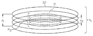
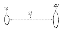
[0015] 전자기계 시스템 및 방법은 예를 들면 방사선 기술에 장점을 제공한다. 전자기는 일반적으로 전류에 대응하는 자기장을 지칭한다. 전류는 자기장의 존재에 의해 전도 재료에서 유도될 수 있다. 자기장은 또한 전도성 재료를 통하여 흐르는 전류의 존재에 의해 유도될 수 있다. 전자기는 다수의 상이한 환경에서 사용될 수 있고, 전자기는 위 내 장치 위치 결정 및 특징화 환경에서 사용될 때 장점을 제공한다.[0015] Electromechanical systems and methods provide advantages, for example, in radiation technology. The electromagnetic generally refers to the magnetic field corresponding to the current. The current can be induced in the conductive material by the presence of a magnetic field. The magnetic field can also be induced by the presence of a current flowing through the conductive material. Electromagnetism can be used in a number of different environments, and electromagnetic offers advantages when used in stomach device localization and characterization environments.
[0016] 전압계 시스템 및 방법은 또한 예를 들면 방사선 기술에 장점을 제공한다. 전압은 하나의 지점의 전위가 다른 지점의 전위와 상이할 때 발생된다. 전압은 다수의 상이한 환경에서 사용될 수 있고, 전압은 위 내 장치 위치 결정 및 특징화 환경에서 사용될 때 장점을 제공한다.[0016] Voltmeter systems and methods also provide advantages for example in radiation technology. Voltage is generated when the potential at one point is different from the potential at another point. The voltage can be used in a number of different environments, and the voltage provides advantages when used in intracorporeal device positioning and characterization environments.
[0017] 미국 특허 제8,858,432호에서는 신호 발생 회로와 통합하는 섭취 마커(ingestible marker)를 개시하며, 이의 내용은 전체가 인용에 의해 본원에 포함된다. 섭취 이벤트 마커 시스템은 섭취 이벤트 마커(IEM) 및 개인 신호 수신기를 포함한다. IEM은 소화관 내부의 목표 부위와 같은 신체의 대상 내부 생리학적 부위와 접촉시 작동되는 생리학적으로 허용가능한 담체와 같은 식별자를 포함한다. 개인 신호 수신기는 생리학적 장소, 예를 들면 신체 상 또는 신체의 내부와 관련되고 IEM 신호를 수신하도록 구성된다. 사용 동안, IEM은 개인 신호 수신기에 의해 수신되는 신호를 송신한다.[0017] U.S. Patent No. 8,858,432 discloses an ingestible marker that integrates with a signal generation circuit, the content of which is incorporated herein by reference in its entirety. The intake event marker system includes an intake event marker (IEM) and a personal signal receiver. The IEM includes an identifier, such as a physiologically acceptable carrier, that is activated upon contact with the internal physiological site of the subject, such as the target site within the digestive tract. A personal signal receiver is configured to receive an IEM signal associated with a physiological location, e.g., a body image or an interior of the body. During use, the IEM transmits the signal received by the personal signal receiver.
[0018] 미국 특허 제 8,836,513호는 소모된 것을 가리키는 섭취 제품을 가지는 시스템을 설명하며, 이의 내용은 전체가 인용에 의해 본원에 포함된다. 상기 시스템은 이종 재료의 형태의 전도성 소자, 전자 컴포넌트 및 부분 전원을 포함한다. 전도성 유체와 접촉할 때, 전위가 생성되고 전원이 완성되어 시스템을 작동시킨다. 전자 컴포넌트는 이종 재료들 사이의 전도성을 제어하여 고유 전류 특성을 형성한다. 상기 시스템은 음식과 관련되어 음식 재료의 소화에 대한 데이터를 리시버로 통신할 수 있다.[0018] U.S. Patent No. 8,836,513 describes a system having an ingested product indicating exhaustion, the content of which is incorporated herein by reference in its entirety. The system includes a conductive element in the form of dissimilar materials, an electronic component, and a partial power supply. When in contact with the conductive fluid, a potential is generated and the power is complete to operate the system. Electronic components control the conductivity between dissimilar materials to form intrinsic current characteristics. The system is capable of communicating data to the receiver about the digestion of the food material in relation to the food.
[0019] 미국 특허 제 8,847, 766호는 약제의 물리적 배달을 위한 시스템을 설명하며, 이의 내용은 전체가 인용에 의해 본원에 포함된다. 상기 시스템은 전도성 신호를 전송하는 식별자 및 이종 재료로 형성된 소모성 전극을 포함한다. 전극은 제 1 및 제 2 전극이 체액과 접촉할 때 식별자를 통전하도록 전압을 생성하고 전도성 신호를 신체에 전송하도록 구성된다.[0019] U.S. Patent No. 8,847,776 describes a system for the physical delivery of a medicament, the content of which is incorporated herein by reference in its entirety. The system includes an identifier for transmitting a conductive signal and a consumable electrode formed of a dissimilar material. The electrode is configured to generate a voltage and to transmit a conductive signal to the body to energize the identifier when the first and second electrodes are in contact with body fluids.
[0020] 초음파계 시스템 및 방법은 또한 예를 들면 방사선 기술에 장점을 제공한다. 초음파는 사람의 청각 범위의 상한보다 더 높은 주파수를 갖는 가진하는 음압파이다. 초음파는 이에 따라 물리적 특성에서의 차이를 기초로 하여 '정상'(가청) 음으로부터 분리되지 않아서 사실상 사람이 초음파를 들을 수 없다. 비록 이러한 한계는 사람마다 변화하지만, 건강하고 ??은 어른에게는 대략 20 kilohertz (20,000 hertz) 이다. 초음파 장치는 20 kHz으로부터 최고 수 기가헤르츠의 주파수로 작동한다.[0020] Ultrasonic systems and methods also provide advantages for example in radiation technology. Ultrasound is a vibrating sound wave with a higher frequency than the upper limit of the human auditory range. Ultrasonic waves are thus not separated from 'normal' (audible) sounds based on differences in physical properties, so virtually no human can hear the ultrasound. Although this limit varies from person to person, it is approximately 20 kilohertz (20,000 hertz) for healthy adults. Ultrasonic devices operate at frequencies from 20 kHz up to several gigahertz.
[0021] 울트라소닉 장치는 대상물을 검출하고 거리를 측정하기 위해 사용될 수 있다. 울트라소닉 영상(소노그래피)은 수의학 및 인간 의학에 모두 사용된다. 제품 및 구조의 비파괴 검사에서, 초음파는 눈에 보이지 않는 결함을 검출하기 위해 사용된다. 산업적으로, 초음파는 세정 및 혼합을 위해 그리고 화학적 공정을 가속하기 위해 사용된다. 박쥐와 돌고래와 같은 동물은 먹이 및 장애물의 위치를 확인하기 위해 초음파를 사용한다.[0021] The ultrasonic device can be used to detect objects and measure distances. Ultrasound imaging (sonography) is used in both veterinary and human medicine. In non-destructive inspection of products and structures, ultrasonic waves are used to detect invisible defects. Industrially, ultrasonic waves are used for cleaning and mixing and to accelerate chemical processes. Animals such as bats and dolphins use ultrasound to locate food and obstacles.
[0022] 울트라소닉(ultrasonics)은 초음파의 적용이다. 초음파는 의료 영상, 검출, 측정 및 세정을 위해 사용될 수 있다. 더 높은 전력 수준에서, 울트라소닉은 물질의 화학적 특성을 변경하기에 유용하다.[0022] Ultrasonics is the application of ultrasound. Ultrasound can be used for medical imaging, detection, measurement and cleaning. At higher power levels, ultrasonics are useful for altering the chemical properties of a material.
[0023] 의료 소노그래피(sonography)(울트라소노그래피)는 실시간 단층 영상으로 근육, 힘줄 및 다수의 내부 장기를 가시화하고 이들의 크기, 구조 및 임의의 병변을 캡쳐(capture)하기 위해 사용된 초음파계 진단 의료 영상화 기술이다. 초음파는 적어도 50년 동안 신체를 영상화하기 위해 방사선 의사 및 소노그래퍼에 의해 사용되어 왔고 진단 툴로서 널리 사용되어 왔다. 상기 기술은 자기 공명 영상 (MRI) 및 컴퓨터 단층 촬영 (CT)과 같은, 다른 기술과 비교할 때, 비교적 저렴하고 휴대가능하다. 초음파는 또한 일상 및 응급 산전 관리 동안 태아를 보기위해 사용된다. 임신 동안 사용된 이 같은 진단 적용 분야는 산부인과 소노그래피로서 지칭된다. 현재 의료 분야에 적용된 바와 같이, 적당히 수행된 초음파는 환자에게 알려진 위험을 제공하지 않는다. 소노그래피는 이온화 방사선을 사용하지 않으며 영상화를 위해 사용된 전력 수준이 너무 낮아서 조직에 가열 또는 압력에 의한 부작용을 일으키지 않는다.Medical sonography (ultrasonography) is an ultrasound system used to visualize muscles, tendons and numerous internal organs in real time tomographic images and to capture their size, structure and any lesions. Diagnostic medical imaging technology. Ultrasound has been used by radiologists and sonographers to image the body for at least 50 years and has been widely used as a diagnostic tool. The technique is relatively inexpensive and portable compared to other techniques, such as magnetic resonance imaging (MRI) and computed tomography (CT). Ultrasound is also used to look at the fetus during routine and emergency antenatal care. These diagnostic applications used during pregnancy are referred to as obstetrical sonograms. As applied in the current medical field, moderately performed ultrasound does not present a known risk to the patient. Sonography does not use ionizing radiation and the power level used for imaging is too low to cause side effects by heating or pressure on the tissue.
[0024] 초음파는 또한 외상 및 응급 처치의 경우에서의 사용이 증가하며, 응급 초음파는 대부분의 EMT 대응 팀의 필수품이 된다. 더욱이, 초음파는 우주에서의 과학적 실험 또는 모바일 스포츠 팀 진단과 같은 원격 상담이 요구되는 원격 진단 경우에서 사용된다. 초음파는 또한 골반 이상의 검출에서 유용하며 복부(경복부) 초음파, 여성에게는 질(경질 또는 질내) 초음파, 및 또한 남성에게는 직장(경직장) 초음파로서 공지된 기술을 포함할 수 있다.[0024] Ultrasonic waves also increase in use in the case of trauma and first aid, and emergency ultrasound is a necessity for most EMT response teams. Moreover, ultrasound is used in remote diagnostic situations where remote consultation is required, such as scientific experiments in the universe or mobile sports team diagnosis. Ultrasound is also useful for detection of pelvic organs and may include techniques known as abdominal (abdominal) ultrasonography, vaginal (hard or vaginal) ultrasonography for women, and rectal (transrectal) ultrasound for men.
[0025] 초음파는 다수의 상이한 환경에서 사용되고, 초음파는 위 내 장치 위치 결정 및 특징화 환경에서 사용될 때 장점을 제공한다.[0025] Ultrasound is used in a number of different environments, and ultrasound offers advantages when used in gastric device localization and characterization environments.
[0026] 의료 영상은 다수의 질병을 진단하기 위해 이용된다. 가장 오래된 방법, 색소 X-선 기술(dye X-ray technology)은 짧은 검사 시간 내에 고해상도 영상을 전달하지만, 이는 환자를 X-선에 노출시키는 단점을 갖는다. 초음파 영상은 방사선을 사용하지 않으면서 작동하는 이미지 습득 방법이다. 상기 초음파 영상으로, 초음파 신호는 초음파 변환기를 통해 검사될 대상으로 송신되고 대응하는 제어 장치는 반사된 초음파 신호를 수신하고 영상화 목적을 위해 수신된 신호를 처리한다.[0026] Medical images are used to diagnose a number of diseases. The oldest method, dye X-ray technology, delivers high-resolution images within short scan times, but it has the disadvantage of exposing the patient to X-rays. Ultrasound imaging is an image acquisition method that works without radiation. With the ultrasound image, the ultrasound signal is transmitted through the ultrasound transducer to the object to be examined, and the corresponding control device receives the reflected ultrasound signal and processes the received signal for imaging purposes.
[0027] 미국 특허 제 8,535,230호는 로봇 팔이 움직일 때 대상을 추적하기 위해 로봇 팔 상에 초음파 변환기를 포함하는 초음파 장치를 설명하며, 이의 내용은 전체가 인용에 의해 본원에 포함된다. 그러나, 이 같은 시스템은 신체 내부의 장치 추적과 호환성이 없다.[0027] U.S. Patent No. 8,535,230 describes an ultrasonic device including an ultrasonic transducer on a robot arm for tracking an object as the robot arm moves, the contents of which are incorporated herein by reference in their entirety. However, such a system is incompatible with internal device tracking.
[0028] 미국 특허 제 8,105,247호는 위 밴딩(banding) 장치의 크기를 측정하기 위해 울트라소닉 송수신기의 사용을 설명하며, 이의 내용은 전체가 인용에 의해 본원에 포함된다. 그러나, 상기 시스템은 고정 위 밴딩 장치를 위한 것이며 위치시키고 특징화하고, 병진 운동시키고, 회전시키고, 변형시키는 위 내 장치에 직접 적용가능하지 않다.[0028] U.S. Patent No. 8,105,247 describes the use of an ultrasonic transceiver to measure the size of a banding device, the contents of which are incorporated herein by reference in their entirety. However, the system is for fixed-bed bending devices and is not directly applicable to stomach devices that position, characterize, translate, rotate, and deform.
[0029] 방사선에 대한 노출을 회피하는 위 내 풍선 장치를 생체 내에 위치시키고 특징화하는 장치 및 방법에 대한 요구가 있다.[0029] There is a need for an apparatus and method for locating and characterizing a stomach balloon device in vivo that avoids exposure to radiation.
[0030] 시간에 대해 용적 및/또는 내압을 미리 결정된 범위 내에서 유지하거나 시간에 대해 용적 및/또는 내압에서의 미리 결정된 조정을 겪는 자유 부동 또는 테터링 위내 용적 점유 장치 또는 장치들이 개시된다. 미리 결정된 용적 및/또는 내압을 유지함으로써, 구조적 일체성에서 틈을 초래하는 장치에 대한 응력이 최소화될 수 있고, 이는 조기 및/또는 제어되지 않은 수축 또는 다른 장치 고장을 방지한다. 시간에 대한 용적 및/또는 내압에서의 미리 결정된 조정을 겪음으로써, 미리 선택된 용적 프로파일은 장치에 대한 처리 도중에 걸쳐 위 크기에서의 변화를 수용하도록 얻어질 수 있다. 상기 장치는 자체 팽창성(또는 자동 팽창이라함) 또는 팽창가능(또는 테터를 통해 수동으로 팽창하는 것이라함)할 수 있다.Disclosed is a free floating or tethering intracavital occupant or device that maintains a volume and / or pressure with respect to time within a predetermined range, or undergoes predetermined adjustments in volume and / or pressure with respect to time. By maintaining a predetermined volume and / or withstanding pressure, the stresses on the device resulting in apertures in structural integrity can be minimized, which prevents premature and / or uncontrolled shrinkage or other device failures. By having undergone predetermined adjustments in volume and / or pressure with respect to time, a preselected volume profile can be obtained to accommodate the change in size over the course of processing for the device. The device may be self-inflatable (or automatically inflated) or inflatable (or manually inflated through a tether).
[0031] 용적 점유 장치 및 이 같은 장치의 제조, 전개, 팽창, 추적, 위치설정, 수축 및 회수를 위한 방법이 제공된다. 바람직한 실시예의 장치 및 방법은 과 중량 및 비만인 개인들에 대한 치료를 위해 사용될 수 있다. 바람직한 실시예의 장치를 사용하는 방법은 수술 절차를 이용할 필요없이, 오히려 상기 장치는 카테터를 부착하거나 부착하지 않고 환자에 의해 간단히 삼켜질 수 있다. 환자의 위 내에 있을 때, 상기 장치는 미리 선택된 유체, 예를 들면 가스, 액체, 증기 또는 이들의 혼합물로 미리 선택된 용적으로 팽창된다. 따라서, 여기서 다양한 실시예를 설명하기 위하여 "가스" 예를 들면 초기 충전 가스와 같은 하나의 유체의 사용은 또한 다른 유체의 사용을 배제하지 않는다. 또한, 초기 충전 유체와 같은 "유체"는 또한 가스 또는 액체와 같은 유체 내에 포함되거나 그 안에 혼합되거나 그 안에서 운반되거나 그렇지 않으면 혼입되는 고체, 액체, 증기, 또는 가스 상태의 재료 또는 재료들을 포함한다. 유체는 본 명세서에서 추가로 설명되는 바와 같이, 하나의 물질, 또는 상이한 물질들의 혼합물을 포함할 수 있고 염수, 생리학적으로 수용가능한 유체 또는 물질 등일 수 있거나 이들을 포함할 수 있다. 상기 장치의 벽은 특별한 유체, 예를 들면 가스 확산 특성에 대해 미리 선택된다. 생체 내 환경에 있을 때, 상기 장치 내에 가스(들)는 장치의 벽을 통하여 확산되고 가스들은 생체 내 환경으로부터 장치 내로 확산한다. 상기 장치를 팽창시키기 위해 초기에 사용된 가스(들) 및 장치 벽을 미리 선택하고, 생체 내 환경으로부터 장치 내로 가스의 확산 특성을 고려함으로써, 상기 장치의 용적 및/또는 내부 압력은 미리 선택된 범위 내에서 유지될 수 있거나 용적 및/또는 압력 변화의 미리 선택된 프로파일을 따를 수 있다. 미리 선택된 시간 기간 후, 상기 장치는 내시경 툴을 사용하여 제거될 수 있거나 용적이 감소하거나 수축되어서 환자의 소화관의 나머지를 통과한다.[0031] A volume occupying apparatus and a method for manufacturing, expanding, expanding, tracking, positioning, shrinking, and recovering such a apparatus are provided. Apparatus and methods of preferred embodiments may be used for treatment of overweight and obese individuals. The method of using the device of the preferred embodiment does not require surgical procedures, but rather the device can be swallowed simply by the patient without attaching or attaching the catheter. When in the stomach, the device is inflated to a preselected volume of preselected fluid, such as gas, liquid, vapor or a mixture thereof. Thus, the use of one fluid such as "gas ", for example an initial charge gas, to illustrate the various embodiments herein does not preclude the use of other fluids. A "fluid ", such as an initial fill fluid, also includes materials or materials in the solid, liquid, vapor, or gaseous state that are contained within, mixed with, or otherwise contained within a fluid such as a gas or liquid. Fluids may include one material, or a mixture of different materials, as described further herein, and may or may not include saline, physiologically acceptable fluids or materials, and the like. The walls of the device are preselected for particular fluids, e.g., gas diffusion properties. When in an in vivo environment, the gas (s) in the device diffuse through the walls of the device and the gases diffuse from the in vivo environment into the device. By pre-selecting the gas (s) and device walls initially used to inflate the device and taking into account the diffusion characteristics of the gas from the in-vivo environment into the device, the volume and / Or may follow a preselected profile of volume and / or pressure variation. After a preselected period of time, the device may be removed using an endoscope tool or the volume may be reduced or contracted to pass through the remainder of the patient's digestive tract.
[0032] 팽창은 환자에 의해 삼켜진 후 초기에 장치와 유체 접촉되어 있는 제거가능한 카테터의 사용에 의해 달성될 수 있다. 대안적으로, 팽창은 자체-팽창 공정, 예를 들면 삼킬 때 장치 내에 포함된 가스 발생 컴포넌트의 반응에 의해 위에 도달할 때 상기 장치 내의 가스의 발생에 의해 또는 제거가능한 카테터의 사용에 의해 가스 발생 공정에서의 하나 이상의 컴포넌트의 장치 내로의 도입에 의해 달성될 수 있다.[0032] Expansion can be accomplished by the use of a removable catheter that is initially in fluid contact with the device after being swallowed by the patient. Alternatively, the expansion can be accomplished by self-expanding processes, for example by the generation of gas in the device when it is reached by the reaction of the gas generating component contained in the device when swallowed, or by the use of a removable catheter, By the introduction of one or more components into the device.
[0033] 장치의 용적 점유 서브컴포넌트는 예를 들면 폴리우레탄, 나일론 또는 폴리에틸렌 테레프탈레이트와 같은 가요성, 가스 불투과성 생체 적합 재료의 주입, 취입 또는 회전 몰딩에 의해 형성될 수 있다. 용적-점유 서브컴포넌트의 가스 투과성/불투과성을 제어하기 위해 사용될 수 있는 재료는 투과성을 감소시키는 것이 바람직할 때 실리콘 산화물(SiOx), 금 또는 다른 귀금속, 사란, 등각 코팅 등을 포함한다. 장치의 벽의 가스-불투과성 특성을 강화하기 위하여, 바람직한 경우, 용적-점유 서브컴포넌트는 하나 이상의 가스-배리어 성분으로 추가 코팅될 수 있거나 가스 불투과성 배리어를 제공하도록 금속화된 표면으로서 마일러 폴리에스테르 필름 코팅, 또는 켈바리트(kelvalite), 은 또는 알루미늄으로 형성될 수 있다.The volume occupying subcomponent of the device may be formed by injection, blowing or rotational molding of a flexible, gas-impermeable biocompatible material such as, for example, polyurethane, nylon or polyethylene terephthalate. Materials that can be used to control the gas permeability / impermeability of volume-occupied subcomponents include silicon oxide (SiOx), gold or other noble metals, saran, conformal coatings, etc., when it is desirable to reduce permeability. In order to enhance the gas-impermeable properties of the walls of the device, if desired, the volume-occupied subcomponent may be additionally coated with one or more gas-barrier components or may be coated with a metallized surface as a metallized surface to provide a gas impermeable barrier An ester film coating, or a kelvalite, silver or aluminum.
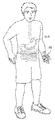
[0034] 추가 실시예에서, 상기 장치는 상기 장치가 환자에게 최소 불편함을 제공하면서 삼켜질 수 있도록 상기 장치가 패키지화된 전달 상태를 이용한다. 전달 상태에서, 상기 장치는 캡슐 내로 패키지화될 수 있다. 대안적으로, 상기 장치는 상기 장치를 한정하고 삼킴이 용이하도록 작용하는 재료로 코팅될 수 있다. 다양한 기술은 또한 예를 들면, 습윤, 온도 처리, 윤활 및 마취제와 같은 제약 처리를 포함하는 장치의 용이한 삼킴을 이용할 수 있다.[0034] In a further embodiment, the device utilizes a packaged delivery state such that the device can be swallowed while providing minimal inconvenience to the patient. In the delivery state, the device may be packaged into a capsule. Alternatively, the device may be coated with a material that serves to confine the device and facilitate swallowing. A variety of techniques may also utilize easy swallowing of the device, including, for example, wetting, temperature treatment, lubrication, and pharmaceutical treatments such as anesthetics.
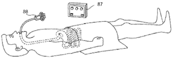
[0035] 상기 장치는 의사가 전자기, 자기, 전압, pH, 및/또는 음파(예를 들면, 울트라소닉) 방법을 사용하여 환자의 신체 내의 장치의 위치, 및/또는 배향 및/또는 상태를 결정하는 것을 가능하게 하는 추적 또는 시각화 컴포넌트 또는 컴포넌트들을 포함한다. 추적 또는 시각화 컴포넌트는 풍선 또는 그의 또는 그 안의 컴포넌트, 또는 그의 또는 그 안의 컴포넌트 또는 풍선에 부가되거나 풍선에 부착되는 부가 컴포넌트, 또는 풍선의 배치를 가리키는 성질을 가지는 부가 컴포넌트일 수 있다.[0035] The device may be used to determine the position, and / or the orientation and / or the state of the device within the patient's body using electromagnetic, magnetic, voltage, pH, and / or sonic (eg, ultrasonics) Lt; RTI ID = 0.0 > components or components. ≪ / RTI > The tracking or visualization component may be an additional component having properties that indicate the placement of a balloon or a component within it, or a component or balloon therein, or an additional component attached to or attached to the balloon.
[0036] 몇몇 실시예에서, 추적하는 서브컴포넌트는 전자기 에너지를 방출하는 재료를 포함할 수 있다. 상기 장치는 상기 장치의 전자기적 성질에 반응하는 상보적 전자기 에너지 센서를 사용하여 추적 및 위치시킬 수 있다. 이 같은 기술은 또한 상기 장치가 환자의 신체 내에 있으면서 소정의 장치 특정 정보 및 사양을 얻기 위해 사용될 수 있고, 이 정보 및 사양은 장치가 환자의 신체 내에서 이동할 때 장치 위치, 배향, 크기 또는 상태를 포함하지만 이에 제한되는 것은 아니다. 신체 외부의 전자기 반응 센서는 내부 장치에 의해 릴레이된 전자기 에너지에 관한 정보를 검출 및 처리할 수 있으며, 이 에너지는 위 내 장치 또는 재료 또는 위 내 장치 내 또는 그 위의 대상물에 대해 반사될 수 있거나 생성될 수 있거나 그렇지 않으면 전파될 수 있다. 이어서 이러한 정보는 장치가 신체 내에 있는 동안 장치의 위치, 배향, 크기 및 다른 속성을 확인하도록 해석될 수 있다. 전자기 시스템은 위 내 장치를 추적하고 위치시키고 특징화하는 간단하고 비 침습적이고 덜 해로운 방법을 제공한다.[0036] In some embodiments, the tracking subcomponent may comprise a material that emits electromagnetic energy. The device can be tracked and positioned using a complementary electromagnetic energy sensor responsive to the electromagnetic properties of the device. Such a technique may also be used to obtain certain device-specific information and specifications while the device is within the patient's body, and the information and specifications may include device location, orientation, size, or condition when the device is moved within the patient's body But are not limited to, An external electromagnetic sensor can detect and process information about electromagnetic energy relayed by an internal device, which energy can be reflected to or within an object in or on a material or stomach device Can be generated or otherwise propagated. This information can then be interpreted to identify the location, orientation, size and other properties of the device while the device is in the body. Electromagnetic systems provide a simple, non-invasive and less deleterious way of tracking, locating and characterizing gastric devices.
[0037] 몇몇 실시예에서, 추적하는 서브컴포넌트는 초음파 또는 다른 음향 에너지에 응답하는 재료를 포함할 수 있다. 상기 장치는 상기 장치의 음향 성질에 반응하는 상보적 초음파 에너지 센서를 사용하여 추적 및 위치시킬 수 있다. 이 같은 기술은 또한 상기 장치가 환자의 신체 내에 있으면서 소정의 장치 특정 정보 및 사양을 얻기 위해 사용될 수 있고, 이 정보 및 사양은 장치가 환자의 신체 내에서 이동할 때 장치 위치, 배향, 크기 또는 상태를 포함하지만 이에 제한되는 것은 아니다. 신체 외부의 음향 반응 센서는 내부 장치에 의해 릴레이된 음향 에너지에 관한 정보를 점출 및 처리할 수 있으며, 이 에너지는 위 내 장치 또는 재료 또는 위 내 장치 내 그 위의 대상물에 대해 반사될 수 있거나 생성될 수 있거나 그렇지 않으면 전파될 수 있다. 이어서 이러한 정보는 장치가 신체 내에 있는 동안 장치의 위치, 배향, 크기 및 다른 속성을 확인하도록 해석될 수 있다. 초음파 시스템은 위 내 장치를 추적하고 위치시키고 특징화하는 간단하고 비 침습적이고 덜 해로운 방법을 제공한다.[0037] In some embodiments, the tracking subcomponent may comprise material that is responsive to ultrasonic or other acoustic energy. The device can be tracked and positioned using a complementary ultrasonic energy sensor responsive to the acoustic properties of the device. Such a technique may also be used to obtain certain device-specific information and specifications while the device is within the patient's body, and the information and specifications may include device location, orientation, size, or condition when the device is moved within the patient's body But are not limited to, The external acoustic response sensor can acquire and process information about the acoustic energy relayed by the internal device and this energy can be reflected or generated for objects in the stomach device or material or stomach device therein Or otherwise propagated. This information can then be interpreted to identify the location, orientation, size and other properties of the device while the device is in the body. Ultrasound systems provide a simple, non-invasive and less deleterious way of tracking, positioning, and characterizing gastric devices.
[0038] 몇몇 실시예에서, 전자기 시스템 또는 이의 부분은 음향 시스템 또는 이의 부분과 조합될 수 있다. 시스템 또는 이의 부분의 조합은 생체 내 위 내 장치를 위치시키고 및/또는 특징화하는 것을 추가로 강화하기 위해 실시될 수 있다.[0038] In some embodiments, the electromagnetic system or portions thereof may be combined with an acoustic system or portions thereof. The system or a combination of portions thereof may be practiced to further enhance positioning and / or characterizing the in vivo gastric device.
[0039] 이 같은 기술은 또한 상기 장치가 환자의 신체 내에 있으면서 소정의 장치 특정 정보 및 사양을 얻기 위해 사용될 수 있고, 이 정보 및 사양은 장치가 환자의 신체 내에서 이동할 때 장치 위치, 배향, 크기 또는 상태를 포함하지만 이에 제한되는 것은 아니다. 자기 반응성 센서, 예를 들면 신체 외부 센서는 내부 장치의 자기장과 관련된 정보를 검출하여 릴레이할 수 있다. 이어서 이러한 정보는 장치가 신체 내에 있는 동안 장치의 위치, 배향, 크기 및 다른 속성을 확인하도록 해석될 수 있다. 자기장 검출 시스템은 위 내 장치를 추적하고 위치시키고 특징화하는 간단하고 비 침습적이고 덜 해로운 방법을 제공한다.[0039] Such techniques may also be used to obtain certain device-specific information and specifications while the device is within the patient's body, and the information and specifications may include device location, orientation, size Or < / RTI > conditions. A self-reactive sensor, for example an external body sensor, can detect and relay information related to the magnetic field of the internal device. This information can then be interpreted to identify the location, orientation, size and other properties of the device while the device is in the body. Magnetic field detection systems provide a simple, non-invasive and less deleterious way of tracking, locating and characterizing gastric devices.
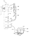
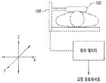
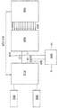
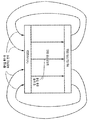
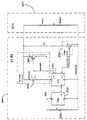
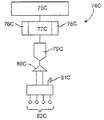
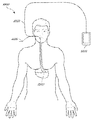
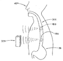
[0040] 제 1 양태에서, 전자기 시스템은 신체 내부에 위 내 장치를 위치시키기 위해 제공되며, 상기 시스템은 전자기장을 형성하도록 구성된 전자기장 발생기; 상기 시스템과 커플링되도록 구성되고 또한 생체 내 위 환경 내에서 전자기장에 노출될 때 전류를 생성하도록 구성되는, 삼킴 가능한 전자기 센서; 및 상기 위 내 장치가 생체 내 위 환경에 있을 때 용적 점유 위 내 장치 내로 초기 충전 유체를 도입하기 위해 구성되고, 상기 위 내 장치와 분리가능하게 커플링되도록 구성된 삼킴 가능한 카테터를 포함하는 밸브 시스템을 가진다.[0040] In a first aspect, an electromagnetic system is provided for positioning a gastric device within a body, the system comprising: an electromagnetic field generator configured to form an electromagnetic field; A swallowable electromagnetic sensor configured to couple with the system and configured to generate current when exposed to an electromagnetic field in an in vivo stomach environment; And a valve system including a swallowable catheter configured to introduce an initial filling fluid into the volume occupying stomach device when the stomach device is in the in vivo stomach environment and configured to be releasably coupled to the stomach device I have.
[0041] 제 1 양태의 일 실시예서, 상기 전자기 센서가 상기 삼킴 가능한 카테터와 커플링하도록 구성된다.[0041] In one embodiment of the first aspect, the electromagnetic sensor is configured to couple with the swallowable catheter.
[0042] 제 1 양태의 일 실시예에서, 상기 전자기 센서가 상기 삼킴 가능한 카테터의 말단부와 커플링하도록 구성된다.[0042] In one embodiment of the first aspect, the electromagnetic sensor is configured to couple with a distal end of the swivable catheter.
[0043] 제 1 양태의 일 실시예에서, 상기 전자기 센서가 상기 위 내 장치와 커플링하도록 구성된다.[0043] In an embodiment of the first aspect, the electromagnetic sensor is configured to couple with the stomach device.
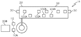
[0044] 제 1 양태의 일 실시예에서, 상기 시스템은 상기 신체 외부에 배치되고 자기장에 노출될 때 전류를 생성하도록 구성된 적어도 하나의 외부 기준 센서를 더 포함한다.[0044] In an embodiment of the first aspect, the system further comprises at least one external reference sensor disposed outside the body and configured to generate current when exposed to a magnetic field.
[0045] 제 1 양태의 일 실시예에서, 상기 시스템은 상기 신체 외부에 배치되고 자기장에 노출될 때 전류를 생성하도록 구성된 3개의 외부 기준 센서를 더 포함한다.[0045] In an embodiment of the first aspect, the system further comprises three external reference sensors disposed outside the body and configured to generate current when exposed to a magnetic field.
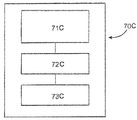
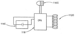
[0046] 제 1 양태의 일 실시예에서, 상기 시스템은 상기 전자기 센서 및 상기 적어도 하나의 외부 기준 센서와 전기적으로 연결되도록 구성된 센서 인터페이스 유닛을 더 포함한다.[0046] In an embodiment of the first aspect, the system further comprises a sensor interface unit configured to be electrically connected to the electromagnetic sensor and the at least one external reference sensor.
[0047] 제 1 양태의 일 실시예에서, 상기 시스템은 상기 센서 인터페이스 유닛 및 상기 전자기장 발생기와 전기적으로 연결되도록 구성된 시스템 제어 유닛을 더 포함한다.[0047] In an embodiment of the first aspect, the system further comprises a system control unit configured to be electrically connected to the sensor interface unit and the electromagnetic field generator.
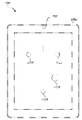
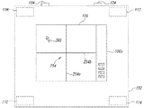
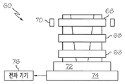
[0048] 제 1 양태의 일 실시예에서, 상기 시스템은 상기 시스템 제어 유닛과 전기적으로 연결되고 상기 신체 내부의 상기 전자기 센서의 위치를 가리키는 식별자를 디스플레이하도록 구성된 컴퓨터를 더 포함한다.[0048] In an embodiment of the first aspect, the system further comprises a computer electrically connected to the system control unit and configured to display an identifier indicating the location of the electromagnetic sensor within the body.
[0049] 제 1 양태의 일 실시예에서, 상기 시스템은 상기 신체 외부에 배치되고 상기 자기장에 노출될 때 전류를 생성하도록 구성된 적어도 하나의 외부 기준 센서를 더 포함하며, 상기 컴퓨터는 상기 적어도 하나의 외부 기준 센서의 위치를 가리키는 적어도 하나의 제 2 식별자를 디스플레이하도록 추가로 구성된다.[0049] In an embodiment of the first aspect, the system further comprises at least one external reference sensor disposed outside the body and configured to generate a current when exposed to the magnetic field, And to display at least one second identifier indicating the location of the external reference sensor.
[0050] 제 1 양태의 일 실시예에서, 상기 컴퓨터는 상기 신체의 내부에서 상기 전자기 센서에 의해 경유되는 경로를 가리키는 트레이스를 디스플레이하도록 추가로 구성된다.[0050] In an embodiment of the first aspect, the computer is further configured to display a trace indicative of a path through the electromagnetic sensor within the body.
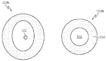
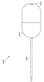
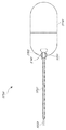
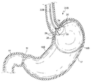
[0051] 제 1 양태의 일 실시예에서, 상기 시스템은 상기 위 내 장치를 더 포함하고, 상기 위 내 장치는 풍선이다.[0051] In an embodiment of the first aspect, the system further comprises the gastric device, wherein the gastric device is a balloon.
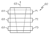
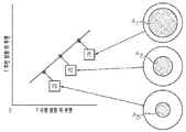
[0052] 제 1 양태의 일 실시예에서, 상기 시스템은 상기 초기 충전 유체를 더 포함하며, 상기 위 내 장치는 생체 내 위 환경의 상태 하에서, 10 cc/m2/day 초과의 CO2에 대한 투과성을 가지도록 구성된 폴리메릭 벽을 포함하여, 상기 폴리메릭 벽을 통하여 상기 생체 내 위 환경으로부터 상기 위 내 장치의 루멘으로 CO2의 확산 속도 및 양이 상기 초기 충전 유체 내의 불활성 가스의 농도에 의해 적어도 부분적으로 제어된다.[0052] In an embodiment of the first aspect, the system further comprises the initial filling fluid, wherein the stomach device is configured for a CO 2 of greater than 10 cc / m 2 / day Wherein the diffusion rate and amount of CO 2 from the in-vivo gastric environment through the polymeric wall to the lumen of the stomach device is greater than the concentration and concentration of inert gas in the initial filling fluid At least partially.
[0053] 제 1 양태의 일 실시예에서, 상기 폴리메릭 벽은 에틸렌 비닐 알콜 층을 포함하는 CO2 배리어 재료를 포함한다.[0053] In one embodiment of the first aspect, the polymeric wall comprises a CO 2 barrier material comprising an ethylene vinyl alcohol layer.
[0054] 제 1 양태의 일 실시예에서, 상기 폴리메릭 벽은 나일론 층 및 폴리에틸렌 층을 포함하는 CO2 배리어 재료의 두 개의 층을 포함한다.[0054] In one embodiment of the first aspect, the polymeric wall comprises two layers of CO 2 barrier material comprising a nylon layer and a polyethylene layer.
[0055] 제 1 양태의 일 실시예에서, 상기 폴리메릭 벽은 나일론 층, 폴리비닐리덴 클로라이드 층, 및 폴리에틸렌 층을 포함하는 세 개의 층의 CO2 배리어 재료를 포함한다.[0055] In one embodiment of the first aspect, the polymeric wall comprises three layers of CO 2 barrier material comprising a nylon layer, a polyvinylidene chloride layer, and a polyethylene layer.
[0056] 제 1 양태의 일 실시예에서, 상기 폴리메릭 벽은 나일론 층, 에틸렌 비닐 알콜 층, 및 폴리에틸렌 층을 포함하는 세 개의 층의 CO2 배리어 재료를 포함한다.[0056] In one embodiment of the first aspect, the polymeric wall comprises three layers of CO 2 barrier material comprising a nylon layer, an ethylene vinyl alcohol layer, and a polyethylene layer.
[0057] 제 1 양태의 일 실시예에서, 상기 초기 충전 유체는 가스 상태의 N2를 필수 구성으로 한다.[0057] In one embodiment of the first aspect, the initial filling fluid has N 2 in gaseous form as an essential constituent.
[0058] 제 1 양태의 일 실시예에서, 상기 초기 충전 유체는 기상 N2 및 기상 CO2를 필수 구성으로 한다.[0058] In one embodiment of the first aspect, the initial filling fluid has gaseous N 2 and gaseous CO 2 as essential constituents.
[0059] 제 1 양태의 일 실시예에서, 상기 초기 충전 유체는 기상 N2 및 기상 CO2를 필수 구성으로 하고, 상기 기상 N2는 상기 초기 충전 유체에서 상기 기상 CO2에 대한 농도가 초과한다.[0059] In an embodiment of the first aspect, the initial filling fluid comprises gaseous N 2 and gaseous CO 2 , wherein the gaseous phase N 2 exceeds the concentration for the gaseous CO 2 in the initial filling fluid .
[0060] 제 1 양태의 일 실시예에서, 상기 초기 충전 유체는 액체 형태, 증기 형태, 또는 기상 형태 중 하나 이상에서 SF6을 포함한다.[0060] In an embodiment of the first aspect, the initial filling fluid comprises SF 6 in at least one of a liquid form, a vapor form, or a vapor form.
[0061] 제 1 양태의 일 실시예에서, 상기 초기 충전 유체는 기상 N2 및 기상 SF6를 포함한다.[0061] In one embodiment of the first aspect, the initial filling fluid comprises gaseous N 2 and gaseous SF 6 .
[0062] 제 1 양태의 일 실시예에서, 상기 폴리메릭 벽은 생체 내 위 환경의 상태 하에서, 50 cc/m2/day 초과의 CO2에 대한 투과성을 갖도록 구성된다.[0062] In one embodiment of the first aspect, the polymeric wall is configured to have a permeability to CO 2 of greater than 50 cc / m 2 / day under the condition of the gastric environment in vivo.
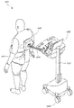
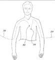
[0063] 제 2 양태에서, 환자의 신체 내부에 위 내 장치를 전자기에 의해 위치시키는 방법이 제공되며, 상기 방법은 상기 환자의 신체의 외부에 위치된 전자기장 발생기로 전자기장을 발생시키는 단계; 삼켜서 환자의 신체 내로 도입하는 단계로서, 상기 위 내 장치는, 팽창되지 않은 위 풍선을 포함하며, 상기 위 내 장치는 카테터와 해제 가능하게 커플링되고 전자기 센서와 커플링되고, 상기 전자기 센서는 상기 자기장 발생기에 의해 발생된 전자기장의 존재시 전류를 생성하도록 구성된, 단계; 상기 전자기장에 의해 상기 전자기 센서에 유도된 전류를 감지하는 단계; 및 상기 전자기 센서에서 도입된 전류의 감지를 기초로 하여 상기 환자 내측의 팽창되지 않은 위 풍선의 위치를 확인하는 단계를 포함한다.[0063] In a second aspect, there is provided a method of electromagnetically positioning a gastric device within a patient's body, the method comprising: generating an electromagnetic field with an electromagnetic field generator positioned external to the patient's body; Wherein the gastric device comprises a non-inflated upper balloon, the gastric device releasably coupled to the catheter and coupled with an electromagnetic sensor, the electromagnetic sensor comprising: And to generate a current in the presence of the electromagnetic field generated by the magnetic field generator; Sensing an electric current induced in the electromagnetic sensor by the electromagnetic field; And confirming the position of the inflated upper balloon on the inside of the patient based on sensing of the current introduced from the electromagnetic sensor.
[0064] 제 2 양태의 일 실시예에 있어서, 상기 환자 내측의 상기 팽창되지 않은 위 풍선의 위치는 환자의 위장이다.[0064] In one embodiment of the second aspect, the position of the inflated upper balloon on the inside of the patient is the stomach of the patient.
[0065] 제 2 양태의 일 실시예에 있어서, 상기 방법은 상기 초기 충전 유체를 카테터를 통하여 팽창되지 않은 위 풍선의 루멘 내로 도입하는 단계, 상기 위 내 풍선은 생체 내 위 환경의 상태 하에서, 10 cc/m2/day 초과의 CO2에 대한 투과성을 가지도록 구성된 폴리메릭 벽을 포함하는 단계, 및 30일 이상의 유효 수명을 위해 상기 팽창된 위 내 풍선을 생체 내 위 내 환경에 노출시키는 단계로서, 상기 폴리메릭 벽을 통하여 상기 생체 내 위 환경으로부터 상기 풍선의 루멘으로 CO2의 확산 속도 및 양이 상기 초기 충전 유체 내의 불활성 가스의 농도에 의해 적어도 부분적으로 제어되는 단계를 더 포함한다.[0065] In one embodiment of the second aspect, the method further comprises introducing the initial filling fluid into a lumen of an inflated upper balloon through a catheter, comprising a polymeric wall configured to have permeability to CO 2 in excess of cc / m 2 / day, and exposing the expanded gastric balloon to an in vivo gastrointestinal environment for an effective lifetime of 30 days or more , Wherein the rate and amount of CO 2 diffusion from the in-vivo gastric environment through the polymeric wall to the lumen of the balloon is at least partially controlled by the concentration of inert gas in the initial filling fluid.
[0066] 제 2 양태의 일 실시예에 있어서, 상기 폴리메릭 벽은 나일론 층, 폴리비닐리덴 클로라이드 층 및 폴리에틸렌 층을 포함하는 세 개의 층의 CO2 배리어 재료를 포함한다.[0066] In one embodiment of the second aspect, the polymeric wall comprises three layers of CO 2 barrier material comprising a nylon layer, a polyvinylidene chloride layer and a polyethylene layer.
[0067] 제 2 양태의 일 실시예에 있어서, 상기 폴리메릭 벽은 나일론 층, 에틸렌 비닐 알콜 층, 및 폴리에틸렌 층을 포함하는 세 개의 층의 CO2 배리어 재료를 포함한다.[0067] In one embodiment of the second aspect, the polymeric wall comprises three layers of CO 2 barrier material comprising a nylon layer, an ethylene vinyl alcohol layer, and a polyethylene layer.
[0068] 제 2 양태의 일 실시예에 있어서, 상기 폴리메릭 벽은 나일론 층 및 폴리에틸렌 층을 포함하는 CO2 배리어 재료의 두 개의 층을 포함한다.[0068] In one embodiment of the second aspect, the polymeric wall comprises two layers of CO 2 barrier material comprising a nylon layer and a polyethylene layer.
[0069] 제 2 양태의 일 실시예에 있어서, 상기 폴리메릭 벽은 에틸렌 비닐 알콜 층을 포함하는 CO2 배리어 재료를 포함한다.[0069] In one embodiment of the second aspect, the polymeric wall comprises a CO 2 barrier material comprising an ethylene vinyl alcohol layer.
[0070] 제 2 양태의 일 실시예에서, 상기 초기 충전 유체는 기상 N2를 필수 구성으로 한다.[0070] In one embodiment of the second aspect, the initial filling fluid has gaseous N 2 as an essential constituent.
[0071] 제 2 양태의 일 실시예에서, 상기 제 1 가스는 기상 N2 및 기상 CO2를 필수 구성으로 한다.[0071] In one embodiment of the second aspect, the first gas has gaseous N 2 and gaseous CO 2 as essential constituents.
[0072] 제 2 양태의 일 실시예에서, 상기 제 1 가스는 기상 N2 및 기상 CO2를 필수 구성으로 하고, 상기 기상 N2는 상기 제 1 가스에서 상기 기상 CO2에 대한 농도가 초과한다.[0072] In one embodiment of the second aspect, the first gas comprises gaseous N 2 and gaseous CO 2 , and the gaseous phase N 2 exceeds the concentration for the gaseous CO 2 in the first gas .
[0073] 제 2 양태의 일 실시예에서, 상기 제 1 가스는 액체 형태, 증기 형태, 또는 기상 형태 중 하나 이상에서 SF6을 포함한다.[0073] In an embodiment of the second aspect, the first gas comprises SF 6 in at least one of a liquid form, a vapor form, or a vapor form.
[0074] 제 2 양태의 일 실시예에서, 상기 제 1 가스는 기상 N2 및 기상 SF6를 포함한다.[0074] In one embodiment of the second aspect, the first gas includes gaseous N 2 and gaseous SF 6 .
[0075] 제 2 양태의 일 실시예에서, 상기 폴리메릭 벽은 생체 내 위 환경의 상태 하에서, 50 cc/m2/day 초과의 CO2에 대한 투과성을 갖도록 구성된다.[0075] In an embodiment of the second aspect, the polymeric wall is configured to have a permeability to CO 2 of greater than 50 cc / m 2 / day under conditions of the gastric environment in vivo.
[0076] 제 2 양태의 일 실시예에서, 상기 전자기 센서에서 도입된 전류의 감지를 기초로 하여 상기 환자 내측의 팽창되지 않은 위 풍선의 위치를 확인하는 단계는 상기 전자기 센서의 위치를 가리키는 식별자를 컴퓨터 상에 디스플레이하는 단계를 포함한다.[0076] In an embodiment of the second aspect, the step of confirming the position of the inflated upper balloon on the inside of the patient based on the sensing of the current introduced from the electromagnetic sensor comprises the step of: And displaying on the computer.
[0077] 제 2 양태의 일 실시예에서, 상기 방법은 상기 환자의 신체 외부에 적어도 하나의 외부 기준 센서를 배치하는 단계로서, 상기 적어도 하나의 외부 기준 센서는 상기 젼자기장에 노출될 때 전류를 생산하도록 구성되는, 단계, 및 상기 전자기장에 의해 적어도 하나의 외부 기준 센서에서 유도되는 전류를 감지하는 단계를 더 포함한다.[0077] In an embodiment of the second aspect, the method further comprises the step of disposing at least one external reference sensor outside the body of the patient, the at least one external reference sensor having a current The method further comprising the step of sensing a current induced in the at least one external reference sensor by the electromagnetic field.
[0078] 제 2 양태의 일 실시예에서, 상기 전자기 센서에서 도입된 전류의 감지를 기초로 하여 상기 환자 내측의 팽창되지 않은 위 풍선의 위치를 확인하는 단계는 상기 적어도 하나의 외부 기준 센서의 위치를 가리키는 적어도 하나의 제 2 식별자를 컴퓨터 상에 디스플레이하는 단계를 포함한다.[0078] In an embodiment of the second aspect, the step of confirming the position of the inflated upper balloon on the inside of the patient based on the sensing of the current introduced in the electromagnetic sensor comprises the step of determining the position of the at least one external reference sensor And displaying the at least one second identifier on the computer.
[0079] 제 2 양태의 일 실시예에서, 상기 전자기 센서가 상기 카테터와 커플링된다.[0079] In an embodiment of the second aspect, the electromagnetic sensor is coupled with the catheter.
[0080] 제 2 양태의 일 실시예에서, 상기 전자기 센서가 상기 위 내 장치와 커플링된다.[0080] In one embodiment of the second aspect, the electromagnetic sensor is coupled with the stomach device.
[0081] 제 3 양태에서, 신체 내부에 위 내 장치를 위치시키기 위한 자기 시스템이 제공되며, 상기 시스템은 자기장을 감지하도록 구성된 자기장 센서; 상기 시스템과 커플링되도록 구성되고 또한 생체 내 위 환경 내에서 국부적 자기장을 생성하도록 구성된, 삼킴가능한 자기 마커를 생성하도록 구성되는, 삼킴 가능한 자기 센서; 및 상기 위 내 장치가 생체 내 위 환경에 있을 때 용적 점유 위 내 장치 내로 초기 충전 유체를 도입하기 위해 구성되고, 상기 위 내 장치와 분리가능하게 커플링되도록 구성된 삼킴 가능한 카테터를 포함하는 밸브 시스템을 가진다.[0081] In a third aspect, there is provided a magnetic system for positioning a gastric device within a body, the system comprising: a magnetic field sensor configured to sense a magnetic field; A swallowable magnetic sensor configured to couple with the system and configured to generate a swallowable magnetic marker configured to generate a local magnetic field in the stomach environment in vivo; And a valve system including a swallowable catheter configured to introduce an initial filling fluid into the volume occupying stomach device when the stomach device is in the in vivo stomach environment and configured to be releasably coupled to the stomach device I have.
[0082] 제 3 양태의 일 실시예에서, 상기 자기 마커가 상기 삼킴 가능한 카테터와 커플링하도록 구성된다.[0082] In an embodiment of the third aspect, the magnetic marker is configured to couple with the swallowable catheter.
[0083] 제 3 양태의 일 실시예에서, 상기 자기 마커가 상기 삼킴 가능한 카테터의 말단부와 커플링하도록 구성된다.[0083] In an embodiment of the third aspect, the magnetic marker is configured to couple with the distal end of the swallowable catheter.
[0084] 제 3 양태의 일 실시예에서, 상기 자기 마커가 상기 위 내 장치와 커플링하도록 구성된다.[0084] In an embodiment of the third aspect, the magnetic marker is configured to couple with the stomach device.
[0085] 제 3 양태의 일 실시예에서, 상기 시스템은 상기 신체 외부에 배치되고 국부적 자기장을 감지하도록 구성된 적어도 하나의 외부 기준 센서를 더 포함한다.[0085] In an embodiment of the third aspect, the system further comprises at least one external reference sensor disposed outside the body and configured to sense a local magnetic field.
[0086] 제 3 양태의 일 실시예에서, 상기 시스템은 상기 자기 마커와 전기적으로 연결되도록 구성된 센서 인터페이스 유닛을 더 포함한다.[0086] In an embodiment of the third aspect, the system further comprises a sensor interface unit configured to be electrically connected to the magnetic marker.
[0087] 제 3 양태의 일 실시예에서, 상기 시스템은 상기 센서 인터페이스 유닛 및 상기 자기장 센서와 전기적으로 연결되도록 구성된 시스템 제어 유닛을 더 포함한다.[0087] In an embodiment of the third aspect, the system further includes a system control unit configured to be electrically connected to the sensor interface unit and the magnetic field sensor.
[0088] 제 3 양태의 일 실시예에서, 상기 시스템은 상기 시스템 제어 유닛과 전기적으로 연결되고 상기 신체 내부의 상기 자기 마커의 위치를 가리키는 식별자를 디스플레이하도록 구성된 컴퓨터를 더 포함한다.[0088] In an embodiment of the third aspect, the system further comprises a computer electrically connected to the system control unit and configured to display an identifier indicative of the position of the magnetic marker within the body.
[0089] 제 3 양태의 일 실시예에서, 상기 컴퓨터는 상기 신체의 내부에서 상기 자기 마커에 의해 경유되는 경로를 가리키는 트레이스를 디스플레이하도록 추가로 구성된다.[0089] In an embodiment of the third aspect, the computer is further configured to display a trace indicating a path through the magnetic marker within the body.
[0090] 제 3 양태의 일 실시예에서, 상기 시스템은 상기 위 내 장치를 더 포함하고, 상기 위 내 장치는 풍선이다.[0090] In an embodiment of the third aspect, the system further comprises the gastric device, wherein the gastric device is a balloon.
[0091] 제 3 양태의 일 실시예에서, 상기 시스템은 상기 초기 충전 유체를 더 포함하며, 상기 위 내 장치는 생체 내 위 환경의 상태 하에서, 10 cc/m2/day 초과의 CO2에 대한 투과성을 가지도록 구성된 폴리메릭 벽을 포함하여, 상기 폴리메릭 벽을 통하여 상기 생체 내 위 환경으로부터 상기 위 내 장치의 루멘으로 CO2의 확산 속도 및 양이 상기 초기 충전 유체 내의 불활성 가스의 농도에 의해 적어도 부분적으로 제어된다.[0091] In an embodiment of the third aspect, the system further comprises the initial filling fluid, wherein the stomach device is configured for a CO 2 of greater than 10 cc / m 2 / day Wherein the diffusion rate and amount of CO 2 from the in-vivo gastric environment through the polymeric wall to the lumen of the stomach device is greater than the concentration and concentration of inert gas in the initial filling fluid At least partially.
[0092] 제 3 양태의 일 실시예에서, 상기 폴리메릭 벽은 에틸렌 비닐 알콜 층을 포함하는 CO2 배리어 재료를 포함한다.[0092] In one embodiment of the third aspect, the polymeric wall comprises a CO 2 barrier material comprising an ethylene vinyl alcohol layer.
[0093] 제 3 양태의 일 실시예에서, 상기 폴리메릭 벽은 나일론 층 및 폴리에틸렌 층을 포함하는 CO2 배리어 재료의 두 개의 층을 포함한다.[0093] In one embodiment of the third aspect, the polymeric wall comprises two layers of CO 2 barrier material comprising a nylon layer and a polyethylene layer.
[0094] 제 3 양태의 일 실시예에서, 상기 폴리메릭 벽은 나일론 층, 폴리비닐리덴 클로라이드 층, 및 폴리에틸렌 층을 포함하는 세 개의 층의 CO2 배리어 재료를 포함한다.[0094] In one embodiment of the third aspect, the polymeric wall comprises three layers of CO 2 barrier material comprising a nylon layer, a polyvinylidene chloride layer, and a polyethylene layer.
[0095] 제 3 양태의 일 실시예에서, 상기 폴리메릭 벽은 나일론 층, 에틸렌 비닐 알콜 층, 및 폴리에틸렌 층을 포함하는 세 개의 층의 CO2 배리어 재료를 포함한다.[0095] In one embodiment of the third aspect, the polymeric wall comprises three layers of CO 2 barrier material comprising a nylon layer, an ethylene vinyl alcohol layer, and a polyethylene layer.
[0096] 제 3 양태의 일 실시예에서, 상기 초기 충전 유체는 기상 N2를 필수 구성으로 한다.[0096] In one embodiment of the third aspect, the initial filling fluid has gaseous N 2 as an essential constituent.
[0097] 제 3 양태의 일 실시예에서, 상기 초기 충전 유체는 기상 N2 및 기상 CO2를 필수 구성으로 한다.[0097] In one embodiment of the third aspect, the initial filling fluid has gaseous N 2 and gaseous CO 2 as essential constituents.
[0098] 제 3 양태의 일 실시예에서, 상기 초기 충전 유체는 기상 N2 및 기상 CO2를 필수 구성으로 하고, 상기 기상 N2는 상기 초기 충전 유체에서 상기 기상 CO2에 대한 농도가 초과한다.[0098] In an embodiment of the third aspect, the initial filling fluid comprises gaseous N 2 and gaseous CO 2 , wherein the gaseous phase N 2 exceeds the concentration for the gaseous CO 2 in the initial filling fluid .
[0099] 제 3 양태의 일 실시예에서, 상기 초기 충전 유체는 액체 형태, 증기 형태, 또는 기상 형태 중 하나 이상에서 SF6을 포함한다.[0099] In one embodiment of the third aspect, the initial filling fluid comprises SF 6 in at least one of a liquid form, a vapor form, or a vapor form.
[0100] 제 3 양태의 일 실시예에서, 상기 초기 충전 유체는 기상 N2 및 기상 SF6를 포함한다.[0100] In one embodiment of the third aspect, the initial filling fluid comprises gaseous N 2 and gaseous SF 6 .
[0101] 제 3 양태의 일 실시예에서, 상기 폴리메릭 벽은 생체 내 위 환경의 상태 하에서, 50 cc/m2/day 초과의 CO2에 대한 투과성을 갖도록 구성된다.[0101] In one embodiment of the third aspect, the polymeric wall is configured to have a permeability to CO 2 of greater than 50 cc / m 2 / day under conditions of the gastric environment in vivo.
[0102] 제 4 양태에서, 환자의 신체 내부에 위 내 장치를 자기에 의해 위치시키는 방법이 제공되며, 상기 방법은 삼켜서 환자의 신체 내로 도입하는 단계로서, 상기 위 내 장치는, 팽창되지 않은 위 내 풍선을 포함하며, 상기 위 내 장치는 카테터와 해제 가능하게 커플링되고 자기 마커와 커플링되고, 상기 자기 마커는 상기 자기장 센서에 의해 감지되도록 구성된, 단계; 상기 자기장 센서에 의해 상기 자기장을 감지하는 단계; 및 상기 자기장 감지를 기초로 하여 상기 환자 내의 팽창되지 않은 위 내 풍선의 위치를 확인하는 단계를 포함한다.[0102] In a fourth aspect, there is provided a method of magnetically positioning a gastric device within a patient's body, the method comprising swallowing into a patient's body, the gastric device comprising an inflated The stomach device releasably coupled to the catheter and coupled with the magnetic marker, the magnetic marker configured to be sensed by the magnetic field sensor; Sensing the magnetic field by the magnetic field sensor; And identifying the position of the inflated stomach inflation balloon in the patient based on the magnetic field sensing.
[0103] 제 4 양태의 일 실시예에서, 상기 환자 내측의 상기 팽창되지 않은 위 풍선의 위치는 환자의 위장이다.[0103] In an embodiment of the fourth aspect, the position of the inflated gastric balloon inside the patient is the patient's stomach.
[0104] 제 4 양태의 일 실시예에서, 상기 방법은 상기 카테터를 통하여 상기 팽창되지 않은 위 내 풍선의 루멘 내로 초기 충전 유체를 도입하는 단계로서, 상기 위 내 풍선은 생체 내 위 환경의 상태 하에서, 10 cc/m2/day 초과의 CO2에 대한 투과성을 가지도록 구성된 폴리메릭 벽을 포함하는, 단계; 및 상기 팽창되지 않은 위 내 풍선을 적어도 30일 이상의 유효 수명 동안 생체 내 위 내 환경에 노출시키는 단계로서, 상기 폴리메릭 벽을 통하여 상기 생체 내 위 내 환경으로부터 상기 풍선의 루멘 내로 CO2의 확산의 속도 및 양이 초기 충전 유체 내의 불활성 가스의 농도에 의해 적어도 부분적으로 제어되는, 단계를 더 포함한다.[0104] In an embodiment of the fourth aspect, the method further comprises introducing an initial fill fluid into the lumen of the inflated upper inflat balloon through the catheter, wherein the inflatable balloon is inflated , A polymeric wall configured to have permeability to CO 2 in excess of 10 cc / m 2 / day; And exposing the uninflated stomach inflating balloon to an in vivo gastrointestinal environment for an effective lifetime of at least 30 days, wherein the diffusion of CO 2 into the lumen of the balloon from the in vivo gastrointestinal environment through the polymeric wall The rate and amount being at least partially controlled by the concentration of the inert gas in the initial fill fluid.
[0105] 제 4 양태의 일 실시예에서, 상기 폴리메릭 벽은 나일론 층 폴리비닐리덴 클로라이드 층, 및 폴리에틸렌 층을 포함하는 세 개의 층의 CO2 배리어 재료를 포함한다.[0105] In one embodiment of the fourth aspect, the polymeric wall comprises a three layer CO 2 barrier material comprising a nylon layer polyvinylidene chloride layer and a polyethylene layer.
[0106] 제 4 양태의 일 실시예에서, 상기 폴리메릭 벽은 나일론 층, 에틸렌 비닐 알콜 층, 및 폴리에틸렌 층을 포함하는 세 개의 층의 CO2 배리어 재료를 포함한다.[0106] In one embodiment of the fourth aspect, the polymeric wall comprises three layers of CO 2 barrier material comprising a nylon layer, an ethylene vinyl alcohol layer, and a polyethylene layer.
[0107] 제 4 양태의 일 실시예에서, 상기 폴리메릭 벽은 나일론 층 및 폴리에틸렌 층을 포함하는 CO2 배리어 재료의 두 개의 층을 포함한다.[0107] In one embodiment of the fourth aspect, the polymeric wall comprises two layers of CO 2 barrier material comprising a nylon layer and a polyethylene layer.
[0108] 제 4 양태의 일 실시예에서, 상기 폴리메릭 벽은 에틸렌 비닐 알콜 층을 포함하는 CO2 배리어 재료를 포함한다.[0108] In one embodiment of the fourth aspect, the polymeric wall comprises a CO 2 barrier material comprising an ethylene vinyl alcohol layer.
[0109] 제 4 양태의 일 실시예에서, 상기 초기 충전 유체는 기상 N2를 필수 구성으로 한다.[0109] In one embodiment of the fourth aspect, the initial filling fluid has gaseous N 2 as an essential constituent.
[0110] 제 4 양태의 일 실시예에서, 상기 제 1 가스는 기상 N2 및 기상 CO2를 필수 구성으로 한다.[0110] In one embodiment of the fourth aspect, the first gas has gaseous N 2 and gaseous CO 2 as essential constituents.
[0111] 제 4 양태의 일 실시예에서, 상기 초기 충전 유체는 기상 N2 및 기상 CO2를 필수 구성으로 하고, 상기 기상 N2는 상기 초기 충전 유체에서 상기 기상 CO2에 대한 농도가 초과한다.[0111] In an embodiment of the fourth aspect, the initial filling fluid comprises gaseous N 2 and gaseous CO 2 , and the gaseous phase N 2 exceeds the concentration for the gaseous CO 2 in the initial filling fluid .
[0112] 제 4 양태의 일 실시예에서, 상기 초기 충전 유체는 액체 형태, 증기 형태, 또는 기상 형태 중 하나 이상에서 SF6을 포함한다.In one embodiment of the fourth aspect, the initial filling fluid comprises SF 6 in at least one of a liquid form, a vapor form, or a vapor form.
[0113] 제 4 양태의 일 실시예에서, 상기 초기 충전 유체는 기상 N2 및 기상 SF6를 포함한다.[0113] In one embodiment of the fourth aspect, the initial filling fluid comprises gaseous N 2 and gaseous SF 6 .
[0114] 제 4 양태의 일 실시예에서, 상기 폴리메릭 벽은 생체 내 위 환경의 상태 하에서, 50 cc/m2/day 초과의 CO2에 대한 투과성을 갖도록 구성된다.[0114] In one embodiment of the fourth aspect, the polymeric wall is configured to have a permeability to CO 2 of greater than 50 cc / m 2 / day under the condition of the gastric environment in vivo.
[0115] 제 4 양태의 일 실시예에서, 상기 자기 마커에 의해 발생된 자기장 감지를 기초로 하여 상기 환자 내측의 팽창되지 않은 위 풍선의 위치를 확인하는 단계는 상기 자기 마커의 위치를 가리키는 식별자를 컴퓨터 상에 디스플레이하는 단계를 포함한다.[0115] In an embodiment of the fourth aspect, the step of identifying the position of the inflated upper balloon on the inside of the patient based on the magnetic field sensing generated by the magnetic marker comprises the step of: And displaying on the computer.
[0116] 제 4 양태의 일 실시예에서, 상기 자기 마커가 상기 카테터와 커플링된다.[0116] In an embodiment of the fourth aspect, the magnetic marker is coupled with the catheter.
[0117] 제 4 양태의 일 실시예에서, 상기 전자기 센서가 상기 위 내 장치와 커플링된다.[0117] In an embodiment of the fourth aspect, the electromagnetic sensor is coupled with the stomach device.
[0118] 제 5 양태에서, 신체 내부에 위 내 장치를 위치시키기 위한 볼타 시스템이 제공되며, 상기 시스템과 커플링되도록 구성되고 생체 내 위 환경 내에서 전압을 생성하도록 추가로 구성되는, 삼킬 수 있는 볼타 센서(voltaic sensor); 및 상기 위 내 장치가 생체 내 위 환경에 있을 때 용적 점유 위 내 장치 내로 초기 충전 유체를 도입하기 위해 구성되고, 상기 위 내 장치와 해제 가능하게 커플링되도록 구성된 삼킴 가능한 카테터를 포함하는 밸브 시스템을 가진다.[0118] In a fifth aspect, there is provided a bolt system for positioning an intragastric device within a body, the device being configured to couple with the system and further configured to generate a voltage in the in-vivo environment, A voltaic sensor; And a valve system configured to introduce an initial fill fluid into the volume occupying stomach when the stomach apparatus is in the in vivo stomach environment and configured to be releasably coupled with the stomach apparatus, I have.
[0119] 제 5 양태의 일 실시예에서, 상기 볼타 센서가 상기 삼킴 가능한 카테터와 커플링하도록 구성된다.[0119] In an embodiment of the fifth aspect, the bolt sensor is configured to couple with the swallowable catheter.
[0120] 제 5 양태의 일 실시예에서, 상기 볼타 센서가 상기 삼킴 가능한 카테터의 말단부와 커플링하도록 구성된다.[0120] In an embodiment of the fifth aspect, the bolt sensor is configured to couple with the distal end of the swallowable catheter.
[0121] 제 5 양태의 일 실시예에서, 상기 볼타 센서가 상기 위 내 장치와 커플링하도록 구성된다.[0121] In an embodiment of the fifth aspect, the bolt sensor is configured to couple with the stomach device.
[0122] 제 5 양태의 일 실시예에서, 상기 시스템은 상기 신체 외부에 배치되고 상기 볼타 센서에 의해 생성된 전압에 관한 신호를 수신하도록 구성된 적어도 하나의 리시버를 더 포함한다.[0122] In an embodiment of the fifth aspect, the system further includes at least one receiver disposed outside the body and configured to receive a signal relating to a voltage generated by the bolt sensor.
[0123] 제 5 양태의 일 실시예에서, 상기 시스템은 상기 볼타 센서와 전기적으로 연결되도록 구성된 센서 인터페이스 유닛을 더 포함한다.[0123] In an embodiment of the fifth aspect, the system further includes a sensor interface unit configured to be electrically connected to the bolt sensor.
[0124] 제 5 양태의 일 실시예에서, 상기 시스템은 상기 센서 인터페이스 유닛 및 상기 볼타 센서와 전기적으로 연결되도록 구성된 시스템 제어 유닛을 더 포함한다.[0124] In an embodiment of the fifth aspect, the system further includes a system control unit configured to be electrically connected to the sensor interface unit and the bolt sensor.
[0125] 제 5 양태의 일 실시예에서, 상기 시스템은 상기 시스템 제어 유닛과 전기적으로 연결되고 상기 신체 내부의 상기 볼타 센서의 위치를 가리키는 식별자를 디스플레이하도록 구성된 컴퓨터를 더 포함한다.[0125] In an embodiment of the fifth aspect, the system further includes a computer electrically connected to the system control unit and configured to display an identifier indicating the position of the voltaic sensor within the body.
[0126] 제 5 양태의 일 실시예에서, 상기 시스템은 상기 위 내 장치를 더 포함하고, 상기 위 내 장치는 풍선이다.[0126] In an embodiment of the fifth aspect, the system further comprises the gastric device, wherein the gastric device is a balloon.
[0127] 제 5 양태의 일 실시예에서, 상기 시스템은 상기 초기 충전 유체를 더 포함하며, 상기 위 내 장치는 생체 내 위 환경의 상태 하에서, 10 cc/m2/day 초과의 CO2에 대한 투과성을 가지도록 구성된 폴리메릭 벽을 포함하여, 상기 폴리메릭 벽을 통하여 상기 생체 내 위 환경으로부터 상기 위 내 장치의 루멘으로 CO2의 확산 속도 및 양이 상기 초기 충전 유체 내의 불활성 가스의 농도에 의해 적어도 부분적으로 제어된다.[0127] In an embodiment of the fifth aspect, the system further comprises the initial filling fluid, wherein the gastrointestinal device is configured for a CO 2 of greater than 10 cc / m 2 / day Wherein the diffusion rate and amount of CO 2 from the in-vivo gastric environment through the polymeric wall to the lumen of the stomach device is greater than the concentration and concentration of inert gas in the initial filling fluid At least partially.
[0128] 제 5 양태의 일 실시예에서, 상기 폴리메릭 벽은 에틸렌 비닐 알콜 층을 포함하는 CO2 배리어 재료를 포함한다.[0128] In one embodiment of the fifth aspect, the polymeric wall comprises a CO 2 barrier material comprising an ethylene vinyl alcohol layer.
[0129] 제 5 양태의 일 실시예에서, 상기 폴리메릭 벽은 나일론 층 및 폴리에틸렌 층을 포함하는 CO2 배리어 재료의 두 개의 층을 포함한다.[0129] In an embodiment of the fifth aspect, the polymeric wall comprises two layers of CO 2 barrier material comprising a nylon layer and a polyethylene layer.
[0130] 제 5 양태의 일 실시예에서, 상기 폴리메릭 벽은 나일론 층, 에틸렌 비닐 알콜 층, 및 폴리에틸렌 층을 포함하는 세 개의 층의 CO2 배리어 재료를 포함한다.[0130] In one embodiment of the fifth aspect, the polymeric wall comprises three layers of CO 2 barrier material comprising a nylon layer, an ethylene vinyl alcohol layer, and a polyethylene layer.
[0131] 제 5 양태의 일 실시예에서, 상기 폴리메릭 벽은 나일론 층, 폴리비닐리덴 클로라이드 층, 및 폴리에틸렌 층을 포함하는 세 개의 층의 CO2 배리어 재료를 포함한다.[0131] In an embodiment of the fifth aspect, the polymeric wall comprises three layers of CO 2 barrier material comprising a nylon layer, a polyvinylidene chloride layer, and a polyethylene layer.
[0132] 제 5 양태의 일 실시예에서, 상기 초기 충전 유체는 기상 N2를 필수 구성으로 한다.[0132] In one embodiment of the fifth aspect, the initial filling fluid has gaseous N 2 as an essential constituent.
[0133] 제 5 양태의 일 실시예에서, 상기 초기 충전 유체는 기상 N2 및 기상 CO2를 필수 구성으로 한다.[0133] In one embodiment of the fifth aspect, the initial filling fluid has gaseous N 2 and gaseous CO 2 as essential constituents.
[0134] 제 5 양태의 일 실시예에서, 상기 초기 충전 유체는 기상 N2 및 기상 CO2를 필수 구성으로 하고, 상기 기상 N2는 상기 초기 충전 유체에서 상기 기상 CO2에 대한 농도가 초과한다.[0134] In an embodiment of the fifth aspect, the initial filling fluid comprises gaseous N 2 and gaseous CO 2 , and the gaseous phase N 2 exceeds the concentration for the gaseous CO 2 in the initial filling fluid .
[0135] 제 5 양태의 일 실시예에서, 상기 초기 충전 유체는 액체 형태, 증기 형태, 또는 기상 형태 중 하나 이상에서 SF6을 포함한다.[0135] In one embodiment of the fifth aspect, the initial filling fluid comprises SF 6 in at least one of a liquid form, a vapor form, or a vapor form.
[0136] 제 5 양태의 일 실시예에서, 상기 초기 충전 유체는 기상 N2 및 기상 SF6를 포함한다.[0136] In one embodiment of the fifth aspect, the initial filling fluid comprises gaseous N 2 and gaseous SF 6 .
[0137] 제 5 양태의 일 실시예에서, 상기 폴리메릭 벽은 생체 내 위 환경의 상태하에서, 50 cc/m2/day 초과의 CO2에 대한 투과성을 갖도록 구성된다.[0137] In one embodiment of the fifth aspect, the polymeric wall is configured to have a permeability to CO 2 of greater than 50 cc / m 2 / day under conditions of the gastric environment in vivo.
[0138] 제 6 양태에서, 환자의 신체 내부에 위 내 장치를 볼타에 의해(voltaically) 위치시키는 방법이 제공되며, 이 방법은 삼켜서 환자의 신체 내로 도입하는 단계로서, 상기 위 내 장치는, 팽창되지 않은 위 풍선을 포함하며, 상기 위 내 장치는 카테터와 해제 가능하게 커플링되고 볼타 센서와 커플링되고, 상기 볼타 센서는 위 환경의 존재시 전압을 생성하도록 구성된, 단계; 상기 위 환경과의 접촉에 응답하여 상기 볼타 센서로 전압을 생성하는 단계; 및 상기 생성된 전압의 감지를 기초로 하여 상기 환자 내측의 팽창되지 않은 위 풍선의 위치를 확인하는 단계를 포함한다.[0138] In a sixth aspect, there is provided a method of voltaically positioning a gastric device within a patient's body, the method comprising swallowing and introducing the device into a patient's body, Wherein the stomach device is releasably coupled to the catheter and is coupled to a bolt sensor, the bolt sensor being configured to generate a voltage in the presence of the stomach; Generating a voltage with the voltaic sensor in response to contact with the stomach; And identifying the position of the inflated upper balloon within the patient based on the detection of the generated voltage.
[0139] 제 6 양태의 일 실시예에서, 상기 환자 내측의 상기 팽창되지 않은 위 풍선의 위치는 환자의 위장이다.[0139] In an embodiment of the sixth aspect, the position of the inflated gastric balloon inside the patient is the patient's stomach.
[0140] 제 6 양태의 일 실시예에서, 상기 방법은 상기 카테터를 통하여 상기 팽창되지 않은 위 내 풍선의 루멘 내로 초기 충전 유체를 도입하는 단계로서, 상기 위 내 풍선은 생체 내 위 환경의 상태 하에서, 10 cc/m2/day 초과의 CO2에 대한 투과성을 가지도록 구성된 폴리메릭 벽을 포함하는, 단계; 및 상기 팽창되지 않은 위 내 풍선을 30일 이상의 유효 수명 동안 생체 내 위 내 환경에 노출시키는 단계로서, 상기 폴리메릭 벽을 통하여 상기 생체 내 위 내 환경으로부터 상기 풍선의 루멘 내로 CO2의 확산의 속도 및 양이 초기 충전 유체 내의 불활성 가스의 농도에 의해 적어도 부분적으로 제어되는, 단계를 더 포함한다.In one embodiment of the sixth aspect, the method further comprises introducing an initial fill fluid into the lumen of the inflated upper inflat balloon through the catheter, wherein the inflatable balloon is inflated , A polymeric wall configured to have permeability to CO 2 in excess of 10 cc / m 2 / day; And exposing the inflated stomach inflating balloon to an in vivo gastrointestinal environment for an effective lifetime of greater than 30 days, wherein the rate of diffusion of CO 2 from the in vivo gastrointestinal environment through the polymeric wall into the lumen of the balloon And the amount is at least partially controlled by the concentration of the inert gas in the initial fill fluid.
[0141] 제 6 양태의 일 실시예에서, 상기 폴리메릭 벽은 나일론 층, 폴리비닐리덴 클로라이드 층, 및 폴리에틸렌 층을 포함하는 세 개의 층의 CO2 배리어 재료를 포함한다.[0141] In an embodiment of the sixth aspect, the polymeric wall comprises three layers of CO 2 barrier material comprising a nylon layer, a polyvinylidene chloride layer, and a polyethylene layer.
[0142] 제 6 양태의 일 실시예에서, 상기 폴리메릭 벽은 나일론 층, 에틸렌 비닐 알콜 층, 및 폴리에틸렌 층을 포함하는 세 개의 층의 CO2 배리어 재료를 포함한다.[0142] In one embodiment of the sixth aspect, the polymeric wall comprises three layers of CO 2 barrier material comprising a nylon layer, an ethylene vinyl alcohol layer, and a polyethylene layer.
[0143] 제 6 양태의 일 실시예에서, 상기 폴리메릭 벽은 나일론 층 및 폴리에틸렌 층을 포함하는 CO2 배리어 재료의 두 개의 층을 포함한다.[0143] In one embodiment of the sixth aspect, the polymeric wall comprises two layers of CO 2 barrier material comprising a nylon layer and a polyethylene layer.
[0144] 제 6 양태의 일 실시예에서, 상기 폴리메릭 벽은 에틸렌 비닐 알콜 층을 포함하는 CO2 배리어 재료를 포함한다.[0144] In one embodiment of the sixth aspect, the polymeric wall comprises a CO 2 barrier material comprising an ethylene vinyl alcohol layer.
[0145] 제 6 양태의 일 실시예에서, 상기 초기 충전 유체는 기상 N2 및 기상 CO2를 필수 구성으로 한다.[0145] In one embodiment of the sixth aspect, the initial filling fluid has gaseous N 2 and gaseous CO 2 as essential constituents.
[0146] 제 6 양태의 일 실시예에서, 상기 초기 충전 유체는 기상 N2를 필수 구성으로 한다.[0146] In one embodiment of the sixth aspect, the initial filling fluid has gaseous N 2 as an essential constituent.
[0147] 제 6 양태의 일 실시예에서, 상기 제 1 가스는 기상 N2 및 기상 CO2를 필수 구성으로 하고, 상기 기상 N2는 상기 초기 충전 유체에서 상기 기상 CO2에 대한 농도가 초과한다.[0147] In one embodiment of the sixth aspect, the first gas comprises gaseous N 2 and gaseous CO 2 , and the gaseous phase N 2 exceeds the concentration for the gaseous CO 2 in the initial filling fluid .
[0148] 제 6 양태의 일 실시예에서, 상기 초기 충전 유체는 액체 형태, 증기 형태, 또는 기상 형태 중 하나 이상에서 SF6을 포함한다.[0148] In an embodiment of the sixth aspect, the initial filling fluid comprises SF 6 in at least one of a liquid form, a vapor form, or a vapor form.
[0149] 제 6 양태의 일 실시예에서, 상기 초기 충전 유체는 기상 N2 및 기상 SF6를 포함한다.[0149] In one embodiment of the sixth aspect, the initial filling fluid comprises gaseous N 2 and gaseous SF 6 .
[0150] 제 6 양태의 일 실시예에서, 상기 폴리메릭 벽은 생체 내 위 환경의 상태 하에서, 50 cc/m2/day 초과의 CO2에 대한 투과성을 갖도록 구성된다.[0150] In one embodiment of the sixth aspect, the polymeric wall is configured to have a permeability to CO 2 of greater than 50 cc / m 2 / day under conditions of the gastric environment in vivo.
[0151] 제 6 양태의 일 실시예에서, 상기 전자기 센서가 상기 카테터와 커플링된다.[0151] In an embodiment of the sixth aspect, the electromagnetic sensor is coupled with the catheter.
[0152] 제 6 양태의 일 실시예에서, 상기 전자기 센서가 상기 위 내 장치와 커플링된다.[0152] In an embodiment of the sixth aspect, the electromagnetic sensor is coupled with the stomach device.
[0153] 제 7 양태에 있어서, 신체 내부에 위 내 장치를 위치시키기 위한 pH계 시스템이 제공되며, 상기 시스템은 상기 시스템과 커플링되도록 구성되고 생체 내 위 환경 내에서 유체의 pH 수준을 감지하도록 추가로 구성되는, 삼킬 수 있는 pH 센서; 및 상기 위 내 장치가 생체 내 위 환경에 있을 때 용적 점유 위 내 장치 내로 초기 충전 유체를 도입하기 위해 구성되고, 상기 위 내 장치와 분리가능하게 커플링되도록 구성된 삼킴 가능한 카테터를 포함하는 밸브 시스템을 가진다.[0153] In a seventh aspect, there is provided a pH meter system for positioning a gastric device within a body, the system being configured to couple with the system and to detect a pH level of the fluid in the gastric environment in vivo Further comprising: a swallowable pH sensor; And a valve system including a swallowable catheter configured to introduce an initial filling fluid into the volume occupying stomach device when the stomach device is in the in vivo stomach environment and configured to be releasably coupled to the stomach device I have.
[0154] 제 7 양태의 일 실시예에서, 상기 pH 센서가 상기 삼킴 가능한 카테터와 커플링하도록 구성된다.[0154] In one embodiment of the seventh aspect, the pH sensor is configured to couple with the swallowable catheter.
[0155] 제 7 양태의 일 실시예에서, 상기 pH 센서가 상기 삼킴 가능한 카테터의 말단부와 커플링하도록 구성된다.[0155] In one embodiment of the seventh aspect, the pH sensor is configured to couple with the distal end of the swallowable catheter.
[0156] 제 7 양태의 일 실시예에서, 상기 pH 센서가 상기 위 내 장치와 커플링하도록 구성된다.[0156] In an embodiment of the seventh aspect, the pH sensor is configured to couple with the stomach device.
[0157] 제 7 양태의 일 실시예에서, 상기 시스템은 상기 신체 외부에 배치되고 상기pH 센서에 의해 감지된 pH 수준에 관한 신호를 수신하도록 구성된 적어도 하나의 리시버를 더 포함한다.[0157] In an embodiment of the seventh aspect, the system further comprises at least one receiver disposed outside the body and configured to receive a signal regarding the pH level sensed by the pH sensor.
[0158] 제 7 양태의 일 실시예에서, 상기 시스템은 상기 pH 센서와 전기적으로 연결되도록 구성된 센서 인터페이스 유닛을 더 포함한다.[0158] In an embodiment of the seventh aspect, the system further comprises a sensor interface unit configured to be electrically connected to the pH sensor.
[0159] 제 7 양태의 일 실시예에서, 상기 시스템은 상기 센서 인터페이스 유닛 및 상기 pH 센서와 전기적으로 연결되도록 구성된 시스템 제어 유닛을 더 포함한다.[0159] In an embodiment of the seventh aspect, the system further includes a system control unit configured to be electrically connected to the sensor interface unit and the pH sensor.
[0160] 제 7 양태의 일 실시예에서, 상기 시스템은 상기 시스템 제어 유닛과 전기적으로 연결되고 상기 신체 내부의 상기 pH 센서의 위치를 가리키는 식별자를 디스플레이하도록 구성된 컴퓨터를 더 포함한다.[0160] In an embodiment of the seventh aspect, the system further comprises a computer electrically connected to the system control unit and configured to display an identifier indicative of the location of the pH sensor within the body.
[0161] 제 7 양태의 일 실시예에서, 상기 시스템은 상기 위 내 장치를 더 포함하고, 상기 위 내 장치는 풍선이다.[0161] In an embodiment of the seventh aspect, the system further comprises the gastric device, wherein the gastric device is a balloon.
[0162] 제 7 양태의 일 실시예에서, 상기 시스템은 상기 초기 충전 유체를 더 포함하며, 상기 위 내 장치는 생체 내 위 환경의 상태 하에서, 10 cc/m2/day 초과의 CO2에 대한 투과성을 가지도록 구성된 폴리메릭 벽을 포함하여, 상기 폴리메릭 벽을 통하여 상기 생체 내 위 환경으로부터 상기 위 내 장치의 루멘으로 CO2의 확산 속도 및 양이 상기 초기 충전 유체 내의 불활성 가스의 농도에 의해 적어도 부분적으로 제어된다.[0162] In an embodiment of the seventh aspect, the system further comprises the initial filling fluid, wherein the stomach device is configured for a CO 2 of greater than 10 cc / m 2 / day Wherein the diffusion rate and amount of CO 2 from the in-vivo gastric environment through the polymeric wall to the lumen of the stomach device is greater than the concentration and concentration of inert gas in the initial filling fluid At least partially.
[0163] 제 7 양태의 일 실시예에서, 상기 폴리메릭 벽은 에틸렌 비닐 알콜 층을 포함하는 CO2 배리어 재료를 포함한다.[0163] In one embodiment of the seventh aspect, the polymeric wall comprises a CO 2 barrier material comprising an ethylene vinyl alcohol layer.
[0164] 제 7 양태의 일 실시예에서, 상기 폴리메릭 벽은 나일론 층 및 폴리에틸렌 층을 포함하는 CO2 배리어 재료의 두 개의 층을 포함한다.[0164] In one embodiment of the seventh aspect, the polymeric wall comprises two layers of a CO 2 barrier material comprising a nylon layer and a polyethylene layer.
[0165] 제 7 양태의 일 실시예에서, 상기 폴리메릭 벽은 나일론 층, 폴리비닐리덴 클로라이드 층, 및 폴리에틸렌 층을 포함하는 세 개의 층의 CO2 배리어 재료를 포함한다.[0165] In one embodiment of the seventh aspect, the polymeric wall comprises three layers of CO 2 barrier material comprising a nylon layer, a polyvinylidene chloride layer, and a polyethylene layer.
[0166] 제 7 양태의 일 실시예에서, 상기 폴리메릭 벽은 나일론 층, 에틸렌 비닐 알콜 층, 및 폴리에틸렌 층을 포함하는 세 개의 층의 CO2 배리어 재료를 포함한다.[0166] In one embodiment of the seventh aspect, the polymeric wall comprises three layers of CO 2 barrier material comprising a nylon layer, an ethylene vinyl alcohol layer, and a polyethylene layer.
[0167] 제 7 양태의 일 실시예에서, 상기 초기 충전 유체는 기상 N2를 필수 구성으로 한다.[0167] In one embodiment of the seventh aspect, the initial filling fluid has gaseous N 2 as an essential constituent.
[0168] 제 7 양태의 일 실시예에서, 상기 초기 충전 유체는 기상 N2 및 기상 CO2를 필수 구성으로 한다.[0168] In one embodiment of the seventh aspect, the initial filling fluid has gaseous N 2 and gaseous CO 2 as essential constituents.
[0169] 제 7 양태의 일 실시예에서, 상기 초기 충전 유체는 기상 N2 및 기상 CO2를 필수 구성으로 하고, 상기 기상 N2는 상기 초기 충전 유체에서 상기 기상 CO2에 대한 농도가 초과한다.[0169] In one embodiment of the seventh aspect, the initial filling fluid comprises gaseous N 2 and gaseous CO 2 , and the gaseous phase N 2 exceeds the concentration for the gaseous CO 2 in the initial filling fluid .
[0170] 제 7 양태의 일 실시예에서, 상기 초기 충전 유체는 액체 형태, 증기 형태, 또는 기상 형태 중 하나 이상에서 SF6을 포함한다.[0170] In an embodiment of the seventh aspect, the initial filling fluid comprises SF 6 in at least one of a liquid form, a vapor form, or a vapor form.
[0171] 제 7 양태의 일 실시예에서, 상기 초기 충전 유체는 기상 N2 및 기상 SF6를 포함한다.[0171] In one embodiment of the seventh aspect, the initial filling fluid comprises gaseous N 2 and gaseous SF 6 .
[0172] 제 7 양태의 일 실시예에서, 상기 폴리메릭 벽은 생체 내 위 환경의 상태 하에서, 50 cc/m2/day 초과의 CO2에 대한 투과성을 갖도록 구성된다.[0172] In one embodiment of the seventh aspect, the polymeric wall is configured to have a permeability to CO 2 of greater than 50 cc / m 2 / day under conditions of the gastric environment in vivo.
[0173] 제 8 양태에서, 신체 내부 유체의 pH 수준의 감지를 기초로 하여 환자의 신체 내부에 위 내 장치를 위치시키는 방법이 제공되며, 상기 방법은 삼켜서 환자의 신체 내로 도입하는 단계로서, 상기 위 내 장치는, 팽창되지 않은 위 풍선을 포함하며, 상기 위 내 장치는 카테터와 해제 가능하게 커플링되고 pH 센서와 커플링되고, 상기 pH 센서는 상기 신체 내측의 위 환경에서 유체의 pH 수준을 감지하도록 구성되는, 단계; 상기 위 환경으로 상기 pH 센서의 접촉에 반응하여 상기 유체의 pH 수준을 감지하는 단계; 및 상기 pH 수준 감지를 기초로 하여 상기 환자 내측의 팽창되지 않은 위 풍선의 위치를 확인하는 단계를 포함한다.[0173] In an eighth aspect, there is provided a method of locating an intragastric device within a patient's body based on the detection of a pH level of an intracorporeal fluid, said method comprising the steps of swallowing into a patient's body, Wherein the gastric device comprises a non-inflated gastric balloon, the gastric device releasably coupled to the catheter and coupled with a pH sensor, the pH sensor having a pH level of the fluid in the stomach inside the body The method comprising the steps of: Sensing a pH level of the fluid in response to contact of the pH sensor with the gastric environment; And ascertaining the position of the inflated upper balloon within the patient based on the detection of the pH level.
[0174] 제 8 양태의 일 실시예에서, 상기 환자 내측의 상기 팽창되지 않은 위 풍선의 위치는 환자의 위장이다.[0174] In an embodiment of the eighth aspect, the position of the inflated gastric balloon inside the patient is the stomach of the patient.
[0175] 제 8 양태의 일 실시예에서, 상기 방법은 상기 카테터를 통하여 상기 팽창되지 않은 위 풍선의 루멘 내로 초기 충전 유체를 도입하는 단계로서, 상기 위 내 풍선은 생체 내 위 환경의 상태 하에서, 10 cc/m2/day 초과의 CO2에 대한 투과성을 가지도록 구성된 폴리메릭 벽을 포함하는, 단계; 및 상기 팽창된 위 내 풍선을 30일 이상의 유효 수명 동안 생체 내 위 내 환경에 노출시키는 단계로서, 상기 폴리메릭 벽을 통하여 상기 생체 내 위 환경으로부터 상기 풍선의 루멘 내로 CO2의 확산의 속도 및 양이 초기 충전 유체 내의 불활성 가스의 농도에 의해 적어도 부분적으로 제어되는, 단계를 더 포함한다.[0175] In one embodiment of the eighth aspect, the method further comprises introducing an initial fill fluid into the lumen of the inflated upper balloon through the catheter, A polymeric wall configured to have permeability to CO 2 in excess of 10 cc / m 2 / day; And exposing the expanded gastric balloon to an in vivo gastrointestinal environment for an effective lifetime of greater than 30 days, wherein the rate and amount of diffusion of CO 2 into the lumen of the balloon from the in vivo gastric environment through the polymeric wall And at least partially controlled by the concentration of the inert gas in the initial filling fluid.
[0176] 제 8 양태의 일 실시예에서, 상기 폴리메릭 벽은 나일론 층 폴리비닐리덴 클로라이드 층, 및 폴리에틸렌 층을 포함하는 세 개의 층의 CO2 배리어 재료를 포함한다.[0176] In one embodiment of the eighth aspect, the polymeric wall comprises a three layer CO 2 barrier material comprising a nylon layer polyvinylidene chloride layer, and a polyethylene layer.
[0177] 제 8 양태의 일 실시예에서, 상기 폴리메릭 벽은 나일론 층, 에틸렌 비닐 알콜 층, 및 폴리에틸렌 층을 포함하는 세 개의 층의 CO2 배리어 재료를 포함한다.[0177] In one embodiment of the eighth aspect, the polymeric wall comprises three layers of CO 2 barrier material comprising a nylon layer, an ethylene vinyl alcohol layer, and a polyethylene layer.
[0178] 제 8 양태의 일 실시예에서, 상기 폴리메릭 벽은 나일론 층 및 폴리에틸렌 층을 포함하는 CO2 배리어 재료의 두 개의 층을 포함한다.[0178] In one embodiment of the eighth aspect, the polymeric wall comprises two layers of CO 2 barrier material comprising a nylon layer and a polyethylene layer.
[0179] 제 8 양태의 일 실시예에서, 상기 폴리메릭 벽은 에틸렌 비닐 알콜 층을 포함하는 CO2 배리어 재료를 포함한다.[0179] In one embodiment of the eighth aspect, the polymeric wall comprises a CO 2 barrier material comprising an ethylene vinyl alcohol layer.
[0180] 제 8 양태의 일 실시예에서, 상기 초기 충전 유체는 기상 N2를 필수 구성으로 한다.[0180] In one embodiment of the eighth aspect, the initial filling fluid has a gaseous phase N 2 as an essential constituent.
[0181] 제 8 양태의 일 실시예에서, 상기 초기 충전 유체는 기상 N2 및 기상 CO2를 필수 구성으로 한다.[0181] In one embodiment of the eighth aspect, the initial filling fluid has gaseous N 2 and gaseous CO 2 as essential constituents.
[0182] 제 8 양태의 일 실시예에서, 상기 초기 충전 유체는 기상 N2 및 기상 CO2를 필수 구성으로 하고, 상기 기상 N2는 상기 제 1 가스에서 상기 기상 CO2에 대한 농도가 초과한다.In one embodiment of the eighth aspect, the initial filling fluid comprises gaseous N 2 and gaseous CO 2 , wherein the gaseous phase N 2 exceeds the concentration for the gaseous CO 2 in the first gas .
[0183] 제 8 양태의 일 실시예에서, 상기 초기 충전 유체는 액체 형태, 증기 형태, 또는 기상 형태 중 하나 이상에서 SF6을 포함한다.[0183] In one embodiment of the eighth aspect, the initial filling fluid comprises SF 6 in at least one of a liquid form, a vapor form, or a vapor form.
[0184] 제 8 양태의 일 실시예에서, 상기 초기 충전 유체는 기상 N2 및 기상 SF6를 포함한다.[0184] In one embodiment of the eighth aspect, the initial filling fluid comprises gaseous N 2 and gaseous SF 6 .
[0185] 제 8 양태의 일 실시예에서, 상기 폴리메릭 벽은 생체 내 위 환경의 상태 하에서, 50 cc/m2/day 초과의 CO2에 대한 투과성을 갖도록 구성된다.[0185] In one embodiment of the eighth aspect, the polymeric wall is configured to have a permeability to CO 2 of greater than 50 cc / m 2 / day under the condition of the gastric environment in vivo.
[0186] 제 8 양태의 일 실시예에서, 상기 pH 센서가 상기 카테터와 커플링된다.[0186] In an embodiment of the eighth aspect, the pH sensor is coupled with the catheter.
[0187] 제 8 양태의 일 실시예에서, 상기 pH 센서가 상기 위 내 장치와 커플링된다.[0187] In an embodiment of the eighth aspect, the pH sensor is coupled with the gastric internal device.
[0188] 제 9 양태에서, 신체 내부에 위 내 장치를 위치시키기 위한 음향 시스템이 제공되며, 상기 시스템은 음향 신호를 생성하도록 구성되는 음향 신호 발생기; 상기 시스템과 커플링되도록 구성되고 상기 생성된 음향 신호에 응답하여 생체 내 위 환경에서의 음향 응답을 생성하도록 추가로 구성된 삼킬 수 있는 음향 마커; 및 상기 위 내 장치가 생체 내 위 환경에 있을 때 용적 점유 위 내 장치 내로 초기 충전 유체를 도입하기 위해 구성되고, 상기 위 내 장치와 분리가능하게 커플링되도록 구성된 삼킴 가능한 카테터를 포함하는 밸브 시스템을 가진다.[0188] In a ninth aspect, there is provided an acoustic system for positioning a gastric device within a body, the system comprising: an acoustic signal generator configured to generate an acoustic signal; An excitable acoustic marker configured to be coupled with the system and configured to generate an acoustic response in the in vivo stomach environment in response to the acoustic signal generated; And a valve system including a swallowable catheter configured to introduce an initial filling fluid into the volume occupying stomach device when the stomach device is in the in vivo stomach environment and configured to be releasably coupled to the stomach device I have.
[0189] 제 9 양태의 일 실시예에서, 상기 음향 마커가 상기 삼킴 가능한 카테터와 커플링하도록 구성된다.[0189] In an embodiment of the ninth aspect, the acoustic marker is configured to couple with the swallowable catheter.
[0190] 제 9 양태의 일 실시예에서, 상기 음향 마커가 상기 삼킴 가능한 카테터의 말단부와 커플링하도록 구성된다.[0190] In an embodiment of the ninth aspect, the acoustic marker is configured to couple with the distal end of the swallowable catheter.
[0191] 제 9 양태의 일 실시예에서, 상기 음향 마커가 상기 위 내 장치와 커플링하도록 구성된다.[0191] In an embodiment of the ninth aspect, the acoustic marker is configured to couple with the stomach device.
[0192] 제 9 양태의 일 실시예에서, 상기 시스템은 상기 신체 외부에 배치되고 상기 음향 마커의 음향 응답을 감지하도록 구성된 적어도 하나의 외부 음향 센서를 더 포함한다.[0192] In an embodiment of the ninth aspect, the system further includes at least one external acoustic sensor disposed outside the body and configured to sense the acoustic response of the acoustic marker.
[0193] 제 9 양태의 일 실시예에서, 상기 시스템은 상기 음향 마커와 상기 음향 센서와 전기적으로 연결되도록 구성된 센서 인터페이스 유닛을 더 포함한다.[0193] In an embodiment of the ninth aspect, the system further includes a sensor interface unit configured to be electrically connected to the acoustic marker and the acoustic sensor.
[0194] 제 9 양태의 일 실시예에서, 상기 시스템은 상기 센서 인터페이스 유닛과 전기적으로 연통하도록 구성된 시스템 제어 유닛을 더 포함한다.[0194] In an embodiment of the ninth aspect, the system further comprises a system control unit configured to be in electrical communication with the sensor interface unit.
[0195] 제 9 양태의 일 실시예에서, 상기 시스템은 상기 시스템 제어 유닛 및 음향 센서와 전기적으로 연통하고 상기 신체 내부의 상기 음향 마커의 위치를 가리키는 식별자를 디스플레이하도록 구성된 컴퓨터를 더 포함한다.[0195] In an embodiment of the ninth aspect, the system further includes a computer configured to communicate with the system control unit and the acoustic sensor and to display an identifier indicating the location of the acoustic marker within the body.
[0196] 제 9 양태의 일 실시예에서, 상기 컴퓨터는 상기 신체의 내부에서 상기 자기 마커에 의해 경유되는 경로를 가리키는 트레이스를 디스플레이하도록 추가로 구성된다.[0196] In an embodiment of the ninth aspect, the computer is further configured to display a trace indicating a path through the magnetic marker within the body.
[0197] 제 9 양태의 일 실시예에서, 상기 시스템은 상기 위 내 장치를 더 포함하고, 상기 위 내 장치는 풍선이다.[0197] In an embodiment of the ninth aspect, the system further comprises the gastric device, wherein the gastric device is a balloon.
[0198] 제 9 양태의 일 실시예에서, 상기 시스템은 상기 초기 충전 유체를 더 포함하며, 상기 위 내 장치는 생체 내 위 환경의 상태 하에서, 10 cc/m2/day 초과의 CO2에 대한 투과성을 가지도록 구성된 폴리메릭 벽을 포함하여, 상기 폴리메릭 벽을 통하여 상기 생체 내 위 환경으로부터 상기 위 내 장치의 루멘으로 CO2의 확산 속도 및 양이 상기 초기 충전 유체 내의 불활성 가스의 농도에 의해 적어도 부분적으로 제어된다.[0198] In an embodiment of the ninth aspect, the system further comprises the initial filling fluid, wherein the stomach device is configured for a CO 2 of greater than 10 cc / m 2 / day Wherein the diffusion rate and amount of CO 2 from the in-vivo gastric environment through the polymeric wall to the lumen of the stomach device is greater than the concentration and concentration of inert gas in the initial filling fluid At least partially.
[0199] 제 9 양태의 일 실시예에서, 상기 폴리메릭 벽은 에틸렌 비닐 알콜 층을 포함하는 CO2 배리어 재료를 포함한다.[0199] In one embodiment of the ninth aspect, the polymeric wall comprises a CO 2 barrier material comprising an ethylene vinyl alcohol layer.
[0200] 제 9 양태의 일 실시예에서, 상기 폴리메릭 벽은 나일론 층 및 폴리에틸렌 층을 포함하는 CO2 배리어 재료의 두 개의 층을 포함한다.[0200] In one embodiment of the ninth aspect, the polymeric wall comprises two layers of a CO 2 barrier material comprising a nylon layer and a polyethylene layer.
[0201] 제 9 양태의 일 실시예에서, 상기 폴리메릭 벽은 나일론 층, 폴리비닐리덴 클로라이드 층, 및 폴리에틸렌 층을 포함하는 세 개의 층의 CO2 배리어 재료를 포함한다.[0201] In one embodiment of the ninth aspect, the polymeric wall comprises three layers of CO 2 barrier material comprising a nylon layer, a polyvinylidene chloride layer, and a polyethylene layer.
[0202] 제 9 양태의 일 실시예에서, 상기 폴리메릭 벽은 나일론 층, 에틸렌 비닐 알콜 층, 및 폴리에틸렌 층을 포함하는 세 개의 층의 CO2 배리어 재료를 포함한다.[0202] In one embodiment of the ninth aspect, the polymeric wall comprises three layers of CO 2 barrier material comprising a nylon layer, an ethylene vinyl alcohol layer, and a polyethylene layer.
[0203] 제 9 양태의 일 실시예에서, 상기 초기 충전 유체는 N2를 필수 구성으로 한다.[0203] In one embodiment of the ninth aspect, the initial filling fluid has N 2 as an essential constituent.
[0204] 제 9 양태의 일 실시예에서, 상기 초기 충전 유체는 기상 N2 및 기상 CO2를 필수 구성으로 한다.[0204] In one embodiment of the ninth aspect, the initial filling fluid has gaseous N 2 and gaseous CO 2 as essential constituents.
[0205] 제 9 양태의 일 실시예에서, 상기 초기 충전 유체는 기상 N2 및 기상 CO2를 필수 구성으로 하고, 상기 기상 N2는 상기 초기 충전 유체에서 상기 기상 CO2에 대한 농도가 초과한다.[0205] In one embodiment of the ninth aspect, the initial filling fluid comprises gaseous N 2 and gaseous CO 2 , and the gaseous phase N 2 exceeds the concentration for the gaseous CO 2 in the initial filling fluid .
[0206] 제 9 양태의 일 실시예에서, 상기 초기 충전 유체는 액체 형태, 증기 형태, 또는 기상 형태 중 하나 이상에서 SF6을 포함한다.[0206] In one embodiment of the ninth aspect, the initial filling fluid comprises SF 6 in at least one of a liquid form, a vapor form, or a vapor form.
[0207] 제 9 양태의 일 실시예에서, 상기 초기 충전 유체는 N2 및 SF6를 포함한다.[0207] In one embodiment of the ninth aspect, the initial filling fluid comprises N 2 and SF 6 .
[0208] 제 9 양태의 일 실시예에서, 상기 폴리메릭 벽은 생체 내 위 환경의 상태 하에서, 50 cc/m2/day 초과의 CO2에 대한 투과성을 갖도록 구성된다.[0208] In one embodiment of the ninth aspect, the polymeric wall is configured to have a permeability to CO 2 of greater than 50 cc / m 2 / day under the condition of the gastric environment in vivo.
[0209] 제 9 양태의 일 실시예에서, 상기 음향 신호는 초음파 신호이다.[0209] In one embodiment of the ninth aspect, the acoustic signal is an ultrasonic signal.
[0210] 제 10 양태에서, 환자의 신체 내부에 위 내 장치를 음향에 의해 위치시키는 방법이 제공되며, 상기 방법은 삼켜서 환자의 신체 내로 도입하는 단계로서, 상기 위 내 장치는, 팽창되지 않은 위 풍선을 포함하며, 상기 위 내 장치는 카테터와 해제 가능하게 커플링되고 음향 마커와 커플링되고, 상기 음향 마커는 음향 신호에 응답하여 음향 응답을 생성하도록 구성되는, 단계; 음향 신호를 생성하는 단계; 및 상기 음향 신호에 응답하여 생성된 응답 반응을 기초로 하여 상기 환자 내부의 상기 팽창되지 않은 위 풍선의 위치를 확인하는 단계를 포함한다.[0210] In a tenth aspect, there is provided a method of acoustically positioning a gastric device within a patient's body, the method comprising swallowing into a patient's body, wherein the gastric device comprises a non- Wherein the stomach device is releasably coupled to the catheter and is coupled to an acoustic marker, the acoustic marker being configured to generate an acoustic response in response to the acoustic signal; Generating an acoustic signal; And confirming the position of the inflated stomach balloon within the patient based on the response response generated in response to the acoustic signal.
[0211] 제 10 양태의 일 실시예에서, 상기 환자 내측의 상기 팽창되지 않은 위 풍선의 위치는 환자의 위장이다.[0211] In an embodiment of the tenth aspect, the position of the inflated gastric balloon inside the patient is the stomach of the patient.
[0212] 제 10 양태의 일 실시예에서, 상기 방법은 상기 카테터를 통하여 상기 팽창되지 않은 위 내 풍선의 루멘 내로 초기 충전 유체를 도입하는 단계로서, 상기 위 내 풍선은 생체 내 위 환경의 상태 하에서, 10 cc/m2/day 초과의 CO2에 대한 투과성을 가지도록 구성된 폴리메릭 벽을 포함하는, 단계; 및 상기 팽창되지 않은 위 내 풍선을 30일 이상의 유효 수명 동안 생체 내 위 내 환경에 노출시키는 단계로서, 상기 폴리메릭 벽을 통하여 상기 생체 내 위 내 환경으로부터 상기 풍선의 루멘 내로 CO2의 확산의 속도 및 양이 초기 충전 유체 내의 불활성 가스의 농도에 의해 적어도 부분적으로 제어되는, 단계를 더 포함한다.In one embodiment of the tenth aspect, the method further comprises the steps of introducing an initial fill fluid into the lumen of the inflated upper inflat balloon through the catheter, wherein the inflatable balloon is inflated , A polymeric wall configured to have permeability to CO 2 in excess of 10 cc / m 2 / day; And exposing the inflated stomach inflating balloon to an in vivo gastrointestinal environment for an effective lifetime of greater than 30 days, wherein the rate of diffusion of CO 2 from the in vivo gastrointestinal environment through the polymeric wall into the lumen of the balloon And the amount is at least partially controlled by the concentration of the inert gas in the initial fill fluid.
[0213] 제 10 양태의 일 실시예에서, 상기 폴리메릭 벽은 나일론 층, 폴리비닐리덴 클로라이드 층 및 폴리에틸렌 층을 포함하는 세 개의 층의 CO2 배리어 재료를 포함한다.In one embodiment of the tenth aspect, the polymeric wall comprises three layers of CO 2 barrier material comprising a nylon layer, a polyvinylidene chloride layer and a polyethylene layer.
[0214] 제 10 양태의 일 실시예에서, 상기 폴리메릭 벽은 나일론 층, 에틸렌 비닐 알콜 층, 및 폴리에틸렌 층을 포함하는 세 개의 층의 CO2 배리어 재료를 포함한다.In one embodiment of the tenth aspect, the polymeric wall comprises three layers of CO 2 barrier material comprising a nylon layer, an ethylene vinyl alcohol layer, and a polyethylene layer.
[0215] 제 10 양태의 일 실시예에서, 상기 폴리메릭 벽은 나일론 층 및 폴리에틸렌 층을 포함하는 CO2 배리어 재료의 두 개의 층을 포함한다.In one embodiment of the tenth aspect, the polymeric wall comprises two layers of a CO 2 barrier material comprising a nylon layer and a polyethylene layer.
[0216] 제 10 양태의 일 실시예에서, 상기 폴리메릭 벽은 에틸렌 비닐 알콜 층을 포함하는 CO2 배리어 재료를 포함한다.[0216] In one embodiment of the tenth aspect, the polymeric wall comprises a CO 2 barrier material comprising an ethylene vinyl alcohol layer.
[0217] 제 10 양태의 일 실시예에서, 상기 초기 충전 유체는 기상 N2를 필수 구성으로 한다.[0217] In one embodiment of the tenth aspect, the initial filling fluid has a gaseous phase N 2 as an essential constituent.
[0218] 제 10 양태의 일 실시예에서, 상기 제 1 가스는 N2 및 CO2을 필수 구성으로 한다.[0218] In one embodiment of the tenth aspect, the first gas has N 2 and CO 2 as essential constituents.
[0219] 제 10 양태의 일 실시예에서, 상기 초기 충전 유체는 기상 N2 및 기상 CO2를 필수 구성으로 하고, 상기 기상 N2는 상기 제 1 가스에서 상기 기상 CO2에 대한 농도가 초과한다.In one embodiment of the tenth aspect, the initial filling fluid comprises gaseous N 2 and gaseous CO 2 , wherein the gaseous phase N 2 exceeds the concentration for the gaseous CO 2 in the first gas .
[0220] 제 10 양태의 일 실시예에서, 상기 초기 충전 유체는 액체 형태, 증기 형태, 또는 기상 형태 중 하나 이상에서 SF6을 포함한다.[0220] In one embodiment of the tenth aspect, the initial filling fluid comprises SF 6 in at least one of a liquid form, a vapor form, or a vapor form.
[0221] 제 10 양태의 일 실시예에서, 상기 초기 충전 유체는 기상 N2 및 기상 SF6를 포함한다.[0221] In one embodiment of the tenth aspect, the initial filling fluid comprises gaseous N 2 and gaseous SF 6 .
[0222] 제 10 양태의 일 실시예에서, 상기 폴리메릭 벽은 생체 내 위 환경의 상태 하에서, 50 cc/m2/day 초과의 CO2에 대한 투과성을 갖도록 구성된다.[0222] In one embodiment of the tenth aspect, the polymeric wall is configured to have a permeability to CO 2 of greater than 50 cc / m 2 / day under the condition of the gastric environment in vivo.
[0223] 제 10 양태의 일 실시예에서, 상기 음향 반응의 감지를 기초로 하여 상기 환자 내측의 팽창되지 않은 위 풍선의 위치를 확인하는 단계는 상기 음향 마커의 위치를 가리키는 식별자를 컴퓨터 상에 디스플레이하는 단계를 포함한다.[0223] In one embodiment of the tenth aspect, the step of identifying the position of the inflated upper balloon on the inside of the patient based on the sensing of the acoustic response comprises displaying on the computer an identifier indicating the position of the acoustic marker .
[0224] 제 10 양태의 일 실시예에서, 상기 음향 마커가 상기 카테터와 커플링된다.[0224] In an embodiment of the tenth aspect, the acoustic marker is coupled with the catheter.
[0225] 제 10 양태의 일 실시예에서, 상기 음향 마커가 상기 위 내 장치와 커플링된다.[0225] In an embodiment of the tenth aspect, the acoustic marker is coupled with the stomach device.
[0226] 제 10 양태의 일 실시예에서, 상기 음향 센서는 초음파 센서이고 상기 음향 마커는 초음파 마커이다.[0226] In an embodiment of the tenth aspect, the acoustic sensor is an ultrasonic sensor and the acoustic marker is an ultrasonic marker.
[0227] 제 11 양태에서, 실질적으로 명세서 및/또는 도면에서 설명된 바와 같은 시스템이 제공된다.[0227] In the eleventh aspect, a system substantially as described in the specification and / or drawings is provided.
[0228] 제 12 양태에서, 실질적으로 명세서 및/또는 도면에서 설명된 바와 같은 방법이 제공된다.[0228] In a twelfth aspect, a method substantially as described in the specification and / or drawings is provided.
[0229] 임의의 전술된 실시예는 다른 실시예 또는 다른 양태 및 관련된 실시예와 조합될 수 있다. 예를 들면, 제 2 양태의 방법들 중 임의의 방법은 제 1 양태의 시스템과 관련하여 이용될 수 있고, 제 4 양태의 방법들 중 임의의 방법은 제 3 양태의 시스템과 관련하여 이용될 수 있고, 제 6 양태의 방법들 중 임의의 방법은 제 5 양태의 시스템과 관련하여 이용될 수 있고, 제 8 양태의 방법들 중 임의의 방법은 제 7 양태의 시스템과 관련하여 이용될 수 있고, 또는 제 10 양태의 방법들 중 임의의 방법은 제 9 양태 등의 시스템과 관련하여 이용될 수 있다. 유사하게, 양태들 중 임의의 양태의 임의의 실시예는 양태들 중 임의의 양태의 하나 이상의 다른 실시예와 조합되어 이용될 수 있다. 또한, 임의의 또는 모든 실시예는 "유체"로서 가스 또는 액상 재료를 사용할 수 있다. 따라서, 임의의 실시예에서 "가스"의 인용은 단지 기상 재료로 제한하는 것을 의미하는 것이 아니고 또한 여기서 추가 상세에서 설명된 바와 같이, 또한 액상 재료를 포함할 수 있다.[0229] Any of the foregoing embodiments may be combined with other embodiments or with other aspects and with related embodiments. For example, any of the methods of the second aspect may be used in connection with the system of the first aspect, and any of the methods of the fourth aspect may be used in conjunction with the system of the third aspect And any of the methods of the sixth aspect may be used in conjunction with the system of the fifth aspect, and any of the methods of the eighth aspect may be used in conjunction with the system of the seventh aspect, Or any of the methods of the tenth aspect may be used in connection with a system such as the ninth aspect. Similarly, any embodiment of any of the aspects may be utilized in combination with one or more other embodiments of any of the aspects. In addition, any or all of the embodiments may use a gas or a liquid material as the "fluid ". Thus, in any embodiment, the citation of "gas " does not only imply a limitation to gas phase materials, but may also include liquid materials, as described in further detail herein.
[0230] 도 1은 센서를 위치시키기 위한 전자기 추적 시스템의 일 실시예를 도시한다.
[0231] 도 2는 위 내 장치를 위치시키기 위한 센서를 사용하는 전자기 추적 시스템의 일 실시예를 도시한다.
[0232] 도 3a는 사람 환자의 신체 내에 위 내 장치를 위치시키기 위한 센서를 사용하기 위한 전자기 추적 시스템의 일 실시예를 도시한다.
[0233] 도 3b는 해부학적 기준 프레임에 대한 외부 기준 센서의 일 실시예를 보여주는 도 3A의 환자의 후면도이다.
[0234] 도 4는 사람 환자의 신체 내에 위 내 장치를 위치시키기 위한 센서를 사용하는 지지부 상의 전자기 추적 시스템의 일 실시예를 도시한다.
[0235] 도 5는 도 2 내지 도 4의 시스템과 함께 사용하기 위한 디스플레이의 일 실시예를 도시한다.
[0236] 도 5는 도 2 내지 도 4의 시스템과 함께 사용할 수 있는 자기장 발생기 및 대응하는 자기장 엔벨로프의 일 실시예를 도시한다.
[0237] 도 7은 도 2 내지 도 4의 시스템과 함께 실시할 수 있는 시스템 제어 유닛 상의 제어 패널의 일 실시예를 도시한다.
[0238] 도 8은 도 2 내지 도 4의 시스템과 함께 실시할 수 있는 센서 제어 유닛의 일 실시예를 도시한다.
[0239] 도 9는 도 2 내지 도 4의 시스템과 함께 실시할 수 있는 일체형 센서를 구비한 카테터의 일 실시예를 도시한다.
[0240] 도 10a는 도 2 내지 도 4의 시스템과 함께 이용될 수 있는 카테터 및 센서의 다른 실시예를 도시한다.
[0241] 도 10b는 도 10a의 카테터와 함께 실시될 수 있는 전자기 센서의 일 실시예를 도시한다.
[0242] 도 10c는 도 10a의 카테터와 함께 실시될 수 있는 볼타 센서의 일 실시예를 도시한다.
[0243] 도 11은 도 2 내지 도 4의 시스템과 함께 해부학적 기준 마커로서 사용될 수 있는 외부 기준 센서의 일 실시예를 도시한다.
[0244] 도 12는 도 2 내지 도 4의 시스템과 함께 사용될 수 있는 점퍼 케이블의 일 실시예를 도시한다.
[0245] 도 13은 자기 센서의 하나의 가능한 배열을 예시하는 검출기의 일 실시예의 평면도이다.
[0246] 도 14는 자석의 위치를 결정하기 위해 도 3의 자기 센서 구성을 사용하는 자기장 세기 벡터의 발생을 예시한다.
[0247] 도 15a는 자석의 위치를 결정하기 위해 구성된 시스템의 예시적인 실시예의 기능적 블록도이다.
[0248] 도 15b는 종래의 영상화 시스템과 관련하여 자석의 위치를 디스플레이하기 위해 도 15a의 시스템의 작동을 예시하는 기능적 블록도이다.
[0249] 도 15c는 검출기 시스템의 위치를 모니터링하기 위해 도 15a의 시스템의 일 실시예를 예시한다.
[0250] 도 16은 센서 어레이를 형성하도록 미리 한정된 영역 내에 배치되는 대다수의 자기 센서를 예시한다.
[0251] 도 17a는 환자의 랜드마크 위치를 선택하기 위한 도 15c의 시스템의 사용을 예시한다.
[0252] 도 17b는 자석의 위치 및 선택된 위치의 디스플레이를 예시한다.
[0253] 도 18a는 자석의 위치를 결정하기 위하여 도 15a의 시스템에 의해 사용된 흐름도이다.
[0254] 도 18b는 도 15a의 시스템의 자동 교정 기능을 예시하는 흐름도이다.
[0255] 도 19a는 도 13의 검출기에 의해 사용된 시각적 디스플레이의 일 실시예를 예시한다.
[0256] 도 19b는 도 13의 검출기와 함께 사용하기 위한 검출기의 대안적인 일 실시예이다.
[0257] 도 19c는 도 13의 검출기와 함께 사용하기 위한 검출기의 대안적인 또 다른 실시예이다.
[0258] 도 19d는 검출기로부터의 자석의 거리를 가리키는 깊이 표시기를 구비한 도 13의 검출기의 디스플레이의 또 다른 대안적인 실시예이다.
[0259] 도 20은 사람 환자의 신체 내에 위치되는 의료 튜브의 단부에 고정된 다수의 자석의 위치를 예시한다.
[0260] 도 21는 다수의 자석의 위치를 결정하기 위한 임의의 자기 센서 구성을 사용하는 자기장 세기 벡터의 발생을 예시한다.
[0261] 도 22는 튜브의 회전 각도를 검출하기 위한 단일 튜브 상의 두 개의 자석의 배향을 예시한다.
[0262] 도 23은 위 내 풍선의 폐쇄 용적 내의 전자기, 자기 또는 자화성 펠릿을 포함하는 일 실시예의 풍선을 예시한다.
[0263] 도 24는 위 내 풍선의 대향 측부들에 부착된 전자기, 자기 또는 자화성 버튼을 포함하는 일 실시예의 풍선을 예시한다.
[0264] 도 25a는 격벽 플러그, 헤드 유닛, 링 정지부, 튜브 격벽, 및 전자기 또는 자화 유지 링을 포함하는 밸브 시스템의 횡단면을 예시한다.
[0265] 도 25b는 도 25a의 선 1D-1D를 따라 횡단면으로 도시된, 밸브 시스템의 평면도이다.
[0266] 도 25c는 위 내 풍선의 벽 내로 포함되는 도 25a 및 도 25b의 밸브 시스템의 평면도이다.
[0267] 도 26은 팽창되지 않은 형태의 도 25a 내지 도 25c의 위 내 풍선을 포함하는 겔 탭(gel tap; 1400)을 도시한다. 팽창되지 않은 풍선을 포함하는 겔 탭은 위 내 풍선의 밸브 시스템을 통해 전자기, 자기, 또는 자화성 컴포넌트를 포함하는 프레스 끼워 맞춤 연결 구조를 통해 2FR 튜브 및 4FR 튜브를 포함하는 이중 카테터 시스템에 맞물린다.
[0268] 도 27 및 도 28은 초음파를 사용하여 위 내 장치를 위치하거나 그렇지 않으면 특정화하기 위한 시스템의 일 실시예를 도시한다.
[0269] 도 29는 도 27 및 도 28의 시스템에서 사용하기 위한 위 내 장치의 일 실시예를 예시하며, 여기서 상기 장치는 고체 기판, 배치 탭, 팽창가능한 섹션을 가지는 내부 코일을 갖는다.
[0270] 도 30a는 서로 동심 및 동축으로 배치되는 내부 코일 및 외부 코일을 보여주는 인덕션을 사용하는 초음파 감지 기구의 일 실시예를 도시한다.
[0271] 도 30b는 서로 동심 및 동축으로 배치되는 내부 코일 및 외부 코일을 보여주는 인덕션을 사용하는 초음파 감지 기구의 다른 실시예를 도시한다.
[0272] 도 31a는 도 30a의 동심, 동축의 인덕션 감지 기구를 사용할 수 있는 코일 홀더의 일 실시예를 도시한다.
[0273] 도 31b는 도 30b의 비-동심, 동축의 인덕션 감지 기구를 사용할 수 있는 코일 홀더의 일 실시예를 도시한다.
[0274] 도 32는 위 내 장치 또는 그 위의 마커를 특정하기 위한 초음파 방법의 일 실시예를 도시한다.
[0275] 도 33a는 위 자화율 팬텀을 사용하여 장비 확인을 위한 시스템의 일 실시예의 평면도이다.
[0276] 도 33b는 도 33a의 시스템의 측면도이다.
[0277] 도 34는 조정가능한 외측 코일의 이동을 보여주는 위 자화율 팬텀을 사용하여 장비 확인을 위한 시스템의 다른 실시예의 평면도이다.
[0278] 도 35는 도 33 및 도 34의 시스템으로 측정된 주파수 데이터의 디스플레이를 보여주는 그래프이다.
[0279] 도 36은 도 33 및 도 34의 시스템을 사용하여 위 루멘의 크기를 결정하기 위한 방법의 일 실시예를 보여주는 흐름도이다.
[0280] 도 37은 위 내 장치를 특징화하기 위한 시스템의 일 실시예를 예시하며, 상기 시스템은 장치 내에 배치되는 두 개의 초음파 모듈을 가져서 상기 시스템이 플라이트 초음파 기술의 시간을 사용하여 마커 및/또는 장치의 크기 및 구성을 측정하는 것을 허용한다.
[0281] 도 38은 도 37의 시스템으로 측정된 데이터의 디스플레이를 보여주는 그래프이다.
[0282] 도 39는 초음파 모듈을 사용하여 플라이트 시간을 도시하는 펄스 타이밍 다이어그램의 일 실시예를 예시한다.
[0283] 도 40은 본 개시물의 초음파 시스템 및 유도 시스템으로 수집된 데이터의 그래픽 표현이 실시예를 보여준다.
[0284] 도 41은 볼타(voltaic) 기반 위 내 위치 결정 시스템에서 사용될 수 있는 식별자의 일 실시예의 도면을 도시한다.
[0285] 도 42는 볼타 기반 위 내 위치 결정 시스템과 함께 사용될 수 있는 볼타 센서의 다양한 실시예들의 전자 회로의 특정 실시의 상세를 제공한다.
[0286] 도 43은 일 실시예에 따른 섭취 이벤트 마커(IEM) 통합 시스템(IC)의 볼타 장치 구성의 일 실시예를 예시한다.
[0287] 도 44는 IEM IC를 위한 설계의 일 실시예를 예시하는 개략도이다.
[0288] 도 45는 볼타 센서의 일 실시예에 따른 "0010"의 비트 패턴을 위한 전달 시퀀스의 일 실시예를 예시한다.
[0289] 도 46은 볼타 센서의 일 실시예에 따른 시퀀스 "10101"의 20 kHz에 대한 파형의 일 실시예를 예시한다.
[0290] 도 47은 볼타 센서의 일 실시예에 따른 시퀀스 "10101"의 10 kHz의 파형의 일 실시예를 예시한다.
[0291] 도 48은 볼타 센서의 일 실시예에 따른 IEM IC의 일 실시예의 작동을 예시하는 상태도이다.
[0292] 도 49는 IEM 칩 구성의 일 실시예를 예시하며 여기서 두 개의 개별 전극들이 볼타 센서에서 배터리 및 신호 전달 각각을 위해 사용된다.
[0293] 도 50은 볼타 센서의 일 실시예에 따른 회로 래치-업을 최소화하는 예시적인 칩 구성을 예시한다.
[0294] 도 51은 IEM에서 래치-업을 최소화하는 IEM 칩을 위한 레이아웃의 일 실시예를 예시한다.
[0295] 도 52는 볼타 센서와 함께 사용될 수 있는 IEM의 일 실시예의 분해도이다.
[0296] 도 53은 볼타 센서와 통합될 수 있는 신호 수신기의 일 실시예를 보여주는 도면이다.
[0297] 도 54는 볼타 센서와 통합될 수 있는 신호 수신기의 일 실시예를 보여주는 도면이다.
[0298] 도 55a 및 도 55b는 볼타 센서의 실시예에 따른 외부 수신기의 실시예의 다양한 양태에 대한 부가 정보를 제공한다.
[0299] 도 56은 그 안에서 풍선이 볼타 센서를 갖는 전달/팽창 카테터에 부착된 위 내 풍선 캡슐의 일 실시예의 측면도이다.
[0300] 도 57은 pH 코팅을 갖는 애노드 및 캐소드를 갖는 위 내 풍선 시스템의 일 실시예의 측면도이다.
[0301] 도 58은 볼타 센서 위치 결정 시스템이 포함될 수 있는 시리즈 배터리의 일 실시예를 도시한다.
[0302] 도 59는 볼타 센서 위치 결정 시스템이 포함될 수 있는 시리즈 배터리의 다른 실시예를 도시한다.
[0303] 도 60은 볼타 센서 위치 결정 시스템이 포함될 수 있는 두 개의 캐소드 및 하나의 애노드를 구비한 온-칩 배터리를 위한 평면형 또는 서로 맞물린 배터리의 일 실시예를 도시한다.
[0304] 도 61은 볼타 센서 위치 결정 시스템이 포함될 수 있는 온-칩 배터리를 위한 대형 판 구성의 일 실시예를 도시한다.
[0305] 도 62는 볼타 센서 위치 결정 시스템이 포함될 수 있는 캐소드 위에 브리지된 3개의 애노드를 구비한 온-칩 배터리의 3-d 구성의 일 실시예를 도시한다.
[0306] 도 63은 볼타 센서 위치 결정 시스템이 포함될 수 있는 온-칩 배터리의 3-d 구성의 사시도이다.
[0307] 도 64는 볼타 센서 위치 결정 시스템이 포함될 수 있는 온-칩 배터리의 다른 실시예를 도시한다.
[0308] 도 65는 볼타 센서 위치 결정 시스템이 포함될 수 있는 온-칩 배터리의 다른 실시예를 도시한다.
[0309] 도 66은 볼타 센서 위치 결정 시스템이 포함될 수 있는 웨이퍼 본딩을 사용하는 온-칩 배터리의 다른 실시예를 도시한다.
[0310] 도 67은 이벤트 마커를 가지는 위치 결정 볼타 시스템의 일 실시예의 환자에 대한 사용을 예시한다.
[0311] 도 68은 애노드 및 캐소드를 갖는 위치 결정 볼타 시스템의 일 실시예의 환자에 대한 사용을 예시한다.
[0312] 도 69a는 환자가 사용하는 동안 증명된, 일체형 제어기 및 디스플레이 뿐만아니라 개별 제어기 유닛 옵션을 구비한 본 개시의 일 실시예를 도시한다.
[0313] 도 69b는 환자 근처에 사용된 무선 외부 제거기를 갖는 본 개시물의 일 실시예를 도시한다.
[0314] 도 69c는 위의 횡 단면 내에 위 내 장치 상에 위치된 본 개시물의 pH 센서의 일 실시예의 측면도를 도시한다.
[0315] 도 70a는 식도 내에 위 내 장치가 포함될 수 있는 pH 모니터를 구비한 사람의 개략적 측면도이다.
[0316] 도 70b는 도 70a의 pH 모니터를 위한 전기 회로의 일 실시예의 개략도이다.
[0317] 도 70c는 pH 모니터 회로의 일 실시예의 개략도이며, 여기서 회로는 또한 마이크로프로세서를 포함한다.
[0318] 도 71a는 pH 수준 검출을 위한 이의 화학적 특성 표시 요소를 보여주는 위 내 튜브의 일 실시예의 선단 섹션의 측면도이다.
[0319] 도 71b는 도 71a의 단면선 44-44을 따라 취한 도 71a의 위 내 튜브의 대안적인 실시예의 횡단면도이다.
[0320] 도 71c는 제 1 예의 구성에서 pH 수준 검출을 위한 이의 화학적 특성 표시 요소를 보여주는 위 내 튜브의 추가 실시예의 선단 섹션의 측면도이다.
[0321] 도 71d는 제 2 예의 구성에서 pH 수준 검출을 위한 이의 화학적 특성 표시 요소를 보여주는 위 내 튜브의 추가 실시예의 선단 섹션의 측면도이다.
[0322] 도 71b는 도 71e의 단면선 47-47을 따라 취한 도 71c의 위 내 튜브의 대안적인 실시예의 횡단면도이다.
[0323] 도 71f는 도 71d의 단면선 48-48을 따라 취한 도 71d의 위 내 튜브의 대안적인 실시예의 횡단면도이다.
[0324] 도 71g는 제 3 예의 구성에서 pH 수준 검출을 위한 이의 화학적 특성 표시 매체를 보여주는 위 내 튜브의 추가 실시예의 측면도이다.
[0325] 도 71h는 제 4 예의 구성에서 pH 수준 검출을 위한 이의 화학적 특성 표시 매체를 보여주는 위 내 튜브의 추가 실시예의 측면도이다.
[0326] 도 72는 스페이서 필러와 직렬로 연결된 pH 센서를 갖는 위 내 장치의 일 실시예를 도시한다.
[0327] 도 73a는 pH 수준을 검출하도록 위 내 장치가 포함될 수 있는 캡슐 장치의 개략도이다.
[0328] 도 73b는 서로 연결되는 두 개의 캡슐을 갖는 pH를 측정하기 위한 위 내 장치가 포함될 수 있는 시스템의 개략도이다.
[0329] 도 74는 두 개의 단단한 캡슐형 유닛 및 캡슐 유닛을 연결하는 연질의 가요성 튜브를 갖는, 위 내 장치와 결합하기 위한 하나 이상의 pH 센서를 갖는 캡슐 시스템의 일 실시예를 예시한다.
[0330] 도 75는 위 내 장치의 위치, 배향, 및/또는 상태를 결정하도록 위 내 장치와 함께 pH 센서를 사용하기 위한 방법의 일 실시예의 흐름도이다. 상기 방법은 자기장, 자기, 볼타 및 초음파 시스템을 포함하는 다른 시스템과 함께 사용될 수 있다.
[0331] 도 76은 본 개시물의 위 내 위치 결정 시스템의 슈트케이스 실시예의 사시도이다.
[0332] 도 77은 본 개시물의 위 내 위치 결정 시스템의 백팩 실시예의 사시도이다.
[0333] 도 78은 충전 가스로서 다양한 농도의 SF6 및/또는 N2에 대한 시간에 걸친 다양한 위 내 풍선 내 압력을 위한 실험 데이터를 제공한다. 라인 A는 폴리에틸렌의 층 및 나일론의 층(PE/나일론)을 포함하는 벽을 가지며 100% SF6로 채워진 제 1 풍선을 지칭한다. 라인 B는 폴리에틸렌의 층 및 나일론의 층(PE/나일론)을 포함하는 벽을 가지며 100% SF6로 채워진 제 2 풍선을 지칭한다. 라인 C는 폴리에틸렌의 층 및 나일론의 층(PE/나일론)을 포함하는 벽을 가지며 75% SF6/25%N2로 채워진 풍선을 지칭한다. 라인 D는 폴리에틸렌의 층 및 나일론의 층(PE/나일론)을 포함하는 벽을 가지며 50% SF6/50%N2로 채워진 풍선을 지칭한다. 라인 E는 폴리에틸렌의 층 및 나일론의 층(PE/나일론)을 포함하는 벽을 가지며 25% SF6/75%N2로 채워진 풍선을 지칭한다. 라인 F는 폴리에틸렌의 층 및 나일론의 층(PE/나일론)을 포함하는 벽을 가지며 18 내지 20% SF6/78 내지 80%N2로 채워진 풍선을 지칭한다. 라인 G는 에틸렌 비닐 알코올의 층(EVOH)을 포함하는 벽을 가지며 100%N2로 채워진 풍선을 지칭한다. 라인 H는 3.5 mil 폴리에틸렌의 층 및 나일론의 층(PE/나일론)을 포함하는 벽을 가지며 100%N2로 채워진 풍선을 지칭한다.[0230] FIG. 1 illustrates one embodiment of an electromagnetic tracking system for positioning a sensor.
[0231] FIG. 2 illustrates one embodiment of an electromagnetic tracking system that uses a sensor to position a stomach device.
[0232] FIG. 3a illustrates one embodiment of an electromagnetic tracking system for using a sensor to position a stomach device within a human patient's body.
FIG. 3B is a rear view of the patient of FIG. 3A showing an embodiment of an external reference sensor for an anatomical reference frame.
[0234] FIG. 4 illustrates one embodiment of an electromagnetic tracking system on a support using a sensor to position the gastric device within the body of a human patient.
[0235] FIG. 5 illustrates one embodiment of a display for use with the systems of FIGS. 2-4.
[0236] FIG. 5 illustrates one embodiment of a magnetic field generator and corresponding magnetic field envelope usable with the system of FIGS. 2-4.
[0237] FIG. 7 illustrates one embodiment of a control panel on a system control unit that may be implemented with the systems of FIGS. 2-4.
[0238] FIG. 8 illustrates an embodiment of a sensor control unit that may be implemented with the system of FIGS. 2-4.
[0239] FIG. 9 illustrates an embodiment of a catheter with an integrated sensor that may be implemented with the system of FIGS. 2-4.
[0240] FIG. 10a illustrates another embodiment of a catheter and sensor that may be used with the system of FIGS. 2-4.
[0241] FIG. 10b illustrates one embodiment of an electromagnetic sensor that may be practiced with the catheter of FIG. 10a.
[0242] FIG. 10c illustrates one embodiment of a voltaic sensor that may be practiced with the catheter of FIG. 10a.
[0243] FIG. 11 illustrates one embodiment of an external reference sensor that may be used as an anatomical fiducial marker with the system of FIGS. 2-4.
[0244] FIG. 12 illustrates one embodiment of a jumper cable that may be used with the systems of FIGS. 2-4.
[0245] FIG. 13 is a plan view of one embodiment of a detector illustrating one possible arrangement of magnetic sensors.
[0246] FIG. 14 illustrates the generation of a magnetic field strength vector using the magnetic sensor configuration of FIG. 3 to determine the position of the magnet.
[0247] FIG. 15A is a functional block diagram of an exemplary embodiment of a system configured to determine the position of a magnet.
[0248] FIG. 15b is a functional block diagram illustrating operation of the system of FIG. 15a to display the position of a magnet in conjunction with a conventional imaging system.
[0249] FIG. 15c illustrates an embodiment of the system of FIG. 15a for monitoring the position of the detector system.
[0250] FIG. 16 illustrates a majority of magnetic sensors disposed within a predefined region to form a sensor array.
[0251] FIG. 17A illustrates the use of the system of FIG. 15C for selecting a patient's landmark position.
FIG. 17B illustrates the display of the position of the magnet and the selected position.
[0253] FIG. 18a is a flow chart used by the system of FIG. 15a to determine the position of the magnet.
[0254] FIG. 18B is a flow chart illustrating the automatic calibration function of the system of FIG. 15A.
[0255] FIG. 19A illustrates an embodiment of a visual display used by the detector of FIG.
[0256] Figure 19b is an alternative embodiment of a detector for use with the detector of Figure 13.
[0257] Figure 19c is yet another alternative embodiment of a detector for use with the detector of Figure 13.
[0258] Figure 19d is yet another alternative embodiment of the display of the detector of Figure 13 with a depth indicator indicating the distance of the magnet from the detector.
[0259] FIG. 20 illustrates the location of a plurality of magnets secured to an end of a medical tube positioned within a human patient's body.
[0260] FIG. 21 illustrates the generation of a magnetic field strength vector using any magnetic sensor configuration for determining the position of a plurality of magnets.
[0261] FIG. 22 illustrates the orientation of two magnets on a single tube for detecting the angle of rotation of the tube.
[0262] FIG. 23 illustrates a balloon of one embodiment that includes electromagnetic, magnetic, or magnetizable pellets within the closure volume of the stomach bubbles.
[0263] FIG. 24 illustrates a balloon of one embodiment that includes an electromagnetic, magnetic, or magnetizable button attached to opposing sides of a stomach bubble.
[0264] FIG. 25A illustrates a cross-sectional view of a valve system including a diaphragm plug, a head unit, a ring stop, a tube bulkhead, and an electromagnetic or magnetization holding ring.
[0265] Figure 25b is a top view of the valve system, shown in cross-section along line 1D-1D of Figure 25a.
[0266] FIG. 25C is a top view of the valve system of FIGS. 25A and 25B included within the wall of the stomach bubble.
[0267] FIG. 26 shows a
[0268] Figures 27 and 28 illustrate one embodiment of a system for locating or otherwise characterizing gastric devices using ultrasound.
[0269] FIG. 29 illustrates an embodiment of a gastric device for use in the systems of FIGS. 27 and 28, wherein the device has a solid substrate, a placement tab, and an inner coil having an inflatable section.
[0270] FIG. 30A shows an embodiment of an ultrasonic sensing device using an induction coil showing an inner coil and an outer coil arranged concentrically and coaxially with each other.
[0271] FIG. 30B shows another embodiment of an ultrasonic sensing mechanism using an induction coil showing an inner coil and an outer coil arranged concentrically and coaxially with each other.
[0272] FIG. 31A shows an embodiment of a coil holder that can use the concentric, coaxial induction sensing mechanism of FIG. 30A.
[0273] FIG. 31B shows an embodiment of a coil holder that can use the non-concentric, coaxial induction sensing mechanism of FIG. 30B.
[0274] FIG. 32 shows an embodiment of an ultrasonic method for specifying a gastric device or a marker thereon.
[0275] FIG. 33A is a top view of one embodiment of a system for device identification using the rate of susceptibility phantom.
[0276] Figure 33B is a side view of the system of Figure 33A.
[0277] FIG. 34 is a top view of another embodiment of a system for device identification using a stiffness phantom showing the movement of an adjustable outer coil.
[0278] FIG. 35 is a graph showing the display of frequency data measured by the system of FIGS. 33 and 34.
[0279] FIG. 36 is a flowchart showing an embodiment of a method for determining the size of the upper lumen using the system of FIGS. 33 and 34. FIG.
[0280] FIG. 37 illustrates an embodiment of a system for characterizing gastric devices, wherein the system has two ultrasound modules disposed within the device, such that the system uses the time of the flight ultrasound technique to position the marker and / Or to measure the size and configuration of the device.
FIG. 38 is a graph showing the display of data measured by the system of FIG. 37.
[0282] FIG. 39 illustrates an embodiment of a pulse timing diagram illustrating flight time using an ultrasonic module.
[0283] FIG. 40 shows an embodiment of a graphical representation of the data collected by the ultrasound system and guidance system of the present disclosure.
[0284] FIG. 41 shows a diagram of one embodiment of an identifier that can be used in a voltaic-based stomach positioning system.
[0285] FIG. 42 provides details of a specific implementation of the electronic circuitry of various embodiments of a voltaic sensor that may be used with a voltaic-based stomach positioning system.
[0286] FIG. 43 illustrates one embodiment of a Volta device configuration of an Intake Event Marker (IEM) Integrated System (IC) according to one embodiment.
[0287] Figure 44 is a schematic diagram illustrating one embodiment of a design for an IEM IC.
[0288] FIG. 45 illustrates one embodiment of a transfer sequence for a bit pattern of "0010" according to one embodiment of a voltaic sensor.
[0289] Figure 46 illustrates one embodiment of a waveform for 20 kHz of sequence "10101 " according to one embodiment of a voltaic sensor.
[0290] Figure 47 illustrates one embodiment of a 10 kHz waveform of sequence "10101" according to one embodiment of a voltaic sensor.
[0291] FIG. 48 is a state diagram illustrating operation of one embodiment of an IEM IC according to one embodiment of a voltaic sensor.
[0292] FIG. 49 illustrates one embodiment of an IEM chip configuration wherein two discrete electrodes are used for battery and signal transfer, respectively, in a voltaic sensor.
[0293] FIG. 50 illustrates an exemplary chip configuration that minimizes circuit latch-up in accordance with one embodiment of a voltaic sensor.
[0294] FIG. 51 illustrates one embodiment of a layout for an IEM chip that minimizes latch-up in an IEM.
[0295] FIG. 52 is an exploded view of one embodiment of an IEM that may be used with a Volta sensor.
[0296] FIG. 53 is a diagram showing one embodiment of a signal receiver that can be integrated with a Voltaic sensor.
[0297] FIG. 54 is a diagram illustrating one embodiment of a signal receiver that may be integrated with a Voltaic sensor.
[0298] Figures 55a and 55b provide additional information on various aspects of an embodiment of an external receiver according to an embodiment of a bolt sensor.
[0299] FIG. 56 is a side view of one embodiment of a gastric balloon capsule in which a balloon is affixed to a delivery / expansion catheter having a bolt sensor.
[0300] Figure 57 is a side view of one embodiment of a gastric balloon system having an anode and a cathode with pH coating.
[0301] FIG. 58 illustrates one embodiment of a series battery that may include a voltaic sensor positioning system.
[0302] Figure 59 illustrates another embodiment of a series battery that may include a voltaic sensor positioning system.
[0303] FIG. 60 illustrates one embodiment of a planar or interdigitated battery for an on-chip battery with two cathodes and one anode that may include a voltaic sensor positioning system.
[0304] FIG. 61 illustrates one embodiment of a large plate configuration for an on-chip battery that may include a voltaic sensor positioning system.
[0305] FIG. 62 illustrates one embodiment of a 3-d configuration of an on-chip battery having three anodes bridged over a cathode that may include a voltaic sensor positioning system.
[0306] Figure 63 is a perspective view of a 3-d configuration of an on-chip battery in which a voltaic sensor positioning system may be included.
[0307] Figure 64 illustrates another embodiment of an on-chip battery in which a voltaic sensor positioning system may be included.
[0308] Figure 65 illustrates another embodiment of an on-chip battery in which a voltaic sensor positioning system may be included.
[0309] FIG. 66 illustrates another embodiment of an on-chip battery employing wafer bonding, which may include a voltaic sensor positioning system.
[0310] FIG. 67 illustrates use for a patient in an embodiment of a positioning bolt system having an event marker.
[0311] FIG. 68 illustrates use for a patient in one embodiment of a positioning bolt system having an anode and a cathode.
[0312] FIG. 69A shows an embodiment of the present disclosure with a separate controller unit option as well as a proven integrated controller and display during use of the patient.
[0313] Figure 69b illustrates one embodiment of the present disclosure having a wireless external remover used near a patient.
[0314] Figure 69c shows a side view of one embodiment of the pH sensor of the present disclosure located on the gastric device within the transverse section above.
[0315] FIG. 70A is a schematic side view of a person having a pH monitor in which the gastric device can be included in the esophagus.
[0316] Figure 70B is a schematic diagram of one embodiment of an electrical circuit for the pH monitor of Figure 70A.
[0317] FIG. 70C is a schematic diagram of one embodiment of a pH monitor circuit, wherein the circuit also includes a microprocessor.
[0318] FIG. 71A is a side view of a distal section of one embodiment of a gastric tube showing its chemical property indicating element for pH level detection.
[0319] FIG. 71 b is a cross-sectional view of an alternate embodiment of the gastric tube of FIG. 71 a taken along section line 44 - 44 of FIG. 71 a.
[0320] FIG. 71C is a side view of a distal section of a further embodiment of a gastric tube showing its chemical property indicating element for pH level detection in the configuration of the first example.
[0321] FIG. 71D is a side view of a distal section of a further embodiment of a gastric tube showing its chemical characterization element for pH level detection in the configuration of the second example.
[0322] FIG. 71B is a cross-sectional view of an alternate embodiment of the gastric tube of FIG. 71C taken along section line 47-47 of FIG. 71E.
[0323] FIG. 71F is a cross-sectional view of an alternate embodiment of the gastric tube of FIG. 71D taken along section line 48-48 of FIG. 71D.
[0324] FIG. 71 g is a side view of a further embodiment of a gastric tube showing its chemical characterization medium for pH level detection in the configuration of the third example.
[0325] FIG. 71h is a side view of a further embodiment of a gastric tube showing its chemical characterization medium for pH level detection in the configuration of the fourth example.
[0326] FIG. 72 illustrates one embodiment of a gastric device having a pH sensor in series with a spacer filler.
[0327] FIG. 73A is a schematic diagram of a capsule device in which the gastric device can be included to detect the pH level.
[0328] FIG. 73b is a schematic view of a system in which a gastric device for measuring pH with two capsules connected to each other can be included.
[0329] FIG. 74 illustrates one embodiment of a capsule system having two rigid capsule units and one or more pH sensors for coupling with a gastric device having a flexible flexible tube connecting the capsule unit.
[0330] Figure 75 is a flow diagram of one embodiment of a method for using a pH sensor with a gastric device to determine the location, orientation, and / or condition of gastric device. The method may be used with other systems, including magnetic fields, magnetic fields, volta and ultrasound systems.
[0331] FIG. 76 is a perspective view of a suit case embodiment of the in-stomach positioning system of the present disclosure.
[0332] FIG. 77 is a perspective view of a backpack embodiment of the in situ positioning system of the present disclosure.
[0333] FIG. 78 provides experimental data for various intraglobulin inflation pressures over time for various concentrations of SF 6 and / or N 2 as a filler gas. Line A has a wall consisting of a layer (PE / nylon) of nylon and a layer of polyethylene, it refers to a first balloon filled with 100% SF 6. Line B has a wall consisting of a layer (PE / nylon) of nylon and a layer of polyethylene, it refers to a second balloon filled with 100% SF 6. Line C refers to a balloon having a layer of polyethylene and a layer of nylon (PE / nylon) and filled with 75% SF 6 /25% N 2 . Line D refers to a balloon having a layer of polyethylene and a layer of nylon (PE / nylon) and filled with 50% SF 6 /50% N 2 . Line E refers to a balloon having a layer of polyethylene and a layer of nylon (PE / nylon) and filled with 25% SF 6 /75% N 2 . Line F refers to the floor and a nylon layer (PE / nylon) has a balloon wall filled with 18 to 20% SF 6/78 to 80% N 2, containing a polyethylene. Line G refers to a balloon filled with 100% N 2 with a wall containing a layer of ethylene vinyl alcohol (EVOH). Line H refers to a balloon filled with 100% N 2 with a wall containing a layer of 3.5 mil polyethylene and a layer of nylon (PE / nylon).
[0334] 아래의 설명 및 예는 본 발명의 바람직한 실시예를 상세하게 설명한다. 당업자는 본 발명의 범위에 의해 포함되는 본 발명의 다양한 변화 및 수정이 있다는 것을 인정할 것이다. 따라서, 바람직한 실시예의 설명은 본 발명의 범위를 제한하는 것으로 간주되어야 한다.[0334] The following description and examples illustrate the preferred embodiments of the present invention in detail. Those skilled in the art will recognize that there are numerous variations and modifications of the present invention that are encompassed by the scope of the present invention. Accordingly, the description of the preferred embodiments should be considered as limiting the scope of the invention.
[0335] 본 명세서에서 사용된 용어 "분해할 수 있는(degradable)"은 폭 넓은 용어이고 일반적이고 관습적인 의미를 당업자에게 제공하며(특별한 또는 맞춤형 의미로 제한되지 않으며) 제한 없이 (예를 들면, 화학적, 기계적, 또는 다른 수단(예를 들면, 광, 방사선, 열, 등)에 의해) 수축이 발생하도록 풍선의 구조적 일체성이 손상되는 과정을 지칭한다. 분해 과정은 침식, 용해, 분리, 소화, 분해, 박리, 분쇄, 및 다른 이 같은 과정들을 포함할 수 있다. 미리 결정된 시간 후 또는 시간의 미리 결정된 윈도우 내, 섭취 후 분해가 특히 바람직하다.The term "degradable" as used herein is a broad term and provides those of ordinary skill in the art with ordinary and customary meanings (including, without limitation, in a special or customized sense) and without limitation (for example, Refers to a process in which structural integrity of a balloon is impaired such that contraction occurs by chemical, mechanical, or other means (e.g., light, radiation, heat, etc.). The decomposition process may include erosion, dissolution, separation, digestion, decomposition, exfoliation, crushing, and other such processes. Partitioning after ingestion is particularly preferred after a predetermined time or within a predetermined window of time.
[0336] 여기서 사용된, 용어 "CO2 배리어 재료(CO2 barrier material)"는 넓은 용어이며, 당업자에게 일반적이고 통상적인 의미로 주어지는 것이고(특수하거나 맞춤형 의미로 제한되는 것은 아님) 제한 없이 시뮬레이션된 생체 내 상태(100% 습도 및 37℃의 체온) 하에서 10 cc/m2/day 또는 그 미만 까지의 투과성을 가지는 재료를 나타낸다. 여기서 사용된, 용어 "생체 내 상태(in vivo conditions)"는 생체 내 위 내 상태와 같은 실제 생체 내 상태 및 시뮬레이션된 생체 내 상태 둘다를 나타낸다. CO2에 대한 재료의 투과성은 그 아래에서 측정되는 상태에 따라 변화될 수 있다.[0336] Here, the term "CO 2 barrier material (CO 2 barrier material)" used is a broad terms, and will given to the common ordinary meaning to those of ordinary skill in the art the (special, but not be limited to customized meaning) simulation, without limitation, Refers to a material having permeability up to 10 cc / m 2 / day or less under in vivo conditions (100% humidity and body temperature at 37 ° C). As used herein, the term "in vivo conditions" refers to both actual and simulated in vivo conditions, such as in vivo gastric conditions. The permeability of the material to CO 2 may vary depending on the conditions under which it is measured.
[0337] 본 명세서에서 사용된 용어 "삼킬 수 있는(swallowable)"은 폭 넓은 용어이고 일반적이고 관습적인 의미를 당업자에게 제공하며(특별한 또는 설정된 의미로 제한되지 않으며) 제한 없이 외부 캡슐 및 이의 구성 성분이 정상적인 연동 운동을 통해 위로 전달되도록 환자에 의한 풍선의 섭취를 지칭한다. 바람직한 실시예들의 시스템들이 삼킬 수 있는 동안, 이 실시예들은 또한 삼킴 외의 방법들에 의한 섭취를 위해 구성된다. 상기 시스템의 삼킴 가능성은 적어도 부분적으로 자체-팽창 시스템을 위한 다른 용기 크기 및 카테터 및 수동 팽창 시스템을 위한 외부 용기 크기에 의해 유도된다. 자체-팽창 시스템에 대해, 외부 캡슐은 내부 용기 및 이의 컴포넌트, 투여 전에 주입된 활성화제의 양, 풍선 크기 및 풍선 재료 두께를 포함하기에 충분하다. 상기 시스템은 평균적인 정상 식도 직경 미만의 크기가 바람직하다.The term "swallowable" as used herein is a broad term and provides the ordinary and customary meaning to those skilled in the art (including, without limitation, in a particular or defined sense) Refers to the ingestion of balloons by the patient so that they are delivered up through normal peristalsis. While the systems of the preferred embodiments are capable of swallowing, these embodiments are also configured for ingestion by methods other than swallowing. The swivability of the system is at least in part driven by other vessel sizes for the self-expanding system and the outer vessel size for the catheter and passive expansion system. For a self-expanding system, the outer capsule is sufficient to include the inner vessel and its components, the amount of activator injected prior to administration, the balloon size and the balloon material thickness. The system is preferably less than the average normal esophageal diameter.
[0338] 여기서 자기, 전자기, 및/또는 초음파 위치 확인, 트랙킹 및/또는 그 밖의 장치 또는 장치의 상태를 감지하는 경구 섭치 장치에 대한 시스템이 설명된다. 바람직한 실시예들에서, 상기 장치는 소화관을 횡단하는 것이 가능하다. 상기 장치는 예를 들면 위 내 용적-점유 장치로서 유용할 수 있다. 상기 장치는 위에서 설명된 문제점들 및 현재의 위 내 용적-점유 장치들에서 발견된 단점들 중 하나 이상을 극복한다. 소정의 실시예에서 특정 장치가 설명되었지만, 재료 및 방법이 또한 다른 장치에 적용될 수 있다는 것이 이해된다.Here, a system for an oral contraceptive device that detects the status of magnetic, electromagnetic, and / or ultrasonic positioning, tracking, and / or other devices or devices is described. In preferred embodiments, the device is capable of traversing the digestive tract. The device may be useful, for example, as a gastric volume-occupying device. The device overcomes one or more of the problems described above and the disadvantages found in current stagnation-occupying devices. Although specific devices have been described in some embodiments, it is understood that the materials and methods may also be applied to other devices.
[0339] 바람직한 실시예들의 요지를 더 명확히 설명하기 위하여 동일한 서브컴포넌트의 상이한 실시예는 단일의 관련된 부제 하에서 설명될 것이다. 이러한 구성은 상이한 부속 컴포넌트의 실시예가 본 발명에 따라 조합될 수 있는 방식으로 제한하는 것이 의도되지 않는다. 현재 개시된 자기, 전자기 및 초음파 시스템에서 사용하기 위한 다양한 서브컴포넌트는 이들의 각각의 소제목 부분 또는 다양한 트랙킹 및 가시화 서브컴포넌트를 논의하는 부분 또는 임의의 부분을 포함하는 임의의 다른 부분 하에서 논의될 수 있다.[0339] In order to more clearly illustrate the gist of the preferred embodiments, different embodiments of the same subcomponent will be described under a single associated subtitle. This configuration is not intended to limit the embodiments of the different subcomponents in a manner that can be combined in accordance with the present invention. The various subcomponents for use in the presently disclosed magnetic, electromagnetic, and ultrasound systems may be discussed under their respective subheading portions or any other portion that includes portions or any portion that discusses the various tracking and visualizing subcomponents.
삼킬 수 있는 위 내 풍선 시스템My inflatable system that can swallow
[0340] 선택된 바람직한 실시예에 따라 삼킬 수 있는 자체 팽창 또는 팽창 가능한 위 내 풍선 시스템은 아래의 컴포넌트를 포함하며, 풍선의 루멘으로 또는 내측 용기("밸브 시스템")으로 유체의 부가를 위한 자체-밀봉 밸브 시스템, 공기가 빠지고 압축된 상태의 풍선("풍선") 및 외측 캡슐, 용기, 또는 풍선을 포함하는 코팅("외측 용기")을 포함한다. 자체-팽창 풍선에 대해, 하나 이상의 CO2 발생 성분을 포함하는 내부 캡슐 또는 다른 용기("내측 용기")는 풍선의 루멘 내부에 존재한다. 상기 시스템은 또한 입으로 및/또는 식도를 통한 풍선의 전달("전달 컴포넌트")을 용이하게 하기 위한 다양한 컴포넌트를 포함할 수 있다.An inflatable self inflatable or inflatable inflatable system that may be swallowed according to a selected preferred embodiment includes the following components and may be a self inflatable inflatable inflatable inflatable inflatable inflatable inflatable inflatable inflatable inflatable inflatable inflatable inflatable inflatable inflatable inflatable inflatable inflatable inflatable inflatable inflatable inflatable inflatable inflatable inflatable inflatable inflatable inflatable ("Outer container") that includes a sealing valve system, air bubbles and compressed air bubbles ("balloons ") and outer capsules, containers, or balloons. For self-expanding balloons, an inner capsule or other container ("inner container") containing one or more CO 2 generating components is present inside the lumen of the balloon. The system may also include various components for facilitating delivery of the balloon through the mouth and / or esophagus ("delivery component").
[0341] 팽창 가능한 풍선에 대해, 팽창 유체 소스, 카테터 및 배관("팽창 조립체")은 섭취 또는 위 내 배치 후 풍선을 팽창시키기 위해 제공된다. 자체-팽창 풍선 구성에서, 밸브는 바람직하게는 접착제 또는 다른 수단(예를 들면, 용접)에 의해 풍선의 내측 표면에 부착되고, 액체 활성화제를 자체-밀봉 밸브를 통해 풍선의 루멘 내로 주입하기 위한 바늘 또는 다른 수단에 의해 내측 용기 및 풍선의 벽의 천공을 방지하도록 접종 스페이서가 제공된다. 풍선으로의 배관의 밸브를 제공하는 분리가능한 부착은 팽창가능한 풍선 구성에 제공된다. 바람직하게는, 팽창 가능한 구성의 풍선(예를 들면, 풍선의 내측 표면 상에)에 부착된 자체-밀봉 밸브 시스템은 "보편적"이거나 삼킬 수 있는 카테터 또는 의사-보조 카테터와 호환가능하다. 밸브 시스템은 바늘 시스템을 포함하고 또한 팽창이 완료된 후 카테터의 분리를 위한 메커니즘을 제공하는 소형 카테터를 사용하여 풍선 팽창을 허용하는 기능을 한다.[0341] For an inflatable balloon, an inflating fluid source, catheter, and tubing ("inflation assembly") are provided to inflate the balloon after ingestion or placement in the stomach. In a self-expanding balloon configuration, the valve is preferably attached to the inner surface of the balloon by an adhesive or other means (e.g., welding), and for injecting the liquid activator through the self-sealing valve into the lumen of the balloon An inoculation spacer is provided to prevent perforation of the inner vessel and the wall of the balloon by a needle or other means. A detachable attachment providing a valve of the piping to the balloon is provided in an inflatable balloon configuration. Preferably, the self-sealing valve system attached to the balloon of the inflatable configuration (e.g., on the inner surface of the balloon) is compatible with a "universal" or swallowable catheter or pseudo-auxiliary catheter. The valve system functions to allow balloon inflation using a miniature catheter that includes a needle system and also provides a mechanism for disengagement of the catheter after expansion is complete.
[0342] 외측 메커니즘은 바람직하게는 활성화 액체가 자체-팽창 풍선 구성의 풍선 내로 주입되는 것을 허용하기에 충분한 공간을 가지고 바람직하게는 압착된 상태(예를 들면, 접히고 감겨진 상태)의 풍선을 포함하며, 상기 액체 활성화제는 내측 용기 내에 포함된 팽창제와의 접촉시 내측 용기의 분리, 침식, 열화 및/또는 용해 및 CO2의 발생을 시작하며, 이는 후속적으로 CO2 가스 압력에 의한 외측 용기 분리, 침식, 열화 및/또는 용해를 유발한다. 팽창 가능한 풍선 구성에서, 외측 용기는 압착된 상태에서 단지 풍선을 포함하는 것을 요구한다.The outer mechanism preferably includes a balloon having a sufficient space to permit injection of the activating liquid into the balloon of the self-inflating balloon configuration, preferably in a squeezed state (eg, folded and coiled) includes, and the liquid activator starts the separation, erosion, degradation and / or the occurrence of dissolution and CO 2 inside the container at the time of contact with the expanding agent contained in the inner container, which subsequently to the outside by the CO 2 gas pressure Vessel separation, erosion, deterioration and / or dissolution. In an inflatable balloon configuration, the outer container requires only the balloon to be contained in the squeezed state.
[0343] 바람직한 실시예의 삼킬 수 있는 위 내 풍선 시스템의 선택된 컴포넌트는 조립되지 않은 형태의 시스템의 성분으로서 방사선 불투과성을 구비한 실리콘 헤드, 트림된 30 D 실리콘 격벽, 나일론 6 접종 스테이서, 압착된 풍선, 내측 용기(자체 팽창하는 경우), 및 외측 용기를 포함할 수 있다. 완전히 조립된 외측 용기는 액체 활성화제(자체-팽창하는 경우)를 주입하기 위한 천공을 위한 격벽 또는 배관(팽창 가능한 경우)의 연결을 위한 포트와 정렬된 벤트 홀(vent hole)을 포함할 수 있다. 아래에서 추가로 설명된 바와 같이, 특히 바람직한 시스템의 컴포넌트는 여기서 논의된 특성을 가지지만, 특정 실시예에서 다른 특성 및/또는 값을 갖는 컴포넌트를 활용하는 시스템을 이용할 수 있다.[0343] Selected components of the inflatable stomach balloon system of the preferred embodiment include a silicone head with radiopacity as a component of the non-assembled system, a trimmed 30 D silicone bulkhead, a
[0344] 바람직한 실시예에 따른 장치는 환자에 의한 섭취 및 침습적 방법에 의존할 필요 없는 배치를 위해 의도된다. 따라서 바람직한 실시예의 장치가 최소의 불쾌감을 가지고 환자에 의해 삼켜질 수 있는 소형 전달 상태에 순응하도록 가동되는 것이 바람직하다. 위 내에 있을 때, 장치가 실질적으로 더 큰 배치 상태를 취하는 것이 바람직하다. 전달 상태로부터 전개된 상태로의 전이를 달성하도록, 상기 장치는 팽창된다.[0344] The device according to the preferred embodiment is intended for an arrangement which is not dependent on the ingestion by the patient and the invasive method. It is therefore desirable that the device of the preferred embodiment be operated to accommodate a compact delivery condition that can be swallowed by the patient with minimal discomfort. When in the stomach, it is desirable for the device to assume a substantially larger deployment condition. To achieve a transition from a delivery state to a deployed state, the device is inflated.
내측 용기Inner container
[0345] 자체-팽창 구성에서 팽창을 시작하기 위하여, 팽창 서브컴포넌트는 활성화제와 같이 외부 입력을 요구할 수 있다. 활성화제는 바람직하게는 25 내지 32의 게이지 직경을 구비한 바늘을 구비한 주사기를 사용하여 주입된다. 니들 길이는 바람직하게는 길이가 약 0.25 인치(0.6 cm) 내지 1 인치(2.54 cm)인 것이 바람직하여 30초 내에 팽창제의 총 용적의 전달을 허용하지만 내측 용기를 물리적으로 손상시키지 않는 방식/스트림/유동으로 유량을 생성하여 조기 CO2 발생 및 팽창을 유발한다. 활성화제는 바람직하게는 순수 물이거나 20℃에서 무수 시트르산의 최고 50% 농도까지 포함하는 용액 또는 무수 시트르산의 용해성을 기초로 하여 변화하는 용액 온도에서 이의 균등물이다. 바람직하게는, 상기 시스템은 약 0.3 ml 내지 약 4.5 ml의 외측 용기에서 압축된 형태에 있을 때 풍선의 중심 루멘에서 점유가능한 빈 공간을 갖도록 구성되어 활성화제의 대응하는 용적이 빈 공간 내로 주입될 수 있다.[0345] To begin expansion in a self-expanding configuration, the expanding subcomponent may require an external input, such as an activator. The activator is preferably injected using a syringe with a needle having a gauge diameter of 25-32. The needle length is preferably about 0.25 inches (0.6 cm) to 1 inch (2.54 cm) in length, preferably in a manner that allows delivery of the total volume of inflator within 30 seconds but does not physically damage the inner container / stream / Flow generates flow and causes early CO 2 generation and expansion. The activator is preferably pure water or an equivalent thereof at a solution temperature varying on the basis of the solubility of the solution or anhydrous citric acid up to a concentration of up to 50% of citric acid anhydrous at 20 < 0 > C. Preferably, the system is configured to have an occupied void space in the central lumen of the balloon when in a compressed form in an outer container of from about 0.3 ml to about 4.5 ml, such that a corresponding volume of activator may be injected into the void space have.
[0346] 일 실시예에서, 접기 전에, CO2 발생을 위한 팽창제를 구비한 자유-부동 내측 용기는 자체-밀봉 밸브 시스템과 수직 방향으로 정렬되어 격벽/접종 공간이 캡슐의 팁의 바로 위에 배치된다. 풍선은 내측 용기를 포함한다. 자체-밀봉 밸브 시스템은 풍선의 벽의 내부에 접착제로 부착되고, 풍선의 도립 형상은 패치로 밀봉된 홀을 통한 도치에 의해 제공된다. 풍선 벽의 상부 대략 1/4는 내부 캡슐 위로 접히고 캡슐에 있는 주름은 페이퍼 에어플레인(paper airplane)를 만드는 제 2 단계에서 형성된 주름과 유사하게 형성되고, 이어서 좌측 또는 우측으로 접힌다. 구의 저부 대략 3/4는 이어서 2 이하의 주름을 이용하여 주름을 형성한다. 좌측 반부는 이어서 캡슐의 우측 반부 위로 접혀지거나 그 반대로 되어 윙들이 접촉한다. 이어서 재료는 타이트한 롤을 형성할 때까지 말려진다. 상기 장치는 이어서 외측 용기 내부에 배치된다.[0346] In one embodiment, prior to folding, the free-floating inner vessel with the inflator for CO 2 generation is vertically aligned with the self-sealing valve system such that the septum / inoculation space is disposed directly above the tip of the capsule . The balloon includes an inner container. The self-sealing valve system is adhesively attached to the interior of the wall of the balloon, and the inverted shape of the balloon is provided by the patten through the hole sealed by the patch. Approximately one quarter of the top of the balloon wall is folded over the inner capsule and the folds in the capsule are formed similar to the folds formed in the second stage of making the paper airplane and then folded to the left or right. Approximately 3/4 of the bottom of the sphere then forms a wrinkle using no more than 2 wrinkles. The left half is then folded over the right half of the capsule and vice versa. The material is then dried until a tight roll is formed. The device is then placed inside the outer container.
[0347] 자체-팽창 구성에서, 풍선은 내측 캡슐 둘레에 포켓을 형성하도록 접혀져서 자체-밀봉 밸브 시스템을 통하여 주입된 액체가 전체 풍선 표면적의 10% 미만의 영역 내에 포함되는 것을 보장한다. 내측 캡슐이 제공되지 않기 때문에, 포켓이 팽창가능한 구성으로 제공되는 것이 필요하지 않다. 풍선은 총 접힘 수가 최소화되어 외측 재료에 가능한 손상 및 배리어 특성의 손상을 최소화하도록 최소화된다. 총 접힘의 수는 바람직하게는 10번의 접힘 미만이다. 풍선 재료는 외측 용기 내에 풍선을 끼우기 위해 요구된 주름의 개수가 최소화되도록 가능한 때 말려진다. 이는 또한 루멘 재료 손상을 방지하기 위한 노력으로 수행된다. 자체-밀봉 밸브는 또한 바람직하게는 풍선의 중심 외에 형성되어 서로의 상부 위에 층을 이루는 접힘 수를 최소화한다.In a self-expanding configuration, the balloon is folded to form a pocket around the inner capsule, ensuring that the liquid injected through the self-sealing valve system is contained within less than 10% of the total balloon surface area. Since the inner capsule is not provided, it is not necessary that the pockets are provided in an inflatable configuration. The balloon is minimized to minimize the total number of folds to minimize possible damage to the outer material and damage to the barrier properties. The total number of folds is preferably less than 10 folds. The balloon material is curled whenever possible to minimize the number of pleats required to fit the balloon in the outer container. This is also done in an effort to prevent lumen material damage. Self-sealing valves are also preferably formed outside the center of the balloon to minimize the number of folds that form a layer on top of each other.
[0348] 자체-팽창 구성에서, 풍선의 벽을 형성하는 재료는 내측 용기 내 반응물에 대해 근접하게 유지되도록 풍선 내로 주입된 개시제를 로컬라이징함으로써 반응 효율을 최소화하되도록 처리 및 접혀진다. 반응이 시작되고 외측 용기가 분리되면, 풍선은 가장 큰 가능한 표면적을 생성하는 방식으로 펼쳐지도록 상기 풍선이 접혀지고 이는 풍선이 유문 괄약근을 용이하게 통과하는 것을 방지한다. 팽창제 및 활성화제의 반응물의 비율은 풍선의 루멘 내부의 임의의 남은 액체의 pH가 산성이 되도록, 그리고 6 미만의 pH로 위산이 유입되는 것을 허용하는 임의의 풍선의 누출 또는 갈라짐이 부가 CO2 발생 및 결과적으로 비의도적인 재 팽창이 유발되지 않도록 한다.[0348] In a self-expanding configuration, the material forming the walls of the balloon is processed and folded to minimize reaction efficiency by localizing the initiator injected into the balloon so as to remain in close proximity to the reactants in the inner vessel. Once the reaction has begun and the outer vessel has been separated, the balloon is folded so that it expands in a manner that creates the largest possible surface area, which prevents the balloon from easily passing through the pyloric sphincter. Swelling agent and the ratio of the reaction product of an activator is added leakage or cracking of any of the balloons to allow the pH of the any remaining liquid in the lumen inside the balloon acid flows into the pH of less than that, and 6, the acidic CO 2 occurs And consequently unintentional re-expansion.
[0349] 자체-팽창 구성에서, 팽창제는 압축되거나 형성되거나 그렇지 않으면 CO2 발생을 위한 반응물을 위한 우수한 표면적 이용가능성을 제공하는 형상으로 유지되면서 내측 용기를 유지하기에 충분한 공간 및/또는 용적을 최소화한다. 바람직하게는, 내측 용기는 약 0.748 inches(1.9 cm) 내지 1.06 inches(2.7 cm) 의 길이(최장 길이) 및 약 0.239 inches(0.6 cm) 내지 약 0.376 inches(1 cm)의 직경 또는 폭을 갖는다. 내측 용기의 용적은 바람직하게는 약 0.41 ml 내지 약 1.37 ml이다. 내측 용기는 바람직하게는 표준 가압-끼움 젤라틴 캡슐의 형태이지만 젤라틴 테이프가 가압-끼움 캡슐 대신 사용될 수 있다. 용기는 바람직하게는 팽창제를 함유하기 위해 필요하지만, 부가 밀봉 또는 다른 캡슐화가 팽창의 타이밍을 제어하기 위해 이용될 수 있다. 젤라틴은 내측 용기로서 사용하기에 특히 바람직하지만 다른 재료, 예를 들면 셀룰로오스가 또한 사용하기에 적합할 수 있다. 시스템의 내부 용적을 최소화하도록, 단지 하나의 내측 용기를 포함하는 것이 일반적으로 바람직하지만, 특정 실시예에서 두 개 또는 세 개 이상의 내부 용기들이 이용될 수 있는 것이 유리하다. 자체-팽창의 타이밍은 정상 식도 통과 시간 및 대형 음식 입자의 위 배출의 정상 시간을 기초로 하여 선택되어, 풍선이 식도 통로를 차단할 수 있거나 유문 괄약근을 조기에 통과할 수 있는 크기로 팽창하지 않도록 한다. 타이밍은 또한 활성화제가 실질적으로 내측 캡슐 다음에 풍선 내에 실질적으로 로컬라이징하도록 풍선을 압축하고 유효한 CO2 자체-팽창 방법을 생성함으로써 제어된다. 풍선 팽창은 내부 용기의 저하를 유발하는 액체 활성화제에 의해 초기화되어, 내측 용기 내의 팽창제는 액체 활성화제와 접촉하여, 가스 발생 반응을 개시한다.In a self-expanding configuration, the inflator is compressed or formed or otherwise minimized in space and / or volume sufficient to maintain the inner vessel while maintaining a shape that provides good surface area availability for reactants for CO 2 generation do. Preferably, the inner container has a diameter or width of about 0.748 inches (1.9 cm) to 1.06 inches (2.7 cm) long (longest length) and about 0.239 inches (0.6 cm) to about 0.376 inches (1 cm). The volume of the inner vessel is preferably from about 0.41 ml to about 1.37 ml. The inner container is preferably in the form of a standard press-fit gelatin capsule, but a gelatin tape can be used instead of a pressure-insertion capsule. The container is preferably required to contain an expanding agent, but additional sealing or other encapsulation may be used to control the timing of the expansion. Gelatin is particularly preferred for use as an inner container, but other materials, such as cellulose, may also be suitable for use. In order to minimize the internal volume of the system it is generally preferred to include only one inner container, but it is advantageous that in some embodiments two or more inner containers can be used. The timing of self-expansion is selected based on the normal esophageal transit time and the normal time of gastric emptying of the large food particles so that the balloon can block the esophageal passageway or expand to a size that allows the pyloric sphincter to pass prematurely . The timing is also controlled by compressing the balloon and creating an effective CO 2 self-expanding method so that the activating agent is substantially localized within the balloon after the inner capsule. The balloon inflation is initiated by the liquid activator causing degradation of the inner vessel so that the inflator in the inner vessel contacts the liquid activator to initiate the gas generation reaction.
[0350] 자체-팽창 풍선을 위한 내측 용기는 풍선의 루멘 내에 함유되고 풍선 자체-팽창을 위해 CO2 발생기를 포함한다. CO2 발생기는 용기 내에 수용된 팽창제 혼합물을 포함한다. 바람직하게는, 사용된 총 팽창제의 약 10% 내지 약 80%는 분말형 구연산을 포함하며 나머지는 분말형 중탄산 나트륨을 포함한다. 충분한 팽창제는 CO2 발생 반응의 완료시 풍선이 상술된 공칭 팽창 압력에서 팽창을 달성하도록 제공된다. 바람직하게는, 팽창될 풍선 크기에 따라 약 0.28 내지 4 그램의 총 팽창제 혼합물이 사용되고; 바람직하게는 최고 1.15 그램의 중탄산 나트륨이 사용되며, 나머지는 공칭 압력에서 CO2의 300cm3을 발생하기 위한 분말형 구연산이다.[0350] Self-expanding inner container for the balloon is contained within the lumen of the balloon and the balloon itself-comprises a CO 2 generator for expansion. The CO 2 generator includes an inflator mixture contained within the vessel. Preferably, from about 10% to about 80% of the total swelling agent used comprises powdered citric acid and the remainder comprises powdered sodium bicarbonate. Sufficient inflator is provided to achieve inflation at the nominal inflation pressure described above at the completion of the CO 2 generating reaction. Preferably, from about 0.28 to about 4 grams of a total swelling mixture is used, depending on the size of the balloon to be inflated; Preferably up to 1.15 grams of sodium bicarbonate is used and the remainder is powdered citric acid for generating 300 cm < 3 & gt; of CO 2 at nominal pressure.
외측Outside 용기 Vessel
[0351] 풍선은 바람직하게는 캡슐 또는 다른 유지, 함유 또는 코팅 구조물("외측 용기") 내에 수축되어 접혀진 상태로 제공된다. 외측 용기는 바람직하게는 표준 가압-끼움 젤라틴 캡슐의 형태이며 가압 끼움부는 수축/접힌 풍선을 포함하기 위해 필요하지만, 젤라틴 랩은 유리하게는 특정 실시예에 이용될 수 있다. 젤라틴은 외측 용기로서 사용하기에 특히 바람직하지만 다른 재료, 예를 들면 셀룰로오스, 콜라겐 등이 또한 사용하기에 적합할 수 있다. 바람직하게는, 외측 용기는 약 0.95 inches(2.4 cm) 내지 2.5 inches(6.3 cm) 의 길이(최장 길이) 및 약 0.35 inches(0.9 cm) 내지 약 0.9 inches(2.4 cm)의 직경 또는 폭을 갖는다. 내측 용기의 용적은 바람직하게는 약 1.2 ml 내지 약 8.25 ml이다. 자체-팽창 구성에서, 외측 용기는 바람직하게는 하나 이상의 홀, 슬릿, 통로 또는 다른 출구가 바람직하게는 각각의 단부 상에 형성되며, 이는 처리 동안 존재하는 다른 대기 습기 또는 응축물에 대한 팽창제 노출에 의해 생성된 임의의 가스가 반응 효율에 대한 바람직하지 않은 효과를 가질 수 있는 액체 활성화제의 접종 후 30초 전에 내측 용기의 조기 분리 또는 열화를 유발하지 않도록 벤트로서 작용한다. 이 같은 출구는 또한 팽창 가능한 구성에서 팽창을 위해 풍선을 준비하도록 외측 용기의 용출을 신속화할 수 있다. 외측 캡슐 열화(예를 들면, 분리, 용해, 또는 그렇지 않으면 개방)의 공정은 풍선의 팽창(자체-팽창 또는 카테터에 의한 팽창)에 의해 유발된 압력 증강에 의해 신속화된다. 외측 캡슐은 재료를 연화하기 위해 짧은 시간 동안 물 내에 침지될 수 있지만 삼킴과 풍선 팽창 사이의 시간 경과를 최소화하도록 삼키기 전에 풍선을 해제할 수 없다. 팽창 가능한 구성에서, 외측 용기는 팽창 튜브 니들 조립체를 수용하기 위한 홀이 제공되며, 카테터 니들 하우징의 직경은 외측 용기 홀의 직경과 기계적으로 호환 가능하여 풍선 조립체의 가압 또는 삼킴을 용이하게 하도록 수용된 풍선을 그 안에 유지하는 동안 바늘이 자체-밀봉 밸브 내로 삽입될 수 있다. 바람직한 실시예에서, 외측 용기는 캡슐이다. 캡슐의 말단 반부는 압축된 풍선이 캡슐 내로 삽입될 때 탭슐의 선행 에지에 의해 풍선 재료의 마모를 방지하기 위해 플레어형이 될 수 있다. 캡슐은 또한 젤 밴드와 함께 유지되고 팽창이 더 신속하게 발생하도록 캡슐의 더 신속한 분리를 허용하는 접혀진 풍선을 포괄하는 두 개의 부분들을 포함한다. 외측 캡슐은 섭취된 유체 복용(예를 들면 물 흡입)과 접촉전에 열화되고(예를 들면, 분리, 용해, 또는 그렇지 않으면 개방) 바람직하게는 5분 이하 내에, 더 바람직하게는 2분 또는 미만 내에 열화되어, 풍선/카테터 튜브가 제 위치에 있는 동안 환자에게 불쾌감을 유발하지 않도록 한다.The balloon is preferably provided in a collapsed collapsed state in a capsule or other oil, containing or coating structure ("outer container"). The outer container is preferably in the form of a standard press-fit gelatin capsule and the press fit is required to include a shrink / folded balloon, but the gelatin wrap can advantageously be used in certain embodiments. Gelatin is particularly preferred for use as an outer container, but other materials such as cellulose, collagen, etc. may also be suitable for use. Preferably, the outer container has a diameter or width of about 0.95 inches (2.4 cm) to 2.5 inches (6.3 cm) long (longest length) and about 0.35 inches (0.9 cm) to about 0.9 inches (2.4 cm). The volume of the inner vessel is preferably from about 1.2 ml to about 8.25 ml. In a self-expanding configuration, the outer container is preferably formed on one or more of the holes, slits, passages, or other outlets, preferably on each end, which can be used to expel infant exposures to other atmospheric moisture or condensate Acts as a vent so as not to cause premature separation or deterioration of the
[0352] 바람직한 실시예에서, 상기 장치는 표준 크기의 젤라틴 캡슐 내로 끼워진다. 상기 캡슐은 열화의 공지된 속도를 갖는 재료로 제조될 수 있어 상기 장치는 위 내로 유입 전에 캡슐로부터 해제되지 않거나 그렇지 않으면 배치될 수 있다. 예를 들면, 캡슐 재료는 하나 이상의 다당류 및/또는 하나 이상의 다가 알코올을 포함할 수 있다.[0352] In a preferred embodiment, the device is fitted into a standard size gelatin capsule. The capsule may be made of a material having a known rate of deterioration so that the device may not be released from the capsule prior to entry into the stomach or may otherwise be deployed. For example, the capsule material may comprise one or more polysaccharides and / or one or more polyhydric alcohols.
[0353] 대안적으로, 전달 상태에서 장치는 또한 삼킴을 용이하게 하면서 장치를 전달 상태로 한정하는 물질로 코팅될 수 있다. 상기 코팅은 대기 또는 양의 압력에서 실행될 수 있는 침지, 스퍼터링, 증기 증착, 또는 분무 공정에 의해 도포될 수 있다.Alternatively, the device in the delivery state may also be coated with a material that confines the device to the delivery state while facilitating swallowing. The coating can be applied by dipping, sputtering, vapor deposition, or spraying processes that can be performed at atmospheric or positive pressure.
[0354] 특정의 바람직한 실시예에서, 캡슐화되거나 코팅된 장치는 윤활되거나 이와 달리 삼킴을 용이하게 하도록 처리될 수 있다. 예를 들면, 캡슐화되거나 코팅된 장치는 환자가 삼키기 전에 가습, 가열, 또는 냉각될 수 있다. 대안적으로, 캡슐화되거나 코팅된 장치는 식도를 통한 상기 장치의 통과를 윤활하는 기능을 할 수 있는 점성 물질 내에 침지될 수 있다. 가능한 코팅의 예는 윤활 및/또는 친수성 특성을 갖는 임의의 물질일 수 있고 글리세린, 폴리비닐피롤리딘(PVP), 피트롤리움 젤리, 알루에 베라, 실리콘계 재료(예를 들면, Dow 360) 및 테트라플루오로에틸렌(TFE)을 포함한다. 상기 코팅은 또한 스퍼터링, 증기 증착 또는 분무 공정에 의해 도포될 수 있다.[0354] In certain preferred embodiments, the encapsulated or coated device can be lubricated or otherwise manipulated to facilitate swallowing. For example, an encapsulated or coated device can be humidified, heated, or cooled before the patient swallows. Alternatively, the encapsulated or coated device may be immersed in a viscous material that may serve to lubricate the passage of the device through the esophagus. Examples of possible coatings may be any material with lubricating and / or hydrophilic properties and may be selected from the group consisting of glycerin, polyvinylpyrrolidine (PVP), pitolium jelly, aluevera, silicone based materials (e. G., Dow 360) And tetrafluoroethylene (TFE). The coating may also be applied by a sputtering, vapor deposition or spray process.
[0355] 부가 실시예에서 코팅 또는 캡슐은 삼킴을 용이하게 하도록 하나 이상의 국부 마취제 또는 진통제로 함침되거나 처리된다. 이 같은 마취제는 아티케인, 리도케인 및 트라임케인과 같은 아미노 아미드 그룹의 마취제 및 벤조케인, 프로케인 및 테트라케인과 같은 아미노 에스테르의 마취제를 포함할 수 있다. 이 같은 진통제는 크롤라셉틱(chloraseptic)을 포함할 수 있다.[0355] In additional embodiments, the coating or capsule is impregnated or treated with one or more local anesthetics or analgesics to facilitate swallowing. Such anesthetics may include anesthetics of aminoamide groups such as atikaine, lidocaine and tramaine, and anesthetics of amino esters such as benzocaine, procaine and tetracaine. Such painkillers may include chloraseptic.
[0356] 특정 실시예에서, 캡슐은 투여되어 식도로 아래로 이동할 때 및/또는 위 내에 있을 때 적절히 배향되도록 특정 단부에서 가중될 수 있다. 가중 컴포넌트는 폴리머 재료 또는 팽창 반응물을 포함할 수 있다.[0356] In certain embodiments, the capsules may be weighted at a particular end to be properly oriented when administered and moved down into the esophagus and / or within the stomach. The weighted component may comprise a polymeric material or an expansion reaction.
[0357] 삼킴 가능하고 자체-팽창하는 위 내 풍선에는 자체-패창의 제어 타이밍을 확실하게 제어하기 위한 메커니즘이 제공되어 삼킴 동안 식도 내에 있는 동안 조기 팽창이 회피되고 위 내에 있을 때 유문 괄약근을 통한 통과를 방지하도록 충분한 팽창이 보장된다. 큰 음식 입자를 위한 정상 식도 통과 시간은 4 내지 8초로서 기록되고 유문을 통한 큰 음식 입자의 위 배출은 적어도 15 내지 20 분동안 발생하지 않는다. 외측 용기는 바람직하게는 바람직하게는 분리, 용해, 열화, 부식, 및/또는 그렇지 않으면 액체 활성화제 접종 후 수축/접혀진 풍선이 60초 이상 15분 미만 동안 접히지 않기 시작하는 것을 허용한다. 내측 용기는 바람직하게는 풍선의 팽창을 시작하기 위한 충분한 CO2가 액체 활성화제 주입후 30초보다 빨리 이용가능하지 않도록 초기 CO2를 발생하는 화학 반응을 지연시키지만 풍선의 점유가능한 용적의 적어도 10%가 30분 내에 채워지고, 풍선의 점유 가능한 용적의 적어도 60%가 12 시간 내에 채워지고, 풍선의 점유 가능한 용적의 적어도 90%가 24 시간 내에 채워지도록 충분한 CO2의 발생을 허용하도록 화학적, 기계적, 또는 이들의 조합으로 구성된다. 이러한 타이밍은 의료 전문가에 의해 외측 용기 내로 활성화제의 주입을 허용하여, 상기 장치가 환자를 통과하고 환자에 의한 정상 연동 수단에 의해 삼켜진다. 이러한 타이밍은 또한 풍선이 풍선의 위 배출이 용이하지 않도록 충분한 크기로 팽창됨으로써 십이지장 내로 팽창되지 않은 풍선의 잠재적 가능성을 방지하는데, 이는 7 mm 초과의 물체가 용이하게 통과하지 않기 때문이다.A swallowable, self-expanding stomach balloon is provided with a mechanism to reliably control the timing of the control of the self-lance window so that during the esophagus, premature inflation is avoided while in the stomach and through the pyloric sphincter Sufficient expansion is ensured. The normal esophageal transit time for large food particles is recorded as 4 to 8 seconds and the gastric emptying of large food particles through the pylorus does not occur for at least 15 to 20 minutes. The outer container preferably allows the deflated / folded balloon to begin to break for not less than 60 seconds and less than 15 minutes, preferably after separation, dissolution, degradation, corrosion, and / or otherwise liquid activator inoculation. The inner vessel preferably delays the chemical reaction that produces initial CO 2 so that sufficient CO 2 to initiate expansion of the balloon is not available earlier than 30 seconds after injection of the liquid activator, but at least 10% the chemical to allow sufficient generation of CO 2 is filled in less than 30 minutes, is at least 60% of the occupied volume as possible of the balloon is filled within 12 hours, so that at least 90% of the balloon occupies available volume is filled within 24 hours, mechanically, Or a combination thereof. This timing allows the injection of activating agent into the outer container by the medical professional, so that the device passes through the patient and is swallowed by normal interlocking means by the patient. This timing also prevents the potential for balloons not inflated into the duodenum by inflating to a sufficient size such that the balloons are not easily ejected above the balloons because they do not readily pass through objects larger than 7 mm.
전달 컴포넌트Forwarding component
[0358] 특정 실시예에서, 장치의 투여자가 장치를 입으로 전달하거나 최적 배향으로 식도롤 통한 장치의 통과를 용이하게 하기 위한 전달 툴을 사용하는 것이 유리할 수 있다. 전달 툴은 장치 투여자가 환자에게 장치를 투여하는 부분으로서 하나 이상의 팽창제 또는 팽창 가스를 이용하여 장치를 주입하는 것을 가능하게 할 수 있다. 바람직한 실시예에서, 이 같은 주입은 장치를 전달 툴로부터 입 또는 식도 내로 해제하도록 이용될 수 있는 투여자의 동일한 기계적 작용(들)로 수행될 수 있다. 예를 들면, 전달 툴은 플런저, 유체를 포함하는 저장부, 및 주입 바늘을 포함할 수 있다. 투여자는 순차적으로 또는 거의 동시에 주입 바늘을 장치 내로 강제하는 플런저를 밀어서, 저장부에 들어 있는 액체가 장치를 주입한다. 플런저로 후속하는 힘의 인가가 상기 장치를 전달 툴의 밖으로 그리고 환자 내의 원하는 위치 내로 밀어낸다. 더욱이, 전달 툴은 또한 장치의 삼킴성을 용이하게 하도록 환자의 입 또는 식도 내로 마취제 또는 윤활제를 투여하는 서브컴포넌트를 포함할 수 있다.[0358] In certain embodiments, it may be advantageous to use a delivery tool to facilitate the passage of the device through the esophagus roll in the optimal orientation or to the mouth of the recipient of the device. The delivery tool may enable the device doser to inject the device using one or more inflating agents or inflation gases as part of the device to administer the device to the patient. In a preferred embodiment, such injection may be performed with the same mechanical action (s) of the subject, which may be utilized to release the device from the delivery tool into the mouth or esophagus. For example, the delivery tool may include a plunger, a reservoir containing fluid, and an injection needle. The applicator pushes the plunger to force the injection needle into the device sequentially or nearly simultaneously, and the liquid in the reservoir injects the device. The application of a subsequent force to the plunger pushes the device out of the delivery tool and into the desired location within the patient. Moreover, the delivery tool may also include a subcomponent that dispenses anesthetic or lubricant into the patient ' s mouth or esophagus to facilitate swallowing of the device.
풍선balloon
[0359] 바람직한 실시예의 용적-점유 서브컴포넌트("풍선")는 일반적으로 외부 표면 및 내부 공동을 형성하는 벽을 형성하는 가요성 재료로 형성된다. 다양하고 상술된 서브컴포넌트는 벽 내로 또는 용적-점유 서브컴포넌트의 내부 공동 내에 포함될 수 있다. 용적-점유 서브컴포넌트는 환자의 내부 크기 및 원하는 결과에 따라 크기 및 형상이 변화할 수 있다. 용적 점유 서브컴포넌트는 반-순응성이 되도록 제작될 수 있어, 용적-점유 서브컴포넌트가 압력 및/또는 온도에서의 증가에 의해 신장되거나 팽창되는 것을 허용한다. 대안적으로, 몇몇 실시예에서, 용적이 증가하도록 적은 저항을 제공하는 순응성 벽이 바람직할 수 있다.[0359] The volume-occupied subcomponent ("balloon") of the preferred embodiment is generally formed of a flexible material forming a wall forming the outer surface and the inner cavity. The various and described subcomponents may be contained within a wall or within the interior cavity of a volume-occupied subcomponent. The volume-occupied subcomponent may vary in size and shape depending on the patient's internal size and the desired outcome. The volume occupied subcomponent can be made semi-compliant, allowing the volume-occupied subcomponent to be stretched or expanded by an increase in pressure and / or temperature. Alternatively, in some embodiments, compliant walls that provide less resistance to increase volume may be desirable.
[0360] 구형 용적-점유 서브컴포넌트는 특정 실시예에서 바람직하다. 대안적으로, 용적-점유 서브컴포넌트는 도넛 형상이 되도록 구성되고 그 중간에 홀을 가지며, 체크 밸브와 유사한, 유문 괄약근 모두 또는 부분을 덮도록 위 내에서 배향되는 방식으로 형성되고 중량을 가질 수 있다. 용적-점유 서브컴포넌트의 중간의 홀은 이어서 소장으로 유입하도록 장의 내용물을 위한 1차 통로로서 기능할 수 있어, 위장 배출을 감소시킴으로써 위로부터의 음식의 통과를 제한하여 포만감을 유도한다. 용적-점유 서브컴포넌트는 위 배출이 감소되는 것이 바람직한 정도에 따라 상이한 크기의 도넛 홀로 제조될 수 있다. 용적-점유 서브컴포넌트의 전달, 팽창 및 수축은 상술된 방법들 중 어느 하나의 방법에 의해 수행될 수 있다.[0360] The spherical volume-occupied subcomponent is preferred in certain embodiments. Alternatively, the volume-occupying subcomponent may be formed and weighted in such a manner as to be oriented in the stomach to cover all or part of the pyloric sphincter, similar to a check valve, configured to be donut-shaped, . The middle hole of the volume-occupied subcomponent can then function as a primary passageway for intestinal contents to enter the small intestine, thereby limiting gastric emptying thereby limiting the passage of food from above, leading to a fullness sensation. The volume-occupied subcomponent may be fabricated into a donut hole of a different size depending on the degree to which the stomach discharge is desired to be reduced. The transfer, expansion and contraction of the volume-occupied subcomponent may be performed by any one of the methods described above.
[0361] 용적-점유 서브컴포넌트 벽은 장치가 환자의 식도를 이동할 때 상기 장치의 압착된 용적을 최소화하도록 강도가 높고 얇아지는 것이 유리하다. 특정 실시예에서, 용적-점유 서브컴포넌트 벽 재료는 고 모듈러스 값을 용적-점유 서브컴포넌트를 전달하는 이축 배향으로 제조된다.[0361] The volume-occupied subcomponent wall advantageously has a high strength and thinness to minimize the squeezed volume of the device when the device moves through the patient's esophagus. In a specific embodiment, the volume-occupied subcomponent wall material is produced in a biaxial orientation that conveys the volume-occupied subcomponent with a high modulus value.
[0362] 일 실시예에서, 용적-점유 서브컴포넌트는 폴리우레탄, 폴리에틸렌 트레프탈레이트, 폴리에틸렌 나프탈레이트, 폴리비닐 클로라이드(PVC), 나일론 6, 나일론 12, 또는 폴리에테르 블록 아미드(PEBA)와 같은 폴리메릭 물질로 구성된다. 용적-점유 서브컴포넌트는 열가소성 물질과 같은, 가스-배리어 특성을 수정(증가, 감소, 또는 시간에 대한 변화)하는 하나 이상의 물질의 층으로 코팅될 수 있다.[0362] In one embodiment, the volume-occupying subcomponent may be a polymeric component such as a polyurethane, a polyethylene terephthalate, a polyethylene naphthalate, a polyvinyl chloride (PVC),
[0363] 바람직하게는, 가스-배리어 재료는 일산화탄소 또는 용적-점유 서브컴포넌트를 팽창하도록 사용될 수 있는 다른 유체에 대한 저 투과성을 갖는다. 배리어 층은 기본 재료에 대한 우수한 접착성을 가져야 한다. 바람직한 배리어 코팅 재료는 생체적합성 폴리(하이드록시아미노 에테르), 폴리에틸렌 나프탈레이트, 폴리비닐리덴 클로라이드(PVDC), 사란, 에틸렌 비닐 알콜 코폴리머, 폴리비닐 아세테이트, 실리콘 산화물(SiOx), 아크릴리오니트릴 코폴리머 또는 테레프탈릭산의 코폴리머 및 에틸렌 글리콜을 구비한 이소프탈릭산 및 적어도 하나의 디올을 포함한다. 대안적인 가스-배리어 재료는 폴리아민-폴리에폭사이드를 포함할 수 있다. 이러한 재료들은 용매 또는 수성계 열경화성 조성물로서 통상적으로 습득되고 일반적으로 예비 성형물 상으로 스프레이 코팅되고 이어서 열경화되어 최종 배리어 코팅을 형성한다. 용적-점유 서브컴포넌트에 대한 코팅으로서 도포될 수 있는 가스-배리어 재료는 은 또는 알루미늄과 같은 금속을 포함한다. 용적-점유 서브컴포넌트의 가스 불투과성을 개선하기 위해 사용될 수 있는 다른 재료는 예를 들면 표 1a-b에서 리스트된 바와 같이 금 또는 다른 귀금속, 사란이 코팅된 PET, 등각 코팅 등을 포함하지만 이에 제한되지 않는다.[0363] Preferably, the gas-barrier material has low permeability to carbon monoxide or other fluids that can be used to expand the volume-occupied subcomponent. The barrier layer should have good adhesion to the base material. Preferred barrier coating materials are biocompatible poly (hydroxyamino ether), polyethylene naphthalate, polyvinylidene chloride (PVDC), saran, ethylene vinyl alcohol copolymer, polyvinylacetate, silicon oxide (SiOx), acrylonitrile copolymer Or copolymers of terephthalic acid and isophthalic acid with ethylene glycol and at least one diol. Alternative gas-barrier materials may include polyamine-polyepoxide. These materials are commonly known as solvent or aqueous system thermoset compositions and are generally spray coated onto the preform and then thermally cured to form the final barrier coating. The gas-barrier material that can be applied as a coating to the volume-occupying subcomponent includes metals such as silver or aluminum. Other materials that may be used to improve the gas impermeability of the volume-occupying subcomponent include, for example, gold or other precious metals, sargan coated PET, conformal coatings as listed in Tables 1a-b, It does not.
[0364] 특정의 바람직한 실시예에서, 용적-점유 서브컴포넌트는 사출, 블로우 또는 회전 성형된다. 이 같은 성형에 바로 후속하거나 경화의 기간 후, 가스-배리어 코팅은 복합 벽 내에 이미 도포되지 않은 경우 도포될 수 있다.[0364] In certain preferred embodiments, the volume-occupying subcomponent is injection molded, blow molded or rotational molded. Immediately following this molding or after a period of curing, the gas-barrier coating can be applied if it has not already been applied in the composite wall.
[0365] 다른 실시예에서, 위 내 용적-점유 서브컴포넌트는 금속화된 표면으로서 은, 알루미늄 또는 케발라이트가 코팅된 마일러 폴리에스테르 필름을 사용하여 형성되어, 용적-점유 서브컴포넌트의 가스 불투과성을 개선한다.[0365] In another embodiment, the stomach-intolerable subcomponent is formed using a mylar polyester film coated with silver, aluminum or kevalite as the metallized surface so that the gas-impermeable subcomponent of the volume- .
[0366] 용적-점유 서브컴포넌트의 벽이 다수의 재료 층으로 구성되는 경우, 이 같은 다수의 층들을 연결, 부착 또는 함께 홀딩하기 위한 특정 물질 또는 방법을 사용하는 것이 필요할 수 있다. 이 같은 물질은 용매 또는 에테르계 접착제를 포함할 수 있다. 이 같은 다중 층은 또한 함께 열-본딩될 수 있다. 이 같은 층이 용적-점유 서브컴포넌트 내로 제조될 재료의 시트(예를 들면)를 형성하도록 함께 부착되면, 또한 부가 처리 단계를 이 같은 재료에 도포하는 것이 필요할 수 있어 용적-점유 서브컴포넌트 내로 제조되도록 함께 밀봉하는 것이 허용된다(예를 들면, 열 및 압력의 소정의 정도의 인가에 의해). 따라서, 밀종하는 용적-점유 서브컴포넌트 특정 재료 내에 부가 층으로서 포함하는 것이 유리할 수 있다. 예를 들면, 선호하는 기계적 및 가스 투과성 특성을 용적-점유 서브컴포넌트에 전달하는 PET 및 SiOx 층의 조합을 포함하는 용적-점유 서브컴포넌트는 이 같은 용적-점유 서브컴포넌트에서 밀봉가능한 폴리에틸렌의 층을 포함함으로써 밀봉될 수 있다.[0366] Where the walls of the volume-occupying subcomponent are composed of multiple layers of material, it may be necessary to use certain materials or methods for connecting, attaching or holding together such multiple layers. Such materials may include solvent or ether based adhesives. Such multiple layers can also be heat-bonded together. If such a layer is attached together to form a sheet (e. G.) Of material to be made into the volume-occupying subcomponent, then it may also be necessary to apply an additional treatment step to such a material so that it is manufactured into a volume- It is allowed to seal together (e.g., by application of a certain degree of heat and pressure). Thus, it may be advantageous to include it as an additional layer in a volume-occupying subcomponent specific material that is sealed. For example, a volume-occupied subcomponent comprising a combination of PET and SiOx layers that delivers the preferred mechanical and gas permeability characteristics to the volume-occupied subcomponent includes a layer of encapsulatable polyethylene in such volume-occupied subcomponents .
[0367] 바람직한 실시예의 다른 실시예에 따라, 용적-점유 서브컴포넌트 및 수축 컴포넌트의 기능성이 부분적으로 또는 전체적으로 조합된다. 예를 들면, 용적-점유 서브컴포넌트는 원하는 시간의 기간에 걸쳐 위 내에서 열화되는 물질로 형성될 수 있다. 열화 공정이 용적-점유 서브컴포넌트의 벽 내에 갈라짐을 형성하면, 용적-점유 서브컴포넌트는 수축되고 열화를 계속하고 소화관의 나머지를 통과한다.[0367] According to another embodiment of the preferred embodiment, the functionality of the volume-occupied subcomponent and the shrinkage component is combined in part or in whole. For example, the volume-occupied subcomponent may be formed of a material that degrades in the stomach over a desired period of time. If the deterioration process forms a crack in the wall of the volume-occupying subcomponent, the volume-occupied subcomponent is contracted, continues to deteriorate, and passes through the remainder of the digestive tract.
[0368] 바람직하게는, 완전히 구성된 용적-점유 서브컴포넌트를 취하고, 내부 공동 내 공기 모두를 배기하고 용적-점유 서브컴포넌트를 원하는 전달 상태로 접거나 압축하는 자동화된 공정이 이용된다. 예를 들면, 용적-점유 서브컴포넌트로부터의 공기의 배기는 진공 또는 기계적 압력에 의해 작동될 수 있다(예를 들면, 용적-점유 서브컴포넌트를 둥글게 말아올림). 특정 실시예에서, 전달 상태일 때 용적-점유 서브컴포넌트에서 생산된 주름의 개수를 최소화하는 것이 바람직하다.Preferably, an automated process is employed to take a fully configured volume-occupied subcomponent, to evacuate all of the air in the internal cavity, and to fold or compress the volume-occupied subcomponent to the desired delivery state. For example, exhaust of air from a volume-occupied subcomponent may be actuated by vacuum or mechanical pressure (e.g., rounding the volume-occupied subcomponent). In certain embodiments, it is desirable to minimize the number of wrinkles produced in the volume-occupied subcomponent when in the delivery state.
[0369] 용적-점유 서브컴포넌트의 수축 및/또는 팽창은 용적-점유 서브컴포넌트의 벽 내의 하나 이상의 주입 장소를 통하여 달성될 수 있다. 예를 들면, 두 개의 자체-밀봉 주입 장소가 용적-점유 서브컴포넌트의 마주하는 측면들에서 포함될 수 있다. 용적-점유 서브컴포넌트는 용적-점유 서브컴포넌트로부터 공기를 배기하도록 두 개의 소형-게이지 바늘을 이용하는 고정물 내에 위치 될 수 있다.The contraction and / or expansion of the volume-occupied subcomponent may be achieved through one or more injection sites within the wall of the volume-occupied subcomponent. For example, two self-sealing injection sites may be included in the facing sides of the volume-occupied subcomponent. The volume-occupied subcomponent may be located in a fixture using two small-gauge needles to vent air from the volume-occupied subcomponent.
[0370] 일 실시예에서, 자체-밀봉 주입 장소는 팽창 서브컴포넌트의 화학 요소를 용적-점유 서브컴포넌트의 내부 내로 삽입하기 위해 추가로 사용될 수 있다. 화학적 요소를 용적-점유 서브컴포넌트 내로 주입한 후, 동일한 바늘은 용적-점유 서브컴포넌트의 배기를 수행하기 위해 사용될 수 있다.[0370] In one embodiment, the self-sealing injection site may additionally be used to insert the chemical elements of the expanded subcomponent into the interior of the volume-occupied subcomponent. After injecting the chemical element into the volume-occupying subcomponent, the same needle can be used to perform the exhaust of the volume-occupied subcomponent.
[0371] 용적-점유 서브컴포넌트가 예를 들면 음의 배기 압력 하에서 또는 양의 외부 압력 하에서 전달 상태로 패킹되는 것이 바람직할 수 있다.It may be desirable for the volume-occupied subcomponent to be packed, for example, under a negative exhaust pressure or under a positive external pressure, in a delivery state.
[0372] 용적-점유 서브컴포넌트 벽 재료는 또한 이 재료가 초기에 천공되거나 찢어지면, 이 같은 천공 또는 찢어짐의 지점으로부터 상대적으로 용이하게 찢어지도록 제작될 수 있다. 이 같은 특성은 예를 들면 용적-점유 서브컴포넌트의 수축이 용적-점유 서브컴포넌트 벽의 찢어짐 또는 천공에 의해 시작된 경우 유리할 수 있고, 이 같은 초기 찢어짐 또는 천공이 이어서 범위 내에서 증가될 수 있기 때문에 수축 공정을 촉진 및/또는 최대화한다.The volume-occupied subcomponent wall material can also be made to tear relatively easily from such puncture or tear points once the material is initially perforated or torn. Such a property can be advantageous, for example, if the contraction of the volume-occupying subcomponent is initiated by tearing or puncturing the volume-occupying subcomponent wall, and since such initial tearing or puncturing can subsequently be increased within the range, Promoting and / or maximizing the process.
[0373] 용적-점유 서브컴포넌트는 또한 수축에 후속하여 신체의 밖으로의 통과를 용이하게 하는 윤활 물질로 코팅될 수 있다. 가능한 코팅의 예는 윤활 및/또는 친수성 특성을 갖는 임의의 물질일 수 있고 글리세린, 폴리비닐피롤리딘(PVP), 피트롤리움 젤리, 알루에 베라, 실리콘계 재료(예를 들면, Dow 360) 및 테트라플루오로에틸렌(TFE)을 포함한다. 상기 코팅은 대기 또는 양의 압력에서 실행될 수 있는 침지, 스퍼터링, 증기 증착, 또는 분무 공정에 의해 도포될 수 있다.[0373] The volume-occupying subcomponent may also be coated with a lubricant material that facilitates passage of the body outwardly following contraction. Examples of possible coatings may be any material with lubricating and / or hydrophilic properties and may be selected from the group consisting of glycerin, polyvinylpyrrolidine (PVP), pitolium jelly, aluevera, silicone based materials (e. G., Dow 360) And tetrafluoroethylene (TFE). The coating can be applied by dipping, sputtering, vapor deposition, or spraying processes that can be performed at atmospheric or positive pressure.
[0374] 풍선 복합 벽 재료는 미국 특허 공보 제 2010-0100116-A1호에서 설명된 것과 유사한 구성 및 조성일 수 있으며, 이의 내용은 전체가 인용에 의해 포함된다. 상기 재료는 바람직하게는 압축성 또는 비 압축성 가스 형태로 예를 들면, N2, Ar, O2, CO2, 또는 이들의 혼합물(들), 또는 위 공간 농도를 시뮬레이션하는 대기(N2, O2, Ar, CO2, NE, CH4, He, Kr, H2, 및 Xe로 구성됨)와 같은 유체를 포함할 수 있다. 특정 실시예에서, 풍선은 유체(가스)를 유지할 수 있고 최고 6개월, 바람직하게는 팽창 후 적어도 1 내지 3 개월 이상 동안 수용가능한 용적을 유지할 수 있다. 특히 바람직한 충전 가스는 전달 동안 압축될 수 있는 무극성의 대형 분자 가스를 포함한다.[0374] The balloon composite wall material may be similar in composition and construction to that described in U.S. Patent Publication No. 2010-0100116-A1, the contents of which are incorporated by reference in their entirety. The material preferably comprises at least one of a N 2 , Ar, O 2 , CO 2 , or mixture thereof, or an atmosphere (N 2 , O 2 , Ar, CO 2 , NE, CH 4 , He, Kr, H 2 , and Xe). In certain embodiments, the balloon can sustain fluid (gas) and maintain acceptable volume for up to 6 months, preferably at least 1-3 months after swelling. Particularly preferred fill gasses include non-polar, large molecular gases that can be compressed during delivery.
[0375] 외측 용기에 배치하기 전에, 풍선은 수축되어 접혀진다. 수축된 상태에서 도립된 구성에서, 풍선은 평평하고 도립된 시임은 풍선의 주변 둘레로 연장한다. 자체-밀봉 밸브 시스템은 수축된 풍선의 중심에 근접한 루멘의 내측 벽에 부착되고 내측 용기는 자체 밀봉 밸브 시스템에 인접하게 위치된다. 풍선의 벽이 이어서 접혀진다. 풍선 설계의 부분으로서, 자체-밀봉 맬브 시스템은 외측 용기 내에 풍선을 끼우기 위해 요구되고 자체 접힘 수(예를 들면 2배 또는 3배)를 최소화하도록 "중심을 벗어나" 배치되는 방식으로 제조된다. 예를 들면, 자체-밀봉 밸브 시스템은 유리하게는 풍선의 중심으로부터 1/2r ±1/4r에 배치될 수 있으며, 여기서 r은 격벽을 통하여 풍선의 중심으로부터 연장하는 라인을 따른 풍선의 반경이다.[0375] Before being placed in the outer container, the balloon is shrunk and folded. In the contoured, contoured configuration, the balloon is flat and the upright seam extends around the perimeter of the balloon. The self-sealing valve system is attached to the inner wall of the lumen proximate the center of the deflated balloon and the inner vessel is positioned adjacent the self-sealing valve system. The wall of the balloon is subsequently folded. As part of the balloon design, the self-sealing malt system is manufactured in such a manner that it is required to fit the balloon in the outer vessel and is disposed "off center" to minimize the self-folding number (e.g., 2x or 3x). For example, a self-sealing valve system may advantageously be located at 1 / 2r +/- 1 / 4r from the center of the balloon, where r is the radius of the balloon along the line extending from the center of the balloon through the septum.
[0376] 바람직한 일 실시예에서, 자체-팽창 풍선은 360도 둘레가 완전히 밀봉된다. 자체-팽창 구성에서, 바늘 주사기에 의한 팽창제의 주입으로, 중심 루멘으로의 외부 개구 또는 오리피스가 없는 것이 바람직하다. 팽창 가능한 구성에서, 밸브 구조(돌출되거나 오목화되거나, 풍선의 표면과 동일 높이임)는 팽창 유체를 중심 루멘으로 제공하기 위해 제공된다. 풍선은 "비도립형", "도립형" 또는 "겹침형" 구성을 가질 수 있다. "비도립형" 구성에서, 시임 또는 용접 및 시접은 있는 경우 팽창 풍선의 외부 상에 있다. "겹침형" 구성에서, 층들은 선택적으로 하나 또는 두번 접혀서 겹쳐지고 용접, 시임, 접착제, 등에 의해 서로 고정되어 매끄러운 외부 표면을 초래한다. "도립형" 구성에서, 풍선은 팽창된 풍선 내부의 시임, 용접, 접착제 비드, 등을 갖는 매끄러운 외부 표면을 갖는다. 도립형 구성을 갖는 풍선, 예를 들면 외부 시접을 갖지 않는 풍선(풍선의 에지와 용접, 시임 또는 측면들을 함께 연결하는 다른 특징물 사이에 벽 재료가 없음)을 구비한 풍선을 생성하기 위하여, 두 개의 풍선 반부들은 소정의 방식으로(예를 들면, 사용된 풍선 재료를 기반으로 접착제 또는 열 등을 사용하여 부착됨) 서로 연결된다. 풍선 반부들 중 하나의 반부는 두 개의 반부들의 부착 후 풍선 자체를 관통하여 당겨지는 것을 허용하고 내측에 풍선의 시임을 갖는 개구를 포함한다. 생성된 개구는 바람직하게는 원형이지만 임의의 유사한 형상일 수 있고, 개구의 직경은 바람직하게는 3.8 cm를 초과하지 않지만, 특정 실시예에서 더 큰 직경이 수용가능할 수 있다. 재료의 패치는 원래의 풍선 반부 개구를 덮도록 부착된다(사용된 재료에 따라 접착제, 열 용접, 등에 의해). 이에 따라 후속적으로 패치되어 생성되는 도립 홀은 충분히 작아서 팽창 동안 가해진 힘이 풍선에서 유체를 유지하기 위해 사용된 재료를 손상시키지 않는다.[0376] In one preferred embodiment, the self-inflating balloon is completely sealed around 360 degrees. In a self-expanding configuration, it is preferred that there is no external opening or orifice to the central lumen with infusion of an inflator by the needle syringe. In an inflatable configuration, the valve structure (projected or recessed, or flush with the surface of the balloon) is provided to provide inflation fluid to the central lumen. The balloon may have a "non-inverting", "inverted" or "overlapping" configuration. In a " non-inverting "configuration, seams or welds and seams are on the outside of the inflation balloon, if any. In a " stacked "configuration, the layers are optionally folded one or two times and then secured together by welding, seaming, adhesive, etc., resulting in a smooth outer surface. In an " upright "configuration, the balloon has a smooth outer surface with seams, welds, adhesive beads, etc. inside the inflated balloon. In order to create a balloon with an inverted configuration, for example a balloon with no external tessellation (no wall material between the edge of the balloon and the weld, seam or other feature connecting the sides together) The balloon halves are connected to each other in a predetermined manner (e.g., attached using an adhesive or heat or the like based on the balloon material used). One half of the balloon halves includes an opening with a balloon seam on the inside allowing it to be pulled through the balloon itself after attachment of the two halves. The resulting apertures are preferably circular but may be of any similar shape and the diameter of the apertures preferably does not exceed 3.8 cm, but in certain embodiments a larger diameter may be acceptable. The patch of material is attached to cover the original balloon opening (by adhesive, heat welding, etc., depending on the material used). So that the subsequently produced patched holes are small enough so that the force applied during expansion does not damage the material used to hold the fluid in the balloon.
[0377] 최종 조립시 팽창된 풍선에 대한 바람직한 형상은 타원체, 바람직하게는 회전타원체 또는 편원의 회전 타원체이며, 1 inch (2.5 cm) 내지 3 inches (7.6 cm)의 공칭 반경, 0.25 inches (0.6 cm) 내지 3 inches (7.6 cm)의 공칭 높이, 90 cm3 내지 350 cm3 (37℃에서 그리고 내부 공칭 압력 및/또는 완전한 팽창시)의 용적, 0 psi (0 Pa) 내지 15 psi (103421 Pa)의 내부 공칭 압력 (37℃에서), 그리고 15g 미만의 중량을 갖는다. 자체-팽창 풍선은 CO2로 자체 팽창을 위해 구성되고 위 내에 머무를 때 25일 이상, 바람직하게는 90일 이상 동안 원래의 공칭 용적의 75% 이상 유지하도록 구성된다. 팽창 가능한 풍선은 적절한 가스의 혼합물로 팽창을 위해 구성되어 미리 선택된 시간 주기(용적 증가 기간, 용적 감소 기간, 또는 정상 상태 용적 기간 중 하나 이상을 포함함)에 걸쳐 미리 선택된 용적 프로파일을 전달한다.The preferred shape for the inflated balloon during final assembly is an ellipsoid, preferably a spheroid or oval spheroid, with a nominal radius of 1 inch (2.5 cm) to 3 inches (7.6 cm), 0.25 inches (0.6 cm ) To 3 inches (7.6 cm), a volume of 90 cm 3 to 350 cm 3 (at 37 ° C and internal nominal pressure and / or full expansion), 0 psi (0 Pa) to 15 psi (103421 Pa) Internal nominal pressure (at < RTI ID = 0.0 > 37 C), < / RTI > The self-expanding balloon is configured for self-expansion with CO 2 and is configured to remain at least 75% of its original nominal volume for at least 25 days, preferably at least 90 days, when in stomach. The inflatable balloon is configured for expansion with a mixture of suitable gases to deliver a preselected volume profile over a preselected time period (including one or more of a volume increasing period, a volume reducing period, or a steady state volume period).
[0378] 장치의 유효 수명에 걸쳐 안정된 용적이 바람직한 특정 실시예에서, 풍선은 이의 원래의 공칭 용적의 90% 내지 110% 이상의 용적을 유지하기 위해 구성된다. 다른 실시예에서, 풍선이 유효 수명에 걸쳐 용적이 증가 및/또는 감소하는 것(예를 들면, 선형 방식, 단계적 방식, 또는 다른 비-선형 장식으로)이 바람직하다. 다른 실시예에서, 풍선은 자신의 원래 공칭 용적의 75% 내지 125% 또는 75% 내지 150%의 용적을 유지한다.[0378] In certain embodiments where a stable volume is desired over the useful life of the device, the balloon is configured to maintain a volume of 90% to 110% or more of its original nominal volume. In other embodiments, it is desirable for the balloon to increase and / or decrease in volume over its useful life (e.g., in a linear fashion, a stepped fashion, or other non-linear decorations). In another embodiment, the balloon maintains a volume of 75% to 125% or 75% to 150% of its original nominal volume.
위 내 장치는 단일 자유 부동 또는 테터형 장치(tethered device)일 수 있다. 몇몇 실시예에서, 다수의 장치(2, 3, 4, 5, 6, 또는 그 이상), 자유 부동식 또는 서로 테터링되는 것, 예를 들면 포도의 클러스터와 유사한 구성이 바람직할 수 있다. 개별 장치는 장치 모두에 연결된 하나의 팽창 시스템으로 동시에 팽창될 수 있거나, 각각의 장치에는 개별 팽창 시스템이 제공될 수 있다.The device may be a single free-floating or tethered device. In some embodiments, a number of devices (2, 3, 4, 5, 6, or more), free-floating or mutually-tethered, such as a cluster of grapes, may be preferred. The individual devices may be expanded simultaneously into one expansion system connected to all of the devices, or each device may be provided with an individual expansion system.
밸브 시스템Valve system
[0379] 바람직한 실시예에서, 금속 동심 시스템 내에 수용된 자체-밀봉 격벽을 포함하는 자체-밀봉 밸브 시스템이 제공된다. 팽창 가능한 구성에서, 자체-밀봉 밸브 시스템은 바람직하게는 풍선 재료의 하부에 부착되어 상기 밸브의 일 부분이 매끄러운 표면을 보장하도록 풍선 표면의 외부로 약간 돌출한다. 팽창 가능한 구성에 대한 밸브 시스템은 자체-팽창 구성을 위해 설계된 동일한 자체-밀봉 격벽을 이용할 수 있다. 격벽은 바람직하게는 20 쇼어 A 내지 60 쇼어 D의 경도를 포함하는 재료로 구성된다. 격벽이 삽입되거나 그렇지 않으면 바람직하게는 형상이 원통형인 동심 금속 유지 구조의 더 작은 실린더로 제조된다. 더 큰 실린더 내의 더 작은 실린더는 격벽과 카테터 니들 슬리브/니들 조립체의 정렬을 제어하고, 경질의 배리어를 제공하여 카테터 니들이 풍선 재료(니들 정지 기구)를 관통하지 않으며 압축을 제공하여 팽창 및 후속하는 바늘 철회 후 밸브/셉텀이 재 밀봉한다.[0379] In a preferred embodiment, a self-sealing valve system is provided that includes self-sealing bulkheads contained within a metal concentric system. In an inflatable configuration, a self-sealing valve system is preferably attached to the bottom of the balloon material such that a portion of the valve projects slightly out of the balloon surface to ensure a smooth surface. The valve system for the inflatable configuration can utilize the same self-sealing bulkhead designed for self-expanding configurations. The septum is preferably composed of a material comprising a hardness of from 20 Shore A to 60 Shore D. A smaller cylinder of a concentric metal-holding structure in which a septum is inserted or is otherwise preferably cylindrical in shape. The smaller cylinders in the larger cylinders control the alignment of the septum and the catheter needle sleeve / needle assembly and provide a hard barrier so that the catheter needle does not penetrate the balloon material (needle stop mechanism) and provides compression, The valve / septum is resealed after withdrawal.
[0380] 동심 밸브 시스템은 또한 이식 동안 방사선 불투과성을 제공할 수 있고 바람직하게는 티타늄, 금, 스테인레스 강, MP35N(비자기, 니켈-코발트-크롬-몰리브덴 합금), 등이다. 비-금속 폴리메릭 재료, 예를 들면 아크릴, 에폭시, 폴리카보네이트, 나일론, 폴리에틸렌, PEEK, ABS, 또는 PVC 또는 임의의 열가소성 일래스토머 또는 X-레이 하에서 가시적이 되는 열가소성 폴리 우레탄(예를 들면, 배리어에 매립됨)이 또한 사용될 수 있다.[0380] The concentric valve system can also provide radiopacity during implantation and is preferably titanium, gold, stainless steel, MP35N (non magnetic, nickel-cobalt-chrome-molybdenum alloy) Thermoplastic polyurethanes that are visible under X-rays or non-metallic polymeric materials such as acrylic, epoxy, polycarbonate, nylon, polyethylene, PEEK, ABS, or PVC or any thermoplastic elastomer (e.g., Buried in a barrier) can also be used.
[0381] 격벽은 바람직하게는 콘 형상이어서 압축력이 팽창 후 자체 밀봉을 위해 최대화된다. 자체-밀봉 격벽은 처리 및 압착 및 외측 용기 내로의 삽입을 위해 공기가 풍선으로부터 배기되는 것을 허용하고 팽창제 주사 니들(자체 팽창 구성) 또는 팽창 카테터 니들(팽창 가능 구성)에 의해 찔러지고 이어서 팽창제 주사 니들의 후속 철회 또는 팽창 카테터의 분리 및 팽창 공정 및 니들 철회/카테터 분리 동안 풍선의 외부로의 가스 누출을 상당히 제한하는 카테터 니들의 철회를 허용한다. 격벽은 압축을 제공하기 위하여 기계적 끼움 기구를 사용하여 밸브 내로 삽입된다. 부가 링은 내부 실린더의 말단 단부에 배치될 수 있어 부가 압축을 제공하여 격벽 재료가 자체적으로 재 밀봉되기에 충분히 밀집하다. 상기 링은 바람직하게는 자연적 금속이지만 또한 아크릴, 에폭시, 또는 열가소성 일래스토머 또는 열가소성 폴리우레탄과 같은 비 금속 폴리메릭 재료일 수 있다. 링 재료는 바람직하게는 실린더 타타늄과 동일한 재료이지만, 또한 금속, 스테인리스 강, MP35N 등일 수 있다.[0381] The partition is preferably cone-shaped so that the compressive force is maximized for self-sealing after expansion. The self-sealing bulkhead allows air to be evacuated from the balloon for insertion into the treatment and compression and outer vessel and is pushed by an inflator needle (self-expanding configuration) or expansion catheter needle (inflatable configuration) And withdrawal of the catheter needle which significantly limits gas leakage to the exterior of the balloon during needle withdrawal / catheter separation. The bulkhead is inserted into the valve using a mechanical fitting to provide compression. The additive ring can be disposed at the distal end of the inner cylinder to provide additional compression and is sufficiently dense that the bulkhead material is self-resealed. The ring is preferably a natural metal, but may also be a non-metal polymeric material such as acrylic, epoxy, or thermoplastic elastomer or thermoplastic polyurethane. The ring material is preferably the same material as the cylinder titanium, but may also be metal, stainless steel, MP35N, and the like.
[0382] 팽창 가능한 구성에서, 동심 밸브 하우징의 더 큰 외측 실린더는 내측 실린더(50 쇼어 A 또는 그 초과)보다 약간 더 단단한 경도 재료를 포함할 수 있지만 또한 실리콘도 바람직하다. 더 단단한 경도 재료를 사용하는 목적은 팽창을 위해 니들 슬리브에 연결될 때 밀봉을 보장하는 것이다. 동심 밸브의 외측 링에 위치된 실리콘은 내측 표면으로부터 풍선에 부착된다. 전체 외측 실린더가 채워지고 내측 실린더의 직경보다 약간 크고 풍선의 외측 표면까지 연장하는 이와 동일한 재료의 작은 원통형 립이 제공된다. 상기 립은 벨 형상 니들 슬리브와 호환성이 있고 카테터로의 밸브의 연결을 강화하여 인가된 팽창 압력을 견디기 위한 밀봉을 제공하여 카테터의 인장력을 또한 증가시킨다. 이러한 실리톤 립은 바람직하게는 풍선 표면을 지나 2 mm를 초과하여 돌출하지 않아서 풍선 표면이 비교적 매끄럽게 유지되고 점막의 긁힘 또는 궤양이 발생하지 않는 것을 보장한다. 팽창 및 분리를 위해 카테터의 니들 슬리브에 대해 압축력을 제공하여 팽창 커테터의 니들 슬리브에 연결될 때, 팽창 공정 동안 연결력이 35PSI까지 견딜 수 있도록 설계된다. 밀봉은 이어서 연결력을 분리하도록 40 PSI 내지 200 PSI의 정수압을 이용하여 분리 동안 파손된다. 바람직하게는 동심 밸브와 동일한 재료로 제조된, 두 개의 부가 유지 링은 밸브 시스템 내에 포함되어 금속과 밸브 실리콘 사이의 밀봉을 추가로 강화하고 부가 기계적 지지부를 제공하여 적절한 기계적 끼움을 보장하고 경질(금속) 밸브 시스템으로부터 실리콘 재료의 미끄러짐을 중단하기 위해 의도된다(인장력 증가 유발).[0382] In an inflatable configuration, the larger outer cylinder of the concentric valve housing may comprise a harder material that is slightly harder than the inner cylinder (50 Shore A or greater), but also silicon is preferred. The purpose of using a harder harder material is to ensure sealing when connected to the needle sleeve for expansion. The silicone located in the outer ring of the concentric valve is attached to the balloon from the inner surface. A small cylindrical lip of the same material is provided, in which the entire outer cylinder is filled and which is slightly larger than the diameter of the inner cylinder and extends to the outer surface of the balloon. The lip is compatible with the bell-shaped needle sleeve and enhances the connection of the valve to the catheter to provide a seal to withstand the applied inflation pressure, thereby also increasing the tension of the catheter. Such a sililized lip preferably does not protrude beyond 2 mm past the balloon surface, thus ensuring that the balloon surface remains relatively smooth and that scratching or ulceration of the mucosa does not occur. The coupling force is designed to withstand up to 35 PSI during the inflation process when it is connected to the needle sleeve of the inflating catheter by providing a compressive force against the needle sleeve of the catheter for inflation and separation. The seal is then broken during separation using an aqueous pressure of 40 PSI to 200 PSI to separate the connection force. Two additional retaining rings, preferably made of the same material as the concentric valve, are included in the valve system to further reinforce the seal between the metal and the valve silicon and provide additional mechanical support to ensure adequate mechanical fit, ) Is intended to stop the slippage of the silicon material from the valve system (causing tensile force to increase).
[0383] 팽창 가능한 구성을 위한 밸브 구조물은 기계적 끼움 기구를 사용하여 카테터 및 후속하는 카테터 분리에 의한 팽창을 위한 자체 밀봉 가능한 밸브의 기능을 제공하지만, 프라이머(primer) 및/또는 접착제는 조립체를 유지하는 부가 지지부를 제공하기 위해 사용될 수 있다. 상기 구성은 금속 컴포넌트의 표면을 수정함으로써 수정될 수 있어, 금속 컴포넌트의 표면을 더 끈적하거나 미끄럽게 제조하여 원하는 기계적/억지 끼워 맞춤을 제공한다. 밸브와 카테터 사이의 억지 끼워 맞춤은 팽창 및/또는 분리를 위해 압력 조건을 변경하도록 수정될 수 있다. 부가 조립체는 금속 부분 또는 동심 시스템을 실리콘으로 오버몰딩하는 것을 포함할 수 있어 카테터 팽창 및 분리 동안 조립체를 유지하기 위해 요구된 힘 및 인장 강도 및 기계적 끼움을 보장하기 위한 부가 지지 링이 생략될 수 있다.[0383] A valve structure for an inflatable configuration provides the function of a self-sealable valve for expansion by catheter and subsequent catheter separation using a mechanical fitting mechanism, but the primer and / May be used to provide additional support. The configuration can be modified by modifying the surface of the metal component, making the surface of the metal component more slippery or slippery to provide the desired mechanical / interference fit. The forced fit between the valve and the catheter can be modified to change the pressure conditions for expansion and / or separation. The subassembly can include overmolding the metal portion or concentric system with silicone so that the additional support ring for ensuring the required force and tensile strength and mechanical fit to hold the assembly during catheter expansion and separation can be omitted .
[0384] 팽창 가능한 구성에서 총 밸브 직경은 직경이 8 프렌치(French)(2.7 mm, 0.105 inches)를 초과하지 않는 소형 카테터 시스템을 조립하도록 설계된다. 총 직경은 삼킴을 용이하게 하도록 1 inch (2.54 cm)를 초과하지 않고 바람직하게는 0.5 inches (1.27 cm) 미만이다. 부가 밸브가 원하는 경우 부가될 수 있지만, 수축되고/접힌 풍선의 용적(그리고 이에 따른 외측 용기 크기)을 가능한 작게 유지하도록 단일 밸브를 적용하는 것이 일반적으로 바람직하다. 밸브 시스템은 바람직하게는 풍선의 내측 표면에 부착되어 9 lbs (40 N)을 초과하는 전단력이 밸브 시스템을 이동시키기 위해 요구된다.[0384] In an inflatable configuration, the total valve diameter is designed to assemble a miniature catheter system whose diameter does not exceed 8 French (2.7 mm, 0.105 inches). The total diameter is not greater than 1 inch (2.54 cm) and preferably less than 0.5 inches (1.27 cm) to facilitate swallowing. Additional valves can be added if desired, but it is generally desirable to apply a single valve to keep the volume of the retracted / folded balloon (and thus the outer vessel size) as small as possible. The valve system is preferably attached to the inner surface of the balloon and a shear force in excess of 9 lbs (40 N) is required to move the valve system.
[0385] 자체-팽창 구성에서, 밸브 시스템은 풍선의 벽 내에 개구, 오리피스 또는 다른 도관의 사용 없이 풍선(예를 들면, 풍선의 내측 표면)에 부착될 수 있다. 밸브 시스템은 20 쇼어 A 내지 60 쇼어 D의 경도를 갖는 격벽을 이용할 수 있다. 상기 밸브가 삽입될 수 있거나 그렇지 않으면 더 높은 경도, 예를 들면 40 쇼어 D 내지 70 쇼어 D 또는 그 초과의 경도를 갖는 유지 구조 내로 제조될 수 있다. 유지 구조물은 실리콘, 고무, 연질 플라스틱 또는 아크릴, 에폭시, 열가소성 일래스토머 또는 열가소성 폴리우레탄과 같은 임의의 적절한 비 금속 플로메릭 재료로 제조될 수 있다. 바람직하게는, 금속 또는 비금속일 수 있지만 방사선 불투과(예를 들면, 바륨) 및 X-레이 하에서 가시적이고 자기성 또는 비 자기성이고 자기장의 감지에 의해 탈착 가능한 링과 같은 구조물이 유지 구조물 내에 매립될 수 있다. 상이한 경도의 두 개의 구조물의 기계적 끼움 기구를 사용하여, 더 큰 직경을 가지는 하나의 더 연질(격벽)의 구조물이 꼭 맞게 삽입될 수 있고, 더 단단한 경도의 구조무은 CO2 유지를 보장하고 CO2 가스 누출에 대한 민감성을 줄이기 위하여 한번 개방된 오리피스 내에 압축력을 생성한다. 방사선 불투과를 위한 금속 링은 격벽 상에 압축력을 형성하는데 도움이 된다. 자체-밀봉 격벽은 공기가 처리/압착 및 외측 용기에 삽입을 위해 풍선으로부터 배기되는 것을 허용하고 또한 팽창제가 팽창 초기 동안 외측 용기 내로 주입되는 것을 허용한다. 부가 격벽이 원하는 경우 제공될 수 있지만, 수축되고/접힌 풍선의 용적(그리고 이에 따른 외측 캡슐)을 가능한 작게 유지하도록 단일 격벽을 적용하는 것이 일반적으로 바람직하다. 밸브 시스템은 바람직하게는 풍선의 내측 표면에 부착되어 9 lbs (40 N)을 초과하는 전단력이 밸브 시스템을 이동시키기 위해 요구된다. 자체-밀봉 시스템의 실리콘 헤드 및 불투과성 링이 웨지형 격벽일 수 있는 바와 같이 이용될 수 있다.[0385] In a self-expanding configuration, the valve system may be attached to a balloon (eg, the inner surface of the balloon) without the use of an opening, orifice, or other conduit within the wall of the balloon. The valve system may utilize a barrier having a hardness of 20 Shore A to 60 Shore D. The valve may be inserted or otherwise manufactured into a retaining structure having a higher hardness, for example, a hardness of 40 Shore D to 70 Shore D or greater. The retaining structure may be made of any suitable non-metallic flow material, such as silicone, rubber, soft plastic or acrylic, epoxy, thermoplastic elastomer or thermoplastic polyurethane. Preferably, a structure such as a ring, which may be metallic or non-metallic, but which is visible under radio-opaque (e.g., barium) and X-ray and is magnetic or non-magnetic and desensitized by the detection of a magnetic field, . By using mechanical fittings of two structures of different hardness, one more flexible (bulkhead) structure with a larger diameter can be snugly inserted, a harder hardened structure can be maintained to ensure CO 2 maintenance, and CO 2 To reduce the sensitivity to gas leakage, a compression force is created in the once-open orifice. Metal rings for radiopaque help to form a compressive force on the bulkhead. The self-sealing bulkhead allows air to be vented from the balloon for processing / squeezing and insertion into the outer vessel and also allows the infuser to be injected into the outer vessel during the initial stage of inflation. Additional barriers may be provided if desired, but it is generally desirable to apply a single barriers to keep the volume of the retracted / folded balloon (and thus the outer capsule) as small as possible. The valve system is preferably attached to the inner surface of the balloon and a shear force in excess of 9 lbs (40 N) is required to move the valve system. The silicon head of the self-sealing system and the impermeable ring may be used as may be a wedge-shaped bulkhead.
[0386] 자체 팽창 구성에서, 접종 공간은 니들을 바람직하게는 액체 활성화제의 풍선의 루멘 내로의 주입을 위한 자체-밀봉 밸브 내로 안내하고 풍선의 루멘 내의 압력이 유지될 수 있도록 니들이 다른 위치에서 수축되고/접힌 풍선의 벽을 관통하는 것을 방지하기 위해 포함된다. 접종 공간은 또한 액체 활성화제가 내측 용기 또는 접힌 풍선 재료를 관통하는 것을 방지하는 것을 용이하게 하여, 전술된 기준에 따른 CO2 발생을 위한 반응물을 적절히 혼합하기 위한 적절한 장식으로 활성화제에 집중한다. 접종 공간은 일반적으로 튜브 또는 실린더 형태이다. 접종 공간은 바람직하게는 내측 용기 및/또는 자체-밀봉 밸브 시스템을 접착제 또는 다른 고정 수단을 사용하여 부착되지만, 특정 실시예에서, 접종 공간은 "자유-부동"될 수 있고 풍선의 벽의 접힘 또는 말림에 의해 제 위치에 유지될 수 있다. 접종 공간은 외측 용기의 분리, 침식, 열화, 분해 및/또는 용해후 통과될 수 있지만, 바람직한 재료는 40 또는 그 초과의 최소 쇼어 D 경도를 갖는 비 금속 재료, 임의의 금속 재료 또는 이들의 조합을 포함한다. 컵형 니들 정지부(접종 공간)은 바람직한 실시예에서 이용될 수 있다.In the self-expanding configuration, the inoculation space guides the needle, preferably into the self-sealing valve for injection into the lumen of the balloon of the liquid activator, and causes the needle to retract in other positions so that the pressure within the lumen of the balloon can be maintained. ≪ / RTI > and / or to penetrate the wall of the folded balloon. The inoculation space also facilitates preventing the liquid activator from penetrating the inner vessel or folded balloon material and concentrates on the activator with a suitable decoration to properly mix the reactants for CO 2 generation according to the above described criteria. The inoculation space is generally in the form of a tube or cylinder. The inoculation space is preferably attached using an adhesive or other fastening means to the inner container and / or the self-sealing valve system, but in certain embodiments, the inoculation space can be "free-floating & And can be held in place by curling. The preferred material may be a non-metallic material having a minimum Shore D hardness of 40 or greater, any metallic material, or a combination thereof, although the inoculation space may be passed after separation, erosion, degradation, degradation and / . The cup-shaped needle stop (inoculation space) can be used in the preferred embodiment.
팽창 조립체Expansion assembly
[0387] 특정의 바람직한 실시예들에서, 용적-점유 서브컴포넌트는 후속적으로 분리되고 용적-점유 서브컴포넌트로부터 제거되는 배관을 사용하여 유체가 채워진다. 용적-점유 서브컴포넌트의 일 단부는 감져지지 않았을 때, 입으로부터 위까지의 식도의 전체 길이에 걸치는 충분한 길이의 배관에 연결된 포트를 갖는다. 이러한 배관은 자체-밀봉가능 밸브 또는 용적-점유 서브컴포넌트로부터 찢어질 수 있고 용적-점유 서브컴포넌트가 팽창되면 자체-밀봉되는 격벽과 용적-점유 서브컴포넌트에 연결된다. 의사 또는 다른 건강 관리 전문가는 환자가 상기 장치를 삼켰을 때 배관의 일 단부를 고정한다. 상기 장치가 위 내에 배치되어 있을 때, 의사는 공기, 질소, SF6, 다른 가스(들), 증기, 염류 용액, 순수 물, 생체 내 온도에서(예를 들면, SF6) 각각 증기 또는 가스를 형성하는 외부 대기 조건(예를 들면 상온) 하에서 액체 또는 증기가 용적-점유 서브컴포넌트내로 전달되어 풍선을 팽창시킨다. 유체는 수성 유체, 예를 들면 물, 하나 이상의 부가물(예를 들면, 전해질, 영양소, 향료, 착색제, 염화나트륨, 포도당 등), 식염수 등과 같은 물리적으로 수용가능한 유체를 포함하는 다양한 다른 유체 또는 비 유체 재료를 또한 포함할 수 있다. 용적-점유 서브컴포넌트가 완전히 팽창된 후, 배관이 해제되어 환자 몸속으로부터 제거될 수 있다.[0387] In certain preferred embodiments, the volume-occupied subcomponent is fluid-filled using a tubing that is subsequently separated and removed from the volume-occupied subcomponent. One end of the volume-occupying subcomponent has a port connected to the tubing of sufficient length over the entire length of the esophagus from the mouth to the top when not depressed. This tubing can be torn from self-sealable valves or volume-occupied subcomponents and is connected to a self-sealing bulkhead and volume-occupied subcomponent when the volume-occupied subcomponent is inflated. A physician or other healthcare professional fixes one end of the tubing when the patient swallows the device. When the device is placed in the stomach, the physician may apply steam or gas (e.g., SF 6 ) at air, nitrogen, SF 6 , other gas (s), steam, saline solution, Under ambient atmospheric conditions (such as room temperature) that form, liquid or vapor is delivered into the volume-occupying subcomponent to inflate the balloon. The fluid may be any of a variety of other fluids, including physically acceptable fluids such as aqueous fluids such as water, one or more additives (e.g., electrolytes, nutrients, fragrances, colorants, sodium chloride, glucose, Materials may also be included. After the volume-occupying subcomponent is fully inflated, the tubing can be released and removed from the patient's body.
[0388] 상기 튜브는 다수의 방식으로 해제될 수 있다. 예를 들면, 배관은 적당한 힘 또는 터그(tug)를 배관에 인가함으로써 분리될 수 있다. 대안적으로, 배관은 자체 또는 전자 해제 장치와 같은 원격 해제 장치를 작동함으로써 분리될 수 있다. 부가적으로, 배관은 자동 배출 기구에 의해 용적-점유 서브컴포넌트로부터 해제될 수 있다. 이 같은 배출 기구는 팽창된 용적-점유 서브컴포넌트의 내부 압력에 의해 작동될 수 있다. 예를 들면, 배출 기구는 특정 압력에 민감할 수 있는데, 이 특정 압력을 넘으면 어떠한 과잉 압력도 해제하고 동시에 튜브를 해제하기 위해 개방될 것이다. 이러한 실시예는 튜브의 해제 장치와 환자의 위 내의 용적-점유 서브컴포넌트의 팽창에 대한 사고를 회피시키는 기능을 하는 안전 밸브와의 조합을 통해 원하는 특징을 제공한다.[0388] The tube can be released in a number of ways. For example, the piping can be separated by applying a suitable force or tug to the piping. Alternatively, the piping can be separated by itself or by operating a remote release device such as an electronic release device. Additionally, the piping can be released from the volume-occupied subcomponent by the automatic drain mechanism. Such an ejection mechanism may be operated by the internal pressure of the expanded volume-occupied subcomponent. For example, the discharge mechanism may be sensitive to a certain pressure, beyond which it will be released to release any excess pressure and simultaneously release the tube. This embodiment provides a desired feature through a combination of a release device of the tube and a safety valve that serves to avoid accidental dilation of the volume-occupied subcomponent within the patient's stomach.
[0389] 이러한 자동 해제 장치 실시예는 또한 장치 팽창 단계가 더 밀접하게 모니터링되고 제어될 수 있는 장점을 제공한다. 현 기술은 일반적으로 구연산과 같은 활성화제를 주입한 후 4분 시간프레임에서 팽창을 시작하는 자체-팽창하는 위 내 용적-점유 서브컴포넌트를 허용한다. 이러한 접근에서, 용적-점유 서브컴포넌트는 몇몇 예들에서, 위 내에(예를 들면, 식도에서) 배치되기 전에 팽창하기 시작할 수 있으며, 위하수 증상(gastric dumping syndrome) 또는 빠른 위배출이 있는 환자들에서, 용적-점유 서브컴포넌트는 팽창이 발생하는 시간 전에 소장에서 종료될 수 있다. 따라서, 특정 실시예에서, 용적-점유 서브컴포넌트가 정확한 위치에 배치되는 것이 확인되면, 명령에 따라 용적-점유 서브컴포넌트를 팽창시키는 것이 바람직할 수 있다.[0389] This automatic release device embodiment also provides the advantage that the device expansion step can be more closely monitored and controlled. Current techniques allow self-expanding volumetric-occupied subcomponents that begin to inflate in a four-minute time frame after injecting an activator, typically citric acid. In this approach, the volume-occupied subcomponent may, in some instances, begin to swell before being placed in the stomach (e.g., in the esophagus) and, in patients with gastric dumping syndrome or fast gastric emptying, The volume-occupied subcomponent may terminate in the small intestine before the time that the expansion occurs. Thus, in certain embodiments, if it is ascertained that the volume-occupied subcomponent is located at the correct location, it may be desirable to inflate the volume-occupied subcomponent in accordance with the instruction.
[0390] 특정 실시예에서, 또한 용적-점유 서브컴포넌트가 시간이 지남에 따라 점차적으로 또는 몇 단계로 팽창하는 것이 유리할 수 있다. 예를 들면, 가스가 원하는 수축 시간 전에 용적-점유 서브컴포넌트로부터 새는 경우, 장치가 용적-점유 서브컴포넌트를 팽창 상태로 유지하도록 재-팽창하는 것이 유리할 수 있다.[0390] In certain embodiments, it may also be advantageous for the volume-occupied subcomponent to expand gradually or in steps over time. For example, if the gas leaks from the volume-occupying subcomponent before the desired retraction time, it may be advantageous for the device to re-inflate to keep the volume-occupied subcomponent in the expanded state.
[0391] 소형 카테터에 의해 수동으로 팽창되는 위 내 풍선 시스템은 특정 실시예에서 이용될 수 있다. 상기 시스템은 "삼킴 가능하게" 유지되는 것이 바람직하다. 전달용 풍선은 압축된 상태에 있고 가요성의 소형 카테터, 바람직하게는 직경이 4 French (1.35 mm) 미만의 카테터에 부착된다. 카테터는 카테터의 일 부분이 캡슐화된 풍선으로 전달을 위해 자체적으로 묶음형이거나 말아질 수 있어, 환자가 위로의 전달시 카테터 및 풍선 둘다를 삼키는 것을 허용한다. 풍선이 위 공동에 도달할 때 카테터의 부착 및 풍선의 팽창을 위한 자체-밀봉 가능한 밸브 시스템을 포함할 수 있다. 카테터의 말단 단부는 단지 환자의 입 외측에 놓일 수 있어, 바람직한 팽창 유체(가스 또는 액체)를 수용할 수 있는 팽창 유체 용기로의 연결을 허용한다. 팽창 후 카테터는 풍선 밸브로부터 분리될 수 있고 입을 통하여 역으로 당겨진다. 이러한 방법은 위 내 풍선이 그의 삼킴성을 유지하지만 카테터를 통한 유체 소스 또는 유체 소스의 혼합에 의한 팽창을 허용한다. 대안적으로, 더 강성이고 푸시 가능한 시스템이 이용될 수 있으며 여기서 풍선 밸브는 삼킴 가능하고 가요적인 카테터 또는 푸시 가능하고 강성의 카테터 조립체와 호환 가능하다.Stomach balloon systems that are manually inflated by a miniature catheter may be used in certain embodiments. Preferably, the system is maintained "swallowable ". The delivery balloon is in a compressed state and is attached to a flexible small catheter, preferably a catheter having a diameter of less than 4 French (1.35 mm). The catheter allows a portion of the catheter to be self-bundled or curled for delivery to the encapsulated balloon, allowing the patient to swallow both the catheter and the balloon upon delivery. Sealable valve system for attachment of the catheter and inflation of the balloon when the balloon reaches the upper cavity. The distal end of the catheter can only rest on the patient's mouth and allow connection to an inflating fluid container that can receive the desired inflation fluid (gas or liquid). After inflation, the catheter can be detached from the balloon valve and pulled back through the mouth. This method allows inflation of the stomach by the mixing of a fluid source or a fluid source through the catheter, while maintaining the swollenness of the balloon. Alternatively, a more rigid and pushable system may be used, wherein the balloon valve is compatible with a swallowable and flexible catheter or a pushable and rigid catheter assembly.
[0392] 여기서 설명된 팽창 카테터(삼킴 가능하거나 투여 보조되어 푸시 가능함)는 구강으로 그리고 어떠한 부가 툴 없이 풍선 장치를 전달하도록 구성된다. 투여 절차는 수면 마취 또는 다른 유사한 마춰 절차를 요구하지 않거나 전달을 위한 내시경 툴을 요구한다. 그러나, 다른 버젼의 장치는 시각화를 위한 내시경 툴과 관련하여 사용될 수 있거나 또한 풍선 장치가 비강을 통해 전달될 수 있도록 적용될 수 있다.The inflatable catheter described herein (which is swallowable or pushable as an administration aid) is configured to deliver the balloon device to the oral cavity and without any additional tools. The administration procedure does not require sleep anesthesia or other similar marine procedure or requires an endoscopic tool for delivery. However, other versions of the device may be used in connection with the endoscopic tool for visualization, or may also be adapted to allow the balloon device to be delivered through the nasal cavity.
[0393] 작업 중, 팽창 카테터의 선단부가 밸브 또는 커넥터에 연결되어 바람직하게는 Y-암 커넥터 또는 팽창 밸브인 팽창 소스 또는 단속 소스로의 연결을 허용한다. 커넥터 재료는 폴리카보네이트 등으로 구성될 수 있고 단일 또는 다중-루멘 카테터 튜브에 연결될 수 있다. 팽창 카테터의 말단부는 압착되고 젤라틴 캡슐 내에 수용되거나 젤라틴 밴드를 사용하여 압착되는 풍선의 유니버셜 풍선 밸브에 연결된다. 카테터 튜브는 바람직하게는 직경이 1 French (0.33 mm) 내지 6 French (2 mm)이다. 카테터는 바람직하게는 입(팽창 커넥터 또는 밸브로 연결됨)을 지나 연장하도록 충분히 길어서 위의 적어도 중간까지 하방으로 식도를 횡단한다(대략 50 내지 60 cm). 측정 틱은 배관 또는 카테터에 부가될 수 있어 튜브의 단부가 위치되는 것을 확인하는데 도움이 된다. 팽창을 위한 타이밍은 두 개의 해부학 소스들 사이에서 상이한 pH를 기초로 하여 식도(pH 5 내지 7)와 위(pH 1 내지 4) 사이의 위치 차이를 결정하는 pH 센서를 포함하는 튜브를 가짐으로써 개시될 수 있거나, 포함된 공간(즉, 식도) 대 덜 구속된 공간(즉, 위) 내의 예상된 압력으로부터 구동되거나 확인될 수 있다. 튜브는 또한 체온으로 조정가능한 전달을 갖는 니티놀(nitinol)을 포함할 수 있어, 삼킴을 위한 타이밍을 고려한다. 튜브는 또한 단일 카테터 상의 일련의 캡슐화된 또는 압착된 풍선으로 연결될 수 있다. 각각이 팽창될 수 있거나 별도로 분리된다. 해제된 풍선의 개수는 환자의 요구 및 원하는 중량 감소에 따라 조정 가능할 수 있다. 특정 실시예에서, 위 내 풍선 또는 카테터는 알에서 상세하게 설명된 바와 같이, 둘다 또는 어느 하나의 장치의 자화가능한 컴포넌트의 자기장을 감지함으로써 몸체 내에 위치되거나 트랙킹된다.During operation, the distal end of the inflatable catheter is connected to a valve or connector to allow connection to an inflation source or intermittent source, preferably a Y-female connector or expansion valve. The connector material may be comprised of polycarbonate or the like and may be connected to a single or multi-lumen catheter tube. The distal end of the inflatable catheter is squeezed and connected to a balloon universal balloon valve that is contained within a gelatin capsule or squeezed using a gelatin band. The catheter tube is preferably 1 French (0.33 mm) to 6 French (2 mm) in diameter. The catheter is preferably long enough to extend past the mouth (connected by an expansion connector or valve) and traverses the esophagus (at least about 50 to 60 cm) down to at least the middle. A measuring tip can be added to the tubing or catheter to help ensure that the end of the tube is positioned. The timing for swelling is based on the different pHs between the two anatomical sources, by having a tube containing a pH sensor that determines the position difference between the esophagus (
[0394] 특정 실시예에서, 말단부에 풍선(공기로 팽창됨)을 구비한 카테터는 임시로 사용되고 풍선을 확실히 제 위치에 유지한다. 소형의 압축된 풍선 카테터는 위 내 풍선(예를 들면, "풍선 내 풍선")의 헤드를 통하여 위치될 수 있고, 이어서 전달 동안 공기로 팽창되어 캡슐 및 풍선을 제 위치에 단단히 유지하고 카테터로부터 풍선의 순간적인 분리를 방지한다. 이러한 풍선 카테터는 듀얼 채널을 포함할 수 있어 또한 더 큰 위 내 풍선이 팽창되는 것(가스 또는 액체에 의해)을 허용할 수 있다. 위 내 풍선이 만족스럽게 팽창되면, 소형 공기 풍선 카테터는 수축될 수 있고 밸브로부터(밸브가 자체 밀봉되는 것을 허용함) 그리고 신체의 밖으로 당겨져서 위로부터 팽창된 위 내 풍선을 나온다.[0394] In certain embodiments, a catheter with a balloon (inflated with air) at the distal end is used temporarily and holds the balloon securely in place. A compact compressed balloon catheter may be positioned through the head of a stomach balloon (e.g., "inflatable balloon") and then inflated with air during delivery to securely hold the capsule and balloon in place, Thereby preventing instantaneous separation of the fluid. Such a balloon catheter may include dual channels and may allow a larger stomach balloon to be inflated (by gas or liquid). Once the stomach balloon is satisfactorily inflated, the small air balloon catheter can be retracted and pulled out of the valve (allowing the valve to self-seal) and pulled out of the body, resulting in an inflated stomach balloon from above.
[0395] 다른 실시예에서 카테터는 삼킴을 강화하도록 코팅될 수 있거나 삼킴을 용이하게 하도록 하나 이상의 국부 마취제 또는 진통제로 함침되거나 처리된다. 이 같은 마취제는 아티케인, 리도케인 및 트라임케인과 같은 아미노 아미드 그룹의 마취제 및 벤조케인, 프로케인 및 테트라케인과 같은 아미노 에스테르의 마취제를 포함할 수 있다. 이 같은 진통제는 크롤라셉틱(chloraseptic)을 포함할 수 있다.[0395] In another embodiment, the catheter may be coated to enhance swallowing or impregnated or treated with one or more local anesthetics or analgesics to facilitate swallowing. Such anesthetics may include anesthetics of aminoamide groups such as atikaine, lidocaine and tramaine, and anesthetics of amino esters such as benzocaine, procaine and tetracaine. Such painkillers may include chloraseptic.
듀얼Dual 루멘lumen 카테터 Catheter
[0396] 바람직한 일 실시예에서, 삼킴 가능한 듀얼 루멘 카테터가 제공된다. 듀얼 루멘 카테터는 5 French (1.67 mm) 이하, 바람직하게는 4 French (1.35 mm) 미만의 안전한 조립체의 직경을 갖는 두 개의 루멘을 갖는다. 내측 루멘은 바람직하게는 3 French (1 mm)을 초과하지 않고 팽창 튜브로서 기능하고, 외측 루멘은 바람직하게는 5 French (1.67 mm)을 초과하지 않고 단속 튜브로서 기능하며, 내측 및 외측 루멘은 각각 직경이 2 French (0.66 mm) 및 4 French (1.35 mm)을 초과하지 않는다. 카테터 조립체는 말단부 및 듀얼 포트에서 아래에서 더 상세하게 설명되는 니들 조립체에 연결되고 선단부에서 듀얼 포트 팽창 커넥터에 연결된다. 카테터 조립체가 이용하는 배관은 삼킴성을 위해 가요적이고 꼬이지 않으며, 체온을 견딜 수 있고, 내산성이고, 튜브가 위장 공동을 횡단하여 소화관으로 연결될 때 생체 적합적이다. 튜브 재료는 바람직하게는 연성이고 가요적이며 적절한 인장 강도를 가지고 인가된 압력을 취급하기 위하여 상당한 양의 후프 강도를 갖는다. 루멘들은 바람직하게는 원형이고 동축이고 자유 부동성이라서 가요성을 제공한다. 듀얼 루멘 조립체는 또한 바람직하게는 접착제 또는 아교를 요구하지 않는다. 대안적인 루멘 구성은 두 개의 D-루멘 또는 D-루멘 및 라운드형 루멘의 조합을 포함할 수 있고, 최종 카테터 조립체의 강성 구성에서 사용될 수 있다. 배관을 위한 바람직한 재료는 PEBAX®과 같은 내열성 폴리에틸렌 배관 또는 PELLETHANETM, PEEK 또는 나일론과 같은 내열성 폴리우레탄 배관을 포함한다. 배관은 또한 폴리락틱산(PLA), 폴리-L-아스파틱산(poly-L-aspartic acid)(PLAA), 폴리아틱/글리콜릭산(PLG), 폴리카프로락톤(PCL), DL-락타이드-코-ε-카프로락탄(DL-PLCL) 등과 같은 생 흡수성 재료로 제조될 수 있고, 튜브는 팽창 및 분리 후 해제될 수 있고 정상적으로 삼킬 수 있다.[0396] In a preferred embodiment, a swallowable dual lumen catheter is provided. The dual lumen catheter has two lumens with a diameter of the safe assembly of less than 5 French (1.67 mm), preferably less than 4 French (1.35 mm). The inner lumen preferably functions as an expansion tube without exceeding 3 French (1 mm), and the outer lumen functions preferably as an intermittent tube, not exceeding 5 French (1.67 mm), with the inner and outer lumens The diameter does not exceed 2 French (0.66 mm) and 4 French (1.35 mm). The catheter assembly is connected to the needle assembly, described in more detail below, at the distal end and the dual port, and to the dual port expansion connector at the distal end. The tubing used by the catheter assembly is biocompatible, flexible and not kinked for swallowing, able to withstand body temperature, acid resistant, and connected to the digestive tract across the gastrointestinal cavity. The tube material is preferably ductile and flexible and has a significant amount of hoop strength to handle the applied pressure with appropriate tensile strength. The lumens are preferably circular, coaxial and free-floating providing flexibility. The dual lumen assembly also preferably does not require glue or glue. Alternative lumen configurations may include a combination of two D-lumens or D-lumens and round lumens, and may be used in a rigid configuration of the final catheter assembly. Preferred materials for the piping include heat resistant polyethylene tubing such as PEBAX® or heat resistant polyurethane tubing such as PELLETHANE ™ , PEEK or nylon. The piping can also be made of polylactic acid (PLA), poly-L-aspartic acid (PLAA), polyacrylic / glycolic acid (PLG), polycaprolactone (PCL), DL- absorbent material such as -.epsilon.-caprolactam (DL-PLCL), etc., and the tube can be released after swelling and separation and can normally swallow.
[0397] 카테터 조립체의 말단부에서, 내측 루멘 또는 팽창 튜브는 풍선의 자체-밀봉 밸브를 천공하기 위해 사용되는 니들 조립체에 부착되고 바람직하게는 외측 용기로서 젤라틴 캡슐의 내부에 수용된 풍선의 정점들 중 하나에 위치된다. 외측 루멘은 니들 조립체에 연결되고 카테터 조립체 및 풍선 사이에 연결력을 제공하여 조립을 함께 유지하면서 인장 강도를 제공하여 풍선 팽창 압력, 예를 들면 10 psi 또는 그 초과까지의 압력을 견딜 수 있다. 니들 조립체는 풍선 밸브 조립체와 기계적으로 커플링되도록 구성된다. 상기 니들은 바람직하게는 금속, 바람직하게는 스테인리스 강 등으로 제조되고, 팽창 타이밍 목적을 위해 25 gauge (0.455 mm)의 최대 크기, 바람직하게는 30 gauge (0.255 mm) 이상을 갖는다. 니들 슬리브는 바람직하게는 나일론 등과 같은 연질 재료이거나 또한 폴라카보네이트, 폴리에틸렌, PEEK, ABS 또는 PVC일 수 있다. 니들 슬리브는 니들의 길이를 완전히 덮어서, 상기 몸체는 니들로부터 보호되고 니들은 단지 풍선 격벽에 구멍을 형성한다. 바람직하게는 니들 슬리브는 니들 길이와 같거나 니들 슬리브보다 약간 더 연장한다. 니들은 삼키기 전에 풍선 격벽 내로 삽입되고 풍선 밸브의 실리콘 영역에 커플링될 때 대략 0.33 lb (0.15 kg)의 유지력을 유지한다. 니들 슬리브는 바람직하게는 약간 벨 형상이고 원형 릴리프 또는 립을 포함하여 밸브의 실리콘 영역 내로 삽입될 때 로크 및 키 기구가 형성되어 조립체의 인장 강도를 증가시키고 팽창을 위한 밀봉을 강화한다.[0397] At the distal end of the catheter assembly, the inner lumen or inflation tube is attached to the needle assembly used to puncture the self-sealing valve of the balloon and is preferably attached as one of the vertices of the balloon received within the gelatin capsule . The outer lumen is connected to the needle assembly and provides a connection force between the catheter assembly and the balloon to maintain tensile strength while maintaining the assembly together to withstand balloon inflation pressures, for example, up to 10 psi or higher. The needle assembly is configured to be mechanically coupled to the balloon valve assembly. The needles are preferably made of metal, preferably stainless steel or the like, and have a maximum size of 25 gauge (0.455 mm), preferably greater than 30 gauge (0.255 mm) for expansion timing purposes. The needle sleeve is preferably a flexible material such as nylon or the like or may also be polycarbonate, polyethylene, PEEK, ABS or PVC. The needle sleeve completely covers the length of the needle so that the body is protected from the needle and the needle only forms a hole in the balloon bulkhead. Preferably the needle sleeve is equal to or longer than the needle length. The needle is inserted into the balloon septum prior to swallowing and maintains a retention of approximately 0.33 lb (0.15 kg) when coupled to the silicone region of the balloon valve. The needle sleeve is preferably slightly bell-shaped and includes a circular relief or lip to form a lock and key mechanism when inserted into the silicon area of the valve to increase the tensile strength of the assembly and enhance the seal for expansion.
[0398] 선단부에서 카테터 조립체는 바람직하게는 폴리카보네이트로 제조된 Y-어댑터 조립체에 연결된다. y-어댑터는 "키이"형이서 팽창 가스 및 연결 유체가 카테터 조립체에 적절히 연결되고 정확한 루멘을 하방으로 이동시킨다.[0398] At the distal end, the catheter assembly is preferably connected to a Y-adapter assembly made of polycarbonate. The y-adapter is a "key" type and inflation gas and connecting fluid are properly connected to the catheter assembly and move the correct lumen downward.
[0399] 팽창 전에, 단속 루멘의 프라이밍은 액체를 사용하여 이용될 수 있다. 예를 들면, 외측 루멘은 먼저 풍선 팽창 전에 2 cc의 물, 염수, DI수 등으로 먼저 세척된다. 그 후, 팽창 소스 용기는 커넥터에 부착되어 내부 루멘으로 연결된다. 팽창 소스 용기는 이상 기체 법칙 및 압력 감쇠 모델의 전제 상에서 작동한다. 주어진 압축 가스 형성 동안, 상기 장치는 동일화되도록 설계되어 더 높은 시작 압력이 풍선의 결과적인 마지막 압력보다 풍선을 팽창하기 위해 사용된다. 시작 압력 및 용적은 선택된 가스 형성 뿐만 아니라 카테터의 길이 및 시작 온도(전형적으로 대기 온도) 및 종료 온도(전형적으로 체온)에 종속한다.Prior to swelling, priming of interrupted lumens can be used using liquids. For example, the outer lumen is first cleaned with 2 cc of water, brine, DI water, etc. prior to balloon inflation. The expansion source container is then attached to the connector and connected to the inner lumen. The expansion source vessel operates on the premise of ideal gas law and pressure attenuation model. During a given compressed gas formation, the device is designed to be identical so that a higher starting pressure is used to inflate the balloon than the resulting final pressure of the balloon. The starting pressure and volume depend on the length of the catheter and the starting temperature (typically ambient temperature) and the termination temperature (typically body temperature) as well as the selected gas formation.
[0400] 팽창 후, 풍선은 유압을 사용하여 카테터 조립체로부터 분리된다. 물, DI수, 또는 바람직하게는 염수로 채워진 주사기는 Y-조립체의 암형 단부에 부착된다. 주사기는 2 cc의 액체를 포함하고 주사기 플런저가 내측으로 푸시될 때 충분한 유압이 가해져서 니들이 풍선 밸브로부터 튀어나온다.[0400] After inflation, the balloon is separated from the catheter assembly using hydraulic pressure. A syringe filled with water, DI water, or preferably brine is attached to the female end of the Y-assembly. The syringe contains 2 cc of liquid and sufficient hydraulic pressure is applied when the syringe plunger is pushed inward so that the needle pops out of the balloon valve.
단일 single 루멘lumen 카테터 Catheter
[0401] 팽창 카테터의 직경을 더 감소시키고 이에 의해 풍선 캡슐 및 카테터의 삼킴성의 편안함을 증가시키기 위해, 직경이 2 French(0.66 mm)를 초과하지 않는 단일 루멘 카테터가 이용될 수 있다.A single lumen catheter may be used that does not exceed 2 French (0.66 mm) in diameter to further reduce the diameter of the inflatable catheter and thereby increase the comfort of the inflatable capsule and the swallowing of the catheter.
[0402] 니들/니들 슬리브 조립체는 설계가 본원에서 설명된 듀얼 루멘 카테터의 설계와 유사하다. 그러나, 단일 루멘 시스템으로, 카테터 루멘의 말단부는 단지 니들 슬리브에 연결되고 내부에 제 2 카테터가 없다. 대신, 니들 허브에 부착된 단일 스레드(thread)는 카테터의 길이와 동축으로 형성되어 분리 및 전체 가요성을 위한 인장 강도에 도움이 된다.Needle / needle sleeve assemblies are similar in design to the dual lumen catheter designs described herein. However, with a single lumen system, the distal end of the catheter lumen is only connected to the needle sleeve and there is no second catheter inside. Instead, a single thread attached to the needle hub is formed coaxially with the length of the catheter to aid in tensile strength for separation and total flexibility.
[0403] 니들 슬리브는 약간의 벨형이고 원형 릴리프 또는 립을 포함하여 밸브의 실리콘 헤드 내로 삽입될 때 로크 및 키 기구는 조립체의 인장 강도를 증가시키고 팽창을 위한 밀봉을 강화하도록 생성되고, 이는 단일 루멘 조립체이기 때문에, 립은 밸브로부터 니들을 제거하기 위해 요구된 힘을 증가시키고 이에 따라 팽창 과정 동안 우연히 발생하지 않는다.When the needle sleeve is inserted into the silicone head of the valve, including a somewhat bell-shaped, circular relief or lip, the lock and key mechanism are created to increase the tensile strength of the assembly and to enhance the seal for expansion, Because of the assembly, the lip increases the force required to remove the needle from the valve and thus does not occur accidentally during the expansion process.
[0404] 카테터의 선단 단부는 팽창 밸브, 바람직하게는 3방 밸브, 또는 풍선의 팽창 및 분리를 위한 차단 방법을 사용하기 위해 허용하는 임의의 밸브에 연결된다. 카테터의 말단 단부는 나일론 또는 다른 유사한 소스로 제조되는 니들 슬리브를 포함한다. 상기 니들은 금속이고 바람직하게는 스테인리스 강이다.[0404] The distal end of the catheter is connected to an expansion valve, preferably a three-way valve, or any valve that allows for use of a blocking method for inflation and separation of the balloon. The distal end of the catheter includes a needle sleeve made of nylon or other similar source. The needles are metal and preferably stainless steel.
[0405] 카테터 조립체가 이용하는 배관은 삼킴성을 위해 가요적이고 꼬이지 않으며, 체온을 견딜 수 있고, 내산성이고, 튜브가 위장 공동을 횡단하여 소화관으로 연결될 때 생체 적합적이다. 튜브 재료는 바람직하게는 연질이고 가요적이고 네킹(necking) 또는 버클링(buckling) 또는 비틀림에 내성을 갖는다. 단일 루멘 시스템에 대해, 카테터 배관은 바람직하게는 PEBAX®로 제조되지만, 또한 PLA, PLAA, PLG, PCL, DL-PLCL 등과 같은 생체 흡수성 재료를 포함할 수 있으며, 상기 튜브는 정상적으로 팽창 및 분리 및 삼켜진 후 해제될 수 있다. 니들에 부착된 카테터 배관 내부의 스레드형 와이어는 바람직하게는 나일론 모노필라멘트이지만, 케블러(Kevlar) 또는 니티놀 와이어 또는 다른 적절한 재료들이 또한 사용될 수 있다.The tubing used by the catheter assembly is biocompatible, flexible, non-kinking, durable, temperature resistant, and biodegradable when the tube is connected to the digestive tract across the gastrointestinal cavity for swallowing. The tube material is preferably soft and flexible and is resistant to necking or buckling or torsion. For a single lumen system, the catheter tubing is preferably made of PEBAX (R), but may also include bioabsorbable materials such as PLA, PLAA, PLG, PCL, DL-PLCL and the like which normally expand, And then released. The threaded wire inside the catheter tubing attached to the needle is preferably a nylon monofilament, but Kevlar or Nitinol wire or other suitable materials may also be used.
[0406] 풍선을 팽창하도록, 카테터의 말단부는 니들이 자체-밀봉 가능 밸브를 통하여 돌출하는 풍선 캡슐에 부착된다. 상기 용기는 삼켜지고 팽창 카테터의 일 부분은 입의 외부에 유지된다. 팽창 소스 용기는 팽창 밸브의 선단 단부에 연결되고, 여기서 다른 포트들을 배제함으로써 팽창 가스의 포트가 선택된다. 팽창 유체(바람직하게는 압축된 질소 가스 또는 가스들의 혼합물)는 단일 카테터 루멘을 하방으로 경유하고, 이에 의해 팽창 가스는 최소 저항의 경로 또는 더 구체적으로는 니들 공동을 통하여 풍선 내로 선택한다. 상기 풍선은 바람직하게는 3분 미만으로 팽창된다.To inflate the balloon, the distal end of the catheter is attached to a balloon capsule that protrudes through the self-sealable valve. The container is swallowed and a portion of the expansion catheter is held outside of the mouth. The expansion source vessel is connected to the leading end of the expansion valve, wherein the port of inflation gas is selected by excluding the other ports. The inflation fluid (preferably a compressed nitrogen gas or mixture of gases) passes down the single catheter lumen, whereby the inflation gas is selected into the balloon through the path of minimum resistance or, more specifically, through the needle cavity. The balloon is preferably inflated to less than three minutes.
[0407] 풍선 밸브로부터 니들을 분리하여 인출하기 위하여, 물 또는 다른 액체의 2cc 또는 다른 적절한 용적이 카테터 내로 고압으로 주입된다. 물이 높은 표면 장력 및 점성을 가지기 때문에, 물은 니들 경로를 막고 압력이 외부 니들 슬리브로 전달되고, 이에 의해 니들 슬리브 및 풍선 사이의 조립부가 파손된다.In order to separate and withdraw the needle from the balloon valve, 2 cc of water or other liquid or other suitable volume is injected into the catheter at high pressure. Because the water has a high surface tension and viscosity, the water blocks the needle path and pressure is transferred to the outer needle sleeve, thereby destroying the assembly between the needle sleeve and the balloon.
[0408] 풍선 내부에 물 또는 산 또는 임의의 대안적인 액체와 같은 물질을 배치하는 것이 바람직한 경우, 액체를 주입하기 위해 낮은 압력을 사용하여 수행될 수 있다.If it is desired to place a material such as water or an acid or any alternative liquid inside the balloon, it may be performed using low pressure to inject the liquid.
소형 강성-몸체의 팽창 카테터Small Rigidity - Body Expansion Catheter
[0409] 소정의 실시예들에서, 강성-몸체의 팽창 카테터가 적용될 수 있고 이 카테터는 구강으로 또는 코를 통하여 배치될 수 있다. 이러한 시스템은 직경이 1 French(0.33 mm) 내지 10 French(3.3 mm), 바람직하게는 8 French(2.7 mm)일 수 있다. 더 큰 직경은 통상적으로 가압성(pushability)을 강화하기 위해 바람직하고, 벽 두께는 또한 가압성 및 뒤틀림 내성에 기여한다. 튜브의 길이는 대략 50 내지 60 cm일 수 있다. 위에서 논의된 바와 같이, 측정 틱(tick)이 배관에 부가될 수 있어 튜브의 단부가 위치되는 위치를 식별할 수 있거나, 카테터 상의 pH 또는 압력 센서가 풍선의 위치를 검출하기 위해 이용될 수 있다.[0409] In certain embodiments, a rigid-body expansion catheter may be applied and the catheter may be deployed into the oral cavity or through the nose. Such a system may have a diameter of 1 French (0.33 mm) to 10 French (3.3 mm), preferably 8 French (2.7 mm). Larger diameters are typically desirable to enhance pushability, and wall thickness also contributes to pressure and warp resistance. The length of the tube may be approximately 50 to 60 cm. As discussed above, a measurement tick can be added to the tubing to identify where the end of the tube is located, or a pH or pressure sensor on the catheter can be used to detect the position of the balloon.
[0410] 팽창/부착을 위한 이러한 시스템은 위에서 설명된 듀얼 루멘 시스템과 유사하지만 더 큰 직경 튜브를 수용하기 위한 더 큰 니들 슬리브를 갖는다. 루멘에서 사용될 수 있는 재료들은 예를 들면 외부 루멘을 위한 팽창된 폴리테트라플루오로에틸렌(EPTFE) 및 내부 루멘을 위한 폴리에테르에테르케톤(PEEK)을 포함한다. 또한 가압성을 강화하기 위해, 변형 방지 장치는 말단 및 선단 단부들에 부가될 수 있다. 카테터가 후두를 우회하고 식도 내로 따라가는 것을 보장하도록 말단 단부에 예를 들면 1 내지 8인치, 바람직하게는 6인치의 변형 방지부를 가지는 것이 특히 바람직하다. 선단 단부는 예를 들면 Y-암의 조립을 보장하기 위하여 또한 변형 방지부를 가질 수 있다. 변형 방지를 위한 바람직한 재료는 폴리올레핀이다. 팽창/분리를 위한 방법은 외부 루멘이 니들 슬리브에 연결하고 내부 루멘이 니들에 연결하는 듀얼 루멘 구성에 대한 것과 동일한 방법이다. 절차의 부분으로서, 환자는 장치의 아래로의 매끄러운 통과를 위한 식도 조직을 팽창시킬 수 있도록 물 또는 다른 적절한 액체를 삼킬 수 있다. 환자는 영역을 감각이 없게 하고 구역질 반사를 줄이기 위해 목구멍 뒤에 마취제를 투여할 수 있다.[0410] Such a system for inflating / attaching is similar to the dual lumen system described above, but has a larger needle sleeve to accommodate a larger diameter tube. Materials that may be used in the lumen include, for example, expanded polytetrafluoroethylene (EPTFE) for the outer lumen and polyetheretherketone (PEEK) for the inner lumen. In order to further enhance the pressure resistance, the deformation prevention device may be added to the distal end and the distal end portions. It is particularly preferred to have a deformation preventing portion at the distal end, for example 1 to 8 inches, preferably 6 inches, to ensure that the catheter bypasses the larynx and follows into the esophagus. The leading end may also have a deformation preventing portion to ensure, for example, assembly of the Y-arm. A preferred material for preventing deformation is a polyolefin. The method for inflation / separation is the same as for a dual lumen configuration in which the outer lumen connects to the needle sleeve and the inner lumen connects to the needle. As part of the procedure, the patient may swallow water or other suitable liquid to inflate the esophageal tissue for smooth passage down the device. The patient may administer anesthetics behind the throat to make the area non-sensory and reduce nausea reflexes.
[0411] 상기 튜브는 또한 단일 카테터 상에 일련의 캡술화되거나 압착된 풍선으로 연결될 수 있어 필요한 경우 최고 1000 cc 또는 그 초과의 총 용적이 투여될 수 있다. 각각이 팽창될 수 있거나 별도로 분리된다. 해제된 풍선의 개수는 환자의 요구 및 원하는 체중 감량에 따라 조정가능하다.The tube may also be connected by a series of encapsulated or compressed balloons on a single catheter, so that a total volume of up to 1000 cc or greater can be administered if necessary. Each of which may be inflated or otherwise separated. The number of released balloons can be adjusted according to the needs of the patient and the desired weight loss.
[0412] 게다가, 카테터는 "오버-더-와이어(over-the-wire)"로 칭해져서 혈관 형성술에서 사용된 풍선 카테터 또는 신속 교환 카테터와 유사한 위 풍선을 투여하기 위해 사용될 수 있다. 환자가 카테터를 삼키기 위해 시도하지만 실패하는 경우, 이에 따라 강성 카테터 또는 의사 보조식 카테터가 가요성 카테터 위로 미끄러질 수 있고 풍선은 의사 보조식 카테터와 동일한 방식으로 하방으로 가압될 수 있다. 다양한 정도의 가요성을 제공하기 위해 상이한 재료로 생성될 수 있거나 강도의 정도를 변화시키기 위해 길이에 걸쳐 상이한 직경으로 제조되는 하나의 재료가 사용될 수 있다.[0412] In addition, the catheter may be referred to as "over-the-wire" and used to administer a stomach balloon similar to a balloon catheter or a swap catheter used in angioplasty. If the patient attempts to swallow the catheter but fails, then the rigid catheter or pseudo-assisted catheter can slide over the flexible catheter and the balloon can be pushed down in the same manner as the pseudo-assisted catheter. One material may be made of different materials to provide varying degrees of flexibility or may be made of different materials over the length to vary the degree of strength.
[0413] 삼킴 가능한 자체-팽창 풍선 구성 방법 및 삼킴 가능한 팽창 튜브 구성 방법 둘다는 풍선을 배치하고 풍선 투여 공정을 덜 외과적이게 하기 위한 내시경에 대한 요구를 제거한다. 이는 또한 총 용적이 환자 내에 배치되는 것을 허용하여 "적정하게 하거나" 조정 가능하다. 풍선이 30일 동안 배치될 때, 환자는 시간이 지남에 따라 환자가 먹지 않으면서도 포만감을 잃음을 보고할 수 있다. 보완하기 위하여, 다른 풍선이 진정제 및 내시경 없이 용이하게 배치될 수 있다. 비-수축성 풍선이 내시경에 의해 제거될 때, 상이한 색상으로 풍선 복합 벽을 칼라 코딩하는 것이 바람직하여 의사가 풍선의 유효 수명의 종료시 풍선을 제거하기 위한 시각적 마커를 가지면서 유효 수명이 남아 있는 풍선을 환자의 위 내에 유지한다.Both the method of constructing the swallowable self-inflatable balloon and the method of constructing the swallowable inflation tube eliminate the need for an endoscope to deploy the balloon and make the balloon administration procedure less surgical. It is also "titrated" or adjustable, allowing the total volume to be placed within the patient. When the balloon is deployed for 30 days, the patient may report a loss of fullness over time as the patient does not eat. To complement, other balloons can be easily deployed without sedation and endoscopy. When the non-shrinking balloon is removed by the endoscope, it is desirable to color-code the balloon composite wall with a different color so that the physician has a visual marker to remove the balloon at the end of its useful life, Keep on the patient's stomach.
[0414] 게다가, 풍선 벽은 자체-밀봉 밸브로부터 대략 180도 마킹될 수 있어, 풍선이 내시경에 의해 펀칭될 때 풍선은 자체적으로 더 유효하게 접혀서 풍선의 형상, 벽 재료의 강도, 및/또는 두께에 의해 풍선에 의한 식도 천공 및/또는 다른 손상을 유발하지 않으면서 얇은-벽 구조의 제거를 용이하게 한다.In addition, the balloon wall may be marked approximately 180 degrees from the self-sealing valve such that when the balloon is punched by the endoscope, the balloon is folded on itself more effectively to reduce the shape of the balloon, the strength of the wall material, and / Facilitates the removal of the thin-walled structure without causing esophageal perforation and / or other damage by the balloon.
팽창 유체 용기Expansion fluid container
[0415] 팽창 유체 용기는 풍선 내부에 배치되는 유체의 양 또는 용적을 제어하기 위해 이용된다. 팽창 유체 용기는 예를 들면, 폴리비닐클로라이드(PVC)과 같은 중합체 재료, 주석 코팅 강, 스테인리스 강, 알루미늄, 알루미늄 합금, 황동, 또는 다른 적합한 재료로 제조된 캐니스터 형태일 수 있다. 상기 용기는 또한 주사기 형태일 수 있다. 이용된 재료는 유체, 바람직하게는 가스 형태, 예를 들면, 압축된 또는 비-압축된 N2, Ar, O2, CO2, 또는 이의 혼합물(들), 또는 압축된 또는 비-압축된 대기(N2, O2, Ar, CO2, Ne,CH4, He, Kr,H2, 및 Xe)의 유체를 포함할 수 있다. 풍선 복합 벽 재료 및 각각의 확산 구배 및 가스 투과성 특성이 위 내 풍선의 팽창을 위한 유체를 선택하기 위해 사용되어 팽창된 풍선에 대한 시간 경과에 따른 원하는 용적 프로파일을 제공한다. 팽창 유체 용기 재료들은 팽창 카테터의 밸브 또는 커넥터로 연결하기 전에 유체의 확산 또는 누출이 없는 것을 보장하도록 선택된다. 팽창 유체 용기 시스템은 바람직하게는 카텍터 및 압력 게이지로의 커넥터를 포함한다. 또한 의료 전문가에게 팽창이 성공적인지 여부 또는 풍선이 시스템에서의 오류에 의해 분리되어야 하는 경우를 통지하는 스마트 칩을 포함할 수 있다.[0415] An inflation fluid container is used to control the amount or volume of fluid disposed within the balloon. The inflation fluid container may be in the form of a canister made of, for example, a polymeric material such as polyvinyl chloride (PVC), tin-coated steel, stainless steel, aluminum, aluminum alloy, brass or other suitable material. The container may also be in the form of a syringe. The material used may be a fluid, preferably a gaseous form, for example compressed or uncompressed N 2 , Ar, O 2 , CO 2 , or a mixture (s) thereof, (N 2 , O 2 , Ar, CO 2 , Ne, CH 4 , He, Kr, H 2 , and Xe). The inflatable composite wall material and the respective diffusion gradient and gas permeability properties are used to select a fluid for inflation of the inflation balloon to provide a desired volumetric profile over time for the inflated balloon. The inflatable fluid container materials are selected to ensure that there is no diffusion or leakage of fluid prior to connection to the valve or connector of the inflatable catheter. The inflatable fluid container system preferably includes a connector to the catheter and the pressure gauge. It may also include a smart chip that notifies the healthcare professional whether the inflation is successful or when the balloon should be separated by an error in the system.
[0416] 풍선의 "삼킴성"을 유지하고 수술 동안 환자의 안락감을 보장하도록, 카테터가 입/식도에 배치되는 시간의 양을 최소화하는 것이 바람직하다. 팽창의 타이밍은 제 위치에서 시간을 최소화하도록 선택될 수 있다. 외부 용기-카테터 조립체는 삼켜지면 위에 도달하도록 대략 4 내지 8초 걸린다. 위에 있을 때, 팽창 유체 용기는 카테터 시스템의 밸브 또는 포트에 부착될 수 있다. 팽창 타이밍은 카테터의 길이, 카테터 튜브의 직경, 시작 온도, 및 시작 압력을 선택함으로써 제어될 수 있다. 질소에 대한 이상 기체 법칙 및 보일의 법칙(P1V1 =P2V2)을 사용하여, 개시 용적/압력의 양이 유도될 수 있으며, 여기서 온도는 신체의 온도와 일치하도록 팽창 소스 용기 내부에서 제어된다. 풍선 분리 및 카테터 인출 전에 5분 미만, 바람직하게는 2 내지 3분의 삼킴 후 팽창 시간을 가지는 것이 바람직하다. 풍선의 팽창을 유도하기 위해 사용된 입력(바람직하게는 3분 미만)은 풍선의 팽창 용기 용적, 팽창 유체(바람직하게는 압축된 가스 또는 압축된 가스 혼합물)의 타입, 시작 압력, 카테터 길이 및 직경, 및 원하는 단부 용적 및 압력을 포함한다. 이에 따라, 직경에서의 차이에 의해, 2 French 카테터 시스템은 더 높은 시작 압력을 요구하여 동일한 시간 프레임에서의 동일한 풍선 용적 및 압력을 달성하며, 이는 동일한 압축 가스 제제의 사용을 추정한다. 일반적으로, 동일한 유량/용적과 함께 저압으로 시작하는 것은 팽창 시간을 감소시킬 수 있다는 것이 이해된다.[0416] It is desirable to minimize the amount of time the catheter is placed in the mouth / esophagus so as to maintain the "swallowing" of the balloon and to ensure the comfort of the patient during surgery. The timing of the expansion may be selected to minimize time in position. The outer vessel-catheter assembly takes approximately 4 to 8 seconds to reach upon swallowing. The inflation fluid container may be attached to a valve or port of the catheter system. Expansion timing can be controlled by selecting the length of the catheter, the diameter of the catheter tube, the starting temperature, and the starting pressure. Using an ideal gas law for nitrogen and Boyle's law (P 1 V 1 = P 2 V 2 ), an amount of initiating volume / pressure can be induced, wherein the temperature is in the expansion source vessel interior Lt; / RTI > It is preferable to have an inflation time of less than 5 minutes, preferably 2 to 3 minutes, after swallowing and catheter withdrawal. The input (preferably less than 3 minutes) used to induce the inflation of the balloon is determined by the inflation vessel volume of the balloon, the type of inflation fluid (preferably a compressed gas or compressed gas mixture), the starting pressure, the catheter length and the diameter , And the desired end volume and pressure. Thus, due to differences in diameter, the 2 French catheter system requires a higher starting pressure to achieve the same balloon volume and pressure in the same time frame, which presumes the use of the same compressed gas formulation. It is generally understood that starting with low pressure with the same flow / volume can reduce the expansion time.
[0417] 팽창 소스 용기는 피드백을 압력 감쇠 시스템을 기초로 한 마지막 사용자에게 제공할 수 있다. 풍선이 적절히 팽창되는지 여부를 표시하기 위한 예상된 시작 압력 및 예상된 단부 압력이 있는 경우, 내시경에 의한 가시화에 대한 요구가 없다. 예상된 압력 출력의 각각의 개요는 허위 양성(false positive)의 가능성을 감소시키기 위해 그 주위에 자체 허용 오차를 가질 수 있고, 팽창 유체 용기는 풍선 팽창 및 분리의 상태에 대한 이러한 허용오차를 기초로 한 피드백을 제공할 수 있다. 이는 이상 기체 법칙을 기초로 하여 유도되고, 여기에는 풍선의 고정 용적을 기초로 한 예상된 단부 압력이 있다. 압력이 높게 남아 있고 예상된 대로 감쇠되지 않는 경우, 이는 시스템에서의 고장을 표시할 수 있다(예를 들면, 풍선 용기는 용해되지 않고, 예를 들면 튜브의 뒤틀림 또는 카테터 시스템에서의 다른 고장이 있기 때문에, 풍선이 식도에서 팽창된다). 예를 들면, 단지 팽창 유체로서만 질소를 사용하여 성공적인 감소에 대해, 시작 압력은 22 PSI이어서 풍선을 나일론-기반 재료를 위한 250 cc 및 1.7 psi(0.120 kg/cm2)로 팽창시킨다. 성공적인 풍선 팽창을 표시하기 위하여, 매쓰 칩은 시각적, 청각적, 또는 감각적 통지 중 하나 이상을 제공하거나 그렇지 않으면 팽창이 성공적인지 여부 또는 예상된 팽창 타이밍 및 미리 결정된 압력 허용오차의 세트 및 압력 곡선 상에 기재된 시스템 내에 오류가 있는 경우 의료 전문가 또는 투여자에게 통지를 전달하는 팽창 소스 용기에 부가될 수 있다.[0417] The expansion source vessel may provide feedback to the end user based on a pressure damping system. If there is an expected starting pressure and an expected end pressure to indicate whether the balloon is inflated properly, there is no need for endoscopic visualization. Each outline of the expected pressure output may have its own tolerance around it to reduce the possibility of false positives and the inflating fluid container may have its own tolerance on the basis of this tolerance to the condition of balloon inflation and separation One can provide feedback. It is derived on the basis of ideal gas law, where there is an expected end pressure based on the fixed volume of the balloon. If the pressure remains high and is not attenuated as expected, this may indicate a failure in the system (eg, the balloon container is not dissolved, eg, due to tube twist or other failure in the catheter system The balloon is inflated in the esophagus). For example, for a successful reduction using only nitrogen as the inflation fluid, the starting pressure is 22 PSI, which inflates the balloon to 250 cc and 1.7 psi (0.120 kg / cm 2 ) for the nylon-based material. To indicate a successful balloon inflation, the Mathchip provides one or more of visual, auditory, or sensory notification, or otherwise determines whether the inflation is successful, or whether the inflation is successful, on a set of expected expansion timing and predetermined pressure tolerance, May be added to the expansion source container which delivers the notification to the medical professional or the transporter if there is an error in the described system.
[0418] 풍선이 경험할 수 있는 임의의 정도의 구속(예를 들면, 캡슐이 용해되지만 풍선이 식도 또는 십이장에 있거나 풍선이 위 내에 있으며 캡슐이 게이지 출력을 판독함으로써 용해되지 않는 것)의 검출을 위한 다른 방법은 두 개 이상의 저장부(하나는 크고 하는 작음) 및 두 개 이상의 게이지를 갖는 팽창 캐니스터를 적용하는 것이며, 제 2 저장부 내로 또는 풍선 자체 내로 가스 방출의 선택을 허용하는 하나 이상의 밸브를 구비한다. 두 개의 저장부에 의해, 대형 저장부는 풍선을 채우기 위해 요구되는 유체의 총 양을 포함할 수 있다. 작은 양의 유체는 대형 저장부로부터 소형 저장부로 방출되어 상기 풍선의 위치 및 완전한 팽창을 위한 이의 판독을 결정한다. 더 작은 저장부에서 작은 양의 유체가 풍선 카테터 내로 방출될 수 있고 더 작은 저장부의 게이지 상에 피드백이 압력이 높음을 가리키는 경우, 이는 풍선이 여전히 캡슐 내에 포함되고 팽창될 준비가 되었음을 표시한다. 게이지가 매체 압력 수준(예를 들면 1 내지 4 psi)를 다시 판독할 때, 이는 풍선이 식도 또는 십이지장과 같은 구속된 공간 내에 있어 팽창되지 않아야 함을 표시한다. 게이지 상의 판독이 대략 1 psi로서 풍선 카테터의 피드백이 판독될 때, 이는 풍선이 위 내에 있고 팽창될 준비가 됨을 표시한다. 피드백이 0 psi인 경우, 이는 풍선 밸브 카테터 시스템이 누출되고 장치가 회수되어야 함을 표시한다. 풍선이 위 공간 내에서 검출되면, 더 큰 저장부는 개방되고 풍선이 이의 원하는 압력까지 팽창된다.The detection of any degree of constraint the balloon may experience (eg, the capsule is dissolved but the balloon is in the esophagus or twelfth, or the balloon is in the stomach and the capsule is not dissolved by reading the gauge output) Another way to do this is to apply an expansion canister having two or more reservoirs (one large and one small) and two or more gauges, and one or more valves that allow selection of gas emissions into the second reservoir or into the balloon itself Respectively. By means of the two reservoirs, the large reservoir can contain the total amount of fluid required to fill the balloon. A small amount of fluid is released from the large reservoir to the small reservoir to determine its position for ballooning and its readout for complete expansion. If a small amount of fluid in the smaller reservoir can be released into the balloon catheter and feedback on the gauge of the smaller reservoir indicates high pressure, this indicates that the balloon is still contained within the capsule and ready to expand. When the gauge re-reads the medium pressure level (e.g., 1 to 4 psi), it indicates that the balloon should not be inflated within the confined space, such as the esophagus or duodenum. When the readout on the gauge is approximately 1 psi and the feedback of the balloon catheter is read, this indicates that the balloon is in the stomach and is ready to expand. If the feedback is 0 psi, it indicates that the balloon valve catheter system has leaked and the device should be withdrawn. When a balloon is detected in the upper space, the larger reservoir is opened and the balloon is inflated to its desired pressure.
[0419] 대안적으로, 풍선은 스프링 기구, 풍선 내 풍선 기구 또는 다른 압력 소스를 사용함으로써 시작 압력을 기초로 하여 채워질 수 있다. 이러한 기구는 잠재적으로 더 예측가능하고/일관된 압력 감쇠 곡선을 초래할 수 있고 다시 최종 사용자까지 피드백을 위한 첨부된 미리 결정된 허용 범위를 가질 수 있다.[0419] Alternatively, the balloon may be filled based on the starting pressure by using a spring mechanism, an inflatable balloon device or other pressure source. Such a mechanism may result in a potentially more predictable / consistent pressure attenuation curve and may again have an attached predetermined tolerance for feedback to the end user.
복합 벽Composite wall
[0420] 풍선의 복합 벽을 위해 선택된 재료들은 충분한 확산 없이 원래의 팽창 가스를 유지하도록 선택될 수 있거나, 또한 위 환경 내에 위치된 가스들, 예를 들면 CO2, O2, 아르곤, 또는 N2 내에 위치된 가스들의 확산을 허용할 수 있어 풍선이 위 내에 배치되면 풍선의 벽을 통하여 확산하여 부분적으로 또는 전체적으로 팽창한다. 유체(액체 또는 가스)는 또한 풍선 복합 벽의 확산 방향을 변경하기 위하여 그리고 유체가 내부 및 외부 환경을 기초로 하여 정체 상태에 도달할 때 본원에서 설명된 팽창 카테터(들)를 사용하여 풍선의 내부에 부가될 수 있다.The materials selected for the composite wall of the balloon may be selected to maintain the original inflation gas without sufficient diffusion or may also contain gases located in the stomach, such as CO 2 , O 2 , argon, or N 2 So that when the balloon is placed in the stomach it spreads through the wall of the balloon and partially or wholly swells. The fluid (liquid or gas) may also be used to change the direction of diffusion of the balloon composite wall and to use the inflatable catheter (s) described herein when the fluid reaches a congested state based on the internal and external environment, As shown in FIG.
[0421] 질소, CO2 가스, 단일 유체(가스) 또는 가스들의 혼합물에 의해 팽창된 위 풍선은 배리어 특성(유체 보유), 풍선의 중심 루멘 내 환경 또는 위의 환경 내에 pH 및 습기 상태들에 대한 내성을 전달하는 특성, 및 위 운동성 힘 생체 내 풍선 벽의 마모 및 풍선의 제조 및 접힘 동안의 손상에 저항하는 구조적 특성을 제공하는 복합 벽을 이용한다. 풍선 재료에 이용되는 특정 재료는 이물질(예를 들면, 음식 입자들)을 파쇄하도록 설계된 위에 불리한 환경을 견딜 수 있다. 위 내 환경이 포함하는 변수들 중 일부는 아래와 같다: 1.5 내지 5의 위 내 액체 pH; 대략 37℃의 온도; 90 내지 100%의 상대 습도; 위 내 공간 가스 함량의 침투; 및 가변 주파수에서 0 내지 4 psi의 일정한 위 운동성 외부 압력 및 위의 공급 상태를 기초로 한 순환 시간. 위 운동성에 의해 전달된 외부 압력은 또한 풍선의 표면 상의 마모를 유발할 수 있다. 풍선 루멘의 내부는 자동-수축의 타이밍 동안 풍선 내에 주입되는 용액으로부터의 습기 또는 외부 습도 환경에 의해 멤브레인을 가로질러 전달된 임의의 습기를 포함할 수 있다. 환경 응력들에 부가하여, 벽 재료들은 생체 호환성을 충족하며 벽(배리어 재료)의 총 두께는 상당한 손상 또는 걸림(lodging) 없이 삼킬 수 있는 크기의 용기("외부 용기")의 내부에서 압착되고 배치되기에 충분히 얇도록 구성된다. 외부 용기는 (대략 2.5 cm의 직경을 갖는) 식도를 통과하기에 충분히 작다. 벽 또는 배리어 재료는 또한 풍선 구조물을 위해 열 형성가능하고 밀봉가능하고 시스템의 가스 환경이 정체 상태에 도달할 때까지 위 공동으로부터 가스 분자의 침입에 의한 압력뿐만 아니라 초기 팽창 압력에 의해 발생된 10 psi 까지의 내부 가스 압력들을 포함할 수 있는 접착 강도를 유지한다. 풍선의 복합 벽에서의 사용을 위한 적합성을 결정하기 위해 평가되는 필름 특성은 pH 내성, 수증기 전달 속도, 가스 배리어 특성, 기계적 강도/마모 특성, 내온성, 성형성, 플렉스-크랙(flex-crack)(겔보(Gelbo)) 내성, 표면 에너지(습윤성) 컴플라이언스, 및 열 접착 포텐셜을 포함한다.Stomach balloons inflated by nitrogen, CO 2 gas, a single fluid (gas) or a mixture of gases can be selected for barrier properties (fluid retention), in the environment within the central lumen of the balloon, And a gastric motility force. The composite wall is used to provide structural characteristics that resist abrasion of the in vivo inflatable wall and damage during the manufacture and folding of the balloon. The particular material used in the balloon material can withstand an adverse environment designed to break up foreign objects (e.g., food particles). Some of the variables involved in the stomach environment are: Liquid pH in the stomach between 1.5 and 5; A temperature of about 37 캜; A relative humidity of 90 to 100%; Penetration of gastric space gas content; And a constant gastric motility of 0 to 4 psi at a variable frequency. The external pressure delivered by gastric motility may also cause wear on the surface of the balloon. The interior of the balloon lumen may contain moisture from a solution injected into the balloon during the timing of auto-contraction or any moisture transferred across the membrane by an external humidity environment. In addition to environmental stresses, the wall materials are pressed and placed inside a container ("outer container") sized to meet biocompatibility and the total thickness of the wall (barrier material) can swallow without significant damage or lodging As shown in Fig. The outer container is small enough to pass through the esophagus (having a diameter of about 2.5 cm). The wall or barrier material may also be thermally formable and sealable for the balloon structure and may include a pressure of 10 psi generated by the initial inflation pressure as well as a pressure due to the ingress of gas molecules from the upper cavity until the gas environment of the system reaches a stagnation Lt; RTI ID = 0.0 > gas pressure. ≪ / RTI > The film properties that are evaluated to determine suitability for use in a composite wall of balloons are pH resistance, water vapor transmission rate, gas barrier properties, mechanical strength / wear properties, thermal resistance, formability, flex- (Gelbo) resistance, surface energy (wettability) compliance, and thermal adhesion potential.
[0422] 복합 벽 내의 다양한 층들은 풍선에 대한 하나 이상의 바람직한 특성(예를 들면, CO2 보유, 습기에 대한 내성, 산성 환경에 대한 내성, 프로세싱을 위한 습윤성, 및 구조적 강도)을 전달할 수 있다. 다층 예비성형된 시스템("복합 벽") 내로 조합될 수 있는 중합체 수지 및 코팅의 리스트가 표 1a 및 표 1b에 제공된다. 이러한 필름들은 함께 접착식으로 접합되거나, 공 압출되거나, 타이 레이어(tie layer) 또는 이의 조합을 통하여 부착하여 후술되는 바와 같이, 복합 벽에 대한 특성의 원하는 조합을 얻는다. 표 1a 내지 1b의 필름 코팅들로서 확인된 재료는 기부 중합체 필름, 예를 들면, PET, 나일론, 또는 다른 구조적 층으로 도포되는 코팅들로서 제공된다.[0422] The various layers within the composite wall can deliver one or more desirable properties (eg, CO 2 retention, moisture tolerance, resistance to acidic environments, wettability for processing, and structural strength) for the balloon. A list of polymer resins and coatings that can be combined into a multilayer preformed system ("composite wall") is provided in Tables 1a and 1b. These films may be adhesively bonded together, co-extruded, attached via a tie layer or a combination thereof to obtain a desired combination of properties for the composite wall, as described below. The material identified as the film coatings of Tables 1a-1b is provided as a coating applied with a base polymer film, for example PET, nylon, or other structural layer.
[표 1a][Table 1a]

[표 1b][Table 1b]

유체 보유 층The fluid retention layer
[0423] 바람직한 실시예에서, 다수의 층을 사용하는 혼합된 중합체 수지는 의도된 사용의 지속을 위해 팽창된 유체를 보유함으로써 팽창된 풍선의 형상 및 용적이 유지되도록 이용된다. 음식 포장 및 플라스틱 병 업계에서 널리 사용되는 특정 배리어 필름은 유리하게는 풍선의 복합 벽에 이러한 목적을 위해 적용될 수 있다. 바람직하게는, 배리어 재료는 이산화탄소(또는 대안적으로 또는 부가적으로 용적-점유 서브컴포넌트를 팽창하기 위해 사용되는 다른 가스, 액체, 또는 유체)에 대한 낮은 투과성을 갖는다. 이러한 배리어 층은 바람직하게는 원료에 대한 우수한 접착성을 갖는다. 바람직한 배리어 코팅 재료 및 필름은 폴리에틸렌 테레프탈레이트(PET), 선형 저 밀도 폴리에틸렌(LLDPE), 에틸렌 비닐 알콜(EVOH), 나일론(PA) 및 나일론-6(PA-6)와 같은 폴리아미드, 폴리이미드(PI), 액정 중합체(LCP), 고밀도 폴리에틸렌(HDPE), 폴리프로필렌(PP), 생체적합성 폴리(하이드록시아민 에테르), 폴리에틸렌 나프탈레이트, 폴리비닐리덴 클로라이드(PVDC), 사란, 에틸렌 비닐 알콜 공중합체, 폴리비닐 아세테이트, 실리콘 산화물(SiOx), 실리콘 디옥사이드(SiO2), 알루미늄 산화물(Al2O3), 폴리비닐 알콜(PVOH), 나노폴리머(예를 들면, 나노클레이), 폴리이미드 열경화성 필름, EVALCA EVAL EF-XL, Hostaphan GN, Hostaphan RHBY, RHB MI, Techbarrier HX (SiOx-코팅 PET), Triad Silver (은 금속화 PET), 옥시실드 2454, Bicor 84 AOH, 아크릴로니트릴 공중합체, 및 테레프탈릭 산의 공중합체 및 에틸렌 글리콜 및 적어도 하나의 디올을 구비한 아이소프탈산을 포함한다. 대안적인 가스-배리어 재료는 폴리아민-폴리에폭사이드를 포함한다. 이러한 재료는 통상적으로 용매-기반 또는 수성-기반 열경화성 조성물로서 제공되며 통상적으로 예비성형물 상으로 스프레이-코팅되고 이어서 마무리된 배리어 코팅을 형성하도록 열 경화된다. 코팅으로서 용적-점유 서브컴포넌트에 인가될 수 있는 대안적인 가스 배리어 재료는 은 또는 알루미늄과 같은 금속들을 포함한다. 용적-점유 서브컴포넌트의 가스 불투과성을 개선하기 위해 사용될 수 있는 다른 재료들은 금 또는 임의의 귀금속, 사란으로 코팅된 PET, 및 보호막을 포함하지만, 이에 제한되는 것은 아니다.[0423] In a preferred embodiment, the mixed polymer resin using multiple layers is utilized to maintain the shape and volume of the inflated balloon by retaining the inflated fluid for continuation of the intended use. Certain barrier films that are widely used in the food packaging and plastic bottles industries can advantageously be applied for this purpose in a composite wall of balloons. Preferably, the barrier material has low permeability to carbon dioxide (or alternatively or additionally other gases, liquids, or fluids used to expand the volume-occupied subcomponent). Such a barrier layer preferably has excellent adhesion to the raw material. Preferred barrier coating materials and films include polyamides such as polyethylene terephthalate (PET), linear low density polyethylene (LLDPE), ethylene vinyl alcohol (EVOH), nylon (PA) and nylon-6 (PA-6) (HDPE), polypropylene (PP), biocompatible poly (hydroxyamine ether), polyethylene naphthalate, polyvinylidene chloride (PVDC), saran, ethylene vinyl alcohol copolymer , Polyvinyl acetate, silicon oxide (SiOx), silicon dioxide (SiO2), aluminum oxide (Al2O3), polyvinyl alcohol (PVOH), nanopolymers (such as nanoclays), polyimide thermosetting films, EVALCA EVAL EF- XL, Hostaphan GN, Hostaphan RHBY, RHB MI, Techbarrier HX (SiOx-coated PET), Triad Silver (silver metallized PET), Oxysil 2454,
[0424] 팽창 유체의 확산을 지연하도록 포장 산업에서 사용되는 하나의 방법은 재료를 두껍게 하는 것이다. 풍선이 환자에 의해 삼켜지기 위한 원하는 전달 용기 크기로 접혀질 수 있도록 총 복합 벽 두께는 바람직하게는 0.004 인치(0.010 cm)를 초과하지 않기 때문에 재료를 두껍게 하는 것이 일반적으로 바람직하지 않다.[0424] One method used in the packaging industry to delay diffusion of inflation fluid is to thicken the material. It is generally undesirable to thicken the material because the total composite wall thickness preferably does not exceed 0.004 inches (0.010 cm) so that the balloon can be folded into the desired delivery container size for swallowing by the patient.
[0425] 풍선의 사용 가능한 수명 동안 위 내 환경을 견딜 수 있는 다중 층 중합체 필름은 나일론 12 필름에 접착제에 의해 접합되는 선형 저밀도 폴리에틸렌(LLDPE)을 포함한다. 대안적으로, PVDC와 같은, 배리어 특성들을 갖는 부가 필름 층이 복합 벽에 부가될 수 있다.Multilayer polymer films capable of withstanding the stomach environment during the lifetime of the balloon include linear low density polyethylene (LLDPE) bonded to the
[0426] 가스 배리어 특성들을 제공하는 층이 나일론 등과 같은 "구조적"으로 고려되는 수지보다 기계적으로 덜 튼튼하기 때문에 이 층은 바람직하게는 복합 벽 내의 내부 층들로서 위치된다.[0426] This layer is preferably positioned as inner layers within the composite wall because the layer providing the gas barrier properties is mechanically less durable than a resin considered "structurally" such as nylon or the like.
구조적 층Structural layer
[0427] 이 같은 층의 pH 저항이 풍선의 중심 루멘 또는 위의 산성 환경을 견딜 수 있다면, 폴리우레탄, 나일론, 또는 폴리에틸렌 테레프탈레이트(PET)와 같은 층은 구조적 목적을 위해 복합 벽에 부가될 수 있고, 바람직하게는 최외(위 내 환경에 근접한 또는 풍선의 중심 루멘에 근접한) 층으로서 배치된다. 다른 층들이 부가하여 또는 대안적으로 포함될 수 있으며, 아래의 "층 화학적 성질"의 하위 섹션에서 설명된 것을 포함하지만 이에 제한되는 것은 아니다.A layer such as polyurethane, nylon, or polyethylene terephthalate (PET) can be added to the composite wall for structural purposes if the pH resistance of such a layer can withstand the central lumen of the balloon or the acidic environment above And is preferably disposed as an outermost layer (proximate to the gastric environment or proximate to the central lumen of the balloon). Other layers may be additionally or alternatively included and include, but are not limited to, those described in the subsection below "Layer Chemistry ".
층 화학적 성질Layer chemistry
폴리에틸렌 Polyethylene 테레프탈레이트Terephthalate (( PETPET ))
[0428] 폴리에틸렌 테레프탈레이트는 폴리에스테르계의 열가소성 폴리머 수지이다. 폴리에틸렌 테레프탈레이트는 비정질(투명성) 또는 반-결정성 물질로서 존재할 수 있다. 반-결정성 재료는 이의 결정 구조 및 구과 크기에 따라 투명성(구과<500 nm) 또는 투명성 및 백색(몇 μm의 크기까지의 구과)가 나타날 수 있다. 의 당량체(비스(bis)-ß-하이드록시테레프탈레이트)는 테레프탈릭산과 에틸렌 글리콜 사이에서 부산물로서 물과 에스테르 반응에 의해 또는 에틸렌 글리콜과 디메틸 테레프탈레이트 사이에서 부산물로서 메탄올과 에스테르 교환 반응에 의해 합성될 수 있다. 중합은 부산물로서 에틸렌 글리콜과 당량체(에스테르 반응/에스테르 교환 반응 직후 수행됨)의 에스테르 교환 반응을 통한다(에틸렌 글리콜은 제조시 직접 제순환됨). PET 제품의 상표명 중 일부는 Dacron, Diolen, Tergal, Terylene, 및 Trevira fibers, Cleartuf, Eastman PET 및 Polyclear bottle resins, Hostaphan, Melinex, 및 Mylar films, 및 Arnite, Ertalyte, Impet, Rynite 및 Valox injection molding resins 이다.Polyethylene terephthalate is a polyester-based thermoplastic polymer resin. The polyethylene terephthalate may be present as an amorphous (transparent) or semi-crystalline material. Semi-crystalline materials may exhibit transparency (<500 nm) or transparency and white (up to a few microns in size) depending on their crystal structure and cone size. (Bis) -ß-hydroxy terephthalate) is obtained by esterification reaction with water as a by-product between terephthalic acid and ethylene glycol or by ester exchange reaction with methanol as a by-product between ethylene glycol and dimethyl terephthalate Can be synthesized. Polymerization is through the transesterification of ethylene glycol with a glycidyl ether (performed immediately after the esterification / transesterification reaction) as a by-product (ethylene glycol is directly cyclized in the preparation). Some of the brand names of PET products are Dacron, Diolen, Tergal, Terylene, and Trevira fibers, Cleartuf, Eastman PET and Polyclear bottle resins, Hostaphan, Melinex, and Mylar films, and Arnite, Ertalyte, Impet, Rynite and Valox injection molding resins .
[0429] PET는 반복된 C10H8O4 유닛을 갖는 당량체 에틸렌 테레프탈레이트의 중합 유닛으로 이루어진다. PET는 그 두께에 따라 반 강성 내지 강성일 수 있고 매우 경량일 수 있다. 이는 양호한 가스 및 적정 수분 배리어, 뿐만 아니라 알콜 및 용매에 대한 우수한 배리어를 형성한다. 이는 강화고 충격에 대한 내성을 갖는다. 이는 자연적으로 높은 투명성을 갖는 무색이다.[0429] PET consists of a polymerized unit of the equivalent of ethylene terephthalate with repeated C10H8O4 units. PET can be semi-rigid or rigid depending on its thickness and can be very lightweight. This forms a good barrier to good gas and adequate moisture barrier, as well as alcohol and solvent. It is resistant to strengthening high impact. It is colorless with high transparency naturally.
[0430] 박막으로서 제조될 때(종종 상표명 중 하나에 의해 공지된 이축 연신 PET 필름, "Mylar"), PET는 얇은 금속 막을 PET 상으로 증발시킴으로써 알루미늄 도금을 할 수 있어 그 투과성을 감소시켜 반사되거나 불투명하게 한다(MPET). 이러한 특성은 가요성 음식물 포장을 포함하는 다수의 적용 분야에서 유용하다. 유리 입자 또는 섬유로 채워질 때, 상당히 더 단단하고 더 내구적이다. 이러한 유리-충전 플라스틱은 반-결정질 제제로 상표명 Rynite, Arnite, Hostadur, 및 Crastin 하에서 시판된다.When produced as a thin film (often a biaxially stretched PET film known by one of the trade names, "Mylar"), PET can be aluminum plated by evaporating a thin metal film onto PET to reduce its permeability to reflect Make it opaque (MPET). This property is useful in many applications including flexible food packaging. When filled with glass particles or fibers, it is significantly harder and more durable. Such glass-filled plastics are marketed under the trade names Rynite, Arnite, Hostadur, and Crastin as semi-crystalline formulations.
[0431] PET의 가장 중요한 특성 중 하나는 고유 점도이다. 그램 당 데시리터(dl/g)로 측정된 재료의 고유 점도는 폴리머 체인의 길이에 종속한다. 체인이 길수록 재료가 더 단단해지고 따라서 고유 점도가 커진다. 수지의 특별한 배치의 평균 체인 길이는 중합 동안 제어된다. 고유 점도는 약: 0.65 dl/g-0.84 dl/g 가 복합 벽에서의 사용에 대해 바람직하다.One of the most important characteristics of PET is intrinsic viscosity. The intrinsic viscosity of the material measured in deciliters per gram (dl / g) is dependent on the length of the polymer chain. The longer the chain, the harder the material and hence the higher the inherent viscosity. The average chain length of a particular batch of resin is controlled during polymerization. An intrinsic viscosity of about 0.65 dl / g-0.84 dl / g is preferred for use in composite walls.
[0432] 순수(호모 폴리머) PET 외에, 공중합에 의해 변형된 PET가 또한 이용가능하다. 소정의 경우, 코폴리머의 변형된 특성은 특별한 적용 분야에 대해 더 바람직하다. 예를 들면, 사이클로헥산 디메탄올(CHDM)은 에텔렌 글리콜 대신 폴리머 백본에 부가될 수 있다. 이러한 빌딩 블록은 교체하는 에틸렌 글리콜 유닛보다 더 많이 크기 때문에(6개의 부가 탄소 원자), 에틸렌 글리콜 유닛이 할 수 있는 방법이 이웃하는 체인과 맞지 않는다. 이는 결정화를 방해하고 폴리머의 용융 온도를 낮춘다. 이 같은 PET는 일반적으로 PETG로서 공지된다(Eastman Chemical 및 SK Chemicals의 단지 두 제조자가 있다). PETG는 사출 성형될 수 있거나 시트 압출될 수 있는 투명한 비정질 열가소성이다. PETG는 처리 동안 채색될 수 있다. 또 다른 통상적인 수정제는 이소프탈산이며, 1,4-(para)-링크 테레프탈레이트 유닛 중 일부를 대체한다. 1,2-(ortho-) or 1,3-(meta-) 링키지는 또한 결정화를 방해하는 체인 내에 각도를 생성한다. 이 같은 코폴리머는 (열 성형과 같은) 특정 몰딩 적용분야에 대해 유리하다. 한편, 결정화는 기계적 및 치수적 안정성이 중요한 다른 적용 분야에서 중요하다. PET 보틀에 대해, 작은 양의 CHDM의 사용 또는 다른 조성물이 유용할 수 있다: 단지 작은 양의 코모노머가 사용되는 경우, 결정화는느려지지만 완전히 방지되지는 않는다. 결과적으로, 병은 스트레치 블로우 성형("SBM")을 통해 얻을 수 있으며, 이는 탄산 음료에서 이산화 탄소와 같은 가스 및 아로마에 대한 적절한 배리어가 되기에 충분한 투명 및 결정질을 갖는다.In addition to pure (homopolymer) PET, PET modified by copolymerization is also available. In some cases, the modified properties of the copolymer are more preferred for particular applications. For example, cyclohexanedimethanol (CHDM) may be added to the polymer backbone instead of ethylene glycol. Because these building blocks are larger than the alternating ethylene glycol units (six additional carbon atoms), the way the ethylene glycol unit can do is not compatible with neighboring chains. This interferes with the crystallization and lowers the melting temperature of the polymer. Such PET is commonly known as PETG (there are only two manufacturers of Eastman Chemical and SK Chemicals). PETG is a transparent amorphous thermoplastic that can be injection molded or sheet extruded. PETG can be colored during processing. Another common modifier is isophthalic acid, which replaces some of the 1,4- (para) -link terephthalate units. 1,2- (ortho-) or 1,3- (meta-) linkages also generate an angle in the chain that prevents crystallization. Such copolymers are advantageous for certain molding applications (such as thermoforming). On the other hand, crystallization is important in other applications where mechanical and dimensional stability are important. For PET bottles, the use of small amounts of CHDM or other compositions may be useful: if only a small amount of comonomer is used, crystallization is slowed but not completely prevented. As a result, the bottle can be obtained through stretch blow molding ("SBM"), which is transparent and crystalline enough to be a suitable barrier to gases and aromas such as carbon dioxide in carbonated beverages.
[0433] 결정화는 폴리머 체인이 반복, 대칭 패턴으로 자체적으로 접혀질 때 발생한다. 긴 폴리머 체인은 자체적으로 꼬이는 경향이 있어, 모두에서 완전한 결정화를 방지하지만 가장 주의깊게 제어된 상황에 있다. 60%의 결정화는 상업적 제품에 대한 상한이며 이는 폴리에스테르 섬유에서는 예외이다.Crystallization occurs when the polymer chain is repeatedly folded itself into a symmetric pattern. Long polymer chains tend to self-twist, preventing complete crystallization in all but in the most carefully controlled situation. Crystallization of 60% is the upper limit for commercial products, which is an exception for polyester fibers.
[0434] 자연적 상태에서 PET는 결정성 수지이다. 투명한 제품은 비정질 고체를 형성하기 위하여 용융 폴리머를 신속하게 냉각함으로써 생산될 수 있다. 유리 처럼, 비정질 PET는 용융물이 냉각될 때 종래 방식으로 자체적으로 배열하기에 충분한 시간이 이의 분자에 주어지지 않을 때 비정질 PET를 형성하다. 실온에서 분자는 제 위치에서 냉각되지만 충분한 열 에너지가 상기 분자로 다시 주어지면, 상기 분자는 다시 움직이지 시작하여, 결정이 핵화되어 성장하는 것을 허용한다. 이러한 절차는 고체 상태 결정화로서 공지된다.[0434] In a natural state, PET is a crystalline resin. Transparent products can be produced by rapid cooling of the molten polymer to form an amorphous solid. Like glass, amorphous PET forms amorphous PET when the melt is not given to its molecules in sufficient time to align itself in the conventional manner when the melt is cooled. At room temperature, the molecules are cooled in situ, but when sufficient heat energy is given back to the molecule, the molecules start moving again, allowing the crystals to nucleate and grow. This procedure is known as solid state crystallization.
[0435] 대부분의 재료와 같이, PET는 비정질 고체로부터 결정화될 때 하나의 대향의 단일 결정을 형성하지 않고 다수의 소형 결정을 생성을 생산하는 경향이 있다. 빛이 결정과 결정들 사이의 비정질 영역 사이의 경계를 가로지를 때, 빛이 산란되는 경향이 있다. 이러한 산란은 대부분의 경우 결정 PET가 불투명하고 백색이라는 것을 의미한다. 섬유 드로잉(fiber drawing)은 거의 단일 결정 제품을 생산하는 몇 개의 산업적 공정 중에 있다.Like most materials, PET tends to produce a large number of small crystals without crystallizing one opposed single crystal when crystallized from an amorphous solid. When light crosses the boundary between amorphous regions between crystals and crystals, light tends to scatter. This scattering means that in most cases the crystalline PET is opaque and white. Fiber drawing is one of the few industrial processes that produce nearly single crystal products.
[0436] CHDM 또는 이소프탈산과 같은 코모너머는 용융 온도를 낮추고 PET의 결정화도(특히 재료가 병 제조를 위해 사용될 때 중요함)를 감소시킨다. 이에 따라 수지는 저온 및/또는 낮음 힘을 가지고 소정적으로 형성될 수 있다. 이는 열화를 방지하여 (즉, 관측 불가능한) 허용가능한 수준으로 완제품의 아세트알테히드 함량을 감소한다. 폴리머의 완정성을 개선하는 다른 방법은 안정화제, 주로 포스페이트와 같은 산화방지제를 사용하는 것이다. 최근에, 나노 구조화된 화학 물질을 이용하여 물질의 분자 수준 안정화도 고려되고 있다.Comonomers such as CHDM or isophthalic acid lower the melting temperature and reduce the crystallinity of the PET (especially when the material is used for bottle manufacturing). Accordingly, the resin can be formed to have a predetermined low temperature and / or low force. This prevents deterioration (i. E., Reduces the acetaldehyde content of the article to an acceptable level). Another way to improve the solubility of the polymer is to use an antioxidant such as a stabilizer, mainly phosphate. In recent years, molecular level stabilization of materials has also been considered using nanostructured chemicals.
[0437] 비강화 PET는 다음과 같은 속성이 있다: 용적밀도 0.800 내지 0.931 g/cc; 온도 285 - 285 ℃에서 밀도 1.10 내지 1.20 g/cc; 1.25 내지 1.91 g/cc; 겉보기 용적 밀도 0.000850 g/cc; 물 흡수도 0.0500 내지 0.800 %; 평형 상태에서 물 흡수 0.200 내지 0.300 %; 물 포화도 0.400 내지 0.500 %; 입자 크기 2500 μm; 수증기 투과 전달 0.490 내지 6.00 g/m²/day; 산소 투과 5.10 내지 23.0 cc-mm/m²-24hr-atm; 점성 측정 0.550 내지 0.980; 점성 테스트 74.0 내지 86.0 cm³/g; 두께 250 내지 254 microns; 선형 몰드 수축 0.00100 내지 0.0200 cm/cm; 선형 몰드 수축, 횡방향 0.00200 - 0.0110 cm/cm; 경도, 로크웰 M 80.0 - 95.0; 경도, 로크웰 R 105 - 120 105 - 120; 볼 만입 경도 160 - 170 MPa; 인상 강도, 최고 22.0 - 207 MPa; 항복시 필름 인장 강도, MD 55.0 - 59.0 MPa; 황복시 필름 인장 강도, TD 53.0 - 57.0 MPa; 파단시 필름 연신율, MD 40.0 - 600 %; 파단시 필름 연신율, TD 200 - 600 %; 항복시 필름 연신율, MD 4.00 - 6.00 %; 항복시 필름 연신율, TD 4.00 - 6.00 %; 항복시 인장 강도 47.0 - 90.0 MPa; 파단시 필름 연신율 1.50 - 600 %; 항복시 필름 연신율 3.50 - 30.0 %; 탄성 계수 1.83 - 14.0 GPa; 굽힘 탄성율 1.90 - 15.2 GPa; 굴곡 항복 강도 55.0 - 240 MPa; 압축 항복 강도 20.0 - 123 MPa; 이조드 임팩트, 노치 없음 2.67 J/cm - NB; 이조드 임팩트, 노치 없음 저온 (ISO) 160 - 181 kJ/m²; 이조드 임팩트, 노치 있음, 저온 (ISO) 3.10 - 4.20 kJ/m²; 사르피 임팩트 노치 없음 3.00 J/cm² - NB; 사르피 임팩트, 노치 있음, 저온 0.270 - 0.500 J/cm²; 사르피 임팩트, 노치 있음 0.200 - 1.40 J/cm²; 임팩트 테스트 -40.0 ℃ 온도에서 0.800 - 8.20 J; 마찰 계수 0.190 - 0.250; 인열 강도, 총 15.0 - 120 N; 엘멘도르프 인열 강도, MD 3.14 - 4.00 g/micron; 엘멘도르프 인열 강도, TD 3.24 - 5.20 g/micron; 다트 드롭 1.08 - 2.00 g/micron; 테이버 마모, mg/1000 사이클; 파단시 필름 인장 강도, MD 13.8 - 60.0 MPa; 파단시 필름 인장 강도, TD 39.0 - 48.0 MPa; 이조드 충격, 노치 있음 @ - 40℃ 0.270 - 0.630 J/cm; 이조드 충격, 노치있음 0.139 - 100 J/cm; 이조드 충격, 노치 있음 (ISO) 2.00 - 10.0 kJ/m²; 전기 저항 5.00e+6 - 1.00e+16 ohm-cm; 표면 저항 1.00e+14 - 1.00e+16 ohm; 유전 상수 2.40 - 3.90; 유전 강도 15.7 - 60.0 kV/mm; 발산 계수 0.00100 - 0.0250; 아크 저항 80.0 - 181 sec; 비교 트랙킹율 175 - 600 V; 융합 열 56.0 - 65.0 J/g; CTE, 선형 25.0 - 92.0 μm/m-℃; CTE, 선형, 유동에 대한 횡방향 48.0 - 80.0 μm/m-℃; 비열 용량 1.10 - 1.20 J/g-℃; 온도 60.0 - 280 ℃에서1.30 - 2.30 J/g-℃; 열 전도도 0.190 - 0.290 W/m-K; 용융점 200 - 255 ℃; 최대 서비스 온도, 공기 100 - 225 ℃; 0.46 MPa (66 psi)에서 변형 온도 66.0 - 245 ℃; 1.8 MPa (264 psi)에서 변형 온도 60.0 - 240 ℃; 비카트 연화점 74.0 - 85.0 ℃; 최소 서비스 온도, 공기 -20.0 ℃; 유리 온도 70.0 - 78.0 ℃; UL RTI, 전기 75.0 - 175 ℃; 헤이즈 0.300 - 10.0 %; 글로스 108 - 166 %; 투과, 가시적 67.0 - 99.0 %; 가드너 색상 번호 -3.00 - 85.0; 처리 온도 120 - 295 ℃; 몰드 온도 10.0 - 163 ℃; 건조 온도 70.0 - 160 ℃; 건조 시간 3.00 - 8.00 hour; 습도 함량 0.0100 - 0.400 %; 주입 압력 68.9 - 120 MPa; 배압 8.00 - 18.0 MPa.Unreinforced PET has the following properties: bulk density of 0.800 to 0.931 g / cc; A density of 1.10 to 1.20 g / cc at a temperature of 285 to 285 DEG C; 1.25 to 1.91 g / cc; Apparent bulk density 0.000850 g / cc; Water absorption of 0.0500 to 0.800%; Water absorption in equilibrium from 0.200 to 0.300%; Water saturation of 0.400 to 0.500%; Particle size 2500 μm; Water vapor transmission 0.490 to 6.00 g / m² / day; Oxygen permeation 5.10 to 23.0 cc-mm / m²-24hr-atm; Viscosity measurement 0.550 to 0.980; Viscosity test 74.0 to 86.0 cm < 3 > / g; A thickness of 250 to 254 microns; Linear mold shrinkage 0.00100 to 0.0200 cm / cm; Linear mold shrinkage, lateral 0.00200 - 0.0110 cm / cm; Hardness, Rockwell M 80.0 - 95.0; Hardness, Rockwell R 105 - 120 105 - 120; Ball indentation Hardness 160 - 170 MPa; Impression strength, up to 22.0 - 207 MPa; Film yield strength at yield, MD 55.0 - 59.0 MPa; Film tensile strength at the time of yellowing, TD 53.0 - 57.0 MPa; Film elongation at break, MD 40.0 - 600%; Film elongation at break, TD 200 - 600%; Film elongation at yield, MD 4.00 - 6.00%; Film elongation at break, TD 4.00 - 6.00%; Tensile strength at yield: 47.0 - 90.0 MPa; Film elongation at break 1.50 - 600%; Film elongation at yield: 3.50 - 30.0%; Elastic modulus 1.83 - 14.0 GPa; Flexural modulus 1.90 - 15.2 GPa; Flexural yield strength 55.0 - 240 MPa; Compressive yield strength 20.0 - 123 MPa; Articulated impact, no notch 2.67 J / cm - NB; Izod impact, no notch Low temperature (ISO) 160 - 181 kJ / m²; Izod impact, notched, low temperature (ISO) 3.10 - 4.20 kJ / m²; Sharfy impact notch 3.00 J / cm² - NB; Sarpy impact, notched, low temperature 0.270 - 0.500 J / cm²; Sharpy impact, with notch 0.200 - 1.40 J / cm²; Impact test-0.800 - 8.20 J at 40.0 ° C temperature; Coefficient of friction 0.190 - 0.250; Tear strength, total 15.0 - 120 N; Elmendorf tear strength, MD 3.14 - 4.00 g / micron; Elmendorf tear strength, TD 3.24 - 5.20 g / micron; Dart drop 1.08 - 2.00 g / micron; Taber wear, mg / 1000 cycles; Film tensile strength at break, MD 13.8 - 60.0 MPa; Film tensile strength at break, TD 39.0 - 48.0 MPa; Strong shock, with notch @ - 40 ℃ 0.270 - 0.630 J / cm; Izod impact, with notches 0.139 - 100 J / cm; Izod impact, notched (ISO) 2.00 - 10.0 kJ / m²; Electrical resistance 5.00e + 6 - 1.00e + 16 ohm-cm; Surface resistance 1.00e + 14 - 1.00e + 16 ohm; Dielectric constant 2.40 - 3.90; Dielectric strength 15.7 - 60.0 kV / mm; Divergence factor 0.00100 - 0.0250; Arc resistance 80.0 - 181 sec; Comparison Tracking Rate 175 - 600 V; Fusion heat 56.0 - 65.0 J / g; CTE, linear 25.0 - 92.0 μm / m- ° C; CTE, linear, transverse to flow 48.0 - 80.0 μm / m- ° C; Specific heat capacity 1.10 - 1.20 J / g-C; 1.30-2.30 J / g-C at a temperature of 60.0-280 < 0 >C; Thermal conductivity 0.190 - 0.290 W / m-K; Melting point 200 - 255 캜; Maximum service temperature, air 100 - 225 ℃; Deformation temperature 66.0 - 245 ℃ at 0.46 MPa (66 psi); Deformation temperature at 1.8 MPa (264 psi) 60.0 - 240 캜; Vicat softening point 74.0 - 85.0 DEG C; Minimum service temperature, air -20.0 ℃; Glass temperature 70.0 - 78.0 캜; UL RTI, Electricity 75.0 - 175 ℃; Haze 0.300 - 10.0%; Gloss 108 - 166%; Permeability, visible 67.0 - 99.0%; Gardner color number -3.00 - 85.0; Processing temperature 120 - 295 ° C; Mold temperature 10.0 - 163 캜; Drying temperature 70.0 - 160 캜; Drying time 3.00 - 8.00 hour; Humidity content 0.0100 - 0.400%; Injection pressure 68.9 - 120 MPa; Back pressure 8.00 - 18.0 MPa.
[0438] 폴리에틸렌 테레프탈레이트 필름은 독일 비스바덴의 미씨비스 폴리에스테르 필름으로부터 상표명 Hostaphan®으로 입수 가능하다. Hostaphan® GN은 폴리에틸렌 테레프탈레이트(PET)로 제조된 유리 투명 이축 연신 필름이며, 이의 고 투명도 및 표면 광택을 특징으로 하고 이이 우수한 기계적 강도 및 치수 안정성을 동반한 낮은 헤이즈를 갖는다. Hostaphan® GN은 개선된 슬립 및 처리성 및 코팅, 프린팅 잉크 또는 금속 층의 개선을 위해 일 측 또는 양측을 화학적으로 처리된다. Hostaphan® RHBY은 구조적으로 최저고하된 폴리에틸렌 테레프탈레이트(PET)로 제조된 이축 연신 필름이고 알루미늄, Al2O3 또는 SiOx로 진공 코팅후 산소, 수증기 및 다른 가스 뿐만 아니라 아로마 물질에 대한 미리 얻을 수 없는 배리어 특성을 제공한다.[0438] The polyethylene terephthalate film is available from Miscvis polyester film of Wiesbaden, Germany under the trade name Hostaphan®. Hostaphan® GN is a glass-transparent biaxially stretched film made of polyethylene terephthalate (PET), characterized by its high transparency and surface gloss, which has low haze with excellent mechanical strength and dimensional stability. Hostaphan® GN is chemically treated on one or both sides for improved slip and processability and for the improvement of coatings, printing inks or metal layers. Hostaphan® RHBY is a biaxially stretched film made from a structurally low minimum polyethylene terephthalate (PET) and is vacuum coated with aluminum, Al 2 O 3, or SiOx to provide oxygen, water vapor and other gases, Barrier properties.
선형 저밀도 폴리에틸렌(Linear low density polyethylene ( LLDPELLDPE ))
[0439] 선형 저밀도 폴리에틸렌(LLDPE)은 실질적인 선형 폴리머(폴리에틸렌)이고, 통상적으로 에틸렌과 장쇄 올레핀과의 공중합으로 제조된 충분한 개수의 짧은 브랜치를 갖는다. 선형 저밀도 폴리에틸렌은 장쇄 브랜칭의 부존재 때문에 종래의 저밀도 폴리에틸렌과 구조적으로 상이하다. LLDPE의 선형은 LLDPE 및 LDPE의 상이한 제조 공정으로부터 초래한다. 일반적으로, LLDPE는 에틸렌과 부탄, 헥산, 또는 옥탄과 같은 이러한 더 높은 알파 올레핀의 공중합에 의해 저온 및 저압에서 생산된다. 공중합 프로세스는 종래의 LDPE보다 더 좁은 분자량 분포를 갖고 선형 구조의 상당히 상이한 유변학적 특성와 조합되는 LLDPE 폴리머를 생산한다.Linear low density polyethylene (LLDPE) is a substantially linear polymer (polyethylene) and typically has a sufficient number of short branches made by copolymerization of ethylene with long chain olefins. Linear low density polyethylene is structurally different from conventional low density polyethylene due to the absence of long chain branching. Linearity of LLDPE results from different manufacturing processes of LLDPE and LDPE. Generally, LLDPE is produced at low temperature and low pressure by copolymerization of such higher alpha olefins with ethylene and butane, hexane, or octane. The copolymerization process produces LLDPE polymers that have a narrower molecular weight distribution than conventional LDPE and are combined with significantly different rheological properties of the linear structure.
[0440] LLDPE의 생산은 전이 금속 촉매, 측히 지글러 또는 필립스 타입의 촉매에 의해 시작된다. 실제 중합 공정은 용액 상 또는 기상 반응기에서 수행될 수 있다. 보통, 옥텐은 용액 상의 코폴리머이고 부탄 및 헥산은 기상 반응기에서 에틸렌으로 공중합된다. 기상 반응기에서 생산된 LLDPE 수지는 입자 형태이고 입자로서 시판될 수 있거나 펠렛으로 처리된다. LLDPE는 LDPE보다 더 높은 인장 강도 및 더 높은 충격 및 천공 저항을 갖는다. 이는 매우 가요적이고 응력 하에서 연신된다. 이는 우수한 환경 응력 균열 저항을 갖는 더 얇은 필름을 제조하기 위해 사용될 수 있다. 이는 화학 물질과 자외선에 대한 우수한 저항을 갖는다. 이는 우수한 전기적 특성을 갖는다. 그러나, LDPE로서 진향하기에 용이하지 않고 낮은 광택 및 열 실링에 대한 좁은 범위를 갖는다.The production of LLDPE is initiated by a transition metal catalyst, a side chain Ziegler or Phillips type catalyst. The actual polymerization process may be carried out in solution or in a gas phase reactor. Normally, octene is a copolymer in solution and butane and hexane are copolymerized with ethylene in a gas phase reactor. The LLDPE resin produced in the gas phase reactor is in particulate form and can be marketed as particles or treated with pellets. LLDPE has higher tensile strength and higher impact and puncture resistance than LDPE. It is very flexible and stretched under stress. This can be used to produce thinner films with good environmental stress crack resistance. It has excellent resistance to chemicals and ultraviolet rays. It has excellent electrical properties. However, it is not easy to evolve as LDPE and has a narrow range for low gloss and heat sealing.
[0441] LDPE 및 LLDPE는 유일한 이론적 또는 용융 유동 특성을 갖는다. LLDPE는 이의 좁은 분자량 분포 및 더 짧은 체인 브랜칭 때문에 적은 전단 민감도를 갖는다. 압출과 같은 전단 공정 동안, LLDPE는 더 많은 점성이 남아 있고 따라서 동일한 융용률의 LDPE보다 처리하기가 어렵다. LLDPE의 저 전단 민감도는 압출 동안 폴리머 체인의 더 빠른 응력 완화를 허용하고 따라서 물리적 특성이 블로우-업 비율에서의 변화에 민감하다. 용융 신장에서, LLDPE는 모든 변형율에서 낮은 점성을 갖는다. 이는 신장될 때 LDPE가 강화 변형되지 않는 것을 의미한다. 폴리에틸렌의 변형율이 증가할 때, LDPE는 체인 엉킴 때문에 점성에서의 상당한 증가를 보여준다. 이러한 현상은 LLDPE에서의 장쇄 브랜칭의 부족 때문에 LLDPE가 엉킴 없이 신장시 체인이 서로 "옆으로 슬라이드"되는 것을 허용하는 것을 보여주지 않는다. 이러한 특징은 LLDPE 필름이 고 강도 및 인성을 유지하는 동안 용이하게 다운게이지될 수 있기 때문에 필름 적용에 대해 중요하다.[0441] LDPE and LLDPE have unique theoretical or melt flow characteristics. LLDPE has low shear sensitivity due to its narrow molecular weight distribution and shorter chain branching. During the shear process, such as extrusion, LLDPE remains more viscous and therefore more difficult to process than LDPE with the same melt rate. The low shear sensitivity of LLDPE allows for faster stress relaxation of the polymer chain during extrusion and therefore the physical properties are sensitive to changes in the blow-up ratio. In melt elongation, LLDPE has a low viscosity at all strain rates. This means that the LDPE is not strengthened and deformed when stretched. As the strain of polyethylene increases, LDPE shows a significant increase in viscosity due to chain entanglement. This phenomenon does not show that the LLDPE allows the chains to "slide sideways" together when extended without tangling because of the lack of long chain branching in LLDPE. This feature is important for film applications because the LLDPE film can be easily downgaged while maintaining high strength and toughness.
[0442] 필름 등급 LLDPE는 아래의 특성을 포함한다: Density 0.902 - 0.960 g/cc; 습증기 투과(Moisture Vapor Transmission) 0.240 - 0.470 cc-mm/m²-24hr-atm; 수증기 투과(Water Vapor Transmission) 6.00 - 8.00 g/m²/day; 산소 투과 0.720 - 236 cc-mm/m²-24hr-atm; 산소 투과율 3500 - 5000 cc/m²/day; 점도 37000 - 79000 cP @온도 190 - 190 ℃; 37000 - 79000 cP @전단 속도 300 - 5000 1/s; 37000 - 79000 cP @전단 속도 300 - 5000 1/s; 두께 12.7 - 76.2 microns; 용융 흐름 0.200 - 40.0 g/10 min; 베이스 수지 용융 지수 0.700 - 3.50 g/10 min; 안티블록 수준(Antiblock Level) 3500 - 9000 ppm; 슬립 수준(Slip Level) 0.000 - 1700 ppm; 인장 강도, Ultimate 9.80 - 26.2 MPa; 항복시 필름 인장 강도, MD 7.38 - 74.0 MPa; 항복시 필름 인장 강도, TD 6.90 - 77.0 MPa; 파단시 필름 연신율, MD 80.0 - 1460 %; 파단시 필름 연신율, TD 460 - 1710 %; 항복시 필름 연신율, MD 435 - 640 %; 항복시 필름 연신율, TD 670 - 890 % 인장 강도, 항복9.70 - 22.1 MPa; 파단시 연신율 8.00 - 1000 %; 탄성 계수 0.0110 - 0.413 GPa; 시컨트 계수, MD 0.0103 - 0.717 GPa; 시컨트 계수(Secant Modulus), TD 0.0106 - 0.869 GPa; ㅇ임팩트 48.0 - 65.0; 임팩트 테스트 0.452 - 5.00 J; 마찰 계수 0.100 - 2.00; ㅁ마찰 계수, Static 0.170 - 1.00; 엘멘도르프 인열 강도 MD 25.0 - 1080 g 2; 엘멘도르프 인열 강도 TD 180 - 1470 g; 엘멘도르프 인열 강도, MD 0.0750 - 20.9 g/micron; 엘멘도르프 인열 강도, TD 0.275 - 37.8 g/micron; 다트 드롭 1.57 - 42.5 g/micron; 다트 드롭 테스트 30.0 - 1350 g; 밀봉 강도 1800 - 2400 g/25 mm; 파단시 필름 인장 강도, MD 9.65 - 82.7 MPa; 파단시 필름 인장 강도, TD 7.24 - 55.1 MPa; 열 밀봉 강도 개시 온도 72.0 - 100 ℃; 용융점 120 - 128 ℃; 결정화 온도 104 - 115 ℃; 비카트 연화점(Vicat Softening Point) 93.0 - 123 ℃; 헤이즈(Haze) 0.700 - 80.0 %; 광택(Gloss) 3.00 - 140 %; 처리 온도 90.0 - 310 ℃; 다이 개방도 0.0810 - 0.254 cm; 취입율(BUR) 1.50 - 4.00.Film grade LLDPE includes the following characteristics: Density 0.902 - 0.960 g / cc; Moisture Vapor Transmission 0.240 - 0.470 cc-mm / m²-24hr-atm; Water Vapor Transmission 6.00 - 8.00 g / m² / day; Oxygen permeability 0.720 - 236 cc-mm / m²-24hr-atm; Oxygen permeability 3500 - 5000 cc / m² / day; Viscosity 37000 - 79000 cP @ temperature 190 - 190 캜; 37000 - 79000 cP @ shear rate 300 - 5000 1 / s; 37000 - 79000 cP @ shear rate 300 - 5000 1 / s; Thickness 12.7 - 76.2 microns; Melt flow 0.200 - 40.0 g / 10 min; Base resin melt index 0.700 - 3.50 g / 10 min; Antiblock Level 3500 - 9000 ppm; Slip Level 0.000 - 1700 ppm; Tensile strength, Ultimate 9.80 - 26.2 MPa; Film tensile strength at yield, MD 7.38 - 74.0 MPa; Film tensile strength at yield, TD 6.90 - 77.0 MPa; Film elongation at break, MD 80.0 - 1460%; Film elongation at break, TD 460 - 1710%; Film elongation at break, MD 435 - 640%; Film elongation at break, TD 670 - 890% tensile strength, yield 9.70 - 22.1 MPa; Elongation at fracture 8.00 - 1000%; Elastic modulus 0.0110 - 0.413 GPa; Secant coefficient, MD 0.0103 - 0.717 GPa; Secant modulus, TD 0.0106 - 0.869 GPa; Impact 48.0 - 65.0; Impact test 0.452 - 5.00 J; Coefficient of friction 0.100 - 2.00; ㅁ Coefficient of friction, Static 0.170 - 1.00; Elmendorf tear strength MD 25.0 - 1080 g 2; Elmendorf tear strength TD 180 - 1470 g; Elmendorf tear strength, MD 0.0750 - 20.9 g / micron; Elmendorf tear strength, TD 0.275 - 37.8 g / micron; Dart drop 1.57 - 42.5 g / micron; Dart drop test 30.0 - 1350 g; Sealing strength 1800 - 2400 g / 25 mm; Film tensile strength at break, MD 9.65 - 82.7 MPa; Film tensile strength at break, TD 7.24 - 55.1 MPa; Heat seal strength initiation temperature 72.0 - 100 캜; Melting point 120 - 128 占 폚; Crystallization temperature 104 - 115 캜; Vicat Softening Point 93.0 - 123 < 0 >C; Haze 0.700 - 80.0%; Gloss 3.00 - 140%; Treatment temperature 90.0 - 310 캜; Die opening 0.0810 - 0.254 cm; BUR (BUR) 1.50 - 4.00.
에틸렌 비닐 Ethylene vinyl 알콜Alcohol (( EVOHEVOH ))
[0443] 에틸렌 비닐 알콜은 에틸렌 및 비닐 알콜의 포멀 고폴리머이다. 후자의 모노머가 주로 이의 토토머(tautomer) 아세트알테이드로서 존재하기 때문에, 코폴리머는 가스 분해가 후속되는 에틸렌 및 비닐 아세테이트의 중합 반응에 의해 제조된다. 플라스틱 수지는 음식 적용예 및 자동차를 위한 플라스틱 가솔린 탱크에서 통상적으로 사용된다. 이의 주요 목적은 주로 개선된 음식 포장 선반 수명을 위한 산소 배리어로서 그리고 연료 탱크를 위한 탄화수소 배리어로서 배리어 특성을 제공한다. EVOH는 전형적으로 카드보드, 포일, 또는 다른 플라스틱 사이의 얇은 층으로서 공압출되거나 적층된다. EVOH 코폴리머는 몰% 에틸렌 함량에 의해 정의되고, 저 에틸렌 함량 등급은 더 높은 배리어 특성을 가지며; 더 높은 에틸렌 함량 등급은 압출에 대한 낮은 온도를 갖는다.Ethylene vinyl alcohol is a formal high polymer of ethylene and vinyl alcohol. Since the latter monomer is predominantly present as its tautomer acetaldehyde, the copolymer is prepared by polymerization of ethylene and vinyl acetate followed by gas decomposition. Plastic resins are commonly used in food applications and in plastic gasoline tanks for automobiles. Its primary purpose is primarily to provide barrier properties as an oxygen barrier for improved food packaging shelf life and as a hydrocarbon barrier for fuel tanks. EVOH is typically co-extruded or laminated as a thin layer between a cardboard, foil, or other plastic. The EVOH copolymer is defined by the mol% ethylene content and the low ethylene content rating has the higher barrier properties; A higher ethylene content rating has a lower temperature for extrusion.
[0444] 에틸렌 비닐 알콜(EVOH)은 오늘날 사용된 가장 통상적인 투명한 고 배리어 필름 중 하나이다. 이는 공 압출에서 이산 층으로서 적용된다. EVOH는 우수한 산소 배리어 특성(0.006 - 0.12 cc-mil/100in2-day)을 제공한다. 특별한 EVOH 필름이 제공하는 배리어는 인자의 개수에 종속한다: 몰 퍼센트- 에틸렌 몰 퍼센트가 증가함에 따라, 배리어가 감소함; 결정화도-결정화도가 증가함에 따라, 배리어 특성이 개선함; 두께-모든 필름에 대해, 두께가 증가함에 따라, 배리어가 증가함; 습도-높은 습도 수준에서, EVOH에 의해 제공된 배리어는 급속하게 저하됨(임계적인 대기 습도가 아닌 EVOH 인터페이스에서의 습도 수준이다. 우수한 산소 배리어를 제공하는 것외에, EVOH는 또한 우수한 냄새와 아로마 배리어이다. 이는 3D 적용을 유행하게 만드는 열성형성의 추가된 장점을 갖는다.[0444] Ethylene vinyl alcohol (EVOH) is one of the most common transparent high barrier films used today. This is applied as a discrete layer in coextrusion. EVOH provides excellent oxygen barrier properties (0.006 - 0.12 cc-mil / 100 in 2-day). The barrier provided by a particular EVOH film is dependent on the number of factors: as the mole percent-ethylene mole percent increases, the barrier decreases; Crystallinity - As the crystallinity increases, the barrier properties improve; Thickness - For all films, as the thickness increases, the barrier increases; Humidity - At high humidity levels, the barrier provided by the EVOH is rapidly degraded (humidity level at the EVOH interface, not at critical atmospheric humidity. In addition to providing excellent oxygen barrier, EVOH is also an excellent odor and aroma barrier. This has the added advantage of thermoforming that makes 3D applications popular.
[0445] EVALCA EVAL® EF-XL 에틸렌 비닐 알콜 코폴리머 필름은 아래의 특성을 갖는다: 습증기 투과 0.600 cc-mm/m²-24hr-atm 40℃, 90% RH; 산소 투과 0.00400 cc-mm/m²-24hr-atm 20℃; 65% RH (투과성은 고습 함량시 상당히 증가한다); 두께 15.2 microns; 파단시 필름 연신율, MD 100 % 10%/min.; ASTM D638 파단시 필름 연신율, TD 100 % 10%/min.; ASTM D638 시컨트 계수, MD 3.50 GPa; 영 계수, ASTM D638, 10%/min.; 시컨트 계수, TD 3.50 GPa; 영 계수, ASTM D638, 10%/min.; 엘멘도르프 인열 강도 MD 260 g; ASTM D638 엘멘도르프 인열 강도 TD 330 g; ASTM D638 엘멘도르프 인열 강도, MD 17.0 g/micron; ASTM D638 엘멘도르프 인열 강도, TD 21.7 g/micron; ASTM D638 파단시 필름 인장 강도, MD 205 MPa 10%/min.; ASTM D638 파단시 필름 인장 강도, TD 195 MPa 10%/min.; 표면 저항 2.70e+15 ohm; 유전 상수 5.00; 소산 계수 0.220; 비열 용량 2.40 J/g-℃; 열 전도성 0.340 W/m-K; 용융점 181 ℃ DSC; 헤이즈 0.500 % 65% RH; 광택 95.0 % 65% RH. EVAL® 에틸렌 비닐 알콜 필름은 미국 텍사스 휴스턴의 uraray America, Inc. 로부터 입수 가능하다.The EVALCA EVAL® EF-XL ethylene vinyl alcohol copolymer film has the following characteristics: wet vapor transmission 0.600 cc-mm / m²-24 hr-atm 40 ° C., 90% RH; Oxygen permeability 0.00400 cc-mm / m²-24hr-atm 20 C; 65% RH (permeability increases considerably in high moisture content); Thickness 15.2 microns; Film elongation at break, MD 100% 10% / min .; Film elongation at break of ASTM D638, TD 100% 10% / min .; ASTM D638 Secant Coefficient, MD 3.50 GPa; Young's modulus, ASTM D638, 10% / min .; Secant modulus, TD 3.50 GPa; Young's modulus, ASTM D638, 10% / min .; Elmendorf tear strength MD 260 g; ASTM D638 Elmendorf tear strength TD 330 g; ASTM D638 Elmendorf tear strength, MD 17.0 g / micron; ASTM D638 Elmendorf tear strength, TD 21.7 g / micron; ASTM D638 Film tensile strength at break, MD 205 MPa 10% / min .; ASTM D638 Film tensile strength at break, TD 195 MPa 10% / min .; Surface resistance 2.70e + 15 ohm; Dielectric constant 5.00; Dissipation factor 0.220; Specific heat capacity 2.40 J / g-C; Thermal conductivity 0.340 W / m-K; Melting point 181 DEG C DSC; Haze 0.500% 65% RH; Gloss 95.0% 65% RH. EVAL® Ethylene Vinyl Alcohol Film is available from uraray America, Inc., Houston, Texas, USA. Lt; / RTI >
나일론nylon
[0446] 나일론은 폴리마미드로서 일반적으로 공지된 합성 폴리머계에 대한 일반 명칭이다. 나일론은 열가소성의 부드러운 재료이다. 섬유 적용을 위한 나일론을 제조하는 두 개의 통상적인 방법이 있다. 하나의 접근 방법은 각각의 단부 상에 산(COOH) 그룹을 갖는 분자가 각각의 단부 상에 아미(NH2)을 포함하는 분자와 반응하는 방법이다. 결과적인 나일론은 두 개의 산 그룹 및 두 개의 아민으로 분리하는 탄소 원자의 개수를 기초로 하여 명명된다. 이들은 중간 분자량의 모노머로 형성되고 이어서 장쇄 폴리머를 형성하도록 반응된다.Nylon is a generic name for a synthetic polymer system generally known as polymamide. Nylon is a thermoplastic soft material. There are two conventional methods for making nylon for fiber application. One approach is to have a molecule with an acid (COOH) group on each end react with a molecule containing amino (NH2) on each end. The resulting nylon is named based on the number of carbon atoms separated into two acid groups and two amines. They are formed from a monomer of intermediate molecular weight and then reacted to form a long chain polymer.
[0447] 고체 나일론은 미리 금속으로 캐스트된 기계 나사, 기어 및 다른 저 내지 중간 응력 컴포넌트와 같은 기계적 컴포넌트용으로 사용된다. 공학 등급 나일론은 압출, 캐스팅, 및 사출 성형에 의해 처리된다. 고체 나일론은 머리 빗에 사용된다. 타입 6/6 나일론 101은 가장 통상적인 상용 등급의 나일론이고, 나일론 6은 성형된 나일론의 가장 통상적인 상업적 등급이다. 나일은 구조적 및 임팩트 강도 및 강성이 증가하는 유리 충전 변형체 및 윤활성이 증가된 몰리브덴 설파이드 충전 변형체이다.Solid nylon is used for mechanical components such as machine screws, gears and other low to intermediate stress components previously cast into metal. Engineered grade nylons are processed by extrusion, casting, and injection molding. Solid nylon is used in hair combs.
[0448] 아라미드는 메인 체인에 아로매틱 그룹을 포함하는 매우 상이한 체인 구조를 갖는 다른 타입의 폴리아미드이다. 이 같은 폴리머는 우수한 방탄 섬유를 제조한다.[0448] Aramid is another type of polyamide having a very different chain structure including aromatic chains in the main chain. These polymers make excellent armor-resistant fibers.
[0449] 나일론은 디아민 및 디카르복실 산의 동일한 부분들이 반응함으로써 형성된 축합 코폴리머이어서, 폴리펩타드 바이오폴리머와 유사한 공정으로 각각의 모노머의 양 단부에 형성한다. 숫자 접미사는 모노머; 디아민 제 1 및 다이싱 제 2;에 의해 제공된 탄소의 개수를 특정한다. 가장 통상적인 변형체는 나일론 6-6이며 이는 디아민(헥사메틸렌 디아민) 및 디아시드(diacid)(아디산) 각각이 폴리머 체인에 대한 6개의 탄소를 나타낸다는 사실을 지칭한다. 폴리에스테르 및 폴리우레탄과 같은 다른 정규 코폴리머에 대해, "반복 유닛"은 각각의 모노머 중 하나로 이루어져서 이들이 체인으로 교번한다. 이러한 코폴리머에서 각각의 폴리머가 양 단부에 동일한 반응 그룹을 갖기 때문에, 아미드 본드의 방향은 전체 지향성을 가지는 천연 폴리아미드 프로테인과 달리 각각의 모노머 사이에서 역전된다. 실험실에서, 나일론 6-6은 또한 아디픽(adipic) 대신 아디포일 클로라이드를 사용하여 제조될 수 있다. 매우 정확한 비율을 얻기가 어렵고 편차는 원하는 10,000 달톤(dalton) 미만의 분자량에서 체인 중단을 초래할 수 있다. 이러한 문제를 극복하기 위하여, 결정질, 고체 "나일론 염"은 서로 중성화하기 위한 산 및 염기의 정확한 1:1 비율을 사용하여 상온에서 형성될 수 있다. 285℃까지 가열하면, 염은 나일론 폴리머를 형성하기 위해 반응한다. 20,000 달톤 위에서, 체인을 얀으로 스핀하는 것이 불가능하여, 이를 해결하기 위하여 이러한 소정의 아세트산이 부가되어 분자량을 제한하기 위하여 폴리머 연신 동안 자유 아미노 단부 그룹과 반응한다. 실제로, 그리고 특히 나일론 6,6에 대해, 모노머는 종종 수용액에서 조합된다. 용액을 제조하기 위해 사용된 물은 제어된 상태에서 증발되고, "염"의 증가 농도는 최종 분자량으로 중합된다.Nylon is a condensation copolymer formed by reacting the same parts of diamine and dicarboxylic acid, and is formed at both ends of each monomer in a process similar to the polypeptide biopolymer. Numerical suffixes include monomers; And the number of carbon atoms provided by the diamine first and dicing second. The most common variant is nylon 6-6, which refers to the fact that each of the diamines (hexamethylenediamine) and diacid (adic acid) represents six carbons for the polymer chain. For other regular copolymers such as polyesters and polyurethanes, the "repeat unit" consists of one of the respective monomers so that they alternate into chains. Since the polymer in each of these polymers has the same reaction group at both ends, the orientation of the amide bond is reversed between the respective monomers, unlike the native polyamide protein having the overall directionality. In the laboratory, nylon 6-6 can also be prepared using adipoyl chloride instead of adipic. Very accurate ratios are difficult to obtain and deviations can lead to chain disruption at molecular weights below the desired 10,000 daltons. To overcome this problem, crystalline, solid "nylon salts" can be formed at room temperature using an accurate 1: 1 ratio of acid and base to neutralize one another. When heated to 285 ° C, the salt reacts to form a nylon polymer. On the 20,000 daltons, it is impossible to spin the chain into yarn, and to overcome this certain acetic acid is added to react with the free amino end group during polymer stretching to limit the molecular weight. In practice, and especially for
[0450] 호모폴리머 나일론 6 또는 폴리카프로락탐은 응축 폴리머가 아니지만 링-개구 중합(대안적으로 아미노카프로익 산을 중합함으로써 제조됨)에 의해 형성된다. 카프로락탐 내의 펩타이트 본드는 모노머가 폴리머 백본의 부분이 되기 때문에 두 개의 새로운 본드로 통합되는 각각의 측 상의 노출된 활성 그룹으로 파손된다. 이러한 경우, 모든 아미노 본드는 동일한 방향에 있지만, 나일론 6의 특성은 때때로 카페츠 및 섬유와 같은 제품에서의 소정의 섬유 특성 및 용융 온도(N6은 더 낮음)를 제외하고, 나일론 6,6의 특성과 때때로 구별가능하지 않다. 또한 나일론 9가 있다.
[0451] 펜타메틸렌 디아민 및 세바신산으로부터 제조된 나일론 5,10은 우수한 특성을 갖지만 제조하기에 비용이 많이 든다. 이러한 명명 규칙을 유지하기 위하여, "나일론 6,12"(N-6,12) 또는 "PA-6,12"는 6C 디아민 및 12C 디아시드의 코폴리머이다. N-5,10 N-6,11; N-10,12 등과 유사하게, 다른 나일론은 위에서 나열된 모노머에 기초하지 않는 공중합된 디카르복실산/다아민 제품을 포함한다. 예를 들면, 소정의 아로매틱 나일론은 폴리에스테르와 더 통상적으로 관련된 테레프탈릭 산(케블라) 또느 이소파찰릭산(노멕스(Nomex))와 같은 이산류의 부가로 중합된다. N-6,6/N6의 코폴리머; N-6,6/N-6/N-12의 코폴리머, 등이 있다. 방식 이미드가 형성되기 때문에, 나일론은 미분기형의 직선형 체인으로 제한되는 것으로 볼 수 있다. 그러나, "별형" 브랜치 나일론은 3개 또는 4개 이상의 아미노 그룹을 갖는 폴리아민과 디카르복산의 축합에 의해 생산될 수 있다.
[0452] 이들의 용융 온도(Tm) 초과에서, 나일론과 같은 열가소성 물질은 사슬이 무작위 코일(random coil)과 비슷한 비정질 고형물 또는 점성 유체이다. Tm 미만에서는, 비정질 부위가 층상 결정인 부위와 교대를 이룬다. 비정질 부위는 탄성의 원인이 되고, 결정질 부위는 강도 및 강성의 원인이 된다. 평면 아미드(-CO-NH-) 기는 매우 극성이고, 그래서, 나일론은 인접 가닥 사이에 복수의 수소 결합을 형성시킨다. 나일론 골격은 너무나 규칙적이고 대칭적이기 때문에, 특히, 모든 아미드 결합이 트랜스 형태로 있다면, 나일론은 흔히 높은 결정도(crystallinity)를 지니며 우수한 섬유를 형성한다. 결정도의 크기는 형성의 세부사항뿐만 아니라, 나일론의 종류에 좌우된다. 자명하게는, 나일론은 용융물로부터 완전히 비정질인 고형물로서 결코 켄칭(quenching)될 수 없다.Beyond their melting temperature (Tm), thermoplastic materials such as nylon are amorphous solids or viscous fluids whose chains are similar to random coils. Below Tm, the amorphous portion alternates with the region in which it is a layered crystal. The amorphous part causes elasticity, and the crystalline part causes strength and stiffness. The plane amide (-CO-NH-) group is very polar, so that nylon forms multiple hydrogen bonds between adjacent strands. Because nylon skeletons are so regular and symmetrical, nylons often have high crystallinity and form good fibers, especially if all amide bonds are in the trans form. The size of the crystallinity depends on the type of nylon as well as the details of the formation. Obviously, the nylon can never be quenched from the melt as a completely amorphous solid.
[0453] 나일론 6,6은 상당한 길이에 걸쳐서 정확히 6 및 4개의 탄소의 조직화된 거리(coordinated separation)에 이들의 이웃 펩티드 결합과 정렬된 복수의 평행한 가닥을 지닐 수 있고, 그래서, 카르보닐 산소와 아미드 수소가 줄을 이루어 중단 없이 사슬간 수소 결합을 반복적으로 형성시킬 수 있다. 나일론 5,10은 5 및 8개의 탄소의 조직화된 진행(coordinated run)을 지닐 수 있다. 따라서, 평행한(그러나, 역평행이 아님) 가닥이 연장되고 파괴되지 않은 다중-사슬 ß-플리티드 시트(multi-chain ß-pleated sheet), 즉, 천연 실크 피브로인 및 깃털 내의 β-케라틴(단백질이 아미노산 a-탄소 분리 순차적 -CO-NH- 기(amino acid a-carbon separating sequential -CO-NH- group)만을 지님)에서 발견되는 것과 유사한 강하고 단단한 초분자 구조(supermolecular structure)에 관여할 수 있다. 나일론 6은 혼합된 방향성으로 중단되지 않은 H-결합된 시트를 형성할 것이지만, ß-시트 주름이 다소 상이하다. 각각의 알칸 탄화수소 사슬의 3-차원 성향은 단일-결합 탄소 원자의 109.47° 사면체 결합에 대한 회전에 좌우된다.
[0454] 블록 나일론은 형성 동안 전단 응력으로 인해서 표면 근처를 제외하고는 결정성이 덜한 경향이 있다. 나일론은 투명하고 무색이거나, 우윳빛이지만, 용이하게 염색된다. 다중 가닥 나일론 코어 및 로프는 미끄러우며 풀리는 경향이 있다. 단부가 이러한 것을 방지하기 위해서 열원, 예컨대, 불꽃 또는 전극에 의해서 용융되어 융합될 수 있다.Block nylons tend to be less crystalline, except near the surface, due to shear stress during formation. Nylon is transparent, colorless or milky, but easily dyed. Multi-stranded nylon cores and ropes tend to slip and unwind. The ends can be melted and fused by a heat source, such as a flame or electrode, to prevent this.
[0455] 건조한 때에, 폴리아미드는 우수한 전기 절연체이다. 그러나, 폴리아미드는 흡습성이다. 물의 흡수는 물질 성질의 일부, 예컨대, 이의 전기 저항을 변화시킬 것이다. 나일론은 양모 또는 면화보다 덜 흡수성이다.[0455] When dry, polyamide is a good electrical insulator. However, polyamides are hygroscopic. The absorption of water will change some of the material properties, such as its electrical resistance. Nylon is less absorbent than wool or cotton.
[0456] 나일론은 유리 섬유 또는 탄소 섬유와 같은 보강 섬유를 함유하며 순수한 나일론보다 더 높은 밀도를 지니는 복합체 물질에서 매트릭스 물질로서 사용될 수 있다. 그러한 열가소성 복합체(25%의 유리 섬유)는 엔진 근처의 자동차 부품, 예컨대, 흡기 매니폴드(intake manifold)에 흔히 사용되며, 그곳에서, 그러한 물질의 우수한 열 내성은 이들이 금속에 대한 적합한 경쟁물질이 되게 한다.Nylon may contain reinforcing fibers such as glass fibers or carbon fibers and may be used as a matrix material in a composite material having a higher density than pure nylon. Such thermoplastic composites (25% glass fibers) are commonly used in automotive parts, such as intake manifolds, near the engine, where the excellent thermal resistance of such materials makes them suitable competing materials for metals do.
[0457] 모든 나일론은 가수분해, 특히, 강산에 의한 가수분해, 즉, 기본적으로는 상기 나타낸 합성 반응의 역반응에 민감하다. 그러한 공격을 받은 나일론 생성물의 분자량은 신속하게 저하되고 영향을 받은 영역에서 균열이 신속하게 형성된다. 나일론의 저급 구성원(예컨대, 나일론 6)은 고급 구성원, 예컨대, 나일론 12보다 더 영향을 받는다. 이러한 사항은 나일론 부분이 황산, 예를 들어, 납-산 배터리(lead-acid battery)에 사용되는 전해질과 접촉 사용될 수 없다는 것을 의미한다. 성형되는 때에, 나일론은 성형 기계 배럴(molding machine barrel)에서의 가수분해를 방지하기 위해서 건조되어야 하는데, 그 이유는 높은 온도에서의 물이 또한 폴리머를 분해할 수 있기 때문이다.All nylons are susceptible to hydrolysis, particularly hydrolysis by strong acid, ie, the reverse reaction of the synthesis reaction shown above. The molecular weight of the nylon product thus attacked is rapidly degraded and cracks are formed rapidly in the affected area. Low-level members of nylon (e.g., nylon 6) are more affected than advanced members such as
폴리이미드(PI)Polyimide (PI)
[0458] 폴리이미드는 이미드 모노머의 폴리머이다. 열경화성 폴리이미드는 비경화된 수지, 스톡 모양(stock shape), 얇은 시트, 적층체 및 기계 부품으로서 상업적으로 구입 가능하다. 열가소성 폴리이미드는 매우 흔히 의사열가소성 물질(pseudothermoplastic)로 일컬어진다. 두 가지의 일반적인 유형의 폴리이미드가 있다. 소위 선형 폴리이미드인 한 가지 유형은 이미드를 장쇄내로 조합시킴으로써 제조된다. 방향족 헤테로사이클릭 폴리이미드는 다른 일반적인 종류이다. 폴리이미드 필름의 예는 Apical, Kapton, UPILEX, VTEC PI, Norton TH 및 Kaptrex를 포함한다. 폴리이미드 부분 및 모양은 VTEC PI, Meldin, Vespel을 포함하고, 전형적인 모노머는 피로멜리틱 디안하이드라이드(pyromellitic dianhydride) 및 4,4'-옥시디아닐린을 포함한다.[0458] Polyimide is a polymer of an imide monomer. Thermosetting polyimides are commercially available as unhardened resins, stock shapes, thin sheets, laminates and mechanical parts. Thermoplastic polyimides are very often referred to as pseudothermoplastic. There are two general types of polyimides. One type of so-called linear polyimide is prepared by combining the imide into the long chain. Aromatic heterocyclic polyimides are another common class. Examples of polyimide films include Apical, Kapton, UPILEX, VTEC PI, Norton TH, and Kaptrex. The polyimide moieties and shapes include VTEC PI, Meldin, Vespel, and typical monomers include pyromellitic dianhydride and 4,4'-oxydianiline.
[0459] 열경화성 폴리이미드는 열 안정성, 우수한 화학적 내성, 우수한 기계적 성질 및 특성적 오랜지/옐로우 컬러(characteristic orange/yellow color)에 대해서 공지되어 있다. 그라파이드 또는 유리 섬유 보강제와 컴파운딩된 폴리이미드는 최대 50,000psi의 굴곡 강도(flexural strength) 및 3,000,000 psi의 굴곡탄성율(flexural modulus)을 지닌다. 열경화성 폴리이미드는 매우 낮은 크리프(creep) 및 높은 인장 강도를 나타낸다. 이들 성질은 짧은 시간 동안의 482℃ 만큼 높은 온도와 함께 232℃의 온도에서의 연속 사용 동안에 유지된다. 사출 성형 폴리이미드 부품 및 적층체는 매우 우수한 내열성을 지닌다. 그러한 부품 및 적층체에 대한 표준 작업 온도는 극저온으로부터 260℃을 초과하는 온도에 이르는 범위이다. 폴리이미드는 또한 화염 연소에 본질적으로 내성이며, 일반적으로는 방염제(flame retardant)와 혼합되는 것을 필요로 하지 않는다. 대부분의 것은 VTM-0의 UL 등급을 지닌다. 폴리이미드 적층체는 249℃에서 400시간(h)의 굴곡 강도 반감기를 지닌다.Thermosetting polyimides are known for their thermal stability, good chemical resistance, good mechanical properties and characteristic orange / yellow color. The polyimide compounded with a grafted or glass fiber reinforcing agent has a flexural strength of up to 50,000 psi and a flexural modulus of 3,000,000 psi. Thermosetting polyimides exhibit very low creep and high tensile strength. These properties are maintained during continuous use at a temperature of 232 DEG C with a temperature as high as 482 DEG C for a short period of time. The injection molded polyimide parts and the laminate have excellent heat resistance. Standard operating temperatures for such parts and laminates range from cryogenic temperatures to temperatures in excess of 260 ° C. Polyimides are also inherently resistant to flame combustion and generally do not require mixing with a flame retardant. Most have a UL rating of VTM-0. The polyimide laminate has a bending strength half life of 400 hours (h) at 249 占 폚.
[0460] 전형적인 폴리이미드 부품은 탄화수소, 에스테르, 에테르, 알콜 및 프레온을 포함한 일반적으로 사용되는 용매 및 오일에 의해서 영향을 받지 않는다. 이들은 또한 약산에 내성이지만, 알칼리 물질 또는 무기 산을 함유하는 환경에서의 사용에 권장되지 않는다. 일부 폴리이미드, 예컨대, CP1 및 CORIN XLS는 용매-가용성이고, 높은 광학적 투명성을 나타낸다. 용해 성질은 이들이 스프레이 적용 및 저온 경화 적용에 가능하게 한다.Typical polyimide components are not affected by commonly used solvents and oils, including hydrocarbons, esters, ethers, alcohols, and freons. They are also resistant to weak acids, but are not recommended for use in environments containing alkaline substances or inorganic acids. Some polyimides such as CP1 and CORIN XLS are solvent-soluble and exhibit high optical transparency. The dissolution properties make them possible for spray applications and low temperature curing applications.
[0461] 폴리이미드 물질은 경량이고, 가요성이며, 열 및 화학물질에 대한 내성이 있다. 따라서, 이들은 가요성 케이블을 위한 전자 장치 산업에서, 자철선 상의 절연 필름으로서, 그리고 의료용 튜브에 사용된다. 예를 들어, 랩탑 컴퓨터(laptop computer)에서, 메인 로직 보드(main logic board)를 디스플레이에 연결하는 케이블(이는 랩탑이 개방되거나 폐쇄되는 때마다 굽혀져야 한다)은 흔히 구리 전도체가 구비된 폴리이미드 베이스(polyimide base)이다. 반도체 산업은 고온 접착체로서 폴리이미드를 사용하며; 그것은 또한 기계적인 응력 완충제로서 사용된다. 일부 폴리이미드는 포토레지스트(photoresist)와 같이 사용될 수 있고; "포지티브(positive)" 및 "네거티브(negative)" 유형 둘 모두의 포토레지스트-유사 폴리이미드가 시장에 존재한다.Polyimide materials are lightweight, flexible, and resistant to heat and chemicals. They are therefore used in the electronics industry for flexible cables, as insulating films on magnetic wire and in medical tubes. For example, in a laptop computer, a cable connecting the main logic board to the display (which must be bent each time the laptop is opened or closed) is often a polyimide base with a copper conductor (polyimide base). The semiconductor industry uses polyimide as a high temperature adhesive; It is also used as a mechanical stress buffer. Some polyimides can be used with photoresists; Both " positive "and" negative "types of photoresist-like polyimides are commercially available.
[0462] 열경화성 필름 폴리이미드는 다음 성질을 지닌다: 밀도 1.40 - 1.67 g/cc; 물 흡수율 1.40 - 3.00 %; 평형에서의 수분 흡수율 0.400 - 1.80 %; 포화상태에서의 물 흡수율 1.20 - 2.50 %; 수증기 투과율(Moisture Vapor Transmission) 2.40 - 17.5 cc-mm/m²-24hr-atm; 산소 투과율(Oxygen Transmission) 9.90 cc-mm/m²-24hr-atm; 두께 22.0 - 187 마이크론; 필름 항복 인장 강도(Film Tensile Strength at Yield), MD 49.0 - 255 MPa; 필름 항복 인장 강도, TD 100 - 160 MPa; 필름 파단시 신장율(Film Elongation at Break), MD 10.0 - 85.0 %; 필름 파단시 신장율, MD 40.0 - 50.0 %; 필름 항복 신장율(Film Elongation at Yield), TD 45.0 - 55.0 %; 항복 인장 강도 73.3 - 160 MPa; 항복 신장율 10.0 - 45.0 %; 푸아송비(Poissons Ratio) 0.340; 시컨트 모듈러스(Secant Modulus) 2.28 - 5.20 GPa; 시컨트 모듈러스, MD 1.76 - 9.12 GPa; 충격 시험(Impact Test) 0.686 - 1.56 J; 마찰 계수(Coefficient of Friction) 0.400 - 0.480; 정적 마찰계수 0.630; 인열 강도 시험 7.20 - 430; 박리 강도 0.240 kN/m; 엘멘도르프 인열 강도(Elmendorf Tear Strength) MD 8.20 - 270 g; 필름 파단시 인열 강도(Film Tensile Strength at Break), MD 98.1 - 736 MPa; 전기 저항 1.00e+10 - 2.30e+17 ohm-cm; 온도 200℃에서 1.00e+15 - 1.00e+16 ohm-cm; 표면 저항 10000 - 1.00e+17 ohm; 온도 200℃에서 1.00e+15 - 1.00e+15 ohm; 유전 상수 2.70 - 4.00; 유전 강도(Dielectric Strength), 온도 200℃에서 48.0 - 272 kV/mm; 유전정접(Dissipation Factor) 0.00130 - 0.0100; 선형 CTE 12.0 - 20.0 μm/m-℃; 온도 100 - 300 ℃에서 32.0 - 40.0 μm/m-℃; 비열용량(Specific Heat Capacity) 1.09 - 1.13 J/g-℃; 열전도도 0.120 - 0.289 W/m-K; 최고 사용 온도(Maximum Service Temperature), 공기 180 - 400 ℃; 최저 사용 온도, 공기 -269 ℃; 유리전이온도(Glass Temperature) 360 - 500 ℃; 산소 지수(Oxygen Index) 37.0 - 66.0 %; 수축률(Shrinkage) 0.0100 - 0.200 %; 굴절률(Refractive Index) 1.70.The thermosetting film polyimide has the following properties: density 1.40 - 1.67 g / cc; Water absorption rate 1.40 - 3.00%; Water absorption at equilibrium 0.400 - 1.80%; Water absorption rate in saturated condition 1.20 - 2.50%; Moisture Vapor Transmission 2.40 - 17.5 cc-mm / m²-24hr-atm; Oxygen Transmission 9.90 cc-mm / m²-24hr-atm; Thickness 22.0 - 187 microns; Film Tensile Strength at Yield, MD 49.0 - 255 MPa; Film yield tensile strength, TD 100 - 160 MPa; Film elongation at break, MD 10.0 - 85.0%; Elongation at break of film, MD 40.0 - 50.0%; Film Elongation at Yield, TD 45.0 - 55.0%; Yield Tensile Strength 73.3 - 160 MPa; Yield elongation 10.0 - 45.0%; Poissons Ratio 0.340; Secant Modulus 2.28 - 5.20 GPa; Secant Modulus, MD 1.76 - 9.12 GPa; Impact Test 0.686 - 1.56 J; Coefficient of Friction 0.400 - 0.480; Static coefficient of friction 0.630; Tear strength test 7.20 - 430; Peel strength 0.240 kN / m; Elmendorf Tear Strength MD 8.20 - 270 g; Film Tensile Strength at Break, MD 98.1 - 736 MPa; Electrical resistance 1.00e + 10 - 2.30e + 17 ohm-cm; 1.00e + 15 - 1.00e + 16 ohm-cm at a temperature of 200 占 폚; Surface resistance 10000 - 1.00e + 17 ohm; 1.00e + 15 - 1.00e + 15 ohm at a temperature of 200 占 폚; Dielectric constant 2.70 - 4.00; Dielectric Strength, 48.0-272 kV / mm at 200 ° C; Dissipation Factor 0.00130 - 0.0100; Linear CTE 12.0 - 20.0 μm / m- ° C; 32.0 - 40.0 μm / m ° C at a temperature of 100 - 300 ° C; Specific Heat Capacity 1.09 - 1.13 J / g-C; Thermal conductivity 0.120 - 0.289 W / mK; Maximum Service Temperature, air 180 - 400 ° C; Minimum operating temperature, air -269 ℃; Glass Temperature 360 - 500 ℃; Oxygen Index 37.0 - 66.0%; Shrinkage 0.0100 - 0.200%; Refractive Index 1.70.
액정 폴리머(LCP)Liquid crystal polymer (LCP)
[0463] 액정 폴리머(Liquid-crystal polymer: LCP)는 방향족 폴리에스테르 폴리머의 부류이다. 이들은 극히 비반응성이고 불활성이며, 고도로 내화성이다. 폴리머에서의 액정성은 폴리머를 용매에 용해시킴으로써(유방성 액정 폴리머: lyotropic liquid-crystal polymer), 또는 폴리머를 이의 유리 또는 용융 전이 점 위로 가열함으로써(열방성 액정 폴리머: thermotropic liquid-crystal polymer) 발생할 수 있다. 액정 폴리머는 용융된 형태/액체 또는 고체 형태로 존재한다. 액체 형태에서 액정 폴리머는 액정 디스플레이(LCD)에 주로 적용된다. 고체 형태에서 유방성 LCP의 주된 예는 Kevlar로 공지된 상업적 아라미드(aramid)이다. 이러한 아라미드의 화학적 구조는 아미드 기에 의해서 연결된 선형의 치환된 방향족 고리로 이루어져 있다. 유사한 방식으로, 몇 가지 부류의 열방성 LCP가 몇몇 회사(예, Vectra)에 의해서 상업적으로 생산되고 있다. 1980년대에 생산된 매우 많은 LCP는 비폴리머 액정에 의해서 나타나는 상과 유사한 용융 상으로 주문되었다. 액정 상(또는 메조상(mesophase)으로부터의 LCP의 가공은 메조상에서의 거대분자 배향으로부터 유래되는 자가-강화 성질의 결과로서 높은 기계적 성질을 지니는 섬유 및 사출된 물질을 생성시킨다. 오늘날, LCP는 몰드 세부사항을 우수하게 복제하면서 통상의 장비에서 고속으로 용융-가공될 수 있다.Liquid-crystal polymer (LCP) is a class of aromatic polyester polymer. They are extremely unreactive, inert, and highly refractory. Liquid crystallinity in the polymer can occur by dissolving the polymer in a solvent (lyotropic liquid-crystal polymer), or by heating the polymer over its glass or melting transition point (thermotropic liquid-crystal polymer) have. The liquid crystal polymer is present in the molten form / liquid or solid form. In liquid form, liquid crystal polymers are mainly applied to liquid crystal displays (LCDs). A major example of a mammalian LCP in solid form is a commercial aramid known as Kevlar. The chemical structure of these aramids consists of linear substituted aromatic rings linked by amide groups. In a similar way, several classes of thermotropic LCPs are commercially produced by some companies (eg, Vectra). A large number of LCPs produced in the 1980s were ordered as molten phases similar to those presented by non-polymer liquid crystals. Processing of LCP from liquid phase (or mesophase) produces fibers and extruded materials with high mechanical properties as a result of the self-reinforcing properties resulting from the macromolecular orientation on the meso. Today, Can be melted-processed at high speed in a conventional equipment while replicating details well.
[0464] p-하이드록시벤조산 및 관련 모노머를 기반으로 하는 특정 부류의 부분적 결정질 방향족 폴리에스테르, 즉 액정 폴리머는 액체 상인 동안에 매우 질서정연한 구조의 부위를 형성시킬 수 있다. 그러나 질서도는 규칙적인 고체 결정의 질서도보다는 다소 덜하다. 전형적으로는, LCP는 고온에서의 높은 기계적 강도, 극도의 화학적 내성, 고유한 방염성, 및 우수한 내후성(weatherability)을 지닌다. 액정 폴리머는 소결 가능한 고온으로부터 사출 성형 가능한 컴파운드(injection moldable compound)까지 다양한 형태가 된다. LCP는 용접될 수 있지만, 용접에 의해서 생성되는 선이 생성되는 제품에서 취약점이다. LCP는 높은 Z-축 열 팽창 계수를 지닌다.Certain classes of partially crystalline aromatic polyesters based on p-hydroxybenzoic acid and related monomers, ie, liquid crystal polymers, can form sites of highly ordered structure during the liquid phase. But orderliness is somewhat less than regular order of solidity. Typically, LCPs have high mechanical strength at high temperatures, extreme chemical resistance, inherent flame retardancy, and excellent weatherability. Liquid crystal polymers come in various forms, from sinterable high temperature to injection moldable compounds. The LCP can be welded, but it is a vulnerability in products where lines generated by welding are created. LCP has a high Z-axis thermal expansion coefficient.
[0465] LCP는 이례적으로 불활성이다. 이들은, 방향족 또는 할로겐화된 탄화수소, 강산, 염기, 케톤 및 그 밖의 공격성 산업 물질을 포함한, 상승된 온도에서의 대부분의 화학물질의 존재하에서 응력 균열에 내성이다. 끓는 물에서의 가수분해 안정성이 우수하다. 폴리머를 열화시키는 환경은 고온의 스팀, 진한 황산, 및 끓는 부식성 물질이다. 이들의 다양한 성질 때문에, LCP는 전기적 및 기계적 부품, 식품 용기, 및 화학적 불활성 및 높은 강도를 필요로 하는 어떠한 다른 적용에 유용하다.[0465] LCP is unusually inert. They are resistant to stress cracking in the presence of most chemicals at elevated temperatures, including aromatic or halogenated hydrocarbons, strong acids, bases, ketones and other aggressive industrial materials. The hydrolysis stability in boiling water is excellent. The environment that degrades the polymer is high temperature steam, concentrated sulfuric acid, and boiling caustic. Because of their various properties, LCPs are useful for electrical and mechanical components, food containers, and any other applications that require chemical inertness and high strength.
고밀도 폴리에틸렌(HDPE)High density polyethylene (HDPE)
[0466] 고밀도 폴리에틸렌(HDPE) 또는 폴리에틸렌 고밀도(PEHD)는 석유로부터 제조된 폴리에틸렌 열가소성 물질이다. HDPE는 분지화가 거의 없어서, 그것에 저밀도 폴리에틸렌보다 더 강한 분자간 힘 및 인장 강도를 부여한다. 또한 그것은 더욱 경질이며 더욱 불투명하고, 다소 더 높은 온도를 견딜 수 있다(120 ℃에서 짧은 기간 동안, 110 ℃에서 연속적으로). 폴리프로필렌과는 달리 고밀도 폴리에틸렌은 일반적으로-요구되는 오토클레이빙 조건(normally-required autoclaving condition)을 견딜 수 없다. 분지화의 결여는 촉매(예, 지글러-나타(Ziegler-Natta) 촉매) 및 반응 조건의 적절한 선택에 의해서 확보된다. HDPE는 화학적 원소 탄소 및 수소를 함유한다. 취입 성형(blow molding)을 통해서 제조된 중공 제품이 HDPE에 대한 가장 일반적인 적용 영역이다.High density polyethylene (HDPE) or polyethylene high density (PEHD) is a polyethylene thermoplastic made from petroleum. HDPE is less branched, giving it a stronger intermolecular force and tensile strength than low density polyethylene. It is also harder and more opaque and can withstand somewhat higher temperatures (120 ° C for a short period of time, 110 ° C continuously). Unlike polypropylene, high-density polyethylene can not withstand normally-required autoclaving conditions. The lack of branching is ensured by proper selection of catalysts (e.g., Ziegler-Natta catalyst) and reaction conditions. HDPE contains chemical elements carbon and hydrogen. Hollow products made by blow molding are the most common application area for HDPE.
폴리프로필렌(PP)Polypropylene (PP)
[0467] 폴리프로필렌 또는 폴리프로펜(PP)은 화학적 산업에 의해서 제조되고, 포장(packaging), 텍스타일(textile)(예, 로프(rope), 방한용 내의(thermal underwear) 및 카페트(carpet)), 문구류, 다양한 유형의 플라스틱 부분 및 재사용 용기, 실험실 장비, 확성기, 자동차 부품, 폴리머 은행권을 포함한 광범위하게 다양한 적용에 사용되는 열가소성 폴리머이다. 모노머 프로필렌으로부터 제조된 부가 폴리머는 러기드(rugged) 폴리머이며 많은 화학적 용매, 염기 및 산에 대단히 내성이다.Polypropylene or polypropylene (PP) is manufactured by the chemical industry and can be used for packaging, textile (eg, rope, thermal underwear and carpet) It is a thermoplastic polymer used in a wide variety of applications including stationary, various types of plastic parts and reusable containers, laboratory equipment, loudspeakers, automotive components, polymer banknotes. The addition polymer made from monomer propylene is a rugged polymer and is very resistant to many chemical solvents, bases and acids.
[0468] 대부분의 상업적 폴리프로필렌은 아이소택틱(isotactic)이고, 저밀도 폴리에틸렌(LDPE)과 고밀도 폴리에틸렌(HDPE)의 결정도 사이의 중간 수준의 결정도를 지니며; 이의 영율(Young's modulus이 또한 중간이다. PP는, 특히 에틸렌과 공중합되는 때에, 일반적으로 강하고 가요성이다. 이러한 사항은 폴리프로필렌이 ABS와 같은 물질과 경쟁하여 공업용 플라스틱으로서 사용되게 한다. 폴리프로필렌은 상당히 경제적이며, 착색되지 않을 때에는 반투명하게 제조될 수 있지만, 폴리스티렌, 아크릴릭 또는 특정의 다른 플라스틱만큼 용이하게 투명하게 되지 않는다. 폴리프로필렌은 흔히 불투명하고/거나 안료를 사용하여 착색된다. 폴리프로필렌은 우수한 피로 내성(resistance to fatigue)을 지닌다.Most commercial polypropylene is isotactic and has a medium degree of crystallinity between the crystallinity of low density polyethylene (LDPE) and high density polyethylene (HDPE); Young's modulus is also moderate. PP is generally strong and flexible when co-polymerized with ethylene, which allows polypropylene to compete with materials such as ABS to be used as industrial plastics. It is quite economical and can be made translucent when not tinted, but it is not as transparent as polystyrene, acrylic or certain other plastics. Polypropylene is often opaque and / or pigmented using pigments. It has resistance to fatigue.
[0469] 폴리프로필렌은, 시차 주사 열량계(Differential scanning calorimetry: DSC)로 측정하는 경우에, ~160℃(320°F)의 융점을 지닌다. MFR(용융 흐름 속도) 또는 MFI(용융 흐름 지수)는 PP의 분자량 척도이다. 이것은 용융된 원료가 가공 동안 어떻게 흐를지를 결정하는 것을 돕는다. 더 높은 MFR PP는 사출 성형 또는 취입 성형 생산 과정 동안에 더욱 용이하게 플라스틱 몰드를 충전시킨다. 용융 흐름이 증가함에 따라서, 그러나, 충격 강도와 같은 일부 물리적인 성질이 감소할 것이다.Polypropylene has a melting point of ~ 160 ° C. (320 ° F.) when measured by differential scanning calorimetry (DSC). The MFR (melt flow rate) or MFI (melt flow index) is a molecular weight measure of PP. This helps to determine how the molten material flows during processing. Higher MFR PPs more easily fill plastic molds during injection molding or blow molding production. As the melt flow increases, however, some physical properties such as impact strength will decrease.
[0470] 세 가지 유형의 PP: 호모 폴리머, 랜덤 코폴리머 및 블록 코폴리머가 있다. 사용되는 코모노머는 전형적으로는 에틸렌이다. PP 호모폴리머에 첨가된 에틸렌-프로필렌 고무 또는 EPDM은 이의 저온 충격 강도를 증가시킨다. PP 호모폴리머에 첨가된 무작위로 중합된 에틸렌 모노머는 폴리머 결정도를 감소시키고 폴리머가 더욱 투명하게 한다.[0470] There are three types of PP: homopolymers, random copolymers and block copolymers. The comonomer used is typically ethylene. The ethylene-propylene rubber or EPDM added to the PP homopolymer increases its low-temperature impact strength. Randomly polymerized ethylene monomers added to the PP homopolymer reduce the polymer crystallinity and make the polymer more transparent.
[0471] 폴리프로필렌은 햇빛에 존재하는 것과 같은 UV 방사선에 대한 노출에 의해서 사슬이 분해되기 쉽다. 외부 적용의 경우에, UV-흡수 첨가제가 사용되어야 한다. 카본 블랙이 또한 UV 공격에 대한 일부 보호를 제공한다. 폴리머는 또한, 성형 작업 동안의 공통의 문제인, 높은 온도에서 산화될 수 있다. 항산화제가 폴리머 분해를 방지하기 위해서 일반적으로 첨가된다.[0471] Polypropylene is susceptible to chain degradation by exposure to UV radiation, such as is present in sunlight. In the case of external application, a UV-absorbing additive should be used. Carbon black also provides some protection against UV attack. Polymers can also be oxidized at high temperatures, a common problem during molding operations. Antioxidants are generally added to prevent polymer degradation.
[0472] 이웃 모노머상의 메틸기에 대한 각각의 메틸기의 상대적인 배향은 결정을 형성하는 최종 폴리머의 능력에 강한 영향을 주는데, 그 이유는 각각의 메틸기가 공간을 점유하고 골격의 굽힘을 강요하기 때문이다.The relative orientation of each methyl group to the methyl group on the neighboring monomer has a strong influence on the ability of the final polymer to form crystals because each methyl group occupies space and forces the skeleton to bend.
[0473] 대부분의 다른 비닐 폴리머와 같이, 유용한 폴리프로필렌은 중합 동안의 알릴 수소의 더 높은 반응성(이량체화를 유도함)으로 인해서 라디칼 중합에 의해서 제조될 수 없다. 게다가, 그러한 공정으로부터 생성될 수 있는 물질은 무작위로 배열되는 메틸기를 지닐 수 있다. 소위 어택틱(atactic) PP가 그러하다. 장거리 규칙도(long-range order)의 결여는 그러한 물질에서의 어떠한 결정성을 방해하여 매우 작은 강도 및 틈새 최종 용도에 적합한 단지 특정된 품질을 지니는 비정질 물질을 생성시킨다.As with most other vinyl polymers, useful polypropylenes can not be prepared by radical polymerization due to the higher reactivity of allylic hydrogen during polymerization (which leads to dimerization). In addition, materials that can be generated from such a process may have a methyl group that is randomly arranged. So-called atactic PPs. The lack of a long-range order hinders any crystallinity in such materials, resulting in amorphous materials with only specified quality suitable for very low strength and interstitial end uses.
[0474] 지글러-나타 촉매는, 들어오는 모노머들이 우측 방향을 향하고 있다면 오로지 이들을 폴리머 사슬에 첨가함으로써, 들어오는 모노머들을 특수 배향으로 제한할 수 있다. 대부분의 상업적으로 구입 가능한 폴리프로필렌은 대부분이 아아이소택틱 폴리프로필렌을 생성시키는 그러한 지글러-나타 촉매에 의해서 제조된다. 한 측 상에서의 일관된 메틸기에 의해서, 그러한 분자는 나선 모양으로 감기는 경향이 있고; 이어서, 이들 나선은 서로 나란히 줄을 이루어서 결정을 형성하고, 그러한 결정은 상업적 폴리프로필렌에 많은 이의 요망되는 성질을 부여한다.Ziegler-Natta catalysts can limit incoming monomers to special orientations by adding them to the polymer chain only if the incoming monomers are pointing in the right direction. Most commercially available polypropylenes are made by such Ziegler-Natta catalysts, most of which produce an isotactic polypropylene. With a consistent methyl group on one side, such molecules tend to roll in a spiral; These spirals then line up side by side to form crystals, and such crystals impart many of the desired properties to commercial polypropylene.
[0475] 더욱 정밀한 공학적 카민스키(Kaminsky) 촉매가 제조되었으며, 이는 더 큰 제어 수준을 부여한다. 메탈로센 분자를 기반으로 하여, 이들 촉매는 유기 기를 사용하여 첨가된 모노머를 조절해서, 촉매의 적절한 선택이 아아이소택틱, 신디오택틱(syndiotactic), 또는 어택틱(atactic) 폴리프로필렌 또는 이들의 조합물 생산할 수 있게 한다. 이러한 정성적인 조절 외에, 이들은 이전의 지글러-나타 촉매에 비해서 훨씬 더 큰 비율의 요망되는 입체 규칙성(tacticity)으로 더 우수한 정량적인 조절을 가능하게 한다. 이들은 또한 통상적인 지글러-나타 촉매에 비해서 더 좁은 분자량 분포를 생성시키며, 이는 성질을 추가로 개선시킬 수 있다.[0475] More precise engineering Kaminsky catalysts have been produced, which gives greater control. Based on the metallocene molecule, these catalysts can be used to control the monomers added using organic groups to ensure that the proper selection of catalysts is achieved through the use of an isotactic, syndiotactic, or atactic polypropylene, Thereby enabling the production of a combination. In addition to this qualitative control, they enable better quantitative regulation with a much higher proportion of desired tacticity than previous Ziegler-Natta catalysts. They also produce narrower molecular weight distributions compared to conventional Ziegler-Natta catalysts, which can further improve properties.
[0476] 질긴(rubbery) 폴리프로필렌을 생성시키기 위해서, 아아이소택틱 폴리프로필렌을 생성시키지만 비교적 약한 결합에 의해서 입체 규칙성을 제 위치에서 고정되게 영향을 주는 유기 기를 지니는 아아이소택틱 폴리프로필렌을 생성시키는 촉매가 제조될 수 있다. 촉매가 결정화될 수 있는 짧은 길이의 폴리머를 생산한 후에, 적절한 주파수의 빛이 사용되어 이러한 약한 결합을 파괴하고, 촉매의 선택성을 제거하여, 사슬의 나머지 길이가 어택틱이게 한다. 결과물은 그 내부에 매립된 작은 결정을 지니는 대체로 비정질인 물질이다. 각각의 사슬은 결정에 한 단부를 지니지만 연질의 비정질 벌크가 대부분의 이의 길이이기 때문에, 결정상 영역은 가황(vulcanization)과 동일한 목적을 제공한다.In order to produce rubbery polypropylene, an isotactic polypropylene is produced which produces an isotactic polypropylene but which has an organic group that fixedly affects the stereoregularity in place by a relatively weak bond A catalyst can be prepared. After producing a short length polymer in which the catalyst can be crystallized, light of appropriate frequency is used to break down this weak bond and remove the selectivity of the catalyst so that the remaining length of the chain becomes atactic. The result is a generally amorphous material with small crystals embedded in it. Each chain has one end to the crystal, but since the soft amorphous bulk is the length of most of it, the crystalline phase provides the same purpose as vulcanization.
[0477] 폴리프로필렌의 용융 가공은 압출 및 성형을 통해서 달성될 수 있다. 통상의 압출 방법은 광범위한 유용한 제품, 예컨대, 안면 마스크, 필터, 기저귀 및 물수건(wipe)으로의 추가의 전환을 위한 긴 롤을 형성시키기 위한 멜트 블로운(melt blown) 및 스펀 본드(spun bond) 섬유의 생산을 포함한다. 가장 일반적인 성형 기술은 컵, 커트레이(cutlery), 바이알(vial), 캡(cap), 용기, 가정용품 및 자동차 부품, 예컨대, 배터리와 같은 제품에 사용되는 사출 성형이다. 압출과 성형 둘 모두를 포함하는 취입 성형 및 사출-스트레치 취입 성형(injection-stretch blow molding)의 관련된 기술이 또한 이용된다.[0477] Melt processing of polypropylene can be achieved by extrusion and molding. Conventional extrusion methods include melt blown and spun bond fibers to form long rolls for further conversion to a wide range of useful products such as facial masks, filters, diapers and wipes, . The most common forming techniques are injection molding used in products such as cups, cutlery, vials, caps, containers, housewares and automotive parts, such as batteries. Related techniques of blow molding and injection-stretch blow molding, including both extrusion and molding, are also utilized.
[0478] 특정한 분자 성질에 의해서 등급을 조정하는 능력 및 이의 제조 동안의 첨가제 때문에 다수의 PP의 최종 사용 적용이 흔히 가능하다. 예를 들어, 정전기 방지 첨가제가 PP 표면이 더스트(dust) 및 오물에 저항하는 것을 돕기 위해서 첨가될 수 있다. 많은 물리적인 마감 기술, 예컨대, 머시닝(machining)이 또한 PP에 이용될 수 있다. 인쇄 잉크 및 페인트의 유착을 촉진시키기 위해서 표면처리가 PP 부분에 적용될 수 있다.It is often possible to apply a number of PP end-use applications due to the ability to tune by specific molecular properties and additives during its manufacture. For example, an antistatic additive may be added to help the PP surface resist dust and dirt. Many physical finishing techniques, such as machining, can also be used for PP. Surface treatment may be applied to the PP portion to promote adhesion of the printing ink and paint.
[0479] 폴리프로필렌은 피로에 내성이기 때문에, 대부분의 플라스틱 작동 힌지(plastic living hinge), 예컨대, 플립-탑 병(flip-top bottle) 상의 힌지가 이러한 물질로부터 제조된다. 그러나 사슬 분자가 강도를 최대화시키기 위해서 힌지를 가로질러서 배향되게 하는 것이 중요하다. 매우 얇은 폴리프로필렌 시트가 특정의 고성능 펄스 및 낮은 손실 RF 커패시터 내의 유전체로서 사용된다.Since polypropylene is resistant to fatigue, most plastic living hinges, such as hinges on a flip-top bottle, are made from such materials. However, it is important that the chain molecules be oriented across the hinge to maximize strength. Very thin polypropylene sheets are used as dielectrics in certain high performance pulses and low loss RF capacitors.
[0480] 고순도 파이핑 시스템(High-purity piping system)이 폴리프로필렌을 사용하여 형성된다. 이동식 배관(potable plumbing), 순환수 난방 및 냉방, 및 재생수 적용(reclaimed water application)에 사용하도록 의도된 더 강하고 더욱 단단한 파이핑 시스템이 또한 폴리프로필렌을 사용하여 제조된다. 이러한 물질은 흔히 부식 및 화학적 침출에 대한 이의 내성, 충격 및 냉동을 포함한 대부분의 물리적인 손상에 대한 이의 회복력, 및 접착이 아닌 열 융합에 의해서 결합되는 이의 능력 때문에 선택된다.[0480] A high-purity piping system is formed using polypropylene. Stronger and harder piping systems intended for use in potable plumbing, circulating water heating and cooling, and reclaimed water applications are also made using polypropylene. These materials are often chosen because of their resistance to corrosion and chemical leaching, their resilience to most physical damage, including impact and refrigeration, and their ability to be bonded by thermal fusion, not adhesion.
[0481] 의료 또는 실험실 사용을 위한 많은 플라스틱 물품이 폴리프로필렌으로부터 제조될 수 있는데, 그 이유는 이것이 오토클레이브내의 열을 견딜 수 있기 때문이다. 이의 열 내성은 또한 그것이 소비자 대상-등급 주전자(consumer-grade kettle)의 제조 재료로서 사용되게 한다. 그것으로부터 제조된 식품 용기는 식기 세척기에서 용융되지 않으며, 산업적 고온 충진 공정(industrial hot filling process) 동안에 용융되지 않는다. 이러한 이유 때문에, 낙농 제품의 대부분의 튜브(tub)가 알루미늄 호일에 의해서 밀봉된 폴리프로필렌이다(둘 모두 열-내성 물질). 제품이 냉각된 후에, 튜브는 흔히 덜 열-내성 물질, 예컨대, LDPE 또는 폴리스티렌으로 제조된 주어진 뚜껑이다. 그러한 용기가 탄성율의 차이의 우수한 실제 예를 제공하는데, 그 이유는 동일한 두께의 PP와 관련한 LDPE의 고무질(더 연성, 더욱 가요성) 느낌이 쉽게 자명하기 때문이다. 비록, 뚜껑은 흔히 다소 더욱 가요성인 LDPE로 제조되어서, 그러한 뚜껑이 용기를 폐쇄하도록 용기에 스냅 온(snap on)될 수 있지만, 다양한 회사, 예컨대, Rubbermaid 및 Sterilite로부터 소비자를 위한 광범위하게 다양한 모양 및 크기로 제조되는 러기드, 반투명, 재사용 가능한 플라스틱 용기가 일반적으로 폴리프로필렌으로부터 제조된다. 비록, HDPE 및 폴리에틸렌 테레프탈레이트가 또한 병을 제조하기 위해서 사용되지만, 폴리프로필렌이 또한 액체, 분쇄된 또는 유사한 소비 제품을 함유하도록 일회용 병으로 제조될 수 있다. 플라스틱 페일(pail), 자동차 배터리, 휴지통, 냉장고 용기, 접시, 및 피처(pitcher)가 흔히 폴리프로필렌 또는 HDPE로 제조되며, 이들 둘 모두는 일반적으로는 주위 온도에서 상당히 유사한 외관, 느낌, 및 성질들을 지닌다.Many plastic articles for medical or laboratory use can be made from polypropylene because it can withstand the heat in the autoclave. Its thermal resistance also allows it to be used as a manufacturing material for consumer-grade kettle. Food containers made therefrom are not melted in a dishwasher and do not melt during an industrial hot filling process. For this reason, most of the tubs of dairy products are polypropylenes sealed by aluminum foil (both heat-resistant materials). After the product has cooled, the tube is often a given lid made of less heat-resistant material, such as LDPE or polystyrene. Such a container provides a good practical example of the difference in modulus because the rubbery (more ductile, more flexible) feel of the LDPE in relation to PP of the same thickness is readily apparent. Although the lid is often made of somewhat more flexible adult LDPE, such a lid can be snap-on to the container to close the container, but a wide variety of shapes for consumers from various companies, such as Rubbermaid and Sterilite, Rugged, translucent, reusable plastic containers made from polypropylene are generally manufactured from polypropylene. Although HDPE and polyethylene terephthalate are also used to make bottles, polypropylene can also be made into disposable bottles to contain liquid, ground or similar consumer products. Plastic pails, automotive batteries, trash cans, refrigerator containers, dishes, and pitchers are often made of polypropylene or HDPE, both of which have very similar appearance, feel, and properties at ambient temperatures I have.
[0482] 폴리프로필렌은, 본질적으로 물을 반발(소수성)하기 보다는 물을 흡수(친수성)하도록 처리되는 기저귀 또는 위생 제품에 50% 이상으로 사용되는, 부직포에 사용되는 주요 폴리머이다. 다른 흥미있는 부직포 사용은 공기, 가스 및 액체를 위한 필터를 포함하며, 그러한 필터에서는, 섬유가 0.5 내지 30 마이크론 범위에서 다양한 효율로 여과하는 카트리지 또는 층을 형성시키기 위해서 주름잡힐 수 있는 시트 또는 웹(web)으로 형성될 수 있다. 그러한 적용은 물 필터 또는 공기 컨디셔너 유형의 필터로서 가정에서 볼 수 있다. 높은 표면적 및 본질적으로 소수성인 폴리프로필렌 부직포는 강에서의 오일 유출 근처의 친숙한 부유 장벽(floating barrier)과 같은 오일 유출에 대한 이상적인 흡수제이다.Polypropylene is the principal polymer used in nonwovens, used in more than 50% of diapers or sanitary products that are treated to absorb (hydrophilic) water, rather than essentially repelling (hydrophobic) water. Other interesting uses of nonwovens include filters for air, gas and liquids, where such fibers can be corrugated sheets or webs to form a cartridge or layer that filters at various efficiencies in the 0.5 to 30 micron range web. Such applications can be found in homes as water filters or air conditioner type filters. High surface area and inherently hydrophobic polypropylene nonwovens are ideal absorbers for oil spills, such as the familiar floating barrier near the oil spill in the river.
[0483] 폴리프로필렌에 대한 일반적인 적용은 이축 배향된 폴리프로필렌(Biaxially Oriented Polypropylene: BOPP)으로서의 적용이다. 이들 BOPP 시트는 투명 봉지를 포함한 광범위하게 다양한 재료를 제조하기 위해서 사용된다. 폴리프로필렌이 이축으로 배향되는 때에, 그것은 투명한 결정이 되고, 예술 및 소매 제품을 위한 우수한 포장 재료의 역할을 한다.A common application for polypropylene is application as biaxially oriented polypropylene (BOPP). These BOPP sheets are used to make a wide variety of materials including transparent bags. When the polypropylene is oriented in biaxiality, it becomes a transparent crystal and serves as an excellent packaging material for art and retail products.
[0484] 폴리프로필렌의 가장 일반적인 의료적 사용은 Ethicon Inc.에 의해서 제조된 합성의 비흡수성 봉합 프롤렌(synthetic, nonabsorbable suture Prolene)에서의 사용이다.[0484] The most common medical use of polypropylene is in synthetic, nonabsorbable suture Prolene, manufactured by Ethicon Inc.
[0485] 폴리프로필렌은 플라스틱 성형을 위해서 가장 일반적으로 사용되며, 그러한 성형에서, 그것은 용융된 동안에 몰드내로 주입되어 비교적 저비용 및 큰 용적의 복잡한 모양을 형성시키고, 그러한 예에는 병뚜껑, 병 및 피팅(fitting)이 포함된다.Polypropylene is most commonly used for plastic molding where it is injected into the mold during melting to form a relatively low cost and complex shape of large volume, examples of which include bottle caps, bottles and fittings fitting.
[0486] 최근에는, 그것이 시트 형태로 생성되었고, 그러한 시트 형태는 고정 폴더(stationary folder), 포장 및 저장 박스의 생산을 위해서 광범위하게 사용되고 있다. 광범위한 색상 범위, 내구성 및 오물에 대한 내성은 그것이 페이퍼 및 다른 물질을 위한 보호 커버로서 이상적이게 한다. 그것은 그들의 특성 때문에 루빅 큐브 스티커(Rubik's cube sticker)에 사용된다.[0486] In recent years, it has been produced in the form of a sheet, and such sheet forms are widely used for the production of stationary folders, packaging and storage boxes. Its broad color range, durability and resistance to dirt make it ideal as a protective cover for paper and other materials. It is used for Rubik's cube sticker because of their characteristics.
[0487] 팽창된 폴리프로필렌(EPP)은 폴리프로필렌의 발포 형태이다. EPP는 이의 낮은 강직성으로 인해서 매우 우수한 충격 특성을 지니며; 이것은 EPP가 충격 후에 그것의 모양으로 회복되게 한다. EPP는 취미자에 의해서 모형 항공기 및 그 밖의 다른 무선 조종 차량에서 광범위하게 사용된다. 이것은 EPP가 초보자 및 아마추어를 위한 RC 항공기를 위한 이상적인 재료가 되게 하는 충격을 흡수하는 이의 능력이 주된 원인이다.[0487] Expanded polypropylene (EPP) is a foamed form of polypropylene. EPP has very good impact properties due to its low stiffness; This causes the EPP to recover in its shape after impact. EPP is widely used by hobbyists in model aircraft and other radio-controlled vehicles. This is the main reason that EPP is capable of absorbing the impact that makes it the ideal material for RC aircraft for beginners and amateurs.
이산화규소(SiOSilicon dioxide (SiO 22 ))
[0488] 실리카로서 또한 공지된 화학적 화합물 이산화규소는 SiO2의 화학식을 지니는 규소의 옥사이드이다. 일반적으로 "SiOx"로 일컬어지는 규소의 옥사이드는 이산화규소를 포함한다. 실리카는 모래 또는 석영뿐만 아니라 규조류의 세포벽에서 천연적으로 발견된다. 그것은 대부분의 부류의 유리 및 콘크리트와 같은 물질의 주된 성분이다. 실리카는 지각( Earth's crust)에서 가장 흔한 광물이다.Also known as silica, the chemical compound silicon dioxide is an oxide of silicon having the formula SiO 2 . The oxides of silicon, commonly referred to as "SiO x & quot ;, include silicon dioxide. Silica is found naturally in the cell walls of diatoms as well as in sand or quartz. It is a major component of most classes of materials such as glass and concrete. Silica is the most common mineral in the earth's crust.
[0489] SiO2는 비정질 형태에 추가로 많은 독특한 결정질 형태를 지닌다. 스티쇼바이트(stishovite) 및 섬유질 실리카 외에, 결정질 형태의 모두가 상이한 배열로 공유된 꼭지점들에 의해서 함께 연결된 사면체 SiO4 단위를 포함한다. 규소-산소 결합 길이는 상이한 결정 형태마다 다르다. a-석영에서, Si-O-Si 각은 144°이다. 표준 조건하에 유일하게 안정한 형태는 a-석영이고, 이것은 결정질 이산화규소가 일반적으로 대면하고 있는 형태이다.SiO 2 has a number of unique crystalline forms in addition to the amorphous form. In addition to stishovite and fibrous silica, all of the crystalline forms include tetrahedral SiO 4 units joined together by shared vertices in different arrangements. The silicon-oxygen bond lengths are different for different crystal forms. In a-quartz, the Si-O-Si angle is 144 °. The only stable form under standard conditions is a-quartz, which is a form of crystalline silicon dioxide generally encountered.
[0490] 이산화규소는 규소가 산소(또는 공기)에 노출되는 때에 형성된다. 규소가 주위 조건하에 공기에 노출되는 때에 소위 "자연 산화물(native oxide)"의 매우 얇은 층(대략 1 nm 또는 10 Å)이 표면에서 형성된다. 더 높은 온도 및 대안적인 환경이, 예를 들어, 600 내지 1200℃의 온도에서, 각각 O2 또는 H2O에 의한 소위 "건식(dry)" 또는 "습식(wet)" 산화를 이용하여, 규소 상에 이산화규소의 잘-조절된 층을 성장시키기 위해서 이용된다. 이산화규소에 의해서 대체되는 규소의 층의 두께는 생성되는 이산화규소 층의 두께의 44%이다. SiO2의 층을 증착시키기 위해서 사용되는 대안적인 방법은 실란의 저온 산화(400-450 ℃); 680-730 ℃에서의 테트라에틸 오르토실리케이트의 분해; 약 400 ℃에서의 TEOS를 사용한 플라즈마 보강 화학적 기상 증착; 촉매로서 아미노산을 사용한 100 ℃ 미만에서의 테트라에틸 오르토실리케이트(tetra에틸 orthosilicate: TEOS)의 중합을 포함한다.[0490] Silicon dioxide is formed when silicon is exposed to oxygen (or air). A very thin layer of so-called "native oxide" (approximately 1 nm or 10 Å) is formed at the surface when silicon is exposed to air under ambient conditions. Higher temperatures and alternative environments can be achieved by using so-called "dry" or "wet" oxidation by O 2 or H 2 O, respectively, at temperatures of, for example, Lt; RTI ID = 0.0 > silicon dioxide. ≪ / RTI > The thickness of the layer of silicon replaced by silicon dioxide is 44% of the thickness of the resulting silicon dioxide layer. An alternative method used for depositing a layer of SiO 2 is low temperature oxidation of silane (400-450 ° C); Decomposition of tetraethyl orthosilicate at 680-730 ° C; Plasma enhanced chemical vapor deposition using TEOS at about 400 < 0 >C; And polymerization of tetraethyl orthosilicate (TEOS) at less than 100 DEG C using amino acids as catalysts.
[0491] 이산화규소의 매우 미세한 미립자인 발열성 실리카(때로는 흄드 실리카(fumed silica) 또는 실리카 흄(silica fume)로 일컬어짐)는 SiO2의 "연기(smoke)"를 생성시키기 위한 산소 풍부 탄화수소 불꽃에서의 SiCl4의 연소에 의해서 제조된다. 비정질 실리카, 실리카 겔은 젤라틴성 침전물을 생성시키기 위한 소듐 실리케이트의 용액의 산성화에 의해서 생산되며, 그러한 침전물은 무색의 미소공성(microporous)의 실리카를 생성시키기 위해서 후속하여 세척되고 탈수된다.The pyrogenic silica (sometimes referred to as fumed silica or silica fume), which is a very fine particle of silicon dioxide, is an oxygen-rich hydrocarbon flame for generating the "smoke" of SiO 2 . SiCl is produced by the combustion of a 4 in. Amorphous silica, silica gel, is produced by acidification of a solution of sodium silicate to form a gelatinous precipitate, which is subsequently washed and dehydrated to produce colorless microporous silica.
알루미늄 옥사이드(AlAluminum oxide (Al 22 OO 33 ))
[0492] 알루미늄 옥사이드는 화학식 Al2O3을 지니는 알루미늄의 양쪽성(amphoteric) 옥사이드이다. 그것은 또한 일반적으로 알루미나, 커런덤(corundum), 사파이서, 루비 또는 알록사이드(aloxite)로 일컬어진다. 알루미늄 옥사이드는 전기적 절연체이지만, 세라믹 물질의 경우에 비교적 높은 열 전도성(40 Wm-1K-1)을 지닌다. 커런덤 또는 a-알루미늄 옥사이드로 일컬어지는 이의 가장 일반적으로 발생하는 결정질 형태에서, 이의 경도는 그것이 연마제로서 및 절삭 공구에서의 부품으로서의 사용에 적합하게 한다. 알루미늄 옥사이드는 풍화에 대한 금속성 알루미늄의 내성의 원인이 된다. 금속성 알루미늄은 대기중 산소와 매우 반응성이고, 알루미나의 얇은 부동화 층(thin passivation layer)(두께 4 nm)이 어떠한 노출된 알루미늄 표면상에서 약 100 피코초(picosecond) 이내에 형성된다. 이러한 층은 금속을 추가의 산화로부터 보호한다. 이러한 옥사이드 층의 두께 및 성질은 양극 산화(anodizing)로 일컬어지는 공정을 이용하여 향상될 수 있다. 많은 합금, 예컨대, 알루미늄 청동(aluminum bronze)은 침식 내성을 향상시키기 위해서 합금내에 일정 비율의 알루미늄을 포함시킴으로써 이러한 성질을 이용한다. 양극 산화에 의해서 생성된 알루미나는 전형적으로는 비정질이지만, 방전 보조 산화 공정, 예컨대, 플라즈마 전기 분해 산화가 코팅으로 상당한 비율의 결정상 알루미나를 생성시켜서 이의 경도를 향상시킨다. 결정상 알루미나, a-알루미늄 옥사이드의 가장 일반적인 형태는 커런덤으로서 공지되어 있다. 알루미나는 또한 다른 상으로 존재한다. 이들 각각은 독특한 결정 구조 및 성질을 지닌다. 알루미늄 하이드록사이드 광물은 알루미늄의 주된 광석인 보크사이트(bauxite)의 주요 성분이다. 알루미나는 다중상(multi-phase)인 경향이 있는데, 예를 들어, 커런덤 단독이 아닌 몇 가지의 알루미나 상들을 구성하는 경향이 있다.[0492] Aluminum oxide is an amphoteric oxide of aluminum having the formula Al 2 O 3 . It is also commonly referred to as alumina, corundum, sapphire, ruby or aloxite. Aluminum oxide is an electrical insulator, but has a relatively high thermal conductivity (40 Wm-1K-1) in the case of ceramic materials. In its most commonly occurring crystalline form, referred to as corundum or a-aluminum oxide, its hardness makes it suitable for use as an abrasive and as a component in cutting tools. Aluminum oxide causes resistance of metallic aluminum to weathering. The metallic aluminum is highly reactive with oxygen in the atmosphere and a thin passivation layer (4 nm thick) of alumina is formed within about 100 picoseconds on any exposed aluminum surface. This layer protects the metal from further oxidation. The thickness and properties of this oxide layer can be improved using a process referred to as anodizing. Many alloys, such as aluminum bronze, utilize this property by including a certain proportion of aluminum in the alloy to improve erosion resistance. Alumina produced by anodization is typically amorphous, but a discharge-assisted oxidation process, such as plasma electrolytic oxidation, produces a significant proportion of crystalline alumina to improve its hardness by coating. The most common form of crystalline alumina, a-aluminum oxide, is known as corundum. Alumina is also present in other phases. Each of these has a unique crystal structure and properties. Aluminum hydroxide minerals are a major component of bauxite, the main ore of aluminum. Alumina tends to be multi-phase, which tends to constitute, for example, some alumina phases that are not corundum alone.
폴리비닐 알콜(PVOH, PVA, 또는 PVAL)Polyvinyl alcohol (PVOH, PVA, or PVAL)
[0493] 폴리비닐 알콜(PVOH, PVA, 또는 PVAL)는 수용성 합성 폴리머이다. 폴리비닐 알콜은 우수한 필름 형성, 유화 및 접착 성질을 지닌다. 그것은 또한 오일, 그리스 및 용매에 내성이다. 그것은 무취 및 비독성이다. 그것은 높은 인장 강도 및 가요성뿐만 아니라, 높은 산소 및 향기 차단 성질을 지닌다. 그러나 이들 성질은 습도에 의존적인데, 달리 표현하면, 습도가 높으면 높을수록 더 많은 물이 흡수된다. 가소제로서 작용하는 물은 또한 이의 인장 강도를 저하시키지만, 이의 신장성 및 인열 강도를 증가시킨다. PVA는 완전히 분해 가능하며, 신속한 용해제이다. PVA는 완전히 가수분해된 등급 및 부분적으로 가수분해된 등급의 경우에 각각 230℃ 및 180-190℃의 융점을 지닌다. 그것은 200℃ 초과에서 신속하게 분해되는데, 그 이유는 그것이 고온에서 열분해를 진행할 수 있기 때문이다.[0493] Polyvinyl alcohol (PVOH, PVA, or PVAL) is a water soluble synthetic polymer. Polyvinyl alcohol has excellent film formation, emulsification and adhesion properties. It is also resistant to oils, greases and solvents. It is odorless and non-toxic. It has high oxygen and fragrance barrier properties as well as high tensile strength and flexibility. However, these properties are humidity-dependent, in other words, the higher the humidity, the more water is absorbed. Water acting as a plasticizer also decreases its tensile strength but increases its elongation and tear strength. PVA is a fully degradable, rapid solubilizer. PVA has a melting point of 230 ° C and 180-190 ° C in the case of completely hydrolyzed and partially hydrolyzed grades, respectively. It decomposes rapidly above 200 ° C, because it can undergo pyrolysis at high temperatures.
[0494] PVA는 어택틱 물질이지만, 결정성을 나타내는데, 그 이유는 하이드록실기가 격자를 파괴하지 않으면서 격자내로 맞춰지기에 충분하게 작기 때문이다. 대부분의 비닐 폴리머와는 달리, PVA는 상응하는 모노머의 중합에 의해서 제조되지 않는다. 모노머, 비닐 알콜은 거의 배타적으로 토토머 형태(tautomeric form), 아세트알레하이드로서 존재한다. PVA는 그 대신에 아세테이트기를 제거하기 위한 폴리비닐 아세테이트의 부분적 또는 완전한 가수분해에 의해서 제조된다.PVA is an atactic material, but it exhibits crystallinity because the hydroxyl groups are small enough to fit into the lattice without destroying the lattice. Unlike most vinyl polymers, PVA is not produced by polymerization of the corresponding monomers. Monomers and vinyl alcohols are almost exclusively present in tautomeric form as acetaldehyde. PVA is instead prepared by partial or complete hydrolysis of polyvinyl acetate to remove the acetate group.
나노폴리머Nanopolymer
[0495] 폴리머 나노복합체(PNC)는 이의 나노입자로 분산되는 폴리머 또는 코폴리머이다. 이들은 상이한 모양(예, 판상체, 섬유, 회전 타원체)일 수 있지만, 적어도 하나의 치수는 1 내지 50 nm 범위에 있다. 마이크로-입자로부터 나노-입자로의 전이는 물리적인 성질뿐만 아니라 화학적 성질에서의 변화를 유도한다. 이것에서의 주요 인자 중 두 가지는 입자의 크기 및 체적에 대한 표면적의 비율의 증가이다. 입자가 더 작아짐에 따라서 증가하는 표면적-대-체적 비율의 증가는 입자의 내부의 원자들의 거동에 비해서 입자의 표면 영역 상의 원자들의 거동의 증가 우위(increasing dominance)를 유도한다. 이것은 입자들이 다른 입자들과 반응되는 때에 입자들의 성질에 영향을 준다. 나노-입자의 더 큰 표면적 때문에, 혼합물내의 다른 입자들과의 상호작용이 더 많고, 이것은 강도, 열 내성 등을 증가시키고, 혼합물에 대한 많은 인자가 변화한다.Polymer nanocomposite (PNC) is a polymer or copolymer dispersed in its nanoparticles. They may be of different shapes (e.g., platelets, fibers, spheroids), but at least one dimension is in the range of 1 to 50 nm. Transition from micro-particles to nano-particles induces changes in physical properties as well as chemical properties. Two of the main factors in this are the increase in the ratio of surface area to particle size and volume. Increasing surface-to-volume ratios as particles get smaller lead to increased dominance of the behavior of atoms on the surface area of the particles compared to the behavior of the atoms inside the particles. This affects the properties of the particles when they react with other particles. Because of the larger surface area of the nano-particles, there is more interaction with other particles in the mixture, which increases strength, heat resistance, and so on, and many factors for the mixture change.
[0496] 나노폴리머의 예는 매우 상이한 특성을 보이는 규소 나노구체이다. 입자 크기는 40 - 100 nm이고, 그것은 규소보다 훨씬 더 단단하다(사파이어와 다이아몬드의 경도 사이의 경도). 단백질, 바이러스 또는 박테리아와 같은 생물학적 물체의 많은 기술적인 적용, 예컨대, 크로마토그래피, 광 정보 기술(optical information technology), 센서, 촉매작용 및 약물 전달은 이들의 고정(immobilization)을 필요로 한다. 카본 나노튜브, 금 입자 및 합성 폴리머가 이러한 목적으로 사용된다. 이러한 고정은 우세하게는 흡착에 의해서 또는 화학적 결합에 의해서 그리고 더 적은 범위로는 이들 물체를 게스트로서 숙주 매트릭스에 혼입시킴으로써 달성된다. 게스트 숙주 시스템에서, 생물학적 물체의 고정 및 계층적 구조(hierarchical architecture)내로의 이들의 통합을 위한 이상적인 방법은 생물학적 나노-물체의 환경과의 그러한 나노-물체의 상호작용을 용이하게 하기 위해서 나노규모로 구조화되어야 한다. 구입 가능한 많은 수의 천연 또는 합성 폴리머 및 나노섬유, 로드(rod), 튜브 등에 대한 그러한 시스템을 처리하도록 개발된 진보된 기술로 인해서, 폴리머가 생물학적 물체의 고정을 위한 우수한 플랫폼이 되게 한다.Examples of nanopolymers are silicon nanospheres that exhibit very different properties. Particle size is 40 - 100 nm, which is much harder than silicon (hardness between sapphire and diamond hardness). Many technical applications of biological objects such as proteins, viruses or bacteria, such as chromatography, optical information technology, sensors, catalysis and drug delivery require their immobilization. Carbon nanotubes, gold particles and synthetic polymers are used for this purpose. This fixation is achieved by incorporating these objects predominantly by adsorption or by chemical bonding and to a lesser extent into the host matrix as a guest. In a guest host system, an ideal method for their integration into a fixed and hierarchical architecture of biological objects is to use a nano-scale to facilitate the interaction of such nano-objects with the environment of the biological nano- It should be structured. Due to the large number of natural or synthetic polymers available and the advanced technology developed to treat such systems for nanofibers, rods, tubes and the like, polymers make it an excellent platform for the fixation of biological objects.
[0497] 폴리머 섬유는, 일반적으로는, 압출에 의해서 기술적 규모로 생산되는데, 예를 들어, 폴리머 용융물 또는 폴리머 용액이 실린더형 다이를 통해서 펌핑되고 당김 장치(take-up device)에 의해서 스피닝/드로우잉(spinning/drawing)된다. 생성되는 섬유는 전형적으로는 10-μm 크기 또는 그 초과의 직경을 지닌다. 직경을 몇 백 나노미터 또는 또한 몇 나노미터의 범위로 낮추기 위해서, 전기 스피닝(electrospinning)이 오늘날 아직까지 이용 가능한 선도적인 폴리머 가공 기술이다. 103 V/cm 정도의 강한 전기장이 실린더형 다이로부터 빠져나오는 폴리머 용액 점적에 인가된다. 표면 장력이 점적 거동(droplet evolution)에 반대작용을 하지만, 점적의 표면상에 축적되는 전기적 전하가 장 방향을 따른 점적 변형을 유발시킨다. 초임계 전기장에서, 장의 세기는 표면 장력을 압도하고, 유체 젯(fluid jet)이 점적 끝으로부터 뿜어져 나온다. 그러한 유체 젯은 반대 전극을 향해서 가속된다. 이러한 수송 상 동안에, 유체 젯은 강한 전기적으로 유도되는 원형 굽힘 운동(strong electrically driven circular bending motion)에 주어지고, 그러한 굽힘 운동은, 최종적으로 고체 나노섬유가 반대 전극에 증착될 때까지, 강한 신장 및 유체 젯의 세선화(thinning), 용매 증발을 유발시킨다.Polymer fibers are typically produced on a technical scale by extrusion, for example, polymer melt or polymer solution is pumped through a cylindrical die and spinned / drawn by a take-up device (Spinning / drawing). The resulting fibers typically have a diameter of 10-μm or larger. Electrospinning is a leading polymer processing technology still available today, in order to reduce the diameter to a few hundred nanometers or even a few nanometers. A strong electric field of about 103 V / cm is applied to the polymer solution droplets exiting the cylindrical die. Although surface tension counteracts droplet evolution, the electrical charge accumulated on the surface of the droplet causes a pointwise deformation along the length direction. In a supercritical electric field, the field strength overwhelms the surface tension, and a fluid jet emerges from the tip of the drop. Such a fluid jet is accelerated toward the opposite electrode. During such a transport phase, the fluid jet is subjected to a strong, electrically-driven, circular bending motion, which until the solid nanofibers are finally deposited on the opposite electrode, Thinning of fluid jets, solvent evaporation.
[0498] 나노섬유를 기반으로 하는 전기 스피닝, 공동-전기 스피닝(co-electrospinning), 및 주형 방법은 원칙적으로 무한하게 긴 나노-물체를 생성시킨다. 촉매작용, 조직 공학, 및 임플란트의 표면 변형을 포함한 광범위한 적용의 경우에, 이러한 무한한 길이가 이점이다. 그러나 흡입 치료법 또는 전신 약물 전달과 같은 일부 적용에서, 잘-정의된 길이가 요구된다. 이하 기재되는 주형 방법은 그것이 매우 높은 정밀도로 나노튜브 및 나노로드의 제조를 가능하게 한다는 이점을 지닌다. 그러한 방법은 잘-정의된 다공성 주형, 예컨대, 다공성 알루미늄 또는 규소의 사용을 기반으로 한다. 이러한 방법의 기본적인 개념은 습식 공정을 이용하는 것이다. 폴리머 용융물 또는 용액은 고에너지 표면이 특성인 물질, 예컨대, 알루미늄 또는 규소에 위치된 기공과 접촉되게 된다. 습윤화(Wetting)는 수십 나노미터 정도의 두께를 지닌 얇은 막으로 기공의 벽에 정착하거나 그러한 벽을 덮는다. 이러한 과정은 전형적으로는, 매우 점성의 폴리머, 예컨대, 폴리테트라플루오로에틸렌인 경우에도, 용융 온도 또는 유리 전이 온도 위의 약 50K의 온도에 대해서 1분 이내에 발생하고, 이러한 사항은 10,000만큼 큰 가로세로비를 지니는 기공의 경우에도 그러하다. 나노튜브를 얻기 위해서, 폴리머/주형 시스템이 실온으로 냉각되거나 용매가 증발되어 고체 층으로 덮힌 기공을 생성시킨다. 생성되는 튜브는, 최대 길이 10 μm의 튜브의 경우에 기계적인 힘에 의해서, 예를 들어, 이들을 기공으로부터 단지 당겨냄으로써 또는 주형을 선택적으로 용해시킴으로써, 제거될 수 있다. 나노튜브의 직경, 직경의 분포, 튜브를 따른 균일성, 및 길이가 조절될 수 있다.Electron spinning, co-electrospinning, and casting methods based on nanofibers in principle produce infinitely long nano-objects. In the case of a wide range of applications, including catalysis, tissue engineering, and surface modification of implants, this infinite length is an advantage. However, in some applications, such as inhalation therapy or systemic drug delivery, a well-defined length is required. The casting process described below has the advantage that it enables the production of nanotubes and nanorods with very high precision. Such a method is based on the use of well-defined porous molds, such as porous aluminum or silicon. The basic idea of this method is to use a wet process. The polymer melt or solution is brought into contact with a material having a high energy surface, e.g., aluminum, or pores located in silicon. Wetting is a thin film with a thickness of the order of a few tens of nanometers to settle or cover the walls of pores. This process typically occurs within 1 minute for a temperature of about 50K above the melting temperature or glass transition temperature, even if it is a very viscous polymer such as polytetrafluoroethylene, This is also true of pore-bearing pits. To obtain the nanotubes, the polymer / mold system is cooled to room temperature or the solvent is evaporated to produce pores covered with the solid layer. The resulting tubes can be removed by mechanical forces in the case of tubes with a maximum length of 10 [mu] m, for example, by simply pulling them out of the pores or by selectively dissolving the template. The diameter, diameter distribution, uniformity along the tube, and length of the nanotube can be controlled.
[0499] 단독 필름(free-standing film) 또는 기판(substrate)과 약한 상호작용을 하는 지지된 필름의 크기-의존 및 압력-의존 유리 전이 온도는 압력 및 크기가 감소함에 따라서 감소한다. 그러나 기질과 강한 상호작용을 하는 지지된 필름의 유리 전이 온도는 압력 및 크기가 감소함에 따라서 증가한다.The size-dependent and pressure-dependent glass transition temperatures of supported films that have weak interactions with free-standing films or substrates decrease with decreasing pressure and size. However, the glass transition temperature of the supported film, which strongly interacts with the substrate, increases with decreasing pressure and size.
[0500] 나노복합체는, 나노미터 범위로 적어도 일차원으로, 충전재, 전형적으로는 실리케이트 나노클레이(silicate nanoclay)를 함유하는 폴리머 구조물이다. 충전재는 층의 매트릭스내로 분산되는 얇은 판상체 내로 분리된다. 층의 매트릭스가 필름을 통해서 투과하려고 하는 가스를 위한 구불부불한 경로를 생성시키기 때문에, 개질된 폴리머의 장벽 성질이 개선된다. 그러나 과제는 충전재 분산이 일정하게 하는 것이다. 더 우수한 장벽 성질 외에, 나노복합체 개질된 필름이 또한 개선된 치수 안정성 및 강직성을 지니고, 그리고 결정도가 증가되기 때문에, 향상된 투명성을 지닌다. 나노복합체 마스터배치(masterbatch)는 나일론 및 폴리올레핀의 경우에 상업적으로 구입 가능하다. 나일론 나노복합체 필름의 산소 장벽은 비개질된 나일론보다 50% 만큼 더 높을 수 있다. 폴리에틸렌 및 폴리프로필렌 나노복합체 구조물은 실험실 세팅(laboratory setting)에서 25 내지 50%의 가스 장벽에서의 개선 및 10 내지 15%의 수증기에서의 개선을 나타낸다. 상업적 규모로 일관된 장벽 성질을 달성하는 것이 과제로 남아있다. 나노복합체 기술은 매우 많은 신생 과학이다. 그것은 매우 장래가 유망하고, 필름 적용에 대해서 더욱 많은 옵션이 이용 가능하게 됨에 따라서, 그것은 장벽 물질 옵션에 상당한 충격을 줄 것이다.Nanocomposites are polymeric structures containing a filler, typically a silicate nanoclay, at least one dimension in the nanometer range. The filler is separated into a thin plate which is dispersed into a matrix of layers. The barrier properties of the modified polymer are improved because the matrix of the layer creates a loose path for the gas that is to permeate through the film. The challenge, however, is to keep the filler dispersion constant. In addition to better barrier properties, nanocomposite modified films also have improved transparency because they have improved dimensional stability and rigidity and increased crystallinity. The nanocomposite masterbatch is commercially available in the case of nylon and polyolefins. The oxygen barrier of nylon nanocomposite films can be as much as 50% higher than unmodified nylon. The polyethylene and polypropylene nanocomposite structures exhibit improvements in gas barriers of 25-50% in laboratory settings and improvements in water vapor of 10-15%. Achieving consistent barrier properties on a commercial scale remains a challenge. Nanocomposite technology is a very new science. It is very promising in the future, and as more options become available for film application, it will have a significant impact on barrier material options.
사란(Saran)Saran
[0501] 사란은, 다른 모노머와 함께, 비닐리덴 클로라이드(특히, 폴리비닐리덴 클로라이드 또는 PVDC)로부터 제조된 많은 폴리머에 대한 상품명이다. 사란 필름은 다른 플라스틱에 비해서 수증기, 향미 및 향기 분자, 및 산소에 대한 매우 낮은 투과성을 지닌다. 산소에 대한 장벽은 식품 부패를 방지하고, 향 및 향기 분자에 대한 장벽은 식품이 이의 향미 및 향기를 유지하는 것을 돕는다. 사란은 또한 가스 장벽 성질을 지닌다.Saran is a trade name for many polymers made from vinylidene chloride (especially polyvinylidene chloride or PVDC), along with other monomers. Saran films have very low permeability to water vapor, flavor and aroma molecules, and oxygen compared to other plastics. Barriers to oxygen prevent food spoilage, and barriers to fragrance and fragrance molecules help the food maintain its flavor and aroma. Saran also has gas barrier properties.
폴리트리메틸렌 테레프탈레이트(PTT)Polytrimethylene terephthalate (PTT)
[0502] 폴리트리메틸렌 테레프탈레이트(PTT)는 PET와 많은 동일한 이점을 지니는 반결정상 폴리머이다. PTT는 우수한 인장 강도, 굴곡 강도, 및 강성도(stiffness)를 나타낸다. 그것은 우수한 흐름 및 표면 마감을 지닌다. PTT는 경쟁 반결정상 물질보다 일부 적용에서 더욱 균일한 수축성 및 더욱 우수한 치수 안정성을 지닐 수 있다. PTT는 실온에서, 지방족 탄화수소, 가솔린, 카본 테트라클로라이드, 퍼클로로에틸렌, 오일, 지방, 알콜, 글리콜, 에스테르, 에테르 및 묽은 산 및 염기를 포함한, 광범위한 범위의 화학물질에 대한 우수한 내성을 지닌다. 강염기는 PTT 화합물을 공격할 수 있다. 충격 개질제 및 강화 섬유(긴 유리, 짧은 유리, 또는 탄소)가 사용되어 충격 성질뿐만 아니라 PTT의 강도 및 강성도를 증가시킬 수 있다.[0502] Polytrimethylene terephthalate (PTT) is a semi-crystalline polymer with many of the same advantages as PET. PTT exhibits excellent tensile strength, flexural strength, and stiffness. It has excellent flow and surface finish. PTT may have more uniform shrinkage and better dimensional stability in some applications than competing semi-crystalline materials. PTT has excellent resistance to a wide range of chemicals at room temperature, including aliphatic hydrocarbons, gasoline, carbon tetrachloride, perchlorethylene, oils, fats, alcohols, glycols, esters, ethers and dilute acids and bases. Strong bases can attack PTT compounds. Impact modifiers and reinforcing fibers (long glass, short glass, or carbon) can be used to increase the strength and stiffness of the PTT as well as the impact properties.
폴리트리메틸렌 나프탈레이트(PTN)Polytrimethylene naphthalate (PTN)
[0503] 폴리(트리메틸렌 프탈레이트 또는 나프탈레이트) 및 코폴리머는 1,3-프로판디올(PDO)과 테레프탈산(PTT), 이소프탈산(PTI) 또는 나프탈산(PTN)의 중축합 및/또는 코모노머(이소프탈산, 1,4-부탄디올 등)과 함께 한 중축합에 의해서 제조된 방향족 폴리에스테르이다. PTN의 필름은 우수한 장벽 성질을 지닌다.The poly (trimethylene phthalate or naphthalate) and the copolymer can be prepared by polycondensation of 1,3-propanediol (PDO) with terephthalic acid (PTT), isophthalic acid (PTI) or naphthalic acid (PTN) and / (Isophthalic acid, 1,4-butanediol, and the like). Films of PTN have excellent barrier properties.
폴리에틸렌 나프탈레이트(PEN)Polyethylene naphthalate (PEN)
[0504] 폴리에틸렌 나프탈레이트(PEN)은 우수한 장벽 성질(폴리에틸렌 테레프탈레이트보다도 더 우수함)을 지니는 폴리에스테르이다. 그것이 매우 우수한 산소 장벽을 제공하기 때문에, 그것은 산화에 민감한 음료, 예컨대, 맥주를 담기에 특히 적절하다. 그것은 에틸렌 글리콜과 적어도 하나의 나프탈렌 디카르복실산으로부터 축합 중합에 의해서 제조된다.[0504] Polyethylene naphthalate (PEN) is a polyester having excellent barrier properties (better than polyethylene terephthalate). Because it provides a very good oxygen barrier, it is particularly suitable for containing oxidation-sensitive beverages such as beer. It is prepared by condensation polymerization from ethylene glycol and at least one naphthalene dicarboxylic acid.
폴리우레탄Polyurethane
[0505] 폴리우레탄은 우레탄(카르바메이트) 연결에 의해서 결합된 유기 단위의 사슬로 이루어진 어떠한 폴리머이다. 폴리우레탄 폴리머는 둘 이상의 이소시아네이트 작용기를 함유하는 모노머를 촉매의 존재하에 둘 이상의 하이드록실(알콜)기를 함유하는 또 다른 모노머와 반응시킴으로써 단계-성장(step-growth) 중합을 통해서 형성된다. 폴리우레탄 포뮬레이션(formulation)은 극히 광범위한 범위의 강성도, 경도, 및 밀도에 걸쳐 분포한다. 폴리우레탄의 성질이 주로 폴리올의 선택에 의해서 결정되지만, 디이소시아네이트가 일부 영향을 주며, 적용에 맞춰져야 한다. 경화 속도(cure rate)가 작용기 반응성 및 작용성 이소시아네이트기의 수에 의해서 영향을 받는다. 기계적인 성질은 작용성 및 분자 모양에 의해서 영향을 받는다. 디이소시아네이트의 선택은 또한 빛에 노출되는 때의 폴리우레탄의 안정성에 영향을 준다. 방향족 디이소시아네이트와 함께 제조된 폴리우레탄은 빛에 대한 노출에 노래지는 반면에, 지방족 디이소시아네이트와 함께 제조된 것들은 안정하다. 일반적으로 폴리에테르 폴리올로 일컬어지는 선형의 이작용성 폴리에틸렌 글리콜 부분이 우레탄 연결을 생성시키기 위해서 사용되는 때에 더욱 연성이고 탄성이며 더욱 가요성인 폴리우레탄이 생성된다. 이러한 방법은 스판덱스(spandex) 엘라스토머 섬유 및 연성 고무 부분뿐만 아니라 발포 고무를 제조하기 위해서 사용된다. 다작용성 폴리올이 사용되면 더욱 강성의 제품이 생성되는데, 그 이유는 이들이 삼차원의 가교-연결된 구조를 생성시키며, 그러한 구조가 또한 저밀도 발포체의 형태로 존재할 수 있기 때문이다.[0505] Polyurethanes are any polymers made up of chains of organic units linked by urethane (carbamate) linkages. A polyurethane polymer is formed through step-growth polymerization by reacting a monomer containing two or more isocyanate functional groups with another monomer containing two or more hydroxyl (alcohol) groups in the presence of a catalyst. Polyurethane formulations are distributed over an extremely wide range of stiffness, hardness, and density. The nature of the polyurethane is largely determined by the choice of polyol, but the diisocyanate has some influence and must be adapted for application. The cure rate is affected by the number of functional isocyanate groups and functional group reactivity. Mechanical properties are influenced by functionalities and molecular shapes. The choice of diisocyanate also affects the stability of the polyurethane when exposed to light. Polyurethanes prepared with aromatic diisocyanates are dark to exposure to light, whereas those made with aliphatic diisocyanates are stable. When a linear, bifunctional polyethylene glycol moiety, commonly referred to as a polyether polyol, is used to create a urethane linkage, a more flexible, more elastic, more flexible polyurethane is produced. This method is used to make foam rubber as well as spandex elastomer fibers and soft rubber parts. When polyfunctional polyols are used, more rigid products are produced because they produce three-dimensional crosslinked-linked structures, and such structures may also be present in the form of low density foams.
폴리에테르 블록 아미드(PEBAX®)Polyether block amide (PEBAX®)
[0506] 폴리에테르 블록 아미드는 강성의 폴리아미드 부분과 가요성 폴리에테르 부분의 규칙적인 선형 사슬로 이루어진 가소제가 없는 열가소성 엘라스토머 또는 가요성 폴리아미드이다.The polyether block amide is a plasticizer-free thermoplastic elastomer or flexible polyamide consisting of regular linear chains of rigid polyamide moieties and flexible polyether moieties.
파릴렌 CParylene C
[0507] 파릴렌(Parylene)은 수분 장벽 및 전기적 절연체로서 사용되는 다양한 화학적 기상 증착된 폴리(p-자일릴렌) 폴리머에 대한 상품명이다. 파릴렌 C는 이의 장벽 성질, 비용 및 다른 제조 이점의 조합으로 인해서 가장 인기있다.Parylene is a trade name for various chemical vapor deposited poly (p-xylylene) polymers used as moisture barrier and electrical insulators. Parylene C is most popular due to its barrier properties, cost and other manufacturing advantages.
실리콘silicon
[0508] 중합된 실록산 또는 폴리실록산으로도 일컬어지는 실리콘은 화학식 [R2SiO]n(여기서, R은 유기 기, 예컨대, 메틸, 에틸, 또는 페닐이다)를 지니는 혼합된 무기-유기 폴리머이다. 이들 물질은 4-배위인 규소 원자에 결합된 유기 측 기(organic side group)와 함께 무기 규소-산소 골격(…-Si-O-Si-O-Si-O-…)으로 이루어진다. 일부의 경우에, 유기 측 기는 이들 -Si-O- 골격 중 둘 이상을 함께 연결시키기 위해서 사용될 수 있다. -Si-O- 사슬 길이, 유기 측 기 및 가교를 다양하게 함으로써, 실리콘은 광범위하게 다양한 성질 및 조성으로 합성될 수 있다. 이들은 액체로부터 겔로, 고무로, 경질 플라스틱으로 컨시스턴시(consistency)가 변화될 수 있다. 가장 일반적인 실록산은 선형 폴리디메틸실록산(polydimethylsiloxane: PDMS), 즉, 실리콘 오일이다. 실리콘 물질의 두 번째로 가장 큰 군은 분지형 및 케이지-유사 올리고실록산으로부터 형성되는 실리콘 수지를 기반으로 한다.Silicon, also referred to as polymerized siloxane or polysiloxane, is a mixed inorganic-organic polymer having the formula [R 2 SiO] n wherein R is an organic group such as methyl, ethyl, or phenyl. These materials are composed of an inorganic silicon-oxygen skeleton (... -Si-O-Si-O-Si-O- ...) together with an organic side group bonded to a silicon atom in the 4-coordinate. In some cases, the organic side groups may be used to link two or more of these -Si-O- backbones together. By varying the -Si-O-chain length, the organic side groups and the cross-linking, silicon can be synthesized in a wide variety of properties and compositions. They can be changed in consistency from liquid to gel, rubber to hard plastic. The most common siloxane is linear polydimethylsiloxane (PDMS), a silicone oil. The second largest group of silicon materials is based on silicone resins formed from branched and cage-like oligosiloxanes.
복합체 벽의 제조Manufacture of composite walls
[0509] 가스 장벽 층들을 포함하는 복합체 벽의 다양한 층들이 어떠한 특정의 순서로 있을 필요는 없지만, 산성, 온도, 기계적인 마모에 대한 우수한 내성 및 우수한 생체적합성 특징의 것들이 바람직하게는 위장 환경과 접촉하는 층으로서 사용된다. 예를 들어, 산성 및 온도에 대한 우수한 내성을 지니는 것들은 바람직하게는 풍선의 중심 루멘과 접촉하는 층들로서 사용된다.While the various layers of the composite wall comprising the gas barrier layers need not be in any particular order, those of good resistance to acidity, temperature, mechanical abrasion, and excellent biocompatibility properties are preferably in contact with the gastrointestinal environment . For example, those having good resistance to acidity and temperature are preferably used as layers in contact with the central lumen of the balloon.
[0510] 벽의 다양한 층들은 단일 층 또는 10 또는 그 초과까지의 상이한 단층(monolayer)들을 포함할 수 있지만; 생성되는 풍선이 삼킬 수 있는 캡슐에 맞도록 구성되게, 0.001 인치(0.0254 cm) 내지 0.004 인치(0.010 cm)의 두께의 필름 두께가 바람직하다. 생성되는 복합체 벽은 바람직하게는 표 1a-b에 열거된 각각의 커테고리와 관련하여 우수한 성능 사양을 지닌다.[0510] The various layers of the wall may comprise a single layer or up to 10 or more different monolayers; A film thickness of 0.001 inches (0.0254 cm) to 0.004 inches (0.010 cm) in thickness is preferred so that the resulting balloon is configured to fit the swallowable capsule. The resulting composite wall preferably has good performance specifications with respect to each of the curtains listed in Tables Ia-b.
[0511] 공-압출되는 필름이 유리하게 사용되는데, 그 이유는 일부 첨가제가 생체 적합성 관점에서 바람직하지 않은 침출 가능물을 함유할 수 있기 때문이다. 또한, 공압출은 더 우수한 배합을 가능하게 하여, 물질들이 이러한 양상으로 조합되는 때에 그들의 최초 성질을 유지하게 하고, 위 운동 힘(gastric motility force)에 노출되는 때에 덜 박리되게 한다.[0511] A coextruded film is advantageously used because some additives may contain leachables that are undesirable from a biocompatibility point of view. Coextrusion also allows for better compounding, allowing the materials to retain their original properties when combined into this aspect and to be less exfoliated when exposed to gastric motility forces.
[0512] 유사한 성질을 지니는 필름들, 예를 들어, 복합체 벽에서 우수한 가스 장벽 성질을 지니는 두 필름 층을 조합하는 것은 팽창 가스로서 질소, 산소, CO2 또는 이들의 혼합물을 함유하는 위 풍선(gastric balloon)에 사용하기에 유리하거나 제품이 놓이는 외부 환경이 CO2를 포함한 가스의 혼합물을 함유하는 곳, 예를 들어, 위(stomach)에 사용하기에 유리하다. 그러한 복합체 필름의 주요 이점은 필름 두께에 대한 제한이 가스 장벽 성질의 희생 없이 관찰될 수 있다는 것이다. 그러한 형태는 또한 가공 손상(예, 제조 및 컴팩팅) 및 생체내 조건(위 운동 힘)에 대한 노출로 인한 손상의 영향을 감소시키데 기여한다.[0512] Films having similar properties, for example, the combination of two film layers having excellent gas barrier properties in the composite wall, can be used to form gastric tubes containing nitrogen, oxygen, CO 2 or mixtures thereof as the inflation gas balloon, or where the external environment in which the product lies is advantageous for use in, for example, stomach where it contains a mixture of gases containing CO 2 . A major advantage of such a composite film is that the limitation on film thickness can be observed without sacrificing the gas barrier properties. Such forms also contribute to reducing the effects of damage due to processing damage (e.g., manufacturing and compacting) and exposure to in vivo conditions (gastric motility forces).
[0513] 특정의 바람직한 실시예에서, 복합체 벽은 복수의 층을 포함한다. 첫 번째 층은 위 환경에 노출되도록 구성되는 외부 보호층이다. 이러한 층은 기계적인 힘, 물(증기)에 대한 노출, 마모, 및 높은 산도 수준에 내성이다. 나일론 또는 더욱 특별하게는 나일론 12가 위 환경에 노출되는 층에 특히 바람직하고, 특히 기계적인 힘에 내성이다.[0513] In certain preferred embodiments, the composite wall comprises a plurality of layers. The first layer is an outer protective layer that is configured to be exposed to the environment. These layers are resistant to mechanical forces, exposure to water (steam), wear, and high acidity levels. Nylon, or more particularly
[0514] 대안적인 실시예에서, 폴리우레탄이 사란에 RF 용접되어 6-7 mil 두께의 복합체 벽을 생성시킨다. 또 다른 실시예에서, 두 개의 폴리우레탄 층들 사이에 샌드위치된 층을 포함하는 5 개의 층 시스템이 제공된다. 사란 층과 폴리우레탄 층들의 각각 사이에 타이 층(tie layer)이 있다. 그러한 층들은 함께 용접되거나, 공-압축되거나, 접착제를 사용하여 접착될 수 있다. 이러한 삼층이 이어서 각각의 측면에 나일론에 공-압출되고, 이어서, 최종 밀봉 층(폴리에틸렌 등)이 전체 복합체 벽을 위해서 나일론 층들 중 하나에 추가된다. 상업적으로 구입 가능하거나 제조 가능한 재료 조합의 대표적인 예가 표 2에 제공되어 있다. 둘 이상의 층들이 제안된 복합체 벽을 지지하도록 기재되면, 층들의 배향(중심 풍선 루멘과 접촉되는 가장 안쪽 또는 위장 환경과 접촉되는 가장 바깥쪽)이 또한 표시된다.[0514] In an alternative embodiment, the polyurethane is RF welded to the sarn to produce a 6-7 mil thick composite wall. In another embodiment, a five layer system is provided that includes a sandwiched layer between two polyurethane layers. There is a tie layer between the silane layer and each of the polyurethane layers. Such layers may be welded together, co-compressed, or glued together using an adhesive. These three layers are then co-extruded to nylon on each side, and then a final sealing layer (such as polyethylene) is added to one of the nylon layers for the entire composite wall. Representative examples of combinations of commercially available or manufacturable materials are provided in Table 2. If more than one layer is described to support the proposed composite wall, the orientation of the layers (innermost in contact with the central balloon lumen or outermost in contact with the gastrointestinal environment) is also indicated.
[0515] 표 2에 열거된 대부분의 필름 수지는 일정한 정도의 가스 장벽 성질을 제공한다. 따라서, 이들은 풍선을 형성시키기 위해서뿐만 아니라 단층 필름(monolayer film)으로서 단독으로 사용될 수 있지만; 이들은 또한 다른 필름 수지와 함께 사용되어 팽창 가스를 기반으로 하는 풍선의 유효 수명 및 풍선이 놓여져야 하는 외적 환경을 위해 요구되는 가스 보유 및 기계적인 사양과 부합되게 할 수 있다. 이들 필름 수지는 또한 표 1a-b에 열거된 가스 장벽 코팅으로 코팅될 수 있다. 추가의 필름 층들이 추가되어 전체 복합체 벽을 형성시킬 수 있다. 그러한 추가의 층은 실질적인 장벽 성질을 부여하지 않는 반면에, 이들은 구조적 및/또는 기계적 성질, 수증기, 습도, 또는 pH 등에 민감한 복합체 벽의 다른 층들을 위한 보호, 또는 다른 바람직한 성질을 제공할 수 있다. 필름 층들은 다양한 접착제를 사용하여, 공-압출을 통해서, 적층을 통해서, 및/또는 타이 층들을 사용하는 등등에 의해서 조립되어서, 특정된 가스 보유 성질을 지니면서, 적어도 25일 동안, 또는 90일 또는 그 초과까지 사용하기에 적합한 위내 풍선의 요건에 부합하는 복합체 벽을 생성시킬 수 있다. 표 2는 위내 풍선을 위한 복합체 벽에 사용하기에 적합한 층들 및 층 조합의 목록을 제공하고 있다. 복합체 설명, 수지 약어, 형태(단일 층, 이층, 또는 삼층 등) 및 상업적으로 구입 가능한 조합물의 상품명이 열거되어 있다. 표시된 층의 수는 복합체 벽을 제조하기 위해서 사용된 어떠한 접착제 층등 또는 타이 층들을 포함하지 않아서, 6-층 복합체 벽은, 예를 들어, 전체 복합체 벽을 완성시키는 둘 또는 셋의 접착제 층 및/또는 타이층을 지니며, 그에 따라서, 층들의 전체 수는 최종 형태에서 8 또는 9일 수 있다. 본원에서 사용된 용어 "층"은 광범위한 용어이며, 당업자에게는 공지된 이의 본래의 및 통상적인 의미로 주어져야 하며(그리고 특수한 의미 또는 사용자 정의된 의미로 제한되지 않아야 함), 제한 없이, 단일 두께의 균질한 물질(예, 코팅, SiOx와 같은 코팅, PET와 같은 층, 또는 균일한 폴리머 배합물)을 나타낼 뿐만 아니라, 위에 코팅을 지니는 지지층(여기서, 코팅은, 예를 들어, 코팅 층에 구조적 지지를 제공하는 물질과 함께 전형적으로 사용되는 물질이다)을 나타낸다. 예를 들어, PET-SiOx "층"은 본원에서 Si-Ox의 층이 지지 PET 층 상에 제공됨을 나타낸다. 이하 표뿐만 아니라, 복합체 벽을 나타내는 다른 표에서, 사선("/")은 명시된 화학의 층들 사이의 경계를 나타내기 위해서 사용된다. 경계는 불연속성일 수 있거나, 타이 층, 접착제 층, 또는 열거된 화학의 층들을 분리하는 다른 층일 수 있다.Most of the film resins listed in Table 2 provide a certain degree of gas barrier properties. Thus, they can be used alone as a monolayer film as well as to form a balloon; They can also be used in conjunction with other film resins to match the gas hold and mechanical specifications required for the effective life of the balloon based on inflation gas and the external environment in which the balloon is to be placed. These film resins can also be coated with the gas barrier coatings listed in Tables Ia-b. Additional film layers may be added to form the entire composite wall. While such additional layers do not impart substantial barrier properties, they may provide protection for other layers of the composite wall that are sensitive to structural and / or mechanical properties, such as water vapor, humidity, or pH, or other desirable properties. The film layers may be assembled using various adhesives, by co-extrusion, through lamination, and / or using tie layers, and so on, for a period of at least 25 days, or 90 days Or more than that of the balloon. ≪ RTI ID = 0.0 > [0031] < / RTI > Table 2 provides a list of layers and layer combinations suitable for use in composite walls for stomach balloons. The description of the complex, the abbreviation of the form, the form (single layer, double layer, or three layer), and the trade names of commercially available combinations. The number of layers displayed does not include any adhesive layer or tie layers used to make the composite wall, so that the 6-layer composite wall may include, for example, two or three adhesive layers to complete the entire composite wall and / Tie layer, whereby the total number of layers may be 8 or 9 in the final form. As used herein, the term "layer" is a broad term and should be given its ordinary and customary meaning to those skilled in the art (and should not be limited to any particular or custom meaning) (E.g., a coating such as a coating, such as SiO x , a layer such as PET, or a homogeneous polymer blend), as well as a support layer having a coating thereon Lt; / RTI > is a substance typically used together with the material it provides). For example, a PET-SiO x "layer" indicates herein that a layer of Si-Ox is provided on the supporting PET layer. In the table below, as well as in other tables representing composite walls, the slash ("/") is used to denote the boundary between the layers of specified chemistry. The boundary can be discontinuous, or it can be a tie layer, an adhesive layer, or another layer separating the layers of enumerated chemistry.
[표 2][Table 2]


[0516] 특정의 바람직한 실시예에서, 복합체 벽은 0.005 인치 또는 그 미만(5.0 mil 또는 그 미만)의 두께를 지니지만; 특정의 실시예에서, 더 두꺼운 복합체 벽이 허용될 수 있다. 일반적으로는, 복합체 벽은 0.004 인치(4.0 mil) 이하의 두께를 지니는 것이 바람직하다.[0516] In certain preferred embodiments, the composite wall has a thickness of 0.005 inches or less (5.0 mil or less); In certain embodiments, a thicker composite wall may be acceptable. Generally, the composite wall preferably has a thickness of less than 0.004 inches (4.0 mils).
풍선의 제조Manufacture of balloons
[0517] 풍선의 우수한 기계적인 강도를 확보하기 위해서, 풍선은 바람직하게는 열성형되고 밀봉되어서 풍선을 형성시키기 위해서 사용된 조각들의 에지가 중첩되게 한다. 이러한 중첩은 어떠한 적합한 방법에 의해서 달성될 수 있다. 예를 들어, 두 개의 평탄한 재료의 시트가 자화된 에지를 지니는 프레임(frame)에 넣어서 두 시트를 제위치에 고정시킬 수 있다. 슬랙(Slack)이 필름의 조각에 첨가되어 재료를 배향시켜서, 재료가 열성형 공정 후에 그의 성질을 유지하게 할 수 있다. 프레임은 풍선의 반구체를 나타내는 몰드 상에 놓일 수 있다. 히터(예, 4520 와트 적외선 히터)가 사용되어 재료를 형성시킬 수 있고, 진공이 가해질 수 있다. 진공이 적용되기 전에 슬랙을 넣은 재료를 재-배향시켜서, 재료가 반구체 모양 둘레에 더욱 고르게 분배되게 한다. 재료는 바람직하게는 중앙에서 가장 두껍고, 재료가 두 번째 조각에 용접되는 측면에서 더 얇게 제조되어 실질적으로 균일한 벽 두께를 지니는 구체 또는 타원체를 생성시킨다. 예를 들어, 0.0295" 필름으로 시작해서, 필름의 중앙 또는 후속 정점은 0.0045"의 종료 필름 두께를 지니고, 에지는 용접 공정 동안의 후속 중첩을 위한 0.0265"의 종료 두께를 지닌다.[0517] In order to ensure excellent mechanical strength of the balloon, the balloon is preferably thermoformed and sealed so that the edges of the pieces used to form the balloon overlap. This overlap can be accomplished by any suitable method. For example, two sheets of flat material may be placed in a frame carrying a magnetized edge to secure the two sheets in position. Slack may be added to the piece of film to orient the material so that the material retains its properties after the thermoforming process. The frame may be placed on a mold representing the hemisphere of the balloon. A heater (eg, a 4520 watt infrared heater) can be used to form the material, and a vacuum can be applied. The slacked material is re-oriented prior to application of the vacuum so that the material is evenly distributed around the hemispherical shape. The material is preferably thickest in the middle and is made thinner on the side where the material is welded to the second piece to create a sphere or ellipsoid having a substantially uniform wall thickness. For example, starting with a 0.0295 "film, the center or subsequent vertex of the film has an end film thickness of 0.0045", and the edge has an end thickness of 0.0265 "for subsequent superposition during the welding process.
[0518] 밸브가 반구체 중 한 쪽(예, 폴리에틸렌, PE)에 부착될 수 있고 반대(예, 나일론) 쪽으로 돌출되어 나올 수 있다. 하나의 반구체는 전형적으로는 가장 바깥 층으로서 나일론으로 이루어지고 두 번째 반구체는 전형적으로는 가장 바깥 층으로서 폴리에틸렌(밀봉 웹)을 지닌다. 두 반구체의 에지는 바람직하게는 정렬되어서 이들이 적어도 1 mm 및 5 mm 이하까지 중첩되게 한다. 두 반구체의 정렬 및 중첩은 성형 공정 동안에 에지가 얇아지는 것을 보상하도록 수행되며, 그러한 수행은 또한 생체내 시임 버스트(seam burst)를 억제한다. 구체의 각각의 절반이 고정구 상에 놓이고, 열성형 공정으로부터의 과량은 트리밍(trimming)된다. 다층 필름의 경우에, 밀봉 층, 즉, PE 또는 유사 층이 두 번째 필름 절반의 밀봉 층에 결합된다. 이러게 하기 위해서, 외부 환경에 노출되는 나일론을 지니는 반구체의 필름은 한쪽 절반 상의 구체의 에지를 따라서 접혀져서 그것이 가장 바깥 층상에 폴리에틸렌을 지니는 반구체에 결합될 수 있게 한다.[0518] A valve may be attached to one of the hemispheres (eg, polyethylene, PE) and protruded to the opposite (eg, nylon) side. One hemisphere is typically the outermost layer of nylon and the second hemisphere typically has the outermost layer of polyethylene (sealing web). The edges of the two hemispheres are preferably aligned such that they overlap by at least 1 mm and up to 5 mm. Alignment and overlap of the two hemispheres is performed to compensate for the thinning of the edges during the molding process, and such performance also suppresses in vivo seam bursts. Each half of the sphere is placed on a fixture and the excess from the thermoforming process is trimmed. In the case of multilayer films, a sealing layer, i. E. A PE or similar layer, is bonded to the sealing layer of the second film half. To do this, the semi-spherical film with the nylon exposed to the external environment is folded along the edge of the sphere on one half so that it can be bonded to the hemisphere carrying the polyethylene on the outermost layer.
[0519] 이어서, 두 개의 필름 조각이 롤러 본더(roller bonder) 또는 밴드 히터(band heater)를 사용하여 밀봉된다. 롤러 본더에서, 공기가 압박을 제공하고, 히터가 밀봉 열을 제공하며, 영역 둘레로 본더를 이동시키는 모터는 적절한 밀봉이 보장되기에 요구되는 시간을 제어한다. 밴드 히터에서, 가열 부재, 압박을 제공하는 팽창 가능한 플러그 및 타이머(timer)가 존재한다. 밴드는 금속, 바람직하게는 구리이고, 스플-유사 고정구(spool-like fixture)가 필요한 압박을 제공한다. 상이한 용융 온도의 필름 층들을 사용하는 것은 최종 풍선의 형태의 장벽 층의 일체성을 확실히 하는 것을 돕는다. 두 가지 유사한 재료가 용접되면, 절연체가 사용될 수 있다. 바람직한 실시예에서, 한 구체에는 밖으로 향한 나일론 층이 제공되고, 두 번째 구체는 PE 층이 밖으로 향해 있다.[0519] Next, the two pieces of film are sealed using a roller bonder or a band heater. In the roller bonder, the motor provides pressure, the heater provides the sealing heat, and the motor that moves the bond around the area controls the time required to ensure proper sealing. In the band heater, there is a heating element, an inflatable plug and a timer providing pressure. The band is a metal, preferably copper, and a spool-like fixture provides the necessary compression. The use of film layers of different melting temperatures helps to ensure the integrity of the barrier layer in the form of a final balloon. If two similar materials are welded, an insulator can be used. In a preferred embodiment, one sphere is provided with an outwardly directed nylon layer, and the second sphere is with the PE layer facing out.
자발적인 수축에 대해 내성을 지니는 풍선Balloons resistant to spontaneous contractions
[0520] 위내 풍선 고장의 가장 큰 백분율은 자발적인 수축이 원인이다. 자발적인 수축은 (1) 위 운동 힘으로 인한 위내 풍선의 외부 천공, (2) 가스 및 수증기의 위 환경의 흡수로 인한 풍선의 증가된 내부 압력에 기인하는 풍선의 과팽창, 및 (3) 과도한 물질의 피로화(fatiguing)를 초래하는 풍선의 풍선의 저팽창(under inflation) 및 풍선의 후속 천공으로 인해서 발생할 수 있다. 역학적 위장 환경에 견디도록 이들 두 가지 변수를 관리하고 이들 변수를 조정함으로써, 풍선 시스템은 이의 유효 수명 전체에 걸쳐서 팽창되어 유지되도록 조절될 수 있다. 이러한 위내 풍선에서의 자발적인 수축의 사례는 복합체 벽 재료의 선택 및 구성과 함께 출발 팽창 가스의 선택에 의해서 최소화될 수 있다. 위 공간 내용물의 성질의 이점을 취하기 위한 복합체 벽의 수증기 전파와 관련된 투과 특성 및 가스 투과성의 선택이 풍선 내로 및 풍선 밖으로의 가스의 확산 속도가 조절되게 할 수 있다. 이러한 방법은 저팽창 및 과팽창의 방지를 위한 조정 가능한 방법을 가능하게 한다.[0520] The greatest percentage of gastric balloon failures are caused by spontaneous contractions. Voluntary contractions include: (1) external perforation of gastric balloon due to gastric motility force, (2) over-expansion of balloon due to increased internal pressure of balloon due to absorption of gastric environment of gas and water vapor, and (3) The under inflation of the balloon resulting in fatiguing of the balloon and subsequent puncturing of the balloon. By managing these two variables and adjusting these variables to withstand the epidemiological camouflage environment, the balloon system can be adjusted to remain inflated throughout its useful life. The example of voluntary contraction in this stomach balloon can be minimized by selection of the starting inflation gas along with selection and construction of the composite wall material. Selection of the permeability and gas permeability associated with the water vapor propagation of the composite wall to take advantage of the nature of the contents of the upper space may allow diffusion of the gas into and out of the balloon. This method enables an adjustable method for preventing low expansion and over expansion.
[0521] 일반적으로 위 풍선 및 비만에 의해서 나타나는 또 다른 현상은 위 적응(stomach accommodation)이다. 위 적응의 과정에서, 위는 공간 점유 장치 또는 소화되는 과도한 식품을 수용하도록 성장한다. 위 적응 과정에서, 위내 풍선을 함유하는 위의 체적은 시간이 지남에 따라서 성장하여, 환자가 더 배고프게 한다. 그러나, 시간이 지남에 따른 풍선 벽을 가로지른 가스 확산 및 수증기 전파를 조절함으로써, 풍선 크기가 또한 중량 손실을 유지시키기 위해서 출발 팽창 가스(들) 및 필름의 물 및 다른 생체내 투과 특성을 선택함으로써 시간이 지남에 따라서 증가될 수 있다. 자발적인 수축에 추가로, 출발 가스들과 함께 복합체 벽의 투과 특성을 선택하고 위 환경으로부더 풍선의 내부의 가스들 및 물의 전달을 이용하여, 풍선은 위 적응에 대한 대응으로 이의 유효 수명 전체에 걸쳐서 성장하도록 설계될 수 있다.[0521] Another phenomenon commonly manifested by gastric ballooning and obesity is stomach accommodation. In the process of stomach adaptation, stomachs grow to accommodate space occupiers or excessive food digested. In the stomach adaptation process, the stomach volume containing stomach balloons grows over time, making the patient hungry more. However, by controlling the gas diffusion across the balloon wall over time and the propagation of water vapor, the balloon size can also be reduced by selecting water and other in vivo permeation characteristics of the starting inflation gas (s) and film to maintain weight loss It can be increased over time. In addition to voluntary contraction, the balloon can be used as a response to stomach adaptation over its useful life span by selecting the permeation characteristics of the composite wall with the starting gases and using the delivery of gases and water within the stomach balloon to the stomach environment Can be designed to grow.
[0522] 다양한 출발 팽창 가스들이 생체내 위 가스 및 물 환경을 의태하는 다양한 외부 가스 환경과 결부되어 선택되는 실험이 수행되었다. 위 환경은 물, 산(염산), 가스들의 혼합물 및 미즙(chyme)(위에 의해서 십이지장으로 밀려가는 부분적으로 소화된 식품의 반유체 물질)으로 이루어진다. 위 가스는 일반적으로는 식사 동안에 삼킨 공기로부터 발생한다. 공기의 조성은 질소(N2) 78.084%; 산소(O2) 20.9476%; 아르곤(Ar) 0.934%; 이산화탄소(CO2) 0.0314%; 네온(Ne) 0.001818%; 메탄(CH4) 0.0002%; 헬륨(He) 0.000524%; 크립톤(Kr) 0.000114%; 수소(H2) 0.00005%; 및 제논(Xe) 0.0000087%이다.[0522] Experiments were performed in which various starting inflation gases were selected in conjunction with various external gas environments that mimic the gastric gas and water environment in vivo. The stomach environment consists of water, acid (hydrochloric acid), a mixture of gases and chyme (a semi-fluid substance of partially digested food pushed into the duodenum by the stomach). The stomach gas usually comes from swallowed air during a meal. The composition of the air was nitrogen (N 2 ) 78.084%; Oxygen (O 2 ) 20.9476%; Argon (Ar) 0.934%; 0.0314% of carbon dioxide (CO 2 ); Neon (Ne) 0.001818%; Methane (CH 4) 0.0002%; Helium (He) 0.000524%; Krypton (Kr) 0.000114%; Hydrogen (H2) 0.00005%; And xenon (Xe) of 0.0000087%.
[0523] 다섯 가지 가스, 즉, N2, O2, CO2, H2 및 메탄이 위장계에서의 99% 초과의 가스를 구성하며, 질소가 지배적이다. 위의 pCO2는 국소(내장) 동맥 및 배출 정맥 혈액 pCO2 값과 매우 유사하다. 위 산의 중화가 또한 가스를 생성시킬 수 있다. 예를 들어, 위산이 소화액 내의 바이카보네이트(예, 특정의 제산제에 존재하는 것과 같은 것)와 반응하는 때에, 화학적 과정은 일반적으로는 혈류로 흡수되는 CO2를 생성시킨다. 주로 결장 박테리아에 의한 발효를 통한 장에서의 식품의 소화는 CO2, H2, 및 메탄을 생성시킨다. 미생물은 장에서 생산되는 수소 및 메탄 모두의 단독 공급원인 듯하다. 이들은 영양물의 발효 및 소화에 의해서 생성된다(과일 및 채소로부터의 폴리사카라이드는 소장에서 소화되지 않는다). 수소, 설파이드, 인돌 및 암모니아를 포함한 소량의 몇 가지 다른 가스가 또한 생성될 수 있다.[0523] Five gases, N 2 , O 2 , CO 2 , H 2 and methane constitute more than 99% of the gas in the gastrointestinal system, and nitrogen is dominant. The above pCO 2 is very similar to the local (internal) artery and excretory venous blood pCO 2 values. Neutralization of the gastric acid can also produce gas. For example, when gastric acid reacts with bicarbonate in digestive juices (such as those present in certain antacids), the chemical process generally produces CO 2 that is absorbed into the bloodstream. Digestion of foodstuffs through fermentation mainly by colon bacteria produces CO 2 , H 2 , and methane. Microbes seem to be the sole source of both hydrogen and methane produced in the field. These are produced by fermentation and digestion of nutrients (polysaccharides from fruits and vegetables are not digested in the small intestine). A few other gases, including hydrogen, sulfide, indole, and ammonia, may also be produced.
[0524] 특정의 실시예에서, 초기 충전 가스의 조성은 실질적으로는 생체내 위 환경에서의 가스들의 혼합물의 조성의 특성인 것이 바람직하다. 그러한 초기 충전 가스는 단지 N2 및 CO2를 포함할 수 있거나, 단지 N2, CO2, 및 O2를 포함할 수 있거나, N2 및 CO2뿐만 아니라 생체내 환경에 존재하는 적어도 하나의 다른 가스들(예, 수증기, H2, CH4, Ar, H2S, 또는 NH3)를 포함할 수 있다. 아르곤 또는 또 다른 불활성 가스(또는 불활성 가스들)은 부분적으로 또는 전체적으로 바람직한 실시예의 내용에서 불활성 가스로 고려되는 N2로 대체될 수 있다. 충전 가스가 단지 N2 또는 CO2를 포함하는 그들 실시예에서, 초기 충전 가스는 약 75% v/v 내지 약 96% v/v N2, 약 5% v/v 내지 약 15%(vol.) O2, 및 약 1% v/v 내지 약 10% v/v CO2, 더욱 바람직하게는, 약 80%(vol.) 내지 약 85%(vol.) N2, 약 5%(vol.) 내지 약 13%(vol.) O2, 및 약 4%(vol.) 내지 약 8%(vol.) CO2를 포함하는 것이 바람직하다. 초기 충전 가스가 단지 N2 또는 CO2를 포함하는 그들 실시예에서, 초기 충전 가스는 약 4%(vol.) 내지 약 8%(vol.) CO2 및 나머지 N2 또는 또 다른 불활성 가스를 포함하는 것이 바람직하다. 초기 충전 가스가 단지 CO2 및 불활성 가스(들)외에 다른 가스들을 포함하는 실시예에서, 초기 충전 가스는 약 4%(vol.) 내지 약 8%(vol.) CO2를 포함하는 것이 바람직하다.[0524] In certain embodiments, it is desirable that the composition of the initial charge gas is substantially a characteristic of the composition of the mixture of gases in the gastric environment in vivo. Such an initial charge gas may comprise only N 2 and CO 2 or may include only N 2 , CO 2 , and O 2 , or may include N 2 and CO 2 as well as at least one other Gases (e.g., water vapor, H 2 , CH 4 , Ar, H 2 S, or NH 3 ). Argon or another inert gas (or inert gases) may be replaced, in part or in whole, by N 2 , which is considered an inert gas in the context of the preferred embodiment. In those embodiments where the charge gas comprises only N 2 or CO 2 , the initial charge gas may be from about 75% v / v to about 96% v / v N 2 , from about 5% v / v to about 15% (vol. ) O 2 , and about 1% v / v to about 10% v / v CO 2 , more preferably about 80% vol to about 85% N 2 , about 5% vol. ) To about 13% (vol.) O 2 , and about 4% (vol.) To about 8% (vol.) CO 2 . In those embodiments where the initial charge gas comprises only N 2 or CO 2 , the initial charge gas comprises about 4% (vol.) To about 8% (vol.) CO 2 and the remainder N 2 or another inert gas . In embodiments in which the initial charge gas comprises only CO 2 and other gases other than the inert gas (s), the initial charge gas preferably comprises about 4% (vol.) To about 8% (vol.) CO 2 .
[0525] 생체내 환경에서의 위장 풍선의 조절된 자가-팽창은 풍선에서 반투과성 또는 투과성 복합체 벽을 사용하고, 초기에 풍선을 소정의 단일 가스, 예컨대, N2 또는 O2로 충전시킴으로써 달성될 수 있다. 풍선은 가스들의 내부 풍선 환경과 생체내 외부 환경(GI/위) 사이의 가스들과 농도 차이를 이용하여 시간이 지남에 따른 체적 및/또는 압력을 증가시키고/거나 감소시킨다. 체적 및/또는 압력에서의 조절된 감소를 달성하기 위해서, 생체내 위장 환경에 존재하는 다른 가스들에 보다는 풍선을 팽창시키기 위해서 사용된 단일 가스에 비교적 더 높은 투과성을 지니는 벽이 사용될 수 있다. 예를 들어, 질소 가스가 팽창 가스로서 사용되면, 생체내 환경에서 시간이 지남에 따라, 풍선내의 체적 및/또는 압력이 감소할 것인데, 그 이유는 질소가 산소 투과성 벽을 통한 생체내 환경으로 확산되기 때문이다. 유사하게, 산소 가스가 팽창 가스로서 사용되면, 생체내 환경에서 시간이 지남에 따라, 풍선내의 체적 및/또는 압력이 감소할 것인데, 그 이유는 산소가 산소 투과성 벽을 통한 생체내 환경으로 확산되기 때문이다. 풍선(더 높은) 대 생체내 환경(더 낮은)에서의 단일 가스의 분압의 차이는 평형 또는 항상성이 도달될 때까지 과정을 유도할 것이다. 체적 및/또는 압력에서의 조절된 증가를 달성하기 위해서, 생체내 위장 환경에 존재하는 다른 가스들에 보다는 풍선을 팽창시키기 위해서 사용된 단일 가스에 비교적 더 낮은 투과성을 지니는 벽이 사용될 수 있다. 예를 들어, 질소 가스가 팽창 가스로서 사용되면, 생체내 환경에서 시간이 지남에 따라, 풍선내의 체적 및/또는 압력이 증가할 것인데, 그 이유는 CO2, 및 위 환경에 존재하는 다른 가스들 모두가 CO2 투과성 벽을 통해서 풍선 내로 확산되기 때문이다. 풍선(더 낮은) 대 생체내 환경(더 높은)에서의 투과성 가스의 분압의 차이는 평형이 도달될 때까지 과정을 유도할 것이다.The controlled self-expansion of the gastrointestinal balloon in the in vivo environment can be achieved by using a semi-permeable or permeable composite wall in the balloon and initially filling the balloon with a predetermined single gas, such as N 2 or O 2 have. Balloons increase and / or decrease volume and / or pressure over time using gases and concentration differences between the internal balloon environment of the gases and the external environment (GI / stomach) of the gases. To achieve a controlled reduction in volume and / or pressure, a wall having a relatively higher permeability to a single gas used to inflate the balloon may be used than other gases present in the gastrointestinal environment in vivo. For example, if nitrogen gas is used as the inflation gas, the volume and / or pressure in the balloon will decrease over time in the in vivo environment because nitrogen diffuses into the in vivo environment through the oxygen permeable wall . Similarly, if oxygen gas is used as the inflation gas, the volume and / or pressure within the balloon will decrease over time in the in vivo environment because oxygen diffuses into the in vivo environment through the oxygen permeable wall Because. The difference in the partial pressure of a single gas at the balloon (higher) vs. in vivo (lower) environment will lead to a process until equilibrium or homeostasis is reached. To achieve a controlled increase in volume and / or pressure, a wall having a relatively lower permeability to a single gas used to inflate the balloon may be used than other gases present in the gastrointestinal environment in vivo. For example, if nitrogen gas is used as the inflation gas, over time in the in vivo environment, the volume and / or pressure within the balloon will increase because the CO 2 , and other gases present in the environment Because they all diffuse into the balloon through the CO 2 permeable wall. The difference in the partial pressure of the permeable gas in the balloon (lower) vs. in vivo environment (higher) will lead to the process until equilibrium is reached.
[0526] 또한 풍선의 팽창의 유지 및/또는 조절은 내부 풍선 환경과 외부 위 환경 사이의 농도의 차이를 이용하여 또한 수행될 수 있으며, 여기서, 풍선 체적/압력은 요구되는 대로 증가되거나 감소되어서 제품의 유효 수명을 연장시킬 수 있다. 압력을 감소시키는 한 가지 이유는, 풍선을 사전-스트레칭시키기 위한 질소와 같은 더욱 불활성인 가스에 추가로, 크지만 매우 확산성/가용성 가스 분자, 예컨대, CO2로 풍선을 먼저 팽창시키기 위한 것일 수 있는데, 가용성 가스는 풍선으로부터 확산되어 나오고 풍선에 본래 존재하지 않은 다른 가스들이 안으로 경유하여 풍선을 충전시킨다.[0526] Maintenance and / or adjustment of the inflation of the balloon may also be performed using the difference in concentration between the internal balloon environment and the external stomach environment, wherein the inflation volume / pressure is increased or decreased as required, Thereby extending the useful life of the battery. One reason for reducing pressure may be to inflate the balloon first with a larger but more diffusible / soluble gas molecule, such as CO 2 , in addition to a more inert gas such as nitrogen to pre-stretch the balloon The soluble gas diffuses out of the balloon and other gases that do not originally exist in the balloon fill the balloon through it.
[0527] 팽창 가스는 큰 불활성 가스 또는 선택된 복합체 벽을 통해서 낮은 확산성을 지니는 가스를 포함하는 풍선 내의 대부분의 가스로 시작하도록 선택될 수 있다. 불활성 가스의 예는, 이로 한정되는 것은 아니지만, 질소뿐만 아니라, SF6, C2F6, C3F8, C4F10, C4F8, C4F8, C3F6, CF4, 및 CClF2-CF3를 포함한다. 위 환경에 더욱 가용성인 덜 불활성 가스(들)와 함께 불활성 가스는 불활성 가스가 더욱 가용성/확산성 가스보다 과량이게 될 출발 풍선 팽창 가스 조성물을 포함하도록 조합될 수 있다. 특정의 실시예에서, 더욱 가용성/확산성 가스로서의 질소를 덜 확산성/가용성의 가스, 예컨대, SF6, C2F6, C3F8, C4F10, C4F8, C4F8, C3F6, CF4, 및 CClF2-CF3와 조합하는 것이 바람직하다. 예를 들어, 특정의 실시예의 충전 가스는 95%(vol.)의 덜 가용성/확산성 불활성 가스와 함께 5%(vol.)의 더욱 가용성/확산성 불활성 가스(예, 95% SF6와 함께 5% N2)를; 또는 90%(vol.)의 덜 가용성/확산성 불활성 가스와 함께 10%(vol.)의 더욱 가용성/확산성 불활성 가스(예, 90% SF6와 함께 10% N2)를; 또는 85%(vol.)의 덜 가용성/확산성 불활성 가스와 함께 15%(vol.)의 더욱 가용성/확산성 불활성 가스(예, 85% SF6와 함께 15% N2)를; 또는 80%(vol.)의 덜 가용성/확산성 불활성 가스와 함께 20%(vol.)의 더욱 가용성/확산성 불활성 가스(예, 80% SF6와 함께 20% N2)를; 또는 75%(vol.)의 덜 가용성/확산성 불활성 가스와 함께 25%(vol.)의 더욱 가용성/확산성 불활성 가스(예, 75% SF6와 함께 25% N2)를; 또는 70%(vol.)의 덜 가용성/확산성 불활성 가스와 함께 30%(vol.)의 더욱 가용성/확산성 불활성 가스(예, 70% SF6와 함께 30% N2)를; 또는 65%(vol.)의 덜 가용성/확산성 불활성 가스와 함께 35%(vol.)의 더욱 가용성/확산성 불활성 가스(예, 65% SF6와 함께 35% N2)를; 또는 60%(vol.)의 덜 가용성/확산성 불활성 가스와 함께 40%(vol.)의 더욱 가용성/확산성 불활성 가스(예, 60% SF6와 함께 40% N2)를; 또는 55%(vol.)의 덜 가용성/확산성 불활성 가스와 함께 45%(vol.)의 더욱 가용성/확산성 불활성 가스(예, 55% SF6와 함께 45% N2)를; 또는 50%(vol.)의 덜 가용성/확산성 불활성 가스와 함께 50%(vol.)의 더욱 가용성/확산성 불활성 가스(예, 50% SF6와 함께 50% N2)를 포함할 수 있다. 특정의 실시예에서, 20%의 덜 가용성/확산성 불활성 가스와 나머지 더욱 가용성/확산성 불활성 가스로 이루어진 초기 충전 가스가 사용되거나; 19-21%의 덜 가용성/확산성 불활성 가스와 나머지 더욱 가용성/확산성 불활성 가스로 이루어진 초기 충전 가스가 사용되거나; 18-22%의 덜 가용성/확산성 불활성 가스와 나머지 더욱 가용성/확산성 불활성 가스로 이루어진 초기 충전 가스가 사용되거나; 17-23%의 덜 가용성/확산성 불활성 가스와 나머지 더욱 가용성/확산성 불활성 가스로 이루어진 초기 충전 가스가 사용되거나; 16-24%의 덜 가용성/확산성 불활성 가스와 나머지 더욱 가용성/확산성 불활성 가스로 이루어진 초기 충전 가스가 사용되거나; 15-25%의 덜 가용성/확산성 불활성 가스와 나머지 더욱 가용성/확산성 불활성 가스로 이루어진 초기 충전 가스가 사용된다. 예를 들어, 18-20% SF6와 나머지 질소; 또는 19-21% SF6와 나머지 질소; 또는 18-22% SF6와 나머지 질소; 또는 17-23% SF6와 나머지 질소; 또는 16-24% SF6와 나머지 질소; 또는 15-25% SF6와 나머지 질소를 포함하는 초기 충전 가스가 사용될 수 있다.[0527] The inflation gas can be selected to start with a large inert gas or most of the gas in the balloon containing a gas with low diffusivity through the selected composite wall. Examples of the inert gas, but not limited to, as well as nitrogen, SF 6, C 2 F 6 , C 3
[0528] 환자 식사 및 약물투여가 또한 - 일차적으로는 위 환경에서 생성되는 CO2 농도 효과에 의해서 - 풍선 팽창에 영향을 주거나 그를 조절할 수 있다. 또한, 위 pH가 또한 CO2 농도에 영향을 준다. 이러한 특정의 방법이 또한 복합체 벽 물질, 예를 들어, 장벽/비-장벽을 기반으로 하고, 풍선이 장벽 벽 때 비-장벽 벽을 지니는 경우에 확산되어 들어가는 가스가 풍선에서 더 길게 유지되는지를 기반으로 하는 장치의 유효 수명의 더 큰 정도의 조정을 가능하게 한다. 이러한 반-팽창의 특정한 형태가 자가-팽창 위 풍선(예, 초기에는 삼킨 후에 개시되는 풍선에서의 가스 생성 반응에 의해서 팽창됨), 또는 팽창 가능한 위 풍선(예, 내시경 도움으로 또는 그러한 도움없이, 코경유 위삽관식으로(nasogastrically) 또는 어떠한 다른 전달 방법으로 전달된 카테테르를 사용하여 팽창됨)을 사용하여 사용될 수 있다. 그러한 방법은 삼킬 수 있는 풍선 및, 예를 들어, 내시경 방법에 의해서 위에 위치된 풍선을 포함한 어떠한 위 풍선과 함께 사용될 수 있다. 그러한 방법은 특히 위내 장치와 함께 사용하기에 바람직하지만; 그것은 또한, 예를 들어, 폐 쐐기 카테테르(pulmonary wedge catheter) 및 요실금 풍선 장치에서 사용되도록 적용될 수 있다. 이러한 기술에 대한 이점은 위 적응을 보상하여 풍선이 시간이 지남에 따라서 체적이 증가할 수 있는 위에 맞춰지게 하여, 환자 안전성을 유지시키는 능력이다. 그것은 또한 자가-팽창 풍선을 위한 더 적은 양의 팽창 가스 구성성분으로 시작하는 것을 허용한다. 그것은 위 풍선 시스템과 생체내 위 환경 사이의 확산 구배를 이용함으로써 자발적인 수축을 방지할 수 있다.Patient meals and drug administration can also affect or control balloon inflation - primarily by the CO 2 concentration effect produced in the stomach environment. In addition, the pH above also affects the CO 2 concentration. This particular method is also based on complex wall materials, e.g. barrier / non-barrier, and based on whether the gas diffused longer when the balloon has a non-barrier wall at the barrier wall is kept longer in the balloon Lt; RTI ID = 0.0 > a < / RTI > Certain forms of this semi-inflation may be present in the form of a self-expanding stomach balloon (e.g., initially inflated by a gas production reaction in a balloon initiated after swallowing), or an inflatable stomach balloon (e.g., Nasogastrically via nasal drips or inflated using catheters delivered by any other delivery method). Such a method may be used with an inflatable balloon and any upper balloon including a balloon positioned thereon, for example, by an endoscopic method. Such a method is particularly advantageous for use with gastric devices; It can also be adapted for use in, for example, pulmonary wedge catheters and incontinence balloon devices. The advantage to this technique is the ability to compensate for the above adaptation and keep the patient safe by allowing the balloon to overlie over time, which can increase in volume. It also allows you to start with a smaller amount of inflation gas components for self-inflating balloons. It can prevent voluntary contraction by utilizing the diffusion gradient between the gastric balloon system and the in vivo gastric environment.
[0529] 팽창 가스로서 적합한 불활성 가스, 예컨대, SF6 및/또는 N2(추가의 팽창 가스로서 CO2와 함께 또는 그것 없이)와 함께 사용되는 특히 바람직한 실시예에서, 벽 층들을 위한 다층 공-압출된 블렌드(blend)가 사용된다. 특히 바람직한 형태는 나일론 12/에틸 메틸 아크릴레이트/폴리비닐리덴 클로라이드/에틸 메틸 아크릴레이트 /나일론 12/선형의 저밀도 폴리에틸렌+저밀도 폴리에틸렌(또한, 공-압출된 나일론 12-캡슐화된 PVDC-나일론 12-LLDPE+LDPE 다층으로 일컬어짐)이다. 또 다른 특히 바람직한 형태는 공-압출된 다층 나일론 12/선형의 저밀도 폴리에틸렌+저밀도 폴리에틸렌이다. 복합체 벽 농도를 위한 수지의 선택(뿐만 아니라 공압출 방법의 사용 또는 접착제의 선택)은 특정의 효과를 달성하기 위한 순응도(신축성), 천공 내성, 두께, 접착성, 밀봉 결합 강도, 배향, 산 내성, 및 기체 및 수증기에 대한 투과 특성을 조절하기 위해서 다양할 수 있다.[0529] In a particularly preferred embodiment for use with an inert gas suitable as inflation gas, such as SF 6 and / or N 2 (with or without CO 2 as additional inflation gas), multi- An extruded blend is used. Particularly preferred forms are
위내 풍선 시스템의 자동 수축Automatic contraction of stomach balloon system
[0530] 자가-팽창(또한, 자동 팽창으로 일컬어짐) 또는 팽창 가능한(또한, 수동 팽창으로 일컬어짐) 위내 풍선에는 수축의 시간 선택을 용이하게 조절하기 위한 메커니즘이 제공된다. 바람직한 실시예에서, 풍선은, 이의 예정된 유효 수명의 종료시에(비-자발적), 바람직하게는 30 내지 90일 사이에, 자동-수축되고, 위를 통해서, 하부 위장관(lower gastrointestinal tract)을 통해서, 그리고 신체 밖으로 통과하지만, 6개월 이내에 수축되도록 시간 선택(timing)될 수 있다. 이하 기재되는 바람직한 실시예에서, 수축의 시간 선택은 외부 위 환경을 통해서(예를 들어, 온도, 습도, 용해도, 및/또는 pH의 조건에 의해서) 또는 팽창된 풍선의 루멘 내의 환경을 통해서 달성될 수 있다. 일관성을 위해서 내부 풍선 환경을 조작함으로써 자가-수축 과정의 개시를 조절하는 것이 바람직하다.A balloon inflated self-inflating (also referred to as auto-inflating) or inflatable (also referred to as manual inflation) is provided with a mechanism for easily adjusting the time of shrinkage selection. In a preferred embodiment, the balloon is auto-contracted at the end of its intended useful life (non-spontaneous), preferably between 30 and 90 days, through the stomach, through the lower gastrointestinal tract, And may pass out of the body, but may be timed to contract within six months. In the preferred embodiment described below, the selection of the time of contraction is accomplished through an external stomach environment (e.g., by conditions of temperature, humidity, solubility, and / or pH) or through an environment within the lumen of the inflated balloon . For consistency, it is desirable to control the onset of the self-constricting process by manipulating the internal balloon environment.
[0531] 다른 실시예에서, 상기 기재된 바와 같은 역전된 시임(inverted seam)을 가능하게 하기 위해서 적용되는 패치(patch) 및/또는 적어도 하나의 추가의 패치 또는 풍선 구성에 추가되는 그 밖의 구조는 침식성, 분해성 또는 용해성 물질(천연 또는 합성)로 제조되고, 풍선의 벽내로 통합된다. 그러한 패치(들)은 신속한 수출을 유발하고, 풍선 내로의 위액의 침투에 의한 재-팽창을 방지하기에 충분한 표면적의 개방을 보장하기에 충분한 크기이다. 풍선 패치(들)은 실질적으로 평탄한 표면이 유지되도록 하는 풍선에 적용될 수 있는 물질을 포함하고, 바람직하게는 단일 층 또는 다층 물질을 포함한다. 패치(들)은 바람직하게는 조직-상용성이며 비-독성 생성물로 분해되거나 시간이 지남에 따라서 서서히 가수분해되고/거나 용해되는 물질인 침식성, 붕해성, 분해성 또는 그 밖의 그러한 물질(예, 폴리(락트산-코-글리콜산)(PLGA), 폴리(락티드-코-글리콜라이드)(PLG), 폴리글리콜산(PGA), 폴리카르로락톤(PCL), 폴리에스테르아미드(PEA), 폴리하이드록시알카노에이트(PHBV), 폴리부틸렌 석시네이트 아디페이트(PBSA), 방향족 코폴리에스테르(PBAT), 폴리(락티드-코-카프로락톤)(PLCL), 폴리비닐 알콜(PVOH), 폴리락트산(PLA), 폴리-L-락트산 PLAA, 풀러란(pullulan), 폴리에틸렌 글리콜(PEG), 폴리안하이드라이드, 폴리오르토에스테르, 폴리아릴에테르케톤(PEEK), 멀티-블록(multi-block) 폴리에테르에스테르, 폴리글레카프론(poliglecaprone), 폴리디옥사논, 폴리트리메틸렌 카보네이트, 및 그 밖의 유사한 물질)을 사용하여 구성된다. 이들 침식성, 붕해성 또는 분해성 물질은 단독으로, 또는 다른 물질과 함께 사용될 수 있거나, 비-침식성 폴리머(예, PET 등)과 함께 캐스팅/공압출되고/거나, 적층되고/거나, 딥 코팅(dip coating)되며 풍선의 구성에 사용된다. 분해/침식은 위 환경에 의해서(예, 온도, 습도, 용해도, 및/또는 pH의 조건에 의해서) 발생되고/거나, 그에 의해서 개시되고/거나, 그에 의해서 조절되거나, 어떠한 패치가 노출되는 지를 기반으로 한 풍선의 루멘내에서(예, 습도 및/또는 유도되는 pH의 조건에 의해서) 조절된다. 폴리머의 두께뿐만 아니라, 분해에 영향을 주는 환경 및 노출 시간이 또한 분해 시간 선택을 용이하게 할 수 있다. 분해/침식은 소정의 풍선 유효 수명이 완료되면 분해/침식이 발생하게 시간 선택된다(예, 분해/침식이 수축을 허용하는 개구의 형성을 생성시키기 전에, 팽창은 생체내 위에서 25 내지 90일 동안 유지된다). 패치를 위한 분해성 물질을 사용하는 것에 대안(또는 그와 함께)으로서, 패치는 약한 접착제를 사용하여 풍선에 접착되거나, 용접되거나, 특정된 양의 시간 후에 패치가 적용된 부위로부터 박리되고 수축을 위한 팽창 유체 방출을 위한 개구를 허용하도록 접착되는 풍선의 나머지 벽과 유사한 유체 보유 장벽 필름 또는 그와 동일한 필름을 포함할 수 있다. 또는 신속한 수축이 필요한 경우에, 전체 복합체 벽이 침식성 물질로 제조될 수 있다. 침식성 물질 또는 미리-특정된 시간 후에 기계적으로 약해지는 물질을 사용하는 메커니즘은 또한 이하 기재된 수축 메커니즘을 위한 모든 실시예와 유사하다. 분해 또는 침식의 시간 선택은 외부 위 환경을 이용하여(예, 온도, 습도, 용해도 및/또는 pH의 조건에 의해서) 조절될 수 있고/거나 풍선의 루멘 내의 조건에 의해서(예, 습도 및/또는 풍선내의 잔류 액체의 pH의 조건에 의해서) 조절될 수 있다.In another embodiment, a patch applied to enable an inverted seam as described above and / or at least one additional patch or other structure added to the balloon configuration may be eroded , Degradable or soluble material (natural or synthetic) and incorporated into the walls of the balloon. Such patch (s) are of sufficient size to induce rapid export and to ensure opening of the surface area sufficient to prevent re-expansion by infiltration of gastric juice into the balloon. The balloon patch (s) comprise a material that can be applied to a balloon such that a substantially planar surface is maintained, and preferably comprises a single layer or a multi-layer material. The patch (s) are preferably erodible, disintegrative, degradable, or other such materials that are tissue-compatible and that slowly decompose and / or dissolve into non-toxic products, (Lactic acid-co-glycolic acid) (PLGA), poly (lactide-co-glycolide) (PLG), polyglycolic acid (PGA), polycarolactone (PCL), polyesteramide (PBL), poly (lactide-co-caprolactone) (PLCL), polyvinyl alcohol (PVOH), polylactic acid (PLA), poly-L-lactic acid PLAA, pullulan, polyethylene glycol (PEG), polyanhydride, polyorthoesters, polyaryletherketone (PEEK), multi- Esters, polyglycaprone, polydioxanone, polytrimethylene carbonate, and Out it is constructed using similar materials). These erodible, disintegrative or degradable materials can be used alone or in combination with other materials, or they can be cast / co-extruded, laminated and / or coated with a non-erodable polymer (e.g., PET, coating and used for balloon construction. The degradation / erosion may be initiated by the environment (e.g., by conditions of temperature, humidity, solubility, and / or pH), initiated and / or controlled by it, (E.g., by conditions of humidity and / or induced pH) within the lumen of the balloon. In addition to the thickness of the polymer, the environment and exposure time that affect the degradation can also facilitate the choice of the degradation time. The decomposition / erosion is selected such that decomposition / erosion occurs at the completion of a given balloon useful life (e.g., before decomposition / erosion creates formation of an opening that allows contraction, maintain). As an alternative to (or in conjunction with) the use of a degradable material for the patch, the patch may be adhered to the balloon using a weak adhesive, welded, peeled from the patch applied area after a specified amount of time, A fluid retaining barrier film similar to the remaining wall of the balloon that is adhered to allow an opening for fluid ejection, or the like. Or when rapid shrinkage is required, the entire composite wall can be made of an erodible material. The mechanism of using an erodible material or a material that is mechanically weakened after a pre-specified time is also similar to all embodiments for the shrinkage mechanism described below. The choice of time for degradation or erosion may be controlled using external gastric conditions (e.g., by conditions of temperature, humidity, solubility and / or pH) and / or by conditions within the lumen of the balloon (e.g., The pH of the residual liquid in the balloon).
[0532] 다른 실시예에서, 플러그 또는 플러그들(임의로, 또 다른 분해성 보유 구조물(retaining structure)과 함께)는 풍선 구성에 통합되고, 상기 기재된 것들과 유사한 침식성, 붕해성, 또는 달리 분해성 합성 또는 천연 폴리머(예, PLGA, PLAA, 또는 PEG 등)의 모두 또는 일부를 이룰 수 있다. 플러그는 침식성 폴리머에 대한 소정의 예측 가능한 벌크 분해 패턴을 제공하도록 다양한 표면-대-체적 비율을 달성하기 위한 다양한 모양(예, 실린더 모양)으로 형성될 수 있다. 플러그는 분해/침식이 시작된 후에 화학적으로 개시될 수 있는 방출 메커니즘을 포함해서, 셉텀(septum) 또는 플러그 물질이 풍선 밖으로 터지게 하여 풍선의 유체 방출 및 후속 수축을 위한 통로를 생성시키게 한다. 플러그와 함께 사용될 수 있는 기계적인 첨가제는 플러그(예, 비-분해성 또는 분해성 물질의 플러그)를 제 자리에 고정시키는 분해성/침식성/붕해성 물질 또는 보유 구조물 또는 플러그 구조물 내에 하우징(housing)된 압축된 스프링을 포함한다. 더욱 특히, 수축을 달성하기 위한 한 가지 바람직한 실시예는 하우징, 방사방향 밀봉재(radial seal), 솔리드 이로딩 코어(solid eroding core), 및 이로딩 코어의 외부 표면에 결합된 보호 필름을 포함할 수 있다. 이로딩 코어의 내부는 내부 풍선 액체에 노출된다. 그러한 코어는 하우징에 대해서 밀봉재를 고정하는 압축력을 생성시킨다. 코어가 침식됨에 따라서, 하우징과 방사방향 밀봉재 사이의 압축은 하우징과 밀봉재 사이에 틈이 존재할 때까지 감소된다. 틈이 존재하면, 가스는 풍선의 내부로부터 외부 환경으로 자유롭게 이동할 수 있다. 밀봉재는 하우징 밖으로 및 풍선 내로 떨어질 수 있다. 직경, 길이 및 물질 유형이 요망되는 시점에서 수축을 생성시키기 위해서 조절될 수 있다. 이러한 수축 메커니즘을 달성하기 위해서 사용되는 각각의 부품에 대한 예시적인 물질은 다음과 같을 수 있다: 하우징: 기밀 밀봉재를 형성시키기에 충분한 방사상 힘을 견딜 수 있는 생체 적합성 구조 물질. 가능한 물질은 폴리에틸렌, 폴리프로필렌, 폴리우레탄, UHMWPE, 티타늄, 스테인리스 스틸, 코발트, 크롬, PEEK, 또는 나일론을 포함하고; 방사방향 밀봉재: 방사방향 밀봉재는 산성 환경에 대한 액체 및 기체 장벽을 제공할 수 있는 생체 적합성 탄성 물질로 구성될 필요가 있다. 가능한 물질은 실리콘, 폴리우레탄, 및 라텍스를 포함하고; 이로딩 코어: 이로딩 코어는 주어진 환경적 조건에서 예측된 속도로 파괴될 수 있는 물질일 필요가 있다. 가능한 물질은 시간이 지남에 따라서 일체성을 상실할 수 있는 PLGA, PLA, 또는 그 밖의 폴리안하이드라이드, 또는 침식성 특성을 제공하는 상기 열거된 어떠한 물질을 포함한다.In another embodiment, plugs or plugs (optionally with another resilient retaining structure) are incorporated into the balloon configuration and are similar to those described above in erosion, disintegration, or otherwise degradable synthetic or natural All or part of a polymer (e.g., PLGA, PLAA, or PEG). The plug can be formed in a variety of shapes (e.g., cylindrically shaped) to achieve various surface-to-volume ratios to provide a predetermined predictable bulk degradation pattern for the erodible polymer. The plug includes a release mechanism that can be chemically initiated after the disassembly / erosion has begun, causing the septum or plug material to pop out of the balloon to create a passage for fluid ejection and subsequent contraction of the balloon. The mechanical additive that may be used with the plug may be a degradable / erodible / non-disintegrative material or retaining structure that fixes the plug (e.g., a plug of non-degradable or degradable material) Spring. More particularly, one preferred embodiment for achieving shrinkage can include a housing, a radial seal, a solid eroding core, and a protective film bonded to the outer surface of the imaging core. have. The interior of the loading core is exposed to the inner balloon liquid. Such a core creates a compressive force to secure the seal to the housing. As the core is corroded, the compression between the housing and the radial seal is reduced until there is a gap between the housing and the seal. If there is a gap, the gas can freely move from the inside of the balloon to the outside environment. The sealing material can fall out of the housing and into the balloon. Diameter, length, and material type can be adjusted to produce shrinkage at desired times. Exemplary materials for each component used to achieve this shrinkage mechanism may be as follows: Housing: A biocompatible structural material capable of withstanding radial forces sufficient to form an airtight seal. Possible materials include polyethylene, polypropylene, polyurethane, UHMWPE, titanium, stainless steel, cobalt, chrome, PEEK, or nylon; Radial Seal: The radial seal must be composed of a biocompatible elastic material capable of providing liquid and gas barriers to the acidic environment. Possible materials include silicone, polyurethane, and latex; The loading core: The loading core needs to be a material that can be destroyed at a predicted rate at a given environmental condition. Possible materials include PLGA, PLA, or other polyanhydrides that may lose their integrity over time, or any of the materials listed above that provide erosion properties.
[0533] 스프링 메커니즘의 경우에, 물질이 분해되면, 스프링이 릴리징(releasing)되고/거나 플러그/셉텀이 풍선내로 당겨지거나 풍선 밖으로 밀려서,유체를 방출시키는데, 그때에 스프링 메커니즘의 릴리징 및 플러그의 밀어냄 또는 당김에 의해서 구멍이 생성된다.In the case of spring mechanisms, when the material is broken, the spring is released and / or the plug / septum is pulled into the balloon or pushed out of the balloon to release the fluid, at which time the release of the spring mechanism and the pushing of the plug A hole is created by drawing or pulling.
[0534] 또 다른 바람직한 실시예는 셉텀, 유입 포트 내부의 수분 침식성 물질, 및 수분 흡수성 팽창 물질을 포함한다. 침식성 물질은 수분에 노출되는 때에 서서히 침식되어 없어져서, 결국에는 수분 흡수성 팽창 물질을 노출시킨다. 수분 팽창 물질이 수분을 흡수하기 시작하는 때에, 팽창은 셉텀 립(septum lip) 또는 셉텀에 결합된 고리에 대해서 밀어냄으로써 헤드(head)에서의 위치 밖으로 셉텀을 당긴다. 셉텀을 위치 밖으로 당기는 것은 풍선의 즉각적인 수축을 유발시킨다. 요망되는 시점까지 수분으로부터 팽창 물질을 보호하기 위해서, 팽창 물질은 물 차단 물질, 예컨대, 파릴렌뿐만 아니라, 완만한 물 분해 물질 내에 피복될 수 있다. 수분 접촉은 작은 유입 포트에 의해서 조절될 수 있다. 유입 포트는 작은 구멍, 또는 조절된 방식으로 수분을 끌어당기는 심지 물질(wick material)일 수 있다. 요망되는 수축 시간은 침식성 물질, 차단 물질 및 유입 포트 크기조절의 조합을 통해서 달성된다.[0534] Another preferred embodiment includes a septum, a water-erodible material within the inlet port, and a water-absorbing expanding material. The erosive material is slowly eroded away upon exposure to moisture, eventually exposing the water absorbing swelling material. When the water expanding material begins to absorb moisture, the expansion pulls the septum out of its position at the head by pushing against the septum lip or a ring coupled to the septum. Pulling the septum out of position causes immediate shrinkage of the balloon. In order to protect the swelling material from moisture up to the desired point, the swelling material can be coated in a water-scavenging material, such as parylene, as well as in a gentle water-degrading material. Moisture contact can be controlled by a small inlet port. The inlet port can be a small hole, or a wick material that attracts moisture in a controlled manner. The desired retraction time is achieved through a combination of erosion material, barrier material and inlet port size control.
[0535] 특정의 실시예에서, 풍선은 압축된 펠릿 또는 가스 방출 펠릿을 함유하는 풍선의 벽에 적어도 하나의 플러그를 포함할 수 있다. 그러한 펠릿은, 활성화되는 때에, CO2 가스를 방출하는 구성성분의 어떠한 조합물(예, 소듐 바이카보네이트와 시트르산, 또는 포타슘 바이카보네이트와 시트르산, 등)을 포함할 수 있다. 펠릿은 바람직하게는 조직-적합성이고 비-독성 생성물로 분해되거나, 상기 기재된 플러그 및 패치와 유사하게 서서히 가수분해되고/거나 용해되는 침식성, 붕해성, 또는 분해성 물질(예, 폴리(락트산-코-글리콜산)(PLGA), 폴리비닐 알콜(PVOH), 폴리락트산(PLA), 폴리-L-락트산 PLAA, 풀러란(pullulan), 폴리에틸렌 글리콜, 폴리안하이드라이드, 폴리오르토에스테르, 폴리아릴에테르케톤(PEEK), 멀티-블록(multi-block) 폴리에테르에스테르, 폴리글레카프론(poliglecaprone), 폴리디옥사논, 폴리트리메틸렌 카보네이트, 및 그 밖의 유사한 물질)에 의해서 보호된 정체 또는 로드(rod) 형태일 수 있다. 플러그의 분해/침식은 펠릿 내의 두 화학물질의 반응을 개시시키고, 후속하여 가스(예, CO2)의 형성을 유도한다. 충분한 가스가 포집되거나 형성됨에 따라서, 결국 충분한 압력이 생성되어 연화된 폴리머 물질을 밀어내고, 풍선 내의 CO2 가스가 빠져나가도록 하는 더 큰 채널을 형성시킨다. 풍선에 대한 위에 의해서 인가된 외부 압력(예, 압착)은 더 큰 채널을 생성시키는 과정의 원인이 될 수 있다. 폴리머를 포함하는 플러그의 치수 및 성질(직경, 두께, 조성, 분자량 등)이 분해의 시간 선택을 유도한다.[0535] In certain embodiments, the balloon may include at least one plug in the wall of the balloon containing compressed pellets or gas-releasing pellets. Such pellets, when activated, may include any combination of constituents that release CO 2 gas (e.g., sodium bicarbonate and citric acid, or potassium bicarbonate and citric acid, etc.). The pellets are preferably erodible, disintegrative, or degradable materials (e.g., poly (lactic-co-glycolide)) that are degraded to tissue-compatible, non-toxic products, or slowly hydrolyzed and / Polylactic acid (PLA), polylactic acid (PLA), poly-L-lactic acid PLAA, pullulan, polyethylene glycol, polyanhydride, polyorthoester, polyaryl ether ketone (E.g., PEEK), multi-block polyether esters, polyglycaprone, polydioxanone, polytrimethylene carbonate, and other similar materials) Lt; / RTI > Disassembly / erosion of the plug initiates the reaction of two chemicals in the pellet and subsequently induces the formation of a gas (e.g., CO 2 ). As sufficient gas is trapped or formed, eventually sufficient pressure is generated to push out the softened polymer material and form a larger channel that allows CO 2 gas in the balloon to escape. External pressure applied by the overhead to the balloon (e.g., crimping) may cause the process of creating a larger channel. The dimensions and properties (diameter, thickness, composition, molecular weight, etc.) of the plug containing the polymer lead to the time selection of the decomposition.
[0536] 다른 실시예에서, 상기 기재된 플러그의 것들과 유사한 상이한 모양 또는 크기의 플러그 또는 패치가 풍선 수축을 촉진하기 위한 반투막을 포함하는 다층 형태로 풍선 루멘 내에 사용될 수 있다. 그러한 플러그 또는 패치는 상기 기재된 바와 같은 유사한 분해성/침식성/용해성 물질(예, 폴리(락트산-코-글리콜산)(PLGA), 폴리비닐 알콜(PVOH), 폴리락트산(PLA), PLAA, 풀러란, 및 그 밖의 유사한 물질)로 제조되고 용질 또는 삼투물질(예컨대, 글루코오스, 수크로오스, 그 밖의 당, 염, 또는 이들의 조합물)의 진한 용액을 함유하는 반투성 막(삼투물질에 투과성)에 의해서 둘러싸인 격벽을 함유한다. 플러그 또는 패치가 분해 또는 침식되기 시작하면, 물 분자가 반-투과성 막을 가로질러 더 높은 물 농도의 영역으로부터 더 낮은 물 농도의 영역으로 격벽 내의 고장성 용액 내로 삼투작용에 의해서 경유하여 물 구배를 낮춘다. 삼투물질을 함유하는 격벽은 부풀어 오르고, 결국 터져서, 막 및 분해된 플러그 또는 패치를 밀어냄으로써, 새롭게 생성된 채널 또는 부위를 통한 신속한 가스 손실을 가능하게 한다.[0536] In other embodiments, plugs or patches of different shapes or sizes similar to those of the plugs described above may be used within the balloon lumen in a multilayered form including a semipermeable membrane to facilitate balloon contraction. Such plugs or patches may be made from similar degradable / erodible / soluble materials such as poly (lactic acid-co-glycolic acid) (PLGA), polyvinyl alcohol (PVOH), polylactic acid (PLA), PLAA, Surrounded by a semipermeable membrane (permeable to osmotic material) containing a concentrated solution of a solute or osmotic material (e.g., glucose, sucrose, other sugars, salts, or a combination thereof) Lt; / RTI > When the plug or patch begins to be decomposed or eroded, the water molecules are passed across the semi-permeable membrane from the region of higher water concentration to the region of lower water concentration through the osmotic action into the hypertonic solution in the bulkhead to lower the water gradient . Partitions containing osmotic material swell and eventually burst to allow rapid gas loss through the newly created channel or area by pushing the membrane and the disassembled plug or patch.
[0537] 특정의 실시예에서, 셉텀, 유입 포트 내부의 수분 침식성 물질, 및 수분 흡수 팽창 물질로 구성된 풍선이 사용된다. 침식성 물질은 수분에 노출되는 때에 서서히 침식되어서, 결국에는 수분 흡수 팽창 물질을 노출시킨다. 수분 팽창 물질이 수분을 흡수하기 시작하는 때에, 팽창은 셉텀 립 또는 셉텀에 결합된 고리에 대해서 밀어냄으로써 헤드에서의 위치 밖으로 셉텀을 당긴다. 셉텀을 위치 밖으로 당기는 것은 풍선의 즉각적인 수축을 유발시킨다. 요망되는 시점이 도달될 때까지 수분으로부터 팽창 물질을 보호하기 위해서, 팽창 물질은 물 차단 물질, 예컨대, 파릴렌뿐만 아니라, 완만한 물 분해 물질 내에 피복될 수 있다. 수분 접촉은 작은 유입 포트에 의해서 조절될 수 있다. 유입 포트는 작은 구멍, 또는 조절된 방식으로 수분을 끌어당기는 심지 물질일 수 있다. 요망되는 수축 시간은 침식성 물질, 차단 물질 및 유입 포트 크기조절의 조합을 통해서 달성된다.[0537] In a particular embodiment, a balloon comprised of a septum, a water-erodible material within the inlet port, and a water-absorbing and expanding material is used. The erosive material slowly erodes when exposed to moisture, eventually exposing the water absorbing and expanding material. When the water expanding material begins to absorb moisture, the expansion pulls the septum out of its position in the head by pushing against the ring coupled to the septum lip or septum. Pulling the septum out of position causes immediate shrinkage of the balloon. In order to protect the swelling material from moisture until a desired point of time is reached, the swelling material may be coated in a gentle water degradation material as well as a water barrier material, such as parylene. Moisture contact can be controlled by a small inlet port. The inlet port can be a small hole, or a wicking material that draws moisture in a controlled manner. The desired retraction time is achieved through a combination of erosion material, barrier material and inlet port size control.
[0538] 자가-수축을 위한 또 다른 메커니즘은 신속한 수축을 확실히 하기 위한 더 큰 표면적을 제공할 수 있는 강제식 박리 방책(forced de-lamination scheme)을 생성시키기 위한 것이다. 예를 들어, 삼층 벽을 지니는 풍선에서, 가장 바깥 층은 팽창 유체를 고정시키기에 충분하게 실질적으로 강하고(예, 폴리에틸렌 테레프탈레이트(PET) 등), 중간 층은 전체적으로 침식성 물질(예, PVOH 등)으로 구성되면서, 내부 층은 더 약한 물질(예, 폴리에틸렌(PE) 등)로 구성된다. PET 또는 가장 바깥 층은 시간이 지남에 따라서 침식되는 작은 채널을 생성시키기 위해서 침식성 물질로 "눈금이 새겨지거나" 교차된 평행선 무늬가 넣어진다. 이것은 채널을 생성시켜서 위액이 풍선 층 내로 스며들고, 완전히 침식성 물질을 분해시키기 시작한다. 침식성 층이 분해되거나 용해되는 때에, 가장 안쪽 층을 구성하는 물질이 또한 침식되거나, 분해되거나, 용해되는데, 그 이유는 그것이 자신의 힘으로 위의 힘/환경을 견디기에 충분히 강하지 않기 때문이다. 풍선은 이어서 자체적으로 붕괴되고 결국에는 하부 위장관을 통과한다. 강한 층과 약한 층 사이에 샌드위치된 침식성 층을 두는 것은 위 환경에 영향을 받는 침식성 플러그 또는 패치보다 더 긴 경로 길이를 생성시킴으로써 침식의 시간 선택을 용이하게 한다. 눈금들 또는 개구들 사이의 거리가 또한 요구되는 수축 속도를 제공하도록 선택될 수 있다.Another mechanism for self-contraction is to create a forced de-lamination scheme that can provide a larger surface area to ensure rapid shrinkage. For example, in a balloon having a three-layer wall, the outermost layer is substantially strong enough to fix the inflation fluid (e.g., polyethylene terephthalate (PET), etc.), the intermediate layer is entirely an erosive material (e.g., PVOH, , The inner layer is composed of a weaker material (e.g., polyethylene (PE), etc.). The PET or outermost layer is "scored" or crossed with an erosive material to create a small channel that erodes over time. This creates channels that cause gastric juices to seep into the balloon layer and begin to degrade completely erosive materials. When the erosion layer is decomposed or dissolved, the material that constitutes the innermost layer is also eroded, degraded, or dissolved because it is not strong enough to withstand the above forces / environment with its own strength. The balloon then collapses itself and eventually passes through the lower gastrointestinal tract. Placing an erosive layer sandwiched between strong and weak layers facilitates time selection of erosion by creating a longer path length than the erosive plug or patch affected by the environment. The distance between scales or apertures may also be selected to provide the required shrinkage rate.
[0539] 요구되는 시간이 경과한 후에 풍선의 급작스런 수축을 제공하는 또 다른 실시예에서, 전체 풍선의 복합체 벽 또는 복합체 벽의 한 부분(패치)은 제조 공정 동안 또는 수축 과정 동안에 풍선 내부에 주입되는 물이 서서히 침투되는 몇 개의 물질 층들을 포함한다. 이러한 물이 층들을 통해서 침투해서, 결국에는 실질적으로 팽창하고, 얇은 외부 보호층을 파열시키고, 가스가 빠져나가고 풍선이 수축되게 하기 위한 큰 구멍을 생성시킨다. 물 팽창 물질은 코팅 또는 외피(sheath), 예컨대, 조절 가능한 양의 수분 노출을 가능하게 하는 파릴렌을 통해서 액체로부터 보호된다. 물이 팽창 물질에 도달하면, 그것은 보호성 외부 층에 침을 가하여, 그러한 층이 파열되게 한다. 외부 층은 약화된 결합 부분, 부분적으로 눈금이 새겨진 부분, 또는 요구되는 파열 위치를 확실히 하는 다른 방법과 함께 또는 자동-수축이 수행되게 하기 위한 요구되는 시간 선택이 용이하도록 생성될 수 있다. 습한 환경과 수분 팽창 중심 사이에 어떠한 수의 층들이 존재할 수 있다. 각각의 물질 층은 상이한 침식 속도(예, 빠르거나 늦은)를 지닐 수 있고, 팽창이 발생되도록 요구되는 예정된 시간(예, 30일, 60일, 또는 그 초과 후에)에 의해서 선택된다. 원주 층들의 수, 두께, 및 이들 각각의 속도를 변화시킴으로써, 수축에 대한 시간이 정확하게 조절될 수 있다.[0539] In another embodiment, which provides a sudden contraction of the balloon after the required time has elapsed, a composite ball of the entire balloon or a portion (patch) of the composite wall is injected into the balloon during the manufacturing process or during the shrinking process It contains several layers of material in which water is slowly permeated. This water penetrates through the layers, eventually expanding substantially, rupturing the thin outer protective layer, creating a large hole for the gas to escape and the balloon to retract. The water swellable material is protected from the liquid through a coating or a sheath, e.g., parylene, which allows an adjustable amount of water exposure. When the water reaches the swelling material, it spits on the protective outer layer, causing the layer to rupture. The outer layer may be created with a weakened bond portion, a partially scored portion, or other methods of ensuring the required burst location, or with a time selection that is easy to achieve the required time for the auto-retraction to be performed. There can be any number of layers between the wet environment and the water expansion center. Each material layer can have a different erosion rate (e.g., early or late) and is selected by a predetermined time (e.g., 30 days, 60 days, or more) that is required to cause the expansion to occur. By varying the number of circumferential layers, the thickness, and their respective velocities, the time for contraction can be precisely controlled.
[0540] 대안적으로는, 풍선 물질에 있는 구멍 위에 접착 결합되는 압력 밀봉 버튼이 수축을 위해서 제공될 수 있다. 버튼을 결합시키고 있는 접착제가 위액으로부터 유도되거나 풍선 내부에 주입된 수분과 접촉되는 때에, 그러한 접착제는 시간이 지남에 따라 침식된다. 접착제가 더 이상 결합할 수 없고 접착제와 버튼 사이에 기밀 밀봉부를 생성시키면, 풍선이 신속하게 수축할 것이다. 구멍 크기 및 접착제의 수분 노출을 조절함으로써, 침식 시간이 정확하게 예측될 수 있다.[0540] Alternatively, a pressure-sealing button that is adhesively bonded over a hole in the balloon material may be provided for shrinkage. When the adhesive joining the button is pulled from the gastric juice or comes into contact with the water injected into the balloon, such an adhesive will erode over time. If the adhesive is no longer bondable and creates a hermetic seal between the adhesive and the button, the balloon will shrink rapidly. By adjusting the hole size and the moisture exposure of the adhesive, the erosion time can be accurately predicted.
[0541] 수축은 또한 셉텀 내에 또는 복합체 벽에 결합된 또 따른 유사한 구조물상에 일련의 연결 포트를 생성시킴으로써 촉진될 수 있다. 그러한 포트는 물- 또는 산-용해성, 생물학적 적합성, 낮은 투과성 물질, 예컨대, 젤라틴을 사용하여 구성될 수 있다. 구멍의 직경, 구멍의 수, 채널 폭, 및 채널 길이는 모두 용해 파라미터를 조절하도록 조정될 수 있다. 포트 및 채널에서의 물질이 용해되면, 풍선에 포집된 가스가 빠져나가서, 결국에는 수축된 풍선을 생성되게 하기 위한 투명한 경로가 존재한다. 물은 위액일 수 있거나 조립시에 또는 팽창 과정 동안에 풍선 내부에 물을 포함시킴으로써 조절될 수 있다. 가스 전달을 보장하기 위한 복수의 포트 개구가 존재할 수 있다. 추가로, 용해 시간; 포트 개수의 크기; 포트 개구의 수; 내부 채널의 길이; 내부 채널의 폭; 및 물질 용해 속도를 조절하기 위해서 조정될 수 있는 몇 가지 변수가 존재한다. 포트/채널 레이아웃 설계(port/channel layout design)가 단지 소량의 표면적이 어떠한 특정의 시간에서 수분에 노출되어서 침식의 속도 및 궁극적으로는 수축을 조절하는 것을 확실히 할 수 있다.[0541] Shrinkage can also be facilitated by creating a series of connection ports within the septum or on another similar structure coupled to the composite wall. Such ports may be constructed using water- or acid-soluble, biocompatible, low permeability materials such as gelatin. The diameter of the hole, the number of holes, the channel width, and the channel length can all be adjusted to adjust the dissolution parameter. Once the materials in the ports and channels are dissolved, the trapped gas escapes into the balloon, and there is a clear path to eventually create a contracted balloon. Water can be gastric juice, or it can be adjusted by including water inside the balloon at the time of assembly or during the expansion process. There may be a plurality of port openings to ensure gas delivery. In addition, dissolution time; Size of port number; Number of port openings; The length of the inner channel; Width of inner channel; And some variables that can be adjusted to control the dissolution rate of the material. The port / channel layout design can ensure that only a small amount of surface area is exposed to moisture at any particular time to control the rate of erosion and ultimately the shrinkage.
[0542] 통과를 용이하게 하기 위한 메커니즘은 풍선이 하부 위장관을 예측 가능하게 통과할 더 높은 확률을 지니는 크기로 파괴되게 하는 침식 메커니즘을 포함한다. 바람직하게는, 수축된 풍선의 크기는 5 cm 길이 및 2 cm 두께 미만(날문부 조임근을 예측 가능하게 그리고 용이하게 통과하는 것으로 밝혀진 유사한 크기의 다양한 외래 물체와 유사함). 이것은 풍선에 "침식성 시임(erodible seam)"들을 제공함으로써 달성될 수 있다. 풍선을 (최소) 두 개의 절반으로 파괴하여 개방하는 하나의 시임 또는 더 많은 시임들이 제공되어 복수의 더 작은 풍선 조각들이 용해 반응에서 생산되게 한다. 사용되는 시임의 수는 풍선의 최초 표면적, 및 풍선을 위장관을 통해서 예측 가능하고 더욱 용이하게 통과할 수 있는 크기인 조각들로 용해시키기에 요구되는 어떠한 것을 기반으로 하여 선택된다. 시임 침식의 속도는, 예를 들어, 외부 위 환경 pH, 액체, 습도, 온도, 또는 이들의 조합에 의해서 영향을 받는 물질을 사용함으로써 조절될 수 있다. 시임은 단지 침식성 물질로 이루어지는 단일 층, 또는 다층일 수 있다. 자가-수축의 시간 선택은 시임 층의 설제에 의해서, 예를 들어, 시임 물질의 반응 및/또는 분해를 외부 환경 대신에 풍선의 내부 환경에 의존하게 함으로써 추가로 조절될 수 있다. 침식 또는 분해가 내부 환경(예, 풍선의 내부 pH, 습도, 또는 그 밖의 인자)에 의해서 개시되게 하는 반응을 조작함으로써, 침식 시간 선택에 영향을 줄 수 있는 사람 간의 위 변수(pH 등)의 어떠한 충격이 최소화된다. 내부 풍선 환경은 더욱 습한 내부 환경을 생성시키기 위해서 사출시에 과량의 물을 첨가함으로써 조작될 수 있거나, 첨가되는 구성성분의 양이 변화되어 pH 등을 조작할 수 있다.[0542] The mechanism for facilitating passage includes an erosion mechanism that causes the balloon to be destroyed to a size that has a higher probability of predicably passing the lower gastrointestinal tract. Preferably, the size of the retracted balloon is less than 5 cm in length and less than 2 cm in thickness (similar to a variety of foreign objects of similar size, which have been found to predictably and easily pass through the blade ram). This can be accomplished by providing "erodible seams" to the balloon. One seam or more seams are provided to break open the balloon into (at least) two halves to allow multiple smaller balloon segments to be produced in the dissolution reaction. The number of seams used is selected based on the initial surface area of the balloon and any required to dissolve the balloon into pieces that are of a size that is predictable through the gastrointestinal tract and can pass through more easily. The rate of seam erosion can be controlled, for example, by using substances that are affected by external stomach pH, liquid, humidity, temperature, or a combination thereof. The seam can be a single layer, or multiple layers, made of erodible material only. The choice of time for autogenous shrinkage can be further controlled by the formulation of the seam layer, for example, by allowing the reaction and / or decomposition of the seam material to depend on the internal environment of the balloon instead of the external environment. By manipulating the reaction that causes erosion or degradation to be initiated by the internal environment (e.g., the internal pH of the balloon, humidity, or other factors), any of the human variables (pH, etc.) The impact is minimized. The internal balloon environment can be manipulated by adding excess water to the release to create a more humid internal environment, or the amount of added ingredients can be manipulated to manipulate the pH and the like.
위내 풍선 시스템의 확인Confirmation of stomach balloon system
[0543] 풍선이 자가-수축이든 또는 비 자가-수축이든 간에, 다양한 메커니즘이 수행되어 풍선의 수축을 확인할 수 있다. 바람직한 실시예에서, 풍선은 수축하고 환자의 감각 중 하나에 의한 반응을 촉발시키도록 구성되는 감각 자극제를 방출한다. 일부 실시예에서, 장치는 환자가 맡을 수 있는 냄새을 방출한다. 일부 실시예에서, 장치는 환자가 맛을 볼는 맛을 방출할 수 있다. 일부 실시예에서, 장치는, 예를 들어, 화장실에서 착색제를 통과시킨 후에 시각적으로 볼 수 있는 그러한 착색제를 방출할 수 있다. 일부 실시예에서, 감각 자극제는 수축의 생리학적인 반응 지표를 유발시킨다. 예를 들어, 수축된 풍선은 장을 통한 통과를 조장하는 물질을 방출할 수 있다.Whether the balloon is self-contraction or non-self-contraction, various mechanisms can be performed to confirm the contraction of the balloon. In a preferred embodiment, the balloon shrinks and releases a sensation stimulant that is configured to trigger a response by one of the patient's senses. In some embodiments, the device emits an odor that the patient can take care of. In some embodiments, the device can release a taste that the patient is tasting. In some embodiments, the device may release such a coloring agent that is visually viewable, for example, after passing the coloring agent through the toilet. In some embodiments, the sensory stimulant causes a physiological response indicator of contraction. For example, a constricted balloon may emit a substance that promotes passage through the intestines.
[0544] 일부 실시예에서, 향미제(flavorant)가 사용되어 환자에게 수축을 나타낼 수 있다. 이들은 일부 실시예에서, 예를 들어, 전압 또는 pH 기반 위치 확인 시스템(locating system)에 대한 섭취 가능한 이벤드 마커(ingestible event marker)와 함께 사용될 수 있는 향료(flavoring agent)와 동일하거나 상이할 수 있다. 따라서, 향미제, 예컨대, 페퍼민트, 노루발풀의 오일, 또는 체리 향이 또한 사용될 수 있다. 추가로, 착색제를 첨가하여 투여량 형태를 외관상 더욱 매력적이게 하거나 제품을 확인하는 것을 돕는 것이 바람직하다.[0544] In some embodiments, a flavorant may be used to indicate shrinkage to the patient. These may be the same or different in some embodiments, for example, a flavoring agent that can be used with an ingestible event marker for a voltage or pH-based locating system . Thus, flavoring agents, such as peppermint, oil of press-fit grass, or cherry flavor, may also be used. In addition, it is desirable to add a colorant to help make the dosage form apparently more attractive or to identify the product.
전자기 및 자기 추적 및 가시화 서브 컴포넌트(Electromagnetic and magnetic tracking and visualization subcomponents ( ELECTROMAGNETICELECTROMAGNETIC ANDAND MAGNETIC TRACKING AND VISUALIZATION SUBCOMPONENT) MAGNETIC TRACKING AND VISUALIZATION SUBCOMPONENT)
[0545] 추적 및 가시화 기능이 상기 기재된 장치 및 시스템에 통합될 수 있다. 본원에서 사용된 용어 "가시화"는 자기장 데이터, 예컨대, 장 세기, 장 배향, 장의 시간적 특성, 자성 센서에 대한 장의 효과, 및 관심의 자성 또는 자화된 항목을 추적, 위치 확인(locating), 확인 및 특성화하는 것을 용이하게 하기 위해서 사용될 수 있는 자기장의 그 밖의 속성뿐만 아니라, 자화된 관심 항목을 특성화하는 자기 데이터를 기반으로 하는 청각, 시각, 촉각 또는 그 밖의 출력을 포함한, 다양한 방식으로 신체의 관심 항목을 확인하는 것을 나타내기 위해서 광범위하게 사용된다, 본 발명의 장치의 비-침습성 본질로 인해서, 의사는 팽창 전에, 치료 과정 동안에, 또는 수축 후에 장치의 위치 및 배향을 측정하거나 확인하기를 원할 수 있다. 따라서, 모든 투여 단계에서 위내 장치의 위치, 배향 및 상태를 측정 및 확인할 수 있도록 구성된 자성 부품을 포함하는 위내 장치가 제공된다.[0545] Tracking and visualization functions can be integrated into the devices and systems described above. As used herein, the term "visualization" refers to tracking, locating, verifying and / or analyzing magnetic field data such as field strength, field orientation, temporal characteristics of a field, effect of a field on a magnetic sensor, Including the auditory, visual, tactile or other output based on magnetic data characterizing the magnetized interest item, as well as other attributes of the magnetic field that can be used to facilitate characterization of the subject's interest Because of the non-invasive nature of the device of the present invention, the physician may want to measure or confirm the position and orientation of the device before, during, or after the swelling. . Thus, a stomach device is provided that includes a magnetic component configured to measure and confirm the position, orientation, and status of the stomach device at all stages of administration.
[0546] 본 부분은 본원에 기재된 전자기 및/또는 자기 실시예를 실행할 수 있는 자성 부품을 논의하고 있다. 비록, 용어 "전자기" 및 "자기"는 본 개시내용에서 상호 교환적으로 사용될 수 있지만, 전자기 실시예는 자기장에 대한 반응으로 전류를 생성시키는 "능동" 센서를 포함하고, 자기 실시예는 자기장을 생성시키는 "수동" 센서를 포함함이 이해된다. 전자기 및 자기 시스템의 특정의 실시예가 본원에서, 예를 들어, 각각 "배치의 전자기적 실시간 확인(“Electromagnetic Real-Time Confirmation of Placement)" 및 "배치의 자기적 실시간 확인(Magnetic Real-Time Confirmation of Placement)" 부분에 기재되어 있다.[0546] This section discusses magnetic components capable of implementing the electromagnetic and / or magnetic embodiments described herein. Although the terms "electromagnetic" and "magnetism" may be used interchangeably in this disclosure, the electromagnetic embodiment includes an "active" sensor that generates current in response to a magnetic field, "Passive" Certain embodiments of the electromagnetic and magnetic systems are described herein, for example, as "Electromagnetic Real-Time Confirmation of Placement" and "Magnetic Real- Placement "section.
마커(Marker)Marker
[0547] 전자기 또는 자기 마커 부품은 자기장을 생산하고/거나 그에 반응성인 다양한 물질 또는 물체를 포함할 수 있다. 자기장은 다른 강자성 물질, 예컨대, 철을 끌어당기고 다른 자극을 끌어당기거나 그에 반발하는 힘이다.[0547] The electromagnetic or magnetic marker component may comprise various materials or objects that produce and / or are reactive to a magnetic field. A magnetic field is a force that attracts another ferromagnetic substance, such as iron, and attracts or repels another stimulus.
[0548] 자성은 다른 자석에 대한 자석에 의해서 발휘되는 힘을 포함하는 한 부유의 물리적인 현상이다. 그것은 전기 전류와 원소 입자들의 기본적인 자기 모멘트에 그 기원이 있다. 이들은 다른 전류 및 모멘트에 대해 작용하는 자기장을 생성시킨다. 모든 물질은 자기장에 어떠한 범위로 영향을 받는다. 가장 강한 효과는 강자성에 의해서 유발되는 영구 자기 모멘트를 지니는 영구 자석에 있다. 대부분의 물질은 영구적인 모멘트를 지니지 않는다. 일부가 자기장에 끌리며(상자성); 다른 것들은 자기장에 의해서 반발되며(반자성); 다른 것들은 인가된 자기장과 훨씬 더 많은 복잡한 관계를 지닌다(스핀 글래스 거동(spin glass behavior) 및 반강자성). 자기장에 무시할만하게 영향을 받는 물질은 비-자성 물질로 공지되어 있다. 이들은 구리, 알루미늄, 가스, 및 플라스틱을 포함한다. 순수한 산소는 액체 상태로 냉각되는 때에 자성을 나타낸다.[0548] Magneticity is a physical phenomenon of floating, including the force exerted by magnets on other magnets. It has its origin in the electric current and the basic magnetic moment of the elementary particles. They produce a magnetic field that acts on different currents and moments. All materials are affected to some extent by the magnetic field. The strongest effect is on permanent magnets with permanent magnetic moments caused by ferromagnetism. Most materials do not have a permanent moment. Some are attracted to the magnetic field (paramagnetic); Others are repelled by a magnetic field (semi-magnetic); Others have much more complex relationships with the applied magnetic field (spin glass behavior and antiferromagnetic). Materials that are neglected in the magnetic field are known as non-magnetic materials. These include copper, aluminum, gas, and plastics. Pure oxygen exhibits magnetism when cooled to a liquid state.
[0549] 영구 자석, 강자성 및 페리자성(ferrimagnetic) 물질, 상자성 물질, 및 반자성 물질에 의해서 나타나는 것을 포함한 자기 거동이 위내 장치와 함께 사용되도록 자기 위치 확인 시스템(magnetic locating system)의 다양한 실시예에서 사용될 수 있다.The magnetic behavior, including those exhibited by permanent magnets, ferromagnetic and ferrimagnetic materials, paramagnetic materials, and semi-magnetic materials, may be used in various embodiments of a magnetic locating system to be used with a stomach device .
[0550] 일부 실시예에서, 자기 위치 확인 시스템은 강자성 또는 페리자성 물질을 사용할 수 있다. 강자성 및 페리자성 물질은 일반적으로 자성으로 생각되는 물질이며; 이들은 끌림이 느껴지기에 충분히 강하게 자석에 끌린다. 이들 물질은 자화를 보유할 수 있고 자석이 될 수 있는 유일한 물질이다. 페라이트(ferrite)를 포함하는 페리자성 물질 및 최고 오래된 자성 물질, 마그네타이트 및 자철석(lodestone)이 강자성 물질과 유사하지만 그보다 약하다. 강자성 물질과 페리자성 물질 사이의 차이는 이들의 현미경 구조와 관련이 있다.[0550] In some embodiments, the magnetic location system may use ferromagnetic or ferrimagnetic materials. Ferromagnetic and ferrimagnetic materials are materials generally considered to be magnetic; They are attracted to the magnet strong enough to be attracted. These materials are the only substances that can hold magnetization and become magnets. Ferrimagnetic materials including ferrite and the oldest magnetic material, magnetite and lodestone are similar to but weaker than ferromagnetic materials. The difference between ferromagnetic and ferrimagnetic materials is related to their microscopic structure.
[0551] 일부 실시예에서, 자기 위치 확인 시스템은 상자성 물질을 사용할 수 있다. 상자성 물질, 예컨대, 백금, 알루미늄 및 산소는 자석의 어느 극에 약하게 끌린다. 이러한 끌림은 강자성 물질의 끌림보다 수 십만배 더 약하며, 그래서, 그것은 단지 감지 장치를 사용함으로써 또는 극히 강한 자석을 사용함으로써 검출될 수 있다. 비록, 자성 페로플루이드(Magnetic ferrofluid)가 액체에 현탁되는 얇은 강자성 입자로 제조되지만, 그러한 자성 페로플루이드는 때로는 상자성으로 여겨지는데, 그 이유는 이들이 자화될 수 없기 때문이다.[0551] In some embodiments, the magnetic location system may use paramagnetic materials. Paramagnetic materials, such as platinum, aluminum and oxygen, are attracted weakly to any pole of the magnet. This attraction is several orders of magnitude weaker than the attraction of the ferromagnetic material, so it can be detected only by using a sensing device or by using an extremely strong magnet. Although magnetic ferrofluids are made of thin ferromagnetic particles suspended in a liquid, such magnetic ferrofluids are sometimes considered paramagnetic, because they can not be magnetized.
[0552] 일부 실시예에서, 자기 위치 확인 시스템은 반자성 물질을 사용할 수 있다. 반자성 물질은 자석의 두 극 모두에 의해서 반발되는 것들이다. 상자성 물질과 강자성 물질에 비해서, 반자성 물질, 예컨대, 탄소, 구리, 물, 및 플라스틱은 자석에 의해서 훨씬 더 약하게 반발된다. 반자성 물질의 투과성은 진공의 투과성보다 덜하다. 다른 유형의 자성중 하나를 보유하지 않는 모든 물질은 반자성이며, 이것은 대부분의 물질을 포함한다. 비록, 통상의 자석으로부터의 반자성 물체에 대한 힘이 느껴지기에 너무 약하지만, 극히 강한 초전도 자석을 사용하여, 반자성 물체, 예컨대, 납 조각이 공중 부상될 수 있다. 초전도체는 이들의 내부로부터 자기장에 반발하고 강하게 반자성이다.[0552] In some embodiments, the magnetic localization system may use a semi-magnetic material. Semi-magnetic materials are those that are repelled by both poles of a magnet. Compared to paramagnetic and ferromagnetic materials, the semi-magnetic materials such as carbon, copper, water, and plastics are much more repulsive by the magnet. The permeability of the semi-magnetic material is less than the permeability of the vacuum. All materials that do not possess one of the other types of magnetism are semi-magnetic, and this includes most materials. Although a force against a semi-magnetic object from a normal magnet is too weak to be felt, a very strong superconducting magnet can be used to levitate a semi-magnetic object, for example, a lead piece. Superconductors repel magnetic fields from their inside and are strongly demagnetized.
[0553] 다양한 다른 유형의 자성, 예컨대, 스핀 글래스, 초상자성, 초반자성, 및 메타자성의 다양한 다른 유형이 있으며, 이들의 각각은 자기 위치 확인 시스템의 다양한 실시예에서 사용될 수 있다.There are various other types of magnetism, such as spin glass, super magnetism, super magnetism, and metamagnetism, each of which can be used in various embodiments of the magnetic localization system.
[0554] 전자석은 전류가 그를 통해서 통과하는 때에 자석으로서 작용하지만 전류가 정지되는 때에는 자석인 것이 정지되는 와이어의 코일로부터 제조된다. 흔히, 코일은 코일에 의해서 생산되는 자기장을 크게 향상시키는 "연성" 강자성 물질, 예컨대, 스틸의 코어 둘레에 감긴다.[0554] An electromagnet is manufactured from a coil of a wire which acts as a magnet when an electric current passes through it but stops when the electric current is stopped. Often, the coil is wound around a core of a "soft" ferromagnetic material, such as steel, which greatly enhances the magnetic field produced by the coil.
[0555] 자석 및 자화된 물체의 다양한 성질이 위내 장치를 위한 자기 위치 확인 시스템의 실시예에 사용될 수 있다. 이들 성질은, 이로 한정되는 것은 아니지만, 자기장, 자기 모멘트, 및 자화를 포함한다.[0555] The various properties of magnets and magnetized objects can be used in embodiments of magnetic location systems for intracavitary devices. These properties include, but are not limited to, magnetic field, magnetic moment, and magnetization.
[0556] 자속 밀도(또한, 자기 B 장 또는 단지 자기장으로 일컬어지며, 일반적으로 B로 표시됨)는 벡터 장이다. 공간 내 주어진 점에서의 자기 B 장 벡터는 두 가지 성질, 즉, 1) 자침의 배향을 따르는 이의 방향, 및 2) 자침이 그 방향을 따라서 얼마나 강하게 배향되는 지의 비율인 이의 크기(또한, 강도로 일컬어짐)에 의해서 특정된다. SI 단위로, 자기 B 장의 강도는 테슬라(tesla)로 주어진다.The magnetic flux density (also referred to as the magnetic field B or just the magnetic field, generally denoted as B) is a vector field. The magnetic B field vector at a given point in space has two properties: 1) the direction of its orientation along the orientation of the needle, and 2) the magnitude of its intensity as well as how strongly the needle is oriented along that direction Quot;). In SI units, the intensity of self B field is given as tesla.
[0557] 자석의 자기 모멘트(또한, 자기 쌍극자 모멘트로 일컬어지며 일반적으로는 μ로 표시됨)는 자석의 전체적인 자기 성질을 특성화하는 벡터이다. 막대 자석의 경우에, 자기 모멘트의 방향은 자성의 남극으로부터 이의 북극으로 향해 있으며, 크기는 이들 극들이 얼마다 강하고 얼마나 멀리 떨어져 있는지와 관련된다. SI 단위로, 자기 모멘트는 A·m2(암페어 곱하기 제공 미터)에 의해서 특정된다.The magnetic moment of a magnet (also referred to as magnetic dipole moment, generally denoted by μ) is a vector that characterizes the overall magnetic properties of the magnet. In the case of a bar magnet, the direction of the magnetic moment is from the magnetic south pole towards its north pole, and the magnitude is related to how strong and how far these poles are. In SI units, the magnetic moment is specified by A · m 2 (Amperes Multiplier Meter).
[0558] 자성은 그 자신의 자기장을 생성시키고 자기장에 대해서 반응하는 둘 모두를 한다. 그것이 생성시키는 자기장의 크기는 그것의 자기 모멘트의 크기에 비례하는 어떠한 주어진 점에 있다. 또한, 자석이 상이한 공급원으로부터 생산된 외부 자기 장에 놓이는 때에, 그것은 그러한 자기장에 평행한 자기 모멘트를 배향시키는 경향을 보이는 토크(torque)를 받는다. 이러한 토크의 양은 자기 모멘트와 외부 자기장 둘 모두에 비례한다. 자석은 또한 자석 및 외부 자기장 공급원의 위치 및 배향에 따라서 한 방향 또는 또 다른 방향으로 이를 유도하는 힘에 주어진다. 자기장이 공간에서 균일하면, 비록 자성이 토크에 주어지기는 하지만, 그러한 자석은 순수 힘에 주어지지 않는다.[0558] Magnetism produces both its own magnetic field and reacts to the magnetic field. The magnitude of the magnetic field it produces is at any given point proportional to the magnitude of its magnetic moment. Also, when a magnet is placed on an external magnetic field produced from a different source, it receives a torque that tends to orient magnetic moments parallel to that magnetic field. The amount of this torque is proportional to both the magnetic moment and the external magnetic field. The magnets are also given a force that directs them in one direction or another, depending on the location and orientation of the magnet and the external magnetic field source. If the magnetic field is uniform in space, such a magnet is not imparted to the net force, although magnetism is imparted to the torque.
[0559] 면적 A를 지니며 전류 I를 운반하는 원의 모양의 와이어는 IA와 동일한 크기의 자기 모멘트를 지니는 자석이다.[0559] A circle-shaped wire carrying area A and carrying current I is a magnet having the same magnetic moment as IA .
[0560] 자화된 물질의 자화는 일반적으로 M으로 나타내며 단위가 A/m인 단위 체적 당 이의 국소 자기 모멘트의 값이다. 그것은 단순히 벡터라기보다는 벡터 장인데(자기 모멘트와 같이), 그 이유는 자석 내의 상이한 면적이 상이한 방향 및 강도로 자화될 수 있기 때문이다. 우수한 막대자석은 크기 0.1 A·m2의 자기 모멘트 및 1cm3, 또는 1×10⁻⁶ m3의 체적을 지니고, 그에 따라서, 평균 자화 크기가 100,000 A/m이기 때문이다. 철은 미터당 약 백만 암페어의 자화를 지닐 수 있다. 그러한 큰 값은 철 자석이 자기장을 생성시키는데 왜 그렇게 효과적인지를 설명한다.The magnetization of a magnetized material is generally represented by M and is the value of its local magnetic moment per unit volume of A / m. It is simply a vector field (like a magnetic moment) rather than a vector, because different areas within a magnet can be magnetized in different directions and intensities. A good bar magnet has a magnetic moment of magnitude 0.1 A · m 2 and a volume of 1 cm 3 , or 1 × 10 -6 m 3 , resulting in an average magnetization size of 100,000 A / m. Iron can have magnetization of about one million amperes per meter. Such a large value explains why iron magnets are so effective in generating a magnetic field.
[0561] 다양한 자석 및 이들의 자기 성질이 자기 마커 및 자기 센서 또는 검출기를 구비한 자기 위내 장치 위치 확인 시스템에서 실행될 수 있다. 자기 마커는 어떠한 자기 또는 자화된 물질, 재료, 또는 물체를 포함하며, 그에 대해서 센서 또는 검출기가 반응성이다.[0561] Various magnets and their magnetic properties can be implemented in a magnetic field localization system with magnetic markers and magnetic sensors or detectors. The magnetic markers include any magnetic or magnetized material, material, or object to which the sensor or detector is reactive.
[0562] 가요성 자기 물질이 또한 다양한 실시예에서 사용될 수 있다. 그러한 물질은 전형적으로는 폴리머 결합제와 혼합물 강자성 화합물(예, 페릭 옥사이드)을 포함한다. 다양한 실시예에서 사용하기에 적합한 자기 물질은 자기 테이프, 자기 시팅(magnetic sheeting), 자기 롤(magnetic roll), 및 잉크젯-인쇄 자석 등을 포함한다. 자기 테이프는 전형적으로는 한쪽에 접착제가 구비된 한 층의 자기 물질을 포함한다. 자기 시팅은 서로 접착될 수 있거나 다른 폴리머 층들 사이에 통합될 수 있는 한 층의 자기 물질을 포함할 수 있다. 자기 롤은 전형적으로는 적어도 하나의 지지층 또는 그에 통합된, 예를 들어, 폴리머 가공 및 박막 형성에서 공지된 바와 같은 압출, 적층, 또는 그 밖의 기술에 의해서 제조된 장벽 층을 지니는 자기 층을 포함한다. 그러한 가요성 자기 물질은 자기 반응에서 등방성 또는 이방성일 수 있다.[0562] Flexible magnetic materials may also be used in various embodiments. Such materials typically include a polymeric binder and a mixture of ferromagnetic compounds (e.g., ferric oxide). Magnetic materials suitable for use in various embodiments include magnetic tape, magnetic sheeting, magnetic rolls, and inkjet-printed magnets. Magnetic tapes typically include a layer of magnetic material with an adhesive on one side. The magnetic seating may comprise a layer of magnetic material that may be adhered to one another or incorporated between different polymer layers. Magnetic rolls typically include at least one support layer or a magnetic layer incorporating therein a barrier layer made by extrusion, lamination, or other techniques as is known for example in polymer processing and thin film formation . Such a flexible magnetic material may be isotropic or anisotropic in a magnetic reaction.
[0563] 잉크젯-인쇄 자석은 잉크젯 또는 버블젯(bubblejet) 기술을 이용하여 기판상에 증착될 수 있는 자기 입자를 포함하는 액체를 포함한다. 대안적으로는, 자기 입자는 레이저 젯 기술을 이용하여 기판에 인쇄될 수 있다.[0563] Inkjet-printing magnets include a liquid comprising magnetic particles that can be deposited on a substrate using inkjet or bubblejet techniques. Alternatively, the magnetic particles can be printed on the substrate using laser jet technology.
[0564] 페릭 옥사이드는 저비용의 이점을 부여하는 반면에, 특정의 실시예에서, 다른 자기 물질, 예를 들어, 스트론튬, 바륨, 네오디늄, 예를 들어, NdFeB, 사마륨 코발트, 백금 코발트, 및 백금 철을 사용하는 것이 바람직할 수 있다.While ferric oxide provides a low cost advantage, it has been found that in certain embodiments, other magnetic materials such as strontium, barium, neodymium, such as NdFeB, samarium cobalt, platinum cobalt, and platinum It may be desirable to use iron.
[0565] 특정의 실시예에서, 자기 물질은 장치에 적어도 하나의 가요성 층으로서 제공된다. 가요성 자기 층은 벽을 포함하는 층들 중 하나로서, 예를 들어, 지지 층으로서 복합체 벽에 통합될 수 있다. 자기 층은 복합체 벽의 전체 면적, 또는 복합체 벽의 일부 면적을 포함할 수 있다. 예를 들어, 적어도 하나의 좁은 스트립(strip) 또는 점적들의 적어도 하나의 패턴들, 고리, 사각, 원, 또는 유사한 구조가 복합체 벽 내의 층들 사이에 삽입되거나, 부가되거나, 달리 복합체 벽의 내부 또는 외부 표면에 접착될 수 있다. 자기 물질은 상기 기재된 바와 같이 시트 또는 롤 형태일 수 있거나, 어떠한 적합한 인쇄 기술(잉크젯, 버블젯, 레이저 젯, 스크린 인쇄, 리소그래피(lithography) 등)을 이용하여 복합체 벽의 층들 중 적어도 하나의 층상에 인쇄될 수 있다.[0565] In certain embodiments, the magnetic material is provided as at least one flexible layer in the device. The flexible magnetic layer may be incorporated into the composite wall as one of the layers comprising the wall, for example as a support layer. The magnetic layer may comprise the entire area of the composite wall, or a portion of the composite wall. For example, at least one pattern, ring, square, circle, or similar structure of at least one narrow strip or dot is inserted or added between layers within the composite wall, Can be adhered to the surface. The magnetic material may be in the form of a sheet or a roll as described above or may be formed on at least one of the layers of the composite wall using any suitable printing technique (inkjet, bubble jet, laser jet, screen printing, lithography, etc.) Can be printed.
[0566] 특정의 실시예에서, 자기 컴포넌트(magnetic component)는 위내 풍성 내로 통합된 강성 컴포넌트들 중 어떠한 컴포넌트로서, 예를 들어, 보유 고리로서, 또는 위내 공간에 풍선을 배향하도록 구성된 웨이트 컴포넌트(예, 플러그, 버튼, 펠릿 또는 풍선의 물질 내로 부가되거나 포함된 그 밖의 고체 모양)으로서, 또는 풍선의 내부 공간에서의 자유-이동 또는 "루즈(loose)" 컴포넌트로서 제공될 수 있다.[0566] In certain embodiments, a magnetic component may be any component of the rigid components integrated into the stomach contents, eg, as a retaining ring, or as a weight component configured to orient the balloon in the stomach space As a free-moving or "loose" component in the inner space of the balloon, as a solid, in the form of a plug, button, pellet, or other solid shape added or contained within the material of the balloon).
[0567] 자기 마커는 공간-점유 서브성분에 적용될 수 있으며, 그러한 때는 공간-점유 서브컴포넌트가 구겨져 있거나 접혀있는 상태에 있어서, 공간-점유 서브컴포넌트가 이의 수축된 상태에 있는 때에는 자기장이 집중되어(더욱 편재되어) 보이게 하고 공간-점유 서브컴포넌트가 이의 팽창된 상태에 있는 때에는 자기장이 더욱 확산되어 보이게 하는 때이다. 대안적으로, 자기 마커는 장치의 다양한 서브컴포넌트, 예컨대, 밸브, 헤드, 또는 웨이트(weight)의 확인 및 위치 확인(location)을 용이하게 하기 위해서 공간-점유 서브컴포넌트에 적용되거나 그안에 통합된다. 자기 마커는 공간-점유 서브컴포넌트의 표면 상에 또는 공간-점유 서브컴포넌트를 형성하는 물질의 층들 사이에 인쇄되거나 페인팅될 수 있다. 대안적으로, 이하 기재된 바와 같은 자기 코팅이 공간-점유 서브컴포넌트를 확인하고/거나 위치 확인을 위한 자기 마커로서 사용될 수 있다. 공간-점유 서브컴포넌트를 가시화시키는 자기 코팅은 상기 기재된 바와 같은 철 또는 어떠한 적합한 자화된 금속성 물질을 포함할 수 있다. 대안적으로, 자기 마커는 공간-점유 서브컴포넌트의 전부 또는 일부를 덮고 있는 엘라스토머 슬리브(elastomeric sleeve)에 적용될 수 있다.[0567] A magnetic marker may be applied to a space-occupied subcomponent, in which the space-occupied subcomponent is wrinkled or folded so that when the space-occupied subcomponent is in its contracted state, More localized) and makes the magnetic field appear more diffused when the space-occupying subcomponent is in its expanded state. Alternatively, the magnetic markers may be applied to or integrated within the space-occupied subcomponent to facilitate the identification and location of various subcomponents of the device, e.g., valves, heads, or weights. The magnetic markers may be printed or painted on the surface of the space-occupying subcomponent or between layers of material forming the space-entrapping subcomponent. Alternatively, a magnetic coating as described below may be used as a magnetic marker for identifying and / or locating the space-occupied subcomponent. The magnetic coating that visualizes the space-occupying subcomponent may comprise iron or any suitable magnetized metallic material as described above. Alternatively, the magnetic markers may be applied to an elastomeric sleeve covering all or a portion of the space-occupied subcomponent.
[0568] 또 다른 실시예에서, 공간-점유 서브컴포넌트는 공간-점유 서브컴포넌트의 팽창시에 기계적으로 변화하는 서브컴포넌트를 포함하며, 그러한 기계적 변화는 자기장 검출 장비를 사용하여 가시화될 수 있다. 예를 들어, 자기 마커를 함유하는 공간-점유 서브컴포넌트의 기계적인 부분이 공간-점유 서브컴포넌트에서의 압력의 증가시에 신장되어서, 더욱 확산성 자기장을 생성시킬 수 있다.[0568] In another embodiment, the space-occupied subcomponent includes subcomponents that change mechanically during inflation of the space-occupied subcomponent, and such mechanical changes can be visualized using magnetic field detection equipment. For example, a mechanical portion of a space-occupied subcomponent containing magnetic markers may be elongated at an increase in pressure in the space-occupied subcomponent, thereby creating a more diffuse magnetic field.
[0569] 대안적으로, 자화된 마커는 공간-점유 서브컴포넌트가 구성되는 물질의 층들 사이에 위치되는 금속화된 메시 또는 그 밖의 패턴을 사용하여 형성될 수 있다. 매립된 자화 마커에 의해서 형성된 패턴 또는 패턴들은 공간-점유 서브컴포넌트가 팽창된, 전개된 상태에 있는 때에 위치 확인될 수 있을 것이다.[0569] Alternatively, the magnetized markers may be formed using a metallized mesh or other pattern located between the layers of material in which the space-occupying subcomponent is composed. The pattern or patterns formed by the embedded magnetization markers may be located when the space-occupying subcomponent is in an expanded, deployed state.
전자기 검출Electromagnetic detection
[0570] 자기 마커(magnetic marker) 재료가 자기 마커를 감지하고 검출하기 위한 다양한 방법 및 장치를 포함하는 다양한 자기 위치결정 및 시각화 시스템을 가능하게 하기 위해서 용적-점유 서브컴포넌트(subcomponent)로 통합될 수 있음이 예상된다.[0570] A magnetic marker material may be integrated into a volume-occupied subcomponent to enable various magnetic localization and visualization systems, including various methods and apparatus for sensing and detecting magnetic markers. Is expected.
[0571] 몇몇 실시예에서, 자기 위치결정 시스템은 자기장 근접 센서를 포함한다. 센서는 자기 마커에 의해 발생되는 자기장의 강도와 방위를 검출한다.[0571] In some embodiments, the magnetic positioning system includes a magnetic field proximity sensor. The sensor detects the intensity and orientation of the magnetic field generated by the magnetic markers.
[0572] 몇몇 실시예에서, 자기 검출기는 벽의 제작 중에 스터드(stud) 내부에 놓이는 못이나 나사를 검출하기 위해서 소형 고정 자석을 사용하는 상업적으로 이용 가능한 자기 스터드 검출기와 유사한 구성일 수 있다. 휴대용 고정 자기 검출기는 장치에 배치된 자기 마커를 검출하기 위해서 소형 (고정)자석을 사용한다. 장치를 휴대하고 있는 사용자에게 자기 마커의 존재를 경고하는 것이 자석에 있는 자기 마커의 "끌어당김(pull)"이다. "끌어당김"의 양은 자기 마커로부터 고정 자석의 거리에 비례한다. 고정 자기 검출기에 대해서, 예를 들어, 약한 당김은 신체에서 더 깊은 깊이를 나타내는 반면에, 강한 당김은 더 얕은 깊이를 나타낸다.[0572] In some embodiments, the magnetic detector may be similar in construction to a commercially available magnetic stud detector using a small stationary magnet to detect nails or screws that are placed inside studs during wall fabrication. Portable fixed magnetic detectors use a small (stationary) magnet to detect the magnetic markers placed in the device. It is the "pull" of magnetic markers on the magnet that warns the user carrying the device of the presence of the magnetic marker. The amount of "pull" is proportional to the distance of the fixed magnet from the magnetic marker. For a fixed magnetic detector, for example, a weak pull represents a deeper depth in the body, while a strong pull represents a shallower depth.
[0573] 다른 실시예에서, 자기 위치결정 시스템은 장치의 자화 부분을 검출하기 위한 이동 자석을 사용한다. 이동 자석 검출기는 자기 마커에 응답하여 자유롭게 경유하도록 현수되는 네오디뮴 자석을 포함하는 개선책이다. 자석 이동의 편리함과 함께, 이러한 희토류 자석의 강도는 이동 자석 탐지기가 다양한 크기의 환자를 포함하도록(예를 들어, 병적 비만 환자를 수용할 수 있는) 그의 검출 범위를 연장할 수 있게 한다. 따라서, 검출기로부터 멀리 떨어진 자기 마커가 이러한 종류의 장치와 함께 위치될 수 있다. 자석은 자석이 자기 마커 위로 직접적으로 이동할 때까지 항상 그의 "홈(home)" 위치에 놓여지는 방식으로 현수된다. 일단 자석이 마커 근처에 있으면, 자석과 금속 사이의 거리에 비례하는 가속률로 신체 쪽으로 끌어 당겨진다. 얕은 위치에 위치된 마커를 위해서, 자석은 분명한 쿵 소리를 내는 그러한 속도로 신체 쪽으로 경유한다. 신체의 깊은 곳에 있는 자기 마커를 위해서, 이동 속도가 감소되기 때문에 쿵 소리(thud)는 오히려 찰칵하는 소리(click)가 된다. 신체의 조직은 자기장에 관한 "차단" 효과를 나타내리라는 것을 예상하지 못했다. 대신에, 자기장의 세기는 위치결정 장치에 대한 검출기의 거리와 위치결정 장치에 의해 발생되는 자기장의 세기의 함수일 것이라는 것이 예상된다. 고정 자기 검출기는 장치의 위치를 정확히 식별하도록 사전교정될 수 있다. 신체의 조직은 자기장에 관한 차단 효과를 나타낼 것을 예상하지 못한다. 따라서, 장치는 거리와 방향에 대한 값을 출력하도록 (예를 들어, 실험적으로 또는 계산에 의해)교정될 수 있다.[0573] In another embodiment, the magnetic positioning system uses a moving magnet for detecting the magnetized portion of the device. The moving magnet detector is an improvement that includes neodymium magnets suspended in suspension to pass freely in response to magnetic markers. With the convenience of magnet movement, the strength of these rare-earth magnets allows the moving magnet detector to extend its detection range to accommodate patients of various sizes (e.g., capable of accommodating morbidly obese patients). Thus, magnetic markers remote from the detector can be placed with this kind of device. The magnet is suspended in such a way that it is always placed in its "home" position until the magnet has moved directly onto the magnetic marker. Once the magnet is near the marker, it is pulled toward the body at an acceleration rate that is proportional to the distance between the magnet and the metal. For a marker placed in a shallow position, the magnet goes toward the body at such a rate that it produces a distinctive thud. For magnetic markers deep in the body, the thud becomes a click because the speed of movement is reduced. The organization of the body did not expect to have a "blocking" effect on the magnetic field. Instead, it is expected that the strength of the magnetic field will be a function of the distance of the detector to the positioning device and the intensity of the magnetic field generated by the positioning device. The static magnetic detector can be pre-calibrated to accurately identify the location of the device. The tissues of the body are not expected to exhibit a blocking effect on the magnetic field. Thus, the device can be calibrated (e.g., experimentally or by calculation) to output values for distance and direction.
[0574] 몇몇 실시예에서, 자기 위치결정 시스템은 센서가 신체에 대해 이동할 때 사람의 신체의 유전체 상수의 변화를 검출하기 위해서 내부 커패시터를 사용한다. 유전체 상수의 변화는 신체 내의 밀집 물체를 나타낸다.[0574] In some embodiments, the magnetic positioning system uses an internal capacitor to detect a change in the dielectric constant of a person's body as the sensor moves relative to the body. The change in dielectric constant represents a compact body in the body.
[0575] 내부 커패시터를 사용하는 몇몇 실시예는 에지 센서, 센터 센서, 또는 순간 금속 탐지기일 수 있다. 몇몇 실시예에서, 자기 위치결정 시스템은 신체를 통해서 진행하는 자기 마커를 따라가는 것처럼 센서가 수동적으로 경유하는 신체 근처에 트랙을 더 포함한다.[0575] Some embodiments using internal capacitors may be edge sensors, center sensors, or instantaneous metal detectors. In some embodiments, the magnetic positioning system further includes a track near the body passively passed by the sensor, such as following a magnetic marker that proceeds through the body.
[0576] 몇몇 실시예에서, 센서는 정적 상태를 유지하고 신체를 통해 진행하는 것처럼 자기 마커의 위치를 수동적으로 검출하는 신체 근처에 배치되는 대형 자기 시트를 포함한다.[0576] In some embodiments, the sensor includes a large magnetic sheet disposed adjacent the body that maintains a static condition and that passively detects the position of the magnetic marker as it progresses through the body.
[0577] 다양한 실시예에서, 수동형 자기 센서는 사용될 수 있거나 능동형 전자기 시스템이 사용될 수 있다. 수동형 시스템에서, 위 내(intragastric) 공간 내의 자기 컴포넌트는 적합한 검출기를 사용하여 검출된다. 예를 들어, 영구 자석으로서의 자기 컴포넌트는 자기장, 예를 들어 자기 컴포넌트 내에 자기장을 유도하도록 구성되는 생체외 장치에 의해서 자기 컴포넌트 내에 유도되는 자기장에 의해 자기장을 수동적으로 발생시킬 수 있다. 대조적으로, 능동 시스템에서, 전자기장이 발생되며 전자기 컴포넌트는 전자기장의 존재하에서 이동되며 그에 의해서 생체내 전자기 컴포넌트를 통한 전류 또는 그를 가로지르는 전압이 전자기장과의 상호작용으로 인해 발생된다. 전자기 컴포넌트는 예를 들어, 전도성 와이어 또는 전도성 트레이스(trace)를 통해서 생체외 전류 또는 전압 소스와 전기 접속된다.[0577] In various embodiments, a passive magnetic sensor may be used, or an active electromagnetic system may be used. In a passive system, magnetic components within the intragastric space are detected using suitable detectors. For example, a magnetic component as a permanent magnet can passively generate a magnetic field by a magnetic field induced in the magnetic component by an in-vitro device configured to induce a magnetic field within a magnetic field, e.g., a magnetic component. In contrast, in an active system, an electromagnetic field is generated and the electromagnetic component is moved in the presence of an electromagnetic field, whereby a current through the electromagnetic component in vivo, or a voltage across it, is generated due to interaction with the electromagnetic field. The electromagnetic component is electrically connected to an ex vivo current or voltage source via, for example, a conductive wire or a conductive trace.
자력계(magnetometer)의 종류Types of magnetometers
[0578] 바람직한 실시예에서, 자력계(또한 자기 센서 또는 자기장 감지 장치로서 지칭됨)가 위 내 장치를 위치결정시키고/시키거나 추적하는데 사용된다. 자력계는 단지 자기장의 세기만을 측정하는 스칼라 장치(scalar device)와 자기장의 방향을 또한 측정하는 벡터 장치로 나누어질 수 있다.[0578] In a preferred embodiment, a magnetometer (also referred to as a magnetic sensor or a magnetic field sensing device) is used to position and / or track the gastric device. The magnetometer can be divided into a scalar device which measures only the intensity of the magnetic field and a vector device which also measures the direction of the magnetic field.
[0579] 자력계는 커다란 거리에서, 예를 들어 수십 미터에서 자기 (제1 철)금속을 검 출할 수 있다. 최근에 자력계는 이들이 아주 낮은 비용으로 집적회로에 통합될 수 있는 정도로 소형화되었다.[0579] A magnetometer can detect magnetic (ferrous) metals at large distances, for example tens of meters. Recently, magnetometers have been miniaturized to such an extent that they can be integrated into integrated circuits at very low cost.
[0580] 스칼러 자력계는 이들이 받게 되는 자기장의 전체 강도를 측정하나 방향은 측정하지 않는다. 또한 양성자 자력계, PPMs 또는 간단히 매그스(mags)로서 공지된 양성자 세차 자력계(proton precession magnetometer)는 핵 자기 공명(NMR)으로 인해 측정될 자기장 내의 양성자(수소 핵)의 공명 주파수를 측정한다. 세차 주파수가 단지 원자 상수 및 주변 자기장의 강도에 의존하기 때문에, 이러한 종류의 자력계의 정확도는 1 ppm에 달할 수 있다. 솔레노이드를 흐르는 직류는 수소-부화 유체 주위에 강한 자기장을 생성하여, 양성자의 일부가 그 자기장과 자체적으로 정렬되게 한다. 그 후 전류가 차단되며, 양성자가 주변 자기장과 자체적으로 재정렬될 때 양성자는 자기장에 정비례하는 주파수에서 세차운동한다. 이는 인덕터에 의해 픽업되고(때론 분리됨), 전자적으로 증폭되고, 출력이 통상적으로 증가되고 자기장 세기로서 직접적으로 표시되거나 디지털 데이터로 출력되는 디지털 주파수 카운터로 공급되는 약하게 회전하는 자기장을 생성한다.[0580] A scalar magnetometer measures the total intensity of the magnetic field that they receive but does not measure the direction. Proton precession magnetometers, also known as proton magnetometers, PPMs or simply as magazines, measure the resonant frequency of protons (hydrogen nuclei) in a magnetic field to be measured due to nuclear magnetic resonance (NMR). Since the car wash frequency depends only on the strength of the atomic constant and the surrounding magnetic field, the accuracy of this kind of magnetometer can reach 1 ppm. The direct current through the solenoid creates a strong magnetic field around the hydrogen-enriched fluid, causing a portion of the proton to align itself with its magnetic field. The current is then interrupted, and when the proton is rearranged itself with the surrounding magnetic field, the proton carries out at a frequency that is directly proportional to the magnetic field. It is picked up (sometimes discrete) by an inductor, amplified electronically, and the output is typically increased and produces a weakly rotating magnetic field that is supplied either directly as a magnetic field intensity or as a digital frequency counter output as digital data.
[0581] 오버하우저(Overhauser) 효과 자력계 또는 오버하우저 자력계는 측정을 수행하기 위해서 양성자 세차 자력계와 동일한 기본 효과를 사용한다. 자유 라디칼을 측정 유체에 추가함으로써, 핵 오버하우저 효과는 양성자 세차 자력계보다 상당히 개선될 정도로 개발될 수 있다. 솔레노이드를 사용하여 양성자를 정렬시키는 것보다 오히려, 오버하우저 효과를 통해서 후에 양성자에 결합되는 자유 라디칼의 전자 스핀을 정렬(양극화)시키기 위해 저전력 무선 주파수 필드가 사용된다. 이는 두 개의 주요 장점: RF 필드를 구동하는데 에너지의 일부를 사용함(휴대용 유닛을 위한 경량의 배터리를 허용함), 및 전자-양성자 결합이 측정하는 순간에 발생할 수 있을 때 빠른 샘플링이 수행되는 장점을 가진다. 오버하우저 자력계는 초당 한 번의 샘플링 중 0.01 nT 내지 0.02 nT의 표준 편차로 읽기를 수행한다.The Overhauser effect magnetometer or overhauser magnetometer uses the same basic effect as the proton wash magnetometer to perform the measurement. By adding free radicals to the measurement fluid, the nuclear overhaul effect can be developed to be significantly improved over proton wash magnetometers. Rather than aligning the protons using a solenoid, a low power radio frequency field is used to align (polarize) the free electron electron spins that are subsequently coupled to the proton through the overhauser effect. This has two main advantages: the use of a fraction of the energy to drive the RF field (allowing a lightweight battery for the portable unit), and the advantage of fast sampling when the electron-proton coupling can occur at the moment of measurement I have. The overhauser magnetometer performs reading with a standard deviation of 0.01 nT to 0.02 nT during one sampling per second.
[0582] 광 펌프 세슘 증기 자력계는 아주 민감하며(300 fT/Hz0 .5) 폭넓은 용례에 사용되는 정밀한 장치이다. 이런 방식으로 사용되는 것은 (루비듐 및 칼륨을 포함한)다수의 알칼리 증기 중의 하나이며, 또한 헬륨이다.[0582] an optical pump cesium vapor magnetometer has to be very sensitive and precise device width used in wide applications (300 fT / Hz 0 .5) . Used in this way is one of many alkali vapors (including rubidium and potassium) and also helium.
[0583] 벡터 자력계는 장치의 공간 방위에 대해, 특정한 방향으로 자기장의 성분을 측정하는 성능을 가진다. 벡터 자력계는 위 내 장치(intragastric device)를 위치시키는데 유리하게 사용될 수 있다. 벡터는 크기와 방향 모두를 갖는 수학적 실체(mathematical entity)이다. 주어진 지점에서의 지구 자기장이 벡터이다. 벡터 자력계는 전체 자기장의 크기와 방향 모두를 측정한다. 3개의 직각 자력계가 모두 3차원으로 자기장의 성분을 측정하는데 사용될 수 있음으로써, 의료 장치의 정밀한 위치를 제공한다. 자력계는 또한, 자기장의 강도가 그들 자체로 공지된 내부 상수로부터 교정될 수 있다면 "절대적(absolute)"인 것으로서 분류되며 그들이 공지된 자기장을 참고하여 교정될 필요가 있다면 "상대적(relative)"인 것으로서 분류될 수 있다. 자력계는 또한, 그들이 제때에 비교적 신속하게 변화하는 자기장을 측정한다면(> 100 Hz) "AC"로서 분류되며 그들이 단지 느리게 변화하거나(준-정적) 정적인 자기장을 측정한다면 "DC"로서 분류될 수 있다.[0583] A vector magnetometer has the capability of measuring the component of a magnetic field in a specific direction with respect to the spatial orientation of the device. A vector magnetometer can be advantageously used to position an intragastric device. A vector is a mathematical entity with both dimensions and directions. The Earth's magnetic field at a given point is a vector. The vector magnetometer measures both the magnitude and direction of the total magnetic field. The three right angle magnetometers can be used to measure the components of the magnetic field in all three dimensions, thereby providing a precise location of the medical device. The magnetometer is also classified as being "absolute" if the intensity of the magnetic field can be calibrated from the internal constants known per se, and "relatively" if they need to be calibrated with reference to the known magnetic field Can be classified. A magnetometer is also classified as "AC" if they measure a relatively rapidly changing magnetic field in time (> 100 Hz) and can be classified as "DC" if they measure only a slow change or a (quasi-static) have.
[0584] 벡터 자력계는 적어도 하나의 자기장 성분을 전자적으로 측정한다. 3개의 직각 자력계를 사용하여, 방위각과 딥(dip)(경사) 모두가 측정될 수 있다. 성분들의 제곱 합의 제곱근을 취함으로써, 전체 자기장 강도(또는 전체 자기장 세기, TMI로도 지칭됨)가 피타고라스 정리에 의해 계산될 수 있다. 벡터 자력계는 온도 드리프트(temperature drift) 및 페라이트 자심의 치수 불안정을 겪는다. 그들은 또한, 전체 자기장(스칼라) 계기와는 달리, 성분 정보를 얻기 위해 수준링(leveling)을 요구한다. 이런 이유로, 그들은 더 이상 미네랄 탐사에 사용되지 않는다.[0584] A vector magnetometer measures at least one magnetic field component electronically. Using three rectangular magnetometers, both azimuth and dip (slope) can be measured. By taking the square root of the square sum of the components, the total magnetic field strength (or total magnetic field strength, also referred to as TMI) can be calculated by Pythagorean theorem. The vector magnetometer undergoes temperature drift and dimensional instability of the ferrite core. They also require leveling to obtain component information, unlike full-field (scalar) meters. For this reason, they are no longer used for mineral exploration.
[0585] 회전 코일 자력계에서, 자기장은 회전 코일에서 사인파를 유발한다. 신호의 진폭은 자기장이 균일하다면 자기장의 강도에, 그리고 코일의 회전 축선과 자기장 선 사이의 각도의 사인에 비례한다. 이러한 종류의 자력계는 구식이다.In a rotating coil magnetometer, the magnetic field induces a sine wave in the rotating coil. The amplitude of the signal is proportional to the intensity of the magnetic field if the magnetic field is uniform and to the sign of the angle between the axis of rotation of the coil and the magnetic field line. This type of magnetometer is outdated.
[0586] 홀 효과(hall effect) 자력계에서, 가해진 자기장에 비례하는 전압이 발생하고 극성이 검출된다. 자기저항 장치는 그의 전기 저항이 자기장의 변화에 따라 변화하는 퍼멀로이(NiFe 자기 필름)의 얇은 스트립으로 만들어진다. 그들은 명확한 감도 축선을 가지며, 3D 버젼으로 생성될 수 있으며 집적 회로로서 대량 생산될 수 있다. 그들은 1 마이크로초 미만의 응답 시간을 가지며 초당 1,000번까지 이동 차량에서 샘플링될 수 있다. 그들은 내부 센서가 0.1°까지 신뢰성 있게 분석해야 하는, 1°이내로 판독하는 나침판에 사용될 수 있다. 플럭스게이트(fluxgate) 자력계는 두 개의 와이어 코일에 의해 감겨져 있는, 소형의 자기적으로 민감한 자심으로 구성된다. 교류 전류가 하나의 코일을 통과함으로써, 자기 포화의 교대 사이클을 통해, 즉 자화, 비자화, 역 자화, 등등을 통해 자심을 구동한다. 이러한 일정하게 변화하는 자기장은 제2 코일에 전류를 유발하며, 이러한 출력 전류는 검출기에 의해 측정된다. 자기적으로 중성인 배경에서, 입력 및 출력 전류는 매칭될 것이다. 그러나 자심이 배경 자기장에 노출될 때, 그 자기장과 정렬되면 더욱 쉽게 포화되고 그와 반대로되면 덜 쉽게 포화될 것이다. 따라서 교류 자기장과 유도된 출력 전류는 입력 전류와 보조가 맞지 않을 것이다. 그런 경우에 그 범위는 배경 자기장의 강도에 의존할 것이다. 종종, 출력 코일 내의 전류가 집적됨으로써, 자기장에 비례하는 출력 아날로그 전압을 생산한다.Hall Effect In the magnetometer, a voltage proportional to the applied magnetic field is generated and the polarity is detected. The magnetoresistive device is made of a thin strip of permalloy (NiFe magnetic film) whose electrical resistance changes with the change of the magnetic field. They have a clear sensitivity axis, can be produced in 3D versions, and can be mass-produced as integrated circuits. They have response times of less than 1 microsecond and can be sampled on up to 1,000 vehicles a second. They can be used in compasses that read within 1 ° of the internal sensor, which must be reliably analyzed up to 0.1 °. A fluxgate magnetometer consists of a small, magnetically sensitive core coiled by two wire coils. By passing an alternating current through one coil, it drives the magnetic core through alternating cycles of magnetization saturation, i.e. magnetization, non-magnetization, inverse magnetization, and so on. This constantly varying magnetic field causes a current in the second coil, and this output current is measured by the detector. In a magnetically neutral background, the input and output currents will match. However, when the magnetic core is exposed to the background magnetic field, it will be more easily saturated when aligned with its magnetic field and vice versa. Therefore, the alternating magnetic field and the induced output current will not keep up with the input current. In such a case, the range will depend on the intensity of the background field. Often, the current in the output coil is integrated to produce an output analog voltage that is proportional to the magnetic field.
[0587] 폭넓은 센서가 현재 이용될 수 있고 자기장을 측정하는데 사용된다. 플럭스게이트 나침판 및 경도측정기가 자기장의 방향과 크기를 측정한다. 플러스게이트는 저렴하고 튼튼하며 소형이다. 이는 그들의 통상적인 낮은 전력 소모에 더하여, 그들을 다양한 감지 용례에 이상적으로 만든다.[0587] A wide variety of sensors are currently available and are used to measure magnetic fields. The fluxgate compass and hardness gauge measures the direction and magnitude of the magnetic field. Plus gates are cheap, sturdy and compact. This, in addition to their usual low power consumption, makes them ideal for a variety of sensing applications.
[0588] 통상적인 플럭스게이트 자력계는 영구 자심 재료 주위를 감고 있는 내부 "구동" (1차) 코일을 둘러싸는 "감지" (2차) 코일로 구성된다. 각각의 센서는 두 개의 신중하게 매칭된 절반부로서 보일 수 있는 자심 요소를 가진다. 자심을 플러스 또는 마이너스 포화 쪽으로 구동하는 구동 권선에 교류가 가해진다. 각각의 자심 절반부에서 순간 구동 전류는 임의의 외부 자기장에 대해 반대 극성으로 구동된다. 임의의 외부 자기장의 부재시, 하나의 자심 절반부의 자속은 다른 하나의 자심 절반부의 자속을 상쇄시키며, 따라서 감지 코일에 의해 알 수 있는 전체 자속은 제로이다. 외부 자기장이 지금 가해지면, 주어진 시간 예에서 하나의 자심 절반부의 자속을 도우며 다른 자심 절반부의 자속에 대항할 것이다. 이는 절반부들 사이에 순수 자속 불균형을 야기함으로써, 그들은 더 이상 서로 상쇄되지 않는다. 플러스 전류가 이제, 모두가 구동 전류 위상 반전으로 감지 코일 권선에 유발된다(또는 2차 코일에, 그리고 모두에 균일한 조화가 유발된다). 이는 외부 자기장 크기와 극성 모두에 의존하는 신호를 초래한다.[0588] A typical fluxgate magnetometer consists of a "sense" (secondary) coil that encloses an internal "drive" (primary) coil that winds around the permanent magnetic core material. Each sensor has a magnetic core element that can be seen as two carefully matched halves. An alternating current is applied to the drive winding which drives the magnetic core to positive or negative saturation. In each half of the core, the instantaneous drive current is driven to the opposite polarity for any external magnetic field. In the absence of an arbitrary external magnetic field, the magnetic flux in one half of the core counteracts the magnetic flux in the other half of the magnetic core, and therefore the total magnetic flux that can be seen by the sense coil is zero. If an external magnetic field is now applied, it will help one half of the magnetic core in a given time instance and will counter the magnetic flux in the other half of the core. This causes a pure magnetic flux imbalance between the halves, so that they no longer cancel each other out. The positive current is now induced in the sense coil windings (or both in the secondary coils, and in the uniform harmonics), all in the drive current phase reversal. This results in signals that depend on both the magnitude of the external magnetic field and the polarity.
[0589] 최종 신호의 크기에 영향을 주는 추가의 요인이 있다. 이들 요인은 감지 권선에서의 감김 수, 자심의 자기 투과율, 센서 형상 및 시간에 대해 변화하는 게이트 자속 속도(gated flux rate)를 포함한다. 위상 동기 검출은 이들 조화 신호를 외부 자기장에 비례하는 DC 전압으로 바꾸는데 사용된다.[0589] There are additional factors that affect the size of the final signal. These factors include the number of turns in the sense winding, the magnetic permeability of the magnetic core, the sensor geometry, and the gated flux rate, which varies with time. Phase synchronization detection is used to convert these harmonic signals into a DC voltage proportional to the external magnetic field.
[0590] SQUIDs, 또는 초전도 양자 간섭 장치는 극히 작은 자기장을 측정한다. 이들은 상업용 계기에서 3 fT Hz-1/2 정도 그리고 실험용 장치에서 0.4 fT Hz-1/2 정도의 잡음 수준을 갖는 매우 민감한 벡터 자력계이다. 많은 액체-헬륨-냉각식 상업용 SQUIDs는 근 DC(1 Hz 미만)로부터 수십 킬로헤르츠까지의 평탄한 잡음 스펙트럼을 달성함으로써, 그러한 장치를 시간-영역 생자기 측정에 이상적으로 만든다. 실험실에서 입증된 SERF 원자 자력계는 단지 비교적 작은 주파수 범위에서만 어느 정도 경쟁력 있는 바닥 잡음에 도달했다.[0590] SQUIDs, or superconducting quantum interference devices, measure extremely small magnetic fields. These are highly sensitive vector magnetometers with noise levels of 3 fT Hz -1/2 on commercial instruments and 0.4 fT Hz -1/2 on laboratory instruments. Many liquid-helium-cooled commercial SQUIDs achieve a flat noise spectrum from near-DC (less than 1 Hz) to tens of kilohertz, making them ideal for time-domain biomolecular measurements. The laboratory-proven SERF atomic magnetometer has reached a somewhat competitive floor noise only in a relatively small frequency range.
[0591] SQUID 자력계는 작동하기 위해서 액체 헬륨(4.2 K) 또는 액체 질소(77 K)로 냉각을 요구하며, 따라서 그들을 사용하기 위한 패키징 요건은 열적-기계적 관점뿐만 아니라 자기적 관점 모두에서 다소 염격하다. SQUID 자력계는 뇌 또는 심장 활성도(각각, 뇌자기도기록(magnetoencephalography) 및 자기 심전계)에 의해 생성되는 자기장을 측정하는데 가장 일반적으로 사용된다. 지구물리 탐사에서는 가끔 SQUIDs를 사용하나, 기호논리학은 코일-기반 자력계보다 훨씬 더 복잡하다.[0591] SQUID magnetometers require cooling with liquid helium (4.2 K) or liquid nitrogen (77 K) to operate, and thus the packaging requirements for their use are somewhat salient both in terms of thermal-mechanical as well as magnetic . SQUID magnetometers are most commonly used to measure magnetic fields generated by brain or cardiac activity (magnetoencephalography and electrocardiography, respectively). Geophysical exploration sometimes uses SQUIDs, but symbol logic is much more complex than coil-based magnetometers.
[0592] 충분히 높은 원자 밀도에서, 극히 높은 감도가 달성될 수 있다. 칼륨, 세슘 또는 루비듐 증기를 포함하는 스핀-교환-완화-자유(spin exchange relaxation free; SERF) 원자 자력계는 전술한 세슘 자력계와 유사하게 작동하나, 1 fT Hz-1/2 미만의 감도에 도달할 수 있다. SERF 자력계는 단지, 작은 자기장에서만 작동한다. 지구 자기장은 약 50 μT이며, SERF 자력계는 0.5 μT 미만의 자기장에서 작동한다.[0592] At sufficiently high atomic densities, extremely high sensitivities can be achieved. A spin exchange relaxation free (SERF) atomic magnetometer containing potassium, cesium or rubidium vapor operates similarly to the cesium magnetometer described above, but has a sensitivity of less than 1 fT Hz -1/2 . The SERF magnetometer only works on small magnetic fields. The Earth's magnetic field is about 50 μT, and the SERF magnetometer operates at a magnetic field of less than 0.5 μT.
[0593] 대용적 검출기는 200 aT Hz-1/2의 감도를 달성했다. 이러한 기술은 SQUID 검출기보다 단위 용적당 더 큰 감도를 가진다. 그 기술은 또한, 변화하는 자기장을 검출하기 위한 코일을 미래에 대체할 수 있는 초소형 자력계를 생산할 수 있다. 이러한 기술은 광-섬유 케이블[10] 상에 광의 형태로 그의 입력 및 출력 신호 모두를 가지는 자기 센서를 생산할 수 있다. 이는 고 전기 전압이 존재하는 장소에서 자기 측정이 이루어질 수 있게 할 것이다.[0593] The large detector achieved a sensitivity of 200 aT Hz -1/2 . This technique has a greater sensitivity per unit volume than the SQUID detector. The technique can also produce a micro-scale magnetometer that can replace the coil for detecting a changing magnetic field in the future. This technique can produce a magnetic sensor having both its input and output signals in the form of light on a light-fiber cable [10] . This will allow magnetic measurements to be made where there is a high electrical voltage.
[0594] 컴퓨팅 시스템이 자기 위치결정 시스템에서 실시될 수 있다. 컴퓨팅 시스템은 자기 센서로부터 데이터를 수신하고 특정 알고리즘에 따라 위 내 장치의 위치, 방위, 및/또는 상태에 관한 정보를 계산하는 하드웨어 및 소프트웨어를 포함한다.[0594] A computing system may be implemented in a self-positioning system. The computing system includes hardware and software that receives data from a magnetic sensor and computes information regarding the position, orientation, and / or state of the stomach device in accordance with a particular algorithm.
[0595] 몇몇 실시예에서, 하드웨어는 중앙 처리 유닛, 메모리, 아날로그 대 디지털 변환기, 아날로그 회로, 디스플레이를 포함할 수 있다.[0595] In some embodiments, the hardware may include a central processing unit, a memory, an analog-to-digital converter, an analog circuit, and a display.
[0596] 몇몇 실시예에서, 소프트웨어는 교정, 초기화, 예측, 추정, 자기 센서 데이터 측정, 위치, 방위, 크기 및 형상을 포함한 다양한 바람직한 출력의 계산을 포함하는 다수의 단계들을 통해 진행한다.[0596] In some embodiments, the software proceeds through a number of steps including calibration, initialization, prediction, estimation, magnetic sensor data measurement, calculation of various desired outputs including position, orientation, size and shape.
[0597] 몇몇 실시예에서, 컴퓨팅 시스템은 자기 마커의 위치, 자세, 방위, 상태 또는 형상을 예측 또는 추정하고, 대응하는 추정 또는 예측된 자기장을 결정하고, 자기 마커에 의해 발생된 자기장의 실제 측정을 행하고, 예측된 자기장과 실제 자기장의 값들 사이의 차이에 기초하여 자기 마커의 실제 위치, 자세, 방위, 상태 또는 형상을 결정한다.[0597] In some embodiments, the computing system predicts or estimates the position, orientation, orientation, state, or shape of the magnetic markers, determines a corresponding estimated or predicted magnetic field, and determines the actual measurement of the magnetic field And determines the actual position, orientation, orientation, state, or shape of the magnetic marker based on the difference between the predicted magnetic field and the actual magnetic field values.
[0598] 추정 또는 예측을 사용하는 실시예에서, 계산은 반복 계산 및/또는 신경망을 사용하여 수행될 수 있으며, 하드웨어는 추정 프로세서를 더 포함할 수 있다.[0598] In an embodiment using estimation or prediction, the calculation may be performed using an iterative calculation and / or a neural network, and the hardware may further include an estimation processor.
[0599] 위 내 장치의 위치, 방위 및/또는 상태에 관한 프로세서의 출력은 다수의 방식으로 사용자와 통신할 수 있다. 몇몇 실시예에서, 출력은 디스플레이 상에 시각적으로 표시된다.[0599] The output of the processor relative to the position, orientation and / or status of the device within the device may be communicated to the user in a number of ways. In some embodiments, the output is visually displayed on the display.
[0600] 몇몇 실시예에서, 위 내 장치의 위치, 방위 및/또는 상태에 관한 프로세서의 출력은 스피커를 통해서 청각적으로 사용자와 통신한다.[0600] In some embodiments, the output of the processor relative to the position, orientation, and / or status of the device within the stomach communicates audibly with the user through the speaker.
[0601] 몇몇 실시예에서, 위 내 장치의 위치, 방위 및/또는 상태에 관한 프로세서의 출력은 방법들의 조합을 통해서 사용자와 통신한다. 예를 들어, 시스템은 스피커를 통해 송신되는 청각 알람과 함께 시각적 그래픽 디스플레이를 사용할 수 있다.[0601] In some embodiments, the output of the processor relative to the position, orientation, and / or state of the device within the stomach communicates with the user through a combination of methods. For example, the system may use a visual graphical display with audible alarms transmitted through the speaker.
[0602] 몇몇 실시예에서, 자기 위치결정 시스템은 사용 전에 교정된다. 자기 마커 및 센서는 출력 신호가 예상된 범위 내에 있음을 확인하기 위해서 사전-계획된 위치 및 방위에 위치된다.[0602] In some embodiments, the magnetic positioning system is calibrated before use. The magnetic markers and sensors are located in a pre-planned position and orientation to ensure that the output signal is within the expected range.
[0603] 몇몇 실시예에서, 자기 위치결정 시스템은 자기 마커가 시뮬레이터를 통해 이동할 때 자기 위치결정 시스템을 테스트하기 위해서 인간 환자 시뮬레이터 또는 인체 모형을 사용하여 교정되거나 그렇지 않으면 확인된다.[0603] In some embodiments, the magnetic positioning system is calibrated or otherwise verified using a human patient simulator or humanoid model to test the magnetic positioning system as the magnetic markers move through the simulator.
[0604] 몇몇 실시예에서, 자기 위치결정 시스템은 인근 자기 간섭으로부터 표류 신호를 체크한다.[0604] In some embodiments, the magnetic positioning system checks drift signals from nearby magnetic interference.
[0605] 일단 삼켜진 위 내 장치는 자기 위 내 위치결정 시스템을 사용하여 위치될 수 있다.[0605] Once swallowed, the stomach device can be positioned using a magnetic stomach positioning system.
[0606] 일단 삼켜진 장치의 방위는 자기 위 내 위치결정 시스템을 사용하여 확인될 수 있다.[0606] Once the orientation of the swallowed device can be ascertained using a magnetic locating system.
[0607] 또한, 일단 삼켜진 장치의 다양한 크기와 형상은 자기 위 내 위치결정 시스템을 사용하여 특성화될 수 있다. 예를 들어, 풍선(balloon)의 팽창, 또는 다수 풍선의 팽창 또는 형상은 특성화되고 평가될 수 있다.[0607] In addition, various sizes and shapes of the device once swallowed can be characterized using a magnetic locating system. For example, the inflation of a balloon, or the inflation or shape of a multiple balloon, can be characterized and evaluated.
[0608] 자기 위치결정 시스템은 또한, 수축 프로세스를 특성화하기 위해서 수축(deflating) 시스템과 함께 사용될 수 있다.[0608] The magnetic positioning system can also be used with a deflating system to characterize the contracting process.
[0609] 다양한 관리 방법의 타이밍과 다른 속성은 개시된 자기 위 내 위치결정 시스템을 사용하여 특성화될 수 있다. 장치가 내시경 기술을 사용하여 관리되거나 입을 통해서 관리되든지 간에, 마치 위로 가는 경로처럼 만들어지는 장치의 진행은 자기 위치결정 시스템에 의해 추적될 수 있다. 예를 들어, 경질 젤라틴 또는 물 또는 기타 소모품과 함께 장치를 삼키는 효과는 삼켜진 그대로의 위치 및 방위를 추적함으로써 특성화될 수 있다.[0609] The timing and other attributes of the various management methods may be characterized using the disclosed self-standing positioning system. Whether the device is managed using endoscopic techniques or managed through the mouth, the progress of the device, which is created as if it were an up path, can be tracked by the self-positioning system. For example, the effect of swallowing a device with hard gelatin or water or other consumables can be characterized by tracking the position and orientation as it is swallowed.
배치에 대한 전자기 실시간 확인Electromagnetic real-time verification of batches
[0610] 특정 실시예에서, 상업적으로 이용되는 그대로의 전자기 추적 기술이 사용된다. 적합한 시스템은 미국 유타주 솔트 레이크 시 소재의 Bard Access Systems에 의해 제작된 바와 같은 Sherlock* Ⅱ Tip Location System, 또는 캐나다 온타리오 주 소재의 NDI Medical, Inc.에 의해 제작되는 Aurora Electromagnetic Tracking System을 포함하지만, 이에 한정되지 않는다.[0610] In certain embodiments, as is commercially available electromagnetic tracking technology is used. Suitable systems include the Sherlock * Ⅱ Tip Location System as manufactured by Bard Access Systems of Salt Lake City, Utah, or the Aurora Electromagnetic Tracking System manufactured by NDI Medical, Inc. of Ontario, Canada, It is not limited.
오로라 시스템(Aurora System)Aurora System
[0611] 몇몇 실시예에서, 카테터는 카테터 내부에 센서를 위치시킴으로써 오로라 시스템 센서를 통합하도록 적응된다. 다른 실시예에서, 센서는 풍선 또는 위 내 장치, 또는 여기서 설명되는 다른 피쳐(features)와 같은 시스템의 다른 컴포넌트들 내에 위치될 수 있다. 호환성 NDI 오로라 시스템 하드웨어 컴포넌트는 밀리미터-이하의 하위-등급(sub-degree)의 정밀도로 전달하는 실시간 전자기 추적 시스템을 사용하여 삼킬수 있는 카테터의 내부에 놓이는 센서의 추적을 허용한다. 소프트웨어는 그래픽 사용자 인터페이스를 GE 사용 및 소화관 내의 캡슐의 검출에 적합하도록 수정되었다.[0611] In some embodiments, the catheter is adapted to incorporate the aurora system sensor by positioning the sensor within the catheter. In other embodiments, the sensor may be located within a balloon or stomach device, or other components of the system, such as other features described herein. Compatibility The NDI Aurora system hardware component allows tracking of sensors that are placed inside the catheter that can be swallowed using a real-time electromagnetic tracking system that delivers sub-degree of accuracy with sub-millimeter or less accuracy. The software has been modified to use the graphical user interface to detect GE and capsules in the digestive tract.
[0612] 도 1은 센서(1521)의 위치결정을 위한 전자기 추적 시스템(1500)의 실시예를 도시한다. 시스템(1500)은 전자기장 발생기(1510), 시스템 제어 유닛(1535), 센서 인터페이스 유닛(1530), 및 말단부 센서(1521)를 갖는 카테터(1503)를 포함한다. 도시된 실시예에서, 전자기장 발생기(1510)는 전자기장을 발생시킨다. 여기서 설명되는 다른 실시예에서, 전자기장 발생기(1510)는 예를 들어, 초음파-기반 시스템(도 27 내지 도 40 참조)에 사용하기 위한 압력 파를 발생시킬 수 있다. 도 1에 도시된 바와 같이, 전자기장 발생기(1510)는 적어도 하나의 장착 구멍(1511)을 포함할 수 있다. 장착 구멍(1511)은 발생기(1510)가 벽, 지지부 또는 다른 부착물에 장착될 수 있게 한다. 자기장 발생기 커넥터(1512)는 자기장 발생기 케이블(1514)를 시스템 제어 유닛(1535)에 연결한다. 자기장 발생기 커넥터(1512)는 19-핀 원형 금속 커넥터이지만, 다른 커넥터가 사용될 수 있다.[0612] FIG. 1 illustrates an embodiment of an
[0613] 도시된 바와 같이, 자기장 발생기(1510)는 평탄할 수 있다. 평탄한 자기장 발생기(1510)는 저-세기 가변 전자기 장을 방출하며 추적 용적(도 6 참조)의 위치를 설정한다. 평탄한 자기장 발생기(1510)는 공지된 전자기 장을 발생시키는 다수의 커다란 코일(도시 않음)을 포함한다. 자기장 발생기(1510)는 일련의 가변 자기장을 생성함으로써, 공지된 용적의 가변 자기 자속을 형성한다. 이러한 용적은 특성화 측정 용적으로서 지칭된다. 특성화 측정 용적의 형상은 자기장 발생기 종류와 그것이 어떻게 특성화되는지에 의존한다. 특성화 측정 용적은 데이터가 수집되고 자기장 발생기(1510)를 특성화하기 위해 사용되는 용적이다. 이는 검출 영역의 부분집합(subset)이다. 검출 영역은 자기장 발생기가 정밀도와 무관하게 센서를 검출할 수 있는 전체 용적이다. 발생된 자기장에 대한 측정 용적은 여기서 예를 들어, 도 6에 대하여 더 상세히 논의된다. 용적은 자기장 발생기(1510)로부터 50mm만큼 오프셋된, 자기장 발생기(1510)의 정면으로부터 외측으로 돌출된다.[0613] As shown, the
[0614] 평탄한 자기장 발생기(1510)는 여기서 예를 들어, 도 4에 대하여 더 상세히 설명되는, 장착 암에 자기장 발생기(1510)를 부착하도록 설계되는 장착 지점(1509)을 가질 수 있다. 자기장 발생기(1510)는 자기장 발생기(1510)가 고정구(fixture)에 단단히 부착될 수 있게 하는 적어도 하나의 장착 구멍(1511)을 가질 수 있다. 도시된 바와 같이, 두 개의 장착 구멍(1511)은 측면당 M8 나사 구멍(나사 피치 1.25 mm, 깊이 13 mm) ×4, 2이다. 그러나 2개보다 더 적거나 많은 장착 홀(1511) 및 다양한 형상과 크기가 있을 수 있다.[0614] The planar
[0615] 자기장 발생기(1510)는 또한, 탁상형 자기장 발생기(도시 않음)일 수 있다. 탁상형 자기장 발생기는 환자와 테이블 사이의 환자 테이블에 배치되도록 설계될 수 있다. 탁상형 자기장 발생기는 탁상형 자기장 발생기 아래에 위치되는 전도체 또는 강자성 재료에 의해 유발되는 임의의 추적 왜곡을 최소화하는 얇은 장벽을 포함한다. 탁상형 자기장 발생기는 공지된 전자기장을 발생하는 다수의 대형 코일을 포함한다. 그 용적은 탁상형 자기장 발생기로부터 120 mm만큼 오프셋된, 탁상형 자기장 발생기의 정면으로부터 외측으로 돌출될 수 있다. 탁상형 자기장 발생기는 임의의 또는 모든 특징을 포함할 수 있고 전술한 평탄한 자기장 발생기로서 기능을 한다.[0615] The
[0616] 자기장 발생기(1510)는 시스템 제어 유닛(1535)에 연결된다. 자기장 발생기(1510)는 그들 사이의 신호의 통신을 허용하는 케이블(1514)에 의해 시스템 제어 유닛(1535)에 연결될 수 있다. 시스템 제어 유닛(1535)은 예를 들어, 컴퓨터 또는 다른 컴포넌트를 연결하기 위한 전력 케이블(1505) 및 보조 케이블(1504), 예를 들어 USB 케이블 또는 시리얼 RS-232 케이블을 포함할 수 있다. 시스템 제어 유닛(1535)은 전력을 자기장 발생기(1510)에 제공할 수 있다.[0616] The
[0617] 시스템 제어 유닛(1535)은 센서 인터페이스 유닛(1530)에 연결된다. 시스템 제어 유닛(1535)은 케이블(1534)에 의해 센서 인터페이스 유닛(1530)에 연결될 수 있다. 거기에는 다중 케이블(1534)을 통해서 시스템 제어 유닛(1535)에 연결되는 적어도 하나의 시스템 인터페이스 유닛(1530)이 있을 수 있다. 케이블(1534)은 시스템 제어 유닛(1535)과 적어도 하나의 센서 인터페이스 유닛(1530) 사이의 신호의 전자 통신을 허용한다.The
[0618] 시스템 제어 유닛(1535)은 시스템(1500)의 작동을 제어할 수 있다. 몇몇 실시예에서, 시스템 제어 유닛(1535)은 시스템(1500)의 컴포넌트들 사이에 인터페이스를 제공한다. 시스템 제어 유닛(1535)은 또한 전력 공급원을 자기장 발생기(1510)에 공급하고/하거나 자기장 발생기(1510)의 전자기 출력을 제어할 수 있다. 시스템 제어 유닛(1535)은 또한, 센서 데이터(센서 인터페이스 유닛(1530)을 통해서)를 수집하고 센서 위치 및 방위를 계산할 수 있다. 따라서 시스템 제어 유닛(1535)은 위치 및 방위 데이터를 호스트 컴퓨터(도 2 참조)로 송신한다. 그러므로, 시스템 제어 유닛(1535)은 또한 컴퓨터와 인터페이스 연결될 수 있다. 시스템 제어 유닛(1535)은 또한 시각적 상태 표시를 제공할 수 있다.[0618] The
[0619] 센서 인터페이스 유닛(1530)은 카테터(1503)에 연결된다. 카테터(1503)는 카테터(1503)의 말단부에 센서(1521)를 포함한다. 몇몇 실시예에서, 센서(1521)는 위 내 장치와 통합될 수 있다. 센서(1521)는 전자기 센서이다. 몇몇 실시예에서, 센서(1521)는 초음파 또는 전압 센서 또는 마커일 수 있다. 전압 센서의 용도는 여기서, 예를 들어 도 10c에 대하여 더 상세히 논의된다. 툴(tool)에 내장될 수 있는 센서(1521)는 적어도 하나의 시스템 인터페이스 유닛(1530)을 통해서 센서 인터페이스 유닛(1530)에 연결된다. 전자기 센서(1521)가 측정 용적 내에 놓이면, 자기장 발생기(1510)에 의해 생성되는 가변 자기장에 의해 유발되는 전압이 센서(1521) 내에 유도될 것이다. 유도된 전압의 특성은 측정 용적 내의 센서(1521) 위치 및 방위, 그리고 가변 자기장의 강도와 위상의 조합에 의존한다.[0619] The
[0620] 도 2는 위 내 장치(1520)를 위치 결정시키기 위한 전자기 센서(1506)를 갖춘 전자기 추적 시스템(1501)의 실시예를 도시한다. 시스템(1501)은 적어도 하나의 센서(1506)를 포함하는 카테터(1502)에 연결되는 위 내 장치(1520)를 포함한다. 시스템(1501)은 컴퓨터와 전기 통신하는 센서 인터페이스 유닛(1530), 시스템 제어 유닛(1535) 및 자기장 발생기(1510)를 더 포함한다.[0620] FIG. 2 illustrates an embodiment of an
[0621] 도시된 바와 같이, 시스템(1501)은 무독성이고, 과민증을 유발하지 않으며 자극적이지 않는 위 내 장치(1520)를 포함한다. 위 내 장치(1520)는 여기서 설명되는 임의의 풍선 또는 다른 위 내 장치일 수 있다.[0621] As shown, the
[0622] 위 내 장치(1520)는 카테터(1502)에 연결된다. 카테터(1502)는 위 내 장치(1520) 근처의 카테터(1502)의 말단부에 전자기 센서(1506)를 포함한다. 몇몇 실시예에서, 센서(1506)는 카테터(1503)와 위 내 장치(1520) 사이의 중간 커넥터와 같은 시스템(1501)의 다른 피쳐에 내장될 수 있다. 카테터(1502)는 소형의 2 Fr 직경의 카테터일 수 있다. 카테터(1502)는 적어도 하나의 소형 유도 센서로서 센서(1506)를 포함할 수 있다. 또한, 외부 기준 센서(1622)(도 3a 참조)는 환자, 예컨대 피부에 놓일 수 있다. 외부 기준 센서(1622)는 자기장 발생기(1510)와 환자 사이의 기준에 대한 해부학적 프레임을 제공하기 위한 것이다. 카테터 센서(1506)는 이들이 GE 접합부를 가로질러 식도를 통해 위 속으로 이동할 때 위치 데이터를 제공할 것이다. 기준 센서(1622) 및 카테터 센서(1506)에 의해 수집된 데이터는 그 후에 랩톱 컴퓨터에 표시된다. 전자기 센서는 5 또는 6의 자유도로 특성화된다.[0622] The
[0623] 카테터(1502)는 센서 인터페이스 유닛(1530)에 연결된다. 몇몇 실시예에서, 카테터(1502)는 센서 인터페이스 유닛(1530)에 직접적으로 연결된다. 다른 실시예에서, 카테터(1502)는 여기서, 예를 들어 도 3a에 대하여 더 상세히 설명되는 바와 같이 중간 점퍼 케이블을 통해서 센서 인터페이스 유닛(1530)에 간접적으로 연결된다. 센서 인터페이스 유닛(1530)은 센서(1506)로부터의 전기 신호를 증폭하고 디지털화한다. 센서 인터페이스 유닛(1530)은 또한 데이터 잡음에 대한 가능성을 최소화하면서, 시스템 제어 유닛(1535)과 센서(1506) 사이에 증가된 거리를 제공한다.[0623] The
[0624] 시스템(1501)은 시스템 제어 유닛(1535)을 포함한다. 시스템 제어 유닛(1535)은 이들 사이의 전기 접속을 허용하는 케이블에 의해 시스템 인터페이스 유닛(1530)에 연결된다. 시스템 제어 유닛(1535)은 시스템 인터페이스 유닛(1530)으로부터 정보를 수집하며 각각의 센서(1506)의 위치와 방위를 계산하며 컴퓨터(1540)와 인터페이스 연결한다.The
[0625] 시스템 제어 유닛(1535)은 이들 사이의 전기 접속을 허용하는 케이블에 의해 자기장 발생기(1510)에 연결된다. 자기장 발생기(1510)는 자기장(1515)을 발생한다. 자기장(1515)은 위 내 장치(1520) 및 카테터(1502) 내의 위 내 장치(1520) 근처에 위치되는 센서(1506)를 둘러싼다. 센서(1506)와 자기장(1515)의 상호작용은 컴퓨터(1540)로 신호를 전달하는 시스템 제어 유닛(1535)에 신호를 전송하는 시스템 인터페이스 유닛(1530)으로 검출되고 전송되는 전기 신호를 형성한다.[0625] The
[0626] 컴퓨터(1540)는 케이블(1504)에 의해 시스템 제어유닛(1535)에 연결된다. 케이블(1504)은 컴퓨터(1540)와 시스템 제어 유닛(1535) 사이의 전자 통신을 허용한다. 컴퓨터(1540)는 디스플레이(1542)를 포함한다. 디스플레이(1542)는 식별자(1544)를 표시한다. 식별자(1544)는 위 내 장치(1520)와 카테터(1502)와 함께 위치되는 다양한 센서의 위치를 나타낸다. 도시된 바와 같이, 거기에는 여기서, 예를 들어 도 3에 대하여 더 상세히 논의되는, 위 내 장치(1520)의 센서(1506)의 위치뿐만 아니라 다른 기준 해부학적 센서의 위치에 대응하는 다중 식별자(1544)가 있다.[0626] The
[0627] 시스템(1501)은 전원이 켜질 수 있으며 카테터 센서(1506)의 존재, 모션 및 방위 변경을 검출한다. 몇몇 실시예에서, 센서(1506)는 자기장 발생기(1510)의 중심 지점으로부터 30 cm 범위에 놓일 때 검출된다. 몇몇 실시예에서, 센서(1506)에 대한 검출 범위는 자기장 발생기(1510)의 중심 지점에서 45 cm 초과이다. 몇몇 실시예에서, 시스템(1501)은 자기장 발생기(1510)의 중심 지점으로부터 30 cm의 범위에 놓일 때 X-방향으로 ±2 cm 이내의 경계부에 자기장 발생기(1510)의 두 개의 하부 코너를 말단부 센서(1506)에 대해 위치시킬 수 있다. [0627] The
[0628] 도 3a는 환자의 신체 내측에 위 내 장치(1620)를 위치시키기 위해서 센서를 사용하기 위한 전자기 추적 시스템(1601)의 실시예를 도시한다. 시스템(1601)은 지지부(1605)에 장착되는 자기장 발생기(1510)를 포함한다. 지지부(1605)는 금속, 플라스틱 또는 다른 적합한 재료로 형성되는 지지 구조물일 수 있다. 지지부(1605)는 환자의 위치에 대한 자기장 발생기(1610)의 위치를 조절하도록 조절될 수 있다. 몇몇 실시예에서, 지지부(1605)는 환자의 가변 높이를 수용하도록 상하로 이동될 수 있다. 이러한 방식으로, 자기장 발생기(1610)는 자기장이 관심 영역, 예를 들어 환자의 상체 및 복부에 발생되도록 위치될 수 있다.[0628] FIG. 3A illustrates an embodiment of an
[0629] 도시된 바와 같이, 환자는 자기장 발생기(1510)일 수 있는 자기장 발생기(1610)의 전방에 서있을 수 있다. 환자는 위 내 장치(1520)일 수 있는 위 내 장치(1620)를 섭취했고 지금은 환자의 신체 내부에 있다. 위 내 장치(1620)는 카테터(1502)일 수 있는 카테터(1602)에 연결된다. 카테터(1602)은 위 내 장치(1620) 근처에 위치되고 그의 말단부에 있는 전자기 센서(도시 않음)를 포함한다. 그러므로 자기장 발생기(1610)는 전자기 센서와 상호작용하는 자기장을 발생할 것이다. 전자기 센서는 센서 인터페이스 유닛(1535)일 수 있는 센서 인터페이스 유닛(1630)과 전기 접속된다. 전기 접속은 카테터(1602)를 통해 센서 인터페이스 유닛(1630)으로 연장하는 센서에 연결되는 와이어링에 의해 제공된다. 자기장의 존재로 인해 전자기 센서에 의해 발생되는 전기 신호는 센서 인터페이스 유닛(1630)으로 전송된다.As shown, the patient may be standing in front of a
[0630] 시스템(1601)은 또한 외부 해부학적 기준 센서(1622)를 포함한다. 외부 기준 센서(1622)는 자기장 발생기(1610)와 환자 사이에 기준에 대한 해부학적 프레임을 제공할 수 있다. 작은 유도 전류는 센서가 추적 용적 안쪽에 있는 동안에 센서에 의해 발생된다. 예시된 바와 같이, 3개의 해부학적 기준 센서(1622)가 포함되지만 단지 두 개만이 도 3a에 도시된다. 몇몇 실시예에서, 해부학적 기준 센서(1622)는 3개보다 많거나 작을 수 있다. 센서(1622)는 전자 케이블(1623)에 의해 센서 인터페이스 유닛(1630)에 연결된다. 센서(1622)는 자기장 발생기(1610)에 의해 발생되는 자기장(1611)에 응답한다. 자기장의 존재시, 센서(1622)는 센서 인터페이스 유닛(1630)으로 전송되는 전류 또는 다른 신호를 발생한다.[0630] The
[0631] 시스템(1601)은 또한, 점퍼 케이블(1626)을 포함한다. 점퍼 케이블(1626)은 카테터(1602)로부터 센서 인터페이스 유닛(1630)으로 전기 연속성을 제공하는 SROM 칩을 포함한다. 점퍼 케이블(1626)은 센서 인터페이스 유닛(1630)과 카테터(1602) 사이에 오류 연결을 방지하기 위해서 커넥터 암수 변환기를 제공할 수 있다. 점퍼 케이블(1626)의 추가 세부사항은 여기서, 예를 들어 도 12에 대하여 설명된다.[0631] The
[0632] 시스템 제어 유닛(1635)은 케이블(1604)에 의해 컴퓨터(1640)에 연결된다. 케이블(1604)은 시스템 제어 유닛(1635)과 컴퓨터(1640) 사이의 전자 통신을 허용한다. 컴퓨터는 디스플레이(1642)를 포함한다. 디스플레이(1642)는 센서 식별자(1644)의 위치뿐만 아니라 3개의 해부학적 식별자(1646)의 위치를 표시한다. 센서 식별자(1644)는 카테터(1602)의 말단부 및 센서의 위치를 나타낸다. 해부학적 식별자(1646)는 해부학적 기준 센서(1622)의 위치를 나타낸다.[0632] The
[0633] 해부학적 기준 센서(1622)는 환자에 고정되고 전자기 센서를 위치시키는 기준 프레임을 제공한다. 일정한 그리고 공지된 위치를 갖게 함으로써, 해부학적 기준 센서(1622)는 전자기 센서를 그리고 그에 따라 위 내 장치(1620)를 정밀하게 위치시키는데 사용될 수 있다. 기준 센서(1622)의 위치는 해부학적 식별자(1646)로서 디스플레이(1642)에 표시되는 반면에, 전자기 센서는 센서 식별자(1644)로서 디스플레이(1642)에 표시된다. 환자 신체에서의 센서(1622)의 위치, 및 해부학적 식별자(1646)에 대한 센서 식별자(1644)의 상대 위치를 알게 함으로써, 신체 안쪽의 전자기 센서의 위치 및 그에 따라 위 내 장치(1620)의 위치가 결정될 수 있다.[0633] The
[0634] 랩톱 컴퓨터일 수 있는 컴퓨터(1640)는 카테터(1602)의 위치뿐만 아니라 기준 센서(1622)의 위치에 대한 "실시간" 디스플레이를 최종 사용자에게 제공하도록 설계되는 시스템 특정 소프트웨어 프로그램을 포함한다. 시스템(1601)은 각각의 사용 전에 교정될 수 있다. 센서는 교정 사이클 중에 그리고 카테터(1602)가 범위 내로 들어올 때 주변 자기장의 배경 측정 수행하며, 센서는 자기장의 변화를 검출하고 컴퓨터(1640)에 있는 소프트웨어 프로그램과 데이터를 통신한다. 소프트웨어는 데이터를 분석하고 다양한 센서의 위치를 컴퓨터 디스플레이(1642)에 제공한다. 몇몇 실시예에서, 센서 또는 컴퓨터(1640)에 의해 발생되는 자기 에너지는 전혀 또는 거의 발생하지 않는다.The
[0635] 위 내 장치(1620)는 삼킬 수 있는 카테터(1602)에 부착되는 풍선 캡슐의 환자 삼킴을 통해서 관리된다. 카테터의 관리는 식도를 가로지르고 GE 접합부를 지나 위 속으로 이동할 때 카테터를 시각화하는 동안에 수행될 수 있다. 사용 설명서(도시 않음)가 시스템(1601)에 제공될 수 있다. 설명서는 카테터(1602)를 어떻게 관리하고, 관리 중 및 관리 후에 환자가 무엇을 예상하며, 절차의 완료 이후 카테터(1602)를 어떻게 회수할 것인지에 관한 정보를 제공할 수 있다.[0635]
[0636] 카테터(1602)에 연결되는 위 내 장치(1620)는 삼켜지고 GE 접합부를 지나서 위를 가로지를 때 다양한 센서에 의해 추적되도록 설계된다. 장치(1620)는 삼켜진 이후에 외부 캡슐 분리를 시작하도록 설계된다. 몇몇 실시예에서, 장치(1620)는 삼켜진 이후에 대략 2분 이내에 외부 캡슐 분리를 시작한다. 카테터(1602)의 완전 배치 및 제거는 각각 삼킴 절차 동안 대략 10분이 걸릴 수 있다. 몇몇 실시예에서, 환자는 3개의 카테터를 삼킬 수 있으며 따라서 이러한 대상에 대한 삼킴 절차의 전체 시간은 대략 30분이다. 각각의 삼킴 절차의 완료 이후에, 카테터(1602)는 입을 통해서 이를 간단히 뒤로 당김으로써 제거된다.The
[0637] 시스템(1601)은 응용 프로그램 인터페이스(API)(도시 않음)를 사용하여 제어될 수 있다. API는 배치를 허용하고 시스템(1601)으로부터 정보의 요청을 허용하는 커맨드 세트이다. 시스템(1601)은 단지 컴퓨터(1640)에 의해 요청된 때에만 정보를 반환할 수 있다. 몇몇 실시예에서, 시스템(1601)은 예를 들어, 설정된 간격으로 또는 연속적으로 정보를 자동으로 반환할 수 있다.[0637] The
[0638] 시스템(1601)이 장치(1620)를 추적할 때, 시스템은 센서에 관한 정보를 컴퓨터(1640)로 반환한다. 시스템(1601)은 자기장 발생기(1610)의 좌표 시스템에 mm 단위로 주어지는 각각의 센서 원점의 위치를 반환할 수 있다. 시스템(1601)은 4원 포맷(quaternion format)으로 주어지는 각각의 센서의 방위를 반환할 수 있다. 4원 값은 반올림됨으로써, 반환된 값은 정규화되지 않을 수 있다. 시스템(1601)은 0 내지 9.9(여기서, 0은 에러 없음이며 9.9는 가장 높은 에러의 표시임) 사이의 에러 표시 값을 반환할 수 있다. 시스템(1601)은 센서가 전자기장 용적 밖에 있는지, 그 용적을 부분적으로 벗어났는지, 또는 오류인지를 나타내는 각각의 센서의 상태를 반환할 수 있다. 시스템(1601)은 각각의 센서 변환을 위한 프레임 수를 반환할 수 있다. 프레임 카운터는 시스템(1601)이 켜지자마자 시작되며 API 커맨드를 사용하여 리셋될 수 있다. 변환되어 반환되는 프레임 수는 그 변환을 계산하는데 사용된 데이터가 수집되었던 프레임에 대응한다. 시스템(1601)은 시스템 에러를 포함할 수 있는 시스템(1601) 현황을 반환할 수 있다.[0638] When
[0639] 다양한 센서는 5 자유도(5DOF) 또는 6 자유도(6DOF)일 수 있다. 5 자유도는 x, y 및 z 축 상의 3개의 변환 값에 대한 정보 및 3개의 회전 값 - 롤(roll), 피치(pitch) 및 요(yaw) - 중 임의의 두 개의 값을 제공한다. 6 자유도는 x, y 및 z 축 상의 3개의 변환 값에 대한 정보 및 3개의 회전 값, 롤, 피치 및 요의 값을 제공한다. 포함된 단지 하나의 센서를 갖춘 실시예에서, 센서의 길이방향 축선 주위에서의 회전은 결정되지 않는다. 그 때문에, 단지 5 자유도(5DOF)만이 단일 센서 실시예에 대해 결정될 수 있다. 예를 들어, 얼마나 많은 니들이 물리적으로 롤(roll)하는지, 니들이 어디를 향하는지 그리고 선단부가 어디에 위치되는지 만큼 중요하지 않다. 그 때문에, 니들은 단지 하나의 센서만이 그의 디자인에 포함되는 5DOF 툴일 수 있다.[0639] The various sensors may be 5 degrees of freedom (5 DOF) or 6 degrees of freedom (6 DOF). The 5 degrees of freedom provides information on three transformed values on the x, y and z axes and two values of three rotational values - roll, pitch and yaw -. The six degrees of freedom provides information about the three transformation values on the x, y, and z axes and three values of rotation, roll, pitch, and yaw. In embodiments with only one sensor included, rotation about the longitudinal axis of the sensor is not determined. Therefore, only five degrees of freedom (5 DOF) can be determined for a single sensor embodiment. For example, it is not as important as how many needles physically roll, where the needle is headed, and where the tip is located. Therefore, the needle can be a 5DOF tool that only one sensor is included in its design.
[0640] 서로에 대해 고정되는 그리고 이상적으론 직교하는 두 개의 센서를 포함하는 실시예에서, 시스템은 6 자유도(6DOF)를 결정할 수 있다. 첫째, 시스템은 각각의 센서에 대한 5DOF 정보를 결정한다. 다음에, 시스템은 이러한 정보를 조합하고 비교하며, 일정한 위치 데이터를 적용하고, 6 자유도(6DOF)를 결정한다.[0640] In an embodiment that includes two sensors that are fixed and ideally orthogonal to each other, the system may determine 6 degrees of freedom (6 DOF). First, the system determines 5DOF information for each sensor. Next, the system combines and compares this information, applies constant position data, and determines six degrees of freedom (6 DOF).
[0641] 예를 들어, 초음파 기술은 그 대상에 대한 실제 물리적 위치에 그의 발견을 매칭시키기 위해서, 프로브가 대상 위로 이동할 때 초음파 프로브의 위치를 알 필요가 있다. 두개의 센서를 초음파 프로브와 통합함으로써 6DOF 측정을 생성하고 프로브의 모든 변환과 회전 값이 포착되는 것을 보장한다.For example, ultrasonic techniques need to know the location of an ultrasonic probe when it moves over an object to match its discovery to the actual physical location for that object. By integrating the two sensors with an ultrasonic probe, you can create a 6 DOF measurement and ensure that every conversion and rotation of the probe is captured.
[0642] 자기장 발생기(1610)는 자기장 발생기(1610)의 표면에 대략적으로 위치되는 원점을 갖춘 좌표계를 사용할 수 있다. 이러한 전체 좌표계(global coordinate system)는 제작 중에 규정될 수 있다. 시스템(1601)은 전체 좌표계에 변환을 보고할 수 있다. 그러나 기준 툴(도시 않음)을 사용하는 몇몇 실시예에서 소프트웨어가 변환을 계산하고 기준 툴의 국소 좌표계에 그 변환을 보고할 수 있다.[0642] The
[0643] 각각의 센서는 원점과 3개의 축에 의해 규정되는 국소 좌표계를 자체적으로 가진다. 국소 좌표계는 측정 프로세스의 일부이다. 몇몇 실시예에서, 그것은 단일 센서일 수 있다. 단일 센서의 국소 좌표계는 직접적으로 센서의 좌표계를 기초로 한다. 디폴트에 의해서, 시스템은 센서의 길이를 따르는 z-축선에 센서의 중심에 있는 원점을 할당한다. 이는 z-축선을 따라서 원점을 이동시키는 것을 가능하게 한다. x축과 y축은 z-축선을 중심으로 한 회전을 결정할 수 없기 때문에, 고정되지 않는다.[0643] Each sensor has its own local coordinate system defined by the origin and three axes. The local coordinate system is part of the measurement process. In some embodiments, it may be a single sensor. The local coordinate system of a single sensor is based directly on the coordinate system of the sensor. By default, the system assigns the origin at the center of the sensor to the z-axis along the length of the sensor. This makes it possible to move the origin along the z-axis. The x and y axes are not fixed because they can not determine a rotation about the z-axis.
[0644] 몇몇 실시예에서, 5DOF를 갖는 이중 센서가 있을 수 있다. 이중 5DOF 센서는 본질적으로, 동일한 센서 보디 커넥터에 결합되는 두 개의 단일 센서이다. 그 때문에, 센서는 실제로 두 개의 국소 좌표계를 가지며, 그 각각은 디자인이 통합된 센서 중의 하나를 기초로 한다. 이들 국소 좌표계는 단일 센서의 좌표계와 동일한 방식으로 결정된다.[0644] In some embodiments, there may be a dual sensor with 5 DOF. Dual 5DOF sensors are essentially two single sensors that are attached to the same sensor body connector. Therefore, the sensor actually has two local coordinate systems, each based on one of the sensors with integrated design. These local coordinate systems are determined in the same way as the coordinate system of a single sensor.
[0645] 몇몇 실시예에서, 시스템(1601)은 테이블, 툴, 브레이스(brace) 등과 같은 금속 물체를 가진다. 이는 전자기 센서를 사용할 때 문제를 만들수 있으며, 따라서 시스템(1601)은 특정 금속에 저항할 수 있다. 전자기 측정 시스템 근처에 금속을 배치함으로써 유발되는 문제점은 맴돌이 전류와 관계가 있다. 맴돌이 전류는 전도체 재료가 동적 자기장에 노출될 때 유발된다. 변화하는 자기장은 전도체 재료 내부의 전자의 순환 유동을 유도함으로써, 전류를 초래한다. 이들 순환 유동(때때로 맴돌이 전류로서 공지됨)은 그 자체의 전자기 효과를 생성함으로써, 원래의 외부 자기장과 반대인 자기장을 형성한다. 전도체 전기 전도율이 크면 클수록, 더 큰 맴돌이 전류가 전개된다(그리고 더 큰 대향 자기장이 생성된다).[0645] In some embodiments, the
[0646] 전도체 금속이 전자기 장(1611)과 교차하면, 결과적인 맴돌이 전류에 의해 형성되는 대향 자기장은 그 자기장을 방해하고 생성된 변환 데이터에 영향을 준다. 이러한 효과를 감소시키는 하나의 방법은 측정될 센서와 맴돌이 전류를 생성할 물체 모두에 대한 배치를 조절하는 것이다. 센서와 자기장 발생기(1610) 사이의 거리가 맴돌이 전류를 형성할 물체에 대한 그의 근접도보다 더 작게 되도록 센서를 이동시키는 것은 센서 측정에 대한 맴돌이 전류의 효과를 감소시킬 수 있다.When the conductor metal crosses the
[0647] 고려해야 할 다른 상황은 금속 루프 내의 맴돌이 전류의 효과이다. 루프는 금속 테이블 프레임, 또는 콘크리트 보강 바와 같은 구조물에서 발생할 수 있다. 루프를 절단하는 것은 맴돌이 전류의 효과를 감소시킬 것이다. 루프를 절단하는 것이 옵션이 아니라면, 루프의 효과를 최소화하도록 시스템(1601)을 위치시키는 것이다. 몇몇 실시예에서, 시스템(1601)은 맴돌이 전류로서 그러한 효과를 고려하기 위해서 특정 기술을 사용한다. 다음의 금속 합금: 코발트-크롬 합금, 스틸 DIN 1.441, 티타늄(TiAl6V4) 및 300 시리즈 스테인리스 스틸은 의료용 툴 구성에 사용되는 것과 유사한 양으로 적용될 때 시스템(1601)과 잘 작동한다.[0647] Another situation to consider is the effect of eddy currents in the metal loop. Loops can occur in structures such as metal table frames, or concrete reinforcement bars. Cutting the loop will reduce the effect of eddy currents. If cutting the loop is not an option, place the
[0648] 또한, 강자성 재료는 일반적으로, 순수 자기 특성을 전혀 또는 거의 갖지 않는다. 그러나 강자성 재료가 자기장(1611) 내에 놓이면, 그의 영역은 그 자기장과 평행하게 재지향될 것이며 심지어 자기장(1611)이 꺼진 때에도 재지향된 상태를 유지할 수 있다. 심지어 그들에 단지 소량의 철계 재료를 갖는 금속이라도 이들 반응을 가질 수 있다.In addition, ferromagnetic materials generally have little or no pure magnetic properties. However, if the ferromagnetic material is placed within the
[0649] 강자성 물체 내에 생성된 자기장은 외부 자기장(1611)을 끌어당김으로써, 물체 자체 쪽으로 구부러지는 외부 자기장(1611)을 초래한다. 그 때문에, 강자성 물체를 시스템(1601)의 전자기 장(1611)으로 도입하는 것은 생성된 변환 데이터에 영향을 줄 수 있는 왜곡을 유발할 수 있다.The magnetic field generated in the ferromagnetic object attracts the external
[0650] 도 3b는 도 3a에 도시된 시스템(1601)으로부터 환자의 후면도이다. 도 3b에 도시된 바와 같이, 환자는 환자의 뒤쪽에 부착된 3개의 해부학적 기준 센서(1622)를 가진다. 센서(1622)는 일반적으로 3각형 형상으로 배열된다. 몇몇 실시예에서, 센서(1622)는 직사각형, 원형, 또는 다른 것과 같은 상이한 형상으로 배열될 수 있다. 센서(1622)는 케이블(1623)에 의해서 센서 인터페이스 유닛(1630)과 같은 시스템(1601)의 다른 컴포넌트에 연결된다. 몇몇 실시예에서, 센서(1622)는 시스템(1601)의 다른 컴포넌트에 무선으로 연결될 수 있다. 추가로 도시되는 바와 같이, 환자는 자기장 발생기(1610)의 전방에 똑바로 서 있다. 몇몇 실시예에서, 환자는 자기장 발생기(1610)의 전방에 똑바로 서 있을 필요가 없다.[0650] FIG. 3B is a rear view of the patient from the
[0651] 도 4는 인간 환자(1651)의 신체 내부에 위 내 장치(도시 않음)를 위치시키기 위해서 지지부(1655)를 포함하고 센서(도시 않음)를 사용하는 전자기 추적 시스템(1650)의 실시예를 도시한다. 시스템(1650)은 여기서 설명된 자기장 발생기(1510, 1610)일 수 있는, 자기장 발생기(1660)의 전방에 서 있는 환자(1651)를 포함한다. 발생기(1660)는 조절 가능한 암(1670)에 연결된다. 암(1670)은 자기장 발생기(1660)가 환자(1651)의 다음에 위치되도록 조절될 수 있다. 암(1670)은 또한, 환자(1651)의 위의 부근에 자기장을 생성하도록 자기장 발생기(1660)를 조절할 수 있다. 암(1670)은 수직뿐만 아니라 수평으로 자기장 발생기(1660)를 조절할 수 있다. 암(1670)은 또한 예를 들어, 눕혀진 환자를 수용하기 위해서 자기장 발생기(1660)를 회전시킬 수 있다.4 illustrates an embodiment of an
[0652] 시스템(1650)은 컴퓨터(1690)를 지지하는 지지부(1655)를 포함한다. 지지부(1655)는 수직 방향으로 조절 가능하다. 몇몇 실시예에서, 지지부(1655)는 다른 방향으로 조절 가능할 수 있으며, 예를 들어 지지부는 수평 방향으로 회전 등을 조절할 수 있다. 지지부(1655)는 컴퓨터(1690) 및 시스템(1650)의 다른 컴포넌트가 놓이거나 장착될 수 있는 표면을 포함한다. 지지부(1655)는 또한, 지지부(1655)가 이동될 수 있게 하는 4개의 휠(1666)을 포함한다. 몇몇 실시예에서, 지지부(1655)는 4개보다 많거나 적은 휠(1666)을 포함할 수 있다.The
[0653] 지지부(1655)는 넘어지지 않게 설계될 수 있다. 몇몇 실시예에서, 지지부(1655)는 넘어짐 없이 임의의 X 또는 Y 방향으로 수평 평면으로부터 10°경사에 견딜 수 있다. 몇몇 실시예에서, 지지부(1655)는 넘어짐 없이 임의의 X 또는 Y 방향으로 전체 중량의 25%와 같은 하중에 견딜 수 있다.[0653] The
[0654] 도 5는 도 2 내지 도 4의 시스템에 사용될 수 있는 디스플레이의 실시예를 도시한다. 디스플레이(1700)는 스크린(1710)을 포함한다. 스크린(1710)은 다양한 센서에 대응하는 다양한 식별자의 위치를 표시한다. 스크린(1710)은 컴퓨터의 디스플레이일 수 있다. 스크린(1710)은 또한 다양한 다른 기계일 수 있다.[0654] FIG. 5 illustrates an embodiment of a display that may be used in the system of FIGS. 2-4. The display 1700 includes a
[0655] 도시된 바와 같이, 디스플레이(1700)는 또한, 식별자(1720,1725)의 위치를 포함한다. 식별자(1720)는 카테터에 결합되는 센서의 위치에 대응한다. 예를 들어, 식별자(1720)는 전자기 센서(1506) 및 카테터(1502)의 위치에 대응할 수 있다. 식별자(1720)는 또한 위 내 장치(1620) 및 카테터(1602)에 결합되는 센서의 위치에 대응할 수 있다.[0655] As shown, display 1700 also includes the location of
[0656] 디스플레이(1700)는 또한 트레이스(1722)를 포함할 수 있다. 트레이스(1722)는 식별자(1720)가 시간 흐름에 따라 경유하는 경로를 나타낼 수 있다. 그러므로 트레이스(1722)는 센서가 환자의 신체의 내부에서 경유하는 경로를 나타낼 수 있다. 도시된 바와 같이, 트레이스(1722)는 예시된 바와 같이 트레이스(1722)의 바닥 근처에 굽힘부가 뒤따르는 수직 섹션을 가질 수 있다. 몇몇 실시예에서, 트레이스(1722) 내의 굽힘부는 환자의 위 속으로 경유하는 센서의 경로의 표시이다. 그러므로 트레이스(1722)의 경로는 센서의 위치 그리고 그에 따라 위 내 장치의 위치를 나타낼 수 있다.[0656] The display 1700 may also include a
[0657] 식별자(1725)는 외부의 해부학적 기준 센서의 위치에 대응할 수 있다. 예를 들어, 식별자(1725)는 3개의 해부학적 기준 센서(1622)의 위치에 대응할 수 있다. 도시된 바와 같이, 식별자(1725)는 일반적으로 삼각형 형상을 형성한다. 이는 예를 들어, 환자의 등 쪽에 위치된 센서(1622)의 일반적으로 삼각형인 형상에 대응할 수 있다. 환자에 대한 식별자(1725)의 위치, 그리고 식별자(1725)에 대한 식별자(1720)의 상대 위치를 알게 됨으로써, 센서 및 그에 따라 신체 내부의 위 내 장치의 위치가 결정될 수 있다. 도 5에 도시된 바와 같이, 식별자(1720)의 위치는 위 내부에 성공적으로 놓이는 위 내 장치의 표시일 수 있다. 도시된 디스플레이(1700)는 단지 일 예이며 다른 적합한 디스플레이가 실시될 수 있다. 몇몇 실시예에서, 스크린(1710)은 다양한 식별자의 위치결정을 용이하게 하기 위한 마킹 또는 다른 기준 지점을 포함할 수 있다.[0657] The
[0658] 도 6은 도 2 내지 도 4의 시스템에 사용될 수 있는 자기장 발생기 및 대응하는 자기장 싸개선(envelope)의 실시예를 도시한다. 싸개선(1815)은 센서가 자기장 발생기(1810)로부터의 발생된 자기장과 상호작용할 수 있는 용적을 나타낸다. 싸개선(1815)은 일반적으로 원통형 형상으로 도시된다. 몇몇 실시예에서 싸개선(1815)은 다양한 형상을 가질 수 있다.[0658] FIG. 6 illustrates an embodiment of a magnetic field generator and corresponding magnetic envelope that may be used in the system of FIGS. 2-4. The
[0659] 도 7은 도 2 내지 도 4의 시스템에서 실시될 수 있는 시스템 제어 유닛(1910) 상의 제어 패널(1915)의 실시예를 도시한다. 패널(1915)은 시스템 제어 유닛(1910)의 뒤쪽일 수 있다.[0659] FIG. 7 shows an embodiment of a
[0660] 패널(1915)은 자기장 발생기 포트(1920) 및 다중 센서 인터페이스 유닛 포트(1925) 그리고 상태 표시등(1926)을 포함한다. 포트(1920)는 시스템 제어 유닛(1910)을 다른 장비와 동기화하는데 사용될 수 있다. 센서 인터페이스 유닛 포트(1925)는 센서 인터페이스 유닛을 시스템 제어 유닛에 연결함으로써, 연결된 센서와의 통신을 허용한다. 예를 들어, 포트(1925)는 센서(1506)와의 통신을 가능하게 하도록 센서 인터페이스 유닛(1630)을 시스템 제어 유닛(1635)에 연결하는데 사용될 수 있다. 상태 표시등(1926)은 대응 포트(1925)가 센서 또는 카테터에 연결되었는지를 나타낼 수 있다.The
[0661] 도 8은 도 2 내지 도 4에서 실시될 수 있는 센서 인터페이스 유닛(2030)의 실시예를 도시한다. 센서 인터페이스 유닛(2030)은 시스템 제어 유닛(1535 또는 1635)과 같은 시스템 제어 유닛과 센서 사이의 인터페이스이다. 센서 인터페이스 유닛(2030)의 주요 기능은 센서에 의해 생성되는 아날로그 신호를 디지털 신호로 바꾸는 것이다. 디지털 신호는 처리를 위해서 시스템 제어 유닛으로 보내진다. 센서 인터페이스 유닛(2030)의 다른 기능은 시스템 제어 유닛과 센서 사이의 거리를 증가시킴으로써, 긴 툴 케이블에 대한 요구를 제거하고 커다란 시스템 컴포넌트를 적용 공간에서 멀리 유지하는 것이다. 또한, 툴 케이블이 짧으면 짧을수록 센서로부터 신호에 더 적은 잡음이 나타날 것이다. 몇몇 실시예에서, 각각의 센서 인터페이스 유닛(2030)은 최대 두 개의 5DOF 센서 또는 하나의 6DOF 센서를 지원할 수 있다.[0661] FIG. 8 illustrates an embodiment of a
[0662] 센서 인터페이스 유닛(2030)은 센서 포트(2040) 및 케이블(2045)을 포함한다. 센서 포트(2040)는 센서 인터페이스 유닛(2030)을 센서(1506)와 같은 센서에 연결한다. 센서 포트(2040)는 10-핀 원형 플라스틱 커넥터일 수 있다. 케이블(2040)은 센서 인터페이스 유닛(2030)을 시스템 제어 유닛(1535 또는 1635)와 같은 시스템 제어 유닛에 전기적으로 연결한다.[0662] The
[0663] 도 9는 도 2 내지 도 4에 사용될 수 있는 집적 센서(2115)를 갖춘 카테터(2100)의 실시예를 도시한다. 카테터(2100)는 카테터(2100)의 길이를 따라 연장하는 샤프트(2110)를 포함한다. 샤프트(2110)는 전기 와이어가 센서(2115)에 부착되도록 연장될 수 있는 중공형 채널을 형성한다. 카테터(2100)는 센서(2115)로서 대향 단부에 플러그(2120)를 포함할 수 있다. 플러그(2120)는 센서 인터페이스 유닛(1530 또는 1630)과 같은 센서 인터페이스 유닛과 결합될 수 있다. 몇몇 실시예에서, 플러그(2120)는 시스템 제어 유닛에 부착되는 점퍼 케이블에 결합된다.[0663] FIG. 9 illustrates an embodiment of a
[0664] 도 10a는 도 2 내지 도 4에 사용될 수 있는 카테터(2101) 및 센서(2114)의 다른 실시예를 도시한다. 카테터는 센서 인터페이스 유닛에의 연결을 허용하도록 대략 40 인치의 펠레탄(pellethane) 연장 튜브에 접착되는 삼킴 가능한 카테터(대략 30 인치)를 포함하는 가요성의 친수성 코팅된 2-Fr 카테터이다. 카테터의 말단부는, 하나가 말단부에 그리고 다른 하나가 말단 선단부로부터 대략 6 인치 떨어진 두 개의 소형 유도 센서를 포함한다. 카테터(2101) 내의 센서가 식도 부위로부터 GE 접합부를 통해 위의 내부로 이동할 때 센서는 전기 신호를 센서 인터페이스 유닛에 제공한다. 이들 신호의 특성화는 센서와 자기장 발생기 사이의 거리와 각도에 의존한다.[0664] FIG. 10A illustrates another embodiment of a
[0665] 몇몇 실시예에서, 카테터(2100 또는 2101)와 같은 다양한 카테터의 말단부는 접착제 플러그로 밀봉된다. 카테터의 말단부에 부착된 것은 식용-등급 설탕을 함유하는 친수성 코팅을 갖는 31 ×12.41 mm 의료 등급 돼지 젤라틴(porcine gelatin) 캡슐이다. 카테터(2101)는 매끄러움을 제공하기 위한 친수성 코팅을 갖춘 삼킴 가능한 카테터를 제공하기 위해서 Pebax®(폴리에테르 블록 아미드) 및 폴리비닐피롤리돈으로 형성되는 2 Fr 카테터 샤프트를 포함할 수 있다. 카테터는 카테터를 추적하기 위한 전기 신호를 제공하기 위해서 에폭시로 캡슐화된 구리 코일을 포함하는 센서를 포함할 수 있다. 카테터는 삼키기 위한 음식물 덩어리 중량을 모방하기 위해 식용 등급의 설탕을 함유하는 Torpac, Inc.(미국 뉴저지)에 의해 공급되는 USP-등급의 경질 돼지 젤라틴 캡슐로 형성되는 외부 캡슐을 포함할 수 있다. 외부 캡슐은 매끄러움을 제공하기 위해서 폴리비닐피롤리돈 친수성 코팅을 가질 수 있다. 카테터는 카테터 샤프트에 젤라틴 갭슐을 유지하기 위한 강도를 제공하기 위해서 열가소성 폴리우레탄 엘라스토머로 형성되는 말단 변형 방지장치를 포함할 수 있다. 카테터는 센서 인터페이스 유닛에 부착하기 위해 카테터의 길이를 연장시키도록 열가소성 폴리우레탄 엘라스토머로 형성되는 연장 튜브를 포함할 수 있다. 카테터는 시각화 중에 카테터의 선단부에 대한 가시성을 제공하기 위해서 316 스테인리스 스틸로 형성되는 마커 밴드(markerband)를 포함할 수 있다. 카테터는 카테터의 압출된 컴포넌트를 함께 결합하고 유체 접촉으로부터 센서를 밀봉하기 위한 UV 경화성인 접착제를 포함할 수 있다. 카테터는 카테터와 센서 인터페이스 유닛 사이에 통신을 제공하기 위한 4-핀 커넥터를 포함할 수 있다. 커넥터는 PBT-스틸-황동(Brass) 재료로 형성될 수 있다. 카테터는 4-핀 커넥터를 연장 튜브에 부착하기 위한 변형 방지장치를 제공하기 위해서 열 수축-커넥터를 포함할 수 있다. 열 수축-커넥터는 플루오로폴리머로 형성될 수 있다.[0665] In some embodiments, distal ends of various catheters, such as
[0666] 도 10a에 도시된 바와 같이, 카테터(2101)는 기단부 루어(luer) 허브(2111)를 포함할 수 있다. 루어 허브(2111)는 주위 컴포넌트의 부착 또는 카테터(2101)의 파지를 허용할 수 있다. 카테터(2101)는 또한, 카테터 니들, 모노필라멘트 스레드, 및 니들 홀더를 포함하는 카테터 내부 조립체(2112)를 포함할 수 있다. 카테터(2101)는 또한, 니들 조립체(2112)를 둘러싸고 보호하는 니들 슬리브(2114)를 포함할 수 있다. 카테터(2101)는 센서(2116)를 갖는 것으로 도시되어 있다. 몇몇 실시예에서, 센서(2116)는 캐나다 온타리오 소재의 Northern Digital Inc.에 제작되는 0.3 ×13 mm 5DOF 센서이다. 그러나, 다른 센서가 실시될 수 있다.[0666] As shown in FIG. 10A, the
[0667] 카테터(2101)는 또한, Y-포트(2118)를 포함할 수 있다. Y-포트(2118)는 카테터(2101)의 다양한 피쳐를 함께 연결하는 스플리터(splitter)일 수 있다. 몇몇 실시예에서, Y-포트(2118)는 루어 허브(2111) 및 변형 방지장치 튜브(2122)를 카테터 범프 튜브(2126)에 연결한다. 변형 방지장치 튜브(2122)는 Y-포트(2118)로부터 축-외로 연장하고 커넥터(2124)에 연결될 수 있다. 커넥터(2124)는 커넥터 스페이서(2128) 및 UV 경화성 접착제(2130)를 포함할 수 있다. 접착제(2130)는 카테터(2101)의 다른 위치에, 예를 들어, 센서(2116)와 카테터 범프 튜브(2126)의 인터페이스에, 그리고 도시된 바와 같은 그 밖의 곳에 사용될 수 있다.The
[0668] 카테터(2101)는 튼튼한 기계적 특성을 가질 수 있다. 몇몇 실시예에서, 카테터(2101)는 Peebax 카테터 샤프트의 중심 부분에서의 킹킹(kinking) 없이 0.5 cm 반경의 축에 대해 180° 구부러질 수 있다. 위 내 장치는 37℃의 물에 잠길 때 카테터(2101)로부터 분리될 수 있다. 캡슐과 카테터(2101) 사이의 접착제(2130) 결합은 실온의 물에서 20초 동안 사전조절될(preconditioned) 때 150 그램보다 많이 없어진다. 변형 방지장치 튜브(2122)와 카테터 튜브(2126) 사이의 접착제(2130) 결합은 1 풋-파운드(foot-pound)보다 많이 없어진다. 카테터(2101)와 마커 밴드 사이의 접착제 결합은 1 풋-파운드보다 많이 없어진다. 연장 튜브와 카테터 튜브(2126) 사이에 접착된 접착제는 1 풋-파운드보다 많이 없어진다.[0668] The
[0669] 도 10b는 도 10a의 카테터에 실시될 수 있는 전자기 센서(2116)의 실시예를 도시한다. 센서(2116)는 센서 보디(2117)를 포함한다. 보디(2117)는 길고 일반적으로 원통형이다. 그러나 보디(2117)는 다양한 형상을 가질 수 있다. 보디(2117)는 전자기 장에 반응하는 금속 또는 다른 재료로 형성된다. 보디(2117)는 길이 방향 축선(2119)에 대해 대칭이다. 보디(2117)는 기하학적 중심(2121)을 포함한다.[0669] Figure 10b illustrates an embodiment of an
[0670] 센서(2116)는 기하학적 중심(2121)과 길이 방향 축선(2119)에 의해 규정되는 자기 자신의 국소 좌표계를 가진다. 나머지 두 개의 축선은 길이 방향 축선(2119)과 직교하고 중심(2121)과 교차한다. 몇몇 실시예에서, z-축선은 센서의 길이를 따라 연장하며 따라서 예시된 바와 같이 길이 방향 축선(2119)에, 그리고 센서의 중심(2121)에 있는 원점에 대응한다. 그러나 z-축선을 따라 원점을 이동시키는 것이 가능하다. 5DOF 센서(2116)의 경우에, 직교하는 X 및 Y 축선은 z-축선에 대한 회전을 결정할 수 없기 때문에 고정되지 않는다.The
[0671] 5DOF 센서(2116)의 경우에, 정보는 x, y 및 z 축 상의 3개의 변환 값 및 3개의 회전 값 - 롤(roll), 피치(pitch) 및 요(yaw) - 중 임의의 두 개의 값으로 제공될 수 있다. 그러나 센서의 길이 방향 축선(2119) 주위에서의 회전은 결정될 수 없다. 그 때문에, 단일 센서 실시예에 대해 단지 5 자유도(5DOF)만이 결정될 수 있다.In the case of the
[0672] 도 10c는 도 10a의 카테터에서 실시될 수 있는 전압 센서(2160)의 실시예를 도시한다. 몇몇 실시예에서, 전압 센서(2160)는 미국 캘리포니아 레드우드 소재의 Proteus Digital Health에 의한 삼킴 이벤트 마커(ingestible event marker)용으로 발전된 바와 같은 마이크로 크기의 집적 회로(IC)를 포함할 수 있다. 마이크로 크기의 집적 회로(IC)는 삼킴 가능한 풍선 캡슐 내부에 내장된다. 회로가 위액에 노출될 때 회로의 표면에 구성된 배터리에 전력을 공급하는 회로에 전해액을 제공한다. IC는 그 후에 전력을 올리고 리시버에 장착되는 보디와 통신한다. 그 후 리시버는 대략적으로 캡슐이 환자의 위액에 도달될 때 의료인에게 정보를 제공하기 위해서 스마트 폰 또는 태블릿 컴퓨터와 같은 외부 장치와 통신한다.[0672] FIG. 10c illustrates an embodiment of a
[0673] 몇몇 실시예에서, IC는 전자기 추적 시스템의 장치(1520 또는 1620)와 같은 위 내 장치에 결합된다. 일단 장치가 위에 도달하면 배터리에 전력을 공급하기 위한 전해액이 제공되고 장치가 위 내부에 있음을 나타내는 그의 리시버와 통신한다. IC는 그 후에 풍선 캡슐로부터 분리되고 소화관을 자연스럽게 통과할 것이다.[0673] In some embodiments, the IC is coupled to a stomach device, such as
[0674] 대체 실시예는 도 10c에 도시된 바와 같이 센서(2160) 내측에 애노드(2165)와 캐소드(2170)를 내장함으로써 위 내 장치 근처의 전압 전위를 형성하는 것을 포함한다. 몇몇 실시예에서 애노드(2165) 및 캐소드(2170)는 카테터(2101)와 같은 카테터에 내장된다. 애노드(2165) 및 캐소드(2170)는 (위액과 같은)전해액의 존재시에 전극들 사이의 전압 전위를 형성한다. 이렇게 발생된 전압은 소형 자석 와이어를 사용하여 카테터를 통과하고 전압을 분석하여 카테터가 위에 진입했음을 확신하기에 충분할 수 있는 임계 전압 수준에 대한 확신을 보고하는 시스템에 연결된다. 일단 임계 전압에 대한 확신이 수신되면, 부착된 전극을 갖춘 카테터는 풍선의 팽창 이후에 보디로부터 꺼내지고, 따라서 애노드/캐소드 재료를 삼킬 임의의 잠재적 위험을 제거할 것이다.[0674] An alternative embodiment includes forming a voltage potential near the gastric device by embedding the
[0675] IC 시스템 또는 애노드/캐소드 구성을 갖춘 전압 센서(2160)의 장점은 전압 센서(2160)가 단지 위액이 존재할 때 위치에 대한 확신을 제공 - 따라서 의사가 위 외측에서 풍선을 조기에 팽창시키는 것을 방지 - 할 수 있다는 점이다.An advantage of the
[0676] 카테터 전극 시스템의 다른 장점은 외부 재료가 풍선 전개 이후에 환자의 신체 내부에(풍선 시스템 자체 이외에) 남아 있지 않다는 점이다.[0676] Another advantage of the catheter electrode system is that the external material does not remain inside the patient's body (other than the balloon system itself) after balloon deployment.
[0677] 다른 실시예는 전극이 위액에 노출될 때의 타이밍을 제어고 따라서 전압 발생의 타이밍을 제어할 수 있는 위 내 장치 또는 카테터에 특정 코팅을 사용하는 것을 포함한다. 이들 코팅은 단지 낮은 pH 값(5.0 미만)에서만 녹을 수 있는, 노출 시간을 증가시키는 친수성 코팅이거나 노출 시간을 지연시키는 자용성 코팅(enteric coating)일 수 있다.[0677] Another embodiment includes using a specific coating on a stomach device or catheter that can control the timing of when the electrode is exposed to stomach fluid and thus control the timing of voltage generation. These coatings may be hydrophilic coatings that only dissolve at low pH values (less than 5.0), increase exposure times, or may be enteric coatings that delay exposure times.
[0678] 도 11은 도 2 내지 도 4의 시스템에 해부학적 기준 센서로서 사용될 수 있는 외부 기준 센서 조립체(2200)의 실시예를 도시한다. 조립체(2200)는 케이블(2210)에 연결되는 센서(2215)를 포함한다. 케이블(2210)의 대향 단부에는 시스템 제어 유닛(1535 또는 1635)과 같은 시스템 제어 유닛에 조립체(2200)를 연결하기 위한 커넥터(2220)가 있다. 센서(2215)는 환자의 뒤쪽에 부착되고 고정될 수 있다. 센서(2215)는 기계적 또는 다른 적합한 수단, 예를 들어 의류에 부착하기 위한 접착제 또는 클립에 의해 환자에 고정될 수 있다.[0678] FIG. 11 illustrates an embodiment of an external
[0679] 도 12는 도 2 내지 도 4의 시스템에 사용될 수 있는 점퍼 케이블(2300)의 실시예를 도시한다. 점퍼 케이블(2300)은 센서 인터페이스 유닛과 카테터 사이, 예를 들어 도 3a의 시스템(1601)의 센서 인터페이스 유닛(1630)과 카테터(1602) 사이의 오류 연결을 방지하기 위한 커넥터 암수 변환기를 제공할 수 있다. 케이블(2300)은 커넥터(2310)를 포함한다. 커넥터(2310)는 4-핀 암형 커넥터일 수 있으나, 다른 커넥터 타입도 또한 사용될 수 있다. 케이블(2300)은 케이블(2300)의 길이를 따라서 열 수축 튜브(2340)를 더 포함한다. 커넥터(2310)로서 대향 단부에는 EPROM 칩(2320)을 갖춘 제2 커넥터(2330)가 있다. 제2 커넥터(2330)는 10-핀 수형 커넥터일 수 있으나, 다른 커넥터 타입도 또한 사용될 수 있다.[0679] FIG. 12 shows an embodiment of a
배치에 대한 자기 실-시간 확인Confirming self-time for placement
[0680] 특정 실시예에서, 상업적으로 이용한 그대로의 자기 추적 기술이 사용된다. 적합한 시스템은 미국 워싱턴 주 소재의 Lucent Medical System, Inc.에 의해 발전된 것과 같은 자기 센서 시스템을 포함하나, 이에 한정되지 않는다. 전술한 NDI Inc.로부터의 오로라 시스템을 포함하는 실시예와 같은 전자기-기반 시스템을 사용하는 실시예가 전술한 바와 같은 능동형 전자기 센서를 사용한다는 것을 주목해야 한다. 이는 Lucent System을 포함하는 실시예와 같은 수동형 자기 센서를 사용하는 실시예와 대조되며, 이는 아래에서 더 구체적으로 설명된다.[0680] In certain embodiments, commercially available magnetic tracking technology is used. Suitable systems include, but are not limited to, magnetic sensor systems such as those developed by Lucent Medical Systems, Inc. of Washington, USA. It should be noted that an embodiment using an electromagnetic-based system, such as the embodiment including the aurora system from NDI Inc. mentioned above, uses an active electromagnetic sensor as described above. This is in contrast to the embodiment using a passive magnetic sensor such as the embodiment including the Lucent System, which will be described in more detail below.
Lucent SystemLucent System
[0681] Lucent Medical System 기술은 미국 특허 제5,879,297호, 미국 특허 제6,129,668호, 미국 특허 제6,216,028호 및 미국 특허 제6,263,230호에 설명되며, 그 내용은 그 전체가 참조로 본 발명에 포함된다. Lucent Medical System 기술은 일반적으로 환자의 신체 내에서 위 내 장치의 위치를 검출하는 시스템 및 방법에 관한 것이며, 더 구체적으로는 위 내 장치와 관련된 자석에 의해 발생되는 자기장 강도를 감지하는 검출 장치에 관한 것이다.Lucent Medical System technology is described in U.S. Patent No. 5,879,297, U.S. Patent No. 6,129,668, U.S. Patent No. 6,216,028, and U.S. Patent No. 6,263,230, the contents of which are incorporated herein by reference in their entirety. Lucent Medical System technology generally relates to systems and methods for detecting the location of stomach devices within the body of a patient, and more particularly to a system and method for detecting the strength of a magnetic field generated by a magnet associated with stomach devices will be.
[0682] Lucent Medical System은 위 내 장치, 예를 들어 위 내 풍선, 또는 위 내 풍선을 배치, 팽창, 수축, 및/또는 제거하는데 사용되는 카테터의 적어도 하나의 부분을 위치시키는데 사용될 수 있다. 위 내 장치의 위치는 위 내 장치와 관련된 영구 자석에 의해 생성되는 자기장을 감지함으로써 결정된다. 여기서 사용된 바와 같이, 용어 "~와 관련된"은 위 내 장치에 영구적으로 고정되거나, 제거 가능하게 부착되거나 아주 가깝게 있는 것을 의미한다. 일 실시예에서, 자석은 위 내 풍선 위의 위치에서 카테터와 관련되어 있다. 다른 실시예에서, 자석은 위 내 풍선 자체와 관련되어 있다. 자석은 소형의, 원통형의, 회전 가능하게 부착되는 희토류 자석일 수 있다. 적합한 자석은 사마륨 코발트 및 니오븀 철 붕소와 같은 희토류 자석을 포함하며, 이 둘은 단위 용적당 높은 자기장 강도를 발생한다. 그들 크기에 대해 높은 자기장 강도를 발생하는 자석이 바람직하지만, 알니코, 세라믹, 또는 철 자석과 같은 약한 자석이 또한 사용될 수 있다.The Lucent Medical System can be used to position at least one portion of a catheter used to place, inflate, constrict, and / or remove a stomach device, eg, a stomach balloon, or a stomach balloon. The position of the stator is determined by sensing the magnetic field generated by the permanent magnet associated with the stator. As used herein, the term " associated with "means that it is permanently fixed, removably affixed, or very close to the gastric device. In one embodiment, the magnet is associated with the catheter at a location above the balloon. In another embodiment, the magnet is associated with the balloon itself. The magnet may be a small, cylindrical, rotatably attached rare earth magnet. Suitable magnets include rare earth magnets such as samarium cobalt and niobium iron boron, both of which produce high magnetic field strength per unit volume. Magnets that produce high magnetic field strength for their size are preferred, but weak magnets such as alnico, ceramic, or ferrous magnets may also be used.
[0683] 자석이 영구 자석이므로, 전력 공급원이 요구되지 않는다. 따라서 자석은 자기장을 무기한으로 유지하며, 이는 내부 또는 외부 전력 공급원과 관련된 단점 없이 위 내 장치의 장기 위치결정과 검출을 허용한다. 특히, 전력 공급원의 사용을 회피함으로써, 전력 공급원의 사용에 필요한 바람직하지 않은 전기 연결이 회피된다. 따라서 환자에 대한 전기 쇼크(또는 환자의 가능한 전기 감전)가 없다. 또한, 자석의 정적 자기장이 신체 조직과 뼈를 통해 약화되지 않고 통과된다. 이러한 특성은 환자의 신체 내부의 어떠한 위치에 있는 위 내 장치를 검출하는데 장치를 사용할 수 있다.[0683] Since the magnet is a permanent magnet, a power source is not required. The magnet thus holds the magnetic field indefinitely, which allows long term positioning and detection of the stomach device without the disadvantages associated with internal or external power sources. In particular, by avoiding the use of a power source, undesirable electrical connections necessary for use of the power source are avoided. There is therefore no electrical shock to the patient (or possible electrical shock of the patient). In addition, the static magnetic field of the magnet passes through the body tissue and bone without being weakened. This feature can be used to detect stomach devices at any location within the patient ' s body.
[0684] 환자의 신체 내에 의료용 튜브를 위치시키기 위한 하나의 공지된 기술은 그 전체가 참조로 본 발명에 포함되는 미국 특허 제5,425,382호에 설명되어 있다. 그의 선단부에 위치되는 영구 자석을 갖춘 튜브, 예를 들어 환자의 콧속으로, 식도 아래로, 그리고 위 속으로 삽입되는 공급 튜브가 환자 내부에 삽입된다. 검출 장치는 두 개의 상이한 거리에서 그리고 지구의 주변 자기장에 담겨 있는 동안에 자석의 정적 자기장 강도를 감지하는데 사용된다. 두 개의 상이한 거리에서 정적 자기장 강도를 측정함으로써, 검출 장치는 자기장 구배(gradient)를 결정한다. 검출 장치가 환자의 신체 주위로 이동될 때, 더 많거나 더 적은 자기장 구배가 나타나게 된다. 튜브는 가장 큰 크기가 검출 장치에 의해 나타날 때까지 검출 장치를 이동시킴으로써 위치된다.[0684] One known technique for placing a medical tube in a patient's body is described in U.S. Patent No. 5,425,382, which is incorporated herein by reference in its entirety. A tube with a permanent magnet located at its distal end, for example a supply tube inserted into the patient's nostril, below the esophagus and into the stomach, is inserted into the patient. The sensing device is used to sense the static magnetic field strength of the magnet at two different distances and while it is contained in the Earth's surrounding magnetic field. By measuring the static magnetic field strength at two different distances, the detection device determines the magnetic field gradient. As the detection device is moved around the patient ' s body, more or less magnetic field gradients appear. The tube is positioned by moving the detection device until the largest size is indicated by the detection device.
[0685] 그 전체가 참조로 본 발명에 포함되는 미국 특허 제5,425,382호에 설명되는 검출 장치는 제1 및 제2 자기 센서를 사용한다. 자기 센서는 각각, 자기장 구배를 검출하기 위해서 플럭스-게이트 토로이달 센서(toroidal sensor)를 포함할 수 있다. 대체 자기장 구배 검출기 시스템은 그 전체가 참조로 본 발명에 포함되는 미국 특허 제5,622,169호에 설명된다. 자기 센서 각각은 세 개의 직교하게 배열되는 플럭스-게이트 토로이달 센서 요소를 포함한다. 자기 센서는 세 개의 직교 방향으로 자기장 강도를 측정하도록 직교하게 배열되는 자기 센서 요소를 포함한다. 유사하게, 자기 센서는 각각 x, y 및 z 방향으로 자기장 강도를 측정하는 자기 센서 요소를 포함한다. 센서를 사용하여, 자기장 구배가 x, y 및 z 방향으로 결정될 수 있다. 세 개의 방향으로 자기장 구배의 측정에 의해서, 자석의 위치가 종래의 벡터 수학을 사용하여 쉽게 결정될 수 있다. 자기 구배의 수학적 사인 값은 자석의 자기장 쌍극의 방향을 나타낸다. 자석, 및 그에 따라서 위 내 장치는 자석에 의해 생성되는 자기장 강도 구배를 여전히 검출하면서, 주변의 균일한 자기장(예를 들어, 지구 자기장)의 검출을 무효로 하도록 기하학적으로 구성되는 적어도 두 개의 정적 자기장 강도 센서를 포함하는 공지된 검출 장치를 사용하여 검출된다. 자기 검출 장치는 두 개의 센서에서의 자기장 강도의 차이에 기초하여 자석의 위치를 검출한다. 그러나 자석의 위치 및 방위에 관한 추가의 데이터를 제공하도록 상이한 센서 구성을 갖는 자기장 검출 장치를 구성하는 것도 가능하다. 다양한 실시예는 3차원으로 자석의 위치를 정밀하게 위치시킬 수 있는 다중 센서 어레이 및 융합 알고리즘을 사용하여 자석을 검출하는 기술에 관한 것이다.The detection apparatus described in U.S. Patent No. 5,425,382, which is hereby incorporated by reference in its entirety, uses first and second magnetic sensors. The magnetic sensors may each include a flux-gate toroidal sensor to detect a magnetic field gradient. Alternative magnetic field gradient detector systems are described in U. S. Patent No. 5,622, 169, which is incorporated herein by reference in its entirety. Each of the magnetic sensors includes three orthogonally arranged flux-gate toroidal sensor elements. The magnetic sensor includes a magnetic sensor element arranged orthogonally to measure magnetic field strength in three orthogonal directions. Similarly, magnetic sensors include magnetic sensor elements that measure magnetic field strength in the x, y, and z directions, respectively. Using the sensor, the magnetic field gradient can be determined in the x, y and z directions. By measuring the magnetic field gradient in three directions, the position of the magnet can be easily determined using conventional vector mathematics. The mathematical sine value of the magnetic gradient represents the direction of the magnetic field dipole of the magnet. The magnet, and thus the stomach device, is configured to detect at least two static magnetic fields (e. G., Magnetic fields) that are geometrically configured to null the detection of a surrounding uniform magnetic field Is detected using a known detection device including an intensity sensor. The magnetic detection device detects the position of the magnet based on the difference of the magnetic field intensities in the two sensors. However, it is also possible to construct a magnetic field detection device with a different sensor configuration to provide additional data regarding the position and orientation of the magnet. Various embodiments are directed to a technique for detecting magnets using multiple sensor arrays and fusion algorithms that can precisely position the magnet in three dimensions.
[0686] 수동형 자기 검출기 시스템(100)의 일 실시예가 도 13에 도시된다. 검출기 시스템(100)은 하우징(102), 전력 스위치 및 리셋 스위치와 같은 제어 스위치(104) 및 디스플레이(106)를 포함한다. 예시적인 실시예에서, 디스플레이(106)는 2차원 액정 디스플레이이다. 디스플레이(106)는 불투명한 배경을 가질 수 있거나 검출기 시스템(100)의 표면 아래의 피부를 돌보는 사람이 볼 수 있게 하는 투명 구역을 가질 수 있다. 환자의 특색을 외부에서 볼 수 있는 성능은 검출기 시스템(100)을 사용하여 카테터를 배치하는 것을 상당히 돕는다. 대안으로, 디스플레이(106)는 비디오 모니터와 같은 외부 디스플레이일 수 있다.One embodiment of a passive
[0687] 하우징(102) 내부에 또한 장착되는 것은 각각 제1, 제2, 제3, 및 제4 자기 센서(108,110,112 및 114)이다. 바람직한 실시예에서, 정적 자기 센서(108-112)는 하우징(102) 내부에 최대 분리를 제공하도록 이격되어 있다. 예시적인 실시예에서, 자기 센서(108-112)는 하우징(102) 내부에 실질적으로 평면 방식으로 배열되고 하우징의 코너 가까이에 위치된다.Also mounted within the
[0688] 자기 센서(108-114)가 하우징(102)의 코너 근처의 각각의 위치(S1 내지 S4)에 각각 위치되는 도 14에 자기 센서(108-114)의 방위가 예시된다. 도 13 및 도 14에서 설명되는 시스템(100)이 자기 센서(108-114)를 위한 직사각형 형상을 예시하고 있지만, 그 원리는 임의의 다중 센서 어레이에 쉽게 적용될 수 있다. 따라서 시스템은 자기 센서의 특정한 물리적 배열에 의해 제한되지 않는다.[0688] The orientation of the magnetic sensors (108-114), a housing position of each of the near corner of the 102 magnetic sensors (108-114) in Fig. 14 which are respectively located at (S 1 to S 4) and the like. Although the
[0689] 예시적인 실시예에서, 각각의 자기 센서(108-114)는 x, y, 및 z 방향으로 3차원 측정을 제공하도록 직교되게 배열되는 3개의 독립형 자기 감지 요소를 포함한다. 자기 센서(108-114)의 감지 요소는 각각의 자기 센서가 동일한 x, y, 및 z 방향으로 정적 자기장을 감지하도록 공통 원점에 대해 정렬된다. 이는 자기 센서(108-114) 각각에 의해 3차원 공간 내의 자기장 강도의 검출을 허용한다. 자기 센서(108-114)의 배열은 환자 내부의 3차원 공간에서 자석의 검출을 허용한다. 즉, 환자 내부의 자석의 위치결정 이외에도, 검출기 시스템(100)은 깊이 정보를 제공한다.[0689] In an exemplary embodiment, each magnetic sensor 108-114 includes three independent magnetic sensing elements arranged orthogonally to provide a three dimensional measurement in the x, y, and z directions. The sensing elements of the magnetic sensors 108-114 are aligned with respect to a common origin such that each magnetic sensor senses a static magnetic field in the same x, y, and z directions. This allows the detection of the magnetic field strength in the three-dimensional space by each of the magnetic sensors 108-114. The arrangement of the magnetic sensors 108-114 allows detection of the magnet in the three-dimensional space inside the patient. That is, in addition to positioning the magnet inside the patient, the
[0690] 자기 센서(108-114)의 구성은 특별한 적용을 위해 쉽게 변경될 수 있다. 예를 들어, 복수의 자기 센서는 위 내부의 자석(120)의 위치를 검출하기 위해서 환자의 허리 주위에 구형 배열로 구성될 수 있다. 또한, 자기 감지 요소는 직교 배열을 필요로 하지 않는다. 예를 들어, 자기 감지 요소는 평면 배열 또는 특정 적용에 적합한 다른 편리한 형상(예를 들어, 구형 배열)으로 구성될 수 있다. 검출기 시스템은 적어도 해결하고자 하는 문제에 공지되어 있지 않은 만큼 많은 데이터를 제공하기 위한 감지 요소를 가져야 하며 자기 감지 요소의 위치와 방위는 공지되어 있다.[0690] The configuration of the magnetic sensors 108-114 can be easily changed for special applications. For example, a plurality of magnetic sensors may be configured in a spherical arrangement around the waist of the patient to detect the position of the
[0691] 3차원 공간 내의 자석(120)의 위치와 방위를 검출하는 것이 바람직하다. 이는 x, y, z, θ, 및 Φ로서 편리하게 고려될 수 있는 5개의 공지되지 않은 매개변수를 초래하며, 여기서 x, y, 및 z은 하우징(102)의 중심과 같은 원점에 대한 3차원 공간 내의 자석(120)의 좌표를 나타내며, θ는 YZ 평면에서 자석의 각도 방위이며 Φ는 XY 평면에서 자석의 각도 방위이다. 또한, x, y, 및 z 방향으로 지구의 자기장의 기여는 공지되어 있지 않다. 따라서 검출기 시스템(100)에 의해 사용되는 모델은 8개의 독립적인 측정을 요구하는 8개의 공지되지 않은 매개변수를 가진다. 본 발명에서 설명되는 검출기 시스템(100)의 예시적인 실시예에서 12개의 자기 감지 요소 세트가 샘플링을 제공하는데 사용된다. 이는 합리적인 수준로의 연산 요건을 유지하면서 더 큰 신뢰성과 정밀성을 초래한다.It is desirable to detect the position and orientation of the
[0692] 아래에서 설명되는 수학적 설명은 x, y, 및 z 방향으로 직각으로 배열되는 자기 감지 요소를 사용하는 직각 좌표계(cartesian coordinate system)에 대해 가장 쉽게 이해될 수 있다. 그러나 실시예가 그러한 배열에 제한되지 않는다는 것이 명확히 이해되어야 한다. 자기 센서(108-114)의 위치 및 방위가 공지되어 있는 한, 자기 감지 요소의 임의의 정렬이 검출기 시스템(100)에 사용될 수 있다. 그러므로 시스템은 자기 감지 요소의 특정 구성에 의해 제한되지 않는다.The mathematical description described below can be most easily understood for a cartesian coordinate system using magnetic sensing elements arranged at right angles in the x, y, and z directions. However, it should be clearly understood that the embodiments are not limited to such an arrangement. Any alignment of the magnetic sensing elements may be used in the
[0693] 도 14에 도시된 바와 같이, 자석(120)은 위치(α)에 위치된다. 당업계에 공지된 바와 같이, 자석(120)은 벡터(m)에 의해 나타내어지는 자기 쌍극자를 가진다. 벡터(m)는 자기 쌍극자의 강도와 방위를 나타낸다. 이상적인 조건하에서, 자기 센서(108-114)는 자석(120)에 의해 발생되는 정적 자기장을 측정하고 단일 측정으로 위치(α)에서의 자석의 위치를 결정할 수 있다. 그러나 지구의 자기장, 자석(120) 부근 근처에 존재할 수 있는 표류 자기장, 자기 센서(108-114)로부터의 내부 잡음, 증폭기 등과 같은 자기 센서와 관련된 전자기기에 의해 발생되는 내부 잡음의 존재는 "이상적인" 조건하에서 측정을 수행하는 것을 실제로 불가능하게 한다. 다양한 형태의 잡음의 존재하에서 자석(120)에 대한 정확한 위치 정보를 제공하기 위해서, 검출기 시스템(100)은 자석(120)의 위치와 방위의 정확한 판독을 제공하도록 수렴하는 추정 알고리즘에 대한 입력으로서의 실제 센서 측정에 더하여, 자기장 강도를 위한 공지된 공식을 사용한다.[0693] As shown in FIG. 14, the
[0694] 자기 센서(108-114)로부터의 데이터를 처리하는데 사용되는 요소는 자기 센서(108-114)가 아날로그 회로(140)에 결합되어 있는 도 15a의 기능 블록선도에 예시된다. 특정 형태의 아날로그 회로(140)는 특정 형태의 자기 센서(108-114)에 의존한다. 예를 들어, 자기 센서(108-114)가 도 14에 예시된 것과 유사한 직각으로 위치되는 플럭스-게이트 토로이달 센서라면, 아날로그 회로(140)는 그 내용이 전체적으로 참고로 본 발명에 포함되는 미국 특허 제5,425,382호 및 제5,622,669호에서 설명되는 것과 같은 증폭기와 적분기를 포함할 수 있다. 다른 예시적인 실시예에서, 자기 센서(108-114)는 그의 저항이 자기장의 강도에 따라 변화하는 자기-저항 요소를 포함한다. 각각의 자기 센서(108-114)는 각각, x, y 및 z 방향으로 정적 자기장을 감지하기 위한 3개의 직각으로 배열되는 자기 저항 감지 요소를 포함한다.[0694] Elements used to process data from the magnetic sensors 108-114 are illustrated in the functional block diagram of FIG. 15A where the magnetic sensors 108-114 are coupled to the
[0695] 그러나 자기 센서(108-114)는 임의의 형태의 자기 센서일 수 있다. 여러 상이한 타입의 자기 센서가 본 발명의 다른 부분에서 설명된 바와 같은, 홀-효과, 플럭스-게이트, 권선-자심 유도, SQUID, 자기-저항, 핵 세차 센서를 포함하지만, 이에 한정되지 않는 방법 실시예의 실행에 사용될 수 있다. 집적 회로의 형태인 상업적 자기장 구배 센서가 또한 검출기 시스템(100)에 사용될 수 있다. 또한, 자기 센서(108-114)는 동일한 타입의 센서를 필요로 하지 않는다. 예를 들어, 자기 센서(108-112)는 한 타입의 센서일 수 있지만 자기 센서(114)는 상이한 타입일 수 있다.However, the magnetic sensors 108-114 may be any type of magnetic sensor. Several different types of magnetic sensors may be used, including, but not limited to, Hall-effect, flux-gate, winding-core induction, SQUID, magnetoresistance, nuclear car wash sensors as described elsewhere herein Can be used for example execution. A commercial magnetic field gradient sensor in the form of an integrated circuit may also be used in the
[0696] 아날로그 회로(140)는 특정 형태의 자기 센서(108-114)와 작동하도록 설계된다.[0696] The
[0697] 아날로그 회로(140)의 출력은 아날로그-대-디지털 변환기(ADC)(142)에 연결된다. ADC(142)는 아날로그 회로(140)로부터의 아날로그 출력 신호를 디지털 형태로 변환한다. ADC(142)의 작동은 당업자에게 주지되어 있으며 본 발명에서는 구체적으로 설명되지 않을 것이다. 검출기 시스템(100)은 또한 중앙 처리 유닛(CPU)(146) 및 메모리(148)를 포함할 수 있다. 예시적인 실시예에서, CPU(146)은 PentiumTM 등과 같은 마이크로프로세서이다. 메모리(148)는 판독-전용 메모리 및 랜덤 어세스 메모리 모두를 포함한다. ADC(142), CPU(146), 메모리(148), 및 디스플레이(106)와 같은 다양한 컴포넌트가 버스 시스템(150)에 의해서 함께 연결된다. 당업자에게 이해될 수 있듯이, 버스 시스템(150)은 통상적인 컴퓨터 버스 시스템을 예시하며 데이터 이외에도 전력 및 제어 신호를 이송할 수 있다.The output of the
[0698] 도 15a의 기능 블록선도에 또한 예시된 것은 추정 프로세서(152)이다. 추정 프로세서(152)는 자기 센서(108-114)로부터 유도되는 데이터에 기초하여 자석(120)의 측정 위치와 자석(120)의 추정 위치 사이의 반복 비교를 수행한다. 반복 프로세스는 추정 위치와 측정 위치가 수렴됨으로써, 자석(120)의 위치(α)(도 14 참조)에 대한 정확한 측정을 초래할 때까지 계속된다. 추정 프로세서(152)가 메모리(148)에 저장되고 CPU(146)에 의해 실행되는 컴퓨터 명령에 의해 바람직하게 실시된다. 그러나 명료함을 목적으로, 도 15a의 기능 블록선도는 추정 프로세서가 독립적인 기능을 수행하기 때문에 독립 블록으로서 추정 프로세서(152)를 예시한다. 대안으로, 추정 프로세서(152)는 디지털 신호 프로세서(도시 않음)와 같은 다른 종래의 컴퓨터 컴포넌트에 의해 실시될 수 있다.Also illustrated in the functional block diagram of FIG. 15A is an
[0699] 검출기 시스템(100)은 자석이 점 쌍극자 소스(point dipole source)로서 처리될 수 있는 자석(120)의 위치(α)로부터 자기 센서(108-114)가 충분히 멀리 떨어져 있다고 가정한다. 또한, 지구의 자기장과 같은 임의의 외부 자기장의 공간 변형이 점 쌍극자 소스의 존재에 의해 생성되는 이질성에 비해서 작다고 가정한다. 그러나 몇몇 환경하에서, 지구의 자기장의 교란이 인근 전기 장비, 금속 건축 구조 요소 등과 같은 외부 소스에 의해 유발될 수 있다. 검출기 시스템(100)은 그와 같은 교란을 보상하도록 쉽게 교정될 수 있다.The
[0700] 추정 프로세서(152)에 의해 사용되는 방정식은 전기와 자기에 관한 물리학의 기본 법칙으로부터 쉽게 유도된다. 강도(m)의 자기 쌍극자에 의해 생성되고, 위치(α)에 위치되고 위치(s)에서 측정되는 정적 자기장(B)은 다음과 같이 주어진다:[0700] The equations used by the

여기서, ![]()
![]()
![]()
![]()
[0701] 자기 센서(108-114)로부터의 값은 각각, 위치(S1-S4)에서 자기장(B)의 강도를 결정하기 위해서 방정식(1)에 사용될 수 있다. 거리에 대한 자기장(B)의 변화는 s에 대한 B의 도함수인 B의 구배(G(s))로서 정의된다. 구배(G(s))는 방정식(1)로부터 유도되고 다음의 형태로 표현되는 3 × 3 행렬로 나타낼 수 있다:[0701] The values from the magnetic sensors 108-114 may be used in Equation (1) to determine the strength of the magnetic field B at positions S 1 -S 4 , respectively. The change in magnetic field (B) with respect to distance is defined as the gradient of B (G (s)), which is a derivative of B with respect to s. The gradient (G (s)) can be represented by a 3 × 3 matrix derived from equation (1) and expressed in the following form:

여기서, T는 전치 행렬이며 I는 다음 형태를 갖는 3 × 3 단위 행렬이다:Where T is a transposed matrix and I is a 3x3 unitary matrix with the following form:

[0702] 방정식(1)은 값(B, m 및 s)이 주어지면 값(α)에 대해 직접적으로 구해질 수 있음을 주목해야 한다. 그러나 그러한 계산은 구하기 어렵고 상당한 연산력을 필요로 할 수 있다. 아래에서 설명되는 반복 추정 프로세스는 위치(α)를 추정함으로써 그리고 추정된 위치에 위치될 자석(120)으로부터 생길 수 있는 예측 또는 추정 자기장을 자기 센서(108-114)에 의해 측정된 대로의 실제 측정된 자기장과 비교함으로써 자석(120)의 위치(α)와 방위를 결정한다. 반복 프로세스는 예측된 자기장이 측정된 자기장과 거의 일치할 때까지 제어 방식으로 추정된 위치를 변경시킨다. 그 지점에서, 추정된 위치와 방위는 자석(120)의 실제 위치(α)와 방위에 일치한다. 그러한 반복 프로세스는 방정식(1)을 직접적으로 사용하여 위치(α)를 구하는데 필요한 광대한 컴퓨터 계산을 필요로 함이 없이 검출기 시스템(100)에 의해 매우 빠르게 수행될 수 있다. 예측된 자기장과 실제 측정된 자기장 사이의 차이는 자석(120)의 위치(α)를 정량적으로 결정하는데 사용될 수 있는 에러 또는 에러 함수이다. 에러 함수는 자석(120)의 추정된 위치를 개선하기 위한 반복 프로세스에 사용된다. 구배(G(s))를 나타내는 방정식(2)은 추정된 위치에서 에러의 크기와 방향을 결정하기 위해서 추정 프로세서(152)(도 3a 참조)에 의해 사용된다. 따라서 방정식(1)은 예측된 값을 발생하는데 사용되며 방정식(2)은 자석(120)의 추정된 위치를 어떻게 변경할지를 결정하기 위해서 에러 결과를 사용한다.It should be noted that Equation (1) can be directly obtained for the value (?) Given the values (B, m and s). However, such calculations are difficult to obtain and may require considerable computing power. The iterative estimation process described below can be used to estimate a predicted or estimated magnetic field, which may arise from the
[0703] 자기장 강도(B)는 각각, 자기 센서(108-114)에 의해 각각의 위치(S1-S4)에서 측정된다. 단지 4개의 자기 센서가 도 13 내지 도 15a에 예시되어 있지만, 측정은 각각의 자기 센서가 지점(S1)에서 B(si)의 측정을 제공하도록 n 센서로 일반화될 수 있으며, 여기서 i = 1 내지 n이다. 추정 프로세서(152)는 양 ![]()
![]()
![]()
![]()
![]()
![]()
![]()
![]()
![]()
![]()
[0704] 추정 프로세서(152)는 또한 자기 센서(108-114) 각각으로부터 측정된 자기장 강도 값을 사용하고 A(예측된)를 ![]()
![]()
![]()
![]()
![]()
![]()
![]()
![]()
![]()
![]()
[0705] ![]()
![]()
![]()
![]()
![]()
![]()
![]()
![]()
![]()
![]()
![]()
![]()
[0706] 추정 프로세서(152)에 의해 수행되는 반복 측정 프로세스는 짧은 시간 기간에 수행될 수 있다. 통상적인 측정 사이클은 1초의 몇분의 1 동안에 수행된다. 튜브 및 관련 자석(120)이 환자 내부에서 이동될 때, 자석의 위치 및 방위는 변경될 것이다. 그러나 측정 사이클이 매우 짧기 때문에, 자석의 위치 및 방위의 변경은 임의의 주어진 측정 사이클 동안에 매우 작으며, 따라서 자석이 환자 내부에서 이동될 때나 하우징(102)이 환자의 표면에서 이동될 때 자석의 실-시간 추적을 용이하게 할 것이다.[0706] The iterative measurement process performed by the
[0707] 위에서 논의된 바와 같이, 추정 프로세서는 자석의 추정 위치와 자석의 측정 위치 사이에 반복 비교를 수행한다. 최초 추정 위치, 즉 최강 최초 판독을 갖는 센서 요소(108-114) 아래의 위치는 무작위 선택과 같은 다수의 가능한 기술에 의해 유도될 수 있거나, 예로서 검출기 시스템(100)은 자석(120)의 위치(α)가 하우징(102) 아래에 중심 맞춰져 있다고 최초에 추정할 수 있다. 그러나 도 15a에 도시된 신경망(154)을 사용하여 자석(120)의 위치(α)에 대한 더 정확한 최초 추정을 제공하는 것이 가능하다. 신경망(154)이 메모리(148) 내에 저장된 컴퓨터 명령에 의해 바람직하게 실시되고 CPU(146)에 의해 실행된다는 것에 주목해야 한다. 그러나 명료함을 위해서 도 15a의 기능 블록선도는 신경망이 독립 기능을 수행하기 때문에 독립 블록으로서 신경망(154)을 예시한다. 대안으로, 신경망(154)은 디지털 신호 프로세서(도시 않음)와 같은 다른 종래의 컴퓨터 컴포넌트에 의해 실행될 수 있다. 학습 프로세스 덕분에 신경망은 많은 변수를 갖는 문제점에 대한 해결책을 발생시키기 위해서 대량의 데이터를 수신하고 처리할 수 있다. 신경망의 작동은 일반적으로 당업계에 공지되어 있으며, 따라서 단지 특정 적용에 대해서만 설명될 것이다. 즉, 최초 위치 추정을 발생시키기 위한 신경망(154)의 작동이 논의될 것이다.[0707] As discussed above, the estimation processor performs a repeated comparison between the estimated position of the magnet and the measured position of the magnet. The position under the sensor element 108-114 with the initial estimated position, i.e., the strongest initial reading, may be derived by a number of possible techniques, such as random selection, or the
[0708] 신경망(154)은 학습 모드 및 작동 모드를 가진다. 학습 모드에서, 신경망(154)에는 자기 센서(108-114)로부터 실제 측정 데이터가 제공된다. 각각의 자기 센서(108-114)가 3개의 상이한 감지 요소를 갖기 때문에, 총 12개의 매개변수가 신경망(154)에 입력으로서 제공된다. 12개의 매개변수에 기초하여, 신경망(154)은 자석(120)의 위치 및 방위를 추정한다. 신경망(154)에는 그 후에 자석(120)의 실제 위치 및 방위를 나타내는 데이터가 제공된다. 이러한 프로세스는 신경망(154)이 12개의 매개변수에 기초하여 자석(120)의 위치와 방위를 정확히 추정하기 위해 학습하도록 다수 회 반복된다. 본 경우에, 전술된 학습 프로세스(예를 들어, 12개의 매개변수의 제공, 위치의 추정, 및 실제 위치의 제공)가 1,000 번 반복되었다. 신경망(154)은 12개의 매개변수 세트에 대한 가장 양호하게 추정된 위치를 학습한다. 검출기 시스템(100)의 사용자는 학습 모드에서 신경망(154)을 작동시킬 필요가 없음에 주목해야 한다. 오히려, 학습 모드 프로세스로부터의 데이터가 검출기 시스템(100)과 함께 제공된다. 정상 작동에서, 신경망(154)은 단지 작동 모드에서만 사용된다.[0708] The
[0709] 작동 모드에서, 자기 센서(108-114)로부터의 12개의 매개변수가 자석(120)의 위치와 방위에 대한 최초 추정을 발생하는 신경망(154)에 주어진다. 발명자에 의해 수행된 실험에 기초하여, 신경망(154)은 대략 ±2 cm 이내로 자석(120)의 위치에 대한 최초 추정을 제공할 수 있다. 그러한 정확한 최초 추정은 자석(120)의 위치(α)를 정확하게 결정하기 위해서 추정 프로세서(152)에 의해 요구되는 반복 회수를 감소시킨다. 자석(120)의 위치(α)가 검출기 시스템(100)으로부터 충분히 멀다면, 자석 센서(108-114)는 매우 낮은 신호 수준을 제공할 것이라는 것을 주목해야 한다. 따라서 신경망(154)은 매개변수(즉, 자석 센서(108-114)로부터의 12개의 입력 신호)가 최소 임계값 위에 있고 따라서 신뢰성 있는 신호를 제공할 수 있을 때까지 최초 추정을 발생하지 않을 것이다.In the operating mode, twelve parameters from the magnetic sensors 108-114 are given to the
[0710] 정확한 최초 추정이 주어지면, 추정 프로세서(152)는 전술한 반복 프로세스를 수행하고 ±1 mm 이내로 자석(120)의 위치(α)를 결정할 수 있다.Given an accurate initial estimate, the
[0711] 검출기 시스템(100)은 또한, 자석 이미지가 외부 디스플레이(도시 않음)에 표시되게 허용하기 위해서 도 15a에 도시된 디스플레이 인터페이스(156)를 포함한다. 당업자가 이해할 수 있듯이, CPU(146)와 메모리(148)와 같은 검출기 시스템(100)의 많은 컴포넌트는 종래의 컴퓨터 컴포넌트이다. 유사하게, 디스플레이 인터페이스(156)는 검출기 시스템 이미지가 라이브 이미지 모니터(168)(도 15b 참조)와 같은 PC 디스플레이 또는 다른 모니터에 나타날 수 있게 허용하는 종래의 인터페이스일 수 있다.[0711] The
[0712] 외부 디스플레이의 하나의 장점은 하우징(102)이 환자에 대해 일정한 위치에 유지될 수 있다는 점이다. 이러한 실시예에서, 4개의 자기 센서(108-114)는 자기 센서의 어레이를 형성하도록(도 16 참조) 하우징(102) 전반에 걸쳐 균일하게 분포되는 다수의 센서(예를 들어, 16개의 센서)로 교체될 수 있다. 자석(120)이 하우징(102)에 대해 이동될 때, 그 이동은 3개 이상의 자기 센서에 의해 검출되고 자석의 위치가 계산되며 외부 디스플레이에 표시된다. 이러한 실시예에서, 사용자는 하우징을 재위치시킬 필요 없이, 자기 센서의 어레이가 자석(120)의 위치를 추적할 수 있는 외부 디스플레이를 단순히 보기만 하면 된다.[0712] One advantage of the external display is that the
[0713] 외부 비디오 디스플레이의 다른 장점은 검출기 시스템(100)에 의해 발생된 이미지를 종래 기술에 의해 발생된 이미지 데이터와 조합시키는 성능이다. 예를 들어, 도 15b는 형광 투시경 시스템(160)과 함께 검출기 시스템(100)의 작동을 예시한다. 형광 투시경 시스템(160)은 형광 투시 헤드(162), 형광 투시 이미지 프로세서(164), 및 저장된 이미지 모니터(166)와 라이브 이미지 모니터(168)를 포함하는 이미지 저장 시스템을 포함하는 종래의 시스템이다. 또한, 종래의 비디오 카세트 레코더(170) 또는 다른 기록 장치(컴퓨터 메모리, DVD 등)가 형광 투시경 시스템(160)에 의해 발생되는 이미지 및 검출기 시스템(100)에 의해 발생되는 이미지를 기록할 수 있다. 형광 투시경 시스템(160)의 작동은 당업계에 공지되어 있다.[0713] Another advantage of an external video display is the ability to combine the image generated by the
[0714] 검출기 시스템(100)은 공지된 공간 관계로 형광 투시 헤드(162)에 고정되게 부착된다. 환자의 단일 "스냅샷(snapshot)" 이미지는 형광 투시 시스템(160)을 사용하여 얻어질 수 있으며 예로서 라이브 이미지 모니터(168)에 표시될 수 있다. 카테터 포함하는 자석(120)(도 14 참조)이 환자 내부에 삽입될 때, 검출기 시스템(100)은 전술한 방식으로 자석(120)의 위치(α)를 검출하고 환자의 스냅샷 이미지와 함께 라이브 이미지 모니터(168)에 자석의 이미지를 투사할 수 있다. 이러한 방식으로, 사용자는 검출기 시스템(100)에 의해 제공되는 라이브 이미지 데이터와 조합된 형광 투시경 시스템(160)에 의해 제공되는 스냅샷 형광 투시경 이미지를 유리하게 사용할 수 있다.[0714] The
[0715] 만족스런 작동을 위해서, 형광 투시경 시스템(160)과 검출기 시스템(100) 사이가 적절히 정렬되는 것이 바람직하다. 이러한 정렬 또는 "등록(registration)"은 방사선 불투과성 마커(redio-opaque marker)가 검출기 시스템(100)의 코너와 정렬되는 환자의 가슴에 방사선 불투과성 마커를 배치시킴으로써 달성될 수 있다. 형과 투시경 시스템(160)이 스냅샷 이미지를 발생할 때, 검출기 시스템(100)의 코너는 방사선 불투과성 마커 덕분에 라이브 이미지 모니터(168)에 표시된다. 검출기 시스템(100)을 사용한 이미지 중첩의 장점은 단지 환자가 형광 투시경 시스템(160)으로부터의 방사선에 단지 순간적으로만 노출된다는 점이다. 그 후에, 스냅샷 이미지가 스냅샷 이미지의 상부에 중첩된 검출기 시스템(100)으로부터의 데이터와 함께 표시된다. 이러한 프로세스가 형광 투시경 시스템(160)에 대하여 설명되었지만, 당업자는 그 시스템이 X-레이, 자기 공명 이미징(MRI), 양전자 방사 단층 촬영(PET), 등을 사용하는 임의의 이미지-안내 수술 과정에 적용될 수 있다는 것을 이해할 수 있다.[0715] For satisfactory operation, it is desirable that the
[0716] 지구의 자기장은 또한 자기 센서(108-114)에 의해 검출된다. 그러나 지구 자기장이 하우징(102)을 가로질러 일정하다고 가정하면, 자기 센서(108-114)로부터의 판독에 대한 지구의 자기장의 기여는 동일할 것이다. 자기 센서(108-114) 중 임의의 두 개의 자기 센서 사이에 상이한 신호를 발생시킴으로써, 지구의 자기장 효과가 효과적으로 상쇄될 수 있다. 그러나 위에서 논의된 바와 같이, 장비, 병원 침대 레일, 금속 건축 구조 요소 등과 같은 금속 요소에 의해 유발되는 지구의 자기장의 교란 또는 이질성이 있을 수 있다. 그러한 간섭 요소의 예측 불가능한 성질 때문에, 검출기 시스템(100)의 적절한 작동에는 교정이 요구된다. 검출기 시스템(100)은 도 15a에 도시된 교정 프로세서(158)를 사용하여 지구의 자기장의 국부적 교란을 보상하도록 용이하게 교정될 수 있다. 교정 프로세서(158)는 메모리(148) 내에 저장된 컴퓨터 명령에 의해 바람직하게 실시되고 CPU(146)에 의해 실행됨을 주목해야 한다. 그러나 명료함을 위해서 도 15a의 기능 블록선도는 교정 프로세서가 독립 기능을 수행하기 때문에 독립 블록으로서 교정 프로세서(158)를 예시한다. 대안으로, 교정 프로세서(158)는 디지털 신호 프로세서(도시 않음)와 같은 다른 종래의 컴퓨터 컴포넌트에 의해 실시될 수 있다.[0716] The magnetic field of the earth is also detected by the magnetic sensors 108-114. However, assuming that the earth's magnetic field is constant across the
[0717] 최초 교정은 자석(120)이 환자 내부에 도입되기 이전에 수행된다. 따라서, 최초 교정은 자석(120)에 의해 발생되는 자기장의 존재 밖에서 발생한다. 측정은 검출기 시스템(100)을 사용하여 수행된다. 지구의 자기장의 국부적 교란이 없는 이상적인 조건하에서, 자기 센서(108-114)에 의해 발생되는 신호는 동일할 것이다. 즉, x 방향으로 지향된 각각의 감지 요소는 이상적인 판독 값을 가지는 한편, y 방향으로 지향된 각각의 감지 요소는 이상적인 판독 값을 가질 것이고 z 방향으로 지향된 각각의 감지 요소는 이상적인 판독 값을 가질 것이다. 그러나 정상적인 작동 조건하에서, 지구의 자기장의 국부적 교란이 존재할 것이다. 이들 환경하에서, 자기 센서(108-114)의 각각의 센서 요소에 의해 발생되는 신호는 모두 지구의 자기장의 검출에 기초하여 약간 상이한 값을 가진다. 자기 센서(108-114)의 임의의 두 개의 센서의 판독 값은 상이하게 조합될 수 있으며, 이는 이론적으로 지구의 자기장을 상쇄시킬 것이다. 그러나 지구의 자기장의 국부적 교란으로 인해서 판독 값과 관련된 오프셋 값이 있을 수 있다.[0717] The initial calibration is performed before the
[0718] 교정 프로세서(158)는 자기 센서 각각과 관련된 오프셋 값을 결정하고 측정 사이클 중에 오프셋 값을 보상한다. 즉, 자기 센서(108-114)의 각각에 대한 오프셋 값은 ADC(142)(도 15a 참조)에 의해 발생된 판독 값으로부터 감산된다. 따라서, 자기 센서(108-114) 중의 임의의 두 개의 센서 사이의 상이한 판독 값은 자석(120)이 도입되기 이전에 0일 것이다. 그 후에, 자석(120)이 도입되기 때문에, 자기 센서(108-114)로부터의 상이한 판독 값은 자석(120)에 의해 발생되는 정적 자기장으로 인해 0이 아닌 값을 가질 것이다. 검출기 시스템(100)이 정적이라면, 도 15b에 예시된 바와 같이 금속 장비, 건축 구조 요소 등과 같은 외부 물체에 의해 유발되는 국부적 교란을 포함한 지구의 자기장의 효과를 상쇄하기에는 단일 교정 프로세스로 충분하다.[0718] The
[0719] 그러나 특정 실시예에서 환자의 표면 위로 검출기 시스템(100)을 이동시키는 것이 바람직하다. 검출기 시스템(100)이 환자의 새로운 위치로 이동될 때, 국부적 교란의 효과가 더 이상 완전히 상쇄되지 않을 수 있기 때문에 지구의 자기장의 국부적 교란은 검출기 시스템(100)의 정확도에 저하를 유발할 수 있다. 그러나 교정 프로세서(158)는 심지어 자석(120)의 존재 하에서도 검출기 시스템(100)의 연속적인 자동 재교정을 허용한다. 이는 검출기 시스템(100)이 디지털화 암(180)에 고정되게 부착되는 도 15c에 예시된다. 디지털화 암(180)은 3차원 이동을 허용하는 종래의 컴포넌트이다. 디지털화 암(180)은 침대 곁에 편리하게 부착될 수 있다. 바람직한 실시예에서, 검출기 시스템(100)은 디지털화 암에 부착되며 디지털화 암의 3차원 이동이 검출기 시스템(100)의 각각 x 축선, y 축선, 및 z 축선에 대응하도록 지향된다. 사용자가 검출기 시스템(100)을 이동시킬 때, 디지털화 암은 검출기 시스템의 위치를 정확하게 추적하고 위치를 나타내는 데이터를 발생한다. 검출기 시스템(100)은 검출기 시스템(100)이 이동될 때 자석(120)에 의해 유발되는 측정된 자기장에서의 변화를 계산하는데 위치 데이터를 사용한다. 이런 방식으로, 자석(120)의 국부 효과가 제거되며, 결과적인 측정은 검출 시스템(100)의 새로운 위치에서 지구의 자기장의 국부 교란을 나타낸다.[0719] However, in certain embodiments it is desirable to move the
[0720] 자동 교정 프로세스는 통상적으로 환자의 팔에 삽입되고 정맥 계통을 통해 심장으로 나갈 수 있는, 말초 삽입형 중심 카테터(PICC)와 같은 상황에 특히 유용하다. 종래 기술을 사용하여, 외과의사는 카테터가 삽입될 예상 루트를 표시하기 위해서 환자의 가슴에 마크를 표시할 것이다. 위치 감지 기술을 사용함이 없이, 외과의사는 카테터를 보이지 않은 채로 삽입하고 예로서, 형광 투시경을 사용하여 그의 위치를 확인해야 한다. 그러나 검출기 시스템(100)은 외과의사에게 PICC의 배치 추적을 허용한다.[0720] The autocalibration process is particularly useful in situations such as a distal insertion-type central catheter (PICC), which is typically inserted into a patient's arm and through the vein system to the heart. Using conventional techniques, the surgeon will mark the patient's chest to indicate the anticipated route into which the catheter will be inserted. Without the use of position sensing technology, the surgeon must insert the catheter invisibly and, for example, use a fluoroscope to determine its position. However, the
[0721] 위의 예에서, 검출기 시스템(100)은 PICC가 최초로 삽입될 환자의 팔 위에 위치될 수 있다. 최초 교정 이후에(자석(120)의 부재시) 검출기 시스템(100)이 교정되고 임의의 국부적 교란을 포함한 지구의 자기장의 효과를 보상할 것이다. 자석(120)이 도입될 때, 검출기 시스템(100)은 이전에 설명된 방식으로 자석의 위치(α)를 검출하고 표시한다. 외과의사가 (부착된 자석(120)에 의해)PICC를 삽입할 때, 검출기 시스템을 재위치시키고 그에 의해서 PICC의 진행을 추적하는 것이 바람직할 수 있다. 디지털화 암(180)을 사용하여, 외과의사는 검출기 시스템(100)을 새로운 위치에 재위치시킨다. 예를 들어, 검출기 시스템(100)이 이동된다고 가정하면, y 방향으로 6 인치, x 방향으로 3 인치 이동되고, z 방향으로는 이동되지 않는다. 검출기 시스템(100)의 새로운 위치에 기초하여, 그리고 전술한 기술을 사용하여, 추정 프로세서(152)(도 15a 참조)는 자석(120)으로 인한 새로운 위치에서 자기장을 계산할 수 있다. 자석(120)에서 생긴 새로운 위치에서의 자기장에 대한 기여가 주어지면, 자석(120)의 효과를 빼내는 것이 가능하다. 자석(120)으로부터의 자기장의 부재시, 임의의 나머지 또는 "잔류" 자기장은 지구의 자기장의 결과라고 추정된다. 잔류 자기장 판독이 최초 교정을 위해 전술한 방식으로 처리되며 그에 의해서 새로운 위치에서 국부적 교란을 포함한 지구의 자기장을 보상하도록 검출기 시스템(100)을 다시 제로로 하거나 재교정한다. 이러한 재교정 프로세스 이후에, 측정 사이클은 단지 자석(120)의 존재로 인한 자기장의 결과적인 측정에 의해 초기화될 수 있다.[0721] In the above example, the
[0722] 사용자는 제때에 임의의 지점에서 검출기 시스템(100)을 수동으로 재교정할 수 있다. 그러나 전술한 기술의 장점은 검출기 시스템(100)이 사용될 때 검출기 시스템(100)이 지속적으로 자동으로 재교정될 수 있다는 점이다. 디지털화 암(180)은 검출기 시스템(100)의 위치에 대한 연속적인 판독을 제공하며 따라서 검출기 시스템의 위치를 정확하게 추적하는 것을 가능하게 만든다. 검출기 시스템(100)이 이동할 때, 지구의 자기장을 보상하도록 연속적으로 재교정된다. 위의 예에서, 검출기 시스템(100)은 병원 침대 레일과 같은 외부 영향이 측정 정확도의 저하를 유발할 것이라는 염려 없이 PICC가 심장에 삽입될 때 PICC의 이동을 따르도록 마음대로 이동될 수 있다. 재교정 시스템이 디지털화 암(180)에 대해 전술하였지만, 다른 위치 감지 시스템이 또한 용이하게 사용될 수 있다고 이해될 수 있다.[0722] The user can manually recalibrate the
[0723] 예를 들어, 상업적 추적 시스템은 Ascension Technology and Polhemus에 의해 제작된다. "Bird Tracker"로서 공지된 Ascension Technology에 의해 제작된 시스템은 6 자유도를 측정하고 5 피트의 거리에서 1/2 인치 이내의 정밀한 측정을 제공하고 5 피트의 거리에서 1/2도 이내의 회전 정보를 제공하는 센서 에레이를 포함한다. Bird Tracker에 사용되는 감지 요소는 하우징(102)에 부착될 수 있으며 하우징의 위치는 상업적 시스템을 사용하여 추적된다. 유사하게, "3D 트랙커"로서 공지된 Polhemus 장치는 디지털화 암(180)의 필요 없이 유사한 위치 측정을 제공한다.[0723] For example, a commercial tracking system is produced by Ascension Technology and Polhemus. The system, manufactured by Ascension Technology, known as the "Bird Tracker", measures 6 degrees of freedom and provides precise measurement within 1/2 inch at a distance of 5 feet and provides rotation information within 1/2 degree at a distance of 5 feet And the sensor array provided. The sensing element used in the Bird Tracker can be attached to the
[0724] 예로서, 디지털화 암(180)을 사용하는 위치 추적의 다른 적용은 외과의사에게 디스플레이에 표시될 디지털화된 특색을 제공할 수 있게 한다. 카테터의 삽입을 돕기 위한 공통의 외과 기술은 카테터에 의해 취해질 루트에 근접하는 특색을 환자의 표면에 배치하는 것이다. 예를 들어, 종래의 기술에서 외과의사는 심장 박동기의 전기 리드의 삽입을 돕기 위해서 마커 펜에 의한 환자의 가슴에 일련의 x자를 특색으로서 배치할 수 있다. 여기서 설명된 원리에 의해서, 디지털화 암(180)은 외과의사에 의해 특정화된 특색을 전기적으로 기록하는데 사용될 수 있다. 이러한 특징은 컴퓨터 입력 스타일러스(input stylus)(182) 또는 다른 전기 입력 장치가 디지털화 암(180)에 장착된 때인 도 17a에 예시된다. 컴퓨터 스타일러스(182)는 검출기 시스템(100)에 부착되거나 예로서, 검출기 시스템의 중심에 대응하는 위치에 있는 디지털화 암(180)에 부착될 수 있다. 자석(120)을 갖춘 카테터의 삽입 이전에, 외과의사는 일련의 x자에 의해 도 17a에 예시된 특색을 전기적으로 발생시키기 위해서 디지털화 암(180) 및 컴퓨터 스타일러스(182)를 사용할 수 있다. 컴퓨터 스타일러스(182)는 환자에게 전자적으로 "마크(marks)"하나, 환자에게 임의의 실제적인 마크를 배치할 필요는 없다는 것을 주목해야 한다. 심장 박동기 리드가 삽입될 위의 예에서, 외과의사는 심장 박동기 리드가 삽입될 루트를 따라서 목에서부터 심장까지 일련의 전자적 특색을 배치할 수 있다. 각각의 특색에서, 디지털화 암(180)은 외과의사에 의해 마크된 위치를 기록한다. 다음 작동에서, 자석(120)을 갖춘 카테터가 환자의 내부에 삽입될 때, 디지털화 암(180)은 외과의사에 의해 이전에 마크된 특색에 대한 자석(120)의 위치를 기록한다. 특색은 화살표에 의해 표시된 자석(120)의 위치와 함께, 도 17b에 도시된 외부 디스플레이(184)에 표시된다. 외과의사가 자석(120)을 삽입할 때, 자석(120)이 특색 1로부터 특색 2로, 특색 3 등등으로 통과하도록 외부 디스플레이(184)에 그 진행이 표시된다. 이러한 기술에 의해서, 외과의사는 예상된 루트로부터 일탈을 용이하게 검출할 수 있다. 예를 들어, 카테터와 자석(120)이 다른 정맥 속으로 의도하지 않게 전환되면, 외과의사는 마크된 경로로부터의 일탈을 쉽게 주목하고 문제를 신속하게 확인할 것이다. 카테터와 자석(120)은 특색 경로를 따라서 빠지거나 재삽입될 수 있다.[0724] By way of example, another application of location tracking using the digitizing
[0725] 검출기 시스템(100)의 일반적인 작동이 도 18a의 흐름도에 예시된다. 시작(200)에서, 자석(120)(도 14 참조)은 환자의 내부에 삽입되었다. 단계(201)에서, 시스템은 최초 교정을 받는다. 예시적인 실시예에서, 최초 교정은 자석(120)이 도입되기 이전에 수행된다. 따라서, 시스템(100)은 자석(120)으로부터 어떠한 기여가 없을 때, 국부적 교란을 포함한 지구의 자기장의 효과를 보상한다. 대안으로, 자석(120)은 자석(120)에 의해 유발된 자기장의 효과가 공지되도록 하우징(102)에 대하여 공지된 위치에 위치될 수 있으며 자동 재교정 프로세스에 대하여 전술한 방식으로 상쇄될 수 있다. 즉, 공지된 위치에서 자석(120)에 의해 유발된 측정된 자기장에 대한 기여는 측정된 판독 값으로부터 감산될 수 있으며, 여기서 결과적인 잔류 값은 단지 지구의 자기장에 의해 유발된 값이다. 최초 교정 이후에, 단계(202)에서 검출기 시스템(100)은 자기 센서(108-114)로부터 센서 값을 측정한다. 단계(204A)에서, 추정 프로세서(152)(도 15a 참조)는 자석(120)의 위치(α) 및 방위에 대한 최초 추정을 계산한다. 최초 추정은 단계(208)로부터의 센서 위치 데이터 및 단계(209)로부터의 자석 교정 데이터를 포함한다. 단계(208)에서 계산된 센서 위치 데이터는 선택된 원점에 대한 자기 센서(108-114) 각각의 위치에 관한 데이터를 제공한다. 예를 들어, 하나의 자기 센서(예를 들어, 자기 센서(108))는 다른 자기 센서(예를 들어, 자기 센서(110-114))의 상대 위치를 결정할 목적으로 수학적 원점으로서 임의로 선택될 수 있다. 공통 원점은 수학적 계산의 목적으로 기준 프레임을 제공한다. 이전에 논의된 바와 같이, 자기 센서(108-114)는 각각의 자기 센서가 동일한 x, y 및 z 방향으로 자기장을 측정하도록 공통 원점에 대하여 정렬된다. 당업자가 이해할 수 있듯이, 임의의 선택된 원점은 검출기 시스템(100)에 만족스럽게 사용될 수 있다.[0725] The general operation of the
[0726] 단계(209)에서 유도된 자기 교정 데이터가 자석 제작자에 의해 통상적으로 제공되고 자기 쌍극자(m)(도 14 참조)의 강도뿐만 아니라 자석(120)의 크기와 형상에 관한 데이터를 포함한다. 측정된 센서 값, 센서 위치 데이터, 및 자석 교정 데이터는 단계(204A)에서 추정 프로세서(152)(도 15a 참조)에 입력으로서 제공된다.The self-calibration data derived in
[0727] 예시적인 실시예에서, 위치(α)의 최초 추정은 단계(202)에서 유도된 측정된 센서 값에 기초하여 신경망(154)(도 15a 참조)에 의해 제공된다. 이전에 논의된 바와 같이, 신경망(154)은 신뢰성 있는 최초 추정을 보장하기 위해서 자기 센서(108-114)로부터 최소값을 요구할 수 있다. 신경망(154)은 자석 위치 및 방위에 대한 최초 추정을 제공한다.In the exemplary embodiment, the initial estimate of position [alpha] is provided by the neural network 154 (see Figure 15A) based on the measured sensor value derived in
[0728] 단계(210)에서, 추정 프로세서(152)(도 15a 참조)는 예측된 센서 값을 계산한다. 전술한 바와 같이, 이는 3개의 직교 방향 x, y 및 z 각각에서 자기 센서(108-114)의 각각의 조합을 위한 측정 ![]()
![]()
![]()
![]()
![]()
![]()
[0729] 도 18b의 흐름도는 자동 재교정이 검출기 시스템(100) 내부에서 실시되는 경우에 교정 프로세서(158)에 의해 수행되는 단계를 예시한다. 이러한 실시에서, 단계(220A)의 완료 이후에 시스템(100)은 교정 프로세서(158)가 검출기 시스템(100)의 현재 위치를 나타내는 디지털화 암(180)(도 15c 참조)으로부터 위치 데이터를 얻는 도 18b에 예시된 단계(224)로 선택적으로 이동될 수 있다. 검출기 시스템(100)의 새로운 위치 및 자석(120)의 공지된 위치(α)가 주어지면, 단계(226)에서 교정 프로세서(158)는 자석으로부터 생기는 자기장을 계산하고 전류 측정으로부터 자석의 효과를 감산한다. 이러한 프로세스의 결과로써, 자기 센서(108-114)(도 15a 참조)에 의해 측정되는 나머지 잔류 값은 국부 교란을 포함한 지구의 자기장의 효과로 인한 것이다.The flowchart of FIG. 18B illustrates the steps performed by the
[0730] 단계(228)에서, 이러한 잔류 값은 새로운 위치에서 지구의 자기장의 효과를 보상하기 위해서 검출기 시스템(100)을 제로로하는데 사용된다. 재교정 프로세스 이후에, 검출기 시스템(100)은 새로운 위치에서 검출기 시스템(100)에 의해 추가의 측정 사이클을 수행하고 새로운 위치에서 작동을 재교정하기 위해서 도 18a에 도시된 단계(202)로 복귀한다.In
[0731] 도 18a의 흐름도에 예시된 자동 재보정 프로세스는 자동적이고 연속적으로 검출기 시스템(100)을 재보정하는 프로세스 이다. 그러나, 다른 실시예에서, 보정 프로세서(158)는 검출기 시스템(100)이 미리 결정된 양만큼 이동되어 있는 경우에만 재보정 프로세스를 수행하는 것이다. 이것은 검출기 시스템(100)이 이동되어 있지 않았을 때, 불필요한 재보정을 방지한다.The automatic recalibration process illustrated in the flowchart of FIG. 18A is a process of automatically and continuously reordering the
[0732] 상술된 반복적인 추정 프로세스는 서로 다른 쌍의 자기 센서(108-114)에 의해 제공된 자기 세기(B)의 차이를 사용하는 것이다. 대안적으로, 검출기 시스템(100)은 측정된 자기장 구배 값(G)을 사용할 수 있다. 이 실시예에서, 식(2)은 자기장(B)의 측정치에 적합하게 반복적인 프로세스에 대해 상술한 바와 같은 방식으로, 측정된 값에 적합하게 할 수 있다. 도 18a의 흐름도와 관련하여, 단계(202)는 쌍의 자기 센서(108-114)에 대한 구배 값을 제공한다. 예를 들어, 자기 구배 측정은 개별적으로 각각의 나머지 자기 센서(108-112)에 의해 측정된 자기장에 대한 자기 센서(114)에 의해 측정된 자기장(B)을 사용하여 계산될 수 있다. 단계(204A)에서, 추정 프로세서(152)는 자석의 장소 및 방향의 초기 추정치를 결정하고, 단계(210)에서는 예측된 센서 값을 식(2)을 사용하여 계산한다. 단계(212)에서, 측정된 센서 값은 상술한 비용 함수와 같은 종래 기술을 사용하여 예측된 센서 값과 비교 한다. 측정된 센서 값과 예측된 센서 값이 미리 결정된 공차 내에서 맞추어질 때까지 반복적인 프로세스는 계속된다.[0732] The above-described repetitive estimation process is to use the difference in magnetic strength B provided by the different pairs of magnetic sensors 108-114. Alternatively, the
[0733] 또 다른 대안적인 기술에서, 검출기 시스템(100)은 측정 데이터를 이용하여 직접적으로 식(2)을 풀어서 해결한다. 직접적인 해결 방식은 G가 양의 고유 값(positive eigenvalues)을 갖는 대칭 행렬(symmetric matrix)이라는 사실을 이용한다. 행렬(G)의 고유 값 및 고유 벡터는 직접적으로 장소(location)(α 및 m)를 해결하기 위해 대수적으로 계산되어 사용될 수 있다. 이것은 크기(m)가, 방향은 아님, 공지되어 있다고 가정한다. 실질적으로, 크기(m)는 자석 보정 데이터가 제조자에 의해 제공되기 때문에 공지된 것이다. 이 기술은 자기 쌍극자의 방향을 결정하는데 추가적인 자기 센서가 필요한 것이다. 수학적으로, 자기 쌍극자의 방향은 + 또는 - 부호로 표시된다. 자기장 세기(B)를 측정하는 데만 필요한 상기 추가적인 자기 센서는, 수학적 함수의 부호를 결정하는 데 사용된다. 또한, 이들 다양한 기술의 조합은 자석(120)의 장소(α)를 결정하기 위한 검출기 시스템(100)에 의해 사용될 수 있다.[0733] In yet another alternative technique, the
[0734] 또 다른 대안으로는, 칼만 필터가 식(1) 및 식(2)을 사용하여 자기 센서(108-114)에 의해 형성된 멀티-검출기 어레이(multi-detector array)에 대하여 자기 쌍극자의 위치(m)를 추적할 수 있다. 당업자에게 알려진 바와 같이, 칼만 필터는 통계적 신호 처리 및 최적의 추정을 사용하는 통계적 예측 필터이다. 예를 들어, 1988년 보스턴, 아카데믹 프레스에서 발행한 Y. 바-샬롬과 R. E. 포트만의 "Tracking And Data Association"와 같은 수많은 교재는, 칼만 필터의 이론과 운용에 대한 세부 정보를 제공한다. 상술한 각 기술에 더하여, 예를 들어 각 센서 타입에 대한 비용 함수의 합과 같은 조합으로 이들 기술 중 일부 또는 전부를 사용할 수 있다. 예를 들어, Δij(예측) 및 Δij(측정) 사이의 차이를 특정 공차 범위 내에 맞출 필요가 있을 수 있다. 복수의 수학적 기술이 그에 대한 모든 차이 값을 그 공차를 충족하는 해법을 식별하는데 사용할 수 없는 경우, 디스플레이(106)(도 15a를 참조)를 사용하는 운용자에게 에러(error) 신호를 나타낼 수 있다. 각각의 센서가 측정한 에러가 독립적이며 작다고 가정하면, 장소(α) 추정에 있어서 불확실성은 예를 들어 크래머-라오 경계(Cramer-Rao bounds)를 사용하여 계산될 수 있다. 따라서, 측정 기술 사이의 용장도(redundancy)는 바람직하게 검출기 시스템(100)에 의해 구현될 수 있다. 그런 용장성은 생의학 용도에 매우 바람직하다.As another alternative, a Kalman filter may be used to determine the position of the magnetic dipole relative to a multi-detector array formed by the magnetic sensors 108-114 using equations (1) and (2) (m). As is known to those skilled in the art, the Kalman filter is a statistical predictive filter that uses statistical signal processing and optimal estimation. For example, numerous books such as Y. Bar-Shalom and R. E. Portman's "Tracking And Data Association" issued by Boston Academic Press, Boston in 1988, provide detailed information on the theory and operation of the Kalman filter. In addition to each of the techniques described above, some or all of these techniques may be used in combination, e. G., The sum of the cost functions for each sensor type. For example, it may be necessary to tailor the difference between DELTA ij (prediction) and DELTA ij (measurement) within a specific tolerance range. An error signal may be presented to an operator using the display 106 (see FIG. 15A) if a plurality of mathematical techniques can not be used to identify a solution that meets the tolerance with all the difference values therefor. Assuming that the errors measured by each sensor are independent and small, the uncertainty in the location (?) Estimation can be calculated, for example, using Cramer-Rao bounds. Thus, the redundancy between measurement techniques can preferably be implemented by the
[0735] 도 13은 자기 센서(108-114)의 특정 구성에 대한 검출기 시스템(100)의 운용을 나타낸다. 그러나, 전술한 기술은 사실상 센서의 임의의 고정된 구성으로 일반화될 수 있는 것이다. 최소 1개의 구배 센서 또는 8개의 자기장 센서가 각각 G(s) 및 B(s)를 측정할 필요가 있으며, 자기 쌍극자의 세기(m)는 공지되어 있다고 가정한다. 자기 센서는 비교적 임의로 구성될 수 있어서, 기기 디자인 및/또는 다른 신호 또는 노이즈를 고려한 하우징(102)(도 13 참조) 내의 장소에 용이하게 배치될 수 있다.[0735] FIG. 13 shows the operation of the
[0736] 자기 센서(108-114)는 지구 자기장(Earth's magnetic field)의 공지된 세기를 사용하여 보정할 수 있다. 비균질 자기장이 없는 경우(즉, 임의의 강자성 쌍극자로부터 떨어져 있을 때), 모든 센서(108-114)의 X 센서 요소는 동시에 판독될 수 있다. 마찬가지로, 모든 Y 센서 요소 및 Z 센서 요소도 동시에 판독될 수 있다. 임의적인 구성에서, 각각의 직교 방향(즉, Bx, By, Bz)에 대한 자기장 세기의 평균 판독 값의 제곱의 합은 일정해야 한다. 지구 자기장의 상수 값은 종래의 대수적 및 최소 오차 제곱 방법을 사용하는 각각의 자기 센서에 대한 적절한 보정 계수를 결정하는 데 사용할 수 있다.[0736] The magnetic sensors 108-114 can be calibrated using a known intensity of the Earth's magnetic field. When there is no inhomogeneous magnetic field (i.e., apart from any ferromagnetic dipole), the X sensor elements of all sensors 108-114 can be read simultaneously. Likewise, all Y sensor elements and Z sensor elements can be read simultaneously. In an optional configuration, the sum of the squares of the average readings of the field strengths for each orthogonal direction (i.e., Bx, By, Bz) must be constant. The constant value of the earth's magnetic field can be used to determine an appropriate correction factor for each magnetic sensor using conventional algebraic and least square error methods.
[0737] 다른 보정 기술은 자기 센서(108-114)에 대해 적어도 하나의 장소에 배치된 공지된 세기의 소형 자석을 사용한다. 측정은 각각의 자기 센서에 대한 적절한 보정 계수를 결정하기 위해 적어도 하나의 장소 각각에서 수행된다. 또한, 전자기 케이지, 헬름홀츠 케이지(Helmholtz cage) 등을 사용하는 것과 같은 다른 기술들도 자기 센서(108-114)를 보정하는 데 사용할 수 있다.[0737] Another calibration technique uses a small magnet of known intensity disposed in at least one location relative to the magnetic sensors 108-114. The measurement is performed in each of the at least one location to determine an appropriate correction factor for each magnetic sensor. In addition, other techniques, such as using an electromagnetic cage, a Helmholtz cage, etc., can also be used to calibrate the magnetic sensors 108-114.
[0738] 디스플레이(106)(도 13 참조)는 하우징(102)에 대한 자석(120)의 위치를 그래픽 표시로 나타낸다. 도 19a 내지 도 19d는 자석(120)의 장소(α)를 나타내는 검출기 시스템(100)에 의해 사용되는 다른 기술 중 일부를 예시한다. 도 19a에 예시된 실시예에서, 디스플레이(106)는 원(250)과 1쌍의 직교 선(252a, 252b)을 사용하여 하우징(102)에 대한 자석(120)의 장소(α)를 나타낸다. 직교 선(252a, 252b)은 간병인에게 시각적 인디케이터를 제공하여 자석(120)이 검출기 시스템(100) 아래에서 중앙에 있을 때를 결정하는 일을 돕는다.The display 106 (see FIG. 13) graphically indicates the position of the
[0739] 다른 실시예에서, 도 19b에 예시된, 직교 선(252a, 252b)과 같은 고정된 인디케이터(254)는 디스플레이(106)의 중앙을 통하는 십자선을 형성한다. 원(250) 또는 다른 인디케이터는 하우징(102)에 대한 자석(120)의 장소(α)의 시각적 표시를 제공하는 데 사용된다. 자석(120)이 검출기 시스템(100)의 바로 아래 중앙에 있을 때, 원(250)은 디스플레이(106)의 중앙에 십자선 중심에 있다.In another embodiment, a fixed
[0740] 또 다른 실시예에서, 도 19c에 도시된 디스플레이(106)는 자석(120)의 장소(α)의 시각적 표시를 제공하기 위해, 예를 들어 화살표(260)와 같은 다른 인디케이터를 제공한다. 화살표(260)는 또한 자석(120)의 방향을 가리키는 데 사용될 수 있다.In another embodiment, the
[0741] 환자의 표면 아래에 있는 자석(120)의 깊이는 다양한 방식으로 디스플레이(106) 상에 나타낼 수 있다. 예를 들어, 디스플레이(106)의 일부분(106a)이 도 19d에 예시된 것과 같은 막대 그래프를 사용하여 자석(120)의 깊이에 대한 시각적 표시를 제공할 수 있다. 그러나, 디스플레이(106)의 깊이 표시 부분(106a)은 또한 센티미터 또는 상관 단위 등과 같은 절대 단위로 자석(120)의 깊이의 판독 수치를 제공할 수도 있다.The depth of the
[0742] 내부 디스플레이(106) 및 외부 디스플레이가 2차원 디스플레이 장치이더라도, 음영 및 그래픽 기능으로 자석(120)을 표시하여 3차원 물체의 외관으로 생성할 수 있다. 비디오 게임 및 다른 컴퓨터 애플리케이션에 사용되는 종래의 디스플레이 기술을 용이하게 시스템(100)에 적용하여서, 자석(120)을 그로부터 연장되는 화살표로 자석의 모양을 모의(simulation)하도록 자기 쌍극자 또는 도넛의 장소와 방향을 가리키는 입체 화살표 모양으로 나타낸다. 이러한 3차원 그래픽 표현을 위해 사용되는 기술은 당 업계에 잘 알려져 있어서, 상세히 설명할 필요는 없을 것이다.Although the
[0743] 3차원 그래픽 이미지로 자석(120)을 가리키는 것 외에도, 시스템(100)은 모든 관점에서 자석을 표시할 수 있다. 예를 들어, 도 17b는 X-Y 평면에서의 자석의 장소를 나타내며, 환자의 상부 표면으로부터 보았을 때의 자석의 장소를 나타낸다. 그러나 특정 상황에서는, Y-Z 평면과 같이, 다른 관점에서 자석을 보는 것이 바람직할 것이다. 이러한 관점은 자석이 환자 내부에서 위아래로 이동(즉, Z축 상에서 이동)하기 때문에 사용자가 자석(120)의 이동을 볼 수 있어야 한다. 사용자-선택 디스플레이 관점은 사용자가 임의의 평면에서 위 내(intragastric) 장치의 이동을 시각화할 수 있는 이미지-유도 수술과 같은 용도에 특히 유용하다. 예를 들어, 심장 카테터를 삽입할 때는 모든 3차원적 방향으로의 이동을 보는 것이 중요하다. 임의의 관점에서 자석(120)의 디스플레이를 허용하는 기술은 공지되어 있다. 예를 들어, 마이크로소프트®윈도우즈®는 사용자가 마우스, 키보드 또는 다른 입력 장치를 사용하여 각각의 디스플레이를 선택할 수 있는 기능을 포함한다.[0743] In addition to pointing the
[0744] 따라서, 검출기 시스템(100)은 3차원 공간에서 자석(120)의 장소(α)를 결정하고 그리고 자기 쌍자극의 방향뿐만 아니라 깊이 표시를 포함한 자석의 장소에 대한 읽기 쉬운 시각적 표시도 제공한다. 하우징(102)은 자기 센서(108-114)가 하우징(102) 내에 등 간격으로 배치된 상태에 있는 직사각형 하우징으로 나타냈으며, 상기 직사각형 형상은 간병인이 움켜잡기(grasping) 용이하게 하기 위해 선택된 것이다. 그러나, 하우징(102)은 임의의 형상 또는 크기를 가질 수 있는 것이다. 또한, 액정 디스플레이로 나타낸 디스플레이(106)도, 예를 들어, 도트 매트릭스 디스플레이와 같은 임의의 간편한 2차원 디스플레이일 수 있다. 따라서, 본 실시예는 하우징(102)의 특정 크기 또는 형상 또는 디스플레이(102)의 특정 타입으로 제한되지 않는다. 또한, 검출기 시스템(100)은 다양한 서로 다른 자기 센서로 양호하게 운용할 수 있다. 따라서, 시스템은 검출기 시스템(100)에 이용되는 자기 센서의 특정 개수 또는 타입에 의해 제한되지 않는다.Thus, the
[0745] 하나의 자석의 3차원적 위치 및 각도 방향을 검출하는 다양한 기술이 전술되었다. 그러나, 상기 실시예들의 원리는 다수의 자석에 대한 검출로 확장될 수 있다. 시스템(100)은 도 20에 도시된 바와 같은 2개의 위 내 장치의 위치를 검출할 수 있고, 제1 둘레 삽입된 중앙 카테터(PICC)(300)는 환자의 한쪽 팔에 삽입되고 그 말단부에 연관된 자석(302)을 갖는다. 제2 PICC(304)는 환자의 다른쪽 팔을 통해 삽입되고, 그 말단부와 연관된 자석(306)을 포함한다. 당업자는 도 20이 다수의 자석을 가진 다수의 튜브의 사용을 설명하는 역할만을 제공하는 것을 인식할 수 있을 것이다. 공지된 위 내 장치의 임의의 조합은 본 명세서에 기재된 기술을 사용하여 배치될 수 있다. 따라서, 본 실시예는 의료 튜브(예를 들어, 카테터) 또는 장치의 특정 타입으로 제한되지 않는 것이다.[0745] Various techniques for detecting the three-dimensional position and angular orientation of one magnet have been described above. However, the principles of the above embodiments can be extended to detection for a plurality of magnets. The
[0746] 전술한 바와 같이, 하나의 자석의 위치 및 방향은 5개의 매개 변수에 의해 3차원으로 설명될 수 있다. 마찬가지로, 대응하는 매개 변수가 다른 값을 가질 가능성을 가졌다 하더라도, 자석(306)의 위치 및 방향은 동일한 5개의 매개 변수에 의해 특징적으로 될 수 있다. 따라서, 자석(302, 306)의 위치 및 방향은 총 10개의 비공지된 매개 변수에 의해 특징적으로 될 수 있다. 또한, x, y, z 방향으로의 지구 자기장의 분담은 공지되어 있지 않다. 따라서, 2개의 자석에 대한 검출기 시스템(100)에 의해 사용되는 모델은 13개의 미지수를 갖고, 13개의 독립적인 측정을 필요로 한다. 검출기 시스템의 일례의 실시예에서, 도 21에 예시된, 위치(S1-S5)에 배치된 5개의 자기 센서는 각각이 3개의 직교 방향의 감지 요소(21)를 갖고, 1세트의 15개 자기 감지 요소(magnetic sensing elements)를 제공한다. 이것은 자석(302, 306)의 위치와 방향을 검출하기에 충분하다.[0746] As described above, the position and orientation of one magnet can be described three-dimensionally by five parameters. Likewise, the position and orientation of the
[0747] 도 21에 예시된 바와 같이, 자석(302)은 장소(α1)에 배치된다. 당 업계에 공지된 바와 같이, 자석(302)은 벡터(m1)로 표시되는 자기 쌍극자를 갖는다. 마찬가지로, 자석(306)은 장소(α2)에 배치되며, 벡터(m2)로 표시되는 자기 쌍극자를 갖는다. 벡터(m1, m2)는 각각 자석(302, 306)의 자기 쌍극자의 세기 및 방향을 나타낸다.As illustrated in FIG. 21, the
[0748] 장소(S1-S5)에 배치된 자기 센서는 양쪽 자석(302) 및 자석(306)에 의해 발생된 총 자기장을 검출할 것이다. 따라서, 장소(S1-S5)에 배치된 각각의 자기 센서에서 감지된 벡터는 자기 쌍극자(m1, m2)의 벡터의 조합이 될 것이다. 그러나, 시스템(100)은 장소(S1-S5)에서 각각의 센서의 위치 및 방향뿐만 아니라 자기 쌍극자(m1, m2)의 세기도 인식하고 있다. 이러한 정보를 고려하면, 15개의 별개의 측정뿐만 아니라, 시스템은 정확하게 자석(302, 306)의 장소 및 방향을 검출할 수도 있다. 측정 기술은 상술한 방정식을 사용하며, 2개의 자석에 적용할 수 있다. 본 명세서에 설명된 프로세스가 2개의 자석을 배치할 수 있는 것이더라도, 그 원리는 보다 많은 자석으로 더 확장될 수 있는 것이다. 상기 예에서 13개의 매개 변수는 지구 자기장(3개의 매개 변수) 및 2개의 자석(302, 306)(5개의 매개 변수 각각)을 특징화 한다. 제3 자석(도시되지 않음)은 전술한 바와 같은 5개의 매개 변수에 의해 특징화 될 수 있다. 따라서, 18개의 독립 센서가 3개의 자석을 특징화 하는 데 필요하게 되면, 23개의 센서는 4개의 자석들을 특징화 하는 데 필요하게 된다.A magnetic sensor disposed at the place (S 1 -S 5 ) will detect the total magnetic field generated by both the
[0749] 자석(302, 306)의 초기 추정된 장소는 또한 본 명세서에 기재된 신경 망(neural network)(154)(도 15a 참조) 또는 다른 기술들을 사용하여 결정될 수도 있다. 아래에서 상세히 설명되는 바와 같이, 시스템(100)은 자기 센서(도 16 참조)의 어레이를 포함할 수 있다. 본 실시예에서, 추정 프로세서(152)는 미리 결정된 임계 값 이상의 측정 자기장 세기의 값을 갖는 서브세트의 센서를 선택할 수 있다. 자석의 초기 위치는 자기 센서의 판독 값이 미리 결정된 임계 값 이상이 되는 자기 센서의 값에 기초할 수 있다.[0749] The initial estimated locations of the
[0750] 또한, 전술한 바와 같이, 시스템(100)은 자석(302, 306)의 장소 및 방향을 결정하는데 반복적인 프로세스를 수행할 수 있다. 다수의 자석에 대한 에러(또는 비용) 함수를 최소화하는 최적의 프로세스는 용이하게 전술한 설명에 기초하여 확인될 수 있다. 간결한 설명을 위해, 그 설명은 본원에서 생략한다.[0750] Also, as described above, the
[0751] 하나의 자석이 위 내 장치와 연관된 경우, 그것은 자석의 위치 및 각도 방향을 결정할 수 있고, 따라서 상술한 방식으로 위 내 장치를 결정할 수 있다. 전술한 기술은 자석 및 그와 연관된 위 내 장치의 5개의 자유도(five degrees of freedom)를 검출하는데 적절하다. 그러나, 당업자는 쌍극자 자석이 자기화(magnetization)의 축에 대하여 대칭임을 알 것이다. 따라서, 위 내 장치는 자기화의 축을 따라 회전될 수 있고, 그리고 자석은 동일한 자기장을 생성할 것이다. 따라서, 전술한 시스템은 위 내 장치의 회전 각속도를 결정할 수 없다.[0751] When one magnet is associated with the stomach device, it can determine the position and angular orientation of the magnet, and thus can determine stomach device in the manner described above. The techniques described above are suitable for detecting five degrees of freedom of a magnet and its associated device. However, those skilled in the art will recognize that dipole magnets are symmetrical about the axis of magnetization. Thus, the stator can be rotated along the axis of magnetization, and the magnets will produce the same magnetic field. Thus, the above-described system can not determine the rotational angular velocity of the stomach device.
[0752] 다른 실시예에서, 자석(302, 306)은 모두 단일 위 내 장치와 연관된다. 도 22에 예시된 바와 같이, 자석(302, 306)은 자기화의 축이 서로 일치하지 않게 배향된다. 도 22에 도시된 예에서, 자석(302)의 자기화의 축은 자석(306)의 자기화의 축에 직교한다. 자기 쌍극자(m1, m2)의 세기, 자기화의 축의 방향 및 자석(306)에 대한 자석(302)의 실제 위치의 지식을 고려하면, 시스템(100)은 위 내 장치의 6개의 자유도를 검출할 수 있다. 이것은 회전 변위(ω)로서 도 22에 나타내었다. 자석(302, 306)의 위치 및 방향을 결정하는 기술은 상기 기재된 것과 동일하다. 그러나, 자석(306)에 대한 자석(302)의 물리적 장소 및 자기화의 축의 고정된 방향에 대한 부가적인 지식을 고려하면, 위 내 장치의 회전 변위(10)를 검출할 수도 있다. 예를 들어, 위 내 장치는 디스플레이(106)(도 15a 참조) 또는 외부 디스플레이에 나타난 이미지에 의해 안내될 수 있는 내시경일 수 있다. 시스템(100)은 바람직하게, 자석(302, 306)과 연관된 위 내 장치의 6개의 자유도(x, y, z, θ, φ, ω)를 계산할 수 있다.[0752] In another embodiment, the
[0753] 전술한 바와 같이, 도 16에 예시된 바와 같은, 많은 수의 자기 센서가 센서 어레이를 형성하도록 배치될 수 있다. 하우징(102)은 충분히 크게 이루어질 수 있다(예를 들어, 9인치 x 12인치). 이 실시예에서, 하우징(102)은 환자의 측정 표면 상의 정적 위치(stationary position)에 고정되어 있을 수 있다. 자석(120)(도 14 참조) 또는 자석(302, 306)(도 20 참조)이 하우징(102)에 근접하여 배치되어서, 하나 또는 그 이상의 센서가 자기장의 존재를 검출할 수 있다. 전술한 바와 같이, 충분한 수의 자기 센서가 자기장을 검출하고 정확하게 자석의 장소 및 방향을 특징화하도록 데이터를 제공하여야 한다.[0753] As described above, a large number of magnetic sensors, as illustrated in FIG. 16, can be arranged to form the sensor array. The
[0754] 도 16은 장소(S1-S16)에서 하우징 내에 균등하게 배치된 16개의 자기 센서의 어레이를 예시한다. 전술한 바와 같이, 각각의 자기 센서는 직교 3차원으로 배치된 개별적인 자기 감지 요소를 포함할 수 있고, 그것은 간편하게 x, y, z로 특징화 될 수 있다. x, y, z 축을 따르는 센서의 방향은 자기 센서를 설명하기 위한 간편한 수단을 제공한다. 그러나, 실시예들의 원리는 장소(S1-S16)에서 센서들의 임의의 특정한 방향을 필요로 하지 않거나 또는 실질적으로 센서들이 장소(S1-S16)에 균등하게 배치될 필요도 없다. 그러나, 시스템(100)의 적절한 운용은 자기 센서 및 자기 감지 요소 각각의 위치 및 방향을 인식할 필요가 있다.[0754] FIG. 16 illustrates an array of 16 magnetic sensors evenly placed in the housing at locations S 1 -S 16 . As described above, each magnetic sensor may include an individual magnetic sensing element disposed in an orthogonal three-dimensional manner, which can be conveniently characterized as x, y, z. The orientation of the sensor along the x, y, and z axes provides a convenient means of describing the magnetic sensor. However, embodiments of the principles are not in place or any need for specific orientation of the sensor in (S 1 -S 16) or substantially the sensors need not be arranged evenly on the location (S 1 -S 16). However, proper operation of the
[0755] 상술한 바와 같이, 연관된 자석에 있어서 위 내 장치의 삽입을 추적하도록, 소형 검출기 어레이가 환자에 대하여 이동될 수 있다. 자기 센서가 이동함에 따라, 지구 자기장의 영향을 변경할 수 있다. 따라서, 센서가 환자에 대해 이동함에 따른, 재보정이 필요하게 된다. 도 16에 예시된 대형 어레이의 장점은 하우징(102)이 환자에 대해 이동할 필요가 없는 것이다. 따라서, 지구 자기장의 효과는 단일 시간(single time) 동안 측정 및 보상(compensat)될 때에만 필요하다.[0755] As described above, the miniature detector array can be moved relative to the patient to track insertion of gastric devices in the associated magnet. As the magnetic sensor moves, the influence of the earth's magnetic field can be changed. Thus, as the sensor moves relative to the patient, re-calibration is required. The advantage of the large array illustrated in Figure 16 is that the
[0756] 전술한 바와 같이, 자석의 초기 위치는 미리 결정된 임계 값보다 최대한 큰 값을 갖는 4개의 센서들로부터 검출된 자기장을 사용하는 도 16의 센서 어레이를 이용하여 결정될 수 있다. 예를 들어, 자석의 초기 위치는 비공지되었고, 장소(S5, S6, S9, S10)에 있는 자기 센서는 모두 미리 결정된 임계 값 이상의 검출된 값을 갖거나 또는 다른 위치에 있는 센서에 의해 검출된 값보다 더 큰 값을 갖는 것으로 가정한다. 초기 추정으로, 추정 프로세서(152)는(도 15a 참조) 자석(120)(도 14 참조)이 장소(S5, S6, S9, S10)에 있는 자기 센서로부터 등 간격 위치에 배치된다고 가정할 수 있다. 대안적으로, 이들 장소(S5, S6, S9, S10)에 의해 정의된 경계 내의 위치는 상기 장소에 있는 각각의 센서에 의해 검출된 값에 기초하여 중량화 될 수 있다. 예를 들어, 장소(S S6)에 있는 센서는 장소(S5, S6, S9, S10)에서 가장 큰 센서 값을 가질 수 있다. 따라서, 추정 프로세서(152)는 각각의 장소(S5, S6, S9, S10)로부터 등 간격보다는 장소(S S6)에 더 근접하여 있는 자석(120)의 초기 위치를 계산할 수 있다. 다른 중량 함수(weighting functions)도 또한 추정 프로세서(152)가 사용할 수 있다.As described above, the initial position of the magnet can be determined using the sensor array of FIG. 16 using the magnetic field detected from four sensors having a maximum value greater than a predetermined threshold value. For example, the initial position of the magnet is not known and all of the magnetic sensors in place (S 5 , S 6 , S 9 , S 10 ) have a detected value above a predetermined threshold value, Is greater than the value detected by < RTI ID = 0.0 > In an initial estimate, the estimating
[0757] 또 다른 대안적 실시예에서, 장소(S5, S6, S9, S10)에 센서에 의해 검출된 값은 신경 망(154)에 제공되어, 전술한 방식으로 처리될 수 있다. 따라서, 시스템(100)은 자석(120)의 초기 추정된 장소를 결정하는 다양한 기술을 제공한다. 상술된 반복적인 프로세스를 통해, 적어도 하나의 자석의 장소 및 방향이 용이하게 검출되어 시스템(100)에 의해 추적될 수 있다.[0757] In yet another alternative embodiment, the values detected by the sensors at the locations (S 5 , S 6 , S 9 , S 10 ) may be provided to the
예Yes
장치에 컴포넌트 통합(COMPONENT INTEGRATION INTO DEVICE)COMPONENT INTEGRATION INTO DEVICE
[0758] 도 23은 위 내 풍선(intragastric balloon)의 포위된 용적에 펠릿(1110)을 합체한 일 실시예의 풍선(1100)을 나타낸다. 펠릿(1110)은 전자기 센서, 자기 센서, 음향 센서, 광전지 센서, pH 센서, 및/또는 본원에 기재된 다른 센서 또는 마커(markers) 일 수 있다. 펠릿(1110)은 느슨하게 있거나 또는 위 내 풍선의 벽에 부착될 수 있다. 도 24는 위 내 풍선의 양측에 부착된 버튼(1210)을 합체한 일 실시예의 풍선(1200)을 나타낸다. 버튼(1210)은 전자기, 자기, 음향, 광전지, pH, 및/또는 본 명세서에 기재된 다른 버튼, 센서 또는 마커 일 수 있다. 도 25a는 격벽 플러그(1310), 헤드 유닛(1312), 링 스톱(1314), 튜브 격벽(1316) 및 유지 링(1318)을 포함하는 밸브 시스템(1300)의 단면을 나타낸다. 유지 링은 전자기, 자기, 음향, 광전지, pH, 및/또는 다른 센서 또는 마커를 포함할 수 있다. 도 25b는 도 13a의 1D-1D선을 따른 단면으로 도시된 밸브 시스템의 평면도이다. 도 25c는 장내 풍선(1320)의 벽에 합체된 도 13a 및 도 13b의 밸브 시스템의 평면도이다. 도 26은 비팽창된 형태의 도 25a-c의 위 내 풍선을 포함하는 겔 캡(1400)을 나타낸다. 비팽창된 풍선을 포함하는 겔 캡이 이중 카테터 시스템에 위 내 풍선의 밸브 시스템을 통해 결합되며, 상기 이중 카테터 시스템은 예를 들어 바늘(도시되지 않음)인 자기화 컴포넌트(magnetized component)를 합체한 압입 끼움 연결 구조(press-fit connecting structure)(1414)를 통하는 2FR 튜브(1410) 및 4FR 튜브(1412)를 포함한다.[0758] FIG. 23 shows an
음향 추적 및 시각화 서브컴포넌트(Sound Tracking and Visualization Subcomponent ( ACOUSTICACOUSTIC TRACKINGTRACKING ANDAND VISUALIZATION SUBCOMPONENT) VISUALIZATION SUBCOMPONENT)
[0759] 다양한 실시예들이 상술한 장치 및 시스템에 음향 추적 및 시각화 기능을 구현할 수 있다. 본원에서 사용되는 "시각화"의 표현은 다수의 방식으로 신체 내에 관심 항목을 위치설정, 특징화, 또는 다른 식별동작을 언급하는 데 광범위하게 사용되는 표현이며, 상기 다수의 방식은 초음파 및 다른 음향 파 데이터, 예를 들면 전파 세기, 전파 방향, 전파의 일시적 특성, 센서에 대한 전파 효과, 및 음성, 시각, 촉각 또는 관심 항목을 특징화하는 초음파 데이터에 기초한 다른 출력뿐만 아니라, 관심 항목의 추적, 위치설정, 식별, 및 특징화를 용이하게 하는데 사용될 수 있는 초음파 또는 음향파의 다른 속성에 의한 것도 포함한다. 본원에서 사용되는 "음향"의 표현은 기체, 액체 또는 고체에서 기계적 파를 사용하는 것을 표현하며 진동, 소리, 초음파, 초저주파로서 그런 기술의 사용을 포함한다. 음향 실시예들은 초음파의 맥락에서 주로 설명되지만, 상기 실시예들은 상술 한 것과 같은 다른 음향 기술로 구현될 수 있고 그리고 명시적으로 언급되지 않은 다른 음향 기술로도 구현될 수 있는 것으로 이해한다. 따라서, 본원에 기재된 초음파 기술은 다른 유형의 음향 실시예에서 구현될 수도 있는 것이다. 음향 기본 장치(acoustic-based device)의 비침습적 특성(non-invasive nature)으로 인해서, 의사들은 팽창에 앞서 또는 치료 과정 동안에 상기 장치의 장소 및 방향을 결정하거나 또는 확인하기를 원할 수 있다. 따라서, 음향 관련 장치 및 투여의 모든 단계에서 위 내 장치의 장소, 방향 및/또는 상태를 결정하고 확인하기 위한 방법이 개시된다. 이러한 음향 기본 장치 및 기술은 초음파 관련 수단을 포함하며, 상기 수단은 제한적이지 않은 기재로 초음파 검사 또는 초음파 이미징, "고 방향성" 도플러 시스템, 도플러 이미징 시스템, 및 혈관 내 초음파 기술에 관련한 시스템을 포함한다.[0759] Various embodiments may implement sound tracking and visualization functions in the above-described apparatus and system. The expression "visualization ", as used herein, is a widely used expression for locating, characterizing, or otherwise identifying an item of interest in the body in a number of ways, the multiple methods including ultrasound and other acoustic waves Data, such as, for example, propagation intensity, propagation direction, temporal characteristics of the propagation, propagation effects on the sensor, and other outputs based on ultrasound data characterizing voice, But also by other properties of ultrasonic or acoustic waves that can be used to facilitate setup, identification, and characterization. As used herein, the expression "acoustics " refers to the use of mechanical waves in a gas, liquid, or solid and includes the use of such techniques as vibration, sound, ultrasound, and ultra low frequency. Acoustic embodiments are described largely in the context of ultrasound, but it is understood that the embodiments may be implemented with other acoustic techniques such as those described above, and with other acoustic techniques not explicitly mentioned. Thus, the ultrasonic techniques described herein may be implemented in other types of acoustic embodiments. Due to the non-invasive nature of the acoustic-based device, physicians may want to determine or confirm the location and orientation of the device prior to or during the course of the swelling. Accordingly, a method for determining and confirming the location, direction and / or condition of a gastric device at all stages of an acoustic-related device and administration is disclosed. Such acoustic base devices and techniques include ultrasonic related means, which include, but are not limited to, ultrasound or ultrasound imaging, "high directional" Doppler systems, Doppler imaging systems, and systems related to intravascular ultrasound technology .
[0760] 초음파는 사람의 청각 범위의 상한치보다 높은 주파수를 갖는 진동 음 압력 파(oscillating sound pressure wave)이다. 초음파는 따라서 사람이 들을 수 없다는 사실만으로 물리적 특성의 차이에 의한 '정상'(가청음) 소리와는 구분되지 않는다. 이 제한이 사람마다 다를 수 있다 하더라도, 그것은 건강한 젊은 성인에게는 대략 20kHz(20,000Hz) 이다. 초음파 장치는 20kHz에서 수 기가헤르쯔까지의 주파수로 작동한다.Ultrasound is an oscillating sound pressure wave with a frequency higher than the upper limit of the human auditory range. Ultrasound, therefore, is not distinguishable from the 'normal' (audible) sound due to the difference in physical characteristics by the fact that no one can hear. Although this limitation may vary from person to person, it is approximately 20kHz (20,000Hz) for healthy young adults. Ultrasonic devices operate at frequencies from 20 kHz to several gigahertz.
[0761] 진단 소노그래피(sonography)(초음파 검사)는 힘줄, 근육, 관절, 혈관, 및 병리 또는 병변 내 조직을 포함한 체내 구조를 시각화하는데 사용되는 초음파 기본 진단 이미징 기술이다. 초음파를 이용하여 임신 여성을 검사하는 방법은 산과 초음파 검사라고 하며, 널리 사용된다. 물리학에서, '초음파'라는 용어는 사람이 들을 수 없는 너무 높은 주파수의 음파를 가리킨다. 초음파 이미지(소노그램(sonograms))는 초음파 변환기(탐침)를 사용하여 조직에 초음파 펄스를 송신함으로써 이루어진다. 소리가 반사하고, 조직의 일부가 에코(반향)(echo)하며; 이 에코는 기록되어 운용자에게 이미지로 표시된다. 초음파를 사용하여 조직 및 장기를 이미징하는 데 이용되는 기술이 상기 실시예의 위 내 장치(들)를 이미징하는 데 채택될 수 있다.Diagnostic sonography (ultrasound) is a basic ultrasound diagnostic imaging technique used to visualize structures in the body including tendons, muscles, joints, blood vessels, and pathology or lesions. The method of examining pregnant women using ultrasound is called acid and ultrasound, and is widely used. In physics, the term 'ultrasound' refers to a sound wave at a frequency that is too high for a human being to hear. Ultrasound images (sonograms) are made by transmitting ultrasound pulses to the tissue using an ultrasound transducer (probe). Sound is reflected, and a portion of the tissue echoes; This echo is recorded and displayed as an image to the operator. Techniques used to image tissues and organs using ultrasound can be employed to image the gastric device (s) of the above embodiments.
[0762] 많은 다른 종류의 이미지가 초음파를 사용하여 형성될 수 있다. 가장 잘 알려진 유형은 조직의 2차원 단면의 이미지를 나타내는 B-모드 이미지이다. 다른 유형의 이미지가 위장 시스템 내에 위 내 장치의 정확한 장소를 가능하게 하는 3차원적 영역을 나타낼 수 있다. 특정 실시예에서, 초음파의 적용은 또한 장치의 사용 수명 말기에 신체 밖으로 수축된 장치(deflated device)의 통과를 용이하게 하는, 장치 파괴를 하는 데 사용될 수도 있다.Many different types of images can be formed using ultrasonic waves. The best known type is a B-mode image that represents an image of a two-dimensional section of tissue. Other types of images may represent a three-dimensional area that enables the precise location of the gastric device within the gastrointestinal system. In certain embodiments, the application of ultrasound may also be used to effect device failure, which facilitates the passage of a deflated device out of the body at the end of its useful life.
[0763] 의료 이미징의 다른 알려진 방법과 대비하여, 초음파는 여러 장점을 갖는다. 초음파는 (습득 후 또는 처리 지연 후 대신) 실시간으로 이미지를 제공하고, 휴대용이고, 아픈 환자의 침대 옆으로 가져갈 수 있고, 실질적으로 비용이 저렴하고, 유해한 이온화 방사선을 사용하지 않는다. 이러한 특징들은 각각 위 내 장치의 위치설정 또는 추적을 하는 데 특히 유리하다.[0763] In contrast to other known methods of medical imaging, ultrasound has several advantages. Ultrasound provides images in real time (after acquisition or after treatment delay), is portable, can be taken to the bedside of a sick patient, is virtually inexpensive, and does not use harmful ionizing radiation. These features are particularly advantageous for positioning or tracking the stomach device, respectively.
[0764] 50-100MHz에 이르는 주파수가 생체 현미경에 사용되어 왔지만, 일반적인 진단 초음파 스캐너는 2 내지 18MHz 의 주파수 범위에서 운용한다. 주파수의 선택은 이미지의 공간 해상도와 이미징 깊이 사이를 절충하여 이루어진다. 즉, 저주파수는 해상도는 덜하지만 신체 내로의 이미지 깊이는 더 깊게 생성한다. 고주파수 음파는 작은 파장을 갖고, 따라서 소형 구조에서 반사 또는 산개(scatter)될 수 있다. 고주파수 음파는 또한 큰 감쇠 계수를 갖고, 따라서 체내에 음파의 침투 깊이를 제한하는 조직에 매우 용이하게 흡수된다. 다른 주파수는 이미징 작업시 위 내 장치의 조건에 따라 이용될 수 있다. 예를 들어, 압축된 형태의 비팽창된 위 내 장치는 소형 단면, 특정적으로 목의 영역에서 이미징 작업을 할 때, 소형 단면으로 인해서, 높은 이미징 파장(예를 들어, 7-18MHz)을 사용함으로 유익하며, 장치가 신체의 표면에 근접하게 있을 것으로 예상할 수 있으면서, 낮은 이미징 파장(예를 들어, 1-6MHz)은 위(stomach) 내에서 크게 팽창된 형태의 위 내 장치용으로 바람직할 수 있고, 여기서 피부 표면에 대한 거리는 더해질 수 있으며, 낮은 축방향 및 횡방향 분해능이지만 상당한 침투성이 관찰된다.[0764] Although frequencies ranging from 50-100 MHz have been used in biomicroscopy, general diagnostic ultrasound scanners operate in the frequency range of 2 to 18 MHz. The choice of frequency is made by compromising the spatial resolution of the image and the imaging depth. That is, low frequencies produce less resolution but deeper image depth into the body. High frequency sound waves have small wavelengths and can therefore be reflected or scattered in a compact structure. High frequency sound waves also have a large attenuation coefficient and are therefore very easily absorbed into tissues that limit the penetration depth of sound waves into the body. Other frequencies may be used depending on the conditions of the device in the imaging operation. For example, uncompressed, non-expanded gastric devices in compressed form use high imaging wavelengths (e.g., 7-18 MHz) due to their small cross-section, particularly when imaging in the neck region, (E.g., 1-6 MHz) is desirable for stomach devices in a greatly expanded form in the stomach, while it is beneficial to be able to expect the device to be close to the surface of the body Where the distance to the surface of the skin can be added, and a low permeability is observed, albeit with low axial and lateral resolution.
[0765] 초음파 검사는 환자에 직접 배치되어 환자를 통해 이동되는 휴대용 탐침(변환기라고 함)을 사용할 수 있다. 소노그래피(sonography)는 인체의 연조직을 이미징하는데 효과적이다. 근육, 힘줄, 고환, 유방, 갑상선 및 부갑상선, 및 신생아 뇌와 같은 피상 구조(superficial structures)는 더 나은 축방향 및 횡방향 분해능을 제공하는 높은 주파수(7-18MHz)에서 이미지 된다. 간, 신장과 같은 깊은 구조는 낮은 축방향 및 횡방향 분해능이지만 상당한 침투성을 갖는 낮은 주파수(1-6MHz)에서 이미지 된다.Ultrasonic testing can use a portable probe (referred to as a transducer) that is placed directly in the patient and travels through the patient. Sonography is effective in imaging the soft tissues of the human body. Superficial structures such as muscle, tendons, testis, breast, thyroid and parathyroid, and neonatal brain are imaged at higher frequencies (7-18 MHz), providing better axial and lateral resolution. Deep structures such as the liver and kidneys are imaged at low frequencies (1-6 MHz) with low axial and lateral resolution but significant penetration.
[0766] 초음파에 있어서, 음파는 통상적으로 다수의 형식을 취할 수 있는 하우징 내에 수용된 압전 변환기 또는 용적성 마이크로머신 변환기에 의해 생성된다. 초음파 기계에서 나오는 강력하고 짧은 전기 펄스는 원하는 주파수에서 변환기 링을 만든다. 주파수는 임의의 장소에서 2MHz 또는 그 이하의 주파수와 18MHz 또는 그 이상의 주파수 사이에 있을 수 있다. 소리는 변환기의 전방에 있는 렌즈인, 변환기의 형상 또는 초음파 스캐너 장치(빔 형성)의 제어 펄스의 복합 세트에 의해 포커스 된다. 이런 포커싱(focusing)은 변환기의 면(face)으로부터 원호(arc)형 음파를 생성한다. 음파는 신체로 경유하여 원하는 깊이에서 포커스 된다.In ultrasonic waves, sound waves are typically generated by a piezoelectric transducer or a capacitive micromachine transducer housed in a housing that can take many forms. Powerful short electric pulses from an ultrasonic machine make the transducer ring at the desired frequency. The frequency may be anywhere between 2 MHz or lower and 18 MHz or higher. The sound is focused by a composite set of the shape of the transducer, which is the lens in front of the transducer, or the control pulse of the ultrasonic scanner device (beam forming). This focusing creates an arc-shaped sound wave from the face of the transducer. The sound waves are focused at the desired depth via the body.
[0767] 변환기는 물리적 렌즈로 빔을 포커스 하거나 또는 초음파 장치가 방향과 초점 심도를 변경하게 하는 위상 어레이 기술(phased array techniques)을 사용하여 포커스 한다. 대부분의 압전 변환기는 세라믹으로 제조된다. 변환기 면에 물질은 몸체로 효과적으로 소리를 전송할 수 있게 하는 물질이다(예를 들어, 고무 코팅, 임피던스 정합 형태). 또한, 수성 겔(water-based gel)이 전형적으로 환자의 피부와 탐침 사이에 배치된다. 상기 실시예들의 기술은 공복(empty stomach)의 환자에 대한 위 장치(gastric device)의 관리에 적용되거나, 또는 부분적으로 액체 및/또는 고체 위 내용물로 채워진 위를 가진 환자에게 적용될 수 있다.The transducer focuses the beam with a physical lens or by using phased array techniques that allow the ultrasound device to change the direction and depth of focus. Most piezoelectric transducers are made of ceramic. The material on the transducer side is a material that allows sound to be effectively transmitted to the body (for example, rubber coating, impedance matching). In addition, a water-based gel is typically placed between the skin of the patient and the probe. The description of the embodiments may be applied to the management of a gastric device for an empty stomach patient or to a patient having a stomach partially filled with liquid and / or solid stomach contents.
[0768] 소리는 부분적으로 상이한 조직 사이의 층에서, 또는 압축된 형태의 장치와 주변 조직 사이의 인터페이스(interface)에서, 또는 팽창된 형태의 장치와 주변 조직 또는 위액 또는 내용물 사이의 인터페이스에서 반사된다. 특히, 소리는 밀도 변화가 있는 곳에서 반사되어서, 반사 소리의 일부는 변환기로 돌아간다. 변환기로의 음파의 리턴은, 역방향을 제외하고, 음파를 보내는 것과 같은 프로세스로 초래 된다. 리턴 음파는 변환기를 진동시키며, 상기 변환기는 진동을 초음파 스캐너로 경유하는 전기적 펄스로 전환하고, 상기 스캐너는 이들을 처리하여 디지털 이미지로 변환시킨다. 초음파 스캐너는 각각의 수신된 에코(echo)로부터 소리가 송신될 때 그로부터 수신되는 에코에 걸린 시간 및 에코의 세기를 결정한다. 위상 어레이의 초점 길이도 또한 그 깊이에서 해당 에코의 선명한 이미지가 가능하게 결정될 수 있다. 초음파 이미징 에너지는 특정 반송 주파수를 갖는 펄스로 제공된다. 이동 물체는 반사 시 주파수를 변경하기 때문에, 동시 도플러 소노그래피(simultaneous Doppler sonography)가 이동을 이미지화 하는 데에는 오직 전자의 문제(a matter of electronics)만이 있다. 다음, 수신된 이미지는 디지털적으로 표시된다.[0768] Sound is reflected at the interface between the partially different tissues, or at the interface between the compressed form of the device and the surrounding tissue, or at the interface between the device of the expanded form and the surrounding tissue or gastric fluid or contents . In particular, the sound is reflected where there is a change in density, so that part of the reflected sound returns to the transducer. The return of a sound wave to a transducer results in the same process as sending a sound wave, except in the reverse direction. The return sound waves oscillate the transducer, which converts the oscillations into electrical pulses that pass through the ultrasonic scanner, which processes them and converts them into digital images. The ultrasound scanner determines the time taken by the echo and the intensity of the echo received from it when a sound is transmitted from each received echo. The focal length of the phased array can also be determined to enable a sharp image of the corresponding echo at that depth. The ultrasonic imaging energy is provided as a pulse with a specific carrier frequency. Since a moving object changes the frequency at the time of reflection, simultaneous Doppler sonography only has a matter of electronics to image the movement. Next, the received image is digitally displayed.
[0769] 초음파 검사(소노그래피)는 복수의 음향 변환기를 포함하는 탐침을 사용하여 소리의 펄스를 물질로 보낸다. 음파가 압축 또는 팽창된 위 내 장치에서와 같이 다른 밀도(음향 임피던스)를 갖는 물질과 마주칠 때마다, 음파의 일부가 다시 탐침으로 반사되어 에코로서 검출된다. 에코가 탐침으로 다시 이동할 때 걸리는 시간을 측정하여, 에코를 발생하는 조직 인터페이스의 깊이를 계산하는 데 사용한다. 음향 임피던스의 차이가 클수록, 더 큰 에코이다. 펄스가 기체 또는 고체와 부딪치는 경우, 밀도 차이가 너무 커서 음향 에너지의 대부분이 반사되며, 그것은 깊이를 알 수 없게 한다. 이런 특징은 팽창된 위 내 장치의 이미징에서 유용하다.Ultrasonic testing (sonography) uses a probe that includes a plurality of acoustic transducers to send pulses of sound to the material. Every time a sound wave encounters a material with a different density (acoustic impedance), such as in a compressed or inflated stomach device, a portion of the sound wave is reflected back into the probe and detected as an echo. Measure the time it takes for the echo to travel back to the probe and use it to calculate the depth of the tissue interface that generates the echo. The larger the difference in acoustic impedance, the larger the echo. When a pulse hits a gas or solid, the density difference is so large that most of the acoustic energy is reflected, which makes the depth unknown. This feature is useful in the imaging of an inflated gastric device.
[0770] 이미징용으로 사용되는 주파수는 일반적으로 1 내지 18MHz 범위 내에 있다. 더 높은 주파수는 대응적으로 더 작은 파장을 갖고, 작은 세부 사항의 초음파 영상을 만드는 데 사용될 수 있다. 그러나, 음파의 감쇠는 높은 주파수에서 증가하므로, 깊은 조직에 대한 양호한 침투를 하기 위해서는, 낮은 주파수(3-5MHz)가 사용된다.The frequency used for imaging is generally in the range of 1 to 18 MHz. The higher frequencies have correspondingly smaller wavelengths and can be used to produce ultrasound images of small detail. However, since the attenuation of sound waves increases at high frequencies, a low frequency (3-5 MHz) is used for good penetration into deep tissue.
[0771] 소노그래피로 몸체 깊숙한 곳을 보는 것은 매우 어렵다. 일부 음향 에너지는 에코가 형성될 때마다 소실되지만, (대체로) 대부분의 에너지는 흡음(acoustic absorption)으로 소실된다. 소리의 속도는 다른 물질을 통해 이동할 때 변하며, 물질의 음향 임피던스에 따른다. 그러나, 초음파 기기는 음향 속도가 1540m/s 로 일정하다고 가정한다. 이러한 가정의 효과로, 불균일한 조직을 가진 실제 몸체에서는 빔이 어느 정도 비-포커스 되고 그리고 이미지 분해능은 감소하게 된다. 그러나, 다양한 실시예에서, 그것의 다른 형태의 (압축된, 팽창 중, 팽창된, 수축 중, 수축된) 장치의 윤곽은 일반적으로 낮은 이미지 분해능에도 불구하고 용이하게 확인된다.[0771] It is very difficult to see where the body is deep with the sonogram. Some acoustic energy is lost every time an echo is formed, but (mostly) most of the energy is lost to acoustic absorption. The speed of sound changes as it moves through other materials, and depends on the acoustic impedance of the material. However, it is assumed that the ultrasonic device has a constant acoustic velocity of 1540 m / s. The effect of this assumption is that the beam is somewhat unfocused and the image resolution is reduced in the actual body with non-uniform texture. However, in various embodiments, the contours of its other forms (compressed, expanded, expanded, contracted, retracted) devices are readily identified despite the generally low image resolution.
[0772] 2차원(2D) 이미지를 생성하기 위해, 초음파 빔을 스위프(sweep) 한다. 변환기는 회전 또는 선회시켜 기계적으로 스위프 할 수 있다. 또는 1차원 위상 어레이 변환기를 사용하여 빔을 전자적으로 스위프 할 수 있다. 수신된 데이터는 처리되어 이미지를 구성하는데 사용된다. 이때, 이미지는 몸체에 대한 슬라이스의 2차원적 표현이다. 2D 이미지는 길이 방향으로 위장관을 통해 상기 장치의 경로를 결정하는 것을 할 수 있게 한다. 일단 제 위치에서는 3차원적으로 위(stomach) 내의 장치를 이미지하는 것이 바람직할 수 있다. 3D 이미지는 일련의 인접한 2D 이미지를 획득하여 생성할 수 있다. 일반적으로 심장 이미징에 사용되는 것과 같이, 3차원에 빔을 스위프 할 수 있는 2D 위상 어레이 변환기가 이용될 수 있다. 도플러 초음파 검사는 동작을 이미지 하는데 사용된다. 다르게 검출된 속도는 해석을 용이하게 하기 위해 색으로 나타낸다. 색은 선택적으로 수신된 에코의 진폭을 나타내는 데 사용될 수 있다. 이러한 초음파 검사는 바람직하게 장치가 식도 아래로 경유하기 때문에 장치를 이미지 하는데 사용할 수 있다.[0772] To generate a two-dimensional (2D) image, the ultrasonic beam is swept. The transducer can be mechanically swept by turning or turning. Or a one-dimensional phased array transducer may be used to sweep the beam electronically. The received data is processed and used to construct an image. At this time, the image is a two-dimensional representation of the slice for the body. The 2D image makes it possible to determine the path of the device through the gastrointestinal tract in the longitudinal direction. Once in place, it may be desirable to image the device in a three-dimensional stomach. A 3D image can be generated by acquiring a series of adjacent 2D images. A 2D phased array transducer capable of sweeping the beam in three dimensions can be used, as is commonly used in cardiac imaging. Doppler ultrasound is used to image motion. The different detected velocities are shown in color for ease of interpretation. The color may optionally be used to indicate the amplitude of the received echo. Such ultrasound can be used to image the device, preferably because the device passes down the esophagus.
[0773] 의료 이미징에 사용되는 초음파의 몇몇 모드는 다양한 실시예에서 이용될 수 있다. A-모드(진폭 모드)는 초음파의 가장 간단한 유형이다. 하나의 변환기는 깊이의 함수로서 스크린에 나타낸 에코와 신체를 통한 라인을 스캔 한다. A-모드 초음파는 또한 예를 들어, 팽창된 위 내 장치를 수축하는데 사용하기 위한 파괴성 파 에너지(destructive wave energy)의 정확한 초점을 정확히 찾아 내게 한다. B-모드(명도 모드) 초음파에서는 변환기의 선형 어레이가 동시적으로 스크린 상에 2차원 이미지로서 볼 수 있는 신체를 통하는 평면을 스캔한다. 상기 모드는 지금은 2D 모드로서 더 일반적으로 알려져 있다. C-모드 이미지는 B-모드 이미지에 대해 수직한 평면에 형성된다. A-모드 라인으로부터 특정 깊이에서 데이터를 선택하는 게이트가 사용되며; 변환기는 이런 고정된 깊이에 전체 영역을 샘플링하도록 2차원 평면으로 경유한다. 변환기가 나선으로 면적을 횡단할 때, 100㎠ 의 면적이 약 10초 간 스캔 될 수 있다. M-모드(동작 모드) 초음파에서는, 펄스가 빠르게 연속하여 방출된다. 즉, 매번, A-모드 또는 B-모드 이미지가 취해진다. 시간이 지나면, 이것은 초음파에 비디오를 기록하는 것과 유사해 진다. 위 내 장치의 경계부가 탐침에 대한 반사 이동을 생성하기 때문에, 이것은 위 내 장치의 속도를 결정하는데 사용될 수 있다. 도플러 모드는 위 내 장치와 같은 물체의 이동을 측정하여 시각화하는 도플러 효과를 이용한다. 속도 정보는 B-모드 이미지의 상부에 컬러-코드 오버레이(color-coded overlay)로 제공될 수 있다. 도플러 정보는 연속적으로 신체를 통한 라인을 따라 샘플링될 수 있으며, 각 지점에서 검출된 모든 속도가 (시간 라인에) 제공된다. 펄스 파(PW) 도플러에서, 도플러 정보는 (2차원 이미지로 정의된) 소형 샘플 용적에서만 샘플링 되어, 시간 라인에 제공된다. 이중 모드(duplex mode)는 2차원 및 (일반적인) PW 도플러 정보의 동시 프리젠테이션(simultaneous presentation)을 언급하는데 사용된다. 컬러 도플러는 삼중 모드(triplex mode)로 지칭 될 수 있다. 펄스 반전 모드(pulse inversion mode)에서는 반대 부호를 가진 2개의 연속 펄스가 방출되며, 서로 차감(subtracted) 된다. 이것은 비선형 압축성능을 가진 기체가 눈에 띄는 동안 임의의 선형적 반응 성분(linearly responding constituent)은 사라지는 것임을 의미한다. 펄스 반전도 또한 배음 모드에서와 같은 유사한 방식으로 사용될 수 있으며, 깊은 침투 기본 주파수(deep penetrating fundamental frequency)는 몸체 내로 방출되고 그리고 배음(harmonic overtone)이 검출된다. 이 방법은 소리의 일탈 및 잔향으로 인한 노이즈 및 부작용이 크게 감소된다. 침투 깊이는 향상된 측면 분해능을 얻을 수 있다. 초음파의 추가적인 확장 또는 추가적인 기술에는 바이플래너(biplanar) 초음파가 있고, 여기서는 탐침이 서로 직교하여 있는 2개의 2D 평면을 갖고, 매우 효과적인 구역화 및 검출을 제공한다. 다평면(omniplane) 탐침은 다중 이미지를 얻기 위해 180°회전할 수 있는 탐침이다. 3차원 초음파에서, 많은 2차원 평면이 디지털 방식으로 물체의 3차원적 이미지를 생성하기 위해 함께 더해 진다.[0773] Some modes of ultrasound used in medical imaging may be used in various embodiments. The A-mode (amplitude mode) is the simplest type of ultrasound. One transducer scans the line through the body and the echo shown on the screen as a function of depth. The A-mode ultrasound can also accurately pinpoint the exact focus of the destructive wave energy for use, for example, to constrict an inflated gastric device. In B-mode (lightness mode) ultrasound, a linear array of transducers simultaneously scan a plane through the body that can be viewed as a two-dimensional image on the screen. This mode is now more commonly known as the 2D mode. The C-mode image is formed in a plane perpendicular to the B-mode image. A gate is used to select data at a certain depth from the A-mode line; The transducer passes to a two-dimensional plane to sample the entire area at this fixed depth. When the transducer traverses the area with a spiral, an area of 100
[0774] 콘트라스트 향상 초음파(contrast-enhanced ultrasound)에서는, 미세 기포 조영재(microbubble contrast agents)가 초음파를 증가시켜 향상된 콘트라스트를 초래한다. 유사한 방식에서, 위 내 장치는 과불화탄소 또는 질소와 같은 무거운 기체로 완전하게 또는 부분적으로 채워져서 바람직하게 콘트라스트를 향상시킬 수 있다. 사용하기에 적합한 무거운 기체는 한정적이지 않은 기재로서, 질소, 아르곤, SF6, 및 C2F6, C3F8, C4F10, C4F8, C3F6, CF4, 및 CClF2-CF3와 같은 할로겐화탄소를 포함한다.[0774] In contrast-enhanced ultrasound, microbubble contrast agents increase ultrasound, resulting in improved contrast. In a similar manner, the device can be fully or partially filled with a heavy gas such as perfluorocarbon or nitrogen to improve contrast preferably. Heavy gas suitable for use is a non-limiting description, nitrogen, argon, SF 6, and C 2 F 6, C 3 F 8, C 4
[0775] 소노그래피는 도플러 측정으로 향상될 수 있으며, 상기 도플러 측정(Doppler measurements)은 위 내 장치와 같은 구조가 탐침을 향하거나 멀어지는 방향으로의 이동 여부 및 구조의 상대 속도를 평가하는데 도플러 효과를 이용하는 것이다. 예를 들어, 동맥 흐름 또는 심장 판막을 통한 혈류 제트의 흐름인, 특정 샘플의 용적의 주파수 시프트를 계산하여, 그 속도와 방향을 결정하고 시각화할 수 있다. 이것은 심혈관 연구(혈관계 및 심장의 초음파)에 있어서 특히 유용하며 그리고 문맥고혈압(portal hypertension)에서 간 혈관(liver vasculature)에 역방향 혈액 흐름을 결정하는 것과 같은 많은 영역에서는 기본적인 것이다. 도플러 정보는 스펙트럼 도플러를 그래픽적으로 사용하여 나타내거나 또는 이미지로서 컬러 도플러(방향성 도플러) 또는 전력 도플러(무 방향성 도플러)를 사용하여 나타낸다. 이런 도플러 시프트는 가청 범위 내에 있으며, 흔히 스테레오 스피커를 사용하여 가청적으로 제공된다. 즉, 이것은 합성의 맥동 소리일지라도, 매우 독특한 음을 생성한다. 대부분의 최신 초음파 검사 기계는 펄스 도플러를 사용하여 속도를 측정한다. 펄스 파 기계는 일련의 펄스를 전송 및 수신한다. 각 펄스의 주파수 시프트는 무시된다. 그러나, 상기 펄스들의 상대적인 위상 변경은 (주파수가 위상 변경의 비율이므로) 주파수 시프트를 구하는데 사용된다. 연속파에 대한 펄스 도플러의 주요한 이점은 거리 정보의 획득(송신 및 수신 펄스들 사이의 시간이 소리의 속도에 대한 지식으로 거리로 전환될 수 있음) 및 게인 교정(gain correction)이 적용되는 것이다. 펄스 도플러의 단점은 측정이 앨리어싱(aliasing)으로 어려울 수 있다는 것이다. 용어 "도플러 초음파" 또는 "도플러 소노그래피"는 다른 메커니즘으로 속도가 측정됨에도 불구하고 펄스 및 연속 도플러 시스템 모두에 적용하는 것으로 인정되어 있다. 컬러 도플러의 디스플레이에 대한 표준은 없다. 일반적인 규정은 적색은 변환기를 향한 흐름을 가리키는데 사용하고, 청색은 변환기로부터 멀어지는 흐름을 가리키는데 사용하거나 또는 타겟으로부터 (산개된)에코의 긴 음파를 나타내는 적색 시프트를 가리키는데 사용하는 것이다.Sonography can be enhanced with Doppler measurements, and the Doppler measurements indicate whether the same structure as the stomach device is moving in the direction toward or away from the probe and the relative velocity of the structure to evaluate the Doppler effect . For example, the frequency shift of the volume of a particular sample, which is a flow of blood flow through an arterial flow or heart valve, can be calculated to determine and visualize its velocity and direction. This is particularly useful in cardiovascular studies (vasculature and cardiac ultrasound) and is fundamental in many areas, such as determining reverse blood flow from portal hypertension to liver vasculature. Doppler information is represented graphically using spectral Doppler or as color Doppler (directional Doppler) or power Doppler (non-directional Doppler) as images. This Doppler shift is within the audible range and is often provided audibly using stereo speakers. That is, it produces a very distinctive sound, even if it is a synthetic pulsating sound. Most modern ultrasound machines use a pulsed Doppler to measure velocity. A pulse wave machine transmits and receives a series of pulses. The frequency shift of each pulse is ignored. However, the relative phase change of the pulses is used to determine the frequency shift (since frequency is the rate of phase change). The main advantage of pulse Doppler over a continuous wave is that the acquisition of distance information (the time between transmit and receive pulses can be converted to distance by knowledge of the speed of sound) and gain correction are applied. A disadvantage of pulse Doppler is that measurement can be difficult with aliasing. The term "Doppler ultrasound" or "Doppler sonography" is accepted to apply to both pulsed and continuous Doppler systems, even though the speed is measured by other mechanisms. There is no standard for display of color Doppler. The general rule is that red is used to indicate the flow towards the transducer and blue is used to indicate the flow away from the transducer, or to indicate the red shift that represents the long sound wave of the (eavesdropped) echo from the target.
[0776] 초음파 검사는 생체 내에서 위 내 장치를 이미징 하기 위한 많은 장점을 제공한다. 초음파 검사는 고체 표면을 매우 잘 이미지화 하고, 특히 고체 및 액체로 채워진 공간 사이의 인터페이스를 묘사하는데 유용하며, 팽창된 형태 또는 심지어는 수축된 형태뿐만 아니라 압축된 형태의 고체 모두에서 장치의 이미징을 할 수 있다. 이 방법은 위 내 장치의 위치뿐만 아니라 동작도 나타내기 때문에, 라이브 이미지를 획득할 수 있는 것이다. 상기 방법은 알려진 장기간(long-term) 부작용이 없고, 환자에게 불편을 야기하지도 않는다. 이 장비는 널리 사용되는 비교적 융통성이 있는 것이다. 소형이며 용이하게 운반되는 스캐너는 의사 진료실 또는 병원 진찰실에서 진찰이 수행될 수 있게 한다. 이 기술은 또한 CAT 이미징 또는 자기 공진(magnetic resonance) 이미징과 같은 다른 방법에 비해 상대적으로 저렴한 비용의 기술이다. 공간 분해능은 위 내 장치의 정확한 추적이 가능하기 때문에, 대부분의 다른 이미징 양태에서 보다는 높은 주파수의 초음파 변환기에서 좋다.[0776] Ultrasound provides many advantages for imaging gastric devices in vivo. Ultrasonic inspection is very useful for imaging solid surfaces very well and especially for describing the interface between solid and liquid filled spaces and for imaging devices in both packed solids as well as in expanded or even shrunk form . This method can acquire a live image because it shows not only the position of the device inside, but also the operation. The method has no known long-term side effects and does not cause discomfort to the patient. This equipment is widely used and relatively flexible. A compact, easily transported scanner allows the examination to be performed in a doctor's office or in a hospital's office. This technique is also a relatively inexpensive technology compared to other methods such as CAT imaging or magnetic resonance imaging. The spatial resolution is good for higher frequency ultrasound transducers than in most other imaging modalities, since accurate tracking of the intracavity device is possible.
[0777] 초음파를 사용하기 때문에, 특히 비만 환자의 몸체에 깊은 조직 구조를 이미징하는데 어려움이 있을 수 있는 것으로 알려져 있다. 체형은 이미지 품질에 큰 영향을 미친다. 이미지 품질과 진단 정밀도는 비만 환자에게는 제약을 받게 되며, 피하 지방 위에서 소리 빔은 감쇠되며, 낮은 주파수 변환기(낮은 분해능을 가짐)가 필요하게 된다. 그러나, 고체의 압축된 형태의 장치는 양호한 이미징 콘트라스트를 제공한다. 특정적으로 질소, SF6, 또는 다른 할로겐화 탄소를 포함한 경우, 팽창된 형태에서의 장치는, 심지어 병적 비만에서의 이미징도 용이하게 할 수 있기 때문에, 생체 조직 구조와는 달리, 우수한 콘트라스트를 나타낸다.Because of the use of ultrasound, it is known that it can be particularly difficult to image deep tissue structures in the body of obese patients. Body shape has a big influence on image quality. Image quality and diagnostic accuracy are limited for obese patients, the sound beam is attenuated above subcutaneous fat, and a low frequency transducer (with low resolution) is required. However, solid compressed form devices provide good imaging contrast. Specifically in the case containing a nitrogen, SF 6, or other halocarbons, since the device in the expanded form, and even can be made even easier imaging in morbid obesity, unlike the biological tissue structure, shows an excellent contrast.
[0778] 특정 실시예에서, 초음파 센서는 비접촉식 센서를 포함한다. 초음파 수준 또는 센서 또는 감지 시스템은 타겟과 접촉할 필요가 없다. 의료 산업에서, 이것은 관심 마커(marker) 또는 항목을 오염시키거나 다르게 방해할 수 있는 인라인 센서에 비해 장점이 된다. 특정 실시예에서, 상기 센서는 마이크로폰이다.[0778] In certain embodiments, the ultrasonic sensor includes a non-contact sensor. The ultrasonic level or sensor or sensing system need not be in contact with the target. In the medical industry, this is an advantage over inline sensors that can contaminate or otherwise interfere with markers or items of interest. In a particular embodiment, the sensor is a microphone.
[0779] 특정 실시예에서는, 펄스 파 시스템(pulsed wave system)이 사용된다. 펄스-초음파 기술을 지원하는 이면의 원리는 송신 신호가 초음파 에너지의 짧은 버스트들(short bursts)로 구성한 것이다. 각각의 버스트 다음에, 센서 전자(sensor electronics)는 에너지가 관심 매체(medium of interest)를 통과하는 데 걸리는 시간에 대응하는 작은 시간 창(window) 내에서 리턴 신호를 찾는다. 상기 창에서 그 동안에 수신된 신호만이 추가 신호 프로세싱에 대상으로 적합할 것이다. 특정 실시예에서는, 연속 파 시스템(continuous wave system)이 사용된다. 펄스, 연속, 또는 다른 파 시스템에서, 센서는 리턴 파 신호를 수신하는 마이크로폰 일 수 있다.[0779] In certain embodiments, a pulsed wave system is used. The principle behind the support of pulse-ultrasound technology is that the transmitted signal consists of short bursts of ultrasound energy. After each burst, the sensor electronics look for a return signal in a small time window corresponding to the time it takes for energy to pass through the medium of interest. Only signals received in the window during that time will be suitable for further signal processing. In a particular embodiment, a continuous wave system is used. In a pulse, continuous, or other wave system, the sensor may be a microphone that receives a return wave signal.
[0780] 특정 실시예에서, 마커는 초음파 신호를 전송할 수 있다. 예를 들어, 초음파 식별(Ultrasound Identification)(USID)은 초음파 장치에 부착된 또는 장착된 단순하고 저렴한 가격의 노드(배지/태그)(badges/tags)를 실시간으로 사용하여 위 내 장치의 위치를 자동적으로 추적하고 식별하는데 사용할 수 있으며, 초음파 장치는 초음파 신호를 마이크로폰과 같은 초음파 센서로 그들의 장소를 전하도록 전송한다.[0780] In certain embodiments, the marker may transmit an ultrasonic signal. For example, Ultrasound Identification (USID) can be used to automatically position the device within a simple, low cost node (badges / tags) attached or attached to an ultrasonic device in real time And the ultrasound device transmits ultrasound signals to an ultrasound sensor, such as a microphone, to transmit their location.
[0781] 컴퓨팅 시스템은 초음파 위치설정(locating) 시스템에서 구현될 수 있다. 컴퓨팅 시스템은 초음파 센서로부터 데이터를 수신하고, 특정 알고리즘에 따른 위 내 장치의 장소, 방향, 및/또는 상태에 관한 정보를 계산하는 하드웨어 및 소프트웨어를 포함한다. 특정 실시예에서, 하드웨어는 중앙 처리 장치, 메모리, 아날로그-디지털 변환기, 아날로그 회로, 디스플레이를 포함할 수 있다. 특정 실시예에서, 소프트웨어의 실행은 보정, 초기화, 예측, 추정, 자기 센서 측정 데이터, 본 명세서에서 논의된 기술에 따른 장소, 방향, 크기, 구성 등을 포함한 다양한 원하는 출력을 계산하는 다수의 단계를 통해 이루어진다.[0781] The computing system may be implemented in an ultrasonic locating system. The computing system includes hardware and software that receives data from an ultrasonic sensor and computes information regarding the location, orientation, and / or status of the stomach device in accordance with a particular algorithm. In certain embodiments, the hardware may include a central processing unit, a memory, an analog-to-digital converter, an analog circuit, and a display. In a particular embodiment, the execution of the software includes a number of steps of computing various desired outputs including calibration, initialization, prediction, estimation, magnetic sensor measurement data, location, orientation, size, configuration, etc., in accordance with the techniques discussed herein .
[0782] 위 내 장치의 장소, 방향 및/또는 상태에 대한 프로세서의 출력은 다수의 방식으로 사용자에게 전달될 수 있다. 특정 실시예에서, 출력은 디스플레이 상에 시각적으로 나타난다.[0782] The output of the processor relative to the location, orientation, and / or state of the device within the device may be communicated to the user in a number of ways. In a particular embodiment, the output appears visually on the display.
[0783] 특정 실시예에서, 위 내 장치의 장소, 방향 및/또는 상태에 대한 프로세서의 출력은 음성으로 스피커를 통해 사용자에게 전달된다.[0783] In certain embodiments, the output of the processor relative to the location, orientation, and / or state of the device within the stomach is delivered to the user via the speaker in voice.
[0784] 특정 실시예에서, 위 내 장치의 장소, 방향 및/또는 상태에 대한 프로세서의 출력은 방법들의 조합을 통해 사용자에게 전달된다. 예를 들어, 시스템은 스피커를 통해 전송된 경고음과 시각적 그래픽 디스플레이를 이용할 수 있다.In a specific embodiment, the output of the processor to the location, direction, and / or state of the device within the stomach is delivered to the user via a combination of methods. For example, the system may utilize a beep and visual graphical display transmitted through the speaker.
[0785] 특정 실시예에서, 초음파 위치설정 시스템은 사용하기 전에 보정된다. 초음파 마커 및 센서는 사전-계획된 장소에 배치되며, 출력 신호를 확인하는 방향은 예상된 범위 내에 있다. 특정 실시예에서, 초음파 위치설정 시스템은 초음파 마커가 시뮬레이터를 통해 경유하는 것처럼 초음파 위치설정 시스템을 시험하기 위하여 인간 환자 시뮬레이터 또는 더미(dummy)를 사용하여 보정 또는 다르게 확인된다. 특정 실시예에서, 초음파 위치설정 시스템은 근방에 음향 간섭으로부터 신호를 벗어나게 하기 위한 체크를 한다.[0785] In certain embodiments, the ultrasound positioning system is calibrated prior to use. Ultrasonic markers and sensors are placed in pre-planned locations, and the direction to identify the output signal is within the expected range. In a particular embodiment, the ultrasound positioning system is calibrated or otherwise identified using a human patient simulator or dummy to test the ultrasound positioning system as the ultrasound marker passes through the simulator. In a particular embodiment, the ultrasound positioning system makes a check to get the signal out of the acoustic interference in the vicinity.
[0786] 초음파 센서는 다양한 실시예에서 마커(들)와 함께 사용하여 먹는 위 내 장치(ingested intragastric device)를 배치하거나 또는 다르게 특징적으로 할 수 있다. 특정 실시예에서, 삼킬 수 있는 팽창성 풍선(swallowable, inflatable balloon)과 같은 지정 위 내 장치(off-the-shelf intragastric device)는 임의의 초음파 마커와 함께 개조하지 않고 사용할 수 있다. 상기 장치와 함께, 음파 펄스 및 마이크로폰에 리턴 신호를 감지하는 초음파 센서를 몸체 외부에서 사용할 수 있다. 상기 장치는 수축된 상태에서 삼킬 수 있고, 먹은 후 팽창되거나 또는 위장 내부에서 일단 팽창된다. 초음파 센서는 상술된 기술에 따라, 장치가 펄스 발생하고 리턴 신호를 수신하여서 장치를 배치하거나 또는 다르게 특징적으로 하는데 사용될 수 있다.[0786] Ultrasonic sensors may be used to position or otherwise characterize an ingested intragastric device in conjunction with the marker (s) in various embodiments. In certain embodiments, an off-the-shelf intragastric device, such as a swallowable inflatable balloon, may be used without modification with any ultrasonic marker. An ultrasonic sensor for sensing a sound wave pulse and a return signal to the microphone can be used outside the body. The device can be swallowed in a contracted state, expanded after ingestion, or once expanded inside the stomach. An ultrasonic sensor may be used to arrange or otherwise characterize the device by pulsing the device and receiving a return signal, in accordance with the techniques described above.
[0787] 일단 삼켜진 장치는 초음파 위 내 위치설정 시스템을 사용하여 배치될 수 있다. 특정 실시예에서, 상기 센서는 다양한 위치에서 펄스를 발생하며, 리턴 신호를 분석하여 장치를 배치할 수 있다. 예를 들어, 장치를 갖지 않은 신체 기관에 대응하는 리턴 신호는 장치를 삼키기 전에 신체 상에 장소로 리턴 파 신호를 연관시켜 미리 결정될 수 있다. 이것은 장치를 갖지 않은 장기 또는 신체의 초음파 맵을 생성할 수 있게 한다. 다음, 장치를 삼킨 후, 신체에 걸쳐 센서를 작동하여, 만일 다른 신호가 신체에 대응하는 위치로 리턴하게 되면, 그에 따라 장치의 장소가 식별된다. 이것은 상기 논의된 기술에 따라 구현될 수 있다.Once swallowed, the device can be placed using an ultrasound locating system. In a particular embodiment, the sensor generates pulses at various positions, and can analyze the return signal to position the device. For example, a return signal corresponding to a bodily organ that does not have a device can be predetermined by relating a return wave signal to a place on the body prior to swallowing the device. This makes it possible to generate an ultrasound map of an organ or body that does not have a device. Then, after swallowing the device, actuating the sensor across the body, if another signal returns to the position corresponding to the body, the location of the device is thereby identified. This can be implemented according to the techniques discussed above.
[0788] 일단 먹은 장치의 방향은 초음파 위 내 위치설정 시스템을 사용하여 확인될 수 있다. 특정 실시예에서, 센서는 장치의 다양한 장소에서 펄스를 발생하고 감지하여 리턴 신호를 분석해서 위 내 장치의 방향을 식별할 수 있다. 예를 들어, 환자가 먹기 전에, 장치는 미리 결정된 데이터베이스가 리턴 파 신호 표시(signatures) 및 장치의 방향과의 사이에 공지된 상관관계가 존재하도록 여러 방향에서 펄스를 발생할 수 있는 것이다. 이것은 수축된, 팽창된, 또는 다른 상태에 있는 장치에 대해 행해질 수 있다. 다음, 먹은 후, 장치는 펄스를 발생하고, 리턴 신호가 상기 논의된 기술에 따라 장치의 방향을 결정하도록 미리 결정된 데이터베이스로 비교된다.[0788] The orientation of the device once eaten can be confirmed using an ultrasound locating system. In certain embodiments, the sensor can generate and sense pulses at various locations of the device and analyze the return signal to identify the orientation of the stomach device. For example, before a patient eats, the device is capable of generating a pulse in a variety of directions so that a predetermined database exists, with known correlations between return wave signal signatures and device orientation. This can be done for devices in shrunken, expanded, or other states. Then, after eating, the device generates a pulse and the return signal is compared to a predetermined database to determine the orientation of the device in accordance with the techniques discussed above.
[0789] 또한, 일단 삼켜진 장치의 다양한 크기와 구성은 상기 논의된 기술에 따라 초음파 위 내 위치설정 시스템을 사용하여 특징화될 수 있다. 예를 들어, 풍선의 팽창, 또는 복합 풍선의 팽창 또는 구성은 특징화될 수 있고, 평가될 수 있다. 특정 실시예에서, 센서는 장치의 다양한 장소에서의 펄스 발생 및 감지에 의해 리턴 신호를 분석하여 장치(들)를 특징화할 수 있다. 예를 들어, 수축된 장치는 팽창된 장치와는 다른 펄스 신호 표시를 리턴할 것이다. 이러한 방식에서는, 장치가 수축된, 팽창된, 또는 어떤 다른 상태 중 하나로 특징화될 수 있다. 팽창된 장치는 부가로 환자가 먹기 전에 리턴 신호 표시가 미리 결정되어 장치의 상태를 평가하기 위한 가이드 포스트로서 작용하도록 특징화될 수 있다. 특정 실시예에서, 초음파 위치설정 시스템은 수축 프로세스를 특징화하도록 수축 시스템과 함께 사용될 수 있다.[0789] In addition, the various sizes and configurations of the swallowed device can be characterized using an ultrasound positioning system in accordance with the techniques discussed above. For example, inflation of a balloon, or inflation or composition of a complex balloon, can be characterized and evaluated. In certain embodiments, the sensor may characterize the device (s) by analyzing the return signal by pulse generation and sensing at various locations of the device. For example, a retracted device will return a pulse signal indication different from the expanded device. In this manner, the device can be characterized as either contracted, expanded, or any other state. The inflated device may additionally be characterized such that the return signal indication is predetermined before the patient eats to act as a guide post for evaluating the condition of the device. In certain embodiments, an ultrasound positioning system may be used with the retraction system to characterize the retraction process.
[0790] 다양한 투여 방법의 타이밍 및 다른 속성을 개시된 초음파 위 내 위치설정 시스템 및 기술을 사용하여 특징화할 수 있다. 장치가 내시경 기술을 사용하여 복용되거나 또는 경구적(orally)으로 복용되거나, 위장에 이르는 장치의 진행은 초음파 위치설정 시스템으로 추적할 수 있다. 예를 들어, 경질 젤라틴 또는 물 또는 다른 소모품으로 장치를 삼키는 방식은 장치를 먹게 됨에 따라 장소 및 방향을 추적하여 특징화시킬 수 있다. 특정 실시예에서, 위 내 장치를 전달하는데 사용되는 내시경은 위 내 장치로부터 미리 설정된 거리에 초음파 발광 장치를 포함하여 배치할 수 있다. 초음파 전송처리(ultrasound transmittal)는 위 내 장치의 근위 단부 팽창(proximal inflation)으로 인한 방출된 초음파의 변경에 의한 팽창 프로세스의 모니터링 뿐만 아니라, 위 내 풍선의 정확한 위치설정도 가능하게 할 수 있다.[0790] The timing and other attributes of the various methods of administration can be characterized using the disclosed ultrasound positioning systems and techniques. The device can be tracked by an ultrasound positioning system using the endoscopic technique, or taken orally, or the progress of the device leading to the stomach. For example, the manner in which the device is swallowed with hard gelatine or water or other consumables can be traced and characterized as the device is fed. In a specific embodiment, the endoscope used to deliver the stomach device can be positioned including the ultrasonic light emitting device at a predetermined distance from the stomach device. Ultrasound transmittal can enable precise positioning of stomach balloons as well as monitoring the expansion process due to changes in the emitted ultrasound due to proximal inflation of the gastric device.
[0791] 특정 실시예에서, 초음파 위치설정 시스템은 원형 또는 타원형의 단면을 갖는 위 내 장치를 특징화할 수 있다. 장치 내에 배치된 2개의 초음파 모듈은, 시스템이 플라이트 초음파 기술(time of flight ultrasound technology)을 사용하는 장치의 크기 및 구성을 측정할 수 있게 한다.[0791] In certain embodiments, the ultrasound positioning system may characterize a gastric device having a circular or elliptical cross section. The two ultrasonic modules disposed within the device allow the system to measure the size and configuration of the device using time of flight ultrasound technology.
[0792] 소리의 속도를 사용하여, 거리를 송신 및 수신 사이의 시간으로부터 계산할 수 있다. 초음파 펄스의 송신과 에코의 수신 사이의 시간은 t = 2d/U 또는 d = Ut/2, (53) 이며, 여기서, U 는 관심 매체의 소리의 속도이고, d 는 장치의 직경이다. 송신이 2개의 직교 방향으로 발생하는 경우, 위 내 장치의 2개의 치수를 결정할 수 있으므로, 장치의 면적을 계산할 수 있다. 장치를 타원인 것으로 가정하면, 장축(a) 및 단축(b)을 사용하는 타원의 면적을 구하는 식은 다음과 같다.[0792] Using the speed of sound, the distance can be calculated from the time between transmission and reception. The time between the transmission of the ultrasonic pulse and the reception of the echo is t = 2d / U or d = Ut / 2, (53) where U is the velocity of sound of the medium of interest and d is the diameter of the device. When transmission occurs in two orthogonal directions, two dimensions of the stomach device can be determined, so the area of the device can be calculated. Assuming that the device is an ellipse, the equation for obtaining the area of the ellipse using the long axis (a) and the short axis (b) is as follows.
![]()
![]()
[0793] 팽창된 장치의 내부가 클리어(clear)한 경우, 클리어 에코 신호가 구해지고, 초음파 펄스의 플라이트는 클리어 면적에서 구해져서 장치 면적이 결정된다. 장치 내의 물질, 이물질 또는 다른 물질의 존재를 검출하기 위한 2가지 방법이 사용될 수 있다. 첫째는, 직교 신호, 즉 직교 방향으로 산개된 초음파 펄스의 진폭을 원래의 펄스 에코 리턴과 대비하는 것이다. 둘째는, 원래의 펄스 에코에서 잘못 리턴된 양(amount of false return)을 장치의 분석된 단면에서 고체 대 액체 물질의 비율로 결정하는 것이다.When the inside of the swelled apparatus is cleared, a clear echo signal is obtained, and the flight of the ultrasonic pulse is obtained from the clear area to determine the apparatus area. Two methods can be used to detect the presence of a substance, foreign matter or other substance in the device. The first is to compare the amplitude of an orthogonal signal, that is, an ultrasonic pulse spread in the orthogonal direction, with the original pulse echo return. The second is to determine the amount of false return in the original pulse echo as the ratio of solid to liquid material in the analyzed cross-section of the device.
[0794] 위 내 장치는 2개의 직교하는 초음파 송신기/수신기("송수신기(transceiver)") 모듈을 포함할 수 있다. 하나의 송수신기는 전방(anterior)/후방(posterior)(a/p) 초음파 모듈이고, 다른 하나의 송수신기는 측방(lateral) 초음파 모듈이다. 상기 장치는 부가로 각각의 송수신기 모듈로부터의 플라이트 시간을 측정하는 마이크로프로세서를 포함한다. 마이크로프로세서는 장치 에코 및 빈(empty) 장치 내부 사이를 구별할 수 있다. 마이크로프로세서는 송신을 위한 신호를 준비할 수 있다. 마이크로프로세서는 컴퓨터와 전기적 연통(electrical communication)을 하는 상태로 있다. 특정 실시예에서, 컴퓨터와 마이크로프로세서는 동일한 컴포넌트에 포함된다. 적어도 하나의 실시예에서, 컴퓨터는 반(semi)-장축, 반-단축, 및 장치와 연관된 분산을 결정할 수 있는 순람표(look up table) 일 수 있다.[0794] The device may include two orthogonal ultrasonic transmitter / receiver ("transceiver") modules. One transceiver is an anterior / posterior (a / p) ultrasonic module and the other transceiver is a lateral ultrasonic module. The apparatus further includes a microprocessor for measuring the flight time from each transceiver module. The microprocessor can distinguish between device echo and empty device interior. The microprocessor can prepare the signal for transmission. The microprocessor is in electrical communication with the computer. In certain embodiments, the computer and the microprocessor are included in the same component. In at least one embodiment, the computer can be a semi-long axis, a half-short axis, and a look up table that can determine the variance associated with the device.
[0795] 위 내 장치는 또한 장치로부터 신체의 외부 위치로 신호를 송신할 수 있는 송신기를 포함할 수도 있다. 송신기는 전송용 안테나 또는 송신기와 전기적 연통을 할 수 있는 주파수 대역(도시되지 않은)의 안테나를 포함할 수 있다. 장치는 또한 배터리를 구비하거나 또는 전자 유도성 위 내 장치에 전력을 제공할 수 있는 모듈을 포함할 수도 있다. 송신된 신호를 수신하기 위한 안테나와 상기 안테나와 작동적으로 연통하는 수신기가 환자의 신체 외부에 있을 수 있다. 컴퓨터는 송신기에 의해 전송되고 수신기에 의해 수신되는 신호들을 디코딩하고 처리할 수 있는 소프트웨어를 갖고, 포함될 수 있다. 컴퓨터 소프트웨어는 위 내 장치의 길이 및 폭을 결정하기 위해 수평 및 수직 초음파 펄스의 플라이트 시간을 측정하고 그리고 상기 길이 및 폭을 합하여 면적을 알아낼 수 있다. 수직 수신기에 대한 수평 수신기의 분산 및 수평 수신기에 대한 수직 수신기의 분산으로부터, 장치에 있는 물질의 존재가 결정될 수 있다.[0795] The device may also include a transmitter capable of transmitting a signal from the device to an external location of the body. The transmitter may include an antenna of a frequency band (not shown) that is in electrical communication with the transmitting antenna or transmitter. The device may also include a battery or a module capable of providing power to the electro-magnetic device. An antenna for receiving the transmitted signal and a receiver in operative communication with the antenna may be external to the patient's body. The computer may include software that is capable of decoding and processing signals transmitted by the transmitter and received by the receiver. The computer software can measure the flight time of the horizontal and vertical ultrasonic pulses to determine the length and width of the stomach device and sum the length and width to determine the area. From the dispersion of the horizontal receiver to the vertical receiver and the dispersion of the vertical receiver to the horizontal receiver, the presence of the material in the device can be determined.
[0796] 다양한 초음파 마커 및 그들의 음향 특성은 초음파 센서 또는 검출기로 초음파 위 내 장치 위치설정 시스템에서 구현될 수 있다. 초음파 마커는 초음파 센서 또는 탐지기가 그에 반응하는 임의의 물질, 재료 또는 물체를 포함한다. 상술한 바와 같이, 본원에 따라서 사용되는 초음파 "마커"는 위 내 장치 자체를 포함하여, 지정된 개조되지 않은 위 내 장치가 본원에 개시된 초음파 위치설정 시스템에 대해 반응하는 또는 다르게 사용될 수 있는 물질을 이미 포함하고 있을 수 있다.A variety of ultrasonic markers and their acoustical properties can be implemented in an ultrasound transducer positioning system with an ultrasonic sensor or detector. Ultrasonic markers include any material, material or object on which the ultrasonic sensor or detector is responsive. As noted above, the ultrasonic "markers" used herein may include any of the above-described devices themselves, such that the designated unmodified gastric device responds to the ultrasonic positioning system described herein, .
[0797] 특정 실시예에서, 마커는 위 내 장치에 부착된 및/또는 장착된 및/또는 다르게 결합된 노드(node)이다. 이러한 노드는, 예를 들어, 인가된 초음파 에너지에 반응하는 배지(badge) 또는 태그(tag)일 수 있다. 노드는 또한 그의 장소와 연통하는 초음파 신호를 마이크로폰 센서로 방출 또는 전송할 수 있다. 노드는 다양한 배열로 위 내 장치에 합체될 수 있다.[0797] In a particular embodiment, the marker is a node attached to and / or mounted and / or otherwise coupled to the device within the stomach. Such a node may be, for example, a badge or tag responsive to the applied ultrasonic energy. The node may also emit or transmit an ultrasonic signal in communication with its location to the microphone sensor. Nodes can be incorporated into the device in various arrangements.
음향 장소(ACOUSTIC LOCATION)ACOUSTIC LOCATION
[0798] 이제 도 27 및 도 28을 참조하면, 초음파를 사용하여 위 내 장치를 위치설정 또는 특징화하는 시스템을 본 발명의 적어도 일 실시예에 따라 설명한다. 도 27의 시스템(10B)은 예를 들어 크기와 같은 장치의 특징을 외부 조정 회로 또는 장치에 내장된 수동 코일을 사용하여 측정하는데 사용된다. 시스템(10B)은 위 내 장치(14)(도 28에 자세하게 도시됨) 내에 위치하는 제1 코일 도체(12)(또는 내부 코일)를 포함한다. "내부 코일(internal coil)" 및 "내 코일(inner coil)"의 표현은 여기에서는 제1 코일 도체(12)를 지칭하는 데도 사용된다. 상기 시스템은 또한 가변 주파수 발생기(16), 스펙트럼 분석기(18) 및 제2 코일 도체(20)를 구비하는 장치와 환자의 외부에 있는 회로를 포함한다. "외부 코일" 및 "외 코일"의 표현은 여기에서는 제2 코일 도체(20)를 지칭하는 데도 사용된다. 주파수 발생기는 예를 들면, 가변 주파수 발진기 일 수 있다. "주파수 발생기"의 표현은 반복적인 전기 또는 전자 신호를 생성하는 임의의 유형의 전기적 또는 전자적 장치를 지칭하는데 사용된다. 예를 들면, 주파수 발생기는 사인파를 반복하여 생성할 수 있는 전자적 장치 일 수 있다. "스펙트럼 분석기"의 표현은 신호의 주파수 및 진폭을 측정할 수 있는 전기적 또는 전자적 장치를 지칭하는 데 사용된다.[0798] Referring now to Figures 27 and 28, a system for positioning or characterizing gastric devices using ultrasound is described in accordance with at least one embodiment of the present invention. The
[0799] 상기 시스템은 부가로 적절한 캐패시턴스, 인덕턴스, 및 저항을 포함하여, 아래에서 상세히 설명되는 바와 같이, 환자가 존재할 때 및 환자가 존재하지 않을 때 모두 공진을 허용한다. 예를 들어, 도 27에 도시된 시스템은 공진을 달성하기 위해 조정될 수 있는 가변 캐패시터(22)를 포함한다. 특정 실시예에서는, 가변 캐패시터(variable capacitor)를 제공하기보다는, 상기 캐패시터가 고정된 값으로 될 수 있으며, 가변 인덕터(variable inductor)가 포함될 수 있다.[0799] The system further allows for resonance both when the patient is present and when the patient is absent, as described in further detail below, including appropriate capacitance, inductance, and resistance. For example, the system shown in Fig. 27 includes a
[0800] 시스템(10B)은 또한 도 28에 도시된 내부 코일(12) 내의 가열을 제어하기 위한 장치(24)를 포함할 수 있다. 도 28에 도시된 바와 같이, 장치(24), 예를 들어 저항은, 내부 코일과 전기적으로 연통한다. 특정 실시예에서, 2개의 단자 저항에 부착된 2개의 전기적 리드(lead)는 위 내 장치로부터 밖으로 연장될 수 있어서, 측정 작업을 수행할 수 있게 한다. 즉, 저항의 제1 단자는 제1 전기적 리드의 제1 단부와 전기적으로 연통할 수 있고, 저항기의 제2 단자는 제2 전기적 리드의 제1 단부와 전기적으로 연통할 수 있다. 제1 및 제2 전기적 리드의 타 단부들은 위 내 장치(14)에 외부로 외향하여 연장될 수 있다.[0800] The
[0801] 적어도 일 실시예에서, 전기적 리드는 도 29에 도시된 바와 같이, 환자의 신체에 접근 포트(access port)를 통해 접근 가능하다. 도 29는 팽창 섹션(26), 고체 기판(28), 및 배치 탭(30)을 갖는 내부 코일(12)을 가진 위 내 장치(14)를 나타낸다. 도시된 바와 같이, 전기적 리드(32)는 인젝션 포트(34)로부터 내부 코일(12)까지 연장되어 코일에 전류를 측정할 수 있다. 특정 실시예에서, 이러한 리드는 외부 회로가 위 내 장치(14)를 포함하도록 외부 회로에 전기가 통하게 연결되며, 그 내부 코일은 동조 회로(tuned circuit)에 있다.In at least one embodiment, the electrical lead is accessible to the patient's body through an access port, as shown in FIG. 29. 29 shows a
[0802] 상술한 실시예에서는, 위 내 장치(14)에 전류가 유도(induction)의 결과이기 때문에, 어떠한 배터리 또는 무선 주파수(RF) 모듈도 필요하지 않은 것이다.[0802] In the above-described embodiment, no battery or radio frequency (RF) module is required, since current in
[0803] 상기 시스템은 부가로 도 27에 도시된 컴퓨터(35B)를 포함할 수 있다. 상기 컴퓨터는 위 내 장치(14)의 크기를 결정하기 위해 외부 회로에 공진 주파수와 제1 코일 도체에 전류에 기초하여 계산을 수행할 수 있는 소프트웨어를 갖는다. 전개, 계산, 및 시스템 작동 이론은 다음과 같다.[0803] The system may additionally include the
[0804] 본 발명의 2개의 실시예는 유도(induction)를 이용하여 위 내 장치(14)의 크기, 방향 또는 다른 특성을 계산한다. 제1 실시예는 도 30a에 개략적으로 나타낸 바와 같이, 내 코일과 외 코일이 동심으로 배치되고 서로 동축 관계로 있을 때, 고려되는 유도를 사용한다. 그런 실시예는 위 내 장치(14) 내에 또는 장치 상에 있는 내 코일이 외부 코일과 동심이 되도록 환자의 신체 주위에 배치될 때 발생한다. 각 솔레노이드의 권수(the number of turns)(N)는 솔레노이드의 단위 길이 당 권수(n) * 길이(d) 와 동일하다. 그래서, 도 30a의 외측 솔레노이드의 권수는 식 N1 = n1 * d1 로 주어진다. 외부 코일은 다음과 같은 전류로 여기(excite)되는 것으로 한다.Two embodiments of the present invention use induction to calculate the size, orientation, or other characteristics of
[0805] I=I0 sinωt, (1)I = I0 sin? T, (1)
[0806] 여기서 ω=전류원의 각 주파수이고 I0는 전류원의 최대 전류이다. 이때, 상대적으로 긴 코일에 대한 자기장 B는 아래 관계식에 의해 주어진다.Where ω = angular frequency of the current source and I 0 is the maximum current of the current source. At this time, the magnetic field B for a relatively long coil is given by the following relational expression.
[0807] B=μ·N1I0·sin(ω·t)/d1,(2)[0807] B =? N 1 I 0 ? Sin (? T) / d 1 , (2)
[0808] 여기서 N1은 코일의 권선수이고 d1은 코일의 길이이다. 위 내 장치(14)에 의해 대응되는 더 큰 외부 코일로부터 자기 플럭스는:Where N 1 is the winding of the coil and d 1 is the length of the coil. The magnetic flux from the larger outer coil corresponding by
[0809] Φ=A2·B=A2·μ·N1·I0·sin(ω·t)/d1, (3)[0809] 陸 = A 2揃 B = A 2 · N 1揃 I 0揃 sin (揃 揃 揃 t) / d 1 , (3)
[0810] 여기서 μ는 내부 코일의 면적 A2 내에 포함된 재료의 자화율이고 B는 자기장 밀도이고 N1은 코일의 권선수이다. 코일(2) 내의 코일(1)에 의해 발생된 전동력(emf)은 아래 관계식에 의해 주어진다:[0810] where μ is the magnetic susceptibility of the material contained within the area A 2 of the inner coil, B is the magnetic field density, and N 1 is the winding of the coil. The electromotive force emf generated by the
[0811] E=-dΦ/dt=-A2·B=A2μ·N1·ω1·I0·(cosωt)/d1, (4)E = -dΦ / dt = -A 2 · B = A 2 μ · N 1 · ω 1 · I 0 · (cosωt) / d 1 , (4)
[0812] 전체 위 내 장치(14)에 유도된 전압은 아래 관계식에 의해 주어진다:The voltage induced in the
[0813] ET=N2·E=-A2·μ·N1·N2·ω1·I0·cos(ω·t)/d1, (5)E T = N 2 · E = -A 2 · μ · N 1 · N 2 · ω 1 · I 0 · cos (ω · t) / d 1 ,
[0814] 코일의 자기 인덕턴스(L)는 아래와 같이 정의된다:[0814] The magnetic inductance (L) of the coil is defined as follows:
[0815] L=N·Φ/i=N·A·μ·N/l=N2·A·μ/d1, (6)L = N · Φ / i = N · A · μ · N / l = N 2 · A · μ / d 1 (6)
[0816] 이때 코일 내의 자기 유도된 emf는 아래와 같다[0816] At this time, the magnetically induced emf in the coil is as follows
[0817] V=-LdI/dt=-ω·N2·A·μ·I0·cos(ω·t)/d1, (7)V = -LdI / dt = -ω N 2 A μ μ I 0 cos (ω · t) / d 1 , (7)
[0818] 두 개의 코일의 상호 인덕턴스(M)는 아래와 같이 정의된다The mutual inductance (M) of the two coils is defined as follows
[0819] M21=N2·Φ21i1, (8)M 21 = N 2 Φ 21 i 1 , (8)
[0820] 여기서 코일(1) 내의 전류는 코일(2) 내의 플럭스를 발생한다.Here, the current in the
[0821] N2·Φ21=N2·B1·π·R2 2, (9)N 2 · Φ 21 = N 2 · B 1 · π · R 2 2 , (9)
[0822] 및 또한[0822] and also
[0823] N2·Φ21=N2·N1·π·μ0·R2 2·i1/2·R1, (10) [0823] N 2 · Φ 21 =
[0824] 이에 따라, 장치 및 외부 코일에 대한 상호 인덕턴스는 아래식에 의해 주어질 수 있다.[0824] Thus, the mutual inductance for the device and the outer coil can be given by the following equation.
[0825] M21=N2·N1·π·μ0·R21 2/2·R1 (11) [0825] M 21 = N 2 ·
[0826] 비록 더 큰 코일에 의해 발생된 자기장이 본질적으로 더 작은 코일을 통하여 일정하지만, 이는 더 작은 코일에 의해 유도된 자기장이 더 크지 않다는 것에 주목하여야 한다. 그러나, 더 작을 때 더 큰 코일의 상호 인덕턴스는 더 클 때 더 작은 코일의 상호 인덕턴스와 동일하다.It should be noted that although the magnetic field generated by the larger coils is essentially constant over the smaller coils, it is not the magnetic field induced by the smaller coils being larger. However, the smaller the mutual inductance of the larger coils is, the larger the mutual inductance of the smaller coils is.
[0827] 유도가 계속되면, 회로의 전압은 아래와 같이 저항(VR), 커패시턴스(VC) 및 인덕턴스(VL)로부터 초래되는 전압의 합이다.[0827] If the induction continues, the voltage of the circuit is the sum of the voltages resulting from the resistance (VR), the capacitance (VC) and the inductance (VL) as shown below.
[0828] V=VR+VC+VL,(12)V = V R + V C + V L , (12)
[0829] 또는 적분-미분 형태의 시간의 함수로서,[0829] Alternatively, as a function of time in an integral-derivative form,
v(t)=I1·R+L1·dI1/dt+1/C·∫I1dt, (13)(t) = I 1 R + L 1 dI 1 / dt + 1 / C? I 1 dt, (13)
[0830] 또는 미분 방정식 (14)로서 완전히 표현된다:[0830] or as the differential equation (14):

[0831] 가변 주파수 가진기가 여기를 외부 코일 및 관련된 저항기 및 커패시터로 인가한다.[0831] A variable frequency exciter applies excitation to the outer coil and associated resistors and capacitors.
![]()
![]()
[0832] 이어서 방정식 (14)가 작성될 수 있다.Next, equation (14) can be prepared.

[0833] 외부 루프를 포함하는 튜닝된 (또는 공진) 회로는 아래 식에 의해 주어진 자연 주파수를 갖는다.[0833] A tuned (or resonant) circuit comprising an outer loop has a natural frequency given by:
[0834][0834]
![]()
![]()
[0835] 공진 회로의 품질 계수 또는 Q는 아래 식에 의해 주어진다:[0835] The quality factor or Q of the resonant circuit is given by:
![]()
![]()
[0836] 주파수 플롯(즉, 스펙트럼 분석기에 의한 반치폭 최대 응답에서의 폭)의 밴드폭(ω2-ω1) 이 아래와 같이 주어진다:[0836] The bandwidth (ω 2 -ω 1 ) of the frequency plot (ie, the width in half-width maximum response by the spectrum analyzer) is given by:
![]()
![]()
[0837] LAGB 코일 내의 유도된 emf가 공지되면,[0837] If the induced emf in the LAGB coil is known,
![]()
![]()
[0838] LAGB가 포함되지 않고 외부 튜닝된 회로를 고려하면,[0838] Considering an external tuned circuit without LAGB,
![]()
![]()
[0839] 이는 직렬 RLC 회로에 대한 일반적인 방정식이다. 따라서,![]()
![]()
[0840] 여기서[0840] Where
![]()
![]()
[0841] 그리고 [0841] And
![]()
![]()
[0842] 비례 반 전력 주파수는 관계식에 의해 주어진다. ![]()
![]()
[0843] 이제, 유도 회로(다른 저항이 없는 단일 전도 루프임)는 위 내 장치(14) 또는 마커를 포함하는 외부 회로 내에 포함된다. 외부 코일은 회로 1이고 위 내 장치(14) 또는 마커는 회로 2이며,[0843] Now, the inductive circuit (which is a single conduction loop without any other resistance) is included in the external circuit, including the
![]()
![]()
[0844] 장치 내 인가된 전압이기 때문이고 저항이 장치 내에서 작기 때문이다.[0844] This is because it is an applied voltage in the device and the resistance is small in the device.
![]()
![]()
[0845] 단지 외부 코일 회로에서 전류 매개변수를 관측하기 때문에, LAGB 내 전류가 제거될 수 있으며, [0845] Since only the current parameters are observed in the outer coil circuit, the current in the LAGB can be removed,
![]()
![]()
[0846] 이어서 방정식 (27)에 대입하면 아래 식이 주어진다:Substituting into equation (27), the following equation is given:
![]()
![]()
[0847] 미분 방정식 (30)을 취하면: Taking the differential equation (30):

[0848] 이는 아래 식과 동일하다[0848] This is the same as the following equation

[0849] 이는 아래 식과 동일하다[0849] This is the same as
![]()
![]()
[0850] 외부 코일의 공진 주파수는 아래에서와 같이, 주파수의 밴드폭이 변하는 것과 같이, LAGB의 존재시 변화한다.[0850] The resonance frequency of the external coil changes in the presence of the LAGB, as in the following, as the frequency band width changes.
![]()
![]()
[0851][0851]
![]()
![]()
[0852] 절연시 그리고 LAGB에 동심일 때 외부 코일의 공진 주파수의 제곱에 비교하면, 아래의 비율이 얻어진다.[0852] Compared to the square of the resonance frequency of the outer coil at the time of insulation and when concentric to the LAGB, the following ratio is obtained.

[0853] 여기서 ωno_ lap_band는 회로 내에 랩 밴드 또는 위내 장치(14) 코일이 없는 자연 주파수이고 ωlap_band는 회로 내에 랩 밴드 또는 위내 장치(14) 코일을 갖는 자연 주파수이다. 방정식 (36)은 LAGB에 관한 외부 코일의 배향이 공진 주파수가 LAGB의 존재시 작은 것이라는 것을 가정한다. 밴드폭의 비율은[0853] where ω no _ lap_band is a natural frequency without a wrap band or
![]()
![]()
[0854] L1, L2 및 M의 값은 코일의 기하학적 형상에 종속한다. 상술된 바와 같이, 제 1 실시예는 내부 코일 및 외부 코일이 도 4a에서와 같이 동심 및 동축으로 배치되는 구성을 향하여 지향된다. 이 같은 실시예에서,[0854] The values of L1, L2 and M depend on the geometry of the coil. As described above, the first embodiment is directed toward a configuration in which the inner coil and the outer coil are arranged concentrically and coaxially as in Fig. 4A. In such an embodiment,

[855] 및[855] and
![]()
![]()
[0856] 여기서 R1 및 R2는 두 개의 코일의 반경이고 d1 및 d2는 두 개의 코일의 길이이고, 그리고 A1 및 A2는 코일에 의해 둘러싸인 각각의 면적이다.Where R 1 and R 2 are the radii of the two coils, d 1 and d 2 are the lengths of the two coils, and A 1 and A 2 are the respective areas enclosed by the coils.
[0857] M, L1, L2에 대한 방정식 (38) 내지 (40)을 기초로 하면,Based on the equations (38) - (40) for M, L 1 , L 2 ,

[0858] 방정식 (36) 내로 대입하면, 아래 식을 초래한다Substitution into equation (36) results in the following equation

[0859] 내부 코일의 면적 A2의 해를 구하면, 아래의 식을 초래한다[0859] When the solution of the area A 2 of the inner coil is obtained, the following equation is obtained

[0860] 고려될 유도를 사용하는 제 2 실시예는 내부 코일(12) 및 외부 코일(20)이 도 30b에 개략적으로 도시된 바와 같이, 서로에 대해 동축의 비-동심 배열로 배치될 때이다. 코일들 사이에 21로 도시된 임피던스 Z가 있다. 이 같은 실시예는 외부 코일이 환자의 신체 주위보다 그 아래 또는 그 위에 배치되다.[0860] A second embodiment using induction to be contemplated is when
[0861] 앞에서 언급된 바와 같이, L1, L2 및 M의 값은 코일의 기하학적 형상에 종속한다. 제 2 실시예의 기하학적 형상으로, 즉 두 개의 동축 비-동심 코일(L1. L2 및 M)의 기하학적 형상은 아래와 같다:As mentioned above, the values of L1, L2 and M depend on the geometry of the coil. In the geometry of the second embodiment, namely the geometry of the two coaxial non-concentric coils L1 and L2 and M, is as follows:
![]()
![]()
[0862] 및[0862] and
![]()
![]()
[0863] 및[0863] and
![]()
![]()
[0864] M, L1, L2에 대해 방정식 (44) 내지 (46)을 기초로 하여Based on the equations (44) - (46) for M,

[0865] 방정식 (36) 내로의 치환은 아래 식을 초래한다.Substitution into equation (36) results in the following equation.

[0866] 내부 코일의 면적(A2)에 대한 해(solving)는 아래와 같다.[0866] Solving for the area (A2) of the inner coil is as follows.

[0867] 방정식 (43)의 동심 동축 실시예 및 방정식 (49)의 비 동심 동축 실시예의 면적이 아래 방정식에 의해 요약된다:The areas of the concentric coaxial example of equation (43) and the non-concentric coaxial example of equation (49) are summarized by the following equation:

[0868] 여기서 k는 코일의 기하학적 형상에 종속한다. 이에 따라, 상기 면적은 스펙트럼 분석기에 의해 측정된 바와 같이, 1- 공진 주파수의 제곱의 비율의 절대 값에 비례한다.[0868] where k depends on the geometry of the coil. Thus, the area is proportional to the absolute value of the ratio of the square of the 1-resonance frequency, as measured by a spectrum analyzer.
![]()
![]()
[0869] 따라서, 공진 주파수 피크의 변경 및 대역폭의 변경은 면적의 승적(product) 및 위 내 장치(14) 또는 마커의 자기 자화율(magnetic susceptibility)을 결정하는데 모두 사용될 수 있다. 유도 방법의 2개의 실시예에서, 외부 코일은 장치 코일에 대한 높이 및 방향 모두를 조정하여 적절한 상대적 위치를 보장하는 고립(isolation)으로부터 최대 공진 주파수의 변화를 줄 수 있다. 장치 또는 마커에서의 높은 자기 자화율 유체의 사용은 오직 장치 또는 마커 면적 만이 위 조직(stomach tissue)을 포함하지 않고 측정되는 것을 보장한다.Thus, changing the resonance frequency peak and changing the bandwidth can both be used to determine the product of the area and the magnetic susceptibility of the
[0870] 전술한 바와 같이, 상기 시스템은 위 내 장치(14) 또는 마커의 면적을 계산하기 위한 컴퓨터를 포함할 수 있다. 당업자는 쉽게 상술한 바에 기초하여, 전술한 식(43) 및 식(49)에 제시된 바와 같이, 내부 코일의 면적을 계산하는 소프트웨어를 작성하는 방법을 이해할 수 있을 것이다.[0870] As described above, the system may include a computer for calculating the area of
[0871] 최대 공진 주파수를 생성하도록 외부 코일을 조정하기 위해, 본 발명의 특정 실시예는 외부 코일이 고정되는 코일 홀더를 포함한다. 이제 도 31a를 참조하면, 동심 동축 유도 실시예를 위한 코일 홀더의 일 실시예가 도시되었다. 코일 홀더는 내부 코일과 외부 코일을 배향하기 위해 사용된다. 상기 계산이 2개의 코일 사이의 방향에 기초하고 있기 때문에, 코일 홀더를 사용하는 것은 외부 코일을 고정함으로써 시스템의 셋업을 단순화시킬 수 있다. 도 31a에 도시된 바와 같이, 코일 홀더(36)는 단순히 수직 마운트(37)에 이동 가능하게 결합된 아암일 수 있다. 코일 홀더(36)가 수직적으로 상승 및 하강할 수 있다는 것은 중요한 사실이다. 또한, 코일 홀더(36)는 예를 들어 코일 홀더 상의 일 지점(38)에 대하여 기울어(tilt) 질 수 있다는 것도 중요한 사실이다. 이와 같은 방식에서는, 외부 코일(20)이 환자 내부에서 내부 코일(12)에 대해 동심 및 동축으로 배치될 수 있다. 코일 홀더는 다수의 다른 가능한 실시예들을 갖는다.[0871] To adjust the outer coil to produce the maximum resonant frequency, certain embodiments of the invention include a coil holder to which the outer coil is fixed. Referring now to FIG. 31A, an embodiment of a coil holder for a concentric coaxial induction embodiment is shown. The coil holders are used to orient the inner and outer coils. Since the calculation is based on the direction between the two coils, using a coil holder can simplify setup of the system by fixing the outer coil. As shown in FIG. 31A, the
[0872] 이제 도 31b를 참조하면, 코일 홀더의 다른 실시예가 도시되어 있다. 구체적으로, 도 31b는 비-동심, 동축 유도 실시예에 대한 코일 홀더를 나타낸다. 도 31b에 도시된 바와 같이, 코일 홀더(36)는 단순히 의자(39)의 좌석 밑에 배치된 작은 테이블 모양의 장치 일 수 있다. 또한, 코일 홀더(36)가 앞서와 같이 기울어질 수 있어서, 외부 코일(20)이 환자 내부의 내부 코일과 정렬되어 배치되게 하는 것은 중요한 사실이다. 이러한 실시예에서, 환자는 의자(39)에 앉아 있고, 공진 주파수가 달성될 때까지 의자 밑에 코일 홀더(36)가 배향된다. 코일 홀더의 다수의 다른 가능한 실시예들이 있다. 특정 실시예에서, 상기 코일은 환자 밑에 있기보다는 환자 위에 배치될 수 있다(도시되지 않음).[0872] Referring now to FIG. 31B, another embodiment of a coil holder is shown. Specifically, Figure 31 (b) shows a coil holder for a non-concentric, coaxial induction embodiment. 31B, the
[0873] 이제 도 32를 참조하며, 해당 위치 상의(thereon) 위 내 장치 또는 마커를 특징화하는 방법(40)이 본 발명의 적어도 일 실시예에 따라 도시된다. 방법(40)은 해당 위치 상의 위 내 장치 또는 마커를 특징화하기 위한 시스템을 제공하는 단계(42)를 포함한다. 이러한 시스템의 실시예는 상술 되었다. 상기 방법은 환자가 없을 때(absence) 제1 공진 주파수로 장치 또는 마커에 대한 외부 회로를 조정하는(tuning) 단계(44)를 부가로 포함한다. 이것은 실시자가 마커의 코일의 영향을 받지 않고 회로를 조정하고 측정할 수 있게 한다. 측정된 제1 공진 주파수는 상기 방법의 단계(46)에서 기록된다. 상기 방법은 부가로 환자 근처에 외부 코일을 위치시키는 단계(48)를 포함한다. 상술한 바와 같이, 외부 코일은 2가지 방식 즉, 동심 및 동축, 그리고 비-동심 및 동축으로, 환자의 근처에 배치될 수 있다. 코일은 장치 또는 마커의 대략적인 수준에서 환자 주위에 배치되거나 또는 환자 아래에 배치된다. 상기 방법은 부가로 환자가 삼키는 마커를 제공하는 단계(50)를 포함한다.[0873] Referring now to FIG. 32, a
[0874] 장치의 측정된 특징, 예를 들어 면적은, 환자가 마커를 삼킨 후에 공진 주파수에서 발생하는 스파이크(spike)에 기초한다. 마커는 자기 공진 이미징(MRI) 조영재(contrast material)와 같은 무독성 상자성 물질(non-toxic paramagnetic material)의 용액과 물일 수 있다. 특정 실시예에서, 상기 마커는 단순히 물 일 수 있다. 많은 경우에, 상기 방법은 장치 또는 마커의 크기 또는 MRI 조영재를 먹지 않거나 매우 묽은 농도를 가진 다른 특징을 검출하기에 충분한 감지성이 있다. 상기 방법은 부가로 환자가 있을 때 제2 공진 주파수로 장치 또는 마커에 대한 외부 회로를 조정하는 단계(52)를 포함한다. 상기 방법의 특정 실시예에서는, 외부 코일을 외부 회로의 공진 주파수에 최대 변경이 이루어지게 이동시킬 수 있다. 예를 들어, 외부 코일은 상하 좌우로 이동될 수 있고, 내부 코일과 정렬되도록 기울어질 수 있다. 끝으로, 상기 방법은 제1 공진 주파수 및 제2 공진 주파수 사이의 차이에 기초하여 상기 마커 또는 장치의 크기, 방향 또는 다른 특징을 계산하는 단계(54)를 포함한다. 상기 외부 조정 회로의 공진 주파수의 변경으로부터, 상기 장치 또는 마커의 면적이 계산되며, MRI 조영재의 자기 자화율을 알게 된다.[0874] The measured characteristics of the device, for example the area, are based on spikes occurring at the resonant frequency after the patient swallowed the marker. The marker may be a solution and water of a non-toxic paramagnetic material such as a magnetic resonance imaging (MRI) contrast material. In certain embodiments, the marker may simply be water. In many cases, the method is sensitive enough to detect the size of the device or marker or other features that do not eat MRI contrast medium or have a very dilute concentration. The method further comprises adjusting (52) external circuitry for the device or marker at a second resonant frequency when the patient is present. In a particular embodiment of the method, the outer coil can be moved to make a maximum change in the resonant frequency of the external circuit. For example, the outer coil can be moved up, down, left, and right, and can be inclined to align with the inner coil. Finally, the method includes calculating (54) the size, direction or other characteristic of the marker or device based on the difference between the first resonant frequency and the second resonant frequency. From the change of the resonance frequency of the external adjustment circuit, the area of the device or the marker is calculated and the magnetic susceptibility of the MRI contrast medium is known.
[0875] 이제 도 33a 내지 도 36을 참조하면, 장비 확인(equipment verification)에 대한 셋업 및 방법은 위 자기 자화율 펜텀(gastric magnetic susceptibility phantom)을 사용한다. 도 33a는 장비 확인을 위한 펜텀의 기본 셋업의 평면도를 도시한다. 상기 셋업은 루멘(64), 조직(66), 위 밴드(gastric bands)와 같은 3개의 테스트 복강경 조절 위 마커(68)를 가진, (도 33b에 도시된) 종축(63)의 연동 펌프(60)를 포함한다. 마커(68)는 원하는 정확도에 따라 더 많이 사용될 수 있는 것임에 유념한다.[0875] Referring now to Figures 33A-36, setup and method for equipment verification uses a gastric magnetic susceptibility phantom. Figure 33A shows a top view of the basic setup of the phantom for equipment identification. The set-up includes a peristaltic pump 60 (shown in FIG. 33B) on the
[0876] 연동 펌프는 자기 조영재로 충전되며, 펌프는 사람이 삼키는 속도와 일치하는 속도로 설정된다. 도 33a에 도시된 실시예의 측면도인, 도 33b에 도시된 바와 같이, 복강경 조절 위 마커는 3개의 위치(P1, P2, P3)에서 펌프(60) 주위에 배치된다. 제1, 제2, 제3 마커는 펌프의 종축(63)을 따라 서로 오프셋 된다.[0876] The peristaltic pump is charged with magnetic contrast material, and the pump is set at a speed that matches the rate at which the person swallows. As shown in FIG. 33B, which is a side view of the embodiment shown in FIG. 33A, the laparoscopic adjustment upper marker is disposed around the
[0877] 이제 도 34를 참조하면, 조절 가능한 외부 코일(70)은 코일이 마커(68)에 대해 배치되도록 이동된다. 펌프에 대해 배치된 마커(68)의 각각의 공진 주파수가 측정된다. 공진 주파수는 자성체(magnetic material)가 리셉터(72) 내로 펜텀을 통과하고 다시 펌프를 통해 돌아오는 동안이 측정된다. 공진 주파수의 값은 픽업 코일(74)에 의해 검출되고, 추가적인 계산을 위해 외부 전자 기기(76)로 전송된다. 공진 주파수의 최대 편차는 스펙트럼 분석기로부터 결정된다.[0877] Referring now to Figure 34, the adjustable
[0878] 상기 기술은 신체 내부의 위 내 장치의 이미지 또는 주변의 해부학적 구조의 이미지를 제공하지는 않는다. 그러나, 수집된 데이터는 도 35에 도시된 바와 같이, 그래프로 표시될 수 있다. 도 35에 도시된 바와 같이, 주파수의 변경은 그래프로, 각각의 위치(P1, P2, P3)에 배치된 마커의 면적(A1, A2, A3)과 같은 기하학적 특징에 상관될 수 있다. 따라서, 전문 의사가 외부 코일이 확인 과정에서 측정된 값 대(versus) A1, A2, A3의 공지된 양호한 값을 비교하여 적절하게 작업하고 있는지를 확인할 수 있다.[0878] The technique does not provide an image of the gastric device within the body or an image of the surrounding anatomy. However, the collected data can be graphically displayed, as shown in Fig. As shown in FIG. 35, the change in frequency can be correlated to the geometric characteristics such as the area A1, A2, and A3 of the marker disposed at each of the positions P1, P2, and P3 in the graph. Thus, the practitioner can verify that the outer coil is working properly by comparing the known good values of the measured values versus A1, A2, and A3 in the verification process.
[0879] 앞서 설명한 외부 주파수 발생 장치는 적절한 무선 주파수 여기를 사용하여 위 루멘을 가로 질러 스캐닝하도록 수정되어, 자기 공진 이미징 장치를 감지하는 흔적 흐름(rudimentary flow)처럼 보이게 할 수 있다는 사실에 유념한다. 이러한 장치는 적절한 주파수 도메인 소프트웨어를 사용하여 이미지를 제공할 수 있다.[0879] It should be noted that the external frequency generator described above may be modified to scan across the gastrum using an appropriate radio frequency excitation to make it look like a rudimentary flow sensing self-resonant imaging device. Such a device can provide images using appropriate frequency domain software.
[0880] 위 자기 자화율 팬텀을 사용하여 위 루멘의 크기를 결정하는 방법이 도 36에 도시되었다. 상기 방법은 물 또는 자기 공진 영상 조영재를 함유한 수용액으로 연동 펌프를 충전하는 단계(82)를 포함한다. 상기 방법은 부가로, 상기 연동 펌프에 대해 내부 코일을 갖는 전술한 바와 같은, 제1, 제2, 제3 마커 또는 장치를 배치하는 단계(84)를 포함한다. 제1, 제2, 제3 마커는 펌프의 종축을 따라 서로 오프셋 된다. 상기 방법은 사람의 삼키는 속도와 거의 동일한 속도로 펌프를 설정하는 단계(86)를 포함한다. 상기 방법은 부가로 펌프를 통해 조영재를 펌핑하는 단계(88)를 포함한다. 상기 방법은 부가로 도 34의 외부 코일(70)을 차례로 제1, 제2, 제3 마커에 대해 위치설정하고, 조영재가 펌프를 통해 펌핑되는 동안 스펙트럼 분석기로부터 제1, 제2, 제3 마커의 각각의 공진 주파수의 최대 편차를 결정하는 단계(90)를 포함한다. 상기 방법은 부가로 자신의 공진 주파수에 기초하여 제1, 제2, 제3 마커의 각각의 면적을 계산하는 단계(92)를 포함한다.A method of determining the size of the upper lumen using the above-described magnetic susceptibility phantom is shown in FIG. The method includes charging (82) a peristaltic pump with an aqueous solution containing water or a self-resonating imaging material. The method further comprises the step of placing (84) a first, second, third marker or device as described above with an inner coil for the peristaltic pump. The first, second and third markers are offset from one another along the longitudinal axis of the pump. The method includes setting (86) the pump at about the same rate as the swallowing rate of a person. The method further comprises pumping (88) the contrast through the pump. The method further includes positioning the
[0881] 도 36에 기술된 방법의 단계는 도시된 순서로 수행될 필요는 없는 것이며, 이와 같이, 상기 방법은 특정한 순서로 제한되지 않는 것임에 유념한다. 오히려, 당업자는 예를 들어, 펌프가 수용액으로 채워지기 전에 특정 속도로 설정되어 있는 경우에도, 상기 방법을 동일하게 수행할 수 있을 것임을 인식할 수 있을 것이다.It should be noted that the steps of the method described in FIG. 36 need not be performed in the order shown, and thus the method is not limited in any particular order. Rather, it will be appreciated by those skilled in the art that the method may be carried out in the same way, for example, even if the pump is set at a certain rate before being filled with aqueous solution.
[0882] 이제 도 37 내지 도 40을 참조하면, 장치의 크기를 측정하는 것과 같은 위 내 장치를 특징화하기 위한 시스템을 본 발명의 적어도 일 실시예에 따라 나타내었다. 도 37은 도 29와 유사한 도면이다. 그러나, 내부 코일 대신, 도 37에 도시된 실시예는 시스템이 플라이트 시간 초음파 기술을 사용하는 마커 및/또는 장치의 크기와 컴포넌트를 측정할 수 있는 장치에 배치된 2개의 초음파 모듈을 갖는다.[0882] Referring now to Figures 37-40, a system for characterizing gastric devices, such as measuring the size of a device, is shown in accordance with at least one embodiment of the present invention. 37 is a view similar to Fig. However, instead of the inner coil, the embodiment shown in FIG. 37 has two ultrasonic modules arranged in a device capable of measuring the size and component of the marker and / or device using the flight time ultrasonic technique.
[0883] 초음파 펄스의 송신 및 에코의 수신 사이의 시간은 다음과 같은 식으로 구해진다.[0883] The time between the transmission of the ultrasonic pulse and the reception of the echo is obtained by the following equation.
![]()
![]()
또는 or
![]()
![]()
여기서 U는 매체, 일반적으로 물에서의 소리의 속도이고, d는 장치 또는 관심 마커의 직경이다.Where U is the velocity of sound in the medium, typically water, and d is the diameter of the device or marker of interest.
[0884] 소리의 속도를 알고 있는 경우, 치수는 송신과 수신 사이의 시간으로부터 계산될 수 있다. 송신이 2개의 직교 방향으로 발생하는 경우, 마커의 2개의 치수를 결정할 수 있으며, 그에 따라서, 마커의 면적이 계산될 수 있다. 루멘이 타원인 것으로 가정하면, 장축(a) 및 단축(b)을 사용하는 타원의 면적에 대한 방정식은 다음과 같다.[0884] If the speed of sound is known, the dimension can be calculated from the time between transmission and reception. If the transmission occurs in two orthogonal directions, two dimensions of the marker can be determined, and accordingly the area of the marker can be calculated. Assuming that the lumen is an ellipse, the equation for the area of the ellipse using the long axis (a) and the short axis (b) is as follows.
![]()
![]()
[0885] 마커는 환자가 물을 마셔서 위 면적을 세척(flushing)하여, 위 조직과 식별되게 있을 수 있다. 만일 마커가 클리어 하면, 클리어 에코 신호가 구해지고 그리고 초음파 펄스의 플라이트 시간이 클리어 면적에서 구해져서 마커 면적을 결정한다.[0885] The marker may be such that the patient drinks water and flushes the area above to be identified with the stomach tissue. If the marker is cleared, a clear echo signal is obtained, and the flight time of the ultrasonic pulse is determined from the clear area to determine the marker area.
[0886] 2가지 방법을 사용하여 영구 고체 물체의 존재를 검출한다. 첫째는, 직교 신호, 즉 수직 방향으로 분산된 초음파 펄스의 진폭을, 원래의 펄스 에코 리턴과 비교한다. 둘째는, 원래의 펄스 에코에서 잘못 리턴된 양으로 마커에 의해 둘러싸인 면적의 단면에서의 고체 대 액체 물질의 비율을 결정한다.[0886] Two methods are used to detect the presence of a permanent solid body. First, the amplitude of an orthogonal signal, i.e., a vertically dispersed ultrasonic pulse, is compared with the original pulse echo return. The second determines the ratio of solid to liquid material in the cross section of the area surrounded by the marker in the amount returned incorrectly in the original pulse echo.
[0887] 이제 도 37을 참조하면, 위 내 장치(14)는 2개의 직교하는 초음파 송신기/수신기("송수신기") 모듈(100A, 102A)을 포함한다. 송수신기(100A)는 전방/후방(a/p) 초음파 모듈이며, 송수신기(102A)는 측방 초음파 모듈이다.Referring now to FIG. 37,
[0888] 장치(14)는 부가로 각각의 송수신기 모듈로부터 플라이트 시간을 측정하는 마이크로프로세서(104A)를 포함한다. 마이크로프로세서는 조직(tissue) 에코 및 빈(empty) 마커를 구별할 수 있다. 마이크로프로세서는 또한 송신을 위한 신호를 준비할 수도 있다. 마이크로프로세서는 컴퓨터(105)와 전기적으로 연통한다. 특정 실시예에서, 컴퓨터와 마이크로프로세서는 동일한 컴포넌트에 포함된다. 적어도 일 실시예에서, 컴퓨터는 반-장축, 반-단축, 및 루멘과 연관된 분산을 결정할 수 있는 순람표 일 수 있다.[0888] The
[0889] 위 내 장치(14)는 또한 몸체의 외부 장소(location)로 마커로부터의 신호를 송신할 수 있는 송신기(106A)를 포함한다. 송신기(106A)는 전송용 안테나 또는 송신기와 전기적으로 연통할 수 있는 대역의 안테나(도시되지 않음)를 포함할 수 있다. 장치(14)는 또한 모듈(108A)을 포함하며, 상기 모듈은 배터리를 포함하거나 또는 유도성 복강경 조절 위 밴드 전자 기기에 전력을 공급할 수 있는 것이다.[0889]
[0890] 환자의 외부에는 전송되는 신호를 수신하기 위한 안테나(110A)와 안테나와 작동적으로 연통하는 수신기(112)가 있다. 상술한 바와 같이, 컴퓨터(35B)는 송신기(106A)에 의해 전송되고 수신기(112)에 의해 수신된 신호를 디코딩 및 처리할 수 있는 소프트웨어를 갖고 포함될 수 있다. 컴퓨터 소프트웨어는 장치(14) 및/또는 마커의 길이 및 폭을 결정하기 위해 수평 및 수직 초음파 펄스의 플라이트 시간을 측정하고, 길이 및 폭을 결합하여 면적을 알아낼 수 있다. 수직 수신기에 대한 수평 수신기의 분산 및 수평 수신기에 대한 수직 수신기의 분산으로 관심 면적에 물질이 결정될 수 있다는 사실에 유념 한다.[0890] Outside the patient there is an
[0891] 초음파 시스템은 도 33a 내지 도 34와 관련하여 상술한 방식과 유사한 방식으로 보정할 수 있다. 상기 기술은 장치(14) 또는 마커 또는 내부 해부학적 구조의 이미지를 제공하지는 않는다. 그러나, 수집된 데이터를 도 38에 도시된 바와 같이 그래프 방식으로 나타낼 수 있다. 도 38에 나타낸 바와 같이, 횡방향 및 수평방향 플라이트 시간은 각각의 위치(P1, P2, P3)에 배치된 마커 또는 장치(14)의 면적(A1, A2, A3)과 그래프식으로 상관될 수 있다.[0891] The ultrasound system may be calibrated in a manner similar to that described above with reference to Figures 33A-34. The technique does not provide an image of the
[0892] 특정 실시예에서, 장치(14) 또는 마커는 내측 및 외측을 갖고, 상기 내측은 외측보다 위 루멘에 가깝게 있으며, 2개의 초음파 모듈이 도 37에 도시된 바와 같이 장치의 외측에 배치된다.In a specific embodiment, the
[0893] 도 39는 초음파 모듈을 사용하는 플라이트 시간을 나타낸 펄스 타이밍 다이어그램을 도시한다. 여기서, 장치(14) 또는 마커는 루멘에 대한 위 밴드(gastric band)인 것으로 가정한다. 도 39에 도시된 바와 같이, 플라이트 시간은 위 밴드 블래더(bladder)를 통과하는 시간, 위 조직을 통과하는 시간, 및 위 루멘을 통과하는 시간에 기초하여 결정될 수 있다.FIG. 39 shows a pulse timing diagram showing the flight time using the ultrasonic module. Here, it is assumed that the
[0894] 도 40은 초음파 실시예(120A) 및 유도 실시예(130A) 모두를 위해 수집된 데이터를 나타낸 도면이다. 초음파 실시예(120A)는 루멘 내의 모든 고체 물질(122)을 검출할 수 있다. 유도 실시예(130A)에서, 유도 실시예의 면적(132)은 조절 가능한 위 밴드 탭 원주로부터의 면적(134)에서 유도 면적으로부터의 면적을 빼는 것과 같이 도시되었다.[0894] FIG. 40 is a diagram showing data collected for both the
[0895] 특정 실시예에서, 초음파 마커는 액체, 고체 또는 이들의 조합이다. 다양한 물질이 위 내 장치에 또는 장치 상에 주머니(sac)에 포함될 수 있다. 액체의 특성은 음향 신호가 쉽게 식별되도록 조정될 수 있다.[0895] In certain embodiments, the ultrasonic markers are liquid, solid, or a combination thereof. Various materials may be included in the stomach device or in the sac on the device. The characteristics of the liquid can be adjusted so that the acoustic signal is easily identified.
[0896] 상기 기술은 초음파 마커와 함께 사용될 수 있으며 용적 점유 서브컴포넌트(volume-occupying subcomponent)가 주름지거나 접힌 상태에 있을 때 용적 점유 서브컴포넌트에 적용되어서, 용적 점유 서브컴포넌트가 수축된 상태에 있을 때 마커는 특징적인 초음파 시각 표시(visualization) 또는 신호 표시(signature)를 갖고, 그리고 용적 점유 서브컴포넌트가 팽창된 상태에 있을 때 마커는 다른 특징적인 초음파 시각 표시 또는 신호 표시를 갖는다. 대안적으로, 초음파 마커는 용적 점유 서브컴포넌트에 적용되거나 또는 포함되어, 밸브, 헤드, 또는 웨이트(weight)와 같은 장치의 다양한 서브컴포넌트의 식별 및 배치를 용이하게 할 수 있다. 초음파 마커는 용적 점유 서브컴포넌트의 표면에 인쇄(printed) 또는 도색(painted)되거나 또는 용적 점유 서브컴포넌트를 형성하는 물질의 층 사이에 인쇄 또는 도색 될 수 있다. 대안적으로, 음향 응답 코팅이 용적 점유 서브컴포넌트를 식별하고 및/또는 위치설정하는 일을 지원하는 초음파 마커로서 사용될 수 있다. 대안적으로, 초음파 마커는 용적 점유 서브컴포넌트의 전부 또는 일부를 커버하는 탄성 슬리브에 적용될 수 있다.This technique can be used with an ultrasonic marker and is applied to the volume occupied subcomponent when the volume occupying subcomponent is in the corrugated or folded state so that when the volume occupied subcomponent is in the retracted state The marker has a characteristic ultrasound visualization or signature, and when the volume occupied subcomponent is in the inflated state, the marker has another distinctive ultrasound visual indication or signal indication. Alternatively, the ultrasonic marker may be applied to or included in the volume occupying subcomponent to facilitate identification and placement of various subcomponents of the device, such as valves, heads, or weights. The ultrasonic markers may be printed or painted between the layers of material that are printed or painted on the surface of the volume occupying subcomponent or that form volume occupying subcomponents. Alternatively, the acoustically responsive coating may be used as an ultrasonic marker to assist in identifying and / or locating volume occupied subcomponents. Alternatively, the ultrasonic marker may be applied to an elastic sleeve covering all or a portion of the volume occupying subcomponent.
[0897] 다른 실시예에서, 용적 점유 서브컴포넌트는 상기 용적 점유 서브컴포넌트의 팽창 시 기계적으로 변하는 서브컴포넌트를 포함하며, 상기 기계적 변화는 초음파 시각 표시 장비를 사용하여 결정될 수 있다. 예를 들어, 초음파 시각 표시 마커를 포함하는 용적 점유 서브컴포넌트의 기계적 부분은 용적 점유 서브컴포넌트의 압력 증가에 따라 신장될 수 있다.[0897] In another embodiment, the volume occupied subcomponent includes a mechanically variable subcomponent upon inflation of the volume occupied subcomponent, and the mechanical change may be determined using ultrasonic visual indication equipment. For example, the mechanical portion of the volume occupied subcomponent, including the ultrasonic visual indicator markers, may be stretched in response to an increase in pressure of the volume occupied subcomponent.
[0898] 대안적으로, 초음파 마커는 용적 점유 서브컴포넌트를 형성하는 재료로 이루어진 층 사이에 배치된, 예를 들어 금속 메쉬(metallic mesh)와 같은 메쉬를 사용하여 형성될 수 있다. 매립된 초음파 마커로 형성된 패턴(들)은 용적 점유 서브컴포넌트가 팽창되어, 배치된 상태에 있을 때 나타난다.[0898] Alternatively, the ultrasonic markers may be formed using a mesh, such as a metallic mesh, disposed between the layers of material forming the volume occupying subcomponent. The pattern (s) formed by the embedded ultrasonic markers appear when the volume occupying subcomponent is expanded and in a deployed state.
[0899] 특정 실시예에서, 초음파 센서는 비접촉 센서를 포함한다. 초음파 수준 또는 센서 또는 감지 시스템은 타겟과 접촉할 필요가 없다. 의료 산업에서, 이것은 마커 또는 관심 항목을 오염시키거나 또는 다르게 간섭하지 않을 인라인 센서에 비해 장점인 것이다. 특정 실시예에서, 센서는 마이크로폰이다.[0899] In certain embodiments, the ultrasonic sensor includes a non-contact sensor. The ultrasonic level or sensor or sensing system need not be in contact with the target. In the medical industry, this is an advantage over inline sensors that will not contaminate or otherwise interfere with markers or items of interest. In a particular embodiment, the sensor is a microphone.
[0900] 특정 실시예에서, 펄스 파 시스템이 사용된다. 펄스-초음파 기술에 숨어있는 원리는 송신 신호가 초음파 에너지의 짧은 버스트들로(short bursts) 구성되어 있는 것이다. 각 버스트 후에, 센서 전자는 에너지가 관심 매체를 통과하는 데 걸리는 시간에 대응하는 작은 창의 시간 내에서 리턴 신호를 찾는다. 이런 창을 통하는 동안 수신된 신호만이 추가적인 신호 처리를 위한 자격이 있을 것이다. 특정 실시예에서는, 연속 파 시스템이 사용된다. 펄스, 연속, 또는 다른 파장 시스템에서, 센서는 리턴 파 신호를 수신하는 마이크로폰 일 수 있다.[0900] In certain embodiments, a pulse wave system is used. The principle behind pulse-ultrasound technology is that the transmitted signal is composed of short bursts of ultrasonic energy. After each burst, the sensor electronics look for a return signal within a small window of time corresponding to the time it takes for energy to pass through the medium of interest. Only signals received during this window will be eligible for additional signal processing. In a particular embodiment, a continuous wave system is used. In pulsed, continuous, or other wavelength systems, the sensor may be a microphone that receives a return wave signal.
[0901] 특정 실시예에서, 마커는 초음파 신호를 전송할 수 있다. 예를 들어, 초음파 식별(USID)은 초음파 장치에 부착된 또는 매립된 단순하고 저렴한 가격의 노드(배지/태그)를 실시간으로 사용하여 위 내 장치의 위치를 자동적으로 추적하고 식별하는데 사용할 수 있으며, 초음파 장치는 초음파 신호를 마이크로폰과 같은 초음파 센서로 그의 장소를 전하도록 전송한다.[0901] In certain embodiments, the marker may transmit an ultrasonic signal. For example, ultrasonic identification (USID) can be used to automatically track and identify the location of an intracorporeal device using real-time, simple and inexpensive nodes (badges / tags) attached to or embedded in an ultrasonic device, The ultrasound device transmits the ultrasound signal to an ultrasound sensor, such as a microphone, to transmit its location.
[0902] 컴퓨팅 시스템은 초음파 위치설정 시스템에서 구현될 수 있다. 컴퓨팅 시스템은 초음파 센서로부터 데이터를 수신하고, 특정 알고리즘에 따른 위 내 장치의 위치, 방향, 및/또는 상태에 관한 정보를 계산하는 하드웨어 및 소프트웨어를 포함한다. 특정 실시예에서, 하드웨어는 중앙 처리 장치, 메모리, 아날로그-디지털 변환기, 아날로그 회로, 디스플레이를 포함할 수 있다. 특정 실시예에서, 소프트웨어의 실행은 보정, 초기화, 예측, 추정, 자기 센서 측정 데이터, 본 명세서에서 논의된 기술에 따른 장소, 방향, 크기, 구성 등을 포함한 다양한 원하는 출력을 계산하는 다수의 단계를 통해 이루어진다.[0902] The computing system may be implemented in an ultrasound positioning system. The computing system includes hardware and software for receiving data from an ultrasonic sensor and computing information regarding the position, orientation, and / or status of the stomach device in accordance with a particular algorithm. In certain embodiments, the hardware may include a central processing unit, a memory, an analog-to-digital converter, an analog circuit, and a display. In a particular embodiment, the execution of the software includes a number of steps of computing various desired outputs including calibration, initialization, prediction, estimation, magnetic sensor measurement data, location, orientation, size, configuration, etc., in accordance with the techniques discussed herein .
[0903] 위 내 장치의 장소, 방향 및/또는 상태에 대한 프로세서의 출력은 다수의 방식으로 사용자에게 전달될 수 있다. 특정 실시예에서, 출력은 디스플레이 상에 시각적으로 나타난다.[0903] The output of the processor relative to the location, orientation and / or state of the device within the device can be communicated to the user in a number of ways. In a particular embodiment, the output appears visually on the display.
[0904] 특정 실시예에서, 위 내 장치의 장소, 방향 및/또는 상태에 대한 프로세서의 출력은 음성으로 스피커를 통해 사용자에게 전달된다.[0904] In a specific embodiment, the output of the processor to the location, direction and / or state of the device within the stomach is delivered to the user via the speaker in voice.
[0905] 특정 실시예에서, 위 내 장치의 장소, 방향 및/또는 상태에 대한 프로세서의 출력은 방법들의 조합을 통해 사용자에게 전달된다. 예를 들어, 시스템은 스피커를 통해 전송된 경고음과 시각적 그래픽 디스플레이를 이용할 수 있다.[0905] In a particular embodiment, the output of the processor to the location, direction and / or state of the device within the stomach is delivered to the user via a combination of methods. For example, the system may utilize a beep and visual graphical display transmitted through the speaker.
[0906] 특정 실시예에서, 초음파 위치설정 시스템은 사용하기 전에 보정된다. 초음파 마커 및 센서는 사전-계획된 위치에 배치되며, 출력 신호를 확인하는 방향은 예상된 범위 내에 있다. 특정 실시예에서, 초음파 위치설정 시스템은 초음파 마커가 시뮬레이터를 통해 경유하는 것처럼 초음파 위치설정 시스템을 테스트하기 위하여 인간 환자 시뮬레이터 또는 더미를 사용하여 보정 또는 다르게 확인된다. 특정 실시예에서, 초음파 위치설정 시스템은 근방에 음향 간섭으로부터 신호가 벗어나게 하기 위해 체크 된다.[0906] In certain embodiments, the ultrasound positioning system is calibrated prior to use. Ultrasonic markers and sensors are placed in pre-planned positions, and the direction to identify the output signal is within the expected range. In certain embodiments, the ultrasound positioning system is calibrated or otherwise identified using a human patient simulator or dummy to test the ultrasound positioning system as the ultrasound marker passes through the simulator. In certain embodiments, the ultrasound positioning system is checked to cause the signal to deviate from acoustic interference in the vicinity.
[0907] 초음파 센서는 먹는 위 내 장치(ingested intragastric device)를 배치하거나 또는 다르게 특징적으로 하는 다양한 실시예에서 마커(들)와 함께 사용할 수 있다. 특정 실시예에서, 삼킬 수 있는 팽창성 풍선(swallowable, inflatable balloon)과 같은 지정 위 내 장치(off-the-shelf intragastric device)는 임의의 초음파 마커와 개조하지 않고 사용할 수 있다. 상기 장치와 함께, 음파 펄스 및 마이크로폰에 리턴 신호를 감지하는 초음파 센서를 신체 외부에서 사용할 수 있다. 상기 장치는 수축된 상태에서 삼킬 수 있고, 먹은 후 위장 내측에서 일단 팽창될 것이다. 초음파 센서는 상술된 기술에 따라, 장치가 펄스를 발생하고 리턴 신호를 수신하여 장치를 배치하거나 또는 다르게 특징적으로 하는데 사용될 수 있다.[0907] Ultrasonic sensors can be used with the marker (s) in various embodiments that position or otherwise characterize an ingested intragastric device. In certain embodiments, an off-the-shelf intragastric device, such as a swallowable inflatable balloon, may be used without modification with any ultrasonic marker. An ultrasonic sensor for sensing a sound wave pulse and a return signal to the microphone can be used outside the body together with the device. The device can be swallowed in a contracted state and once swollen inside the gastrointestinal tract after ingestion. Ultrasonic sensors may be used in accordance with the techniques described above to cause the device to generate pulses and receive return signals to position or otherwise characterize the device.
[0908] 일단 삼켜진 장치는 초음파 위 내 위치설정 시스템을 사용하여 배치될 수 있다. 특정 실시예에서, 상기 센서는 다양한 위치에서 펄스를 발생하고, 리턴 신호를 분석하여 장치를 배치할 수 있다. 예를 들어, 장치를 갖지 않은 신체 기관에 대응하는 리턴 신호는 장치를 삼키기 전에 신체 상의 장소에 리턴 파 신호를 연관시켜 미리 결정될 수 있다. 이것은 장치를 갖지 않은 장기 또는 신체의 초음파 맵을 생성할 수 있다. 다음, 장치를 삼킨 후, 신체에 걸쳐 센서를 작동하여, 만일 다른 신호가 신체에 대응하는 위치로 리턴하게 되면, 그에 따라 장치의 장소가 식별된다. 이것은 상기 논의된 기술에 따라 구현될 수 있다.[0908] Once swallowed, the device may be deployed using an ultrasound locating system. In a particular embodiment, the sensor can generate pulses at various positions and analyze the return signal to position the device. For example, a return signal corresponding to a bodily organ that does not have a device can be predetermined by associating a return wave signal with a body location before swallowing the device. This can produce an ultrasound map of the organ or body that does not have a device. Then, after swallowing the device, actuating the sensor across the body, if another signal returns to the position corresponding to the body, the location of the device is thereby identified. This can be implemented according to the techniques discussed above.
[0909] 일단 먹은 장치의 방향은 초음파 위 내 위치설정 시스템을 사용하여 확인될 수 있다. 특정 실시예에서, 센서는 장치의 다양한 위치에서 펄스를 발생하고 감지하여 리턴 신호를 분석해서 위 내 장치의 방향을 식별할 수 있다. 예를 들어, 환자가 먹기 전에, 장치는 미리 결정된 데이터베이스가 리턴 파 신호 표시(signatures) 및 장치의 방향과의 사이에 공지된 상관관계가 존재하도록 여러 방향에서 펄스를 발생할 수 있다. 이것은 수축된, 팽창된, 또는 다른 상태에 장치에 대해 행해질 수 있다. 다음, 먹은 후, 장치는 펄스를 발생하고, 리턴 신호가 상기 논의된 기술에 따라 장치의 방향을 결정하도록 미리 결정된 데이터베이스로 비교 된다.[0909] The orientation of the device once fed can be confirmed using an ultrasound locating system. In a particular embodiment, the sensor can generate and sense pulses at various locations of the device and analyze the return signal to identify the orientation of the stomach device. For example, before a patient eats, the device may generate a pulse in a variety of directions such that a predetermined database has known correlations between return wave signal signatures and device orientation. This can be done to the device in a contracted, expanded, or other state. Then, after eating, the device generates a pulse and the return signal is compared to a predetermined database to determine the orientation of the device in accordance with the techniques discussed above.
[0910] 또한, 일단 삼켜진 장치의 다양한 크기와 구성은 상기 논의된 기술에 따라 초음파 위 내 위치설정 시스템을 사용하여 특징화시킬 수 있다. 예를 들어, 풍선의 팽창, 또는 복합 풍선의 팽창 또는 구성은 특징화될 수 있고, 평가될 수 있다. 특정 실시예에서, 센서는 장치의 다양한 위치에서 펄스를 발생하고 감지하여 리턴 신호를 분석하여 장치(들)를 특징화할 수 있다. 예를 들어, 수축된 장치는 팽창된 장치와는 다른 펄스 신호 표시를 리턴 할 것이다. 이러한 방식에서는, 장치가 수축된, 팽창된, 또는 어떤 다른 상태 중 하나로 특징화될 수 있다. 팽창된 장치는 부가로 환자가 먹기 전에 리턴 신호 표시가 미리 결정되어 장치의 상태를 평가하기 위한 가이드 포스트로서 작용하도록 특징화될 수 있다. 특정 실시예에서, 초음파 위치설정 시스템은 수축 프로세스를 특징화하도록 수축 시스템과 함께 사용될 수 있다.[0910] Moreover, the various sizes and configurations of the swallowed device can be characterized using an ultrasound positioning system in accordance with the techniques discussed above. For example, inflation of a balloon, or inflation or composition of a complex balloon, can be characterized and evaluated. In certain embodiments, the sensor can generate and sense pulses at various locations of the device and analyze the return signal to characterize the device (s). For example, a retracted device will return a pulse signal indication different from the expanded device. In this manner, the device can be characterized as either contracted, expanded, or any other state. The inflated device may additionally be characterized such that the return signal indication is predetermined before the patient eats to act as a guide post for evaluating the condition of the device. In certain embodiments, an ultrasound positioning system may be used with the retraction system to characterize the retraction process.
[0911] 다양한 투여 방법의 타이밍 및 다른 속성은 개시된 초음파 위 내 위치설정 시스템 및 기술을 사용하여 특징화될 수 있다. 장치가 내시경 기술을 사용하여 복용되거나 또는 경구적(orally)으로 복용되거나, 위장에 이르는 장치의 진행은 초음파 위치설정 시스템으로 추적할 수 있다. 예를 들어, 경질 젤라틴 또는 물 또는 다른 소모품으로 장치를 삼키는 방식은 장치를 먹게 됨에 따라 위치 및 방향을 추적하여 특징화시킬 수 있다.The timing and other attributes of the various methods of administration can be characterized using the disclosed ultrasound positioning system and techniques. The device can be tracked by an ultrasound positioning system using the endoscopic technique, or taken orally, or the progress of the device leading to the stomach. For example, the manner in which the device is swallowed with hard gelatin or water or other consumables can be traced and characterized as the device is eaten.
[0912] 특정 실시예에서, 초음파 위치설정 시스템은 원형 또는 타원형의 단면을 갖는 위 내 장치를 특징화할 수 있다. 장치 내에 배치된 2개의 초음파 모듈은, 시스템이 플라이트 시간 초음파 기술(time of flight ultrasound technology)을 사용하는 장치의 크기 및 구성을 측정할 수 있게 한다.[0912] In certain embodiments, the ultrasound positioning system may characterize a gastric device having a circular or elliptical cross-section. The two ultrasonic modules disposed within the device allow the system to measure the size and configuration of the device using time of flight ultrasound technology.
[0913] 소리의 속도를 사용하여, 거리를 송신 및 수신 사이의 시간으로부터 계산할 수 있다. 초음파 펄스의 송신과 에코의 수신 사이의 시간은 t = 2d/U 또는 d = Ut/2, (53) 이다. 여기서, U 는 관심 매체의 소리의 속도이고, d 는 장치의 직경이다. 송신이 2개의 직교 방향으로 발생하는 경우, 위 내 장치의 2개의 치수를 결정할 수 있어서, 장치의 면적을 계산할 수 있다. 장치를 타원인 것으로 가정하면, 장축(a) 및 단축(b)을 사용하는 타원의 면적을 구하는 식은 다음과 같다.[0913] Using the speed of sound, the distance can be calculated from the time between transmission and reception. The time between the transmission of the ultrasonic pulse and the reception of the echo is t = 2d / U or d = Ut / 2, (53). Where U is the velocity of sound of the medium of interest and d is the diameter of the device. If the transmission occurs in two orthogonal directions, two dimensions of the stomach device can be determined, so that the area of the device can be calculated. Assuming that the device is an ellipse, the equation for obtaining the area of the ellipse using the long axis (a) and the short axis (b) is as follows.
![]()
![]()
[0914] 팽창된 장치의 내부가 클리어(clear)한 경우, 클리어 에코 신호가 구해지고, 초음파 펄스의 플라이트 시간은 클리어 면적으로 구해져 장치 면적을 결정한다. 장치 내의 물질, 이물질 또는 다른 물질의 존재를 검출하기 위한 2가지 방법이 사용될 수 있다. 첫째는, 직교 신호, 즉 수직 방향으로 산개된 초음파 펄스의 진폭을 원래의 펄스 에코 리턴과 대비하는 것이다. 둘째는, 원래의 펄스 에코에서 잘못 리턴된 양으로 장치의 분석된 단면에서의 고체 대 액체 물질의 비율로 결정하는 것이다.When the inside of the inflated device is cleared, a clear echo signal is obtained, and the flight time of the ultrasonic pulse is determined by the cleared area to determine the device area. Two methods can be used to detect the presence of a substance, foreign matter or other substance in the device. The first is to compare the amplitude of the orthogonal signal, i.e., the ultrasonic pulse spread in the vertical direction, with the original pulse echo return. The second is to determine the ratio of solid to liquid material in the analyzed cross section of the device in the wrongly returned amount in the original pulse echo.
[0915] 위 내 장치는 2개의 직교하는 초음파 송신기/수신기("송수신기") 모듈을 포함할 수 있다. 하나의 송수신기는 전방/후방(a/p) 초음파 모듈이며, 다른 하나의 송수신기는 측방 초음파 모듈이다. 장치는 부가로 각각의 송수신기 모듈로부터 플라이트 시간을 측정하는 마이크로프로세서를 포함한다. 마이크로프로세서는 장치 에코와 빈(empty) 장치 내부 사이를 구별할 수 있다. 마이크로프로세서는 또한 송신을 위한 신호를 준비할 수도 있다. 마이크로프로세서는 컴퓨터와 전기적으로 연통한다. 특정 실시예에서, 컴퓨터와 마이크로프로세서는 동일한 컴포넌트에 포함된다. 적어도 일 실시예에서, 컴퓨터는 반-장축, 반-단축, 및 장치와 연관된 분산을 결정할 수 있는 순람표 일 수 있다.[0915] The above apparatus may include two orthogonal ultrasonic transmitter / receiver ("transceiver") modules. One transceiver is a front / rear (a / p) ultrasonic module, and the other transceiver is a lateral ultrasonic module. The apparatus further includes a microprocessor for measuring flight time from each transceiver module. The microprocessor can distinguish between device echo and the interior of an empty device. The microprocessor may also prepare a signal for transmission. The microprocessor is in electrical communication with the computer. In certain embodiments, the computer and the microprocessor are included in the same component. In at least one embodiment, the computer can be a semi-long axis, a half-short axis, and a turn table that can determine the variance associated with the device.
[0916] 위 내 장치는 또한 장치로부터 신체의 외부 장소로 신호를 전송할 수 있는 송신기를 포함할 수도 있다. 송신기는 전송용 안테나 또는 송신기와 전기적 연통을 할 수 있는 밴드(도시되지 않음)의 안테나를 포함할 수 있다. 장치는 또한 배터리를 구비하거나 또는 전자 유도성 위 내 장치에 전력을 제공할 수 있는 모듈을 포함할 수도 있다. 송신된 신호를 수신하기 위한 안테나와 상기 안테나와 작동적으로 연통하는 수신기가 환자의 신체 외부에 있을 수 있다. 컴퓨터는 송신기에 의해 전송되고 수신기에 의해 수신되는 신호들을 디코딩하고 처리할 수 있는 소프트웨어를 갖고, 포함될 수 있다. 컴퓨터 소프트웨어는 위 내 장치의 길이 및 폭을 결정하기 위해 수평 및 수직 초음파 펄스의 플라이트 시간을 측정하고 그리고 상기 길이와 폭을 결합하여 면적을 알아낼 수 있다. 수직 수신기에 대한 수평 수신기의 분산 및 수평 수신기에 대한 수직 수신기의 분산으로부터, 장치에 있는 물질의 존재가 결정될 수 있다는 사실에 유념한다.[0916] The device may also include a transmitter capable of transmitting signals from the device to an external location of the body. The transmitter may include an antenna of a band (not shown) that is in electrical communication with the transmitting antenna or transmitter. The device may also include a battery or a module capable of providing power to the electro-magnetic device. An antenna for receiving the transmitted signal and a receiver in operative communication with the antenna may be external to the patient's body. The computer may include software that is capable of decoding and processing signals transmitted by the transmitter and received by the receiver. The computer software can measure the flight time of the horizontal and vertical ultrasonic pulses to determine the length and width of the stomach device and combine the length and width to determine the area. It should be noted that from the variance of the horizontal receiver to the vertical receiver and from the variance of the vertical receiver to the horizontal receiver, the presence of the material in the device can be determined.
[0917] 특정 실시예에서, 상기 초음파 시스템은 보정될 수 있다. 수집된 데이터는 위 내 장치의 여러 면적에 그래프 식으로 상호 연관된 횡방향 및 수평방향 플라이트 시간으로 그래프 방식으로 표시될 수 있다.[0917] In certain embodiments, the ultrasound system may be calibrated. The collected data can be graphically displayed with the horizontal and horizontal flight times correlated graphically in various areas of the device above.
[0918] 특정 실시예에서, 위 내 장치는 내측 및 외측을 갖고, 여기서 내측은 외측보다 위 내 장치에 더 가깝게 있고, 2개의 초음파 모듈이 위 내 장치의 외측에 배치된다. 플라이트 시간은 위 내 장치를 횡단하는 시간에 기초하여 결정될 수 있다.In a specific embodiment, the gastric device has an inner side and an outer side, wherein the inner side is closer to the gastric internal device than the external side, and the two ultrasonic modules are disposed outside the gastric internal device. The flight time may be determined based on the time of traversing the device within the stomach.
볼타Volta 트래킹Tracking 및 가시화 서브컴포넌트( And the visualization subcomponent ( VOLTAICVOLTAIC TRACKINGTRACKING ANDAND VISUALIZATIONVISUALIZATION SUBCOMPONENT) SUBCOMPONENT)
[0919] 트래킹 및 가시화 기능성(tracking visualization functionality)은 전술된 장치(devices) 및 시스템에 통합될 수 있다. 본원에서 사용되는 바와 같이, "가시화"는 대체로, 전압 센서(voltage sensor) 또는 마커(marker)에 의해 접하게 되는 위 환경(gastric environment)에 응답하여 전압을 발생시키기 위해, 센서 또는 마커를 제공하는 것에 의한 것을 포함하여, 다수의 방식으로 본체 내의 관심 항목을 식별하는 것을 나타내는데 사용된다. 본 장치의 비-침습성 특징으로 인해, 내과의(physician)는 팽창 이전에, 치료(treatment)의 과정 중에, 또는 수축 이후에, 장치의 위치 및 배향을 결정하도록 요구할 수 있거나 그러한 위치 및 배향을 확인할 수 있다. 따라서, 투여(administration)의 모든 단계들에서 위 내 장치의 위치, 배향 및/또는 상태를 결정 및 확인할 수 있도록 구성된 볼타(voltaic) 감지 컴포넌트를 통합하는 위 내(intragastric) 장치가 제공된다.Tracking and visualization functionality may be incorporated into the devices and systems described above. As used herein, "visualization" generally refers to providing a sensor or marker to generate a voltage in response to a gastric environment encountered by a voltage sensor or a marker. Quot; is used to indicate identifying an item of interest in the body in a number of ways. Because of the non-invasive nature of the device, the physician may require or determine the location and orientation of the device prior to inflation, during the course of treatment, or after shrinkage, . Accordingly, an intragastric device incorporating a voltaic sensing component configured to determine and confirm the position, orientation and / or status of the gastric device is provided at all stages of administration.
[0920] 몇몇 실시예에서, 볼타 트래킹 및 가시화 서브컴포넌트는 전술된 다른 실시예에서 구현될 수 있다. 예를 들면, 전술된 바와 같이, 도 10c는, 도 10a의 카테터(catheter)와 함께 구현될 수 있는 전압 센서의 실시예를 도시한다. 이는 단지 한 예일 뿐이며, 다른 실시예가 볼타 센서를 또한 구현할 수 있다. 특정 볼타 센서 실시예가 하기에서 설명되며, 이러한 실시예는 본원에서 설명된 다른 시스템 또는 도 10c의 센서에 또는 그와 함께 구현될 수 있다.In some embodiments, the voltaic tracking and visualization subcomponent may be implemented in other embodiments described above. For example, as discussed above, FIG. 10C illustrates an embodiment of a voltage sensor that may be implemented with the catheter of FIG. 10A. This is only an example, and other embodiments may also implement a Volta sensor. Certain voltaic sensor embodiments are described below, and such embodiments may be implemented with or in conjunction with other systems described herein or with the sensors of Fig. 10c.
[0921] 몇몇 실시예에서, 섭취가능 이벤트 마커(즉, IEM; ingestible event marker) 및/또는 개인 신호 수신기가 위 내 장치와 함께 구현된다. IEM의 실시예는 식별자를 포함하며, 식별자는 생리적으로 허용가능한 캐리어(physiologically acceptable carrier)에 존재할 수 있거나 존재하지 않을 수 있다. 식별자는 신체(예를 들면, 목표 화학적 환경, 목표 물리적 환경, 등을 포함하여, 특정 목표 환경)의 목표 내부 생리학적 사이트(target internal physiological site), 이를테면 위를 포함하는 소화관 내부 목표 사이트(digestive tract internal target site)와 접촉시 활성화되는 것을 특징으로 한다. 개인 신호 수신기는 생리적 위치, 예를 들면, 신체 상의 또는 신체의 내부와 연관되도록, 그리고 IEM으로부터의 신호를 수신하도록 구성된다. 사용중에, IEM은, 개인 신호 수신기에 의해 수신되고 센서의 위치를 나타낼 수 있는 신호를 브로드캐스트하거나(broadcast) 그렇지 않으면 통신한다. 예를 들어, 생성된 신호는 볼타 센서가 위 내에 위치되는 것을 나타낼 수 있다. 요구되는 경우, 신호 수신기는 적어도 하나의 후속 동작, 이를테면, 제 3 외부 장치에 신호를 릴레이하는 것(relaying), 신호를 기록하는 것, 기록된 신호를 부가적인 데이터 포인트에 대해 프로세싱하는 것, 등을 수행한다.In some embodiments, an ingestible event marker (ie, an IEM; ingestible event marker) and / or a personal signal receiver is implemented with the on-premises device. Embodiments of the IEM include an identifier, which may or may not be present on a physiologically acceptable carrier. The identifier may be a target internal physiological site of the body (e.g., the target chemical environment, the target physical environment, etc., a specific target environment), such as a digestive tract internal target site). The personal signal receiver is configured to be associated with a physiological location, e.g., the body or body interior, and to receive signals from the IEM. In use, the IEM broadcasts or otherwise communicates signals that are received by the personal signal receiver and can indicate the position of the sensor. For example, the generated signal may indicate that the bolt sensor is located in the stomach. If desired, the signal receiver may perform at least one subsequent operation, such as relaying the signal to the third external device, recording the signal, processing the recorded signal for additional data points, etc. .
[0922] 실시예는 섭취가능한 이벤트 마커 구성(composition)을 포함하며, 섭취가능한 이벤트 마커 구성은 이와 안정되게 연관되는 식별자를 갖는다. IEM 구성의 식별자는 목표 생리적 사이트와 식별자의 접촉시 검출가능한 신호를 생성하는(즉, 방출하는) 식별자이다. 본 구성의 식별자는, 목표 생리적 위치, 예를 들어, 위와 접촉시 활성화되는(즉, 턴 온되는) 한, 구성의 의도된 적용 및 특정 실시예에 따라 달라질 수 있다. 따라서, 식별자는, 목표 신체(즉, 생리적) 사이트와 접촉할 때 신호를 방출하는 식별자일 수 있다. 식별자는 활성화에 이어, 예를 들면, 목표 사이트와 접촉시, 검출가능한 신호를 제공할 수 있는 임의의 컴포넌트 또는 장치일 수 있다. 특정 실시예에서, 예를 들면, 상기에서 요약된 바와 같이, 구성이 생리적 목표 사이트와 접촉하면, 식별자는 신호를 방출한다.[0922] Embodiments include an ingestible event marker composition, wherein the ingestible event marker configuration has an identifier that is stably associated with it. The identifier of the IEM configuration is an identifier that generates (i.e., emits) a detectable signal upon contact of the target physiological site and the identifier. The identifiers of this configuration may vary depending on the intended application of the configuration and the particular embodiment, as long as it is activated (i.e., turned on) at the target physiological location, e.g., in contact with the stomach. Thus, the identifier may be an identifier that emits a signal when in contact with the target body (i.e., physiological) site. The identifier may be any component or device that, following activation, may provide a detectable signal, for example, in contact with the target site. In certain embodiments, for example, as summarized above, when the configuration contacts the physiological target site, the identifier emits a signal.
[0923] 실시예에 따르면, 목표 생리적 사이트 또는 위치는 달라질 수 있으며, 관심 있는 대표적 목표 생리적 사이트는: 입, 식도, 위, 소장, 대장, 등과 같은 위장관에서의 위치를 포함하지만, 이에 제한되는 것은 아니다. 특정 실시예에서, 식별자는 타겟 사이트의 특정 구성에 관계 없이, 타겟 사이트 내의 유체와 접촉할 때 활성화되도록 구성된다. 몇몇 실시예에서, 식별자는, 예를 들면, 위 내 장치의 위치를 확인하기 위해, 위와 같은 관심 영역 또는 목표 사이트와 접촉시에만 활성화되도록 구성된다.According to an embodiment, the target physiological site or location may vary, and representative target physiological sites of interest include, but are not limited to, locations in the gastrointestinal tract such as the mouth, esophagus, stomach, small intestine, colon, no. In certain embodiments, the identifier is configured to be activated when in contact with fluid in the target site, regardless of the particular configuration of the target site. In some embodiments, the identifier is configured to be activated only in contact with the region of interest or the target site, for example, to identify the location of the device within the stomach.
[0924] 식별자로부터 획득된 신호는 포괄적(generic) 신호, 예를 들면, 구성이 목표 사이트와 접촉한 것을 단지 식별하는 신호, 또는 고유의 신호, 예를 들면, 배치 내의 상이한 마커들의 그룹 또는 복수의 상이한 마커들로부터의 특정의 섭취 가능한 이벤트 마커가 목표 생리적 사이트와 접촉한 것을 어떻게 해서든(in some way) 고유하게 식별하는 신호일 수 있다. 또 다른 실시예에서, 식별자는 그러한 특정의 식별자를 고유하게 식별하는 신호를 방출한다. 따라서, 특정 실시예에서, 식별자는 다른 유형의 식별자로부터 한 종류의 식별자를 구별하는 고유의 신호를 방출한다. 특정 실시예에서, 식별자는 다른 식별자로부터 그러한 식별자를 구별하는 고유의 신호를 방출한다. 특정 실시예에서, 식별자는 고유한, 즉, 지금까지 발생된 임의의 다른 식별자에 의해 방출된 신호와 구별가능한 신호를 방출하며, 그러한 신호는 보편적으로 고유의 신호로서 보여질 수 있다(예를 들면, 임의의 다른 개인의 임의의 다른 지문과 별개이며 그에 따라 보편적 수준에서 개인을 고유하게 식별하는 사람의 지문과 유사함). 일 실시예에서, 신호는 주어진 이벤트에 관한 정보를 직접적으로 전달할 수 있거나 식별 코드를 제공할 수 있으며, 이는 데이터베이스, 즉, 식별 코드를 구성과 링크하는(linking) 데이터베이스로부터 이벤트에 관한 정보를 검색하는데(retrieve) 사용될 수 있다. A signal obtained from an identifier may be a generic signal, eg, a signal that merely identifies a configuration contacting a target site, or a unique signal, eg, a group or a plurality of different markers in a batch It may be a signal that uniquely identifies a particular ingestible event marker from different markers in some way in contact with the target physiological site. In yet another embodiment, the identifier emits a signal that uniquely identifies that particular identifier. Thus, in certain embodiments, the identifier emits a unique signal that distinguishes one type of identifier from another type of identifier. In certain embodiments, the identifier emits a unique signal that distinguishes that identifier from another identifier. In certain embodiments, the identifier emits a signal that is distinct, i.e., distinguishable from the signal emitted by any other identifier generated so far, and such signal may be viewed as a universally unique signal (e.g., , Which is distinct from any other fingerprint of any other person and is thus analogous to the fingerprint of a person who uniquely identifies an individual at a universal level). In one embodiment, the signal can directly convey information about a given event or provide an identification code, which retrieves information about the event from a database, i.e., a database linking the identification code to the configuration can be used to retrieve.
[0925] 식별자는: 볼타(voltaic), RF 신호, 자기 신호, 전도성(근거리 장) 신호, 음향 신호, 등을 포함하지만 이에 제한되지는 않는 여러가지 상이한 유형의 신호를 생성할 수 있다. 식별자의 전송 시간은 달라질 수 있으며, 특정 실시예에서 전송 시간은 약 0.1 μsec 내지 약 48 시간 또는 그 초과, 예를 들면, 약 0.1 μsec 내지 약 24 시간 또는 그 초과, 이를테면 약 0.1 μsec 내지 약 4 시간 또는 그 초과, 이를테면 약 1 분 내지 약 10 분을 포함하여, 약 1 초 내지 약 4 시간의 범위일 수 있다. 주어진 실시예에 따르면, 식별자는 신호를 한 번 전송할 수 있거나, 신호를 두 번 이상 전송할 수 있으며, 그에 따라 신호는 중복 신호(redundant signal)로서 보여질 수 있다.The identifier may generate various different types of signals including, but not limited to: voltaic, RF signals, magnetic signals, conductive (near field) signals, acoustic signals, The transmission time of the identifier may vary and in certain embodiments the transmission time may be from about 0.1 μsec to about 48 hours or more, such as from about 0.1 μsec to about 24 hours or more, such as from about 0.1 μsec to about 4 hours Or greater, such as from about 1 minute to about 10 minutes, such as from about 1 second to about 4 hours. According to a given embodiment, the identifier may transmit the signal once or may transmit the signal more than once, so that the signal may be viewed as a redundant signal.
[0926] 특정 실시예에서, 식별자는, 예를 들면, 단독으로, 또는 삼킬수 있는 카테터 또는 풍선과 같은 구성의 생리적으로 허용가능한 캐리어 컴포넌트와 결합하여, 입을 통해 섭취 가능하도록 치수가 정해진다. 따라서, 특정 실시예에서, 식별자 요소는 약 0.05 내지 약 2 또는 그 초과 mm, 예를 들면, 약 0.05 mm 내지 약 1 mm, 이를테면 약 0.1 m 내지 약 0.2 mm 범위의 폭; 약 0.05 내지 약 2 또는 그 초과 mm, 예를 들면, 약 0.05 mm 내지 약 1 mm, 이를테면 약 0.1 mm 내지 약 0.2mm 범위의 길이, 및 약 0.05 내지 약 2 또는 그 초과 mm, 예를 들면, 약 0.1 mm 내지 약 1 mm, 이를테면 약 0.1 mm 내지 약 0.2 mm를 포함하여, 약 0.05 mm 내지 약 0.3 mm의 범위의 높이를 갖도록 치수가 정해진다. 특정 실시예에서, 식별자는 1 ㎣ 또는 그 미만, 이를테면 0.2 ㎣ 또는 그 미만을 포함하여, 0.1 ㎣ 또는 그 미만이다. 식별자 요소는, 이를테면: 칩 형태(chip configuration), 실린더 형태, 구상(spherical) 형태, 디스크 형태, 등에 제한되지 않는 여러가지 상이한 형태들을 취할 수 있으며, 의도된 적용, 제조 방법, 등에 기초하여 특정 형태가 선택될 수 있다.In certain embodiments, the identifier is dimensioned to be ingestible, for example, alone or in combination with a physiologically acceptable carrier component of a configuration such as a swallowable catheter or balloon. Thus, in a particular embodiment, the identifier element has a width in the range of from about 0.05 to about 2 or more mm, such as from about 0.05 mm to about 1 mm, such as from about 0.1 m to about 0.2 mm; Such as from about 0.05 to about 2 or more mm, such as from about 0.05 mm to about 1 mm, such as from about 0.1 mm to about 0.2 mm, and from about 0.05 to about 2 or more mm, Is dimensioned to have a height ranging from about 0.05 mm to about 0.3 mm, including from about 0.1 mm to about 1 mm, such as from about 0.1 mm to about 0.2 mm. In certain embodiments, the identifier is less than or equal to 1 picosecond, including less than or equal to 1 picosecond, such as less than or equal to 0.2 picoseconds. The identifier element may take a number of different forms, such as, but not limited to, chip configuration, cylinder configuration, spherical configuration, disk configuration, and the like, Can be selected.
[0927] 특정 실시예에서, 식별자는 제조 이후에 프로그램가능한 식별자일 수 있다. 예를 들면, 식별자에 의해 생성되는 신호는 식별자가 발생된 이후에 결정될 수 있으며, 식별자는 필드 프로그램가능하고(field programmable), 매스 프로그램가능하고(mass programmable), 퓨즈 프로그램가능하며(fuse programmable), 심지어 재프로그램 가능할 수 있다. 그러한 실시예는, 코딩되지 않은(uncoded) 식별자가 먼저 발생되고 구성 내로의 다음 결합(incorporation)이 그러한 구성에 대한 식별 신호를 방출하도록 코딩되는 경우에 관심 대상이다. 임의의 편리한 프로그래밍 기술이 사용될 수 있다. 특정 실시예에서, 사용되는 프로그래밍 기술은 RFID 기술이다. 대상 식별자에 사용될 수 있는 관심 있는 RFID 스마트 태그 기술은: 미국 특허 제7,035,877호; 제7,035,818호, 제7,032,822호; 제7,031,946호, 및 공개 출원 제20050131281호, 등에서 설명된 것을 포함하지만 이에 제한되지는 않으며, 이들의 개시내용은 전체로서 인용에 의해 본원에 포함된다. RFID 또는 다른 스마트 태그 기술을 이용하면, 식별자가 구성에 통합된 이후에도, 제조자/판매자가 고유의 ID 코드를 주어진 식별자와 연관시킬 수 있다. 특정 실시예에서, 사용 전에 구성의 핸들링에 관련되는(involved) 각각의 개인 또는 실체는, 예를 들면, 미국 특허 번호 제7,031,946호에서 설명된 바와 같이, 예를 들어 식별자에 의해 발생된 신호에 대한 프로그래밍의 형태로, 식별자 내로 정보를 도입할 수 있으며, 이 미국 특허의 개시내용은 전체로서 인용에 의해 본원에 포함된다.[0927] In certain embodiments, the identifier may be a programmable identifier after manufacture. For example, the signal generated by the identifier may be determined after the identifier is generated, and the identifier may be field programmable, mass programmable, fuse programmable, It can even be reprogrammable. Such an embodiment is of interest if an uncoded identifier is first generated and the next incorporation into the configuration is coded to emit an identification signal for such a configuration. Any convenient programming technique may be used. In a particular embodiment, the programming technique used is RFID technology. An interesting RFID smart tag technology that may be used for the destination identifier is: U.S. Patent No. 7,035,877; 7,035,818, 7,032,822; 7,031, 946, and 20050131281, etc., the disclosure of which is incorporated herein by reference in its entirety. With RFID or other smart tag technology, the manufacturer / seller can associate a unique ID code with a given identifier even after the identifier is incorporated into the configuration. In a particular embodiment, each individual or entity involved in the handling of a configuration prior to use may be, for example, as described in U.S. Patent No. 7,031,946, for example, for signals generated by an identifier In the form of programming, information may be introduced into an identifier, the disclosure of which is incorporated herein by reference in its entirety.
[0928] 특정 실시예의 식별자는 메모리 요소를 포함하며, 메모리 요소는 그 용량에 관하여 달라질 수 있다. 특정 실시예에서, 메모리 요소는 약 1 비트 내지 1 기가 바이트 또는 그 초과, 이를테면 약 1 비트 내지 약 128 비트를 포함하여, 1 비트 내지 1 메가바이트의 범위인 용량을 갖는다. 사용되는 특정 용량은 적용예, 예를 들면, 신호가 포괄적 신호이거나 코딩된 신호인지 여부에 따라 달라질 수 있으며, 신호는 몇몇 부가적인 정보, 예를 들면, 식별자와 연관된 활성제(active agent)의 이름, 등으로 주석이 달릴 수 있거나 달릴 수 없다.[0928] The identifier of a particular embodiment includes a memory element, which may vary with respect to its capacity. In certain embodiments, the memory element has a capacity ranging from about 1 bit to 1 gigabyte or more, such as from about 1 bit to about 128 bits, ranging from 1 bit to 1 megabyte. The particular capacity used may vary depending on the application, e.g. whether the signal is a generic signal or a coded signal and the signal may include some additional information, such as the name of the active agent associated with the identifier, You can not run or comment on it.
[0929] 몇몇 실시예의 식별자 컴포넌트는: (a) 활성화 컴포넌트; 및 (b) 신호 생성 컴포넌트를 가지며, 신호 생성 컴포넌트는, 예를 들면, 전술된 바와 같이, 식별 신호를 발생시키기 위해 활성화 컴포넌트에 의해 활성화된다.[0929] The identifier components of some embodiments include: (a) an activation component; And (b) a signal generation component, wherein the signal generation component is activated by the activation component to generate an identification signal, for example, as described above.
[0930] 활성화 컴포넌트는, 위와 같은, 관심 있는 목표 생리적 사이트와 구성의 접촉 이후에, 예를 들면, 방출에 의해 또는 호출신호(interrogation) 시, 신호를 제공하기 위해 식별자의 신호 생성 요소를 활성화시키는 컴포넌트이다. 식별자의 활성화는 다수의 상이한 방식으로 달성될 수 있으며, 그러한 접근법은: 배터리 완성(battery completion), 배터리 연결, 등을 포함하지만, 이에 제한되지는 않는다.The activation component may be configured to activate the signal generating element of the identifier to provide a signal after contact with the target physiological site of interest, such as, for example, by emission or interrogation, as above Component. Activation of an identifier may be accomplished in a number of different ways, including but not limited to: battery completion, battery connection, and the like.
[0931] 배터리 완성 포맷에 기초한 활성화 요소의 실시예는, 완성되는 경우, 캐소드, 애노드, 및 전해질을 포함하는 배터리를 사용하며, 여기서 전해질은 적어도 부분적으로, 목표 생리적 사이트에 존재하는 유체(예를 들면, 위 내에 존재하는 위액(stomach fluid), 여기서 위는 목표 생리적 사이트임)로 구성된다. 예를 들면, 위액 활성화되는 IEM이 섭취되는 경우, IEM은, 예를 들면, 삼킬 수 있는 카테터 및/또는 위 내 장치를 이용하여, 식도를 통해 경유하여 위로 들어가도록 진행될 수 있다. IEM 상에 제공되는 캐소드 및 애노드는 전체 배터리를 구성하지 않는다. 그러나, 캐소드 및 애노드가 위액에 노출되는 경우, 위액은 배터리의 전해질 컴포넌트로서의 역할을 하며 배터리를 완성한다. 따라서, IEM이 목표 사이트와 접촉할 때, 식별자를 활성화시키는 전원이 제공된다. 그 후 데이터 신호가 전송된다.An embodiment of an activation element based on a battery complete format uses a battery comprising a cathode, an anode, and an electrolyte, when completed, wherein the electrolyte is at least partially filled with a fluid (eg, The stomach fluid in the stomach, where the stomach is the target physiological site). For example, if a gastric-activated IEM is ingested, the IEM may be advanced through the esophagus using, for example, a swallowable catheter and / or gastric device. The cathode and the anode provided on the IEM do not constitute an entire battery. However, when the cathode and the anode are exposed to the gastric juice, the gastric juice acts as an electrolyte component of the battery and completes the battery. Thus, when the IEM contacts the target site, power is provided to activate the identifier. Thereafter, the data signal is transmitted.
[0932] 특정 실시예에서, 사용되는 배터리는, 배터리의 2개의 전극(예를 들면, 애노드 및 캐소드)을 구성하는 2개의 다른 전기 화학 재료를 포함하는 배터리이다. 전극 재료가 위산 또는 다른 유형의 유체와 같은 체액에 노출되고 접촉하는 경우, 2개의 전극 재료를 발생시키는 각각의 산화 및 환원 반응의 결과로서 전극들 사이에 전위차(즉, 전압)가 생성된다. 전해질 내의 2개의 다른 재료는 상이한 전위에 있다. 예로서, 전지(cell) 안에 삽입할(put into) 때, 구리와 아연은 상이한 전위를 갖는다. 마찬가지로, 금과 마그네슘은 상이한 전위를 갖는다.[0932] In certain embodiments, the battery used is a battery comprising two different electrochemical materials that make up two electrodes (eg, an anode and a cathode) of the battery. When the electrode material is exposed to and exposed to bodily fluids such as gastric acid or other types of fluids, a potential difference (i.e., voltage) is generated between the electrodes as a result of the respective oxidation and reduction reactions that generate the two electrode materials. The two different materials in the electrolyte are at different potentials. As an example, when put into a cell, copper and zinc have different potentials. Likewise, gold and magnesium have different potentials.
[0933] 애노드를 위한 재료는 마그네슘, 아연, 나트륨, 리튬, 철, 및 이들의 합금들과 같은 금속들을 포함하지만, 이에 제한되지는 않는다. 캐소드를 위한 재료는 아이오다이드, 클로라이드, 브로마이드, 설페이트, 포메이트(다른 가능한 음이온들)를 포함하는 구리 염들과 같은 염들; 또는 오르토포스페이트, 파이로포스페이트, (다른 가능한 음이온들)와 같은 Fe3+ 염들; 또는 백금, 금, 또는 다른 촉매 표면 상의 산소 또는 수소를 포함하지만, 이에 제한되지는 않는다.; 층간 화합물(intercalation compound)이 또한 사용될 수 있다. 애노드에 대하여, 재료는 Li, K, Ca, Na, Mg를 갖는 그래파이트를 포함하며, 캐소드에 대하여, 재료는 바나듐 옥사이드 및 망간 옥사이드를 포함한다.Materials for the anode include, but are not limited to, metals such as magnesium, zinc, sodium, lithium, iron, and alloys thereof. Materials for the cathode include salts such as copper salts including iodide, chloride, bromide, sulfate, formate (other possible anions); Or Fe3 + salts such as orthophosphates, pyrophosphates, (other possible anions); Or oxygen or hydrogen on platinum, gold, or other catalyst surfaces; Intercalation compounds may also be used. For the anode, the material comprises graphite with Li, K, Ca, Na, Mg, and for the cathode, the material comprises vanadium oxide and manganese oxide.
[0934] Li, Na와 같은 특정 고 에너지 애노드 재료 및 다른 알칼리 금속들은 물 또는 산소가 존재할 때, 이들의 순수한 형태로 불안정하다. 그러나, 이들은 안정화되는 경우, 수성 환경에서 사용될 수 있다. 이러한 안정화의 일 예는 Polyplus Corporation (캘리포니아 버클리)에 의해 개발된 소위 "보호되는 리튬 애노드(protected lithium anode)"이며, 여기서 리튬 금속의 표면 상에는, 급속 산화로부터 리튬 금속을 보호하고 그리고 수성 환경 또는 주위 공기(air ambient)에서의 리튬 금속의 사용을 허용하기 위해 폴리머 필름이 증착된다(deposited). (Polyplus는 이에 관하여 계류중인(pending) IP를 갖는다.) (.†..†.)(.dagger..dagger.) 용존 산소가 또한 캐소드로서의 역할을 할 수 있다. 이 경우, 체액 내의 용존 산소는 Pt 또는 금과 같은 적합한 촉매 표면에서 OH-로 환원될 것이다. 다른 촉매가 또한 이용가능하다. 또한, 수소 환원 반응에서 용존 수소가 관심 대상이다.Certain high energy anode materials such as Li and Na and other alkali metals are unstable in their pure form when water or oxygen are present. However, when they are stabilized, they can be used in an aqueous environment. One example of such stabilization is the so-called "protected lithium anode" developed by Polyplus Corporation (Berkeley, California), on which the lithium metal is protected from rapid oxidation, A polymer film is deposited to allow the use of lithium metal in the air ambient. (Polyplus has a pending IP for this.) Dissolved oxygen can also act as a cathode. In this case, dissolved oxygen in body fluids will be reduced to OH- on a suitable catalyst surface such as Pt or gold. Other catalysts are also available. Also, dissolved hydrogen is of interest in the hydrogen reduction reaction.
[0935] 특정 실시예에서, 금속들 중 하나 또는 양자 모두는, 예를 들면, 배터리의 전압 출력을 향상시키기 위해, 비-금속으로 도핑될 수 있다. 특정 실시예에서 도핑제로서 사용될 수 있는 비-금속은: 황, 요오드, 등을 포함하지만, 이에 제한되지는 않는다.[0935] In certain embodiments, one or both of the metals may be doped with a non-metal, for example, to improve the voltage output of the battery. Non-metals that may be used as dopants in certain embodiments include, but are not limited to: sulfur, iodine, and the like.
[0936] 특정 실시예에서, 전극 재료는 캐소드로서 큐프러스 아이오딘(CuI) 또는 큐프러스 클로라이드이고, 애노드로서 마그네슘(Mg) 금속 또는 마그네슘 합금이다. 본 발명의 실시예는 인체(human body)에 해롭지 않은 전극 재료를 사용한다. 이러한 실시예들 중 일부에서, 배터리 전원은 위액(gastric fluid), 혈액, 또는 다른 체액들과 같은 이온 용액 및 일부 조직들에서의 전기화학 반응을 활용하는 전원으로서 보여질 수 있다.In certain embodiments, the electrode material is cuprous iodine (CuI) or cuprous chloride as the cathode and magnesium (Mg) metal or magnesium alloy as the anode. Embodiments of the present invention use electrode materials that are not harmful to the human body. In some of these embodiments, the battery power can be viewed as a power source that utilizes electrochemical reactions in ionic solutions and some tissues such as gastric fluid, blood, or other bodily fluids.
[0937] 도 41은 본 발명의 실시예에 따른 식별자(30M)의 도식적 표현을 제공한다. 제 1 및 제 2 전극 재료(32M 및 33M)는 이온 용액(39M)(예를 들면, 위액)에 있다. 이러한 구성은 전자 회로(40M)에 인가되는 바와 같은 고 전압(V+) 및 저 전압(V-)을 생성한다. 그러한 전자 회로(40M)의 2개의 출력은 전극들(41M 및 42M)이며, 이러한 전극들은 신호-전송 전극이다. 대체(alternate) 실시예에서, 신호 생성 요소(30M)는 단일 전극을 포함한다. 대안적 실시예에서, 통신을 위한 코일이 제공될 수 있다. 특정 실시예에서, 전류가 경유하는 경로를 정의하는 칩보다 더 큰 구조, 예를 들면, 막(membrane)이 제공된다.[0437] FIG. 41 provides a graphical representation of an
[0938] 도 41을 참조하면, 전극(32M 및 33M)은, 식별자(30M)가 동작할 환경에 적절한 임의의 2개의 재료로 구성될 수 있다. 활성 재료는 상이한 전기화학적 전위를 갖는 재료들의 임의의 쌍이다. 예를 들면, 이온 용액(39M)이 위산들을 포함하는 몇몇 실시예에서, 전극들(32M 및 33M)은 이들이 조기에 부식되지 않도록 귀금속(예를 들면, 금, 은, 백금, 팔라듐, 등)으로 구성될 수 있다. 대안적으로, 전극은, 적용가능한 이온 용액에서의 생존 시간이 충분히 길어서 식별자(30M)가 그 의도된 기능을 수행할 수 있게 하는, 알루미늄 또는 임의의 다른 전도성 재료로 제조될 수 있다. 적합한 재료는 금속으로 제한되지 않으며, 특정 실시예에서 쌍을 이룬(paired) 재료가 금속 및 비-금속, 예를 들면, (Mg와 같은) 금속 및 (CuI와 같은) 염으로 구성된 쌍으로부터 선택된다. 활성 전극 재료에 대하여, 적합하게 상이한 전기화학적 전위(전압) 및 낮은 계면 저항을 갖는 물질(substances)--금속들, 염들, 또는 층간 화합물들--의 임의의 쌍(pairing)이 적합하다.Referring to FIG. 41, the
[0939] 특정 실시예에서, IEM들은 직렬 배터리 구조를 포함하는 것을 특징으로 하며, 이러한 직렬 배터리 구조는, 그러한 직렬의 상이한 배터리 구조의 전극 요소 사이의 단락(shorting)을, 제거되지 않는다면, 실질적으로 감소시키도록 구성될 수 있다. 본 발명의 배터리는 직렬 배터리이기 때문에, 배터리는 둘 이상의 개별 배터리 구조 또는 유닛을 포함하며, 본 발명의 주어진 직렬 배터리에 존재할 수 있는 배터리 구조의 개수는, 배터리의 주어진 적용예에 대해 요구되는 바에 따라, 둘 이상, 셋 이상, 넷 이상, 다섯 이상, 등일 수 있다. 각각의 개별 배터리 구조는 적어도 하나의 애노드 및 적어도 하나의 캐소드를 포함하며, 애노드 및 캐소드는 고체 지지부의 표면 상에 존재하고, 애노드 및 캐소드 각각에 대한 지지부는 동일하거나 상이할 수 있다.In certain embodiments, the IEMs are characterized by including a series battery structure, wherein such a series battery structure may provide a shorting between the electrode elements of such a different battery structure in series, . ≪ / RTI > Since the battery of the present invention is a series battery, the battery includes two or more individual battery structures or units, and the number of battery structures that may be present in a given series battery of the present invention may vary depending on the requirements for a given application of the battery , Two or more, three or more, four or more, five or more, etc. Each individual battery structure includes at least one anode and at least one cathode, wherein the anode and the cathode are on the surface of the solid support, and the supports for each of the anode and the cathode may be the same or different.
[0940] 직렬 배터리의 양태는 주어진 직렬의 배터리 중 둘 이상의 사이의 단락을, 제거되지 않는다면, 실질적으로 감소시키는 구성들을 포함한다. 단락의 이러한 제거는, 예를 들면, 배터리 유닛이 고체 지지부의 표면 상에 존재하는 경우, 둘 이상의 직렬의 배터리에 의해 점유되는 작은 영역에도 불구하고 제공된다. 대상 직렬 배터리의 실시예는, 직렬 배터리의 2개의 상이한 배터리 구조의 전극들 사이의 저항이 주어진 배터리 구조 내의 전극들 사이의 저항보다 훨씬 더 높은 형태를 포함한다. 특정 실시예에서, 단일 배터리 구조 내의 전극(즉, 애노드 및 캐소드)과 비교하여 2개의 상이한 배터리 구조의 전극들 사이의 이온 저항의 비는 약 1.5배 또는 그 초과, 이를테면 약 10배 또는 그 초과를 포함하여 약 5배 또는 그 초과이다.[0940] Embodiments of a series battery include configurations that substantially reduce shorting between two or more of a given series of batteries if not eliminated. This removal of the short circuit is provided, for example, despite the small area occupied by two or more in-line batteries when the battery unit is present on the surface of the solid support. Embodiments of the targeted serial battery include those in which the resistance between the electrodes of two different battery structures of the series battery is much higher than the resistance between the electrodes in a given battery structure. In certain embodiments, the ratio of ion resistance between the electrodes of two different battery cells compared to the electrodes (i.e., anode and cathode) in a single battery structure is about 1.5 times or more, such as about 10 times or more About 5 times or more.
[0941] 특정 직렬 배터리 형태에 따라, 배터리들 사이의 단락은, 제거되지 않는다면, 여러가지 상이한 접근법을 사용하여 감소될 수 있다. 사용될 수 있는 특정 접근법은 하기에서 보다 상세히 재검토되며, 하기의 접근법은 관심 있는 특정 배터리 구성에 따라, 결합하여 사용될 수 있거나 사용될 수 없다.[0941] Depending on the particular serial battery type, shorts between the batteries may be reduced using a number of different approaches, if not eliminated. The specific approaches that may be used are reviewed in more detail below, and the following approaches may or may not be used in combination, depending on the particular battery configuration of interest.
[0942] 특정 실시예에서, 둘 이상의 배터리 구조가 직렬로 제공되며, 각각의 배터리 구조는 챔버를 포함하며, 이 챔버는 챔버 내측에, 예를 들면, 동일한 내부 벽 또는 상이한 내부 벽 상에 위치되는 애노드 및 캐소드를 갖는다. 챔버는 변화할 수 있는 체적을 가지며, 특정 실시예에서 약 10-12 내지 약 10-5 L, 이를테면 약 10-11 내지 약 10-7 L 및 약 10-10 내지 약 10-8 L을 포함하는 범위이다. 특정 실시예에서, 챔버는 PCT 출원 일련 번호 제PCT/US07/82563호에서 설명되는 바와 같이, 상당한 양의(an amount of) 건조된 전도성 매체를 포함할 수 있으며, 이 PCT 출원의 개시내용은 전체로서 인용에 의해 본원에 포함된다.In a particular embodiment, two or more battery structures are provided in series, each battery structure comprising a chamber, which is located inside the chamber, for example on the same inner wall or on a different inner wall An anode and a cathode. The chamber has a volume that can vary, and in certain embodiments, from about 10 -12 to about 10 -5 L, such as about 10 -11 to about 10 -7 L and about 10 -10 to about 10 -8 L, Range. In a particular embodiment, the chamber may comprise an amount of dried conductive medium, as described in PCT Application Serial No. PCT / US07 / 82563, the disclosure of which is incorporated herein by reference in its entirety Which is incorporated herein by reference.
[0943] 특정 실시예에서, 주어진 챔버는 적어도 하나의 유체 입구 포트 및 적어도 하나의 유체 출구 포트를 포함하며, 그에 따라 액체, 예를 들면, 위액은 내부에 배터리가 존재하는 구성(composition)이 관심 있는 목표 사이트에 도달할 때 챔버에 들어갈 수 있으며, 가스는 액체의 진입시 챔버를 나갈 수 있다. 유체 입구 포트 및 출구 포트의 치수는 달라질 수 있지만, 특정 실시예에서 포트는 약 0.01 ㎛ 내지 약 2 mm, 이를테면 약 5 ㎛ 내지 약 500 ㎛ 범위의 직경을 갖는다.In a particular embodiment, a given chamber comprises at least one fluid inlet port and at least one fluid outlet port, whereby a liquid, for example gastric fluid, It can enter the chamber when it reaches the target site, and the gas can exit the chamber upon entry of the liquid. The dimensions of the fluid inlet and outlet ports may vary, but in certain embodiments the port has a diameter in the range of from about 0.01 microns to about 2 mm, such as from about 5 microns to about 500 microns.
[0944] 주어진 챔버의 포트는 다른 챔버의 포트에 비해, 효율적인 챔버 내로의 유체의 진입 및 챔버로부터의 가스의 진출을 제공하도록 위치되며, 또한, 만약에 있다면, 직렬 배터리의 둘 이상의 상이한 챔버들 사이의 단락을 실질적으로 전혀 제공하지 않도록 위치된다. 따라서, 포트의 위치는 배터리 구조 자체 및 직렬 배터리의 다른 배터리 구조에 대한 그 물리적 관계 양자 모두를 고려하여 선택된다. 유체(fluid) 포트들의 임의의 형태는, 예를 들면, 전술된 바와 같이, 그러한 형태가 희망 저항비를 제공하는 한 선택될 수 있다.The ports of a given chamber are positioned to provide efficient entry of fluids into and out of the chamber relative to the ports of the other chambers, and also, if present, between two or more different chambers of the series battery Lt; RTI ID = 0.0 > substantially < / RTI > Thus, the position of the port is selected taking into account both the battery structure itself and its physical relationship to other battery structures of the series battery. Any form of fluid ports can be selected, for example, as described above, so long as such form provides a desired resistance ratio.
[0945] 도 58은 일 실시예에 따른 직렬 배터리의 부감도(overhead view)를 제공한다. 도 58에서, 직렬 배터리(150)는 고체 지지부(153)의 표면(152X) 상에 존재하는 2개의 상이한 배터리 구조(151A 및 151B)로 구성된다. 배터리 구조(151A)는 캐소드(154A) 및 애노드(155A)를 포함하는 반면, 구조(151B)는 캐소드(154B) 및 애노드(155B)를 포함한다. 예시된 바와 같이, 각각의 배터리 구조의 캐소드 및 애노드는 경계선(156A 및 156B)에 의해 정의되는 챔버에 존재한다. 구조(151A)의 벽(156A)에는, 챔버로부터의 유체 진입 및 진출을 제공하는 포트(157A 및 158A)가 있다. 구조(151A)의 포트(157A 및 158A)는, 구조(151A 및 151B)의 전극들 사이의 단락에 대한 전위가, 완전히 제거되는 않는다면, 상당히 제거되도록, 구조(151B)의 포트(157B 및 158B)에 대하여 위치된다. 도 58에 도시된 구성에서, 포트(157A 및 158A)들은 경계선(156A)의 대향하는 벽들 상에 위치되며, 포트(157B 및 158B)들은, 경계선(156B)의 대향하는 벽들 상에 위치된다. 뿐만 아니라, 포트(157A 및 158A)들은 경계선 요소(156B)의 포트(157B 및 158B)들의 포지셔닝(poisitioning)에 대한, 포트들(157A 및 158A)의 경계선 요소(156A)의 대향하는 벽들 상에 존재한다.FIG. 58 provides an overhead view of a tandem battery in accordance with one embodiment. 58, the
[0946] 도 59는 실시예에 따른 직렬 배터리의 부감도를 제공한다. 도 59에서, 직렬 배터리(160A)는 고체 지지부(163)의 표면(162) 상에 존재하는 2개의 상이한 배터리 구조(161A 및 161B)로 구성된다. 배터리 구조(161A)는 캐소드(164A) 및 애노드(165A)를 포함하는 반면, 구조(161B)는 캐소드(164B) 및 애노드(165B)를 포함한다. 도 59에 예시된 구조는, 배터리 구조들이 나란히 적층되기 때문에, 도 58에 도시된 것과 상이하다. 예시된 바와 같이, 각각의 배터리 구조의 캐소드 및 애노드는 경계선(166A 및 166B)에 의해 정의되는 챔버 내에 존재한다. 구조(161A)의 벽(166A)에는 챔버로부터의 유체 진입 및 진출을 제공하는 포트(167A 및 168A)가 존재한다. 구조(161A)의 포트(167A 및 168A)는, 구조(161A 및 161B)의 전극들 사이의 단락에 대한 전위가, 완전히 제거되는 않는다면, 실질적으로 제거되도록, 구조(161B)의 포트(167B 및 168B)에 대하여 위치된다.[0946] Figure 59 provides a sense of sub-sensitivity of a series battery according to an embodiment. In Figure 59, a
[0947] 희망 저항비를 제공하기 위해 유체 포트를 위치시키는 것에 부가하여, 또는 그 대신에, 유체 포트는 배터리 구조들 사이에 희망 저항을 제공하도록 변경될(modified) 수 있다. 예를 들면, 포트는 선택적 반-투과성 막(selective semi-permeable membrane)을 포함할 수 있다. 임의의 편리한 반-투과성 막이 사용될 수 있다. 반-투과성 막은 ePTFE, Dacron.RTM., 폴리우레탄, 실리콘 고무(silicone rubber), 폴리(락타이드-코-글리콜라이드)(PLGA), 폴리(카프롤락톤)(PCL), 폴리(에틸렌 글리콜)(PEG), 콜라겐, 폴리프로필렌, 셀루로스 아세테이트, 폴리(비닐리덴 플루오라이드)(PVDF), 내피온 또는 다른 생체적합성 재료를 포함할 수 있다. 막의 공극 크기는 특정 형태에 따라 달라질 수 있으며, 특정 실시예에서 막은 임의의 공극 크기(약 1000 d 또는 그 미만, 이를테면 약 250 d 또는 그 미만을 포함하여, 약 500 d 또는 그 미만, 예를 들면, 약 100 d 또는 그 미만, 이를테면 약 50 d 또는 그 미만의 MW 컷오프)를 갖는다. 특정 실시예에서, 막은 물만 투과가능한 막이며, 그에 따라 물, 그러나 목표 사이트에 임의의 다른 유체 성분들이 있다면 소량(little), 은 식별자의 건조된 전도성 매체 전구체에 도달하도록 막을 통과한다.[0947] In addition to or in lieu of placing a fluid port to provide a desired resistance ratio, the fluid port may be modified to provide a desired resistance between battery structures. For example, the ports may include a selective semi-permeable membrane. Any convenient semi-transmissive film can be used. The semi-permeable membrane can be made of a material such as ePTFE, Dacron.RTM., Polyurethane, silicone rubber, poly (lactide-co-glycolide) (PLGA), poly (caprolactone) (PCL), poly (ethylene glycol) (PEG), collagen, polypropylene, cellulose acetate, poly (vinylidene fluoride) (PVDF), nepheline or other biocompatible materials. The pore size of the membrane may vary depending on the particular form and in certain embodiments the membrane may have any pore size (about 1000 d or less, such as about 250 d or less, about 500 d or less, , A MW cutoff of about 100 d or less, such as about 50 d or less). In certain embodiments, the membrane is a water-only permeable membrane, so that, if there is water, but any other fluid components at the target site, a small amount passes through the membrane to reach the dried conductive medium precursor of the identifier.
[0948] 특정 실시예에서, 고체 지지부(153, 163)는 회로망(circuitry) 지지 요소이다. 회로망 지지 요소는 임의의 편리한 형태를 취할 수 있으며, 특정 실시예에서는 집적 회로(IC) 칩이다. 전극 요소가 위치되는 표면은 정상부 표면(top surface), 바닥 표면, 또는 어떤 다른 표면, 예를 들면, 요구되는 바에 따라, 측면 표면일 수 있으며, 특정 실시예에서 전극 요소가 적어도 부분적으로 존재하는 표면은 IC 칩의 정상부 표면이다.[0948] In certain embodiments,
[0949] 특정 실시예에서, 직렬 배터리는 작은 폼 팩터(small form factor)를 갖는다. 배터리는 약 20 ㎣ 또는 그 미만, 예를 들면, 약 10 ㎣ 또는 그 미만, 이를테면 0.02 ㎣ 또는 그 미만을 포함하는 0.1 ㎣ 또는 그 미만을 포함하여, 1.0 ㎣ 또는 그 미만일 수 있다. 특정 실시예에서, 배터리 요소는 약 0.01 mm 내지 약 100 mm, 예를 들면, 약 0.5 mm 내지 약 2 mm를 포함하여 약 0.1 mm 내지 약 20 mm 범위의 폭; 약 0.01 mm 내지 약 100 mm, 예를 들면, 약 0.5 mm 내지 약 2 mm를 포함하여 약 0.1 mm 내지 약 20 mm 범위의 길이, 및 약 0.01 mm 내지 약 10 mm, 예를 들면, 약 0.1 mm 내지 약 0.5 mm를 포함하여 약 0.05 mm 내지 약 2 mm 범위의 높이를 갖도록 치수가 정해진다.[0949] In certain embodiments, the series battery has a small form factor. The battery may be 1.0 ㎣ or less, including 0.1 ㎣ or less, including about 20 ㎣ or less, such as about 10 ㎣ or less, such as 0.02 ㎣ or less. In certain embodiments, the battery element has a width in the range of about 0.1 mm to about 20 mm, including from about 0.01 mm to about 100 mm, such as from about 0.5 mm to about 2 mm; Such as from about 0.01 mm to about 100 mm, such as from about 0.5 mm to about 2 mm, and from about 0.01 mm to about 10 mm, such as from about 0.1 mm to about 10 mm, Is dimensioned to have a height ranging from about 0.05 mm to about 2 mm, including about 0.5 mm.
[0950] 직렬 배터리 실시예는 미국 가출원 일련 번호 제60/889,871호에서 더 설명되는 실시예를 포함하며, 이 가출원의 개시내용은 전체로서 인용에 의해 본원에 포함된다. 식별자 요소의 신호 생성 컴포넌트는, 활성화 컴포넌트에 의해 활성화될 때 검출가능한 신호를 방출하는, 예를 들면, 하기에서 더 상세히 설명되는 바와 같은, 예를 들면, 수신기에 의해 수신될 수 있는 구조이다. 특정 실시예의 신호 생성 컴포넌트는, 활성화 컴포넌트에 의해 활성화될 때, 검출가능한 신호를 발생시킬 수 있고 그리고/또는 변환된 브로드캐스트 전력을 변조할 수 있는 임의의 편리한 컴포넌트 또는 요소일 수 있다. 관심 있는 검출가능한 신호는: 전도성 신호, 음향 신호, 등을 포함하지만, 이에 제한되지는 않는다. 신호 생성기에 의해 방출되는 신호는 포괄적 신호 또는 고유의 신호일 수 있으며, 관심 있는 대표 유형의 신호는: 주파수 편이 코딩 신호(frequency shift coded signal); 진폭 변조 신호; 주파수 변조 신호; 등을 포함하지만, 이에 제한되지는 않는다.[0950] The serial battery embodiment includes embodiments described further in U.S. Provisional Serial No. 60 / 889,871, the disclosure of which is incorporated herein by reference in its entirety. The signal generating component of the identifier element is a structure that can be received by the receiver, for example, as described in more detail below, for example, that emits a detectable signal when activated by the activation component. The signal generating component of a particular embodiment may be any convenient component or element that, when activated by the activation component, is capable of generating a detectable signal and / or modulating the transformed broadcast power. Detectable signals of interest include, but are not limited to: conductive signals, acoustic signals, and the like. The signal emitted by the signal generator may be a generic signal or a unique signal, and representative representative signals of interest are: a frequency shift coded signal; Amplitude modulation signal; Frequency modulated signal; But are not limited thereto.
[0951] 특정 실시예에서, 신호 생성 요소는 신호를 발생 또는 생성시키는 회로망을 포함한다. 선택된 회로망의 유형은, 적어도 부분적으로, 식별자의 전원에 의해 공급되는 구동 전력에 좌우될 수 있다. 예를 들면, 구동 전력이 1.2 볼트 또는 그 초과인 경우, 표준 CMOS 회로망이 사용될 수 있다. 다른 실시예에서, 구동 전력이 약 0.7 내지 약 1.2 V 범위인 경우, 임계치-하 회로 디자인(sub-threshold circuit design)이 사용될 수 있다. 약 0.7 V 또는 그 미만의 구동 전력에 대해, 제로-임계치 트랜지스터 디자인이 사용될 수 있다. 몇몇 실시예에서, 전원은, 본원에서 더 상세히 논의되는 바와 같이, 위 환경과 볼타 센서의 접촉에 의해 발생되는 전압일 수 있다.[0951] In certain embodiments, the signal generating element comprises a network for generating or generating a signal. The type of the selected network may depend, at least in part, on the drive power supplied by the power supply of the identifier. For example, if the drive power is 1.2 volts or more, a standard CMOS network can be used. In other embodiments, a sub-threshold circuit design may be used if the drive power is in the range of about 0.7 to about 1.2 V. [ For drive power of about 0.7 V or less, a zero-threshold transistor design can be used. In some embodiments, the power source may be a voltage generated by contact of the bolometer sensor with the stomach environment, as discussed in more detail herein.
[0952] 특정 실시예에서, 신호 생성 컴포넌트는, 활성화 컴포넌트에 의한 활성화에 응답하여 디지털 클록 신호를 생성할 수 있는 전압-제어 발진기(VCO; voltage-controlled oscillator)를 포함한다. VCO는 디지털 회로에 의해 제어될 수 있으며, 디지털 회로는 어드레스가 할당되며, 제어 전압을 이용하여 VCO를 제어할 수 있다. 이러한 디지털 제어 회로는 활성화 컴포넌트 및 발진기를 포함하는 칩 상에 내장될 수 있다. 어드레스를 인코딩하기 위해 진폭 변조 또는 위상 편이 방식(phase shift keying)을 사용하여, 식별 신호가 전송된다.[0952] In a particular embodiment, the signal generating component includes a voltage-controlled oscillator (VCO) that is capable of generating a digital clock signal in response to activation by an activating component. The VCO can be controlled by a digital circuit, the digital circuit is assigned an address, and the control voltage can be used to control the VCO. Such a digital control circuit may be embedded on a chip including an activation component and an oscillator. An identification signal is transmitted using amplitude modulation or phase shift keying to encode the address.
[0953] 신호 생성 컴포넌트는 생성된 신호를, 환자의 내부 또는 외부에 있을 수 있는 원격 수신기에 전송하는 역할을 하는 별개의 전송기를 포함할 수 있다. 전송기 컴포넌트는, 존재하는 경우, 예를 들면, 생성되어 방출될 신호의 유형에 따라서, 다수의 상이한 형태를 취할 수 있다. 특정 실시예에서, 전송기 컴포넌트는 적어도 하나의 전극으로 구성된다. 특정 실시예에서, 전송기 컴포넌트는, 예를 들면, 안테나 형태의 적어도 하나의 와이어로 구성된다. 특정 실시예에서, 전송기 컴포넌트는 적어도 하나의 코일로 구성된다. 따라서, 신호 전송기는 여러가지 상이한 전송기, 예를 들면, 전극, (예를 들어, 와이어의 형태의) 안테나 코일들, 등을 포함할 수 있다. 특정 실시예에서, 신호는 적어도 하나의 전극에 의해서 또는 적어도 하나의 와이어에 의해서 전송된다(2-전극 전송기가 쌍극자이고; 1 전극 전송기가 단극(monopole)을 형성한다). 특정 실시예에서, 전송기는 전력의 1 다이오드 강하(one diode drop)만을 요구한다. 몇몇 실시예에서, 전송기 유닛은 신호를 전송하기 위해 전기 쌍극자 또는 전기 단극 안테나를 사용한다. 특정 실시예에서, 식별자는, 신체 자체가 전도성 매체로서 사용되는 전도성 근거리 장 통신 모드를 사용한다. 그러한 실시예에서, 신호는 자기 신호 또는 고주파(RF) 신호가 아니다.The signal generation component may include a separate transmitter that is responsible for transmitting the generated signal to a remote receiver, which may be internal or external to the patient. The transmitter component, if present, can take a number of different forms, depending on the type of signal to be generated and emitted, for example. In a particular embodiment, the transmitter component comprises at least one electrode. In a particular embodiment, the transmitter component is comprised of at least one wire in the form of an antenna, for example. In a particular embodiment, the transmitter component comprises at least one coil. Thus, the signal transmitter may include various different transmitters, e.g., electrodes, antenna coils (e.g., in the form of wires), and the like. In a particular embodiment, the signal is transmitted by at least one electrode or by at least one wire (the two-electrode transmitter is a dipole and the one electrode transmitter is a monopole). In a particular embodiment, the transmitter requires only one diode drop of power. In some embodiments, the transmitter unit uses an electric dipole or an electrical unipolar antenna to transmit the signal. In a specific embodiment, the identifier uses a conductive short-range communication mode in which the body itself is used as a conductive medium. In such an embodiment, the signal is not a magnetic signal or a radio frequency (RF) signal.
[0954] 도 42는 몇몇 실시예에 따른, 식별기에서 사용될 수 있는 전자 회로의 일 구현예의 세부사항을 도시한다. 좌측에는 2개의 배터리 전극들, 즉 제 1 금속(32M) 및 제 2 금속(33M)이 있다. 이들 금속은, 전해질과 접촉시, 이 경우에는 개략도로 도시된 발진기(61M)에 전력을 제공하는 배터리를 형성한다. 금속(32M)은 발진기(61M)에 저 전압(접지)을 제공한다. 금속(33M)은 발진기(61M)에 고 전압(V-하이(V-high))을 제공한다. 발진기(61M)는 동작될 때, 클록 신호(62M) 및 역 클록 신호(63M)를 생성하며, 이들 신호는 서로 반대이다. 이러한 2개의 클록 신호는 카운터(64M)에 들어가며, 카운터는 클록 사이클의 개수를 단순히 카운팅하고 이러한 카운트를 다수의 레지스터에 저장한다. 여기 도시된 예에서, 8비트 카운터가 사용된다. 따라서, 카운터(64M)의 출력은 "00000000"의 값으로 시작하고, 제 1 클록 사이클에서 "00000001"로 변화하여, "11111111"까지 계속된다. 카운터(64M)의 8-비트 출력은 어드레스 멀티플렉서(mux)(65M)의 입력에 커플링된다. 일 실시예에서, 멀티플렉서(65M)는 회로에 배선에 의해 접속될(hard-wired) 수 있는 어드레스 해석기를 포함하며, 발진기(61M)를 제어하기 위해 제어 전압을 생성한다. 멀티플렉서(65M)는, 신호-전송 구동 회로에 더 피딩되는(fed) 직렬 비트 스트림으로 어드레스를 재생하기 위해 카운터(64M)의 출력을 사용한다. 멀티플렉서(65M)는 또한, 신호 전송의 듀티-사이클을 제어하는데 사용될 수 있다. 일 실시예에서, 멀티플렉서(65M)는 카운터(64M)에 의해 생성된 클록 카운트를 사용하여, 한 시간의 1/16만 신호 전송을 턴 온(turn on)한다. 그러한 낮은 듀티 사이클은 전력을 보존하고, 또한 다른 장치들이 이들의 신호를 방해하지 않고 전송할 수 있게 한다. 주어진 집의 어드레스는 8 비트, 16비트, 또는 32 비트일 수 있다.[0954] FIG. 42 illustrates details of one implementation of an electronic circuit that may be used in an identifier, in accordance with some embodiments. On the left side, there are two battery electrodes: a
[0955] 일 실시예에 따르면, 멀티플렉서(65M)는 제어 전압을 발생시키며, 제어 전압은 어드레스를 직렬로(serially) 인코딩하며 발진기(61M)의 출력 주파수를 변화시키는데 사용된다. 예로서, 제어 전압이 낮을 경우, 즉, 직렬 어드레스 비트가 0에 있는 경우, 1 메가헤르츠 신호가 발진기에 의해 생성된다. 제어 전압이 높은 경우, 즉, 어드레스 비트가 1인 경우, 2 메가헤르츠 신호가 발진기에 의해 생성된다. 대안적으로, 이는 10 메가헤르츠 및 20 메가헤르츠일 수 있거나, 장치가 위상을 변조하도록 제한되는 위상 편이 방식 접근법일 수 있다. 멀티플렉서(65M)의 목적은 증폭된 발진 신호의 AC 대안적 실시예 및 발진기의 주파수를 제어하는 것이다.[0955] According to one embodiment, the
[0956] 멀티플렉서(65M)의 출력은 전극 드라이브(66M)에 커플링되며, 전극 드라이브는 용액(solution)에 차동 전위(differential potential)를 가하도록 전극을 구동시키거나, 자기 신호를 생성하도록 코일을 통해 발진 전류를 구동시키거나, 또는 용액에 전하를 밀어 넣거나 용액으로부터 전하를 끌어당기도록 단일 전극을 구동시킬 수 있다.The output of the
[0957] 이러한 방식으로, 장치는 멀티플렉서(65M)에 저장된 어드레스를 구성하는 0's 및 1's의 시퀀스를 브로드캐스트한다. 그러한 어드레스는 반복적으로 브로드캐스트될 것이며, 배터리가 더 이상 동작하지 않을 때, 금속(32M) 또는 금속(33M)이 소모되고, 용액 내에 용해될 때까지 계속 브로드캐스트할 것이다.[0957] In this way, the device broadcasts a sequence of 0's and 1's that make up the address stored in the
[0958] 신호 생성 컴포넌트에 대한 다른 형태가 물론 가능하다. 관심 있는 다른 형태는: 2006년 7월 11일에 출원된 가출원 일련 번호 제 60/807,060호 및 PCT 출원 일련 번호 제PCT/US2006/016370호에서 설명되는 것들을 포함하지만, 이에 제한되지 않으며, 이 출원 각각의 개시내용은 인용에 의해 본원에 포함된다.[0958] Other forms of signal generation components are of course possible. Other forms of interest include, but are not limited to, those described in Provisional Application Serial No. 60 / 807,060, filed July 11, 2006, and PCT Application Serial No. PCT / US2006 / 016370, The disclosure of which is incorporated herein by reference.
[0959] 특정 실시예에서, 활성화 컴포넌트는 전력 저장 요소를 포함한다. 예를 들어, 듀티 사이클 구성이 사용될 수 있으며, 예를 들면, 여기서 배터리로부터의 느린 에너지 발생(production)이 전력 저장 요소, 예를 들어, 캐피시터에 저장되며, 그 후 단일 생성 컴포넌트에 전개되는(deployed) 전력의 버스트(burst)를 제공한다. 특정 실시예에서, 활성화 컴포넌트는 신호 생성 요소로의 전력의 전달을 변조하는, 예를 들면, 지연시키는 타이밍 요소를 포함하며, 예를 들면, 실질적으로 동시에 투여되는(administered) 상이한 구성, 예를 들면, 상이한 IEM들로부터의 그러한 신호는 상이한 시간들에 발생되며, 그에 따라 구별가능하다.[0959] In certain embodiments, the activation component includes a power storage element. For example, a duty cycle configuration may be used, for example where slow energy production from a battery is stored in a power storage element, e.g., a capacitor, and then deployed to a single generating component Quot;) power. ≪ / RTI > In a particular embodiment, the activation component includes a timing element that modulates, e.g., delays, the transmission of power to the signal generating element, and may include, for example, a different configuration that is administered substantially simultaneously, , Such signals from different IEMs are generated at different times and are therefore distinguishable.
[0960] 특정 실시예에서, 섭취 가능한 이벤트 마커의 식별자의 컴포넌트 또는 기능 블록은 집적 회로 상에 존재하며, 집적 회로는 다수의 별개의 기능 블록, 즉, 모듈을 포함한다. 주어진 식별기 내에서, 기능 블록들, 예를 들면, 전력 소스, 전송기, 등의 전부를 포함하는 것까지, 이들의 적어도 일부, 예를 들면, 둘 이상이 수신기 내의 단일 집적 회로에 존재할 수 있다. 단일 집적 회로에 의해, 상이한 기능 블록들 전부를 포함하는 단일 회로 구조가 의미된다. 따라서, 집적 회로는 반도체 재료의 얇은 기판의 표면에 제조된 (반도체 장치, 및 패시브 컴포넌트(passive component)를 포함할 수 있는) 소형화된 전자 회로인 모놀리식 집적 회로(IC, 마이크로회로, 마이크로칩, 실리콘 칩, 컴퓨터 칩, 또는 칩으로 또한 알려져 있음)이다. 본 발명의 특정 실시예의 집적 회로는 하이브리드 집적 회로일 수 있으며, 하이브리드 집적 회로는 기판 또는 회로 보드에 본딩되는 개별 반도체 장치, 및 패시브 컴포넌트로 구성되는 소형화된 전자 회로이다.[0960] In a specific embodiment, the component or function block of an identifier of an ingestible event marker is on an integrated circuit, and the integrated circuit includes a plurality of distinct functional blocks, ie, modules. Within a given identifier, at least some, e.g., two or more of them may be present in a single integrated circuit in the receiver, up to and including all of the functional blocks, e.g., power source, transmitter, By a single integrated circuit is meant a single circuit structure that includes all of the different functional blocks. Thus, an integrated circuit may be a monolithic integrated circuit (IC, microcircuit, microchip, etc.) that is a miniaturized electronic circuit fabricated on the surface of a thin substrate of semiconductor material (which may include a semiconductor device and a passive component) , Also known as silicon chips, computer chips, or chips). The integrated circuit of certain embodiments of the present invention may be a hybrid integrated circuit, wherein the hybrid integrated circuit is a discrete semiconductor device bonded to a substrate or circuit board, and a miniaturized electronic circuit comprising passive components.
[0961] 본 발명의 실시예는, 집적 회로(IC)를 포함하는 저-전력, 소형의 섭취가능한 마커를 제공하며, 이러한 집적 회로는, 마커가 환자의 체액과 접촉한 후에 그 자신을 자동으로 활성화시키고, 국소적으로 생성된 전력에 기초하여 미리 결정된 신호를 전송하며, 일정 기간(certain period of time) 이후에 그 자신을 비-활성화시킨다. 이러한 실시예에서, 전술된 바와 같이, IEM은 볼타 전지(voltaic cell)를 형성하기 위해, 위액과 같은 환자의 체액을 사용한다. 또한, IEM은 특정 회로를 사용하고, 특정 회로는 볼타 전지를 형성하는 폐쇄 회로의 임피던스를 변화시키며, 그에 따라 환자의 조직 및 체액을 통하여 흐르는 전류의 파형 및 진폭을 변조함으로써 외부 신호를 생성한다. 하기에서 보다 상세히 설명되는 바와 같이, 그러한 회로 형태는, 환자의 신체와 접촉하는 수신기에 의해 검출될 만큼 충분히 강한 신호를 생성하면서, 회로망이 저 전압으로 동작할 수 있게 한다.Embodiments of the present invention provide a low-power, small, ingestible marker that includes an integrated circuit (IC), which integrates itself with the marker after it contacts the body fluid of the patient Activates, transmits a predetermined signal based on the locally generated power, and deactivates itself after a certain period of time. In this embodiment, as described above, the IEM uses patient fluid such as gastric juice to form a voltaic cell. In addition, the IEM uses specific circuitry and certain circuits change the impedance of the closed circuit that forms the Voltaic cell, thereby generating an external signal by modulating the waveform and amplitude of the current flowing through the patient's tissue and body fluids. As will be described in greater detail below, such a circuit type allows the network to operate at a low voltage while generating a signal strong enough to be detected by a receiver in contact with the patient ' s body.
[0962] IEM의 IC는, IC 회로와 동일 기판 상에 제조될 수 있는 집적된 볼타 전지와 함께 패키징될 수 있다. 이러한 웨이퍼 수준 집적(wafer level integration)은 칩을 상당히 감소시키며, 제조 프로세스를 단순화한다. 결과적으로, 각각의 IEM의 가격이 상당히 낮아질 수 있다. 일 실시예에서, 애노드 및 캐소드 전극 재료는 기판의 각 측면 상에 제조되며, 그에 따라 IC 로직은 2개의 전극들 사이에 놓인다. 일 실시예에서, 로직 회로는 애노드 또는 캐소드 전극과 수직으로 오버랩핑하는 영역을 최소화하도록 선택된 위치에 놓인다. The IC of an IEM can be packaged with an integrated voltaic cell that can be fabricated on the same substrate as the IC circuit. This wafer level integration significantly reduces the chip and simplifies the manufacturing process. As a result, the price of each IEM can be significantly reduced. In one embodiment, the anode and cathode electrode materials are fabricated on each side of the substrate, so that the IC logic lies between the two electrodes. In one embodiment, the logic circuit is placed at a selected location to minimize the area overlapping vertically with the anode or cathode electrode.
[0963] 도 43은 일 실시예에 따른 IEM IC의 예시적인 장치 구성을 예시한다. 일 실시예에서, IC 칩의 기판(204A)은 볼타 전지의 애노드(S1)에 커플링되며, 이러한 애노드는 기판(204A)의 후면측 상에 코팅되는 마그네슘(Mg) 층(206A)일 수 있다. 기판(204A)의 반대측 상에는, 이 예에서 염화 구리(CuCl)인 캐소드(S2) 재료의 층(202A)이 있다. 전극(202A 및 206A), 및 전해질 유체로서의 역할을 하는 체액은 볼타 전지를 형성한다. 기판(204A) 상에 제조되는 IEM IC 회로망은 볼타 전지에 대한 복귀 회로를 형성하는 "외부" 회로이다. 본질적으로, IEM IC는 이러한 "외부" 회로의 임피던스를 변화시키며, 그에 따라 체액을 통하여 흐르는 전류의 전체 양을 변화시킨다. 체액과 접촉하는, 예를 들면, 하기에서 더 상세히 설명되는 바와 같은 개인 건강 수신기(personal health receiver) 상의 수신 회로는 이러한 전류 변화를 검출할 수 있고 인코딩된 메시지를 수신할 수 있다.FIG. 43 illustrates an exemplary device configuration of an IEM IC according to an embodiment. In one embodiment, the
[0964] 볼타 전지의 2개의 전극(S1 및 S2)은 또한 IC에 대한 전송 전극으로서의 역할을 함에 주목한다. 이러한 구성은 IC 칩의 복잡성을 상당히 감소시킨다. 또한, 유체-금속 인터페이스가 종종 고 임피던스를 나타내기 때문에, 볼타-전지 전극들과 상이한 전극들의 별도의 쌍을 사용하는 것은 부가적인 고 임피던스를 회로에 도입할 수 있으며, 그에 따라 전송 효율을 감소시키고 전력 소모를 증가시킨다. 따라서, 전송을 위해 볼타-전지 전극을 사용하는 것은 또한, IC 회로망의 전력-효율을 개선한다.It is noted that the two electrodes S1 and S2 of the Voltaic cell also serve as transfer electrodes for the IC. This configuration significantly reduces the complexity of the IC chip. In addition, since the fluid-metal interface often exhibits high impedance, the use of a separate pair of different electrodes from the voltage electrodes of the battery can introduce additional high impedance into the circuit, thereby reducing transmission efficiency Increases power consumption. Thus, using a Volta-cell electrode for transmission also improves the power-efficiency of the IC network.
[0965] IEM의 IC는, 일단 전력이 공급되면(powered on), 고유 식별 코드를 전송하는 섭취가능한 전송기로서 기능한다. 이러한 IC는, 예를 들면, 전술된 바와 같이, 약학적으로 허용가능한 매개체(vehicle) 내에 패키징될 수 있다. IEM이 삼켜져 위 안쪽에 있을 때, 집적된 볼타 전지 또는 배터리는 메인 칩에 전력을 넣기(power up) 위해 배터리 전해질로서 위액을 사용하고, 브로드캐스팅 또는 그렇지 않으면 그 후의 전기적 통신을 시작한다. 또한, 몇 개의 알약이 동시에 섭취되고 전송될 수 있다. 동작 중에, 고유의 식별 코드가, 예를 들면, BPSK 모듈을 사용하여 브로드캐스트된다. 이러한 브로드캐스트는 수신기, 예를 들면, 센서 인터페이스 유닛에 의해 수신되고 복조될(demodulated) 수 있다. 수신기는 타임 스탬프에 따라 식별 코드를 디코딩하고 저장할 수 있다.[0965] The IEM's ICs, once powered on, function as an ingestible transmitter that transmits a unique identification code. Such an IC may be packaged in a pharmaceutically acceptable vehicle, for example, as described above. When the IEM is swallowed and is in the stomach inside, the integrated Voltaic cell or battery uses stomach fluid as the battery electrolyte to power up the main chip and initiates broadcasting or otherwise subsequent electrical communication. Also, several pills can be ingested and transmitted simultaneously. In operation, a unique identification code is broadcast using, for example, a BPSK module. Such a broadcast may be received and demodulated by a receiver, for example, a sensor interface unit. The receiver can decode and store the identification code according to the time stamp.
[0966] 일 실시예에서, IEM IC는 임피던스-검출 회로망을 포함한다. 이러한 회로망은 애노드 전극과 캐소드 전극 사이의 임피던스를 검출하도록 구성된다. 전극이 전해질 유체, 예를 들면, 위액 내에 침지되지 않는 경우, 전극들 사이의 임피던스는 높으며 IC는 활성화되지 않는다. 전극이 전해질 유체와 접촉하고 임피던스-검출 회로가 임피던스의 강하를 검출하는 경우, 그 후 IC가 활성화된다.[0966] In one embodiment, the IEM IC includes an impedance-detection network. Such a network is configured to detect the impedance between the anode electrode and the cathode electrode. If the electrode is not immersed in the electrolyte fluid, for example, gastric juice, the impedance between the electrodes is high and the IC is not activated. If the electrode contacts the electrolyte fluid and the impedance-detection circuit detects a drop in impedance, then the IC is activated.
[0967] 일부 실시예는 볼타 센서가 저 전압에서 동작하도록 허용한다. 일반적으로, IC는 0.8-2 V의 전력 공급부와 동작할 수 있다. 일 실시예에서, IC는 대략 1.0-1.6 V의 전력 공급부와 동작하도록 구성된다. 게다가, 볼타 전지는 200-10 K 옴의 내부 임피던스를 나타낸다. 일 실시예에서, 볼타 전지는 대략 500-5 K 옴의 내부 임피던스를 나타낸다. IC는 또한 극도로 안정적인 캐리어 클록 주파수(ultra stable carrier clock frequency)를 제공하며, 그에 따라 오류-방지 통신(error-resistant communication)을 가능하게 한다.[0967] Some embodiments allow the Voltaic sensor to operate at a low voltage. In general, the IC can operate with a power supply of 0.8-2 V. In one embodiment, the IC is configured to operate with a power supply of approximately 1.0-1.6 volts. In addition, the voltaic cell exhibits an internal impedance of 200-10 K ohms. In one embodiment, the Voltaic cell exhibits an internal impedance of approximately 500-5 K ohms. The IC also provides an ultra stable carrier clock frequency, thereby enabling error-resistant communication.
[0968] 일 실시예에서, IC는 회로망의 3개의 부분을 포함한다. 제 1 부분은, 전력 공급부로서 배터리를 사용하는 임피던스-검출 회로망이다. 제 2 부분은 메시지를 브로드캐스트하는 메인 회로이다. 임피던스 검출 회로는, 배터리가 10 K 옴 미만의 임피던스를 검출하기 전에, 메인 회로를 실질적으로 제로 전력 소모로 유지할 수 있다. 임피던스가 대략 10 K 옴으로 강하하는 경우, 메인 회로는 활성화되며, 임피던스 검출 회로는 임피던스 검출 회로 자체를 배터리로부터 디커플링할 수 있다. 제 3 부분은, 위험한 상황이 발생하는 경우, 환자의 안전을 보호하도록 디자인된 감시 회로망(watchdog circuitry)이다.[0968] In one embodiment, the IC includes three portions of the network. The first part is an impedance-detection network using a battery as a power supply. The second part is the main circuit that broadcasts the message. The impedance detection circuit can maintain the main circuit at substantially zero power consumption before the battery detects an impedance of less than 10 K ohms. When the impedance drops to approximately 10 K ohms, the main circuit is activated and the impedance detection circuit can decouple the impedance detection circuit itself from the battery. The third part is a watchdog circuitry designed to protect the patient's safety in the event of a hazardous situation.
[0969] 도 44는 본 발명의 일 실시예에 따른, IEM IC의 디자인을 예시하는 예시적인 개략도를 나타낸다. 일반적으로, IEM 칩은 배터리 섹션(302A) 및 IC 회로망(304A)을 갖는다. 배터리 섹션(302A)은, 전해질 유체와 커플링될 때 볼타 전지를 형성하는 볼타-전지 전극을 포함한다. 2개의 배터리 전극은 각각, IC 회로망을 위해 접지 및 고-전압 레일(VCC)에 커플링된다. IC 회로망(304A)은 전송 스위치 트랜지스터(306A), 재충전 트랜지스터(recharge transistor; 308A), 재충전-보호 다이오드(310A), 재충전 캐패시터(316A), 로컬 발진기(314A), 및 제어 로직(312A)을 포함한다. 로컬 발진기(314A)는, 전송 스위치 트랜지스터(306A)를 턴 온 및 오프(turn on and off)하기 위해 전송 명령("브로드캐스트"로 라벨링됨)을 발하도록, 제어 로직(312A)에 의해 사용되는 적어도 하나의 반송 주파수를 발생시킨다. 예를 들면, 발진기(316A)는, 어느 제어 로직(312A)이 이진-위상 편이 방식(BPSK)-인코딩된 메시지를 생성할 수 있는지에 기초하여, 20 KHz 신호를 발생시킬 수 있다. 그 후, 제어 로직(312A)은 이러한 메시지를 전송하기 위해 트랜지스터(306A)를 스위치 온 및 오프(switch on and off)한다.[0469] Figure 44 illustrates an exemplary schematic diagram illustrating the design of an IEM IC, in accordance with an embodiment of the present invention. Generally, the IEM chip has a
[0970] 트랜지스터(312A)가 턴 온(turn on)되면, 저-임피던스 외부 복귀 회로(low-impedance external return circuit)가 2개의 볼타-전지 전극들 사이에 제공된다. 결과적으로, 환자의 신체를 통하여 흐르는 전류는 또한 증가된다. 트랜지스터(312A)가 턴 오프되면, 2개의 볼타-전지 전극들 사이의 외부 복귀 회로가 고 임피던스를 나타낸다. 대응하여, 환자의 신체를 통하여 흐르는 전류는 상당히 더 낮다. 회로망의 나머지, 예를 들면, 발진기(314A) 및 제어 로직(312A)의 전류 인출(current draw)은, 브로드캐스트 기간과 침묵 기간(silence period) 사이에 생체 전류(body current)의 상당한 차이가 존재하도록 충분히 낮음에 주목한다.When the
[0971] 트랜지스터(306A)가 턴 온되는 경우, 2개의 볼타-전지 전극이 효과적으로 단락된다. 결과적으로, 전극에 의해 제공되는 전압은, 트랜지스터(306A)가 턴 오프되는 경우보다 상당히 더 낮다. 제어 로직(312A)이 계속해서 적절히 동작하는 것을 보장하기 위해, 재충전 캐패시터(316A)는 로직(312A)을 제어하는데 필요한 전압(VCC)을 제공한다. 재충전 캐패시터(316A)는, IC 칩이 침묵 기간일 때, 즉, 트랜지스터(306A)가 오프로 남아 있을 때, 재충전됨에 주목한다. 배터리 전극들 사이의 전압을 강하시키는 트랜지스터(306A)가 턴 온되는 경우, 다이오드(310A)는 캐패시터(316A)에 저장된 전하가 배터리 전극으로 역류하는 것을 방지한다. 일 실시예에서, 다이오드(310A)는 빠른 스위칭 시간을 보장하기 위한 쇼트키 다이오드(Schottky diode)이다.When the
[0972] 전송 기간 동안, 발진기(314A) 및/또는 제어 로직(312A)은 캐패시터(316A)에 저장된 전하를 고갈시켜, VCC를 특정 임계값 아래로 강하시키는 것이 가능하다. 예를 들면, 재충전 캐패시터(316A)에 의해 제공되는 전압은 볼타 전지에 의해 제공되는 전압 아래로 강하할 수 있다. 이러한 2개의 전압들 사이의 차이는 쇼트키 다이오드(310A)를 턴 온시킬만큼 충분히 크지 않을 수 있다. 이 경우, 제어 로직(312A)은 재충전 스위칭 트랜지스터(308A)를 턴 온시키도록 재충전 신호를 발할 수 있으며, 이는 캐패시터(316A)에 배터리 전압을 커플링하고 캐패시터(316A)를 재충전한다.During the transfer period, the
[0973] 일 실시예에서, IEM IC와 수신기 사이의 통신은 단방향(simplex)이다. 즉, IEM IC는 임의의 신호를 수신하지 않으면서 단지 신호만 전송한다. 환자의 신체 조직 및 체액을 통한 IC 전극과 수신기 회로망 사이의 직접 커플링에 의해 통신이 수행된다. 전송은, 예를 들면, 하나의 주파수는 10 kHz이고 다른 주파수는 20 kHz인 2개의 주파수에서 수행된다. 다른 개수의 주파수 및 주파수 값이 또한 가능하다. 일반적으로, 본 발명의 시스템에 대해 상이한 데이터-패킷 형식(data-packet format)이 사용될 수 있다. 일 실시예에서, 전송되는 데이터 패킷은 40-비트 길이이며, 그 중 16 비트는 동기화/프리앰블 패턴(synchronization/preamble pattern)으로서 사용된다. 나머지 24 비트는 IEM의 식별자를 인코딩하는 페이로드(payload)를 수행한다(carry). 일 실시예에서, 페이로드는 또한, 전송이 보다 확고하도록(robust), 순방향 오류 정정(FEC) 코드를 포함할 수 있다. 일 실시예에서, 데이터 비트는 캐리어 클록의 16개의 사이클을 점유한다. 비트는 BPSK 인코딩된다. 다른 인코딩 체계가 또한 가능하다. 다른 실시예에서, 16-비트 동기화/프리앰블 패턴은 동기화를 위한 12 비트 및 프리앰블로서의 4 비트를 포함한다.[0973] In one embodiment, the communication between the IEM IC and the receiver is simplex. That is, the IEM IC transmits only signals without receiving any signals. Communication is performed by direct coupling between the IC electrode and the receiver network through the body tissue and body fluids of the patient. Transmission is performed at two frequencies, for example, one frequency is 10 kHz and the other frequency is 20 kHz. Other numbers of frequency and frequency values are also possible. Generally, a different data-packet format may be used for the system of the present invention. In one embodiment, the transmitted data packet is 40-bits long, of which 16 bits are used as a synchronization / preamble pattern. The remaining 24 bits carry a payload that encodes the identifier of the IEM. In one embodiment, the payload may also include a forward error correction (FEC) code that is robust in transmission. In one embodiment, the data bits occupy 16 cycles of the carrier clock. The bits are BPSK encoded. Other encoding schemes are also possible. In another embodiment, the 16-bit synchronization / preamble pattern includes 12 bits for synchronization and 4 bits as a preamble.
[0974] 도 45는 본 발명의 일 실시예에 따른, "0010"의 비트 패턴에 대한 예시적인 전송 시퀀스를 예시한다. 각각의 비트는 16개의 클록 사이클에 의해 표시된다. 배터리 구성에 따라, 발진기에 충분한 전력을 유지하기 위해, 구동 트랜지스터(306A)의 듀티 사이클을 제한하는 것이 바람직할 수 있다. 일 실시예에서, 구동 트랜지스터(306A)의 "온" 상태는 25 μs와 실질적으로 동일하거나 그 미만이도록 유지된다. 따라서, 클록 사이클이 50 μs인 20 kHz의 전송 동안, 구동기는 25 μs 동안 온이고 25 μs 동안 오프이다. 10 kHz의 전송 동안, 구동기는 25 μs 동안 온이고 75 μs 동안 오프이다. 논리적 "0" 전송이 데이터-클록 사이클의 상승 엣지(rising edge)로 시작하며, 16개의 클록 사이클 동안 지속된다. 대응하여, 논리적 "1" 전송은 데이터-클록 사이클의 하강 엣지(falling edge)로 시작하며, 또한 16 사이클동안 지속된다. 다른 듀티-사이클 형태 및 인코딩 체계가 또한 가능함에 주목한다.[0474] FIG. 45 illustrates an exemplary transmission sequence for a bit pattern of "0010", in accordance with an embodiment of the present invention. Each bit is represented by 16 clock cycles. Depending on the battery configuration, it may be desirable to limit the duty cycle of the
[0975] 도 46은 본 발명의 일 실시예에 따른, 시퀀스 "10101"의 20 kHz 전송에 대한 예시적인 파형을 나타낸다. 예시의 목적을 위해, 각각의 논리적 비트는 16개의 사이클 대신에 3개의 클록 사이클을 점유한다. 도 47은 본 발명의 일 실시예에 따른, 시퀀스 "10101"의 10 kHz 전송의 예시적인 파형을 나타낸다. 각각의 논리적 비트는 또한, 3개의 클록 사이클로 단축됨에 주목한다.[465] FIG. 46 shows an exemplary waveform for a 20 kHz transmission of sequence "10101", in accordance with an embodiment of the present invention. For purposes of illustration, each logical bit occupies three clock cycles instead of sixteen cycles. 47 shows an exemplary waveform of a 10 kHz transmission of sequence "10101 ", according to one embodiment of the present invention. It is noted that each logical bit is also shortened to three clock cycles.
[0976] 특정 실시예에서, IEM의 동작은 다음 4개의 기간: 저장, 유지 기간, 브로드캐스트 기간, 및 전력 차단(power down)으로 나뉠 수 있다. 저장 기간 동안, IC는 턴 오프되고, 전형적으로 5 mA 미만을 소모한다. 유지 기간 동안, IC는 턴 온된다. 그러나, 브로드캐스트는 발진기 클록 신호가 안정화되는데 사용될 수 없다(disabled). 일 실시예에서, 브로드캐스트 기간 동안, 패킷은 256번 전송된다. 각각의 전송 동안, 전송 구동기 트랜지스터는 패킷을 전송하도록 동작하며, 그 후 일정 기간동안 턴 오프된다. 전송 구동기 트랜지스터가 오프일 때, IEM IC의 나머지는 전력 공급되어 유지된다. 일 실시예에서, 전체 브로드캐스트 기간 동안의 평균 듀티 사이클은 대략 3.9%로 유지된다. 평균 듀티 사이클의 다른 값들이 또한 가능하다. 전력-차단 기간 동안, IEM IC는 적절하게(gracefully) 전력 차단된다. 브로드캐스트는 완전히 턴 오프된다.In a specific embodiment, the operation of the IEM can be divided into four periods: a store, a hold period, a broadcast period, and a power down. During the storage period, the IC is turned off, typically consuming less than 5 mA. During the sustain period, the IC is turned on. However, the broadcast can not be used to stabilize the oscillator clock signal. In one embodiment, during the broadcast period, the packet is transmitted 256 times. During each transmission, the transmit driver transistor is operated to transmit a packet, and then is turned off for a period of time. When the transfer driver transistor is off, the remainder of the IEM IC is powered on. In one embodiment, the average duty cycle during the entire broadcast period is maintained at approximately 3.9%. Other values of the average duty cycle are also possible. During the power-off period, the IEM IC is gracefully powered off. The broadcast is completely turned off.
[0977] 도 48은 일 실시예에 따른, IC의 동작을 예시하는 예시적 상태도를 나타낸다. 동작 중에, 임피던스 검출 회로가 2개의 배터리 전극들 사이의 임피던스를 검출하도록 동작할 때, 시스템은 먼저 저장 기간(702)에 들어간다. 한편, IC는 전력-게이트 오프된다(power-gated off). 임피던스 검출 회로가 저 임피던스, 예를 들면, 대략 10 k옴의 임피던스를 검출한 후, 회로는 전력-게이트-오프된 상태로부터 IEM IC를 해제한다(release). 대응하여, 시스템은 유지 기간(704)에 들어간다. 유지 기간(704) 동안, 칩의 브로드캐스트 기능은 클록 신호가 안정화되는 대략 10초 동안 사용할 수 없다. 다음으로, 시스템은 브로드캐스트 기간(706)에 들어간다. 이 기간 동안, 데이터 패킷은 한 사이클에 두 번, 즉 10 kHz에서 한번 그리고 20 kHz에서 한번, 32 ms 동안 온(10 KHz)-768 ms 동안 오프-64 ms 동안 온(20 KHz)-1536 ms 동안 오프의 사이클 패턴으로 브로드캐스트된다. 각각의 사이클은 대략 2.4초이며, 시스템은 대략 10분에 256 사이클을 끝낸다. 각각의 주파수에서, 칩의 전송 듀티 사이클은 대략 3.9%로 유지됨에 주목한다. 남아 있는 시간의 96.1% 동안, 재충전 캐패시터가 재충전된다. 그 후, 발진기가 정지되고 칩이 전력-게이트 차단될(power-gated down) 때, 전력-차단 상태(708)에 들어간다. 어떤 이유로, 10-분 브로드캐스트 기간의 종료 전에 칩이 브로드캐스트를 연속적으로 계속한다면, 시스템은 칩의 전력 공급부를 리셋하고, 브로드캐스트 프로세스가 다시 시작됨에 주목한다. 그러한 상황은, 예를 들면, 위의 전도율(conductivity)이 갑자기 강하하여 발진기 및 발진기의 생성된 클록이 적절하게 기능할 수 없을 때 일어날 수 있다.[0977] FIG. 48 illustrates an exemplary state diagram illustrating operation of an IC, in accordance with one embodiment. In operation, when the impedance detection circuit operates to detect the impedance between the two battery electrodes, the system first enters a storage period 702. On the other hand, the IC is power-gated off. After the impedance detection circuit detects an impedance of low impedance, for example, approximately 10 k ohms, the circuit releases the IEM IC from the power-gate-off state. Correspondingly, the system enters sustain
[0978] 몇몇 실시예에서, IC에 대한 동작 파라미터는 다음일 수 있다: 동작 온도는 섭씨 20 내지 45도일 수 있다; 저장 온도는 섭씨 0 내지 60도일 수 있다; 저장 습도는 20% 내지 90% 상대 습도일 수 있다; 인체 전도율/pH 값은 0.01/4 내지 1000/11 S·m-1/pH일 수 있다.[0978] In some embodiments, the operating parameters for the IC may be: the operating temperature may be 20 to 45 degrees Celsius; The storage temperature may be from 0 to 60 degrees Celsius; The storage humidity can be from 20% to 90% relative humidity; The human body conductivity / pH value may be 0.01 / 4 to 1000/11 S m -1 / pH.
[0979] 몇몇 실시예에서, IEM 회로는 다음의 DC 파라미터를 가질 수 있다: 임피던스 검출 회로를 제외한 메인 칩에 대한 전력 공급부("Vcc"), 및 출력 구동기가 1.0 내지 1.8 볼트 및 전형적으로 약 1.6 볼트일 수 있다; 재충전 동안 칩에 대한 DC 전류("I(s2)")는 8 내지 12 μA 및 전형적으로 약 1.6 μA일 수 있다; 배터리 전압("V(s2)")은 1.0 내지 1.8 볼트 및 전형적으로 1.6 볼트일 수 있다; 출력 구동기의 온-저항("Zon")("Vbattery"의 함수)은 7 내지 55 옴 및 전형적으로 11 옴일 수 있다; 출력 구동기의 오프-저항("Zoff")은 약 75K 내지 500k 옴 및 전형적으로 100K 옴일 수 있다; 완전히 습윤될 때 배터리 전압("Vbattery")은 약 1.0 내지 8 볼트 및 전형적으로 약 1.6 볼트일 수 있다; 칩이 적절히 기능하는 용액의 전도율("Rbattery")은 약 500 내지 5K옴 및 전형적으로 약 1K 내지 3K옴일 수 있다.In some embodiments, the IEM circuit may have the following DC parameters: a power supply ("Vcc") for the main chip with the exception of the impedance detection circuit, and an output driver of 1.0 to 1.8 volts and typically about 1.6 It can be a bolt; The DC current ("I (s2)") for the chip during recharging may be 8-12 μA and typically about 1.6 μA; The battery voltage ("V (s2)") may be between 1.0 and 1.8 volts and typically 1.6 volts; The on-resistance ("Zon") of the output driver (a function of "Vbattery") can be 7 to 55 ohms and typically 11 ohms; The off-resistance ("Zoff") of the output driver can be about 75K to 500k ohms and typically 100K ohms; When fully wet, the battery voltage ("Vbattery") may be about 1.0 to 8 volts and typically about 1.6 volts; The conductivity ("Rbattery") of the solution in which the chip functions properly can be about 500 to 5 K ohms and typically about 1 K to 3 K ohms.
[0980] 몇몇 실시예에서, IEM 회로는 다음의 AC 파라미터를 가질 수 있다(실제 칩 디자인에 대해 목표된(targeted) 값은 온도, 전력 공급 전압, 및 트랜지스터의 임계 전압 범위에 걸쳐서 +/- 5% 내지 +/- 10%를 가질 수 있음에 주목한다): 발진기의 주파수("f_osc")는 256 내지 384 kHz 및 전형적으로 약 320 kHz일 수 있다; 낮은 브로드캐스트 주파수("f1_broadcast")는 약 8 내지 12 kHz 및 전형으로 약 10 kHz일 수 있다; 높은 브로드캐스트 주파수("f2_broadcast")는 약 16 내지 24 kHz 및 전형적으로 약 20 kHz일 수 있다; 전력 인가시(at power-on) 칩이 브로드캐스트하는 것을 가능하게 하기 전의 유지 시간("T_brdcsten")은 약 8 내지 12초 및 전형적으로 약 10초일 수 있다; 브로드캐스트를 위한 시간("T_brdsctoff")은 약 8 내지 12분 및 전형적으로 약 10분일 수 있다.In some embodiments, the IEM circuit may have the following AC parameters (targeted values for actual chip design are +/- 5 over temperature, power supply voltage, and transistor threshold voltage range) % To +/- 10%): the frequency of the oscillator ("f_osc") may be 256 to 384 kHz and typically about 320 kHz; The low broadcast frequency ("f1_broadcast") may be about 8 to 12 kHz and typically about 10 kHz; The high broadcast frequency ("f2_broadcast") may be about 16 to 24 kHz and typically about 20 kHz; The hold time ("T_brdcsten") before enabling the at power-on chip to be broadcast may be about 8 to 12 seconds and typically about 10 seconds; The time for broadcast ("T_brdsctoff") may be about 8 to 12 minutes and typically about 10 minutes.
[0981] IEM 칩의 물리적 크기는 0.1 ㎟ 내지 10 ㎟일 수 있다. 특별한 IC 형태로 인해, 본 발명의 실시예는 대부분의 유형의 알약에 포함되기에 충분히 작은 IEM 칩을 제공할 수 있다. 예를 들면, IEM IC 칩은 2x2 ㎟ 미만인 크기를 가질 수 있다. 일 실시예에서, IC 칩은 1x1 ㎟ 또는 그 미만일 수 있다. 일 실시예에서, 칩은 1 mm x 1 mm이다. 칩의 기판의 바닥 측은 S1 전극으로서의 역할을 하며, S2는 기판의 정상부 측 상에 제조되는 패드이다. 패드의 크기는 2500 μ㎡ 내지 0.25 ㎟일 수 있다. 일 실시예에서, 패드는 대략 85 ㎛ x 85 ㎛이다.The physical size of the IEM chip may be from 0.1
[0982] 앞서의 설명은 배터리 및 신호 전송을 위해 동일 전극을 사용하는 칩 형태를 개시하지만, 특정 실시예에서 전력 생성 및 신호 전송을 위해 별도의 전극들이 사용된다.Although the foregoing description discloses a chip type using the same electrode for battery and signal transmission, separate electrodes are used for power generation and signal transmission in certain embodiments.
[0983] 도 49는, 2개의 별도의 전극이 각각 배터리 및 신호 전송을 위해 사용되는 하나의 예시적인 IEM 칩 형태를 예시한다. 기판(800)의 바닥 측 상에 접지 전극(802)이 제조된다. 기판(800)의 정상부 측 상에는 배터리 전극(804) 및 전송 전극(806)이 있다. 또한, 기판(800) 상에는 회로망 영역(808)이 제조된다. 동작 중에, 전극(802 및 804)에 의해 형성되는 배터리는 영역(808) 내의 회로망에 전력 공급부를 제공한다. 회로망은 전송 전극(806 및 802)을 구동시키고, 환자의 신체에 전류 변화를 발생시킨다. 전송 전극(806)으로부터 접지 전극(802)으로 흐르는 전류가 회로망 영역(808) 아래로 흐를 수 있어서, 회로 요소 내의 전기 전위에 대한 변화를 야기하는 것이 가능하다. 그러한 전위 변화는, 회로망 영역(808) 내의 트랜지스터에 바람직하지 않은 래치-업(latch-up)을 야기할 수 있다.FIG. 49 illustrates one exemplary IEM chip form in which two separate electrodes are used for battery and signal transmission, respectively. A
[0984] 그러한 래치-업을 회피하기 위한 한가지 접근법은, 전위를 변화시킬 최소 측면 전류 흐름(minimum lateral current flow)이 회로 아래에 존재하도록, 회로망 영역과 전송-전극 영역을 분리시키는 것이다. 예를 들면, 회로망 영역으로부터의 전류 흐름을 전환시킬 수 있는 영역들에 기판 접점(substrate contact)이 위치될 수 있다.One approach to avoid such a latch-up is to separate the network region and the transfer-electrode region such that a minimum lateral current flow to vary the potential is present under the circuit. For example, a substrate contact may be located in areas that can divert current flow from the network area.
[0985] 도 50은 본 발명의 일 실시예에 따른, 회로 래치-업을 최소화하는 예시적인 칩 형태를 예시한다. 도 50에 도시된 바와 같이, 기판의 4개의 모서리에 기판 접점 영역을 배치하는 것이 가능하다. 결과적으로, 기판을 향해 흐르는 전극 전류는, 중앙에 있는 회로망 영역으로부터 4개의 모서리로 전환된다. 마찬가지로, 병합된-전극 칩 형태를 위해 특별한 레이아웃 디자인이 사용될 수 있다.[0985] Figure 50 illustrates an exemplary chip form that minimizes circuit latch-up, in accordance with one embodiment of the present invention. As shown in Fig. 50, it is possible to dispose the substrate contact region at four corners of the substrate. As a result, the electrode current flowing toward the substrate is switched from the central network region to the four corners. Likewise, a special layout design can be used for the merged-electrode chip form.
[0986] 도 51은 IEM 칩에서 래치-업을 최소화하는 예시적인 레이아웃을 예시한다. 도 51에 도시된 바와 같이, 기판(1000)의 바닥에는 Mg 전극(1002)이 있다. 기판(1000)의 정상부 측에는 CuCl 전극(1006)이 있다. 전극(1002 및 1006)은 배터리 전극과 전송 전극 양자 모두로서의 역할을 한다. CuCl 전극(1006) 아래에는 다수의 전송 구동기 회로망 영역(1004)이 있으며, 이러한 영역은 레이아웃의 주변부에 위치된다. 제어-로직 회로망 영역(1008)이 칩의 중심에 위치된다. 이러한 방식으로, 전송 구동기로부터 Mg 전극(1002)으로 흐르는 전류는 제어-로직 회로망 영역(1008)으로부터 멀리 전환되며, 그에 따라 트랜지스터에서의 임의의 래치-업을 회피한다.[0986] Figure 51 illustrates an exemplary layout that minimizes latch-up in an IEM chip. As shown in FIG. 51, a
[0987] 도 52는 볼타 센서와 사용될 수 있는 IEM의 실시예의 분해도이다. 도 52에서, IEM(1200)은, 예를 들면, 300 ㎛의 두께를 갖는 실리콘 다이옥사이드 기판(1201)을 포함한다. 바닥 표면 상에는, 예를 들면, 8 ㎛의 두께를 갖는, 마그네슘으로 된 전극 층(1202)이 있다. 기판(1201)의 바닥 표면과 Mg 전극 층(1202) 사이에는, 예를 들면, 1000 옹스트롬의 두께를 갖는 티타늄 층(1203)이 위치된다. 기판(1201)의 상부 표면 상에는, 예를 들면, 6 ㎛의 두께를 갖는 전극 층(CuCl)(1204)이 위치된다. 상부 전극 층(1204)과 기판(1201) 사이에는, 예를 들면, 1000 옹스트롬의 두께를 갖는 티타늄 층(1205) 및 예를 들면, 5 ㎛의 두께를 갖는 금 층(1206)이 위치된다.FIG. 52 is an exploded view of an embodiment of an IEM that may be used with a voltaic sensor. In Fig. 52, the
[0988] 상기의 신호 생성 및 방출 프로토콜은 실질적으로 동시에, 예를 들면, 목표 사이트 및/또는 환경과의 접촉 이후에 일어나는 전송 및 활성화에 관하여 설명되었지만, 특정 실시예에서 IEM의 활성화 및 신호의 전송은 별도의 이벤트일 수 있다, 즉, 약간의 기간에 의해 분리되는 별개의 시간에 일어날 수 있다. 예를 들면, IEM은 섭취 이전에 활성화를 제공하는 전도 매체를 포함할 수 있다. 특정 실시예에서, IEM은 유체, 전해질 스폰지(electrolyte sponge), 또는 다른 전도 매체 내에 캡슐화되며, 그에 따라 IEM은 소화 이전에 외부에서 활성화될 수 있다. 이러한 실시예에서, 관심 있는 목표 사이트로부터 신호가 전송되는 경우에만, 수신기는 전송된 신호를 검출하도록 구성된다. 예를 들면, 시스템은, 적절한 이벤트 마킹을 보증하는, 신체 조직과의 접촉시에만 전송이 일어날 수 있도록 구성될 수 있다. 예를 들면, 활성화는 IEM의 핸들링과 함께 일어날 수 있다. 핸들링 또는 접촉과 함께 파괴되는 압력 감지 막(pressure sensitive membrane)은, 파괴가 전해질 재료로 하여금 배터리 요소의 연결을 가능하게 하는 경우에 사용될 수 있다. 대안적으로, 위 내에서의 젤 캡슐(gel capsule)의 열화는 또한, 저장된 전해질을 방출하고 IEM을 활성화할 수 있다. (IEM에 가까이 물을 유지하는 전도 재료로 구성되는) 스폰지 내에 IEM을 캡슐화하는 것은, 소량의 액체가 존재할 때 활성화가 일어나도록 허용한다. 이러한 구성(configuration)은, 전도 유체가 없을 때의 열악한 전송 성능을 상쇄시킨다(counteract).[0988] While the above signal generation and emission protocols have been described at substantially the same time, for example, with regard to transmission and activation occurring after contact with the target site and / or environment, in certain embodiments activation of the IEM and signal transmission Can be a separate event, i. E. Can occur at a distinct time separated by a small period of time. For example, an IEM may include a conduction medium that provides activation prior to ingestion. In certain embodiments, the IEM is encapsulated in a fluid, an electrolyte sponge, or other conductive medium, such that the IEM can be externally activated prior to digestion. In this embodiment, the receiver is configured to detect the transmitted signal only when a signal is transmitted from the target site of interest. For example, the system may be configured such that transmission only occurs upon contact with body tissue, ensuring proper event marking. For example, activation may occur with the handling of the IEM. A pressure sensitive membrane that is destroyed with handling or contact can be used when failure causes the electrolyte material to allow connection of the battery element. Alternatively, deterioration of the gel capsule in the stomach may also release the stored electrolyte and activate the IEM. Encapsulating the IEM in a sponge (consisting of a conductive material that holds water close to the IEM) allows activation to occur when a small amount of liquid is present. This configuration counteracts poor transmission performance in the absence of conducting fluid.
[0989] 다른 레이아웃 디자인이 또한 가능하다. 또한, 전송 전류가 제어 회로를 방해할 수 없도록, 전도성 기판으로부터 로직-제어 회로망 영역을 절연시키기 위해, 실리콘-오버-인슐레이터(SOI: silicon-over-insulator) 제조 기술이 사용될 수 있다.[0989] Other layout designs are also possible. In addition, a silicon-over-insulator (SOI) fabrication technique may be used to isolate the logic-control network region from the conductive substrate such that the transfer current can not interfere with the control circuitry.
[0990] 특정 실시예에서, 식별기 구성은 환자(subject)에게 투여(administration)시 방해가 된다. 따라서, 특정 실시예에서, 그러한 구성은, 예를 들면, 섭취, 주입, 등을 통해 신체에 전달된 이후에, 예를 들면, 분리, 열화, 부식, 등과 같이, 물리적으로 분해된다. 이러한 실시예의 구성은, 섭취되고 그리고, 완전히가 아니라면, 실질적으로 완전히(intact), 위장관을 통한 통과 후까지 생존하도록 구성되는 장치와 구별된다.[0990] In certain embodiments, the identifier configuration is disturbed at administration to the subject. Thus, in certain embodiments, such a configuration is physically disassembled, such as, for example, separation, deterioration, corrosion, etc., after delivery to the body, e.g., through ingestion, injection, The configuration of this embodiment is distinguished from devices that are configured to be ingested and, if not completely, substantially intact, survive until passage through the gastrointestinal tract.
[0991] 특정 실시예에서, 식별자는 화상 시스템, 예를 들면, 카메라 또는 다른 가시화 또는 화상 요소, 또는 이들의 컴포넌트, 예를 들면, CCD 요소, 조명 요소, 등을 포함하지 않는다. 특정 실시예에서, 식별자는, 액티베이터(activator)가 미치지 않는 곳에(beyond), 예를 들면, 생리적 파라미터를 감지하기 위한 감지 요소를 포함하지 않으며, 이러한 감지 요소는 목표된 생리적 사이트와의 접촉을 검출한다. 특정 실시예에서, 식별자는 추진 요소를 포함하지 않는다. 특정 실시예에서, 식별자는 유체 복구 요소와 같은 샘플링 요소를 포함하지 않는다. 특정 실시예에서, 식별자는 활성화가능한 활성제 전달 요소, 이를테면 전달 요소가 활성제를 방출하게 하는 신호가 수신될 때까지의 구성으로 활성제를 보유하는 요소를 포함하지 않는다.In certain embodiments, the identifier does not include a picture system, for example, a camera or other visualization or picture element, or a component thereof, such as a CCD element, a lighting element, or the like. In a particular embodiment, the identifier does not include a sensing element for sensing, for example, a physiological parameter, beyond which the activator does not touch, and the sensing element detects contact with the desired physiological site do. In certain embodiments, the identifier does not include a propelling element. In certain embodiments, the identifier does not include a sampling element such as a fluid recovery element. In certain embodiments, the identifier does not include an activator active agent delivery element, such as an element that retains the active agent in a configuration until the signal that causes the delivery element to release the active agent is received.
[0992] 식별기는 임의의 편리한 프로세싱 기술을 사용하여 제조될 수 있다. 특정 실시예에서, 평면 프로세싱 프로토콜은 표면 전극을 갖는 전원을 제조하는데 사용되며, 표면 전극은, 적어도 부분적으로 회로망 지지 요소의 동일 표면 상에 적어도 애노드와 캐소드를 포함한다. 특정 실시예에서, 평면 프로세싱 프로토콜이 웨이퍼 본딩 프로토콜에 사용되어, 배터리 소스(battery source)를 발생시킨다. 표면 마이크로머시닝 및 벌크 마이크로머시닝 기술을 포함하여, 마이크로-전자-기계 시스템(MEMS) 제조 기술과 같은 평면 프로세싱 기술이 사용될 수 있다. 구조를 제조하는 특정 실시예에서 사용될 수 있는 증착 기술은: 전착(예를 들면, 전기도금), 캐소드의(cathodic) 아크 증착, 플라즈마 스프레이, 스퍼터링, e-빔 증발, 물리 기상 증착, 화학 기상 증착, 플라즈마 강화 화학 기상 증착, 등을 포함하지만, 이에 제한되지는 않는다. 재료 제거 기술은: 예를 들면, 화학적 기계적 폴리싱, 레이저 절제, 전자 방출 머시닝(EDM), 등을 통한, 반응성 이온 에칭, 이방성 화학 에칭, 등방성 화학 에칭, 평탄화를 포함하지만, 이에 제한되지는 않는다. 또한, 관심 대상은 리소그래픽 프로토콜(lithographic protocol)이다. 특정 실시예에서 관심 대상은 평면 프로세싱 프로토콜의 사용이며, 여기서 구조는 순차적 방식으로 기판에 적용되는 여러가지 상이한 재료 제거 및 증착 프로토콜을 사용하여 축적되고 그리고/또는 초기 평면 기판의 표면들 또는 표면으로부터 제거된다. 관심 있는 예시적 제조 방법은 PCT 출원 일련 번호 제PCT/US2006/016370호에서 더 상세히 설명되며, 이 출원의 개시내용은 전체로서 인용에 의해 본원에 포함된다.[0992] The identifier may be manufactured using any convenient processing technique. In a particular embodiment, the planar processing protocol is used to fabricate a power supply with surface electrodes, wherein the surface electrode comprises at least an anode and a cathode at least partially on the same surface of the network support element. In certain embodiments, a planar processing protocol is used in the wafer bonding protocol to generate a battery source. Planar processing techniques such as micro-electro-mechanical system (MEMS) fabrication techniques, including surface micromachining and bulk micromachining techniques, can be used. Deposition techniques that can be used in certain embodiments to fabricate structures include: electrodeposition (e.g., electroplating), cathodic arc deposition, plasma spray, sputtering, e-beam evaporation, physical vapor deposition, chemical vapor deposition , Plasma enhanced chemical vapor deposition, and the like. Material removal techniques include, but are not limited to, reactive ion etching, anisotropic chemical etching, isotropic chemical etching, planarization, for example, through chemical mechanical polishing, laser ablation, electron emission machining (EDM) Also of interest is the lithographic protocol. In a particular embodiment, the object of interest is the use of a planar processing protocol, wherein the structure is accumulated using various different material removal and deposition protocols applied to the substrate in a sequential manner and / or removed from the surfaces or surfaces of the initial planar substrate . An exemplary method of manufacture of interest is described in more detail in PCT Application Serial No. PCT / US2006 / 016370, the disclosure of which is incorporated herein by reference in its entirety.
[0993] 특정 제조 프로토콜에서, 희생 층이 사용된다. 예를 들면, 하기에서 더 상세히 설명되는 것과 같은, 갭 또는 공간이 요구되는 특정한 3-차원 실시예에서, 제조 중에 희생 층이 사용될 수 있으며, 그러한 층은 배터리의 사용 이전에 전부 또는 부분적으로 제거된다. 관심 있는 희생 층 재료는, 포토레지스트를 포함하지만, 이에 제한되지는 않으며, 포토레지스트는 하드 베이킹되어(hard baked) 안정적 프로세싱을 하게 할 수 있다. 포토레지스트 희생 층은, 정상부 전극의 증착이 완료되면, 임의의 편리한 프로토콜을 사용하여, 예를 들면, 아세톤으로 제거될 수 있다. 희생 층으로 사용될 수 있는 다른 재료는 실리콘 나이트라이드, 실리콘 다이옥사이드, 벤조사이클로부텐, 또는 텅스텐을 포함하지만, 이에 제한되지는 않는다. 희생 층을 제거하는 다른 방법은 가스 위상 제거, 건식 에칭 제거, 및 과산화수소를 포함하지만, 이에 제한되지는 않는다.[0993] In certain manufacturing protocols, a sacrificial layer is used. For example, in a particular three-dimensional embodiment where a gap or space is required, such as is described in more detail below, a sacrificial layer may be used during fabrication, such a layer being removed in whole or in part prior to use of the battery . The sacrificial layer material of interest includes, but is not limited to, photoresist, and the photoresist can be hard baked to provide stable processing. The photoresist sacrificial layer can be removed, for example, with acetone, using any convenient protocol, once deposition of the top electrode is complete. Other materials that can be used as the sacrificial layer include, but are not limited to, silicon nitride, silicon dioxide, benzocyclobutene, or tungsten. Other methods of removing the sacrificial layer include, but are not limited to, gas phase removal, dry etch removal, and hydrogen peroxide.
[0994] 몇몇 실시예에서, 평면 프로세싱, 예를 들면, MEMS, 제조 프로토콜이 사용되어, 적어도 부분적으로 회로망 지지 요소의 동일 평면 상에 존재하는, 애노드와 캐소드를 포함하는 배터리를 제조한다. "적어도 부분적으로 회로망 지지 요소의 동일 평면 상에 존재하는"에 의해, 캐소드의 적어도 일부 및 애노드의 적어도 일부가 회로망 지지 요소의 동일 표면 상에 존재함이 의미되는데, 양(both) 전극은 완전히 회로망 지지 요소의 표면 상에 존재할 수 있으며, 하나의 전극이 완전히 표면 상에 존재할 수 있고 다른 전극이 부분적으로만 표면 상에 존재할 수 있으며, 예를 들면, 여기서 다른 전극은, 제 1 전극이 위치되는 표면과 상이한 표면 상에 존재하는 부분을 포함하고, 이때 양 전극은 부분적으로 동일 표면 상에 존재하고, 그 다음 부분적으로 상이한 표면 상에 존재한다. 다양한 방식으로 칩 상에, 주입가능한 온-칩 배터리(implantable on-chip battery)가 증착될 수 있다. 회로망 지지 요소는 임의의 편리한 형태를 취할 수 있으며, 특정 실시예에서는 집적 회로(IC) 칩이다. 전극 요소가 위치되는 표면은 정상부 표면, 바닥 표면, 또는 요구되는 바에 따라, 어떤 다른 표면, 예를 들면, 측면 표면일 수 있으며, 특정 실시예에서 전극 요소가 적어도 부분적으로 존재하는 표면은 IC 칩의 정상부 표면이다. In some embodiments, planar processing, such as MEMS, manufacturing protocols, is used to fabricate a battery that includes an anode and a cathode that are at least partially on the same plane of a network support element. Means that at least a portion of the cathode and at least a portion of the anode are present on the same surface of the network support element by "at least partially on the same plane of the network support element " May be present on the surface of the support element, one electrode may be entirely on the surface and the other electrode may be only partially on the surface, for example, the other electrode may be on the surface Wherein both electrodes are present on the same partially surface and then on a partially different surface. On the chip in various manners, an implantable on-chip battery can be deposited. The network support element may take any convenient form and in certain embodiments is an integrated circuit (IC) chip. The surface on which the electrode element is located may be a top surface, a bottom surface, or any other surface, e.g., a side surface, as desired, and in certain embodiments the surface on which the electrode element is at least partially, Top surface.
[0995] MEMS 제조 기술을 사용하여, 예를 들면, 위에서 검토된 바와 같이, 몇몇 실시예의 배터리는 매우 작은 크기가 되도록 제조될 수 있다. 배터리의 전극은, 예를 들면, 약 0.001 내지 약 1000 ㎛, 이를테면 약 0.5 내지 약 10 ㎛ 범위인 다양한 두께로 증착될 수 있다. 전극들 사이에 갭이 존재하는 경우, 갭은 약 0.001 내지 약 1000 ㎛, 이를테면 약 1 내지 약 10 ㎛ 범위의 폭을 가질 수 있다.[0995] Using MEMS fabrication techniques, for example, as discussed above, batteries of some embodiments can be fabricated to be very small in size. Electrodes of the battery can be deposited in a variety of thicknesses ranging, for example, from about 0.001 to about 1000 microns, such as from about 0.5 to about 10 microns. If there is a gap between the electrodes, the gap may have a width in the range of about 0.001 to about 1000 microns, such as about 1 to about 10 microns.
[0996] 일 실시예에서, 2개의 캐소드가 칩의 표면 상에 증착되며, 이때 애노드가 2개의 캐소드를 분리시킨다. 칩 표면을 관통하는(penetrating) 회로 접점을 갖는 회로 칩과 전극 사이에 유전체 층이 증착된다. 이러한 형태는 복수의(multiple) 배터리가 직렬로 삽입될 수 있게 하며, 이는 목표 사이트와의 접촉에 의한 배터리의 활성화시, 회로 칩에 인가될 더 큰 전압을 제공한다. 도 60은 평면의 깍지형(inter-digitated) 배터리 레이아웃을 도시한다. 유전체 재료(9)는 회로 접점(7)과 접촉하는 회로 칩(5) 상에 증착된다. 애노드(3)는 제 1 캐소드(1)를 제 2 캐소드(2)로부터 분리시킨다. 이러한 형태를 사용하는 실시예는 배터리가 직렬인(예를 들면, 전술한 바와 같음) 실시예를 포함하며, 이는 목표 생리적 사이트와의 접촉시 회로에 의해 사용될 수 있는 더 높은 전압을 제공한다. 특정 실시예에서, 이러한 구성은 또한, 전극이 서로 매우 밀접하게 배치되기 때문에, 낮은 배터리 임피던스를 제공한다. 이러한 실시예는, 캐소드 요소와 애노드 요소 양자 모두가 칩의 동일 표면 상에 완전히 존재하는 것을 특징으로 한다.[0996] In one embodiment, two cathodes are deposited on the surface of the chip, with the anode separating the two cathodes. A dielectric layer is deposited between the electrode and a circuit chip having a circuit contact that penetrates the chip surface. This configuration allows a plurality of multiple batteries to be inserted in series, which provides a greater voltage to be applied to the circuit chip upon activation of the battery by contact with the target site. Figure 60 shows a planar inter-digitated battery layout. A dielectric material (9) is deposited on the circuit chip (5) in contact with the circuit contacts (7). The anode (3) separates the first cathode (1) from the second cathode (2). Embodiments using this form include embodiments in which the battery is in series (e. G., As described above), which provides a higher voltage that can be used by the circuit upon contact with the target physiological site. In certain embodiments, this arrangement also provides low battery impedance, since the electrodes are placed very close together. This embodiment is characterized in that both the cathode element and the anode element are completely present on the same surface of the chip.
[0997] 몇몇 실시예에서, 애노드 요소와 캐소드 요소 중 적어도 하나는 다른 전극과 동일 표면 상에 부분적으로 존재하지만, 또한 칩의 다른 표면, 예를 들면, 측면, 바닥, 등 상에 부분적으로 존재한다. 예를 들면, 애노드는 회로 칩의 표면의 일 측면의 작은 부분 상에 존재할 수 있으며, 회로 칩의 바닥을 커버하도록 그러한 측면을 둘러쌀 수 있다. 캐소드는 회로 칩의 정상부 표면의 나머지 상에 존재하며, 캐소드와 애노드 사이에는 작은 갭이 제공된다. 일 양태에서, 넓은 캐소드 플레이트가 회로 칩의 정상부 표면의 대부분(majority)을 커버하는 한편, 애노드는 회로 칩의 바닥 표면을 커버하고 정상부 표면에 대해 그러한 측면을 둘러싼다. 양 전극, 예를 들면, 플레이트는 칩의 정상부 표면 상의 유전체 층을 통하는 회로 접점을 통해 회로 칩에 연결될 수 있다.[0997] In some embodiments, at least one of the anode element and the cathode element is partially present on the same surface as the other electrode, but is also partially present on other surfaces of the chip, for example, sides, bottoms, . For example, the anode may be on a small portion of one side of the surface of the circuit chip and may surround such side to cover the bottom of the circuit chip. The cathode is present on the rest of the top surface of the circuit chip and a small gap is provided between the cathode and the anode. In one aspect, the wide cathode plate covers the majority of the top surface of the circuit chip while the anode covers the bottom surface of the circuit chip and surrounds the side surface with respect to the top surface. Both electrodes, for example, the plate, may be connected to the circuit chip through circuit contacts through the dielectric layer on the top surface of the chip.
[0998] 도 61은 회로 칩(5)을 커버하는 유전체 재료(9)를 도시한다. 캐소드(1)는 유전체 재료(9)의 정상부 표면의 대부분 위에 증착된다. 애노드(3)는, 정상부 상의 애노드(3)와 캐소드(1) 사이의 분리 외에는, 회로 칩(5)의 바닥 표면과 측면뿐만 아니라 정상부 표면의 나머지 위에 증착된다. 특정 실시예에서, 분리는 약 0.001 내지 약 1000 ㎛, 이를테면 약 0.1 내지 약 100 ㎛, 예를 들면, 약 2.0 ㎛의 범위이다. 특정 실시예에서, 회로 칩(5)은 칩(5)의 바닥 표면 상에 애노드(3)를 증착하기 위해, 제조 중에 뒤집힐 수 있다. 애노드(3)와 캐소드(1) 양자 모두에 대한 회로 접점(7)은 회로 칩(5)의 정상부 표면 상에 제공되어서, 유전체(9)를 통하여 아래로 경유한다. 이러한 형태는, 회로 칩(5)의 정상부와 바닥 양자 모두 뿐만 아니라 측면 중 하나를 활용하기 때문에, 매우 큰 전극 영역을 제공한다.[0998] FIG. 61 shows a
[0999] 다른 실시예에서, 캐소드는 회로 칩의 정상부 표면 상에 위치되며, 예를 들면, 회로 칩의 정상부 표면 상의 유전체 위에 증착된 층으로서 존재한다. 제조 동안, 캐소드 층의 정상부 상에는 그 후 희생 층이 증착된다. 그 후 애노드 층이 희생 층의 정상부 상에 증착된다. 희생 층은 그 후, 애노드와 캐소드를 접촉시키기 위해, 목표 사이트 유체, 예를 들면, 전해질 위액을 위한 영역을 제공하는 갭을 남기고 제거될 수 있다. 이러한 실시예를 사용하여, 애노드의 정상부 상에 다른 희생 층을 증착한 후에, 부가적인 전극 층들이 차곡차곡 적층될 수 있다. 그렇게 해서, 예를 들면, 수직의 직렬 형태가 요구되는 경우, 주입가능한 온-칩 배터리가 직렬로 삽입될 수 있다.[0999] In another embodiment, the cathode is located on the top surface of the circuit chip, for example, as a layer deposited over the dielectric on the top surface of the circuit chip. During fabrication, a sacrificial layer is then deposited on top of the cathode layer. The anode layer is then deposited on top of the sacrificial layer. The sacrificial layer may then be removed leaving a gap providing an area for the target site fluid, e. G. Electrolyte stomach, to contact the anode and the cathode. Using this embodiment, after depositing another sacrificial layer on top of the anode, additional electrode layers can be stacked. Thus, for example, if a vertical serial form is desired, an injectable on-chip battery may be inserted in series.
[1000] 도 62는 회로 칩(5)의 정상부 상에 배치되는 유전체 층(9)을 도시한다. 캐소드(1)는 유전체 층(9)의 정상부 상에 그리고 회로 접점(7) 까지 증착된다. 희생 층(미도시)은, 증착될 애노드(3)를 위한 베이스를 제공하기 위해 캐소드(1)의 정상부 상에 증착된다. 희생 층이 증착되면, 희생 층의 표면은 더 거친 표면을 제공하도록 에칭될 수 있다. 따라서, 애노드(3)가 희생 층 상에 증착되는 경우, 애노드(3)의 바닥은 거친 표면에 맞을 것이다. 희생 층은 또한, 캐소드의 아크를 사용하여 증착될 수 있으며, 캐소드의 아크는 희생 층을 거친 다공성 방식으로 증착할 것이다. 복수의 애노드(3)는 칩 회로(5)에 다중 전압(multiple voltage)을 제공하기 위해 복수의 크기로 증착될 수 있다. 애노드(3)가 증착되면, 갭을 생성하도록 희생 층이 제거될 수 있으며, 특정 실시예에서 갭은 약 0.001 내지 약 1000 ㎛, 이를테면 약 0.1 내지 약 100 ㎛, 및 약 1 내지 약 10 ㎛를 포함하는 범위이다. 특정 실시예에서, 애노드(3)와 캐소드(1) 사이의 갭은 희망 임피던스 및 상이한 전류를 갖는 배터리를 제공하도록 선택된다. 애노드(3)의 영역은 또한, 요구되는 바에 따라, 회로 칩(5)에 상이한 전압을 제공하도록 제조될 수 있다. 따라서, 애노드(3)는 칩 공간을 최소로 사용하면서, 동일 칩에 대해, 다중 임피던스를 갖는 다중 전압 및 전류를 제공하도록 제조될 수 있다.[1000] FIG. 62 shows a
[1001] 몇몇 실시예에서, 칩의 표면 상의 유전체 위에 캐소드 층이 증착되며, 캐소드의 상이한 영역 위에 복수의 애노드가 증착된다. 희생 층은, 제조 중에 캐소드로부터 애노드를 분리시키도록 증착되며, 제거시 캐소드 위에 위치되는 둘 이상의 애노드와 공통 캐소드 사이에 갭을 발생시킨다. 도 63에 도시된 바와 같이, 애노드(3)는 회로 칩(5)의 외측 영역에 고정될 수 있다. 애노드(3)에 대한 회로 접점이 배치될 수 있는 그러한 지점(4)이 있다. 도 63은, 2개의 애노드(3)만이 캐소드(1) 위에 증착된다는 점에서 도 62와 상이하다. 2개의 애노드(3)는 또한 상이한 크기이며, 그에 따라 상이한 표면적을 제공한다. 애노드(3)는 적용예에 대한 요건을 충족시키도록 제조될 수 있다. 다중 전압이 요구되는 경우, 애노드(3)는 상이한 재료로 제조될 수 있다. 다중 전류가 요구되는 경우, 애노드(3)는 복수의 크기로 증착될 수 있다. 다중 임피던스가 요구되는 경우, 애노드(3)는 애노드(3)와 캐소드(1) 사이에 상이한 크기의 갭을 가지고 증착될 수 있다.In some embodiments, a cathode layer is deposited over a dielectric on the surface of the chip, and a plurality of anodes are deposited over different areas of the cathode. The sacrificial layer is deposited to separate the anode from the cathode during fabrication and generates a gap between the common cathode and the two or more anodes located above the cathode upon removal. As shown in Fig. 63, the
[1002] 몇몇 실시예에서, 2개의 애노드 플레이트는, 표면의 중앙에 증착되는 캐소드 회로 접점을 갖는 회로 칩의 표면 상에 존재한다. 그 후, 캐소드는, 캐소드가 애노드 위에 현수되는 방식으로, 회로 접점에 부착되며, 그에 따라 캐소드와 애노드 사이에 갭이 형성된다. 도 64는 회로 칩(5) 위의 공간을 활용하는 주입가능한 온-칩 캐패시터의 다른 실시예를 도시한다. 회로 칩(5)의 표면 상에는 절연 층(171)이 형성된다. 캐소드(1)에 대한 회로 접점은, 애노드(3)와 회로 접점 사이에 갭을 남기면서, 애노드(3)가 양쪽 측면에 형성되는 상태로 칩의 중심에 형성된다. 제조 동안, 캐소드(1)를 위한 베이스를 형성하기 위해, 애노드(3)의 정상부 상에는 그 후 희생 층이 증착된다. 캐소드(1)가 증착되면, 희생 층이 제거되어, 액체가 들어가는 공간을 제공한다.In some embodiments, two anode plates are present on the surface of a circuit chip having cathode circuit contacts deposited at the center of the surface. The cathode is then attached to the circuit contacts in such a manner that the cathode is suspended above the anode, thereby forming a gap between the cathode and the anode. Fig. 64 shows another embodiment of an implantable on-chip capacitor utilizing the space above the
[1003] 몇몇 실시예에서, 캐소드 위에 그리고 적어도 부분적으로 캐소드 주위에 개방 챔버를 제공하기에 충분한 방식으로 애노드가 위치되는 상태에서, 회로 칩의 표면 상에 캐소드가 존재한다. 전해질 유체가 챔버 내로 유동할 수 있게 하는 개구가 제공되며, 챔버는 애노드와 캐소드 사이에 전류 경로를 생기게 한다(produce). 예를 들면, 챔버의 내측에 어떠한 공기도 포집되지 않는 것을 보장하기 위해, 요구되는 바에 따라, 복수의 개구가 제공될 수 있다. 도 65에서, 애노드(3)는 캐소드(1)를 둘러싸서, 전해질 유체가 내부로 들어갈 챔버(173)를 생성한다. 절연 층(171)이 캐소드(1)를 회로 칩(5)으로부터 분리시킨다. 목표 사이트와 접촉시, 전해질 유체는 개구(175)를 통해 챔버(173)에 들어갈 것이다. 개구(175)는 어떠한 공기도 내측에 포집되지 않는 것을 확실히 하기 위해, 챔버(173)의 반대편 모서리에 놓일 수 있다. 도 65의 형태는 특정 예에서 바람직할 수 있다. 예를 들면, 위에 존재하는 많은 양의 전해질 유체가 존재하지 않을 때, 주입가능한 온-칩 배터리는, 예를 들면, 도 65에 도시된 바와 같이, 전극 주위에서 접촉하게 되는 유체를 포함하도록 제조될 수 있다. 그렇게 함으로써, 배터리는 연속적인 반응을 갖는 것을 보증할 것인 반면, 개방된다면, 유체는 반응 영역에 출입할 수 있으며 배터리를 정지시킬 수 있다.In some embodiments, a cathode is present on the surface of the circuit chip with the anode positioned over the cathode and at least partially around the cathode in a manner sufficient to provide an open chamber. An opening is provided to allow the electrolyte fluid to flow into the chamber, which chambers produce a current path between the anode and the cathode. For example, a plurality of openings may be provided, as required, to ensure that no air is trapped inside the chamber. In Figure 65, the
[1004] 주어진 배터리 유닛이 챔버를 포함하는 경우, 예를 들면, 도 65에 도시된 바와 같이, 요구되는 바에 따라 챔버의 내부 및 외부로의 유체 유동을 조절하기 위한 표면 코팅이, 사용될 수 있다. 특정 실시예에서, 챔버의 일부의 표면, 예를 들면, 챔버의 내부 표면은 희망 유체 유동 특성을 제공하도록 변경될 수 있다. 예를 들면, 유체 포트 및 챔버의 적어도 하나의 표면의 표면 에너지는 챔버 내로 향상된 유체 유동을 제공하도록 변경될 수 있다. 예를 들면, 챔버의 적어도 하나의 표면의 표면 에너지는 증가될 수 있으며, 그에 따라 표면은 보다 친수성이 된다. 여러가지 상이한 표면 에너지 변경 프로토콜이 사용될 수 있으며, 선택되는 특정 프로토콜은 희망 표면 에너지 특성 및 배리어의 특별한 구성에 좌우될 수 있다. 예를 들면, 주어진 표면의 표면 에너지를 증가시키고자 하는 경우, 표면은, 예를 들면, 미국 특허 번호 제5,948,227호 및 제6,042,710호에서 설명된 표면 변경 중합체 용액(surface modifying polymer solution)과 같은 표면 에너지 변경부와 접촉되는 플라즈마 처리를 받을 수 있으며, 이들 특허 각각의 개시내용은 모든 목적을 위해 전체로서 본원에 포함된다. 특정 실시예에서, 예를 들면, PCT 출원 일련번호 제PCT/US07/82563호에서 설명되는 바와 같이, 친수성 물질이 사용되어 챔버 내에 전해질 유체를 끌어당기고 보유할 수 있으며, 이 출원의 개시 내용은 전체로서 인용에 의해 본원에 포함된다.If a given battery unit comprises a chamber, a surface coating can be used to adjust the flow of fluid into and out of the chamber as desired, for example, as shown in Figure 65. In certain embodiments, the surface of a portion of the chamber, e.g., the interior surface of the chamber, can be modified to provide the desired fluid flow characteristics. For example, the surface energy of the fluid port and the surface of at least one of the chambers may be altered to provide improved fluid flow into the chamber. For example, the surface energy of at least one surface of the chamber can be increased, so that the surface becomes more hydrophilic. A variety of different surface energy modification protocols may be used, and the particular protocol selected may depend on the desired surface energy characteristics and the particular configuration of the barrier. For example, if it is desired to increase the surface energy of a given surface, the surface may have a surface energy such as, for example, the surface modifying polymer solution described in U.S. Patent Nos. 5,948,227 and 6,042,710 May be subjected to a plasma treatment in contact with the alteration, the disclosure of each of which is incorporated herein by reference in its entirety for all purposes. In certain embodiments, a hydrophilic material may be used to attract and retain electrolyte fluid within the chamber, as described, for example, in PCT Application Serial No. PCT / US07 / 82563, Which is incorporated herein by reference.
[1005] 특정 실시예에서, 배터리의 적어도 하나의 표면, 예를 들면, 챔버의 내부 표면은 가스 기포 형성 및 표면 상의 포지셔닝을 조절하도록 변경된다. 예를 들면, 배터리의 활성화는 기포 발생, 예를 들면, 수소 가스 기포 발생을 초래할 수 있다. 표면 변경이 사용될 수 있으며, 그에 따라, 활성화 동안, 예를 들면, 활성 캐소드 상에 발생된 기포는 캐소드로부터 다른 위치로, 예를 들면, 캐소드로부터 멀리, 챔버의 외부로, 등으로 끌어 당겨진다.In a particular embodiment, at least one surface of the battery, for example, the inner surface of the chamber, is modified to control gas bubble formation and surface positioning. For example, activation of a battery may result in bubbling, for example, hydrogen gas bubbling. Surface modification can be used so that bubbles generated on the active cathode, for example, during activation, are drawn from the cathode to another location, e.g., away from the cathode, out of the chamber, and so on.
[1006] 상기 실시 형태는, 적어도 하나의 양극 및 적어도 하나의 음극이 회로 지지 요소의 동일 표면에 존재하는, 평면 처리 프로토콜로 제조되는 배터리의 예이다. 상기 통상적인 특성을 갖는 다른 실시 형태가 가능하기 때문에, 위의 설명은 결코 제한적인 것이 아니다.The embodiment is an example of a battery fabricated with a planar processing protocol in which at least one anode and at least one cathode are on the same surface of the circuit support element. The above description is by no means limiting, since other embodiments having the above-described conventional features are possible.
[1007] 어떤 실시 형태에서, 평면 처리 프로토콜은 배터리 소스를 제조하기 위해 웨이퍼 결합 프로토콜에 사용된다. 일부 그러한 실시 형태에서, 유전체가 회로 칩상에 배치될 수 있다. 그리고 음극 층이 그 유전체 위에 배치될 수 있다. 양극은 별도의 지지 웨이퍼 상에 배치될 수 있다. 그리고 양극은 지지 웨이퍼가 엣칭되어 양극 표면이 전해질 유체와 접촉할 수 있는 회로 칩의 바닥에 결합될 수 있다. 따라서, 이식가능한 온칩 배터리를 만드는데에 사용될 수 있는 다른 제작 기술은 웨이퍼 결합이다.[1007] In some embodiments, the planar processing protocol is used in a wafer combining protocol to fabricate a battery source. In some such embodiments, the dielectric may be disposed on the circuit chip. And a cathode layer may be disposed over the dielectric. The anode may be disposed on a separate support wafer. And the anode can be bonded to the bottom of the circuit chip where the support wafer is etched so that the anode surface can contact the electrolyte fluid. Thus, another fabrication technique that can be used to make implantable on-chip batteries is wafer bonding.
[1008] 이식가능한 온칩 배터리는 도 66의 실시 형태에서와 같이 2개의 웨이퍼를 사용하여 제조될 수 있다. 회로 칩(5)은 음극(1)을 위한 기부를 제공하고, 이 기부는 유전체(9) 위에 배치된다. 유전체는 제 1 웨이퍼 어셈블리(179)를 구성한다. 제 2 웨이퍼 어셈블리(178)는 지지 웨이퍼(177) 및 양극(3)으로 구성된다. 양극(3)은 지지 웨이퍼(177)의 표면에 배치된다. 그리고 양극(3)은 회로 칩(5)에 결합되고, 벌크 지지 웨이퍼(177)가 엣칭되어 양극(3)의 영역이 노출된다. 엣칭되는 지지 웨이퍼(177)의 양은, 양극(3)에 대해 요망되는 면적에 달려 있다. 이 제작 방법은 이식가능한 온칩 배터리에 유용할 수 있는데, 더 많은 회로가 요구될 때 그것이 지지 웨이퍼(177) 안에 배치될 수 있기 때문이다.An implantable on-chip battery may be fabricated using two wafers as in the embodiment of FIG. 66. The
[1009] 위에서 논의한 이들 실시 형태 및 다른 실시 형태는 음극을 양극으로 또는 그 반대로 전환하도록 변경되어, 본 발명의 다른 추가적인 개시된 구성을 제공할 수 있다. 관심 대상의 추가적인 평면 처리 제작되는 실시 형태는 미국 가출원 제 60/889,868 호에 개시되어 있는 것을 포함하는데, 이 가출원의 개시 내용 전체는 본원에 참조로 관련되어 있다.These and other embodiments discussed above may be altered to switch the cathode to an anode or vice versa to provide another further disclosed configuration of the present invention. Additional planarization of interest The fabricated embodiment includes what is disclosed in U.S. Provisional Application No. 60 / 889,868, the entire disclosure of which is incorporated herein by reference.
[1010] 위에서 설명한 식별자 요소에 추가로, 섭취가능한 이벤트 마커가 생리적으로 허용가능한 캐리어 요소, 예컨대, 식별자가 관심 대상의 목표 지점에 도달할 때까지 그 식별자의 섭취를 도와 주며 그리고/또는 식별자를 보호해주는 조성물 또는 비히클(vehicle)이 존재할 수 있다(즉, 그와 결합할 수 있음). "생리적으로 허용가능한 캐리어 요소"는, 섭취가능한 조성물(고체 또는 유체(예컨대, 액체)일 수 있음)을 의미하는 것이다. 이러한 마커는 여기서 설명하는 방식 중 어떤 것으로도, 예컨대 카테터(catheter)에 포함되거나, 풍선과 같은 위 내 장치, 카테터와 위 내 장치를 연결하는 중간 장치, 또는 다른 것들을 사용하여 위 내 위치 결정 시스템에 포함될 수 있다. 상기 마커는 예컨대 위치가 확인된 후에 어떤 구조의 위 내 위치 결정 시스템으로부터도 분리되도록 구성될 수 있다. 이러한 마커는 마커의 통과, 배치 등을 도와주는 생리적으로 허용가능한 캐리어 요소에서 실행될 수 있다.In addition to the identifier elements described above, it is also contemplated that an ingestible event marker may be used to facilitate the ingestion of a physiologically acceptable carrier element, e.g., an identifier until it reaches a target point of interest, and / (I. E., May be associated therewith). ≪ / RTI > By "physiologically acceptable carrier element" is meant an ingestible composition (which may be a solid or fluid (e.g., liquid)). Such markers may be incorporated into any of the methods described herein, for example, in a catheter, using a stomach device such as a balloon, an intermediate device connecting the catheter and gastric device, or the like, . The marker may be configured to be detached, for example, from a stomach positioning system of any structure after the position has been identified. These markers may be implemented in physiologically acceptable carrier elements that aid in the passage, placement, etc. of the markers.
[1011] 옥수수 전분 또는 젤라틴, 젖당, 포도당, 자당, 미세결정질 셀룰로스, 카올린, 마니톨, 인산이칼슘, 염화나트늄, 및 알긴산과 같은 통상적인 캐리어 및 부형제(excipient)가 관심 대상이다. 본 발명의 제제에 일반적으로 사용되는 분해제는 크로스카멜로스, 미세결정질 셀룰로스, 옥수수 전분, 나트륨 전분 글리콜레이트 및 알긴산을 포함한다.Of interest are conventional carriers and excipients such as corn starch or gelatin, lactose, glucose, sucrose, microcrystalline cellulose, kaolin, mannitol, dicalcium phosphate, sodium chloride, and alginic acid. Disintegrants commonly used in the formulations of the present invention include croscarmellose, microcrystalline cellulose, corn starch, sodium starch glycolate and alginic acid.
[1012] 액체 조성물은 현탁제, 방부제, 계면활성제, 습윤제, 착향제 또는 착색제와 함께, 적절한 액체 캐리어(들), 예컨대 에탄올, 글리세린, 소르비톨, 폴리에틸렌 글리콜과 같은 비수성 용제, 오일 또는 물에 들어 있는 화합물 또는 약학적으로 허용가능한 염의 현탁액 또는 용액을 포함할 수 있다. 대안적으로, 재구성 가능한 분말로부터 액체 제제가 제조될 수 있다. 예컨대, 작용 화합물, 현탁제, 자당 또는 감미료를 함유하는 분말을 물로 재구성하여 현탁액을 형성할 수 있고, 작용 성분, 자당 및 감미료를 함유하는 분말로부터 시럽을 제조할 수 있다.Liquid compositions may be formulated with suitable liquid carrier (s), such as, for example, ethanol, glycerin, sorbitol, polyethylene glycols, oils or water, together with suspending agents, preservatives, surfactants, wetting agents, flavoring agents or coloring agents ≪ / RTI > or a pharmaceutically acceptable salt thereof. Alternatively, liquid preparations can be prepared from reconstitutable powders. For example, a powder containing the active compound, the suspending agent, the sucrose or the sweetener can be reconstituted with water to form a suspension, and the syrup can be prepared from the powder containing the active ingredient, sucrose and sweetener.
[1013] 정제(tablet) 또는 알약의 형태로 되어 있는 조성물이, 고체 조성물을 제조하는데에 통상적으로 사용되는 적절한 약학적 캐리어(들)를 사용하여 제조될 수 있다. 이러한 캐리어의 예는, 마그네슘 스테아레이트, 전분, 젖당, 자당, 미세결정질 셀룰로스 및 결합제, 예컨대 폴리비닐피롤리돈을 포함한다. 정제에는, 캐리어(들)의 일 부분으로서 포함되는 색 필름 코팅 또는 색이 또한 제공될 수 있다. 추가로, 작용 화합물이 친수성 또는 소수성 기재(matrix)로서 제어식 방출 투여 형태로 만들어질 수 있다.Compositions in the form of tablets or pellets may be prepared using suitable pharmaceutical carrier (s) routinely used in preparing solid compositions. Examples of such carriers include magnesium stearate, starch, lactose, sucrose, microcrystalline cellulose and binders such as polyvinylpyrrolidone. The tablets may also be provided with a color film coating or color that is included as part of the carrier (s). In addition, the functional compound can be made into a controlled release dosage form as a hydrophilic or hydrophobic matrix.
"제어식 방출", "지속식 방출", 및 유사한 용어는, 작용제가 투여 또는 주입시 즉시 분산되는 것이 아니라 일정 시간에 걸쳐 확인 가능하고 제어가능한 속도로 전달 비히클로부터 방출될 때 일어나는 작용제 전달 모드를 의미하기 위해 사용된다. 제어식 또는 지속식 방출은 수 시간, 수 일 또는 수 개월 동안 계속될 수 있고, 많은 요인에 따라 변할 수 있다. 본 발명의 약학적 조성물의 경우에, 방출 속도는 선택된 부형제의 종류 및 조성물 중에서의 부형제의 농도에 달려 있다. 방출 속도의 다른 결정 요인은 폴리오르토에스테르의 단위 사이 및 그 내부의 연결의 가수 분해 속도이다. 그리고 이 가수 분해 속도는 폴리오르토에스테르의 조성 및 폴리오르토에스테르에 있는 가수 분해 가능한 결합의 수에 의해 제어될 수 있다. 본 약학적 조성물로부터의 작용제의 방출 속도를 결정하는 다른 요인은, 입자 크기, 매체(기재의 내부 또는 외부에 있는)의 산성도, 기재 내 작용제의 물리적 및 화학적 특성을 포함한다.&Quot; Controlled release ", "sustained release ", and like terms mean an agent delivery mode that occurs when the agent is not immediately dispersed upon administration or infusion but when released from the delivery vehicle at a verifiable and controllable rate over a period of time Lt; / RTI > Controlled or sustained release can last for hours, days or months and can vary depending on many factors. In the case of pharmaceutical compositions of the invention, the rate of release will depend on the type of excipient selected and the concentration of the excipient in the composition. Another determinant of release rate is the rate of hydrolysis between the units of the polyorthoester and the connections therein. And this hydrolysis rate can be controlled by the composition of the polyorthoester and the number of hydrolyzable bonds in the polyorthoester. Other factors that determine the rate of release of agonist from the pharmaceutical composition include particle size, acidity of the medium (internal or external to the substrate), and physical and chemical properties of the agent in the substrate.
[1014] 통상적인 캡슐화 과정, 예컨대, 작용 화합물과 부형제를 경질 젤라틴 캡슐 안에 포함시켜 캡슐형의 조성물을 제조할 수 있다. 대안적으로, 작용 화합물의 반고체 기재 및 고분자량 폴리에틸렌 글리콜을 제조하여 경질 젤라틴 캡슐 안에 충전할 수 있고, 또는 작용 화합물과 폴리에틸렌 글리콜의 용액 또는 식용 오일, 예컨대 액체 파라핀 또는 분별된 코코넛 오일 내의 현탁액을 준비하여 연질 젤라틴 캡슐 안에 충전할 수 있다.Conventional encapsulation processes can be employed, for example, by incorporating the active compound and excipient into hard gelatin capsules to prepare a capsule-like composition. Alternatively, a semi-solid base of the active compound and high molecular weight polyethylene glycols can be prepared and filled into hard gelatine capsules, or a suspension of the active compound in a solution of polyethylene glycol or an edible oil, such as liquid paraffin or fractionated coconut oil, And filled in a soft gelatin capsule.
[1015] 포함될 수 있는 정제 결합제는 아카시아, 메틸셀룰로스, 나트륨 카르복시메틸셀룰로스, 폴리비닐피롤리돈(포비돈), 하이드록시프로필 메틸-셀룰로스, 자당, 전분 및 에틸셀룰로스이다. 사용될 수 있는 윤활제는 마그네슘 스테아레이트 또는 다른 금속 스테아레이트, 스테아르산, 실리콘 유체, 활석, 왁스, 오일 및 콜로이드성 실리카를 포함한다.Tablet binders that may be included are acacia, methylcellulose, sodium carboxymethylcellulose, polyvinylpyrrolidone (povidone), hydroxypropylmethyl-cellulose, sucrose, starch and ethylcellulose. Lubricants that may be used include magnesium stearate or other metal stearate, stearic acid, silicone fluid, talc, wax, oil, and colloidal silica.
[1016] 박하, 노루발풀 오일, 체리 착향제 등과 같은 착향제가 또한 사용될 수 있다. 추가적으로, 외양이 더욱 매력적인 투여형을 만들거나 제품 확인을 도와 주기 위해 착색제를 추가하는 것이 바람직할 수 있다. 이 착색제는 여기서 설명하는 바와 같이 위 내 풍선이 수축되었음을 사용자에게 알려주기 위해 일부 실시 형태에서 사용되는 착향제와 유사할 수 있다.Flavoring agents such as peppermint, press-fit oil, cherry flavoring agents and the like may also be used. In addition, it may be desirable to create a more attractive dosage form or to add colorants to aid in product identification. This colorant may be similar to the flavor used in some embodiments to inform the user that the stomach balloon has been contracted, as described herein.
[1017] 본 발명의 제제에 사용되기에 적합한 다른 성분은 레밍턴의 약학 과학(메이스 출판 회사, 필라델피아, 파, 17판(1985))에서 찾아 볼 수 있다.Other ingredients suitable for use in the formulations of the present invention can be found in Remington's Pharmacy Science (Mace Publishing Company, Philadelphia, Pa., 17th Edition (1985)).
[1018] 상기 위치 결정 시스템은, IEM의 섭취 후에 IEM과 생리적 목표 지점의 접촉시 IEM의 식별자로부터 신호를 받도록, 즉 IEM에 의해 방출되는 신호를 받도록 구성되어 있는 신호 수신기를 포함할 수 있다. 이 신호 수신기는 아래에서 검토하는 바와 같이 예컨대 신호 발생 요소에 의해 발생되는 신호의 특성에 따라 크게 변할 수 있다. 따라서, 신호 수신기는 위에서 언급한 바와 같이 RF 신호, 자기적 신호, 전도(근접장) 신호, 음향 신호 등을 포함하여(이에 한정되지 않음) 서로 다른 다양한 종류의 신호를 받도록 구성될 수 있다.The position determination system may include a signal receiver configured to receive a signal from an identifier of the IEM upon contact of the IEM and the physiological target point after ingestion of the IEM, ie, to receive the signal emitted by the IEM. This signal receiver can vary greatly, for example, depending on the characteristics of the signal generated by the signal generating element, as discussed below. Thus, the signal receiver may be configured to receive a variety of different types of signals, including but not limited to RF signals, magnetic signals, conducted (near field) signals, acoustic signals, etc., as mentioned above.
[1019] 어떤 실시 형태에서, 수신기는 다른 요소, 예컨대 IEM의 식별자로부터 신호를 전도적으로 받도록 구성되어 있으며, 그래서 그 두 요소는 환자의 몸을 통신 매체로서 사용한다. 따라서, IEM의 식별자와 수신기 사이에 전달되는 신호는 몸을 통과하고, 몸을 전도 매체로서 요구한다. 식별자에서 방출된 신호는 몸 조직을 통해 전도되는 교류(a.c.) 전압 신호의 형태로 대상체 몸의 피부 및 다른 몸 조직을 통해 전송되고 그로부터 수신될 수 있다. 그 결과, 이러한 실시 형태는 자율적인 센서 유닛으로부터 센서 데이터를 시스템의 중앙 송수신 유닛 및 다른 요소에 전달하기 위한 추가적인 케이블 또는 하드 와이어 연결, 또는 심지어 무선 링크 연결을 필요로 하지 않는데, 센서 데이터는 대상체의 피부 및 다른 몸 조직을 통해 직접 교환되기 때문이다. 이 통신 프로토콜이 갖는 이점은, 수신기는 대상체의 몸에서 어떤 원하는 위치에도 적응 가능하게 배치될 수 있어 수신기는 신호 전송을 이루기 위해 필요한 전기 도체에 자동적으로 연결된다는 것으로, 즉 대상체의 피부 및 다른 몸 조직에 의해 제공되는 전기 도체를 통해 신호 전송이 이루어진다는 것이다. 수신기가 감지 요소(아래 참조)를 포함하는 경우, 몸 전체에 걸쳐 분포되어 있고 이 몸 전도성 매체 프로토콜을 통해 서로 통신하는 복수의 수신기/센서 요소를 가질 수 있다. 이러한 몸 기반 데이터 전송은 필요한 전송 전력이 극히 작다는 이점을 추가로 갖는다. 이리하여, 다른 장치의 전기적 작동시 간섭이 발생되지 않으며, 또한 민감한 의료 데이터의 의도치 않은 차단 또는 이용 및 감시를 방지하는데에 도움이 된다. 결과적인 매우 낮은 전력 소비는, 특히 전력 공급이 제한된 용도에서 장기적인 모니터링의 목표를 달성하는 데에 추가적으로 유리하다.[1019] In some embodiments, the receiver is configured to conductively receive a signal from another element, eg, an identifier of the IEM, so that the two elements use the patient's body as a communications medium. Thus, the signal transmitted between the identifier of the IEM and the receiver passes through the body and requires the body as the conduction medium. The signal emitted from the identifier may be transmitted through and received from the skin and other body tissues of the subject body in the form of an alternating (a.c.) voltage signal conducted through the body tissue. As a result, this embodiment does not require additional cable or hardwire connections, or even wireless link connections, to transfer sensor data from the autonomous sensor unit to the central transceiver unit and other elements of the system, Skin, and other body tissues. An advantage of this communication protocol is that the receiver can be arranged adaptively to any desired position in the body of the object so that the receiver is automatically connected to the electrical conductors necessary for achieving signal transmission, Lt; RTI ID = 0.0 > electrically < / RTI > If the receiver includes a sensing element (see below), it may have a plurality of receiver / sensor elements distributed throughout the body and communicating with each other through this body-conduction medium protocol. Such body-based data transmission has the additional advantage that the required transmission power is extremely small. Thus, interference does not occur during the electrical operation of other devices, and also helps prevent unintentional interception or use and monitoring of sensitive medical data. The resulting very low power consumption is additionally advantageous in achieving long-term monitoring goals, particularly in power-limited applications.
[1020] 상기 신호 수신기는 IEM의 식별 요소로부터 신호를 받도록 구성되어 있다. 따라서, 신호 수신기는 IEM의 식별자로부터 방출된 신호를 확인할 수 있도록 구성되어 있다. 어떤 실시 형태에서, 신호 검출 요소는, 식별자로부터 방출된 신호의 검출시 활성화되는 것이다. 어떤 실시 형태에서, 신호 수신기는 파마-인포매틱스(pharma-informatics) 활성화되는 복수의(예컨대, 2개 이상, 5개 이상, 10개 이상 등) 조성물을 동시에 검출할 수 있다(검출하도록 구성되어 있다).The signal receiver is configured to receive a signal from an identification element of the IEM. Thus, the signal receiver is configured to identify the emitted signal from the identifier of the IEM. In some embodiments, the signal detection element is activated upon detection of a signal emitted from the identifier. In some embodiments, the signal receiver is configured to simultaneously detect (detect) multiple (e.g., two or more, five or more, ten or more) compositions that are pharma-informatics activated ).
[1021] 신호 수신기는 서로 다른 다양한 종류의 신호 수신기 요소를 포함할 수 있는데, 이 경우, 수신기 요소의 특성은 신호 발생 요소에 의해 생성된 신호의 특성에 따라 필연적으로 변하게 된다. 어떤 실시 형태에서, 신호 수신기는 신호 발생 요소에 의해 생성된 신호를 검출하기 위해 적어도 하나의 전극을 포함할 수 있다(예컨대, 2개 이상의 전극 또는 3개 이상의 전극이 복수의 전극쌍, 예컨대 2개 이상, 3개 이상 또는 4개 이상의 전극쌍을 포함함). 어떤 실시 형태에서, 수신기 장치에는, 거리(예컨대, 전극들이 전압차를 검출할 수 있는 거리)를 두고 분산되어 있는 2개의 전극이 제공될 수 있다. 이 거리는 변할 수 있는데, 어떤 실시 형태에서는 약 0.1 내지 약 5 cm, 예컨대 약 0.5 내지 약 2.5 cm 일 수 있으며, 예컨대 약 1 cm 일 수 있다. 어떤 실시 형태에서, 제 1 전극은 전기 전도성 몸 요소, 예컨대 혈액과 접촉하고, 제 2 전극은 상기 전도성 몸 요소에 대한 전기 절연성 몸 요소, 예컨대 지방질 조직(지방)과 접촉한다. 대안적인 실시 형태에서, 신호 전극을 이용하는 수신기가 사용된다. 어떤 실시 형태에서, 신호 검출 요소는 신호 발생 요소에 의해 방출된 신호를 검출하기 위한 적어도 하나의 코일을 포함할 수 있다. 어떤 실시 형태에서, 신호 검출 요소는 신호 발생 요소에 의해 방출된 신호를 검출하기 위한 음향 검출 요소를 포함한다. 어떤 실시 형태에서는, 예컨대 신호의 검출 확률을 증가시키기 위해 복수의 전극 쌍(예컨대, 위에서 검토한 바와 같은 것)이 제공된다.Signal receivers may include different types of signal receiver elements, in which case the characteristics of the receiver element necessarily change according to the characteristics of the signal generated by the signal generator element. In some embodiments, the signal receiver may include at least one electrode for detecting a signal generated by the signal generating element (e.g., two or more electrodes or three or more electrodes may be arranged in a plurality of pairs of electrodes, Or more, three or more, or four or more electrode pairs). In some embodiments, the receiver device may be provided with two electrodes with a distance (e.g., a distance at which the electrodes can detect a voltage difference) dispersed. This distance may vary, in some embodiments, from about 0.1 to about 5 cm, such as from about 0.5 to about 2.5 cm, for example, about 1 cm. In certain embodiments, the first electrode is in contact with an electrically conductive body element, such as blood, and the second electrode is in contact with an electrically insulating body element, such as fatty tissue (fat), for the conductive body element. In an alternative embodiment, a receiver using a signal electrode is used. In certain embodiments, the signal detection element may comprise at least one coil for detecting the signal emitted by the signal generating element. In some embodiments, the signal detection element includes a sound detection element for detecting a signal emitted by the signal generation element. In certain embodiments, a plurality of pairs of electrodes (e.g., as discussed above) are provided to increase the probability of detection of a signal, for example.
[1022] 관심 대상의 신호 수신기는 외부형 신호 수신기 및 이식가능한 신호 수신기 둘다를 포함한다. 외부형 실시 형태에서, 신호 수신기는 생체 밖에 있는데, 이는 수신기가 사용 중에 몸의 외부에 있음을 의미한다. 수신기가 이식되는 경우에는, 신호 수신기는 생체 안에 있다. 그 신호 수신기는, 적어도 IEM으로부터 방출된 신호를 받는 시간 동안에는 예컨대 생체 안 또는 생체 밖에서 몸과 안정적으로 관련되도록 구성되어 있다.The signal receiver of interest includes both an external type signal receiver and an implantable signal receiver. In an external embodiment, the signal receiver is in-vivo, which means that the receiver is external to the body during use. When the receiver is implanted, the signal receiver is in vivo. The signal receiver is configured to be stably associated with the body, for example, in or out of the living body, at least during a period of receiving the signal emitted from the IEM.
[1023] 가장 넓은 의미로, 본 발명의 수신기는 이 수신기가 작동하도록 되어 있는 환자에 대해 이동가능하거나 또는 이동가능하지 않다. 이동가능한 신호 수신기의 실시 형태는, 살아 있는 대상체의 움직임에 실질적으로 영향을 주지 않는 방식으로 그 살아 있는 대상체와 안정적으로 관련되는 크기로 되어 있는 신호 수신기를 포함한다. 따라서, 신호 수신기는, 인간 대상체와 같은 대상체에 사용될 때 그 대상체가 움직일 수 있는 능력의 차이를 경험하지 않도록 하는 치수를 갖는다. 이들 실시 형태에서, 수신기는 그의 크기가 대상체가 육체적으로 움직일 수 있는 능력을 방해하지 않는 치수로 되어 있다.In the broadest sense, the receiver of the present invention is not movable or movable relative to the patient for whom the receiver is intended to operate. Embodiments of a mobile signal receiver include a signal receiver that is sized to be stably associated with the living subject in a manner that does not substantially affect the motion of the living subject. Thus, the signal receiver has dimensions that when used with a target, such as a human object, do not experience a difference in the ability of the target to move. In these embodiments, the receiver is dimensioned so that its size does not hinder the ability of the object to move physically.
[1024] 어떤 실시 형태에서, 신호 수신기는 매우 작은 크기를 갖도록 구성될 수 있다. 신호 수신기가 작은 크기를 갖는 경우, 어떤 실시 형태에서 그 신호 수신기는 약 1 cm3 이하를 포함하여, 약 3 cm3 이하와 같은 약 5 cm3 이하의 공간 용적을 차지한다. 어떤 실시 형태에서, 신호 수신기의 원하는 기능은 하나의 재충전 가능한 배터리로 달성된다.[1024] In some embodiments, the signal receiver may be configured to have a very small size. When the signal receiver has a small size, in some embodiments the signal receiver occupies a space volume of less than about 5 cm 3 , such as less than about 3 cm 3 , including less than about 1 cm 3 . In certain embodiments, the desired function of the signal receiver is achieved with one rechargeable battery.
[1025] 섭취 가능한 이벤트 마커의 식별자로부터 신호를 받는 것에 추가로, 신호 수신기는 적어도 하나의 개별적인 생리적 파라미터 감지 능력을 더 포함할 수 있다. 생리적 파라미터 감지 능력은, 유체의 화학적 조성과 같은(이에 한정되지 않음) 생리적 파라미터 또는 바이오마커를 감지할 수 있는 능력을 의미한다.In addition to receiving a signal from an identifier of an ingestible event marker, the signal receiver may further include at least one individual physiological parameter sensing capability. Physiological parameter sensing capability refers to the ability to sense biomarkers or physiological parameters such as, but not limited to, the chemical composition of the fluid.
[1026] 어떤 실시 형태에서, 신호 수신기는 신호 수신과 감지의 이중 기능을 제공하는 2개 이상의 전극을 한 세트로 포함한다. 예컨대, 신호 수신에 추가로, 전극은 추가적인 감지의 기능도 할 수 있다.[1026] In some embodiments, the signal receiver includes two or more electrodes as a set, providing dual function of signal reception and sensing. For example, in addition to signal reception, the electrodes may also function as additional sensing.
[1027] 어떤 실시 형태에서, 자율적인 센서 유닛인 것으로 생각될 수 있는 신호 수신기가 포함된다. 일부 이들 실시 형태에서, 상기 센서 유닛은 대상체의 피부 또는 몸 표면에 배치되는 센서 및 한쌍의 송수신 전극을 포함한다. 수신기는 대상체의 몸에 배치되는 중앙 송수신 유닛 및 휴대용 데이터 기록 유닛을 더 포함할 수 있다. 상기 자율적인 센서 유닛은 대상체의 몸으로부터 센서 데이터를 얻도록 되어 있고, 그 센서 데이터는, 마커의 위치, 즉 맥박수, 혈중 산소량, 혈중 포도당 량, 다른 혈액 조성 데이터, 혈압 데이터, 심전도 데이터, 뇌전도 데이터, 호흡 속도 데이터, 호흡 데이터, 체온 데이터, 활성도, 움직임, 전극 임피던스 등 중의 하나 이상과 같은 의학적 및/또는 물리적 데이터를 나타낼 수 있다. 추가로, 상기 요소는 내부 장치, 예컨대 IEM의 식별자로부터 신호를 받을 수 있는 능력을 포함한다. 각각의 자율적인 센서 유닛의 송수신 전극은 얻은 센서 데이터를 대상체의 몸 안으로 전송하고, 그래서 이들 센서 데이터는 대상체의 피부 및/또는 다른 몸 조직을 통해, 전자기 위치 결정 시스템과 관련하여 전술한 센서 인터페이스 유닛과 같은 중앙 송수신 유닛에 전송된다. 모니터링 신호 및 폴링(polling) 신호와 같은 다른 신호가 중앙 송수신 유닛으로부터 대상체의 몸 조직을 통해 센서 유닛에 전송될 수 있고, 그 센서 유닛에서 이들 신호는 각각의 센서 유닛의 송수신 전극에 의해 잡히게 된다.[1027] In some embodiments, a signal receiver is included which may be thought of as an autonomous sensor unit. In some of these embodiments, the sensor unit includes a sensor disposed on a skin or a body surface of a subject and a pair of transmitting and receiving electrodes. The receiver may further include a central transmission / reception unit and a portable data recording unit disposed in the body of the object. Wherein the autonomous sensor unit is adapted to obtain sensor data from a body of a subject and the sensor data includes at least one of a position of a marker, such as a pulse rate, a blood oxygen amount, a blood glucose amount, other blood composition data, blood pressure data, electrocardiogram data, , Respiration rate data, breathing data, body temperature data, activity, movement, electrode impedance, and the like. In addition, the element includes the ability to receive signals from an identifier of an internal device, e.g., an IEM. The transmitting and receiving electrodes of the respective autonomous sensor units transmit the obtained sensor data into the body of the object so that these sensor data can be transmitted to the sensor interface unit described above with respect to the electromagnetic positioning system through the skin and / Lt; / RTI > unit, such as < / RTI > Other signals, such as monitoring signals and polling signals, may be transmitted from the central transceiver unit to the sensor unit through the body tissue of the subject, where these signals are captured by the transceiving electrodes of the respective sensor units.
[1028] 신호 수신기에 존재할 수 있는 추가적인 요소는, 예컨대 섭취 가능한 이벤트 마커로부터 방출된 신호를 디코딩하기 위한 신호 복조기; 예컨대 신호 수신기로부터 신호를 외부 위치에 보내기 위한 신호 전송기; 예컨대 수신된 신호에 관한 데이터, 생리적 파라미터 데이터, 의료 기록 데이터 등을 저장하기 위한 데이터 저장 요소; 예컨대 특정 시간을 신호 수신과 같은 이벤트와 관련시키기 위한 클록(clock) 요소; 예비 증폭기; 예컨대 신호 수신기의 서로 다른 기능 중의 하나 이상을 조정하기 위한 마이크로프로세서를 포함하지만, 이에 한정되지 않는다.Additional elements that may be present in the signal receiver include, for example, a signal demodulator for decoding a signal emitted from an ingestible event marker; A signal transmitter for sending a signal from the signal receiver to an external location; A data storage element for storing, for example, data relating to a received signal, physiological parameter data, medical record data, and the like; A clock element for associating a particular time with an event such as signal reception; Preamplifier; But are not limited to, a microprocessor for adjusting one or more of the different functions of the signal receiver.
[1029] 신호 수신기의 이식 가능한 버젼의 양태는, 생체 적합적인 인클로저(enclosuer), 2개 이상의 감지 전극, 전력원(주 전지 또는 재충전 가능한 배터리일 수 있음), 또는 코일에 유도적으로 동보 통신에 의해 전력 공급을 받는 것을 가질 것이다. 신호 수신기는 또한 전송된 신호를 디코딩하는 복조기, 이벤트를 기록하는 몇몇 저장부, 클록, 및 몸 외부로 전송하는 경로를 포함하는 회로를 가질 수도 있다. 어떤 실시 형태에서, 클록 및 전송 기능은 생략될 수 있다. 송신기는 국부적인 데이터 저장부로부터 정보를 외부 데이터 저장 장치에 전달하는 RF 링크 또는 전도 링크일 수 있다.Aspects of the implantable version of the signal receiver may include a biocompatible encloser, two or more sensing electrodes, a power source (which may be a main cell or a rechargeable battery), or inductively broadcast to a coil Lt; / RTI > The signal receiver may also have circuitry that includes a demodulator for decoding the transmitted signal, some storage for recording the event, a clock, and a path for transmitting out of the body. In some embodiments, the clock and transfer functions may be omitted. The transmitter may be an RF link or a conduction link that transfers information from the local data store to the external data store.
[1030] 복조기 요소는 존재하는 경우, 파마-인포매틱스 활성화되는 약학적 조성물의 식별자로부터 방출된 신호를 복조하도록 구성되어 있는 어떤 편리한 복조기라도 될 수 있다. 어떤 실시 형태에서, 상기 복조기는 매우 낮은 전력을 소비하는 작은 스케일의 칩을 사용하여 상당한 노이즈가 존재하는 경우에도 저수준의 신호의 정확한 신호 디코딩을 가능하게 하는 생체내 송신 디코더이다. 일 실시 형태에서, 그 생체내 송신 디코더는 이진 위상 편이 변조(BPSK)를 사용하여 변조된 신호를 디코딩하도록 설계되어 있다. 그리고 나서 신호는 코스타스 루프(Costas loop)를 사용하여 복조될 수 있다. 이진 코드는 코스타스 루프 출력에 기호 회복 기술을 적용하여 회복된다. 어떤 실시 형태에서, 생체내 송신 디코더는 자동 이득 제어(AGC) 블럭을 포함할 수 있다. 이 AGC 블럭은 들어오는 신호의 가장 강한 주파수 성분 및 신호 파워를 결정할 수 있다. 신호의 가장 강한 주파수를 사용하여, 알고리즘의 다른 부분에서 필터 및 전압 제어 오실레이터를 조정할 수 있다. 이는 수신기가 들어오는 신호 주파수의 변화 및 들어오는 신호 주파수의 드리프트(drift)에 능동적으로 조정되는 데에 도움을 줄 수 있다. 그런 다음, 신호 파워를 측정하여 AGC 블럭은 신호 파워를 미리 정해진 값으로 정규화시키는 데에 필요한 이득을 계산하여 적용할 수 있다. 이 이득은 코스타스 루프에서 신호 파워를 판독하여 더 조정될 수 있다. 일 실시 형태에서, 생체내 송신 디코더는 들어오는 신호의 샘플링 속도를 능동적으로 조정하여 존재하는 노이즈의 양과 같은 조건에 조정될 수 있다. 예컨대, 신호-노이즈 비(SNR)가 충분하면, 샘플링 속도는 낮은 값으로 유지될 수 있다. SNR이 디코딩 과정 중에 설정된 한계값 아래로 감소하면, 샘플링 속도는 증가될 수 있다. 이렇게 해서, 샘플링 속도는 회복된 신호의 정확도를 훼손시킴이 없이 가능한 한 낮게 유지될 수 있다. 샘플링 속도를 가능한 한 낮게 능등적으로 조정함으로써, 알고리즘은 파워를 절감하게 된다. 또한, 이러한 생체내 송신 디코더의 다른 양태가, "생체내 송신 디코더"라는 명칭의 미국 가출원 제 60,866,581 호에 제공되어 있으며, 이 가출원의 개시 내용 전체는 본원에 참조로 관련되어 있다.The demodulator element, if present, can be any convenient demodulator that is configured to demodulate the signal emitted from the identifier of the pharmaceutical composition being activated by the pharma-informatics activation. In some embodiments, the demodulator is an in-vivo transmit decoder that enables accurate signal decoding of low-level signals even in the presence of significant noise using a small-scale chip that consumes very low power. In one embodiment, the in-vivo transmit decoder is designed to decode the modulated signal using binary phase shift keying (BPSK). The signal can then be demodulated using a Costas loop. The binary code is recovered by applying the symbol recovery technique to the Costas loop output. In certain embodiments, the in-vivo transmit decoder may include an automatic gain control (AGC) block. This AGC block can determine the strongest frequency component and signal power of the incoming signal. Using the strongest frequency of the signal, you can adjust the filter and voltage-controlled oscillator in different parts of the algorithm. This can help the receiver to be actively tuned to changes in the incoming signal frequency and drift in the incoming signal frequency. Then the signal power is measured and the AGC block can calculate and apply the gain needed to normalize the signal power to a predetermined value. This gain can be further adjusted by reading the signal power in the Costas loop. In one embodiment, the in-vivo transmit decoder can actively adjust the sampling rate of the incoming signal and adjust to conditions such as the amount of noise present. For example, if the signal-to-noise ratio (SNR) is sufficient, the sampling rate can be kept at a low value. If the SNR decreases below the limit set during the decoding process, the sampling rate can be increased. In this way, the sampling rate can be kept as low as possible without compromising the accuracy of the recovered signal. By tuning the sampling rate as low as possible, the algorithm saves power. Further, another aspect of such an in-vivo transmit decoder is provided in U.S. Provisional Patent Application No. 60,866,581, entitled " In Vivo Transmit Decoder, " the disclosure of which is incorporated herein by reference in its entirety.
[1031] 어떤 실시 형태에서, 본 수신기의 요소 또는 기능 블럭은 집적 회로에 존재하며, 이 집적 회로는 다수의 개별적인 기능 블럭, 즉 모듈을 포함한다. 주어진 수신기 내에서, 기능 블럭의 적어도 일부(예컨대, 2개 이상, 최대로는 모두)가 수신기 내의 단일 집적 회로에 존재할 수 있다. 단일 집적 회로는 모든 서로 다른 기능 블럭을 포함하는 단일 회로 구조를 의미한다. 따라서, 집적 회로는, 반도체 재료의 얇은 기판의 표면에 만들어진 소형화된 전자 회로(반도제 장치 및 수동 요소를 포함할 수 있음)인 단체형 집적 회로(IC, 마이크로회로, 마이크로칩, 실리콘 칩, 컴퓨터 칩 또는 칩으로도 알려져 있음)이다. 본 발명의 어떤 실시 형태의 집적 회로는 하이브리드 집적 회로일 수 있는데, 이 하이브리드 집적 회로는 기판 또는 회로판에 결합되는 개별적인 반도체 장치 및 수동 요소로 구성되는 소형화된 전자 회로이다.[1031] In certain embodiments, the elements or functional blocks of the present receiver reside in an integrated circuit, which includes a plurality of individual functional blocks, or modules. Within a given receiver, at least some (e.g., two or more, at most all) of the functional blocks may reside in a single integrated circuit within the receiver. A single integrated circuit means a single circuit structure including all different functional blocks. Thus, the integrated circuit may be a single-chip integrated circuit (IC, microcircuit, microchip, silicon chip, computer) that is a miniaturized electronic circuit made on the surface of a thin substrate of semiconductor material Chip or chip). The integrated circuit of certain embodiments of the present invention may be a hybrid integrated circuit, which is a miniaturized electronic circuit comprised of individual semiconductor devices and passive elements coupled to a substrate or circuit board.
[1032] 도 53 은 본 발명의 일 실시 형태에 따른 기능 블럭도를 개략적으로 나타낸다. 도 53 에서, 수신기(10C)는 제 1 및 제 2 전극(11C, 12C)을 각각 포함하며, 이들 전극은 거리(X)를 두고 분리되어 있고 식별자에 의해 발생된 신호를 받는 안테나로서 역할한다. 상기 거리(X)는 변할 수 있고, 어떤 실시 형태에서는 약 0.5 내지 약 5 cm, 예컨대 약 0.5 내지 약 1.5 cm 일 수 있으며, 예컨대 약 1 cm 일 수 있다. 증폭기(13C)는 전극에서의 차동 신호를 검출한다. 그리고, 검출된 신호는 복조기(14C) 안으로 간다. 복조된 데이터를 저장하는 메모리(15C)도 나타나 있다. 이벤트를 타임 스탬프 찍는 클록(16C)이 그 메모리에 기록한다. 송신 회로(Tx)(16)는 상기 메모리로부터 데이터를 외부 수신기(나타나 있지 않음)에 전달한다. 모든 마이크로 전자 장치에 전력을 공급하는 전력원(17C)도 있다. 나타나 있는 실시 형태에서, 모든 이들 블럭 사이의 기능을 조정하는 마이크로프로세서(18C)도 존재한다. 마지막으로, 주변에 감겨 있는 코일(19C)은 RF 외부 전송을 제공한다. 위에서 간략히 설명한 바와 같이, 도 53 의 실시 형태에 나타나 있는 서로 다른 모든 기능 블럭은 동일한 집적 회로에 있을 수 있다.FIG. 53 schematically shows a functional block diagram according to an embodiment of the present invention. In Fig. 53, the receiver 10C includes first and second electrodes 11C and 12C, respectively, which serve as antennas that are separated at a distance X and receive a signal generated by the identifier. The distance X may vary and, in some embodiments, may be from about 0.5 to about 5 cm, such as from about 0.5 to about 1.5 cm, for example, about 1 cm. The
[1033] 다른 실시 형태가 도 54 에 나타나 있다. 도 54 에서, 수신기(20C)의 주요부는 위에서 열거된 모든 기능 및 전극(21C)을 포함한다. 와이어(23C)의 단부에 있는 전극(22C)도 나타나 있다. 이러한 구성은 e0 와 e1 사이에 충분한 거리를 제공하여 효과적인 수신기로서 역할하며 그럼에도 수신기(20C)의 전체 크기를 최소화시킨다.Another embodiment is shown in FIG. In Fig. 54, the main part of the
[1034] 어떤 실시 형태에서, 신호 수신기는 외부형일 수 있다. 신호 수신기가 외부형인 경우, 그 신호 수신기는 어떤 편리한 방식으로도 구성될 수 있다. 외부형 구성은, 원한다면, 이식가능한 실시 형태에 대해 전술한 요소들 중 어떤 것도 포함할 수 있다. 따라서, 외부형 수신기는 도 53 에 나타나 있는 전술한 바와 같은 회로를 포함할 수 있다. 따라서, 신호 수신기, 송신기, 메모리, 프로세서, 복조기 등과 같은 전술한 바와 같은 요소가 원한다면 본 발명의 외부형 수신기에 존재할 수 있다. 예컨대, 본 발명의 외부형 수신기에 존재할 수 있는 회로의 기능도가 도 55a 및 55b에 나타나 있다.[1034] In some embodiments, the signal receiver may be external. If the signal receiver is external, the signal receiver can be configured in any convenient manner. The external configuration may include any of the elements described above for the implantable embodiment, if desired. Therefore, the external type receiver may include the circuit as described above as shown in Fig. Thus, such elements, such as signal receivers, transmitters, memories, processors, demodulators, etc., may be present in the external type receiver of the present invention if desired. For example, a functional diagram of a circuit that may be present in the external type receiver of the present invention is shown in Figs. 55A and 55B.
[1035] 도 55a 는 일 실시 형태에 따른 수신기(70C)의 기능 블럭도를 나타내는데, 여기서 수신기는 외부 인터페이스 블럭(71C)을 포함하고, 이 외부 인터페이스 블럭은 무선 통신 요소(예컨대, 안테나), 직렬 접속구, 전도 인터페이스 등을 포함할 수 있다. 또한 신호 수신기 회로 블럭(72C)이 존재한다. 또한 수신기 전극 기능 블럭(73C)도 존재한다. 도 55b 는 본 발명의 일 실시 형태에 따른 수신기에 있는 회로(74C)를 나타낸다. 이 회로(74C)는 외부 인터페이스(75C), 메모리(76C), 디지털 신호 프로세서(DSP)(77C), 및 실시간 클록(RTC)(78C)을 포함한다. 아날로그-디지털 변환기(ADC)(79C), 예비 증폭기(80C), 선택적인 기준(통상적인 모드 취소 회로)(81C) 및 전극(82C)을 포함한다.55A illustrates a functional block diagram of a
[1036] 어떤 외부형 실시 형태에서, 수신기는 예컨대 섭취 가능한 이벤트 마커가 실제로 섭취되고 있는 중일 때 임시적으로 즉 일시적으로만 환자와 접촉하거나 관련되도록 구성될 수 있다. 예컨대, 수신기는 2개의 핑거 전극 또는 손잡이를 갖는 외부형 장치로서 구성될 수 있다. IEM의 섭취시, 환자 또는 건강 관리 제공자는 전극과 접촉하거나 손잡이를 완전히 잡아 수신기와 전도 회로를 형성한다. IEM으로부 신호가 발생될 때, 예컨대 IEM이 위와 접촉하면 IEM의 식별자에 의해 방출된 신호는 수신기에 의해 잡히게 된다. 이때, 수신기는 IEM으로부터 나온 신호가 수신되었음을 환자 또는 건강 관리 제공자에게 예컨대 청각적 또는 시각적 신호의 형태로 알려줄 수 있다. 위에서 언급한 바와 같이, 어떤 외부형 실시 형태에서, 수신기는 예컨대 위 내 장치, 섭취 가능한 마커 등이 실제로 섭취되고 있는 중일 때 임시적으로, 즉 일시적으로만 환자와 접촉하거나 관련되도록 구성되어 있다.[1036] In some external embodiments, the receiver may be configured to contact or be associated with the patient only temporarily, ie, temporarily, for example, when an ingestible event marker is actually being consumed. For example, the receiver may be configured as an external device having two finger electrodes or knobs. Upon ingestion of the IEM, the patient or health care provider contacts the electrodes or fully grabs the handle to form a receiver and conduction circuit. When a negative signal is generated by the IEM, for example, when the IEM contacts the stomach, the signal emitted by the identifier of the IEM is captured by the receiver. At this time, the receiver may inform the patient or healthcare provider that a signal from the IEM has been received, e.g., in the form of an audible or visual signal. As mentioned above, in some external embodiments, the receiver is configured to be in contact with or associated with the patient only temporarily, i.e. temporarily, only when, for example, gastric device, ingestible marker, etc. are actually being ingested.
[1037] 어떤 실시 형태에서, 마커는 원하는 결과를 낼 수 있는 편리한 수단을 사용하여 대상체에 의해 섭취될 수 있고, 투여 경로는 적어도 부분적으로 예컨대 위에서 검토한 바와 같이 조성물의 특정 포맷에 의존하며, 예컨대 위 내 장치 및/또는 삼킬 수 있는 카테터와 함께 IEM 조성물을 삼켜 상기 섭취 가능한 이벤트 마커를 섭취하는 것과 관련되어 있다. 특정 용도에 따라, 상기 방법은 이벤트 마커만 섭취하거나 또는 위 내 장치와 같은 다른 물체와 함께 섭취하는 것을 포함할 수 있다. 일단 상기 섭취 가능한 이벤트 마커가 생리적 목표 지점에 도달하면, 예컨대 위에서 검토한 바와 같이 IEM의 식별자가 검출 가능한 신호를 방출하게 된다. 신호 수신기는 수신된 데이터(예컨대, 섭취 가능한 이벤트 마커로부터 방출되는 신호의 형태로 되어 있음)를 다양한 방식으로 다룰 수 있다. 어떤 실시 형태에서, 신호 수신기는 예컨대 즉시 또는 어떤 시간 후에 데이터를 외부 장치에 단순히 재전송하게 되며(예컨대, 카테터를 통해 연장되어 있는 와이어를 사용하여, 종래의 RF 통신을 사용하여, 또는 다른 방법을 사용하여), 이 경우 데이터는 수신기의 저장 요소에 저장된다. 따라서, 어떤 실시 형태에서, 신호 수신기는, 다음에 외부 장치에 재전송하기 위해 또는 다음 데이터의 처리(예컨대, 일부 파라미터의 시간에 따른 변화를 검출하는 것)에 사용될 수 있도록, 수신된 신호를 저장한다. 예컨대, 이식형 콜렉터가 종래의 RF 회로(예컨대 405 MHz의 의료 장치 대역에서 작동함)를 포함할 수 있는데, 종래 기술에 알려져 있는 바와 같이, 시술자가 예컨대 봉(wand)과 같은 데이터 회수 장치를 사용하여 상기 RF 회로와 통신할 수 있다. 다른 실시 형태에서, 신호 수신기는 수신된 신호를 처리하여, 제어를 받는 이펙터(effector)를 작동시키는 일, 시각적 또는 청각적 경보를 활성화시키는 일, 몸 내의 다른 곳에 위치되는 이펙터에 제어 신호를 전송하는 일 등과 같은 어떤 행위를 취할지의 여부를 결정하게 된다. 신호 수신기는 수신된 데이터를 사용하여 이들 작동 및/또는 다른 작동의 조합을 수행할 수 있다.In some embodiments, the marker can be taken by the subject using a convenient means to produce the desired result, and the route of administration depends, at least in part, on the particular format of the composition, as discussed above, And ingesting the ingestible event marker by swallowing the IEM composition with a gastric device and / or a swallowable catheter. Depending on the particular application, the method may include ingesting only event markers or ingesting with other objects such as gastric devices. Once the ingestible event marker reaches the physiological target point, the identifier of the IEM will emit a detectable signal, for example, as discussed above. The signal receiver may handle the received data in a variety of ways (e.g., in the form of a signal emitted from an ingestible event marker). In some embodiments, the signal receiver simply retransmits the data to an external device, e.g., immediately or after some time (e.g., using wires extending through the catheter, using conventional RF communication, or using other methods ), In which case the data is stored in the storage element of the receiver. Thus, in some embodiments, the signal receiver stores the received signal so that it can then be used for retransmission to an external device or for processing of the next data (e.g., detecting a change over time of some parameter) . For example, the implantable collector may include a conventional RF circuit (e.g., operating in a medical device band of 405 MHz), as known in the art, the practitioner may use a data recovery device, such as a wand To communicate with the RF circuit. In another embodiment, the signal receiver processes the received signal to activate an effector that is under control, activate a visual or audible alert, transmit a control signal to an effector located elsewhere in the body And whether or not to take any action, such as work. The signal receiver may use these received data to perform these and / or other combinations of operations.
[1038] 도 56 은 전달/팽창 카테터(5620)에 부착되어 있는 풍선 캡슐(5610)을 갖는 위 내 시스템(5600)의 일 실시 형태의 측면도인데, 여기서 풍선 안에는 볼타(voltaic) 센서(5630)가 들어 있다. 캡슐(5610) 및 카테터(5620)는 여기서 설명하는 실시 형태 중 어떤 것이라도 될 수 있다. 센서(5630)는 여기서 설명하는 바와 같은 섭취 가능한 이벤트 마커의 실시 형태 중 어떤 것이라도 될 수 있다. 센서(5630)는 카테터(5620)와의 연결부의 반대쪽에 있는 캡슐(5610)의 단부에 위치해 있는 것으로 나타나 있다. 그러나, 이는 단지 일 예이고, 센서(630)는 캡슐(5610)의 내부 또는 외부의 어떤 적절한 위치에도 있을 수 있다.56 is a side view of an embodiment of a
[1039] 도 57 은 풍선(5710) 및 카테터(5720)를 포함하는 위 내 풍선 시스템(5700)의 측면인데, 상기 카테터는 특정한 pH 코팅(5760)을 갖는 양극(5750)과 음극(5740)을 갖는다. pH 코팅(5760)은 위액과 같은 위 환경에 대한 양극과 음극의 노출을 제어하도록 선택될 수 있다. 카테터(5720)는 상기 시스템에 의해 수신된 전기 신호(예컨대, 전압)을 전달하는 와이어(5720)를 가질 수 있다. 여기서 설명하는 바와 같이 와이어(5720)는 예컨대 센서 인터페이스 유닛과 전기적으로 연결될 수 있다.57 is a side view of a
[1040] 도 67 은 이벤트 마커를 갖는 볼타 위치 결정 시스템(6700)의 일 실시 형태가 환자에 사용되고 있는 것을 도시한다. 그 시스템(6700)은 환자의 위 안에서 위액에 노출되는 풍선 캡슐(6710)을 포함한다. 캡슐(6710)은 여기서 설명하는 방식 중 어떤 것으로도 섭취될 수 있다. 캡슐(6710)은 풍선 카테터(6720)와 연결되어 있다. 어떤 실시 형태에서, 카테터(6720)는 섭취 가능한 이벤트 마커와 연결된다. 어떤 실시 형태에서, 캡슐(6710)은 마커와 연결된다. 어떤 실시 형태에서, 도 56 의 풍선 시스템(5600)이 도 67 에 나타나 있는 시스템(6700)에서 실시될 수 있다. 도 67 에 더 나타나 있는 바와 같이, 상기 시스템(6700)은 환자 몸의 외부에 있을 수 있는 신호 수신기(6730)를 더 포함할 수 있다. 어떤 실시 형태에서, 수신기(6730)는 환자의 위 근처에 위치된다. 상기 시스템(6700)은 수신기(6730)와 통신하는 스마트폰 또는 타블렛과 같은 이동형 장치(6740)도 포함할 수 있다.FIG. 67 shows that an embodiment of a Volta
[1041] 도 68 은 음극과 양극을 갖는 볼타 위치 결정 시스템(6800)의 일 실시 형태가 환자에 사용되고 있는 것을 도시한다. 그 시스템(6800)은 환자의 위 안에서 위액에 노출되는 풍선 캡슐(6810)을 포함할 수 있다. 캡슐(6810)은 여기서 설명하는 방식 중 어떤 것으로도 섭취될 수 있다. 캡슐(6810)은 풍선 카테터(6820) 내의 와이어와 전기적으로 연결된다. 어떤 실시 형태에서, 카테터(6820)는 풍선(6810) 근처의 원위 단부에서 양극과 음극을 포함한다. 여기서 설명하는 바와 같이, 양극과 음극은 위액과 접촉하면 위 안에의 배치를 확인시켜 주기 위해 전압 신호를 제공할 수 있다. 상기 시스템(6800)은 상기 음극 및 양극과 전기적으로 연결되어 있는 전압 리드(6830)를 또한 포함할 수 있다. 이 전압 리드는 양극과 음극을 전압을 측정하는 신호 수신기(6840)에 연결할 수 있다. 수신기(6840)는 전압 수준이 소정의 한계값, 예컨대 위의 위 환경을 나타내는 전압 수준에 도달하면 시스템(6800)의 사용자에게 보고할 수 있다.[1041] FIG. 68 shows that one embodiment of a
PH 기반 추적 및 시각화 서브컴포넌트PH-based tracking and visualization subcomponent
[1042] 위에서 설명한 장치 및 시스템에 추적 및 시각화 기능이 포함될 수 있다. 여기서 사용되는 "시각화"는, 위 내 장치 또는 그의 일 부분이 만나는 pH 수준을 측정하는 것을 포함한 많은 방법으로 몸 내의 관심 대상 항목을 확인하는 것을 말하기 위해 넓은 의미로 사용된다. 본 장치의 비침습적 특성 때문에, 의사는 팽창 전에, 치료 중에 또는 수축 후에 상기 장치의 위치와 배향을 판단하거나 확인하고자 할 수 있다. 따라서, 모든 투여 과정에서 위 내 장치의 위치, 배향 및/또는 상태를 판단하고 확인할 수 있게 해주는 pH 감지 컴포넌트를 포함하는 위 내 장치가 제공된다.[1042] Tracking and visualization capabilities may be included in the above-described devices and systems. As used herein, the term "visualization" is used in a broad sense to refer to identifying items of interest in the body in many ways, including measuring the pH level at which the device, or portion thereof, meets. Because of the non-invasive nature of the device, the surgeon may want to determine or confirm the position and orientation of the device before, during, or after inflation. Accordingly, a gastric device is provided that includes a pH sensing component that allows the user to determine and verify the location, orientation and / or status of the gastric device during all dosing regimes.
[1043] 위 내 장치가 만나는 소화관을 따른 pH 수준을 알려 주기 위해 다양한 pH 측정 시스템을 사용할 수 있다. 도 69a 는 외부 제어기(86) 및 별도의 디스플레이 유닛(87) 옵션을 갖는 환자 내부의 위 내 장치(10A)(도 69b 에 나타나 있음)가 환자에 사용되고 있는 것을 나타낸다. 나타나 있는 바와 같이, 외부 제어기(86)는 상기 장치와 일체화될 수 있다. 도 69a 는 더 크거나 더 정교한 디스플레이를 위해 제어기(86)가 별도의 디스플레이 유닛(87)에 연결될 수 있는 실시 형태도 나타낸다.[1043] A variety of pH measurement systems can be used to indicate the pH level along the digestive tract where the gastric device meets. 69A shows that the
[1044] 도 69b 는 무선 외부 디스플레이(88)를 갖는 위 내 장치(10A)의 일 실시 형태를 나타낸다. 나타나 있는 바와 같이, 무선 통신이 이용되고 있을 때 외부 디스플레이(88)는 위 내 장치(10A)와 함께 사용되거나 그에 부속될 수 있다. 데이터를 모니터링하고 있을 때, 의사는 위 내 장치가 이상적인 위치 및 배향 등의 내에 있도록 그 위 내 장치의 배향, 위치 등을 변경할 수 있다. 상기 장치(10A)는 데이터를 모아서 알고리즘으로 분석하여 장치가 이상적인 위치, 배향 등에 있는지를 판단할 수 있다.FIG. 69 b shows an embodiment of a
[1045] 어떤 실시 형태에서, 위 내 장치 및/또는 그의 부속물은 식도, 위 및/또는 창자를 포함한 소화관 내의 pH와 같은 적어도 하나의 파라미터를 모니터링하기 위해 위 내 장치 또는 절차에 사용되는 센서(들)를 포함하다. 도 69c 는 풍선과 같은 위 내 장치(16B)에 위치되는 위 내 시스템(20B)의 pH 센서(28B)의 일 실시 형태의 측면도를 위의 단면 내에서 나타내고 있다. 어떤 실시 형태에서, 상기 센서(28B)는 미세한 분해능과 낮은 히스테리시스로 pH를 정확히 모니터링하도록 되어 있고 또한 조직 접촉에 적합하게 되어 있다. 상기 센서는 매우 작은 면 접촉 영역을 가지거나 더 넓은 면 접촉 영역을 가질 수 있다.[1045] In some embodiments, the device and / or its appendages are sensors (or sensors) used in a gastric device or procedure to monitor at least one parameter such as pH in the digestive tract, including the esophagus, stomach and / ). Figure 69c shows a side view of one embodiment of the pH sensor 28B of the gastric system 20B located in the
[1046] 상기 시스템(20B)은 위 내 장치(16B)와는 별개인 기구를 포함할 수 있는데, 이 기구는 식도를 따라 아래로 내려가 배치하기 위한 축 및 가능하게는 조작용 아암으로 구성될 수 있다. 상기 시스템은 위 내 장치(16B)에 부착되거나 접촉하는 부속물을 더 포함할 수 있고, 이 부속물은 위 내 장치가 배치된 후에는 제거될 수 있다.[1046] The system 20B may include a mechanism that is separate from the
[1047] 어떤 실시 형태에서, 상기 센서(28B)는 필요하다면 배치, 성능, 조정 또는 다른 데이터를 모니터링하기 위해 위 내 장치(16B)의 배치 동안에 가이드로서 사용된다. 상기 센서(28B)는, 위 내 장치를 배치할 때 또는 다양한 중량 감소 기구에 의해 중량 감소를 유도하는 비만 치료학적 수술 절차를 수행할 때 사용된다. 상기 센서는 위 내 장치가 적절한 위치에 배치되는 것을 보장하기 위해 사용될 수 있다. 상기 중량 감소 기구는 도 69c 에 나타나 있는 바와 같은 팽창 가능한 위 내 풍선과 같은 공간 점유 장치 또는 여기서 설명하는 다른 유사한 장치를 포함할 수 있고, 이 경우, 상기 센서는 예컨대 중량 감소를 위해 적절한 충전 용적이 얻어지는 것을 보장하기 위해 사용될 수 있다. 센서(28B)를 구비하는 위 내 장치(16B)는 또한 주문된 배치에 맞추고 그리고/또는 개선된 강기간 성능을 위해 환자에 맞추기 위해 배치 또는 조정 데이터를 모을 수 있다.[1047] In some embodiments, the sensor 28B is used as a guide during placement of
[1048] 유선 또는 무선 센서(28B)가 사용되든지 간에, 외부 디스플레이는 위 내 장치(16B) 주위의 주변 pH 수준에 관한 데이터를 모아서 기록할 수 있다. 어떤 실시 형태에서, 외부 디스플레이는 도 69a 및 69b 에 나타나 있는 제어기(86), 외부 디스플레이(87) 및/또는 무선 외부 디스플레이(88) 상에 있을 수 있다. 외부 디스플레이는 또한 추가 진단 능력을 위해 수집된 데이터를 분석할 수 있다. 외부 디스플레이는 데이터를 모아서 다양한 표현으로 나타낼 수 있다. 외부 디스플레이는 원(raw) 데이터, 평균을 나타낼 수 있고 또는 데이터를 분석할 수 있으며 일반화된 상태를 적절한 것으로 또는 부적절한 것으로 진단할 수 있다. 예컨대, 부적절한 상태는 적색 빛으로 표시될 수 있고, 적절한 상태는 녹색 빛으로 표시될 수 있다. 유사하게, 외부 디스플레이는 조명되는 막대 그래프로 나타내질 수 있는데, 이 경우 더 적절한 상태는 더 많은 막대로 나타내지고 덜 적절한 상태는 더 적은 막대로 나타내진다. 유선 센서가 사용되는 경우, 외부 디스플레이(87)(도 69a)는 파라미터 데이터를 판독하기 위해 시스템(20B)에 연결되어 통합될 수 있다. 무선 센서가 사용되는 경우에는, 무선 외부 디스플레이(88)(도 69b)는 상기 시스템(20B)에 무선으로 연결될 수 있다.Whether wired or wireless sensor 28B is used, the external display can collect and record data about ambient pH levels around
[1049] 어떤 실시 형태에서, 위 내 장치(16B) 또는 그의 일 부분은 얇은 가요성 시트(sheet) 또는 요소 상에 위치되거나 그에 통합되는 센서(28B) 어레이를 포함할 수 있다. 이 요소는 스트립, 디스크, 절두 원추형, 구, 이들 형상의 일 부분 또는 다른 형상을 포함한 다양한 형상을 취할 수 있다. 센서(28B) 어레이가 사용되는 경우, 디스플레이는 그 센서 어레이를 가로지르는 pH 맵핑의 2D 또는 3D 컬러 플롯(plot) 또는 그래픽 표현을 나타낼 수 있다. 다양한 시각적 표시를 사용하여 장치(16B) 조건의 상태를 나타낼 수 있다.In some embodiments,
[1050] 어떤 실시 형태에서, 복수의 센서 어레이가 단일 아암(24) 또는 복수의 아암(24)에 위치될 수 있다. 단일 아암(24)은 관심 대상 영역을 덮기 위해 루프, 곡선형 와이어, 나선형, 원통, 원추 또는 이들 형태의 복합형, 다른 형상 및 복합형의 형태를 취할 수 있다. 아암(들)(24)은 몸 안으로 도입되는 중에 장치(16B)의 이상적인 배치를 위한 조작이 가능하도록 관절식으로 될 수 있다. 어떤 실시 형태에서, 센서(28B)는 좁은 단면의 기구와 결합하여 위 내시경의 작업 통로를 따라 아래로 맞춰 내려갈 수 있다. 대안적으로, 상기 센서는 관절식 아암과 같은 추가적인 요소를 위해 더 큰 크기를 필요로 할 수 있지만, 위 내시경 옆에서 식도 아래로 맞춰 내려가기에 충분히 작은 크기일 수 있고 또한 몸 외부에서의 적절한 조작을 위해 충분히 길 수 있다. 팽창형 또는 관절식 요소가 있는 경우, 장치(16B) 또는 부속물은 식도를 따라 내려가는 배치를 용이하게 하기 위해 긴 좁은 프로파일로 붕괴될 수 있는 적절한 능력을 가질 수 있다. 장치(16B)는 또한 조직 자극의 가능성을 줄이기 위한 매끄러움과 윤곽을 가질 수 있다.[1050] In some embodiments, a plurality of sensor arrays may be located in a
[1051] 센서(28B)는 사이징 풍선의 외부 또는 관의 외부에 있는 것과 같이 환자와 간접적으로 접촉할 수 있고, 이 경우 소화관은 그 풍선 또는 관과 접촉한다. 센서(28B) 또는 장치(16B)는 재사용 가능하거나 일회용 일 수 있다. 장치(16B)의 배치, 조정 또는 절차가 완료된 후에, 센서(28B) 또는 장치(16B)를 배치하기 위해 사용되는 기구(예컨대, 카테터)는 제거될 수 있다.The sensor 28B may be in indirect contact with the patient, such as outside the sizing balloon or outside of the tube, in which case the digestive tract contacts the balloon or tube. Sensor 28B or
[1052] 상기 장치(16B)를 배치하기 위해 사용되는 기구 또는 부속물은 많은 다른 재료 또는 재료의 조합으로 만들어질 수 있다. 기구의 경우, 일회 또는 반복 사용을 위해 재료는 위와의 일시적인 접촉을 위해 내산성을 가질 수 있다. 장치(16B) 상에 남아 있게 되는 장치 부속물의 경우에는, 그 부속물은 더 큰 내산성을 필요로 할 수 있다. 장치(16B)의 요소는 니티놀, 형상 기억 플라스틱, 형상 기억 겔, 스테인레스강, 초합금, 티타늄, 실리콘, 탄성중합체, 테플론, 폴리우레탄, 폴리노보렌, 스티렌 부타디엔 공중합체, 가교 결합 폴리에틸렌, 가교 결합 폴리시클로옥텐, 폴리에테르, 폴리아크릴레이트, 폴리아미드, 폴리실록산, 폴리에테르 아미드, 폴리에테르 에스테르, 및 우레탄-부타디엔 공중합체, 다른 중합체, 또는 이것들의 조합물, 또는 다른 적절한 재료 또는 본 명세서의 다른 곳에서 설명한 재료로 만들어질 수 있다.Instruments or accessories used to place the
[1053] 어떤 실시 형태에서, 상기 시스템(20B)은 무선 또는 유선 센서(28B)를 포함할 수 있다. 유선 와이어(28B)가 기구(20)에 사용되는 경우, 데이터를 전송하기 위해 사용되는 와이어는 축(22B) 내부에 포함될 수 있고, 데이터는 센서(28B)로부터 모니터링용 디스플레이, 예컨대 제어기(86)에 있는 소형 디스플레이 또는 도 69a 에 있는 더 큰 디스플레이 유닛(87)에 직접 보내질 수 있고, 또는 분석용 마이크로프로세서에 보내질 수 있으며, 그런 다음 디스플레이에 보내질 수 있다. 마이크로프로세서 또는 외부 디스플레이는 시스템(20B)에 직접 통합될 수 있거나 그 시스템(20B)은 별도의 더 큰 외부 디스플레이(87)(도 69a 에 나타나 있음)에 연결될 수 있다.[1053] In some embodiments, the system 20B may include a wireless or wired sensor 28B. A wire used to transmit data may be contained within
[1054] 무선 센서(28B)가 시스템(20B)에 사용되는 경우, 도 69b 에 나타나 있는 무선 외부 디스플레이(88)와 같은 외부 디스플레이를 사용하여, 원격 측정을 통해 센서(28B)로부터 신호를 보내고 받을 수 있다. 외부 디스플레이(88)는 모니터링을 위해 데이터를 표시할 수 있고 또는 분석용 마이크로프로세서를 내장하고 데이터를 표시할 수 있다.When the wireless sensor 28B is used in the system 20B, signals are sent and received from the sensor 28B via the remote measurement, using an external display, such as the wireless
[1055] 일 실시 형태에서, 무선 또는 유선 센서(28B)가 시스템(20B)에 사용되어, 별도의 외부 디스플레이 유닛과 통신할 수 있다(제어기(86)에 있는 소형 디스플레이든, 더 큰 유선 디스플레이(87)이든, 또는 무선 디스플레이(88)이든 상관 없이). 외부 디스플레이 유닛으로부터 센서(28B)를 제어하는 것이 바람직할 수 있다. 외부 디스플레이 유닛은 센서(28B)에 명령을 보내어 데이터 수집을 시작하라고 할 수 있다. 외부 디스플레이 유닛은 또한 데이터를 보내라는 별도의 또는 동시적인 명령을 보낼 수도 있다. 센서(28B)는 외부 디스플레이 유닛으로부터 명령을 받아서 데이터를 전송하거나 응답하여 데이터를 모으며 그리고/또는 보낼 수 있다. 충분한 데이터를 받으면, 센서(28B)에게 데이터 수집 및/또는 보내기를 중단하라고 지시하는 명령이 외부 디스플레이 유닛으로부터 그 센서(28B)에 보내질 수 있다.In one embodiment, a wireless or wired sensor 28B is used in the system 20B to communicate with a separate external display unit (either a small display in the
[1056] 추가적으로, 시스템(20B)의 센서(28B) 및/또는 메모리 모듈은 송신기, 수신기, 또는 둘 모두와 통신적으로 연결되어, 외부 수신기 및 송신기와의 데이터 통신 또는 다른 정보 통신을 가능하게 해준다. 송신기는 센서로부터 받은 신호 또는 메모리 모듈에 저장되어 있는 신호 데이터를 전송할 수 있다.In addition, the sensor 28B and / or the memory module of the system 20B may be communicatively coupled with a transmitter, a receiver, or both to enable data communication or other information communication with external receivers and transmitters . The transmitter can transmit the signal received from the sensor or the signal data stored in the memory module.
[1057] 어떤 실시 형태에서, 센서(28B)는 위 내 장치(16B)의 배치를 도와 줄 수 있다. 상기 장치(16B)는 식도를 따라 아래로 내려가 배치되고 그런 다음에 충전 관 또는 여기서 설명하는 바와 같은 다른 방법을 통해 염수, 공기 또는 다른 유체로 적절한 용적까지 충전될 수 있다. 이 시스템(20B)으로, 센서(28B)는 풍선(16)과 주변의 해부학적 구조 사이에 배치되어 pH 수준을 측정할 수 있다. 시스템(20B)은 시간이 지남에 따라 피트(fit)를 각 환자에 맞추기 위해 상기 장치(16B) 내에 유체를 충전하거나 제거하여 나중에 장치(16B)를 조정하기 위해 사용될 수 있다. 어떤 경우에는, 중량 감소를 증가시키기 위해 장치(16B) 충전 용적을 증가시키는 것이 필요할 수 있다. 또한, 예컨대 풍선이 배치시에 과도하게 충전된 경우에 과민증을 줄이기 위해 장치(16B)로부터 유체를 제거하는 것이 필요할 수 있다. 상기 장치(16B)는 위 안에서 자유롭게 움직이고 회전할 수 있으므로, 모니터링 배향도 될수 있다.[1057] In some embodiments, the sensor 28B may assist in the placement of the
[1058] 센서(28B)는 성능, 배치, 환자 상태 또는 조정 가능한 위 내 장치(16B)를 위해 조정이 수행될 필요가 있는 지의 여부 또는 장치(16B)의 교체 또는 크기 재조정이 필요한지의 여부를 알기 위해 중요한 환자 데이터를 모으기 위해 사용될 수 있다. 상기 장치가 이상적인 조건에 있는지의 여부를 감지된 pH를 통해 알 수 있고, 또한 이 정보를 외부 디스플레이(86)에 표시할 수 있다.The sensor 28B may know whether adjustment is required for performance, placement, patient status or an
[1059] 적절한 알고리즘(들)이 이상적인 파라미터 조건(들)을 결정하고/결정하거나 제어할 수 있으며, 또는 그러한 조건(들)은 파라미터 범위에 근거할 수 있다. 예컨대, 데이터는 일정한 시간 동안에 센서(28B)로부터 수집될 수 있다. 외부 제어기(86) 또는 디스플레이(87, 88)에 있는 마이크로프로세서는 시간에 대한 평균, 최소값, 최대값, 표준 편차, 시간에 대한 표준 편차의 변화 또는 다른 적절한 분석을 계산할 수 있다. 분석에 근거하여, 마이크로프로세서는 위 내 장치(16B)가 이상적인 위치 또는 조정 상태에 있는지를 판단할 수 있다.The appropriate algorithm (s) may determine and / or control the ideal parameter condition (s), or such condition (s) may be based on parameter ranges. For example, data may be collected from the sensor 28B for a period of time. The microprocessor in the
[1060] 도 70a 는 식도 내부의 위 내 장치와 결합할 수 있는 pH 모니터(18B)를 갖는 사람의 개략적인 측면도이다. 도 70a 는 pH와 같은 생리적 파라미터 데이터가 모니터(18B)(식도(30E) 내부에 위치됨)에 의해 사람(40P)의 몸 외부에 위치하는 무선 주파수 수신기 또는 무선 수신기(32B)에 어떻게 전달될 수 있는지를 보여준다. 도 70a 에 도시되어 있는 바와 같이, 하나 보다 많은 모니터(18B)가 위 내 장치(도 70a 에는 나타나 있지 않음)와 결합될 수 있고, 그래서 복수의 위치로부터 데이터를 얻을 수 있다. 또한, 모니터(18B)는 여기서 논의되는 어떠한 pH 센서라도 될 수 있는데, 예컨대 도 69a 내지 69c에 대한 센서(28B)일 수 있다.FIG. 70A is a schematic side view of a person having a
[1061] 어떤 실시 형태에서, 이 테이터 전송은 실시간으로 무선 원격 측정으로 이루어진다. 무선 수신기(32B)는 생리적 파라미터 데이터가 모니터(18B)에 의해 측정된 후 12 초 이내에 그 생리적 파라미터 데이터를 수신한다. 이 데이터의 수신 후에, 상기 무선 수신기(32B) 장치는 당업자에게 잘 알려져 있는 기술을 사용하여 데이터를 기록, 조작, 해석 및/또는 표시할 수 있다. 어떤 실시 형태에서, 환자는 pH 분석 기간 동안에 예컨대 벨트, 팔찌, 팔 또는 다리 밴드 또는 목걸이에 수신기(32)와 기록기를 착용할 수 있다.[1061] In some embodiments, the data transmission is in real-time wireless telemetry. The
[1062] 어떤 실시 형태에서, 모니터(18B)는 pH 수준과 같은 생리적 파라미터 테이터가 수집됨에 따라, 그 데이터를 실시간으로 전송하기 보다는 기록하고 압축할 수 있다. 평가 기간 후에, 또는 그 기간 내의 일정 간격으로, 외부 송수신기를 사용하여, 압축된 데이터의 펄스를 다운로딩할 수 있다. 당업자라면 이해하는 바와 같이, 데이터 전송은 소정의 간격으로 또는 외부 송수신기 또는 다른 활성화 장치로부터 모니터(18B)에 보내지는 활성화 신호에 의해 개시될 수 있다. 이러한 방식으로, 테이블탑 송수신기가 환자의 집 또는 의사의 사무실 또는 다른 임상 치료 장소에서 사용될 수 있다.[1062] In some embodiments, the
[1063] 다른 실시 형태에서, 모니터(18B)는 생리적 파라미터 테이터가 수집됨에 따라, 메모리 칩 또는 마이크로프로세서를 사용하여 그 데이터를 기록, 압축 및 저장할 수 있다. 사람(40P)은 모니터(18B)를 대변으로 배설할 수 있고, 그 모니터(18B)는 회수될 수 있다. 이어서, 모니터(18B)에 저장되어 있는 데이터가 외부 데이터 회수 장치에 다운로딩될 수 있고, 그 회수 장치는 환자의 몸 외부에 위치하는 컴퓨터 또는 다른 분석 기계일 수 있다. 이 다운로딩은 당업자에게 잘 알려져 있는 자기장 또는 무선 주파수 기술을 사용하여 활성화 신호에 응답하여 IR 또는 RF 전송으로 달성될 수 있다.In another embodiment, the
[1064] 도 70b 는 pH 모니터(18B)를 위한 전기 회로의 일 실시 형태의 개략도이다. 도 70b 는 pH 수준과 같은 생리적 파라미터의 모니터(18B)를 위한 단순화된 회로를 도시한다. 이 모니터(18B)는 "프로브" 또는 "알약(pill)" 이라고도 할 수 있으며 여기서 설명하는 위 내 장치와 결합될 수 있다. 도 70b 에 도시되어 있는 특정 실시 형태에서, pH 는 감지될 생리적 파라미터이고 트랜스듀서(110C)에 의해 검출되며, 이 트랜스듀서는 pH 센서 및 바람직하게는 또한 기준 센서를 포함한다. 본 발명에서, 모니터링 트랜스듀서는, 생리적 파라미터를 감지하고 측정된 생리적 파라미터에 비례하는 전류 또는 전압과 같은 전기적 특성을 갖는 신호를 제공하는 트랜스듀서일 수 있다.FIG. 70B is a schematic diagram of one embodiment of an electrical circuit for
[1065] 여기서 pH 센서를 설명하고 있지만, 당업자라면, 압력 또는 온도와 같은 다양한 다른 생리적 파라미터 중 어떤 것의 센서라도 검출 및 모니터링될 수 있음을 알 것이다. 가끔, pH 판독을 조정하거나 보정하여 그 판독을 더 정확하게 하거나 또는 환자의 조건의 분석에 도움이 되는 추가적인 데이터를 공급하기 위해 온도 및/또는 압력이 pH와 함께 감지되고 변환될 것이다. 추가로, 본 발명을 사용하여, 체액에 존재하는 이온 또는 다른 용질의 농도를 검출하여 분석할 수 있다. 예컨대, 나트륨, 칼륨, 칼슘, 마그네슘, 염화물, 중탄산염 또는 인산염과 같은 이온이 측정될 수 있다. 체액 내의 농도가 중요하고 본 발명에 의해 측정될 수 있는 다른 용질은 무엇 보다도, 포도당, 빌리루빈(총 빌리루빈, 결합 빌리루빈, 또는 비결합 빌리루빈), 크레아티닌, 혈액 요소(urea) 질소, 소변 질소, 레닌(renin) 및 앤지오텐신을 포함한다. 이들 파라미터 중 2개 이상의 어떤 조합도 트랜스듀서(110C)로 감지될 수 있다. 트랜스듀서로 감지되고 변환되는 어떤 생리적 파라미터에 대해서도, 기준 센서가 필요하거나 필요하지 않을 수 있다.Although a pH sensor is described herein, it will be appreciated by those skilled in the art that sensors of any of a variety of other physiological parameters such as pressure or temperature can be detected and monitored. Sometimes, the temperature and / or pressure will be sensed and converted with the pH to adjust or calibrate the pH readings to make the readings more accurate, or to provide additional data to aid in the analysis of the patient's condition. Additionally, the present invention can be used to detect and analyze concentrations of ions or other solutes present in body fluids. For example, ions such as sodium, potassium, calcium, magnesium, chloride, bicarbonate or phosphate can be measured. Other solutes which are important in the body fluids and which can be measured by the present invention include, among other things, glucose, bilirubin (total bilirubin, conjugated bilirubin, or unconjugated bilirubin), creatinine, blood urea nitrogen, urine nitrogen, renin) and angiotensin. Any combination of two or more of these parameters may be sensed by the
[1066] 도 70b 는 또한 무선 주파수 송신기 회로(112C) 및 전력원(114C)을 도시한다. 무선 주파수 송신기 회로(112C)는 안테나(또는 안테나 코일)를 포함할 수 있고, 이 안테나는 적어도 부분적으로 모니터(18B)의 외부에 있을 수 있다. 대안적으로, 안테나는, 존재하는 경우, 모니터(18B) 내부에 완전히 자납(self-contained)될 수 있다. RF 전송에 대한 대안으로, 모니터링된 파라미터를 나타내는 신호가 프로브에 있는 전기 접촉자로부터 환자의 조직을 통해, 그 환자와 접촉하고 있는 전도성 피부 전극 또는 다른 전도체에 전파될 수 있다.[1066] FIG. 70B also shows a radio
[1067] 상기 전력원(114C)은, 모니터(18B) 내부에 위치되는 경우, 적어도 일시적으로 전하를 저장할 수 있는 배터리나 캐패시터 또는 다른 장치일 수 있다. 배터리식 실시 형태에서, 배터리를 다른 회로 요소로부터 분리시켜 기생 전류 드레인을 제한하면, 배터리 수명을 연장시킬 수 있다. 이는 다양한 방식으로 달성될 수 있는데, 예컨대 자기적으로 활성화되는 스위치를 모니터(18B)에 포함시켜 달성될 수 있다. 이 스위치는 배터리를 필요에 따라 연결하거나 분리하기 위해 사용될 수 있다. 모니터(18B)를 인접한 영구 자석과 함께 패키징하면, 스위치가 개방되어 배터리를 분리시킬 수 있고 그래서 장치의 유효 기한이 연장될 수 있다. 패키징(및 인접한 영구 자석)으로부터 모니터(18B)를 제거하면, 스위치가 닫히고 배터리가 연결되어 모니터(18B)에 전력이 공급된다.The
[1068] 어떤 실시 형태에서, 모니터(18B)에 대한 전력원은 그 모니터(18B)의 외부에 있을 수 있다. 예컨대, 당업자에게 잘 알려져 있는 RF 커플링과 같은 수동 RF 원격 측정 기술의 경우처럼, 모니터(18B)는 외부 전자기 무선 주파수(RF) 소스로부터 전력을 얻을 수 있다. 모니터(18B)는 모니터(18B)로부터 오는 데이터의 판독기로서의 역할도 할 수 있는 외부 송수신기(32)("질문기"라고도 함)에 의해 전송되는 시간 변화 RF 파에 의해 에너지를 받을 수 있다. RF 장(field)이 모니터(18B) 내부에 위치되어 있는 안테나 코일을 통과할 때, AC 전압이 그 코일에 유도된다. 이 전압은 정류되어 모니터(18B)에 전력을 공급한다. 모니터(18B)에 저장되어 있는 생리적 파라미터 데이터는 종종 "후방 산란"이라고 하는 과정에서 질문기(32)(도 70a)에 되전송된다. 후방 산란 신호를 검출함으로써, 모니터(18B)에 저장되어 있는 데이터가 완전히 전달될 수 있다.[1068] In certain embodiments, the power source for
[1069] 모니터(18B)를 위한 다른 가능한 전력원은 빛, 체열, 및 체액에서 발생될 수 있고 변하는 재료로 만들어져 있는 전극으로 검출될 수 있는 전압의 전위차를 포함한다. 생물 원격 측정법 목적으로 이러한 전력원을 이용하는 것은, R. Stuart Mackay의 "Bio-Medical Telemetry , Sensing and Transmitting Biological Information from Animals and Man"(2판)(IEEE Press, New York, 1993)에 잘 기재되어 있고, 이의 "Electronics: Power Sources"라는 명칭을 갖는 절의 전체 내용은 본원에 참조로 관련되어 있다.Another possible power source for the
[1070] 도 70c 는 pH 모니터 회로의 일 실시 형태의 개략도인데, 여기서 회로는 마이크로프로세서(116)를 또한 포함한다. 어떤 실시 형태에서, 마이크로프로세서(116)는, 당업자에게 명백할 다른 기능들 중에서도, 데이터의 임시 저장 또는 기억, 트랜스듀서로부터의 입력 신호 수신, 및 아날로그 신호와 디지털 신호 사이의 변환를 포함한 적어도 하나의 기능을 수행할 수 있다. 트랜스듀서(110C), 무선 주파수 송신기(112C), 및 전력원(114C)이 또한 존재한다. 전기 신호를 발생시키고, 증폭시키고, 수정하거나 명확히 하는데에 도움을 줄 수 있는 다른 많은 회로 요소가 모니터의 다른 실시 형태에 사용될 수 있다. 이러한 요소는, 무엇 보다도, 버퍼, 증폭기, 신호 오프셋 제어기, 신호 이득 제어기, 로패스 필터, 출력 전압 클램프, 및 아날로그 - 디지털 변환기를 포함한다. 휴대용 pH 모니터링 장치의 많은 가능한 회로 요소(모두 본 발명에서 사용될 수 있음)가 Miller 등의 미국 특허 제 4,748,562 호에 잘 기재되어 있고, 이의 개시 내용 전체는 본원에 참조로 관련되어 있다.FIG. 70C is a schematic diagram of one embodiment of a pH monitor circuit, wherein the circuit also includes a
[1071] 어떤 실시 형태에서, 모니터(18B)는 디지털 기록기 또는 메모리 칩(미도시)을 더 포함하는데, 이는 변환된 생리적 파라미터 데이터를 기록한다. 이 기록기 또는 메모리 칩은 시간이 지나면서 축적된 이 데이터의 임시 저장을 가능하게 할 것이다.[1071] In some embodiments, the
[1072] 도 71a 내지 71h 에는, pH 수준을 검출하기 위해 화학적 특성 표시 매체를 사용하는 위 내 시스템 및 장치의 다양한 실시 형태의 다양한 도가 나타나 있다. 어떤 실시 형태에서, 위 내 장치는 검출 인디케이터 및 하우징을 포함할 수 있다. 검출 인디케이터는 산성도와 같은 유체의 특성에 근거하여 유체와의 접촉시 제 1 시각적 표시로부터 제 2 시각적 표시로 변하도록 구성될 수 있다. 하우징은 유체를 수용하고 유체와 검출 인디케이터 사이의 접촉을 제공하도록 구성된 내부 챔버를 포함할 수 있다. 하우징은 환자 안으로 삽입된 루멘(lumen)과 제거 가능하게 결합하여 그 루멘을 통해 환자로부터 유체를 받도록 더 구성될 수 있다. 어떤 실시 형태에서, 제거 가능한 하우징의 제 1 개구가 환자 안으로 삽입되는 루멘의 근위 단부에 결합한다. 루멘의 원위 단부로부터 유체 샘플이 루멘과 제 1 개구를 통과해 상기 제거 가능한 하우징 안으로 전달될 수 있으며, 그래서 유체 샘플이 상기 제거 가능한 하우징과 연결되어 있는 검출 인디케이터와 접촉하게 된다. 그런 다음에, 검출 인디케이터와 기준 인디케이터(제거 가능한 하우징에 연결됨)를 시각적으로 비교하여, 유체 샘플의 특성을 판단할 수 있다. 제거 가능한 하우징의 제 1 개구는 루멘의 근위 단부로부터 제거될 수 있다.Figures 71a-71h show various views of various embodiments of systems and devices in stomachs using chemical characterization media to detect pH levels. In certain embodiments, the stomach device may include a detection indicator and a housing. The detection indicator may be configured to change from a first visual indication to a second visual indication upon contact with the fluid based on a characteristic of the fluid, such as acidity. The housing may include an inner chamber configured to receive fluid and provide a contact between the fluid and the detection indicator. The housing may be further configured to removably engage a lumen inserted into the patient to receive fluid from the patient through the lumen. In certain embodiments, the first opening of the removable housing engages the proximal end of the lumen into which the patient is inserted. A fluid sample from the distal end of the lumen can be passed through the lumen and the first opening into the removable housing such that the fluid sample comes into contact with the detection indicator connected to the removable housing. The detection indicator and the reference indicator (connected to the removable housing) can then be visually compared to determine the characteristics of the fluid sample. The first opening of the removable housing can be removed from the proximal end of the lumen.
[1073] 어떤 실시 형태에서, 위 내 관 또는 안내 요소는, 위 내 관 및/또는 그에 있는 위 내 장치가 환자의 위 안으로 적절히 삽입되었는지 확인하는 것을 용이하게 하기 위해 화학적 특성 표시 매체를 포함할 수 있다. 환자의 위 안에 존재하는 유체는 5.0 미만의 산성 pH 를 갖는다. 위 내 관의 원위 단부 주변에 있는 유체에 상기 표시 매체를 노출시키면, 그 표시 매체를 통해 사용자는 그들 유체의 pH가 5.0 미만인 것을 확인할 수 있고, 그래서 위 내 관이 적절한 위치, 배향, 상태 등으로 정확하게 삽입되었음을 확인할 수 있다. 상기 표시 매체가 위 내 관에 포함되면, 관의 원위 단부 주변에 있는 유체는 그 관을 통해 흡인되어 상기 매체와 접촉하게 되며, 그런 다음 사용자는 그 매체의 상태를 관찰할 수 있다. 표시 매체가 안내 요소에 포함되면, 매체의 상태를 관찰할 수 있도록 안내 요소는 다음에 환자로부터 빼내져야 하지만, 관의 원위 단부 주변에 있는 유체는 사용자에 의한 추가적인 명백한 행위 없이 상기 매체와 접촉하게 될 것이다. 인디케이터는 일반적으로 위 pH의 측정값을 얻기 위해 사용될 수 있다.In some embodiments, the gastric tube or guiding element may include a chemical characterization medium to facilitate ascertaining whether the gastric tube and / or stomach device therein has been properly inserted into the patient's stomach. have. The fluid present in the stomach of the patient has an acidic pH of less than 5.0. By exposing the display medium to a fluid around the distal end of the tube, the user can confirm that the pH of the fluid is less than 5.0 through the display medium, so that the gastric tube can be placed in a suitable position, orientation, It can be confirmed that it is inserted correctly. If the display medium is contained in a gastric tube, fluid around the distal end of the tube is drawn through the tube and brought into contact with the medium, and then the user can observe the condition of the medium. If the indicator medium is included in the guide element, the guide element must then be withdrawn from the patient so that the condition of the medium can be observed, but the fluid around the distal end of the tube will come into contact with the medium without further apparent action by the user will be. Indicators can generally be used to obtain measurements of gastric pH.
[1074] 도 71a 에는, 화학적 특성 표시 매체가 근위 단부(114D) 근처에 포함되어 있는 위 내 관(810)의 일 예시적인 실시 형태의 측면도가 나타나 있다. 도 71b 는 도 3a 의 44 - 44 단면선을 따라 취한, 예시적인 실시 형태의 관(810)의 단면도이다.FIG. 71A shows a side view of an exemplary embodiment of a
[1075] 도 71a 및 71b 에 나타나 있는 바와 같이, 위 내 관(810)은 대체로 관형인 근위 단부(114D)를 포함할 수 있는데, 이 근위 단부는 적어도 하나의 루멘(146D)을 형성하는 내벽(814)을 갖는다. 복수의 루멘이 관(810) 안에 제공되는 경우, 루멘(146D)은 관의 원위 단부 근처에 있는 유체를 흡인하는데에 사용되기에 적합한 루멘일 수 있다. 위 내 관(810)은 화학적 특성 표시 매체(820)를 수용하기 위한 부분(812)을 포함할 수 있다. 이 부분(812)은 위 내 관의 다른 부분의 직경과 비교하여 클 수 있다. 바람직하게는, 화학적 특성 표시 매체(820)가 잡혀 있는 통로(822)가 제공된다. 바람직하게는 루멘(146D)과 통로(822) 사이에 수개의 개구(816)가 제공되어 있어, 루멘(146D)과 통로(822) 사이에 유체가 전달될 수 있다. 개구(816), 통로(822) 및 매체(820)는 바람직하게는, 유체가 루멘(146D) 안에 존재하면 통로(822)를 범람하고 매체(820)를 노출시키도록 되어 있다.71A and 71B, the
[1076] 어떤 실시 형태에서, 매체(820)는 pH와 같은 화학적 특성을 시각적으로 나타내 주는데, 이 화학적 특성은 예컨대 색, 반사도 등의 변화로 나타날 수 있다. 부분(812)은 투명 또는 반투명하여 외부에서 매체(820)를 볼 수 있다. 부분(812)의 형상은 작은 매체가 쉽게 보일 수 있게 해주는 확대 렌즈로서 작용할 수 있다. 리트머스, pH 표시 스트립 종이, 천, 또는 pH 인디케이터로 함침되어 있거나 그 인디케이터를 지니고 있는 다른 기재 등을 포함하여(이에 한정되지 않음) 어떤 적절한 화학적 특성 표시 매체라도 사용하여 매체(820)를 실현할 수 있다. 바람직하게는, 상기 부분(812)의 위치와 크기는, 유체가 처음에 루멘(146D)을 통해 흡인될 때 인디케이터 스트립의 상태를 시각적으로 명확히 알 수 있도록 선택되며, 그래서 사용자는 위 내 관이 환자의 위 안에 정확히 삽입되었는지를 확인하기 위해 어떤 추가적인 조치도 취할 필요가 없다.In some embodiments, the media 820 visually represents chemical properties such as pH, which may manifest as changes in color, reflectivity, and the like, for example.
[1077] 도 71c 에는, 화학적 특성 표시 매체가 근위 단부(114D) 근처에 포함되어 있는 위 내 관(830)의 예시적인 추가 실시 형태의 측면도가 나타나 있다. 도 71d 에는, 화학적 특성 표시 매체가 근위 단부(114D) 근처에 포함되어 있는 위 내 관(840)의 예시적인 추가 실시 형태의 측면도가 나타나 있다. 도 71e 는 47 - 47 단면선을 따라 취한 실시 형태(830)의 단면도이다. 도 71f 는 48 - 48 단면선을 따라 취한 실시 형태(840)의 단면도이다.FIG. 71C shows a side view of an exemplary additional embodiment of a
[1078] 도 71c 내지 71f 에 나타나 있는 바와 같이, 어떤 실시 형태에서, 위 내 관(830, 830) 각각은 대체로 관형인 근위 단부(114D)를 포함하고, 이 근위 단부는 적어도 하나의 루멘(146D)을 형성하는 내벽(814)을 갖는다. 복수의 루멘이 관(830 또는 840) 안에 제공되는 경우, 루멘(146D)은 관의 원위 단부 근처에 있는 유체를 흡인하는데에 사용되기에 적합한 루멘일 수 있다. 위 내 관(830)은, 내벽(814)을 따라 원주 방향으로 서로 이격되어 있는 복수의 표시 요소(832)의 형태로 내벽(814)에 부착되는 화학적 특성 표시 매체를 포함할 수 있다. 위 내 관(840)은, 내벽(814)의 원주를 덮는 표시 요소(842)의 형태로 내벽(814)에 부착되는 화학적 특성 표시 매체를 포함할 수 있다.In some embodiments, each of the
[1079] 어떤 실시 형태에서, 표시 요소(832, 842)는, 코팅, 리트머스, pH 표시 스트립, 종이, 천 등을 포함한(이에 한정되지 않음) 어떤 적절한 화학적 특성 표시 매체라도 사용하여 형성될 수 있다. 예컨대, 상기 매체는 페놀프탈레인을 갖는 코팅 또는 젤라틴으로 형성될 수 있다. 상기 매체라는 용어는, 표시 화학물질 또는 성분이 기재, 매트릭스, 또는 유사한 캐리어 안에 또는 그 위에 있는지에 상관 없이, 어떠한 표시 물질이라도 의미하는 것이다. 다른 표시 매체도 사용될 수 있다. 매체가 종이 스트립과 같은 기재와 일체화되어 있는 경우, 그러한 기재는 적절한 접착제나 체결 기술(적외선 또는 초음파 결합을 포함할 수 있음)을 사용하여 내벽(814)에 부착될 수 있다. 표시 요소(832, 842)의 위치 및 크기는 바람직하게는, 유체가 처음에 루멘(146D)을 통해 흡인될 때 표시 요소의 상태를 시각적으로 명확히 알 수 있도록 선택되며, 그래서 사용자는 위 내 관이 환자의 위 안에 정확히 삽입되었는지를 확인하기 위해 어떠한 추가적인 조치도 취할 필요가 없다. 어떤 용도에서는, 표시 매체와 접촉하는 흡인된 유체는 환자 안으로 다시 들어갈 수 있거나 그렇지 않으면 환자와 접촉할 수 있다.In some embodiments, the
[1080] 어떤 실시 형태에서, 표시 매체는 내벽(814)에 부착되거나 부착성이 있어, 표시 매체 자체의 입자나 파편이 부주의로 위 내 관을 통해 환자 안으로 들어가거나 아니면 환자와 접촉하는 것이 방지된다. 어떤 실시 형태에서, 표시 매체는 바람직하게는 잠재적인 독성 효과를 피하기 위해 생체 적합적인 것으로 선택된다. In some embodiments, the display medium is attached to or adheres to the
[1081] 도 71g 에는, 화학적 특성 표시 매체가 근위 단부(114D) 근처에 포함되어 있는 위 내 관(850)의 예시적인 추가 실시 형태의 측면도가 나타나 있다. 도 71g 에나타나 있는 바와 같이, "852", "854" 및 "856"과 같은 복수의 개별적인 표시 요소가 제공되어 있는데, 각각의 표시 요소는 다른 화학적 특성 또는 화학적 특성의 다른 값을 시각적으로 또한 개별적으로 표시하기 위한 매체를 갖는다. 표시 요소(852, 854, 856)는 다른 pH 한계값이 감지되었음을 나타내기 위해 예컨대 외양을 변화시킬 수 있거나, 또는 위 내 관의 원위 단부 근처에서 흡인된 유체 내의 특정 화학물질, 단백질, 또는 다른 검출가능한 성분의 존재 여부를 나타내기 위해 외양을 변화시킬 수 있다. 이렇게 해서, 위 pH의 측정값이 얻어지고 또한 위 내 관 및/또는 장치의 적절한 배치, 배향, 상태 등을 확인할 수 있다. 표시 요소(852, 854, 856) 각각의 활성화된 외양은 시각적으로 뚜렷히 구별될 수 있다. 예컨대, 표시 요소들은 구별가능한 다른 색으로 나타날 수 있으며, 그래서 어느 인디케이터가 활성화되었는지에 대한 모호함이 최소화된다. 상기 표시 요소는 점의 형태로 나타나 있지만, 어떤 적절한 형태도 사용될 수 있고, 표시 요소는 어떤 실용적인 크기 및 개수로도 제공될 수 있다. 도 71c 및 71d의 실시 형태(830, 840)와 관련하여 설명한 것과 같은, 어떤 적절한 표시 매체라도 사용하여 표시 요소(852, 854, 856)를 실현할 수 있다.Figure 71g shows a side view of an exemplary additional embodiment of a gastric tube 850 in which a chemical characterization medium is contained near the
[1082] 도 71h 에는, 화학적 특성 표시 매체가 근위 단부(114D) 근처에 포함되어 있는 위 내 관(860)의 예시적인 추가 실시 형태의 측면도가 나타나 있다. 도 71h 에나타나 있는 바와 같이, "862", "864" 및 "866"과 같은 복수의 개별적인 표시 요소가 제공되어 있는데, 각각의 표시 요소는 다른 화학적 특성 또는 화학적 특성의 다른 값을 시각적으로 또한 개별적으로 표시하기 위한 매체를 가지며, 또한 각각의 표시 요소는 다른 형상, 크기 또는 다른 특성을 가지고 있어, 어느 인디케이터가 활성화되었는지에 대한 모호함이 없다. 표시 요소(862, 864, 866)는 다른 pH 한계값이 감지되었음을 나타내기 위해 예컨대 외양을 변화시킬 수 있거나, 또는 위 내 관의 원위 단부 근처에서 흡인된 유체 내의 특정 화학물질, 단백질, 또는 다른 검출가능한 성분의 존재 여부를 나타내기 위해 외양을 변화시킬 수 있다. 표시 요소의 형상, 크기 또는 다른 특성은 표시되는 특성에 대응하도록 선택될 수 있다. 어떤 실시 형태에서, 표시 요소(862, 864, 866)는, 유체 pH가 4.0, 5.0 및 3.0의 특정 pH 한계값을 각각을 가로지를 때 외양을 변화시키도록 설계될 수 있고, 표시 요소는 이들 한계값에 대응하는 인식 가능한 문자, 기호 또는 상형 문자로 형성될 수 있다. 표시 요소의 시각적 독특성과 감지되는 특성 사이의 대응을 규정하는 다른 독특한 형상과 형태 및 다른 체계도 사용될 수 있다. 표시 요소(862, 864, 866) 각각의 활성화된 외양은 형상에 추가적인 방식으로 시각적으로 독특할 수 있는데, 예컨대 표시 요소는 구별 가능하게 서로 다른 색으로 나타나, 어느 인디케이터가 활성화되었는지에 대한 모호함을 더 최소화할 수 있다. 도 71c 및 71d의 실시 형태(830, 840)와 관련하여 설명한 것과 같은 표시 요소(862, 864, 866)를 실현하기 위해 어떤 적절한 표시 매체라도 사용될 수 있다.Figure 71h shows a side view of an exemplary additional embodiment of a gastric tube 860 in which a chemical characterization medium is contained near the
[1083] 도 72 는 공간 필러(22A) 및 pH 센서와 같은 센서(22C)를 갖는 위 내 장치(19B)의 다른 실시 형태를 나타내는 것으로, 상기 장치와 센서를 이식하고 회수하기 위한 전달 수단도 나타나 있다. 어떤 실시 형태에서, 센서(22C)는 환자의 위 pH를 감지하기 위한 센서 요소를 포함하며, pH 센서 요소는 감지된 pH를 무선으로 환자의 몸 외부에 있는 수신기에 전송하기 위한 송신기를 더 포함할 수 있다. 감지된 pH 또는 감지된 pH의 변화는 위 내 장치(19B)의 위치, 배향, 상태, 성능 등을 평가하기 위해 분석될 수 있다. 도 72 는 센서(22C)에 직렬로 고정되는 공간 필러(22A)를 갖는 위 내 장치(19B)의 일 실시 형태를 나타낸다. 어떤 실시 형태에서, 공간 필러(22A)는 센서(22C)에 병렬로 고정된다. 어떤 실시 형태에서, 위 내 장치(19B)의 공간 필러(22A)와 센서(22C)는 위 주머니 내에 직렬로 있도록 구성된다.FIG. 72 shows another embodiment of a gastric device 19B having a
[1084] 어떤 실시 형태에서는, 2개 이상의 공간 필러(22A)가 있을 수 있다. 어떤 실시 형태에서, 센서(22C)는 또한 제 2 공간 필러일 수 있다. 어떤 실시 형태에서, 2개 이상의 공간 필러가 서로 직렬로 되어 있다. 어떤 실시 형태서는, 2개 이상의 공간 필러가 서로 병렬로 되어 있다. 어떤 실시 형태에서는, 제 2 공간 필러는 제 1 공간 필러(22A) 내부에 완전히 또는 부분적으로 내장된다.[1084] In some embodiments, there may be more than one
[1085] 어떤 실시 형태에서, 두 공간 필러 중의 하나 또는 둘 모두의 적어도 일 부분은 생분해성 재료로 만들어지며, 하나 또는 둘 모두는 공간 필러(들) 주변에 있는, 안에 있는 또는 그 근처에 있는 내용물의 특성을 측정하기 위한 센서(22C)를 가지며, 그 특성은 pH를 포함한다. 어떤 실시 형태에서, 2개 보다 많은 공간 필러(22A) 및/또는 센서(22C)가 위 내 장치(19B)의 주변 또는 그 위 내 장치 상에 포함되거나 또는 그와 결합된다.In some embodiments, at least a portion of one or both of the two space fillers is made of a biodegradable material, one or both of which is around, in or near the space filler (s) And a
[1086] 어떤 실시 형태에서, 위 내 장치(19B)를 위한 카테터 쉬스(sheath)(25) 또는 전달 장치가 식도(24) 및 심장 절흔을 통과하여 환자의 위(40Z) 안으로 들어간다. 일단 상기 카테터 쉬스 또는 전달 장치가 위에 전달되면, 공간 필러(들)(22A) 및/또는 센서(22C)가 팽창하게 된다. 도 72 에 나타나 있는 바와 같이, 어떤 실시 형태에서, 위 내 장치(19B)는 제 1 공간 필러(22A)와 제 2 공간 필러 또는 센서(22C) 사이에 복수의 연결 부재(36Z)를 포함하며, 제 1 공간 필러(22A)는 시일링된 입구를 통해 주입 관(23)에 연결되어 있다.[1086] In certain embodiments, a catheter sheath 25 or delivery device for gastric device 19B passes through
[1087] 어떤 실시 형태에서, pH 수준을 감지하기 위해 캡슐 기술이 위 내 장치와 결합될 수 있다. 도 73a 는 pH 수준을 감지하기 위해 위 내 장치와 결합될 수 있는 캡슐 장치의 일 실시 형태를 개략적으로 도시한다. 도 73b 는 서로 연결된 2개의 캡슐을 갖는 pH 측정용 위 내 장치와 결합될 수 있는 시스템을 개략적으로 도시한다.[1087] In certain embodiments, a capsule technique may be combined with a gastric device to detect a pH level. Figure 73A schematically illustrates one embodiment of a capsule device that can be combined with a gastric device to sense a pH level. Figure 73b schematically shows a system that can be combined with a gastric device for pH measurement with two capsules connected to each other.
[1088] 도 73a 를 참조하면, 캡슐 장치의 일 실시 형태와 그의 컴포넌트가 도시되어 있다. 나타나 있는 바와 같이, 캡슐 장치는 pH 전극(8B)을 포함하는데, 이 전극은 캡슐 장치에 위치되어 캡슐 장치 주변의 환경과 직접 접촉할 수 있다. pH 전극(8B)은 기준 전극(9B)과 더 전기적 접촉을 한다. 추가적으로, 캡슐 장치는 pH 측정 데이터를 기록 및/또는 분석 유닛에 전송하기 위해 송신기(5B)와 연결될 수 있는 수단을 포함한다.Referring to FIG. 73A, one embodiment of a capsule device and its components are shown. As shown, the capsule device comprises a
[1089] 어떤 실시 형태에서, 상기 캡슐 장치는, 바람직하게는 비움가능한 웰(well) 및 핀을 포함하는 고정 수단(10B)을 내장한다. 캡슐 장치는 상기 고정 수단을 통해 위 내 장치에 고정될 수 있는데, 그 고정 수단은 캡슐을 상기 장치에 부착 및 고정시키기 위한 기계적, 화학적 수단 또는 다른 수단일 수 있다.[1089] In certain embodiments, the capsule device incorporates fastening means 10B, preferably including a well and a pin that can be emptied. The capsule device may be secured to the gastric device via the securing means, which may be mechanical, chemical or other means for attaching and securing the capsule to the device.
[1090] 어떤 실시 형태에서, 캡슐 장치는 이미징 시스템과 함께 사용되는 pH 센서를 가질 수 있다. pH 수준은 있음직한 위치, 배향, 장소 등을 나타낼 수 있고 이미징 시스템은 위치 등을 확인하거나 입증을 제공하는데에 사용될 수 있다. 어떤 실시 형태에서, 캡슐 장치는 광학 윈도우(1B) 및 식도 내부로부터 이미지를 얻기 위한 이미징 시스템을 포함할 수 있다. 이미징 시스템은 백색 LED와 같은 조명원(2B), 이미지를 검출하는 이미징 카메라(3B), 및 이 이미징 카메라(3B)에 이미지를 촛점맞추는 광학 시스템(4B)을 포함할 수 있다. 조명원(2B)은 광학 윈도우(1B)를 통해 식도의 내부를 조명할 수 있다. 캡슐 장치는 이미징 카메라(3B)의 비디오 신호를 전송하기 위한 송신기(5B)와 안테나(6B), 및 캡슐 장치의 전기 요소에 전력을 제공하는 배터리와 같은 전력원(7B)을 더 포함한다.[1090] In certain embodiments, the capsule device may have a pH sensor used with the imaging system. The pH level may indicate possible locations, orientations, locations, etc., and the imaging system may be used to identify locations or provide evidence. In certain embodiments, the capsule device may include an optical window 1B and an imaging system for obtaining images from within the esophagus. The imaging system may include an illumination source 2B such as a white LED, an
[1091] 이제, 본 발명의 일 실시 형태에 따른 복수의 연결된 캡슐(11B, 12B)을 개략적으로 도시하는 도 73b 를 참조한다. 복수의 캡슐은 예컨대 실, 관, 케이블, 와이어 또는 가요성의 좁은 축(13B)으로 연결될 수 있다. 어떤 실시 형태에 따르면, 하나 보다 많은 연결 와이어 또는 축을 사용하여 2개 이상의 캡슐을 연결할 수 있다. 연결 와이어(13B)는 2개 이상의 캡슐을 물리적으로 그리고/또는 전기적으로 연결할 수 있고 수 밀리미터에서 일 센티미터 이상까지 어떤 적절한 길이도 될 수 있다. 두 캡슐 사이의 가요적인 연결에 의해, 상기 캡슐은 동일한 크기 또는 질량을 갖는 단일의 강성적인 또는 부분적으로 가요적인 캡슐 장치의 경우보다 식도 안에서 더 잘 날 수 있고 조종 가능하게 된다. 어떤 실시 형태에서, 제 1 캡슐(11B)은 pH 측정에 필요한 컴포넌트 및 캡슐 장치를 위 내 장치에, 위 내 장치 안에 또는 그 위 내 장치 상에 고정시키기 위한 컴포넌트를 내장할 수 있고, 제 2 캡슐(12B)도 pH 측정에 필요한 컴포넌트 및/또는 캡슐 장치를 위 내 장치에, 위 내 장치 안에 또는 그 위 내 장치 상에 고정시키기 위한 컴포넌트를 내장할 수 있다. 어떤 실시 형태에서, 2개 보다 많은 캡슐이 사용되고, 이 경우 각각의 캡슐이 pH 감지 및/또는 고정에 사용될 수 있다. 어떤 실시 형태에서, 제 1 캡슐(11B)은 pH 측정에 필요한 컴포넌트 및 캡슐 장치를 위의 벽면에 고정시키기 위한 컴포넌트를 내장할 수 있고, 제 2 캡슐(12B)은 위 및/또는 위 내 장치를 촬영하는데에 필요한 컴포넌트를 내장할 수 있다.Reference is now made to FIG. 73B, which schematically illustrates a plurality of
[1092] 도 74 는 위 내 장치와 결합되는 캡슐 시스템(2C)의 일 실시 형태를 도시하는데, 이 캡슐 시스템은 적어도 하나의 pH 센서(61D), 2개의 경질 캡슐형 유닛(11E, 11F) 및 이들 캡슐 유닛을 연결하는 연질 가요성 관(12D)을 갖는다. 캡슐형 시스템(2C)은 서로 다른 직경을 갖는 2개의 캡슐형 경질 유닛인 제 1 캡슐(11E)과 제 2 캡슐(11F), 및 이들 캡슐을 연결하고 두 캡슐(11E, 11F)의 직경 보다 작은 직경을 갖는 연질의 가요성 관(12D)을 포함하며, 또한 두 캡슐(11E, 11F)이 상기 관으로 연결되어 있는 구조를 갖는다.74 shows one embodiment of a capsule system 2C coupled with a gastric device comprising at least one
[1093] 캡슐형 시스템(2C)은, pH 센서와 같은 적어도 하나의 센서(61D)가 예컨대 제 1 캡슐(11E)에 제공되는 구조를 가질 수 있다. 센서(들)(61D)는 투명한 덮개(15D)와 같은 캡슐의 외부 부재에 고정되며, 그래서 센서(61D)의 감지 영역은 외부에 노출되고 캡슐의 내부는 수밀한 상태로 유지된다.The capsule system 2C may have a structure in which at least one
[1094] 체액의 화학적 파라미터(예컨대, pH 값)와 같은 데이터는 감지 영역으로부터 얻어진다. 얻어진 데이터는 캡슐 내부에 위치되는 메모리(도면에는 나타나 있지 않음)에 임시로 저장되며, 송수신 회로와 안테나에 의해 몸의 외부에 위치되는 외부 유닛과 같은 수신기에 전송된다.[1094] Data such as chemical parameters (e.g., pH values) of body fluids are obtained from the sensing area. The obtained data is temporarily stored in a memory (not shown in the figure) located inside the capsule, and transmitted to a receiver such as an external unit located outside the body by a transmission / reception circuit and an antenna.
[1095] 어떤 실시 형태에서, pH 센서(61D)는 이미징 시스템과 함께 사용될 수 있다. 예컨대, 제 1 캡슐(11E)에서, 경질 캡슐 프레임의 원통형 주변부는 시일 부재를 통해 돔형 경질 투명 덮개(15D)로 수밀하게 시일링될 수 있다. 이미지 픽업 장치와 조명 장치가 제 1 캡슐 내부에 수용될 수 있다. 어떤 실시 형태에서, 상기 이미지 픽업 장치를 구성하는 대물 렌즈(16D)가 광차폐 렌즈 프레임(17D) 상에 장착될 수 있고 돔형 투명 덮개(15D)로 덮이는 내부 공간의 중앙부에서 그 투명 덮개(15D)와 대향하여 배치된다. 이미지 픽업 요소, 예컨대 CMOS 이미지 픽업 장치가 대물 렌즈의 이미지 형성 위치에 배치될 수 있다. 어떤 실시 형태에서, 백색 LED(19D)가 렌즈 프레임(17D) 주변의 복수의 지점에서 조명 장치로서 배치되며, 그 백색 LED(19D)에 의해 방출된 빛이 투명 덮개(15D)를 통과하여 그 덮개 외부의 공간을 조명하게 된다. 탄성 수지 덮개(28D)가 제 2 캡슐(11F)의 외부에 있을 수 있다. 어떤 실시 형태에서, 이미지 픽업 장치는 pH 센서(61D)가 특정 pH 수준을 표시한 후에 위 내 장치의 위치, 배향, 상태 등을 확인하는 데에 사용될 수 있다.In some embodiments, the
[1096] pH 센서는 많은 방식으로 위 내 위치 결정 장치와 일체화될 수 있다. 예컨대, 도 23 에 나타나 있는 바와 같이, 풍선(1100)은 pH 센서 펠릿(pellet)인 펠릿(1110)을 포함할 수 있다. 이 펠릿은 위 내 풍선(1100)의 벽에 느슨하게 있거나 또는 부착될 수 있다. 다른 예로서, 도 24 에 나타나 있는 바와 같이, 일 실시 형태의 풍선(1200)은, 위 내 풍선(1200)의 양측에 부착되는 pH 센서 버튼인 버튼(1210)을 포함할 수 있다. 다른 예로서, 도 25a 에 단면으로 나타나 있는 바와 같이, 밸브 시스템(1300)은 pH 센서를 내장하는 유지 링(1318)을 포함할 수 있다. 도 25b 는 도 25a 에 있는 1D - 1D 선을 따른 단면으로 나타나 있는, pH 센서를 내장할 수 있는 밸브 시스템(1300)의 상면도이다. 도 25c 는 pH 센서를 내장할 수 있는 위 내 풍선(1320)의 벽에 포함되어 있는 도 25a 및 25b의 밸브 시스템의 상면도이다. 다른 예로서, 도 26 은 pH 센서를 포함할 수 있는 비팽창 형태의 도 25a ∼ 25c의 위 내 풍선을 내장하는 겔 캡(1400)을 나타낸다. 위 내 풍선의 밸브 시스템을 통해 비팽창 풍선을 내장하는 겔 캡은 pH 센서를 포함할 수 있는 압입 끼워맞춤 연결 구조(1414)(예컨대, 바늘(미도시))를 통해, 2FR 관(1410) 및 4FR 관(1412)을 포함하는 이중 카테터 시스템에 결합된다.[1096] The pH sensor can be integrated with a gastric positioning device in many ways. For example, as shown in FIG. 23, the
[1097] 상기 장치의 이전 실시예 및/또는 다른 실시 형태는 다양한 방식으로 사용될 수 있다. 도 75 는 pH 검출을 사용하여 위 내 장치를 위치시키고/위치시키거나 특성화하기 위한 방법(1100)의 일 실시 형태의 흐름도이다. 이 방법(1100)은 pH 센서를 갖는 위 내 장치 시스템이 제공되는 블럭(1110)을 포함할 수 있다. pH 센서를 갖는 위 내 장치 시스템은 예컨대 도 1a ∼ 10 과 관련하여 여기서 설명한 실시예 또는 실시 형태 중 어떤 것이라도 될 수 있다. 상기 방법(1100)은 위 내 장치가 환자 안으로 삽입되는 블럭(1120)을 더 포함할 수 있다. 위 내 장치는 여기서 설명하는 방식 중 어떤 방식으로도, 예컨대 풍선을 삼키거나, 풍선을 갖는 카테터 등을 삽입하여 환자 안으로 삽입될 수 있다.[1097] Previous and / or other embodiments of the apparatus may be used in various ways. 75 is a flow diagram of one embodiment of a
[1098] 상기 방법(1100)은 주변 pH 수준이 감지되는 블럭(1130)을 더 포함할 수 있다. 주변 pH 수준은 위 내 장치가 만나는 소화관 내의 주변 유체의 pH 수준일 수 있다. 예컨대, 상기 장치가 소화관의 각 부위를 통해 이동할 때 식도 및/또는 위의 pH 수준이 감지될 수 있다. 상기 방법은 pH 수준에 대한 데이터가 컴퓨터에 전송되는 블럭(1140)을 더 포함할 수 있다. 컴퓨터는 데이터를 포함하는 신호를 받는 어떤 장치(예컨대, 수신기)라도 포함하는 것이다. 어떤 실시 형태에서, 데이터는 무선으로 수신기에 보내진다. 어떤 실시 형태에서, 데이터는 유선으로 유선 센서로부터, 연결되어 있는 컴퓨터 또는 수신기에 보내진다. 여기서 논의되는 실시예 및/또는 실시 형태 중 어떤 것도 pH 데이터를 전송하기 위해 블럭(1140)에 사용될 수 있다.The
[1099] 상기 방법(1100)은 pH 데이터가 분석되는 블럭(1150)을 더 포함할 수 있다. pH 데이터는 여기서 논의되는 방법 중 어떤 방법으로도, 예컨대 디스플레이 상에서의 시각적 판독, 수치 분석 및/또는 기타 방법으로 분석될 수 있다. 어떤 실시 형태에서, pH 데이터는 컴퓨터로 분석된다. 어떤 실시 형태에서, pH 데이터는 의사 또는 기술자에 의해 분석된다.The
[1100] 마지막으로, 상기 방법(1100)은 위 내 장치의 위치, 배향, 상태 등이 pH 데이터에 근거하여 판단되는 블럭(1160)을 더 포함할 수 있다. 어떤 실시 형태에서, pH 데이터의 분석을 통해 상기 장치의 있음직한 위치, 배향, 상태 등을 알 수 있다. 예컨대, 더 낮은 pH 수준은 상기 장치가 위 안에 있음을 나타낼 수 있고, 더 높은 pH 수준은 상기 장치가 식도 안에 있음을 나타낼 수 있다. 이러한 정보는 예컨대 풍선을 팽창시킬지를 결정하는 데에 유용할 수 있다.Finally, the
상용 시스템(COMMERCIAL SYSTEMS)COMMERCIAL SYSTEMS
[1101] 특정 실시예에서, 상용 시스템이 pH 감지를 제공하기 위해 본 명세서에 포함될 수 있다. 그런 상용 시스템의 하나가 Given Imaging의 BRAVO® pH 모니터링 시스템이다. BRAVO® pH 모니터링 시스템은 최대 96시간까지 pH 데이터를 전송하는데 소형 pH 캡슐을 이용하는 카테터-프리 이동(ambulatory) pH 테스트 이다. 상기 시스템은 위식도 역류 질환(GERD)의 진단을 지원하는 역류 위산의 pH 측정 및 모니터링을 하는 데 유용한 것이지만, 상기 시스템은 또한 신체 내에 위 내 장치의 장소, 방향, 상태 등을 식별하기 위해 본원의 실시예에 포함될 수 있는 것이다.[1101] In certain embodiments, a commercial system may be included herein to provide pH sensing. One such commercial system is Given Imaging's BRAVO® pH monitoring system. The BRAVO® pH monitoring system is a catheter-free ambulatory pH test that uses a small pH capsule to deliver pH data for up to 96 hours. While the system is useful for pH measurement and monitoring of reflux gastric acid to support the diagnosis of GERD, the system may also be used to identify the location, direction, condition, etc. of the gastric device within the body. Which may be included in the embodiment.
[1102] 특정 실시예에서, pH 를 감지하기 위한 2개의 메인 컴포넌트를 사용하는 시스템이 구현된다. 제1 메인 컴포넌트는 위 내 장치 내에 또는 그 상에 또는 그 밖에 다른 방식으로 포함되는 겔캡(gelcap)의 크기에 대해 소형 pH 캡슐이며, 데이터를 수신기로 전송한다. 제2 메인 컴포넌트는 캡슐로부터 pH 데이터를 수신하는 페이저(pager) 크기의 수신기이다. 상기 수신기로부터의 데이터는 적외선 기술을 사용하여 pH 분석 소프트웨어에 업로드 될 수 있다. 캡슐은 다수의 방식으로 위 내 장치에 통합될 수 있다. 또한, 복수의 캡슐은 다양한 위치에서 위 내 장치에 통합될 수 있다. 특정 실시예에서, 캡슐은 상부/하부, 전방/후방, 좌측/우측 과 같이 위 내 장치의 반대편 측에 배치된다. 각각의 센서로부터의 개별적인 판독(reading)은 장소, 상태 등에 더하여, 장치의 방향의 표시도 제공할 수 있다.[1102] In certain embodiments, a system is implemented that uses two main components to sense pH. The first main component is a small pH capsule for the size of the gelcap contained in, on, or otherwise in the gastric device and transmits data to the receiver. The second main component is a pager-sized receiver that receives pH data from the capsule. The data from the receiver can be uploaded to pH analysis software using infrared technology. Capsules can be incorporated into stomach devices in a number of ways. In addition, a plurality of capsules may be incorporated into the gastric device at various locations. In certain embodiments, the capsule is disposed on the opposite side of the gastric device, such as an upper / lower, a front / rear, a left / right. Individual readings from each sensor can also provide an indication of the orientation of the device, in addition to location, status, and so on.
[1103] 특정 실시예에 통합될 수 있는 다른 상용 시스템은 미국 캘리포니아 로스앤젤레스에 소재하는 시에라 과학 기기(Sierra Scientific Instruments)의 VersaFlex ™ 시스템 이다. 상기 시스템은 위 루멘에 삽입되고 pH 기록 장치에 연결된 pH 센서와 같은 탐침을 구비하며, 상기 pH 기록 장치로는 예를 들어 미국 캘리포니아 로스앤젤레스에 소재하는 시에라 과학 기기에서 제조한 Digitrapper 이 있다. 탐침은 환자에게 최대의 편안함을 보장하는 소형의 가요성인 것이다. 탐침은 싱글 또는 듀얼 채널 구성으로 사용할 수 있다. 튜브는 일반적으로 센서 팁에서 발견되는 대형 "범프"를 제거하기 위해 원만한 표면을 가진 1.5mm(4 Fr) 직경의 튜브 일 수 있다. 튜브는 부가로 환자에게 상당한 편안함을 주기 위해 체온에서 부드럽게 되어 쉽게 삽관을 하기 위한 최적한 경도(stiffness)를 가질 수 있다. 듀얼 채널 구성은 2개의 센서가 5cm 간격으로 떨어져 있는 특징을 갖추고 있다. pH 탐침은 임의적인 과정에 앞서 담그어지고(soak) 보정되어야 하기 때문에, 보정 키트가 pH 완충제를 가진 일회용 튜브를 포함하고 제공되어서, 사전 과정의 작업을 간소화할 수 있는 편리한 방안을 제공한다. 보정 키트는 세척을 위해 탈 이온수뿐만 아니라 예를 들어, pH7 및 pH4 완충제를 포함할 수도 있다.Another commercial system that may be incorporated in a particular embodiment is the VersaFlex (TM) system of Sierra Scientific Instruments of Los Angeles, California, USA. The system includes a probe, such as a pH sensor, inserted into the gastric lumen and connected to a pH recorder. The pH recorder is, for example, Digitrapper, manufactured by Sierra Scientific Instruments of Los Angeles, California. The probe is a miniature dog that guarantees maximum comfort for the patient. The probe can be used in a single or dual channel configuration. The tube may be a 1.5 mm (4 Fr) diameter tube with a smooth surface to remove large "bumps" typically found on the sensor tip. The tube may be additionally softened at body temperature to provide the patient with considerable comfort and may have optimal stiffness for easy intubation. The dual channel configuration features two sensors spaced 5 cm apart. Since the pH probe must be soaked and corrected before any procedure, the calibration kit is provided with a disposable tube with a pH buffer to provide a convenient way to simplify the work of the preliminary process. The calibration kits may include, for example,
[1104] 도 76은 본원의 위 내 위치설정 시스템을 위한 슈트케이스 키트(3800)의 일 실시예의 사시도이다. 키트(3800)는 예를 들어, 시스템(1501 또는 1601)인, 본원에 기술된 추적 시스템 중 하나를 포함할 수 있다. 키트(3800)는 다양한 시스템을 운반하기 위해 접을 수 있는 휴대용 어셈블리를 제공한다. 키트(3800)는 케이스(3810)를 포함한다. 케이스(3810)는 쉽게 운반하기 위해 손잡이를 가진 표준 슈트케이스와 유사하게 형성될 수 있다. 케이스(3810)는 상부(3815) 및 하부(3820)를 포함한다. 상부(3815)는 상부(3815)가 개방 및 폐쇄를 하기 위해 회전할 수 있도록 하부(3820)에 회전 가능하게 부착된다. 상부(3815)는 시스템의 다른 특징부와 전기적으로 연결될 수 있는 디스플레이(3825)를 포함한다.FIG. 76 is a perspective view of one embodiment of a
[1105] 하부(3820)는 내부에 공동(3830)을 형성할 수 있다. 공동(3820)은 다양한 시스템의 여러 컴포넌트를 저장하기 위한 공간을 포함할 수 있다. 예를 들어, 시스템(1501 또는 1601)의 컴포넌트가 상기 공동(3820)에 저장될 수 있다. 상부(3815)를 폐쇄함으로써, 공동(3830)의 내용물은 분실 또는 자연환경으로부터 보호를 받을 수 있다. 하부(3820)는 또한 1세트의 수직 및 수평 지지대(3835, 3840)를 포함할 수 있다. 지지대(3835, 3840)는 함께 결합되어 이들이 서로 상대적으로 회전하게 하여 하부(3820)에 집어 넣어질 수 있게 할 수 있다. 도시된 바와 같이, 지지대(3835, 3840)는 케이스(3810)가 상승하도록 연장된다. 지지대(3835, 3840)는 조인트(3842)에 회전 가능하게 결합될 수 있고, 조인트에는 회전할 수 있게 핀 또는 부싱이 있을 수 있다.The
[1106] 도 77은 본원의 위 내 위치설정 시스템을 위한 배낭 키트(3900)의 일 실시예의 사시도이다. 키트(3900)는 예를 들어, 시스템(1501 또는 1601)인, 본원에 기술된 추적 시스템 중 하나를 포함 할 수 있다. 도시된 바와 같이, 키트(3900)는 케이스(3910)를 포함한다. 케이스(3910)는 다양한 시스템의 여러 컴포넌트를 저장할 수 있으며, 다른 키트(3900)로 또는 그로부터의 해당 컴포넌트의 이동이 용이하게 할 수 있다. 케이스(3910)는 스트랩(3915)에 의해 지지 부재(3908)에 걸려져 있다. 스트랩(3915)은 부재(3908)에 케이스(3910)가 고정되게 할 수 있다. 스트랩(3915)은 또한 전형적인 배낭처럼 케이스(3910)를 운반하는데 사용될 수 있다.77 is a perspective view of one embodiment of a backpack kit 3900 for the in situ positioning system of the present application. Kit 3900 may include, for example, one of the tracking systems described herein, which is
[1107] 지지 부재(3908)는 지지 표면(3920)과 연결된다. 상기 표면(3920)은 시스템과 과정을 수행하는 동안 항목(item)을 그 위에 배치할 수 있는 승강 플랫폼(elevated platform)을 제공한다. 상기 표면(3920)은 디스플레이(3925)를 지지한다. 디스플레이(3925)는 다양한 센서의 위치를 가리키는 식별자(identifiers)를 나타내는 데 사용될 수 있다. 표면(3920)은 또한 접이식 단부(3930)를 포함할 수도 있다. 단부(3930)는 아래로 접혀져 도시되어 있다. 상기 단부는 위로 회전하여 표면(3920)에 더 많은 면적을 제공할 수도 있다. 표면(3920) 및 단부(3930)는 프레임(3935)에서 지지 된다. 프레임(3935)은 환자 기록 또는 일회용 카테터와 같은 시스템의 컴포넌트와 같은 항목을 저장하기 위한 격실을 포함 할 수 있다. 특정 실시예에서, 프레임(3935)은 항목을 저장하기 위한 서랍(drawer)을 포함한다. 프레임(3935)은 키트(3900)가 휠(3942)의 롤링에 의해 용이하게 이동될 수 있게 하는 휠(3942)을 가진 마운트(3940)에 의해 지지된다.[1107] The
필름 투과성(FILM PERMEABILITY)Film permeability (FILM PERMEABILITY)
[1108] 다양한 서로 다른 복합 필름이 37℃ 에서 CO2의 확산에 의해 측정되는 기체 투과성에 대해 시험되며, 그리고 다양한 실시예의 위 내 장치의 벽 또는 다른 컴포넌트에 대한 물질로 사용하기에 적합한 정도에 대해 시험된다. 표 3의 데이터에 나타낸 바와 같이, 다양한 복합체 벽 구조물의 투과성은 CO2 확산율에 대한 저항으로 평가되어 결정되며, 소형일수록 투과성 시험은, 필름이 기체 확산에 대한 더 높은 배리어를 제공하게 했다. 언급한 바와 같이, 필름의 투과성 및 필름이 기체 확산에 제공하는 배리어 도(degree of barrier)는 37℃ 에서 가장 투과성이 좋은 기체 중 하나인 CO2를 사용하는 것을 유도해 내었다. 이것은 다른 기체 확산율에 대용물로 사용될 수 있으며, 일반적으로 CO2는 산소보다 3 내지 5배 빠르게 막을 가로지르는 확산을 하며, 질소는 이들이 25℃에서 평가되는 경우 산소 전송율보다 0.2 내지 0.4배 빠르다. 표 3에 나타낸 바와 같이, 필름의 투과성도 (층이 먼저 이산화탄소 기체에 노출되는) 필름의 배향 및 상대 습도에 의한 영향을 받는다. 벽은 낮은 상대 습도(0%, 충전시 풍선 내부 상황을 나타냄)와 높은 상대 습도(100%, 생체 상황을 나타냄)의 조건에서 시험했다. 특정 실시예에서, <10 cc/㎡/일(day)의 투과성을 갖는 복합체 벽이 일반적으로 바람직하다. 그러나, CO2와 같은 생체내 기체에 의한 원하는 팽창 및 재팽창의 작용에 따라서는, 생체내의 조건에서 >10 cc/㎡/일의 높은 투과성이 바람직할 수 있다. 예를 들어, 상기 표에서 필름의 각각은 다양한 선택된 실시예에 사용하기에 적합할 수 있으며, 생성된 풍선 벽은 >10 cc/㎡/일 보다 훨씬 큰 CO2에 대한 투과성을 갖고, 그 예를 들면, >50 cc/㎡/일, >100 cc/㎡/일, >200 cc/㎡/일, >300 cc/㎡/일, >400 cc/㎡/일, >500 cc/㎡/일, >750 cc/㎡/일, >1000 cc/㎡/일, >1500 cc/㎡/일, >2000 cc/㎡/일, >2500 cc/㎡/일, >3000 cc/㎡/일, >3500 cc/㎡/일, 또는 심지어 >4000 cc/㎡/일 의 투과성을 갖는다. 선택된 실시예에서는, 일반적으로 약 1, 2, 3, 4, 5, 6, 7, 8, 9, 또는 10 cc/㎡/일 로부터 약 15, 20, 25, 30, 35, 40, 45, 50, 60, 70, 80, 90, 100, 110, 120, 130, 140, 또는 150 cc/㎡/일 까지의 투과성을 갖는 것이 바람직하다. 표 3 및 본원의 다른 부분에, 다양한 필름이 나열되어 있다. 필름이 2개 또는 그 이상의 층을 포함하는 경우, "/"의 표시를 사용하여 선택적으로 개재(intervening) 층 또는 물질을 갖고, 다른 층에 인접하여 있는 하나의 물질의 층을 나타내었다. 예를 들어, "A/B/C"는 필름이, 개재 층 또는 물질(예를 들면, 타이(tie) 층, 접착제, 표면 준비물, 표면 처리물, 등등)을 갖고 또는 갖지 않고, B물질의 층에 인접한 A물질의 층, 및 A 층에 인접한 측으로부터 B 층의 반대편 측상에 C물질의 층에 인접한 B물질의 층을 포함하는 것을 나타낸 것이다. 표 3의 제1 칸을 참조하면, "PE/EVOH/PE"는 필름이 에틸렌 비닐 알코올의 층에 인접한 폴리에틸렌의 제1 층, 및 폴리에틸렌의 제1 층에 인접한 측에 대한 에틸렌 비닐 알코올의 반대편 측 상에 폴리에틸렌의 제2 층에 인접한 에틸렌 비닐 알코올의 층을 포함하는 것을 나타낸다.A variety of different composite films are tested for gas permeability as measured by diffusion of CO 2 at 37 ° C and for the extent suitable for use as a material for the walls or other components of gastric devices of various embodiments Is tested. As shown in the data in Table 3, the permeability of the various composite wall structures was determined by evaluating resistance to CO 2 diffusion rate, and the smaller the permeability test, the more film provided a higher barrier to gas diffusion. As mentioned, the permeability of the film and the degree of barrier it provides for gas diffusion led to the use of CO 2 , one of the most permeable gases at 37 ° C. It can be used as a substitute for other gas diffusion rates, and CO 2 typically diffuses across the membrane three to five times faster than oxygen, and nitrogen is 0.2 to 0.4 times faster than the oxygen transfer rate when they are evaluated at 25 ° C. As shown in Table 3, the permeability of the film is also affected by the orientation and relative humidity of the film (the layer is first exposed to carbon dioxide gas). The walls were tested under conditions of low relative humidity (0%, indicating the situation inside the balloon during charging) and high relative humidity (100%, indicating a living situation). In certain embodiments, a composite wall having a permeability of < 10 cc / m < 2 > / day (day) is generally preferred. However, depending on the function of desired expansion and re-expansion by in vivo gases such as CO 2 , high permeability of> 10 cc /
[표 3][Table 3]


동물 연구(Animal Studies ANIMALANIMAL STUDIESSTUDIES ))
[1109] 2개의 서로 다른 복합체 벽을 시험 했다. 즉, 높은 배리어 물질 특성을 가진 물질(나일론12/PvDC/나일론12/LLDPE+LDPE) 및 낮은 배리어 특성(다층 나일론12/LLDPE+LDPE)을 가진 물질. 일련의 실험은 풍선 초기 충전으로서 75% N2 및 25% CO2 의 혼합물을 사용하여 수행하였다. 표 4의 데이터로 나타낸 바와 같이, 각각의 풍선은 시험받는 동안 압력을 유지했지만, 실질적으로 용적은 증가했다. 연구되는 복합체 벽이 금속 캐니스터(재료의 신축성으로 인한 용적 및 압력의 변화)가 아닌 것을 고려하면, 초기 기체 충전으로부터 풍선 내부 전체 기체 분자의 수에 있어서 상당한 변화가 있었다. 내부 풍선 환경이 아마도 환경으로 인해서 추가적인 CO2 가 유입되는, CO2 와 질소로 시작하기 때문에, 풍선은 헤드 공간에서 N2 및 CO2 를 받게 되고, 또한 풍선 벽 내에서 확산되는 수증기뿐만 아니라 아마도 공기 중에서 이용할 수 있는 다른 기체도 받게 된다.[1109] Two different composite walls were tested. That is, materials with high barrier material properties (
[표 4][Table 4]

[1110] 용적 증가는 논-배리어 벽보다 배리어 물질 복합체 벽에서 더 높았다. 외식(explant) 후 풍선 내의 기체의 분석(표 5a 및 5b)은 이미 초기 팽창 때 풍선에 존재한 질소 및 이산화탄소 이외에 산소, 수소, 아르곤의 증가도 나타낸다. 좋은 배리어 복합체 벽(표 5a)과 나쁜 배리어 복합체 벽(표 5b)을 모두 가진 풍선은 생체내에서 30일 후 압력을 유지하면서 전체 용적은 증가했다. 좋은 배리어 물질을 포함하는 복합체 벽을 가진 풍선의 외식 결과(#2, 표 5a)는 배리어 물질을 갖지 않은 벽보다 이산화탄소가 약간 높게 증가했음을 나타낸다(#3, 표 5b). 외부 위장 환경뿐만 아니라 불활성으로 인한 풍선 안 또는 밖으로 확산되는 질소는 아마도, 질소 기체에 대한 확산 구배(diffusion gradient)가 없게(또는 무의미하게) 질소의 내부 농도(internal concentration)와 맞추어지기는 어렵다.[1110] The volume increase was higher in the barrier material composite wall than in the non-barrier wall. Analysis of the gas in the balloon after explant (Table 5a and 5b) also shows an increase in oxygen, hydrogen, and argon in addition to the nitrogen and carbon dioxide present in the balloon at the initial swell. Balloons with both a good barrier composite wall (Table 5a) and a bad barrier composite wall (Table 5b) increased in volume while maintaining pressure in vivo after 30 days. Eating outcomes (# 2, Table 5a) of balloons with composite walls containing good barrier materials indicate a slightly higher increase in carbon dioxide (# 3, Table 5b) than walls without barrier material. Nitrogen diffusing in or out of the balloon due to inactivity, as well as external gastrointestinal conditions, is likely to be unlikely to match the internal concentration of nitrogen (or meaninglessly) with no diffusion gradient to nitrogen gas.
[표 5a][Table 5a]

[표 5b][Table 5b]

[1111] 데이터는 장치의 유효 수명 동안 용적 증가를 최소화하는 것이 바람직한 경우, 논-배리어 복합체 벽 물질이 배리어 벽보다 더 바람직할 수 있음을 나타낸다. 이러한 관찰은 위 내 풍선 벽의 배리어 성능을 최대화하여 풍선 내의 기체의 초기 충전을 유지하고자 하는 종래의 생각에 반하는 것이다.[1111] Data indicate that non-barrier composite wall material may be more desirable than a barrier wall if it is desired to minimize volume growth during the useful life of the device. This observation contradicts the conventional idea of maximizing the barrier performance of the stomach balloon wall to maintain the initial charge of the gas in the balloon.
모의 위장 환경(SIMULATED GASTRIC ENVIRONMENT)SIMULATED GASTRIC ENVIRONMENT
[1112] 논-배리어 필름 복합체 벽(non-barrier film composite walls)으로 구성된 풍선이 모의 위장 환경(NaCl을 가진 1.2 pH HCl 용액 및 가변성 N2/CO2 헤드 공간을 가진 40℃ 펩신을 함유하는 탱크; 샘플은 탱크 내에서 50% 에 피크 CO2 및 0% 에 통과 CO2 를 취했음)에서 시험되었다(다층 나일론12/LLDPE+LDPE). 풍선은 초기에 순수 N2 또는 N2(75%) 및 CO2(25%)의 혼합물로 충전했으며, 압력, 용적, 및 기체 증가를 시간 경과에 따라 모니터링 했다. 순수 질소로 채워진 풍선은 N2/CO2 혼합물로 채워진 풍선에 비해 CO2 의 상당히 높은 증가가 있음을 나타낸다. (CO2 기체의 증가로 나타난 바와 같이) 용적 증가를 원하는 경우, 논-배리어 필름과 관련한 초기 충전 가스와 같은 순수한 질소가 바람직하다. 실험에 대한 데이터는 표 6에 제공되었다.A balloon composed of non-barrier film composite walls was placed in a simulated gastric environment (a 1.2 pH HCl solution with NaCl and a tank containing 40 ° C pepsin with a variable N 2 / CO 2 headspace) ; Samples were tested at 50% peak CO 2 and 0% pass CO 2 in the tank (
[표 6][Table 6]


[1113] 다양한 복합체 벽, 배리어 물질(나일론12/PvDC/나일론12/LLDPE+LDPE), 및 논-배리어 물질(다층 나일론12/LLDPE+LDPE)로 구성된 풍선이 모의 위장 환경(NaCl을 가진 1.2 pH HCl 용액 및 가변성 N2/CO2 헤드 공간(75%/25% 내지 100%/0%)을 가진 40℃ 펩신을 함유하는 탱크)에서 시험 했다. 풍선은 초기에 N2(75%) 및 CO2(25%)의 혼합물로 채웠다. CO2 배리어 물질로 제조된 풍선에 대한 압력은 시험을 받는 시간 동안 압력 및 용적을 유지한 반면에, CO2 논-배리어 물질로 제조된 풍선은 시험을 받는 동일한 시간 동안 소량의 용적 증가와 함께 실질적인 압력 증가를 나타냈다. 표 7에 그 결과를 제시했다.Balloons composed of various composite walls, barrier materials (
[표 7][Table 7]


[1114] 높은 CO2 배리어 특성을 가진 복합체 벽(실험 1, 2, 3)(나일론12/PvDC/나일론12/LLDPE+LDPE) 및 다층 나일론12/LLDPE+LDPE로 구성된 CO2 에 더 높은 투과성을 가진 벽(실험 4, 5, 6)으로 구성된 풍선을 모의 위장 환경에 노출했다. 모의 위장 환경은 40℃에서 펩신 및 NaCl 을 가진 1.2 pH HCl 용액을 함유하는 탱크를 포함한다. 탱크의 헤드 공간은 75% N2/25% CO2 의 헤드 공간을 포함하는 기체 혼합물에서 100% N2/0% CO2 를 포함하는 기체로 순환된다. 풍선은 초기에 N2 및 CO2의 다양한 혼합물로 충전했으며, 용적은 모니터링 된다. 용적 변화에 대한 데이터는 표 8에 제시했다. 풍선은 높은 CO2 배리어 특성의 벽에 비해 실질적으로 용적에 증가된 CO2 에 대한 높은 투과성을 갖는 벽을 사용하여 구성 했다. CO2 에 대한 높은 투과성을 가진 벽을 사용하여 구성된 풍선용으로, 초기에 충전 가스로 CO2 에 대한 N2 의 높은 비율을 가진 벽들은 CO2 에 대한 N2 의 낮은 비율을 가진 벽들보다 적은 용적이 증가했다. 데이터는 CO2 에 대한 더 높은 투과성을 갖는 벽으로 제조된 풍선 내로의 CO2의 투과가 상기 위장 환경에서 빠르게 발생하며, 이 과정은 내식(implant)의 초기 단계에서 팽창을 지원하기 위해 사용될 수 있음을 보여준다.[1114] Higher permeability to CO 2 composed of composite walls with high CO 2 barrier properties (
[표 8][Table 8]


인간 위장 환경(HUMAN GASTRIC ENVIRONMENT)HUMAN GASTRIC ENVIRONMENT
[1115] 논-배리어 필름 복합물 벽으로 구성된 풍선을 30일 동안 임상 연구에서 10명의 환자에게 생체내 시험을 했다. 풍선 벽은 다층 나일론12/LLDPE+LDPE 을 포함한다. 환자 당 1개의 풍선이 투여되었다. 풍선은 상기 분위기에서 1.01 psi의 평균 개시 풍선 압력으로 약 245 cc 까지 혼합 가스로 채워 졌다. 초기 충전 가스는 95% 질소 및 5% CO2 이다. 30일이 끝났을 때, 종료된 압력과 용적은, 시각적/내시경적으로 식별되지 않을 수 있지만, 완전하고(full) 단단하게(firm) 남아 있었다. 검색된 10개의 풍선에서, 10개의 풍선은 획득한 내부 기체 샘플을 가졌고, 8개는 의미있는 데이터를 제공했다. 표 9는 풍선에서 검색한 데이터를 제공한다. 종료된 가스 샘플은 위장 환경을 반영하며, 다음과 같이, 82.4% N2, 10.6% O2, 5.9% CO2, 0.84% Ar 으로 평균화 된다. 따라서, 내부 풍선 환경은 평균 위장 환경 기체 농도의 환경을 반영한다. 실험에 대한 데이터는 표 9에 제공되었다.[1115] Non-barrier film composite Wall-mounted balloons were tested in vivo in 10 patients in a clinical study for 30 days. The balloon wall contains
[표 9][Table 9]

[1116] 특정 실시예에서, 바람직하게 장치의 개시 압력 및 용적을 유지하는 것은, 위장 환경에 면밀하게 내식(즉, 충전 가스)에서의 내부 풍선 환경을 맞추어 달성할 수 있다. 이러한 실시예에서, 풍선은 초기 가스 충전 가스가 약 80-85% 질소, 8-12% 산소, 4-8% 이산화탄소를 포함하여 팽창될 수 있다. 아르곤 및 다른 생체내 기체의 농도는 총 용적/압력에 대해 사소한 것으로 간주될 수 있고, 필요에 따라 편의상 생략되거나 포함될 수 있다. 생체내 풍선의 팽창을 촉진하기 위하여, 산소 및/또는 이산화탄소의 개시 농도는 감소될 수 있다.[1116] In certain embodiments, preferably maintaining the initiation pressure and volume of the device may be accomplished by tailoring the internal balloon environment to corrosion (ie, fill gas) closely to the gastrointestinal environment. In this embodiment, the balloon can be inflated with the initial gas charge gas including about 80-85% nitrogen, 8-12% oxygen, 4-8% carbon dioxide. The concentration of argon and other in vivo gases can be considered negligible for total volume / pressure and can be omitted or included for convenience as needed. In order to promote the expansion of the in vivo balloon, the initial concentration of oxygen and / or carbon dioxide can be reduced.
[1117] 실험은 서로 다른 초기 충전 기체에 대한 다양한 풍선에서 압력을 시간별로 결정하기 위해 수행되었다. 도 43을 참조하며, 초기 충전 가스는 다음(용적%): 100% SF6; 100% N2; 50% N2 와 배합된 50% SF6; 75% N2 와 배합된 25% SF6; 78-80% N2 와 배합된 18-20% SF6을 포함한다. 일 유형의 시험 풍선은 3.5mil 폴리에틸렌 층과 나일론 층을 구비하는 복합 폴리머 벽을 포함한다. 다른 유형의 시험 풍선은 복합 폴리머 벽에 에틸렌 비닐 알콜 층을 포함한다. 도 43에 제시된 데이터로 도시된 바와 같이, 충전 기체로서 100% N2 를 포함하는 풍선은 시간에 따른 압력 손실이 이어지는, 대략 처음 2-4주의 시험 기간에 걸쳐 약간의 압력 증가를 나타내었다. 에틸렌 비닐 알콜 층을 포함하는 풍선이 대략 4개월 동안 초기 충전 압력보다 높거나 같은 수준으로 압력을 유지할 수 있는 반면에, 폴리에틸렌/나일론 벽을 포함하는 풍선은 대략 1개월 동안 그런 압력을 유지할 수 있었다. 100% SF6 을 포함하는 풍선은 처음 대략 2 내지 3개월에 걸쳐 실질적인 압력의 증가를 나타내며, 이때에 압력은 시험을 받는 동안 변동이 없게 되는 경향이 있다. SF6에 N2 를 첨가하여, 발생하는 압력 수준을 저하한다. 잔량 N2 와 대략 18-20% SF6 의 혼합물은 대략 1개월에 걸쳐 압력의 완만한 상승을 나타내며, 대략 4개월의 기간에 걸쳐 대체로 압력 수준의 유지가 뒤따른다.[1117] Experiments were performed to determine the pressure over time in different balloons for different initial charging gases. Referring to Figure 43, the initial charge gas is then (vol%): 100% SF 6 ; 100% N 2 ; 50% SF 6 combined with 50% N 2 ; 25% SF6 combined with 75% N 2 ; And 18-20% SF 6 combined with 78-80% N 2 . One type of test balloon includes a composite polymer wall having a 3.5 mil polyethylene layer and a nylon layer. Another type of test balloon contains an ethylene vinyl alcohol layer on the composite polymer wall. As shown by the data presented in FIG. 43, the balloon containing 100% N 2 as a filler gas exhibited a slight increase in pressure over a test period of approximately the first 2-4 weeks followed by pressure loss over time. While the balloon containing the ethylene vinyl alcohol layer could maintain the pressure at or above the initial filling pressure for approximately four months, the balloon containing the polyethylene / nylon wall could maintain such pressure for approximately one month. Balloons containing 100% SF 6 show a substantial increase in pressure over the first two to three months, at which time the pressure tends to be unchanged during the test. N 2 is added to SF 6 to lower the pressure level that occurs. The mixture of residual N 2 and approximately 18-20% SF 6 represents a gradual increase in pressure over a period of approximately one month followed by a maintenance of the pressure level generally over a period of approximately four months.
[1118] 본 발명은 구체적인 실시양태를 참조하여 설명하였다. 그러나 상술한 것 이외의 실시예도 본 발명의 범위 내에서 균등하게 가능하다. 상술한 것과 다른 방법 단계들은 본 발명의 범위 내에 제공될 수 있다. 본 발명의 상이한 특징 및 단계는 상술한 것과 다른 조합으로 조합될 수 있다. 본 발명의 범위는 첨부된 특허청구범위에 의해서만 제한된다.The present invention has been described with reference to specific embodiments thereof. However, embodiments other than those described above are equally possible within the scope of the present invention. Other method steps than those described above may be provided within the scope of the present invention. The different features and steps of the present invention may be combined in different combinations from those described above. The scope of the invention is limited only by the appended claims.
[1119] 여기에서 인용된 모든 인용물들은 전체가 본원에 인용에 의해 포함된다. 인용에 의해 포함된 공보 및 특허 또는 특허 출원이 본 명세서에 포함된 개시 내용과 상반되는 한, 본 명세서가 어떠한 이러한 상반되는 자료를 대체하고 및/또는 이 자료에 대해 우선된다.All references cited herein are incorporated herein by reference in their entirety. This specification supersedes and / or supersedes any and all such contradictory material, so long as the publication and patent or patent application contained by it are inconsistent with the disclosure contained herein.
[1120] 여기에서 참고로 인용된 대부분의 공보 및 특허 또는 특허출원이 명세서에 포함된 기재내용과 상반되는 한, 본 명세서가 어떠한 이러한 상반되는 자료를 대체하고 및/또는 이 자료에 대해 우선된다.[1120] As long as most publications and patents or patent applications cited herein are inconsistent with the descriptions contained in this specification, this specification supersedes and / or supersedes any such contradictory material.
[1121] 달리 규정되지 않는 한, 모든 용어(기술적 또는 과학적 용어를 포함함)는 당업자에게 일반적이고 관습적인 의미로 주어지며, 여기서 특별히 규정되지 않는 한, 특수한 또는 특별히 맞추어진 의미로 제한되지 않아야 한다.Unless otherwise defined, all terms (including technical and scientific terms) are given to the skilled artisan in the normal and customary sense and unless otherwise specified, should not be construed as limited to any particular or specially tailored meaning .
[1122] 특별히 달리 주장되지 않는 한, 본 출원에서 사용되는 용어 및 문구, 및 이들의 변형은 제한적인 것과 달리 확장 가능한 것으로 해석되어야 한다. 전술한 내용의 예로서, 용어 "포함하는"(including)은 "제한 없이 포함하는" 등을 의미하는 것으로 해독하여야 하며, 여기에서 사용되는 용어 "포함하는"(comprising)은 "포함하는"(including), "함유하는(containing)" 또는 "특징으로 하는(characterized by)"과 유의어이며, 포괄적이거나 확장 가능하며 추가적인 인용되지 않는 요소들 또는 방법 단계들을 배제하지 않으며; 용어 "예"는 그의 소모적 또는 제한적 리스트가 아닌 논의중인 아이템의 예시적인 예들을 제공하기 위해 사용되며: "공지된", "통상의", "표준의"와 같은 형용사 및 유사한 의미의 용어가 주어진 시간에 대해 설명된 제한 아이템으로서 또는 주어진 시간의 이용가능한 아이템으로 해석되지 않아야 하지만, 그러나 대신에 지금 또는 장차 어느 시점에서 이용 가능하거나 공지될 수 있는 공지의, 통상의 또는 표준 기술을 포함하는 것으로 이해되어야 하며: "바람직하게", "바람직한", "원하는" 또는 "원할 수 있는" 같은 용어의 사용 및 유사한 의미의 단어는 특정한 특징들이 본 발명의 구조 또는 작용에 중요하고, 필수적이거나 또는 중요한 것을 내포하는 것으로 이해되어서는 안되지만, 대신에 본 발명의 특별한 실시예에서 사용될 수 있거나 사용될 수 없는 대안적 또는 부가적 특징들을 단순히 강조하려고 하는 것으로 의도되는 것으로 이해되지 않아야 한다. 마찬가지로, 접속사 "및(and)"과 관련된 아이템의 군은 이들 아이템의 각각 및 모든 것이 군(group) 내에 존재해야 하는 것이 필요한 것으로 이해되지 않아야 하지만, 명확하게 달리 언급되지 않는 한 "및/또는"으로 이해되어야 한다. 유사하게, 접속사 "또는(or)"과 연관된 항목의 군은 상기 군 중에 상호 배타성을 요구하는 것으로 이해되지 않아야 하지만 차라리 달리 명확하게 언급이 없는 한 "및/또는"으로 읽혀야 한다. 그 외에, 이 출원에서 사용되는 바와 같이, 관사 "a" 및 "an"은 물품의 문법적 대상의 적어도 하나의 것 (즉, 적어도 하나의 것)을 언급하는 것으로 해석되어야 한다. 예를 들어, "요소"는 하나의 요소 또는 적어도 하나의 요소를 의미한다.[1122] Unless otherwise specifically stated, the terms and phrases used in this application, and their variations, are to be construed as being expandable, apart from the limitations. As an example of the foregoing, the word "including " should be interpreted to mean" including without limitation ", etc., and the term "comprising "Quot; containing "or " characterized by," and does not exclude inclusive or extensible and additional un-quoted elements or method steps; The term "example" is used to provide illustrative examples of the item under discussion, rather than its exhaustive or restrictive list: adjective and similar terms such as " It should be understood that the term should not be construed as a limiting item of time or as an available item of a given time, but instead includes any known, ordinary, or standard technique that may be or will be available now or at some point in the future. And the use of terms such as "preferred," "preferred," "desired," or "may be desired," and words of similar meaning, are intended to include certain features that are important, essential, or important to the structure or function of the invention But it should be understood that they may alternatively be used in a particular embodiment of the present invention, It should not be understood to be intended to simply try to emphasize anjeok or additional feature. Similarly, a group of items associated with a conjunction "and" should not be understood as requiring that each and every one of these items must be in a group, but unless explicitly stated otherwise, "and / . Similarly, a group of items associated with a conjunction "or" should not be understood as requiring mutual exclusivity among the group, but should be read as "and / or" unless explicitly stated otherwise. In addition, as used in this application, articles "a" and "an" should be interpreted to refer to at least one (ie, at least one) of the grammatical object of the article. For example, "element" means one element or at least one element.
[1123] "하나 또는 그 초과". "적어도", "이로 제한되지 않지만", 또는 다른 유사한 문구들과 같은 광의의 단어 및 문구의 일부 경우에서의 존재는 이러한 광의의 문구가 없을 수 있는 경우에 협의의 경우가 의도되거나 필요하다는 것을 의미하는 것으로 이해되어서는 아니 될 것이다.[1123] "One or more". The presence in some instances of broad terms and phrases such as "at least "," not limited to, ", or other similar phrases means that the case of consultation is intended or necessary in the absence of such broad statement It should not be understood as doing.
[1124] 본 명세서에서 사용된 성분들의 량, 반응 조건 등을 표현하는 모든 수치는 모든 경우에 용어 "약(about)"에 의해 수정되는 것으로 이해해야 한다. 따라서 달리 표시되지 않는 한, 여기에 기술된 수치적 인자들은 얻고자 하는 원하는 특성들에 따라 변화할 수 있는 근사치이다. 적어도 및 본 출원에 대한 우선권을 주장하는 임의의 출원에서 임의의 청구범위의 범주에 대한 균등물 원칙의 적용을 제한하려는 시도가 아니라, 각각의 수치 매개변수는 유효 자리수 및 통상적인 반올림 방법을 고려하여 해석되어야 한다. 값의 범위가 제공되면, 상한 및 하한 및 상기 범위의 상한과 하한 사이의 각각의 중간 값이 실시예 내에 포함된다.It is to be understood that all values expressing quantities of ingredients, reaction conditions, etc., as used herein are to be modified in all instances by the term "about". Unless otherwise indicated, therefore, the numerical parameters described herein are approximations that may vary depending upon the desired properties to be obtained. At the very least, and not as an attempt to limit the application of the doctrine of equivalents to the scope of any claims in any application claiming priority to this application, each numerical parameter is determined by considering the number of significant digits and the usual rounding method Should be interpreted. If a range of values is provided, each intermediate value between the upper and lower limits and the upper and lower limits of the range is included in the embodiment.
[1125] 더욱이, 전술한 내용이 명확성 및 이해를 목적으로 예시 및 실시예를 통하여 약간 상세하게 기술되어 있지만, 특정의 변화 및 수정이 실시될 수 있다는 것이 당업자에게 자명하다. 따라서 내용 및 예는 발명의 범위를 여기에 기술된 구체적 실시예 및 예로 제한하는 것으로 해석하지 않고, 차라리 본 발명의 진정한 범위 및 사상에 부합하는 모든 수정 및 대체를 포함하는 것으로 해석되어야 한다.Furthermore, although the foregoing is described in some detail by way of illustration and example for purposes of clarity and understanding, it will be apparent to those skilled in the art that various changes and modifications may be practiced. Accordingly, the content and examples should not be construed as limiting the scope of the invention to the specific embodiments and examples described herein, but rather construed to include all modifications and permutations consistent with the true scope and spirit of the invention.
Claims (189)
전자기장을 발생하도록 구성된 전자기 장 발생기;
상기 시스템과 커플링되도록 구성되고 또한 생체 내 위 환경 내에서 전자기장에 노출될 때 전류를 생성하도록 구성되는, 삼킴 가능한 전자기 센서; 및
상기 위 내 장치는 생체 내 위 환경에 있을 때 용적 점유 위 내 장치 내로 초기 충전 유체를 도입하기 위해 구성되고, 상기 위 내 장치와 분리가능하게 커플링되도록 구성된 삼킴 가능한 카테터를 포함하는 밸브 시스템을 가진,
전자기 시스템.An electromagnetic system for positioning a gastric device within a body,
An electromagnetic field generator configured to generate an electromagnetic field;
A swallowable electromagnetic sensor configured to couple with the system and configured to generate current when exposed to an electromagnetic field in an in vivo stomach environment; And
The stomach device having a valve system including a swallowable catheter configured to introduce an initial filling fluid into the volume occupant stomach device when in a stomach environment in vivo and configured to be releasably coupled with the stomach device ,
Electromagnetic systems.
상기 전자기 센서는 상기 삼킴 가능한 카테터와 커플링하도록 구성되는,
전자기 시스템.The method according to claim 1,
Wherein the electromagnetic sensor is configured to couple with the swallowable catheter,
Electromagnetic systems.
상기 전자기 센서는 상기 삼킴 가능한 카테터의 말단부와 플링하도록 구성되는,
전자기 시스템.3. The method of claim 2,
Wherein the electromagnetic sensor is configured to flip with a distal end of the swallowable catheter,
Electromagnetic systems.
상기 전자기 센서는 상기 위 내 장치와 커플링하도록 구성되는,
전자기 시스템.The method according to claim 1,
Wherein the electromagnetic sensor is configured to couple with the stomach device,
Electromagnetic systems.
상기 신체 외부에 배치되고 자기장에 노출될 때 전류를 생성하도록 구성된 적어도 하나의 외부 기준 센서를 더 포함하는,
전자기 시스템.5. The method according to any one of claims 1 to 4,
Further comprising at least one external reference sensor disposed outside the body and configured to generate a current when exposed to a magnetic field,
Electromagnetic systems.
상기 신체 외부에 배치되고 자기장에 노출될 때 전류를 생성하도록 구성된 3개의 외부 기준 센서를 더 포함하는,
전자기 시스템.The method according to any one of claims 1 to 5,
Further comprising three external reference sensors disposed outside the body and configured to generate current when exposed to a magnetic field,
Electromagnetic systems.
상기 전자기 센서 및 상기 적어도 하나의 외부 기준 센서와 전기적으로 연결되도록 구성된 센서 인터페이스 유닛을 더 포함하는,
전자기 시스템.The method according to claim 5 or 6,
Further comprising a sensor interface unit configured to be electrically connected to the electromagnetic sensor and the at least one external reference sensor,
Electromagnetic systems.
상기 센서 인터페이스 유닛 및 상기 전자기장 발생기와 전기적으로 연결되도록 구성된 시스템 제어 유닛을 더 포함하는,
전자기 시스템.8. The method of claim 7,
Further comprising a system control unit configured to be electrically connected to the sensor interface unit and the electromagnetic field generator,
Electromagnetic systems.
상기 시스템 제어 유닛과 전기적으로 연결되고 상기 신체 내부의 상기 전자기 센서의 위치를 가리키는 식별자를 디스플레이하도록 구성된 컴퓨터를 더 포함하는,
전자기 시스템.9. The method of claim 8,
Further comprising a computer configured to be electrically connected to the system control unit and configured to display an identifier indicative of the position of the electromagnetic sensor within the body,
Electromagnetic systems.
상기 신체 외부에 배치되고 상기 자기장에 노출될 때 전류를 생성하도록 구성된 적어도 하나의 외부 기준 센서를 더 포함하며, 상기 컴퓨터는 상기 적어도 하나의 외부 기준 센서의 위치를 가리키는 적어도 하나의 제 2 식별자를 디스플레이하도록 추가로 구성되는,
전자기 시스템.9. The method of claim 8,
Further comprising at least one external reference sensor disposed outside the body and configured to generate a current when exposed to the magnetic field, wherein the computer displays at least one second identifier indicative of the position of the at least one external reference sensor Lt; / RTI >
Electromagnetic systems.
상기 컴퓨터는 상기 신체의 내부에서 상기 전자기 센서에 의해 경유되는 경로를 가리키는 트레이스를 디스플레이하도록 추가로 구성되는,
전자기 시스템.11. The method according to claim 9 or 10,
Wherein the computer is further configured to display a trace within the body indicative of a path via the electromagnetic sensor,
Electromagnetic systems.
상기 위 내 장치를 더 포함하고, 상기 위 내 장치는 풍선인,
전자기 시스템.12. The method according to any one of claims 1 to 11,
Wherein the stomach device further comprises a balloon,
Electromagnetic systems.
상기 초기 충전 유체를 더 포함하며, 상기 위 내 장치는 생체 내 위 환경의 상태 하에서, 10 cc/m2/day 초과의 CO2에 대한 투과성을 가지도록 구성된 폴리메릭 벽을 포함하여, 상기 폴리메릭 벽을 통하여 상기 생체 내 위 환경으로부터 상기 위 내 장치의 루멘으로 CO2의 확산 속도 및 양이 상기 초기 충전 유체 내의 불활성 가스의 농도에 의해 적어도 부분적으로 제어되는,
전자기 시스템.13. The method of claim 12,
The initial charge, and further comprising a fluid, the apparatus wherein the above living body under my conditions as the above environment, 10 cc / m 2 / day in excess of including the polymeric wall is configured so as to have a permeability to CO 2, wherein the polymeric Wherein the diffusion rate and amount of CO 2 from the in vivo gastric environment through the wall to the lumen of the stomach device is at least partially controlled by the concentration of inert gas in the initial filling fluid,
Electromagnetic systems.
상기 폴리메릭 벽은 에틸렌 비닐 알콜 층을 포함하는 CO 2 배리어 재료를 포함하는,
전자기 시스템.14. The method of claim 13,
Wherein the polymeric wall comprises a CO 2 barrier material comprising an ethylene vinyl alcohol layer,
Electromagnetic systems.
상기 폴리메릭 벽은 나일론 층 및 폴리에틸렌 층을 포함하는 두 개의 층의 CO 2 배리어 재료를 포함하는,
전자기 시스템.14. The method of claim 13,
Wherein the polymeric wall comprises two layers of CO 2 barrier material comprising a nylon layer and a polyethylene layer.
Electromagnetic systems.
상기 폴리메릭 벽은 나일론 층, 폴리비닐리덴 클로라이드 층, 및 폴리에틸렌 층을 포함하는 세 개의 층의 CO 2 배리어 재료를 포함하는,
전자기 시스템.14. The method of claim 13,
Wherein the polymeric wall comprises three layers of CO 2 barrier material comprising a nylon layer, a polyvinylidene chloride layer, and a polyethylene layer.
Electromagnetic systems.
상기 폴리메릭 벽은 나일론 층, 에틸렌 비닐 알콜 층, 및 폴리에틸렌 층을 포함하는 세 개의 층의 CO 2 배리어 재료를 포함하는,
전자기 시스템.14. The method of claim 13,
Wherein the polymeric wall comprises three layers of CO 2 barrier material comprising a nylon layer, an ethylene vinyl alcohol layer, and a polyethylene layer.
Electromagnetic systems.
상기 초기 충전 유체는 기상 N2를 필수 구성으로 하는,
전자기 시스템.18. The method according to any one of claims 13 to 17,
Wherein the initial filling fluid comprises gaseous N 2 as an essential constituent,
Electromagnetic systems.
상기 초기 충전 유체는 기상 N2 및 기상 CO 2 를 필수 구성으로 하는,
전자기 시스템.18. The method according to any one of claims 13 to 17,
Wherein the initial filling fluid comprises gaseous N 2 and gaseous CO 2 as essential constituents,
Electromagnetic systems.
상기 초기 충전 유체는 기상 N2 및 기상 CO 2 를 필수 구성으로 하고, 상기 기상 N2는 상기 초기 충전 유체에서 상기 기상 CO 2 에 대한 농도가 초과하는,
전자기 시스템.18. The method according to any one of claims 13 to 17,
Wherein the initial filling fluid comprises gaseous N 2 and gaseous CO 2 , wherein the gaseous phase N 2 is such that the concentration for the gaseous CO 2 in the initial filling fluid is greater than the concentration in the gaseous phase CO 2 ,
Electromagnetic systems.
상기 초기 충전 유체는 액체 형태, 증기 형태, 또는 기상 형태 중 하나 이상에서 SF6을 포함하는,
전자기 시스템.18. The method according to any one of claims 13 to 17,
The initial filling fluid comprising the SF 6 in at least one of a liquid form, vapor form, or a vapor form,
Electromagnetic systems.
상기 초기 충전 유체는 기상 N2 및 기상 SF6를 포함하는,
전자기 시스템.18. The method according to any one of claims 13 to 17,
Wherein the initial filling fluid comprises gaseous N 2 and gaseous SF 6 .
Electromagnetic systems.
상기 폴리메릭 벽은 생체 내 위 환경의 상태 하에서, 50 cc/m2/day 초과의 CO 2 에 대한 투과성을 갖도록 구성되는,
전자기 시스템.24. The method according to any one of claims 13 to 22,
Wherein the polymeric wall is configured to have permeability to CO 2 in excess of 50 cc / m 2 / day under conditions of the gastric environment in vivo,
Electromagnetic systems.
상기 환자의 신체의 외부에 위치된 전자기장 발생기로 전자기장을 발생시키는 단계;
삼켜서 환자의 신체 내로 도입하는 단계로서, 상기 위 내 장치는 , 팽창되지 않은 위 내 풍선을 포함하며, 상기 위 내 장치는 카테터와 해제 가능하게 커플링되고 전자기 센서와 커플링되고, 상기 전자기 센서는 상기 전자기장 발생기에 의해 발생된 자기장의 존재시 전류를 생성하도록 구성된, 단계;
상기 전자기장에 의해 상기 전자기 센서에 유도된 전류를 감지하는 단계; 및
상기 전자기 센서에서 도입된 전류의 감지를 기초로 하여 상기 환자 내측의 팽창되지 않은 위 내 풍선의 위치를 확인하는 단계를 포함하는,
방법.CLAIMS What is claimed is: 1. A method for locating a gastric device by electromagnetic within a patient's body,
Generating an electromagnetic field with an electromagnetic field generator located outside the body of the patient;
Wherein the gastric device comprises a non-inflated gastric inflatable balloon, the gastric device releasably coupled to the catheter and coupled with the electromagnetic sensor, the electromagnetic sensor Is configured to generate a current in the presence of a magnetic field generated by the electromagnetic field generator;
Sensing an electric current induced in the electromagnetic sensor by the electromagnetic field; And
And determining the position of the inflated upper inflation balloon on the inside of the patient based on the sensing of the current introduced from the electromagnetic sensor.
Way.
상기 환자 내측의 상기 팽창되지 않은 위 내 풍선의 위치는 환자의 위장인,
방법. 25. The method of claim 24,
Wherein the position of the inflated gastric inflatable inside the patient is located in the patient ' s stomach,
Way.
상기 카테터를 통하여 상기 팽창되지 않은 위 내 풍선의 루멘 내로 초기 충전 유체를 도입하는 단계로서, 상기 위 내 풍선은 생체 내 위 환경의 상태 하에서, 10 cc/m2/day 초과의 CO 2 에 대한 투과성을 가지도록 구성된 폴리메릭 벽을 포함하는, 단계; 및
상기 팽창되지 않은 위 내 풍선을 30일 이상의 유효 수명 동안 생체 내 위 내 환경에 노출시키는 단계로서, 상기 폴리메릭 벽을 통하여 상기 생체 내 위 내 환경으로부터 상기 풍선의 루멘 내로 CO 2 의 확산의 속도 및 양이 초기 충전 유체 내의 불활성 가스의 농도에 의해 적어도 부분적으로 제어되는, 단계를 더 포함하는,
방법.26. The method according to claim 24 or 25,
The method comprising: introducing the initial charge fluid into the lumen of the balloon above are not the expansion through the catheter, the above balloon are in vivo under the conditions of the above circumstances, 10 cc / m 2 / day in excess of the permeability to CO 2 And a polymeric wall configured to have a polymeric wall; And
Exposing the uninvolved stomach inflating balloon to an in vivo gastrointestinal environment for an effective lifetime of greater than 30 days, wherein the rate of diffusion of CO 2 into the lumen of the balloon from the in vivo stomach environment through the polymeric wall, Wherein the amount is controlled at least in part by the concentration of inert gas in the initial fill fluid.
Way.
상기 폴리메릭 벽은 나일론 층, 폴리비닐리덴 클로라이드 층, 및 폴리에틸렌 층을 포함하는 세 개의 층의 CO 2 배리어 재료를 포함하는,
방법.27. The method of claim 26,
Wherein the polymeric wall comprises three layers of CO 2 barrier material comprising a nylon layer, a polyvinylidene chloride layer, and a polyethylene layer.
Way.
상기 폴리메릭 벽은 나일론 층, 에틸렌 비닐 알콜 층, 및 폴리에틸렌 층을 포함하는 세 개의 층의 CO 2 배리어 재료를 포함하는,
방법.27. The method of claim 26,
Wherein the polymeric wall comprises three layers of CO 2 barrier material comprising a nylon layer, an ethylene vinyl alcohol layer, and a polyethylene layer.
Way.
상기 폴리메릭 벽은 나일론 층 및 폴리에틸렌 층을 포함하는 CO 2 배리어 재료의 두 개의 층을 포함하는,
방법.27. The method of claim 26,
Wherein the polymeric wall comprises two layers of a CO 2 barrier material comprising a nylon layer and a polyethylene layer.
Way.
상기 폴리메릭 벽은 에틸렌 비닐 알콜 층을 포함하는 CO 2 배리어 재료를 포함하는,
방법.27. The method of claim 26,
Wherein the polymeric wall comprises a CO 2 barrier material comprising an ethylene vinyl alcohol layer,
Way.
상기 초기 충전 유체는 기상 N2를 필수 구성으로 하는,
방법.31. The method according to any one of claims 26 to 30,
Wherein the initial filling fluid comprises gaseous N 2 as an essential constituent,
Way.
상기 초기 충전 유체는 기상 N2 및 기상 CO 2 를 필수 구성으로 하는,
방법.32. The method according to any one of claims 26 to 31,
Wherein the initial filling fluid comprises gaseous N 2 and gaseous CO 2 as essential constituents,
Way.
상기 초기 충전 유체는 기상 N2 및 기상 CO 2 를 필수 구성으로 하고, 상기 기상 N2는 상기 초기 충전 유체에서 상기 기상 CO 2 에 대한 농도가 초과하는,
방법.32. The method according to any one of claims 26 to 31,
Wherein the initial filling fluid comprises gaseous N 2 and gaseous CO 2 , wherein the gaseous phase N 2 is such that the concentration for the gaseous CO 2 in the initial filling fluid is greater than the concentration in the gaseous phase CO 2 ,
Way.
상기 초기 충전 유체는 액체 형태, 증기 형태, 또는 기상 형태 중 하나 이상에서 SF6을 포함하는,
방법.32. The method according to any one of claims 26 to 31,
The initial filling fluid comprising the SF 6 in at least one of a liquid form, vapor form, or a vapor form,
Way.
상기 초기 충전 유체는 기상 N2 및 기상 SF6를 포함하는,
방법.32. The method according to any one of claims 26 to 31,
Wherein the initial filling fluid comprises gaseous N 2 and gaseous SF 6 .
Way.
상기 폴리메릭 벽은 생체 내 위 환경의 상태 하에서, 50 cc/m2/day 초과의 CO 2 에 대한 투과성을 갖도록 구성되는,
방법.32. The method according to any one of claims 26 to 31,
Wherein the polymeric wall is configured to have permeability to CO 2 in excess of 50 cc / m 2 / day under conditions of the gastric environment in vivo,
Way.
상기 전자기 센서에서 도입된 전류의 감지를 기초로 하여 상기 환자 내측의 팽창되지 않은 위 내 풍선의 위치를 확인하는 단계는 상기 전자기 센서의 위치를 가리키는 식별자를 컴퓨터 상에 디스플레이하는 단계를 포함하는,
방법.37. The method according to any one of claims 24 to 36,
Wherein the step of identifying the position of the inflated upper inflation balloon on the inside of the patient based on the sensing of the current introduced from the electromagnetic sensor comprises displaying on the computer an identifier indicating the position of the electromagnetic sensor,
Way.
적어도 하나의 외부 기준 센서를 상기 환자의 신체 외부에 배치하는 단계로서, 상기 적어도 하나의 외부 기준 센서는 상기 전자기장에 노출될 때 전류를 생성하도록 구성되는, 단계; 및
상기 전자기장에 의해 상기 적어도 하나의 외부 기준 센서에 유도된 전류를 감지하는 단계를 더 포함하는,
방법.37. The method according to any one of claims 24 to 37,
Placing at least one external reference sensor outside the body of the patient, wherein the at least one external reference sensor is configured to generate a current when exposed to the electromagnetic field; And
Further comprising the step of sensing a current induced in the at least one external reference sensor by the electromagnetic field,
Way.
상기 전자기 센서에서 도입된 전류의 감지를 기초로 하여 상기 환자 내측의 팽창되지 않은 위 내 풍선의 위치를 확인하는 단계는 상기 적어도 하나의 외부 기준 센서의 위치를 가리키는 적어도 하나의 제 2 식별자를 컴퓨터 상에 디스플레이하는 단계를 포함하는,
방법.39. The method of claim 38,
Wherein the step of identifying the position of the inflated upper inflation balloon on the inside of the patient based on the sensing of the current introduced from the electromagnetic sensor comprises at least one second identifier indicating the position of the at least one external reference sensor, Lt; RTI ID = 0.0 >
Way.
상기 전자기 센서는 상기 카테터와 커플링되는,
방법.39. The method according to any one of claims 24 to 38,
Wherein the electromagnetic sensor is coupled to the catheter,
Way.
상기 전자기 센서는 상기 위 내 장치와 커플링되는,
방법.39. The method according to any one of claims 24 to 38,
Wherein the electromagnetic sensor is coupled to the stomach device,
Way.
자기장을 감지하도록 구성된 자기장 센서;
상기 시스템과 커플링되도록 구성되고 생체 내 위 환경 내에서 국부적 자기장을 생성하도록 추가로 구성되는, 삼킬 수 있는 자기 마커; 및
상기 위 내 장치는 생체 내 위 환경에 있을 때 용적 점유 위 내 장치 내로 초기 충전 유체를 도입하기 위해 구성되고, 상기 위 내 장치와 분리가능하게 커플링되도록 구성된 삼킴 가능한 카테터를 포함하는 밸브 시스템을 가진,
자기 시스템.A magnetic system for positioning a gastric device within a body,
A magnetic field sensor configured to sense a magnetic field;
A swallowable magnetic marker configured to be coupled with the system and configured to generate a local magnetic field in the in vivo gastrointestinal environment; And
The stomach device having a valve system including a swallowable catheter configured to introduce an initial filling fluid into the volume occupant stomach device when in a stomach environment in vivo and configured to be releasably coupled to the stomach device ,
Magnetic system.
상기 자기 마커가 상기 삼킴 가능한 카테터와 커플링하도록 구성되는,
자기 시스템.43. The method of claim 42,
Wherein the magnetic marker is configured to couple with the swallowable catheter.
Magnetic system.
상기 자기 마커가 상기 삼킴 가능한 카테터의 말단부와 플링하도록 구성되는,
자기 시스템.44. The method of claim 43,
Wherein the magnetic marker is configured to flip with a distal end of the swallowable catheter.
Magnetic system.
상기 자기 마커가 상기 위 내 장치와 커플링하도록 구성되는,
자기 시스템.43. The method of claim 42,
Wherein the magnetic marker is configured to couple with the stomach device,
Magnetic system.
상기 신체 외부에 배치되고 국부적 자기장을 감지하도록 구성된 적어도 하나의 외부 기준 센서를 더 포함하는,
자기 시스템.46. The method according to any one of claims 42 to 45,
Further comprising at least one external reference sensor disposed outside the body and configured to sense a local magnetic field,
Magnetic system.
상기 자기 마커와 전기적으로 연결되도록 구성된 센서 인터페이스 유닛을 더 포함하는,
자기 시스템.46. The method according to any one of claims 42 to 45,
Further comprising a sensor interface unit configured to be electrically coupled to the magnetic marker,
Magnetic system.
상기 센서 인터페이스 유닛 및 상기 자기장 센서와 전기적으로 연결되도록 구성된 시스템 제어 유닛을 더 포함하는,
자기 시스템.49. The method of claim 47,
Further comprising a system control unit configured to be electrically connected to the sensor interface unit and the magnetic field sensor,
Magnetic system.
상기 시스템 제어 유닛과 전기적으로 연결되고 상기 신체 내부의 상기 전자기 마커의 위치를 가리키는 식별자를 디스플레이하도록 구성된 컴퓨터를 더 포함하는,
자기 시스템.49. The method of claim 48,
Further comprising a computer configured to display an identifier that is electrically connected to the system control unit and indicates the location of the electromagnetic marker within the body,
Magnetic system.
상기 컴퓨터는 상기 신체의 내부에서 상기 전자기 마커에 의해 경유되는 경로를 가리키는 트레이스를 디스플레이하도록 추가로 구성되는,
자기 시스템.50. The method of claim 49,
Wherein the computer is further configured to display a trace within the body indicative of a path via the electromagnetic marker,
Magnetic system.
상기 위 내 장치를 더 포함하고, 상기 위 내 장치는 풍선인,
자기 시스템.A method according to any one of claims 42 to 50,
Wherein the stomach device further comprises a balloon,
Magnetic system.
상기 초기 충전 유체를 더 포함하며, 상기 위 내 장치는 생체 내 위 환경의 상태 하에서, 10 cc/m2/day 초과의 CO 2 에 대한 투과성을 가지도록 구성된 폴리메릭 벽을 포함하여, 상기 폴리메릭 벽을 통하여 상기 생체 내 위 환경으로부터 상기 위 내 장치의 루멘으로 CO 2 의 확산 속도 및 양이 상기 초기 충전 유체 내의 불활성 가스의 농도에 의해 적어도 부분적으로 제어되는,
자기 시스템.52. The method of claim 51,
The initial charge, and further comprising a fluid, the apparatus wherein the above living body under my conditions as the above environment, 10 cc / m 2 / day in excess of including the polymeric wall is configured so as to have a permeability to CO 2, wherein the polymeric Wherein the diffusion rate and amount of CO 2 from the in vivo gastric environment through the wall to the lumen of the stomach device is at least partially controlled by the concentration of inert gas in the initial filling fluid,
Magnetic system.
상기 폴리메릭 벽은 에틸렌 비닐 알콜 층을 포함하는 CO 2 배리어 재료를 포함하는,
자기 시스템.53. The method of claim 52,
Wherein the polymeric wall comprises a CO 2 barrier material comprising an ethylene vinyl alcohol layer,
Magnetic system.
상기 폴리메릭 벽은 나일론 층 및 폴리에틸렌 층을 포함하는 두 개의 층의 CO 2 배리어 재료를 포함하는,
자기 시스템.53. The method of claim 52,
Wherein the polymeric wall comprises two layers of CO 2 barrier material comprising a nylon layer and a polyethylene layer.
Magnetic system.
상기 폴리메릭 벽은 나일론 층, 폴리비닐리덴 클로라이드 층, 및 폴리에틸렌 층을 포함하는 세 개의 층의 CO 2 배리어 재료를 포함하는,
자기 시스템.53. The method of claim 52,
Wherein the polymeric wall comprises three layers of CO 2 barrier material comprising a nylon layer, a polyvinylidene chloride layer, and a polyethylene layer.
Magnetic system.
상기 폴리메릭 벽은 나일론 층, 에틸렌 비닐 알콜 층, 및 폴리에틸렌 층을 포함하는 세 개의 층의 CO 2 배리어 재료를 포함하는,
자기 시스템.53. The method of claim 52,
Wherein the polymeric wall comprises three layers of CO 2 barrier material comprising a nylon layer, an ethylene vinyl alcohol layer, and a polyethylene layer.
Magnetic system.
상기 초기 충전 유체는 기상 N2를 필수 구성으로 하는,
자기 시스템.58. The method according to any one of claims 52-56,
Wherein the initial filling fluid comprises gaseous N 2 as an essential constituent,
Magnetic system.
상기 초기 충전 유체는 기상 N2 및 기상 CO 2 를 필수 구성으로 하는,
자기 시스템.58. The method according to any one of claims 52-56,
Wherein the initial filling fluid comprises gaseous N 2 and gaseous CO 2 as essential constituents,
Magnetic system.
상기 초기 충전 유체는 기상 N2 및 기상 CO 2 를 필수 구성으로 하고, 상기 기상 N2는 상기 초기 충전 유체에서 상기 기상 CO 2 에 대한 농도가 초과하는,
자기 시스템.58. The method according to any one of claims 52-56,
Wherein the initial filling fluid comprises gaseous N 2 and gaseous CO 2 , wherein the gaseous phase N 2 is such that the concentration for the gaseous CO 2 in the initial filling fluid is greater than the concentration in the gaseous phase CO 2 ,
Magnetic system.
상기 초기 충전 유체는 액체 형태, 증기 형태, 또는 기상 형태 중 하나 이상에서 SF6을 포함하는,
자기 시스템.58. The method according to any one of claims 52-56,
The initial filling fluid comprising the SF 6 in at least one of a liquid form, vapor form, or a vapor form,
Magnetic system.
상기 초기 충전 유체는 기상 N2 및 기상 SF6를 포함하는,
자기 시스템.58. The method according to any one of claims 52-56,
Wherein the initial filling fluid comprises gaseous N 2 and gaseous SF 6 .
Magnetic system.
상기 폴리메릭 벽은 생체 내 위 환경의 상태 하에서, 50 cc/m2/day 초과의 CO 2 에 대한 투과성을 갖도록 구성되는,
자기 시스템.62. The method according to any one of claims 52 to 61,
Wherein the polymeric wall is configured to have permeability to CO 2 in excess of 50 cc / m 2 / day under conditions of the gastric environment in vivo,
Magnetic system.
삼켜서 환자의 신체 내로 도입하는 단계로서, 상기 위 내 장치는, 팽창되지 않은 위 내 풍선을 포함하며, 상기 위 내 장치는 카테터와 해제 가능하게 커플링되고 전자기 마커와 커플링되고, 상기 전자기 마커는 상기 자기장 센서에 의해 감지되도록 구성된, 단계;
상기 자기장 센서로 상기 자기장을 감지하는 단계; 및
상기 자기장의 감지를 기초로 하여 상기 환자 내측의 팽창되지 않은 위 내 풍선의 위치를 확인하는 단계를 포함하는,
방법.A method of magnetically positioning a gastric device within a patient's body,
The stomach device comprising a non-inflated stomach inflating balloon, the stomach device being releasably coupled with the catheter and coupled with an electromagnetic marker, the electromagnetic marker Is configured to be sensed by the magnetic field sensor;
Sensing the magnetic field with the magnetic field sensor; And
And determining the position of the inflated upper inflation balloon on the inside of the patient based on the sensing of the magnetic field.
Way.
상기 환자 내측의 상기 팽창되지 않은 위 내 풍선의 위치는 환자의 위장인,
방법.64. The method of claim 63,
Wherein the position of the inflated gastric inflatable inside the patient is located in the patient ' s stomach,
Way.
상기 카테터를 통하여 상기 팽창되지 않은 위 내 풍선의 루멘 내로 초기 충전 유체를 도입하는 단계로서, 상기 위 내 풍선은 생체 내 위 환경의 상태 하에서, 10 cc/m2/day 초과의 CO 2 에 대한 투과성을 가지도록 구성된 폴리메릭 벽을 포함하는, 단계; 및
상기 팽창되지 않은 위 내 풍선을 적어도 30일 이상의 유효 수명 동안 생체 내 위 내 환경에 노출시키는 단계로서, 상기 폴리메릭 벽을 통하여 상기 생체 내 위 내 환경으로부터 상기 풍선의 루멘 내로 CO 2 의 확산의 속도 및 양이 초기 충전 유체 내의 불활성 가스의 농도에 의해 적어도 부분적으로 제어되는, 단계를 더 포함하는,
방법.65. The method of claim 63 or 64,
The method comprising: introducing the initial charge fluid into the lumen of the balloon above are not the expansion through the catheter, the above balloon are in vivo under the conditions of the above circumstances, 10 cc / m 2 / day in excess of the permeability to CO 2 And a polymeric wall configured to have a polymeric wall; And
Exposing the inflated gastric balloon to an in vivo gastrointestinal environment for an effective lifetime of at least 30 days, wherein the rate of diffusion of CO 2 into the lumen of the balloon from the in vivo gastrointestinal environment through the polymeric wall And wherein the amount is at least partially controlled by the concentration of the inert gas in the initial filling fluid.
Way.
상기 폴리메릭 벽은 나일론 층, 폴리비닐리덴 클로라이드 층, 및 폴리에틸렌 층을 포함하는 세 개의 층의 CO 2 배리어 재료를 포함하는,
방법.66. The method of claim 65,
Wherein the polymeric wall comprises three layers of CO 2 barrier material comprising a nylon layer, a polyvinylidene chloride layer, and a polyethylene layer.
Way.
상기 폴리메릭 벽은 나일론 층, 에틸렌 비닐 알콜 층, 및 폴리에틸렌 층을 포함하는 세 개의 층의 CO 2 배리어 재료를 포함하는,
방법.66. The method of claim 65,
Wherein the polymeric wall comprises three layers of CO 2 barrier material comprising a nylon layer, an ethylene vinyl alcohol layer, and a polyethylene layer.
Way.
상기 폴리메릭 벽은 나일론 층 및 폴리에틸렌 층을 포함하는 CO 2 배리어 재료의 두 개의 층을 포함하는,
방법.66. The method of claim 65,
Wherein the polymeric wall comprises two layers of a CO 2 barrier material comprising a nylon layer and a polyethylene layer.
Way.
상기 폴리메릭 벽은 에틸렌 비닐 알콜 층을 포함하는 CO 2 배리어 재료를 포함하는,
방법.66. The method of claim 65,
Wherein the polymeric wall comprises a CO 2 barrier material comprising an ethylene vinyl alcohol layer,
Way.
상기 초기 충전 유체는 기상 N2를 필수 구성으로 하는,
방법.71. The method according to any one of claims 65 to 69,
Wherein the initial filling fluid comprises gaseous N 2 as an essential constituent,
Way.
상기 초기 충전 유체는 기상 N2 및 기상 CO 2 를 필수 구성으로 하는,
방법.71. The method according to any one of claims 65 to 69,
Wherein the initial filling fluid comprises gaseous N 2 and gaseous CO 2 as essential constituents,
Way.
상기 초기 충전 유체는 기상 N2 및 기상 CO 2 를 필수 구성으로 하고, 상기 기상 N2는 상기 초기 충전 유체에서 상기 기상 CO 2 에 대한 농도가 초과하는,
방법.71. The method according to any one of claims 65 to 69,
Wherein the initial filling fluid comprises gaseous N 2 and gaseous CO 2 , wherein the gaseous phase N 2 is such that the concentration for the gaseous CO 2 in the initial filling fluid is greater than the concentration in the gaseous phase CO 2 ,
Way.
상기 초기 충전 유체는 액체 형태, 증기 형태, 또는 기상 형태 중 하나 이상에서 SF6을 포함하는,
방법.71. The method according to any one of claims 65 to 69,
The initial filling fluid comprising the SF 6 in at least one of a liquid form, vapor form, or a vapor form,
Way.
상기 초기 충전 유체는 기상 N2 및 기상 SF6를 포함하는,
방법.71. The method according to any one of claims 65 to 69,
Wherein the initial filling fluid comprises gaseous N 2 and gaseous SF 6 .
Way.
상기 폴리메릭 벽은 생체 내 위 환경의 상태 하에서, 50 cc/m2/day 초과의 CO 2 에 대한 투과성을 갖는,
방법.71. The method according to any one of claims 65 to 69,
Wherein said polymeric wall has a permeability to CO 2 in excess of 50 cc / m 2 / day under conditions of a gastric environment in vivo,
Way.
상기 자기 마커에 의해 발생된 자기장 감지를 기초로 하여 상기 환자 내측의 팽창되지 않은 위 내 풍선의 위치를 확인하는 단계는 상기 자기 마커의 위치를 가리키는 식별자를 컴퓨터상에 디스플레이하는 단계를 포함하는,
방법.76. The method according to any one of claims 63 to 75,
Wherein identifying the position of the inflated stomach inflating balloon on the inside of the patient based on magnetic field sensing generated by the magnetic marker comprises displaying on the computer an identifier indicating the position of the magnetic marker.
Way.
상기 자기 마커는 상기 카테터와 커플링되는,
방법.76. The method according to any one of claims 63 to 75,
Wherein the magnetic marker is coupled to the catheter,
Way.
상기 전자기 센서는 상기 위 내 장치와 커플링되는,
방법.76. The method according to any one of claims 63 to 75,
Wherein the electromagnetic sensor is coupled to the stomach device,
Way.
상기 시스템과 커플링되도록 구성되고 생체 내 위 환경 내에서 전압을 생성하도록 추가로 구성되는, 삼킬 수 있는 볼타 센서; 및
상기 위 내 장치는 생체 내 위 환경에 있을 때 용적 점유 위 내 장치 내로 초기 충전 유체를 도입하기 위해 구성되고, 상기 위 내 장치와 분리가능하게 커플링되도록 구성된 삼킴 가능한 카테터를 포함하는 밸브 시스템을 가진,
볼타 시스템.A voltaic system for locating gastric devices within the body,
A swallowable voltaic sensor configured to be coupled to the system and configured to generate a voltage in the in vivo gastrointestinal environment; And
The stomach device having a valve system including a swallowable catheter configured to introduce an initial filling fluid into the volume occupant stomach device when in a stomach environment in vivo and configured to be releasably coupled to the stomach device ,
Volta system.
상기 볼타 센서는 상기 삼킴 가능한 카테터와 커플링하도록 구성되는,
볼타 시스템.80. The method of claim 79,
Wherein the bolt sensor is configured to couple with the swallowable catheter,
Volta system.
상기 볼타 센서는 상기 삼킴 가능한 카테터의 말단부와 커플링하도록 구성되는,
볼타 시스템.79. The method of claim 80,
Wherein the bolt sensor is configured to couple with a distal end of the swallowable catheter,
Volta system.
상기 볼타 센서는 상기 위 내 장치와 커플링하도록 구성되는,
볼타 시스템.80. The method of claim 79,
Wherein the bolt sensor is configured to couple with the stomach device,
Volta system.
상기 신체 외부에 배치되고 상기 볼타 센서에 의해 생성된 전압에 관한 신호를 수신하도록 구성된 적어도 하나의 리시버를 더 포함하는,
볼타 시스템.A method according to any one of claims 79 to 82,
Further comprising at least one receiver disposed outside the body and configured to receive a signal relating to a voltage generated by the bolt sensor,
Volta system.
상기 볼타 센서와 전기적으로 연결되도록 구성된 센서 인터페이스 유닛을 더 포함하는,
볼타 시스템.83. The method according to any one of claims 79 to 83,
Further comprising a sensor interface unit configured to be electrically connected to the bolt sensor,
Volta system.
상기 센서 인터페이스 유닛 및 상기 볼타 센서와 전기적으로 연결되도록 구성된 시스템 제어 유닛을 더 포함하는,
볼타 시스템.85. The method of claim 84,
Further comprising a system control unit configured to be electrically connected to the sensor interface unit and the bolt sensor,
Volta system.
상기 시스템 제어 유닛과 전기적으로 연결되고 상기 신체 내부의 상기 볼타 센서의 위치를 가리키는 식별자를 디스플레이하도록 구성된 컴퓨터를 더 포함하는,
볼타 시스템.92. The method of claim 85,
Further comprising: a computer configured to be electrically connected to the system control unit and configured to display an identifier indicating a position of the bolt sensor inside the body,
Volta system.
상기 위 내 장치를 더 포함하고, 상기 위 내 장치는 풍선인,
볼타 시스템.87. The method according to any one of claims 79 to 86,
Wherein the stomach device further comprises a balloon,
Volta system.
상기 초기 충전 유체를 더 포함하며, 상기 위 내 장치는 생체 내 위 환경의 상태 하에서, 10 cc/m2/day 초과의 CO 2 에 대한 투과성을 가지도록 구성된 폴리메릭 벽을 포함하여, 상기 폴리메릭 벽을 통하여 상기 생체 내 위 환경으로부터 상기 위 내 장치의 루멘으로 CO 2 의 확산 속도 및 양이 상기 초기 충전 유체 내의 불활성 가스의 농도에 의해 적어도 부분적으로 제어되는,
볼타 시스템.88. The method of claim 87,
The initial charge, and further comprising a fluid, the apparatus wherein the above living body under my conditions as the above environment, 10 cc / m 2 / day in excess of including the polymeric wall is configured so as to have a permeability to CO 2, wherein the polymeric Wherein the diffusion rate and amount of CO 2 from the in vivo gastric environment through the wall to the lumen of the stomach device is at least partially controlled by the concentration of inert gas in the initial filling fluid,
Volta system.
상기 폴리메릭 벽은 에틸렌 비닐 알콜 층을 포함하는 CO 2 배리어 재료를 포함하는,
볼타 시스템.90. The method of claim 88,
Wherein the polymeric wall comprises a CO 2 barrier material comprising an ethylene vinyl alcohol layer,
Volta system.
상기 폴리메릭 벽은 나일론 층 및 폴리에틸렌 층을 포함하는 두 개의 층의 CO 2 배리어 재료를 포함하는,
볼타 시스템.90. The method of claim 88,
Wherein the polymeric wall comprises two layers of CO 2 barrier material comprising a nylon layer and a polyethylene layer.
Volta system.
상기 폴리메릭 벽은 나일론 층, 에틸렌 비닐 알콜 층, 및 폴리에틸렌 층을 포함하는 세 개의 층의 CO 2 배리어 재료를 포함하는,볼타 시스템.90. The method of claim 88,
Wherein the polymeric wall comprises three layers of CO 2 barrier material comprising a nylon layer, an ethylene vinyl alcohol layer, and a polyethylene layer.
상기 폴리메릭 벽은 나일론 층, 폴리비닐리덴 클로라이드 층, 및 폴리에틸렌 층을 포함하는 세 개의 층의 CO 2 배리어 재료를 포함하는,
볼타 시스템.90. The method of claim 88,
Wherein the polymeric wall comprises three layers of CO 2 barrier material comprising a nylon layer, a polyvinylidene chloride layer, and a polyethylene layer.
Volta system.
상기 초기 충전 유체는 기상 N2를 필수 구성으로 하는,
볼타 시스템.A method according to any one of claims 88 to 92,
Wherein the initial filling fluid comprises gaseous N 2 as an essential constituent,
Volta system.
상기 초기 충전 유체는 기상 N2 및 기상 CO 2 를 필수 구성으로 하는,
볼타 시스템.A method according to any one of claims 88 to 92,
Wherein the initial filling fluid comprises gaseous N 2 and gaseous CO 2 as essential constituents,
Volta system.
상기 초기 충전 유체는 기상 N2 및 기상 CO 2 를 필수 구성으로 하고, 상기 기상 N2는 상기 초기 충전 유체에서 상기 기상 CO 2 에 대한 농도가 초과하는,
볼타 시스템.A method according to any one of claims 88 to 92,
Wherein the initial filling fluid comprises gaseous N 2 and gaseous CO 2 , wherein the gaseous phase N 2 is such that the concentration for the gaseous CO 2 in the initial filling fluid is greater than the concentration in the gaseous phase CO 2 ,
Volta system.
상기 초기 충전 유체는 액체 형태, 증기 형태, 또는 기상 형태 중 하나 이상에서 SF6을 포함하는,
볼타 시스템.A method according to any one of claims 88 to 92,
The initial filling fluid comprising the SF 6 in at least one of a liquid form, vapor form, or a vapor form,
Volta system.
상기 초기 충전 유체는 기상 N2 및 기상 SF6를 포함하는,
볼타 시스템.A method according to any one of claims 88 to 92,
Wherein the initial filling fluid comprises gaseous N 2 and gaseous SF 6 .
Volta system.
상기 폴리메릭 벽은 생체 내 위 환경의 상태 하에서, 50 cc/m2/day 초과의 CO 2 에 대한 투과성을 갖도록 구성되는,
볼타 시스템.A method according to any one of claims 88 to 97,
Wherein the polymeric wall is configured to have permeability to CO 2 in excess of 50 cc / m 2 / day under conditions of the gastric environment in vivo,
Volta system.
삼켜서 환자의 신체 내로 도입하는 단계로서, 상기 위 내 장치는, 팽창되지 않은 위 내 풍선을 포함하며, 상기 위 내 장치는 카테터와 해제 가능하게 커플링되고 볼타 센서와 커플링되고, 상기 볼타 센서는 위 환경의 존재시 전압을 생성하도록 구성된, 단계;
상기 위 환경과의 접촉에 응답하여 상기 볼타 센서로 전압을 생성하는 단계; 및
상기 생성된 전압의 감지를 기초로 하여 상기 환자 내측의 팽창되지 않은 위 풍선의 위치를 확인하는 단계를 포함하는,
방법.A method of (voltaically) positioning a gastric device within a patient ' s body,
Wherein the stomach device comprises a non-inflated stomach inflating balloon, the stomach device releasably coupled to the catheter and coupled with the bolt sensor, the bolt sensor Is configured to generate a voltage in the presence of the environment;
Generating a voltage with the voltaic sensor in response to contact with the stomach; And
And determining the position of the inflated upper balloon within the patient based on the detection of the generated voltage.
Way.
상기 환자 내측의 상기 팽창되지 않은 위 내 풍선의 위치는 환자의 위장인,
방법.The method of claim 99,
Wherein the position of the inflated gastric inflatable inside the patient is located in the patient ' s stomach,
Way.
상기 카테터를 통하여 상기 팽창되지 않은 위 내 풍선의 루멘 내로 초기 충전 유체를 도입하는 단계로서, 상기 위 내 풍선은 생체 내 위 환경의 상태 하에서, 10 cc/m2/day 초과의 CO 2 에 대한 투과성을 가지도록 구성된 폴리메릭 벽을 포함하는, 단계; 및
상기 팽창되지 않은 위 내 풍선을 30일 이상의 유효 수명 동안 생체 내 위 내 환경에 노출시키는 단계로서, 상기 폴리메릭 벽을 통하여 상기 생체 내 위 내 환경으로부터 상기 풍선의 루멘 내로 CO 2 의 확산의 속도 및 양이 초기 충전 유체 내의 불활성 가스의 농도에 의해 적어도 부분적으로 제어되는, 단계를 더 포함하는,
방법.100. The method of claim 99 or claim 100,
The method comprising: introducing the initial charge fluid into the lumen of the balloon above are not the expansion through the catheter, the above balloon are in vivo under the conditions of the above circumstances, 10 cc / m 2 / day in excess of the permeability to CO 2 And a polymeric wall configured to have a polymeric wall; And
Exposing the uninvolved stomach inflating balloon to an in vivo gastrointestinal environment for an effective lifetime of greater than 30 days, wherein the rate of diffusion of CO 2 into the lumen of the balloon from the in vivo stomach environment through the polymeric wall, Wherein the amount is controlled at least in part by the concentration of inert gas in the initial fill fluid.
Way.
상기 폴리메릭 벽은 나일론 층, 폴리비닐리덴 클로라이드 층, 및 폴리에틸렌 층을 포함하는 세 개의 층의 CO 2 배리어 재료를 포함하는,
방법.102. The method of claim 101,
Wherein the polymeric wall comprises three layers of CO 2 barrier material comprising a nylon layer, a polyvinylidene chloride layer, and a polyethylene layer.
Way.
상기 폴리메릭 벽은 나일론 층, 에틸렌 비닐 알콜 층, 및 폴리에틸렌 층을 포함하는 세 개의 층의 CO 2 배리어 재료를 포함하는,
방법.102. The method of claim 101,
Wherein the polymeric wall comprises three layers of CO 2 barrier material comprising a nylon layer, an ethylene vinyl alcohol layer, and a polyethylene layer.
Way.
상기 폴리메릭 벽은 나일론 층 및 폴리에틸렌 층을 포함하는 CO 2 배리어 재료의 두 개의 층을 포함하는,
방법.102. The method of claim 101,
Wherein the polymeric wall comprises two layers of a CO 2 barrier material comprising a nylon layer and a polyethylene layer.
Way.
상기 폴리메릭 벽은 에틸렌 비닐 알콜 층을 포함하는 CO 2 배리어 재료를 포함하는,
방법.102. The method of claim 101,
Wherein the polymeric wall comprises a CO 2 barrier material comprising an ethylene vinyl alcohol layer,
Way.
상기 초기 충전 유체는 기상 N2를 필수 구성으로 하는,
방법.A method according to any one of claims 101 to 105,
Wherein the initial filling fluid comprises gaseous N 2 as an essential constituent,
Way.
상기 초기 충전 유체는 기상 N2 및 기상 CO 2 를 필수 구성으로 하는,
방법.A method according to any one of claims 101 to 105,
Wherein the initial filling fluid comprises gaseous N 2 and gaseous CO 2 as essential constituents,
Way.
상기 초기 충전 유체는 기상 N2 및 기상 CO 2 를 필수 구성으로 하고, 상기 기상 N2는 상기 초기 유체에서 상기 기상 CO 2 에 대한 농도가 초과하는,
방법.A method according to any one of claims 101 to 105,
Wherein the initial filling fluid comprises gaseous N 2 and gaseous CO 2 , wherein the gaseous phase N 2 is such that the concentration of the gaseous phase in the initial fluid exceeds the concentration of gaseous CO 2 ,
Way.
상기 초기 충전 유체는 액체 형태, 증기 형태, 또는 기상 형태 중 하나 이상에서 SF6을 포함하는,
방법.A method according to any one of claims 101 to 105,
The initial filling fluid comprising the SF 6 in at least one of a liquid form, vapor form, or a vapor form,
Way.
상기 초기 충전 유체는 기상 N2 및 기상 SF6를 포함하는,
방법. A method according to any one of claims 101 to 105,
Wherein the initial filling fluid comprises gaseous N 2 and gaseous SF 6 .
Way.
상기 폴리메릭 벽은 생체 내 위 환경의 상태 하에서, 50 cc/m2/day 초과의 CO 2 에 대한 투과성을 갖도록 구성되는,
방법.112. The method according to any one of claims 101 to < RTI ID = 0.0 > 110,
Wherein the polymeric wall is configured to have permeability to CO 2 in excess of 50 cc / m 2 / day under conditions of the gastric environment in vivo,
Way.
상기 볼타 센서는 상기 카테처와 커플링되는,
방법.111. The method according to any one of claims 99 to 111,
Wherein the bolt sensor is coupled to the catheter,
Way.
상기 전자기 센서는 상기 위 내 장치와 커플링되는,
방법.111. The method according to any one of claims 99 to 111,
Wherein the electromagnetic sensor is coupled to the stomach device,
Way.
상기 시스템과 커플링되도록 구성되고 생체 내 위 환경 내에서 유체의 pH 수준을 감지하도록 추가로 구성되는, 삼킬 수 있는 pH 센서; 및
상기 위 내 장치는 생체 내 위 환경에 있을 때 용적 점유 위 내 장치 내로 초기 충전 유체를 도입하기 위해 구성되고, 상기 위 내 장치와 분리가능하게 커플링되도록 구성된 삼킴 가능한 카테터를 포함하는 밸브 시스템을 가진,
pH계 시스템.A pH system for placing a gastric device within the body,
A swallowable pH sensor configured to couple with the system and configured to detect a pH level of fluid in the in vivo gastrointestinal environment; And
The stomach device having a valve system including a swallowable catheter configured to introduce an initial filling fluid into the volume occupant stomach device when in a stomach environment in vivo and configured to be releasably coupled with the stomach device ,
pH system.
상기 pH 센서는 상기 삼킴 가능한 카테터와 커플링하도록 구성되는,
pH계 시스템.115. The method of claim 114,
Wherein the pH sensor is configured to couple with the swallowable catheter,
pH system.
상기 pH 센서는 상기 삼킴 가능한 카테터의 말단부와 커플링하도록 구성되는,
pH계 시스템.116. The method of claim 115,
Wherein the pH sensor is configured to couple with a distal end of the swallowable catheter,
pH system.
상기 pH 센서는 상기 위 내 장치와 커플링하도록 구성되는,
pH계 시스템.115. The method of claim 114,
Wherein the pH sensor is configured to couple with the stomach device,
pH system.
상기 신체 외부에 배치되고 상기pH 센서에 의해 감지된 pH 수준에 관한 신호를 수신하도록 구성된 적어도 하나의 리시버를 더 포함하는,
pH계 시스템.117. The method according to any one of claims 114 to 117,
Further comprising at least one receiver disposed outside the body and configured to receive a signal relating to a pH level sensed by the pH sensor,
pH system.
상기 pH 센서와 전기적으로 연결되도록 구성된 센서 인터페이스 유닛을 더 포함하는,
pH계 시스템.114. The method according to any one of claims 114 to < RTI ID = 0.0 > 118,
Further comprising a sensor interface unit configured to be electrically connected to the pH sensor,
pH system.
상기 센서 인터페이스 유닛 및 상기 pH 센서와 전기적으로 연결되도록 구성된 시스템 제어 유닛을 더 포함하는,
pH계 시스템.120. The method of claim 119,
Further comprising a system control unit configured to be electrically connected to the sensor interface unit and the pH sensor,
pH system.
상기 시스템 제어 유닛과 전기적으로 연결되고 상기 신체 내부의 상기 pH 센서의 위치를 가리키는 식별자를 디스플레이하도록 구성된 컴퓨터를 더 포함하는,
pH계 시스템.119. The method of claim 120,
Further comprising a computer electrically connected to the system control unit and configured to display an identifier indicating a position of the pH sensor inside the body,
pH system.
상기 위 내 장치를 더 포함하고, 상기 위 내 장치는 풍선인,
pH계 시스템.The method according to any one of claims 114 to 121,
Wherein the stomach device further comprises a balloon,
pH system.
상기 초기 충전 유체를 더 포함하며, 상기 위 내 장치는 생체 내 위 환경의 상태 하에서, 10 cc/m2/day 초과의 CO 2 에 대한 투과성을 가지도록 구성된 폴리메릭 벽을 포함하여, 상기 폴리메릭 벽을 통하여 상기 생체 내 위 환경으로부터 상기 위 내 장치의 루멘으로 CO 2 의 확산 속도 및 양이 상기 초기 충전 유체 내의 불활성 가스의 농도에 의해 적어도 부분적으로 제어되는,
pH계 시스템.124. The method of claim 122,
The initial charge, and further comprising a fluid, the apparatus wherein the above living body under my conditions as the above environment, 10 cc / m 2 / day in excess of including the polymeric wall is configured so as to have a permeability to CO 2, wherein the polymeric Wherein the diffusion rate and amount of CO 2 from the in vivo gastric environment through the wall to the lumen of the stomach device is at least partially controlled by the concentration of inert gas in the initial filling fluid,
pH system.
상기 폴리메릭 벽은 에틸렌 비닐 알콜 층을 포함하는 CO 2 배리어 재료를 포함하는,
pH계 시스템.124. The method of claim 123,
Wherein the polymeric wall comprises a CO 2 barrier material comprising an ethylene vinyl alcohol layer,
pH system.
상기 폴리메릭 벽은 나일론 층 및 폴리에틸렌 층을 포함하는 두 개의 층의 CO 2 배리어 재료를 포함하는,
pH계 시스템.124. The method of claim 123,
Wherein the polymeric wall comprises two layers of CO 2 barrier material comprising a nylon layer and a polyethylene layer.
pH system.
상기 폴리메릭 벽은 나일론 층, 폴리비닐리덴 클로라이드 층, 및 폴리에틸렌 층을 포함하는 세 개의 층의 CO 2 배리어 재료를 포함하는,
pH계 시스템.124. The method of claim 123,
Wherein the polymeric wall comprises three layers of CO 2 barrier material comprising a nylon layer, a polyvinylidene chloride layer, and a polyethylene layer.
pH system.
상기 폴리메릭 벽은 나일론 층, 에틸렌 비닐 알콜 층, 및 폴리에틸렌 층을 포함하는 세 개의 층의 CO 2 배리어 재료를 포함하는,
pH계 시스템.124. The method of claim 123,
Wherein the polymeric wall comprises three layers of CO 2 barrier material comprising a nylon layer, an ethylene vinyl alcohol layer, and a polyethylene layer.
pH system.
상기 초기 충전 유체는 기상 N2를 필수 구성으로 하는,
pH계 시스템.127. The method according to any one of claims 123 to 127,
Wherein the initial filling fluid comprises gaseous N 2 as an essential constituent,
pH system.
상기 초기 충전 유체는 기상 N2 및 기상 CO 2 를 필수 구성으로 하는,
pH계 시스템.127. The method according to any one of claims 123 to 127,
Wherein the initial filling fluid comprises gaseous N 2 and gaseous CO 2 as essential constituents,
pH system.
상기 초기 충전 유체는 기상 N2 및 기상 CO 2 를 필수 구성으로 하고, 상기 기상 N2는 상기 초기 충전 유체에서 상기 기상 CO 2 에 대한 농도가 초과하는,
pH계 시스템.127. The method according to any one of claims 123 to 127,
Wherein the initial filling fluid comprises gaseous N 2 and gaseous CO 2 , wherein the gaseous phase N 2 is such that the concentration for the gaseous CO 2 in the initial filling fluid is greater than the concentration in the gaseous phase CO 2 ,
pH system.
상기 초기 충전 유체는 액체 형태, 증기 형태, 또는 기상 형태 중 하나 이상에서 SF6을 포함하는,
pH계 시스템.127. The method according to any one of claims 123 to 127,
The initial filling fluid comprising the SF 6 in at least one of a liquid form, vapor form, or a vapor form,
pH system.
상기 초기 충전 유체는 기상 N2 및 기상 SF6를 필수 구성으로 하는,
pH계 시스템.127. The method according to any one of claims 123 to 127,
Wherein the initial filling fluid comprises gaseous N 2 and gaseous phase SF 6 ,
pH system.
상기 폴리메릭 벽은 생체 내 위 환경의 상태 하에서, 50 cc/m2/day의 CO 2 에 대한 투과성을 갖는,
pH계 시스템.133. The method according to any one of claims 123 to 132,
The polymeric wall has a permeability to CO 2 of 50 cc / m 2 / day under conditions of the gastric environment in vivo,
pH system.
삼켜서 환자의 신체 내로 도입하는 단계로서, 상기 위 내 장치는, 팽창되지 않은 위 내 풍선을 포함하며, 상기 위 내 장치는 카테터와 해제 가능하게 커플링되고 pH 센서와 커플링되고, 상기 pH 센서는 상기 신체 내측의 위 환경에서 유체의 pH 수준을 감지하도록 구성되는, 단계;
상기 위 환경으로 상기 pH 센서의 접촉에 반응하여 상기 유체의 pH 수준을 감지하는 단계; 및
상기 pH 수준 감지를 기초로 하여 상기 환자 내측의 팽창되지 않은 위 내 풍선의 위치를 확인하는 단계를 포함하는,
방법.CLAIMS What is claimed is: 1. A method of locating a gastric device within a patient's body based on the detection of a pH level of fluid in the body,
Wherein the gastric device comprises a non-inflated gastric balloon, the gastric device releasably coupled to the catheter and coupled with a pH sensor, the pH sensor < RTI ID = 0.0 > Is configured to sense a pH level of the fluid in the stomach interior of the body;
Sensing a pH level of the fluid in response to contact of the pH sensor with the gastric environment; And
And determining the position of the inflated stomach inflating balloon on the inside of the patient based on the detection of the pH level.
Way.
상기 환자 내측의 상기 팽창되지 않은 위 풍선의 위치는 환자의 위장인,
방법.136. The method of claim 134,
The position of the inflated gastric balloon on the inside of the patient is the patient's stomach,
Way.
상기 카테터를 통하여 상기 팽창되지 않은 위 풍선의 루멘 내로 초기 충전 유체를 도입하는 단계로서, 상기 위 내 풍선은 생체 내 위 환경의 상태 하에서, 10 cc/m2/day 초과의 CO 2 에 대한 투과성을 가지도록 구성된 폴리메릭 벽을 포함하는, 단계; 및
상기 팽창되지 않은 위 내 풍선을 30일 이상의 유효 수명 동안 생체 내 위 내 환경에 노출시키는 단계로서, 상기 폴리메릭 벽을 통하여 상기 생체 내 위 환경으로부터 상기 풍선의 루멘 내로 CO 2 의 확산의 속도 및 양이 초기 충전 유체 내의 불활성 가스의 농도에 의해 적어도 부분적으로 제어되는, 단계를 더 포함하는,
방법.135. The method of claim 134 or 135,
The method comprising: introducing the initial charge fluid into the lumen of the stomach balloon is not the expansion through the catheter, the upper balloon is the permeability of the under the conditions of in vivo above environment, 10 cc / m 2 of / day in excess CO 2 Comprising a polymeric wall configured to have; And
Exposing the inflated stomach inflating balloon to an in vivo gastrointestinal environment for an effective lifetime of greater than 30 days, wherein the rate and rate of diffusion of CO 2 into the lumen of the balloon from the in vivo gastrointestinal environment through the polymeric wall And at least partially controlled by the concentration of inert gas in the initial filling fluid.
Way.
상기 폴리메릭 벽은 나일론 층, 폴리비닐리덴 클로라이드 층, 및 폴리에틸렌 층을 포함하는 세 개의 층의 CO 2 배리어 재료를 포함하는,
방법.137. The method of claim 136,
Wherein the polymeric wall comprises three layers of CO 2 barrier material comprising a nylon layer, a polyvinylidene chloride layer, and a polyethylene layer.
Way.
상기 폴리메릭 벽은 나일론 층, 에틸렌 비닐 알콜 층, 및 폴리에틸렌 층을 포함하는 세 개의 층의 CO 2 배리어 재료를 포함하는,
방법.137. The method of claim 136,
Wherein the polymeric wall comprises three layers of CO 2 barrier material comprising a nylon layer, an ethylene vinyl alcohol layer, and a polyethylene layer.
Way.
상기 폴리메릭 벽은 나일론 층 및 폴리에틸렌 층을 포함하는 CO 2 배리어 재료의 두 개의 층을 포함하는,
방법.137. The method of claim 136,
Wherein the polymeric wall comprises two layers of a CO 2 barrier material comprising a nylon layer and a polyethylene layer.
Way.
상기 폴리메릭 벽은 에틸렌 비닐 알콜 층을 포함하는 CO 2 배리어 재료를 포함하는,
방법.137. The method of claim 136,
Wherein the polymeric wall comprises a CO 2 barrier material comprising an ethylene vinyl alcohol layer,
Way.
상기 초기 충전 유체는 기상 N2를 필수 구성으로 하는,
방법.The method according to any one of claims 136 to 140,
Wherein the initial filling fluid comprises gaseous N 2 as an essential constituent,
Way.
상기 초기 충전 유체는 기상 N2 및 기상 CO 2 를 필수 구성으로 하는,
방법.The method according to any one of claims 136 to 140,
Wherein the initial filling fluid comprises gaseous N 2 and gaseous CO 2 as essential constituents,
Way.
상기 초기 충전 유체는 기상 N2 및 기상 CO 2 를 필수 구성으로 하고, 상기 기상 N2는 상기 초기 충전 유체에서 상기 기상 CO 2 에 대한 농도가 초과하는,
방법.The method according to any one of claims 136 to 140,
Wherein the initial filling fluid comprises gaseous N 2 and gaseous CO 2 , wherein the gaseous phase N 2 is such that the concentration for the gaseous CO 2 in the initial filling fluid is greater than the concentration in the gaseous phase CO 2 ,
Way.
상기 초기 충전 유체는 액체 형태, 증기 형태, 또는 기상 형태 중 하나 이상에서 SF6을 포함하는,
방법.The method according to any one of claims 136 to 140,
The initial filling fluid comprising the SF 6 in at least one of a liquid form, vapor form, or a vapor form,
Way.
상기 초기 충전 유체는 기상 N2 및 기상 SF6를 포함하는,
방법.The method according to any one of claims 136 to 140,
Wherein the initial filling fluid comprises gaseous N 2 and gaseous SF 6 .
Way.
상기 폴리메릭 벽은 생체 내 위 환경의 상태 하에서, 50 cc/m2/day 초과의 CO 2 에 대한 투과성을 갖도록 구성되는,
방법.The method according to any one of claims 136 to 140,
Wherein the polymeric wall is configured to have permeability to CO 2 in excess of 50 cc / m 2 / day under conditions of the gastric environment in vivo,
Way.
상기 pH 센서는 상기 카테처와 커플링되는,
방법.A method according to any one of claims 136 to 146,
Wherein the pH sensor is coupled to the catheter,
Way.
상기 pH 센서는 상기 위 내 장치와 커플링되는,
방법.A method according to any one of claims 136 to 146,
Wherein the pH sensor is coupled to the stomach device,
Way.
음향 신호를 생성하도록 구성되는 음향 신호 발생기;
상기 시스템과 커플링되도록 구성되고 상기 생성된 음향 신호에 응답하여 생체 내 위 환경에서의 음향 응답을 생성하도록 추가로 구성된 삼킬 수 있는 음향 마커; 및
상기 위 내 장치는 생체 내 위 환경에 있을 때 용적 점유 위 내 장치 내로 초기 충전 유체를 도입하기 위해 구성되고, 상기 위 내 장치와 해제 가능하게 커플링되도록 구성된 삼킴 가능한 카테터를 포함하는 밸브 시스템을 가진,
음향 시스템.An acoustic system for locating a gastric device within a body,
An acoustic signal generator configured to generate an acoustic signal;
An excitable acoustic marker configured to be coupled with the system and configured to generate an acoustic response in the in vivo stomach environment in response to the acoustic signal generated; And
The stomach device having a valve system comprising a swallowable catheter configured to introduce an initial filling fluid into the volume occupying stomach device when in a stomach environment in vivo and configured to releasably couple with the stomach device ,
Acoustic system.
상기 음향 마커는 상기 삼킴 가능한 카테터와 커플링하도록 구성되는,
음향 시스템.155. The method of claim 149,
Wherein the acoustic marker is configured to couple with the swallowable catheter,
Acoustic system.
상기 음향 마커는 상기 삼킴 가능한 카테터의 말단부와 플링하도록 구성되는,
음향 시스템.155. The method of claim 150,
Wherein the acoustic marker is configured to flap with a distal end of the swallowable catheter.
Acoustic system.
상기 음향 마커는 상기 위 내 장치와 커플링하도록 구성되는,
음향 시스템.155. The method of claim 149,
Wherein the acoustic marker is configured to couple with the gastric device,
Acoustic system.
상기 신체 외부에 배치되고 상기 음향 마커의 음향 응답을 감지하도록 구성된 적어도 하나의 외부 음향 센서를 더 포함하는,
음향 시스템.A method according to any one of claims 149 to 152,
Further comprising at least one external acoustic sensor disposed outside the body and configured to sense the acoustic response of the acoustic marker,
Acoustic system.
상기 음향 마커 및 상기 음향 센서와 전기적으로 연결되도록 구성된 센서 인터페이스 유닛을 더 포함하는,
음향 시스템.155. The method of claim 153,
Further comprising a sensor interface unit configured to be electrically connected to the acoustic marker and the acoustic sensor,
Acoustic system.
상기 센서 인터페이스 유닛과 전기적으로 연통하도록 구성된 시스템 제어 유닛을 더 포함하는,
음향 시스템.156. The method of claim 154,
Further comprising a system control unit configured to communicate electrically with the sensor interface unit,
Acoustic system.
상기 시스템 제어 유닛 및 음향센서와 전기적으로 연통하고 상기 신체 내부의 상기 음향 마커의 위치를 가리키는 식별자를 디스플레이하도록 구성된 컴퓨터를 더 포함하는,
음향 시스템.The method of claim 155,
Further comprising a computer configured to communicate with the system control unit and the acoustic sensor and to display an identifier indicating the location of the acoustic marker within the body,
Acoustic system.
상기 컴퓨터는 상기 신체의 내부에서 상기 전자기 마커에 의해 경유되는 경로를 가리키는 트레이스를 디스플레이하도록 추가로 구성되는,
음향 시스템.156. The method of claim 156,
Wherein the computer is further configured to display a trace within the body indicative of a path via the electromagnetic marker,
Acoustic system.
상기 위 내 장치를 더 포함하고, 상기 위 내 장치는 풍선인,
음향 시스템.The method according to any one of claims 149 to 157,
Wherein the stomach device further comprises a balloon,
Acoustic system.
상기 초기 충전 유체를 더 포함하며, 상기 위 내 장치는 생체 내 위 환경의 상태 하에서, 10 cc/m2/day 초과의 CO 2 에 대한 투과성을 가지도록 구성된 폴리메릭 벽을 포함하여, 상기 폴리메릭 벽을 통하여 상기 생체 내 위 환경으로부터 상기 위 내 장치의 루멘으로 CO 2 의 확산 속도 및 양이 상기 초기 충전 유체 내의 불활성 가스의 농도에 의해 적어도 부분적으로 제어되는,
음향 시스템.153. The method of claim 158,
The initial charge, and further comprising a fluid, the apparatus wherein the above living body under my conditions as the above environment, 10 cc / m 2 / day in excess of including the polymeric wall is configured so as to have a permeability to CO 2, wherein the polymeric Wherein the diffusion rate and amount of CO 2 from the in vivo gastric environment through the wall to the lumen of the stomach device is at least partially controlled by the concentration of inert gas in the initial filling fluid,
Acoustic system.
상기 폴리메릭 벽은 에틸렌 비닐 알콜 층을 포함하는 CO 2 배리어 재료를 포함하는,
음향 시스템.159. The method of claim 159,
Wherein the polymeric wall comprises a CO 2 barrier material comprising an ethylene vinyl alcohol layer,
Acoustic system.
상기 폴리메릭 벽은 나일론 층 및 폴리에틸렌 층을 포함하는 두 개의 층의 CO 2 배리어 재료를 포함하는,
음향 시스템.159. The method of claim 159,
Wherein the polymeric wall comprises two layers of CO 2 barrier material comprising a nylon layer and a polyethylene layer.
Acoustic system.
상기 폴리메릭 벽은 나일론 층, 폴리비닐리덴 클로라이드 층, 및 폴리에틸렌 층을 포함하는 세 개의 층의 CO 2 배리어 재료를 포함하는,
음향 시스템.159. The method of claim 159,
Wherein the polymeric wall comprises three layers of CO 2 barrier material comprising a nylon layer, a polyvinylidene chloride layer, and a polyethylene layer.
Acoustic system.
상기 폴리메릭 벽은 나일론 층, 에틸렌 비닐 알콜 층, 및 폴리에틸렌 층을 포함하는 세 개의 층의 CO 2 배리어 재료를 포함하는,
음향 시스템.159. The method of claim 159,
Wherein the polymeric wall comprises three layers of CO 2 barrier material comprising a nylon layer, an ethylene vinyl alcohol layer, and a polyethylene layer.
Acoustic system.
상기 초기 충전 유체는 기상 N2를 필수 구성으로 하는,
음향 시스템.169. The method according to any one of claims 159 to 163,
Wherein the initial filling fluid comprises gaseous N 2 as an essential constituent,
Acoustic system.
상기 초기 충전 유체는 기상 N2 및 기상 CO 2 를 필수 구성으로 하는,
음향 시스템.169. The method according to any one of claims 159 to 163,
Wherein the initial filling fluid comprises gaseous N 2 and gaseous CO 2 as essential constituents,
Acoustic system.
상기 초기 충전 유체는 기상 N2 및 기상 CO 2 를 필수 구성으로 하고, 상기 기상 N2는 상기 초기 충전 유체에서 상기 기상 CO 2 에 대한 농도가 초과하는,
음향 시스템.169. The method according to any one of claims 159 to 163,
Wherein the initial filling fluid comprises gaseous N 2 and gaseous CO 2 , wherein the gaseous phase N 2 is such that the concentration for the gaseous CO 2 in the initial filling fluid is greater than the concentration in the gaseous phase CO 2 ,
Acoustic system.
상기 초기 충전 유체는 액체 형태, 증기 형태, 또는 기상 형태 중 하나 이상에서 SF6을 포함하는,
음향 시스템.The method according to any one of claims 159 to 160,
The initial filling fluid comprising the SF 6 in at least one of a liquid form, vapor form, or a vapor form,
Acoustic system.
상기 초기 충전 유체는 기상 N2 및 기상 SF6를 포함하는,
음향 시스템.169. The method according to any one of claims 159 to 163,
Wherein the initial filling fluid comprises gaseous N 2 and gaseous SF 6 .
Acoustic system.
상기 폴리메릭 벽은 생체 내 위 환경의 상태 하에서, 50 cc/m2/day 초과의 CO 2 에 대한 투과성을 갖도록 구성되는,
음향 시스템.The method according to any one of claims 159 to 168,
Wherein the polymeric wall is configured to have permeability to CO 2 in excess of 50 cc / m 2 / day under conditions of the gastric environment in vivo,
Acoustic system.
상기 음향 신호는 초음파 신호인,
음향 시스템.A method according to any one of claims 149 to 169,
The acoustic signal is an ultrasonic signal,
Acoustic system.
삼켜서 환자의 신체 내로 도입하는 단계로서, 상기 위 내 장치는, 팽창되지 않은 위 풍선을 포함하며, 상기 위 내 장치는 카테터와 해제 가능하게 커플링되고 음향 마커와 커플링되고, 상기 음향 마커는 음향 신호에 응답하여 음향 응답을 생성하도록 구성되는, 단계;
음향 신호를 생성하는 단계; 및
상기 음향 신호에 응답하여 생성된 음향 반응을 기초로 하여 상기 환자 내부의 상기 팽창되지 않은 위 풍선의 위치를 확인하는 단계를 포함하는,
방법.A method of acoustically positioning a gastric device within a patient's body,
Introducing into the body of a patient, wherein the gastric device comprises a non-inflated upper balloon, the gastric device releasably coupled to the catheter and coupled with the acoustic marker, and the acoustic marker Configured to generate an acoustic response in response to the acoustic signal;
Generating an acoustic signal; And
And determining the position of the inflated stomach balloon within the patient based on the acoustic response generated in response to the acoustic signal.
Way.
상기 환자 내측의 상기 팽창되지 않은 위 풍선의 위치는 환자의 위장인,
방법.170. The method of claim 171,
The position of the inflated gastric balloon on the inside of the patient is the patient's stomach,
Way.
상기 카테터를 통하여 상기 팽창되지 않은 위 내 풍선의 루멘 내로 초기 충전 유체를 도입하는 단계로서, 상기 위 내 풍선은 생체 내 위 환경의 상태 하에서, 10 cc/m2/day 초과의 CO 2 에 대한 투과성을 가지도록 구성된 폴리메릭 벽을 포함하는, 단계; 및
상기 팽창되지 않은 위 내 풍선을 30일 이상의 유효 수명 동안 생체 내 위 내 환경에 노출시키는 단계로서, 상기 폴리메릭 벽을 통하여 상기 생체 내 위 내 환경으로부터 상기 풍선의 루멘 내로 CO 2 의 확산의 속도 및 양이 초기 충전 유체 내의 불활성 가스의 농도에 의해 적어도 부분적으로 제어되는, 단계를 더 포함하는,
방법.172. The method according to claim 171 or 172,
The method comprising: introducing the initial charge fluid into the lumen of the balloon above are not the expansion through the catheter, the above balloon are in vivo under the conditions of the above circumstances, 10 cc / m 2 / day in excess of the permeability to CO 2 And a polymeric wall configured to have a polymeric wall; And
Exposing the uninvolved stomach inflating balloon to an in vivo gastrointestinal environment for an effective lifetime of greater than 30 days, wherein the rate of diffusion of CO 2 into the lumen of the balloon from the in vivo stomach environment through the polymeric wall, Wherein the amount is controlled at least in part by the concentration of inert gas in the initial fill fluid.
Way.
상기 폴리메릭 벽은 나일론 층, 폴리비닐리덴 클로라이드 층, 및 폴리에틸렌 층을 포함하는 세 개의 층의 CO 2 배리어 재료를 포함하는,
방법.77. The method of claim 73,
Wherein the polymeric wall comprises three layers of CO 2 barrier material comprising a nylon layer, a polyvinylidene chloride layer, and a polyethylene layer.
Way.
상기 폴리메릭 벽은 나일론 층, 에틸렌 비닐 알콜 층, 및 폴리에틸렌 층을 포함하는 세 개의 층의 CO 2 배리어 재료를 포함하는,
방법.172. The method of claim 173,
Wherein the polymeric wall comprises three layers of CO 2 barrier material comprising a nylon layer, an ethylene vinyl alcohol layer, and a polyethylene layer.
Way.
상기 폴리메릭 벽은 나일론 층 및 폴리에틸렌 층을 포함하는 CO 2 배리어 재료의 두 개의 층을 포함하는,
방법.172. The method of claim 173,
Wherein the polymeric wall comprises two layers of a CO 2 barrier material comprising a nylon layer and a polyethylene layer.
Way.
상기 폴리메릭 벽은 에틸렌 비닐 알콜 층을 포함하는 CO 2 배리어 재료를 포함하는,
방법.172. The method of claim 173,
Wherein the polymeric wall comprises a CO 2 barrier material comprising an ethylene vinyl alcohol layer,
Way.
상기 초기 충전 유체는 기상 N2를 필수 구성으로 하는,
방법.A method according to any one of claims 173 to 177,
Wherein the initial filling fluid comprises gaseous N 2 as an essential constituent,
Way.
상기 초기 충전 유체는 기상 N2 및 기상 CO 2 를 필수 구성으로 하는,
방법.A method according to any one of claims 173 to 177,
Wherein the initial filling fluid comprises gaseous N 2 and gaseous CO 2 as essential constituents,
Way.
상기 초기 충전 유체는 기상 N2 및 기상 CO 2 를 필수 구성으로 하고, 상기 기상 N2는 상기 초기 충전 유체에서 상기 기상 CO 2 에 대한 농도가 초과하는,
방법.A method according to any one of claims 173 to 177,
Wherein the initial filling fluid comprises gaseous N 2 and gaseous CO 2 , wherein the gaseous phase N 2 is such that the concentration for the gaseous CO 2 in the initial filling fluid is greater than the concentration in the gaseous phase CO 2 ,
Way.
상기 초기 충전 유체는 액체 형태, 증기 형태, 또는 기상 형태 중 하나 이상에서 SF6을 포함하는,
방법.A method according to any one of claims 173 to 177,
The initial filling fluid comprising the SF 6 in at least one of a liquid form, vapor form, or a vapor form,
Way.
상기 초기 충전 유체는 기상 N2 및 기상 SF6를 포함하는,
방법.A method according to any one of claims 173 to 177,
Wherein the initial filling fluid comprises gaseous N 2 and gaseous SF 6 .
Way.
상기 폴리메릭 벽은 생체 내 위 환경의 상태 하에서, 50 cc/m2/day 초과의 CO 2 에 대한 투과성을 갖도록 구성되는,
방법.A method according to any one of claims 173 to 177,
Wherein the polymeric wall is configured to have permeability to CO 2 in excess of 50 cc / m 2 / day under conditions of the gastric environment in vivo,
Way.
상기 음향 응답 감지를 기초로 하여 상기 환자 내측의 팽창되지 않은 위 내 풍선의 위치를 확인하는 단계는 상기 음향 마커의 위치를 가리키는 식별자를 컴퓨터상에 디스플레이하는 단계를 포함하는,
방법.178. The method according to any one of claims 173 to 178,
Wherein identifying the position of the inflated stomach inflating balloon on the inside of the patient based on the acoustic response sensing comprises displaying on the computer an identifier indicating the position of the acoustic marker.
Way.
상기 음향 마커는 상기 카테처와 커플링되는,
방법.174. The method according to any one of claims 173 to 174,
Wherein the acoustic marker is coupled to the catheter,
Way.
상기 음향 마커는 상기 위 내 장치와 커플링되는,
방법.183. The method according to any one of claims 173 to 184,
Wherein the acoustic marker is coupled to the stomach device,
Way.
상기 음향 센서는 초음파 센서이고 상기 음향 마커는 초음파 마커인,
방법.A method according to any one of claims 173 to 186,
Wherein the acoustic sensor is an ultrasonic sensor and the acoustic marker is an ultrasonic marker,
Way.
Applications Claiming Priority (5)
| Application Number | Priority Date | Filing Date | Title |
|---|---|---|---|
| US201361911958P | 2013-12-04 | 2013-12-04 | |
| US61/911,958 | 2013-12-04 | ||
| US201462062081P | 2014-10-09 | 2014-10-09 | |
| US62/062,081 | 2014-10-09 | ||
| PCT/US2014/068458 WO2015085011A1 (en) | 2013-12-04 | 2014-12-03 | Systems and methods for locating and/or characterizing intragastric devices |
Publications (1)
| Publication Number | Publication Date |
|---|---|
| KR20160094397A true KR20160094397A (en) | 2016-08-09 |
Family
ID=53274096
Family Applications (1)
| Application Number | Title | Priority Date | Filing Date |
|---|---|---|---|
| KR1020167017491A KR20160094397A (en) | 2013-12-04 | 2014-12-03 | Systems and methods for locating and/or characterizing intragastric devices |
Country Status (9)
| Country | Link |
|---|---|
| US (4) | US10264995B2 (en) |
| EP (1) | EP3077037B1 (en) |
| JP (2) | JP6580567B2 (en) |
| KR (1) | KR20160094397A (en) |
| CN (1) | CN105960261A (en) |
| BR (1) | BR112016012548B1 (en) |
| IL (1) | IL245670B (en) |
| MX (1) | MX2016007236A (en) |
| WO (1) | WO2015085011A1 (en) |
Cited By (7)
| Publication number | Priority date | Publication date | Assignee | Title |
|---|---|---|---|---|
| KR101896250B1 (en) * | 2017-06-29 | 2018-09-07 | 정성웅 | A magnet assembly device for treating obesity and a method for using the same |
| KR20190050026A (en) * | 2017-11-02 | 2019-05-10 | 재단법인 아산사회복지재단 | Endotracheal tube for depth measurement |
| KR20200114842A (en) * | 2019-03-29 | 2020-10-07 | 전남대학교산학협력단 | System for controlling micro robot using redundant of magnetic field |
| KR20200122289A (en) * | 2017-07-24 | 2020-10-27 | 오발론 테라퓨틱스 인코퍼레이티드 | Systems and methods for locating and/or characterizing devices in the stomach |
| WO2021184023A1 (en) * | 2020-03-13 | 2021-09-16 | Gilmartin Charles Kim | Colorimetric based gastric tube placement verification system and method |
| US11279467B2 (en) * | 2018-10-17 | 2022-03-22 | Subaru Corporation | Aircraft control system |
| WO2023017546A1 (en) * | 2021-08-13 | 2023-02-16 | Nesa Medtech Private Limited | System, apparatus, and method for delivering a drug into a target volume of a subject |
Families Citing this family (373)
| Publication number | Priority date | Publication date | Assignee | Title |
|---|---|---|---|---|
| US9060770B2 (en) | 2003-05-20 | 2015-06-23 | Ethicon Endo-Surgery, Inc. | Robotically-driven surgical instrument with E-beam driver |
| US20070084897A1 (en) | 2003-05-20 | 2007-04-19 | Shelton Frederick E Iv | Articulating surgical stapling instrument incorporating a two-piece e-beam firing mechanism |
| US11896225B2 (en) | 2004-07-28 | 2024-02-13 | Cilag Gmbh International | Staple cartridge comprising a pan |
| US11246590B2 (en) | 2005-08-31 | 2022-02-15 | Cilag Gmbh International | Staple cartridge including staple drivers having different unfired heights |
| US10159482B2 (en) | 2005-08-31 | 2018-12-25 | Ethicon Llc | Fastener cartridge assembly comprising a fixed anvil and different staple heights |
| US11484312B2 (en) | 2005-08-31 | 2022-11-01 | Cilag Gmbh International | Staple cartridge comprising a staple driver arrangement |
| US7934630B2 (en) | 2005-08-31 | 2011-05-03 | Ethicon Endo-Surgery, Inc. | Staple cartridges for forming staples having differing formed staple heights |
| US7669746B2 (en) | 2005-08-31 | 2010-03-02 | Ethicon Endo-Surgery, Inc. | Staple cartridges for forming staples having differing formed staple heights |
| US20070106317A1 (en) | 2005-11-09 | 2007-05-10 | Shelton Frederick E Iv | Hydraulically and electrically actuated articulation joints for surgical instruments |
| US7845537B2 (en) | 2006-01-31 | 2010-12-07 | Ethicon Endo-Surgery, Inc. | Surgical instrument having recording capabilities |
| US8186555B2 (en) | 2006-01-31 | 2012-05-29 | Ethicon Endo-Surgery, Inc. | Motor-driven surgical cutting and fastening instrument with mechanical closure system |
| US20110290856A1 (en) | 2006-01-31 | 2011-12-01 | Ethicon Endo-Surgery, Inc. | Robotically-controlled surgical instrument with force-feedback capabilities |
| US8708213B2 (en) | 2006-01-31 | 2014-04-29 | Ethicon Endo-Surgery, Inc. | Surgical instrument having a feedback system |
| US7753904B2 (en) | 2006-01-31 | 2010-07-13 | Ethicon Endo-Surgery, Inc. | Endoscopic surgical instrument with a handle that can articulate with respect to the shaft |
| US11793518B2 (en) | 2006-01-31 | 2023-10-24 | Cilag Gmbh International | Powered surgical instruments with firing system lockout arrangements |
| US8820603B2 (en) | 2006-01-31 | 2014-09-02 | Ethicon Endo-Surgery, Inc. | Accessing data stored in a memory of a surgical instrument |
| US20120292367A1 (en) | 2006-01-31 | 2012-11-22 | Ethicon Endo-Surgery, Inc. | Robotically-controlled end effector |
| US8992422B2 (en) | 2006-03-23 | 2015-03-31 | Ethicon Endo-Surgery, Inc. | Robotically-controlled endoscopic accessory channel |
| US10568652B2 (en) | 2006-09-29 | 2020-02-25 | Ethicon Llc | Surgical staples having attached drivers of different heights and stapling instruments for deploying the same |
| US8684253B2 (en) | 2007-01-10 | 2014-04-01 | Ethicon Endo-Surgery, Inc. | Surgical instrument with wireless communication between a control unit of a robotic system and remote sensor |
| US11291441B2 (en) | 2007-01-10 | 2022-04-05 | Cilag Gmbh International | Surgical instrument with wireless communication between control unit and remote sensor |
| US8701958B2 (en) | 2007-01-11 | 2014-04-22 | Ethicon Endo-Surgery, Inc. | Curved end effector for a surgical stapling device |
| US20090001130A1 (en) | 2007-03-15 | 2009-01-01 | Hess Christopher J | Surgical procedure using a cutting and stapling instrument having releasable staple-forming pockets |
| US8931682B2 (en) | 2007-06-04 | 2015-01-13 | Ethicon Endo-Surgery, Inc. | Robotically-controlled shaft based rotary drive systems for surgical instruments |
| US11857181B2 (en) | 2007-06-04 | 2024-01-02 | Cilag Gmbh International | Robotically-controlled shaft based rotary drive systems for surgical instruments |
| US11849941B2 (en) | 2007-06-29 | 2023-12-26 | Cilag Gmbh International | Staple cartridge having staple cavities extending at a transverse angle relative to a longitudinal cartridge axis |
| US7819298B2 (en) | 2008-02-14 | 2010-10-26 | Ethicon Endo-Surgery, Inc. | Surgical stapling apparatus with control features operable with one hand |
| US9179912B2 (en) | 2008-02-14 | 2015-11-10 | Ethicon Endo-Surgery, Inc. | Robotically-controlled motorized surgical cutting and fastening instrument |
| US8636736B2 (en) | 2008-02-14 | 2014-01-28 | Ethicon Endo-Surgery, Inc. | Motorized surgical cutting and fastening instrument |
| BRPI0901282A2 (en) | 2008-02-14 | 2009-11-17 | Ethicon Endo Surgery Inc | surgical cutting and fixation instrument with rf electrodes |
| US7866527B2 (en) | 2008-02-14 | 2011-01-11 | Ethicon Endo-Surgery, Inc. | Surgical stapling apparatus with interlockable firing system |
| US9005230B2 (en) | 2008-09-23 | 2015-04-14 | Ethicon Endo-Surgery, Inc. | Motorized surgical instrument |
| US9386983B2 (en) | 2008-09-23 | 2016-07-12 | Ethicon Endo-Surgery, Llc | Robotically-controlled motorized surgical instrument |
| US11648005B2 (en) | 2008-09-23 | 2023-05-16 | Cilag Gmbh International | Robotically-controlled motorized surgical instrument with an end effector |
| US8210411B2 (en) | 2008-09-23 | 2012-07-03 | Ethicon Endo-Surgery, Inc. | Motor-driven surgical cutting instrument |
| US8608045B2 (en) | 2008-10-10 | 2013-12-17 | Ethicon Endo-Sugery, Inc. | Powered surgical cutting and stapling apparatus with manually retractable firing system |
| US8593141B1 (en) | 2009-11-24 | 2013-11-26 | Hypres, Inc. | Magnetic resonance system and method employing a digital squid |
| US8970217B1 (en) | 2010-04-14 | 2015-03-03 | Hypres, Inc. | System and method for noise reduction in magnetic resonance imaging |
| US9386988B2 (en) | 2010-09-30 | 2016-07-12 | Ethicon End-Surgery, LLC | Retainer assembly including a tissue thickness compensator |
| US10405854B2 (en) | 2010-09-30 | 2019-09-10 | Ethicon Llc | Surgical stapling cartridge with layer retention features |
| US9211120B2 (en) | 2011-04-29 | 2015-12-15 | Ethicon Endo-Surgery, Inc. | Tissue thickness compensator comprising a plurality of medicaments |
| US11925354B2 (en) | 2010-09-30 | 2024-03-12 | Cilag Gmbh International | Staple cartridge comprising staples positioned within a compressible portion thereof |
| US11298125B2 (en) | 2010-09-30 | 2022-04-12 | Cilag Gmbh International | Tissue stapler having a thickness compensator |
| US10945731B2 (en) | 2010-09-30 | 2021-03-16 | Ethicon Llc | Tissue thickness compensator comprising controlled release and expansion |
| US20120080336A1 (en) | 2010-09-30 | 2012-04-05 | Ethicon Endo-Surgery, Inc. | Staple cartridge comprising staples positioned within a compressible portion thereof |
| US9629814B2 (en) | 2010-09-30 | 2017-04-25 | Ethicon Endo-Surgery, Llc | Tissue thickness compensator configured to redistribute compressive forces |
| US11812965B2 (en) | 2010-09-30 | 2023-11-14 | Cilag Gmbh International | Layer of material for a surgical end effector |
| US8695866B2 (en) | 2010-10-01 | 2014-04-15 | Ethicon Endo-Surgery, Inc. | Surgical instrument having a power control circuit |
| CA2834649C (en) | 2011-04-29 | 2021-02-16 | Ethicon Endo-Surgery, Inc. | Staple cartridge comprising staples positioned within a compressible portion thereof |
| CN103635153A (en) * | 2011-05-06 | 2014-03-12 | 史密夫和内修有限公司 | Targeting landmark of orthopaedic devices |
| US9072535B2 (en) | 2011-05-27 | 2015-07-07 | Ethicon Endo-Surgery, Inc. | Surgical stapling instruments with rotatable staple deployment arrangements |
| US20130303944A1 (en) | 2012-05-14 | 2013-11-14 | Intuitive Surgical Operations, Inc. | Off-axis electromagnetic sensor |
| US20130096385A1 (en) * | 2011-10-14 | 2013-04-18 | Intuitive Surgical Operations, Inc. | Vision probe and catheter systems |
| US9452276B2 (en) | 2011-10-14 | 2016-09-27 | Intuitive Surgical Operations, Inc. | Catheter with removable vision probe |
| US10238837B2 (en) | 2011-10-14 | 2019-03-26 | Intuitive Surgical Operations, Inc. | Catheters with control modes for interchangeable probes |
| MX350846B (en) | 2012-03-28 | 2017-09-22 | Ethicon Endo Surgery Inc | Tissue thickness compensator comprising capsules defining a low pressure environment. |
| CN104321024B (en) | 2012-03-28 | 2017-05-24 | 伊西康内外科公司 | Tissue thickness compensator comprising a plurality of layers |
| US9101358B2 (en) | 2012-06-15 | 2015-08-11 | Ethicon Endo-Surgery, Inc. | Articulatable surgical instrument comprising a firing drive |
| US9649111B2 (en) | 2012-06-28 | 2017-05-16 | Ethicon Endo-Surgery, Llc | Replaceable clip cartridge for a clip applier |
| US9226751B2 (en) | 2012-06-28 | 2016-01-05 | Ethicon Endo-Surgery, Inc. | Surgical instrument system including replaceable end effectors |
| US20140001231A1 (en) | 2012-06-28 | 2014-01-02 | Ethicon Endo-Surgery, Inc. | Firing system lockout arrangements for surgical instruments |
| BR112014032776B1 (en) | 2012-06-28 | 2021-09-08 | Ethicon Endo-Surgery, Inc | SURGICAL INSTRUMENT SYSTEM AND SURGICAL KIT FOR USE WITH A SURGICAL INSTRUMENT SYSTEM |
| US9289256B2 (en) | 2012-06-28 | 2016-03-22 | Ethicon Endo-Surgery, Llc | Surgical end effectors having angled tissue-contacting surfaces |
| BR112015021098B1 (en) | 2013-03-01 | 2022-02-15 | Ethicon Endo-Surgery, Inc | COVERAGE FOR A JOINT JOINT AND SURGICAL INSTRUMENT |
| BR112015026109B1 (en) | 2013-04-16 | 2022-02-22 | Ethicon Endo-Surgery, Inc | surgical instrument |
| US9826976B2 (en) | 2013-04-16 | 2017-11-28 | Ethicon Llc | Motor driven surgical instruments with lockable dual drive shafts |
| US9924942B2 (en) | 2013-08-23 | 2018-03-27 | Ethicon Llc | Motor-powered articulatable surgical instruments |
| MX369362B (en) | 2013-08-23 | 2019-11-06 | Ethicon Endo Surgery Llc | Firing member retraction devices for powered surgical instruments. |
| DE102013222230A1 (en) | 2013-10-31 | 2015-04-30 | Fiagon Gmbh | Surgical instrument |
| MX2016007236A (en) | 2013-12-04 | 2016-08-04 | Obalon Therapeutics Inc | Systems and methods for locating and/or characterizing intragastric devices. |
| DE112014005532T5 (en) * | 2013-12-05 | 2016-08-18 | Fisher & Paykel Healthcare Limited | Surface size measurement tools and methods |
| US11806266B2 (en) | 2014-03-19 | 2023-11-07 | Purewick Corporation | Apparatus and methods for receiving discharged urine |
| US11376152B2 (en) | 2014-03-19 | 2022-07-05 | Purewick Corporation | Apparatus and methods for receiving discharged urine |
| US11090183B2 (en) | 2014-11-25 | 2021-08-17 | Purewick Corporation | Container for collecting liquid for transport |
| US10952889B2 (en) | 2016-06-02 | 2021-03-23 | Purewick Corporation | Using wicking material to collect liquid for transport |
| US9804618B2 (en) | 2014-03-26 | 2017-10-31 | Ethicon Llc | Systems and methods for controlling a segmented circuit |
| JP6006432B2 (en) * | 2014-04-16 | 2016-10-12 | オリンパス株式会社 | Endoscope and treatment tool |
| CN106456158B (en) | 2014-04-16 | 2019-02-05 | 伊西康内外科有限责任公司 | Fastener cartridge including non-uniform fastener |
| JP6636452B2 (en) | 2014-04-16 | 2020-01-29 | エシコン エルエルシーEthicon LLC | Fastener cartridge including extension having different configurations |
| US20150297225A1 (en) | 2014-04-16 | 2015-10-22 | Ethicon Endo-Surgery, Inc. | Fastener cartridges including extensions having different configurations |
| CN106456159B (en) | 2014-04-16 | 2019-03-08 | 伊西康内外科有限责任公司 | Fastener cartridge assembly and nail retainer lid arragement construction |
| US11311294B2 (en) | 2014-09-05 | 2022-04-26 | Cilag Gmbh International | Powered medical device including measurement of closure state of jaws |
| US10016199B2 (en) | 2014-09-05 | 2018-07-10 | Ethicon Llc | Polarity of hall magnet to identify cartridge type |
| BR112017004361B1 (en) | 2014-09-05 | 2023-04-11 | Ethicon Llc | ELECTRONIC SYSTEM FOR A SURGICAL INSTRUMENT |
| WO2016037028A1 (en) * | 2014-09-05 | 2016-03-10 | Hyperfine Research, Inc. | Noise suppression methods and apparatus |
| SG11201702153YA (en) | 2014-09-17 | 2017-04-27 | Canary Medical Inc | Devices, systems and methods for using and monitoring medical devices |
| US11523821B2 (en) | 2014-09-26 | 2022-12-13 | Cilag Gmbh International | Method for creating a flexible staple line |
| US9924944B2 (en) | 2014-10-16 | 2018-03-27 | Ethicon Llc | Staple cartridge comprising an adjunct material |
| US11219406B2 (en) * | 2014-10-22 | 2022-01-11 | GI Bionics LLC | Devices for testing distal colonic and anorectal function |
| US11141153B2 (en) | 2014-10-29 | 2021-10-12 | Cilag Gmbh International | Staple cartridges comprising driver arrangements |
| US10517594B2 (en) | 2014-10-29 | 2019-12-31 | Ethicon Llc | Cartridge assemblies for surgical staplers |
| US9844376B2 (en) | 2014-11-06 | 2017-12-19 | Ethicon Llc | Staple cartridge comprising a releasable adjunct material |
| FR3029642B1 (en) * | 2014-12-09 | 2017-12-08 | ISKn | METHOD FOR LOCATING AT LEAST ONE MOBILE MAGNETIC OBJECT AND ASSOCIATED SYSTEM |
| US10736636B2 (en) | 2014-12-10 | 2020-08-11 | Ethicon Llc | Articulatable surgical instrument system |
| US9844374B2 (en) | 2014-12-18 | 2017-12-19 | Ethicon Llc | Surgical instrument systems comprising an articulatable end effector and means for adjusting the firing stroke of a firing member |
| MX2017008108A (en) | 2014-12-18 | 2018-03-06 | Ethicon Llc | Surgical instrument with an anvil that is selectively movable about a discrete non-movable axis relative to a staple cartridge. |
| US9844375B2 (en) | 2014-12-18 | 2017-12-19 | Ethicon Llc | Drive arrangements for articulatable surgical instruments |
| US10085748B2 (en) | 2014-12-18 | 2018-10-02 | Ethicon Llc | Locking arrangements for detachable shaft assemblies with articulatable surgical end effectors |
| US9968355B2 (en) | 2014-12-18 | 2018-05-15 | Ethicon Llc | Surgical instruments with articulatable end effectors and improved firing beam support arrangements |
| US9987000B2 (en) | 2014-12-18 | 2018-06-05 | Ethicon Llc | Surgical instrument assembly comprising a flexible articulation system |
| US11154301B2 (en) | 2015-02-27 | 2021-10-26 | Cilag Gmbh International | Modular stapling assembly |
| US9993248B2 (en) | 2015-03-06 | 2018-06-12 | Ethicon Endo-Surgery, Llc | Smart sensors with local signal processing |
| US10052044B2 (en) | 2015-03-06 | 2018-08-21 | Ethicon Llc | Time dependent evaluation of sensor data to determine stability, creep, and viscoelastic elements of measures |
| JP2020121162A (en) | 2015-03-06 | 2020-08-13 | エシコン エルエルシーEthicon LLC | Time dependent evaluation of sensor data to determine stability element, creep element and viscoelastic element of measurement |
| US10441279B2 (en) | 2015-03-06 | 2019-10-15 | Ethicon Llc | Multiple level thresholds to modify operation of powered surgical instruments |
| WO2016151914A1 (en) * | 2015-03-25 | 2016-09-29 | オリンパス株式会社 | Position detection system and guidance system |
| CN112023214B (en) | 2015-03-26 | 2023-09-26 | 柯惠有限合伙公司 | Improved acoustic guidance and monitoring system |
| US10213201B2 (en) | 2015-03-31 | 2019-02-26 | Ethicon Llc | Stapling end effector configured to compensate for an uneven gap between a first jaw and a second jaw |
| EP3285701B1 (en) * | 2015-04-23 | 2020-12-23 | Obalon Therapeutics, Inc. | Systems and methods for determining failure of intragastric devices |
| CN107750148B (en) | 2015-06-19 | 2021-01-01 | 圣犹达医疗用品心脏病学部门有限公司 | Impedance displacement and drift detection and correction |
| WO2016205807A1 (en) | 2015-06-19 | 2016-12-22 | St. Jude Medical, Cardiology Division, Inc. | Electromagnetic dynamic registration for device navigation |
| US20170007155A1 (en) * | 2015-07-06 | 2017-01-12 | Biosense Webster (Israel) Ltd. | Fluoro-invisible location pad structure for cardiac procedures |
| US10682176B2 (en) * | 2015-08-25 | 2020-06-16 | Biosense Webster (Israel) Ltd. | System and method for controlling catheter power based on contact force |
| CN108093659B (en) * | 2015-09-03 | 2021-09-14 | 皇家飞利浦有限公司 | Connector and device for wireless transmission of data and power |
| US10238386B2 (en) | 2015-09-23 | 2019-03-26 | Ethicon Llc | Surgical stapler having motor control based on an electrical parameter related to a motor current |
| US10105139B2 (en) | 2015-09-23 | 2018-10-23 | Ethicon Llc | Surgical stapler having downstream current-based motor control |
| US10271849B2 (en) | 2015-09-30 | 2019-04-30 | Ethicon Llc | Woven constructs with interlocked standing fibers |
| US11890015B2 (en) | 2015-09-30 | 2024-02-06 | Cilag Gmbh International | Compressible adjunct with crossing spacer fibers |
| US10335303B2 (en) | 2015-12-07 | 2019-07-02 | Obalon Therapeutics, Inc. | Intragastric device |
| BR112018012550B1 (en) * | 2015-12-21 | 2023-11-14 | Versuni Holding B.V. | DEVICE FOR MONITORING FOOD AND/OR DRINK INTAKE BY AN INDIVIDUAL |
| US10292704B2 (en) | 2015-12-30 | 2019-05-21 | Ethicon Llc | Mechanisms for compensating for battery pack failure in powered surgical instruments |
| US11213293B2 (en) | 2016-02-09 | 2022-01-04 | Cilag Gmbh International | Articulatable surgical instruments with single articulation link arrangements |
| CN108882932B (en) | 2016-02-09 | 2021-07-23 | 伊西康有限责任公司 | Surgical instrument with asymmetric articulation configuration |
| US11224426B2 (en) | 2016-02-12 | 2022-01-18 | Cilag Gmbh International | Mechanisms for compensating for drivetrain failure in powered surgical instruments |
| US10448948B2 (en) | 2016-02-12 | 2019-10-22 | Ethicon Llc | Mechanisms for compensating for drivetrain failure in powered surgical instruments |
| US11064904B2 (en) | 2016-02-29 | 2021-07-20 | Extremity Development Company, Llc | Smart drill, jig, and method of orthopedic surgery |
| MX2018011544A (en) | 2016-03-23 | 2019-06-24 | Canary Medical Inc | Implantable reporting processor for an alert implant. |
| US11191479B2 (en) | 2016-03-23 | 2021-12-07 | Canary Medical Inc. | Implantable reporting processor for an alert implant |
| US10751880B2 (en) * | 2016-03-30 | 2020-08-25 | Panasonic Intellectual Property Management Co., Ltd. | Data storage device, robot system, and data storage method |
| WO2017167691A1 (en) * | 2016-04-01 | 2017-10-05 | Solvay Specialty Polymers Usa, Llc | Method for manufacturing a three-dimensional object |
| CN105852778A (en) * | 2016-04-05 | 2016-08-17 | 苏州佳像视讯科技有限公司 | Multi-shell capsule endoscopy |
| US10492783B2 (en) | 2016-04-15 | 2019-12-03 | Ethicon, Llc | Surgical instrument with improved stop/start control during a firing motion |
| US10828028B2 (en) | 2016-04-15 | 2020-11-10 | Ethicon Llc | Surgical instrument with multiple program responses during a firing motion |
| US10426467B2 (en) | 2016-04-15 | 2019-10-01 | Ethicon Llc | Surgical instrument with detection sensors |
| US11607239B2 (en) | 2016-04-15 | 2023-03-21 | Cilag Gmbh International | Systems and methods for controlling a surgical stapling and cutting instrument |
| US10357247B2 (en) | 2016-04-15 | 2019-07-23 | Ethicon Llc | Surgical instrument with multiple program responses during a firing motion |
| US11317917B2 (en) | 2016-04-18 | 2022-05-03 | Cilag Gmbh International | Surgical stapling system comprising a lockable firing assembly |
| US20170296173A1 (en) | 2016-04-18 | 2017-10-19 | Ethicon Endo-Surgery, Llc | Method for operating a surgical instrument |
| US10363037B2 (en) | 2016-04-18 | 2019-07-30 | Ethicon Llc | Surgical instrument system comprising a magnetic lockout |
| US10470799B2 (en) | 2016-04-21 | 2019-11-12 | Massachusetts Institute Of Technology | Origami robots, systems, and methods of treatment |
| US10932850B2 (en) * | 2016-05-02 | 2021-03-02 | Affera, Inc. | Lesion formation |
| JP6812424B2 (en) * | 2016-05-18 | 2021-01-13 | テルモ株式会社 | Blood test system and control method of blood test system |
| US11826522B2 (en) * | 2016-06-01 | 2023-11-28 | Becton, Dickinson And Company | Medical devices, systems and methods utilizing permanent magnet and magnetizable feature |
| USD928946S1 (en) | 2016-06-02 | 2021-08-24 | Purewick Corporation | Urine receiving apparatus |
| US10973678B2 (en) | 2016-07-27 | 2021-04-13 | Purewick Corporation | Apparatus and methods for receiving discharged urine |
| US10032552B2 (en) | 2016-08-30 | 2018-07-24 | Becton, Dickinson And Company | Cover for tissue penetrating device with integrated magnets and magnetic shielding |
| JP7016111B2 (en) * | 2016-09-30 | 2022-02-04 | 国立研究開発法人産業技術総合研究所 | How to operate the surgical target site monitoring system and the surgical target site monitoring system |
| US10321849B2 (en) * | 2016-10-13 | 2019-06-18 | Etectrx, Inc. | System for ingestion event monitoring and method for detecting ingestion events with high accuracy |
| WO2018085079A1 (en) | 2016-11-04 | 2018-05-11 | Obalon Therapeutics, Inc. | Pressure control system for intragastric device |
| CN108474180B (en) | 2016-11-23 | 2019-11-05 | 美国Ibs公司 | Monitor the method and monitoring system of paper machine |
| US11642538B2 (en) * | 2016-12-08 | 2023-05-09 | Dongguan Bang Bang Tang Electronic Technologies Co., Ltd. | Voltage converting device |
| US11638830B2 (en) * | 2016-12-08 | 2023-05-02 | Dongguan Bang Bang Tang Electronic Technologies Co., Ltd. | Voltage converter for medical devices |
| US10016611B2 (en) | 2016-12-08 | 2018-07-10 | Shenzhen Dansha Technology Co., Ltd. | DC-DC converter for implantable medical devices |
| CN110267701A (en) * | 2016-12-11 | 2019-09-20 | 瓦索梅特里克有限责任公司 | The system of wriggling conduit with automation related product |
| JP7010956B2 (en) | 2016-12-21 | 2022-01-26 | エシコン エルエルシー | How to staple tissue |
| US10610224B2 (en) | 2016-12-21 | 2020-04-07 | Ethicon Llc | Lockout arrangements for surgical end effectors and replaceable tool assemblies |
| US20180168623A1 (en) | 2016-12-21 | 2018-06-21 | Ethicon Endo-Surgery, Llc | Surgical stapling systems |
| US20180168615A1 (en) | 2016-12-21 | 2018-06-21 | Ethicon Endo-Surgery, Llc | Method of deforming staples from two different types of staple cartridges with the same surgical stapling instrument |
| US11419606B2 (en) | 2016-12-21 | 2022-08-23 | Cilag Gmbh International | Shaft assembly comprising a clutch configured to adapt the output of a rotary firing member to two different systems |
| US10675026B2 (en) | 2016-12-21 | 2020-06-09 | Ethicon Llc | Methods of stapling tissue |
| US10758230B2 (en) | 2016-12-21 | 2020-09-01 | Ethicon Llc | Surgical instrument with primary and safety processors |
| US10568626B2 (en) | 2016-12-21 | 2020-02-25 | Ethicon Llc | Surgical instruments with jaw opening features for increasing a jaw opening distance |
| US10675025B2 (en) | 2016-12-21 | 2020-06-09 | Ethicon Llc | Shaft assembly comprising separately actuatable and retractable systems |
| JP6983893B2 (en) | 2016-12-21 | 2021-12-17 | エシコン エルエルシーEthicon LLC | Lockout configuration for surgical end effectors and replaceable tool assemblies |
| US11207505B2 (en) * | 2017-01-06 | 2021-12-28 | Cardiofocus, Inc. | Balloon catheter and fluid management system thereof |
| AU2018221471B2 (en) | 2017-02-14 | 2021-01-21 | Sage Products, Llc | Devices and methods for urine collection |
| EP3372356B1 (en) * | 2017-03-06 | 2020-05-06 | Siemens Healthcare GmbH | System and method for motion capture and controlling a robotic tool |
| TWI644698B (en) * | 2017-03-20 | 2018-12-21 | 德瑪凱股份有限公司 | Automatic external cardiac shock defibrillator capable of stabilizing output energy and method for stabilizing output energy of automatic external cardiac shock defibrillator |
| TR201705242A2 (en) * | 2017-04-10 | 2018-10-22 | Sinan Altan Kocaman | Development of 3D electroanatomic mapping methods based on conventional electropotential measurement with endocardial biological magnetic field signals: Message tissue mapping |
| KR101786981B1 (en) * | 2017-04-25 | 2017-10-18 | 한국과학기술원 | Catheter-guided miniaturized wireless viscera compliance sensor system |
| ES2926050T3 (en) * | 2017-04-27 | 2022-10-21 | Bard Access Systems Inc | Magnetization system for needle sets |
| DE102017110761A1 (en) * | 2017-05-17 | 2018-11-22 | Ottobock Se & Co. Kgaa | method |
| RU2667880C1 (en) * | 2017-05-25 | 2018-09-24 | Общество с ограниченной ответственностью "Фармаг" (ООО "Фармаг") | Device for controlling the movement of a foreign body inside the patient by external magnetic field |
| US11517325B2 (en) | 2017-06-20 | 2022-12-06 | Cilag Gmbh International | Closed loop feedback control of motor velocity of a surgical stapling and cutting instrument based on measured displacement distance traveled over a specified time interval |
| US11382638B2 (en) | 2017-06-20 | 2022-07-12 | Cilag Gmbh International | Closed loop feedback control of motor velocity of a surgical stapling and cutting instrument based on measured time over a specified displacement distance |
| US10307170B2 (en) | 2017-06-20 | 2019-06-04 | Ethicon Llc | Method for closed loop control of motor velocity of a surgical stapling and cutting instrument |
| US10779820B2 (en) | 2017-06-20 | 2020-09-22 | Ethicon Llc | Systems and methods for controlling motor speed according to user input for a surgical instrument |
| US11653914B2 (en) | 2017-06-20 | 2023-05-23 | Cilag Gmbh International | Systems and methods for controlling motor velocity of a surgical stapling and cutting instrument according to articulation angle of end effector |
| US10881399B2 (en) | 2017-06-20 | 2021-01-05 | Ethicon Llc | Techniques for adaptive control of motor velocity of a surgical stapling and cutting instrument |
| US11324503B2 (en) | 2017-06-27 | 2022-05-10 | Cilag Gmbh International | Surgical firing member arrangements |
| US10993716B2 (en) | 2017-06-27 | 2021-05-04 | Ethicon Llc | Surgical anvil arrangements |
| US11389161B2 (en) | 2017-06-28 | 2022-07-19 | Cilag Gmbh International | Surgical instrument comprising selectively actuatable rotatable couplers |
| USD906355S1 (en) | 2017-06-28 | 2020-12-29 | Ethicon Llc | Display screen or portion thereof with a graphical user interface for a surgical instrument |
| EP3420947B1 (en) | 2017-06-28 | 2022-05-25 | Cilag GmbH International | Surgical instrument comprising selectively actuatable rotatable couplers |
| US10786253B2 (en) | 2017-06-28 | 2020-09-29 | Ethicon Llc | Surgical end effectors with improved jaw aperture arrangements |
| US20190006030A1 (en) * | 2017-06-28 | 2019-01-03 | Hill-Rom Services, Inc. | Automated healthcare system |
| US10765427B2 (en) | 2017-06-28 | 2020-09-08 | Ethicon Llc | Method for articulating a surgical instrument |
| US11564686B2 (en) | 2017-06-28 | 2023-01-31 | Cilag Gmbh International | Surgical shaft assemblies with flexible interfaces |
| US10932772B2 (en) | 2017-06-29 | 2021-03-02 | Ethicon Llc | Methods for closed loop velocity control for robotic surgical instrument |
| US10433708B1 (en) * | 2017-06-30 | 2019-10-08 | Bruce Yacyshyn | Industrial operation having a monitoring system and method |
| US11304695B2 (en) | 2017-08-03 | 2022-04-19 | Cilag Gmbh International | Surgical system shaft interconnection |
| US11944300B2 (en) | 2017-08-03 | 2024-04-02 | Cilag Gmbh International | Method for operating a surgical system bailout |
| US11471155B2 (en) | 2017-08-03 | 2022-10-18 | Cilag Gmbh International | Surgical system bailout |
| JP6899276B2 (en) * | 2017-08-04 | 2021-07-07 | Hoya株式会社 | Endoscope shape display device, endoscope system |
| US11813070B2 (en) * | 2017-08-10 | 2023-11-14 | Vipun Medical Nv | Apparatus for measuring pressure changes in stomach |
| US11911144B2 (en) | 2017-08-22 | 2024-02-27 | C. R. Bard, Inc. | Ultrasound imaging system and interventional medical device for use therewith |
| USD882768S1 (en) | 2017-09-08 | 2020-04-28 | Sage Products, Llc | Urine collection device |
| EP3684463A4 (en) | 2017-09-19 | 2021-06-23 | Neuroenhancement Lab, LLC | Method and apparatus for neuroenhancement |
| CN107669236B (en) * | 2017-10-19 | 2019-04-30 | 安翰科技(武汉)股份有限公司 | The adaptive wireless capsule endoscope system of image frame per second and frame per second adaptive approach |
| US10842490B2 (en) | 2017-10-31 | 2020-11-24 | Ethicon Llc | Cartridge body design with force reduction based on firing completion |
| US10238516B1 (en) * | 2017-11-01 | 2019-03-26 | Barix Medical Corp. | Simplified implantable gastric balloon system with self deflating timer |
| CN108186017B (en) * | 2017-11-30 | 2020-10-02 | 北京理工大学 | Detection system and method for determining in-vivo pose of endoscope capsule |
| US11717686B2 (en) | 2017-12-04 | 2023-08-08 | Neuroenhancement Lab, LLC | Method and apparatus for neuroenhancement to facilitate learning and performance |
| WO2019112768A1 (en) | 2017-12-07 | 2019-06-13 | Obalon Therapeutics, Inc. | Intragastric device with self-deflation |
| KR102092445B1 (en) * | 2017-12-12 | 2020-03-23 | 한국과학기술원 | Powerless electromagnetic sensor and surgical navigation system comprising the same |
| US10779826B2 (en) | 2017-12-15 | 2020-09-22 | Ethicon Llc | Methods of operating surgical end effectors |
| US10835330B2 (en) | 2017-12-19 | 2020-11-17 | Ethicon Llc | Method for determining the position of a rotatable jaw of a surgical instrument attachment assembly |
| US11147547B2 (en) | 2017-12-21 | 2021-10-19 | Cilag Gmbh International | Surgical stapler comprising storable cartridges having different staple sizes |
| US11311290B2 (en) | 2017-12-21 | 2022-04-26 | Cilag Gmbh International | Surgical instrument comprising an end effector dampener |
| US11273283B2 (en) | 2017-12-31 | 2022-03-15 | Neuroenhancement Lab, LLC | Method and apparatus for neuroenhancement to enhance emotional response |
| US10916903B2 (en) * | 2018-02-04 | 2021-02-09 | Creganna Unlimited Company | System having a cable assembly and plug and receptacle connectors |
| US11039898B2 (en) * | 2018-02-08 | 2021-06-22 | William T. MCCLELLAN | MRI safe tissue expander port |
| US10561489B2 (en) * | 2018-03-05 | 2020-02-18 | Olympus Corporation | Gastrointestinal-tract constricting method |
| CN108433713A (en) * | 2018-03-21 | 2018-08-24 | 唐山新时电气有限公司 | A kind of method of human body big data monitoring |
| US11364361B2 (en) | 2018-04-20 | 2022-06-21 | Neuroenhancement Lab, LLC | System and method for inducing sleep by transplanting mental states |
| EP3787568B1 (en) | 2018-05-01 | 2023-12-06 | Purewick Corporation | Fluid collection devices, related systems, and related methods |
| AU2019262944A1 (en) | 2018-05-01 | 2020-11-26 | Purewick Corporation | Fluid collection garments |
| CN112770701A (en) | 2018-05-01 | 2021-05-07 | 普利维克公司 | Fluid collection devices, systems, and methods |
| CN108634953A (en) * | 2018-05-14 | 2018-10-12 | 郑州大学第附属医院 | A kind of portable body cavity catheter localizer and its method based on Magnetic oriented |
| CN108635685B (en) * | 2018-05-22 | 2020-08-18 | 河南中医药大学 | Esophageal cancer radiotherapy body surface positioning device |
| DE102018209449A1 (en) * | 2018-06-13 | 2019-12-19 | Neuroloop GmbH | Medical implant, arrangement for implanting the medical implant and arrangement for detecting an intracorporeal movement pattern with the medical implant |
| EP3583892A1 (en) * | 2018-06-20 | 2019-12-25 | Koninklijke Philips N.V. | Pressure sensing unit, system and method for remote pressure sensing |
| US11324501B2 (en) | 2018-08-20 | 2022-05-10 | Cilag Gmbh International | Surgical stapling devices with improved closure members |
| WO2020056418A1 (en) | 2018-09-14 | 2020-03-19 | Neuroenhancement Lab, LLC | System and method of improving sleep |
| AU2019350675A1 (en) | 2018-09-28 | 2021-05-20 | Obalon Therapeutics, Inc. | Intragastric device systems and methods |
| CN109445274B (en) * | 2018-10-25 | 2021-08-27 | 清华大学深圳研究生院 | Flexible space manipulator vibration control method and system |
| US11918334B2 (en) | 2018-11-07 | 2024-03-05 | St Jude Medical International Holding, Sa.R.L. | Impedance transformation model for estimating catheter locations |
| US11751936B2 (en) * | 2018-11-21 | 2023-09-12 | Biosense Webster (Israel) Ltd. | Configuring perimeter of balloon electrode as location sensor |
| WO2020160120A1 (en) * | 2019-01-30 | 2020-08-06 | Extremity Development Company, Llc | Position sensing system for medical devices, orthopedic drill or driver, and method of performing surgery |
| US11585869B2 (en) | 2019-02-08 | 2023-02-21 | Genetesis, Inc. | Biomagnetic field sensor systems and methods for diagnostic evaluation of cardiac conditions |
| US11696761B2 (en) | 2019-03-25 | 2023-07-11 | Cilag Gmbh International | Firing drive arrangements for surgical systems |
| CN113660899A (en) * | 2019-04-01 | 2021-11-16 | 吉温成象有限公司 | In vivo immunoassay system |
| US20220192532A1 (en) * | 2019-04-01 | 2022-06-23 | King Abdullah University Of Science And Technology | Positioning of a subcutateous device and method |
| EP3719749A1 (en) | 2019-04-03 | 2020-10-07 | Fiagon AG Medical Technologies | Registration method and setup |
| JP2022525837A (en) * | 2019-04-03 | 2022-05-20 | シーカ テクノロジー アクチェンゲゼルシャフト | Vent with foam coating for large passenger cars |
| US11432816B2 (en) | 2019-04-30 | 2022-09-06 | Cilag Gmbh International | Articulation pin for a surgical instrument |
| US11426251B2 (en) | 2019-04-30 | 2022-08-30 | Cilag Gmbh International | Articulation directional lights on a surgical instrument |
| US11452528B2 (en) | 2019-04-30 | 2022-09-27 | Cilag Gmbh International | Articulation actuators for a surgical instrument |
| US11903581B2 (en) | 2019-04-30 | 2024-02-20 | Cilag Gmbh International | Methods for stapling tissue using a surgical instrument |
| US11648009B2 (en) | 2019-04-30 | 2023-05-16 | Cilag Gmbh International | Rotatable jaw tip for a surgical instrument |
| US11471157B2 (en) | 2019-04-30 | 2022-10-18 | Cilag Gmbh International | Articulation control mapping for a surgical instrument |
| US11786694B2 (en) | 2019-05-24 | 2023-10-17 | NeuroLight, Inc. | Device, method, and app for facilitating sleep |
| USD929578S1 (en) | 2019-06-06 | 2021-08-31 | Purewick Corporation | Urine collection assembly |
| US11399837B2 (en) | 2019-06-28 | 2022-08-02 | Cilag Gmbh International | Mechanisms for motor control adjustments of a motorized surgical instrument |
| US11376098B2 (en) | 2019-06-28 | 2022-07-05 | Cilag Gmbh International | Surgical instrument system comprising an RFID system |
| US11361176B2 (en) | 2019-06-28 | 2022-06-14 | Cilag Gmbh International | Surgical RFID assemblies for compatibility detection |
| US11298132B2 (en) | 2019-06-28 | 2022-04-12 | Cilag GmbH Inlernational | Staple cartridge including a honeycomb extension |
| US11660163B2 (en) | 2019-06-28 | 2023-05-30 | Cilag Gmbh International | Surgical system with RFID tags for updating motor assembly parameters |
| US11229437B2 (en) | 2019-06-28 | 2022-01-25 | Cilag Gmbh International | Method for authenticating the compatibility of a staple cartridge with a surgical instrument |
| US11298127B2 (en) | 2019-06-28 | 2022-04-12 | Cilag GmbH Interational | Surgical stapling system having a lockout mechanism for an incompatible cartridge |
| US11553971B2 (en) | 2019-06-28 | 2023-01-17 | Cilag Gmbh International | Surgical RFID assemblies for display and communication |
| US11771419B2 (en) | 2019-06-28 | 2023-10-03 | Cilag Gmbh International | Packaging for a replaceable component of a surgical stapling system |
| US11638587B2 (en) | 2019-06-28 | 2023-05-02 | Cilag Gmbh International | RFID identification systems for surgical instruments |
| US11291451B2 (en) | 2019-06-28 | 2022-04-05 | Cilag Gmbh International | Surgical instrument with battery compatibility verification functionality |
| US11464601B2 (en) | 2019-06-28 | 2022-10-11 | Cilag Gmbh International | Surgical instrument comprising an RFID system for tracking a movable component |
| US11523822B2 (en) | 2019-06-28 | 2022-12-13 | Cilag Gmbh International | Battery pack including a circuit interrupter |
| US11684434B2 (en) | 2019-06-28 | 2023-06-27 | Cilag Gmbh International | Surgical RFID assemblies for instrument operational setting control |
| US11853835B2 (en) | 2019-06-28 | 2023-12-26 | Cilag Gmbh International | RFID identification systems for surgical instruments |
| US11426167B2 (en) | 2019-06-28 | 2022-08-30 | Cilag Gmbh International | Mechanisms for proper anvil attachment surgical stapling head assembly |
| US11627959B2 (en) | 2019-06-28 | 2023-04-18 | Cilag Gmbh International | Surgical instruments including manual and powered system lockouts |
| US11478241B2 (en) | 2019-06-28 | 2022-10-25 | Cilag Gmbh International | Staple cartridge including projections |
| US11497492B2 (en) | 2019-06-28 | 2022-11-15 | Cilag Gmbh International | Surgical instrument including an articulation lock |
| CN110313970B (en) * | 2019-07-09 | 2021-03-16 | 广东工业大学 | Gastric acid reflux blocking system |
| IT201900014556A1 (en) * | 2019-08-09 | 2021-02-09 | Mectron S P A | ASSEMBLY INSERT WITH RADIOFREQUENCY IDENTIFIER FOR MEDICAL DEVICE |
| CN110420054A (en) * | 2019-09-02 | 2019-11-08 | 苏州爱科硕科技有限公司 | A kind of radio frequency plasma procedures electrode |
| US11890221B2 (en) | 2019-09-06 | 2024-02-06 | Sage Products, Llc | Devices and systems for urine collection |
| CN114615949A (en) * | 2019-09-13 | 2022-06-10 | 因特尔赛克特耳鼻喉国际有限责任公司 | Navigation unit and method |
| CN110653016B (en) * | 2019-11-05 | 2021-05-28 | 英华达(上海)科技有限公司 | Pipetting system and calibration method thereof |
| RU196036U1 (en) * | 2019-11-25 | 2020-02-13 | Общество с ограниченной ответственностью "Юсонтек" | PERSONAL FETAL MONITOR |
| US11576672B2 (en) | 2019-12-19 | 2023-02-14 | Cilag Gmbh International | Surgical instrument comprising a closure system including a closure member and an opening member driven by a drive screw |
| US11844520B2 (en) | 2019-12-19 | 2023-12-19 | Cilag Gmbh International | Staple cartridge comprising driver retention members |
| US11529139B2 (en) | 2019-12-19 | 2022-12-20 | Cilag Gmbh International | Motor driven surgical instrument |
| US11304696B2 (en) | 2019-12-19 | 2022-04-19 | Cilag Gmbh International | Surgical instrument comprising a powered articulation system |
| US11529137B2 (en) | 2019-12-19 | 2022-12-20 | Cilag Gmbh International | Staple cartridge comprising driver retention members |
| US11504122B2 (en) | 2019-12-19 | 2022-11-22 | Cilag Gmbh International | Surgical instrument comprising a nested firing member |
| US11291447B2 (en) | 2019-12-19 | 2022-04-05 | Cilag Gmbh International | Stapling instrument comprising independent jaw closing and staple firing systems |
| US11607219B2 (en) | 2019-12-19 | 2023-03-21 | Cilag Gmbh International | Staple cartridge comprising a detachable tissue cutting knife |
| US11446029B2 (en) | 2019-12-19 | 2022-09-20 | Cilag Gmbh International | Staple cartridge comprising projections extending from a curved deck surface |
| US11559304B2 (en) | 2019-12-19 | 2023-01-24 | Cilag Gmbh International | Surgical instrument comprising a rapid closure mechanism |
| US11464512B2 (en) | 2019-12-19 | 2022-10-11 | Cilag Gmbh International | Staple cartridge comprising a curved deck surface |
| US11701111B2 (en) | 2019-12-19 | 2023-07-18 | Cilag Gmbh International | Method for operating a surgical stapling instrument |
| US11911032B2 (en) | 2019-12-19 | 2024-02-27 | Cilag Gmbh International | Staple cartridge comprising a seating cam |
| EP4094383A4 (en) * | 2020-01-21 | 2024-02-14 | Lisnr | Ultrasonic beacon tracking systems and methods |
| US20210275400A1 (en) * | 2020-03-03 | 2021-09-09 | Ethan Hiram Dubin | Apparatuses for use with Replacement Gastrostomy Tubes for Status Indication, Durability and Design of Temporary Distal Tips |
| US11920299B2 (en) | 2020-03-06 | 2024-03-05 | Ibs Of America | Formation detection system and a process of controlling |
| CA3165588A1 (en) * | 2020-03-21 | 2021-09-30 | Smart Medical Systems Ltd. | Artificial intelligence detection system for mechanically-enhanced topography |
| TWI799819B (en) * | 2020-03-30 | 2023-04-21 | 秀傳醫療社團法人秀傳紀念醫院 | Implantable capsule and gastroesophageal reflux disease determining system thereof |
| US20210361934A1 (en) * | 2020-05-22 | 2021-11-25 | Avent, Inc. | System and Method for Muscle Stimulation and/or Impedance Measurement to Verify Proper Tube Placement |
| US20210369373A1 (en) * | 2020-05-28 | 2021-12-02 | The Chinese University Of Hong Kong | Mobile-electromagnetic coil-based magnetic actuation systems |
| USD975278S1 (en) | 2020-06-02 | 2023-01-10 | Cilag Gmbh International | Staple cartridge |
| USD966512S1 (en) | 2020-06-02 | 2022-10-11 | Cilag Gmbh International | Staple cartridge |
| USD974560S1 (en) | 2020-06-02 | 2023-01-03 | Cilag Gmbh International | Staple cartridge |
| USD967421S1 (en) | 2020-06-02 | 2022-10-18 | Cilag Gmbh International | Staple cartridge |
| USD975851S1 (en) | 2020-06-02 | 2023-01-17 | Cilag Gmbh International | Staple cartridge |
| USD976401S1 (en) | 2020-06-02 | 2023-01-24 | Cilag Gmbh International | Staple cartridge |
| USD975850S1 (en) | 2020-06-02 | 2023-01-17 | Cilag Gmbh International | Staple cartridge |
| CN116209377A (en) * | 2020-06-29 | 2023-06-02 | 布瑞威利私人有限公司 | Kitchen appliance with magnetometer |
| USD967409S1 (en) | 2020-07-15 | 2022-10-18 | Purewick Corporation | Urine collection apparatus cover |
| US11464464B2 (en) * | 2020-07-24 | 2022-10-11 | International Business Machines Corporation | Internal and external proximate scanning |
| US20220031320A1 (en) | 2020-07-28 | 2022-02-03 | Cilag Gmbh International | Surgical instruments with flexible firing member actuator constraint arrangements |
| US20220039906A1 (en) * | 2020-08-04 | 2022-02-10 | Medtronic Navigation, Inc. | Nanofiber adhesives for navigation tracker fixation |
| US11759117B2 (en) * | 2020-08-23 | 2023-09-19 | Albert A. Mikhail | Surgical ferromagnetic object detection system and method |
| US11801186B2 (en) | 2020-09-10 | 2023-10-31 | Purewick Corporation | Urine storage container handle and lid accessories |
| CN111973136B (en) * | 2020-09-14 | 2022-11-25 | 上海安翰医疗技术有限公司 | Control method and control system of magnetic control capsule endoscope device |
| US11779330B2 (en) | 2020-10-29 | 2023-10-10 | Cilag Gmbh International | Surgical instrument comprising a jaw alignment system |
| US11534259B2 (en) | 2020-10-29 | 2022-12-27 | Cilag Gmbh International | Surgical instrument comprising an articulation indicator |
| US11931025B2 (en) | 2020-10-29 | 2024-03-19 | Cilag Gmbh International | Surgical instrument comprising a releasable closure drive lock |
| US11452526B2 (en) | 2020-10-29 | 2022-09-27 | Cilag Gmbh International | Surgical instrument comprising a staged voltage regulation start-up system |
| US11896217B2 (en) | 2020-10-29 | 2024-02-13 | Cilag Gmbh International | Surgical instrument comprising an articulation lock |
| US11517390B2 (en) | 2020-10-29 | 2022-12-06 | Cilag Gmbh International | Surgical instrument comprising a limited travel switch |
| USD1013170S1 (en) | 2020-10-29 | 2024-01-30 | Cilag Gmbh International | Surgical instrument assembly |
| USD980425S1 (en) | 2020-10-29 | 2023-03-07 | Cilag Gmbh International | Surgical instrument assembly |
| US11717289B2 (en) | 2020-10-29 | 2023-08-08 | Cilag Gmbh International | Surgical instrument comprising an indicator which indicates that an articulation drive is actuatable |
| US11617577B2 (en) | 2020-10-29 | 2023-04-04 | Cilag Gmbh International | Surgical instrument comprising a sensor configured to sense whether an articulation drive of the surgical instrument is actuatable |
| US11844518B2 (en) | 2020-10-29 | 2023-12-19 | Cilag Gmbh International | Method for operating a surgical instrument |
| CN116456922A (en) * | 2020-11-04 | 2023-07-18 | 南洋理工大学 | Tracking method and system based on magnetic field |
| US11678882B2 (en) | 2020-12-02 | 2023-06-20 | Cilag Gmbh International | Surgical instruments with interactive features to remedy incidental sled movements |
| US11744581B2 (en) | 2020-12-02 | 2023-09-05 | Cilag Gmbh International | Powered surgical instruments with multi-phase tissue treatment |
| US11944296B2 (en) | 2020-12-02 | 2024-04-02 | Cilag Gmbh International | Powered surgical instruments with external connectors |
| US11653920B2 (en) | 2020-12-02 | 2023-05-23 | Cilag Gmbh International | Powered surgical instruments with communication interfaces through sterile barrier |
| US11849943B2 (en) | 2020-12-02 | 2023-12-26 | Cilag Gmbh International | Surgical instrument with cartridge release mechanisms |
| US11627960B2 (en) | 2020-12-02 | 2023-04-18 | Cilag Gmbh International | Powered surgical instruments with smart reload with separately attachable exteriorly mounted wiring connections |
| US11737751B2 (en) | 2020-12-02 | 2023-08-29 | Cilag Gmbh International | Devices and methods of managing energy dissipated within sterile barriers of surgical instrument housings |
| US11653915B2 (en) | 2020-12-02 | 2023-05-23 | Cilag Gmbh International | Surgical instruments with sled location detection and adjustment features |
| US11890010B2 (en) | 2020-12-02 | 2024-02-06 | Cllag GmbH International | Dual-sided reinforced reload for surgical instruments |
| CN112735800A (en) * | 2020-12-15 | 2021-04-30 | 杭州永磁集团振泽磁业有限公司 | Safe, environment-friendly and anti-oxidation preparation method of neodymium iron boron |
| CN112881530B (en) * | 2021-01-15 | 2022-11-04 | 哈尔滨国铁科技集团股份有限公司 | Probe frame guider |
| CN115335012A (en) | 2021-01-19 | 2022-11-11 | 普利维克公司 | Variable fitting fluid collection apparatus, system and method |
| US11925349B2 (en) | 2021-02-26 | 2024-03-12 | Cilag Gmbh International | Adjustment to transfer parameters to improve available power |
| US11751869B2 (en) | 2021-02-26 | 2023-09-12 | Cilag Gmbh International | Monitoring of multiple sensors over time to detect moving characteristics of tissue |
| US11950779B2 (en) | 2021-02-26 | 2024-04-09 | Cilag Gmbh International | Method of powering and communicating with a staple cartridge |
| US11696757B2 (en) | 2021-02-26 | 2023-07-11 | Cilag Gmbh International | Monitoring of internal systems to detect and track cartridge motion status |
| US11749877B2 (en) | 2021-02-26 | 2023-09-05 | Cilag Gmbh International | Stapling instrument comprising a signal antenna |
| US11723657B2 (en) | 2021-02-26 | 2023-08-15 | Cilag Gmbh International | Adjustable communication based on available bandwidth and power capacity |
| US11950777B2 (en) | 2021-02-26 | 2024-04-09 | Cilag Gmbh International | Staple cartridge comprising an information access control system |
| JP2023553620A (en) | 2021-02-26 | 2023-12-25 | ピュアウィック コーポレイション | Fluid collection device having a drainage basin between a pipe opening and a barrier, and related systems and methods |
| US11812964B2 (en) | 2021-02-26 | 2023-11-14 | Cilag Gmbh International | Staple cartridge comprising a power management circuit |
| US11701113B2 (en) | 2021-02-26 | 2023-07-18 | Cilag Gmbh International | Stapling instrument comprising a separate power antenna and a data transfer antenna |
| US11730473B2 (en) | 2021-02-26 | 2023-08-22 | Cilag Gmbh International | Monitoring of manufacturing life-cycle |
| US11793514B2 (en) | 2021-02-26 | 2023-10-24 | Cilag Gmbh International | Staple cartridge comprising sensor array which may be embedded in cartridge body |
| US11744583B2 (en) | 2021-02-26 | 2023-09-05 | Cilag Gmbh International | Distal communication array to tune frequency of RF systems |
| CN115025372B (en) * | 2021-03-03 | 2023-07-25 | 郝畅 | Special floating catheter for anesthesia department |
| US11938054B2 (en) | 2021-03-10 | 2024-03-26 | Purewick Corporation | Bodily waste and fluid collection with sacral pad |
| US11826012B2 (en) | 2021-03-22 | 2023-11-28 | Cilag Gmbh International | Stapling instrument comprising a pulsed motor-driven firing rack |
| US11717291B2 (en) | 2021-03-22 | 2023-08-08 | Cilag Gmbh International | Staple cartridge comprising staples configured to apply different tissue compression |
| US11759202B2 (en) | 2021-03-22 | 2023-09-19 | Cilag Gmbh International | Staple cartridge comprising an implantable layer |
| US11723658B2 (en) | 2021-03-22 | 2023-08-15 | Cilag Gmbh International | Staple cartridge comprising a firing lockout |
| US11826042B2 (en) | 2021-03-22 | 2023-11-28 | Cilag Gmbh International | Surgical instrument comprising a firing drive including a selectable leverage mechanism |
| US11737749B2 (en) | 2021-03-22 | 2023-08-29 | Cilag Gmbh International | Surgical stapling instrument comprising a retraction system |
| US11806011B2 (en) | 2021-03-22 | 2023-11-07 | Cilag Gmbh International | Stapling instrument comprising tissue compression systems |
| US11849944B2 (en) | 2021-03-24 | 2023-12-26 | Cilag Gmbh International | Drivers for fastener cartridge assemblies having rotary drive screws |
| US11903582B2 (en) | 2021-03-24 | 2024-02-20 | Cilag Gmbh International | Leveraging surfaces for cartridge installation |
| US11786239B2 (en) | 2021-03-24 | 2023-10-17 | Cilag Gmbh International | Surgical instrument articulation joint arrangements comprising multiple moving linkage features |
| US11857183B2 (en) | 2021-03-24 | 2024-01-02 | Cilag Gmbh International | Stapling assembly components having metal substrates and plastic bodies |
| US11744603B2 (en) | 2021-03-24 | 2023-09-05 | Cilag Gmbh International | Multi-axis pivot joints for surgical instruments and methods for manufacturing same |
| US11896218B2 (en) | 2021-03-24 | 2024-02-13 | Cilag Gmbh International | Method of using a powered stapling device |
| US11832816B2 (en) | 2021-03-24 | 2023-12-05 | Cilag Gmbh International | Surgical stapling assembly comprising nonplanar staples and planar staples |
| US11896219B2 (en) | 2021-03-24 | 2024-02-13 | Cilag Gmbh International | Mating features between drivers and underside of a cartridge deck |
| US11793516B2 (en) | 2021-03-24 | 2023-10-24 | Cilag Gmbh International | Surgical staple cartridge comprising longitudinal support beam |
| US11786243B2 (en) | 2021-03-24 | 2023-10-17 | Cilag Gmbh International | Firing members having flexible portions for adapting to a load during a surgical firing stroke |
| US11849945B2 (en) | 2021-03-24 | 2023-12-26 | Cilag Gmbh International | Rotary-driven surgical stapling assembly comprising eccentrically driven firing member |
| US11944336B2 (en) | 2021-03-24 | 2024-04-02 | Cilag Gmbh International | Joint arrangements for multi-planar alignment and support of operational drive shafts in articulatable surgical instruments |
| WO2022212822A1 (en) * | 2021-04-02 | 2022-10-06 | University Of Washington | Systems and methods for clearing indwelling catheters |
| US11918217B2 (en) | 2021-05-28 | 2024-03-05 | Cilag Gmbh International | Stapling instrument comprising a staple cartridge insertion stop |
| CN113361207A (en) * | 2021-07-01 | 2021-09-07 | 兰州空间技术物理研究所 | Metal diaphragm initial overturning pressure difference prediction system and method |
| WO2023022966A1 (en) * | 2021-08-16 | 2023-02-23 | Bionaut Labs Ltd. | Tether-free robotic system to perform a remote microsurgery in the central nervous system (cns) |
| US11877745B2 (en) | 2021-10-18 | 2024-01-23 | Cilag Gmbh International | Surgical stapling assembly having longitudinally-repeating staple leg clusters |
| US11937816B2 (en) | 2021-10-28 | 2024-03-26 | Cilag Gmbh International | Electrical lead arrangements for surgical instruments |
| EP4190265A1 (en) * | 2021-12-01 | 2023-06-07 | Erbe Elektromedizin GmbH | Device and method for image-aided support of a user |
| TWI796866B (en) * | 2021-12-08 | 2023-03-21 | 財團法人工業技術研究院 | System and method for establishing pressure map of human body and system and method for remote detection |
| CN113913702A (en) * | 2021-12-15 | 2022-01-11 | 广州国家实验室 | Electrode lead, electrode and preparation method thereof |
| CN114424976B (en) * | 2021-12-31 | 2023-05-26 | 老肯医疗科技股份有限公司 | Endoscope transfer trolley |
| TWI778922B (en) * | 2022-02-21 | 2022-09-21 | 國立勤益科技大學 | nasal measurement system |
Family Cites Families (178)
| Publication number | Priority date | Publication date | Assignee | Title |
|---|---|---|---|---|
| US2183900A (en) | 1938-01-10 | 1939-12-19 | William J Voit | Inflation valve |
| US3797492A (en) | 1972-12-27 | 1974-03-19 | Alza Corp | Device for dispensing product with directional guidance member |
| US3788322A (en) | 1972-12-27 | 1974-01-29 | Alza Corp | Drug delivery device with means for maintaining device in environment of use |
| US4133315A (en) | 1976-12-27 | 1979-01-09 | Berman Edward J | Method and apparatus for reducing obesity |
| DE2721548C2 (en) | 1977-05-13 | 1982-11-04 | Friedrich Gerd 5000 Köln Lauterjung | probe |
| US4340626A (en) | 1978-05-05 | 1982-07-20 | Rudy Marion F | Diffusion pumping apparatus self-inflating device |
| US4246893A (en) | 1978-07-05 | 1981-01-27 | Daniel Berson | Inflatable gastric device for treating obesity |
| US4234454A (en) | 1979-07-27 | 1980-11-18 | Phillips Petroleum Company | Diolefin dimerization catalyst and method for producing nitrosyl halides of iron triad metals |
| US4899747A (en) | 1981-12-10 | 1990-02-13 | Garren Lloyd R | Method and appartus for treating obesity |
| US4416267A (en) | 1981-12-10 | 1983-11-22 | Garren Lloyd R | Method and apparatus for treating obesity |
| US4545367A (en) | 1982-07-16 | 1985-10-08 | Cordis Corporation | Detachable balloon catheter and method of use |
| US4485805A (en) | 1982-08-24 | 1984-12-04 | Gunther Pacific Limited Of Hong Kong | Weight loss device and method |
| EP0103481A1 (en) | 1982-09-14 | 1984-03-21 | Ainsworth Nominees Proprietary Limited | Treatment and reduction of obesity in humans |
| US4607618A (en) | 1983-02-23 | 1986-08-26 | Angelchik Jean P | Method for treatment of morbid obesity |
| US4748562A (en) | 1983-05-04 | 1988-05-31 | Akron City Hospital | Portable circuit and method for performing a time study and analysis of bodily characteristics |
| US4517979A (en) | 1983-07-14 | 1985-05-21 | Cordis Corporation | Detachable balloon catheter |
| US4489440A (en) | 1983-10-14 | 1984-12-18 | Bear Medical Systems, Inc. | Pressure-compensated pneumatic speech simulator |
| US4560392A (en) | 1983-11-22 | 1985-12-24 | Basevi John L | Noise making balloon valve |
| JPS61100519A (en) | 1984-10-23 | 1986-05-19 | Shin Etsu Chem Co Ltd | Hard capsule for drug |
| US4723547A (en) | 1985-05-07 | 1988-02-09 | C. R. Bard, Inc. | Anti-obesity balloon placement system |
| GB8517092D0 (en) | 1985-07-05 | 1985-08-14 | Taylor T V | Artificial bezoar |
| DE3540936C1 (en) | 1985-11-19 | 1986-10-02 | Reinhard Dr.Med. Stricker | Intragastric balloon |
| US4694827A (en) | 1986-01-14 | 1987-09-22 | Weiner Brian C | Inflatable gastric device for treating obesity and method of using the same |
| US4739758A (en) | 1986-05-19 | 1988-04-26 | Criticare Systems, Inc. | Apparatus for stomach cavity reduction |
| IL78883A0 (en) | 1986-05-23 | 1986-09-30 | Omikron Scient Ltd | Device and method for treating a patient for obesity |
| US4718639A (en) | 1987-02-17 | 1988-01-12 | Sherwood Allen L | Tire valve bodies |
| US4812315A (en) | 1987-05-14 | 1989-03-14 | Tarabishi M Hisham | Diet pills |
| US4857029A (en) | 1987-07-07 | 1989-08-15 | Enviro-Spray Systems, Inc. | Balloon storage and inflation assembly |
| US4813934A (en) | 1987-08-07 | 1989-03-21 | Target Therapeutics | Valved catheter device and method |
| US4819637A (en) | 1987-09-01 | 1989-04-11 | Interventional Therapeutics Corporation | System for artificial vessel embolization and devices for use therewith |
| US5084061A (en) | 1987-09-25 | 1992-01-28 | Gau Fred C | Intragastric balloon with improved valve locating means |
| US4929214A (en) | 1987-11-02 | 1990-05-29 | Liebermann Ron B | Inflatable enclosure and means to inflate same |
| US5129915A (en) | 1988-07-05 | 1992-07-14 | Jose Cantenys | Intragastric balloon |
| US4925446A (en) | 1988-07-06 | 1990-05-15 | Transpharm Group Inc. | Removable inflatable intragastrointestinal device for delivering beneficial agents |
| DK0574378T3 (en) | 1989-06-28 | 1996-03-11 | David S Zimmon | Balloon tamponade device |
| US5049106A (en) | 1990-06-04 | 1991-09-17 | Sunyong Kim | Self-contained, self-inflating novelty balloon |
| US5728119A (en) | 1991-05-29 | 1998-03-17 | Origin Medsystems, Inc. | Method and inflatable chamber apparatus for separating layers of tissue |
| US7744617B2 (en) | 1991-05-29 | 2010-06-29 | Covidien Ag | Method and inflatable chamber apparatus for separating layers of tissue |
| US5234454A (en) | 1991-08-05 | 1993-08-10 | Akron City Hospital | Percutaneous intragastric balloon catheter and method for controlling body weight therewith |
| US5259399A (en) | 1992-03-02 | 1993-11-09 | Alan Brown | Device and method of causing weight loss using removable variable volume intragastric bladder |
| US5431917A (en) | 1992-10-08 | 1995-07-11 | Japan Elanco Company, Ltd. | Hard capsule for pharmaceutical drugs and method for producing the same |
| FR2708888A1 (en) | 1993-08-09 | 1995-02-17 | Sedepro | Method and apparatus for vulcanizing tires. |
| US5425382A (en) | 1993-09-14 | 1995-06-20 | University Of Washington | Apparatus and method for locating a medical tube in the body of a patient |
| US5952065A (en) | 1994-08-31 | 1999-09-14 | Nike, Inc. | Cushioning device with improved flexible barrier membrane |
| US5852889A (en) | 1994-08-31 | 1998-12-29 | Rinaldi; Robert | Greeting card with self-inflating balloon |
| US5964709A (en) * | 1995-06-29 | 1999-10-12 | Teratech Corporation | Portable ultrasound imaging system |
| ES2236435T3 (en) | 1996-01-11 | 2005-07-16 | C.R. Bard Inc. | RETENTION HEAD FOR TUBE ASSEMBLY TO ACCESS THE BODY. |
| IES73225B2 (en) | 1996-12-02 | 1997-05-21 | Michael Sinsteden | An attachment for power tools |
| JPH10230016A (en) * | 1996-12-18 | 1998-09-02 | Masahiro Ogami | Method for detecting medical instrument position, medical instrument set using therefor, medical instrument used therefor, medical instrument tip position detecting member and medical instrument tip position detecting device |
| US6129668A (en) | 1997-05-08 | 2000-10-10 | Lucent Medical Systems, Inc. | System and method to determine the location and orientation of an indwelling medical device |
| US5879297A (en) | 1997-05-08 | 1999-03-09 | Lucent Medical Systems, Inc. | System and method to determine the location and orientation of an indwelling medical device |
| US6263230B1 (en) | 1997-05-08 | 2001-07-17 | Lucent Medical Systems, Inc. | System and method to determine the location and orientation of an indwelling medical device |
| US5868141A (en) | 1997-05-14 | 1999-02-09 | Ellias; Yakub A. | Endoscopic stomach insert for treating obesity and method for use |
| US5993473A (en) | 1997-11-19 | 1999-11-30 | Chan; Yung C. | Expandable body device for the gastric cavity and method |
| US7035818B1 (en) | 1997-11-21 | 2006-04-25 | Symbol Technologies, Inc. | System and method for electronic inventory |
| US5948227A (en) | 1997-12-17 | 1999-09-07 | Caliper Technologies Corp. | Methods and systems for performing electrophoretic molecular separations |
| US6427089B1 (en) | 1999-02-19 | 2002-07-30 | Edward W. Knowlton | Stomach treatment apparatus and method |
| US7031946B1 (en) | 1999-12-28 | 2006-04-18 | Matsushita Electric Industrial Co., Ltd. | Information recording medium, noncontact IC tag, access device, access system, life cycle management system, input/output method, and access method |
| MXPA00001922A (en) | 2000-02-24 | 2002-03-08 | De Hayos Garza Andres | Percutaneous intra-gastric balloon catheter for obesity treatment. |
| FR2805986B1 (en) | 2000-03-13 | 2002-10-11 | Districlass Madical | INTRA-GASTRIC DEVICE WITH VARIABLE VOLUME |
| US6976950B2 (en) | 2000-04-14 | 2005-12-20 | Solace Therapeutics, Inc. | Implantable valved pressure attenuation device |
| US6682473B1 (en) | 2000-04-14 | 2004-01-27 | Solace Therapeutics, Inc. | Devices and methods for attenuation of pressure waves in the body |
| AU2001287400A1 (en) | 2000-08-21 | 2002-03-04 | Robert Martel | Inflatable object and method of inflating |
| FR2813786B1 (en) | 2000-09-11 | 2003-03-14 | Medical Innovation Dev | METHOD AND DEVICE FOR CONTROLLING THE INFLATION OF AN INFLATABLE PROSTHETIC BODY AND PROSTHESIS USING THE SAME |
| US6579301B1 (en) | 2000-11-17 | 2003-06-17 | Syntheon, Llc | Intragastric balloon device adapted to be repeatedly varied in volume without external assistance |
| WO2002091961A1 (en) | 2001-05-17 | 2002-11-21 | Wilson-Cook Medical, Inc. | Intragastric device for treating obesity |
| IL143259A (en) | 2001-05-20 | 2006-08-01 | Given Imaging Ltd | Method for moving an object through the colon |
| US6625563B2 (en) * | 2001-06-26 | 2003-09-23 | Northern Digital Inc. | Gain factor and position determination system |
| US6627206B2 (en) | 2001-07-25 | 2003-09-30 | Greg A. Lloyd | Method and apparatus for treating obesity and for delivering time-released medicaments |
| ES2333414T3 (en) | 2001-09-17 | 2010-02-22 | Durect Corporation | DEVICE AND METHOD FOR THE PRECISE DELIVERY OF AN ACTIVE AGENT. |
| FR2834202B1 (en) | 2001-12-28 | 2004-03-19 | Cie Euro Etude Rech Paroscopie | MULTI-POCKET INTRA-GASTRIC BALLOON, SURGICAL EXPANSION DEVICE FOR SAID BALLOON AND MANUFACTURING METHOD THEREOF |
| US7035877B2 (en) | 2001-12-28 | 2006-04-25 | Kimberly-Clark Worldwide, Inc. | Quality management and intelligent manufacturing with labels and smart tags in event-based product manufacturing |
| US6733512B2 (en) | 2002-03-07 | 2004-05-11 | Mcghan Jim J. | Self-deflating intragastric balloon |
| JP2004073284A (en) * | 2002-08-09 | 2004-03-11 | Terumo Corp | Medical instrument |
| US20040044351A1 (en) | 2002-08-27 | 2004-03-04 | Gary Searle | Mechanical occluding device |
| US20040081780A1 (en) | 2002-10-29 | 2004-04-29 | Anatoliy Goldman | Container closure with a multi-layer oxygen barrier liner |
| JP2006509537A (en) | 2002-11-14 | 2006-03-23 | エシコン・エンド−サージェリィ・インコーポレイテッド | Method and apparatus for detecting tissue cells |
| GB2395613B (en) | 2002-11-21 | 2006-09-06 | Hewlett Packard Co | Memory tag,read/write device and method of operating a memory tag |
| AU2003304041A1 (en) * | 2002-12-24 | 2004-11-04 | Entrack, Inc. | Optical capsule and spectroscopic method for treating or diagnosing the intestinal tract |
| US6951675B2 (en) | 2003-01-27 | 2005-10-04 | Scimed Life Systems, Inc. | Multilayer balloon catheter |
| US20080051866A1 (en) | 2003-02-26 | 2008-02-28 | Chao Chin Chen | Drug delivery devices and methods |
| US6981980B2 (en) | 2003-03-19 | 2006-01-03 | Phagia Technology | Self-inflating intragastric volume-occupying device |
| US20060058829A1 (en) | 2003-03-19 | 2006-03-16 | Sampson Douglas C | Intragastric volume-occupying device |
| US8048169B2 (en) * | 2003-07-28 | 2011-11-01 | Baronova, Inc. | Pyloric valve obstructing devices and methods |
| US7427266B2 (en) | 2003-12-15 | 2008-09-23 | Hewlett-Packard Development Company, L.P. | Method and apparatus for verification of ingestion |
| US20050154284A1 (en) * | 2003-12-31 | 2005-07-14 | Wright J. N. | Method and system for calibration of a marker localization sensing array |
| WO2005067563A2 (en) * | 2004-01-12 | 2005-07-28 | Calypso Medical Technologies, Inc. | Instruments with location markers and methods for tracking instruments through anatomical passageways |
| US8147561B2 (en) | 2004-02-26 | 2012-04-03 | Endosphere, Inc. | Methods and devices to curb appetite and/or reduce food intake |
| US7931693B2 (en) | 2004-02-26 | 2011-04-26 | Endosphere, Inc. | Method and apparatus for reducing obesity |
| US8585771B2 (en) | 2004-02-26 | 2013-11-19 | Endosphere, Inc. | Methods and devices to curb appetite and/or to reduce food intake |
| ATE517652T1 (en) | 2004-03-18 | 2011-08-15 | Allergan Inc | DEVICE FOR ADJUSTING THE VOLUME OF INTRAGASTRAL BALLOONS |
| US7883491B2 (en) | 2004-04-01 | 2011-02-08 | Shah Tilak M | Extrusion laminate polymeric film article and gastric occlusive device comprising same |
| US7505808B2 (en) | 2004-04-28 | 2009-03-17 | Sunnybrook Health Sciences Centre | Catheter tracking with phase information |
| WO2005107641A2 (en) | 2004-05-03 | 2005-11-17 | Fulfillium, Inc. | Method and system for gastric volume control |
| US7112186B2 (en) | 2004-05-26 | 2006-09-26 | Shah Tilak M | Gastro-occlusive device |
| CA2577040C (en) | 2004-08-13 | 2013-03-05 | Phagia Technology | Intragastric volume-occupying device |
| US20070078476A1 (en) | 2004-10-12 | 2007-04-05 | Hull Wendell C Sr | Overweight control apparatuses for insertion into the stomach |
| US7713210B2 (en) | 2004-11-23 | 2010-05-11 | St. Jude Medical, Atrial Fibrillation Division, Inc. | Method and apparatus for localizing an ultrasound catheter |
| EP1858417A1 (en) | 2005-02-28 | 2007-11-28 | Wilson-Cook Medical Inc. | Echogenic markers on gi medical devices |
| US7785291B2 (en) | 2005-03-01 | 2010-08-31 | Tulip Medical Ltd. | Bioerodible self-deployable intragastric implants |
| US7699863B2 (en) | 2005-03-01 | 2010-04-20 | Tulip Medical Ltd. | Bioerodible self-deployable intragastric implants |
| US8836513B2 (en) | 2006-04-28 | 2014-09-16 | Proteus Digital Health, Inc. | Communication system incorporated in an ingestible product |
| EP2671507A3 (en) | 2005-04-28 | 2014-02-19 | Proteus Digital Health, Inc. | Pharma-informatics system |
| PL1893141T3 (en) | 2005-06-01 | 2009-05-29 | Compagnie Europeenne Detude Et De Rech De Dispositifs Pour Limplantation Par Laparoscopie | Intra-gastric ballon with double membrane valve and corresponding kit for setting the same |
| ES2351762T3 (en) | 2005-06-01 | 2011-02-10 | Compagnie Européenne D' Etude Et De Recherche De Dispositifs Pour L'implantation Par Laparoscopie | INTRAGASTRIC BALL PROVIDED WITH A VALVE CONTAINING A GEL AND KIT. |
| US8491464B2 (en) * | 2005-07-08 | 2013-07-23 | Olympus Corporation | In-vivo information acquiring apparatus, in-vivo information acquiring system, and in-vivo information acquiring method |
| US8641729B2 (en) | 2005-07-13 | 2014-02-04 | Creighton University | Systems and techniques for minimally invasive gastrointestinal procedures |
| US7811251B2 (en) | 2005-10-13 | 2010-10-12 | Tyco Healthcare Group Lp | Trocar anchor |
| US20070100367A1 (en) | 2005-10-31 | 2007-05-03 | Quijano Rodolfo C | Intragastric space filler |
| ES2570503T3 (en) | 2005-10-31 | 2016-05-18 | Reshape Medical Corp | Intragastric space filling |
| US20070100369A1 (en) | 2005-10-31 | 2007-05-03 | Cragg Andrew H | Intragastric space filler |
| US7879355B2 (en) | 2005-11-08 | 2011-02-01 | Plensat Llc | Method and system for treatment of eating disorders |
| US7674396B2 (en) | 2005-11-08 | 2010-03-09 | Plensat Llc | Method and system for treatment of eating disorders |
| EP1962682B1 (en) * | 2005-12-15 | 2012-02-15 | Koninklijke Philips Electronics N.V. | Electromagnetic tracking method and apparatus for compensation of metal artifacts using modular arrays of reference sensors |
| US20070207199A1 (en) | 2005-12-28 | 2007-09-06 | Sogin Stephen J | Appetite suppression device |
| JP5313689B2 (en) * | 2005-12-29 | 2013-10-09 | ギブン イメージング リミテッド | System for determining the position of an in-vivo sensing device and method of operating the system |
| US8152710B2 (en) | 2006-04-06 | 2012-04-10 | Ethicon Endo-Surgery, Inc. | Physiological parameter analysis for an implantable restriction device and a data logger |
| US8858855B2 (en) | 2006-04-20 | 2014-10-14 | Boston Scientific Scimed, Inc. | High pressure balloon |
| JP5220001B2 (en) | 2006-05-18 | 2013-06-26 | チューリップ メディカル リミテッド | Biodegradable self-expanding intragastric and non-gastric implants |
| US9060835B2 (en) | 2006-05-26 | 2015-06-23 | Endosphere, Inc. | Conformationally-stabilized intraluminal device for medical applications |
| US20070288033A1 (en) | 2006-06-09 | 2007-12-13 | Allergan, Inc. | Intragastric balloon retrieval mechanisms |
| US9326877B2 (en) | 2006-09-29 | 2016-05-03 | Apollo Endosurgery, Inc. | Apparatus and method for intragastric balloon with in situ adjustment means |
| SG175681A1 (en) | 2006-10-25 | 2011-11-28 | Proteus Biomedical Inc | Controlled activation ingestible identifier |
| IL188262A (en) * | 2007-01-10 | 2011-10-31 | Mediguide Ltd | System and method for superimposing a representation of the tip of a catheter on an image acquired by a moving imager |
| AU2008210291B2 (en) | 2007-02-01 | 2013-10-03 | Otsuka Pharmaceutical Co., Ltd. | Ingestible event marker systems |
| US20090082644A1 (en) | 2007-03-15 | 2009-03-26 | Jiayi Li | Devices, Systems, Kits and Methods for Treatment of Obesity |
| US8226602B2 (en) | 2007-03-30 | 2012-07-24 | Reshape Medical, Inc. | Intragastric balloon system and therapeutic processes and products |
| US20080255601A1 (en) | 2007-04-13 | 2008-10-16 | Allergan, Inc. | Apparatus and method for remote deflation of intragastric balloon |
| US8540632B2 (en) * | 2007-05-24 | 2013-09-24 | Proteus Digital Health, Inc. | Low profile antenna for in body device |
| US20080306506A1 (en) | 2007-06-11 | 2008-12-11 | Leatherman Dennis A | Self-inflating and deflating intragastric balloon implant device |
| US7834725B2 (en) * | 2007-09-05 | 2010-11-16 | The Smartpill Corporation | Magnetic activation and deactivation circuit and system |
| DE102007046700A1 (en) | 2007-09-28 | 2009-04-16 | Siemens Ag | ultrasound device |
| FR2922095B1 (en) | 2007-10-16 | 2010-09-03 | Cie Euro Etude Rech Paroscopie | DEVICE FOR INFLATION OF A SURGICAL IMPLANT |
| CA2703486A1 (en) | 2007-10-23 | 2009-04-30 | Allergan, Inc. | Pressure sensing intragastric balloon |
| WO2009059803A1 (en) | 2007-11-09 | 2009-05-14 | Venera Khafizova | Externally inflatable gastric balloon device |
| US8287562B2 (en) | 2007-12-20 | 2012-10-16 | 7L, Llc | Swallowable self-expanding gastric space occupying device |
| US20090171383A1 (en) * | 2007-12-31 | 2009-07-02 | David Cole | Gastric space occupier systems and methods of use |
| EP3925580A1 (en) * | 2008-01-29 | 2021-12-22 | Implantica Patent Ltd. | Apparatus for treating obesity |
| US20090259246A1 (en) | 2008-04-14 | 2009-10-15 | Sherif Eskaros | Intragastric Volume-Occupying Device |
| WO2010004555A1 (en) * | 2008-07-10 | 2010-01-14 | Given Imaging Ltd. | Localization of capsule with a synthetic source of quadrupoles and dipoles |
| US8105247B2 (en) | 2008-07-25 | 2012-01-31 | Buchwald O'dea Llc | Device for monitoring size of luminal cavity |
| FR2934949B1 (en) | 2008-08-14 | 2010-09-10 | Quidd | AUTONOMOUS DETECTION CAPSULE INTENDED TO BE INTRODUCED IN A CONDUIT OF A HUMAN OR ANIMAL BODY |
| US8437833B2 (en) * | 2008-10-07 | 2013-05-07 | Bard Access Systems, Inc. | Percutaneous magnetic gastrostomy |
| US9072583B2 (en) | 2008-10-16 | 2015-07-07 | Obalon Therapeutics, Inc. | Intragastric volume-occupying device and method for fabricating same |
| US20100100115A1 (en) | 2008-10-20 | 2010-04-22 | Wilson-Cook Medical Inc. | Foam filled intragastric balloon for treating obesity |
| WO2010068467A1 (en) | 2008-11-25 | 2010-06-17 | Attenuex Technologies, Inc. | Implant with high vapor pressure medium |
| CA2783009A1 (en) | 2008-12-27 | 2010-07-01 | John Hancock | High specific gravity intragastric device |
| FR2941617B1 (en) | 2009-02-04 | 2012-06-29 | Endalis | INTRA-GASTRIC BALLOON. |
| WO2010097774A2 (en) | 2009-02-26 | 2010-09-02 | G-Sense Ltd. | Pressurized reservoir system for storing and dispensing liquids |
| CN101836862B (en) * | 2009-03-16 | 2014-03-26 | 上海微创医疗器械(集团)有限公司 | Three-dimensional mapping method of human chamber inner wall and equipment and system thereof |
| US8684010B2 (en) * | 2009-12-08 | 2014-04-01 | Magnetecs Corporation | Diagnostic and therapeutic magnetic propulsion capsule and method for using the same |
| WO2011084704A2 (en) * | 2009-12-21 | 2011-07-14 | The Smart Pill Corporation | Tethering capsule system |
| US8721620B2 (en) | 2009-12-24 | 2014-05-13 | Rani Therapeutics, Llc | Swallowable drug delivery device and methods of drug delivery |
| US9504572B2 (en) | 2010-02-17 | 2016-11-29 | Medtronic Vascular, Inc. | Apparatus and methods for creating a venous valve from autologous tissue |
| SG185090A1 (en) | 2010-04-30 | 2012-12-28 | Univ Nanyang Tech | A balloon inflating device and a method for inflating a balloon |
| US9592119B2 (en) | 2010-07-13 | 2017-03-14 | C.R. Bard, Inc. | Inflatable medical devices |
| US8844514B2 (en) * | 2010-07-22 | 2014-09-30 | General Electric Company | Latching system for an appliance |
| US8870966B2 (en) | 2010-10-18 | 2014-10-28 | Apollo Endosurgery, Inc. | Intragastric balloon for treating obesity |
| US8734429B2 (en) | 2010-12-23 | 2014-05-27 | Rani Therapeutics, Llc | Device, system and methods for the oral delivery of therapeutic compounds |
| US8809269B2 (en) | 2010-12-23 | 2014-08-19 | Rani Therapeutics, Llc | Therapeutic agent preparations comprising insulin for delivery into a lumen of the intestinal tract using a swallowable drug delivery device |
| US8809271B2 (en) | 2010-12-23 | 2014-08-19 | Rani Therapeutics, Llc | Therapeutic agent preparations comprising liraglutide for delivery into a lumen of the intestinal tract using a swallowable drug delivery device |
| US8764733B2 (en) | 2010-12-23 | 2014-07-01 | Rani Therapeutics, Llc | Therapeutic agent preparations for delivery into a lumen of the intestinal tract using a swallowable drug delivery device |
| US9149617B2 (en) | 2010-12-23 | 2015-10-06 | Rani Therapeutics, Llc | Device, system and methods for the oral delivery of therapeutic compounds |
| US20130226219A1 (en) | 2011-01-21 | 2013-08-29 | Obalon Therapeutics, Inc. | Intragastric device |
| PT3117865T (en) | 2011-01-21 | 2017-12-14 | Obalon Therapeutics Inc | Intragastric device |
| US8292911B2 (en) | 2011-01-21 | 2012-10-23 | Obalon Therapeutics, Inc. | Intragastric device |
| US8647358B2 (en) | 2011-01-21 | 2014-02-11 | Obalon Therapeutics Inc. | Intragastric device |
| US8202291B1 (en) | 2011-01-21 | 2012-06-19 | Obalon Therapeutics, Inc. | Intragastric device |
| DK2665511T3 (en) | 2011-01-21 | 2016-11-14 | Obalon Therapeutics Inc | Intragastric device |
| US20120296365A1 (en) | 2011-05-17 | 2012-11-22 | Endobese, Inc. | Method and Apparatus for Buoyant Gastric Implant |
| US8657109B2 (en) * | 2011-08-03 | 2014-02-25 | Fujifilm North America Corporation | Packaging for beverage containers of different sizes |
| EP2819584B1 (en) * | 2012-02-17 | 2020-04-08 | Progenity, Inc. | Ingestible medical device |
| US20130267983A1 (en) | 2012-04-05 | 2013-10-10 | Allergan, Inc. | Intragastric balloon shell materials and construction |
| US10137023B2 (en) * | 2012-09-14 | 2018-11-27 | Medibotics Llc | Colonnade (TM) expandable intragastric food flow lumen device |
| US20150313503A1 (en) | 2012-11-20 | 2015-11-05 | University Of Washington Through Its Center For Commercialization | Electromagnetic sensor integration with ultrathin scanning fiber endoscope |
| MX2016007236A (en) | 2013-12-04 | 2016-08-04 | Obalon Therapeutics Inc | Systems and methods for locating and/or characterizing intragastric devices. |
| EP3203916B1 (en) | 2014-10-09 | 2021-12-15 | ReShape Lifesciences Inc. | Ultrasonic systems and methods for locating and /or characterizing intragastric devices |
| US20180290693A1 (en) | 2017-04-10 | 2018-10-11 | Clay Ogden | Adjustable tailgate |
-
2014
- 2014-12-03 MX MX2016007236A patent/MX2016007236A/en unknown
- 2014-12-03 WO PCT/US2014/068458 patent/WO2015085011A1/en active Application Filing
- 2014-12-03 US US14/407,923 patent/US10264995B2/en active Active
- 2014-12-03 KR KR1020167017491A patent/KR20160094397A/en not_active Application Discontinuation
- 2014-12-03 EP EP14867432.8A patent/EP3077037B1/en active Active
- 2014-12-03 CN CN201480074792.5A patent/CN105960261A/en active Pending
- 2014-12-03 BR BR112016012548-7A patent/BR112016012548B1/en active IP Right Grant
- 2014-12-03 JP JP2016533604A patent/JP6580567B2/en active Active
-
2015
- 2015-10-09 US US14/880,121 patent/US20160058322A1/en not_active Abandoned
- 2015-10-09 US US14/880,144 patent/US20160029998A1/en not_active Abandoned
-
2016
- 2016-05-17 IL IL245670A patent/IL245670B/en active IP Right Grant
-
2018
- 2018-12-21 JP JP2018239711A patent/JP2019069203A/en active Pending
-
2019
- 2019-08-01 US US16/529,706 patent/US20190365277A1/en not_active Abandoned
Cited By (7)
| Publication number | Priority date | Publication date | Assignee | Title |
|---|---|---|---|---|
| KR101896250B1 (en) * | 2017-06-29 | 2018-09-07 | 정성웅 | A magnet assembly device for treating obesity and a method for using the same |
| KR20200122289A (en) * | 2017-07-24 | 2020-10-27 | 오발론 테라퓨틱스 인코퍼레이티드 | Systems and methods for locating and/or characterizing devices in the stomach |
| KR20190050026A (en) * | 2017-11-02 | 2019-05-10 | 재단법인 아산사회복지재단 | Endotracheal tube for depth measurement |
| US11279467B2 (en) * | 2018-10-17 | 2022-03-22 | Subaru Corporation | Aircraft control system |
| KR20200114842A (en) * | 2019-03-29 | 2020-10-07 | 전남대학교산학협력단 | System for controlling micro robot using redundant of magnetic field |
| WO2021184023A1 (en) * | 2020-03-13 | 2021-09-16 | Gilmartin Charles Kim | Colorimetric based gastric tube placement verification system and method |
| WO2023017546A1 (en) * | 2021-08-13 | 2023-02-16 | Nesa Medtech Private Limited | System, apparatus, and method for delivering a drug into a target volume of a subject |
Also Published As
| Publication number | Publication date |
|---|---|
| IL245670A0 (en) | 2016-06-30 |
| EP3077037A1 (en) | 2016-10-12 |
| IL245670B (en) | 2020-06-30 |
| WO2015085011A9 (en) | 2015-07-16 |
| JP2016540563A (en) | 2016-12-28 |
| EP3077037B1 (en) | 2021-11-17 |
| CN105960261A (en) | 2016-09-21 |
| BR112016012548A2 (en) | 2017-08-08 |
| EP3077037A4 (en) | 2017-08-02 |
| US10264995B2 (en) | 2019-04-23 |
| JP2019069203A (en) | 2019-05-09 |
| BR112016012548B1 (en) | 2022-04-05 |
| MX2016007236A (en) | 2016-08-04 |
| US20190365277A1 (en) | 2019-12-05 |
| WO2015085011A1 (en) | 2015-06-11 |
| JP6580567B2 (en) | 2019-09-25 |
| US20160058322A1 (en) | 2016-03-03 |
| US20160278662A1 (en) | 2016-09-29 |
| US20160029998A1 (en) | 2016-02-04 |
Similar Documents
| Publication | Publication Date | Title |
|---|---|---|
| US20190365277A1 (en) | Systems and methods for locating and/or characterizing intragastric devices | |
| US10709592B2 (en) | Ultrasonic systems and methods for locating and/or characterizing intragastric devices | |
| US9445930B2 (en) | Methods, devices, and systems for obesity treatment | |
| US8235903B2 (en) | Remotely controlled implantable transducer and associated displays and controls | |
| KR102631251B1 (en) | above my device system | |
| US10524946B2 (en) | Methods, devices, and systems for obesity treatment | |
| JP4934024B2 (en) | Method and system for controlling stomach volume | |
| US10350100B2 (en) | System for detecting an intragastric balloon | |
| CN101524299B (en) | Implantable restriction system and method having an antenna |
Legal Events
| Date | Code | Title | Description |
|---|---|---|---|
| A201 | Request for examination | ||
| E902 | Notification of reason for refusal | ||
| E601 | Decision to refuse application |