JP5669529B2 - Imaging apparatus, program, and focus control method - Google Patents
Imaging apparatus, program, and focus control method Download PDFInfo
- Publication number
- JP5669529B2 JP5669529B2 JP2010257025A JP2010257025A JP5669529B2 JP 5669529 B2 JP5669529 B2 JP 5669529B2 JP 2010257025 A JP2010257025 A JP 2010257025A JP 2010257025 A JP2010257025 A JP 2010257025A JP 5669529 B2 JP5669529 B2 JP 5669529B2
- Authority
- JP
- Japan
- Prior art keywords
- focusing
- unit
- image
- focusing process
- focus
- Prior art date
- Legal status (The legal status is an assumption and is not a legal conclusion. Google has not performed a legal analysis and makes no representation as to the accuracy of the status listed.)
- Active
Links
- 238000000034 method Methods 0.000 title claims description 337
- 238000003384 imaging method Methods 0.000 title claims description 89
- 230000008569 process Effects 0.000 claims description 307
- 238000012545 processing Methods 0.000 claims description 184
- 238000004364 calculation method Methods 0.000 claims description 113
- 239000013598 vector Substances 0.000 claims description 54
- 230000003287 optical effect Effects 0.000 claims description 40
- 238000001514 detection method Methods 0.000 claims description 36
- 230000008859 change Effects 0.000 claims description 26
- 238000006243 chemical reaction Methods 0.000 claims description 12
- 230000002123 temporal effect Effects 0.000 claims description 8
- 238000011156 evaluation Methods 0.000 description 7
- 238000005286 illumination Methods 0.000 description 7
- 230000010354 integration Effects 0.000 description 7
- 238000012986 modification Methods 0.000 description 7
- 230000004048 modification Effects 0.000 description 7
- 210000004204 blood vessel Anatomy 0.000 description 6
- 230000003902 lesion Effects 0.000 description 6
- 230000001276 controlling effect Effects 0.000 description 4
- 238000010586 diagram Methods 0.000 description 4
- 239000000835 fiber Substances 0.000 description 4
- 210000001035 gastrointestinal tract Anatomy 0.000 description 4
- 238000012327 Endoscopic diagnosis Methods 0.000 description 3
- 230000008901 benefit Effects 0.000 description 3
- 238000004590 computer program Methods 0.000 description 3
- 239000000470 constituent Substances 0.000 description 3
- 230000000875 corresponding effect Effects 0.000 description 3
- 230000006870 function Effects 0.000 description 3
- 230000002265 prevention Effects 0.000 description 3
- NAWXUBYGYWOOIX-SFHVURJKSA-N (2s)-2-[[4-[2-(2,4-diaminoquinazolin-6-yl)ethyl]benzoyl]amino]-4-methylidenepentanedioic acid Chemical compound C1=CC2=NC(N)=NC(N)=C2C=C1CCC1=CC=C(C(=O)N[C@@H](CC(=C)C(O)=O)C(O)=O)C=C1 NAWXUBYGYWOOIX-SFHVURJKSA-N 0.000 description 2
- 101100478627 Arabidopsis thaliana S-ACP-DES2 gene Proteins 0.000 description 2
- 101000836261 Homo sapiens U4/U6.U5 tri-snRNP-associated protein 2 Proteins 0.000 description 2
- 101150038966 SAD2 gene Proteins 0.000 description 2
- 102100027243 U4/U6.U5 tri-snRNP-associated protein 2 Human genes 0.000 description 2
- 230000001133 acceleration Effects 0.000 description 2
- 238000004891 communication Methods 0.000 description 2
- 230000006866 deterioration Effects 0.000 description 2
- 230000010349 pulsation Effects 0.000 description 2
- 229920006395 saturated elastomer Polymers 0.000 description 2
- 238000002834 transmittance Methods 0.000 description 2
- 230000002596 correlated effect Effects 0.000 description 1
- 230000007423 decrease Effects 0.000 description 1
- 230000000593 degrading effect Effects 0.000 description 1
- 238000003780 insertion Methods 0.000 description 1
- 230000037431 insertion Effects 0.000 description 1
- 230000001678 irradiating effect Effects 0.000 description 1
- 238000005259 measurement Methods 0.000 description 1
- 238000010606 normalization Methods 0.000 description 1
- 230000002572 peristaltic effect Effects 0.000 description 1
- 230000035699 permeability Effects 0.000 description 1
- 238000003672 processing method Methods 0.000 description 1
- 238000001228 spectrum Methods 0.000 description 1
Images


Classifications
-
- H—ELECTRICITY
- H04—ELECTRIC COMMUNICATION TECHNIQUE
- H04N—PICTORIAL COMMUNICATION, e.g. TELEVISION
- H04N23/00—Cameras or camera modules comprising electronic image sensors; Control thereof
- H04N23/60—Control of cameras or camera modules
- H04N23/66—Remote control of cameras or camera parts, e.g. by remote control devices
-
- H—ELECTRICITY
- H04—ELECTRIC COMMUNICATION TECHNIQUE
- H04N—PICTORIAL COMMUNICATION, e.g. TELEVISION
- H04N23/00—Cameras or camera modules comprising electronic image sensors; Control thereof
- H04N23/60—Control of cameras or camera modules
- H04N23/61—Control of cameras or camera modules based on recognised objects
- H04N23/611—Control of cameras or camera modules based on recognised objects where the recognised objects include parts of the human body
-
- H—ELECTRICITY
- H04—ELECTRIC COMMUNICATION TECHNIQUE
- H04N—PICTORIAL COMMUNICATION, e.g. TELEVISION
- H04N23/00—Cameras or camera modules comprising electronic image sensors; Control thereof
- H04N23/90—Arrangement of cameras or camera modules, e.g. multiple cameras in TV studios or sports stadiums
Landscapes
- Engineering & Computer Science (AREA)
- Multimedia (AREA)
- Signal Processing (AREA)
- Automatic Focus Adjustment (AREA)
- Studio Devices (AREA)
- Focusing (AREA)
Description
本発明は、撮像装置、プログラム及びフォーカス制御方法等に関する。 The present invention relates to an imaging apparatus, a program, a focus control method, and the like.
撮像装置のAF(オートフォーカス)を行う手法として、一般的にコントラストAFと呼ばれる手法が用いられている。この手法では、取得される画像から検出したコントラスト情報に基づいて、レンズの合焦位置を推定する。 As a technique for performing AF (autofocus) of the image pickup apparatus, a technique generally called contrast AF is used. In this method, the in-focus position of the lens is estimated based on contrast information detected from the acquired image.
具体的には、合焦位置とは、ピントが合う場合におけるレンズの焦点位置のことである。合焦位置においては、コントラスト情報が最大となる特徴がある。そのため、コントラストAFでは、レンズの焦点位置を変化させて取得した複数の画像よりコントラスト情報を検出し、検出したコントラスト情報が最大となる焦点位置を合焦位置とする。 Specifically, the in-focus position is the focal position of the lens when in focus. At the in-focus position, there is a feature that the contrast information is maximized. Therefore, in contrast AF, contrast information is detected from a plurality of images acquired by changing the focal position of the lens, and the focal position where the detected contrast information is maximized is set as the in-focus position.
しかしながら、この手法では、焦点位置を変更して複数枚の画像を取得する必要があるため、合焦位置を決定するまでに多くの時間を要するという課題がある。 However, with this method, since it is necessary to change the focal position and acquire a plurality of images, there is a problem that it takes a lot of time to determine the in-focus position.
例えば内視鏡診断においては、スコープを挿入しながら観察を行うことや、被写体である生体は拍動などの影響により動く特徴があることなどの理由により、特に高速度なAFが要求される。しかしながら上述のように、一般的なコントラストAFでは、合焦位置を決定するまでに時間を要する。そのため、コントラストAFを内視鏡装置に適用した場合には、AFが十分に機能しない可能性がある。 For example, in endoscopic diagnosis, particularly high-speed AF is required because observation is performed while a scope is inserted, and a living body as a subject has a feature that moves due to the influence of pulsation or the like. However, as described above, in general contrast AF, it takes time to determine the in-focus position. Therefore, when contrast AF is applied to an endoscope apparatus, AF may not function sufficiently.
特許文献1には、内視鏡の撮像部先端に加速度センサを設け、その加速度センサにより撮像部先端の移動方向を検出することにより、合焦位置が近点・遠点側のどちらに変位したかを検出する手法が開示されている。しかしながら、この手法では、移動方向を検出した後は、一般的なコントラストAF処理を用いる必要があるため、内視鏡装置等に適用した場合に、AFが十分に機能しない可能性がある。
In
本発明の幾つかの態様によれば、撮像装置におけるAF処理を高速化することが可能な撮像装置、プログラム及びフォーカス制御方法等を提供できる。 According to some aspects of the present invention, it is possible to provide an imaging apparatus, a program, a focus control method, and the like that can speed up AF processing in the imaging apparatus.
本発明の一態様は、光学系と、前記光学系の焦点位置を制御して、第1の合焦処理を行う第1の合焦処理部と、前記光学系の前記焦点位置を制御して、第2の合焦処理を行う第2の合焦処理部と、前記第1の合焦処理と前記第2の合焦処理を切り替える制御を行う合焦処理切り替え部と、を含み、前記第1合焦処理部は、前記第1の合焦処理が成されたか否かを判定する合焦判定部を有し、前記合焦処理切り替え部は、前記第1の合焦処理が成されたと前記合焦判定部により判定された場合に、前記第1の合焦処理から前記第2の合焦処理に切り替える撮像装置に関係する。 One embodiment of the present invention controls an optical system, a first focus processing unit that performs a first focusing process by controlling a focal position of the optical system, and controls the focal position of the optical system. A second focusing processing unit that performs a second focusing process; and a focusing processing switching unit that performs control to switch between the first focusing process and the second focusing process. The one focusing processing unit includes a focusing determination unit that determines whether or not the first focusing processing is performed, and the focusing processing switching unit is configured that the first focusing processing is performed. The present invention relates to an imaging apparatus that switches from the first focusing process to the second focusing process when determined by the focusing determination unit.
本発明の一態様によれば、第1の合焦処理が行われ、第1の合焦処理が成されたと判定された場合に第2の合焦処理に切り替えられ、第2の合焦処理が行われる。これにより、撮像装置におけるAF処理を高速化すること等が可能になる。 According to one aspect of the present invention, when the first focusing process is performed and it is determined that the first focusing process has been performed, the second focusing process is switched to the second focusing process. Is done. As a result, it is possible to speed up the AF processing in the imaging apparatus.
また、本発明の他の態様は、光学系の焦点位置を制御して、第1の合焦処理を行う第1の合焦処理部と、前記光学系の前記焦点位置を制御して、第2の合焦処理を行う第2の合焦処理部と、前記第1の合焦処理と前記第2の合焦処理を切り替える制御を行う合焦処理切り替え部として、コンピュータを機能させ、前記第1合焦処理部は、前記第1の合焦処理が成されたか否かを判定する合焦判定部を有し、前記合焦処理切り替え部は、前記第1の合焦処理が成されたと前記合焦判定部により判定された場合に、前記第1の合焦処理から前記第2の合焦処理に切り替えるプログラムに関係する。 According to another aspect of the present invention, a first focusing processing unit that performs a first focusing process by controlling a focal position of an optical system, and a focal position of the optical system is controlled by a first focusing unit. A second focusing processing unit that performs the second focusing processing; and a focusing processing switching unit that performs control to switch between the first focusing processing and the second focusing processing; The one focusing processing unit includes a focusing determination unit that determines whether or not the first focusing processing is performed, and the focusing processing switching unit is configured that the first focusing processing is performed. The program relates to a program for switching from the first focusing process to the second focusing process when determined by the focusing determination unit.
また、本発明のさらに他の態様は、光学系の焦点位置を制御して、第1の合焦処理を行い、前記光学系の前記焦点位置を制御して、第2の合焦処理を行うと共に、前記第1の合焦処理と前記第2の合焦処理を切り替える制御を行う場合に、前記第1の合焦処理が成されたか否かを判定し、前記第1の合焦処理が成されたと判定された場合に、前記第1の合焦処理から前記第2の合焦処理に切り替えるフォーカス制御方法に関係する。 According to still another aspect of the present invention, the focal position of the optical system is controlled to perform the first focusing process, and the focal position of the optical system is controlled to perform the second focusing process. In addition, when performing control to switch between the first focusing process and the second focusing process, it is determined whether or not the first focusing process has been performed, and the first focusing process is performed. The present invention relates to a focus control method for switching from the first focusing process to the second focusing process when it is determined that it has been achieved.
以下、本実施形態について説明する。なお、以下に説明する本実施形態は、特許請求の範囲に記載された本発明の内容を不当に限定するものではない。また本実施形態で説明される構成の全てが、本発明の必須構成要件であるとは限らない。 Hereinafter, this embodiment will be described. In addition, this embodiment demonstrated below does not unduly limit the content of this invention described in the claim. In addition, all the configurations described in the present embodiment are not necessarily essential configuration requirements of the present invention.
1.本実施形態の手法
本実施形態が行う合焦処理の概要について説明する。まず、コントラストAF(AF:Auto-Focus)について説明する。図5に示すように、複数の焦点位置d1〜d5において画像を撮像し、その画像からコントラスト値(例えば高周波成分やエッジ量など)を求める。そして、求めた複数のコントラスト値の中で、コントラスト値が最大となる焦点位置を合焦位置とする。あるいは、d1〜d5でのコントラスト値を補間する処理を行い、補間処理後のコントラスト値が最大となる焦点位置を推定し、推定された焦点位置を合焦位置としてもよい。
1. The method of this embodiment The outline | summary of the focusing process which this embodiment performs is demonstrated. First, contrast AF (Auto-Focus) will be described. As shown in FIG. 5, images are taken at a plurality of focal positions d1 to d5, and contrast values (for example, high frequency components and edge amounts) are obtained from the images. Then, among the obtained plurality of contrast values, the focus position where the contrast value is maximum is set as the in-focus position. Alternatively, a process of interpolating the contrast values at d1 to d5 may be performed, a focus position where the contrast value after the interpolation process is maximized is estimated, and the estimated focus position may be set as the focus position.
しかしながら、このコントラストAFでは、焦点位置d1〜d5に対応する複数枚の画像を取得する必要がある。そのため、複数回の焦点位置変更と撮像動作を行う必要があり、合焦までに時間がかかるという課題がある。例えば内視鏡では、スコープを体腔内に挿入して移動させながら観察を行うため、合焦までの時間が長いと病変の見落としにつながってしまう。また、消化管の内壁に正対して観察する場合、心臓の拍動や消化管の蠕動運動によって撮像部と内壁の間の距離が変動するため、高速なAFが要求される。 However, in this contrast AF, it is necessary to acquire a plurality of images corresponding to the focal positions d1 to d5. Therefore, it is necessary to change the focal position a plurality of times and perform an imaging operation, and there is a problem that it takes time to focus. For example, in an endoscope, observation is performed while inserting a scope into a body cavity and moving the endoscope. Therefore, if the time until focusing is long, a lesion may be overlooked. Further, when observing the gastrointestinal tract facing the inner wall, high-speed AF is required because the distance between the imaging unit and the inner wall varies depending on the pulsation of the heart and the peristaltic movement of the gastrointestinal tract.
そこで本実施形態では、図1に示すように、第1合焦処理部340が第1の合焦処理を行い、合焦処理切り替え部360が第1の合焦処理の終了後に第2の合焦処理に切り替える。そして、第2合焦処理部350が、切り替え後の撮像において第2の合焦処理を行う。例えば、第1の合焦処理はコントラストAFである。第2の合焦処理は、例えば図6等で後述するように、画像の平均輝度に基づいて撮像部と被写体の間の距離変化を検出して合焦処理を行う。この第2の合焦処理では、各フレームにおける合焦位置が算出されるため、複数フレームを要するコントラストAFよりも高速なAFが可能である。
Therefore, in the present embodiment, as shown in FIG. 1, the first focusing
ここで、フレームとは、例えば撮像素子により1つの画像が撮影されるタイミングや、画像処理において1つの画像が処理されるタイミングである。あるいは、画像データにおける1つの画像も適宜フレームと呼ぶ。 Here, the frame is, for example, the timing at which one image is captured by the image sensor or the timing at which one image is processed in the image processing. Alternatively, one image in the image data is also referred to as a frame as appropriate.
2.第1の実施形態
2.1.内視鏡システムの第1の構成例
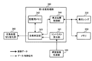
図1に、内視鏡システム(内視鏡装置)の第1の構成例を示す。内視鏡システムは、光源部100、撮像部200、制御装置300(画像処理部)、表示部400、外部I/F部500を含む。
2. First embodiment 2.1. First Configuration Example of Endoscope System FIG. 1 shows a first configuration example of an endoscope system (endoscope apparatus). The endoscope system includes a
光源部100は、白色光を発生する白色光源110と、その白色光をライトガイドファイバ210に集光するためのレンズ120を含む。
The
撮像部200は、例えば体腔への挿入を可能にするため細長く且つ湾曲可能に形成されている。また撮像部200は、観察する部位により異なる撮像部が用いられるため、着脱可能な構造をしている。撮像部200は、光源部100で集光された光を導くためのライトガイドファイバ210と、そのライトガイドファイバ210により導かれた光を拡散させて被写体に照射する照明レンズ220と、被写体からの反射光を集光する集光レンズ230と、集光レンズ230により集光された反射光を検出するための撮像素子240を含む。
The
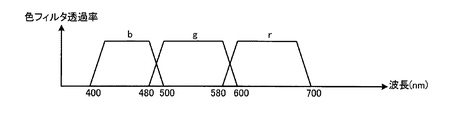
撮像素子240は、図2に示すベイヤ配列の色フィルタを有する撮像素子である。また図2に示す3種類の色フィルタr,g,bは、図3に示す透過率特性を有する。すなわち、rフィルタが580〜700nm、gフィルタが480〜600nm、bフィルタが400〜500nmの光を透過させる特性を有する。
The
さらに撮像部200は、内部にメモリ250を有しており、メモリ250には各スコープ固有の識別番号が保持されている。そのため、メモリ250に保持されている識別番号を参照することで、接続されているスコープの種類を識別することが可能である。
Furthermore, the
集光レンズ230は、焦点位置を可変制御することができ、例えば焦点位置をd1〜d5[mm]の5段階で調整できるものとする。5段階の焦点位置d1〜d5[mm]には、下式(1)に示す関係が成立するものとする。ここで、本実施形態において焦点位置とは、ピントが合う場合における集光レンズ230と被写体との間の距離を表す。集光レンズ230は、選択可能な各焦点位置d1〜d5において、例えば図4に示す被写界深度を有する。例えば焦点位置d2における被写界深度は、焦点位置d1〜d3の範囲である。なお、d1〜d5における被写界深度は図4に限定されず、隣り合う被写界深度に重なりがあればよい。
![]()
![]()
撮像部200の焦点位置は、接続されるスコープにより異なる。上述したように、メモリ250には各スコープ固有の識別番号が保持されているため、その識別番号を参照することで接続されているスコープの種類を識別し、選択可能な焦点位置の情報(d1〜d5)を取得可能である。
The focal position of the
制御装置300は、内視鏡システムの各構成要素の制御や画像処理を行う。制御装置300は、補間処理部310、表示画像生成部320、輝度画像生成部330(輝度画像取得部)、第1合焦処理部340、第2合焦処理部350、合焦処理切り替え部360、制御部370を含む。
The
外部I/F部500は、内視鏡システムに対するユーザからの入力等を行うためのインターフェースであり、電源のオン/オフを行うための電源スイッチや、撮影モードやその他各種のモードを切り換えるためのモード切換ボタンなどを含んで構成されている。また、外部I/F部500は、入力された情報を制御部370へ出力する。
The external I /
補間処理部310は、表示画像生成部320と、輝度画像生成部330に接続されている。輝度画像生成部330は第1合焦処理部340と、第2合焦処理部350に接続されている。合焦処理切り替え部360は、第1合焦処理部340と、第2合焦処理部350にそれぞれ双方向に接続されており、これらの制御を行う。
The
また、第1合焦処理部340、第2合焦処理部350、合焦処理切り替え部360はそれぞれメモリ250及び集光レンズ230と双方向に接続されており、集光レンズ230の焦点位置の制御を行う。さらに制御部370は、表示画像生成部320と、第2合焦処理部350と、合焦処理切り替え部360に接続されており、これらの制御を行う。
The first focusing
補間処理部310は、撮像素子240により取得(撮像)される画像に対して、補間処理を施す。上述したように、撮像素子240は図2に示すベイヤ配列を有するため、撮像素子240で取得される画像の各画素は、R,G,B信号のうちの何れか1つの信号値を有するのみで、他の2種類の信号が欠落した状態である。
The
そのため、補間処理部310は、取得画像の各画素に対して補間処理を施すことで、欠落している信号値を補間し、各画素でR,G,B信号の全ての信号値を有する画像を生成する。ここで補間処理としては、例えば公知のバイキュービック補間処理を用いればよい。なお以下では、補間処理部310で生成された画像をRGB画像と適宜表記する。
Therefore, the
補間処理部310は、生成したRGB画像を、表示画像生成部320と輝度画像生成部330に出力する。
The
表示画像生成部320は、補間処理部310から出力されるRGB画像に対して、例えば公知のホワイトバランス処理や色変換処理、階調変換処理等を施し、表示画像を生成する。そして、表示画像生成部320は、生成した表示画像を表示部400に出力する。
The display
輝度画像生成部330は、補間処理部310から出力されるRGB画像に基づいて輝度画像を生成する。具体的には、輝度画像生成部330は、RGB画像の各画素について、下式(2)を用いて輝度信号Yを算出することで、輝度画像を生成する。そして、輝度画像生成部330は、生成した輝度画像を第1合焦処理部340と、第2合焦処理部350に出力する。
![]()
![]()
第1合焦処理部340、及び第2合焦処理部350はそれぞれ異なる方法で、集光レンズ230の合焦位置を検出する処理を行う。以下の説明では、第1合焦処理部340での合焦処理を第1合焦処理、第2合焦処理部350での合焦処理を第2合焦処理と表記する。それぞれの合焦処理の詳細については後述する。
The first focusing
合焦処理切り替え部360は、2種類の合焦処理の切り替えを行う。ここで、2種類の合焦処理とは、上述の第1合焦処理、及び第2の合焦処理に相当する。
The focusing
合焦処理の切り替えは、トリガ信号によって行う。具体的には、第1合焦処理部340で合焦処理を行う場合、合焦処理切り替え部360は第1合焦処理部340にトリガ信号を出力し、第2合焦処理部350で合焦処理を行う場合には、第2合焦処理部350にトリガ信号を出力する。以上に示すように、合焦処理切り替え部360は、トリガ信号の出力先を切り替えることで、合焦処理の切り替えを行う。なお、以下の説明ではトリガ信号を、合焦処理実行信号と適宜表記する。
The focusing process is switched by a trigger signal. Specifically, when the focusing process is performed by the first focusing
本実施形態では、初期状態において、合焦処理切り替え部360は第1合焦処理部340に対して合焦処理実行信号を出力するものとする。初期状態は、合焦処理を開始するときの状態であり、例えば電源投入時や撮影開始時である。
In the present embodiment, it is assumed that the focusing
第1合焦処理部340は、合焦処理切り替え部360より合焦処理実行信号が出力されている場合に、輝度画像生成部330から出力される輝度画像を用いて合焦位置を検出する。
The first focusing
一般に、合焦位置においては、輝度画像のコントラストが最大となることが知られている。例えば図5に示すように、合焦位置がd3である場合、焦点位置d1〜d5におけるコントラストのうち合焦位置d3におけるコントラストが最大となる。そのため、第1合焦処理部340は、輝度画像生成部330から出力される輝度画像のコントラストが最大となる焦点位置を合焦位置として検出する。例えば、コントラスト値として、輝度画像の高周波成分を用いればよく、あるいは、任意のHPFフィルタの出力を用いればよい。
In general, it is known that the contrast of the luminance image is maximized at the in-focus position. For example, as shown in FIG. 5, when the in-focus position is d3, the contrast at the in-focus position d3 is the maximum among the contrasts at the focus positions d1 to d5. Therefore, the first focusing
なお、本実施形態では、第1の合焦処理に用いる評価値はコントラスト値に限定されず、合焦状態を評価するための評価値であればよい。また、コントラスト値は、輝度画像の高周波成分やHPFフィルタの出力に限定されない。例えば、コントラスト値として、輝度画像の勾配情報やエッジ量などを用いることも可能である。勾配情報とは具体的には、輝度画像中の任意の方向における輝度信号の傾きを意味する。例えば水平方向における輝度信号の傾きとしては、勾配情報の算出対象となる注目画素と、その注目画素より水平方向に1画素以上はなれた1つ以上の周辺画素との差分値を算出し、その差分値を輝度信号の傾き(勾配情報)として用いればよい。また、エッジ量としては例えば、複数の方向について算出した上記勾配情報の加重平均値を用いればよい。 In the present embodiment, the evaluation value used for the first focusing process is not limited to the contrast value, and may be an evaluation value for evaluating the in-focus state. The contrast value is not limited to the high-frequency component of the luminance image or the output of the HPF filter. For example, the gradient information of the luminance image, the edge amount, or the like can be used as the contrast value. Specifically, the gradient information means the gradient of the luminance signal in an arbitrary direction in the luminance image. For example, as the gradient of the luminance signal in the horizontal direction, the difference value between the target pixel for which the gradient information is calculated and one or more neighboring pixels that are one or more pixels away from the target pixel in the horizontal direction is calculated. The value may be used as the slope (gradient information) of the luminance signal. As the edge amount, for example, a weighted average value of the gradient information calculated for a plurality of directions may be used.
2.2.第1合焦処理部
次に、第1の合焦処理について詳細に説明する。図6に、第1合焦処理部の詳細な構成例を示す。図6に示すように第1合焦処理部340は、コントラスト算出部341、記憶用メモリ342(記憶部)、合焦判定部343、焦点位置制御部344を含む。コントラスト算出部341は合焦判定部343に接続されている。焦点位置制御部344は合焦判定部343と、集光レンズ230と、メモリ250に接続されている。また、記憶用メモリ342は、合焦判定部343と双方向に接続されている。
2.2. First Focusing Processing Unit Next, the first focusing processing will be described in detail. FIG. 6 shows a detailed configuration example of the first focusing processing unit. As shown in FIG. 6, the first
第1合焦処理は以下の(i)〜(vi)の手順で行われる。
(i)まず、記憶用メモリ342の内容をすべて“0”にセットする。記憶用メモリ342には後述するように、コントラストC_memと焦点位置d_memが保持される。
The first focusing process is performed according to the following procedures (i) to (vi).
(I) First, all the contents of the
(ii)次に、焦点位置制御部344が、メモリ250に保持されている識別番号を参照し、接続されているスコープを識別することで、集光レンズ230において選択可能な焦点位置の情報(d1〜d5)を取得する。
(Ii) Next, the focal
(iii)次に、焦点位置制御部344が、集光レンズ230の焦点位置をdm(mは自然数。mの初期値は“1”)に設定する。焦点位置制御部344は、焦点位置dmを合焦判定部343に出力する。
(Iii) Next, the focal
(iv)次に、コントラスト算出部341が、輝度画像生成部330から出力される輝度画像のコントラストCを算出する。コントラスト算出部341は、そのコントラストCを合焦判定部343に出力する。
(Iv) Next, the
(v)次に、合焦判定部343が、コントラスト算出部341から出力されるコントラストCと、記憶用メモリ342に保持されているコントラストC_memを比較する。合焦判定部343は、下式(3)の関係が成立する場合に、記憶用メモリ342に保持されている焦点位置d_memを合焦位置と判定する。ここで下式(3)において“|V|”は実数Vの絶対値を取得する処理を表す。
![]()
![]()
上式(3)の関係が成立して合焦と判定された場合、合焦判定部343はd_memを焦点位置制御部344に出力し、焦点位置制御部344は集光レンズ230の焦点位置をd_memに変更する。その後、合焦判定部343は合焦処理が完了したことを示すトリガ信号とコントラストC_memを、合焦処理切り替え部360に出力し、合焦処理を終了する。
一方、上式(3)の関係が成立しない場合は、以下の(vi)の処理を実行する。
When the relationship of the above formula (3) is established and the focus is determined to be in focus, the
On the other hand, when the relationship of the above equation (3) is not established, the following process (vi) is executed.
(vi)上記の(v)で非合焦と判定された場合は、合焦判定部343は、記憶用メモリ342のC_mem,d_memの値をそれぞれC,dmに更新する。さらに合焦判定部343は、mの値をインクリメントし、上記の(iii)の処理に戻る。
(vi) When it is determined as out of focus in (v) above, the
ただし、インクリメント後のmの値が、“m>5”となる場合には、d5を合焦位置と判定する。そして、d5を焦点位置制御部344に出力し、焦点位置制御部344がレンズの焦点位置をd5に変更する。その後、合焦判定部343は合焦処理が完了したことを示すトリガ信号とコントラストCを、合焦処理切り替え部360に出力し、合焦処理を終了する。
However, when the incremented value of m is “m> 5”, d5 is determined as the in-focus position. Then, d5 is output to the focal
以上に示すように、第1の合焦処理では、集光レンズ230の焦点位置を変更し、輝度画像のコントラストが最大となる焦点位置を合焦位置と判定するため、高精度に合焦位置を検出することができる。しかしながら、合焦位置を検出するために、複数枚の画像を取得する必要があるため、合焦位置の検出に時間を要するという課題がある。
As described above, in the first focusing process, the focal position of the
そこで、本実施形態では、第1の合焦処理で合焦位置を決定した後は、より高速に合焦位置を検出可能な第2の合焦処理を用いることで、高速な合焦処理を実現する。なお、第2合焦処理の詳細については後述する。 Therefore, in the present embodiment, after the focus position is determined by the first focus process, the second focus process that can detect the focus position at a higher speed is used to perform the high-speed focus process. Realize. Details of the second focusing process will be described later.
合焦処理切り替え部360は、第1の合焦処理が終了したことを表すトリガ信号が第1合焦処理部340から出力された場合、合焦処理実行信号の出力先を第2合焦処理部350に切り替える。これにより、合焦処理が第1合焦処理から第2の合焦処理に切り替わる。さらに、合焦処理切り替え部360は、第1合焦処理部340から出力されるコントラスト値を第2合焦処理部350に出力する。
When the trigger signal indicating that the first focusing process is completed is output from the first focusing
第2合焦処理部350は、合焦処理切り替え部360より合焦処理実行信号が出力されている場合に、輝度画像生成部330から出力される輝度画像を用いて合焦位置を検出する。
The second
2.3.第2合焦処理部
次に、第2の合焦処理について詳細に説明する。まず、画像の輝度値に基づいて、撮像部と被写体との間の相対的な移動量を検出する手法について説明する。
2.3. Second Focusing Processing Unit Next, the second focusing processing will be described in detail. First, a method for detecting the relative movement amount between the imaging unit and the subject based on the luminance value of the image will be described.
図7に示すように、ある時刻tにおいて、撮像部200先端と被写体間の距離がDであり、集光レンズ230で集光される反射光の強度がLorgであるとする。図8に示すように、時刻t+1において撮像部200先端と被写体間の距離が“A×D”に変化した場合に、集光レンズ230で集光される反射光の強度Lnowについて考える。ここで、時刻tは、例えば動画像の中の第1フレームを撮影するときの露光タイミングである。時刻t+1は、例えば動画像の中の第2フレームを第1フレームの次のフレームとする場合に、その第2フレームを撮影するときの露光タイミングである。
As shown in FIG. 7, it is assumed that at a certain time t, the distance between the tip of the
一般に、光の強度は光源からの距離の2乗に反比例して減衰する特徴がある。そのため、撮像部200先端と被写体間の距離が“A×D”に変化した場合の反射光の強度Lnowは、下式(4)で求められる。

上式(4)において、Aは、時刻tでの撮像部200先端と被写体間の距離Dを基準とした場合における、時刻t+1での撮像部200先端と被写体間の相対的な移動量に相当する。また上式(4)において、Iorgは、時刻tにおける照明レンズ220からの出射光量であり、Inowは、時刻t+1における照明レンズ220からの出射光量である。本実施形態では、照明レンズ220からの出射光量は時刻によらず一定であるため、“Inow/Iorg=1”となる。
In the above equation (4), A corresponds to the relative movement amount between the front end of the
輝度画像生成部330から出力される輝度画像の平均的な輝度信号の大きさは、被写体が同一であれば、集光レンズ230で集光される反射光の強度に比例する。従って、例えば時刻tで取得された輝度画像の平均輝度をYorg、時刻t+1で取得された輝度画像の平均輝度をYnowとすると、下式(5)の関係が成立する。
従って、時刻tを基準とした相対的な移動量Aは、Yorg,Ynowを用いて下式(6)により算出される。
なお、本実施形態では、上述のように照明レンズ220の出射光量を一定としているが、出射光量を時間的に変化させる場合においても、移動量Aを算出することが可能である。この場合、移動量Aは、下式(7)を用いて算出することができる。
図9に、上述の移動量Aに基づいて合焦処理を行う第2合焦処理部の詳細な構成例を示す。図9に示すように、第2合焦処理部350は、移動量検出部351、経過時間算出部352、合焦位置算出部353、焦点位置制御部354、コントラスト算出部358、切り替え判定部357aを含む。
FIG. 9 shows a detailed configuration example of the second focusing processing unit that performs focusing processing based on the above-described movement amount A. As shown in FIG. 9, the second
移動量検出部351は、合焦位置算出部353と切り替え判定部357aに接続されている。焦点位置制御部354は、合焦位置算出部353と、集光レンズ230と、メモリ250に接続されている。コントラスト算出部358と、経過時間算出部352は切り替え判定部357aに接続されている。また、経過時間算出部352と、移動量検出部351と、切り替え判定部357aはそれぞれ制御部370に接続されている。なお、コントラスト算出部358の処理は、図6で上述のコントラスト算出部341と同様の処理によりコントラスト値を求めるため、適宜説明を省略する。
The movement
移動量検出部351が行う処理の詳細について説明する。移動量検出部351は、初期フレームを基準とした場合の相対的な移動量Aを、上式(6)を用いて算出する。ここで、初期フレームとは、合焦処理が第2の合焦処理に切り替えられた直後に取得された輝度画像に相当する。
Details of processing performed by the movement
図10に、移動量検出部351の詳細な構成例を示す。移動量検出部351は、平均輝度算出部710、平均輝度記憶部711、移動量算出部712を含む。平均輝度算出部710は、平均輝度記憶部711と移動量算出部712に接続されている。平均輝度記憶部711は、移動量算出部712に接続されている。また、制御部370は、平均輝度算出部710に接続されている。
FIG. 10 shows a detailed configuration example of the movement
平均輝度算出部710は、輝度画像生成部330から出力される輝度画像に基づいて、平均輝度Ynowを算出する。例えば、平均輝度Ynowは、下式(8)に示すように輝度画像の所定領域における輝度信号値の平均値とすればよい。
ここで、上式(8)において、Y(x、y)は、輝度画像の座標(x,y)における輝度信号値である。また、(xs、ys)は、所定領域の始点座標であり、(xe,ye)は、所定領域の終点座標である。また、座標(x,y)のx軸、y軸は、画像上での画素の座標を表すための座標軸であり、例えば図13に示すように直交する2軸である。例えば、x軸は走査線に沿った方向の座標軸であり、y軸は走査線に直交する座標軸である。
とする。
Here, in the above equation (8), Y (x, y) is a luminance signal value at the coordinates (x, y) of the luminance image. Further, (xs, ys) is a start point coordinate of the predetermined area, and (xe, ye) is an end point coordinate of the predetermined area. Further, the x-axis and y-axis of the coordinates (x, y) are coordinate axes for representing the coordinates of the pixel on the image, for example, two axes orthogonal to each other as shown in FIG. For example, the x-axis is a coordinate axis in a direction along the scanning line, and the y-axis is a coordinate axis orthogonal to the scanning line.
And
なお、上式(8)に示す所定領域の始点・終点座標は、予め一定の値を決めておくこともできるし、外部I/F部500より、ユーザが任意の値を設定する構成としてもよい。また、本実施形態では、平均輝度Ynowを一つの所定領域より算出する例を示したが、複数の所定領域より平均輝度Ynowを算出する構成とすることも可能である。
Note that the start point / end point coordinates of the predetermined area shown in the above equation (8) can be determined in advance, or the user can set arbitrary values from the external I /
平均輝度算出部710は、算出した平均輝度Ynowを、移動量算出部712と切り替え判定部357aに出力する。平均輝度算出部710は、輝度画像が初期フレームの場合には、平均輝度Ynowを平均輝度記憶部711に出力する。平均輝度記憶部711は、平均輝度算出部710から出力された平均輝度YnowをYorgとして保持(記憶)する。
The average
移動量算出部712は、平均輝度算出部710から出力される平均輝度Ynowと、平均輝度記憶部711に保持されている平均輝度Yorgと、上式(6)を用いて初期フレームを基準として求められた相対的な移動量Aと、を算出する。そして移動量算出部712は、算出した移動量Aを合焦位置算出部353に出力する。
The movement
合焦位置算出部353は、移動量検出部351から出力される、初期フレームを基準とした相対的な移動量Aと、焦点位置制御部354から出力される焦点位置の情報と、に基づいて合焦位置を算出する。具体的には、焦点位置制御部354から出力される焦点位置の情報は、集光レンズ230の初期フレームでの焦点位置dorgや、集光レンズ230の現在の焦点位置dnow、選択可能な全ての焦点位置(d1〜d5)である。
The in-focus
合焦位置算出部353は、撮像部200先端と被写体間の距離distを下式(9)を用いて算出する。
![]()
![]()
そして、上式(9)で算出した距離distに応じて合焦位置を変更する。具体的には、距離distに一番近い焦点位置を合焦位置dnewと判定する。具体的な判定式は、例えば下式(10)を用いればよい。
合焦位置算出部353は、合焦位置dnewと現在の集光レンズ230の焦点位置dnowが同一の場合には焦点位置を変更しない。一方、合焦位置算出部353は、dnewとdnowが異なる場合には、焦点位置を変更する。この場合、合焦位置算出部353は、dnewを焦点位置制御部354に出力し、焦点位置制御部354が、集光レンズ230の焦点位置をdnewに変更する。
Focus
経過時間算出部352は、合焦処理が第2の合焦処理に切り替えられてからの経過時間を算出する。経過時間としては、例えば初期フレームからのフレーム数FNUMをカウントすればよい。具体的には経過時間算出部352は、輝度画像生成部330から輝度画像が出力される毎に、フレーム数FNUMを下式(11)を用いてインクリメントすることで、フレーム数をカウントする。ここで、フレーム数FNUMの初期値は“0”とする。経過時間算出部352は、フレーム数FNUMを切り替え判定部357aに出力する。
![]()
![]()
切り替え判定部357aは、コントラスト算出部358から出力されるコントラストCnow、経過時間算出部352から出力されるフレーム数FNUM、平均輝度算出部710から出力される平均輝度Ynowに基づいて、合焦処理を切り替えるか否かの判定処理を行う。判定処理の手法は、例えば後述する3種類の手法がある。そして、それらの判定処理の何れかにおいて、合焦処理を切り替えるべきと判定された場合には、合焦処理を切り替えることを示すトリガ信号を合焦処理切り替え部360に出力する。
合焦処理切り替え部360は、切り替え判定部357aから上記トリガ信号が出力された場合、合焦処理実行信号の出力先を第1合焦処理部340に切り替える。これにより、合焦処理が第2合焦処理から第1合焦処理に切り替わる。
When the trigger signal is output from the switching
2.4.切り替え判定部
図11に、切り替え判定部357aの詳細な構成例を示す。切り替え判定部357aは、コントラスト判定部770、経過時間判定部771、平均輝度判定部772を含む。コントラスト判定部770と、経過時間判定部771と、平均輝度判定部772はそれぞれ制御部370に接続されている。
2.4. Switching Determination Unit FIG. 11 shows a detailed configuration example of the switching
コントラスト判定部770は、コントラスト算出部358から出力されるコントラストCnowと、合焦処理切り替え部360から出力されるコントラストCorgとを比較する。そして、コントラスト判定部770は、下式(12)の関係が成立する場合、合焦処理を切り替えるものと判定し、合焦処理切り替え部360に合焦処理を切り替えることを示すトリガ信号を出力する。ここで、下式(12)においてCTHは、“1>CTH>0”の条件を満たす実数とする。
![]()
![]()
経過時間判定部771は、経過時間算出部352から出力されるフレーム数FNUMに対して閾値FTHを用いて判定処理を行う。具体的には、経過時間判定部771は、“FNUM>FTH”の条件が成立する場合に、合焦処理を切り替えるものと判定し、合焦処理切り替え部360に合焦処理を切り替えることを示すトリガ信号を出力する。
The elapsed
平均輝度判定部772は、平均輝度算出部710から出力される平均輝度Ynowに対して、2つの閾値Ymin,Ymaxを用いて判定処理を行う。具体的には、平均輝度判定部772は、“Ynow<Ymin”若しくは“Ynow>Ymax”の条件が成立する場合に、合焦処理を切り替えるものと判定し、合焦処理切り替え部360に合焦処理を切り替えることを示すトリガ信号を出力する。
The average
なお、閾値FTH,CTH,Ymin,Ymaxは、予め一定の値を設定しておいてもよいし、外部I/F部500よりユーザが任意の値を設定できる構成としてもよい。
Note that the threshold values F TH , C TH , Y min , and Y max may be set in advance, or may be configured such that the user can set arbitrary values from the external I /
本実施形態では、上式(4)〜(6)で説明したように、輝度画像の平均輝度の時間的な変化量に基づいて、初期フレームを基準とした相対的な移動量Aを算出する。 In the present embodiment, as described in the above formulas (4) to (6), the relative movement amount A based on the initial frame is calculated based on the temporal change amount of the average luminance of the luminance image. .
ここで、被写体に近接した状態で観察を行う場合には、撮像部200先端と被写体間の距離が小さくなる。そのため、集光レンズ230で集光される反射光の強度が強くなり、撮像素子240で取得される信号が飽和することが考えられる。この時、輝度画像生成部330から出力される輝度画像も飽和した画像となる。従ってこの場合、上式(5)に示した関係が成立しないため、上式(6)では上記移動量を算出することができない。
Here, when observation is performed in the state of being close to the subject, the distance between the tip of the
さらに、被写体を遠景で観察する場合には、集光レンズ230で集光される反射光の強度が弱くなる。この場合、平均輝度の大きさは小さくなり、ノイズの影響を受けやすくなるため、正確な移動量を算出することができない。
Furthermore, when the subject is observed in a distant view, the intensity of the reflected light collected by the
以上に示すように、平均輝度の大きさによっては、上記移動量を算出できない場合がある。そこで本実施形態では、上述のように平均輝度算出部710から出力される平均輝度Ynowに対して、2つの閾値Ymin,Ymaxを用いて閾値処理を行う。そして、上記閾値処理の結果、合焦処理を切り替えるべきと判定された場合には、合焦処理を第1の合焦処理に切り替える。
As described above, the movement amount may not be calculated depending on the average luminance. Thus, in the present embodiment, threshold processing is performed using the two threshold values Y min and Y max for the average luminance Y now output from the average
また、第2の合焦処理では、合焦位置を高速に決定できる利点がある。しかしながら、第2の合焦処理では、観察対象である被写体が変化しない前提条件の基に、合焦位置を算出している。一方、内視鏡診断においては、当然ながら、複数の部位を診断するため、所定の時間ごとに観察対象となる被写体は変化する特徴がある。 The second focusing process has an advantage that the focusing position can be determined at high speed. However, in the second focusing process, the focus position is calculated based on the precondition that the subject to be observed does not change. On the other hand, in the endoscopic diagnosis, naturally, since a plurality of parts are diagnosed, the subject to be observed changes every predetermined time.
そのため、第2の合焦処理を内視鏡システムに適用すると、上述のように被写体が変化した場合に、合焦位置の検出精度が悪くなる問題がある。この場合、輝度画像生成部330から出力される輝度画像のコントラストが低下することが予想される。そこで本実施形態では、合焦処理を第2の合焦処理に切り換えた後でも、輝度画像生成部330から出力される輝度画像からコントラストCnowを検出し、そのコントラストCnowが“CTH×|Corg|”よりも低かった場合には、合焦処理を第1の合焦処理に切り替えるものとする。
Therefore, when the second focusing process is applied to the endoscope system, there is a problem that the detection accuracy of the in-focus position is deteriorated when the subject changes as described above. In this case, it is expected that the contrast of the luminance image output from the luminance
さらに、本実施形態では、合焦処理を第2の合焦処理に切り替えた後、所定の時間が経過した場合にも、合焦処理を第1の合焦処理に切り替えるものとする。具体的には、合焦処理が第2の合焦処理に切り替えられた後に、輝度画像生成部330から出力されるフレーム数FNUMを上式(11)を用いてカウントする。そして上記フレーム数FNUMが閾値FTHを超えた場合に、合焦処理を第2合焦処理から第1の合焦処理に切り替える。
Further, in the present embodiment, the focusing process is switched to the first focusing process even when a predetermined time has elapsed after the focusing process is switched to the second focusing process. Specifically, after the focusing process is switched to the second focusing process, the number of frames F NUM output from the luminance
以上の方法を用いることで、高精度に合焦位置を検出しつつ、高速に合焦位置を制御することが可能となる。これにより、医師が手作業で焦点位置を調整することがなくなるため、医師の負担を軽減することができる。さらに、常にコントラストの高い画像を提供することが可能となり、病変の見落とし防止にもつながる。 By using the above method, it is possible to control the focus position at high speed while detecting the focus position with high accuracy. This eliminates the need for the doctor to manually adjust the focal position, thereby reducing the burden on the doctor. Furthermore, it becomes possible to provide an image with high contrast at all times, leading to prevention of oversight of lesions.
なお、本実施形態では、合焦位置を制御する例を示したが、内視鏡診断において合焦位置の制御が必要となるのは、主に拡大観察を行う場合である。従って、上述のような合焦位置の制御は、拡大観察時のみ機能する構成としてもよい。 In the present embodiment, an example in which the in-focus position is controlled has been shown. However, in the endoscopic diagnosis, the in-focus position needs to be controlled mainly when performing magnified observation. Therefore, the above-described focus position control may be configured to function only during magnified observation.
拡大観察と通常観察の切り替えは、例えば外部I/F部500によりユーザが切り替える構成とすればよい。そしてこの場合、通常観察が選択されている期間は、合焦処理切り替え部360は合焦処理実行信号を、第1合焦処理部340、及び第2合焦処理部350のどちらにも出力しないものとする。さらに、通常観察が選択された場合には、合焦処理切り替え部360が、集光レンズの焦点位置を強制的にd5に設定する。ここで、d5は通常観察時における焦点位置とする。
For example, the external I /
さて上述のように、コントラストAFでは、複数の焦点位置に対応する複数枚の画像を取得する必要があるため、複数回の焦点位置変更と撮像動作を行う必要があり、合焦までに時間がかかるという課題がある。 As described above, in contrast AF, since it is necessary to acquire a plurality of images corresponding to a plurality of focal positions, it is necessary to perform a plurality of focal position changes and imaging operations. There is such a problem.
この点、本実施形態の撮像装置は図1に示すように、光学系と、光学系の焦点位置を制御して第1の合焦処理を行う第1合焦処理部340と、光学系の焦点位置を制御して第2の合焦処理を行う第2合焦処理部350と、第1の合焦処理と第2の合焦処理を切り替える制御を行う合焦処理切り替え部360を含む。そして図6に示すように、第1合焦処理部340は、第1の合焦処理が成されたか否かを判定する合焦判定部343を有する。合焦処理切り替え部360は、第1の合焦処理が成されたと合焦判定部343により判定された場合に、第2の合焦処理に切り替える。
In this regard, as shown in FIG. 1, the imaging apparatus of the present embodiment includes an optical system, a first focusing
ここで、光学系は焦点位置を制御可能な光学系であり、本実施形態では図1に示す集光レンズ230に対応する。また、第1の合焦処理が成されるとは、例えば第1の合焦処理が終了することであり、あるいは合焦状態に至ったと判定されることである。例えばコントラストAFの場合、コントラスト値の最大値に対応する焦点位置に設定されたとき、第1の合焦処理が成されたと判定される。
Here, the optical system is an optical system capable of controlling the focal position, and corresponds to the
本実施形態によれば、撮像装置におけるAF処理を高速化することが可能になる。すなわち、第1の合焦処理よりも高速に合焦可能な第2の合焦処理に切り替えることで、AF処理を高速化できる。例えば、第1の合焦処理は合焦に至るまでに複数フレームを要するAFであり、第2の合焦処理は各フレームにおいて合焦に至るAFである。 According to the present embodiment, it is possible to increase the speed of AF processing in the imaging apparatus. That is, the AF process can be speeded up by switching to the second focusing process that can focus at a higher speed than the first focusing process. For example, the first focusing process is an AF that requires a plurality of frames before focusing, and the second focusing process is an AF that reaches focusing in each frame.
また、第1の合焦処理が成されたと判定された場合に第2の合焦処理に切り替えることで、第2の合焦処理を合焦状態の初期フレームでスタートできる。これにより、初期フレームを基準とした撮像部と被写体との間の移動量(距離変化)に基づいて合焦状態を維持することが可能になる。 Further, when it is determined that the first focusing process has been performed, the second focusing process can be started with the initial frame in the focused state by switching to the second focusing process. Accordingly, it is possible to maintain the in-focus state based on the movement amount (distance change) between the imaging unit and the subject with reference to the initial frame.
また本実施形態では、図1に示すように、時系列に(連続して)画像を取得する撮像部200を含む。合焦処理切り替え部360は、第1の合焦処理が成されたと判定されるまでは、第1合焦処理部340による第1の合焦処理を継続する。一方、合焦処理切り替え部360は、第1の合焦処理が成されたと判定された場合は、その後に取得される画像に対する合焦処理を、第2合焦処理部350による第2の合焦処理に切り替える。
In the present embodiment, as shown in FIG. 1, an
本実施形態では、ベイヤ配列の撮像素子240が時系列に画像を撮像し、補間処理部310(広義には画像取得部)が補間処理を行うことで、時系列のRGB画像(動画像)が取得される。また、合焦処理切り替え部360は、合焦処理の実行を指示する制御信号を第1合焦処理部340に出力することで第1の合焦処理を継続し、その制御信号を第2合焦処理部350に出力することで第2の合焦処理に切り替える。
In the present embodiment, the Bayer array
このようにすれば、時系列に画像を撮像する場合に、まず時系列の画像を用いて第1の合焦処理により合焦させ、合焦した後に第2の合焦処理に切り替えて、その後の時系列の画像を撮像できる。 In this way, when capturing images in time series, first, the time-series images are used to focus by the first focusing process, and after focusing, the second focusing process is switched, and then It is possible to capture time-series images.
また本実施形態では、撮像部200は、複数の焦点位置d1〜d5の画像を時系列に取得する。第1合焦処理部340は、時系列に取得された複数の焦点位置d1〜d5の画像のコントラスト値(広義には、合焦状態を評価するための評価値)を算出し、算出したコントラスト値に基づいて第1の合焦処理を行って光学系の焦点位置を制御する。第2合焦処理部350は、切り替えが行われた後に時系列に取得される画像の各画像に対して第2の合焦処理を行う。第2合焦処理部350は、撮像部200と被写体の間の相対的な移動量A(またはA’,Aall)を検出し、検出した移動量Aに基づいて光学系の焦点位置を制御する。
In the present embodiment, the
このようにすれば、第1の合焦処理としてコントラストAF処理を行い、第2の合焦処理として、撮像部と被写体の間の相対的な移動量に基づく合焦処理を行うことができる。第2の合焦処理では、各画像(各フレーム)の撮像で合焦するため、複数フレーム必要なコントラストAFよりも高速なAFが可能である。 In this way, the contrast AF process can be performed as the first focusing process, and the focusing process based on the relative movement amount between the imaging unit and the subject can be performed as the second focusing process. In the second focusing process, since each image (each frame) is focused, it is possible to perform AF faster than contrast AF that requires a plurality of frames.
また本実施形態では、図9に示すように、第2合焦処理部350は、第2の合焦処理における合焦状態を評価するためのパラメータに基づいて、合焦処理を切り替えるか否かを判定する切り替え判定部357aを有する。合焦処理切り替え部360は、切り替え判定部357aからの判定結果に基づいて、第2の合焦処理から第1の合焦処理に切り替える。
In the present embodiment, as illustrated in FIG. 9, the second
このようにすれば、第2の合焦処理から第1の合焦処理に切り替えることができる。すなわち、合焦状態を評価するためのパラメータを用いることで、合焦精度が劣化した可能性があることを判定可能になる。これにより、第1の合焦処理に切り替えて再び確実な合焦状態に復帰することが可能になる。 In this way, it is possible to switch from the second focusing process to the first focusing process. That is, it is possible to determine that there is a possibility that the focusing accuracy has deteriorated by using the parameter for evaluating the in-focus state. As a result, it is possible to switch back to the first in-focus process and return to a sure in-focus state again.
また本実施形態では、切り替え判定部が用いるパラメータは、第2の合焦処理に用いられる制御パラメータである。 In the present embodiment, the parameter used by the switching determination unit is a control parameter used for the second focusing process.
ここで、制御パラメータとは、第2の合焦処理における合焦処理過程において取得または算出されるパラメータである。例えば、上述の平均輝度Ynowや、後述する周波数特性のマッチング誤差εや、動きベクトルのマッチング誤差SADmin等である。 Here, the control parameter is a parameter acquired or calculated in the focusing process in the second focusing process. For example, the above-described average luminance Y now , a frequency characteristic matching error ε described later, a motion vector matching error SAD min, and the like.
このように、制御パラメータは合焦位置の算出に用いる値であるため、制御パラメータを用いることで第2の合焦処理の合焦状態を評価することができる。これにより、第2の合焦処理の合焦状態に基づいて切り替え判定を行うことが可能になる。 Thus, since the control parameter is a value used for calculation of the in-focus position, the in-focus state of the second in-focus processing can be evaluated by using the control parameter. This makes it possible to perform switching determination based on the focus state of the second focus process.
また本実施形態では、図9に示すように、第2合焦処理部350は、取得された画像に基づいてコントラスト値を算出するコントラスト算出部358を有する。切り換え判定部357aは、コントラスト値をパラメータとして、合焦処理を切り替えるか否かの判定を行う。
In the present embodiment, as illustrated in FIG. 9, the second
例えば本実施形態では、切り換え判定部357aは、コントラスト値が閾値CTHよりも小さい場合には、合焦処理を第1の合焦処理に切り替えると判定する。
For example, in this embodiment, the switching
このようにすれば、コントラスト値に基づいて第1の合焦処理に切り替えることができる。ピントがぼけるほどコントラスト値は小さくなるため、コントラスト値を用いることで合焦状態を評価することができる。 In this way, it is possible to switch to the first focusing process based on the contrast value. Since the contrast value decreases as the focus is blurred, the in-focus state can be evaluated by using the contrast value.
また本実施形態では、図10に示すように、取得された画像の平均輝度Ynowを算出する平均輝度算出部710を有する。切り替え判定部357aは、平均輝度Ynowをパラメータとして、合焦処理を切り替えるか否かの判定を行う。
In the present embodiment, as shown in FIG. 10, an average
例えば本実施形態では、平均輝度Ynowが閾値Ymaxよりも大きい場合、あるいは平均輝度Ynowが閾値Yminよりも小さい場合に、合焦処理を第1の合焦処理に切り替えると判定する。 For example, in this embodiment, when the average luminance Y now is larger than the threshold Y max or when the average luminance Y now is smaller than the threshold Y min , it is determined that the focusing process is switched to the first focusing process.
このようにすれば、画像の平均輝度に基づいて第1の合焦処理に切り替えることができる。例えば輝度が大きすぎる場合には画像が白飛びしている可能性があり、輝度が小さすぎる場合には画像のS/Nが劣化している可能性がある。これらの場合には、画像から移動量を算出する精度が劣化してしまう。例えば平均輝度から移動量を推定する場合、白飛びやS/N劣化により推定精度が劣化してしまう。そのため、閾値Ymax,Yminにより判定することで、第1の合焦処理に切り替えて確実な合焦状態に復帰することが可能になる。 In this way, it is possible to switch to the first focusing process based on the average luminance of the image. For example, when the luminance is too high, the image may be over-exposed, and when the luminance is too low, the S / N of the image may be deteriorated. In these cases, the accuracy of calculating the movement amount from the image is deteriorated. For example, when the movement amount is estimated from the average luminance, the estimation accuracy deteriorates due to overexposure or S / N deterioration. Therefore, it is possible to switch to the first focusing process and return to a surely focused state by determining with the threshold values Y max and Y min .
また本実施形態では、図9に示すように、第2合焦処理部350は、合焦処理切り替え部360により第2の合焦処理に切り替えられた後の経過時間を計測する経過時間算出部352(経過時間計測部)を有する。切り替え判定部357aは、経過時間をパラメータとして、合焦処理を切り替えるか否かの判定を行う。
In the present embodiment, as illustrated in FIG. 9, the second focusing
例えば本実施形態では、フレーム数FNUMを経過時間としてカウントし、閾値FTHを超えた場合に切り替えを行う。なお経過時間はフレーム数に限定されず、クロックのカウント数等の経過時間を表す情報であればよい。 For example, in the present embodiment, the number of frames F NUM is counted as an elapsed time, and switching is performed when the threshold value F TH is exceeded. The elapsed time is not limited to the number of frames, and may be information indicating the elapsed time such as a clock count number.
このようにすれば、経過時間に基づいて第1の合焦処理に切り替えることができる。例えば、時間が経過するほど観察位置が移動している可能性がある。あるいは、後述のようにフレーム間の移動量を積算していく場合、時間が経過するほど誤差が蓄積する可能性がある。そのため、経過時間に応じて第1の合焦処理に切り替えることで、確実な合焦状態に復帰することが可能になる。 In this way, it is possible to switch to the first focusing process based on the elapsed time. For example, the observation position may move as time elapses. Alternatively, when the movement amount between frames is integrated as will be described later, errors may accumulate as time elapses. Therefore, by switching to the first focusing process according to the elapsed time, it is possible to return to a surely focused state.
また本実施形態では、図9に示すように、第2合焦処理部350は、撮像部200と被写体の間の相対的な移動量Aを検出する移動量検出部351を有する。第2合焦処理部350は、移動量Aに基づいて光学系の焦点位置を制御する。具体的には、移動量検出部351は、取得された画像の画像信号の時間的な変化量に基づいて移動量Aを検出する。より具体的には、撮像部200は、第1の画像と第2の画像を時系列に取得する。上式(6)に示すように、移動量検出部351は、第1の画像の平均輝度値Yorgと第2の画像の平均輝度値Ynowの比を画像信号の時間的な変化量として、移動量Aを検出する。
In the present embodiment, as illustrated in FIG. 9, the second focusing
このようにすれば、移動量検出部により移動量を検出でき、その移動量に基づいて焦点位置を合焦位置に制御できる。また、画像信号の時間的な変化量を用いることで、画像処理により移動量を算出できる。また、フレーム間の平均輝度値の比を用いることで、照明光と距離の関係を利用して移動量を算出できる。なお、画像信号の時間的な変化量は、平均輝度値に限定されず、撮像部と被写体の間の距離変化に応じて変化する変化量であればよい。 In this way, the movement amount detection unit can detect the movement amount, and the focal position can be controlled to the in-focus position based on the movement amount. Also, by using the temporal change amount of the image signal, the movement amount can be calculated by image processing. Further, by using the ratio of the average luminance value between frames, the amount of movement can be calculated using the relationship between the illumination light and the distance. Note that the temporal change amount of the image signal is not limited to the average luminance value, and may be any change amount that changes in accordance with a change in the distance between the imaging unit and the subject.
また本実施形態では、光学系は、所定数の焦点位置d1〜d5の中から一つの焦点位置を選択することで焦点位置を変更する。 In this embodiment, the optical system changes the focal position by selecting one focal position from among a predetermined number of focal positions d1 to d5.
具体的には、第1合焦処理部340は、所定数の焦点位置d1〜d5の各焦点位置において取得された画像のコントラスト値を算出し、コントラスト値が最も高い焦点位置に光学系の焦点位置を変更する。第2合焦処理部350は、第2の合焦処理により求めた合焦位置に最も近い焦点位置を所定数の焦点位置d1〜d5の中から選択し、選択した焦点位置に光学系の焦点位置を変更する。
Specifically, the first
また本実施形態では、光学系は、ズーム処理を行ってもよい。そして、第1合焦処理部340は、通常観察モードよりもズーム処理の倍率が高倍率に設定された拡大観察モードにおいて、第1の合焦処理を行う。第2合焦処理部350は、拡大観察モードにおいて第2の合焦処理を行う。
In the present embodiment, the optical system may perform zoom processing. Then, the first focusing
例えば、観察モードは、ズーム調整ノブによって設定される光学系のズーム倍率に応じて設定される。例えば、ズーム倍率の可変範囲のうち最低倍率に設定された場合は、通常観察モードである。また、最低倍率よりも高倍率に設定された場合は、拡大観察モードである。通常観察モードでは、例えば消化管内を移動しながら低倍率で病変をサーチする通常観察が行われる。拡大観察モードでは、例えば消化管の内壁に正対して病変を高倍率で観察する拡大観察が行われる。 For example, the observation mode is set according to the zoom magnification of the optical system set by the zoom adjustment knob. For example, when the minimum magnification is set in the variable range of the zoom magnification, the normal observation mode is set. When the magnification is set higher than the minimum magnification, the magnification observation mode is set. In the normal observation mode, for example, normal observation in which a lesion is searched at a low magnification while moving in the digestive tract is performed. In the magnified observation mode, magnified observation is performed in which, for example, a lesion is observed at a high magnification directly facing the inner wall of the digestive tract.
このようにすれば、拡大観察モードにおいて第1の合焦処理と第2の合焦処理によりAFを行うことで、ズーム倍率が高倍率に設定されて被写界深度が狭くなった場合であっても合焦状態を維持することが容易になる。 In this way, the AF is performed by the first focusing process and the second focusing process in the magnification observation mode, so that the zoom magnification is set to a high magnification and the depth of field becomes narrow. However, it is easy to maintain the in-focus state.
また本実施形態では、第2合焦処理部350は、移動量が閾値より小さい場合、光学系の焦点位置を変更しない。
In the present embodiment, the second
例えば、上式(10)に示すように、算出した距離distに最も近い焦点位置を所定の焦点位置d1〜d5の中から選択する。この場合、1フレーム前の合焦位置がd2であり、d1+(d2−d1)/2≦dist<d2+(d3−d2)/2を満たす場合には再びd2が選択される。すなわち、移動量の変化がこの範囲内であれば光学系の焦点位置が変更されない。 For example, as shown in the above formula (10), the focal position closest to the calculated distance dist is selected from predetermined focal positions d1 to d5. In this case, when the in-focus position one frame before is d2, and d1 + (d2-d1) / 2 ≦ dist <d2 + (d3-d2) / 2 is satisfied, d2 is selected again. That is, if the change in the movement amount is within this range, the focal position of the optical system is not changed.
3.第2の実施形態
第1の実施形態では、輝度画像の平均輝度に基づいて上式(6)を用いて初期フレームを基準とした相対的な移動量を検出する手法について説明したが、本実施形態では、輝度画像の周波数特性に基づいて移動量を検出してもよい。
3. Second Embodiment In the first embodiment, the method of detecting the relative movement amount based on the initial frame using the above equation (6) based on the average luminance of the luminance image has been described. In the embodiment, the movement amount may be detected based on the frequency characteristic of the luminance image.
図12に、この場合の構成例として、第2合焦処理部350の第2の詳細な構成例を示す。第2合焦処理部350は、移動量検出部355、経過時間算出部352、合焦位置算出部353、焦点位置制御部354、コントラスト算出部358、切り替え判定部357bを含む。なお、内視鏡システムの基本構成は第1の実施形態と同様であり、第2合焦処理部350以外の処理は第1の実施形態と同一であるため、適宜説明を省略する。また、移動量検出部355と切り替え判定部357b以外の処理は、第1の実施形態と同一であるため、適宜説明を省略する。
FIG. 12 shows a second detailed configuration example of the second focusing
まず、輝度画像の周波数特性と、移動量の関係について説明する。図7に示すように、ある時刻tにおいて、撮像部200先端と被写体間の距離が“D”の場合に、輝度画像生成部330により図13に示す画像が取得されたとする。
First, the relationship between the frequency characteristics of the luminance image and the movement amount will be described. As illustrated in FIG. 7, it is assumed that the image illustrated in FIG. 13 is acquired by the luminance
図13に示す輝度画像を周波数変換すると、例えば図15のR1に示す周波数特性が得られる。内視鏡画像は、図13に示すように血管が高周波成分を有する特徴がある。この血管の周波数特性により、周波数特性R1は、例えば特定の周波数f1pre,f2preでピークを有する。なお、ピークは2つに限定されない。ここで、周波数特性R1は、図13のP1に示す点線上の輝度信号を周波数変換したものとする。 When the luminance image shown in FIG. 13 is frequency-converted, for example, a frequency characteristic indicated by R1 in FIG. 15 is obtained. An endoscopic image has a characteristic that blood vessels have high frequency components as shown in FIG. Due to the frequency characteristic of the blood vessel, the frequency characteristic R1 has a peak at, for example, specific frequencies f1 pre and f2 pre . Note that the number of peaks is not limited to two. Here, the frequency characteristic R1 is obtained by frequency-converting the luminance signal on the dotted line indicated by P1 in FIG.
次に、図8に示すように、時刻t+1において、撮像部200先端と被写体間の距離が“A×D”となった場合を考える。例えばAが1よりも大きい実数である場合、撮像部200先端と被写体間の距離は時刻tの場合と比較して相対的に大きくなる。
Next, as shown in FIG. 8, consider a case where the distance between the front end of the
この場合、輝度画像生成部330では、図14に示す画像が取得される。図14に示すように、Z1に示す領域が時刻tにおける撮像領域に対応しており、図13と比べて画像上での血管の大きさが相対的に小さくなる特徴がある。従って、図14のP2に示す点線上の輝度信号を周波数変換すると、図15のR2に示す周波数特性となる。上述のように血管は高周波成分を有する特徴があるため、周波数特性R2も特定の周波数f1now,f2nowでピークを有する。
In this case, the luminance
上述のf1pre,f2pre,f1now,f2nowと、時刻tを基準とした相対的な移動量Aの間には、下式(13)に示す関係が成立する。
上式(13)より、時刻t+1での周波数が時刻tでの周波数に比例することがわかる。この比例係数をxとおいて時刻t+1での周波数をx×fとし、周波数特性R1,R2をそれぞれWpre(f),Wnow(f)と表記すると、下式(14)に示すεが求められる。このεは、“x=A”の時に最小となる。ここで、fmaxはナイキスト周波数とする。また、下式(14)第2項の“Wpre(0)/Wnow(0)”は輝度信号の正規化処理に相当する。
以上より、上式(14)に示すεが最小となるxを求めることで、移動量Aを算出することが可能である。ここで、Wnow(f)は離散値であるため、上式(14)のWnow(x×f)は、下式(15)を用いて算出するものとする。下式(15)において、f>fmaxの場合にはWnow(f)=0である。fmaxは、例えばFFT処理における空間周波数の上限値である。また、下式(15)において、int(V)は実数Vの整数部を取得する処理を表し、a(V)は実数Vの小数部を取得する処理を表すものとする。
図16に、移動量検出部355の詳細な構成例を示す。移動量検出部355は、周波数特性取得部750、周波数特性記憶部751、移動量算出部752、移動量積算部753を含む。周波数特性取得部750は、移動量算出部752に接続されている。周波数特性記憶部751は、移動量算出部752と双方向に接続されている。移動量算出部752はさらに、移動量積算部753に接続されている。また、周波数特性取得部750と、移動量算出部752は制御部370に接続されている。
FIG. 16 shows a detailed configuration example of the movement
周波数特性取得部750は、輝度画像生成部330から出力される輝度画像を周波数変換することで、周波数特性Wnow(f)を取得する。周波数変換の処理としては例えば、公知のフーリエ変換を用いればよい。周波数特性取得部750は、例えば図13のP1に示す点線上の輝度信号を周波数変換する。
The frequency
なお、周波数変換に用いる輝度画像の領域は、上記の領域に限定されるものではなく、外部I/F部500より、ユーザが任意の領域を設定できる構成としてもよい。また、P1以外に複数の領域を設定することも可能である。この場合、例えば複数の領域より取得した周波数特性の平均値を周波数特性Wnow(f)として用いればよい。
Note that the area of the luminance image used for frequency conversion is not limited to the above-described area, and the external I /
周波数特性取得部750は、上述の方法で取得した周波数特性Wnow(f)を移動量算出部752に出力する。
The frequency
移動量算出部752は、フレーム間における相対的な移動量A’を算出する。移動量算出部752は、周波数特性取得部750から出力される周波数特性Wnow(f)と、周波数特性記憶部751に保持されている周波数特性と、上式(14)と、を用いてフレーム間における相対的な移動量A’を算出する。周波数特性記憶部751には、後述するように、1フレーム前の輝度画像の周波数特性Wpre(f)が保持されている。
The movement
移動量算出部752は、上式(14)に示すεが最小となるxを移動量A’とする。具体的には、移動量算出部752は、下式(16)に示すようにN+1通りのxの値の全てについて、上式(14)に示すεを算出し、この中でεが最小となるxを移動量A’とする。ここでは、εの最小値をεminと表記する。ここで下式(16)においてnは、0≦n≦Nの整数である。
例えば、“dx=0.2”,“N=20”とすれば、“x=0.8〜1.2”まで、刻み幅“0.02”の20通りの条件で上式(14)に示すεが算出される。なお、上式(16)に示したN,dxの値は、予め一定の値を設定することもできるし、外部I/F部500によりユーザが任意の値を設定する構成としてもよい。
For example, if “dx = 0.2” and “N = 20”, the above equation (14) is obtained under 20 conditions with a step size “0.02” from “x = 0.8 to 1.2”. Is calculated. It should be noted that the values of N and dx shown in the above equation (16) can be set in advance, or the user can set arbitrary values by the external I /
移動量算出部752は、算出した移動量A’を移動量積算部753に出力し、周波数特性取得部750から出力された周波数特性Wnow(f)を、周波数特性記憶部751に出力する。周波数特性記憶部751は、出力された周波数特性Wnow(f)をWpre(f)として保持する。従って、周波数特性記憶部751には、1フレーム前の輝度画像より取得した周波数特性が保持されることになる。また、移動量算出部752は、εの最小値εminを切り替え判定部357bに出力する。
The movement
なお、初期フレームにおいては、移動量算出部752は移動量A’を“1”、εの最小値εminを“0”に強制的に設定するものとする。
In the initial frame, the movement
移動量積算部753は、移動量算出部752から出力されるフレーム間における相対的な移動量A’を積算することで、初期フレームを基準とした相対的な移動量Aallを算出する。具体的には、移動量積算部753は、下式(17)を用いて、前記移動量Aallの値を更新することで、初期フレームを基準とした相対的な移動量Aallを算出する。なお、移動量Aallの初期値は“1”とする。
![]()
![]()
切り替え判定部357bは、第2の合焦処理から第1の合焦処理に切り替える制御を行う。具体的には、切り替え判定部357bは、コントラスト値や経過時間、移動量の算出精度に基づいて切り替えるか否かの判定を行う。
The switching
図17に、切り替え判定部357bの詳細な構成例を示す。切り替え判定部357bは、コントラスト判定部770、経過時間判定部771、算出精度判定部773を含む。なお、コントラスト判定部770と経過時間判定部771の処理は、第1の実施形態と同一であるため、適宜説明を省略する。算出精度判定部773は制御部370に接続されている。
FIG. 17 shows a detailed configuration example of the switching
算出精度判定部773は、移動量算出部752から出力されるεminに対して、閾値εTHを用いた判定処理を行う。εminは、上式(14)に示すように、2つの周波数特性Wnow(A’×f),Wpre(f)のスペクトルが、どれだけ一致しているかを示す評価値となる。そのため、εminが大きい場合には、算出された移動量A’の精度が低いことが予測される。
The calculation
そのため、算出精度判定部773は、“εmin>εTH”の条件が成立する場合、移動量A’の算出精度が低いものと判定する。この場合、算出精度判定部773は合焦処理切り替え部360に対して、合焦処理を切り替えることを示すトリガ信号を出力する。
Therefore, the calculation
本実施形態によれば、高精度に合焦位置を検出しつつ、高速に合焦位置を制御することが可能となる。これにより、医師が手作業で焦点位置を調整することがなくなるため、医師の負担を軽減することができる。さらに、常にコントラストの高い画像を提供することが可能となり、病変の見落とし防止にもつながる。 According to the present embodiment, it is possible to control the focus position at high speed while detecting the focus position with high accuracy. This eliminates the need for the doctor to manually adjust the focal position, thereby reducing the burden on the doctor. Furthermore, it becomes possible to provide an image with high contrast at all times, leading to prevention of oversight of lesions.
さらに、本実施形態では、輝度画像の周波数成分に基づいて移動量を検出するため、光源部100の出射光量の時間的な変動の影響を受けない利点がある。具体的には、図1等で上述の実施形態では、上式(8)を用いて算出した輝度画像の平均輝度を基に移動量を検出する。そのため、光源部100の出射光量が時間的に変動する場合には、その変動の影響によっても平均輝度が変動する可能性がある。この点、本実施形態によれば、上述のように光源部100の出射光量が変動する場合にも移動量の推定精度が劣化せず、安定して合焦位置を検出できる利点がある。
Further, in the present embodiment, since the movement amount is detected based on the frequency component of the luminance image, there is an advantage that it is not affected by the temporal variation of the emitted light amount of the
本実施形態によれば、図16に示すように、第2合焦処理部350は、取得された画像の周波数特性Wpre(f),Wnow(f)を取得する周波数特性取得部750を有する。移動量検出部355は、周波数特性Wpre(f),Wnow(f)に基づいて移動量Aallを検出する。
According to the present embodiment, as shown in FIG. 16, the second focusing
具体的には、時系列に画像を取得する撮像部200を含み、撮像部200は、第1の画像と第2の画像を時系列に取得する。上式(14)に示すように、移動量検出部355は、第2の画像の周波数特性Wnow(f)に対して周波数軸fのスケール変換(x×f)を行い、スケール変換の変換倍率xを変化させながら第1の画像の周波数特性Wpre(f)と第2の画像の周波数特性Wnow(x×f)のマッチング処理を行い、マッチング誤差を表す誤差値εが最も小さい変換倍率xに基づいて移動量Aallを検出する。より具体的には、上式(17)に示すように、εが最も小さい場合の変換倍率xをフレーム間の移動量A’とし、移動量A’を積算して移動量Aallを求める。
Specifically, it includes an
このようにすれば、画像の周波数特性に基づいて、撮像部と被写体の間の相対的な移動量を検出できる。すなわち、被写体までの距離が変化すれば画像上での被写体の大きさが変化し、それにより周波数特性の周波数軸方向のスケールが変化することを利用して移動量を検出できる。 In this way, it is possible to detect the relative movement amount between the imaging unit and the subject based on the frequency characteristics of the image. That is, if the distance to the subject changes, the size of the subject on the image changes, and the amount of movement can be detected by utilizing the change in the frequency characteristic scale in the frequency axis direction.
なお、本実施形態では周波数特性に限定されず、後述する動きベクトル等の他の動き情報を用いて移動量を検出してもよい。動き情報とは、撮像部と被写体の間の距離が変化したことで生じる画像上での被写体の動きを表す情報である。 In the present embodiment, the movement amount is not limited to the frequency characteristics, and the movement amount may be detected using other motion information such as a motion vector described later. The motion information is information representing the motion of the subject on the image that is generated when the distance between the imaging unit and the subject is changed.
また本実施形態では、図12に示すように、第2合焦処理部350は、第2の合焦処理における合焦状態を評価するためのパラメータに基づいて、合焦処理を切り替えるか否かを判定する切り替え判定部357bを有する。切り替え判定部357bは、合焦処理を切り替えるか否かの判定を、周波数特性Wpre(f),Wnow(f)に基づいて行う。
In the present embodiment, as shown in FIG. 12, the second
具体的には、第2合焦処理部350は、第1の画像の周波数特性Wpre(f)と第2の画像の周波数特性Wnow(f)のマッチング処理を行い、マッチング誤差を表す誤差値εに基づいて第2の合焦処理を行う。切り替え判定部357bは、パラメータとしての誤差値εmin(上記xを変化させた場合のεの最小値)が閾値εTHより大きい場合に、第2の合焦処理から第1の合焦処理に切り替える。
Specifically, the second focusing
このようにすれば、周波数特性に基づいて第2の合焦処理から第1の合焦処理に切り替えることができる。また、マッチング処理の誤差値が閾値を超えた場合に切り替えることで、マッチング処理の精度が劣化して移動量の推定が不正確となった可能性がある場合に、第1の合焦処理に切り替えて確実な合焦状態に復帰することが可能になる。 In this way, it is possible to switch from the second focusing process to the first focusing process based on the frequency characteristics. In addition, when the error value of the matching process exceeds the threshold value, the first focusing process is performed when there is a possibility that the estimation of the movement amount becomes inaccurate due to deterioration of the accuracy of the matching process. It is possible to return to a surely focused state by switching.
4.第3の実施形態
第1の実施形態では、輝度画像の平均輝度に基づいて上式(6)を用いて初期フレームを基準とした相対的な移動量を検出する手法について説明したが、本実施形態では、輝度画像の局所領域より検出した動きベクトル(広義には動き情報)に基づいて移動量を検出してもよい。
4). Third Embodiment In the first embodiment, the method of detecting the relative movement amount based on the initial frame using the above equation (6) based on the average luminance of the luminance image has been described. In the embodiment, the movement amount may be detected based on a motion vector (motion information in a broad sense) detected from a local region of the luminance image.
図18に、この場合の構成例として、第2合焦処理部350の第3の詳細な構成例を示す。第2合焦処理部350は、移動量検出部356、経過時間算出部352、合焦位置算出部353、焦点位置制御部354、コントラスト算出部358、切り替え判定部357cを含む。なお、内視鏡システムの基本構成は第1の実施形態と同様であり、第2合焦処理部350以外の処理は第1の実施形態と同一であるため、適宜説明を省略する。また、移動量検出部356と切り替え判定部357c以外の処理は、第1の実施形態と同一であるため、適宜説明を省略する。
FIG. 18 shows a third detailed configuration example of the second focusing
まず、動きベクトルと移動量の関係について説明する。図7に示すように、ある時刻tにおいて、撮像部200先端と被写体間の距離が“D”の場合に、輝度画像生成部330により図19に示す画像が取得されたとする。
First, the relationship between the motion vector and the movement amount will be described. As illustrated in FIG. 7, it is assumed that the image illustrated in FIG. 19 is acquired by the luminance
次に、図8に示すように、時刻t+1において、撮像部200先端と被写体間の距離が“A×D”となった場合を考える。例えばAが1よりも大きい実数である場合、撮像部200先端と被写体間の距離は時刻tの場合と比較して相対的に大きくなる。そのため、輝度画像生成部330では、図20に示す画像が取得されることになる。図20では、Z2に示す領域が時刻tにおける撮像領域に対応している。
Next, as shown in FIG. 8, consider a case where the distance between the front end of the
図19に示す画像に対して、S1,S2に示す局所領域を設定する。この時、局所領域S1,S2は、図20に示す画像上において局所領域S1’,S2’にそれぞれ対応する。この対応関係は、例えば公知のブロックマッチング処理を用いることで算出される。 For the image shown in FIG. 19, local regions shown in S1 and S2 are set. At this time, the local areas S1 and S2 correspond to the local areas S1 'and S2' on the image shown in FIG. This correspondence is calculated by using, for example, a known block matching process.
局所領域S1,S2の中心座標をそれぞれ(x1,y1),(x2,y2)、局所領域S1’,S2’の中心座標をそれぞれ(x1’,y1’),(x2’,y2’)とする。そうすると、これらの座標と、時刻tを基準とした相対的な移動量Aとの間には、下式(18)に示す関係が成立する。ここで、rdpreは、S1とS2の中心座標間の距離であり、rdnowは、S1’とS2’の中心座標間の距離である。
以上より、上式(18)を用いることで、相対的な移動量Aを算出することができる。 As described above, the relative movement amount A can be calculated by using the above equation (18).
移動量検出部356は、画像上に設定された局所領域間の距離の変化に基づいて、撮像部と被写体との間の相対的な移動量を検出する。図21に、移動量検出部356の詳細な構成例を示す。移動量検出部356は、局所領域設定部760、動きベクトル算出部761、フレームメモリ762、移動量算出部763、移動量積算部753を含む。局所領域設定部760は、移動量算出部763と動きベクトル算出部761に接続されている。フレームメモリ762は動きベクトル算出部761と双方向に接続されている。移動量算出部763は動きベクトル算出部761と、移動量積算部753に接続されている。
The movement
局所領域設定部760は、輝度画像生成部330から出力される輝度画像に対して、図19のS1,S2に示す2つの局所領域を設定する。局所領域S1,S2の中心座標をそれぞれ(x1,y1)、(x2,y2)と表記する。局所領域設定部760は、輝度画像と、設定した局所領域の情報を動きベクトル算出部761に出力する。具体的には、局所領域の情報とは、局所領域の中心座標や、局所領域の大きさである。局所領域設定部760は、設定した局所領域の中心座標を移動量算出部763に出力する。
The local
なお、設定される局所領域は2つに限定されず、複数の領域であればよい。また、局所領域の座標や局所領域の大きさは、予め一定の値を決めてこともできるし、外部I/F部500よりユーザが任意の値を設定する構成とすることもできる。
In addition, the local area | region to be set is not limited to two, What is necessary is just a some area | region. In addition, the coordinates of the local area and the size of the local area can be determined in advance, or the user can set arbitrary values from the external I /
動きベクトル算出部761は、局所領域設定部760から出力される輝度画像と、フレームメモリ762に保持されている輝度画像を用いて、例えば公知のブロックマッチング処理により、上述の2つの局所領域の動きベクトルを算出する。局所領域S1,S2の動きベクトルをそれぞれ(dx1,dy1)、(dx2,dy2)と表記する。なお、フレームメモリ762には、後述するように1フレーム前の輝度画像が保持されている。
The motion
ブロックマッチング処理は、基準画像の任意のブロックに対して、相関が高いブロックの位置を対象画像内で探索する方法である。ブロック間の相対的なズレ量が、そのブロックの動きベクトルに対応する。本実施形態においては、局所領域設定部760から出力される輝度画像が基準画像、フレームメモリ762に保持されている輝度画像が対象画像に相当する。
The block matching process is a method of searching for a position of a block having a high correlation with respect to an arbitrary block of the reference image in the target image. The relative shift amount between blocks corresponds to the motion vector of the block. In the present embodiment, the luminance image output from the local
ブロックマッチングで相関の高いブロックを探索する方法としては、例えば絶対誤差SADを用いればよい。これは基準画像におけるブロック領域をB、対象画像におけるブロック領域をB’として、Bと相関が高いB’の位置を求める方法である。各ブロック領域での画素位置をp∈B及びq∈B’として、各画素の信号値をLp,Lqとすると、SADは下式(19)で表わされる。下式(19)に示す値が小さいほど相関が高いと評価する。
ここで、上式(19)において、pとqはそれぞれ2次元の値を持ち、BとB’は2次元の領域を持つものとし、p∈Bは座標pが領域Bに含まれていることを示し、q∈B’は座標qが領域B’に含まれていることを示す。ブロックマッチング処理では、上式(19)に示す絶対誤差SADの値が最小となる場合における、ブロック間の相対的なズレ量を動きベクトルとして出力する。以下では、局所領域S1,S2における絶対誤差の最小値をそれぞれSAD1min,SAD2minと表記する。 Here, in the above equation (19), p and q each have a two-dimensional value, B and B ′ have a two-dimensional region, and p∈B includes the coordinate p in the region B. QεB ′ indicates that the coordinate q is included in the region B ′. In the block matching process, the relative shift amount between the blocks when the absolute error SAD value shown in the above equation (19) is minimized is output as a motion vector. Hereinafter, the minimum values of the absolute errors in the local regions S1 and S2 are denoted as SAD1 min and SAD2 min , respectively.
動きベクトル算出部761は、算出した動きベクトル(dx1,dy1)、(dx2,dy2)を移動量算出部763に出力する。その後、動きベクトル算出部761は、局所領域設定部760から出力された輝度画像をフレームメモリ762に出力する。従って、次のフレームでは、フレームメモリ762に保持されている画像が1フレーム前の輝度画像となる。また、動きベクトル算出部761は、上述の絶対誤差の最小値SAD1min,SAD2minの中で最小となる評価値を、SADminとして算出精度判定部774に出力する。
The motion
なお、初期フレームにおいては、フレームメモリに画像が保持されていないため、動きベクトルを算出できない。そのため、初期フレームでは、動きベクトル算出部761は動きベクトルの大きさをすべて“0”に設定し、さらにSADminの値も“0”に設定するものとする。
In the initial frame, no image is stored in the frame memory, and therefore a motion vector cannot be calculated. Therefore, in the initial frame, the motion
移動量算出部763は、局所領域設定部760から出力される局所領域の中心座標(x1,y1),(x2,y2)と、動きベクトル算出部761から出力される動きベクトル(dx1,dy1),(dx2,dy2)と、上式(18)と、を用いてフレーム間における相対的な移動量A’を算出する。上式(18)の(x1’,y1’),(x2’,y2’)は、下式(20)を用いて算出する。
移動量算出部763は、算出したフレーム間における相対的な移動量A’を移動量積算部753に出力する。移動量積算部753は、第2の実施形態と同一の処理により移動量A’を積算し、初期フレームを基準とする移動量の積算値Aallを算出する。
The movement
切り替え判定部357cは、第2の合焦処理から第1の合焦処理に切り替える制御を行う。具体的には、切り替え判定部357cは、コントラスト値や経過時間、動きベクトルの算出精度に基づいて切り替えるか否かの判定を行う。
The switching
図22に、切り替え判定部357cの詳細な構成例を示す。切り替え判定部357cはコントラスト判定部770、経過時間判定部771、算出精度判定部774を含む。なお、コントラスト判定部770と、経過時間判定部771の処理は第1の実施形態と同一であるため、適宜説明を省略する。算出精度判定部774は制御部370に接続されている。
FIG. 22 shows a detailed configuration example of the switching
算出精度判定部774は、動きベクトル算出部761から出力されるSADminに対して、閾値SADTHを用いた判定処理を行う。ここで、SADminは、ブロック間の相関の高さを表す評価値に相当する。そのため、この評価値が大きい場合には、ブロック間の相関が低く、算出された動きベクトルの精度は低いことになる。
The calculation
本実施形態では、フレーム間の相対的な移動量A’は、動きベクトル算出部761で算出された動きベクトルと上式(18)を用いて算出される。そのため、移動量A’の精度は動きベクトルの算出精度に左右される。
In the present embodiment, the relative movement amount A ′ between frames is calculated using the motion vector calculated by the motion
そこで、算出精度判定部774は、SADminに対して閾値SADTHを用いた判定処理を行う。具体的には、算出精度判定部774は、“SADmin>SADTH”の条件が成立する場合に、動きベクトルの算出精度が低いものと判定する。この場合、算出精度判定部774は、合焦処理切り替え部360に対して、合焦処理を切り替えることを示すトリガ信号を出力する。
Therefore, the calculation
なお、閾値SADTHは、予め一定の値を設定しておくこともできるし、外部I/F部500よりユーザが任意の値を設定する構成としてもよい。
Note that the threshold value SAD TH may be set to a predetermined value in advance, or may be configured such that the user sets an arbitrary value from the external I /
一般に、図8に示すように撮像部200と被写体間の距離が変動する場合には、画像上での被写体の大きさが変化する。例えば被写体が血管である場合には、画像上における血管の太さや長さが変化する。そのため、撮像部200と被写体間の距離が大きく変動する場合には、初期フレームと現在フレームの間でブロックマッチング処理を行うと、動きベクトル算出が困難である。
In general, when the distance between the
しかしながら、一般的に撮像部200のフレームレートは30fps程度であるため、フレーム間における撮像部200と被写体間の距離の変動量は微小である。
However, since the frame rate of the
本実施形態では、上述のようにフレーム間で検出した動きベクトルより、フレーム間での相対的な移動量A’を算出し、その移動量A’を上式(17)を用いて積算することで、初期フレームを基準とした相対的な移動量Aallを検出する。このように、本実施形態ではフレーム間の移動量A’を積算するため、撮像部200と被写体間の距離が大きく変動する場合にも、移動量Aallを検出することが可能である。
In the present embodiment, the relative movement amount A ′ between frames is calculated from the motion vector detected between frames as described above, and the movement amount A ′ is integrated using the above equation (17). Thus, the relative movement amount A all with respect to the initial frame is detected. As described above, in this embodiment, since the movement amount A ′ between frames is integrated, it is possible to detect the movement amount A all even when the distance between the
以上の方法を用いることで、高精度に合焦位置を検出しつつ、高速に合焦位置を制御することが可能となる。これにより、医師が手作業で焦点位置を調整することがなくなるため、医師の負担を軽減することができる。さらに、常にコントラストの高い画像を提供することが可能となり、病変の見落とし防止にもつながる。 By using the above method, it is possible to control the focus position at high speed while detecting the focus position with high accuracy. This eliminates the need for the doctor to manually adjust the focal position, thereby reducing the burden on the doctor. Furthermore, it becomes possible to provide an image with high contrast at all times, leading to prevention of oversight of lesions.
なお、上記の実施形態では、局所領域の動きベクトルに基づいて移動量を算出する場合について説明したが、本実施形態ではこれに限定されない。すなわち、動きベクトルに限らず、フレーム間における局所領域間の距離の変化を算出できる動き情報を取得できればよく、その動き情報に基づいて移動量を算出できればよい。 In the above embodiment, the case where the movement amount is calculated based on the motion vector of the local region has been described. However, the present embodiment is not limited to this. That is, not only a motion vector but also motion information that can calculate a change in the distance between local regions between frames can be acquired, and a movement amount can be calculated based on the motion information.
本実施形態によれば、図21に示すように、第2合焦処理部350は、取得された画像から動きベクトル(dx1,dy1),(dx2,dy2)を検出する動きベクトル検出部を有する。移動量検出部356は、検出された動きベクトル(dx1,dy1),(dx2,dy2)に基づいて移動量Aallを検出する。本実施形態では、動きベクトル算出部761が動きベクトル検出部に対応する。
According to the present embodiment, as shown in FIG. 21, the second focusing
具体的には、撮像部200は、第1の画像と第2の画像を時系列に取得する。第2合焦処理部350は、第1の画像と第2の画像のマッチング処理を行って局所領域S1,S2の動きベクトル(dx1,dy1),(dx2,dy2)を検出し、その動きベクトルに基づいて局所領域S1,S2間の距離の変化rdpre/rdnowを求め、その距離の変化に基づいてフレーム間の移動量A’を求め、その移動量A’を積算して移動量Aallを求める。
Specifically, the
このようにすれば、動きベクトルに基づいて、撮像部と被写体の間の相対的な移動量を検出できる。すなわち、被写体までの距離が変化すれば画像上での被写体間の距離が変化することを利用して移動量を検出できる。 In this way, the relative movement amount between the imaging unit and the subject can be detected based on the motion vector. That is, the amount of movement can be detected by utilizing the fact that the distance between subjects on the image changes if the distance to the subject changes.
また本実施形態では、図18に示すように、第2合焦処理部350は、第2の合焦処理における合焦状態を評価するためのパラメータに基づいて、合焦処理を切り替えるか否かを判定する切り替え判定部357cを有する。動きベクトル検出部は、マッチング処理において、マッチング誤差を表す誤差値SADminを求める。切り換え判定部357cは、誤差値SADminをパラメータとして、合焦処理を切り替えるか否かの判定を行う。
In the present embodiment, as shown in FIG. 18, the second
より具体的には、切り換え判定部357cは、マッチング誤差の最小値である誤差値SADminが閾値SADTHよりも大きい場合に、第1の合焦処理に切り替えると判定する。
More specifically, the switching
このようにすれば、動きベクトルのマッチング誤差に基づいて第2の合焦処理から第1の合焦処理に切り替えることができる。また、誤差値が閾値を超えた場合に切り替えることで、マッチング処理の精度が劣化して移動量の推定が不正確となった可能性がある場合に、第1の合焦処理に切り替えて確実な合焦状態に復帰することが可能になる。 In this way, it is possible to switch from the second focusing process to the first focusing process based on the motion vector matching error. In addition, when the error value exceeds the threshold, switching to the first focusing process is surely performed when there is a possibility that the accuracy of the matching process is deteriorated and the estimation of the movement amount is inaccurate. It becomes possible to return to a focused state.
5.ソフトウェア
上記の本実施形態では、制御装置300を構成する各部をハードウェアで構成することとしたが、これに限定されるものではない。例えば、撮像部により取得された画像に対してCPUが各部の処理を行う構成とし、CPUがプログラムを実行することによってソフトウェアとして実現することとしてもよい。あるいは、各部が行う処理の一部をソフトウェアで構成することとしてもよい。
5. Software In the present embodiment described above, each unit configuring the
撮像部を別体とし、制御装置300の各部が行う処理をソフトウェアとして実現する場合には、ワークステーションやパソコン等の公知のコンピュータシステムを制御装置として用いることができる。そして、制御装置300の各部が行う処理を実現するためのプログラム(制御プログラム)を予め用意し、この制御プログラムをコンピュータシステムのCPUが実行することによって実現できる。
When the imaging unit is a separate body and the processing performed by each unit of the
図23は、本変形例におけるコンピュータシステム600の構成を示すシステム構成図であり、図24は、このコンピュータシステム600における本体部610の構成を示すブロック図である。図23に示すように、コンピュータシステム600は、本体部610と、本体部610からの指示によって表示画面621に画像等の情報を表示するためのディスプレイ620と、このコンピュータシステム600に種々の情報を入力するためのキーボード630と、ディスプレイ620の表示画面621上の任意の位置を指定するためのマウス640とを備える。
FIG. 23 is a system configuration diagram showing a configuration of a
また、このコンピュータシステム600における本体部610は、図24に示すように、CPU611と、RAM612と、ROM613と、ハードディスクドライブ(HDD)614と、CD−ROM660を受け入れるCD−ROMドライブ615と、USBメモリ670を着脱可能に接続するUSBポート616と、ディスプレイ620、キーボード630およびマウス640を接続するI/Oインターフェース617と、ローカルエリアネットワークまたは広域エリアネットワーク(LAN/WAN)N1に接続するためのLANインターフェース618を備える。
As shown in FIG. 24, the
さらに、このコンピュータシステム600には、インターネット等の公衆回線N3に接続するためのモデム650が接続されるとともに、LANインターフェース618およびローカルエリアネットワークまたは広域エリアネットワークN1を介して、他のコンピュータシステムであるパソコン(PC)681、サーバ682、プリンタ683等が接続される。
Further, the
そして、このコンピュータシステム600は、所定の記録媒体に記録された制御プログラム(例えば図25)を参照して、後述する処理手順を実現するための制御プログラムを読み出して実行することで制御装置を実現する。ここで、所定の記録媒体とは、CD−ROM660やUSBメモリ670の他、MOディスクやDVDディスク、フレキシブルディスク(FD)、光磁気ディスク、ICカード等を含む「可搬用の物理媒体」、コンピュータシステム600の内外に備えられるHDD614やRAM612、ROM613等の「固定用の物理媒体」、モデム650を介して接続される公衆回線N3や、他のコンピュータシステム(PC)681またはサーバ682が接続されるローカルエリアネットワークまたは広域エリアネットワークN1等のように、プログラムの送信に際して短期にプログラムを記憶する「通信媒体」等、コンピュータシステム600によって読み取り可能な制御プログラムを記録するあらゆる記録媒体を含む。
And this
すなわち、制御プログラムは、「可搬用の物理媒体」「固定用の物理媒体」「通信媒体」等の記録媒体にコンピュータ読み取り可能に記録されるものであり、コンピュータシステム600は、このような記録媒体から制御プログラムを読み出して実行することで制御装置を実現する。なお、制御プログラムは、コンピュータシステム600によって実行されることに限定されるものではなく、他のコンピュータシステム(PC)681またはサーバ682が制御プログラムを実行する場合や、これらが協働して制御プログラムを実行するような場合にも、本発明を同様に適用することができる。
That is, the control program is recorded on a recording medium such as “portable physical medium”, “fixed physical medium”, and “communication medium” in a computer-readable manner, and the
各部が行う処理の一部をソフトウェアで構成する場合の一例として、撮像部により取得された画像に対して、制御装置300の処理をソフトウェアで実現する場合の処理手順を、図25のフローチャートを用いて説明する。
As an example of a case where a part of processing performed by each unit is configured by software, a processing procedure when the processing of the
図25に示すように、この処理が開始されると、画像を撮像し(S1)、第1の合焦処理における合焦判定を行う(S2)。非合焦であると判定した場合には(S2、No)、光学系の焦点位置を移動する制御を行い(S3)、画像を撮像する(S1)。合焦であると判定した場合には(S2、Yes)、光学系の焦点位置を合焦位置に移動する制御を行う(S4)。次に、第1の合焦処理が終了したことを表す終了信号を出力し(S5)、合焦処理を第2の合焦処理に切り替える(S6)。 As shown in FIG. 25, when this process is started, an image is picked up (S1), and in-focus determination is performed in the first in-focus process (S2). If it is determined that it is out of focus (S2, No), control is performed to move the focal position of the optical system (S3), and an image is captured (S1). If it is determined that the focus is achieved (S2, Yes), control is performed to move the focus position of the optical system to the focus position (S4). Next, an end signal indicating the end of the first focusing process is output (S5), and the focusing process is switched to the second focusing process (S6).
第2の合焦処理に切り替わると、画像を取得し(S7)、移動量を推定して合焦位置を算出する(S8)。次に、光学系の焦点位置を合焦位置に移動する制御を行い(S9)、第1の合焦処理に切り替えるか否かの判定を行う(S10)。切り替えると判定した場合には(S10,Yes)、合焦処理を第1の合焦処理に切り替える(S1)。切り替えないと判定した場合には(S10,No)、撮像終了の判定を行う(S11)。撮像を続ける場合には(S11,No)、画像を取得して第2の合焦処理を行う(S7)。撮像を終了する場合には(S11,Yes)、処理を終了する。 When switched to the second focusing process, an image is acquired (S7), the movement amount is estimated, and the focusing position is calculated (S8). Next, control is performed to move the focus position of the optical system to the focus position (S9), and it is determined whether or not to switch to the first focus process (S10). If it is determined to switch (S10, Yes), the focusing process is switched to the first focusing process (S1). If it is determined not to switch (S10, No), the end of imaging is determined (S11). When imaging is continued (S11, No), an image is acquired and the second focusing process is performed (S7). When the imaging is finished (S11, Yes), the process is finished.
これにより、例えば別体の撮像部により撮像を行って画像データを取得し、その画像データに対してPC等のコンピュータシステムでソフトウェア的に処理を行うことが可能になる。 Thus, for example, it is possible to acquire image data by capturing an image with a separate image capturing unit, and to process the image data in a software system using a computer system such as a PC.
また本実施形態は、本実施形態の各部(第1合焦処理部、第2合焦処理部、合焦処理切り替え部、輝度画像生成部等)を実現するプログラムコードが記録されたコンピュータプログラムプロダクトにも適用できる。 In addition, the present embodiment is a computer program product in which program codes for realizing each unit (first focusing processing unit, second focusing processing unit, focusing processing switching unit, luminance image generation unit, etc.) of the present embodiment are recorded. It can also be applied to.
ここで、プログラムコードとは、第1の合焦処理を行う第1合焦処理部と、第2の合焦処理を行う第2合焦処理部と、前記第1の合焦処理と前記第2の合焦処理を切り替える制御を行う合焦処理切り替え部と、を実現する。そして、前記第1合焦処理部は、前記第1の合焦処理が成されたか否かを判定する合焦判定部を有する。前記合焦処理切り替え部は、前記第1の合焦処理が成されたと前記合焦判定部により判定された場合に、前記第2の合焦処理に切り替える。 Here, the program code means a first focusing processing unit that performs a first focusing process, a second focusing processing unit that performs a second focusing process, the first focusing process, and the first focusing process. And a focusing process switching unit that performs control to switch the focusing process of No. 2. The first focusing processing unit includes a focusing determination unit that determines whether or not the first focusing processing has been performed. The focusing process switching unit switches to the second focusing process when the focusing determination unit determines that the first focusing process has been performed.
またコンピュータプログラムプロダクトは、例えば、プログラムコードが記録された情報記憶媒体(DVD等の光ディスク媒体、ハードディスク媒体、メモリ媒体等)、プログラムコードが記録されたコンピュータ、プログラムコードが記録されたインターネットシステム(例えば、サーバとクライアント端末を含むシステム)など、プログラムコードが組み込まれた情報記憶媒体、装置、機器或いはシステム等である。この場合に、本実施形態の各構成要素や各処理プロセスは各モジュールにより実装され、これらの実装されたモジュールにより構成されるプログラムコードは、コンピュータプログラムプロダクトに記録される。 The computer program product includes, for example, an information storage medium (an optical disk medium such as a DVD, a hard disk medium, a memory medium, etc.) on which a program code is recorded, a computer on which the program code is recorded, and an Internet system (for example, a program code is recorded). , A system including a server and a client terminal), and the like. In this case, each component and each processing process of this embodiment are mounted by each module, and the program code constituted by these mounted modules is recorded in the computer program product.
以上、本発明を適用した実施形態およびその変形例について説明したが、本発明は、各実施形態やその変形例そのままに限定されるものではなく、実施段階では、発明の要旨を逸脱しない範囲内で構成要素を変形して具体化することができる。また、上記した各実施形態や変形例に開示されている複数の構成要素を適宜組み合わせることによって、種々の発明を形成することができる。例えば、各実施形態や変形例に記載した全構成要素からいくつかの構成要素を削除してもよい。さらに、異なる実施の形態や変形例で説明した構成要素を適宜組み合わせてもよい。このように、発明の主旨を逸脱しない範囲内において種々の変形や応用が可能である。 As mentioned above, although embodiment and its modification which applied this invention were described, this invention is not limited to each embodiment and its modification as it is, and in the range which does not deviate from the summary of invention in an implementation stage. The component can be modified and embodied. Further, various inventions can be formed by appropriately combining a plurality of constituent elements disclosed in the above-described embodiments and modifications. For example, some constituent elements may be deleted from all the constituent elements described in each embodiment or modification. Furthermore, you may combine suitably the component demonstrated in different embodiment and modification. Thus, various modifications and applications are possible without departing from the spirit of the invention.
また、明細書又は図面において、少なくとも一度、より広義または同義な異なる用語(内視鏡システム、第1の合焦処理、等)と共に記載された用語(内視鏡装置、コントラストAF、等)は、明細書又は図面のいかなる箇所においても、その異なる用語に置き換えることができる。 In the specification or drawings, terms (endoscope apparatus, contrast AF, etc.) described together with different terms (endoscope system, first focusing process, etc.) having a broader meaning or the same meaning at least once The different terms can be used anywhere in the specification or drawings.
100 光源部、110 白色光源、120 レンズ、200 撮像部、
210 ライトガイドファイバ、220 照明レンズ、230 集光レンズ、
240 撮像素子、250 メモリ、300 制御装置、310 補間処理部、
320 表示画像生成部、330 輝度画像生成部、340 第1合焦処理部、
341 コントラスト算出部、342 記憶用メモリ、343 合焦判定部、
344 焦点位置制御部、350 第2合焦処理部、
351,355,356 移動量検出部、352 経過時間算出部、
353 合焦位置算出部、354 焦点位置制御部、
357a,357b,357c 切り替え判定部、358 コントラスト算出部、
360 合焦処理切り替え部、361 動きベクトル算出部、370 制御部、
400 表示部、500 外部I/F部、
600 コンピュータシステム、610 本体部、
611 CPU、612 RAM、613 ROM、614 HDD、
615 CD−ROMドライブ、616 USBポート、
617 I/Oインターフェース、618 LANインターフェース、
620 ディスプレイ、621 表示画面、630 キーボード、640 マウス、
650 モデム、660 CD−ROM、670 USBメモリ、681 PC、
682 サーバ、683 プリンタ、
710 平均輝度算出部、711 平均輝度記憶部、712 移動量算出部、
750 周波数特性取得部、751 周波数特性記憶部、752 移動量算出部、
753 移動量積算部、760 局所領域設定部、761 動きベクトル算出部、
762 フレームメモリ、763 移動量算出部、770 コントラスト判定部、
771 経過時間判定部、772 平均輝度判定部、773,774 算出精度判定部、
A,A’,Aall 移動量、C,Cnow,Corg コントラスト、CTH 閾値、
D,A×D 距離、d1〜d5,dnow,dorg 焦点位置、dist 距離、
f 周波数軸、f,f1now,f2now,f1pre,f2pre 周波数、
FNUM フレーム数、FTH 閾値、N1 広域エリアネットワーク、
N3 公衆回線、p,q 座標、r,g,b 色フィルタ、R1,R2 周波数特性、
rdpre,rdnow 局所領域間の距離、S1,S2 局所領域、SAD 誤差値、
SADmin 誤差値の最小値、SADTH 閾値、Wnow,Wpre 周波数特性、
x 変換倍率、Y 輝度信号、Ymin,Ymax 閾値、
Ynow,Yorg 平均輝度値、ε 誤差値、εmin 誤差値の最小値、
εTH 閾値
100 light source unit, 110 white light source, 120 lens, 200 imaging unit,
210 light guide fiber, 220 illumination lens, 230 condenser lens,
240 image sensor, 250 memory, 300 control device, 310 interpolation processing unit,
320 display image generation unit, 330 luminance image generation unit, 340 first focusing processing unit,
341 contrast calculation unit, 342 memory for storage, 343 focusing determination unit,
344 focus position control unit, 350 second focusing processing unit,
351, 355, 356 Movement amount detection unit, 352 elapsed time calculation unit,
353 In-focus position calculator, 354 Focus position controller,
357a, 357b, 357c switching determination unit, 358 contrast calculation unit,
360 focus processing switching unit, 361 motion vector calculation unit, 370 control unit,
400 display unit, 500 external I / F unit,
600 computer system, 610 main body,
611 CPU, 612 RAM, 613 ROM, 614 HDD,
615 CD-ROM drive, 616 USB port,
617 I / O interface, 618 LAN interface,
620 display, 621 display screen, 630 keyboard, 640 mouse,
650 modem, 660 CD-ROM, 670 USB memory, 681 PC,
682 server, 683 printer,
710 average luminance calculation unit, 711 average luminance storage unit, 712 movement amount calculation unit,
750 frequency characteristic acquisition unit, 751 frequency characteristic storage unit, 752 movement amount calculation unit,
753 Movement amount integration unit, 760 local region setting unit, 761 motion vector calculation unit,
762 frame memory, 763 movement amount calculation unit, 770 contrast determination unit,
771 elapsed time determination unit, 772 average luminance determination unit, 773,774 calculation accuracy determination unit,
A, A ′, A all movement amount, C, C now , C org contrast, C TH threshold,
D, A × D distance, d1 to d5, d now , d org focal position, dist distance,
f frequency axis, f, f1 now , f2 now , f1 pre , f2 pre frequency,
F NUM frame count, F TH threshold, N1 wide area network,
N3 public line, p, q coordinate, r, g, b color filter, R1, R2 frequency characteristics,
rd pre , rd now local area distance, S1, S2 local area, SAD error value,
Minimum value of SAD min error value, SAD TH threshold, W now , W pre frequency characteristics,
x conversion magnification, Y luminance signal, Y min , Y max threshold,
Y now , Y org average luminance value, ε error value, minimum value of ε min error value,
ε TH threshold
Claims (20)
時系列に取得された前記複数の焦点位置の画像のコントラスト値を算出し、算出した前記コントラスト値に基づいて第1の合焦処理を行って前記光学系の前記焦点位置を制御する第1合焦処理部と、
前記撮像部と被写体の間の相対的な移動量を検出し、前記撮像部と被写体との距離に応じて段階的に定められた焦点位置に対して前記光学系の前記焦点位置を前記検出した前記移動量に基づいて制御して、第2の合焦処理を行う第2合焦処理部と、
前記第1の合焦処理が成されたか否かを判定する合焦判定部と、
前記合焦判定部により前記第1の合焦処理が成されたと判定された場合に、前記第1の合焦処理から前記第2の合焦処理に切り替える合焦処理切り替え部と、
を備え、
前記第2合焦処理部は、
前記切り替えが行われた後に時系列に取得される前記画像の各画像に対して前記第2の合焦処理を行い、
前記第2合焦処理部は、
前記第2の合焦処理における合焦状態を評価するためのパラメータに基づいて、合焦処理を切り替えるか否かを判定する切り替え判定部を有し、
前記合焦処理切り替え部は、
前記切り替え判定部からの判定結果に基づいて、前記第2の合焦処理から前記第1の合焦処理に切り替えることを特徴とする撮像装置。 An imaging unit have a optical system, to acquire images of a plurality of focus positions in chronological,
A contrast value of the images at the plurality of focal positions acquired in time series is calculated, and a first focusing process is performed based on the calculated contrast value to control the focal position of the optical system. A focus processing unit;
Detecting the amount of relative movement between the imaging unit and the object, said detecting the focus position of the pre-Symbol optical system with respect to stepwise-determined focal position according to the distance between the imaging unit and the object A second focusing processing unit that performs a second focusing process by controlling based on the amount of movement performed,
An in-focus determination unit that determines whether or not the first in-focus processing has been performed;
A focusing process switching unit that switches from the first focusing process to the second focusing process when the focusing determination unit determines that the first focusing process has been performed;
With
The second focusing processor is
Performing the second focusing process on each of the images acquired in time series after the switching is performed;
The second focusing processor is
A switching determination unit that determines whether or not to switch the focusing process based on a parameter for evaluating the focusing state in the second focusing process;
The focusing process switching unit
An imaging apparatus that switches from the second focusing process to the first focusing process based on a determination result from the switching determination unit .
前記パラメータは、
前記第2の合焦処理に用いられる制御パラメータであることを特徴とする撮像装置。 In claim 1 ,
The parameter is
An image pickup apparatus that is a control parameter used for the second focusing process.
前記第2合焦処理部は、
取得された前記画像に基づいてコントラスト値を算出するコントラスト算出部を有し、
前記切り替え判定部は、
前記コントラスト値を前記パラメータとして、合焦処理を切り替えるか否かの前記判定を行うことを特徴とする撮像装置。 In claim 1 ,
The second focusing processor is
A contrast calculator that calculates a contrast value based on the acquired image;
The cut-exchange example determination unit,
An image pickup apparatus that performs the determination as to whether or not to switch a focusing process using the contrast value as the parameter.
前記第2合焦処理部は、
取得された前記画像の平均輝度を算出する平均輝度算出部を有し、
前記切り替え判定部は、
前記平均輝度を前記パラメータとして、合焦処理を切り替えるか否かの前記判定を行うことを特徴とする撮像装置。 In claim 1 ,
The second focusing processor is
An average luminance calculation unit for calculating an average luminance of the acquired image;
The switching determination unit
An image pickup apparatus that performs the determination as to whether or not to switch a focusing process using the average luminance as the parameter.
前記第2合焦処理部は、
取得された前記画像の周波数特性を取得する周波数特性取得部を有し、
前記切り替え判定部は、
合焦処理を切り替えるか否かの前記判定を、前記周波数特性に基づいて行うことを特徴とする撮像装置。 In claim 1 ,
The second focusing processor is
A frequency characteristic acquisition unit that acquires the frequency characteristic of the acquired image;
The switching determination unit
An imaging apparatus characterized in that the determination as to whether or not to switch focus processing is performed based on the frequency characteristics.
前記撮像部は、
前記画像として、時系列に第1の画像と第2の画像を取得し、
前記第2合焦処理部は、
前記第1の画像の周波数特性と前記第2の画像の周波数特性のマッチング処理を行い、マッチング誤差を表す誤差値に基づいて前記第2の合焦処理を行い、
前記切り替え判定部は、
前記パラメータとしての前記誤差値が閾値より大きい場合に、前記第2の合焦処理から前記第1の合焦処理に切り替える判定を行うことを特徴とする撮像装置。 In claim 5 ,
The imaging unit
As the image, a first image and a second image are acquired in time series,
The second focusing processor is
Performing a matching process between the frequency characteristics of the first image and the frequency characteristics of the second image, and performing the second focusing process based on an error value representing a matching error;
The switching determination unit
An imaging apparatus, wherein when the error value as the parameter is larger than a threshold value, a determination is made to switch from the second focusing process to the first focusing process.
前記撮像部は、
前記画像として、時系列に第1の画像と第2の画像を取得し、
前記第2合焦処理部は、
前記第1の画像と前記第2の画像のマッチング処理を行って被写体の動きベクトルを検出する動きベクトル検出部を有し、
前記動きベクトル検出部は、
前記マッチング処理において、マッチング誤差を表す誤差値を求め、
前記切り換え判定部は、
前記誤差値を前記パラメータとして、合焦処理を切り替えるか否かの前記判定を行うことを特徴とする撮像装置。 In claim 1 ,
The imaging unit
As the image, a first image and a second image are acquired in time series,
The second focusing processor is
A motion vector detection unit that detects a motion vector of a subject by performing a matching process between the first image and the second image;
The motion vector detection unit
In the matching process, an error value representing a matching error is obtained,
The switching determination unit
An image pickup apparatus that performs the determination as to whether or not to switch a focusing process using the error value as the parameter.
前記第2合焦処理部は、
前記合焦処理切り替え部により前記第2の合焦処理に切り替えられた後の経過時間を計測する経過時間算出部を有し、
前記切り替え判定部は、
前記経過時間を前記パラメータとして、合焦処理を切り替えるか否かの前記判定を行うことを特徴とする撮像装置。 In claim 1 ,
The second focusing processor is
An elapsed time calculating unit that measures an elapsed time after being switched to the second focusing process by the focusing process switching unit;
The switching determination unit
An image pickup apparatus that performs the determination as to whether or not to switch a focusing process using the elapsed time as the parameter.
前記第2合焦処理部は、
前記撮像部と被写体の間の相対的な移動量を検出する移動量検出部を有し、
前記第2合焦処理部は、
前記移動量に基づいて前記光学系の前記焦点位置を制御することを特徴とする撮像装置。 In claim 1,
The second focusing processor is
A movement amount detection unit that detects a relative movement amount between the imaging unit and the subject;
The second focusing processor is
An image pickup apparatus that controls the focal position of the optical system based on the amount of movement.
前記移動量検出部は、
取得された前記画像の画像信号の時間的な変化量に基づいて前記移動量を検出することを特徴とする撮像装置。 In claim 9 ,
The movement amount detector
An image pickup apparatus that detects the movement amount based on a temporal change amount of an image signal of the acquired image.
前記撮像部は、
前記画像として、時系列に第1の画像と第2の画像を取得し、
前記移動量検出部は、
前記第1の画像の平均輝度値と前記第2の画像の平均輝度値との比を前記画像信号の時間的な変化量として、前記移動量を検出することを特徴とする撮像装置。 In claim 10 ,
The imaging unit
As the image, a first image and a second image are acquired in time series,
The movement amount detector
An image pickup apparatus, wherein the amount of movement is detected using a ratio between an average luminance value of the first image and an average luminance value of the second image as a temporal change amount of the image signal.
前記第2合焦処理部は、
取得された前記画像の周波数特性を取得する周波数特性取得部を有し、
前記移動量検出部は、
前記周波数特性に基づいて前記移動量を検出することを特徴とする撮像装置。 In claim 9 ,
The second focusing processor is
A frequency characteristic acquisition unit that acquires the frequency characteristic of the acquired image;
The movement amount detector
An image pickup apparatus that detects the amount of movement based on the frequency characteristic.
前記撮像部は、
前記画像として、時系列に第1の画像と第2の画像を取得し、
前記移動量検出部は、
前記第2の画像の周波数特性に対して周波数軸のスケール変換を行い、前記スケール変換の変換倍率を変化させながら前記第1の画像の周波数特性と前記第2の画像の周波数特性のマッチング処理を行い、マッチング誤差を表す誤差値が最も小さい前記変換倍率に基づいて前記移動量を検出することを特徴とする撮像装置。 In claim 12 ,
The imaging unit
As the image, a first image and a second image are acquired in time series,
The movement amount detector
A frequency axis scale conversion is performed on the frequency characteristic of the second image, and the frequency characteristic of the first image and the frequency characteristic of the second image are matched while changing the conversion factor of the scale conversion. An image pickup apparatus characterized in that the moving amount is detected based on the conversion magnification having the smallest error value representing a matching error.
前記第2合焦処理部は、
取得された前記画像から動きベクトルを検出する動きベクトル検出部を有し、
前記移動量検出部は、
検出された前記動きベクトルに基づいて前記移動量を検出することを特徴とする撮像装置。 In claim 9 ,
The second focusing processor is
A motion vector detection unit for detecting a motion vector from the acquired image;
The movement amount detector
An imaging apparatus that detects the amount of movement based on the detected motion vector.
前記光学系は、
所定数の焦点位置の中から一つの焦点位置を選択することで前記焦点位置を変更することを特徴とする撮像装置。 In claim 1,
The optical system is
An imaging apparatus, wherein the focal position is changed by selecting one focal position from a predetermined number of focal positions.
前記光学系は、
ズーム処理を行い、
前記第1合焦処理部は、
通常観察モードよりも前記ズーム処理の倍率が高倍率に設定された拡大観察モードにおいて、前記第1の合焦処理を行い、
前記第2合焦処理部は、
前記拡大観察モードにおいて、前記第2の合焦処理を行うことを特徴とする撮像装置。 In claim 1,
The optical system is
Perform zoom processing,
The first focusing processing unit includes:
In the magnification observation mode in which the zoom processing magnification is set to be higher than that in the normal observation mode, the first focusing processing is performed.
The second focusing processor is
An image pickup apparatus that performs the second focusing process in the magnification observation mode.
前記第2合焦処理部は、
前記移動量が閾値より小さい場合、前記光学系の前記焦点位置を変更しないことを特徴とする撮像装置。 In claim 9 ,
The second focusing processor is
The imaging apparatus, wherein the focal position of the optical system is not changed when the movement amount is smaller than a threshold value.
前記第1合焦処理部は、
取得された前記画像から前記コントラスト値を算出するコントラスト算出部を有し、
前記第1合焦処理部は、
前記コントラスト値に基づいて前記第1の合焦処理を行って前記光学系の前記焦点位置を制御することを特徴とする撮像装置。 In claim 1,
The first focusing processing unit includes:
A contrast calculator that calculates the contrast value from the acquired image;
The first focusing processing unit includes:
An imaging apparatus characterized by controlling the focal position of the optical system by performing the first focusing process based on the contrast value.
前記撮像部と被写体の間の相対的な移動量を検出し、前記撮像部と被写体との距離に応じて段階的に定められた焦点位置に対して前記光学系の前記焦点位置を前記検出した前記移動量に基づいて制御して、第2の合焦処理を行う第2合焦処理部と、
前記第1の合焦処理が成されたか否かを判定する合焦判定部と、
前記合焦判定部により前記第1の合焦処理が成されたと判定された場合に、前記第1の合焦処理から前記第2の合焦処理に切り替える合焦処理切り替え部として、
コンピュータを機能させ、
前記第2合焦処理部は、
前記切り替えが行われた後に時系列に取得される前記画像の各画像に対して前記第2の合焦処理を行い、
前記第2合焦処理部は、
前記第2の合焦処理における合焦状態を評価するためのパラメータに基づいて、合焦処理を切り替えるか否かを判定する切り替え判定部を有し、
前記合焦処理切り替え部は、
前記切り替え判定部からの判定結果に基づいて、前記第2の合焦処理から前記第1の合焦処理に切り替えることを特徴とするプログラム。 Focus position of the optical system to calculate a contrast value by performing a first focusing process on the basis of the calculated contrast value of an image of a plurality of focal positions acquired in time series by an imaging unit having an optical science system A first focus processing unit for controlling
Detecting the amount of relative movement between the imaging unit and the object, said detecting the focus position of the pre-Symbol optical system with respect to stepwise-determined focal position according to the distance between the imaging unit and the object A second focusing processing unit that performs a second focusing process by controlling based on the amount of movement performed,
An in-focus determination unit that determines whether or not the first in-focus processing has been performed;
As a focusing process switching unit that switches from the first focusing process to the second focusing process when the focusing determination unit determines that the first focusing process has been performed,
Make the computer work,
The second focusing processor is
Performing the second focusing process on each of the images acquired in time series after the switching is performed;
The second focusing processor is
A switching determination unit that determines whether or not to switch the focusing process based on a parameter for evaluating the focusing state in the second focusing process;
The focusing process switching unit
A program for switching from the second focusing process to the first focusing process based on a determination result from the switching determination unit .
前記撮像部と被写体の間の相対的な移動量を検出し、前記撮像部と被写体との距離に応じて段階的に定められた焦点位置に対して前記光学系の前記焦点位置を前記検出した前記移動量に基づいて制御して、第2の合焦処理を行い、
前記第1の合焦処理が成されたか否かを判定し、
前記合焦判定部により前記第1の合焦処理が成されたと判定された場合に、前記第1の合焦処理から前記第2の合焦処理に切り替え、
前記切り替えが行われた後に時系列に取得される前記画像の各画像に対して前記第2の合焦処理を行い、
前記第2の合焦処理における合焦状態を評価するためのパラメータに基づいて、合焦処理を切り替えるか否かを判定し、
前記合焦処理を切り替えるか否かの判定結果に基づいて、前記第2の合焦処理から前記第1の合焦処理に切り替える、
ことを特徴とするフォーカス制御方法。
Focus position of the optical system to calculate a contrast value by performing a first focusing process on the basis of the calculated contrast value of an image of a plurality of focal positions acquired in time series by an imaging unit having an optical science system Control
Detecting the amount of relative movement between the imaging unit and the object, said detecting the focus position of the pre-Symbol optical system with respect to stepwise-determined focal position according to the distance between the imaging unit and the object And performing a second focusing process based on the amount of movement performed,
Determining whether the first focusing process has been performed;
Wherein when said first focusing process is determined to have been made by the focusing determination unit, you switch from said first focusing process on the second focusing process,
Performing the second focusing process on each of the images acquired in time series after the switching is performed;
Based on the parameter for evaluating the in-focus state in the second focusing process, it is determined whether to switch the focusing process,
Switching from the second focusing process to the first focusing process based on the determination result of whether to switch the focusing process;
A focus control method characterized by the above.
Priority Applications (2)
| Application Number | Priority Date | Filing Date | Title |
|---|---|---|---|
| JP2010257025A JP5669529B2 (en) | 2010-11-17 | 2010-11-17 | Imaging apparatus, program, and focus control method |
| US13/291,423 US20120120305A1 (en) | 2010-11-17 | 2011-11-08 | Imaging apparatus, program, and focus control method |
Applications Claiming Priority (1)
| Application Number | Priority Date | Filing Date | Title |
|---|---|---|---|
| JP2010257025A JP5669529B2 (en) | 2010-11-17 | 2010-11-17 | Imaging apparatus, program, and focus control method |
Publications (3)
| Publication Number | Publication Date |
|---|---|
| JP2012108313A JP2012108313A (en) | 2012-06-07 |
| JP2012108313A5 JP2012108313A5 (en) | 2013-12-26 |
| JP5669529B2 true JP5669529B2 (en) | 2015-02-12 |
Family
ID=46047446
Family Applications (1)
| Application Number | Title | Priority Date | Filing Date |
|---|---|---|---|
| JP2010257025A Active JP5669529B2 (en) | 2010-11-17 | 2010-11-17 | Imaging apparatus, program, and focus control method |
Country Status (2)
| Country | Link |
|---|---|
| US (1) | US20120120305A1 (en) |
| JP (1) | JP5669529B2 (en) |
Families Citing this family (39)
| Publication number | Priority date | Publication date | Assignee | Title |
|---|---|---|---|---|
| US8421906B2 (en) * | 2008-10-31 | 2013-04-16 | Hewlett-Packard Development Company, L.P. | Method and digital imaging appliance adapted for selecting a focus setting |
| US8672837B2 (en) | 2010-06-24 | 2014-03-18 | Hansen Medical, Inc. | Methods and devices for controlling a shapeable medical device |
| KR101795604B1 (en) * | 2011-11-24 | 2017-11-09 | 삼성전자주식회사 | Auto focuse adjusting apparatus and controlling method thereof |
| US9277111B2 (en) * | 2012-05-18 | 2016-03-01 | Canon Kabushiki Kaisha | Image capture apparatus and control method therefor |
| JP5820794B2 (en) * | 2012-10-05 | 2015-11-24 | オリンパス株式会社 | Imaging device |
| US9057600B2 (en) | 2013-03-13 | 2015-06-16 | Hansen Medical, Inc. | Reducing incremental measurement sensor error |
| US9629595B2 (en) | 2013-03-15 | 2017-04-25 | Hansen Medical, Inc. | Systems and methods for localizing, tracking and/or controlling medical instruments |
| US9271663B2 (en) | 2013-03-15 | 2016-03-01 | Hansen Medical, Inc. | Flexible instrument localization from both remote and elongation sensors |
| US9014851B2 (en) | 2013-03-15 | 2015-04-21 | Hansen Medical, Inc. | Systems and methods for tracking robotically controlled medical instruments |
| US11020016B2 (en) | 2013-05-30 | 2021-06-01 | Auris Health, Inc. | System and method for displaying anatomy and devices on a movable display |
| WO2014199980A1 (en) * | 2013-06-12 | 2014-12-18 | オリンパスメディカルシステムズ株式会社 | Endoscope system |
| US20150022679A1 (en) * | 2013-07-16 | 2015-01-22 | Motorola Mobility Llc | Fast Motion Detection with GPU |
| CN105378534B (en) | 2013-10-04 | 2018-01-02 | 奥林巴斯株式会社 | The method of work of camera device, camera device |
| EP3067727A4 (en) * | 2013-10-31 | 2017-11-22 | Olympus Corporation | Imaging system and imaging system operation method |
| JP6243364B2 (en) * | 2015-01-26 | 2017-12-06 | 富士フイルム株式会社 | Endoscope processor, operation method, and control program |
| WO2017049163A1 (en) | 2015-09-18 | 2017-03-23 | Auris Surgical Robotics, Inc. | Navigation of tubular networks |
| US10143526B2 (en) | 2015-11-30 | 2018-12-04 | Auris Health, Inc. | Robot-assisted driving systems and methods |
| KR101850363B1 (en) * | 2016-02-16 | 2018-04-20 | 주식회사 이오테크닉스 | Photographing apparatus and photographing method |
| KR101993670B1 (en) * | 2016-03-17 | 2019-06-27 | 주식회사 이오테크닉스 | Photographing method and object alignment method using the photographing method |
| US10244926B2 (en) | 2016-12-28 | 2019-04-02 | Auris Health, Inc. | Detecting endolumenal buckling of flexible instruments |
| KR102558061B1 (en) | 2017-03-31 | 2023-07-25 | 아우리스 헬스, 인코포레이티드 | A robotic system for navigating the intraluminal tissue network that compensates for physiological noise |
| US10022192B1 (en) | 2017-06-23 | 2018-07-17 | Auris Health, Inc. | Automatically-initialized robotic systems for navigation of luminal networks |
| US11058493B2 (en) | 2017-10-13 | 2021-07-13 | Auris Health, Inc. | Robotic system configured for navigation path tracing |
| US10555778B2 (en) | 2017-10-13 | 2020-02-11 | Auris Health, Inc. | Image-based branch detection and mapping for navigation |
| JP7322026B2 (en) | 2017-12-14 | 2023-08-07 | オーリス ヘルス インコーポレイテッド | System and method for instrument localization |
| WO2019125964A1 (en) | 2017-12-18 | 2019-06-27 | Auris Health, Inc. | Methods and systems for instrument tracking and navigation within luminal networks |
| WO2019191143A1 (en) | 2018-03-28 | 2019-10-03 | Auris Health, Inc. | Systems and methods for displaying estimated location of instrument |
| WO2019191144A1 (en) | 2018-03-28 | 2019-10-03 | Auris Health, Inc. | Systems and methods for registration of location sensors |
| WO2019231895A1 (en) | 2018-05-30 | 2019-12-05 | Auris Health, Inc. | Systems and methods for location sensor-based branch prediction |
| WO2019231990A1 (en) * | 2018-05-31 | 2019-12-05 | Auris Health, Inc. | Robotic systems and methods for navigation of luminal network that detect physiological noise |
| EP3801348B1 (en) | 2018-05-31 | 2024-05-01 | Auris Health, Inc. | Image-based airway analysis and mapping |
| CN110831481B (en) | 2018-05-31 | 2022-08-30 | 奥瑞斯健康公司 | Path-based navigation of tubular networks |
| JP7166821B2 (en) * | 2018-07-18 | 2022-11-08 | ソニー・オリンパスメディカルソリューションズ株式会社 | Medical imaging device and medical observation system |
| US12076100B2 (en) | 2018-09-28 | 2024-09-03 | Auris Health, Inc. | Robotic systems and methods for concomitant endoscopic and percutaneous medical procedures |
| WO2021038495A1 (en) | 2019-08-30 | 2021-03-04 | Auris Health, Inc. | Instrument image reliability systems and methods |
| KR20220058569A (en) | 2019-08-30 | 2022-05-09 | 아우리스 헬스, 인코포레이티드 | System and method for weight-based registration of position sensors |
| CN118383870A (en) | 2019-12-31 | 2024-07-26 | 奥瑞斯健康公司 | Alignment interface for percutaneous access |
| WO2021137072A1 (en) | 2019-12-31 | 2021-07-08 | Auris Health, Inc. | Anatomical feature identification and targeting |
| US11660147B2 (en) | 2019-12-31 | 2023-05-30 | Auris Health, Inc. | Alignment techniques for percutaneous access |
Family Cites Families (14)
| Publication number | Priority date | Publication date | Assignee | Title |
|---|---|---|---|---|
| JP2772079B2 (en) * | 1989-01-09 | 1998-07-02 | オリンパス光学工業株式会社 | Automatic focusing device |
| JP2979182B2 (en) * | 1992-06-15 | 1999-11-15 | 富士写真フイルム株式会社 | Focus lens drive device, focus lens and aperture drive device |
| US6972798B1 (en) * | 1999-08-31 | 2005-12-06 | Canon Kabushiki Kaisha | Focusing device and method |
| JP3955458B2 (en) * | 2001-11-06 | 2007-08-08 | ペンタックス株式会社 | Endoscope autofocus device |
| JP2004205982A (en) * | 2002-12-26 | 2004-07-22 | Pentax Corp | Automatic focusing device |
| JP4595563B2 (en) * | 2005-01-27 | 2010-12-08 | ソニー株式会社 | Autofocus control device, autofocus control method, and imaging device |
| JP2006319596A (en) * | 2005-05-12 | 2006-11-24 | Fuji Photo Film Co Ltd | Imaging apparatus and imaging method |
| US7909256B2 (en) * | 2005-12-31 | 2011-03-22 | Motorola Mobility, Inc. | Method and system for automatically focusing a camera |
| JP2008052225A (en) * | 2006-08-28 | 2008-03-06 | Olympus Imaging Corp | Camera, focus control method, and program |
| JP2008090059A (en) * | 2006-10-03 | 2008-04-17 | Samsung Techwin Co Ltd | Imaging apparatus and autofocus control method therefor |
| JP5028138B2 (en) * | 2007-05-08 | 2012-09-19 | オリンパス株式会社 | Image processing apparatus and image processing program |
| JP5048468B2 (en) * | 2007-11-28 | 2012-10-17 | 富士フイルム株式会社 | Imaging apparatus and imaging method thereof |
| JP5483953B2 (en) * | 2009-08-18 | 2014-05-07 | キヤノン株式会社 | Focus adjustment device, focus adjustment method and program |
| US8248448B2 (en) * | 2010-05-18 | 2012-08-21 | Polycom, Inc. | Automatic camera framing for videoconferencing |
-
2010
- 2010-11-17 JP JP2010257025A patent/JP5669529B2/en active Active
-
2011
- 2011-11-08 US US13/291,423 patent/US20120120305A1/en not_active Abandoned
Also Published As
| Publication number | Publication date |
|---|---|
| US20120120305A1 (en) | 2012-05-17 |
| JP2012108313A (en) | 2012-06-07 |
Similar Documents
| Publication | Publication Date | Title |
|---|---|---|
| JP5669529B2 (en) | Imaging apparatus, program, and focus control method | |
| JP5562808B2 (en) | Endoscope apparatus and program | |
| JP5816511B2 (en) | Image processing apparatus, endoscope apparatus, and operation method of image processing apparatus | |
| JP6137921B2 (en) | Image processing apparatus, image processing method, and program | |
| WO2012032914A1 (en) | Image processing device, endoscope device, image processing program and image processing method | |
| JP5576739B2 (en) | Image processing apparatus, image processing method, imaging apparatus, and program | |
| CN107005646B (en) | Focus control device, endoscope device, and control method for focus control device | |
| JP5663331B2 (en) | Control apparatus, endoscope apparatus, diaphragm control method, and program | |
| JP6453905B2 (en) | FOCUS CONTROL DEVICE, ENDOSCOPE DEVICE, AND FOCUS CONTROL DEVICE CONTROL METHOD | |
| JP6103849B2 (en) | Endoscope apparatus and method for operating endoscope apparatus | |
| JP6574448B2 (en) | Endoscope apparatus and focus control method for endoscope apparatus | |
| JP2012245157A (en) | Endoscope apparatus | |
| WO2017122287A1 (en) | Endoscope device and method for operating endoscope device | |
| WO2017221507A1 (en) | Endoscope system | |
| JP2012239644A (en) | Image processing apparatus, endoscope apparatus and image processing method | |
| JP5063480B2 (en) | Imaging system with autofocus mechanism and adjustment method thereof | |
| JP6120491B2 (en) | Endoscope apparatus and focus control method for endoscope apparatus | |
| JP2012110481A (en) | Endoscope apparatus, focus control method, and program | |
| JP6242230B2 (en) | Image processing apparatus, endoscope apparatus, operation method of image processing apparatus, and image processing program | |
| US9323978B2 (en) | Image processing device, endoscope apparatus, and image processing method | |
| JP6530067B2 (en) | Endoscope apparatus and operating method of endoscope apparatus | |
| WO2022191058A1 (en) | Endoscopic image processing device, method, and program | |
| JP6653386B2 (en) | Image processing apparatus, endoscope system, program, and method of operating image processing apparatus | |
| JP2012055412A (en) | Image processor, endoscope apparatus, image processing method, and program | |
| CN114785948B (en) | Endoscope focusing method and device, endoscope image processor and readable storage medium |
Legal Events
| Date | Code | Title | Description |
|---|---|---|---|
| A521 | Request for written amendment filed |
Free format text: JAPANESE INTERMEDIATE CODE: A523 Effective date: 20131107 |
|
| A621 | Written request for application examination |
Free format text: JAPANESE INTERMEDIATE CODE: A621 Effective date: 20131107 |
|
| A977 | Report on retrieval |
Free format text: JAPANESE INTERMEDIATE CODE: A971007 Effective date: 20140827 |
|
| A131 | Notification of reasons for refusal |
Free format text: JAPANESE INTERMEDIATE CODE: A131 Effective date: 20140902 |
|
| A521 | Request for written amendment filed |
Free format text: JAPANESE INTERMEDIATE CODE: A523 Effective date: 20141029 |
|
| TRDD | Decision of grant or rejection written | ||
| A01 | Written decision to grant a patent or to grant a registration (utility model) |
Free format text: JAPANESE INTERMEDIATE CODE: A01 Effective date: 20141125 |
|
| A61 | First payment of annual fees (during grant procedure) |
Free format text: JAPANESE INTERMEDIATE CODE: A61 Effective date: 20141216 |
|
| R151 | Written notification of patent or utility model registration |
Ref document number: 5669529 Country of ref document: JP Free format text: JAPANESE INTERMEDIATE CODE: R151 |
|
| S531 | Written request for registration of change of domicile |
Free format text: JAPANESE INTERMEDIATE CODE: R313531 |
|
| R350 | Written notification of registration of transfer |
Free format text: JAPANESE INTERMEDIATE CODE: R350 |
|
| R250 | Receipt of annual fees |
Free format text: JAPANESE INTERMEDIATE CODE: R250 |
|
| R250 | Receipt of annual fees |
Free format text: JAPANESE INTERMEDIATE CODE: R250 |
|
| R250 | Receipt of annual fees |
Free format text: JAPANESE INTERMEDIATE CODE: R250 |
|
| R250 | Receipt of annual fees |
Free format text: JAPANESE INTERMEDIATE CODE: R250 |
|
| R250 | Receipt of annual fees |
Free format text: JAPANESE INTERMEDIATE CODE: R250 |
|
| R250 | Receipt of annual fees |
Free format text: JAPANESE INTERMEDIATE CODE: R250 |