WO2016076100A1 - Treatment instrument and treatment system - Google Patents
Treatment instrument and treatment system Download PDFInfo
- Publication number
- WO2016076100A1 WO2016076100A1 PCT/JP2015/079960 JP2015079960W WO2016076100A1 WO 2016076100 A1 WO2016076100 A1 WO 2016076100A1 JP 2015079960 W JP2015079960 W JP 2015079960W WO 2016076100 A1 WO2016076100 A1 WO 2016076100A1
- Authority
- WO
- WIPO (PCT)
- Prior art keywords
- treatment
- clamping
- clamping surface
- energy
- heating element
- Prior art date
Links
Images


Classifications
-
- A—HUMAN NECESSITIES
- A61—MEDICAL OR VETERINARY SCIENCE; HYGIENE
- A61B—DIAGNOSIS; SURGERY; IDENTIFICATION
- A61B18/00—Surgical instruments, devices or methods for transferring non-mechanical forms of energy to or from the body
- A61B18/04—Surgical instruments, devices or methods for transferring non-mechanical forms of energy to or from the body by heating
- A61B18/08—Surgical instruments, devices or methods for transferring non-mechanical forms of energy to or from the body by heating by means of electrically-heated probes
- A61B18/082—Probes or electrodes therefor
- A61B18/085—Forceps, scissors
-
- A—HUMAN NECESSITIES
- A61—MEDICAL OR VETERINARY SCIENCE; HYGIENE
- A61B—DIAGNOSIS; SURGERY; IDENTIFICATION
- A61B17/00—Surgical instruments, devices or methods, e.g. tourniquets
- A61B17/064—Surgical staples, i.e. penetrating the tissue
- A61B17/0644—Surgical staples, i.e. penetrating the tissue penetrating the tissue, deformable to closed position
-
- A—HUMAN NECESSITIES
- A61—MEDICAL OR VETERINARY SCIENCE; HYGIENE
- A61B—DIAGNOSIS; SURGERY; IDENTIFICATION
- A61B17/00—Surgical instruments, devices or methods, e.g. tourniquets
- A61B17/068—Surgical staplers, e.g. containing multiple staples or clamps
- A61B17/0682—Surgical staplers, e.g. containing multiple staples or clamps for applying U-shaped staples or clamps, e.g. without a forming anvil
-
- A—HUMAN NECESSITIES
- A61—MEDICAL OR VETERINARY SCIENCE; HYGIENE
- A61B—DIAGNOSIS; SURGERY; IDENTIFICATION
- A61B17/00—Surgical instruments, devices or methods, e.g. tourniquets
- A61B17/068—Surgical staplers, e.g. containing multiple staples or clamps
- A61B17/072—Surgical staplers, e.g. containing multiple staples or clamps for applying a row of staples in a single action, e.g. the staples being applied simultaneously
- A61B17/07207—Surgical staplers, e.g. containing multiple staples or clamps for applying a row of staples in a single action, e.g. the staples being applied simultaneously the staples being applied sequentially
-
- A—HUMAN NECESSITIES
- A61—MEDICAL OR VETERINARY SCIENCE; HYGIENE
- A61B—DIAGNOSIS; SURGERY; IDENTIFICATION
- A61B18/00—Surgical instruments, devices or methods for transferring non-mechanical forms of energy to or from the body
- A61B18/04—Surgical instruments, devices or methods for transferring non-mechanical forms of energy to or from the body by heating
- A61B18/08—Surgical instruments, devices or methods for transferring non-mechanical forms of energy to or from the body by heating by means of electrically-heated probes
- A61B18/10—Power sources therefor
-
- A—HUMAN NECESSITIES
- A61—MEDICAL OR VETERINARY SCIENCE; HYGIENE
- A61B—DIAGNOSIS; SURGERY; IDENTIFICATION
- A61B18/00—Surgical instruments, devices or methods for transferring non-mechanical forms of energy to or from the body
- A61B18/04—Surgical instruments, devices or methods for transferring non-mechanical forms of energy to or from the body by heating
- A61B18/12—Surgical instruments, devices or methods for transferring non-mechanical forms of energy to or from the body by heating by passing a current through the tissue to be heated, e.g. high-frequency current
- A61B18/14—Probes or electrodes therefor
- A61B18/1442—Probes having pivoting end effectors, e.g. forceps
- A61B18/1445—Probes having pivoting end effectors, e.g. forceps at the distal end of a shaft, e.g. forceps or scissors at the end of a rigid rod
-
- A—HUMAN NECESSITIES
- A61—MEDICAL OR VETERINARY SCIENCE; HYGIENE
- A61B—DIAGNOSIS; SURGERY; IDENTIFICATION
- A61B17/00—Surgical instruments, devices or methods, e.g. tourniquets
- A61B2017/00004—(bio)absorbable, (bio)resorbable, resorptive
-
- A—HUMAN NECESSITIES
- A61—MEDICAL OR VETERINARY SCIENCE; HYGIENE
- A61B—DIAGNOSIS; SURGERY; IDENTIFICATION
- A61B17/00—Surgical instruments, devices or methods, e.g. tourniquets
- A61B17/068—Surgical staplers, e.g. containing multiple staples or clamps
- A61B17/072—Surgical staplers, e.g. containing multiple staples or clamps for applying a row of staples in a single action, e.g. the staples being applied simultaneously
- A61B2017/07214—Stapler heads
- A61B2017/07228—Arrangement of the staples
-
- A—HUMAN NECESSITIES
- A61—MEDICAL OR VETERINARY SCIENCE; HYGIENE
- A61B—DIAGNOSIS; SURGERY; IDENTIFICATION
- A61B17/00—Surgical instruments, devices or methods, e.g. tourniquets
- A61B17/068—Surgical staplers, e.g. containing multiple staples or clamps
- A61B17/072—Surgical staplers, e.g. containing multiple staples or clamps for applying a row of staples in a single action, e.g. the staples being applied simultaneously
- A61B2017/07214—Stapler heads
- A61B2017/07257—Stapler heads characterised by its anvil
-
- A—HUMAN NECESSITIES
- A61—MEDICAL OR VETERINARY SCIENCE; HYGIENE
- A61B—DIAGNOSIS; SURGERY; IDENTIFICATION
- A61B17/00—Surgical instruments, devices or methods, e.g. tourniquets
- A61B17/068—Surgical staplers, e.g. containing multiple staples or clamps
- A61B17/072—Surgical staplers, e.g. containing multiple staples or clamps for applying a row of staples in a single action, e.g. the staples being applied simultaneously
- A61B2017/07214—Stapler heads
- A61B2017/07278—Stapler heads characterised by its sled or its staple holder
-
- A—HUMAN NECESSITIES
- A61—MEDICAL OR VETERINARY SCIENCE; HYGIENE
- A61B—DIAGNOSIS; SURGERY; IDENTIFICATION
- A61B17/00—Surgical instruments, devices or methods, e.g. tourniquets
- A61B17/068—Surgical staplers, e.g. containing multiple staples or clamps
- A61B17/072—Surgical staplers, e.g. containing multiple staples or clamps for applying a row of staples in a single action, e.g. the staples being applied simultaneously
- A61B2017/07214—Stapler heads
- A61B2017/07285—Stapler heads characterised by its cutter
-
- A—HUMAN NECESSITIES
- A61—MEDICAL OR VETERINARY SCIENCE; HYGIENE
- A61B—DIAGNOSIS; SURGERY; IDENTIFICATION
- A61B18/00—Surgical instruments, devices or methods for transferring non-mechanical forms of energy to or from the body
- A61B2018/00571—Surgical instruments, devices or methods for transferring non-mechanical forms of energy to or from the body for achieving a particular surgical effect
- A61B2018/00601—Cutting
-
- A—HUMAN NECESSITIES
- A61—MEDICAL OR VETERINARY SCIENCE; HYGIENE
- A61B—DIAGNOSIS; SURGERY; IDENTIFICATION
- A61B18/00—Surgical instruments, devices or methods for transferring non-mechanical forms of energy to or from the body
- A61B2018/00571—Surgical instruments, devices or methods for transferring non-mechanical forms of energy to or from the body for achieving a particular surgical effect
- A61B2018/00607—Coagulation and cutting with the same instrument
-
- A—HUMAN NECESSITIES
- A61—MEDICAL OR VETERINARY SCIENCE; HYGIENE
- A61B—DIAGNOSIS; SURGERY; IDENTIFICATION
- A61B18/00—Surgical instruments, devices or methods for transferring non-mechanical forms of energy to or from the body
- A61B2018/00571—Surgical instruments, devices or methods for transferring non-mechanical forms of energy to or from the body for achieving a particular surgical effect
- A61B2018/0063—Sealing
-
- A—HUMAN NECESSITIES
- A61—MEDICAL OR VETERINARY SCIENCE; HYGIENE
- A61B—DIAGNOSIS; SURGERY; IDENTIFICATION
- A61B18/00—Surgical instruments, devices or methods for transferring non-mechanical forms of energy to or from the body
- A61B2018/00636—Sensing and controlling the application of energy
- A61B2018/00696—Controlled or regulated parameters
- A61B2018/00702—Power or energy
-
- A—HUMAN NECESSITIES
- A61—MEDICAL OR VETERINARY SCIENCE; HYGIENE
- A61B—DIAGNOSIS; SURGERY; IDENTIFICATION
- A61B18/00—Surgical instruments, devices or methods for transferring non-mechanical forms of energy to or from the body
- A61B2018/00636—Sensing and controlling the application of energy
- A61B2018/00696—Controlled or regulated parameters
- A61B2018/00714—Temperature
-
- A—HUMAN NECESSITIES
- A61—MEDICAL OR VETERINARY SCIENCE; HYGIENE
- A61B—DIAGNOSIS; SURGERY; IDENTIFICATION
- A61B18/00—Surgical instruments, devices or methods for transferring non-mechanical forms of energy to or from the body
- A61B2018/0091—Handpieces of the surgical instrument or device
- A61B2018/00916—Handpieces of the surgical instrument or device with means for switching or controlling the main function of the instrument or device
- A61B2018/0094—Types of switches or controllers
Definitions
- the present invention relates to a treatment tool and a treatment system for treating a living tissue using thermal energy.
- US Pat. No. 7,329,257 discloses a treatment instrument for treating a living tissue sandwiched between a pair of sandwiching surfaces using energy.
- this treatment instrument one protruding surface protrudes toward the other holding surface, and the protruding portion is formed thin in the width direction. For this reason, this treatment tool makes it easy to incise the living tissue by applying heat energy to the living tissue to be treated while applying pressure to the living tissue in a line.
- the present invention can minimize the influence of clamping when a living tissue is clamped between a pair of clamping surfaces, and when treating a living tissue to be treated by adding energy, It is an object of the present invention to provide a treatment tool and a treatment system capable of treating a living tissue while applying a larger pressure to a part of the living tissue than other portions.
- a treatment instrument includes a first clamping unit having a first clamping surface, and a second clamping that faces the first clamping surface and clamps a living tissue in cooperation with the first clamping surface.
- a second sandwiching portion having a surface, and the first sandwiching portion, wherein the biological tissue is sandwiched between the first and second sandwiching surfaces and the supply of thermal energy is stopped.
- the first projecting amount projects from the first clamping surface by a first projecting amount
- the second projecting amount projects from the first clamping surface more than the first projecting amount in response to the supply of the thermal energy.
- a treatment body having a treatment surface for treating the living tissue in cooperation with the action of the thermal energy by increasing the pressure on the living tissue when reaching the quantity.
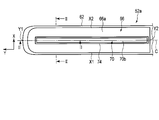
- FIG. 1 is a schematic view showing a treatment system according to the first embodiment.
- FIG. 2 is a schematic block diagram showing the treatment system according to the first embodiment.
- FIG. 3 is a schematic view showing a clamping surface of the first clamping part of the first treatment piece of the treatment part of the treatment tool of the treatment system according to the first embodiment.
- 4A is a line II in FIG. 3 in a state where supply of heat energy from the heating element of the first treatment piece of the treatment portion of the treatment device of the treatment system according to the first embodiment to the treatment body is stopped. It is a schematic longitudinal cross-sectional view which follows this.
- FIG. 4B is a schematic cross-sectional view of the first treatment piece of the treatment portion of the treatment tool of the treatment system according to the first embodiment, taken along line II-II in FIG.
- FIG. 5A is a cross-sectional view taken along line I- in FIG. 3 and FIG. 5B in a state where heat energy is supplied from the heating element of the first treatment piece of the treatment portion of the treatment device of the treatment system according to the first embodiment to the treatment body.
- It is a schematic longitudinal cross-sectional view which follows an I line.
- FIG. 5B is a schematic cross-sectional view of the first treatment piece of the treatment portion of the treatment tool of the treatment system according to the first embodiment, taken along line II-II in FIG. 3 and FIG. 5A.
- 6A is a schematic diagram illustrating a clamping surface of a second clamping part of a second treatment piece of the treatment part of the treatment tool of the treatment system according to the first embodiment.
- 6B is a schematic cross-sectional view of the second treatment piece of the treatment portion of the treatment tool of the treatment system according to the first embodiment, taken along line III-III in FIG. 6A.
- 7A is a schematic cross-sectional view showing a state in which a living tissue is sandwiched between the first treatment piece shown in FIG. 4B and the second treatment piece shown in FIG. 6B.
- FIG. 7B is a treatment body that is thermally expanded by transferring heat from the heating element of the first treatment piece shown in FIG.
- FIG. 8A shows a treatment portion of a treatment tool of a treatment system according to a first modification of the first embodiment, in which a protrusion and a thermal expansion member adjacent to each other of the treatment body of the first treatment piece
- the second treatment piece 2 is a schematic cross-sectional view showing a state in which a living tissue is sandwiched between two clamping surfaces.
- FIG. FIG. 8A shows a treatment portion of a treatment tool of a treatment system according to a first modification of the first embodiment, in which a protrusion and a thermal expansion member adjacent to each other of the treatment body of the first treatment piece
- the second treatment piece 2 is a schematic cross-sectional view showing a state in which a living tissue is sandwiched between two clamping surfaces.
- FIG. 8B shows a treatment portion of the treatment tool of the treatment system according to the first modification of the first embodiment, and heat is applied to the thermal expansion member among the protrusions and thermal expansion members adjacent to each other of the treatment body of the first treatment piece.
- FIG. 6 is a schematic cross-sectional view showing a state in which energy is applied and expanded, and a living tissue held between the second treatment piece and the second holding surface of the second treatment piece is incised by a thermal expansion member.
- FIG. 9A shows a treatment portion of a treatment tool of a treatment system according to a second modification of the first embodiment, and a pair of protrusions of the treatment body of the first treatment piece and a thermal expansion member disposed between the protrusions.
- FIG. 10 is a schematic cross-sectional view showing a state in which a living tissue is held between a second holding surface of a second treatment piece.
- FIG. 9B shows a treatment portion of the treatment tool of the treatment system according to the second modification of the first embodiment, in which thermal energy is added to the thermal expansion member of the treatment body of the first treatment piece to expand the thermal expansion member.
- FIG. 6 is a schematic cross-sectional view showing a state in which a living tissue held between a thermal expansion member and a second holding surface of a second treatment piece is incised.
- FIG. 10A shows a treatment portion of a treatment tool of a treatment system according to a third modification of the first embodiment, which is disposed between a pair of protrusions of the treatment body of the first treatment piece and the protrusions and deformed by the addition of heat. It is a rough cross-sectional view which shows the state which clamped the biological tissue between the movable body arrange
- FIG. 10B shows a treatment portion of the treatment tool of the treatment system according to the third modification of the first embodiment. The deformation body is deformed by applying thermal energy to the deformation body of the treatment body of the first treatment piece.
- FIG. 11A is a view in FIG. 3 in a state in which the supply of thermal energy from the heating element of the first treatment piece of the treatment unit of the treatment tool of the treatment system according to the fourth modification of the first embodiment to the treatment body is stopped.
- FIG. 2 is a schematic longitudinal sectional view taken along line II of FIG.
- FIG. 11B is a schematic cross-sectional view taken along the line II-II in FIG. 3 of the first treatment piece of the treatment portion of the treatment tool of the treatment system according to the fourth modification example of the first embodiment.
- FIG. 12 is a schematic view showing a treatment system according to the second embodiment.
- FIG. 13 is a schematic view showing a clamping surface of the first clamping part of the first treatment piece of the treatment part of the treatment tool of the treatment system according to the second embodiment.
- FIG. 14 is a schematic view showing a clamping surface of a second clamping part of a second treatment piece of a treatment part of a treatment tool of a treatment system according to the second embodiment.
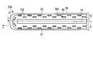
- FIG. 15 shows a state in which substantially U-shaped staples are projected from the first clamping part of the treatment part of the treatment instrument of the treatment system according to the second embodiment, and the leg parts of the staples are bent at the clamping surface of the second clamping part.
- FIG. 14 is a schematic longitudinal sectional view taken along line XV-XV in FIG.
- FIG. 16 is a schematic block diagram showing a treatment system according to the third embodiment.
- the treatment system 10 includes a treatment tool (energy treatment tool) 12 and a controller 14 that applies energy to the treatment tool 12.
- the controller 14 controls the temperature of a heating element 72 described later of the treatment instrument 12 to an appropriate temperature.
- a foot switch 16 having a pedal 16 a for switching ON / OFF of energy applied to the treatment instrument 12 is connected to the controller 14.
- the treatment instrument 12 and the controller 14 are electrically connected by a first cable 18a, and the controller 14 and the foot switch 16 are electrically connected by a second cable 18b.
- the foot switch 16 can input a signal to the controller 14 by operating the pedal 16a, and the controller 14 can control the energy applied to the treatment instrument 12 based on the operation of the pedal 16a of the foot switch 16. .
- the controller 14 includes a control unit 22 configured by a CPU or the like, a heating element drive circuit (energy output circuit) 24 as an energy source, and a display unit 26.
- the heating element driving circuit 24 and the display unit 26 are controlled by the control unit 22.
- the display unit 26 is used when displaying the state of the controller 14 or making various settings. For example, the temperature of a heating element (energy output unit) 72 described later may be displayed on the display unit 26.
- the control unit 22 can adjust the temperature (the rising temperature and the maximum temperature per unit time) of the heating element 72 by adjusting the energy output from the heating element driving circuit 24 to the heating element 72.
- the treatment instrument 12 includes an insertion portion 42 and an operation portion 44.
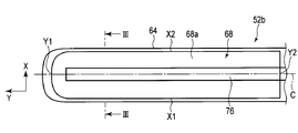
- the insertion part 42 includes a treatment part 52 for treating the living tissues L1 and L2 and a shaft 54.
- a base end portion of the shaft 54 is connected to one end 44 a of the operation portion 44.
- the treatment portion 52 is disposed at the distal end portion of the shaft 54.
- the treatment part 52 includes a first treatment piece 52a and a second treatment piece 52b.
- 1st and 2nd treatment piece 52a, 52b is opened and closed by operation of the opening-and-closing lever (opening-and-closing knob) 46 of the operation part 44 by a well-known mechanism.
- the opening / closing lever 46 When the opening / closing lever 46 is operated so as to be close to the other end 44b of the operation portion 44, the first and second treatment pieces 52a, 52b are formed by a known means such as a wire or a rod disposed inside the insertion portion 42, for example. At least one of them moves and closes close to each other.
- the opening / closing lever 46 is operated so as to be separated from the other end 44b of the operation unit 44, at least one of the first and second treatment pieces 52a, 52b is moved by a known means and is opened apart from each other. . Note that only one of the first and second treatment pieces 52a, 52b may be moved by operating the opening / closing lever 46 of the operation unit 44, or both may be moved. That is, the first and second treatment pieces 52a
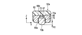
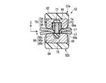
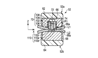
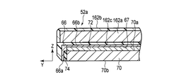
- the treatment portion 52 includes a pair of jaws (first and second jaws) 62, 64, a first clamping portion 66 having a first clamping surface 66a, a second clamping portion 68 having a second clamping surface 68a, And a treatment body 70 provided on the first clamping surface 66a.
- the second clamping surface 68a of the second clamping unit 68 faces the first clamping surface 66a and cooperates with the first clamping surface 66a to clamp the living tissues L1 and L2.
- a heating element (energy output unit) 72 is disposed in the first clamping unit 66 or on the back surface 66b.
- the treatment portion 52 includes the first jaw 62 in which the first clamping portion 66 is disposed and the first clamping surface 66a and the second clamping surface 68a can be brought close to and separated from each other.
- the treatment portion 52 includes a second jaw 64 provided with a second clamping portion 68 and capable of bringing the first clamping surface 66a and the second clamping surface 68a close to and away from each other.
- the heating element 72 is formed as a heater that generates heat when energy is input.
- the heating element 72 is electrically connected to the heating element driving circuit 24 of the controller 14 via the insertion section 42 and the operation section 44. For this reason, energy is output to the heat generating body 72 from the heat generating body drive circuit 24 by operation of the pedal 16a of the foot switch 16, and the heat generating body 72 is heated.
- the heating element 72 generates heat, the temperature of the clamping surface 66a of the first clamping part 66 and the temperature of the treatment surface 70b of the treatment body 70 rise from room temperature to, for example, about 150 ° C. to about 300 ° C. in several seconds. It is preferred that it can be warmed.
- the first treatment piece 52 a is formed by a first jaw 62, a first clamping part 66, a treatment body 70 and a heating element 72.
- the second treatment piece 52 b is formed by the second jaw 64 and the second clamping portion 68.
- first and second jaws 62 and 64 for example, ceramic, a heat-resistant and electrically insulating resin material, an insulating metal material, or the like is appropriately used.
- the first and second jaws 62 and 64 are preferably made of a heat-insulating material.
- the first clamping portion 66 is disposed on the first jaw 62.
- the back surface 66 b of the first clamping portion 66 with respect to the first clamping surface 66 a is supported by the first jaw 62 or fixed to the first jaw 62.
- the longitudinal direction passing through the distal end Y1 and the proximal end Y2 of the first clamping unit 66 is the Y direction
- the width direction orthogonal to the longitudinal direction Y is the X direction
- a height direction with respect to the clamping surface 66a of the first clamping unit 66 (an opening / closing direction with respect to the second clamping unit 68) is defined as a Z direction. That is, the longitudinal direction Y of the first clamping unit 66 is defined by the distal end Y1 and the proximal end Y2 of the first clamping unit 66.
- the width direction X of the first clamping part 66 is defined by a pair of edge parts X1 and X2 of the first clamping part 66.
- a line connecting the centers of the pair of edge portions X1 and X2 along the longitudinal direction Y is defined as a center line C.
- the first clamping part 66 is formed in a substantially rectangular flat plate shape that is long in the direction along the longitudinal direction Y of the insertion part 42 and whose width direction X orthogonal to the longitudinal direction Y is smaller than the longitudinal direction Y. It is preferable that the 1st clamping part 66 is formed with the metal material which has favorable thermal conductivity.
- an Fe—Ni 36% alloy material thermal expansion coefficient: 0.8 ⁇ E ⁇ 6 [1 / K]
- a material having a low coefficient of thermal expansion is preferably used for the first clamping unit 66.
- heat (heat energy) from the heating element 72 is transferred to the first clamping unit 66. For this reason, when energy is supplied and the heating element 72 generates heat, heat can be transferred to the first clamping surface 66a, and the temperature of the first clamping surface 66a rises.
- the clamping surface 66a of the first clamping part 66 has a first jaw 62 extending from the clamping surface 66a to the approximate center in the width direction X (on the symbol C in FIG. 3).
- a recess 67 is formed toward the end.
- the recess 67 is preferably formed in an appropriate length along the longitudinal direction Y.
- the concave portion 67 is formed between the distal end Y ⁇ b> 1 and the proximal end Y ⁇ b> 2 of the first sandwiching portion 66.
- a heating element 72 is disposed in the recess 67. That is, the heating element 72 is disposed in the first sandwiching portion 66 at a position close to the back surface 66b or the back surface 66b.
- the length of the treatment body 70 is slightly shorter than the length along the longitudinal direction Y of the concave portion 67 and slightly smaller than the width along the width direction X of the concave portion 67.
- the heat generating area of the heat generating body 72 is substantially the same as the length along the longitudinal direction Y of the recess 67.
- the heating element 72 generates heat uniformly from the distal end to the proximal end.
- a treatment body 70 is disposed in the recess 67.
- the heating element 72 is fixed to the treatment body 70.
- the buffer part 74 which has heat resistance and is elastically deformable is arrange
- heat resistant paper knitted with ceramic fiber is preferably used.
- the buffer part 74 uses the steel wool made from a stainless steel material.
- an elastically deformable resin material such as a silicone rubber material.
- the treatment body 70 is a heat transfer surface 70a that receives heat from the heat generating body 72 (receives heat), and a holding surface of the second holding portion 68 from the holding surface 66a of the first holding portion 66 on the opposite side of the heat transfer surface 70a. 68b and a treatment surface (edge) 70b for treating the living tissues L1 and L2.
- the treatment surface 70 b of the treatment body 70 extends along the longitudinal direction Y of the first sandwiching portion 66.
- the treatment surface 70b has an appropriate length along the longitudinal direction Y of the first sandwiching portion 66, and is shorter than the length of the treatment surface 70b in the longitudinal direction Y and perpendicular to the longitudinal direction Y of the first sandwiching portion 66.
- the width is smaller than the width in the direction X.
- the treatment surface 70b is formed in a blunt shape. For this reason, it is possible to prevent as much as possible from leaving traces of pinching in the living tissues L1 and L2 while the living tissues L1 and L2 are held between the holding surfaces 66a and 68a of the first and second holding portions 66 and 68. it can.
- an aluminum alloy thermal expansion coefficient: 23.1 ⁇ E ⁇ 6 [1 / K]
- the thermal expansion coefficient of the treatment body 70 is about 20 to 30 times larger than the thermal expansion coefficient of the first sandwiching portion 66.
- the heating element 72 when the heating element 72 generates heat, the temperature of the treatment surface 70 b of the treatment body 70 rises and the treatment body 70 expands compared to the first clamping unit 66. That is, the treatment body 70 is formed of a material that expands when the heat energy of the heating element 72 is transferred.
- the first protrusion amount (initial protrusion amount) P1 of the treatment surface 70b of the treatment body 70 with respect to the first holding surface 66a of the first holding portion 66 is: It is preferable that the thickness is 0 mm (equal to the treatment surface 70b) to about 1 millimeter.
- the first protrusion amount P1 may be negative depending on the coefficient of thermal expansion. That is, it is also preferable that the treatment surface 70b of the treatment body 70 is in a state of being drawn with respect to the clamping surface 66a of the first clamping unit 66.
- the maximum protrusion amount (second protrusion amount) P2 is preferably larger than the first protrusion amount P1 by about 1 millimeter to several millimeters, for example.
- the second protrusion amount P2 is always positive, and the treatment surface 70b of the treatment body 70 is in a state of protruding with respect to the first holding surface 66a of the first holding portion 66.
- the treatment surface 70b of the treatment body 70 is provided in the first sandwiching portion 66, and the supply of thermal energy is stopped in a state where the living tissues L1 and L2 are sandwiched between the first and second sandwiching surfaces 66a and 68a. Projecting from the first clamping surface 66a by the first projecting amount P1. And the treatment surface 70b of the treatment body 70 becomes the 2nd protrusion amount P2 which protrudes rather than the 1st protrusion amount P1 from the 1st clamping surface 66a according to supply of thermal energy.
- the treatment surface 70b of the treatment body 70 increases the pressure on the living tissues L1 and L2 when reaching the second protruding amount P2 from the first protruding amount P1, and cooperates with the action of thermal energy to cause the living tissues L1 and L2 to cooperate. To treat.
- the second clamping unit 68 is disposed on the second jaw 64.
- the back surface 68 b with respect to the clamping surface 68 a is supported by the second jaw 64 or fixed to the second jaw 64.
- the 2nd clamping part 68 is formed with the metal material.
- the 2nd clamping part 68 is formed, for example with copper.
- the clamping surface 68 a of the second clamping unit 68 is opposed to the clamping surface 66 a of the first clamping unit 68.
- a recess 69 is formed at the approximate center in the width direction X from the clamping surface 68a toward the second jaw 64.
- the recess 69 is preferably formed to have an appropriate length along the longitudinal direction Y.
- the recess 69 is formed between the distal end and the proximal end of the second sandwiching portion 68.
- An elastic member 76 having heat resistance is disposed in the recess 69.
- the elastic member 76 is formed to be substantially the same as or longer than the length along the longitudinal direction Y of the treatment body 70 facing the elastic member 76. That is, the clamping surface 68a of the second clamping unit 68 has an elastic member 76 that has heat resistance to the temperature of the treatment body 70 in a state where thermal energy is supplied and receives the treatment surface 70b of the treatment body 70.
- heat-resistant paper using ceramic fibers can be used for the elastic member 76.
- the ceramic fiber has a high heat resistance of 1000 ° C. or higher and can withstand the temperature of the treatment surface 70 b of the treatment body 70.
- the heat-resistant paper is knitted and formed into a paper shape.
- This heat-resistant paper is soft and felt like a felt fabric.
- the elastic member 76 can use the member which rounded the thin wire made from metal like steel wool as a heat resistant member.
- the heating element driving circuit 24 of the controller 14 can control the surface temperature of the heating element 72 of the treatment instrument 12. Specifically, the controller 14 can control the temperature of the surface (biological tissue holding surface) of the treatment body 70 when the heat generation body 72 generates heat and the heat (heat energy) is transferred to the treatment body 70. Is possible. Then, heat (thermal energy) can be transferred to the treatment target living tissues L1 and L2 through the treatment surface 70b of the treatment body 70.
- the heating element drive circuit 24 of the controller 14 adds energy to the heating element 72 for a few seconds (for example, about 10 seconds at the maximum) to cause the heating element 72 to generate heat, and then automatically stops supplying energy once. It is controlled to let you.
- the user brings the treatment unit 52 close to the biological tissues L1 and L2 to be treated in a state where the operation unit 44 of the treatment tool 12 is appropriately grasped. Then, the first and second jaws 62 and 64 (first and second treatment pieces 52a and 52b) are relatively opened by appropriately operating the opening / closing lever 46, and the living tissues L1 and L2 are first and second. It arrange
- the treatment body 70 protrudes from the clamping surface 66a of the first clamping part 66 by the first projection amount P1 (see FIG. 4B).
- the first protrusion amount P1 is not flush with the clamping surface 66a (that is, the protrusion amount is zero) or hardly protrudes, and is prevented from affecting the living tissues L1 and L2.
- the living tissues L1 and L2 are held, even if the holding surfaces 66a and 68a of the first and second holding portions 66 and 68 are opened, the living tissues L1 and L2 held by the treatment body 70 are affected. Is prevented as much as possible.
- the opening / closing lever 46 is operated again, and the living tissues L1 and L2 to be treated are clamped by the clamping surfaces 66a and 68a of the first and second clamping parts 66 and 68.
- the user presses the pedal 16a of the foot switch 16 while holding a desired position to be treated among the living tissues L1 and L2.
- energy is output from the heating element driving circuit 24 to the heating element 72, and the heating element 72 generates heat.
- the treatment surface 70b (clamping surface) of the treatment body 70 is heated to approximately 250 ° C., for example, at a time t1 (eg, an arbitrary time such as several seconds to several tens of seconds), and the temperature is maintained. Be controlled.
- the heat energy of the heating element 72 is transferred from the heat transfer surface 70 a to the treatment body 70, and is transferred to the first clamping part 66 that forms the recess 67. Since the 1st clamping part 66 is formed with the raw material with a low thermal expansion coefficient, it hardly expands or it is hard to expand
- the sandwiching surface 66a of the first sandwiching section 66 and the treatment surface 70b of the treatment body 70 are heated from 150 ° C. to about 300 ° C. within a few seconds. For this reason, thermal energy is applied to the living tissues L1 and L2 such that the living tissues L1 and L2 are sealed by the clamping surface 66a of the first clamping unit 66. Further, thermal energy is applied to the living tissues L1 and L2 by the treatment body 70. At this time, as shown in FIG. 7B, the treatment body 70 expands, so that the treatment surface 70b of the treatment body 70 increases the pressure in a line shape along the longitudinal direction Y with respect to the living tissue.
- the treatment surface 70b of the treatment body 70 increases the pressure acting toward the clamping surface 68a of the second clamping unit 68. For this reason, among the living tissues L1 and L2, in particular, a position pressed in a line shape on the treatment surface 70b of the treatment body 70 is incised in a line shape. That is, when the treatment body 70 moves from the first protrusion amount P1 to the second protrusion amount P2 in response to the supply of heat energy, the living tissue L1, L2 is incised in cooperation with the action of the heat energy on the treatment surface 70b.
- the living tissues L1 and L2 are incised, at least a part of the treatment surface 70b of the treatment body 70 abuts on the elastic member 76 disposed on the clamping surface 68a of the second clamping unit 68. Due to the elastic deformation of the elastic member 76, it is difficult to form a gap between the treatment surface 70 b of the treatment body 70 and the elastic member 76. Therefore, the presence of the elastic member 76 can prevent the living tissue from being cut as much as possible. Further, since the elastic member 76 has heat resistance and elasticity, it absorbs the force due to contact. For this reason, the elastic member 76 can prevent a load from being applied to the treatment surface 70 b of the treatment body 70.
- the thicknesses of the living tissues L1 and L2 are not uniform. For this reason, force may be applied from the treatment surface 70b of the treatment body 70 to the elastic member 76 disposed on the clamping surface 68a of the second clamping unit 68 from a direction shifted from the Z direction. At this time, the elastic member 76 prevents an excessive force from being applied to the second clamping portion 68 and the second jaw 64 as much as possible.
- the treatment body 70 has a coefficient of thermal expansion of several tens of times with respect to the first holding part 66.
- the treatment surface 70b of the treatment body 70 has a projection amount P1 with respect to the clamping surface 66a that is flush with or slightly projected. .
- the first It is possible to prevent a load from being applied to the living tissue at the center position in the width direction X of the clamping surface 66a of the 1 clamping unit 66.
- the clamping surface 66a of the 1st clamping part 66 and the treatment surface 70b of the treatment body 70 are made into 150 to 300 degreeC, for example.
- the temperature can be raised to about 0 ° C., and the living tissue can be further pressed by the linear treatment surface 70 b of the treatment body 70. Therefore, the living tissue can be sealed in the region between the clamping surfaces 66a and 68a of the first and second clamping parts 66 and 68, and at the approximate center in the width direction X of the clamping surface 66a of the first clamping part 66.
- the living tissue can be incised by the treatment surface 70b of the disposed treatment body 70. That is, in the treatment instrument 12 according to this embodiment, the periphery of the incision position of the living tissues L1 and L2 can be treated in a sealed state.
- the living tissues L1 and L2 when the living tissues L1 and L2 are held between the pair of holding surfaces 66a and 68a without adding energy, the living tissues L1 and L2 It is possible to minimize the influence of pinching on. Further, according to the treatment tool 12 and the treatment system 10, when energy is applied to treat a living tissue to be treated, the treatment body 70 is expanded so that the protrusion amount of the treatment surface 70b with respect to the sandwiching surface 66a is increased. By increasing the size, it is possible to treat the living tissues L1 and L2 while applying a larger pressure to a part of the living tissues L1 and L2 to be treated than other parts.
- the elastic member 76 is disposed so as to receive the treatment surface 70b of the treatment body 70 in the second sandwiching portion 68. And this elastic member 76 has sufficient heat resistance with respect to the temperature of about 300 degreeC. For this reason, when the living tissues L1 and L2 are pressed by the treatment surface 70b of the treatment body 70, the elastic member 76 is elastically deformed, thereby forming a gap between the treatment surface 70b of the treatment body 70 and the elastic member 76. It is hard to be done. For this reason, according to the treatment tool 12 according to this embodiment, due to the presence of the elastic member 76, it is possible to prevent the living tissue L1, L2 from being cut off as much as possible.
- the example in which the heating element 72 is arranged in the first clamping unit 66 has been described. It is also preferable to arrange the heating element 72 in the first clamping part 66 and arrange the heating element (not shown) that generates heat simultaneously with the heating element 72 in the second clamping part 68.
- the shaft 54 is not necessarily required. It is also preferable that the treatment portion 52 is directly attached to the operation portion 44.
- the treatment body 70 includes first and second blades 82 and 84.
- the first and second blades 82 and 84 are formed of a metal material or a heat resistant resin material having different coefficients of thermal expansion.
- the first and second blades 82 and 84 are adjacent to each other in the width direction X. At this time, the first and second blades 82 and 84 may be in contact with each other or may be separated from each other.
- the first protrusion amount (initial protrusion amount) P1 of the first and second blades 82 and 84 is formed larger than that of the treatment body 70 shown in FIG. 7A described in the first embodiment.
- the first protrusion amount P1 can be appropriately set according to the living tissues L1 and L2 to be treated.
- an aluminum alloy (thermal expansion coefficient: 23.1 ⁇ E ⁇ 6 [1 / K]) is used for the first blade 82.
- an Fe—Ni 36% alloy material (thermal expansion coefficient: 0.8 ⁇ E ⁇ 6 [1 / K]) is used for the second blade 84. That is, the thermal expansion coefficients of the first blade 82 and the second blade 84 have a difference of about 20 to 30 times. For this reason, when the heating element 72 generates heat and heat is transferred to the first and second blades 82 and 84, the first blade 82 expands more than the second blade 84. Note that the second blade 84 hardly expands.
- the treatment body 70 is adjacent to the first blade 82 (thermal expansion member) 82 in which the treatment surface 86a reaches from the first protrusion amount P1 to the second protrusion amount P2 by supplying heat energy, and the first blade 82, And a second blade (projecting body) 84 having a treatment surface (supporting surface for biological tissue) 86b projecting by a first projecting amount P1 with respect to the sandwiching surface 66a.
- the first and second blades 82 and 84 cooperate with each other to form a treatment surface 86.
- the treatment surface 86 includes a first treatment surface 86 a formed on the first blade 82 and a second treatment surface 86 b formed on the second blade 84.
- the operation of the treatment system 10 according to the first modification of the first embodiment will be briefly described.
- the living tissues L1 and L2 are held between the holding surfaces 66a and 68a of the holding parts 66 and 68. Hold it.
- the distance to the treatment surfaces 86a and 86b of the treatment body 70 relative to the clamping surface 66a of the first clamping unit 66, that is, the first protrusion amount P1 is substantially the same.
- energy is supplied from the heating element drive circuit 24 (see FIG. 2) to the heating element 72 of the treatment section 52 shown in FIG. 8A to cause the heating element 72 to generate heat to an appropriate temperature (for example, about 250 ° C.).
- the heat of the heating element 72 is transferred to the first blade 82, the second blade 84, and the clamping surface 66 a of the first clamping part 66.
- the treatment surface 86a of the first blade 82 increases the pressure in a line shape along the longitudinal direction Y with respect to the living tissues L1 and L2. For this reason, in particular, the positions of the living tissues L1 and L2 that are pressed in a line shape on the treatment surface 86a of the first blade 82 are incised in a line shape.
- the contact area of the portion where the coefficient of thermal expansion with respect to the living tissues L1 and L2 increases can be made smaller than the state shown in FIGS. 7A and 7B. Further, it is possible to increase the pressing force on the living tissues L1 and L2. For this reason, when treating the living tissues L1 and L2 as shown in FIG. 8B, the living tissues L1 and L2 can be incised at a lower temperature than the state shown in FIG. 7B.
- the living tissues L1 and L2 when the living tissues L1 and L2 are held between the pair of holding surfaces 66a and 68a without adding energy, the living tissues L1 and L2 It is possible to minimize the influence of pinching on. Further, according to the treatment tool 12 and the treatment system 10, when energy is applied to treat the living tissues L1 and L2 to be treated, the first blade 82 of the treatment body 70 is expanded to hold the clamping surface 66a. By increasing the protrusion amount of the treatment surface 86a with respect to the body tissue L1, L2, it is possible to treat the body tissues L1, L2 while applying a larger pressure to a part of the body tissues L1, L2 to be treated than other parts.
- the first protrusion amount P1 of the treatment surface 86 of the treatment body 70 is made larger than the state shown in FIG. 7A.
- the first protrusion amount P1 of the treatment surface 86 of the treatment body 70 may be formed in the same protrusion amount as in the state illustrated in FIG. 7A. is there.
- the treatment body 70 includes a central first blade (thermal expansion member) 92 and second and third blades (projections) 94 adjacent to both sides thereof. 96.
- the first blade 92 and the second and third blades 94 and 96 are formed of a metal material or a heat resistant resin material having different thermal expansion coefficients.
- the first blade 92 is at the approximate center in the width direction X (on the symbol C (see FIG. 3)).
- the second and third blades 94 and 96 are adjacent to the first blade 92.
- the second blade 94 may be in contact with or separated from the first blade 92.
- the third blade 96 may be in contact with the first blade 92 or may be separated from the first blade 92.
- an aluminum alloy thermal expansion coefficient: 23.1 ⁇ E ⁇ 6 [1 / K]
- an Fe—Ni 36% alloy material thermal expansion coefficient: 0.8 ⁇ E ⁇ 6 [1 / K]
- the first blade 92 and the second and third blades 94 and 96 have a difference of about 20 to 30 times in thermal expansion coefficient. For this reason, when the heating element 72 generates heat and heat is transferred from the first to the third blades 92, 94, 96, the first blade 92 expands more than the second and third blades 94, 96.
- the second and third blades 94 and 96 hardly expand.
- the first to third blades 92, 94, and 96 form a treatment surface 98 in cooperation with each other.
- the treatment surface 98 is formed on the first treatment surface 98 a formed on the first blade 92, the second treatment surface (biological tissue support surface) 98 b formed on the second blade 94, and the third blade 96. And a third treatment surface (biological tissue support surface) 98c.
- the treatment instrument 12 and the treatment system 10 according to this modified example, as shown in FIG. 9A, when the living tissues L1 and L2 are sandwiched between the pair of sandwiching surfaces 66a and 68a without adding energy, The influence of clamping on the living tissues L1 and L2 can be minimized.
- the treatment tool 12 and the treatment system 10 as shown in FIG. 9B, when treating the living tissues L1 and L2 to be treated by applying energy, the first blade 92 of the treatment body 70 is moved. By inflating and increasing the protrusion amount of the treatment surface 98a with respect to the sandwiching surface 66a, the living tissues L1 and L2 are treated while applying a larger pressure to a part of the treatment target living tissues L1 and L2 than other parts. can do.
- FIGS. 10A and 10B a third modification of the first embodiment will be described with reference to FIGS. 10A and 10B.
- it demonstrates as a further modification of the 2nd modification of the treatment part 52 shown to FIG. 9A and FIG. 9B.
- the treatment body 70 includes a central first blade (moving member) 102, second and third blades 104 and 106 adjacent to both sides thereof, and shape memory. Alloy (deformable member) 108.
- the treatment body 70 according to this embodiment includes a deformable member 108 that is deformed by the supply of thermal energy, and a first blade (movable member) that moves in a direction substantially perpendicular to the first clamping surface 66a in accordance with the deformation of the deformable member 108. ) 102. It is preferable that the first blade 102 and the second blade 104 and the first blade 102 and the third blade 106 are slidably in contact with each other.
- the first to third blades 102, 104, 106 cooperate with each other to form the treatment surface 110.
- the treatment surface 110 includes a first treatment surface 110a formed on the first blade 102, a second treatment surface 110b formed on the second blade 104, and a third treatment surface 110c formed on the third blade 106. Have.
- the first to third blades 102, 104, and 106 can be made of the same material having a low coefficient of thermal expansion.
- an Fe—Ni 36% alloy material thermal expansion coefficient: 0.8 ⁇ E ⁇ 6 [1 / K]
- the first to third blades 102, 104, and 106 are preferably made of the same material as that of the first clamping unit 66.
- the shape memory alloy 108 is disposed between the first blade 102 and the heating element 72.
- shape memory alloys 108 formed in a plurality of coil spring shapes are arranged along the longitudinal direction Y at appropriate intervals.
- the shape memory alloy 108 formed in each coil spring shape is memorized so as to extend when heated to an appropriate temperature higher than room temperature.
- a Ti—Ni alloy is used as the shape memory alloy 108 of this modification.
- the shape memory alloy 108 can be adjusted so as to exhibit the property of returning to the memorized shape when heated to an appropriate temperature (for example, about 90 ° C.).
- the shape memory alloy 108 is heated and deformed from the state shown in FIG. 10A to the state shown in FIG. 10B.
- the first blade (moving member) 102 is moved from the first clamping surface 66a as shown in FIG. 10B from the state of protruding from the first clamping surface 66a by the first protruding amount P1 as shown in FIG. 10A. It moves to the state where it protrudes by the protrusion amount P2. Therefore, when the heating element 72 is heated, the shape memory alloy 108 is heated, and the first blade 102 can be moved away from the heating element 72.
- the treatment instrument 12 and the treatment system 10 when the living tissues L1 and L2 are held between the pair of holding surfaces 66a and 68a, the influence of the holding on the living tissues L1 and L2 is minimized. Can be suppressed. Further, according to the treatment tool 12 and the treatment system 10, when the energy is applied to treat the living tissues L1 and L2 to be treated, the first blade 102 of the treatment body 70 is moved by the shape memory alloy 108. Thus, by increasing the protrusion amount of the treatment surface 110a with respect to the sandwiching surface 66a, it is possible to treat the living tissue while applying a larger pressure to a part of the treatment target living tissues L1 and L2 than other portions.
- shape memory alloy 108 may be a Ti—Ni alloy or a high-temperature shape memory alloy that deforms into a memorized shape when a temperature exceeding 100 ° C. is reached.
- the treatment section 52 of this modification has been described as a further modification of the treatment section 52 of the second modification. It is also preferable to dispose the shape memory alloy 108 between the heat transfer surface 70a of the treatment body 70 of the treatment section 52 and the heating element 72 shown in FIGS. 7A and 7B. Similarly, it is also preferable to dispose the shape memory alloy 108 between the first blade 82 and the heating element 72 of the treatment body 70 of the treatment section 52 shown in FIGS. 8A and 8B.
- the example in which the shape memory alloy 108 is used between the first blade 102 and the heating element 72 has been described. It is also suitable to use a known bimetal (deformable member) (not shown) instead of the shape memory alloy 108 or together with the shape memory alloy 108.
- Bimetal is a laminate of two types of metal materials. The bimetal can be deformed when appropriate heat is applied by utilizing the difference in coefficient of thermal expansion between each other, and can be restored to its original state when the temperature is lowered.
- the elastic member 76 does not necessarily need to be arrange
- FIG. 10A and FIG. 10B the elastic member 76 does not necessarily need to be arrange
- FIGS. 11A and 11B a fourth modification of the first embodiment will be described with reference to FIGS. 11A and 11B.
- it demonstrates as a further modification of 1st Embodiment and a 1st-3rd modification.
- the structure of the first jaw 62 described in this modification can be appropriately employed in the structure of the first jaw 62 described in the first embodiment and the first to third modifications.
- the first treatment piece 52a of the treatment portion 52 is provided with the first sandwiching portion 66, and the first sandwiching surface 66a and the second sandwiching surface 68a are close to each other. And a first jaw 62 that can be spaced apart.
- the first jaw 62 includes a support member 162a and an outer cover (heat insulating cover) 162b.
- a heat-resistant inner cover 162c is disposed between the support member 162a and the first holding portion 66, that is, on the back surface 66b of the first holding portion 66.
- the inner cover 162c serves as a spacer that separates the support member 162a from the heat generating body 72, and heat of the heat generating body 72 is difficult to transfer to the support member 162a, and is prevented from being transferred to the outside of the outer cover 162b through the support member 162a. Has been.
- the inner cover 162c has an electrical insulating property so as to prevent electric energy from moving between the first clamping unit 66 and / or the heat generating unit 72 and the support member 162a of the first jaw 62. Is preferred.
- the cover 162b has an electrical insulating property similarly to the inner cover 162c.
- the inner cover 162c is preferably formed of a ceramic material or a heat-resistant plastic material. It is also preferable that the inner cover 162c is integrated with the back surface 66b of the first clamping unit 66 by coating.
- the inner cover 162c protects the side surface in addition to the back surface 66b of the first clamping unit 66. It is also preferable that the side surface of the first clamping portion 66 is protected not by the inner cover 162c but by the outer cover 162b.
- the support member 162a is formed to operate by operating the opening / closing lever 46 shown in FIG. Then, following the operation of the support member 162a, the inner cover 162c, the first clamping unit 66, the heating element 72, the treatment body 70, and the buffer unit 74 operate. For this reason, it is possible to make the 1st clamping surface 66a and the 2nd clamping surface 68a adjoin and space apart by operation
- the support member 162a is preferably made of a highly rigid material such as an aluminum alloy or stainless steel. For this reason, the deformation of the entire first jaw 62 is suppressed.
- the outer cover 162b is preferably formed of a ceramic material or a heat-resistant plastic material. It is also preferable that an air layer is formed between the outer cover 162b and the support member 162a.
- the outer cover 162b is preferably integrated with the support member 162a by coating.
- the treatment part 52 is very small and it is difficult to maintain the strength. For this reason, when the living tissue is gripped with a strong force, a load is applied to the first clamping unit 66, and the first clamping unit 66 may be deformed, making it difficult to appropriately treat the living tissue.
- the support member 162a formed of a highly rigid material as in this modification, it is easy to maintain the shape of the first sandwiching portion 66 even if the living tissue is gripped with a strong force.
- the 1st clamping part 66 may be fixed with respect to the support member 162a, and may be rockable. That is, it is also preferable that the inner cover 162c, the first clamping part 66, the heating element 72, the treatment body 70, and the buffer part 74 are swingable like a seesaw with respect to the support member 162a.
- the inner cover 162c is not always necessary, and the outer cover 162b can protect the side surface of the first holding portion 66.
- the first jaw 62 includes the support member 162a, the outer cover 162b, and the inner cover 162c.
- the second jaw 64 has a similar structure.
- This embodiment is a modification of the first embodiment including each modification, and the same members or members having the same functions as those described in the first embodiment are denoted by the same reference numerals, and detailed. Description is omitted.
- the operation unit 44 includes a drive lever 46 a provided in parallel with the opening / closing lever 46.
- the drive lever 46a functions to move a pusher rod 182 described later.
- the first treatment piece 52a has a surgical staple 180 that is a substantially U-shaped needle.
- Surgical staple 180 is preferably formed of a bioabsorbable material, for example.
- a plurality of staples 180 are accommodated in the magazine 178 between the first jaw 62 and the back surface 66b of the first clamping unit 66.
- a pusher rod 182 having an inclined surface 182 a is accommodated in a magazine 178 for discharging a surgical staple (absorbent member) 180 of the first jaw 62 so as to be movable in parallel with the longitudinal direction Y.
- the pusher rod 182 according to this embodiment operates according to the operation of the drive lever 46a.
- a staple 180 having a pair of leg portions 180a and an arm 180b that connects the leg portions 180a is accommodated so that the leg portions 180a can protrude toward the pinching surface 68a of the second pinching portion 68.
- a guide groove (discharge port) 184 is formed on the clamping surface 66 a of the first clamping unit 66 so as to face the pusher rod 182.
- a staple pusher 186 having an inclined surface 186 a that is inclined in the same manner as the inclined surface 182 a of the pusher rod 182 is slidably disposed with respect to the guide groove 184.
- a plurality of staple deformation grooves (clincher) 192 are formed on the clamping surface 68 a of the second clamping unit 68.
- Each staple deformation groove 192 has a bottom surface formed in, for example, a substantially arc shape so that the pair of leg portions 180a (see FIG. 15) of the staple 180 can be bent and deformed inward. Therefore, the clamping surface 68 a of the second clamping unit 68 also has a function as an anvil of the staple 180.
- the guide groove 184 shown in FIG. 13 and the staple deformation groove 192 shown in FIG. 14 are formed at positions facing each other.
- a living tissue is treated using thermal energy.
- the pusher rod 182 advances by a known mechanism. For this reason, the living tissue treated with thermal energy is penetrated by the pair of legs 180 a of the staple 180 through the guide groove 184.
- the pair of legs 180a of the staple 180 is folded so as to face each other by the staple deformation groove 192, and the staple 180 is fixed to the living tissue.
- This embodiment is a modification of the first and second embodiments, and the same members or members having the same functions as those described in the first and second embodiments are denoted by the same reference numerals and detailed. Description is omitted.
- the example in which the heating element 72 is arranged in the first clamping unit 66 has been described. It is also preferable to form the first clamping part 66 and the second clamping part 68 as electrodes (energy output parts), respectively. That is, it is also preferable to treat the living tissue by combining the heat energy generated by the heating element 72 and the high-frequency energy using the first holding part 66 and the second holding part 68 as electrodes.
- the controller 14 has a high frequency energy drive circuit (energy output circuit) 28 as an energy source, as shown in FIG.
- the high-frequency energy drive circuit 28 is electrically connected to a first clamping unit (first high-frequency electrode) 66 and a second clamping unit (second high-frequency electrode) 68.
- the living tissue between the first and second sandwiching portions 66 and 68 is dehydrated by Joule heat due to high-frequency energy, and the living tissue is transferred to the sandwiching surfaces 66a and 68a by the heat energy due to heat generated by the heating element 72. Be treated. At this time, the treatment body 70 expands due to the heat generated by the heat generating body 72, and a gradually greater pressure can be applied to the living tissues L1, L2.
- the living tissues L1 and L2 between the first and second sandwiching portions 66 and 68 are heated by high-frequency energy in a shorter time than using the heat transfer of the heating element 72 described in the first embodiment.
- the treatment tool 12 according to this embodiment is shorter than the treatment tool 12 described in the first embodiment, for example, by cutting the living tissues L1 and L2 at the treatment surface 70b in a shorter time. Can be treated.
- the heating element 72 of the treatment tool 12 according to this embodiment can complete the treatment at a lower temperature than the treatment of the treatment tool 12 described in the first embodiment.
- the mechanism capable of releasing the staple 180 described in the second embodiment may be combined with the treatment instrument 12 according to this embodiment.
- DESCRIPTION OF SYMBOLS 10 ... Treatment treatment system, 12 ... Surgical treatment tool, 52 ... Treatment part, 52a ... 1st treatment piece, 52b ... 2nd treatment piece, 62 ... 1st jaw, 64 ... 2nd jaw, 66 ... 1st clamping part , 66a ... first clamping surface, 67 ... recess, 68 ... second clamping portion, 68a ... second clamping surface, 69 ... recess, 70 ... treatment body, 70a ... heat transfer surface, 70b ... treatment surface, 72 ... heating element , 74: buffer part, 76: elastic member, L1, L2 ... biological tissue, P1: first protrusion amount, P2: second protrusion amount.
Abstract
This treatment instrument comprises a treatment body which is provided on a first clamping surface and has a treatment surface that protrudes against biological tissue by a first protrusion amount from the first clamping surface when supply of heat energy is stopped while the biological tissue is clamped between the first clamping surface and a second clamping surface, protrudes by a second protrusion amount from the first clamping surface beyond the first protrusion amount when heat energy is being supplied, and increases the pressure on the biological tissue when changing from the first protrusion amount to the second protrusion amount to treat the biological tissue in coordination with the effect of heat energy.
Description
この発明は、熱エネルギを用いて生体組織を処置する処置具及び処置システムに関する。
The present invention relates to a treatment tool and a treatment system for treating a living tissue using thermal energy.
例えば米国特許第7329257号明細書には、1対の挟持面間に挟持した生体組織をエネルギを用いて処置する処置具が開示されている。この処置具は、一方の挟持面を他方の挟持面に向かって突出させつつ、突出部分を幅方向に薄肉に形成している。このため、この処置具は、生体組織に対してライン状に圧力を付加しながら処置対象の生体組織に熱エネルギを付加することで、その生体組織を切開し易くしている。
For example, US Pat. No. 7,329,257 discloses a treatment instrument for treating a living tissue sandwiched between a pair of sandwiching surfaces using energy. In this treatment instrument, one protruding surface protrudes toward the other holding surface, and the protruding portion is formed thin in the width direction. For this reason, this treatment tool makes it easy to incise the living tissue by applying heat energy to the living tissue to be treated while applying pressure to the living tissue in a line.
生体組織を処置する際、所望の位置とはずれた位置の生体組織を1対の挟持面間に把持してしまい、挟持し直すことが必要な場合がある。このとき、所望の位置とはずれた位置の生体組織に対して、挟持したときの影響を最小限に抑制することが求められている。
一方、1対の挟持面間に生体組織を挟持した状態でエネルギを付加して処置対象の生体組織を切開等、処置する際には、生体組織の一部に他の部分よりも大きな圧力を付加して生体組織を処置し易くすることが求められている。 When treating a living tissue, it may be necessary to grip the living tissue at a position deviated from a desired position between the pair of sandwiching surfaces and re-clamp it. At this time, there is a demand for minimizing the influence of holding the living tissue at a position different from the desired position.
On the other hand, when treating a living tissue to be treated, such as incision, by applying energy in a state where the living tissue is sandwiched between a pair of sandwiching surfaces, a larger pressure is applied to a part of the living tissue than the other part. In addition, there is a demand for facilitating treatment of living tissue.
この発明は、1対の挟持面間に生体組織を挟持したときに挟持の影響を最小限に抑制可能であるとともに、エネルギを付加して処置対象の生体組織を処置する際には、処置対象の生体組織の一部にその他の部位よりも大きな圧力を付加しながら生体組織を処置可能な処置具、及び、処置システムを提供することを目的とする。
The present invention can minimize the influence of clamping when a living tissue is clamped between a pair of clamping surfaces, and when treating a living tissue to be treated by adding energy, It is an object of the present invention to provide a treatment tool and a treatment system capable of treating a living tissue while applying a larger pressure to a part of the living tissue than other portions.
この発明の一態様に係る処置具は、第1挟持面を有する第1挟持部と、前記第1挟持面に対向し、前記第1挟持面と協働して生体組織を挟持する第2挟持面を有する第2挟持部と、前記第1挟持部に設けられ、前記第1及び第2挟持面間に前記生体組織を挟持した状態で、熱エネルギの供給が停止されているときに前記第1挟持面から第1突出量だけ突出し、前記熱エネルギの供給に応じて前記第1挟持面から前記第1突出量よりも突出する第2突出量となり、前記第1突出量から前記第2突出量に至る際に前記生体組織に対する圧力を上昇させて前記熱エネルギの作用と協働して前記生体組織を処置する処置面を有する処置体とを有する。
A treatment instrument according to an aspect of the present invention includes a first clamping unit having a first clamping surface, and a second clamping that faces the first clamping surface and clamps a living tissue in cooperation with the first clamping surface. A second sandwiching portion having a surface, and the first sandwiching portion, wherein the biological tissue is sandwiched between the first and second sandwiching surfaces and the supply of thermal energy is stopped. The first projecting amount projects from the first clamping surface by a first projecting amount, and the second projecting amount projects from the first clamping surface more than the first projecting amount in response to the supply of the thermal energy. And a treatment body having a treatment surface for treating the living tissue in cooperation with the action of the thermal energy by increasing the pressure on the living tissue when reaching the quantity.
以下、図面を参照しながらこの発明を実施するための形態について説明する。
Hereinafter, embodiments for carrying out the present invention will be described with reference to the drawings.
まず、第1実施形態について図1から図7Bを用いて説明する。
First, the first embodiment will be described with reference to FIGS. 1 to 7B.
図1及び図2に示すように、この実施形態に係る処置システム10は、処置具(エネルギ処置具)12と、処置具12にエネルギを付与するコントローラ14とを有する。コントローラ14は処置具12の後述する発熱体72の温度を適宜の温度に制御する。
コントローラ14には処置具12に付与するエネルギのON/OFFを切り替えるペダル16aを有するフットスイッチ16が接続されている。処置具12とコントローラ14との間は第1ケーブル18aにより電気的に接続され、コントローラ14とフットスイッチ16との間は第2ケーブル18bにより電気的に接続されている。フットスイッチ16はペダル16aの操作等によりコントローラ14に信号を入力することが可能であり、コントローラ14はフットスイッチ16のペダル16aの操作等に基づいて処置具12に付与するエネルギを制御可能である。
フットスイッチ16のペダル16aを術者が操作することにより、コントローラ14から外科用処置具12へのエネルギの供給のON/OFFが切り換えられる。ペダル16aが押圧されているときには、後述する発熱体72を発熱させて処置体(熱膨張部材)70及び第1挟持部66に伝熱させ、ペダル16aを解放すると、発熱体72へのエネルギの供給が停止される。
なお、フットスイッチ16の代わりに、又は、フットスイッチ16とともに、図示しないハンドスイッチを用いても良いことはもちろんである。 As shown in FIGS. 1 and 2, thetreatment system 10 according to this embodiment includes a treatment tool (energy treatment tool) 12 and a controller 14 that applies energy to the treatment tool 12. The controller 14 controls the temperature of a heating element 72 described later of the treatment instrument 12 to an appropriate temperature.
Afoot switch 16 having a pedal 16 a for switching ON / OFF of energy applied to the treatment instrument 12 is connected to the controller 14. The treatment instrument 12 and the controller 14 are electrically connected by a first cable 18a, and the controller 14 and the foot switch 16 are electrically connected by a second cable 18b. The foot switch 16 can input a signal to the controller 14 by operating the pedal 16a, and the controller 14 can control the energy applied to the treatment instrument 12 based on the operation of the pedal 16a of the foot switch 16. .
When the operator operates the pedal 16a of thefoot switch 16, the supply of energy from the controller 14 to the surgical treatment instrument 12 is switched ON / OFF. When the pedal 16a is pressed, a heating element 72 described later is heated to transfer heat to the treatment body (thermal expansion member) 70 and the first clamping unit 66, and when the pedal 16a is released, the energy of the heating element 72 is transferred. Supply is stopped.
It goes without saying that a hand switch (not shown) may be used instead of or together with thefoot switch 16.
コントローラ14には処置具12に付与するエネルギのON/OFFを切り替えるペダル16aを有するフットスイッチ16が接続されている。処置具12とコントローラ14との間は第1ケーブル18aにより電気的に接続され、コントローラ14とフットスイッチ16との間は第2ケーブル18bにより電気的に接続されている。フットスイッチ16はペダル16aの操作等によりコントローラ14に信号を入力することが可能であり、コントローラ14はフットスイッチ16のペダル16aの操作等に基づいて処置具12に付与するエネルギを制御可能である。
フットスイッチ16のペダル16aを術者が操作することにより、コントローラ14から外科用処置具12へのエネルギの供給のON/OFFが切り換えられる。ペダル16aが押圧されているときには、後述する発熱体72を発熱させて処置体(熱膨張部材)70及び第1挟持部66に伝熱させ、ペダル16aを解放すると、発熱体72へのエネルギの供給が停止される。
なお、フットスイッチ16の代わりに、又は、フットスイッチ16とともに、図示しないハンドスイッチを用いても良いことはもちろんである。 As shown in FIGS. 1 and 2, the
A
When the operator operates the pedal 16a of the
It goes without saying that a hand switch (not shown) may be used instead of or together with the
図2に示すように、コントローラ14は、CPU等から構成される制御部22と、エネルギ源としての発熱体駆動回路(エネルギ出力回路)24と、表示部26とを有する。発熱体駆動回路24及び表示部26は制御部22により制御される。表示部26は、コントローラ14の状態を表示したり、各種の設定をする際に用いられる。表示部26には、例えば後述する発熱体(エネルギ出力部)72の温度が表示されるようにしても良い。
なお、フットスイッチ16とコントローラ14の制御部22とが電気的に接続された状態でフットスイッチ16のペダル16aが押圧されると、発熱体駆動回路24から後述する発熱体72にエネルギが出力される。このとき、制御部22は、発熱体駆動回路24から発熱体72に出力されるエネルギを調整して、発熱体72の温度(単位時間当たりの上昇温度及び最高温度)を調整可能である。 As shown in FIG. 2, thecontroller 14 includes a control unit 22 configured by a CPU or the like, a heating element drive circuit (energy output circuit) 24 as an energy source, and a display unit 26. The heating element driving circuit 24 and the display unit 26 are controlled by the control unit 22. The display unit 26 is used when displaying the state of the controller 14 or making various settings. For example, the temperature of a heating element (energy output unit) 72 described later may be displayed on the display unit 26.
When thefoot switch 16 and the control unit 22 of the controller 14 are electrically connected and the pedal 16a of the foot switch 16 is pressed, energy is output from the heating element drive circuit 24 to the heating element 72 described later. The At this time, the control unit 22 can adjust the temperature (the rising temperature and the maximum temperature per unit time) of the heating element 72 by adjusting the energy output from the heating element driving circuit 24 to the heating element 72.
なお、フットスイッチ16とコントローラ14の制御部22とが電気的に接続された状態でフットスイッチ16のペダル16aが押圧されると、発熱体駆動回路24から後述する発熱体72にエネルギが出力される。このとき、制御部22は、発熱体駆動回路24から発熱体72に出力されるエネルギを調整して、発熱体72の温度(単位時間当たりの上昇温度及び最高温度)を調整可能である。 As shown in FIG. 2, the
When the
図1に示すように、処置具12は、挿入部42と、操作部44とを有する。挿入部42は、生体組織L1,L2を処置する処置部52と、シャフト54とを有する。シャフト54の基端部は操作部44の一端44aに連結されている。処置部52はシャフト54の先端部に配設されている。処置部52は、第1処置片52aと第2処置片52bとを有する。
As shown in FIG. 1, the treatment instrument 12 includes an insertion portion 42 and an operation portion 44. The insertion part 42 includes a treatment part 52 for treating the living tissues L1 and L2 and a shaft 54. A base end portion of the shaft 54 is connected to one end 44 a of the operation portion 44. The treatment portion 52 is disposed at the distal end portion of the shaft 54. The treatment part 52 includes a first treatment piece 52a and a second treatment piece 52b.
第1及び第2処置片52a,52bは公知の機構により操作部44の開閉レバー(開閉ノブ)46の操作により開閉される。開閉レバー46が操作部44の他端44bに近接するように操作されると、例えば挿入部42の内部に配置されたワイヤやロッド等の公知の手段により第1及び第2処置片52a,52bの少なくとも一方が移動して、互いに対して近接して閉じる。開閉レバー46が操作部44の他端44bに離隔するように操作されると、公知の手段により第1及び第2処置片52a,52bの少なくとも一方が移動して、互いに対して離隔して開く。なお、第1及び第2処置片52a,52bは操作部44の開閉レバー46の操作により片方だけが動くようにしても良いし、両方が動くようにしても良い。すなわち第1及び第2処置片52a,52bは相対的に開閉可能である。
1st and 2nd treatment piece 52a, 52b is opened and closed by operation of the opening-and-closing lever (opening-and-closing knob) 46 of the operation part 44 by a well-known mechanism. When the opening / closing lever 46 is operated so as to be close to the other end 44b of the operation portion 44, the first and second treatment pieces 52a, 52b are formed by a known means such as a wire or a rod disposed inside the insertion portion 42, for example. At least one of them moves and closes close to each other. When the opening / closing lever 46 is operated so as to be separated from the other end 44b of the operation unit 44, at least one of the first and second treatment pieces 52a, 52b is moved by a known means and is opened apart from each other. . Note that only one of the first and second treatment pieces 52a, 52b may be moved by operating the opening / closing lever 46 of the operation unit 44, or both may be moved. That is, the first and second treatment pieces 52a and 52b can be relatively opened and closed.
処置部52は、1対のジョー(第1及び第2ジョー)62,64と、第1挟持面66aを有する第1挟持部66と、第2挟持面68aを有する第2挟持部68と、第1挟持面66aに設けられた処置体70とを有する。第2挟持部68の第2挟持面68aは、第1挟持面66aに対向し第1挟持面66aと協働して生体組織L1,L2を挟持する。第1挟持部66の内部又は裏面66bには、発熱体(エネルギ出力部)72が配設されている。すなわち、処置部52は、第1挟持部66が配設され、第1挟持面66aと第2挟持面68aとを近接及び離隔させることが可能な第1ジョー62を有する。処置部52は、第2挟持部68が配設され、第1挟持面66aと第2挟持面68aとを近接及び離隔させることが可能な第2ジョー64を有する。
The treatment portion 52 includes a pair of jaws (first and second jaws) 62, 64, a first clamping portion 66 having a first clamping surface 66a, a second clamping portion 68 having a second clamping surface 68a, And a treatment body 70 provided on the first clamping surface 66a. The second clamping surface 68a of the second clamping unit 68 faces the first clamping surface 66a and cooperates with the first clamping surface 66a to clamp the living tissues L1 and L2. A heating element (energy output unit) 72 is disposed in the first clamping unit 66 or on the back surface 66b. That is, the treatment portion 52 includes the first jaw 62 in which the first clamping portion 66 is disposed and the first clamping surface 66a and the second clamping surface 68a can be brought close to and separated from each other. The treatment portion 52 includes a second jaw 64 provided with a second clamping portion 68 and capable of bringing the first clamping surface 66a and the second clamping surface 68a close to and away from each other.
この実施形態では、発熱体72は、エネルギが入力されると発熱するヒータとして形成されている。発熱体72は挿入部42及び操作部44を介してコントローラ14の発熱体駆動回路24に電気的に接続されている。このため、フットスイッチ16のペダル16aの操作により発熱体駆動回路24から発熱体72にエネルギを出力して、発熱体72を発熱させる。発熱体72を発熱させる場合、第1挟持部66の挟持面66aの温度、及び、処置体70の処置面70bの温度は、常温から、例えば150℃から300℃程度の間までそれぞれ数秒で昇温させることができることが好ましい。
In this embodiment, the heating element 72 is formed as a heater that generates heat when energy is input. The heating element 72 is electrically connected to the heating element driving circuit 24 of the controller 14 via the insertion section 42 and the operation section 44. For this reason, energy is output to the heat generating body 72 from the heat generating body drive circuit 24 by operation of the pedal 16a of the foot switch 16, and the heat generating body 72 is heated. When the heating element 72 generates heat, the temperature of the clamping surface 66a of the first clamping part 66 and the temperature of the treatment surface 70b of the treatment body 70 rise from room temperature to, for example, about 150 ° C. to about 300 ° C. in several seconds. It is preferred that it can be warmed.
第1処置片52aは、第1ジョー62、第1挟持部66、処置体70及び発熱体72で形成されている。第2処置片52bは、第2ジョー64及び第2挟持部68で形成されている。
The first treatment piece 52 a is formed by a first jaw 62, a first clamping part 66, a treatment body 70 and a heating element 72. The second treatment piece 52 b is formed by the second jaw 64 and the second clamping portion 68.
第1及び第2ジョー62,64は例えばセラミックや耐熱性及び電気絶縁性を有する樹脂材、更には絶縁処理された金属材等が適宜に用いられる。また、第1及び第2ジョー62,64は断熱性を有する素材が用いられることが好ましい。
As the first and second jaws 62 and 64, for example, ceramic, a heat-resistant and electrically insulating resin material, an insulating metal material, or the like is appropriately used. The first and second jaws 62 and 64 are preferably made of a heat-insulating material.
第1挟持部66は第1ジョー62に配設されている。第1挟持部66のうち、第1挟持面66aに対する裏面66bは、第1ジョー62に支持され、又は、第1ジョー62に固定されている。
The first clamping portion 66 is disposed on the first jaw 62. The back surface 66 b of the first clamping portion 66 with respect to the first clamping surface 66 a is supported by the first jaw 62 or fixed to the first jaw 62.
なお、図3から図5Bに示すように、この実施形態では、第1挟持部66の先端Y1と基端Y2とを通る長手方向をY方向、長手方向Yに直交する幅方向をX方向、第1挟持部66の挟持面66aに対する高さ方向(第2挟持部68に対する開閉方向)をZ方向と規定する。すなわち、第1挟持部66の長手方向Yは、第1挟持部66の先端Y1と基端Y2とにより規定される。第1挟持部66の幅方向Xは、第1挟持部66の1対の縁部X1,X2により規定される。なお、1対の縁部X1,X2の中央を長手方向Yに沿って結ぶ線を中心線Cとする。
As shown in FIGS. 3 to 5B, in this embodiment, the longitudinal direction passing through the distal end Y1 and the proximal end Y2 of the first clamping unit 66 is the Y direction, and the width direction orthogonal to the longitudinal direction Y is the X direction. A height direction with respect to the clamping surface 66a of the first clamping unit 66 (an opening / closing direction with respect to the second clamping unit 68) is defined as a Z direction. That is, the longitudinal direction Y of the first clamping unit 66 is defined by the distal end Y1 and the proximal end Y2 of the first clamping unit 66. The width direction X of the first clamping part 66 is defined by a pair of edge parts X1 and X2 of the first clamping part 66. A line connecting the centers of the pair of edge portions X1 and X2 along the longitudinal direction Y is defined as a center line C.
第1挟持部66は、挿入部42の長手方向Yに沿った方向に長く、長手方向Yに直交する幅方向Xが長手方向Yよりも小さい、略矩形状の平板状に形成されている。第1挟持部66は良好な熱伝導性を有する金属材で形成されていることが好ましい。第1挟持部66は、例えばFe-Ni36%合金材(熱膨張率:0.8×E-6[1/K])が用いられる。すなわち、第1挟持部66には熱膨張率が低い素材が用いられることが好ましい。
なお、第1挟持部66には発熱体72からの熱(熱エネルギ)が伝熱される。このため、エネルギが供給されて発熱体72が発熱させられると、第1挟持面66aに伝熱可能であり、第1挟持面66aの温度は上昇する。 Thefirst clamping part 66 is formed in a substantially rectangular flat plate shape that is long in the direction along the longitudinal direction Y of the insertion part 42 and whose width direction X orthogonal to the longitudinal direction Y is smaller than the longitudinal direction Y. It is preferable that the 1st clamping part 66 is formed with the metal material which has favorable thermal conductivity. For example, an Fe—Ni 36% alloy material (thermal expansion coefficient: 0.8 × E −6 [1 / K]) is used for the first clamping unit 66. That is, a material having a low coefficient of thermal expansion is preferably used for the first clamping unit 66.
Note that heat (heat energy) from theheating element 72 is transferred to the first clamping unit 66. For this reason, when energy is supplied and the heating element 72 generates heat, heat can be transferred to the first clamping surface 66a, and the temperature of the first clamping surface 66a rises.
なお、第1挟持部66には発熱体72からの熱(熱エネルギ)が伝熱される。このため、エネルギが供給されて発熱体72が発熱させられると、第1挟持面66aに伝熱可能であり、第1挟持面66aの温度は上昇する。 The
Note that heat (heat energy) from the
図3、図4B及び図5Bに示すように、第1挟持部66の挟持面66aには、幅方向Xの略中央(図3中の符号C上)に、挟持面66aから第1ジョー62に向かって凹部67が形成されている。凹部67は、長手方向Yに沿って適宜の長さに形成されていることが好ましい。ここでは、図3に示すように、凹部67は、第1挟持部66の先端Y1と基端Y2との間に形成されている。
As shown in FIGS. 3, 4B and 5B, the clamping surface 66a of the first clamping part 66 has a first jaw 62 extending from the clamping surface 66a to the approximate center in the width direction X (on the symbol C in FIG. 3). A recess 67 is formed toward the end. The recess 67 is preferably formed in an appropriate length along the longitudinal direction Y. Here, as shown in FIG. 3, the concave portion 67 is formed between the distal end Y <b> 1 and the proximal end Y <b> 2 of the first sandwiching portion 66.
凹部67には、発熱体72が配設されている。すなわち、第1挟持部66のうち、裏面66b又は裏面66bに近接する位置に発熱体72が配設されている。
A heating element 72 is disposed in the recess 67. That is, the heating element 72 is disposed in the first sandwiching portion 66 at a position close to the back surface 66b or the back surface 66b.
常温において、処置体70の長さは、凹部67の長手方向Yに沿った長さよりも僅かに短く、凹部67の幅方向Xに沿った幅よりも僅かに小さい。発熱体72の発熱領域は、凹部67の長手方向Yに沿った長さと略同一である。なお、ここでは、発熱体72はその先端から基端まで均一に発熱するものとする。
At normal temperature, the length of the treatment body 70 is slightly shorter than the length along the longitudinal direction Y of the concave portion 67 and slightly smaller than the width along the width direction X of the concave portion 67. The heat generating area of the heat generating body 72 is substantially the same as the length along the longitudinal direction Y of the recess 67. Here, it is assumed that the heating element 72 generates heat uniformly from the distal end to the proximal end.
凹部67には、処置体70が配設されている。言い換えると、処置体70には、発熱体72が固定されている。凹部67と処置体70との間には、耐熱性を有するとともに弾性変形可能な緩衝部74が配設されている。緩衝部74は、例えばセラミックファイバーで編み込まれた耐熱ペーパーを用いることが好適である。また、緩衝部74は、ステンレス鋼材製のスチールウールを用いることも好ましい。その他、例えば300℃程度の温度において機能が確保されるのであれば、シリコーンゴム材等の弾性変形可能な樹脂材を用いることも好適である。
A treatment body 70 is disposed in the recess 67. In other words, the heating element 72 is fixed to the treatment body 70. Between the recessed part 67 and the treatment body 70, the buffer part 74 which has heat resistance and is elastically deformable is arrange | positioned. For the buffer portion 74, for example, heat resistant paper knitted with ceramic fiber is preferably used. Moreover, it is also preferable that the buffer part 74 uses the steel wool made from a stainless steel material. In addition, for example, if the function is secured at a temperature of about 300 ° C., it is also preferable to use an elastically deformable resin material such as a silicone rubber material.
処置体70は、発熱体72から伝熱される(熱を受ける)伝熱面70aと、伝熱面70aの反対側にあり第1挟持部66の挟持面66aから第2挟持部68の挟持面68aに向かって突出して生体組織L1,L2を処置する処置面(縁部)70bとを有する。処置体70の処置面70bは、第1挟持部66の長手方向Yに沿って延出されている。処置面70bは、第1挟持部66の長手方向Yに沿って適宜の長さを有するとともに、処置面70bの長手方向Yの長さよりも短く第1挟持部66の長手方向Yに直交する幅方向Xの幅に対して小さい幅を有する。処置面70bは鈍形状に形成されている。このため、第1及び第2挟持部66,68の挟持面66a,68a間に生体組織L1,L2を挟持した状態で、生体組織L1,L2に挟持の痕跡を残すのを極力防止することができる。
第1挟持部66に配設される処置体70は、良好な熱伝導性を有する、例えばアルミニウム合金(熱膨張率:23.1×E-6[1/K])が用いられる。すなわち、処置体70の熱膨張率は、第1挟持部66の熱膨張率に比べて20倍から30倍程度大きい。このため、発熱体72が発熱すると、処置体70の処置面70bの温度が上昇するとともに、処置体70が第1挟持部66に比べて膨張する。すなわち、処置体70は発熱体72の熱エネルギが伝熱されると膨張する素材で形成されている。 Thetreatment body 70 is a heat transfer surface 70a that receives heat from the heat generating body 72 (receives heat), and a holding surface of the second holding portion 68 from the holding surface 66a of the first holding portion 66 on the opposite side of the heat transfer surface 70a. 68b and a treatment surface (edge) 70b for treating the living tissues L1 and L2. The treatment surface 70 b of the treatment body 70 extends along the longitudinal direction Y of the first sandwiching portion 66. The treatment surface 70b has an appropriate length along the longitudinal direction Y of the first sandwiching portion 66, and is shorter than the length of the treatment surface 70b in the longitudinal direction Y and perpendicular to the longitudinal direction Y of the first sandwiching portion 66. The width is smaller than the width in the direction X. The treatment surface 70b is formed in a blunt shape. For this reason, it is possible to prevent as much as possible from leaving traces of pinching in the living tissues L1 and L2 while the living tissues L1 and L2 are held between the holding surfaces 66a and 68a of the first and second holding portions 66 and 68. it can.
For example, an aluminum alloy (thermal expansion coefficient: 23.1 × E −6 [1 / K]) having a good thermal conductivity is used for thetreatment body 70 disposed in the first sandwiching portion 66. That is, the thermal expansion coefficient of the treatment body 70 is about 20 to 30 times larger than the thermal expansion coefficient of the first sandwiching portion 66. For this reason, when the heating element 72 generates heat, the temperature of the treatment surface 70 b of the treatment body 70 rises and the treatment body 70 expands compared to the first clamping unit 66. That is, the treatment body 70 is formed of a material that expands when the heat energy of the heating element 72 is transferred.
第1挟持部66に配設される処置体70は、良好な熱伝導性を有する、例えばアルミニウム合金(熱膨張率:23.1×E-6[1/K])が用いられる。すなわち、処置体70の熱膨張率は、第1挟持部66の熱膨張率に比べて20倍から30倍程度大きい。このため、発熱体72が発熱すると、処置体70の処置面70bの温度が上昇するとともに、処置体70が第1挟持部66に比べて膨張する。すなわち、処置体70は発熱体72の熱エネルギが伝熱されると膨張する素材で形成されている。 The
For example, an aluminum alloy (thermal expansion coefficient: 23.1 × E −6 [1 / K]) having a good thermal conductivity is used for the
なお、発熱体72から処置体70にエネルギが出力されていない場合、第1挟持部66の第1挟持面66aに対する処置体70の処置面70bの第1突出量(初期突出量)P1は、0mm(処置面70bに対して面一)から1ミリメートル程度であることが好ましい。なお、第1突出量P1は、熱膨張率によっては、マイナスであっても良い。すなわち、処置体70の処置面70bは第1挟持部66の挟持面66aに対して引き込まれた状態にあることも好適である。
発熱体72から処置体70にエネルギが出力されている(すなわち、処置体70に熱が伝達されている)場合、第1挟持部66の第1挟持面66aに対する処置体70の処置面70bの最大突出量(第2突出量)P2は、第1突出量P1よりも例えば1ミリメートルから数ミリメートル程度大きいことが好ましい。なお、第2突出量P2は必ずプラスとなり、処置体70の処置面70bは、第1挟持部66の第1挟持面66aに対して突出した状態にある。 When energy is not output from theheating element 72 to the treatment body 70, the first protrusion amount (initial protrusion amount) P1 of the treatment surface 70b of the treatment body 70 with respect to the first holding surface 66a of the first holding portion 66 is: It is preferable that the thickness is 0 mm (equal to the treatment surface 70b) to about 1 millimeter. The first protrusion amount P1 may be negative depending on the coefficient of thermal expansion. That is, it is also preferable that the treatment surface 70b of the treatment body 70 is in a state of being drawn with respect to the clamping surface 66a of the first clamping unit 66.
When energy is output from theheating element 72 to the treatment body 70 (that is, heat is transmitted to the treatment body 70), the treatment surface 70b of the treatment body 70 with respect to the first sandwiching surface 66a of the first sandwiching section 66 is The maximum protrusion amount (second protrusion amount) P2 is preferably larger than the first protrusion amount P1 by about 1 millimeter to several millimeters, for example. The second protrusion amount P2 is always positive, and the treatment surface 70b of the treatment body 70 is in a state of protruding with respect to the first holding surface 66a of the first holding portion 66.
発熱体72から処置体70にエネルギが出力されている(すなわち、処置体70に熱が伝達されている)場合、第1挟持部66の第1挟持面66aに対する処置体70の処置面70bの最大突出量(第2突出量)P2は、第1突出量P1よりも例えば1ミリメートルから数ミリメートル程度大きいことが好ましい。なお、第2突出量P2は必ずプラスとなり、処置体70の処置面70bは、第1挟持部66の第1挟持面66aに対して突出した状態にある。 When energy is not output from the
When energy is output from the
すなわち、処置体70の処置面70bは、第1挟持部66に設けられ、第1及び第2挟持面66a,68a間に生体組織L1,L2を挟持した状態で、熱エネルギの供給が停止されているときに第1挟持面66aから第1突出量P1だけ突出する。そして、処置体70の処置面70bは、熱エネルギの供給に応じて第1挟持面66aから第1突出量P1よりも突出する第2突出量P2となる。処置体70の処置面70bは、第1突出量P1から第2突出量P2に至る際に生体組織L1,L2に対する圧力を上昇させて、熱エネルギの作用と協働して生体組織L1,L2を処置する。
That is, the treatment surface 70b of the treatment body 70 is provided in the first sandwiching portion 66, and the supply of thermal energy is stopped in a state where the living tissues L1 and L2 are sandwiched between the first and second sandwiching surfaces 66a and 68a. Projecting from the first clamping surface 66a by the first projecting amount P1. And the treatment surface 70b of the treatment body 70 becomes the 2nd protrusion amount P2 which protrudes rather than the 1st protrusion amount P1 from the 1st clamping surface 66a according to supply of thermal energy. The treatment surface 70b of the treatment body 70 increases the pressure on the living tissues L1 and L2 when reaching the second protruding amount P2 from the first protruding amount P1, and cooperates with the action of thermal energy to cause the living tissues L1 and L2 to cooperate. To treat.
第2挟持部68は第2ジョー64に配設されている。第2挟持部68のうち、挟持面68aに対する裏面68bは、第2ジョー64に支持され、又は、第2ジョー64に固定されている。第2挟持部68は金属材で形成されていることが好ましい。第2挟持部68は、例えば銅などで形成されている。
The second clamping unit 68 is disposed on the second jaw 64. Of the second clamping part 68, the back surface 68 b with respect to the clamping surface 68 a is supported by the second jaw 64 or fixed to the second jaw 64. It is preferable that the 2nd clamping part 68 is formed with the metal material. The 2nd clamping part 68 is formed, for example with copper.
そして、第2挟持部68の挟持面68aは、第1挟持部68の挟持面66aに対向している。
第2挟持部68の挟持面68aには、幅方向Xの略中央に、挟持面68aから第2ジョー64に向かって凹部69が形成されている。凹部69は、長手方向Yに沿って適宜の長さに形成されていることが好ましい。ここでは、図6Aに示すように、凹部69は、第2挟持部68の先端と基端との間に形成されている。 The clampingsurface 68 a of the second clamping unit 68 is opposed to the clamping surface 66 a of the first clamping unit 68.
On the clampingsurface 68a of the second clamping part 68, a recess 69 is formed at the approximate center in the width direction X from the clamping surface 68a toward the second jaw 64. The recess 69 is preferably formed to have an appropriate length along the longitudinal direction Y. Here, as shown in FIG. 6A, the recess 69 is formed between the distal end and the proximal end of the second sandwiching portion 68.
第2挟持部68の挟持面68aには、幅方向Xの略中央に、挟持面68aから第2ジョー64に向かって凹部69が形成されている。凹部69は、長手方向Yに沿って適宜の長さに形成されていることが好ましい。ここでは、図6Aに示すように、凹部69は、第2挟持部68の先端と基端との間に形成されている。 The clamping
On the clamping
凹部69には、耐熱性を有する弾性部材76が配設されている。弾性部材76は、対向する処置体70の長手方向Yに沿った長さと略同一か、それよりも長く形成されている。すなわち、第2挟持部68の挟持面68aは、熱エネルギが供給された状態の処置体70の温度に対する耐熱性を有し処置体70の処置面70bを受ける弾性部材76を有する。
弾性部材76には、例えばセラミックファイバーを用いた耐熱ペーパーを用いることができる。セラミックファイバーは、1000℃以上の高い耐熱性を有し、処置体70の処置面70bの温度に耐えることができる。耐熱ペーパーは編み込んでペーパー状に形成されて形成されている。この耐熱ペーパーは、フェルト生地のように柔らかく、弾性を有する。
また、弾性部材76には、スチールウールのように金属材製の細線を丸めた部材を耐熱性部材として用いることができる。ただし、鉄製のスチールウールは加熱すると酸化して発火するおそれがあるので、ステンレス鋼材を用いることが好ましい。 Anelastic member 76 having heat resistance is disposed in the recess 69. The elastic member 76 is formed to be substantially the same as or longer than the length along the longitudinal direction Y of the treatment body 70 facing the elastic member 76. That is, the clamping surface 68a of the second clamping unit 68 has an elastic member 76 that has heat resistance to the temperature of the treatment body 70 in a state where thermal energy is supplied and receives the treatment surface 70b of the treatment body 70.
For theelastic member 76, for example, heat-resistant paper using ceramic fibers can be used. The ceramic fiber has a high heat resistance of 1000 ° C. or higher and can withstand the temperature of the treatment surface 70 b of the treatment body 70. The heat-resistant paper is knitted and formed into a paper shape. This heat-resistant paper is soft and felt like a felt fabric.
Moreover, theelastic member 76 can use the member which rounded the thin wire made from metal like steel wool as a heat resistant member. However, it is preferable to use a stainless steel material because iron steel wool may oxidize and ignite when heated.
弾性部材76には、例えばセラミックファイバーを用いた耐熱ペーパーを用いることができる。セラミックファイバーは、1000℃以上の高い耐熱性を有し、処置体70の処置面70bの温度に耐えることができる。耐熱ペーパーは編み込んでペーパー状に形成されて形成されている。この耐熱ペーパーは、フェルト生地のように柔らかく、弾性を有する。
また、弾性部材76には、スチールウールのように金属材製の細線を丸めた部材を耐熱性部材として用いることができる。ただし、鉄製のスチールウールは加熱すると酸化して発火するおそれがあるので、ステンレス鋼材を用いることが好ましい。 An
For the
Moreover, the
なお、コントローラ14の発熱体駆動回路24は、処置具12の発熱体72の表面温度を制御することが可能である。具体的には、コントローラ14は、発熱体72を発熱させ、その熱(熱エネルギ)を処置体70に伝熱したとき、処置体70の表面(生体組織保持面)の温度を制御することが可能である。そして、処置体70の処置面70bを通して処置対象の生体組織L1,L2に熱(熱エネルギ)を伝熱することができる。
コントローラ14の発熱体駆動回路24は、例えば数秒間(例えば最大で10秒程度)だけ発熱体72にエネルギを付加して発熱体72を発熱させた後、エネルギの供給を一旦、自動的に停止させるように制御される。 Note that the heatingelement driving circuit 24 of the controller 14 can control the surface temperature of the heating element 72 of the treatment instrument 12. Specifically, the controller 14 can control the temperature of the surface (biological tissue holding surface) of the treatment body 70 when the heat generation body 72 generates heat and the heat (heat energy) is transferred to the treatment body 70. Is possible. Then, heat (thermal energy) can be transferred to the treatment target living tissues L1 and L2 through the treatment surface 70b of the treatment body 70.
The heatingelement drive circuit 24 of the controller 14 adds energy to the heating element 72 for a few seconds (for example, about 10 seconds at the maximum) to cause the heating element 72 to generate heat, and then automatically stops supplying energy once. It is controlled to let you.
コントローラ14の発熱体駆動回路24は、例えば数秒間(例えば最大で10秒程度)だけ発熱体72にエネルギを付加して発熱体72を発熱させた後、エネルギの供給を一旦、自動的に停止させるように制御される。 Note that the heating
The heating
次に、この実施形態に係る処置システム10の作用について説明する。ここでは、生体組織L1,L2を第1及び第2挟持部66,68で挟持したときに生体組織L1,L2に対して挟持の影響を抑制する場合の作用について説明する。続いて、第1及び第2挟持部66,68で挟持した生体組織L1,L2にエネルギを付加したときに、生体組織L1,L2をシールしながら切断する場合の作用について説明する。
Next, the operation of the treatment system 10 according to this embodiment will be described. Here, an operation in the case of suppressing the influence of clamping on the living tissues L1 and L2 when the living tissues L1 and L2 are held between the first and second holding portions 66 and 68 will be described. Subsequently, an operation in the case of cutting while sealing the living tissues L1 and L2 when energy is applied to the living tissues L1 and L2 held by the first and second holding portions 66 and 68 will be described.
ユーザは、処置具12の操作部44を適宜に把持した状態で、処置部52を処置対象の生体組織L1,L2に近接させる。そして、開閉レバー46を適宜に操作して、第1及び第2ジョー62,64(第1及び第2処置片52a,52b)を相対的に開いて生体組織L1,L2を第1及び第2挟持部66,68の挟持面66a,68a間に配置する。この状態で、開閉レバー46を操作して、図7Aに示すように、挟持面66a,68a間に生体組織L1,L2を把持する。
The user brings the treatment unit 52 close to the biological tissues L1 and L2 to be treated in a state where the operation unit 44 of the treatment tool 12 is appropriately grasped. Then, the first and second jaws 62 and 64 (first and second treatment pieces 52a and 52b) are relatively opened by appropriately operating the opening / closing lever 46, and the living tissues L1 and L2 are first and second. It arrange | positions between the clamping surfaces 66a and 68a of the clamping parts 66 and 68. FIG. In this state, the open / close lever 46 is operated to hold the living tissues L1 and L2 between the clamping surfaces 66a and 68a as shown in FIG. 7A.
このとき、処置体70は、第1挟持部66の挟持面66aに対して第1突出量P1(図4B参照)だけ突出している。しかしながら、第1突出量P1は挟持面66aに対して面一(すなわち、突出量ゼロ)又は殆ど突出しておらず、生体組織L1,L2に影響を与えることが防止されている。このため、一旦、生体組織L1,L2を挟持した後、第1及び第2挟持部66,68の挟持面66a,68a同士を開いても、処置体70により挟持した生体組織L1,L2に影響を与えることが極力防止されている。
At this time, the treatment body 70 protrudes from the clamping surface 66a of the first clamping part 66 by the first projection amount P1 (see FIG. 4B). However, the first protrusion amount P1 is not flush with the clamping surface 66a (that is, the protrusion amount is zero) or hardly protrudes, and is prevented from affecting the living tissues L1 and L2. For this reason, once the living tissues L1 and L2 are held, even if the holding surfaces 66a and 68a of the first and second holding portions 66 and 68 are opened, the living tissues L1 and L2 held by the treatment body 70 are affected. Is prevented as much as possible.
そして、開閉レバー46を再び操作して、処置対象の生体組織L1,L2を第1及び第2挟持部66,68の挟持面66a,68aで挟持する。生体組織L1,L2のうち、処置したい所望の位置を挟持した状態で、ユーザはフットスイッチ16のペダル16aを押圧する。このため、発熱体駆動回路24から発熱体72にエネルギが出力されて、発熱体72が発熱する。発熱体72は、処置体70の処置面70b(挟持面)が例えば時間t1(例えば数秒から数十秒等の任意の時間)で略250℃に昇温され、その温度が維持されるように制御される。
Then, the opening / closing lever 46 is operated again, and the living tissues L1 and L2 to be treated are clamped by the clamping surfaces 66a and 68a of the first and second clamping parts 66 and 68. The user presses the pedal 16a of the foot switch 16 while holding a desired position to be treated among the living tissues L1 and L2. For this reason, energy is output from the heating element driving circuit 24 to the heating element 72, and the heating element 72 generates heat. In the heating element 72, the treatment surface 70b (clamping surface) of the treatment body 70 is heated to approximately 250 ° C., for example, at a time t1 (eg, an arbitrary time such as several seconds to several tens of seconds), and the temperature is maintained. Be controlled.
発熱体72の熱エネルギは伝熱面70aから処置体70に伝熱されるとともに、凹部67を形成する第1挟持部66に伝熱される。第1挟持部66は、熱膨張率が低い素材で形成されているので、殆ど膨張しない、又は、膨張し難い。一方、処置体70は熱膨張率が高い素材で形成されているので膨張する。このとき、処置体70は、緩衝部74を押し退けるように膨張する。そして、処置体70は、発熱体72からの伝熱により、第1突出量P1よりも大きい第2突出量P2に至るまで、挟持面66aに対して突出する。
The heat energy of the heating element 72 is transferred from the heat transfer surface 70 a to the treatment body 70, and is transferred to the first clamping part 66 that forms the recess 67. Since the 1st clamping part 66 is formed with the raw material with a low thermal expansion coefficient, it hardly expands or it is hard to expand | swell. On the other hand, the treatment body 70 expands because it is made of a material having a high thermal expansion coefficient. At this time, the treatment body 70 expands so as to push away the buffer portion 74. And the treatment body 70 protrudes with respect to the clamping surface 66a by the heat transfer from the heat generating body 72 until it reaches the second protrusion amount P2 larger than the first protrusion amount P1.
発熱体72を発熱させると、第1挟持部66の挟持面66a及び処置体70の処置面70bは150℃から300℃程度まで数秒の間に昇温する。このため、第1挟持部66の挟持面66aにより生体組織L1,L2がシールされるように、生体組織L1,L2に熱エネルギが付加される。また、処置体70により生体組織L1,L2に熱エネルギが付加される。このとき、図7Bに示すように、処置体70は膨張するので、処置体70の処置面70bは、生体組織に対して長手方向Yに沿ったライン状に圧力を高める。処置体70の処置面70bは、第2挟持部68の挟持面68aに向かって作用する圧力を上昇させる。このため、生体組織L1,L2のうち、特に、処置体70の処置面70bにライン状に押圧された位置が、ライン状に切開される。すなわち、処置体70が熱エネルギの供給に応じて第1突出量P1から第2突出量P2に至る際に処置面70bで熱エネルギの作用と協働して生体組織L1,L2を切開する。
When the heating element 72 is heated, the sandwiching surface 66a of the first sandwiching section 66 and the treatment surface 70b of the treatment body 70 are heated from 150 ° C. to about 300 ° C. within a few seconds. For this reason, thermal energy is applied to the living tissues L1 and L2 such that the living tissues L1 and L2 are sealed by the clamping surface 66a of the first clamping unit 66. Further, thermal energy is applied to the living tissues L1 and L2 by the treatment body 70. At this time, as shown in FIG. 7B, the treatment body 70 expands, so that the treatment surface 70b of the treatment body 70 increases the pressure in a line shape along the longitudinal direction Y with respect to the living tissue. The treatment surface 70b of the treatment body 70 increases the pressure acting toward the clamping surface 68a of the second clamping unit 68. For this reason, among the living tissues L1 and L2, in particular, a position pressed in a line shape on the treatment surface 70b of the treatment body 70 is incised in a line shape. That is, when the treatment body 70 moves from the first protrusion amount P1 to the second protrusion amount P2 in response to the supply of heat energy, the living tissue L1, L2 is incised in cooperation with the action of the heat energy on the treatment surface 70b.
なお、第2処置片52bのうち、処置体70の処置面70bを受ける部位が硬質であると、処置面70bと硬質の受部との間に隙間が生じるおそれがある。この隙間により、生体組織L1,L2を切開しようとするときに、生体組織L1,L2の切れ残りが生じるおそれがある。また、第2処置片52bの硬質の受部で処置体70の処置面70bを受けると、処置体70の処置面70bに対して負荷がかかるおそれがある。
ここでは、生体組織L1,L2が切開される際、処置体70の処置面70bの少なくとも一部は、第2挟持部68の挟持面68aに配置された弾性部材76に当接する。弾性部材76が弾性変形することにより、処置体70の処置面70bと弾性部材76との間に隙間が形成され難い。したがって、弾性部材76の存在により、生体組織の切れ残りを極力防止することができる。また、弾性部材76は耐熱性を有するとともに、弾性を有するので、当接による力を吸収する。このため、弾性部材76は、処置体70の処置面70bに対して負荷をかけるのを防止することができる。
また、生体組織L1,L2の厚さは均一ではない。このため、処置体70の処置面70bから第2挟持部68の挟持面68aに配設された弾性部材76に、Z方向に対してずれた方向から力が加えられることがある。このとき、弾性部材76により、第2挟持部68及び第2ジョー64に無理な力が加えられるのが極力防止される。 In addition, when the site | part which receives thetreatment surface 70b of the treatment body 70 among the 2nd treatment pieces 52b is hard, there exists a possibility that a clearance gap may arise between the treatment surface 70b and a hard receiving part. Due to this gap, there is a possibility that the living tissue L1, L2 may be left uncut when attempting to cut the living tissue L1, L2. Further, if the treatment surface 70b of the treatment body 70 is received by the hard receiving portion of the second treatment piece 52b, there is a possibility that a load is applied to the treatment surface 70b of the treatment body 70.
Here, when the living tissues L1 and L2 are incised, at least a part of thetreatment surface 70b of the treatment body 70 abuts on the elastic member 76 disposed on the clamping surface 68a of the second clamping unit 68. Due to the elastic deformation of the elastic member 76, it is difficult to form a gap between the treatment surface 70 b of the treatment body 70 and the elastic member 76. Therefore, the presence of the elastic member 76 can prevent the living tissue from being cut as much as possible. Further, since the elastic member 76 has heat resistance and elasticity, it absorbs the force due to contact. For this reason, the elastic member 76 can prevent a load from being applied to the treatment surface 70 b of the treatment body 70.
Further, the thicknesses of the living tissues L1 and L2 are not uniform. For this reason, force may be applied from thetreatment surface 70b of the treatment body 70 to the elastic member 76 disposed on the clamping surface 68a of the second clamping unit 68 from a direction shifted from the Z direction. At this time, the elastic member 76 prevents an excessive force from being applied to the second clamping portion 68 and the second jaw 64 as much as possible.
ここでは、生体組織L1,L2が切開される際、処置体70の処置面70bの少なくとも一部は、第2挟持部68の挟持面68aに配置された弾性部材76に当接する。弾性部材76が弾性変形することにより、処置体70の処置面70bと弾性部材76との間に隙間が形成され難い。したがって、弾性部材76の存在により、生体組織の切れ残りを極力防止することができる。また、弾性部材76は耐熱性を有するとともに、弾性を有するので、当接による力を吸収する。このため、弾性部材76は、処置体70の処置面70bに対して負荷をかけるのを防止することができる。
また、生体組織L1,L2の厚さは均一ではない。このため、処置体70の処置面70bから第2挟持部68の挟持面68aに配設された弾性部材76に、Z方向に対してずれた方向から力が加えられることがある。このとき、弾性部材76により、第2挟持部68及び第2ジョー64に無理な力が加えられるのが極力防止される。 In addition, when the site | part which receives the
Here, when the living tissues L1 and L2 are incised, at least a part of the
Further, the thicknesses of the living tissues L1 and L2 are not uniform. For this reason, force may be applied from the
以上説明したように、この実施形態に係る処置システム10及び処置具12によれば、以下のことが言える。
この実施形態では、第1挟持部66に対して、処置体70の熱膨張率が数十倍のものを用いている。発熱体72から第1挟持部66及び処置体70にそれぞれ熱エネルギを付加しない状態では、処置体70の処置面70bが挟持面66aに対する突出量P1を面一又は僅かに突出する程度にしている。このため、生体組織を第1挟持部66の挟持面66a及び処置体70の処置面70bと、第2挟持部68の挟持面68a及び弾性部材76との間に挟持したときに、特に、第1挟持部66の挟持面66aの幅方向Xの中央位置で生体組織に負荷をかけるのを防止することができる。 As described above, according to thetreatment system 10 and the treatment tool 12 according to this embodiment, the following can be said.
In this embodiment, thetreatment body 70 has a coefficient of thermal expansion of several tens of times with respect to the first holding part 66. In a state where no heat energy is applied from the heating element 72 to the first clamping unit 66 and the treatment body 70, the treatment surface 70b of the treatment body 70 has a projection amount P1 with respect to the clamping surface 66a that is flush with or slightly projected. . Therefore, when the biological tissue is sandwiched between the clamping surface 66a of the first clamping unit 66 and the treatment surface 70b of the treatment body 70, and the clamping surface 68a of the second clamping unit 68 and the elastic member 76, the first It is possible to prevent a load from being applied to the living tissue at the center position in the width direction X of the clamping surface 66a of the 1 clamping unit 66.
この実施形態では、第1挟持部66に対して、処置体70の熱膨張率が数十倍のものを用いている。発熱体72から第1挟持部66及び処置体70にそれぞれ熱エネルギを付加しない状態では、処置体70の処置面70bが挟持面66aに対する突出量P1を面一又は僅かに突出する程度にしている。このため、生体組織を第1挟持部66の挟持面66a及び処置体70の処置面70bと、第2挟持部68の挟持面68a及び弾性部材76との間に挟持したときに、特に、第1挟持部66の挟持面66aの幅方向Xの中央位置で生体組織に負荷をかけるのを防止することができる。 As described above, according to the
In this embodiment, the
そして、発熱体72から第1挟持部66及び処置体70にそれぞれ熱エネルギを付加した状態では、第1挟持部66の挟持面66aと、処置体70の処置面70bとを例えば150℃から300℃程度まで昇温することができるとともに、処置体70のライン状の処置面70bで生体組織をさらに押圧することができる。このため、第1及び第2挟持部66,68の挟持面66a,68a間の領域で生体組織をシールすることができるとともに、第1挟持部66の挟持面66aの幅方向Xの略中央に配置された処置体70の処置面70bで、生体組織を切開することができる。すなわち、この実施形態に係る処置具12では、生体組織L1,L2の切開位置の周囲を、シール状態に処置することができる。
And in the state which added the heat energy from the heat generating body 72 to the 1st clamping part 66 and the treatment body 70, respectively, the clamping surface 66a of the 1st clamping part 66 and the treatment surface 70b of the treatment body 70 are made into 150 to 300 degreeC, for example. The temperature can be raised to about 0 ° C., and the living tissue can be further pressed by the linear treatment surface 70 b of the treatment body 70. Therefore, the living tissue can be sealed in the region between the clamping surfaces 66a and 68a of the first and second clamping parts 66 and 68, and at the approximate center in the width direction X of the clamping surface 66a of the first clamping part 66. The living tissue can be incised by the treatment surface 70b of the disposed treatment body 70. That is, in the treatment instrument 12 according to this embodiment, the periphery of the incision position of the living tissues L1 and L2 can be treated in a sealed state.
したがって、この実施形態に係る処置具12及び処置システム10によれば、エネルギを付加せずに1対の挟持面66a,68a間に生体組織L1,L2を挟持したときに、生体組織L1,L2に対する挟持の影響を最小限に抑制することができる。また、この処置具12及び処置システム10によれば、エネルギを付加して処置対象の生体組織を処置する際には、処置体70を膨張させて、挟持面66aに対する処置面70bの突出量を大きくすることにより、処置対象の生体組織L1,L2の一部にその他の部位よりも大きな圧力を付加しながら生体組織L1,L2を処置することができる。
Therefore, according to the treatment tool 12 and the treatment system 10 according to this embodiment, when the living tissues L1 and L2 are held between the pair of holding surfaces 66a and 68a without adding energy, the living tissues L1 and L2 It is possible to minimize the influence of pinching on. Further, according to the treatment tool 12 and the treatment system 10, when energy is applied to treat a living tissue to be treated, the treatment body 70 is expanded so that the protrusion amount of the treatment surface 70b with respect to the sandwiching surface 66a is increased. By increasing the size, it is possible to treat the living tissues L1 and L2 while applying a larger pressure to a part of the living tissues L1 and L2 to be treated than other parts.
また、この実施形態に係る処置具12は、第2挟持部68のうち、処置体70の処置面70bを受けるように弾性部材76を配置している。そして、この弾性部材76は、300℃程度の温度に対して十分な耐熱性を有する。このため、生体組織L1,L2が処置体70の処置面70bにより押圧される際、弾性部材76が弾性変形することにより、処置体70の処置面70bと弾性部材76との間に隙間が形成され難い。このため、この実施形態に係る処置具12によれば、弾性部材76の存在により、生体組織L1,L2の切れ残りを極力防止することができる。
In the treatment instrument 12 according to this embodiment, the elastic member 76 is disposed so as to receive the treatment surface 70b of the treatment body 70 in the second sandwiching portion 68. And this elastic member 76 has sufficient heat resistance with respect to the temperature of about 300 degreeC. For this reason, when the living tissues L1 and L2 are pressed by the treatment surface 70b of the treatment body 70, the elastic member 76 is elastically deformed, thereby forming a gap between the treatment surface 70b of the treatment body 70 and the elastic member 76. It is hard to be done. For this reason, according to the treatment tool 12 according to this embodiment, due to the presence of the elastic member 76, it is possible to prevent the living tissue L1, L2 from being cut off as much as possible.
この実施形態では、第1挟持部66に発熱体72を配置する例について説明した。第1挟持部66に発熱体72を配置するとともに、第2挟持部68に、発熱体72と同時に発熱する発熱体(図示せず)を配置することも好適である。
In this embodiment, the example in which the heating element 72 is arranged in the first clamping unit 66 has been described. It is also preferable to arrange the heating element 72 in the first clamping part 66 and arrange the heating element (not shown) that generates heat simultaneously with the heating element 72 in the second clamping part 68.
この実施形態では、挿入部42として、処置部52及びシャフト54を有する例について説明したが、シャフト54は必ずしも必要ではない。操作部44に処置部52が直接取付けられることも好適である。
In this embodiment, although the example which has the treatment part 52 and the shaft 54 as the insertion part 42 was demonstrated, the shaft 54 is not necessarily required. It is also preferable that the treatment portion 52 is directly attached to the operation portion 44.
次に、第1実施形態の第1変形例について図8A及び図8Bを用いて説明する。
図8A及び図8Bに示すように、この実施形態では、処置体70は、第1及び第2ブレード82,84を有する。第1及び第2ブレード82,84は互いに異なる熱膨張率を有する金属材や耐熱性樹脂材で形成されている。この実施形態では、第1及び第2ブレード82,84は、幅方向Xに隣接している。このとき、第1及び第2ブレード82,84は、互いに接触していても良く、離間していても良い。 Next, a first modification of the first embodiment will be described with reference to FIGS. 8A and 8B.
As shown in FIGS. 8A and 8B, in this embodiment, thetreatment body 70 includes first and second blades 82 and 84. The first and second blades 82 and 84 are formed of a metal material or a heat resistant resin material having different coefficients of thermal expansion. In this embodiment, the first and second blades 82 and 84 are adjacent to each other in the width direction X. At this time, the first and second blades 82 and 84 may be in contact with each other or may be separated from each other.
図8A及び図8Bに示すように、この実施形態では、処置体70は、第1及び第2ブレード82,84を有する。第1及び第2ブレード82,84は互いに異なる熱膨張率を有する金属材や耐熱性樹脂材で形成されている。この実施形態では、第1及び第2ブレード82,84は、幅方向Xに隣接している。このとき、第1及び第2ブレード82,84は、互いに接触していても良く、離間していても良い。 Next, a first modification of the first embodiment will be described with reference to FIGS. 8A and 8B.
As shown in FIGS. 8A and 8B, in this embodiment, the
図8A中、第1実施形態で説明した図7Aに示す処置体70に比べて第1及び第2ブレード82,84の第1突出量(初期突出量)P1が大きく形成されている。第1突出量P1は処置対象とする生体組織L1,L2に合わせて適宜に設定可能である。
8A, the first protrusion amount (initial protrusion amount) P1 of the first and second blades 82 and 84 is formed larger than that of the treatment body 70 shown in FIG. 7A described in the first embodiment. The first protrusion amount P1 can be appropriately set according to the living tissues L1 and L2 to be treated.
第1ブレード82は例えばアルミニウム合金(熱膨張率:23.1×E-6[1/K])が用いられる。第2ブレード84は例えばFe-Ni36%合金材(熱膨張率:0.8×E-6[1/K])が用いられる。すなわち、第1ブレード82及び第2ブレード84の熱膨張率は、20倍から30倍程度の差がある。このため、発熱体72を発熱させ第1及び第2ブレード82,84に熱を伝熱したとき、第1ブレード82は、第2ブレード84よりも大きく膨張する。なお、第2ブレード84は殆ど膨張しない。すなわち、処置体70は、熱エネルギの供給により処置面86aが第1突出量P1から第2突出量P2に至る第1ブレード(熱膨張部材)82と、第1ブレード82に隣接し、第1挟持面66aに対して第1突出量P1だけ突出する処置面(生体組織の支持面)86bを有する第2ブレード(突出体)84とを有する。
For example, an aluminum alloy (thermal expansion coefficient: 23.1 × E −6 [1 / K]) is used for the first blade 82. For example, an Fe—Ni 36% alloy material (thermal expansion coefficient: 0.8 × E −6 [1 / K]) is used for the second blade 84. That is, the thermal expansion coefficients of the first blade 82 and the second blade 84 have a difference of about 20 to 30 times. For this reason, when the heating element 72 generates heat and heat is transferred to the first and second blades 82 and 84, the first blade 82 expands more than the second blade 84. Note that the second blade 84 hardly expands. That is, the treatment body 70 is adjacent to the first blade 82 (thermal expansion member) 82 in which the treatment surface 86a reaches from the first protrusion amount P1 to the second protrusion amount P2 by supplying heat energy, and the first blade 82, And a second blade (projecting body) 84 having a treatment surface (supporting surface for biological tissue) 86b projecting by a first projecting amount P1 with respect to the sandwiching surface 66a.
第1及び第2ブレード82,84は、互いに協働して処置面86を形成する。処置面86は、第1ブレード82に形成された第1処置面86aと、第2ブレード84に形成された第2処置面86bとを有する。
The first and second blades 82 and 84 cooperate with each other to form a treatment surface 86. The treatment surface 86 includes a first treatment surface 86 a formed on the first blade 82 and a second treatment surface 86 b formed on the second blade 84.
次に、第1実施形態の第1変形例の処置システム10の作用について、簡単に説明する。
発熱体72にエネルギは供給されておらず、又は、エネルギの供給が停止された状態で、図8Aに示すように、挟持部66,68の挟持面66a,68a間で生体組織L1,L2を挟持する。このとき、第1挟持部66の挟持面66aに対する処置体70の処置面86a,86bまでの距離、すなわち、第1突出量P1は互いに略同一である。 Next, the operation of thetreatment system 10 according to the first modification of the first embodiment will be briefly described.
As shown in FIG. 8A, when the energy is not supplied to theheating element 72 or the supply of energy is stopped, the living tissues L1 and L2 are held between the holding surfaces 66a and 68a of the holding parts 66 and 68. Hold it. At this time, the distance to the treatment surfaces 86a and 86b of the treatment body 70 relative to the clamping surface 66a of the first clamping unit 66, that is, the first protrusion amount P1 is substantially the same.
発熱体72にエネルギは供給されておらず、又は、エネルギの供給が停止された状態で、図8Aに示すように、挟持部66,68の挟持面66a,68a間で生体組織L1,L2を挟持する。このとき、第1挟持部66の挟持面66aに対する処置体70の処置面86a,86bまでの距離、すなわち、第1突出量P1は互いに略同一である。 Next, the operation of the
As shown in FIG. 8A, when the energy is not supplied to the
図8Aに示す処置部52は、図7Aに示す処置部52よりも、第1挟持部66の挟持面66aに対する処置体70の第1突出量P1が大きい。しかしながら、処置対象の生体組織L1,L2によっては、第1挟持部66の挟持面66aに対する処置体70の第1突出量P1を大きくした影響を無視することができる。
8A has a larger first protrusion amount P1 of the treatment body 70 with respect to the clamping surface 66a of the first clamping unit 66 than the treatment unit 52 shown in FIG. 7A. However, depending on the living tissues L1 and L2 to be treated, the influence of increasing the first protrusion amount P1 of the treatment body 70 on the sandwiching surface 66a of the first sandwiching section 66 can be ignored.
図8Aに示す処置部52の発熱体72に対して、発熱体駆動回路24(図2参照)からエネルギを供給して、発熱体72を適宜の温度(例えば250℃程度)まで発熱させる。発熱体72の熱は、第1ブレード82、第2ブレード84及び第1挟持部66の挟持面66aに伝熱する。
8A, energy is supplied from the heating element drive circuit 24 (see FIG. 2) to the heating element 72 of the treatment section 52 shown in FIG. 8A to cause the heating element 72 to generate heat to an appropriate temperature (for example, about 250 ° C.). The heat of the heating element 72 is transferred to the first blade 82, the second blade 84, and the clamping surface 66 a of the first clamping part 66.
このため、第1ブレード82、第2ブレード84及び第1挟持部66の挟持面66aに接触し、第2挟持部68の挟持面68aとの間に挟持された生体組織L1,L2に熱が加えられてシールされる。
Therefore, heat is applied to the living tissues L1 and L2 that are in contact with the first blade 82, the second blade 84, and the clamping surface 66a of the first clamping unit 66 and are clamped between the clamping surface 68a of the second clamping unit 68. Added and sealed.
このとき、図8Bに示すように、第1ブレード82は膨張するので、第1ブレード82の処置面86aは、生体組織L1,L2に対して長手方向Yに沿ったライン状に圧力を高める。このため、生体組織L1,L2のうち、特に、第1ブレード82の処置面86aにライン状に押圧された位置が、ライン状に切開される。
At this time, as shown in FIG. 8B, since the first blade 82 expands, the treatment surface 86a of the first blade 82 increases the pressure in a line shape along the longitudinal direction Y with respect to the living tissues L1 and L2. For this reason, in particular, the positions of the living tissues L1 and L2 that are pressed in a line shape on the treatment surface 86a of the first blade 82 are incised in a line shape.
以上説明したように、この変形例に係る処置システム10及び処置具12によれば、以下のことが言える。
生体組織L1,L2を第1挟持部66の挟持面66a及び処置体70の処置面70bと、第2挟持部68の挟持面68a及び弾性部材76との間に挟持したとき、生体組織L1,L2の種類(例えば、胃や肝臓等の臓器の種類)により、第1挟持部66の挟持面66aの幅方向Xの中央位置で生体組織L1,L2に付加をかけるのを防止することができる。このため、この変形例の処置部52を用いても、生体組織L1,L2の種類によっては、挟持により生体組織L1,L2に付加をかけるのを防止することができる。 As described above, according to thetreatment system 10 and the treatment tool 12 according to this modification, the following can be said.
When the biological tissues L1 and L2 are sandwiched between the clampingsurface 66a of the first clamping unit 66 and the treatment surface 70b of the treatment body 70, and the clamping surface 68a of the second clamping unit 68 and the elastic member 76, Depending on the type of L2 (for example, the type of organ such as stomach or liver), it is possible to prevent the biological tissues L1 and L2 from being added at the center position in the width direction X of the clamping surface 66a of the first clamping unit 66. . For this reason, even if it uses the treatment part 52 of this modification, depending on the kind of living tissue L1, L2, it can prevent applying addition to living tissue L1, L2 by clamping.
生体組織L1,L2を第1挟持部66の挟持面66a及び処置体70の処置面70bと、第2挟持部68の挟持面68a及び弾性部材76との間に挟持したとき、生体組織L1,L2の種類(例えば、胃や肝臓等の臓器の種類)により、第1挟持部66の挟持面66aの幅方向Xの中央位置で生体組織L1,L2に付加をかけるのを防止することができる。このため、この変形例の処置部52を用いても、生体組織L1,L2の種類によっては、挟持により生体組織L1,L2に付加をかけるのを防止することができる。 As described above, according to the
When the biological tissues L1 and L2 are sandwiched between the clamping
そして、この変形例では、発熱体72を発熱させたとき、生体組織L1,L2に対する熱による膨張率が大きくなる部分の接触面積を図7A及び図7Bに示す状態よりも小さくすることができるため、生体組織L1,L2への押圧力を大きくすることができる。このため、図8Bに示すように生体組織L1,L2を処置する際、図7Bに示す状態よりも低温で生体組織L1,L2を切開することができる。
And in this modification, when the heat generating body 72 is made to generate heat, the contact area of the portion where the coefficient of thermal expansion with respect to the living tissues L1 and L2 increases can be made smaller than the state shown in FIGS. 7A and 7B. Further, it is possible to increase the pressing force on the living tissues L1 and L2. For this reason, when treating the living tissues L1 and L2 as shown in FIG. 8B, the living tissues L1 and L2 can be incised at a lower temperature than the state shown in FIG. 7B.
したがって、この変形例に係る処置具12及び処置システム10によれば、エネルギを付加せずに1対の挟持面66a,68a間に生体組織L1,L2を挟持したときに、生体組織L1,L2に対する挟持の影響を最小限に抑制することができる。また、この処置具12及び処置システム10によれば、エネルギを付加して処置対象の生体組織L1,L2を処置する際には、処置体70の第1ブレード82を膨張させて、挟持面66aに対する処置面86aの突出量を大きくすることにより、処置対象の生体組織L1,L2の一部にその他の部位よりも大きな圧力を付加しながら生体組織L1,L2を処置することができる。
Therefore, according to the treatment tool 12 and the treatment system 10 according to this modification, when the living tissues L1 and L2 are held between the pair of holding surfaces 66a and 68a without adding energy, the living tissues L1 and L2 It is possible to minimize the influence of pinching on. Further, according to the treatment tool 12 and the treatment system 10, when energy is applied to treat the living tissues L1 and L2 to be treated, the first blade 82 of the treatment body 70 is expanded to hold the clamping surface 66a. By increasing the protrusion amount of the treatment surface 86a with respect to the body tissue L1, L2, it is possible to treat the body tissues L1, L2 while applying a larger pressure to a part of the body tissues L1, L2 to be treated than other parts.
なお、図8Aに示すように、この変形例では、処置体70の処置面86の第1突出量P1を図7Aに示す状態に対して大きくした。しかしながら、処置対象(生体組織L1,L2の種類)によっては、図7Aに示す状態と同様の突出量に処置体70の処置面86の第1突出量P1を形成しても良いことはもちろんである。
As shown in FIG. 8A, in this modification, the first protrusion amount P1 of the treatment surface 86 of the treatment body 70 is made larger than the state shown in FIG. 7A. However, depending on the treatment target (types of living tissues L1 and L2), the first protrusion amount P1 of the treatment surface 86 of the treatment body 70 may be formed in the same protrusion amount as in the state illustrated in FIG. 7A. is there.
次に、第1実施形態の第2変形例について図9A及び図9Bを用いて説明する。この変形例は、第1変形例の更なる変形例である。
図9A及び図9Bに示すように、この実施形態では、処置体70は、中央の第1ブレード(熱膨張部材)92と、その両側に隣接する第2及び第3ブレード(突出体)94,96とを有する。第1ブレード92と、第2及び第3ブレード94,96は互いに異なる熱膨張率を有する金属材や耐熱性樹脂材で形成されている。この実施形態では、第1ブレード92は、幅方向Xの略中央(符号C(図3参照)上)にある。第2及び第3ブレード94,96は第1ブレード92に隣接している。このとき、第1ブレード92に対して第2ブレード94は、互いに接触していても良く、離間していても良い。同様に、第1ブレード92に対して第3ブレード96は、互いに接触していても良く、離間していても良い。 Next, a second modification of the first embodiment will be described with reference to FIGS. 9A and 9B. This modification is a further modification of the first modification.
9A and 9B, in this embodiment, thetreatment body 70 includes a central first blade (thermal expansion member) 92 and second and third blades (projections) 94 adjacent to both sides thereof. 96. The first blade 92 and the second and third blades 94 and 96 are formed of a metal material or a heat resistant resin material having different thermal expansion coefficients. In this embodiment, the first blade 92 is at the approximate center in the width direction X (on the symbol C (see FIG. 3)). The second and third blades 94 and 96 are adjacent to the first blade 92. At this time, the second blade 94 may be in contact with or separated from the first blade 92. Similarly, the third blade 96 may be in contact with the first blade 92 or may be separated from the first blade 92.
図9A及び図9Bに示すように、この実施形態では、処置体70は、中央の第1ブレード(熱膨張部材)92と、その両側に隣接する第2及び第3ブレード(突出体)94,96とを有する。第1ブレード92と、第2及び第3ブレード94,96は互いに異なる熱膨張率を有する金属材や耐熱性樹脂材で形成されている。この実施形態では、第1ブレード92は、幅方向Xの略中央(符号C(図3参照)上)にある。第2及び第3ブレード94,96は第1ブレード92に隣接している。このとき、第1ブレード92に対して第2ブレード94は、互いに接触していても良く、離間していても良い。同様に、第1ブレード92に対して第3ブレード96は、互いに接触していても良く、離間していても良い。 Next, a second modification of the first embodiment will be described with reference to FIGS. 9A and 9B. This modification is a further modification of the first modification.
9A and 9B, in this embodiment, the
第1ブレード92は例えばアルミニウム合金(熱膨張率:23.1×E-6[1/K])が用いられる。第2及び第3ブレード94,96は例えばFe-Ni36%合金材(熱膨張率:0.8×E-6[1/K])が用いられる。すなわち、第1ブレード92と、第2及び第3ブレード94,96とは、熱膨張率が、20倍から30倍程度の差がある。このため、発熱体72を発熱させ第1から第3ブレード92,94,96に熱を伝熱したとき、第1ブレード92は、第2及び第3ブレード94,96よりも大きく膨張する。なお、第2及び第3ブレード94,96は殆ど膨張しない。
For example, an aluminum alloy (thermal expansion coefficient: 23.1 × E −6 [1 / K]) is used for the first blade 92. For the second and third blades 94 and 96, for example, an Fe—Ni 36% alloy material (thermal expansion coefficient: 0.8 × E −6 [1 / K]) is used. That is, the first blade 92 and the second and third blades 94 and 96 have a difference of about 20 to 30 times in thermal expansion coefficient. For this reason, when the heating element 72 generates heat and heat is transferred from the first to the third blades 92, 94, 96, the first blade 92 expands more than the second and third blades 94, 96. The second and third blades 94 and 96 hardly expand.
第1から第3ブレード92,94,96は、互いに協働して処置面98を形成する。処置面98は、第1ブレード92に形成された第1処置面98aと、第2ブレード94に形成された第2処置面(生体組織の支持面)98bと、第3ブレード96に形成された第3処置面(生体組織の支持面)98cとを有する。
The first to third blades 92, 94, and 96 form a treatment surface 98 in cooperation with each other. The treatment surface 98 is formed on the first treatment surface 98 a formed on the first blade 92, the second treatment surface (biological tissue support surface) 98 b formed on the second blade 94, and the third blade 96. And a third treatment surface (biological tissue support surface) 98c.
この変形例に係る処置具12及び処置システム10によれば、図9Aに示すように、エネルギを付加せずに1対の挟持面66a,68a間に生体組織L1,L2を挟持したときに、生体組織L1,L2に対する挟持の影響を最小限に抑制することができる。また、この処置具12及び処置システム10によれば、図9Bに示すように、エネルギを付加して処置対象の生体組織L1,L2を処置する際には、処置体70の第1ブレード92を膨張させて、挟持面66aに対する処置面98aの突出量を大きくすることにより、処置対象の生体組織L1,L2の一部にその他の部位よりも大きな圧力を付加しながら生体組織L1,L2を処置することができる。
According to the treatment instrument 12 and the treatment system 10 according to this modified example, as shown in FIG. 9A, when the living tissues L1 and L2 are sandwiched between the pair of sandwiching surfaces 66a and 68a without adding energy, The influence of clamping on the living tissues L1 and L2 can be minimized. Further, according to the treatment tool 12 and the treatment system 10, as shown in FIG. 9B, when treating the living tissues L1 and L2 to be treated by applying energy, the first blade 92 of the treatment body 70 is moved. By inflating and increasing the protrusion amount of the treatment surface 98a with respect to the sandwiching surface 66a, the living tissues L1 and L2 are treated while applying a larger pressure to a part of the treatment target living tissues L1 and L2 than other parts. can do.
次に、第1実施形態の第3変形例について図10A及び図10Bを用いて説明する。ここでは、図9A及び図9Bに示す処置部52の第2変形例のさらなる変形例として説明する。
Next, a third modification of the first embodiment will be described with reference to FIGS. 10A and 10B. Here, it demonstrates as a further modification of the 2nd modification of the treatment part 52 shown to FIG. 9A and FIG. 9B.
図10A及び図10Bに示すように、この実施形態では、処置体70は、中央の第1ブレード(移動部材)102と、その両側に隣接する第2及び第3ブレード104,106と、形状記憶合金(変形部材)108とを有する。この実施形態に係る処置体70は、熱エネルギの供給により変形する変形部材108と、変形部材108の変形に応じて第1挟持面66aに対して略垂直方向に移動する第1ブレード(移動部材)102とを有する。
第1ブレード102と第2ブレード104との間、第1ブレード102と第3ブレード106との間はそれぞれ摺動可能に接触していることが好ましい。第1から第3ブレード102,104,106は、互いに協働して処置面110を形成する。処置面110は、第1ブレード102に形成された第1処置面110aと、第2ブレード104に形成された第2処置面110bと、第3ブレード106に形成された第3処置面110cとを有する。 As shown in FIGS. 10A and 10B, in this embodiment, thetreatment body 70 includes a central first blade (moving member) 102, second and third blades 104 and 106 adjacent to both sides thereof, and shape memory. Alloy (deformable member) 108. The treatment body 70 according to this embodiment includes a deformable member 108 that is deformed by the supply of thermal energy, and a first blade (movable member) that moves in a direction substantially perpendicular to the first clamping surface 66a in accordance with the deformation of the deformable member 108. ) 102.
It is preferable that thefirst blade 102 and the second blade 104 and the first blade 102 and the third blade 106 are slidably in contact with each other. The first to third blades 102, 104, 106 cooperate with each other to form the treatment surface 110. The treatment surface 110 includes a first treatment surface 110a formed on the first blade 102, a second treatment surface 110b formed on the second blade 104, and a third treatment surface 110c formed on the third blade 106. Have.
第1ブレード102と第2ブレード104との間、第1ブレード102と第3ブレード106との間はそれぞれ摺動可能に接触していることが好ましい。第1から第3ブレード102,104,106は、互いに協働して処置面110を形成する。処置面110は、第1ブレード102に形成された第1処置面110aと、第2ブレード104に形成された第2処置面110bと、第3ブレード106に形成された第3処置面110cとを有する。 As shown in FIGS. 10A and 10B, in this embodiment, the
It is preferable that the
ここでは、第1から第3ブレード102,104,106は低熱膨張率の、同一素材を用いることができる。第1から第3ブレード102,104,106は例えばFe-Ni36%合金材(熱膨張率:0.8×E-6[1/K])が用いられる。また、第1から第3ブレード102,104,106は、第1挟持部66と同一の素材を用いることも好適である。
Here, the first to third blades 102, 104, and 106 can be made of the same material having a low coefficient of thermal expansion. For the first to third blades 102, 104, 106, for example, an Fe—Ni 36% alloy material (thermal expansion coefficient: 0.8 × E −6 [1 / K]) is used. The first to third blades 102, 104, and 106 are preferably made of the same material as that of the first clamping unit 66.
形状記憶合金108は第1ブレード102と発熱体72との間に配置されている。ここでは、例えば複数のコイルバネ状に形成された形状記憶合金108が長手方向Yに沿って適宜の間隔に並べられている。各コイルバネ状に形成された形状記憶合金108は、常温よりも高い適宜の温度に加熱されると延びるように形状が記憶されている。
この変形例の形状記憶合金108には例えばTi-Ni合金が用いられる。形状記憶合金108は適宜の温度(例えば90℃程度)に加熱されると、記憶された形状に戻る性質を発揮するように調整することができる。 Theshape memory alloy 108 is disposed between the first blade 102 and the heating element 72. Here, for example, shape memory alloys 108 formed in a plurality of coil spring shapes are arranged along the longitudinal direction Y at appropriate intervals. The shape memory alloy 108 formed in each coil spring shape is memorized so as to extend when heated to an appropriate temperature higher than room temperature.
For example, a Ti—Ni alloy is used as theshape memory alloy 108 of this modification. The shape memory alloy 108 can be adjusted so as to exhibit the property of returning to the memorized shape when heated to an appropriate temperature (for example, about 90 ° C.).
この変形例の形状記憶合金108には例えばTi-Ni合金が用いられる。形状記憶合金108は適宜の温度(例えば90℃程度)に加熱されると、記憶された形状に戻る性質を発揮するように調整することができる。 The
For example, a Ti—Ni alloy is used as the
このため、第2変形例で説明したように発熱体72を発熱させると、形状記憶合金108が加熱されて図10Aに示す状態から図10Bに示す状態に変形する。このとき、第1ブレード(移動部材)102は、図10Aに示すように第1挟持面66aから第1突出量P1だけ突出した状態から、図10Bに示すように第1挟持面66aから第2突出量P2だけ突出した状態に移動する。したがって、発熱体72を発熱させると、形状記憶合金108が加熱されて、第1ブレード102を発熱体72から離隔するように移動させることができる。
Therefore, when the heating element 72 is heated as described in the second modification, the shape memory alloy 108 is heated and deformed from the state shown in FIG. 10A to the state shown in FIG. 10B. At this time, the first blade (moving member) 102 is moved from the first clamping surface 66a as shown in FIG. 10B from the state of protruding from the first clamping surface 66a by the first protruding amount P1 as shown in FIG. 10A. It moves to the state where it protrudes by the protrusion amount P2. Therefore, when the heating element 72 is heated, the shape memory alloy 108 is heated, and the first blade 102 can be moved away from the heating element 72.
なお、形状記憶合金108が第1ブレード102を発熱体72から離隔させたときであっても、第2及び第3ブレード104,106を通して第1ブレード102の第1処置面110aに熱を伝えることができる。
Note that, even when the shape memory alloy 108 separates the first blade 102 from the heating element 72, heat is transmitted to the first treatment surface 110 a of the first blade 102 through the second and third blades 104 and 106. Can do.
この変形例に係る処置具12及び処置システム10によれば、1対の挟持面66a,68a間に生体組織L1,L2を挟持したときに、生体組織L1,L2に対する挟持の影響を最小限に抑制することができる。また、この処置具12及び処置システム10によれば、エネルギを付加して処置対象の生体組織L1,L2を処置する際には、処置体70の第1ブレード102を形状記憶合金108により移動させて、挟持面66aに対する処置面110aの突出量を大きくすることにより、処置対象の生体組織L1,L2の一部にその他の部位よりも大きな圧力を付加しながら生体組織を処置することができる。
According to the treatment instrument 12 and the treatment system 10 according to this modification, when the living tissues L1 and L2 are held between the pair of holding surfaces 66a and 68a, the influence of the holding on the living tissues L1 and L2 is minimized. Can be suppressed. Further, according to the treatment tool 12 and the treatment system 10, when the energy is applied to treat the living tissues L1 and L2 to be treated, the first blade 102 of the treatment body 70 is moved by the shape memory alloy 108. Thus, by increasing the protrusion amount of the treatment surface 110a with respect to the sandwiching surface 66a, it is possible to treat the living tissue while applying a larger pressure to a part of the treatment target living tissues L1 and L2 than other portions.
なお、形状記憶合金108は、Ti-Ni合金の他、100℃を超える温度に至ったときに記憶された形状に変形する高温型形状記憶合金を用いることもできる。
Note that the shape memory alloy 108 may be a Ti—Ni alloy or a high-temperature shape memory alloy that deforms into a memorized shape when a temperature exceeding 100 ° C. is reached.
この変形例の処置部52は、第2変形例の処置部52の更なる変形例として説明した。図7A及び図7Bに示す処置部52の処置体70の伝熱面70aと発熱体72との間に形状記憶合金108を配置することも好適である。同様に、図8A及び図8Bに示す処置部52の処置体70の第1ブレード82と発熱体72との間に形状記憶合金108を配置することも好適である。
The treatment section 52 of this modification has been described as a further modification of the treatment section 52 of the second modification. It is also preferable to dispose the shape memory alloy 108 between the heat transfer surface 70a of the treatment body 70 of the treatment section 52 and the heating element 72 shown in FIGS. 7A and 7B. Similarly, it is also preferable to dispose the shape memory alloy 108 between the first blade 82 and the heating element 72 of the treatment body 70 of the treatment section 52 shown in FIGS. 8A and 8B.
また、この変形例では、第1ブレード102と発熱体72との間に形状記憶合金108を用いる例について説明した。形状記憶合金108の代わりに、又は、形状記憶合金108とともに図示しない公知のバイメタル(変形部材)を用いることも好適である。バイメタルは、2種類の金属材が貼り合わせられたものである。バイメタルは、互いの熱膨張率の相違を利用して適宜の熱が加えられると変形させることができ、温度が下がると、再び元の状態に戻すことができる。
In this modification, the example in which the shape memory alloy 108 is used between the first blade 102 and the heating element 72 has been described. It is also suitable to use a known bimetal (deformable member) (not shown) instead of the shape memory alloy 108 or together with the shape memory alloy 108. Bimetal is a laminate of two types of metal materials. The bimetal can be deformed when appropriate heat is applied by utilizing the difference in coefficient of thermal expansion between each other, and can be restored to its original state when the temperature is lowered.
なお、図10A及び図10B中に示すように、第2挟持部68には、必ずしも弾性部材76が配設されている必要はない。
In addition, as shown in FIG. 10A and FIG. 10B, the elastic member 76 does not necessarily need to be arrange | positioned in the 2nd clamping part 68. FIG.
次に、第1実施形態の第4変形例について図11A及び図11Bを用いて説明する。ここでは、第1実施形態及び第1から第3変形例のさらなる変形例として説明する。この変形例で説明する第1ジョー62の構造を、第1実施形態及び第1から第3変形例で説明した第1ジョー62の構造に適宜に採用することが可能である。
Next, a fourth modification of the first embodiment will be described with reference to FIGS. 11A and 11B. Here, it demonstrates as a further modification of 1st Embodiment and a 1st-3rd modification. The structure of the first jaw 62 described in this modification can be appropriately employed in the structure of the first jaw 62 described in the first embodiment and the first to third modifications.
図11A及び図11Bに示すように、この変形例では、処置部52の第1処置片52aは、第1挟持部66が配設され、第1挟持面66aと第2挟持面68aとを近接及び離隔させることが可能な第1ジョー62を有する。
As shown in FIGS. 11A and 11B, in this modification, the first treatment piece 52a of the treatment portion 52 is provided with the first sandwiching portion 66, and the first sandwiching surface 66a and the second sandwiching surface 68a are close to each other. And a first jaw 62 that can be spaced apart.
第1ジョー62は、支持部材162aと、外カバー(断熱カバー)162bとを有する。また、ここでは、支持部材162aと第1挟持部66との間、すなわち第1挟持部66の裏面66bに、耐熱性を有する内カバー162cが配設されている。内カバー162cは、発熱体72から支持部材162aを離すスペーサの役割を果たし、発熱体72の熱が支持部材162aに伝熱し難く、支持部材162aを通して外カバー162bの外部に伝熱されるのが防止されている。また、内カバー162cは、電気エネルギが、第1挟持部66及び/又は発熱部72と、第1ジョー62の支持部材162aとの間を移動するのを防止するように電気絶縁性を有することが好ましい。なお、カバー162bも内カバー162cと同様に電気絶縁性を有することが好ましい。
The first jaw 62 includes a support member 162a and an outer cover (heat insulating cover) 162b. In addition, here, a heat-resistant inner cover 162c is disposed between the support member 162a and the first holding portion 66, that is, on the back surface 66b of the first holding portion 66. The inner cover 162c serves as a spacer that separates the support member 162a from the heat generating body 72, and heat of the heat generating body 72 is difficult to transfer to the support member 162a, and is prevented from being transferred to the outside of the outer cover 162b through the support member 162a. Has been. Further, the inner cover 162c has an electrical insulating property so as to prevent electric energy from moving between the first clamping unit 66 and / or the heat generating unit 72 and the support member 162a of the first jaw 62. Is preferred. In addition, it is preferable that the cover 162b has an electrical insulating property similarly to the inner cover 162c.
内カバー162cはセラミックス材や耐熱プラスチック材で形成されていることが好ましい。内カバー162cは、コーティングにより第1挟持部66の裏面66bに一体化されていることも好ましい。
The inner cover 162c is preferably formed of a ceramic material or a heat-resistant plastic material. It is also preferable that the inner cover 162c is integrated with the back surface 66b of the first clamping unit 66 by coating.
なお、ここでは、内カバー162cは、第1挟持部66の裏面66bに加えて側面を保護している。内カバー162cではなく、外カバー162bで第1挟持部66の側面を保護するように形成されていることも好ましい。
In addition, here, the inner cover 162c protects the side surface in addition to the back surface 66b of the first clamping unit 66. It is also preferable that the side surface of the first clamping portion 66 is protected not by the inner cover 162c but by the outer cover 162b.
支持部材162aは、図1に示す開閉レバー46の操作により動作するように形成されている。そして、支持部材162aの動作に追従して、内カバー162c、第1挟持部66、発熱体72、処置体70及び緩衝部74が動作する。このため、支持部材162aの動作により、第1挟持面66aと第2挟持面68aとを近接及び離隔させることが可能である。
The support member 162a is formed to operate by operating the opening / closing lever 46 shown in FIG. Then, following the operation of the support member 162a, the inner cover 162c, the first clamping unit 66, the heating element 72, the treatment body 70, and the buffer unit 74 operate. For this reason, it is possible to make the 1st clamping surface 66a and the 2nd clamping surface 68a adjoin and space apart by operation | movement of the support member 162a.
支持部材162aは例えばアルミニウム合金やステンレス鋼材等の高剛性材が用いられることが好ましい。このため、第1ジョー62の全体の変形が抑制される。
The support member 162a is preferably made of a highly rigid material such as an aluminum alloy or stainless steel. For this reason, the deformation of the entire first jaw 62 is suppressed.
外カバー162bはセラミックス材や耐熱プラスチック材で形成されていることが好ましい。外カバー162bと支持部材162aとの間に空気層が形成されていることも好ましい。外カバー162bは、コーティングにより支持部材162aに一体化されていることも好ましい。
The outer cover 162b is preferably formed of a ceramic material or a heat-resistant plastic material. It is also preferable that an air layer is formed between the outer cover 162b and the support member 162a. The outer cover 162b is preferably integrated with the support member 162a by coating.
処置部52は非常に小さく、強度を維持するのが難しい。このため、強い力で生体組織を把持すると、第1挟持部66に負荷がかかり、第1挟持部66が変形して生体組織を適切に処置し難い場合があり得る。この変形例のように、高剛性の素材で形成された支持部材162aを用いることにより、強い力で生体組織を把持しても、第1挟持部66の形状を維持し易い。
The treatment part 52 is very small and it is difficult to maintain the strength. For this reason, when the living tissue is gripped with a strong force, a load is applied to the first clamping unit 66, and the first clamping unit 66 may be deformed, making it difficult to appropriately treat the living tissue. By using the support member 162a formed of a highly rigid material as in this modification, it is easy to maintain the shape of the first sandwiching portion 66 even if the living tissue is gripped with a strong force.
なお、支持部材162aに対して第1挟持部66は、固定されていても良いし、揺動可能であっても良い。すなわち、支持部材162aに対して内カバー162c、第1挟持部66、発熱体72、処置体70及び緩衝部74がシーソーのように揺動可能であることも好ましい。
In addition, the 1st clamping part 66 may be fixed with respect to the support member 162a, and may be rockable. That is, it is also preferable that the inner cover 162c, the first clamping part 66, the heating element 72, the treatment body 70, and the buffer part 74 are swingable like a seesaw with respect to the support member 162a.
内カバー162cは必ずしも必要ではなく、外カバー162bで第1挟持部66の側面を保護することも可能である。
The inner cover 162c is not always necessary, and the outer cover 162b can protect the side surface of the first holding portion 66.
また、この変形例では、第1ジョー62が支持部材162a、外カバー162b、内カバー162cを有するものとしたが、第2ジョー64が同様の構造であることも好適である。
In this modification, the first jaw 62 includes the support member 162a, the outer cover 162b, and the inner cover 162c. However, it is also preferable that the second jaw 64 has a similar structure.
次に、第2実施形態について図12から図15を用いて説明する。この実施形態は、各変形例を含む第1実施形態の変形例であって、第1実施形態で説明した部材と同一の部材又は同一の機能を有する部材には同一の符号を付し、詳しい説明を省略する。
Next, a second embodiment will be described with reference to FIGS. This embodiment is a modification of the first embodiment including each modification, and the same members or members having the same functions as those described in the first embodiment are denoted by the same reference numerals, and detailed. Description is omitted.
ここでは、発熱体72を用いるのに加えて、ステープル180を放出して生体組織L1,L2同士を接合可能とする例について説明する。
Here, in addition to using the heating element 72, an example will be described in which the staples 180 are released so that the living tissues L1 and L2 can be joined to each other.
図12に示すように、操作部44は、開閉レバー46に並設して駆動レバー46aを有する。駆動レバー46aは、後述するプッシャロッド182を移動させるために機能する。
As shown in FIG. 12, the operation unit 44 includes a drive lever 46 a provided in parallel with the opening / closing lever 46. The drive lever 46a functions to move a pusher rod 182 described later.
図13から図15に示すように、この実施形態では、第1処置片52aは、略U字状の針であるサージカルステープル180を有する。サージカルステープル180は例えば生体吸収性材料で形成されることが好ましい。
As shown in FIGS. 13 to 15, in this embodiment, the first treatment piece 52a has a surgical staple 180 that is a substantially U-shaped needle. Surgical staple 180 is preferably formed of a bioabsorbable material, for example.
第1ジョー62と第1挟持部66の裏面66bとの間のマガジン178には複数のステープル180が収容されている。
A plurality of staples 180 are accommodated in the magazine 178 between the first jaw 62 and the back surface 66b of the first clamping unit 66.
図15に示すように、第1ジョー62の、サージカルステープル(吸収性部材)180を放出するためのマガジン178には、傾斜面182aを有するプッシャロッド182が長手方向Yに平行に移動可能に収納されている。この実施形態に係るプッシャロッド182は、駆動レバー46aの操作にしたがって動作する。
As shown in FIG. 15, a pusher rod 182 having an inclined surface 182 a is accommodated in a magazine 178 for discharging a surgical staple (absorbent member) 180 of the first jaw 62 so as to be movable in parallel with the longitudinal direction Y. Has been. The pusher rod 182 according to this embodiment operates according to the operation of the drive lever 46a.
マガジン178には、1対の脚部180aと脚部180a同士を繋ぐアーム180bとを有するステープル180が、脚部180aを、第2挟持部68の挟持面68aに向けて突出可能に収納されている。第1挟持部66の挟持面66aには、プッシャロッド182に対向してガイド溝(放出口)184が形成されている。ガイド溝184には、プッシャロッド182の傾斜面182aと同様に傾斜された傾斜面186aを有するステープルプッシャ186がガイド溝184に対してスライド可能に配設されている。
In the magazine 178, a staple 180 having a pair of leg portions 180a and an arm 180b that connects the leg portions 180a is accommodated so that the leg portions 180a can protrude toward the pinching surface 68a of the second pinching portion 68. Yes. A guide groove (discharge port) 184 is formed on the clamping surface 66 a of the first clamping unit 66 so as to face the pusher rod 182. In the guide groove 184, a staple pusher 186 having an inclined surface 186 a that is inclined in the same manner as the inclined surface 182 a of the pusher rod 182 is slidably disposed with respect to the guide groove 184.
図14及び図15に示すように、第2挟持部68の挟持面68aには、複数のステープル変形溝(クリンチャ)192が形成されている。各ステープル変形溝192は、ステープル180の1対の脚部180a(図15参照)をそれぞれ内側に折り曲げて変形させることができるように、底面が例えば略円弧状に形成されている。したがって、第2挟持部68の挟持面68aは、ステープル180のアンビルとしての機能をも有する。
図13に示すガイド溝184と、図14に示すステープル変形溝192とは、それぞれ対向する位置に形成されている。 As shown in FIGS. 14 and 15, a plurality of staple deformation grooves (clincher) 192 are formed on the clampingsurface 68 a of the second clamping unit 68. Each staple deformation groove 192 has a bottom surface formed in, for example, a substantially arc shape so that the pair of leg portions 180a (see FIG. 15) of the staple 180 can be bent and deformed inward. Therefore, the clamping surface 68 a of the second clamping unit 68 also has a function as an anvil of the staple 180.
Theguide groove 184 shown in FIG. 13 and the staple deformation groove 192 shown in FIG. 14 are formed at positions facing each other.
図13に示すガイド溝184と、図14に示すステープル変形溝192とは、それぞれ対向する位置に形成されている。 As shown in FIGS. 14 and 15, a plurality of staple deformation grooves (clincher) 192 are formed on the clamping
The
この実施形態に係る治療処置システム10の作用について簡単に説明する。第1実施形態で説明した内容については適宜に記載を省略する。
第1実施形態で説明したように、熱エネルギを用いて生体組織を処置する。 The operation of thetherapeutic treatment system 10 according to this embodiment will be briefly described. Description of the contents described in the first embodiment is omitted as appropriate.
As described in the first embodiment, a living tissue is treated using thermal energy.
第1実施形態で説明したように、熱エネルギを用いて生体組織を処置する。 The operation of the
As described in the first embodiment, a living tissue is treated using thermal energy.
その後、駆動レバー46aを操作部44の他端44bに近接させると、公知の機構によりプッシャロッド182が前進する。このため、熱エネルギを用いて処置した生体組織に対して、ガイド溝184を通してステープル180の1対の脚部180aで生体組織を貫通させる。ステープル変形溝192で、ステープル180の1対の脚部180aを互いに対向するように折り込んで、生体組織にステープル180を固定する。
Thereafter, when the drive lever 46a is brought close to the other end 44b of the operation unit 44, the pusher rod 182 advances by a known mechanism. For this reason, the living tissue treated with thermal energy is penetrated by the pair of legs 180 a of the staple 180 through the guide groove 184. The pair of legs 180a of the staple 180 is folded so as to face each other by the staple deformation groove 192, and the staple 180 is fixed to the living tissue.
なお、ここでは、先に熱エネルギを用いて生体組織L1,L2を処置した後、生体組織同士をステープル180で固定する場合について説明したが、生体組織同士をステープルで保持した状態で、熱エネルギを用いて切開等の処置を行うことも好適である。
Here, a case has been described in which the living tissues L1 and L2 are first treated with thermal energy, and then the living tissues are fixed with staples 180. However, in the state where the living tissues are held with staples, It is also preferable to perform an incision or the like using
次に、第3実施形態について図16を用いて説明する。この実施形態は第1及び第2実施形態の変形例であって、第1及び第2実施形態で説明した部材と同一の部材又は同一の機能を有する部材には同一の符号を付し、詳しい説明を省略する。
Next, a third embodiment will be described with reference to FIG. This embodiment is a modification of the first and second embodiments, and the same members or members having the same functions as those described in the first and second embodiments are denoted by the same reference numerals and detailed. Description is omitted.
第1実施形態では、第1挟持部66に発熱体72を配置する例について説明した。第1挟持部66及び第2挟持部68をそれぞれ電極(エネルギ出力部)として形成することも好適である。すなわち、発熱体72による熱エネルギと、電極としての第1挟持部66及び第2挟持部68を用いた高周波エネルギとを組み合わせて生体組織を処置することも好適である。
In the first embodiment, the example in which the heating element 72 is arranged in the first clamping unit 66 has been described. It is also preferable to form the first clamping part 66 and the second clamping part 68 as electrodes (energy output parts), respectively. That is, it is also preferable to treat the living tissue by combining the heat energy generated by the heating element 72 and the high-frequency energy using the first holding part 66 and the second holding part 68 as electrodes.
この場合、コントローラ14は、図16に示すように、エネルギ源としての高周波エネルギ駆動回路(エネルギ出力回路)28を有する。高周波エネルギ駆動回路28は第1挟持部(第1高周波電極)66及び第2挟持部(第2高周波電極)68に電気的に接続されている。
In this case, the controller 14 has a high frequency energy drive circuit (energy output circuit) 28 as an energy source, as shown in FIG. The high-frequency energy drive circuit 28 is electrically connected to a first clamping unit (first high-frequency electrode) 66 and a second clamping unit (second high-frequency electrode) 68.
電極間、すなわち第1及び第2挟持部66,68間に生体組織L1,L2を把持した状態で、高周波エネルギ駆動回路28から第1及び第2挟持部66,68間にエネルギを出力するとともに、発熱体駆動回路24から第1及び第2挟持部66,68間にエネルギを出力する。
While the living tissues L1 and L2 are gripped between the electrodes, that is, between the first and second sandwiching portions 66 and 68, energy is output between the first and second sandwiching portions 66 and 68 from the high-frequency energy drive circuit 28. Then, energy is output from the heating element driving circuit 24 between the first and second holding portions 66 and 68.
第1及び第2挟持部66,68間の生体組織は、高周波エネルギによるジュール熱により脱水されるとともに、発熱体72の発熱による熱エネルギにより、挟持面66a,68aに伝熱されて生体組織が処置される。このとき、発熱体72の発熱により処置体70が膨張して、生体組織L1,L2に対して次第に大きな圧力を付加することができる。
The living tissue between the first and second sandwiching portions 66 and 68 is dehydrated by Joule heat due to high-frequency energy, and the living tissue is transferred to the sandwiching surfaces 66a and 68a by the heat energy due to heat generated by the heating element 72. Be treated. At this time, the treatment body 70 expands due to the heat generated by the heat generating body 72, and a gradually greater pressure can be applied to the living tissues L1, L2.
第1及び第2挟持部66,68間の生体組織L1,L2は、高周波エネルギにより、第1実施形態で説明した発熱体72の伝熱を用いるよりも短時間で昇温する。このため、この実施形態に係る処置具12は、第1実施形態で説明した処置具12よりも、例えば生体組織L1,L2を処置面70bで切開するなど、より短時間で生体組織L1,L2を処置することができる。また、この実施形態に係る処置具12の発熱体72は、第1実施形態で説明した処置具12の処置よりも、より低温で処置を完了することができる。
The living tissues L1 and L2 between the first and second sandwiching portions 66 and 68 are heated by high-frequency energy in a shorter time than using the heat transfer of the heating element 72 described in the first embodiment. For this reason, the treatment tool 12 according to this embodiment is shorter than the treatment tool 12 described in the first embodiment, for example, by cutting the living tissues L1 and L2 at the treatment surface 70b in a shorter time. Can be treated. Further, the heating element 72 of the treatment tool 12 according to this embodiment can complete the treatment at a lower temperature than the treatment of the treatment tool 12 described in the first embodiment.
なお、第2実施形態で説明したステープル180を放出可能な機構を、この実施形態に係る処置具12に組み合わせても良いことはもちろんである。
Of course, the mechanism capable of releasing the staple 180 described in the second embodiment may be combined with the treatment instrument 12 according to this embodiment.
これまで、いくつかの実施形態について図面を参照しながら具体的に説明したが、この発明は、上述した実施形態に限定されるものではなく、その要旨を逸脱しない範囲で行なわれるすべての実施を含む。
Although several embodiments have been specifically described so far with reference to the drawings, the present invention is not limited to the above-described embodiments, and all the embodiments performed without departing from the scope of the invention are not limited thereto. Including.
10…治療処置システム、12…外科用処置具、52…処置部、52a…第1処置片、52b…第2処置片、62…第1ジョー、64…第2ジョー、66…第1挟持部、66a…第1挟持面、67…凹部、68…第2挟持部、68a…第2挟持面、69…凹部、70…処置体、70a…伝熱面、70b…処置面、72…発熱体、74…緩衝部、76…弾性部材、L1,L2…生体組織、P1…第1突出量、P2…第2突出量。
DESCRIPTION OF SYMBOLS 10 ... Treatment treatment system, 12 ... Surgical treatment tool, 52 ... Treatment part, 52a ... 1st treatment piece, 52b ... 2nd treatment piece, 62 ... 1st jaw, 64 ... 2nd jaw, 66 ... 1st clamping part , 66a ... first clamping surface, 67 ... recess, 68 ... second clamping portion, 68a ... second clamping surface, 69 ... recess, 70 ... treatment body, 70a ... heat transfer surface, 70b ... treatment surface, 72 ... heating element , 74: buffer part, 76: elastic member, L1, L2 ... biological tissue, P1: first protrusion amount, P2: second protrusion amount.
Claims (15)
- 第1挟持面を有する第1挟持部と、
前記第1挟持面に対向し、前記第1挟持面と協働して生体組織を挟持する第2挟持面を有する第2挟持部と、
前記第1挟持部に設けられ、前記第1及び第2挟持面の間に前記生体組織を挟持した状態で、熱エネルギの供給が停止されているときに前記第1挟持面に対して第1突出量だけ突出し、前記熱エネルギの供給に応じて前記第1挟持面に対して前記第1突出量よりも突出する第2突出量となり、前記第1突出量から前記第2突出量に至る際に前記生体組織に対する圧力を上昇させて前記熱エネルギの作用と協働して前記生体組織を処置する処置面を有する処置体と
を具備する処置具。 A first clamping part having a first clamping surface;
A second clamping unit having a second clamping surface that faces the first clamping surface and cooperates with the first clamping surface to clamp biological tissue;
When the supply of thermal energy is stopped in a state where the living tissue is sandwiched between the first and second clamping surfaces, the first clamping surface is provided with a first to the first clamping surface. When projecting from the first projecting amount to the second projecting amount, the projecting amount projects from the first projecting amount to the second projecting amount. And a treatment tool having a treatment surface for treating the living tissue in cooperation with the action of the thermal energy by increasing the pressure on the living tissue. - 前記処置体の前記処置面は、前記第1挟持部の長手方向に沿って延出され、前記処置体が前記熱エネルギの供給に応じて前記第1突出量から前記第2突出量に至る際に前記処置面で前記熱エネルギの作用と協働して前記生体組織を切開する、請求項1に記載の処置具。 The treatment surface of the treatment body is extended along the longitudinal direction of the first clamping portion, and the treatment body reaches the second projection amount from the first projection amount in response to the supply of the thermal energy. The treatment tool according to claim 1, wherein the living tissue is incised in cooperation with the action of the thermal energy on the treatment surface.
- 前記処置体の前記処置面は、前記第1挟持部の長手方向に沿って適宜の長さを有するとともに、前記処置面の前記長手方向の長さよりも短く前記第1挟持部の前記長手方向に直交する幅方向の幅に対して小さい幅を有する、請求項1に記載の処置具。 The treatment surface of the treatment body has an appropriate length along the longitudinal direction of the first sandwiching portion, and is shorter than the longitudinal length of the treatment surface in the longitudinal direction of the first sandwiching portion. The treatment tool according to claim 1, wherein the treatment tool has a width that is smaller than a width in a direction perpendicular to the width.
- 前記処置体は、前記熱エネルギの供給に応じて膨張する熱膨張部材で形成されている、請求項1に記載の処置具。 The treatment tool according to claim 1, wherein the treatment body is formed of a thermal expansion member that expands in response to the supply of the thermal energy.
- 前記処置体は、前記熱エネルギの供給により変形する変形部材と、前記変形部材の変形に応じて前記第1挟持面に対して略垂直方向に移動する移動部材とを有する、請求項1に記載の処置具。 The said treatment body has a deformation member which deform | transforms by the supply of the said heat energy, and a moving member which moves to a substantially perpendicular direction with respect to a said 1st clamping surface according to a deformation | transformation of the said deformation member. Treatment tool.
- 前記処置体は、
前記熱エネルギの供給により前記処置面が第1突出量から前記第2突出量に至る熱膨張部材と、
前記熱膨張部材に隣接し、前記第1挟持面に対して前記第1突出量だけ突出し前記生体組織を支持する支持面を有する突出体と
を有する、請求項1に記載の処置具。 The treatment body is:
A thermal expansion member in which the treatment surface reaches from the first protrusion amount to the second protrusion amount by the supply of the thermal energy;
The treatment tool according to claim 1, further comprising: a protrusion that is adjacent to the thermal expansion member and protrudes from the first clamping surface by the first protrusion amount and has a support surface that supports the living tissue. - 前記処置体は、前記熱膨張部材に対して前記突出体とは反対側の位置に隣接し、前記第1挟持面に対して前記第1突出量だけ突出し前記生体組織を支持する支持面を有する他の突出体をさらに有する、請求項6に記載の処置具。 The treatment body has a support surface that is adjacent to a position opposite to the protrusion with respect to the thermal expansion member, protrudes by the first protrusion amount with respect to the first clamping surface, and supports the living tissue. The treatment tool according to claim 6, further comprising another protrusion.
- 前記第2挟持面は、前記熱エネルギが供給された状態の前記処置体の温度に対する耐熱性を有し前記処置体の処置面を受ける弾性部材を有する、請求項1に記載の処置具。 The treatment instrument according to claim 1, wherein the second clamping surface has an elastic member that has heat resistance to the temperature of the treatment body in a state where the thermal energy is supplied and receives the treatment surface of the treatment body.
- 前記第1挟持部が配設され、前記第1挟持面と前記第2挟持面とを近接及び離隔させることが可能なジョーをさらに具備する、請求項1に記載の処置具。 The treatment instrument according to claim 1, further comprising a jaw provided with the first clamping portion and capable of bringing the first clamping surface and the second clamping surface close to and away from each other.
- 前記第2挟持部が配設され、前記第1挟持面と前記第2挟持面とを近接及び離隔させることが可能なジョーをさらに具備する、請求項1に記載の処置具。 The treatment instrument according to claim 1, further comprising a jaw provided with the second clamping portion and capable of bringing the first clamping surface and the second clamping surface close to and away from each other.
- 前記第1挟持部は、前記処置体に伝熱される熱エネルギを前記第1挟持面に伝熱可能である、請求項1に記載の処置具。 The treatment instrument according to claim 1, wherein the first clamping unit is capable of transferring heat energy transferred to the treatment body to the first clamping surface.
- 前記第1挟持部は、第1高周波電極として形成され、
前記第2挟持部は、前記第1高周波電極と協働して前記生体組織を処置する第2高周波電極として形成されている、請求項1に記載の処置具。 The first sandwiching portion is formed as a first high-frequency electrode,
2. The treatment tool according to claim 1, wherein the second clamping unit is formed as a second high-frequency electrode that treats the living tissue in cooperation with the first high-frequency electrode. - 前記第1及び第2挟持部の一方の挟持部の挟持面は、前記一方の挟持部に保持されたステープルを放出可能な放出口を有し、
前記第1及び第2挟持部の他方の挟持部の挟持面は、前記放出口から放出された前記ステープルの脚部を曲げるクリンチャを有する、請求項1に記載の処置具。 The clamping surface of one clamping part of the first and second clamping parts has a discharge port capable of discharging the staple held in the one clamping part,
2. The treatment tool according to claim 1, wherein a clamping surface of the other clamping part of the first and second clamping parts has a clincher that bends a leg part of the staple released from the discharge port. - 請求項1に記載の処置具と、
前記処置具の前記第1挟持部に設けられた発熱体と、
前記発熱体に電気的に接続され、前記発熱体にエネルギを供給するエネルギ出力回路と、
前記エネルギ出力回路を制御する制御部と
を具備する処置システム。 A treatment instrument according to claim 1;
A heating element provided in the first clamping part of the treatment instrument;
An energy output circuit electrically connected to the heating element and supplying energy to the heating element;
A treatment system comprising: a control unit that controls the energy output circuit. - 前記制御部は、前記エネルギ出力回路から前記発熱体に出力されるエネルギを調整して前記発熱体の温度を調整可能である、請求項14に記載の処置システム。 The treatment system according to claim 14, wherein the control unit is capable of adjusting the temperature of the heating element by adjusting energy output from the energy output circuit to the heating element.
Priority Applications (4)
| Application Number | Priority Date | Filing Date | Title |
|---|---|---|---|
| JP2016543755A JP6010269B1 (en) | 2014-11-11 | 2015-10-23 | Treatment tool and treatment system |
| EP15859711.2A EP3219275A4 (en) | 2014-11-11 | 2015-10-23 | Treatment instrument and treatment system |
| CN201580030868.9A CN106470631A (en) | 2014-11-11 | 2015-10-23 | Treatment apparatus and disposal system |
| US15/409,961 US10058373B2 (en) | 2014-11-11 | 2017-01-19 | Treatment instrument and treatment system |
Applications Claiming Priority (2)
| Application Number | Priority Date | Filing Date | Title |
|---|---|---|---|
| JP2014229014 | 2014-11-11 | ||
| JP2014-229014 | 2014-11-11 |
Related Child Applications (1)
| Application Number | Title | Priority Date | Filing Date |
|---|---|---|---|
| US15/409,961 Continuation US10058373B2 (en) | 2014-11-11 | 2017-01-19 | Treatment instrument and treatment system |
Publications (1)
| Publication Number | Publication Date |
|---|---|
| WO2016076100A1 true WO2016076100A1 (en) | 2016-05-19 |
Family
ID=55954192
Family Applications (1)
| Application Number | Title | Priority Date | Filing Date |
|---|---|---|---|
| PCT/JP2015/079960 WO2016076100A1 (en) | 2014-11-11 | 2015-10-23 | Treatment instrument and treatment system |
Country Status (5)
| Country | Link |
|---|---|
| US (1) | US10058373B2 (en) |
| EP (1) | EP3219275A4 (en) |
| JP (1) | JP6010269B1 (en) |
| CN (1) | CN106470631A (en) |
| WO (1) | WO2016076100A1 (en) |
Cited By (1)
| Publication number | Priority date | Publication date | Assignee | Title |
|---|---|---|---|---|
| JPWO2020016974A1 (en) * | 2018-07-18 | 2021-07-15 | オリンパス株式会社 | Treatment tools and treatment systems |
Families Citing this family (348)
| Publication number | Priority date | Publication date | Assignee | Title |
|---|---|---|---|---|
| US9060770B2 (en) | 2003-05-20 | 2015-06-23 | Ethicon Endo-Surgery, Inc. | Robotically-driven surgical instrument with E-beam driver |
| US20070084897A1 (en) | 2003-05-20 | 2007-04-19 | Shelton Frederick E Iv | Articulating surgical stapling instrument incorporating a two-piece e-beam firing mechanism |
| US8215531B2 (en) | 2004-07-28 | 2012-07-10 | Ethicon Endo-Surgery, Inc. | Surgical stapling instrument having a medical substance dispenser |
| US11890012B2 (en) | 2004-07-28 | 2024-02-06 | Cilag Gmbh International | Staple cartridge comprising cartridge body and attached support |
| US7669746B2 (en) | 2005-08-31 | 2010-03-02 | Ethicon Endo-Surgery, Inc. | Staple cartridges for forming staples having differing formed staple heights |
| US11484312B2 (en) | 2005-08-31 | 2022-11-01 | Cilag Gmbh International | Staple cartridge comprising a staple driver arrangement |
| US11246590B2 (en) | 2005-08-31 | 2022-02-15 | Cilag Gmbh International | Staple cartridge including staple drivers having different unfired heights |
| US9237891B2 (en) | 2005-08-31 | 2016-01-19 | Ethicon Endo-Surgery, Inc. | Robotically-controlled surgical stapling devices that produce formed staples having different lengths |
| US7934630B2 (en) | 2005-08-31 | 2011-05-03 | Ethicon Endo-Surgery, Inc. | Staple cartridges for forming staples having differing formed staple heights |
| US10159482B2 (en) | 2005-08-31 | 2018-12-25 | Ethicon Llc | Fastener cartridge assembly comprising a fixed anvil and different staple heights |
| US20070106317A1 (en) | 2005-11-09 | 2007-05-10 | Shelton Frederick E Iv | Hydraulically and electrically actuated articulation joints for surgical instruments |
| US11278279B2 (en) | 2006-01-31 | 2022-03-22 | Cilag Gmbh International | Surgical instrument assembly |
| US8186555B2 (en) | 2006-01-31 | 2012-05-29 | Ethicon Endo-Surgery, Inc. | Motor-driven surgical cutting and fastening instrument with mechanical closure system |
| US20110024477A1 (en) | 2009-02-06 | 2011-02-03 | Hall Steven G | Driven Surgical Stapler Improvements |
| US8820603B2 (en) | 2006-01-31 | 2014-09-02 | Ethicon Endo-Surgery, Inc. | Accessing data stored in a memory of a surgical instrument |
| US7845537B2 (en) | 2006-01-31 | 2010-12-07 | Ethicon Endo-Surgery, Inc. | Surgical instrument having recording capabilities |
| US11793518B2 (en) | 2006-01-31 | 2023-10-24 | Cilag Gmbh International | Powered surgical instruments with firing system lockout arrangements |
| US8708213B2 (en) | 2006-01-31 | 2014-04-29 | Ethicon Endo-Surgery, Inc. | Surgical instrument having a feedback system |
| US7753904B2 (en) | 2006-01-31 | 2010-07-13 | Ethicon Endo-Surgery, Inc. | Endoscopic surgical instrument with a handle that can articulate with respect to the shaft |
| US11224427B2 (en) | 2006-01-31 | 2022-01-18 | Cilag Gmbh International | Surgical stapling system including a console and retraction assembly |
| US20110290856A1 (en) | 2006-01-31 | 2011-12-01 | Ethicon Endo-Surgery, Inc. | Robotically-controlled surgical instrument with force-feedback capabilities |
| US20120292367A1 (en) | 2006-01-31 | 2012-11-22 | Ethicon Endo-Surgery, Inc. | Robotically-controlled end effector |
| US8992422B2 (en) | 2006-03-23 | 2015-03-31 | Ethicon Endo-Surgery, Inc. | Robotically-controlled endoscopic accessory channel |
| US8322455B2 (en) | 2006-06-27 | 2012-12-04 | Ethicon Endo-Surgery, Inc. | Manually driven surgical cutting and fastening instrument |
| US10568652B2 (en) | 2006-09-29 | 2020-02-25 | Ethicon Llc | Surgical staples having attached drivers of different heights and stapling instruments for deploying the same |
| US11291441B2 (en) | 2007-01-10 | 2022-04-05 | Cilag Gmbh International | Surgical instrument with wireless communication between control unit and remote sensor |
| US8684253B2 (en) | 2007-01-10 | 2014-04-01 | Ethicon Endo-Surgery, Inc. | Surgical instrument with wireless communication between a control unit of a robotic system and remote sensor |
| US8652120B2 (en) | 2007-01-10 | 2014-02-18 | Ethicon Endo-Surgery, Inc. | Surgical instrument with wireless communication between control unit and sensor transponders |
| US11039836B2 (en) | 2007-01-11 | 2021-06-22 | Cilag Gmbh International | Staple cartridge for use with a surgical stapling instrument |
| US8540128B2 (en) | 2007-01-11 | 2013-09-24 | Ethicon Endo-Surgery, Inc. | Surgical stapling device with a curved end effector |
| US8727197B2 (en) | 2007-03-15 | 2014-05-20 | Ethicon Endo-Surgery, Inc. | Staple cartridge cavity configuration with cooperative surgical staple |
| US11857181B2 (en) | 2007-06-04 | 2024-01-02 | Cilag Gmbh International | Robotically-controlled shaft based rotary drive systems for surgical instruments |
| US8931682B2 (en) | 2007-06-04 | 2015-01-13 | Ethicon Endo-Surgery, Inc. | Robotically-controlled shaft based rotary drive systems for surgical instruments |
| US7753245B2 (en) | 2007-06-22 | 2010-07-13 | Ethicon Endo-Surgery, Inc. | Surgical stapling instruments |
| US11849941B2 (en) | 2007-06-29 | 2023-12-26 | Cilag Gmbh International | Staple cartridge having staple cavities extending at a transverse angle relative to a longitudinal cartridge axis |
| BRPI0901282A2 (en) | 2008-02-14 | 2009-11-17 | Ethicon Endo Surgery Inc | surgical cutting and fixation instrument with rf electrodes |
| US9179912B2 (en) | 2008-02-14 | 2015-11-10 | Ethicon Endo-Surgery, Inc. | Robotically-controlled motorized surgical cutting and fastening instrument |
| US7866527B2 (en) | 2008-02-14 | 2011-01-11 | Ethicon Endo-Surgery, Inc. | Surgical stapling apparatus with interlockable firing system |
| US8758391B2 (en) | 2008-02-14 | 2014-06-24 | Ethicon Endo-Surgery, Inc. | Interchangeable tools for surgical instruments |
| US8636736B2 (en) | 2008-02-14 | 2014-01-28 | Ethicon Endo-Surgery, Inc. | Motorized surgical cutting and fastening instrument |
| US8573465B2 (en) | 2008-02-14 | 2013-11-05 | Ethicon Endo-Surgery, Inc. | Robotically-controlled surgical end effector system with rotary actuated closure systems |
| US7819298B2 (en) | 2008-02-14 | 2010-10-26 | Ethicon Endo-Surgery, Inc. | Surgical stapling apparatus with control features operable with one hand |
| US9770245B2 (en) | 2008-02-15 | 2017-09-26 | Ethicon Llc | Layer arrangements for surgical staple cartridges |
| US9386983B2 (en) | 2008-09-23 | 2016-07-12 | Ethicon Endo-Surgery, Llc | Robotically-controlled motorized surgical instrument |
| US11648005B2 (en) | 2008-09-23 | 2023-05-16 | Cilag Gmbh International | Robotically-controlled motorized surgical instrument with an end effector |
| US9005230B2 (en) | 2008-09-23 | 2015-04-14 | Ethicon Endo-Surgery, Inc. | Motorized surgical instrument |
| US8210411B2 (en) | 2008-09-23 | 2012-07-03 | Ethicon Endo-Surgery, Inc. | Motor-driven surgical cutting instrument |
| US8608045B2 (en) | 2008-10-10 | 2013-12-17 | Ethicon Endo-Sugery, Inc. | Powered surgical cutting and stapling apparatus with manually retractable firing system |
| US8517239B2 (en) | 2009-02-05 | 2013-08-27 | Ethicon Endo-Surgery, Inc. | Surgical stapling instrument comprising a magnetic element driver |
| CN102341048A (en) | 2009-02-06 | 2012-02-01 | 伊西康内外科公司 | Driven surgical stapler improvements |
| US8220688B2 (en) | 2009-12-24 | 2012-07-17 | Ethicon Endo-Surgery, Inc. | Motor-driven surgical cutting instrument with electric actuator directional control assembly |
| US8851354B2 (en) | 2009-12-24 | 2014-10-07 | Ethicon Endo-Surgery, Inc. | Surgical cutting instrument that analyzes tissue thickness |
| US8783543B2 (en) | 2010-07-30 | 2014-07-22 | Ethicon Endo-Surgery, Inc. | Tissue acquisition arrangements and methods for surgical stapling devices |
| US9386988B2 (en) | 2010-09-30 | 2016-07-12 | Ethicon End-Surgery, LLC | Retainer assembly including a tissue thickness compensator |
| US9016542B2 (en) | 2010-09-30 | 2015-04-28 | Ethicon Endo-Surgery, Inc. | Staple cartridge comprising compressible distortion resistant components |
| US9282962B2 (en) | 2010-09-30 | 2016-03-15 | Ethicon Endo-Surgery, Llc | Adhesive film laminate |
| US10945731B2 (en) | 2010-09-30 | 2021-03-16 | Ethicon Llc | Tissue thickness compensator comprising controlled release and expansion |
| US9629814B2 (en) | 2010-09-30 | 2017-04-25 | Ethicon Endo-Surgery, Llc | Tissue thickness compensator configured to redistribute compressive forces |
| US9211120B2 (en) | 2011-04-29 | 2015-12-15 | Ethicon Endo-Surgery, Inc. | Tissue thickness compensator comprising a plurality of medicaments |
| US11812965B2 (en) | 2010-09-30 | 2023-11-14 | Cilag Gmbh International | Layer of material for a surgical end effector |
| US11298125B2 (en) | 2010-09-30 | 2022-04-12 | Cilag Gmbh International | Tissue stapler having a thickness compensator |
| US11849952B2 (en) | 2010-09-30 | 2023-12-26 | Cilag Gmbh International | Staple cartridge comprising staples positioned within a compressible portion thereof |
| US8695866B2 (en) | 2010-10-01 | 2014-04-15 | Ethicon Endo-Surgery, Inc. | Surgical instrument having a power control circuit |
| CA2834649C (en) | 2011-04-29 | 2021-02-16 | Ethicon Endo-Surgery, Inc. | Staple cartridge comprising staples positioned within a compressible portion thereof |
| US9072535B2 (en) | 2011-05-27 | 2015-07-07 | Ethicon Endo-Surgery, Inc. | Surgical stapling instruments with rotatable staple deployment arrangements |
| US11207064B2 (en) | 2011-05-27 | 2021-12-28 | Cilag Gmbh International | Automated end effector component reloading system for use with a robotic system |
| CN104379068B (en) | 2012-03-28 | 2017-09-22 | 伊西康内外科公司 | Holding device assembly including tissue thickness compensation part |
| BR112014024102B1 (en) | 2012-03-28 | 2022-03-03 | Ethicon Endo-Surgery, Inc | CLAMP CARTRIDGE ASSEMBLY FOR A SURGICAL INSTRUMENT AND END ACTUATOR ASSEMBLY FOR A SURGICAL INSTRUMENT |
| BR112014024098B1 (en) | 2012-03-28 | 2021-05-25 | Ethicon Endo-Surgery, Inc. | staple cartridge |
| US9101358B2 (en) | 2012-06-15 | 2015-08-11 | Ethicon Endo-Surgery, Inc. | Articulatable surgical instrument comprising a firing drive |
| US9226751B2 (en) | 2012-06-28 | 2016-01-05 | Ethicon Endo-Surgery, Inc. | Surgical instrument system including replaceable end effectors |
| US9289256B2 (en) | 2012-06-28 | 2016-03-22 | Ethicon Endo-Surgery, Llc | Surgical end effectors having angled tissue-contacting surfaces |
| BR112014032776B1 (en) | 2012-06-28 | 2021-09-08 | Ethicon Endo-Surgery, Inc | SURGICAL INSTRUMENT SYSTEM AND SURGICAL KIT FOR USE WITH A SURGICAL INSTRUMENT SYSTEM |
| US9282974B2 (en) | 2012-06-28 | 2016-03-15 | Ethicon Endo-Surgery, Llc | Empty clip cartridge lockout |
| US11278284B2 (en) | 2012-06-28 | 2022-03-22 | Cilag Gmbh International | Rotary drive arrangements for surgical instruments |
| US20140001231A1 (en) | 2012-06-28 | 2014-01-02 | Ethicon Endo-Surgery, Inc. | Firing system lockout arrangements for surgical instruments |
| JP6290201B2 (en) | 2012-06-28 | 2018-03-07 | エシコン・エンド−サージェリィ・インコーポレイテッドEthicon Endo−Surgery,Inc. | Lockout for empty clip cartridge |
| JP6345707B2 (en) | 2013-03-01 | 2018-06-20 | エシコン・エンド−サージェリィ・インコーポレイテッドEthicon Endo−Surgery,Inc. | Surgical instrument with soft stop |
| JP6382235B2 (en) | 2013-03-01 | 2018-08-29 | エシコン・エンド−サージェリィ・インコーポレイテッドEthicon Endo−Surgery,Inc. | Articulatable surgical instrument with a conductive path for signal communication |
| US9629629B2 (en) | 2013-03-14 | 2017-04-25 | Ethicon Endo-Surgey, LLC | Control systems for surgical instruments |
| US9332987B2 (en) | 2013-03-14 | 2016-05-10 | Ethicon Endo-Surgery, Llc | Control arrangements for a drive member of a surgical instrument |
| US9844368B2 (en) | 2013-04-16 | 2017-12-19 | Ethicon Llc | Surgical system comprising first and second drive systems |
| BR112015026109B1 (en) | 2013-04-16 | 2022-02-22 | Ethicon Endo-Surgery, Inc | surgical instrument |
| US20150053746A1 (en) | 2013-08-23 | 2015-02-26 | Ethicon Endo-Surgery, Inc. | Torque optimization for surgical instruments |
| JP6416260B2 (en) | 2013-08-23 | 2018-10-31 | エシコン エルエルシー | Firing member retractor for a powered surgical instrument |
| US9962161B2 (en) | 2014-02-12 | 2018-05-08 | Ethicon Llc | Deliverable surgical instrument |
| BR112016021943B1 (en) | 2014-03-26 | 2022-06-14 | Ethicon Endo-Surgery, Llc | SURGICAL INSTRUMENT FOR USE BY AN OPERATOR IN A SURGICAL PROCEDURE |
| US9733663B2 (en) | 2014-03-26 | 2017-08-15 | Ethicon Llc | Power management through segmented circuit and variable voltage protection |
| US10004497B2 (en) | 2014-03-26 | 2018-06-26 | Ethicon Llc | Interface systems for use with surgical instruments |
| JP6636452B2 (en) | 2014-04-16 | 2020-01-29 | エシコン エルエルシーEthicon LLC | Fastener cartridge including extension having different configurations |
| BR112016023825B1 (en) | 2014-04-16 | 2022-08-02 | Ethicon Endo-Surgery, Llc | STAPLE CARTRIDGE FOR USE WITH A SURGICAL STAPLER AND STAPLE CARTRIDGE FOR USE WITH A SURGICAL INSTRUMENT |
| US20150297223A1 (en) | 2014-04-16 | 2015-10-22 | Ethicon Endo-Surgery, Inc. | Fastener cartridges including extensions having different configurations |
| US10561422B2 (en) | 2014-04-16 | 2020-02-18 | Ethicon Llc | Fastener cartridge comprising deployable tissue engaging members |
| JP6532889B2 (en) | 2014-04-16 | 2019-06-19 | エシコン エルエルシーEthicon LLC | Fastener cartridge assembly and staple holder cover arrangement |
| BR112017004361B1 (en) | 2014-09-05 | 2023-04-11 | Ethicon Llc | ELECTRONIC SYSTEM FOR A SURGICAL INSTRUMENT |
| US11311294B2 (en) | 2014-09-05 | 2022-04-26 | Cilag Gmbh International | Powered medical device including measurement of closure state of jaws |
| US10111679B2 (en) | 2014-09-05 | 2018-10-30 | Ethicon Llc | Circuitry and sensors for powered medical device |
| US10105142B2 (en) | 2014-09-18 | 2018-10-23 | Ethicon Llc | Surgical stapler with plurality of cutting elements |
| JP6648119B2 (en) | 2014-09-26 | 2020-02-14 | エシコン エルエルシーEthicon LLC | Surgical stapling buttress and accessory materials |
| US11523821B2 (en) | 2014-09-26 | 2022-12-13 | Cilag Gmbh International | Method for creating a flexible staple line |
| US10076325B2 (en) | 2014-10-13 | 2018-09-18 | Ethicon Llc | Surgical stapling apparatus comprising a tissue stop |
| US9924944B2 (en) | 2014-10-16 | 2018-03-27 | Ethicon Llc | Staple cartridge comprising an adjunct material |
| US10517594B2 (en) | 2014-10-29 | 2019-12-31 | Ethicon Llc | Cartridge assemblies for surgical staplers |
| US11141153B2 (en) | 2014-10-29 | 2021-10-12 | Cilag Gmbh International | Staple cartridges comprising driver arrangements |
| US9844376B2 (en) | 2014-11-06 | 2017-12-19 | Ethicon Llc | Staple cartridge comprising a releasable adjunct material |
| US10736636B2 (en) | 2014-12-10 | 2020-08-11 | Ethicon Llc | Articulatable surgical instrument system |
| US9844375B2 (en) | 2014-12-18 | 2017-12-19 | Ethicon Llc | Drive arrangements for articulatable surgical instruments |
| US10004501B2 (en) | 2014-12-18 | 2018-06-26 | Ethicon Llc | Surgical instruments with improved closure arrangements |
| US9987000B2 (en) | 2014-12-18 | 2018-06-05 | Ethicon Llc | Surgical instrument assembly comprising a flexible articulation system |
| US9844374B2 (en) | 2014-12-18 | 2017-12-19 | Ethicon Llc | Surgical instrument systems comprising an articulatable end effector and means for adjusting the firing stroke of a firing member |
| US10085748B2 (en) | 2014-12-18 | 2018-10-02 | Ethicon Llc | Locking arrangements for detachable shaft assemblies with articulatable surgical end effectors |
| MX2017008108A (en) | 2014-12-18 | 2018-03-06 | Ethicon Llc | Surgical instrument with an anvil that is selectively movable about a discrete non-movable axis relative to a staple cartridge. |
| US11154301B2 (en) | 2015-02-27 | 2021-10-26 | Cilag Gmbh International | Modular stapling assembly |
| US10687806B2 (en) | 2015-03-06 | 2020-06-23 | Ethicon Llc | Adaptive tissue compression techniques to adjust closure rates for multiple tissue types |
| US10441279B2 (en) | 2015-03-06 | 2019-10-15 | Ethicon Llc | Multiple level thresholds to modify operation of powered surgical instruments |
| US9901342B2 (en) | 2015-03-06 | 2018-02-27 | Ethicon Endo-Surgery, Llc | Signal and power communication system positioned on a rotatable shaft |
| US9993248B2 (en) | 2015-03-06 | 2018-06-12 | Ethicon Endo-Surgery, Llc | Smart sensors with local signal processing |
| JP2020121162A (en) | 2015-03-06 | 2020-08-13 | エシコン エルエルシーEthicon LLC | Time dependent evaluation of sensor data to determine stability element, creep element and viscoelastic element of measurement |
| US10245033B2 (en) | 2015-03-06 | 2019-04-02 | Ethicon Llc | Surgical instrument comprising a lockable battery housing |
| US10548504B2 (en) | 2015-03-06 | 2020-02-04 | Ethicon Llc | Overlaid multi sensor radio frequency (RF) electrode system to measure tissue compression |
| US10213201B2 (en) | 2015-03-31 | 2019-02-26 | Ethicon Llc | Stapling end effector configured to compensate for an uneven gap between a first jaw and a second jaw |
| US11058425B2 (en) | 2015-08-17 | 2021-07-13 | Ethicon Llc | Implantable layers for a surgical instrument |
| US10105139B2 (en) | 2015-09-23 | 2018-10-23 | Ethicon Llc | Surgical stapler having downstream current-based motor control |
| US10238386B2 (en) | 2015-09-23 | 2019-03-26 | Ethicon Llc | Surgical stapler having motor control based on an electrical parameter related to a motor current |
| US10299878B2 (en) | 2015-09-25 | 2019-05-28 | Ethicon Llc | Implantable adjunct systems for determining adjunct skew |
| US10285699B2 (en) | 2015-09-30 | 2019-05-14 | Ethicon Llc | Compressible adjunct |
| US11890015B2 (en) | 2015-09-30 | 2024-02-06 | Cilag Gmbh International | Compressible adjunct with crossing spacer fibers |
| US10980539B2 (en) | 2015-09-30 | 2021-04-20 | Ethicon Llc | Implantable adjunct comprising bonded layers |
| US10327777B2 (en) | 2015-09-30 | 2019-06-25 | Ethicon Llc | Implantable layer comprising plastically deformed fibers |
| US10265068B2 (en) | 2015-12-30 | 2019-04-23 | Ethicon Llc | Surgical instruments with separable motors and motor control circuits |
| US10292704B2 (en) | 2015-12-30 | 2019-05-21 | Ethicon Llc | Mechanisms for compensating for battery pack failure in powered surgical instruments |
| US10368865B2 (en) | 2015-12-30 | 2019-08-06 | Ethicon Llc | Mechanisms for compensating for drivetrain failure in powered surgical instruments |
| BR112018016098B1 (en) | 2016-02-09 | 2023-02-23 | Ethicon Llc | SURGICAL INSTRUMENT |
| US11213293B2 (en) | 2016-02-09 | 2022-01-04 | Cilag Gmbh International | Articulatable surgical instruments with single articulation link arrangements |
| US10448948B2 (en) | 2016-02-12 | 2019-10-22 | Ethicon Llc | Mechanisms for compensating for drivetrain failure in powered surgical instruments |
| US11224426B2 (en) | 2016-02-12 | 2022-01-18 | Cilag Gmbh International | Mechanisms for compensating for drivetrain failure in powered surgical instruments |
| US10456137B2 (en) | 2016-04-15 | 2019-10-29 | Ethicon Llc | Staple formation detection mechanisms |
| US11179150B2 (en) | 2016-04-15 | 2021-11-23 | Cilag Gmbh International | Systems and methods for controlling a surgical stapling and cutting instrument |
| US10828028B2 (en) | 2016-04-15 | 2020-11-10 | Ethicon Llc | Surgical instrument with multiple program responses during a firing motion |
| US10357247B2 (en) | 2016-04-15 | 2019-07-23 | Ethicon Llc | Surgical instrument with multiple program responses during a firing motion |
| US10492783B2 (en) | 2016-04-15 | 2019-12-03 | Ethicon, Llc | Surgical instrument with improved stop/start control during a firing motion |
| US10426467B2 (en) | 2016-04-15 | 2019-10-01 | Ethicon Llc | Surgical instrument with detection sensors |
| US10335145B2 (en) | 2016-04-15 | 2019-07-02 | Ethicon Llc | Modular surgical instrument with configurable operating mode |
| US11607239B2 (en) | 2016-04-15 | 2023-03-21 | Cilag Gmbh International | Systems and methods for controlling a surgical stapling and cutting instrument |
| US10368867B2 (en) | 2016-04-18 | 2019-08-06 | Ethicon Llc | Surgical instrument comprising a lockout |
| US20170296173A1 (en) | 2016-04-18 | 2017-10-19 | Ethicon Endo-Surgery, Llc | Method for operating a surgical instrument |
| US11317917B2 (en) | 2016-04-18 | 2022-05-03 | Cilag Gmbh International | Surgical stapling system comprising a lockable firing assembly |
| CN110167461B (en) * | 2016-12-21 | 2022-08-09 | 爱惜康有限责任公司 | Staple cartridge and arrangement of staples and staple cavities therein |
| US20180168625A1 (en) | 2016-12-21 | 2018-06-21 | Ethicon Endo-Surgery, Llc | Surgical stapling instruments with smart staple cartridges |
| US10856868B2 (en) | 2016-12-21 | 2020-12-08 | Ethicon Llc | Firing member pin configurations |
| CN110099619B (en) | 2016-12-21 | 2022-07-15 | 爱惜康有限责任公司 | Lockout device for surgical end effector and replaceable tool assembly |
| US11134942B2 (en) | 2016-12-21 | 2021-10-05 | Cilag Gmbh International | Surgical stapling instruments and staple-forming anvils |
| MX2019007311A (en) | 2016-12-21 | 2019-11-18 | Ethicon Llc | Surgical stapling systems. |
| US20180168615A1 (en) | 2016-12-21 | 2018-06-21 | Ethicon Endo-Surgery, Llc | Method of deforming staples from two different types of staple cartridges with the same surgical stapling instrument |
| US20180168633A1 (en) | 2016-12-21 | 2018-06-21 | Ethicon Endo-Surgery, Llc | Surgical stapling instruments and staple-forming anvils |
| US10568624B2 (en) | 2016-12-21 | 2020-02-25 | Ethicon Llc | Surgical instruments with jaws that are pivotable about a fixed axis and include separate and distinct closure and firing systems |
| US10588631B2 (en) | 2016-12-21 | 2020-03-17 | Ethicon Llc | Surgical instruments with positive jaw opening features |
| US11090048B2 (en) | 2016-12-21 | 2021-08-17 | Cilag Gmbh International | Method for resetting a fuse of a surgical instrument shaft |
| US10695055B2 (en) | 2016-12-21 | 2020-06-30 | Ethicon Llc | Firing assembly comprising a lockout |
| US11419606B2 (en) | 2016-12-21 | 2022-08-23 | Cilag Gmbh International | Shaft assembly comprising a clutch configured to adapt the output of a rotary firing member to two different systems |
| US10888322B2 (en) | 2016-12-21 | 2021-01-12 | Ethicon Llc | Surgical instrument comprising a cutting member |
| US10918385B2 (en) | 2016-12-21 | 2021-02-16 | Ethicon Llc | Surgical system comprising a firing member rotatable into an articulation state to articulate an end effector of the surgical system |
| US10682138B2 (en) | 2016-12-21 | 2020-06-16 | Ethicon Llc | Bilaterally asymmetric staple forming pocket pairs |
| US10973516B2 (en) | 2016-12-21 | 2021-04-13 | Ethicon Llc | Surgical end effectors and adaptable firing members therefor |
| US10959727B2 (en) | 2016-12-21 | 2021-03-30 | Ethicon Llc | Articulatable surgical end effector with asymmetric shaft arrangement |
| JP7010956B2 (en) | 2016-12-21 | 2022-01-26 | エシコン エルエルシー | How to staple tissue |
| US10307170B2 (en) | 2017-06-20 | 2019-06-04 | Ethicon Llc | Method for closed loop control of motor velocity of a surgical stapling and cutting instrument |
| USD890784S1 (en) | 2017-06-20 | 2020-07-21 | Ethicon Llc | Display panel with changeable graphical user interface |
| US10980537B2 (en) | 2017-06-20 | 2021-04-20 | Ethicon Llc | Closed loop feedback control of motor velocity of a surgical stapling and cutting instrument based on measured time over a specified number of shaft rotations |
| US10888321B2 (en) | 2017-06-20 | 2021-01-12 | Ethicon Llc | Systems and methods for controlling velocity of a displacement member of a surgical stapling and cutting instrument |
| US11382638B2 (en) | 2017-06-20 | 2022-07-12 | Cilag Gmbh International | Closed loop feedback control of motor velocity of a surgical stapling and cutting instrument based on measured time over a specified displacement distance |
| US10881399B2 (en) | 2017-06-20 | 2021-01-05 | Ethicon Llc | Techniques for adaptive control of motor velocity of a surgical stapling and cutting instrument |
| US10779820B2 (en) | 2017-06-20 | 2020-09-22 | Ethicon Llc | Systems and methods for controlling motor speed according to user input for a surgical instrument |
| US11517325B2 (en) | 2017-06-20 | 2022-12-06 | Cilag Gmbh International | Closed loop feedback control of motor velocity of a surgical stapling and cutting instrument based on measured displacement distance traveled over a specified time interval |
| US11090046B2 (en) | 2017-06-20 | 2021-08-17 | Cilag Gmbh International | Systems and methods for controlling displacement member motion of a surgical stapling and cutting instrument |
| US11653914B2 (en) | 2017-06-20 | 2023-05-23 | Cilag Gmbh International | Systems and methods for controlling motor velocity of a surgical stapling and cutting instrument according to articulation angle of end effector |
| US11071554B2 (en) | 2017-06-20 | 2021-07-27 | Cilag Gmbh International | Closed loop feedback control of motor velocity of a surgical stapling and cutting instrument based on magnitude of velocity error measurements |
| US20180368844A1 (en) | 2017-06-27 | 2018-12-27 | Ethicon Llc | Staple forming pocket arrangements |
| US11266405B2 (en) | 2017-06-27 | 2022-03-08 | Cilag Gmbh International | Surgical anvil manufacturing methods |
| US10993716B2 (en) | 2017-06-27 | 2021-05-04 | Ethicon Llc | Surgical anvil arrangements |
| US11324503B2 (en) | 2017-06-27 | 2022-05-10 | Cilag Gmbh International | Surgical firing member arrangements |
| US10856869B2 (en) | 2017-06-27 | 2020-12-08 | Ethicon Llc | Surgical anvil arrangements |
| US11564686B2 (en) | 2017-06-28 | 2023-01-31 | Cilag Gmbh International | Surgical shaft assemblies with flexible interfaces |
| US11298128B2 (en) * | 2017-06-28 | 2022-04-12 | Cilag Gmbh International | Surgical system couplable with staple cartridge and radio frequency cartridge, and method of using same |
| EP3420947B1 (en) | 2017-06-28 | 2022-05-25 | Cilag GmbH International | Surgical instrument comprising selectively actuatable rotatable couplers |
| US11478242B2 (en) | 2017-06-28 | 2022-10-25 | Cilag Gmbh International | Jaw retainer arrangement for retaining a pivotable surgical instrument jaw in pivotable retaining engagement with a second surgical instrument jaw |
| US11246592B2 (en) | 2017-06-28 | 2022-02-15 | Cilag Gmbh International | Surgical instrument comprising an articulation system lockable to a frame |
| US10765427B2 (en) | 2017-06-28 | 2020-09-08 | Ethicon Llc | Method for articulating a surgical instrument |
| US10903685B2 (en) | 2017-06-28 | 2021-01-26 | Ethicon Llc | Surgical shaft assemblies with slip ring assemblies forming capacitive channels |
| US11484310B2 (en) | 2017-06-28 | 2022-11-01 | Cilag Gmbh International | Surgical instrument comprising a shaft including a closure tube profile |
| US11259805B2 (en) | 2017-06-28 | 2022-03-01 | Cilag Gmbh International | Surgical instrument comprising firing member supports |
| USD906355S1 (en) | 2017-06-28 | 2020-12-29 | Ethicon Llc | Display screen or portion thereof with a graphical user interface for a surgical instrument |
| US10932772B2 (en) | 2017-06-29 | 2021-03-02 | Ethicon Llc | Methods for closed loop velocity control for robotic surgical instrument |
| US11304695B2 (en) | 2017-08-03 | 2022-04-19 | Cilag Gmbh International | Surgical system shaft interconnection |
| US11944300B2 (en) | 2017-08-03 | 2024-04-02 | Cilag Gmbh International | Method for operating a surgical system bailout |
| US11471155B2 (en) | 2017-08-03 | 2022-10-18 | Cilag Gmbh International | Surgical system bailout |
| US11399829B2 (en) | 2017-09-29 | 2022-08-02 | Cilag Gmbh International | Systems and methods of initiating a power shutdown mode for a surgical instrument |
| USD907648S1 (en) | 2017-09-29 | 2021-01-12 | Ethicon Llc | Display screen or portion thereof with animated graphical user interface |
| USD907647S1 (en) | 2017-09-29 | 2021-01-12 | Ethicon Llc | Display screen or portion thereof with animated graphical user interface |
| USD917500S1 (en) | 2017-09-29 | 2021-04-27 | Ethicon Llc | Display screen or portion thereof with graphical user interface |
| US10743872B2 (en) | 2017-09-29 | 2020-08-18 | Ethicon Llc | System and methods for controlling a display of a surgical instrument |
| US11134944B2 (en) | 2017-10-30 | 2021-10-05 | Cilag Gmbh International | Surgical stapler knife motion controls |
| US11090075B2 (en) | 2017-10-30 | 2021-08-17 | Cilag Gmbh International | Articulation features for surgical end effector |
| US10779903B2 (en) | 2017-10-31 | 2020-09-22 | Ethicon Llc | Positive shaft rotation lock activated by jaw closure |
| US10842490B2 (en) | 2017-10-31 | 2020-11-24 | Ethicon Llc | Cartridge body design with force reduction based on firing completion |
| US10743875B2 (en) | 2017-12-15 | 2020-08-18 | Ethicon Llc | Surgical end effectors with jaw stiffener arrangements configured to permit monitoring of firing member |
| US11071543B2 (en) | 2017-12-15 | 2021-07-27 | Cilag Gmbh International | Surgical end effectors with clamping assemblies configured to increase jaw aperture ranges |
| US10828033B2 (en) | 2017-12-15 | 2020-11-10 | Ethicon Llc | Handheld electromechanical surgical instruments with improved motor control arrangements for positioning components of an adapter coupled thereto |
| US11197670B2 (en) | 2017-12-15 | 2021-12-14 | Cilag Gmbh International | Surgical end effectors with pivotal jaws configured to touch at their respective distal ends when fully closed |
| US11033267B2 (en) | 2017-12-15 | 2021-06-15 | Ethicon Llc | Systems and methods of controlling a clamping member firing rate of a surgical instrument |
| US10779826B2 (en) | 2017-12-15 | 2020-09-22 | Ethicon Llc | Methods of operating surgical end effectors |
| US10687813B2 (en) | 2017-12-15 | 2020-06-23 | Ethicon Llc | Adapters with firing stroke sensing arrangements for use in connection with electromechanical surgical instruments |
| US10869666B2 (en) | 2017-12-15 | 2020-12-22 | Ethicon Llc | Adapters with control systems for controlling multiple motors of an electromechanical surgical instrument |
| US10743874B2 (en) | 2017-12-15 | 2020-08-18 | Ethicon Llc | Sealed adapters for use with electromechanical surgical instruments |
| US10779825B2 (en) | 2017-12-15 | 2020-09-22 | Ethicon Llc | Adapters with end effector position sensing and control arrangements for use in connection with electromechanical surgical instruments |
| US10966718B2 (en) | 2017-12-15 | 2021-04-06 | Ethicon Llc | Dynamic clamping assemblies with improved wear characteristics for use in connection with electromechanical surgical instruments |
| US11020112B2 (en) | 2017-12-19 | 2021-06-01 | Ethicon Llc | Surgical tools configured for interchangeable use with different controller interfaces |
| US10716565B2 (en) | 2017-12-19 | 2020-07-21 | Ethicon Llc | Surgical instruments with dual articulation drivers |
| US10729509B2 (en) | 2017-12-19 | 2020-08-04 | Ethicon Llc | Surgical instrument comprising closure and firing locking mechanism |
| US10835330B2 (en) | 2017-12-19 | 2020-11-17 | Ethicon Llc | Method for determining the position of a rotatable jaw of a surgical instrument attachment assembly |
| USD910847S1 (en) | 2017-12-19 | 2021-02-16 | Ethicon Llc | Surgical instrument assembly |
| US11045270B2 (en) | 2017-12-19 | 2021-06-29 | Cilag Gmbh International | Robotic attachment comprising exterior drive actuator |
| US11179152B2 (en) | 2017-12-21 | 2021-11-23 | Cilag Gmbh International | Surgical instrument comprising a tissue grasping system |
| US11129680B2 (en) | 2017-12-21 | 2021-09-28 | Cilag Gmbh International | Surgical instrument comprising a projector |
| US11311290B2 (en) | 2017-12-21 | 2022-04-26 | Cilag Gmbh International | Surgical instrument comprising an end effector dampener |
| US11076853B2 (en) | 2017-12-21 | 2021-08-03 | Cilag Gmbh International | Systems and methods of displaying a knife position during transection for a surgical instrument |
| US10912559B2 (en) | 2018-08-20 | 2021-02-09 | Ethicon Llc | Reinforced deformable anvil tip for surgical stapler anvil |
| US11039834B2 (en) | 2018-08-20 | 2021-06-22 | Cilag Gmbh International | Surgical stapler anvils with staple directing protrusions and tissue stability features |
| US11324501B2 (en) | 2018-08-20 | 2022-05-10 | Cilag Gmbh International | Surgical stapling devices with improved closure members |
| USD914878S1 (en) | 2018-08-20 | 2021-03-30 | Ethicon Llc | Surgical instrument anvil |
| US11207065B2 (en) | 2018-08-20 | 2021-12-28 | Cilag Gmbh International | Method for fabricating surgical stapler anvils |
| US11083458B2 (en) | 2018-08-20 | 2021-08-10 | Cilag Gmbh International | Powered surgical instruments with clutching arrangements to convert linear drive motions to rotary drive motions |
| US11253256B2 (en) | 2018-08-20 | 2022-02-22 | Cilag Gmbh International | Articulatable motor powered surgical instruments with dedicated articulation motor arrangements |
| US10856870B2 (en) | 2018-08-20 | 2020-12-08 | Ethicon Llc | Switching arrangements for motor powered articulatable surgical instruments |
| US11291440B2 (en) | 2018-08-20 | 2022-04-05 | Cilag Gmbh International | Method for operating a powered articulatable surgical instrument |
| US11045192B2 (en) | 2018-08-20 | 2021-06-29 | Cilag Gmbh International | Fabricating techniques for surgical stapler anvils |
| US11696761B2 (en) | 2019-03-25 | 2023-07-11 | Cilag Gmbh International | Firing drive arrangements for surgical systems |
| US11147551B2 (en) | 2019-03-25 | 2021-10-19 | Cilag Gmbh International | Firing drive arrangements for surgical systems |
| US11172929B2 (en) | 2019-03-25 | 2021-11-16 | Cilag Gmbh International | Articulation drive arrangements for surgical systems |
| US11147553B2 (en) | 2019-03-25 | 2021-10-19 | Cilag Gmbh International | Firing drive arrangements for surgical systems |
| CN110124154B (en) * | 2019-04-24 | 2021-08-03 | 浙江科技学院 | Vaccine needle |
| US11471157B2 (en) | 2019-04-30 | 2022-10-18 | Cilag Gmbh International | Articulation control mapping for a surgical instrument |
| US11253254B2 (en) | 2019-04-30 | 2022-02-22 | Cilag Gmbh International | Shaft rotation actuator on a surgical instrument |
| US11903581B2 (en) | 2019-04-30 | 2024-02-20 | Cilag Gmbh International | Methods for stapling tissue using a surgical instrument |
| US11426251B2 (en) | 2019-04-30 | 2022-08-30 | Cilag Gmbh International | Articulation directional lights on a surgical instrument |
| US11432816B2 (en) | 2019-04-30 | 2022-09-06 | Cilag Gmbh International | Articulation pin for a surgical instrument |
| US11452528B2 (en) | 2019-04-30 | 2022-09-27 | Cilag Gmbh International | Articulation actuators for a surgical instrument |
| US11648009B2 (en) | 2019-04-30 | 2023-05-16 | Cilag Gmbh International | Rotatable jaw tip for a surgical instrument |
| US11298132B2 (en) | 2019-06-28 | 2022-04-12 | Cilag GmbH Inlernational | Staple cartridge including a honeycomb extension |
| US11298127B2 (en) | 2019-06-28 | 2022-04-12 | Cilag GmbH Interational | Surgical stapling system having a lockout mechanism for an incompatible cartridge |
| US11638587B2 (en) | 2019-06-28 | 2023-05-02 | Cilag Gmbh International | RFID identification systems for surgical instruments |
| US11259803B2 (en) | 2019-06-28 | 2022-03-01 | Cilag Gmbh International | Surgical stapling system having an information encryption protocol |
| US11350938B2 (en) | 2019-06-28 | 2022-06-07 | Cilag Gmbh International | Surgical instrument comprising an aligned rfid sensor |
| US11660163B2 (en) | 2019-06-28 | 2023-05-30 | Cilag Gmbh International | Surgical system with RFID tags for updating motor assembly parameters |
| US11523822B2 (en) | 2019-06-28 | 2022-12-13 | Cilag Gmbh International | Battery pack including a circuit interrupter |
| US11051807B2 (en) | 2019-06-28 | 2021-07-06 | Cilag Gmbh International | Packaging assembly including a particulate trap |
| US11376098B2 (en) | 2019-06-28 | 2022-07-05 | Cilag Gmbh International | Surgical instrument system comprising an RFID system |
| US11219455B2 (en) | 2019-06-28 | 2022-01-11 | Cilag Gmbh International | Surgical instrument including a lockout key |
| US11464601B2 (en) | 2019-06-28 | 2022-10-11 | Cilag Gmbh International | Surgical instrument comprising an RFID system for tracking a movable component |
| US11399837B2 (en) | 2019-06-28 | 2022-08-02 | Cilag Gmbh International | Mechanisms for motor control adjustments of a motorized surgical instrument |
| US11684434B2 (en) | 2019-06-28 | 2023-06-27 | Cilag Gmbh International | Surgical RFID assemblies for instrument operational setting control |
| US11627959B2 (en) | 2019-06-28 | 2023-04-18 | Cilag Gmbh International | Surgical instruments including manual and powered system lockouts |
| US11478241B2 (en) | 2019-06-28 | 2022-10-25 | Cilag Gmbh International | Staple cartridge including projections |
| US11553971B2 (en) | 2019-06-28 | 2023-01-17 | Cilag Gmbh International | Surgical RFID assemblies for display and communication |
| US11291451B2 (en) | 2019-06-28 | 2022-04-05 | Cilag Gmbh International | Surgical instrument with battery compatibility verification functionality |
| US11426167B2 (en) | 2019-06-28 | 2022-08-30 | Cilag Gmbh International | Mechanisms for proper anvil attachment surgical stapling head assembly |
| US11246678B2 (en) | 2019-06-28 | 2022-02-15 | Cilag Gmbh International | Surgical stapling system having a frangible RFID tag |
| US11224497B2 (en) | 2019-06-28 | 2022-01-18 | Cilag Gmbh International | Surgical systems with multiple RFID tags |
| US11771419B2 (en) | 2019-06-28 | 2023-10-03 | Cilag Gmbh International | Packaging for a replaceable component of a surgical stapling system |
| US11497492B2 (en) | 2019-06-28 | 2022-11-15 | Cilag Gmbh International | Surgical instrument including an articulation lock |
| US11911032B2 (en) | 2019-12-19 | 2024-02-27 | Cilag Gmbh International | Staple cartridge comprising a seating cam |
| US11234698B2 (en) | 2019-12-19 | 2022-02-01 | Cilag Gmbh International | Stapling system comprising a clamp lockout and a firing lockout |
| US11464512B2 (en) | 2019-12-19 | 2022-10-11 | Cilag Gmbh International | Staple cartridge comprising a curved deck surface |
| US11931033B2 (en) | 2019-12-19 | 2024-03-19 | Cilag Gmbh International | Staple cartridge comprising a latch lockout |
| US11529139B2 (en) | 2019-12-19 | 2022-12-20 | Cilag Gmbh International | Motor driven surgical instrument |
| US11291447B2 (en) | 2019-12-19 | 2022-04-05 | Cilag Gmbh International | Stapling instrument comprising independent jaw closing and staple firing systems |
| US11304696B2 (en) | 2019-12-19 | 2022-04-19 | Cilag Gmbh International | Surgical instrument comprising a powered articulation system |
| US11446029B2 (en) | 2019-12-19 | 2022-09-20 | Cilag Gmbh International | Staple cartridge comprising projections extending from a curved deck surface |
| US11844520B2 (en) | 2019-12-19 | 2023-12-19 | Cilag Gmbh International | Staple cartridge comprising driver retention members |
| US11504122B2 (en) | 2019-12-19 | 2022-11-22 | Cilag Gmbh International | Surgical instrument comprising a nested firing member |
| US11576672B2 (en) | 2019-12-19 | 2023-02-14 | Cilag Gmbh International | Surgical instrument comprising a closure system including a closure member and an opening member driven by a drive screw |
| US11701111B2 (en) | 2019-12-19 | 2023-07-18 | Cilag Gmbh International | Method for operating a surgical stapling instrument |
| US11607219B2 (en) | 2019-12-19 | 2023-03-21 | Cilag Gmbh International | Staple cartridge comprising a detachable tissue cutting knife |
| US11529137B2 (en) | 2019-12-19 | 2022-12-20 | Cilag Gmbh International | Staple cartridge comprising driver retention members |
| US11559304B2 (en) | 2019-12-19 | 2023-01-24 | Cilag Gmbh International | Surgical instrument comprising a rapid closure mechanism |
| US11844519B2 (en) * | 2020-03-03 | 2023-12-19 | Boston Scientific Scimed, Inc. | Systems, devices, and related methods for fastening tissue |
| USD975278S1 (en) | 2020-06-02 | 2023-01-10 | Cilag Gmbh International | Staple cartridge |
| USD967421S1 (en) | 2020-06-02 | 2022-10-18 | Cilag Gmbh International | Staple cartridge |
| USD966512S1 (en) | 2020-06-02 | 2022-10-11 | Cilag Gmbh International | Staple cartridge |
| USD974560S1 (en) | 2020-06-02 | 2023-01-03 | Cilag Gmbh International | Staple cartridge |
| USD975850S1 (en) | 2020-06-02 | 2023-01-17 | Cilag Gmbh International | Staple cartridge |
| USD976401S1 (en) | 2020-06-02 | 2023-01-24 | Cilag Gmbh International | Staple cartridge |
| USD975851S1 (en) | 2020-06-02 | 2023-01-17 | Cilag Gmbh International | Staple cartridge |
| US20220031320A1 (en) | 2020-07-28 | 2022-02-03 | Cilag Gmbh International | Surgical instruments with flexible firing member actuator constraint arrangements |
| US11844518B2 (en) | 2020-10-29 | 2023-12-19 | Cilag Gmbh International | Method for operating a surgical instrument |
| USD1013170S1 (en) | 2020-10-29 | 2024-01-30 | Cilag Gmbh International | Surgical instrument assembly |
| US11534259B2 (en) | 2020-10-29 | 2022-12-27 | Cilag Gmbh International | Surgical instrument comprising an articulation indicator |
| US11452526B2 (en) | 2020-10-29 | 2022-09-27 | Cilag Gmbh International | Surgical instrument comprising a staged voltage regulation start-up system |
| US11617577B2 (en) | 2020-10-29 | 2023-04-04 | Cilag Gmbh International | Surgical instrument comprising a sensor configured to sense whether an articulation drive of the surgical instrument is actuatable |
| US11779330B2 (en) | 2020-10-29 | 2023-10-10 | Cilag Gmbh International | Surgical instrument comprising a jaw alignment system |
| US11896217B2 (en) | 2020-10-29 | 2024-02-13 | Cilag Gmbh International | Surgical instrument comprising an articulation lock |
| US11517390B2 (en) | 2020-10-29 | 2022-12-06 | Cilag Gmbh International | Surgical instrument comprising a limited travel switch |
| US11717289B2 (en) | 2020-10-29 | 2023-08-08 | Cilag Gmbh International | Surgical instrument comprising an indicator which indicates that an articulation drive is actuatable |
| USD980425S1 (en) | 2020-10-29 | 2023-03-07 | Cilag Gmbh International | Surgical instrument assembly |
| US11931025B2 (en) | 2020-10-29 | 2024-03-19 | Cilag Gmbh International | Surgical instrument comprising a releasable closure drive lock |
| US11944296B2 (en) | 2020-12-02 | 2024-04-02 | Cilag Gmbh International | Powered surgical instruments with external connectors |
| US11890010B2 (en) | 2020-12-02 | 2024-02-06 | Cllag GmbH International | Dual-sided reinforced reload for surgical instruments |
| US11653915B2 (en) | 2020-12-02 | 2023-05-23 | Cilag Gmbh International | Surgical instruments with sled location detection and adjustment features |
| US11849943B2 (en) | 2020-12-02 | 2023-12-26 | Cilag Gmbh International | Surgical instrument with cartridge release mechanisms |
| US11653920B2 (en) | 2020-12-02 | 2023-05-23 | Cilag Gmbh International | Powered surgical instruments with communication interfaces through sterile barrier |
| US11737751B2 (en) | 2020-12-02 | 2023-08-29 | Cilag Gmbh International | Devices and methods of managing energy dissipated within sterile barriers of surgical instrument housings |
| US11744581B2 (en) | 2020-12-02 | 2023-09-05 | Cilag Gmbh International | Powered surgical instruments with multi-phase tissue treatment |
| US11627960B2 (en) | 2020-12-02 | 2023-04-18 | Cilag Gmbh International | Powered surgical instruments with smart reload with separately attachable exteriorly mounted wiring connections |
| US11678882B2 (en) | 2020-12-02 | 2023-06-20 | Cilag Gmbh International | Surgical instruments with interactive features to remedy incidental sled movements |
| US11793514B2 (en) | 2021-02-26 | 2023-10-24 | Cilag Gmbh International | Staple cartridge comprising sensor array which may be embedded in cartridge body |
| US11950777B2 (en) | 2021-02-26 | 2024-04-09 | Cilag Gmbh International | Staple cartridge comprising an information access control system |
| US11696757B2 (en) | 2021-02-26 | 2023-07-11 | Cilag Gmbh International | Monitoring of internal systems to detect and track cartridge motion status |
| US11701113B2 (en) | 2021-02-26 | 2023-07-18 | Cilag Gmbh International | Stapling instrument comprising a separate power antenna and a data transfer antenna |
| US11950779B2 (en) | 2021-02-26 | 2024-04-09 | Cilag Gmbh International | Method of powering and communicating with a staple cartridge |
| US11925349B2 (en) | 2021-02-26 | 2024-03-12 | Cilag Gmbh International | Adjustment to transfer parameters to improve available power |
| US11749877B2 (en) | 2021-02-26 | 2023-09-05 | Cilag Gmbh International | Stapling instrument comprising a signal antenna |
| US11723657B2 (en) | 2021-02-26 | 2023-08-15 | Cilag Gmbh International | Adjustable communication based on available bandwidth and power capacity |
| US11730473B2 (en) | 2021-02-26 | 2023-08-22 | Cilag Gmbh International | Monitoring of manufacturing life-cycle |
| US11751869B2 (en) | 2021-02-26 | 2023-09-12 | Cilag Gmbh International | Monitoring of multiple sensors over time to detect moving characteristics of tissue |
| US11812964B2 (en) | 2021-02-26 | 2023-11-14 | Cilag Gmbh International | Staple cartridge comprising a power management circuit |
| US11744583B2 (en) | 2021-02-26 | 2023-09-05 | Cilag Gmbh International | Distal communication array to tune frequency of RF systems |
| US11717291B2 (en) | 2021-03-22 | 2023-08-08 | Cilag Gmbh International | Staple cartridge comprising staples configured to apply different tissue compression |
| US11737749B2 (en) | 2021-03-22 | 2023-08-29 | Cilag Gmbh International | Surgical stapling instrument comprising a retraction system |
| US11759202B2 (en) | 2021-03-22 | 2023-09-19 | Cilag Gmbh International | Staple cartridge comprising an implantable layer |
| US11806011B2 (en) | 2021-03-22 | 2023-11-07 | Cilag Gmbh International | Stapling instrument comprising tissue compression systems |
| US11826042B2 (en) | 2021-03-22 | 2023-11-28 | Cilag Gmbh International | Surgical instrument comprising a firing drive including a selectable leverage mechanism |
| US11723658B2 (en) | 2021-03-22 | 2023-08-15 | Cilag Gmbh International | Staple cartridge comprising a firing lockout |
| US11826012B2 (en) | 2021-03-22 | 2023-11-28 | Cilag Gmbh International | Stapling instrument comprising a pulsed motor-driven firing rack |
| US11832816B2 (en) | 2021-03-24 | 2023-12-05 | Cilag Gmbh International | Surgical stapling assembly comprising nonplanar staples and planar staples |
| US11849944B2 (en) | 2021-03-24 | 2023-12-26 | Cilag Gmbh International | Drivers for fastener cartridge assemblies having rotary drive screws |
| US11896218B2 (en) | 2021-03-24 | 2024-02-13 | Cilag Gmbh International | Method of using a powered stapling device |
| US11903582B2 (en) | 2021-03-24 | 2024-02-20 | Cilag Gmbh International | Leveraging surfaces for cartridge installation |
| US11744603B2 (en) | 2021-03-24 | 2023-09-05 | Cilag Gmbh International | Multi-axis pivot joints for surgical instruments and methods for manufacturing same |
| US11896219B2 (en) | 2021-03-24 | 2024-02-13 | Cilag Gmbh International | Mating features between drivers and underside of a cartridge deck |
| US11849945B2 (en) | 2021-03-24 | 2023-12-26 | Cilag Gmbh International | Rotary-driven surgical stapling assembly comprising eccentrically driven firing member |
| US11786239B2 (en) | 2021-03-24 | 2023-10-17 | Cilag Gmbh International | Surgical instrument articulation joint arrangements comprising multiple moving linkage features |
| US11857183B2 (en) | 2021-03-24 | 2024-01-02 | Cilag Gmbh International | Stapling assembly components having metal substrates and plastic bodies |
| US11786243B2 (en) | 2021-03-24 | 2023-10-17 | Cilag Gmbh International | Firing members having flexible portions for adapting to a load during a surgical firing stroke |
| US11944336B2 (en) | 2021-03-24 | 2024-04-02 | Cilag Gmbh International | Joint arrangements for multi-planar alignment and support of operational drive shafts in articulatable surgical instruments |
| US11793516B2 (en) | 2021-03-24 | 2023-10-24 | Cilag Gmbh International | Surgical staple cartridge comprising longitudinal support beam |
| US11826047B2 (en) | 2021-05-28 | 2023-11-28 | Cilag Gmbh International | Stapling instrument comprising jaw mounts |
| US11877745B2 (en) | 2021-10-18 | 2024-01-23 | Cilag Gmbh International | Surgical stapling assembly having longitudinally-repeating staple leg clusters |
| US11937816B2 (en) | 2021-10-28 | 2024-03-26 | Cilag Gmbh International | Electrical lead arrangements for surgical instruments |
Citations (6)
| Publication number | Priority date | Publication date | Assignee | Title |
|---|---|---|---|---|
| JPH06296577A (en) * | 1993-02-19 | 1994-10-25 | Olympus Optical Co Ltd | Thermal expansion type actuator and inserting device for medical use |
| JP2004000460A (en) * | 2002-03-26 | 2004-01-08 | Olympus Corp | Medical apparatus |
| JP2005348820A (en) * | 2004-06-08 | 2005-12-22 | Olympus Corp | Heating element, medical treatment tool and apparatus using thereof |
| US20130018372A1 (en) * | 2011-07-11 | 2013-01-17 | Tyco Healthcare Group Lp | Surgical Forceps |
| US20140128867A1 (en) * | 2011-07-11 | 2014-05-08 | Covidien Lp | Surgical forceps |
| WO2015122351A1 (en) * | 2014-02-12 | 2015-08-20 | オリンパス株式会社 | Treatment instrument |
Family Cites Families (12)
| Publication number | Priority date | Publication date | Assignee | Title |
|---|---|---|---|---|
| JPS62233153A (en) * | 1986-04-03 | 1987-10-13 | オリンパス光学工業株式会社 | Thrombus removing instrument |
| US5507773A (en) * | 1994-02-18 | 1996-04-16 | Ethicon Endo-Surgery | Cable-actuated jaw assembly for surgical instruments |
| US6585735B1 (en) * | 1998-10-23 | 2003-07-01 | Sherwood Services Ag | Endoscopic bipolar electrosurgical forceps |
| US20030171747A1 (en) | 1999-01-25 | 2003-09-11 | Olympus Optical Co., Ltd. | Medical treatment instrument |
| US7041102B2 (en) * | 2001-10-22 | 2006-05-09 | Surgrx, Inc. | Electrosurgical working end with replaceable cartridges |
| US7025763B2 (en) * | 2002-03-26 | 2006-04-11 | Olympus Corporation | Medical apparatus |
| US20080015575A1 (en) * | 2006-07-14 | 2008-01-17 | Sherwood Services Ag | Vessel sealing instrument with pre-heated electrodes |
| WO2008109695A2 (en) * | 2007-03-06 | 2008-09-12 | Orthobond, Inc. | Preparation tools and methods of using the same |
| EP3034023A4 (en) * | 2013-08-16 | 2017-05-03 | Olympus Corporation | Treatment tool and treatment system |
| EP3087941B1 (en) * | 2014-08-05 | 2020-03-11 | Olympus Corporation | Therapeutic treatment system |
| JP6099818B2 (en) * | 2014-09-05 | 2017-03-22 | オリンパス株式会社 | Grasping treatment unit, grasping treatment instrument, and grasping treatment system |
| CN106456240A (en) * | 2014-10-31 | 2017-02-22 | 奥林巴斯株式会社 | Gripping and treating unit, gripping and treating instrument, and gripping and treating system |
-
2015
- 2015-10-23 EP EP15859711.2A patent/EP3219275A4/en not_active Withdrawn
- 2015-10-23 WO PCT/JP2015/079960 patent/WO2016076100A1/en active Application Filing
- 2015-10-23 CN CN201580030868.9A patent/CN106470631A/en active Pending
- 2015-10-23 JP JP2016543755A patent/JP6010269B1/en active Active
-
2017
- 2017-01-19 US US15/409,961 patent/US10058373B2/en active Active
Patent Citations (6)
| Publication number | Priority date | Publication date | Assignee | Title |
|---|---|---|---|---|
| JPH06296577A (en) * | 1993-02-19 | 1994-10-25 | Olympus Optical Co Ltd | Thermal expansion type actuator and inserting device for medical use |
| JP2004000460A (en) * | 2002-03-26 | 2004-01-08 | Olympus Corp | Medical apparatus |
| JP2005348820A (en) * | 2004-06-08 | 2005-12-22 | Olympus Corp | Heating element, medical treatment tool and apparatus using thereof |
| US20130018372A1 (en) * | 2011-07-11 | 2013-01-17 | Tyco Healthcare Group Lp | Surgical Forceps |
| US20140128867A1 (en) * | 2011-07-11 | 2014-05-08 | Covidien Lp | Surgical forceps |
| WO2015122351A1 (en) * | 2014-02-12 | 2015-08-20 | オリンパス株式会社 | Treatment instrument |
Non-Patent Citations (1)
| Title |
|---|
| See also references of EP3219275A4 * |
Cited By (2)
| Publication number | Priority date | Publication date | Assignee | Title |
|---|---|---|---|---|
| JPWO2020016974A1 (en) * | 2018-07-18 | 2021-07-15 | オリンパス株式会社 | Treatment tools and treatment systems |
| JP7055875B2 (en) | 2018-07-18 | 2022-04-18 | オリンパス株式会社 | Treatment tools and treatment systems |
Also Published As
| Publication number | Publication date |
|---|---|
| CN106470631A (en) | 2017-03-01 |
| US10058373B2 (en) | 2018-08-28 |
| JP6010269B1 (en) | 2016-10-19 |
| EP3219275A1 (en) | 2017-09-20 |
| JPWO2016076100A1 (en) | 2017-04-27 |
| US20170128121A1 (en) | 2017-05-11 |
| EP3219275A4 (en) | 2018-07-11 |
Similar Documents
| Publication | Publication Date | Title |
|---|---|---|
| JP6010269B1 (en) | Treatment tool and treatment system | |
| JP6461275B2 (en) | Treatment tool and treatment system | |
| JP5020916B2 (en) | Bipolar forceps having a monopolar extension | |
| JP5154050B2 (en) | Inline vascular seal separator | |
| JP5988868B2 (en) | Therapeutic treatment device | |
| US20130172887A1 (en) | Treatment instrument system | |
| CN102727283A (en) | Surgical forceps and method of manufacturing thereof | |
| CN103381104A (en) | Surgical forceps | |
| JP2006102515A (en) | Mechanism for dividing tissue in hemostatic forceps-type device | |
| CN110870789B (en) | Medical apparatus and instruments | |
| US20190357967A1 (en) | Dual stage energy activation for electrosurgical shears | |
| US9750562B2 (en) | Treatment instrument | |
| WO2016167197A1 (en) | Medical device | |
| US10531909B2 (en) | Treatment instrument | |
| US20230225782A1 (en) | Control device, electrosurgical instrument and method for controlling an electrosurgical instrument | |
| JP2012249807A (en) | Treatment apparatus for therapy, and control method for the same | |
| WO2019092822A1 (en) | Treatment tool | |
| WO2017175281A1 (en) | Energy treatment tool | |
| JPWO2016175038A1 (en) | Treatment tool | |
| JP2015179600A (en) | Heater and therapeutic treatment apparatus having the same | |
| WO2024061659A1 (en) | Electrosurgical instruments |
Legal Events
| Date | Code | Title | Description |
|---|---|---|---|
| 121 | Ep: the epo has been informed by wipo that ep was designated in this application |
Ref document number: 15859711 Country of ref document: EP Kind code of ref document: A1 |
|
| ENP | Entry into the national phase |
Ref document number: 2016543755 Country of ref document: JP Kind code of ref document: A |
|
| NENP | Non-entry into the national phase |
Ref country code: DE |
|
| REEP | Request for entry into the european phase |
Ref document number: 2015859711 Country of ref document: EP |