US7712182B2 - Air flow-producing device, such as a vacuum cleaner or a blower - Google Patents
Air flow-producing device, such as a vacuum cleaner or a blower Download PDFInfo
- Publication number
- US7712182B2 US7712182B2 US10/898,437 US89843704A US7712182B2 US 7712182 B2 US7712182 B2 US 7712182B2 US 89843704 A US89843704 A US 89843704A US 7712182 B2 US7712182 B2 US 7712182B2
- Authority
- US
- United States
- Prior art keywords
- power
- housing
- battery
- motor
- vacuum cleaner
- Prior art date
- Legal status (The legal status is an assumption and is not a legal conclusion. Google has not performed a legal analysis and makes no representation as to the accuracy of the status listed.)
- Active, expires
Links
- 238000004891 communication Methods 0.000 claims description 6
- 239000012530 fluid Substances 0.000 claims description 6
- 238000010276 construction Methods 0.000 description 99
- 239000000356 contaminant Substances 0.000 description 20
- 238000003860 storage Methods 0.000 description 9
- 230000003247 decreasing effect Effects 0.000 description 7
- 239000000463 material Substances 0.000 description 7
- 230000007246 mechanism Effects 0.000 description 7
- 230000000903 blocking effect Effects 0.000 description 6
- -1 dirt Substances 0.000 description 6
- 238000009826 distribution Methods 0.000 description 4
- 238000005096 rolling process Methods 0.000 description 4
- 239000004576 sand Substances 0.000 description 4
- 239000004519 grease Substances 0.000 description 3
- 229920001903 high density polyethylene Polymers 0.000 description 3
- 239000004700 high-density polyethylene Substances 0.000 description 3
- 238000003780 insertion Methods 0.000 description 3
- 230000037431 insertion Effects 0.000 description 3
- 239000007788 liquid Substances 0.000 description 3
- 229910001416 lithium ion Inorganic materials 0.000 description 3
- 229910052751 metal Inorganic materials 0.000 description 3
- 239000002184 metal Substances 0.000 description 3
- 238000000034 method Methods 0.000 description 3
- 239000003921 oil Substances 0.000 description 3
- 239000007787 solid Substances 0.000 description 3
- XLYOFNOQVPJJNP-UHFFFAOYSA-N water Substances O XLYOFNOQVPJJNP-UHFFFAOYSA-N 0.000 description 3
- RNFJDJUURJAICM-UHFFFAOYSA-N 2,2,4,4,6,6-hexaphenoxy-1,3,5-triaza-2$l^{5},4$l^{5},6$l^{5}-triphosphacyclohexa-1,3,5-triene Chemical compound N=1P(OC=2C=CC=CC=2)(OC=2C=CC=CC=2)=NP(OC=2C=CC=CC=2)(OC=2C=CC=CC=2)=NP=1(OC=1C=CC=CC=1)OC1=CC=CC=C1 RNFJDJUURJAICM-UHFFFAOYSA-N 0.000 description 2
- 230000008901 benefit Effects 0.000 description 2
- 238000001816 cooling Methods 0.000 description 2
- 230000008878 coupling Effects 0.000 description 2
- 238000010168 coupling process Methods 0.000 description 2
- 238000005859 coupling reaction Methods 0.000 description 2
- 230000007423 decrease Effects 0.000 description 2
- 238000013461 design Methods 0.000 description 2
- 239000003063 flame retardant Substances 0.000 description 2
- 230000003116 impacting effect Effects 0.000 description 2
- 239000004033 plastic Substances 0.000 description 2
- 229920003023 plastic Polymers 0.000 description 2
- 238000000926 separation method Methods 0.000 description 2
- 244000043261 Hevea brasiliensis Species 0.000 description 1
- HBBGRARXTFLTSG-UHFFFAOYSA-N Lithium ion Chemical compound [Li+] HBBGRARXTFLTSG-UHFFFAOYSA-N 0.000 description 1
- 240000000528 Ricinus communis Species 0.000 description 1
- 235000004443 Ricinus communis Nutrition 0.000 description 1
- 239000011358 absorbing material Substances 0.000 description 1
- 230000009471 action Effects 0.000 description 1
- 230000004913 activation Effects 0.000 description 1
- 230000001174 ascending effect Effects 0.000 description 1
- 238000007664 blowing Methods 0.000 description 1
- OJIJEKBXJYRIBZ-UHFFFAOYSA-N cadmium nickel Chemical compound [Ni].[Cd] OJIJEKBXJYRIBZ-UHFFFAOYSA-N 0.000 description 1
- 230000008859 change Effects 0.000 description 1
- 238000013016 damping Methods 0.000 description 1
- 230000001419 dependent effect Effects 0.000 description 1
- 238000000151 deposition Methods 0.000 description 1
- 230000000881 depressing effect Effects 0.000 description 1
- 230000000994 depressogenic effect Effects 0.000 description 1
- 229920001971 elastomer Polymers 0.000 description 1
- 239000013536 elastomeric material Substances 0.000 description 1
- 238000009413 insulation Methods 0.000 description 1
- 230000003993 interaction Effects 0.000 description 1
- 238000012423 maintenance Methods 0.000 description 1
- 238000004519 manufacturing process Methods 0.000 description 1
- 229910052987 metal hydride Inorganic materials 0.000 description 1
- 229920003052 natural elastomer Polymers 0.000 description 1
- 229920001194 natural rubber Polymers 0.000 description 1
- 239000004814 polyurethane Substances 0.000 description 1
- 229920003225 polyurethane elastomer Polymers 0.000 description 1
- 230000001681 protective effect Effects 0.000 description 1
- 238000010926 purge Methods 0.000 description 1
- 238000012552 review Methods 0.000 description 1
- 238000007789 sealing Methods 0.000 description 1
- 125000006850 spacer group Chemical group 0.000 description 1
- 238000003756 stirring Methods 0.000 description 1
- 238000010408 sweeping Methods 0.000 description 1
- 239000002699 waste material Substances 0.000 description 1
Images


Classifications
-
- A—HUMAN NECESSITIES
- A47—FURNITURE; DOMESTIC ARTICLES OR APPLIANCES; COFFEE MILLS; SPICE MILLS; SUCTION CLEANERS IN GENERAL
- A47L—DOMESTIC WASHING OR CLEANING; SUCTION CLEANERS IN GENERAL
- A47L9/00—Details or accessories of suction cleaners, e.g. mechanical means for controlling the suction or for effecting pulsating action; Storing devices specially adapted to suction cleaners or parts thereof; Carrying-vehicles specially adapted for suction cleaners
- A47L9/0009—Storing devices ; Supports, stands or holders
- A47L9/0018—Storing devices ; Supports, stands or holders integrated in or removably mounted upon the suction cleaner for storing parts of said suction cleaner
- A47L9/0027—Storing devices ; Supports, stands or holders integrated in or removably mounted upon the suction cleaner for storing parts of said suction cleaner specially adapted for holding the suction cleaning tools
-
- A—HUMAN NECESSITIES
- A47—FURNITURE; DOMESTIC ARTICLES OR APPLIANCES; COFFEE MILLS; SPICE MILLS; SUCTION CLEANERS IN GENERAL
- A47L—DOMESTIC WASHING OR CLEANING; SUCTION CLEANERS IN GENERAL
- A47L5/00—Structural features of suction cleaners
- A47L5/12—Structural features of suction cleaners with power-driven air-pumps or air-compressors, e.g. driven by motor vehicle engine vacuum
- A47L5/14—Structural features of suction cleaners with power-driven air-pumps or air-compressors, e.g. driven by motor vehicle engine vacuum cleaning by blowing-off, also combined with suction cleaning
-
- A—HUMAN NECESSITIES
- A47—FURNITURE; DOMESTIC ARTICLES OR APPLIANCES; COFFEE MILLS; SPICE MILLS; SUCTION CLEANERS IN GENERAL
- A47L—DOMESTIC WASHING OR CLEANING; SUCTION CLEANERS IN GENERAL
- A47L5/00—Structural features of suction cleaners
- A47L5/12—Structural features of suction cleaners with power-driven air-pumps or air-compressors, e.g. driven by motor vehicle engine vacuum
- A47L5/22—Structural features of suction cleaners with power-driven air-pumps or air-compressors, e.g. driven by motor vehicle engine vacuum with rotary fans
- A47L5/24—Hand-supported suction cleaners
-
- A—HUMAN NECESSITIES
- A47—FURNITURE; DOMESTIC ARTICLES OR APPLIANCES; COFFEE MILLS; SPICE MILLS; SUCTION CLEANERS IN GENERAL
- A47L—DOMESTIC WASHING OR CLEANING; SUCTION CLEANERS IN GENERAL
- A47L5/00—Structural features of suction cleaners
- A47L5/12—Structural features of suction cleaners with power-driven air-pumps or air-compressors, e.g. driven by motor vehicle engine vacuum
- A47L5/22—Structural features of suction cleaners with power-driven air-pumps or air-compressors, e.g. driven by motor vehicle engine vacuum with rotary fans
- A47L5/36—Suction cleaners with hose between nozzle and casing; Suction cleaners for fixing on staircases; Suction cleaners for carrying on the back
-
- A—HUMAN NECESSITIES
- A47—FURNITURE; DOMESTIC ARTICLES OR APPLIANCES; COFFEE MILLS; SPICE MILLS; SUCTION CLEANERS IN GENERAL
- A47L—DOMESTIC WASHING OR CLEANING; SUCTION CLEANERS IN GENERAL
- A47L7/00—Suction cleaners adapted for additional purposes; Tables with suction openings for cleaning purposes; Containers for cleaning articles by suction; Suction cleaners adapted to cleaning of brushes; Suction cleaners adapted to taking-up liquids
- A47L7/0085—Suction cleaners adapted for additional purposes; Tables with suction openings for cleaning purposes; Containers for cleaning articles by suction; Suction cleaners adapted to cleaning of brushes; Suction cleaners adapted to taking-up liquids adapted for special purposes not related to cleaning
-
- A—HUMAN NECESSITIES
- A47—FURNITURE; DOMESTIC ARTICLES OR APPLIANCES; COFFEE MILLS; SPICE MILLS; SUCTION CLEANERS IN GENERAL
- A47L—DOMESTIC WASHING OR CLEANING; SUCTION CLEANERS IN GENERAL
- A47L9/00—Details or accessories of suction cleaners, e.g. mechanical means for controlling the suction or for effecting pulsating action; Storing devices specially adapted to suction cleaners or parts thereof; Carrying-vehicles specially adapted for suction cleaners
- A47L9/0009—Storing devices ; Supports, stands or holders
- A47L9/0018—Storing devices ; Supports, stands or holders integrated in or removably mounted upon the suction cleaner for storing parts of said suction cleaner
- A47L9/0036—Storing devices ; Supports, stands or holders integrated in or removably mounted upon the suction cleaner for storing parts of said suction cleaner specially adapted for holding the suction hose
-
- A—HUMAN NECESSITIES
- A47—FURNITURE; DOMESTIC ARTICLES OR APPLIANCES; COFFEE MILLS; SPICE MILLS; SUCTION CLEANERS IN GENERAL
- A47L—DOMESTIC WASHING OR CLEANING; SUCTION CLEANERS IN GENERAL
- A47L9/00—Details or accessories of suction cleaners, e.g. mechanical means for controlling the suction or for effecting pulsating action; Storing devices specially adapted to suction cleaners or parts thereof; Carrying-vehicles specially adapted for suction cleaners
- A47L9/009—Carrying-vehicles; Arrangements of trollies or wheels; Means for avoiding mechanical obstacles
-
- A—HUMAN NECESSITIES
- A47—FURNITURE; DOMESTIC ARTICLES OR APPLIANCES; COFFEE MILLS; SPICE MILLS; SUCTION CLEANERS IN GENERAL
- A47L—DOMESTIC WASHING OR CLEANING; SUCTION CLEANERS IN GENERAL
- A47L9/00—Details or accessories of suction cleaners, e.g. mechanical means for controlling the suction or for effecting pulsating action; Storing devices specially adapted to suction cleaners or parts thereof; Carrying-vehicles specially adapted for suction cleaners
- A47L9/22—Mountings for motor fan assemblies
-
- A—HUMAN NECESSITIES
- A47—FURNITURE; DOMESTIC ARTICLES OR APPLIANCES; COFFEE MILLS; SPICE MILLS; SUCTION CLEANERS IN GENERAL
- A47L—DOMESTIC WASHING OR CLEANING; SUCTION CLEANERS IN GENERAL
- A47L9/00—Details or accessories of suction cleaners, e.g. mechanical means for controlling the suction or for effecting pulsating action; Storing devices specially adapted to suction cleaners or parts thereof; Carrying-vehicles specially adapted for suction cleaners
- A47L9/24—Hoses or pipes; Hose or pipe couplings
-
- A—HUMAN NECESSITIES
- A47—FURNITURE; DOMESTIC ARTICLES OR APPLIANCES; COFFEE MILLS; SPICE MILLS; SUCTION CLEANERS IN GENERAL
- A47L—DOMESTIC WASHING OR CLEANING; SUCTION CLEANERS IN GENERAL
- A47L9/00—Details or accessories of suction cleaners, e.g. mechanical means for controlling the suction or for effecting pulsating action; Storing devices specially adapted to suction cleaners or parts thereof; Carrying-vehicles specially adapted for suction cleaners
- A47L9/28—Installation of the electric equipment, e.g. adaptation or attachment to the suction cleaner; Controlling suction cleaners by electric means
- A47L9/2857—User input or output elements for control, e.g. buttons, switches or displays
-
- A—HUMAN NECESSITIES
- A47—FURNITURE; DOMESTIC ARTICLES OR APPLIANCES; COFFEE MILLS; SPICE MILLS; SUCTION CLEANERS IN GENERAL
- A47L—DOMESTIC WASHING OR CLEANING; SUCTION CLEANERS IN GENERAL
- A47L9/00—Details or accessories of suction cleaners, e.g. mechanical means for controlling the suction or for effecting pulsating action; Storing devices specially adapted to suction cleaners or parts thereof; Carrying-vehicles specially adapted for suction cleaners
- A47L9/28—Installation of the electric equipment, e.g. adaptation or attachment to the suction cleaner; Controlling suction cleaners by electric means
- A47L9/2868—Arrangements for power supply of vacuum cleaners or the accessories thereof
- A47L9/2884—Details of arrangements of batteries or their installation
-
- A—HUMAN NECESSITIES
- A47—FURNITURE; DOMESTIC ARTICLES OR APPLIANCES; COFFEE MILLS; SPICE MILLS; SUCTION CLEANERS IN GENERAL
- A47L—DOMESTIC WASHING OR CLEANING; SUCTION CLEANERS IN GENERAL
- A47L9/00—Details or accessories of suction cleaners, e.g. mechanical means for controlling the suction or for effecting pulsating action; Storing devices specially adapted to suction cleaners or parts thereof; Carrying-vehicles specially adapted for suction cleaners
- A47L9/28—Installation of the electric equipment, e.g. adaptation or attachment to the suction cleaner; Controlling suction cleaners by electric means
- A47L9/2894—Details related to signal transmission in suction cleaners
-
- A—HUMAN NECESSITIES
- A47—FURNITURE; DOMESTIC ARTICLES OR APPLIANCES; COFFEE MILLS; SPICE MILLS; SUCTION CLEANERS IN GENERAL
- A47L—DOMESTIC WASHING OR CLEANING; SUCTION CLEANERS IN GENERAL
- A47L9/00—Details or accessories of suction cleaners, e.g. mechanical means for controlling the suction or for effecting pulsating action; Storing devices specially adapted to suction cleaners or parts thereof; Carrying-vehicles specially adapted for suction cleaners
- A47L9/32—Handles
- A47L9/327—Handles for suction cleaners with hose between nozzle and casing
-
- F—MECHANICAL ENGINEERING; LIGHTING; HEATING; WEAPONS; BLASTING
- F04—POSITIVE - DISPLACEMENT MACHINES FOR LIQUIDS; PUMPS FOR LIQUIDS OR ELASTIC FLUIDS
- F04D—NON-POSITIVE-DISPLACEMENT PUMPS
- F04D25/00—Pumping installations or systems
- F04D25/02—Units comprising pumps and their driving means
-
- F—MECHANICAL ENGINEERING; LIGHTING; HEATING; WEAPONS; BLASTING
- F04—POSITIVE - DISPLACEMENT MACHINES FOR LIQUIDS; PUMPS FOR LIQUIDS OR ELASTIC FLUIDS
- F04D—NON-POSITIVE-DISPLACEMENT PUMPS
- F04D25/00—Pumping installations or systems
- F04D25/02—Units comprising pumps and their driving means
- F04D25/06—Units comprising pumps and their driving means the pump being electrically driven
- F04D25/0673—Battery powered
-
- H—ELECTRICITY
- H01—ELECTRIC ELEMENTS
- H01M—PROCESSES OR MEANS, e.g. BATTERIES, FOR THE DIRECT CONVERSION OF CHEMICAL ENERGY INTO ELECTRICAL ENERGY
- H01M50/00—Constructional details or processes of manufacture of the non-active parts of electrochemical cells other than fuel cells, e.g. hybrid cells
- H01M50/20—Mountings; Secondary casings or frames; Racks, modules or packs; Suspension devices; Shock absorbers; Transport or carrying devices; Holders
- H01M50/204—Racks, modules or packs for multiple batteries or multiple cells
-
- H—ELECTRICITY
- H01—ELECTRIC ELEMENTS
- H01M—PROCESSES OR MEANS, e.g. BATTERIES, FOR THE DIRECT CONVERSION OF CHEMICAL ENERGY INTO ELECTRICAL ENERGY
- H01M50/00—Constructional details or processes of manufacture of the non-active parts of electrochemical cells other than fuel cells, e.g. hybrid cells
- H01M50/20—Mountings; Secondary casings or frames; Racks, modules or packs; Suspension devices; Shock absorbers; Transport or carrying devices; Holders
- H01M50/244—Secondary casings; Racks; Suspension devices; Carrying devices; Holders characterised by their mounting method
-
- H—ELECTRICITY
- H01—ELECTRIC ELEMENTS
- H01M—PROCESSES OR MEANS, e.g. BATTERIES, FOR THE DIRECT CONVERSION OF CHEMICAL ENERGY INTO ELECTRICAL ENERGY
- H01M50/00—Constructional details or processes of manufacture of the non-active parts of electrochemical cells other than fuel cells, e.g. hybrid cells
- H01M50/20—Mountings; Secondary casings or frames; Racks, modules or packs; Suspension devices; Shock absorbers; Transport or carrying devices; Holders
- H01M50/247—Mountings; Secondary casings or frames; Racks, modules or packs; Suspension devices; Shock absorbers; Transport or carrying devices; Holders specially adapted for portable devices, e.g. mobile phones, computers, hand tools or pacemakers
-
- H—ELECTRICITY
- H01—ELECTRIC ELEMENTS
- H01M—PROCESSES OR MEANS, e.g. BATTERIES, FOR THE DIRECT CONVERSION OF CHEMICAL ENERGY INTO ELECTRICAL ENERGY
- H01M50/00—Constructional details or processes of manufacture of the non-active parts of electrochemical cells other than fuel cells, e.g. hybrid cells
- H01M50/20—Mountings; Secondary casings or frames; Racks, modules or packs; Suspension devices; Shock absorbers; Transport or carrying devices; Holders
- H01M50/269—Mechanical means for varying the arrangement of batteries or cells for different uses, e.g. for changing the number of batteries or for switching between series and parallel wiring
-
- H—ELECTRICITY
- H01—ELECTRIC ELEMENTS
- H01M—PROCESSES OR MEANS, e.g. BATTERIES, FOR THE DIRECT CONVERSION OF CHEMICAL ENERGY INTO ELECTRICAL ENERGY
- H01M50/00—Constructional details or processes of manufacture of the non-active parts of electrochemical cells other than fuel cells, e.g. hybrid cells
- H01M50/20—Mountings; Secondary casings or frames; Racks, modules or packs; Suspension devices; Shock absorbers; Transport or carrying devices; Holders
- H01M50/271—Lids or covers for the racks or secondary casings
-
- H—ELECTRICITY
- H01—ELECTRIC ELEMENTS
- H01M—PROCESSES OR MEANS, e.g. BATTERIES, FOR THE DIRECT CONVERSION OF CHEMICAL ENERGY INTO ELECTRICAL ENERGY
- H01M50/00—Constructional details or processes of manufacture of the non-active parts of electrochemical cells other than fuel cells, e.g. hybrid cells
- H01M50/20—Mountings; Secondary casings or frames; Racks, modules or packs; Suspension devices; Shock absorbers; Transport or carrying devices; Holders
- H01M50/284—Mountings; Secondary casings or frames; Racks, modules or packs; Suspension devices; Shock absorbers; Transport or carrying devices; Holders with incorporated circuit boards, e.g. printed circuit boards [PCB]
-
- H—ELECTRICITY
- H01—ELECTRIC ELEMENTS
- H01M—PROCESSES OR MEANS, e.g. BATTERIES, FOR THE DIRECT CONVERSION OF CHEMICAL ENERGY INTO ELECTRICAL ENERGY
- H01M50/00—Constructional details or processes of manufacture of the non-active parts of electrochemical cells other than fuel cells, e.g. hybrid cells
- H01M50/20—Mountings; Secondary casings or frames; Racks, modules or packs; Suspension devices; Shock absorbers; Transport or carrying devices; Holders
- H01M50/296—Mountings; Secondary casings or frames; Racks, modules or packs; Suspension devices; Shock absorbers; Transport or carrying devices; Holders characterised by terminals of battery packs
-
- H—ELECTRICITY
- H02—GENERATION; CONVERSION OR DISTRIBUTION OF ELECTRIC POWER
- H02K—DYNAMO-ELECTRIC MACHINES
- H02K5/00—Casings; Enclosures; Supports
-
- H—ELECTRICITY
- H05—ELECTRIC TECHNIQUES NOT OTHERWISE PROVIDED FOR
- H05K—PRINTED CIRCUITS; CASINGS OR CONSTRUCTIONAL DETAILS OF ELECTRIC APPARATUS; MANUFACTURE OF ASSEMBLAGES OF ELECTRICAL COMPONENTS
- H05K5/00—Casings, cabinets or drawers for electric apparatus
-
- Y—GENERAL TAGGING OF NEW TECHNOLOGICAL DEVELOPMENTS; GENERAL TAGGING OF CROSS-SECTIONAL TECHNOLOGIES SPANNING OVER SEVERAL SECTIONS OF THE IPC; TECHNICAL SUBJECTS COVERED BY FORMER USPC CROSS-REFERENCE ART COLLECTIONS [XRACs] AND DIGESTS
- Y02—TECHNOLOGIES OR APPLICATIONS FOR MITIGATION OR ADAPTATION AGAINST CLIMATE CHANGE
- Y02E—REDUCTION OF GREENHOUSE GAS [GHG] EMISSIONS, RELATED TO ENERGY GENERATION, TRANSMISSION OR DISTRIBUTION
- Y02E60/00—Enabling technologies; Technologies with a potential or indirect contribution to GHG emissions mitigation
- Y02E60/10—Energy storage using batteries
Definitions
- This invention relates generally to an air flow-producing device and, more particularly, to vacuum cleaners or blowers.
- an air flow-producing device typically includes a housing supporting a motor operable to generate an air flow through a passageway.
- the motor may drive an air flow-generating mechanism, such as a fan.
- the housing defines a debris chamber to collect and store vacuumed debris therein.
- the passageway in the housing fluidly connects the debris chamber and the ambient surroundings of the housing.
- the motor is selectively connectable with a power source to drive the air flow-generating mechanism to create a vacuum within the passageway.
- the vacuum established in the passageway causes the debris to enter the passageway and move toward the debris chamber.
- Some vacuum cleaners include a conduit coupled to the housing and in fluid communication with the passageway. The conduit may be manipulatable by an operator to vacuum at a location a distance from the housing.
- the motor creates a positive pressure air flow in the passageway, and, as the passageway encounters debris, the air flow causes the debris to be forced away from the passageway.
- Some vacuum cleaners may be operated as a blower by providing a passageway at the outlet of the air flow-producing mechanism rather than at the inlet.
- Existing vacuum cleaners or blowers and their individual components are not suited for heavy-duty use commonly found at a work site, including impacts from falling objects or from the vacuum cleaner falling or impacting an obstacle. Also, existing vacuum cleaners and blowers and their individual components are not suited for outdoor use, including being exposed to weather (i.e. sun, rain, wind, etc.) and other contaminants (i.e. dirt, sand, gravel, mud, sawdust, etc.). Weather and contaminants can damage the components of the vacuum cleaner and may render the vacuum cleaner inoperable.
- weather i.e. sun, rain, wind, etc.
- other contaminants i.e. dirt, sand, gravel, mud, sawdust, etc.
- Existing portable vacuum cleaners or blowers are typically corded and operate using line power. Since line power is only available through fixed-location power outlets, the existing portable vacuum cleaners typically have long power cords so that the vacuum cleaner may be moved over a large area while being plugged into a particular power outlet. The long power cords can be cumbersome, since they must be constantly moved and re-positioned during the course of operating the vacuum cleaner. Also, the length of the power cord determines the size of the area that may be vacuumed before having to switch power outlets to continue vacuuming outside the area determined by the previous power outlet. Further, a power outlet may not even be available near the location to be vacuumed. As a result, an extension to the power cord must be employed to reach to the nearest power outlet.
- Some existing portable vacuum cleaners utilize a remote control positioned near the portion of the vacuum cleaner grasped by the operator.
- the remote control therefore, may allow the operator to control operation of the vacuum cleaner with the same hand as that used to grasp and manipulate the vacuum cleaner.
- vacuum cleaners with remote controls are typically corded, and suffer from the same restrictions as those described above.
- Existing vacuum cleaners or blowers require excessive power consumption upon start-up of the electric motor.
- the electric motor is required to work harder upon start-up of the vacuum cleaner to bring up to speed an impeller, or a fan, which is typically coupled to the electric motor and rotatable, to create the vacuum in the passageway.
- the amount of time required to bring the fan up to steady-state operating speed is dependent upon the amount of air that must be initially drawn from the passageway to establish the air flow (e.g., vacuum) in the passageway.
- the electric motor draws more power from the power source. This is wasteful, especially with a limited power source, such as a battery.
- the power consumption from the power source typically decreases.
- the present invention provides an air flow-producing device, such as a vacuum cleaner, blower, etc., which substantially alleviates one or more of the above-described and other problems with existing vacuum cleaners or blowers.
- the vacuum cleaner or blower includes a battery charger for charging power tool batteries.
- the vacuum cleaner or blower is “heavy-duty” and is designed to be used outdoors and/or in harsh working conditions.
- the invention provides an electrical component generally including a housing defining a passageway and having an outer surface, a motor supported by the housing and selectively electrically connectable with a power source, a fan connected to the motor to generate an airflow through the passageway, a battery supported on the outer surface of the housing, and a base connected to the housing for supporting the housing on a surface.
- the base extends beyond the outer surface of the housing and beyond the battery.
- the electrical component also includes a bar connected to at least one of the housing and the base, the bar extending beyond the outer surface of the housing.
- the invention provides an electrical component generally including a housing defining a passageway, a motor supported by the housing and selectively electrically connectable with a power source, a fan connected to the motor to generate an airflow through the passageway, and a vent defined by the housing.
- the vent releases heated air from the housing and impedes entry of contaminants into the housing.
- the vent causes the heated air to turn downwardly through the vent before being released from the housing.
- the housing further defines a drain configured to release contaminants from the housing.
- the invention provides an electrical component generally including a housing defining a passageway, a motor supported by the housing and selectively electrically connectable with a power source, a fan connected to the motor to generate an airflow through the passageway, and a battery port connected to the housing and operable to support a battery.
- the battery port includes a battery terminal electrically connectable to the motor to electrically connect the battery to the motor.
- the battery port also includes a battery terminal support defining an opening. The battery terminal is supported in the opening. A battery terminal cover is supported by the battery port, and the battery terminal cover closes the opening when the battery is not supported by the battery port.
- the invention provides an electrical component generally including a housing defining a passageway.
- the housing also includes a support portion having a housing projection and a housing groove.
- the electrical component also generally includes a motor supported by the housing and selectively electrically connectable with a power source, a fan connected to the motor to generate an airflow through the passageway, an electric circuit supported by the housing and selectively electrically connectable with the power source, and a power-tool battery electrically connectable with the circuit such that power is selectively transferred between the battery and the circuit.
- the battery includes a battery support portion having a battery projection and a battery groove. The battery projection is engageable with the housing groove, and the housing projection is engageable with the battery groove to connect the battery to the housing.
- the invention provides an electrical component generally including a housing, an electric circuit supported by the housing and selectively electrically connectable with a power source, a first battery connected to the housing and selectively electrically connectable with the circuit such that power is selectively transferable between the first battery and the circuit, a second battery connected to the housing and selectively electrically connectable with the circuit such that power is selectively transferable between the second battery and the circuit, and a controller electrically connected with the circuit, the first battery, and the second battery.
- the controller is operable to electrically connect at least one of the first battery and the second battery to the circuit.
- the invention provides an electrical component generally including a housing defining a passageway, a motor supported by the housing and selectively electrically connectable with a power source, a fan connected to the motor to generate an airflow through the passageway, a hose connected to the housing and in fluid communication with the passageway such that the airflow passes through the hose.
- the hose is manipulatable by a user.
- the electrical component also includes a battery connected to the housing and selectively electrically connectable with the motor such that power is selectively transferred between the battery and the motor, and a remote control supported on the hose.
- the remote control is operable by the user to selectively electrically connect the battery and the motor to selectively operate the fan.
- the remote control may be operable to select a mode of operation of the electrical component and a speed of the motor.
- the invention provides an electrical component generally including a housing defining a passageway, a motor supported by the housing and selectively electrically connectable with a power source.
- the motor is operable at a first speed.
- the electrical component also includes a fan supported by the housing and selectively driven by the motor. The fan is operable to generate an airflow through the passageway.
- the electrical component further includes a door positioned in the passageway and movable to affect the airflow through the passageway, and a controller operably connected with the motor and the door. The controller is operable to allow movement of the door when the motor operates at the first speed.
- the invention provides an electrical component generally including a housing defining a passageway, a first motor supported by the housing and selectively connectable with a first power source, and a second motor different from the first motor.
- the second motor is supported by the housing and selectively connectable with a second power source different from the first power source.
- the electrical component also includes a fan connected to at least one of the first motor and the second motor to generate an airflow through the passageway.
- the invention provides an electrical component generally including a housing defining a passageway, a motor supported by the housing and selectively electrically connectable with a power source, a fan connected to the motor to generate an airflow through the passageway, and a charging circuit supported by the housing.
- the charging circuit is electrically connectable with the power source and with a power-tool battery.
- the charging circuit is operable to charge the power-tool battery.
- the invention generally provides an LED positioned at least partially outside of the housing and electrically connected to the charging circuit, the LED being operable to display a charge status of the power-tool battery.
- a translucent cover is connected to the housing and at least partially encloses the LED.
- the invention generally provides a charging routine having a temperature rate termination technique.
- This charging routine is designed to function with, for example, Nickel-Metal Hydride (NiMH), Nickel-Cadmium (NiCd), Lithium-ion (Li-ion) etc. battery cells and includes a maintenance routine and boost routine that follows the normal charge execution of the battery.
- NiMH Nickel-Metal Hydride
- NiCd Nickel-Cadmium
- Li-ion Lithium-ion
- the invention generally provides a multiple-port battery charger including a separate and dedicated charging circuit for each charging port. This configuration allows the remaining charging circuits to be operable if one charging circuit should fail.
- the heavy-duty construction of the electrical component allows the electrical component and its sub-components to withstand impacts after falling several feet or being impacted by other objects, in addition to protecting an attached battery from jarring loose as a result of the impact.
- the contaminant-resistant air vents prevent any liquid or solid contaminants from entering the housing.
- a series of drains may be incorporated within the housing to purge any contaminant that may enter the housing, and the charging circuits are suspended and kept out of contact from such contaminants.
- a battery terminal cover prevents any contaminants from contacting the battery terminals when a battery is not connected with the electrical component.
- the cover also provides a sweeping action to keep clean the interconnection between the battery terminals and the battery.
- LED charge status indicators are bright enough to see in the outdoor sunlight and are viewable from a long distance about a wide range of viewing angles.
- the temperature rate termination technique of the charging routine reduces charge time by several minutes, reduces heat due to charging, and/or increases the cycle life of the battery.
- the independent charging circuits provide the user increased reliability such that a failure of one charging circuit does not result in a complete failure of the multiple port battery charger.
- FIG. 1 is a front perspective view of a first construction of an air flow-producing device, such as, for example, a vacuum cleaner.
- FIG. 2 is a front perspective view of a second construction of a vacuum cleaner.
- FIG. 3 is a rear perspective view of the vacuum cleaner of FIG. 1 .
- FIG. 4 is a side view of a third construction of a vacuum cleaner.
- FIG. 5 is a rear view of the vacuum cleaner of FIG. 4 .
- FIG. 6 is a front perspective view of a battery port.
- FIG. 7 is a front perspective view of a power-tool battery that is connectable to the battery port of FIG. 6 .
- FIG. 8 is a perspective view of structure allowing a battery port to be moved relative to a housing.
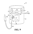
- FIG. 9 is a schematic view of the vacuum cleaner of FIGS. 1 , 2 , and 4 , illustrating multiple batteries being supported by a housing.
- FIG. 10 is an electrical schematic showing various electrical components and their interconnection.
- FIG. 11 a is a schematic view of the vacuum cleaner of FIGS. 1 , 2 , and 4 , illustrating a wired remote control coupled to a hose extending from the housing.
- FIG. 11 b is a schematic view of the vacuum cleaner of FIGS. 1 , 2 , and 4 , illustrating a wireless remote control coupled to the hose.
- FIG. 11 c are views of a portion of the hose and one construction remote control assembly.
- FIG. 11 d are views of a portion of the hose and another construction of a remote control assembly.
- FIG. 12 is a schematic view of the vacuum cleaner of FIGS. 1 , 2 , and 4 , illustrating a door positioned in a passageway defined in the housing.
- FIG. 13 a is a schematic view of the vacuum cleaner of FIGS. 1 , 2 , and 4 , illustrating a first motor and a second motor being supported by the housing.
- FIG. 13 b is a cross-sectional view of a portion of a vacuum cleaner and illustrating a two-motor arrangement.
- FIG. 13 c is another cross-sectional view of a portion of a vacuum cleaner and illustrating a two-motor arrangement.
- FIG. 14 a is a schematic view of a portion of the vacuum cleaner of FIGS. 1 , 2 , and 4 , illustrating one construction of debris receptacle or debris tray for transporting debris outside the housing to inside the debris chamber.
- FIG. 14 b is a schematic view of a portion of a vacuum cleaner and illustrating another construction of a debris receptacle.
- FIG. 15 is a cross-sectional view of a portion of a vacuum cleaner and illustrating an exhaust air outlet arrangement.
- FIG. 16 is front and rear perspective views of another construction of a vacuum cleaner.
- FIG. 17 is a front perspective view of another construction of a vacuum cleaner.
- FIG. 18 is a front perspective view of another construction of a vacuum cleaner.
- FIG. 19 is front and rear perspective views of another construction of a vacuum cleaner.
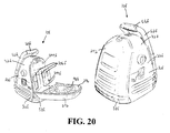
- FIG. 20 is a pair of rear perspective views of another construction of a vacuum cleaner, one of the rear perspective views shown with a storage door in an open position.
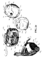
- FIG. 21 is a pair of rear perspective views of another construction of a vacuum cleaner, one of the rear perspective views shown with a storage door in an open position.
- FIG. 22 is a front perspective view of another construction of a vacuum cleaner.
- FIG. 23 is a rear perspective view of another construction of a vacuum cleaner.
- FIG. 24 is a plurality of perspective views of other constructions of a vacuum cleaner.
- FIG. 25 is a plurality of perspective views of other constructions of a vacuum cleaner.
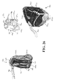
- FIG. 26 is a plurality of perspective views of other constructions of a vacuum cleaner.
- FIG. 27 is a plurality of perspective views of other constructions of a vacuum cleaner.
- FIG. 28 is a plurality of perspective views of other constructions of a vacuum cleaner.
- FIG. 29 is a plurality of perspective views of other constructions of a vacuum cleaner.
- FIG. 30 is a plurality of perspective views of other constructions of a vacuum cleaner.
- FIG. 31 is a plurality of perspective views of other constructions of a vacuum cleaner.
- FIG. 32 is a plurality of perspective views of other constructions of a vacuum cleaner.
- FIG. 33 is a plurality of perspective views of other constructions of a vacuum cleaner.
- FIG. 34 is a perspective view of another construction of a vacuum cleaner
- FIG. 35 is a plurality of perspective views of other constructions of a vacuum cleaner.
- FIGS. 1-35 Constructions of an air flow-producing device, such as, for example, a vacuum cleaner 10 , embodying independent aspects of the invention are illustrated in FIGS. 1-35 . It should be understood that the independent aspects of the invention disclosed herein may be incorporated in any of the vacuum cleaner constructions illustrated in FIGS. 1-35 . As such, the same reference numeral will be used to reference each vacuum cleaner construction illustrated in FIGS. 1-35 . It should be understood that, in some aspects, the air flow-producing device may be another air flow-producing device, such as, for example, a blower. It should also be understood that some independent aspects of the invention may be applied to another type of device, such as, for example, a power tool (e.g., hand-held or stationary), audio device, video device, etc.
- a power tool e.g., hand-held or stationary
- audio device e.g., video device, etc.
- the vacuum cleaner 10 is constructed for heavy-duty use in harsh working environments (for electrical equipment) such as outdoor construction sites, machine shops, manufacturing floors, etc.
- the vacuum cleaner 10 may be configured to operate using batteries 14 , such as, for example, 12V, 14.4V, 18V, 24V, 28V or similar power tool or other equipment batteries of various chemistries (NiCd, NiMH, Li-ion, etc.).
- the vacuum cleaner 10 may also be configured to operate using line power via an electrical cord 18 .
- the vacuum cleaner 10 may also be configured to charge the batteries 14 .
- the vacuum cleaner 10 includes a housing 22 generally defining a passageway 26 and a debris chamber 30 .
- the passageway 26 fluidly connects the debris chamber 30 and the ambient surroundings of the housing 22 , such that debris moving through the passageway 26 is collected and stored in the debris chamber 30 .
- An openable cover 32 closes the debris chamber 30 and allows the debris chamber 30 to be emptied.
- a latch 33 secures the cover 32 , and a seal (not shown) ensures that the debris chamber 30 is substantially air tight when the cover 32 is in a covering position (shown in FIG. 1 ).
- the cover 32 may be pivotable or otherwise movable between the covering position (shown in FIG. 1 ) and the emptying position (not shown). Alternatively, the cover 32 may be removable from the housing 22 to empty the debris chamber 30 .
- a vacuum may be established in the passageway 26 by a fan 34 that is connected to and selectively driven by an electric motor 38 .
- the electric motor 38 depending on the configuration of the vacuum cleaner 10 , may receive power from the electrical cord 18 or the batteries 14 or from both, selectively.
- the motor 38 and/or the fan 34 may be supported on the cover 32 or on the housing 22 .
- the vacuum cleaner 10 may also include one or more battery ports 42 for supporting one or more batteries 14 .
- the one or more battery ports 42 may correspond with one or more electrical circuits 46 , which may be or include battery charging circuits/components.
- the circuits 46 may be supported by suspended and cushioned mounting boards housed within the cavity.
- the mounting boards are made of a flame-retardant material, such as a V ⁇ -rated plastic.
- the circuits 46 and the mounting boards may be formed as an assembly, and the circuits 46 may be potted in the flame retardant material to seal and insulate the components of the circuits 46 .
- the components of the circuits 46 may be supported on the mounting boards with required spacing, sealing and insulation to meet UL requirements.
- one or more of the circuits 46 may include a battery charging circuit portion operable to charge a battery 14 connected to the associated battery port 42 .
- the cushioned mounting configuration of the mounting boards protects the circuits 46 during an impact.
- Such cushioning may be provided by any elastically deformable material (not shown), such as, for example, rubber washers, positioned between the board and housing 22 .
- This mounting configuration also helps minimize exposure of the circuits 46 to any contaminant (e.g. dirt, sand, gravel, sawdust, metal shavings, water, oil, grease, etc.) that may enter the cavity. Any contaminant entering the cavity will come to rest along an interior wall or adjacent walls of the housing 22 , depending on the orientation of the housing 22 . Therefore, with the circuits 46 suspended in the cavity, it is unlikely any contaminants will contact or come to rest on the circuits 46 .
- any contaminant e.g. dirt, sand, gravel, sawdust, metal shavings, water, oil, grease, etc.
- the circuits 46 may be connectable to a power source (not shown), such as an AC power source through the electrical cord 18 , or a DC power source. Battery terminals 50 on the battery ports 42 connect the batteries 14 to the circuits 46 .
- a separate and dedicated circuit 46 is matched with each battery port 42 . With this configuration, if one circuit 46 fails, the remaining circuits 46 will be operable.
- Each circuit 46 may be similar to the charging circuit 46 described in U.S. Pat. No. 6,222,343, issued Apr. 24, 2001, and U.S. Pat. No. 6,456,035, issued Sep. 24, 2002, the entire contents of both are hereby incorporated by reference. Further, the charging of the batteries 14 may be controlled by a temperature rate (“TR”) termination protocol, which is described in more detail in the '234 Application.
- TR temperature rate
- the vacuum cleaner 10 may thus be used as a battery charger for the batteries 14 .
- the charged batteries 14 may then be used to power the vacuum cleaner 10 or to power another battery-powered device, such as, for example, a cordless power tool, video or audio component, etc.
- An operational circuit 54 electrically connecting the motor 38 and at least one of the battery 14 and the electrical cord 18 may also be supported and/or suspended in the cavity of the housing 22 along with the circuits 46 and in a similar manner.
- Air vents may be defined in housing 22 to allow an airflow to pass through the housing 22 .
- Multiple sets of air vents may be defined in the housing 22 , such that some sets of vents may be at a higher elevation than other sets of vents.
- the air vents include ascending and stepped passageways into the cavity. Structure defining each passageway includes an outer lip, a spacer portion, which may have a substantially flat surface, and an inner lip toward the end of the portion. This structure helps to prevent any solid (i.e. dirt, sand, sawdust, metal shavings, etc.) or liquid (i.e. water, oil, grease, etc.) contaminants from entering the cavity. The outer lip will deflect contaminants.
- heat is generated during operation of the circuits 46 and 54 .
- a cooling airflow may be drawn through air vents that are at a lower elevation in the housing 22 into the cavity to flow across the heated circuits 46 and/or 54 .
- the cooling airflow is heated by the circuits 46 and/or 54 , causing the heated air to rise and escape the cavity through air vents that are at a higher elevation in the housing 22 .
- the vacuum cleaner 10 may utilize an electrically-operated fan (e.g., the fan 34 or a separate fan (not shown)) to cool the heated circuits 46 and/or 54 rather than unforced convection through air vents.
- an electrically-operated fan e.g., the fan 34 or a separate fan (not shown)
- heat removal elements such as, for example, heat sinks, heat pipes, etc. may be incorporated into the housing 22 to draw heat from the circuits 46 .
- the housing 22 is mounted to a base 58 which is designed to buffer and cushion the housing 22 along the edges of the base 58 .
- the base 58 may be blow molded from a high density polyethylene (HDPE) which is a very strong and impact-resistant material. This material selection allows the base 58 to more effectively absorb the energy associated with an impact.
- the base 58 may also include a uniform wall thickness of about 0.100′′ around the base 58 to prevent its collapse (especially near the corners) when the base 58 is impacted after a fall or some other impacting event.
- the base 58 may also include a drain (not shown) positioned at a low spot molded into the base 58 .
- the drain in the housing 22 and the drain in the base 58 are in fluid communication but are offset from each other so that direct access to the cavity through both of the drains is inhibited. Any contaminants that enter the housing 22 can be released through both of the drains.
- the air vents and the base 58 are shown and described in more detail in the '234 Application.
- a handle 62 is connected to at least one of the housing 22 and the base 58 . As shown in FIG. 1 , the handle 62 is connected to the base 58 only, while FIG. 2 illustrates the handle 62 being connected to both the base 58 and the housing 22 .
- the handle 62 may be generally positioned towards the portion of the vacuum cleaner 10 where the battery 14 attaches to the battery port 42 .
- the handle 62 may include some portions connected to the housing 22 through impact-absorbing bumpers and other portions connected to the base 58 .
- the bumpers are designed to both absorb and dampen impact energy.
- the bumpers may be made of an elastomeric material, such as polyurethane or natural rubber, with spring and/or damping characteristics.
- An ergonomic grip 66 may be centrally positioned on the handle 62 to provide a comfortable, sure and steady grip on the handle 62 .
- the grip 66 may include an elastic, non-slip material covering to provide comfort while the vacuum cleaner 10 is carried.
- the handle 62 allows the user to carry the vacuum cleaner 10 to and from a work site.
- An attached battery 14 may be generally encompassed by a boundary defined by the base 58 and handle 62 .
- the handle 62 may also function as a “roll bar,” or protective structure.
- the handle 62 is shown and described in more detail in the '234 Application.
- the handle 62 may be movable relative to the housing 22 . In one position, the handle 62 may act to secure the cover 32 to the housing 22 (in combination with or in place of the latch 33 ), and, in another position, the handle 62 may allow the cover 32 to be opened to the emptying position.
- Bumpers may also be coupled to the housing 22 to absorb some of the energy upon impact, thereby decreasing the chance of jarring loose an attached battery 14 and decreasing the chance of breaking the vacuum cleaner 10 or the sub-components of the vacuum cleaner 10 .
- the bumpers may be positioned along all sides of the housing 22 to protect the respective sides of the housing 22 .
- the bumpers may be made of an impact-resistant and energy absorbing material, such as HDPE. The bumpers are shown and described in more detail in the '234 Application.
- the battery 14 is a slide-on power-tool battery 14 and includes a battery projection 70 and a battery groove 74 .
- the battery port 42 includes a battery port projection 78 and a battery port groove 82 .
- the battery port projection 78 is engageable with the battery groove 74
- the battery projection 70 is engageable with the battery port groove 82 to connect the battery 14 and the battery port 42 . Further detail regarding the structural connection and the electrical connection between the battery ports 42 and the batteries 14 may be found in the '234 Application.
- the vacuum cleaner 10 may also include one or more status indicators, including light-emitting diodes (“LED”), that are electrically connected with each circuit 46 to relay status information to the user (e.g., the charging status of each battery 14 ).
- the LEDs are designed to emit an amount of light necessary to overcome the intensity of outdoor sunlight.
- the LEDs are positioned outside of the housing 22 so that the outer perimeter is generally viewable from any direction relative to the housing 22 . Further detail regarding the charge status indicators may be found in the '234 Application.
- the vacuum cleaner 10 is schematically shown to include two batteries 14 supported thereon. Each battery 14 is connected to the housing 22 via a battery port 42 . Each battery port 42 , in turn, is electrically connected to a circuit 46 . Both circuits 46 are shown electrically connected to a power distribution circuit 90 , which in turn is electrically connected to the operational circuit 54 . The power distribution circuit 90 is electrically connectable to line power when the electrical cord 18 is plugged into an electrical outlet. A controller 94 is electrically connected with the power distribution circuit 90 to control the interaction between the circuits 46 , 54 , 90 . The arrangement of the power distribution circuit 90 , the circuits 46 , the operational circuit 54 , and the controller 94 is illustrated in FIG. 10 , and is generally shown and described in the '107 Application.
- the fan 34 is shown positioned at least partially extending into the passageway 26 to create an airflow when driven by the motor 38 .
- the motor 38 is shown electrically connected to the operational circuit 54 , which is responsive to the controller 94 to selectively activate the motor 38 .
- a conduit, or hose 98 is coupled to the housing 22 such that the hose 98 is in fluid communication with the passageway 26 .
- the hose 98 is manipulatable by a user for vacuuming debris. The debris is collected and stored in the debris chamber 30 .
- FIG. 11 a illustrates the vacuum cleaner 10 including a wired remote control 102 coupled to a vacuum accessory 106 that is coupled to the hose 98 .
- the vacuum cleaner 10 is substantially similar to that shown in FIG. 9 , as such, like components will be labeled with like reference numerals.
- the remote control 102 may include a display panel 110 and any number of conventional switches and/or buttons 114 for controlling operation of the vacuum cleaner 10 .
- a wire 118 may electrically connect the remote control 102 and the controller 94 .
- the wire 118 may be externally mounted to the hose 98 , or, the wire 118 may be internally mounted within the hose 98 .
- the user may operate the vacuum cleaner 10 using the remote control 102 .
- the user may be able to turn the vacuum cleaner 10 on or off, or change operating speeds of the motor 38 .
- the user may also be able to view the charge levels of the batteries 14 via the display panel 110 .
- FIG. 11 b illustrates the vacuum cleaner 10 including a wireless remote control 122 coupled to the vacuum accessory 106 .
- the remote control 122 may include a display panel 110 and buttons 114 like that shown in FIG. 11 a , however, a transmitter 126 may be mounted in the vacuum accessory 106 or the hose 98 for transmitting radio signals to a receiver 130 , which may be positioned in the housing 22 .
- the receiver 130 receives the radio signals from the transmitter 126 and relays an appropriate signal to the controller 94 .
- the remote control 102 or 122 enables power conservation when the user is operating with the hose 98 at a distance from the housing of the vacuum cleaner 10 .
- the user can position inlet of the hose 98 adjacent to debris before turning on the vacuum cleaner 10 and may then turn off the vacuum cleaner 10 while moving the hose 98 to other sites of debris.
- the vacuum cleaner 10 may include a separate on/off switch (not shown).
- the switch may be positioned on the hose 96 c in proximity to the turbo button 114 c or may be positioned on the housing (not shown) of the vacuum cleaner 10 .
- the vacuum cleaner 10 generally provides two power levels for the user.
- the first power level is a normal running mode, in which the vacuum cleaner 10 provides standard operating function and is operable to pick up most debris.
- the second mode is a selective “turbo” power mode, in which the vacuum cleaner 10 provides a generally higher power to pick up heavier objects.
- the turbo power mode provides for increased suction when required and is generally only active when the turbo button 114 c is actuated by the user.
- the turbo button 114 c is actuated (e.g., depressed) by the user to select the higher power turbo power mode, and the user maintains the turbo button 114 c in the actuated condition to operate the vacuum cleaner 10 in the turbo power mode.
- the vacuum cleaner 10 returns to the normal operating mode.
- the turbo button 114 c is biased to the non-actuated position corresponding to the normal operating mode.
- the user may be required to deactuate the turbo button 114 c and to de-select the turbo power mode, for example, by depressing the turbo button 114 c a second time.
- the vacuum cleaner 10 In the normal running mode, the vacuum cleaner 10 generally operates at a relatively lower power which provides an increased battery life and a decreased noise level. In the turbo power mode, the vacuum cleaner 10 provides increased power to pick up heavier objects. However, this increased power requires greater supply of power from the battery 14 and would tend to decrease battery life. This increased power also provides an increased noise level. By providing selective turbo power mode, the user can conveniently and effectively operate the vacuum cleaner 10 in two modes to provide an increased run time overall for the vacuum cleaner 10 while maintaining sufficient suction power and quiet noise performance during most operations.
- FIG. 11 d illustrates a portion of a hose 96 d including a remote control 102 d .
- the remote control 102 d includes a three position button 114 d which generally combines the functions of the on/off switch and the separate turbo button 114 c illustrated in FIG. 11 c .
- the button 114 d has an “off” position, in which the motor 38 is not operated, an “on” position, in which the motor 38 is operated in a normal running mode, and a “turbo” position, in which the motor 38 is operated in an increased turbo power mode.
- the turbo button 114 d communicates with the controller (not shown) of the vacuum cleaner 10 to operate the motor 38 at the appropriate speed to provide the appropriate power level in the selected operating mode.
- the user actuates (e.g., slides) the button 114 d to the “on” position.
- the user further actuates the button 114 d to the “turbo” position.
- the user is required to hold the button 114 d in the “turbo” position to provide for momentary operation of the turbo mode.
- the button 114 d is biased from the “turbo” position to the “on” position.
- Structure may be provided to selectively hold the button 114 d in one or more of the positions (e.g., the “off” position, the “on” position) so that the user is not required to hold the button 114 d in such positions.
- the button 114 d is selectively held in the “on” position and in the “off” position.
- the button 114 d may be biased to the “off” position, and the user may be required to hold the button 114 d in the other positions (e.g., the “on” position, the “turbo” position). In other constructions, the structure may also selectively hold the button 114 d in the “turbo” position.
- Two power modes may enable the size of the hose to be optimized to provide for most efficient suction power and for increased opening diameter for larger debris.
- FIG. 12 illustrates the vacuum cleaner 10 including a door 134 positioned in the passageway 26 .
- the door 134 is movable between a blocking position, in which the airflow through the passageway 26 is at least partially blocked, and an unblocking position, in which unobstructed airflow may be allowed through the passageway 26 .
- the door 134 may be operably connected to any of a number of conventional actuating mechanisms (not shown) that can move the door 134 between the blocking and unblocking positions.
- the actuating mechanism is electrically connected with the controller 94 , such that the controller 94 may send a signal to the actuating mechanism to move the door 134 .
- the controller 94 is configured to maintain the door 134 in the blocking position until the motor 38 reaches a pre-determined speed after start-up. This allows the motor 38 to accelerate to its steady-state operating speed more quickly, since the fan 34 only has to initially evacuate the portion of the passageway 26 downstream from the fan 34 (i.e., between the door 134 and the fan 34 ). As a result, the amount of energy required to accelerate the fan 34 is decreased, and a large power draw from the one or more batteries 14 is decreased.
- the controller 94 may signal the actuating mechanism to move the door 134 to the unblocking position.
- the “waste gate” or door 134 thus provides power conservation by reducing the large power draw at start-up of the motor 38 and fan 34 .
- FIG. 13 a illustrates the vacuum cleaner 10 including two motors 138 , 142 supported by the housing 22 .
- the first motor 138 may operate using a first type of power source, such as an AC power source, and the separate second motor 142 may operate using another type of power source, such as a DC power source.
- the controller 94 may be operable to switch between which of the first and second motors 138 , 142 drives the fan 34 . Any of a number of selective drive configurations between the first motor 138 , the second motor 142 , and the fan 34 may be used with the schematic shown in FIG. 13 a.
- the first motor 138 may be used to drive the fan 34 when the electrical cord 18 is plugged into an electrical outlet to receive AC power.
- the second motor 142 may be used to drive the fan 34 when the electrical cord 18 is not plugged into an electrical outlet. Further, the second motor 142 may be sized to consume less energy than the first motor 138 , thus extending the run time of the vacuum cleaner 10 when operating off of the batteries 14 .
- FIGS. 13 b and 13 c illustrate a vacuum cleaner 10 including two motors 138 b , 142 b supported by the housing 22 b .
- the first motor 138 b operates using a first type of power source (e.g., an AC power source), and the separate second motor 142 b operates using another type of power source (e.g., a DC power source).
- a controller may be operable to switch between the motor 138 b or 142 b which drives the output shaft 144 to which the fan (not shown) of the vacuum cleaner 10 is connected.
- the vacuum cleaner 10 b includes a selective drive arrangement between the motors 138 b , 142 b and the drive shaft 144 .
- the drive arrangement includes a first clutch 180 , such as, for example, a needle clutch, in selective driving arrangement between the first motor 138 b and the drive shaft 144 and a second clutch 184 , such as, for example, a needle clutch, in selective driving arrangement between the second motor 142 b and the drive shaft 144 .
- a gear arrangement may be provided between the second motor 142 b and the drive shaft 144 .
- the gear arrangement includes a first gear 188 supported on the drive shaft 144 and a second gear 192 driven by the second motor 142 b and engageable with the first gear 188 .
- the motor 138 b When the vacuum cleaner 10 is powered by an AC power source, the motor 138 b directly drives the drive shaft 144 .
- the second motor 142 b When the vacuum cleaner 10 is operated by a DC power source, the second motor 142 b will drive the drive shaft 144 through the gear assembly.
- the drive arrangement including the clutches 180 and 184 allows operation of either the AC motor 138 b or the DC motor 142 b to drive the drive shaft 144 .
- the motors 138 b , 142 b may be arranged in a different manner to drive the drive shaft 144 .
- the motors 138 b , 142 b may be in-line rather than being offset.
- a different drive arrangement may be provided to enable the motors 138 b , 142 b to selectively drive the drive shaft 144 .
- FIG. 14 a illustrates a “chunk dump” or debris tray 146 allows the user to deposit large pieces of debris, which are too large to be easily picked up (or to be picked up at all) with the hose 98 , directly into the debris chamber 30 without having to turn off the motor 38 .
- the debris tray 146 is slidably extendable from the housing 22 .
- the debris tray 146 is slidable within an opening 150 in the housing 22 , which is sized to provide a snug fit with the debris tray 146 .
- Conventional lip seals 154 may be used to prevent the compressed airflow generated by the fan 34 from escaping through the gap between the opening 150 and the debris tray 146 .
- the debris tray 146 includes an aperture 158 therethrough, into which the large debris may be inserted. In combination with a bottom surface 162 of the opening 150 , the aperture 158 forms a cup in which to receive the large debris.
- the housing 22 may also include a recess 166 to allow easy access to the debris tray 146 . Once the large debris is inserted into the aperture 158 , the debris tray 146 may be slidably moved toward a depositing position, in which the aperture 158 encounters a hole 170 in the bottom surface 162 of the opening 150 to allow the debris to enter into the debris chamber 30 (by falling, under the force of the vacuum, etc.). The debris tray 146 may subsequently be returned to the extended position, in which the aperture 158 is accessible from outside of the housing 22 for the user to insert more debris therein.
- FIG. 14 b illustrates another construction of a “chunk-dump” or debris bin 196 which allows the user to deposit large pieces of debris which are too large to be easily picked up (or to be picked up at all) with the hose 98 , without having to turn off the motor 38 .
- the debris bin 196 is provided separately from the debris chamber 30 in the housing 22 .
- the housing 22 includes a tank 200 providing the debris chamber 30 , into which debris is provided by suction by the fan 34 , and the debris bin 196 , into which debris may be deposited through a door 198 .
- the debris bin 196 is separated from the debris chamber 30 by a wall 204 and is sealed from the debris chamber 30 .
- the debris bin 196 is generally not required to be sealed from the ambient surroundings of the housing 22 because the debris chamber 30 is sealed.
- the user may pick up debris using the hose 98 , and that vacuumed debris is deposited in the debris chamber 30 under the suction of the fan 34 .
- the user may deposit debris through the door 198 into the debris bin 196 .
- the user may remove the cover 32 and empty debris from the debris chamber 30 and from the debris bin 196 at the same time.
- a debris receptacle may be provided on the housing 22 and in which large debris may be held until the user has completed operation of the vacuum cleaner.
- Dispersement of exhaust air in one location from the housing 22 enables the vacuum cleaner 10 to have a blower mode.
- confined air exhaust increases the noise level of the vacuum cleaner, and high velocity of the air exhaust may stir up debris in the work area.
- FIG. 15 illustrates an exhaust air outlet arrangement 210 for a vacuum cleaner 10 in which the vacuum cleaner 10 may provide two modes for air dispersement—a dispersed air mode, in which the velocity of exhaust air is decreased and a generally quieter operation is provided, and a blower mode.
- the vacuum cleaner 10 may include structure for modifying the exhaust outlet 214 of the vacuum cleaner 10 to provide for a confined air exhaust for a blower mode and a dispersed air exhaust for a dispersed air mode.
- the exhaust outlet 214 includes a first exhaust opening 218 and one or more second exhaust opening(s) 222 .
- a connector 219 is provided proximate to the first exhaust opening 218 , and a blower attachment 220 (partially illustrated) is connectable to the connector 219 so that blower air may be provided through the blower attachment 220 to a location.
- a selective blocking member 226 is movable (e.g., slidable, pivotable, rotatable, etc.) relative to the exhaust outlet 214 to selectively cover and uncover one or more of the second exhaust openings 222 .
- the member 226 includes opening(s) 230 and blocking portion(s) 234 which are selectively alignable with the second exhaust opening(s) 222 to uncover and cover, respectively, the second exhaust opening(s) 222 .
- An actuator 238 is provided to adjust the mode of air dispersement, for example, by moving the member 226 .
- the member 226 is movable between a first or blower mode position (shown in FIG. 15 ) in which at least some of the second exhaust openings 222 are covered and blocked by the blocking portions 234 to restrict or prevent air flow through the second exhaust openings 222 , and a second or dispersed air mode position, in which at least some of the second exhaust opening(s) 222 are uncovered and aligned with the opening(s) 230 to allow at least some air flow through the second exhaust openings 222 .
- a first or blower mode position shown in FIG. 15
- a second or dispersed air mode position in which at least some of the second exhaust opening(s) 222 are uncovered and aligned with the opening(s) 230 to allow at least some air flow through the second exhaust openings 222 .
- exhaust air flow through the exhaust outlet 214 is restricted and provided at least in most part through the first exhaust opening 218 .
- exhaust air flow is relatively less restricted, and exhaust air is allowed to flow at least partially through one or more of the second
- the vacuum cleaner 10 may include structure to provide increased power so that the vacuum cleaner 10 may be used in a blower mode. Such structure may be similar to the “turbo” structure described above.
- the vacuum cleaner 10 may include a muffler arrangement which may be installed on the exhaust outlet 214 .
- the muffler arrangement may be removable or adjustable so that the exhaust outlet 214 is usable in a blower mode.
- FIG. 16 An alternative construction of vacuum cleaner 10 d is illustrated in FIG. 16 . Reference is made to the above discussion regarding the structure, operation, and alternatives of the vacuum cleaner 10 illustrated in FIGS. 1-15 . Common elements are identified by the same reference numbers “d”.
- the vacuum cleaner 10 d includes a plurality of wheels or rollers 240 connected to a bottom of the base 58 d to facilitate rolling movement of the vacuum cleaner 10 d along a ground surface of a working environment.
- the vacuum cleaner 10 d includes four rollers 240 , however, the vacuum cleaner 10 d can include any number of rollers thereon to facilitate rolling movement of the vacuum cleaner 10 d .
- the rollers 240 are castors. In other constructions, the rollers 240 are wheels having tread or some other type of resilient gripping surface to provide grip between the wheels and the ground surface.
- the base 58 d is selectively detachable from the housing 22 d and includes a plurality of accessory receptacles 244 defined in a top surface thereof for receiving a plurality of vacuum accessories 106 d .
- the base 58 d and housing 22 d are selectively connected by a pressure-fit projection and groove connection 248 .
- the base 58 d is detached from the housing 22 d by applying sufficient force in opposite directions upon the housing 22 d and the base 59 d .
- the housing 22 d and the base 58 d is re-connected by aligning the projection and groove and applying sufficient force toward one another to snap or pressure-fit the projection within the groove.
- a latch similar to the latch 33 d may be used to selectively connect the housing 22 d to the base 58 d.
- a receptacle 249 is defined in the housing 22 d for receiving a battery 14 and a cover 250 is attached to the housing 22 d to close and secure the battery within the receptacle.
- the receptacle for receiving a battery is described in more detail in the '107 Application.
- a pair of strap anchors 252 are defined in the housing 22 d for receiving ends of a shoulder strap (not shown) to allow a user to support the vacuum cleaner 10 d on their shoulder and carry the vacuum cleaner around the working environment on their shoulder rather than by the handle 62 d .
- the vacuum cleaner 10 d also defines a hose storage bin 256 on a rear of the vacuum cleaner 10 d .
- the bin 256 is properly sized to contain the hose when coiled.
- the vacuum cleaner 10 d includes wet and dry vacuuming capabilities.
- the vacuum cleaner 10 d includes a wet/dry switch (not shown) manipulatable by a user to select the function of the vacuum cleaner 10 d and the debris container 30 d includes a dry portion 260 for containing debris collected during dry vacuuming operation and a wet portion 264 for containing debris collect during wet vacuuming operation.
- the latches 33 d are released to allow separation of the upper portion of the housing 22 d from the debris container 30 d .
- the debris container 30 d is then dumped to remove the debris from the dry portion 264 .
- Debris located in the wet portion 264 of the debris container 30 d can be removed in two manners. Firstly, the latches 33 d can be released to allow separation of the upper portion of the housing 22 d from the debris container 30 d and the debris container 30 d can be dumped to remove the debris in the wet portion 264 .
- the debris can be removed from the wet portion 264 without separating the upper portion of the housing 22 d from the debris container 30 d .
- a plug 268 is positioned in an aperture defined in a side wall of the wet portion 264 of the debris container 30 d and is removable by a user to allow the debris to flow or be poured through the aperture. After the debris has sufficiently been vacated from the wet portion 264 , the plug is replaced and operation of the vacuum cleaner 10 d can continue.
- FIG. 17 An alternative construction of vacuum cleaner 10 e is illustrated in FIG. 17 . Reference is made to the above discussion regarding the structure, operation, and alternatives of the vacuum cleaner 10 illustrated in FIGS. 1-16 . Common elements are identified by the same reference numbers “e”.
- the handle 62 e is configured to extend beyond exterior surfaces of the housing 22 e to provide protection to the housing 22 e from impacts.
- the handle 62 e configuration is described in more detail in the '234 Application.
- the base defines a hose wrapping channel 272 for receiving the hose 98 e when it is wrapped around the vacuum cleaner 10 e for storage purposes.
- the hose 98 e is press-fit within the channel to ensure that the hose 98 e does not undesirably fall out of the channel 272 .
- a clip (not shown) can be supported by the housing 22 e or the base 58 e and positioned in or near the channel 272 for receiving a portion of the hose in a press-fit or snap-fit manner to secure the hose 98 e to the vacuum cleaner 10 e.
- the handle 62 e and channel 272 are configured to provide protection to the hose 98 e when the hose 98 e is wrapped around the vacuum cleaner 10 e within the channel 272 .
- the handle 62 e extends beyond the hose 98 e to provide protection from impacts.
- FIG. 18 An alternative construction of vacuum cleaner 10 f is illustrated in FIG. 18 . Reference is made to the above discussion regarding the structure, operation, and alternatives of the vacuum cleaner 10 illustrated in FIGS. 1-17 . Common elements are identified by the same reference numbers “f”.
- the vacuum cleaner 10 f includes an accessory bag 276 connected to the rear of the vacuum cleaner for receiving the hose 98 f , vacuuming accessories or other items, such as, for example a CD player, telephone, power tool batteries, and jobsite tools.
- the accessory bag 276 is described in more detail in the '107 Application.
- the cover 32 f can be removed by releasing latch 33 f and pivoting the cover rearward to expose the interior of the vacuum cleaner 10 f and the debris container 30 f .
- the handle 62 f is configured to allow the cover to pivot rearward without interference.
- the handle 62 f can be removed from the base 58 f to allow the cover 32 f to be removed.
- the handle 62 f can be pivoted forward to move out of the path of the cover 32 f and allow removal of the cover 32 f.
- FIG. 19 An alternative construction of vacuum cleaner 10 g is illustrated in FIG. 19 . Reference is made to the above discussion regarding the structure, operation, and alternatives of the vacuum cleaner 10 illustrated in FIGS. 1-18 . Common elements are identified by the same reference numbers “g”.
- the vacuum cleaner 10 g includes a hose wrapping projection (hidden behind accessory bag 276 g ) around which the hose 98 g is wrapped for storage.
- the vacuum cleaner 10 g also includes a securing strap 280 having one end connected to the hose wrapping projection and having a plurality of apertures 284 defined in the other end of the strap 280 .
- the strap 280 wraps around the coiled hose and one of the apertures 284 is slipped over a securement projection 288 on the housing 22 d to secure the hose 98 g to the housing 22 g .
- the accessory bag 276 g is connected to the hose wrapping projection.
- FIGS. 20 and 21 Alternative constructions of vacuum cleaners 10 h and 10 I are illustrated in FIGS. 20 and 21 . Reference is made to the above discussion regarding the structure, operation, and alternatives of the vacuum cleaner 10 illustrated in FIGS. 1-19 . Common elements are identified by the same reference numbers “f” and “i”, respectively.
- the vacuum cleaner 10 f , 10 i includes a storage door 292 pivotal between an open position (shown in the left perspective view) and a closed position (shown in the right perspective view).
- a latch similar to the latch 33 f , 33 i is disposed at the top of the door 292 to secure the door 292 to the housing 22 f , 22 i in the closed position. Releasing the latch allows the door 292 to pivot to the open position.
- the receptacle 249 f , 249 i is exposed to allow insertion and removal of batteries and a plurality of accessory receptacles 244 f , 244 i are exposed to allow insertion and removal of vacuum accessories 106 f from the accessory receptacles 244 f , 244 i .
- the door 292 defines a hose well 296 in a rear thereof for storing the hose 98 f , 98 i when not in use.
- FIGS. 22 and 23 Alternative constructions of vacuum cleaners 10 j and 10 k are illustrated in FIGS. 22 and 23 . Reference is made to the above discussion regarding the structure, operation, and alternatives of the vacuum cleaner 10 illustrated in FIGS. 1-21 . Common elements are identified by the same reference numbers “i” and “k”.
- FIG. 24 Alternative constructions of vacuum cleaners 10 m , 10 n , 10 p and 10 q are illustrated in FIG. 24 . Reference is made to the above discussion regarding the structure, operation, and alternatives of the vacuum cleaner 10 illustrated in FIGS. 1-23 . Common elements are identified by the same reference numbers “m”, “n”, “p” and “q”, respectively.
- the vacuum cleaner 10 q includes a handle 62 q that is moveable between a retracted position (not shown) and an extended position (illustrated). In the extended position, a user can grasp the handle 62 q and pull the vacuum cleaner 10 q behind them on the rollers 240 q .
- the handle 62 q can be moved to the retracted position for storage purposes when the vacuum cleaner 10 q is located in a desired location or when other means of moving the vacuum cleaner 10 q are desired.
- the handle 62 q slides between the retracted position and the extended position, however, the handle 62 q can be moved between the retracted position and the extended position in a variety of manners and still be within the spirit and scope of the present invention.
- FIG. 25 Alternative constructions of vacuum cleaners 10 r and 10 s are illustrated in FIG. 25 . Reference is made to the above discussion regarding the structure, operation, and alternatives of the vacuum cleaner 10 illustrated in FIGS. 1-24 . Common elements are identified by the same reference numbers “r” and “s”, respectively.
- FIG. 26 Alternative constructions of vacuum cleaners 10 t , 10 u and 10 w are illustrated in FIG. 26 . Reference is made to the above discussion regarding the structure, operation, and alternatives of the vacuum cleaner 10 illustrated in FIGS. 1-25 . Common elements are identified by the same reference numbers “t”, “u” and “w”, respectively.
- FIG. 27 Alternative constructions of vacuum cleaners 10 x , 10 y and 10 z are illustrated in FIG. 27 . Reference is made to the above discussion regarding the structure, operation, and alternatives of the vacuum cleaner 10 illustrated in FIGS. 1-26 . Common elements are identified by the same reference numbers “x”, “y” and “z”, respectively.
- the vacuum cleaners 10 x and 10 z include a storage drawer 300 moveable between a retracted position and an extended position.
- Components such as, for example the hose 98 x and 98 z , vacuuming accessories, a CD player, telephone, power tool batteries, and jobsite tools, can be stored in the drawer 300 .
- the drawer 300 is slideable between the retracted position and the extended position, however, the drawer 30 may be moveable between the retracted position and the extended position in a variety of other manners and still be within the spirit and scope of the present invention.
- FIG. 28 Alternative constructions of vacuum cleaners 10 aa , 10 bb and 10 cc are illustrated in FIG. 28 . Reference is made to the above discussion regarding the structure, operation, and alternatives of the vacuum cleaner 10 illustrated in FIGS. 1-27 . Common elements are identified by the same reference numbers “aa”, “bb” and “cc”, respectively.
- the vacuum cleaner 10 bb includes a hose support 304 that rotates between a supporting position, in which the hose support 304 is rotated outwardly away from the housing 22 bb in a position under the hose 98 bb and the hose 98 bb rests upon the support 304 , and a stored position, in which the hose 98 bb is disconnected from the housing 22 bb and the hose support 304 is rotated inward toward the housing 22 bb to a position where the hose support 304 is substantially flush with the exterior of the housing 22 bb .
- the hose support 304 is moveable between the supporting position and the stored position in a manner other than rotation.
- the hose support 304 is selectively connectable and disconnectable from the housing 22 bb.
- FIGS. 29-31 Alternative constructions of vacuum cleaners 10 dd , 10 ee , 10 ff , 10 gg , 10 hh , 10 ii , 10 jj , 10 mm , 10 nn and 10 pp are illustrated in FIGS. 29-31 . Reference is made to the above discussion regarding the structure, operation, and alternatives of the vacuum cleaner 10 illustrated in FIGS. 1-28 . Common elements are identified by the same reference numbers “dd”, “ee”, “ff”, “gg”, “hh”, “ii”, “jj”, “mm”, “nn” and “pp”, respectively.
- FIG. 32 Alternative constructions of vacuum cleaners 10 qq , 10 rr , 10 ss , 10 tt , 10 uu and 10 xx are illustrated in FIG. 32 . Reference is made to the above discussion regarding the structure, operation, and alternatives of the vacuum cleaner 10 illustrated in FIGS. 1-31 . Common elements are identified by the same reference numbers “qq”, “rr”, “ss”, “tt”, “uu” and “xx”, respectively.
- the vacuum cleaner 10 qq includes a storage drawer 308 that is removable from the housing 22 qq .
- the vacuum cleaner 10 qq can include a debris chamber 30 qq removable from the housing 22 qq .
- the debris is removed from the debris chamber 30 qq and the debris chamber 30 qq is replaceable back into the housing 22 qq .
- the vacuum cleaner 10 qq also includes a handle 62 qq that is pivotable between a stored position, in which the handle 62 qq is rotated downward toward and against the top of the housing 22 qq , and an operating position, in which the handle 62 qq is rotated away from the housing 22 qq .
- a user can grasp the handle 62 qq and pull the vacuum cleaner 10 qq to a desired location. Once the vacuum cleaner 10 qq is in the desired location, the user can move the handle 62 qq to the stored position.
- the vacuum cleaner 10 xx includes a handle 62 xx moveable between a stored position, in which the handle 62 xx is secured to the housing 22 xx by a pair of snapfits 312 , and an operating position, in which the handle 62 xx is removed from the snapfits 312 , rotated upwardly away from the housing 22 xx and telescoped outwardly to increase the length of the handle 62 xx.
- FIG. 33 Alternative constructions of vacuum cleaners 10 zz , 10 aaa , 10 bbb , 10 ccc , 10 ddd , 10 eee , 10 fff , 10 ggg and 10 hhh are illustrated in FIG. 33 .
- Common elements are identified by the same reference numbers “zz”, “aaa”, “bbb”, “ccc”, “ddd”, “eee”, “ff” and “ggg”, respectively.
- the vacuum cleaner 10 zz includes four rollers 240 zz sufficiently sized to extend beyond the planes of the exterior of the housing 22 zz in order to facilitate rolling of the vacuum cleaner 10 zz in any orientation.
- the vacuum cleaner 10 ccc has a different roller 240 ccc configuration than vacuum cleaner 10 zz to facilitate rolling of the vacuum cleaner 10 ccc in any orientation.
- FIG. 34 An alternative construction of a vacuum cleaner 10 hhh is illustrated in FIG. 34 . Reference is made to the above discussion regarding the structure, operation, and alternatives of the vacuum cleaner 10 illustrated in FIGS. 1-33 . Common elements are identified by the same reference numbers “hhh”.
- the vacuum cleaner 10 hhh includes a debris chamber 30 hhh that is removable from the housing 22 hhh . Once the debris chamber 30 hhh is removed from the housing 22 hhh , the cover 250 hhh can be opened to remove and/or replace a battery 14 hhh from and/or into the receptacle 249 hhh .
- the debris chamber 30 hhh is reconnected to the housing 22 hhh after the cover 250 hhh is closed and by sliding the debris chamber 30 hhh into the housing 22 hhh.
- the vacuum cleaner 10 hhh also includes a moveable hose connector 316 that is moveable relative to the remainder of the housing 22 hhh .
- the moveable hose connector 316 moves with the hose 98 hhh as the hose 98 hhh changes elevations relative to the housing 22 hhh .
- the hose connector 316 pivots about a horizontal axis substantially parallel to the axis of the rollers 240 hhh .
- the hose connector 316 pivots about a horizontal axis substantially perpendicular to the axis of the rollers 240 hhh .
- the hose connector 316 is a ball type connector and allows movement in all directions.
- FIG. 35 Alternative constructions of vacuum cleaners 10 iii and 10 jjj are illustrated in FIG. 35 . Reference is made to the above discussion regarding the structure, operation, and alternatives of the vacuum cleaner 10 illustrated in FIGS. 1-34 . Common elements are identified by the same reference numbers “iii” and “jjj”, respectively.
- the vacuum cleaner 10 iii is attachable to the lower back of a user via a shoulder strap 320 and a waist belt 324 .
- the majority of the vacuum weight is ergonomically positioned to make carrying of the vacuum cleaner 10 iii as easy as possible.
- a removable external debris bag 328 is connected to the vacuum cleaner 10 iii and is similar in function to a mulching bag or collecting bag for lawnmowers.
- the vacuum cleaner 10 jjj has a backpack type design and includes to shoulder straps 320 jjj that are positionable over a user's shoulders.
- the debris bag 328 jjj is positioned externally on the rear of the housing 22 jjj.
- vacuum cleaners 10 iii and 10 jjj can have different configurations than that illustrated in FIG. 35 while still maintaining the general concept and idea of a waist or lower back supported vacuum and a backpack vacuum cleaner and still be within the spirit and scope of the present invention.
Abstract
Description
Claims (10)
Priority Applications (7)
| Application Number | Priority Date | Filing Date | Title |
|---|---|---|---|
| US10/898,437 US7712182B2 (en) | 2003-07-25 | 2004-07-23 | Air flow-producing device, such as a vacuum cleaner or a blower |
| DE102004036209A DE102004036209A1 (en) | 2003-07-25 | 2004-07-26 | Air power generation device, such as a vacuum cleaner or a blower |
| GB0618455A GB2426921B (en) | 2003-07-25 | 2004-07-26 | A vacuum cleaner |
| GB0618454A GB2426920B (en) | 2003-07-25 | 2004-07-26 | Air flow-producing device, such as a vacuum cleaner or a blower |
| CN2004100556926A CN1618391B (en) | 2003-07-25 | 2004-07-26 | Air flow-producing device |
| GB0618458A GB2426922B (en) | 2003-07-25 | 2004-07-26 | Air flow-producing device, such as a vacuum cleaner or a blower |
| GB0416608A GB2405787B (en) | 2003-07-25 | 2004-07-26 | Air flow-producing device, such a s a vacuum cleaner or blower |
Applications Claiming Priority (3)
| Application Number | Priority Date | Filing Date | Title |
|---|---|---|---|
| US49019003P | 2003-07-25 | 2003-07-25 | |
| US57802904P | 2004-06-08 | 2004-06-08 | |
| US10/898,437 US7712182B2 (en) | 2003-07-25 | 2004-07-23 | Air flow-producing device, such as a vacuum cleaner or a blower |
Publications (2)
| Publication Number | Publication Date |
|---|---|
| US20050055795A1 US20050055795A1 (en) | 2005-03-17 |
| US7712182B2 true US7712182B2 (en) | 2010-05-11 |
Family
ID=34198940
Family Applications (1)
| Application Number | Title | Priority Date | Filing Date |
|---|---|---|---|
| US10/898,437 Active 2029-03-10 US7712182B2 (en) | 2003-07-25 | 2004-07-23 | Air flow-producing device, such as a vacuum cleaner or a blower |
Country Status (4)
| Country | Link |
|---|---|
| US (1) | US7712182B2 (en) |
| CN (1) | CN1618391B (en) |
| DE (1) | DE102004036209A1 (en) |
| GB (4) | GB2426922B (en) |
Cited By (427)
| Publication number | Priority date | Publication date | Assignee | Title |
|---|---|---|---|---|
| US20110056443A1 (en) * | 2009-09-08 | 2011-03-10 | Andreas Stihl Ag & Co. Kg. | Back-carried work apparatus |
| US20110088309A1 (en) * | 2009-10-05 | 2011-04-21 | Emory University Office Of Technology Transfer | Device for capturing insects |
| US8365350B2 (en) | 2002-11-12 | 2013-02-05 | Black & Decker Inc. | AC/DC hand portable wet/dry vacuum having improved portability and convenience |
| US20150145444A1 (en) * | 2013-11-22 | 2015-05-28 | Techtronic Industries Co., Ltd. | Battery-powered cordless cleaning system |
| US20150202796A1 (en) * | 2014-01-18 | 2015-07-23 | Diamond Products, Limited | Electric concrete saw |
| US9427859B2 (en) | 2013-01-08 | 2016-08-30 | Techtrnoic Outdoor Products Technology Limited | Motor system for dual voltage devices |
| US20170086382A1 (en) * | 2015-09-25 | 2017-03-30 | Virger Brown | Mulching Assembly |
| US9700310B2 (en) | 2013-08-23 | 2017-07-11 | Ethicon Llc | Firing member retraction devices for powered surgical instruments |
| US9706991B2 (en) | 2006-09-29 | 2017-07-18 | Ethicon Endo-Surgery, Inc. | Staple cartridge comprising staples including a lateral base |
| US9724098B2 (en) | 2012-03-28 | 2017-08-08 | Ethicon Endo-Surgery, Llc | Staple cartridge comprising an implantable layer |
| US9724094B2 (en) | 2014-09-05 | 2017-08-08 | Ethicon Llc | Adjunct with integrated sensors to quantify tissue compression |
| US9730697B2 (en) | 2012-02-13 | 2017-08-15 | Ethicon Endo-Surgery, Llc | Surgical cutting and fastening instrument with apparatus for determining cartridge and firing motion status |
| US9737303B2 (en) | 2004-07-28 | 2017-08-22 | Ethicon Llc | Articulating surgical stapling instrument incorporating a two-piece E-beam firing mechanism |
| US9743929B2 (en) | 2014-03-26 | 2017-08-29 | Ethicon Llc | Modular powered surgical instrument with detachable shaft assemblies |
| US9750501B2 (en) | 2007-01-11 | 2017-09-05 | Ethicon Endo-Surgery, Llc | Surgical stapling devices having laterally movable anvils |
| US9757124B2 (en) | 2014-02-24 | 2017-09-12 | Ethicon Llc | Implantable layer assemblies |
| US9770821B2 (en) | 2011-10-06 | 2017-09-26 | Husqvarna Ab | Battery operated handheld power tool |
| US9775614B2 (en) | 2011-05-27 | 2017-10-03 | Ethicon Endo-Surgery, Llc | Surgical stapling instruments with rotatable staple deployment arrangements |
| US9795381B2 (en) | 2007-06-04 | 2017-10-24 | Ethicon Endo-Surgery, Llc | Robotically-controlled shaft based rotary drive systems for surgical instruments |
| US9795383B2 (en) | 2010-09-30 | 2017-10-24 | Ethicon Llc | Tissue thickness compensator comprising resilient members |
| US9801628B2 (en) | 2014-09-26 | 2017-10-31 | Ethicon Llc | Surgical staple and driver arrangements for staple cartridges |
| US9801634B2 (en) | 2010-09-30 | 2017-10-31 | Ethicon Llc | Tissue thickness compensator for a surgical stapler |
| US9808246B2 (en) | 2015-03-06 | 2017-11-07 | Ethicon Endo-Surgery, Llc | Method of operating a powered surgical instrument |
| US9814462B2 (en) | 2010-09-30 | 2017-11-14 | Ethicon Llc | Assembly for fastening tissue comprising a compressible layer |
| US9814460B2 (en) | 2013-04-16 | 2017-11-14 | Ethicon Llc | Modular motor driven surgical instruments with status indication arrangements |
| US9820738B2 (en) | 2014-03-26 | 2017-11-21 | Ethicon Llc | Surgical instrument comprising interactive systems |
| US9826978B2 (en) | 2010-09-30 | 2017-11-28 | Ethicon Llc | End effectors with same side closure and firing motions |
| US9826977B2 (en) | 2014-03-26 | 2017-11-28 | Ethicon Llc | Sterilization verification circuit |
| US9833238B2 (en) | 2010-09-30 | 2017-12-05 | Ethicon Endo-Surgery, Llc | Retainer assembly including a tissue thickness compensator |
| US9833242B2 (en) | 2010-09-30 | 2017-12-05 | Ethicon Endo-Surgery, Llc | Tissue thickness compensators |
| US9833241B2 (en) | 2014-04-16 | 2017-12-05 | Ethicon Llc | Surgical fastener cartridges with driver stabilizing arrangements |
| US9844375B2 (en) | 2014-12-18 | 2017-12-19 | Ethicon Llc | Drive arrangements for articulatable surgical instruments |
| US9844374B2 (en) | 2014-12-18 | 2017-12-19 | Ethicon Llc | Surgical instrument systems comprising an articulatable end effector and means for adjusting the firing stroke of a firing member |
| US9844376B2 (en) | 2014-11-06 | 2017-12-19 | Ethicon Llc | Staple cartridge comprising a releasable adjunct material |
| US9867618B2 (en) | 2008-02-14 | 2018-01-16 | Ethicon Llc | Surgical stapling apparatus including firing force regulation |
| US9872682B2 (en) | 2007-03-15 | 2018-01-23 | Ethicon Llc | Surgical stapling instrument having a releasable buttress material |
| US9883860B2 (en) | 2013-03-14 | 2018-02-06 | Ethicon Llc | Interchangeable shaft assemblies for use with a surgical instrument |
| US9895148B2 (en) | 2015-03-06 | 2018-02-20 | Ethicon Endo-Surgery, Llc | Monitoring speed control and precision incrementing of motor for powered surgical instruments |
| US9895147B2 (en) | 2005-11-09 | 2018-02-20 | Ethicon Llc | End effectors for surgical staplers |
| US9901345B2 (en) | 2008-02-14 | 2018-02-27 | Ethicon Llc | Stapling assembly |
| US9901342B2 (en) | 2015-03-06 | 2018-02-27 | Ethicon Endo-Surgery, Llc | Signal and power communication system positioned on a rotatable shaft |
| US9907620B2 (en) | 2012-06-28 | 2018-03-06 | Ethicon Endo-Surgery, Llc | Surgical end effectors having angled tissue-contacting surfaces |
| US9907234B2 (en) | 2014-11-20 | 2018-03-06 | Black & Decker, Inc. | Battery-powered backpack blower |
| US9924944B2 (en) | 2014-10-16 | 2018-03-27 | Ethicon Llc | Staple cartridge comprising an adjunct material |
| US9924961B2 (en) | 2015-03-06 | 2018-03-27 | Ethicon Endo-Surgery, Llc | Interactive feedback system for powered surgical instruments |
| US9931118B2 (en) | 2015-02-27 | 2018-04-03 | Ethicon Endo-Surgery, Llc | Reinforced battery for a surgical instrument |
| US9943309B2 (en) | 2014-12-18 | 2018-04-17 | Ethicon Llc | Surgical instruments with articulatable end effectors and movable firing beam support arrangements |
| US9962161B2 (en) | 2014-02-12 | 2018-05-08 | Ethicon Llc | Deliverable surgical instrument |
| US9962158B2 (en) | 2008-02-14 | 2018-05-08 | Ethicon Llc | Surgical stapling apparatuses with lockable end effector positioning systems |
| US9974538B2 (en) | 2012-03-28 | 2018-05-22 | Ethicon Llc | Staple cartridge comprising a compressible layer |
| US9987000B2 (en) | 2014-12-18 | 2018-06-05 | Ethicon Llc | Surgical instrument assembly comprising a flexible articulation system |
| US9993258B2 (en) | 2015-02-27 | 2018-06-12 | Ethicon Llc | Adaptable surgical instrument handle |
| US10004498B2 (en) | 2006-01-31 | 2018-06-26 | Ethicon Llc | Surgical instrument comprising a plurality of articulation joints |
| US10045778B2 (en) | 2008-09-23 | 2018-08-14 | Ethicon Llc | Robotically-controlled motorized surgical instrument with an end effector |
| US10045776B2 (en) | 2015-03-06 | 2018-08-14 | Ethicon Llc | Control techniques and sub-processor contained within modular shaft with select control processing from handle |
| US10045781B2 (en) | 2014-06-13 | 2018-08-14 | Ethicon Llc | Closure lockout systems for surgical instruments |
| US10052102B2 (en) | 2015-06-18 | 2018-08-21 | Ethicon Llc | Surgical end effectors with dual cam actuated jaw closing features |
| US10052044B2 (en) | 2015-03-06 | 2018-08-21 | Ethicon Llc | Time dependent evaluation of sensor data to determine stability, creep, and viscoelastic elements of measures |
| US10058963B2 (en) | 2006-01-31 | 2018-08-28 | Ethicon Llc | Automated end effector component reloading system for use with a robotic system |
| US10064688B2 (en) | 2006-03-23 | 2018-09-04 | Ethicon Llc | Surgical system with selectively articulatable end effector |
| US10064621B2 (en) | 2012-06-15 | 2018-09-04 | Ethicon Llc | Articulatable surgical instrument comprising a firing drive |
| US10070861B2 (en) | 2006-03-23 | 2018-09-11 | Ethicon Llc | Articulatable surgical device |
| US10070863B2 (en) | 2005-08-31 | 2018-09-11 | Ethicon Llc | Fastener cartridge assembly comprising a fixed anvil |
| US10076326B2 (en) | 2015-09-23 | 2018-09-18 | Ethicon Llc | Surgical stapler having current mirror-based motor control |
| US10076325B2 (en) | 2014-10-13 | 2018-09-18 | Ethicon Llc | Surgical stapling apparatus comprising a tissue stop |
| US10085748B2 (en) | 2014-12-18 | 2018-10-02 | Ethicon Llc | Locking arrangements for detachable shaft assemblies with articulatable surgical end effectors |
| US10085751B2 (en) | 2015-09-23 | 2018-10-02 | Ethicon Llc | Surgical stapler having temperature-based motor control |
| US10098642B2 (en) | 2015-08-26 | 2018-10-16 | Ethicon Llc | Surgical staples comprising features for improved fastening of tissue |
| US10098636B2 (en) | 2006-01-31 | 2018-10-16 | Ethicon Llc | Surgical instrument having force feedback capabilities |
| US10105139B2 (en) | 2015-09-23 | 2018-10-23 | Ethicon Llc | Surgical stapler having downstream current-based motor control |
| US10117652B2 (en) | 2011-04-29 | 2018-11-06 | Ethicon Llc | End effector comprising a tissue thickness compensator and progressively released attachment members |
| US10117649B2 (en) | 2014-12-18 | 2018-11-06 | Ethicon Llc | Surgical instrument assembly comprising a lockable articulation system |
| US10149683B2 (en) | 2008-10-10 | 2018-12-11 | Ethicon Llc | Powered surgical cutting and stapling apparatus with manually retractable firing system |
| US10172620B2 (en) | 2015-09-30 | 2019-01-08 | Ethicon Llc | Compressible adjuncts with bonding nodes |
| US10180463B2 (en) | 2015-02-27 | 2019-01-15 | Ethicon Llc | Surgical apparatus configured to assess whether a performance parameter of the surgical apparatus is within an acceptable performance band |
| US10188385B2 (en) | 2014-12-18 | 2019-01-29 | Ethicon Llc | Surgical instrument system comprising lockable systems |
| US20190038100A1 (en) * | 2016-01-27 | 2019-02-07 | Samsung Electronics Co., Ltd | Vacuum cleaner and method of controlling the same |
| US10201363B2 (en) | 2006-01-31 | 2019-02-12 | Ethicon Llc | Motor-driven surgical instrument |
| US10206676B2 (en) | 2008-02-14 | 2019-02-19 | Ethicon Llc | Surgical cutting and fastening instrument |
| US10211586B2 (en) | 2017-06-28 | 2019-02-19 | Ethicon Llc | Surgical shaft assemblies with watertight housings |
| US10206678B2 (en) | 2006-10-03 | 2019-02-19 | Ethicon Llc | Surgical stapling instrument with lockout features to prevent advancement of a firing assembly unless an unfired surgical staple cartridge is operably mounted in an end effector portion of the instrument |
| US10213201B2 (en) | 2015-03-31 | 2019-02-26 | Ethicon Llc | Stapling end effector configured to compensate for an uneven gap between a first jaw and a second jaw |
| US10226249B2 (en) | 2013-03-01 | 2019-03-12 | Ethicon Llc | Articulatable surgical instruments with conductive pathways for signal communication |
| US10238386B2 (en) | 2015-09-23 | 2019-03-26 | Ethicon Llc | Surgical stapler having motor control based on an electrical parameter related to a motor current |
| US10245030B2 (en) | 2016-02-09 | 2019-04-02 | Ethicon Llc | Surgical instruments with tensioning arrangements for cable driven articulation systems |
| US10245032B2 (en) | 2005-08-31 | 2019-04-02 | Ethicon Llc | Staple cartridges for forming staples having differing formed staple heights |
| US10245033B2 (en) | 2015-03-06 | 2019-04-02 | Ethicon Llc | Surgical instrument comprising a lockable battery housing |
| US10258333B2 (en) | 2012-06-28 | 2019-04-16 | Ethicon Llc | Surgical fastening apparatus with a rotary end effector drive shaft for selective engagement with a motorized drive system |
| US10258331B2 (en) | 2016-02-12 | 2019-04-16 | Ethicon Llc | Mechanisms for compensating for drivetrain failure in powered surgical instruments |
| US10258418B2 (en) | 2017-06-29 | 2019-04-16 | Ethicon Llc | System for controlling articulation forces |
| US10265074B2 (en) | 2010-09-30 | 2019-04-23 | Ethicon Llc | Implantable layers for surgical stapling devices |
| US10265068B2 (en) | 2015-12-30 | 2019-04-23 | Ethicon Llc | Surgical instruments with separable motors and motor control circuits |
| US10271849B2 (en) | 2015-09-30 | 2019-04-30 | Ethicon Llc | Woven constructs with interlocked standing fibers |
| US10271846B2 (en) | 2005-08-31 | 2019-04-30 | Ethicon Llc | Staple cartridge for use with a surgical stapler |
| US10278780B2 (en) | 2007-01-10 | 2019-05-07 | Ethicon Llc | Surgical instrument for use with robotic system |
| US10293100B2 (en) | 2004-07-28 | 2019-05-21 | Ethicon Llc | Surgical stapling instrument having a medical substance dispenser |
| US10292704B2 (en) | 2015-12-30 | 2019-05-21 | Ethicon Llc | Mechanisms for compensating for battery pack failure in powered surgical instruments |
| US10299878B2 (en) | 2015-09-25 | 2019-05-28 | Ethicon Llc | Implantable adjunct systems for determining adjunct skew |
| US10307170B2 (en) | 2017-06-20 | 2019-06-04 | Ethicon Llc | Method for closed loop control of motor velocity of a surgical stapling and cutting instrument |
| US10314589B2 (en) | 2006-06-27 | 2019-06-11 | Ethicon Llc | Surgical instrument including a shifting assembly |
| USD851762S1 (en) | 2017-06-28 | 2019-06-18 | Ethicon Llc | Anvil |
| US10327767B2 (en) | 2017-06-20 | 2019-06-25 | Ethicon Llc | Control of motor velocity of a surgical stapling and cutting instrument based on angle of articulation |
| US10327769B2 (en) | 2015-09-23 | 2019-06-25 | Ethicon Llc | Surgical stapler having motor control based on a drive system component |
| US10335145B2 (en) | 2016-04-15 | 2019-07-02 | Ethicon Llc | Modular surgical instrument with configurable operating mode |
| USD854151S1 (en) | 2017-06-28 | 2019-07-16 | Ethicon Llc | Surgical instrument shaft |
| US10357247B2 (en) | 2016-04-15 | 2019-07-23 | Ethicon Llc | Surgical instrument with multiple program responses during a firing motion |
| US10363037B2 (en) | 2016-04-18 | 2019-07-30 | Ethicon Llc | Surgical instrument system comprising a magnetic lockout |
| US10363036B2 (en) | 2015-09-23 | 2019-07-30 | Ethicon Llc | Surgical stapler having force-based motor control |
| US10363031B2 (en) | 2010-09-30 | 2019-07-30 | Ethicon Llc | Tissue thickness compensators for surgical staplers |
| US10368864B2 (en) | 2017-06-20 | 2019-08-06 | Ethicon Llc | Systems and methods for controlling displaying motor velocity for a surgical instrument |
| US10368865B2 (en) | 2015-12-30 | 2019-08-06 | Ethicon Llc | Mechanisms for compensating for drivetrain failure in powered surgical instruments |
| US10376263B2 (en) | 2016-04-01 | 2019-08-13 | Ethicon Llc | Anvil modification members for surgical staplers |
| US10390841B2 (en) | 2017-06-20 | 2019-08-27 | Ethicon Llc | Control of motor velocity of a surgical stapling and cutting instrument based on angle of articulation |
| US10398433B2 (en) | 2007-03-28 | 2019-09-03 | Ethicon Llc | Laparoscopic clamp load measuring devices |
| US10398434B2 (en) | 2017-06-29 | 2019-09-03 | Ethicon Llc | Closed loop velocity control of closure member for robotic surgical instrument |
| US10405859B2 (en) | 2016-04-15 | 2019-09-10 | Ethicon Llc | Surgical instrument with adjustable stop/start control during a firing motion |
| US10413294B2 (en) | 2012-06-28 | 2019-09-17 | Ethicon Llc | Shaft assembly arrangements for surgical instruments |
| US10420549B2 (en) | 2008-09-23 | 2019-09-24 | Ethicon Llc | Motorized surgical instrument |
| US10420550B2 (en) | 2009-02-06 | 2019-09-24 | Ethicon Llc | Motor driven surgical fastener device with switching system configured to prevent firing initiation until activated |
| US10426471B2 (en) | 2016-12-21 | 2019-10-01 | Ethicon Llc | Surgical instrument with multiple failure response modes |
| US10426481B2 (en) | 2014-02-24 | 2019-10-01 | Ethicon Llc | Implantable layer assemblies |
| US10426467B2 (en) | 2016-04-15 | 2019-10-01 | Ethicon Llc | Surgical instrument with detection sensors |
| US10426463B2 (en) | 2006-01-31 | 2019-10-01 | Ehticon LLC | Surgical instrument having a feedback system |
| US10441285B2 (en) | 2012-03-28 | 2019-10-15 | Ethicon Llc | Tissue thickness compensator comprising tissue ingrowth features |
| US10448950B2 (en) | 2016-12-21 | 2019-10-22 | Ethicon Llc | Surgical staplers with independently actuatable closing and firing systems |
| US10448948B2 (en) | 2016-02-12 | 2019-10-22 | Ethicon Llc | Mechanisms for compensating for drivetrain failure in powered surgical instruments |
| US10456137B2 (en) | 2016-04-15 | 2019-10-29 | Ethicon Llc | Staple formation detection mechanisms |
| US10463370B2 (en) | 2008-02-14 | 2019-11-05 | Ethicon Llc | Motorized surgical instrument |
| US10485536B2 (en) | 2010-09-30 | 2019-11-26 | Ethicon Llc | Tissue stapler having an anti-microbial agent |
| US10485543B2 (en) | 2016-12-21 | 2019-11-26 | Ethicon Llc | Anvil having a knife slot width |
| US10492785B2 (en) | 2016-12-21 | 2019-12-03 | Ethicon Llc | Shaft assembly comprising a lockout |
| US10492783B2 (en) | 2016-04-15 | 2019-12-03 | Ethicon, Llc | Surgical instrument with improved stop/start control during a firing motion |
| USD869655S1 (en) | 2017-06-28 | 2019-12-10 | Ethicon Llc | Surgical fastener cartridge |
| US10499890B2 (en) | 2006-01-31 | 2019-12-10 | Ethicon Llc | Endoscopic surgical instrument with a handle that can articulate with respect to the shaft |
| US10499914B2 (en) | 2016-12-21 | 2019-12-10 | Ethicon Llc | Staple forming pocket arrangements |
| US10517594B2 (en) | 2014-10-29 | 2019-12-31 | Ethicon Llc | Cartridge assemblies for surgical staplers |
| US10517595B2 (en) | 2016-12-21 | 2019-12-31 | Ethicon Llc | Jaw actuated lock arrangements for preventing advancement of a firing member in a surgical end effector unless an unfired cartridge is installed in the end effector |
| US10517590B2 (en) | 2007-01-10 | 2019-12-31 | Ethicon Llc | Powered surgical instrument having a transmission system |
| US10524790B2 (en) | 2011-05-27 | 2020-01-07 | Ethicon Llc | Robotically-controlled surgical stapling devices that produce formed staples having different lengths |
| US10537325B2 (en) | 2016-12-21 | 2020-01-21 | Ethicon Llc | Staple forming pocket arrangement to accommodate different types of staples |
| US10568652B2 (en) | 2006-09-29 | 2020-02-25 | Ethicon Llc | Surgical staples having attached drivers of different heights and stapling instruments for deploying the same |
| US10568626B2 (en) | 2016-12-21 | 2020-02-25 | Ethicon Llc | Surgical instruments with jaw opening features for increasing a jaw opening distance |
| US10568625B2 (en) | 2016-12-21 | 2020-02-25 | Ethicon Llc | Staple cartridges and arrangements of staples and staple cavities therein |
| US10575868B2 (en) | 2013-03-01 | 2020-03-03 | Ethicon Llc | Surgical instrument with coupler assembly |
| US10588632B2 (en) | 2016-12-21 | 2020-03-17 | Ethicon Llc | Surgical end effectors and firing members thereof |
| US10588633B2 (en) | 2017-06-28 | 2020-03-17 | Ethicon Llc | Surgical instruments with open and closable jaws and axially movable firing member that is initially parked in close proximity to the jaws prior to firing |
| US10588623B2 (en) | 2010-09-30 | 2020-03-17 | Ethicon Llc | Adhesive film laminate |
| USD879809S1 (en) | 2017-06-20 | 2020-03-31 | Ethicon Llc | Display panel with changeable graphical user interface |
| USD879808S1 (en) | 2017-06-20 | 2020-03-31 | Ethicon Llc | Display panel with graphical user interface |
| US10617418B2 (en) | 2015-08-17 | 2020-04-14 | Ethicon Llc | Implantable layers for a surgical instrument |
| US10617413B2 (en) | 2016-04-01 | 2020-04-14 | Ethicon Llc | Closure system arrangements for surgical cutting and stapling devices with separate and distinct firing shafts |
| US10617416B2 (en) | 2013-03-14 | 2020-04-14 | Ethicon Llc | Control systems for surgical instruments |
| US10617412B2 (en) | 2015-03-06 | 2020-04-14 | Ethicon Llc | System for detecting the mis-insertion of a staple cartridge into a surgical stapler |
| US10624861B2 (en) | 2010-09-30 | 2020-04-21 | Ethicon Llc | Tissue thickness compensator configured to redistribute compressive forces |
| US10624633B2 (en) | 2017-06-20 | 2020-04-21 | Ethicon Llc | Systems and methods for controlling motor velocity of a surgical stapling and cutting instrument |
| US10631859B2 (en) | 2017-06-27 | 2020-04-28 | Ethicon Llc | Articulation systems for surgical instruments |
| US10646220B2 (en) | 2017-06-20 | 2020-05-12 | Ethicon Llc | Systems and methods for controlling displacement member velocity for a surgical instrument |
| US10660640B2 (en) | 2008-02-14 | 2020-05-26 | Ethicon Llc | Motorized surgical cutting and fastening instrument |
| US10667809B2 (en) | 2016-12-21 | 2020-06-02 | Ethicon Llc | Staple cartridge and staple cartridge channel comprising windows defined therein |
| US10675028B2 (en) | 2006-01-31 | 2020-06-09 | Ethicon Llc | Powered surgical instruments with firing system lockout arrangements |
| US10682134B2 (en) | 2017-12-21 | 2020-06-16 | Ethicon Llc | Continuous use self-propelled stapling instrument |
| US10687813B2 (en) | 2017-12-15 | 2020-06-23 | Ethicon Llc | Adapters with firing stroke sensing arrangements for use in connection with electromechanical surgical instruments |
| US10687806B2 (en) | 2015-03-06 | 2020-06-23 | Ethicon Llc | Adaptive tissue compression techniques to adjust closure rates for multiple tissue types |
| US10695062B2 (en) | 2010-10-01 | 2020-06-30 | Ethicon Llc | Surgical instrument including a retractable firing member |
| US10716614B2 (en) | 2017-06-28 | 2020-07-21 | Ethicon Llc | Surgical shaft assemblies with slip ring assemblies with increased contact pressure |
| US10716565B2 (en) | 2017-12-19 | 2020-07-21 | Ethicon Llc | Surgical instruments with dual articulation drivers |
| USD890784S1 (en) | 2017-06-20 | 2020-07-21 | Ethicon Llc | Display panel with changeable graphical user interface |
| US10729501B2 (en) | 2017-09-29 | 2020-08-04 | Ethicon Llc | Systems and methods for language selection of a surgical instrument |
| US10729509B2 (en) | 2017-12-19 | 2020-08-04 | Ethicon Llc | Surgical instrument comprising closure and firing locking mechanism |
| US10736628B2 (en) | 2008-09-23 | 2020-08-11 | Ethicon Llc | Motor-driven surgical cutting instrument |
| US10736636B2 (en) | 2014-12-10 | 2020-08-11 | Ethicon Llc | Articulatable surgical instrument system |
| US10743872B2 (en) | 2017-09-29 | 2020-08-18 | Ethicon Llc | System and methods for controlling a display of a surgical instrument |
| US10743874B2 (en) | 2017-12-15 | 2020-08-18 | Ethicon Llc | Sealed adapters for use with electromechanical surgical instruments |
| US10743875B2 (en) | 2017-12-15 | 2020-08-18 | Ethicon Llc | Surgical end effectors with jaw stiffener arrangements configured to permit monitoring of firing member |
| US10743851B2 (en) | 2008-02-14 | 2020-08-18 | Ethicon Llc | Interchangeable tools for surgical instruments |
| US10751076B2 (en) | 2009-12-24 | 2020-08-25 | Ethicon Llc | Motor-driven surgical cutting instrument with electric actuator directional control assembly |
| US10758233B2 (en) | 2009-02-05 | 2020-09-01 | Ethicon Llc | Articulatable surgical instrument comprising a firing drive |
| US10758230B2 (en) | 2016-12-21 | 2020-09-01 | Ethicon Llc | Surgical instrument with primary and safety processors |
| US10758229B2 (en) | 2016-12-21 | 2020-09-01 | Ethicon Llc | Surgical instrument comprising improved jaw control |
| US10765429B2 (en) | 2017-09-29 | 2020-09-08 | Ethicon Llc | Systems and methods for providing alerts according to the operational state of a surgical instrument |
| US10765427B2 (en) | 2017-06-28 | 2020-09-08 | Ethicon Llc | Method for articulating a surgical instrument |
| US20200281425A1 (en) * | 2017-09-29 | 2020-09-10 | Robert Bosch Gmbh | Suction Apparatus |
| US10772629B2 (en) | 2017-06-27 | 2020-09-15 | Ethicon Llc | Surgical anvil arrangements |
| US10779903B2 (en) | 2017-10-31 | 2020-09-22 | Ethicon Llc | Positive shaft rotation lock activated by jaw closure |
| US10779826B2 (en) | 2017-12-15 | 2020-09-22 | Ethicon Llc | Methods of operating surgical end effectors |
| US10779824B2 (en) | 2017-06-28 | 2020-09-22 | Ethicon Llc | Surgical instrument comprising an articulation system lockable by a closure system |
| US10779820B2 (en) | 2017-06-20 | 2020-09-22 | Ethicon Llc | Systems and methods for controlling motor speed according to user input for a surgical instrument |
| US10779825B2 (en) | 2017-12-15 | 2020-09-22 | Ethicon Llc | Adapters with end effector position sensing and control arrangements for use in connection with electromechanical surgical instruments |
| US10779821B2 (en) | 2018-08-20 | 2020-09-22 | Ethicon Llc | Surgical stapler anvils with tissue stop features configured to avoid tissue pinch |
| US10796471B2 (en) | 2017-09-29 | 2020-10-06 | Ethicon Llc | Systems and methods of displaying a knife position for a surgical instrument |
| US10813639B2 (en) | 2017-06-20 | 2020-10-27 | Ethicon Llc | Closed loop feedback control of motor velocity of a surgical stapling and cutting instrument based on system conditions |
| US10828028B2 (en) | 2016-04-15 | 2020-11-10 | Ethicon Llc | Surgical instrument with multiple program responses during a firing motion |
| US10828033B2 (en) | 2017-12-15 | 2020-11-10 | Ethicon Llc | Handheld electromechanical surgical instruments with improved motor control arrangements for positioning components of an adapter coupled thereto |
| US10835330B2 (en) | 2017-12-19 | 2020-11-17 | Ethicon Llc | Method for determining the position of a rotatable jaw of a surgical instrument attachment assembly |
| US10842491B2 (en) | 2006-01-31 | 2020-11-24 | Ethicon Llc | Surgical system with an actuation console |
| US10842490B2 (en) | 2017-10-31 | 2020-11-24 | Ethicon Llc | Cartridge body design with force reduction based on firing completion |
| US10842492B2 (en) | 2018-08-20 | 2020-11-24 | Ethicon Llc | Powered articulatable surgical instruments with clutching and locking arrangements for linking an articulation drive system to a firing drive system |
| US10856869B2 (en) | 2017-06-27 | 2020-12-08 | Ethicon Llc | Surgical anvil arrangements |
| US10856870B2 (en) | 2018-08-20 | 2020-12-08 | Ethicon Llc | Switching arrangements for motor powered articulatable surgical instruments |
| US10869666B2 (en) | 2017-12-15 | 2020-12-22 | Ethicon Llc | Adapters with control systems for controlling multiple motors of an electromechanical surgical instrument |
| USD906355S1 (en) | 2017-06-28 | 2020-12-29 | Ethicon Llc | Display screen or portion thereof with a graphical user interface for a surgical instrument |
| US10881396B2 (en) | 2017-06-20 | 2021-01-05 | Ethicon Llc | Surgical instrument with variable duration trigger arrangement |
| US10881399B2 (en) | 2017-06-20 | 2021-01-05 | Ethicon Llc | Techniques for adaptive control of motor velocity of a surgical stapling and cutting instrument |
| USD907648S1 (en) | 2017-09-29 | 2021-01-12 | Ethicon Llc | Display screen or portion thereof with animated graphical user interface |
| USD907647S1 (en) | 2017-09-29 | 2021-01-12 | Ethicon Llc | Display screen or portion thereof with animated graphical user interface |
| US10888321B2 (en) | 2017-06-20 | 2021-01-12 | Ethicon Llc | Systems and methods for controlling velocity of a displacement member of a surgical stapling and cutting instrument |
| US10898183B2 (en) | 2017-06-29 | 2021-01-26 | Ethicon Llc | Robotic surgical instrument with closed loop feedback techniques for advancement of closure member during firing |
| US10903685B2 (en) | 2017-06-28 | 2021-01-26 | Ethicon Llc | Surgical shaft assemblies with slip ring assemblies forming capacitive channels |
| US10912559B2 (en) | 2018-08-20 | 2021-02-09 | Ethicon Llc | Reinforced deformable anvil tip for surgical stapler anvil |
| USD910847S1 (en) | 2017-12-19 | 2021-02-16 | Ethicon Llc | Surgical instrument assembly |
| US10932772B2 (en) | 2017-06-29 | 2021-03-02 | Ethicon Llc | Methods for closed loop velocity control for robotic surgical instrument |
| US10945731B2 (en) | 2010-09-30 | 2021-03-16 | Ethicon Llc | Tissue thickness compensator comprising controlled release and expansion |
| USD914878S1 (en) | 2018-08-20 | 2021-03-30 | Ethicon Llc | Surgical instrument anvil |
| US10966718B2 (en) | 2017-12-15 | 2021-04-06 | Ethicon Llc | Dynamic clamping assemblies with improved wear characteristics for use in connection with electromechanical surgical instruments |
| US10980537B2 (en) | 2017-06-20 | 2021-04-20 | Ethicon Llc | Closed loop feedback control of motor velocity of a surgical stapling and cutting instrument based on measured time over a specified number of shaft rotations |
| US10980539B2 (en) | 2015-09-30 | 2021-04-20 | Ethicon Llc | Implantable adjunct comprising bonded layers |
| US10987102B2 (en) | 2010-09-30 | 2021-04-27 | Ethicon Llc | Tissue thickness compensator comprising a plurality of layers |
| USD917500S1 (en) | 2017-09-29 | 2021-04-27 | Ethicon Llc | Display screen or portion thereof with graphical user interface |
| US10993716B2 (en) | 2017-06-27 | 2021-05-04 | Ethicon Llc | Surgical anvil arrangements |
| US11007022B2 (en) | 2017-06-29 | 2021-05-18 | Ethicon Llc | Closed loop velocity control techniques based on sensed tissue parameters for robotic surgical instrument |
| US11007004B2 (en) | 2012-06-28 | 2021-05-18 | Ethicon Llc | Powered multi-axial articulable electrosurgical device with external dissection features |
| US11006955B2 (en) | 2017-12-15 | 2021-05-18 | Ethicon Llc | End effectors with positive jaw opening features for use with adapters for electromechanical surgical instruments |
| US11013387B2 (en) * | 2018-05-31 | 2021-05-25 | Techtronic Floor Care Technology Limited | Vacuum cleaner |
| US11013511B2 (en) | 2007-06-22 | 2021-05-25 | Ethicon Llc | Surgical stapling instrument with an articulatable end effector |
| US11020112B2 (en) | 2017-12-19 | 2021-06-01 | Ethicon Llc | Surgical tools configured for interchangeable use with different controller interfaces |
| US11033267B2 (en) | 2017-12-15 | 2021-06-15 | Ethicon Llc | Systems and methods of controlling a clamping member firing rate of a surgical instrument |
| US11039836B2 (en) | 2007-01-11 | 2021-06-22 | Cilag Gmbh International | Staple cartridge for use with a surgical stapling instrument |
| US11039834B2 (en) | 2018-08-20 | 2021-06-22 | Cilag Gmbh International | Surgical stapler anvils with staple directing protrusions and tissue stability features |
| US11045192B2 (en) | 2018-08-20 | 2021-06-29 | Cilag Gmbh International | Fabricating techniques for surgical stapler anvils |
| US11045270B2 (en) | 2017-12-19 | 2021-06-29 | Cilag Gmbh International | Robotic attachment comprising exterior drive actuator |
| US11051813B2 (en) | 2006-01-31 | 2021-07-06 | Cilag Gmbh International | Powered surgical instruments with firing system lockout arrangements |
| US11051807B2 (en) | 2019-06-28 | 2021-07-06 | Cilag Gmbh International | Packaging assembly including a particulate trap |
| US11071554B2 (en) | 2017-06-20 | 2021-07-27 | Cilag Gmbh International | Closed loop feedback control of motor velocity of a surgical stapling and cutting instrument based on magnitude of velocity error measurements |
| US11071543B2 (en) | 2017-12-15 | 2021-07-27 | Cilag Gmbh International | Surgical end effectors with clamping assemblies configured to increase jaw aperture ranges |
| US11071545B2 (en) | 2014-09-05 | 2021-07-27 | Cilag Gmbh International | Smart cartridge wake up operation and data retention |
| US11076853B2 (en) | 2017-12-21 | 2021-08-03 | Cilag Gmbh International | Systems and methods of displaying a knife position during transection for a surgical instrument |
| US11083458B2 (en) | 2018-08-20 | 2021-08-10 | Cilag Gmbh International | Powered surgical instruments with clutching arrangements to convert linear drive motions to rotary drive motions |
| US11090075B2 (en) | 2017-10-30 | 2021-08-17 | Cilag Gmbh International | Articulation features for surgical end effector |
| US11090046B2 (en) | 2017-06-20 | 2021-08-17 | Cilag Gmbh International | Systems and methods for controlling displacement member motion of a surgical stapling and cutting instrument |
| US11129680B2 (en) | 2017-12-21 | 2021-09-28 | Cilag Gmbh International | Surgical instrument comprising a projector |
| US11133106B2 (en) | 2013-08-23 | 2021-09-28 | Cilag Gmbh International | Surgical instrument assembly comprising a retraction assembly |
| US11134942B2 (en) | 2016-12-21 | 2021-10-05 | Cilag Gmbh International | Surgical stapling instruments and staple-forming anvils |
| US11134944B2 (en) | 2017-10-30 | 2021-10-05 | Cilag Gmbh International | Surgical stapler knife motion controls |
| US11141153B2 (en) | 2014-10-29 | 2021-10-12 | Cilag Gmbh International | Staple cartridges comprising driver arrangements |
| US11147551B2 (en) | 2019-03-25 | 2021-10-19 | Cilag Gmbh International | Firing drive arrangements for surgical systems |
| US11147553B2 (en) | 2019-03-25 | 2021-10-19 | Cilag Gmbh International | Firing drive arrangements for surgical systems |
| US11154301B2 (en) | 2015-02-27 | 2021-10-26 | Cilag Gmbh International | Modular stapling assembly |
| US11172929B2 (en) | 2019-03-25 | 2021-11-16 | Cilag Gmbh International | Articulation drive arrangements for surgical systems |
| US11179150B2 (en) | 2016-04-15 | 2021-11-23 | Cilag Gmbh International | Systems and methods for controlling a surgical stapling and cutting instrument |
| US11197671B2 (en) | 2012-06-28 | 2021-12-14 | Cilag Gmbh International | Stapling assembly comprising a lockout |
| US11197670B2 (en) | 2017-12-15 | 2021-12-14 | Cilag Gmbh International | Surgical end effectors with pivotal jaws configured to touch at their respective distal ends when fully closed |
| US11202633B2 (en) | 2014-09-26 | 2021-12-21 | Cilag Gmbh International | Surgical stapling buttresses and adjunct materials |
| US11207064B2 (en) | 2011-05-27 | 2021-12-28 | Cilag Gmbh International | Automated end effector component reloading system for use with a robotic system |
| US11207065B2 (en) | 2018-08-20 | 2021-12-28 | Cilag Gmbh International | Method for fabricating surgical stapler anvils |
| US11213293B2 (en) | 2016-02-09 | 2022-01-04 | Cilag Gmbh International | Articulatable surgical instruments with single articulation link arrangements |
| US11219455B2 (en) | 2019-06-28 | 2022-01-11 | Cilag Gmbh International | Surgical instrument including a lockout key |
| US11224497B2 (en) | 2019-06-28 | 2022-01-18 | Cilag Gmbh International | Surgical systems with multiple RFID tags |
| US11224423B2 (en) | 2015-03-06 | 2022-01-18 | Cilag Gmbh International | Smart sensors with local signal processing |
| US11224426B2 (en) | 2016-02-12 | 2022-01-18 | Cilag Gmbh International | Mechanisms for compensating for drivetrain failure in powered surgical instruments |
| US11224427B2 (en) | 2006-01-31 | 2022-01-18 | Cilag Gmbh International | Surgical stapling system including a console and retraction assembly |
| US11224428B2 (en) | 2016-12-21 | 2022-01-18 | Cilag Gmbh International | Surgical stapling systems |
| US11229437B2 (en) | 2019-06-28 | 2022-01-25 | Cilag Gmbh International | Method for authenticating the compatibility of a staple cartridge with a surgical instrument |
| US11234698B2 (en) | 2019-12-19 | 2022-02-01 | Cilag Gmbh International | Stapling system comprising a clamp lockout and a firing lockout |
| US11241230B2 (en) | 2012-06-28 | 2022-02-08 | Cilag Gmbh International | Clip applier tool for use with a robotic surgical system |
| US11246592B2 (en) | 2017-06-28 | 2022-02-15 | Cilag Gmbh International | Surgical instrument comprising an articulation system lockable to a frame |
| US11246678B2 (en) | 2019-06-28 | 2022-02-15 | Cilag Gmbh International | Surgical stapling system having a frangible RFID tag |
| US11246590B2 (en) | 2005-08-31 | 2022-02-15 | Cilag Gmbh International | Staple cartridge including staple drivers having different unfired heights |
| US11253256B2 (en) | 2018-08-20 | 2022-02-22 | Cilag Gmbh International | Articulatable motor powered surgical instruments with dedicated articulation motor arrangements |
| US11253254B2 (en) | 2019-04-30 | 2022-02-22 | Cilag Gmbh International | Shaft rotation actuator on a surgical instrument |
| US11259805B2 (en) | 2017-06-28 | 2022-03-01 | Cilag Gmbh International | Surgical instrument comprising firing member supports |
| US11259803B2 (en) | 2019-06-28 | 2022-03-01 | Cilag Gmbh International | Surgical stapling system having an information encryption protocol |
| US11259799B2 (en) | 2014-03-26 | 2022-03-01 | Cilag Gmbh International | Interface systems for use with surgical instruments |
| US11266409B2 (en) | 2014-04-16 | 2022-03-08 | Cilag Gmbh International | Fastener cartridge comprising a sled including longitudinally-staggered ramps |
| US11266405B2 (en) | 2017-06-27 | 2022-03-08 | Cilag Gmbh International | Surgical anvil manufacturing methods |
| US11272927B2 (en) | 2008-02-15 | 2022-03-15 | Cilag Gmbh International | Layer arrangements for surgical staple cartridges |
| US11278279B2 (en) | 2006-01-31 | 2022-03-22 | Cilag Gmbh International | Surgical instrument assembly |
| US11284898B2 (en) | 2014-09-18 | 2022-03-29 | Cilag Gmbh International | Surgical instrument including a deployable knife |
| US11291447B2 (en) | 2019-12-19 | 2022-04-05 | Cilag Gmbh International | Stapling instrument comprising independent jaw closing and staple firing systems |
| US11291440B2 (en) | 2018-08-20 | 2022-04-05 | Cilag Gmbh International | Method for operating a powered articulatable surgical instrument |
| US11291451B2 (en) | 2019-06-28 | 2022-04-05 | Cilag Gmbh International | Surgical instrument with battery compatibility verification functionality |
| US11291441B2 (en) | 2007-01-10 | 2022-04-05 | Cilag Gmbh International | Surgical instrument with wireless communication between control unit and remote sensor |
| US11291449B2 (en) | 2009-12-24 | 2022-04-05 | Cilag Gmbh International | Surgical cutting instrument that analyzes tissue thickness |
| US20220104673A1 (en) * | 2020-10-06 | 2022-04-07 | Guido Valentini | Electrically operated mobile vacuum cleaner |
| US11298127B2 (en) | 2019-06-28 | 2022-04-12 | Cilag GmbH Interational | Surgical stapling system having a lockout mechanism for an incompatible cartridge |
| US11298132B2 (en) | 2019-06-28 | 2022-04-12 | Cilag GmbH Inlernational | Staple cartridge including a honeycomb extension |
| US11298125B2 (en) | 2010-09-30 | 2022-04-12 | Cilag Gmbh International | Tissue stapler having a thickness compensator |
| US11304696B2 (en) | 2019-12-19 | 2022-04-19 | Cilag Gmbh International | Surgical instrument comprising a powered articulation system |
| US11304695B2 (en) | 2017-08-03 | 2022-04-19 | Cilag Gmbh International | Surgical system shaft interconnection |
| US20220117451A1 (en) * | 2019-07-04 | 2022-04-21 | Positec Power Tools (Suzhou) Co., Ltd. | Vacuum cleaner |
| US11311290B2 (en) | 2017-12-21 | 2022-04-26 | Cilag Gmbh International | Surgical instrument comprising an end effector dampener |
| US11311294B2 (en) | 2014-09-05 | 2022-04-26 | Cilag Gmbh International | Powered medical device including measurement of closure state of jaws |
| US11317917B2 (en) | 2016-04-18 | 2022-05-03 | Cilag Gmbh International | Surgical stapling system comprising a lockable firing assembly |
| US11317913B2 (en) | 2016-12-21 | 2022-05-03 | Cilag Gmbh International | Lockout arrangements for surgical end effectors and replaceable tool assemblies |
| US11324501B2 (en) | 2018-08-20 | 2022-05-10 | Cilag Gmbh International | Surgical stapling devices with improved closure members |
| US11324503B2 (en) | 2017-06-27 | 2022-05-10 | Cilag Gmbh International | Surgical firing member arrangements |
| US11350928B2 (en) | 2016-04-18 | 2022-06-07 | Cilag Gmbh International | Surgical instrument comprising a tissue thickness lockout and speed control system |
| US11376098B2 (en) | 2019-06-28 | 2022-07-05 | Cilag Gmbh International | Surgical instrument system comprising an RFID system |
| US11382638B2 (en) | 2017-06-20 | 2022-07-12 | Cilag Gmbh International | Closed loop feedback control of motor velocity of a surgical stapling and cutting instrument based on measured time over a specified displacement distance |
| US11382627B2 (en) | 2014-04-16 | 2022-07-12 | Cilag Gmbh International | Surgical stapling assembly comprising a firing member including a lateral extension |
| US11399837B2 (en) | 2019-06-28 | 2022-08-02 | Cilag Gmbh International | Mechanisms for motor control adjustments of a motorized surgical instrument |
| US11399829B2 (en) | 2017-09-29 | 2022-08-02 | Cilag Gmbh International | Systems and methods of initiating a power shutdown mode for a surgical instrument |
| US11419606B2 (en) | 2016-12-21 | 2022-08-23 | Cilag Gmbh International | Shaft assembly comprising a clutch configured to adapt the output of a rotary firing member to two different systems |
| US11426251B2 (en) | 2019-04-30 | 2022-08-30 | Cilag Gmbh International | Articulation directional lights on a surgical instrument |
| US11426167B2 (en) | 2019-06-28 | 2022-08-30 | Cilag Gmbh International | Mechanisms for proper anvil attachment surgical stapling head assembly |
| US11432816B2 (en) | 2019-04-30 | 2022-09-06 | Cilag Gmbh International | Articulation pin for a surgical instrument |
| US11446029B2 (en) | 2019-12-19 | 2022-09-20 | Cilag Gmbh International | Staple cartridge comprising projections extending from a curved deck surface |
| US11452526B2 (en) | 2020-10-29 | 2022-09-27 | Cilag Gmbh International | Surgical instrument comprising a staged voltage regulation start-up system |
| US11452528B2 (en) | 2019-04-30 | 2022-09-27 | Cilag Gmbh International | Articulation actuators for a surgical instrument |
| US11464601B2 (en) | 2019-06-28 | 2022-10-11 | Cilag Gmbh International | Surgical instrument comprising an RFID system for tracking a movable component |
| US11464512B2 (en) | 2019-12-19 | 2022-10-11 | Cilag Gmbh International | Staple cartridge comprising a curved deck surface |
| USD966512S1 (en) | 2020-06-02 | 2022-10-11 | Cilag Gmbh International | Staple cartridge |
| US11464513B2 (en) | 2012-06-28 | 2022-10-11 | Cilag Gmbh International | Surgical instrument system including replaceable end effectors |
| US11471157B2 (en) | 2019-04-30 | 2022-10-18 | Cilag Gmbh International | Articulation control mapping for a surgical instrument |
| US11471155B2 (en) | 2017-08-03 | 2022-10-18 | Cilag Gmbh International | Surgical system bailout |
| USD967421S1 (en) | 2020-06-02 | 2022-10-18 | Cilag Gmbh International | Staple cartridge |
| US11478241B2 (en) | 2019-06-28 | 2022-10-25 | Cilag Gmbh International | Staple cartridge including projections |
| US11478247B2 (en) | 2010-07-30 | 2022-10-25 | Cilag Gmbh International | Tissue acquisition arrangements and methods for surgical stapling devices |
| US11484312B2 (en) | 2005-08-31 | 2022-11-01 | Cilag Gmbh International | Staple cartridge comprising a staple driver arrangement |
| US11497492B2 (en) | 2019-06-28 | 2022-11-15 | Cilag Gmbh International | Surgical instrument including an articulation lock |
| US11504122B2 (en) | 2019-12-19 | 2022-11-22 | Cilag Gmbh International | Surgical instrument comprising a nested firing member |
| US11517325B2 (en) | 2017-06-20 | 2022-12-06 | Cilag Gmbh International | Closed loop feedback control of motor velocity of a surgical stapling and cutting instrument based on measured displacement distance traveled over a specified time interval |
| US11517390B2 (en) | 2020-10-29 | 2022-12-06 | Cilag Gmbh International | Surgical instrument comprising a limited travel switch |
| US11523823B2 (en) | 2016-02-09 | 2022-12-13 | Cilag Gmbh International | Surgical instruments with non-symmetrical articulation arrangements |
| US11523821B2 (en) | 2014-09-26 | 2022-12-13 | Cilag Gmbh International | Method for creating a flexible staple line |
| US11523822B2 (en) | 2019-06-28 | 2022-12-13 | Cilag Gmbh International | Battery pack including a circuit interrupter |
| US11529139B2 (en) | 2019-12-19 | 2022-12-20 | Cilag Gmbh International | Motor driven surgical instrument |
| US11529137B2 (en) | 2019-12-19 | 2022-12-20 | Cilag Gmbh International | Staple cartridge comprising driver retention members |
| US11534259B2 (en) | 2020-10-29 | 2022-12-27 | Cilag Gmbh International | Surgical instrument comprising an articulation indicator |
| USD974560S1 (en) | 2020-06-02 | 2023-01-03 | Cilag Gmbh International | Staple cartridge |
| USD975278S1 (en) | 2020-06-02 | 2023-01-10 | Cilag Gmbh International | Staple cartridge |
| USD975851S1 (en) | 2020-06-02 | 2023-01-17 | Cilag Gmbh International | Staple cartridge |
| US11553971B2 (en) | 2019-06-28 | 2023-01-17 | Cilag Gmbh International | Surgical RFID assemblies for display and communication |
| USD975850S1 (en) | 2020-06-02 | 2023-01-17 | Cilag Gmbh International | Staple cartridge |
| USD976401S1 (en) | 2020-06-02 | 2023-01-24 | Cilag Gmbh International | Staple cartridge |
| US11559304B2 (en) | 2019-12-19 | 2023-01-24 | Cilag Gmbh International | Surgical instrument comprising a rapid closure mechanism |
| US11564682B2 (en) | 2007-06-04 | 2023-01-31 | Cilag Gmbh International | Surgical stapler device |
| US11564545B2 (en) * | 2014-10-03 | 2023-01-31 | Makita Corporation | Self-propelled, dust-collecting robot |
| US11564686B2 (en) | 2017-06-28 | 2023-01-31 | Cilag Gmbh International | Surgical shaft assemblies with flexible interfaces |
| US11571215B2 (en) | 2010-09-30 | 2023-02-07 | Cilag Gmbh International | Layer of material for a surgical end effector |
| US11576672B2 (en) | 2019-12-19 | 2023-02-14 | Cilag Gmbh International | Surgical instrument comprising a closure system including a closure member and an opening member driven by a drive screw |
| USD980425S1 (en) | 2020-10-29 | 2023-03-07 | Cilag Gmbh International | Surgical instrument assembly |
| US11607239B2 (en) | 2016-04-15 | 2023-03-21 | Cilag Gmbh International | Systems and methods for controlling a surgical stapling and cutting instrument |
| US11607219B2 (en) | 2019-12-19 | 2023-03-21 | Cilag Gmbh International | Staple cartridge comprising a detachable tissue cutting knife |
| US11617577B2 (en) | 2020-10-29 | 2023-04-04 | Cilag Gmbh International | Surgical instrument comprising a sensor configured to sense whether an articulation drive of the surgical instrument is actuatable |
| US11622766B2 (en) | 2012-06-28 | 2023-04-11 | Cilag Gmbh International | Empty clip cartridge lockout |
| US11622763B2 (en) | 2013-04-16 | 2023-04-11 | Cilag Gmbh International | Stapling assembly comprising a shiftable drive |
| US11627959B2 (en) | 2019-06-28 | 2023-04-18 | Cilag Gmbh International | Surgical instruments including manual and powered system lockouts |
| US11627960B2 (en) | 2020-12-02 | 2023-04-18 | Cilag Gmbh International | Powered surgical instruments with smart reload with separately attachable exteriorly mounted wiring connections |
| US11638587B2 (en) | 2019-06-28 | 2023-05-02 | Cilag Gmbh International | RFID identification systems for surgical instruments |
| US11638582B2 (en) | 2020-07-28 | 2023-05-02 | Cilag Gmbh International | Surgical instruments with torsion spine drive arrangements |
| US11647878B2 (en) | 2019-11-13 | 2023-05-16 | Emerson Electric Co. | Vacuum cleaner motor assemblies and methods of operating same |
| US11648005B2 (en) | 2008-09-23 | 2023-05-16 | Cilag Gmbh International | Robotically-controlled motorized surgical instrument with an end effector |
| US11648009B2 (en) | 2019-04-30 | 2023-05-16 | Cilag Gmbh International | Rotatable jaw tip for a surgical instrument |
| US11653915B2 (en) | 2020-12-02 | 2023-05-23 | Cilag Gmbh International | Surgical instruments with sled location detection and adjustment features |
| US11653920B2 (en) | 2020-12-02 | 2023-05-23 | Cilag Gmbh International | Powered surgical instruments with communication interfaces through sterile barrier |
| US11653914B2 (en) | 2017-06-20 | 2023-05-23 | Cilag Gmbh International | Systems and methods for controlling motor velocity of a surgical stapling and cutting instrument according to articulation angle of end effector |
| US11660163B2 (en) | 2019-06-28 | 2023-05-30 | Cilag Gmbh International | Surgical system with RFID tags for updating motor assembly parameters |
| US11678877B2 (en) | 2014-12-18 | 2023-06-20 | Cilag Gmbh International | Surgical instrument including a flexible support configured to support a flexible firing member |
| US11678882B2 (en) | 2020-12-02 | 2023-06-20 | Cilag Gmbh International | Surgical instruments with interactive features to remedy incidental sled movements |
| US11684434B2 (en) | 2019-06-28 | 2023-06-27 | Cilag Gmbh International | Surgical RFID assemblies for instrument operational setting control |
| US11696757B2 (en) | 2021-02-26 | 2023-07-11 | Cilag Gmbh International | Monitoring of internal systems to detect and track cartridge motion status |
| US11696761B2 (en) | 2019-03-25 | 2023-07-11 | Cilag Gmbh International | Firing drive arrangements for surgical systems |
| US11701113B2 (en) | 2021-02-26 | 2023-07-18 | Cilag Gmbh International | Stapling instrument comprising a separate power antenna and a data transfer antenna |
| US11701111B2 (en) | 2019-12-19 | 2023-07-18 | Cilag Gmbh International | Method for operating a surgical stapling instrument |
| US11717294B2 (en) | 2014-04-16 | 2023-08-08 | Cilag Gmbh International | End effector arrangements comprising indicators |
| US11717289B2 (en) | 2020-10-29 | 2023-08-08 | Cilag Gmbh International | Surgical instrument comprising an indicator which indicates that an articulation drive is actuatable |
| US11717291B2 (en) | 2021-03-22 | 2023-08-08 | Cilag Gmbh International | Staple cartridge comprising staples configured to apply different tissue compression |
| US11723657B2 (en) | 2021-02-26 | 2023-08-15 | Cilag Gmbh International | Adjustable communication based on available bandwidth and power capacity |
| US11723658B2 (en) | 2021-03-22 | 2023-08-15 | Cilag Gmbh International | Staple cartridge comprising a firing lockout |
| US11723662B2 (en) | 2021-05-28 | 2023-08-15 | Cilag Gmbh International | Stapling instrument comprising an articulation control display |
| US11730473B2 (en) | 2021-02-26 | 2023-08-22 | Cilag Gmbh International | Monitoring of manufacturing life-cycle |
| US11737751B2 (en) | 2020-12-02 | 2023-08-29 | Cilag Gmbh International | Devices and methods of managing energy dissipated within sterile barriers of surgical instrument housings |
| US11737749B2 (en) | 2021-03-22 | 2023-08-29 | Cilag Gmbh International | Surgical stapling instrument comprising a retraction system |
| US11749877B2 (en) | 2021-02-26 | 2023-09-05 | Cilag Gmbh International | Stapling instrument comprising a signal antenna |
| US11744581B2 (en) | 2020-12-02 | 2023-09-05 | Cilag Gmbh International | Powered surgical instruments with multi-phase tissue treatment |
| US11744603B2 (en) | 2021-03-24 | 2023-09-05 | Cilag Gmbh International | Multi-axis pivot joints for surgical instruments and methods for manufacturing same |
| US11744583B2 (en) | 2021-02-26 | 2023-09-05 | Cilag Gmbh International | Distal communication array to tune frequency of RF systems |
| US11751869B2 (en) | 2021-02-26 | 2023-09-12 | Cilag Gmbh International | Monitoring of multiple sensors over time to detect moving characteristics of tissue |
| US11759202B2 (en) | 2021-03-22 | 2023-09-19 | Cilag Gmbh International | Staple cartridge comprising an implantable layer |
| US11766260B2 (en) | 2016-12-21 | 2023-09-26 | Cilag Gmbh International | Methods of stapling tissue |
| US11766259B2 (en) | 2016-12-21 | 2023-09-26 | Cilag Gmbh International | Method of deforming staples from two different types of staple cartridges with the same surgical stapling instrument |
| US11771419B2 (en) | 2019-06-28 | 2023-10-03 | Cilag Gmbh International | Packaging for a replaceable component of a surgical stapling system |
| US11779330B2 (en) | 2020-10-29 | 2023-10-10 | Cilag Gmbh International | Surgical instrument comprising a jaw alignment system |
| US11786243B2 (en) | 2021-03-24 | 2023-10-17 | Cilag Gmbh International | Firing members having flexible portions for adapting to a load during a surgical firing stroke |
| US11786239B2 (en) | 2021-03-24 | 2023-10-17 | Cilag Gmbh International | Surgical instrument articulation joint arrangements comprising multiple moving linkage features |
| US11793522B2 (en) | 2015-09-30 | 2023-10-24 | Cilag Gmbh International | Staple cartridge assembly including a compressible adjunct |
| US11793514B2 (en) | 2021-02-26 | 2023-10-24 | Cilag Gmbh International | Staple cartridge comprising sensor array which may be embedded in cartridge body |
| US11793516B2 (en) | 2021-03-24 | 2023-10-24 | Cilag Gmbh International | Surgical staple cartridge comprising longitudinal support beam |
| US11793518B2 (en) | 2006-01-31 | 2023-10-24 | Cilag Gmbh International | Powered surgical instruments with firing system lockout arrangements |
| US11806011B2 (en) | 2021-03-22 | 2023-11-07 | Cilag Gmbh International | Stapling instrument comprising tissue compression systems |
| US11812964B2 (en) | 2021-02-26 | 2023-11-14 | Cilag Gmbh International | Staple cartridge comprising a power management circuit |
| US11826012B2 (en) | 2021-03-22 | 2023-11-28 | Cilag Gmbh International | Stapling instrument comprising a pulsed motor-driven firing rack |
| US11826042B2 (en) | 2021-03-22 | 2023-11-28 | Cilag Gmbh International | Surgical instrument comprising a firing drive including a selectable leverage mechanism |
| US11826048B2 (en) | 2017-06-28 | 2023-11-28 | Cilag Gmbh International | Surgical instrument comprising selectively actuatable rotatable couplers |
| US11826132B2 (en) | 2015-03-06 | 2023-11-28 | Cilag Gmbh International | Time dependent evaluation of sensor data to determine stability, creep, and viscoelastic elements of measures |
| US11832816B2 (en) | 2021-03-24 | 2023-12-05 | Cilag Gmbh International | Surgical stapling assembly comprising nonplanar staples and planar staples |
| US11844520B2 (en) | 2019-12-19 | 2023-12-19 | Cilag Gmbh International | Staple cartridge comprising driver retention members |
| US11844518B2 (en) | 2020-10-29 | 2023-12-19 | Cilag Gmbh International | Method for operating a surgical instrument |
| US11849943B2 (en) | 2020-12-02 | 2023-12-26 | Cilag Gmbh International | Surgical instrument with cartridge release mechanisms |
| US11849944B2 (en) | 2021-03-24 | 2023-12-26 | Cilag Gmbh International | Drivers for fastener cartridge assemblies having rotary drive screws |
| US11849941B2 (en) | 2007-06-29 | 2023-12-26 | Cilag Gmbh International | Staple cartridge having staple cavities extending at a transverse angle relative to a longitudinal cartridge axis |
| US11849952B2 (en) | 2010-09-30 | 2023-12-26 | Cilag Gmbh International | Staple cartridge comprising staples positioned within a compressible portion thereof |
| US11849945B2 (en) | 2021-03-24 | 2023-12-26 | Cilag Gmbh International | Rotary-driven surgical stapling assembly comprising eccentrically driven firing member |
| US11857183B2 (en) | 2021-03-24 | 2024-01-02 | Cilag Gmbh International | Stapling assembly components having metal substrates and plastic bodies |
| US11877745B2 (en) | 2021-10-18 | 2024-01-23 | Cilag Gmbh International | Surgical stapling assembly having longitudinally-repeating staple leg clusters |
| US11883026B2 (en) | 2014-04-16 | 2024-01-30 | Cilag Gmbh International | Fastener cartridge assemblies and staple retainer cover arrangements |
| USD1013170S1 (en) | 2020-10-29 | 2024-01-30 | Cilag Gmbh International | Surgical instrument assembly |
| US11890012B2 (en) | 2004-07-28 | 2024-02-06 | Cilag Gmbh International | Staple cartridge comprising cartridge body and attached support |
| US11890010B2 (en) | 2020-12-02 | 2024-02-06 | Cllag GmbH International | Dual-sided reinforced reload for surgical instruments |
| US11896218B2 (en) | 2021-03-24 | 2024-02-13 | Cilag Gmbh International | Method of using a powered stapling device |
| US11896219B2 (en) | 2021-03-24 | 2024-02-13 | Cilag Gmbh International | Mating features between drivers and underside of a cartridge deck |
| US11896217B2 (en) | 2020-10-29 | 2024-02-13 | Cilag Gmbh International | Surgical instrument comprising an articulation lock |
| US11903581B2 (en) | 2019-04-30 | 2024-02-20 | Cilag Gmbh International | Methods for stapling tissue using a surgical instrument |
| US11903582B2 (en) | 2021-03-24 | 2024-02-20 | Cilag Gmbh International | Leveraging surfaces for cartridge installation |
| US11911032B2 (en) | 2019-12-19 | 2024-02-27 | Cilag Gmbh International | Staple cartridge comprising a seating cam |
| US11925349B2 (en) | 2021-02-26 | 2024-03-12 | Cilag Gmbh International | Adjustment to transfer parameters to improve available power |
| US11925302B2 (en) | 2018-05-09 | 2024-03-12 | Hilti Aktiengesellschaft | Air outlet system for a portable dry vacuum cleaner |
| US11931025B2 (en) | 2020-10-29 | 2024-03-19 | Cilag Gmbh International | Surgical instrument comprising a releasable closure drive lock |
| US11931033B2 (en) | 2019-12-19 | 2024-03-19 | Cilag Gmbh International | Staple cartridge comprising a latch lockout |
| US11937816B2 (en) | 2021-10-28 | 2024-03-26 | Cilag Gmbh International | Electrical lead arrangements for surgical instruments |
| US11944300B2 (en) | 2017-08-03 | 2024-04-02 | Cilag Gmbh International | Method for operating a surgical system bailout |
| US11944338B2 (en) | 2015-03-06 | 2024-04-02 | Cilag Gmbh International | Multiple level thresholds to modify operation of powered surgical instruments |
| US11944336B2 (en) | 2021-03-24 | 2024-04-02 | Cilag Gmbh International | Joint arrangements for multi-planar alignment and support of operational drive shafts in articulatable surgical instruments |
| US11944296B2 (en) | 2020-12-02 | 2024-04-02 | Cilag Gmbh International | Powered surgical instruments with external connectors |
| US11950779B2 (en) | 2021-02-26 | 2024-04-09 | Cilag Gmbh International | Method of powering and communicating with a staple cartridge |
| US11950777B2 (en) | 2021-02-26 | 2024-04-09 | Cilag Gmbh International | Staple cartridge comprising an information access control system |
| US11957339B2 (en) | 2021-11-09 | 2024-04-16 | Cilag Gmbh International | Method for fabricating surgical stapler anvils |
Families Citing this family (38)
| Publication number | Priority date | Publication date | Assignee | Title |
|---|---|---|---|---|
| US10285694B2 (en) * | 2001-10-20 | 2019-05-14 | Covidien Lp | Surgical stapler with timer and feedback display |
| US20050273969A1 (en) * | 2002-11-12 | 2005-12-15 | Watson James B | AC/DC portable wet/dry vacuum having improved portability and convenience |
| US11291443B2 (en) | 2005-06-03 | 2022-04-05 | Covidien Lp | Surgical stapler with timer and feedback display |
| DE102005045656A1 (en) * | 2005-09-13 | 2007-03-15 | Alfred Kärcher Gmbh & Co. Kg | Rechargeable battery |
| CA2562810C (en) * | 2005-10-07 | 2015-12-08 | Cube Investments Limited | Central vacuum cleaner multiple vacuum source control |
| US20070136984A1 (en) * | 2005-12-15 | 2007-06-21 | Zweita International Co., Ltd. | Rechargeable vacuum cleaner |
| DE602006012794D1 (en) * | 2006-01-27 | 2010-04-22 | Black & Decker Inc | Filter cleaning mechanism of vacuum cleaner |
| DE102006009233B4 (en) * | 2006-02-28 | 2008-01-10 | BSH Bosch und Siemens Hausgeräte GmbH | Device for controlling the suction power of a vacuum cleaner |
| EP2139370B1 (en) * | 2007-04-03 | 2014-10-08 | Arçelik Anonim Sirketi | A vacuum cleaner |
| US8607405B2 (en) | 2008-03-14 | 2013-12-17 | Techtronic Floor Care Technology Limited | Battery powered cordless cleaning system |
| US9776296B2 (en) | 2008-05-09 | 2017-10-03 | Milwaukee Electric Tool Corporation | Power tool dust collector |
| US9273857B2 (en) * | 2008-06-23 | 2016-03-01 | Milwaukee Electric Tool Corporation | Electrical component including tool and battery charger ports |
| EP3132730B1 (en) | 2008-10-16 | 2019-10-16 | Royal Appliance Mfg. Co. | Battery powered cordless cleaning system |
| EP2189094A1 (en) * | 2008-11-03 | 2010-05-26 | Koninklijke Philips Electronics N.V. | A robotic vacuum cleaner comprising a sensing handle |
| DE102009010074A1 (en) * | 2009-02-11 | 2010-08-12 | Alfred Kärcher Gmbh & Co. Kg | vacuum-cleaning device |
| US20110146719A1 (en) * | 2009-12-18 | 2011-06-23 | Todd Randall | Bio hazard spill cleanup system for home and institutional use |
| DE102010040336A1 (en) | 2010-09-07 | 2012-03-08 | Alfred Kärcher Gmbh & Co. Kg | Device and method for detecting a change in operating state of a power tool and vacuum cleaner |
| DE102010041823A1 (en) * | 2010-09-30 | 2012-04-05 | BSH Bosch und Siemens Hausgeräte GmbH | Electrically operated floor cleaning apparatus i.e. hand-held vacuum cleaner, for use in e.g. houses, has switch for automatically switching-on and -off power sources of respective alternating current and direct current motors |
| DE102010043582A1 (en) * | 2010-11-08 | 2012-05-10 | Hilti Aktiengesellschaft | Mobile electrical device with charge level indicator and accumulator for this |
| DE102010043585A1 (en) * | 2010-11-08 | 2012-05-10 | Hilti Aktiengesellschaft | Method and charger for charging at least two accumulators |
| CN101999860B (en) * | 2010-11-29 | 2012-07-04 | 向广宏 | Dust collector |
| DE102011052817A1 (en) | 2011-08-18 | 2013-02-21 | Alfred Kärcher Gmbh & Co. Kg | Suction head, vacuum cleaner and method for storing a suction hose of a nipple |
| US9115906B2 (en) * | 2012-04-09 | 2015-08-25 | Sharp Kabushiki Kaisha | Air blowing device |
| DE102012109418A1 (en) * | 2012-10-04 | 2014-05-15 | Miele & Cie. Kg | Cooling system for vacuum cleaner, has cooling device that is driven using the heat generated by fan and is arranged along suction air stream and/or exhaust air stream |
| CN103103955A (en) * | 2013-01-31 | 2013-05-15 | 苏州苏农园艺景观有限公司 | Novel gardening blower |
| EP2792231B1 (en) * | 2013-04-17 | 2016-10-05 | Black & Decker Inc. | Attachment for a blower vacuum device |
| US10271840B2 (en) * | 2013-09-18 | 2019-04-30 | Covidien Lp | Apparatus and method for differentiating between tissue and mechanical obstruction in a surgical instrument |
| US9211470B2 (en) | 2013-10-21 | 2015-12-15 | Equalia LLC. | Pitch-propelled vehicle |
| JP6837908B2 (en) * | 2017-04-28 | 2021-03-03 | 京セラインダストリアルツールズ株式会社 | Rechargeable dust collector |
| CN109008797A (en) * | 2017-06-09 | 2018-12-18 | 天佑电器(苏州)有限公司 | Dust catcher |
| JP2019037491A (en) * | 2017-08-25 | 2019-03-14 | パナソニックIpマネジメント株式会社 | Dust collection device |
| CN107960951A (en) * | 2017-12-06 | 2018-04-27 | 潘兆坤 | Play the sweeping robot of CD music |
| US11707168B2 (en) * | 2019-02-01 | 2023-07-25 | Techtronic Floor Care Technology Limited | Vacuum cleaner |
| GB2582348B (en) * | 2019-03-20 | 2021-09-08 | Dyson Technology Ltd | Vacuum cleaner |
| DE102020103093A1 (en) * | 2020-02-06 | 2021-08-12 | Wessel-Werk Gmbh | Vacuum cleaner assembly and method of operation |
| US20220151447A1 (en) * | 2020-11-19 | 2022-05-19 | Milwaukee Electric Tool Corporation | Portable dust extractor |
| WO2022226256A1 (en) * | 2021-04-23 | 2022-10-27 | Sharkninja Operating Llc | Determining state of charge for battery powered devices including battery powered surface treatment apparatuses |
| FR3135281A1 (en) * | 2022-05-06 | 2023-11-10 | Seb S.A. | Household appliance including a carrying strap. |
Citations (179)
| Publication number | Priority date | Publication date | Assignee | Title |
|---|---|---|---|---|
| US3267510A (en) | 1964-04-22 | 1966-08-23 | Amanda B Cote | Portable vacuum cleaner |
| US3855665A (en) | 1971-12-28 | 1974-12-24 | Electrolux Ab | Remote control for vacuum cleaner motor |
| US3952239A (en) | 1974-08-23 | 1976-04-20 | The Black And Decker Manufacturing Company | Modular cordless tools |
| CH575748A5 (en) | 1974-12-17 | 1976-05-31 | Baehni Heinz | Multi purpose cleaning machine - has drum containing dual suction motors and liquid container suspended above shampoo |
| US4011624A (en) | 1975-08-25 | 1977-03-15 | The Black And Decker Manufacturing Company | Cordless vacuum cleaner |
| US4021879A (en) | 1975-11-28 | 1977-05-10 | Consolidated Foods Corporation | Constant performance vacuum cleaner |
| GB1524254A (en) | 1976-08-27 | 1978-09-06 | Goblin Ltd B V C | Vacuum cleaner |
| US4225814A (en) | 1978-08-11 | 1980-09-30 | Black & Decker, Inc. | Cordless vacuum cleaner storing and recharging system |
| DE2923588A1 (en) | 1979-06-11 | 1980-12-18 | Miele & Cie | Domestic cylinder vacuum cleaner - uses remote control link, for controlling motor rating, between receiver in hand-grip and transmitter in vacuum body |
| US4306329A (en) | 1978-12-31 | 1981-12-22 | Nintendo Co., Ltd. | Self-propelled cleaning device with wireless remote-control |
| US4369543A (en) | 1980-04-14 | 1983-01-25 | Jen Chen | Remote-control radio vacuum cleaner |
| US4394606A (en) | 1979-11-21 | 1983-07-19 | Dupro A.G. | Speed control circuit for electric motor |
| US4399585A (en) | 1980-08-08 | 1983-08-23 | Progress-Elektrogerate Mauz & Pfeiffer Gmbh & Co. | Vacuum cleaner with constant air flow |
| US4419783A (en) | 1981-06-18 | 1983-12-13 | Aktiebolaget Electrolux | Remote control for a vacuum cleaner motor |
| US4513469A (en) | 1983-06-13 | 1985-04-30 | Godfrey James O | Radio controlled vacuum cleaner |
| US4513470A (en) | 1983-06-13 | 1985-04-30 | Sanyo Electric Co., Ltd. | Combined structure of hand-held cordless vacuum cleaner and flashlight |
| US4517502A (en) | 1983-03-31 | 1985-05-14 | Vorwerk & Co. Interholding Gmbh | Load monitoring circuit for electric motors |
| US4541142A (en) | 1983-01-12 | 1985-09-17 | Cep Continental Engineering Products Co., Ltd. | Vacuum cleaner |
| US4542557A (en) | 1984-03-07 | 1985-09-24 | Cic Int'l. Corp. | Wet-dry vacuum cleaner |
| US4573234A (en) | 1984-01-30 | 1986-03-04 | The Scott & Fetzer Company | Hand-held vacuum cleaner |
| US4577365A (en) | 1983-09-14 | 1986-03-25 | John Manufacturing Limited | Rechargeable vacuum cleaner |
| US4611365A (en) | 1983-02-12 | 1986-09-16 | Matsushita Electric Industrial Co., Ltd. | Vacuum cleaner |
| US4654924A (en) | 1985-12-31 | 1987-04-07 | Whirlpool Corporation | Microcomputer control system for a canister vacuum cleaner |
| US4670701A (en) | 1984-11-19 | 1987-06-02 | Matsushita Electric Industrial Co., Ltd. | Rechargeable cordless vacuum cleaner apparatus |
| US4682384A (en) | 1983-10-05 | 1987-07-28 | The Scott & Fetzer Company | Vacuum generating system for hand-held vacuum cleaner |
| US4748712A (en) | 1987-02-24 | 1988-06-07 | Digiovanni Judith | Cobweb vacuum cleaner |
| US4835409A (en) | 1988-02-26 | 1989-05-30 | Black & Decker Inc. | Corded/cordless dual-mode power-operated device |
| USD301647S (en) | 1986-12-16 | 1989-06-13 | Ryobi Motor Products Corp. | Canister vacuum cleaner |
| US4845793A (en) | 1987-12-22 | 1989-07-11 | Philips Home Products, Inc. | Dual vacuum cleaner |
| US4852208A (en) | 1987-10-08 | 1989-08-01 | Sanyo Electric Co., Ltd. | Vacuum cleaner |
| US4863593A (en) | 1985-10-29 | 1989-09-05 | The University Of Akron | Battery powered vacuum unit |
| USRE33074E (en) | 1984-03-07 | 1989-10-03 | Cic Int'l Corp. | Wet-dry vacuum cleaner |
| US4899418A (en) | 1987-07-24 | 1990-02-13 | Emerson Electric Co. | Portable wet/dry vacuum cleaner and recharging base |
| US4920606A (en) | 1989-01-09 | 1990-05-01 | Black & Decker, Inc. | Electrical power circuit for a vacuum cleaner |
| US4920608A (en) | 1988-08-08 | 1990-05-01 | Emerson Electric Co. | Portable hand held vacuum cleaner |
| US4924548A (en) | 1986-08-08 | 1990-05-15 | Sanyo Electric Co., Ltd. | Portable vacuum cleaner |
| US4934020A (en) | 1989-01-09 | 1990-06-19 | Black & Decker Inc. | Charging unit and vacuum cleaner |
| US4945603A (en) | 1988-10-24 | 1990-08-07 | Ryobi Motor Products Corp. | Front caster assembly for canister vacuum cleaner |
| US4947514A (en) | 1989-01-09 | 1990-08-14 | Black & Decker, Inc. | Internal contact for a charging circuit |
| US4956892A (en) | 1989-05-03 | 1990-09-18 | Fawkes Donald G | Cordless vacuum brush |
| US4961246A (en) | 1989-03-29 | 1990-10-09 | Ronald Hauge | Vacuum cleaning device |
| US4962559A (en) | 1988-11-16 | 1990-10-16 | Rainbow Lifegard Products, Inc. | Submersible vacuum cleaner |
| US4992718A (en) | 1989-09-11 | 1991-02-12 | Nihon Patent Electric Co., Ltd. | Electric floor cleaner with a soft start function |
| US4993106A (en) | 1988-08-08 | 1991-02-19 | Emerson Electric Co. | Portable hand held vacuum cleaner |
| US5005252A (en) | 1987-07-24 | 1991-04-09 | Emerson Electric Co. | Portable wet/dry vacuum cleaner and recharging base |
| US5014386A (en) | 1989-01-11 | 1991-05-14 | Dupro Ag | Suction nozzle, with a brush, for a vacuum cleaner |
| US5014388A (en) | 1989-05-15 | 1991-05-14 | White Consolidated Industries, Inc. | Battery powered vacuum cleaner |
| US5018238A (en) | 1989-05-17 | 1991-05-28 | Nelle Joseph A | Hand held wand with on/off switch remotely connected to motor/fan |
| US5020186A (en) | 1990-01-24 | 1991-06-04 | Black & Decker Inc. | Vacuum cleaners |
| US5023973A (en) | 1988-12-19 | 1991-06-18 | Sanyo Electric Co., Ltd. | Vacuum cleaner |
| US5025529A (en) | 1988-08-08 | 1991-06-25 | Emerson Electric Co. | Portable hand held vacuum cleaner |
| US5035024A (en) | 1987-07-24 | 1991-07-30 | Emerson Electric Co. | Portable wet/dry vacuum cleaner and recharging base |
| US5072484A (en) | 1989-02-14 | 1991-12-17 | Aktiebolaget Electrolux | Vaccum cleaner suction control |
| US5084934A (en) | 1990-01-24 | 1992-02-04 | Black & Decker Inc. | Vacuum cleaners |
| US5089037A (en) | 1991-05-28 | 1992-02-18 | Marsolais Guy H | Industrial vacuum cleaning apparatus |
| US5095259A (en) | 1988-06-29 | 1992-03-10 | Black & Decker, Inc. | Low voltage, high current capacity connector assembly and mobile power tool and appliance operating system |
| US5115538A (en) | 1990-01-24 | 1992-05-26 | Black & Decker Inc. | Vacuum cleaners |
| US5134752A (en) | 1990-07-05 | 1992-08-04 | Shipman Frank M | Vacuum cleaner |
| US5208525A (en) | 1988-12-10 | 1993-05-04 | Gardena Kress + Kastner Gmbh | Electric power supply assembly for a cordless electric appliance |
| US5220269A (en) | 1991-10-04 | 1993-06-15 | Innova Electronics Corporation | Power supply unit |
| DE4126320C2 (en) | 1991-08-08 | 1993-09-16 | Steinbeis Gessner Gmbh, 83098 Brannenburg, De | |
| EP0564817A1 (en) | 1992-03-27 | 1993-10-13 | WAP Reinigungssysteme GmbH & Co. | Wet-dry cleaner with deduster and additional electric tool |
| US5274878A (en) | 1991-07-23 | 1994-01-04 | Cen-Tec Systems Inc. | Remote control system for central vacuum systems |
| GB2269475A (en) | 1992-08-06 | 1994-02-09 | Gsl Rechargeable Products Limi | Battery operated electrical device having easily removable battery pack and charging device |
| EP0607059A1 (en) | 1993-01-15 | 1994-07-20 | Hoover Limited | Vacuum cleaner |
| US5337443A (en) | 1992-07-21 | 1994-08-16 | Bissell Inc. | Vacuum cleaner |
| US5343590A (en) | 1992-02-11 | 1994-09-06 | Lindsay Manufacturing, Inc. | Low voltage central vacuum control handle with an air flow sensor |
| US5353468A (en) | 1991-10-17 | 1994-10-11 | U.S. Philips Corporation | Vacuum cleaner comprising a suction tube and suction tube provided with a remote-control circuit comprising a capacitive sensor |
| US5355548A (en) | 1991-03-29 | 1994-10-18 | U.S. Philips Corporation | Apparatus comprising an electric motor with variable motor power |
| US5449988A (en) | 1994-03-30 | 1995-09-12 | U.S. Products, Inc. | Vacuum motor control including float switch and in-rush current restraint |
| US5455984A (en) | 1993-09-01 | 1995-10-10 | Bissell Inc. | Cleaning machine and control switch therefor |
| US5495636A (en) | 1994-04-06 | 1996-03-05 | U.S. Philips Corporation | Vacuum cleaner with independently operating on/off switches on the handle and the motor housing |
| US5560076A (en) * | 1994-11-14 | 1996-10-01 | Hoovine Industrial Limited | Combined vacuum cleaner and torch |
| US5588177A (en) | 1993-05-28 | 1996-12-31 | Eriksen; Steen M. | Backpack vacuum cleaner |
| US5664285A (en) | 1996-01-11 | 1997-09-09 | Black & Decker Inc. | Vacuum cleaner with combined filter element and collection unit |
| GB2311207A (en) | 1996-03-19 | 1997-09-24 | Joseph Charteris | Cordless electric vacuum cleaner |
| US5671499A (en) | 1996-01-11 | 1997-09-30 | Black & Decker Inc. | Vacuum cleaner with all components in floor traveling head |
| US5673457A (en) | 1995-01-30 | 1997-10-07 | Black & Decker Inc. | Debris blower and/or vacuum devices |
| US5699586A (en) | 1996-01-11 | 1997-12-23 | Black & Decker Inc. | Vacuum cleaner with improved suction inlet |
| US5701632A (en) | 1995-09-04 | 1997-12-30 | Black & Decker Inc. | Debris blowing apparatus |
| US5709007A (en) | 1996-06-10 | 1998-01-20 | Chiang; Wayne | Remote control vacuum cleaner |
| US5718014A (en) | 1996-04-29 | 1998-02-17 | Black & Decker Inc. | Hand held motorized tool with over-molded cover |
| US5727283A (en) | 1994-05-28 | 1998-03-17 | Black & Decker Inc. | Collection apparatus |
| US5787546A (en) | 1995-01-13 | 1998-08-04 | Black & Decker Inc. | Vacuum cleaner |
| US5794303A (en) | 1996-02-28 | 1998-08-18 | Sanfilippo; Jakie | Hand held vacuum and scraper combination |
| US5839156A (en) | 1995-12-19 | 1998-11-24 | Kwangju Electronics Co., Ltd. | Remote controllable automatic moving vacuum cleaner |
| US5869947A (en) | 1995-01-13 | 1999-02-09 | Royal Appliance Mfg. Co. | Rechargeable hand held vacuum cleaner with electrical connections circuit board with spring contacts |
| US5926909A (en) | 1996-08-28 | 1999-07-27 | Mcgee; Daniel | Remote control vacuum cleaner and charging system |
| US5940930A (en) | 1997-05-12 | 1999-08-24 | Samsung Kwang-Ju Electronics Co., Ltd. | Remote controlled vacuum cleaner |
| US5954863A (en) | 1996-11-18 | 1999-09-21 | Loveless; Michael L. | Wet and dry vacuum with float valve system |
| US6044519A (en) * | 1995-12-07 | 2000-04-04 | Emerson Electric Co. | Portable electric tool vacuum cleaner control |
| US6049944A (en) | 1998-06-29 | 2000-04-18 | Lopez; Evelyn A. | Web vac |
| US6066211A (en) | 1998-11-20 | 2000-05-23 | The Servicemaster Company | Battery-powered electric vacuum cleaner system |
| US6075341A (en) | 1999-02-17 | 2000-06-13 | Black & Decker Inc. | Power pack charging system for a power tool |
| US6099661A (en) | 1999-06-01 | 2000-08-08 | Fantom Technologies Inc. | Method and apparatus for increasing the air flow into a vacuum cleaner head |
| EP1025961A1 (en) | 1999-01-29 | 2000-08-09 | Black & Decker Inc. | Battery powered hand guided power tool |
| US6104162A (en) | 1999-09-11 | 2000-08-15 | Sainsbury; Simon R. | Method and apparatus for multi-power source for power tools |
| US6105202A (en) | 1998-01-30 | 2000-08-22 | Stmicrolectronics S.R.L. | Intelligent suction device capable of automatically adapting the suction force according to the conditions of the surface, particularly for vacuum cleaners and the like |
| US6181032B1 (en) | 1999-07-14 | 2001-01-30 | Black & Decker Inc. | Releasably connecting power packs to electrical appliances |
| US6198195B1 (en) | 1999-10-12 | 2001-03-06 | Oreck Holdings, Llc | High efficiency motor for low velocity, high volume fan and other applications |
| USRE37081E1 (en) | 1994-05-27 | 2001-03-06 | Steen M. Eriksen | Backpack vacuum cleaner |
| US6260235B1 (en) | 2000-05-02 | 2001-07-17 | Hoovine Plastic & Electronic Factory Ltd. | Vacuum cleaners |
| US20010023517A1 (en) | 2000-03-23 | 2001-09-27 | Yuji Onishi | Electric vacuum cleaner |
| US6295682B1 (en) | 1999-09-24 | 2001-10-02 | John H. Klucznik | Rideable cleaning appliance |
| US6295692B1 (en) | 2000-05-10 | 2001-10-02 | Pro-Team, Inc. | Convertible vacuum cleaner |
| GB2361100A (en) | 1998-12-18 | 2001-10-10 | Dyson Ltd | An electrical appliance with battery packs |
| US6305048B1 (en) | 1999-03-03 | 2001-10-23 | Harold Salisian | Electric backpack blower and accessory operator |
| US6311366B1 (en) | 1998-11-18 | 2001-11-06 | White Consolidated Industries, Inc. | Battery power combination vacuum cleaner |
| US20010042442A1 (en) | 1999-04-23 | 2001-11-22 | Rexair, Inc. | Filter assembly for a vacuum cleaner |
| US20010054212A1 (en) | 1998-05-21 | 2001-12-27 | Jimmie Walker | Rechargeable industrial broom |
| US20020011054A1 (en) | 1999-12-08 | 2002-01-31 | Billy Yung | Bagless canister vacuum cleaner |
| US6357070B1 (en) | 2000-02-16 | 2002-03-19 | Windsor Industries, Inc. | Multi-function, battery-powered, rider cleaning machine |
| US6363574B2 (en) | 1998-09-17 | 2002-04-02 | Pullman-Holt Corporation | Vacuum cleaner |
| US20020038489A1 (en) | 2000-09-29 | 2002-04-04 | Paterson Chris M. | Low-profile and highly-maneuverable vacuum cleaner having at least one anti-ingestion bar |
| US20020039015A1 (en) | 2000-10-03 | 2002-04-04 | Paul Riley | Cleaning apparatus |
| US20020042969A1 (en) | 1998-07-28 | 2002-04-18 | Sharp Kabushiki Kaisha | Electric vacuum cleaner and nozzle unit therefor |
| US6376942B1 (en) | 1999-03-15 | 2002-04-23 | Hilti Aktiengesellschaft | Battery-powered drill |
| US6383266B1 (en) | 1999-01-08 | 2002-05-07 | Fantom Technologies Inc. | Vacuum cleaner utilizing electrostatic filtration and electrostatic precipitator for use therein |
| GB2331919B (en) | 1997-12-05 | 2002-05-08 | Bissell Inc | Handheld extraction cleaner |
| US6393656B1 (en) | 2000-07-20 | 2002-05-28 | Oreck Holdings, Llc | Belt-mounted vacuum apparatus and methods |
| US20020066153A1 (en) | 2000-12-01 | 2002-06-06 | Sclafani Adam C. | Multi-purpose position sensitive floor cleaning device |
| US20020069476A1 (en) | 1999-12-08 | 2002-06-13 | Billy Yung | Bagless canister vacuum cleaner |
| US20020083550A1 (en) * | 2000-12-29 | 2002-07-04 | Lg Electronics Inc. | Vacuum cleaner |
| US20020089306A1 (en) | 2000-08-11 | 2002-07-11 | Mark Kubale | Adapter for a power tool battery |
| US20020104184A1 (en) | 2001-02-05 | 2002-08-08 | Rogers Alma L. | Portable vaccum cleaning apparatus |
| US20020108209A1 (en) | 2001-02-12 | 2002-08-15 | Peterson Robert A. | Wet vacuum |
| US6442792B1 (en) | 1999-01-29 | 2002-09-03 | Hitachi, Ltd. | Vacuum cleaner |
| US20020121000A1 (en) | 2001-03-02 | 2002-09-05 | Tyler Alexander Martin | Freedom vac (upright high-powered cordless vacuum cleaner) |
| US6448732B1 (en) | 1999-08-10 | 2002-09-10 | Pacific Steamex Cleaning Systems, Inc. | Dual mode portable suction cleaner |
| WO2002074150A1 (en) | 2001-03-16 | 2002-09-26 | Vision Robotics Corporation | Autonomous mobile canister vacuum cleaner |
| US6457206B1 (en) | 2000-10-20 | 2002-10-01 | Scott H. Judson | Remote-controlled vacuum cleaner |
| US6457205B1 (en) | 2000-05-24 | 2002-10-01 | Fantom Technologies Inc. | Vacuum cleaner having a plurality of power modes |
| EP1260170A1 (en) | 2001-05-23 | 2002-11-27 | Toshiba Tec Kabushiki Kaisha | Electric vacuum cleaner |
| US6493903B1 (en) | 2001-05-18 | 2002-12-17 | Quest Industries, Inc. | Hand-held vacuum cleaner with headlamp |
| US6499182B2 (en) | 2001-05-29 | 2002-12-31 | Shop-Vac Corporation | Convertible blower port for vacuum cleaner |
| US20030028994A1 (en) | 2001-08-08 | 2003-02-13 | Matsushita Electric Industrial Co., Ltd. | Vacuum cleaner |
| US20030037403A1 (en) | 2001-08-22 | 2003-02-27 | Ningbo Fujia Electric Appliance Co., Ltd. | Portable vacuum cleaner with charging and discharging functions |
| EP1289032A1 (en) | 2001-08-24 | 2003-03-05 | Black & Decker Inc. | Power tool, battery pack and attachment/ejection mechanism therefor |
| US20030070254A1 (en) | 2001-10-15 | 2003-04-17 | Lg Electronics Inc. | Device for protecting motor in vacuum cleaner |
| US20030090234A1 (en) * | 2001-11-09 | 2003-05-15 | Glasgow Kevin L. | Battery charger |
| US20030101533A1 (en) | 2001-12-05 | 2003-06-05 | Noreen Mary Ellen | Canister vacuum cleaner |
| US20030120389A1 (en) | 2001-09-26 | 2003-06-26 | F Robotics Acquisitions Ltd. | Robotic vacuum cleaner |
| US20030117107A1 (en) | 2001-11-09 | 2003-06-26 | Zick Jonathan A. | Electrical component, such as a radio, audio component, battery charger or radio/charger |
| US20030115714A1 (en) | 2001-12-20 | 2003-06-26 | Lg Electronics Inc. | Locking device for exhaust filter cover of vacuum cleaner |
| US20030121120A1 (en) | 2001-12-28 | 2003-07-03 | Ji Heon Pycong | Vacuum cleaner |
| US20030127932A1 (en) | 1999-07-02 | 2003-07-10 | Yosuke Ishida | Portable motor powered device |
| US20030134189A1 (en) | 2001-12-28 | 2003-07-17 | Hideyuki Kanai | Battery pack and rechargeable vacuum cleaner |
| US20030145417A1 (en) | 2002-02-04 | 2003-08-07 | Wen-Sung Lee | Multiple functional vacuum cleaner |
| US20030160587A1 (en) | 2002-02-26 | 2003-08-28 | Jia-Hua Fan | AC motor used wirelessly and charged with DC |
| US6615446B2 (en) * | 2001-11-30 | 2003-09-09 | Mary Ellen Noreen | Canister vacuum cleaner |
| US20030178968A1 (en) | 2002-03-25 | 2003-09-25 | Kazuyuki Sakakibara | Apparatus for refreshing batteries |
| US20030182758A1 (en) | 2002-03-29 | 2003-10-02 | Kabushiki Kaisha Toshiba | Battery-powered vacuum cleaner and method of cooling battery-powered vacuum cleaner |
| USD480845S1 (en) | 2002-11-14 | 2003-10-14 | One World Technologies Limited | Handheld vacuum |
| US20030201754A1 (en) | 2002-04-25 | 2003-10-30 | Conrad Wayne Ernest | Method for operation an appliance and an appliance that uses the method |
| US20030208875A1 (en) | 2002-05-08 | 2003-11-13 | Matsushita Electric Industrial Co., Ltd. | Vacuum cleaner |
| US6647587B1 (en) | 1999-08-02 | 2003-11-18 | Matsushita Electric Industrial Co., Ltd. | Vacuum cleaner using centrifugal force dust collection to prevent filter blinding |
| US20030217431A1 (en) | 2002-05-22 | 2003-11-27 | Matsushita Electric Industrial Co. , Ltd. | Vacuum cleaner and suction nozzle employed therein |
| US6712868B2 (en) | 2000-09-01 | 2004-03-30 | Royal Appliance Mfg. Co. | Bagless canister vacuum cleaner |
| EP1410751A2 (en) | 2002-10-17 | 2004-04-21 | Toshiba Tec Kabushiki Kaisha | Electric vacuum cleaner |
| US6732403B2 (en) | 2001-04-07 | 2004-05-11 | Glen E. Moore | Portable cleaning assembly |
| US20040088820A1 (en) | 1998-07-06 | 2004-05-13 | Tomonori Kato | Vacuum cleaner |
| US20040088817A1 (en) | 2002-11-12 | 2004-05-13 | Cochran John R. | AC/DC hand portable wet/dry vacuum having improved portability and convenience |
| US6735813B2 (en) | 2001-02-15 | 2004-05-18 | Ryobi, Ltd. | Mechanism for switching airflow mode of air blower/vacuum |
| US20040098822A1 (en) | 2002-11-21 | 2004-05-27 | David Martinez | Wet-dry vacuum cleaner with securely nestable tool holder and basket |
| US20040103493A1 (en) | 2002-04-04 | 2004-06-03 | Moore Glen E. | Portable Cleaning Assembly |
| US20040134025A1 (en) | 2003-01-10 | 2004-07-15 | Royal Appliance Mfg. Co. | Vacuum cleaner with cleaning pad |
| US20040134016A1 (en) | 2003-01-10 | 2004-07-15 | Royal Appliance Manufacturing Company | Suction wet jet mop |
| US6763548B1 (en) | 2002-03-05 | 2004-07-20 | Ruben Birle | Vacuum cleaner |
| US6785932B2 (en) | 2001-07-06 | 2004-09-07 | Black & Decker Inc. | Air flow modification in vacuum cleaners |
| USD496764S1 (en) | 2003-06-12 | 2004-09-28 | Black & Decker Inc. | Vacuum cleaner |
| EP1256306A3 (en) | 2001-05-08 | 2004-10-27 | EKO S.p.A. | Vacuum cleaner with water filter |
| US6818036B1 (en) | 1999-10-20 | 2004-11-16 | Dyson Limited | Cyclonic vacuum cleaner |
| WO2004100752A1 (en) | 2003-05-15 | 2004-11-25 | BSH Bosch und Siemens Hausgeräte GmbH | Vacuum cleaner comprising cleaning device for ceramic filters that is operated by compressed air |
| US6839934B2 (en) | 2001-07-25 | 2005-01-11 | Black & Decker Inc. | Multi-operational battery powered vacuum cleaner |
| US20050011037A1 (en) | 2003-07-10 | 2005-01-20 | Liguo Zhao | Mobile unit for a portable vacuum system |
| US20050017681A1 (en) | 2003-07-17 | 2005-01-27 | Toshiba Tec Kabushiki Kaisha | Rechargeable vacuum cleaner system |
| US20050015916A1 (en) | 2003-06-06 | 2005-01-27 | Lawrence Orubor | Wet-dry vacuum cleaning device |
| US20050155177A1 (en) | 2003-12-08 | 2005-07-21 | Shop Vac Corporation | Vacuum with rechargeable battery |
| US20060005346A1 (en) | 2004-07-09 | 2006-01-12 | Mark Rupp | Portable vacuum system |
Family Cites Families (9)
| Publication number | Priority date | Publication date | Assignee | Title |
|---|---|---|---|---|
| JPH03218722A (en) * | 1990-01-24 | 1991-09-26 | Matsushita Electric Ind Co Ltd | Vacuum cleaner |
| JPH09248264A (en) * | 1996-03-15 | 1997-09-22 | Tec Corp | Suction port body for vacuum cleaner |
| US6230235B1 (en) * | 1996-08-08 | 2001-05-08 | Apache Systems, Inc. | Address lookup DRAM aging |
| US6228292B1 (en) * | 1998-05-12 | 2001-05-08 | Degussa Ag | Process for the preparation of pulverulent heterogeneous substances |
| JP2002125900A (en) * | 2000-08-18 | 2002-05-08 | Matsushita Electric Ind Co Ltd | Vacuum cleaner |
| JP2002119448A (en) * | 2000-10-18 | 2002-04-23 | Matsushita Electric Ind Co Ltd | Vacuum cleaner |
| JP2003047577A (en) * | 2001-08-03 | 2003-02-18 | Hitachi Ltd | Vacuum cleaner |
| JP2003093301A (en) * | 2001-09-26 | 2003-04-02 | Sanyo Electric Co Ltd | Vacuum cleaner |
| JP2003204910A (en) * | 2002-01-15 | 2003-07-22 | Matsushita Electric Ind Co Ltd | Vacuum cleaner |
-
2004
- 2004-07-23 US US10/898,437 patent/US7712182B2/en active Active
- 2004-07-26 GB GB0618458A patent/GB2426922B/en not_active Expired - Fee Related
- 2004-07-26 GB GB0416608A patent/GB2405787B/en not_active Expired - Fee Related
- 2004-07-26 CN CN2004100556926A patent/CN1618391B/en not_active Expired - Fee Related
- 2004-07-26 DE DE102004036209A patent/DE102004036209A1/en not_active Withdrawn
- 2004-07-26 GB GB0618455A patent/GB2426921B/en not_active Expired - Fee Related
- 2004-07-26 GB GB0618454A patent/GB2426920B/en not_active Expired - Fee Related
Patent Citations (196)
| Publication number | Priority date | Publication date | Assignee | Title |
|---|---|---|---|---|
| US3267510A (en) | 1964-04-22 | 1966-08-23 | Amanda B Cote | Portable vacuum cleaner |
| USRE28920E (en) | 1971-12-28 | 1976-08-03 | Aktiebolaget Electrolux | Remote control for vacuum cleaner motor |
| US3855665A (en) | 1971-12-28 | 1974-12-24 | Electrolux Ab | Remote control for vacuum cleaner motor |
| US3952239A (en) | 1974-08-23 | 1976-04-20 | The Black And Decker Manufacturing Company | Modular cordless tools |
| CH575748A5 (en) | 1974-12-17 | 1976-05-31 | Baehni Heinz | Multi purpose cleaning machine - has drum containing dual suction motors and liquid container suspended above shampoo |
| US4011624A (en) | 1975-08-25 | 1977-03-15 | The Black And Decker Manufacturing Company | Cordless vacuum cleaner |
| US4021879A (en) | 1975-11-28 | 1977-05-10 | Consolidated Foods Corporation | Constant performance vacuum cleaner |
| GB1524254A (en) | 1976-08-27 | 1978-09-06 | Goblin Ltd B V C | Vacuum cleaner |
| US4225814A (en) | 1978-08-11 | 1980-09-30 | Black & Decker, Inc. | Cordless vacuum cleaner storing and recharging system |
| US4306329A (en) | 1978-12-31 | 1981-12-22 | Nintendo Co., Ltd. | Self-propelled cleaning device with wireless remote-control |
| DE2923588A1 (en) | 1979-06-11 | 1980-12-18 | Miele & Cie | Domestic cylinder vacuum cleaner - uses remote control link, for controlling motor rating, between receiver in hand-grip and transmitter in vacuum body |
| US4394606A (en) | 1979-11-21 | 1983-07-19 | Dupro A.G. | Speed control circuit for electric motor |
| US4369543A (en) | 1980-04-14 | 1983-01-25 | Jen Chen | Remote-control radio vacuum cleaner |
| US4399585A (en) | 1980-08-08 | 1983-08-23 | Progress-Elektrogerate Mauz & Pfeiffer Gmbh & Co. | Vacuum cleaner with constant air flow |
| US4419783A (en) | 1981-06-18 | 1983-12-13 | Aktiebolaget Electrolux | Remote control for a vacuum cleaner motor |
| US4541142A (en) | 1983-01-12 | 1985-09-17 | Cep Continental Engineering Products Co., Ltd. | Vacuum cleaner |
| US4611365A (en) | 1983-02-12 | 1986-09-16 | Matsushita Electric Industrial Co., Ltd. | Vacuum cleaner |
| US4517502A (en) | 1983-03-31 | 1985-05-14 | Vorwerk & Co. Interholding Gmbh | Load monitoring circuit for electric motors |
| US4513469A (en) | 1983-06-13 | 1985-04-30 | Godfrey James O | Radio controlled vacuum cleaner |
| US4513470A (en) | 1983-06-13 | 1985-04-30 | Sanyo Electric Co., Ltd. | Combined structure of hand-held cordless vacuum cleaner and flashlight |
| US4577365A (en) | 1983-09-14 | 1986-03-25 | John Manufacturing Limited | Rechargeable vacuum cleaner |
| US4682384A (en) | 1983-10-05 | 1987-07-28 | The Scott & Fetzer Company | Vacuum generating system for hand-held vacuum cleaner |
| US4573234A (en) | 1984-01-30 | 1986-03-04 | The Scott & Fetzer Company | Hand-held vacuum cleaner |
| US4542557A (en) | 1984-03-07 | 1985-09-24 | Cic Int'l. Corp. | Wet-dry vacuum cleaner |
| USRE33074E (en) | 1984-03-07 | 1989-10-03 | Cic Int'l Corp. | Wet-dry vacuum cleaner |
| US4670701A (en) | 1984-11-19 | 1987-06-02 | Matsushita Electric Industrial Co., Ltd. | Rechargeable cordless vacuum cleaner apparatus |
| US4863593A (en) | 1985-10-29 | 1989-09-05 | The University Of Akron | Battery powered vacuum unit |
| US4654924A (en) | 1985-12-31 | 1987-04-07 | Whirlpool Corporation | Microcomputer control system for a canister vacuum cleaner |
| US4924548A (en) | 1986-08-08 | 1990-05-15 | Sanyo Electric Co., Ltd. | Portable vacuum cleaner |
| USD301647S (en) | 1986-12-16 | 1989-06-13 | Ryobi Motor Products Corp. | Canister vacuum cleaner |
| US4748712A (en) | 1987-02-24 | 1988-06-07 | Digiovanni Judith | Cobweb vacuum cleaner |
| US4899418A (en) | 1987-07-24 | 1990-02-13 | Emerson Electric Co. | Portable wet/dry vacuum cleaner and recharging base |
| US5035024A (en) | 1987-07-24 | 1991-07-30 | Emerson Electric Co. | Portable wet/dry vacuum cleaner and recharging base |
| US5005252A (en) | 1987-07-24 | 1991-04-09 | Emerson Electric Co. | Portable wet/dry vacuum cleaner and recharging base |
| US4852208A (en) | 1987-10-08 | 1989-08-01 | Sanyo Electric Co., Ltd. | Vacuum cleaner |
| US4845793A (en) | 1987-12-22 | 1989-07-11 | Philips Home Products, Inc. | Dual vacuum cleaner |
| US4835409A (en) | 1988-02-26 | 1989-05-30 | Black & Decker Inc. | Corded/cordless dual-mode power-operated device |
| US5095259A (en) | 1988-06-29 | 1992-03-10 | Black & Decker, Inc. | Low voltage, high current capacity connector assembly and mobile power tool and appliance operating system |
| US4920608A (en) | 1988-08-08 | 1990-05-01 | Emerson Electric Co. | Portable hand held vacuum cleaner |
| US5025529A (en) | 1988-08-08 | 1991-06-25 | Emerson Electric Co. | Portable hand held vacuum cleaner |
| US4993106A (en) | 1988-08-08 | 1991-02-19 | Emerson Electric Co. | Portable hand held vacuum cleaner |
| US4945603A (en) | 1988-10-24 | 1990-08-07 | Ryobi Motor Products Corp. | Front caster assembly for canister vacuum cleaner |
| US4962559A (en) | 1988-11-16 | 1990-10-16 | Rainbow Lifegard Products, Inc. | Submersible vacuum cleaner |
| US5208525A (en) | 1988-12-10 | 1993-05-04 | Gardena Kress + Kastner Gmbh | Electric power supply assembly for a cordless electric appliance |
| US5023973A (en) | 1988-12-19 | 1991-06-18 | Sanyo Electric Co., Ltd. | Vacuum cleaner |
| US4920606A (en) | 1989-01-09 | 1990-05-01 | Black & Decker, Inc. | Electrical power circuit for a vacuum cleaner |
| US4934020A (en) | 1989-01-09 | 1990-06-19 | Black & Decker Inc. | Charging unit and vacuum cleaner |
| US4947514A (en) | 1989-01-09 | 1990-08-14 | Black & Decker, Inc. | Internal contact for a charging circuit |
| US5014386A (en) | 1989-01-11 | 1991-05-14 | Dupro Ag | Suction nozzle, with a brush, for a vacuum cleaner |
| US5072484A (en) | 1989-02-14 | 1991-12-17 | Aktiebolaget Electrolux | Vaccum cleaner suction control |
| US4961246A (en) | 1989-03-29 | 1990-10-09 | Ronald Hauge | Vacuum cleaning device |
| US4956892A (en) | 1989-05-03 | 1990-09-18 | Fawkes Donald G | Cordless vacuum brush |
| US5014388A (en) | 1989-05-15 | 1991-05-14 | White Consolidated Industries, Inc. | Battery powered vacuum cleaner |
| US5018238A (en) | 1989-05-17 | 1991-05-28 | Nelle Joseph A | Hand held wand with on/off switch remotely connected to motor/fan |
| US4992718A (en) | 1989-09-11 | 1991-02-12 | Nihon Patent Electric Co., Ltd. | Electric floor cleaner with a soft start function |
| US5115538A (en) | 1990-01-24 | 1992-05-26 | Black & Decker Inc. | Vacuum cleaners |
| US5084934A (en) | 1990-01-24 | 1992-02-04 | Black & Decker Inc. | Vacuum cleaners |
| US5020186A (en) | 1990-01-24 | 1991-06-04 | Black & Decker Inc. | Vacuum cleaners |
| US5134752A (en) | 1990-07-05 | 1992-08-04 | Shipman Frank M | Vacuum cleaner |
| US5355548A (en) | 1991-03-29 | 1994-10-18 | U.S. Philips Corporation | Apparatus comprising an electric motor with variable motor power |
| US5089037A (en) | 1991-05-28 | 1992-02-18 | Marsolais Guy H | Industrial vacuum cleaning apparatus |
| US5274878A (en) | 1991-07-23 | 1994-01-04 | Cen-Tec Systems Inc. | Remote control system for central vacuum systems |
| DE4126320C2 (en) | 1991-08-08 | 1993-09-16 | Steinbeis Gessner Gmbh, 83098 Brannenburg, De | |
| US5220269A (en) | 1991-10-04 | 1993-06-15 | Innova Electronics Corporation | Power supply unit |
| US5353468A (en) | 1991-10-17 | 1994-10-11 | U.S. Philips Corporation | Vacuum cleaner comprising a suction tube and suction tube provided with a remote-control circuit comprising a capacitive sensor |
| US5343590A (en) | 1992-02-11 | 1994-09-06 | Lindsay Manufacturing, Inc. | Low voltage central vacuum control handle with an air flow sensor |
| EP0564817A1 (en) | 1992-03-27 | 1993-10-13 | WAP Reinigungssysteme GmbH & Co. | Wet-dry cleaner with deduster and additional electric tool |
| US5337443A (en) | 1992-07-21 | 1994-08-16 | Bissell Inc. | Vacuum cleaner |
| US5504412A (en) | 1992-08-06 | 1996-04-02 | Gsl Rechargeable Products, Limited | Replaceable battery pack of rechargeable batteries |
| GB2269475A (en) | 1992-08-06 | 1994-02-09 | Gsl Rechargeable Products Limi | Battery operated electrical device having easily removable battery pack and charging device |
| EP0607059A1 (en) | 1993-01-15 | 1994-07-20 | Hoover Limited | Vacuum cleaner |
| US5588177A (en) | 1993-05-28 | 1996-12-31 | Eriksen; Steen M. | Backpack vacuum cleaner |
| US5455984A (en) | 1993-09-01 | 1995-10-10 | Bissell Inc. | Cleaning machine and control switch therefor |
| US5449988A (en) | 1994-03-30 | 1995-09-12 | U.S. Products, Inc. | Vacuum motor control including float switch and in-rush current restraint |
| US5495636A (en) | 1994-04-06 | 1996-03-05 | U.S. Philips Corporation | Vacuum cleaner with independently operating on/off switches on the handle and the motor housing |
| USRE37081E1 (en) | 1994-05-27 | 2001-03-06 | Steen M. Eriksen | Backpack vacuum cleaner |
| US5727283A (en) | 1994-05-28 | 1998-03-17 | Black & Decker Inc. | Collection apparatus |
| US5560076A (en) * | 1994-11-14 | 1996-10-01 | Hoovine Industrial Limited | Combined vacuum cleaner and torch |
| US5869947A (en) | 1995-01-13 | 1999-02-09 | Royal Appliance Mfg. Co. | Rechargeable hand held vacuum cleaner with electrical connections circuit board with spring contacts |
| US5787546A (en) | 1995-01-13 | 1998-08-04 | Black & Decker Inc. | Vacuum cleaner |
| US5673457A (en) | 1995-01-30 | 1997-10-07 | Black & Decker Inc. | Debris blower and/or vacuum devices |
| US5701632A (en) | 1995-09-04 | 1997-12-30 | Black & Decker Inc. | Debris blowing apparatus |
| US6044519A (en) * | 1995-12-07 | 2000-04-04 | Emerson Electric Co. | Portable electric tool vacuum cleaner control |
| US5839156A (en) | 1995-12-19 | 1998-11-24 | Kwangju Electronics Co., Ltd. | Remote controllable automatic moving vacuum cleaner |
| US5765258A (en) | 1996-01-11 | 1998-06-16 | Black & Decker Inc. | Vacuum cleaner with all components in floor traveling head |
| US5829090A (en) | 1996-01-11 | 1998-11-03 | Black & Decker Inc. | Vacuum cleaner with combined filter element and collection unit |
| US5699586A (en) | 1996-01-11 | 1997-12-23 | Black & Decker Inc. | Vacuum cleaner with improved suction inlet |
| US5671499A (en) | 1996-01-11 | 1997-09-30 | Black & Decker Inc. | Vacuum cleaner with all components in floor traveling head |
| US5664285A (en) | 1996-01-11 | 1997-09-09 | Black & Decker Inc. | Vacuum cleaner with combined filter element and collection unit |
| US5794303A (en) | 1996-02-28 | 1998-08-18 | Sanfilippo; Jakie | Hand held vacuum and scraper combination |
| GB2311207A (en) | 1996-03-19 | 1997-09-24 | Joseph Charteris | Cordless electric vacuum cleaner |
| US5718014A (en) | 1996-04-29 | 1998-02-17 | Black & Decker Inc. | Hand held motorized tool with over-molded cover |
| US5709007A (en) | 1996-06-10 | 1998-01-20 | Chiang; Wayne | Remote control vacuum cleaner |
| US5926909A (en) | 1996-08-28 | 1999-07-27 | Mcgee; Daniel | Remote control vacuum cleaner and charging system |
| US5954863A (en) | 1996-11-18 | 1999-09-21 | Loveless; Michael L. | Wet and dry vacuum with float valve system |
| US5940930A (en) | 1997-05-12 | 1999-08-24 | Samsung Kwang-Ju Electronics Co., Ltd. | Remote controlled vacuum cleaner |
| GB2331919B (en) | 1997-12-05 | 2002-05-08 | Bissell Inc | Handheld extraction cleaner |
| US6255792B1 (en) | 1998-01-30 | 2001-07-03 | Stmicroelectronics S.R.L. | Intelligent suction device capable of automatically adapting the suction force according to the conditions of the surface, particularly for vacuum cleaners and the like |
| US6105202A (en) | 1998-01-30 | 2000-08-22 | Stmicrolectronics S.R.L. | Intelligent suction device capable of automatically adapting the suction force according to the conditions of the surface, particularly for vacuum cleaners and the like |
| US20010054212A1 (en) | 1998-05-21 | 2001-12-27 | Jimmie Walker | Rechargeable industrial broom |
| US20020000020A1 (en) | 1998-05-21 | 2002-01-03 | Jimmie C. Walker | Rechargeable industrial broom |
| US6049944A (en) | 1998-06-29 | 2000-04-18 | Lopez; Evelyn A. | Web vac |
| US20040088820A1 (en) | 1998-07-06 | 2004-05-13 | Tomonori Kato | Vacuum cleaner |
| US20030163891A1 (en) | 1998-07-28 | 2003-09-04 | Sharp Kabushiki Kaisha | Electric vacuum cleaner and nozzle unit therefor |
| US20020042969A1 (en) | 1998-07-28 | 2002-04-18 | Sharp Kabushiki Kaisha | Electric vacuum cleaner and nozzle unit therefor |
| US6363574B2 (en) | 1998-09-17 | 2002-04-02 | Pullman-Holt Corporation | Vacuum cleaner |
| US6311366B1 (en) | 1998-11-18 | 2001-11-06 | White Consolidated Industries, Inc. | Battery power combination vacuum cleaner |
| US6066211A (en) | 1998-11-20 | 2000-05-23 | The Servicemaster Company | Battery-powered electric vacuum cleaner system |
| GB2361100A (en) | 1998-12-18 | 2001-10-10 | Dyson Ltd | An electrical appliance with battery packs |
| US6383266B1 (en) | 1999-01-08 | 2002-05-07 | Fantom Technologies Inc. | Vacuum cleaner utilizing electrostatic filtration and electrostatic precipitator for use therein |
| US6442792B1 (en) | 1999-01-29 | 2002-09-03 | Hitachi, Ltd. | Vacuum cleaner |
| EP1025961A1 (en) | 1999-01-29 | 2000-08-09 | Black & Decker Inc. | Battery powered hand guided power tool |
| US6075341A (en) | 1999-02-17 | 2000-06-13 | Black & Decker Inc. | Power pack charging system for a power tool |
| US6305048B1 (en) | 1999-03-03 | 2001-10-23 | Harold Salisian | Electric backpack blower and accessory operator |
| US6376942B1 (en) | 1999-03-15 | 2002-04-23 | Hilti Aktiengesellschaft | Battery-powered drill |
| US20010042442A1 (en) | 1999-04-23 | 2001-11-22 | Rexair, Inc. | Filter assembly for a vacuum cleaner |
| US6099661A (en) | 1999-06-01 | 2000-08-08 | Fantom Technologies Inc. | Method and apparatus for increasing the air flow into a vacuum cleaner head |
| US20030127932A1 (en) | 1999-07-02 | 2003-07-10 | Yosuke Ishida | Portable motor powered device |
| US6181032B1 (en) | 1999-07-14 | 2001-01-30 | Black & Decker Inc. | Releasably connecting power packs to electrical appliances |
| US6647587B1 (en) | 1999-08-02 | 2003-11-18 | Matsushita Electric Industrial Co., Ltd. | Vacuum cleaner using centrifugal force dust collection to prevent filter blinding |
| US6448732B1 (en) | 1999-08-10 | 2002-09-10 | Pacific Steamex Cleaning Systems, Inc. | Dual mode portable suction cleaner |
| US6104162A (en) | 1999-09-11 | 2000-08-15 | Sainsbury; Simon R. | Method and apparatus for multi-power source for power tools |
| US6295682B1 (en) | 1999-09-24 | 2001-10-02 | John H. Klucznik | Rideable cleaning appliance |
| US6246133B1 (en) | 1999-10-12 | 2001-06-12 | Oreck Holdings, Llc | High efficiency motor for low velocity, high volume fan and other applications |
| US6198195B1 (en) | 1999-10-12 | 2001-03-06 | Oreck Holdings, Llc | High efficiency motor for low velocity, high volume fan and other applications |
| US6818036B1 (en) | 1999-10-20 | 2004-11-16 | Dyson Limited | Cyclonic vacuum cleaner |
| US20020069476A1 (en) | 1999-12-08 | 2002-06-13 | Billy Yung | Bagless canister vacuum cleaner |
| US20020011054A1 (en) | 1999-12-08 | 2002-01-31 | Billy Yung | Bagless canister vacuum cleaner |
| US6357070B1 (en) | 2000-02-16 | 2002-03-19 | Windsor Industries, Inc. | Multi-function, battery-powered, rider cleaning machine |
| US20010023517A1 (en) | 2000-03-23 | 2001-09-27 | Yuji Onishi | Electric vacuum cleaner |
| US6260235B1 (en) | 2000-05-02 | 2001-07-17 | Hoovine Plastic & Electronic Factory Ltd. | Vacuum cleaners |
| US6295692B1 (en) | 2000-05-10 | 2001-10-02 | Pro-Team, Inc. | Convertible vacuum cleaner |
| US6457205B1 (en) | 2000-05-24 | 2002-10-01 | Fantom Technologies Inc. | Vacuum cleaner having a plurality of power modes |
| US6393656B1 (en) | 2000-07-20 | 2002-05-28 | Oreck Holdings, Llc | Belt-mounted vacuum apparatus and methods |
| US20020089306A1 (en) | 2000-08-11 | 2002-07-11 | Mark Kubale | Adapter for a power tool battery |
| US20040163201A1 (en) | 2000-09-01 | 2004-08-26 | Royal Appliance Mfg. Co. | Bagless canister vacuum cleaner |
| US6712868B2 (en) | 2000-09-01 | 2004-03-30 | Royal Appliance Mfg. Co. | Bagless canister vacuum cleaner |
| US20020038489A1 (en) | 2000-09-29 | 2002-04-04 | Paterson Chris M. | Low-profile and highly-maneuverable vacuum cleaner having at least one anti-ingestion bar |
| US6608466B2 (en) | 2000-10-03 | 2003-08-19 | Paul Riley | Cleaning apparatus |
| US20020039015A1 (en) | 2000-10-03 | 2002-04-04 | Paul Riley | Cleaning apparatus |
| US6457206B1 (en) | 2000-10-20 | 2002-10-01 | Scott H. Judson | Remote-controlled vacuum cleaner |
| US20020066153A1 (en) | 2000-12-01 | 2002-06-06 | Sclafani Adam C. | Multi-purpose position sensitive floor cleaning device |
| US20020083550A1 (en) * | 2000-12-29 | 2002-07-04 | Lg Electronics Inc. | Vacuum cleaner |
| US20020104184A1 (en) | 2001-02-05 | 2002-08-08 | Rogers Alma L. | Portable vaccum cleaning apparatus |
| US6647586B2 (en) | 2001-02-05 | 2003-11-18 | Alma L. Rogers | Portable vacuum cleaning apparatus |
| US20020108209A1 (en) | 2001-02-12 | 2002-08-15 | Peterson Robert A. | Wet vacuum |
| US6735813B2 (en) | 2001-02-15 | 2004-05-18 | Ryobi, Ltd. | Mechanism for switching airflow mode of air blower/vacuum |
| US20020121000A1 (en) | 2001-03-02 | 2002-09-05 | Tyler Alexander Martin | Freedom vac (upright high-powered cordless vacuum cleaner) |
| WO2002074150A1 (en) | 2001-03-16 | 2002-09-26 | Vision Robotics Corporation | Autonomous mobile canister vacuum cleaner |
| US6732403B2 (en) | 2001-04-07 | 2004-05-11 | Glen E. Moore | Portable cleaning assembly |
| EP1256306A3 (en) | 2001-05-08 | 2004-10-27 | EKO S.p.A. | Vacuum cleaner with water filter |
| US6493903B1 (en) | 2001-05-18 | 2002-12-17 | Quest Industries, Inc. | Hand-held vacuum cleaner with headlamp |
| EP1260170A1 (en) | 2001-05-23 | 2002-11-27 | Toshiba Tec Kabushiki Kaisha | Electric vacuum cleaner |
| US6664748B2 (en) | 2001-05-23 | 2003-12-16 | Toshiba Tec Kabushiki Kaisha | Electric vacuum cleaner |
| US6499182B2 (en) | 2001-05-29 | 2002-12-31 | Shop-Vac Corporation | Convertible blower port for vacuum cleaner |
| US6785932B2 (en) | 2001-07-06 | 2004-09-07 | Black & Decker Inc. | Air flow modification in vacuum cleaners |
| US6839934B2 (en) | 2001-07-25 | 2005-01-11 | Black & Decker Inc. | Multi-operational battery powered vacuum cleaner |
| US20030028994A1 (en) | 2001-08-08 | 2003-02-13 | Matsushita Electric Industrial Co., Ltd. | Vacuum cleaner |
| US20030037403A1 (en) | 2001-08-22 | 2003-02-27 | Ningbo Fujia Electric Appliance Co., Ltd. | Portable vacuum cleaner with charging and discharging functions |
| EP1289032A1 (en) | 2001-08-24 | 2003-03-05 | Black & Decker Inc. | Power tool, battery pack and attachment/ejection mechanism therefor |
| US20030120389A1 (en) | 2001-09-26 | 2003-06-26 | F Robotics Acquisitions Ltd. | Robotic vacuum cleaner |
| US20030070254A1 (en) | 2001-10-15 | 2003-04-17 | Lg Electronics Inc. | Device for protecting motor in vacuum cleaner |
| US20030117107A1 (en) | 2001-11-09 | 2003-06-26 | Zick Jonathan A. | Electrical component, such as a radio, audio component, battery charger or radio/charger |
| US20030090234A1 (en) * | 2001-11-09 | 2003-05-15 | Glasgow Kevin L. | Battery charger |
| US6615446B2 (en) * | 2001-11-30 | 2003-09-09 | Mary Ellen Noreen | Canister vacuum cleaner |
| US20030101533A1 (en) | 2001-12-05 | 2003-06-05 | Noreen Mary Ellen | Canister vacuum cleaner |
| US20030115714A1 (en) | 2001-12-20 | 2003-06-26 | Lg Electronics Inc. | Locking device for exhaust filter cover of vacuum cleaner |
| US20030134189A1 (en) | 2001-12-28 | 2003-07-17 | Hideyuki Kanai | Battery pack and rechargeable vacuum cleaner |
| US20050095499A1 (en) | 2001-12-28 | 2005-05-05 | Hideyuki Kanai | Battery pack and rechargeable vacuum cleaner |
| US7014949B2 (en) | 2001-12-28 | 2006-03-21 | Kabushiki Kaisha Toshiba | Battery pack and rechargeable vacuum cleaner |
| US20030121120A1 (en) | 2001-12-28 | 2003-07-03 | Ji Heon Pycong | Vacuum cleaner |
| US20030145417A1 (en) | 2002-02-04 | 2003-08-07 | Wen-Sung Lee | Multiple functional vacuum cleaner |
| US20030160587A1 (en) | 2002-02-26 | 2003-08-28 | Jia-Hua Fan | AC motor used wirelessly and charged with DC |
| US6763548B1 (en) | 2002-03-05 | 2004-07-20 | Ruben Birle | Vacuum cleaner |
| US20030178968A1 (en) | 2002-03-25 | 2003-09-25 | Kazuyuki Sakakibara | Apparatus for refreshing batteries |
| US20030182758A1 (en) | 2002-03-29 | 2003-10-02 | Kabushiki Kaisha Toshiba | Battery-powered vacuum cleaner and method of cooling battery-powered vacuum cleaner |
| US20040103493A1 (en) | 2002-04-04 | 2004-06-03 | Moore Glen E. | Portable Cleaning Assembly |
| US20030201754A1 (en) | 2002-04-25 | 2003-10-30 | Conrad Wayne Ernest | Method for operation an appliance and an appliance that uses the method |
| US20030208875A1 (en) | 2002-05-08 | 2003-11-13 | Matsushita Electric Industrial Co., Ltd. | Vacuum cleaner |
| US20030217431A1 (en) | 2002-05-22 | 2003-11-27 | Matsushita Electric Industrial Co. , Ltd. | Vacuum cleaner and suction nozzle employed therein |
| EP1410751A2 (en) | 2002-10-17 | 2004-04-21 | Toshiba Tec Kabushiki Kaisha | Electric vacuum cleaner |
| US20040088817A1 (en) | 2002-11-12 | 2004-05-13 | Cochran John R. | AC/DC hand portable wet/dry vacuum having improved portability and convenience |
| USD480845S1 (en) | 2002-11-14 | 2003-10-14 | One World Technologies Limited | Handheld vacuum |
| US20040098822A1 (en) | 2002-11-21 | 2004-05-27 | David Martinez | Wet-dry vacuum cleaner with securely nestable tool holder and basket |
| US7137169B2 (en) | 2003-01-10 | 2006-11-21 | Royal Appliance Mfg. Co. | Vacuum cleaner with cleaning pad |
| US20040139572A1 (en) | 2003-01-10 | 2004-07-22 | David Kisela | Suction wet jet mop |
| US7048804B2 (en) | 2003-01-10 | 2006-05-23 | Royal Appliance Mfg. Co. | Suction wet jet mop |
| US20040134016A1 (en) | 2003-01-10 | 2004-07-15 | Royal Appliance Manufacturing Company | Suction wet jet mop |
| US20040134025A1 (en) | 2003-01-10 | 2004-07-15 | Royal Appliance Mfg. Co. | Vacuum cleaner with cleaning pad |
| WO2004100752A1 (en) | 2003-05-15 | 2004-11-25 | BSH Bosch und Siemens Hausgeräte GmbH | Vacuum cleaner comprising cleaning device for ceramic filters that is operated by compressed air |
| US20050015916A1 (en) | 2003-06-06 | 2005-01-27 | Lawrence Orubor | Wet-dry vacuum cleaning device |
| USD496764S1 (en) | 2003-06-12 | 2004-09-28 | Black & Decker Inc. | Vacuum cleaner |
| US20050011037A1 (en) | 2003-07-10 | 2005-01-20 | Liguo Zhao | Mobile unit for a portable vacuum system |
| US20050017681A1 (en) | 2003-07-17 | 2005-01-27 | Toshiba Tec Kabushiki Kaisha | Rechargeable vacuum cleaner system |
| US20050155177A1 (en) | 2003-12-08 | 2005-07-21 | Shop Vac Corporation | Vacuum with rechargeable battery |
| US20060005346A1 (en) | 2004-07-09 | 2006-01-12 | Mark Rupp | Portable vacuum system |
Non-Patent Citations (2)
| Title |
|---|
| Black and Decker VersaPak Tool Set, 1995 Black and Decker, Inc. Catalog. |
| Hitachi Instruction Manual and Safety Instructions for Dust Collector, publicly discolored prior to Jul. 25, 2002. |
Cited By (1034)
| Publication number | Priority date | Publication date | Assignee | Title |
|---|---|---|---|---|
| US8365350B2 (en) | 2002-11-12 | 2013-02-05 | Black & Decker Inc. | AC/DC hand portable wet/dry vacuum having improved portability and convenience |
| US11684365B2 (en) | 2004-07-28 | 2023-06-27 | Cilag Gmbh International | Replaceable staple cartridges for surgical instruments |
| US10485547B2 (en) | 2004-07-28 | 2019-11-26 | Ethicon Llc | Surgical staple cartridges |
| US11083456B2 (en) | 2004-07-28 | 2021-08-10 | Cilag Gmbh International | Articulating surgical instrument incorporating a two-piece firing mechanism |
| US10292707B2 (en) | 2004-07-28 | 2019-05-21 | Ethicon Llc | Articulating surgical stapling instrument incorporating a firing mechanism |
| US10383634B2 (en) | 2004-07-28 | 2019-08-20 | Ethicon Llc | Stapling system incorporating a firing lockout |
| US10687817B2 (en) | 2004-07-28 | 2020-06-23 | Ethicon Llc | Stapling device comprising a firing member lockout |
| US11116502B2 (en) | 2004-07-28 | 2021-09-14 | Cilag Gmbh International | Surgical stapling instrument incorporating a two-piece firing mechanism |
| US11896225B2 (en) | 2004-07-28 | 2024-02-13 | Cilag Gmbh International | Staple cartridge comprising a pan |
| US10278702B2 (en) | 2004-07-28 | 2019-05-07 | Ethicon Llc | Stapling system comprising a firing bar and a lockout |
| US10314590B2 (en) | 2004-07-28 | 2019-06-11 | Ethicon Llc | Articulating surgical stapling instrument incorporating a two-piece e-beam firing mechanism |
| US10716563B2 (en) | 2004-07-28 | 2020-07-21 | Ethicon Llc | Stapling system comprising an instrument assembly including a lockout |
| US11890012B2 (en) | 2004-07-28 | 2024-02-06 | Cilag Gmbh International | Staple cartridge comprising cartridge body and attached support |
| US9737303B2 (en) | 2004-07-28 | 2017-08-22 | Ethicon Llc | Articulating surgical stapling instrument incorporating a two-piece E-beam firing mechanism |
| US11135352B2 (en) | 2004-07-28 | 2021-10-05 | Cilag Gmbh International | End effector including a gradually releasable medical adjunct |
| US10293100B2 (en) | 2004-07-28 | 2019-05-21 | Ethicon Llc | Surgical stapling instrument having a medical substance dispenser |
| US11812960B2 (en) | 2004-07-28 | 2023-11-14 | Cilag Gmbh International | Method of segmenting the operation of a surgical stapling instrument |
| US10568629B2 (en) | 2004-07-28 | 2020-02-25 | Ethicon Llc | Articulating surgical stapling instrument |
| US10799240B2 (en) | 2004-07-28 | 2020-10-13 | Ethicon Llc | Surgical instrument comprising a staple firing lockout |
| US11882987B2 (en) | 2004-07-28 | 2024-01-30 | Cilag Gmbh International | Articulating surgical stapling instrument incorporating a two-piece E-beam firing mechanism |
| US10271845B2 (en) | 2005-08-31 | 2019-04-30 | Ethicon Llc | Fastener cartridge assembly comprising a cam and driver arrangement |
| US10321909B2 (en) | 2005-08-31 | 2019-06-18 | Ethicon Llc | Staple cartridge comprising a staple including deformable members |
| US11246590B2 (en) | 2005-08-31 | 2022-02-15 | Cilag Gmbh International | Staple cartridge including staple drivers having different unfired heights |
| US10869664B2 (en) | 2005-08-31 | 2020-12-22 | Ethicon Llc | End effector for use with a surgical stapling instrument |
| US10159482B2 (en) | 2005-08-31 | 2018-12-25 | Ethicon Llc | Fastener cartridge assembly comprising a fixed anvil and different staple heights |
| US11771425B2 (en) | 2005-08-31 | 2023-10-03 | Cilag Gmbh International | Stapling assembly for forming staples to different formed heights |
| US10842489B2 (en) | 2005-08-31 | 2020-11-24 | Ethicon Llc | Fastener cartridge assembly comprising a cam and driver arrangement |
| US11179153B2 (en) | 2005-08-31 | 2021-11-23 | Cilag Gmbh International | Staple cartridges for forming staples having differing formed staple heights |
| US10463369B2 (en) | 2005-08-31 | 2019-11-05 | Ethicon Llc | Disposable end effector for use with a surgical instrument |
| US10245035B2 (en) | 2005-08-31 | 2019-04-02 | Ethicon Llc | Stapling assembly configured to produce different formed staple heights |
| US10245032B2 (en) | 2005-08-31 | 2019-04-02 | Ethicon Llc | Staple cartridges for forming staples having differing formed staple heights |
| US11793512B2 (en) | 2005-08-31 | 2023-10-24 | Cilag Gmbh International | Staple cartridges for forming staples having differing formed staple heights |
| US11399828B2 (en) | 2005-08-31 | 2022-08-02 | Cilag Gmbh International | Fastener cartridge assembly comprising a fixed anvil and different staple heights |
| US11172927B2 (en) | 2005-08-31 | 2021-11-16 | Cilag Gmbh International | Staple cartridges for forming staples having differing formed staple heights |
| US11730474B2 (en) | 2005-08-31 | 2023-08-22 | Cilag Gmbh International | Fastener cartridge assembly comprising a movable cartridge and a staple driver arrangement |
| US10842488B2 (en) | 2005-08-31 | 2020-11-24 | Ethicon Llc | Fastener cartridge assembly comprising a fixed anvil and different staple heights |
| US11839375B2 (en) | 2005-08-31 | 2023-12-12 | Cilag Gmbh International | Fastener cartridge assembly comprising an anvil and different staple heights |
| US10729436B2 (en) | 2005-08-31 | 2020-08-04 | Ethicon Llc | Robotically-controlled surgical stapling devices that produce formed staples having different lengths |
| US11484312B2 (en) | 2005-08-31 | 2022-11-01 | Cilag Gmbh International | Staple cartridge comprising a staple driver arrangement |
| US11134947B2 (en) | 2005-08-31 | 2021-10-05 | Cilag Gmbh International | Fastener cartridge assembly comprising a camming sled with variable cam arrangements |
| US11484311B2 (en) | 2005-08-31 | 2022-11-01 | Cilag Gmbh International | Staple cartridge comprising a staple driver arrangement |
| US10271846B2 (en) | 2005-08-31 | 2019-04-30 | Ethicon Llc | Staple cartridge for use with a surgical stapler |
| US10070863B2 (en) | 2005-08-31 | 2018-09-11 | Ethicon Llc | Fastener cartridge assembly comprising a fixed anvil |
| US11272928B2 (en) | 2005-08-31 | 2022-03-15 | Cilag GmbH Intemational | Staple cartridges for forming staples having differing formed staple heights |
| US10278697B2 (en) | 2005-08-31 | 2019-05-07 | Ethicon Llc | Staple cartridge comprising a staple driver arrangement |
| US10932774B2 (en) | 2005-08-31 | 2021-03-02 | Ethicon Llc | Surgical end effector for forming staples to different heights |
| US11576673B2 (en) | 2005-08-31 | 2023-02-14 | Cilag Gmbh International | Stapling assembly for forming staples to different heights |
| US11090045B2 (en) | 2005-08-31 | 2021-08-17 | Cilag Gmbh International | Staple cartridges for forming staples having differing formed staple heights |
| US10420553B2 (en) | 2005-08-31 | 2019-09-24 | Ethicon Llc | Staple cartridge comprising a staple driver arrangement |
| US11793511B2 (en) | 2005-11-09 | 2023-10-24 | Cilag Gmbh International | Surgical instruments |
| US9968356B2 (en) | 2005-11-09 | 2018-05-15 | Ethicon Llc | Surgical instrument drive systems |
| US10993713B2 (en) | 2005-11-09 | 2021-05-04 | Ethicon Llc | Surgical instruments |
| US10149679B2 (en) | 2005-11-09 | 2018-12-11 | Ethicon Llc | Surgical instrument comprising drive systems |
| US10028742B2 (en) | 2005-11-09 | 2018-07-24 | Ethicon Llc | Staple cartridge comprising staples with different unformed heights |
| US10806449B2 (en) | 2005-11-09 | 2020-10-20 | Ethicon Llc | End effectors for surgical staplers |
| US9895147B2 (en) | 2005-11-09 | 2018-02-20 | Ethicon Llc | End effectors for surgical staplers |
| US11246616B2 (en) | 2006-01-31 | 2022-02-15 | Cilag Gmbh International | Motor-driven surgical cutting and fastening instrument with tactile position feedback |
| US11350916B2 (en) | 2006-01-31 | 2022-06-07 | Cilag Gmbh International | Endoscopic surgical instrument with a handle that can articulate with respect to the shaft |
| US11648024B2 (en) | 2006-01-31 | 2023-05-16 | Cilag Gmbh International | Motor-driven surgical cutting and fastening instrument with position feedback |
| US10709468B2 (en) | 2006-01-31 | 2020-07-14 | Ethicon Llc | Motor-driven surgical cutting and fastening instrument |
| US11648008B2 (en) | 2006-01-31 | 2023-05-16 | Cilag Gmbh International | Surgical instrument having force feedback capabilities |
| US10675028B2 (en) | 2006-01-31 | 2020-06-09 | Ethicon Llc | Powered surgical instruments with firing system lockout arrangements |
| US11612393B2 (en) | 2006-01-31 | 2023-03-28 | Cilag Gmbh International | Robotically-controlled end effector |
| US10653435B2 (en) | 2006-01-31 | 2020-05-19 | Ethicon Llc | Motor-driven surgical cutting and fastening instrument with tactile position feedback |
| US10743849B2 (en) | 2006-01-31 | 2020-08-18 | Ethicon Llc | Stapling system including an articulation system |
| US11000275B2 (en) | 2006-01-31 | 2021-05-11 | Ethicon Llc | Surgical instrument |
| US10959722B2 (en) | 2006-01-31 | 2021-03-30 | Ethicon Llc | Surgical instrument for deploying fasteners by way of rotational motion |
| US11364046B2 (en) | 2006-01-31 | 2022-06-21 | Cilag Gmbh International | Motor-driven surgical cutting and fastening instrument with tactile position feedback |
| US10993717B2 (en) | 2006-01-31 | 2021-05-04 | Ethicon Llc | Surgical stapling system comprising a control system |
| US10952728B2 (en) | 2006-01-31 | 2021-03-23 | Ethicon Llc | Powered surgical instruments with firing system lockout arrangements |
| US11793518B2 (en) | 2006-01-31 | 2023-10-24 | Cilag Gmbh International | Powered surgical instruments with firing system lockout arrangements |
| US11801051B2 (en) | 2006-01-31 | 2023-10-31 | Cilag Gmbh International | Accessing data stored in a memory of a surgical instrument |
| US10806479B2 (en) | 2006-01-31 | 2020-10-20 | Ethicon Llc | Motor-driven surgical cutting and fastening instrument with tactile position feedback |
| US11020113B2 (en) | 2006-01-31 | 2021-06-01 | Cilag Gmbh International | Surgical instrument having force feedback capabilities |
| US11278279B2 (en) | 2006-01-31 | 2022-03-22 | Cilag Gmbh International | Surgical instrument assembly |
| US10278722B2 (en) | 2006-01-31 | 2019-05-07 | Ethicon Llc | Motor-driven surgical cutting and fastening instrument |
| US10842491B2 (en) | 2006-01-31 | 2020-11-24 | Ethicon Llc | Surgical system with an actuation console |
| US11051813B2 (en) | 2006-01-31 | 2021-07-06 | Cilag Gmbh International | Powered surgical instruments with firing system lockout arrangements |
| US10499890B2 (en) | 2006-01-31 | 2019-12-10 | Ethicon Llc | Endoscopic surgical instrument with a handle that can articulate with respect to the shaft |
| US10485539B2 (en) | 2006-01-31 | 2019-11-26 | Ethicon Llc | Surgical instrument with firing lockout |
| US11051811B2 (en) | 2006-01-31 | 2021-07-06 | Ethicon Llc | End effector for use with a surgical instrument |
| US11058420B2 (en) | 2006-01-31 | 2021-07-13 | Cilag Gmbh International | Surgical stapling apparatus comprising a lockout system |
| US10004498B2 (en) | 2006-01-31 | 2018-06-26 | Ethicon Llc | Surgical instrument comprising a plurality of articulation joints |
| US10463384B2 (en) | 2006-01-31 | 2019-11-05 | Ethicon Llc | Stapling assembly |
| US10299817B2 (en) | 2006-01-31 | 2019-05-28 | Ethicon Llc | Motor-driven fastening assembly |
| US11224454B2 (en) | 2006-01-31 | 2022-01-18 | Cilag Gmbh International | Motor-driven surgical cutting and fastening instrument with tactile position feedback |
| US11224427B2 (en) | 2006-01-31 | 2022-01-18 | Cilag Gmbh International | Surgical stapling system including a console and retraction assembly |
| US10463383B2 (en) | 2006-01-31 | 2019-11-05 | Ethicon Llc | Stapling instrument including a sensing system |
| US11660110B2 (en) | 2006-01-31 | 2023-05-30 | Cilag Gmbh International | Motor-driven surgical cutting and fastening instrument with tactile position feedback |
| US10653417B2 (en) | 2006-01-31 | 2020-05-19 | Ethicon Llc | Surgical instrument |
| US11944299B2 (en) | 2006-01-31 | 2024-04-02 | Cilag Gmbh International | Surgical instrument having force feedback capabilities |
| US11166717B2 (en) | 2006-01-31 | 2021-11-09 | Cilag Gmbh International | Surgical instrument with firing lockout |
| US10098636B2 (en) | 2006-01-31 | 2018-10-16 | Ethicon Llc | Surgical instrument having force feedback capabilities |
| US10052099B2 (en) | 2006-01-31 | 2018-08-21 | Ethicon Llc | Surgical instrument system comprising a firing system including a rotatable shaft and first and second actuation ramps |
| US10052100B2 (en) | 2006-01-31 | 2018-08-21 | Ethicon Llc | Surgical instrument system configured to detect resistive forces experienced by a tissue cutting implement |
| US10893853B2 (en) | 2006-01-31 | 2021-01-19 | Ethicon Llc | Stapling assembly including motor drive systems |
| US10201363B2 (en) | 2006-01-31 | 2019-02-12 | Ethicon Llc | Motor-driven surgical instrument |
| US10918380B2 (en) | 2006-01-31 | 2021-02-16 | Ethicon Llc | Surgical instrument system including a control system |
| US10058963B2 (en) | 2006-01-31 | 2018-08-28 | Ethicon Llc | Automated end effector component reloading system for use with a robotic system |
| US11883020B2 (en) | 2006-01-31 | 2024-01-30 | Cilag Gmbh International | Surgical instrument having a feedback system |
| US10426463B2 (en) | 2006-01-31 | 2019-10-01 | Ehticon LLC | Surgical instrument having a feedback system |
| US11890008B2 (en) | 2006-01-31 | 2024-02-06 | Cilag Gmbh International | Surgical instrument with firing lockout |
| US11103269B2 (en) | 2006-01-31 | 2021-08-31 | Cilag Gmbh International | Motor-driven surgical cutting and fastening instrument with tactile position feedback |
| US11890029B2 (en) | 2006-01-31 | 2024-02-06 | Cilag Gmbh International | Motor-driven surgical cutting and fastening instrument |
| US10213262B2 (en) | 2006-03-23 | 2019-02-26 | Ethicon Llc | Manipulatable surgical systems with selectively articulatable fastening device |
| US10064688B2 (en) | 2006-03-23 | 2018-09-04 | Ethicon Llc | Surgical system with selectively articulatable end effector |
| US10070861B2 (en) | 2006-03-23 | 2018-09-11 | Ethicon Llc | Articulatable surgical device |
| US10314589B2 (en) | 2006-06-27 | 2019-06-11 | Ethicon Llc | Surgical instrument including a shifting assembly |
| US11272938B2 (en) | 2006-06-27 | 2022-03-15 | Cilag Gmbh International | Surgical instrument including dedicated firing and retraction assemblies |
| US10420560B2 (en) | 2006-06-27 | 2019-09-24 | Ethicon Llc | Manually driven surgical cutting and fastening instrument |
| US10448952B2 (en) | 2006-09-29 | 2019-10-22 | Ethicon Llc | End effector for use with a surgical fastening instrument |
| US9706991B2 (en) | 2006-09-29 | 2017-07-18 | Ethicon Endo-Surgery, Inc. | Staple cartridge comprising staples including a lateral base |
| US10172616B2 (en) | 2006-09-29 | 2019-01-08 | Ethicon Llc | Surgical staple cartridge |
| US10568652B2 (en) | 2006-09-29 | 2020-02-25 | Ethicon Llc | Surgical staples having attached drivers of different heights and stapling instruments for deploying the same |
| US11571231B2 (en) | 2006-09-29 | 2023-02-07 | Cilag Gmbh International | Staple cartridge having a driver for driving multiple staples |
| US11622785B2 (en) | 2006-09-29 | 2023-04-11 | Cilag Gmbh International | Surgical staples having attached drivers and stapling instruments for deploying the same |
| US10595862B2 (en) | 2006-09-29 | 2020-03-24 | Ethicon Llc | Staple cartridge including a compressible member |
| US10206678B2 (en) | 2006-10-03 | 2019-02-19 | Ethicon Llc | Surgical stapling instrument with lockout features to prevent advancement of a firing assembly unless an unfired surgical staple cartridge is operably mounted in an end effector portion of the instrument |
| US11877748B2 (en) | 2006-10-03 | 2024-01-23 | Cilag Gmbh International | Robotically-driven surgical instrument with E-beam driver |
| US11382626B2 (en) | 2006-10-03 | 2022-07-12 | Cilag Gmbh International | Surgical system including a knife bar supported for rotational and axial travel |
| US10342541B2 (en) | 2006-10-03 | 2019-07-09 | Ethicon Llc | Surgical instruments with E-beam driver and rotary drive arrangements |
| US11064998B2 (en) | 2007-01-10 | 2021-07-20 | Cilag Gmbh International | Surgical instrument with wireless communication between a control unit of a robotic system and remote sensor |
| US11849947B2 (en) | 2007-01-10 | 2023-12-26 | Cilag Gmbh International | Surgical system including a control circuit and a passively-powered transponder |
| US11006951B2 (en) | 2007-01-10 | 2021-05-18 | Ethicon Llc | Surgical instrument with wireless communication between control unit and sensor transponders |
| US11000277B2 (en) | 2007-01-10 | 2021-05-11 | Ethicon Llc | Surgical instrument with wireless communication between control unit and remote sensor |
| US10278780B2 (en) | 2007-01-10 | 2019-05-07 | Ethicon Llc | Surgical instrument for use with robotic system |
| US11666332B2 (en) | 2007-01-10 | 2023-06-06 | Cilag Gmbh International | Surgical instrument comprising a control circuit configured to adjust the operation of a motor |
| US10952727B2 (en) | 2007-01-10 | 2021-03-23 | Ethicon Llc | Surgical instrument for assessing the state of a staple cartridge |
| US10945729B2 (en) | 2007-01-10 | 2021-03-16 | Ethicon Llc | Interlock and surgical instrument including same |
| US11937814B2 (en) | 2007-01-10 | 2024-03-26 | Cilag Gmbh International | Surgical instrument for use with a robotic system |
| US10751138B2 (en) | 2007-01-10 | 2020-08-25 | Ethicon Llc | Surgical instrument for use with a robotic system |
| US11931032B2 (en) | 2007-01-10 | 2024-03-19 | Cilag Gmbh International | Surgical instrument with wireless communication between a control unit of a robotic system and remote sensor |
| US11134943B2 (en) | 2007-01-10 | 2021-10-05 | Cilag Gmbh International | Powered surgical instrument including a control unit and sensor |
| US10918386B2 (en) | 2007-01-10 | 2021-02-16 | Ethicon Llc | Interlock and surgical instrument including same |
| US11771426B2 (en) | 2007-01-10 | 2023-10-03 | Cilag Gmbh International | Surgical instrument with wireless communication |
| US11350929B2 (en) | 2007-01-10 | 2022-06-07 | Cilag Gmbh International | Surgical instrument with wireless communication between control unit and sensor transponders |
| US11918211B2 (en) | 2007-01-10 | 2024-03-05 | Cilag Gmbh International | Surgical stapling instrument for use with a robotic system |
| US11812961B2 (en) | 2007-01-10 | 2023-11-14 | Cilag Gmbh International | Surgical instrument including a motor control system |
| US10433918B2 (en) | 2007-01-10 | 2019-10-08 | Ethicon Llc | Surgical instrument system configured to evaluate the load applied to a firing member at the initiation of a firing stroke |
| US10517682B2 (en) | 2007-01-10 | 2019-12-31 | Ethicon Llc | Surgical instrument with wireless communication between control unit and remote sensor |
| US11291441B2 (en) | 2007-01-10 | 2022-04-05 | Cilag Gmbh International | Surgical instrument with wireless communication between control unit and remote sensor |
| US10517590B2 (en) | 2007-01-10 | 2019-12-31 | Ethicon Llc | Powered surgical instrument having a transmission system |
| US10441369B2 (en) | 2007-01-10 | 2019-10-15 | Ethicon Llc | Articulatable surgical instrument configured for detachable use with a robotic system |
| US11844521B2 (en) | 2007-01-10 | 2023-12-19 | Cilag Gmbh International | Surgical instrument for use with a robotic system |
| US11166720B2 (en) | 2007-01-10 | 2021-11-09 | Cilag Gmbh International | Surgical instrument including a control module for assessing an end effector |
| US10912575B2 (en) | 2007-01-11 | 2021-02-09 | Ethicon Llc | Surgical stapling device having supports for a flexible drive mechanism |
| US11839352B2 (en) | 2007-01-11 | 2023-12-12 | Cilag Gmbh International | Surgical stapling device with an end effector |
| US11039836B2 (en) | 2007-01-11 | 2021-06-22 | Cilag Gmbh International | Staple cartridge for use with a surgical stapling instrument |
| US9750501B2 (en) | 2007-01-11 | 2017-09-05 | Ethicon Endo-Surgery, Llc | Surgical stapling devices having laterally movable anvils |
| US11337693B2 (en) | 2007-03-15 | 2022-05-24 | Cilag Gmbh International | Surgical stapling instrument having a releasable buttress material |
| US10702267B2 (en) | 2007-03-15 | 2020-07-07 | Ethicon Llc | Surgical stapling instrument having a releasable buttress material |
| US9872682B2 (en) | 2007-03-15 | 2018-01-23 | Ethicon Llc | Surgical stapling instrument having a releasable buttress material |
| US10398433B2 (en) | 2007-03-28 | 2019-09-03 | Ethicon Llc | Laparoscopic clamp load measuring devices |
| US11648006B2 (en) | 2007-06-04 | 2023-05-16 | Cilag Gmbh International | Robotically-controlled shaft based rotary drive systems for surgical instruments |
| US10299787B2 (en) | 2007-06-04 | 2019-05-28 | Ethicon Llc | Stapling system comprising rotary inputs |
| US10327765B2 (en) | 2007-06-04 | 2019-06-25 | Ethicon Llc | Drive systems for surgical instruments |
| US10441280B2 (en) | 2007-06-04 | 2019-10-15 | Ethicon Llc | Robotically-controlled shaft based rotary drive systems for surgical instruments |
| US10368863B2 (en) | 2007-06-04 | 2019-08-06 | Ethicon Llc | Robotically-controlled shaft based rotary drive systems for surgical instruments |
| US11857181B2 (en) | 2007-06-04 | 2024-01-02 | Cilag Gmbh International | Robotically-controlled shaft based rotary drive systems for surgical instruments |
| US11147549B2 (en) | 2007-06-04 | 2021-10-19 | Cilag Gmbh International | Stapling instrument including a firing system and a closure system |
| US11564682B2 (en) | 2007-06-04 | 2023-01-31 | Cilag Gmbh International | Surgical stapler device |
| US11559302B2 (en) | 2007-06-04 | 2023-01-24 | Cilag Gmbh International | Surgical instrument including a firing member movable at different speeds |
| US11134938B2 (en) | 2007-06-04 | 2021-10-05 | Cilag Gmbh International | Robotically-controlled shaft based rotary drive systems for surgical instruments |
| US11672531B2 (en) | 2007-06-04 | 2023-06-13 | Cilag Gmbh International | Rotary drive systems for surgical instruments |
| US9795381B2 (en) | 2007-06-04 | 2017-10-24 | Ethicon Endo-Surgery, Llc | Robotically-controlled shaft based rotary drive systems for surgical instruments |
| US11911028B2 (en) | 2007-06-04 | 2024-02-27 | Cilag Gmbh International | Surgical instruments for use with a robotic surgical system |
| US11154298B2 (en) | 2007-06-04 | 2021-10-26 | Cilag Gmbh International | Stapling system for use with a robotic surgical system |
| US10363033B2 (en) | 2007-06-04 | 2019-07-30 | Ethicon Llc | Robotically-controlled surgical instruments |
| US9987003B2 (en) | 2007-06-04 | 2018-06-05 | Ethicon Llc | Robotic actuator assembly |
| US11013511B2 (en) | 2007-06-22 | 2021-05-25 | Ethicon Llc | Surgical stapling instrument with an articulatable end effector |
| US11925346B2 (en) | 2007-06-29 | 2024-03-12 | Cilag Gmbh International | Surgical staple cartridge including tissue supporting surfaces |
| US11849941B2 (en) | 2007-06-29 | 2023-12-26 | Cilag Gmbh International | Staple cartridge having staple cavities extending at a transverse angle relative to a longitudinal cartridge axis |
| US9901344B2 (en) | 2008-02-14 | 2018-02-27 | Ethicon Llc | Stapling assembly |
| US10779822B2 (en) | 2008-02-14 | 2020-09-22 | Ethicon Llc | System including a surgical cutting and fastening instrument |
| US9901345B2 (en) | 2008-02-14 | 2018-02-27 | Ethicon Llc | Stapling assembly |
| US10265067B2 (en) | 2008-02-14 | 2019-04-23 | Ethicon Llc | Surgical instrument including a regulator and a control system |
| US10716568B2 (en) | 2008-02-14 | 2020-07-21 | Ethicon Llc | Surgical stapling apparatus with control features operable with one hand |
| US11571212B2 (en) | 2008-02-14 | 2023-02-07 | Cilag Gmbh International | Surgical stapling system including an impedance sensor |
| US11484307B2 (en) | 2008-02-14 | 2022-11-01 | Cilag Gmbh International | Loading unit coupleable to a surgical stapling system |
| US9877723B2 (en) | 2008-02-14 | 2018-01-30 | Ethicon Llc | Surgical stapling assembly comprising a selector arrangement |
| US10722232B2 (en) | 2008-02-14 | 2020-07-28 | Ethicon Llc | Surgical instrument for use with different cartridges |
| US11612395B2 (en) | 2008-02-14 | 2023-03-28 | Cilag Gmbh International | Surgical system including a control system having an RFID tag reader |
| US10682142B2 (en) | 2008-02-14 | 2020-06-16 | Ethicon Llc | Surgical stapling apparatus including an articulation system |
| US9872684B2 (en) | 2008-02-14 | 2018-01-23 | Ethicon Llc | Surgical stapling apparatus including firing force regulation |
| US11464514B2 (en) | 2008-02-14 | 2022-10-11 | Cilag Gmbh International | Motorized surgical stapling system including a sensing array |
| US10682141B2 (en) | 2008-02-14 | 2020-06-16 | Ethicon Llc | Surgical device including a control system |
| US9867618B2 (en) | 2008-02-14 | 2018-01-16 | Ethicon Llc | Surgical stapling apparatus including firing force regulation |
| US10660640B2 (en) | 2008-02-14 | 2020-05-26 | Ethicon Llc | Motorized surgical cutting and fastening instrument |
| US11638583B2 (en) | 2008-02-14 | 2023-05-02 | Cilag Gmbh International | Motorized surgical system having a plurality of power sources |
| US10307163B2 (en) | 2008-02-14 | 2019-06-04 | Ethicon Llc | Detachable motor powered surgical instrument |
| US11446034B2 (en) | 2008-02-14 | 2022-09-20 | Cilag Gmbh International | Surgical stapling assembly comprising first and second actuation systems configured to perform different functions |
| US10743870B2 (en) | 2008-02-14 | 2020-08-18 | Ethicon Llc | Surgical stapling apparatus with interlockable firing system |
| US10743851B2 (en) | 2008-02-14 | 2020-08-18 | Ethicon Llc | Interchangeable tools for surgical instruments |
| US11717285B2 (en) | 2008-02-14 | 2023-08-08 | Cilag Gmbh International | Surgical cutting and fastening instrument having RF electrodes |
| US10639036B2 (en) | 2008-02-14 | 2020-05-05 | Ethicon Llc | Robotically-controlled motorized surgical cutting and fastening instrument |
| US10765432B2 (en) | 2008-02-14 | 2020-09-08 | Ethicon Llc | Surgical device including a control system |
| US11801047B2 (en) | 2008-02-14 | 2023-10-31 | Cilag Gmbh International | Surgical stapling system comprising a control circuit configured to selectively monitor tissue impedance and adjust control of a motor |
| US9901346B2 (en) | 2008-02-14 | 2018-02-27 | Ethicon Llc | Stapling assembly |
| US10542974B2 (en) | 2008-02-14 | 2020-01-28 | Ethicon Llc | Surgical instrument including a control system |
| US9962158B2 (en) | 2008-02-14 | 2018-05-08 | Ethicon Llc | Surgical stapling apparatuses with lockable end effector positioning systems |
| US9980729B2 (en) | 2008-02-14 | 2018-05-29 | Ethicon Endo-Surgery, Llc | Detachable motor powered surgical instrument |
| US10806450B2 (en) | 2008-02-14 | 2020-10-20 | Ethicon Llc | Surgical cutting and fastening instrument having a control system |
| US10925605B2 (en) | 2008-02-14 | 2021-02-23 | Ethicon Llc | Surgical stapling system |
| US10238387B2 (en) | 2008-02-14 | 2019-03-26 | Ethicon Llc | Surgical instrument comprising a control system |
| US10238385B2 (en) | 2008-02-14 | 2019-03-26 | Ethicon Llc | Surgical instrument system for evaluating tissue impedance |
| US9999426B2 (en) | 2008-02-14 | 2018-06-19 | Ethicon Llc | Detachable motor powered surgical instrument |
| US10470763B2 (en) | 2008-02-14 | 2019-11-12 | Ethicon Llc | Surgical cutting and fastening instrument including a sensing system |
| US10905427B2 (en) | 2008-02-14 | 2021-02-02 | Ethicon Llc | Surgical System |
| US10004505B2 (en) | 2008-02-14 | 2018-06-26 | Ethicon Llc | Detachable motor powered surgical instrument |
| US10874396B2 (en) | 2008-02-14 | 2020-12-29 | Ethicon Llc | Stapling instrument for use with a surgical robot |
| US10463370B2 (en) | 2008-02-14 | 2019-11-05 | Ethicon Llc | Motorized surgical instrument |
| US10888329B2 (en) | 2008-02-14 | 2021-01-12 | Ethicon Llc | Detachable motor powered surgical instrument |
| US10905426B2 (en) | 2008-02-14 | 2021-02-02 | Ethicon Llc | Detachable motor powered surgical instrument |
| US10888330B2 (en) | 2008-02-14 | 2021-01-12 | Ethicon Llc | Surgical system |
| US10898194B2 (en) | 2008-02-14 | 2021-01-26 | Ethicon Llc | Detachable motor powered surgical instrument |
| US10206676B2 (en) | 2008-02-14 | 2019-02-19 | Ethicon Llc | Surgical cutting and fastening instrument |
| US10898195B2 (en) | 2008-02-14 | 2021-01-26 | Ethicon Llc | Detachable motor powered surgical instrument |
| US11154297B2 (en) | 2008-02-15 | 2021-10-26 | Cilag Gmbh International | Layer arrangements for surgical staple cartridges |
| US10856866B2 (en) | 2008-02-15 | 2020-12-08 | Ethicon Llc | Surgical end effector having buttress retention features |
| US11272927B2 (en) | 2008-02-15 | 2022-03-15 | Cilag Gmbh International | Layer arrangements for surgical staple cartridges |
| US10390823B2 (en) | 2008-02-15 | 2019-08-27 | Ethicon Llc | End effector comprising an adjunct |
| US11058418B2 (en) | 2008-02-15 | 2021-07-13 | Cilag Gmbh International | Surgical end effector having buttress retention features |
| US10456133B2 (en) | 2008-09-23 | 2019-10-29 | Ethicon Llc | Motorized surgical instrument |
| US10898184B2 (en) | 2008-09-23 | 2021-01-26 | Ethicon Llc | Motor-driven surgical cutting instrument |
| US10238389B2 (en) | 2008-09-23 | 2019-03-26 | Ethicon Llc | Robotically-controlled motorized surgical instrument with an end effector |
| US11103241B2 (en) | 2008-09-23 | 2021-08-31 | Cilag Gmbh International | Motor-driven surgical cutting instrument |
| US10105136B2 (en) | 2008-09-23 | 2018-10-23 | Ethicon Llc | Robotically-controlled motorized surgical instrument with an end effector |
| US11045189B2 (en) | 2008-09-23 | 2021-06-29 | Cilag Gmbh International | Robotically-controlled motorized surgical instrument with an end effector |
| US11871923B2 (en) | 2008-09-23 | 2024-01-16 | Cilag Gmbh International | Motorized surgical instrument |
| US11684361B2 (en) | 2008-09-23 | 2023-06-27 | Cilag Gmbh International | Motor-driven surgical cutting instrument |
| US10130361B2 (en) | 2008-09-23 | 2018-11-20 | Ethicon Llc | Robotically-controller motorized surgical tool with an end effector |
| US11517304B2 (en) | 2008-09-23 | 2022-12-06 | Cilag Gmbh International | Motor-driven surgical cutting instrument |
| US10420549B2 (en) | 2008-09-23 | 2019-09-24 | Ethicon Llc | Motorized surgical instrument |
| US10045778B2 (en) | 2008-09-23 | 2018-08-14 | Ethicon Llc | Robotically-controlled motorized surgical instrument with an end effector |
| US10980535B2 (en) | 2008-09-23 | 2021-04-20 | Ethicon Llc | Motorized surgical instrument with an end effector |
| US11812954B2 (en) | 2008-09-23 | 2023-11-14 | Cilag Gmbh International | Robotically-controlled motorized surgical instrument with an end effector |
| US10485537B2 (en) | 2008-09-23 | 2019-11-26 | Ethicon Llc | Motorized surgical instrument |
| US11617576B2 (en) | 2008-09-23 | 2023-04-04 | Cilag Gmbh International | Motor-driven surgical cutting instrument |
| US10736628B2 (en) | 2008-09-23 | 2020-08-11 | Ethicon Llc | Motor-driven surgical cutting instrument |
| US11617575B2 (en) | 2008-09-23 | 2023-04-04 | Cilag Gmbh International | Motor-driven surgical cutting instrument |
| US11648005B2 (en) | 2008-09-23 | 2023-05-16 | Cilag Gmbh International | Robotically-controlled motorized surgical instrument with an end effector |
| US11406380B2 (en) | 2008-09-23 | 2022-08-09 | Cilag Gmbh International | Motorized surgical instrument |
| US10765425B2 (en) | 2008-09-23 | 2020-09-08 | Ethicon Llc | Robotically-controlled motorized surgical instrument with an end effector |
| US10932778B2 (en) | 2008-10-10 | 2021-03-02 | Ethicon Llc | Powered surgical cutting and stapling apparatus with manually retractable firing system |
| US11793521B2 (en) | 2008-10-10 | 2023-10-24 | Cilag Gmbh International | Powered surgical cutting and stapling apparatus with manually retractable firing system |
| US11583279B2 (en) | 2008-10-10 | 2023-02-21 | Cilag Gmbh International | Powered surgical cutting and stapling apparatus with manually retractable firing system |
| US10149683B2 (en) | 2008-10-10 | 2018-12-11 | Ethicon Llc | Powered surgical cutting and stapling apparatus with manually retractable firing system |
| US11730477B2 (en) | 2008-10-10 | 2023-08-22 | Cilag Gmbh International | Powered surgical system with manually retractable firing system |
| US11129615B2 (en) | 2009-02-05 | 2021-09-28 | Cilag Gmbh International | Surgical stapling system |
| US10758233B2 (en) | 2009-02-05 | 2020-09-01 | Ethicon Llc | Articulatable surgical instrument comprising a firing drive |
| US10420550B2 (en) | 2009-02-06 | 2019-09-24 | Ethicon Llc | Motor driven surgical fastener device with switching system configured to prevent firing initiation until activated |
| US20110056443A1 (en) * | 2009-09-08 | 2011-03-10 | Andreas Stihl Ag & Co. Kg. | Back-carried work apparatus |
| US20110088309A1 (en) * | 2009-10-05 | 2011-04-21 | Emory University Office Of Technology Transfer | Device for capturing insects |
| US10751076B2 (en) | 2009-12-24 | 2020-08-25 | Ethicon Llc | Motor-driven surgical cutting instrument with electric actuator directional control assembly |
| US11291449B2 (en) | 2009-12-24 | 2022-04-05 | Cilag Gmbh International | Surgical cutting instrument that analyzes tissue thickness |
| US11478247B2 (en) | 2010-07-30 | 2022-10-25 | Cilag Gmbh International | Tissue acquisition arrangements and methods for surgical stapling devices |
| US9795383B2 (en) | 2010-09-30 | 2017-10-24 | Ethicon Llc | Tissue thickness compensator comprising resilient members |
| US10987102B2 (en) | 2010-09-30 | 2021-04-27 | Ethicon Llc | Tissue thickness compensator comprising a plurality of layers |
| US10194910B2 (en) | 2010-09-30 | 2019-02-05 | Ethicon Llc | Stapling assemblies comprising a layer |
| US10743877B2 (en) | 2010-09-30 | 2020-08-18 | Ethicon Llc | Surgical stapler with floating anvil |
| US10363031B2 (en) | 2010-09-30 | 2019-07-30 | Ethicon Llc | Tissue thickness compensators for surgical staplers |
| US9801634B2 (en) | 2010-09-30 | 2017-10-31 | Ethicon Llc | Tissue thickness compensator for a surgical stapler |
| US10182819B2 (en) | 2010-09-30 | 2019-01-22 | Ethicon Llc | Implantable layer assemblies |
| US11395651B2 (en) | 2010-09-30 | 2022-07-26 | Cilag Gmbh International | Adhesive film laminate |
| US10463372B2 (en) | 2010-09-30 | 2019-11-05 | Ethicon Llc | Staple cartridge comprising multiple regions |
| US10258330B2 (en) | 2010-09-30 | 2019-04-16 | Ethicon Llc | End effector including an implantable arrangement |
| US10588623B2 (en) | 2010-09-30 | 2020-03-17 | Ethicon Llc | Adhesive film laminate |
| US10945731B2 (en) | 2010-09-30 | 2021-03-16 | Ethicon Llc | Tissue thickness compensator comprising controlled release and expansion |
| US10258332B2 (en) | 2010-09-30 | 2019-04-16 | Ethicon Llc | Stapling system comprising an adjunct and a flowable adhesive |
| US10149682B2 (en) | 2010-09-30 | 2018-12-11 | Ethicon Llc | Stapling system including an actuation system |
| US10888328B2 (en) | 2010-09-30 | 2021-01-12 | Ethicon Llc | Surgical end effector |
| US9814462B2 (en) | 2010-09-30 | 2017-11-14 | Ethicon Llc | Assembly for fastening tissue comprising a compressible layer |
| US10485536B2 (en) | 2010-09-30 | 2019-11-26 | Ethicon Llc | Tissue stapler having an anti-microbial agent |
| US11812965B2 (en) | 2010-09-30 | 2023-11-14 | Cilag Gmbh International | Layer of material for a surgical end effector |
| US11406377B2 (en) | 2010-09-30 | 2022-08-09 | Cilag Gmbh International | Adhesive film laminate |
| US10265072B2 (en) | 2010-09-30 | 2019-04-23 | Ethicon Llc | Surgical stapling system comprising an end effector including an implantable layer |
| US10898193B2 (en) | 2010-09-30 | 2021-01-26 | Ethicon Llc | End effector for use with a surgical instrument |
| US10335150B2 (en) | 2010-09-30 | 2019-07-02 | Ethicon Llc | Staple cartridge comprising an implantable layer |
| US9833238B2 (en) | 2010-09-30 | 2017-12-05 | Ethicon Endo-Surgery, Llc | Retainer assembly including a tissue thickness compensator |
| US10028743B2 (en) | 2010-09-30 | 2018-07-24 | Ethicon Llc | Staple cartridge assembly comprising an implantable layer |
| US10265074B2 (en) | 2010-09-30 | 2019-04-23 | Ethicon Llc | Implantable layers for surgical stapling devices |
| US11298125B2 (en) | 2010-09-30 | 2022-04-12 | Cilag Gmbh International | Tissue stapler having a thickness compensator |
| US10835251B2 (en) | 2010-09-30 | 2020-11-17 | Ethicon Llc | Surgical instrument assembly including an end effector configurable in different positions |
| US9924947B2 (en) | 2010-09-30 | 2018-03-27 | Ethicon Llc | Staple cartridge comprising a compressible portion |
| US11944292B2 (en) | 2010-09-30 | 2024-04-02 | Cilag Gmbh International | Anvil layer attached to a proximal end of an end effector |
| US10335148B2 (en) | 2010-09-30 | 2019-07-02 | Ethicon Llc | Staple cartridge including a tissue thickness compensator for a surgical stapler |
| US11672536B2 (en) | 2010-09-30 | 2023-06-13 | Cilag Gmbh International | Layer of material for a surgical end effector |
| US11602340B2 (en) | 2010-09-30 | 2023-03-14 | Cilag Gmbh International | Adhesive film laminate |
| US11850310B2 (en) | 2010-09-30 | 2023-12-26 | Cilag Gmbh International | Staple cartridge including an adjunct |
| US11154296B2 (en) | 2010-09-30 | 2021-10-26 | Cilag Gmbh International | Anvil layer attached to a proximal end of an end effector |
| US10869669B2 (en) | 2010-09-30 | 2020-12-22 | Ethicon Llc | Surgical instrument assembly |
| US11583277B2 (en) | 2010-09-30 | 2023-02-21 | Cilag Gmbh International | Layer of material for a surgical end effector |
| US11849952B2 (en) | 2010-09-30 | 2023-12-26 | Cilag Gmbh International | Staple cartridge comprising staples positioned within a compressible portion thereof |
| US11925354B2 (en) | 2010-09-30 | 2024-03-12 | Cilag Gmbh International | Staple cartridge comprising staples positioned within a compressible portion thereof |
| US11737754B2 (en) | 2010-09-30 | 2023-08-29 | Cilag Gmbh International | Surgical stapler with floating anvil |
| US10064624B2 (en) | 2010-09-30 | 2018-09-04 | Ethicon Llc | End effector with implantable layer |
| US11857187B2 (en) | 2010-09-30 | 2024-01-02 | Cilag Gmbh International | Tissue thickness compensator comprising controlled release and expansion |
| US11684360B2 (en) | 2010-09-30 | 2023-06-27 | Cilag Gmbh International | Staple cartridge comprising a variable thickness compressible portion |
| US10548600B2 (en) | 2010-09-30 | 2020-02-04 | Ethicon Llc | Multiple thickness implantable layers for surgical stapling devices |
| US11571215B2 (en) | 2010-09-30 | 2023-02-07 | Cilag Gmbh International | Layer of material for a surgical end effector |
| US11883025B2 (en) | 2010-09-30 | 2024-01-30 | Cilag Gmbh International | Tissue thickness compensator comprising a plurality of layers |
| US11911027B2 (en) | 2010-09-30 | 2024-02-27 | Cilag Gmbh International | Adhesive film laminate |
| US9826978B2 (en) | 2010-09-30 | 2017-11-28 | Ethicon Llc | End effectors with same side closure and firing motions |
| US9833242B2 (en) | 2010-09-30 | 2017-12-05 | Ethicon Endo-Surgery, Llc | Tissue thickness compensators |
| US10624861B2 (en) | 2010-09-30 | 2020-04-21 | Ethicon Llc | Tissue thickness compensator configured to redistribute compressive forces |
| US10398436B2 (en) | 2010-09-30 | 2019-09-03 | Ethicon Llc | Staple cartridge comprising staples positioned within a compressible portion thereof |
| US11559496B2 (en) | 2010-09-30 | 2023-01-24 | Cilag Gmbh International | Tissue thickness compensator configured to redistribute compressive forces |
| US11083452B2 (en) | 2010-09-30 | 2021-08-10 | Cilag Gmbh International | Staple cartridge including a tissue thickness compensator |
| US11540824B2 (en) | 2010-09-30 | 2023-01-03 | Cilag Gmbh International | Tissue thickness compensator |
| US11529142B2 (en) | 2010-10-01 | 2022-12-20 | Cilag Gmbh International | Surgical instrument having a power control circuit |
| US10695062B2 (en) | 2010-10-01 | 2020-06-30 | Ethicon Llc | Surgical instrument including a retractable firing member |
| US10117652B2 (en) | 2011-04-29 | 2018-11-06 | Ethicon Llc | End effector comprising a tissue thickness compensator and progressively released attachment members |
| US11504116B2 (en) | 2011-04-29 | 2022-11-22 | Cilag Gmbh International | Layer of material for a surgical end effector |
| US11439470B2 (en) | 2011-05-27 | 2022-09-13 | Cilag Gmbh International | Robotically-controlled surgical instrument with selectively articulatable end effector |
| US9775614B2 (en) | 2011-05-27 | 2017-10-03 | Ethicon Endo-Surgery, Llc | Surgical stapling instruments with rotatable staple deployment arrangements |
| US10231794B2 (en) | 2011-05-27 | 2019-03-19 | Ethicon Llc | Surgical stapling instruments with rotatable staple deployment arrangements |
| US10736634B2 (en) | 2011-05-27 | 2020-08-11 | Ethicon Llc | Robotically-driven surgical instrument including a drive system |
| US10383633B2 (en) | 2011-05-27 | 2019-08-20 | Ethicon Llc | Robotically-driven surgical assembly |
| US10524790B2 (en) | 2011-05-27 | 2020-01-07 | Ethicon Llc | Robotically-controlled surgical stapling devices that produce formed staples having different lengths |
| US10420561B2 (en) | 2011-05-27 | 2019-09-24 | Ethicon Llc | Robotically-driven surgical instrument |
| US10426478B2 (en) | 2011-05-27 | 2019-10-01 | Ethicon Llc | Surgical stapling systems |
| US10780539B2 (en) | 2011-05-27 | 2020-09-22 | Ethicon Llc | Stapling instrument for use with a robotic system |
| US11207064B2 (en) | 2011-05-27 | 2021-12-28 | Cilag Gmbh International | Automated end effector component reloading system for use with a robotic system |
| US10617420B2 (en) | 2011-05-27 | 2020-04-14 | Ethicon Llc | Surgical system comprising drive systems |
| US11266410B2 (en) | 2011-05-27 | 2022-03-08 | Cilag Gmbh International | Surgical device for use with a robotic system |
| US10004506B2 (en) | 2011-05-27 | 2018-06-26 | Ethicon Llc | Surgical system |
| US10130366B2 (en) | 2011-05-27 | 2018-11-20 | Ethicon Llc | Automated reloading devices for replacing used end effectors on robotic surgical systems |
| US11918208B2 (en) | 2011-05-27 | 2024-03-05 | Cilag Gmbh International | Robotically-controlled shaft based rotary drive systems for surgical instruments |
| US10980534B2 (en) | 2011-05-27 | 2021-04-20 | Ethicon Llc | Robotically-controlled motorized surgical instrument with an end effector |
| US11583278B2 (en) | 2011-05-27 | 2023-02-21 | Cilag Gmbh International | Surgical stapling system having multi-direction articulation |
| US11612394B2 (en) | 2011-05-27 | 2023-03-28 | Cilag Gmbh International | Automated end effector component reloading system for use with a robotic system |
| US10813641B2 (en) | 2011-05-27 | 2020-10-27 | Ethicon Llc | Robotically-driven surgical instrument |
| US10071452B2 (en) | 2011-05-27 | 2018-09-11 | Ethicon Llc | Automated end effector component reloading system for use with a robotic system |
| US11129616B2 (en) | 2011-05-27 | 2021-09-28 | Cilag Gmbh International | Surgical stapling system |
| US10485546B2 (en) | 2011-05-27 | 2019-11-26 | Ethicon Llc | Robotically-driven surgical assembly |
| US10335151B2 (en) | 2011-05-27 | 2019-07-02 | Ethicon Llc | Robotically-driven surgical instrument |
| US9770821B2 (en) | 2011-10-06 | 2017-09-26 | Husqvarna Ab | Battery operated handheld power tool |
| US10695063B2 (en) | 2012-02-13 | 2020-06-30 | Ethicon Llc | Surgical cutting and fastening instrument with apparatus for determining cartridge and firing motion status |
| US9730697B2 (en) | 2012-02-13 | 2017-08-15 | Ethicon Endo-Surgery, Llc | Surgical cutting and fastening instrument with apparatus for determining cartridge and firing motion status |
| US9918716B2 (en) | 2012-03-28 | 2018-03-20 | Ethicon Llc | Staple cartridge comprising implantable layers |
| US11918220B2 (en) | 2012-03-28 | 2024-03-05 | Cilag Gmbh International | Tissue thickness compensator comprising tissue ingrowth features |
| US11406378B2 (en) | 2012-03-28 | 2022-08-09 | Cilag Gmbh International | Staple cartridge comprising a compressible tissue thickness compensator |
| US11793509B2 (en) | 2012-03-28 | 2023-10-24 | Cilag Gmbh International | Staple cartridge including an implantable layer |
| US10667808B2 (en) | 2012-03-28 | 2020-06-02 | Ethicon Llc | Staple cartridge comprising an absorbable adjunct |
| US10441285B2 (en) | 2012-03-28 | 2019-10-15 | Ethicon Llc | Tissue thickness compensator comprising tissue ingrowth features |
| US9974538B2 (en) | 2012-03-28 | 2018-05-22 | Ethicon Llc | Staple cartridge comprising a compressible layer |
| US9724098B2 (en) | 2012-03-28 | 2017-08-08 | Ethicon Endo-Surgery, Llc | Staple cartridge comprising an implantable layer |
| US11707273B2 (en) | 2012-06-15 | 2023-07-25 | Cilag Gmbh International | Articulatable surgical instrument comprising a firing drive |
| US10959725B2 (en) | 2012-06-15 | 2021-03-30 | Ethicon Llc | Articulatable surgical instrument comprising a firing drive |
| US10064621B2 (en) | 2012-06-15 | 2018-09-04 | Ethicon Llc | Articulatable surgical instrument comprising a firing drive |
| US11857189B2 (en) | 2012-06-28 | 2024-01-02 | Cilag Gmbh International | Surgical instrument including first and second articulation joints |
| US10383630B2 (en) | 2012-06-28 | 2019-08-20 | Ethicon Llc | Surgical stapling device with rotary driven firing member |
| US11141155B2 (en) | 2012-06-28 | 2021-10-12 | Cilag Gmbh International | Drive system for surgical tool |
| US11058423B2 (en) | 2012-06-28 | 2021-07-13 | Cilag Gmbh International | Stapling system including first and second closure systems for use with a surgical robot |
| US11534162B2 (en) | 2012-06-28 | 2022-12-27 | Cilag GmbH Inlernational | Robotically powered surgical device with manually-actuatable reversing system |
| US11141156B2 (en) | 2012-06-28 | 2021-10-12 | Cilag Gmbh International | Surgical stapling assembly comprising flexible output shaft |
| US11241230B2 (en) | 2012-06-28 | 2022-02-08 | Cilag Gmbh International | Clip applier tool for use with a robotic surgical system |
| US11622766B2 (en) | 2012-06-28 | 2023-04-11 | Cilag Gmbh International | Empty clip cartridge lockout |
| US10687812B2 (en) | 2012-06-28 | 2020-06-23 | Ethicon Llc | Surgical instrument system including replaceable end effectors |
| US11154299B2 (en) | 2012-06-28 | 2021-10-26 | Cilag Gmbh International | Stapling assembly comprising a firing lockout |
| US11602346B2 (en) | 2012-06-28 | 2023-03-14 | Cilag Gmbh International | Robotically powered surgical device with manually-actuatable reversing system |
| US11007004B2 (en) | 2012-06-28 | 2021-05-18 | Ethicon Llc | Powered multi-axial articulable electrosurgical device with external dissection features |
| US11510671B2 (en) | 2012-06-28 | 2022-11-29 | Cilag Gmbh International | Firing system lockout arrangements for surgical instruments |
| US11540829B2 (en) | 2012-06-28 | 2023-01-03 | Cilag Gmbh International | Surgical instrument system including replaceable end effectors |
| US11918213B2 (en) | 2012-06-28 | 2024-03-05 | Cilag Gmbh International | Surgical stapler including couplers for attaching a shaft to an end effector |
| US10413294B2 (en) | 2012-06-28 | 2019-09-17 | Ethicon Llc | Shaft assembly arrangements for surgical instruments |
| US10874391B2 (en) | 2012-06-28 | 2020-12-29 | Ethicon Llc | Surgical instrument system including replaceable end effectors |
| US10420555B2 (en) | 2012-06-28 | 2019-09-24 | Ethicon Llc | Hand held rotary powered surgical instruments with end effectors that are articulatable about multiple axes |
| US11109860B2 (en) | 2012-06-28 | 2021-09-07 | Cilag Gmbh International | Surgical end effectors for use with hand-held and robotically-controlled rotary powered surgical systems |
| US11083457B2 (en) | 2012-06-28 | 2021-08-10 | Cilag Gmbh International | Surgical instrument system including replaceable end effectors |
| US11278284B2 (en) | 2012-06-28 | 2022-03-22 | Cilag Gmbh International | Rotary drive arrangements for surgical instruments |
| US9907620B2 (en) | 2012-06-28 | 2018-03-06 | Ethicon Endo-Surgery, Llc | Surgical end effectors having angled tissue-contacting surfaces |
| US10485541B2 (en) | 2012-06-28 | 2019-11-26 | Ethicon Llc | Robotically powered surgical device with manually-actuatable reversing system |
| US11779420B2 (en) | 2012-06-28 | 2023-10-10 | Cilag Gmbh International | Robotic surgical attachments having manually-actuated retraction assemblies |
| US10639115B2 (en) | 2012-06-28 | 2020-05-05 | Ethicon Llc | Surgical end effectors having angled tissue-contacting surfaces |
| US10258333B2 (en) | 2012-06-28 | 2019-04-16 | Ethicon Llc | Surgical fastening apparatus with a rotary end effector drive shaft for selective engagement with a motorized drive system |
| US11039837B2 (en) | 2012-06-28 | 2021-06-22 | Cilag Gmbh International | Firing system lockout arrangements for surgical instruments |
| US11197671B2 (en) | 2012-06-28 | 2021-12-14 | Cilag Gmbh International | Stapling assembly comprising a lockout |
| US10932775B2 (en) | 2012-06-28 | 2021-03-02 | Ethicon Llc | Firing system lockout arrangements for surgical instruments |
| US11202631B2 (en) | 2012-06-28 | 2021-12-21 | Cilag Gmbh International | Stapling assembly comprising a firing lockout |
| US11806013B2 (en) | 2012-06-28 | 2023-11-07 | Cilag Gmbh International | Firing system arrangements for surgical instruments |
| US11464513B2 (en) | 2012-06-28 | 2022-10-11 | Cilag Gmbh International | Surgical instrument system including replaceable end effectors |
| US11373755B2 (en) | 2012-08-23 | 2022-06-28 | Cilag Gmbh International | Surgical device drive system including a ratchet mechanism |
| US9427859B2 (en) | 2013-01-08 | 2016-08-30 | Techtrnoic Outdoor Products Technology Limited | Motor system for dual voltage devices |
| US10575868B2 (en) | 2013-03-01 | 2020-03-03 | Ethicon Llc | Surgical instrument with coupler assembly |
| US11529138B2 (en) | 2013-03-01 | 2022-12-20 | Cilag Gmbh International | Powered surgical instrument including a rotary drive screw |
| US10226249B2 (en) | 2013-03-01 | 2019-03-12 | Ethicon Llc | Articulatable surgical instruments with conductive pathways for signal communication |
| US10285695B2 (en) | 2013-03-01 | 2019-05-14 | Ethicon Llc | Articulatable surgical instruments with conductive pathways |
| US11246618B2 (en) | 2013-03-01 | 2022-02-15 | Cilag Gmbh International | Surgical instrument soft stop |
| US10893867B2 (en) | 2013-03-14 | 2021-01-19 | Ethicon Llc | Drive train control arrangements for modular surgical instruments |
| US11266406B2 (en) | 2013-03-14 | 2022-03-08 | Cilag Gmbh International | Control systems for surgical instruments |
| US9883860B2 (en) | 2013-03-14 | 2018-02-06 | Ethicon Llc | Interchangeable shaft assemblies for use with a surgical instrument |
| US10617416B2 (en) | 2013-03-14 | 2020-04-14 | Ethicon Llc | Control systems for surgical instruments |
| US10238391B2 (en) | 2013-03-14 | 2019-03-26 | Ethicon Llc | Drive train control arrangements for modular surgical instruments |
| US10470762B2 (en) | 2013-03-14 | 2019-11-12 | Ethicon Llc | Multi-function motor for a surgical instrument |
| US11622763B2 (en) | 2013-04-16 | 2023-04-11 | Cilag Gmbh International | Stapling assembly comprising a shiftable drive |
| US9844368B2 (en) | 2013-04-16 | 2017-12-19 | Ethicon Llc | Surgical system comprising first and second drive systems |
| US10136887B2 (en) | 2013-04-16 | 2018-11-27 | Ethicon Llc | Drive system decoupling arrangement for a surgical instrument |
| US11690615B2 (en) | 2013-04-16 | 2023-07-04 | Cilag Gmbh International | Surgical system including an electric motor and a surgical instrument |
| US11633183B2 (en) | 2013-04-16 | 2023-04-25 | Cilag International GmbH | Stapling assembly comprising a retraction drive |
| US9814460B2 (en) | 2013-04-16 | 2017-11-14 | Ethicon Llc | Modular motor driven surgical instruments with status indication arrangements |
| US11395652B2 (en) | 2013-04-16 | 2022-07-26 | Cilag Gmbh International | Powered surgical stapler |
| US11564679B2 (en) | 2013-04-16 | 2023-01-31 | Cilag Gmbh International | Powered surgical stapler |
| US10149680B2 (en) | 2013-04-16 | 2018-12-11 | Ethicon Llc | Surgical instrument comprising a gap setting system |
| US10405857B2 (en) | 2013-04-16 | 2019-09-10 | Ethicon Llc | Powered linear surgical stapler |
| US11638581B2 (en) | 2013-04-16 | 2023-05-02 | Cilag Gmbh International | Powered surgical stapler |
| US10702266B2 (en) | 2013-04-16 | 2020-07-07 | Ethicon Llc | Surgical instrument system |
| US10888318B2 (en) | 2013-04-16 | 2021-01-12 | Ethicon Llc | Powered surgical stapler |
| US9867612B2 (en) | 2013-04-16 | 2018-01-16 | Ethicon Llc | Powered surgical stapler |
| US11406381B2 (en) | 2013-04-16 | 2022-08-09 | Cilag Gmbh International | Powered surgical stapler |
| US11026680B2 (en) | 2013-08-23 | 2021-06-08 | Cilag Gmbh International | Surgical instrument configured to operate in different states |
| US10869665B2 (en) | 2013-08-23 | 2020-12-22 | Ethicon Llc | Surgical instrument system including a control system |
| US11504119B2 (en) | 2013-08-23 | 2022-11-22 | Cilag Gmbh International | Surgical instrument including an electronic firing lockout |
| US10441281B2 (en) | 2013-08-23 | 2019-10-15 | Ethicon Llc | surgical instrument including securing and aligning features |
| US11701110B2 (en) | 2013-08-23 | 2023-07-18 | Cilag Gmbh International | Surgical instrument including a drive assembly movable in a non-motorized mode of operation |
| US11389160B2 (en) | 2013-08-23 | 2022-07-19 | Cilag Gmbh International | Surgical system comprising a display |
| US11133106B2 (en) | 2013-08-23 | 2021-09-28 | Cilag Gmbh International | Surgical instrument assembly comprising a retraction assembly |
| US10624634B2 (en) | 2013-08-23 | 2020-04-21 | Ethicon Llc | Firing trigger lockout arrangements for surgical instruments |
| US9700310B2 (en) | 2013-08-23 | 2017-07-11 | Ethicon Llc | Firing member retraction devices for powered surgical instruments |
| US10898190B2 (en) | 2013-08-23 | 2021-01-26 | Ethicon Llc | Secondary battery arrangements for powered surgical instruments |
| US9924942B2 (en) | 2013-08-23 | 2018-03-27 | Ethicon Llc | Motor-powered articulatable surgical instruments |
| US11918209B2 (en) | 2013-08-23 | 2024-03-05 | Cilag Gmbh International | Torque optimization for surgical instruments |
| US11376001B2 (en) | 2013-08-23 | 2022-07-05 | Cilag Gmbh International | Surgical stapling device with rotary multi-turn retraction mechanism |
| US11000274B2 (en) | 2013-08-23 | 2021-05-11 | Ethicon Llc | Powered surgical instrument |
| US11109858B2 (en) | 2013-08-23 | 2021-09-07 | Cilag Gmbh International | Surgical instrument including a display which displays the position of a firing element |
| US10828032B2 (en) | 2013-08-23 | 2020-11-10 | Ethicon Llc | End effector detection systems for surgical instruments |
| US11134940B2 (en) | 2013-08-23 | 2021-10-05 | Cilag Gmbh International | Surgical instrument including a variable speed firing member |
| US10201349B2 (en) | 2013-08-23 | 2019-02-12 | Ethicon Llc | End effector detection and firing rate modulation systems for surgical instruments |
| US10231590B2 (en) | 2013-11-22 | 2019-03-19 | Techtronic Industries Co. Ltd. | Battery-powered cordless cleaning system |
| US20150145444A1 (en) * | 2013-11-22 | 2015-05-28 | Techtronic Industries Co., Ltd. | Battery-powered cordless cleaning system |
| US9456726B2 (en) * | 2013-11-22 | 2016-10-04 | Techtronic Industries Co. Ltd. | Battery-powered cordless cleaning system |
| US20150202796A1 (en) * | 2014-01-18 | 2015-07-23 | Diamond Products, Limited | Electric concrete saw |
| US10894339B2 (en) | 2014-01-18 | 2021-01-19 | Diamond Products, Limited | Electric concrete saw |
| US9873210B2 (en) * | 2014-01-18 | 2018-01-23 | Diamond Products, Limited | Electric concrete saw |
| US20180099432A1 (en) * | 2014-01-18 | 2018-04-12 | Diamond Products, Limited | Electric concrete saw |
| US11020115B2 (en) | 2014-02-12 | 2021-06-01 | Cilag Gmbh International | Deliverable surgical instrument |
| US9962161B2 (en) | 2014-02-12 | 2018-05-08 | Ethicon Llc | Deliverable surgical instrument |
| US9839422B2 (en) | 2014-02-24 | 2017-12-12 | Ethicon Llc | Implantable layers and methods for altering implantable layers for use with surgical fastening instruments |
| US9884456B2 (en) | 2014-02-24 | 2018-02-06 | Ethicon Llc | Implantable layers and methods for altering one or more properties of implantable layers for use with fastening instruments |
| US9775608B2 (en) | 2014-02-24 | 2017-10-03 | Ethicon Llc | Fastening system comprising a firing member lockout |
| US10426481B2 (en) | 2014-02-24 | 2019-10-01 | Ethicon Llc | Implantable layer assemblies |
| US9757124B2 (en) | 2014-02-24 | 2017-09-12 | Ethicon Llc | Implantable layer assemblies |
| US9839423B2 (en) | 2014-02-24 | 2017-12-12 | Ethicon Llc | Implantable layers and methods for modifying the shape of the implantable layers for use with a surgical fastening instrument |
| US9750499B2 (en) | 2014-03-26 | 2017-09-05 | Ethicon Llc | Surgical stapling instrument system |
| US10863981B2 (en) | 2014-03-26 | 2020-12-15 | Ethicon Llc | Interface systems for use with surgical instruments |
| US9820738B2 (en) | 2014-03-26 | 2017-11-21 | Ethicon Llc | Surgical instrument comprising interactive systems |
| US10898185B2 (en) | 2014-03-26 | 2021-01-26 | Ethicon Llc | Surgical instrument power management through sleep and wake up control |
| US10588626B2 (en) | 2014-03-26 | 2020-03-17 | Ethicon Llc | Surgical instrument displaying subsequent step of use |
| US11259799B2 (en) | 2014-03-26 | 2022-03-01 | Cilag Gmbh International | Interface systems for use with surgical instruments |
| US9826977B2 (en) | 2014-03-26 | 2017-11-28 | Ethicon Llc | Sterilization verification circuit |
| US11497488B2 (en) | 2014-03-26 | 2022-11-15 | Cilag Gmbh International | Systems and methods for controlling a segmented circuit |
| US10117653B2 (en) | 2014-03-26 | 2018-11-06 | Ethicon Llc | Systems and methods for controlling a segmented circuit |
| US10136889B2 (en) | 2014-03-26 | 2018-11-27 | Ethicon Llc | Systems and methods for controlling a segmented circuit |
| US10004497B2 (en) | 2014-03-26 | 2018-06-26 | Ethicon Llc | Interface systems for use with surgical instruments |
| US10201364B2 (en) | 2014-03-26 | 2019-02-12 | Ethicon Llc | Surgical instrument comprising a rotatable shaft |
| US9743929B2 (en) | 2014-03-26 | 2017-08-29 | Ethicon Llc | Modular powered surgical instrument with detachable shaft assemblies |
| US11596406B2 (en) | 2014-04-16 | 2023-03-07 | Cilag Gmbh International | Fastener cartridges including extensions having different configurations |
| US10327776B2 (en) | 2014-04-16 | 2019-06-25 | Ethicon Llc | Surgical stapling buttresses and adjunct materials |
| US11266409B2 (en) | 2014-04-16 | 2022-03-08 | Cilag Gmbh International | Fastener cartridge comprising a sled including longitudinally-staggered ramps |
| US11382627B2 (en) | 2014-04-16 | 2022-07-12 | Cilag Gmbh International | Surgical stapling assembly comprising a firing member including a lateral extension |
| US11883026B2 (en) | 2014-04-16 | 2024-01-30 | Cilag Gmbh International | Fastener cartridge assemblies and staple retainer cover arrangements |
| US11185330B2 (en) | 2014-04-16 | 2021-11-30 | Cilag Gmbh International | Fastener cartridge assemblies and staple retainer cover arrangements |
| US10299792B2 (en) | 2014-04-16 | 2019-05-28 | Ethicon Llc | Fastener cartridge comprising non-uniform fasteners |
| US10561422B2 (en) | 2014-04-16 | 2020-02-18 | Ethicon Llc | Fastener cartridge comprising deployable tissue engaging members |
| US10542988B2 (en) | 2014-04-16 | 2020-01-28 | Ethicon Llc | End effector comprising an anvil including projections extending therefrom |
| US10010324B2 (en) | 2014-04-16 | 2018-07-03 | Ethicon Llc | Fastener cartridge compromising fastener cavities including fastener control features |
| US11918222B2 (en) | 2014-04-16 | 2024-03-05 | Cilag Gmbh International | Stapling assembly having firing member viewing windows |
| US9833241B2 (en) | 2014-04-16 | 2017-12-05 | Ethicon Llc | Surgical fastener cartridges with driver stabilizing arrangements |
| US11717294B2 (en) | 2014-04-16 | 2023-08-08 | Cilag Gmbh International | End effector arrangements comprising indicators |
| US11517315B2 (en) | 2014-04-16 | 2022-12-06 | Cilag Gmbh International | Fastener cartridges including extensions having different configurations |
| US10470768B2 (en) | 2014-04-16 | 2019-11-12 | Ethicon Llc | Fastener cartridge including a layer attached thereto |
| US11298134B2 (en) | 2014-04-16 | 2022-04-12 | Cilag Gmbh International | Fastener cartridge comprising non-uniform fasteners |
| US11944307B2 (en) | 2014-04-16 | 2024-04-02 | Cilag Gmbh International | Surgical stapling system including jaw windows |
| US9877721B2 (en) | 2014-04-16 | 2018-01-30 | Ethicon Llc | Fastener cartridge comprising tissue control features |
| US9844369B2 (en) | 2014-04-16 | 2017-12-19 | Ethicon Llc | Surgical end effectors with firing element monitoring arrangements |
| US11925353B2 (en) | 2014-04-16 | 2024-03-12 | Cilag Gmbh International | Surgical stapling instrument comprising internal passage between stapling cartridge and elongate channel |
| US11382625B2 (en) | 2014-04-16 | 2022-07-12 | Cilag Gmbh International | Fastener cartridge comprising non-uniform fasteners |
| US10045781B2 (en) | 2014-06-13 | 2018-08-14 | Ethicon Llc | Closure lockout systems for surgical instruments |
| US9724094B2 (en) | 2014-09-05 | 2017-08-08 | Ethicon Llc | Adjunct with integrated sensors to quantify tissue compression |
| US11389162B2 (en) | 2014-09-05 | 2022-07-19 | Cilag Gmbh International | Smart cartridge wake up operation and data retention |
| US10905423B2 (en) | 2014-09-05 | 2021-02-02 | Ethicon Llc | Smart cartridge wake up operation and data retention |
| US10135242B2 (en) | 2014-09-05 | 2018-11-20 | Ethicon Llc | Smart cartridge wake up operation and data retention |
| US11311294B2 (en) | 2014-09-05 | 2022-04-26 | Cilag Gmbh International | Powered medical device including measurement of closure state of jaws |
| US9757128B2 (en) | 2014-09-05 | 2017-09-12 | Ethicon Llc | Multiple sensors with one sensor affecting a second sensor's output or interpretation |
| US11717297B2 (en) | 2014-09-05 | 2023-08-08 | Cilag Gmbh International | Smart cartridge wake up operation and data retention |
| US10016199B2 (en) | 2014-09-05 | 2018-07-10 | Ethicon Llc | Polarity of hall magnet to identify cartridge type |
| US11406386B2 (en) | 2014-09-05 | 2022-08-09 | Cilag Gmbh International | End effector including magnetic and impedance sensors |
| US9788836B2 (en) | 2014-09-05 | 2017-10-17 | Ethicon Llc | Multiple motor control for powered medical device |
| US9737301B2 (en) | 2014-09-05 | 2017-08-22 | Ethicon Llc | Monitoring device degradation based on component evaluation |
| US10111679B2 (en) | 2014-09-05 | 2018-10-30 | Ethicon Llc | Circuitry and sensors for powered medical device |
| US11071545B2 (en) | 2014-09-05 | 2021-07-27 | Cilag Gmbh International | Smart cartridge wake up operation and data retention |
| US11076854B2 (en) | 2014-09-05 | 2021-08-03 | Cilag Gmbh International | Smart cartridge wake up operation and data retention |
| US11653918B2 (en) | 2014-09-05 | 2023-05-23 | Cilag Gmbh International | Local display of tissue parameter stabilization |
| US11284898B2 (en) | 2014-09-18 | 2022-03-29 | Cilag Gmbh International | Surgical instrument including a deployable knife |
| US10206677B2 (en) | 2014-09-26 | 2019-02-19 | Ethicon Llc | Surgical staple and driver arrangements for staple cartridges |
| US9801627B2 (en) | 2014-09-26 | 2017-10-31 | Ethicon Llc | Fastener cartridge for creating a flexible staple line |
| US10751053B2 (en) | 2014-09-26 | 2020-08-25 | Ethicon Llc | Fastener cartridges for applying expandable fastener lines |
| US11523821B2 (en) | 2014-09-26 | 2022-12-13 | Cilag Gmbh International | Method for creating a flexible staple line |
| US10426476B2 (en) | 2014-09-26 | 2019-10-01 | Ethicon Llc | Circular fastener cartridges for applying radially expandable fastener lines |
| US9801628B2 (en) | 2014-09-26 | 2017-10-31 | Ethicon Llc | Surgical staple and driver arrangements for staple cartridges |
| US10327764B2 (en) | 2014-09-26 | 2019-06-25 | Ethicon Llc | Method for creating a flexible staple line |
| US10426477B2 (en) | 2014-09-26 | 2019-10-01 | Ethicon Llc | Staple cartridge assembly including a ramp |
| US11202633B2 (en) | 2014-09-26 | 2021-12-21 | Cilag Gmbh International | Surgical stapling buttresses and adjunct materials |
| US11564545B2 (en) * | 2014-10-03 | 2023-01-31 | Makita Corporation | Self-propelled, dust-collecting robot |
| US10736630B2 (en) | 2014-10-13 | 2020-08-11 | Ethicon Llc | Staple cartridge |
| US10076325B2 (en) | 2014-10-13 | 2018-09-18 | Ethicon Llc | Surgical stapling apparatus comprising a tissue stop |
| US11185325B2 (en) | 2014-10-16 | 2021-11-30 | Cilag Gmbh International | End effector including different tissue gaps |
| US11918210B2 (en) | 2014-10-16 | 2024-03-05 | Cilag Gmbh International | Staple cartridge comprising a cartridge body including a plurality of wells |
| US10052104B2 (en) | 2014-10-16 | 2018-08-21 | Ethicon Llc | Staple cartridge comprising a tissue thickness compensator |
| US11701114B2 (en) | 2014-10-16 | 2023-07-18 | Cilag Gmbh International | Staple cartridge |
| US9924944B2 (en) | 2014-10-16 | 2018-03-27 | Ethicon Llc | Staple cartridge comprising an adjunct material |
| US10905418B2 (en) | 2014-10-16 | 2021-02-02 | Ethicon Llc | Staple cartridge comprising a tissue thickness compensator |
| US11931031B2 (en) | 2014-10-16 | 2024-03-19 | Cilag Gmbh International | Staple cartridge comprising a deck including an upper surface and a lower surface |
| US11864760B2 (en) | 2014-10-29 | 2024-01-09 | Cilag Gmbh International | Staple cartridges comprising driver arrangements |
| US11241229B2 (en) | 2014-10-29 | 2022-02-08 | Cilag Gmbh International | Staple cartridges comprising driver arrangements |
| US11931038B2 (en) | 2014-10-29 | 2024-03-19 | Cilag Gmbh International | Cartridge assemblies for surgical staplers |
| US11141153B2 (en) | 2014-10-29 | 2021-10-12 | Cilag Gmbh International | Staple cartridges comprising driver arrangements |
| US11457918B2 (en) | 2014-10-29 | 2022-10-04 | Cilag Gmbh International | Cartridge assemblies for surgical staplers |
| US10517594B2 (en) | 2014-10-29 | 2019-12-31 | Ethicon Llc | Cartridge assemblies for surgical staplers |
| US9844376B2 (en) | 2014-11-06 | 2017-12-19 | Ethicon Llc | Staple cartridge comprising a releasable adjunct material |
| US11337698B2 (en) | 2014-11-06 | 2022-05-24 | Cilag Gmbh International | Staple cartridge comprising a releasable adjunct material |
| US10617417B2 (en) | 2014-11-06 | 2020-04-14 | Ethicon Llc | Staple cartridge comprising a releasable adjunct material |
| US9907234B2 (en) | 2014-11-20 | 2018-03-06 | Black & Decker, Inc. | Battery-powered backpack blower |
| US11606917B2 (en) * | 2014-11-20 | 2023-03-21 | Black & Decker, Inc. | Battery-powered backpack blower |
| US20230200310A1 (en) * | 2014-11-20 | 2023-06-29 | Black & Decker, Inc. | Battery-powered backpack blower |
| US10645884B2 (en) | 2014-11-20 | 2020-05-12 | Black & Decker, Inc. | Battery-powered backpack blower |
| US11382628B2 (en) | 2014-12-10 | 2022-07-12 | Cilag Gmbh International | Articulatable surgical instrument system |
| US10736636B2 (en) | 2014-12-10 | 2020-08-11 | Ethicon Llc | Articulatable surgical instrument system |
| US11553911B2 (en) | 2014-12-18 | 2023-01-17 | Cilag Gmbh International | Surgical instrument assembly comprising a flexible articulation system |
| US9844374B2 (en) | 2014-12-18 | 2017-12-19 | Ethicon Llc | Surgical instrument systems comprising an articulatable end effector and means for adjusting the firing stroke of a firing member |
| US11517311B2 (en) | 2014-12-18 | 2022-12-06 | Cilag Gmbh International | Surgical instrument systems comprising an articulatable end effector and means for adjusting the firing stroke of a firing member |
| US10945728B2 (en) | 2014-12-18 | 2021-03-16 | Ethicon Llc | Locking arrangements for detachable shaft assemblies with articulatable surgical end effectors |
| US9943309B2 (en) | 2014-12-18 | 2018-04-17 | Ethicon Llc | Surgical instruments with articulatable end effectors and movable firing beam support arrangements |
| US10188385B2 (en) | 2014-12-18 | 2019-01-29 | Ethicon Llc | Surgical instrument system comprising lockable systems |
| US11571207B2 (en) | 2014-12-18 | 2023-02-07 | Cilag Gmbh International | Surgical system including lateral supports for a flexible drive member |
| US11812958B2 (en) | 2014-12-18 | 2023-11-14 | Cilag Gmbh International | Locking arrangements for detachable shaft assemblies with articulatable surgical end effectors |
| US10743873B2 (en) | 2014-12-18 | 2020-08-18 | Ethicon Llc | Drive arrangements for articulatable surgical instruments |
| US10085748B2 (en) | 2014-12-18 | 2018-10-02 | Ethicon Llc | Locking arrangements for detachable shaft assemblies with articulatable surgical end effectors |
| US11547403B2 (en) | 2014-12-18 | 2023-01-10 | Cilag Gmbh International | Surgical instrument having a laminate firing actuator and lateral buckling supports |
| US11547404B2 (en) | 2014-12-18 | 2023-01-10 | Cilag Gmbh International | Surgical instrument assembly comprising a flexible articulation system |
| US10004501B2 (en) | 2014-12-18 | 2018-06-26 | Ethicon Llc | Surgical instruments with improved closure arrangements |
| US10806448B2 (en) | 2014-12-18 | 2020-10-20 | Ethicon Llc | Surgical instrument assembly comprising a flexible articulation system |
| US10117649B2 (en) | 2014-12-18 | 2018-11-06 | Ethicon Llc | Surgical instrument assembly comprising a lockable articulation system |
| US9968355B2 (en) | 2014-12-18 | 2018-05-15 | Ethicon Llc | Surgical instruments with articulatable end effectors and improved firing beam support arrangements |
| US11399831B2 (en) | 2014-12-18 | 2022-08-02 | Cilag Gmbh International | Drive arrangements for articulatable surgical instruments |
| US10695058B2 (en) | 2014-12-18 | 2020-06-30 | Ethicon Llc | Surgical instrument systems comprising an articulatable end effector and means for adjusting the firing stroke of a firing member |
| US11678877B2 (en) | 2014-12-18 | 2023-06-20 | Cilag Gmbh International | Surgical instrument including a flexible support configured to support a flexible firing member |
| US11083453B2 (en) | 2014-12-18 | 2021-08-10 | Cilag Gmbh International | Surgical stapling system including a flexible firing actuator and lateral buckling supports |
| US10245027B2 (en) | 2014-12-18 | 2019-04-02 | Ethicon Llc | Surgical instrument with an anvil that is selectively movable about a discrete non-movable axis relative to a staple cartridge |
| US9987000B2 (en) | 2014-12-18 | 2018-06-05 | Ethicon Llc | Surgical instrument assembly comprising a flexible articulation system |
| US9844375B2 (en) | 2014-12-18 | 2017-12-19 | Ethicon Llc | Drive arrangements for articulatable surgical instruments |
| US11744588B2 (en) | 2015-02-27 | 2023-09-05 | Cilag Gmbh International | Surgical stapling instrument including a removably attachable battery pack |
| US10245028B2 (en) | 2015-02-27 | 2019-04-02 | Ethicon Llc | Power adapter for a surgical instrument |
| US10159483B2 (en) | 2015-02-27 | 2018-12-25 | Ethicon Llc | Surgical apparatus configured to track an end-of-life parameter |
| US10180463B2 (en) | 2015-02-27 | 2019-01-15 | Ethicon Llc | Surgical apparatus configured to assess whether a performance parameter of the surgical apparatus is within an acceptable performance band |
| US10182816B2 (en) | 2015-02-27 | 2019-01-22 | Ethicon Llc | Charging system that enables emergency resolutions for charging a battery |
| US10321907B2 (en) | 2015-02-27 | 2019-06-18 | Ethicon Llc | System for monitoring whether a surgical instrument needs to be serviced |
| US9993258B2 (en) | 2015-02-27 | 2018-06-12 | Ethicon Llc | Adaptable surgical instrument handle |
| US9931118B2 (en) | 2015-02-27 | 2018-04-03 | Ethicon Endo-Surgery, Llc | Reinforced battery for a surgical instrument |
| US10226250B2 (en) | 2015-02-27 | 2019-03-12 | Ethicon Llc | Modular stapling assembly |
| US11324506B2 (en) | 2015-02-27 | 2022-05-10 | Cilag Gmbh International | Modular stapling assembly |
| US10045779B2 (en) | 2015-02-27 | 2018-08-14 | Ethicon Llc | Surgical instrument system comprising an inspection station |
| US11154301B2 (en) | 2015-02-27 | 2021-10-26 | Cilag Gmbh International | Modular stapling assembly |
| US11224423B2 (en) | 2015-03-06 | 2022-01-18 | Cilag Gmbh International | Smart sensors with local signal processing |
| US11826132B2 (en) | 2015-03-06 | 2023-11-28 | Cilag Gmbh International | Time dependent evaluation of sensor data to determine stability, creep, and viscoelastic elements of measures |
| US10687806B2 (en) | 2015-03-06 | 2020-06-23 | Ethicon Llc | Adaptive tissue compression techniques to adjust closure rates for multiple tissue types |
| US9924961B2 (en) | 2015-03-06 | 2018-03-27 | Ethicon Endo-Surgery, Llc | Interactive feedback system for powered surgical instruments |
| US11944338B2 (en) | 2015-03-06 | 2024-04-02 | Cilag Gmbh International | Multiple level thresholds to modify operation of powered surgical instruments |
| US10617412B2 (en) | 2015-03-06 | 2020-04-14 | Ethicon Llc | System for detecting the mis-insertion of a staple cartridge into a surgical stapler |
| US9895148B2 (en) | 2015-03-06 | 2018-02-20 | Ethicon Endo-Surgery, Llc | Monitoring speed control and precision incrementing of motor for powered surgical instruments |
| US10206605B2 (en) | 2015-03-06 | 2019-02-19 | Ethicon Llc | Time dependent evaluation of sensor data to determine stability, creep, and viscoelastic elements of measures |
| US10966627B2 (en) | 2015-03-06 | 2021-04-06 | Ethicon Llc | Time dependent evaluation of sensor data to determine stability, creep, and viscoelastic elements of measures |
| US10772625B2 (en) | 2015-03-06 | 2020-09-15 | Ethicon Llc | Signal and power communication system positioned on a rotatable shaft |
| US10245033B2 (en) | 2015-03-06 | 2019-04-02 | Ethicon Llc | Surgical instrument comprising a lockable battery housing |
| US11426160B2 (en) | 2015-03-06 | 2022-08-30 | Cilag Gmbh International | Smart sensors with local signal processing |
| US11109859B2 (en) | 2015-03-06 | 2021-09-07 | Cilag Gmbh International | Surgical instrument comprising a lockable battery housing |
| US10524787B2 (en) | 2015-03-06 | 2020-01-07 | Ethicon Llc | Powered surgical instrument with parameter-based firing rate |
| US11350843B2 (en) | 2015-03-06 | 2022-06-07 | Cilag Gmbh International | Time dependent evaluation of sensor data to determine stability, creep, and viscoelastic elements of measures |
| US9901342B2 (en) | 2015-03-06 | 2018-02-27 | Ethicon Endo-Surgery, Llc | Signal and power communication system positioned on a rotatable shaft |
| US10045776B2 (en) | 2015-03-06 | 2018-08-14 | Ethicon Llc | Control techniques and sub-processor contained within modular shaft with select control processing from handle |
| US10729432B2 (en) | 2015-03-06 | 2020-08-04 | Ethicon Llc | Methods for operating a powered surgical instrument |
| US10052044B2 (en) | 2015-03-06 | 2018-08-21 | Ethicon Llc | Time dependent evaluation of sensor data to determine stability, creep, and viscoelastic elements of measures |
| US9808246B2 (en) | 2015-03-06 | 2017-11-07 | Ethicon Endo-Surgery, Llc | Method of operating a powered surgical instrument |
| US10531887B2 (en) | 2015-03-06 | 2020-01-14 | Ethicon Llc | Powered surgical instrument including speed display |
| US10548504B2 (en) | 2015-03-06 | 2020-02-04 | Ethicon Llc | Overlaid multi sensor radio frequency (RF) electrode system to measure tissue compression |
| US10390825B2 (en) | 2015-03-31 | 2019-08-27 | Ethicon Llc | Surgical instrument with progressive rotary drive systems |
| US11918212B2 (en) | 2015-03-31 | 2024-03-05 | Cilag Gmbh International | Surgical instrument with selectively disengageable drive systems |
| US10433844B2 (en) | 2015-03-31 | 2019-10-08 | Ethicon Llc | Surgical instrument with selectively disengageable threaded drive systems |
| US10213201B2 (en) | 2015-03-31 | 2019-02-26 | Ethicon Llc | Stapling end effector configured to compensate for an uneven gap between a first jaw and a second jaw |
| US10052102B2 (en) | 2015-06-18 | 2018-08-21 | Ethicon Llc | Surgical end effectors with dual cam actuated jaw closing features |
| US10835249B2 (en) | 2015-08-17 | 2020-11-17 | Ethicon Llc | Implantable layers for a surgical instrument |
| US11058425B2 (en) | 2015-08-17 | 2021-07-13 | Ethicon Llc | Implantable layers for a surgical instrument |
| US10617418B2 (en) | 2015-08-17 | 2020-04-14 | Ethicon Llc | Implantable layers for a surgical instrument |
| US10433845B2 (en) | 2015-08-26 | 2019-10-08 | Ethicon Llc | Surgical staple strips for permitting varying staple properties and enabling easy cartridge loading |
| US10098642B2 (en) | 2015-08-26 | 2018-10-16 | Ethicon Llc | Surgical staples comprising features for improved fastening of tissue |
| US10390829B2 (en) | 2015-08-26 | 2019-08-27 | Ethicon Llc | Staples comprising a cover |
| US10363036B2 (en) | 2015-09-23 | 2019-07-30 | Ethicon Llc | Surgical stapler having force-based motor control |
| US10076326B2 (en) | 2015-09-23 | 2018-09-18 | Ethicon Llc | Surgical stapler having current mirror-based motor control |
| US10863986B2 (en) | 2015-09-23 | 2020-12-15 | Ethicon Llc | Surgical stapler having downstream current-based motor control |
| US10085751B2 (en) | 2015-09-23 | 2018-10-02 | Ethicon Llc | Surgical stapler having temperature-based motor control |
| US11344299B2 (en) | 2015-09-23 | 2022-05-31 | Cilag Gmbh International | Surgical stapler having downstream current-based motor control |
| US11849946B2 (en) | 2015-09-23 | 2023-12-26 | Cilag Gmbh International | Surgical stapler having downstream current-based motor control |
| US11026678B2 (en) | 2015-09-23 | 2021-06-08 | Cilag Gmbh International | Surgical stapler having motor control based on an electrical parameter related to a motor current |
| US10105139B2 (en) | 2015-09-23 | 2018-10-23 | Ethicon Llc | Surgical stapler having downstream current-based motor control |
| US10238386B2 (en) | 2015-09-23 | 2019-03-26 | Ethicon Llc | Surgical stapler having motor control based on an electrical parameter related to a motor current |
| US11490889B2 (en) | 2015-09-23 | 2022-11-08 | Cilag Gmbh International | Surgical stapler having motor control based on an electrical parameter related to a motor current |
| US10327769B2 (en) | 2015-09-23 | 2019-06-25 | Ethicon Llc | Surgical stapler having motor control based on a drive system component |
| US20170086382A1 (en) * | 2015-09-25 | 2017-03-30 | Virger Brown | Mulching Assembly |
| US10299878B2 (en) | 2015-09-25 | 2019-05-28 | Ethicon Llc | Implantable adjunct systems for determining adjunct skew |
| US11076929B2 (en) | 2015-09-25 | 2021-08-03 | Cilag Gmbh International | Implantable adjunct systems for determining adjunct skew |
| US11944308B2 (en) | 2015-09-30 | 2024-04-02 | Cilag Gmbh International | Compressible adjunct with crossing spacer fibers |
| US10307160B2 (en) | 2015-09-30 | 2019-06-04 | Ethicon Llc | Compressible adjunct assemblies with attachment layers |
| US11712244B2 (en) | 2015-09-30 | 2023-08-01 | Cilag Gmbh International | Implantable layer with spacer fibers |
| US10561420B2 (en) | 2015-09-30 | 2020-02-18 | Ethicon Llc | Tubular absorbable constructs |
| US10980539B2 (en) | 2015-09-30 | 2021-04-20 | Ethicon Llc | Implantable adjunct comprising bonded layers |
| US11903586B2 (en) | 2015-09-30 | 2024-02-20 | Cilag Gmbh International | Compressible adjunct with crossing spacer fibers |
| US10327777B2 (en) | 2015-09-30 | 2019-06-25 | Ethicon Llc | Implantable layer comprising plastically deformed fibers |
| US10524788B2 (en) | 2015-09-30 | 2020-01-07 | Ethicon Llc | Compressible adjunct with attachment regions |
| US10433846B2 (en) | 2015-09-30 | 2019-10-08 | Ethicon Llc | Compressible adjunct with crossing spacer fibers |
| US11793522B2 (en) | 2015-09-30 | 2023-10-24 | Cilag Gmbh International | Staple cartridge assembly including a compressible adjunct |
| US10478188B2 (en) | 2015-09-30 | 2019-11-19 | Ethicon Llc | Implantable layer comprising a constricted configuration |
| US10285699B2 (en) | 2015-09-30 | 2019-05-14 | Ethicon Llc | Compressible adjunct |
| US11890015B2 (en) | 2015-09-30 | 2024-02-06 | Cilag Gmbh International | Compressible adjunct with crossing spacer fibers |
| US10172620B2 (en) | 2015-09-30 | 2019-01-08 | Ethicon Llc | Compressible adjuncts with bonding nodes |
| US11690623B2 (en) | 2015-09-30 | 2023-07-04 | Cilag Gmbh International | Method for applying an implantable layer to a fastener cartridge |
| US11553916B2 (en) | 2015-09-30 | 2023-01-17 | Cilag Gmbh International | Compressible adjunct with crossing spacer fibers |
| US10271849B2 (en) | 2015-09-30 | 2019-04-30 | Ethicon Llc | Woven constructs with interlocked standing fibers |
| US10932779B2 (en) | 2015-09-30 | 2021-03-02 | Ethicon Llc | Compressible adjunct with crossing spacer fibers |
| US10736633B2 (en) | 2015-09-30 | 2020-08-11 | Ethicon Llc | Compressible adjunct with looping members |
| US10603039B2 (en) | 2015-09-30 | 2020-03-31 | Ethicon Llc | Progressively releasable implantable adjunct for use with a surgical stapling instrument |
| US11484309B2 (en) | 2015-12-30 | 2022-11-01 | Cilag Gmbh International | Surgical stapling system comprising a controller configured to cause a motor to reset a firing sequence |
| US10368865B2 (en) | 2015-12-30 | 2019-08-06 | Ethicon Llc | Mechanisms for compensating for drivetrain failure in powered surgical instruments |
| US11759208B2 (en) | 2015-12-30 | 2023-09-19 | Cilag Gmbh International | Mechanisms for compensating for battery pack failure in powered surgical instruments |
| US11058422B2 (en) | 2015-12-30 | 2021-07-13 | Cilag Gmbh International | Mechanisms for compensating for battery pack failure in powered surgical instruments |
| US10265068B2 (en) | 2015-12-30 | 2019-04-23 | Ethicon Llc | Surgical instruments with separable motors and motor control circuits |
| US11083454B2 (en) | 2015-12-30 | 2021-08-10 | Cilag Gmbh International | Mechanisms for compensating for drivetrain failure in powered surgical instruments |
| US10292704B2 (en) | 2015-12-30 | 2019-05-21 | Ethicon Llc | Mechanisms for compensating for battery pack failure in powered surgical instruments |
| US11129613B2 (en) | 2015-12-30 | 2021-09-28 | Cilag Gmbh International | Surgical instruments with separable motors and motor control circuits |
| US10905300B2 (en) * | 2016-01-27 | 2021-02-02 | Samsung Electronics Co., Ltd. | Vacuum cleaner and method of controlling the same |
| US20190038100A1 (en) * | 2016-01-27 | 2019-02-07 | Samsung Electronics Co., Ltd | Vacuum cleaner and method of controlling the same |
| US11523823B2 (en) | 2016-02-09 | 2022-12-13 | Cilag Gmbh International | Surgical instruments with non-symmetrical articulation arrangements |
| US10433837B2 (en) | 2016-02-09 | 2019-10-08 | Ethicon Llc | Surgical instruments with multiple link articulation arrangements |
| US11730471B2 (en) | 2016-02-09 | 2023-08-22 | Cilag Gmbh International | Articulatable surgical instruments with single articulation link arrangements |
| US10413291B2 (en) | 2016-02-09 | 2019-09-17 | Ethicon Llc | Surgical instrument articulation mechanism with slotted secondary constraint |
| US10245029B2 (en) | 2016-02-09 | 2019-04-02 | Ethicon Llc | Surgical instrument with articulating and axially translatable end effector |
| US10588625B2 (en) | 2016-02-09 | 2020-03-17 | Ethicon Llc | Articulatable surgical instruments with off-axis firing beam arrangements |
| US10653413B2 (en) | 2016-02-09 | 2020-05-19 | Ethicon Llc | Surgical instruments with an end effector that is highly articulatable relative to an elongate shaft assembly |
| US10245030B2 (en) | 2016-02-09 | 2019-04-02 | Ethicon Llc | Surgical instruments with tensioning arrangements for cable driven articulation systems |
| US10470764B2 (en) | 2016-02-09 | 2019-11-12 | Ethicon Llc | Surgical instruments with closure stroke reduction arrangements |
| US11213293B2 (en) | 2016-02-09 | 2022-01-04 | Cilag Gmbh International | Articulatable surgical instruments with single articulation link arrangements |
| US10258331B2 (en) | 2016-02-12 | 2019-04-16 | Ethicon Llc | Mechanisms for compensating for drivetrain failure in powered surgical instruments |
| US11779336B2 (en) | 2016-02-12 | 2023-10-10 | Cilag Gmbh International | Mechanisms for compensating for drivetrain failure in powered surgical instruments |
| US11826045B2 (en) | 2016-02-12 | 2023-11-28 | Cilag Gmbh International | Mechanisms for compensating for drivetrain failure in powered surgical instruments |
| US11344303B2 (en) | 2016-02-12 | 2022-05-31 | Cilag Gmbh International | Mechanisms for compensating for drivetrain failure in powered surgical instruments |
| US10448948B2 (en) | 2016-02-12 | 2019-10-22 | Ethicon Llc | Mechanisms for compensating for drivetrain failure in powered surgical instruments |
| US11224426B2 (en) | 2016-02-12 | 2022-01-18 | Cilag Gmbh International | Mechanisms for compensating for drivetrain failure in powered surgical instruments |
| US10617413B2 (en) | 2016-04-01 | 2020-04-14 | Ethicon Llc | Closure system arrangements for surgical cutting and stapling devices with separate and distinct firing shafts |
| US10376263B2 (en) | 2016-04-01 | 2019-08-13 | Ethicon Llc | Anvil modification members for surgical staplers |
| US10426467B2 (en) | 2016-04-15 | 2019-10-01 | Ethicon Llc | Surgical instrument with detection sensors |
| US10405859B2 (en) | 2016-04-15 | 2019-09-10 | Ethicon Llc | Surgical instrument with adjustable stop/start control during a firing motion |
| US11284891B2 (en) | 2016-04-15 | 2022-03-29 | Cilag Gmbh International | Surgical instrument with multiple program responses during a firing motion |
| US11517306B2 (en) | 2016-04-15 | 2022-12-06 | Cilag Gmbh International | Surgical instrument with detection sensors |
| US11191545B2 (en) | 2016-04-15 | 2021-12-07 | Cilag Gmbh International | Staple formation detection mechanisms |
| US11026684B2 (en) | 2016-04-15 | 2021-06-08 | Ethicon Llc | Surgical instrument with multiple program responses during a firing motion |
| US11642125B2 (en) | 2016-04-15 | 2023-05-09 | Cilag Gmbh International | Robotic surgical system including a user interface and a control circuit |
| US11051810B2 (en) | 2016-04-15 | 2021-07-06 | Cilag Gmbh International | Modular surgical instrument with configurable operating mode |
| US10492783B2 (en) | 2016-04-15 | 2019-12-03 | Ethicon, Llc | Surgical instrument with improved stop/start control during a firing motion |
| US11607239B2 (en) | 2016-04-15 | 2023-03-21 | Cilag Gmbh International | Systems and methods for controlling a surgical stapling and cutting instrument |
| US10357247B2 (en) | 2016-04-15 | 2019-07-23 | Ethicon Llc | Surgical instrument with multiple program responses during a firing motion |
| US11179150B2 (en) | 2016-04-15 | 2021-11-23 | Cilag Gmbh International | Systems and methods for controlling a surgical stapling and cutting instrument |
| US10828028B2 (en) | 2016-04-15 | 2020-11-10 | Ethicon Llc | Surgical instrument with multiple program responses during a firing motion |
| US11931028B2 (en) | 2016-04-15 | 2024-03-19 | Cilag Gmbh International | Surgical instrument with multiple program responses during a firing motion |
| US11771454B2 (en) | 2016-04-15 | 2023-10-03 | Cilag Gmbh International | Stapling assembly including a controller for monitoring a clamping laod |
| US10456137B2 (en) | 2016-04-15 | 2019-10-29 | Ethicon Llc | Staple formation detection mechanisms |
| US10335145B2 (en) | 2016-04-15 | 2019-07-02 | Ethicon Llc | Modular surgical instrument with configurable operating mode |
| US11350932B2 (en) | 2016-04-15 | 2022-06-07 | Cilag Gmbh International | Surgical instrument with improved stop/start control during a firing motion |
| US11317910B2 (en) | 2016-04-15 | 2022-05-03 | Cilag Gmbh International | Surgical instrument with detection sensors |
| US11311292B2 (en) | 2016-04-15 | 2022-04-26 | Cilag Gmbh International | Surgical instrument with detection sensors |
| US10368867B2 (en) | 2016-04-18 | 2019-08-06 | Ethicon Llc | Surgical instrument comprising a lockout |
| US11317917B2 (en) | 2016-04-18 | 2022-05-03 | Cilag Gmbh International | Surgical stapling system comprising a lockable firing assembly |
| US11350928B2 (en) | 2016-04-18 | 2022-06-07 | Cilag Gmbh International | Surgical instrument comprising a tissue thickness lockout and speed control system |
| US11811253B2 (en) | 2016-04-18 | 2023-11-07 | Cilag Gmbh International | Surgical robotic system with fault state detection configurations based on motor current draw |
| US10426469B2 (en) | 2016-04-18 | 2019-10-01 | Ethicon Llc | Surgical instrument comprising a primary firing lockout and a secondary firing lockout |
| US10433840B2 (en) | 2016-04-18 | 2019-10-08 | Ethicon Llc | Surgical instrument comprising a replaceable cartridge jaw |
| US10478181B2 (en) | 2016-04-18 | 2019-11-19 | Ethicon Llc | Cartridge lockout arrangements for rotary powered surgical cutting and stapling instruments |
| US10363037B2 (en) | 2016-04-18 | 2019-07-30 | Ethicon Llc | Surgical instrument system comprising a magnetic lockout |
| US11147554B2 (en) | 2016-04-18 | 2021-10-19 | Cilag Gmbh International | Surgical instrument system comprising a magnetic lockout |
| US11559303B2 (en) | 2016-04-18 | 2023-01-24 | Cilag Gmbh International | Cartridge lockout arrangements for rotary powered surgical cutting and stapling instruments |
| US10813638B2 (en) | 2016-12-21 | 2020-10-27 | Ethicon Llc | Surgical end effectors with expandable tissue stop arrangements |
| US10639034B2 (en) | 2016-12-21 | 2020-05-05 | Ethicon Llc | Surgical instruments with lockout arrangements for preventing firing system actuation unless an unspent staple cartridge is present |
| US10835247B2 (en) | 2016-12-21 | 2020-11-17 | Ethicon Llc | Lockout arrangements for surgical end effectors |
| US10835245B2 (en) | 2016-12-21 | 2020-11-17 | Ethicon Llc | Method for attaching a shaft assembly to a surgical instrument and, alternatively, to a surgical robot |
| US10426471B2 (en) | 2016-12-21 | 2019-10-01 | Ethicon Llc | Surgical instrument with multiple failure response modes |
| US11350934B2 (en) | 2016-12-21 | 2022-06-07 | Cilag Gmbh International | Staple forming pocket arrangement to accommodate different types of staples |
| US11350935B2 (en) | 2016-12-21 | 2022-06-07 | Cilag Gmbh International | Surgical tool assemblies with closure stroke reduction features |
| US11317913B2 (en) | 2016-12-21 | 2022-05-03 | Cilag Gmbh International | Lockout arrangements for surgical end effectors and replaceable tool assemblies |
| US10448950B2 (en) | 2016-12-21 | 2019-10-22 | Ethicon Llc | Surgical staplers with independently actuatable closing and firing systems |
| US11564688B2 (en) | 2016-12-21 | 2023-01-31 | Cilag Gmbh International | Robotic surgical tool having a retraction mechanism |
| US10695055B2 (en) | 2016-12-21 | 2020-06-30 | Ethicon Llc | Firing assembly comprising a lockout |
| US10736629B2 (en) | 2016-12-21 | 2020-08-11 | Ethicon Llc | Surgical tool assemblies with clutching arrangements for shifting between closure systems with closure stroke reduction features and articulation and firing systems |
| US10856868B2 (en) | 2016-12-21 | 2020-12-08 | Ethicon Llc | Firing member pin configurations |
| US11369376B2 (en) | 2016-12-21 | 2022-06-28 | Cilag Gmbh International | Surgical stapling systems |
| US10485543B2 (en) | 2016-12-21 | 2019-11-26 | Ethicon Llc | Anvil having a knife slot width |
| US11571210B2 (en) | 2016-12-21 | 2023-02-07 | Cilag Gmbh International | Firing assembly comprising a multiple failed-state fuse |
| US11931034B2 (en) | 2016-12-21 | 2024-03-19 | Cilag Gmbh International | Surgical stapling instruments with smart staple cartridges |
| US10492785B2 (en) | 2016-12-21 | 2019-12-03 | Ethicon Llc | Shaft assembly comprising a lockout |
| US11090048B2 (en) | 2016-12-21 | 2021-08-17 | Cilag Gmbh International | Method for resetting a fuse of a surgical instrument shaft |
| US10687809B2 (en) | 2016-12-21 | 2020-06-23 | Ethicon Llc | Surgical staple cartridge with movable camming member configured to disengage firing member lockout features |
| US10499914B2 (en) | 2016-12-21 | 2019-12-10 | Ethicon Llc | Staple forming pocket arrangements |
| US10517595B2 (en) | 2016-12-21 | 2019-12-31 | Ethicon Llc | Jaw actuated lock arrangements for preventing advancement of a firing member in a surgical end effector unless an unfired cartridge is installed in the end effector |
| US10881401B2 (en) | 2016-12-21 | 2021-01-05 | Ethicon Llc | Staple firing member comprising a missing cartridge and/or spent cartridge lockout |
| US10517596B2 (en) | 2016-12-21 | 2019-12-31 | Ethicon Llc | Articulatable surgical instruments with articulation stroke amplification features |
| US11701115B2 (en) | 2016-12-21 | 2023-07-18 | Cilag Gmbh International | Methods of stapling tissue |
| US10682138B2 (en) | 2016-12-21 | 2020-06-16 | Ethicon Llc | Bilaterally asymmetric staple forming pocket pairs |
| US10524789B2 (en) | 2016-12-21 | 2020-01-07 | Ethicon Llc | Laterally actuatable articulation lock arrangements for locking an end effector of a surgical instrument in an articulated configuration |
| US10537325B2 (en) | 2016-12-21 | 2020-01-21 | Ethicon Llc | Staple forming pocket arrangement to accommodate different types of staples |
| US11096689B2 (en) | 2016-12-21 | 2021-08-24 | Cilag Gmbh International | Shaft assembly comprising a lockout |
| US10888322B2 (en) | 2016-12-21 | 2021-01-12 | Ethicon Llc | Surgical instrument comprising a cutting member |
| US10542982B2 (en) | 2016-12-21 | 2020-01-28 | Ethicon Llc | Shaft assembly comprising first and second articulation lockouts |
| US10568626B2 (en) | 2016-12-21 | 2020-02-25 | Ethicon Llc | Surgical instruments with jaw opening features for increasing a jaw opening distance |
| US10568624B2 (en) | 2016-12-21 | 2020-02-25 | Ethicon Llc | Surgical instruments with jaws that are pivotable about a fixed axis and include separate and distinct closure and firing systems |
| US11653917B2 (en) | 2016-12-21 | 2023-05-23 | Cilag Gmbh International | Surgical stapling systems |
| US10568625B2 (en) | 2016-12-21 | 2020-02-25 | Ethicon Llc | Staple cartridges and arrangements of staples and staple cavities therein |
| US11419606B2 (en) | 2016-12-21 | 2022-08-23 | Cilag Gmbh International | Shaft assembly comprising a clutch configured to adapt the output of a rotary firing member to two different systems |
| US11918215B2 (en) | 2016-12-21 | 2024-03-05 | Cilag Gmbh International | Staple cartridge with array of staple pockets |
| US10582928B2 (en) | 2016-12-21 | 2020-03-10 | Ethicon Llc | Articulation lock arrangements for locking an end effector in an articulated position in response to actuation of a jaw closure system |
| US10588631B2 (en) | 2016-12-21 | 2020-03-17 | Ethicon Llc | Surgical instruments with positive jaw opening features |
| US10588632B2 (en) | 2016-12-21 | 2020-03-17 | Ethicon Llc | Surgical end effectors and firing members thereof |
| US10675025B2 (en) | 2016-12-21 | 2020-06-09 | Ethicon Llc | Shaft assembly comprising separately actuatable and retractable systems |
| US10588630B2 (en) | 2016-12-21 | 2020-03-17 | Ethicon Llc | Surgical tool assemblies with closure stroke reduction features |
| US11224428B2 (en) | 2016-12-21 | 2022-01-18 | Cilag Gmbh International | Surgical stapling systems |
| US10675026B2 (en) | 2016-12-21 | 2020-06-09 | Ethicon Llc | Methods of stapling tissue |
| US10980536B2 (en) | 2016-12-21 | 2021-04-20 | Ethicon Llc | No-cartridge and spent cartridge lockout arrangements for surgical staplers |
| US11766260B2 (en) | 2016-12-21 | 2023-09-26 | Cilag Gmbh International | Methods of stapling tissue |
| US11849948B2 (en) | 2016-12-21 | 2023-12-26 | Cilag Gmbh International | Method for resetting a fuse of a surgical instrument shaft |
| US10667810B2 (en) | 2016-12-21 | 2020-06-02 | Ethicon Llc | Closure members with cam surface arrangements for surgical instruments with separate and distinct closure and firing systems |
| US10603036B2 (en) | 2016-12-21 | 2020-03-31 | Ethicon Llc | Articulatable surgical instrument with independent pivotable linkage distal of an articulation lock |
| US10610224B2 (en) | 2016-12-21 | 2020-04-07 | Ethicon Llc | Lockout arrangements for surgical end effectors and replaceable tool assemblies |
| US10667811B2 (en) | 2016-12-21 | 2020-06-02 | Ethicon Llc | Surgical stapling instruments and staple-forming anvils |
| US10893864B2 (en) | 2016-12-21 | 2021-01-19 | Ethicon | Staple cartridges and arrangements of staples and staple cavities therein |
| US11766259B2 (en) | 2016-12-21 | 2023-09-26 | Cilag Gmbh International | Method of deforming staples from two different types of staple cartridges with the same surgical stapling instrument |
| US10617414B2 (en) | 2016-12-21 | 2020-04-14 | Ethicon Llc | Closure member arrangements for surgical instruments |
| US10624635B2 (en) | 2016-12-21 | 2020-04-21 | Ethicon Llc | Firing members with non-parallel jaw engagement features for surgical end effectors |
| US10779823B2 (en) | 2016-12-21 | 2020-09-22 | Ethicon Llc | Firing member pin angle |
| US10667809B2 (en) | 2016-12-21 | 2020-06-02 | Ethicon Llc | Staple cartridge and staple cartridge channel comprising windows defined therein |
| US10898186B2 (en) | 2016-12-21 | 2021-01-26 | Ethicon Llc | Staple forming pocket arrangements comprising primary sidewalls and pocket sidewalls |
| US10905422B2 (en) | 2016-12-21 | 2021-02-02 | Ethicon Llc | Surgical instrument for use with a robotic surgical system |
| US11191539B2 (en) | 2016-12-21 | 2021-12-07 | Cilag Gmbh International | Shaft assembly comprising a manually-operable retraction system for use with a motorized surgical instrument system |
| US10918385B2 (en) | 2016-12-21 | 2021-02-16 | Ethicon Llc | Surgical system comprising a firing member rotatable into an articulation state to articulate an end effector of the surgical system |
| US11191540B2 (en) | 2016-12-21 | 2021-12-07 | Cilag Gmbh International | Protective cover arrangements for a joint interface between a movable jaw and actuator shaft of a surgical instrument |
| US11191543B2 (en) | 2016-12-21 | 2021-12-07 | Cilag Gmbh International | Assembly comprising a lock |
| US10758229B2 (en) | 2016-12-21 | 2020-09-01 | Ethicon Llc | Surgical instrument comprising improved jaw control |
| US11179155B2 (en) | 2016-12-21 | 2021-11-23 | Cilag Gmbh International | Anvil arrangements for surgical staplers |
| US10959727B2 (en) | 2016-12-21 | 2021-03-30 | Ethicon Llc | Articulatable surgical end effector with asymmetric shaft arrangement |
| US11497499B2 (en) | 2016-12-21 | 2022-11-15 | Cilag Gmbh International | Articulatable surgical stapling instruments |
| US10639035B2 (en) | 2016-12-21 | 2020-05-05 | Ethicon Llc | Surgical stapling instruments and replaceable tool assemblies thereof |
| US11134942B2 (en) | 2016-12-21 | 2021-10-05 | Cilag Gmbh International | Surgical stapling instruments and staple-forming anvils |
| US10973516B2 (en) | 2016-12-21 | 2021-04-13 | Ethicon Llc | Surgical end effectors and adaptable firing members therefor |
| US11160551B2 (en) | 2016-12-21 | 2021-11-02 | Cilag Gmbh International | Articulatable surgical stapling instruments |
| US10758230B2 (en) | 2016-12-21 | 2020-09-01 | Ethicon Llc | Surgical instrument with primary and safety processors |
| US11160553B2 (en) | 2016-12-21 | 2021-11-02 | Cilag Gmbh International | Surgical stapling systems |
| US10888321B2 (en) | 2017-06-20 | 2021-01-12 | Ethicon Llc | Systems and methods for controlling velocity of a displacement member of a surgical stapling and cutting instrument |
| US10980537B2 (en) | 2017-06-20 | 2021-04-20 | Ethicon Llc | Closed loop feedback control of motor velocity of a surgical stapling and cutting instrument based on measured time over a specified number of shaft rotations |
| USD890784S1 (en) | 2017-06-20 | 2020-07-21 | Ethicon Llc | Display panel with changeable graphical user interface |
| US10307170B2 (en) | 2017-06-20 | 2019-06-04 | Ethicon Llc | Method for closed loop control of motor velocity of a surgical stapling and cutting instrument |
| US11653914B2 (en) | 2017-06-20 | 2023-05-23 | Cilag Gmbh International | Systems and methods for controlling motor velocity of a surgical stapling and cutting instrument according to articulation angle of end effector |
| US11871939B2 (en) | 2017-06-20 | 2024-01-16 | Cilag Gmbh International | Method for closed loop control of motor velocity of a surgical stapling and cutting instrument |
| US10624633B2 (en) | 2017-06-20 | 2020-04-21 | Ethicon Llc | Systems and methods for controlling motor velocity of a surgical stapling and cutting instrument |
| US11090046B2 (en) | 2017-06-20 | 2021-08-17 | Cilag Gmbh International | Systems and methods for controlling displacement member motion of a surgical stapling and cutting instrument |
| USD879808S1 (en) | 2017-06-20 | 2020-03-31 | Ethicon Llc | Display panel with graphical user interface |
| USD879809S1 (en) | 2017-06-20 | 2020-03-31 | Ethicon Llc | Display panel with changeable graphical user interface |
| US10595882B2 (en) | 2017-06-20 | 2020-03-24 | Ethicon Llc | Methods for closed loop control of motor velocity of a surgical stapling and cutting instrument |
| US10327767B2 (en) | 2017-06-20 | 2019-06-25 | Ethicon Llc | Control of motor velocity of a surgical stapling and cutting instrument based on angle of articulation |
| US11517325B2 (en) | 2017-06-20 | 2022-12-06 | Cilag Gmbh International | Closed loop feedback control of motor velocity of a surgical stapling and cutting instrument based on measured displacement distance traveled over a specified time interval |
| US10646220B2 (en) | 2017-06-20 | 2020-05-12 | Ethicon Llc | Systems and methods for controlling displacement member velocity for a surgical instrument |
| US11213302B2 (en) | 2017-06-20 | 2022-01-04 | Cilag Gmbh International | Method for closed loop control of motor velocity of a surgical stapling and cutting instrument |
| US11793513B2 (en) | 2017-06-20 | 2023-10-24 | Cilag Gmbh International | Systems and methods for controlling motor speed according to user input for a surgical instrument |
| US10779820B2 (en) | 2017-06-20 | 2020-09-22 | Ethicon Llc | Systems and methods for controlling motor speed according to user input for a surgical instrument |
| US10881399B2 (en) | 2017-06-20 | 2021-01-05 | Ethicon Llc | Techniques for adaptive control of motor velocity of a surgical stapling and cutting instrument |
| US11382638B2 (en) | 2017-06-20 | 2022-07-12 | Cilag Gmbh International | Closed loop feedback control of motor velocity of a surgical stapling and cutting instrument based on measured time over a specified displacement distance |
| US10881396B2 (en) | 2017-06-20 | 2021-01-05 | Ethicon Llc | Surgical instrument with variable duration trigger arrangement |
| US11672532B2 (en) | 2017-06-20 | 2023-06-13 | Cilag Gmbh International | Techniques for adaptive control of motor velocity of a surgical stapling and cutting instrument |
| US10390841B2 (en) | 2017-06-20 | 2019-08-27 | Ethicon Llc | Control of motor velocity of a surgical stapling and cutting instrument based on angle of articulation |
| US10813639B2 (en) | 2017-06-20 | 2020-10-27 | Ethicon Llc | Closed loop feedback control of motor velocity of a surgical stapling and cutting instrument based on system conditions |
| US10368864B2 (en) | 2017-06-20 | 2019-08-06 | Ethicon Llc | Systems and methods for controlling displaying motor velocity for a surgical instrument |
| US11071554B2 (en) | 2017-06-20 | 2021-07-27 | Cilag Gmbh International | Closed loop feedback control of motor velocity of a surgical stapling and cutting instrument based on magnitude of velocity error measurements |
| US11090049B2 (en) | 2017-06-27 | 2021-08-17 | Cilag Gmbh International | Staple forming pocket arrangements |
| US10772629B2 (en) | 2017-06-27 | 2020-09-15 | Ethicon Llc | Surgical anvil arrangements |
| US11324503B2 (en) | 2017-06-27 | 2022-05-10 | Cilag Gmbh International | Surgical firing member arrangements |
| US10631859B2 (en) | 2017-06-27 | 2020-04-28 | Ethicon Llc | Articulation systems for surgical instruments |
| US11141154B2 (en) | 2017-06-27 | 2021-10-12 | Cilag Gmbh International | Surgical end effectors and anvils |
| US10993716B2 (en) | 2017-06-27 | 2021-05-04 | Ethicon Llc | Surgical anvil arrangements |
| US11766258B2 (en) | 2017-06-27 | 2023-09-26 | Cilag Gmbh International | Surgical anvil arrangements |
| US10856869B2 (en) | 2017-06-27 | 2020-12-08 | Ethicon Llc | Surgical anvil arrangements |
| US11266405B2 (en) | 2017-06-27 | 2022-03-08 | Cilag Gmbh International | Surgical anvil manufacturing methods |
| US11826048B2 (en) | 2017-06-28 | 2023-11-28 | Cilag Gmbh International | Surgical instrument comprising selectively actuatable rotatable couplers |
| US11000279B2 (en) | 2017-06-28 | 2021-05-11 | Ethicon Llc | Surgical instrument comprising an articulation system ratio |
| US11678880B2 (en) | 2017-06-28 | 2023-06-20 | Cilag Gmbh International | Surgical instrument comprising a shaft including a housing arrangement |
| US10786253B2 (en) | 2017-06-28 | 2020-09-29 | Ethicon Llc | Surgical end effectors with improved jaw aperture arrangements |
| USD906355S1 (en) | 2017-06-28 | 2020-12-29 | Ethicon Llc | Display screen or portion thereof with a graphical user interface for a surgical instrument |
| US11020114B2 (en) | 2017-06-28 | 2021-06-01 | Cilag Gmbh International | Surgical instruments with articulatable end effector with axially shortened articulation joint configurations |
| US11083455B2 (en) | 2017-06-28 | 2021-08-10 | Cilag Gmbh International | Surgical instrument comprising an articulation system ratio |
| USD1018577S1 (en) | 2017-06-28 | 2024-03-19 | Cilag Gmbh International | Display screen or portion thereof with a graphical user interface for a surgical instrument |
| USD869655S1 (en) | 2017-06-28 | 2019-12-10 | Ethicon Llc | Surgical fastener cartridge |
| US11389161B2 (en) | 2017-06-28 | 2022-07-19 | Cilag Gmbh International | Surgical instrument comprising selectively actuatable rotatable couplers |
| USD854151S1 (en) | 2017-06-28 | 2019-07-16 | Ethicon Llc | Surgical instrument shaft |
| US10779824B2 (en) | 2017-06-28 | 2020-09-22 | Ethicon Llc | Surgical instrument comprising an articulation system lockable by a closure system |
| US10758232B2 (en) | 2017-06-28 | 2020-09-01 | Ethicon Llc | Surgical instrument with positive jaw opening features |
| US11259805B2 (en) | 2017-06-28 | 2022-03-01 | Cilag Gmbh International | Surgical instrument comprising firing member supports |
| US11058424B2 (en) | 2017-06-28 | 2021-07-13 | Cilag Gmbh International | Surgical instrument comprising an offset articulation joint |
| US11564686B2 (en) | 2017-06-28 | 2023-01-31 | Cilag Gmbh International | Surgical shaft assemblies with flexible interfaces |
| US10695057B2 (en) | 2017-06-28 | 2020-06-30 | Ethicon Llc | Surgical instrument lockout arrangement |
| US11246592B2 (en) | 2017-06-28 | 2022-02-15 | Cilag Gmbh International | Surgical instrument comprising an articulation system lockable to a frame |
| US11529140B2 (en) | 2017-06-28 | 2022-12-20 | Cilag Gmbh International | Surgical instrument lockout arrangement |
| US10588633B2 (en) | 2017-06-28 | 2020-03-17 | Ethicon Llc | Surgical instruments with open and closable jaws and axially movable firing member that is initially parked in close proximity to the jaws prior to firing |
| US11696759B2 (en) | 2017-06-28 | 2023-07-11 | Cilag Gmbh International | Surgical stapling instruments comprising shortened staple cartridge noses |
| USD851762S1 (en) | 2017-06-28 | 2019-06-18 | Ethicon Llc | Anvil |
| US10211586B2 (en) | 2017-06-28 | 2019-02-19 | Ethicon Llc | Surgical shaft assemblies with watertight housings |
| US10639037B2 (en) | 2017-06-28 | 2020-05-05 | Ethicon Llc | Surgical instrument with axially movable closure member |
| US10716614B2 (en) | 2017-06-28 | 2020-07-21 | Ethicon Llc | Surgical shaft assemblies with slip ring assemblies with increased contact pressure |
| US11642128B2 (en) | 2017-06-28 | 2023-05-09 | Cilag Gmbh International | Method for articulating a surgical instrument |
| US11478242B2 (en) | 2017-06-28 | 2022-10-25 | Cilag Gmbh International | Jaw retainer arrangement for retaining a pivotable surgical instrument jaw in pivotable retaining engagement with a second surgical instrument jaw |
| US10903685B2 (en) | 2017-06-28 | 2021-01-26 | Ethicon Llc | Surgical shaft assemblies with slip ring assemblies forming capacitive channels |
| US11484310B2 (en) | 2017-06-28 | 2022-11-01 | Cilag Gmbh International | Surgical instrument comprising a shaft including a closure tube profile |
| US10765427B2 (en) | 2017-06-28 | 2020-09-08 | Ethicon Llc | Method for articulating a surgical instrument |
| US11007022B2 (en) | 2017-06-29 | 2021-05-18 | Ethicon Llc | Closed loop velocity control techniques based on sensed tissue parameters for robotic surgical instrument |
| US11890005B2 (en) | 2017-06-29 | 2024-02-06 | Cilag Gmbh International | Methods for closed loop velocity control for robotic surgical instrument |
| US10258418B2 (en) | 2017-06-29 | 2019-04-16 | Ethicon Llc | System for controlling articulation forces |
| US10898183B2 (en) | 2017-06-29 | 2021-01-26 | Ethicon Llc | Robotic surgical instrument with closed loop feedback techniques for advancement of closure member during firing |
| US10932772B2 (en) | 2017-06-29 | 2021-03-02 | Ethicon Llc | Methods for closed loop velocity control for robotic surgical instrument |
| US10398434B2 (en) | 2017-06-29 | 2019-09-03 | Ethicon Llc | Closed loop velocity control of closure member for robotic surgical instrument |
| US11471155B2 (en) | 2017-08-03 | 2022-10-18 | Cilag Gmbh International | Surgical system bailout |
| US11304695B2 (en) | 2017-08-03 | 2022-04-19 | Cilag Gmbh International | Surgical system shaft interconnection |
| US11944300B2 (en) | 2017-08-03 | 2024-04-02 | Cilag Gmbh International | Method for operating a surgical system bailout |
| US11399829B2 (en) | 2017-09-29 | 2022-08-02 | Cilag Gmbh International | Systems and methods of initiating a power shutdown mode for a surgical instrument |
| USD907648S1 (en) | 2017-09-29 | 2021-01-12 | Ethicon Llc | Display screen or portion thereof with animated graphical user interface |
| US10743872B2 (en) | 2017-09-29 | 2020-08-18 | Ethicon Llc | System and methods for controlling a display of a surgical instrument |
| US10729501B2 (en) | 2017-09-29 | 2020-08-04 | Ethicon Llc | Systems and methods for language selection of a surgical instrument |
| US10796471B2 (en) | 2017-09-29 | 2020-10-06 | Ethicon Llc | Systems and methods of displaying a knife position for a surgical instrument |
| USD907647S1 (en) | 2017-09-29 | 2021-01-12 | Ethicon Llc | Display screen or portion thereof with animated graphical user interface |
| USD917500S1 (en) | 2017-09-29 | 2021-04-27 | Ethicon Llc | Display screen or portion thereof with graphical user interface |
| US20200281425A1 (en) * | 2017-09-29 | 2020-09-10 | Robert Bosch Gmbh | Suction Apparatus |
| US10765429B2 (en) | 2017-09-29 | 2020-09-08 | Ethicon Llc | Systems and methods for providing alerts according to the operational state of a surgical instrument |
| US11090075B2 (en) | 2017-10-30 | 2021-08-17 | Cilag Gmbh International | Articulation features for surgical end effector |
| US11134944B2 (en) | 2017-10-30 | 2021-10-05 | Cilag Gmbh International | Surgical stapler knife motion controls |
| US11478244B2 (en) | 2017-10-31 | 2022-10-25 | Cilag Gmbh International | Cartridge body design with force reduction based on firing completion |
| US10779903B2 (en) | 2017-10-31 | 2020-09-22 | Ethicon Llc | Positive shaft rotation lock activated by jaw closure |
| US10842490B2 (en) | 2017-10-31 | 2020-11-24 | Ethicon Llc | Cartridge body design with force reduction based on firing completion |
| US11006955B2 (en) | 2017-12-15 | 2021-05-18 | Ethicon Llc | End effectors with positive jaw opening features for use with adapters for electromechanical surgical instruments |
| US10743875B2 (en) | 2017-12-15 | 2020-08-18 | Ethicon Llc | Surgical end effectors with jaw stiffener arrangements configured to permit monitoring of firing member |
| US10743874B2 (en) | 2017-12-15 | 2020-08-18 | Ethicon Llc | Sealed adapters for use with electromechanical surgical instruments |
| US11071543B2 (en) | 2017-12-15 | 2021-07-27 | Cilag Gmbh International | Surgical end effectors with clamping assemblies configured to increase jaw aperture ranges |
| US11197670B2 (en) | 2017-12-15 | 2021-12-14 | Cilag Gmbh International | Surgical end effectors with pivotal jaws configured to touch at their respective distal ends when fully closed |
| US11033267B2 (en) | 2017-12-15 | 2021-06-15 | Ethicon Llc | Systems and methods of controlling a clamping member firing rate of a surgical instrument |
| US10687813B2 (en) | 2017-12-15 | 2020-06-23 | Ethicon Llc | Adapters with firing stroke sensing arrangements for use in connection with electromechanical surgical instruments |
| US10966718B2 (en) | 2017-12-15 | 2021-04-06 | Ethicon Llc | Dynamic clamping assemblies with improved wear characteristics for use in connection with electromechanical surgical instruments |
| US10869666B2 (en) | 2017-12-15 | 2020-12-22 | Ethicon Llc | Adapters with control systems for controlling multiple motors of an electromechanical surgical instrument |
| US10779825B2 (en) | 2017-12-15 | 2020-09-22 | Ethicon Llc | Adapters with end effector position sensing and control arrangements for use in connection with electromechanical surgical instruments |
| US10828033B2 (en) | 2017-12-15 | 2020-11-10 | Ethicon Llc | Handheld electromechanical surgical instruments with improved motor control arrangements for positioning components of an adapter coupled thereto |
| US11896222B2 (en) | 2017-12-15 | 2024-02-13 | Cilag Gmbh International | Methods of operating surgical end effectors |
| US10779826B2 (en) | 2017-12-15 | 2020-09-22 | Ethicon Llc | Methods of operating surgical end effectors |
| US11045270B2 (en) | 2017-12-19 | 2021-06-29 | Cilag Gmbh International | Robotic attachment comprising exterior drive actuator |
| US10716565B2 (en) | 2017-12-19 | 2020-07-21 | Ethicon Llc | Surgical instruments with dual articulation drivers |
| US10729509B2 (en) | 2017-12-19 | 2020-08-04 | Ethicon Llc | Surgical instrument comprising closure and firing locking mechanism |
| USD910847S1 (en) | 2017-12-19 | 2021-02-16 | Ethicon Llc | Surgical instrument assembly |
| US11284953B2 (en) | 2017-12-19 | 2022-03-29 | Cilag Gmbh International | Method for determining the position of a rotatable jaw of a surgical instrument attachment assembly |
| US11020112B2 (en) | 2017-12-19 | 2021-06-01 | Ethicon Llc | Surgical tools configured for interchangeable use with different controller interfaces |
| US10835330B2 (en) | 2017-12-19 | 2020-11-17 | Ethicon Llc | Method for determining the position of a rotatable jaw of a surgical instrument attachment assembly |
| US11849939B2 (en) | 2017-12-21 | 2023-12-26 | Cilag Gmbh International | Continuous use self-propelled stapling instrument |
| US10743868B2 (en) | 2017-12-21 | 2020-08-18 | Ethicon Llc | Surgical instrument comprising a pivotable distal head |
| US11337691B2 (en) | 2017-12-21 | 2022-05-24 | Cilag Gmbh International | Surgical instrument configured to determine firing path |
| US11751867B2 (en) | 2017-12-21 | 2023-09-12 | Cilag Gmbh International | Surgical instrument comprising sequenced systems |
| US11311290B2 (en) | 2017-12-21 | 2022-04-26 | Cilag Gmbh International | Surgical instrument comprising an end effector dampener |
| US11129680B2 (en) | 2017-12-21 | 2021-09-28 | Cilag Gmbh International | Surgical instrument comprising a projector |
| US11076853B2 (en) | 2017-12-21 | 2021-08-03 | Cilag Gmbh International | Systems and methods of displaying a knife position during transection for a surgical instrument |
| US11179151B2 (en) | 2017-12-21 | 2021-11-23 | Cilag Gmbh International | Surgical instrument comprising a display |
| US11576668B2 (en) | 2017-12-21 | 2023-02-14 | Cilag Gmbh International | Staple instrument comprising a firing path display |
| US10682134B2 (en) | 2017-12-21 | 2020-06-16 | Ethicon Llc | Continuous use self-propelled stapling instrument |
| US11364027B2 (en) | 2017-12-21 | 2022-06-21 | Cilag Gmbh International | Surgical instrument comprising speed control |
| US11369368B2 (en) | 2017-12-21 | 2022-06-28 | Cilag Gmbh International | Surgical instrument comprising synchronized drive systems |
| US11883019B2 (en) | 2017-12-21 | 2024-01-30 | Cilag Gmbh International | Stapling instrument comprising a staple feeding system |
| US11179152B2 (en) | 2017-12-21 | 2021-11-23 | Cilag Gmbh International | Surgical instrument comprising a tissue grasping system |
| US11583274B2 (en) | 2017-12-21 | 2023-02-21 | Cilag Gmbh International | Self-guiding stapling instrument |
| US11925302B2 (en) | 2018-05-09 | 2024-03-12 | Hilti Aktiengesellschaft | Air outlet system for a portable dry vacuum cleaner |
| US11013387B2 (en) * | 2018-05-31 | 2021-05-25 | Techtronic Floor Care Technology Limited | Vacuum cleaner |
| US20210274991A1 (en) * | 2018-05-31 | 2021-09-09 | Techtronic Floor Care Technology Limited | Vacuum cleaner |
| US11291440B2 (en) | 2018-08-20 | 2022-04-05 | Cilag Gmbh International | Method for operating a powered articulatable surgical instrument |
| US11253256B2 (en) | 2018-08-20 | 2022-02-22 | Cilag Gmbh International | Articulatable motor powered surgical instruments with dedicated articulation motor arrangements |
| US11083458B2 (en) | 2018-08-20 | 2021-08-10 | Cilag Gmbh International | Powered surgical instruments with clutching arrangements to convert linear drive motions to rotary drive motions |
| USD914878S1 (en) | 2018-08-20 | 2021-03-30 | Ethicon Llc | Surgical instrument anvil |
| US11324501B2 (en) | 2018-08-20 | 2022-05-10 | Cilag Gmbh International | Surgical stapling devices with improved closure members |
| US10842492B2 (en) | 2018-08-20 | 2020-11-24 | Ethicon Llc | Powered articulatable surgical instruments with clutching and locking arrangements for linking an articulation drive system to a firing drive system |
| US11207065B2 (en) | 2018-08-20 | 2021-12-28 | Cilag Gmbh International | Method for fabricating surgical stapler anvils |
| US10912559B2 (en) | 2018-08-20 | 2021-02-09 | Ethicon Llc | Reinforced deformable anvil tip for surgical stapler anvil |
| US10856870B2 (en) | 2018-08-20 | 2020-12-08 | Ethicon Llc | Switching arrangements for motor powered articulatable surgical instruments |
| US11039834B2 (en) | 2018-08-20 | 2021-06-22 | Cilag Gmbh International | Surgical stapler anvils with staple directing protrusions and tissue stability features |
| US10779821B2 (en) | 2018-08-20 | 2020-09-22 | Ethicon Llc | Surgical stapler anvils with tissue stop features configured to avoid tissue pinch |
| US11045192B2 (en) | 2018-08-20 | 2021-06-29 | Cilag Gmbh International | Fabricating techniques for surgical stapler anvils |
| US11172929B2 (en) | 2019-03-25 | 2021-11-16 | Cilag Gmbh International | Articulation drive arrangements for surgical systems |
| US11147553B2 (en) | 2019-03-25 | 2021-10-19 | Cilag Gmbh International | Firing drive arrangements for surgical systems |
| US11147551B2 (en) | 2019-03-25 | 2021-10-19 | Cilag Gmbh International | Firing drive arrangements for surgical systems |
| US11696761B2 (en) | 2019-03-25 | 2023-07-11 | Cilag Gmbh International | Firing drive arrangements for surgical systems |
| US11648009B2 (en) | 2019-04-30 | 2023-05-16 | Cilag Gmbh International | Rotatable jaw tip for a surgical instrument |
| US11471157B2 (en) | 2019-04-30 | 2022-10-18 | Cilag Gmbh International | Articulation control mapping for a surgical instrument |
| US11253254B2 (en) | 2019-04-30 | 2022-02-22 | Cilag Gmbh International | Shaft rotation actuator on a surgical instrument |
| US11903581B2 (en) | 2019-04-30 | 2024-02-20 | Cilag Gmbh International | Methods for stapling tissue using a surgical instrument |
| US11426251B2 (en) | 2019-04-30 | 2022-08-30 | Cilag Gmbh International | Articulation directional lights on a surgical instrument |
| US11452528B2 (en) | 2019-04-30 | 2022-09-27 | Cilag Gmbh International | Articulation actuators for a surgical instrument |
| US11432816B2 (en) | 2019-04-30 | 2022-09-06 | Cilag Gmbh International | Articulation pin for a surgical instrument |
| US11684434B2 (en) | 2019-06-28 | 2023-06-27 | Cilag Gmbh International | Surgical RFID assemblies for instrument operational setting control |
| US11426167B2 (en) | 2019-06-28 | 2022-08-30 | Cilag Gmbh International | Mechanisms for proper anvil attachment surgical stapling head assembly |
| US11219455B2 (en) | 2019-06-28 | 2022-01-11 | Cilag Gmbh International | Surgical instrument including a lockout key |
| US11224497B2 (en) | 2019-06-28 | 2022-01-18 | Cilag Gmbh International | Surgical systems with multiple RFID tags |
| US11553919B2 (en) | 2019-06-28 | 2023-01-17 | Cilag Gmbh International | Method for authenticating the compatibility of a staple cartridge with a surgical instrument |
| US11478241B2 (en) | 2019-06-28 | 2022-10-25 | Cilag Gmbh International | Staple cartridge including projections |
| US11291451B2 (en) | 2019-06-28 | 2022-04-05 | Cilag Gmbh International | Surgical instrument with battery compatibility verification functionality |
| US11229437B2 (en) | 2019-06-28 | 2022-01-25 | Cilag Gmbh International | Method for authenticating the compatibility of a staple cartridge with a surgical instrument |
| US11298127B2 (en) | 2019-06-28 | 2022-04-12 | Cilag GmbH Interational | Surgical stapling system having a lockout mechanism for an incompatible cartridge |
| US11298132B2 (en) | 2019-06-28 | 2022-04-12 | Cilag GmbH Inlernational | Staple cartridge including a honeycomb extension |
| US11376098B2 (en) | 2019-06-28 | 2022-07-05 | Cilag Gmbh International | Surgical instrument system comprising an RFID system |
| US11399837B2 (en) | 2019-06-28 | 2022-08-02 | Cilag Gmbh International | Mechanisms for motor control adjustments of a motorized surgical instrument |
| US11627959B2 (en) | 2019-06-28 | 2023-04-18 | Cilag Gmbh International | Surgical instruments including manual and powered system lockouts |
| US11497492B2 (en) | 2019-06-28 | 2022-11-15 | Cilag Gmbh International | Surgical instrument including an articulation lock |
| US11553971B2 (en) | 2019-06-28 | 2023-01-17 | Cilag Gmbh International | Surgical RFID assemblies for display and communication |
| US11464601B2 (en) | 2019-06-28 | 2022-10-11 | Cilag Gmbh International | Surgical instrument comprising an RFID system for tracking a movable component |
| US11771419B2 (en) | 2019-06-28 | 2023-10-03 | Cilag Gmbh International | Packaging for a replaceable component of a surgical stapling system |
| US11241235B2 (en) | 2019-06-28 | 2022-02-08 | Cilag Gmbh International | Method of using multiple RFID chips with a surgical assembly |
| US11051807B2 (en) | 2019-06-28 | 2021-07-06 | Cilag Gmbh International | Packaging assembly including a particulate trap |
| US11246678B2 (en) | 2019-06-28 | 2022-02-15 | Cilag Gmbh International | Surgical stapling system having a frangible RFID tag |
| US11638587B2 (en) | 2019-06-28 | 2023-05-02 | Cilag Gmbh International | RFID identification systems for surgical instruments |
| US11684369B2 (en) | 2019-06-28 | 2023-06-27 | Cilag Gmbh International | Method of using multiple RFID chips with a surgical assembly |
| US11523822B2 (en) | 2019-06-28 | 2022-12-13 | Cilag Gmbh International | Battery pack including a circuit interrupter |
| US11744593B2 (en) | 2019-06-28 | 2023-09-05 | Cilag Gmbh International | Method for authenticating the compatibility of a staple cartridge with a surgical instrument |
| US11660163B2 (en) | 2019-06-28 | 2023-05-30 | Cilag Gmbh International | Surgical system with RFID tags for updating motor assembly parameters |
| US11259803B2 (en) | 2019-06-28 | 2022-03-01 | Cilag Gmbh International | Surgical stapling system having an information encryption protocol |
| US11350938B2 (en) | 2019-06-28 | 2022-06-07 | Cilag Gmbh International | Surgical instrument comprising an aligned rfid sensor |
| US20220117451A1 (en) * | 2019-07-04 | 2022-04-21 | Positec Power Tools (Suzhou) Co., Ltd. | Vacuum cleaner |
| US11647878B2 (en) | 2019-11-13 | 2023-05-16 | Emerson Electric Co. | Vacuum cleaner motor assemblies and methods of operating same |
| US11672390B2 (en) | 2019-11-13 | 2023-06-13 | Emerson Electric Co. | Vacuum cleaner motor assemblies and methods of operating same |
| US11529137B2 (en) | 2019-12-19 | 2022-12-20 | Cilag Gmbh International | Staple cartridge comprising driver retention members |
| US11559304B2 (en) | 2019-12-19 | 2023-01-24 | Cilag Gmbh International | Surgical instrument comprising a rapid closure mechanism |
| US11464512B2 (en) | 2019-12-19 | 2022-10-11 | Cilag Gmbh International | Staple cartridge comprising a curved deck surface |
| US11844520B2 (en) | 2019-12-19 | 2023-12-19 | Cilag Gmbh International | Staple cartridge comprising driver retention members |
| US11446029B2 (en) | 2019-12-19 | 2022-09-20 | Cilag Gmbh International | Staple cartridge comprising projections extending from a curved deck surface |
| US11911032B2 (en) | 2019-12-19 | 2024-02-27 | Cilag Gmbh International | Staple cartridge comprising a seating cam |
| US11607219B2 (en) | 2019-12-19 | 2023-03-21 | Cilag Gmbh International | Staple cartridge comprising a detachable tissue cutting knife |
| US11234698B2 (en) | 2019-12-19 | 2022-02-01 | Cilag Gmbh International | Stapling system comprising a clamp lockout and a firing lockout |
| US11576672B2 (en) | 2019-12-19 | 2023-02-14 | Cilag Gmbh International | Surgical instrument comprising a closure system including a closure member and an opening member driven by a drive screw |
| US11701111B2 (en) | 2019-12-19 | 2023-07-18 | Cilag Gmbh International | Method for operating a surgical stapling instrument |
| US11504122B2 (en) | 2019-12-19 | 2022-11-22 | Cilag Gmbh International | Surgical instrument comprising a nested firing member |
| US11931033B2 (en) | 2019-12-19 | 2024-03-19 | Cilag Gmbh International | Staple cartridge comprising a latch lockout |
| US11529139B2 (en) | 2019-12-19 | 2022-12-20 | Cilag Gmbh International | Motor driven surgical instrument |
| US11291447B2 (en) | 2019-12-19 | 2022-04-05 | Cilag Gmbh International | Stapling instrument comprising independent jaw closing and staple firing systems |
| US11304696B2 (en) | 2019-12-19 | 2022-04-19 | Cilag Gmbh International | Surgical instrument comprising a powered articulation system |
| US11963678B2 (en) | 2020-04-03 | 2024-04-23 | Cilag Gmbh International | Fastener cartridges including extensions having different configurations |
| USD975851S1 (en) | 2020-06-02 | 2023-01-17 | Cilag Gmbh International | Staple cartridge |
| USD975850S1 (en) | 2020-06-02 | 2023-01-17 | Cilag Gmbh International | Staple cartridge |
| USD975278S1 (en) | 2020-06-02 | 2023-01-10 | Cilag Gmbh International | Staple cartridge |
| USD966512S1 (en) | 2020-06-02 | 2022-10-11 | Cilag Gmbh International | Staple cartridge |
| USD976401S1 (en) | 2020-06-02 | 2023-01-24 | Cilag Gmbh International | Staple cartridge |
| USD974560S1 (en) | 2020-06-02 | 2023-01-03 | Cilag Gmbh International | Staple cartridge |
| USD967421S1 (en) | 2020-06-02 | 2022-10-18 | Cilag Gmbh International | Staple cartridge |
| US11963679B2 (en) | 2020-07-20 | 2024-04-23 | Cilag Gmbh International | Articulating surgical stapling instrument incorporating a two-piece E-beam firing mechanism |
| US11660090B2 (en) | 2020-07-28 | 2023-05-30 | Cllag GmbH International | Surgical instruments with segmented flexible drive arrangements |
| US11737748B2 (en) | 2020-07-28 | 2023-08-29 | Cilag Gmbh International | Surgical instruments with double spherical articulation joints with pivotable links |
| US11826013B2 (en) | 2020-07-28 | 2023-11-28 | Cilag Gmbh International | Surgical instruments with firing member closure features |
| US11638582B2 (en) | 2020-07-28 | 2023-05-02 | Cilag Gmbh International | Surgical instruments with torsion spine drive arrangements |
| US11857182B2 (en) | 2020-07-28 | 2024-01-02 | Cilag Gmbh International | Surgical instruments with combination function articulation joint arrangements |
| US11864756B2 (en) | 2020-07-28 | 2024-01-09 | Cilag Gmbh International | Surgical instruments with flexible ball chain drive arrangements |
| US11883024B2 (en) | 2020-07-28 | 2024-01-30 | Cilag Gmbh International | Method of operating a surgical instrument |
| US11871925B2 (en) | 2020-07-28 | 2024-01-16 | Cilag Gmbh International | Surgical instruments with dual spherical articulation joint arrangements |
| US20220104673A1 (en) * | 2020-10-06 | 2022-04-07 | Guido Valentini | Electrically operated mobile vacuum cleaner |
| USD1013170S1 (en) | 2020-10-29 | 2024-01-30 | Cilag Gmbh International | Surgical instrument assembly |
| USD980425S1 (en) | 2020-10-29 | 2023-03-07 | Cilag Gmbh International | Surgical instrument assembly |
| US11931025B2 (en) | 2020-10-29 | 2024-03-19 | Cilag Gmbh International | Surgical instrument comprising a releasable closure drive lock |
| US11617577B2 (en) | 2020-10-29 | 2023-04-04 | Cilag Gmbh International | Surgical instrument comprising a sensor configured to sense whether an articulation drive of the surgical instrument is actuatable |
| US11844518B2 (en) | 2020-10-29 | 2023-12-19 | Cilag Gmbh International | Method for operating a surgical instrument |
| US11896217B2 (en) | 2020-10-29 | 2024-02-13 | Cilag Gmbh International | Surgical instrument comprising an articulation lock |
| US11534259B2 (en) | 2020-10-29 | 2022-12-27 | Cilag Gmbh International | Surgical instrument comprising an articulation indicator |
| US11517390B2 (en) | 2020-10-29 | 2022-12-06 | Cilag Gmbh International | Surgical instrument comprising a limited travel switch |
| US11452526B2 (en) | 2020-10-29 | 2022-09-27 | Cilag Gmbh International | Surgical instrument comprising a staged voltage regulation start-up system |
| US11717289B2 (en) | 2020-10-29 | 2023-08-08 | Cilag Gmbh International | Surgical instrument comprising an indicator which indicates that an articulation drive is actuatable |
| US11779330B2 (en) | 2020-10-29 | 2023-10-10 | Cilag Gmbh International | Surgical instrument comprising a jaw alignment system |
| US11678882B2 (en) | 2020-12-02 | 2023-06-20 | Cilag Gmbh International | Surgical instruments with interactive features to remedy incidental sled movements |
| US11653920B2 (en) | 2020-12-02 | 2023-05-23 | Cilag Gmbh International | Powered surgical instruments with communication interfaces through sterile barrier |
| US11627960B2 (en) | 2020-12-02 | 2023-04-18 | Cilag Gmbh International | Powered surgical instruments with smart reload with separately attachable exteriorly mounted wiring connections |
| US11849943B2 (en) | 2020-12-02 | 2023-12-26 | Cilag Gmbh International | Surgical instrument with cartridge release mechanisms |
| US11944296B2 (en) | 2020-12-02 | 2024-04-02 | Cilag Gmbh International | Powered surgical instruments with external connectors |
| US11737751B2 (en) | 2020-12-02 | 2023-08-29 | Cilag Gmbh International | Devices and methods of managing energy dissipated within sterile barriers of surgical instrument housings |
| US11744581B2 (en) | 2020-12-02 | 2023-09-05 | Cilag Gmbh International | Powered surgical instruments with multi-phase tissue treatment |
| US11890010B2 (en) | 2020-12-02 | 2024-02-06 | Cllag GmbH International | Dual-sided reinforced reload for surgical instruments |
| US11653915B2 (en) | 2020-12-02 | 2023-05-23 | Cilag Gmbh International | Surgical instruments with sled location detection and adjustment features |
| US11812964B2 (en) | 2021-02-26 | 2023-11-14 | Cilag Gmbh International | Staple cartridge comprising a power management circuit |
| US11730473B2 (en) | 2021-02-26 | 2023-08-22 | Cilag Gmbh International | Monitoring of manufacturing life-cycle |
| US11950777B2 (en) | 2021-02-26 | 2024-04-09 | Cilag Gmbh International | Staple cartridge comprising an information access control system |
| US11950779B2 (en) | 2021-02-26 | 2024-04-09 | Cilag Gmbh International | Method of powering and communicating with a staple cartridge |
| US11751869B2 (en) | 2021-02-26 | 2023-09-12 | Cilag Gmbh International | Monitoring of multiple sensors over time to detect moving characteristics of tissue |
| US11744583B2 (en) | 2021-02-26 | 2023-09-05 | Cilag Gmbh International | Distal communication array to tune frequency of RF systems |
| US11701113B2 (en) | 2021-02-26 | 2023-07-18 | Cilag Gmbh International | Stapling instrument comprising a separate power antenna and a data transfer antenna |
| US11696757B2 (en) | 2021-02-26 | 2023-07-11 | Cilag Gmbh International | Monitoring of internal systems to detect and track cartridge motion status |
| US11749877B2 (en) | 2021-02-26 | 2023-09-05 | Cilag Gmbh International | Stapling instrument comprising a signal antenna |
| US11723657B2 (en) | 2021-02-26 | 2023-08-15 | Cilag Gmbh International | Adjustable communication based on available bandwidth and power capacity |
| US11925349B2 (en) | 2021-02-26 | 2024-03-12 | Cilag Gmbh International | Adjustment to transfer parameters to improve available power |
| US11793514B2 (en) | 2021-02-26 | 2023-10-24 | Cilag Gmbh International | Staple cartridge comprising sensor array which may be embedded in cartridge body |
| US11826012B2 (en) | 2021-03-22 | 2023-11-28 | Cilag Gmbh International | Stapling instrument comprising a pulsed motor-driven firing rack |
| US11723658B2 (en) | 2021-03-22 | 2023-08-15 | Cilag Gmbh International | Staple cartridge comprising a firing lockout |
| US11806011B2 (en) | 2021-03-22 | 2023-11-07 | Cilag Gmbh International | Stapling instrument comprising tissue compression systems |
| US11826042B2 (en) | 2021-03-22 | 2023-11-28 | Cilag Gmbh International | Surgical instrument comprising a firing drive including a selectable leverage mechanism |
| US11717291B2 (en) | 2021-03-22 | 2023-08-08 | Cilag Gmbh International | Staple cartridge comprising staples configured to apply different tissue compression |
| US11737749B2 (en) | 2021-03-22 | 2023-08-29 | Cilag Gmbh International | Surgical stapling instrument comprising a retraction system |
| US11759202B2 (en) | 2021-03-22 | 2023-09-19 | Cilag Gmbh International | Staple cartridge comprising an implantable layer |
| US11857183B2 (en) | 2021-03-24 | 2024-01-02 | Cilag Gmbh International | Stapling assembly components having metal substrates and plastic bodies |
| US11903582B2 (en) | 2021-03-24 | 2024-02-20 | Cilag Gmbh International | Leveraging surfaces for cartridge installation |
| US11793516B2 (en) | 2021-03-24 | 2023-10-24 | Cilag Gmbh International | Surgical staple cartridge comprising longitudinal support beam |
| US11849945B2 (en) | 2021-03-24 | 2023-12-26 | Cilag Gmbh International | Rotary-driven surgical stapling assembly comprising eccentrically driven firing member |
| US11832816B2 (en) | 2021-03-24 | 2023-12-05 | Cilag Gmbh International | Surgical stapling assembly comprising nonplanar staples and planar staples |
| US11744603B2 (en) | 2021-03-24 | 2023-09-05 | Cilag Gmbh International | Multi-axis pivot joints for surgical instruments and methods for manufacturing same |
| US11896219B2 (en) | 2021-03-24 | 2024-02-13 | Cilag Gmbh International | Mating features between drivers and underside of a cartridge deck |
| US11849944B2 (en) | 2021-03-24 | 2023-12-26 | Cilag Gmbh International | Drivers for fastener cartridge assemblies having rotary drive screws |
| US11786239B2 (en) | 2021-03-24 | 2023-10-17 | Cilag Gmbh International | Surgical instrument articulation joint arrangements comprising multiple moving linkage features |
| US11944336B2 (en) | 2021-03-24 | 2024-04-02 | Cilag Gmbh International | Joint arrangements for multi-planar alignment and support of operational drive shafts in articulatable surgical instruments |
| US11896218B2 (en) | 2021-03-24 | 2024-02-13 | Cilag Gmbh International | Method of using a powered stapling device |
| US11786243B2 (en) | 2021-03-24 | 2023-10-17 | Cilag Gmbh International | Firing members having flexible portions for adapting to a load during a surgical firing stroke |
| US11826047B2 (en) | 2021-05-28 | 2023-11-28 | Cilag Gmbh International | Stapling instrument comprising jaw mounts |
| US11918217B2 (en) | 2021-05-28 | 2024-03-05 | Cilag Gmbh International | Stapling instrument comprising a staple cartridge insertion stop |
| US11723662B2 (en) | 2021-05-28 | 2023-08-15 | Cilag Gmbh International | Stapling instrument comprising an articulation control display |
| US11957344B2 (en) | 2021-09-27 | 2024-04-16 | Cilag Gmbh International | Surgical stapler having rows of obliquely oriented staples |
| US11957337B2 (en) | 2021-10-18 | 2024-04-16 | Cilag Gmbh International | Surgical stapling assembly with offset ramped drive surfaces |
| US11877745B2 (en) | 2021-10-18 | 2024-01-23 | Cilag Gmbh International | Surgical stapling assembly having longitudinally-repeating staple leg clusters |
| US11937816B2 (en) | 2021-10-28 | 2024-03-26 | Cilag Gmbh International | Electrical lead arrangements for surgical instruments |
| US11957339B2 (en) | 2021-11-09 | 2024-04-16 | Cilag Gmbh International | Method for fabricating surgical stapler anvils |
| US11957795B2 (en) | 2021-12-13 | 2024-04-16 | Cilag Gmbh International | Tissue thickness compensator configured to redistribute compressive forces |
| US11963680B2 (en) | 2022-10-19 | 2024-04-23 | Cilag Gmbh International | Cartridge body design with force reduction based on firing completion |
| US11957345B2 (en) | 2022-12-19 | 2024-04-16 | Cilag Gmbh International | Articulatable surgical instruments with conductive pathways for signal communication |
Also Published As
| Publication number | Publication date |
|---|---|
| US20050055795A1 (en) | 2005-03-17 |
| DE102004036209A1 (en) | 2005-03-10 |
| GB2426922A (en) | 2006-12-13 |
| GB0618455D0 (en) | 2006-11-01 |
| GB2405787A (en) | 2005-03-16 |
| GB2426921A (en) | 2006-12-13 |
| GB0618454D0 (en) | 2006-11-01 |
| CN1618391B (en) | 2010-05-26 |
| GB2426920B (en) | 2007-06-13 |
| GB2426921B (en) | 2007-06-13 |
| GB2405787B (en) | 2007-01-31 |
| CN1618391A (en) | 2005-05-25 |
| GB0618458D0 (en) | 2006-11-01 |
| GB2426920A (en) | 2006-12-13 |
| GB0416608D0 (en) | 2004-08-25 |
| GB2426922B (en) | 2007-09-19 |
Similar Documents
| Publication | Publication Date | Title |
|---|---|---|
| US7712182B2 (en) | Air flow-producing device, such as a vacuum cleaner or a blower | |
| US11826007B2 (en) | Hand carryable surface cleaning apparatus | |
| US10165913B2 (en) | Hand carryable surface cleaning apparatus | |
| CN108135416B (en) | Vacuum cleaner and carrier assembly | |
| US4334337A (en) | Compact wet-dry electric vacuum cleaner | |
| KR20010106162A (en) | Vacuum cleaner | |
| WO2001087130A1 (en) | Vacuum cleaner | |
| CN211673995U (en) | Vacuum cleaning station | |
| JP2001087182A (en) | Vacuum cleaner | |
| KR20140061257A (en) | Portable vacuum cleaner | |
| JP3283503B1 (en) | Electric vacuum cleaner | |
| KR20010106161A (en) | Vacuum cleaner | |
| JP2002355198A (en) | Vacuum cleaner | |
| JP2002355199A (en) | Vacuum cleaner | |
| JP3435353B2 (en) | Handy type vacuum cleaner | |
| US7480959B2 (en) | Vacuum cleaner comprising a base compartment for attachments | |
| CN112741530A (en) | Vacuum cleaner | |
| KR100278756B1 (en) | cleaner | |
| KR100401596B1 (en) | Electric cleaner | |
| CN212462825U (en) | Charging seat for cleaning equipment | |
| CN113749558B (en) | Cleaning equipment | |
| KR100401597B1 (en) | Electric cleaner | |
| JP2002355197A (en) | Vacuum cleaner | |
| GB2307848A (en) | A suction cleaner with an auxiliary cleaner | |
| JP2002017635A (en) | Electric vacuum cleaner |
Legal Events
| Date | Code | Title | Description |
|---|---|---|---|
| AS | Assignment |
Owner name: MILWAUKEE ELECRIC TOOL CORPORATION, WISCONSIN Free format text: ASSIGNMENT OF ASSIGNORS INTEREST;ASSIGNORS:ZEILER, JEFFREY M.;SELBY, DAVID A.;ZICK, JONATHAN A.;AND OTHERS;REEL/FRAME:016045/0610;SIGNING DATES FROM 20041122 TO 20041129 Owner name: MILWAUKEE ELECRIC TOOL CORPORATION,WISCONSIN Free format text: ASSIGNMENT OF ASSIGNORS INTEREST;ASSIGNORS:ZEILER, JEFFREY M.;SELBY, DAVID A.;ZICK, JONATHAN A.;AND OTHERS;SIGNING DATES FROM 20041122 TO 20041129;REEL/FRAME:016045/0610 |
|
| STCF | Information on status: patent grant |
Free format text: PATENTED CASE |
|
| FPAY | Fee payment |
Year of fee payment: 4 |
|
| MAFP | Maintenance fee payment |
Free format text: PAYMENT OF MAINTENANCE FEE, 8TH YEAR, LARGE ENTITY (ORIGINAL EVENT CODE: M1552) Year of fee payment: 8 |
|
| MAFP | Maintenance fee payment |
Free format text: PAYMENT OF MAINTENANCE FEE, 12TH YEAR, LARGE ENTITY (ORIGINAL EVENT CODE: M1553); ENTITY STATUS OF PATENT OWNER: LARGE ENTITY Year of fee payment: 12 |